
AFRL-RX-WP-TR-2012-0346 - CiteSeerX - Penn State
88
AFRL-RX-WP-TR-2012-0346 CONFIGURING AND EXPLORING THE FOUNDRY TRADE SPACE Michael Yukish Pennsylvania State University MAY 2012 Final Report Approved for public release, distribution unlimited. See additional restrictions described on inside pages STINFO COPY AIR FORCE RESEARCH LABORATORY MATERIALS AND MANUFACTURING DIRECTORATE WRIGHT-PATTERSON AIR FORCE BASE, OH 45433-7750 AIR FORCE MATERIEL COMMAND UNITED STATES AIR FORCE
-
Upload
khangminh22 -
Category
Documents
-
view
1 -
download
0
Transcript of AFRL-RX-WP-TR-2012-0346 - CiteSeerX - Penn State

AFRL-RX-WP-TR-2012-0346
CONFIGURING AND EXPLORING THE FOUNDRY TRADE SPACE
Michael Yukish
Pennsylvania State University
MAY 2012 Final Report
Approved for public release, distribution unlimited.
See additional restrictions described on inside pages
STINFO COPY
AIR FORCE RESEARCH LABORATORY MATERIALS AND MANUFACTURING DIRECTORATE
WRIGHT-PATTERSON AIR FORCE BASE, OH 45433-7750 AIR FORCE MATERIEL COMMAND
UNITED STATES AIR FORCE

NOTICE AND SIGNATURE PAGE Using Government drawings, specifications, or other data included in this document for any purpose other than Government procurement does not in any way obligate the U.S. Government. The fact that the Government formulated or supplied the drawings, specifications, or other data does not license the holder or any other person or corporation; or convey any rights or permission to manufacture, use, or sell any patented invention that may relate to them. This report was cleared for public release by the USAF 88th Air Base Wing (88 ABW) Public Affairs Office (PAO) and is available to the general public, including foreign nationals. Copies may be obtained from the Defense Technical Information Center (DTIC) (http://www.dtic.mil). AFRL-RX-WP-TR-2012-0346 HAS BEEN REVIEWED AND IS APPROVED FOR PUBLICATION IN ACCORDANCE WITH ASSIGNED DISTRIBUTION STATEMENT. _____________//SIGNED//______________ ___________//SIGNED//________ BRANDON C. LOVETT, Program Manager SCOTT M. PEARL, Branch Chief AFRL/RXMS AFRL/RXMS This report is published in the interest of scientific and technical information exchange, and its publication does not constitute the Government’s approval or disapproval of its ideas or findings.

1. REPORT DOCUMENTATION PAGE Form Approved OMB No. 0704-0188
The public reporting burden for this collection of information is estimated to average 1 hour per response, including the time for reviewing instructions, searching existing data sources, searching existing data sources, gathering and maintaining the data needed, and completing and reviewing the collection of information. Send comments regarding this burden estimate or any other aspect of this collection of information, including suggestions for reducing this burden, to Department of Defense, Washington Headquarters Services, Directorate for Information Operations and Reports (0704-0188), 1215 Jefferson Davis Highway, Suite 1204, Arlington, VA 22202-4302. Respondents should be aware that notwithstanding any other provision of law, no person shall be subject to any penalty for failing to comply with a collection of information if it does not display a currently valid OMB control number. PLEASE DO NOT RETURN YOUR FORM TO THE ABOVE ADDRESS.
1. REPORT DATE (DD-MM-YY) 2. REPORT TYPE 3. DATES COVERED (From - To) May 2012 Final 29 April 2011 – 30 May 2012
4. TITLE AND SUBTITLE CONFIGURING AND EXPLORING THE FOUNDRY TRADE SPACE
5a. CONTRACT NUMBER FA8650-11-C-7131
5b. GRANT NUMBER 5c. PROGRAM ELEMENT NUMBER
62303E 6. AUTHOR(S)
Michael Yukish
5d. PROJECT NUMBER
3000 5e. TASK NUMBER
00 5f. WORK UNIT NUMBER
M0129701 7. PERFORMING ORGANIZATION NAME(S) AND ADDRESS(ES) 8. PERFORMING ORGANIZATION Pennsylvania State University 408 Old Main University Park, PA 16802-1505
REPORT NUMBER
9. SPONSORING/MONITORING AGENCY NAME(S) AND ADDRESS(ES) 10. SPONSORING/MONITORING Air Force Research Laboratory Materials and Manufacturing Directorate Wright-Patterson Air Force Base, OH 45433-7750 Air Force Materiel Command United States Air Force
Defense Advanced Research Projects Agency/ (DARPA) 3701 N. Fairfax Drive Arlington, VA 22203-1714
AGENCY ACRONYM(S) AFRL/RXMS 11. SPONSORING/MONITORING AGENCY REPORT NUMBER(S) AFRL-RX-WP-TR-2012-0346
12. DISTRIBUTION/AVAILABILITY STATEMENT Approved for public release; distribution unlimited. 13. SUPPLEMENTARY NOTES The U.S. Government is joint author of this work and has the right to use, modify, reproduce, release, perform, display, or disclose the work. PA Case Number and clearance date: 88ABW-2012-3764, 5 July 2012. This document contains color. 14. ABSTRACT ARL has developed a software architecture and supporting analysis tools to allow decision makers to first explore the broad range of possibilities of foundries that can be used to manufacture complex systems such as armored vehicles, and then to converge in the decision making to a final foundry configuration that represents a consensus choice of a decision-making team. To test and validate the architecture, ARL built a number of foundry testbeds for artifacts ranging from a commonly available commercial truck transmission to a typical Amphibious Combat Vehicle such as will be addressed under DARPA’s Adaptive Vehicle Make (AVM) program. Components have included higher level sub-assemblies, parametric parts, arbitrary geometry machine components, and catalog items. Our effort has proved the validity of the architecture for supporting AVM, and reaffirmed the critical position of automated process planning capability on the path to AVM program success. 15. SUBJECT TERMS
Foundry, manufacturing, automated process planning 16. SECURITY CLASSIFICATION OF: 17. LIMITATION
OF ABSTRACT: SAR
18. NUMBER OF PAGES
88
19a. NAME OF RESPONSIBLE PERSON (Monitor) a. REPORT Unclassified
b. ABSTRACT Unclassified
c. THIS PAGE Unclassified
C. Brandon Lovett 19b. TELEPHONE NUMBER (Include Area Code)
(N/A) Standard Form 298 (Rev. 8-98)
Prescribed by ANSI Std. Z39-18

i Approved for public release; distribution unlimited.
Table of Contents
LIST OF FIGURES ..................................................................................................................... III
LIST OF TABLES ......................................................................................................................... V
1.0 SUMMARY .......................................................................................................................... 1
2.0 INTRODUCTION ................................................................................................................ 2 2.1 PROBLEM ............................................................................................................................................ 2 2.2 SOLUTION ........................................................................................................................................... 3
3.0 METHODS, ASSUMPTIONS, AND PROCEDURES ..................................................... 5 3.1 TRANSMISSION TESTBED .................................................................................................................. 5 3.2 ROCK ISLAND FOUNDRY CONFIGURATION ....................................................................................... 5 3.3 R/C CAR STUDY ................................................................................................................................. 8 3.3.1 COLLABORATIVE ............................................................................................................................................. 9 3.3.2 FOCUSED EFFORT ON PARAMETRIC PARTS AND DESIGN SPACE ........................................................ 13
4.0 RESULTS & DISCUSSION .............................................................................................. 15 4.1 THE CRITICALITY OF AUTOMATED PROCESS PLANNING ............................................................. 15 4.1.1 STATE OF THE ART IN PROCESS PLANNING ............................................................................................ 15 4.1.2 PARAMETRIC PROCESS PLANNING ........................................................................................................... 16 4.1.3 MANUFACTURING FEEDBACK FOR PARAMETRIC DESIGNS ................................................................... 18 4.1.4 CREATING THE PARAMETRIC PROCESS PLANS ...................................................................................... 19 4.1.5 CNC-RAPID PROTOTYPING & WIRE ELECTRICAL DISCHARGE MACHINING-RAPID PROTOTYPING ............................................................................................................................................................. 22 2.0.1.1. AMFA ....................................................................................................................................................... 26 4.1.6 ASSEMBLY SEQUENCING ............................................................................................................................ 27 4.1.7 GENERATING THE PART CLASSES ............................................................................................................. 28 4.1.8 SUMMARY OF BENEFITS OF PRE-NEGOTIATED PART CLASSES ........................................................... 29 4.2 INFORMATION ARCHITECTURE ...................................................................................................... 29 4.2.1 ARCHITECTURE DETAILS ........................................................................................................................... 31 4.2.2 COMPONENT MODEL LIBRARY ................................................................................................................. 31 4.2.3 COMPONENT MANUFACTURING MODEL LIBRARY ................................................................................ 32 4.2.4 MANUFACTURING MODEL LIBRARY ........................................................................................................ 32 4.2.5 PROCESS PLANNING ENGINE ..................................................................................................................... 33 4.2.6 MANUFACTURABILITY FEEDBACK ENGINE ............................................................................................. 33 4.2.7 BUILD STATUS TRACKER ........................................................................................................................... 33 4.2.8 FINAL ASSY LAYOUT GENERATOR ............................................................................................................ 34 4.2.9 MODEL DECOMPOSITION ENGINE ............................................................................................................ 34 4.2.10 SYSTEM/SOFTWARE INTERFACE ........................................................................................................... 34 4.2.11 HUMAN WORK INSTRUCTION GENERATOR ......................................................................................... 34 4.2.12 CNC CODE GENERATOR .......................................................................................................................... 35 4.2.13 AGENT SYSTEM ......................................................................................................................................... 36

ii Approved for public release; distribution unlimited.
4.3 OBJECT MODEL & USE CASES ........................................................................................................ 38 4.3.1 MANUFACTURABILITY FEEDBACK IN SUPPORT OF DESIGN ................................................................. 40 4.3.2 FINAL FOUNDRY CONFIGURATION ........................................................................................................... 42 4.3.3 METROLOGY, QA/QC, AND STATUS TRACKING .................................................................................... 43 4.3.4 FOUNDRY EXPLORATION TOOLS .............................................................................................................. 44
5.0 CONCLUSIONS ................................................................................................................ 48
6.0 REFERENCES ................................................................................................................... 49
7.0 APPENDIX ......................................................................................................................... 51

iii Approved for public release; distribution unlimited.
LIST OF FIGURES Figure Page
1 Example WBS for a gearbox .................................................................................. 2 2 Alternate paths of manufacture for transmission gears ........................................... 3 3 Foundry configuration environment. Couples the ATSV tool for visualizing and
steering exploration with the Agent Marketplace, where foundry concepts are generated. ................................................................................................................ 4
4 Foundry configuration tool for Rock Island Arsenal .............................................. 5 5 Full IFV WBS level 4 and liaison relationships ..................................................... 6 6 Visualizing multiple foundry concepts in a comparative view ............................... 7 7 Distribution of manufacturing span based on Monte Carlo discrete event sim ...... 7 8 Results of layout allocation tool showing two different foundry configurations,
one of which violates physical constraints of the site ............................................. 8 9 Challenge Problem .................................................................................................. 8 10 Collaborative effort in challenge problem .............................................................. 9 11 Front upper brace with features ............................................................................ 11 12 Using AMFA to assess designs............................................................................. 11 13 XML representation of the feature list .................................................................. 12 14 Visualizing challenge problem foundry trade space in ATSV ............................. 13 15 Suspension with arms parameterized .................................................................... 13 16 Simple dynamic model of suspension................................................................... 14 17 Lower suspension arm test case using CNC-RP ................................................... 14 18 Automotive connecting rod, fully parameterized with 20 features and 100
parameters (Chen, Huang et al. 2006) .................................................................. 16 19 Cannondale’s slot-and-tab design (Ulrich, Randall et al. 1998) ........................... 17 20 From parameter sets to 3D machineable solid model for complex propulsor
geometries at ARL Penn State .............................................................................. 18 21 Simple plate part with 4 drilled holes ................................................................... 18 22 Parameter space for the part, with the manufacturable subspace identified ......... 19 23 Semi-automated process planning methodology .................................................. 19 24 High-level process plan (monocoque hull example) ............................................ 20 25 Mid-level process plan (monocoque hull example) .............................................. 21 26 Set-up for CNC-RP ............................................................................................... 23 27 Bicycle component being machined and resulting part ........................................ 24 28 Steel linkage undergoing machining and finished part ......................................... 24 29 V-8 engine block, intakes, and heads all milled using CNC-RP. ......................... 24 30 Engine block machined using CNC-RP to verify the design and generate process
plan. Block is cast iron. ......................................................................................... 25 31 Axially symmetric part setup and finished geometry machined using WEDM-RP.
............................................................................................................................... 25 32 AMFA tool screenshot .......................................................................................... 26 33 Proposed Assembly Sequence Generation Approach. .......................................... 28

iv Approved for public release; distribution unlimited.
34 Foundry trade space exploration support. Designs are submitted to the agent infrastructure with agents representing each the manufacturing concerns and all of the items in the product BOM. Candidate foundries are streamed to the decision tools. The decision team steers foundry creation to regions of interest and uses augmented views to gain insight. A final foundry configuration is chosen based on team consensus................................................................................................. 29
35 ARL Penn State iFoundry Architecture Model. ................................................... 31 36 Agent Design and Performatives. ......................................................................... 36 37 Object model ......................................................................................................... 39 38 Overall sequence of events through the course of a challenge. Key Uses Cases for
the iFoundry are Manufacturability Feedback, Foundry Configuration, and Build................................................................................................................................ 40
39 Manufacturability Feedback Sequence Diagram. ................................................. 41 40 Manufacturability Feedback Diagram (Purchased Parts). .................................... 41 41 Final Foundry Configuration Workflow Diagram. ............................................... 42 42 Build Status Tracking Workflow Diagram. .......................................................... 44 43 Foundry configuration trade space in ATSV ........................................................ 45 44 Detailed foundry configuration view .................................................................... 46 45 Foundry configuration comparison view .............................................................. 47

v Approved for public release; distribution unlimited.
LIST OF TABLES Table Page
46 Sample of COTS parts entries, two suplliers per part ........................................... 10

1 Approved for public release; distribution unlimited.
1.0 SUMMARY ARL has developed a software architecture and supporting analysis tools to allow decision makers to first explore the broad range of possibilities of foundries that can be used to manufacture complex systems such as armored vehicles, and then to converge in the decision making to a final foundry configuration that represents a consensus choice of a decision-making team. To test and validate the architecture, ARL built a number of foundry testbeds for artifacts ranging from a commonly available commercial truck transmission to a typical Amphibious Combat Vehicle such as will be addressed under DARPA’s Adaptive Vehicle Make (AVM) program. Components have included higher level sub-assemblies, parametric parts, arbitrary geometry machine components, and catalog items. Our effort has proved the validity of the architecture for supporting AVM, and reaffirmed the critical position of automated process planning capability on the path to AVM program success.

2 Approved for public release; distribution unlimited.
2.0 INTRODUCTION
2.1 Problem The problem tackled by this effort starts with a product design, captured in a design metalanguage, ready to be assessed for manufacturability and then to be fabricated. Now the team must first determine if a foundry exists that can fabricate the design, and then choose one of there are multiple options, where the foundry refers to the entire coalition of manufacturing concerns to fabricate the components and assemblies, along with their plan to manufacture the goods. Key metrics for choosing a foundry are cost and schedule.
Figure 1. Example WBS for a gearbox
As an example, a transmission has a product work breakdown structure (WBS) shown in Figure 1 with the output assembly decomposed to the level of individual gears. For the gears, Figure 2 shows a flow diagram with 480 distinct combinations of individual processes, each with its own combination of cost, schedule, and adaptability.

3 Approved for public release; distribution unlimited.
Figure 2. Alternate paths of manufacture for transmission gears
Considering just the five gears contained in the Output Assembly, there are at least 4805 = 2.5 × 10¹³ possible configurations of combined manufacturing processes to choose from. When considering the entirety of the transmission fabrication, assembly and test, the number of potential foundry configurations is essentially infinite. Additionally, the decision problem for the foundries is both multi-objective with cost and schedule in conflict with each other, and is multi-decision-maker with all the difficulties associated with forming a group preference. So it is neither possible to fully enumerate the space of potential foundries, nor derive a simple preference function that can rank order the space. How best, then, to identify an ideal foundry?
2.2 Solution The solution is to couple Visual Steering tools developed to explore the foundry trade space with a marketplace of agents that can rapidly generate foundry concepts. The tools are then used to interactively explore the space of potential foundry solutions to determine tradeoffs available, followed by exploiting the knowledge gained to converge on a solution (Figure 3).

4 Approved for public release; distribution unlimited.
Figure 3. Foundry configuration environment. Couples the ATSV tool for visualizing and steering
exploration with the Agent Marketplace, where foundry concepts are generated.
In order to select a single foundry, the decision makers will first need to see a broad diversity of foundries across the full decision space, in the numbers of thousands. Initially, the design to be fabricated along with the number of units to fabricate will be released to the agent marketplace. The agents in the marketplace may interact to form foundry concepts through a mix of top-down interaction through prime assemblers and bottoms-up interaction from candidate providers of fabrication, assembly, and testing services. The marketplace will continually generate diverse sets of candidate foundry configurations across the trade space.
ATSV: Explore & Exploit through Visual Steering
Agent Marketplace: Rapidly generate foundryconcepts
KPPs and steering commands reflecting trade space and user preference
Design strings with parameters as per meta-language grammar
Cost, schedule, adaptability metrics along with descriptors of the foundry concepts
Assembly Agent
Shaft Agent
GearAgent
BearingsAgent
Shaft AgentShaft
AgentShaft Agent
GearAgentGear
AgentGearAgent
BearingsAgentBearings
AgentBearingsAgent
Assembly AgentAssembly
AgentAssembly Agent
5 Approved for public release; distribution unlimited.
3.0 METHODS, ASSUMPTIONS, AND PROCEDURES As per the introduction, the initial goal was to develop an infrastructure that could support exploring the trade space of foundry concepts and guide decision makers to their final choice. To focus our work, we developed a transmission testbed example, a foundry configuration study for Rock Island, and tackled the Vanderbilt challenge problem. Each are discussed below.
3.1 Transmission Testbed Three students from Penn State’s Industrial Engineering 480 course, a capstone course on design and manufacturing, were tasked with a project to reverse engineer three components of a Ford F-150 pickup transmission: the synchronizer hub, synchronizer sleeve and front bearing retainer. They were asked to deliver 3D models, rapid prototypes and process plans for each component by the end of the semester. To do this successfully, they used reverse engineering and measurement processes along with conducting detailed research on manufacturing processes to produce the most efficient and accurate deliverables. The effort provided a data point affirmed the criticality of process planning as central to success, and validated using students on AVM tasks. The student final report is attached in the Appendices.
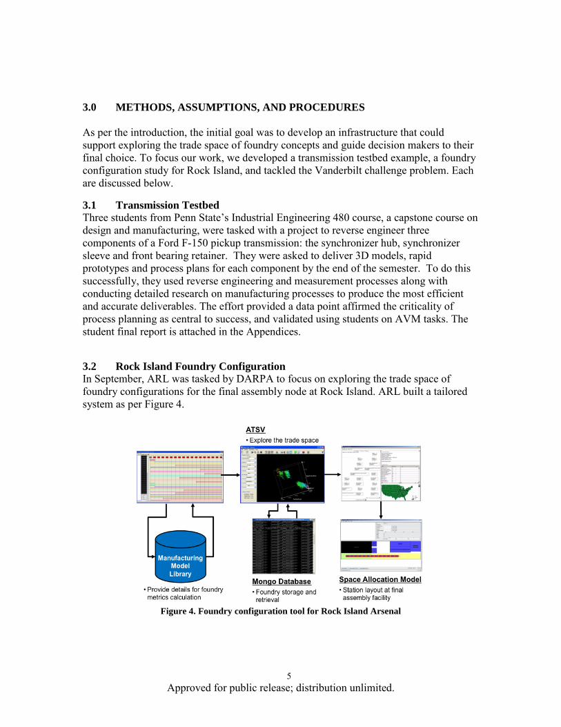
3.2 Rock Island Foundry Configuration In September, ARL was tasked by DARPA to focus on exploring the trade space of foundry configurations for the final assembly node at Rock Island. ARL built a tailored system as per Figure 4.
Figure 4. Foundry configuration tool for Rock Island Arsenal

6 Approved for public release; distribution unlimited.
The objective of the exercise was to rapidly populate the trade space of foundry concepts to support near-term decisions on what will constitute a foundry for Phase I of the FANG. Assumptions were that full IFV WBS level 4 subassemblies up to entire assembled vehicle, painted, and tested; that the the vehicle would be similar in scale to AAV / EFV, and that major subsystems would be fabricated/manufactured off site and shipped to the foundry location. Figure 5 shows all of the components considered for the IFV, decomposed to WBS level 4. The numbers to the right of the components point to other components that are connected, thus the table represents the liaison graph of the assembly.
Figure 5. Full IFV WBS level 4 and liaison relationships
The combinatorial orderings possible for assembling the IFV are essentially uncountable. To populate the trade space, we first randomly search through assembly sequence orderings. Each ordering results in a different cost/schedule set of metrics. These arwe visualized and explored, for example in Figure 6.

7 Approved for public release; distribution unlimited.
Figure 6. Visualizing multiple foundry concepts in a comparative view
A discrete event simulation is used to verify the robustness of the manufacturing schedule by modeling resource constraints and contention for capacity. Using monte carlo methods results in distributions of times for manufacturing spans, Figure 7.
Figure 7. Distribution of manufacturing span based on Monte Carlo discrete event sim
Finally, in support of the exercise ARL adapted a space allocation planning tool developed for shipyard use to this problem. The tool allows a user to plan space usage based on IFV configuration, process flow, and physical layout constraints, Figure 8

8 Approved for public release; distribution unlimited.
Figure 8. Results of layout allocation tool showing two different foundry configurations, one of which
violates physical constraints of the site
A key lesson from the foundry configuration exercise was again the criticality of automated process planning.
3.3 R/C Car Study Vanderbilt was tasked to provide the AVM iFAB team with a challenge problem. In response, they used the 3D model of a radio controlled car, Figure 9. The geometry was provided in both Pro Engineer CREO format and in STEP AP 203. Augmenting the geometry was an Excel file which called out which parts were considered manufactured and which were COTS.
Figure 9. Challenge Problem
ARL broke the challenge problem into two separate aspects; the first was a collaborative effort between ARL and the other iFAB performers to instantiate our iFAB architecture for the R/C car. The second was a solo effort to explore the impact of parameterizing the design space of the R/C car components on our ability to exectute the AVM goals.

9 Approved for public release; distribution unlimited.
3.3.1 Collaborative Under the collaborative effort, ARL composed the problem as in Figure 10.
Figure 10. Collaborative effort in challenge problem
ARL manually opened and decomposed the challenge problem, developing an mBOM (manufacturing bill of materials) that reflected a logical grouping of parts into subassemblies and then a final assembly. We completed describing the parts to include weights and volumes (for assembly analysis), and indentified parts for analysis approach for manufactured parts (feature-based versus arbitrary geometry). We then used an internally developed assembly planning and sequencing tool to generate the space of potential assembly sequences and estimate their time and cost. In determining time and cost, we connected to Boeing’s MCPML tool through their internet API to allow them to determine costs of specific interconnect steps. Boeing MCPML was accessed through SOAP commands invoking the following queries:
• getFasteningMethods • getFasteningMedium • getAssemblyFastenTime
Assembly time analysis currently considers two parts. Part weights not complete in current META challenge, so we augmented the problem with weight values. Fastening method and medium also required assumption. This information must be provided by design / META. To demonstrate accessing a Component Model Library, ARL instantiated one specific to this problem and populated it with the COTS parts from the challenge problem. Ninety-three parts in the META challenge problem are OTS. The library was written using a PostgreSQL database, and specifies multiple suppliers for each purchased part, with cost and time metrics. Cost and delivery times for the COTS parts were notional. A sample is in Table 1.

10 Approved for public release; distribution unlimited.
Table 1. Sample of COTS parts entries, two suplliers per part
Part Number Quantity S1 Cost ($) LeadTime (days) S2 Cost ($) LeadTime
(days) 86417 2 1 117.58 12.39 1 555.58 19.97 94510 2 0 0.00 0.00 1 0.00 6.26 94631 2 1 55.03 0.29 1 19.03 27.95 94632 2 0 0.00 0.00 0 0.00 0.00 94707 2 1 77.57 12.18 0 0.00 0.00 94710 2 0 0.00 0.00 1 0.00 13.40 94730 2 1 6.57 3.82 1 278.02 5.64
85418_1 1 1 52.33 12.41 1 56.66 1.15 85418_2 1 1 27.74 14.54 1 407.20 27.94 85418_3 1 0 0.00 0.00 0 0.00 0.00 85418_4 1 1 105.04 15.35 0 0.00 0.00 85422_12 2 0 0.00 0.00 0 0.00 0.00 85438_1 2 0 0.00 0.00 1 0.00 24.31
Z664 2 1 69.60 19.57 0 0.00 0.00 Z665 6 1 218.85 24.31 1 404.79 25.33
102480 2 0 0.00 0.00 1 0.00 13.95 85400_2 1 1 55.70 1.54 0 0.00 0.00 86405 1 1 31.29 17.95 1 1759.40 19.78 86417 1 0 0.00 0.00 0 0.00 0.00 86634 1 1 82.11 1.78 0 0.00 0.00 94520 1 1 76.20 13.59 0 0.00 0.00
85422_6 1 0 0.00 0.00 0 0.00 0.00 Z103 2 0 0.00 0.00 0 0.00 0.00 Z216 1 1 87.92 21.59 0 0.00 0.00 Z684 1 1 122.75 5.06 0 0.00 0.00
85400_2 1 1 53.33 2.38 0 0.00 0.00 86405 1 1 83.68 4.02 0 0.00 0.00 86417 1 1 67.21 4.69 0 0.00 0.00 86634 1 1 71.30 16.67 1 73.22 0.23
To assess manufacturability, we utilized Georgia Tech’s feature/attribute-based approach and PARC’s AMFA software to determine manufacturability and estimate cost and schedule. The first approach is independent of actual geometry, requiring only a list of features and their attributes. The second can tolerate (in theory) any arbitrary geometry. For the feature-based approach, geometry is not necessary to analyze part for manufacturability (cost and schedule). It does require an input method for designers to specify feature attributes. Once available, one can query the GT and PSU libraries for available processes / resources capable of making the feature. Advantage is that it eliminates the need for CAD model reasoning. Drawbacks include that there currently is no standardization of features (a taxonomy) and it is difficult to identify features that can be considered in a single machine setup. A front upper brace part was used for the feature-based approach, Figure 11.

11 Approved for public release; distribution unlimited.
Figure 11. Front upper brace with features
The identified features were • a boundary-through feature-complex • through holes • chamfer • fillet
The feature list was represented in XML as per Figure 13. No geometry was needed for the input. For the arbitrary geometry case we integrated with the PARC AMFA tool for geometric reasoning and process planning of difficult-to-characterize components. AMFA returns alternative process plans and corresponding cost and manufacture time, but is currently limited to machined components on a 3-axis mill. The flow for using AMFA is shown in Figure 12.
Figure 12. Using AMFA to assess designs

12 Approved for public release; distribution unlimited.
Figure 13. XML representation of the feature list
One the system was composed, ARL was able to exercise and generate a notional trade space capturing the trade-offs of cost and schedule, and visualize it in ATSV (Figure 14).

13 Approved for public release; distribution unlimited.
Figure 14. Visualizing challenge problem foundry trade space in ATSV
3.3.2 Focused Effort on Parametric Parts and Design Space In this effort, ARL’s goal was to do an end-to-end exercising of the tool chain, from design all the way to manufacture. To do so we used suspension components from Vanderbilt problem, which were originally considered OTS. We parameterized the suspension (Figure 15) and remodeled in SiemensNX to develop parametric models with full GD&T data tied to model. We then tied models to NC code generation and used vericut for machine simulation. The SiemensNX CAD was exposed through an interface to iFAB agent architecture. Bounds were set on acceptable parameter values.
Figure 15. Suspension with arms parameterized
For the design side, we developed a simplistic dynamic model that modeled the impact of tire with curb and calculated max deflection and max force on the suspension, Figure 16. We could then exercise the tradespace for performance and manufacturability.

14 Approved for public release; distribution unlimited.
Figure 16. Simple dynamic model of suspension
For the lower suspension, we used the CNC-RP technique developed by Iowa State University to machine the lower arm as-is (Figure 17). This method is restricted to certain part geometries such that there exists an axis of rotation where all faces of the part can be reached by a tool. This will be the case as long as there are no set of holes that form an orthogonal set of axes in 3D space. Using their capability it took 53 seconds for process planning algorithms (axis, visibility, supports, setup angles, tool selection, etc.) and then 4 minutes and 22 seconds for Toolpath generation. We had Iowa State make two parts, the first out of high density foam (6 hours mill time) and the second from aluminum (7 hours).
Figure 17. Lower suspension arm test case using CNC-RP
The following lessons-learned emerged from the two efforts: • Integration was a challenge
o Plethora of languages/formats o No full-scale standard API (Intentional working on it)
• Parameterizing models enables rapid design alternatives and manufacturability feedback for manufactured parts
• Manual Intervention Required: o Feature Identification – Underscores need for part-to-process mapping o Fastener Identification – from design? o Additional meta-data generation and inclusion – material, tolerances,
finishes, etc.

15 Approved for public release; distribution unlimited.
4.0 RESULTS & DISCUSSION This section presents first the philosophical approach towards instantiating an iFoundry, particularly with regards to automated process planning,that has emerged through our work. Second is a description of the final iFAB information architecture that has evolved over the course of the project.
4.1 The Criticality of Automated Process Planning Automated process planning is the heart of the matter in accomplishing the AVM goals of instantly instantiating a foundry and manufacturing a vehicle. Such automated planning must determine the manufacturing operations, operation sequence and resources required to manufacture a product based on the design data. A process plan elaborates the machines, setups, tool specifications, operation time estimates, etc. required to convert raw material into a part. It is at the center of the manufacturing process.
4.1.1 State of the Art in Process Planning Current state of the art in manufacturability assessment and process plan generation does not support automatically assessing a design for manufacturability and generating a complete process plan for typical machined component designs such as found in armored vehicles like the AAV and the EFV. First, there are no open adopted standards for passing manufacturing information from the designer to the manufacturer. Second, the tools and techniques do not yet exist to automatically generate process plans for all but the narrowest cases. STEP AP 242 (ISO-10303-1 1994) is a standard for incorporating manufacturing information with geometry and is currently under review by the manufacturing and design community, but it is not yet been accepted. When accepted, the major CAD vendors will lag in implementing the capabilities. Until they do implement STEP AP 242, users are restricted to a proprietary tool chain, which is counter to the openness of crowd challenges. Even when geometry can be tagged with manufacturability information, except for very limited subsets of the design space, the state of the art in manufacturability assessment and process plan generation for a typical manufacturing concern does not currently support automation (Denkena, Shpitalni et al. 2007; Xu, Wang et al. 2011). Instead, humans are directly in the loop in analyzing the design and providing feedback to the designers, usually iterating over individual designs. The design changes then propagate back into the total system design, creating additional changes with time delays that are unacceptable to this effort. In order to do automated planning we need to model component manufacturing resources such as machine tools and material handling equipment, and model individual process steps such as cutting and grinding. However, while the models are necessary to

16 Approved for public release; distribution unlimited.
automating the process planning, they are in no way sufficient. The crux lies in linking them to form the plan. Denkena (2007) states with respect to Computer Aided Process Planning (CAPP) that “no viable off-the-shelf solution can yet be easily or widely implemented in industry.” In the recent 2011 survey paper of the field of Computer Aided Process Planning, Xu (2011) notes that “CAPP has been lagging behind in terms of providing practical, matured, professional and commercialized solutions to the manufacturing industry. This is though not attributed to the lack of research effort.” The design case studies conducted under the META/iFAB efforts have consistently identified process planning as a critical gap, and PARC has made strong progress in dynamically creating process plans for geometric parts, albeit of simplistic topologies, yet neither the ongoing efforts in the DARPA AVM program nor this effort expected to extend automated planning to the complete family of parts typically found in an armored vehicle. So Xu’s comments accurately capture the current state of the art that the iFoundry performer must live with. The question then is, for what subclass of parts and assemblies can automated planning be successfully executed?
4.1.2 Parametric Process Planning One method that is within the scope of the state of the art for automated process planning today is a blend of variant and generative modeling (Swift 1987), based on product classes and templates. In Chen (2006) they develop a parametric process planning approach which shares similarities with both variant and generative approaches. It is similar to variant in that parts are classed into similar topologies that can be parameterized to be fully understood. Generative, in that the process can be fully automated and extended to parts with varying sets of parameters. Doing so, they were able enable automated process planning for parts as complex as in Figure 18, which had 20 discrete features and 100 parameters total.
Figure 18. Automotive connecting rod, fully parameterized with 20 features and 100 parameters
(Chen, Huang et al. 2006)
In the bicycle industry, several manufacturers have achieved customization through modularity and part family design in order to satisfy the wide range of customer needs and the variability in rider anthropometry. For instance, the National Bicycle Industry Company (NBIC) in Japan is able to produce over 8 million variations of their Panasonic bicycle through an online custom ordering system that guarantees delivery in 2 weeks (Kotha 1995). Once a customer order is received, a CAD file for the custom frame is generated along with computer-aided manufacturing instructions for tube cutting and finishing, front and rear triangle assembly, and automated measuring for inspection. The

17 Approved for public release; distribution unlimited.
tubes are then cut to size, welded, and assembled together into a raw frame, which is heat treated, cleaned, and painted according to the user specification; components are then added to the frame based on the user’s specification. Cannondale also redesigned one of their bicycle lines and automated their manufacturing operations to enable customized orders (Ulrich, Randall et al. 1998). Specifically, they implemented a CNC laser cutting process to cut, miter, and create a slot-and-tab design on each tube (Figure 19). This significantly simplified the fixturing and tooling that was needed to position tubes for welding since the slot-and-tab ensures any frame geometry can be quickly assembled and welded together once an order is received online.
Figure 19. Cannondale’s slot-and-tab design (Ulrich, Randall et al. 1998)
Meanwhile, the automotive industry has tried to leverage fabricate-to-order approaches like these, while emulating assemble-to-order approaches popularized by computer companies like Dell (Shimokawa, Jurgens et al. 1997). The challenges of such approaches are extensive and daunting (Parry and Graves 2008); however, many companies are making significant progress using platforms and modular bodies (Untiedt 2008), and the performance of modular outer panels and doors has shown remarkable progress compared to conventional approaches (Cetin and Saitou 2004; Gude and Hufenbach 2008). In our own work with underwater vehicles at ARL Penn State we have developed parameterized models for complex hydrodynamic shapes such as propulsors and pump jets that can automatically generate the models that are machineable at ARL’s facilities (Figure 20).

18 Approved for public release; distribution unlimited.
Figure 20. From parameter sets to 3D machineable solid model for complex propulsor geometries at
ARL Penn State
Another potential example of a generative design is a wire harness. The harness is more complex in terms of modeling in that there is not a fixed set of parameters. While each wire in a harness can be parameterized, (e.g., wire material, insulation material, diameter and length), the information about a complete harness cannot be captured by a simple set of parameters. Instead, rules for numbers of wires in bundles and terminating at connectors combine with the parameters associated with individual wires and connectors to fully define and constrain the harness. Similarly piping is a candidate for modeling as a generative design, with individual pipe segments parameterized by length and diameter for example, and the number of segments ranging from 1 to an arbitrary N.
4.1.3 Manufacturing Feedback for parametric designs Adopting a parametric form provides a very natural interpretation of the space of manufacturable designs. For a design with n parameters, there is an n-dimensional space with each dimension related to a parameter of the design. Within this space there is a subspace of parameter values for which the design is iFAB-able (can manufacture, generate cost & schedule, and generate NC code and work instructions). Evaluating a design for iFAB-ability means verifying the design is in this subspace. If it is not, then we can calculate the nearest point(s) in the subspace to the desired point as feedback to the designer. Consider the simple part in Figure 21.
Figure 21. Simple plate part with 4 drilled holes

19 Approved for public release; distribution unlimited.
The part has 4 drilled holes with fixed distances to the edges, and has define by two parameters, X and Y that constrain its manufacturability and that correspond to a 2D space with a subspace of feasibility (Figure 22).
Figure 22. Parameter space for the part, with the manufacturable subspace identified
If a submitted design is outside the subspace, the agent can return the region of the subspace closest to the submitted design as part of the manufacturing feedback analysis. For designs that are generative as opposed to parametric, or are not strictly parametric, they can be modeled as strings in a language, with the iFoundry covering a subset of all possible strings, i.e., a sub-language. Submitted designs that are not a part of the sub-language are not manufacturable. Feedback can return strings/designs that are in the language using metrics of semantic distance to identify closest designs.
4.1.4 Creating the Parametric Process Plans While it is not possible to devise a one-size-fits-all structure for a process planning engine given the differences in manufacturing challenges between products as diverse as wire harnesses, machined parts, and direct digital manufacturing, Figure 23 illustrates the automated process planning methodology that can be broadly used to build automated process planning capability. Process planning can accommodate the lowest component level (e.g., a bracket), the sub-assembly level (e.g., suspension system), all the way up to an entire ACV.
Figure 23.Semi-automated process planning methodology
The process planning methodology is based on three levels of process plans, starting with a high-level plan of manufacturing process classes and working towards a fully detailed process plan with specific foundry resources selected and NC code and human

20 Approved for public release; distribution unlimited.
instructions generated. Key to this process is the identification of a part/process class for each design component received. Figure 24 shows a high-level process plan for a notional amphibious combat vehicle non-composite, monocoque hull. The first step in the high-level plan includes the cutting of the many sheets of steel or aluminum needed to make up the hull. The second step is plate prep. The third step includes the forming of those plates to the required hull shape. The forth step is a heat treatment/plate hardening step. The fifth step welds the hull structure. Finally, the high-level process plan concludes with a machining step.
Figure 24: High-level process plan (monocoque hull example)
Note that high-level process plans will be developed a priori once the Infantry Fighting Vehicle (IFV) part classes are fully defined. However, the mapping of the part class to the high-level process plan (i.e., the instantaneous identification of the high-level process plan) will occur after designs are submitted for manufacturability feedback analysis. The high-level process plan will not likely rule out the manufacturability of a particular component unless that component does not belong to one of the pre-defined part classes. However, once the high-level process plan is generated, the process planning algorithm can begin considering available process alternatives and process capabilities. The result of this is the mid-level process plan, as described in the next section. There are typically many different ways a particular component can be manufactured. For example, steel plate cutting capabilities in the foundry include laser cutting, waterjet cutting, plasma cutting, and oxyfuel cutting. Each has its own cost, schedule, and quality tradeoffs. After verifying material, plate thickness, etc., it may be found the waterjet, plasma, and oxyfuel cutting processes are capable of manufacturing the unique shape, but perhaps the laser cutting process cannot be used due to material thickness limitations. In this case, only the waterjet, plasma, and oxyfuel processes would be considered for more detailed process planning, which would include selection of specific equipment, determination of estimated manufacturing cost and schedule, selection of machine parameters (i.e., feeds and speeds) and generation of NC code and human instructions. Following up on the example from Figure 24, process alternatives for the balance of the steps for the mid-level process plan for the monocoque hull are shown in Figure 25.

21 Approved for public release; distribution unlimited.
Figure 25: Mid-level process plan (monocoque hull example)
Similar to the high-level process classes, mid-level processes (those made available by the iFoundry team) will be modeled and included in the MML. Each mid-level process model will be attributed with a corresponding high-level process class. Note that previously modeled processes (from iFAB teams) will need to be augmented with this high-level process class information. Attributing the mid-level process plans with the high-level process class information enables the full mapping of the high-level process plan to the expanded mid-level process plan with manufacturing alternatives. As highlighted in the steel shape-cutting example above, manufacturability of a component can sometimes be determined in the mid-level process planning step by using attributes from the design product model. For instance, a part that requires cutting of 4” thick steel cannot be manufactured if the cutting processes are modeled for a maximum of 3” thick steel based on the foundry team’s capabilities. Mid-level process capabilities that will map to design model attributes include
• Material • Surface Finish • Hardness • Thickness • Size (LxWxH) • Bend radius/angles • Outer/Inner diameter • Minimum tolerance
Both High-level and Mid-level process plans will be coded in advanced and stored in the MML for retrieval. The mid-level process plan is essentially a collection of more detailed process models from the MML and identifies process alternatives for a high-level process.

22 Approved for public release; distribution unlimited.
Low-level (detailed) process planning is necessary to provide accurate manufacturability metrics as well as for configuring the foundry for all levels of FANG designs. The primary metrics of interest include cost and schedule, where schedule may infer several sub-metrics including time to first part, per part cycle time, and time to full rate production. Low-level process planning will be dynamic, as there may be thousands of process plan candidates based on process and resource choices. Developing a detailed process plan will begin with selecting one of the process alternatives from the mid-level process plan by our agent system. Once a process alternative is selected, the agent system will query the MML to retrieve the corresponding process model as well as the resource models needed to complete that process. Just as there are several mid-level processes that map to a high-level process class, there can also be several specific resources (e.g., machines) that map to a specific mid-level process. A detailed process plan will tie to a specific selected resource where alternative resources exist. This implies that multiple detailed process plans can be generated for a selected process. Once the set of all resources is selected by the agent system based on requirements as defined in the process model (i.e., machines, tools, labor, etc.), the submitted design will then be analyzed for cost and schedule metrics. We will use the manufacturing rules and constraints identified by the foundry manufacturing partners and captured in the manufacturing agents to calculate these metrics based on part/process class attributes. Once the resources have been determined for a selected process, manufacturability has been confirmed, and cost and schedule metrics have been generated for the component being analyzed, the detailed process plan can be completed by generating CNC and human worker instruction sets, where applicable. These steps are discussed in Section 2.1.
4.1.5 CNC-Rapid Prototyping & Wire Electrical Discharge Machining-Rapid Prototyping Iowa State’s Rapid Manufacturing and Prototyping Laboratory1 along with researchers from University Alabama-Birmingham and Bradley University have developed the techniques and supporting software tools to use both CNC machining and wire electrical discharge machining as mechanisms for rapid prototyping. The software tools are CNC-RP and WEDM-RP respectively. The software can quickly (minutes) assess whether the techniques are applicable, and if so the software can on the order of to 30-40 minutes generate a complete process plan and CNC machine code ready for manufacture. The key to this capability lies again in restrictions to the design space. CNC-RP presents a method for ‘feature-free’ CNC machining that requires little or no human-provided process engineering. This methodology is a purely subtractive process that can be applied to any material that can be milled on CNC machines. Achievable tolerances are at the limits of current 3, 4, and 5 axis milling machines The method 1 http://www.ie.imse.iastate.edu/rmpl/default.aspx

23 Approved for public release; distribution unlimited.
described herein was developed in response to the challenge of automating as much of the process engineering as possible. The ultimate goal is to generate both the NC code and an automatically executed fixturing system by the touch of a button, using only a CAD model and material data as input. The process is perfectly suited for prototypes as well as parts that are to be produced in small quantities (Frank 2003; Frank, Wysk et al. 2004; Frank and Wysk 2006). For CNC-RP the basic concept is to machine the visible surfaces of a part from each of a plurality of orientations. In order to simplify the problem from both a process and fixture-planning standpoint, only rotations about one axis for orientations of the stock material during processing are used. This not only reduces the problems associated with process planning, but it assures the absolute collision-free nature of the approach. From each orientation, some, but not all of the part surfaces will be visible. The goal is to machine the part from enough orientations, such that, after all toolpaths are complete, all surfaces have been fully machined from at least one orientation. For each orientation, there is no particular plan for a set of feature machining operations; rather, geometry is machined using simple 2 ½D layer-based toolpaths.
Figure 26. Set-up for CNC-RP
The rapid machining process is based on a setup strategy whereby a rotary device is used to rotate round stock material that is fixed between two opposing chucks (Figure 26). For each orientation, all visible surfaces are machined and the sacrificial supports keep it connected to the uncut ends of the stock material. Once all operations are complete, the supports are severed (sawed or milled) in a final series of operations and the part is removed. Post-processing is performed to finish the minimal support contact patches on the part. The key restriction to part geometry is that there must exist an axis of rotation and a set of orientations so that eventually the entire part surface is “visible” to the mill. The CNC-RP software can make this determination on the order of minutes, and generate the plan in under an hour. Below are some of the parts and geometries that have been machined using CNC-RP. Figure 27 is a steel bicycle component undergoing machining, and the finished part. Note the sacrificial fixturing connected to the rotary indexers.

24 Approved for public release; distribution unlimited.
Figure 27. Bicycle component being machined and resulting part
Figure 28 is a steel linkage with machining complete but before the sacrificial fixturing has been cut, along with the completed part.
Figure 28. Steel linkage undergoing machining and finished part
The final example is a V-8 engine with the block being cast iron and the intake and heads machined from aluminum (Figure 29).
Figure 29. V-8 engine block, intakes, and heads all milled using CNC-RP.

25 Approved for public release; distribution unlimited.
The view of the engine block alone highlights the ability of CNC-RP to machine complex shapes (Figure 30).
Figure 30. Engine block machined using CNC-RP to verify the design and generate process plan.
Block is cast iron.
In a similar fashion, the WEDM-RP can machine complex shapes as long as all surfaces are visible, in this case an entire facet must be visible, no cavities permitted. However, within those constraints complex parts such as Figure 31 can be instantly assessed and machined.
Figure 31. Axially symmetric part setup and finished geometry machined using WEDM-RP.
Both CNC-RP and WEDM-RP are ready for AVM. The current CNC-RP process has been implemented in the ISU RMPL lab on a FADAL VMC15 4-axis milling machine, and on CNC machines at the John Deere Service Parts Operations in Waterloo Iowa, North Carolina State University, and at the University of Iowa, Orthopedic biomechanics Laboratory. The John Deere test site was devoted to service parts for legacy agricultural equipment, the NC State site for post processing Electron Beam Melting (EBM) parts and the University of Iowa Site for the rapid machining of bone implants for high energy trauma (IED, gunshot, high-height falls, etc.). Although the current version of CNC-RP is focused on delivering physical parts, it implicitly delivers Design for Manufacturing (DFM) analysis. That is, one must determine if and by how much a design is manufacturable before ever starting to process
26 Approved for public release; distribution unlimited.
plan. The research efforts have thereby been devoted to answering questions about the CAD model put in front of it, i.e., 1) Can it be fixturing about an axis? 2) How visible is it about that axis? 3) What are my tooling and cost trade-offs for each setup choice? 4) how can the part be fixture, if at all? 5) What angles should I machine from and what should I machine from each? and 6) What tools and parameters will I need to start the machine? These along with others must be determined in seconds and minutes, not hours or days. The current CNC-RP software can receive a CAD model, and under one hour, cycle-start the milling machine.
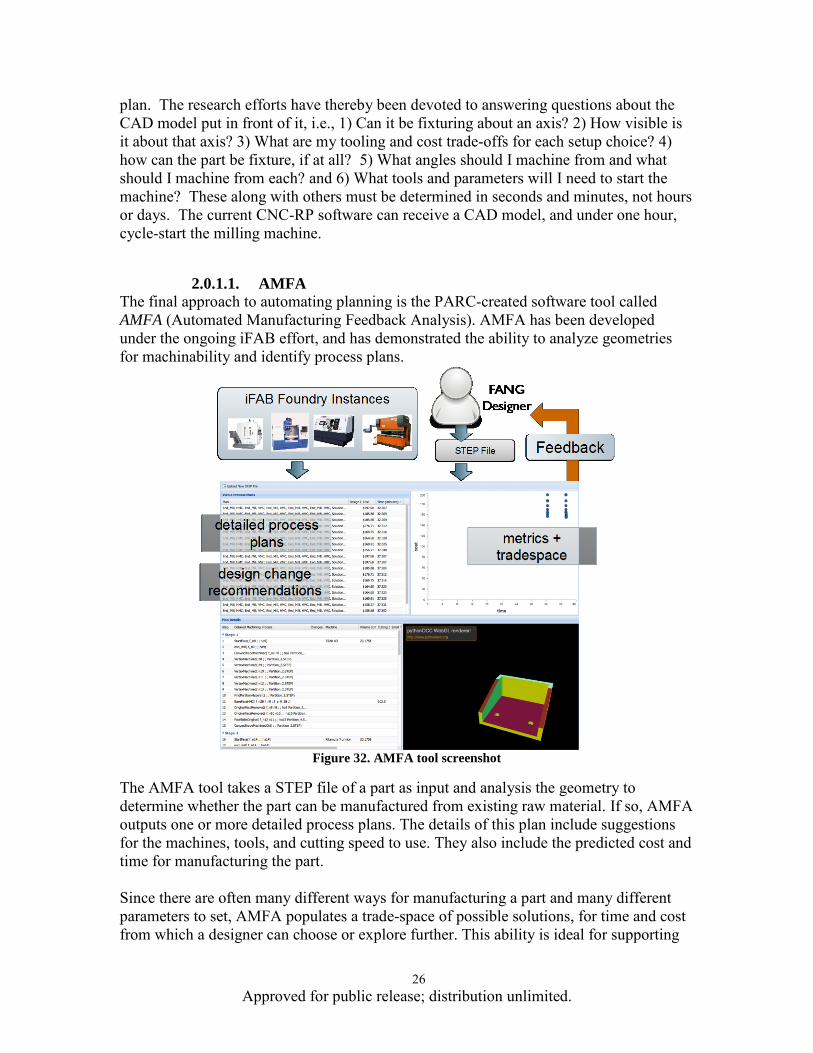
2.0.1.1. AMFA The final approach to automating planning is the PARC-created software tool called AMFA (Automated Manufacturing Feedback Analysis). AMFA has been developed under the ongoing iFAB effort, and has demonstrated the ability to analyze geometries for machinability and identify process plans.
Figure 32. AMFA tool screenshot
The AMFA tool takes a STEP file of a part as input and analysis the geometry to determine whether the part can be manufactured from existing raw material. If so, AMFA outputs one or more detailed process plans. The details of this plan include suggestions for the machines, tools, and cutting speed to use. They also include the predicted cost and time for manufacturing the part. Since there are often many different ways for manufacturing a part and many different parameters to set, AMFA populates a trade-space of possible solutions, for time and cost from which a designer can choose or explore further. This ability is ideal for supporting

27 Approved for public release; distribution unlimited.
foundry trade space exploration. When no plan can be found, AMFA makes design change recommendations that would make the provided design manufacturable. Currently, AMFA is capable of reasoning about 3-axis CNC milling, drilling, and basic fixturing. PARC has also demonstrated proof-of-concept extensions for waterjet cutting, bending, and reasoning about pre-cast models. PARC anticipates using the output of AMFA to feed into a manufacturing process and demonstrate building a part in the near future. PARC will expand coverage to cutting, lathe turning, pre-cast, fixturing, 4/5 axis CNC milling, sheet-metal bending, and tube bending, and will also extend AMFA's capabilities to provide manufacturability feedback to tolerances and tool accessibility, as well as to quickly provide feedback based on verification of common design-for-manufacturing practices.
4.1.6 Assembly Sequencing The assembly sequencing has two main functions 1) creating feasible assembly sequences, 2) creating an assembly structure. An assembly can be considered as a combination of several subassemblies, parts and features. Assembly sequencing is a combinatorial problem that deals with different subassemblies or parts. Creating assembly sequences implicitly entails developing an assembly structure. The three steps of assembly sequencing include defining precedence constraints, generating feasible assembly sequences, and choosing one final assembly. We will implement a method derived from the present two classes of techniques used to solve the assembly sequencing problem: (a) Geometric Reasoning and (b) Combinatorial Approach. In the Geometric Reasoning approach, assembly sequencing is interpreted as a reverse disassembly-sequencing problem that involves inferring a sequence of actions that transforms an assembly to an unassembled state - consisting of isolated components (Romney, Godard et al. 1995). The advantage of starting from an assembled state is that it reduces the search space due to inherent constraints (degrees of freedom) on the mobility of individual components. The geometry of the design is used to determine if a part or sub-assembly can be removed without interfering with other components in the design. This approach can be used to solve the assembly sequencing problem, however it is computationally expensive. The Combinatorial Approach requires the precedence relationships of all the components prior to the development of the graph or tree structures (De Mello and Sanderson 1991). The current state of this approach requires a complex algorithm to cut the liaison graph to generate the precedence relationships or relies on a domain expert. However, once the precedence relationships have been generated, this approach offers more flexibility and reduced computational complexity to generate the assembly sequences and structure. In addition, combinatorial optimization techniques can be applied to quickly search the graphs to determine the assembly sequences. A hybrid approach would exploit the good properties of each method while making up for the shortfalls. The proposed approach would receive CAD geometry and an associated liaison graph, perform geometric reasoning to determine the precedence

28 Approved for public release; distribution unlimited.
relationships, and perform combinatorial search to derive the assembly structure and sequence. Figure 33 shows the high-level flowchart of the proposed approach.
Figure 33: Proposed Assembly Sequence Generation Approach.
Geometric reasoning determines the precedence relationships between the components in the design. We expect that most of assemblies will be decomposable via the geometric reasoning approach and only a few complex designs in a vehicle will need to be interpreted by a human expert. Once the precedence relation is set, the combinatorial approach can complete the solution. We will implement a Geometric Reasoning approach, a Combinatorial approach, and a hybrid approach that will leverage the positive aspects of each. The Assembly Sequence Generator (ASG), the embodiment of the algorithms, will be developed in a custom Java-based application developed by ARL Penn State in coordination with the Penn State College of Engineering. The Java-based application will interface with the open source (C++ based) geometry engine, OpenCascade2. The ASG will be hosted on the cloud due to the significant number of computations and inferences for larger problems.
4.1.7 Generating the Part Classes Adopting the approach of limiting the design space to restricted part classes that support either parametric process planning or CNC/WEDM/CAST-RP process planning offers the AVM program the best opportunity to realize the goals of instantly instantiating a foundry and manufacturing components. It is the approach we advocate, however it directly impacts the other AVM efforts to include the FANG, iFAB, and C2ML projects. Therefore in order to provide sufficient variety for the designers, we will work with the FANG performer to extend pre-validated and purchased parts to parameterized and generative parts that support parametric process planning. Under the AVM effort the FANG performer is required to seed the design space with feasible designs. The individual instances of parts can be parameterized, and relationships developed between the parameters of the part and cost & schedule, and also the particulars of the individual steps of the process plan. Similarly, we will work with the FANG performers to capture to the maximum extent possible the restrictions imposed by the CNC-RP and WEDM-RP methods in the FANG design software so as to minimize the negative manufacturing feedback results and incentivize correct design for manufacturability.
2 http://www.opencascade.org/

29 Approved for public release; distribution unlimited.
4.1.8 Summary of Benefits of Pre-negotiated Part Classes The methods and tools of parametric process planning, CNC/WEDM/CAST-RP, AMFA, and the Assembly Sequence Generator all provide bridging mechanisms that, while constraining the design space, still enable a broad variety of parts for the designers while meeting the essential goal of enabling automated process planning. In forming the bridge, each requires an understanding by both the manufacturing and the design side as to how the tool constrains the design space and an agreement on the particulars of how model data are passed. However, we believe that designs of sufficient performance can be created from these part classes right now, and that once we engage and use the challenges to drive research, the space of parts that fit in this paradigm will expand rapidly.
4.2 Information Architecture ARL’s information architecture, developed under this effort to support the AVM design challenges, is conceptualized in Figure 34.
Figure 34. Foundry trade space exploration support. Designs are submitted to the agent
infrastructure with agents representing each the manufacturing concerns and all of the items in the product BOM. Candidate foundries are streamed to the decision tools. The decision team steers foundry creation to regions of interest and uses augmented views to gain insight. A final foundry
configuration is chosen based on team consensus.
Leveraging an agent-based architecture for a project of this scale and complexity is critical to its extensibility and robustness. The following details the key benefits from using an agent-based architecture:

30 Approved for public release; distribution unlimited.
• Scalability – The Agent System can be deployed on individual desktop
computers, compute clusters and on cloud-based computing systems. Agents can migrate seamlessly between computers, thereby distributing the workload across all available processors. Furthermore, agent systems can gracefully scale with the system load. As the system load changes over time, compute nodes can be brought online or shutdown as needed.
• Modularity – Modularity is an important consideration when developing large-scale software systems. Building a large-scale system from smaller modules, whose functionality can be defined, implemented and tested, follows tried and tested software development best practices. Agent-based systems implicitly support a modular design, as each agent performs tasks independently or jointly through well-defined communication protocols.
• Testability – Resulting from its modular design, each module or agent can be extensively tested to ensure their correctness and reliability. Unit tests exercise each agent independently whereas integration tests validate the interactions between agents. Both forms of tests will be used extensively to ensure the correctness of the entire iFoundry.
• Expandability – Most software systems must be completely shut down and
restarted in order to integrate new or upgraded components. This would result in service outage. With an agent-based system, new agents can be introduced into the system at runtime. For instance, a new type of manufacturing agent can be introduced into the Agent System without causing manufacturability feedback or other vital services from going offline.
• Fail-safe Error Handling – In the event of a catastrophic error or system outage,
agent-based systems can provide fail-safe error handling and recovery. For instance, an agent experiencing an unrecoverable software error may cause said agent to terminate, but the Agent System as a whole will continue unaffected. The Agent System actively monitors agent responsiveness, and will automatically create a new agent instance to replace the crashed agent. This same strategy permits recovery in the event of partial system outage, such as due to power loss.
• Segregation – The Foundation for Intelligent Physical Agents (FIPA), an IEEE
standards organization, developed a standardized protocol for communication between agent systems. Any FIPA compliant agent software, such as the JADE agent system proposed for use in the ARL Penn State iFoundry effort, can communicate with any other FIPA compliant agent software. This implies there is no requirement for agents to be implemented on the same software or executed on the same hardware as the proposed Agent System. A performer with intellectual property concerns can implement and host agents on their own hardware, keeping their proprietary methods and data segregated from the rest of the Agent System.

31 Approved for public release; distribution unlimited.
4.2.1 Architecture Details The ARL Penn State iFoundry Architecture model is a coordinated system of software applications and databases that interact to provide foundry configurations, manufacturability feedback, process planning, CNC code, human work instructions, and build status reports. The overall System Architecture is shown in with the agent system as the core.
Figure 35: ARL Penn State iFoundry Architecture Model.
4.2.2 Component Model Library The component model library (CML) will be comprised of models for purchased (Off The Shelf) parts. Purchased parts are essentially catalog items that are either actively manufactured or have been manufactured in the past and therefore are guaranteed to be manufacturable. Purchased parts can be either piece parts (e.g., nuts and bolts) or assemblies (e.g., engines, struts). Purchased parts do not need to be assessed for manufacturability using the iFAB tools. However, there is information about purchased parts that will be critical for generating cost and schedule metrics for designs that use those parts. In addition, the cost and

32 Approved for public release; distribution unlimited.
schedule information for purchased/OTS parts will be necessary during the iFoundry configuration exercise once the final FANG challenge designs are selected. Methods for the population of purchased/OTS parts are currently being developed under the current C2M2L-1 program using technologies such as web-crawling. However, as these parts are added to the CML, it is not anticipated that the cost and schedule information for those parts, as it is required for iFAB, will be available.
4.2.3 Component Manufacturing Model Library We developed an additional library for components that are not purchased and therefore are either fabricated or assembled within the iFoundry manufacturing network. We call this library the Component Manufacturing Model Library (CMML). There are two types of component manufacturing models that will be added to the CMML: 1) manufactured parts and 2) assemblies. Manufactured parts are any newly designed piece parts presented by a FANG challenge participant. Assemblies are any combination of purchased parts and fabricated parts that have been assessed to be manufacturable. The makeup of assemblies in the CMML will have been defined by the FANG challenge designers.
4.2.4 Manufacturing Model Library The manufacturing model library (MML) being developed through current iFAB and C2M2L efforts provides information critical to assessing designs in terms of manufacturability and enable the final configuration of the iFoundry once a design is selected. In general, the MML are comprised of process models, which define relationships between sub-processes, physical and informational objects, and resources, both human and non-human, and resource models, which are used to calculate performance metrics, such as cost and schedule, and ultimately define process constraints. Manufacturing models are currently under development by performers under the DARPA AVM program. We anticipate iFoundry team members having processes that are not contained within the current process model libraries, and so will develop the process and resource models and include them in the MML. The ARL Penn State C2M2L-1 team is currently developing process and resource models for welding, casting, forging, ausforming, coatings (organic and inorganic), sheet and plate cutting, material handling, dimensional control, and wire harness assembly. Resource models are also being developed for processes being modeled by other iFAB/C2M2L teams, including machining, additive manufacturing, assembly, and forming. GA Tech is modeling a range of manufacturing processes common to the manufacture to ground vehicle components. These include, but are not limited to machining / material removal processes, permanent joining / assembly, and heat treatment. GA Tech has developed a custom language, Manufacturing SysML (M-SysML) to support the modeling of production processes. In addition, they have developed

33 Approved for public release; distribution unlimited.
templates for the modeling of specific resources used to execute those processes (e.g., 3-axis CNC Mill). The GA Tech process and resource models captured using M-SysML are stored in a database that is integrated with a query language to enable inquires into the database about processes and the resources associated with those processes. The database schema, as well as the model schema has been shared with Intentional Software for inclusion in the system MML. Boeing, in collaboration with General Motors, is developing a Manufacturing Capability and Process Model Library (MCPML) and is particularly focusing on processes that involve human interaction (e.g., assembly). Similar to the ARL Penn State approach to process modeling, each process is captured as a sequence of steps that reference resources (e.g., humans, tools, machines) required to execute the process. The models have the ability to identify the assembly type (e.g., mechanical – fastener), the elemental assembly steps, and the tooling required which are required elements in determining cost and schedule information. Any Manufacturing Model Library will need to be supplemented with both process and resource models above and beyond those currently being addressed.
4.2.5 Process Planning Engine As per Section XXX, automated process planning is the key to successfully achieving the AVM goals. The Process Planning Engine embodies this capability for whatever system considered, e.g., wire harness, machined part, or complex assembly. For each component it applies to the Process Planning Engine must accommodate one or more of the following:
• Assembly sequence generator • Fixture generator • Raw stock generator • CNC code generator • Work Instruction generator
4.2.6 Manufacturability Feedback Engine This block embodies the rules needed to provide manufacturability feedback. Since manufacturability implies the existence of a process plan and available resources, the MFE is closely related to the PPE and may internally embody the PPE in its construction. For example, the MFE can answer queries as to a component’s manufacturability by attempting to generate a process plan. If successful, it can then return associated cost and schedule metrics. If unsuccessful, it must then calculate a suggested change to the design to make it manufacturable. Conversely, the MFE could be built up from higher level heuristics and surrogate models, but these would ultimately need to trace their validation to realized processes. Additionally the MFE will track all queries, storing results in a database to act as a cache of previous queries and for mining.
4.2.7 Build Status Tracker The agent infrastructure mirrors the actual supply chain infrastructure that will be used to conduct the challenges, so the information architecture has been augmented with the code to track build status.

34 Approved for public release; distribution unlimited.
4.2.8 Final Assy Layout Generator The final assembly node will be located at Rock Island. It’s layout will be tailored to the particular design chosen and could be significantly different based on type of design (tracks versus wheels, hybrid-electric versus traditional configuration).
4.2.9 Model Decomposition Engine The Model Decomposition Engine will be responsible for decomposing the designs into operable pieces of geometrical and informational objects. This occur up front as one of the first steps in receiving a design. It is expected that the designs submitted will come as a package of information to include geometric information, geometric dimensioning and tolerance information, as well as information about material, surface finish, hardness, etc. In addition, there are no restrictions on CAD packages, thus it is expected that a native CAD model along with STEP models will be included in the package. The purpose of the Model Decomposition Engine is to convert the design package into a standard format that will be used throughout the Penn State iFoundry environment. From the standard format, the engine will decompose the design into graph structures as well as individual part representations, both geometric and textual. The agent system will be structured along the decomposition from which a detailed assembly structure can be made.
4.2.10 System/Software Interface The System/Software Interface is will embody both APIs that will allow interconnection to other code, and graphical, command line, and web-based interfaces to support human interaction.
4.2.11 Human Work Instruction Generator Human Work Instruction creation will be based on the process planning and assembly sequencing methodologies provided by the iFoundry architecture, and will leverage the development of human work instruction templates based on part classes and the selection of specific manufacturing sequences and resources. Recon will be the lead performer in developing the human work instruction templates. Recon will work with the individual Foundry manufacturing partners to review their standard work instructions for the processes and part classes they have been identified in the Foundry configuration to perform. Templates will be initially created for the following processes:
o CNC Machining o Casting o Plate Cutting o Plate Forming o Pipe Bending o Heat Treating o Blasting o Painting
35 Approved for public release; distribution unlimited.
o Dip Coating o Weld assembly o Mechanical assembly o Wire Harness Assembly o Hose Assembly o Inspection / Accuracy Control
ARL Penn State will develop software that will be able to perform the following functions to support the human instruction generation:
1. Obtain design relevant design data, based on part and process class, from the fully attributed product model
2. Obtain foundry configuration data for a particular part or assembly, including assembly sequence information and required resources.
3. Obtain resource specific information from the manufacturing model libraries (MMLs)
4. Obtain human instruction template information developed by Recon The output of the human work instructions will be concise documents with step-by-step process information, tool requirements, and machine settings that will be delivered electronically to the various manufacturing partners through their agent. We will also investigate automatically generating 3D isometric explosion diagrams for assembly work instructions, based on the geometric reasoning capability for assemblies. Finally, we will develop a prototype web-based work instruction viewer, where in addition to the textual step-by-step information, we will provide a light-weight CAD viewer to interrogate parts and assemblies where CAD models exist as well as standard views of exploded assemblies and rudimentary assembly simulation.
4.2.12 CNC Code Generator The iFoundry network will generate CNC instruction sets for NC equipment identified from the foundry configuration once a FANG design is selected. Therefore, generation of NC code, which can be computationally expensive, is not necessary during the design phase, where thousands of manufacturability queries will be executed during peak times. CNC code generation using one of the many off-the-shelf Computer-Aided-Manufacturing (CAM) products has historically been a largely manual process. The actual generation of the G or M-code does not require line-by-line manual programming, however, to initiate this generation, there are several manual steps that must be completed. This includes the selection of machine controllers, the identification of features (e.g., holes, notches, slots, chamfers, etc.), the identification of home position, and the selection of machining processes (e.g., 5-axis milling) mapped to the features. In addition, the CAM programmer is also responsible for providing the relevant GD&T information, such as feature nominal dimensions, tolerances, and surface finishes. Fortunately, manually applying GD&T information to part features can be avoided if the design is fully-attributed and contains Product Manufacturing Information (PMI). PMI is used in 3D CAD to convey information about the design of a product’s components for manufacturing, particularly GD&T, 3D annotation, surface finish, and material

36 Approved for public release; distribution unlimited.
specifications. Large CAD vendors such as Siemens NX offer CAM solutions that actually use the PMI information along with internal algorithms for feature and process recognition to automatically generate NC code.
4.2.13 Agent System The agent system is the central hub of the architecture and is responsible for accepting designs, manufacturability inquiries, and status update inquiries and coordinates the computations and analyses requested by the user. All agents are implemented using the JADE3 (Java Agent Development) Framework. JADE is an open source software Framework fully implemented in the Java programming language and is fully compliant with the FIPA specifications. Internal to the agents will typically be additional codes that actually carry out the computations defined in the interface, i.e., the back end. The particulars of the agent’s back end code will depend heavily on the function (supplier, manufacturer, status reporting) and also on who the agent is serving as a representative for (wire harness manufacturer, armor manufacturing, machining facility). The agent system is comprised of four types of agents: controller, product, supplier, and manufacturing agents. Figure 36 shows the class hierarchy of the agents, with arrows indicating inheritance. A class inherits all the functionality and behaviors from its parent class. For instance, the Manufacturer Agent inherits all the behavior of a Supplier Agent, but adds additional functionality to support manufacturability feedback requests. Within each class in Figure 36 are the agent performatives (the messages transmitted between agents).
Figure 36: Agent Design and Performatives.
3 http://jade.tilab.com/

37 Approved for public release; distribution unlimited.
The following sections describe the responsibilities and behaviors of the components of the agent system in greater detail.
4.2.13.1 Agent System Controller The Agent System Controller coordinates the behaviors and activities of the agent system. Depending on the input to the system, this controller will determine how to process the information and engage the specific nodes within the system that need to answer the specific inquiry. The Agent System Controller also coordinates the processing of multiple users requesting information. It will manage the queue of requests and ensure that the proper agent is handling the request. Its primary interaction will be with the product, supplier, manufacturing/assembly, and other specialized controller agents.
4.2.13.2 Controller Agents The controller agents are specialized extensions to the system controller that perform a specific function. These agents are responsible for accepting the input from the user, invoking the analysis objects, interfacing with the build statusing object, and providing information to the system controller for further action. The proposed agent system consists of two controller agents: the iFAB Controller Agent and the Manufacturability Controller Agent. The iFAB Controller Agent operates the iFAB toolchain developed ARL Penn State to exercise the agent marketplace, generate the foundry tradespace, and facilitate steering commands. The Manufacturability Controller Agent performs manufacturability assessments to provide real-time feedback to FANG Challenge participants.
4.2.13.3 Product Agents Product agents will ensure that every part in the design is accounted for through either purchasing the part or manufacturing the part, which includes assemblies. The product agents will be aligned according to the manufacturing product structure (manufacturing bill of materials; MBOM). The product agent responsible for a given node in the MBOM, will be attributed with a make or buy classification. Given this information, the product agent can determine if it needs to interact with the buyer agents or manufacturing/assembly agents.
4.2.13.4 Buyer Agents Buyer agents interact with the product agents to supply purchased parts. These agents draw information from the Component Model Library in terms of availability, cost and schedule of a part in the design.
4.2.13.5 Manufacturing Assembly Agents Given that a part/assembly will be made, the manufacturing/assembly agents are responsible for determining the cost and schedule for making it. To do this, these agents must interface with the process planning object and the MML to determine the process plan, assembly sequence, fixture requirements, labor requirements, etc.

38 Approved for public release; distribution unlimited.
4.2.13.6 Foundry Agents Foundry agents represent a complete iFoundry configuration and are responsible for generating detailed foundry configurations and providing status updates. The Foundry Agents interact with the Controller Agent and the Final Assembly Layout Generator to generate and maintain the final foundry configuration including layout, manufacturing capabilities, and flow of information and goods.
4.3 Object Model & Use Cases The object model is shown in Figure 37, and serves as a reference for the use cases. The overall sequence of events in the course of a challenge is shown in Figure 38, and can be divided into phases of Manufacturability Feedback, Foundry Configuration, and Build.

39 Approved for public release; distribution unlimited.
Figure 37. Object model

40 Approved for public release; distribution unlimited.
Figure 38. Overall sequence of events through the course of a challenge. Key Uses Cases for the
iFoundry are Manufacturability Feedback, Foundry Configuration, and Build.
The iFoundry will be exercised quite differently depending on the status of the FANG challenges (i.e., design phase versus post design selection). We have identified three main “use cases” for the iFAB System Architecture and describe them in detail in the following sections. In addition to highlighting who is involved in the architecture interaction, we attempt to also describe key agent communications, system object interactions, and data flows. We fully expect to review and vet the use cases with DARPA upon contract award.
4.3.1 Manufacturability Feedback in Support of Design Manufacturability feedback analysis will start with the receipt of a design. The system/software interface will obtain design information from the design submission interface (provided by the FANG or vehicleforge.mil performer). This will come in the product description language (PDL) format (developed separately under the AVM effort). The specific design PDL will identify an engineering bill of materials, part class definition for each component in the design (for both purchased and fabricated parts), and component design attributes (based on part class). Once a design is received by the system/software interface, it will be processed through the agent system. Depending on design type (purchased, assembly, or fabricated part), the agent system will instantiate a different set of messaging protocols. For instance, for a single fabricated part, the agent system messaging may include communication with the model decomposition engine, the geometric reasoning engine, the process planning engine, and the MML. The process for providing manufacturability feedback to the designers differs depending on whether the component is a make or buy part. Figure 39 shows the sequence diagram for the make case.

41 Approved for public release; distribution unlimited.
Figure 39: Manufacturability Feedback Sequence Diagram.
For the case where the component is purchased, the sequence diagram differs slightly from the make case. Figure 40 shows the sequence diagram for purchase parts.
Figure 40: Manufacturability Feedback Diagram (Purchased Parts).
In the purchased part case, the controller agent interacts with the buyer agent and the component model library rather than the manufacturing agent and the manufacturing model library, as is the case for a manufactured part. The manufacturability feedback use case concludes with the return of information back to the designer. There are three types of feedback that may be sent by the iFoundry architecture to the designers. The part/assembly
1. is manufacturable, and a trade space of cost and schedule metrics is returned 2. is not manufacturable, and a reason (i.e., constraint violation) is returned 3. cannot be determined if it is not manufacturable (i.e., may be manufacturable),
and a list of missing required design parameters is returned.

42 Approved for public release; distribution unlimited.
4.3.2 Final Foundry Configuration The second use case identified is the final foundry configuration once a final FANG challenge design is selected. Figure 41 shows the foundry configuration process within the iFoundry Software Architecture.
Figure 41: Final Foundry Configuration Workflow Diagram.
The final analysis of the design will begin with receipt of the entire challenge design (PDL, part class attributes, CAD model). It will be fully vetted for manufacturability at that time prior to foundry configuration. This information will be then processed in the iFoundry agent system, where initially, the model decomposition engine will be exercised to identify components, both at the piece part and assembly level, purchased and fabricated. The availability of purchased parts will be verified by identifying the purchased component from the CML. For non-OTS assemblies, the agent system will communicate design information to the process planning engine to assess whether that assembly can be manufactured by the iFoundry. The MML will be queried to determine specific assembly subprocesses required given a provided assembly sequence from the process planning engine. For fabricated parts, manufacturability assessment will be executed. For parametric components, the related process-planning engine will be queried to verify that the design parameters still satisfy the allowable constraints specified in the baseline parametric model. For fabricated parts that are primarily machined, the design information will be passed through messaging to the geometric reasoning, process planning, and eventually MML objects to obtain feedback on whether the part is manufacturable or not. For most other components that are identified by the pre-negotiated part/process classes, manufacturability can be assessed based on the design attributes provided and communicated by the agent system to the process-planning engine.

43 Approved for public release; distribution unlimited.
The manufacturability assessment of the final FANG challenge design will also support populating the foundry trade space. As manufacturability of assemblies and piece parts is verified, a cloud of cost and schedule metrics will be generated. The cloud of foundry metrics will be communicated back to the agent system, where they can then be passed to the iFoundry system main user interface to explore the trade space and choose a particular foundry configuration. Once a final foundry design is selected by the DARPA stakeholders, the CNC Code Generator and Human Work Instruction generator will be exercised, and the output of these engines will be communicated to the appropriate manufacturing agents so they can be used to support manufacturing at that manufacturing partner. The man-hour requirements from the agent system for a selected foundry configuration will drive the Facility Layout Generator, which will automatically generate a baseline facility layout for the final assembly node (Rock Island Arsenal). The facility layout will be accessible through the main iFoundry interface for the DARPA stakeholders and final assembly management partner, Demmer, to review and modify as needed. The baseline schedule generated for the selected foundry configuration will be passed to the Capacity Analysis Tool, where simulation analyses and scheduling algorithms will be executed to obtain a more realistic and robust build schedule that minimizes resource conflicts and achieve minimal lead time for the overall build.
4.3.3 Metrology, QA/QC, and Status Tracking Once the FANG Performer and DARPA have selected the final design, it will be submitted to the iFoundry system for detailed analysis and manufacture. For each of the three design challenges, as well as the test cases that we are proposing to exercise the system and manufacturing capabilities, a detailed analysis will be performed on the design package to determine cost and schedule. The schedule generated in the detailed analysis phase will be passed to the team member(s) that will be invoked to manufacture the design. This schedule will be used to track the progress of the build. A web-based interface will be developed such that each partner can log in and update the status of the build relating it to the detailed schedule. Figure 42 shows the detailed process flow through the iFoundry system.

44 Approved for public release; distribution unlimited.
Figure 42: Build Status Tracking Workflow Diagram.
Note that the system controller agent will request daily status updates from the team members as it pertains to schedule. This information will be posted to a database from which the iFoundry team, the FANG Performer team, and DARPA can view the status of the build at various levels of detail. Team members will also provide status updates as events occur, such as work complete or quality assurance test results. The other element of build statusing is QA/QC Monitoring. This information will be included in the daily status reports as well as contained within the database. This data will be available to the FANG Performer for modification of the design models to augment the original designs with ‘as-built’ information.
4.3.4 Foundry Exploration Tools The iFoundry system architecture will include a foundry configuration capability, where a trade space of foundry designs will be presented, allowing for comparison of foundries, identification of the Pareto frontier of foundry designs given multiple, sometimes competing, foundry metrics (e.g., cost and schedule), and steering functionality that will help the DARPA decision makers to select the final preferred foundry. The foundry configuration capability was initially developed and demonstrated by ARL through their existing iFAB effort. The premise for a foundry configuration exercise stems from the fact that for a single complex design (e.g., the winning FANG challenge designs), there are essentially an infinite number of ways to realize that product when considering alternative available processes, alternative available machines capable of performing a specific process, and alternative feasible sequences for assembling products. Once a winning FANG challenge design is selected, that design will be fully analyzed using many of the process planning, geometric reasoning, manufacturability assessment, and model library querying to determine cost and schedule information from the piece part level, purchased or fabricated, to the higher level assembly level, again, purchased or fabricated. For purchased parts and assemblies, we will rely on our logistics partner,GENCO, to query the component model library for those items and retrieve up to

45 Approved for public release; distribution unlimited.
date cost and lead time information. This information can be received as a single set of metrics (i.e., cost and schedule are firm) or as a “cloud” of metrics (i.e., receipt of various costs based on the lead time). Either option is acceptable as this simply introduces alternative foundry configurations to consider in the trade space. For fabricated parts and assemblies, we anticipate nearly always receiving a cloud of cost and schedule metrics for any single component (i.e., there are typically always going to be alternatives methods of manufacture, and therefore alternative costs and schedules). Hence, the exercising of the process planning engine, model library querying, and the manufacturability analyses, in conjunction with the trade space of cost and schedule for purchased parts, for the entire vehicle will result in our overall iFoundry trade space. The ARL Trade Space Visualizer (ATSV), along with custom foundry views for detailed assessment and comparison, will be used to present the foundry configuration trade space. A view of the ATSV software, as it was used in iFoundry configuration exercises throughout the initial iFAB effort, is shown in Figure 43. In this instance, ATSV is displaying a glyph plot of foundry configurations where there are four objectives being displayed: 1) Time to first part (x-axis), 2) Initial cost (y-axis), 3) Per part cost (z-axis), and 4) Number of people (color). Each point in the ATSV glyph plot corresponds to a single foundry configuration. In the plot, the pareto frontier of non-dominated solutions is presented as crosses over the points.
Figure 43. Foundry configuration trade space in ATSV
Foundry designs that appear neighboring in the trade space are likely to differ significantly from one another given the millions of possibilities to make the product. Therefore, we propose to enhance the currently developed foundry details view, which provides overall foundry details (i.e.,metrics), graphical representations of manufacturing

46 Approved for public release; distribution unlimited.
activities, a summary of resources used in that foundry, a schedule of manufacturing operations, and a simulation view of goods flowing through the foundry network. The existing foundry view interface is displayed in Figure 44.
Figure 44. Detailed foundry configuration view
While helpful in interrogating the details of an individual foundry configuration design, the detailed foundry configuration view was recognized as ineffective for comparison of foundry configurations. We propose to enhance a foundry configuration comparison vieer, developed through ARL Penn State’s current iFAB effort, and shown in Figure 45. In this particular instance of the foundry configuration comparison for a particular vehicle design, eight foundries are displayed in a plot of per part cost incurred over time, where each jump in the cost curve corresponds to the cost of a specific manufacturing activity. Below the plot is a tabular view of each foundry configuration’s performance metrics, which will allow decision makers another way of comparing foundries.

47 Approved for public release; distribution unlimited.
Figure 45. Foundry configuration comparison view

48 Approved for public release; distribution unlimited.
5.0 CONCLUSIONS The main conclusion stemming form this effort is that the goals of the AVM program (mainly a 5-fold reduction in time to build an IFV) are indeed achievable. However, the design space that the IFV is going to come from is going to be highly restrictive, with the main restriction coming from the need to support automated process planning for the components manufacturing and assembly processes. Without automated process planning one cannot be sure that a part is manufacturable, calculate the cost and schedule, and create automatically the NC code and human work instructions. Automated process planning is the crux of the matter. Through extensive testing and iteration, the software architecture developed for this effort has been proven effective. The agent framework approach flexibly supports a continually evolving set of services that will emerge as AVM gains traction. The decomposition of functionality into discreet services (e.g., model decomposition, build tracking) works from the perspective of both mapping to organizations with capability in those areas, coding approaches, and physical deployment. The key to its continued evolution is application to problems of continually increasing level of complexity culminating in the design and manufacture of an actual IFV.

49 Approved for public release; distribution unlimited.
6.0 REFERENCES Cetin, O. L. and K. Saitou (2004). "Decomposition-Based Assembly Synthesis for
Maximum Structural Strength and Modularity." ASME Journal of Mechanical Design 126(2): 244-253.
Chen, Y., Z. Huang, et al. (2006). "Parametric process planning based on feature parameters of parts." International Journal of Advanced Manufacturing Technologies 28(7-8): 727-736.
De Mello, H. and A. C. Sanderson (1991). "A Correct and Complete Algorithm for the Generation of Mechanical Assembly Sequences." IEEE Transactions on Robotics and Automation 7(2): 228-240.
Denkena, B., M. Shpitalni, et al. (2007). "Knowledge management in process planning." Annals of the CIRP 56(1): 175-180.
Frank, M. C. (2003). The development of a rapid prototyping process using computer numerical controlled machining. PhD, The Pennsylvania State University.
Frank, M. C. and R. A. Wysk (2006). "Determining setup orientations from the visibility of slice geometry for rapid computer numerically controlled machining." Journal of Manufacturing Science and Engineering, Transactions of the ASME 128(1): 228-238.
Frank, M. C., R. A. Wysk, et al. (2004). "Rapid Planning for CNC Milling - A New Approach." Journal of Manufacturing Systems 23(3): 242-255.
Gude, M. and W. Hufenbach (2008). Modular Concepts and the Design of the ModCar Body Shell. Build to Order: The Road to the 5-Day Car. G. Parry and A. Graves. London, Springer: 133-153.
ISO-10303-1 (1994). Industrial automation systems and integration Product data representation and exchange - Overview and Fundamental Principles, International Standard.
Kotha, S. (1995). "Mass Customization: Implementing the Emerging Paradigm for Competitive Advantage." Strategic Management Journal 16(3): 21-42.
Parry, G. and A. Graves, Eds. (2008). Build to Order: The Road to the 5-Day Car. London, Springer.
Romney, B. C. G., C. Godard, et al. (1995). An Efficient System For Geometric Assembly Sequence Generation And Evaluation. ASME Ijnternational Computers in Engineering Conference.
Shimokawa, K., U. Jurgens, et al., Eds. (1997). Transforming Automobile Assembly: Experience in Automation and Work Organization. New York, Springer.
Swift, K. G. (1987). Knowledge-Based Design for Manufacture. Englewood Cliffs, N.J., Prentice-Hall.
Ulrich, K., T. Randall, et al. (1998). Managing Product Variety: A Study of the Bicycle Industry. Product Variety Management: Research Advances. T.-H. Ho and C. S. Tang. Norwell, MA, Kluwer: 177-206.
Untiedt, A. (2008). The Modular Body. Build to Order: The Road to the 5-Day Car. G. Parry and A. Graves. London, Springer: 109-132.

50 Approved for public release; distribution unlimited.
Xu, X., L. Wang, et al. (2011). "Computer-aided process planning – A critical review of recent developments and future trends." International Journal of Computer Integrated Manufacturing 24(1): 1-31.

51 Approved for public release; distribution unlimited.
7.0 APPENDIX

52 Approved for public release; distribution unlimited.
IE 480W Final Report
T h e P e n n s y l v a n i a S t a t e U n i v e r s i t y
N o v e m b e r 1 7 , 2 0 1 1
S p o n s o r : P S U A p p l i e d R e s e a r c h L a b
A d v i s o r : M i c h a e l I m m e l
Joshua M. Charlier Stephen R. Constable Lauren E. Schwartz Zachary J. Wilkoski

53 Approved for public release; distribution unlimited.
Table of Contents EXECUTIVE SUMMARY ........................................................................................................................ 54
DELIVERABLES PROGRESS .................................................................................................................. 55
APPROACH ............................................................................................................................................... 56
Reverse Engineering ............................................................................................................................... 57
Measurements ..................................................................................................................................... 61
3D Modeling ........................................................................................................................................... 61
Rapid Prototyping ................................................................................................................................... 65
Process Plan Development ...................................................................................................................... 68
PROGRESS ................................................................................................................................................ 70
Provided Deliverables and Setbacks ....................................................................................................... 70
Casting Blank of Front Bearing Retainer ................................................................................................ 71
Plans for Remainder of Semester ............................................................................................................ 75
CONCLUSION ........................................................................................................................................... 76
APPENDIX ................................................................................................................................................. 77

54 Approved for public release; distribution unlimited.
EXECUTIVE SUMMARY
The Pennsylvania State University Applied Research Lab (ARL) team presented us with a
Defense Advanced Research Projects Agency (DARPA) sponsored project to reverse engineer
three components of a Ford transmission: the synchronizer hub, synchronizer sleeve and front
bearing retainer. We were asked to deliver 3D models, rapid prototypes and process plans for
each component by the end of the semester. To do this successfully, a careful reverse
engineering and measurement process took place along with detailed research on manufacturing
processes to produce the most efficient and accurate deliverables.
We have been working the entire semester and, despite setbacks, have been able to produce
many of the deliverables the ARL team requested at the start of the project. We will continue to
utilize the rest of the semester to collaborate with lab technicians and industry experts to develop
more detail into our process plans to ensure the team who inherits this project will be able to
easily fabricate the components in the industrial engineering department Factory for Advanced
Manufacturing Education (FAME) laboratory.
This report explains our methodology and progress in detail, the knowledge we have gained,
setbacks we have endured, as well as outlines the work planned for the rest of the semester. We
have been grateful to have the opportunity to work on this project and have gained considerable
knowledge through this reverse engineering and process plan generation progression.

55 Approved for public release; distribution unlimited.
DELIVERABLES PROGRESS
From the start of the project the ARL team outlined certain physical deliverables which should
result from the reverse engineering of the three transmission components. The physical
outcomes expected at the beginning of the semester were:
SolidWorks® 3D solid models of the front bearing retainer, synchronizer hub and
synchronizer sleeve.
Rapid prototypes from a fused deposition modeling machine of the transmission
components.
Three detailed process plans which outline the process to fabricate the components using
FAME lab capabilities. Plans will include choice of metal, equipment and settings used,
tools required and heat treatment processing.
Fabricated parts for each transmission component using one of the process plans.
While fabrication of the components was not originally a deliverable for this semester, the ARL
team felt confident that we would be able to start this process and make progress for the next
semester’s team. A mid-semester conversation with ARL adjusted these goals to be more
realistic for the semester. We would focus on developing one process plan for fabrication in the
FAME lab which would be as detailed as possible.
After expanding our machining knowledge and tackling a large learning curve, we were able to
provide the ARL team with a detailed process plan for FAME lab fabrication as well as 3D
SolidWorks® files and rapid prototypes for each of the three transmission components.

56 Approved for public release; distribution unlimited.
APPROACH To deliver the expected deliverables, the team had to take many intermediate steps to produce
quality work. This included a strategic reverse engineering process, gathering accurate part
measurements, 3D modeling in SolidWorks® and rapid prototyping. A significant amount of
research was performed to develop process plans which provided the desired level of detail and
robust justification. The team was sure to plan carefully for the development of the process
plans in order to assure the greatest level of efficiency for fabrication in addition to ease of
comprehension for those who inherit the project.
The scope of this project was three components of the transmission: The synchronizer hub seen
in Figure 1, the synchronizer sleeve in Figure 2 and the front bearing retainer in Figure 3.
Figure 1: Synchronizer Hub

57 Approved for public release; distribution unlimited.
Figure 2: Synchronizer Sleeve
Figure 3: Front Bearing Retainer
Reverse Engineering The reverse engineering phase for each component started with examining the features to be
reproduced, and determining the desired prototype applications. Due to the function of these
parts, high levels of accuracy and precision were vital in order to meet form, fit and function
requirements. In order to reverse engineer all the parts properly, many aspects, including mating
parts, were considered in addition to the parts themselves. The synchronizer hub mates with two
other parts, the main shaft and the synchronizer sleeve. Analyzing both of these pieces was

58 Approved for public release; distribution unlimited.
crucial as they mated with the synchronizer hub in a gear-like fashion. In addition to having the
proper tooth measurements, the diameter measurement was also critical.
Fit was the most important application for the synchronizer sleeve since it mates directly over the
synchronizer hub. This was then the starting point for the reverse engineering of the synchronizer
sleeve, with a high level of focus to the inner and outer diameters that are to be mated with the
hub.
After consulting an expert, Robert C. Voigt, Ph.D., Metallurgical Engineering, the synchronizer
hub and sleeve were most likely produced by casting a steel "blank" to a near net shape followed
by heat treatment and post machining. The "blank" was machined most likely by a gear hobbing
machine or traditional CNC machines to meet final specifications. There are other casting and
machining specialists that work in the FAME lab, Dan Supko and Randy Wells, who believe the
parts were sintered using powder metal technology.
In the transmission assembly, five parts were mated with the front bearing retainer: the main
transmission case, front retainer bolts, front input seal, input shim kit and the input baffle seal.
The reverse engineering process began with the mating of the front bearing retainer and the main
transmission case. To ensure the retainer was a functioning component of the assembly, it was
necessary that the bolt holes on the retainer correspond to the holes on the main transmission
case in both size and spacing. The shape of the retainer was dependent on the location of the bolt
holes. The positioning of the through hole where the input shaft penetrates the retainer was
another important reference for function. The through hole is the location of the front input seal
which ensures the input shaft does not rub against the front bearing retainer. The input shim kit
and the input baffle seal were concentric with the through hole. The significant dimension for

59 Approved for public release; distribution unlimited.
the location of these parts is the distance from the bottom of the front bearing retainer. The
difficulty in the reverse engineering process was ensuring that these five parts are mated
correctly with the retainer.
The ARL team, along with the project’s advisor, speculated that the front bearing retainer was a
forged aluminum part with post machining. Other faculty members have speculated that the
retainer was die-casted with post machining. After investigating the part, we believe that it is a
die casted part. The surface finish of the part replicates the surface finish of a die-casted part
more than that of a forged part. The intricate features on the part can be achieved through die-
casting easier than that of a forging process. Additionally, at high volumes die casting can be
more cost effective than forging.
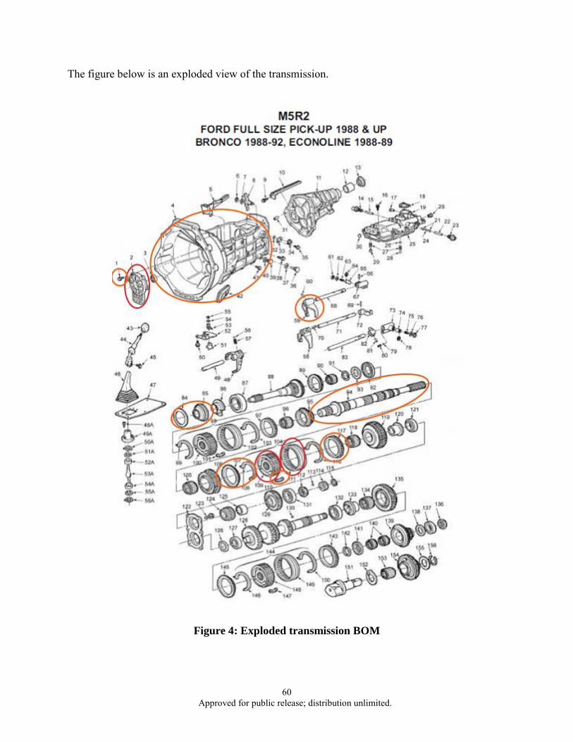
60 Approved for public release; distribution unlimited.
The figure below is an exploded view of the transmission.
Figure 4: Exploded transmission BOM
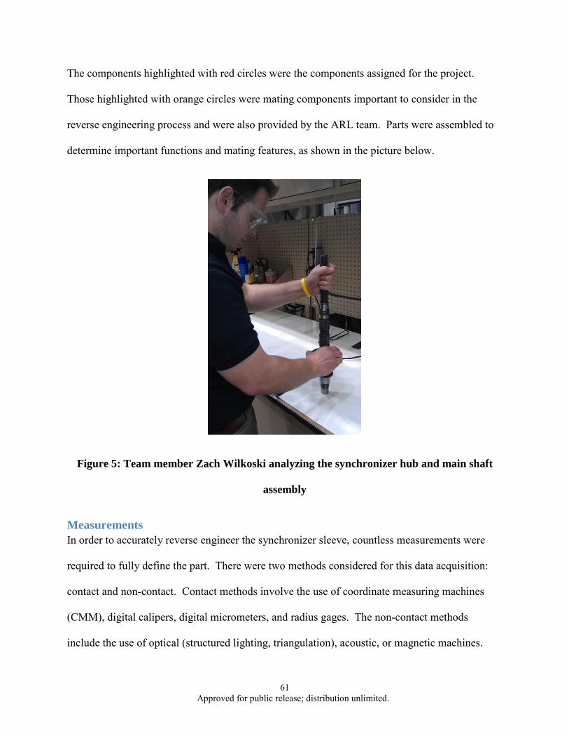
61 Approved for public release; distribution unlimited.
The components highlighted with red circles were the components assigned for the project.
Those highlighted with orange circles were mating components important to consider in the
reverse engineering process and were also provided by the ARL team. Parts were assembled to
determine important functions and mating features, as shown in the picture below.
Figure 5: Team member Zach Wilkoski analyzing the synchronizer hub and main shaft
assembly
Measurements In order to accurately reverse engineer the synchronizer sleeve, countless measurements were
required to fully define the part. There were two methods considered for this data acquisition:
contact and non-contact. Contact methods involve the use of coordinate measuring machines
(CMM), digital calipers, digital micrometers, and radius gages. The non-contact methods
include the use of optical (structured lighting, triangulation), acoustic, or magnetic machines.

62 Approved for public release; distribution unlimited.
Due to our past experiences and knowledge of the two method styles, it was determined that the
most ideal method for measuring our parts would involve all contact style tools. Although non-
contact methods have advantages of higher levels of precision, the errors associated with data
acquisition using a non-contact method were too numerous and the time required to obtain the
necessary data points would put the project behind schedule. All of the measurements necessary
for the synchronizer sleeve were achieved using digital calipers (accuracy up to a thousandth of a
millimeter) and radius gages.
Measurements for the synchronizer hub presented many challenges. The crucial mating surfaces
of the synchronizer hub were both sets of teeth on the outer and inner diameters for mating with
the sleeve and main shaft. Initial measurements for diameter, thickness, etc., were taken using
digital calipers and micrometers. The Machinery’s Handbook was consulted for equations to
calculate the needed specification for the gear, such as the teeth dimensions. However, after
calculation it was concluded that these equations could not be used in order to calculate the
specifications of the teeth as they are not actual gear teeth. Radius gauges were instead utilized.
The front bearing retainer required dimensioning features from the center of the through hole.
Since the center of the hole could not be easily found for every measurement, all dimensions
were found by measuring from the inside edge of the hole and adding its radius. This
measurement technique eliminated the error of locating the center of the hole in space every time
a measurement was needed.
3D Modeling After the measurement collection process the team used SolidWorks® to complete the 3D solid
modeling of each transmission component. We considered using other 3D modeling software

63 Approved for public release; distribution unlimited.
such as Pro/Engineer® but chose SolidWorks® based on the team’s comfort level and ease of
access to SolidWorks®.
The synchronizer hub and sleeve were modeled in conjunction to ensure they mated correctly. In
order to maintain accuracy, we referenced all of the measurements for the overall shape of the
parts excluding teeth from the origin in SolidWorks®. With the orientation of these parts
matching, both additive and subtractive methods were utilized in building the part. To begin
modeling each part, the inner and outer diameters were sketched and extruded to the proper
width. With the shape of the synchronizer hub and sleeve in place, the teeth were carefully
added to ensure they functioned together. For the sleeve, a single tooth was sketched on the
inner diameter and circular patterned around the inside of the sleeve to match the corresponding
number of teeth. This process was repeated for the synchronizer hub on the outside diameter to
model the gear teeth. The sleeve required three knockout sections on the inner teeth to
accommodate a key. These knockouts were cut away from the already generated teeth. The
inner teeth on the hub were added to model the hub’s mate to the main shaft. Appropriate fillets
and chamfers were the last features to be added to complete the modeling of these parts.
The front bearing retainer gave us a lot of challenges in the modeling process. The top of the
retainer is shelled to reduce the weight of the part. However, due to the varying heights of the
part, SolidWorks® could not accurately perform the shell feature. Instead of shelling the part, a
series of cuts and extrusions were performed in its place. Another challenge with modeling the
piece was the four threaded holes. Instead of actually cutting out the threads, a cosmetic thread
feature was used to show where the threads were located as well as giving the depth at which the
threads are to be cut. The four holes were found, in the reverse engineering process, to be ANSI
metric M8 1.25 threaded holes. The largest challenge faced while modeling the retainer was

64 Approved for public release; distribution unlimited.
using the fillet feature to round edges. Filleting edges in SolidWorks® is dependent on the order
of fillets, but since most of the edges on the part are rounded this became challenging early in the
filleting process. Also, SolidWorks® did not allow the fillet of multiple edges at one time on the
part. In an effort to fix these problems, more experienced SolidWorks’® users were consulted
but no solution was found. As a last resort, all of the edges were filleted one at a time and in a
trial and error order to get all of them rounded.
SolidWorks® files were provided to the ARL team as requested. Below are isometric views of
the components and respective 3D models screenshots.
Figure 6: Synchronizer Hub

65 Approved for public release; distribution unlimited.
Figure 7: Synchronizer Sleeve
Figure 8: Front Bearing Retainer
Rapid Prototyping Once we completed creating our CAD models, the next phase was to rapid prototype the parts.
The SolidWorks 3D CAD modeling program includes the processing capability of converting the
standard part file to a .STL file that can be read and processed by a rapid prototyping machine.
Included in the .STL file are specifications related to: part verification/validation, build
orientation, and support generation. This .STL file will be a layer by layer representation of the
part, which uses tessellation to generate triangles that approximate the part boundary.
After the part files have been converted, the next step was to use a rapid prototyping machine to
build the part. This process works similarly to that of a normal ink printer in that it uses two jet
heads to deliver both the build and support material respectively. After the first layer is
completed, the build platform lowers and then the next level of material is applied. As the second
layer is printed, it cures the previous layer during the same process. This process was repeated
until all of the build layers were completed. The post processing phase for this part was very
minor; it consisted of using a high pressure wash cleaning station to remove the support material.

66 Approved for public release; distribution unlimited.
Once we had completed the post processing, an overall evaluation of the part was conducted.
Several of the parts experienced some of the common errors that can occur during the RP
process. These errors included losing some of the finer details, do to their size or the build style
of the part. A new VeroBlack material was used for these prototypes at first, and a significant
difference in material strength was noticed compared to parts previously built in a different
material. We then proceeded to re-print one of the parts with the VeroWhite Plus material, and
we observed increases in both material strength and the detail of the part features. For future
reference, we would only recommend using the VeroWhite Plus for rapid prototypes where
form, fit, and function are required. On a positive note, the synchronizer sleeve and synchronizer
hub were able to mate correctly which in turn validated the accuracy and precision of the
prototype measurements.
The rapid prototypes we generated were quite useful in confirming whether the taken
measurements were accurate. In the case of the synchronizer hub, the innermost diameter was
observed to be incorrect and was subsequently corrected and re-prototyped. The rapid prototype
of the front bearing retainer was also analyzed to find and correct any problems within the
SolidWorks model. Often in solid modeling, part features can be overlooked resulting in an
incorrect model. The mistakes that were found by the prototype were the radius dimensions on
certain fillets and added material on the back and the right side of the model. After these errors
were found on the prototype, we edited them in the solid model, and then re-printed a second
prototype.
The finished prototypes were provided to the ARL team and can be seen in the images below.

67 Approved for public release; distribution unlimited.
Figure 9: Synchronizer Hub Rapid Prototype
Figure 10: Synchronizer Sleeve Rapid Prototype

68 Approved for public release; distribution unlimited.
Figure 11: Front Bearing Retainer Rapid Prototype
Process Plan Development The process plan development phase of our parts turned out to the most challenging and difficult
of all the desired deliverables for the ARL project. After consulting with our project advisor and
several members in the field of machining and casting, we realized that we would need to start
researching how a typical process plan is laid out. Since no standard format was found, we
generated our own format with the assistance of our project advisor.
We decided to model our process plan off simple baking directions, in that it would start with
listing the build material along with its respective quantity and dimensions. From our previous
discussions with the machining and casting lab technicians, we were able to determine the
process for how each part would have been created. The front retainer bearing appeared to be an
aluminum casting, which is a process we could replicate in the FAME Lab. As for the
synchronizer hub and sleeve, we determined that these parts would be generated from steel bar
stock, and then machined to their respective dimensions.

69 Approved for public release; distribution unlimited.
Once we had determined the materials used in generating these parts, the next stage in the
process planning development was to break down the part into its individual features. This was
an easier step in the process since we had already developed the 3-D part files, which gave us a
breakdown of the individual features (extruded cuts, gear-like teeth, fillets, chamfers, etc.). With
this breakdown of the features, we then returned to the casting and machining experts to see
which type of processing method would be ideal to process them. This represented the first
column in our process plans, “Process Type”. Our two most detailed process plans centered on
the synchronizer hub and sleeve, due to the extensive amount of CNC machining required for
these parts. The front retainer bearing, as previously mentioned, was a casting and required
minor post process machining.
The next phase of our process plan was to determine which CNC machine would be optimal for
recreating each part feature. For both the synchronizer hub and sleeve, the SL-30 CNC machine
proved to possess the capabilities we needed. The only other machine we determined to be used
would be the Wire EDM, to process the gear-like teeth of these two parts. Once we had
determined the machines required, the next phase was to see how we could fixture each part and
the orientation of each part in the machine. Following this phase, we wrote a description of how
each feature would be machined. This included examples such as, boring out the inside of the
synchronizer sleeve to a diameter just smaller than the actual diameter to leave additional
material for processing of the inner teeth.
The final stage in developing the process plans involved generating the machine codes required
to carry out the machining description for each feature. This process started with converting our
SolidWorks Part files into .DXF files which could be loaded into MasterCam, similar to the rapid
prototyping process, this is the type of file that the CNC machines can read. Once loaded into

70 Approved for public release; distribution unlimited.
Mastercam, tool paths could be generated that the CNC machines could read. This code would
have to be cleaned and validated before a CNC machine could process it.
PROGRESS Provided Deliverables and Setbacks 3D SolidWorks® files, rapid prototypes and rough draft process plans for each component have
been provided to ARL team thus far. The approach for producing these was previously
described. During these processes the team endured setbacks which prevented them from
providing the ARL team with the full list of deliverables outlined at the start of the semester.
The largest setback was our limited knowledge of machining processes. While all group
members had some experience in the FAME lab, no one had exposure or practice operating the
CNC machines to the extent necessary for the intricate transmission components. The group had
to quickly overcome a steep learning curve in order to develop detailed and efficient process
plans. To do this we had to collaborate greatly with the technicians in the FAME lab. This
dependency created another setback; much of the progress, with the exception of research and
3D modeling, could only be made during normal business hours. All group members first
needed to coordinate time when we could meet, then these times needed to be convenient for the
lab technicians when help was needed. Within these constraints, there were many occurrences of
the FAME lab technicians being unavailable or on vacation when the team was looking to make
progress. In addition, the rapid prototyping process was delayed several times due to absences of
the lab technician required for operation.

71 Approved for public release; distribution unlimited.
Casting Blank of Front Bearing Retainer To begin the process plans for the front bearing retainer it was desirable to determine if the part
could be green sand casted to near net shape and still get the ribbed and shelled features to come
out correctly. We made a casting using the original front bearing retainer to ensure it was
possible.
To start the casting process, the features that are post machined were filled with clay so they
would not be casted. The part was then glued to a match plate to produce the mold. This was
possible since the bottom of the part was completely post machined and didn’t have any features
that needed to be casted. Otherwise, the entire experiment would not have been impossible since
it would have been necessary for the part to be in two pieces for the cope and drag. We casted
the part upside down to pour the aluminum into the bottom since there was no features on it.
This meant the cope of the casting was going to be completely full of sand minus the sprue hole.
Therefore, the drag of the casting contained the entire mold of the part to be casted. Aluminum
356 was used to create the casting since this alloy was approved by the ARL team for the part
and readily available for use in the FAME lab. The aluminum was heated to a temperature of
1400⁰ F to increase the fluidity of the alloy. It was understood that using a temperature this high
was going to compromise the surface finish of the casting. However, since the goal of the
casting was to understand if certain features could be casted, fluidity took precedence over
surface finish. Once the casting was cooled, it was taken out of the sand and analyzed. The goal
of the casting experiment was met and the important shell features were accurate. This result
reassured that the best manufacturing process for a FAME lab capable process plan was green
sanding casting the front retainer bearing followed by post machining and heat treatment.

72 Approved for public release; distribution unlimited.
As expected, the casting experienced some liquid to solid shrinkage. Since the part is not very
thick this shrinkage was minimal. Two solutions were found to accommodate the shrinkage.
One would be to add a riser big enough to eliminate the shrinkage and the other would be to
design in added material to the mold and allow the minimal shrinkage.
The casting process is shown in Figures 12-16.
Figure 12: Zach Wilkoski and Randy Wells, lab technician, pouring Aluminum 356 at 1400 degrees F

73 Approved for public release; distribution unlimited.
Figure 13: Team members Zach Wilkoski and Josh Charlier transfer casting and green sand mold
Figure 14: Casted part revealed from green sand mold

74 Approved for public release; distribution unlimited.
Figure 15: Full casting with hardened sprue hole and excess metal
Figure 16: Casted part post sprue removal and sand blasting

75 Approved for public release; distribution unlimited.
Plans for Remainder of Semester The nature of the IE 480W course dictates that we have a final report by November 18, 2011,
however we plan to continue our work after this date. We plan on getting as far as possible
given the time constraints brought on by end of semester obligations. We intend on finalizing
each individual process plan for manufacture of the three transmission components in the FAME
lab. The goal is that whoever inherits the project could take our work and use it to manufacture
the transmission components almost immediately. In addition to our continued work, we will
also be presenting our semesters work at the design showcase along with all other capstone
design groups. Our ARL sponsor, Chris Ligetti, will be on hand to answer any questions
regarding the background or any other questions associated with the project as a whole. We will
present our poster as well as have all transmission components as well as their corresponding
rapid prototypes on hand to show judges as well as spectators.
We will also be preparing a presentation for ARL to review the progress made through the
semester. This presentation will build off the mid semester presentation and include the
development of the process plans for each component as well as future recommendations for the
team who continues this project.

76 Approved for public release; distribution unlimited.
CONCLUSION We were able to deliver 3D models, rapid prototypes, and process plans for the three
transmission components in the scope of this project: the synchronizer hub, synchronizer sleeve,
and front bearing retainer. The reverse engineering process included measurements and part
analysis which was vital to developing the physical deliverables.
We suggest that for a full reverse engineering of the components a material science expert should
be consulted to perform a metallurgic analysis to determine the exact type of metal which should
be used to recreate the parts. Testing should also be performed to determine hardness and
surface finish specifications so they can be considered in the process plan.
We will continue to utilize the remainder of the semester to build detail into our process plans so
that the team who inherits the project will be able to easily comprehend and implement them.
The senior design showcase and final presentation will allow us to explain our approach and
discuss our progress.

77 Approved for public release; distribution unlimited.
APPENDIX
Figure 17: Process Plan Standard Template

78 Approved for public release; distribution unlimited.
Figure 18: Synchronizer Hub Process Plan

79 Approved for public release; distribution unlimited.
Figure 19: Synchronizer Sleeve Process Plan

80 Approved for public release; distribution unlimited.
Figure 20: Front Bearing Retainer Process Plan