RX Series Type V1 User's Manual - Omron eData
686
High-function General-purpose Inverter RX Series Type V1 User’s Manual I578-E1-02 3G3RX--V1
-
Upload
khangminh22 -
Category
Documents
-
view
0 -
download
0
Transcript of RX Series Type V1 User's Manual - Omron eData

High-function General-purpose Inverter
RX Series Type V1
User’s Manual
I578-E1-02
3G3RX- -V1

• Microsoft, Windows, Windows 98, and Windows Vista are either registered trademarks or trademarks of Microsoft Corporation in the USA and other countries.
• EtherCAT® is registered trademark and patented technology, licensed by Beckhoff Automation GmbH, Germany.
• ODVA, CIP, CompoNet, DeviceNet, and EtherNet/IP are trademarks of ODVA.
Other system names and product names in this document are the trademarks or registered trademarks of their respective companies.
Trademarks
© OMRON, 2012All rights reserved. No part of this publication may be reproduced, stored in a retrieval system, or transmitted, in any form, or by any means, mechanical, electronic, photocopying, recording, or otherwise, without the prior written permission of OMRON.
No patent liability is assumed with respect to the use of the information contained herein. Moreover, because OMRON is constantly striving to improve its high-quality products, the information contained in this manual is subject to change without notice. Every precaution has been taken in the preparation of this manual. Nevertheless, OMRON assumes no responsibility for errors or omissions. Neither is any liability assumed for damages resulting from the use of the information contained in this publication.

1
Introduction
High-function General-purpose Inverter 3G3RX-V1 User’s Manual (I578-E1)
Introduction
Thank you for purchasing the High-function General-purpose Inverter (Model: 3G3RX- -V1).
This manual describes the installation and wiring methods of the 3G3RX-V1 Series Inverter, and parameter setting methods which are required for the operation, as well as troubleshooting and inspection methods.
This manual is intended for the following individuals.
Those who have electrical knowledge (certified electricians or individuals who have equivalent knowledge) and also are qualified for one of the following:
• Introducing control equipment
• Designing control system
• Installing and connecting control systems
• Managing control systems and facilities
This manual contains information you need to know to correctly use the High-function General-purpose Inverter (Model: 3G3RX- -V1).
Before using the inverter, read this manual and gain a full understanding of the information provided herein.
After you finished reading this manual, keep it in a convenient place so that it can be referenced at any time.
Make sure this manual is delivered to the end user.
Intended Readers
Notice

Manual Configuration
2 High-function General-purpose Inverter 3G3RX-V1 User’s Manual (I578-E1)
Manual Configuration
This manual is compiled section by section for user’s convenience as follows.
Section/Title Outline
Section 1 OverviewThis section provides the features of this product, specifications, external dimensions, and part names.
Section 2 DesignThis section describes the installation and wiring methods for this product.
Section 3 Operation and Test Run
This section describes the part names and key operation of the Digital Operator, and the operation method of this product as well as the test run procedure.
Section 4 Parameter ListThis section provides lists of parameters for setting various functions of this product.
Section 5 Basic SettingsThis section describes the basic functions, such as the Run command.
Section 6 Vector ControlThis section describes the applied functions, such as vector control.
Section 7 Detailed FunctionsThis section describes the details of functions not described in Section 5 or Section 6.
Section 8 Communications FunctionsThis section describes the general-purpose serial communications functions (RS-485 communication).
Section 9 Overview of DriveProgrammingThis section describes the features of the DriveProgramming.
Section 10 TroubleshootingThis section describes how to analyze the cause and take countermeasures if the inverter fails, and provides troubleshooting for possible troubles.
Section 11 Maintenance and InspectionThis section describes the maintenance and periodical inspection items.
Section 12 OptionsThis section describes the specifications and external dimension of peripheral equipment.
AppendicesThis section provides information on the capacitor life curve and the life alarm output.

3
Manual Structure
High-function General-purpose Inverter 3G3RX-V1 User’s Manual (I578-E1)
Manual Structure
The following page structure and symbol icons are used in this manual.
Note The above page is only a sample for illustrative purposes. It is not the actual content of the manual.
Page Structure and Symbol Icons
2 - 9
2 Design
High-function General-purpose Inverter 3G3RX-V1 User’s Manual (I578-E1)
2-2 Rem
oval o
f Each
Part
2
2-2-1 Rem
oving Covers
2-2 Removal of Each Part
Before wiring each terminal block, you need to remove the terminal block cover and the backing plate.
In addition, to install a PG Board or communications unit, you must remove the Digital Operator, spacer cover, terminal block cover, and front cover beforehand.
This section describes how to remove these covers.
To reinstall it, reverse the removal procedure.
1 Loosen the terminal block cover fixation screws.
There are two terminal block cover fixation screws, one for each side of the cover.Larger capacity Inverter models have three terminal block cover fixation screws.
2 Remove the terminal block cover in the direction of (a) while holding it from the bottom.
1 Remove the Digital Operator in the direction of (a) by pushing the lip on the top.
2 In the same way, remove the spacer cover in the direction of (b).
2-2-1 Removing Covers
Removing Terminal Block Cover
Removing Digital Operator and Spacer Cover
(a)
Terminal block cover fixation screws
(a)
(b)
Level 1 heading
Level 2 heading
Level 3 headingLevel 2 heading
Operation Steps
Manual Name
Level 3 heading Shows which paragraph the content of the current page belongs to.
Describes the operation steps.
Note, Supplementary Information, Reference TargetA note, supplementary information, reference target, etc. are provided with difference icons.
Shows which section the content of the current page belongs to.
Section Number of Level 1 heading

Manual Structure
4 High-function General-purpose Inverter 3G3RX-V1 User’s Manual (I578-E1)
Special information in this manual is classified as follows:
Precautions for Safe Use
Precautions on what to do and what not to do to ensure safe usage of the product.
Precautions for Correct UsePrecautions for Correct Use
Precautions on what to do and what not to do to ensure proper operation and performance.
Additional Information
Additional information to read as required.
This information is provided to increase understanding or make operation easier.
Special Information

5
Sections in this Manual
High-function General-purpose Inverter 3G3RX-V1 User’s Manual (I578-E1)
1 10
2 11
3 12
4 A
5
6
7
8
9
1 10
2 11
3 12
4 A
5 I
6
7
8
9
Overview Troubleshooting
Design Maintenance and Inspection
Operation and Test Run Options
Parameter List Appendices
I IndexBasic Settings
Vector Control
Detailed Functions
Communications Functions
Overview of DriveProgramming
Sections in this Manual

Terms and Conditions Agreement
6 High-function General-purpose Inverter 3G3RX-V1 User’s Manual (I578-E1)
Terms and Conditions Agreement
Exclusive WarrantyOmron’s exclusive warranty is that the Products will be free from defects in materials and workman-ship for a period of twelve months from the date of sale by Omron (or such other period expressed in writing by Omron). Omron disclaims all other warranties, express or implied.
LimitationsOMRON MAKES NO WARRANTY OR REPRESENTATION, EXPRESS OR IMPLIED, ABOUT NON-INFRINGEMENT, MERCHANTABILITY OR FITNESS FOR A PARTICULAR PURPOSE OF THE PRODUCTS. BUYER ACKNOWLEDGES THAT IT ALONE HAS DETERMINED THAT THE PRODUCTS WILL SUITABLY MEET THE REQUIREMENTS OF THEIR INTENDED USE.
Omron further disclaims all warranties and responsibility of any type for claims or expenses based on infringement by the Products or otherwise of any intellectual property right.
Buyer RemedyOmron’s sole obligation hereunder shall be, at Omron’s election, to (i) replace (in the form originally shipped with Buyer responsible for labor charges for removal or replacement thereof) the non-com-plying Product, (ii) repair the non-complying Product, or (iii) repay or credit Buyer an amount equal to the purchase price of the non-complying Product; provided that in no event shall Omron be responsible for warranty, repair, indemnity or any other claims or expenses regarding the Products unless Omron’s analysis confirms that the Products were properly handled, stored, installed and maintained and not subject to contamination, abuse, misuse or inappropriate modification. Return of any Products by Buyer must be approved in writing by Omron before shipment. Omron Companies shall not be liable for the suitability or unsuitability or the results from the use of Products in combi-nation with any electrical or electronic components, circuits, system assemblies or any other materi-als or substances or environments. Any advice, recommendations or information given orally or in writing, are not to be construed as an amendment or addition to the above warranty.
See http://www.omron.com/global/ or contact your Omron representative for published information.
OMRON COMPANIES SHALL NOT BE LIABLE FOR SPECIAL, INDIRECT, INCIDENTAL, OR CON-SEQUENTIAL DAMAGES, LOSS OF PROFITS OR PRODUCTION OR COMMERCIAL LOSS IN ANY WAY CONNECTED WITH THE PRODUCTS, WHETHER SUCH CLAIM IS BASED IN CONTRACT, WARRANTY, NEGLIGENCE OR STRICT LIABILITY.
Further, in no event shall liability of Omron Companies exceed the individual price of the Product on which liability is asserted.
Warranty, Limitations of Liability
Warranties
Limitation on Liability; Etc

7
Terms and Conditions Agreement
High-function General-purpose Inverter 3G3RX-V1 User’s Manual (I578-E1)
Omron Companies shall not be responsible for conformity with any standards, codes or regulations which apply to the combination of the Product in the Buyer’s application or use of the Product. At Buyer’s request, Omron will provide applicable third party certification documents identifying ratings and limitations of use which apply to the Product. This information by itself is not sufficient for a com-plete determination of the suitability of the Product in combination with the end product, machine, sys-tem, or other application or use. Buyer shall be solely responsible for determining appropriateness of the particular Product with respect to Buyer’s application, product or system. Buyer shall take applica-tion responsibility in all cases.
NEVER USE THE PRODUCT FOR AN APPLICATION INVOLVING SERIOUS RISK TO LIFE OR PROPERTY WITHOUT ENSURING THAT THE SYSTEM AS A WHOLE HAS BEEN DESIGNED TO ADDRESS THE RISKS, AND THAT THE OMRON PRODUCT(S) IS PROPERLY RATED AND INSTALLED FOR THE INTENDED USE WITHIN THE OVERALL EQUIPMENT OR SYSTEM.
Omron Companies shall not be responsible for the user’s programming of a programmable Product, or any consequence thereof.
Data presented in Omron Company websites, catalogs and other materials is provided as a guide for the user in determining suitability and does not constitute a warranty. It may represent the result of Omron’s test conditions, and the user must correlate it to actual application requirements. Actual perfor-mance is subject to the Omron’s Warranty and Limitations of Liability.
Product specifications and accessories may be changed at any time based on improvements and other reasons. It is our practice to change part numbers when published ratings or features are changed, or when significant construction changes are made. However, some specifications of the Product may be changed without any notice. When in doubt, special part numbers may be assigned to fix or establish key specifications for your application. Please consult with your Omron’s representative at any time to confirm actual specifications of purchased Product.
Information presented by Omron Companies has been checked and is believed to be accurate; how-ever, no responsibility is assumed for clerical, typographical or proofreading errors or omissions.
Application Considerations
Suitability of Use
Programmable Products
Disclaimers
Performance Data
Change in Specifications
Errors and Omissions

Safety Precautions
8 High-function General-purpose Inverter 3G3RX-V1 User’s Manual (I578-E1)
Safety Precautions
To ensure that the High-function General-purpose Inverter (Model: 3G3RX- -V1) is used safely and correctly, be sure to read this Safety Precautions section and the main text before using the product.
Learn all items you should know before use, regarding the equipment as well as required safety information and precautions.
Make an arrangement so that this manual also gets to the end user of this product.
After reading this manual, keep it in a convenient place so that it can be referenced at any time.
In this user’s manual, the following precautions and signal words are used to provide information to ensure the safe use of the High-function General-purpose Inverter (Model: 3G3RX- -V1). The information provided here is vital to safety. Strictly observe the precautions provided.
Indications and Meanings of Safety Information
Meanings of Signal Words
Indicates an imminently hazardous situation which, if not avoided, is likely to result in serious injury or may result in death.
Additionally, there may be severe property damage.
Indicates a potentially hazardous situation which, if not avoided, may result in minor or moderate injury or in property damage.
WARNING
Caution

9
Safety Precautions
High-function General-purpose Inverter 3G3RX-V1 User’s Manual (I578-E1)
Explanation of Symbols
This symbol indicates a prohibited item (an item you must not do).
The specific instruction is indicated using an illustration or text inside or near .
The symbol shown to the left indicates “disassembly prohibited.”
This symbol indicates danger and caution.
The specific instruction is indicated using an illustration or text inside or near .
The symbol shown to the left indicates “beware of electric shock.”
This symbol indicates danger and caution.
The specific instruction is indicated using an illustration or text inside or near .The symbol shown to the left indicates “non-specific general danger.”
This symbol indicates caution (including warning).
The specific instruction is indicated using an illustration or text inside or near .The symbol shown to the left indicates “risk of hot surface.”
This symbol indicates a compulsory item (an item that must be done).
The specific instruction is indicated using an illustration or text inside or near .
The symbol shown to the left indicates “general compulsory items.”
This symbol indicates a compulsory item (an item that must be done).
The specific instruction is indicated using an illustration or text inside or near .
The symbol shown to the left indicates “grounding required.”

Safety Precautions
10 High-function General-purpose Inverter 3G3RX-V1 User’s Manual (I578-E1)
Turn off the power supply and implement wiring correctly.
Not doing so may result in a serious injury due to an electric shock.
Wiring work must be carried out only by qualified personnel.
Not doing so may result in a serious injury due to an electric shock.
Do not change wiring and slide switches (SW1), put on or take off Operator and optional devices, replace cooling fans while the input power is being supplied. Doing so may result in a serious injury due to an electric shock.
Be sure to ground the unit. Not doing so may result in a serious injury due to an electric shock or fire.
(200-V class: type-D grounding, 400-V class: type-C grounding)
Do not remove the terminal cover during the power supply and 10 minutes after the power shut off. Doing so may result in a serious injury due to an electric shock.
Do not operate the Operator or switches with wet hands.
Doing so may result in a serious injury due to an electric shock.
Inspection of the inverter must be conducted after the power supply was turned off. Not doing so may result in a serious injury due to an electric shock.
The main power supply is not necessarily shut off even if the emergency shut off function is activated.
Do not touch the inverter fins, braking resistors and the motor, which become too hot during the power supply and for some time after the power shut off. Doing so may result in a burn.
Do not connect resistors to the terminals (+1, P/+2, N/–) directly. Doing so might result in a small-scale fire, heat generation, or damage to the unit.
Install a stop motion device to ensure safety. Not doing so might result in a minor injury. (A holding brake is not a stop motion device designed to ensure safety.)
Be sure to use a specified type of braking resistor/regenerative braking unit. In case of a braking resistor, install a thermal relay that monitors the temperature of the resistor. Not doing so might result in a moderate burn due to the heat generated in the braking resistor/regenerative braking unit. Configure a sequence that enables the inverter power to turn off when unusual over eating is detected in the braking resistor/regenerative braking unit.
The inverter has high voltage parts inside which, if short-circuited, might cause damage to itself or other property. Place covers on the openings or take other precautions to make sure that no metal objects such as cutting bits or lead wire scraps go inside when installing and wiring.
Take safety precautions such as setting up a molded-case circuit breaker (MCCB) that matches the inverter capacity on the power supply side.
Not doing so might result in damage to property due to the short circuit of the load.
Do not dismantle, repair or modify the product.
Doing so may result in an injury.
WARNING
Caution

11
Precautions for Safe Use
High-function General-purpose Inverter 3G3RX-V1 User’s Manual (I578-E1)
Precautions for Safe Use
Do not store or use the product in the following places.
• Locations subject to direct sunlight.
• Locations subject to ambient temperature exceeding the specifications.
• Locations subject to relative humidity exceeding the specifications.
• Locations subject to condensation due to severe temperature fluctuations.
• Locations subject to corrosive or flammable gases.
• Locations subject to exposure to combustibles.
• Locations subject to dust (especially iron dust) or salts.
• Locations subject to exposure to water, oil, or chemicals.
• Locations subject to shock or vibration.
• Do not drop or apply strong impact on the product. Doing so may result in damaged parts or malfunction.
• Do not hold by the front cover and terminal cover, but hold by the fins during transportation.
• Confirm that the rated input voltage of the inverter is the same as AC power supply voltage.
• Do not connect an AC power supply voltage to the control input/output terminals. Doing so may result in damage to the product.
• Be sure to tighten the screws on the terminal block securely. Wiring work must be done after installing the unit body.
• Do not connect any load other than a three-phase inductive motor to the U, V, and W output terminals.
• Take sufficient shielding measures when using the product in the following locations. Not doing so may result in damage to the product.
Locations subject to static electricity or other forms of noise.
Locations subject to strong magnetic fields.
Locations close to power lines.
• If a parameter is set incorrectly when starting up, adjusting, maintaining, or replacing, an unexpected operation may occur. Perform the operation after enough confirmation.
• When using DriveProgramming, confirm that the program data is downloaded normally before starting operation.
Installation and Storage
Transportation, Installation, and Wiring

Precautions for Safe Use
12 High-function General-purpose Inverter 3G3RX-V1 User’s Manual (I578-E1)
• Be sure to confirm the permissible range of motors and machines before operation because the inverter speed can be changed easily from low to high.
• Provide a separate holding brake if necessary.
• If the DriveProgramming stops during multi-function output, the output status is held. Take safety precautions such as stopping peripheral devices.
• If the clock command is used in DriveProgramming, an unexpected operation may occur due to weak battery. Take measures such as detecting a weak battery by a check that the clock data returns to the initial setting and stopping the inverter or programs. When the LCD Digital Operator is removed or disconnected, DriveProgramming is in a waiting status by the clock command.
• Be sure to confirm safety before conducting maintenance, inspection or parts replacement.
• The capacitor service life is influenced by the ambient temperature. Refer to “Smoothing Capacitor Life Curve” described in the manual. When a capacitor reaches the end of its service life and does not work as the product, you need to replace the capacitor.
• When disposing of LCD digital operators and wasted batteries, follow the applicable ordinances of your local government. When disposing of the battery, insulate it using tape.
• Do not short + and –, charge, disassemble, heat, put into the fire, or apply strong impact on the battery. The battery may leak, explode, produce heat or fire. Never use the battery which was applied strong impact due to such as fall on the floor, it may leak.
• UL standards establish that the battery shall be replaced by an expert engineer. The expert engineer must be in charge of the replacement and also replace the battery according to the method described in this manual.
• When the display of LCD Digital Operator can not be recognized due to the service life, replace the LCD Digital Operator.
Operation and Adjustment
Maintenance and Inspection
The following display must be indicated when products using lithium primary batteries (withmore than 6 ppb of perchlorate) are transport to or through the State of California, USA.
Perchlorate Material - special handling may apply.See www.dtsc.ca.gov/hazardouswaste/perchlorate
The 3G3AX-OP05 has the lithium primary battery (with more than 6 ppb of perchlorate).Label or mark the above display on the exterior of all outer shipping packages of your prod-ucts when exporting your products which the 3G3AX-OP05 are installed to the State of Cali-fornia, USA.

13
Precautions for Correct Use
High-function General-purpose Inverter 3G3RX-V1 User’s Manual (I578-E1)
Precautions for Correct Use
Mount the product vertically on a wall with the product’s longer sides upright.
The material of the wall must be noninflammable such as a metal plate.
• Do not come close to the machine when using the Restart Selection function (b001, b008) because the machine may abruptly start when stopped by an alarm.
• Be sure to confirm the RUN signal is turned off before resetting the alarm because the machine may abruptly start.
Do not come close to the machine when selecting reset in the Deceleration Stop Function (b050) because the machine may abruptly start after the power is turned on.
• Provide a separate emergency stop switch because the STOP Key on the Operator is valid only when function settings are performed.
• When checking a signal during the power supply and the voltage is erroneously applied to the control input terminals, the motor may start abruptly. Be sure to confirm safety before checking a signal.
• Inverters contain components and will operate properly only when each component operates normally. Some of the electrical components require maintenance depending on application conditions. Periodic inspection and replacement are necessary to ensure proper long-term operation of Inverters. (Quoted from The Recommendation for Periodic Maintenance of a General-purpose Inverter published by JEMA.)
• When a cooling fan reaches the end of its service life, replace it.
Comply with the local ordinance and regulations when disposing of the product.
Installation
Restart Selection Function
Deceleration Stop Function
Operation Stop Command
Maintenance and Parts Replacement
Product Disposal

Precautions for Correct Use
14 High-function General-purpose Inverter 3G3RX-V1 User’s Manual (I578-E1)
• This product bears a warning label at the following location to provide handling warnings.
• Be sure to follow the instructions.The appearance differs depending on the capacity of the inverter.
Warning Label
Warning Description

15
Regulations and Standards
High-function General-purpose Inverter 3G3RX-V1 User’s Manual (I578-E1)
Regulations and Standards
To export (or provide to nonresident aliens) any part of this product that falls under the category of goods (or technologies) for which an export certificate or license is mandatory according to the Foreign Exchange and Foreign Trade Control Law of Japan, an export certificate or license (or service transaction approval) according to this law is required.
The 3G3RX-V1 Series complies as standard with both the EC Directives and UL/cUL Standards.
EC Directives and UL/cUL Standards
Standard Applicable Standard
EC Directives EMC Directive EN61800-3
Low Voltage Directive EN61800-5-1
UL/cUL Standards UL 508C

Items to Check after Unpacking
16 High-function General-purpose Inverter 3G3RX-V1 User’s Manual (I578-E1)
Items to Check after Unpacking
After unpacking, check the following items.
• Is this the model you ordered?
• Was there any damage sustained during shipment?
The nameplate is affixed to the product.
Checking the Nameplate
Checking the Model
Inverter model
Input specificationsOutput specifications
3 G 3 R X - A 2 0 5 5 - V 1Maximum applicable motor capacity
00400701502203705507511015018522030037045055075090011K13K
0.4 kW0.75 kW1.5 kW2.2 kW3.7 kW5.5 kW7.5 kW11 kW15 kW18.5 kW22 kW30 kW37 kW45 kW55 kW75 kW90 kW110 kW132 kW
Voltage class
24
3-phase 200 VAC (200-V class)3-phase 400 VAC (400-V class)
Enclosure rating
A Panel-mounting (IP20) or closed wall-mounting modelsB Panel-mounting (IP00)

17
Items to Check after Unpacking
High-function General-purpose Inverter 3G3RX-V1 User’s Manual (I578-E1)
The instruction manual is the only accessory included in the High-function General-purpose Inverter (Model: 3G3RX- -V1).
Mounting screws and other necessary parts must be provided by the user.
Checking the Accessories

Related Manuals
18 High-function General-purpose Inverter 3G3RX-V1 User’s Manual (I578-E1)
Related Manuals
Please see the manuals below for related product information.
Name Catalog No.
Regenerative Braking Unit 3G3AX-RBU User’s Manual I563
Encorder Feedback Board 3G3AX-PG User’s Manual I564
CX-Drive Operation Manual W453
LCD Digital Operator 3G3AX-OP05 User’s Manual I579
DriveProgramming User’s Manual I580
MX2/RX Series EtherCAT® Communication Unit User's Manual I574
MX2/RX Series CompoNet™ Communications Unit User’s Manual I582
MX2/RX Series DeviceNet™ Communications Unit User’s Manual I581

19
Revision History
High-function General-purpose Inverter 3G3RX-V1 User’s Manual (I578-E1)
Revision History
The manual revision code is a number appended to the end of the catalog number found in the bottom right-hand corner of the front and back covers.
Example
Revision code Revision date Revised Content
01 November 2012 Original production
02 March 2015 • Added explanations.
• Corrected mistakes.
Cat.No. I578-E1-02Revision code

20 High-function General-purpose Inverter 3G3RX-V1 User’s Manual (I578-E1)
CONTENTS
CONTENTS
Introduction ...............................................................................................................1Intended Readers ........................................................................................................................................ 1Notice........................................................................................................................................................... 1
Manual Configuration ...............................................................................................2
Manual Structure .......................................................................................................3Page Structure and Symbol Icons ............................................................................................................... 3Special Information ...................................................................................................................................... 4
Sections in this Manual ............................................................................................5
Terms and Conditions Agreement...........................................................................6Warranty, Limitations of Liability .................................................................................................................. 6Application Considerations .......................................................................................................................... 7Disclaimers .................................................................................................................................................. 7
Safety Precautions....................................................................................................8Indications and Meanings of Safety Information.......................................................................................... 8Meanings of Signal Words........................................................................................................................... 8Explanation of Symbols ............................................................................................................................... 9
Precautions for Safe Use........................................................................................11Installation and Storage ............................................................................................................................. 11Transportation, Installation, and Wiring ..................................................................................................... 11Operation and Adjustment ......................................................................................................................... 12Maintenance and Inspection...................................................................................................................... 12
Precautions for Correct Use...................................................................................13Installation.................................................................................................................................................. 13Restart Selection Function ........................................................................................................................ 13Deceleration Stop Function ....................................................................................................................... 13Operation Stop Command......................................................................................................................... 13Maintenance and Parts Replacement........................................................................................................ 13Product Disposal........................................................................................................................................ 13Warning Label............................................................................................................................................ 14Warning Description .................................................................................................................................. 14
Regulations and Standards....................................................................................15EC Directives and UL/cUL Standards........................................................................................................ 15
Items to Check after Unpacking.............................................................................16Checking the Nameplate ........................................................................................................................... 16Checking the Model ................................................................................................................................... 16Checking the Accessories ......................................................................................................................... 17
Related Manuals ......................................................................................................18
Revision History ......................................................................................................19
Section 1 Overview
1-1 Overview of Functions ............................................................................................................ 1-21-1-1 Features of 3G3RX-V1 Series Inverter ....................................................................................... 1-21-1-2 Classes of 3G3RX-V1 Series Inverter ........................................................................................ 1-61-1-3 Compliance with International Standards (EC Directives and UL/cUL Standards) ..................... 1-7

21High-function General-purpose Inverter 3G3RX-V1 User’s Manual (I578-E1)
CONTENTS
1-2 Appearance and Part Names.................................................................................................. 1-8
1-3 Specifications .......................................................................................................................... 1-91-3-1 Standard Specifications.............................................................................................................. 1-91-3-2 External Dimensions................................................................................................................. 1-14
1-4 Restrictions............................................................................................................................ 1-23
1-5 Comparison with Previous Model ........................................................................................ 1-24
Section 2 DesignPrecautions for Safe Use..............................................................................................................................3
2-1 Installation................................................................................................................................ 2-42-1-1 Inverter Installation ..................................................................................................................... 2-42-1-2 Installation Environment ............................................................................................................. 2-4
2-2 Removal of Each Part.............................................................................................................. 2-92-2-1 Removing Covers ....................................................................................................................... 2-92-2-2 Terminal Blocks......................................................................................................................... 2-112-2-3 Preparing Backing Plate ........................................................................................................... 2-13
2-3 Wiring ..................................................................................................................................... 2-142-3-1 Standard Connection Diagram ................................................................................................. 2-142-3-2 Arrangement and Function of Main Circuit Terminal Block....................................................... 2-152-3-3 Arrangement and Function of Control Circuit Terminal Block ................................................... 2-162-3-4 Wiring for Main Circuit Terminals .............................................................................................. 2-202-3-5 Wiring for Control Circuit Terminals .......................................................................................... 2-432-3-6 Wiring for PG Board.................................................................................................................. 2-492-3-7 Wiring for RS485 Communications Terminals .......................................................................... 2-532-3-8 Wiring for Digital Operator ........................................................................................................ 2-552-3-9 Wiring for Emergency Shutoff Function .................................................................................... 2-562-3-10 Conformance to EC Directives ................................................................................................. 2-582-3-11 Reference Manuals for Options ................................................................................................ 2-60
Section 3 Operation and Test RunPrecautions for Safe Use..............................................................................................................................2Precautions for Correct Use .........................................................................................................................3
3-1 Operation of Digital Operator ................................................................................................. 3-43-1-1 Part Names and Descriptions..................................................................................................... 3-43-1-2 Key Operation Method ................................................................................................................ 3-6
3-2 Overview of LCD Digital Operator........................................................................................ 3-15
3-3 Connections and Functions of CX-Drive............................................................................. 3-163-3-1 CX-Drive Connection Method ................................................................................................... 3-163-3-2 Outline of CX-Drive................................................................................................................... 3-20
3-4 Flow of Test Run.................................................................................................................... 3-24
3-5 Test Run Procedure............................................................................................................... 3-25
Section 4 Parameter List
4-1 Monitor Mode ........................................................................................................................... 4-24-1-1 Group d....................................................................................................................................... 4-2
4-2 Basic Function Mode .............................................................................................................. 4-54-2-1 Group F: Basic Function Parameters.......................................................................................... 4-5
4-3 Extended Function Mode........................................................................................................ 4-64-3-1 Group A: Standard Function Parameters ................................................................................... 4-74-3-2 Group b: Detailed Function Parameters ................................................................................... 4-194-3-3 Group C: Multi-function Terminal Function Parameters............................................................ 4-28

22 High-function General-purpose Inverter 3G3RX-V1 User’s Manual (I578-E1)
CONTENTS
4-3-4 Group H: Motor Control Parameters .........................................................................................4-394-3-5 Group P: Option Parameters..................................................................................................... 4-424-3-6 Group U: User Setting Display Parameters............................................................................... 4-49
Section 5 Basic Settings
5-1 Parameter Display and Parameter Initialization.................................................................... 5-35-1-1 Display Selection......................................................................................................................... 5-35-1-2 Parameter Initialization................................................................................................................ 5-6
5-2 V/f Control Settings ................................................................................................................. 5-85-2-1 Control Method (V/f Characteristics) ........................................................................................... 5-85-2-2 Heavy Load/Light Load Selection ............................................................................................. 5-12
5-3 Motor Parameter Settings ..................................................................................................... 5-185-3-1 Motor Capacity/Pole Number Selection .................................................................................... 5-185-3-2 Electronic Thermal Function ..................................................................................................... 5-18
5-4 RUN Command Settings ....................................................................................................... 5-235-4-1 RUN Command Selection ......................................................................................................... 5-23
5-5 Frequency Reference Settings ............................................................................................. 5-245-5-1 Frequency Reference Selection ................................................................................................ 5-245-5-2 Frequency Limit......................................................................................................................... 5-33
5-6 Acceleration/Deceleration Time Settings............................................................................ 5-355-6-1 Acceleration/Deceleration Time Settings .................................................................................. 5-355-6-2 Acceleration/Deceleration Pattern............................................................................................. 5-375-6-3 Automatic Optimum Acceleration/Deceleration......................................................................... 5-395-6-4 2-step Acceleration/Deceleration Function ............................................................................... 5-41
5-7 Stop Method Settings............................................................................................................ 5-435-7-1 Stop Selection........................................................................................................................... 5-435-7-2 Free-run Stop Selection ............................................................................................................ 5-435-7-3 STOP Key Selection.................................................................................................................. 5-46
5-8 Reset Method Settings.......................................................................................................... 5-475-8-1 Reset......................................................................................................................................... 5-475-8-2 Restart after Resetting .............................................................................................................. 5-48
5-9 Multi-function Input Settings................................................................................................ 5-515-9-1 Multi-function Input Selection.................................................................................................... 5-515-9-2 Multi-function Input Operation Selection ................................................................................... 5-525-9-3 Input Terminal Response Time ................................................................................................. 5-525-9-4 Reverse Command (RV) ........................................................................................................... 5-525-9-5 Multi-step Speed Operation Function........................................................................................ 5-535-9-6 Jogging (JG).............................................................................................................................. 5-565-9-7 2-step Acceleration/Deceleration (2CH)................................................................................ 5-575-9-8 Reset (RS) ................................................................................................................................ 5-575-9-9 3-wire Input Function (STA, STP, F/R) ...................................................................................... 5-58
5-10 Multi-function Output Settings............................................................................................. 5-595-10-1 Multi-function Output Selection ................................................................................................. 5-595-10-2 Multi-function Output Operation Selection ................................................................................ 5-605-10-3 Multi-function Output ON/OFF Delay Time ............................................................................... 5-605-10-4 Signal during RUN (RUN) ......................................................................................................... 5-615-10-5 Constant Speed Arrival Signal (FA1) ........................................................................................ 5-615-10-6 Alarm Signal (AL)...................................................................................................................... 5-625-10-7 0-Hz Detection Signal (ZS) ....................................................................................................... 5-635-10-8 Operation Ready (IRDY) ........................................................................................................... 5-635-10-9 Forward Run Signal (FWR)....................................................................................................... 5-645-10-10 Reverse Run Signal (RVR)........................................................................................................ 5-64
5-11 Torque Boost Function Settings .......................................................................................... 5-655-11-1 Torque Boost ............................................................................................................................. 5-65
5-12 Measures against Overvoltage............................................................................................. 5-685-12-1 Overvoltage Suppression Function during Deceleration........................................................... 5-68

23High-function General-purpose Inverter 3G3RX-V1 User’s Manual (I578-E1)
CONTENTS
5-12-2 Regenerative Braking Function ................................................................................................ 5-70
Section 6 Vector Control
6-1 Overview of Vector Control..................................................................................................... 6-2
6-2 Sensorless Vector Control...................................................................................................... 6-46-2-1 Sensorless Vector Control Parameter Settings........................................................................... 6-46-2-2 0-Hz Sensorless Vector Control Parameter Settings .................................................................. 6-46-2-3 Auto-tuning of Motor Parameters................................................................................................ 6-56-2-4 Motor Parameter Settings......................................................................................................... 6-116-2-5 Adjustment for Sensorless Vector Control ................................................................................ 6-136-2-6 Adjustment for 0 Hz Sensorless Vector Control........................................................................ 6-14
6-3 Sensor Vector Control........................................................................................................... 6-156-3-1 Sensor Vector Control Parameter Settings ............................................................................... 6-156-3-2 Overview of PG Board .............................................................................................................. 6-166-3-3 PG Board Function Settings ..................................................................................................... 6-176-3-4 Auto-tuning of Motor Parameters.............................................................................................. 6-186-3-5 Motor Parameter Settings......................................................................................................... 6-246-3-6 Adjustment for Sensor Vector Control (Speed Control) ............................................................ 6-26
6-4 Speed Control ........................................................................................................................ 6-276-4-1 Speed Control Gain Parameters............................................................................................... 6-276-4-2 P/PI Switching Function............................................................................................................ 6-286-4-3 Control Gain Switching Function .............................................................................................. 6-296-4-4 Torque Bias Function Settings .................................................................................................. 6-30
6-5 Torque Limit Function ........................................................................................................... 6-316-5-1 Torque Limit Function Settings ................................................................................................. 6-316-5-2 Torque LADSTOP Function Settings ........................................................................................ 6-33
6-6 Pulse Train Position Control Mode ...................................................................................... 6-346-6-1 Pulse Train Position Control Mode Settings.............................................................................. 6-346-6-2 Electronic Gear Function .......................................................................................................... 6-366-6-3 Position Bias Function .............................................................................................................. 6-386-6-4 Speed Bias Function................................................................................................................. 6-39
6-7 Absolute Position/High-resolution Absolute Position Control Mode ............................... 6-406-7-1 Absolute Position/High-resolution Absolute Position Control Mode Parameter Settings .......... 6-406-7-2 Operation Sequences ............................................................................................................... 6-436-7-3 Origin Search Function............................................................................................................. 6-486-7-4 Teaching Function..................................................................................................................... 6-506-7-5 Forward/Reverse Driving Stop and Position Limit Setting Functions........................................ 6-51
6-8 Orientation Function ............................................................................................................. 6-536-8-1 Orientation Function Parameter Settings.................................................................................. 6-53
6-9 Torque Control ....................................................................................................................... 6-566-9-1 Torque Control Parameter Settings........................................................................................... 6-56
Section 7 Detailed Functions
7-1 Monitor Mode (Group d).......................................................................................................... 7-2
7-2 Basic Functions (Group F).................................................................................................... 7-14
7-3 Basic Functions (Group A) ................................................................................................... 7-17
7-4 Detailed Functions (Group b) ............................................................................................... 7-61
7-5 Multi-function Terminal Functions (Group C) ................................................................... 7-108
7-6 Motor Parameters (Group H) .............................................................................................. 7-145
7-7 Option Functions (Group P) ............................................................................................... 7-147
7-8 User Setting Display Functions (Group U)........................................................................ 7-149

24 High-function General-purpose Inverter 3G3RX-V1 User’s Manual (I578-E1)
CONTENTS
Section 8 Communications Functions
8-1 Communication Specifications .............................................................................................. 8-2
8-2 Modbus Method ....................................................................................................................... 8-6
8-3 Explanation of Each Function Code .................................................................................... 8-10
8-4 Saving a Change to Holding Register (Enter Command) .................................................. 8-20
8-5 Modbus Communication Register Number List ................................................................. 8-228-5-1 Coil Number List........................................................................................................................ 8-228-5-2 Monitor Function/Enter Command Register List ....................................................................... 8-278-5-3 Group F Register List ................................................................................................................ 8-378-5-4 Group A/b/C/H/P Register List .................................................................................................. 8-388-5-5 2nd Control Register Number List............................................................................................. 8-718-5-6 3rd Control Register Number List.............................................................................................. 8-75
8-6 ASCII Method ......................................................................................................................... 8-778-6-1 Communications Procedure...................................................................................................... 8-778-6-2 Communications Commands.................................................................................................... 8-78
Section 9 Overview of DriveProgramming
9-1 Overview of DriveProgramming ............................................................................................. 9-2
Section 10 Troubleshooting
10-1 Alarm Codes and Remedies ................................................................................................. 10-210-1-1 Alarm Display ............................................................................................................................ 10-210-1-2 Alarm Code List ........................................................................................................................ 10-310-1-3 Option Board Protective Function List....................................................................................... 10-9
10-2 Warning Function ................................................................................................................ 10-12
10-3 Other Indications on Digital Operator................................................................................ 10-14
10-4 Troubleshooting................................................................................................................... 10-15
Section 11 Maintenance and InspectionPrecautions for Safe Use............................................................................................................................. 2Precautions for Correct Use ........................................................................................................................ 3
11-1 Inspection............................................................................................................................... 11-411-1-1 Daily Inspection......................................................................................................................... 11-411-1-2 Periodic Inspection.................................................................................................................... 11-411-1-3 Inspection Items........................................................................................................................ 11-5
11-2 Cleaning ................................................................................................................................. 11-8
11-3 Test Methods.......................................................................................................................... 11-911-3-1 Megger Test .............................................................................................................................. 11-911-3-2 Withstand Voltage Test.............................................................................................................. 11-911-3-3 Inverter/Converter Unit Test .................................................................................................... 11-1011-3-4 I/O Voltage/Current/Electric Power Measurement Method...................................................... 11-12
Section 12 Options
12-1 Overview of Optional Equipment ......................................................................................... 12-312-1-1 Part Names and Descriptions ................................................................................................... 12-3
12-2 Regenerative Braking Unit (Model: 3G3AX-RBU )......................................................... 12-5

25High-function General-purpose Inverter 3G3RX-V1 User’s Manual (I578-E1)
CONTENTS
12-2-1 Specifications............................................................................................................................ 12-512-2-2 External Dimensions................................................................................................................. 12-712-2-3 Connection Examples............................................................................................................. 12-11
12-3 Braking Resistor (Model: 3G3AX-RBA/RBB/RBC )............................................... 12-1212-3-1 Specifications.......................................................................................................................... 12-1212-3-2 External Dimensions............................................................................................................... 12-1312-3-3 Connection Example............................................................................................................... 12-15
12-4 Regenerative Braking Unit and Braking Resistor Combination Selection Table .......... 12-16
12-5 DC Reactor (Model: 3G3AX-DL ) ............................................................................ 12-2312-5-1 Specifications.......................................................................................................................... 12-2312-5-2 External Dimensions............................................................................................................... 12-2512-5-3 Connection Examples............................................................................................................. 12-28
12-6 AC Reactor (Model: 3G3AX-AL )............................................................................. 12-2912-6-1 Specifications.......................................................................................................................... 12-2912-6-2 External Dimensions............................................................................................................... 12-3112-6-3 Connection Examples............................................................................................................. 12-32
12-7 Input Noise Filter (Model: 3G3AX-NFI ) ........................................................................ 12-3312-7-1 Specifications.......................................................................................................................... 12-3312-7-2 External Dimensions............................................................................................................... 12-3512-7-3 Connection Examples............................................................................................................. 12-40
12-8 Output Noise Filter (Model: 3G3AX-NFO ) ................................................................... 12-4112-8-1 Specifications.......................................................................................................................... 12-4112-8-2 External Dimensions............................................................................................................... 12-4312-8-3 Connection Example............................................................................................................... 12-44
12-9 Radio Noise Filter (Model: 3G3AX-ZCL )......................................................................... 12-4512-9-1 Specifications.......................................................................................................................... 12-4512-9-2 External Dimensions............................................................................................................... 12-4612-9-3 Connection Example............................................................................................................... 12-47
12-10EMC Noise Filter (Model: 3G3AX-EFI ) ......................................................................... 12-4812-10-1 Specifications.......................................................................................................................... 12-4812-10-2 External Dimensions............................................................................................................... 12-5012-10-3 Connection Example............................................................................................................... 12-52
12-11Digital Operator (Model: 3G3AX-OP01/OP05) .................................................................... 12-5312-11-1 Specifications.......................................................................................................................... 12-53
12-12Digital Operator Cable (Model: 3G3AX-OPCN ) .............................................................. 12-5612-12-1 Specifications.......................................................................................................................... 12-56
12-13PG Board (Model: 3G3AX-PG01)........................................................................................ 12-5712-13-1 Specifications.......................................................................................................................... 12-5712-13-2 External Dimensions............................................................................................................... 12-5812-13-3 Connection Examples............................................................................................................. 12-58
12-14EtherCAT Communications Unit (Model: 3G3AX-RX-ECT).............................................. 12-5912-14-1 Specifications.......................................................................................................................... 12-5912-14-2 External Dimensions............................................................................................................... 12-60
12-15CompoNet Communications Unit (Model: 3G3AX-RX-CRT-E)......................................... 12-6112-15-1 Specifications.......................................................................................................................... 12-6112-15-2 External Dimensions............................................................................................................... 12-62
12-16DeviceNet Communications Unit (Model: 3G3AX-RX-DRT-E) ......................................... 12-6312-16-1 Specifications.......................................................................................................................... 12-6312-16-2 External Dimensions............................................................................................................... 12-64
Appendices
A-1 Smoothing Capacitor Life Curve............................................................................................A-2
A-2 Life Alarm Output ....................................................................................................................A-3

26 High-function General-purpose Inverter 3G3RX-V1 User’s Manual (I578-E1)
CONTENTS
A-3 Packing Dimensions and Weight ...........................................................................................A-4
A-4 Overview of Inverter Selection ...............................................................................................A-5
Index

1 - 1
1
High-function General-purpose Inverter 3G3RX-V1 User’s Manual (I578-E1)
This section provides an overview of the 3G3RX-V1 Series features, standard specifications, and external dimensions by inverter capacity. It also shows the differences of this inverter from the conventional inverter for those who use the previous model.
1-1 Overview of Functions . . . . . . . . . . . . . . . . . . . . . . . . . . . . . . . . . . . . . . . . . . 1-21-1-1 Features of 3G3RX-V1 Series Inverter . . . . . . . . . . . . . . . . . . . . . . . . . . . . . . 1-2
1-1-2 Classes of 3G3RX-V1 Series Inverter . . . . . . . . . . . . . . . . . . . . . . . . . . . . . . . 1-6
1-1-3 Compliance with International Standards (EC Directives and UL/cUL Standards) . . . . . . . . . . . . . . . . . . . . . . . . . . . . . . 1-7
1-2 Appearance and Part Names . . . . . . . . . . . . . . . . . . . . . . . . . . . . . . . . . . . . 1-8
1-3 Specifications . . . . . . . . . . . . . . . . . . . . . . . . . . . . . . . . . . . . . . . . . . . . . . . . . 1-91-3-1 Standard Specifications . . . . . . . . . . . . . . . . . . . . . . . . . . . . . . . . . . . . . . . . . . 1-9
1-3-2 External Dimensions . . . . . . . . . . . . . . . . . . . . . . . . . . . . . . . . . . . . . . . . . . . 1-14
1-4 Restrictions . . . . . . . . . . . . . . . . . . . . . . . . . . . . . . . . . . . . . . . . . . . . . . . . . 1-23
1-5 Comparison with Previous Model . . . . . . . . . . . . . . . . . . . . . . . . . . . . . . . 1-24
Overview

1 Overview
1 - 2 High-function General-purpose Inverter 3G3RX-V1 User’s Manual (I578-E1)
1-1 Overview of Functions
The High-function General-purpose Inverter (Model: 3G3RX- -V1) is a human- and environmental-friendly inverter suitable for a variety of applications. It provides various features, such as convenient functions intended for ease of use, network support, and diverse I/O.
In addition, the 3G3RX-V1 Series complies as standard with both the EC Directives and UL/cUL Standards. You can use this product as a world standard inverter.
The 3G3RX-V1 Series Inverter has the following features.
The 3G3RX-V1 Series provides high performance and high functionality, which are the requirements of a general-purpose inverter.
It enhances the capability to support applications and addresses diverse needs with optimal performance.
Addition of the dual rating function (heavy load and light load)In addition to the conventional heavy load mode, the 3G3RX-V1 Series Inverter newly has the light load mode to provide the dual rating function.
The light load mode is available for a fan, pump, or other device that operates at the rated motor torque or less in a normal state. Setting the light load mode causes the rated current of the inverter to increase, enabling the inverter to drive a motor that is one size larger in capacity.
However, pay attention to when selecting an inverter because the overload capacity decreases to 1 minute, 120% of the rated current.
Precautions for Correct UsePrecautions for Correct Use
Switching between the heavy load mode and the light load mode changes the setting ranges and default data of the related parameters. Refer to 5-2-2 Heavy Load/Light Load Selection on page 5-12 for details.
Implementation of the programming functionThe 3G3RX-V1 Series has the built-in simple sequence function (DriveProgramming), which enables a stand-alone inverter to perform simple sequence control.
You can create programs easily in flowchart or text language method by using the CX-Drive.
For details, refer to “DriveProgramming User’s Manual (I580)”.
1-1-1 Features of 3G3RX-V1 Series Inverter
Enhanced Application Support

1 - 3
1 Overview
High-function General-purpose Inverter 3G3RX-V1 User’s Manual (I578-E1)
1-1 Overview
of F
un
ction
s
1
1-1-1 Features of 3G
3RX
-V1 S
eries Inverter
Implementation of the vector control functionsWith sensorless vector control, the inverter realizes a high starting torque at 200% of the motor rating in 0.3 Hz.
With 0-Hz sensorless vector control, the inverter can also output a high starting torque at 150% of the motor rating in even lower frequencies.
The inverter has various vector control functions as listed below, in addition to V/f control.
• Sensorless vector control
• 0-Hz sensorless vector control
• Sensor vector control
Availability of position control by the feedbackThe inverter can realize accurate position control by feeding back the load-side position information, just like a servo system. It is effective to save costs for the whole system because the position control system with a motor over 15 kW is available, and also other position controllers are unnecessary if the inverter’s internal position control function is used.
This inverter has the following position control functions.
• Absolute position control mode and high-resolution absolute position control mode that can control up to 8 points
• Pulse train position control mode that can control via pulse input from the host controller
• Orientation function that controls a rotating shaft to stop at a fixed position
PID control functionThe inverter provides PID control that adjusts the feedback value to match the target value.
This is available to the process control such as temperature, pressure, flow rate without temperature controller or external controller.
Power interruption restart functionIf a momentary power interruption occurs during operation, the inverter automatically recognizes the rotation speed of the motor at power recovery, without detecting undervoltage, to enable a smooth restart.
Stall prevention functionInduction motors may stall (or step out) if a large load is applied due to rapid acceleration or load fluctuation.
This inverter has the overload limit function that prevents such a stall condition and ensures a persistent operation.

1 Overview
1 - 4 High-function General-purpose Inverter 3G3RX-V1 User’s Manual (I578-E1)
The 3G3RX-V1 Series Inverter contributes to the reduction of man-hours in all phases of inverter-related work: from wiring, parameter setting, operation, through to maintenance.
Removable Digital Operator as standard equipmentThis inverter has a removable Digital Operator as standard equipment.
By connecting the optional special cable, it is possible to operate the Digital Operator at hand or install it to the front face of the control panel. This is convenient during setup or maintenance operation.
The operability of the keys and the method to initialize parameters were changed to the same as those for the 3G3MX2 Series.
Addition of the initial screen automatic return functionThe inverter newly has the “initial screen automatic return function” which automatically switches the screen to the initial screen if the Digital Operator is not operated for 10 minutes.
5-line LCD Digital OperatorThis inverter supports the newly released LCD Digital Operator 3G3AX-OP05 with the 5-line display capability. The LCD Digital Operator can display four monitor functions or parameter settings in the selected language (currently English only), which effectively improves the readability of the device status and other information.
In addition, the LCD Digital Operator can store up to four sets of inverter parameter setting data, or a single set of inverter parameter setting data and a single DriveProgramming program in its internal memory. This saves time when you set the same parameter or write the same program to more than one inverter.
Removable control terminal blockThe removable control circuit terminal block enables you to replace an Unit with wiring connected, which facilitates the maintenance and inspection of the inverter.
Emergency shutoff functionThis function enables to shut off output by the hardware without the software, which can provide more reliable emergency shutoff operation.
Modbus communication function as standardThe inverter has the RS485 communications circuit and the Modbus communication protocol as standard.
You can use Modbus communication to control and monitor the inverter status, or read and write various parameter settings.
Change of default parameter settingThe default parameter settings of the conventional 3G3RX Series Inverter were reviewed and were changed according to the user’s usage. Some functions are enabled by default for reducing the workload of the user.
The default parameter settings changed in the 3G3RX-V1 Series are shown in Section 4 Parameter List. Check if these are appropriate for your application.
Ease of Use

1 - 5
1 Overview
High-function General-purpose Inverter 3G3RX-V1 User’s Manual (I578-E1)
1-1 Overview
of F
un
ction
s
1
1-1-1 Features of 3G
3RX
-V1 S
eries Inverter
Simplified parameter setting by user parametersThis inverter provides User Selection 1 to 12 (U001 to U012) as user parameters. You can register parameters that are frequently used to simplify the parameter setting and adjustment.
It is also possible to automatically register changed parameters as user parameters.
Open field network Installing any of the following optional communications units enables the inverter to support the corresponding open network.
It means that the host of each communications unit can perform the inverter operations, stop control, status monitor, and functions to read and write various parameter settings.
• EtherCAT Communications Unit (Model: 3G3AX-RX-ECT)
• CompoNet Communications Unit (Model: 3G3AX-RX-CRT-E)
• DeviceNet Communications Unit (Model: 3G3AX-RX-DRT-E)
OMRON gives consideration to not only the inverter, but also the service life and energy efficiency of the connected motor.
This inverter, as a standard product, complies with the RoHS directive and international standards to realize an environmental-friendly inverter.
Measures against noise and harmonic interference for peripheral protectionThe inverter has the built-in EMC noise filter as standard as a measure against noise for compliance with the EMC directive.
Long life designThe inverter has a design life of 10 years through the use of long-life pars for its capacitors, fan, and other consumables. Using an inverter for a longer period than ever before has an advantage in extending the life of your facility.
Automatic energy-saving functionThe automatic energy-saving function automatically adjusts the output power of the inverter operating at a constant speed to the minimum. It has an energy-saving effect in applications such as a fan or pump.
Compliance with safety standardsThe inverter complies as standard with the EC Directives and UL/cUL Standards.
Complies with RoHS DirectiveThis inverter, as a standard product, complies with the RoHS Directive that restricts the use of six hazardous substances.
Environmental Consideration

1 Overview
1 - 6 High-function General-purpose Inverter 3G3RX-V1 User’s Manual (I578-E1)
There are two voltage classes for 3G3RX-V1 Series Inverters: 3-phase 200 VAC and 3-phase 400 VAC.
The applicable motor capacity is 0.4 to 132 kW.
All models comply as standard with the EC Directives and UL/cUL Standards.
1-1-2 Classes of 3G3RX-V1 Series Inverter
Rated voltage Enclosure ratingMax. applicable motor
capacityModel
3-phase 200 VAC IP20
0.4 kW 3G3RX-A2004-V1
0.75 kW 3G3RX-A2007-V1
1.5 kW 3G3RX-A2015-V1
2.2 kW 3G3RX-A2022-V1
3.7 kW 3G3RX-A2037-V1
5.5 kW 3G3RX-A2055-V1
7.5 kW 3G3RX-A2075-V1
11 kW 3G3RX-A2110-V1
15 kW 3G3RX-A2150-V1
18.5 kW 3G3RX-A2185-V1
22 kW 3G3RX-A2220-V1
30 kW 3G3RX-A2300-V1
37 kW 3G3RX-A2370-V1
45 kW 3G3RX-A2450-V1
55 kW 3G3RX-A2550-V1
3-phase 400 VAC
IP20
0.4 kW 3G3RX-A4004-V1
0.75 kW 3G3RX-A4007-V1
1.5 kW 3G3RX-A4015-V1
2.2 kW 3G3RX-A4022-V1
3.7 kW 3G3RX-A4037-V1
5.5 kW 3G3RX-A4055-V1
7.5 kW 3G3RX-A4075-V1
11 kW 3G3RX-A4110-V1
15 kW 3G3RX-A4150-V1
18.5 kW 3G3RX-A4185-V1
22 kW 3G3RX-A4220-V1
30 kW 3G3RX-A4300-V1
37 kW 3G3RX-A4370-V1
45 kW 3G3RX-A4450-V1
55 kW 3G3RX-A4550-V1
IP00
75 kW 3G3RX-B4750-V1
90 kW 3G3RX-B4900-V1
110 kW 3G3RX-B411K-V1
132 kW 3G3RX-B413K-V1

1 - 7
1 Overview
High-function General-purpose Inverter 3G3RX-V1 User’s Manual (I578-E1)
1-1 Overview
of F
un
ction
s
1
1-1-3 Com
pliance with International S
tandards (EC
Directives and U
L/cUL S
tandards)
The 3G3RX-V1 Series complies as standard with both the EC Directives and UL/cUL Standards. You can use this product as a world standard inverter.
Checking the Model
1-1-3 Compliance with International Standards (EC Directives and UL/cUL Standards)
Standard Applicable Standard
EC Directives EMC Directive EN61800-3
Low Voltage Directive EN61800-5-1
UL/cUL Standards UL 508C
3 G 3 R X – A 2 0 5 5 – V 1Maximum applicable motor capacity
00400701502203705507511015018522030037045055075090011K13K
0.4 kW0.75 kW1.5 kW2.2 kW3.7 kW5.5 kW7.5 kW11 kW15 kW18.5 kW22 kW30 kW37 kW45 kW55 kW75 kW90 kW110 kW132 kW
Voltage class
24
3-phase 200 VAC (200-V class)3-phase 400 VAC (400-V class)
Enclosure rating
A Panel-mounting (IP20) or closed wall-mounting modelsB Panel-mounting (IP00)

1 Overview
1 - 8 High-function General-purpose Inverter 3G3RX-V1 User’s Manual (I578-E1)
1-2 Appearance and Part Names
The following shows the front view when the product is unpacked (an example of 3G3RX-A2055-V1/A2075-V1/A2110-V1/A4055-V1/A4075-V1/A4110-V1).
Open the terminal block cover to wire the main circuit terminal block and the control circuit terminal block.
Moreover, you can open the front cover to mount option boards.
Digital Operator
Data Display
Front Cover
Spacer Cover
Terminal Block Cover
Use this to set parameters, view various monitor data, run/stop the inverter, etc.
This displays the frequency reference value, output frequency, parameter set value, or other relevant data.
Remove this to mount option boards.
Remove this to mount optional units or 5-line LCD Digital Operator.
Remove this when connecting cables to each terminal block.
Connector for mounting option board 1
Connector for mounting option board 2
Use this to connect an option board.
Use this to connect an option board or communications unit.
Control circuit terminal blockUse this to connect various digital/analog I/O signals for inverter control.
Backing plateCut off the cutout portions of this plate to connect power supply lines, signal lines, etc.
Main circuit terminal blockUse this to connect the inverter main power supply, motor, braking resistor, and other devices.

1 - 9
1 Overview
High-function General-purpose Inverter 3G3RX-V1 User’s Manual (I578-E1)
1-3 Sp
ecification
s
1
1-3-1 Standard S
pecifications
1-3 Specifications
CT: Heavy load mode, VT: Light load mode
1-3-1 Standard Specifications
3-phase 200-V Class
ItemModel (3G3RX)
A2004-V1 A2007-V1 A2015-V1 A2022-V1 A2037-V1 A2055-V1 A2075-V1 A2110-V1
Maximum applicable motor capacity [kW]
CT 0.4 0.75 1.5 2.2 3.7 5.5 7.5 11
VT 0.75 1.5 2.2 3.7 5.5 7.5 11 15
Rated output capacity [kVA]
200 VCT 1.0 1.7 2.5 3.6 5.7 8.3 11.0 15.9
VT 1.2 2.1 3.2 4.1 6.7 10.3 15.2 20.0
240 VCT 1.2 2.0 3.1 4.3 6.8 9.9 13.3 19.1
VT 1.5 2.6 3.9 4.9 8.1 12.4 18.2 24.1
Rated input voltage 3-phase: 200 V –15% to 240 V 10%, 50/60 Hz ±5%
Rated input current [A]CT 3.3 5.5 8.3 12 18 26 35 51
VT 3.9 7.2 10.8 13.9 23 37 48 64
Rated output voltage 3-phase: 200 to 240 V (Cannot exceed that of incoming voltage)
Rated output current [A]CT 3.0 5.0 7.5 10.5 16.5 24 32 46
VT 3.7 6.3 9.4 12 19.6 30 44 58
EMC noise filter Built-in (EMC Directive EN61800-3 Category C3)
Weight [kg] 3.5 3.5 3.5 3.5 3.5 6 6 6
BrakingRegenerative braking Built-in braking resistor circuit (Discharge resistor separately mounted)
Minimum connection resistance [Ω] 50 50 35 35 35 16 10 10
Maximum leakage current [mA]
EMC filter enabled 2.5 48
EMC filter disabled 0.1
ItemModel (3G3RX)
A2150-V1 A2185-V1 A2220-V1 A2300-V1 A2370-V1 A2450-V1 A2550-V1
Maximum applicable motor capacity [kW]CT 15 18.5 22 30 37 45 55
VT 18.5 22 30 37 45 55 75
Rated input capacity [kVA]
200 VCT 22.1 26.3 32.9 41.9 50.2 63.0 76.2
VT 25.2 29.4 39.1 48.5 58.5 72.7 93.5
240 VCT 26.6 31.5 39.4 50.2 60.2 75.6 91.4
VT 30.3 35.3 46.9 58.1 70.2 87.2 112.2
Rated input voltage 3-phase: 200 V –15% to 240 V 10%, 50/60 Hz ±5%
Rated input current [A]CT 70 84 105 133 160 200 242
VT 80 94 120 150 186 240 280
Rated output voltage 3-phase: 200 to 240 V (Cannot exceed that of incoming voltage)
Rated output current [A]CT 64 76 95 121 145 182 220
VT 73 85 113 140 169 210 270
EMC noise filter Built-in (EMC Directive EN61800-3 Category C3)
Weight [kg] 14 14 14 22 30 30 43
Braking
Regenerative brakingBuilt-in braking resistor circuit (discharge resistor separately mounted)
Regenerative braking unit separately mounted
Minimum connection resistance [Ω]
7.5 7.5 5 –
Maximum leakage current [mA]
EMC filter enabled 23
EMC filter disabled 0.1

1 Overview
1 - 10 High-function General-purpose Inverter 3G3RX-V1 User’s Manual (I578-E1)
CT: Heavy load mode, VT: Light load mode
3-phase 400-V Class
Item
Model (3G3RX)
A4004-V1
A4007-V1
A4015-V1
A4022-V1
A4037-V1
A4055-V1
A4075-V1
A4110-V1
A4150-V1
A4185-V1
A4220-V1
Maximum applicable motor capacity [kW]
CT 0.4 0.75 1.5 2.2 3.7 5.5 7.5 11 15 18.5 22
VT 0.75 1.5 2.2 3.7 5.5 7.5 11 15 18.5 22 30
Rated output capacity [kVA]
400 VCT 1.0 1.7 2.6 3.6 6.2 9.6 13.1 17.3 22.1 26.3 33.2
VT 1.3 2.1 3.3 4.6 7.6 11.0 15.2 20.0 25.6 29.7 39.4
480 VCT 1.2 2.0 3.1 4.4 7.4 11.6 15.7 20.7 26.6 31.5 39.9
VT 1.5 2.5 3.9 5.5 9.2 13.3 18.2 24.1 30.7 35.7 47.3
Rated input voltage 3-phase: 380 V –15% to 480 V 10%, 50/60 Hz ±5%
Rated input current [A]CT 1.8 2.8 4.2 5.8 9.8 15 21 28 35 42 53
VT 2.1 4.3 5.9 8.1 13.3 20 24 32 41 47 63
Rated output voltage 3-phase: 380 to 480 V (Cannot exceed that of incoming voltage)
Rated output current [A]CT 1.5 2.5 3.8 5.3 9.0 14 19 25 32 38 48
VT 1.9 3.1 4.8 6.7 11.1 16 22 29 37 43 57
EMC noise filter Built-in (EMC Directive EN61800-3 Category C3)
Weight [kg] 3.5 3.5 3.5 3.5 3.5 6 6 6 14 14 14
Braking
Regenerative braking Built-in braking resistor circuit (Discharge resistor separately mounted)
Minimum connection resistance [Ω]
100 100 100 100 70 70 35 35 24 24 20
Maximum leakage current [mA]
EMC filter enabled 5 95 56
EMC filter disabled 0.2
Item
Model (3G3RX)
A4300-V1
A4370-V1
A4450-V1
A4550-V1
A4750-V1
B4900-V1
B411K-V1
B413K-V1
Maximum applicable motor capacity [kW]
CT 30 37 45 55 75 90 110 132
VT 37 45 55 75 90 110 132 160
Rated output capacity [kVA]
400 V CT 40.1 51.9 63.0 77.5 103.2 121.9 150.3 180.1
VT 48.4 58.8 72.7 93.5 110.8 135 159.3 200.9
480 V CT 48.2 62.3 75.6 93.1 123.8 146.3 180.4 216.1
VT 58.1 70.6 87.2 112.2 133 162.1 191.2 241.1
Rated input voltage 3-phase: 380 V –15% to 480 V 10%, 50/60 Hz ±5%
Rated input current [A]CT 64 83 100 121 164 194 239 286
VT 77 94 116 149 176 199 253 300
Rated output voltage 3-phase: 380 to 480 V (Cannot exceed that of incoming voltage)
Rated output current [A]CT 58 75 91 112 149 176 217 260
VT 70 85 105 135 160 195 230 290
EMC noise filter Built-in (EMC Directive EN61800-3 Category 3)
Weight [kg] 22 30 30 30 55 55 70 70
Braking
Regenerative braking Regenerative braking unit separately mounted
Minimum connection resistance [Ω]
–
Maximum leakage current [mA]
EMC filter enabled 56 0.2 (No enabled/disabled setting available)EMC filter disabled 0.2

1 - 11
1 Overview
High-function General-purpose Inverter 3G3RX-V1 User’s Manual (I578-E1)
1-3 Sp
ecification
s
1
1-3-1 Standard S
pecifications
Common Specifications
Item Specifications
Enclosure ratingIP20 (0.4 to 55 kW)
IP00 (75 to 132 kW)
Control method Phase-to-phase sinusoidal modulation PWM
Output frequency range 0.1 to 400 Hz
Frequency precisionDigital command: ±0.01% of the maximum frequency, Analog command: ±0.2% of the maximum frequency (25±10°C)
Frequency resolution
Digital setting: 0.01 Hz
Analog setting: Maximum frequency/4000 (Terminal FV: 12 bits/0 to 10 V), (Terminal FE: 12 bits/–10 to 10 V), (Terminal FI: 12 bits/0 to 20 mA)
Voltage/Frequency characteristics
Heavy load (CT): V/f characteristics (constant torque, reduced torque, free V/f setting), sensorless vector control, 0-Hz sensorless vector control, sensor vector control
Light load (VT): V/f characteristics (constant torque, reduced torque, free V/f setting), sensorless vector control
Overload current ratingHeavy load (CT): 150%/60 s, 200%/3 s (180%/3 s for 75 kW or more)
Light load (VT): 120%/60 s, 150%/5 s
Instantaneous overcurrent protection 200% of heavy load rating (CT) value
Acceleration/Deceleration time 0.01 to 3600.0 s (line/curve setting)
Speed fluctuationHeavy load (CT): ±0.5% *1 *2
Light load (VT): ±0.5% *1
Carrier frequency change range
<For 0.4 to 55 kW> <For 75 to 132 kW>
Heavy load (CT): 0.5 to 15 kHz Heavy load (CT): 0.5 to 10 kHz
Light load (VT): 0.5 to 12 kHz Light load (VT): 0.5 to 8 kHz
Starting torque
Sensorless vector control
<For 0.4 to 55 kW> <For 75 to 132 kW>
Heavy load (CT): 200%/0.3 Hz *1 Heavy load (CT): 180%/0.3 Hz *1
Light load (VT): 150%/0.5 Hz *1 Light load (VT): 120%/0.5 Hz *1
0-Hz sensorless vector control
<For 0.4 to 55 kW> <For 75 to 132 kW>
Heavy load (CT): 150%/Torque at 0 Hz *3 Heavy load (CT): 130%/Torque at 0 Hz *3
Light load (VT): No function available Light load (VT): No function available
DC injection braking
Operates when the starting frequency is lower than that in deceleration via the STOP command, when the frequency reference is lower than the operation frequency, or via an external input (braking power, time, and frequency are adjustable)
Protective functions
Overcurrent protection, Overvoltage protection, Undervoltage protection, Electronic thermal protection, Temperature error protection, Momentary power interruption/Power interruption protection, Input phase loss protection, Braking resistor overload protection, Ground-fault current detection at power-on, USP error, External trip, Emergency shutoff trip, CT error, Communication error, Option error, etc.

1 Overview
1 - 12 High-function General-purpose Inverter 3G3RX-V1 User’s Manual (I578-E1)
Input signal
Frequency settings
Standard Digital Operator Setting via / keys
External signal *40 to 10 VDC, –10 to 10 VDC (Input impedance: 10 kΩ), 4 to 20 mA (Input impedance: 100 Ω)
External port Setting through RS485 communications
Forward or Reverse operation/Stop
Standard Digital Operator
RUN/STOP (Forward/reverse switched via parameter settings)
External signal Forward/Stop (Reverse/Stop available at the time of multi-functional input terminal allocation), 3-wire input available (at the time of control circuit terminal block allocation)
External port Setting through RS485 communications
Multi-function input *5
8 terminals, NO/NC switchable, sink/source logic switchable
Heavy load (CT): 8 functions can be selected from among 72
Light load (VT): 8 functions can be selected from among 57
Thermistor input terminal1 terminal (Positive/Negative temperature coefficient of resistance element switchable)
Output signal
Multi-function output *5
5 open collector output terminals: NO/NC switchable, sink/source logic switchable
1 relay (SPDT contact) output terminal: NO/NC switchable
Heavy load (CT): 6 functions can be selected from among 55
Light load (VT): 6 functions can be selected from among 51
Multi-function monitor output terminal
Analog voltage output (0 to 10 V) *6 , Analog current output (0 to 20 mA) *6 , pulse train output (maximum frequency 3.6 kHz)
Display monitorOutput frequency, Output current, Output torque, Frequency conversion value, Trip history, I/O terminal status, Electric power, etc.
Other functions
<Heavy load (CT)>
V/f free setting (7), Upper/lower frequency limit, Frequency jump, Curve acceleration/deceleration, Manual torque boost level/break, Energy-saving operation, Analog meter adjustment, Starting frequency, Carrier frequency adjustment, Electronic thermal function (free setting available), External start/end (frequency/rate), Analog input selection, Trip retry, Restart during momentary power interruption, Various signal outputs, Reduced voltage startup, Overload limit, Initialization value setting, Automatic deceleration at power-off, AVR function, Automatic acceleration/deceleration, Auto tuning (Online/Offline)
<Light load (VT)>
V/f free setting (7), Upper/lower frequency limit, Frequency jump, Curve acceleration/deceleration, Manual torque boost level/break, Energy-saving operation, Analog meter adjustment, Starting frequency, Carrier frequency adjustment, Electronic thermal function (free setting available), External start/end (frequency/rate), Analog input selection, Trip retry, Restart during momentary power interruption, Various signal outputs, Reduced voltage startup, Overload limit, Initialization value setting, Automatic deceleration at power-off, AVR function, Auto tuning (Online/Offline)
Operating environment
Operating ambient temperature
Heavy load (CT): –10 to 50 °C
Light load (VT): –10 to 40 °C
Storage ambient temperature –20 to 65 °C
Operating ambient humidity 20% to 90% (with no condensation)
Vibration resistance *75.9 m/s2 (0.6 G), 10 to 55 Hz (0.4 to 22 kW)
2.94 m/s2 (0.3 G), 10 to 55 Hz (30 to 132 kW)
Location At a maximum altitude of 1,000 m (without corrosive gases or dust)*8
Item Specifications

1 - 13
1 Overview
High-function General-purpose Inverter 3G3RX-V1 User’s Manual (I578-E1)
1-3 Sp
ecification
s
1
1-3-1 Standard S
pecifications
Options
PG Board 3G3AX-PG01 for sensor vector control
EtherCAT Communications Unit
3G3AX-RX-ECT
CompoNet Communications Unit
3G3AX-RX-CRT-E
DeviceNet Communications Unit
3G3AX-RX-DRT-E
Other optionsBraking resistor, AC reactor, DC reactor, Digital Operator, Digital Operator cables, Noise filter, Regenerative braking unit, etc.
*1. Applicable in the sensorless vector control
*2. Applicable in the 0-Hz sensorless vector control
*3. Applicable in the 0 Hz sensorless vector control when using a motor one size smaller in capacity than the inverter
*4. The maximum frequency is set to 9.8 V for a voltage input of 0 to 10 VDC and to 19.8 mA for an current input of 4 to 20 mA, respectively. If this causes any inconvenience, change the default data.
*5. In the VT mode, the available functions are limited compared with the CT mode. The default data and setting range of some functions also differ.
*6. The analog voltage and current values for the multi-function monitor output terminals show values that can only be used as a guide for analog meter connection. The maximum output value may differ slightly from 10 V or 20 mA due to the variability of the analog output circuit. If this causes any inconvenience, refer to AM/AMI Gain Setting on page 7-144 to adjust the default data.
*7. Complies with the test method specified in JIS C60068-2-6: 2010 (IEC 60068-2-6: 2007).
*8. If the altitude is higher than 1,000 m, reduce the amount of heat generation because air density decreases by 1% with the increasing altitude by 100 m. For switching devices such as IGBTs, the amount of heat generation is proportional to the current flowing in the device and the applied voltage. Therefore, reduce the value of the rated current by 1% with the increasing altitude by 100 m to use a standard inverter. However, this is applicable to an altitude of 2,500 m or lower.
Item Specifications

1 Overview
1 - 14 High-function General-purpose Inverter 3G3RX-V1 User’s Manual (I578-E1)
3G3RX-A2004-V1/A2007-V1/A2015-V1/A2022-V1/A2037-V1/A4004-V1/A4007-V1/A4015-V1/A4022-V1/A4037-V1
1-3-2 External Dimensions
2-φ6
130
130150
143
8024.5
6
7916
4
140
6224
1
255
130
241
Mounting dimensions4-M5

1 - 15
1 Overview
High-function General-purpose Inverter 3G3RX-V1 User’s Manual (I578-E1)
1-3 Sp
ecification
s
1
1-3-2 External D
imensions
3G3RX-A2055-V1/A2075-V1/A2110-V1/A4055-V1/A4075-V1/A4110-V1
203
8213.6
2-φ7
169
189
24.5 80
1897
246
79
260
210
170
189
246
Mounting dimensions4-M6

1 Overview
1 - 16 High-function General-purpose Inverter 3G3RX-V1 User’s Manual (I578-E1)
3G3RX-A2150-V1/A2185-V1/A2220-V1/A4150-V1/A4185-V1/A4220-V1
229
24.5 80
7927
3.4
7
229
244
9.5 83
376
390
2-φ7
250
190
229
376
Mounting dimensions4-M6

1 - 17
1 Overview
High-function General-purpose Inverter 3G3RX-V1 User’s Manual (I578-E1)
1-3 Sp
ecification
s
1
1-3-2 External D
imensions
3G3RX-A2300-V1/A4300-V1
368
79
265
310
10
510
540
2-φ10
195
45 80
265
265
510
Mounting dimensions4-M8

1 Overview
1 - 18 High-function General-purpose Inverter 3G3RX-V1 User’s Manual (I578-E1)
3G3RX-A2370-V1/A2450-V1/A4370-V1/A4450-V1/A4550-V1
390
12
300
277
79
520
550
250
2-φ12
300
300
520
Mounting dimensions4-M10
8032.5

1 - 19
1 Overview
High-function General-purpose Inverter 3G3RX-V1 User’s Manual (I578-E1)
1-3 Sp
ecification
s
1
1-3-2 External D
imensions
3G3RX-A2550-V1
670
700
2-φ12
12380480
250
352
79380
8072.5
380
670
Mounting dimensions4-M10

1 Overview
1 - 20 High-function General-purpose Inverter 3G3RX-V1 User’s Manual (I578-E1)
3G3RX-B4750-V1/B4900-V1
12300390
270
700
79
670
357
300
670
Mounting dimensions4-M10
2-φ12
300
8032.5

1 - 21
1 Overview
High-function General-purpose Inverter 3G3RX-V1 User’s Manual (I578-E1)
1-3 Sp
ecification
s
1
1-3-2 External D
imensions
3G3RX-B411K-V1/B413K-V1
12380480
270
740
79
710
480
2-φ12
380
8072.5
380
710
Mounting dimensions4-M10

1 Overview
1 - 22 High-function General-purpose Inverter 3G3RX-V1 User’s Manual (I578-E1)
Built-in LED Digital Operator
18
2-ø4
26.5
18
259
6.5
80
3G3RX INVERTER
RUN
POWERALARM
HzVA
kW
%PRG
RUN STOPRESET
7913
8
2-M3 depth 3.5Panel cut dimensions

1 - 23
1 Overview
High-function General-purpose Inverter 3G3RX-V1 User’s Manual (I578-E1)
1-4 Restrictio
ns
1
1-4 Restrictions
Selecting the light load mode disables the following controls.
• 0-Hz sensorless vector control
• Sensor vector control
Therefore, functions associated with these controls such as position and torque control functions are unavailable.
In addition, switching from the heavy load mode to the light load mode causes the rated current and overload detection level of the inverter to be changed, which also changes the default data and setting ranges of some parameters accordingly.
Check the ambient environment; the operating ambient temperature for the light mode is –10 to 40°C.
When 0-Hz sensorless vector control is used, a large current flows at low frequencies. To protect the inverter against overload, select and use an inverter whose rated capacity is one size larger than the rated capacity of the motor.
When the inverter is used with any of the following communications units, the inverter’s RS485 communications function cannot be used due to conflict in command system information. Control the inverter from the host of each communications unit.
• EtherCAT Communications Unit (Model: 3G3AX-RX-ECT)
• CompoNet Communications Unit (Model: 3G3AX-RX-CRT-E)
• DeviceNet Communications Unit (Model: 3G3AX-RX-DRT-E)
If the EMC filter that is built into this inverter is used, a stand-alone inverter complies with the EMC directives (EN61800-3 Category C3) required by CE standards.
However, if any of the following communications units is used, the optional EMC Noise Filter (upcoming product) is required.
• EtherCAT Communications Unit (Model: 3G3AX-RX-ECT)
• CompoNet Communications Unit (Model: 3G3AX-RX-CRT-E)
• DeviceNet Communications Unit (Model: 3G3AX-RX-DRT-E)
Restriction on Light Load Mode
Limitation on 0-Hz Sensorless Vector Control
Limitation on RS485 Communications
Limitation on Built-in EMC Filter

1 Overview
1 - 24 High-function General-purpose Inverter 3G3RX-V1 User’s Manual (I578-E1)
1-5 Comparison with Previous Model
The following describes the changes and additions from the conventional 3G3RX Series.
Use this information when replacing the previous model.
The color scheme for Digital Operator keys was reviewed thoroughly based on a global concept that “run- and start-related keys are green” and “stop-related keys are red.” As a result, the key colors were changed as shown below.
The inverter operation and parameter initialization methods are simplified according to the 3G3MX2 Series.
For details, refer to 3-1-2 Key Operation Method on page 3-6.
Elimination of the top display layer (complete display of each function mode)
The top display layer in the operation ( ) was eliminated, although the concept of the function modes remains as before.
Change of scroll behavior in each function mode The parameter numbers loop in each function mode when scrolled.
Functions of Mode key and Enter key The functions of the Mode key and the Enter key were changed as follows for consistency and simplicity in operation.
• Mode key (or ESC key): Moves to the upper display layer (without entering the data).
• Enter key: Moves to the lower display layer, or enters the last data and returns to the upper display layer.
Parameter Initialization method Parameter initialization is performed by the parmeter setting without the complicated key operation (simultaneous press of three keys).
Change in Colors of Digital Operator Keys
Key Name Previous model 3G3RX Type V1
RUN key Gray Green
STOP/RESET key Yellow Red
Mode key Blue Blue (No change)
Enter key Yellow Yellow (No change)
Increment key Green Gray
Decrement key Green Gray
Changes in Operation and Initialization Methods from Previous Model

1 - 25
1 Overview
High-function General-purpose Inverter 3G3RX-V1 User’s Manual (I578-E1)
1-5 Co
mp
arison
with
Previo
us
Mo
del
1
The default parameter settings of the conventional 3G3RX Series Inverter were reviewed and were changed according to the user’s usage. Some functions are enabled by default for reducing the workload of the user.
The default parameter settings changed in the 3G3RX-V1 Series are shown in Section 4 Parameter List. Check if these are appropriate for your application.
Change of Default Parameter Setting
No. Parameter nameDefault setting change
No. Parameter nameDefault setting change
Conventional 3G3RX-V1 Conventional 3G3RX-V1
F002 1st Acceleration Time 1
30.00 10.00 A097 Acceleration Pattern Selection
00 01
F202 2nd Acceleration Time 1
30.00 10.00 A098 Deceleration Pattern Selection
00 01
F302 3rd Acceleration Time 1
30.00 10.00 A150 EL-S Shape Acceleration Curve Ratio 1
25 10
F003 1st Deceleration Time 1
30.00 10.00 A151 EL-S Shape Acceleration Curve Ratio 2
25 10
F203 2nd Deceleration Time 1
30.00 10.00 A152 EL-S Shape Deceleration Curve Ratio 1
25 10
F303 3rd Deceleration Time 1
30.00 10.00 A153 EL-S Shape Deceleration Curve Ratio 2
25 10
A039 Jogging Stop Selection
00 04 b006 Input Phase Loss Protection Selection
00 01
A041 1st Torque Boost Selection
00 01 b037 Display Selection 04 00
A241 2nd Torque Boost Selection
00 01 b082 Starting Frequency 0.50 1.50
A047 1st Automatic Torque Boost Slip Compensation Gain
100 0 b130 Overvoltage Suppression Function Selection During Deceleration
00 01
A247 2nd Automatic Torque Boost Slip Compensation Gain
100 0 C071 Communication Speed Selection (Baud Rate Selection)
04 05
A092 1st Acceleration Time 2
30.00 10.00 C073 Communication Bit Length Selection
7 8
A292 2nd Acceleration Time 2
30.00 10.00 C102 Reset Selection 00 02
A392 3rd Acceleration Time 2
30.00 10.00 P070 Origin Search Mode 1 Frequency
0.00 5.00
A093 1st Deceleration Time 2
30.00 10.00 P071 Origin Search Mode 2 Frequency
0.00 5.00
A293 2nd Deceleration Time 2
30.00 10.00
A393 3rd Deceleration Time 2
30.00 10.00

1 Overview
1 - 26 High-function General-purpose Inverter 3G3RX-V1 User’s Manual (I578-E1)
For Modbus communication, the inverter provides the function to read and write multiple coils for the control of control I/O.
This function was changed to use the same byte order as that of the 3G3MX2 Series when transferring data over 1 byte. Previously the byte with the largest coil number was the first to be processed, however, in the 3G3RX-V1 Series the byte with the smallest coil number is the first. This enables the use of programs created via Modbus communication for both models.
In addition to the conventional heavy load mode, the 3G3RX-V1 Series Inverter newly has the light load mode to provide the dual rating function.
The light load mode is available for a fan, pump, or other device that operates at the rated motor torque or less in a normal state. Setting the light load mode causes the rated current of the inverter to increase, enabling the inverter to drive a motor that is one size larger in capacity.
However, pay attention to when selecting an inverter because the overload capacity decreases to 1 minute, 120% of the rated current.
Precautions for Correct UsePrecautions for Correct Use
Switching between the heavy load mode and the light load mode changes the setting ranges and default data of the related parameters. Refer to 5-2-2 Heavy Load/Light Load Selection on page 5-12 for details.
The 3G3RX-V1 Series has the built-in simple sequence function (DriveProgramming), which enables a stand-alone inverter to perform simple sequence control.
You can create programs easily in flowchart or text language method by using the CX-Drive.
For details, refer to “DriveProgramming User’s Manual (I580)”.
This inverter supports the newly released LCD Digital Operator 3G3AX-OP05 with the 5-line display capability. The LCD Digital Operator can display four monitor functions or parameter settings in the selected language (currently English only), which effectively improves the readability of the device status and other information.
In addition, the LCD Digital Operator can store up to four sets of inverter parameter setting data, or a single set of inverter parameter setting data and a single DriveProgramming program in its internal memory. This saves time when you set the same parameter or write the same program to more than one inverter.
The 3G3RX-V1 Series Inverter does not support the OMRON DI Board (Model: 3G3AX-DI01).
Do not connect the DI Board (Model: 3G3AX-DI01).
Change in Byte Order of Read/Write Function for Multiple Coils in Modbus Communication
Addition of the Dual Rating Function (Heavy Load and Light Load)
Implementation of the Programming Function
5-line LCD Digital Operator
DI Board Not Supported

2 - 1
2
High-function General-purpose Inverter 3G3RX-V1 User’s Manual (I578-E1)
This section describes the installation and wiring methods.
2-1 Installation . . . . . . . . . . . . . . . . . . . . . . . . . . . . . . . . . . . . . . . . . . . . . . . . . . . 2-42-1-1 Inverter Installation . . . . . . . . . . . . . . . . . . . . . . . . . . . . . . . . . . . . . . . . . . . . . 2-4
2-1-2 Installation Environment . . . . . . . . . . . . . . . . . . . . . . . . . . . . . . . . . . . . . . . . . 2-4
2-2 Removal of Each Part . . . . . . . . . . . . . . . . . . . . . . . . . . . . . . . . . . . . . . . . . . 2-92-2-1 Removing Covers . . . . . . . . . . . . . . . . . . . . . . . . . . . . . . . . . . . . . . . . . . . . . . 2-9
2-2-2 Terminal Blocks . . . . . . . . . . . . . . . . . . . . . . . . . . . . . . . . . . . . . . . . . . . . . . . 2-112-2-3 Preparing Backing Plate . . . . . . . . . . . . . . . . . . . . . . . . . . . . . . . . . . . . . . . . 2-13
2-3 Wiring . . . . . . . . . . . . . . . . . . . . . . . . . . . . . . . . . . . . . . . . . . . . . . . . . . . . . . 2-142-3-1 Standard Connection Diagram . . . . . . . . . . . . . . . . . . . . . . . . . . . . . . . . . . . 2-14
2-3-2 Arrangement and Function of Main Circuit Terminal Block . . . . . . . . . . . . . . 2-15
2-3-3 Arrangement and Function of Control Circuit Terminal Block . . . . . . . . . . . . 2-162-3-4 Wiring for Main Circuit Terminals . . . . . . . . . . . . . . . . . . . . . . . . . . . . . . . . . . 2-20
2-3-5 Wiring for Control Circuit Terminals . . . . . . . . . . . . . . . . . . . . . . . . . . . . . . . . 2-43
2-3-6 Wiring for PG Board . . . . . . . . . . . . . . . . . . . . . . . . . . . . . . . . . . . . . . . . . . . . 2-492-3-7 Wiring for RS485 Communications Terminals . . . . . . . . . . . . . . . . . . . . . . . . 2-53
2-3-8 Wiring for Digital Operator . . . . . . . . . . . . . . . . . . . . . . . . . . . . . . . . . . . . . . . 2-55
2-3-9 Wiring for Emergency Shutoff Function . . . . . . . . . . . . . . . . . . . . . . . . . . . . . 2-562-3-10 Conformance to EC Directives . . . . . . . . . . . . . . . . . . . . . . . . . . . . . . . . . . . 2-58
2-3-11 Reference Manuals for Options . . . . . . . . . . . . . . . . . . . . . . . . . . . . . . . . . . . 2-60
Design

2 Design
2 - 2 High-function General-purpose Inverter 3G3RX-V1 User’s Manual (I578-E1)
Turn off the power supply and implement wiring correctly.
Not doing so may result in a serious injury due to an electric shock.
Wiring work must be carried out only by qualified personnel.
Not doing so may result in a serious injury due to an electric shock.
Do not change wiring and the slide switch (SW1), install/remove the Digital Operator and optional devices, or replace the cooling fan while the input power is being supplied.
Doing so may result in a serious injury due to an electric shock.
Be sure to ground the unit.
Not doing so may result in a serious injury due to an electric shock or fire.
(200-V class: type-D grounding, 400-V class: type-C grounding)
Do not connect resistors to the terminals (+1, P/+2, N/–) directly.
Doing so might result in a small-scale fire, heat generation, or damage to the unit.
Install a stop motion device to ensure safety.
Not doing so might result in a minor injury.
(A holding brake is not a stop motion device designed to ensure safety.)
Be sure to use a specified type of braking resistor and regenerative braking unit. In case of a braking resistor, install a thermal relay that monitors the temperature of the resistor.
Not doing so might result in a moderate burn due to the heat generated in the braking resistor/regenerative braking unit.
Configure a sequence that enables the inverter power to turn off when unusual overheating is detected in the braking resistor and regenerative braking unit.
The inverter has high voltage parts inside which, if short-circuited, might cause damage to itself or other property. Place covers on the openings or take other precautions to make sure that no metal objects such as cutting bits or lead wire scraps go inside when installing and wiring.
WARNING
Caution

2 - 3
2 Design
High-function General-purpose Inverter 3G3RX-V1 User’s Manual (I578-E1)
2
Do not store or use the product in the following places.
• Locations subject to direct sunlight.
• Locations subject to ambient temperature exceeding the specifications.
• Locations subject to relative humidity exceeding the specifications.
• Locations subject to condensation due to severe temperature fluctuations.
• Locations subject to corrosive or flammable gases.
• Locations subject to exposure to combustibles.
• Locations subject to dust (especially iron dust) or salts.
• Locations subject to exposure to water, oil, or chemicals.
• Locations subject to shock or vibration.
• Do not drop or apply strong impact on the product. Doing so may result in damaged parts or malfunction.
• Do not hold by the front cover and terminal cover, but hold by the fins during transportation.
• Confirm that the rated input power voltage of the inverter is the same as AC power supply voltage.
• Do not connect an AC power supply voltage to the control input/output terminals. Doing so may result in damage to the product.
• Be sure to tighten the screws on the terminal block securely. Wiring work must be done after installing the unit body.
• Do not connect any load other than a three-phase inductive motor to the U, V, and W output terminals.
• Take sufficient shielding measures when using the product in the following locations. Not doing so may result in damage to the product.
Locations subject to static electricity or other forms of noise.
Locations subject to strong magnetic fields.
Locations close to power lines.
• If a parameter is set incorrectly when starting up, adjusting, maintaining, or replacing, an unexpected operation may occur. Perform the operation after enough confirmation.
• When using the DriveProgramming, confirm that the program data is downloaded normally before starting operation.
Precautions for Safe Use
Installation and Storage
Transportation, Installation, and Wiring

2 Design
2 - 4 High-function General-purpose Inverter 3G3RX-V1 User’s Manual (I578-E1)
2-1 Installation
Mount the 3G3RX-V1 Series Inverter vertically on a wall with the product’s longer sides upright.
The material of the wall must be noninflammable such as a metal plate.
For the mounting dimensions, refer to 1-3-2 External Dimensions on page 1-14.
Install the inverter in a location that meets the following conditions.
• Avoid installing the inverter in a dirty environment subject to oil mist, dust, or other airborne particles. Install the inverter in a clean place, or in a full-enclosure type panel.
• Take measures during installation and operation to prevent foreign objects such as metal particles, oil, and water from entering the inverter.
2-1-1 Inverter Installation
2-1-2 Installation Environment
Operating Environment Conditions
Rating Operating ambient temperature Operating ambient humidity
Heavy load mode –10 to 50°C 20% to 90% (with no condensation)
Light load mode –10 to 40°C 20% to 90% (with no condensation)

2 - 5
2 Design
High-function General-purpose Inverter 3G3RX-V1 User’s Manual (I578-E1)
2-1 Installatio
n
2
2-1-2 Installation Environm
ent
Keep the inverter clear of heating elements such as a braking resistor or reactor.
If the inverter is installed in a control panel, take into consideration dimensions and ventilation to keep the ambient temperature within the range of the specifications.
To allow heat dispersion from inside the inverter, provide the clearance specified in the figure below during installation.
Do not install more than one inverter side by side without clearance.
To ensure reliable operation, use the inverter in an environment subject to minimal temperature rise as much as possible.
If you install a ventilation fan in a control panel where several inverters are installed, be careful about the layout of the inverters and the air intake and ventilation apertures.
Remember that poor air circulation around inverters causes an internal temperature rise, which may inversely affect the internal components of the inverters.
Place a cover over the inverter or take other preventative measures to prevent foreign objects, such as drill filings, from entering the inverter during installation.
Be sure to remove the cover after installation is complete. Using the inverter with the cover placed results in poor ventilation, which causes the inverter to overheat.
Installation Conditions
Ambient Temperature Control
Entry of Foreign Objects during Installation
Inverter Inverter5 cm min. 5 cm min.
*1Airflow
*2
Wall
*1 10 cm min.*2 10 cm min.
Note that replacing the smoothing capacitor requires 22 cm or more.
Save enough space to prevent the upper and lower wiring ducts from blocking cooling airflow.
Ventilation fan Ventilation fan
Inverter Inverter
(Correct example) (Incorrect example)

2 Design
2 - 6 High-function General-purpose Inverter 3G3RX-V1 User’s Manual (I578-E1)
For the calculation of heat radiation from a cabinet, the following table shows the amount of heat generation (loss) according to the inverter capacity.
The table below shows the derating specifications for the rated output current of the 3G3RX-V1 Series Inverter.
Make sure that you use the correct data. The derating value differs between the heavy load mode and the light load mode.
• Necessity of derating (Yes/No): Shows whether derating is necessary.
• Max. carrier frequency fc: Shows the maximum carrier frequency for which derating is not necessary.
• Derating at fc = ** kHz: Shows the rated output current reduction rate when the carrier frequency is set to ** kHz.
Loss according to the Inverter Capacity
Voltage 200-V class/400-V class
Capacity [kW]
Heavy load Light load
Loss at 70% load [W]
Loss at 100% load [W]
Efficiency at rated output [%]
Loss at 70% load [W]
Loss at 100% load [W]
Efficiency at rated output [%]
0.4 64 70 85.1 76 88 89.5
0.75 76 88 89.5 102 125 92.3
1.5 102 125 92.3 127 160 93.2
2.2 127 160 93.2 179 235 94.0
3.7 179 235 94.0 242 325 94.4
5.5 242 325 94.4 312 425 94.6
7.5 312 425 94.6 435 600 94.8
11 435 600 94.8 575 800 94.9
15 575 800 94.9 698 975 95.0
18.5 698 975 95.0 820 1,150 95.0
22 820 1,150 95.0 1,100 1,550 95.0
30 1,100 1,550 95.0 1,345 1,900 95.1
37 1,345 1,900 95.1 1,625 2,300 95.1
45 1,625 2,300 95.1 1,975 2,800 95.1
55 1,975 2,800 95.1 2,675 3,800 95.2
75 2,675 3,800 95.2 3,375 4,800 95.2
90 3,375 4,800 95.2 3,900 5,550 95.2
110 3,900 5,550 95.2 4,670 6,650 95.2
132 4,670 6,650 95.2 5,660 8,060 95.2
Derating of Rated Output Current

2 - 7
2 Design
High-function General-purpose Inverter 3G3RX-V1 User’s Manual (I578-E1)
2-1 Installatio
n
2
2-1-2 Installation Environm
ent
Derating at the heavy load
Voltage 200-V class 400-V class
Capacity [kW]
Heavy load mode Heavy load mode
Necessity of derating
Max. carrier frequency fc
[kHz]
Derating at fc = 15 kHz
Necessity of derating
Max. carrier frequency fc
[kHz]
Derating at fc = 15 kHz (10 kHz for 75 kW or more)
0.4 No 15 100% No 15 100%
0.75 No 15 100% No 15 100%
1.5 No 15 100% No 15 100%
2.2 No 15 100% No 15 100%
3.7 No 15 100% No 15 100%
5.5 No 15 100% No 15 100%
7.5 No 15 100% No 15 100%
11 Yes 12 90%(41.4 A max.)
No 15 100%
15 Yes 12 95%(60.8 A max.)
Yes 14 95%(30.4 A max.)
18.5 Yes 10 90%(68.4 A max.)
Yes 10 90%(34.2 A max.)
22 Yes 7 70%(66.5 A max.)
Yes 6 75%(36.0 A max.)
30 Yes 5 80%(96.8 A max.)
Yes 10 75%(43.5 A max.)
37 Yes 10 75%(108.7 A max.)
Yes 8 80%(60.0 A max.)
45 Yes 5 70%(127.4 A max.)
Yes 9 75%(68.2 A max.)
55 Yes 5 70%(154.0 A max.)
Yes 6 60%(67.2 A max.)
75 – – – Yes 6 85%(126.7 A max.)
90 – – – Yes 4 75%(132.0 A max.)
110 – – – Yes 6 70%(151.9 A max.)
132 – – – Yes 3 60%(156.0 A max.)
6055
10095908580757065
15 kW
18.5 kW
37 kW30 kW
0.5 2 4 6 8 10 12 1514
6055
10095908580757065
15 kW
22 kW132 kW
110 kW
11 kW22 kW
0.5 2 4 6 8 10 12 1514
18.5 kW
37 kW
55 kW
45,55 kW
30 kW45 kW75 kW90 kW200-V class 400-V class
Out
put c
urre
nt d
erat
ing
Carrier frequency [kHz]
Out
put c
urre
nt d
erat
ing
Carrier frequency [kHz]

2 Design
2 - 8 High-function General-purpose Inverter 3G3RX-V1 User’s Manual (I578-E1)
Derating at the light load
Voltage 200-V class 400-V class
Capacity [kW]
Light load mode Light load mode
Necessity of derating
Max. carrier frequency fc
[kHz]
Derating at fc = 12 kHz
Necessity of derating
Max. carrier frequency fc
[kHz]
Derating at fc = 12 kHz (8 kHz for 75 kW or more)
0.4 No 12 100% No 12 100%
0.75 No 12 100% No 12 100%
1.5 No 12 100% No 12 100%
2.2 No 12 100% No 12 100%
3.7 Yes 6 90%(17.6 A max.)
Yes 10 90%(9.9 A max.)
5.5 No 12 100% No 12 100%
7.5 No 12 100% No 12 100%
11 Yes 7 90%(52.2 A max.)
No 12 100%
15 Yes 8 90%(65.7 A max.)
No 12 100%
18.5 Yes 6 90%(76.5 A max.)
Yes 8 95%(40.8 A max.)
22 Yes 5 90%(101.7 A max.)
Yes 8 90%(51.3 A max.)
30 Yes 8 80%(112.0 A max.)
Yes 10 80%(56.0 A max.)
37 Yes 3 75%(126.7 A max.)
Yes 9 90%(76.5 A max.)
45 Yes 8 90%(189.0 A max.)
Yes 8 80%(84.0 A max.)
55 Yes 3 90%(243.0 A max.)
Yes 6 75%(101.2 A max.)
75 – – – Yes 7 90%(144.0 A max.)
90 – – – Yes 3 80%(156.0 A max.)
110 – – – Yes 4 85%(195.5 A max.)
132 – – – Yes 3 70%(203.0 A max.)
6055
10095908580757065
Out
put c
urre
nt d
erat
ing
200-V class 400-V class
6055
10095908580757065
Out
put c
urre
nt d
erat
ing
0.5 2 4 6 8 10 12Carrier frequency [kHz]
0.5 2 4 6 8 10 12Carrier frequency [kHz]
22 kW
55 kW
11 kW 15,45 kW
3.7,18.5 kW
37 kW30 kW 132 kW
90 kW
110 kW
18.5 kW37 kW
3.7 kW75 kW
22 kW
30 kW55 kW
45 kW

2 - 9
2 Design
High-function General-purpose Inverter 3G3RX-V1 User’s Manual (I578-E1)
2-2 Rem
oval of E
ach P
art
2
2-2-1 Rem
oving Covers
2-2 Removal of Each Part
Before wiring each terminal block, you need to remove the terminal block cover and the backing plate.
In addition, to install a PG Board or communications unit, you must remove the Digital Operator, spacer cover, terminal block cover, and front cover beforehand.
This section describes how to remove these covers.
To reinstall it, reverse the removal procedure.
1 Loosen the terminal block cover fixation screws.
There are two terminal block cover fixation screws, one for each side of the cover.Larger capacity inverter models have three terminal block cover fixation screws.
2 Remove the terminal block cover in the direction of (a) while holding it from the bottom.
1 Remove the Digital Operator in the direction of (a) by pushing the lip on the top.
2 In the same way, remove the spacer cover in the direction of (b).
2-2-1 Removing Covers
Removing Terminal Block Cover
Removing Digital Operator and Spacer Cover
(a)
Terminal block cover fixation screws
(a)
(b)

2 Design
2 - 10 High-function General-purpose Inverter 3G3RX-V1 User’s Manual (I578-E1)
1 After removing the terminal block cover, Digital Operator, and spacer cover, loosen the front cover fixation screws.
There are two front cover fixation screws, one for each side of the cover.
2 Remove the front cover in the direction of (a) while holding it from the bottom.
After removing the terminal block cover, pull out the backing plate in the direction of (a).
For how to cut the backing plate, refer to 2-2-3 Preparing Backing Plate on page 2-13.
Removing Front Cover
Removing Backing Plate
Front cover fixation screws
(a)
Backing plate
(a)

2 - 11
2 Design
High-function General-purpose Inverter 3G3RX-V1 User’s Manual (I578-E1)
2-2 Rem
oval of E
ach P
art
2
2-2-2 Terminal B
locks
Before wiring each terminal block, remove the terminal block cover and the backing plate.
2-2-2 Terminal Blocks
Name Description
Control circuit terminal blockThe terminal block for connecting various digital/analog I/O devices used for inverter control.
Main circuit terminal blockThe terminal block for connecting the main power supply for the inverter, outputs to the motor, Braking Resistor, etc.
Mounting position of option board 1
The position where the option board (PG Board) is mounted.
Mounting position of option board 2
The position where the option board (communications unit) is mounted.
Ground terminal with short-circuit bar for switching EMC filter function
The ground terminal with a short-circuit bar for switching the filter function for compliance with the EMC Directives required by EC Directive.
RS485 communications terminal block
The communications terminal for RS485 communications between the inverter and external control equipment.
Charge indicatorLights up even after power supply shutoff if the main circuit DC voltage (between the P/+2 terminal and N/– terminal) is approximately 45 V or higher. Make sure the charge indicator is not lit before wiring etc.
Slide switch SW1 Enables or disables the emergency shutoff function.
Mounting position of option board 1
Mounting position of option board 2
Control circuit terminal block
Main circuit terminal block
Charge indicator
RS485 communications terminal block
Slide switch SW1
Ground terminal with short-circuit bar for switching EMC filter function

2 Design
2 - 12 High-function General-purpose Inverter 3G3RX-V1 User’s Manual (I578-E1)
The following is the procedure for removing the control circuit terminal block.
To reinstall it, reverse the removal procedure.
1 Loosen the control circuit terminal block fixation screws.
There are two control circuit terminal block fixation screws, one for each side of the terminal block.
2 Pull the control circuit terminal block PCB straight forward to remove it.
Precautions for Correct UsePrecautions for Correct Use
Pull the control circuit terminal block PCB slowly. At this time, be careful not to bend or break the connector pins and the PCB guide pins.
Removing Control Circuit Terminal Block
PCB guide pin PCB guide pin
PCB guide pin x 2
Fixation screw
Fixation screw (M3) x 2
Fixation screwConnector(60 pins)

2 - 13
2 Design
High-function General-purpose Inverter 3G3RX-V1 User’s Manual (I578-E1)
2-2 Rem
oval of E
ach P
art
2
2-2-3 Preparing B
acking Plate
When wiring cables, cut the points between the backing plate and unnecessary portions with nippers or a wire cutter, and remove.
For connection without any cable conduitMake an X-cut in each rubber bushing of the backing plate with nippers or a wire cutter, and insert a cable.
For connection with a cable conduitRemove the rubber bushing from each portion where you connect the cable conduit.
Precautions for Safe Use
Do not remove the rubber bushing unless you connect a cable conduit. Doing so may result in damage to the cable sheath by the inner edge of the backing plate, resulting in a short-circuit or ground fault.
2-2-3 Preparing Backing Plate
Inverter with 22 kW or Lower Capacity
Inverter with 30 kW or Higher Capacity
Connecting points
Unnecessary portion
Backing plate
Rubber bushing

2 Design
2 - 14 High-function General-purpose Inverter 3G3RX-V1 User’s Manual (I578-E1)
2-3 Wiring
*1 Variable volume adjuster (2 kΩ 1/4 W or larger recommended)
2-3-1 Standard Connection Diagram
DC reactor (option)
3-phase 200 VAC3-phase 400 VAC
Frequency reference power supplyFrequency setting unit 500 to 2 kΩ
Frequency reference input (voltage)
Frequency reference input (current)
Frequency reference common
Sequence input common
M
R/L1
+1 P/+2
Braking resistor (option)
RBN/–
T/L3
R
T
Ro
To
S/L2
U/T1
W/T3
MB
MA
MC
P2Multi-function output 2
P3 Multi-function output 3P4
Multi-function output 4P5
Multi-function output 5
PC
RS+
RS–
RP
RS–
AM
AMI
MP
Option 1
Option 2
Multi-function output common
Multi-function analog output (voltage output)Multi-function analog output (current output)Multi-function digital output (PWM output)
P1Multi-function output 1
Multi-function relay output
Multi-function relay output common
V/T2
S1
FW
P24
PSC
S4
SC
Thermistor
TH
FS
FI
FC
FV
Frequency reference auxiliary input (voltage) FE
S3S2
S5
For termination resistors
RS485 communicationS6S7S8
Short-circuit wire
Control circuit power supply
J51
10 VDC10 kΩ
10 kΩ
100 Ω
Multi-function input 1Multi-function input 2Multi-function input 3Multi-function input 4Multi-function input 5Multi-function input 6Multi-function input 7Multi-function input 8
24 VDC
100 Ω
MCMCCB
Forward rotation command
Internal 24 VDC
Multi-function common
*1
*1
*1
To wire the control circuit power supply and main circuit power supply separately, be sure to remove the J51 connector wire first.(Refer to page 2-42.)

2 - 15
2 Design
High-function General-purpose Inverter 3G3RX-V1 User’s Manual (I578-E1)
2-3 Wirin
g
2
2-3-2 Arrangem
ent and Function of M
ain Circuit Term
inal Block
The table below shows the arrangement of the main circuit terminal block and description of each terminal.
2-3-2 Arrangement and Function of Main Circuit Terminal Block
Main Circuit Terminal Block
Terminal symbol
Terminal name Description
R/L1Main power supply input terminal
Connect the input power supply.
200-V class: 170 to 264 VAC, 50/60 Hz ±5%
400-V class: 323 to 528 VAC, 50/60 Hz ±5%
S/L2
T/L3
U/T1
Inverter output terminal
Connect a 3-phase motor.
The maximum output voltage depends on the input power supply voltage.
200-V class: 170 to 264 VAC
400-V class: 323 to 528 VAC
V/T2
W/T3
+1External DC reactor terminal
Remove the short-circuit bar between the terminals +1 and P/+2, and connect the optional power factor improvement DC reactor.P/+2
P/+2 Braking resistor connection terminal
Connect optional external braking resistors. The terminal RB is provided for the inverters with 22 kW or lower capacity.RB
P/+2 Regenerative braking unit connection terminal
Connect optional regenerative braking units.N/–
GGround terminal
The inverter’s ground terminal. Connect this terminal to the ground.
Class D (200-V class), Class C (400-V class)
Ro Control circuit power supply terminal
Power supply terminals for inverter control circuit.To
Ro ToRB
R/L1 S/L2 T/L3 +1 P/+2 N/- U/T1 V/T2 W/T3
G G+1–P/+2 short-circuit bar
Charge indicator
Ground terminal with short-circuit bar (shaded area) for EMC filter function switching
When not using the DC reactor, keep the +1–P/+2 short-circuit bar attached.

2 Design
2 - 16 High-function General-purpose Inverter 3G3RX-V1 User’s Manual (I578-E1)
The table below shows the arrangement of the control circuit terminal block, and description and specifications of each terminal.
2-3-3 Arrangement and Function of Control Circuit Terminal Block
Control Circuit Terminal Block
TerminalTerminal symbol
Terminal name
Description Specifications
Analog Frequency reference input
FS
Frequency reference power supply output
10 VDC power supply for the terminal FV.
Allowable load current: 20 mA max.
FV
Frequency reference input (Voltage reference)
0 to 10 VDC analog input.
By default, this is set so that the frequency reaches the maximum at 9.8 V (Adjustable in A012/A014).
This terminal is enabled when Frequency Reference Selection (A001) is set to 01 (Terminal).
Input impedance: 10 kΩAllowable input voltage range: –0.3 to 12 VDC
FE
Auxiliary frequency reference input (Voltage reference)
–10 to 10 VDC analog input.
By default, this is set so that the frequency reaches the maximum at 9.8 V (Adjustable in A112/A114).
Setting these parameters adds the terminal FE signal to the frequency reference signal at the terminal FV or FI.
It is also possible to input the frequency reference independently to the terminal FE.
Input impedance: 10 kΩ
Allowable input voltage range: 0 to ±12 VDC
FI
Frequency reference input (Current reference)
4 to 20 mA analog DC input.
By default, this is set so that the frequency reaches the maximum at 19.8 mA (Adjustable in A102/A104).
By default, the terminal FI signal is added to the frequency reference signal at the terminal FV.
If any of the multi-function input terminals is set to AT, this terminal is enabled only when the AT terminal is ON.
Input impedance: 100 Ω
Max. allowable current: 24 mA
FCFrequency reference common
Common terminal for the frequency setting signals (FV, FE and FI) and the analog output terminals (AM and AMI).
Do not connect this terminal to the ground.
–
Terminal screw size M3
FS FE AM MP TH FW S8 SC S5 S3 S1 P4 P3 P1 MA
FC FV FI AMI P24 PSC SC S7 S6 S4 S2 P5 PC P2 MC MB

2 - 17
2 Design
High-function General-purpose Inverter 3G3RX-V1 User’s Manual (I578-E1)
2-3 Wirin
g
2
2-3-3 Arrangem
ent and Function of C
ontrol Circuit Term
inal Block
Analog Monitor output
AMMulti-function analog output (Voltage)
This terminal outputs a signal selected from the “0 to 10 VDC Voltage Output” monitor items: Output frequency, Output current, Output torque (with/without sign), Output voltage, Input power, Electronic thermal load rate, LAD frequency, Motor temperature, and Fin temperature.
Max. allowable current: 2 mA
AMIMulti-function analog output (Current)
This terminal outputs a signal selected from the “4 to 20 mA DC Current Output” monitor items: Output frequency, Output current, Output torque (without sign), Output voltage, Input power, Electronic thermal load rate, LAD frequency, Motor temperature, and Fin temperature.
Allowable load impedance: 250 Ω max.
Digital (contact)
Monitor output MPMulti-function digital output
This terminal outputs a signal selected from the “0 to 10 VDC Voltage Output (PWM)” monitor items: Output frequency, Output current, Output torque (without sign), Output voltage, Input power, Electronic thermal load rate, LAD frequency, Motor temperature, Fin temperature, Digital output frequency, and Digital current monitor.
“Digital output frequency” and “Digital current monitor” output a frequency at a pulse of 0/10 VDC pulse voltage and with a duty ratio of 50%.
Max. allowable current: 1.2 mA
Max. frequency: 3.6 kHz
Power supply
P24Internal 24 VDC
24-VDC power supply for contact input signal.
When the source logic is selected, this terminal functions as the contact input common terminal.
Max. allowable output current: 100 mA
SCSequence input common
Common terminal for the interface power supply terminal P24, thermistor input terminal TH , and digital monitor terminal MP.
When the sink logic is selected, this terminal functions as the contact input common terminal.
Do not connect this terminal to the ground.
–
TerminalTerminal symbol
Terminal name
Description Specifications

2 Design
2 - 18 High-function General-purpose Inverter 3G3RX-V1 User’s Manual (I578-E1)
Digital (contact)
Contact input
RUN command
FWForward RUN command terminal
When the FW signal is ON, the motor runs forward. When it is OFF, the motor decelerates and stops.
[Contact input ON condition]
Voltage between each input terminal and the terminal PSC: 18 VDC or more
Input impedance between each input terminal and the terminal PSC: 4.7 kΩ
Max. allowable voltage: Voltage between each input terminal and the terminal PSC: 27 VDC
Load current at 27 VDC power supply voltage: Approx. 5.6 mA
Function, switching, etc.
S1
Multi-function input
Select 8 functions from among the 70 functions and allocate them to terminals S1 to S8.
S2
S3
S4
S5
S6
S7
S8
PSCMulti-function input common
The sink and source logics for contact input can be switched by connecting a short-circuit bar on the control terminal block.
• Short-circuiting P24 and SC: Sink logic
• Short-circuiting SC and PSC: Source logic
To activate contact input via an external power supply, remove the short-circuit bar and connect terminal PSC to the external interface circuit.
–
Open collector output
Status, factor, etc.
P1
Multi-function output
Select five functions from among 52 functions, and allocate them to terminals P1 through P5.
When an alarm code is selected in C062, terminals P1 to P3, or terminals P1 to P4 always output an alarm factor code (e.g. inverter trip).
The signal between each terminal and PC always corresponds to the sink or source logic.
Between each terminal and PC
Voltage drop at power-on: 4 V max.
Max. allowable voltage: 27 VDC
Max. allowable current: 50 mA
P2
P3
P4
P5
PCMulti-function output common
Common terminal for multi-function output terminals P1 to P5.
–
Relay outputStatus, alarm, etc.
MA
MBMulti-function relay output
Select the desired function from among 52 functions, and allocate it to these terminals.
SPDT contact output.
By factory default, Multi-function Relay Output (MA, MB) Operation Selection (C036) is set at NC contact between MA and MC, and NO contact between MB and MC.
Max. contact capacity
Between MA and MC
• 250 VAC: 2 A (Resistance)/0.2 A (Induction)
• 30 VDC: 8 A (Resistance)/0.6 A (Induction)
Between MB and MC
• 250 VAC: 1 A (Resistance)/0.2 A (Induction)
• 30 VDC: 1 A (Resistance)/0.2 A (Induction)
Min. contact capacity
• 100 VAC, 10 mA
• 5 VDC, 100 mA
MCMulti-function relay output common
TerminalTerminal symbol
Terminal name
Description Specifications

2 - 19
2 Design
High-function General-purpose Inverter 3G3RX-V1 User’s Manual (I578-E1)
2-3 Wirin
g
2
2-3-3 Arrangem
ent and Function of C
ontrol Circuit Term
inal Block
Precautions for Correct UsePrecautions for Correct Use
The relay output terminals are allocated to 05 (AL: Alarm output) by default. However, the relay output status of the inverter when the input power supply is OFF is different from the previous model (3G3 V Series).
The table below shows the relationship between the relay output status when the inverter input power supply is ON/OFF and the Multi-function Relay Output (MA, MB) Operation Selection (C036) setting. Select the parameter setting appropriate to the sequence of your inverter according to this table.
Note Set C036 to 00 to have the same relay output status as with the previous model (3G3 V Series).
Analog Analog input Sensor THExternal thermistor input terminal
Connect an external thermistor to this terminal, to cause the inverter to trip when a temperature error occurs. The terminal SC functions as the common terminal.
[Recommended thermistor characteristics]
Allowable rated power: 100 mW min.
Impedance at temperature error: 3 kΩ
Temperature error detection level is adjustable between 0 and 9999 Ω.
Allowable input voltage range: 0 to 8 VDC
[Input circuit]
Setting in C036
Input power supply
Inverter statusRelay output status
Between MA and MC Between MB and MC
00 ON Normal Open Closed
Alarm output Closed Open
OFF – Open Closed
01 (Default data)
ON Normal Closed Open
Alarm output Open Closed
OFF – Open Closed
TerminalTerminal symbol
Terminal name
Description Specifications
TH
SCThermistor
8 VDC10 kΩ
1 kΩ

2 Design
2 - 20 High-function General-purpose Inverter 3G3RX-V1 User’s Manual (I578-E1)
The table below shows the arrangement of the RS485 communications terminal block and description of each terminal.
Precautions for Safe Use
• Before wiring, make sure that the charge indicator is not lit.
• Once the power supply is turned on, the capacitor in the inverter remains charged with a high voltage for a while after the power supply is shut off regardless of whether the inverter operates or not, which is dangerous.
• If you change cable connections after the power supply is shut off, wait for at least 10 minutes and, before wiring, check with a circuit tester etc. to be sure that there is no residual voltage between terminals P/+2 and N/–.
RS-485 Communications Terminal Block
TerminalTerminal symbol
Terminal name Description Specifications
Communication function
Communications Signal
RS+RS485 communications send/receive terminal, positive side
Positive side send/receive signal for RS485 communications. Conform to
RS485 signal level
RS–RS485 communications send/receive terminal, negative side
Negative-side send/receive signal for RS485 communications.
Termination Termination
RPTerminating Resistor enable terminal
The RP terminal is used to enable the built-in Terminating Resistor.
Connect this terminal to the negative side RS485 communications send/receive terminal (for Termination Resistor connection) to enable the built-in Terminating Resistor.
100 ΩRS–
RS485 communications send/receive terminal, negative side (for Terminating Resistor connection)
2-3-4 Wiring for Main Circuit Terminals
RS+ RS– RP RS–

2 - 21
2 Design
High-function General-purpose Inverter 3G3RX-V1 User’s Manual (I578-E1)
2-3 Wirin
g
2
2-3-4 Wiring for M
ain Circuit Term
inals
The diagram below shows the configuration of the inverter main circuit. The function of each peripheral component is also described.
Main Circuit Configuration Diagram
Name Function
(a) (b) (c) Refer to Recommended Cable Size, Wiring Device, and Crimp Terminal on page 2-26.
(d) AC reactor This is used as a harmonic suppression measure. It also helps improve the power factor. The AC reactor is used when the power supply voltage unbalance factor is 3% or more, the inverter capacity is 500 kVA or more, or rapid change in the power supply voltage occurs to reduce its effect.
(e) Input noise filter This filter reduces the conductive noise generated in the inverter and transmitted via wires. Connect it to the primary side (input side) of the inverter.
(f) Radio noise filter The inverter in operation may cause noise through the power supply wiring etc., which could affect radio receivers or other equipment nearby. This filter reduces such noise (radiated noise).
(g) DC reactor This reactor helps suppress harmonics generated by the inverter.
(h) Braking Resistor
(i) Regenerative braking unit
These are used to increase the inverter’s braking torque in applications where the signal turns ON/OFF frequently in a repetitive manner or where the speed of a load with a large moment of inertia is decelerated.
(j) Output noise filter This filter is installed between the inverter and the motor to reduce the radiated noise emitted from cables. It is used to reduce radio and television interference and prevent meter and sensor malfunction.
(k) Radio noise filter This filter is used to reduce noise generated on the input or output side of the inverter.
(c)
(d)
(e)
(f)
(g)
(h)(i)
(h)
R S T+1
P/+2
RB
N/–
U V W
(j)
(k)
M
MC
MC
CB
Power supply
(a)
(b)
Inverter

2 Design
2 - 22 High-function General-purpose Inverter 3G3RX-V1 User’s Manual (I578-E1)
The arrangement of the inverter main circuit terminals is shown below.
Arrangement of Main Circuit Terminals
Terminal arrangement Applicable model
3G3RX-A2004-V1 to A2037-V1
3G3RX-A4004-V1 to A4037-V1
Ro, To: M4
Ground terminal: M4
Others: M4
[EMC filter function switching method]
3G3RX-A2055-V1, A2075-V1
3G3RX-A4055-V1, A4075-V1
Ro, To: M4
Ground terminal: M5
Others: M5
[EMC filter function switching method] 3G3RX-A2110-V1
3G3RX-A4110-V1
Ro, To: M4
Ground terminal: M5
Others: M6
RB
Ro To
G G
Charge indicator
+1–P/+2short-circuit bar
R/L1 S/L2 T/L3
+1 P/+2 N/–
U/T1 V/T2 W/T3
When not using the DC reactor, keep the +1–P/+2 short-circuit bar attached.
Dummy plug (green)
Filter disable pin (J62)
Filter enable pin (J61)
Short plug
In order to enable the EMC filter function, set up the plug inserted into the filter enable pin (J61) and filter disable pin (J62) as shown in the table below. Confirm that electrical power is disconnected before performing this setup. Not doing so may result in electric shock. Also, use with the plug inserted.
Filter enable pin (J61)
EMC filter disabled (factory setting)
EMC filter enabled
Dummy plug (green)
Dummy plug (green)
Short plug
Short plug
Filter disable pin (J62)
RB Ro To
GG
Charge indicator
+1–P/+2short-circuit bar
R/L1 S/L2 T/L3 +1 P/+2 N/– U/T1 V/T2 W/T3
Ground terminal with short-circuit bar (shaded area) for EMC filter function switching
When not using the DC reactor, keep the +1–P/+2 short-circuit bar attached.
EMC filter enabled EMC filter disabled (factory setting)

2 - 23
2 Design
High-function General-purpose Inverter 3G3RX-V1 User’s Manual (I578-E1)
2-3 Wirin
g
2
2-3-4 Wiring for M
ain Circuit Term
inals
3G3RX-A2150-V1 to A2185-V1
3G3RX-A4150-V1 to A4220-V1
Ro, To: M4
Ground terminal: M6
Others: M6
[EMC filter function switching method] 3G3RX-A2220-V1
Ro, To: M4
Ground terminal: M6
Others: M8
[EMC filter function switching method]
3G3RX-A2300-V1
Ro, To: M4
Ground terminal: M6
Others: M8
3G3RX-A4300-V1
Ro, To: M4
Ground terminal: M6
Others: M6
3G3RX-A2370-V1
3G3RX-A4370-V1
Ro, To: M4
Ground terminal: M8
Others: M8
Terminal arrangement Applicable model
Ro ToRB
R/L1 S/L2 T/L3 +1 P/+2 N/– U/T1 V/T2 W/T3
G G+1–P/+2 short-circuit bar
Charge indicator
Ground terminal with short-circuit bar (shaded area) for EMC filter function switching
When not using the DC reactor, keep the +1–P/+2 short-circuit bar attached.
EMC filter enabled EMC filter disabled (factory setting)
Ro To
R/L1 S/L2 T/L3 +1 P/+2 N/– U/T1 V/T2 W/T3
+1–P/+2 short-circuit bar
Charge indicator
GG
Ground terminal with short-circuit bar (shaded area) for EMC filter function switching
When not using the DC reactor, keep the +1–P/+2 short-circuit bar attached.
EMC filter enabled EMC filter disabled (factory setting)

2 Design
2 - 24 High-function General-purpose Inverter 3G3RX-V1 User’s Manual (I578-E1)
3G3RX-A2450-V1
3G3RX-A4450-V1
3G3RX-A4550-V1
Ro, To: M4
Ground terminal: M8
Others: M8
[EMC filter function switching method]
3G3RX-A2550-V1
Ro, To: M4
Ground terminal: M8
Others: M10
[EMC filter function switching method]
Terminal arrangement Applicable model
Ro To
GG
G
Charge indicator
+1–P/+2short-circuit bar
R/L1 S/L2 T/L3 +1 P/+2 N/– U/T1 V/T2 W/T3
Ground terminal with short-circuit bar (shaded area) for EMC filter function switchingWhen not using the DC reactor,
keep the +1–P/+2 short-circuit bar attached.
EMC filter enabled EMC filter disabled (factory setting)
Charge indicator
+1–P/+2short-circuit bar
Ro To
G
G
G
R/L1 S/L2 T/L3 +1 P/+2 N/– U/T1 V/T2 W/T3
Ground terminal with short-circuit bar (shaded area) for EMC filter function switchingWhen not using the DC reactor,
keep the +1–P/+2 short-circuit bar attached.
EMC filter enabled EMC filter disabled (factory setting)

2 - 25
2 Design
High-function General-purpose Inverter 3G3RX-V1 User’s Manual (I578-E1)
2-3 Wirin
g
2
2-3-4 Wiring for M
ain Circuit Term
inals
3G3RX-B4750-V1
3G3RX-B4900-V1
3G3RX-B411K-V1
3G3RX-B413K-V1
Ro, To: M4
Ground terminal: M8
Others: M10
Terminal arrangement Applicable model
Charge indicator
+1–P/+2short-circuit bar
Ro To
G
G
R/L1 S/L2 T/L3 +1 P/+2 N/– U/T1 V/T2 W/T3
When not using the DC reactor, keep the +1–P/+2 short-circuit bar attached.

2 Design
2 - 26 High-function General-purpose Inverter 3G3RX-V1 User’s Manual (I578-E1)
For inverter wiring, crimp terminal, and terminal screw tightening torque, refer to the table below.
200-V class
Recommended Cable Size, Wiring Device, and Crimp Terminal
Model
Heavy/Light load
mode
Max. applicable
motor capacity
[kW]
Rated input
current [A]
Power cable
[mm2]R, S, T, U, V, W,
+1, P/+2, N/–
Ground cable
[mm2]
External braking resistor
between +1
and RB [mm2]
Terminal screw size
Crimp terminal
Tightening torque [N·m]
Molded case
circuit breaker (MCCB)
3G3RX-A2004-V1 Heavy load
0.4 3.3 1.25 1.25 1.25 M4 1.25-4 1.2 (1.8 max.) 5 A
Light load
0.75 3.9 1.25 1.25 1.25 1.25-4 10 A
3G3RX-A2007-V1 Heavy load
0.75 5.5 1.25 1.25 1.25 M4 1.25-4 1.2 (1.8 max.) 10 A
Light load
1.5 7.2 2 2 2 2-4 15 A
3G3RX-A2015-V1 Heavy load
1.5 8.3 2 2 2 M4 2-4 1.2 (1.8 max.) 15 A
Light load
2.2 10.8 2 2 2 2-4 20 A
3G3RX-A2022-V1 Heavy load
2.2 12 2 2 2 M4 2-4 1.2 (1.8 max.) 20 A
Light load
3.7 13.9 3.5 3.5 3.5 3.5-4 30 A
3G3RX-A2037-V1 Heavy load
3.7 18 3.5 3.5 3.5 M4 3.5-4 1.2 (1.8 max.) 30 A
Light load
5.5 23 5.5 5.5 5.5 R5.5-4 50 A
3G3RX-A2055-V1 Heavy load
5.5 26 5.5 5.5 5.5 M5 R5.5-5 2.4 (4.0 max.) 50 A
Light load
7.5 37 8 8 8 R8-5 60 A
3G3RX-A2075-V1 Heavy load
7.5 35 8 8 8 M5 R8-5 2.4 (4.0 max.) 60 A
Light load
11 48 14 14 14 R14-5 75 A
3G3RX-A2110-V1 Heavy load
11 51 14 14 14 M6 R14-6 4.0 (4.4 max.) 75 A
Light load
15 64 22 22 14 R22-6 100 A
3G3RX-A2150-V1 Heavy load
15 70 22 22 22 M6 22-6 4.5 (4.9 max.) 100 A
Light load
18.5 80 30 22 22 38-6 100 A
3G3RX-A2185-V1 Heavy load
18.5 84 30 22 30 M6 38-6 4.5 (4.9 max.) 100 A
Light load
22 94 38 30 30 38-6 150 A

2 - 27
2 Design
High-function General-purpose Inverter 3G3RX-V1 User’s Manual (I578-E1)
2-3 Wirin
g
2
2-3-4 Wiring for M
ain Circuit Term
inals
*1 When the cable is connected without using the crimp terminal (as bare wires), use the square washer included with the product.
Note The wire size is based on HIV wire (with a heat resistance of 75°C).
3G3RX-A2220-V1 Heavy load
22 105 38 30 38 M8 38-8 8.1 (8.8 max.) 150 A
Light load
30 120 60 (22 × 2) 30 38 R60-8 200 A
3G3RX-A2300-V1 Heavy load
30 133 60 (22 × 2) 30 – M8 60-8 8.1 (8.8 max.) 200 A
Light load
37 150 100 (38 × 2) 38 – 100-8 225 A
3G3RX-A2370-V1 Heavy load
37 160 100 (38 × 2) 38 – M8 *1 100-8 8.1 (20.0 max.) 225 A
Light load
45 186 100 (38 × 2) 38 – 100-8 225 A
3G3RX-A2450-V1 Heavy load
45 200 100 (38 × 2) 38 – M8 *1 100-8 8.1 (20.0 max.) 225 A
Light load
55 240 150 (60 × 2) 60 – 150-8 350 A
3G3RX-A2550-V1 Heavy load
55 242 150 (60 × 2) 60 – M10 150-10 20.0 (22.0 max.) 350 A
Light load
75 280 150 (60 × 2) 80 – R150-10 350 A
Model
Heavy/Light load
mode
Max. applicable
motor capacity
[kW]
Rated input
current [A]
Power cable
[mm2]R, S, T, U, V, W,
+1, P/+2, N/–
Ground cable
[mm2]
External braking resistor
between +1
and RB [mm2]
Terminal screw size
Crimp terminal
Tightening torque [N·m]
Molded case
circuit breaker (MCCB)

2 Design
2 - 28 High-function General-purpose Inverter 3G3RX-V1 User’s Manual (I578-E1)
400-V class
Model
Heavy/Light load
mode
Max. applicable
motor capacity
[kW]
Rated input
current [A]
Power cable
[mm2]R, S, T, U, V, W,
+1, P/+2, N/–
Ground cable
[mm2]
External braking resistor
between +1
and RB [mm2]
Terminal screw size
Crimp terminal
Tightening torque [N·m]
Molded case
circuit breaker (MCCB)
3G3RX-A4004-V1 Heavy load
0.4 1.8 1.25 1.25 1.25 M4 1.25-4 1.2 (1.8 max.) 5 A
Light load
0.75 2.1 1.25 1.25 1.25 1.25-4 5 A
3G3RX-A4007-V1 Heavy load
0.75 2.8 1.25 1.25 1.25 M4 1.25-4 1.2 (1.8 max.) 5 A
Light load
1.5 4.3 2 2 2 2-4 10 A
3G3RX-A4015-V1 Heavy load
1.5 4.2 2 2 2 M4 2-4 1.2 (1.8 max.) 10 A
Light load
2.2 5.9 2 2 2 2-4 10 A
3G3RX-A4022-V1 Heavy load
2.2 5.8 2 2 2 M4 2-4 1.2 (1.8 max.) 10 A
Light load
3.7 8.1 2 2 2 2-4 15 A
3G3RX-A4037-V1 Heavy load
3.7 9.8 2 2 2 M4 2-4 1.2 (1.8 max.) 15 A
Light load
5.5 13.3 3.5 3.5 3.5 R2-4 30 A
3G3RX-A4055-V1 Heavy load
5.5 15 3.5 3.5 3.5 M5 R2-5 2.4 (4.0 max.) 30 A
Light load
7.5 20 3.5 3.5 3.5 3.5-5 30 A
3G3RX-A4075-V1 Heavy load
7.5 21 3.5 3.5 3.5 M5 3.5-5 2.4 (4.0 max.) 30 A
Light load
11 24 5.5 5.5 5.5 R5.5-5 50 A
3G3RX-A4110-V1 Heavy load
11 28 5.5 5.5 5.5 M6 R5.5-6 4.0 (4.4 max.) 50 A
Light load
15 32 8 8 5.5 R8-6 60 A
3G3RX-A4150-V1 Heavy load
15 35 8 8 8 M6 8-6 4.5 (4.9 max.) 60 A
Light load
18.5 41 14 14 8 R14-6 60 A
3G3RX-A4185-V1 Heavy load
18.5 42 14 14 14 M6 14-6 4.5 (4.9 max.) 60 A
Light load
22 47 14 14 14 R14-6 75 A
3G3RX-A4220-V1 Heavy load
22 53 14 14 14 M6 14-6 4.5 (4.9 max.) 75 A
Light load
30 63 22 22 14 R22-6 100 A
3G3RX-A4300-V1 Heavy load
30 64 22 22 – M6 22-6 4.5 (4.9 max.) 100 A
Light load
37 77 38 22 – 38-6 100 A

2 - 29
2 Design
High-function General-purpose Inverter 3G3RX-V1 User’s Manual (I578-E1)
2-3 Wirin
g
2
2-3-4 Wiring for M
ain Circuit Term
inals
*1 When the cable is connected without using the crimp terminal (as bare wires), use the square washer included with the product.
Note The wire size is based on HIV wire (with a heat resistance of 75°C).
3G3RX-A4370-V1 Heavy load
37 83 38 22 – M8 *1 38-8 8.1 (20.0 max.) 100 A
Light load
45 94 38 22 – R38-8 150 A
3G3RX-A4450-V1 Heavy load
45 100 38 22 – M8 *1 38-8 8.1 (20.0 max.) 150 A
Light load
55 116 60 30 – R60-8 175 A
3G3RX-A4550-V1 Heavy load
55 121 60 30 – M8 *1 R60-8 8.1 (22.0 max.) 175 A
Light load
75 149 100 (38 × 2) 38 – 100-8 225 A
3G3RX-B4750-V1 Heavy load
75 164 100 (38 × 2) 38 – M10 *1 100-10 20.0 (22.0 max.) 225 A
Light load
90 176 100 (38 × 2) 38 – R100-10 225 A
3G3RX-B4900-V1 Heavy load
90 194 100 (38 × 2) 38 – M10 *1 100-10 20.0 (22.0 max.) 225 A
Light load
110 199 150 (60 × 2) 60 – R150-10 350 A
3G3RX-B411K-V1 Heavy load
110 239 150 (60 × 2) 60 – M10 *1 150-10 20.0 (35.0 max.) 350 A
Light load
132 253 80 × 2 80 – 80-10 350 A
3G3RX-B413K-V1 Heavy load
132 286 80 × 2 80 – M10 *1 80-10 20.0 (35.0 max.) 350 A
Light load
160 300 100 × 2 80 – R100-10 350 A
Model
Heavy/Light load
mode
Max. applicable
motor capacity
[kW]
Rated input
current [A]
Power cable
[mm2]R, S, T, U, V, W,
+1, P/+2, N/–
Ground cable
[mm2]
External braking resistor
between +1
and RB [mm2]
Terminal screw size
Crimp terminal
Tightening torque [N·m]
Molded case
circuit breaker (MCCB)

2 Design
2 - 30 High-function General-purpose Inverter 3G3RX-V1 User’s Manual (I578-E1)
For the 3G3RX-A2055-V1/A2075-V1/A4055-V1/A4075-V1, be sure to install the main circuit terminal block washers with their recessed portions aligned vertically, as shown below.
Not doing so may result in a contact failure or fire.(Applicable terminals: R/L1, S/L2, T/L3, +1, P/+2, N/–, U/T1, V/T2, W/T3, RB)
The following describes the wiring for the main power supply input terminals and for peripheral equipment.
Installing molded case circuit breakerIf the inverter’s protective function is activated, the inverter internal circuit may be damaged depending on the condition.
Be sure to connect the main power supply input terminals (R/L1, S/L2, T/L3) to the power supply via a molded case circuit-breaker (MCCB) according to each inverter.
• When using multiple inverters, install one MCCB per inverter.
• Determine the capacity of the MCCB according to the Molded case circuit breaker (MCCB) value shown in the previous table.
• Determine the time characteristic of the MCCB upon due consideration of the time characteristic of the inverter’s overheat protection function (150% of the rated output current for 1 min).
• In applications where one MCCB is shared with multiple inverters or other equipment, construct a sequence that turns OFF the power supply via the alarm output signal, as shown in the figure below.
Installing Main Circuit Terminal Block Screws
Wiring for Main Power Supply Input Terminals (R/L1, S/L2, T/L3)
Terminal block screw washer
R/L1
S/L2
T/L3
MB
MC
3-phase 200 VAC3-phase 400 VAC
Inverter
Power supply X
X
X
ONOFF
*1
MCMCCB
Alarm output(NC contact )
*2*3
*1. For 400-V class inverters, connect a 400/200-V transformer.*2. Set the Multi-function Relay Output (MA, MB) Function Selection (C026) to 05 (AL: Alarm output).*3. Set the Multi-function Relay Output (MA, MB) Operation Selection (C036) to 00 (NC contact between MB and MC).

2 - 31
2 Design
High-function General-purpose Inverter 3G3RX-V1 User’s Manual (I578-E1)
2-3 Wirin
g
2
2-3-4 Wiring for M
ain Circuit Term
inals
Installing earth leakage breakerWhen selecting the earth leakage breaker to use between the power supply and the main power supply input terminals (R/L1, S/L2, T/L3), consider the following two points.
High-frequency leakage current from inverter
The inverter produces a high-frequency leakage current due to its high-speed output switching.
In general, a leakage current of approximately 100 mA will flow for the power cable length of 1 m per inverter. Moreover, an additional leakage current of approximately 5 mA will flow with the increasing length by 1 m.
Therefore, an earth leakage breaker to use in the power input section must be dedicated for the inverter, which removes high-frequency leakage current and detects only the leakage current in a frequency range that is dangerous to the human body.
• Select a special earth leakage breaker for the inverter with a sensitivity current rating of 10 mA or higher per inverter.
• If you use a general earth leakage breaker (which detects high-frequency leakage current), select one with a sensitivity current rating of 200 mA or higher per inverter and an operation time of 0.1 s or longer.
Leakage current from EMC noise filter
The EMC noise filter is designed to comply with European CE standards.
Specifically, it is designed to meet the neutral-point grounding requirement of the European power supply specifications.
Therefore, using the EMC noise filter with the phase S grounding causes an increase of leakage current.
For use with the phase S grounding, it is recommended to use the Input Noise Filter (Model: 3G3AX-NFI).
• Check the maximum leakage current value in the standard built-in EMC filter specifications for 3G3RX Series.
• Check also the maximum leakage current value in the optional external EMC noise filter specifications.
Installing magnetic contactorTo shut off the main circuit power supply with a sequence, you can use a magnetic contactor (MC) on the inverter side closer than a molded case circuit-breaker (MCCB).
However, do not run or stop the inverter by turning ON/OFF a magnetic contactor.
Use the RUN command signal (FW/RV) via the control circuit terminal of the inverter.
• Construct a sequence that turns OFF the power supply via the alarm output signal of the inverter.
• To use one or more braking resistors/regenerative braking units, construct a sequence that turns OFF a magnetic contactor via a thermal relay contact in each unit.
Precautions for Correct UsePrecautions for Correct Use
Do not shut off the power supply more than once in 3 minutes. Doing so may result in an inverter damage.

2 Design
2 - 32 High-function General-purpose Inverter 3G3RX-V1 User’s Manual (I578-E1)
Inrush current flow when the inverter power supply is turned ONWhen the inverter power supply is turned ON, the charging current, which is called inrush current, flows in the main circuit board capacitor.
The table below shows the reference values at a power supply voltage of 240 V or 480 V when the power supply impedance is low. Take this into consideration when selecting the inverter power supply.
• With a low-speed no-fuse breaker, an inrush current 10 times the rated current can flow for 20 ms.
• To turn ON the power supply for multiple inverters simultaneously, select a no-fuse breaker with a 20-ms allowable current greater than the total inrush current shown in the following table.
Main power supply phase loss and single-phase inputThis inverter is designed for 3-phase power supply input. It cannot be used with a single-phase power supply. Similarly, do not use the inverter in an input phase lost state of the 3-phase power supply. Doing so may result in an inverter damage.
Be sure to check the wiring for the 3-phase power supply before using the inverter. Note that the inverter operates without detecting a phase loss if it occurs in the phase S as shown below.
Precautions for Safe Use
Even when the inverter is in an input phase lost state, built-in capacitors are charged, which may result in an electric shock or injury.
Be sure to check the precautions provided in the Precautions for Safe Use on page 2-3.
Power supply environmentIn the following cases, the internal converter module (rectifier) may be damaged.
Take countermeasures such as installing an AC reactor on the main circuit input side of the inverter.
• The power supply voltage unbalance factor is 3% or more.
• The power supply capacity is at least 10 times larger than the inverter capacity and, at the same time, 500 kVA or more.
• Rapid change in the power supply voltage occurs.
Example. When the phase advance capacitor is turned on/off, the inverter may detect an overvoltage or the rectifier may be damaged.
3-phase 200-V class 3-phase 400-V class
3G3RX- -V1Inrush current value
(A0-P)3G3RX- -V1
Inrush current value (A0-P)
A2004 to A2037 17 A4004 to A4037 15
A2055 to A2110 40 A4055 to A4110 29
A2150 to A2370 48 A4150 to A4370 34
A2450, A2550 87 A4450, A4550 57
B4750, B4900 113
B411L, B413K 226
Phase loss State
Phase RThe inverter does not operate.
Phase T
Phase SThe inverter operates independently.Under this state, the inverter may cause an undervoltage or overvoltage trip, or could be damaged.

2 - 33
2 Design
High-function General-purpose Inverter 3G3RX-V1 User’s Manual (I578-E1)
2-3 Wirin
g
2
2-3-4 Wiring for M
ain Circuit Term
inals
Installing input surge absorberWhen using an inductive load (such as a magnetic contactor, magnetic relay, magnetic valve, solenoid, or electromagnetic brake), use a surge absorber or diode together.
Installing input noise filterThe inverter performs high-speed output switching, which may cause the noise flow from the inverter to power supply lines that negatively affects on peripheral equipment. Therefore, it is recommended to use an input noise filter to reduce noise flowing out to power supply lines. This also helps to reduce noise that enters the inverter from power supply lines.
To prevent electric shock, be sure to ground the inverter and the motor.
The 200-V class should be connected to the ground terminal under type-D grounding conditions (conventional Class 3 grounding conditions: 100 Ω or less ground resistance), The 400-V class should be connected to the ground terminal under type-C grounding conditions (conventional special Class 3 grounding conditions: 10 Ω or less ground resistance).
For the ground cable, use the applicable cable or a cable with a larger diameter. Make the cable length as short as possible.
When several inverters are connected, the ground cable must not be connected across several inverters or looped. Otherwise, the inverters and peripheral control equipment may malfunction.
Wiring for Ground Terminal (G )
MNoise filter
3G3RX-V1Series
Inverter
CS/CJ series
Other control equipment
Input noise filter for inverterfor general: 3GAX-NFI��for EMC: 3GAX-EFI��
3-phase 200 VAC3-phase 400 VAC
Power supplyMCMCCB
Inverter
Inverter
Inverter
Inverter
Inverter
Inverter
Your ground bolt

2 Design
2 - 34 High-function General-purpose Inverter 3G3RX-V1 User’s Manual (I578-E1)
In recent years, there is an increasing concern about harmonic currents generated from industrial machinery.
The following provides an overview of harmonics and measures against harmonics implemented in this inverter.
HarmonicsThe voltage or current whose frequency is an integral multiple of certain standard frequency (base frequency) is called a harmonic.
If a commercial power supply frequency of 60 Hz (50 Hz) is the reference frequency, the harmonics of that signal is:
x2 = 120 Hz (100 Hz),
x3 = 180 Hz (150 Hz), and so on.
Reason why harmonics cause problemsAs the number of harmonics increases, the waveform of the commercial supply has more distortion. This distortion causes the malfunction of the connected equipment or leads to abnormal heat generation.
Causes of harmonics• General electrical equipment internally
converts AC input power (commercial power) into DC power. At this time, harmonic currents occur because of the difference in the current flow direction between AC power and DC power.
• In an AC-to-DC power conversion, the rectifier converts the input power into a unidirectional voltage, which is then smoothened by the capacitor. As a result, the current charged into the capacitor has a waveform that contains harmonic components.
• This inverter also performs an AC-to-DC conversion as with other electrical equipment, which allows current with harmonic components to flow. In particular, the inverter has more current than other equipment, so the number of harmonic components in current is larger.
Harmonic Current Measures and DC/AC Reactor Wiring (+1, P/2)
Base frequency(60 Hz)
2nd harmonics (120 Hz)
3rd harmonics (180 Hz)
Base frequency (60 Hz) 3rd harmonics (180 Hz)
Distorted waveform
Voltage
Time
Conversion with a rectifieVoltage
Time
Voltage
TimeCurrent
Time
Smoothing with a capacitor
Current flows only during the charging of a capacitor.The waveforms of current differs from voltage.

2 - 35
2 Design
High-function General-purpose Inverter 3G3RX-V1 User’s Manual (I578-E1)
2-3 Wirin
g
2
2-3-4 Wiring for M
ain Circuit Term
inals
DC/AC reactorTo suppress harmonic currents, use the DC (direct current) and AC (alternating current) reactors.
The DC/AC reactor functions to suppress a steep change in the current.
The DC reactor has a higher harmonics suppression ability, so even higher suppression ability can be expected when used in conjunction with the AC reactor.
Suppressing harmonic currents also leads to the improvement in the power factor on the input side of the inverter.
Before wiringThe DC reactor is connected to the DC power supply located inside the inverter. Before wiring, be sure to turn off the power supply and make sure that the charge indicator is not lit.
Do not touch the interior of the inverter during inverter opertaion. Doing so may result in electric shock or burn injury.
By factory default, a short-circuit bar is connected between the terminals +1 and –P/+2. Before connecting the DC reactor, remove this short-circuit bar.
Note that the length of the DC reactor connection cable must be 5 m or shorter.
Remove the short-circuit bar only if you connect the DC reactor for use.
If you remove the short-circuit bar with the DC reactor unconnected, the inverter cannot operate because no power is supplied to its main circuit.
Wiring methodWith DC reactor
With DC reactor and AC reactor
P/+2
M
+1
DC reactor (option)
R/L1
S/L2
T/L3
U/T1
V/T2
W/T33-phase 200 VAC3-phase 400 VAC
Power supplyMCMCCB
M
+1 P/+2
DC reactor(option)
AC reactor(option)
R/L1
S/L2
T/L3
U/T1
V/T2
W/T33-phase 200 VAC3-phase 400 VAC
Power supplyMCMCCB

2 Design
2 - 36 High-function General-purpose Inverter 3G3RX-V1 User’s Manual (I578-E1)
Effect of reactorsThrough the use of the DC/AC reactor, the rate of harmonic current occurrences can be reduced as shown in the table of typical examples below.
Guideline for reactor selectionWhen implementing measures against harmonics, first install a DC reactor and evaluate its effect. Then, if further reduction is required, add an AC reactor.
To implement harmonic countermeasures in consideration of the power supply environment, first install an AC reactor and evaluate its effect. Then, if further reduction is required, add a DC reactor.
If you have multiple inverters and use the AC reactor, use one AC reactor for each inverter. Using only one AC reactor for more than one inverter does not provide sufficient reduction.
The following describes the wiring for the inverter output terminals (U/T1, V/T2, W/T3).
Never connect power supply to output terminalsNever connect the power supply to the output terminals U/T1, V/T2, W/T3.
The inverter is damaged internally if power supply voltage is applied to the output terminals.
Never short or ground output terminalsDo not touch the output terminals with bare hand or contact the output wires with the inverter’s case. Doing so may result in electric shock or ground fault.
Be careful not to short the output wires.
Do not use phase advance capacitors/noise filters.Never connect a phase advance capacitor or LC/RC noise filter for general-purpose power supplies to the output circuit.
Doing so may result in damage to the inverter or burnout of these parts.
Do not use magnetic switchesDo not connect any magnetic switch or magnet contactor to the output circuit.
If a load is connected to the inverter in operation, the inverter’s overcurrent protection circuit is activated due to the inrush current.
Measure against harmonics
Harmonic current occurrence rate [%]
5th 7th 11th 13th 17th 19th 23rd 25th
None (Inverter only) 65 41 8.5 7.7 4.3 3.1 2.6 1.8
With AC reactor 38 14.5 7.4 3.4 3.2 1.9 1.7 1.3
With DC reactor 30 13 8.4 5 4.7 3.2 3.0 2.2
With DC and AC Reactors
28 9.1 7.2 4.1 3.2 2.4 1.6 1.4
Wiring for Inverter Output Terminals (U/T1, V/T2, W/T3)

2 - 37
2 Design
High-function General-purpose Inverter 3G3RX-V1 User’s Manual (I578-E1)
2-3 Wirin
g
2
2-3-4 Wiring for M
ain Circuit Term
inals
Precautions for connecting more than one motors to inverter’s output terminalsIf connecting more than one motors to the output terminals of the inverter, note the following three points.
• Make sure that the rated current of the inverter is higher than the sum of the rated current values of the connected motors. Select an inverter with a sufficient capacity, taking emergency situations into consideration.
• The inverter cannot provide overload protection for individual motors, because it only detects a sum of the current values for all the connected motors. Install a thermal relay for each motor. The RC value of each thermal relay must be 1.1 times larger than the rated current of the motor.
• Set the inverter to detect only overloading that occurred in it by setting the Electronic Thermal Level to the rated output current of the inverter.
Installing output noise filterConnecting a noise filter to the output side of the inverter enables the reduction of radio noise and inductive noise.
Measures against inductive noiseIn addition to the noise filter described above, you can suppress the inductive noise produced on the output side by connecting a bundle of wires through a grounded metal conduit. Simply moving the conduit 30 cm away from signal lines also helps the reduction of inductive noise.
Noise Description
Inductive noiseProduced by electromagnetic induction, this noise causes malfunction of control equipment due to noise in signal lines.
Radio noiseThe electromagnetic waves emitted from the inverter body or cables cause noise in radio receivers.
3G3RX-V1 Series
M
3G3AX-ZCL�3G3AX-NFO�
Controlequipment AM radio
Radio noiseInductive noiseSignal line
Inverter Noise filter
3-phase 200 VAC3-phase 400 VAC
Power supplyMCMCCB
M
Metallic conduit3G3RX-V1 Series
Inverter
Controlequipment
Signal line
30 cm or more
3-phase 200 VAC3-phase 400 VAC
Power supplyMCMCCB

2 Design
2 - 38 High-function General-purpose Inverter 3G3RX-V1 User’s Manual (I578-E1)
Measures against radio noiseBesides the I/O wires, radio noise is radiated from the inverter itself. This radio noise can be reduced by installing noise filters on both the input and output sides of the inverter and by installing and shielding the inverter body in a grounded iron enclosure etc.
Keep the cables between the inverter and the motor as short as possible.
Cable length between inverter and motorIf the length of the cables between the inverter and the motor is long, consider how to address the following problems.
• Voltage drop in output cables
As the cable length between the inverter and the motor increases, the resistance in the cables becomes higher and accordingly the amount of voltage drop in the inverter output voltage becomes larger. This causes a decrease in the voltage that is applied to the motor, which results in a low output torque.
If the cables are long, take measures to reduce the resistance, for example, by selecting cables whose wire diameter is larger than specified.
• Surge in long cables
If the cable length exceeds 20 m, a surge voltage (approximately 1200 V maximum for 400-V class) may be generated at the motor terminal depending on the stray capacitance or inductance of the cable, which may result in motor burnout.
In particular, when using a 400-V class inverter with a cable length of over 20 m, it is recommended to use a dedicated inverter motor. Dedicated inverter motors are designed to support the above surge voltage level.
• Leakage current from output cables
As the cable length between the inverter and the motor increases, stray capacitance increases between the inverter output and the ground. The increase in the stray capacitance on the output side of the inverter causes an increase of the high-frequency leakage current.
This high-frequency leakage current may negatively affect on the current detector in the inverter output section or peripheral equipment. It is recommended to keep the wiring distance between the inverter and the motor at 100 m or shorter.
If your system configuration requires the wiring distance of over 100 m, take measures to decrease the stray capacitance. The applicable measures are such as not wiring in a metal duct and using a separate cable for each phase.
In addition, set a carrier frequency appropriate for the wiring distance between the inverter and the motor according to the table below.
Wiring distance between inverter and motor 50 m max. 100 m max. Over 100 m
Carrier frequency 10 kHz max. 5 kHz max. 2.5 kHz
3G3RX-V1 Series
MNoise filter Noise filter
Metallic conduit
Iron enclosure
Inverter
3-phase 200 VAC3-phase 400 VAC
Power supplyMCMCCB

2 - 39
2 Design
High-function General-purpose Inverter 3G3RX-V1 User’s Manual (I578-E1)
2-3 Wirin
g
2
2-3-4 Wiring for M
ain Circuit Term
inals
When driving a load with a large inertia or a vertical axis, regenerated energy is fed back to the inverter when it is decelerating or generating downward movement. If the amount of regenerative energy exceeds the amount allowable for the inverter, an overvoltage is detected. Use braking resistors or regenerative braking units to prevent this.
200/400-V class models with 22 kW or lower capacityThe models have a built-in regenerative braking circuit.
To improve the braking capacity, connect the optional external braking resistor to these terminals (P/+2, RB).
Precautions for Safe Use
• Be sure to install a circuit that detects overheating of the braking resistor via alarm contacts (thermal relay output terminals) and shuts off the input power supply of the inverter.
• Do not connect a resistor whose resistance is lower than the minimum connection resistance value specified in the standard specifications table. Doing so may result in damage to the regenerative braking circuit.
• When using the Braking Resistor (Model: 3G3AX-RBA/RBB/RBC) with a 400-V class inverter, be sure to connect two braking resistors of the same model in series. Using the inverter with only one braking resistor connected may cause damage to the braking resistor.
• Wiring diagram
200/400-V class models with 30 kW or higher capacityThese models have no built-in regenerative braking circuit.
To improve the braking capacity, use the optional external braking resistor(s) and regenerative braking unit(s). In this case, connect the terminals (P, N) of the regenerative braking unit to the inverter’s terminals (P/+2, N/–).
Precautions for Safe Use
• Be sure to install a circuit that detects overheating of the regenerative braking unit(s) and braking resistor(s) via alarm contacts (thermal relay output terminals) and shuts off the input power supply of the inverter.
• Do not connect a resistor whose resistance is lower than the connection resistance value specified in the specifications table for that regenerative braking unit. Doing so may result in damage to the regenerative braking unit.
• When using the Braking Resistor (Model: 3G3AX-RBA/RBB/RBC) with a 400-V class Regenerative Braking Unit (Model: 3G3AX-RBU41/RBU42/RBU43), be sure to connect two braking resistors of the same model in series. Using the Regenerative Braking Unit with only one braking resistor connected may cause damage to the braking resistor.
• When using the Regenerative Braking Unit (Model: 3G3AX-RBU21/RBU22/RBU41) with a built-in braking resistor with the Braking Resistor (Model: 3G3AX-RBA/RBB/RBC), remove the built-in resistor according to the manual for the regenerative braking unit. Using the Regenerative Braking Unit with the built-in resistor connected may cause burnout of the built-in resistor.
External Braking Resistor Connection Terminal (P/+2, RB)/Regenerative Braking Unit Connection Terminal (P/+2, N/–)
+1 P/+2
Braking resistors
RBN/–

2 Design
2 - 40 High-function General-purpose Inverter 3G3RX-V1 User’s Manual (I578-E1)
• Wiring diagram for connecting one Regenerative Braking Unit (Model: 3G3AX-RBU23)
• Wiring diagram for connecting two Regenerative Braking Units (Model: 3G3AX-RBU23)
Inverter
Fuse
Motor
PPN
SL1 SL2 AL1 AL2 RB
MA1 MA2
3G3AX-RBU23Master
ON
OFF RY
RY
MC1
*1
R/L1
S/L2
T/L3
U/T1
V/T2
W/T3
P/+2
N/–
3-phase 200 V
1(AL1)
2(AL2) P
RB
3G3AX-RBA/RBB/RBC
MC1 MC2
MC2
*1. For RY, select the contact rating according to the ratings of the coils MC1 and MC2.*2. MC1 and MC2 are used not only to provide redundancy, but also to meet safety standards.
MC1MCCB MC2
R
S
T
*2
Regenerative braking unit
Inverter
Fuse
Motor
PPN
SL1 SL2 AL1 AL2 RB
MA1 MA2
3G3AX-RBU23Master
PPN
SL1 SL2 AL1 AL2 RB
MA1 MA2
3G3AX-RBU23Slave*3
ON
OFF RY
RY
MC1
*1
R/L1
S/L2
T/L3
U/T1
V/T2
W/T3
P/+2
N/– 1(AL1)
2(AL2) P
RB
3G3AX-RBA/RBB/RBC
1(AL1)
2(AL2) P
RB
3G3AX-RBA/RBB/RBC
MC1 MC2
MC2
Regenerative braking unit
Regenerative braking unit
*1. For RY, select the contact rating according to the ratings of the coils MC1 and MC2.*2. MC1 and MC2 are used not only to provide redundancy, but also to meet safety standards.*3. You need to set DIP switch to regenerative braking unit as a slave, and wire terminal SL1 and SL2.
3-phase 200 V
MC1MCCB MC2
R
S
T
*2

2 - 41
2 Design
High-function General-purpose Inverter 3G3RX-V1 User’s Manual (I578-E1)
2-3 Wirin
g
2
2-3-4 Wiring for M
ain Circuit Term
inals
Precautions for Correct UsePrecautions for Correct Use
• Each braking resistor has alarm contact (thermal relay output) terminals as shown below. Be sure to perform wiring for these terminals.
• To remove the built-in resistor from the Regenerative Braking Unit Built-in Braking Resistor (Model: 3G3AX-RBU21/RBU22/RBU41) in order to use the Braking Resistor (Model: 3G3AX-RBA/RBB/RBC), remove the wiring of thermal relay for the built-in resistor and connect the alarm contact (thermal relay output) terminals of the braking resistor with the terminals R1 and R2.
Model Alarm contact terminals
3G3AX-RBA /RBB Between terminal 1 and terminal 2
3G3AX-RBC Between terminal AL1 and terminal AL2
AL1 AL2
R1
R2
Regenerative braking unit built-in braking resistor (Model: 3G3AX-RBU21/RBU22/RBU41)
Remove the built-in resistor.
Resistor P
RB
Resistor
1(AL1)
2(AL2)
P
RB
External braking resistor (Model: 3G3AX-RBA/RBB/RBC)

2 Design
2 - 42 High-function General-purpose Inverter 3G3RX-V1 User’s Manual (I578-E1)
If the inverter protection circuit is activated to shut off the magnetic contactor of the input power supply, the power to the inverter control circuit is also turned off, and the alarm signal cannot be retained.
If the alarm signal must be retained, use control circuit power supply terminals Ro and To.
Connect control circuit power supply terminals Ro and To with the primary circuit of the magnetic contactor according to the following procedure.
Precautions for Correct UsePrecautions for Correct Use
To separate the control circuit power supply (Ro, To) from the main circuit power supply (R, S, T), observe the following instructions:
• For wiring between terminals Ro and To (terminal screw size: M4), use a cable of 1.25 mm2 or more.
• Connect a 3 A fuse to the control circuit power supply cable.
• If the control circuit power supply (Ro, To) is turned on before the main circuit power supply (R, S, T), ground fault detection at power-on is disabled.
• To use a DC power supply for the control circuit power supply (Ro, To), set the Multi-function Output Operation Selection (C031 to C036) for the multi-function output terminals (P1 to P5) and relay output terminals (MA, MB, MC) to 00. If the Multi-function Output Operation Selection is set to 01, the output signal may chatter when the DC power supply is turned off.
• For the terminals Ro and To, the tightening torque should be as follows. M4: 1.2 N·m (1.4 N·m max.)
Connection for Separating Inverter Control Circuit Power Supply from Main Power Supply
(1) Disconnect the connected wire.
(2) Disconnect the J51 connector.
(Connection method)Receiving electricity specifications200-V class: 200 to 240 V (+10%, –15%) (50/60 Hz ±5%) (282 to 339 VDC)400-V class: 380 to 480 V (+10%, –15%) (50/60 Hz ±5%) (537 to 678 VDC)
(3) Connect the control circuit power cable to the control circuit power supply terminal block.

2 - 43
2 Design
High-function General-purpose Inverter 3G3RX-V1 User’s Manual (I578-E1)
2-3 Wirin
g
2
2-3-5 Wiring for C
ontrol Circuit Term
inals
• The terminals FC and SC are insulated from each other via the input and output signal common terminals.Do not short-circuit or ground these common terminals.Do not ground these common terminals via external equipment. When finished wiring, check the external equipment ground conditions.
• For wiring to the control circuit terminals, use twisted-pair shielded cables (recommended diameter:
0.75 mm2). Connect the sheathed shielded cable to each common terminal.
• Twist a cable connected to the terminal TH (thermistor input) with a cable of the terminal SC individually, and separate them from other SC common cables. Since the current flowing through the thermistor is weak, separate the thermistor cable from main circuit wiring (power lines). The thermistor connection cable should be 20 m or shorter.
• To use a relay for a multi-function output terminal, connect a surge-absorbing diode in parallel with the coil.
• The control circuit terminal block has two rows of terminals. Start wiring from the lower terminals. Wiring from the upper terminals makes it difficult to wire the lower terminals.
Precautions for Correct UsePrecautions for Correct Use
• Wiring the I/O signal lines for more than one inverter results in creating a sneak path in the circuit. Connect a diode for sneak current prevention. For wiring instructions, refer to Precaution for Wiring Control Circuit Terminals on page 2-47.
• The control circuit connection cables should be 20 m or shorter.
• Separate the cables for control circuit terminal connection from the main circuit cable (power lines) and the relay control circuit cable. If you cannot avoid crossing cables each other, try to keep them at right angles to each other. Not doing so may result in the inverter malfunction. Separate signal lines from power supply lines when wiring.
• Do not short-circuit the analog power supply terminals FS and FC and/or the interface power supply terminals P24 and SC. Doing so may result in failure of the inverter.
• After wiring, lightly pull the wire to confirm that it is connected properly.
2-3-5 Wiring for Control Circuit Terminals
Wiring for Control Circuit Terminals
TH FW S8 SC S5
PSC SC S7 S6 S4
Thermistor
PLC

2 Design
2 - 44 High-function General-purpose Inverter 3G3RX-V1 User’s Manual (I578-E1)
The arrangement of the control circuit terminal block is shown below.
By factory default, the terminal FW and the multi-function input terminal are set to sink logic (NPN).
To change the input control logic to source logic (PNP), remove the short-circuit bar between the terminals P24 and PSC on the control circuit terminal block, and connect it between the terminals PSC and SC.
Sink logic
Arrangement of Control Circuit Terminal
Changing Input Control Logic
Multi-function Input Terminals and Programmable Controller Connection
When inverter’s internal interface power supply is used
When external power supply is used(Remove the short-circuit bar from the control
terminal block)
FS FE AM MP TH FW S8 SC S5 S3 S1 P4 P3 P1 MA
FC FV FI AMI P24 PSC SC S7 S6 S4 S2 P5 PC P2 MC MB
Terminal screw size M3 Tightening torque 0.7 N·m (0.8 max.)
P24 PSC SC S7 S6
Short-circuit bar
(b) Source logic
P24 PSC SC S7 S6
Short-circuit bar
(a) Sink logic
P24
PSC
SC
FW
S8
24 VDC
Inverter
Short-circuit bar+V
Output unit etc.
COM
P24+V
PSC
SC
FW
S8
24 VDC
InverterOutput unit etc.
COM 24 VDC

2 - 45
2 Design
High-function General-purpose Inverter 3G3RX-V1 User’s Manual (I578-E1)
2-3 Wirin
g
2
2-3-5 Wiring for C
ontrol Circuit Term
inals
Source logic
No-voltage switch
When inverter’s internal interface power supply is used
When external power supply is used(Remove the short-circuit bar from the control
terminal block)
When inverter’s internal interface power supply is used
When external power supply is used(Remove the short-circuit bar from the control
terminal block)
P24
PSC
SC
FW
S8
24 VDC
InverterOutput unit etc.
Short-circuit bar
COM
0V
P24PSCSC
FW
S8
24 VDC
InverterOutput unit etc.
COM
0V
24 VDC
P24
PSC
SC
S1
S8
24 VDC
P24
PSC
SC
S1
S8
Short-circuit bar Short-circuit
bar
Inverter Inverter
24 VDC
P24
PSC
SC
S1
S8
24 VDC
P24
PSC
SC
S1
S8
24 VDC 24 VDC
Inverter Inverter
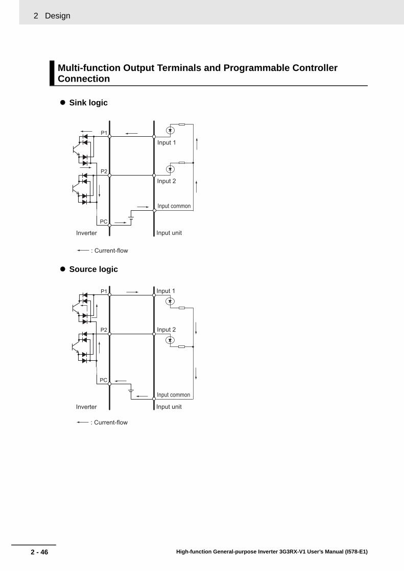
2 Design
2 - 46 High-function General-purpose Inverter 3G3RX-V1 User’s Manual (I578-E1)
Sink logic
Source logic
Multi-function Output Terminals and Programmable Controller Connection
Inverter
: Current-flow
P2
PC
P1
Input unit
Input common
Input 2
Input 1
Inverter
: Current-flow
P2
PC
P1
Input unit
Input common
Input 2
Input 1

2 - 47
2 Design
High-function General-purpose Inverter 3G3RX-V1 User’s Manual (I578-E1)
2-3 Wirin
g
2
2-3-5 Wiring for C
ontrol Circuit Term
inals
Precaution for using more than one inverterIf more than one inverter uses a common input (such as a switch), and their power-on timing is different, a sneak current will flow in the circuit as shown below. This may cause the inverters to falsely recognize the input signal is ON even if it is OFF. If this occurs, insert a diode (rating: 50 V/0.1 A) in the position shown in the diagram or redesign the circuit to use an external power supply to prevent sneak current.
For sink logic
Precaution for Wiring Control Circuit Terminals
Add a diode
Use an external power supply
P24
PSC
SC
S1
Short-circuit bar
P24
PSC
SC
S1
Switch OFFWith no diode inserted, the input turns ON due to sneak current even when the switch is OFF.
Power ON
Power OFF Short-circuit wire
Input ON
P24
PSC
SC
S1
P24
PSC
SC
S1
Switch OFFIn place of short-circuit bar, insert a diode to prevent sneak current.
Power ON
Power OFF
Input OFF
P24
PSC
SC
S1
P24
PSC
SC
S1
Switch OFFThe use of an external power supply with the short-circuit bar removed does not cause sneak current.
Power ON
Power OFF
Input OFF
24-VDC Power supply

2 Design
2 - 48 High-function General-purpose Inverter 3G3RX-V1 User’s Manual (I578-E1)
For source logic
P24
PSC
SC
S1
P24
PSC
SC
S1
Switch OFFWith no diode inserted, the input turns ON due to sneak current even when the switch is OFF.
Power ON
P24
PSC
SC
S1
P24
PSC
SC
S1
Switch OFFIn place of short-circuit bar, insert a diode to prevent sneak current.
Power ON
P24
PSC
SC
S1
P24
PSC
SC
S1
Power ON
Add a diode
Use an external power supply
Switch OFFThe use of an external power supply with the short-circuit bar removed does not cause sneak current.
Power OFF Power OFF
Power OFF
Short-circuit wire
Short-circuit wire
Input ON
Input OFF
Input OFF
24-VDC Power supply

2 - 49
2 Design
High-function General-purpose Inverter 3G3RX-V1 User’s Manual (I578-E1)
2-3 Wirin
g
2
2-3-6 Wiring for P
G B
oard
To use PG vector control with this inverter, you need to mount and wire the PG Board. Then, install a detector (encoder) to the motor rotating shaft and wire it to the PG Board. For the detector (encoder), use a line-driver output type encoder. This is required for PG vector control, position control, or torque control operation.
For details on the PG Board, refer to PG Board 3G3AX-PG User’s Manual (I564).
The PG Board can be mounted on the option port 1 or 2. Securely mount the PG Board as shown below.
Place the four holes in the corners of the PG Board; two holes on the guideposts and the other two on the screw holes. Put the connector at the back of the PG Board on the option port 1 or 2 correctly.
Then, tighten the two fixing screws for the PG Board securely.
Precautions for Correct UsePrecautions for Correct Use
To mount the PG Board, be sure to tightly fix it with the two provided fixing screws after putting in place the connector securely. Otherwise, the inverter cannot operate properly.
2-3-6 Wiring for PG Board
PG Board Mounting
Option port 1
Option port 2
Fixing screw holes for the PG Board (M3 screws)
PG board
Guideposts for positioning the PG Board
Guideposts for positioning the PG Board

2 Design
2 - 50 High-function General-purpose Inverter 3G3RX-V1 User’s Manual (I578-E1)
The arrangement of the terminals on the PG Board is shown below.
Input terminals
Terminal Arrangement on PG Board
Terminal symbol
Terminal name
Functional description Electrical specifications
SAP
SAN
SBP
SBN
Pulse train position command input
• Pulse Train Input Selection (P013) *1
Mode 0: 90°phase difference pulse train
Mode 1: Forward/Reverse command + pulse train
Mode 2: Forward command + Reverse pulse train
• Use the DIP switches on the PG Board to enable/disable the built-in terminating resistor (150 Ω).
*1. Select the pulse train mode with the inverter parameter P013.
Line-driver input
5-VDC receiver input
(RS-422 compliant)
EAP
EAN
EBP
EBN
EZP
EZN
Encoder signal input
A/B/Z: Encoder signal inputPhotocoupler input
(5 VDC line-driver output type rotary encoders supported)
TM1 TM2
DIP Switch
Connector to the inverter
EP5 EG5 EAP EAN EBP EBN EZP EZN SAP SAN SBP SBN AP AN BP BN
SWENCDIP Switch
SWR
TM1 Terminal arrangement TM2 Terminal arrangement

2 - 51
2 Design
High-function General-purpose Inverter 3G3RX-V1 User’s Manual (I578-E1)
2-3 Wirin
g
2
2-3-6 Wiring for P
G B
oard
Output terminal
Terminal symbol
Terminal name
Functional description Electrical specifications
AP
AN
BP
BN
Encoder signal output
Output pulses in a ratio 1 to 1 to encode input pulses.
5 VDC line-driver output
(RS-422 compliant)
EP5
EG5
(Common)
Encoder power supply
+5 VDC power supply 150 mA max.
DIP switch name Switch No. DescriptionDefault
data
SWENC
1
ONDisconnection detection enabled when the encoder phase A/B is not connected
OFF
OFFDisconnection detection disabled when the encoder phase A/B is not connected
2
ONDisconnection detection enabled when the encoder phase Z is not connected
OFFOFF
Disconnection detection disabled when the encoder phase Z is not connected
SWR*1
*1. To input the pulse train position command into more than one inverter, set the DIP switches SWR1 and SWR2 to ON only one inverter that is farthest from the master.
1ON
Built-in terminating resistor between SAP and SAN enabled (150 Ω)
OFF
OFFBuilt-in terminating resistor between SAP and SAN disabled
2ON
Built-in terminating resistor between SBP and SBN enabled (150 Ω)
OFF
OFFBuilt-in terminating resistor between SBP and SBN disabled

2 Design
2 - 52 High-function General-purpose Inverter 3G3RX-V1 User’s Manual (I578-E1)
The encoder input terminals (EAP/EAN/EBP/EBN/EZP/EZN) have a function that detects disconnection when no encoder is connected.
When no encoder is connected, set both of the DIP switches SWENC1 and 2 to OFF to disable the disconnection detection function.
When connecting an encoder without the phase Z signal, set the DIP switch SWENC2 to OFF to disable the disconnection detection for the phase Z.
Wiring for PG Board
Disconnection Detection Function of PG Board
FSFVFC
Inverter control terminalAvailable to allocate to multi-function input terminals 1 to 8
EP55 VDC
EG5EAPEANEBPEBNEZPEZN
M
EC
Motor with an encoder
SAPSANSBPSBN
Pulse train position command
POKZS
DSE
Output terminal
FWRVLAC
PCLR (Position deviation clear)ORT
CM1
Input terminal
APANBPBN
Encoder signal output
STAT
Encoder signalTM1
Photocoupler
Photocoupler
Photocoupler
Reciever IC
TM2
(LAD cancel)
(Orientation)(Pulse train position command permission)
Available to allocate to multi-function output terminals 1 to 5
(Position ready)(0 Hz signal)(Excessive speed deviation)
PG board
Reciever IC
Driver IC
Driver IC

2 - 53
2 Design
High-function General-purpose Inverter 3G3RX-V1 User’s Manual (I578-E1)
2-3 Wirin
g
2
2-3-7 Wiring for R
S485 C
omm
unications Terminals
The 3G3RX-V1 Series has an RS485 communications capability that enables the inverter to communicate with an external controller from its RS485 communications terminal block on the control terminal block PCB.
For the communications protocol, the inverter supports the Modbus communication and the ASCII format.
This section describes the wiring procedure for the RS485 communications terminal block and the installation of the terminating resistor.
Wire size and tightening torque
2-3-7 Wiring for RS485 Communications Terminals
Wiring for RS485 Communications Terminal Block
Terminal symbol
Terminal name Function
RS+
RS485 communications send/receive terminal, positive side
Positive-side send/receive terminal signal for RS485 communications.
RS–
RS485 communications send/receive terminal, negative side
Negative-side send/receive terminal signal for RS485 communications.
RPTerminating Resistor enable terminal
The RP terminal is used to enable the built-in Terminating Resistor (100 Ω).
Connect the negative-side RS485 communications send/receive terminal (for Termination Resistor connection) with the terminal RP to enable the built-in Terminating Resistor.
RS–
RS485 communications send/receive terminal, negative side (for Terminating Resistor connection)
Screw sizeTightening
torque [N·m]Wire type Wire size [mm2]
M2 0.22 to 0.25
Solid wire0.14 to 1.5
(If two equal-sized wires are connected to one pole: 0.14 to 0.5)
Stranded wire0.14 to 1.0
(If two equal-sized wires are connected to one pole: 0.14 to 0.2)
Stranded wire with ferrule
0.25 to 0.5
(Example: PC-1.25 F-7 from JST Mfg. Co., Ltd.)
RS+ RS− RP RS−
Control terminal block
Control terminal block board
TM2
Communication terminal block TM2

2 Design
2 - 54 High-function General-purpose Inverter 3G3RX-V1 User’s Manual (I578-E1)
Wiring method(1) Loosen the terminal screw with a thin flat-blade screwdriver.
(2) Insert the wire through the bottom of the terminal block.
(3) Tighten the terminal screw securely.
Be sure to tighten the terminal screws to the tightening torque specified in the table on the previous page.
Precautions for Correct UsePrecautions for Correct Use
• Separate signal lines for control from the main circuit cable and other power supply/power lines when wiring.
• Do not solder the wire ends. Doing so may result in a contact failure.
• When ferrules are not used, the wire strip length must be approximately 5.0 mm.
• Connect the shielded cable to the terminal FC (frequency reference common) of the 3G3RX-V1 Series . Do not connect it to the controller.
• Insulate the cable shields with tape or some other means to prevent them from contact with other signal lines or equipment.
• Tightening the screws to an excessive tightening torque may result in damage to the terminals. Tightening them with a weak torque may also cause a malfunction or short-circuit.
Connect each inverter in series as shown below.
Because a terminating resistor must be installed at each end of communications wiring, enable the terminating resistor only for the terminal inverter.
Use the terminating resistor even if you have only one inverter connected.
For this inverter, shorting the terminals RP and RS– enables the built-in terminating resistor (100 Ω).
Terminating Resistor Installation
Thin flat-blade screwdriverTerminal block
Wire with crimp ferrule, or solderless wire
Cable
Strip lengthApprox. 5.0 mm(Without ferrule)
RS+ RS– RP RS–
Terminating resistorenabled
RS+ RS– RP RS– RS+ RS– RP RS–
Externalequipment(Master)
+–

2 - 55
2 Design
High-function General-purpose Inverter 3G3RX-V1 User’s Manual (I578-E1)
2-3 Wirin
g
2
2-3-8 Wiring for D
igital Operator
In addition to the standard Digital Operator, this inverter can be operated via the optional Digital Operator (Model: 3G3AX-OP01) or LCD Digital Operator (Model: 3G3AX-OP05).
To use these options with the standard Digital Operator removed from the inverter, you need the optional Digital Operator Cable (Model: 3G3AX-OPCN1 (1 m)/3G3AX-OPCN3 (3 m)).
Note that the maximum length of these optional cables is 3 m. Exceeding 3 m may result in malfunction.
For details on the LCD Digital Operator, refer to the LCD Digital Operator 3G3AX-OP05 User’s Manual (I579).
2-3-8 Wiring for Digital Operator
Cable for Digital OperatorModel: 3G3AX-OPCN1 (Length: 1 m)Model: 3G3AX-OPCN3 (Length: 3 m)
Digital Operator(Model: 3G3AX-OP01)
LCD Digital Operator (Model: 3G3AX-OP05)
High-function General-purpose Inverter (Model: 3G3RX-�-V1)
POWER RUN WARNING ALARM
1 2 3
4 5 6
6 8 9
10 11 12
LOCAL READ
ESC
WRITE
NEXT PAGEPREV PAGE
REMOTE
FWDRUN
REVRUN
STOPRESET
OPE
KEY ENABLED
Standard Digital Operator

2 Design
2 - 56 High-function General-purpose Inverter 3G3RX-V1 User’s Manual (I578-E1)
The built-in slide switch is used to enable or disable the emergency shutoff function. This function is disabled by factory default.
For the location of the slide switch, refer to the figure below.
For how to remove the control circuit terminal block, refer to Removing Control Circuit Terminal Block on page 2-12.
This function is intended to shut off the inverter output (stop switching the main element) via only the multi-function input terminal of the hardware circuit without use of the built-in CPU software.
To enable this function, set the slide switch SW1 lever in the inverter to ON. By factory default, slide switch SW1 is OFF (function disabled).
When this function is enabled, the multi-function input terminals S1 and S3 are dedicated for this function. No other function can be allocated to these terminals. If another function is allocated, it is automatically disabled, and terminals S1 and S3 are changed to the emergency shutoff terminals.
2-3-9 Wiring for Emergency Shutoff Function
Slide Switch (SW1) Setting
Emergency Shutoff Function
Special function of multi-function input terminal S1 when SW1 is ON
Reset signal (RS)/NO contact (Fixed)This signal is used to reset the inverter, and to reset the emergency shutoff trip (E37.*).
Special function of multi-function input terminal S3 when SW1 is ON
Emergency shutoff signal (EMR)/NC contact (Fixed)This signal is used to turn off the inverter output without using the built-in CPU.With this signal input, the inverter activates an emergency shutoff trip (E37.*).
ON
Slide switch SW1
Slide lever (factory setting: OFF)ONOFF

2 - 57
2 Design
High-function General-purpose Inverter 3G3RX-V1 User’s Manual (I578-E1)
2-3 Wirin
g
2
2-3-9 Wiring for E
mergency S
hutoff Function
Precautions for Correct UsePrecautions for Correct Use
• Although this function stops switching of the main element, the circuit is not electrically shut off. While the power supply is ON, do not touch the inverter terminals and power cable (e.g. motor cable). Doing so may result in electric shock, injury, or ground fault.
• Before operating slide switch SW1, make sure that the input power supply is OFF.
• If multi-function input terminal S3 is not connected or disconnected, or if the signal logic does not match, the inverter activates an emergency shutoff trip (E37.*). After checking the cable connection and the signal logic, input the reset signal (RS).Note that emergency shutoff trip (E37.*) can be reset only by the reset signal (RS) via multi-function input terminal S1 and cannot be reset with the Digital Operator.
The slide switch SW1 setting and the status of the multi-function input terminals S1 and S3 are shown below.
*1 When the Multi-function Input S1 Selection (C001) is set to 18 (RS), C011 is fixed to 00 (NO).
*2 When the Multi-function Input S3 Selection (C003) is set to 64 (EMR), C013 is fixed to 01 (NC).
*3 If the switch SW1 is turned ON with a Multi-function Input terminal other than S1 and S3 set to 18 (RS), the function to prevent duplicated allocation is activated and automatically changes this Input Selection setting to no (No allocation). If this occurs, just turning the switch SW1 back to OFF does not restore the previous setting. Re-allocate the terminal function.
Example: When the Multi-function Input S2 Selection (C002) is allocated to 18 (RS), if the switch SW1 is turned ON, the C002 setting is changed to no (No allocation), and the Multi-function Input S1 Selection (C001) is allocated to 18 (RS). Then, even if the switch SW1 is turned back to OFF, the Multi-function Input S2 Selection (C002) setting is no (No allocation) and the Multi-function Input S1 Selection (C001) is 18 (RS).
*4 Multi-function Input Selection parameters cannot be set to 64 (EMR) via the Digital Operator. This function is allocated automatically when the slide switch SW1 is turned ON.
*5 Once the slide switch SW1 is turned ON, turning OFF SW1 does not restore the previous allocations for the multi-function input terminal S1/S3. Allocate the terminal function again.
Slide switch SW1 setting and status of multi-function input terminals S1 and S3
Slide switch (SW1) setting
Multi-function input terminal S1 Multi-function input terminal S3
Multi-function Input S1 Selection (C001)
Multi-function Input S1 Operation
Selection (C011) *1
Multi-function Input S3 Selection (C003)
Multi-function Input S3 Operation
Selection (C013) *2
SW1 “OFF”
Emergency shutoff: Disabled (Factory default)
[Can be selected
randomly] *4[Can be selected
randomly] *4[Can be selected
randomly] *4[Can be selected
randomly] *4
Factory default
01: RVFactory default
00: NOFactory default
12: EXTFactory default
00: NO
SW1 “ON” Emergency shutoff: Enabled *5
Automatic allocation to multi-function input terminals S1 and S3, and the input terminal with “18
(RS)” setting *3
Fixed function (Cannot be changed)
18: RS
Fixed function (Cannot be changed)
00: NO
Fixed function (Cannot be changed)
64: EMR
Fixed function (Cannot be changed)
01: NC
SW1 “ON,” then “OFF”
Emergency shutoff: Disabled *3 *5
[Can be selected
randomly] *4[Can be selected
randomly] *4[Can be selected
randomly] *4[Can be selected
randomly] *4
Holds setting while SW1 is ON
18: RS
Holds setting while SW1 is ON
00: NO
Emergency shutoff function: Reset
no (No allocation)
Holds setting while SW1 is ON
01: NC

2 Design
2 - 58 High-function General-purpose Inverter 3G3RX-V1 User’s Manual (I578-E1)
This section provides conditions that must be met for compliance with European EC Directives.Take measures to meet the conditions shown here for the entire system as well as peripheral equipment.For the system that incorporates this inverter, perform the final compliance verification separately on the whole system.
The 3G3RX-V1 Series complies with the following standards.
EMC DirectiveOMRON products are the electrical devices incorporated and used in various machines or manufacturing equipment. For this reason, OMRON makes efforts to manufacture products that meet the related EMC standards so that the machines or equipment in which they are incorporated can easily comply with the EMC standards.
The 3G3RX-V1 Series Inverter complies with the EMC Directive EN61800-3 when installed and wired to equipment according to the methods described below. However, your machines and equipment vary in type, and in addition, EMC performance depends on the configuration, wiring, and location of the device or control panel in which EC Directive compliant products are incorporated. This does not allow OMRON to verify the compliance under your usage conditions. Please perform the final verification on the EMC compliance of your machines or the entire system at your own responsibility.
This is a Class A product designed for industrial environments. Use in residential area may cause radio interference, in which case the user may be required to take adequate measures to reduce interference.
Built-in EMC noise filterThe EMC noise filter that is built into the 3G3RX-V1 Series complies with EN61800-3 Category C3.
Other EMC noise filtersRefer to the table below. These filters are effective for improving of EMC conditions.When setting the light load mode, select the maximum applicable motor capacity for the light load mode.
2-3-10 Conformance to EC Directives
Applicable Standards
Standard Applicable standard
EMC Directive EN61800-3
Low-voltage Directive EN61800-5-1
Concepts of Compliance
Power supply Model
Max. applicable motor capacity [kW] Input current [In]
Leakage current[mA max.] at 60 Hz3-phase 200 V 3-phase 400 V
3-phase 200 VAC/400 VAC
3G3AX-EFI41 0.4, 0.75 0.4 to 2.2 7 A 150
3G3AX-EFI42 1.5 3.7 10 A 150
3G3AX-EFI43 2.2, 3.7 5.5, 7.5 20 A 170
3G3AX-EFI44 5.5 11 30 A 170
3G3AX-EFI45 7.5 15 40 A 170
3G3AX-EFI46 – 18.5 50 A 250
3G3AX-EFI47 11 22 60 A 250
3G3AX-EFI48 15 30 80 A 250
3G3AX-EFI49 18.5 37 100 A 250
3G3AX-EFI4A 22, 30 45, 55 150 A 250
3G3AX-EFI4B 37 75, 90 200 A 250

2 - 59
2 Design
High-function General-purpose Inverter 3G3RX-V1 User’s Manual (I578-E1)
2-3 Wirin
g
2
2-3-10 Conform
ance to EC
Directives
Wiring for power supplyKeep the ground cable as short as possible.
Place the inverter and the noise filter on the same earth (ground) plate.
Always connect the power supply input terminals (R/L1, S/L2, T/L3) of the inverter to the power supply via an EMC noise filter.
Keep the cable between the inverter and the EMC noise filter as short as possible (40 cm maximum).
Connection Example
Wiring between inverter and motorWhen connecting a motor to the inverter, be sure to use shield braided cables.
Keep the cables as short as possible.
Measures against noise• For the power supply lines of the inverter, use a shield braided cable with a minimum cable length,
and connect via an EMC compliant input noise filter.
• Ground the cable shield.
• Keep the ground cable as short as possible. For 400-V class inverters, the ground terminal must be connected to the neutral point of a power supply. Also ground the metal control panel as well as the door simultaneously.
• Use shield braided cables also for connection between the inverter and the motor. Keep the cable as short as possible at a length 20 m or less, with the cable shield grounded. Installing a clamp filter near the inverter output terminals is an effective countermeasure.
• Connect the cable shield directly to an earth (ground) plate with a conductive cable clamp.
• With the motor frame grounded directly, connect the ground cable from the motor directly to an EMC compliant input noise filter.
• For the control panel door, use a conductive gasket to improve the shielding effect.
• In the same control panel, do not install equipment that generates by design electromagnetic waves, especially radio waves.
Low-voltage DirectiveThe 3G3RX-V1 Series Inverter complies with the EMC Directive EN61800-5-1 when installed with a molded case circuit-breaker (MCCB) and wired according to the specified wiring method.
• The 3G3RX-V1 Series Inverter is an open type device. Be sure to install it inside the control panel.
• The power supply and voltage (SELV) with reinforced or double insulation should be used for wiring to the control circuit terminals.
• To satisfy requirements of the LVD (Low Voltage Directive), the inverter must be protected with a molded case circuit breaker (MCCB) in case a short-circuiting accident occurs. Be sure to install a molded case circuit breaker (MCCB) on the power supply side of the inverter.
• Use one molded case circuit breaker (MCCB) per inverter.
• Use the crimp terminal with an insulation sleeve to connect to the main circuit terminals.
• For 400-V class inverters, the ground terminal must be connected to the neutral point of a power supply.
L1 L1' (Red)
L2' (White)
L3' (Blue)
L2
L3
R/L1
S/L2
T/L3
U/T1
V/T2
W/T3M
(Power)
EMC noise filterMolded casecircuit breaker
Motor
Inverter

2 Design
2 - 60 High-function General-purpose Inverter 3G3RX-V1 User’s Manual (I578-E1)
This section provides an outline of options and peripheral equipment used with this inverter and information on their reference manual.
This option is used in conjunction with a braking resistor to shorten the motor deceleration time.
This option detects the rotation speed of the motor with an encoder and feeds back the detected value to enable high-accuracy operation with reduced speed variation, as well as position control via pulse train position command input.
This is a Digital Operator with the 5-line display capability.
This optional support tool enables you to edit inverter parameter data and monitor the status of the inverter.
This option enables a stand-alone inverter to perform simple sequence control.
2-3-11 Reference Manuals for Options
Regenerative Braking Unit (Model: 3G3AX-RBU )
Name Catalog No.
Regenerative Braking Unit 3G3AX-RBU User’s Manual I563
PG Board (Model: 3G3AX-PG01)
Name Catalog No.
Encorder Feedback Board 3G3AX-PG User’s Manual I564
LCD Digital Operator (Model: 3G3AX-OP05)
Name Catalog No.
LCD Digital Operator 3G3AX-OP05 User’s Manual I579
CX-Drive
Name Catalog No.
CX-Drive Operation Manual W453
DriveProgramming
Name Catalog No.
DriveProgramming User’s Manual I580

3 - 1
3
High-function General-purpose Inverter 3G3RX-V1 User’s Manual (I578-E1)
This section describes the operations of the Digital Operator and this product as well as the test run procedure.
3-1 Operation of Digital Operator . . . . . . . . . . . . . . . . . . . . . . . . . . . . . . . . . . . . 3-43-1-1 Part Names and Descriptions . . . . . . . . . . . . . . . . . . . . . . . . . . . . . . . . . . . . . 3-4
3-1-2 Key Operation Method . . . . . . . . . . . . . . . . . . . . . . . . . . . . . . . . . . . . . . . . . . . 3-6
3-2 Overview of LCD Digital Operator . . . . . . . . . . . . . . . . . . . . . . . . . . . . . . . 3-15
3-3 Connections and Functions of CX-Drive . . . . . . . . . . . . . . . . . . . . . . . . . . 3-163-3-1 CX-Drive Connection Method . . . . . . . . . . . . . . . . . . . . . . . . . . . . . . . . . . . . 3-16
3-3-2 Outline of CX-Drive . . . . . . . . . . . . . . . . . . . . . . . . . . . . . . . . . . . . . . . . . . . . 3-20
3-4 Flow of Test Run . . . . . . . . . . . . . . . . . . . . . . . . . . . . . . . . . . . . . . . . . . . . . 3-24
3-5 Test Run Procedure . . . . . . . . . . . . . . . . . . . . . . . . . . . . . . . . . . . . . . . . . . . 3-25
Operation and Test Run

3 Operation and Test Run
3 - 2 High-function General-purpose Inverter 3G3RX-V1 User’s Manual (I578-E1)
• Be sure to confirm the permissible range of motors and machines before operation because the inverter speed can be changed easily from low to high.
• Provide a separate holding brake if necessary.
• If a parameter is set incorrectly when starting up, adjusting, maintaining, or replacing, an unexpected operation may occur. Perform the operation after enough confirmation.
• When using DriveProgramming, confirm that the program data is downloaded normally before starting the operation.
Do not change wiring and slide switches (SW1), put on or take off Operator and optional devices, replace cooling fans while the input power is being supplied. Doing so may result in a serious injury due to an electric shock.
Do not remove the terminal cover during the power supply and 10 minutes after the power shut off. Doing so may result in a serious injury due to an electric shock.
Do not operate the Operator or switches with wet hands.
Doing so may result in a serious injury due to an electric shock.
Inspection of the inverter must be conducted after the power supply was turned off. Not doing so may result in a serious injury due to an electric shock.
The main power supply is not necessarily shut off even if the emergency shut off function is activated.
Do not touch the inverter fins, braking resistors and the motor, which become too hot during the power supply and for some time after the power shut off.
Doing so may result in a burn.
Take safety precautions such as setting up a molded-case circuit breaker (MCCB) that matches the inverter capacity on the power supply side. Not doing so might result in damage to property due to the short circuit of the load.
Precautions for Safe Use
Operation and Adjustment
WARNING
Caution

3 - 3
3 Operation and Test Run
High-function General-purpose Inverter 3G3RX-V1 User’s Manual (I578-E1)
3
• Do not come close to the machine when using the Restart Selection function (b001, b008) because the machine may abruptly start when stopped by an alarm.
• Be sure to confirm the RUN signal has turned OFF before resetting the alarm because the machine may abruptly start.
• Do not come close to the machine when selecting reset in the Deceleration Stop Function (b050) because the machine may abruptly start after the power is turned on.
• Provide a separate emergency stop switch because the STOP Key on the Operator is valid only when function settings are performed.
• When checking a signal during the power supply and the voltage is erroneously applied to the control input terminals, the motor may start abruptly. Be sure to confirm safety before checking a signal.
Precautions for Correct Use
Restart Selection Function
Deceleration Stop Function
Operation Stop Command

3 Operation and Test Run
3 - 4 High-function General-purpose Inverter 3G3RX-V1 User’s Manual (I578-E1)
3-1 Operation of Digital Operator
The Digital Operator is a display operation panel equipped as standard on the 3G3RX-V1 Series Inverter.
The table below shows the name and function of each part of the Digital Operator.
3-1-1 Part Names and Descriptions
Part Name Function
POWER LED Lights (green) when the power is supplied to the control circuit.
ALARM LED Lights (red) when the inverter is in a trip error state.
For how to reset a trip error state, refer to How to Reset a Trip State on page 10-3.
RUN LED Lights (green) during operation.
Program LED Lights (green) when the set value for the selected function is displayed on the data display.
Blinks if the set value is invalid (during warning).
Refer to 10-2 Warning Function on page 10-12.
Data display Displays the frequency reference value, output current value or set value, or other relevant data.
Data display LED Lights (green) according to the content of the data display.
Hz: Frequency, V: Voltage, A: Current, kW: Power, %: Rate
RUN command LED indicator
Lights (green) when the RUN command source is set to the Digital Operator.
This indicates that the RUN key of the Digital Operator is enabled.
RUN key Starts inverter operation. Operation via the Digital Operator is enabled and the RUN command is selected.
Check that the RUN command LED indicator is lit.
STOP/RESET key Stops the inverter.
The STOP/RESET key is enabled by factory setting even when the RUN command source is not set to the Digital Operator. This key can be disabled by setting the STOP Key Selection (b087).
When the inverter is in a trip error state, if you press this key, the trip error state is reset.
Data display
Operation keys
RUN command LED indicator

3 - 5
3 Operation and Test Run
High-function General-purpose Inverter 3G3RX-V1 User’s Manual (I578-E1)
3-1 Op
eration
of D
igital O
perato
r
3
3-1-1 Part N
ames and D
escriptions
Precautions for Correct UsePrecautions for Correct Use
• The color scheme of the Digital Operator keys was changed. Operate the keys correctly according to the following information on the displays and colors.
• Install or remove the Digital Operator with the power supply shut off. Not doing so may result in failure.
Mode key When parameter is displayed: Moves to the beginning of the next
function mode.
When data is displayed: Cancels the setting and returns to the parameter display.
In individual input mode: Moves the blinking position one digit to the left, if not located at the left end. At the left end, cancels the input data and returns to the previous display.
Regardless of the display, if you press the Mode key for 3 seconds or more, the data of Output Frequency Monitor (d001) is displayed.
Enter key When parameter is displayed: Switches to the data display.
When data is displayed: Enters and stores the set value (into the EEPROM) and returns to the parameter display.
In individual input mode: Enters the value in the blinking position and moves it one digit to the right.
Increment key Increases the parameter number or the set data value. Press and hold the key to quickly increase the number or value.
Press the increment key and the decrement key simultaneously to enter the individual input mode, where you can edit the value in each digit independently.
Decrement key Decreases the parameter number or the set data value. Press and hold the key to quickly decrease the number or value.
Press the increment key and the decrement key simultaneously to enter the individual input mode, where you can edit the value in each digit independently.
Key Name Previous model 3G3RX-V1
RUN key Gray Green
STOP/RESET key Yellow Red
Mode key Blue Blue (No change)
Enter key Yellow Yellow (No change)
Increment key Green Gray
Decrement key Green Gray
Part Name Function

3 Operation and Test Run
3 - 6 High-function General-purpose Inverter 3G3RX-V1 User’s Manual (I578-E1)
This section explains how to use the Digital Operator keys in a typical operation (when the Display Selection is “Complete display”) and in the extended function mode U as operation examples.
This operation will be the same even if you select a different setting in the Display Mode (b037), although the number of parameters that you will see on the display differs.
Precautions for Correct UsePrecautions for Correct Use
• You can change the parameter display on the Digital Operator by the Display Selection (b037). For details, refer to Display Selection on page 7-78.
• In the 3G3RX-V1, the factory setting for the Display Selection (b037) is “Complete display,” which was changed from the conventional default “Basic display.” You can see and set all parameters when you turn on the power supply for the first time.
Additional Information
• You can set the initial screen displayed after turning on the power supply by the Initial Screen Selection (b038). For details, refer to Initial Screen Selection (Initial Screen after Power-on) on page 7-81.
• You can display only the parameters registered as user parameters. It is also possible to automatically register changed parameters, or directly set specific parameters. For details, refer to User Parameter Automatic Setting Function on page 7-81.
Additional Information
Regardless of the display mode of the Digital Operator, if you press the Mode key for 3 seconds or more, the data of Output Frequency Monitor (d001) is displayed. However, the Digital Operator continues to display the function group parameters in sequence as the normal operation if you press the Mode key for less than 3 seconds. (Example: A001 → F001 → b001 → C001 ... (after 3 s) “500” appears)
3-1-2 Key Operation Method
Item Parameter No. Data Description
Display Selection b037
00 Complete display (Factory setting)
01 Individual display of functions
02 User setting
03 Data comparison display
04 Basic display
Initial Screen Selection (Initial screen after power-on)
b038
000 Screen on which the Enter key is pressed last
001 to 060 d001 to d060 (001: Factory setting)
201 F001
202 Do not set.
User Parameter Automatic Setting Function
b03900 Disabled (Factory setting)
01 Enabled

3 - 7
3 Operation and Test Run
High-function General-purpose Inverter 3G3RX-V1 User’s Manual (I578-E1)
3-1 Op
eration
of D
igital O
perato
r
3
3-1-2 Key O
peration Method
The following figure shows how to operate the Digital Operator to reach the intended parameter display.
Transition of Parameter Display
Monitor Mode “d”
Parameter display
On the parameter display
: Moves to Data display.
Data displayData cannot be changed in the monitor mode “d”.
d001: Output Frequency Monitor
On the parameter display
On the parameter display
: Moves to the next mode.
Stores Data display
F001: Output Frequency Setting
On the data display (F001 to F*03)Changes are entered instantaneously, so the value does not blink.
: Press this to store the value to the EEPROM and return to the parameter display.
: Press this to return to the parameter display, without storing the value to the EEPROM.
Function Mode “F”
Parameter display
Extended Function Mode “A”
Parameter display Data display
A001: Frequency Reference Selection
On the data displayAll digits of the value blink after each change.While the digit is blinking, the changes are not reflected.
Extended Function Mode “C”
Extended Function Mode “H”
Extended Function Mode “b”
Extended Function Mode “P”
Extended Function Mode “U”
Monitor Mode “d”
Returns to d001.
: Press this to enter and store the value and return to the parameter display.
: Press this to discard the changes and return to the parameter display.
Note*1
*2
Use the Increment/Decrement key to increase or decrease a parameter number. Pressing the Increment key at the end of mode returns to the beginning of the same mode.
*1 Data cannot be changed in the monitor mode “d”.*2 After the extended function mode “U”, returns to the monitor
mode “d”.
In the parameter display or data display mode, pressing the Increment and Decrement keys simultaneously enables quick change of the parameter data.
For details, refer to Individual Input Mode (Direct Input or Selection) on page 3-10.

3 Operation and Test Run
3 - 8 High-function General-purpose Inverter 3G3RX-V1 User’s Manual (I578-E1)
In the extended function mode U, you can operate the Digital Operator in the same way as in other modes.However, do not be confused although each parameter number is displayed again for the set value.Press the Enter key to enter the selected parameter number. Then the display returns to the parameter display in the extended function mode U.To display only the user set parameters, set the Display Selection (b037) to 02 (User setting).
Transition of Parameter Display and Key Operation in Function Group U
or
Extended FunctionMode A
Extended FunctionMode P
Extended FunctionMode H
Extended FunctionMode U
Extended FunctionMode C
Extended FunctionMode B
MonitorMode
FunctionMode
(Factory setting)
Press the Enter key to enter the selected parameter number in “U”.
Pressing the Enter key does not return.

3 - 9
3 Operation and Test Run
High-function General-purpose Inverter 3G3RX-V1 User’s Manual (I578-E1)
3-1 Op
eration
of D
igital O
perato
r
3
3-1-2 Key O
peration Method
You can initialize the changed parameters and also clear the fault monitor data.
As a measure to prevent inadvertent parameter initialization, the inverter is designed to force the user to set several parameters to execute initialization.
For details on parameter initialization, refer to 5-1 Parameter Display and Parameter Initialization on page 5-3.
Precautions for Correct UsePrecautions for Correct Use
• The following parameters are not initialized: the settings of the DriveProgramming User Parameters U00 to U31 (P100 to P131), Total RUN Time Monitor (d016), Total Power ON Time Monitor (d017), Initialization Data Selection (b085), Heavy Load/Light Load Selection (b049), Thermistor Adjustment (C085), and analog adjustment parameters (C081 to C083, C121 to C123).
• The inverter does not display the initialization-related parameters depending on the Display Selection (b037) setting. If they are not displayed, change b037 to 00 (Complete display).
• When the Soft Lock Selection (b031) is set to prohibit changes of the parameter settings, the parameter initialization function does not work. Disable the soft lock function before attempting parameter initialization.
• The 3G3RX-V1 Inverter does not support the conventional initialization which is performed by pressing multiple keys simultaneously.
• Remember that it is impossible to undo the initialization once you press the Enter key to execute parameter initialization, with the Initialization Execution (b180) set to 01.
The following figure shows the steps of complete parameter initialization.
Complete initialization means to clear the Fault Monitor and DriveProgramming application data, as well as the parameter data.
Parameter Initialization
Step3:Step1: Step2:
Initializing
Initialization completes.
Press the Enter key to set b084 to “04”.
Press the Enter key to set b180 to “01”.
Initialization is completed when the initialization display disappears.

3 Operation and Test Run
3 - 10 High-function General-purpose Inverter 3G3RX-V1 User’s Manual (I578-E1)
If the parameter number or data is far away from the current value on the display, using the individual input mode is efficient for changing the parameter data.
In the individual input mode, you can change the parameter number or data by selecting and entering a value digit by digit.
The following is an example of changing the monitor mode parameter number d001 on the display to the extended function parameter number A029.
(1) Display the monitor mode parameter number.
(“d001” is displayed.)
Individual Input Mode (Direct Input or Selection)
Press and simultaneously.
Step1:
The most significant digit is blinking.
Step2: Step3:
Moves to left. Moves to right.–1+1
Press the Increment key and Decrement key simultaneously.
Enter when the least significant digit blinks.
Move blinking digit to left and right with the Mode and Enter keys to change numbers with the Increment/Decrement keys.

3 - 11
3 Operation and Test Run
High-function General-purpose Inverter 3G3RX-V1 User’s Manual (I578-E1)
3-1 Op
eration
of D
igital O
perato
r
3
3-1-2 Key O
peration Method
(2) Change to the extended function mode.
(3) Change the 3rd digit of the extended function parameter number.
• In the left-end digit (4th digit), “d” starts blinking.
• Press twice.(“A001” is displayed.)
Note If you press when the left-end digit is blinking, the selected value is canceled and it returns to the display on which you pressed
and simultaneously.
• In the left-end digit, “A” is blinking.
• Press to enter the value blinking in the digit.(“A” is entered.)
Note If you press when the digit is blinking, the blink returns to the digit in which you entered the previous value.
• In the 3rd digit, “0” is blinking.
• This “0” in the 3rd digit need not be changed, so
press to enter “0”.

3 Operation and Test Run
3 - 12 High-function General-purpose Inverter 3G3RX-V1 User’s Manual (I578-E1)
(4) Change the 2nd digit of the extended function parameter number.
(5) Change the 1st digit of the extended function parameter number.
• In the 2nd digit, “0” is blinking.
• Press twice.(“A021” is displayed.)
• In the 2nd digit, “2” is blinking.
• Press to enter the value blinking in the digit. (“2” is entered.)
Note If you press when the digit is blinking, the blink returns to the digit in which you entered the previous value.
• In the 1st digit, “1” is blinking.
• Press 8 times, or press twice.(“A029” is displayed.)
• In the 1st digit, “9” is blinking.
• Press to enter the value blinking in the digit.(“9” is entered.)

3 - 13
3 Operation and Test Run
High-function General-purpose Inverter 3G3RX-V1 User’s Manual (I578-E1)
3-1 Op
eration
of D
igital O
perato
r
3
3-1-2 Key O
peration Method
(6) The extended function parameter number setting is completed.
Precautions for Correct UsePrecautions for Correct Use
If the set parameter number is not listed in the Parameter List, or if the parameter number is hidden in the Display Selection setting, “A” in the left-end digit (4th digit) is blinking again. Refer to Display Selection on page 7-78 to check the parameter number and set it again.
(7) Press (Enter key) to display the parameter setting; press / (Increment/Decrement
key) to change the data; and press (Enter key) again to enter the new setting.
To change the parameter setting, follow the steps (1) to (6) in a similar manner.
Regardless of the display mode of the Digital Operator, if you press (Mode key) for 3 seconds or more, the data of Output Frequency Monitor (d001) is displayed. However, the Digital Operator continues to display the function mode and extended function mode in sequence as the normal operation if you press the Mode key for less than 3 seconds.
• The parameter number “A029” is selected.
Returning Display to d001

3 Operation and Test Run
3 - 14 High-function General-purpose Inverter 3G3RX-V1 User’s Manual (I578-E1)
For the 3G3RX-V1, the operation method was changed from the conventional 3G3RX Series.
The following table shows the changes and simplified operation method according to the 3G3MX2 Series.
Elimination of the top display layer (overall display of each function mode)
The top display layer in the operation was eliminated, although the concept of the function modes remains as before.
Change of scroll behavior in each function mode The parameter numbers loop in each function mode when scrolled.
In the previous model, when the highest parameter number in a function mode appears, the display switches to display the first parameter number in the next function mode.
Functions of Mode key and Enter key The functions of the Mode key and the Enter key were changed as follows for consistency and simplicity in operation.
Changes in Operation Method from Previous Model
Name Previous model 3G3RX Series This model 3G3RX-V1
Enter key • Moves to the upper layer.
• Enters and stores the setting, and returns to the parameter display.
• Moves to the data display.
• Enters and stores the setting, and returns to the parameter display.
Mode key • Moves to the upper layer.
• Moves to the parameter display.• Moves to the data display.
• Cancels the setting and returns to the parameter display.
• Displays the data of Output Frequency Monitor (d001) if you press the Mode key for 3 seconds or more.
• Moves to the beginning of the next function mode.
• Cancels the setting and returns to the parameter display.
• Displays the data of Output Frequency Monitor (d001) if you press the Mode key for 3 seconds or more.
Difference in key operation
Cancels the setting and returns.
Enters and stores the setting, and returns.
Moves to the upper layer.
Displays the data of Output Frequency Monitor (d001) data if you press the Mode key for 3 seconds or more.
Cancels the setting and returns.Enters and stores the setting, and returns.
Displays the data of Output Frequency Monitor (d001) data if you press the Mode key for 3 seconds or more.

3 - 15
3 Operation and Test Run
High-function General-purpose Inverter 3G3RX-V1 User’s Manual (I578-E1)
3-2 Overview
of L
CD
Dig
ital Op
erator
3
3-2 Overview of LCD Digital Operator
The LCD Digital Operator (Model: 3G3AX-OP05) is an optional Digital Operator with a 5-line LCD screen.
This LCD Digital Operator is newly supported in the 3G3RX-V1 Series and cannot be used with the previous model.
• The LCD Digital Operator can display up to four monitor functions or parameter settings in the selected language (currently English only).
• Similar to the standard LED Digital Operator, the LCD Digital Operator supports the starting/stopping of the inverter, parameter setting, monitor checking, trip error/warning data checking, and other operations.
• The LCD Digital Operator can store up to four sets of inverter parameter setting data, or a single set of inverter parameter setting data and a single DriveProgramming program in its internal memory.
• The LCD Digital Operator supports all read/write of inverter parameters and DriveProgramming program data. However, it can write parameter data to only the same model and the same version of inverters.
• The LCD Digital Operator has a capability to verify the parameter data stored in it and that stored inside the inverter.
• The LCD Digital Operator can be mounted directly on the inverter. The use of the Digital Operator Cable not only extends its application to handy operation but also enables panel-mounting.
Install or remove the Digital Operator with the power supply shut off. Not doing so may result in failure.
For details on the functions of the LCD Digital Operator, refer to “LCD Digital Operator 3G3AX-OP05 User’s Manual (I579)”.

3 Operation and Test Run
3 - 16 High-function General-purpose Inverter 3G3RX-V1 User’s Manual (I578-E1)
3-3 Connections and Functions of CX-Drive
The inverter/Servo support tool CX-Drive is support software to edit the inverter parameter settings.
Installing the OMRON CX-One software on your PC also installs the CX-Drive simultaneously.
The 3G3RX-V1 Series Inverter is supported in the following or higher versions of the CX-Drive product:
• CX-One: Ver. 4.23
• CX-Drive: Ver. 2.7
This section describes how to connect the CX-Drive to an inverter and provides an overview of its functions.
For details on the functions of the CX-Drive, refer to “CX-Drive Operation Manual (W453)”.
The following figure shows how to connect the 3G3RX-V1 Series with the inverter/Servo support tool CX-Drive.
Connect the CX-Drive directly to the serial communications port of the inverter.
3-3-1 CX-Drive Connection Method
Direct Connection via Serial Communications
CX-Drive
USB
USB-RS422 Conversion Cable (Model: 3G3AX-PCACN2)
Connector for Digital Operator
(A)
(B)
Remove Digital Operator (A) and Connector (B).

3 - 17
3 Operation and Test Run
High-function General-purpose Inverter 3G3RX-V1 User’s Manual (I578-E1)
3-3 Co
nn
ection
s and
Fu
nctio
ns o
f CX
-Drive
3
3-3-1 CX
-Drive C
onnection Method
There are two methods to connect the CX-Drive with the inverter.
The step-by-step procedure for each method is provided below.
Connecting by registering inverter connection method beforehandCreate a new inverter project, set the connecting method, and connect with the inverter.
Follow the steps below.
1 Start the CX-Drive and, from the [File] menu, select [New].
2 In the [New Drive] window, set the drive type of the target inverter.
Under [Drive Type], select the inverter series name and click the [Settings] button to the right.
In the [Drive Type Settings] window, set the Installation Type/Option, Voltage Class, and Maximum Motor Capacity and select [V1] in Specifications.
After setting these items, click the [OK] button to close the [Drive Type Settings] window.
CX-Drive Connection Procedure

3 Operation and Test Run
3 - 18 High-function General-purpose Inverter 3G3RX-V1 User’s Manual (I578-E1)
3 In the [New Drive] window, set the type of connection to the inverter.
Under [Connection Type], select [Direct] and click the [Settings] button to the right.
On the [Driver] tab, set the Port Selection to the port name of the computer on which the CX-Drive is installed Data bits to 8, Parity to Even, and Stop bits to 1.
4 After setting these items, click the [OK] button and close all windows.
The new project is registered in the workspace.
Click the [ ] (Work Online) icon to connect to the inverter.
Automatically detecting the connected inverterSet the [Autodetect Options] in the CX-Drive and use the Autodetect function to automatically connect to the inverter.
Follow the steps below.
1 Start the CX-Drive and, from the [Drive] menu, select [Autodetect Options] to open the Options window.

3 - 19
3 Operation and Test Run
High-function General-purpose Inverter 3G3RX-V1 User’s Manual (I578-E1)
3-3 Co
nn
ection
s and
Fu
nctio
ns o
f CX
-Drive
3
3-3-1 CX
-Drive C
onnection Method
2 On the [Autodetect] tab, under [Drive Type Selection], check the [Inverter] box.
Then, under [Connection Type Selection], check the [Direct] box and click the [Advanced Options: Direct] button to the right.
Additional Information
For the reduction of the automatic search time, deselect unnecessary check boxes to narrow down the scope of autodetection.
3 In the [Advanced Options [Direct (X-Series)]] window, set communications options.
4 After setting communications options, click the [OK] button and close all windows. Then, click [Autodetect].
The Autodetect function starts to create new drive projects automatically.

3 Operation and Test Run
3 - 20 High-function General-purpose Inverter 3G3RX-V1 User’s Manual (I578-E1)
The Inverter/Servo support tool CX-Drive enables you to edit inverter parameters and monitor the inverter status.
This section provides a functional outline of CX-Drive.
The screen structure of the CX-Drive is as shown below.
The workspace shows a list of registered drive projects. Double-clicking a project displays the functions contained in it.
Then, double-clicking each function opens a window corresponding to that function.
Precautions for Correct UsePrecautions for Correct Use
CX-Drive, by default, does not allow connection to the inverter unless the software versions match.
• Software number of the inverter set in the CX-Drive project
• Software number of the inverter actually connected
If you cannot connect to the inverter due to a software number mismatch, select [Tools] - [Options] in the menu bar and, in the [Online] tab, deselect the [Check Drive Software Compatibility] check box. This allows CX-Drive to connect to the inverter operate normally, although a warning display appears.
To match the software numbers, right-click the project, select [Properties], and click the [Settings] button in the [Drive Type] section. In the Drive Type Settings window, set the Software Number that matches that of the inverter. If you cannot find the applicable software number in the CX-Drive’s Software Number list, please upgrade the CX-Drive version.
3-3-2 Outline of CX-Drive
Screen Structure of CX-Drive
Workspace
Output window
Status bar
Window
Toolbar

3 - 21
3 Operation and Test Run
High-function General-purpose Inverter 3G3RX-V1 User’s Manual (I578-E1)
3-3 Co
nn
ection
s and
Fu
nctio
ns o
f CX
-Drive
3
3-3-2 Outline of C
X-D
rive
Double-clicking [Parameter Editor] in the project opens a window in which all inverter parameters are listed (in ascending order).
You can edit inverter parameters in this window.
To upload/download inverter parameters, use the [Transfer] buttons in the toolbar.
• Double-click one of the folders under Parameter Editor to narrow down the parameter list to only those parameters associated with it.
• Edit the value set for each parameter in the Value field of the parameter list.
• When a parameter is selected, the explanation of that parameter is displayed in the upper area.
• At the left end of the list, icons that represent the status of parameter data are displayed: Not default, Not default and different from the inverter, or Invalid. You can display only parameters with the same icon.
• You can select specific parameters and transfer data for only those selected parameters to the inverter.
Editing Device Parameters Using CX-Drive

3 Operation and Test Run
3 - 22 High-function General-purpose Inverter 3G3RX-V1 User’s Manual (I578-E1)
Open the Status folder in the project and double-click the status information.
The window corresponding to the selected status information opens.
Status Function of CX-Drive
Status icon category Description
[Digital Inputs]Displays the current ON/OFF status information, including the input function settings for the selected inverter.
[Digital Outputs]Displays the current ON/OFF status information, including the output function settings for the selected inverter.
[Monitor Mode]Displays the internal status values of the inverter. These status values are similar to those displayed in the monitor mode (dxxx) of the inverter.
[Alarms] Displays an alarm history of the current and past alarms.

3 - 23
3 Operation and Test Run
High-function General-purpose Inverter 3G3RX-V1 User’s Manual (I578-E1)
3-3 Co
nn
ection
s and
Fu
nctio
ns o
f CX
-Drive
3
3-3-2 Outline of C
X-D
rive
Open the Monitor folder in the project and double-click Real Time Trace.
The Real Time Trance window opens, in which you can monitor the operation status of the inverter.
• Up to 8 signals can be traced.
• Triggers can be set to the ON/OFF timing of the inverter’s internal status, or numerically.
Monitor Function of CX-Drive

3 Operation and Test Run
3 - 24 High-function General-purpose Inverter 3G3RX-V1 User’s Manual (I578-E1)
3-4 Flow of Test Run
Perform a test run of the inverter according to the following flow.
Item Description Reference
Installation Install the inverter according to the installation conditions. Section 2, 2-1
Wiring and connections
Connect the inverter to the power supply and peripheral equipment. Section 2, 2-3
Power-on Check the points mentioned in the next page before turning on the power supply.
Section 2, 2-3
Display status checks
Check that there is no error in the Inverter. Section 10
Parameter Initialization
Initialize the inverter parameters. Section 5, 5-1
Parameter setting Set the parameters required for the test run. Section 5, 5-3, 5-4
No-load run Run the motor with no-load via the Digital Operator. Section 3, 3-1
Load run Run the motor via Digital Operator, with the mechanical system connected.
Section 3, 3-1
Operation
Basic settings (operation with the basic settings required to operate and stop the inverter.)
Section 5
Vector control (operation the inveter with the vector control and other functions.)
Section 6

3 - 25
3 Operation and Test Run
High-function General-purpose Inverter 3G3RX-V1 User’s Manual (I578-E1)
3-5 Test Ru
n P
roced
ure
3
3-5 Test Run Procedure
The following describes the test run procedure.
Check that the inverter meets the installation conditions.
For details on installing the inverter, refer to 2-1 Installation on page 2-4.
Select peripheral equipment according to the specifications and wire the cables securely.
For details on wiring the inverter, refer to 2-3 Wiring on page 2-14.
Points to be checked before turning ON the powerCheck that the power supply voltage is appropriate and that the power supply input terminals (R/L1, S/L2, T/L3) are securely wired. The power supply voltage of the 3G3RX-V1 Series Inverter is as follows.
Check that the motor is securely connected to the motor output terminals (U/T1, V/T2, W/T3).
Check that the controller is securely connected to the control circuit terminals. In addition, turn off the control terminals.
Set the motor in a no-load state (not connected to the mechanical system).
Power-onIf no problem is found in above checks, turn on the power supply.
Installation
Wiring and Connections
Power-on
Model Power supply voltage
3G3RX-A2 -V1 (IP20) 3-phase 200 to 240 VAC
3G3RX-A4 -V1 (IP20) 3-phase 400 to 480 VAC
3G3RX-B4 -V1 (IP00) 3-phase 400 to 480 VAC

3 Operation and Test Run
3 - 26 High-function General-purpose Inverter 3G3RX-V1 User’s Manual (I578-E1)
If no problem is found at power-on, the display status will be as follows.
If any problem is found, the display status will be as follows.
Take countermeasures according to Section 10 Troubleshooting.
You can initialize the changed parameters and also clear the fault monitor data.
As a measure to prevent inadvertent parameter initialization, the inverter is designed to force the user to set several parameters to execute initialization.
The following figure shows the steps of complete parameter initialization.
Complete initialization means to clear the Fault Monitor and DriveProgramming application data, as well as the parameter data.
For details on parameter initialization, refer to 5-1 Parameter Display and Parameter Initialization on page 5-3.
Display Status Checks
Name Display status
POWER LED Lit
ALARM LED Not lit
RUN LED Not lit (Lit during RUN)
RUN command LED indicator Lit
Data display LED (Hz) Lit
Data display Displays d001 setting.
Name Display status
POWER LED Lit
ALARM LED Lit
RUN LED Not lit
RUN command LED indicator Lit
Data display LED (Hz) Lit
Data displayDisplays error code such as E01.
(Displayed error code differs depending on error condition.)
Parameter Initialization
Step3:Step1: Step2:
Initializing
Initialization completes.
Press the Enter key to set b084 to “04”.
Press the Enter key to set b180 to “01”.
Initialization is completed when the initialization display disappears.

3 - 27
3 Operation and Test Run
High-function General-purpose Inverter 3G3RX-V1 User’s Manual (I578-E1)
3-5 Test Ru
n P
roced
ure
3
Precautions for Correct UsePrecautions for Correct Use
• The following parameters are not initialized: the settings of the DriveProgramming User Parameters U00 to U31 (P100 to P131), Total RUN Time Monitor (d016), Total Power ON Time Monitor (d017), Initialization Data Selection (b085), Heavy Load/Light Load Selection (b049), Thermistor Adjustment (C085), and analog adjustment parameters (C081 to C083, C121 to C123).
• The inverter does not display the initialization-related parameters depending on the Display Selection (b037) setting. If they are not displayed, change b037 to 00 (Complete display).
• When the Soft Lock Selection (b031) is set to prohibit changes of the parameter settings, the parameter initialization function does not work. Disable the soft lock function before attempting parameter initialization.
• The 3G3RX-V1 Inverter does not support the conventional initialization which is performed by pressing multiple keys simultaneously.
• Remember that it is impossible to undo the initialization once you press the Enter key to execute parameter initialization, with the Initialization Execution (b180) set to 01.
To operate the inverter, two commands are required: the RUN command and the frequency reference.
First, set the sources of these commands in the Frequency Reference Selection (A001) and RUN Command Selection (A002). For Test Run, set these parameter to 02 (Digital Operator) to operate the inverter via the Digital Operator.
Next, set the 1st Motor Capacity (H003) and the 1st Motor Pole Number (H004). These values are used as the reference values for the automatic torque boost, motor protection, and torque limit functions.
Then, in the 1st Electronic Thermal Level (b012), set the rated current of your motor.
Set the value correctly according to the motor.
Precautions for Correct UsePrecautions for Correct Use
The STOP/RESET key on the Digital Operator is enabled when the STOP Key Selection parameter is set to Enabled. Make sure that this parameter is set correctly, although the STOP/RESET key is set to Enabled by default.
Parameter Setting
Parameter No. Function name Set value Default data Unit
A001 Frequency Reference Selection
02: Digital Operator 02 –
A002 RUN Command Selection 02: Digital Operator 02 –
H003 1st Motor Capacity 0.20 to 160.0 Maximum applicable motor capacity
kW
H004 1st Motor Pole Number 2/4/6/8/10 4 pole
b0121st Electronic Thermal Level
0.2 x Rated current to 1.0 x Rated current
Rated current A
b087 STOP Key Selection 00 to 02 00 –

3 Operation and Test Run
3 - 28 High-function General-purpose Inverter 3G3RX-V1 User’s Manual (I578-E1)
Rotate the motor with no-load (in a state not connected to the mechanical system) via the Digital Operator.
Forward/reverse rotation via Digital OperatorFollow the steps below to run the motor in the forward or reverse rotation.
(1) Set the Output Frequency Setting/Monitor (F001).
It is recommended to initially set this to approximately 10 Hz or slower for safety reasons (Factory settings: F001 = 6.0).
(2) Set the RUN Direction Selection (F004).
In the RUN Direction Selection (F004), select 00 (Forward) or 01 (Reverse).
Display the Output Frequency Monitor (d001) on the Digital Operator and press the Enter key.
Make sure that the displayed value is 0.00 (Hz).
(3) Press the RUN key.
The motor starts rotating with the RUN LED lit.
(4) Check that there is no problem with the output frequency, motor rotation direction or inveter operation displayed on the Digital Operator.
For the rotation direction of motor, refer to the explanation for the RUN Direction Monitor (d003).
Stopping motorAfter running the motor with no-load in the forward or reverse rotation, press the STOP/RESET key
. The motor stops rotating.
No-load Run
Parameter No. Function name Data range Default data Unit
F001Output Frequency Setting/Monitor
0.0
Starting Frequency to 1st Maximum Frequency
6.0 Hz
F004 RUN Direction Selection00: Forward
01: Reverse00 –
d001 Output Frequency Monitor0.00 to 99.9
100.0 to 400.0– Hz
d003 RUN Direction Monitor
F: Forward
o: Stop
r: Reverse
– –
Key Data display example Description
Press the Mode key for 1 s or more to display the d001 data “0.00”.
Press the RUN key.
The RUN command LED indicator lights and the frequency reference monitor value is displayed on the data display.

3 - 29
3 Operation and Test Run
High-function General-purpose Inverter 3G3RX-V1 User’s Manual (I578-E1)
3-5 Test Ru
n P
roced
ure
3
If no problem is found during no-load run, connect the mechanical system and run the inverter with load via the Digital Operator.
Mechanical system connectionMake sure that the motor has stopped completely before connecting the mechanical system.
Then, connect the mechanical system with the motor shaft securely to prevent the screws from loosening.
Operation via digital operator
In case of abnormal inverter run, be prepared to press the STOP/RESET key on the Digital Operator.
In the same way as you did during no-load run, stop the machine via the Digital Operator.
RUN mode checksStart with a low speed and, while checking that the machine moves smoothly in a correct direction, increase the Output Frequency Setting/Monitor (F001) value.
Check that there is no mechanical vibration and noise by varying the Output Frequency Setting/Monitor (F001) and RUN Direction Selection (F004) settings.
Also, check, using the Output Current Monitor (d002) and DC Voltage Monitor (d102), that the current/voltage is still far from the value at which a trip error occurs.
To operate the inverter with only basic parameters, refer to Section 5 Basic Settings.
To use applied functions such as the sensorless vector control, sensor vector control, speed control, torque control, and position control modes, in addition to Section 5 Basic Settings. refer to Section 6 Vector Control.
Load Run
Operation

3 Operation and Test Run
3 - 30 High-function General-purpose Inverter 3G3RX-V1 User’s Manual (I578-E1)

4 - 1
4
High-function General-purpose Inverter 3G3RX-V1 User’s Manual (I578-E1)
This section describes the parameters used with this inverter.
4-1 Monitor Mode . . . . . . . . . . . . . . . . . . . . . . . . . . . . . . . . . . . . . . . . . . . . . . . . . 4-24-1-1 Group d . . . . . . . . . . . . . . . . . . . . . . . . . . . . . . . . . . . . . . . . . . . . . . . . . . . . . . 4-2
4-2 Basic Function Mode . . . . . . . . . . . . . . . . . . . . . . . . . . . . . . . . . . . . . . . . . . . 4-54-2-1 Group F: Basic Function Parameters . . . . . . . . . . . . . . . . . . . . . . . . . . . . . . . . 4-5
4-3 Extended Function Mode . . . . . . . . . . . . . . . . . . . . . . . . . . . . . . . . . . . . . . . 4-64-3-1 Group A: Standard Function Parameters . . . . . . . . . . . . . . . . . . . . . . . . . . . . . 4-7
4-3-2 Group b: Detailed Function Parameters . . . . . . . . . . . . . . . . . . . . . . . . . . . . 4-19
4-3-3 Group C: Multi-function Terminal Function Parameters . . . . . . . . . . . . . . . . . 4-284-3-4 Group H: Motor Control Parameters . . . . . . . . . . . . . . . . . . . . . . . . . . . . . . . 4-39
4-3-5 Group P: Option Parameters . . . . . . . . . . . . . . . . . . . . . . . . . . . . . . . . . . . . . 4-42
4-3-6 Group U: User Setting Display Parameters . . . . . . . . . . . . . . . . . . . . . . . . . . 4-49
Parameter List

4 Parameter List
4 - 2 High-function General-purpose Inverter 3G3RX-V1 User’s Manual (I578-E1)
4-1 Monitor Mode
The inverter by default displays the content of the parameter d001at power-on. To monitor the desired parameter, change the setting in the Initial Screen Selection (b038).
4-1-1 Group d
Parameter No.
Function name Monitor or data rangeDefault
data
Changes during operation Unit Page
Normal b031 = 10d001 Output Frequency
Monitor0.00 to 99.99
100.0 to 400.0
– Enabled Enabled Hz 7-2
d002 Output Current Monitor
0.0 to 999.9
1000. to 9999.
– – – A 7-2
d003 RUN Direction Monitor
F: Forward
o: Stop
r: Reverse
– – – – 7-2
d004 PID Feedback Value Monitor
0.00 to 99.99
100.0 to 999.9
1000. to 9999.
1000 to 9999(10000 to 99990)
Γ100 to Γ999(100000 to 999000)
(Enabled when the PID function is selected)
– – – – 7-3
d005 Multi-function Input Monitor
– – – – 7-3
d006 Multi-function Output Monitor
– – – – 7-4
d007 Output Frequency Monitor (After Conversion)
0.00 to 99.99
100.0 to 999.9
1000. to 9999.
1000 to 3996(10000 to 39960)
[Output Frequency (d001) x Frequency Conversion Factor (b086)]
– Enabled Enabled – 7-4
d008 Real Frequency Monitor
0.00 to 99.99 (Forward)
100.0 to 400.0 (Forward)
–99.9 to –00.0 (Reverse)
–400. to –100. (Reverse)
– – – Hz 7-5
d009 Torque Reference Monitor
–200. to 200. – – – % 7-5
d010 Torque Bias Monitor
–200. to 200. – – – % 7-5
d012 Output Torque Monitor
–200. to 200. – – – % 7-6
d013 Output Voltage Monitor
0.0 to 600.0 – – – V 7-6
ONOFF
ON
OFFMulti-function input terminals
S8 S7 S6 S5 S4 S3 S2 S1(OFF) (ON) (OFF) (OFF) (OFF) (OFF) (ON) (ON)
: ON: OFF
Display
FW
ONOFF
MA P5 P4 P3 P2 P1(OFF) (OFF) (OFF) (OFF) (ON) (ON)
Multi-function output terminalsRelay output terminals
: ON: OFF
Display

4 - 3
4 Parameter List
High-function General-purpose Inverter 3G3RX-V1 User’s Manual (I578-E1)
4-1 Mo
nito
r Mo
de
4
4-1-1 Group d
d014 Input Power Monitor
0.0 to 999.9 – – – kW 7-6
d015 Integrated Power Monitor
0. to 9999.
1000 to 9999(10000 to 99990)
Γ100 to Γ999(100000 to 999000)
– – – kWh 7-7
d016 Total RUN Time Monitor
0. to 9999.
1000 to 9999(10000 to 99990)
Γ100 to Γ999(100000 to 999000)
– – – h 7-7
d017 Total Power ON Time Monitor
0. to 9999.
1000 to 9999(10000 to 99990)
Γ100 to Γ999(100000 to 999000)
– – – h 7-8
d018 Fin Temperature Monitor
–020.0 to 200.0 – – – °C 7-8
d019 Motor Temperature Monitor
–020.0 to 200.0 – – – °C 7-8
d022 Life Assessment Monitor
– – – – 7-8
d023 Program Counter (DriveProgramming)
0 to 1024 – – – – 7-9
d024 Program Number Monitor (DriveProgramming)
0000 to 9999 – – – – 7-9
d025 User Monitor 0 (DriveProgramming)
–2147483647 to 2147483647
(Displays DriveProgramming execution result)
– – – – 7-9
d026 User Monitor 1 (DriveProgramming)
–2147483647 to 2147483647
(Displays DriveProgramming execution result)
– – – –
d027 User Monitor 2 (DriveProgramming)
–2147483647 to 2147483647
(Displays DriveProgramming execution result)
– – – –
d028 Pulse Counter Monitor
0 to 2147483647(Displays MSB 4 digits)
– – – – 7-10
d029 Position Command Monitor
–268435455 to 268435455 (P012 = “02”)
–1073741823 to 1073741823 (P012 = “03”)
Displays MSB 4 digits (1 digit for “–”)
– – – – 7-10
d030 Current Position Monitor
–268435455 to 268435455 (P012 = “02”)
–1073741823 to 1073741823 (P012 = “03”)
Displays MSB 4 digits (1 digit for “–”)
– – – – 7-10
Parameter No.
Function name Monitor or data rangeDefault
data
Changes during operation Unit Page
Normal b031 = 10
Life assessmentNormal
2 1
1: Main circuit board capacitor 2: Cooling fan rotation speed reduced

4 Parameter List
4 - 4 High-function General-purpose Inverter 3G3RX-V1 User’s Manual (I578-E1)
*1 This can be displayed when the LCD Digital Operator is used.
Description for Data Range
Display of MSB 4 Digits
d031 *1 Current Time Monitor
mm/dd hh: mm(Month/Day and Hours/Minutes, 12 characters)
– – – – 7-11
d060 Inverter Mode Monitor
Displays currently set mode
I-C: IM motor heavy load
I-V: IM motor light load
– – – – 7-11
d080 Fault Counter 0. to 9999.
1000 to 6553(10000 to 65530)
– – – time 7-11
d081 Fault Monitor 1 (Latest)
Error code (Fault factor)
• Output frequency [Hz]
• Output current [A]
• P-N voltage [V]• RUN time [h]
• Power ON time [h]
– – – – 7-12
d082 Fault Monitor 2 – – – –d083 Fault Monitor 3 – – – –d084 Fault Monitor 4 – – – –d085 Fault Monitor 5 – – – –d086 Fault Monitor 6 – – – –d090 Warning Monitor Warning code – – – – 7-12d102 DC Voltage
Monitor0.0 to 999.9 – – – V 7-13
d103 Regenerative Braking Load Rate Monitor
0.0 to 100.0 – – – % 7-13
d104 Electronic Thermal Load Rate Monitor
0.0 to 100.0 – – – % 7-13
Data range Description
0.00 to 99.99 Displays in increments of 0.01.
0.0 to 999.9 Displays in increments of 0.1.
0. to 9999. Displays in increments of 1.
1000 to 9999 (10000 to 99990) Displays in increments of 10.
Γ100 to Γ999 (100000 to 999000) Displays in increments of 1000.
Data Display
1230000 1230
–1230000 –123
Parameter No.
Function name Monitor or data rangeDefault
data
Changes during operation Unit Page
Normal b031 = 10

4 - 5
4 Parameter List
High-function General-purpose Inverter 3G3RX-V1 User’s Manual (I578-E1)
4-2 Basic F
un
ction
Mo
de
4
4-2-1 Group F
: Basic F
unction Param
eters
4-2 Basic Function Mode
The table below lists the basic function mode parameters.
*1 The default data was changed from the previous model.
Description for Data Range
4-2-1 Group F: Basic Function Parameters
Parameter No.
Function name Monitor or data rangeDefault
data
Changes during operation Unit Page
Normal b031 = 10F001 Output Frequency
Setting/Monitor0.0/Starting frequency to
1st/2nd/3rd max. frequency
0.0 to 100.0 (PID function enabled)
– Enabled Enabled Hz 7-14
F002 1st Acceleration Time 1
0.01 to 99.99
100.0 to 999.9
1000. to 3600.
10.0 *1 Enabled Enabled s 7-15
F202 2nd Acceleration Time 1
10.0 *1 Enabled Enabled s
F302 3rd Acceleration Time 1
10.0 *1 Enabled Enabled s
F003 1st Deceleration Time 1
0.01 to 99.99
100.0 to 999.9
1000. to 3600.
10.0 *1 Enabled Enabled s
F203 2nd Deceleration Time 1
10.0 *1 Enabled Enabled s
F303 3rd Deceleration Time 1
10.0 *1 Enabled Enabled s
F004 RUN Direction Selection
00: Forward
01: Reverse
00 Disabled Disabled – 7-16
Data range Description
0.00 to 99.99 Displays in increments of 0.01.
0.0 to 999.9 Displays in increments of 0.1.
0. to 9999. Displays in increments of 1.
1000 to 9999 (10000 to 99990) Displays in increments of 10.
Γ100 to Γ999 (100000 to 999000) Displays in increments of 1000.

4 Parameter List
4 - 6 High-function General-purpose Inverter 3G3RX-V1 User’s Manual (I578-E1)
4-3 Extended Function Mode
In the extended function mode, inverter parameters are categorized in five groups: A, b, C, H, and P.
This section provides the parameter list for each group.
Note that the parameters displayed on the Digital Operator depend on the setting in the Display Selection (b037). To display all parameters, set this parameter to 00 (Complete display).
Precautions for Correct UsePrecautions for Correct Use
• You can change the parameter display on the Digital Operator by the Display Selection (b037). For details, refer to Display Selection on page 7-78.
• In the 3G3RX-V1, the factory setting for the Display Selection (b037) is “Complete display,” which was changed from the conventional default “Basic display.” You can see and set all parameters when you turn on the power supply for the first time.
Additional Information
• You can set the initial screen displayed after turning on the power supply by the Initial Screen Selection (b038). For details, refer to Initial Screen Selection (Initial Screen after Power-on) on page 7-81.
• You can display only the parameters registered as user parameters. It is also possible to automatically register changed parameters, or directly set specific parameters. For details, refer to User Parameter Automatic Setting Function on page 7-81.

4 - 7
4 Parameter List
High-function General-purpose Inverter 3G3RX-V1 User’s Manual (I578-E1)
4-3 Exten
ded
Fu
nctio
n M
od
e
4
4-3-1 Group A
: Standard F
unction Param
eters
4-3-1 Group A: Standard Function Parameters
Parameter No.
Function name Monitor or data rangeDefault
data
Changes during operation Unit Page
Normal b031 = 10A001 Frequency
Reference Selection
00: Digital Operator (Volume adjuster)(Enabled when 3G3AX-OP01 is connected)
01: Control circuit terminal block (Analog input)
02: Digital Operator (F001)
03: Modbus communication
04: Option 1
05: Option 2
06: Pulse train frequency
07: DriveProgramming
10: Operation function output
02 Disabled Disabled – 7-17
A002 RUN Command Selection
01: Control circuit terminal block
02: Digital Operator
03: Modbus communication
04: Option 1
05: Option 2
02 Disabled Disabled – 7-18
A003 1st Base Frequency
30. to 1st Maximum Frequency (A004)
60. Disabled Disabled Hz 7-19
A203 2nd Base Frequency
30. to 2nd Maximum Frequency (A204)
60.
A303 3rd Base Frequency
30. to 3rd Maximum Frequency (A304)
60.
A004 1st Maximum Frequency
30. to 400. 60. Disabled Disabled Hz 7-19
A204 2nd Maximum Frequency
30. to 400. 60.
A304 3rd Maximum Frequency
30. to 400. 60.
Bas
ic S
ettin
gs

4 Parameter List
4 - 8 High-function General-purpose Inverter 3G3RX-V1 User’s Manual (I578-E1)
Parameter No.
Function name Monitor or data rangeDefault
data
Changes during operation Unit Page
Normal b031 = 10A005 FV/FI Selection 00: Switching between FV
(Voltage) and FI (Current) via terminal AT
02: Switching between FV and volume adjuster via terminal AT
03: Switching between FI and volume adjuster via terminal AT
04: Switching between FE and volume adjuster via terminal AT
00 Disabled Disabled – 7-21
A006 FE Selection 00: FE only
01: FV/FI auxiliary frequency reference (not reversible)
02: FV/FI auxiliary frequency reference (reversible)
03: FE disabled
03 Disabled Disabled –
A011 FV Start
Frequency *10.00 to 99.99
100.0 to 400.0
0.00 Disabled Enabled Hz 7-24
A012 FV End
Frequency *10.00 to 99.99
100.0 to 400.0
0.00 Disabled Enabled Hz
A013 FV Start Ratio 0. to FV End Ratio (A014) 0. Disabled Enabled %A014 FV End Ratio FV Start Ratio (A013) to 100. 100. Disabled Enabled %A015 FV Start Selection 00: FV Start Frequency (A011)
01: 0 Hz
01 Disabled Enabled –
A016 Analog Input Filter 1. to 30. (x 2 ms)
31. : With 500 ms filter ±0.1 Hz hysteresis
31. Disabled Enabled – 7-26
A017 DriveProgramming Function Selection
00: Disabled
01: Enabled (Start/stop via multi-function input PRG terminal)
02: Enabled (Start/stop via power on/off)
00 Disabled Disabled – 7-26
*1 The inverter operates at 0 to 9.8 V when A011and A012 are set to 0.00.
Ana
log
inpu
t, ot
hers

4 - 9
4 Parameter List
High-function General-purpose Inverter 3G3RX-V1 User’s Manual (I578-E1)
4-3 Exten
ded
Fu
nctio
n M
od
e
4
4-3-1 Group A
: Standard F
unction Param
eters
Parameter No.
Function name Monitor or data rangeDefault
data
Changes during operation Unit Page
Normal b031 = 10A019 Multi-step Speed
Selection00: Binary (16-step selection with
4 terminals)
01: Bit (8-step selection with 7 terminals)
00 Disabled Disabled – 7-26
A020 1st Multi-step Speed Reference 0
0.00
Starting Frequency (b082) to 1st Maximum Frequency (A004)
6.00 Enabled Enabled Hz
A220 2nd Multi-step Speed Reference 0
0.00
Starting Frequency (b082) to 2nd Maximum Frequency (A204)
6.00 Enabled Enabled Hz
A320 3rd Multi-step Speed Reference 0
0.00
Starting Frequency (b082) to 3rd Maximum Frequency (A304)
6.00 Enabled Enabled Hz
A021 Multi-step Speed Reference 1
0.00
Starting Frequency (b082) to 1st/2nd/3rd Maximum Frequency (A004/A204/A304)
0.00 Enabled Enabled Hz
A022 Multi-step Speed Reference 2
0.00
A023 Multi-step Speed Reference 3
0.00
A024 Multi-step Speed Reference 4
0.00
A025 Multi-step Speed Reference 5
0.00
A026 Multi-step Speed Reference 6
0.00
A027 Multi-step Speed Reference 7
0.00
A028 Multi-step Speed Reference 8
0.00
A029 Multi-step Speed Reference 9
0.00
A030 Multi-step Speed Reference 10
0.00
A031 Multi-step Speed Reference 11
0.00
A032 Multi-step Speed Reference 12
0.00
A033 Multi-step Speed Reference 13
0.00
Starting Frequency (b082) to 1st/2nd/3rd Maximum Frequency (A004/A204/A304)
0.00 Enabled Enabled Hz
A034 Multi-step Speed Reference 14
0.00
A035 Multi-step Speed Reference 15
0.00
A038 Jogging Frequency
0.00
Starting Frequency to 9.99
6.00 Enabled Enabled Hz 7-30
Mul
ti-st
ep s
peed
, jog
ging

4 Parameter List
4 - 10 High-function General-purpose Inverter 3G3RX-V1 User’s Manual (I578-E1)
*1 The default data was changed from the previous model.
A039 Jogging Stop Selection
00: Free running during jogging stop/Disabled during operation
01: Deceleration stop during jogging stop/Disabled during operation
02: DC injection braking during jogging stop/Disabled during operation
03: Free running during jogging stop/Enabled during operation
04: Deceleration stop during jogging stop/Enabled during operation
05: DC injection braking during jogging stop/Enabled during operation
04 *1 Disabled Enabled – 7-30
Parameter No.
Function name Monitor or data rangeDefault
data
Changes during operation Unit Page
Normal b031 = 10
Mul
ti-st
ep s
peed
, jog
ging

4 - 11
4 Parameter List
High-function General-purpose Inverter 3G3RX-V1 User’s Manual (I578-E1)
4-3 Exten
ded
Fu
nctio
n M
od
e
4
4-3-1 Group A
: Standard F
unction Param
eters
*1 The default data was changed from the previous model.
Parameter No.
Function name Monitor or data rangeDefault
data
Changes during operation Unit Page
Normal b031 = 10A041 1st Torque Boost
Selection00: Manual torque boost
01: Automatic torque boost01 *1 Disabled Disabled – 7-31
A241 2nd Torque Boost Selection
00: Manual torque boost
01: Automatic torque boost01 *1
A042 1st Manual Torque Boost Voltage
0.0 to 20.0(Percentage of Motor Rated Voltage Selection (A082))
1.0 Enabled Enabled %
A242 2nd Manual Torque Boost Voltage
0.0 to 20.0(Percentage of Motor Rated Voltage Selection (A082))
1.0
A342 3rd Manual Torque Boost Voltage
0.0 to 20.0(Percentage of Motor Rated Voltage Selection (A082))
1.0
A043 1st Manual Torque Boost Frequency
0.0 to 50.0(Percentage of 1st Base Frequency (A003))
5.0 Enabled Enabled %
A243 2nd Manual Torque Boost Frequency
0.0 to 50.0(Percentage of 2nd Base Frequency (A203))
5.0
A343 3rd Manual Torque Boost Frequency
0.0 to 50.0(Percentage of 3rd Base Frequency (A303))
5.0
A044 1st Control Method
Heavy load (CT)
00: Constant torque characteristics (VC)
01: Reduced torque characteristics (VP 1.7th power (VC at low speed))
02: Free V/f setting
03: Sensorless vector control (SLV)
04: 0-Hz sensorless vector control
05: Sensor vector control (V2)
00 Disabled Disabled – 7-34
Light load (VT)
00: Constant torque characteristics (VC)
01: Reduced torque characteristics (VP 1.7th power (VC at low speed))
02: Free V/f setting
03: Sensorless vector control (SLV)
00
V/f
char
acte
ristic
s

4 Parameter List
4 - 12 High-function General-purpose Inverter 3G3RX-V1 User’s Manual (I578-E1)
*1 The default data was changed from the previous model.
Parameter No.
Function name Monitor or data rangeDefault
data
Changes during operation Unit Page
Normal b031 = 10A244 2nd Control
MethodHeavy load(CT)
00: Constant torque characteristics (VC)
01: Reduced torque characteristics (VP 1.7th power (VC at low speed))
02: Free V/f setting
03: Sensorless vector control (SLV)
04: 0-Hz sensorless vector control
00 Disabled Disabled – 7-34
Light load(VT)
00: Constant torque characteristics (VC)
01: Reduced torque characteristics (VP 1.7th power (VC at low speed))
02: Free V/f setting
03: Sensorless vector control (SLV)
00
A344 3rd Control Method
00: Constant torque characteristics (VC)
01: Reduced torque characteristics (VP 1.7th power (VC at low speed))
00
A045 Output Voltage Gain
20. to 100. 100. Enabled Enabled % 7-38
A046 1st Automatic Torque Boost Voltage Compensation Gain
0. to 255. 100. Enabled Enabled – 5-65
A246 2nd Automatic Torque Boost Voltage Compensation Gain
0. to 255. 100.
A047 1st Automatic Torque Boost Slip Compensation Gain
0. to 255. 0. *1 Enabled Enabled –
A247 2nd Automatic Torque Boost Slip Compensation Gain
0. to 255. 0. *1
V/f
char
acte
ristic
s

4 - 13
4 Parameter List
High-function General-purpose Inverter 3G3RX-V1 User’s Manual (I578-E1)
4-3 Exten
ded
Fu
nctio
n M
od
e
4
4-3-1 Group A
: Standard F
unction Param
eters
Parameter No.
Function name Monitor or data rangeDefault
data
Changes during operation Unit Page
Normal b031 = 10
A051 DC Injection Braking Selection
00: Disabled
01: Enabled
02: Enabled (Operates only at set frequency)
00 Disabled Enabled – 7-38
A052 DC Injection Braking Frequency
0.00 to 99.99
100.0 to 400.0
0.50 Disabled Enabled Hz
A053 DC Injection Braking Delay Time
0.0 to 5.0 0.0 Disabled Enabled s
A054 DC Injection Braking Power
Heavy load(CT)
0. to 100.(0.4 to 55 kW)
50 Disabled Enabled %
0. to 80.(75 to 132 kW)
40 Disabled Enabled %
Light load(VT)
0. to 70.(0.4 to 55 kW)
50 Disabled Enabled %
0. to 50.(75 to 132 kW)
40 Disabled Enabled %
A055 DC Injection Braking Time
0.0 to 60.0 0.5 Disabled Enabled s
A056 DC Injection Braking Edge/Level Selection
00: Edge operation
01: Level operation
01 Disabled Enabled –
A057 Startup DC Injection Braking Power
Heavy load(CT)
0. to 100.(0.4 to 55 kW)
0. Disabled Enabled %
0. to 80.(75 to 132 kW)
0. Disabled Enabled %
Light load(VT)
0. to 70.(0.4 to 55 kW)
0. Disabled Enabled %
0. to 50.(75 to 132 kW)
0. Disabled Enabled %
A058 Startup DC Injection Braking Time
0.0 to 60.0 0.0 Disabled Enabled s
A059 DC Injection Braking Carrier Frequency
Heavy load(CT)
0.5 to 15.0(0.4 to 55 kW)
5.0 Disabled Enabled kHz
0.5 to 10.0(75 to 132 kW)
3.0 Disabled Disabled kHz
Light load(VT)
0.5 to 12.0(0.4 to 55 kW)
3.0 Disabled Enabled kHz
0.5 to 8.0(75 to 132 kW)
3.0 Disabled Disabled kHz
DC
inje
ctio
n br
akin
g

4 Parameter List
4 - 14 High-function General-purpose Inverter 3G3RX-V1 User’s Manual (I578-E1)
A061 1st Frequency Upper Limit
0.00: Disabled (Function not active)
1st Frequency Lower Limit (A062) to 1st Maximum Frequency (A004)
0.00 Disabled Enabled Hz 7-42
A261 2nd Frequency Upper Limit
0.00: Disabled (Function not active)
2nd Frequency Lower Limit (A262) to 2nd Maximum Frequency (A204)
0.00
A062 1st Frequency Lower Limit
0.00: Disabled (Function not active)
Starting Frequency (b082) to 1st Frequency Upper Limit (A061)
0.00 Disabled Enabled Hz
A262 2nd Frequency Lower Limit
0.00: Disabled (Function not active)
Starting Frequency (b082) to 2nd Frequency Upper Limit (A261)
0.00
A063 Jump Frequency 1 0.00: Disabled (Function not active)
0.01 to 99.99
100.0 to 400.0
0.00 Disabled Enabled Hz 7-44
A064 Jump Frequency Width 1
0.0 to 10.0 0.50
A065 Jump Frequency 2 0.00: Disabled (Function not active)
0.01 to 99.99
100.0 to 400.0
0.00
A066 Jump Frequency Width 2
0.0 to 10.0 0.50
A067 Jump Frequency 3 0.00: Disabled (Function not active)
0.01 to 99.99
100.0 to 400.0
0.00
A068 Jump Frequency Width 3
0.0 to 10.0 0.50
A069 Acceleration Stop Frequency
0.00 to 99.99
100.0 to 400.0
0.00 Disabled Enabled Hz 7-45
A070 Acceleration Stop Time
0.0 to 60.0 0.0 Disabled Enabled s
Parameter No.
Function name Monitor or data rangeDefault
data
Changes during operation Unit Page
Normal b031 = 10
Upp
er/L
ower
lim
it, ju
mp

4 - 15
4 Parameter List
High-function General-purpose Inverter 3G3RX-V1 User’s Manual (I578-E1)
4-3 Exten
ded
Fu
nctio
n M
od
e
4
4-3-1 Group A
: Standard F
unction Param
eters
Parameter No.
Function name Monitor or data rangeDefault
data
Changes during operation Unit Page
Normal b031 = 10A071 PID Selection 00: Disabled
01: Enabled
02: Reverse output enabled
00 Disabled Enabled – 7-45
A072 PID P Gain 0.2 to 5.0 1.0 Enabled Enabled –A073 PID I Gain 0.0 to 999.9
1000. to 3600.
1.0 Enabled Enabled s
A074 PID D Gain 0.00 to 99.99
100.0
0.00 Enabled Enabled s
A075 PID Scale 0.01 to 99.99 1.00 Disabled Enabled timeA076 PID Feedback
Selection00: FI (Current)
01: FV (Voltage)
02: Modbus communication
03: Pulse train frequency
10: Operation function output
00 Disabled Enabled –
A077 PID Deviation Reverse Output
00: Disabled (Deviation = Target value – Feedback value)
01: Enabled (Deviation = Feedback value – Target value)
00 Disabled Enabled –
A078 PID Variable Range Limit
0.0: Disabled
0.1 to 100.0
0.0 Disabled Enabled %
A079 PID Feedforward Selection
00: Disabled
01: FV (Voltage)
02: FI (Current)
03: FE (Voltage)
00 Disabled Enabled –
\ A081 AVR Selection 00: Always ON
01: Always OFF
02: OFF during deceleration
02 Disabled Disabled – 7-51
A082 Motor Rated Voltage Selection
200-V class: 200/215/220/230/240
400-V class: 380/400/415/440/460/480
200/400 Disabled Disabled V
PID
Bra
king
AV
R

4 Parameter List
4 - 16 High-function General-purpose Inverter 3G3RX-V1 User’s Manual (I578-E1)
Parameter No.
Function name Monitor or data rangeDefault
data
Changes during operation Unit Page
Normal b031 = 10A085 Operation Mode
SelectionHeavy load (CT)
00: Normal operation
01: Energy-saving operation
02: Automatic operation
00 Disabled Disabled – 7-53
Light load (VT)
00: Normal operation
01: Energy-saving operation
00 Disabled Disabled –
A086 Energy-saving Response/Accuracy Adjustment
0.0 to 100.0 50.0 Enabled Enabled –
A092 1st Acceleration Time 2
0.01 to 99.99
100.0 to 999.9
1000. to 3600.
10.0 *1 Enabled Enabled s 7-55
A292 2nd Acceleration Time 2
10.0 *1
A392 3rd Acceleration Time 2
10.0 *1
A093 1st Deceleration Time 2
10.0 *1
A293 2nd Deceleration Time 2
10.0 *1
A393 3rd Deceleration Time 2
10.0 *1
A094 1st 2-step Acceleration/Deceleration Selection
00: 2CH terminal (Switched by multi-function Input: “09”)
01: Switched by setting (A095/A295/A096/A296)
02: Switched only during forward/reverse switching
00 Disabled Disabled –
A294 2nd 2-step Acceleration/Deceleration Selection
00
A095 1st 2-step Acceleration Frequency
0.00 to 99.9
100.0 to 400.0
0.00 Disabled Disabled Hz
A295 2nd 2-step Acceleration Frequency
0.00
A096 1st 2-step Deceleration Frequency
0.00 Disabled Disabled Hz
A296 2nd 2-step Deceleration Frequency
0.00
A097 Acceleration Pattern Selection
00: Line
01: S-shape curve
02: U-shape curve
03: Inverted U-shape curve
04: EL-S-shape curve
01 *1 Disabled Disabled – 7-57
A098 Deceleration Pattern Selection
01 *1 Disabled Disabled –
RU
N m
ode,
Acc
eler
atio
n/D
ecel
erat
ion
func
tion

4 - 17
4 Parameter List
High-function General-purpose Inverter 3G3RX-V1 User’s Manual (I578-E1)
4-3 Exten
ded
Fu
nctio
n M
od
e
4
4-3-1 Group A
: Standard F
unction Param
eters
*1 The default data was changed from the previous model.
*2 The inverter operates at 4 to 19.8 mA when A101 and A102 are set to 0.00.
*3 The inverter operates at –9.8 to 9.8 V when A111 and A112 are set to 0.00.
\ A101 FI Start
Frequency *20.00 to 99.9
100.0 to 400.0
0.00 Disabled Enabled Hz 7-24
A102 FI End Frequency *2 0.00 Disabled Enabled Hz
A103 FI Start Ratio 0. to FI End Ratio (A104) 20. Disabled Enabled %A104 FI End Ratio FV Start Ratio (A103) to 100. 100. Disabled Enabled %A105 FI Start Selection 00: Use FI Start Frequency (A101)
01: 0 Hz
00 Disabled Enabled –
A111 FE Start
Frequency *3–400. to –100.
–99.9 to –00.0
0.00 to 99.99
100.0 to 400.0
0.00 Disabled Enabled Hz 7-25
A112 FE End
Frequency *30.00 Disabled Enabled Hz
A113 FE Start Ratio –100. to FE End Ratio (A114) –100. Disabled Enabled %A114 FE End Ratio FE Start Ratio (A113) to 100. 100. Disabled Enabled %A131 Acceleration
Curve Parameter01 (Small curve) to 10 (Large curve)
02 Disabled Enabled – 7-57
A132 Deceleration Curve Parameter
02 Disabled Enabled –
Parameter No.
Function name Monitor or data rangeDefault
data
Changes during operation Unit Page
Normal b031 = 10
Ext
erna
l fre
quen
cy a
djus
tmen
tA
ccel
erat
ion/
Dec
eler
atio
n

4 Parameter List
4 - 18 High-function General-purpose Inverter 3G3RX-V1 User’s Manual (I578-E1)
*1 This setting is enabled when the 3G3AX-OP01 is connected.
*2 The default data was changed from the previous model.
Parameter No.
Function name Monitor or data rangeDefault
data
Changes during operation Unit Page
Normal b031 = 10A141 Calculation
Frequency Selection 1
00: Digital Operator
01: Digital Operator (Volume
adjuster) *1
02: Input FV (Voltage)
03: Input FI (Current)
04: Modbus communication
05: Option 1
06: Option 2
07: Pulse train frequency
02 Disabled Enabled – 7-59
A142 Calculation Frequency Selection 2
03 Disabled Enabled –
A143 Calculation Function Operator Selection
00: Addition (A141 + A142)
01: Subtraction (A141 – A142)
02: Multiplication (A141 x A142)
00 Disabled Enabled –
A145 Frequency Addition Amount Setting
0.00 to 99.99
100.0 to 400.0
0.00 Disabled Enabled Hz 7-60
A146 Frequency Addition Sign Selection
00: Frequency reference + A145
01: Frequency reference – A145
00 Disabled Enabled –
A150 EL-S Shape Acceleration Curve Ratio 1
0. to 50. 10. *2 Disabled Disabled % 7-57
A151 EL-S Shape Acceleration Curve Ratio 2
0. to 50. 10. *2 Disabled Disabled %
A152 EL-S Shape Deceleration Curve Ratio 1
0. to 50. 10. *2 Disabled Disabled %
A153 EL-S Shape Deceleration Curve Ratio 2
0. to 50. 10. *2 Disabled Disabled %
Cal
cula
tion
freq
uenc
yA
ccel
erat
ion/
Dec
eler
atio
n

4 - 19
4 Parameter List
High-function General-purpose Inverter 3G3RX-V1 User’s Manual (I578-E1)
4-3 Exten
ded
Fu
nctio
n M
od
e
4
4-3-2 Group b: D
etailed Function P
arameters
*1 The default data was changed from the previous model.
4-3-2 Group b: Detailed Function Parameters
Parameter No.
Function name Monitor or data rangeDefault
data
Changes during operation Unit Page
Normal b031 = 10b001 Power
Interruption/Undervoltage Restart Selection
00: Trip
01: 0-Hz restart
02: Frequency matching restart
03: Trip after frequency matching deceleration stop
04: Frequency pull-in restart
00 Disabled Enabled – 7-61
b002 Allowable Power Interruption Time
0.3 to 25.0 1.0 Disabled Enabled s
b003 Restart Standby Time
0.3 to 100.0 1.0 Disabled Enabled s
b004 Power Interruption/Undervoltage Trip Selection During Stop
00: Disabled
01: Enabled
02: Disabled during stop and deceleration stop
00 Disabled Enabled –
b005 Power Interruption Restart Count
00: 16 times
01: No limit
00 Disabled Enabled –
b006 Input Phase Loss Protection Selection
00: Disabled
01: Enabled01 *1 Disabled Enabled – 7-65
b007 Frequency Matching Lower Limit Frequency
0.00 to 99.99
100.0 to 400.0
0.00 Disabled Enabled Hz 7-61
b008 Overvoltage/Overcurrent Restart Selection
00: Trip
01: 0-Hz restart
02: Frequency matching restart
03: Trip after frequency matching deceleration stop
04: Frequency pull-in restart
00 Disabled Enabled –
b009 Undervoltage Restart Count
00: 16 times
01: No limit
00 Disabled Enabled –
b010 Overvoltage/Overcurrent Restart Count
1 to 3 3 Disabled Enabled time
b011 Overvoltage/Overcurrent Restart Standby Time
0.3 to 100.0 1.0 Disabled Enabled s
Mom
enta
ry p
ower
inte
rrup
tion/
Trip
res
tart

4 Parameter List
4 - 20 High-function General-purpose Inverter 3G3RX-V1 User’s Manual (I578-E1)
Parameter No.
Function name Monitor or data rangeDefault
data
Changes during operation Unit Page
Normal b031 = 10b012 1st Electronic
Thermal Level0.20 x Rated current to 1.00 x Rated current
Rated current value
Disabled Enabled A 7-66
b212 2nd Electronic Thermal Level
b312 3rd Electronic Thermal Level
b013 1st Electronic Thermal Characteristics Selection
00: Reduced torque characteristics
01: Constant torque characteristics
02: Free setting
00 Disabled Enabled –
b213 2nd Electronic Thermal Characteristics Selection
b313 3rd Electronic Thermal Characteristics Selection
b015 Free-electronic Thermal Frequency 1
0: Disabled
0. to Free-electronic Thermal Frequency 2
0. Disabled Enabled Hz
b016 Free-electronic Thermal Current 1
0.00 to Rated current 0.00 Disabled Enabled A
b017 Free-electronic Thermal Frequency 2
0: Disabled
Free-electronic Thermal Frequency 1 to Free-electronic Thermal Frequency 3
0. Disabled Enabled Hz
b018 Free-electronic Thermal Current 2
0.00 to Rated current 0.00 Disabled Enabled A
b019 Free-electronic Thermal Frequency 3
0: Disabled
Free-electronic Thermal Frequency 2. to 400.
0. Disabled Enabled Hz
b020 Free-electronic Thermal Current 3
0.00 to Rated current 0.00 Disabled Enabled A
Ele
ctro
nic
ther
mal

4 - 21
4 Parameter List
High-function General-purpose Inverter 3G3RX-V1 User’s Manual (I578-E1)
4-3 Exten
ded
Fu
nctio
n M
od
e
4
4-3-2 Group b: D
etailed Function P
arameters
Parameter No.
Function name Monitor or data rangeDefault
data
Changes during operation Unit Page
Normal b031 = 10b021 Overload Limit
Selection00: Disabled
01: Enabled during acceleration and constant speed
02: Enabled during constant speed
03: Enabled during acceleration and constant speed (Accelerated during regeneration)
01 Disabled Enabled – 7-72
b022 Overload Limit Level
Heavy load (CT)
0.20 x Rated current to 2.00 x Rated current (0.4 to 55 kW)
Rated current value x 1.5
Disabled Enabled A
0.20 x Rated current to 1.80 x Rated current (75 to 132 kW)
Light load (VT)
0.20 x Rated current to 1.50 x Rated current
Rated current value x 1.2
Disabled Enabled A
b023 Overload Limit Parameter
0.10 to 30.00 1.00 Disabled Enabled s
b024 Overload Limit Selection 2
00: Disabled
01: Enabled during acceleration and constant speed
02: Enabled during constant speed
03: Enabled during acceleration and constant speed (Accelerated during regeneration)
01 Disabled Enabled –
b025 Overload Limit Level 2
Heavy load (CT)
0.20 x Rated current to 2.00 x Rated current (0.4 to 55 kW)
Rated current value x 1.5
Disabled Enabled A
0.20 x Rated current to 1.80 x Rated current (75 to 132 kW)
Light load (VT)
0.20 x Rated current to 1.50 x Rated current
Rated current value x 1.2
Disabled Enabled A
b026 Overload Limit Parameter 2
0.10 to 30.00 1.00 Disabled Enabled s
b027 Overcurrent Suppression Selection
00: Disabled
01: Enabled
01 Disabled Enabled – 7-75
b028 Frequency Pull-in Restart Level
Heavy load (CT)
0.20 x Rated current to 2.00 x Rated current (0.4 to 55 kW)
Rated current value
Disabled Enabled A 7-98
0.20 x Rated current to 1.80 x Rated current (75 to 132 kW)
Light load (VT)
0.20 x Rated current to 1.50 x Rated current
Rated current value
Disabled Enabled A
b029 Frequency Pull-in Restart Parameter
0.10 to 30.00 0.50 Disabled Enabled s
b030 Starting Frequency Selection at Frequency Pull-in Restart
00: Frequency at shutoff
01: Max. frequency
02: Set frequency (Reference frequency)
00 Disabled Enabled –
Ove
rload
lim
it, o
verc
urre
nt p
rote
ctio
n

4 Parameter List
4 - 22 High-function General-purpose Inverter 3G3RX-V1 User’s Manual (I578-E1)
*1 The default data was changed from the previous model.
Parameter No.
Function name Monitor or data rangeDefault
data
Changes during operation Unit Page
Normal b031 = 10b031 Soft Lock
Selection00: Data other than b031 cannot
be changed when terminal SFT is ON.
01: Data other than b031 and the set frequency cannot be changed when terminal SFT is ON.
02: Data other than b031 cannot be changed.
03: Data other than b031 and the specified frequency parameter cannot be changed.
10: Data can be changed during RUN.
01 Disabled Enabled – 7-75
b034 RUN Time/Power ON Time Detection Level
0: Disabled (Function not active)
1. to 9999. (0 to 9999)
1000 to 6553(10000 to 65530)
0. Disabled Enabled 10 h 7-76
b035 RUN Direction Limit Selection
00: No direction limit
01: Only Forward enabled (Reverse limited)
02: Only Reverse enabled (Forward limited)
00 Disabled Disabled – 7-77
b036 Reduced Voltage Startup Selection
0 (Reduced voltage startup time: small) to 255 (Reduced voltage startup time: large)
6 Disabled Enabled – 7-77
b037 Display Selection 00: Complete display
01: Individual display of functions
02: User setting + b037
03: Data comparison display
04: Basic display
00 *1 Disabled Enabled – 7-78
b038 Initial Screen Selection
000: Screen on which the Enter key was last pressed
001 to 010: d001 to d010
012 to 019: d012 to d019
022 to 030: d022 to d030
060: d060
201: F001
202: Do not set.
001 Disabled Enabled – 7-81
b039 User Parameter Automatic Setting Function
00: Disabled
01: Enabled
00 Disabled Enabled – 7-81
Lock
Oth
ers

4 - 23
4 Parameter List
High-function General-purpose Inverter 3G3RX-V1 User’s Manual (I578-E1)
4-3 Exten
ded
Fu
nctio
n M
od
e
4
4-3-2 Group b: D
etailed Function P
arameters
Parameter No.
Function name Monitor or data rangeDefault
data
Changes during operation Unit Page
Normal b031 = 10b040 Torque Limit
Selection00: Four-quadrant separate setting
(b041 to b044)
01: Terminal switching
02: Analog voltage input
03: Option 1
04: Option 2
00 Disabled Enabled – 7-82
b041 Torque Limit 1 (Four-quadrant Mode Forward Power Running)
Heavy load(CT)
0. to 200.(0.4 to 55 kW)
150. Disabled Enabled %
0. to 180.(75 to 132 kW)no: Torque limit disabled
Light load(VT)
0. to 150. 120. Disabled Enabled %no: Torque limit disabled
b042 Torque Limit 2 (Four-quadrant Mode Reverse Regeneration)
Heavy load(CT)
0. to 200.(0.4 to 55 kW)
150. Disabled Enabled %
0. to 180.(75 to 132 kW)no: Torque limit disabled
Light load(VT)
0. to 150.(0.4 to 132 kW)
120. Disabled Enabled %
no: Torque limit disabledb043 Torque Limit 3
(Four-quadrant Mode Reverse Power Running)
Heavy load(CT)
0. to 200.(0.4 to 55 kW)
150. Disabled Enabled %
0. to 180.(75 to 132 kW)no: Torque limit disabled
Light load(VT)
0. to 150.(0.4 to 132 kW)
120. Disabled Enabled %
no: Torque limit disabledb044 Torque Limit 4
(Four-quadrant Mode Forward Regeneration)
Heavy load (CT)
0. to 200.(0.4 to 55 kW)
150. Disabled Enabled %
0. to 180.(75 to 132 kW)no: Torque limit disabled
Light load (VT)
0. to 150.(0.4 to 132 kW)
120. Disabled Enabled %
no: Torque limit disabledb045 Torque LADSTOP
Selection00: Disabled
01: Enabled
00 Disabled Enabled – 7-83
b046 Reverse Rotation Prevention Selection
00: Disabled
01: Enabled
00 Disabled Enabled – 7-83
b049 Heavy Load/Light Load Selection
00: Heavy load mode
01: Light load mode
00 Disabled Disabled – 7-83
b050 Deceleration Stop Selection on Power Interruption
00: Disabled
01: Enabled (deceleration stop)
02: Enabled (Constant voltage, without recovery)
03: Enabled (Constant voltage, with recovery)
00 Disabled Disabled – 7-88
b051 Starting Voltage on Power Interruption
0.0 to 999.9
1000.
220.0/440.0
Disabled Disabled V
Torq
ue li
mit
Oth
ers

4 Parameter List
4 - 24 High-function General-purpose Inverter 3G3RX-V1 User’s Manual (I578-E1)
b052 Deceleration Hold Level on Power Interruption
0.0 to 999.9
1000.
360.0/720.0
Disabled Disabled V 7-88
b053 Deceleration Time on Power Interruption
0.01 to 99.99
100.0 to 999.9
1000. to 3600.
1.00 Disabled Disabled s
b054 Deceleration Starting Width on Power Interruption
0.00 to 10.00 0.00 Disabled Disabled Hz
b055 Proportional Gain on Power Interruption
0.00 to 2.55 0.20 Enabled Enabled –
b056 Integral Time on Power Interruption
0.000 to 9.999
10.00 to 65.53
0.100 Enabled Enabled s
b060 Window Comparator FV Upper Limit Level
Set the upper limit level.
Setting range: 0 to 100
Minimum value: Lower limit level + Hysteresis width x 2
100. Enabled Enabled % 7-92
b061 Window Comparator FV Lower Limit Level
Set the lower limit level.
Setting range: 0. to 100.
Maximum value: Upper limit level – Hysteresis width x 2
0. Enabled Enabled %
b062 Window Comparator FV Hysteresis Width
Set the hysteresis width for the upper and lower limit levels.
Setting range: 0. to 10.
Maximum value: (Upper limit level – Lower limit level) / 2
0. Enabled Enabled %
b063 Window Comparator FI Upper Limit Level
Set the upper limit level.
Setting range: 0. to 100.
Lower limit: Lower limit level + Hysteresis width x 2
100. Enabled Enabled %
b064 Window Comparator FI Lower Limit Level
Set the lower limit level.
Setting range: 0. to 100.
Maximum value: Upper limit level – Hysteresis width x 2
0. Enabled Enabled %
b065 Window Comparator FI Hysteresis Width
Set a hysteresis width for the upper and lower limit levels.
Setting range: 0. to 10.
Maximum value: (Upper limit level – Lower limit level) / 2
0. Enabled Enabled %
b066 Window Comparator FE Upper Limit Level
Set the upper limit level.
Setting range: –100. to 100.
Minimum value: Lower limit level + Hysteresis width x 2
100. Enabled Enabled %
b067 Window Comparator FE Lower Limit Level
Set the lower limit level.
Setting range: –100. to 100.
Maximum value: Upper limit level – Hysteresis width x 2
–100. Enabled Enabled %
Parameter No.
Function name Monitor or data rangeDefault
data
Changes during operation Unit Page
Normal b031 = 10
Oth
ers

4 - 25
4 Parameter List
High-function General-purpose Inverter 3G3RX-V1 User’s Manual (I578-E1)
4-3 Exten
ded
Fu
nctio
n M
od
e
4
4-3-2 Group b: D
etailed Function P
arameters
b068 Window Comparator FE Hysteresis Width
Set the hysteresis width for the upper and lower limit levels.
Setting range: 0. to 10.
Maximum value: (Upper limit level – Lower limit level) / 2
0. Enabled Enabled % 7-92
b070 Analog Operation Level at FV Disconnection
0. to 100.
no: Ignored
no Disabled Enabled –
b071 Analog Operation Level at FI Disconnection
0. to 100.
no: Ignored
no Disabled Enabled –
b072 Analog Operation Level at FE Disconnection
–100. to 100.
no: Ignored
no Disabled Enabled –
b078 Integrated Power Clear
Cleared by pressing Enter key after changing to 01
00 Enabled Enabled – 7-7
b079 Integrated Power Display Scale
1. to 1000. 1. Enabled Enabled –
b082 Starting Frequency
0.10 to 9.99 1.5 *1 Disabled Enabled Hz 7-94
b083 Carrier Frequency *2
Heavy load (CT)
0.5 to 15.0(0.4 to 55 kW)
5.0 Disabled Disabled kHz 7-94
0.5 to 10.0(75 to 132 kW)
3.0 Disabled Disabled kHz
Light load (VT)
0.5 to 12.0(0.4 to 55 kW)
3.0 Disabled Disabled kHz
0.5 to 8.0(75 to 132 kW)
3.0 Disabled Disabled kHz
b084 Initialization Selection
00: Initialization disabled
01: Clear fault monitor
02: Initialize data
03: Clear fault monitor + initialize data
04: Clear fault monitor + initialize data + Clear DriveProgramming
00 Disabled Disabled – 7-95
b085 Initialization Data Selection
00 *3 00 Disabled Disabled –
b086 Frequency Conversion Coefficient
0.1 to 99.9 1.0 Enabled Enabled – 7-4
b087 STOP Key Selection
00: Enabled
01: Disabled
02: Only RESET enabled
00 Disabled Enabled – 7-97
b088 Free-run Stop Selection
00: 0 Hz-restart
01: Frequency matching restart
02: Frequency pull-in restart
00 Disabled Enabled – 7-98
b089 Automatic Carrier Reduction
00: Disabled
01: Enabled, dependent on the current
00 Disabled Disabled – 7-100
b090 Usage Rate of Regenerative
Braking *4
0.0: Disabled (Function not active)
0.1 to 100.0
0.0 Disabled Enabled % 7-101
b091 Stop Selection 00: Deceleration stop
01: Free-run stop
00 Disabled Enabled – 7-97
Parameter No.
Function name Monitor or data rangeDefault
data
Changes during operation Unit Page
Normal b031 = 10
Oth
ers

4 Parameter List
4 - 26 High-function General-purpose Inverter 3G3RX-V1 User’s Manual (I578-E1)
*1 The default data was changed from the previous model.
*2 Check the derating of the inverter rated output current when you change the default data.
*3 Do not change this setting.
*4 Set Regenerative Braking Selection (b095) simultaneously.
*5 Set Usage Rate of Regenerative Braking (b090) simultaneously.
b092 Cooling Fan Operation
00: Always enabled
01: Enabled only during RUN (including 5 minutes after power on/stop)
01 Disabled Enabled – 7-103
b095 Regenerative
Braking Selection *500: Disabled (Function not active)
01: Enabled (Disabled during stop)
02: Enabled (Enabled during stop)
00 Disabled Enabled – 7-101
b096 Regenerative Braking ON Level
200-V class: 330 to 380
200-V class: 660 to 760
360./720. Disabled Enabled V
b098 Thermistor Selection
00: Disabled (Function not active)
01: PTC enabled
02: NTC enabled
00 Disabled Enabled – 7-103
b099 Thermistor Error Level
0. to 9999. 3000. Disabled Enabled Ω
Parameter No.
Function name Monitor or data rangeDefault
data
Changes during operation Unit Page
Normal b031 = 10b100 Free V/f
Frequency 10: Disabled (Function not active)
1. to Free V/f Frequency 2
0. Disabled Disabled Hz 7-36
b101 Free V/f Voltage 1 0.0 to 800.0 0.0 Disabled Disabled Vb102 Free V/f
Frequency 20: Disabled (Function not active)
Free V/f Frequency 1 to Free V/f Frequency 3
0. Disabled Disabled Hz
b103 Free V/f Voltage 2 0.0 to 800.0 0.0 Disabled Disabled Vb104 Free V/f
Frequency 30: Disabled (Function not active)
Free V/f Frequency 2 to Free V/f Frequency 4
0. Disabled Disabled Hz
b105 Free V/f Voltage 3 0.0 to 800.0 0.0 Disabled Disabled Vb106 Free V/f
Frequency 40: Disabled (Function not active)
Free V/f Frequency 3 to Free V/f Frequency 5
0. Disabled Disabled Hz
b107 Free V/f Voltage 4 0.0 to 800.0 0.0 Disabled Disabled Vb108 Free V/f
Frequency 50: Disabled (Function not active)
Free V/f Frequency 4 to Free V/f Frequency 6
0. Disabled Disabled Hz
b109 Free V/f Voltage 5 0.0 to 800.0 0.0 Disabled Disabled Vb110 Free V/f
Frequency 60: Disabled (Function not active)
Free V/f Frequency 5 to Free V/f Frequency 7
0. Disabled Disabled Hz
b111 Free V/f Voltage 6 0.0 to 800.0 0.0 Disabled Disabled Vb112 Free V/f
Frequency 70: Disabled (Function not active)
Free V/f Frequency 6 to 400.
0. Disabled Disabled Hz
b113 Free V/f Voltage 7 0.0 to 800.0 0.0 Disabled Disabled V
Parameter No.
Function name Monitor or data rangeDefault
data
Changes during operation Unit Page
Normal b031 = 10
Oth
ers
V/f
free
set
ting

4 - 27
4 Parameter List
High-function General-purpose Inverter 3G3RX-V1 User’s Manual (I578-E1)
4-3 Exten
ded
Fu
nctio
n M
od
e
4
4-3-2 Group b: D
etailed Function P
arameters
*1 The default data was changed from the previous model.
b120 Brake Control Function Selection
00: Disabled
01: Enabled
00 Disabled Enabled – 7-104
b121 Brake Release Wait Time
0.00 to 5.00 0.00 Disabled Enabled s
b122 Acceleration Wait Time on Brake Control
0.00 to 5.00 0.00 Disabled Enabled s
b123 Stop Wait Time on Brake Control
0.00 to 5.00 0.00 Disabled Enabled s
b124 Brake Error Detection Time
0.00 to 5.00 0.00 Disabled Enabled s
b125 Brake Release Frequency
0.00 to 99.99
100.0 to 400.0
0.00 Disabled Enabled Hz
b126 Brake Release Current
0.00 to 2.00 x Rated current(0.4 to 55 kW)
0.00 to 1.80 x Rated current(75 to 132 kW)
Rated current value
Disabled Enabled –
b127 Brake Force Frequency
0.00 to 99.99
100.0 to 400.0
0.00 Disabled Enabled Hz
b130 Overvoltage Suppression Function Selection During Deceleration
00: Disabled
01: Enabled (DC voltage kept constant)
02: Enabled (Acceleration enabled)
01 *1 Disabled Enabled – 7-106
b131 Overvoltage Suppression Level During Deceleration
200-V class: 330 to 390
400-V class: 660 to 780
380./760. Disabled Enabled V
b132 Overvoltage Suppression Parameter During Deceleration
0.10 to 30.00 1.00 Disabled Enabled s
b133 Overvoltage Suppression Proportional Gain During Deceleration
0.00 to 2.55 0.50 Enabled Enabled –
b134 Overvoltage Suppression Integral Time During Deceleration
0.000 to 9.999
10.00 to 65.53
0.060 Enabled Enabled s
b164 Initial Screen Automatic Return Function
00: Disabled
01: Enabled
00 Enabled Enabled – 7-107
b166 Data Read/Write Selection
00: R/W OK
01: R/W protected
00 Enabled Enabled – 7-76
b180 Initialization Execution
00: Function is disabled
01: Execute initialization
00 Disabled Disabled – 7-95
Parameter No.
Function name Monitor or data rangeDefault
data
Changes during operation Unit Page
Normal b031 = 10
Oth
ers

4 Parameter List
4 - 28 High-function General-purpose Inverter 3G3RX-V1 User’s Manual (I578-E1)
4-3-3 Group C: Multi-function Terminal Function Parameters
Parameter No.
Function name Monitor or data rangeDefault
data
Changes during operation Unit Page
Normal b031 = 10C001 Multi-function
Input S1 Selection *1
01: RV (Reverse)02: CF1 (Multi-step speed setting binary 1)03: CF2 (Multi-step speed setting binary 2)04: CF3 (Multi-step speed setting binary 3)05: CF4 (Multi-step speed setting binary 4)06: JG (Jogging)07: DB (External DC injection braking)08: SET (2nd control)09: 2CH (2-step acceleration/deceleration)11: FRS (Free-run stop)12: EXT (External trip)13: USP (Power recovery restart prevention function)14: CS (Commercial switch)15: SFT (Soft lock)16: AT (Analog input switching)17: SET3 (3rd control)18: RS (Reset)20: STA (3-wire start)21: STP (3-wire stop)22: F/R (3-wire forward/reverse)23: PID (PID disabled)24: PIDC (PID integral reset)26: CAS (Control gain switching)27: UP (Remote operation accelerated)28: DWN (Remote operation decelerated)29: UDC (Remote data clear)31: OPE (Forced operator function)32: SF1 (Multi-step speed setting bit 1)33: SF2 (Multi-step speed setting bit 2)34: SF3 (Multi-step speed setting bit 3)35: SF4 (Multi-step speed setting bit 4)36: SF5 (Multi-step speed setting bit 5)37: SF6 (Multi-step speed setting bit 6)38: SF7 (Multi-step speed setting bit 7)39: OLR (Overload limit switching)40: TL (Torque limit enabled/disabled)41: TRQ1 (Torque limit switching 1)42: TRQ2 (Torque limit switching 2)43: PPI (P/PI switching)44: BOK (Brake confirmation)45: ORT (Orientation)46: LAC (LAD cancel)47: PCLR (Position deviation clear)48: STAT (Pulse train position command input permission)50: ADD (Set frequency A145 addition)51: F-TM: (Forced terminal block)52: ATR (Torque command input permission)53: KHC (Integrated power clear)54: SON (Servo ON)55: FOC (Preliminary excitation)
01 Disabled Enabled – 5-51
C002 Multi-function Input S2 Selection
18
C003 Multi-function Input S3 Selection *1
12
C004 Multi-function Input S4 Selection
02
C005 Multi-function Input S5 Selection
03
C006 Multi-function Input S6 Selection
04
*1 When the emergency shutoff function is enabled (SW1 = ON), the C001 and C003 data are force-rewritten with 18 (RS) and 64 (EMR), respectively. 64 cannot be set by the user. If you turn ON and then OFF the slide switch SW1, C003 is set to no (No allocation).
Mul
ti-fu
nctio
n in
put t
erm
inal
s

4 - 29
4 Parameter List
High-function General-purpose Inverter 3G3RX-V1 User’s Manual (I578-E1)
4-3 Exten
ded
Fu
nctio
n M
od
e
4
4-3-3 Group C
: Multi-function Term
inal Function P
arameters
Parameter No.
Function name Monitor or data rangeDefault
data
Changes during operation Unit Page
Normal b031 = 10C007 Multi-function
Input S7 Selection56: MI1 (General-purpose input 1)57: MI2 (General-purpose input 2)58: MI3 (General-purpose input 3)59: MI4 (General-purpose input 4)60: MI5 (General-purpose input 5)61: MI6 (General-purpose input 6)62: MI7 (General-purpose input 7)63: MI8 (General-purpose input 8)65: AHD (Analog command held)66: CP1 (Position command selection 1)67: CP2 (Position command selection 2)68: CP3 (Position command selection 3)69: ORL (Zero return limit signal)70: ORG (Zero return startup signal)71: FOT (Forward driving stop)72: ROT (Reverse driving stop)73: SPD (Speed/Position switching)74: PCNT (Pulse counter)75: PCC (Pulse counter clear)82: PRG (DriveProgramming start)no: NO (No allocation)
05 Disabled Enabled – 5-51
C008 Multi-function Input S8 Selection
06
C011 Multi-function Input S1 Operation Selection
00: NO (Normally open contact)
01: NC (Normally closed contact)
00 Disabled Enabled – 5-52
C012 Multi-function Input S2 Operation Selection
00: NO (Normally open contact)
01: NC (Normally closed contact)
00
C013 Multi-function Input S3 Operation Selection
00: NO (Normally open contact)
01: NC (Normally closed contact)
00
C014 Multi-function Input S4 Operation Selection
00: NO (Normally open contact)
01: NC (Normally closed contact)
00
C015 Multi-function Input S5 Operation Selection
00: NO (Normally open contact)
01: NC (Normally closed contact)
00
C016 Multi-function Input S6 Operation Selection
00: NO (Normally open contact)
01: NC (Normally closed contact)
00
C017 Multi-function Input S7 Operation Selection
00: NO (Normally open contact)
01: NC (Normally closed contact)
00
C018 Multi-function Input S8 Operation Selection
00: NO (Normally open contact)
01: NC (Normally closed contact)
00
C019 Forward RUN Command FW Operation Selection
00: NO (Normally open contact)
01: NC (Normally closed contact)
00
Mul
ti-fu
nctio
n in
put t
erm
inal
s

4 Parameter List
4 - 30 High-function General-purpose Inverter 3G3RX-V1 User’s Manual (I578-E1)
Parameter No.
Function name Monitor or data rangeDefault
data
Changes during operation Unit Page
Normal b031 = 10C021 Multi-function
Output P1 Selection
00: RUN (Signal during RUN)01: FA1 (Constant speed arrival signal)02: FA2 (Set frequency exceeded signal)03: OL (Overload warning)04: OD (Excessive PID deviation)05: AL (Alarm signal)06: FA3 (Set-frequency only signal)07: OTQ (Overtorque/Undertorque signal)08: IP (Signal during momentary power interruption)09: UV (Signal during undervoltage)10: TRQ (Torque limit)11: RNT (RUN time over)12: ONT (Power ON time over)13: THM (Electronic thermal warning)19: BRK (Brake release)20: BER (Brake error)21: ZS (0 Hz detection signal)22: DSE (Excessive speed deviation)23: POK (Position ready)24: FA4 (Set frequency exceeded signal 2)25: FA5 (Set-frequency only signal 2)26: OL2 (Overload warning 2)27: FVDc (Analog FV disconnection detection)28: FIDc (Analog FI disconnection detection)29: FEDc (Analog FE disconnection detection)31: FBV (PID feedback comparison signal)32: NDc (Communications disconnection detection)33: LOG1 (Logic operation output 1)34: LOG2 (Logic operation output 2)35: LOG3 (Logic operation output 3)36: LOG4 (Logic operation output 4)37: LOG5 (Logic operation output 5)38: LOG6 (Logic operation output 6)39: WAC (Capacitor life warning signal)40: WAF (Cooling fan life warning signal)41: FR (Starting contact signal)42: OHF (Cooling fin overheat warning)43: LOC (Low current signal)44: MO1 (General-purpose output 1)45: MO2 (General-purpose output 2)46: MO3 (General-purpose output 3)47: MO4 (General-purpose output 4)48: MO5 (General-purpose output 5)49: MO6 (General-purpose output 6)50: IRDY (Operation ready)51: FWR (Forward run signal)52: RVR (Reverse run signal)53: MJA (Fatal fault signal)54: WCFV (Window comparator FV)55: WCFI (Window comparator FI)56: WCFE (Window comparator FE)63: OPO (Option)no: NO (No allocation)
00 Disabled Enabled – 5-59
C022 Multi-function Output P2 Selection
01
C023 Multi-function Output P3 Selection
03
C024 Multi-function Output P4 Selection
07
C025 Multi-function Output P5 Selection
40
C026 Multi-function Relay Output (MA, MB) Function Selection
05
Mul
ti-fu
nctio
n ou
tput
term
inal
s

4 - 31
4 Parameter List
High-function General-purpose Inverter 3G3RX-V1 User’s Manual (I578-E1)
4-3 Exten
ded
Fu
nctio
n M
od
e
4
4-3-3 Group C
: Multi-function Term
inal Function P
arameters
Parameter No.
Function name Monitor or data rangeDefault
data
Changes during operation Unit Page
Normal b031 = 10C027 MP Selection 00: Output frequency
01: Output current
02: Output torque (Only in the heavy load mode)
03: Digital output frequency
04: Output voltage
05: Input power
06: Electronic thermal load rate
07: LAD frequency
08: Digital current monitor
09: Motor temperature
10: Cooling fin temperature
12: DriveProgramming (YA (0))
19: Option 1
20: Option 2
00 Disabled Enabled – 7-140
C028 AM Selection 00: Output frequency
01: Output current
02: Output torque (Only in the heavy load mode)
04: Output voltage
05: Input power
06: Electronic thermal load rate
07: LAD frequency
09: Motor temperature
10: Cooling fin temperature
11: Output torque (signed)(Only in the heavy load mode)
13: DriveProgramming (YA (1))
19: Option 1
20: Option 2
00 00 Disabled – 7-142
C029 AMI Selection 00: Output frequency
01: Output current
02: Output torque
04: Output voltage
05: Input power
06: Electronic thermal load rate
07: LAD frequency
09: Motor temperature
10: Cooling fin temperature
14: DriveProgramming (YA (2))
00 00 Disabled –
C030 Digital Current Monitor Reference Value
Heavy load (CT)
0.20 x Rated current to 2.00 x Rated current
(Current value at digital current monitor output 1,440 Hz)
Rated current value
Enabled Enabled A 7-141
Light load (VT)
0.20 x Rated current to 1.50 x Rated current
Rated current value
Enabled Enabled A
Ana
log
mon
itor

4 Parameter List
4 - 32 High-function General-purpose Inverter 3G3RX-V1 User’s Manual (I578-E1)
Parameter No.
Function name Monitor or data rangeDefault
data
Changes during operation Unit Page
Normal b031 = 10C031 Multi-function
Output P1 Operation Selection
00: NO (NO contact at MA; NC contact at MB)
01: NC (NC contact at MA; NO contact at MB)
00 Disabled Enabled – 5-60
C032 Multi-function Output P2 Operation Selection
00: NO (NO contact at MA; NC contact at MB)
01: NC (NC contact at MA; NO contact at MB)
00
C033 Multi-function Output P3 Operation Selection
00: NO (NO contact at MA; NC contact at MB)
01: NC (NC contact at MA; NO contact at MB)
00
C034 Multi-function Output P4 Operation Selection
00: NO (NO contact at MA; NC contact at MB)
01: NC (NC contact at MA; NO contact at MB)
00
C035 Multi-function Output P5 Operation Selection
00: NO (NO contact at MA; NC contact at MB)
01: NC (NC contact at MA; NO contact at MB)
00
C036 Multi-function Relay Output (MA, MB) Operation Selection
00: NO contact between MA and MC, NC contact between MB and MC
01: NC contact between MA and MC, NO contact between MB and MC
01
Mul
ti-fu
nctio
n ou
tput
term
inal
s

4 - 33
4 Parameter List
High-function General-purpose Inverter 3G3RX-V1 User’s Manual (I578-E1)
4-3 Exten
ded
Fu
nctio
n M
od
e
4
4-3-3 Group C
: Multi-function Term
inal Function P
arameters
C038 Low Current Signal Output Mode
00: Enabled during acceleration/deceleration and constant speed
01: Enabled only during constant speed
01 Disabled Enabled – 7-136
C039 Low Current Detection Level
Heavy load (CT)
0.00 to 2.00 x Rated current (0.4 to 55 kW)
Rated current value
Enabled Enabled A
0.00 to 1.80 x Rated current (75 to 132 kW)
Rated current value
Light load (VT)
0.00 to 1.50 x Rated current
Rated current value
Enabled Enabled A
C040 Overload Warning Signal Output Mode Selection
00: Enabled during acceleration/deceleration and constant speed
01: Enabled only during constant speed
01 Disabled Enabled – 7-74
C041 Overload Warning Level
0.0: Disabled – Enabled Enabled A
Heavy load (CT)
0.00 to 2.00 x Rated current (0.4 to 55 kW)
Rated current value
0.00 to 1.80 x Rated current (75 to 132 kW)
Rated current value
Light load (VT)
0.00 to 1.50 x Rated current
Rated current value
Enabled Enabled A
C042 Arrival Frequency During Acceleration 1
0.00: Does not output arrival signal during acceleration
0.01 to 99.99
100.0 to 400.0
0.00 Disabled Enabled Hz 7-127
C043 Arrival Frequency During Deceleration 1
0.00: Does not output arrival signal during deceleration
0.01 to 99.99
100.0 to 400.0
0.00 Disabled Enabled Hz
Parameter No.
Function name Monitor or data rangeDefault
data
Changes during operation Unit Page
Normal b031 = 10
Leve
l and
out
put t
erm
inal
sta
tus

4 Parameter List
4 - 34 High-function General-purpose Inverter 3G3RX-V1 User’s Manual (I578-E1)
Parameter No.
Function name Monitor or data rangeDefault
data
Changes during operation Unit Page
Normal b031 = 10C044 PID Deviation
Excessive Level0.0 to 100.0 3.0 Disabled Enabled % 7-45
C045 Arrival Frequency During Acceleration 2
0.00 to 99.99
100.0 to 400.0
0.00 Disabled Enabled Hz 7-127
C046 Arrival Frequency During Deceleration 2
0.00 to 99.99
100.0 to 400.0
0.00 Disabled Enabled Hz
C052 Feedback Comparison Signal Off Level
0.0 to 100.0 100.0 Disabled Enabled % 7-45
C053 Feedback Comparison Signal On Level
0.0 to 100.0 0.0 Disabled Enabled %
C055 Overtorque Level (Forward Power Running)
Heavy load (CT)
0. to 200.(0.4 to 55 kW)
100. Disabled Enabled % 7-129
0. to 180.(75 to 132 kW)
100.
Light load (VT)
0. to 150. 100. Disabled Enabled %
C056 Overtorque Level (Reverse Regeneration)
Heavy load (CT)
0. to 200.(0.4 to 55 kW)
100. Disabled Enabled %
0. to 180.(75 to 132 kW)
100.
Light load (VT)
0. to 150. 100. Disabled Enabled %
C057 Overtorque Level (Reverse Power Running)
Heavy load (CT)
0. to 200.(0.4 to 55 kW)
100. Disabled Enabled %
0. to 180.(75 to 132 kW)
100.
Light load (VT)
0. to 150. 100. Disabled Enabled %
C058 Overtorque Level (Forward Regeneration)
Heavy load (CT)
0. to 200.(0.4 to 55 kW)
100. Disabled Enabled %
0. to 180.(75 to 132 kW)
100.
Light load (VT)
0. to 150. 100. Disabled Enabled %
C061 Electronic Thermal Warning Level
0. to 100. 80. Disabled Enabled % 7-71
C062 Alarm Code Selection
00: Disabled
01: 3 bits
02: 4 bits
00 Disabled Enabled – 7-130
C063 0 Hz Detection Level
0.00 to 99.99100.0
0.00 Disabled Enabled Hz 7-130
C064 Cooling Fin Overheat Warning Level
0. to 200. 120. Disabled Enabled °C 7-135
Leve
l and
out
put t
erm
inal
sta
tus

4 - 35
4 Parameter List
High-function General-purpose Inverter 3G3RX-V1 User’s Manual (I578-E1)
4-3 Exten
ded
Fu
nctio
n M
od
e
4
4-3-3 Group C
: Multi-function Term
inal Function P
arameters
Parameter No.
Function name Monitor or data rangeDefault
data
Changes during operation Unit Page
Normal b031 = 10C071 Communication
Speed Selection (Baud Rate Selection)
02: Loop-back test
03: 2,400 bps
04: 4,800 bps
05: 9,600 bps
06: 19,200 bps
05 *1 Disabled Enabled – 8-4
C072 Communication Station No. Selection
1. to 32. 1. Disabled Enabled –
C073 Communication Bit Length Selection
7: 7 bits
8: 8 bits8 *1 Disabled Enabled –
C074 Communication Parity Selection
00: No parity
01: Even parity
02: Odd parity
00 Disabled Enabled –
C075 Communication Stop Bit Selection
1: 1 bit
2: 2 bits
1 Disabled Enabled –
C076 Operation Selection on Communication Error
00: Trip
01: Trip after deceleration stop
02: Ignore
03: Free-run stop
04: Deceleration stop
02 Disabled Enabled –
C077 Communication Error Timeout Time
0.00: Disabled (Function not active)
0.01 to 99.99
0.00 Disabled Enabled s
C078 Communication Wait Time
0. to 1000. 0. Disabled Enabled ms
C079 Communication Method Selection
00: ASCII
01: Modbus
01 Disabled Enabled –
C081 FV Adjustment 0. to 9999.
1000 to 6553(10000 to 65535)
Factory setting
Enabled Enabled – 7-24
C082 FI Adjustment 0. to 9999.
1000 to 6553(10000 to 65535)
Factory setting
Enabled Enabled –
C083 FE Adjustment 0. to 9999.
1000 to 6553(10000 to 65535)
Factory setting
Enabled Enabled –
C085 Thermistor Adjustment
0.0 to 999.9
1000.
Factory setting
Enabled Enabled – 7-103
C091 Debug Mode
Selection *2Use “00.” 00 Disabled Disabled – –
C101 UP/DWN Storage Selection
00: Do not store frequency data
01: Store frequency data
00 Disabled Enabled – 7-119
C102 Reset Selection 00: Trip reset at power-on
01: Trip reset at power-off
02: Enabled only during trip (Reset at power-on)
03: Trip reset only
02 *1 Enabled Enabled – 7-115
C103 Reset Restart Selection
00: 0 Hz restart
01: Frequency matching restart
02: Frequency pull-in restart
00 Disabled Enabled –
Com
mun
icat
ions
func
tion
Adj
ustm
ent
Oth
ers

4 Parameter List
4 - 36 High-function General-purpose Inverter 3G3RX-V1 User’s Manual (I578-E1)
*1 The default data was changed from the previous model.
*2 Do not set.
C105 MP Gain Setting 50. to 200. 100. Enabled Enabled % 7-141C106 AM Gain Setting 50. to 200. 100. Enabled Enabled % 7-144C107 AMI Gain Setting 50. to 200. 100. Enabled Enabled %C109 AM Bias Setting 0. to 100. 0. Enabled Enabled %C110 AMI Bias Setting 0. to 100. 20. Enabled Enabled %
Parameter No.
Function name Monitor or data rangeDefault
data
Changes during operation Unit Page
Normal b031 = 10C111 Overload Warning
Level 20.0: Disabled Rated
current value
Enabled Enabled A 7-74Heavy load (CT)
0.00 to 2.00 x Rated current (0.4 to 55 kW)0.00 to 1.80 x Rated current (75 to 132 kW)
Light load (VT)
0.00 to 1.50 x Rated current (0.4 to 132 kW)
Rated current value
Enabled Enabled A
C121 FV Zero Adjustment
0. to 9999.
1000 to 6553(10000 to 65535)
Factory default
Enabled Enabled – 7-24
C122 FI Zero Adjustment
0. to 9999.
1000 to 6553(10000 to 65535)
Factory default
Enabled Enabled –
C123 FE Zero Adjustment
0. to 9999.
1000 to 6553(10000 to 65535)
Factory default
Enabled Enabled –
C130 Multi-function Output P1 ON Delay Time
0.0 to 100.0 0.0 Disabled Enabled s 5-60
C131 Multi-function Output P1 OFF Delay Time
0.0 to 100.0 0.0
C132 Multi-function Output P2 ON Delay Time
0.0 to 100.0 0.0
C133 Multi-function Output P2 OFF Delay Time
0.0 to 100.0 0.0
C134 Multi-function Output P3 ON Delay Time
0.0 to 100.0 0.0
C135 Multi-function Output P3 OFF Delay Time
0.0 to 100.0 0.0
C136 Multi-function Output P4 ON Delay Time
0.0 to 100.0 0.0
C137 Multi-function Output P4 OFF Delay Time
0.0 to 100.0 0.0
C138 Multi-function Output P5 ON Delay Time
0.0 to 100.0 0.0
Parameter No.
Function name Monitor or data rangeDefault
data
Changes during operation Unit Page
Normal b031 = 10
Met
erad
just
men
tTe
rmin
alA
djus
tmen
tO
utpu
t ter
min
al o
pera
tion
func
tion

4 - 37
4 Parameter List
High-function General-purpose Inverter 3G3RX-V1 User’s Manual (I578-E1)
4-3 Exten
ded
Fu
nctio
n M
od
e
4
4-3-3 Group C
: Multi-function Term
inal Function P
arameters
C139 Multi-function Output P5 OFF Delay Time
0.0 to 100.0 0.0 Disabled Enabled s 5-60
C140 Multi-function Relay Output ON Delay Time
0.0 to 100.0 0.0
C141 Multi-function Relay Output OFF Delay Time
0.0 to 100.0 0.0
C142 Logic Output Signal 1 Selection 1
Same as options for C021 to C026 (33 (LOG1), 34 (LOG2), 35 (LOG3), 36 (LOG4), 37 (LOG5), 38 (LOG6), 63 (OPO), and no (NO) cannot be selected)
00 Disabled Enabled – 7-132
C143 Logic Output Signal 1 Selection 2
Same as options for C021 to C026 (33 (LOG1), 34 (LOG2), 35 (LOG3), 36 (LOG4), 37 (LOG5), 38 (LOG6), 63 (OPO), and no (NO) cannot be selected)
00
C144 Logic Output Signal 1 Operator Selection
00: AND
01: OR
02: XOR
00
C145 Logic Output Signal 2 Selection 1
Same as options for C021 to C026 (33 (LOG1), 34 (LOG2), 35 (LOG3), 36 (LOG4), 37 (LOG5), 38 (LOG6), 63 (OPO), and no (NO) cannot be selected)
00
C146 Logic Output Signal 2 Selection 2
Same as options for C021 to C026 (33 (LOG1), 34 (LOG2), 35 (LOG3), 36 (LOG4), 37 (LOG5), 38 (LOG6), 63 (OPO), and no (NO) cannot be selected)
00
C147 Logic Output Signal 2 Operator Selection
00: AND
01: OR
02: XOR
00
C148 Logic Output Signal 3 Selection 1
Same as options for C021 to C026 (33 (LOG1), 34 (LOG2), 35 (LOG3), 36 (LOG4), 37 (LOG5), 38 (LOG6), 63 (OPO), and no (NO) cannot be selected)
00
C149 Logic Output Signal 3 Selection 2
Same as options for C021 to C026 (33 (LOG1), 34 (LOG2), 35 (LOG3), 36 (LOG4), 37 (LOG5), 38 (LOG6), 63 (OPO), and no (NO) cannot be selected)
00
C150 Logic Output Signal 3 Operator Selection
00: AND
01: OR
02: XOR
00
C151 Logic Output Signal 4 Selection 1
Same as options for C021 to C026 (33 (LOG1), 34 (LOG2), 35 (LOG3), 36 (LOG4), 37 (LOG5), 38 (LOG6), 63 (OPO), and no (NO) cannot be selected)
00
C152 Logic Output Signal 4 Selection 2
Same as options for C021 to C026 (33 (LOG1), 34 (LOG2), 35 (LOG3), 36 (LOG4), 37 (LOG5), 38 (LOG6), 63 (OPO), and no (NO) cannot be selected)
00
Parameter No.
Function name Monitor or data rangeDefault
data
Changes during operation Unit Page
Normal b031 = 10
Out
put t
erm
inal
ope
ratio
n fu
nctio
n

4 Parameter List
4 - 38 High-function General-purpose Inverter 3G3RX-V1 User’s Manual (I578-E1)
*1 When 0 is set, the response time is 2 ms.
C153 Logic Output Signal 4 Operator Selection
00: AND
01: OR
02: XOR
00 Disabled Enabled – 7-132
C154 Logic Output Signal 5 Selection 1
Same as options for C021 to C026 (33 (LOG1), 34 (LOG2), 35 (LOG3), 36 (LOG4), 37 (LOG5), 38 (LOG6), 63 (OPO), and no (NO) cannot be selected)
00
C155 Logic Output Signal 5 Selection 2
Same as options for C021 to C026 (33 (LOG1), 34 (LOG2), 35 (LOG3), 36 (LOG4), 37 (LOG5), 38 (LOG6), 63 (OPO), and no (NO) cannot be selected)
00
C156 Logic Output Signal 5 Operator Selection
00: AND
01: OR
02: XOR
00
C157 Logic Output Signal 6 Selection 1
Same as options for C021 to C026 (33 (LOG1), 34 (LOG2), 35 (LOG3), 36 (LOG4), 37 (LOG5), 38 (LOG6), 63 (OPO), and no (NO) cannot be selected)
00
C158 Logic Output Signal 6 Selection 2
Same as options for C021 to C026 (33 (LOG1), 34 (LOG2), 35 (LOG3), 36 (LOG4), 37 (LOG5), 38 (LOG6), 63 (OPO), and no (NO) cannot be selected)
00
C159 Logic Output Signal 6 Operator Selection
00: AND
01: OR
02: XOR
00
C160 Multi-function Input S1 Response Time
0. to 200. (x 2 ms)*1 1. Disabled Enabled ms 7-140
C161 Multi-function Input S2 Response Time
0. to 200. (x 2 ms)*1 1.
C162 Multi-function Input S3 Response Time
0. to 200. (x 2 ms)*1 1.
C163 Multi-function Input S4 Response Time
0. to 200. (x 2 ms)*1 1.
C164 Multi-function Input S5 Response Time
0. to 200. (x 2 ms)*1 1.
C165 Multi-function Input S6 Response Time
0. to 200. (x 2 ms)*1 1.
C166 Multi-function Input S7 Response Time
0. to 200. (x 2 ms)*1 1.
C167 Multi-function Input S8 Response Time
0. to 200. (x 2 ms)*1 1.
C168 Forward RUN Command FW Response Time
0. to 200. (x 2 ms)*1 1.
C169 Multi-step Speed/Position Determination Time
0. to 200. (x 10 ms)*1 0. Disabled Enabled ms 6-40
Parameter No.
Function name Monitor or data rangeDefault
data
Changes during operation Unit Page
Normal b031 = 10
Out
put t
erm
inal
ope
ratio
n fu
nctio
nIn
put t
erm
inal
res
pons
eO
ther
s

4 - 39
4 Parameter List
High-function General-purpose Inverter 3G3RX-V1 User’s Manual (I578-E1)
4-3 Exten
ded
Fu
nctio
n M
od
e
4
4-3-4 Group H
: Motor C
ontrol Param
eters
4-3-4 Group H: Motor Control Parameters
Parameter No.
Function name Monitor or data rangeDefault
data
Changes during operation Unit Page
Normal b031 = 10H001 Auto-tuning
Selection00: Disabled
01: Enabled (No motor rotation)
02: Enabled (Motor rotation)
00 Disabled Disabled – 6-5
H002 1st Motor Parameter selection
00: Standard motor parameter
01: Auto-tuning
02: Auto-tuning (Online auto-tuning enabled)
00 Disabled Disabled –
H202 2nd Motor Parameter selection
00: Standard motor parameter
01: Auto-tuning
02: Auto-tuning (Online auto-tuning enabled)
00 Disabled Disabled –
H003 1st Motor Capacity
0.1/0.2/0.4/0.55/0.75/1.1/1.5/2.2/3.0/3.7/4.0/5.5/7.5/11.0/15.0/18.5/22/30/37/45/55/75/90/110/132
Maximum applicable motor capacity
Disabled Disabled kW
H203 2nd Motor Capacity
Disabled Disabled
H004 1st Motor Pole Number
2/4/6/8/10 4 Disabled Disabled pole
H204 2nd Motor Pole
Number 4 Disabled Disabled
H005 1st Speed Response
0.001 to 9.999
10.00 to 80.00(10.000 to 80.000)
1.590 Enabled Enabled – 6-27
H205 2nd Speed
Response 1.590
H006 1st Stabilization Parameter
0. to 255. 100. Enabled Enabled – 7-146
H206 2nd Stabilization Parameter
100.
H306 3rd Stabilization Parameter
100.
H020 1st Motor Parameter R1
0.001 to 9.999
10.00 to 65.53
Depends on the motor capacity.
Disabled Disabled Ω 6-11
H220 2nd Motor Parameter R1
Depends on the motor capacity.
H021 1st Motor Parameter R2
0.001 to 9.999
10.00 to 65.53
Depends on the motor capacity.
Disabled Disabled Ω
H221 2nd Motor Parameter R2
Depends on the motor capacity.
H022 1st Motor Parameter L
0.01 to 99.99100.0 to 655.3
Depends on the motor capacity.
Disabled Disabled mH
H222 2nd Motor Parameter L
Depends on the motor capacity.
H023 1st Motor Parameter Io
0.01 to 99.99
100.0 to 655.3
Depends on the motor capacity.
Disabled Disabled A
H223 2nd Motor Parameter Io
Depends on the motor capacity.
Con
trol
par
amet
ers

4 Parameter List
4 - 40 High-function General-purpose Inverter 3G3RX-V1 User’s Manual (I578-E1)
H024 1st Motor Parameter J
0.001 to 9.999
10.00 to 99.99
100.0 to 999.9
1000. to 9999.
Depends on the motor capacity.
Disabled Disabled kg/m2 6-11
H224 2nd Motor Parameter J
Depends on the motor capacity.
H030 1st Motor Parameter R1 (Auto-tuning Data)
0.001 to 9.999
10.00 to 65.53
Depends on the motor capacity.
Disabled Disabled Ω 6-5
H230 2nd Motor Parameter R1 (Auto-tuning Data)
Depends on the motor capacity.
H031 1st Motor Parameter R2 (Auto-tuning Data)
0.001 to 9.999
10.00 to 65.53
Depends on the motor capacity.
Disabled Disabled Ω
H231 2nd Motor Parameter R2 (Auto-tuning Data)
Depends on the motor capacity.
H032 1st Motor Parameter L (Auto-tuning Data)
0.01 to 99.99
100.0 to 655.3
Depends on the motor capacity.
Disabled Disabled mH
H232 2nd Motor Parameter L (Auto-tuning Data)
Depends on the motor capacity.
H033 1st Motor Parameter Io (Auto-tuning Data)
0.01 to 99.99
100.0 to 655.3
Depends on the motor capacity.
Disabled Disabled A
H233 2nd Motor Parameter Io (Auto-tuning Data)
Depends on the motor capacity.
H034 1st Motor Parameter J (Auto-tuning Data)
0.001 to 9.999
10.00 to 99.99
100.0 to 999.9
1000. to 9999.
Depends on the motor capacity.
Disabled Disabled kg/m2
H234 2nd Motor Parameter J (Auto-tuning Data)
Depends on the motor capacity.
H050 1st PI Proportional Gain
0.0 to 999.9
1000.
100.0 Enabled Enabled – 6-27
H250 2nd PI Proportional Gain
100.0
H051 1st PI Integral Gain 0.0 to 999.9
1000.
100.0 Enabled Enabled – 6-28H251 2nd PI Integral
Gain100.0
H052 1st P Proportional Gain
0.01 to 10.00 1.00 Enabled Enabled –
H252 2nd P Proportional Gain
1.00
H060 1st Limit at 0 Hz 0.0 to 100.0 100.0 Enabled Enabled % 6-4H260 2nd Limit at 0 Hz 100.0
Parameter No.
Function name Monitor or data rangeDefault
data
Changes during operation Unit Page
Normal b031 = 10
Con
trol
par
amet
ers

4 - 41
4 Parameter List
High-function General-purpose Inverter 3G3RX-V1 User’s Manual (I578-E1)
4-3 Exten
ded
Fu
nctio
n M
od
e
4
4-3-4 Group H
: Motor C
ontrol Param
eters
Parameter No.
Function name Monitor or data rangeDefault
data
Changes during operation Unit Page
Normal b031 = 10H061 1st Boost Amount
at SLV Startup, 0 Hz0. to 50. 50. Enabled Enabled % 6-4
H261 2nd Boost Amount at SLV Startup, 0 Hz
50.
H070 For PI Proportional Gain Switching
0.0 to 999.9
1000.
100.0 Enabled Enabled – 6-29
H071 For PI Integral Gain Switching
0.0 to 999.9
1000.
100.0 Enabled Enabled –
H072 For P Proportional Gain Switching
0.00 to 10.00 1.00 Enabled Enabled –
H073 Gain Switching Time
0. to 9999. 100. Enabled Enabled ms
Con
trol
par
amet
ers

4 Parameter List
4 - 42 High-function General-purpose Inverter 3G3RX-V1 User’s Manual (I578-E1)
4-3-5 Group P: Option Parameters
Parameter No.
Function name Monitor or data rangeDefault
data
Changes during operation Unit Page
Normal b031 = 10P001 Operation
Selection on Option 1 Error
00: Trip
01: Continues operation
00 Disabled Enabled – 7-147
P002 Operation Selection on Option 2 Error
00: Trip
01: Continues operation
00 Disabled Enabled –
P011 Number of Encoder Pulses
128. to 9999.
1000 to 6553(10000 to 65535)
1024. Disabled Disabled pulse 6-17
P012 V2 Control Mode Selection
00: ASR (Speed control mode)
01: APR (Pulse train position control mode)
02: APR2 (Absolute position control mode)
03: HAPR (High-resolution absolute position control mode)
00 Disabled Disabled – 6-15
P013 Pulse Train Input Selection
00: Mode 0
01: Mode 1
02: Mode 2
00 Disabled Disabled – 6-34
P014 Orientation Stop Position
0. to 4095. 0. Disabled Enabled – 6-53
P015 Orientation Speed Setting
Starting Frequency (b082) to 1st Maximum Frequency (A004) (Upper limit: 120.0)
5.00 Disabled Enabled Hz
P016 Orientation Direction Setting
00: Forward side
01: Reverse side
00 Disabled Disabled –
P017 Positioning Completion Range Setting
0. to 9999.
1000 (10000)
5. Disabled Enabled pulse 6-34
P018 Positioning Completion Delay Time Setting
0.00 to 9.99 0.00 Disabled Enabled s
P019 Electronic Gear Position Selection
00: Position feedback side (FB)
01: Position command side (REF)
00 Disabled Enabled –
P020 Electronic Gear Ratio Numerator
0. to 9999. 1. Enabled Enabled –
P021 Electronic Gear Ratio Denominator
0. to 9999. 1. Enabled Enabled –
P022 Position Control Feedforward Gain
0.00 to 99.99
100.0 to 655.3
0.00 Enabled Enabled –
P023 Position Loop Gain
0.00 to 99.99
100.0
0.50 Enabled Enabled rad/s
P024 Position Bias Amount
–204 (–2048.)
–999. to 2048.
0. Enabled Enabled –
P025 Secondary Resistance Compensation Selection
00: Disabled
01: Enabled
00 Disabled Enabled – 7-147
P026 Overspeed Error Detection Level
0.0 to 150.0 135.0 Disabled Enabled % 7-83
Opt
ions

4 - 43
4 Parameter List
High-function General-purpose Inverter 3G3RX-V1 User’s Manual (I578-E1)
4-3 Exten
ded
Fu
nctio
n M
od
e
4
4-3-5 Group P
: Option P
arameters
P027 Speed Deviation Excessive Level
0.00 to 99.99
100.0 to 120.0
7.50 Disabled Enabled Hz 6-17
P028 Motor Gear Ratio Numerator
1. to 9999. 1. Disabled Enabled – 6-17
P029 Motor Gear Ratio Denominator
1. to 9999. 1. Disabled Enabled –
P031 Acceleration/Deceleration Time Input Type
00: Digital Operator
01: Option 1
02: Option 2
03: DriveProgramming
00 Disabled Disabled – 5-35
P032 Orientation Stop Position Input Type
00: Digital Operator
01: Option 1
02: Option 2
00 Disabled Enabled – 7-83
P033 Torque Reference Input Selection
00: Terminal FV
01: Terminal FI
02: Terminal FE
03: Digital Operator
06: Option
00 Disabled Disabled – 6-56
P034 Torque Reference Setting
0. to 200. (0.4 to 55 kW)
0. to 180. (75 to 132 kW)
0. Enabled Enabled %
P035 Polarity Selection at Torque Reference via FE
00: Signed
01: Depends on the RUN direction
00 Disabled Enabled –
P036 Torque Bias Mode 00: None
01: Digital Operator
02: Terminal FE
00 Disabled Enabled –
P037 Torque Bias Value –200. to 200. (0.4 to 55 kW)
–180. to 180.
(75 to 132 kW)
0. Enabled Enabled %
P038 Torque Bias Polarity Selection
00: Signed
01: Depends on the RUN direction
00 Disabled Disabled –
P039 Speed Limit Value in Torque Control (Forward)
0.00 to 1st Maximum Frequency (A004)
0.00 Disabled Enabled Hz
P040 Speed Limit Value in Torque Control (Reverse)
0.00 to 1st Maximum Frequency (A004)
0.00 Disabled Enabled Hz
P044 Communications Error Detection Timer Setting
0.00 to 99.99 1.00 Disabled Disabled s 7-147
P045 Operation Selection at Host Communications Error
00: Trip
01: Trip after deceleration stop
02: Ignore
03: Free-run stop
04: Deceleration stop
00 Disabled Disabled –
P046 Assembly Instance Number
0 to 20 1 Disabled Disabled –
P048 Operation Selection at Idle Mode Detection
00: Trip
01: Trip after deceleration stop
02: Ignore
03: Free-run stop
04: Deceleration stop
00 Disabled Disabled –
Parameter No.
Function name Monitor or data rangeDefault
data
Changes during operation Unit Page
Normal b031 = 10
Opt
ions

4 Parameter List
4 - 44 High-function General-purpose Inverter 3G3RX-V1 User’s Manual (I578-E1)
P049 Number of Poles for Rotation Speed Setting
0/2/4/8/10/12/14/16/18/20/22/24/26/28/30/32/34/36/38
0 Disabled Disabled – 7-147
P055 Pulse Train Frequency Scale
1.0 to 50.0 25.0 Disabled Enabled kHz 7-47
P056 Pulse Train Frequency Filter Time Parameter
0.01 to 2.00 0.10 Disabled Enabled s 5-24
P057 Pulse Train Frequency Bias Amount
–100. to 100. 0 Disabled Enabled %
P058 Pulse Train Frequency Limit
0. to 100. 100. Disabled Enabled %
P060 Multi-step Position Command 0
Position range specification (reverse side) to Position range specification (forward side)
Displays MSB 4 digits (1 digit for “–”)
0 Enabled Enabled – 6-40
P061 Multi-step Position Command 1
Position range specification (reverse side) to Position range specification (forward side)Displays MSB 4 digits (1 digit for “–”)
0
P062 Multi-step Position Command 2
Position range specification (reverse side) to Position range specification (forward side)Displays MSB 4 digits (1 digit for “–”)
0
P063 Multi-step Position Command 3
Position range specification (reverse side) to Position range specification (forward side)Displays MSB 4 digits (1 digit for “–”)
0
P064 Multi-step Position Command 4
Position range specification (reverse side) to Position range specification (forward side)Displays MSB 4 digits (1 digit for “–”)
0
P065 Multi-step Position Command 5
Position range specification (reverse side) to Position range specification (forward side)Displays MSB 4 digits (1 digit for “–”)
0
P066 Multi-step Position Command 6
Position range specification (reverse side) to Position range specification (forward side)Displays MSB 4 digits (1 digit for “–”)
0
P067 Multi-step Position Command 7
Position range specification (reverse side) to Position range specification (forward side)Displays MSB 4 digits (1 digit for “–”)
0
P068 Origin Search Mode
00: Origin search mode 1
01: Origin search mode 2
02: Origin search mode 3
00
P069 Origin Search Direction Selection
00: Forward side
01: Reverse side
00
Parameter No.
Function name Monitor or data rangeDefault
data
Changes during operation Unit Page
Normal b031 = 10
Opt
ions

4 - 45
4 Parameter List
High-function General-purpose Inverter 3G3RX-V1 User’s Manual (I578-E1)
4-3 Exten
ded
Fu
nctio
n M
od
e
4
4-3-5 Group P
: Option P
arameters
*1 The default data was changed from the previous model.
P070 Origin Search Mode 1 Frequency
0.00 to 10.00 5.00 *1 Enabled Enabled Hz 6-40
P071 Origin Search Mode 2 Frequency
0.00 to 99.99
100.0 to 1st Maximum Frequency (A004)
5.00 *1 Enabled Enabled Hz
P072 Position Limit Setting (Forward Side)
0 to 268435455 (When P012 = 02)
0 to 1073741823 (When P012 = 03)
(Displays MSB 4 digits)
268435355 Enabled Enabled –
P073 Position Limit Setting (Reverse Side)
–268435455 to 0 (When P012 = 02)
–1073741823 to 0 (When P012 = 03)
Displays MSB 4 digits (1 digit for “–”)
–268435455 Enabled Enabled –
P074 Teaching Selection
00: Multi-step Position Command 0 (P060)
01: Multi-step Position Command 1 (P061)
02: Multi-step Position Command 2 (P062)
03: Multi-step Position Command 3 (P063)
04: Multi-step Position Command 4 (P064)
05: Multi-step Position Command 5 (P065)
06: Multi-step Position Command 6 (P066)
07: Multi-step Position Command 7 (P067)
00 Enabled Enabled –
P100 DriveProgramming User Parameter U00
0. to 9999.
1000 to 65535(10000 to 65535)
0. Enabled Enabled – 7-148
P101 DriveProgramming User Parameter U01
0. to 9999.
1000 to 65535(10000 to 65535)
0. Enabled Enabled –
P102 DriveProgramming User Parameter U02
0. to 9999.
1000 to 65535(10000 to 65535)
0. Enabled Enabled –
P103 DriveProgramming User Parameter U03
0. to 9999.
1000 to 65535(10000 to 65535)
0. Enabled Enabled –
P104 DriveProgramming User Parameter U04
0. to 9999.
1000 to 65535(10000 to 65535)
0. Enabled Enabled –
P105 DriveProgramming User Parameter U05
0. to 9999.
1000 to 65535(10000 to 65535)
0. Enabled Enabled –
Parameter No.
Function name Monitor or data rangeDefault
data
Changes during operation Unit Page
Normal b031 = 10
Opt
ions

4 Parameter List
4 - 46 High-function General-purpose Inverter 3G3RX-V1 User’s Manual (I578-E1)
Parameter No.
Function name Monitor or data rangeDefault
data
Changes during operation Unit Page
Normal b031 = 10P106 DriveProgramming
User Parameter U06
0. to 9999.
1000 to 65535(10000 to 65535)
0. Enabled Enabled – 7-148
P107 DriveProgramming User Parameter U07
0. to 9999.
1000 to 65535(10000 to 65535)
0. Enabled Enabled –
P108 DriveProgramming User Parameter U08
0. to 9999.
1000 to 65535(10000 to 65535)
0. Enabled Enabled –
P109 DriveProgramming User Parameter U09
0. to 9999.
1000 to 65535(10000 to 65535)
0. Enabled Enabled –
P110 DriveProgramming User Parameter U10
0. to 9999.
1000 to 65535(10000 to 65535)
0. Enabled Enabled –
P111 DriveProgramming User Parameter U11
0. to 9999.
1000 to 65535(10000 to 65535)
0. Enabled Enabled –
P112 DriveProgramming User Parameter U12
0. to 9999.
1000 to 65535(10000 to 65535)
0. Enabled Enabled –
P113 DriveProgramming User Parameter U13
0. to 9999.
1000 to 65535(10000 to 65535)
0. Enabled Enabled –
P114 DriveProgramming User Parameter U14
0. to 9999.
1000 to 65535(10000 to 65535)
0. Enabled Enabled –
P115 DriveProgramming User Parameter U15
0. to 9999.
1000 to 65535(10000 to 65535)
0. Enabled Enabled –
P116 DriveProgramming User Parameter U16
0. to 9999.
1000 to 65535(10000 to 65535)
0. Enabled Enabled –
P117 DriveProgramming User Parameter U17
0. to 9999.
1000 to 65535(10000 to 65535)
0. Enabled Enabled –
P118 DriveProgramming User Parameter U18
0. to 9999.
1000 to 65535(10000 to 65535)
0. Enabled Enabled –
P119 DriveProgramming User Parameter U19
0. to 9999.
1000 to 65535(10000 to 65535)
0. Enabled Enabled –
P120 DriveProgramming User Parameter U20
0. to 9999.
1000 to 65535(10000 to 65535)
0. Enabled Enabled –
P121 DriveProgramming User Parameter U21
0. to 9999.
1000 to 65535(10000 to 65535)
0. Enabled Enabled –
P122 DriveProgramming User Parameter U22
0. to 9999.
1000 to 65535(10000 to 65535)
0. Enabled Enabled –
P123 DriveProgramming User Parameter U23
0. to 9999.
1000 to 65535(10000 to 65535)
0. Enabled Enabled –
Opt
ions

4 - 47
4 Parameter List
High-function General-purpose Inverter 3G3RX-V1 User’s Manual (I578-E1)
4-3 Exten
ded
Fu
nctio
n M
od
e
4
4-3-5 Group P
: Option P
arameters
Parameter No.
Function name Monitor or data rangeDefault
data
Changes during operation Unit Page
Normal b031 = 10P124 DriveProgramming
User Parameter U24
0. to 9999.
1000 to 65535(10000 to 65535)
0. Enabled Enabled – 7-148
P125 DriveProgramming User Parameter U25
0. to 9999.
1000 to 65535(10000 to 65535)
0. Enabled Enabled –
P126 DriveProgramming User Parameter U26
0. to 9999.
1000 to 65535(10000 to 65535)
0. Enabled Enabled –
P127 DriveProgramming User Parameter U27
0. to 9999.
1000 to 65535(10000 to 65535)
0. Enabled Enabled –
P128 DriveProgramming User Parameter U28
0. to 9999.
1000 to 65535(10000 to 65535)
0. Enabled Enabled –
P129 DriveProgramming User Parameter U29
0. to 9999.
1000 to 65535(10000 to 65535)
0. Enabled Enabled –
P130 DriveProgramming User Parameter U30
0. to 9999.
1000 to 65535(10000 to 65535)
0. Enabled Enabled –
P131 DriveProgramming User Parameter U31
0. to 9999.
1000 to 65535(10000 to 65535)
0. Enabled Enabled –
P160 Option I/F Flexible Format Output Register 1
0000 to FFFF 0000 Enabled Enabled – 7-147
P161 Option I/F Flexible Format Output Register 2
0000 to FFFF 0000 Enabled Enabled –
P162 Option I/F Flexible Format Output Register 3
0000 to FFFF 0000 Enabled Enabled –
P163 Option I/F Flexible Format Output Register 4
0000 to FFFF 0000 Enabled Enabled –
P164 Option I/F Flexible Format Output Register 5
0000 to FFFF 0000 Enabled Enabled –
P165 Option I/F Flexible Format Output Register 6
0000 to FFFF 0000 Enabled Enabled –
P166 Option I/F Flexible Format Output Register 7
0000 to FFFF 0000 Enabled Enabled –
P167 Option I/F Flexible Format Output Register 8
0000 to FFFF 0000 Enabled Enabled –
P168 Option I/F Flexible Format Output Register 9
0000 to FFFF 0000 Enabled Enabled –
P169 Option I/F Flexible Format Output Register 10
0000 to FFFF 0000 Enabled Enabled –
P170 Option I/F Flexible Format Input Register 1
0000 to FFFF 0000 Enabled Enabled –
Opt
ions

4 Parameter List
4 - 48 High-function General-purpose Inverter 3G3RX-V1 User’s Manual (I578-E1)
*1 Do not set.
P171 Option I/F Flexible Format Input Register 2
0000 to FFFF 0000 Enabled Enabled – 7-147
P172 Option I/F Flexible Format Input Register 3
0000 to FFFF 0000 Enabled Enabled –
P173 Option I/F Flexible Format Input Register 4
0000 to FFFF 0000 Enabled Enabled –
P174 Option I/F Flexible Format Input Register 5
0000 to FFFF 0000 Enabled Enabled –
P175 Option I/F Flexible Format Input Register 6
0000 to FFFF 0000 Enabled Enabled –
P176 Option I/F Flexible Format Input Register 7
0000 to FFFF 0000 Enabled Enabled –
P177 Option I/F Flexible Format Input Register 8
0000 to FFFF 0000 Enabled Enabled –
P178 Option I/F Flexible Format Input Register 9
0000 to FFFF 0000 Enabled Enabled –
P179 Option I/F Flexible Format Input Register 10
0000 to FFFF 0000 Enabled Enabled –
P180 Not used *1 Use default data. 0. – – – –
P181 Not used *1 Use default data. 00 – – – –
P182 Not used *1 Use default data. 00 – – – –
P185 Not used *1 Use default data. 0. – – – –
P186 Not used *1 Use default data. 06 – – – –
P190 CompoNet Node Address
0 to 63 0 Disabled Disabled – 7-147
P192 DeviceNet MAC ID
0 to 63 63 Disabled Disabled – 7-147
P195 Not used *1 Use default data. 00 – – – –
P196 Not used *1 Use default data. 21 hex – – – –
Parameter No.
Function name Monitor or data rangeDefault
data
Changes during operation Unit Page
Normal b031 = 10
Opt
ions

4 - 49
4 Parameter List
High-function General-purpose Inverter 3G3RX-V1 User’s Manual (I578-E1)
4-3 Exten
ded
Fu
nctio
n M
od
e
4
4-3-6 Group U
: User S
etting Display P
arameters
4-3-6 Group U: User Setting Display Parameters
Parameter No.
Function name Monitor or data rangeDefault
data
Changes during operation Unit Page
Normal b031 = 10U001 User Selection 1 no: No registration
d001 to P196: Select the parameter number you want to display.
no Enabled Enabled – 7-149
U002 User Selection 2 no: No registration
d001 to P196: Select the parameter number you want to display.
no
U003 User Selection 3 no: No registration
d001 to P196: Select the parameter number you want to display.
no
U004 User Selection 4 no: No registration
d001 to P196: Select the parameter number you want to display.
no
U005 User Selection 5 no: No registration
d001 to P196: Select the parameter number you want to display.
no
U006 User Selection 6 no: No registration
d001 to P196: Select the parameter number you want to display.
no
U007 User Selection 7 no: No registration
d001 to P196: Select the parameter number you want to display.
no
U008 User Selection 8 no: No registration
d001 to P196: Select the parameter number you want to display.
no
U009 User Selection 9 no: No registration
d001 to P196: Select the parameter number you want to display.
no
U010 User Selection 10 no: No registration
d001 to P196: Select the parameter number you want to display.
no
U011 User Selection 11 no: No registration
d001 to P196: Select the parameter number you want to display.
no
U012 User Selection 12 no: No registration
d001 to P196: Select the parameter number you want to display.
no
Use
r pa
ram
eter

4 Parameter List
4 - 50 High-function General-purpose Inverter 3G3RX-V1 User’s Manual (I578-E1)

5 - 1
5
High-function General-purpose Inverter 3G3RX-V1 User’s Manual (I578-E1)
This section describes the basic parameter settings.
5-1 Parameter Display and Parameter Initialization . . . . . . . . . . . . . . . . . . . . . 5-35-1-1 Display Selection . . . . . . . . . . . . . . . . . . . . . . . . . . . . . . . . . . . . . . . . . . . . . . . 5-3
5-1-2 Parameter Initialization . . . . . . . . . . . . . . . . . . . . . . . . . . . . . . . . . . . . . . . . . . 5-6
5-2 V/f Control Settings . . . . . . . . . . . . . . . . . . . . . . . . . . . . . . . . . . . . . . . . . . . . 5-85-2-1 Control Method (V/f Characteristics) . . . . . . . . . . . . . . . . . . . . . . . . . . . . . . . . 5-8
5-2-2 Heavy Load/Light Load Selection . . . . . . . . . . . . . . . . . . . . . . . . . . . . . . . . . 5-12
5-3 Motor Parameter Settings . . . . . . . . . . . . . . . . . . . . . . . . . . . . . . . . . . . . . . 5-185-3-1 Motor Capacity/Pole Number Selection . . . . . . . . . . . . . . . . . . . . . . . . . . . . . 5-185-3-2 Electronic Thermal Function . . . . . . . . . . . . . . . . . . . . . . . . . . . . . . . . . . . . . 5-18
5-4 RUN Command Settings . . . . . . . . . . . . . . . . . . . . . . . . . . . . . . . . . . . . . . . 5-235-4-1 RUN Command Selection . . . . . . . . . . . . . . . . . . . . . . . . . . . . . . . . . . . . . . . 5-23
5-5 Frequency Reference Settings . . . . . . . . . . . . . . . . . . . . . . . . . . . . . . . . . . 5-245-5-1 Frequency Reference Selection . . . . . . . . . . . . . . . . . . . . . . . . . . . . . . . . . . . 5-24
5-5-2 Frequency Limit . . . . . . . . . . . . . . . . . . . . . . . . . . . . . . . . . . . . . . . . . . . . . . . 5-33
5-6 Acceleration/Deceleration Time Settings . . . . . . . . . . . . . . . . . . . . . . . . . 5-355-6-1 Acceleration/Deceleration Time Settings . . . . . . . . . . . . . . . . . . . . . . . . . . . . 5-35
5-6-2 Acceleration/Deceleration Pattern . . . . . . . . . . . . . . . . . . . . . . . . . . . . . . . . . 5-375-6-3 Automatic Optimum Acceleration/Deceleration . . . . . . . . . . . . . . . . . . . . . . . 5-39
5-6-4 2-step Acceleration/Deceleration Function . . . . . . . . . . . . . . . . . . . . . . . . . . 5-41
5-7 Stop Method Settings . . . . . . . . . . . . . . . . . . . . . . . . . . . . . . . . . . . . . . . . . 5-435-7-1 Stop Selection . . . . . . . . . . . . . . . . . . . . . . . . . . . . . . . . . . . . . . . . . . . . . . . . 5-43
5-7-2 Free-run Stop Selection . . . . . . . . . . . . . . . . . . . . . . . . . . . . . . . . . . . . . . . . . 5-435-7-3 STOP Key Selection . . . . . . . . . . . . . . . . . . . . . . . . . . . . . . . . . . . . . . . . . . . 5-46
5-8 Reset Method Settings . . . . . . . . . . . . . . . . . . . . . . . . . . . . . . . . . . . . . . . . 5-475-8-1 Reset . . . . . . . . . . . . . . . . . . . . . . . . . . . . . . . . . . . . . . . . . . . . . . . . . . . . . . . 5-47
5-8-2 Restart after Resetting . . . . . . . . . . . . . . . . . . . . . . . . . . . . . . . . . . . . . . . . . . 5-48
5-9 Multi-function Input Settings . . . . . . . . . . . . . . . . . . . . . . . . . . . . . . . . . . . 5-515-9-1 Multi-function Input Selection . . . . . . . . . . . . . . . . . . . . . . . . . . . . . . . . . . . . . 5-51
5-9-2 Multi-function Input Operation Selection . . . . . . . . . . . . . . . . . . . . . . . . . . . . 5-525-9-3 Input Terminal Response Time . . . . . . . . . . . . . . . . . . . . . . . . . . . . . . . . . . . 5-52
5-9-4 Reverse Command (RV) . . . . . . . . . . . . . . . . . . . . . . . . . . . . . . . . . . . . . . . . 5-52
Basic Settings

5 Basic Settings
5 - 2 High-function General-purpose Inverter 3G3RX-V1 User’s Manual (I578-E1)
5-9-5 Multi-step Speed Operation Function . . . . . . . . . . . . . . . . . . . . . . . . . . . . . . . 5-53
5-9-6 Jogging (JG) . . . . . . . . . . . . . . . . . . . . . . . . . . . . . . . . . . . . . . . . . . . . . . . . . . 5-56
5-9-7 2-step Acceleration/Deceleration (2CH) . . . . . . . . . . . . . . . . . . . . . . . . . . . . . 5-575-9-8 Reset (RS) . . . . . . . . . . . . . . . . . . . . . . . . . . . . . . . . . . . . . . . . . . . . . . . . . . . 5-57
5-9-9 3-wire Input Function (STA, STP, F/R) . . . . . . . . . . . . . . . . . . . . . . . . . . . . . . 5-58
5-10 Multi-function Output Settings . . . . . . . . . . . . . . . . . . . . . . . . . . . . . . . . . . 5-595-10-1 Multi-function Output Selection . . . . . . . . . . . . . . . . . . . . . . . . . . . . . . . . . . . . 5-59
5-10-2 Multi-function Output Operation Selection . . . . . . . . . . . . . . . . . . . . . . . . . . . 5-605-10-3 Multi-function Output ON/OFF Delay Time . . . . . . . . . . . . . . . . . . . . . . . . . . . 5-60
5-10-4 Signal during RUN (RUN) . . . . . . . . . . . . . . . . . . . . . . . . . . . . . . . . . . . . . . . . 5-61
5-10-5 Constant Speed Arrival Signal (FA1) . . . . . . . . . . . . . . . . . . . . . . . . . . . . . . . 5-615-10-6 Alarm Signal (AL) . . . . . . . . . . . . . . . . . . . . . . . . . . . . . . . . . . . . . . . . . . . . . . 5-62
5-10-7 0-Hz Detection Signal (ZS) . . . . . . . . . . . . . . . . . . . . . . . . . . . . . . . . . . . . . . . 5-63
5-10-8 Operation Ready (IRDY) . . . . . . . . . . . . . . . . . . . . . . . . . . . . . . . . . . . . . . . . . 5-635-10-9 Forward Run Signal (FWR) . . . . . . . . . . . . . . . . . . . . . . . . . . . . . . . . . . . . . . . 5-64
5-10-10 Reverse Run Signal (RVR) . . . . . . . . . . . . . . . . . . . . . . . . . . . . . . . . . . . . . . . 5-64
5-11 Torque Boost Function Settings . . . . . . . . . . . . . . . . . . . . . . . . . . . . . . . . . 5-655-11-1 Torque Boost . . . . . . . . . . . . . . . . . . . . . . . . . . . . . . . . . . . . . . . . . . . . . . . . . . 5-65
5-12 Measures against Overvoltage . . . . . . . . . . . . . . . . . . . . . . . . . . . . . . . . . . 5-685-12-1 Overvoltage Suppression Function during Deceleration . . . . . . . . . . . . . . . . . 5-68
5-12-2 Regenerative Braking Function . . . . . . . . . . . . . . . . . . . . . . . . . . . . . . . . . . . . 5-70

5 - 3
5 Basic Settings
High-function General-purpose Inverter 3G3RX-V1 User’s Manual (I578-E1)
5-1 Param
eter Disp
lay and
Param
eter Initializatio
n
5
5-1-1 Display S
election
5-1 Parameter Display and Parameter Initialization
• You can select the parameters to be displayed on the Digital Operator.
• To display all parameters, set the Display Selection to 00 (Complete display).
Displays all inverter parameters.
If a specific function is not selected, its related parameter is not displayed.
For details on the display conditions, refer to the following table.
5-1-1 Display Selection
Parameter No. Function name DataDefault
dataUnit
b037 Display Selection
00: Complete display
01: Individual display of functions
02: User setting + b037
03: Data comparison display
04: Basic display
00 *1
*1. The default data was changed from the previous model.
–
U001 to U012User Selection 1 to User Selection 12
no: No registration
d001 to P196: Select the parameter number you want to display.
no –
Complete Display (b037 = 00)
Individual Display of Functions (b037 = 01)
No. Display condition Parameters displayed when display condition is met
1 A001 = 01 A005, A006, A011 to A016, A101, A102A111 to A114, C081 to C083, C121 to C123
2 A001 = 10 A141 to A143
3 A002 = 01, 03, 04, 05 b087
4 A017 = 01d025 to d027, P100 to P131P100 to P131 cannot be used.
5 A041 = 01 A046, A047
6 A044 = 00, 01 A041, A042, A043
7 A044 = 03, 04, 05 H002, H005, H050
8 A044 = 04 H060, H061
9 A044 = 03, 04, 05, and H002 = 00 H020 to H024
10 A044 = 03, 04, 05, and H002 = 01, 02 H030 to H034
11Either A044 or A244, or both of them are 03, 04, 05.
d008 to d010, d012, b040 to b046, H001, H070 to H073
12 Either A044 or A244, or both of them are 02. b100 to b113
13 A051 = 01, 02 A052, A056 to A058
14 A051 = 01, 02 A053 to A055, A059

5 Basic Settings
5 - 4 High-function General-purpose Inverter 3G3RX-V1 User’s Manual (I578-E1)
15 A071 = 01, 02d004, A005, A006, A011 to A016, A072 to A078A101, A102, A111 to A114, C044, C052, C053, C081 to C083, C121 to C123
16 A076 = 10 A141 to A143
17 A094 = 01, 02 A095, A096
18 A097 = 01, 02, 03, 04 A131
19 A097 = 01, 02, 03, 04 A132
20 One or more of b012, b212, or b312 are 02. b015 to b020
21 b021 = 01, 02, 03 b022, b023
22 b024 = 01, 02, 03 b025, b026
23 b050 = 01 b051 to b054
24 b095 = 01, 02 b090, b096
25 b098 = 01, 02 b099, C085
26 b120 = 01 b121 to b127
27 One of C001 to C008 is 05 and A019 = 00. A028 to A035
28 One of C001 to C008 is 06. A038, A039
29 One of C001 to C008 is 07. A053 to A055, A059
30 One of C001 to C008 is 08.F202, F203, A203, A204, A220, A244, A246, A247, A261, A262, A292, A293, A294, b212, b213, H203, H204, H206
31 One of C001 to C008 is 08 and A041 = 01. A246, A247
32 One of C001 to C008 is 08 and A244 = 00 or 01. A241, A242, A243
33 One of C001 to C008 is 08 and A244 = 03 or 04. H202, H205, H250, H251, H252
34 One of C001 to C008 is 08 and A244 = 04. H260, H261
35One of C001 to C008 is 08 and A244 = 03 or 04 and H202 = 00.
H220 to H224
36One of C001 to C008 is 08 and A244 = 03 or 04 and H202 = 01 or 02.
H230 to H234
37 One of C001 to C008 is 08 and A094 = 01 or 02. A295, A296
38 One of C001 to C008 is 11. b088
39 One of C001 to C008 is 17.F302, F303, A303, A304, A320, A342, A343, A392, A393, b312, b313, H306
40 One of C001 to C008 is 18. C102
41 One of C001 to C008 is 27, 28, or 29. C101
42 One of C021 to C026 is 03. C040, C041
43 One of C021 to C026 is 26. C040, C111
44 One of C021 to C026 is 02 or 06. C042, C043
45 One of C021 to C026 is 07. C055 to C058
46 One of C021 to C026 is 21. C063
47 One of C021 to C026 is 24 or 25. C045, C046
48 One of C021 to C026 is 33. C142 to C144
49 One of C021 to C026 is 34. C145 to C147
50 One of C021 to C026 is 35. C148 to C150
51 One of C021 to C026 is 36. C151 to C153
52 One of C021 to C026 is 37. C154 to C156
53 One of C021 to C026 is 38. C157 to C159
54 One of C021 to C026 is 42. C064
No. Display condition Parameters displayed when display condition is met

5 - 5
5 Basic Settings
High-function General-purpose Inverter 3G3RX-V1 User’s Manual (I578-E1)
5-1 Param
eter Disp
lay and
Param
eter Initializatio
n
5
5-1-1 Display S
election
• Displays only the parameters set in U001 to U012.
• In addition to U001 to U012, the parameter d001, F001, and b037 are displayed.
• Displays only the changed parameters from the factory default settings.However, the parameters for analog input adjustment (C081 to C083, C121 to C123) and Thermistor Adjustment (C085) are not displayed.
• All monitor display parameters (d***) and F001 will be always displayed.
• Displays only the basic parameters.
• When this setting is enabled, the following parameters are displayed.
User Setting (b037 = 02)
Data Comparison Display (b037 = 03)
Basic Display (b037 = 04)
No.Parameter
No.Function name No.
Parameter No.
Function name
1 d001 Output Frequency Monitor 18 A044 1st Control Method
2 d002 Output Current Monitor 19 A045 Output Voltage Gain
3 d003 RUN Direction Monitor 20 A085 Operation Mode Selection
4 d004 PID Feedback Value Monitor 21 b001Power Interruption/Undervoltage Restart Selection
5 F001Output Frequency Setting/Monitor
22 b002Allowable Power Interruption Time
6 F002 1st Acceleration Time 1 23 b008Overvoltage/Overcurrent Restart Selection
7 F003 1st Deceleration Time 1 24 b011Overvoltage/Overcurrent Restart Standby Time
8 F004 RUN Direction Selection 25 b037 Display Selection
9 A001 Frequency Reference Selection 26 b083 Carrier Frequency
10 A002 RUN Command Selection 27 b084 Initialization Selection
11 A003 1st Base Frequency 28 b130Overvoltage Suppression Function Selection During Deceleration
12 A004 1st Maximum Frequency 29 b131Overvoltage Suppression Level During Deceleration
13 A005 FV/FI Selection 30 b180 Initialization Execution
14 A020 1st Multi-step Speed Reference 0 31 C021Multi-function Output P1 Selection
15 A021 Multi-step Speed Reference 1 32 C022Multi-function Output P2 Selection
16 A022 Multi-step Speed Reference 2 33 C036Multi-function Relay Output (MA, MB) Operation Selection
17 A023 Multi-step Speed Reference 3
Related functions U001 to U012

5 Basic Settings
5 - 6 High-function General-purpose Inverter 3G3RX-V1 User’s Manual (I578-E1)
• The parameter initialization function restores the changed parameters to the factory default settings.
• It also can clear the fault monitor data.
• As a measure to prevent inadvertent parameter initialization, you need to set several parameters to execute initialization.
• The following parameters are not initialized: the settings of the DriveProgramming User Parameters U00 to U31 (P100 to P131), Total RUN Time Monitor (d016), Total Power ON Time Monitor (d017), Initialization Data Selection (b085), Heavy Load/Light Load Selection (b049), analog adjustment parameters (C081 to C083, C121 to C123), and Thermistor Adjustment (C085).
• If you use the 3G3RX-V1 Series Inverter for the first time or newly configure settings, execute 04 (Clear fault monitor + initialize data + Clear DriveProgramming) in b084.
• Remember that you cannot restore the initialized data to the previous settings once you execute parameter initialization.
Precautions for Correct UsePrecautions for Correct Use
• Remember that it is impossible to undo the initialization once you press the Enter key to execute parameter initialization, with the Initialization Execution (b180) set to 01.
• The 3G3RX-V1 Inverter does not support the conventional initialization which is performed by pressing multiple keys simultaneously.
5-1-2 Parameter Initialization
Parameter No. Function name DataDefault
dataUnit
b084Initialization Selection
00: Initialization disabled
01: Clear fault monitor
02: Initialize data
03: Clear fault monitor + initialize data
04: Clear fault monitor + initialize data + Clear DriveProgramming
00 –
b085Initialization Data Selection
00: Do not change.00 –
b180Initialization Execution
00: Function disabled
01: Execute initialization00 –
Initializing the Parameter Settings (Clear Fault Monitor + Initialize Data + Clear DriveProgramming)
Step3:Step1: Step2:
Initializing
Initialization completes.
Press the Enter key to set b084 to “04” .
Press the Enter key to set b180 to “01” .
Initialization is completed when the initialization display disappears.

5 - 7
5 Basic Settings
High-function General-purpose Inverter 3G3RX-V1 User’s Manual (I578-E1)
5-1 Param
eter Disp
lay and
Param
eter Initializatio
n
5
5-1-2 Param
eter Initialization
Precautions for Correct UsePrecautions for Correct Use
• As a measure to prevent inadvertent parameter initialization, the Initialization Selection (b084) and Initialization Execution (b180) settings are designed to be reset to 00 when the initialization is completed or after power cycle. Be sure to set these parameters each time when you need to initialize the parameter settings.
• The following parameters are not initialized: the settings of the DriveProgramming User Parameters U00 to U31 (P100 to P131), Total RUN Time Monitor (d016), Total Power ON Time Monitor (d017), Initialization Data Selection (b085), Heavy Load/Light Load Selection (b049), analog adjustment parameters (C081 to C083, C121 to C123), and Thermistor Adjustment (C085).
• Remember that you cannot restore the initialized data to the previous settings once you execute parameter initialization.
• The 3G3RX-V1 Series Inverter provides three controls that can be switched as required.
• With a single motor, only the 1st control is used normally.However, even with a single motor, you can use the 2nd or 3rd control to configure the settings suitable for your application.
• The 2nd or 3rd control is allocated in the 200s or 300s parameter number respectively.
• For parameters with the 2nd and 3rd controls, the display changes in the order of the 1st control, the 2nd control, and the 3rd control. Therefore, when using the Digital Operator, the displayed parameter number can change to the 200s and then the 300s.
For the explanation of the 2nd/3rd control, refer to 2nd/3rd Control Functions on page 7-111.
Clearing Fault Monitor Data
Switching among 1st, 2nd, and 3rd Controls
Step3:Step1: Step2:
Clearing
Clear completes.
Press the Enter key to set b084 to “01” .
Press the Enter key to set b180 to “01” .
Clear is completed when the clearing display disappears.

5 Basic Settings
5 - 8 High-function General-purpose Inverter 3G3RX-V1 User’s Manual (I578-E1)
5-2 V/f Control Settings
• V/f control is the control mode used for the conventional general-purpose inverter and can be used easily.
• You can set the following V/f (output voltage/output frequency) characteristics.
5-2-1 Control Method (V/f Characteristics)
Parameter No. Function name DataDefault
dataUnit
A0441st Control Method
Heavy load (CT)
00: Constant torque characteristics (VC)
01: Reduced torque characteristics (VP 1.7th power (VC at low speed))
02: Free V/f setting
03: Sensorless vector control (SLV) *1
04: 0-Hz sensorless vector control *1
05: Sensor vector control (V2) *2
*1.Refer to 6-2 Sensorless Vector Control on page 6-4 .
*2.Refer to 6-3 Sensor Vector Control on page 6-15.
00
–
Light load (VT)
00: Constant torque characteristics (VC)
01: Reduced torque characteristics (VP 1.7th power (VC at low speed))
02: Free V/f setting
03: Sensorless vector control (SLV)
00
A2442nd Control
Method *3
*3.To enable the switching to the 2nd/3rd control, allocate one of the Multi-function Input S1 to S8 Selection (C001 to C008) to 08 (SET) or 17 (SET3) and turn ON that terminal.
Heavy load (CT)
00: Constant torque characteristics (VC)
01: Reduced torque characteristics (VP 1.7th power (VC at low speed))
02: Free V/f setting
03: Sensorless vector control (SLV) *1
04: 0-Hz sensorless vector control *1
00
Light load (VT)
00: Constant torque characteristics (VC)
01: Reduced torque characteristics (VP 1.7th power (VC at low speed))
02: Free V/f setting
03: Sensorless vector control (SLV)
00
A3443rd Control
Method *3
00: Constant torque characteristics (VC)
01: Reduced torque characteristics (VP 1.7th power (VC at low speed))

5 - 9
5 Basic Settings
High-function General-purpose Inverter 3G3RX-V1 User’s Manual (I578-E1)
5-2 V/f C
on
trol S
etting
s
5
5-2-1 Control M
ethod (V/f C
haracteristics)
This setting is suitable for cart, conveyor, overhead traveling crane, and other applications where a constant torque is required, independent of the motor rotation speed.
The output voltage is generated in proportion to the output frequency to realize the output of a constant torque.
However, the output voltage is proportional from 0 Hz to the base frequency, it is constant independent of the frequency, from the base frequency to the maximum frequency.
For the base frequency, set the rated frequency of the motor.
For the maximum frequency, set the highest frequency required for your application, within the maximum frequency of the motor.
This setting is suitable for fan, pump, and other applications that do not require large torque at low speeds.
It provides high efficiency, reduced noise, and vibration, because the output voltage is reduced in the low speed range.
In the low speed range at 10% of the base frequency or less, the setting provides constant torque characteristics (VC) to secure a sufficient starting torque.
Range (a): Constant torque characteristics are provided from 0 Hz to 10% of the base frequency.(Example) If the base frequency is 60 Hz, the setting provides constant torque characteristics from 0 to 6 Hz.
Range (b): Reduced torque characteristics are provided from 10% to 100% of the base frequency.The inverter outputs voltage based on a curve of the 1.7th power of the frequency.
Range (c): Constant voltage characteristics are provided from the base frequency to the maximum frequency.
Constant Torque Characteristics (VC)
Reduced Torque Characteristics (VP 1.7th Power (VC at low speed))
0
Output voltage[100%]
Base frequency
Output frequency [Hz]
Maximumfrequency
0
Output voltage[100%]
Output frequency [Hz]
VCVP (f )
10% of basefrequency
1.7
(a) (b) (c)
Basefrequency
Maximumfrequency

5 Basic Settings
5 - 10 High-function General-purpose Inverter 3G3RX-V1 User’s Manual (I578-E1)
• The free V/f setting function is suitable for the applications below.The output voltage of the inverter can be adjusted according to your application.
• In the free V/f setting, you can configure the desired V/f characteristics by setting the voltage and frequency values at 7 points in the parameters b100 to b113.
• The set values of the Free V/f Frequency 1 to 7 must satisfy the following relationship: 1 ≤ 2 ≤ 3 ≤ 4 ≤ 5 ≤ 6 ≤ 7.
• All of the default data are set to 0 Hz. Start by setting the Free V/f Frequency 7 (b112) and Free V/f Voltage 7 (b113).You cannot operate the inverter with the factory default settings.
• If the free V/f settings are enabled, the Torque Boost Selection (A041/A241), Base Frequency (A003/A203/A303), and Maximum Frequency (A004/A204/A304) functions are disabled. The Free V/f Frequency 7 data is regarded as the maximum frequency.
Free V/f Setting
Application Adjustment method
Motor integrated with a brake (that uses a shared power supply for the motor and the brake)
If the motor and the brake share the same power supply, a large voltage is required at low frequencies to release the brake. The release timing of the brake can be adjusted by setting the frequency at which you want to release the brake and adjusting the voltage at that frequency.
Applications subject to significant load variation at different motor speeds
When the load value changes significantly depending on the motor speed (frequency), the output torque of the inverter can be adjusted by setting the frequency at which the load value becomes large and adjusting the voltage at that frequency.
Parameter No.
Function name Data DescriptionDefault
dataUnit
b100Free V/f Frequency 1 (f1)
0. : Disabled
1. to Free V/f Frequency 2
Set the frequency at each break point.
0 Hz
b102Free V/f Frequency 2 (f2)
0. : Disabled
Free V/f Frequency 1 to Free V/f Frequency 3
b104Free V/f Frequency 3 (f3)
0. : Disabled
Free V/f Frequency 2 to Free V/f Frequency 4
b106Free V/f Frequency 4 (f4)
0. : Disabled
Free V/f Frequency 3 to Free V/f Frequency 5
b108Free V/f Frequency 5 (f5)
0. : Disabled
Free V/f Frequency 4 to Free V/f Frequency 6
b110Free V/f Frequency 6 (f6)
0. : Disabled
Free V/f Frequency 5 to Free V/f Frequency 7
b112Free V/f Frequency 7 (f7)
0. : Disabled
Free V/f Frequency 6 to 400.

5 - 11
5 Basic Settings
High-function General-purpose Inverter 3G3RX-V1 User’s Manual (I578-E1)
5-2 V/f C
on
trol S
etting
s
5
5-2-1 Control M
ethod (V/f C
haracteristics)
Precautions for Correct UsePrecautions for Correct Use
Even if the Free V/f Voltage 1 to 7 are set to 800 V, the inverter cannot produce output voltage higher than the input voltage or the value of the Motor Rated Voltage Selection (A082).Be sure to check that the output characteristic setting is proper. An improper setting causes overcurrent during acceleration or deceleration, or vibration of the motor and/or machine.
b101 Free V/f Voltage 1 (V1)
0. to 800.0Set the voltage at each break point.
0.0 V
b103 Free V/f Voltage 2 (V2)
b105 Free V/f Voltage 3 (V3)
b107 Free V/f Voltage 4 (V4)
b109 Free V/f Voltage 5 (V5)
b111 Free V/f Voltage 6 (V6)
b113 Free V/f Voltage 7 (V7)
Related functions A044, A244, A344
Parameter No.
Function name Data DescriptionDefault
dataUnit
(Example) Output voltage [V]
V7
V6
V5
V4V1
V2, V3
f10 f2 f3 f4 f5 f6 f7Output frequency [Hz]
V7
V6
0 f6 f7 Output frequency [Hz]
The output voltage will be limited to the applicable voltage even if exceeded.
Output voltage [V]

5 Basic Settings
5 - 12 High-function General-purpose Inverter 3G3RX-V1 User’s Manual (I578-E1)
The 3G3RX-V1 Series Inverter supports dual load ratings (heavy load mode and light load mode).
This enables the efficient utilization of the inverter according to your application.
• According to your application, select one of the two modes: heavy load mode and light load mode.
• The heavy load mode provides the same load rating as the conventional 3G3RX Series Inverter. This means that the overload capacity is 150% of the rated current of the inverter for 1 minute.
• For loads (such as fan and pumps) that do not require frequent use of the inverter above the rated torque, you can select the light load mode.Setting the light load mode causes the rated current of the inverter to increase, which enables the inverter to drive a motor, one size larger in capacity. However, the overload capacity is 120% of the rated current of the inverter for 1 minute.
• Use the Heavy Load/Light Load Selection (b049) to switch between the heavy load mode and the light load mode.It is not necessary to cycle the power supply after changing this setting.
The characteristics in the heavy load mode and the light load mode are as shown below.
Changing the Heavy Load/Light Load Selection (b049) setting switches the setting ranges and default data of some parameters.
Doing so also causes some parameter settings to be initialized at the same time.
For these parameters, you must set data again after changing the b049 setting even if you configured them beforehand.
• Changing from heavy load mode to light load mode:Basically causes the parameter settings to be initialized. For details, refer to the Initialization at mode switching column in the following table.
• Changing from light load mode to heavy load mode:Basically does NOT cause the parameter settings to be initialized. For details, refer to the Initialization at mode switching column in the following table.
5-2-2 Heavy Load/Light Load Selection
Parameter No. Function name Data Default data Unit
b049Heavy Load/Light Load Selection
00: Heavy load mode (CT)
01: Light load mode (VT)00 –
Item Heavy load (CT) Light load (VT)
FeatureLoads that require a high torque during acceleration/deceleration etc.
Loads that do not require frequent use of the inverter above rated torque
Application Elevator, crane, conveyor, etc. Fan, pump, air conditioner, etc.
Rated current (Example)
3.0 A (3-phase 200-V, 0.4-kW inverter) 3.7 A (3-phase 200-V, 0.4-kW inverter)
Overload current rating
150%, 60 s 120%, 60 s

5 - 13
5 Basic Settings
High-function General-purpose Inverter 3G3RX-V1 User’s Manual (I578-E1)
5-2 V/f C
on
trol S
etting
s
5
5-2-2 Heavy Load/Light Load S
election
Parameters whose Setting Ranges and Default Settings are Switched between Heavy Load and Light Load Mode
No.Parameter
name
Setting range Default dataInitialization at
mode switching
Heavy load (CT) Light load (VT)Heavy load
(CT)Light load
(VT)Heavy
to LightLight to Heavy
A0441st Control Method
00: Constant torque characteristics
01: Reduced torque characteristics
02: Free V/f setting
03: Sensorless vector control
04: 0-Hz sensorless vector control
05: Sensor vector control
00: Constant torque characteristics
01: Reduced torque characteristics
02: Free V/f setting
03: Sensorless vector control
00No switching
Enabled Disabled
A2442nd Control Method
00: Constant torque characteristics
01: Reduced torque characteristics
02: Free V/f setting
03: Sensorless vector control
04: 0-Hz sensorless vector control
00: Constant torque characteristics
01: Reduced torque characteristics
02: Free V/f setting
03: Sensorless vector control
00No switching
A054DC Injection Braking Power Percentage of heavy-load
rated current
0. to 100.[%] (0. to 80.[%])
Percentage of light-load rated current
0. to 70.[%] (0. to 50.[%])
50.[%](40.[%])
No switching
Enabled Disabled
A057
Startup DC Injection Braking Power
0.[%]No switching
A059
DC Injection Braking Carrier Frequency
0.5 to 15.0 [kHz] (0.5 to 10.0 [kHz])
0.5 to 12.0 [kHz] (0.5 to 8.0 [kHz])
5.0 [kHz](3.0 [kHz])
3.0 [kHz](3.0 [kHz])
Enabled Disabled
A085Operation Mode Selection
00: Normal operation
01: Energy-saving operation
02: Automatic operation
00: Normal operation
01: Energy-saving operation00
No switching
Enabled Disabled
b0121st Electronic Thermal Level
0.20 x Heavy-load rated current to 1.00 x Heavy-load rated current [A]
0.20 x Light-load rated current to 1.00 x Light-load rated current [A]
Heavy-load rated current [A]
Light-load rated current [A]
Conversion *1
Conversion *1
b212
2nd Electronic Thermal Level
b3123rd Electronic Thermal Level
b016Free-electronic Thermal Current 1
0.00 x Heavy-load rated current to 1.00 x Heavy-load rated current [A]
0.00 x Light-load rated current to 1.00 x Light-load rated current [A]
0.00 [A]No switching
Disabled Disabledb018Free-electronic Thermal Current 2
b020Free-electronic Thermal Current 3

5 Basic Settings
5 - 14 High-function General-purpose Inverter 3G3RX-V1 User’s Manual (I578-E1)
b022Overload Limit Level
0.20 x Heavy-load rated current to 2.00 x Heavy-load rated current [A] (0.20 x Heavy-load rated current to 1.80 x Heavy-load rated current [A]
0.20 x Light-load rated current to 1.50 x Light-load rated current [A] (0.20 x Light-load rated current to 1.50 x Light-load rated current [A])
1.50 xHeavy-load rated current [A]
1.20 xLight-load rated current [A]
Enabled Conversion *1
b025Overload Limit Level 2
b028Frequency Pull-in Restart Level
0.20 x Heavy-load rated current to 2.00 x Heavy-load rated current [A] (0.20 x Heavy-load rated current to 1.80 x Heavy-load rated current [A])
0.20 x Light-load rated current to 1.50 x Light-load rated current [A] (0.20 x Light-load rated current to 1.50 x Light-load rated current [A])
Heavy-load rated current [A]
Light-load rated current [A]
Enabled Conversion *1
b041
Torque Limit 1 (Four-quadrant Mode Forward Power Running)
Percentage of heavy-load rated current
0. to 200.[%] (0. to 180.[%])
no: Function disabled
Percentage of light-load rated current
0. to 150.[%] (0. to 150.[%])
no: Function disabled
150.[%] 120.[%] Enabled Disabled
b042
Torque Limit 2 (Four-quadrant Mode Reverse Regeneration)
b043
Torque Limit 3 (Four-quadrant Mode Reverse Power Running)
b044
Torque Limit 4 (Four-quadrant Mode Forward Regeneration)
b083Carrier Frequency
0.5 to 15.0 [kHz] (0.5 to 10.0 [kHz])
0.5 to 12.0 [kHz] (0.5 to 8.0 [kHz])
5.0 [kHz] (3.0 [kHz])
3.0 [kHz] (3.0 [kHz])
Enabled Disabled
C030
Digital Current Monitor Reference Value
0.20 x Heavy-load rated current to 2.00 x Heavy-load rated current [A]
0.20 x Light-load rated current to 1.50 x Light-load rated current [A]
Heavy-load rated current [A]
Light-load rated current [A]
Enabled Conversion *1
C039Low Current Detection Level
0.00 x Heavy-load rated current to 2.00 x Heavy-load rated current [A] (0.00 x Heavy-load rated current to 1.80 x Heavy-load rated current [A])
0.00 x Light-load rated current to 1.50 x Light-load rated current [A] (0.00 x Light-load rated current to 1.50 x Light-load rated current [A])
Heavy-load rated current [A]
Light-load rated current [A]
Enabled Conversion *1
C041Overload Warning Level
0.00 x Heavy-load rated current to 2.00 x Heavy-load rated current [A] (0.00 x Heavy-load rated current to 1.80 x Heavy-load rated current [A])
0.00: Function disabled
0.00 x Light-load rated current to 1.50 x Light-load rated current [A] (0.00 x Light-load rated current to 1.50 x Light-load rated current [A])
0.00: Function disabled
Heavy-load rated current [A]
Light-load rated current [A]
Enabled Conversion *1
No.Parameter
name
Setting range Default dataInitialization at
mode switching
Heavy load (CT) Light load (VT)Heavy load
(CT)Light load
(VT)Heavy
to LightLight to Heavy

5 - 15
5 Basic Settings
High-function General-purpose Inverter 3G3RX-V1 User’s Manual (I578-E1)
5-2 V/f C
on
trol S
etting
s
5
5-2-2 Heavy Load/Light Load S
electionNote For each parameter in the above table, the values enclosed in parentheses ( ) represent the setting range/default data for high-capacity type (75 to 132 kW) inverters. Without parentheses ( ), the parameter has the same setting range/default data regardless of the inverter capacity.
C055
Overtorque Level (Forward Power Running)
Percentage of heavy-load rated current
0. to 200.[%] (0. to 180.[%])
Percentage of light-load rated current
0. to 150.[%] (0. to 150.[%])100.[%] 100.[%] Enabled Disabled
C056Overtorque Level (Reverse Regeneration)
C057
Overtorque Level (Reverse Power Running)
C058Overtorque Level (Forward Regeneration)
C111Overload Warning Level 2
0.00 x Heavy-load rated current to 2.00 x Heavy-load rated current [A] (0.00 x Heavy-load rated current to 1.80 x Heavy-load rated current [A])
0.00: Function disabled
0.00 x Light-load rated current to 1.50 x Light-load rated current [A] (0.00 x Light-load rated current to 1.50 x Light-load rated current [A])
0.00: Function disabled
Heavy-load rated current [A]
Light-load rated current [A]
Enabled Conversion *1
H0031st Motor Capacity 0.1 to 132 [kW]
Setting in steps *2No switching
Heavy-load rated capacity [kW]
Light-load rated capacity [kW]
Disabled Disabled
H2032nd Motor Capacity
*1. Conversion: The current value will be converted at the ratio of the rated current for the heavy load/light load mode.
(Example) If you change from a light load mode setting of 5 A (rated current: 10 A) to the heavy load mode (rated current: 8 A), the current value will be converted as follows: Rated current 8A x 50% (5 A/10 A) = 4 A.
*2. Setting in steps: 0.1/0.2/0.4/0.55/0.75/1.1/1.5/2.2/3.0/3.7/4.0/5.5/7.5/11.0/15.0/18.5/22/30/37/45/55/75/90/110/132 [kW] can be selected.
No.Parameter
name
Setting range Default dataInitialization at
mode switching
Heavy load (CT) Light load (VT)Heavy load
(CT)Light load
(VT)Heavy
to LightLight to Heavy

5 Basic Settings
5 - 16 High-function General-purpose Inverter 3G3RX-V1 User’s Manual (I578-E1)
In the light load mode, 0-Hz sensorless vector control, sensor vector control and brake control are disabled. Therefore, the following parameters and function options are not displayed.
Parameter No.
Function nameParameter
No.Function name
d008 Real Frequency Monitor P024 Position Bias Amount
d009 Torque Reference Monitor P026 Overspeed Error Detection Level
d010 Torque Bias Monitor P027 Speed Deviation Excessive Level
d029 Position Command Monitor P028 Motor Gear Ratio Numerator
d030 Current Position Monitor P029 Motor Gear Ratio Denominator
b120 Brake Control Function Selection P032 Orientation Stop Position Input Type
b121 Brake Release Wait Time P033 Torque Reference Input Selection
b122 Acceleration Wait Time on Brake Control P034 Torque Reference Setting
b123 Stop Wait Time on Brake Control P035Polarity Selection at Torque Reference via FE
b124 Brake Error Detection Time P036 Torque Bias Mode
b125 Brake Release Frequency P037 Torque Bias Value
b126 Brake Release Current P038 Torque Bias Polarity Selection
b127 Brake Force Frequency P039Speed Limit Value in Torque Control (Forward)
H060 1st Limit at 0 Hz P040Speed Limit Value in Torque Control (Reverse)
H260 2nd Limit at 0 Hz P060 Multi-step Position Command 0
H061 1st Boost Amount at SLV Startup, 0 Hz P061 Multi-step Position Command 1
H261 2nd Boost Amount at SLV Startup, 0 Hz P062 Multi-step Position Command 2
P011 Number of Encoder Pulses P063 Multi-step Position Command 3
P012 V2 Control Mode Selection P064 Multi-step Position Command 4
P013 Pulse Train Input Selection P065 Multi-step Position Command 5
P014 Orientation Stop Position P066 Multi-step Position Command 6
P015 Orientation Speed Setting P067 Multi-step Position Command 7
P016 Orientation Direction Setting P068 Origin Search Mode
P017 Positioning Completion Range Setting P069 Origin Search Direction Selection
P018 Positioning Completion Delay Time Setting
P070 Origin Search Mode 1 Frequency
P019 Electronic Gear Position Selection P071 Origin Search Mode 2 Frequency
P020 Electronic Gear Ratio Numerator P072 Position Limit Setting (Forward Side)
P021 Electronic Gear Ratio Denominator P073 Position Limit Setting (Reverse Side)
P022 Position Control Feedforward Gain P074 Teaching Selection
P023 Position Loop Gain

5 - 17
5 Basic Settings
High-function General-purpose Inverter 3G3RX-V1 User’s Manual (I578-E1)
5-2 V/f C
on
trol S
etting
s
5
5-2-2 Heavy Load/Light Load S
election
Similarly, in the light load mode, the following function options are not displayed.
Function options for Multi-function Input S1 to S8 Selection (C001 to C008)
44: BOK Brake confirmation
45: ORT Orientation
47: PCLR Position deviation clear
48: STAT Pulse train position command input permission
52: ATR Torque command input permission
54: SON Servo ON
55: FOC Preliminary excitation
66: CP1 Position command selection 1
67: CP2 Position command selection 2
68: CP3 Position command selection 3
69: ORL Zero return limit signal
70: ORG Zero return startup signal
71: FOT Forward driving stop
72: ROT Reverse driving stop
73: SPD Speed/Position switching
Function options for Multi-function Output P1 to P5 Selection/Multi-function Relay Output (MA, MB) Function Selection
(C021 to C026)
19: BRK Brake release
20: BER Brake error
22: DSE Excessive speed deviation
23: POK Position ready

5 Basic Settings
5 - 18 High-function General-purpose Inverter 3G3RX-V1 User’s Manual (I578-E1)
5-3 Motor Parameter Settings
Set the following parameters according to your motor.
The electronic thermal function prevents the motor from overloading and burning.
Set the rated current value of your motor in the Electronic Thermal Level parameters.
In the Electronic Thermal Characteristics Selection parameters, set the motor torque characteristics as follows, according to the motor specifications.
Precautions for Correct UsePrecautions for Correct Use
• You cannot disable the electronic thermal function because it also provides overload protection for the inverter.
• To connect several motors to a single inverter, set the Electronic Thermal Level to the rated output current of the inverter and install a thermal relay etc. for each motor.
• Before setting the electronic thermal function, set the 1st/2nd Motor Capacity (H003/H203) and the 1st/2nd Motor Pole Number (H004/H204) correctly according to your motor.
5-3-1 Motor Capacity/Pole Number Selection
ParameterNo.
Function name Data Default data Unit
H003 1st Motor Capacity0.1/0.2/0.4/0.55/0.75/1.1/1.5/2.2/3.0/3.7/4.0/5.5/7.5/11.0/15.0/18.5/22/30/37/45/55/75/90/110/132
Maximum applicable motor capacity
kW
H203 2nd Motor Capacity0.1/0.2/0.4/0.55/0.75/1.1/1.5/2.2/3.0/3.7/4.0/5.5/7.5/11.0/15.0/18.5/22/30/37/45/55/75/90/110/132
Maximum applicable motor capacity
kW
H004 1st Motor Pole Number 2/4/6/8/10 4 pole
H204 2nd Motor Pole Number 2/4/6/8/10 4 pole
5-3-2 Electronic Thermal Function
Characteristics Description
Reduced torque characteristics
Use this setting for general-purpose motors.In an air-cooled motor that uses the rear fan coupled directly to the motor shaft, the cooling effect degrades as the motor rotation speed decreases. This characteristics setting enables overload detection that takes into account such degradation of the cooling effect at low speeds.
Constant torque characteristics
Use this setting for dedicated inverter motors.
Dedicated inverter motors are designed to prevent degradation of the cooling effect that arises as the motor speed changes. This characteristics setting provides overload detection independent of the motor rotation speed.

5 - 19
5 Basic Settings
High-function General-purpose Inverter 3G3RX-V1 User’s Manual (I578-E1)
5-3 Mo
tor P
arameter S
etting
s
5
5-3-2 Electronic T
hermal F
unction
Additional Information
• To check the status of the electronic thermal function, use the Electronic Thermal Load Rate Monitor (d104). An overload trip (E05) error will occur if the value reaches approximately 100%.
• This inverter has the free-electronic thermal function. This function enables you to change the overload detection characteristics of the electronic thermal function according to the motor specifications, if they are not applicable to the overload characteristics of your motor.For details, refer to the Free-electronic Thermal Function section in 7-4 Detailed Functions (Group b) on page 7-61.
• The electronic thermal function can output a warning signal before the inverter is stopped by an overload detection.The use of a warning signal is effective to reduce the system down time because it enables you to solve problems previously.For details, refer to the Electronic Thermal Function section in 7-5 Multi-function Terminal Functions (Group C) on page 7-108 .
Parameter No.
Function name Data Default data Unit
b0121st Electronic Thermal Level
0.20 x Rated current to 1.00 x Rated
current *1 *2
*1. To enable the switching to the 2nd/3rd control, allocate one of the Multi-function Input S1 to S8 Selection (C001 to C008) to 08 (SET) or 17 (SET3) and turn ON that terminal.
*2. Set according to the rated current of your motor.
Rated current of inverter
Ab2122nd Electronic Thermal
Level *1
b3123rd Electronic Thermal
Level *1
b0131st Electronic Thermal Characteristics Selection
00: Reduced torque characteristics (for general-purpose motor)
01: Constant torque characteristics (for dedicated inverter motor)
02: Free setting (Select 00 or 01 according to your motor.)
00 –b2132nd Electronic Thermal
Characteristics Selection *1
b3133rd Electronic Thermal
Characteristics Selection *1

5 Basic Settings
5 - 20 High-function General-purpose Inverter 3G3RX-V1 User’s Manual (I578-E1)
The electronic thermal function enables you to change the overload detection characteristics by setting the 1st/2nd/3rd Electronic Thermal Characteristics Selection (b013/b213/b313) according to the motor in use.
This section first describes the basic electronic thermal characteristics and then provides the details of individual detection characteristics.
Basic CharacteristicsThe electronic thermal characteristics differ between the heavy load mode and the light load mode. In addition, because the electronic thermal characteristics are different at 75 kW or higher, this inverter has four basic characteristics as follows.
The basic electronic thermal characteristics of four different inverters (Model: 3G3RX-A4750-V1 to B413K-V1) are as follows.
Electronic Thermal Characteristics
Basic Characteristics in Heavy Load Mode Basic Characteristics in Light Load Mode
Basic Characteristics in Heavy Load Mode Basic Characteristics in Light Load Mode
Overload detection time [s]
60
3.0
0% 109% 150% 200% Percentage for rated output current of inverter heavy load
60
5.0
0% 109% 120% 150% Percentage for rated output current of inverter light load
Overload detection time [s]
Overload detection time [s]
60
3.0
0% 109% 150% 200% Percentage for rated output current of inverter heavy load
60
5.0
0% 109% 120% 150% Percentage for rated output current of inverter light load
Overload detection time [s]

5 - 21
5 Basic Settings
High-function General-purpose Inverter 3G3RX-V1 User’s Manual (I578-E1)
5-3 Mo
tor P
arameter S
etting
s
5
5-3-2 Electronic T
hermal F
unction
Reduced Torque CharacteristicsUse the reduced torque characteristics setting for general-purpose (standard) motors.
In an air-cooled motor that uses the rear fan coupled directly to the motor shaft, the cooling effect degrades as the motor rotation speed decreases.
This characteristics setting enables overload detection that takes into account such degradation of the cooling effect at low speeds.
Reduction Factor Characteristics
Constant Torque CharacteristicsUse the reduced torque characteristics setting for dedicated inverter motors.
Dedicated inverter motors are designed to prevent degradation of the cooling effect that arises as the motor speed changes, except at 5 Hz or less.
For constant torque characteristics, the reduction factor is defined only for frequencies of 5 Hz or less.
Reduction Factor Characteristics
Reduction factor
x1.0
x0.8
x0.6
00
56
1620
5060
Inverter output frequency [Hz]
Base frequency
x1.0
x0.8
x0.6
0 2.5 5 60
Reduction factor
Inverter output frequency [Hz]

5 Basic Settings
5 - 22 High-function General-purpose Inverter 3G3RX-V1 User’s Manual (I578-E1)
Examples of Actual Electronic Thermal CharacteristicsElectronic thermal characteristics are as shown in the graphs below under the following four conditions.
• The inverter (Model: G3RX-A2150-V1) is used. (Rated output current: 64 A in the heavy load mode, 73 A in the light load mode)1st Electronic Thermal Level (b012) is set to 64 A in the heavy load mode, and 73 A in the light load mode.
• 1st Electronic Thermal Characteristics Selection (b013) is set to 00 (Reduced torque characteristics).
• 1st Base Frequency (A003) is set to 60 Hz.
• While the output frequency is output at 20 Hz. (Reduction factor: x0.8)
For the configuration of the V/f control characteristics to output to the motor, set the base frequency and maximum frequency of your motor.
For the base frequency, set the rated frequency of the motor (the frequency put on the motor rating nameplate).
For the maximum frequency, set the highest frequency required for your application.
However, do not exceed the maximum rotation speed of the motor.
Basic Characteristics in Heavy Load Mode Basic Characteristics in Light Load Mode
Base Frequency and Maximum Frequency of Motor
Parameter No. Function name Data Default data Unit
A003 1st Base Frequency 30. to 1st Maximum Frequency (A004)
60. Hz
A203 2nd Base Frequency *1
*1. To enable the switching to the 2nd/3rd control, allocate one of the Multi-function Input S1 to S8 Selection (C001 to C008) to 08 (SET) or 17 (SET3) and turn ON that terminal.
30. to 2nd Maximum Frequency (A204)
60. Hz
A303 3rd Base Frequency *1
30. to 3rd Maximum Frequency (A304)
60. Hz
A004 1st Maximum Frequency
30. to 400. 60. Hz
A204 2nd Maximum
Frequency *130. to 400. 60. Hz
A304 3rd Maximum
Frequency *130. to 400. 60. Hz
Overload detection time [s]
60
3.0
0.0 A 55.8 A[87.2%]
76.8 A[120%]
102.4 A[160%]
Overload detection time [s]
60
3.0
0.0 A 63.7 A[87.2%]
70.1 A[96%]
87.6 A[120%]
Motor current(percentage for rated output current of inverter heavy load)
Motor current(percentage for rated output current of inverter light load)

5 - 23
5 Basic Settings
High-function General-purpose Inverter 3G3RX-V1 User’s Manual (I578-E1)
5-4 RU
N C
om
man
d S
etting
s
5
5-4-1 RU
N C
omm
and Selection
5-4 RUN Command Settings
Select the input method for the RUN command.
Below are the details of the parameter settings.
5-4-1 RUN Command Selection
ParameterNo.
Function name Data Default data Unit
A002
RUN Command Selection
01: Control circuit terminal block
02: Digital Operator (F001)
03: Modbus communication
04: Option 1
05: Option 2
02 –
Related functions F004, C001 to C008, C019
Data RUN command source
01
Inputs the RUN command via the ON/OFF of the FW/RV signal allocated to the control circuit terminal block.
It will be regarded as the STOP command if both the forward and reverse commands are input simultaneously.
02Inputs the RUN command via the RUN key and the STOP/RESET key on the Digital Operator or LCD Digital Operator.
03 Inputs the RUN command via Modbus communication.
04 Inputs the RUN command via the option board mounted on the option port 1.
05 Inputs the RUN command via the option board mounted on the option port 2.

5 Basic Settings
5 - 24 High-function General-purpose Inverter 3G3RX-V1 User’s Manual (I578-E1)
5-5 Frequency Reference Settings
• Select the input method for the frequency reference.
• When the multi-step speed reference function is used (by setting the multi-function input terminals for the Multi-step Speed Reference 0 to 15), the value set in A001 is effective only for the Frequency Reference 0.The values set in the Frequency Reference 1 to 15 have priority over the value set in A001.
*1 This setting is enabled when the 3G3AX-OP01 is connected.
Below are the details of the parameter data.
*1 Refer to 6-2 Sensorless Vector Control on page 6-4 .
*2 Refer to “DriveProgramming User’s Manual (I580)”.
*3 Refer to Calculation Frequency Function on page 7-59.
5-5-1 Frequency Reference Selection
Parameter No.
Function name Data Default data Unit
A001Frequency Reference Selection
00: Digital Operator (Volume adjuster) *1
01: Control circuit terminal block (Analog input)
02: Digital Operator (F001)
03: Modbus communication
04: Option 1
05: Option 2
06: Pulse train frequency
07: DriveProgramming
10: Operation function output
02 –
Related functions A005, A141 to A143, A145, A146
Data Frequency reference source
00Sets the frequency reference via the volume adjuster on the external Digital Operator (3G3AX-OP01).
01Sets the frequency reference via the control circuit terminal block (analog input signals). (FV-FC, FI-FC, FE-FC)
02Sets the frequency reference via the Digital Operator or LCD Digital Operator. (Output Frequency Setting: F001)
03 Sets the frequency reference via Modbus communication.
04 Sets the frequency reference via the option board mounted on the option port 1.
05 Sets the frequency reference via the option board mounted on the option port 2.
06 Sets the frequency reference as a pulse train via the 3G3AX-PG01.*1
07 Sets the frequency reference via the DriveProgramming.*2
10 Sets the calculation result of the frequency operation function as the frequency reference.*3

5 - 25
5 Basic Settings
High-function General-purpose Inverter 3G3RX-V1 User’s Manual (I578-E1)
5-5 Freq
uen
cy Referen
ce Settin
gs
5
5-5-1 Frequency Reference S
election
Precautions for Correct UsePrecautions for Correct Use
The Output Frequency Setting/Monitor (F001) shows the frequency reference configured in the internal memory (RAM).
F001 displays the frequency reference value selected at that time.
If you change the frequency reference value displayed in F001 and save it (by pressing the Enter key), the data will be stored with the frequency reference selected at that time.
• For the frequency reference 0, the data will be stored with the 1st Multi-step Speed Reference 0 (A020)/2nd Multi-step Speed Reference 0 (A220)/3rd Multi-step Speed Reference 0 (A320) according to the 1st/2nd/3rd Control Method selection.
• For the multi-step speed reference 1 to 15, the data will be stored with the corresponding Multi-step Speed Reference 1 to 15 (A021 to A035).
* The frequency reference selection of Digital Operator (Volume adjuster), Control terminal block (Analog input), Modbus communication, Options, DriveProgramming, and Operation function output cannot be changed in F001.

5 Basic Settings
5 - 26 High-function General-purpose Inverter 3G3RX-V1 User’s Manual (I578-E1)
The frequency reference methods that are used generally are shown below.
Set the frequency reference via the volume adjuster for frequency setting on the Digital Operator (Model: 3G3AX-OP01).
*1 This setting is enabled when the 3G3AX-OP01 is connected.
Set a frequency reference in the Output Frequency Setting/Monitor (F001) or 1st/2nd/3rd Multi-step Speed Reference 0 (A020/A220/A320) via the built-in digital operator or the optional LCD Digital Operator.
Using Digital Operator (Volume Adjuster)
Parameter No. Function name DataDefault
dataUnit
A001 Frequency Reference Selection
00: Digital Operator (Volume adjuster) *1 02 –
Using Digital Operator
Parameter No. Function name DataDefault
dataUnit
A001Frequency Reference Selection
02: Digital Operator (F001)02 –
Data display
Operation keys
RUN command LED indicator
Volume adjuster for frequency setting

5 - 27
5 Basic Settings
High-function General-purpose Inverter 3G3RX-V1 User’s Manual (I578-E1)
5-5 Freq
uen
cy Referen
ce Settin
gs
5
5-5-1 Frequency Reference S
election
To use an analog voltage input or analog current input to set the inverter frequency reference, set the parameters as follows.
This enables the frequency reference input (voltage reference) or frequency reference input (current directive) terminal.
If inputs are made to both the frequency reference input (voltage reference) and frequency reference input (current reference) terminals, the sum of the two analog input values will be set as the inverter frequency reference.
• Frequency reference input (Voltage reference), between terminal FV and FC: 0 to 10 VDC
• Frequency reference input (Current reference), between terminal FI and FC: 4 to 20 mA
Note By default, each analog input signal is set to reach the maximum frequency at 9.8 V or 19.8 mA.
*1 If C001 to C008 is not set to 16 (AT), FV input and FI input reference values will be added according to the 01 to 03 setting.
Using an Analog Voltage Input or Analog Current Input
Parameter No. Function name DataDefault
dataUnit
A001Frequency Reference Selection
01: Control circuit terminal block (Analog input)
02 –
A005 FV/FI Selection *100: Switching between FV and FI via
terminal AT00 –
A006 FE Selection 03: FE disabled 03 –
C001 to C008Multi-function Input S1 to S8 Selection
Do not set C001 to C008 to 16 (Terminal AT: Analog input switching).
– –
V A

5 Basic Settings
5 - 28 High-function General-purpose Inverter 3G3RX-V1 User’s Manual (I578-E1)
To switch between analog voltage and analog current inputs to set the frequency reference, set the parameters as follows.
This enables switching between the frequency reference input (voltage reference) and frequency reference input (current reference) terminals.
To switch between these analog input signals, use the terminal AT (Analog input switching) allocated to a multi-function input terminal.
• Frequency reference input (Voltage reference), between terminal FV and FC: 0 to 9.8 VDC
• Frequency reference input (Current reference), between terminal FI and FC: 4 to 19.8 mA
Note By default, each analog input signal is set to reach the maximum frequency at 9.8 V or 19.8 mA.
*1 When the terminal AT is ON, the frequency reference input (current reference) terminal is enabled.
Using an Analog Voltage Input or Analog Current Input by Switching
Parameter No. Function name DataDefault
dataUnit
A001Frequency Reference Selection
01: Control circuit terminal block (Analog input)
02 –
A005 FV/FI Selection *100: Switching between FV and FI via
terminal AT00 –
A006 FE Selection 03: FE disabled 03 –
C001 to C008Multi-function Input S1 to S8 Selection
16: Terminal AT (Analog input switching)
– –
V A

5 - 29
5 Basic Settings
High-function General-purpose Inverter 3G3RX-V1 User’s Manual (I578-E1)
5-5 Freq
uen
cy Referen
ce Settin
gs
5
5-5-1 Frequency Reference S
election
To switch between two analog voltage inputs to set the frequency reference, set the parameters as follows.
This enables switching between the frequency reference input (voltage reference) terminal and auxiliary frequency reference input (voltag reference) terminal.
To switch between these analog input signals, use the terminal AT (Analog input switching) allocated to a multi-function input terminal.
• Frequency reference input (Voltage reference), between terminal FV and FC: 0 to 9.8 VDC
• Auxiliary frequency reference input (Voltage reference), between terminal FE and FC: –9.8 to 9.8 VDC
Note By default, each analog input signal is set to reach the maximum frequency at 9.8 V or 19.8 mA.
*1 When the terminal AT is ON, the auxiliary frequency reference input (voltage reference) terminal is enabled.
Using Two Analog Voltage Inputs by Switching
Parameter No. Function name DataDefault
dataUnit
A001Frequency Reference Selection
01: Control circuit terminal block (Analog input)
02 –
A005 FV/FI Selection *101: Switching between FV and FE via
terminal AT00 –
A006 FE Selection
Select one of the following settings.
00: FE only
03: FE disabled
03 –
C001 to C008Multi-function Input S1 to S8 Selection
16: Terminal AT (Analog input switching)
– –
V

5 Basic Settings
5 - 30 High-function General-purpose Inverter 3G3RX-V1 User’s Manual (I578-E1)
To use a sum of multiple analog inputs to set the frequency reference, set the parameters as follows.
This enables the sum of three analog inputs to the frequency reference input (voltage reference), frequency reference input (current reference), and auxiliary frequency reference input (Voltage reference) terminals to be set as the frequency reference inverter.
In the FE Selection (A006), set the operation to be performed if the sum of these three analog inputs is negative.
• 01: FV/FI auxiliary frequency reference (not reversible) The frequency is limited to 0 Hz, and the motor does not rotate in reverse direction to the RUN command.
• 02: FV/FI auxiliary frequency reference (reversible) The motor rotates in a reverse direction to the RUN command.
• Frequency reference input (Voltage reference), between terminal FV and FC: 0 to 9.8 VDC
• Frequency reference input (Current reference), between terminal FI and FC: 4 to 19.8 mA
• Auxiliary frequency reference input (Voltage reference), between terminal FE and FC: –9.8 to 9.8 VDC
Note By default, each analog input signal is set to reach the maximum frequency at 9.8 V or 19.8 mA.
*1 If C001 to C008 is not set to 16 (AT), FV input and FI input reference values will be added according to the 01 to 03 setting.
Using Sum of Multiple Analog Inputs
Parameter No. Function name DataDefault
dataUnit
A001Frequency Reference Selection
01: Control circuit terminal block (Analog input)
02 –
A005 FV/FI Selection*1 00: Switches between FV and FI via terminal AT
00 –
A006 FE Selection
01: FV/FI auxiliary frequency reference (Not reversible)
02: FV/FI auxiliary frequency reference (Reversible)
03 –
C001 to C008Multi-function Input S1 to S8 Selection
Do not set C001 to C008 to 16 (Terminal AT: Analog input switching).
– –
V A ±V+ +

5 - 31
5 Basic Settings
High-function General-purpose Inverter 3G3RX-V1 User’s Manual (I578-E1)
5-5 Freq
uen
cy Referen
ce Settin
gs
5
5-5-1 Frequency Reference S
election
To use a positive/negative analog voltage input to set the frequency reference of inverter, set the parameters as follows.
This enables inputs to the auxiliary frequency reference input (voltage reference) terminal only.
If a negative voltage is input to the auxiliary frequency reference input (voltage reference) terminal, the motor will rotate in a reverse direction to the RUN command.
• Auxiliary frequency reference input (Voltage reference), between terminal FE and FC: –9.8 to 9.8 VDC
Note By default, each analog input signal is set to reach the maximum frequency at 9.8 V or 19.8 mA.
*1 If C001 to C008 is not set to 16 (AT), FV input and FI input reference values will be added according to the 01 to 03 setting.
To use an analog voltage input and the volume adjuster on the Digital Operator (Model: 3G3AX-OP01) to set the frequency reference, set the following parameters.
This enables switching between the frequency reference input (voltage reference) and the volume adjuster on the 3G3AX-OP01.
To switch the reference input, use the terminal AT (Analog input switching) allocated to a multi-function input terminal.
• Auxiliary frequency reference input (Voltage reference), between terminal FE and FC: –9.8 to 9.8 VDC
• Volume adjuster on Digital Operator (Model: 3G3AX-OP01)
Note By default, each analog input signal is set to reach the maximum frequency at 9.8 V or 19.8 mA.
*1 When the terminal AT is ON, the volume adjuster on the 3G3AX-OP01 is enabled.
Using a Positive/Negative Analog Voltage Input
Parameter No. Function name Data Default data Unit
A001Frequency Reference Selection
01: Control circuit terminal block (Analog input)
02 –
A005 FV/FI Selection *1 Ignores the set data in A005. 00 –
A006 FE Selection 00: FE only (Reversible) 03 –
C001 to C008Multi-function Input S1 to S8 Selection
Do not set C001 to C008 to 16 (Terminal AT: Analog input switching).
– –
Using an Analog Voltage Input or Volume Adjuster by Switching
Parameter No. Function name Data Default data Unit
A001Frequency Reference Selection
01: Control circuit terminal block (Analog input)
02 –
A005 FV/FI Selection02: Switches between FV and volume
adjuster via terminal AT (Enabled only when 3G3AX-OP01 is used)
00 –
A006 FE Selection 03: FE disabled 03 –
C001 to C008Multi-function Input S1 to S8 Selection
16: Terminal AT (Analog input
switching) *1– –
±V
V

5 Basic Settings
5 - 32 High-function General-purpose Inverter 3G3RX-V1 User’s Manual (I578-E1)
Allocate one of the Multi-function Input S1 to S8 Selection (C001 to C008) to 02 to 05 or 21 to 38 (Multi-step speed) and turn ON that terminal. This enables the inverter to perform multi-step speed operation, independent of Frequency Reference Selection (A001) settings.
The frequency depends on the value set in the Multi-step Speed Reference 1 to 15 (A021 to A035). However, at the 0th speed where multi-step input signals are all OFF, the frequency depends on the Frequency Reference Selection (A001) setting.
Using Multi-step Speed Reference
Parameter No. Function name DataDefault
dataUnit
A001Frequency Reference Selection 02: Digital Operator (F001) *1
*1. Only the frequency reference at the 0th speed depends on the Frequency Reference Selection (A001) setting.
02 –
A019Multi-step Speed Selection
00: Binary (16-step selection with 4 terminals)
01: Bit (8-step selection with 7 terminals)
00 –
C001 to C008Multi-function Input S1 to S8 Selection
02 to 05: CF1 to CF4
Binary 15-step– –
32 to 38: SF1 to SF7
Bit 7-step
A0201st Multi-step Speed
Reference 0 *1
0.00
Starting Frequency to 1st Maximum Frequency
6.0 HzA2202nd Multi-step Speed Reference 0 *2
*2. To enable the switching to the 2nd/3rd control, allocate one of the Multi-function Input Terminal S1 to S8 Selection parameter (C001 to C008) to 08 (SET) or 17 (SET3) and turn ON that terminal.
0.00
Starting Frequency to 2nd Maximum Frequency
A3203rd Multi-step Speed Reference 0 *2
0.00
Starting Frequency to 3rd Maximum Frequency
A021 to A035
Multi-step Speed Reference 1 to Multi-step Speed Reference 15
0.00
Starting Frequency to 1st Maximum Frequency
0.0 Hz
V
Communications

5 - 33
5 Basic Settings
High-function General-purpose Inverter 3G3RX-V1 User’s Manual (I578-E1)
5-5 Freq
uen
cy Referen
ce Settin
gs
5
5-5-2 Frequency Limit
• Use this function to set the upper and lower limits of the output frequency. The set limits will be applied if the input frequency reference is beyond the upper/lower limit(s).
• Set the upper limit first. Be sure that the value set in the 1st/2nd Frequency Upper Limit (A061/A261) must be larger than the value set in the 1st/2nd Frequency Lower Limit (A062/A262).
• Set the upper and lower limit values so that they do not exceed the 1st/2nd/3rd Maximum Frequency (A004/A204/A304).
• Set the Output Frequency Setting/Monitor (F001) and the Multi-step Speed Reference 1 to 15 (A021 to A035) whithin the upper and lower limit settings.
• The upper/lower limit setting is disabled when 0 Hz is set.
• These functions are disabled when the 3rd control is selected.
Setting the lower limit causes the inverter to output the frequency set in the 1st/2nd Frequency Lower Limit (A062/A262) when 0 V (4 mA) is input to the frequency reference.
The graph below shows the FV/FI characteristics with the default analog input adjustment function settings (FV: A012 to A015, FI: A101 to A105).
5-5-2 Frequency Limit
Parameter No. Function name DataDefault
dataUnit
A061 1st Frequency Upper Limit0.00: Disabled (Function not active)
1st Frequency Lower Limit to 1st Maximum Frequency
0.00 Hz
A261 2nd Frequency Upper Limit *1
*1. To enable the switching to the 2nd control, allocate one of the Multi-function Input S1 to S8 Selection (C001 to C008) to 08 (SET) and turn ON that terminal.
0.00: Disabled (Function not active)
2nd Frequency Lower Limit to 2nd Maximum Frequency
A062 1st Frequency Lower Limit0.00: Disabled (Function not active)
Starting Frequency to 1st Frequency Upper Limit
A262 2nd Frequency Lower Limit *10.00: Disabled (Function not active)
Starting Frequency to 2nd Frequency Upper Limit
Related functions C001 to C008
When Using FV-FC, FI-FC
Output frequency [Hz]Maximum frequencyA004/A204
A061
A062
0 V4 mA
10 V20 mA
Frequency reference

5 Basic Settings
5 - 34 High-function General-purpose Inverter 3G3RX-V1 User’s Manual (I578-E1)
When an input is made to FE with the lower limit set, the rotation frequency at 0 V is fixed to the forward-side lower limit (A062/A262) or the reverse-side lower limit setting (A062/A262), as shown below.
The graph below shows the FE characteristics with the default analog adjustment function settings (FE: A111 to A114).
• RUN Command Selection (A002) = 01 (Control circuit terminal block)
• RUN Command Selection (A002) = 02 (Digital Operator)
When Using FE-FC
Terminal Rotation when FE = 0 V
FW (ON) A062 (Forward side)
RV (ON) A062 (Reverse side)
RUN Direction Selection (F004) Rotation when FE = 0 V
00: Forward A062 (Forward side)
01: Reverse A062 (Reverse side)
Maximum frequencyA004/A204
A061
A062
10 V
–10 V
A062
A061
Maximum frequencyA004/A204
ForwardReverse

5 - 35
5 Basic Settings
High-function General-purpose Inverter 3G3RX-V1 User’s Manual (I578-E1)
5-6 Acceleratio
n/D
eceleration
Tim
e Settin
gs
5
5-6-1 Acceleration/D
eceleration Tim
e Settings
5-6 Acceleration/Deceleration Time Settings
• Set the motor acceleration/deceleration time. To accelerate/decelerate slowly, set a large value. To accelerate/decelerate quickly, set a small value.
• The set time here indicates the acceleration/deceleration time from 0 Hz to the maximum frequency.The actual acceleration/deceleration time varies depending on the frequency reference value.
• The acceleration/deceleration time settings will be ignored and the output frequency will instantaneously follow the reference frequency if you allocate the LAD cancel (LAC) function to one of the multi-function input terminals and turn ON the signal for that terminal.
• To enable the switching to the 1st/2nd/3rd Acceleration Time and to the 1st/2nd/3rd Deceleration Time, allocate one of the Multi-function Input S1 to S8 Selection to 08 (SET) or 17 (SET3) and turn ON that terminal. For multi-function input selection, refer to Multi-function Input Selection on page 7-108.
• The Acceleration/Deceleration Time Input Type (P031) sets the input type of the acceleration/deceleration type.Select 00 (Digital Operator) to input via an inverter parameter or 03 (DriveProgramming) to input via the DriveProgramming function. Note that 00 (Option 1) and 02 (Option 2) settings are disabled.
• The actual motor acceleration/deceleration time cannot be set shorter than the minimum acceleration/deceleration time, which is determined by the mechanical inertia moment and the motor torque. Setting a time shorter than the minimum acceleration/deceleration time may cause an overcurrent/overvoltage trip error.
• These acceleration/deceleration pattern settings are effective also for frequency reference input via analog input terminals.
5-6-1 Acceleration/Deceleration Time Settings
Output frequency
Maximum frequency
A004/A204/A304 Output frequency setting value
Actual acceleration time
Actual deceleration time
F002/F202/F302 F003/F203/F303
0 Hz

5 Basic Settings
5 - 36 High-function General-purpose Inverter 3G3RX-V1 User’s Manual (I578-E1)
*1 To enable the switching to the 2nd Acceleration Time 1/3rd Acceleration Time 1 and to the 2nd Deceleration Time 1/3rd Deceleration Time 1, allocate one of the Multi-function Input S1 to S8 Selection (C001 to C008) to 08 (SET) or 17 (SET3) and turn ON that terminal.
*2 The default data was changed from the previous model.
Additional Information
• If a short deceleration time is set, the amount of regeneration fed back during deceleration becomes large. If the amount of regeneration exceeds the amount allowable for the inverter, the deceleration time will be extended according to the Overvoltage Suppression Function Selection During Deceleration (b130) setting, or an overvoltage will occur. In such a case, use the regenerative braking function.
• For the regenerative braking function, refer to 5-12-2 Regenerative Braking Function on page 5-70.
Parameter No.
Function name DataDefault
dataUnit
F002 1st Acceleration Time 1 Acceleration time from 0 to maximum frequency
0.01 to 99.99
100.0 to 99.99
1000 to 3600
10.00 *2 sF202 2nd Acceleration Time 1 *1
F302 3rd Acceleration Time 1 *1
F003 1st Deceleration Time 1 Deceleration time from maximum frequency to 0
0.01 to 99.99
100.0 to 99.99
1000 to 3600
10.00 *2 sF203 2nd Deceleration Time 1 *1
F303 3rd Deceleration Time 1 *1
P031Acceleration/Deceleration Time Input Type
00: Digital Operator
01: Option 1
02: Option 2
03: DriveProgramming
00 –
Related functions A004, A204, A304, C001 to C008

5 - 37
5 Basic Settings
High-function General-purpose Inverter 3G3RX-V1 User’s Manual (I578-E1)
5-6 Acceleratio
n/D
eceleration
Tim
e Settin
gs
5
5-6-2 Acceleration/D
eceleration Pattern
• Use this function to set the acceleration/deceleration pattern for each system.
• Select the acceleration and deceleration patterns in the Acceleration Pattern Selection (A097) and Deceleration Pattern Selection (A098), respectively.
• The acceleration pattern and the deceleration pattern can be set independently.
• These acceleration/deceleration pattern settings are effective also for frequency reference via analog input terminals.
5-6-2 Acceleration/Deceleration Pattern
Parameter No.
Function name DataDefault
dataUnit
A097 Acceleration Pattern Selection00: Line
01: S-shape curve
02: U-shape curve
03: Inverted U-shape curve
04: EL-S-shape curve
01 *1
*1.The default data was changed from the previous model.
–
A098 Deceleration Pattern Selection
A131 Acceleration Curve Parameter01 (Small curve) to 10 (Large curve) 02 –
A132 Deceleration Curve Parameter
A150EL-S Shape Acceleration Curve Ratio 1
0. to 50. 10 *1 %
A151EL-S Shape Acceleration Curve Ratio 2
A152EL-S Shape Deceleration Curve Ratio 1
0. to 50. 10 *1 %
A153EL-S Shape Deceleration Curve Ratio 2

5 Basic Settings
5 - 38 High-function General-purpose Inverter 3G3RX-V1 User’s Manual (I578-E1)
Select an acceleration/deceleration pattern with reference to the following table.
Use the following graphs to determine the curve factor.
• The S-shape pattern has a portion where acceleration/deceleration time is faster in the middle of the curve.
• If the LAD cancel (LAC) function is allocated to a multi-function input terminal and that terminal turns ON, the acceleration/deceleration pattern is ignored and the output frequency follows the reference frequency instantaneously.
Pattern Selection
Parameter No.
Set value
00 01 02 03 04
Line S shape U shape Inverted U shape EL-S shape
A097 (Acceleration)
A098 (Deceleration)
Description
The motor accelerates/decelerates linearly until the set output frequency value is reached.
This pattern is effective to prevent the collapse of load on an elevator, conveyor, etc.
These patterns are effective for tension control and roll-break prevention applications for winding equipment etc.
Provides shockless start/stop as with the S shape, but the intermediate section is linear.
Pattern Curve Parameter (Curve Factor)
Out
put f
requ
ency
Time
Out
put f
requ
ency
Time
Out
put f
requ
ency
Time
Out
put f
requ
ency
Time
Out
put f
requ
ency
Time
Out
put f
requ
ency
Time
Out
put f
requ
ency
Time
Out
put f
requ
ency
Time
Out
put f
requ
ency
Time
Out
put f
requ
ency
Time
Output frequency [Hz] Output frequency [Hz] Output frequency [Hz]Target frequency[100%]
Target frequency[100%]
Target frequency[100%]
96.982.4
17.6
3.102
25 50 75
10
10 02
Time
99.693.887.568.464.6
35
25 50 75 Time
65
35.431.6
12.56.250.39
25 50 75 Time
10
02
10
1002
Acceleration time until the set output frequency value [100%]
Acceleration time until the set output frequency value [100%]
Acceleration time until the set output frequency value [100%]

5 - 39
5 Basic Settings
High-function General-purpose Inverter 3G3RX-V1 User’s Manual (I578-E1)
5-6 Acceleratio
n/D
eceleration
Tim
e Settin
gs
5
5-6-3 Autom
atic Optim
um A
cceleration/Deceleration
With the EL-S-shape pattern, you can set the EL-S Shape Acceleration/Deceleration Curve Ratio parameters (A151 to A153) independently.
Setting all of these parameters to 50 [%] is equivalent to selecting the S-shape pattern.
• The automatic acceleration/deceleration function eliminates the need for acceleration/deceleration settings for inverter operation.
• To use this function, set the Operation Mode Selection (A085) to 02 (Automatic operation).
• Although, conventionally, the user had to set an inverter acceleration/deceleration time depending on the load conditions etc., this function can automatically adjust the acceleration/deceleration time to make full use of the inverter’s capacity.
• The acceleration time is the time during which the motor accelerates at the current value within the setting in the Overload Limit Level (b022) if the overload limit function is enabled, or at approximately 150% or less of the rated current of the inverter if the overload limit function is disabled, respectively. The deceleration time is the time during which the motor decelerates at a current value of approximately 150% or less, or at a DC current of approximately 370 V or less (for 200-V class) or at approximately 740 V or less (for 400-V class) in the inverter.Thus, the function automatically sets the acceleration/deceleration time by responding in real time to changes in the load and inertia.
EL-S-shape Curve Ratio
5-6-3 Automatic Optimum Acceleration/Deceleration
Parameter No.
Function name DataDefault
dataUnit
A085Operation Mode Selection
Heavy load (CT)
00: Normal operation
01: Energy-saving operation
02: Automatic operation 00 –Light load (VT)
00: Normal operation
01: Energy-saving operation
Related functions A044, A244, A344, b021, b024, b022, b025
Output frequency ratio [%]
100
50
AccelerationCurve Ratio 2
(A151)
AccelerationCurve Ratio 1
(A150)
DecelerationCurve Ratio 1
(A152)
DecelerationCurve Ratio 2
(A153)
Time [s]

5 Basic Settings
5 - 40 High-function General-purpose Inverter 3G3RX-V1 User’s Manual (I578-E1)
Precautions for Correct UsePrecautions for Correct Use
• This function is not intended for machines that require a constant acceleration/deceleration time. The acceleration/deceleration time changes based on the size of the load and inertia.
• If the inertia of the machine is more than approximately 20 times that of the motor shaft, a trip error may occur. In this case, deal with the trip error instead of using the automatic optimum acceleration/deceleration function.
• The automatic optimum acceleration/deceleration setting is enabled in the V/f control mode only. In other words, the inverter performs normal operation in other operation modes.
• When the automatic operation mode is selected, jogging operation will be performed with automatic acceleration enabled, which is different from normal jogging operation.
• Repeating the automatic optimum acceleration/deceleration function frequently may cause overloading because the motor is accelerated/decelerated at 150% of the rated current of the inverter.
• When the internal braking circuit or an external regenerative braking unit is used separately, the motor cannot decelerate based on the internal DC voltage. In this case, do not use the automatic optimum acceleration/deceleration function.
• When using a smaller motor in capacity than the inverter, set the Overload Limit Selection (b021) to Enabled and the Overload Limit Level (b022) to 150% of the rated current of the motor.

5 - 41
5 Basic Settings
High-function General-purpose Inverter 3G3RX-V1 User’s Manual (I578-E1)
5-6 Acceleratio
n/D
eceleration
Tim
e Settin
gs
5
5-6-4 2-step Acceleration/D
eceleration Function
• Use this function to switch between two acceleration/deceleration time settings or change the acceleration/deceleration time on the way during acceleration/deceleration.
• The acceleration/deceleration time switching method can be selected from the following three.
• Switching via a multi-function input
• Automatic switching at a specified frequency
• Automatic switching via forward/reverse switching
Note that, automatic switching to 2-step acceleration/deceleration is disabled when the 3rd control function is selected.
• To switch via a multi-function input terminal, set one of C001 to C008 to 09 (2CH).
*1 To enable the switching to the 2nd Acceleration Time 1/3rd Acceleration Time 1 and to the 2nd Deceleration Time 1/3rd Deceleration Time 1, allocate one of the Multi-function Input S1 to S8 Selection (C001 to C008) to 08 (SET) or 17 (SET3) and turn ON that terminal.
*2 The default data was changed from the previous model.
5-6-4 2-step Acceleration/Deceleration Function
Parameter No.
Function name DataDefault
dataUnit
A092 1st Acceleration Time 2 0.01 to 99.99
100.0 to 999.9
1000. to 3600.10.00 *2 sA292 2nd Acceleration Time 2 *1
A392 3rd Acceleration Time 2 * 1
A093 1st Deceleration Time 2 0.01 to 99.99
100.0 to 999.9
1000. to 3600.10.00 *2 sA293 2nd Deceleration Time 2 *1
A393 3rd Deceleration Time 2 *1
A0941st 2-step Acceleration/Deceleration Selection
00: Switched via 2CH terminal (multi-function input set to 09) (Example 1)
01: Switched via setting (Example 2)
02: Switched only during forward/reverse switching (Example 3)
00 –
A2942nd 2-step Acceleration/Deceleration
Selection *1
A095 1st 2-step Acceleration Frequency 0.00 to 99.990.00 Hz
A295 2nd 2-step Acceleration Frequency *1 100.0 to 400.0
A096 1st 2-step Deceleration Frequency 0.00 to 99.990.00 Hz
A296 2nd 2-step Deceleration Frequency *1 100.0 to 400.0
Related functions F002, F202, F302, F003, F203, F303, C001 to C008

5 Basic Settings
5 - 42 High-function General-purpose Inverter 3G3RX-V1 User’s Manual (I578-E1)
(Example 1) When 1st/2nd 2-step Acceleration/Deceleration Selection (A094/A294) is set to 00 (Switched by 2CH terminal)
(Example 2) When 1st/2nd 2-step Acceleration/Deceleration Selection (A094/A294) is set to 01 (Switched by setting)
(Example 3) When 1st/2nd 2-step Acceleration/Deceleration Selection (A094/A294) is set to 02 (Switched only during forward/reverse switching)
FW
2CH
Output frequency
Acceleration Time 1
Acceleration Time 2
Deceleration Time 2
Deceleration Time 1
F002/F202/F302
A092/A292/A392
A093/A293/A393
F003/F203/F303
FW
Output frequency
Acceleration 1
Acceleration 2 Deceleration 2
Deceleration 1
F002/F202 A092/A292
A093/A293
F003/F203
A095/A295A096/A296
Acceleration Time 1
Acceleration Time 2
Deceleration Time 2
Deceleration Time 1
FW
RV
Output frequency
F002/F202/F302
A092/A292/A392
A093/A293/A393
F003/F203/F303
Acceleration Time 1
Acceleration Time 2
Deceleration Time 2
Deceleration Time 1

5 - 43
5 Basic Settings
High-function General-purpose Inverter 3G3RX-V1 User’s Manual (I578-E1)
5-7 Sto
p M
etho
d S
etting
s
5
5-7-1 Stop S
election
5-7 Stop Method Settings
• Select whether the motor is stopped by a deceleration stop according to the deceleration time setting or a free-run stop, when the STOP command is input via the Digital Operator or the control circuit terminal block.
• If the RUN command is input again during free run, the inverter will restart according to the Free-run Stop Selection (b088) setting.
• Free-run stop is a method of shutting off the inverter output to stop the motor rotation.Executing the free-run stop function causes the motor to fall a free-run state, in which it decelerates due to the load and friction forces exerted on the motor and/or machine and comes to a stop.
• In the Free-run Stop Selection (b088), set how to restart the motor rotating in a free-run state after the execution of the free-run stop.
• The Free-run Stop Selection (b088) setting is enabled for the following cases.
When Stop Selection (b091) is set to 01 (Free-run stop)
Restarting the motor in a free-run stop state when the When Stop Selection (b091) is set to 01 (Free-run stop) causes the motor to restart according to the Free-run Stop Selection (b088) setting.
When free-run stop (FRS) function is used via a multi-function input terminal
Setting the Multi-function Input S1 to S8 Selection (C001 to C008) to 11 (FRS) and turning ON the corresponding input terminal causes the motor to fall in a free-run stop state (with the inverter output shut off). Then, when the FRS terminal turns OFF, the motor restarts according to the Free-run Stop Selection (b088) setting.However, the motor does not restart when the RUN Command Selection (A002) is set to 02 (Digital Operator).
• Set the Free-run Stop Selection (b088) as follows.
00: 0-Hz restart
Forces the inverter to restart at 0 Hz. Note that the inverter restarts suddenly while in a free-run state. Use this setting if the motor stops shortly due to the load.
01: Frequency matching restart
Causes the inverter to restart by recognizing the frequency from the voltage between the motor terminals during free-run stop and adjusting to it. The inverter restarts at 0 Hz if it cannot fully recognize the voltage between the motor terminals.
Use this setting if the inverter is in a free-run stop for a few seconds.
02: Frequency pull-in restart
Causes the inverter to restart by outputting the starting frequency set in the Starting Frequency Selection at Frequency Pull-in Restart (b030) to the motor in a free-run stop state and re-accelerating when the Frequency Pull-in Restart Level (b028) is reached.
5-7-1 Stop Selection
Parameter No.
Function name DataDefault
dataUnit
b091 Stop Selection00: Deceleration stop
01: Free-run stop00 –
5-7-2 Free-run Stop Selection

5 Basic Settings
5 - 44 High-function General-purpose Inverter 3G3RX-V1 User’s Manual (I578-E1)
This enables a smooth restart independent of the voltage between motor terminals.
Use this setting when the inverter is in free-run state for a long time due to a large load inertia.
• When the Frequency Matching Lower Limit Frequency (b007) is set, executing the frequency pull-in restart function causes the inverter to restart at 0 Hz if the set frequency or less is detected.
• Immediately after a free-run stop, a large residual voltage remains between motor terminals. If the inverter restarts the output, an overcurrent may occur. To circumvent this, set the Restart Standby Time (b003) to a large value (at least 0.3 s).
• While in a free-run stop state, the motor is not subject to external influence because the inverter output is shut off.Even if the motor is stopped by an external brake or the effect of other equipment, the inverter can still be used without detecting any overcurrent. However, if the motor in a free-run state is rotated externally, the regenerated energy may be fed back to the inverter. In this case, use the regenerative braking function.
• The examples below assume that you are using the FRS terminal. Consider that, when the motor is in a free-run stop state, restarting of the inverter occurs in the same timing as when the FRS terminal turns OFF.
Parameter No.
Function name DataDefault
dataUnit
b088Free-run Stop Selection
00: 0-Hz restart
01: Frequency matching restart
02: Frequency pull-in restart
00 –
b003 Restart Standby Time 0.3 to 100.0 1.0 s
b007Frequency Matching Lower Limit Frequency
0.00 to 99.99
100.0 to 400.00.00 Hz
b028Frequency Pull-in Restart Level
Heavy load (CT)
0.20 x Rated current to 2.00 x Rated current (0.4 to 55 kW)
Rated current value
A0.20 x Rated current to 1.80 x Rated current (75 to 132 kW)
Light load (VT)
0.20 x Rated current to 1.50 x Rated current
b029Frequency Pull-in Restart Parameter
0.10 to 30.00 0.50 s
b030Starting Frequency Selection at Frequency Pull-in Restart
00: Frequency at shutoff
01: Max. frequency
02: Set frequency
00 –

5 - 45
5 Basic Settings
High-function General-purpose Inverter 3G3RX-V1 User’s Manual (I578-E1)
5-7 Sto
p M
etho
d S
etting
s
5
5-7-2 Free-run Stop S
election
(Example 1) 0-Hz restart (b088 = 00) (Example 2) Frequency matching start (b088 = 01)
• The inverter restarts at 0 Hz independent of the motor rotation speed. The restart standby time setting will be ignored during 0-Hz restart.
• If the inverter starts at 0 Hz at a high motor rotation speed, an overcurrent trip may occur.
• When the restart standby time elapses after the FRS terminal is turned OFF, the inverter pulls in the motor frequency to execute the frequency matching restart function without stopping the motor rotation. If an overcurrent trip occurs during a frequency matching restart, increase the restart standby time.
• Even when the Free-run Stop Selection is set to 01 (Frequency matching start), the inverter may restart at 0 Hz in the following cases.
• The output frequency is equal to or lower than 1/2 of the base frequency.
• The motor induction voltage decays quickly.
• The inverter recognizes that the detected frequency is equal to or less than the value set in the Frequency Matching Lower Limit Frequency (b007).
(Example 3) Frequency pull-in restart (b088 = 02)
• When the set Restart Standby Time (b003) elapses, the inverter starts output at the frequency set in the Starting Frequency Selection at Frequency Pull-in Restart (b030).Then, the inverter decelerates the motor according to the Frequency Pull-in Restart Parameter (b029) setting, while suppressing the output current to the value set in the Frequency Pull-in Restart Level (b028).
• When the current decreases to or below the Frequency Pull-in Restart Level (b028), the inverter accelerates the motor again to return to the original frequency.
• If an overcurrent trip occurs with this method, reduce the Frequency Pull-in Restart Level (b028).
FW
FRS
Motor rotation speed 0
Free running 0-Hz start
FW
FRS
Motor rotation speed
Free running
b0030
Frequency matching start
FW Input(forward)
RS Input
Output current
Inverter output frequency
Motor rotation speed
Decelerates according to b029
Frequency selected in b030
b028
b003

5 Basic Settings
5 - 46 High-function General-purpose Inverter 3G3RX-V1 User’s Manual (I578-E1)
• Enable/disable the STOP/RESET key on the Digital Operator or LCD Digital Operator.
• This setting is enabled when the RUN Command Selection (A002) is not set to 02 (Digital Operator). However, when the RUN Command Selection (A002) is set to 02 (Digital Operator), the STOP/RESET key is enabled independent of this setting.
Precautions for Safe Use
The STOP/RESET key on the Digital Operator or LCD Digital Operator is enabled only when the STOP Key Selection parameter is set to Enabled.
Be sure to provide a separate emergency stop switch.
5-7-3 STOP Key Selection
Parameter No.
Function name DataDefault
dataUnit
b087 STOP Key Selection
00: Enabled
01: Disabled
02: Only RESET enabled
00 –
DataSTOP command via STOP/
RESET key on Digital OperatorTrip reset via STOP/RESET key
on Digital Operator
00 Enabled Enabled
01 Disabled Disabled
02 Disabled Enabled

5 - 47
5 Basic Settings
High-function General-purpose Inverter 3G3RX-V1 User’s Manual (I578-E1)
5-8 Reset M
etho
d S
etting
s
5
5-8-1 Reset
5-8 Reset Method Settings
• Use the reset function to reset the trip status of the inverter. This function is used also when the inverter operates normally to shut off the inverter output.To disable the reset function when the inverter operates normally, set the Reset Selection (C102) to 02 (Enabled only during trip) or 03 (Trip reset only).
• If the reset signal is input to the inverter, calculated electronic thermal function data, calculated regenerative braking usage rate data, multi-function pulse counter/current position counter data, and internal counter data used for the Teaching Selection (P074) and protective function are cleared. To prevent these data from being cleared, set the Reset Selection (C102) to 03 (Trip reset only).
• Setting the STOP Key Selection (b087) to 00 (Enabled) or 02 (Only RESET enabled) enables the input of the reset signal via the STOP/RESET key on the Digital Operator.
• To input the reset signal via the control circuit terminal block, set the Multi-function Input S1 to S8 Selection (C001 to C008) to 18 (RS: Reset).
• The terminal RS (Reset) only supports NO (normally open contact) as the input method. The Multi-function Input S1 to S8 Operation Selection (C011 to C018) cannot be set to 01 (NC: Normally closed contact). Be sure to set the NO contact.In addition, selecting the Reset Selection (C102) is set to 02 (Trip reset at power-off) enables the reset function to be activated at the falling edge of the signal.
• In the Reset Restart Selection (C103), select the restart method after reset is executed.However, when the Reset Selection (C102) is set to 03 (Trip reset only), or when the Reset Restart Selection (C103) is set to 00 (0-Hz restart), the inverter does not restart.
5-8-1 Reset
Parameter No.
Function name Data Default data Unit
C102 Reset Selection
00: Trip reset at power-on (Example 1)
01: Trip reset at power-off (Example 2)
02: Enabled only during trip (Reset at power-on) (Example 1)
03: Trip reset only (Example 1)
02 *1
*1. The default data was changed from the previous model.
–
C103 Reset Restart Selection
00: 0-Hz restart
01: Frequency matching restart
02: Frequency pull-in restart
00 –
RS
Alarm
RS
Alarm
(Example 1) Trip reset at power-on (C102: 00, 02, 03)
(Example 2) Trip reset at power-off(C102: 00, 02, 03)

5 Basic Settings
5 - 48 High-function General-purpose Inverter 3G3RX-V1 User’s Manual (I578-E1)
Precautions for Correct UsePrecautions for Correct Use
The reset function clears calculated electronic thermal function data, calculated regenerative braking usage rate data, and other data.
Therefore, if the reset function is often used, the motor overload protection and braking resistor overheat protection cannot be performed properly.
If you need to execute the reset function more than once, provide a few minutes of interval between each execution.
To shut off the inverter output, use the free-run stop function, instead of the reset function.
• In the Reset Restart Selection (C103), select the restart method after trip reset is executed.
• To reset via the control circuit terminal block, set the Multi-function Input S1 to S8 Selection (C008) to 18 (RS: Reset).
• After the reset signal is input and the motor falls in a free-run state, a large residual voltage remains between motor terminals. If the inverter restarts the output, an overcurrent may occur. To circumvent this, set the Restart Standby Time (b003) to a large value (at least 0.3 s).
5-8-2 Restart after Resetting
Parameter No.
Function name DataDefault
dataUnit
b003 Restart Standby Time 0.3 to 100.0 1.0 s
b007Frequency Matching Lower Limit Frequency
0.00 to 99.99
100.0 to 400.00.00 Hz
b028Frequency Pull-in Restart Level
Heavy load (CT)
0.20 x Rated current to 2.00 x Rated current (0.4 to 55 kW)
Rated current value
A0.20 x Rated current to 1.80 x Rated current (75 to 132 kW)
Light load (VT)
0.20 x Rated current to 1.50 x Rated current
b029Frequency Pull-in Restart Parameter
0.10 to 30.00 0.50 s
b030Starting Frequency Selection at Frequency Pull-in Restart
00: Frequency at shutoff
01: Max. frequency
02: Set frequency
00 –
C103Reset Restart Selection
00: 0-Hz restart
01: Frequency matching restart (Example 1)
02: Frequency pull-in restart (Example 2)
00 –

5 - 49
5 Basic Settings
High-function General-purpose Inverter 3G3RX-V1 User’s Manual (I578-E1)
5-8 Reset M
etho
d S
etting
s
5
5-8-2 Restart after R
esetting
(Example 1) Frequency matching restart
Setting Reset Restart Selection (C103) to 01 (Frequency matching restart) causes the inverter to perform frequency matching restart also after the power supply is turned off and then on again.
Also, when it is set to 00 (0-Hz restart), the Restart Standby Time (b003) will be ignored. However, even when the Setting Reset Restart Selection is set to 01 (Frequency matching start), the inverter may restart at 0 Hz in the following cases.
• The output frequency is equal to or lower than 1/2 of the base frequency.
• The motor induction voltage decreases quickly.
• The inverter recognizes that the detected frequency is equal to or less than the value set in the Frequency Matching Lower Limit Frequency (b007).
(Example 2) Frequency pull-in restart
When the set Restart Standby Time (b003) elapses, the inverter starts output at the frequency set in the Starting Frequency Selection at Frequency Pull-in Restart (b030).
Then, the inverter decelerates the motor according to the Frequency Pull-in Restart Parameter (b029) setting, while suppressing the output current to the value set in the Frequency Pull-in Restart Level (b028).
When the current decreases to or below the Frequency Pull-in Restart Level (b028), the inverter accelerates the motor again to return to the original frequency.
If this method causes an overcurrent trip, decrease the value set in the Frequency Pull-in Restart Level (b028).
Power supply
FW
Motor rotation speed
Free runningFrequency matching
FW Input(forward)
RS Input
Output current
Inverter output frequency
Motor rotation speed
Decelerates according to b029
Frequency selected in b030
b028
b003

5 Basic Settings
5 - 50 High-function General-purpose Inverter 3G3RX-V1 User’s Manual (I578-E1)
Additional Information
• If the reset signal is input during the restart standby time, the frequency at shutoff value stored in the inverter will be cleared, resulting in a 0-Hz start.
• The details of the Starting Frequency Selection at Frequency Pull-in Restart (b030) are shown below.
Set value Description Explanation
00Frequency at shutoff
Executes pull-in restart at frequency at which inverter output is shut off.
01Maximum frequency
Executes pull-in restart at maximum frequency.
02 Set frequencyExecutes pull-in restart at reference frequency at which inverter operates normally.

5 - 51
5 Basic Settings
High-function General-purpose Inverter 3G3RX-V1 User’s Manual (I578-E1)
5-9 Mu
lti-fun
ction
Inp
ut S
etting
s
5
5-9-1 Multi-function Input S
election
5-9 Multi-function Input Settings
• You can allocate any of the following functions to the multi-function input terminals S1 to S8 to use them. To do so, set the Multi-function Input S1 to S8 Selection (C001 to C008) according to the table below.
• Do not allocate the same function to more than one multi-function input terminal. If you allocate the same function to two or more multi-function input terminals by mistake, the function will be set only for the terminal to which you allocated the function last and the terminal to which the function is allocated previously will be reset to 255 (no: No allocation).
• This section describes seven types of primary functions. For other functions, refer to 7-5 Multi-function Terminal Functions (Group C) on page 7-108.
5-9-1 Multi-function Input Selection
ParameterNo.
Data Function name Reference item Page
Multi-function Input S1 to S8 Selection (C001 to C008)
01 RV: Reverse Reverse run command 5-52
02 CF1: Multi-step speed setting binary 1
Multi-step speed operation function 5-5303 CF2: Multi-step speed setting binary 2
04 CF3: Multi-step speed setting binary 3
05 CF4: Multi-step speed setting binary 4
06 JG: Jogging Jogging operation function 5-56
09 2CH: 2-step acceleration/deceleration
2-step acceleration/deceleration function
5-57
18 RS: Reset Reset 5-57
20 STA: 3-wire start
3-wire input function 5-5821 STP: 3-wire stop
22 F/R: 3-wire forward/reverse
32 SF1: Multi-step speed setting bit 1
Multi-step speed operation function 5-53
33 SF2: Multi-step speed setting bit 2
34 SF3: Multi-step speed setting bit 3
35 SF4: Multi-step speed setting bit 4
36 SF5: Multi-step speed setting bit 5
37 SF6: Multi-step speed setting bit 6
38 SF7: Multi-step speed setting bit 7

5 Basic Settings
5 - 52 High-function General-purpose Inverter 3G3RX-V1 User’s Manual (I578-E1)
The multi-function input terminals can be set to either NO (Normally open contact) or NC (Normally closed contact) individually.
*1 NO contact: ON when closed, OFF when openNC contact: ON when open, OFF when closed
• Set the response time for each multi-function input S1 to S8 terminal and the forward RUN command terminal FW independently.This function is effective for removing noise caused by chattering etc.
• If the terminal input becomes unstable because of chattering, increase the set value.However, increasing the set value results in a slow response. The setting range is 0 to 200, which provides a response time of approximately 2 to 400 ms.
*1 When 0 is set, the response time is 2 ms.
To execute the reverse command, set the Multi-function Input S1 to S8 Selection (C008) to 01 (RV).To execute the RUN command via the control circuit terminal block, set the RUN Command Selection (A002) to 01 (Control circuit terminal block).
5-9-2 Multi-function Input Operation Selection
Parameter No. Function name Data Default data Unit
C011Multi-function Input S1 Operation Selection
00: NO (Normally open contact)
01: NC (Normally closed contact)
• Each multi-function input terminal S1 to S8 and the terminal FW can be set individually to either an NO (Normally open contact) or NC (Normally closed contact) input
terminal. *1
• The terminal allocated to 18 (RS: Reset) cannot be set to NC contact. Be sure to set NO contact.
00 –
C012Multi-function Input S2 Operation Selection
C013Multi-function Input S3 Operation Selection
C014Multi-function Input S4 Operation Selection
C015Multi-function Input S5 Operation Selection
C016Multi-function Input S6 Operation Selection
C017Multi-function Input S7 Operation Selection
C018Multi-function Input S8 Operation Selection
C019Forward RUN Command FW Operation Selection
00 –
Related functions C001 to C008
5-9-3 Input Terminal Response Time
Parameter No. Function name Data Default data Unit
C160 to C167
Multi-function Input S1 to S8 Response Time
0. to 200. (x 2 ms) *1 1 msC168
Forward RUN Command FW Response Time
5-9-4 Reverse Command (RV)
Parameter No. Function name Data Default data Unit
C001 to C008
Multi-function Input S1 to S8 Selection
01: RV (Reverse) – –

5 - 53
5 Basic Settings
High-function General-purpose Inverter 3G3RX-V1 User’s Manual (I578-E1)
5-9 Mu
lti-fun
ction
Inp
ut S
etting
s
5
5-9-5 Multi-step S
peed Operation F
unction
• Use this function to switch the frequency reference set in the Multi-step Speed Reference 0 to 15 based on the combination of inputs to multi-function input terminals.
• For multi-step speed operation, you can select either 4-terminal binary operation (in 16 steps maximum) or 7-terminal bit operation (in 8 steps maximum).
Precautions for Correct UsePrecautions for Correct Use
For the Multi-step Speed Reference 0, set the Frequency Reference Selection (A001). To enable the 1st/2nd/3rd frequency reference 0 setting, set A001 to 02 (Digital Operator: F001).
5-9-5 Multi-step Speed Operation Function
Parameter No.
Function name Data Default data Unit
A019 Multi-step Speed Selection
00: Binary (16-step selection with 4 terminals)
01: Bit (8-step selection with 7 terminals)
00 –
A0201st Multi-step Speed Reference 0
0.00
Starting Frequency (b082) to 1st Maximum Frequency (A004)
6.0
Hz
A2202nd Multi-step Speed
Reference 0 *1
*1. To enable the switching to the 2nd/3rd control, allocate one of the Multi-function Input S1 to S8 Selection (C001 to C008) to 08 (SET) or 17 (SET3) and turn ON that terminal.
0.00
Starting Frequency (b082) to 2nd Maximum Frequency (A204)
A3203rd Multi-step Speed
Reference 0 *1
0.00
Starting Frequency (b082) to 3rd Maximum Frequency (A304)
A021 Multi-step Speed Reference 1
0.00
Starting Frequency (b082) to 1st/2nd/3rd Maximum Frequency (A004/204/304)
0.0
A022 Multi-step Speed Reference 2
A023 Multi-step Speed Reference 3
A024 Multi-step Speed Reference 4
A025 Multi-step Speed Reference 5
A026 Multi-step Speed Reference 6
A027 Multi-step Speed Reference 7
A028 Multi-step Speed Reference 8
A029 Multi-step Speed Reference 9
A030 Multi-step Speed Reference 10
A031 Multi-step Speed Reference 11
A032 Multi-step Speed Reference 12
A033 Multi-step Speed Reference 13
A034 Multi-step Speed Reference 14
A035 Multi-step Speed Reference 15

5 Basic Settings
5 - 54 High-function General-purpose Inverter 3G3RX-V1 User’s Manual (I578-E1)
• Setting the Multi-function Input S1 to S8 Selection (C001 to C008) to 02 (CF1) to 05 (CF4) enables the selection of the Multi-step Speed Reference 0 to 15.
• Use the Multi-step Speed Reference 1 to 15 (A021 to A035) to set the frequency for the 1st to 15th multi-step speeds.
• For the Multi-step Speed Reference 0, set the Frequency Reference Selection (A001).To enable the 1st/2nd/3rd frequency reference 0 setting, set A001 to 02 (Digital Operator: F001). If this parameter is set to 01 (Control circuit terminal block: Analog input), the frequency reference for the Multi-step Speed Reference 0 is set via analog input.
• For multi-step speed binary operation, the wait time until the inverter recognizes terminal input can be set in the Multi-step Speed/Position Determination Time (C169). This prevents the transitional status before terminal input is recognized from being accepted.
• Input data will be determined if it remains unchanged for the time set in the Multi-step Speed/Position Determination Time (C169). Note that setting a long determination time results in a slow input response.
Binary Operation
Parameter No. Function name Data Default data Unit
C001 to C008
Multi-function Input S1 to S8 Selection
02: CF1 (Multi-step speed setting binary 1)
– –
03: CF2 (Multi-step speed setting binary 2)
– –
04: CF3 (Multi-step speed setting binary 3)
– –
05: CF4 (Multi-step speed setting binary 4)
– –
Multi-step speed CF4 CF3 CF2 CF1
0th OFF OFF OFF OFF
1st ON
2nd ON OFF
3rd ON
4th ON OFF OFF
5th ON
6th ON OFF
7th ON
8th ON OFF OFF OFF
9th ON
10th ON OFF
11th ON
12th ON OFF OFF
13th ON
14th ON OFF
15th ON
CF1
CF2
CF3
CF4
FW
1st
2nd
3rd
4th5th
6th7th
8th
9th
10th
11th
12th13th
14th15th
0th
Frequency from the Digital Operator or the external analog input terminal
CF1
CF2
CF3
13
1 5
9
Without determination time (C169)
Frequency reference
11
CF4
15 With determination time (C169)
4Determination time (C169)

5 - 55
5 Basic Settings
High-function General-purpose Inverter 3G3RX-V1 User’s Manual (I578-E1)
5-9 Mu
lti-fun
ction
Inp
ut S
etting
s
5
5-9-5 Multi-step S
peed Operation F
unction
• Setting the Multi-function Input S1 to S8 Selection (C001 to C008) to 32 (SF1) to 38 (SF7) enables the selection of the 0th to 7th multi-step speed.
• Use the Multi-step Speed Reference 1 to 7 (A021 to A027) to set the frequency for SF1 to SF7.
• For the Multi-step Speed Reference 0, set the Frequency Reference Selection (A001). To enable the 1st/2nd/3rd frequency reference 0 setting, set A001 to 02 (Digital Operator: F001). If this parameter is set to 01 (Control circuit terminal block: Analog input), the frequency reference for the Multi-step Speed Reference 0 is set via analog input.
Bit Operation
Parameter No.
Function name Data Default data Unit
C001 to C008
Multi-function Input S1 to S8 Selection
32: SF1 (Multi-step speed setting bit 1)
– –
33: SF2 (Multi-step speed setting bit 2)
– –
34: SF3 (Multi-step speed setting bit 3)
– –
35: SF4 (Multi-step speed setting bit 4)
– –
36: SF5 (Multi-step speed setting bit 5)
– –
37: SF6 (Multi-step speed setting bit 6)
– –
38: SF7 (Multi-step speed setting bit 7)
– –
Multi-step speed
SF7 SF6 SF5 SF4 SF3 SF2 SF1
0th OFF OFF OFF OFF OFF OFF OFF
1st Disabled Disabled Disabled Disabled Disabled Disabled ON
2nd Disabled Disabled Disabled Disabled Disabled ON OFF
3rd Disabled Disabled Disabled Disabled ON OFF OFF
4th Disabled Disabled Disabled ON OFF OFF OFF
5th Disabled Disabled ON OFF OFF OFF OFF
6th Disabled ON OFF OFF OFF OFF OFF
7th ON OFF OFF OFF OFF OFF OFF
Note When several terminals simultaneously turn ON, priority is given to the terminal with the smallest number.“Disabled” in the above table indicates that speed is selected regardless of ON/OFF status.
SF1
SF2
SF3
SF4
FW
1st2nd
3rd4th
5th6th
7th
0th
1st
SF5
SF6
SF7
SF8
Frequency from the Digital Operator or the external analog input terminal

5 Basic Settings
5 - 56 High-function General-purpose Inverter 3G3RX-V1 User’s Manual (I578-E1)
• When the jogging function is enabled, jogging operation starts when the RUN command is input.
• To enable the jogging function, set the Multi-function Input S1 to S8 Selection (C001 to C008) to 06 (JG: Jogging).
• Set the frequency reference for jogging operation in the Jogging Frequency (A038).Because, in jogging operation, the frequency reference is output instantaneously without acceleration time, setting a high jogging frequency value may cause an overload or trip error. Be sure to set a frequency value that does not cause a trip error.
• Use the Jogging Stop Selection (A039) to set the jogging stop method and whether to enable or disable the jogging function during operation.
Disabled during OperationTo perform jogging operation, turn ON the JG terminal and then turn ON the FW or RV terminal.
When the Jogging Stop Selection (A039) is set to 00, 01, or 02, jogging operation will not occur if the FW signal turns ON first.
5-9-6 Jogging (JG)
Parameter No.
Function name Data Default data Unit
C001 to C008
Multi-function Input S1 to S8 Selection
06: JG (Jogging) – –
A038 Jogging Frequency0.00
Starting Frequency to 9.996.00 Hz
A039 Jogging Stop Selection
00: Free running during jogging stop/Disabled during operation
01: Deceleration stop during jogging stop/Disabled during operation
02: DC injection braking on jogging stop/Disabled in operation *
03: Free running during jogging stop/Enabled during operation
04: Deceleration stop during jogging stop/Enabled during operation
05: DC injection braking on jogging
stop/Enabled in operation *1
*1.If the Jogging Stop Selection(A039) is set to 02 or 05, set the DC Injection Braking Selection (A051).
00 –
Jogging Operation Enabled Jogging Operation Disabled
JG
FW
RVOutput frequency
A038
JG
FW
Output frequency

5 - 57
5 Basic Settings
High-function General-purpose Inverter 3G3RX-V1 User’s Manual (I578-E1)
5-9 Mu
lti-fun
ction
Inp
ut S
etting
s
5
5-9-7 2-step Acceleration/D
eceleration (2CH
)
Enabled during OperationWhen the Jogging Stop Selection (A039) is set to 03, 04, or 05, jogging operation will occur even if the FW signal turns ON first.
However, if the JG signal turns OFF first, the motor will make a free-run stop.
• Use this function to change the acceleration/deceleration time on the way during acceleration/deceleration.
• Allocate one of the Multi-function Input S1 to S8 Selection (C001 to C008) to 09 (2CH).
• For the 2-step acceleration/deceleration function, refer to 5-6 Acceleration/Deceleration Time Settings on page 5-35.
• This function resets an inverter trip error.
• Allocate one of the Multi-function Input S1 to S8 Selection (C001 to C008) to 18 (RS).
• For the reset function, refer to 5-8 Reset Method Settings on page 5-47.
5-9-7 2-step Acceleration/Deceleration (2CH)
Parameter No.
Function name Data Default data Unit
C001 to C008
Multi-function Input S1 to S8 Selection
09: 2CH (2-step acceleration/deceleration)
– –
5-9-8 Reset (RS)
Parameter No.
Function name Data Default data Unit
C001 to C008
Multi-function Input S1 to S8 Selection
18: RS (Reset) – –
JG
FW
Output frequency
Normaloperation
DecelerationJoggingoperation
Free running
Accelerates according to the b088 setting

5 Basic Settings
5 - 58 High-function General-purpose Inverter 3G3RX-V1 User’s Manual (I578-E1)
• Use this function to start and stop the inverter via an automatic reset contact such as a pushbutton switch.
• Set the Multi-function Input S1 to S8 Selection (C001 to C008) to 20 (STA), 21 (STP), and 22 (F/R).
• Set the RUN Command Selection (A002) to 01 (Control circuit terminal block).
• Allocating the terminal STP disables the terminals FW and RV.
• The operation timing is as follows.
5-9-9 3-wire Input Function (STA, STP, F/R)
Parameter No.
Function name Data Default data Unit
C001 toC008
Multi-function Input S1 to S8 Selection
20: STA (3-wire start)
21: STP (3-wire stop)
22: F/R (3-wire forward/reverse)
– –
Data Symbol Function name Status Description
20 STA 3-wire startON Start via automatic reset contact
OFF Independent of motor operation
21 STP 3-wire stopON Motor operation enabled
OFF Stop via automatic reset contact
22 F/R 3-wire forward/reverseON Reverse
OFF Forward
Required setting A002 = 01
STA (3-wire start)
STP (3-wire stop)
F/R (3-wire forward/reverse)
SC (Input common)
STOP SW(NC)
RUN SW(NO)
Direction SW
STA
STP
F/R
Outputfrequency
ForwardReverse
ON
OFFON
OFF
OFF ON

5 - 59
5 Basic Settings
High-function General-purpose Inverter 3G3RX-V1 User’s Manual (I578-E1)
5-10 Mu
lti-fun
ction
Ou
tpu
t Settin
gs
5
5-10-1 Multi-function O
utput Selection
5-10 Multi-function Output Settings
• Use this function to allocate the functions listed below to the multi-function output P1 to P5 terminals and the multi-function relay output (MA, MB) terminals.
• The multi-function output P1 to P5 terminals are for open collector output and the multi-function relay output (MA, MB) terminals are for relay output.
• Set the desired function in the Multi-function Output P1 Selection (C021 to C025) and the Multi-function Relay Output (MA, MB) Function Selection (C026).
• If the alarm code output function is enabled in Alarm Code Selection (C062) (Alarm Code Output (AC0 to AC3) on page 7-130), some multi-function output settings to select alarm code output are disabled. When C062 is set to 01 (3 bits), the output terminals P1 to P3 are used for alarm code output; when C062 is set to 02 (4 bits), the output terminals P1 to P4 are used for alarm code output.
• This section describes seven types of primary functions. For other functions, refer to 7-5 Multi-function Terminal Functions (Group C) on page 7-108.
5-10-1 Multi-function Output Selection
Parameter No.
Data Function name Reference item Page
C021 to C025, C026
00 RUN: During RUN signal During RUN signal 5-61
01 FA1: Constant speed arrival signal Frequency arrival signal 5-61
05 AL: Alarm signal Alarm signal 5-62
21 ZS: 0-Hz detection signal 0-Hz detection signal 5-63
50 IRDY: Operation ready Operation ready signal 5-63
51 FWR: Forward run signal Forward run signal 5-64
52 RVR: Reverse run signal Reverse run signal 5-64

5 Basic Settings
5 - 60 High-function General-purpose Inverter 3G3RX-V1 User’s Manual (I578-E1)
• Set the multi-function output P1 to P5 terminals and the multi-function relay output (MA, MB) terminal to either NO (Normally open contact) or NC (Normally closed contact) individually.
• Each multi-function output terminal can be allocated with the ON/OFF delay time.
• All output signals turn ON/OFF immediately when the set conditions are satisfied. Depending on the selected signal, chattering may occur. In such a case, use this function to hold or delay the signal.
• Set the parameter for each output terminal. For the output terminal, multi-function output terminals P1 to P5 and a multi-function relay output (MA, MB) terminal are provided. For the output terminals and the corresponding parameters, refer to the table below.
5-10-2 Multi-function Output Operation Selection
Parameter No.
Function name Data Default data Unit
C031Multi-function Output P1 Operation Selection
00: NO (Normally open contact)
01: NC (Normally closed contact)00 –
C032Multi-function Output P2 Operation Selection
C033Multi-function Output P3 Operation Selection
C034Multi-function Output P4 Operation Selection
C035Multi-function Output P5 Operation Selection
C036Multi-function Relay Output (MA, MB) Operation Selection
00: NO contact between MA and MC, NC contact between MB and MC
01: NC contact between MA and MC, NO contact between MB and MC
01 –
5-10-3 Multi-function Output ON/OFF Delay Time
Parameter No.
Function name Data Default data Unit
C130 Multi-function Output P1 ON Delay Time
0.0 to 100.0 0.0 s
C132 Multi-function Output P2 ON Delay Time
C134 Multi-function Output P3 ON Delay Time
C136 Multi-function Output P4 ON Delay Time
C138 Multi-function Output P5 ON Delay Time
C140 Multi-function Relay Output ON Delay Time
C131 Multi-function Output P1 OFF Delay Time
0.0 to 100.0 0.0 s
C133 Multi-function Output P2 OFF Delay Time
C135 Multi-function Output P3 OFF Delay Time
C137 Multi-function Output P4 OFF Delay Time
C139 Multi-function Output P5 OFF Delay Time
C141 Multi-function Relay Output OFF Delay Time

5 - 61
5 Basic Settings
High-function General-purpose Inverter 3G3RX-V1 User’s Manual (I578-E1)
5-10 Mu
lti-fun
ction
Ou
tpu
t Settin
gs
5
5-10-4 Signal during R
UN
(RU
N)
• The RUN signal is output during inverter operation.
• Allocate one of the Multi-function Output P1 to P5 Selection (C021 to C025) or Multi-function Relay Output (MA, MB) Function Selection (C026) to 00 (RUN).
• The RUN signal is also output when DC injection braking is active.
• The RUN signal is output even when the inverter does not output because the frequency reference is 0 Hz, as long as the RUN command is ON.
The timing diagram is as follows.The inverter outputs the RUN signal until the motor is stopped even if the RUN command (FW) turns OFF.
• This signal will be output when the output frequency reaches the set frequency reference.
• Allocate one of the Multi-function Output P1 to P5 Selection (C021 to C025) or the Multi-function Relay Output (MA, MB) Function Selection (C026) to 01 (FA1).
• The hysteresis of this frequency arrival signal is calculated as follows.
5-10-4 Signal during RUN (RUN)
Parameter No. Function name Data Default data Unit
C021 to C025Multi-function Output P1 to P5 Selection
00: RUN (Signal during RUN)– –
C026Multi-function Relay Output (MA, MB) Function Selection
05 –
5-10-5 Constant Speed Arrival Signal (FA1)
ON : Set frequency – 1% of maximum frequency) [Hz]
OFF : Set frequency – 2% of maximum frequency) [Hz]
Parameter No. Function name Data Default data Unit
C021 to C025Multi-function Output P1 to P5 Selection 01: FA1 (Constant speed arrival
signal)
– –
C026Multi-function Relay Output (MA,MB) Function Selection
05 –
Output frequency
FWON OFF
ON OFF
RUN
Output frequency
fon foff
FA1
Set frequencyfon: 1% of the max. frequency
foff: 2% of the max. frequency
(Example) Max. frequency fmax=120 [Hz] Set frequency fset=60 [Hz] fon=120×0.01=1.2 [Hz] foff=120×0.02=2.4 [Hz] During acceleration: ON at 60 - 1.2 = 58.8 [Hz]During deceleration: OFF at 60 - 2.4 = 57.6 [Hz]

5 Basic Settings
5 - 62 High-function General-purpose Inverter 3G3RX-V1 User’s Manual (I578-E1)
• If an overcurrent, overvoltage, or some other error occurs, the inverter shuts off its output and generates an alarm signal. This is called a “trip.”
• A trip state can be cancelled by resetting the inverter, by which the alarm signal also turns OFF. To reset the inverter, press the STOP/RESET key on the Digital Operator or turn ON the reset terminal. However, you may not be able to reset some trip factors by using these methods. In such cases, cycle the power supply.
• Allocate one of the Multi-function Output P1 to P5 Selection (C021 to C025) or the Multi-function Relay Output (MA, MB) Function Selection (C026) to 05 (AL). By default, the Multi-function Relay Output (MA, MB) Function Selection (C026) is set to 05 (AL: Alarm signal).
The alarm signal will be output as shown below. You can change whether the inverter outputs an alarm when it recognizes the power supply OFF status by using the combination of the Multi-function Output P1 to P5 Operation Selection and Multi-function Relay Output (MA, MB) Operation Selection (C031 to C036).
Precautions for Correct UsePrecautions for Correct Use
The relay output terminals are allocated to 05 (AL: Alarm output) by default. However, the relay output status of the inverter when the input power supply is OFF is different from the previous model (3G3 V Series).
The table below shows the relationship between the relay output status when the inverter input power supply is ON/OFF and the Multi-function Relay Output (MA, MB) Operation Selection (C036) setting. Select the parameter setting appropriate to the sequence of your inverter according to this table.
Note Set C036 to 00 to have the same relay output status as with the previous model (3G3 V Series).
5-10-6 Alarm Signal (AL)
Parameter No.
Function name Data Default data Unit
C021 to C025Multi-function Output P1 to P5 Selection
05: AL (Alarm signal)
– –
C026Multi-function Relay Output (MA,MB) Function Selection
05 –
Setting in C036
Input power supply
Inverter statusRelay output status
Between MA and MC Between MB and MC
00 ON Normal Open Closed
Alarm output Closed Open
OFF – Open Closed
01 (Default data)
ON Normal Closed Open
Alarm output Open Closed
OFF – Open Closed

5 - 63
5 Basic Settings
High-function General-purpose Inverter 3G3RX-V1 User’s Manual (I578-E1)
5-10 Mu
lti-fun
ction
Ou
tpu
t Settin
gs
5
5-10-7 0-Hz D
etection Signal (Z
S)
• Use this function to output a detection signal when the output frequency of the inverter falls below the 0 Hz Detection Level (C063).
• Allocate one of the Multi-function Output P1 to P5 Selection (C021 to C025) or the Multi-function Relay Output (MA, MB) Function Selection (C026) to 21 (ZS) to enable this function.
• This function works upon the inverter output frequency when the control method is set to Constant torque characteristics, Reduced torque characteristics, Free V/f setting, Sensorless vector control, or 0-Hz sensorless vector control, or upon the motor rotation frequency when the control method is set to Sensor vector control.
• This signal will be output when the inverter becomes ready to run (ready to accept the RUN command).
• When this command is not output, the inverter does not recognize the RUN command even if it is input.
• If this signal is not output, check if the input power supply voltage (R, S, T) is within the specified range.
• Allocate one of the Multi-function Output P1 to P5 Selection (C021 to C025) or the Multi-function Relay Output (MA, MB) Function Selection (C026) to 50 (IRDY) to enable this function.
5-10-7 0-Hz Detection Signal (ZS)
Parameter No.
Function name Data Default data Unit
C021 to C025Multi-function Output P1 to P5 Selection
21: ZS (0-Hz detection signal)
–
–C026
Multi-function Relay Output (MA,MB) Function Selection
05
C063 0 Hz Detection Level0.00 to 99.99
100.00.00 Hz
Related functions A044, A244, A344
5-10-8 Operation Ready (IRDY)
Parameter No.
Function name Data Default data Unit
C021 to C025Multi-function Output P1 to P5 Selection
50: IRDY (Operation ready)– –
C026Multi-function Relay Output (MA, MB) Function Selection
05
Output frequency
ZS output
RUN command
C063
ON ON
ON

5 Basic Settings
5 - 64 High-function General-purpose Inverter 3G3RX-V1 User’s Manual (I578-E1)
• This signal is output while the inverter performs the forward operation.
• While the inverter performs the reverse operation or when stopped, this signal is not output.
• Allocate one of the Multi-function Output P1 to P5 Selection (C021 to C025) or the Multi-function Relay Output (MA, MB) Function Selection (C026) to 51 (FWR) to enable this function.
• This signal is output while the inverter performs the reverse operation.
• While the inverter performs the forward operation or when stopped, this signal is not output.
• Allocate one of the Multi-function Output P1 to P5 Selection (C021 to C025) or the Multi-function Relay Output (MA, MB) Function Selection (C026) to 52 (RVR) to enable this function.
5-10-9 Forward Run Signal (FWR)
Parameter No.
Function name Data Default data Unit
C021 to C025Multi-function Output P1 to P5 Selection
51: FWR (Forward run signal)
–
–C026
Multi-function Relay Output (MA, MB) Function Selection
05
5-10-10 Reverse Run Signal (RVR)
Parameter No.
Function name Data Default data Unit
C021 to C025Multi-function Output P1 to P5 Selection
52: RVR (Reverse run signal)–
–
C026Multi-function Relay Output (MA, MB) Function Selection
05
Output frequency [kHz]
Forward
ReverseForward run (FWR) signal
Reverse run (RVR) signal

5 - 65
5 Basic Settings
High-function General-purpose Inverter 3G3RX-V1 User’s Manual (I578-E1)
5-11 Torq
ue B
oo
st Fu
nctio
n S
etting
s
5
5-11-1 Torque Boost
5-11 Torque Boost Function Settings
• Use the torque boost function to adjust the output torque if it is not sufficient at low speeds.
• This inverter provides two torque boost options: Manual torque boost for manual adjustment and Automatic torque boost for automatic adjustment.
• By factory default, the Automatic torque boost option is selected.
*1 To enable the switching to the 2nd Acceleration Time 1/3rd Acceleration Time 1 and to the 2nd Deceleration Time 1/3rd Deceleration Time 1, allocate one of the Multi-function Input S1 to S8 Selection (C001 to C008) to 08 (SET) or 17 (SET3) and turn ON that terminal.
*2 Set data as a percentage of Motor Rated Voltage Selection (A082).
*3 The default data was changed from the previous model.
5-11-1 Torque Boost
Parameter No.
Function name Data Default data Unit
A041 1st Torque Boost Selection 00: Manual torque boost
01: Automatic torque boost01 *3 –
A241 2nd Torque Boost Selection *1
A042 1st Manual Torque Boost Voltage
0.0 to 20.0 *2 1.0 %A242 2nd Manual Torque Boost Voltage *1
A342 3rd Manual Torque Boost Voltage *1
A0431st Manual Torque Boost Frequency
0.0 to 50.0 5.0 %A2432nd Manual Torque Boost
Frequency *1
A3433rd Manual Torque Boost
Frequency *1
H003 1st Motor Capacity 0.1/0.2/0.4/0.55/0.75/1.1/1.5/2.2/3.0/3.7/4.0/5.5/7.5/11.0/15.0/18.5/22/30/37/45/55/75/90/110/132
Maximum applicable motor capacity
kWH203 2nd Motor Capacity *1
H004 1st Motor Pole Number2/4/6/8/10 4 pole
H204 2nd Motor Pole Number *1
A0461st Automatic Torque Boost Voltage Compensation Gain
0. to 255. 100.
%A246
2nd Automatic Torque Boost Voltage Compensation Gain
A0471st Automatic Torque Boost Slip Compensation Gain
0. to 255. 0. *3
A2472nd Automatic Torque Boost Slip Compensation Gain

5 Basic Settings
5 - 66 High-function General-purpose Inverter 3G3RX-V1 User’s Manual (I578-E1)
• In the 3G3RX-V1 Series Inverter, the automatic torque boost function is enabled by default (A041/A241 = 01).With this setting, the inverter adjusts the output voltage automatically, depending on the load condition. However, the actual control must be provided in conjunction with the manual torque boost function.
• To use the automatic torque boost function effectively, set the 1st/2nd Motor Capacity (H003/H203) and the 1st/2nd Motor Pole Number (H004/H204) correctly according to your motor.
• To avoid possible overcurrent trip during deceleration, set the AVR Selection (A081) to 00 (Always ON).
• To enable the slip compensation function in addition to the voltage compensation provided by the automatic torque boost function, set the 1st/2nd Automatic Torque Boost Slip Compensation Gain (A047/A247) to 100%.
• If the automatic torque boost does not provide the intended performance characteristics, adjust each adjustment item shown in the following table.
Automatic Torque Boost
Phenomenon Adjustment method Adjustment item
Torque is insufficient at low speeds. (Motor does not rotating at low speeds.)
(1) Gradually increase the Automatic Torque Boost Voltage Compensation Gain.
A046/A246
(2) Set the Automatic Torque Boost Slip Compensation Gain to 100. Then, increase the set value gradually.
A047/A247
(3) Gradually increase the Manual Torque Boost Voltage. A042/A242
(4) Decrease the Carrier Frequency. b083
Overcurrent trip occurs when load is applied.
(1) Gradually decrease the Automatic Torque Boost Voltage Compensation Gain.
A046/A246
(2) Set the Automatic Torque Boost Slip Compensation Gain to 100. Then, decrease the set value gradually.
A047/A247
(3) Gradually decrease the Manual Torque Boost Voltage. A042/A242
(4) Gradually decrease the Overload Limit Parameter. b023/b026
Phenomenon Adjustment method Adjustment item
Rotation speed decreases when load is applied.
Gradually increase the Automatic Torque Boost Slip Compensation Gain.
A047/A247
Rotation speed increases when load is applied.
Gradually decrease the Automatic Torque Boost Slip Compensation Gain.
A047/A247

5 - 67
5 Basic Settings
High-function General-purpose Inverter 3G3RX-V1 User’s Manual (I578-E1)
5-11 Torq
ue B
oo
st Fu
nctio
n S
etting
s
5
5-11-1 Torque Boost
• The manual torque boost function sets the starting voltage for the output voltage of the inverter. The automatic torque boost function starts the adjustment of the output voltage and the output frequency from the value set in the manual torque boost function.
• When the automatic torque boost function is enabled, normally it is not necessary to adjust the manual torque boost function.Adjust it when the automatic torque boost function is disabled or if the motor stalls at low speeds.
• Set the 1st/2nd/3rd Manual Torque Boost Frequency (A043/A243/A343) appropriate to the rotation speed that provides the required output torque.While observing the movement of the load, adjust the 1st/2nd/3rd Manual Torque Boost Voltage (A042/A242/A342) at which the motor speed does not decrease. Check the output current of the inverter and adjust it to 150% of the rated current of the motor or less.
• Set A042/A242/A342 as 100% of the Motor Rated Voltage Selection (A082) value. The set data is defined as a voltage equivalent to V/f characteristics at 0 Hz.
• Set A043/A243/A343 as 100% of the 1st/2nd/3rd Base Frequency (A003/A203/A303) value.
• Setting the manual torque boost voltage data too high may cause motor overexcitation. Although an overexcited motor can still produce torque output, it is inefficient and causes overload or overcurrent conditions easily. Check the output current of the inverter and adjust it to 150% of the rated current of the motor or less.
Manual Torque Boost
Output voltage [%]
A042/A242/A342
Base frequency[100%]
Output frequency
100
A043/A243/A343

5 Basic Settings
5 - 68 High-function General-purpose Inverter 3G3RX-V1 User’s Manual (I578-E1)
5-12 Measures against Overvoltage
• Use this function to prevent overvoltage trip caused by the regenerative energy from the motor during deceleration.
• Enable or disable the function in the Overvoltage Suppression Function Selection During Deceleration (b130).
• If the Overvoltage Suppression Function Selection During Deceleration (b130) is set to 01 (Enabled: DC voltage constant control), the inverter automatically decelerates while keeping the main circuit DC voltage rise due to deceleration start at the Overvoltage Suppression Level During Deceleration (b131).
• If the Overvoltage Suppression Function Selection During Deceleration (b130) is set to 02 (Enabled: acceleration enabled), the inverter starts accelerating according to the Overvoltage Suppression Parameter During Deceleration (b132) setting when the main circuit DC voltage increases due to the start of deceleration to exceed the Overvoltage Suppression Level During Deceleration (b131). After that, when the main circuit DC voltage falls below the value set in b131, the inverter starts deceleration again.
• To use this function, set the Usage Rate of Regenerative Braking (b090) and the Regenerative Braking Selection (b095) to 0.0 (Disabled).
*1 When b130 is set to 01, PI control works to keep the internal DC voltage constant. Although increasing the Overvoltage Suppression Proportional Gain During Deceleration (b133) provides a faster response, setting it to an excessive large value may cause an overcurrent trip. Increasing the Overvoltage Suppression Integral Time During Deceleration (b134) also provides a faster response, but setting it to an excessive small value may cause an overcurrent trip.
*2 If b131 is set to a value less than the input voltage, the inverter may not be able to stop the motor. Normally, do not set this value to 350 V or less for 200-V class and 700 V or less for 400-V class.
*3 The default data was changed from the previous model.
5-12-1 Overvoltage Suppression Function during Deceleration
Parameter No.
Function name Data Default data Unit
b130Overvoltage Suppression Function Selection During Deceleration
00: Disabled
01: Enabled (DC voltage kept constant) (Example 1) *1
02: Enabled (Acceleration enabled) (Example 2)
01 *3 –
b131Overvoltage Suppression Level During Deceleration *2
200-V class: 330 to 390
400-V class: 660 to 780380/760 V
b132Overvoltage Suppression Parameter During Deceleration
0.10 to 30.00:Set the acceleration rate applied when this function is enabled.
1.00 s
b133Overvoltage Suppression Proportional Gain During Deceleration
0.00 to 2.55:Proportional gain for DC voltage constant control (b130 = 01 only)
0.50 –
b134Overvoltage Suppression Integral Time During Deceleration
0.000 to 9.999/10.00 to 65.53:Integral time when DC voltage is kept constant (b130 = 01 only)
0.060 s

5 - 69
5 Basic Settings
High-function General-purpose Inverter 3G3RX-V1 User’s Manual (I578-E1)
5-12 Measu
res again
st Overvo
ltage
5
5-12-1 Overvoltage S
uppression Function during D
eceleration
Precautions for Correct UsePrecautions for Correct Use
• When the overvoltage suppression function during deceleration function is enabled, the actual deceleration time is longer than the set time. If the motor load inertia is considerably large, the motor may take a long time to stop.To shorten the time until the motor stops, change to the deceleration stop method according to 5-12-2 Regenerative Braking Function on page 5-70.
• Setting the Overvoltage Suppression Level During Deceleration (b131) to a value less than the input power supply voltage prevents deceleration.Be sure to set this to a value higher than the input power supply voltage multiplied by the square root of 2. Normally, do not set this value to 350 V or less for 200-V class and 700 V or less for 400-V class.
• Even when the overvoltage suppression function during deceleration function is enabled, rapid deceleration may cause a trip error if the motor cannot respond in time.In this case, change to the deceleration stop method according to 5-12-2 Regenerative Braking Function on page 5-70.
(Example 1) When DC voltage is kept constant (b130 = 01) (Example 2) When acceleration is enabled (b130 = 02)
Overvoltage protection level(b131)
Main circuit DC voltage [V]
Time [s]Output frequency [Hz]
Deceleration started
Time [s]
DC voltage kept constant
Main circuit DC voltage [V]
Overvoltage protection level(b131)
Output frequency [Hz]
Deceleration started
Accelerates according to b132.
Time [s]
Time [s]

5 Basic Settings
5 - 70 High-function General-purpose Inverter 3G3RX-V1 User’s Manual (I578-E1)
• When decelerating, generating downward movement, or being rotated by an external load (that is, when the output torque direction and the rotation direction are opposite), the motor serves as a generator and the regenerated energy is fed back to the inverter.However, if the motor load inertia is large, the amount of regeneration may become large, which causes an overvoltage in the inverter during rapid deceleration or when driving an elevating axis.
• The regenerative braking function uses the built-in or an external regenerative braking circuit to decrease the internal DC voltage of the inverter by converting the regenerated energy from the motor into heat via external braking resistors.
• Connect external braking resistors or external regenerative braking units according to the description of External Braking Resistor Connection Terminal or Regenerative Braking Unit Connection Terminal in 2-3-4 Wiring for Main Circuit Terminals on page 2-20.The regenerative braking function is enabled only when the inverter is connected with external braking resistors or external regenerative braking units.
• The following models have a built-in regenerative braking circuit. Connect external braking resistors only.[200-V class] 3G3RX-A2004-V1 (0.4 kW) to 3G3RX-A2220-V1 (22 kW)[400-V class] 3G3RX-A4004-V1 (0.4 kW) to 3G3RX-A4220-V1 (22 kW)
• To use models other than the above or process a very large amount of regenerative energy, you need to use regenerative braking units.
• To use the built-in regenerative braking function of the inverter, set the Regenerative Braking Selection (b095) to 01 or 02 (Enabled).Normally, this parameter is set to 01 (Enabled: Disabled during stop).At this time, set the usage condition (%) of the braking resistor in use in the Usage Rate of Regenerative Braking (b090).Note that the regenerative braking function is enabled only when both b090 and b095 are set.
• For the Regenerative Braking ON Level (b096), you need not change the default data normally. This parameter is used for adjusting the level at which the regenerative braking function according to the input power supply voltage.
• External regenerative braking units are processed on the external regenerative braking unit side. Therefore, set the Regenerative Braking Selection (b095) to 00 (Disabled). In this case, the b090 and b096 settings are ignored.
• To this function, set the Overvoltage Suppression Function Selection During Deceleration (b130) to 00 (Disabled).
5-12-2 Regenerative Braking Function
Parameter No.
Function name Data Default data Unit
b090Usage Rate of Regenerative Braking
0.0: Regenerative braking not active
0.1 to 100.0
Set the usage rate of the regenerative braking function in units of 0.1%.
Exceeding the set usage rate causes a trip error.
0.0 %
b095Regenerative Braking Selection
00: Disabled
01: Enabled (Disabled during stop)
02: Enabled (Enabled during stop)
00 –
t1 t2 t3
ON ON ONRegenerative braking function activated
100 s
Usage rate [%] =(t1 + t2 + t3)
100 s×100

5 - 71
5 Basic Settings
High-function General-purpose Inverter 3G3RX-V1 User’s Manual (I578-E1)
5-12 Measu
res again
st Overvo
ltage
5
5-12-2 Regenerative B
raking Function
Precautions for Correct UsePrecautions for Correct Use
• To use the built-in regenerative braking function of the inverter, be sure to set both the Usage Rate of Regenerative Braking (b090) and the regenerative Braking Selection (b095). Otherwise, the function cannot work.
• Setting the Regenerative Braking ON Level (b096) to the input power supply voltage or lower causes the built-in regenerative braking function to be always active, which results in overheating or burning of the braking resistor. Be sure to set this to a value higher than the input power supply voltage multiplied by the square root of 2. Normally, do not set this value to 350 V or less for 200-V class and 700 V or less for 400-V class.
• To use the regenerative braking function, connect external braking resistor(s) or external regenerative braking unit(s) according to the description of External Braking Resistor Connection Terminal/Regenerative Braking Unit Connection Terminal in 2-3-4 Wiring for Main Circuit Terminals on page 2-20. Be sure to install a circuit that detects overheating of the braking resistor(s) and the regenerative braking unit(s) via alarm contacts (thermal relay output terminals) and shuts off the input power supply of the inverter.
b096Regenerative Braking ON Level
200-V class: 330 to 380 VDC *1200-V class: 360 V
V
400-V class: 660 to 760 VDC *1400-V class: 720 V
*1.Regenerative Braking ON Level refers to the voltage setting for the internal converter (DC unit) of the inverter.
Parameter No.
Function name Data Default data Unit

5 Basic Settings
5 - 72 High-function General-purpose Inverter 3G3RX-V1 User’s Manual (I578-E1)

6 - 1
6
High-function General-purpose Inverter 3G3RX-V1 User’s Manual (I578-E1)
This section describes the vector control.
6-1 Overview of Vector Control . . . . . . . . . . . . . . . . . . . . . . . . . . . . . . . . . . . . . . 6-26-2 Sensorless Vector Control . . . . . . . . . . . . . . . . . . . . . . . . . . . . . . . . . . . . . . 6-4
6-2-1 Sensorless Vector Control Parameter Settings . . . . . . . . . . . . . . . . . . . . . . . . 6-46-2-2 0-Hz Sensorless Vector Control Parameter Settings . . . . . . . . . . . . . . . . . . . . 6-46-2-3 Auto-tuning of Motor Parameters . . . . . . . . . . . . . . . . . . . . . . . . . . . . . . . . . . . 6-56-2-4 Motor Parameter Settings . . . . . . . . . . . . . . . . . . . . . . . . . . . . . . . . . . . . . . . 6-116-2-5 Adjustment for Sensorless Vector Control . . . . . . . . . . . . . . . . . . . . . . . . . . . 6-136-2-6 Adjustment for 0 Hz Sensorless Vector Control . . . . . . . . . . . . . . . . . . . . . . . 6-14
6-3 Sensor Vector Control . . . . . . . . . . . . . . . . . . . . . . . . . . . . . . . . . . . . . . . . . 6-156-3-1 Sensor Vector Control Parameter Settings . . . . . . . . . . . . . . . . . . . . . . . . . . 6-156-3-2 Overview of PG Board . . . . . . . . . . . . . . . . . . . . . . . . . . . . . . . . . . . . . . . . . . 6-166-3-3 PG Board Function Settings . . . . . . . . . . . . . . . . . . . . . . . . . . . . . . . . . . . . . 6-176-3-4 Auto-tuning of Motor Parameters . . . . . . . . . . . . . . . . . . . . . . . . . . . . . . . . . . 6-186-3-5 Motor Parameter Settings . . . . . . . . . . . . . . . . . . . . . . . . . . . . . . . . . . . . . . . 6-246-3-6 Adjustment for Sensor Vector Control (Speed Control) . . . . . . . . . . . . . . . . . 6-26
6-4 Speed Control . . . . . . . . . . . . . . . . . . . . . . . . . . . . . . . . . . . . . . . . . . . . . . . . 6-276-4-1 Speed Control Gain Parameters . . . . . . . . . . . . . . . . . . . . . . . . . . . . . . . . . . 6-276-4-2 P/PI Switching Function . . . . . . . . . . . . . . . . . . . . . . . . . . . . . . . . . . . . . . . . . 6-286-4-3 Control Gain Switching Function . . . . . . . . . . . . . . . . . . . . . . . . . . . . . . . . . . 6-296-4-4 Torque Bias Function Settings . . . . . . . . . . . . . . . . . . . . . . . . . . . . . . . . . . . . 6-30
6-5 Torque Limit Function . . . . . . . . . . . . . . . . . . . . . . . . . . . . . . . . . . . . . . . . . 6-316-5-1 Torque Limit Function Settings . . . . . . . . . . . . . . . . . . . . . . . . . . . . . . . . . . . 6-316-5-2 Torque LADSTOP Function Settings . . . . . . . . . . . . . . . . . . . . . . . . . . . . . . . 6-33
6-6 Pulse Train Position Control Mode . . . . . . . . . . . . . . . . . . . . . . . . . . . . . . . 6-346-6-1 Pulse Train Position Control Mode Settings . . . . . . . . . . . . . . . . . . . . . . . . . . 6-346-6-2 Electronic Gear Function . . . . . . . . . . . . . . . . . . . . . . . . . . . . . . . . . . . . . . . . 6-366-6-3 Position Bias Function . . . . . . . . . . . . . . . . . . . . . . . . . . . . . . . . . . . . . . . . . . 6-386-6-4 Speed Bias Function . . . . . . . . . . . . . . . . . . . . . . . . . . . . . . . . . . . . . . . . . . . 6-39
6-7 Absolute Position/High-resolution Absolute Position Control Mode . . . 6-406-7-1 Absolute Position/High-resolution Absolute
Position Control Mode Parameter Settings . . . . . . . . . . . . . . . . . . . . . . . . . . 6-406-7-2 Operation Sequences . . . . . . . . . . . . . . . . . . . . . . . . . . . . . . . . . . . . . . . . . . 6-436-7-3 Origin Search Function . . . . . . . . . . . . . . . . . . . . . . . . . . . . . . . . . . . . . . . . . 6-486-7-4 Teaching Function . . . . . . . . . . . . . . . . . . . . . . . . . . . . . . . . . . . . . . . . . . . . . 6-506-7-5 Forward/Reverse Driving Stop and Position Limit Setting Functions . . . . . . . 6-51
6-8 Orientation Function . . . . . . . . . . . . . . . . . . . . . . . . . . . . . . . . . . . . . . . . . . 6-536-8-1 Orientation Function Parameter Settings . . . . . . . . . . . . . . . . . . . . . . . . . . . . 6-53
6-9 Torque Control . . . . . . . . . . . . . . . . . . . . . . . . . . . . . . . . . . . . . . . . . . . . . . . 6-566-9-1 Torque Control Parameter Settings . . . . . . . . . . . . . . . . . . . . . . . . . . . . . . . . 6-56
Vector Control

6 Vector Control
6 - 2 High-function General-purpose Inverter 3G3RX-V1 User’s Manual (I578-E1)
6-1 Overview of Vector Control
Induction motors have a characteristic that their output torque and rotation speed change depending on the load.
The vector control function enables to output the output torque and rotation speed of induction motors as the target values.
It calculates the output voltage and frequency of the inverter based on vector operations considering with phases such as the current, voltage, and magnetic flux inside the motor.
The 3G3RX-V1 Series Inverter provides three types of vector controls as described below.
Use an appropriate control mode according to the torque and speed accuracy required by the load.
The 3G3RX-V1 Series Inverter’s sensorless vector control provides a high starting torque of 200% at 0.3 Hz.
It estimates the motor rotation speed based on the output current and voltage of the inverter to enable such a high torque even at low speeds.
In addition to sensorless vector control, the inverter also provides the auto-tuning function (motor rotation/no motor rotation).
The auto-tuning function enables you to set motor parameters without use of speed sensors (PG), so you can easily use the sensorless vector control for your system.
Compared with conventional V/f control, sensorless vector control provides improved motor speed accuracy (±0.5% maximum) and torque characteristics in the range of low to high speed.
The 3G3RX-V1 Series Inverter’s 0-Hz sensorless vector control is designed to achieve a high starting torque output of 150% especially in a 0-Hz range.
It is suitable particularly for elevating applications such as a crane and hoist that requires a high torque at low frequencies when the brake is released.
Because of a high torque at 0 Hz, timing and other adjustments of the brake are fairly easy.
To use this control, however, use an inverter that is one size larger in capacity than the motor.
It is required to use an inverter that is one size larger in capacity than the motor to supply a sufficient current at low speeds without error detection such as overcurrent, overvoltage and overload.
Sensorless Vector Control
0-Hz Sensorless Vector Control

6 - 3
6 Vector Control
High-function General-purpose Inverter 3G3RX-V1 User’s Manual (I578-E1)
6-1 Overview
of V
ector C
on
trol
6
Using sensor vector control with a speed sensor (PG) realizes even more accurate speed and torque control.
Sensor vector control provides the following control modes.
Speed controlSensor vector control, when enabled, automatically uses a speed sensor (PG) as the source of speed feedback to configure a speed control loop.
It provides speed control at an accuracy of ±0.5 % or less as long as the resolution of the speed sensor (PG) is sufficient.
This enables the accurate monitoring and follow-up of the line speed in winding control, tension control, or other applications.
Position controlIn the position control, a speed sensor (PG) can be used as the source of position feedback to configure a position control loop.
Similar to ordinary servo systems, it realizes a positioning accuracy corresponding to the resolution of the speed sensor in use. The Positioning Completion Range Setting (P017) is set to ±5 pulses by default.
The position control mode includes position control functions such as “pulse train position control” under which the position is controlled based on the pulse input and “absolute position control” under which the position is controlled to the position reference set inside the inverter.
Torque controlSensor vector control supports the direct control of the motor output torque, which is suitable for press control and press-fit control applications. It also includes the torque limit function that controls the torque to the torque limit value or less while providing the speed control or position control function.
Sensor Vector Control

6 Vector Control
6 - 4 High-function General-purpose Inverter 3G3RX-V1 User’s Manual (I578-E1)
6-2 Sensorless Vector Control
• Set the 1st/2nd Control Method (A044/A244) to 03 (Sensorless vector control).
• Set the 1st/2nd Motor Capacity (H003/H203) and the 1st Motor Pole Number (H004/H204) according to your motor.
• In the 1st/2nd Base Frequency (A003/A203), set the rated frequency of the motor. In the Motor Rated Voltage Selection (A082), set the rated voltage of the motor.
• To use this function, be sure to set the motor parameters appropriately according to 6-2-3 Auto-tuning of Motor Parameters on page 6-5.
• Set the 1st/2nd Control Method (A044/A244) to 04 (0-Hz sensorless vector control).
• Set the 1st/2nd Motor Capacity (H003/H203) and the 1st Motor Pole Number (H004/H204) according to your motor.
• In the 1st/2nd Base Frequency (A003/A203), set the rated frequency of the motor. In the Motor Rated Voltage Selection (A082), set the rated voltage of the motor.
• To use this function, be sure to set the motor parameters appropriately according to 6-3-4 Auto-tuning of Motor Parameters on page 6-18.
• Use the 1st/2nd Limit at 0 Hz (H060/H260) to set the current under constant current control in a 0-Hz range (approximately 3.0 Hz or less). Set this as a percentage of the rated current of the inverter.
• In the 1st Boost Amount at SLV Startup, 0 Hz (H061/H261), set the amount of current boost during startup. Set this as a percentage of the rated current of the inverter. The value set here will be added to the value set in the 1st Limit at 0 Hz (H060/H260) during startup only.
• 0-Hz sensorless vector control cannot be used in the light load mode. Be sure to set the Heavy Load/Light Load Selection (b049) to 00 (Heavy load mode).
6-2-1 Sensorless Vector Control Parameter Settings
Parameter No.
Function name Data Default data Unit
A044/A244 1st/2nd Control Method *1
*1. To enable the switching to the 2nd control, allocate one of the Multi-function Input S1 to S8 Selection (C001 to C008) to 08 (SET) and turn ON that terminal.
03: Sensorless vector control *2
*2. Sensorless vector control can be selected for the 1st/2nd control only.
00 –
H003/H203 1st/2nd Motor Capacity0.2/0.4/0.55/0.75/1.1/1.5/2.2/3.0/3.7/4.0/5.5/7.5/11.0/15.0/18.5/22/30/37/45/55/75/90/110/132
Maximum applicable motor capacity
kW
H004/H2041st/2nd Motor Pole Number
2/4/6/8/10 4 pole
A003/A203 1st/2nd Base Frequency30. to 1st/2nd Maximum Frequency (A004/A204)
60 Hz
A082Motor Rated Voltage Selection
200-V class: 200 V/215 V/220 V/230 V/240 V
200 V
400-V class: 380 V/400 V/415 V/440 V/460 V/480 V
400 V
6-2-2 0-Hz Sensorless Vector Control Parameter Settings

6 - 5
6 Vector Control
High-function General-purpose Inverter 3G3RX-V1 User’s Manual (I578-E1)
6-2 Sen
sorless V
ector C
on
trol
6
6-2-3 Auto-tuning of M
otor Param
eters
• Use this function to measure and automatically set the motor parameters required for the sensorless vector control, 0-Hz sensorless vector control, or sensor vector control.
• To use the sensorless vector control, 0-Hz sensorless vector control, or sensor vector control method, perform offline auto-tuning to measure the motor parameter values.
• The offline auto-tuning function is applicable to the 1st and 2nd control methods only. It cannot be used for the 3rd control method.
• The measured motor parameter values will be set as 50-Hz data for one phase in 3-phase Y-connection.
Parameter No.
Function name Data Default data Unit
A044/A244 1st/2nd Control Method *1
*1. To enable the switching to the 2nd control, allocate one of the Multi-function Input S1 to S8 Selection (C001 to C008) to 08 (SET) and turn ON that terminal.
04: 0-Hz sensorless vector control 00 –
H003/H203 1st/2nd Motor Capacity0.2/0.4/0.55/0.75/1.1/1.5/2.2/3.0/3.7/4.0/5.5/7.5/11.0/15.0/18.5/22/30/37/45/55/75/90/110/132
Maximum applicable motor capacity
kW
H004/H2041st/2nd Motor Pole Number
2/4/6/8/10 4 pole
A003/A203 1st/2nd Base Frequency30. to 1st/2nd Maximum Frequency (A004/A204)
60 Hz
A082Motor Rated Voltage Selection
200-V class: 200 V/215 V/220 V/230 V/240 V
200 V
400-V class: 380 V/400 V/415 V/440 V/460 V/480 V
400 V
b049Heavy Load/Light Load Selection
00: Heavy load mode (CT)
01: Light load mode (VT)00
H060/H260 1st/2 Limit at 0 Hz 0.0 to 100.0 100.0
%H061/H261
1st/2nd Boost Amount at SLV Startup, 0 Hz
0. to 50. 50.
6-2-3 Auto-tuning of Motor Parameters
Parameter No.
Function name Data Default data Unit
H001 Auto-tuning Selection
00: Disabled
01: Enabled (No motor rotation)
02: Enabled (Motor rotation)
00 –
H002/H2021st/2nd Motor Parameter selection
00: Standard motor parameter
01: Auto-tuning
02: Auto-tuning (Online auto-tuning enabled)
00 –
H003/H203 1st/2nd Motor Capacity0.1/0.2/0.4/0.55/0.75/1.1/1.5/2.2/3.0/3.7/4.0/5.5/7.5/11.0/15.0/18.5/22/30/37/45/55/75/90/110/132
Maximum applicable motor capacity
kW
H004/H2041st/2nd Motor Pole Number
2/4/6/8/10 4 pole

6 Vector Control
6 - 6 High-function General-purpose Inverter 3G3RX-V1 User’s Manual (I578-E1)
Offline auto-tuning consists of the following five steps:
• Presetting of parameters
• Selection of motor rotation during auto-tuning
• Auto-tuning
• Operations after auto-tuning
• Operations in case of error
1 Presetting of parameters
(1) Set the 1st Motor Capacity (H003) and the 1st Motor Pole Number (H004) according to your motor.
(2) Set the 1st Base Frequency (A003) to the rated frequency of the motor and the Motor Rated Voltage Selection (A082) to the rated voltage of the motor.
(3) Change the DC Injection Braking Selection (A051) from 01 (Enabled) to 00 (Disabled).
If the DC Injection Braking Selection (A051) is set to 01 (Enabled), change it to 00 (Disabled). If it is set to enabled, auto-tuning will not complete.
(4) Set the Output Voltage Gain (A045) to 100%.
This parameter is set to 100% by default. Restore it to 100% if the data is different.
(5) Make sure that the torque reference input permission terminal (52: ATR) is OFF.
Correct measurement is not possible when the terminal is ON.
H030/H2301st/2nd Motor Parameter R1 (Auto-tuning Data) 0.001 to 9.999
10.00 to 65.53
Dependent on motor capacity
OH031/H231
1st/2nd Motor Parameter R2 (Auto-tuning Data)
H032/H2321st/2nd Motor Parameter L (Auto-tuning Data) 0.01 to 99.99
100.0 to 655.3
mH
H033/H2331st/2nd Motor Parameter lo (Auto-tuning Data)
A
H034/H2341st/2nd Motor Parameter J (Auto-tuning Data)
0.001 to 9.999
10.00 to 99.99
100.0 to 999.9
1000. to 9999.
kg/m2
A003/A203 1st/2nd Base Frequency30. to 1st/2nd Maximum Frequency (A004/A204)
60 Hz
A051DC Injection Braking Selection
00: Disabled
01: Enabled
02: Enabled (Operates only at set frequency)
00 –
A082Motor Rated Voltage Selection
200-V class: 200/215/220/230/240 200V
400-V class: 380/400/415/440/460/480 400
Offline Auto-Tuning Steps
Parameter No.
Function name Data Default data Unit

6 - 7
6 Vector Control
High-function General-purpose Inverter 3G3RX-V1 User’s Manual (I578-E1)
6-2 Sen
sorless V
ector C
on
trol
6
6-2-3 Auto-tuning of M
otor Param
eters
2 Selection of motor rotation during auto-tuning
In the Auto-tuning Selection (H001), select whether the motor rotates during auto-tuning.
3 Auto-tuning
(1) After presetting of parameters, set the Auto-tuning Selection (H001) to 01 (Enabled: No motor rotation) or 02 (Enabled: Motor rotation).
(2) Turn ON the RUN command.Turning ON the RUN command starts automatic operation in the following procedure.
Parameter No.
Function name Data Default data Unit
H003/H203 1st/2nd Motor Capacity0.1/0.2/0.4/0.55/0.75/1.1/1.5/2.2/3.0/3.7/4.0/5.5/7.5/11.0/15.0/18.5/22/30/37/45/55/75/90/110/132
Maximum applicable motor capacity
kW
H004/H2041st/2nd Motor Pole Number
2/4/6/8/10 4 pole
A003/A203 1st/2nd Base Frequency30. to 1st/2nd Maximum Frequency (A004/A204)
60 Hz
A045 Output Voltage Gain 20. to 100. 100. %
A051DC Injection Braking Selection
00: Disabled
01: Enabled
02: Enabled (Operates only at set frequency)
00 –
A082Motor Rated Voltage Selection
200-V class: 200 V/215 V/220 V/230 V/240 V
200
V400-V class: 380 V/400 V/415 V/440 V/
460 V/480 V400
Set value Description
01 The motor does not rotate during auto-tuning.
02 The motor rotates during auto-tuning.
Motor rotation selection
Description
Motor does not rotate (01)
Measures motor parameter values without rotating the motor. Use this setting if you do not rotate the motor. Because the motor does not rotate, the Motor Parameter Io (No-load current) and Motor Parameter J (Moment of inertia) values cannot be measured.
Motor rotates (02)Measures motor parameter values with the motor rotating. Use this setting if you can rotate the motor without any problem.
Parameter No. Function name Data Default data Unit
H001 Auto-tuning Selection
00: Disabled
01: Enabled (No motor rotation)
02: Enabled (Motor rotation)
00 –

6 Vector Control
6 - 8 High-function General-purpose Inverter 3G3RX-V1 User’s Manual (I578-E1)
1) 1st AC excitation (Motor does not rotate.) ↓
2) 2nd AC excitation (Motor does not rotate.)↓
3) 1st DC excitation (Motor does not rotate.)↓
4) V/f operation (Motor accelerates up to 80% of base frequency.)↓
5) SLV operation (Motor accelerates up to X% of base frequency.)↓
6) 2nd DC excitation (Motor does not rotate.)↓
7) Auto-tuning result is displayed.
Note 1 Steps 4 and 5 will be skipped in auto-tuning without motor rotation (H001 = 01).
2 The motor speed X in step 5 is given as follows, where T is the acceleration or deceleration time in step 4, whichever is greater. T ≤ 0 < 50 s: X = 40% 0 s ≤ T ≤ 100 s: X = 20% 100 s ≤ T: X = 10%
3 The auto-tuning result will be displayed as follows.
If auto-tuning is aborted by an error, retry it. To clear the above display, press the STOP/RESET key.
Precautions for Correct UsePrecautions for Correct Use
• Even if you set H001 to 01 (Auto-tuning without motor rotation), the motor may rotate slightly.
• To perform auto-tuning for a motor one size smaller in capacity than the inverter, enable the overload limit function and set the overload limit level to 150% of the rated current of the motor.
• If the Overvoltage Suppression Integral Time During Deceleration (b134) is set too small, an Overvoltage trip (E07) may occur during auto-tuning. In this case, increase the b134 value and retry auto-tuning.
• Make sure the following points before starting auto-tuning with motor rotation enabled.
There is no problem even if the motor accelerates up to approximately 80% of the base frequency.
The motor is not driven by external equipment.
The brake is released.
During auto-tuning, the inverter does not provide full output torque, which could result in a slip-and-fall accident in elevating or other applications. To prevent this, remove the motor from the load and perform the auto-tuning with the single motor. In this case, because the moment of inertia J is given for the single motor, calculate the motor-shaft conversion of the moment of inertia of the load machine and add it to this value.
In applications such as an elevator or ball screw where the amount of motor shaft rotation is limited, the motor may rotate over the allowable rotation amount, which may result in a mechanical damage. Be sure to set H001 to 01 (Enabled: No motor rotation).
If the Motor Parameter Io (No-load current) value is unknown, measure in advance the no-load current value at 50 Hz under V/f control and set it in H033/H233 before auto-tuning.
Normal end
Abnormal end

6 - 9
6 Vector Control
High-function General-purpose Inverter 3G3RX-V1 User’s Manual (I578-E1)
6-2 Sen
sorless V
ector C
on
trol
6
6-2-3 Auto-tuning of M
otor Param
eters
4 Operations after auto-tuning
• After normal completion of auto-tuning, set the 1st Motor Parameter selection (H002) to 01 (Auto-tuning).This enables the 1st/2nd motor parameters (H030 to H034/H230 to H234) set by the auto-tuning function.
• At the end of auto-tuning, the inverter automatically resets the Auto-tuning Selection (H001) to 00 (Disabled).To retry auto-tuning, set H001 again to enable auto-tuning.
• During auto-tuning without motor rotation, the Motor Parameter Io (No-load current) and Motor Parameter J (Moment of inertia J) values are not measured. Set the following parameters at the end of auto-tuning.
Precautions for Correct UsePrecautions for Correct Use
• To operate the inverter with the auto-tuned data after normal completion of auto-tuning, be sure to change the 1st Motor Parameter selection (H002) setting to 01.
• Adjust the DC Injection Braking Selection (A051) and Output Voltage Gain (A045) values according to the user environment.
1st/2nd Motor Parameter Io (H033/H233): Measure and set the no-load current of the single motor at 50 Hz in advance.Alternatively, check the no-load current of the motor at 50 Hz with the motor manufacturer and set it.
1st/2nd Motor Parameter J (H034/H234): Calculate and set the motor-shaft conversion of the moment of inertia of the load machine.
Parameter No. Function name Data Default data Unit
H002/H2021st/2nd Motor Parameter selection
00: Standard motor parameter
01: Auto-tuning
02: Auto-tuning (Online auto-tuning enabled)
00 –
H030/H2301st/2nd Motor Parameter R1 (Auto-tuning Data) 0.001 to 9.999
10.00 to 65.53
Dependent on motor capacity
ΩH031/H231
1st/2nd Motor Parameter R2 (Auto-tuning Data)
H032/H2321st/2nd Motor Parameter L (Auto-tuning Data) 0.01 to 99.99
100.0 to 655.3
mH
H033/H2331st/2nd Motor Parameter lo (Auto-tuning Data)
A
H034/H2341st/2nd Motor Parameter J (Auto-tuning Data)
0.001 to 9.999
10.00 to 99.99
100.0 to 999.9
1000. to 9999.
kg/m2
A045 Output Voltage Gain 20. to 100. 100. %
A051DC Injection Braking Selection
00: Disabled
01: Enabled
02: Enabled (Operates only at set frequency)
00 –

6 Vector Control
6 - 10 High-function General-purpose Inverter 3G3RX-V1 User’s Manual (I578-E1)
5 Operations in case of error
If auto-tuning is aborted by an error, review the preset parameters and check the rated motor torque ratio of the inverter to that of the motor. If the load is too heavy, disconnect the load and retry auto-tuning.
If the error persists or auto-tuning is still aborted, enter the motor parameter values directly.
For details, refer to 6-2-4 Motor Parameter Settings on page 6-11.
Precautions for Correct UsePrecautions for Correct Use
• If a trip error occurs during auto-tuning, the auto-tuning process will be force-terminated. In this case, the inverter displays the alarm code for the trip error in preference to the abort display. Check the cause of the trip error.
• If the auto-tuning process does not terminate, press the STOP/RESET key. Then, the process will be force-terminated. Review the preset parameters and retry auto-tuning.
• If the auto-tuning process is terminated by STOP command input by pressing the STOP key or by turning OFF the RUN command, the parameters for auto-tuning may be left in the inverter.
• When the control method is set to Free V/f setting, starting offline auto-tuning causes the inverter to terminate the process with the abort display.
• The performance of sensorless vector control is sufficiently provided by simply executing offline auto-tuning.
• However, motor parameter values change with time due to a temperature rise in the motor and many other aspects. To compensate for such changes in the motor parameter values to perform more stable operation with less speed changes, use the online auto-tuning function.
• The online auto-tuning function, measures the motor parameter values each time the inverter stops the operation and applies them to the motor parameters used for sensorless vector control.
• This function is applicable to the 1st and 2nd control methods only. It cannot be used for the 3rd control method.
Note the following points before using this function.
• Before using the online auto-tuning function, be sure to perform offline auto-tuning. The data required for online auto-tuning is calculated during offline auto-tuning.
• The online auto-tuning function will be activated for up to 5 seconds after the motor stops. (The inverter executes DC excitation once for tuning the Motor Parameters R1 and R2, this result is not displayed, however). If the RUN command is input during this period, the online auto-tuning process will be aborted at that point because the RUN command is given priority. (In this case, the tuning result will not be reflected.)
• If the DC injection braking on jogging stop function is enabled, online auto-tuning will start after DC injection braking is completed.
• When the Multi-function Input S1 to S8 Selection (C001 to C008) is set to 54 (SON) or 55 (FOC), the online auto-tuning function is not performed.
Online Auto-Tuning Function
Parameter No.
Function name DataDefault
dataUnit
H002/H2021st/2nd Motor Parameter selection
00: Standard motor parameter
01: Auto-tuning
02: Auto-tuning (Online auto-tuning enabled)
00 –

6 - 11
6 Vector Control
High-function General-purpose Inverter 3G3RX-V1 User’s Manual (I578-E1)
6-2 Sen
sorless V
ector C
on
trol
6
6-2-4 Motor P
arameter S
ettings
Operating Procedure
1 Set the 1st Motor Parameter selection (H002) to 02 (Online auto-tuning enabled).
The Auto-tuning Selection (H001) must be set to 00 (Disabled).
2 Input the RUN command.
The inverter will perform online auto-tuning automatically during the stop.
• This function provides compensation for suppressing the variation of the rotation speed due to temperature changes in the motor. It is enabled when sensorless vector control, 0-Hz sensorless vector control, or sensor vector control is selected as the control method. Use the thermistor PB-41E (from SHIBAURA ELECTRONICS).
• To use this function, set the Thermistor Selection (b098) to 02 (NTC). Other thermistor settings do not provide correct temperature detection.
• To use the sensorless vector control, 0-Hz sensorless vector control, or sensor vector control method, you need to set the motor parameters. Normally, perform offline auto-tuning to determine the motor parameter values.
• Set the motor parameters manually if the offline auto-tuning process is aborted, for example, if the inverter does not reach 50% of the rated current during auto-tuning.
• Set the 1st/2nd Motor Parameter selection (H002/H202) to 00 (Standard motor parameter).By default, the inverter is set to use the motor parameter values for typical general-purpose motors.To maximize the performance of the vector control, adjust each parameter value according to your motor.
• Obtain the motor’s datasheet from the motor manufacturer to set the motor parameters.
The following values must be set as 50-Hz data for one phase in 3-phase Y-connection.
• For the 3rd control, the motor parameter values set for the 1st control will be used.
Secondary Resistance Compensation Function (Temperature Compensation)
Parameter No. Function name Data Default data Unit
P025Secondary Resistance Compensation Selection
00: Disabled
01: Enabled00 –
6-2-4 Motor Parameter Settings
Winding resistance on primary side of motor: Set the wiring resistance (in Ω) on the primary side of the motor for one phase in Y-connection.
Winding resistance on secondary side of motor: Set the wiring resistance (in Ω) on the secondary side of the motor for one phase in Y-connection.
Motor leakage inductance: Set the motor leakage inductance (in mH) in Y-connection.
Motor no-load current: Set the no-load current of the motor, or set the current value measured when the motor rotates with no load at 50 Hz.
Moment of inertia: Add the moment of inertia of the motor and that of the load and set the motor-shaft conversion of the sum.

6 Vector Control
6 - 12 High-function General-purpose Inverter 3G3RX-V1 User’s Manual (I578-E1)
Precautions for Correct UsePrecautions for Correct Use
Under sensorless vector control, 0-Hz sensorless vector control, or sensor vector control, because of its control characteristics, the inverter may output a rotation signal opposite to the RUN command direction at low speeds. If allowing the motors to rotate in the opposite rotation may pose a risk of mechanical damage or any other problem, set the Reverse Rotation Prevention Selection (b046) to 01 (Enabled). (Refer to Reverse Rotation Prevention Function on page 7-83).
Parameter No.
Function name Data Default data Unit
A044/A244 1st/2nd Control Method
00: Constant torque characteristics (VC)
01: Reduced torque characteristics *1
02: Free V/f setting *2
03: Sensorless vector control *2
04: 0-Hz sensorless vector control *2
05: Sensor vector control (V2)*2
*1. VP 1.7th Power (VC at low speed).
*2. Although the 1st Control Method (A044) can be set to any of 00 to 05, the 2nd Control Method (A244) can be set to 00 to 04 and the 3rd Control Method (A344) can be set to 00 to 01 only. In the light load mode, this parameter cannot be set to 04 or 05.
00 –
H002/H2021st/2nd Motor Parameter selection
00: Standard motor parameter
01: Auto-tuning
02: Auto-tuning (Online auto-tuning enabled)
00 –
H003/H203 1st/2nd Motor Capacity0.2/0.4/0.55/0.75/1.1/1.5/2.2/3.0/3.7/4.0/5.5/7.5/11.0/15.0/18.5/22/30/37/45/55/75/90/110/132
Maximum applicable motor capacity
kW
H004/H2041st/2nd Motor Pole Number
2/4/6/8/10 4 pole
H020/H2201st/2nd Motor Parameter R1 (Winding resistance on primary side) 0.001 to 9.999
10.00 to 65.53
Dependent on motor capacity
Ω
H021/H2211st/2nd Motor Parameter R2 (Winding resistance on secondary side)
H022/H2221st/2nd Motor Parameter L (Leakage inductance)
0.01 to 99.99
100.0 to 655.3mH
H023/H2231st/2nd Motor Parameter Io (No-load current)
0.01 to 99.99
100.0 to 655.3A
H024/H2241st/2nd Motor Parameter J (Moment of inertia)
0.001 to 9.999 *3
10.00 to 99.99
100.0 to 999.9
1000. to 9999.
*3. For the Moment of Inertia J, set the motor conversion value. The larger the J value, the higher the response speed, which results in a steep torque rise; the smaller the J value, the lower the response speed, which results in gradual torque rise. After setting the J value, adjust the response speed in the 1st/2nd Speed Response (H005/H205).
kg/m2

6 - 13
6 Vector Control
High-function General-purpose Inverter 3G3RX-V1 User’s Manual (I578-E1)
6-2 Sen
sorless V
ector C
on
trol
6
6-2-5 Adjustm
ent for Sensorless V
ector Control
• To use the sensorless vector control method, perform offline auto-tuning. If you cannot perform offline auto-tuning, set the motor parameters appropriately according to 6-2-4 Motor Parameter Settings on page 6-11.
• The inverter may not provide sufficient performance characteristics if your motor is two or more sizes smaller than the maximum applicable motor capacity. This is because the inverter requires a current accuracy of at least 50% of the rated current.
• If the sensorless vector control method does not provide the intended performance characteristics, adjust the appropriate motor parameter depending on the phenomenon, as shown in the following table.
Precautions for Correct UsePrecautions for Correct Use
• Be sure to set the Carrier Frequency (b083) to 2.1 kHz or higher. The inverter will not operate normally at 2.1 Hz or lower.
• To use a motor one size smaller in capacity than the inverter, set the Torque Limit 1 to 4 (b041 to b044) to the value calculated by using the following formula. Be sure that the value α is not more than 200%. Otherwise, the motor may burn out.
α = Torque Limit set value x (Inverter capacity) / (Motor capacity)
ExampleTo result in α = 200% when the inverter capacity is 0.75 kW and the motor capacity is 0.4 kW, according to the above formula, the Torque Limit set value (b041 to b044) can be calculated as follows: α x (Motor capacity) / (Inverter capacity) = 200% x (0.4 kW) / (0.75 kW) = 106%.
6-2-5 Adjustment for Sensorless Vector Control
Operation status
Phenomenon Adjustment methodAdjustment
item
Power running
Actual motor speed is lower than target speed.
Increase the Motor Parameter R2 value gradually, up to 120% of the set value.
H021/H221/H031/H231
Actual motor speed is higher than target speed.
Decrease the Motor Parameter R2 value gradually, up to 80% of the set value.
H021/H221/H031/H231
RegenerationTorque is insufficient at low frequencies (at 1 to 3 Hz).
Increase the Motor Parameter R1 value gradually, up to 120% of the set value.
H020/H220/H030/H230
Increase the Motor Parameter Io value gradually, up to 120% of the set value.
H023/H223/H033/H233
During startupShock occurs during startup.
Decrease the Motor Parameter J value gradually, relative to the set value.
H024/H224/H034/H234
During deceleration
Motor is hunting.
Decrease the Speed Response value. H005/H205
Decrease the Motor Parameter J value gradually, relative to the set value.
H024/H224/H034/H234
During torque limit
Torque becomes insufficient at low frequencies when torque limit is enabled.
Set the Overload Limit Level to a value lower than the Torque Limit.
b021/b041 to b044
Low-frequency operation
Rotation is unstable.Increase the Motor Parameter J value, relative to the set value.
H024/H224/H034/H234

6 Vector Control
6 - 14 High-function General-purpose Inverter 3G3RX-V1 User’s Manual (I578-E1)
• To use the 0-Hz sensorless vector control method, perform offline auto-tuning. If you cannot perform offline auto-tuning, set the motor parameters appropriately according to 6-2-4 Motor Parameter Settings on page 6-11.
• The inverter may not provide sufficient performance characteristics if your motor is two or more sizes smaller than the maximum applicable motor capacity. This is because the inverter requires a current accuracy of at least 50% of the rated current.
• If the sensorless vector control method does not provide the intended performance characteristics, adjust the appropriate motor parameter depending on the phenomenon, as shown in the following table.
Precautions for Correct UsePrecautions for Correct Use
• Be sure to set the Carrier Frequency (b083) to 2.1 kHz or higher. The inverter will not operate normally at 2.1 Hz or lower.
• To use a motor one size smaller in capacity than the inverter, set the Torque Limit 1 to 4 (b041 to b044) to the value calculated by using the following formula. Be sure that the value α is not more than 200%. Otherwise, the motor may burn out.
α = Torque Limit set value x (Inverter capacity) / (Motor capacity)
ExampleTo result in α = 200% when the inverter capacity is 0.75 kW and the motor capacity is 0.4 kW, according to the above formula, the Torque Limit set value (b041 to b044) can be calculated as follows: α x (Motor capacity) / (Inverter capacity) = 200% x (0.4 kW) / (0.75 kW) = 106%.
6-2-6 Adjustment for 0 Hz Sensorless Vector Control
Operation status
Phenomenon Adjustment methodAdjustment
item
Power running
Actual motor speed is lower than target speed.
Increase the Motor Parameter R2 value gradually, up to 120% of the set value.
H021/H221/H031/H231
Actual motor speed is higher than target speed.
Decrease the Motor Parameter R2 value gradually, up to 80% of the set value.
H021/H221/H031/H231
RegenerationTorque is insufficient at low frequencies (at 1 to 3 Hz).
Increase the Motor Parameter R1 value gradually, up to 120% of the set value.
H020/H220/H030/H230
Increase the Motor Parameter Io value gradually, up to 120% of the set value.
H023/H223/H033/H233
During startupShock occurs during startup.
Decrease the Motor Parameter J value gradually, relative to the set value.
H024/H224/H034/H234
During low-speed startup
Workpiece falls when brake is released during low-speed startup.
Increase the Limit at 0 Hz value, up to 150% of the rated current of the inverter.
If the workpiece falls only at the moment when the brake is released, increase the Boost Amount at SLV Startup value.
H060/H260H061/H261
During deceleration
Motor is hunting.
Decrease the Speed Response value. H005/H205
Decrease the Motor Parameter J value gradually, relative to the set value.
H024/H224/H034/H234
Immediately after deceleration
Overcurrent or overvoltage protection error occurs.
Decrease the Motor Parameter Io value gradually, up to 80% of the set value.
H023/H223/H033/H233
Set the AVR Selection (A081) value to 00 (Always ON) or 01 (Always OFF).
A081
Low-frequency operation
Rotation is unstable.Increase the Motor Parameter J value, relative to the set value.
H024/H224/H034/H234

6 - 15
6 Vector Control
High-function General-purpose Inverter 3G3RX-V1 User’s Manual (I578-E1)
6-3 Sen
sor V
ector C
on
trol
6
6-3-1 Sensor V
ector Control P
arameter S
ettings
6-3 Sensor Vector Control
Follow the steps below to set the sensor vector control function.
• Sensor vector control parameter settings
• PG Board settings
• Auto-tuning
• Adjustment
• Set the 1st Control Method (A044) to 05 (Sensor vector control).
• Set the 1st Motor Capacity (H003) and the 1st/ Motor Pole Number (H004) according to your motor.
• In the 1st Base Frequency (A003), set the rated frequency of the motor. In the Motor Rated Voltage Selection (A082), set the rated voltage of the motor.
• Sensor vector control can be used only for the 1st control method.
• Sensor vector control cannot be used in the light load mode.
• In the V2 Control Mode Selection (P012), set the control method used for sensor vector control. You can select speed control, position control, etc.
6-3-1 Sensor Vector Control Parameter Settings
Parameter No.
Function name Data Default data Unit
A044 1st Control Method 05: Sensor vector control (V2) *1
*1. Sensor vector control can be selected only for the 1st control method.
00 –
H003 1st Motor Capacity0.1/0.2/0.4/0.55/0.75/1.1/1.5/2.2/3.0/3.7/4.0/5.5/7.5/11.0/15.0/18.5/22/30/37/45/55/75/90/110/132
Maximum applicable motor capacity
kW
H004 1st Motor Pole Number 2/4/6/8/10 4 pole
A003 1st Base Frequency 30. to 1st Maximum Frequency (A004) 60 Hz
A082Motor Rated Voltage Selection
200-V class: 200V/215V/220V/230V/240 V
200
V400-V class: 380 V/400 V/415 V/440 V/
460 V/480 V400
b049Heavy Load/Light Load Selection
00: Heavy load mode (CT)
01: Light load mode (VT)00 –
P012V2 Control Mode Selection
00: ASR (Speed control mode)
01: APR (Pulse train position control mode)
02: APR2 (Absolute position control mode)
03: HAPR (High-resolution absolute position control mode)
00 –

6 Vector Control
6 - 16 High-function General-purpose Inverter 3G3RX-V1 User’s Manual (I578-E1)
The PG Board 3G3AX-PG01 enables the inverter capture the feedback signal from an encoder.
In addition, the use of the PG Board enables the following controls.
• Sensor vector control
• Pulse train frequency input (Frequency Reference Selection (A001) = 06)
The PG Board has the following functions.
• Encoder feedback pulse input
• Pulse train command input (Frequency reference or Position command)
• Encoder feedback pulse output
To confirm that the encoder is wired correctly, once set the 1st Control Method (A044) to 00 (Constant torque characteristics), start inverter operation, and check the rotation direction in the Real Frequency Monitor (d008).
The encoder is wired correctly if the monitor displays a positive value for the Forward command and a negative value the Reverse command.
Additional Information
• The inverter supports line driver encoders only. Open collector type encoders are not supported.
• The PG Board (Model: 3G3AX-PG01) has a built-in power supply for encoder use. Power supply specifications: +5 VDC, 150 mA maximum.
6-3-2 Overview of PG Board
FSFVFC
Inverter control terminalAvailable to allocate to multi-function input terminals 1 to 8
EP55 VDC
EG5EAPEANEBPEBNEZPEZN
M
PG
Motor with an encoder
SAPSANSBPSBN
Pulse train position command
POKZS
DSE
Output terminal
FWRVLAC
PCLR (Position deviation clear)ORT
CM1
Input terminal
APANBPBN
Encoder signal output
STAT
Encoder signalTM1
Photocoupler
Photocoupler
Photocoupler
Reciever IC
TM2
(LAD cancel)
(Orientation)(Pulse train position command permission)
Available to allocate to multi-function output terminals 1 to 5
(Position ready)(0 Hz signal)(Excessive speed deviation)
PG board
Reciever IC
Driver IC
Driver IC

6 - 17
6 Vector Control
High-function General-purpose Inverter 3G3RX-V1 User’s Manual (I578-E1)
6-3 Sen
sor V
ector C
on
trol
6
6-3-3 PG
Board F
unction Settings
• Set the number of actual encoder pulses in the Number of Encoder Pulses (P011). In P011, set the number of pulses (after x1 multiplication).
• Allocate one of the Multi-function Input S1 to S8 Selection (C001 to C008) to 22 (DSE) to output the excessive speed deviation signal.
• In the Speed Deviation Excessive Level (P027), set the level of excessive deviation. The DSE signal turns ON when the deviation between the real frequency and the reference frequency becomes equal to or greater than the P027 value. However, the inverter does not detect this as a trip error.
• Use this function for equipment that cannot be directly coupled to the encoder motor shaft, which uses a reduction gear system between the motor and the encoder.
• Set the number of actual encoder pulses in the Number of Encoder Pulses (P011).
• In the Motor Gear Ratio Numerator/Denominator (P028/P029), set the reduction ratio of the motor to the encoder.These settings convert the set number of encoder pulses into the motor-shaft conversion and generate the resulting number of pulses in the inverter. This allows the inverter to detect the speed/position based on the motor-shaft conversion number of encoder pulses.
Note Be sure to set the numerator and the denominator so that the following condition is met: 1/50 ≤ N/D ≤ 20.(N: Motor gear ratio numerator, D: Motor gear ratio denominator)
6-3-3 PG Board Function Settings
Parameter No. Function name Data Default data Unit
P011Number of Encoder Pulses
128 to 9999.
1000 to 6553 (10000 to 65535): Set the number of actual encoder pulses.
1024 pulse
P027Speed Deviation Excessive Level
0.00 to 99.99, 100.0 to 120.0: DSE signal output level
7.50 Hz
H004 1st Motor Pole Number 2/4/6/8/10 4 pole
C021 to C025Multi-function Output P1 to P5 Selection
22: DSE (Excessive speed deviation)
–
–
C026Multi-function Relay Output (MA, MB) Function Selection
05
Motor Gear Ratio Setting Function
Parameter No. Function name Data Default data Unit
P011Number of Encoder Pulses
128. to 9999.
1000 to 6553
(10000 to 65535)
Set the number of actual encoder pulses.
1024. pulse
P028Motor Gear Ratio Numerator 0. to 9999
Set the rotation ratio of the motor to the encoder.
1. –P029
Motor Gear Ratio Denominator

6 Vector Control
6 - 18 High-function General-purpose Inverter 3G3RX-V1 User’s Manual (I578-E1)
Example
For a motor-to-encoder reduction ratio of 1 to 10, set the following parameters values.
• Number of Encoder Pulses (P011): 1,024
• Motor Gear Ratio Numerator (P028): 1
• Motor Gear Ratio Denominator (P029): 10
• Use this function to measure and automatically set the motor parameters required for the sensorless vector control, 0-Hz sensorless vector control, or sensor vector control.
• To use the sensorless vector control, 0-Hz sensorless vector control, or sensor vector control method, perform offline auto-tuning to measure the motor parameter values.
• If an Encoder disconnection (E60. / E70. ) or Overspeed (E61. /E71. ) error occurs, check the encoder wiring and the parameter settings for the PG Board.
• Sensor vector control can be used only for the 1st control method.
• The measured motor parameter values will be set as 50-Hz data for one phase in 3-phase Y-connection.
6-3-4 Auto-tuning of Motor Parameters
Parameter No.
Function name Data Default data Unit
H001 Auto-tuning Selection
00: Disabled
01: Enabled (No motor rotation)
02: Enabled (Motor rotation)
00 –
H0021st Motor Parameter selection
00: Standard motor parameter
01: Auto-tuning
02: Auto-tuning (Online auto-tuning enabled)
00 –
H003 1st Motor Capacity0.1/0.2/0.4/0.55/0.75/1.1/1.5/2.2/3.0/3.7/4.0/5.5/7.5/11.0/15.0/18.5/22/30/37/45/55/75/90/110/132
Maximum applicable motor capacity
kW
H004 1st Motor Pole Number 2/4/6/8/10 4 pole
H0301st Motor Parameter R1 (Auto-tuning Data) 0.001 to 9.999
10.00 to 65.53
Dependent on motor capacity
ΩH031
1st Motor Parameter R2 (Auto-tuning Data)
H0321st Motor Parameter L (Auto-tuning Data) 0.01 to 99.99
100.0 to 655.3
mH
H0331st Motor Parameter lo (Auto-tuning Data)
A
H0341st Motor Parameter J (Auto-tuning Data)
0.001 to 9.999
10.00 to 99.99
100.0 to 999.9
1000. to 9999.
kg/m2
A003 1st Base Frequency30. to 1st/2nd Maximum Frequency (A004, A204)
60 Hz
Encoder(1,024 pulse)
Gear/Load(1:10) Motor

6 - 19
6 Vector Control
High-function General-purpose Inverter 3G3RX-V1 User’s Manual (I578-E1)
6-3 Sen
sor V
ector C
on
trol
6
6-3-4 Auto-tuning of M
otor Param
eters
Offline auto-tuning consists of the following five steps:
• Presetting of parameters
• Selection of motor rotation during auto-tuning
• Auto-tuning
• Operations after auto-tuning
• Operations in case of error
1 Presetting of parameters
(1) Set the 1st Motor Capacity (H003) and the 1st Motor Pole Number (H004) according to your motor.
(2) Set the 1st Base Frequency (A003) to the rated frequency of the motor and the Motor Rated Voltage Selection (A082) to the rated voltage of the motor.
(3) Change the DC Injection Braking Selection (A051) from 01 (Enabled) to 00 (Disabled).
If the DC Injection Braking Selection (A051) is set to 01 (Enabled), change it to 00 (Disabled). If it is set to enabled, auto-tuning will not complete.
(4) Set the Output Voltage Gain (A045) to 100%.
This parameter is set to 100% by default. Restore it to 100% if the data is different.
(5) Make sure that the torque reference input permission terminal (52: ATR) is OFF.
Correct measurement is not possible when the terminal is ON.
A051DC Injection Braking Selection
00: Disabled
01: Enabled
02: Enabled (Operates only at set frequency)
00 –
A082Motor Rated Voltage Selection
200-V class: 200V/215V/220V/230V/240 V
200 V
400-V class: 380 V/400 V/415 V/440 V/460 V/480 V
400 V
Offline Auto-Tuning Steps
Parameter No.
Function name Data Default data Unit
H003 1st Motor Capacity0.1/0.2/0.4/0.55/0.75/1.1/1.5/2.2/3.0/3.7/4.0/5.5/7.5/11.0/15.0/18.5/22/30/37/45/55/75/90/110/132
Maximum applicable motor capacity
kW
H004 1st Motor Pole Number 2/4/6/8/10 4 pole
A003 1st Base Frequency30. to 1st/2nd Maximum Frequency (A004, A204)
60 Hz
A045 Output Voltage Gain 20. to 100. 100. %
A051DC Injection Braking Selection
00: Disabled
01: Enabled
02: Enabled (Operates only at set frequency)
00 –
A082Motor Rated Voltage Selection
200-V class: 200V/215V/220V/230V/240 V 200 V
400-V class: 380 V/400 V/415 V/440 V/460 V/480 V
400 V
Parameter No.
Function name Data Default data Unit

6 Vector Control
6 - 20 High-function General-purpose Inverter 3G3RX-V1 User’s Manual (I578-E1)
2 Selection of motor rotation during auto-tuning
In the Auto-tuning Selection (H001), select whether the motor rotates during auto-tuning.
3 Auto-tuning
(1) After presetting of parameters, set the Auto-tuning Selection (H001) to 01 (Enabled: No motor rotation) or 02 (Enabled: Motor rotation).
(2) Turn ON the RUN command.Turning ON the RUN command starts automatic operation in the following procedure.
1) 1st AC excitation (Motor does not rotate.)↓
2) 2nd AC excitation (Motor does not rotate.)↓
3) 1st DC excitation (Motor does not rotate.)↓
4) V/f operation (Motor accelerates up to 80% of base frequency.)↓
5) SLV operation (Motor accelerates up to X% of base frequency.)↓
6) 2nd DC excitation (Motor does not rotate.)↓
7) Auto-tuning result is displayed.
Note 1 Steps 4 and 5 will be skipped in auto-tuning without motor rotation (H001 = 01).
2 The motor speed X in step 5 is given as follows, where T is the acceleration or deceleration time in step 4, whichever is greater. T ≤ 0 < 50 s: X = 40% 0 s ≤ T ≤ 100 s: X = 20% 100 s ≤ T: X = 10%
Set value Description
01 The motor does not rotate during auto-tuning.
02 The motor rotates during auto-tuning.
Motor rotation selection
Description
Motor does not rotate (01)
Measures motor parameter values without rotating the motor. Use this setting if you do not rotate the motor. Because the motor does not rotate, the Motor Parameter Io (No-load current) and Motor Parameter J (Moment of inertia) values cannot be measured.
Motor rotates (02)Measures motor parameter values with the motor rotating. Use this setting if you can rotate the motor without any problem.
Parameter No. Function name Data Default data Unit
H001 Auto-tuning Selection
00: Disabled
01: Enabled (No motor rotation)
02: Enabled (Motor rotation)
00 –

6 - 21
6 Vector Control
High-function General-purpose Inverter 3G3RX-V1 User’s Manual (I578-E1)
6-3 Sen
sor V
ector C
on
trol
6
6-3-4 Auto-tuning of M
otor Param
eters
3 The auto-tuning result will be displayed as follows.
If auto-tuning is aborted by an error, retry it. To clear the above display, press the STOP/RESET key.
Precautions for Correct UsePrecautions for Correct Use
• Even if you set H001 to 01 (Auto-tuning without motor rotation), the motor may rotate slightly.
• To perform auto-tuning for a motor one size smaller in capacity than the inverter, enable the overload limit function and set the overload limit level to 150% of the rated current of the motor.
• If the Overvoltage Suppression Integral Time During Deceleration (b134) is set too small, an Overvoltage trip (E07) may occur during auto-tuning. In this case, increase the b134 value and retry auto-tuning.
• Make sure the following points before starting auto-tuning with motor rotation enabled.
4 Operations after auto-tuning
• After normal completion of auto-tuning, set the 1st Motor Parameter selection (H002) to 01 (Auto-tuning).This enables the 1st motor parameters (H030 to H034) set by the auto-tuning function.
• At the end of auto-tuning, the inverter automatically resets the Auto-tuning Selection (H001) to 00 (Disabled).To retry auto-tuning, set H001 again to enable auto-tuning.
• During auto-tuning without motor rotation, the Motor Parameter Io (No-load current) and Motor Parameter J (Moment of inertia J) values are not measured. Set the following parameters at the end of auto-tuning.
There is no problem even if the motor accelerates up to approximately 80% of the base frequency.
The motor is not driven by external equipment.
The brake is released.
During auto-tuning, the inverter does not provide full output torque, which could result in a slip-and-fall accident in elevating or other applications. To prevent this, remove the motor from the load and perform the auto-tuning with the single motor. In this case, because the moment of inertia J is given for the single motor, calculate the motor-shaft conversion of the moment of inertia of the load machine and add it to this value.
In applications such as an elevator or ball screw where the amount of motor shaft rotation is limited, the motor may rotate over the allowable rotation amount, which may result in a mechanical damage. Be sure to set H001 to 01 (Enabled: No motor rotation).
If the Motor Parameter Io (No-load current) value is unknown, measure in advance the no-load current value at 50 Hz under V/f control and set it in H033/H233 before auto-tuning.
1st Motor Parameter Io (H033): Measure and set the no-load current of the single motor at 50 Hz in advance.Alternatively, check the no-load current of the motor at 50 Hz with the motor manufacturer and set it.
1st Motor Parameter J (H034): Calculate and set the motor-shaft conversion of the moment of inertia of the load machine.
Normal end
Abnormal end

6 Vector Control
6 - 22 High-function General-purpose Inverter 3G3RX-V1 User’s Manual (I578-E1)
Precautions for Correct UsePrecautions for Correct Use
• To operate the inverter with the auto-tuned data after normal completion of auto-tuning, be sure to change the 1st Motor Parameter selection (H002) setting to 01.
• Adjust the DC Injection Braking Selection (A051) and Output Voltage Gain (A045) values according to the user environment.
5 Operations in case of error
If auto-tuning is aborted by an error, review the preset parameters and check the rated motor torque ratio of the inverter to that of the motor. If the load is too heavy, disconnect the load and retry auto-tuning.
If the error persists or auto-tuning is still aborted, enter the motor parameter values directly.
For details, refer to 6-3-5 Motor Parameter Settings on page 6-24.
Parameter No. Function name Data Default data Unit
H0021st Motor Parameter selection
00: Standard motor parameter
01: Auto-tuning
02: Auto-tuning (Online auto-tuning enabled)
00 –
H0301st Motor Parameter R1 (Auto-tuning Data) 0.001 to 9.999
10.00 to 65.53
Dependent on motor capacity
ΩH031
1st Motor Parameter R2 (Auto-tuning Data)
H0321st Motor Parameter L (Auto-tuning Data) 0.01 to 99.99
100.0 to 655.3
mH
H0331st Motor Parameter lo (Auto-tuning Data)
A
H0341st Motor Parameter J (Auto-tuning Data)
0.001 to 9.999
10.00 to 99.99
100.0 to 999.9
1000. to 9999.
kg/m2
A045 Output Voltage Gain 20. to 100. 100. %
A051DC Injection Braking Selection
00: Disabled
01: Enabled
02: Enabled (Operates only at set frequency)
00 –

6 - 23
6 Vector Control
High-function General-purpose Inverter 3G3RX-V1 User’s Manual (I578-E1)
6-3 Sen
sor V
ector C
on
trol
6
6-3-4 Auto-tuning of M
otor Param
eters
Precautions for Correct UsePrecautions for Correct Use
• If a trip error occurs during auto-tuning, the auto-tuning process will be force-terminated. In this case, the inverter displays the alarm code for the trip error in preference to the abort display. Check the cause of the trip error.
• If the auto-tuning process does not terminate, press the STOP/RESET key. Then, the process will be force-terminated. Review the preset parameters and retry auto-tuning.
• If the auto-tuning process is terminated by STOP command input by pressing the STOP key or by turning OFF the RUN command, the parameters for auto-tuning may be left in the inverter.
• When the control method is set to Free V/f setting, starting offline auto-tuning causes the inverter to terminate the process with the abort display.
• The performance of sensorless vector control is sufficiently provided by simply executing offline auto-tuning.
• However, motor parameter values change with time due to a temperature rise in the motor and many other aspects. To compensate for such changes in the motor parameter values to perform more stable operation with less torque changes, use the online auto-tuning function.
• The online auto-tuning function, measures the motor parameter values each time the inverter stops the operation and applies them to the motor parameters used for sensor vector control.
• Sensor vector control can be used only for the 1st control method.
Note the following points before using this function.
• Before using the online auto-tuning function, be sure to perform offline auto-tuning. The data required for online auto-tuning is calculated during offline auto-tuning.
• The online auto-tuning function will be activated for up to 5 seconds after the motor stops. (The inverter executes DC excitation once for tuning the Motor Parameters R1 and R2, this result is not displayed, however). If the RUN command is input during this period, the online auto-tuning process will be aborted at that point because the RUN command is given priority. (In this case, the tuning result will not be reflected.)
• If the DC injection braking on jogging stop function is enabled, online auto-tuning will start after DC injection braking is completed.
• When the Multi-function Input S1 to S8 Selection (C001 to C008) is set to 54 (SON) or 55 (FOC), the online auto-tuning function is not performed.
Operating Procedure
1 Set the 1st Motor Parameter selection (H002) to 02 (Online auto-tuning enabled).
The Auto-tuning Selection (H001) must be set to 00 (Disabled).
2 Input the RUN command.
The inverter will perform online auto-tuning automatically during the stop.
Online Auto-Tuning Function
Parameter No.
Function name Data Default data Unit
H0021st Motor Parameter selection
00: Standard motor parameter
01: Auto-tuning
02: Auto-tuning (Online auto-tuning enabled)
00 –

6 Vector Control
6 - 24 High-function General-purpose Inverter 3G3RX-V1 User’s Manual (I578-E1)
• This function provides compensation for suppressing the variation of the rotation speed due to temperature changes in the motor. It is enabled when sensorless vector control, 0-Hz sensorless vector control, or sensor vector control is selected as the control method. Use the thermistor PB-41E (from SHIBAURA ELECTRONICS).
• To use this function, set the Thermistor Selection (b098) to 02 (NTC). Other thermistor settings do not provide correct temperature detection.
• To use the sensorless vector control, 0-Hz sensorless vector control, or sensor vector control method, you need to set the motor parameters. Normally, perform offline auto-tuning to determine the motor parameter values.
• Set the motor parameters manually if the offline auto-tuning process is aborted, for example, if the inverter does not reach 50% of the rated current during auto-tuning.
• Set the 1st Motor Parameter selection (H002) to 00 (Standard motor parameter).By default, the inverter is set to use the motor parameter values for typical general-purpose motors.To maximize the performance of the vector control, adjust each parameter value according to your motor.
• Obtain the motor’s datasheet from the motor manufacturer to set the motor parameters.
The following values must be set as 50-Hz data for one phase in 3-phase Y-connection.
Secondary Resistance Compensation Function (Temperature Compensation)
Parameter No. Function name Data Default data Unit
P025Secondary Resistance Compensation Selection
00: Disabled
01: Enabled00 –
6-3-5 Motor Parameter Settings
Winding resistance on primary side of motor: Set the wiring resistance (in Ω) on the primary side of the motor for one phase in Y-connection.
Winding resistance on secondary side of motor: Set the wiring resistance (in Ω) on the secondary side of the motor for one phase in Y-connection.
Motor leakage inductance: Set the motor leakage inductance (in mH) in Y-connection.
Motor no-load current: Set the no-load current of the motor, or set the current value measured when the motor rotates with no load at 50 Hz.
Moment of inertia: Add the moment of inertia of the motor and that of the load and set the motor-shaft conversion of the sum.

6 - 25
6 Vector Control
High-function General-purpose Inverter 3G3RX-V1 User’s Manual (I578-E1)
6-3 Sen
sor V
ector C
on
trol
6
6-3-5 Motor P
arameter S
ettings
Precautions for Correct UsePrecautions for Correct Use
Under sensorless vector control, 0-Hz sensorless vector control, or sensor vector control, because of its control characteristics, the inverter may output a rotation signal opposite to the RUN command direction at low speeds. If allowing the motors to rotate in the opposite rotation may pose a risk of mechanical damage or any other problem, set the Reverse Rotation Prevention Selection (b046) to 01 (Enabled). (Refer to Reverse Rotation Prevention Function on page 7-83).
Parameter No.
Function name Data Default data Unit
A044 1st Control Method
00: Constant torque characteristics (VC)
01: Reduced torque characteristics
02: Free V/f setting
03: Sensorless vector control
04: 0-Hz sensorless vector control
05: Sensor vector control (V2)
00 –
H0021st Motor Parameter selection
00: Standard motor parameter
01: Auto-tuning
02: Auto-tuning (Online auto-tuning enabled)
00 –
H003 1st Motor Capacity0.2/0.4/0.55/0.75/1.1/1.5/2.2/3.0/3.7/4.0/5.5/7.5/11.0/15.0/18.5/22/30/37/45/55/75/90/110/132
Maximum applicable motor capacity
kW
H004 1st Motor Pole Number 2/4/6/8/10 4 pole
H0201st Motor Parameter R1
(Winding resistance on primary side) 0.001 to 9.999
10.00 to 65.53
Dependent on motor capacity
Ω
H0211st Motor Parameter R2
(Winding resistance on secondary side)
H0221st Motor Parameter L
(Leakage inductance)
0.01 to 99.99
100.0 to 655.3mH
H0231st Motor Parameter Io
(No-load current)
0.01 to 99.99
100.0 to 655.3A
H0241st Motor Parameter J
(Moment of inertia)
0.001 to 9.999 *1
10.00 to 99.99
100.0 to 999.9
1000. to 9999.
*1. For the Moment of Inertia J, set the motor conversion value. The larger the J value, the higher the response speed, which results in a steep torque rise; the smaller the J value, the lower the response speed, which results in gradual torque rise. After setting the J value, adjust the response speed in the 1st/2nd Speed Response (H005/H205).
kg/m2

6 Vector Control
6 - 26 High-function General-purpose Inverter 3G3RX-V1 User’s Manual (I578-E1)
• To use the sensor vector control method, perform offline auto-tuning. If you cannot perform offline auto-tuning, set the motor parameters appropriately according to 6-3-5 Motor Parameter Settings on page 6-24.
• After completion of auto-tuning, set the V2 Control Mode Selection (P012) to 00 (Speed control) to adjust the motor parameter values.
• The inverter may not provide sufficient performance characteristics if you motor is two or more sizes smaller than the maximum applicable motor capacity.
• If acceleration is abnormal, or if an Encoder disconnection (E60. / E70. ) or Overspeed (E61. /E71. ) error occurs, check the encoder wiring and the parameter settings for the PG Board.
• If sensor vector control cannot provide the desired characteristics, adjust the motor parameters depending on the phenomena, as shown in the table below.
Precautions for Correct UsePrecautions for Correct Use
• Be sure to set the Carrier Frequency (b083) to 2.1 kHz or higher. The inverter will not operate normally at 2.1 Hz or lower.
• To use a motor one size smaller in capacity than the inverter, set the Torque Limit 1 to 4 (b041 to b044) to the value calculated by using the following formula. Be sure that the value α is not more than 200%. Otherwise, the motor may burn out.
α = Torque Limit set value x (Inverter capacity) / (Motor capacity)
ExampleTo result in α = 200% when the inverter capacity is 0.75 kW and the motor capacity is 0.4 kW, according to the above formula, the Torque Limit set value (b041 to b044) can be calculated as follows: α x (Motor capacity) / (Inverter capacity) = 200% x (0.4 kW) / (0.75 kW) = 106%.
6-3-6 Adjustment for Sensor Vector Control (Speed Control)
Operation status
Phenomenon Adjustment methodAdjustment
item
During startupShock occurs during startup.
Decrease the Motor Parameter J value gradually, relative to the set value.
H024/H034
During deceleration
Motor is hunting.
Decrease the Speed Response value. H005
Decrease the Motor Parameter J value gradually, relative to the set value.
H024/H034
During torque limit
Torque becomes insufficient at low frequencies when torque limit is enabled.
Set the Overload Limit Level to a value lower than the Torque Limit.
b021/b041 to b044
Low-frequency operation
Rotation is unstable.Increase the Motor Parameter J value, relative to the set value.
H024/H034

6 - 27
6 Vector Control
High-function General-purpose Inverter 3G3RX-V1 User’s Manual (I578-E1)
6-4 Sp
eed C
on
trol
6
6-4-1 Speed C
ontrol Gain P
arameters
6-4 Speed Control
Sensorless vector control, 0-Hz sensorless vector control, or Sensor vector control, when enabled, configures a speed control loop inside the inverter. By configuring a speed control loop, it improves the accuracy of speed control.To improve the responsiveness in load operation, adjust the following speed control loop gain parameters.
Configure the speed control loop gain parameters to improve the responsiveness in load operation.Adjust the following gain parameters while repeating a typical application operation and, when you are sure that the responsiveness has improved, fix the settings.
• If vibration or hunting occurs before adjusting the 1st/2nd PI Proportional Gain (H050/H250) or 1st/2nd PI Integral Gain (H051/H251) value, gradually decrease the 1st/2nd Speed Response (H005/H205) value to improve the condition.
• Gradually increase the 1st/2nd PI Proportional Gain (H050/H250) value to make sure that the speed responsiveness has improved.
• Next, gradually increase the 1st/2nd PI Integral Gain (H051/H251) value to make sure that a sufficient holding force is obtained during stop.
• If vibration or overshooting/undershooting occurs, decrease the PI Integral Gain value to improve the condition.
• If adjusting the PI Proportional Gain and PI Integral Gain settings still does not provide sufficient responsiveness, gradually increase the 1st/2nd Speed Response (H005/H205) to improve the condition. If vibration or hunting occurs as you improve the speed responsiveness, further adjustment is difficult. Restore the previous setting.
Parameter No. Function name Data Default data Unit
A044/A244 1st/2nd Control Method03: Sensorless vector control04: 0-Hz sensorless vector control05: Sensor vector control (V2)
00 –
P012V2 Control Mode Selection
00: ASR (Speed control mode)
6-4-1 Speed Control Gain Parameters
Parameter No. Function name Data Default data Unit
H005/H205 1st/2nd Speed Response0.001 to 9.99910.00 to 80.00(10.000 to 80.000)
1.590 –
H050/H250 1st/2nd PI Proportional Gain 0.0 to 999.9, 1000. 100.0 –
H051/H251 1st/2nd PI Integral Gain 0.0 to 999.9, 1000. 100.0 –
FrequencyReference
A001MotorPI Proportional Gain
H050/H250InverterOutput
PI Integral GainH051/H251
Speed Feedback• Sensorless Vector Control: Internal calculations speed• Sensor Vector Control: PG feedback

6 Vector Control
6 - 28 High-function General-purpose Inverter 3G3RX-V1 User’s Manual (I578-E1)
Precautions for Correct UsePrecautions for Correct Use
Before adjusting these parameters, adjust the motor parameters with no load. For details, refer to 6-2-3 Auto-tuning of Motor Parameters on page 6-5.
• This function is enabled when sensorless vector control, 0-Hz sensorless vector control, or sensor vector control is selected as the control method.
• It enables the control gain setting for the speed control loop to be switched from normally used proportional integral (PI) control to proportional (P) control.
• Switching to proportional (P) control lowers the overall speed control loop gain level and is an effective method to reduce vibration etc. It is used in the following cases.
Note 1 Sensorless vector control and 0-Hz sensorless vector control can be selected for the 1st/2nd control.
2 Sensor vector control can be selected for the 1st control.
• When the Multi-function Input S1 to S8 Selection (C001 to C008) is set to 43 (PPI: P/PI switching), turning OFF/ON the signal switches the control method as follows.
• When the Multi-function Input S1 to S8 Selection (C001 to C008) is not set to 43 (PPI: P/PI switching), the inverter provides proportional integral control.
6-4-2 P/PI Switching Function
Equipment generates a large friction force and a torque equivalent to that friction force is produced during stop, resulting in an overload.
Switch the control method to proportional (P) control. By doing so, the torque during stop will decrease, preventing overloading.
Equipment has low machine rigidity and is likely to cause vibration.
Switch the control method to proportional (P) control in a state where vibration is likely to occur. This prevents vibration.
If two axes are coupled, switch the control method for one axis to proportional (P) control to keep balance with the other.
Parameter No. Function name Data Default data Unit
C001 to C008Multi-function Input S1 to S8 Selection
43: PPI (P/PI switching) – –
H050/H2501st/2nd PI Proportional Gain
0.0 to 999.9, 1000. 100.0 –
H051/H251 1st/2nd PI Integral Gain 0.0 to 999.9, 1000. 100.0 –
H052/H2521st/2nd P Proportional Gain
0.01 to 10.00 1.00 –
OFF Proportional integral control
ON Proportional control

6 - 29
6 Vector Control
High-function General-purpose Inverter 3G3RX-V1 User’s Manual (I578-E1)
6-4 Sp
eed C
on
trol
6
6-4-3 Control G
ain Sw
itching Function
Normally, for speed control, the inverter uses the proportional integral (PI) control method, which controls so that the difference between the frequency reference and the actual rotation speed becomes 0. However, in order to drive a single load with more than one motor, proportional (P) control may be used. To switch to proportional (P) control, allocate the P/PI switching function to one of the multi-function input S1 to S8 via the Digital Operator and turn ON the terminal. Then, set the KPP value in the 1st P Proportional Gain (H052) to enable proportional control.
• This function is enabled when sensorless vector control, 0-Hz sensorless vector control, or sensor vector control is selected as the control method.
• It provides two speed control loop gain settings, which can be switched as required.For example, switch the gain setting according to the load condition in the following cases.
Note 1 Sensorless vector control and 0-Hz sensorless vector control can be selected for the 1st/2nd control.
2 Sensor vector control can be selected for the 1st control.
6-4-3 Control Gain Switching Function
When using two control gain settings to switch between a low-level gain that does not cause vibration during stop and a high-level gain that provides higher responsiveness for high-speed operation
When the applied load (inertia) changes to a large extent and requires the control gain to be switched between the high-load and low-load settings
Parameter No. Function name Data Default data Unit
C001 to C008Multi-function Input S1 to S8 Selection
26: CAS (Control gain switching) – –
H050/H2501st/2nd PI Proportional Gain
0.0 to 999.9, 1000. 100.0 –
H051/H251 1st/2nd PI Integral Gain 0.0 to 999.9, 1000. 100.0 –
H052/H2521st/2nd P Proportional Gain
0.01 to 10.00 1.00 –
H070For PI Proportional Gain Switching
0.0 to 999.9, 1000. 100.0 –
H071For PI Integral Gain Switching
0.0 to 999.9, 1000. 100.0 –
H072For P Proportional Gain Switching
0.0 to 10.00 1.00 –
H073 Gain Switching Time 0. to 9999.: Gain switching taper time 100. ms
Torque
100%
0
P control PI control
(A)
rpm
The relationship between the KPP value and speed change ratio is expressed broadly in the following formula:
(Speed change ratio) =(KPP set value)
10[%]
The relationship between speed change ratio and speed error is expressed broadly in the following formula:
(Speed change ratio) =Synchronous rpm at base frequency
Speed error at rated torque [A]× 100 [%]

6 Vector Control
6 - 30 High-function General-purpose Inverter 3G3RX-V1 User’s Manual (I578-E1)
• When the Multi-function Input S1 to S8 Selection (C001 to C008) is set to 26 (CAS: Control gain switching), turning OFF/ON the signal switches the control method as follows.
• When the Multi-function Input S1 to S8 Selection (C001 to C008) is not set to 26 (CAS: Control gain switching), the inverter uses the same parameter settings as when the signal is OFF.
• This function applies bias to the torque reference output from the speed control loop and is enabled when sensor vector control is selected.It is useful when the inverter needs to output a sufficient torque to ensure smooth release/hold of the brake in elevating axis.
OFF H050/H250/H051/H251/H052/H252
ON H070/H071/H072
6-4-4 Torque Bias Function Settings
Parameter No. Function name Data Default data Unit
P036 Torque Bias Mode
00: None
01: Set via the Digital Operator (P037)
02: Set via terminal FE *1
*1. When the torque bias function is allocated to the terminal FE, the inverter recognizes –10 to 10 V as –200 to 200% (for 0.4 to 55 kW) and as –180 to 180% (for 75 to 132 kW), respectively.
00 –
P037 Torque Bias Value
–200 to 200. (04 to 55 kW)
–180 to 180. (75 to 132 kW)
Enabled when P036 = 01
0. %
P038Torque Bias Polarity
Selection *2
*2. When P038 = 00 (Signed): The torque increases in the forward direction when the torque bias signal is positive (+) and in the reverse direction when negative (–), independent of the RUN direction.When P038 = 01 (Depends on the RUN direction): The torque bias signal sign (+/–) and the direction in which the torque bias function operates change depending on the RUN command direction.
00: Signed
01: Depends on the RUN direction00 –
Related functions d010
Forward commandTorque bias value increases in forward direction when torque bias value is positive (+).
Reverse commandTorque bias value increases in reverse direction when torque bias value is positive (+).

6 - 31
6 Vector Control
High-function General-purpose Inverter 3G3RX-V1 User’s Manual (I578-E1)
6-5 Torq
ue L
imit F
un
ction
6
6-5-1 Torque Limit F
unction Settings
6-5 Torque Limit Function
• Use the torque limit function to limit the output torque of motor.This function is enabled when the 1st/2nd Control Method (A044/A244) is set to 03 (Sensorless vector control), 04 (0-Hz sensorless vector control), or 05 (Sensor vector control).
6-5-1 Torque Limit Function Settings
Parameter No. Function name DataDefault
dataUnit
A044 1st Control Method
Heavy load (CT)
03: Sensorless vector control (SLV)
04: 0-Hz sensorless vector control
05: Sensor vector control (V2)
00
–
Light load (VT)
03: Sensorless vector control (SLV) 00
A244 2nd Control Method
Heavy load (CT)
03: Sensorless vector control (SLV)
04: 0-Hz sensorless vector control 00
Light load (VT)
03: Sensorless vector control (SLV) 00
b040 Torque Limit Selection
00: Four-quadrant separate setting
01: Terminal switching
02: Analog voltage input
03: Option 1
04: Option 2
00 –
b041
Torque Limit 1 (Four-quadrant Mode Forward Power Running)
Heavy load(CT)
0. to 200.(0.4 to 55 kW)
150. %0. to 180.(75 to 132 kW)
no: Torque limit disabled
Light load(VT)
0. to 150.120. %
no: Torque limit disabled
b042
Torque Limit 2 (Four-quadrant Mode Reverse Regeneration)
Heavy load(CT)
0. to 200.(0.4 to 55 kW)
150. %0. to 180.(75 to 132 kW)
no: Torque limit disabled
Light load(VT)
0. to 150.(0.4 to 132 kW) 120. %no: Torque limit disabled
b043
Torque Limit 3 (Four-quadrant Mode Reverse Power Running)
Heavy load(CT)
0. to 200.(0.4 to 55 kW)
150. %0. to 180.(75 to 132 kW)
no: Torque limit disabled
Light load(VT)
0. to 150.(0.4 to 132 kW) 120. %no: Torque limit disabled

6 Vector Control
6 - 32 High-function General-purpose Inverter 3G3RX-V1 User’s Manual (I578-E1)
• The Torque Limit Selection (b040) provides four modes as shown below.
• When the Torque limit enabled (TL) function is allocated to one of the multi-function input terminals, the torque limit function set in the Torque Limit Selection (b040) is enabled only when the terminal TL is ON. When this terminal is OFF, the torque limit setting is disabled and the inverter uses the maximum value as the torque limit value.When the Torque limit enabled (TL) function is not allocated to one of the multi-function input terminals, the torque limit function set in the Torque Limit Selection (b040) is always enabled.
• This function regards the torque limit value when the inverter outputs the maximum potential current as 200%.To convert to the rated motor torque ratio from this value, use the following formula:Rated motor torque ratio = Set value x Rated motor current / Rated output current of inverter
b044
Torque Limit 4 (Four-quadrant Mode Forward Regeneration)
Heavy load (CT)
0. to 200.(0.4 to 55 kW)
150. %0. to 180.(75 to 132 kW)
no: Torque limit disabled
Light load (VT)
0. to 150.(0.4 to 132 kW) 120. %no: Torque limit disabled
C001 to C008Multi-function Input S1 to S8 Selection
40: Torque limit enabled
41: Torque limit switching 1
42: Torque limit switching 2
– –
C021 to C025Multi-function Output P1 to P5 Selection
10: Torque limit
– –
C026Multi-function Relay Output (MA, MB) Function Selection
– –
Mode Description
Four-quadrant separate setting mode
Use this mode to set the four-quadrant (Forward Power Running, Reverse Regeneration, Reverse Power Running, and Forward Regeneration) torque limits in Torque Limit 1 to 4 (b041 to b044).
Terminal switching mode
Use this mode to switch the Torque Limit 1 to 4 (b041 to b044) setting based on the combination of the torque limit switching functions 1 and 2 (TRQ1 and TRQ2) allocated to multi-function input terminals.The selected torque limit value is enabled for all RUN modes.
Analog input mode
Use this mode to set the torque limit value based on the voltage applied to the terminal FE of the control terminal block.
0 to 10 V corresponds to the torque limit value of 0% to 200%. The selected torque limit values are effective for all RUN modes.
Option (option 1, option 2) mode
Use this mode to set the torque limit value from optional equipment. At present, OMRON provides no options that support this mode.
Parameter No. Function name DataDefault
dataUnit

6 - 33
6 Vector Control
High-function General-purpose Inverter 3G3RX-V1 User’s Manual (I578-E1)
6-5 Torq
ue L
imit F
un
ction
6
6-5-2 Torque LAD
STO
P F
unction Settings
• The following figure shows the Torque Limit 1 to 4 (b041 to b044) when the Torque Limit Selection (b040) is set to 00 (Four-quadrant separate setting).
• When the Torque Limit Selection (b040) is set to 01 (Terminal switching), the Torque Limit 1 to 4 (b041 to b044) switched by the torque limit switching 1 and 2 functions allocated to two of the multi-function input terminals are defined as follows.
Example. When TRQ1 (torque limit switching 1) and TRQ2 (torque limit switching 2) are allocated to multi-function input terminals S7 and S8, respectively (C007 =41, C008 =42)
• To use the torque limit function in a low speed range, also use the overload limit function.
• Use this function to stop temporarily the frequency acceleration/deceleration function (LAD) when the torque limit function is activated.The torque limit function is enabled when the 1st/2nd Control Method (A044/A244) is set to 03 (Sensorless vector control), 04 (0-Hz sensorless vector control, or 05 (Sensor vector control). LAD functions to calculate transient frequency reference value to enable the motor to reach the reference frequency in the set acceleration/deceleration time.
• This function stops temporarily the frequency reference at the transient value calculated by LAD when it reaches the torque limit and restarts at that frequency when the torque limit is reset.This enables the motor to run smoothly after the reset of the torque limit, which prevents overloading.
6-5-2 Torque LADSTOP Function Settings
Parameter No. Function name Data Default data Unit
b045Torque LADSTOP Selection
00: Disabled
01: Enabled00 –
Torque
Regenerationb042
Power runningb041
Regenerationb044
Power runningb043
Reverse (RV) Forward (FW)
Multi function input terminal
(41) (42)TRQ1 TRQ2
S7 S8 SC
OFF OFF b041ON OFFOFF ONON ON
b042b043b044

6 Vector Control
6 - 34 High-function General-purpose Inverter 3G3RX-V1 User’s Manual (I578-E1)
6-6 Pulse Train Position Control Mode
• To use this function, set the 1st Control Method (A044) to 05 (Sensor vector control) and the V2 Control Mode Selection (P012) to 01 (Pulse train position control).
• Select the input mode for the pulse train position command in the Pulse Train Input Selection (P013).
• Set the positioning completion signal that determines the completion of position control.Set the Multi-function Output P1 to P5 Selection (C021 to C025) or the Multi-function Relay Output (MA, MB) Function Selection (C026) to 23 (POK: Position ready).The position completion signal will be output when the current position reaches the target position range set in the Positioning Completion Range Setting (P017). In the Positioning Completion Delay Time Setting (P018), set the time until the signal is stabilized depending on your application.
6-6-1 Pulse Train Position Control Mode Settings
Under sensor vector control, select the heavy load mode (b049 = 00).
Sensor vector control can be selected only for the 1st control.
Parameter No. Function name Data Default data Unit
P012V2 Control Mode Selection
01: APR (Pulse train position control mode)
00 –
P013Pulse Train Input Selection
00: Mode 0 (90°phase difference pulse train)
01: Mode 1 ( Forward/Reverse command + pulse train)
02: Mode 2 (Forward/pulse train + Reverse pulse train)
00 –
P017Positioning Completion Range Setting
0. to 9999., 1000 (10000):
Set as a value equivalent to encoder resolution x4.
5. pulse
P018Positioning Completion Delay Time Setting
0.00 to 9.99 0.00 s
P019Electronic Gear Position Selection
00: FB (Position feedback side)
01: REF (Position command side)00 –
P020Electronic Gear Ratio Numerator
1. to 9999. 1. –
P021Electronic Gear Ratio Denominator
1. to 9999. 1. –
P022Position Control Feedforward Gain
0.00 to 99.99, 100.0 to 655.3 0.00 –
P023 Position Loop Gain 0.00 to 99.99, 100.0 0.50 rad/s
P024 Position Bias Amount –204 (–2048), –999. to 2048. 0. –
C001 to C008Multi-function Input S1 to S8 Selection
47: PCLR (Position deviation clear)
48: STAT (Pulse train position command input permission)
– –
C021 to C025Multi-function Output P1 to P5 Selection
23: POK (Position ready) – –
C026Multi-function Relay Output (MA, MB) Function Selection

6 - 35
6 Vector Control
High-function General-purpose Inverter 3G3RX-V1 User’s Manual (I578-E1)
6-6 Pu
lse Train P
ositio
n C
on
trol M
od
e
6
6-6-1 Pulse Train P
osition Control M
ode Settings
Precautions for Correct UsePrecautions for Correct Use
To provide pulse train position control via an OMRON Programmable Controller, use the Position Control Unit (Model: CJ1W-NC 3 /CS1W-NC 3 ).
After connecting the unit, set the Pulse Train Input Selection (P013) to 01 (Mode 1: Forward/Reverse command + pulse train) on the inverter and then perform the pulse/direction output setting on the Position Control Unit.
Note that setting P013 to 02 (Mode 2: Forward/pulse train + Reverse pulse train) cannot establish connection.
The frequency reference for the pulse train position control mode is calculated from the following formula:
In the position control mode, the acceleration/deceleration time settings are disabled. (The state will be the LAD cancel automatically.)
The higher the position loop-back gain, the shorter the acceleration/deceleration time.
For details on the pulse train input mode, refer to the following figures.
• Mode 0: 90°phase difference pulse train
• Mode 1: Forward/Reverse command + pulse train
P: Number of motor poles
Kv: Position loop gain
ENC:Number of encoder pulses
P: Position deviation
×P
255Frequency reference [Hz] =
6.4 x P x Kv
ENC
SAP
SAN
SBP
SBN
(Pulse train input)
Detected pulses
Time
(Pulse train input)
Forward Reverse
Time
Forward Reverse
SAP
SAN
SBP SBN
(Pulse train input)
Detected pulses
(Forward/Reverse command)

6 Vector Control
6 - 36 High-function General-purpose Inverter 3G3RX-V1 User’s Manual (I578-E1)
• Mode 2: Forward/pulse train + Reverse pulse train
Note 1 To input a forward or reverse pulse train, the other pulse train input must be kept in a High state. When the other pulse train input in a Low state, pulse train input will not be recognized because it is judged as disconnected.
2 With the Position Control Unit (Model: CJ1W-NC 3 /CS1W-NC 3 ), the inverter cannot establish connection in Mode 2.
Use this function to set the gain for the position command or position feedback side. You can adjust the main/sub motor rotation ratio, particularly for synchronous operation.
6-6-2 Electronic Gear Function
Parameter No. Function name Data Default data Unit
P019Electronic Gear Position Selection
00: FB (Feedback side)
01: REF (Command side)00 –
P020Electronic Gear Ratio
Numerator *1
*1. Be sure to set the numerator and the denominator so that the following condition is met: 1/50 ≤ N/D ≤ 20. N: Electronic Gear Ratio Numerator (P020), D: Electronic Gear Ratio Denominator (P021)
1. to 9999. 1. –
P021Electronic Gear Ratio
Denominator *11. to 9999. 1. –
P022Position Control Feed
forward Gain *2
*2. It is recommended to start position control feedforward gain adjustment with P022 set to 2.00. To reduce the position deviation between the main and sub motors, increase the feedforward gain. If motor hunting occurs, reduce the feedforward gain.
0.00 to 99.99, 100.0 to 655.3 0.00 –
P023 Position Loop Gain*3
*3. It is recommended to start position loop gain adjustment with P023 set to 2.00. To increase the positioning accuracy and the holding power, increase the position loop gain. If the position loop gain is set too high and causes hunting, decrease the position loop gain.
0.00 to 99.99, 100.0 0.50 rad/s
Time
Forward
SAP
SAN
SBP SBN
(Forward pulse train input)
Detected pulses
(Reverse pulse train input)
Reverse

6 - 37
6 Vector Control
High-function General-purpose Inverter 3G3RX-V1 User’s Manual (I578-E1)
6-6 Pu
lse Train P
ositio
n C
on
trol M
od
e
6
6-6-2 Electronic G
ear Function
Below are the block diagrams of the electronic gear function.
Example: Synchronous Operation
The inverter (master) on the main motor side can be set to either the speed control or pulse train position control mode.
The inverter (slave) on the sub motor side must be set to the pulse train position control mode.
Setting in P019 Description
00 (FB)
01 (REF)
Position command
ND
11+sT
Position feedback
Electronic gear
Position controlfeedforward gainFirst-order lag filter
P022
P023 Speed command
Position loop gain
Position command
ND
Position feedback
Electronic gear
Position controlfeedforward gain
P022
P023 Speed command
Position loop gain
11+sT
First-order lag filter
Master
Encoder signal output
Pulse train position command input
Encoder signal input
Encoder power common - - Encoder power common
Encoder signal input
AP,BPAN,BN
EG5
EAP,EBPEAN,EBN
SAP,SBPSAN,SBNEG5
EAP,EBPEAN,EBN
Slave
M
PG
Mainmotor
Encoder Encoder
M
PG
Submotor

6 Vector Control
6 - 38 High-function General-purpose Inverter 3G3RX-V1 User’s Manual (I578-E1)
Setting Example
To operate the inverter under the above conditions, set the following data on the slave inverter.
The following shows an example of the ratio of the slave rpm to the master rpm according to the P019 to P021 settings.
It assumes that the same number of encoder pulses (1,024 pulses) is set on both inverters.
• Use this function to shift the origin position by adding the value set in the Position Bias Amount (P024) to the value of the origin determined through origin search (encoder Z-phase detection) operation in the pulse train position control mode.
• This function is useful for shifting the mechanical system origin to an application-specific origin, adjusting the phase of synchronization points during synchronous operation, and so on.
• Set an addition value in the Position Bias Amount (P024). A positive value adds the value in the forward direction.
Note The current value at completion of origin search operation, etc. can be preset.
Item Setting
Main motor Number of encoder pulses = 1,024
Sub motor Number of encoder pulses = 3,000
Ratio of main motor rpm to sub motor rpm = 2:1
Item Setting
Pulse Train Input Selection (P013) 00 (90°phase difference pulse train)
Electronic Gear Position Selection (P019) 01 (REF)
Electronic Gear Ratio Numerator (P020) 3,000
Electronic Gear Ratio Denominator (P021) 1,024 × 2 = 2,048
Electronic Gear Position Selection (P019)
REF(Position
command side)
REF(Position
command side)
FB(Position
feedback side)
FB(Position
feedback side)
Electronic Gear Ratio Numerator (P020) 1,024 2,048 1,024 2,048
Electronic Gear Ratio Denominator (P021) 2,048 1,024 2,048 1,024
Slave rpm/Master rpm 1/2 2 2 1/2
6-6-3 Position Bias Function
Parameter No. Function name Data Default data Unit
P024 Position Bias Amount–204 to –100 (–2048 to –1000), –999. to 2048
0. –

6 - 39
6 Vector Control
High-function General-purpose Inverter 3G3RX-V1 User’s Manual (I578-E1)
6-6 Pu
lse Train P
ositio
n C
on
trol M
od
e
6
6-6-4 Speed B
ias Function
• Use this function to apply speed command bias to the speed command in the pulse train position control mode.
• It adds the set speed command bias value at the start of the positioning process to enable quick startup.
• Clear the speed command bias amount before the positioning process is completed.If the speed bias amount is added during stop, the stop position will be misaligned accordingly.
• Set the bias amount in the Frequency Addition Amount Setting (A145) and the frequency addition sign in the Frequency Addition Sign Selection (A146).
• Allocate one of the Multi-function Input S1 to S8 Selection (C001 to C008) to 50 (ADD: Frequency addition).The set bias value will be added to the speed command while the terminal ADD is ON.
6-6-4 Speed Bias Function
Parameter No. Function name Data Default data Unit
A145Frequency Addition Amount Setting
0.00 to 99.99
100.0 to 400.00.00 –
A146Frequency Addition Sign Selection
00: Add A145 value to output frequency.
01: Subtract A145 value from output frequency.
00 –
C001 to C008Multi-function Input S1 to S8 Selection
50: ADD (Set frequency A145 addition) – –

6 Vector Control
6 - 40 High-function General-purpose Inverter 3G3RX-V1 User’s Manual (I578-E1)
6-7 Absolute Position/High-resolution Absolute Position Control Mode
• To use the absolute position control mode, set the 1st Control Method (A044) to 05 (Sensor vector control) and the V2 Control Mode Selection (P012) to 02 (APR2: Absolute position control mode).
• When the V2 Control Mode Selection (P012) is set to 03 (HAPR: High-resolution absolute position control mode), the current position is controlled based on the quadrupled (x4) pulse count used in internal calculations. Set the Multi-step Position Command/Position Limit Setting to a quadruple precision.
• Using the combination of the multi-step input terminals enables switching among eight position command settings.
• Origin search can be performed in different frequencies, either at a low speed (Mode 1) or at a high speed (Mode 2, 3). The orientation function is disabled during origin search operation. For the orientation function, refer to 6-8 Orientation Function on page 6-53.
• The teaching function allows you to set the position command while operating the machine.
• Allocating one of the Multi-function Input S1 to S8 Selection (C001 to C008) to 73 (SPD: Speed/Position switching) enables the switching between speed control and position control via the corresponding terminal.
• For the position command or other data with many digits, only the four most significant bits (MSBs) will be displayed. It is recommended to use the CX-Drive for setting these parameters.
6-7-1 Absolute Position/High-resolution Absolute Position Control Mode Parameter Settings
Parameter No.
Function name Data Default data Unit
A044 1st Control Method 05: Sensor vector control (V2) *1 00 –
P012V2 Control Mode Selection
02: APR2 (Absolute position control mode)
03: HAPR (High-resolution absolute position control mode)
00 –
P023 Position Loop Gain 0.00 to 99.99, 100.0 0.50 rad/s
P060Multi-step Position Command 0
Position range specification (reverse side) to position range specification (forward side)
Displays MSB 4digit (1 digit for “–”)00 –
P061Multi-step Position Command 1
Position range specification (reverse side) to position range specification (forward side)
Displays MSB 4 digits (1 digit for “–”)00 –
P062Multi-step Position Command 2
Position range specification (reverse side) to position range specification (forward side)
Displays MSB 4 digits (1 digit for “–”)00 –
P063Multi-step Position Command 3
Position range specification (reverse side) to position range specification (forward side)
Displays MSB 4 digits (1 digit for “–”)00 –
P064Multi-step Position Command 4
Position range specification (reverse side) to position range specification (forward side)
Displays MSB 4 digits (1 digit for “–”)00 –
P065Multi-step Position Command 5
Position range specification (reverse side) to position range specification (forward side)
Displays MSB 4 digits (1 digit for “–”)00 –

6 - 41
6 Vector Control
High-function General-purpose Inverter 3G3RX-V1 User’s Manual (I578-E1)
6-7 Ab
solu
te Po
sition
/Hig
h-reso
lutio
n A
bso
lute P
ositio
n C
on
trol M
od
e
6
6-7-1 Absolute P
osition/High-resolution A
bsolute Position C
ontrol Mode
Param
eter Settings
*1 Under sensor vector control, select the heavy load mode (b049 = 00).
P066Multi-step Position Command 6
Position range specification (reverse side) to position range specification (forward side)
Displays MSB 4 digits (1 digit for “–”)00 –
P067Multi-step Position Command 7
Position range specification (reverse side) to position range specification (forward side)
Displays MSB 4 digits (1 digit for “–”)00 –
P068 Origin Search Mode
00: Origin search mode 1
01: Origin search mode 2
02: Origin search mode 3
00 –
P069Origin Search Direction Selection
00: Forward side
01: Reverse side00 –
P070Origin Search Mode 1 Frequency
0.00 to 10.00 5.00 Hz
P071Origin Search Mode 2 Frequency
.00 to 99.99/100.0 to 400.0 5.00 Hz
P072Position Limit Setting (Forward Side)
0 to 268435456: When P012 = 02
0 to 1073741823: When P012 = 03
Displays MSB 4 digits (1 digit for “–”)
268435455 –
P073Position Limit Setting (Reverse Side)
268435456 to 0: When P012 = 02
–1073741823 to 0: When P012 = 03
Displays MSB 4 digits (1 digit for “–”)
–268435455 –
P074 Teaching Selection
00: Multi-step Position Command 0 (P060)
01: Multi-step Position Command 1 (P061)
02: Multi-step Position Command 2 (P062)
03: Multi-step Position Command 3 (P063)
04: Multi-step Position Command 4 (P064)
05: Multi-step Position Command 5 (P065)
06: Multi-step Position Command 6 (P066)
07: Multi-step Position Command 7 (P067)
00 –
C169Multi-step Speed/Position Determination Time
0 to 200. (x 10 ms) 0 ms
d029Position Command Monitor
–268435455 to 268435455
(P012 = 02)
–1073741823 to 1073741823
(P012 = 03)
(Displays MSB 4 digits including “–”)
– –
Parameter No.
Function name Data Default data Unit

6 Vector Control
6 - 42 High-function General-purpose Inverter 3G3RX-V1 User’s Manual (I578-E1)
*2 The reset function does not initialize the internal data including position control settings.
Parameter No.
Function name Data Default data Unit
d030 Current Position Monitor
–268435455 to 268435455
(P012 = 02)
–1073741823 to 1073741823
(P012 = 03)
(Displays MSB 4 digits including “–”)
– –
C001 to C008
Multi-function Input S1 to S8 Selection
45: ORT (Orientation)
54: SON (Servo ON)
66: CP1 (Position command selection 1)
67: CP2 (Position command selection 2)
68: CP3 (Position command selection 3)
69: ORL (Zero return limit signal)
70: ORG (Zero return startup signal)
71: FOT (Forward driving stop)
72: ROT (Reverse driving stop)
73: SPD (Speed/Position switching)
– –
C021 to C025
Multi-function Output P1 to P5 Selection
22: DSE (Excessive speed deviation)
23: POK (Reverse driving stop)C026
Multi-function Relay Output (MA, MB) Function Selection
C102 Reset Selection 03: Trip reset only *2 02 –

6 - 43
6 Vector Control
High-function General-purpose Inverter 3G3RX-V1 User’s Manual (I578-E1)
6-7 Ab
solu
te Po
sition
/Hig
h-reso
lutio
n A
bso
lute P
ositio
n C
on
trol M
od
e
6
6-7-2 Operation S
equences
• This function is enabled when the 1st Control Method (A044) is set to 05 (Sensor vector control) to set the motor shaft in a speed servo lock state.Set the Multi-function Input S1 to S8 Selection (C001 to C008) to 54 (SON: Servo ON).Once the SON function is allocated, the inverter does not accept the RUN command unless the SON terminal turns ON.If the SON terminal turns OFF during operation, the inverter will fall in a free-run state. In this case, turning ON the SON terminal again causes the inverter to restart according to the Free-run Stop Selection (b088) setting.
• Do not set the Multi-function Input S1 to S8 Selection (C001 to C008) to 55 (FOC: Preliminary excitation).
6-7-2 Operation Sequences
Servo ON Function
Parameter No. Function name Data Default data Unit
C001 to C008Multi-function Input S1 to S8 Selection
54: SON (Servo ON)
55: FOC (Preliminary excitation)– –
b088 Free-run Stop Selection
00: 0-Hz restart
01: Frequency matching restart
02: Frequency pull-in restart
00 –
SON
FW (RV)
Output Frequency
Speed servo-lock status
ON ON
ON ON ON
Free running Restarts according to b088.
Does not operate because the SON terminal is OFF.

6 Vector Control
6 - 44 High-function General-purpose Inverter 3G3RX-V1 User’s Manual (I578-E1)
Precautions for Correct UsePrecautions for Correct Use
Inputting the servo ON (SON) signal causes the motor shaft to be locked in a speed servo lock state.
However, because this is not the position servo lock function, the stop position will be misaligned when the speed is offset.
To prevent this misalignment of the stop position, input the RUN command (FW or RW) to set the motor shaft in a position servo lock state. Follow the steps below to control the stop position.
(1) After inputting the servo ON (SON) signal, perform origin search operation. Unless you perform origin search operation, the position in which the power supply is turned ON will be the origin (position 0).
(2) Set the Multi-step Position Command 0 (P060) to 0 and, with the Multi-step Position Command 0 selected, input the RUN command (FW or RV).
(3) The inverter will move the motor to the next target position in the timing based on the multi-step position switching function (CP1/CP2/CP3) described later. When you change the position command selection 1 to 3 set in C001 to C008, the inverter moves the motor to the next target position at that time. The RUN command (FW or RV) must be input constantly.
(4) Subsequently, the servo ON (SON) and RUN command (FW or RV) signals will be controlled to turn ON/OFF in the same timing.
In the absolute position control mode/high-resolution absolute position control mode, the inverter moves the motor to the target position according to the Acceleration Time or Deceleration Time parameter settings and then falls in a position servo lock state.
The servo lock state will be maintained until the RUN command turns OFF.
• Under absolute position control, the inverter operates according to the frequency reference and acceleration/deceleration command settings selected for the RUN command.
• If the position command has a small value, the inverter may perform positioning before the speed command value is reached.
Inverter Operation in Absolute Position/High-resolution Absolute Position Control Mode
Position
Speed Command
RUN Command
POK Signal
Positioning Completion Delay Time Setting (P018)
ON
ON
Output Frequency [Hz]
Positioning Completion Range Setting (P017)
When the position command level is low, the motor decelerates and its position is determined before the output frequency reaches the speed command level.

6 - 45
6 Vector Control
High-function General-purpose Inverter 3G3RX-V1 User’s Manual (I578-E1)
6-7 Ab
solu
te Po
sition
/Hig
h-reso
lutio
n A
bso
lute P
ositio
n C
on
trol M
od
e
6
6-7-2 Operation S
equences
• In the absolute position control mode, the direction of RUN command (FW or RV) does not mean the rotating direction. It serves as a start or stop signal. The motor rotates in the forward or reverse direction based on whether the result of the subtraction, Target position – Current position, is a positive or negative value, respectively.
• Unless you perform origin search operation, the position in which the power supply is turned ON will be regarded as the origin (position 0).
• If the position command value is 0, the inverter will be in a positioning completed state immediately when the RUN command turns ON.
• Set the Reset Selection (C102) to 03 (Trip reset only).
Additional Information
When the Reset Selection (C102) is not set to 03, turning ON the reset terminal (or RESET key) of the inverter causes the current position counter to be cleared. In this case, perform origin search operation again.
• When the Multi-function Input S1 to S8 Selection (C001 to C008) is set to 47 (PCLR: Position deviation clear), turning ON the terminal PCLR causes the current position counter to be cleared. This also clears the internal position deviation counter simultaneously.
• In the absolute position/high-resolution absolute position control mode, 52 (ATR: Torque reference input permission) is disabled, so torque control does not function.
• In the absolute position/high-resolution absolute position control mode, 48 (STAT: Pulse train position command input permission) is disabled, so pulse train position control does not function.
• In the absolute position/high-resolution absolute position control mode, the orientation function is disabled. However, the terminal ORT is used for teaching, as described later.
*1 The reset function does not initialize the internal data including position control settings.
Parameter No. Function name Data Default data Unit
C001 to C008Multi-function Input S1 to S8 Selection
47: PCLR (Position deviation clear)
48: STAT (Pulse train position command input permission)
52: ATR (Torque reference input permission)
– –
C102 Reset Selection 03: Trip reset only *1 02 –

6 Vector Control
6 - 46 High-function General-purpose Inverter 3G3RX-V1 User’s Manual (I578-E1)
• Setting the Multi-function Input S1 to S8 Selection (C001 to C008) to 66 (CP1: Position command selection 1) to 68 (CP3: Position command selection 3) enables the selection of the Multi-step Position Command 0 to 7.
• Set the position commands in the Multi-step Position Command 0 to 7 (P060 to P067).
• If the multi-step position switching function is not allocated, the Multi-step Position Command 0 (P060) is used as the position command.
For multi-step position command input, the wait time until the inverter determines the input terminal can be set. This prevents the transitional status before terminal input is recognized from being accepted as an input.
Set this wait time in the Multi-step Speed/Position Determination Time (C169). Input data will be determined as the final data if it remains unchanged for the time set in the Multi-step Speed/Position Determination Time (C169). Note that setting a long determination time results in a slow input response.
Multi-step Position Switching Function (CP1/CP2/CP3)
Parameter No. Function name Data Default data Unit
C001 to C008Multi-function Input S1 to S8 Selection
66: Position command selection 1
67: Position command selection 2
68: Position command selection 3
– –
Position command CP3 CP2 CP1
Multi-step Position Command 0 (P060) 0 0 0
Multi-step Position Command 1 (P061) 0 0 1
Multi-step Position Command 2 (P062) 0 1 0
Multi-step Position Command 3 (P063) 0 1 1
Multi-step Position Command 4 (P064) 1 0 0
Multi-step Position Command 5 (P065) 1 0 1
Multi-step Position Command 6 (P066) 1 1 0
Multi-step Position Command 7 (P067) 1 1 1
Determination time (C169)
CP1
CP2
CP3
Position Command
With determination time (C169)
4
1
5 3
Without determination time (C169)7

6 - 47
6 Vector Control
High-function General-purpose Inverter 3G3RX-V1 User’s Manual (I578-E1)
6-7 Ab
solu
te Po
sition
/Hig
h-reso
lutio
n A
bso
lute P
ositio
n C
on
trol M
od
e
6
6-7-2 Operation S
equences
• Use this function to switch between speed control and position control.
• Allocate one of the Multi-function Input S1 to S8 Selection (C001 to C008) to 73 (SPD: Speed/Position switching).
• While the SPD terminal is ON, the current position counter value remains 0. From the moment when the terminal SPD turns OFF during operation, the inverter starts position control (which is referred to as “speed/position switching”).
• When the Multi-step Position Command 0 to 7 (P060 to P067) is set to 0, the inverter starts stopping immediately when the terminal SPD turns OFF.Hunting may occur depending on the Position Loop Gain setting.
• While the terminal SPD is ON, the inverter operates the motor in the direction based on the RUN command. Be sure to set the RUN command so that the inverter operates the motor in the same direction at the speed/position switching.
Speed/Position Switching Function (SPD)
Parameter No. Function name Data Default data Unit
C001 to C008Multi-function Input S1 to S8 Selection
73: SPD (Speed/Position switching) – –
Position ControlSpeed Control
Output Frequency
SPD Terminal
Time
Target Position
Position Count Started
ON

6 Vector Control
6 - 48 High-function General-purpose Inverter 3G3RX-V1 User’s Manual (I578-E1)
In the Origin Search Mode (P068), select one of the three origin search modes. When origin search is completed, a new origin is established with the Current Position Monitor (d030) cleared (= 0).Allocate one of the Multi-function Input S1 to S8 Selection (C001 to C008) to 54 (SON: Servo ON) and turn ON that terminal SON. Then, start the origin search operation.
Set the origin search direction in the Origin Search Direction Selection (P069).
Unless you perform origin search operation, the position in which the power supply is turned ON will be used as the origin for position control.
*1 The reset function does not initialize the internal data including position control settings.
*2 The default data was changed from the previous model.
6-7-3 Origin Search Function
Parameter No. Function name Data Default data Unit
P068 Origin Search Mode
00: Origin search mode 1
01: Origin search mode 2
02: Origin search mode 3
00 –
P069Origin Search Direction Selection
00: Forward side
01: Reverse side00 –
P070Origin Search Mode 1 Frequency
0.00 to 10.00 5.00 *2 Hz
P071Origin Search Mode 2 Frequency
0.00 to 1st Maximum Frequency (A004) 5.00 *2 Hz
C001 to C008Multi-function Input S1 to S8 Selection
69: ORL (Zero return limit signal)
70: ORG (Zero return startup signal)– –
C102 Reset Selection 03: Trip reset only *1 02 –
d030 Current Position Monitor
–268435455 to 268435455
(P012 = 02)
–1073741823 to 1073741823
(P012 = 03)
Displays MSB 4digits (1digit for “–”)
– –

6 - 49
6 Vector Control
High-function General-purpose Inverter 3G3RX-V1 User’s Manual (I578-E1)
6-7 Ab
solu
te Po
sition
/Hig
h-reso
lutio
n A
bso
lute P
ositio
n C
on
trol M
od
e
6
6-7-3 Origin S
earch Function
Low-speed Origin Search (P068 = 00: Origin Search Mode 1)
High-speed Origin Search 1 (P068 = 01: Origin Search Mode 2)
High-speed Origin Search 2 (P068 = 02: Origin Search Mode 3)
(a) Accelerates to Origin Search Mode 1 Frequency according to Acceleration Time settings.
(b) Runs at Origin Search Mode 1 Frequency.
(c) Performs positioning when ORL signal is input.
(a) Accelerates to Origin Search Mode 2 Frequency according to Acceleration Time settings.
(b) Runs at Origin Search Mode 2 Frequency.
(c) Starts deceleration when ORL signal turns ON.
(d) Runs in reverse at Origin Search Mode 1 Frequency.
(e) Performs positioning when the ORL signal turns OFF.
(a) Accelerates to Origin Search Mode 2 Frequency according to Acceleration Time settings.
(b) Runs at Origin Search Mode 2 Frequency.
(c) Starts deceleration when ORL signal turns ON.
(d) Runs in reverse at Origin Search Mode 1 Frequency.
(e) Starts deceleration when ORL signal turns OFF.
(f) Runs forward at Origin Search Mode 1 Frequency.
(g) Performs positioning to first Z-pulse position after ORL signal turns ON.
(a)
(b)
(c)
Position Origin
ORG Terminal
ORL Terminal
OutputFrequency
Origin Search Mode 1 Frequency (P070)
ON
ON
(a)
(b)
(c)
(d)(e) Position
Origin
Origin Search Mode 2 Frequency (P071)
Origin Search Mode 1 Frequency (P070)
ON
ON
ORG Terminal
ORL Terminal
OutputFrequency
ON
ON
(a)
(b)
(c)
(d)(e)
(f) (g)
Position
Origin
Origin Search Mode 2 Frequency (P071)
Origin Search Mode 1 Frequency (P070)
Origin Search Mode 1 Frequency (P070)
Z pulse
ORG Terminal
ORL Terminal
OutputFrequency

6 Vector Control
6 - 50 High-function General-purpose Inverter 3G3RX-V1 User’s Manual (I578-E1)
• Use this function to start/stop the motor at the desired position and store that position as position command data in the specified position command area.
• Set the Multi-function Input S1 to S8 Selection (C001 to C008) to 45 (ORT: Orientation).
• When the V2 Control Mode Selection (P012) is set to 02 (Absolute position control mode) or 03 (HAPR: High resolution absolute position control mode), the terminal ORT serves as the teaching terminal, instead of the orientation terminal.
Teaching Procedure
1 In the Teaching Selection (P074), select the position command you want to set.
2 Move the workpiece.
Input the RUN command with the terminal ORT ON. At this time, the inverter operates according to the selected speed command and acceleration/deceleration time settings selected for the RUN command.
6-7-4 Teaching Function
Parameter No. Function name Data Default data Unit
P012V2 Control Mode Selection
02: APR2 (Absolute position control mode)
03: HAPR (High resolution absolute position control mode)
00 –
P074 Teaching Selection
00: Multi-step Position Command 0 (P060)
01: Multi-step Position Command 1 (P061)
02: Multi-step Position Command 2 (P062)
03: Multi-step Position Command 3 (P063)
04: Multi-step Position Command 4 (P064)
05: Multi-step Position Command 5 (P065)
06: Multi-step Position Command 6 (P066)
07: Multi-step Position Command 7 (P067)
00 –
C001 to C008Multi-function Input S1 to S8 Selection
45: ORT (Orientation) – –
Position
ORT Terminal
RUN Command
Output Frequency
ON
ON
Depends on the selected speed command.

6 - 51
6 Vector Control
High-function General-purpose Inverter 3G3RX-V1 User’s Manual (I578-E1)
6-7 Ab
solu
te Po
sition
/Hig
h-reso
lutio
n A
bso
lute P
ositio
n C
on
trol M
od
e
6
6-7-5 Forw
ard/Reverse D
riving Stop and P
osition Limit S
etting Functions
Precautions for Correct UsePrecautions for Correct Use
The teaching function is available as long as the power is supplied to the power supply input terminals Ro and To of the inverter control circuit. Because the current position counter is always active, you can perform teaching by moving the workpiece via external equipment etc. At this time, make sure that the power supply to the terminals (R/L1, S/L2, T/L3) of the inverter drive circuit is shut off, or that the motor output terminals (U/T1, V/T2, W/T3) of the inverter is disconnected from the motor. Not doing so may result in injury and/or damage to the equipment.
3 When the workpiece reached the target position, (with the PRG indicator lit,) press the Enter key on the Digital Operator.
4 The current position is set in the position command source set in the Teaching Selection (P074). Note that the P074 setting is not stored. It will be reset to 00 when the power supply is turned off or when the inverter is reset.
• This function uses the limit switches installed at both machine edges of equipment to suppress movement out of its allowable operating range.
• With the torque limit set to 10%, the movement on the forward side is suppressed when the terminal FOT turns ON and the movement on the reverse side is suppressed when the terminal ROT turns ON. At both ends of the machine edge, provide a mechanical mechanism such as a stopper.
• To use this function, set the Multi-function Input S1 to S8 Selection (C001 to C008) to 71 (FOT: Forward driving stop) and 72 (ROT: Reverse driving stop) and connect the limit switches.
Value set in P074 Position command allocated
00 P060: Multi-step Position Command 0
01 P061: Multi-step Position Command 1
02 P062: Multi-step Position Command 2
03 P063: Multi-step Position Command 3
04 P064: Multi-step Position Command 4
05 P065: Multi-step Position Command 5
06 P066: Multi-step Position Command 6
07 P067: Multi-step Position Command 7
6-7-5 Forward/Reverse Driving Stop and Position Limit Setting Functions
Forward/Reverse Driving Stop Function (FOT/ROT)
Parameter No. Function name Data Default data Unit
C001 to C008Multi-function Input S1 to S8 Selection
71: FOT (Forward driving stop)
72: ROT (Reverse driving stop)– –

6 Vector Control
6 - 52 High-function General-purpose Inverter 3G3RX-V1 User’s Manual (I578-E1)
• Set the forward/reverse position limit of the control range in the Position Limit Setting (Forward Side) (P072)/Position Limit Setting (Reverse Side) (P073). If the current position counter exceeds the set value, a Position control range error (E63.*/E73.*) will occur, which causes the inverter to fall into a free-run state.
• The multi-step position command set in the Multi-step Position Command 0 to 7 (P060 to P067) is subject to these upper limit settings.You cannot set a position command value over the position limit setting.
Position Limit Setting Function
Parameter No. Function name Data Default data Unit
P072Position Limit Setting (Forward Side)
0 to 268435455 (When P012 = 02)
0 to 1073741823 (When P012 = 03)
(Displays MSB 4 digits)
268435455 –
P073Position Limit Setting (Reverse Side)
–268435455 to 0 (When P012 = 02)
–1073741823 to 0 (When P012 = 03)
Displays MSB 4digit (1 digit for “–”)
–268435455 –

6 - 53
6 Vector Control
High-function General-purpose Inverter 3G3RX-V1 User’s Manual (I578-E1)
6-8 Orien
tation
Fu
nctio
n
6
6-8-1 Orientation F
unction Param
eter Settings
6-8 Orientation Function
• Use this function to stop the motor at any point in one rotation. It is useful for applications such as tool change on the main spindle of a machine tool.
• To use this function, set the 1st Control Method (A044) to 05 (Sensor vector control) and the V2 Control Mode Selection (P012) to 00 (Speed control mode) or 01 (Pulse train position control mode).
• As the reference signal for positioning, the function uses the phase-Z pulse signal (one rotation position signal). Input a phase-Z pulse between the terminals EZP and EZN of the PG Board (Model: 3G3AX-PG01).
• Set the Multi-function Input S1 to S8 Selection (C001 to C008) to 45 (ORT: Orientation).
6-8-1 Orientation Function Parameter Settings
Parameter No. Function name Data Default data Unit
P011Number of Encoder Pulses
128. to 9999., 1000 to 6553(10000 to 65530)
1024. pulse
P014 Orientation Stop Position 0. to 4095. 0. –
P015 Orientation Speed Setting 0.00 to 99.99, 100.0 to 120.0 5.00 Hz
P016Orientation Direction Setting
00: Forward side
01: Reverse side00 –
P017Positioning Completion Range Setting
0. to 9999., 1000 (10000) 5. pulse
P018Positioning Completion Delay Time Setting
0.00 to 9.99 0.00 s
P023 Position Loop Gain 0.00 to 99.99, 100.0 0.50 rad/s
C001 to C008Multi-function Input S1 to S8 Selection
45: ORT (Orientation) –
C021 to C025Multi-function Output P1 to P5 Selection
23: POK (Position ready)
–
C026Multi-function Relay Output (MA, MB) Function Selection
05
RUN Command (FW/RV)ORT Terminal
Z pulse
Output Frequency
ON
POK Signal(Position ready)
Speed Control
Position Control
(1)(2)
(3)
(4)
ON
ON
Orientation Speed Setting (P015)
Positioning Completion Delay Time Setting (P018)
Positioning Completion Range Setting (P017)

6 Vector Control
6 - 54 High-function General-purpose Inverter 3G3RX-V1 User’s Manual (I578-E1)
(1) Set the Multi-function Input S1 to S8 Selection (C001 to C008) to 45 (ORT: Orientation) and turn ON that terminal. In this state, turning ON the RUN command causes the inverter to accelerate to the speed set in the Orientation Speed Setting (P015) and perform constant speed operation. If the terminal ORT turns ON when the RUN command is input, the inverter changes to operation speed after input of the ORT signal.
(2) After the orientation speed is reached, the inverter switches to the position control mode when the first phase-Z pulse is detected.
(3) When the Orientation Direction Setting (P016) is set to 00 (Forward side), the inverter controls the position to the target value of “Orientation Stop Position (P014) + 1 rotation”; When the Orientation Direction Setting (P016) is set to 01 (Reverse side), the inverter controls the position to the target value of “Orientation Stop Position (P014) + 2 rotations” (instead of rotating the motor in reverse).At this time, regardless of the Deceleration Time value, the deceleration time decreases as the Position Loop Gain (P023) increases.
(4) When the time set in the Positioning Completion Delay Time Setting (P018) elapsed after the number of remaining pulses reached the Positioning Completion Range Setting (P017), the inverter outputs the POK signal. The POK output continues until the ORT signal turns OFF.After completion of positioning, the inverter remains in a servo lock state until the RUN command turns OFF.

6 - 55
6 Vector Control
High-function General-purpose Inverter 3G3RX-V1 User’s Manual (I578-E1)
6-8 Orien
tation
Fu
nctio
n
6
6-8-1 Orientation F
unction Param
eter Settings
Precautions for Correct UsePrecautions for Correct Use
• Do not set the Orientation Speed Setting to a high frequency value because the inverter decelerates and completes positioning within 2 rotations. Decelerating to stop in approximately 1 to 2 rotations causes a rapid movement, having a large impact on the equipment. In addition, it is more likely to cause an inverter trip error.
• The Orientation Stop Position is defined as 4,096 (0 to 4,095) divisions of one forward rotation from the reference point. The number of divisions is fixed to 4,096, regardless of the number of encoder pulses.The reference point is a point where the pulse signal is input between the terminals EZP and EZN of the PG Board. The location of the target stop position is as shown below (in the case of positive-phase connection).
Motor shaft viewed from motor shaft load side
Position of Z pulseReference point
0
1024 3072
2048

6 Vector Control
6 - 56 High-function General-purpose Inverter 3G3RX-V1 User’s Manual (I578-E1)
6-9 Torque Control
• The inverter also provides torque control, in addition to speed control and pulse train position control.
• To use this function, set the 1st Control Method (A044) to 05 (Sensor vector control) and the V2 Control Mode Selection (P012) to 00 (Speed control mode).
• To use torque control, allocate one of the Multi-function Input S1 to S8 Selection (C001 to C008) to 52 (ATR: Torque command input permission). The torque reference input is enabled when the terminal ATR is ON.
• In the Torque Reference Input Selection (P033), select whether to input the torque reference via an analog input terminal or the Digital Operator.
• Because, under torque control, the speed of the inverter is determined by the balance between torque and load, set the Speed Limit Value in Torque Control (Forward/Reverse) (P039/P040) to prevent the inverter from going out of control.
6-9-1 Torque Control Parameter Settings
Parameter No. Function name Data Default data Unit
P033Torque Reference Input Selection
00: Terminal FV
01: Terminal FI
02: Terminal FE
03: Digital Operator
00 –
P034 Torque Reference Setting
0. to 200. (0.4 to 55 kW)
0. to 180. (75 to 132 kW)
Torque reference when P033 = 03
0. %
P035Polarity Selection at Torque Reference via FE
00: Signed
01: Depends on the RUN direction00 –
P036 Torque Bias Mode
00: None
01: Digital Operator
02: Terminal FE
00 –
P037 Torque Bias Value
–200. to 200. (0.4 to 55 kW)
–180. to 180. (75 to 132 kW)
Enabled when P036 = 01
0. %
P038Torque Bias Polarity Selection
00: Signed
01: Depends on the RUN direction00 –
P039Speed Limit Value in Torque Control (Forward)
0.00 to 1st Maximum Frequency (A004) 0.00 Hz
P040Speed Limit Value in Torque Control (Reverse)
0.00 to 1st Maximum Frequency (A004) 0.00 Hz
C001 to C008Multi-function Input S1 to S8 Selection
52: ATR (Torque command input permission)
– –
Related functions
d009, d010, d012

6 - 57
6 Vector Control
High-function General-purpose Inverter 3G3RX-V1 User’s Manual (I578-E1)
6-9 Torq
ue C
on
trol
6
6-9-1 Torque Control P
arameter S
ettings
Control Block Diagram
ATR Terminal
Torque Reference Input
Torque Bias Value(P037) Torque Limit
Torque Reference (Reference value for current control)
Speed Control(P control)
SpeedMonitorSpeed Limit Value
P039/P040Speed Detection Value
The Speed Control (P control) operates when a Speed Detection Value exceeds the limit value.

6 Vector Control
6 - 58 High-function General-purpose Inverter 3G3RX-V1 User’s Manual (I578-E1)

7 - 1
7
High-function General-purpose Inverter 3G3RX-V1 User’s Manual (I578-E1)
This section describes each function (parameter) in detail.
7-1 Monitor Mode (Group d) . . . . . . . . . . . . . . . . . . . . . . . . . . . . . . . . . . . . . . . . 7-2
7-2 Basic Functions (Group F) . . . . . . . . . . . . . . . . . . . . . . . . . . . . . . . . . . . . . 7-14
7-3 Basic Functions (Group A) . . . . . . . . . . . . . . . . . . . . . . . . . . . . . . . . . . . . . 7-17
7-4 Detailed Functions (Group b) . . . . . . . . . . . . . . . . . . . . . . . . . . . . . . . . . . . 7-61
7-5 Multi-function Terminal Functions (Group C) . . . . . . . . . . . . . . . . . . . . . 7-108
7-6 Motor Parameters (Group H) . . . . . . . . . . . . . . . . . . . . . . . . . . . . . . . . . . . 7-145
7-7 Option Functions (Group P) . . . . . . . . . . . . . . . . . . . . . . . . . . . . . . . . . . . 7-147
7-8 User Setting Display Functions (Group U) . . . . . . . . . . . . . . . . . . . . . . . 7-149
Detailed Functions

7 Detailed Functions
7 - 2 High-function General-purpose Inverter 3G3RX-V1 User’s Manual (I578-E1)
7-1 Monitor Mode (Group d)
This section describes the output frequency, trip monitor, and other monitor function of the inverter.
Use this function to display the output frequency of the inverter. The value is 0.00 when the inverter is stopped.
The data display LED “Hz” is lit while the value of d001 is displayed.
Precautions for Correct UsePrecautions for Correct Use
• If the Digital Operator is used to set output reference, only during operation, you can change the Output Frequency Setting/Monitor (F001) setting by entering new data in the Output Frequency Monitor (After Conversion) (d007) using the Increment/Decrement key.
• The new Output Frequency Monitor (d001) value is reflected on the Output Frequency Setting/Monitor (F001) setting and stored to the EEPROM when you press the Enter key.
Use this function to display the output current value of the inverter. The value is 0.0 when the inverter is stopped.
The data display LED “A” is lit while the value of d002 is displayed.
Use this function to display the RUN direction of the inverter.
The RUN LED is lit during inverter operation (in the forward/reverse direction).
Output Frequency Monitor [d001]
Parameter No. Function name Data Default data Unit
d001 Output Frequency Monitor
0.00 to 99.99 (Displayed in increments of 0.01 Hz)100.0 to 400.0 (Displayed in increments of 0.1 Hz)
– Hz
Output Current Monitor [d002]
Parameter No. Function name Data Default data Unit
d002 Output Current Monitor
0.0 to 999.9 (Displayed in increments of 0.1A)
1000. to 9999. (Displayed in increments of 1A)
– A
RUN Direction Monitor [d003]
Parameter No. Function name Data Default data Unit
d003 RUN Direction Monitor
F: Forward
o: Stop
r: Reverse
– –

7 - 3
7 Detailed Functions
High-function General-purpose Inverter 3G3RX-V1 User’s Manual (I578-E1)
7-1 Mo
nito
r Mo
de (G
rou
p d
)
7
Generally, the forward rotation is defined as the direction in which the motor rotates counterclockwise when viewed from the shaft.
Use this function to display the PID feedback value when the PID Selection (A071) is set to 01 (Enabled) or 02 (Reverse output enabled).
The monitor value can be converted by setting the PID Scale (A075) as follows.
d004 = PID Feedback value [%] x PID Scale (A075)
The value of A075 can be set to 0.01 to 99.99 (in increments of 0.01).
Use this function to display the input status of each multi-function input terminal, based on whether the corresponding 7-segment LED is lit or not lit.
The terminal for which the built-in CPU detected the input of a signal is indicated as ON.
Note that this is not affected by the NO/NC contact setting.
(Example)FW and Multi-function input terminals S7, S2, S1: ONMulti-function input terminals S8, S6, S5, S4, S3: OFF
PID Feedback Value Monitor [d004]
Parameter No. Function name Data Default data Unit
d004PID Feedback Value Monitor
0.00 to 99.99 (Displayed in increments of 0.01)
100.0 to 999.9 (Displayed in increments of 0.1)
1000. to 9999. (Displayed in increments of 1)
1000 to 9999 (10000 to 99990)(Displayed in increments of 10)
Γ100 to Γ999 (100000 to 999000)(Displayed in increments of 1000, enabled when the PID function is selected)
– –
Multi-function Input Monitor [d005]
Forward
ONOFF
ON
OFFMulti-function input terminals
S8 S7 S6 S5 S4 S3 S2 S1(OFF) (ON) (OFF) (OFF) (OFF) (OFF) (ON) (ON)
: ON : OFF
Display
FW(ON)

7 Detailed Functions
7 - 4 High-function General-purpose Inverter 3G3RX-V1 User’s Manual (I578-E1)
Use this function to display the output status of each multi-function output terminal, based on whether the corresponding 7-segment LED is lit or not lit.
Each LED shows the output status detected by the built-in CPU. It is not the status of the control circuit terminals.
Note that this is not affected by the NO/NC contact setting.
(Example)Multi-function relay output terminal MA: OFFMulti-function output terminals P1, P2: ONMulti-function output terminals P3, P4, P5: OFF
Use this function to display the output frequency value that is converted based on the Frequency Conversion Coefficient (b086).
This parameter is useful when you want to view the output frequency in a different display unit, for example to monitor the motor rotation speed.
d007 = Output Frequency Monitor (d001) x Frequency Conversion Coefficient (b086)
(Example) To monitor the rotation speed of a 4-pole motor:Motor rotation speed N [min-1] = (120 x f [Hz])/P [pole] = f [Hz] x 30Therefore, if the Frequency Conversion Coefficient (b086) is set to 30.0, at 60 Hz, the value of this parameter will be: 60 x 30.0 = 1800.
Precautions for Correct UsePrecautions for Correct Use
• If the Digital Operator is used to set output reference, only during operation, you can change the Output Frequency Setting/Monitor (F001) setting by entering new data in the Output Frequency Monitor (After Conversion) (d007) using the Increment/Decrement key.
• The new Output Frequency Monitor (d007) value is reflected on the Output Frequency Setting/Monitor (F001) setting and stored to the EEPROM when you press the Enter key.
Multi-function Output Monitor [d006]
Output Frequency Monitor (After Conversion) [d007]
Parameter No.
Function name DataDefault
dataUnit
d007Output Frequency Monitor (After Conversion)
0.00 to 99.99 (Displayed in increments of 0.01)
100.0 to 999.9 (Displayed in increments of 0.1)
1000. to 9999. (Displayed in increments of 1)
1000 to 3996 (10000 to 39960)(Displayed in increments of 10)
– –
b086Frequency Conversion Coefficient
0.1 to 99.9 1.0 –
ONOFF
MA P5 P4 P3 P2 P1(OFF) (OFF) (OFF) (OFF) (ON) (ON)
: ON : OFF
Display

7 - 5
7 Detailed Functions
High-function General-purpose Inverter 3G3RX-V1 User’s Manual (I578-E1)
7-1 Mo
nito
r Mo
de (G
rou
p d
)
7
Use this function to display the real frequency of the motor when a motor with an encoder is connected to a load and the PG Board (Model: 3G3AX-PG01) is used. This parameter does not depend on the control method setting.
Note 1 Set the Number of Encoder Pulses (P011) and the 1st/2nd Motor Pole Number (H004/H204) correctly.
2 This parameter does not depend on the 1st Control Method (A044).
Use this function to display the torque command value that is currently input when torque control is selected for sensor vector control.
The data display LED “%” is lit while the value of d009 is displayed.
Use this function to display the current torque bias amount setting when sensor vector control is selected.
The data display LED “%” is lit while the value of d010 is displayed.
Real Frequency Monitor [d008]
Parameter No. Function name Data Default data Unit
d008 Real Frequency Monitor
0.00 to 99.99: During forward run
(Displayed in increments of 0.01Hz)
100.0 to 400.0: During forward run
(Displayed in increments of 0.1Hz)
–99.9 to –0.0: During reverse run
(Displayed in increments of 0.1Hz)
–400 to –100: During reverse run
(Displayed in increments of 1 Hz)
– Hz
Torque Reference Monitor [d009]
Parameter No. Function name Data Default data Unit
d009 Torque Reference Monitor–200. to 200. (Displayed in increments of 1%)
– %
Torque Bias Monitor [d010]
Parameter No. Function name Data Default data Unit
d010 Torque Bias Monitor–200. to 200. (Displayed in increments of 1%)
– %

7 Detailed Functions
7 - 6 High-function General-purpose Inverter 3G3RX-V1 User’s Manual (I578-E1)
Use this function to display the estimated output torque value of the inverter.
The data display LED “%” is lit while the value of d012 is displayed.
Precautions for Correct UsePrecautions for Correct Use
This parameter value can be displayed only when the sensorless vector control, 0-Hz sensorless vector control, or sensor vector control mode is selected.
Use this function to display the output voltage of the inverter.
The data display LED “V” is lit while the value of d013 is displayed.
Precautions for Correct UsePrecautions for Correct Use
Set the Motor Rated Voltage Selection (A082) correctly to obtain a correct parameter value.
Use this function to display the input power (instantaneous value) of the inverter.
The data display LED “kW” (“V” and “A”) is lit while the value of d014 is displayed.
Output Torque Monitor [d012]
Parameter No. Function name Data Default data Unit
d012 Output Torque Monitor–200. to 200. (Displayed in increments of 1%)
– %
Output Voltage Monitor [d013]
Parameter No. Function name Data Default data Unit
d013 Output Voltage Monitor0.0 to 600.0 (Displayed in increments of 0.1 V)
– V
Input Power Monitor [d014]
Parameter No. Function name Data Default data Unit
d014 Input Power Monitor0.0 to 999.9 (Displayed in increments of 0.1 kW)
– kW

7 - 7
7 Detailed Functions
High-function General-purpose Inverter 3G3RX-V1 User’s Manual (I578-E1)
7-1 Mo
nito
r Mo
de (G
rou
p d
)
7
Use this function to display the integrated power (integrated input power value) of the inverter.
The monitor value can be converted and displayed with a different scale factor by setting the Integrated Power Display Scale (b079)
d015 = Calculated input power value [kWh]/Integrated Power Display Scale (b079)
(Example) With the Integrated Power Display Scale (b079) set to 100, the actual integrated power is 100,000 [kWh] when the displayed value is 1,000.
To clear the integrated power value, set the Integrated Power Clear (b078) to 01.It is also possible to clear the integrated power value via terminal input, if you allocate one of the Multi-function Input S1 to S8 Selection (C001 to C008) to 53 (KHC: Integrated power clear).When the Integrated Power Display Scale (b079) is set to 1,000, an integrate power value of up to 999,000,000 [kWh] can be displayed.
Use this function to display the total RUN time of the inverter.
Integrated Power Monitor [d015]
Parameter No. Function name Data Default data Unit
d015 Integrated Power Monitor
0.0 to 999.9(Displayed in increments of 1 kWh/(Value set in b079))
1000. to 9999.(Displayed in increments of 1 kWh/(Value set in b079))
1000 to 9999 (10000 to 99990)(Displayed in increments of 1 kWh/(Value set in b079))
Γ100 to Γ999 (100000 to 999000)(Displayed in increments of 1 kWh/(Value set in b079))
– kWh
b078 Integrated Power Clear
00: Normal
01: Execute Integrated Power Clear. (Reset from 01 to 00 after execution.)
00 –
b079Integrated Power Display Scale
1. to 1000. 1. –
C001 to C008Multi-function Input S1 to S8 Selection
53: KHC (Integrated power clear) – –
Total RUN Time Monitor [d016]
Parameter No. Function name Data Default data Unit
d016 Total RUN Time Monitor
0. to 9999. (Displayed in increments of 1 hour)
1000 to 9999 (10000 to 99990)(Displayed in increments of 10 hours)
Γ100 to Γ999 (100000 to 999000)(Displayed in increments of 1,000 hours)
– h

7 Detailed Functions
7 - 8 High-function General-purpose Inverter 3G3RX-V1 User’s Manual (I578-E1)
Use this function to display the total power ON time of the inverter.
Use this function to display the temperature of the cooling fin that is built into the inverter.
Use this function to display the temperature of the thermistor connected between the control circuit terminals TH and SC.
Use the thermistor PB-41E (manufactured by Shibaura Electronics Co., Ltd.).
Set the Thermistor Selection (b098) to 02 (NTC enabled).
Use this function to display the output status of each multi-function output terminal, based on whether the corresponding 7-segment LED is lit or not lit.
This parameter can be set to display either of the following two:
• Life expectancy of main circuit board capacitor: 1
• Life expectancy of cooling fan: 2
Total Power ON Time Monitor [d017]
Parameter No. Function name Data Default data Unit
d017Total Power ON Time Monitor
0. to 9999. (Displayed in increments of 1 hour)
1000 to 9999 (10000 to 99990)(Displayed in increments of 10 hours)
Γ100 to Γ999 (100000 to 999000)(Displayed in increments of 1,000 hours)
– h
Fin Temperature Monitor [d018]
Parameter No. Function name Data Default data Unit
d018 Fin Temperature Monitor–20.0 to 200.0: (Displayed in increments of 0.1°C)
– °C
Motor Temperature Monitor [d019]
Parameter No. Function name Data Default data Unit
d019Motor Temperature Monitor
–20.0 to 200.0 (Displayed in increments of 0.1°C)
– °C
Life Assessment Monitor [d022]
Life assessmentNormal
2 1

7 - 9
7 Detailed Functions
High-function General-purpose Inverter 3G3RX-V1 User’s Manual (I578-E1)
7-1 Mo
nito
r Mo
de (G
rou
p d
)
7
Precautions for Correct UsePrecautions for Correct Use
• The inverter calculates the capacitor life once every 10 minutes. If the power supply is turned on/off more frequently than this cycle, the inverter cannot evaluate the capacitor life successfully.
• If the Cooling Fan Operation (b092) is set to 01, the rotation speed of the cooling fan will be evaluated as normal while the cooling fan is stopped.
Use this function to display the line number of the program that is executed while a DriveProgramming function is active.
For details, refer to “DriveProgramming User’s Manual (I580)”.
Use this function to display the program number of the downloaded DriveProgramming program.
However, you need to set a program number during programming.
For details, refer to “DriveProgramming User’s Manual (I580)”.
Use these functions to monitor the result of the calculation performed in the DriveProgramming program.
For details, refer to “DriveProgramming User’s Manual (I580)”.
Program Counter (DriveProgramming) [d023]
Parameter No. Function name Data Default data Unit
d023 Program Counter 0 to 1024 (Displayed in increments of 1) – –
Program Number Monitor (DriveProgramming) [d024]
Parameter No. Function name Data Default data Unit
d024 Program Number Monitor0000 to 9999 (Displayed in increments of 1)
– –
User Monitor 0 to 2 (DriveProgramming) [d025 to d027]
Parameter No. Function name Data Default data Unit
d025 User Monitor 0 –2147483647 to 2147483647(Displays MSB 4digits of DriveProgramming execution result)
– –d026 User Monitor 1
d027 User Monitor 2

7 Detailed Functions
7 - 10 High-function General-purpose Inverter 3G3RX-V1 User’s Manual (I578-E1)
Use this function to monitor the total pulse count of the pulse counter (74: PCNT), which is allocated to one of the Multi-function Input S1 to S8 Selection (C001 to C008).
Use this function to monitor the position command value in the absolute position control mode.
Precautions for Correct UsePrecautions for Correct Use
• This monitor value is displayed only when the V2 Control Mode Selection (P012) is set to 02 or 03 in the sensor vector control mode.
• When the V2 Control Mode Selection (P012) is set to 03 (High-resolution absolute position control mode), the current position is controlled based on the quadrupled (x4) pulse count used in internal calculations.
Pulse Counter Monitor [d028]
Parameter No. Function name Data Default data Unit
d028 Pulse Counter Monitor 0 to 2147483647 (Displays MSB 4 digits) – –
Position Command Monitor (Absolute Position Control Mode) [d029]
Parameter No. Function name Data Default data Unit
d029Position Command Monitor
–268435455 to 268435455 (P012 = 02)
–1073741823 to 1073741823 (P012 = 03)
Displays MSB 4digit (1 digit for “–”)
– –
Current Position Monitor (Absolute Position Control Mode) [d030]
Parameter No. Function name Data Default data Unit
d030 Current Position Monitor
–268435455 to 268435455 (P012 = 02)
–1073741823 to 1073741823 (P012 = 03)
Displays MSB 4digit (1 digit for “–”)
– –

7 - 11
7 Detailed Functions
High-function General-purpose Inverter 3G3RX-V1 User’s Manual (I578-E1)
7-1 Mo
nito
r Mo
de (G
rou
p d
)
7
Use this function to monitor the current time only when the inverter is connected with the optional LCD Digital Operator (Model: 3G3AX-OP05).
This monitor function is not available with the built-in Digital Operator.
(Example)“05/28 10:16” means May 28, 10 o’clock and 16 minutes.
Use this function to display the current inverter mode.
Use this function to display the number of inverter trips.
This count value will be saved to the inverter’s EEPROM when the power supply is turned OFF.
Current Time Monitor [d031]
Parameter No. Function name Data Default data Unit
d031 Current Time Monitormm/dd hh:mm (Month/Day and Hours/Minutes, 12 characters)
– –
Inverter Mode Monitor [d060]
Parameter No. Function name Data Default data Unit
d060 Inverter Mode MonitorI-C: IM motor heavy load
I-V: IM motor light load– –
Fault Counter [d080]
Parameter No. Function name Data Default data Unit
d080 Fault Counter
0. to 9999. (Displayed in increments of 1 time)
1000 to 6553 (Displayed in increments of 10 times)
– time

7 Detailed Functions
7 - 12 High-function General-purpose Inverter 3G3RX-V1 User’s Manual (I578-E1)
Use these functions to display the fault history of up to the last six faults.
To display the latest fault history, set the Fault Monitor 1 (d081).
<Displayed Items>
(a) Error code (Fault factor) (Displayed in E01 to E79.)*
(b) Output frequency at the trip [Hz]
(c) Output current at the trip [A]
(d) DC voltage between P and N on main circuit at the trip [V]
(e) Total RUN time of inverter before the trip [h]
(f) Total power ON time of inverter before the trip [h]
Note Refer to 10-1-2 Alarm Code List on page 10-3.
<Trip Monitor Display Sequence>
Use this function to display a warning code if any inconsistency is found among the set data.
The program LED “PRG” remains lit during the warning, until the inconsistent data is corrected.
For details on the warning display, refer to 10-2 Warning Function on page 10-12.
Fault Monitor 1 to 6 [d081 to 086]
Warning Monitor [d090]
(a) Trip factor* (b) Output frequency
(c) Output current
* Displays if there is no trip.
(d) P-N DC voltage
(e) Total RUN tim
(f) Total power ON time

7 - 13
7 Detailed Functions
High-function General-purpose Inverter 3G3RX-V1 User’s Manual (I578-E1)
7-1 Mo
nito
r Mo
de (G
rou
p d
)
7
Use this function to display the inverter DC voltage called “P-N voltage” (the DC voltage between the P/+2 and N/– terminals of the inverter.)
During operation, the monitor value changes according to the actual DC voltage of the inverter.
Use this function to display the regenerative braking load rate. If this monitor value exceeds the value set in the Usage Rate of Regenerative Braking (b090), the inverter will cause a trip with the alarm code E06 (Braking resistor overload protection).
Use this function to display the electronic thermal load rate. If this monitor value exceeds 100%, the inverter will cause a trip with the alarm code E05 (Overload protection).
DC Voltage Monitor [d102]
Parameter No. Function name Data Default data Unit
d102 DC Voltage Monitor0.0 to 999.0 (Displayed in increments of 0.1 V)
– V
Regenerative Braking Load Rate Monitor [d103]
Parameter No. Function name Data Default data Unit
d103Regenerative Braking Load Rate Monitor
0.0 to 100.0 (Displayed in increments of 0.1%)
– %
Electronic Thermal Load Rate Monitor [d104]
Parameter No. Function name Data Default data Unit
d104Electronic Thermal Load Rate Monitor
0.0 to 100.0 (Displayed in increments of 0.1%)
– %

7 Detailed Functions
7 - 14 High-function General-purpose Inverter 3G3RX-V1 User’s Manual (I578-E1)
7-2 Basic Functions (Group F)
This section describes the output frequency setting, acceleration/deceleration time, and other basic parameters.
• Use these parameters to set the output frequency of the inverter.
• F001 can be used to set the output frequency only when the Frequency Reference Selection (A001) is set to 02 (Digital Operator). For other frequency setting methods, refer to Frequency Reference Selection on page 7-17. F001 functions as the frequency reference monitor when A001 is set to other than 02.
• Setting a frequency in F001 automatically configures the 1st Multi-step Speed Reference 0 (A020) to the same value.To configure the 2nd/3rd control, set the 2nd Multi-step Speed Reference 0 (A220)/3rd Multi-step Speed Reference 0 (A320), or set F001 with the SET/SET3 terminal turned ON.To use the SET/SET3 terminal, allocate one of the Multi-function Input S1 to S8 Selection to 08 (SET)/17 (SET3).
• If the output frequency is used as the PID target value, it will be displayed as a percentage [%]. In this case, 100% is the maximum frequency.
Output Frequency Setting/Monitor
Parameter No. Function name Data Default data Unit
F001Output Frequency Setting/Monitor
0.0/Starting frequency to1st/2nd/3rd Maximum Frequency
0.0 to 100.0 (PID function enabled)
–
Hz
A0201st Multi-step Speed Reference 0
6.0A2202nd Multi-step Speed
Reference 0*1
*1. To enable the switching to the 2nd/3rd control, allocate one of the Multi-function Input S1 to S8 Selection (C001 to C008) to 08 (SET) or 17 (SET3) and turn ON that terminal.
A3203rd Multi-step Speed Reference 0*1
A001Frequency Reference Selection
00: Digital Operator (Volume adjuster)
01: Control circuit terminal block (Analog input)
02: Digital Operator (F001)
03: Modbus communication
04: Option 1
05: Option 2
06: Pulse train frequency
07: DriveProgramming
10: Operation function output
02 –
Related functions C001 to C008

7 - 15
7 Detailed Functions
High-function General-purpose Inverter 3G3RX-V1 User’s Manual (I578-E1)
7-2 Basic F
un
ction
s (Gro
up
F)
7
Precautions for Correct UsePrecautions for Correct Use
The Output Frequency Setting/Monitor (F001) shows the frequency reference configured in the internal memory (RAM).
F001 displays the frequency reference value selected at that time.
If you change the frequency reference value displayed in F001 and save it (by pressing the Enter key), the data will be stored with the frequency reference selected at that time.
• For the multi-step speed reference 0, the data will be stored with the 1st Multi-step Speed Reference 0 (A020)/2nd Multi-step Speed Reference 0 (A220)/3rd Multi-step Speed Reference 0 (A320) according to the 1st/2nd/3rd Control Method selection.
• For the multi-step speed reference 1 to 15, the data will be stored with the corresponding Multi-step Speed Reference 1 to 15 (A021 to A035).
* The frequency reference selection of Digital Operator (Volume adjuster), Control terminal block (Analog input), Modbus communication, Options, DriveProgramming, and Calculation function output cannot be changed in F001.
• Set the motor acceleration/deceleration time. To accelerate/decelerate slowly, set a large value. To accelerate/decelerate quickly, set a small value.
• The acceleration/deceleration time settings will be ignored and the output frequency will instantaneously follow the reference frequency if you allocate the LAD cancel (LAC) function to one of the multi-function input terminals and turn ON the signal for that terminal.
• To enable the switching to the 1st/2nd/3rd Acceleration Time and to the 1st/2nd/3rd Deceleration Time, allocate one of the Multi-function Input S1 to S8 Selection to 08 (SET) or 17 (SET3) and turn ON the terminal SET/SET3. For the multi-function input terminals, refer to Multi-function Input Selection on page 7-108.
• Set the Acceleration/Deceleration Time Input Type (P031) to 00 (Digital Operator), 01 (Option board 1), 02 (Option board 2), or 03 (DriveProgramming) to select the desired input type.
Acceleration/Deceleration Time Settings
Parameter No. Function name Data Default data Unit
F002 1st Acceleration Time 1 Acceleration time from 0 to maximum frequency0.01 to 99.99100.0 to 999.91000. to 3600.
10.00*2 sF202 2nd Acceleration Time 1*1
*1. To enable the switching to the 2nd Acceleration Time 1/3rd Acceleration Time 1 and to the 2nd Deceleration Time 1/3rd Deceleration Time 1, allocate one of the Multi-function Input S1 to S8 Selection (C001 to C008) to 08 (SET) or 17 (SET3) and turn ON that terminal.
*2. The default data was changed from the previous model.
F302 3rd Acceleration Time 1*1
F003 1st Deceleration Time 1 Deceleration time from maximum frequency to 00.01 to 99.99100.0 to 999.91000. to 3600.
10.00*2 sF203 2nd Deceleration Time 1*1
F303 3rd Deceleration Time 1*1
P031Acceleration/Deceleration Time Input Type
00: Digital Operator01: Option 102: Option 203: DriveProgramming
00 –
Related functions A004, A204, A304, C001 to C008

7 Detailed Functions
7 - 16 High-function General-purpose Inverter 3G3RX-V1 User’s Manual (I578-E1)
• The set time here indicates the acceleration/deceleration time from 0 Hz to the maximum frequency.
• Depending on the maximum frequency and output frequency settings, the actual acceleration/deceleration time may be shorter than the set acceleration/deceleration time, as shown below.
• The actual motor acceleration/deceleration time cannot be set shorter than the minimum acceleration/deceleration time, which is determined by the mechanical inertia moment and the motor torque. Setting a time shorter than the minimum acceleration/deceleration time may cause an overcurrent/overvoltage trip error.
• If a shorter acceleration/deceleration time is required, use the regenerative braking function.
• Select the rotation direction when the RUN command is executed via the Digital Operator.
• This setting is disabled when the RUN command is input via the control circuit terminal block.
Generally, the forward rotation is defined as the direction in which the motor rotates counterclockwise when viewed from the shaft.
RUN Direction Selection
Parameter No. Function name Data Default data Unit
F004 RUN Direction Selection00: Forward
01: Reverse00 –
Output frequency
Max. frequencyA004/A204/A304
0 Hz
Output frequency set value(F001)
Actual acceleration time
Actual deceleration time
F002/F202/F302 F003/F203/F303
Acceleration Time TS
Deceleration Time TS
JL
JM
NM
TS
TB
TL
: Inertia moment of the load converted to the motor shaft [kg·m2]: Inertia moment of the motor [kg·m2]: Motor rotation speed [r/min]: Max. acceleration torque with the Inverter driving [N·m]: Max. deceleration torque with the Inverter driving [N·m]: Required driving torque [N·m]
Forward

7 - 17
7 Detailed Functions
High-function General-purpose Inverter 3G3RX-V1 User’s Manual (I578-E1)
7-3 Basic F
un
ction
s (Gro
up
A)
7
7-3 Basic Functions (Group A)
This section describes the Frequency Reference Selection, RUN Command Selection, and other basic parameters commonly used for the inverter.
• Select the frequency reference selection method.
• When the multi-step speed reference function is used (by setting the multi-function input terminals for the Multi-step Speed Reference 0 to 15), the value set in A001 is effective only for the Multi-step Speed Reference 0.The values set in the Multi-step Speed Reference 1 to 15 have priority over the value set in A001.
Below are the details of the parameter data.
*1 Refer to 6-2 Sensorless Vector Control on page 6-4.
*2 Refer to the “DriveProgramming User’s Manual (I580)”.
*3 Refer to Calculation Frequency Function on page 7-59.
Frequency Reference Selection
Parameter No. Function name Data Default data Unit
A001Frequency Reference Selection
00: Digital Operator (Volume adjuster)(Enabled when 3G3AX-OP01 is connected)
01: Control circuit terminal block (Analog input)
02: Digital Operator (F001)
03: Modbus communication
04: Option 1
05: Option 2
06: Pulse train frequency
07: DriveProgramming
10: Operation function output
02 –
Related functions A005, A141 to A143, A145, A146
Data Frequency reference source
00 Sets the frequency via the volume adjuster on the external Digital Operator (Model: 3G3AX-OP01).
01 Sets the frequency via the control circuit terminal block (analog input signals). (FV-FC, FI-FC, FE-FC)
02 Sets the frequency via the Digital Operator or LCD Digital Operator. (Output Frequency Setting: F001)
03 Sets the frequency via Modbus communication.
04 Sets the frequency via the option board mounted on the option port 1.
05 Sets the frequency via the option board mounted on the option port 2.
06 Sets the frequency as a pulse train via the 3G3AX-PG01.*1
07 Sets the frequency via the DriveProgramming.*2
10 Sets the calculation result of the frequency operation function as the frequency reference.*3

7 Detailed Functions
7 - 18 High-function General-purpose Inverter 3G3RX-V1 User’s Manual (I578-E1)
Precautions for Correct UsePrecautions for Correct Use
The Output Frequency Setting/Monitor (F001) shows the frequency reference configured in the internal memory (RAM).
F001 displays the frequency reference value selected at that time.
If you change the frequency reference value displayed in F001 and save it (by pressing the Enter key), the data will be stored with the frequency reference selected at that time.
• For the multi-step speed reference 0, the data will be stored with the 1st Multi-step Speed Reference 0 (A020)/2nd Multi-step Speed Reference 0 (A220)/3rd Multi-step Speed Reference 0 (A320) according to the 1st/2nd/3rd Control Method selection.
• For the multi-step speed reference 1 to 15, the data will be stored with the corresponding Multi-step Speed Reference 1 to 15 (A021 to A035).
* The frequency reference selection of Digital Operator (Volume adjuster), Control terminal block (Analog input), Modbus communication, Options, DriveProgramming, and Operation function output cannot be changed in F001.
Select the RUN/STOP command selection method.
Below are the details of the parameter data.
RUN Command Selection
Parameter No. Function name Data Default data Unit
A002 RUN Command Selection
01: Control circuit terminal block
02: Digital Operator
03: Modbus communication
04: Option 1
05: Option 2
02 –
Related functions F004, C001 to C008, C019
Data Frequency reference source
01
Inputs the RUN command via the ON/OFF of the FW/RV signal allocated to the control circuit terminal block.
It will be regarded as the STOP command if both the forward and reverse commands are input simultaneously.
02Inputs the RUN command via the RUN key and the STOP/RESET key on the Digital Operator or LCD Digital Operator.
03 Inputs the RUN command via Modbus communication.
04 Inputs the RUN command via the option board mounted on the option port 1.
05 Inputs the RUN command via the option board mounted on the option port 2.

7 - 19
7 Detailed Functions
High-function General-purpose Inverter 3G3RX-V1 User’s Manual (I578-E1)
7-3 Basic F
un
ction
s (Gro
up
A)
7
Set the inverter output (frequency and voltage) according to the motor rating. Note in particular that setting the base frequency to lower than 50 Hz may cause motor burnout.
Be sure to set the rated frequency of the motor.
• In the Base Frequency (A003/A203/A303) and Motor Rated Voltage Selection (A082), set the inverter output (frequency and voltage) to the motor rating.
• Setting the base frequency to 60 Hz or higher is regarded as a special motor setting. This may require the use of a larger inverter capacity because the maximum applicable motor for the inverter is different.
• Set the Motor Rated Voltage Selection (A082) according to the motor specifications. Note in particular that setting the parameter to a value higher than specified in the motor specifications may cause motor burnout.
• Set the maximum output frequency.
• The value set here is defined as the maximum value for external analog input (frequency reference) (for example, 10 V if the setting range is 0 to 10 V).
• The maximum output voltage of the inverter from the base frequency to the maximum frequency is the voltage set in the Motor Rated Voltage Selection (A082).
• The inverter cannot produce output voltage over the incoming voltage.
Base Frequency
Parameter No. Function name Data Default data Unit
A003 1st Base Frequency 30. to 1st Maximum Frequency (A004)
60. HzA203 2nd Base Frequency*1
*1. To enable the switching to the 2nd/3rd control, allocate one of the Multi-function Input S1 to S8 Selection (C001 to C008) to 08 (SET) or 17 (SET3) and turn ON that terminal.
30. to 2nd Maximum Frequency (A204)
A303 3rd Base Frequency*1 30. to 3rd Maximum Frequency (A304)
Related functions A004, A204, A304, A081, A082
Maximum Frequency
Output voltage
Output frequency [Hz]
Motor rated voltage selection(A082)
Base frequency(A003/A203/A303)

7 Detailed Functions
7 - 20 High-function General-purpose Inverter 3G3RX-V1 User’s Manual (I578-E1)
• Set the maximum frequency to the maximum motor rotation speed or lower.
Parameter No. Function name Data Default data Unit
A004 1st Maximum Frequency 30. to 400.
60. HzA204 2nd Maximum Frequency*1
*1. To enable the switching to the 2nd/3rd control, allocate one of the Multi-function Input S1 to S8 Selection (C001 to C008) to 08 (SET) or 17 (SET3) and turn ON that terminal.
30. to 400.
A304 3rd Maximum Frequency*1 30. to 400.
Related functions A003, A203, A303, A081, A082
Output voltage
Motor rated voltage selection(A082)
Base frequency Max. frequency(A004/A204/A304)

7 - 21
7 Detailed Functions
High-function General-purpose Inverter 3G3RX-V1 User’s Manual (I578-E1)
7-3 Basic F
un
ction
s (Gro
up
A)
7
The inverter has the following three types of external analog input terminals.
By default, these analog input terminals are set to reach the maximum frequency at 9.8 V or 19.8 mA.
• FV-FC terminal: 0 to 10 V (Voltage input)
• FI-FC terminal: 4 to 20 mA (Current input)
• FE-FC terminal: –10 to 10 V (Voltage input)
• Note the following when setting these parameters. The judgment on the frequency reference and reversibility will be made based on conditions that 16 (AT: analog input switching) is allocated to any of the multi-function input terminals and the combination of the values set in A005 and A006.
• When reversibility is enabled, the motor will rotate in the reverse direction if the sum of the main frequency reference and the auxiliary frequency reference is less than 0 (that is, analog input is negative) even when the FW (Forward) terminal is ON. Also, even when the FE terminal is not connected, the motor may also rotate in the reverse direction if the voltage is unstable at around 0 V, which may result in a prolonged acceleration time or other phenomenon.
Analog Input (FV, FE, FI)
Parameter No. Function name Data Default data Unit
A005 FV/FI Selection
00: Switching between FV (Voltage) and FI (Current) via terminal AT
01: Switching between FV and FE via terminal AT
02: Switching between FV and volume
adjuster via terminal AT*1
03: Switching between FI and volume
adjuster via terminal AT*1
04: Switching between FE and volume
adjuster via terminal AT*1
*1. The volume adjuster is enabled only when the 3G3AX-OP01 is connected.
00 –
A006 FE Selection
00: FE only
01: FV/FI auxiliary frequency reference (Not reversible)
02: FV/FI auxiliary frequency reference (Reversible)
03: FE disabled
03 –
Related functions A005, A006, C001 to C008, C081, C082

7 Detailed Functions
7 - 22 High-function General-purpose Inverter 3G3RX-V1 User’s Manual (I578-E1)
• When 16 (AT: analog input switching) is allocated to a multi-function input terminal
Setting in A005
Setting in A006
Multi-function input
16: Terminal AT(Analog input
switching)
Frequency reference input
terminal
Auxiliary frequency
reference input terminal
Reversibility Enabled/Disabled
00
00 or 03OFF FV-FC Disabled Disabled
ON FI-FC Disabled Disabled
01 (Example 1)OFF FV-FC FE-FC Disabled
ON FI-FC FE-FC Disabled
02 (Example 2)OFF FV-FC FE-FC Enabled
ON FI-FC FE-FC Enabled
01
00 or 03OFF FV-FC Disabled Disabled
ON FE-FC Disabled Enabled
01 (Example 1)OFF FV-FC FE-FC Disabled
ON FE-FC Disabled Enabled
02 (Example 2)OFF FV-FC FE-FC Enabled
ON FE-FC Disabled Enabled
02
00 or 03OFF FV-FC Disabled Disabled
ON Volume adjuster Disabled Disabled
01 (Example 1)OFF FV-FC FE-FC Disabled
ON Volume adjuster Disabled Disabled
02 (Example 2)OFF FV-FC FE-FC Enabled
ON Volume adjuster Disabled Disabled
03
00 or 03OFF FI-FC Disabled Disabled
ON Volume adjuster Disabled Disabled
01 (Example 1)OFF FI-FC FE-FC Disabled
ON Volume adjuster Disabled Disabled
02 (Example 2)OFF FI-FC FE-FC Enabled
ON Volume adjuster Disabled Disabled
04
00 or 03OFF FE-FC Disabled Enabled
ON Volume adjuster Disabled Disabled
01 (Example 1)OFF FE-FC Disabled Enabled
ON Volume adjuster Disabled Disabled
02 (Example 2)OFF FI-FC Disabled Enabled
ON Volume adjuster Disabled Disabled

7 - 23
7 Detailed Functions
High-function General-purpose Inverter 3G3RX-V1 User’s Manual (I578-E1)
7-3 Basic F
un
ction
s (Gro
up
A)
7
• When 16 (AT: analog input switching) is not allocated to a multi-function input terminal
If any of Multi-function Input Selection parameters is not set to 16 (AT), the input values of FV (voltage input) and FI (current input) will be added. Therefore, the operations are as follows.
Setting in A005
Setting in A006
Multi-function input
16: Terminal AT(Analog input
switching)
Frequency reference input
terminal
Auxiliary frequency
reference input terminal
Reversibility Enabled/Disabled
Disabled
00 – FE-FC Disabled Enabled
01 –Sum of FV-FC and FI-FC
FE-FC Disabled
02 –Sum of FV-FC and FI-FC
FE-FC Enabled
03 –Sum of FV-FC and FI-FC
Disabled Disabled
FW
(Example 1) Not reversible (Example 2) Reversible
Multi-function input: AT(16)
Main frequency referenceFI or FV terminal FV
FEAuxiliary frequency reference FE terminal
Real frequency reference
Multi-function input: AT(16)
Main frequency referenceFI or FV terminal
Auxiliary frequency reference FE terminal
Real frequency reference
fFV + fFE
Forward
fFI fFV
fFE
fFI + fFE
FW
FV
FE
fFV + fFE
Forward
Reverse
fFI fFV
fFE
fFI + fFE
FI FI

7 Detailed Functions
7 - 24 High-function General-purpose Inverter 3G3RX-V1 User’s Manual (I578-E1)
Set the following external analog input (frequency reference):
• FV-FC terminal: 0 to 10 V (Voltage input)
• FI-FC terminal: 4 to 20 mA (Current input)
• FE-FC terminal: –10 to 10 V (Voltage input)
And the output frequency for the volume adjuster on the Digital Operator.
By default, each analog input is set to reach the maximum frequency at 9.8 V or 19.8 mA.
Analog Input (Voltage or Current) Adjustment
Adjustments for FV-FC Terminals
Parameter No. Function name Data Default data Unit
A011 FV Start Frequency 0.00 to 99.99, 100.00 to 400.00
(Set start and end frequencies.)*1
*1. The inverter operates at 0 to 10 V when both A011 and A012 are set to 0.00.
0.00 HzA012 FV End Frequency
A013 FV Start Ratio0. to FV end ratio(Set a start ratio relative to an external frequency reference of 0 to 10 V)
0.
%
A014*2
*2. To supply an input voltage of 0 to 5 V between the FV and FC terminals, set A014 to 50%.
FV End RatioFV Start Ratio to 100.(Set an end ratio relative to an external frequency reference of 0 to 10 V)
100.
A015 FV Start Selection00: Use FV Start Frequency (A011)
01: 0 Hz01 –
Related functions A005, A006, C001 to C008, C081, C082
Adjustments for FI-FC Terminals
Parameter No. Function name Data Default data Unit
A101 FI Start Frequency 0.00 to 99.99, 100.00 to 400.00
(Set start and end frequencies.)*1
*1. The inverter operates at 0 to 10 V when both A101 and A102 are set to 0.00.
0.00 HzA102 FI End Frequency
A103 FI Start Ratio0. to FI End Ratio
(Set a start ratio relative to an external frequency reference of 4 to 20 mA)
20.
%
A104 FI End RatioFI Start Ratio to 100.
(Set an end ratio relative to an external frequency reference of 4 to 20 mA)
100.
A105 FI Start Selection00: Use FI Start Frequency (A101)
01: 0 Hz00 –
Related functions A005, A006, C001 to C008, C081, C082

7 - 25
7 Detailed Functions
High-function General-purpose Inverter 3G3RX-V1 User’s Manual (I578-E1)
7-3 Basic F
un
ction
s (Gro
up
A)
7
Adjustments for FE-FC Terminals
Parameter No. Function name Data Default data Unit
A111 FE Start Frequency –400. to –100.
–99.9 to –00.0
0.00 to 99.99
100. to 400.
(Set start and end frequencies.)*1
*1. The inverter operates at –10 to 10 V when both A111 and A112 are set to 0.00.
0.00 HzA112 FE End Frequency
A113 FE Start Ratio–100. to FE End Ratio(Set a start ratio relative to an external
frequency reference of –10 to 10 V)*2
*2. The ratio relative to an external frequency reference of –10 to 10 V is as follows.· –10 to 0 V: –100% to 0%· 0 to 10 V: 0% to 100%For example, to use an external frequency reference of –5 to 5 V between the FE and FC terminals, set A113 to –50% and A114 to 50%.
0.
%
A114 FE End RatioFE Start Ratio to 100.(Set an end ratio relative to an external frequency reference of –10 to 10 V)*2
100.
Related functions A005, A006, C001 to C008, C081, C082
Max. frequency
A012/A102
A011/A101
A013/A1030 A014/A104 100% Analog input(0 V/0 mA) (10 V/20 mA) (FV/FI)
(Example 1) A015/A105: 00 (Start frequency)
The output frequency from 0% to A013/A103 is A011/A101.
The output frequency from 0% to A013/A103 is 0 Hz.
Max. frequency
A012/A102
A011/A101
(Example 2) A015/A105: 01 (0 Hz)
A013/A1030 A014/A104 100% Analog input(0 V/0 mA) (10 V/20 mA) (FV/FI)
Forward max. frequency
A112
Analog input(FE)
(Example 3)
(–10 V)–100% A113
A111A114 100%
(10 V)
Reverse max. frequency

7 Detailed Functions
7 - 26 High-function General-purpose Inverter 3G3RX-V1 User’s Manual (I578-E1)
• Set the built-in filter applied to the frequency setting signals via external voltage/current input.
• This function is effective for removing noise in the frequency setting circuit.
• Set a larger data value if stable operation cannot be secured because of noise.However, setting a large data value results in a slow response. The filter time constant is a set value of 1. to 30 (x 2 ms).
• When set to 31., the parameter applies a filter time constant of 500 ms and a hysteresis of ±0.1 Hz (factory setting).
Enable or disable the DriveProgramming function.
For details, refer to “DriveProgramming User’s Manual (I580)”.
• Use this function to set several speed reference values in the Multi-step Speed Reference 0 to 15 and switch the speed among those settings via terminal input.
• For the Multi-step Speed Reference 0, set the Frequency Reference Selection (A001).To enable the 1st/2nd/3rd frequency reference 0 setting, set A001 to 02 (Digital Operator: F001). If this parameter is set to 01 (Control circuit terminal block: Analog input), the frequency reference for the Multi-step Speed Reference 0 is set via analog input.
• For multi-step speed operation, you can select either 4-terminal binary operation (in 16 steps max.) or 7-terminal bit operation (in 8 steps max.).
Analog Input Filter
Parameter No. Function name Data Default data Unit
A016 Analog Input Filter1. to 30.(x 2 ms)
31. (500-ms filter with ±0.1-Hz hysteresis)
31. time
Related functions A011 to A016, C001 to C008
DriveProgramming Function Selection
Parameter No. Function name Data Default data Unit
A017DriveProgramming Function Selection
00: Disabled
01: Enabled (Start/Stop via multi-function input terminal (S1 to S8)
02: Enabled (Start/Stop via power on/off)
00 –
Related functions P100 to P131
Multi-step Speed Operation Function

7 - 27
7 Detailed Functions
High-function General-purpose Inverter 3G3RX-V1 User’s Manual (I578-E1)
7-3 Basic F
un
ction
s (Gro
up
A)
7
Parameter No. Function name Data Default data Unit
A019Multi-step Speed Selection
00: Binary (16-step selection with 4 terminals)
01: Bit (8-step selection with 7 terminals)00 –
A0201st Multi-step Speed Reference 0
0.00
Starting Frequency (b082) to 1st Maximum Frequency (A004)
6.0
Hz
A2202nd Multi-step Speed
Reference 0*1
*1. To enable the switching to the 2nd/3rd control, allocate one of the Multi-function Input S1 to S8 Selection (C001 to C008) to 08 (SET) or 17 (SET3) and turn ON that terminal.
0.00
Starting Frequency (b082) to 2nd Maximum Frequency (A204)
A3203rd Multi-step Speed
Reference 0*1
0.00
Starting Frequency (b082) to 3rd Maximum Frequency (A304)
A021Multi-step Speed Reference 1
0.00
Starting Frequency (b082) to 1st/2nd/3rd Maximum Frequency (A004/A204/A304)
0.0
A022Multi-step Speed Reference 2
A023Multi-step Speed Reference 3
A024Multi-step Speed Reference 4
A025Multi-step Speed Reference 5
A026Multi-step Speed Reference 6
A027Multi-step Speed Reference 7
A028Multi-step Speed Reference 8
A029Multi-step Speed Reference 9
A030Multi-step Speed Reference 10
A031Multi-step Speed Reference 11
A032Multi-step Speed Reference 12
A033Multi-step Speed Reference 13
A034Multi-step Speed Reference 14
A035Multi-step Speed Reference 15

7 Detailed Functions
7 - 28 High-function General-purpose Inverter 3G3RX-V1 User’s Manual (I578-E1)
• Setting the Multi-function Input S1 to S8 Selection (C001 to C008) to 02 (CF1) to 05 (CF4) enables the selection of the Multi-step Speed Reference 0 to 15.
• Use the Multi-step Speed Reference 1 to 15 (A021 to A035) to set the frequency for the 1st to 15th multi-step speeds.
• For the Multi-step Speed Reference 0, set the Frequency Reference Selection (A001). To enable the 1st/2nd/3rd Multi-step Speed Reference 0 setting, set A001 to 02 (Digital Operator: F001). If this parameter is set to 01 (Control circuit terminal block: Analog input), the frequency reference for the Multi-step Speed Reference 0 is set via analog input.
• For multi-step speed binary operation, the wait time until the inverter recognizes terminal input can be set in the Multi-step Speed/Position Determination Time (C169). This prevents the transitional status before terminal input is recognized from being accepted as an input.
• Input data will be determined if it remains unchanged for the time set in the Multi-step Speed/Position Determination Time (C169). Note that setting a long determination time results in a slow input response.
Binary Operation
Parameter No. Function name DataDefault
dataUnit
C001 to C008Multi-function Input S1 to S8 Selection
02: CF1 (Multi-step speed setting binary 1)
03: CF2 (Multi-step speed setting binary 2)
04: CF3 (Multi-step speed setting binary 3)
05: CF4 (Multi-step speed setting binary 4)
– –
Multi-step speed
CF4 CF3 CF2 CF1
0th
OFF
OFF OFF OFF
1st ON
2nd ON OFF
3rd ON
4th ON OFF OFF
5th ON
6th ON OFF
7th ON
8th
ON
OFF OFF OFF
9th ON
10th ON OFF
11th ON
12th ON OFF OFF
13th ON
14th ON OFF
15th ON
CF1
CF2
CF3
CF4
FW
1st
2nd
3rd
4th5th
6th7th
8th
9th
10th
11th
12th13th
14th15th
0th
Frequency from the Digital Operator or the external analog input terminal

7 - 29
7 Detailed Functions
High-function General-purpose Inverter 3G3RX-V1 User’s Manual (I578-E1)
7-3 Basic F
un
ction
s (Gro
up
A)
7
• Setting the Multi-function Input S1 to S8 Selection (C001 to C008) to 32 (SF1) to 38 (SF7) enables the selection of the Multi-step Speed Reference 0 to 7.
• Use the Multi-step Speed Reference 1 to 7 (A021 to A027) to set the frequency for SF1 to SF7.
• For the Multi-step Speed Reference 0, set the Frequency Reference Selection (A001). To enable the 1st/2nd/3rd Multi-step Speed Reference 0 setting, set A001 to 02 (Digital Operator: F001). If this parameter is set to 01 (Control circuit terminal block: Analog input), the frequency reference for the Multi-step Speed Reference 0 is set via analog input.
Bit Operation
Parameter No. Function name Data Default data Unit
C001 to C008Multi-function Input S1 to S8 Selection
32: SF1 (Multi-step speed setting bit 1)
33: SF2 (Multi-step speed setting bit 2)
34: SF3 (Multi-step speed setting bit 3)
35: SF4 (Multi-step speed setting bit 4)
36: SF5 (Multi-step speed setting bit 5)
37: SF6 (Multi-step speed setting bit 6)
38: SF7 (Multi-step speed setting bit 7)
– –
CF1
CF2
CF3
Frequency reference
13
1 5
9
Without determination time (C169) 11
CF4
15 With determination time (C169)
4Determination time (C169)
Multi-step speed
SF7 SF6 SF5 SF4 SF3 SF2 SF1
0th OFF OFF OFF OFF OFF OFF OFF
1st × × × × × × ON
2nd × × × × × ON OFF
3rd × × × × ON OFF OFF
4th × × × ON OFF OFF OFF
5th × × ON OFF OFF OFF OFF
6th × ON OFF OFF OFF OFF OFF
7th ON OFF OFF OFF OFF OFF OFF
• When several terminals simultaneously turn ON, the bit with the smallest number has priority.In the above table, x indicates that a speed is selected regardless of the ON/OFF status of the bit.
SF1
SF2
SF3
SF4
FW
1st2nd
3rd4th
5th6th
7th
0thFrequency from the Digital Operator or the external analog input terminal
1st
SF5
SF6
SF7
SF8

7 Detailed Functions
7 - 30 High-function General-purpose Inverter 3G3RX-V1 User’s Manual (I578-E1)
• When the jogging function is enabled, jogging operation starts when the RUN command is input.
• To enable the jogging function, set the Multi-function Input S1 to S8 Selection (C001 to C008) to 06 (JG: Jogging).
• Set the frequency reference for jogging operation in the Jogging Frequency (A038).Because, in jogging operation, the frequency reference is output instantaneously without acceleration time, setting a high jogging frequency value may cause an overload or trip error. Be sure to set a frequency value that does not cause a trip error.
• Use the Jogging Stop Selection (A039) to set the jogging stop method and whether to enable or disable the jogging function during operation.
To perform jogging operation, turn ON the JG terminal and then turn ON the FW or RV terminal.
When the Jogging Stop Selection (A039) is set to 00, 01, or 02, jogging operation will not occur if the FW signal turns ON first.
Jogging Operation Function (JG)
Parameter No. Function name Data Default data Unit
C001 to C008Multi-function Input S1 to S8 Selection
06: JG (Jogging) – –
A038 Jogging Frequency 0.00, Starting Frequency (b082) to 9.99 6.00 Hz
A039 Jogging Stop Selection
00: Free-run stop/Disabled in operation
01: Deceleration stop/Disabled in operation
02: DC injection braking stop/Disabled in
operation*1
03: Free-run stop/Enabled in operation
04: Deceleration stop/Enabled in operation
05: DC injection braking stop/Enabled in
operation*1
*1. If the Jogging Stop Selection(A039) is set to 02 or 05, set the DC Injection Braking Selection (A051).
04*2
*2. The default data was changed from the previous model.
–
Disabled during Operation
JG input
FW input
RV inputOutput frequency
Turn ON the JG input first.Jogging operable Jogging not operable
A038
JG input
FW input
Output frequency
Set frequencyJogging frequency

7 - 31
7 Detailed Functions
High-function General-purpose Inverter 3G3RX-V1 User’s Manual (I578-E1)
7-3 Basic F
un
ction
s (Gro
up
A)
7
When the Jogging Stop Selection (A039) is set to 03, 04, or 05, jogging operation will occur even if the FW signal turns ON first.
However, if the JG signal turns OFF first, the motor will make a free-run stop.
• The torque boost function compensates for the voltage drop caused by the primary resistance in the motor or by wiring to suppress torque reduction at a low speed range.
• To select Automatic torque boost in the 1st/2nd Torque Boost Selection(A041/A241), set the 1st/2nd Motor Capacity (H003/H203) and the 1st/2nd Motor Pole Number (H004/H204) according to your motor.
• By factory setting, the automatic torque boost option is selected.
Enabled during Operation
Torque Boost
Parameter No. Function name Data Default data Unit
A0411st Torque Boost Selection 00: Manual torque boost
01: Automatic torque boost01*2 –
A2412nd Torque Boost
Selection*1
A0421st Manual Torque Boost Voltage
0.0 to 20.0
(Percentage of Motor Rated Voltage Selection (A082))
1.0 %A2422nd Manual Torque Boost
Voltage*1
A3423rd Manual Torque Boost
Voltage*1
A0431st Manual Torque Boost Frequency
0.0 to 50.0
(Percentage of Base Frequency (A003/A203/A303))
5.0 %A2432nd Manual Torque Boost
Frequency*1
A3433rd Manual Torque Boost
Frequency*1
H003 1st Motor Capacity0.1/0.2/0.4/0.55/0.75/1.1/1.5/2.2/3.0/3.7/4.0/5.5/7.5/11.0/15.0/18.5/22/30/37/45/55/75/90/110/132
Maximum applicable motor capacity
kWH203 2nd Motor Capacity*1
H004 1st Motor Pole Number2/4/6/8/10 4 pole
H204 2nd Motor Pole Number*1
JG input
FW input
Output frequency
Free runningAccelerates according to the b088 setting.
Deceleration
Normal operation Jogging operationJogging frequency

7 Detailed Functions
7 - 32 High-function General-purpose Inverter 3G3RX-V1 User’s Manual (I578-E1)
• In the 3G3RX-V1 Series Inverter, the default data for the 1st/2nd Torque Boost Selection (A041/A241) was changed to 01 to enable the automatic torque boost function.
• The automatic torque boost function adds the voltage automatically calculated from the output current to the output voltage set for the manual torque boost function to increase the output torque.
• To use the automatic torque boost function effectively, set the 1st/2nd Motor Capacity (H003/H203) and the 1st/2nd Motor Pole Number (H004/H204) correctly according to your motor.
• To avoid possible overcurrent trip during deceleration, set the AVR Selection (A081) to 00 (Always ON).
• To enable the slip compensation function in addition to the voltage compensation provided by the automatic torque boost function, set the 1st/2nd Automatic Torque Boost Slip Compensation Gain (A047/A247) to 100%.
• If the automatic torque boost does not provide the intended performance characteristics, adjust each adjustment item shown in the following table.
A0461st Automatic Torque Boost Voltage Compensation Gain
0. to 255. 100.
%A246
2nd Automatic Torque Boost Voltage Compensation Gain
A0471st Automatic Torque Boost Slip Compensation Gain
0. to 255. 0. *2
A2472nd Automatic Torque Boost Slip Compensation Gain
*1. To enable the switching to the 2nd/3rd control, allocate one of the Multi-function Input S1 to S8 Selection (C001 to C008) to 08 (SET) or 17 (SET3) and turn ON that terminal.
*2. The default data was changed from the previous model.
Automatic Torque Boost
Phenomenon Adjustment methodAdjustment
item
Insufficient torque at low speeds(Motor does not run at low speeds.)
(1) Gradually increase the Automatic Torque Boost Voltage Compensation Gain.
A046/A246
(2) Set the Automatic Torque Boost Slip Compensation Gain to 100. Then, increase the set value gradually.
A047/A247
(3) Gradually increase the Manual Torque Boost Voltage. A042/A242
(4) Decrease the Carrier Frequency. b083
Overcurrent trip occurs when load is applied.
(1) Gradually decrease the Automatic Torque Boost Voltage Compensation Gain.
A046/A246
(2) Set the Automatic Torque Boost Slip Compensation Gain to 100. Then, decrease the set value gradually.
A047/A247
(3) Gradually decrease the Manual Torque Boost Voltage. A042/A242
(4) Gradually decrease the Overload Limit Parameter. b023/b026
Phenomenon Adjustment methodAdjustment
item
Rotation speed decreases when load is applied.
Gradually increase the Automatic Torque Boost Slip Compensation Gain.
A047/A247
Rotation speed increases when load is applied.
Gradually decrease the Automatic Torque Boost Slip Compensation Gain.
A047/A247
Parameter No. Function name Data Default data Unit

7 - 33
7 Detailed Functions
High-function General-purpose Inverter 3G3RX-V1 User’s Manual (I578-E1)
7-3 Basic F
un
ction
s (Gro
up
A)
7
• The manual torque boost function sets the starting voltage for the output voltage of the inverter. The automatic torque boost function starts the adjustment of the output voltage and the output frequency from the value set in the manual torque boost function.
• When the automatic torque boost function is enabled, normally it is not necessary to adjust the manual torque boost function.Adjust it when the automatic boost function is disabled or if the motor stalls at low speeds.
• Set the 1st/2nd/3rd Manual Torque Boost Frequency (A043/A243/A343) appropriate to the rotation speed that provides the required output torque. While observing the movement of the load, adjust the 1st/2nd/3rd Manual Torque Boost Voltage (A042/A242/A342) at which the motor speed does not decrease. Check the output current of the inverter and adjust it to 150% of the rated current of the motor or less.
• Set A042/A242/A342 as a percentage of the Motor Rated Voltage Selection (A082) value. The set data is defined as a voltage equivalent to V/f Characteristics at 0 Hz.
• Set A043/A243/A343 as a percentage of the 1st/2nd/3rd Base Frequency (A003/A203/A303) value.
• Setting the Manual Torque Boost Voltage data too high may cause motor overexcitation. Although an overexcited motor can still produce torque output, it is inefficient and causes overload or overcurrent conditions easily. Check the output current of the inverter and adjust it to 150% of the rated current of the motor or less.
Manual Torque Boost
Output voltage [%]
A042/A242/A342
Base frequency[100%]
Output frequency
100
A043/A243/A343

7 Detailed Functions
7 - 34 High-function General-purpose Inverter 3G3RX-V1 User’s Manual (I578-E1)
You can set the following V/f (output voltage/output frequency) characteristics.
*1 To enable the switching to the 2nd/3rd control, allocate one of the Multi-function Input S1 to S8 Selection (C001 to C008) to 08 (SET) or 17 (SET3) and turn ON that terminal.
*2 Refer to 6-2 Sensorless Vector Control on page 6-4.
*3 Refer to 6-3 Sensor Vector Control on page 6-15.
Control Method (V/f Characteristics)
Parameter No.
Function name Data Default data Unit
A0441st Control Method
Heavy load (CT)
00: Constant torque characteristics (VC)
01: Reduced torque characteristics
02: Free V/f setting
03: Sensorless vector control (SLV)*2
04: 0-Hz sensorless vector control*2
05: Sensor vector control (V2)*3
00
–
Light load (VT)
00: Constant torque characteristics (VC)
01: Reduced torque characteristics
02: Free V/f setting
03: Sensorless vector control (SLV)*2
00
A2442nd Control
Method*1
Heavy load (CT)
00: Constant torque characteristics (VC)
01: Reduced torque characteristics
02: Free V/f setting
03: Sensorless vector control (SLV)*2
04: 0-Hz sensorless vector control*2
00
Light load (VT)
00: Constant torque characteristics (VC)
01: Reduced torque characteristics
02: Free V/f setting
03: Sensorless vector control (SLV)*2
00
A3443rd Control
Method*100: Constant torque characteristics
01: Reduced torque characteristics00 –

7 - 35
7 Detailed Functions
High-function General-purpose Inverter 3G3RX-V1 User’s Manual (I578-E1)
7-3 Basic F
un
ction
s (Gro
up
A)
7
This setting is suitable for cart, conveyor, overhead traveling crane, and other applications where a constant torque is required, independent of the motor rotation speed.
The output voltage is generated in proportion to the output frequency to realize the output of a constant torque.
However, the output voltage is proportional from 0 Hz to the base frequency, it is constant independent of the frequency, from the base frequency to the maximum frequency.
For the base frequency, set the rated frequency of the motor. For the maximum frequency, set the highest frequency required for your application, within the maximum frequency of the motor.
This setting is suitable for fan, pump, and other applications that do not require large torque at low speeds.
It provides high efficiency, reduced noise, and vibration, because the output voltage is reduced in the low speed range.
In only the low speed range at 10% of the base frequency or less, the setting provides constant torque characteristics (VC) to secure a sufficient starting torque.
Range (a): Constant torque characteristics are provided from 0 Hz to 10% of the base frequency.(Example) If the base frequency is 60 Hz, the setting provides constant torque characteristics from 0 to
6 Hz.
Range (b): Reduced torque characteristics are provided from 10% to 100% of the base frequency.The inverter outputs voltage based on a curve of the 1.7th power of the frequency.
Range (c): Constant voltage characteristics are provided from the base frequency to the maximum frequency.
Constant Torque Characteristics (VC)
Reduced Torque Characteristics (VP 1.7th Power (VC at Low Speed))
0
Output voltage [%]
Base frequency
Output frequency [Hz]
Max. frequency
0
Output voltage [%]
Base frequency
Output frequency [Hz]
Max. frequency
VCVP(f )
10% of base frequency
1.7
(a) (b) (c)

7 Detailed Functions
7 - 36 High-function General-purpose Inverter 3G3RX-V1 User’s Manual (I578-E1)
• The free V/f setting function is suitable for the applications below.
• The output voltage of the inverter can be adjusted according to your application.
• In the free V/f setting, you can configure the desired V/f characteristics by setting the voltage and frequency values at 7 points in the parameters b100 to b113.
• The set values of the Free V/f Frequency 1 to 7 must satisfy the following relationship: 1 ≤ 2 ≤ 3 ≤ 4 ≤ 5 ≤ 6 ≤ 7.All of the default data are set to 0 Hz. Start by setting the Free V/f Frequency 7 (b112). You cannot operate the inverter with the factory default settings.
• If the free V/f settings are enabled, the 1st/2nd Torque Boost Selection (A041/A241), 1st/2nd/3rd Base Frequency (A003/A203/A303), and 1st/2nd/3rd Maximum Frequency (A004/A204/A304) functions are disabled. The Free V/f Frequency 7 data is regarded as the maximum frequency.
Free V/f Setting
Application Adjustment method
Motor integrated with a brake(that uses a shared power supply for the motor and the brake)
If the motor and the brake share the same power supply, a large voltage is required at low frequencies to release the brake.
The release timing of the brake can be adjusted by setting the frequency at which you want to release the brake and adjusting the voltage at that frequency.
Applications subject to significant load variation at different motor speeds
When the load value changes significantly depending on the motor speed, the output torque of the inverter can be adjusted by setting the frequency at which the load value becomes large and adjusting the voltage at that frequency.
Parameter No. Function name Data Description Default data Unit
b100 Free V/f Frequency 1 (f1)0. Disabled
1. to Free V/f Frequency 2
Set the frequency at each break point.
0 Hz
b102 Free V/f Frequency 2 (f2)0. Disabled
Free V/f Frequency 1 to Free V/f Frequency 3
b104 Free V/f Frequency 3 (f3)0. Disabled
Free V/f Frequency 2 to Free V/f Frequency 4
b106 Free V/f Frequency 4 (f4)0. Disabled
Free V/f Frequency 3 to Free V/f Frequency 5
b108 Free V/f Frequency 5 (f5)0. Disabled
Free V/f Frequency 4 to Free V/f Frequency 6
b110 Free V/f Frequency 6 (f6)0. Disabled
Free V/f Frequency 5 to Free V/f Frequency 7
b112 Free V/f Frequency 7 (f7)0. Disabled
Free V/f Frequency 6 to 400.

7 - 37
7 Detailed Functions
High-function General-purpose Inverter 3G3RX-V1 User’s Manual (I578-E1)
7-3 Basic F
un
ction
s (Gro
up
A)
7
Precautions for Correct UsePrecautions for Correct Use
Even if the Free V/f Voltage 1 to 7 are set to 800 V, the inverter cannot produce output voltage higher than the input voltage or the value of the Motor Rated Voltage Selection (A082).Be sure to check that the output characteristic setting is proper. An improper setting causes overcurrent during acceleration or deceleration, or vibration of the motor and/or machine.
b101 Free V/f Voltage 1 (V1)
0.0 to 800.0Set the voltage at each break point.
0.0 V
b103 Free V/f Voltage 2 (V2)
b105 Free V/f Voltage 3 (V3)
b107 Free V/f Voltage 4 (V4)
b109 Free V/f Voltage 5 (V5)
b111 Free V/f Voltage 6 (V6)
b113 Free V/f Voltage 7 (V7)
Related functions A044, A244, A344
Parameter No. Function name Data Description Default data Unit
(Example) Output voltage [V]
V7
V6
V5
V4V1
V2,V3
f10 f2 f3 f4 f5 f6 f7Output frequency [Hz]
Output voltage [V]
V7
V6
0f6 f7 Output frequency [Hz]
Select the voltage or motor voltage applicable for output.
The output voltage will be limited to the applicable voltage even if exceeded.

7 Detailed Functions
7 - 38 High-function General-purpose Inverter 3G3RX-V1 User’s Manual (I578-E1)
• Use this function to adjust the inverter output voltage as 100% of the voltage set in the Motor Rated Voltage Selection (A082).
• You can avoid motor hunting by decreasing the value set in the Output Voltage Gain.
• Use this function to apply DC injection braking to the motor according to the load.
• Two types of DC injection braking are available: via a multifunction input terminal that is allocated to 07: DB (External DC injection braking), and automatic application at the time when the motor is started or stopped.Note, however that the use of DC injection braking may not be able to stop the motor due to the moment of inertia of the motor load.
Output Voltage Gain
Parameter No. Function name Data Default data Unit
A045 Output Voltage Gain 20. to 100. 100. %
Related functions A082
DC Injection Braking
Parameter No. Function name Data Default data Unit
A051DC Injection Braking Selection
00: Disabled01: Enabled02: Enabled (Operates only at set frequency)
00 –
A052DC Injection Braking Frequency
0.00 to 99.99100.0 to 400.0
0.50 Hz
A053DC Injection Braking Delay Time
0.0 to 5.0 0.0 s
A054DC Injection Braking Power
Heavy load (CT)0. to 100. (0.4 to 55 kW) 50
%0. to 80. (75 to 132 kW) 40
Light load (VT)0. to 70. (0.4 to 55 kW) 50
0. to 50. (75 to 132 kW) 40
A055DC Injection Braking Time
0.0 to 60.0 0.5 s
A056DC Injection Braking Edge/Level Selection
00: Edge operation01: Level operation
01 –
A057Startup DC Injection Braking Power
Heavy load (CT)0. to 100. (0.4 to 55 kW) 0.
%0. to 80. (75 to 132 kW) 0.
Light load (VT)0. to 70. (0.4 to 55 kW) 0.
0. to 50. (75 to 132 kW) 0.
A058Startup DC Injection Braking Time
0.0 to 60.0 0.0 s
A045
Motor Rated Voltage Selection (A082)
Base frequency(A003/A203/A303)
Max. frequency(A004/A204/A304)

7 - 39
7 Detailed Functions
High-function General-purpose Inverter 3G3RX-V1 User’s Manual (I578-E1)
7-3 Basic F
un
ction
s (Gro
up
A)
7
The carrier frequency for DC injection braking can be set in the DC Injection Braking Carrier Frequency (A059). Note, however, that setting a 5 kHz or higher frequency automatically reduces the upper limit of the braking power. Refer to the following figure.
• DC injection braking can be applied without terminal operation during startup/stop of the inverter. To enable the DC injection braking function, set the DC Injection Braking Selection (A051) to 01.
• Set the DC injection braking power during startup in the Startup DC Injection Braking Power (A057) and, regardless of the edge/level operation selection, the DC injection braking time during start up in the Startup DC Injection Braking Time (A058). (Example 4-a, 4-b.)
• In the DC Injection Braking Power (A054), set the DC injection braking power other than during startup.
• In the DC Injection Braking Frequency (A052), set the frequency at which you want to start DC injection braking.
• When the DC Injection Braking Delay Time (A053) is set, turning OFF the RUN command (FW) causes the inverter to shut off its output when the frequency reaches the value set in A052 and remain in a free-run state during the time set in A053. After the expiration of the time set in A053, the inverter starts DC injection braking.
• DC injection braking works differently between edge and level operations, when the RUN command is switched from STOP to RUN.
Edge operation: The inverter performs DC injection braking for the time set in the DC Injection Braking Time (A055), which is given priority. Once the RUN command (FW) turns OFF, the inverter applies DC injection braking for the time set in A055 when the output frequency reaches the value set in A052. Even if the RUN command is turned ON while DC injection braking is active, the inverter continues to apply DC injection braking during the time set in A055. (Example 5-a, 6-a)
Level operation: The inverter ignores the DC Injection Braking Time (A055) setting and shifts to normal operation by the RUN command that is priority given. If the RUN command is turned ON while DC injection braking is active, the inverter returns to normal operation with the time set in A055 ignored. (Example 5-b, 6-b)
A059DC Injection Braking Carrier Frequency
Heavy load (CT)0.5 to 15.0 (0.4 to 55 kW) 5.0
kHz0.5 to 10.0 (75 to 132 kW) 3.0
Light load (VT)0.5 to 12.0 (0.4 to 55 kW) 3.0
0.5 to 8.0 (75 to 132 kW) 3.0
DC Injection Braking Carrier Frequency
DC Injection Braking Power Limit (55 kW max.) DC Injection Braking Power Limit (75 to 132 kW)
DC Injection Braking (A051 = 01)
Parameter No. Function name Data Default data Unit
10987654321
3 5 7 9 11 13 15
(75)
(46)(34)
(22)(10)
Max. braking power
DC injection braking carrier frequency
Max. braking power [%]
80
100
70605040302010
90
10 9 8 7 6
(60)
(40)
(20) (10)
543DC injection braking carrier frequency [kHz]

7 Detailed Functions
7 - 40 High-function General-purpose Inverter 3G3RX-V1 User’s Manual (I578-E1)
• Use this setting to apply DC injection braking with the setting of the DC Injection Braking Power (A054), if the frequency reference falls to or below the value set in the DC Injection Braking Frequency (A052) with the RUN command ON.
• Selecting this setting disables the DC injection braking applied during startup/stop and the multi-function input terminal allocated to 07: DB (External DC injection braking).
• DC injection braking starts when the frequency reference falls to or below the DC Injection Braking Frequency (A052). (Example 7-a)
• When the reference frequency becomes 2 Hz higher than the value set in the DC Injection Braking Frequency (A052), the inverter releases DC injection braking and returns to normal output. (Example 7-a)
(a) Edge operation (b) Level operation
(i) During startup (Example 4-a) (i) During startup (Example 4-b)
(ii) During stop (Example 5-a) (ii) During stop (Example 5-b)
(iii) During stop (Example 6-a) (iii) During stop (Example 6-b)
DC Injection Braking (Operates Only at Set Frequency) (A051 = 02)
FW
Output frequency
A057
A058
FW
Output frequency
A057
A058
FW
Output frequency
A052A053 A055
Free running
FW
A052A053 A055
Output frequency
Free running
FW
Output frequency
A052A055
FW
Output frequency
A052A055

7 - 41
7 Detailed Functions
High-function General-purpose Inverter 3G3RX-V1 User’s Manual (I578-E1)
7-3 Basic F
un
ction
s (Gro
up
A)
7
• If the reference frequency is 0 during startup via analog input etc., the inverter starts operating with DC injection braking. (Example 7-b)If the RUN command turns ON when the frequency reference is higher than the DC Injection Braking Frequency (A052), the inverter starts operating with normal output. (Example 7-a)
• The inverter behaves differently when returning to normal operation depending on the value set in the DC Injection Braking Edge/Level Selection (A056).
• Allocate one of the Multi-function Input S1 to S8 Selection (C001 to C008) to 07 (DB: External DC injection braking).
• DC injection braking is applied by turning ON/OFF the DB terminal, independent of the DC Injection Braking Selection (A051).
• In the DC Injection Braking Power (A054), set the strength or weakness of the DC injection braking power.
• When the DC Injection Braking Delay Time (A053) is set, the inverter shuts off its output and remains in a free-run state during the set time. After the expiration of the set time, the inverter starts DC injection braking.
• Set the DC injection time via the DC Injection Braking Time (A055) or the DB terminal, while taking into account the heat generation of the motor.
• Select the operation in the DC Injection Braking Edge/Level Selection (A056) and configure the required settings according to your system.
(Example 7-a) (Example 7-b)
(a) Edge operation (A056= 00) (b) Level operation (A056= 01)
External DC Injection Braking
ON
RUN command
A052Frequency reference
Output frequency
ON
A052
RUN command
Frequency reference
Output frequency
ON
A052
A055
RUN command
Frequency reference
Output frequency
A052
ONFW input
Frequency reference
Output frequency

7 Detailed Functions
7 - 42 High-function General-purpose Inverter 3G3RX-V1 User’s Manual (I578-E1)
• Use this function to set the upper and lower limits of the output frequency. The set limits will be applied if the input frequency reference is beyond the upper/lower limit(s).
• Set the upper limit first. Be sure that the value set in the 1st/2nd Frequency Upper Limit (A061/A261) must be larger than the value set in the 1st/2nd Frequency Lower Limit (A062/A262).
• Set the upper and lower limit values so that they do not exceed the 1st/2nd/3rd Maximum Frequency (A004/A204/A304).
• Set the Output Frequency Setting/Monitor (F001) and the Multi-step Speed Reference 1 to 15 (A021 to A035) whithin the upper and lower limit settings.
• The upper/lower limit setting is disabled when 0 Hz is set.
• These functions are disabled when the 3rd control is selected.
(a) Edge operation (A056 = 00) (b) Level operation (A056 = 01)
(Example 1-a) (Example 1-b)
(Example 2-a) (Example 2-b)
(Example 3-a) (Example 3-b)
Frequency Limit
FW
DB
Output frequency
A055
FW
DB
Output frequency
FW
DB
Output frequency
A055
FW
DB
Output frequency
FW
DB
Output frequency
A055A053
Free running
FW
DB
Output frequency
A053
Free running

7 - 43
7 Detailed Functions
High-function General-purpose Inverter 3G3RX-V1 User’s Manual (I578-E1)
7-3 Basic F
un
ction
s (Gro
up
A)
7
• Setting the lower limit causes the inverter to output the frequency set in the 1st/2nd Frequency Lower Limit (A062/A262) when 0 V or 4 mA is input to the frequency reference via analog input.
• When a frequency is input to the auxiliary frequency reference input (voltage reference) terminal FE via positive/negative analog input, the lower limit on the forward/reverse side is judged as follows.
• When RUN Command Selection (A002) is set to 01 (Control circuit terminal block)
Parameter No. Function name Data Default data Unit
A061 1st Frequency Upper Limit0.00: Disabled (Function not active)
1st Frequency Lower Limit to 1st Maximum Frequency
0.00 Hz
A2612nd Frequency Upper
Limit*1
*1. To enable the switching to the 2nd/3rd control, allocate one of the Multi-function Input S1 to S8 Selection (C001 to C008) to 08 (SET) or 17 (SET3) and turn ON that terminal.
0.00: Disabled (Function not active)
2nd Frequency Lower Limit to 2nd Maximum Frequency
A062 1st Frequency Lower Limit0.00: Disabled (Function not active)
Starting Frequency to 1st Frequency Upper Limit
A2622nd Frequency Lower
Limit*1
0.00: Disabled (Function not active)
Starting Frequency to 2nd Frequency Upper Limit
When Using FV-FC and FI-FC
Note: The analog frequency reference (FV, FI) shows characteristics with the default data.
When Using FE-FC
Output frequency [Hz]Max. frequencyA004/A204
A061
A062
0 V4 mA
10 V20 mA
Frequency reference
Max. frequencyA004/A204
A061
A062
10 V
-10 V
A062
A061
Max. frequencyA004/A204
ForwardReverse

7 Detailed Functions
7 - 44 High-function General-purpose Inverter 3G3RX-V1 User’s Manual (I578-E1)
• When RUN Command Selection (A002) is set to 02 (Digital Operator)
Use the frequency jump function to avoid the resonant point of the load machine during operation.
• In the Jump Frequency 1 to 3 (A063/A065/A067), set the center of the jump-target frequency range.
• In the Jump Frequency Width 1 to 3 (A064/A066/A068) set 1/2 of the width of the jump-target frequency range.
• When a jump frequency is set, the output frequency is the upper/lower-limit frequency of the set jump frequency range, avoiding frequencies within that range.
• The output frequency changes continuously according to the acceleration/deceleration time settings during acceleration/deceleration.
• You can set up to three jump frequency ranges.
Terminal Rotation when FE = 0 V
FW (ON) A062 (Forward side)
RV (ON) A062 (Reverse side)
RUN Direction Selection
(F004) settingRotation when FE = 0 V
00: Forward A062 (Forward side)
01: Reverse A062 (Reverse side)
Frequency Jump Function
Parameter No. Function name Data Default data Unit
A063 Jump Frequency 1 0.00: Disabled (Function not active)
0.01 to 99.99
100.0 to 400.0
0.00
Hz
A065 Jump Frequency 2
A067 Jump Frequency 3
A064 Jump Frequency Width 1
0.00 to 10.00 0.50A066 Jump Frequency Width 2
A068 Jump Frequency Width 3
Related functions C001 to C008
Output frequency
A067
A065
A063
A068A068
A066
A064
A066
A064 Frequency reference

7 - 45
7 Detailed Functions
High-function General-purpose Inverter 3G3RX-V1 User’s Manual (I578-E1)
7-3 Basic F
un
ction
s (Gro
up
A)
7
• If the moment of inertia of a load machine is large, use this function to delay the acceleration of the motor until the amount of motor slip during startup becomes small.This function is useful if the inverter cannot start the motor or detects an overcurrent during startup.
• It works for all acceleration patterns at any time, independent of the Acceleration Pattern Selection (A097) setting.
Use this function to control the flow rate, air volume, pressure, and other processes.
Acceleration Stop Function
Parameter No. Function name Data Default data Unit
A069Acceleration Stop Frequency
0.00 to 99.99
100.0 to 400.00.00 Hz
A070 Acceleration Stop Time 0.0 to 60.0 0.0 s
PID Function
Parameter No. Function name Data Default data Unit
A071 PID Selection
00: Disabled
01: Enabled (Reverse output disabled)
02: Enabled (Reverse output enabled)
00 –
A072 PID P Gain 0.2 to 5.0 1.0 –
A073 PID I Gain0.0 to 999.9
1000. to 3600.1.0 s
A074 PID D Gain0.00 to 99.99
100.00.00 s
A075 PID Scale 0.01 to 99.99 1.00 time
A076 PID Feedback Selection
00: FI (Current)
01: FV (Voltage)
02: Modbus communication
03: Pulse train frequency
10: Operation function output
00 –
A077PID Deviation Reverse Output
00: Disabled
01: Enabled00 –
A078 PID Variable Range Limit0.0: Disabled
0.1 to 100.00.0 %
A079PID Feedforward Selection
00: Disabled
01: FV (Voltage)
02: FI (Current)
03: FE (Voltage)
00 –
Output frequency
A069A070 Frequency
reference

7 Detailed Functions
7 - 46 High-function General-purpose Inverter 3G3RX-V1 User’s Manual (I578-E1)
• To use this function, set A071 to 01 (Enabled: Reverse output disabled) or 02 (Enabled: Reverse output enabled).
• The PID function can be disabled during PID operation via external signal input. To use this function, allocate one of the multi-function input terminals to 23 (PID: PID disabled). This causes the PID function to be disabled while the PID terminal is ON and the inverter generates a normal output.
• Using PID control ensures the feedback value to match the set target value. Specifically, you can install a flow-rate, air-volume, or pressure feedback sensor and control its feedback value to the intended target value.
The basic configuration of a control system using the PID function is as shown in the block diagram below.
(1) P Operation
In this operation, the control volume is proportional to the deviation (difference between the target value and the current value).
C044PID Deviation Excessive Level
0.0 to 100.0 3.0
%C052Feedback Comparison Signal Off Level
0.0 to 100.0 100.0
C053Feedback Comparison Signal On Level
0.0 to 100.0 0.0
Related functions d004, A001, A005, A006, C001 to C008, C021 to C025
Basic Structure of PID Control
PID Operation
Parameter No. Function name Data Default data Unit
fs M =+–
Deviation ε sTd
sTKp
i
11
Target value(A001)0 to 10 V4 to 20 mA
+·
·+
Controlvolume
Disabled0 to 10 V4 to 20 mA–10 to 10 V
Feedback 0 to 10 V4 to 20 mA
Normal control of the inverter
Transducer
Sensor
Kp: Proportional gain (A072: PID P gain) Ti: Integral time (A073: PID I gain) Td: Derivative time (A074: PID D gain) s: Operator ε: Deviation
Feedforward
+–
Small
Target value
Controlvolume
Step transition
Large
A072
Ramp transition
Small
Large
A072

7 - 47
7 Detailed Functions
High-function General-purpose Inverter 3G3RX-V1 User’s Manual (I578-E1)
7-3 Basic F
un
ction
s (Gro
up
A)
7
(2) I Operation
In this operation, the control volume is proportional to the time integral value of the deviation. The P operation is less effective as the current value approaches the target value due to smaller deviation, taking a long time to reach the target value. The I operation compensates this disadvantage.
(3) D Operation
In this operation, the control volume is proportional to the percentage of change in the deviation. Because using only the PI operation is time-consuming, the D operation is used to effectively compensate for the disadvantage in responsiveness.
The PI operation is the combination of the P and I operations; the PD operation is the combination the P and D operations; the PID operation is the combination of the P, I, and D operations.
• Select the terminals used to input the feedback signal in PID Feedback Selection (A076).
• For the target value, the frequency reference selection method depends on the Frequency Reference Selection (A001) setting. When A001 is set to 01 (Terminal), the FV/FI Selection (A005) setting is disabled.
• When you select analog input terminals for the PID feedback function and set A001 to 01 (Terminal), the PID target value is selected based on the value set in the FE Selection (A006) set value, as shown in the following table.
• Be sure that the input terminal setting for the target value and that for the feedback signal do not overlap.
• To use the PID feedback function via RS485 communications, transfer data as described below.
Feedback Selection and Target Value Setting
PID Feedback Selection (A076)PID target value
A006 = 00 A006 = 01 A006 = 02 A006 = 03
00 (FI-FC) FV + FE (Not reversible) FV + FE (Reversible) FV
01 (FV-FC) FI + FE (Not reversible) FI + FE (Reversible) FI
10 (Calculation result)
FI included in operands
FV + FE (Not reversible) FV + FE (Reversible) FV
FV included in operands
FI + FE (Not reversible) FI + FE (Reversible) FI
FI and FV are operands
FE (Reversible)
Large
SmallTarget value
Control volume
A073
Large
Small
A073
Large
Small
A074Large
Small
A074
Target value
Control volume

7 Detailed Functions
7 - 48 High-function General-purpose Inverter 3G3RX-V1 User’s Manual (I578-E1)
<Modbus (C078 = 01)>Write data in the holding register address 0006 hex. (100% = 10,000)
Precautions for Correct UsePrecautions for Correct Use
Although the PID feedback function supports reading/writing of data, you can write data only when PID Feedback Selection is set to Modbus communication. You cannot write data with other settings.
<ASCII (C078 = 00)>Transfer data using the command 01. To transfer the feedback data, set the most significant byte of the frequency data to 1.
(Example)To send 5 Hz:Transmission data is “Set value x 100” and has 6 bytes: 000500Set the most significant byte to 1: 100500Convert it to ASCII: 31 30 30 35 30 30
Precautions for Correct UsePrecautions for Correct Use
Note that, in the ASCII method, the set value is frequency [Hz].
• When the PID Feedback Selection (A076) is set to 03 (Pulse train input), the pulse train frequency input to the PG Board (Model: 3G3AX-PG01) will be fed back.The feedback value is the result of percentage conversion, as 100% of the frequency set in the Pulse Train Frequency Scale (P055).
• Select the terminals used to input the feedforward signal in the PID Feedforward Selection (A079).
• The A079 setting will be used “as is” even if the terminal selected in A079 overlap with the terminal selected for the target/feedback value.
• If A079 is set to Disabled, feedforward control will not be performed.
• Feedforward control is effective for tension control applications, where the tension is controlled according to the line speed. In this case, the line speed is input as the feedforward signal.
Register No. Function nameParameter
No.R/W Monitor or setting data
Data resolution
0006hex PID feedback – R/W 0 to 10000 0.01 [%]
Feedforward Selection

7 - 49
7 Detailed Functions
High-function General-purpose Inverter 3G3RX-V1 User’s Manual (I578-E1)
7-3 Basic F
un
ction
s (Gro
up
A)
7
Depending on the system configuration, sensor characteristics, etc., the polarity of deviation between the target and feedback values may not match the inverter’s command. In this case, you can invert the deviation polarity by setting the PID Deviation Reverse Output (A077) to 01.
(Example)To control a refrigerator compressorIf you are using a temperature sensor designed for use in a temperature range of 0 to 100°C at 0 to 10 V and the target and current temperatures are 5°C and 10°C, respectively, the inverter attempts to reduce the frequency under normal PID control since the feedback value is larger than the target value.In this case, set A077 to 01. Then, the inverter attempts to increase the frequency.
• This function limits the PID output to within the variable range defined based on the target value.
• To use this function, set the PID Variable Range Limit (A078) with the maximum frequency defined as 100%. Then, the output frequency will be limited to within a range of “Target value ±A078.”
• This function is disabled when A078 is set to 0.0.
• Under normal PID control, the frequency reference to the inverter will be limited to 0 Hz if the result of PID operation is a negative value. However, when the PID Selection (A071) is set to 02 (Reverse output enabled), reverse output is enabled for the inverter if the result of PID operation is a negative value.
• When A071 is set to 02, the PID Variable Range Limit (A078) and the PID disabled function allocated to any multi-function input terminal are disabled.
PID Deviation Reverse Output
PID Variable Range Limit
PID Reverse Output
PID target value
PID feedback value
–1
A077
PID calculation
PID output [%]
PID target value
PID output range
PID variable range (A078)
PID variable range (A078)
Time

7 Detailed Functions
7 - 50 High-function General-purpose Inverter 3G3RX-V1 User’s Manual (I578-E1)
If PID control does not provide a stable response, adjust the appropriate gain setting according to the table below.
• You can set the PID Deviation Excessive Level (C044) for PID control. This enables the inverter to output a control signal from the multi-function output terminal to which the function is allocated when the deviation reaches the value set in C044.
• The setting range for C044 is 0 to 100. Set this with the maximum target value defined as 100%.
• Set the Multi-function Output P1 to P5 Selection (C021 to C025) or the Multi-function Relay Output (MA, MB) Function Selection (C026) to 04 (OD).
• The inverter can be configured to output a control signal from the multi-function output terminal to which the function is allocated when the PID feedback value falls out of the setting range.
• Allocate one of the Multi-function Output P1 to P5 Selection (C021 to C025) or the Multi-function Relay Output (MA, MB) Function Selection (C026) to 31 (FBV).
• Use this parameter to monitor the PID feedback value.
• The monitor value is displayed as a product of the feedback value and the PID Scale (A075).PID Feedback Value Monitor (d004) = Feedback value [%] x PID Scale (A075)
PID Gain Adjustment
Changes in target value are not reflected quickly on feedback value. Increase PID P Gain (A072).
Changes are reflected quickly on feedback value, but not stable. Decrease PID P Gain (A072).
Target and feedback values do not match quickly. Decrease PID I Gain (A073).
Feedback value fluctuates unstably. Increase PID I Gain (A073).
Increasing PID P Gain does not improve response speed. Increase PID D Gain (A074).
Increasing PID P Gain results in fluctuating and unstable feedback value. Decrease PID D Gain (A074).
PID Deviation Excessive Level Detection (OD)
Feedback Comparison Signal
PID Feedback Value Monitor (d004)
PID feedback
FW input ONOFF
FBV output
ONOFF
Time
C052 (OFF level)
C053 (ON level)

7 - 51
7 Detailed Functions
High-function General-purpose Inverter 3G3RX-V1 User’s Manual (I578-E1)
7-3 Basic F
un
ction
s (Gro
up
A)
7
• Use this function to clear the integral value of PID operation.
• Set the Multi-function Input S1 to S8 Selection (C001 to C008) to 24 (PIDC).
• The integral value is cleared every time the PIDC terminal is turned ON.Never turn ON the PIDC terminal during PID operation. Doing so may cause an overcurrent trip.Be sure to disable PID operation before you turn ON the PIDC terminal.
• Low input power supply voltage causes the inverter to produce a low output voltage, which in turn causes a low motor torque. This function corrects the output voltage to the motor even when the input power supply voltage to the inverter fluctuates, ensuring a reliable operation.
• In the AVR Selection (A081), select whether to enable or disable this function.
• The inverter will output voltage to the motor according to the value set in the Motor Rated Voltage Selection (A082). Note, however, that the inverter cannot output voltage exceeding the incoming voltage to the inverter.
• To avoid possible overcurrent tripping during deceleration, set the AVR Selection (A081) to 00 (Always ON).
The details of the AVR Selection (A081) are as follows.
PID Integral Reset (PIDC)
AVR (Automatic Voltage Regulator) Function
Parameter No. Function name Data Default data Unit
A081 AVR Selection
00: Always ON
01: Always OFF
02: OFF during deceleration
02 –
A082Motor Rated Voltage Selection
200-V class: 200 V/215 V/220 V/230 V/240 V
200
V400-V class: 380 V/400 V/415 V/440 V/460 V/480 V
400
Related functions d004, A001, A005
Parameter No. Data Description Remarks
A081
00 Always ONFunction enabled during acceleration, constant speed, and deceleration.
01 Always OFFFunction disabled during acceleration, constant speed, and deceleration.
02OFF during deceleration
Function disabled only during deceleration to increase motor loss, whereby reducing regenerated energy to Inverter.

7 Detailed Functions
7 - 52 High-function General-purpose Inverter 3G3RX-V1 User’s Manual (I578-E1)
(Example 1) AVR = OFF
If the incoming voltage fluctuates, the output voltage also fluctuates.
In particular, low incoming voltage causes a low motor torque.
(Example 2) AVR = ON
The output voltage is controlled to a constant level even when the incoming voltage fluctuates.
However, if the incoming voltage is low, the motor toque may decrease as the value approaches the base frequency because the inverter cannot output voltage exceeding the incoming voltage.
Output voltage
220 V (C) High incoming power supply voltage (220 V)
200 V
180 V
(A) Normal (200 V)
(B) Low incoming power supply voltage (180 V)
60 HzOutput frequency
Base frequency: 60 HzIncoming voltage: set to 200 V
Output voltage
220 V
(C) High incoming power supply voltage
200 V
180 V(A) Normal
(B) Low incoming power supply voltage
60 HzOutput frequency
Base frequency: 60 HzIncoming voltage: set to 200 V
54 Hz

7 - 53
7 Detailed Functions
High-function General-purpose Inverter 3G3RX-V1 User’s Manual (I578-E1)
7-3 Basic F
un
ction
s (Gro
up
A)
7
• This function automatically adjusts the inverter output power during constant speed operation to the minimum level.It is suitable for fan, pump, or other load that has reduced torque characteristics.
• To perform energy-saving operation using this function, set the Operation Mode Selection (A085) to 01 (Energy-saving operation).You can adjust the response and accuracy of the function in the Energy-saving Response/Accuracy Adjustment (A086).
• Because this function controls the output power moderately, it may cause the motor to stall if a rapid load variation such as an impact load occurs, which may result in an overcurrent trip.
• The automatic acceleration/deceleration function eliminates the need for acceleration/deceleration settings for Inverter operation.
• To use this function, set the Operation Mode Selection (A085) to 02 (Automatic operation).
• Although, conventionally, the user had to set an inverter acceleration/deceleration time depending on the load conditions etc., this function can automatically adjust the acceleration/deceleration time to make full use of the inverter’s capacity.
• The acceleration time is the time during which the motor accelerates at the current value within the setting in the Overload Limit Level (b022) if the overload limit function is enabled, or at approximately 150% or less of the rated current of the inverter if the overload limit function is disabled, respectively.
• The deceleration time is the time during which the motor decelerates at a current value of approximately 150% or less, or at a DC voltage of 370 V or less (for 200-V class) or at 740 V or less (for 400-V class) in the inverter.
• To ensure stable operation, set the Overload Limit Level (b022) to 150% of the rated current of your motor.
Thus, the function automatically sets the acceleration/deceleration time by responding in real time to changes in the load and inertia.
Automatic Energy-saving Operation Function
Parameter No.
Function name Data Default data Unit
A085Operation Mode Selection
Heavy load (CT)
00: Normal operation
01: Energy-saving operation
02: Automatic operation
00 –
Light load (VT)
00: Normal operation
01: Energy-saving operation00
A086Energy-saving Response/Accuracy Adjustment
0.0 to 100.0 50 %
Parameter No. Function name Data Response Accuracy
A086Energy-saving Response/Accuracy Adjustment
0
100
Slow
Fast
High
Low
Automatic Optimum Acceleration/Deceleration

7 Detailed Functions
7 - 54 High-function General-purpose Inverter 3G3RX-V1 User’s Manual (I578-E1)
Precautions for Correct UsePrecautions for Correct Use
• This function is not intended for machines that require a constant acceleration/deceleration time. The acceleration/deceleration time changes constantly based on the size of the load and inertia.
• If the inertia of the machine is more than approximately 20 times that of the motor shaft, a trip error may occur. In this case, deal with the trip error instead of using the automatic optimum acceleration/deceleration function.
• The automatic optimum acceleration/deceleration setting is enabled in the V/f control mode only. In other words, the inverter performs normal operation in other operation modes.
• When the automatic operation mode is selected, jogging operation will be carried out with automatic acceleration enabled, which is different from normal jogging operation.
• Repeating the automatic optimum acceleration/deceleration function frequently may cause overloading because the motor is accelerated/decelerated at 150% of the rated current of the inverter.
• When the internal braking circuit or an external regenerative braking unit is used, the motor cannot decelerate based on the internal DC voltage. In this case, do not use the automatic optimum acceleration/deceleration function.
• When using a smaller motor in capacity than the inverter, set the Overload Limit Selection (b021) to Enabled and the Overload Limit Level (b022) to 150% of the rated current of the motor.
Parameter No.
Function name Data Default data Unit
A085Operation Mode Selection
Heavy load (CT)
00: Normal operation
01: Energy-saving operation
02: Automatic operation
00 –
Light load (VT)
00: Normal operation
01: Energy-saving operation00
Related functions A044, A244, A344, b021, b024, b022, b025

7 - 55
7 Detailed Functions
High-function General-purpose Inverter 3G3RX-V1 User’s Manual (I578-E1)
7-3 Basic F
un
ction
s (Gro
up
A)
7
• Use this function to switch between two acceleration/deceleration time settings or change the acceleration/deceleration time on the way during acceleration/deceleration.
• The acceleration/deceleration time switching method can be selected from the following three.
Note that, automatic switching to 2-step acceleration/deceleration is disabled when the 3rd control method is selected.
• To switch via a multi-function input terminal, set one of C001 to C008 to 09 (2CH).
*1 To enable the switching to the 2nd/3rd control, allocate one of the Multi-function Input S1 to S8 Selection (C001 to C008) to 08 (SET) or 17 (SET3) and turn ON that terminal.
*2 The default data was changed from the previous model.
2-step Acceleration/Deceleration Function
Switching via a multi-function input terminal
Automatic switching at a specific frequency
Automatic switching only during forward/reverse switching
Parameter No. Function name Data Default data Unit
A092 1st Acceleration Time 2
0.01 to 99.99
100.0 to 999.9
1000. to 3600.10.00*2 s
A2922nd Acceleration Time
2*1
A3923rd Acceleration Time
2*1
A093 1st Deceleration Time 2
0.01 to 99.99
100.0 to 999.9
1000. to 3600.10.00*2 s
A2932nd Deceleration Time
2*1
A3933rd Deceleration Time
2*1
A0941st 2-step Acceleration/Deceleration Selection
00: Switched via 2CH terminal (Example 1)
01: Switched via setting (Example 2)
02: Switched only during forward/reverse switching (Example 3)
00 –
A2942nd 2-step Acceleration/Deceleration
Selection*1
A0951st 2-step Acceleration Frequency 0.00 to 99.99
100.0 to 400.00.00 Hz
A2952nd 2-step Acceleration
Frequency*1
A0961st 2-step Deceleration Frequency 0.00 to 99.99
100.0 to 400.00.00 Hz
A2962nd 2-step Deceleration
Frequency*1
Related functions F002, F202, F302, F003, F203, F303, C001 to C008

7 Detailed Functions
7 - 56 High-function General-purpose Inverter 3G3RX-V1 User’s Manual (I578-E1)
(Example 1) When 1st/2nd 2-step Acceleration/Deceleration Selection (A094/A294) is set to 00 (Switched via terminal 2CH)
(Example 2) When 1st/2nd 2-step Acceleration/Deceleration Selection (A094/A294) is set to 01 (Switched by setting)
(Example 3) When 1st/2nd 2-step Acceleration/Deceleration Selection (A094/A294) is set to 02 (Switched only during forward/reverse switching)
FW
2CH
Output frequency
Acceleration time 1
Acceleration time 2
Deceleration time 2
Deceleration time 1
F002/F202/F302
A092/A292/A392
A093/A293/A393
F003/F203/F303
FW
Output frequency
Acceleration 1
Acceleration 2 Deceleration 2
Deceleration 1
F002/F202 A092/A292
A093/A293
F003/F203
A095/A295A096/A296
Acceleration time 1
Acceleration time 2
Deceleration time 2
Deceleration time 1
FW
RV
Output frequency
Acceleration time 1
Acceleration time 2
Deceleration time 2
Deceleration time 1
F002/F202/F302
A092/A292/A392
A093/A293/A393
F003/F203/F303

7 - 57
7 Detailed Functions
High-function General-purpose Inverter 3G3RX-V1 User’s Manual (I578-E1)
7-3 Basic F
un
ction
s (Gro
up
A)
7
• Use this function to set the acceleration/deceleration pattern for each system.
• Select the acceleration/deceleration pattern in the Acceleration Pattern Selection (A097)/Deceleration Pattern Selection (A098).
• The acceleration pattern and the deceleration pattern can be set independently.
• These acceleration/deceleration pattern settings are effective also for frequency reference via analog input terminals.
*1 The default data was changed from the previous model.
Acceleration/Deceleration Pattern
Parameter No. Function name Data Default data Unit
A097Acceleration Pattern Selection
00: Line
01: S-shape curve
02: U-shape curve
03: Inverted U-shape curve
04: EL-S-shape curve
01*1 –
A098Deceleration Pattern Selection
A131Acceleration Curve Parameter
01 (Small curve) to 10 (Large curve) 02 –A132
Deceleration Curve Parameter
A150EL-S Shape Acceleration Curve Ratio 1
0. to 50. 10*1 %
A151EL-S Shape Acceleration Curve Ratio 2
A152EL-S Shape Deceleration Curve Ratio 1
0. to 50. 10*1 %
A153EL-S Shape Deceleration Curve Ratio 2

7 Detailed Functions
7 - 58 High-function General-purpose Inverter 3G3RX-V1 User’s Manual (I578-E1)
Select the acceleration/deceleration pattern according to the following table.
Use the following graphs to determine the curve factor.
• The S-shape pattern has a portion where acceleration/deceleration time is faster in the middle of the curve.
• If the LAD cancel (LAC) function is allocated to a multi-function input terminal and that terminal turns ON, the acceleration/deceleration pattern is ignored and the output frequency follows the reference frequency instantaneously.
Pattern Selection
Parameter No.
Set value
00 01 02 03 04
Line S shape U shape Inverted U shape EL-S shape
A097 (Acceleration)
A098 (Deceleration)
Description
The motor accelerates/decelerates linearly until the set output frequency value is reached.
This pattern is effective to prevent the collapse of load on an elevator, conveyor, etc.
These patterns are effective for tension control and roll-break prevention applications for winding equipment etc.
This pattern, with a linear portion in the middle of the curve, provides shockless start/stop as with the S-shape pattern.
Pattern Curve Parameter (Curve Factor)
Time
Out
put f
requ
ency
Time
Out
put f
requ
ency
Time
Out
put f
requ
ency
Time
Out
put f
requ
ency
Time
Out
put f
requ
ency
Time
Out
put f
requ
ency
Time
Out
put f
requ
ency
Time
Out
put f
requ
ency
Time
Out
put f
requ
ency
Time
Out
put f
requ
ency
Output frequency [Hz] Output frequency [Hz] Output frequency [Hz]Target frequency (100%)
Target frequency (100%)
Target frequency (100%)
96.982.4
17.6
3.102
25 50 75
10
10 02
Time
Acceleration time before reaching the output frequency set value (100%)
99.693.887.568.464.6
35
25 50 75 Time
Acceleration time before reaching the output frequency set value (100%)
65
35.431.6
12.56.250.39
25 50 75 Time
Acceleration time before reaching the output frequency set value (100%)
10
02
10
1002

7 - 59
7 Detailed Functions
High-function General-purpose Inverter 3G3RX-V1 User’s Manual (I578-E1)
7-3 Basic F
un
ction
s (Gro
up
A)
7
With the EL-S-shape pattern, you can set the EL-S Shape Acceleration/Deceleration Curve Ratio parameters (A151 to A153).
Setting all of these parameters to 50 [%] is equivalent to selecting the S-shape pattern.
• The calculation frequency function enables the use of calculation results from two analog input channels for the frequency reference and the PID feedback value.
Precautions for Correct UsePrecautions for Correct Use
When this function is enabled, the Multi-function Input S1 to S8 Selection (C001 to C008) cannot be set to 27, 28, or 29 to enable the UP/DWN function. In addition, the frequency settings of the Output Frequency Monitor (d001), Output Frequency Monitor (After Conversion) (d007), and Output Frequency Setting/Monitor (F001) cannot be changed via the Digital Operator keys.
A141 and A142 can have the same setting.
• To use this function for the frequency reference, set the Frequency Reference Selection (A001) to 10 (Operation function output).
• To use this function for the PID feedback value, set the PID Feedback Selection (A076) to 10 (Operation function output).
EL-S-shape Curve Ratio
Calculation Frequency Function
Parameter No. Function name Data Default data Unit
A141Calculation Frequency Selection 1
00: Digital Operator (F001)
01: Digital Operator (Volume adjuster) (Enabled when 3G3AX-OP01 is connected)
02: Input FV (Voltage)
03: Input FI (Current)
04: Modbus communication
05: Option 1
06: Option 2
07: Pulse train frequency
02 –
A142Calculation Frequency Selection 2
03 –
A143Calculation Function Operator Selection
00: Addition (A141 + A142)
01: Subtraction (A141 – A142)
02: Multiplication (A141 x A142)
00 –
Related functions A001 = 10, A076 = 10
Output frequency ratio [%]
100
50
Curve ratio 2 during acceleration
(A151)
Curve ratio 1 during acceleration
(A150)
Curve ratio 1 during deceleration
(A152)
Curve ratio 2 during deceleration
(A153)
Time [s]

7 Detailed Functions
7 - 60 High-function General-purpose Inverter 3G3RX-V1 User’s Manual (I578-E1)
• Use this function to add or subtract the value set in the Frequency Addition Amount Setting (A145) to the selected frequency reference value.
• To use this function, allocate one of the multi-function input terminals to 50 (ADD). The value set in A145 will be added or subtracted when the ADD terminal is ON.
Precautions for Correct UsePrecautions for Correct Use
• If the +/– sign in front of the frequency reference changes (from “–” to “+” or “+” to “–”) as a result of operation, the rotation direction of the motor will be reversed.
• When the PID function is used, this function is enabled for the PID target value. (Note that A145 is displayed in % (in increments of 0.01%).)
Frequency Addition Function
Parameter No. Function name Data Default data Unit
A145Frequency Addition Amount Setting
0.00 to 99.99
100.0 to 400.00.00 Hz
A146Frequency Addition Sign Selection
00: Frequency reference + A145
01: Frequency reference – A14500 –

7 - 61
7 Detailed Functions
High-function General-purpose Inverter 3G3RX-V1 User’s Manual (I578-E1)
7-4 Detailed
Fu
nctio
ns (G
rou
p b
)
7
7-4 Detailed Functions (Group b)
This section describes the detailed function parameters associated with operation or protection.
• The Power Interruption/Undervoltage Restart Selection (b001) can be used to select whether the inverter trips or restarts if a momentary power interruption or undervoltage occurs.
• The Overvoltage/Overcurrent Restart Selection (b008) can be used select whether the inverter trips or restarts if an overvoltage or overcurrent occurs.
• When the Power Interruption/Undervoltage Restart Selection (b001) is set to one of the restart options, the inverter repeats restart operation for the number of times set in the Power Interruption Restart Count (b005) in the event of a power interruption, or for the number of times set in the Undervoltage Restart Count (b009) in the event of an undervoltage, and then trips. When b009 is set to No limit, the inverter does not trip.
• When the Overvoltage/Overcurrent Restart Selection (b008) is set to one of the restart options, the inverter repeats restart operation for the number of times set in the Overvoltage/Overcurrent Restart Count (b010) in the event of an overvoltage or overcurrent and then trip.
• In the Power Interruption/Undervoltage Trip Selection During Stop (b004), select conditions of the inverter judges the occurrence of a power interruption or undervoltage during stop as a trip cause.
• The Power Interruption/Undervoltage Restart Selection (b001) and Overvoltage/Overcurrent Restart Selection (b008) provide restart options that you can select according to your system (0-Hz restart/Frequency matching restart/Trip after frequency matching deceleration stop/Frequency pull-in restart).
• If the inverter is in an undervoltage state continuously for 40 seconds during restart operation, an Undervoltage protection (E09) trip will occur.
Restart during Power Interruption, Undervoltage/Overvoltage, Overcurrent
Restart during Power Interruption, Undervoltage/Overvoltage, Overcurrent
Parameter No.
Function name Data Default data Unit
b001
Power Interruption/Undervoltage Restart
Selection*1*2
00: Trip
01: 0-Hz restart
02: Frequency matching restart (Example 1)*3
03: Trip after frequency matching deceleration
stop*3*4
04: Frequency pull-in restart (Example 1)*3
00 –
b002Allowable Power Interruption Time
0.3 to 25.0 1.0 –
b003Restart Standby Time
0.3 to 100.0 1.0 s
b004
Power Interruption/Undervoltage Trip Selection During
Stop*1*5
00: Disabled
01: Enabled
02: Disabled during stop and deceleration stop
00 –
b005Power Interruption Restart Count
00: 16 times
01: No limit00 –
b007Frequency Matching Lower Limit Frequency
0.00 to 99.99
100.0 to 400.0 (Examples 3 and 4)0.00 Hz

7 Detailed Functions
7 - 62 High-function General-purpose Inverter 3G3RX-V1 User’s Manual (I578-E1)
b008Overvoltage/Overcurrent
Restart Selection*6
00: Trip
01: 0-Hz restart
02: Frequency matching restart
03: Trip after frequency matching deceleration stop
04: Frequency pull-in restart
00 –
b009Undervoltage Restart Count
00: 16 times
01: No limit00 –
b010Overvoltage/Overcurrent Restart Count
1 to 3 (times)*7 3 time
b011
Overvoltage/Overcurrent Restart Standby Time
0.3 to 100.0 1.0 s
b028Frequency Pull-in Restart Level
Heavy load (CT)
0.20 x Rated current to 2.00 x Rated current (0.4 to 55 kW)
Rated current value
A0.20 x Rated current to 1.80 x Rated current (75 to 132 kW)
Light load (VT)
0.20 x Rated current to 1.50 x Rated current
b029Frequency Pull-in Restart Parameter
0.10 to 30.00 0.50 s
b030
Starting Frequency Selection at Frequency Pull-in Restart
00: Frequency at shutoff
01: Max. frequency
02: Set frequency
00 –
Related functions C021 to C025, C026
*1. Even when the Power Interruption/Undervoltage Restart Selection (b001) is set to 01 to 03 (a restart option) or the Power Interruption/Undervoltage Trip Selection During Stop (b004) is set to 00 or 02 (a disabled option), the inverter will trip if the actual power interruption time exceeds the Allowable Power Interruption Time. (Example 2)
*2. Even when an restart option is selected, the inverter will trip if it is in an undervoltage state continuously for 40 seconds or more.
*3. The inverter may restart at 0 Hz in any of the following cases:
• The output frequency is equal to or lower than 1/2 of the base frequency.• The motor induction voltage decreases quickly.• The inverter recognizes that the frequency is equal to or less than the value set in the Frequency
Matching Lower Limit Frequency (b007).*4. If an overvoltage, overcurrent, or other trip occurs during deceleration, the motor will fall in a free-run state with
a power interruption protection (E16) error. In this case, increase the deceleration time.
*5. When the control power supply terminals Ro-To are supplied with direct current (P-N), the inverter may detect an undervoltage during power supply shutoff and then trip. If this causes any problem with your system, set the Power Interruption/Undervoltage Trip Selection During Stop (b004) to 00 or 02 (a disabled option).
*6. Note that selecting a restart option may cause the inverter to restart suddenly when the power supply is turned on or an alarm is reset.
*7. Even when you selected to restart the inverter during a trip, unless the trip factor is removed, the inverter will trip when the Restart Standby Time (b003) elapses. In this case, increase the restart standby time.
Parameter No.
Function name Data Default data Unit

7 - 63
7 Detailed Functions
High-function General-purpose Inverter 3G3RX-V1 User’s Manual (I578-E1)
7-4 Detailed
Fu
nctio
ns (G
rou
p b
)
7
• Below is the timing charts for different cases when the Power Interruption/Undervoltage Restart Selection (b001) is set to 02.Note, however, that, regardless of the parameter setting, the inverter will be in the initial power ON state if the internal DC power is completely discharged. t0: Power interruption time t1: Allowable Power Interruption Time (b002) t2: Restart Standby Time (b003)
Power supply
Inverter output
Motor rpm
Free running
Trip
t0 t2t1
Power supply
Inverter output
Motor rpm
Free running
t0t1
(Example 1) Duration of power interruption < Allowable Power Interruption Time (b002)
(Example 2) Duration of power interruption > Allowable Power Interruption Time (b002)
(Example 3) Motor frequency (rpm) > Frequency Matching Lower Limit Frequency (b007)
Power supply
Inverter output
Motor frequency (rpm)
Free running
t0 t2
Power supply
Inverter output
(Example 4) Motor frequency (rpm) < Frequency Matching Lower Limit Frequency (b007)
Free running
t0 t2
b007
Frequency matching start
Motor frequency (rpm)
0 Hz start
b007

7 Detailed Functions
7 - 64 High-function General-purpose Inverter 3G3RX-V1 User’s Manual (I578-E1)
• In the Power Interruption/Undervoltage Trip Selection During Stop (b004), select conditions of the inverter judges the occurrence of a power interruption or undervoltage as a trip cause.
• If the inverter judges this as a trip, it outputs an alarm. This alarm output will continue while the inverter’s control power supply is ON.
• Alarm output during normal power input (Examples 5 to 7)
• Alarm output when direct current (P-N) is supplied to control power supply terminals Ro-To (Examples 8 to 10)
Note To output an alarm, allocate one of the Multi-function Output P1 to P5 Selection (C021 to C025) or the Multi-function Relay Output (MA, MB) Function Selection (C026) to 08 (IP: During power interruption signal) or 09 (UV: During undervoltage signal).
Alarm Output for Power Interruption/Undervoltage during Stop
(Example 5) b004: 00
Power supply
RUN command
Inverter output
Alarm
Signal during powerinterruption (IP)
ONOFFONOFFONOFFONOFFONOFF
Inverter is stoppedPower supply
RUN command
Inverter output
Alarm
Signal during powerinterruption (IP)
ONOFFONOFFONOFFONOFFONOFF
Inverter is in operation
(Example 6) b004: 01Power supply
RUN command
Inverter output
Alarm
Signal during powerinterruption (IP)
ONOFFONOFFONOFFONOFFONOFF
Inverter is stoppedPower supply
RUN command
Inverter output
Alarm
Signal during powerinterruption (IP)
ONOFFONOFFONOFFONOFFONOFF
Inverter is in operation
(Example 7) b004: 02Power supply
RUN command
Inverter output
Alarm
Signal during powerinterruption (IP)
ONOFFONOFFONOFFONOFFONOFF
Inverter is stoppedPower supply
RUN command
Inverter output
Alarm
Signal during powerinterruption (IP)
ONOFFONOFFONOFFONOFFONOFF
Inverter is in operation
(Example 8) b004: 00ONOFFONOFFONOFFONOFFONOFF
ONOFFONOFFONOFFONOFFONOFF
(Example 9) b004: 01ONOFFONOFFONOFFONOFFONOFF
ONOFFONOFFONOFFONOFFONOFF
(Example 10) b004: 02ONOFFONOFFONOFFONOFFON
ONOFFONOFFONOFFONOFFONOFFOFF
Undervoltage
Power supply
RUN command
Inverter output
Alarm
Signal during powerinterruption (IP)
Inverter is stoppedPower supply
RUN command
Inverter output
Alarm
Signal during powerinterruption (IP)
Inverter is in operation
Power supply
RUN command
Inverter output
Alarm
Signal during powerinterruption (IP)
Inverter is stoppedPower supply
RUN command
Inverter output
Alarm
Signal during powerinterruption (IP)
Inverter is in operation
Power supply
RUN command
Inverter output
Alarm
Signal during powerinterruption (IP)
Inverter is stoppedPower supply
RUN command
Inverter output
Alarm
Signal during powerinterruption (IP)
Inverter is in operation

7 - 65
7 Detailed Functions
High-function General-purpose Inverter 3G3RX-V1 User’s Manual (I578-E1)
7-4 Detailed
Fu
nctio
ns (G
rou
p b
)
7
• The inverter provides the following restart options. Select one that is suited to your application.
[00: 0-Hz restart]Forces the inverter to restart at 0 Hz. Note that the inverter restarts suddenly while in a free-run state. Use this setting if the motor stops shortly due to the load.
[01: Frequency matching restart]Causes the inverter to restart by recognizing the frequency from the voltage between the motor terminals during free-run stop and adjusting to it. The inverter restarts at 0 Hz if it cannot fully recognize the voltage between the motor terminals.Use this setting if the inverter is in a free-run stop for a few seconds.
[02: Frequency pull-in restart]Causes the inverter to restart by outputting the starting frequency set in the Starting Frequency Selection at Frequency Pull-in Restart (b030) to the motor in a free-run stop state and re-accelerating when the Frequency Pull-in Restart Level (b028) is reached.This enables a smooth restart independent of the voltage between motor terminals. Use this setting when the inverter is in free-run state for a long time due to a large load inertia.
• For restart operation examples, refer to 5-8-2 Restart after Resetting on page 5-48.
Use this function to cause the inverter to trip when a phase loss is detected in the inverter input power supply.
*1 The default data was changed from the previous model.
Note The inverter will trip if it is in a phase-loss state for approximately 1 s or more (due to the Input phase loss protection (E24) error).
A phase loss will cause the following, which may result in an inverter malfunction.
• The ripple current in the main capacitor will increase, which remarkably reduces the life expectancy of the inverter.
• Under a loaded condition, the inverter’s internal converter may be damaged.
Restart Options
Input Power Supply Phase Loss Protection Selection
Parameter No. Function name Data Default data Unit
b006Input Phase Loss Protection Selection
00: Disabled
01: Enabled01*1 –

7 Detailed Functions
7 - 66 High-function General-purpose Inverter 3G3RX-V1 User’s Manual (I578-E1)
• The electronic thermal function prevents the motor from overloading and burning.
• Before setting the electronic thermal function, set the 1st/2nd Motor Capacity (H003/H203) and the 1st/2nd Motor Pole Number (H004/H204) according to your motor. This switches the parameters that can be set.
• Set the rated current of your motor in the 1st/2nd/3rd Electronic Thermal Level (b012/b212/b312) and, in the 1st/2nd/3rd Electronic Thermal Characteristics Selection (b013/b213/b313), set the motor torque characteristics as follows, according to the motor specifications.
• The electronic thermal function can be to output an electronic thermal warning before the inverter detects an overload.
• To check the status of the electronic thermal function, use the Electronic Thermal Load Rate Monitor (d104).An Overload trip (E05) error will occur if the value reaches approximately 100%.
Precautions for Correct UsePrecautions for Correct Use
• You cannot disable the electronic thermal function because it also provides overload protection for the inverter.
• To connect several motors to a single Inverter, set the Electronic Thermal Level to the rated output current of the inverter and install a thermal relay etc. for each motor.
• When the 1st/2nd/3rd Electronic Thermal Characteristics Selection (b013/b213/b313) is set to 02 (Free setting), you need to set a frequency value in the Free-electronic Thermal Frequency 1 to 3. Otherwise, a warning will occur.
Electronic Thermal Function
Characteristics Description
Reduced torque characteristics
Use this setting for general-purpose motors.
In an air-cooled motor that uses the rear fan coupled directly to the motor shaft, the cooling effect degrades as the motor rotation speed decreases. This characteristics setting enables overload detection that takes into account such degradation of the cooling effect at low speeds.
Constant torque characteristics
Use this setting for dedicated Inverter motors.
Dedicated Inverter motors are designed to prevent degradation of the cooling effect that arises as the motor speed increases. This characteristics setting provides overload detection independent of the motor rotation speed.
Parameter No. Function name Data Default data Unit
H003 1st Motor Capacity0.1/0.2/0.4/0.55/0.75/1.1/1.5/2.2/3.0/3.7/4.0/5.5/7.5/11.0/15.0/18.5/22/30/37/45/55/75/90/110/132
Maximum applicable motor capacity
kW
H203 2nd Motor Capacity*10.1/0.2/0.4/0.55/0.75/1.1/1.5/2.2/3.0/3.7/4.0/5.5/7.5/11.0/15.0/18.5/22/30/37/45/55/75/90/110/132
Maximum applicable motor capacity
kW
H004 1st Motor Pole Number 2/4/6/8/10 4 pole
H2042nd Motor Pole
Number*12/4/6/8/10 4 pole
b0121st Electronic Thermal Level
0.20 x Rated current to 1.00 x Rated current (Set to match the rated
current of your motor.) *2
Rated current of Inverter
Ab2122nd Electronic Thermal
Level*1
b3123rd Electronic Thermal
Level*1

7 - 67
7 Detailed Functions
High-function General-purpose Inverter 3G3RX-V1 User’s Manual (I578-E1)
7-4 Detailed
Fu
nctio
ns (G
rou
p b
)
7
b0131st Electronic Thermal Characteristics Selection
00: Reduced torque characteristics (for general-purpose motor)
01: Constant torque characteristics (for dedicated Inverter motor)
02: Free setting
(Select 00 or 01 according to your motor.)
00 –b2132nd Electronic Thermal Characteristics
Selection*1
b3133rd Electronic Thermal Characteristics
Selection*1
b015Free-electronic Thermal Frequency 1
0. to Free-electronic Thermal
Frequency 2*3
0. Hzb017Free-electronic Thermal Frequency 2
Free-electronic Thermal Frequency 1 to Free-electronic Thermal
Frequency*3
b019Free-electronic Thermal Frequency 3
Free-electronic Thermal Frequency 2
to 400*3
b016Free-electronic Thermal Current 1
0.00 to Rated current(Set to match the rated current of your motor.)
0.00 Ab018Free-electronic Thermal Current 2
b020Free-electronic Thermal Current 3
C061Electronic Thermal Warning Level 0. to 100. *4 80 %
*1. To enable the switching to the 2nd/3rd control, allocate one of the Multi-function Input S1 to S8 Selection (C001 to C008) to 08 (SET) or 17 (SET3) and turn ON that terminal.
*2. You cannot disable the electronic thermal function because it also serves as a thermal for not only the motor, but also the inverter.Setting the Electronic Thermal Level to the maximum value is equivalent to disabling it.
*3. Setting the Free-electronic Thermal Frequency to 0 causes a warning (120).
*4. Set this value as a percentage of the integrated electronic thermal value. Take into consideration that an Overload trip (E05) error occurs when the integrated electronic thermal value reaches 100%.This integrated electronic thermal value can be checked with the Electronic Thermal Load Rate Monitor (d104).
Parameter No. Function name Data Default data Unit

7 Detailed Functions
7 - 68 High-function General-purpose Inverter 3G3RX-V1 User’s Manual (I578-E1)
The electronic thermal function enables you to change the overload detection characteristics by setting the 1st/2nd/3rd Electronic Thermal Characteristics Selection (b013/b213/b313) according to the motor in use.
This section first describes the basic electronic thermal characteristics and then provides the details of individual detection characteristics.
Basic CharacteristicsThe electronic thermal characteristics differ between the heavy load mode and the light load mode. In addition, because the electronic thermal characteristics are different at 75 kW or higher, this inverter has four basic characteristics as follows.
Electronic Thermal Characteristics
Overload detection time [s]
60
3.0
0 109% 150% 200% Percentage for rated output current of inverter heavy load
Overload detection time [s]
Basic characteristics of the heavy load mode
Basic characteristics of 3G3RX-A2004-V1 to A2550-V1, 4004-V1 to A4550-V1
Basic characteristics of the light load mode
60
5
0 109% 120% 150% Percentage for rated output current of inverter light load
60
0.5
0 109% 150% 180%
Basic characteristics of 3G3RX-A4750-V1 to A413K-V1
60
5
0 109% 120% 150%
Overload detection time [s] Overload detection time [s]
Basic characteristics of the heavy load mode Basic characteristics of the light load mode
Percentage for rated output current of inverter heavy load
Percentage for rated output current of inverter light load

7 - 69
7 Detailed Functions
High-function General-purpose Inverter 3G3RX-V1 User’s Manual (I578-E1)
7-4 Detailed
Fu
nctio
ns (G
rou
p b
)
7
Reduced torque characteristicsUse the reduced torque characteristics setting for general-purpose (standard) motors.
In an air-cooled motor that uses the fan coupled directly to the motor shaft, the cooling effect degrades as the motor rotation speed decreases.
This characteristics setting enables overload detection that takes into account such degradation of the cooling effect at low speeds.
Reduction Factor Characteristics
Constant torque characteristicsUse the constant torque characteristics setting for dedicated Inverter motors.
Dedicated Inverter motors are designed to prevent degradation of the cooling effect that arises as the motor speed increases, except at 5 Hz or less.
For constant torque characteristics, the reduction factor is defined only for frequencies of 5 Hz or less.
Reduction Factor Characteristics
Reduction factor
x1.0
x0.8
x0.6
00
56
1620
5060
Inverter output frequency [Hz]
Base frequency
x1.0
x0.8
x0.6
0 2.5 5 60
Reduction factor
Inverter output frequency [Hz]

7 Detailed Functions
7 - 70 High-function General-purpose Inverter 3G3RX-V1 User’s Manual (I578-E1)
Examples of Actual Electronic Thermal CharacteristicsElectronic thermal characteristics are as shown in the graphs below under the following four conditions.
• The inverter (Model: G3RX-A2150-V1) is used. (Rated output current: 64 A in the heavy load mode, 73 A in the light load mode) 1st Electronic Thermal Level (b012) is set to 64 A in the heavy load mode, and 73 A in the light load mode.
• 1st Electronic Thermal Characteristics Selection (b013) is set to 00 (Reduced torque characteristics).
• 1st Base Frequency (A003) is set to 60 Hz.
• While the output frequency is output at 20 Hz. (Reduction factor: x 0.8)
• The free-electronic thermal function enables you to change the electronic thermal characteristics according to the motor or load in use.
• Set the desired electronic thermal characteristics in the Free-electronic Thermal Frequency 1 to 3 (b015/b017/b019) and the Free-electronic Thermal Current 1 to 3 (b016/b018/b020).
• Set the 1st/2nd/3rd Electronic Thermal Characteristics Selection (b013/b213/b313) to 02 (Free setting).
Basic Characteristics in Heavy Load Mode Basic Characteristics in Light Load Mode
Free-electronic Thermal Function
Parameter No.
Function name Data Default data Unit
b015Free-electronic Thermal Frequency 1
0. : Disabled
1. to Free-electronic Thermal Frequency 2*1
*1. Setting the Free-electronic Thermal Frequency to 0 causes a warning (120).
0. Hzb017
Free-electronic Thermal Frequency 2
0. : Disabled
Free-electronic Thermal Frequency 1 to
Free-electronic Thermal Frequency 3*1
b019Free-electronic Thermal Frequency 3
0. : Disabled
Free-electronic Thermal Frequency 2 to
400*1
b016Free-electronic Thermal Current 1
0.00 to Rated current(Set to match the rated current of your motor.)
0.00 Ab018Free-electronic Thermal Current 2
b020Free-electronic Thermal Current 3
Overload detection time [s]
60
3.0
0.0 A 55.8 A(87.2%)
76.8 A(120%)
102.4 A(160%)
Motor current (percentage for rated output current of inverter heavy load)
Overload detection time [s]
60
3.0
0.0A 63.7 A(87.2%)
70.1 A(96%)
87.6 A(120%)
Motor current (percentage for rated output current of inverter light load)

7 - 71
7 Detailed Functions
High-function General-purpose Inverter 3G3RX-V1 User’s Manual (I578-E1)
7-4 Detailed
Fu
nctio
ns (G
rou
p b
)
7
(Example) Examples of Free-Electronic Thermal Characteristics
• Start by setting the Free-electronic Thermal Frequency 3 and the Free-electronic Thermal Current 3.
• The reduction factor for frequencies of 5 Hz or less is defined independent of that for the free-electronic thermal function.The actual reduction factor will be multiplied by the Free-electronic Thermal Current settings.
• The electronic thermal function can be to output an electronic thermal warning before the inverter detects an overload.This output not only allows the prior recognition of an overload condition, but also can be used as a timing signal to improve that overloaded condition.
• In the Electronic Thermal Warning Level (C061), set the level at which a warning is output. Set this value as a percentage of the integrated electronic thermal value. Take into consideration that an overload error is detected when the integrated electronic thermal value reaches 100%.
• Set the Multi-function Output P1 to P5 Selection (C021 to C025) or the Multi-function Relay Output (MA, MB) Function Selection (C026) to 13 (THM: Electronic thermal warning).
Electronic Thermal Warning Function
Parameter No. Function name Data Default data Unit
C061Electronic Thermal Warning Level
0. to 100. 80 %
C021 to C025Multi-function Output P1 to P5 Selection
13: THM (Electronic thermal warning)
– –C026
Multi-function Relay Output (MA, MB) Function Selection
Reduction factor
x1.0
x0.8
0 5 40Inverter output frequency [Hz]
Output current value [A]
b020
b018
b016
0 b015 b017 b019 A004/A204/A304Max. frequency [Hz]
Trip time [s]
60
3.0
0 (x) (y) (z)Motor current [A](Ratio to the rated current of the Inverter)
(Example) Output frequency = b017
(x): (b018/Rated current) ×109%(y): (b018/Rated current) ×150%(z): (b018/Rated current) ×200%

7 Detailed Functions
7 - 72 High-function General-purpose Inverter 3G3RX-V1 User’s Manual (I578-E1)
If the load value changes rapidly during acceleration and constant speed operation, the motor may stall (or step out), causing overload or overcurrent. This section describes the function that helps prevent the motor from stalling.
• To enable the overload limit function, set the Overload Limit Selection/Overload Limit Selection 2 (b021/b024) to 01 to 03.
• The inverter monitors the motor current during acceleration or constant speed operation and, if the Overload Limit Level/Overload Limit Level 2 (b022/b025) is reached, decreases the output frequency automatically according to the Overload Limit Parameter/Overload Limit Parameter 2 (b023/b026).
• This function prevents the motor from stalling during acceleration under heavy load conditions or during constant speed operation subject to rapid load fluctuations.
• You can have two different overload limit function settings and switch between them by setting the Multi-function Input S1 to S8 Selection (C001 to C008) to 39 (OLR: Overload limit switching).
• Set the Overload Limit Level/Overload Limit Level 2 (b022/b025) to 150% of the rated current of your motor.
• In the Overload Limit Parameter/Overload Limit Parameter 2 (b023/b026), set the time during which the motor automatically decelerates from the maximum frequency to 0 Hz during automatic deceleration.
• When this function is enabled, the acceleration time will be longer than the set time.
• When the 1st/2nd Control Method (A044/A244) is set to 03 (Sensorless vector control), 04 (0-Hz sensorless vector control), or 05 (Sensor vector control), the frequency will be accelerated when the following conditions are met.
• Overload Limit Selection/Overload Limit Selection 2 (b021/b024) is set to 03 (Enabled during acceleration/constant speed (Accelerated during regeneration)).
• A current exceeding the Overload Limit Level/Overload Limit Level 2 (b022/b025) flows during regenerative operation.
• Because this function causes automatic deceleration even during acceleration, if the value set in the Overload Limit Parameter/Overload Limit Parameter 2 (b023/b026) is too small, an overvoltage may occur due to the regenerative energy from the motor.In this case, use the regenerative braking function.
• If this function is activated during acceleration to prevent the target frequency from being attained, make the following adjustments.
• Increase the acceleration time. (Refer to Acceleration/Deceleration Time Settings on page 7-15.)
• Increase the torque boost value. (Refer to Torque Boost on page 7-31.)
• Increase the Overload Limit Level/Overload Limit Level 2 (b022/b025).
Overload Limit and Overload Warning Functions
Overload Limit Function
Parameter No.
Function name Data Default data Unit
b021Overload Limit Selection
00: Disabled
01: Enabled during acceleration and constant speed
02: Enabled during constant speed
03: Enabled during acceleration/constant speed (Accelerated during regeneration)
01 –
b024Overload Limit Selection 2

7 - 73
7 Detailed Functions
High-function General-purpose Inverter 3G3RX-V1 User’s Manual (I578-E1)
7-4 Detailed
Fu
nctio
ns (G
rou
p b
)
7
Precautions for Correct UsePrecautions for Correct Use
If the set overload limit level is reached during acceleration, the inverter decreases the output frequency according to the overload limit parameter.
This decrease in the frequency causes the motor decelerate, which may results in an overvoltage.
b022 Overload Limit LevelHeavy load (CT)
0.20 x Rated current to 2.00 x Rated current (0.4 to 55 kW) Rated
current x 1.5A
0.20 x Rated current to 1.80 x Rated current (75 to 132 kW)
b025Overload Limit Level 2 Light
load (VT)0.20 x Rated current to 1.50 x Rated current
Rated current x 1.2
b023Overload Limit Parameter
0.10 to 30.00 1.0 sb026
Overload Limit Parameter 2
Related functions C001 to C008, C021 to C025, C026
Parameter No.
Function name Data Default data Unit
Overload limit level
Output current
Max. frequency
Inverter output frequency
Decelerates according to the set overload limit parameter.
Target frequency
b022/b025
A004/A204/A304
b023/b026
F001

7 Detailed Functions
7 - 74 High-function General-purpose Inverter 3G3RX-V1 User’s Manual (I578-E1)
• The overload warning function can be set so that the inverter outputs an overload warning if the load is too large, before it causes an overload trip.This helps prevent mechanical damage to transfer machines etc. due to overweighed loading, or stoppage of transfer lines due to an overload.
• Setting the Multi-function Output P1 to P5 Selection (C021 to C025), or the Multi-function Relay Output (MA, MB) Function Selection (C026), to 03 (OL: Overload warning) or 26 (OL2: Overload warning 2) enables the inverter to output two types of overload warning signals.
Overload Warning Function
Parameter No.
Function name DataDefault
dataUnit
C040Overload Warning Signal Output Mode Selection
00: Enabled during acceleration/deceleration and constant speed
01: Enabled only during constant speed01 –
C041Overload Warning Level
Heavy load
(CT)
0.00: Function disabled
0.01 x Rated current to 2.00 x Rated current (0.4 to 55 kW)
0.01 x Rated current to 1.80 x Rated current (75 to 132 kW)
Heavy load Rated current [A]
A
Light load
(VT)
0.00: Function disabled
0.01 x Rated current to 1.50 x Rated current (0.4 to 55 kW)
0.01 x Rated current to 1.50 x Rated current (75 to 132 kW)
Light load Rated current [A]
A
C111Overload Warning Level 2
Heavy load
(CT)
0.00: Function disabled
0.01 x Rated current to 2.00 x Rated current (0.4 to 55 kW)
0.01 x Rated current to 1.80 x Rated current (75 to 132 kW)
Heavy load Rated current [A]
A
Light load
(VT)
0.00: Function disabled
0.01 x Rated current to 1.50 x Rated current (0.4 to 55 kW)
0.01 x Rated current to 1.50 x Rated current (75 to 132 kW)
Light load Rated current [A]
A
Related functions C001 to C008, C021 to C025, C026
Overload limit levelb022/b025
Overload warning levelC041/C111
Output current
Overload warningOL/OL2 output

7 - 75
7 Detailed Functions
High-function General-purpose Inverter 3G3RX-V1 User’s Manual (I578-E1)
7-4 Detailed
Fu
nctio
ns (G
rou
p b
)
7
• This function suppresses the overcurrent caused by a steep current increase during rapid acceleration.
• Enable or disable the function in the Overcurrent Suppression Selection (b027).
This section describes the functions you can use to protect Inverter parameter settings from rewriting.
• Use the soft lock function to set whether to enable or disable the writing of parameter data. This helps prevent data rewriting due to erroneous operation.
• In the Soft Lock Selection (b031), select to which parameter data you want to apply the soft lock.
• To control the soft lock function via a multi-function input terminal, set the Multi-function Input S1 to S8 Selection to 15 (SFT: Soft lock).
• Setting the Soft Lock Selection (b031) to 10 (Data can be changed during RUN) enables to change parameter data, which is marked with under “Changes during operation” in Section 4 Parameter List, during operation. Note that only this setting is provided for disabling, instead of enabling, the parameter lock function.
Overcurrent Suppression Selection
Parameter No. Function name Data Default data Unit
b027Overcurrent Suppression Selection
00: Disabled
01: Enabled01 –
Parameter Write Protection
Soft Lock Function
Parameter No. Function name Data Default data Unit
b031 Soft Lock Selection
00: Data other than b031 cannot be changed when terminal SFT is ON.
01: Data other than b031 and set frequency cannot be changed when terminal SFT is ON.
02: Data other than b031 cannot be changed.
03: Data other than b031 and set frequency cannot be changed.
10: Data can be changed during RUN.
01 –
Related functions C001 to C008, SFT input
Output frequency Desired
Actual acceleration after overcurrent suppression operation
Time
Output current
Time
Overcurrent suppression level(about 180% of the rating)

7 Detailed Functions
7 - 76 High-function General-purpose Inverter 3G3RX-V1 User’s Manual (I578-E1)
The optional LCD Digital Operator provides the function to read and write all inverter parameters.
In the Data Read/Write Selection (b166), you can set the parameter to protect data from the all Read/Write operations via the LCD Digital Operator.
• If the total RUN time or power ON time of the inverter exceeds the RUN Time/Power ON Time Detection Level (b034), the inverter will output a RUN time over (RNT) or Power ON time over (ONT) signal.
• Set the Multi-function Output P1 to P5 Selection (C021 to C025) or the Multi-function Relay Output (MA, MB) Function Selection (C026) to 11 (RNT).
• Set the RUN Time/Power ON Time Detection Level (b034).
• Set the Multi-function Output P1 to P5 Selection (C021 to C025) or the Multi-function Relay Output (MA, MB) Function Selection (C026) to 12 (ONT).
• Set the RUN Time/Power ON Time Detection Level (b034).
Data Read/Write Selection
Parameter No. Function name Data Default data Unit
b166Data Read/Write Selection
00: R/W OK
01: R/W protected00 –
RUN Time/Power ON Time Detection Level
Parameter No. Function name Data Default data Unit
b034RUN Time/Power ON Time Detection Level
0.: Function disabled
1. to 9999. (1 to 9999)
1000 to 6553 (10000 to 65530)
0 10 h
RUN Time Over (RNT)
Power ON Time Over (ONT)

7 - 77
7 Detailed Functions
High-function General-purpose Inverter 3G3RX-V1 User’s Manual (I578-E1)
7-4 Detailed
Fu
nctio
ns (G
rou
p b
)
7
• Use this function to limit the RUN direction of the motor.
• This function is effective for all settings provided in the RUN Command Selection (A002).
• When the inverter receives a RUN command input with the RUN direction limit function enabled, is displayed on the Digital Operator.
• Use this function to increase the voltage slowly during motor startup.
• To increase the torque during startup etc., decrease the value set in the Reduced Voltage Startup Selection (b036). Note, however, that setting a small value could trigger a full-voltage start, causing an overcurrent trip easily.
RUN Direction Limit Selection
Parameter No. Function name Data Default data Unit
b035RUN Direction Limit Selection
00: No direction limit
01: Forward only (Reverse limited)
02: Reverse only (Forward limited)
00 –
Reduced Voltage Startup Selection
Parameter No. Function name Data Default data Unit
b036Reduced Voltage Startup Selection
0: Reduced voltage startup disabled
1 (Reduced voltage startup time: small) to 255 (Reduced voltage startup time: large)
1: Short (Approx. 6 ms)
255: Long (Approx. 1.53 s)
6 –
RUN command(FW input)
Output frequency
Output voltage
Starting frequency
b082
b036=00Reduced voltage startup disabled
RUN command(FW input)
Output frequency
Output voltage
Starting frequency
b082
b036Small(1)
Large(255)
Reduced voltage startup enabled

7 Detailed Functions
7 - 78 High-function General-purpose Inverter 3G3RX-V1 User’s Manual (I578-E1)
• Use this function to set the parameters displayed on the Digital Operator.
• To display all parameters, set this parameter to 00 (Complete display).
• Displays all Inverter parameters.
• If a specific function is not selected, its related parameter is not displayed.
• For details on the display conditions, refer to the following table.
Display Selection
Parameter No. Function name Data Default data Unit
b037 Display Selection
00: Complete display
01: Individual display of functions
02: User setting + b037
03: Data comparison display
04: Basic display
00*1
*1. The default data was changed from the previous model.
–
U001 to U012User Selection 1 to User Selection 12
no: No allocation
d001 to P196: Select the parameter number you want to display.
no –
Complete Display (b037 = 00)
Individual Display of Functions (b037 = 01)
No. Display condition Parameters displayed when display condition is met
1 A001 = 01 A005, A006, A011 to A016, A101, A102A111 to A114, C081 to C083, C121 to C123
2 A001 = 10 A141 to A143
3 A002 = 01, 03, 04, 05 b087
4 A017 = 01 d025 to d027, P100 to P131
P100 to P131 cannot be used.
5 A041 = 01 A046, A047
6 A044 = 00, 01 A041, A042, A043
7 A044 = 03, 04, 05 H002, H005, H050
8 A044 = 04 H060, H061
9 A044 = 03, 04, 05, and H002 = 00 H020 to H024
10 A044 = 03, 04, 05, and H002 = 01, 02 H030 to H034
11Either A044 or A244, or both of them are 03, 04, 05.
d008 to d010, d012, b040 to b046, H001, H070 to H073
12Either A044 or A244, or both of them are 02.
b100 to b113
13 A051 = 01, 02 A052, A056 to A058
14 A051 = 01, 02 A053 to A055, A059
15 A071 = 01, 02d004, A005, A006, A011 to A016, A072 to A078A101, A102, A111 to A114, C044, C052, C053, C081 to C083, C121 to C123
16 A076 = 10 A141 to A143
17 A094 = 01, 02 A095, A096

7 - 79
7 Detailed Functions
High-function General-purpose Inverter 3G3RX-V1 User’s Manual (I578-E1)
7-4 Detailed
Fu
nctio
ns (G
rou
p b
)
7
18 A097 = 01, 02, 03, 04 A131
19 A097 = 01, 02, 03, 04 A132
20One or more of b012, b212, or b312 are 02.
b015 to b020
21 b021 = 01, 02, 03 b022, b023
22 b024 = 01, 02, 03 b025, b026
23 b050 = 01 b051 to b054
24 b095 = 01, 02 b090, b096
25 b098 = 01, 02 b099, C085
26 b120 = 01 b121 to b127
27One of C001 to C008 is 05 and A019 = 00.
A028 to A035
28 One of C001 to C008 is 06. A038, A039
29 One of C001 to C008 is 07. A053 to A055, A059
30 One of C001 to C008 is 08.F202, F203, A203, A204, A220, A244, A246, A247, A261, A262, A292, A293, A294, b212, b213, H203, H204, H206
31One of C001 to C008 is 08 and A041 = 01.
A246, A247
32One of C001 to C008 is 08 and A244 = 00 or 01.
A241, A242, A243
33One of C001 to C008 is 08 and A244 = 03 or 04.
H202, H205, H250, H251, H252
34One of C001 to C008 is 08 and A244 = 04.
H260, H261
35One of C001 to C008 is 08 and A244 = 03 or 04 and H202 = 00.
H220 to H224
36One of C001 to C008 is 08 and A244 = 03 or 04 and H202 = 01 or 02.
H230 to H234
37One of C001 to C008 is 08 and A094 = 01 or 02.
A295, A296
38 One of C001 to C008 is 11. b088
39 One of C001 to C008 is 17.F302, F303, A303, A304, A320, A342, A343, A392, A393, b312, b313, H306
40 One of C001 to C008 is 18. C102
41 One of C001 to C008 is 27, 28, or 29. C101
42 One of C021 to C026 is 03. C040, C041
43 One of C021 to C026 is 26. C040, C111
44 One of C021 to C026 is 02 or 06. C042, C043
45 One of C021 to C026 is 07. C055 to C058
46 One of C021 to C026 is 21. C063
47 One of C021 to C026 is 24 or 25. C045, C046
48 One of C021 to C026 is 33. C142 to C144
49 One of C021 to C026 is 34. C145 to C147
50 One of C021 to C026 is 35. C148 to C150
51 One of C021 to C026 is 36. C151 to C153
52 One of C021 to C026 is 37. C154 to C156
53 One of C021 to C026 is 38. C157 to C159
54 One of C021 to C026 is 42. C064
No. Display condition Parameters displayed when display condition is met

7 Detailed Functions
7 - 80 High-function General-purpose Inverter 3G3RX-V1 User’s Manual (I578-E1)
• Displays only the parameters set U001 to U012.
• In addition to U001 to U012, d001, F001, and b037 are displayed.
• Displays only the changed parameters from the factory default settings.However, the parameters for analog input adjustment (C081 to C083, C121 to C123) and Thermistor Adjustment (C085) are not displayed.
• All monitor display parameters (d***) and F001 will be always displayed.
• Displays only the basic parameters.
• When this setting is enabled, the following parameters are displayed.
User Setting (b037 = 02)
Data Comparison Display (b037 = 03)
Basic Display (b037 = 04)
No. Parameter No. Function name No. Parameter No. Function name
1 d001 Output Frequency Monitor 18 A044 1st Control Method
2 d002 Output Current Monitor 19 A045 Output Voltage Gain
3 d003 RUN Direction Monitor 20 A085 Operation Mode Selection
4 d004 PID Feedback Value Monitor 21 b001Power Interruption/Undervoltage Restart Selection
5 F001Output Frequency Setting/Monitor
22 b002Allowable Power Interruption Time
6 F002 1st Acceleration Time 1 23 b008Overvoltage/Overcurrent Restart Selection
7 F003 1st Deceleration Time 1 24 b011Overvoltage/Overcurrent Restart Standby Time
8 F004 RUN Direction Selection 25 b037 Display Selection
9 A001Frequency Reference Selection
26 b083 Carrier Frequency
10 A002 RUN Command Selection 27 b084 Initialization Selection
11 A003 1st Base Frequency 28 b130Overvoltage Suppression Function Selection During Deceleration
12 A004 1st Maximum Frequency 29 b131Overvoltage Suppression Level During Deceleration
13 A005 FV/FI Selection 30 b180 Initialization Execution
14 A0201st Multi-step Speed Reference 0
31 C021Multi-function Output P1 Selection
15 A021 Multi-step Speed Reference 1 32 C022Multi-function Output P2 Selection
16 A022 Multi-step Speed Reference 2 33 C036Multi-function Relay Output (MA, MB) Function Selection
17 A023 Multi-step Speed Reference 3
Related functions U001 to U012

7 - 81
7 Detailed Functions
High-function General-purpose Inverter 3G3RX-V1 User’s Manual (I578-E1)
7-4 Detailed
Fu
nctio
ns (G
rou
p b
)
7
Use the Initial Screen Selection parameter to select from the following the screen that appears on the Digital Operator at power-ON.
By factory default, this is set to 001 (d001).
• Setting the User Parameter Automatic Setting Function (b039) to 01 (Enabled) causes the inverter to store automatically the parameters whose data have been changed in an ascending order from U001 to U012. This function is useful to keep track of changes made to the default data.
• Parameter changes are stored when the Enter key is pressed. This is also true for the monitor functions (d***).
• U001 stores the most recent parameter data; U012 stores the oldest.
• The same parameter will be stored only once. In addition, attempting to store more than 12 user parameter data results in erasing the data from the oldest (U012).
Initial Screen Selection (Initial Screen after Power-on)
Parameter No. Function name Data Default data Unit
b038 Initial Screen Selection
000: Screen on which the Enter key was last pressed
001 to 060: d001 to d060
201: F001
202: Do not set.
001 –
User Parameter Automatic Setting Function
Parameter No. Function name Data Default data Unit
b039User Parameter Automatic Setting Function
00: Disabled
01: Enabled00 –
Related functions U001 to U012

7 Detailed Functions
7 - 82 High-function General-purpose Inverter 3G3RX-V1 User’s Manual (I578-E1)
• This function is enabled when the 1st/2nd Control Method (A044/A244) is set to 03 (Sensorless vector control), 04 (0-Hz sensorless vector control), or 05 (Sensor vector control). It is used to set the upper limit of the motor output torque.
• For details on the torque limit function, refer to 6-5-1 Torque Limit Function Settings on page 6-31.
Torque Limit Function
Parameter No.
Function name Data Default data Unit
b040Torque Limit Selection
00: Four-quadrant separate setting
01: Terminal switching
02: Analog voltage input
03: Option 1
04: Option 2
00 –
b041
Torque Limit 1 (Four-quadrant Mode Forward Power Running)
Heavy load(CT)
0. to 200.(0.4 to 55 kW)
150. %0. to 180.(75 to 132 kW)
no: Torque limit disabled
Light load(VT)
0. to 150.120. %
no: Torque limit disabled
b042
Torque Limit 2 (Four-quadrant Mode Reverse Regeneration)
Heavy load(CT)
0. to 200.(0.4 to 55 kW)
150. %0. to 180.(75 to 132 kW)
no: Torque limit disabled
Light load(VT)
0. to 150.(0.4 to 132 kW) 120. %no: Torque limit disabled
b043
Torque Limit 3 (Four-quadrant Mode Reverse Power Running)
Heavy load(CT)
0. to 200.(0.4 to 55 kW)
150. %0. to 180.(75 to 132 kW)
no: Torque limit disabled
Light load(VT)
0. to 150.(0.4 to 132 kW) 120. %no: Torque limit disabled
b044
Torque Limit 4 (Four-quadrant Mode Forward Regeneration)
Heavy load (CT)
0. to 200.(0.4 to 55 kW)
150. %0. to 180.(75 to 132 kW)
no: Torque limit disabled
Light load (VT)
0. to 150.(0.4 to 132 kW) 120. %no: Torque limit disabled

7 - 83
7 Detailed Functions
High-function General-purpose Inverter 3G3RX-V1 User’s Manual (I578-E1)
7-4 Detailed
Fu
nctio
ns (G
rou
p b
)
7
• This function is enabled when the 1st/2nd Control Method (A044/A244) is set to 03 (Sensorless vector control), 04 (0-Hz sensorless vector control), or 05 (Sensor vector control).
• Because of its control characteristics, the inverter may output a rotation signal opposite to the RUN command direction at low speeds. If allowing the motors to rotate in the opposite rotation may pose a risk of mechanical damage or any other problem, set the Reverse Rotation Prevention Selection (b046) to 01 (Enabled).
• This function is enabled when the 1st/2nd Control Method (A044/A244) is set to 03 (Sensorless vector control), 04 (0-Hz sensorless vector control), or 05 (Sensor vector control). It functions to stop temporarily the frequency acceleration/deceleration function (LAD) when the torque limit function is activated.
• For the torque LADSTOP function, refer to 6-5-1 Torque Limit Function Settings on page 6-31.
The 3G3RX-V1 Series Inverter supports dual load ratings (heavy load mode and light load mode).This enables the efficient utilization of the inverter according to your application.
• According to your application, select one of the two modes: heavy load mode and light load mode.
• The heavy load mode provides the same load rating as the conventional 3G3RX Series Inverter. This means that the overload capacity is 150% of the rated current of the inverter for 1 minute.
• For loads (such as fan and pumps) that do not require frequent use of the inverter above the rated torque, you can select the light load mode.Setting the light load mode causes the rated current of the inverter to increase, which enables the inverter to drive a motor, one size larger in capacity. However, the overload capacity is 120% of the rated current of the inverter for 1 minute.
• Use the Heavy Load/Light Load Selection (b049) to switch between the heavy load mode and the light load mode.It is not necessary to cycle the power supply after changing this setting.
Reverse Rotation Prevention Function
Parameter No. Function name Data Default data Unit
A044 1st Control Method 03: Sensorless vector control
04: 0-Hz sensorless vector control
05: Sensor vector control (V2)
00 –A244 2nd Control Method
b046Reverse Rotation Prevention Selection
00: Disabled
01: Enabled00 –
Torque LADSTOP Function
Parameter No. Function name Data Default data Unit
b045Torque LADSTOP Selection
00: Disabled
01: Enabled00 –
Heavy Load/Light Load Selection
Parameter No. Function name Data Default data Unit
b049Heavy Load/Light Load Selection
00: Heavy load mode (CT)
01: Light load mode (VT)00 –

7 Detailed Functions
7 - 84 High-function General-purpose Inverter 3G3RX-V1 User’s Manual (I578-E1)
The characteristics in the heavy load mode and the light load mode are as shown below.
Changing the Heavy Load/Light Load Selection (b049) setting switches the setting ranges and default data of some parameters.
Doing so also causes some parameter settings to be initialized at the same time.
For these parameters, you need to set data again after changing the b049 setting even if you configured them beforehand.
• Changing from heavy load mode to light load mode:Basically causes the parameter settings to be initialized. For details, refer to the Initialization at mode switching column in the following table.
• Changing from light load mode to heavy load mode:Basically does NOT cause the parameter settings to be initialized. For details, refer to the Initialization at mode switching column in the following table.
Item Heavy load (CT) Light load (VT)
FeatureLoads that require a high torque during startup, acceleration/deceleration etc.
Loads that do not require frequent use of the inverter above rated torque
Application Elevator, crane, conveyor, etc. Fan, pump, air conditioner, etc.
Rated current (Example) 3.0 A (3-phase 200 V, 0.4-kW Inverter) 3.7 A (3-phase 200 V, 0.4-kW Inverter)
Overload current rating 150%, 60 s 120%, 60 s
No.Parameter
name
Setting range Default dataInitialization at
mode switching
Heavy load (CT) Light load (VT)Heavy
load (CT)Light load
(VT)Heavy to
LightLight to Heavy
A0441st Control Method
00: Constant torque characteristics
01: Reduced torque characteristics
02: Free V/f setting
03: Sensorless vector control
04: 0-Hz sensorless vector control
05: Sensor vector control
00: Constant torque characteristics
01: Reduced torque characteristics
02: Free V/f setting
03: Sensorless vector control
00No switching
Enabled Disabled
A2442nd Control Method
00: Constant torque characteristics
01: Reduced torque characteristics
02: Free V/f setting
03: Sensorless vector control
04: 0-Hz sensorless vector control
00: Constant torque characteristics
01: Reduced torque characteristics
02: Free V/f setting
03: Sensorless vector control
00No switching
A054DC Injection Braking Power Percentage of heavy-load
rated current
0. to 100. [%] (0. to 80. [%])
Percentage of light-load rated current
0. to 70. [%] (0. to 50. [%])
50. [%](40. [%])
No switching
Enabled Disabled
A057Startup DC Injection Braking Power
0. [%]No switching
A059DC Injection Braking Carrier Frequency
0.5 to 15.0 [kHz](0.5 to 10.0 [kHz])
0.5 to 12.0 [kHz](0.5 to 8.0 [kHz])
5.0 [kHz](3.0 [kHz])
3.0 [kHz](3.0 [kHz])
Enabled Disabled
A085Operation Mode Selection
00: Normal operation
01: Energy-saving operation
02: Automatic operation
00: Normal operation
01: Energy-saving operation
00No switching
Enabled Disabled

7 - 85
7 Detailed Functions
High-function General-purpose Inverter 3G3RX-V1 User’s Manual (I578-E1)
7-4 Detailed
Fu
nctio
ns (G
rou
p b
)
7
b0121st Electronic Thermal Level 0.20 x Heavy-load rated
current to 1.00 x Heavy-load rated current [A]
0.20 x Light-load rated current to 1.00 x Light-load rated current [A]
Heavy-load rated current [A]
Light-load rated current [A]
Conversion*1 Conversion*1b2122nd Electronic Thermal Level
b3123rd Electronic Thermal Level
b016Free-electronic Thermal Current 1
0.00 x Heavy-load rated current to 1.00 x Heavy-load rated current [A]
0.00 x Light-load rated current to 1.00 x Light-load rated current [A]
0.00 [A]No switching
Disabled Disabledb018Free-electronic Thermal Current 2
b020Free-electronic Thermal Current 3
b022Overload Limit Level
0.20 x Heavy-load rated current to 2.00 x Heavy-load rated current [A](0.20 x Heavy-load rated current to 1.80 x Heavy-load rated current [A])
0.20 x Light-load rated current to 1.50 x Light-load rated current [A](0.20 x Light-load rated current to 1.50 x Light-load rated current [A])
1.50×Heavy-load rated current [A]
1.20×Light-load rated current [A]
Enabled Conversion*1
b025Overload Limit Level 2
b028Frequency Pull-in Restart Level
0.20 x Heavy-load rated current to 2.00 x Heavy-load rated current [A](0.20 x Heavy-load rated current to 1.80 x Heavy-load rated current [A])
0.2 x Light-load rated current to 1.50 x Light-load rated current [A](0.20 x Light-load rated current to 1.50 x Light-load rated current [A])
Heavy-load rated current [A]
Light-load rated current [A]
Enabled Conversion*1
b041
Torque Limit 1 (Four-quadrant Mode Forward Power Running)
Percentage of heavy-load rated current0. to 200. [%](0. to 180. [%])
no: Function disabled
Percentage of light-load rated current0. to 150. [%](0. to 150. [%])
no: Function disabled
150. [%] 120. [%] Enabled Disabled
b042
Torque Limit 2 (Four-quadrant Mode Reverse Regeneration)
b043
Torque Limit 3 (Four-quadrant Mode Reverse Power Running)
b044
Torque Limit 4 (Four-quadrant Mode Forward Regeneration)
b083Carrier Frequency
0.5 to 15.0 [kHz](0.5 to 10.0 [kHz])
0.5 to 12.0 [kHz](0.5 to 8.0 [kHz])
5.0 [kHz](3.0 [kHz])
3.0 [kHz](3.0 [kHz])
Enabled Disabled
C030
Digital Current Monitor Reference Value
0.20 x Heavy-load rated current to 2.00 x Heavy-load rated current [A]
0.20 x Light-load rated current to 1.50 x Light-load rated current [A]
Heavy-load rated current [A]
Light-load rated current [A]
Enabled Conversion*1
No.Parameter
name
Setting range Default dataInitialization at
mode switching
Heavy load (CT) Light load (VT)Heavy
load (CT)Light load
(VT)Heavy to
LightLight to Heavy

7 Detailed Functions
7 - 86 High-function General-purpose Inverter 3G3RX-V1 User’s Manual (I578-E1)
Note For each parameter in the above table, the values enclosed in parentheses ( ) represent the setting range/default data for high-capacity type (75 to 132 kW) Inverters. Without parentheses ( ), the parameter has the same setting range/default data regardless of the inverter capacity.
C039Low Current Detection Level
0.00 x Heavy-load rated current to 2.00 x Heavy-load rated current [A](0.00 x Heavy-load rated current to 1.80 x Heavy-load rated current [A])
0.00 x Light-load rated current to 1.50 x Light-load rated current [A](0.00 x Light-load rated current to 1.50 x Light-load rated current [A])
Heavy-load rated current [A]
Light-load rated current [A]
Enabled Conversion*1
C041Overload Warning Level
0.00 x Heavy-load rated current to 2.00 x Heavy-load rated current [A](0.00 x Heavy-load rated current to 1.80 x Heavy-load rated current [A])
0.00: Function disabled
0.00 x Light-load rated current to 1.50 x Light-load rated current [A](0.00 x Light-load rated current to 1.50 x Light-load rated current [A])
0.00: Function disabled
Heavy-load rated current [A]
Light-load rated current [A]
Enabled Conversion*1
C055
Overtorque Level (Forward Power Running)
Percentage of heavy-load rated current
0. to 200. [%](0. to 180. [%])
Percentage of light-load rated current
0. to 150. [%](0. to 150. [%])
100. [%] 100. [%] Enabled Disabled
C056Overtorque Level (Reverse Regeneration)
C057
Overtorque Level (Reverse Power Running)
C058Overtorque Level (Forward Regeneration)
C111Overload Warning Level 2
0.00 x Heavy-load rated current to2.00 x Heavy-load rated current [A](0.00 x Heavy-load rated current to1.80 x Heavy-load rated current [A])
0.00: Function disabled
0.00 x Light-load rated current to1.50 x Light-load rated current [A](0.00 x Light-load rated current to1.50 x Light-load rated current [A])
0.00: Function disabled
Heavy-load rated current [A]
Light-load rated current [A]
Enabled Conversion*1
H0031st Motor Capacity 0.2 to 160 [kW]*2
Setting in stepsNo switching
Heavy-load rated capacity [kW]
Light-load rated capacity [kW]
Disabled Disabled
H2032nd Motor Capacity
*1. Conversion: The current value will be converted at the ratio of the rated current for the heavy load/light load mode.(Example) If you change from a light load mode setting of 5A (rated current: 10A) to the heavy load mode (rated current: 8A), the current
value will be converted as follows: Rated current 8A x 50% (5A/10A) = 4A.*2. Setting in steps: 0.2/0.4/0.55/0.75/1.1/1.5/2.2/3.0/3.7/4.0/5.5/7.5/11.0/15.0/18.5/22/30/37/45/55/75/90/110/132/160 [kW] can be selected.
No.Parameter
name
Setting range Default dataInitialization at
mode switching
Heavy load (CT) Light load (VT)Heavy
load (CT)Light load
(VT)Heavy to
LightLight to Heavy

7 - 87
7 Detailed Functions
High-function General-purpose Inverter 3G3RX-V1 User’s Manual (I578-E1)
7-4 Detailed
Fu
nctio
ns (G
rou
p b
)
7
In the light load mode, 0-Hz sensorless vector control, sensor vector control and brake control are disabled.
Therefore, the following parameters and function options are not displayed.
Parameter No.
Function nameParameter
No.Function name
d008 Real Frequency Monitor P024 Position Bias Amount
d009 Torque Reference Monitor P026 Overspeed Error Detection Level
d010 Torque Bias Monitor P027 Speed Deviation Excessive Level
d029 Position Command Monitor P028 Motor Gear Ratio Numerator
d030 Current Position Monitor P029 Motor Gear Ratio Denominator
b120 Brake Control Function Selection P032 Orientation Stop Position Input Type
b121 Brake Release Wait Time P033 Torque Reference Input Selection
b122 Acceleration Wait Time on Brake Control P034 Torque Reference Setting
b123 Stop Wait Time on Brake Control P035 Polarity Selection at Torque Reference via FE
b124 Brake Error Detection Time P036 Torque Bias Mode
b125 Brake Release Frequency P037 Torque Bias Value
b126 Brake Release Current P038 Torque Bias Polarity Selection
b127 Brake Force Frequency P039 Speed Limit Value in Torque Control (Forward)
H060 1st Limit at 0 Hz P040 Speed Limit Value in Torque Control (Reverse)
H260 2nd Limit at 0 Hz P060 Multi-step Position Command 0
H061 1st Boost Amount at SLV Startup, 0 Hz P061 Multi-step Position Command 1
H261 2nd Boost Amount at SLV Startup, 0 Hz P062 Multi-step Position Command 2
P011 Number of Encoder Pulses P063 Multi-step Position Command 3
P012 V2 Control Mode Selection P064 Multi-step Position Command 4
P013 Pulse Train Input Selection P065 Multi-step Position Command 5
P014 Orientation Stop Position P066 Multi-step Position Command 6
P015 Orientation Speed Setting P067 Multi-step Position Command 7
P016 Orientation Direction Setting P068 Origin Search Mode
P017 Positioning Completion Range Setting P069 Origin Search Direction Selection
P018 Positioning Completion Delay Time Setting P070 Origin Search Mode 1 Frequency
P019 Electronic Gear Position Selection P071 Origin Search Mode 2 Frequency
P020 Electronic Gear Ratio Numerator P072 Position Limit Setting (Forward Side)
P021 Electronic Gear Ratio Denominator P073 Position Limit Setting (Reverse Side)
P022 Position Control Feedforward Gain P074 Teaching Selection
P023 Position Loop Gain

7 Detailed Functions
7 - 88 High-function General-purpose Inverter 3G3RX-V1 User’s Manual (I578-E1)
• If the inverter detects a power supply shutoff during operation, this function causes the motor to stop after deceleration so that the internal DC voltage of the inverter is maintained at the Deceleration Hold Level on Power Interruption (b052).
• This function can be enabled in three ways in the Deceleration Stop Selection on Power Interruption (b050).
• This function does not reset until the motor stops running. To restart the inverter after power recovery with this function activated, turn ON the STOP command input (to turn OFF the RUN command) and then turn ON the RUN command input again.
Function options for Multi-function Input S1 to S8 Selection (C001 to C008)
44: BOK Brake confirmation
45: ORT Orientation
47: PCLR Position deviation clear
48: STAT Pulse train position command permission
52: ATR Torque command input permission
54: SON Servo ON
55: FOC Preliminary excitation
66: CP1 Position command selection 1
67: CP2 Position command selection 2
68: CP3 Position command selection 3
69: ORL Zero return limit signal
70: ORG Zero return startup signal
71: FOT Forward driving stop
72: ROT Reverse driving stop
73: SPD Speed/Position switching
Function options for Multi-function Output P1 to P5 Selection/Multi-function Relay Output (MA, MB) Function Selection (C021 to C026)
19: BRK Brake release
20: BER Brake error
22: DSE Excessive speed deviation
23: POK Position ready
Deceleration Stop on Power Interruption Function
Parameter No.
Function name Data Default data Unit
b050Deceleration Stop Selection on Power Interruption
00: Disabled
01: Enabled (deceleration stop)
02: Enabled (Constant voltage, without recovery)
03: Enabled (Constant voltage, with recovery)
00 –
b051Starting Voltage on Power Interruption
0.0 to 999.9
1000.220/440 V
b052Deceleration Hold Level on Power Interruption
0.0 to 999.9
1000.360/720 V

7 - 89
7 Detailed Functions
High-function General-purpose Inverter 3G3RX-V1 User’s Manual (I578-E1)
7-4 Detailed
Fu
nctio
ns (G
rou
p b
)
7
• If a power supply shutoff or undervoltage is detected during operation, the function causes the inverter to stop after deceleration so that the internal DC power of the inverter does not exceed the Deceleration Hold Level on Power Interruption (b052).
• To use this function, remove the J51 connector cable connected between the terminals Ro and To and connect the main circuit terminals P and N to Ro and To via cables, respectively.
The cable size should be 0.75 mm2 or larger.
• If, after a power supply shutoff is detected during operation, the internal DC power of the inverter falls to or below the Starting Voltage on Power Interruption (b051), the inverter will decrease the frequency to the value set in the Deceleration Starting Width on Power Interruption (b054) and then cause the motor to decelerate according to the Deceleration Time on Power Interruption (b053).
• The motor will stop decelerating if, due to the regenerative energy produced during deceleration, the internal DC power of the inverter rises to or above the Deceleration Hold Level on Power Interruption (b052) and start decelerating again if it falls to or below the value set in b052.
Precautions for Correct UsePrecautions for Correct Use
• Be sure to set the Deceleration Hold Level on Power Interruption (b052) to a value higher than the input power supply voltage multiplied by the square root of 2. Normally, do not set this value to 350 V or less for 200-V class and 700 V or less for 400-V class. If it is set to a value less than the input power supply voltage multiplied by the square root of 2, the motor will remain in a deceleration stop state even after the power is restored and cannot decelerate. (Neither the RUN command and the frequency reference do not accept input until the operation completes after a deceleration stop.)
• If the value set in the Deceleration Hold Level on Power Interruption (b052) is less than the value set in the Starting Voltage on Power Interruption (b051), the inverter will ignore the b052 setting and run according to the b051 setting.
• This function will not reset until the motor decelerates and stops running. To restart the inverter after power recovery with this function activated, after the motor stops, turn ON the RUN command input again.
• If the value set in the Deceleration Starting Width on Power Interruption (b054) is too large, the motor may decelerate rapidly, causing an overcurrent. If an overcurrent occurs, decrease the b054 value.
• If the Deceleration Starting Width on Power Interruption (b054) is too small or if the Deceleration Time on Power Interruption (b053) is too long, there will be a shortage of the regenerative energy, causing the internal DC power voltage of inverter to drop, which in turn causes an undervoltage. Should an undervoltage occur, increase the b054 value or decrease the b053 value.
b053Deceleration Time on Power Interruption
0.01 to 99.99
100.0 to 999.91000. to 3600.
1.00 s
b054Deceleration Starting Width on Power Interruption
0.00 to 10.00 0.00 Hz
b055Proportional Gain on Power Interruption
0.00 to 2.55:Proportional gain for DC voltage constant control (b050 = 02, 03 only)
0.20 –
b056Integral Time on Power Interruption
0.000 to 9.999/10.00 to 65.53: Integral time when DC voltage is kept constant (b050 = 02, 03 only)
0.100 s
Deceleration Stop on Power Interruption: b050 = 01 (Deceleration Stop)
Parameter No.
Function name Data Default data Unit

7 Detailed Functions
7 - 90 High-function General-purpose Inverter 3G3RX-V1 User’s Manual (I578-E1)
• If a power supply shutoff or undervoltage is detected during operation, the function causes the inverter to stop after deceleration so that the internal DC power of the inverter does not exceed the Deceleration Hold Level on Power Interruption (b052).
• To use this function, remove the J51 connector cable connected between the terminals Ro and To and connect the main circuit terminals P and N to Ro and To via cables, respectively. The cable size
should be 0.75 mm2 or larger.
• If, after a power supply shutoff or undervoltage is detected during operation, the internal DC power of the inverter falls to or below the Starting Voltage on Power Interruption (b051), the inverter will start decelerating the motor so that the internal DC power of the inverter does not exceed the Deceleration Hold Level on Power Interruption (b052) under PI control.
• In case of a short momentary power interruption, the inverter can operate continuously without shutting off its output. However, if an undervoltage occurs during deceleration after an momentary power interruption, the inverter will shut off its output immediately to terminate this function. The subsequent operation when the power is restored after a momentary power interruption depends on the Power Interruption/Undervoltage Restart Selection (b001) setting.
• If, after this function is activated, the power is recovered before another momentary power interruption is detected, the inverter can return to normal operation. In this case, the subsequent operation varies depending on the Deceleration Stop Selection on Power Interruption (b050) and Deceleration Hold Level on Power Interruption (b052) settings.
Deceleration Stop on Power Interruption: b050 = 02 (Without Recovery), b050 = 03 (With Recovery)
b050 b052 Operation
02: (without recovery)
b052 > Main circuit DC voltage at incoming voltage recovery
Deceleration stop (DC voltage constant control) (Example 1)
b052 < Main circuit DC voltage at incoming voltage recovery
Deceleration stop (Normal operation) (Example 2)
03: (with recovery)
b052 > Main circuit DC voltage at incoming voltage recovery
Deceleration stop (DC voltage constant control) (Example 1)
b052 < Main circuit DC voltage at incoming voltage recovery
Operation (Normal operation) (Example 2)
Time [s]
Time [s]
b052
b051
b053
b054
Undervoltage level
Output frequency[Hz]
Main circuit P-N voltageVPN [V]

7 - 91
7 Detailed Functions
High-function General-purpose Inverter 3G3RX-V1 User’s Manual (I578-E1)
7-4 Detailed
Fu
nctio
ns (G
rou
p b
)
7
• If this function is activated, the inverter will force the motor to stop even when the RUN command input is ON. To restart the inverter, make sure that the power is recovered and then input the RUN command again.
• If the inverter stops operating due to an undervoltage when the deceleration stop on power interruption function is used to execute a deceleration stop, set the Proportional Gain on Power Interruption (b055) to a large value and the Integral Time on Power Interruption (b056) to a small value.
• Setting the Proportional Gain on Power Interruption (b055) value too large, or setting the Integral Time on Power Interruption (b056) value too small, may cause the deceleration time to fluctuate widely, which may result in trip.If this occurs, adjust by first increasing the value set in b056 and then decreasing the value set in b055.
Precautions for Correct UsePrecautions for Correct Use
• The Starting Voltage on Power Interruption (b051) and the Deceleration Hold Level on Power Interruption (b052) must be set to the undervoltage detection level (200-V class: 210 V, 400-V class: 410 V) or higher. This function will be disabled if these parameter settings are lower than the undervoltage detection level.
• To ensure that this function operates in a stable manner, set these parameters as follows: Starting Voltage on Power Interruption (b051) < Deceleration Hold Level on Power Interruption (b052)
(Example 1)Main circuit P-N voltageVpn [V]
Time
Time
Output frequency
[Hz]
DC voltage kept constant
b050=02, 03 (Deceleration stop)
Power recoveryMain circuit DC voltage
b052
b051
Power recovery
Main circuit P-N voltageVpn [V]
Time
Time
Output frequency
[Hz]
DC voltage kept constant
b050=03 (Operation)
b050=02 (Deceleration stop)
Power recovery Main circuit DC voltage
b052b051
(Example 2)
Power recovery

7 Detailed Functions
7 - 92 High-function General-purpose Inverter 3G3RX-V1 User’s Manual (I578-E1)
• The window comparator function generates an output when the FV/FI/FV2 analog input value is between the set upper limit and lower limit levels, enabling the analog input monitoring at the desired level to detect a disconnection etc.
• The hysteresis width is provided for the window comparator upper/lower limit level setting.
• You can set upper and lower limit levels and a hysteresis width independently for analog input terminals FV, FI, and FE.
• The analog input value used when the WCFV/WCFI/WCFE signal is output from an analog output terminal can be fixed to any value. Set the Analog Operation Level at FV/FI/FE Disconnection (b070/b071/b072). When set to no, the analog input value will be used “as is.”
• The multi-function output signal FVDc/FIDc/FEDc will be output in the same way as the WCFV/WCFI/WCFE signal, respectively.
Window Comparator (Disconnection Detection FVDc/FIDc/FEDc)
Parameter No. Function name Data Default data Unit
C021 to C025Multi-function Output P1 to P5 Selection
27: FVDc (Analog FV disconnection detection)
28: FIDc (Analog FI disconnection detection)
29: FEDc (Analog FE disconnection detection)
54: WCFV (Window comparator FV)
55: WCFI (Window comparator FI)
56: WCFE (Window comparator FE)
–
–
C026Multi-function Relay Output (MA, MB) Function Selection
05
b060Window Comparator FV Upper Limit Level
Set the upper limit level.
Setting range: 0. to 100.
Minimum value: Lower limit level + Hysteresis width x 2
100.
%
b061Window Comparator FV Lower Limit Level
Set the lower limit level.
Setting range: 0. to 100.
Maximum value: Upper limit level – Hysteresis width x 2
0.
b062Window Comparator FV Hysteresis Width
Set the hysteresis width for the upper and lower limit levels.
Setting range: 0. to 10.
Maximum value: (Upper limit level – Lower limit level)/2
b063Window Comparator FI Upper Limit Level
Set the upper limit level.
Setting range: 0. to 100.
Lower limit: Lower limit level + Hysteresis width x 2
100.
b064Window Comparator FI Lower Limit Level
Set the lower limit level.
Setting range: 0. to 100.
Maximum value: Upper limit level – Hysteresis width x 2
0.
b065Window Comparator FI Hysteresis Width
Set the hysteresis width for the upper and lower limit levels.
Setting range: 0. to 10.
Maximum value: (Upper limit level – Lower limit level)/2

7 - 93
7 Detailed Functions
High-function General-purpose Inverter 3G3RX-V1 User’s Manual (I578-E1)
7-4 Detailed
Fu
nctio
ns (G
rou
p b
)
7
Note The upper and lower limit level settings for the window comparator function are independent of the external frequency start/end settings. Set the voltage between 0 and 10 V or between –10 and 10 V; the current as a percentage of 0 to 20 mA.
Additional Information
To use this function for disconnection detection, set the disconnection detection level to the same value as the window comparator upper limit level (so that the inverter uses the frequency range above the upper limit value and detects a disconnection if the frequency falls to or below the upper limit value.)
b066Window Comparator FE Upper Limit Level
Set the upper limit level.
Setting range: –100. to 100.
Minimum value: Lower limit level + Hysteresis width x 2
100.
%b067
Window Comparator FE Lower Limit Level
Set the lower limit level.
Setting range: –100. to 100.
Maximum value: Upper limit level – Hysteresis width x 2
–100.
b068Window Comparator FE Hysteresis Width
Set the hysteresis width for the upper and lower limit levels.
Setting range: 0. to 10.
Maximum value: (Upper limit level – Lower limit level)/2
0.
b070Analog Operation Level at FV Disconnection 0. to 100.
no (Ignored)no –b071
Analog Operation Level at FI Disconnection
b072Analog Operation Level at FE Disconnection
–100. to 100.
no (Ignored)
Parameter No. Function name Data Default data Unit
WCFV/WCFI/WCFE FVDc/FIDc/FEDc
Max. (100%)
Min. (FV/FI: 0%) (FE: –100%)
FV/FI/FE inputs
Analog application value
Analog input value
Analog operating level on disconnection(b070/b071/b072)
Window comparator upper limit level(b060/b063/b066)
Window comparator lower limit level(b061/b064/b067)
Hysteresis width (b062, b065, b068)

7 Detailed Functions
7 - 94 High-function General-purpose Inverter 3G3RX-V1 User’s Manual (I578-E1)
• Set the frequency at which the inverter starts to output when the RUN signal turns ON.
• Normally, you need not adjust the Starting Frequency (b082). Decrease the default data if control must be provided at less than 1.5 Hz.
• Setting the Starting Frequency (b082) too high may trigger the overload limit function or result in an overcurrent.
• This function is disabled when the 1st Control Method (A044) is set to 04 (0SLV: 0-Hz sensorless vector control) or 05 (V2: Sensor vector control).
• Set the carrier frequency at which the inverter generates a PWM output.
• Set a higher carrier frequency value to reduce the metallic sound generated by the motor.
• However, setting the carrier frequency too high may require derating (a limitation) at inverter rated output current because of the increase in the amount of heat generation in the inverter.For the relationship between the carrier frequency and derating, refer to Derating of Rated Output Current on page 2-6.
• Use the following information as a guide if the carrier frequency must be adjusted.
Starting Frequency
Parameter No. Function name Data Default data Unit
b082 Starting Frequency 0.10 to 9.99 1.5*1
*1. The default data was changed from the previous model.
Hz
Carrier Frequency
Parameter No. Function name DataDefault
dataUnit
b083Carrier
Frequency*1
*1. This parameter requires derating.
Heavy load (CT)
0.5 to 15.0 (0.4 to 55 kW) 5.0
Hz0.5 to 10.0 (75 to 132 kW) 3.0
Light load (VT)
0.5 to 12.0 (0.4 to 55 kW) 3.0
0.5 to 8.0 (75 to 132 kW) 3.0
Carrier frequency setting Low High Explanation
Metallic sound from motor Large SmallHigh carrier frequencies produce a high tone sound, which is difficult to be heard by human ears.
Electrical noise and high-frequency leakage current
Small LargeHigh carrier frequencies results in an increase in the number of ON/OFF times, having a larger impact accordingly.
Output torqueSlight increase
Slight decrease
Carrier frequency has little effect on output torque.
FW
b082Output frequency
Output voltage

7 - 95
7 Detailed Functions
High-function General-purpose Inverter 3G3RX-V1 User’s Manual (I578-E1)
7-4 Detailed
Fu
nctio
ns (G
rou
p b
)
7
• The parameter initialization function restores the changed parameters to the factory default settings.
• It also can clear the fault monitor data.
• As a measure to prevent inadvertent parameter initialization, the inverter is designed to force the user to set several parameters to execute initialization.
• The following parameters are not initialized: the settings of the DriveProgramming User Parameters U00 to U31 (P100 to P131), Total RUN Time Monitor (d016), Total Power ON Time Monitor (d017), Initialization Data Selection (b085), Heavy Load/Light Load Selection (b049), Thermistor Adjustment (C085), and analog adjustment parameters (C081 to C083, C121 to C123).
• If you use the 3G3RX-V1 Series Inverter for the first time or newly configure settings, execute 04 (Clear fault monitor + initialize data + Clear DriveProgramming) in b084.
• Remember that you cannot restore the initialized data to the previous settings once you execute parameter initialization.
Precautions for Correct UsePrecautions for Correct Use
The 3G3RX-V1 Series Inverter does not support the conventional initialization which is performed by pressing multiple keys simultaneously.
Parameter Initialization
Parameter No. Function name DataDefault
dataUnit
b084Initialization Selection
00: Initialization disabled
01: Clear fault monitor
02: Initialize data
03: Clear fault monitor + initialize data
04: Clear fault monitor + initialize data + Clear DriveProgramming
00 –
b085Initialization Data Selection
00: Do not change.00 –
b180Initialization
Execution*1
*1.Remember that it is impossible to undo the initialization once you press the Enter key ( ) to execute parameter initialization, with the Initialization Execution (b180) set to 01.
00: Function disabled
01: Execute initialization00 –
Carrier frequency: Low Carrier frequency: High

7 Detailed Functions
7 - 96 High-function General-purpose Inverter 3G3RX-V1 User’s Manual (I578-E1)
Precautions for Correct UsePrecautions for Correct Use
• As a measure to prevent inadvertent parameter initialization, the Initialization Selection (b084) and Initialization Execution (b180) settings are designed to be reset to 00 when the initialization is completed or after power cycle. Be sure to set these parameters each time when you need to initialize the parameter settings.
• The following parameters are not initialized: the settings of the DriveProgramming User Parameters U00 to U31 (P100 to P131), Total RUN Time Monitor (d016), Total Power ON Time Monitor (d017), Initialization Data Selection (b085), Heavy Load/Light Load Selection (b049), Thermistor Adjustment (C085), and analog adjustment parameters (C081 to C083, C121 to C123).
• Remember that you cannot restore the initialized data to the previous settings once you execute parameter initialization.
Initializing the Parameter Settings (Clear Fault Monitor + Initialize Data + Clear DriveProgramming)
Clearing Fault Monitor Methods
Step3:Step1: Step2:
Initializing
Initialization completes.
Press the Enter key to set b084 to “04” .
Press the Enter key to set b180 to “01” .
Initialization is completed when the initialization display disappears.
Step3:Step1: Step2:
Clearing
Clear completes.
Press the Enter key to set b084 to “01” .
Press the Enter key to set b180 to “01” .
Clear is completed when the clearing display disappears.

7 - 97
7 Detailed Functions
High-function General-purpose Inverter 3G3RX-V1 User’s Manual (I578-E1)
7-4 Detailed
Fu
nctio
ns (G
rou
p b
)
7
• Enable/disable the STOP/RESET key on the Digital Operator or LCD Digital Operator.
• This setting is enabled when the RUN Command Selection (A002) is not set to 02 (Digital Operator). However, when the RUN Command Selection (A002) is set to 02 (Digital Operator), the STOP/RESET key is enabled independent of this setting.
Precautions for Safe Use
• The STOP/RESET key on the Digital Operator or LCD Digital Operator is enabled only when the STOP Key Selection parameter is set to Enabled. Be sure to provide a separate emergency stop switch.
• Select whether the motor is stopped by a deceleration stop according to the deceleration time setting or a free-run stop, when the STOP command is input via the Digital Operator or the control circuit terminal block.
• If the RUN command is input again during free run, the inverter will restart according to the Free-run Stop Selection (b088) setting. (Refer to Free-run Stop Selection on page 7-98.)
STOP Key Selection
Parameter No. Function name Data Default data Unit
b087 STOP Key Selection
00: Enabled
01: Disabled
02: Only RESET enabled
00 –
DataSTOP command via STOP/RESET
key on Digital Operator
Trip reset operation via STOP/RESET key on Digital
Operator
00 Enabled Enabled
01 Disabled Disabled
02 Disabled Enabled
Stop Selection
Parameter No. Function name Data Default data Unit
b091 Stop Selection00: Deceleration stop
01: Free-run stop00 –

7 Detailed Functions
7 - 98 High-function General-purpose Inverter 3G3RX-V1 User’s Manual (I578-E1)
• Free-run stop is a method of shutting off the inverter output to stop the motor rotation.Executing the free-run stop function causes the motor to fall a free-run state, in which it decelerates due to the load and friction forces exerted on the motor and/or machine and comes to a stop.
• In the Free-run Stop Selection (b088), set how to restart the motor rotating in a free-run state after the execution of the free-run stop.
• The Free-run Stop Selection (b088) setting is enabled for the following cases.
[When Stop Selection (b091) is set to 01 (Free-run stop)]Restarting the motor in a free-run stop state when the Stop Selection (b091) is set to 01 (Free-run stop) causes the motor to restart according to the Free-run Stop Selection (b088) setting.
[When free-run stop (FRS) function is used via a multi-function input terminal]Setting the Multi-function Input S1 to S8 Selection (C001 to C008) to 11 (FRS) and turning ON the corresponding input terminal causes the motor to fall in a free-run stop state (with the inverter output shut off). Then, when the FRS terminal turns OFF, the motor restarts according to the Free-run Stop Selection (b088) setting.However, the motor does not restart when the RUN Command Selection (A002) is set to 02 (Digital Operator).
• Set the Free-run Stop Selection (b088) as follows.
[00: 0-Hz restart]Forces the inverter to restart at 0 Hz. Note that the inverter restarts suddenly while in a free-run state. Use this setting if the motor stops shortly due to the load.
[01: Frequency matching restart]Causes the inverter to restart by recognizing the frequency from the voltage between the motor terminals during free-run stop and adjusting to it. The inverter restarts at 0 Hz if it cannot fully recognize the voltage between the motor terminals.Use this setting if the inverter is in a free-run stop for a few seconds.
[02: Frequency pull-in restart]Causes the inverter to restart by outputting the starting frequency set in the Starting Frequency Selection at Frequency Pull-in Restart (b030) to the motor in a free-run stop state and re-accelerating when the Frequency Pull-in Restart Level (b028) is reached.This enables a smooth restart independent of the voltage between motor terminals. Use this setting when the inverter is in free-run state for a long time due to a large load inertia.
• When the Frequency Matching Lower Limit Frequency (b007) is set, executing the frequency pull-in restart function causes the inverter to restart at 0 Hz if the set frequency or less is detected.
• Immediately after a free-run stop, a large residual voltage remains between motor terminals. If the inverter restarts the output, an overcurrent may occur. To circumvent this, set the Restart Standby Time (b003) to a large value (at least 0.3 s).
• While in a free-run stop state, the motor is not subject to external influence because the inverter output is shut off.Even if the motor is stopped by an external brake or the effect of other equipment, the inverter can still be used without detecting any overcurrent. However, if the motor in a free-run state is rotated externally, the regenerated energy may be fed back to the inverter. In this case, use the regenerative braking function.
• The examples below assume that you are using the FRS terminal. Consider that, when the motor is in a free-run stop state, restarting of the inverter occurs in the same timing as when the FRS terminal turns OFF.
Free-run Stop Selection

7 - 99
7 Detailed Functions
High-function General-purpose Inverter 3G3RX-V1 User’s Manual (I578-E1)
7-4 Detailed
Fu
nctio
ns (G
rou
p b
)
7
Parameter No.
Function name Data Default data Unit
b088 Free-run Stop Selection
00: 0-Hz restart
01: Frequency matching restart
02: Frequency pull-in restart
00 –
b003 Restart Standby Time 0.3 to 100.0 1.0 Hz
b007Frequency Matching Lower Limit Frequency
0.00 to 99.99
100.0 to 400.00.00 s
b028Frequency Pull-in Restart Level
Heavy load (CT)
0.20 x Rated current to 2.00 x Rated current (0.4 to 55 kW) Rated current
valueA
0.20 x Rated current to 1.80 x Rated current (75 to 132 kW)
Light load (VT)
0.20 x Rated current to 1.50 x Rated current
Rated current value
b029Frequency Pull-in Restart Parameter
0.10 to 30.00 0.50 s
b030Starting Frequency Selection at Frequency Pull-in Restart
00: Frequency at shutoff 00 –
(Example 1) 0-Hz restart (b088 = 00) (Example 2) Frequency matching restart (b088 = 01)
• The inverter restarts at 0 Hz independent of themotor rotation speed. The Restart Standby Time setting will be ignoredduring 0-Hz restart.
• If the inverter starts at 0 Hz at a high motor rotationspeed, an overcurrent trip may occur.
• When the restart standby time elapses after the FRS terminal is turned OFF, the inverter pulls in the motor frequency to execute the frequency matching restart function without stopping the motor rotation. If an overcurrent trip occurs during a frequency matching restart, increase the restart standby time.
• Even when the Free-run Stop Selection is set to 01 (Frequency matching start), the inverter may restart at 0 Hz in the following cases.
• The output frequency is equal to or lower than 1/2 of the base frequency.
• The motor induction voltage decreases quickly.• The inverter recognizes that the detected
frequency is equal to or less than the value set in the Frequency Matching Lower Limit Frequency (b007).
FW
FRS
Motor rpm
0
Free running
0 Hz start
FW
FRS
Motor rpm
Free running
b0030Frequency matching start

7 Detailed Functions
7 - 100 High-function General-purpose Inverter 3G3RX-V1 User’s Manual (I578-E1)
• Use this function to reduce the carrier frequency automatically as the output current increases.
• To enable this function, set the Automatic Carrier Reduction (b089) to 01 (Enable).
• When the output current exceeds 60%, 72%, 84%, and 96% of the rated current, this function reduces the carrier frequency to 12, 9, 6, and 3 kHz, respectively.The normal carrier frequency will be restored when the output current exceeds the carrier reduction start level –5% (Reset level).
(Example 3) Frequency pull-in restart (b088 = 02)
• When the set Restart Standby Time (b003) elapses, the inverter starts to output at the frequency set in the Starting Frequency Selection at Frequency Pull-in Restart (b030).
• Then, the inverter decelerates the motor according to the Frequency Pull-in Restart Parameter (b029) setting, while suppressing the output current to the value set in the Frequency Pull-in Restart Level (b028).
• When the current decreases to or below the Frequency Pull-in Restart Level (b028), the inverter accelerates the motor again to return to the original frequency.
• If this method causes an overcurrent trip, decrease the value set in the Frequency Pull-in Restart Level (b028).
Automatic Carrier Frequency Reduction Function
Parameter No. Function name Data Default data Unit
b089Automatic Carrier Reduction
00: Disabled
01: Enabled, dependent on the current00 –
Carrier reduction start level (Reset level) Reduced carrier frequency (kHz)
Less than 60% of rated current 15.0
60% (55%) of rated current 12.0
72% (67%) of rated current 9.0
84% (79%) of rated current 6.0
96% (91%) of rated current 3.0
FW input(Forward)
FRS input
Output current
Inverter output frequency
Motor rpm
Decelerates according to b029
Frequency selected in b030
b028
b003

7 - 101
7 Detailed Functions
High-function General-purpose Inverter 3G3RX-V1 User’s Manual (I578-E1)
7-4 Detailed
Fu
nctio
ns (G
rou
p b
)
7
• The carrier frequency reduction rate is 2 kHz per second.
• The upper limit of the carrier frequency range in which this function operates is the value set in the Carrier Frequency (b083); the lower limit of the carrier frequency range is 3 kHz.
Note This function is disabled when the Carrier Frequency (b083) is set to 3 kHz or less, independent of the b089 setting.
• When decelerating, generating downward movement, or being rotated by an external load (that is, when the output torque direction and the rotation direction are opposite), the motor serves as a generator and the regenerated energy is fed back to the inverter.However, if the motor load inertia is large, the amount of regeneration may become large, which causes an overvoltage in the inverter during rapid deceleration or when driving an elevating axis.
• The regenerative braking function uses the built-in or an external regenerative braking circuit to decrease the internal DC voltage of the inverter by converting the regenerated energy from the motor into heat via external braking resistors.
• Connect external braking resistors or external regenerative braking units according to the description of External Braking Resistor Connection Terminal/Regenerative Braking Unit Connection Terminal in 2-3-4 Wiring for Main Circuit Terminals on page 2-20.The regenerative braking function is enabled only when the inverter is connected with external braking resistors/external regenerative braking units.
• The following models have a built-in regenerative braking circuit. Connect external braking resistors only.[200-V class] 3G3RX-A2004-V1 (0.4 kW) to 3G3RX-A2220-V1 (22 kW)[400-V class] 3G3RX-A4004-V1 (0.4 kW) to 3G3RX-A4220-V1 (22 kW)
• To use models other than the above or process a very large amount of regenerative energy, you need to use regenerative braking units.
• To use the built-in regenerative braking function of the inverter, set the Regenerative Braking Selection (b095) to 01 or 02 (Enabled).Normally, this parameter is set to 01 (Enabled: Disabled during stop).At this time, set the usage condition [%] of the braking resistor in use in the Usage Rate of Regenerative Braking (b090).Note that the regenerative braking function is enabled only when both b090 and b095 are set.
• For the Regenerative Braking ON Level (b096), you need not change the default data normally. This parameter is used for adjusting the level at which the regenerative braking function operates according to the input power supply voltage.
• External regenerative braking units are processed on the external regenerative braking unit side. Therefore, set the Regenerative Braking Selection (b095) to 00 (Disabled). In this case, the b090 and b096 settings are ignored.
Regenerative Braking Function
15.0 kHz
60%
Output current [%]
Carrier frequency
12.0 kHz
9.0 kHz
6.0 kHz
3.0 kHz
72% 84% 96%
0 10050

7 Detailed Functions
7 - 102 High-function General-purpose Inverter 3G3RX-V1 User’s Manual (I578-E1)
• To this function, set the Overvoltage Suppression Function Selection During Deceleration (b130) to 00 (Disabled).
Precautions for Correct UsePrecautions for Correct Use
• To use the built-in regenerative braking function of the inverter, be sure to set both the Usage Rate of Regenerative Braking (b090) and the Regenerative Braking Selection (b095). Otherwise, the function cannot work.
• Setting the Regenerative Braking ON Level (b096) to the input power supply voltage or lower causes the built-in regenerative braking function to be always active, which results in overheating or burning of the braking resistor. Be sure to set this to a value higher than the input power supply voltage multiplied by the square root of 2. Normally, do not set this value to 350 V or less for 200-V class and 700 V or less for 400-V class.
• To use the regenerative braking function, connect external braking resistor(s) or external regenerative braking unit(s) according to the description of External Braking Resistor Connection Terminal/Regenerative Braking Unit Connection Terminal in 2-3-4 Wiring for Main Circuit Terminals on page 2-20. Be sure to install a circuit that detects overheating of the braking resistor(s) and the regenerative braking unit(s) via alarm contacts (thermal relay output terminals) and shuts off the input power supply of the inverter.
Parameter No. Function name Data Default data Unit
b090Usage Rate of Regenerative Braking
0.0: Regenerative braking not active
0.1 to 100.0
Set the usage rate of the regenerative braking function in units of 0.1%.
Exceeding the set usage rate causes a trip error.
0.0 %
b095Regenerative Braking Selection
00: Disabled
01: Enabled (Disabled during stop)
02: Enabled (Enabled during stop)
00 –
b096Regenerative Braking ON Level
200-V class: 330 to 380 VDC*1
*1.Regenerative Braking ON Level refers to the voltage setting for the internal converter (DC unit) of the inverter. Normally, use the default data.
200-V class: 360 VV
400-V class: 660 to 760 VDC*1 400-V class: 720 V
t1 t2 t3
ON ON ONRegenerative braking function activated
100 s
Usage rate [%] =(t1+t2+t3)
100 s×100

7 - 103
7 Detailed Functions
High-function General-purpose Inverter 3G3RX-V1 User’s Manual (I578-E1)
7-4 Detailed
Fu
nctio
ns (G
rou
p b
)
7
Select whether to enable the inverter’s built-in cooling fan constantly or only during inverter operation.
Precautions for Correct UsePrecautions for Correct Use
If a power interruption or power shutoff occurs when the cooling fan is operating, the cooling fan will stop temporarily and, when the power supply is restored, restart automatically.
• You can provide thermal protection for external equipment such as a motor by connecting the thermistor installed on it to the inverter.
• To do so, set the following functions according to the specifications of the thermistor.
Precautions for Correct UsePrecautions for Correct Use
• Setting the Thermistor Selection (b098) to 01 or 02 (Enable) when the inverter is not connected to any external thermistor causes a trip.
• Connect an external thermistor between the control terminals TH and SC.
• To use this function, keep the wiring distance between the motor and the inverter at 20 m or shorter. Since the current flowing through the thermistor is weak, take measures, such as isolating the thermistor cable, to prevent noise due to the motor current.
Cooling Fan Control
Parameter No. Function name Data Default data Unit
b092 Cooling Fan Operation
00: Always enabled
01: Enabled only during RUN (Operates for 5 minutes after power on and after stop.)
01 –
External Thermistor (TH)
Parameter No. Function name Data Default data Unit
b098 Thermistor Selection
00: Disabled
01: PTC enabled (Positive temperature coefficient resistor element)
02: NTC enabled (Negative temperature coefficient resistor element)
00 –
b099 Thermistor Error Level 0. to 9999. 3000. O
C085 Thermistor Adjustment0.0 to 999.9
1000.Factory setting –

7 Detailed Functions
7 - 104 High-function General-purpose Inverter 3G3RX-V1 User’s Manual (I578-E1)
Use this function to control the external brake used in an elevating system etc. from the inverter.
The brake control function can be used independent of the 1st/2nd/3rd Control Method (A044/A244/A344) selection. When the Brake Control Function Selection (b120) is set to 01 (Enabled), the inverter operates as follows.
(1) When the RUN command is input, the inverter starts to output and accelerates to the Brake Release Frequency (b125).
(2) After reaching the Brake Release Frequency, the inverter outputs the brake release signal (BRK) when the Brake Release Wait Time (b121) elapses. However, if the output current of the inverter is less than the Brake Release Current (b126), the inverter trips and outputs the brake error signal (BER) instead of the brake release signal.
(3) If the brake confirmation signal (BOK) is allocated to a multi-function input terminal (if the Multi-function Input S1 to S8 Selection (C001 to C008) is set to 44), after the brake release signal is output, the inverter waits for the brake confirmation signal during the Brake Error Detection Time(b124) without starting acceleration. If the brake confirmation signal does not turn ON within the period set in b124, the inverter outputs the brake error signal (BER) and trips. If the brake confirmation signal is not allocated to any multi-function input terminal, the Brake Error Detection Time (b124) setting is disabled and the inverter proceeds to step (4) after the brake release signal is output.
(4) After the brake confirmation signal is input (or after the brake release signal is output if BOK is not selected), the inverter restarts acceleration up to the set frequency after the period set in the Acceleration Wait Time on Brake Control (b122) elapses.
(5) After the RUN command is turned OFF, the inverter decelerates to the Brake Force Frequency (b127) and turns OFF the brake release signal (BRK).
(6) If the brake confirmation signal (BOK) is allocated to a multi-function input terminal (if the Multi-function Input S1 to S8 Selection (C001 to C008) is set to 44), after the brake release signal turns OFF, the inverter waits for the brake confirmation signal during the Brake Error Detection Time (b124) without starting deceleration. If the brake confirmation signal does not turn OFF within the period set in b124, the inverter outputs the brake error signal (BER) and trips. If the brake confirmation signal is not allocated to any multi-function input terminal, the Brake Error Detection Time (b124) setting is disabled and the inverter proceeds to step (7) after the brake release signal turns OFF.
(7) After the brake confirmation signal turns OFF (or after the brake release signal turns OFF if BOK is not selected), the inverter restarts deceleration down to 0 Hz after the period set in the Stop Wait Time on Brake Control (b123) elapses.
Brake Control Function
b125 Brake release frequency
Output frequency(1)
RUN command
Brake release signal(BRK)Brake confirmation signal (BOK)
(2)
b121 Brake wait time for release(4)
b122 Acceleration wait time
(5)
b127 Brake input frequency
(3)
b123 Brake wait time for stopping
b124 Brake confirmation wait time
(7)
(6)
b124 Brake confirmation wait time

7 - 105
7 Detailed Functions
High-function General-purpose Inverter 3G3RX-V1 User’s Manual (I578-E1)
7-4 Detailed
Fu
nctio
ns (G
rou
p b
)
7
Precautions for Correct UsePrecautions for Correct Use
The above operation chart applies to a case where 44: BOK (Brake confirmation signal) is allocated to one of the Multi-function Input S1 to S8 Selection (C001 to C008). If BOK is not selected, the Acceleration Wait Time on Brake Control (b122) starts when the brake release signal turns ON and the Stop Wait Time on Brake Control (b123) starts when the brake release signal turns OFF.
• To use the brake control function, allocate the following functions to multi-function I/O terminals, as required.
• When using the brake control function, it is recommended to use sensorless vector control (A044 = 03), 0-Hz sensorless vector control (A044 = 04), or Sensor vector control (A044 = 05), which generates a high torque during startup.
(1) To input a brake release signal from an external brake to the inverter, allocate one of the Multi-function Input S1 to S8 Selection (C001 to C008) to 44: BOK (Brake confirmation signal).
(2) To release a brake, allocate one of the multi-function output terminals P1 to P5 (C021 to C025) to 19: BRK (Brake release signal). Also, to use a brake error output signal, allocate one of them to 20: BER (Brake error).
Parameter No.
Function name Data Default data Unit
b120Brake Control Function Selection
00: Disabled
01: Enabled00 –
b121Brake Release Wait Time
0.00 to 5.00:Set the time required for the output current to reach the brake release current after reaching the brake release frequency.
0.00 s
b122Acceleration Wait Time on Brake Control
0.00 to 5.00:Set the mechanical delay time from when the brake release signal is output until the brake is released.
0.00 s
b123Stop Wait Time on Brake Control
0.00 to 5.00:Set the mechanical delay time from when the brake release signal turns OFF until the brake is applied.
0.00 s
b124Brake Error Detection Time
0.00 to 5.00:Set this to longer than the time from when the release signal is output until the release completion signal output by the brake is input to the inverter.
0.00 s
b125Brake Release Frequency
0.00 to 99.99/100.0 to 400.0 [Hz]: Set the frequency at which the brake release signal
is output. *1
*1. Set this to a value larger than the Starting Frequency (b082).
0.00 Hz
b126 Brake Release Current0.0 to 2.00 x Rated current (0.4 to 55 kW)*2
0.0 to 1.80 x Rated current (75 to 132 kW)*2
*2. If the set value is too low, the inverter may not output a sufficient torque when the brake is released.
Rated current value
–
b127 Brake Force Frequency
0.00 to 99.99/100.0 to 400.0:
Set the frequency at which the brake is
closed during stop.*10.00 Hz
Related functions C001 to C008, C021 to C025

7 Detailed Functions
7 - 106 High-function General-purpose Inverter 3G3RX-V1 User’s Manual (I578-E1)
In the following cases, the inverter trips and outputs the brake error signal (BER). (Brake error: E36)
• The output current remains lower than the brake release current when the Brake Release Wait Time (b121) has elapsed.
• If the brake confirmation signal (BOK) is used, this error is detected when:
• The brake confirmation signal did not turn ON within the Brake Error Detection Time (b124) during acceleration.
• The brake confirmation signal did not turn ON within the Brake Error Detection Time (b124) during deceleration.
• The brake confirmation signal turned OFF although the brake release signal is output.
• Use this function to prevent overvoltage trip caused by the regenerative energy from the motor during deceleration.
• Enable or disable the function in the Overvoltage Suppression Function Selection During Deceleration (b130).
• If the Overvoltage Suppression Function Selection During Deceleration (b130) is set to 01 (Enabled: DC voltage constant control), the inverter decelerates automatically so that the increase in the main circuit DC voltage due to the start of deceleration is maintained to the Overvoltage Suppression Level During Deceleration (b131).
• If the Overvoltage Suppression Function Selection During Deceleration (b130) is set to 02 (Enabled: acceleration enabled), the inverter starts accelerating according to the Overvoltage Suppression Parameter During Deceleration (b132) setting when the main circuit DC voltage increases due to the start of deceleration to exceed the Overvoltage Suppression Level During Deceleration (b131). After that, when the main circuit DC voltage falls below the value set in b131, the inverter restrats deceleration.
• To use this function, set the Usage Rate of Regenerative Braking (b090) to 0.0 (Disabled) and the Regenerative Braking Selection (b095) to 00 (Disabled).
*1 When b130 is set to 01, PI control works to keep the internal DC voltage constant. Although increasing the Overvoltage Suppression Proportional Gain During Deceleration (b133) provides a faster response, setting it to an excessive large value may cause an overcurrent trip. Increasing the Overvoltage Suppression Integral Time During Deceleration (b134) also provides a faster response, but setting it to an excessive small value may cause an overcurrent trip.
*2 If b131 is set to a value less than the incoming voltage, the inverter may not be able to stop the motor. Normally, do not set this value to 350 V or less for 200-V class and 700 V or less for 400-V class.
*3 The default data was changed from the previous model.
Overvoltage Suppression Function during Deceleration
Parameter No.
Function name DataDefault
dataUnit
b130Overvoltage Suppression Function Selection During Deceleration
00: Disabled
01: Enabled (DC voltage constant control)
(Example 1)*1
02: Enabled (Acceleration enabled) (Example 2)
01*3 –
b131Overvoltage Suppression Level
During Deceleration*2200-V class: 330 to 390
400-V class: 660 to 780380/760 V
b132Overvoltage Suppression Parameter During Deceleration
0.10 to 30.00: Set the acceleration rate applied when this function is enabled.
1.00 s
b133Overvoltage Suppression Proportional Gain During Deceleration
0.00 to 2.55: Proportional gain for DC voltage constant control (b130 = 01 only)
0.50 –
b134Overvoltage Suppression Integral Time During Deceleration
0.000 to 9.999/10.00 to 65.53: Integral time for DC voltage constant control (b130 = 01 only)
0.060 s

7 - 107
7 Detailed Functions
High-function General-purpose Inverter 3G3RX-V1 User’s Manual (I578-E1)
7-4 Detailed
Fu
nctio
ns (G
rou
p b
)
7
Precautions for Correct UsePrecautions for Correct Use
• When the Overvoltage Suppression Function during Deceleration function is enabled, the actual deceleration time is longer than the set time. If the motor load inertia is considerably large, the motor may take a long time to stop.To shorten the time until the motor stops, change to the deceleration stop method according to 5-12-2 Regenerative Braking Function on page 5-70.
• Setting the Overvoltage Suppression Level During Deceleration (b131) to a value less than the input power supply voltage prevents deceleration.Be sure to set this to a value higher than the input power supply voltage multiplied by the square root of 2. Normally, do not set this value to 350 V or less for 200-V class and 700 V or less for 400-V class.
• Even when the Overvoltage Suppression Function during Deceleration function is enabled, rapid deceleration may cause a trip error if the motor cannot respond in time.In this case, change to the deceleration stop method according to 5-12-2 Regenerative Braking Function on page 5-70.
To enable this function, set the Initial Screen Automatic Return Function (b164) to 01 (Enabled).When enabled, the function will automatically switch the display to the initial screen set in the Initial Screen Selection (b038) if the Digital Operator is not operated for 10 minutes.
(Example 1) When DC voltage is kept constant (b130 = 01) (Example 2) Before acceleration starts (b130 = 02)
Initial Screen Automatic Return Function
Parameter No. Function name Data Default data Unit
b164Initial Screen Automatic Return Function
00: Automatic return disabled
01: Automatic return enabled00 –
Overvoltage protection level(b131)
Main circuit DC voltage [V]
Time [s]Output frequency [Hz]
Deceleration started
Time [s]
DC voltage constant control
Accelerates according to b132
Overvoltage protection level(b131)
Main circuit DC voltage [V]
Time [s]Output frequency [Hz]
Deceleration started
Time [s]

7 Detailed Functions
7 - 108 High-function General-purpose Inverter 3G3RX-V1 User’s Manual (I578-E1)
7-5 Multi-function Terminal Functions (Group C)
This section describes the multi-function input selection and other function parameters related to the I/O signals of the inverter.
• You can allocate any of the following functions to the multi-function input terminals S1 to S8 to use them. To do so, set the Multi-function Input S1 to S8 Selection (C001 to C008) according to the table below.
• Do not allocate the same function to more than one multi-function input terminal. If you allocate the same function to two or more multi-function input terminals by mistake, the function will be set only for the terminal to which you allocated the function last and the terminal to which the function is allocated previously will be reset to 255 (no: No allocation).
• When the emergency shutoff function is enabled (SW1 = ON), the Multi-function Input S1 Selection (C001) and Multi-function Input S3 Selection (C003) data will be force-rewritten with 18 (RS) and 64 (EMR), respectively. “64 (EMR)” cannot be set via the Digital Operator. In addition, if you turn ON and then OFF the switch SW1, the Multi-function Input S3 Selection (C003) will be set to 255 (no: No allocation).
Multi-function Input Selection
Parameter No. Data Function name Reference item Page
Multi-function Input
S1 to S8 Selection
C001 to C008
01 RV: Reverse RUN Command Selection 5-23
02 CF1: Multi-step speed setting binary 1
Multi-step Speed Operation Function
5-5303 CF2: Multi-step speed setting binary 2
04 CF3: Multi-step speed setting binary 3
05 CF4: Multi-step speed setting binary 4
06 JG: Jogging Jogging operation function 5-56
07 DB: External DC injection braking External DC injection braking 7-38
08 SET: 2nd control 2nd control function 5-8
092CH: 2-step acceleration/deceleration
2-step Acceleration/Deceleration Function
5-41
11 FRS: Free-run stop Free-run Stop Selection 5-43
12 EXT: External trip External trip 7-112
13USP: Power recovery restart prevention function
Power Recovery Restart Prevention Function
7-112
14 CS: Commercial switch Commercial switching 7-113
15 SFT: Soft lock Soft Lock Function 7-75
16 AT: Analog input switch Analog Input (FV, FI, FE) 5-27
17 SET3: 3rd control 3rd control function 7-111
18 RS: Reset Reset 7-115
20 STA: 3-wire start
3-wire input function 5-5821 STP: 3-wire stop
22 F/R: 3-wire forward/reverse
23 PID: PID disabledPID Function 7-45
24 PIDC: PID integral reset
26 CAS: Control gain switching Control gain switching function 6-29
27 UP: Remote operation accelerated
Up/Down function 7-11928 DWN: Remote operation decelerated
29 UDC: Remote data clear
31 OPE: Forced operator function Forced Digital Operator function 7-120

7 - 109
7 Detailed Functions
High-function General-purpose Inverter 3G3RX-V1 User’s Manual (I578-E1)
7-5 Mu
lti-fun
ction
Termin
al Fu
nctio
ns (G
rou
p C
)
7
Parameter No. Data Function name Reference item Page
Multi-function Input S1 to S8 Selection C001 to C008
32 SF1: Multi-step speed setting bit 1
Multi-step Speed Operation Function
5-53
33 SF2: Multi-step speed setting bit 2
34 SF3: Multi-step speed setting bit 3
35 SF4: Multi-step speed setting bit 4
36 SF5: Multi-step speed setting bit 5
37 SF6: Multi-step speed setting bit 6
38 SF7: Multi-step speed setting bit 7
39 OLR: Overload limit switching Overload Limit/Overload Warning 7-72
40 TL: Torque limit enabled/disabled
Torque Limit Function 7-8241 TRQ1: Torque limit switching 1
42 TRQ2: Torque limit switching 2
43 PPI: P/PI switching P/PI switching 6-28
44 BOK: Brake confirmation Brake Control Function 7-104
45 ORT: Orientation Orientation Function 6-53
46 LAC: LAD cancel LAD Cancel Function 7-15
47 PCLR: Position deviation clear
V2 Control Mode Selection 6-1548 STAT: Pulse train position command permission
50 ADD: Set frequency A145 addition Frequency Addition Function 7-60
51 F-TM: Forced terminal block Forced Terminal Block Function (F-TM)
7-121
52 ATR: Torque command input permission Torque Control 6-56
53 KHC: Integrated power clear Integrated Power Monitor 7-7
54 SON: Servo ON Servo ON Function 6-43
55 FOC: Preliminary excitation Preliminary Excitation Function (FOC) 7-122
56 MI1: General-purpose input 1
DriveProgramming Function 7-26
57 MI2: General-purpose input 2
58 MI3: General-purpose input 3
59 MI4: General-purpose input 4
60 MI5: General-purpose input 5
61 MI6: General-purpose input 6
62 MI7: General-purpose input 7
63 MI8: General-purpose input 8
65 AHD: Analog command held Analog Command Hold Function 7-122
66 CP1:Position command selection 1
Absolute Position/High-resolution Absolute Position Control Mode
6-40
67 CP2: Position command selection 2
68 CP3: Position command selection 3
69 ORL: Zero return limit signal
70 ORG: Zero return startup signal
71 FOT: Forward driving stop
72 ROT: Reverse driving stop
73 SPD: Speed/Position switching
74 PCNT: Pulse counterMulti-function Pulse Counter 7-123
75 PCC: Pulse counter clear
82 PRG: DriveProgramming start DriveProgramming Function 7-26
no NO: No allocation – –

7 Detailed Functions
7 - 110 High-function General-purpose Inverter 3G3RX-V1 User’s Manual (I578-E1)
• The multi-function input terminals can be set to either NO (Normally open contact) or NC (Normally closed contact) individually.
Multi-function Input Operation Selection
Parameter No. Function name Data Default data Unit
C011Multi-function Input S1 Operation Selection
00: NO (Normally open contact)
01: NC (Normally closed contact)
• Each multi-function input terminal S1 to S8 and the terminal FW can be set individually to either an NO contact or NC contact input terminal.NO contact: ON when closed, OFF when openNC contact: ON when open, OFF when closed
• The terminal allocated to 18 (RS: Reset) cannot be set to NC contact. Be sure to set NO contact.
00 –
C012Multi-function Input S2 Operation Selection
C013Multi-function Input S3 Operation Selection
C014Multi-function Input S4 Operation Selection
C015Multi-function Input S5 Operation Selection
C016Multi-function Input S6 Operation Selection
C017Multi-function Input S7 Operation Selection
C018Multi-function Input S8 Operation Selection
C019Forward RUN Command FW Operation Selection
00 –
Related functions C001 to C008

7 - 111
7 Detailed Functions
High-function General-purpose Inverter 3G3RX-V1 User’s Manual (I578-E1)
7-5 Mu
lti-fun
ction
Termin
al Fu
nctio
ns (G
rou
p C
)
7
• Use this function to control three motors by switching.
• To switch among three motors, set the Multi-function Input S1 to S8 Selection (C001 to C008) to 08 (SET) or 17 (SET3) and turn ON/OFF the terminal SET or SET3.
*1 *: For these parameters, data can be changed during operation.
2nd/3rd Control Functions
The functions that support switching of motor via the SET/SET3 terminal are as follows.
F002/F202/F302*1: 1st/2nd/3rd Acceleration Time 1F003/F203/F303*1: 1st/2nd/3rd Deceleration Time 1A003/A203/A303: 1st/2nd/3rd Base FrequencyA004/A204/A304: 1st/2nd/3rd Maximum FrequencyA020/A220/A320*1: 1st/2nd/3rd Multi-step Speed Reference 0A041/A241: 1st/2nd Torque Boost SelectionA042/A242/A342*1: 1st/2nd/3rd Manual Torque Boost VoltageA043/A243/A343*1: 1st/2nd/3rd Manual Torque Boost FrequencyA044/A244/A344: 1st/2nd/3rd Control MethodA046/A246*1: 1st/2nd Automatic Torque Boost Voltage
Compensation GainA047/A247*1: 1st/2nd Automatic Torque Boost Slip
Compensation GainA061/A261*1: 1st/2nd Frequency Upper LimitA062/A262*1: 1st/2nd Frequency Lower LimitA092/A292/A392*1: 1st/2nd/3rd Acceleration Time 2A093/A293/A393*1: 1st/2nd/3rd Deceleration Time 2A094/A294: 1st/2nd 2-step Acceleration/Deceleration
SelectionA095/A295: 1st/2nd 2-step Acceleration FrequencyA096/A296: 1st/2nd 2-step Deceleration Frequencyb012/b212/b312*1: 1st/2nd/3rd Electronic Thermal Levelb013/b213/b313*1: 1st/2nd/3rd Electronic Thermal Characteristics
SelectionH002/H202: 1st/2nd Motor Parameter selectionH003/H203: 1st/2nd Motor CapacityH004/H204: 1st/2nd Motor Pole NumberH005/H205*1: 1st/2nd Speed ResponseH006/H206/H306*1: 1st/2nd/3rd Stabilization ParameterH020/H220: 1st/2nd Motor Parameter R1H021/H221: 1st/2nd Motor Parameter R2H022/H222: 1st/2nd Motor Parameter LH023/H223: 1st/2nd Motor Parameter IoH024/H224: 1st/2nd Motor Parameter JH030/H230: 1st/2nd Motor Parameter R1 (Auto-tuning
Data)H031/H231: 1st/2nd Motor Parameter R2 (Auto-tuning
Data)H032/H232: 1st/2nd Motor Parameter L (Auto-tuning Data)H033/H233: 1st/2nd Motor Parameter Io (Auto-tuning Data)H034/H234: 1st/2nd Motor Parameter J (Auto-tuning Data)H050/H250*: 1st/2nd PI Proportional GainH051/H251*: 1st/2nd PI Integral GainH052/H252*: 1st/2nd P Proportional GainH060/H260*: 1st/2nd Limit at 0 Hz
U/T1V/T2W/T3
SET
SET3
SC
Motor1
Motor2
Motor3
Inverter

7 Detailed Functions
7 - 112 High-function General-purpose Inverter 3G3RX-V1 User’s Manual (I578-E1)
Precautions for Correct UsePrecautions for Correct Use
It is not possible to distinguish among the 1st/2nd/3rd control functions on the Digital Operator display. Check the ON/OFF status of each terminal to determine which control function is enabled.
When the terminals SET and SET3 are both ON, SET is given priority, which means that the 2nd control function is enabled.
During operation, you cannot switch among the 1st, 2nd, and 3rd control functions. Switching is possible only during stop.
Use this parameter to have the inverter trip via an error (trip) signal generated by a peripheral system. To do so, set the Multi-function Input S1 to S8 Selection (C001 to C008) to 12 (EXT).
Note Do not turn ON the terminal EXT after turning off the power supply. Otherwise, the inverter may not store the error status correctly.
• When the EXT terminal turns ON, the inverter trips with the alarm code E12 displayed and stops output.
• Once the inverter trips with the alarm code E12 displayed, the trip status will not be reset even if the error signal is reset from external equipment (the terminal EXT is turned OFF).
• In this case, perform the reset operation or turn off and then the power supply again to reset the trip.
Use this function to cause the inverter to trip with the alarm code E13 displayed, if the power supply is turned on with the RUN command input in the inverter.
Set the Multi-function Input S1 to S8 Selection (C001 to C008) to 13 (USP).
External Trip (EXT)
Data Symbol Function name Status Description
12 EXT External tripON Shuts off output to set motor in a free-run state.
OFF Motor is in normal operation.
Power Recovery Restart Prevention Function (USP)
Data Symbol Function name Status Description
13 USPPower recovery restart prevention function
ONDisables restart of Inverter with RUN command input at power-on.
OFFEnables restart of Inverter with RUN command input at power-on.
RUN commands FW, RV
EXT terminal
Motor rpm
RS terminal
Alarm output terminal
Free running

7 - 113
7 Detailed Functions
High-function General-purpose Inverter 3G3RX-V1 User’s Manual (I578-E1)
7-5 Mu
lti-fun
ction
Termin
al Fu
nctio
ns (G
rou
p C
)
7
• To reset a trip, perform the reset operation, or turn OFF the RUN command. (Example 1)
• If a trip is reset with the RUN command input, the inverter starts operating immediately after the trip is reset. (Example 2)
• If the RUN command turns ON after the power supply is turned on, the inverter operates normally. (Example 3)
• The following shows how the power recovery restart prevention function works.
• Use this function to drive a system subject to a large load inertia moment during acceleration and deceleration with the inverter and during constant speed operation with a commercial power supply, respectively.
• Set the Multi-function Input S1 to S8 Selection (C001 to C008) to 14 (CS).
• When the terminal CS turns ON with the RUN command input, the inverter shuts off its output. Be sure that the output is maintained while the motor sequence is switched.
• When the terminal CS is turned from ON to OFF with the RUN command ON, after expiration of the Restart Standby Time (b003), the inverter accelerates at the frequency according to the rotation speed of the motor in a free-run state (“frequency matching restart”). However, the inverter may restart at 0 Hz in any of the following cases:
• When the Frequency Matching Lower Limit Frequency (b007) is set, the inverter may restart at 0 Hz if the motor rotation speed decreases to the set frequency. (Refer to page 7-63.)
Commercial Switch (CS)
The motor rotation speed is equal to or lower than 1/2 of the base rotation speed.
The motor induction voltage decreases quickly.
Parameter No. Function name Data Default data Unit
C001 to C008Multi-function Input S1 to S8 Selection
14: CS (Commercial switch) – –
Power supply
FW(Forward)
ON OFF
ONUSP
RS(Reset)
Alarm
Output frequency
Power supply
FW(Forward)
ON OFF ON
ON
OFF
ONUSP
RS(Reset)
Alarm
Output frequency
(Example 1) Power-ON with RUN command ON (Reset with RUN command OFF)
(Example 2) Power-ON with RUN command ON (Reset with RS)
(Example 3) Power-ON, then RUN command ON (Normal operation)
Power supply
FW(Forward)
USP
RS(Reset)
Alarm
Output frequency

7 Detailed Functions
7 - 114 High-function General-purpose Inverter 3G3RX-V1 User’s Manual (I578-E1)
Connection and timing diagrams for commercial switching operation
• Make sure that MC3 and MC2 are mechanically interlocked. Not doing so may result in damage to the inverter.
• If the earth leakage breaker (ELB) trips due to a ground fault, the commercial power supply circuit does not work as well. If necessary, provide a backup power supply circuit separate from the commercial circuit.
• If an overcurrent trip occurs during frequency matching, increase the Restart Standby Time (b003).
• For commercial switching operation, refer to the above Connection and timing diagrams for commercial switching operation.
• For FWY, RVY, and CSY, use low-voltage relays. Use the above timing sequence diagrams for reference.
• The inverter can be set up to restart automatically at power-on. In this case, the terminal CS is not required. For details, refer to Reset (RS) on page 7-115.
MCCB ELBC
MC2
MC1RST
RoTo
FSFVFC
FWRVCSSC
FWYRVYCSY
MAMBMC
UVW
MC3 THRY
Motor
MC1
MC2
MC3
FW
CS
MC1
MC2
MC3
FW
CS
ON
ON
ON
ON
ON
OperationInverter output frequency
Interlock time of MC2 and MC3(0.5 to 1 s)
ON
ON
ON OFF
0.5 to 1 sRetry wait time b003
OperationOperates after frequency matching.
Inverter-to-Commercial switching operation timing diagram
Commercial-to-Inverter switching operation timing diagram

7 - 115
7 Detailed Functions
High-function General-purpose Inverter 3G3RX-V1 User’s Manual (I578-E1)
7-5 Mu
lti-fun
ction
Termin
al Fu
nctio
ns (G
rou
p C
)
7
• Use the reset function to reset the trip status of the inverter. This function is used also when the inverter operates normally to shut off the inverter output.To disable the reset function when the inverter operates normally, set the Reset Selection (C102) to 02 (Enabled only during trip) or 03 (Trip reset only).
• If the reset signal is input to the inverter, calculated electronic thermal function data, calculated regenerative braking usage rate data, multi-function pulse counter/current position counter data, and internal counter data used for the Teaching Selection (P074) and protective function are cleared. To prevent these data from being cleared, set the Reset Selection (C102) to 03 (Trip reset only).
• Setting the STOP Key Selection (b087) to 00 (Enabled) or 02 (Only RESET enabled) enables the input of the reset signal via the STOP/RESET key on the Digital Operator.
• To input the reset signal via the control circuit terminal block, set the Multi-function Input S1 to S8 Selection (C008) to 18 (RS: Reset).
• The terminal RS (Reset) only supports NO (normally open contact) as the input method.Therefore, the Multi-function Input S1 to S8 Operation Selection (C011 to C018) cannnot be set to 01 (NC: Normally closed contact). Be sure to set NO contact.In addition, setting the Reset Selection (C102) to 02 (Trip reset at power-off) enables the reset function to be activated at the falling edge of the signal.
• In the Reset Restart Selection (C103), select the restart method after reset is executed.Setting C103 to 01 (Frequency matching restart) causes the inverter to perform frequency matching restart also after the power supply is turned off and then on again.However, when the Reset Selection (C102) is set to 03 (Trip reset only), or when the Reset Restart Selection (C103) is set to 00 (0-Hz restart), the inverter does not restart.
Reset (RS)
Parameter No.
Function name Data Default data Unit
b003 Restart Standby Time 0.3 to 100.0 1.0 s
b007Frequency Matching Lower Limit Frequency
0.00 to 99.99
100.0 to 400.00.00 Hz
b028Frequency Pull-in Restart Level
Heavy load (CT)
0.20 x Rated current to 2.00 x Rated current (0.4 to 55 kW) Rated current
valueA
0.20 x Rated current to 1.80 x Rated current (75 to 132 kW)
Light load (VT)
0.20 x Rated current to 1.50 x Rated current
Rated current value
b029Frequency Pull-in Restart Parameter
0.10 to 30.00 0.50 s
b030Starting Frequency Selection at Frequency Pull-in Restart
00: Frequency at shutoff
01: Max. frequency
02: Set frequency
00 –
C102 Reset Selection
00: Trip reset at power-on (Example 1)
01: Trip reset at power-off (Example 2)
02: Enabled only during trip (Reset at power-on) (Example 1)
03: Trip reset only (Example 1)
02 –
C103 Reset Restart Selection
00: 0-Hz restart
01: Frequency matching restart (Example 3)
02: Frequency pull-in restart (Example 4)
00 –
C001 to C008
Multi-function Input S1 to S8 Selection
18: RS (reset) – –

7 Detailed Functions
7 - 116 High-function General-purpose Inverter 3G3RX-V1 User’s Manual (I578-E1)
Precautions for Correct UsePrecautions for Correct Use
The reset function clears calculated electronic thermal function data, calculated regenerative braking usage rate data, and other data. Therefore, if the reset function is often used, the motor overload protection and braking resistor overheat protection cannot be performed properly. If you need to execute the reset function more than once, provide a few minutes of interval between each execution. To shut off the inverter output, use the free-run stop function, instead of the reset function.
(Example 1)Trip reset at power-on (Example 2)Trip reset at power-off(C102 = 00, 02, 03) (C102 = 01)
(Example 3) Frequency matching restart
Setting Reset Restart Selection (C103) to 01 (Frequency matching restart) causes the inverter to perform frequency matching restart also after the power supply is turned off and then on again. Also, when it is set to 00 (0-Hz restart), the Restart Standby Time (b003) will be ignored. However, even when the Free-run Stop Selection is set to 01 (Frequency matching start), the inverter may restart at 0 Hz in the following cases.
(Example 4) Frequency pull-in restart
When the set Restart Standby Time (b003) elapses, the inverter starts to output at the frequency set in the Starting Frequency Selection at Frequency Pull-in Restart (b030).
Then, the inverter decelerates the motor according to the Frequency Pull-in Restart Parameter (b029) setting, while suppressing the output current to the value set in the Frequency Pull-in Restart Level (b028).
When the current decreases to or below the Frequency Pull-in Restart Level (b028), the inverter accelerates the motor again to return to the original frequency.
If this method causes an overcurrent trip, decrease the value set in the Frequency Pull-in Restart Level (b028).
The output frequency is equal to or lower than 1/2 of the base frequency.
The motor induction voltage decreases quickly.
The inverter recognizes that the detected frequency is equal to or less than the value set in the Frequency Matching Lower Limit Frequency (b007).
RS
Alarm
RS
Alarm
Power supply
FW
Motor rpmFree running
Frequency matching

7 - 117
7 Detailed Functions
High-function General-purpose Inverter 3G3RX-V1 User’s Manual (I578-E1)
7-5 Mu
lti-fun
ction
Termin
al Fu
nctio
ns (G
rou
p C
)
7
Additional Information
If the reset signal is input during the restart standby time, the “frequency at shutoff” value stored in the inverter will be cleared, which results in a 0-Hz start.
• Use this function to start and stop the inverter via an automatic reset contact such as a pushbutton switch.
• Set the Multi-function Input S1 to S8 Selection (C001 to C008) to 20 (STA), 21 (STP), and 22 (F/R).
• Set the RUN Command Selection (A002) to 01 (Control circuit terminal block).
• Allocating the terminal STP disables the terminals FW and RV.
3-wire Input Function (STA, STP, F/R)
Parameter No. Function name Data Default data Unit
C001 to C008Multi-function Input S1 to S8 Selection
20: STA (3-wire start)
21: STP (3-wire stop)
22: F/R (3-wire forward/reverse)
– –
Data Symbol Function name Status Description
20 STA 3-wire startON Start via automatic reset contact
OFF Independent of motor operation
21 STP 3-wire stopON Motor operation enabled
OFF Stop via automatic reset contact
22 F/R 3-wire forward/reverseON Reverse
OFF Forward
Required setting A002 = 01
FW input(Forward)
RS input
Output current
Inverter output frequency
Motor rpm
Decelerates according to b029
Frequency selected in b030
b028
b003

7 Detailed Functions
7 - 118 High-function General-purpose Inverter 3G3RX-V1 User’s Manual (I578-E1)
• The operation timing is as follows.
• This function is enabled when the 1st/2nd Control Method (A044/A244) is set to 03 (Sensorless vector control), 04 (0-Hz sensorless vector control), or 05 (Sensor vector control). It provides two sets of gain and time constant settings for the speed control system (proportional, integral), which can be selected for use.
• For the control gain switching function, refer to 6-4-3 Control Gain Switching Function on page 6-29.
Control Gain Switching Function (CAS)
Parameter No. Function name Data Default data Unit
A044 1st Control Method 03: Sensorless vector control (Only in the heavy load mode)
04: 0-Hz sensorless vector control
05: Sensor vector control (V2)
00 –A244 2nd Control Method
C001 to C008Multi-function Input S1 to S8 Selection
26: CAS (Control gain switching) – –
H005 1st Speed Response 0.001 to 9.999/10.00 to 80.00(10.000 to 80.000)
1.590 –H205 2nd Speed Response
H050 1st PI Proportional Gain0.0 to 999.9
1000.100.0
%H250
2nd PI Proportional Gain
H051 1st PI Integral Gain 0.0 to 999.9
1000.100.0
H251 2nd PI Integral Gain
H052 1st P Proportional Gain0.01 to 10.00 1.00 –
H252 2nd P Proportional Gain
H070For PI Proportional Gain Switching
0.0 to 999.9
1000.100.0
%
H071For PI Integral Gain Switching
0.0 to 999.9
1000.100.0
H072For P Proportional Gain Switching
0.00 to 10.00 1.00 –
H073 Gain Switching Time 0. to 9999. 1.00 ms
STA (3-wire start)
STP (3-wire stop)
F/R (3-wire forward/reverse)
SC (Input common)
STOP SW(NC)
RUN SW(NO)
Direction SW
STA
STP
F/R
Output frequency
Forward
ON
OFFON
OFF
OFF ON
Reverse

7 - 119
7 Detailed Functions
High-function General-purpose Inverter 3G3RX-V1 User’s Manual (I578-E1)
7-5 Mu
lti-fun
ction
Termin
al Fu
nctio
ns (G
rou
p C
)
7
• Use this function to change the inverter output frequency via the multi-function input terminals UP and DWN.
• Set the Multi-function Input terminals S1 to S8 Selection (C001 to C008) to 27 (UP) and 28 (DWN).
• This function is enabled only when the Frequency Reference Selection (A001) is set to 01 or 02. However, the setting 01 (Terminal) is effective only for multi-step speed operation. It is not effective when using an external analog input for the frequency reference or when setting the jogging operation frequency.
• The acceleration/deceleration time when the UP/DWN terminal is ON depends on the F002, F003/F202, F203/F302, and F303 settings. To enable the switching to the 1st/2nd/3rd control, allocate one of the Multi-function Input S1 to S8 Selection (C001 to C008) to 08 (SET) or 17 (SET3) and turn ON the terminal SET/SET3.
Precautions for Correct UsePrecautions for Correct Use
Do not turn ON/OFF the terminal UP/DWN after turning off the power supply. Otherwise, the inverter may not store data normally.
Up/Down Function (UP, DWN, UDC)
Parameter No. Function name Data Default data Unit
C001 to C008Multi-function Input S1 to S8 Selection
27: UP (Remote operation acceleration)
28: DWN (Remote operation deceleration)
29: UDC (Remote data clear)
– –
Data Symbol Function name Status Description
27 UPRemote operation acceleration
ONAccelerates from the current speed during the signal input period.
OFF Keeps the current speed.
28 DWNRemote operation deceleration
ONDecelerates from the current speed during the signal input period.
OFF Keeps the current speed.
29 UDC Remote data clearON Clears the stored UP/DWN speed.
OFFKeeps the stored UP/DWN speed unchanged.

7 Detailed Functions
7 - 120 High-function General-purpose Inverter 3G3RX-V1 User’s Manual (I578-E1)
• The set frequency value after UP/DWN adjustment can be stored. Select whether to store the setting in the UP/DWN Storage Selection (C101).The set frequency value after adjustment will be stored when the power supply is turned off. Until stored, you can clear the set frequency value after adjustment and restore the value before adjustment.To clear the frequency reference value adjusted via UP/DWN, set the Multi-function Input S1 to S8 Selection (C001 to C008) to 29 (UDC) and turn ON/OFF the terminal UDC.
• Use this function when the Digital Operator is not selected as the frequency reference/RUN command source to force enable operation via the Digital Operator by turning ON/OFF the multi-function input terminal to which the function is allocated.
• To allocate this function, set the Multi-function Input S1 to S8 Selection (C001 to C008) to 31 (OPE).
• When the forced operator function is allocated to a multi-function input terminal, the inverter accepts the frequency reference source and RUN command via the sources selected in A001 and A002 if the signal is OFF and via the Digital Operator if the signal is ON.
• If you switch on/off this function during operation, the RUN command will be reset to stop the inverter output. In this case, to ensure safety, once turn OFF the RUN command from the selected command source and input it again before resuming operation.
Parameter No. Data Description
C101
(UP/DWN Storage Selection)
00Do not store the frequency reference adjusted via UP/DWN.
Turn off and then on the power supply to restore the set value before UP/DWN adjustment.
01Stores the frequency reference adjusted via UP/DWN.
Turn off and then on the power supply to keep the set value after UP/DWN adjustment.
Forced Operator Function (OPE)
Parameter No. Function name Data Default data Unit
C001 to C008 Multi-function Input S1 to S8 Selection
31: OPE (Forced Operator) – –
Data Symbol Function name Status Description
31 OPE Forced Operator
ONAccepts command from Digital Operator preferentially, independent of A001 and A002.
OFFAccepts command from source selected in A001 and A002.
Related parameters A001, A002
RUN command(FW, RV)
UP
DWN
Output frequency
Acceleration/Deceleration does not occur if the UP and DWN terminals turn on simultaneously.

7 - 121
7 Detailed Functions
High-function General-purpose Inverter 3G3RX-V1 User’s Manual (I578-E1)
7-5 Mu
lti-fun
ction
Termin
al Fu
nctio
ns (G
rou
p C
)
7
• This function is enabled when the 1st/2nd Control Method (A044/A244) is set to 03 (Sensorless vector control), 04 (0-Hz sensorless vector control), or 05 (Sensor vector control). It allows the control method in the speed control system to be switched between the proportional integral control and the proportional control.
• For the P/PI switching function, refer to 6-4-2 P/PI Switching Function on page 6-28.
• Use this function when the control circuit terminal block is not selected as the frequency reference/RUN command source to force enable operation via the terminal block by turning ON/OFF the multi-function input terminal to which the function is allocated.
• To allocate this function, set the Multi-function Input S1 to S8 Selection (C001 to C008) to 51 (F-TM).
• When the forced terminal block function is allocated to a multi-function input terminal, the inverter accepts the frequency reference source and RUN command via the sources selected in A001 and A002 if the signal is OFF and via the control circuit terminal block if the signal is ON.
• The forced operator function (C001 to C008 = 31: OPE) has priority to this function if both signals turn ON simultaneously.
P/PI Switching Function (PPI)
Parameter No. Function name Data Default data Unit
A044 1st Control Method 03: Sensorless vector control (Only in the heavy load mode)
04: 0-Hz sensorless vector control
05: Sensor vector control (V2)
00 –A244 2nd Control Method
C001 to C008Multi-function Input S1 to S8 Selection
43: PPI (P/PI switching) – –
H005 1st Speed Response 0.001 to 9.999/10.00 to 80.00 (10.000 to 80.000)
1.590 –H205 2nd Speed Response
H050 1st PI Proportional Gain0.0 to 999.9
1000.100.0
%H250
2nd PI Proportional Gain
H051 1st PI Integral Gain 0.0 to 999.9
1000.100.0
H251 2nd PI Integral Gain
H052 1st P Proportional Gain0.01 to 10.00 1.00 –
H252 2nd P Proportional Gain
Forced Terminal Block Function (F-TM)
Parameter No. Function name Data Default data Unit
C001 to C008 Multi-function Input S1 to S8 Selection
51: F-TM (Forced terminal block) – –
Data Symbol Function name Description
51 F-TM Multi-function Input Selection
Forced terminal block
Related parameters A001, A002

7 Detailed Functions
7 - 122 High-function General-purpose Inverter 3G3RX-V1 User’s Manual (I578-E1)
• This function is enabled when the 1st/2nd Control Method (A044/A244) is set to 03 (Sensorless vector control), 04 (0-Hz sensorless vector control), or 05 (Sensor vector control). It supplies a flow of excitation current to the selected input terminal to establish the magnetic flux in advance.
• In addition to establishing the magnetic flux in advance, this function improves the torque responsiveness during startup and therefore is useful for applications such as the elevating axis.
• To allocate this function, set the Multi-function Input S1 to S8 Selection (C001 to C008) to 55 (FOC).
• Once the FOC function is allocated, the inverter does not accept the RUN command unless the terminal FOC turns ON.
• If the terminal FOC is turned OFF during operation, the inverter will fall in a free-run state. In this case, turning ON the terminal FOC again causes the inverter to restart according to the Free-run Stop Selection (b088) setting.
• This function causes the inverter to hold the result of external analog input to the terminal AHD while it is ON.
• To allocate this function, set the Multi-function Input S1 to S8 Selection (C001 to C008) to 65 (AHD).
• While the terminal AHD is ON, you can use the UP/DWN function using the analog signal held by this function as a reference value.
• Setting the UP/DWN Storage Selection (C101) to 01 enables the inverter to store the UP/DWN result.
• If the power supply is turned on, or if the terminal RS (C001 to C008 = 18) turns from ON to OFF, with the terminal AHD ON, the last held data is available.
Preliminary Excitation Function (FOC)
Parameter No. Function name Data Default data Unit
C001 to C008Multi-function Input S1 to S8 Selection
55: FOC (Preliminary excitation) – –
Related functions A044/A244
Analog Command Hold Function (AHD)
Parameter No. Function name Data Default data Unit
C001 to C008Multi-function Input S1 to S8 Selection
65: AHD (Analog command held)– –
Related functions C101
FOC
FW (RV)
Output frequency
Excitation current flows
Free running Restarts according to b088
Does not operate because the FOC terminal is OFF

7 - 123
7 Detailed Functions
High-function General-purpose Inverter 3G3RX-V1 User’s Manual (I578-E1)
7-5 Mu
lti-fun
ction
Termin
al Fu
nctio
ns (G
rou
p C
)
7
Precautions for Correct UsePrecautions for Correct Use
• If you switch the control via the terminal SET/SET3 (C001 to C008 = 08/17) with the terminal AHD ON, the set frequency remains “as is.” To switch the control function, turn OFF the terminal AHD and have the inverter hold the signal again.
• Frequent use of this function could shorten the life expectancy of the internal storage element.
• Use this function to capture pulses from a pulse train input via one of the multi-function input terminals.
• You can monitor the captured pulses as the total count in the Pulse Counter Monitor (d028).
• To use this function, set the Multi-function Input S1 to S8 Selection (C001 to C008) to 74 (PCNT) or 75 (PCC).
• The total count value cannot be stored. It will be reset to zero when the power supply is turned off and then on again or when the inverter is reset.
• To clear the total count value, turn ON the terminal to which PCC (pulse counter clear) is allocated.
• The resolution of the input pulse frequency can be obtained from the formula shown below. Note, however, that this applies to pulse input with a duty ratio of 50%. The inverter cannot capture input pulses at frequencies higher than the specified resolution. It is recommended that you use a frequency resolution of 100 Hz or less. For details on input terminal response, refer to Input Terminal Response Time on page 7-140.
(Example) Input terminal response time = 1, Frequency resolution = 125 Hz
Multi-function Pulse Counter (PCNT, PCC)
Parameter No. Function name Data Default data Unit
C001 to C008Multi-function Input S1 to S8 Selection
74: PCNT (Pulse counter)
75: PCC (Pulse counter clear)– –
Related functions d028
AHD terminal
Analog input value
Frequency reference
ON
Frequency resolution [Hz] = 250/(Input terminal response time set values C160 to C168 + 1)
Input pulse
PCNT ON OFF
Input terminal response time
1 2 3 4 Counter value
Input pulses are too short and cannot be captured during this period.

7 Detailed Functions
7 - 124 High-function General-purpose Inverter 3G3RX-V1 User’s Manual (I578-E1)
• Use this function to allocate the functions listed below to the multi-function output P1 to P5 terminals and the multi-function relay output (MA, MB) terminals.
• The multi-function output P1 to P5 terminals are for open collector output and the multi-function relay output (MA, MB) terminals are for relay output.
• Set the desired function in the Multi-function Output P1 to P5 Selection (C021 to C025) and the Multi-function Relay Output (MA, MB) Function Selection (C026).
• These output terminals can be set to either NO (Normally open contact) or NC (Normally closed contact) in the Multi-function Output P1 to P5 Operation Selection (C031 to C035) and the Multi-function Relay Output (MA, MB) Operation Selection (C036) independently.
• If the alarm code output function is enabled in Alarm Code Selection (C062) (Alarm Code Output (AC0 to AC3) on page 7-130), some multi-function output settings are disabled.When C062 is set to 01 (3 bits), the output terminals P1 to P3 are used for alarm code output; when C062 is set to 02 (4 bits), the output terminals P1 to P4 are used for alarm code output.
Multi-function Output Selection
Parameter No. Data Function name Reference item Page
C021 to C025, C026
00 RUN: Signal during RUN Signal during RUN 5-61
01 FA1: Constant speed arrival signalFrequency Arrival Signal 5-61
02 FA2: Set frequency exceeded signal
03 OL: Overload warning Overload Limit/Overload Warning 7-72
04 OD: Excessive PID deviation PID Function 7-45
05 AL: Alarm signal – –
06 FA3: Set-frequency only signal Frequency Arrival Signal 7-127
07 OTQ: Overtorque/Undertorque signal Overtorque (OTQ) 7-129
08 IP: Signal during power interruption Alarm Output for Power Interruption/Undervoltage during Stop
7-6409 UV: Signal during undervoltage
10 TRQ: Torque limit Torque Limit Function 7-82
11 RNT: RUN time over RUN time over (RNT) 7-76
12 ONT: Power ON time over Power ON time over (ONT) 7-76
13 THM: Electronic thermal warning Electronic Thermal Function 5-18
19 BRK: Brake releaseBrake Control Function 7-104
20 BER: Brake error
21 ZS: 0 Hz detection signal 0-Hz Detection Signal 5-63
22 DSE: Excessive speed deviation V2 Control Mode Selection 6-15
23 POK: Position ready Orientation Function 6-53
24 FA4: Set frequency exceeded signal 2Frequency Arrival Signal 5-61
25 FA5: Set-frequency only signal 2
26 OL2: Overload warning 2 Overload Limit/Overload Warning 7-72
27FVDc: Analog FV disconnection
detection Window Comparator (Disconnection Detection FVDc/FIDc/FEDc)
7-9228 FIDc: Analog FI disconnection detection
29FEDc: Analog FE disconnection
detection
31 FBV: PID feedback comparison signal PID Function 7-45
32NDc: Communications disconnection
detectionNetwork Error –

7 - 125
7 Detailed Functions
High-function General-purpose Inverter 3G3RX-V1 User’s Manual (I578-E1)
7-5 Mu
lti-fun
ction
Termin
al Fu
nctio
ns (G
rou
p C
)
7
C021 to C025, C026
33 LOG1: Logic operation output 1
Logic Output Signal Operator 7-132
34 LOG2: Logic operation output 2
35 LOG3: Logic operation output 3
36 LOG4: Logic operation output 4
37 LOG5: Logic operation output 5
38 LOG6: Logic operation output 6
39 WAC: Capacitor life warning signal Capacitor Life Warning Signal 7-134
40 WAF: Cooling fan life warning signal Cooling Fan Speed Drop Signal 7-134
41 FR: Starting contact signal Starting Contact Signal 7-135
42 OHF: Cooling fin overheat warning Cooling Fin Overheat Warning 7-135
43 LOC: Low current signal Light Load Detection Signal –
44 MO1: General-purpose output 1
DriveProgramming Function 7-26
45 MO2: General-purpose output 2
46 MO3: General-purpose output 3
47 MO4: General-purpose output 4
48 MO5: General-purpose output 5
49 MO6: General-purpose output 6
50 IRDY: Operation ready Operation Ready Signal 5-63
51 FWR: Forward run signal During Forward Run Signal 5-64
52 RVR: Reverse run signal During Reverse Run Signal 5-64
53 MJA: Fatal fault signal Fatal Fault Signal 7-138
54 WCFV: Window comparator FV Window Comparator (Disconnection Detection FVDc/FIDc/FEDc)
7-9255 WCFI: Window comparator FI
56 WCFE: Window comparator FE
63 OPO: Option – –
no NO: No allocation – –
Parameter No. Data Function name Reference item Page

7 Detailed Functions
7 - 126 High-function General-purpose Inverter 3G3RX-V1 User’s Manual (I578-E1)
• Set the multi-function output P1 to P5 terminals and the multi-function relay output (MA, MB) terminal to output specifications either of NO (Normally open contact) or NC (Normally closed contact) individually.
• The multi-function output P1 to P5 terminals are for open collector output.
• The RUN signal is output from the multi-function output P1 to P5 terminals and the multi-function relay output (MA, MB) terminal during operation.
• Allocate one of the Multi-function Output P1 to P5 Selection (C021 to C025) or the Multi-function Relay Output (MA, MB) Function Selection (C026) to 00 (RUN).
• This signal is also output when DC injection braking is active.
• The RUN signal is output even when the inverter does not output because the frequency reference is 0 Hz, as long as the RUN command is ON.
The timing diagram is as follows.
The inverter outputs the RUN signal until the motor is stopped even if the RUN command (FW) turns OFF.
Multi-function Output Operation Selection
Parameter No. Function name Data Default data Unit
C031Multi-function Output P1 Operation Selection
00: NO (Normally open contact)
01: NC (Normally closed contact)00 –
C032Multi-function Output P2 Operation Selection
C033Multi-function Output P3 Operation Selection
C034Multi-function Output P4 Operation Selection
C035Multi-function Output P5 Operation Selection
C036Multi-function Relay Output (MA, MB) Function Selection
00: NO contact between MA and MC, NC contact between MB and MC
01: NC contact between MA and MC, NO contact between MB and MC
01 –
Signal during RUN (RUN)
Parameter No. Function name Data Default data Unit
C021 to C025Multi-function Output P1 to P5 Selection
00: RUN (Signal during RUN)
– –
C026Multi-function Relay Output (MA, MB) Function Selection
05 –
Output frequency
FW
ON
ON
OFF
OFF
RUN

7 - 127
7 Detailed Functions
High-function General-purpose Inverter 3G3RX-V1 User’s Manual (I578-E1)
7-5 Mu
lti-fun
ction
Termin
al Fu
nctio
ns (G
rou
p C
)
7
• These frequency arrival signals will be output when the output frequency reaches the set level.
• In applications such as an elevator, use this signal for applying the brake. To release the brake, use the overtorque (OTQ) signal (C021 to C025, C026 = 07).
• Set the Multi-function Output P1 to P5 Selection (C021 to C025) or Multi-function Relay Output (MA, MB) Function Selection (C026) to 01 (FA1: Constant speed arrival signal), 02 (FA2: Set frequency exceeded signal), 06 (FA3: Set-frequency only signal), 24 (FA4: Set frequency exceeded signal 2), or 25 (FA5: Set-frequency only signal 2) to allocate the desired signal.
• Below is the hysteresis of the frequency arrival signal:ON: Set frequency – 1% of maximum frequency [Hz]OFF: Set frequency – 2% of maximum frequency [Hz]
However, when the above parameter is set to 06 (FA3) or 25 (FA5), the hysteresis during acceleration is: ON: Set frequency – 1% of maximum frequency [Hz]OFF: Set frequency + 2% of maximum frequency [Hz]
And the hysteresis during deceleration is:ON: Set frequency + 1% of maximum frequency [Hz]OFF: Set frequency – 2% of maximum frequency [Hz]
Frequency Arrival Signal (FA1 to FA5)
Parameter No. Function name Data Default data Unit
C021 to C025Multi-function Output P1 to P5 Selection
01: FA1 (Constant speed arrival signal)
02: FA2 (Set frequency exceeded signal)
06: FA3 (Set-frequency only signal)
24: FA4 (Set frequency exceeded signal 2)
25: FA5 (Set-frequency only signal 2)
– –
C026Multi-function Relay Output (MA, MB) Function Selection
05 –
C042Arrival Frequency During Acceleration 1
0.00: Does not output arrival signal during acceleration
0.00 to 99.99
100.0 to 400.0
0.00
Hz
C045Arrival Frequency During Acceleration 2
C043Arrival Frequency During Deceleration 1
0.00: Does not output arrival signal during deceleration
0.00 to 99.99
100.0 to 400.0
0.00C046
Arrival Frequency During Deceleration 2

7 Detailed Functions
7 - 128 High-function General-purpose Inverter 3G3RX-V1 User’s Manual (I578-E1)
• This signal will be output when the frequency reaches the level set in the frequency settings (F001, A020, A220, and A320) or the multi-step speed settings (A021 to A035).
• Set the Multi-function Output P1 to P5 Selection (C021 to C025) or the Multi-function Relay Output (MA, MB) Function Selection (C026) to 01 (FA1).
• FA2 will be output when the output frequency exceed the Arrival Frequency During Acceleration/Deceleration 1 (C042/C043); FA4 will be output when the output frequency exceed the Arrival Frequency During Acceleration/Deceleration 2 (C045/C046).
• Set the Multi-function Output P1 to P5 Selection (C021 to C025) or Multi-function Relay Output (MA, MB) Function Selection (C026) to 02 (FA2) or 24 (FA4) to allocate the desired signal.
Constant Speed Arrival Signal (01: FA1)
Set Frequency Exceeded Signal (02: FA2, 24: FA4)
Output frequency
fon foff
FA1
fsetfon: 1% of the max. frequency
foff: 2% of the max. frequency
(Example)Max. frequency fmax=120 [Hz]Set frequency fset=60 [Hz]Hysteresis at power ON: fon=120×0.01=1.2 [Hz]Hysteresis at power OFF: foff=120×0.02=2.4 [Hz]During acceleration: ON at 60 - 1.2 = 58.8 [Hz]During deceleration: OFF at 60 - 2.4 = 57.6 [Hz]
fon foff
fon: 1% of the max. frequency
foff: 2% of the max. frequencyC042/C045 C043/C046
Output frequency
FA2/FA4

7 - 129
7 Detailed Functions
High-function General-purpose Inverter 3G3RX-V1 User’s Manual (I578-E1)
7-5 Mu
lti-fun
ction
Termin
al Fu
nctio
ns (G
rou
p C
)
7
• FA3 will be output only when the output frequency exceed the Arrival Frequency During Acceleration/Deceleration 1 (C042/C043); FA5 will be output when the output frequency exceed the Arrival Frequency During Acceleration/Deceleration 2 (C045/C046).
• Set the Multi-function Output P1 to P5 Selection (C021 to C025) or Multi-function Relay Output (MA, MB) Function Selection (C026) to 06 (FA3) or 25 (FA5) to allocate the desired signal.
Use this function to detect that the estimated motor output torque value has exceeded the set level and output the overtorque signal.
• To enable this function, set the Multi-function Output P1 to P5 Selection (C021 to C025) or Multi-function Relay Output (MA, MB) Function Selection (C026) to 07 (Overtorque signal).
• This function is enabled only when the 1st/2nd Control Method (A044/A244) is set to 03 (Sensorless vector control), 04 (0-Hz sensorless vector control), or 05 (Sensor vector control). Note that the output will be unstable with other settings.
• In applications such as an elevator, use this signal for releasing the brake. To apply the brake, use the frequency arrival signals.
Set-frequency Only Signal (06: FA3, 25: FA5)
Overtorque (OTQ)
Parameter No. Function name Data Default data Unit
C021 to C025Multi-function Output P1 to P5 Selection
07: OTQ (Overtorque/Undertorque signal)
–
–
C026Multi-function Relay Output (MA, MB) Function Selection
05
C055Overtorque Level (Forward Power Running)
Heavy load (CT)
0. to 200. (0.4 to 55 kW)
0. to 180. (75 to 132 kW)100. %
C056Overtorque Level (Reverse Regeneration)
C057Overtorque Level (Reverse Power Running)
Light load (VT)
0. to 150. 100. %
C058Overtorque Level (Forward Regeneration)
Related functions A044, A244, A344, C063
Output frequency
FA3/FA5 output
fon
foffC042/C045 C043/C046fon
foff

7 Detailed Functions
7 - 130 High-function General-purpose Inverter 3G3RX-V1 User’s Manual (I578-E1)
• Use this function to output a detection signal when the output frequency of the inverter falls below the 0 Hz Detection Level (C063).
• Allocate one of the Multi-function Output P1 to P5 Selection (C021 to C025) or the Multi-function Relay Output (MA, MB) Function Selection (C026) to 21 (ZS) to enable this function.
• This function works upon the inverter output frequency when the control method is set to Constant torque characteristics, Special reduced torque characteristics, Free V/f setting, Sensorless vector control, or 0-Hz sensorless vector control, or upon the motor rotation frequency when the control method is set to Sensor vector control.
Use this function to output the inverter trip factor as a 3-bit or 4-bit code signal.
0-Hz Detection Signal (ZS)
Parameter No. Function name Data Default data Unit
C021 to C025Multi-function Output P1 to P5 Selection
21: ZS (0-Hz detection signal)
–
–
C026Multi-function Relay Output (MA, MB) Function Selection
05
C063 0 Hz Detection Level
0.00 to 99.99
100.0
Set a frequency to be detected as 0 Hz.
0.00 Hz
Related functions A044, A244, A344
Alarm Code Output (AC0 to AC3)
Parameter No. Function name Data Default data Unit
C062 Alarm Code Selection
00: Disabled
01: 3 bits
02: 4 bits
00 –
Output frequency
ZS output
RUN command
C063
ON ON
ON

7 - 131
7 Detailed Functions
High-function General-purpose Inverter 3G3RX-V1 User’s Manual (I578-E1)
7-5 Mu
lti-fun
ction
Termin
al Fu
nctio
ns (G
rou
p C
)
7
• When the Alarm Code Selection (C062) is set to 01 (3 bits) or 02 (4 bits), the multi-function output terminals P1 to P3 or P1 to P4 are used forcedly for alarm code output. The following table shows the alarm codes that will be output.
Multi-function output terminals
With 4-bit code selected With 3-bit code selected
P4 P3 P2 P1 Factor code
Trip dataFactor code
Trip dataAC3 AC2 AC1 AC0
0 0 0 0 Normal Normal Normal Normal
0 0 0 1E01 to E03, E04
Overcurrent protectionE01 to E03, E04
Overcurrent protection
0 0 1 0 E05, E38Overload protection
Overload protection in a low speed range
E05 Overload protection
0 0 1 1 E07, E15Overvoltage/Incoming overvoltage protection
E07, E15Overvoltage/Incoming overvoltage protection
0 1 0 0 E09 Undervoltage protection E09 Undervoltage protection
0 1 0 1 E16 Power interruption protection E16 Power interruption protection
0 1 1 0 E30 IGBT error E30 IGBT error
0 1 1 1 E06Braking resistor overload protection
– Other errors
1 0 0 0E08, E11, E23, E25
EEPROM error, CPU error, GA communication error, Main circuit error
– –
1 0 0 1 E10 CT error – –
1 0 1 0E12, E13, E35, E36
External trip, USP error, Thermistor error, Brake error
– –
1 1 0 0 E14 Ground protection – –
1 1 0 1 E20Temperature error due to cooling fin speed drop
1 1 0 1 E21 Temperature error – –
1 1 1 0 E24 Input phase loss protection – –
1 1 1 1E50 to E79
Network error, Option 1/2 error 0 to 9
– –

7 Detailed Functions
7 - 132 High-function General-purpose Inverter 3G3RX-V1 User’s Manual (I578-E1)
• Use these signals to have the inverter internally perform logical operations with output signals.
• All output signals can be used as operands.However, the logic operation outputs, LOG1 to LOG6, OPO, and no (No allocation) (C021 to C025, C026 = 33 to 38, 63, 255), cannot be used as operands.
• Three operators, AND, OR, and XOR, are available.
Logic Output Signal Operator (LOG1 to LOG3)
Parameter No. Function name DataDefault
dataUnit
C021 to C025Multi-function Output P1 to P5 Selection
33: LOG1 (Logic operation output 1 (C142, C143, C144))
34: LOG2 (Logic operation output 2 (C145, C146, C147))
35: LOG3 (Logic operation output 3 (C148, C149, C150))
36: LOG4 (Logic operation output 4 (C151, C152, C153))
37: LOG5 (Logic operation output 5 (C154, C155, C156))
38: LOG6 (Logic operation output 6 (C157, C158, C159))
– –
C026Multi-function Relay Output (MA, MB) Function Selection
05 –
C142/C145/C148/C151/C154/C157
Logic Output Signal 1 Selection 1 to Logic Output Signal 6 Selection 1
Same as options for C021 to C026 (33 (LOG1), 34 (LOG2), 35 (LOG3), 36 (LOG4), 37 (LOG5), 38 (LOG6), 63 (OPO), and no (NO) cannot be selected)
00 –
C143/C146/C149/C152/C155/C158
Logic Output Signal 1 Selection 2 to Logic Output Signal 6 Selection 2
Same as options for C021 to C026 (33 (LOG1), 34 (LOG2), 35 (LOG3), 36 (LOG4), 37 (LOG5), 38 (LOG6), 63 (OPO), and no (NO) cannot be selected)
00 –
C144/C147/C150/C153/C156/C159
Logic Output Signal 1 Operator Selection to Logic Output Signal 6 Operator Selection
00: AND
01: OR
02: XOR
00 –
Output signal 1
Output signal 2
LOG x (AND)
LOG x (OR)
LOG x (XOR)

7 - 133
7 Detailed Functions
High-function General-purpose Inverter 3G3RX-V1 User’s Manual (I578-E1)
7-5 Mu
lti-fun
ction
Termin
al Fu
nctio
ns (G
rou
p C
)
7
• The required parameters vary depending on the selected logic operation output.Use the following table as a reference to set the necessary parameters.
(Example) To output the result of the AND operation between RUN (During RUN signal: 00) and FA2 (Set frequency exceeded signal: 02) to the multi-function output terminal P2 as a logic output operation 1 (LOG1) terminal (C022 = 33)
• This signal is enabled only when Modbus communication is selected for RS485 communications.
• Set the Multi-function Output P1 to P5 Selection (C021 to C025) or Multi-function Relay Output (MA, MB) Function Selection (C026) to 32 (NDc) to allocate the desired signal.
• If a reception timeout error occurs, this signal is output until the next data is received.
• Set the time until the reception timeout in the Communication Error Timeout Time (C077).
• For details, refer to Section 8 Communications Functions.
Selected signal Operand 1 selection Operand 2 selection Operator selection
33: LOG1 (Logic operation output 1) C142 C143 C144
34: LOG2 (Logic operation output 2) C145 C146 C147
35: LOG3 (Logic operation output 3) C148 C149 C150
36: LOG4 (Logic operation output 4) C151 C152 C153
37: LOG5 (Logic operation output 5) C154 C155 C156
38: LOG6 (Logic operation output 6) C157 C158 C159
Item Setting
Multi-function Output P2 Selection (C022) 33: LOG1
Logic Output Signal 1 Selection 1 (C142) 00: RUN
Logic Output Signal 1 Selection 2 (C143) 02: FA2
Logic Output Signal 1 Operator Selection (C144) 00: AND
Communication Disconnection Detection Signal (NDc)
Parameter No. Function name Data Default data Unit
C021 to C025Multi-function Output P1 to P5 Selection
32: NDc (Communications disconnection detection)
–
–C026
Multi-function Relay Output (MA, MB) Function Selection
05
C077Communication Error Timeout Time
0.00: Timeout disabled
0.01 to 99.990.00 s
External controller
Inverter
Monitor timerCommunication trip time
(C077)Communication disconnection detection signal (NDc)

7 Detailed Functions
7 - 134 High-function General-purpose Inverter 3G3RX-V1 User’s Manual (I578-E1)
• Use this signal to determines the life expectancy of the capacitor on the option board based on the inverter’s internal temperature and conduction time.
• The status of this signal can be monitored in the Life Assessment Monitor (d022).
• Set the Multi-function Output P1 to P5 Selection (C021 to C025) or Multi-function Relay Output (MA, MB) Function Selection (C026) to 39 (WAC) to allocate the desired signal.
• This signal will be output when the rotation speed of the inverter’s built-in cooling fan decreases to 75% or less.
• Set the Multi-function Output P1 to P5 Selection (C021 to C025) or Multi-function Relay Output (MA, MB) Function Selection (C026) to 40 (WAF) to allocate the desired signal.
• When the Cooling Fan Operation (b092) is set to 01 (Enabled only during RUN (including 5 minutes after power on/stop)), this signal will not be output while the fan is stopped.
• If this signal is output, check the cooling fan for clogging etc.
• The status of this signal can be monitored in the Life Assessment Monitor (d022).
Capacitor Life Warning Signal (WAC)
Parameter No. Function name Data Default data Unit
C021 to C025Multi-function Output P1 to P5 Selection
39: WAC (Capacitor life warning signal)
–
–
C026Multi-function Relay Output (MA, MB) Function Selection
05
Cooling Fan Life Warning Signal (WAF)
Parameter No. Function name Data Default data Unit
C021 to C025Multi-function Output P1 to P5 Selection
40: WAF (Cooling fan life warning signal)
–
–
C026
Multi-function Relay Output (MA, MB) Function Selection
05
Related functions b092, d022

7 - 135
7 Detailed Functions
High-function General-purpose Inverter 3G3RX-V1 User’s Manual (I578-E1)
7-5 Mu
lti-fun
ction
Termin
al Fu
nctio
ns (G
rou
p C
)
7
• The starting contact signal will be output while the inverter is ready to accept the RUN command.
• Set the Multi-function Output P1 to P5 Selection (C021 to C025) or Multi-function Relay Output (MA, MB) Function Selection (C026) to 41 (FR) to allocate the desired signal.
• The output is enabled independent of the RUN Command Selection (A002).
• The inverter will stop if both the FW and RV signals are input simultaneously.
• This function monitors the temperature of the cooling fin located inside the inverter and outputs a signal if the temperature is at or higher than the Cooling Fin Overheat Warning Level (C064).
• Set the Multi-function Output P1 to P5 Selection (C021 to C025) or Multi-function Relay Output (MA, MB) Function Selection (C026) to 42 (OHF) to allocate the desired signal.
Starting Contact Signal (FR)
Parameter No. Function name Data Default data Unit
C021 to C025Multi-function Output P1 to P5 Selection
41: FR (Starting contact signal)
–
–
C026Multi-function Relay Output (MA, MB) Function Selection
05
Cooling Fin Overheat Warning (OHF)
Parameter No. Function name Data Default data Unit
C021 to C025Multi-function Output P1 to P5 Selection
42: OHF (Cooling fin overheat warning)
–
–
C026Multi-function Relay Output (MA, MB) Function Selection
05
C064Cooling Fin Overheat Warning Level
0. to 200.
Set the temperature at which to the overheat warning signal is output.
120 °C
Forward command (FW)
Reverse command (RV)
Starting contact signal (FR)

7 Detailed Functions
7 - 136 High-function General-purpose Inverter 3G3RX-V1 User’s Manual (I578-E1)
• This signal will be output when the output current falls to or below the Low Current Detection Level (C039).
• In the Low Current Signal Output Mode (C038), select whether to enable the function during acceleration and constant speed or only during constant speed.
• Set the Multi-function Output P1 to P5 Selection (C021 to C025) or the Multi-function Relay Output (MA, MB) Function Selection (C026) to 43 (LOC) to enable this function.
Low Current Signal (LOC)
Parameter No.
Function name
Data Default data Unit
C021 to C025
Multi-function Output P1 to P5 Selection
43: LOC (Low current signal)
–
–
C026
Multi-function Relay Output (MA, MB) Function Selection
05
C038Low Current Signal Output Mode
00: Enabled during acceleration/deceleration and constant speed
01: Enabled only during constant speed*1
*1. When the Frequency Reference Selection (A001) is set to 01 (Control circuit terminal block), the signal may not be judged as a constant speed depending on the sampling condition. In this case, set C038 to 00 (Enabled during acceleration/deceleration and constant speed) or increase the value set in the Analog Input Filter (A016).
01 –
C039Low Current Detection Level
Heavy load (CT)
0.00 to 2.00 x Rated current (0.4 to 55 kW) Rated current value
A0.00 to 1.80 x Rated current (75 to 132 kW)
Light load (VT)
0.00 to 1.50 x Rated currentRated current value
A
Output current [A]
Low Current Detection Level(C039)
Low current signal (LOC)
ON ON

7 - 137
7 Detailed Functions
High-function General-purpose Inverter 3G3RX-V1 User’s Manual (I578-E1)
7-5 Mu
lti-fun
ction
Termin
al Fu
nctio
ns (G
rou
p C
)
7
• This signal will be output when the inverter becomes ready to accept the RUN command or ready to run.
• When this command is not output, the inverter does not recognize the RUN command even if it is input.
• If this signal is not output, check if the input power supply voltage (R, S, T) is within the specified range.
• Allocate one of the Multi-function Output P1 to P5 Selection (C021 to C025) or the Multi-function Relay Output (MA, MB) Function Selection (C026) to 50 (IRDY) to enable this function.
• This signal is output while the inverter performs the forward operation.
• This signal is OFF while the inverter performs the reverse operation or stopped.
• Allocate one of the Multi-function Output P1 to P5 Selection (C021 to C025) or the Multi-function Relay Output (MA, MB) Function Selection (C026) to 51 (FWR) to enable this function.
• This signal is output while the inverter performs the reverse operation.
• This signal is OFF while the inverter performs the forward operation or stopped.
• Allocate one of the Multi-function Output P1 to P5 Selection (C021 to C025) or the Multi-function Relay Output (MA, MB) Function Selection (C026) to 52 (RVR) to enable this function.
Operation Ready Signal (IRDY)
Parameter No.
Function name DataDefault
dataUnit
C021 to C025
Multi-function Output P1 to P5 Selection
50: IRDY (Operation ready)–
–
C026Multi-function Relay Output (MA, MB) Function Selection
05
Forward Run Signal (FWR)
Parameter No.
Function name DataDefault
dataUnit
C021 to C025
Multi-function Output P1 to P5 Selection
51: FWR (Forward run signal)
–
–
C026Multi-function Relay Output (MA, MB) Function Selection
05
Reverse Run Signal (RVR)
Parameter No.
Function name DataDefault
dataUnit
C021 to C025
Multi-function Output P1 to P5 Selection
52: RVR (Reverse run signal)–
–
C026Multi-function Relay Output (MA, MB) Function Selection
05

7 Detailed Functions
7 - 138 High-function General-purpose Inverter 3G3RX-V1 User’s Manual (I578-E1)
• This signal will be output if any of the following trips occurs. It is different from the alarm signal AL (C021 to C025, C026 = 05) that will be output for all trips.
• This signal coverts the trips caused by a hardware failure.
• Set the Multi-function Output P1 to P5 Selection (C021 to C025) or the Multi-function Relay Output (MA, MB) Function Selection (C026) to 53 (MJA) to enable this function.
Fatal Fault Signal (MJA)
No. Error code Description
1 E10.* CT error
2 E11.* CPU error
3 E14.* Ground protection
4 E20.* Temperature error due to cooling fin stop
5 E23.* Gate array communications error
6 E25.* Main circuit error
Parameter No.
Function name DataDefault
dataUnit
C021 to C025
Multi-function Output P1 to P5 Selection
53: MJA (Fatal fault signal)–
–
C026Multi-function Relay Output (MA, MB) Function Selection
05
Output frequency [Hz]
Forward
Reverse
Output during forward run (FWR)
Output during reverse run (RVR)

7 - 139
7 Detailed Functions
High-function General-purpose Inverter 3G3RX-V1 User’s Manual (I578-E1)
7-5 Mu
lti-fun
ction
Termin
al Fu
nctio
ns (G
rou
p C
)
7
• Each multi-function output terminal can be allocated with the ON/OFF delay time.
• All output signals turn ON/OFF immediately when the set conditions are satisfied. However, depending on the selected signal, chattering may occur. In such a case, use this function to hold or delay the signal.
• Set the ON/OFF delay parameter for a total of the six output terminals: multi-function output terminals P1 to P5 and one relay output (MA, MB) terminal. The correspondence between each output terminal and the related ON/OFF delay parameter is shown in the table below.
Multi-function Output ON/OFF Delay Time
Output terminal ON delay time OFF delay time
P1 C130 C131
P2 C132 C133
P3 C134 C135
P4 C136 C137
P5 C138 C139
Relay (MA, MB) C140 C141
Parameter No.
Function name DataDefault
dataUnit
C130Multi-function Output P1 ON Delay Time
0.0 to 100.0 0.0 s
C132Multi-function Output P2 ON Delay Time
C134Multi-function Output P3 ON Delay Time
C136Multi-function Output P4 ON Delay Time
C138Multi-function Output P5 ON Delay Time
C140Multi-function Relay Output ON Delay Time
C131Multi-function Output P1 OFF Delay Time
0.0 to 100.0 0.0 s
C133Multi-function Output P2 OFF Delay Time
C135Multi-function Output P3 OFF Delay Time
C137Multi-function Output P4 OFF Delay Time
C139Multi-function Output P5 OFF Delay Time
C141Multi-function Relay Output OFF Delay Time

7 Detailed Functions
7 - 140 High-function General-purpose Inverter 3G3RX-V1 User’s Manual (I578-E1)
• Set the response time for each multi-function input S1 to S8 terminal and the forward RUN command terminal FW independently.This function is effective for removing noise caused by chattering etc.
• If stable terminal input is not possible due to chattering, increase the set value. However, increasing the set value results in a slow response. The setting range is 0 to 200, which provides a response time of approximately 2 to 400 ms.
• The digital terminal MP on the control circuit terminal block enables the monitoring of the output frequency and the output current.
• The terminal MP provides 10-VDC pulse output or PWM output.
• Select the signal you want to output from the following table.
• When this parameter is set to 03 (Digital output frequency) or 08 (Digital current monitor), the terminal provides pulse output.
• For pulse output signals, use a digital frequency counter.For other output signals, use an analog meter.
Input Terminal Response Time
Parameter No.
Function name DataDefault
dataUnit
C160 to C167
Multi-function Input S1 to S8 Response Time
0. to 200. (x 2 ms)*1
*1. When 0 is set, the response time is 2 ms.
1. msC168
Forward RUN Command FW Response Time
Digital MP Terminal
MP Selection
Parameter No. Data DescriptionPWM/pulse
Full-scale value
C027
00 Output frequency*1 PWM 0 to Maximum frequency [Hz]*2
01 Output current PWM 0% to 200%
02Output torque (Only in the heavy load
mode)*3PWM 0% to 200%
03 Digital output frequency*4 pulse 0 to Maximum frequency [Hz]
04 Output voltage PWM 0% to 100%
05 Input power PWM 0% to 200%
06 Electronic thermal load rate PWM 0% to 100%
07 LAD frequency*1 PWM 0 to Maximum frequency [Hz]
08 Digital current monitor pulse *5
09 Motor temperature PWM0 to 200°C (0°C output at 0°C or lower)
10 Cooling fin temperature PWM0 to 200°C (0°C output at 0°C or lower)
12 DriveProgramming (YA(0))*6 PWM 0% to 100%
19 Option 1 PWM –
20 Option 2 PWM –

7 - 141
7 Detailed Functions
High-function General-purpose Inverter 3G3RX-V1 User’s Manual (I578-E1)
7-5 Mu
lti-fun
ction
Termin
al Fu
nctio
ns (G
rou
p C
)
7
The MP Gain Setting (C105) is available for setting the output gain only when an signal that provides PWM output is selected in the MP Selection (C027).When the MP Selection (C027) is set to 08 (Digital current monitor), you can set the output pulse in the Digital Current Monitor Reference Value (C030). Then, the C030 value will be output as a 1440-Hz pulse.
*1. 00 (Output frequency) represents a frequency value that takes into account the aspects of vector control compensation (such as sensorless vector control) and even stabilization control.07 (LAD frequency) represents the frequency commanded by the inverter and is equivalent of the Output Frequency Monitor (d001) value.
*2. When Sensor vector control is selected (A044 = 05), the real frequency (detected frequency) will be displayed.
*3. This signal will be output only when Sensorless vector control, 0-Hz sensorless vector control, or Sensor vector control is selected in Control Method (V/f Characteristics) on page 7-34.
*4. When the Frequency Conversion Coefficient (b086) is set, the Digital output frequency signal will be converted into a gain value. Refer to Output Frequency Monitor (After Conversion) [d007] on page 7-4.
*5. For the digital current monitor function, refer to MP Gain Setting on page 7-141 in the next section.
*6. For functional details, refer to “DriveProgramming User’s Manual (I580)”.
MP Gain Setting
Parameter No. Function name Data Default data Unit
C105 MP Gain Setting 50. to 200. 100 %
C030Digital Current MonitorReference Value
Heavy load (CT)
0.20 x Rated current to 2.00 x Rated current (Current value at digital current monitor output 1440 Hz)
Rated current A
Light load (VT)
0.20 x Rated current to 1.50 x Rated current (Current value at digital current monitor output 1440 Hz)
Rated current A
Related functions C027, b081
(Example 1) PWM output (Example 2) Pulse output
Cycle T: Constant (6.4 ms)Duty ratio t/T: Variable
Cycle T: VariableDuty ratio t/T: Fixed to 1/2
t
T
t
T

7 Detailed Functions
7 - 142 High-function General-purpose Inverter 3G3RX-V1 User’s Manual (I578-E1)
• The digital terminal AM/AMI on the control circuit terminal block enables the monitoring of the output frequency and the output current.The terminal AM provides an analog output of 0 to 10 V.The terminal AMI provides an analog output of 0 to 20 mA. By default, this terminal is set to provide an analog output of 4 to 20 mA.
Select the signal you want to output from the following table.
Analog Output AM/AMI Terminals
AM/AMI Selection
Parameter No. Function name Data Description Full-scale value
C028/C029
AM Selection/AMI Selection
00 Output frequency*1
*1. 00 (Output frequency) represents a frequency value that takes into account the aspects of vector control compensation (such as sensorless vector control) and even stabilization control.07 (LAD frequency) represents the frequency commanded by the inverter and is equivalent of the Output Frequency Monitor (d001) value.
0 to Maximum frequency (Hz) *2
*2. When Sensor vector control is selected (A044 = 05), the real frequency (detected frequency) will be displayed.
01 Output current 0% to 200%
02 Output torque*3
*3. This signal will be output only when Sensorless vector control, 0-Hz sensorless vector control, or Sensor vector control is selected in Control Method (V/f Characteristics) on page 7-34.
*4. The specifications of the output torque (signed) are as follows.
In the above example, · When AM Gain Setting (C106) = 100%, AM output = 10 V at torque output of 100%, and· When AM Gain Setting (C106) = 50%, AM output = 7.5 V at torque output of 100%.
*5. For functional details, refer to “DriveProgramming User’s Manual (I580)”.
0% to 200%
04 Output voltage 0% to 100%
05 Input power 0% to 200%
06 Electronic thermal load rate 0% to 100%
07 LAD frequency*1 0 to Maximum frequency [Hz]
09 Motor temperature 0 to 200°C (0°C output at 0°C or lower)
10 Cooling fin temperature 0 to 200°C (0°C output at 0°C or lower)
11 Output torque (signed)*3
AM output only0% to 200%*4 (C028 only)
13 DriveProgramming (YA(1))*5
AM output only0% to 100% (C028 only)
14 DriveProgramming (YA(2))*5
AM output only0% to 100% (C029 only)
19 Option 1 –
20 Option 2 –
AM output [V]10
5
0 100 200
AM gain setting (C106) = 100%
AM gain setting (C106) = 50%
AM bias setting (C109) = 50%
Torque [%]

7 - 143
7 Detailed Functions
High-function General-purpose Inverter 3G3RX-V1 User’s Manual (I578-E1)
7-5 Mu
lti-fun
ction
Termin
al Fu
nctio
ns (G
rou
p C
)
7
This function allows you to monitor an estimated motor output torque, when Sensorless vector control, 0-Hz sensorless vector control, or Sensor vector control is selected as the control method.
• To monitor the motor output torque via the Digital Operator, set the Output Torque Monitor (d012). To monitor the motor output torque as a signal from the control circuit terminal block, refer to the Digital MP Terminal on page 7-140 or Analog Output AM/AMI Terminals on page 7-142 section.
• When the 1st/2nd Control Method (A044/A244) is set to 00 (Constant torque characteristics), 01 (Reduced torque characteristics), or 02 (Free V/f setting), this function is disabled. Note that the output signal to the display or the control circuit terminal block will be indefinite. This function shows the output torque during synchronous rotation at the rated frequency equivalent to the rated motor output as 100%.
• Since this function estimates the output torque based on the motor current, the accuracy is approximately 20% when a motor with the same output capacity as the inverter is used.
Torque Monitor Function
Parameter No. Function name Data Default data Unit
A044/A244/A344
1st/2nd/3rd Control Method
00: Constant torque characteristics
01: Reduced torque characteristics
02: Free V/f setting
03: Sensorless vector control*1
04: 0-Hz sensorless vector control*1
05: Sensor vector control (V2)*1
*1. The 1st Control Method (A044) can be set to 00 to 05; the 2nd Control Method (A244) can be set to 00 to 04; the 3rd Control Method (A344) can be set to 00 to 01.When the Heavy Load/Light Load Selection (b049) is set to 01 (Light load mode), this parameter cannot be set to 04 or 05.
00 –
C027/C028/C029
MP Selection/AM Selection/AMI Selection
(Heavy load mode only)
02: Output torque
11: Output torque (signed)(C028 only)
00 –
H003/H203 1st/2nd Motor Capacity0.1/0.2/0.4/0.55/0.75/1.1/1.5/2.2/3.0/3.7/4.0/5.5/7.5/11.0/15.0/18.5/22/30/37/45/55/75/90/110/132
Maximum applicable motor capacity
kW
H004/H2041st/2nd Motor Pole Number
2/4/6/8/10 4 poles

7 Detailed Functions
7 - 144 High-function General-purpose Inverter 3G3RX-V1 User’s Manual (I578-E1)
• Use these parameters to set the output gain of the inverter according to the meter connected to the terminal AM/AMI.
(Example) If AMI provides an output of 4 to 20 mA: C110 = 4 ÷ 20 = 20 [%] (Default data)
The relationship between the AM Gain Setting (C106) and the AM Bias Setting (C109) when there values are changed is as follows.
Note The relationship between the AMI Gain Setting (C106) and the AMI Bias Setting (C110) is similar to this.
AM/AMI Gain Setting
Parameter No. Function name Data Default data Unit
C106 AM Gain Setting50. to 200.
Set AM monitor gain.100.
%
C107 AMI Gain Setting50. to 200.
Set AMI monitor gain.
C109 AM Bias Setting0. to 100.
Set AM monitor offset.0.
C110 AMI Bias Setting0. to 100.
Set AMI monitor offset.20.
• C109 = 0 (Offset 0%) • C109 = 50 (Offset 50%)
AM output(AMI output)
Full-scale1/2
Full-scale
C106=200%(C107=200%)
C106=100%(C107=100%)
C106=50%(C107=50%)
C109=0%(C110=0%)
Select monitor value
AM output(AMI output)
Full-scale1/2
Full-scale
C106=200%(C107=200%)
C106=100%(C107=100%)
C106=50%(C107=50%)
C109=50%(C110=50%)
Select monitor value

7 - 145
7 Detailed Functions
High-function General-purpose Inverter 3G3RX-V1 User’s Manual (I578-E1)
7-6 Mo
tor P
arameters (G
rou
p H
)
7
7-6 Motor Parameters (Group H)
This section describes the motor parameters and the related functions including the auto-tuning function.
• Use this function to measure and automatically set the motor parameter data required for the sensorless vector control, 0-Hz sensorless vector control, or sensor vector control.
• To use the sensorless vector control, 0-Hz sensorless vector control, or sensor vector control method using a motor whose motor parameter data is unknown, perform offline auto-tuning to measure the motor parameter values.
• Before using the online auto-tuning function, be sure to perform offline auto-tuning.
• This function is applicable to the 1st and 2nd control methods only. It cannot be used for the 3rd control method.
• For the offline auto-tuning function, refer to 6-2 Sensorless Vector Control on page 6-4.
• Online auto-tuning adjusts the motor parameter values according to changes such as a temperature rise in the motor, thus ensuring stable operation.
• This function is applicable to the 1st and 2nd control methods only. It cannot be used for the 3rd control method.
• For the online auto tuning function, refer to 6-2 Sensorless Vector Control on page 6-4.
• Set the motor parameters according to your motor.
• To use two or more motors using a single Inverter in the constant torque characteristics, special reduced torque characteristics, or free V/f setting control mode, calculate the total capacity of the motors and select the closest value in the Motor Capacity setting.
• Using the automatic torque boost function with improper motor parameter settings may result in torque reduction or motor hunting.
• For motor parameters, refer to 6-2 Sensorless Vector Control on page 6-4.
Offline Auto-Tuning Function
Online Auto-Tuning Function
Motor Parameter Selection

7 Detailed Functions
7 - 146 High-function General-purpose Inverter 3G3RX-V1 User’s Manual (I578-E1)
• Use this function to stabilize the motor in hunting.
• If the motor is hunting, check first whether the 1st/2nd Motor Capacity (H003/H203) and 1st/2nd Motor Pole Number (H004/H204) settings match your motor and, if they do not, match them.If the motor’s primary resistance is smaller than that of the standard motor, increase the value set in the 1st/2nd/3rd Stabilization Parameter (H006/H206/H306) gradually. To drive a motor with a capacity larger than the rated capacity of the inverter, reduce the set value.
• To suppress hunting, you can try the following methods as alternatives to this function.
Stabilization Parameters
Method Reference
Decrease the Carrier Frequency (b083). Carrier Frequency on page 7-94
Decrease the Output Voltage Gain (A045).
Output Voltage Gain on page 7-38
Parameter No. Function name Data Default data Unit
H006/H206/H306
1st/2nd/3rd Stabilization Parameter
0. to 255. 100. –
A045 Output Voltage Gain 20. to 100. 100 %
b083 Carrier Frequency
Heavy load (CT)
0.5 to 15.0
(0.4 to 55 kW)5.0
Hz
0.5 to 10.0
(75 to 132 kW)3.0
Light load (VT)
0.5 to 12.0
(0.4 to 55 kW)3.0
0.5 to 8.0
(75 to 132 kW)3.0

7 - 147
7 Detailed Functions
High-function General-purpose Inverter 3G3RX-V1 User’s Manual (I578-E1)
7-7 Op
tion
Fu
nctio
ns (G
rou
p P
)
7
7-7 Option Functions (Group P)
For the functions available when using the optional PG Board (Model: 3G3AX-PG01), refer to 6-2 Sensorless Vector Control on page 6-4 to 6-9 Torque Control on page 6-56.
Select whether to have the inverter trip or continue operation with the error from the option unit ignored, if an option error occurs.
• This function provides compensation for suppressing the variation of the rotation speed due to temperature changes in the motor when Sensorless vector control, 0-Hz sensorless vector control, or Sensor vector control is selected as the control method.
• Use the thermistor PB-41E (from SHIBAURA ELECTRONICS).
• To use this function, set the Thermistor Selection (b098) to 02 (NTC). Other thermistor settings do not provide correct temperature detection.
• Use this function when using a communications unit to communicate with optional equipment.
• For details of parameters, refer to the following manuals.
• EtherCAT Communication Unit User’s Manual (I574)
• CompoNet Communications Unit User’s Manual (I582)
• DeviceNet Communications Unit User’s Manual (I581)
• Set the network slave address in the DeviceNet MAC ID (P192) or CompoNet Node Address (P190).
• In the Assembly Instance Number (P046), set the remote I/O function of the communications unit.
• If you select the flexible format for the remote I/O function, use the following parameters to configure the interface for the remote I/O function.
• Option I/F Flexible Format Output Register 1 to 10 (P160 to P169)
• Option I/F Flexible Format Input Register 1 to 10 (P170 to P179)
• To command the inverter frequency reference as a rotation speed, set the number of motor poles in the Number of Poles for Rotation Speed Setting (P049).
• In the Communications Error Detection Timer Setting (P044), set the function for monitoring the data communications between the inverter and the communications unit.
• In the Operation Selection at Host Communications Error (P045), set how the inverter should operate if an error etc. occurs in the host network.
Operation Selection on Option Error
Parameter No. Function name Data Default data Unit
P001Operation Selection on Option 1 Error 00: Trip
01: Continues operation00 –
P002Operation Selection on Option 2 Error
Secondary Resistance Compensation Function (Temperature Compensation)
Parameter No. Function name Data Default data Unit
P025Secondary Resistance Compensation Selection
00: None
01: Enabled00 –
Communications Option Function

7 Detailed Functions
7 - 148 High-function General-purpose Inverter 3G3RX-V1 User’s Manual (I578-E1)
• In the Operation Selection at Idle Mode Detection (P048), set how the inverter should operate when the network is in the Idle (communications standby) mode.
• Use these parameters to set user-defined values available with the DriveProgramming function.
• Changes made to DriveProgramming User Parameters via the Digital Operator are reflected on the user variables (U00 to U31) used in the program.
• For details, refer to “DriveProgramming User’s Manual (I580)”.
Parameter No. Function name Data Default data Unit
P044Communications Error Detection Timer Setting
0.00 to 99.9 1.00 s
P045Operation Selection at Host Communications Error
00: Trip
01: Trip after deceleration stop
02: Ignore
03: Free-run stop
04: Deceleration stop
00 –
P046Assembly Instance Number
00 to 20 01 –
P048Operation Selection at Idle Mode Detection
00: Trip
01: Trip after deceleration stop
02: Ignore
03: Free-run stop
04: Deceleration stop
00 –
P049Number of Poles for Rotation Speed Setting
0/2/4/8/10/12/14/16/18/20/22/24/26/28/30/32/34/36/38
0 –
P160 to P169Option I/F Flexible Format Output Register 1 to 10
0000 to FFFF 0000 –
P170 to P179Option I/F Flexible Format Input Register 1 to 10
0000 to FFFF 0000 –
P190CompoNet Node Address
0 to 63 00 –
P192 DeviceNet MAC ID 0 to 63 63 –
DriveProgramming User Parameters
Parameter No. Function name Data Default data Unit
P100 to P131DriveProgramming User Parameter U00 to U31
0. to 9999.
1000 to 6553 (10000 to 65535)0. –

7 - 149
7 Detailed Functions
High-function General-purpose Inverter 3G3RX-V1 User’s Manual (I578-E1)
7-8 User S
etting
Disp
lay Fu
nctio
ns (G
rou
p U
)
7
7-8 User Setting Display Functions (Group U)
This section describes the user setting display functions.
In the User Selection 1 to 12 (U001 to U012), register up to 12 user parameters you want to display.
When registration is done, set the Display Selection to 02 (User setting). After that, you will see only the functions registered with U001 to U012, in addition to d001, F001, and b037.
User Parameter Setting Functions
Parameter No. Function name Data Default data Unit
U001 to U012 User Selection 1 to 12
no: No registration
d001 to P196: Register the parameter numbers you want to display
no –
b037 Display Selection 02: User setting 00 –

7 Detailed Functions
7 - 150 High-function General-purpose Inverter 3G3RX-V1 User’s Manual (I578-E1)

8 - 1
8
High-function General-purpose Inverter 3G3RX-V1 User’s Manual (I578-E1)
This section describes the communications functions.
8-1 Communication Specifications . . . . . . . . . . . . . . . . . . . . . . . . . . . . . . . . . . . 8-2
8-2 Modbus Method . . . . . . . . . . . . . . . . . . . . . . . . . . . . . . . . . . . . . . . . . . . . . . . 8-6
8-3 Explanation of Each Function Code . . . . . . . . . . . . . . . . . . . . . . . . . . . . . . 8-10
8-4 Saving a Change to Holding Register (Enter Command) . . . . . . . . . . . . . 8-20
8-5 Modbus Communication Register Number List . . . . . . . . . . . . . . . . . . . . 8-228-5-1 Coil Number List . . . . . . . . . . . . . . . . . . . . . . . . . . . . . . . . . . . . . . . . . . . . . . 8-228-5-2 Monitor Function/Enter Command Register List . . . . . . . . . . . . . . . . . . . . . . 8-278-5-3 Group F Register List . . . . . . . . . . . . . . . . . . . . . . . . . . . . . . . . . . . . . . . . . . . 8-378-5-4 Group A/b/C/H/P Register List . . . . . . . . . . . . . . . . . . . . . . . . . . . . . . . . . . . . 8-388-5-5 2nd Control Register Number List . . . . . . . . . . . . . . . . . . . . . . . . . . . . . . . . . 8-718-5-6 3rd Control Register Number List . . . . . . . . . . . . . . . . . . . . . . . . . . . . . . . . . 8-75
8-6 ASCII Method . . . . . . . . . . . . . . . . . . . . . . . . . . . . . . . . . . . . . . . . . . . . . . . . 8-778-6-1 Communications Procedure . . . . . . . . . . . . . . . . . . . . . . . . . . . . . . . . . . . . . 8-778-6-2 Communications Commands . . . . . . . . . . . . . . . . . . . . . . . . . . . . . . . . . . . . . 8-78
Communications Functions

8 Communications Functions
8 - 2 High-function General-purpose Inverter 3G3RX-V1 User’s Manual (I578-E1)
8-1 Communication Specifications
The 3G3RX-V1 Series has an RS485 communications capability that enables the inverter to communicate with an external controller from its communications terminal block TM2 on the control terminal block PCB.
Communications Specifications
Item ASCII format Modbus format Remarks
Transmission speed 2,400/4,800/9,600/19,200 bpsSelectable via Digital Operator
Communications method
Half-duplex communications
Synchronous system Start-stop synchronous system
Transmission code ASCII code Binary
Transmission mode Transmission starts with Least Significant Bit (LSB first)
Compatible interface RS485
Data bit length 7 or 8 bits 8 bitsSelectable via Digital Operator
Parity No/Even/OddSelectable via Digital Operator
Stop bit length 1 or 2 bitsSelectable via Digital Operator
Startup method One-side start using host command
Wait time 10 to 1,000 [ms] 0 to 1,000 [ms]Selectable via Digital Operator
Connection form 1:N (N = 32 max.)Station No. selectable via Digital Operator
Error checkOverrun/Framing/BCC/Vertical parity/Horizontal parity
Overrun/Framing/CRC-16/Horizontal parity

8 - 3
8 Communications Functions
High-function General-purpose Inverter 3G3RX-V1 User’s Manual (I578-E1)
8-1 Co
mm
un
ication
Sp
ecification
s
8
The RS485 communications function uses the communications terminal block TM2 located on the left side of the control terminal block.
Wire the RS485 communications terminal block as follows.
The wire size and tightening torque recommended for the communications terminal block TM2 are as follows.
Connect the inverters parallel to each other as shown below. For termination, enable the terminating resistor only for the terminal Inverter.
Use the terminating resistor even if you have only one Inverter connected.
Selecting a terminating resistor that matches the cable impedance improves the terminating effect.
For the 3G3RX-V1 Series Inverter, shorting the RP and RS terminals enables the built-in terminating resistor (100 Ω).
RS485 Port Specifications and Connections
Terminal symbol
Terminal name Description
RS+RS485 communications port
RS485 communications send/receive terminal, positive side
RS–RS485 communications send/receive terminal, negative side
RPTerminating Resistor enable terminal Use these terminals to enable the
built-in terminating resistor for the RS485 communications port.
The terminating resistor is enabled when shorted. (Built-in terminating resistor value: 100 Ω)
RS–
RS485 communications send/receive terminal, negative side (for Terminating Resistor connection)
Screw size
Tightening torque [N·m]
Wire type Wire size [mm2]
M2 0.22 to 0.25
Solid wire0.14 to 1.5
(If two equal-sized wires are connected to one pole: 0.14 to 0.5)
Stranded wire0.14 to 1.0
(If two equal-sized wires are connected to one pole: 0.14 to 0.2)
Stranded wire with ferrule
0.25 to 0.5 (Example: PC-1.25 F7 from JST Mfg. Co., Ltd.)
Connections
RS+ RS− RP RS−
Control terminal block
Control terminal block PCB
TM2
Communications terminal block TM2
RS+ RS– RP RS–
Terminating resistorenabled (100Ω)
RS+ RS– RP RS– RS+ RS– RP RS–
Externalequipment(Master)
+–

8 Communications Functions
8 - 4 High-function General-purpose Inverter 3G3RX-V1 User’s Manual (I578-E1)
To configure the 3G3RX-V1 Series Inverter for RS485 communications, the following settings are required.
*1 When the Communication Method Selection (C079) is set to 01 (Modbus), the Communication Bit Length Selection (C073) is disabled.
*2 The default data was changed from the previous model.
Settings
Parameter No. Function name Data Default data Unit
C071Communication Speed Selection
(Baud Rate Selection)
02: Loop-back test
03: 2,400 bps
04: 4,800 bps
05: 9,600 bps
06: 19,200 bps
05 *2 –
C072Communication Station No. Selection
1. to 32.: Allocate each inverter’s station number. Set station numbers to control several inverters simultaneously.
1. –
C073Communication Bit Length Selection
7: 7 bits
8: 8 bits8 *2 –
C074Communication Parity Selection
00: No parity
01: Even
02: Odd
00 –
C075Communication Stop Bit Selection
1: 1 bit
2: 2 bits1 –
C076Operation Selection on Communication Error
00: Trip
01: Trip after deceleration stop
02: Ignore
03: Free-run stop
04: Deceleration stop
02 –
C077Communication Error Timeout Time
0.00: Function disabled
0.01 to 99.99: Length of time to occurrence of a communications timeout
0.00 s
C078 Communication Wait Time0. to 1000. : Time to wait for response
from the inverter0. ms
C079Communication Method Selection
00: ASCII
01: Modbus *101 –
Related functions A001, A002

8 - 5
8 Communications Functions
High-function General-purpose Inverter 3G3RX-V1 User’s Manual (I578-E1)
8-1 Co
mm
un
ication
Sp
ecification
s
8
Use the communication test mode to check the RS485 communications line (hardware).
Communications Test Procedure
(1) To perform a loop-back test, disconnect the cables from the communications terminal block TM2.
(2) Set the following parameters via the Digital Operator.
• Communication Method Selection (C079): 00 (ASCII) or 01 (Modbus)
• Communication Speed Selection (Baud Rate Selection) (C071): 02 (Loop-back test)
(3) Turn off and then on the inverter again.
The test starts.
After completion of the test, the Digital Operator displays the following result:
• Normal
• Error
(4) Press the RESET button on the Digital Operator to display the normal setting screen and restore the parameters that you changed in Step 2 to the previous settings.
Communications Test Mode

8 Communications Functions
8 - 6 High-function General-purpose Inverter 3G3RX-V1 User’s Manual (I578-E1)
8-2 Modbus Method
The inverter communicates with an external controller as follows.
(1) Frame (Query) that is sent from the external control device to the inverter
(2) After receiving a query frame, the inverter waits for the total time of the Silent Interval and the Communication Wait Time (C078), before returning a response.Silent Interval The wait time that is specified on Modbus communication; its data length is 3.5 characters (3.5 bytes).It depends on the Modbus communication speed setting.
(3) Frame (Response) that is sent from the inverter back to the external controller
(4) After sending a response, the inverter monitors the time until it completes receiving the query frame from the external control device. The inverter judges it as a communications error if it receives no response within the Communication Error Timeout Time (C077).Then, the inverter operates according the Operation Selection on Communication Error (C076), while waiting for the reception of the first data again. The monitoring of the Communication Error Timeout Time starts from the first sending/receiving operation is established after the power supply is cycled or after the inverter is reset.The inverter does not recognize as a communications error timeout if the sending/receiving operation is not established at all.For setting details, refer to the following information.
Communications Procedure
Parameter No. Function name DataDefault
dataUnit
C076Operation Selection on Communication Error
00: Trip (Trip after receiving timeout (E41))
01: Trip after deceleration stop (Deceleration stop after receiving timeout, Trip after stop (E41))
02: Ignore (No trip and no alarm output)
03: Free-run stop (Free-run stop after receiving timeout. No trip and no alarm output)
04: Deceleration stop (Deceleration stop after receiving timeout. No trip and no alarm output)
02 –
C077Communication Error Timeout Time
0.00: Function disabled
0.01 to 99.99: Length of time to occurrence of a communications timeout
0.00 –
C078 Communication Wait Time0. to 1000.: Wait time until response starts
after receiving is completed (excluding silent interval)
0. –
External controller
Inverter
(1) Query
(3) Response
(2) Wait time (Silent interval + C078) (4) Communication Error Timeout (C077)(Operates according to Operation Selection on Communication Error (C076) when reception times out.)
Time
(1) Query

8 - 7
8 Communications Functions
High-function General-purpose Inverter 3G3RX-V1 User’s Manual (I578-E1)
8-2 Mo
dbu
s Meth
od
8
The format of a query frame (command) is as follows.
<Slave Address>
• A serial number from 1 to 32 preset for each inverter (slave). Only the inverter that matches the slave address specified in the query will capture that query.
• Set the slave address to 0 to perform broadcasting (distributing a query to all slave addresses at a time).
• During a broadcast, you cannot perform data call or loop-back operation.
<Function Code>
• This specifies the function to be performed by the inverter.
• The 3G3RX-V1 Series Inverter supports the following function codes.
Function Code
<Data>
• This sends the function command.
• The data format differs depending on the function code.
• The 3G3RX-V1 Series supports the following data formats used in Modbus communication.
<Error Check>
• In Modbus communication, CRC (Cyclic Redundancy Check) is used for error checking.
• The CRC code is 16-bit data generated for any data block with a data length in 8-bit unit.
• For CRC code generation, the following generator polynomial is used: CRC-16 (X16 + X15 + X2 + 1).
Query Frame Configuration
Header (Silent interval)
Slave address
Function code
Data
Error check
Trailer (Silent interval)
Function code FunctionMaximum number of
data bytes per messageMaximum number of
coils/registers per message
01 hex Read coil status 4 32 coils (in bits)
03 hex Read from holding register 8 4 registers (in bytes)
05 hex Write to coil 2 1 coil (in bits)
06 hex Write to holding register 2 1 register (in bytes)
08 hex Loop-back test – –
0F hex Write to multiple coils 4 32 coils (in bits)
10 hex Write to multiple registers 8 4 registers (in bytes)
Data name Description
Coil Binary data (1 bit) that can be referenced or changed.
Holding register 16-bit data that can be referenced to or changed.

8 Communications Functions
8 - 8 High-function General-purpose Inverter 3G3RX-V1 User’s Manual (I578-E1)
CRC-16 Polynomial Calculation Example
<Header/Trailer (Silent Interval)>
• The silent interval is the length of time during which the inverter waits after receiving a query from the master, before sending back a response to it.
• Be sure to include a silent interval of 3.5 characters (3.5 bytes) as the wait time. If less than 3.5 characters, the inverter will send no response.
• The actual wait time during communications is the sum of the silent interval (3.5 characters) and the Communication Wait Time (C078).
<Required Communications Time>
• The time that the inverter takes to send a response after receiving a query is the sum of the silent interval (3.5 characters) and the Communication Wait Time (C078).
• After receiving a response from an inverter, be sure to include an interval equivalent to the silent interval (3.5 characters) or more before sending the next query to the inverter.
<Normal Response>
• If a query includes the loop-back function code (08 hex), the inverter sends back a response with the same content as that of the query.
• If a query includes a function code for writing data to a holding register/coil (05 hex, 06 hex, 0F hex, 10 hex), the inverter returns the query as a response.
• If a query includes a function code for reading data from a holding register/coil (01 hex, 03 hex), the inverter sends back a response that includes the same slave address and function code as the query, with the read data.
Response Frame Configuration
CRC-16calculation
CRC = FFFFh
CRC
Hi Lo
CRC register (2 bytes)
Target data Exists
All target datacompleted
Interchange the Hi andLo bytes of CRC
Completed
CRC = CRC XOR target data
8-bit shift Completed
Bits left
Shift CRC = CRC by 1 bit to the right
0
1
Overflow bitafter shift
CRC = CRC XOR A001h
Shift by 1 byte against target data

8 - 9
8 Communications Functions
High-function General-purpose Inverter 3G3RX-V1 User’s Manual (I578-E1)
8-2 Mo
dbu
s Meth
od
8
<Abnormal Response>
Field Configuration
• If an error (except for a communications error) is found in the query content, the inverter will return an exception response without performing any operation.
• For the cause of an error, check the function code for the response. The function code for an exception response is the sum of the function code for the query and 80 hex.
• For the cause of an error, check the exceptional code.
Exception code
<No Response>
The inverter will ignore the query and send back no response if:
• It receives a broadcast query.
• It detects a communications error in receiving a query.
• The slave address specified in a query does not match the inverter’s slave address setting.
• The length of the time interval set for the inverter to receive the next data of the message after receiving a message is less than 3.5 characters.
• The data length of a query is inappropriate.
• The length of the reception interval in a frame exceeds the 1.5 characters.
• The error check code specified in a query does not match (CRC error).
Note Provide a timer on the master side for monitoring the response and set it to resend the same query if no response is received within the set time.
Slave address
Function code
Exception code
CRC-16
Code Description
01 hex An unsupported function is specified.
02 hex The specified address does not exist.
03 hex The specified data is in an unacceptable format.
21 hex Writing to a holding register is specified, but the data is out of the range allowed for the inverter.
22 hex
The inverter does not allow this function because:
• Inverter is in an operation busy state.• Function attempts to change a register that cannot be changed during RUN.
• Function attempts to issue the Enter command during RUN (in an undervoltage state).
• Function attempts to write data to a register during trip (in an undervoltage state).• Function attempts to write data to a read-only register (coil).

8 Communications Functions
8 - 10 High-function General-purpose Inverter 3G3RX-V1 User’s Manual (I578-E1)
8-3 Explanation of Each Function Code
Reads the coil status (ON/OFF).
Precautions for Correct UsePrecautions for Correct Use
In the 3G3RX-V1 Series Inverter, Read Coil Status function of Modbus communication was changed to use the same byte order as that of the 3G3MX2 Series when transferring data over 1 byte.
Receive data in the data layout as shown below, according to the number of data bytes to be read.
• Data received as 1-byte data (1 to 8 coils)
• Data received as 2-byte data (9 to 16 coils)
• Data received as 3-byte data (17 to 24 coils)
• Data received as 4-byte data (25 to 32 coils)
Example
To read data from multi-function input terminals S1 to S6 of the inverter with slave address 8.
The status of each multi-function input terminal is as follows.
Coil numbers 000D hex and 000E hex are OFF.
Read Coil Status [01 hex]
Coil 8 to Coil 1
Coil 8 to Coil 1 Coil 16 to Coil 9
Coil 8 to Coil 1 Coil 16 to Coil 9 Coil 24 to Coil 17
Coil 8 to Coil 1 Coil 16 to Coil 9 Coil 24 to Coil 17 Coil 32 to Coil 25
Item Data
Multi-function input terminal S1 S2 S3 S4 S5 S6
Coil number 0007 hex 0008 hex 0009 hex 000A hex 000B hex 000C hex
Terminal status ON ON ON OFF ON OFF

8 - 11
8 Communications Functions
High-function General-purpose Inverter 3G3RX-V1 User’s Manual (I578-E1)
8-3 Exp
lanatio
n o
f Each
Fu
nctio
n C
od
e
8
Query
Response
*1 Broadcasting cannot be performed.
*2 Note that the coil start number is 0006, which is 1 less than the coil number 0007.
*3 If the number of coils to be read is set to 0 or more than 32, an error code (3 hex) will be returned.
*4 Data as much as the number of data bytes will be transferred.
The data received in a response shows the status for coil numbers 0007 hex to 000E hex (multi-function input terminal S1 to S8).
Therefore, the received data “17 hex = 00010111 binary” can be read from the LSB that shows the status of coil number 0007 hex, as follows:
If, in the last coil data, the read coil exceeds the defined coil range, such out-of-range coil data will be transferred as 0.
If the Read Coil Status function is not executed normally, refer to the “Exception Response” section.
No. Field name Example [hex] Remarks
1 Slave address *1 08
2 Function code 01
3 Coil start number (MSB) *2 00(Coil address) = (Coil number) – 1
4 Coil start number (LSB) *2 06
5 Number of coils (MSB) *3 00
6 Number of coils (LSB) *3 06
7 CRC-16 (MSB) 5C
8 CRC-16 (LSB) 90
No. Field name Example [hex] Remarks
1 Slave address 08
2 Function code 01
3 Number of data bytes 01
4 Coil data *4 17 17 hex = 0 0 0 1 0 1 1 1
Input terminal S6 Input terminal S1
5 CRC-16 (MSB) 12
6 CRC-16 (LSB) 1A
Coil No. 000E hex 000D hex 000C hex 000B hex 000A hex 0009 hex 0008 hex 0007 hex
Coil status OFF OFF OFF ON OFF ON ON ON
Multi-function input terminal
S8 S7 S6 S5 S4 S3 S2 S1

8 Communications Functions
8 - 12 High-function General-purpose Inverter 3G3RX-V1 User’s Manual (I578-E1)
Reads the contents of consecutive holding registers. From the specified holding register, the specified number of holding registers can be read.
Example
To read past trip data from the inverter with slave address 5.
The inverter status for the past three trips is as follows.
Query
Response
*1 Broadcasting cannot be performed.
*2 Note that the register start number is 0011 hex, which is 1 less than the register number 0012 hex.
*3 Data as much as the number of data bytes will be transferred. In this example, the inverter sends back 4 bytes of data from two holding registers.
If the Read from Holding Register function is executed normally, refer to the “Exception Response” section.
Read from Holding Register [03 hex]
Item Previous factor Previous inverter status
3G3RX-V1 command d081 d081
Holding register number 0012 hex 0013 hex
Trip factor (MSB) Overvoltage (E07) During deceleration (02)
No. Field name Example [hex] Remarks
1 Slave address *1 05
2 Function code 03
3 Register start number (MSB) *2 00(Register address) = (Register number) – 1
4 Register start number (LSB) *2 11
5 Number of holding registers (MSB) 002 registers
6 Number of holding registers (LSB) 02
7 CRC-16 (MSB) 95
8 CRC-16 (LSB) 8A
No. Field name Example [hex] Remarks
1 Slave address 05
2 Function code 03
3 Number of data bytes *3 04
4 Register start number (MSB) 00 0007 hex → 07 decimal → E07 (Factor: Overvoltage)5 Register start number (LSB) 07
6 Register start number +1 (MSB) 00 0002 hex → 2 (Inverter status: During deceleration)7 Register start number +1 (LSB) 02
8 CRC-16 (MSB) 36
9 CRC-16 (LSB) 37

8 - 13
8 Communications Functions
High-function General-purpose Inverter 3G3RX-V1 User’s Manual (I578-E1)
8-3 Exp
lanatio
n o
f Each
Fu
nctio
n C
od
e
8
Writes the ON/OFF status to a single coil. The coil status changes as shown in the table below.
Example
To issue the RUN command to the inverter with slave address 10.
To operate the inverter, you need to set A002 to 03. Write the RUN command to the coil number 0001.
Query
Response
*1 During a broadcast, no response will be sent back.
*2 Note that the coil start number is 0000, which is 1 less than the coil number 0001.
If the Write to Coil function is not executed normally, refer to the “Exception Response” section.
Write to Coil [05 hex]
DataCoil status
OFF to ON ON to OFF
Written data (MSB) FF hex 00 hex
Written data (LSB) 00 hex 00 hex
No. Field name Example [hex] Remarks
1 Slave address *1 0A
2 Function code 05
3 Coil start number (MSB) *2 00(Coil address) = (Coil number) – 1
4 Coil start number (LSB) *2 00
5 Written data (MSB) FFOFF to ON: FF00 hex
6 Written data (LSB) 00
7 CRC-16 (MSB) 8D
8 CRC-16 (LSB) 41
No. Field name Example [hex]
1 Slave address 0A
2 Function code 05
3 Coil start number (MSB) 00
4 Coil start number (LSB) 00
5 Written data (MSB) FF
6 Written data (LSB) 00
7 CRC-16 (MSB) 8D
8 CRC-16 (LSB) 41

8 Communications Functions
8 - 14 High-function General-purpose Inverter 3G3RX-V1 User’s Manual (I578-E1)
Writes data to the specified holding register.
Example
To write 50 Hz to the inverter with slave address 5 as the 1st Base Frequency (A003) value.
Because the holding register 1203 hex for the 1st Base Frequency (A003) has a data resolution of 1 Hz, to set 50 Hz, set the written data to 50 (0032 hex).
Query
Response
*1 During a broadcast, no response will be sent back.
*2 Note that the register start number is 1202 hex, which is 1 less than the register number 1203 hex.
Note that, except for F001, changing the parameter value on the data display does not update the displayed data realtime.
To view the updated value, once return to the parameter display and then display the data again.
If the Write to Holding Register function is executed normally, refer to the “Exception Response” section.
Write to Holding Register [06 hex]
No. Field name Example [hex] Remarks
1 Slave address *1 05
2 Function code 06
3 Register start number (MSB) *2 12(Register address) = (Register number) – 1
4 Register start number (LSB) *2 02
5 Written data (MSB) 000032 hex → 50 decimal → 50 Hz
6 Written data (LSB) 32
7 CRC-16 (MSB) AD
8 CRC-16 (LSB) 23
No. Field name Example [hex]
1 Slave address 05
2 Function code 06
3 Register start number (MSB) 12
4 Register start number (LSB) 02
5 Written data (MSB) 00
6 Written data (LSB) 32
7 CRC-16 (MSB) AD
8 CRC-16 (LSB) 23

8 - 15
8 Communications Functions
High-function General-purpose Inverter 3G3RX-V1 User’s Manual (I578-E1)
8-3 Exp
lanatio
n o
f Each
Fu
nctio
n C
od
e
8
Checks the communications between the master and the slave. Any value can be used for test data.
Example
To perform a loop-back test on the inverter with slave address 1.
Query
Response
*1 Broadcasting cannot be performed.
The test sub code supports the Echo Query Data command (00 hex, 00 hex) only. Other commands are not supported.
Loop-back Test [08 hex]
No. Field name Example [hex]
1 Slave address *1 01
2 Function code 08
3 Test sub code (MSB) 00
4 Test sub code (LSB) 00
5 Data (MSB) Any
6 Data (LSB) Any
7 CRC-16 (MSB) CRC
8 CRC-16 (LSB) CRC
No. Field name Example [hex]
1 Slave address *1 01
2 Function code 08
3 Test sub code (MSB) 00
4 Test sub code (LSB) 00
5 Data (MSB) Any
6 Data (LSB) Any
7 CRC-16 (MSB) CRC
8 CRC-16 (LSB) CRC

8 Communications Functions
8 - 16 High-function General-purpose Inverter 3G3RX-V1 User’s Manual (I578-E1)
Rewrites the ON/OFF status to consecutive multiple coils.
Precautions for Correct UsePrecautions for Correct Use
In the 3G3RX-V1 Series Inverter, the Write to Multiple Coils function of Modbus communication was changed to use the same byte order as that of the 3G3MX2 Series when transferring data over 1 byte. In addition, due to the specifications of Modbus communication, the inverter cannot process any odd number of bytes.
If the data to be written has an odd number of bytes, add 1 byte of padding data.
Send data in the data layout for an even number of bytes as shown below, according to the number of data bytes to be written.
• Data sent as 1-byte data (1 to 8 coils)
• Data sent as 2-byte data (9 to 16 coils)
• Data sent as 3-byte data (17 to 24 coils)
• Data sent as 4-byte data (25 to 32 coils)
Note, however, that this Inverter does not send data of 2 bytes or more because it can write to coil numbers 0001 hex to 000E hex.
Example
To change the status of multi-function input terminals S1 to S6 of the inverter with slave address 5.
Change the ON/OFF status of the multi-function input terminal as shown in the following table.
Write to Multiple Coils [0F hex]
Coil 8 to Coil 1 (Padding data)
Coil 8 to Coil 1 Coil 16 to Coil 9
Coil 8 to Coil 1 Coil 16 to Coil 9 Coil 24 to Coil 17 (Padding data)
Coil 8 to Coil 1 Coil 16 to Coil 9 Coil 24 to Coil 17 Coil 32 to Coil 25
Item Data
Multi-function input terminal S1 S2 S3 S4 S5 S6
Coil number 0007 hex 0008 hex 0009 hex 000A hex 000B hex 000C hex
Terminal status ON ON ON OFF ON OFF

8 - 17
8 Communications Functions
High-function General-purpose Inverter 3G3RX-V1 User’s Manual (I578-E1)
8-3 Exp
lanatio
n o
f Each
Fu
nctio
n C
od
e
8
Query
Response
*1 During a broadcast, no response will be sent back.
*2 Note that the coil start number is 0006, which is 1 less than the coil number 0007.
*3 Since the change data comprises both MSB and LSB as a set, make the byte to be an even number by adding 1, even if the byte which actually needs to be changed is an odd number.
A multi-function input terminal is recognized as ON when either the terminal block input or the communications setting turns ON.
If the Write to Holding Register function is not executed normally, refer to the “Exception Response” section.
No. Field name Example [hex] Remarks
1 Slave address *1 05
2 Function code 0F
3 Coil start number (MSB) *2 00(Coil address) = (Coil number) – 1
4 Coil start number (LSB) *2 06
5 Number of coils (MSB) 00
6 Number of coils (LSB) 06
7 Number of bytes *3 02
8 Change data (MSB) *3 17 17 hex = 0 0 0 1 0 1 1 1
Input terminal S6 Input terminal S1
9 Change data (LSB) *3 00
10 CRC-16 (MSB) DB
11 CRC-16 (LSB) 3E
No. Field name Example [hex]
1 Slave address 05
2 Function code 0F
3 Coil start number (MSB) 00
4 Coil start number (LSB) 06
5 Number of coils (MSB) 00
6 Number of coils (LSB) 06
7 CRC-16 (MSB) 34
8 CRC-16 (LSB) 4C

8 Communications Functions
8 - 18 High-function General-purpose Inverter 3G3RX-V1 User’s Manual (I578-E1)
Writes data to consecutive multiple holding registers.
Example
To write 3,000 seconds to the inverter with slave address 1 as the 1st Acceleration Time 1 (F002) value.
Because the holding registers 1103 hex to 1104 hex for the 1st Acceleration Time 1 (F002) has a data resolution of 0.01 seconds, to set 3,000 seconds, set the written data to 300000 (493E0 hex).
Query
Response
*1 During a broadcast, no response will be sent back.
*2 Note that the register start address is 1102 hex, which is 1 less than the register number 1103 hex.
*3 This is not the number of holding registers, but the number of bytes to be changed actually.
If the Write to Holding Register function is not executed normally, refer to the “Exception Response” section.
Write to Multiple Holding Registers [10 hex]
No. Field name Example [hex] Remarks
1 Slave address *1 01
2 Function code 10
3 Register start address (MSB) *2 11(Register address) = (Register number) – 1
4 Register start address (LSB) *2 02
5 Number of holding registers (MSB) 00
6 Number of holding registers (LSB) 02
7 Number of bytes *3 04
8 Written data 1 (MSB) 00
000493E0 hex → 300000 decimal → 3,000.00 s9 Written data 1 (LSB) 04
10 Written data 2 (MSB) 93
11 Written data 2 (LSB) E0
12 CRC-16 (MSB) 9E
13 CRC-16 (LSB) 9F
No. Field name Example [hex]
1 Slave address 01
2 Function code 10
3 Register start address (MSB) 11
4 Register start address (LSB) 02
5 Number of holding registers (MSB) 00
6 Number of holding registers (LSB) 02
7 CRC-16 (MSB) E5
8 CRC-16 (LSB) 34

8 - 19
8 Communications Functions
High-function General-purpose Inverter 3G3RX-V1 User’s Manual (I578-E1)
8-3 Exp
lanatio
n o
f Each
Fu
nctio
n C
od
e
8
The broadcast and master request for response. Although the slave Inverter normally returns a response to the query, it will return an exception response if the query has an error.
A exception response has the following field configuration.
The details of the field configuration are as shown below. An exception response will have a function code, which is the sum of the function code value of the query and 80 hex. A exception code shows the reason why the exception response is returned.
Function code
Exception code
Exception Response
Field Configuration
Slave address
Function code
Exception code
Error check
Query Exception response
01 hex 81 hex
03 hex 83 hex
05 hex 85 hex
06 hex 86 hex
0F hex 8F hex
10 hex 90 hex
Code Explanation
01 hex An unsupported function is specified.
02 hex The specified address does not exist.
03 hex The specified data is in an unacceptable format.
21 hex Writing to a holding register is specified, but the data is out of the range allowed for the inverter.
22 hex
The inverter does not allow this function because:
• Inverter is in a communications busy state.• Function attempts to change a register that cannot be changed during RUN.
• Function attempts to issue the Enter command during RUN (in an undervoltage state).
• Function attempts to write data to a register during trip (in an undervoltage state).• Function attempts to write data to a read-only register (coil).

8 Communications Functions
8 - 20 High-function General-purpose Inverter 3G3RX-V1 User’s Manual (I578-E1)
8-4 Saving a Change to Holding Register (Enter Command)
The Write to Holding Register (06 hex) or Write to Consecutive Holding Registers (10 hex) function is used to enable the new data. However, the new data is not stored in the EEPROM of the inverter and is restored to the previous value when the inverter power supply is shut off.
To store a change to holding registers in the inverter’s EEPROM memory, issue the Enter command according to the following procedure. In addition, after changing a control parameter, you need to recalculate the motor parameters. In this case, also use the Enter command to execute recalculation.
Use the Write to Holding Register (06 hex) command to write data to the holding register for the Enter command (0900 hex). Below are the values to be written to the holding register (0900 hex).
Note After changing any of the parameters shown below, you must recalculate the motor parameters. To recalculate the motor parameters, write 0000 hex or 0002 hex to the holding register for the Enter command.
The list of parameters that require the motor parameter recalculation
Precautions for Correct UsePrecautions for Correct Use
• After receiving the Enter command, the inverter returns a response to the host and writes the value to the EEPROM memory. You can monitor the during data write signal (Coil No. 0049 hex) to check whether the data is written.
• Since the inverter’s EEPROM memory has a limit for the number of rewrites (approximately 100,000 times), the inverter life may be shortened if the Enter command is frequently used.
How to Issue Enter Command
Set value Description
0000 Motor parameter recalculation
0001 Set value storage
0002 to FFFF Motor parameter recalculation and Set value storage
Parameter No. Item Parameter No. Item
A003/A203/A303 Base Frequency H003/H203 Motor Capacity
A004/A204/A304 Maximum Frequency H004/H204 Motor Pole Number
A044/A244/A344 Control Method H005/H205 Speed Response
A082Motor Rated Voltage Selection
H020/H220 to H024/H224Various motor parameters
b112 Free V/f Frequency 7 H030/H230 to H034/H234Various motor parameters (Auto-tuning)
H002/H202 Motor parameter selection – –

8 - 21
8 Communications Functions
High-function General-purpose Inverter 3G3RX-V1 User’s Manual (I578-E1)
8-4 Savin
g a C
han
ge to
Ho
ldin
g R
egister (E
nter C
om
man
d)
8
Example
To issue the Enter command (storing set value) for the inverter with slave address 8.
Query
Response
*1 During a broadcast, no response will be sent back.
*2 Note that the register start address is 08FF hex, which is 1 less than the register number 0900 hex.
No. Field name Example [hex] Remarks
1 Slave address *1 08
2 Function code 06
3 Register start address (MSB) *2 08(Register address) = (Register number) – 1
4 Register start address (LSB) *2 FF
5 Written data (MSB) 00
6 Written data (LSB) 01
7 CRC-16 (MSB) 7A
8 CRC-16 (LSB) C3
No. Field name Example [hex]
1 Slave address 08
2 Function code 06
3 Coil address (MSB) 08
4 Coil address (LSB) FF
5 Written data (MSB) 00
6 Written data (LSB) 01
7 CRC-16 (MSB) 7A
8 CRC-16 (LSB) C3

8 Communications Functions
8 - 22 High-function General-purpose Inverter 3G3RX-V1 User’s Manual (I578-E1)
8-5 Modbus Communication Register Number List
• R/W in the list shows whether data can be read from, or written to, the coil or holding register.
R: Read only R/W: Read and Write enabled
Precautions for Correct UsePrecautions for Correct Use
• The “Coil No.” in the table header shows the coil number used inside the inverter.Use this coil number when setting communications or other options for the inverter.
• The “Modbus coil spec. No.” in the table header shows the coil number used to actually specify the coil in the Modbus communication process.This coil number is 1 less than the inverter “Coil No.” according to the Modbus communication specifications.
Coil Number List
*1 Normally, this is ON when the control circuit terminal block input or the coil is ON.In this case, however, priority for the multi-function input terminals is given to the control circuit terminal block.If the ON status of a coil cannot be reset from the master due to communications disconnection, turning the control circuit terminal block from ON to OFF switches the coil to the OFF status.
8-5-1 Coil Number List
Coil No.Modbus
coil spec. No.
Item R/W Description
0000 hex – Not used – –
0001 hex 0000 hex RUN command R/W1: Run
0: Stop (Enabled when A002 = 03)
0002 hex 0001 hex Rotation direction command R/W1: Reverse
0: Forward (Enabled when A002 = 03)
0003 hex 0002 hex External trip (EXT) R/W 1: Trip
0004 hex 0003 hex Trip reset (RS) R/W 1: Reset
0005 hex – Not used – –
0006 hex – Not used – –
0007 hex 0006 hex Multi-function input terminal S1 R/W1: ON
0: OFF *1
0008 hex 0007 hex Multi-function input terminal S2 R/W1: ON
0: OFF *1
0009 hex 0008 hex Multi-function input terminal S3 R/W1: ON
0: OFF *1
000A hex 0009 hex Multi-function input terminal S4 R/W1: ON
0: OFF *1

8 - 23
8 Communications Functions
High-function General-purpose Inverter 3G3RX-V1 User’s Manual (I578-E1)
8-5 Mo
dbu
s Co
mm
un
ication
Reg
ister Nu
mb
er List
8
8-5-1 Coil N
umber List
*1 Normally, this is ON when the control circuit terminal block input or the coil is ON.In this case, however, priority for the multi-function input terminals is given to the control circuit terminal block.If the ON status of a coil cannot be reset from the master due to communications disconnection, turning the control circuit terminal block from ON to OFF switches the coil to the OFF status.
Coil No.Modbus
coil spec. No.
Item R/W Description
000B hex 000A hex Multi-function input terminal S5 R/W1: ON
0: OFF *1
000C hex 000B hex Multi-function input terminal S6 R/W1: ON
0: OFF *1
000D hex 000C hex Multi-function input terminal S7 R/W1: ON
0: OFF *1
000E hex 000D hex Multi-function input terminal S8 R/W1: ON
0: OFF *1
000F hex 000E hex Operation status R1: Run
0: Stop (Interlocked with d003)
0010 hex 000F hex RUN direction R1: Reverse
0: Forward (Interlocked with d003)
0011 hex 0010 hex Inverter ready R1: Ready
0: Not ready
0012 hex – Not used – –
0013 hex 0012 hex RUN (Signal during RUN) R1: During RUN
0: Normal
0014 hex 0013 hex FA1 (Constant speed arrival signal) R1: ON
0: OFF
0015 hex 0014 hex FA2 (Set frequency exceeded signal) R1: ON
0: OFF
0016 hex 0015 hex OL (Overload warning) R1: ON
0: OFF
0017 hex 0016 hex OD (Excessive PID deviation) R1: ON
0: OFF
0018 hex 0017 hex AL (Alarm signal) R1: ON
0: OFF
0019 hex 0018 hex FA3 (Set-frequency only signal) R1: ON
0: OFF
001A hex 0019 hex OTQ (Overtorque/Undertorque signal) R1: ON
0: OFF
001B hex 001A hex IP (Signal during power interruption) R1: ON
0: OFF
001C hex 001B hex UV (Signal during undervoltage) R1: ON
0: OFF
001D hex 001C hex TRQ (Torque limit) R1: ON
0: OFF
001E hex 001D hex RNT (RUN time over) R1: ON
0: OFF

8 Communications Functions
8 - 24 High-function General-purpose Inverter 3G3RX-V1 User’s Manual (I578-E1)
Coil No.Modbus
coil spec. No.
Item R/W Description
001F hex 001E hex ONT (Power ON time over) R1: ON
0: OFF
0020 hex 001F hex THM (Electronic thermal warning) R1: ON
0: OFF
0021 hex – Not used – –
0022 hex – Not used – –
0023 hex – Not used – –
0024 hex – Not used – –
0025 hex – Not used – –
0026 hex 0025 hex BRK (Brake release) R1: ON
0: OFF
0027 hex 0026 hex BER (Brake error) R1: ON
0: OFF
0028 hex 0027 hex ZS (0-Hz detection signal) R1: ON
0: OFF
0029 hex 0028 hex DSE (Excessive speed deviation) R1: ON
0: OFF
002A hex 0029 hex POK (Position ready) R1: ON
0: OFF
002B hex 002A hex FA4 (Set frequency exceeded signal 2) R1: ON
0: OFF
002C hex 002B hex FA5 (Set-frequency only signal 2) R1: ON
0: OFF
002D hex 002C hex OL2 (Overload warning 2) R1: ON
0: OFF
002E hex 002D hexFVDc (Analog FV disconnection detection)
R1: ON
0: OFF
002F hex 002E hexFIDc (Analog FI disconnection detection)
R1: ON
0: OFF
0030 hex 002F hexFEDc (Analog FE disconnection detection)
R1: ON
0: OFF
0031 hex – Not used – –
0032 hex 0031 hex FBV (PID feedback comparison signal) R1: ON
0: OFF
0033 hex 0032 hexNDc (Communications disconnection detection)
R1: ON
0: OFF
0034 hex 0033 hex LOG1 (Logic operation output 1) R1: ON
0: OFF
0035 hex 0034 hex LOG2 (Logic operation output 2) R1: ON
0: OFF
0036 hex 0035 hex LOG3 (Logic operation output 3) R1: ON
0: OFF
0037 hex 0036 hex LOG4 (Logic operation output 4) R1: ON
0: OFF
0038 hex 0037 hex LOG5 (Logic operation output 5) R1: ON
0: OFF

8 - 25
8 Communications Functions
High-function General-purpose Inverter 3G3RX-V1 User’s Manual (I578-E1)
8-5 Mo
dbu
s Co
mm
un
ication
Reg
ister Nu
mb
er List
8
8-5-1 Coil N
umber List
0039 hex 0038 hex LOG6 (Logic operation output 6) R1: ON
0: OFF
003A hex 0039 hex WAC (Capacitor life warning signal) R1: ON
0: OFF
003B hex 003A hex WAF (Cooling fan life warning signal) R1: ON
0: OFF
003C hex 003B hex FR (Starting contact signal) R1: ON
0: OFF
003D hex 003C hex OHF (Cooling fin overheat warning) R1: ON
0: OFF
003E hex 003D hex LOC (Low current signal) R1: ON
0: OFF
003F hex 003E hex MO1 (General-purpose output 1) R1: ON
0: OFF
0040 hex 003F hex MO2 (General-purpose output 2) R1: ON
0: OFF
0041 hex 0040 hex MO3 (General-purpose output 3) R1: ON
0: OFF
0042 hex 0041 hex MO4 (General-purpose output 4) R1: ON
0: OFF
0043 hex 0042 hex MO5 (General-purpose output 5) R1: ON
0: OFF
0044 hex 0043 hex MO6 (General-purpose output 6) R1: ON
0: OFF
0045 hex 0044 hex IRDY (Operation ready) R1: ON
0: OFF
0046 hex 0045 hex FWR (Forward run signal) R1: ON
0: OFF
0047 hex 0046 hex RVR (Reverse run signal) R1: ON
0: OFF
0048 hex 0047 hex MJA (Fatal fault signal) R1: ON
0: OFF
0049 hex 0048 hex During data write R1: Writing
0: Normal
Coil No.Modbus
coil spec. No.
Item R/W Description

8 Communications Functions
8 - 26 High-function General-purpose Inverter 3G3RX-V1 User’s Manual (I578-E1)
*1 The content of communication error is held until a fault reset is input. Fault reset can be executed during operation.
Coil No.Modbus
coil spec. No.
Item R/W Description
004A hex 0049 hex CRC error R1: Error
0: No error *1
004B hex 004A hex Overrun error R1: Error
0: No error *1
004C hex 004B hex Framing error R1: Error
0: No error *1
004D hex 004C hex Parity error R1: Error
0: No error *1
004E hex 004D hex Checksum error R1: Error
0: No error *1
004F hex – Not used –
0050 hex 004F hexWCFV
(Window Comparator FV)–
1: ON
0: OFF
0051 hex 0050 hexWCFI
(Window Comparator FI)–
1: ON
0: OFF
0052 hex 0051 hexWCFE
(Window Comparator FE)–
1: ON
0: OFF
0053 to 0058 hex
0052 to
0057 hex(Reserved) – –
005 9hex to
0058 hex to
Not used R –

8 - 27
8 Communications Functions
High-function General-purpose Inverter 3G3RX-V1 User’s Manual (I578-E1)
8-5 Mo
dbu
s Co
mm
un
ication
Reg
ister Nu
mb
er List
8
8-5-2 Monitor F
unction/Enter C
omm
and R
egister List
Precautions for Correct UsePrecautions for Correct Use
• The “Register No.” in the table header shows the register number used inside the inverter.Use this register number when setting communications or other options for the inverter.
• The “Modbus register spec. No.” in the table header shows the register number used to actually specify the register in the Modbus communication process.This register number is 1 less than the inverter “Register No.” according to the Modbus communication specifications.
Note 1 The inverter’s rated current is 1,000.
2 When the set value is 10,000 (100.0 s) or more, the value in the second decimal place is ignored.
8-5-2 Monitor Function/Enter Command Register List
Register No.
Modbus register
spec. No.Function name
Parameter No.
R/W Monitor or setting data Resolution
0001 hex 0000 hexOutput Frequency Setting/Monitor
F001(HIGH)
R/W0 to 40000
(Enabled when A001 = 03)0.01 [Hz]
0002 hex 0001 hexF001(LOW)
R/W
0003 hex 0002 hex Inverter status A – R
0: Initial status
1: –
2: Stop
3: RUN
4: Free-run stop
5: Jogging
6: DC injection braking
7: Retry
8: Trip
9: During UV
–
0004 hex 0003 hex Inverter Status B – R
0: During stop
1: During RUN
2: During trip
–

8 Communications Functions
8 - 28 High-function General-purpose Inverter 3G3RX-V1 User’s Manual (I578-E1)
Note 1 The inverter’s rated current is 1,000.
2 When the set value is 10,000 (100.0 s) or more, the value in the second decimal place is ignored.
3 The PID Feedback Value Monitor function (Register No.: 0006 hex) can be written only when the PID Feedback Selection (A076) is set to 02 (Modbus communication).
Register No.
Modbus register
spec. No.Function name
Parameter No.
R/W Monitor or setting data Resolution
0005 hex 0004 hex Inverter Status C – R
0: –
1: Stop
2: Deceleration
3: Constant speed
4: Acceleration
5: Forward
6: Reverse
7: Forward to reverse
8: Reverse to forward
9: Forward run start
10: Reverse run start
–
0006 hex 0005 hex PID Feedback Value Monitor – R/W 0 to 10000 0.01 [%]
0007 hex to0010 hex
– Not used – – – –
0011 hex 0010 hex Fault Counter d080 R 0 to 65530 1 [time]
0012 hex 0011 hex Fault Monitor 1 Factor
d081 R
Refer to Inverter Fault Monitor Factor List on page 8-34.
–
0013 hex 0012 hexFault Monitor 1 Inverter Status
Refer to Inverter Fault Monitor Factor List on page 8-34.
–
0014 hex 0013 hexFault Monitor 1 Output Frequency (HIGH)
0 to 40000 0.01 [Hz]0015 hex 0014 hex
Fault Monitor 1 Output Frequency (LOW)
0016 hex 0015 hexFault Monitor 1 Output Current
Output current value at the time of trip
0.1 [A]
0017 hex 0016 hexFault Monitor 1 Main Circuit DC Voltage
DC input voltage at the time of trip
1 [V]
0018 hex 0017 hexFault Monitor 1 Total RUN Time (HIGH)
Total RUN time before the trip 1 [h]
0019 hex 0018 hexFault Monitor 1 Total RUN Time (LOW)
001A hex 0019 hexFault Monitor 1 Total Power ON Time (HIGH) Total power ON time before the
trip1 [h]
001B hex 001A hexFault Monitor 1 Total Power ON Time (LOW)

8 - 29
8 Communications Functions
High-function General-purpose Inverter 3G3RX-V1 User’s Manual (I578-E1)
8-5 Mo
dbu
s Co
mm
un
ication
Reg
ister Nu
mb
er List
8
8-5-2 Monitor F
unction/Enter C
omm
and R
egister List
Note 1 The inverter’s rated current is 1,000.
2 When the set value is 10,000 (100.0 s) or more, the value in the second decimal place is ignored.
Register No.
Modbus register
spec. No.Function name
Parameter No.
R/W Monitor or setting data Resolution
001C hex 001B hex Fault Monitor 2 Factor
d082 R
Refer to Inverter Fault Monitor Factor List on page 8-34.
–
001D hex 001C hexFault Monitor 2 Inverter Status
Refer to Inverter Fault Monitor Factor List on page 8-34.
–
001E hex 001D hexFault Monitor 2 Output Frequency (HIGH)
0 to 40000 0.01 [Hz]
001F hex 001E hexFault Monitor 2 Output Frequency (LOW)
0020 hex 001F hexFault Monitor 2 Output Current
Output current value at the time of trip
0.1 [A]
0021 hex 0020 hexFault Monitor 2 Main Circuit DC Voltage
DC input voltage at the time of trip
1 [V]
0022 hex 0021 hexFault Monitor 2 Total RUN Time (HIGH)
Total RUN time before the trip 1 [h]
0023 hex 0022 hexFault Monitor 2 Total RUN Time (LOW)
0024 hex 0023 hexFault Monitor 2 Total Power ON Time (HIGH) Total power ON time before the
trip1 [h]
0025 hex 0024 hexFault Monitor 2 Total Power ON Time (LOW)
0026 hex 0025 hex Fault Monitor 3 Factor
d083 R
Refer to Inverter Fault Monitor Factor List on page 8-34.
–
0027 hex 0026 hexFault Monitor 3 Inverter Status
Refer to Inverter Fault Monitor Factor List on page 8-34.
–
0028 hex 0027 hexFault Monitor 3 Output Frequency (HIGH)
0 to 40000 0.01 [Hz]
0029 hex 0028 hexFault Monitor 3 Output Frequency (LOW)
002A hex 0029 hexFault Monitor 3 Output Current
Output current value at the time of trip
0.1 [A]
002B hex 002A hexFault Monitor 3 Main Circuit DC Voltage
DC input voltage at the time of trip
1 [V]
002C hex 002B hexFault Monitor 3 Total RUN Time (HIGH)
Total RUN time before the trip 1 [h]
002D hex 002C hexFault Monitor 3 Total RUN Time (LOW)
002E hex 002D hexFault Monitor 3 Total Power ON Time (HIGH) Total power ON time before the
trip1 [h]
002F hex 002E hexFault Monitor 3 Total Power ON Time (LOW)

8 Communications Functions
8 - 30 High-function General-purpose Inverter 3G3RX-V1 User’s Manual (I578-E1)
Note 1 The inverter’s rated current is 1,000.
2 When the set value is 10,000 (100.0 s) or more, the value in the second decimal place is ignored.
Register No.
Modbus register
spec. No.Function name
Parameter No.
R/W Monitor or setting data Resolution
0030 hex 002F hex Fault Monitor 4 Factor
d084 R
Refer to Inverter Fault Monitor Factor List on page 8-34.
–
0031 hex 0030 hexFault Monitor 4 Inverter Status
Refer to Inverter Fault Monitor Factor List on page 8-34.
–
0032 hex 0031 hexFault Monitor 4 Output Frequency (HIGH)
0 to 40000 0.01 [Hz]
0033 hex 0032 hexFault Monitor 4 Output Frequency (LOW)
0034 hex 0033 hexFault Monitor 4 Output Current
Output current value at the time of trip
0.1 [A]
0035 hex 0034 hexFault Monitor 4 Main Circuit DC Voltage
DC input voltage at the time of trip
1 [V]
0036 hex 0035 hexFault Monitor 4 Total RUN Time (HIGH)
Total RUN time before the trip 1 [h]
0037 hex 0036 hexFault Monitor 4 Total RUN Time (LOW)
0038 hex 0037 hexFault Monitor 4 Total Power ON Time (HIGH) Total power ON time before the
trip1 [h]
0039 hex 0038 hexFault Monitor 4 Total Power ON Time (LOW)
003A hex 0039 hex Fault Monitor 5 Factor
d085 R
Refer to Inverter Fault Monitor Factor List on page 8-34.
–
003B hex 003A hexFault Monitor 5 Inverter Status
Refer to Inverter Fault Monitor Factor List on page 8-34.
–
003C hex 003B hexFault Monitor 5 Output Frequency (HIGH)
0 to 40000 0.01 [Hz]
003D hex 003C hexFault Monitor 5 Output Frequency (LOW)
003E hex 003D hexFault Monitor 5 Output Current
Output current value at the time of trip
0.1 [A]
003F hex 003E hexFault Monitor 5 Main Circuit DC Voltage
DC input voltage at the time of trip
1 [V]
0040 hex 003F hexFault Monitor 5 Total RUN Time (HIGH)
Total RUN time before the trip 1 [h]
0041 hex 0040 hexFault Monitor 5 Total RUN Time (LOW)
0042 hex 0041 hexFault Monitor 5 Total Power ON Time (HIGH) Total power ON time before the
trip1 [h]
0043 hex 0042 hexFault Monitor 5 Total Power ON Time (LOW)

8 - 31
8 Communications Functions
High-function General-purpose Inverter 3G3RX-V1 User’s Manual (I578-E1)
8-5 Mo
dbu
s Co
mm
un
ication
Reg
ister Nu
mb
er List
8
8-5-2 Monitor F
unction/Enter C
omm
and R
egister List
Register No.
Modbus register
spec. No.Function name
Parameter No.
R/W Monitor or setting data Resolution
0044 hex 0043 hex Fault Monitor 6 Factor
d086 R
Refer to Inverter Fault Monitor Factor List on page 8-34.
–
0045 hex 0044 hexFault Monitor 6 Inverter Status
Refer to Inverter Fault Monitor Factor List on page 8-34.
–
0046 hex 0045 hexFault Monitor 6 Output Frequency (HIGH)
0 to 40000 0.01 [Hz]
0047 hex 0046 hexFault Monitor 6 Output Frequency (LOW)
0048 hex 0047 hexFault Monitor 6 Output Current
Output current value at the time of trip
0.1 [A]
0049 hex 0048 hexFault Monitor 6 Main Circuit DC Voltage
DC input voltage at the time of trip
1 [V]
004A hex 0049 hexFault Monitor 6 Total RUN Time (HIGH)
Total RUN time before the trip 1 [h]
004B hex 004A hexFault Monitor 6 Total RUN Time (LOW)
004C hex 004B hexFault Monitor 6 Total Power ON Time (HIGH) Total power ON time before the
trip1 [h]
004D hex 004C hexFault Monitor 6 Total Power ON Time (LOW)
004E hex 004D hex Warning Monitor d090 R Warning code –
004F to 0050 hex
004E to 004F hex
Not used – – –
0051 hex 0050 hexFault Monitor 1 Detection Year
d081 RYear in which error was detected
(Enabled when LCD Digital Operator is connected)
BCD
0052 hex 0051 hexFault Monitor 1 Detection Date
d081 R
Date (month and day) at which error was detected
(Enabled when LCD Digital Operator is connected)
BCD
0053 hex 0052 hexFault Monitor 1 Detection Time
d081 R
Time (o’clock and minutes) at which error was detected
(Enabled when LCD Digital Operator is connected)
BCD
0054 to 0055 hex
0053 to 0054 hex
Not used – – –
0056 hex 0055 hexFault Monitor 2 Detection Year
d082 RYear in which error was detected
(Enabled when LCD Digital Operator is connected)
BCD
0057 hex 0056 hexFault Monitor 2 Detection Date
d082 R
Date (month and day) at which error was detected
(Enabled when LCD Digital Operator is connected)
BCD

8 Communications Functions
8 - 32 High-function General-purpose Inverter 3G3RX-V1 User’s Manual (I578-E1)
Note 1 The inverter’s rated current is 1,000.
2 When the set value is 10,000 (100.0 s) or more, the value in the second decimal place is ignored.
3 The time information used for register No. 0051 hex to 006C hex is enabled when the LCD Operator is connected.
Register No.
Modbus register
spec. No.Function name
Parameter No.
R/W Monitor or setting data Resolution
0058 hex 0057 hexFault Monitor 2 Detection Time
d082 R
Time (o’clock and minutes) at which error was detected
(Enabled when LCD Digital Operator is connected)
BCD
0059 to 005A hex
0058 to 0059 hex
Not used – – –
005B hex 005A hexFault Monitor 3 Detection Year
d083 RYear in which error was detected
(Enabled when LCD Digital Operator is connected)
BCD
005C hex 005B hexFault Monitor 3 Detection Date
d083 R
Date (month and day) at which error was detected
(Enabled when LCD Digital Operator is connected)
BCD
005D hex 005C hexFault Monitor 3 Detection Time
d083 R
Time (o’clock and minutes) at which error was detected
(Enabled when LCD Digital Operator is connected)
BCD
005E to 005F hex
005D to 005E hex
Not used – – –
0060 hex 005F hexFault Monitor 4 Detection Year
d084 RYear in which error was detected
(Enabled when LCD Digital Operator is connected)
BCD
0061 hex 0060 hexFault Monitor 4 Detection Date
d084 R
Date (month and day) at which error was detected
(Enabled when LCD Digital Operator is connected)
BCD
0062 hex 0061 hexFault Monitor 4 Detection Time
d084 R
Time (o’clock and minutes) at which error was detected
(Enabled when LCD Digital Operator is connected)
BCD
0063 to
0064 hex0062 to 0063 hex
Not used – – –
0065 hex 0064 hexFault Monitor 5 Detection Year
d085 RYear in which error was detected
(Enabled when LCD Digital Operator is connected)
BCD
0066 hex 0065 hexFault Monitor 5 Detection Date
d085 R
Date (month and day) at which error was detected
(Enabled when LCD Digital Operator is connected)
BCD
0067 hex 0066 hexFault Monitor 5 Detection Time
d085 R
Time (o’clock and minutes) at which error was detected
(Enabled when LCD Digital Operator is connected)
BCD
0068 to
0069 hex0067 to 0068 hex
Not used – – –

8 - 33
8 Communications Functions
High-function General-purpose Inverter 3G3RX-V1 User’s Manual (I578-E1)
8-5 Mo
dbu
s Co
mm
un
ication
Reg
ister Nu
mb
er List
8
8-5-2 Monitor F
unction/Enter C
omm
and R
egister List
Note 1 The inverter’s rated current is 1,000.
2 When the set value is 10,000 (100.0 s) or more, the value in the second decimal place is ignored.
3 The time information used for register No. 0051 hex to 006C hex is enabled when the LCD Operator is connected.
Register No.
Modbus register
spec. No.Function name
Parameter No.
R/W Monitor or setting data Resolution
006A hex 0069 hexFault Monitor 6 Detection Year
d086 RYear in which error was detected
(Enabled when LCD Digital Operator is connected)
BCD
006B hex 006A hexFault Monitor 6 Detection Date
d086 R
Date (month and day) at which error was detected
(Enabled when LCD Digital Operator is connected)
BCD
006C hex 006B hexFault Monitor 6 Detection Time
d086 R
Time (o’clock and minutes) at which error was detected
(Enabled when LCD Digital Operator is connected)
BCD
006D to 08FF hex
006C to 08FE hex
Not used – – –
0900 hex 08FF hexEnter command
(Write to EEPROM)– W
0000: Motor parameter recalculation
0001: Set value storage in EEPROM
Other: Motor parameter recalculation and Set value storage in EEPROM
–
0901 to 1000 hex
0900 to 0FFF hex
Not used – – –

8 Communications Functions
8 - 34 High-function General-purpose Inverter 3G3RX-V1 User’s Manual (I578-E1)
Inverter Fault Monitor Factor List
Fault monitor factor Fault monitor Inverter status
Name Code Actual data Name Code Actual data
No trip factor 0 0 hex During reset 0 0 hex
Overcurrent protection during constant speed
1 1 hex During stop 1 1 hex
Overcurrent protection during deceleration
2 2 hex During deceleration 2 2 hex
Overcurrent protection during acceleration
3 3 hex During constant speed 3 3 hex
Overcurrent protection during stop
4 4 hex During acceleration 4 4 hex
Overload protection 5 5 hex Operates at frequency = 0 5 5 hex
Braking resistor overload protection
6 6 hex During startup 6 6 hex
Overvoltage protection 7 7 hex During DB 7 7 hex
EEPROM error 8 8 hex During overload limit 8 8 hex
Undervoltage protection 9 9 hex During SON/FOC 9 9 hex
CT error 10 A hex
CPU error 11 B hex
External trip 12 C hex
USP error 13 D hex
Ground protection 14 E hex
Incoming overvoltage protection 15 F hex
Power interruption protection 16 10 hex
Power module abnormal temperature (during FAN stop)
20 14 hex
Power module abnormal temperature
21 15 hex
Gate array communications error 23 17 hex
Input phase loss protection 24 18 hex
Main circuit error 25 19 hex
IGBT error 30 1E hex
Thermistor error 35 23 hex
Brake error addition 36 24 hex
Emergency shutoff error 37 25 hex
Low-speed-range electronic thermal
38 26 hex
Option 1 error 0 to 9 60 to 69 3C to 45 hex
Option 2 error 0 to 9 70 to 79 46 to 4F hex

8 - 35
8 Communications Functions
High-function General-purpose Inverter 3G3RX-V1 User’s Manual (I578-E1)
8-5 Mo
dbu
s Co
mm
un
ication
Reg
ister Nu
mb
er List
8
8-5-2 Monitor F
unction/Enter C
omm
and R
egister List
Register No.
Modbus register
spec. No.Function name
Parameter No.
R/W Monitor or setting data Resolution
1001 hex 1000 hex
Output Frequency Monitor
d001(HIGH)
R 0 to 40000 0.01 [Hz]1002 hex 1001 hex
d001(LOW)
1003 hex 1002 hex Output Current Monitor d002 R 0 to 9999 0.1 [A]
1004 hex 1003 hex RUN Direction Monitor d003 R
0: Stop
1: Forward
2: Reverse
–
1005 hex 1004 hex
PID Feedback Value Monitor
d004(HIGH)
R 0 to 9990 0.1 [%]
1006 hex 1005 hexd004(LOW)
1007 hex 1006 hex Multi-function Input Monitor d005 R20 (Terminal S1) to 27 (Terminal S8)
28 (Terminal FW)–
1008 hex 1007 hex Multi-function Output Monitor d006 R20 (Terminal P1) to 24 (Terminal P5)
26 (Relay terminal)–
1009 hex 1008 hexOutput frequency monitor (After conversion)
d007(HIGH)
R 0 to 3996000 0.01100A hex 1009 hex
d007(LOW)
100B hex 100A hexReal Frequency Monitor
d008(HIGH)
R–40000 to 40000 0.01 [Hz]
100C hex 100B hexd008(LOW)
R
100D hex 100C hex Torque Reference Monitor d009 R –200 to 200 1 [%]
100E hex 100D hex Torque Bias Monitor d010 R –200 to 200 1 [%]
100F hex – Not used – – – –
1010 hex 100F hex Output Torque Monitor d012 R –200 to 200 1 [%]
1011 hex 1010 hex Output Voltage Monitor d013 R 0 to 6000 0.1 [V]
1012 hex 1011 hex Input Power Monitor d014 R 0 to 9999 0.1 [kW]
1013 hex 1012 hex
Integrated Power Monitor
d015(HIGH)
R 0 to 9999999 0.1 [kW]
1014 hex 1013 hexd015(LOW)
1015 hex 1014 hex
Total RUN Time Monitor
d016(HIGH)
R 0 to 999900 0.1 [h]1016 hex 1015 hex
d016(LOW)
1017 hex 1016 hexTotal Power ON Time Monitor
d017(HIGH)
R 0 to 999900 1 [h]
1018 hex 1017 hexd017(LOW)
1019 hex 1018 hex Fin Temperature Monitor d018 R –200 to 2000 0.1 [°C]
101A hex 1019 hex Motor Temperature Monitor d019 R –200 to 2000 0.1 [°C]
101B hex –Not used – – – –
101C hex –

8 Communications Functions
8 - 36 High-function General-purpose Inverter 3G3RX-V1 User’s Manual (I578-E1)
101D hex 101C hex Life Assessment Monitor d022 R
20: Capacitor on main circuit board
21: Cooling fan rotation speed reduced
–
101E to1023 hex
– Not used – – – –
1024 hex 1023 hex
LAD frequency
d101
(HIGH)R 0 to 400000
0.001 [Hz]
1025 hex 1024 hexd101
(LOW)
1026 hex 1025 hex DC Voltage Monitor d102 R 0 to 9999 0.1 [V]
1027 hex 1026 hexRegenerative Braking Load Rate Monitor
d103 R 0 to 1000 0.1 [%]
1028 hex 1027 hexElectronic Thermal Load Rate Monitor
d104 R 0 to 1000 0.1 [%]
1029 to 102D hex
–Not used – – – –
–
102E hex 102D hexUser Monitor 0
(DriveProgramming)
d025
(HIGH)R –2147483647 to 2147483647 1
102F hex 102E hexd025
(LOW)
1030 hex 102F hexUser Monitor 1
(DriveProgramming)
d026
(HIGH)R –2147483647 to 2147483647 1
1031 hex 1030 hexd026
(LOW)
1032 hex 1031 hexUser Monitor 2
(DriveProgramming)
d027
(HIGH)R –2147483647 to 2147483647 1
1033 hex 1032 hexd027
(LOW)
1034 hex 1033 hex
Pulse Counter Monitor
d028(HIGH)
R/W
0 to 2147483647 1
1035 hex 1034 hexd028(LOW)
R/W
1036 hex 1035 hex
Position Command Monitor
d029(HIGH)
R
–2147483647 to 2147483647 11037 hex 1036 hex
d029(LOW)
R
1038 hex 1037 hexCurrent Position Monitor
d030(HIGH)
R–2147483647 to 2147483647 1
1039 hex 1038 hexd030(LOW)
R
103A to 1102 hex
– Not used – – – –
Register No.
Modbus register
spec. No.Function name
Parameter No.
R/W Monitor or setting data Resolution

8 - 37
8 Communications Functions
High-function General-purpose Inverter 3G3RX-V1 User’s Manual (I578-E1)
8-5 Mo
dbu
s Co
mm
un
ication
Reg
ister Nu
mb
er List
8
8-5-3 Group F
Register List
Precautions for Correct UsePrecautions for Correct Use
• The “Register No.” in the table header shows the register number used inside the inverter.Use this register number when setting communications or other options for the inverter.
• The “Modbus register spec. No.” in the table header shows the register number used to actually specify the register in the Modbus communication process.This register number is 1 less than the inverter “Register No.” according to the Modbus communication specifications.
8-5-3 Group F Register List
RegisterNo.
Modbusregister
spec. No.Function name
Parameter No.
R/W Monitor or setting data Resolution
1103 hex 1102 hex
1st Acceleration Time 1
F002(HIGH)
R/W 1 to 360000 0.01 [s]
1104 hex 1103 hexF002(LOW)
1105 hex 1104 hex
1st Deceleration Time 1
F003(HIGH)
R/W 1 to 360000 0.01 [s]1106 hex 1105 hex
F003(LOW)
1107 hex 1106 hex RUN Direction Selection F004 R/W0: Forward
1: Reverse–
1108 to 1200 hex
– Not used – – –

8 Communications Functions
8 - 38 High-function General-purpose Inverter 3G3RX-V1 User’s Manual (I578-E1)
Precautions for Correct UsePrecautions for Correct Use
• The “Register No.” in the table header shows the register number used inside the inverter.Use this register number when setting communications or other options for the inverter.
• The “Modbus register spec. No.” in the table header shows the register number used to actually specify the register in the Modbus communication process.This register number is 1 less than the inverter “Register No.” according to the Modbus communication specifications.
8-5-4 Group A/b/C/H/P Register List
Register No.
Modbusregister
spec. No.Function name
Parameter No.
R/W Monitor or setting data Resolution
1201 hex 1200 hexFrequency Reference Selection
A001 R/W
0: Digital Operator (Volume adjuster)
1: Control Circuit Terminal Block
2: Digital Operator (F001)3: Modbus communication
4: Option 1
5: Option 26: Pulse train frequency
7: DriveProgramming
10: Operation function output
–
1202 hex 1201 hex RUN Command Selection A002 R/W
1: Control Circuit Terminal Block
2: Digital Operator (F001)3: Modbus communication
4: Option 1
5: Option 2
–
1203 hex 1202 hex 1st Base Frequency A003 R/W 30 to Max. frequency 1 [Hz]
1204 hex 1203 hex 1st Maximum Frequency A004 R/W 30 to 400 1 [Hz]
1205 hex 1204 hex FV/FI Selection A005 R/W
0: Switching between FV (voltage) and FI (current)
1: Switching between FV and FE2: Switching between FV and
volume adjuster via terminal AT3: Switching between FI and
volume adjuster via terminal AT4: Switching between FE and
volume adjuster via terminal AT
–
1206 hex 1205 hex FE Selection A006 R/W
0: FE only1: FV/FI auxiliary frequency
reference (Not reversible)2: FV/FI auxiliary frequency
reference (Reversible)3: FE disabled
–
1207 to 120A hex
– Not used – – – –
120B hex 120A hex
FV Start Frequency
A011(HIGH)
R/W 0 to 40000 0.01 [Hz]
120C hex 120B hexA011(LOW)

8 - 39
8 Communications Functions
High-function General-purpose Inverter 3G3RX-V1 User’s Manual (I578-E1)
8-5 Mo
dbu
s Co
mm
un
ication
Reg
ister Nu
mb
er List
8
8-5-4 Group A
/b/C/H
/P R
egister List
120D hex 120C hex
FV End Frequency
A012(HIGH)
R/W 0 to 40000 0.01 [Hz]
120E hex 120D hexA012(LOW)
120F hex 120E hex FV Start Ratio A013 R/W 0 to FV End Ratio 1 [%]
1210 hex 120F hex FV End Ratio A014 R/W FV Start Ratio to 100 1 [%]
1211 hex 1210 hex FV Start Selection A015 R/W0: Start frequency (A011)
1: 0 Hz–
1212 hex 1211 hex Analog Input Filter A016 R/W1. to 30. (×2 ms)
31. (500-ms filter with ±0.1–Hz hysteresis)
1
1213 hex 1212 hexDriveProgramming Function Selection
A017 –
0: Disabled
1: Enabled (Start/stop via multi-function input terminal (S1 to S8))
2: Enabled (Start/stop via power on/off)
–
1214 hex – Not used – – – –
1215 hex 1214 hex Multi-step Speed Selection A019 R/W
0: Binary (16-step selection with 4 terminals)
1: Bit (8-step selection with 7 terminals)
–
1216 hex 1215 hex1st Multi-step Speed Reference 0
A020(HIGH)
R/W 0
Starting Frequency to 1st Maximum Frequency
0.01 [Hz]1217 hex 1216 hex
A020(LOW)
R/W
1218 hex 1217 hexMulti-step Speed Reference 1
A021(HIGH)
R/W 0
Starting frequency to Max. frequency
0.01 [Hz]
1219 hex 1218 hexA021(LOW)
R/W
121A hex 1219 hex
Multi-step Speed Reference 2
A022(HIGH)
R/W 0
Starting frequency to Max. frequency
0.01 [Hz]
121B hex 121A hexA022(LOW)
R/W
121C hex 121B hex
Multi-step Speed Reference 3
A023(HIGH)
R/W 0
Starting frequency to Max. frequency
0.01 [Hz]121D hex 121C hex
A023(LOW)
R/W
121E hex 121D hexMulti-step Speed Reference 4
A024(HIGH)
R/W 0
Starting frequency to Max. frequency
0.01 [Hz]
121F hex 121E hexA024(LOW)
R/W
1220 hex 121F hex
Multi-step Speed Reference 5
A025(HIGH)
R/W 0
Starting frequency to Max. frequency
0.01 [Hz]
1221 hex 1220 hexA025(LOW)
R/W
1222 hex 1221 hex
Multi-step Speed Reference 6
A026(HIGH)
R/W 0
Starting frequency to Max. frequency
0.01 [Hz]1223 hex 1222 hex
A026(LOW)
R/W
Register No.
Modbusregister
spec. No.Function name
Parameter No.
R/W Monitor or setting data Resolution

8 Communications Functions
8 - 40 High-function General-purpose Inverter 3G3RX-V1 User’s Manual (I578-E1)
1224 hex 1223 hex
Multi-step Speed Reference 7
A027(HIGH)
R/W 0
Starting frequency to Max. frequency
0.01 [Hz]
1225 hex 1224 hexA027(LOW)
R/W
1226 hex 1225 hex
Multi-step Speed Reference 8
A028(HIGH)
R/W 0
Starting frequency to Max. frequency
0.01 [Hz]1227 hex 1226 hex
A028(LOW)
R/W
1228 hex 1227 hexMulti-step Speed Reference 9
A029(HIGH)
R/W 0
Starting frequency to Max. frequency
0.01 [Hz]
1229 hex 1228 hexA029(LOW)
R/W
122A hex 1229 hexMulti-step Speed Reference 10
A030(HIGH)
R/W 0
Starting frequency to Max. frequency
0.01 [Hz]
122B hex 122A hexA030(LOW)
R/W
122C hex 122B hexMulti-step Speed Reference 11
A031(HIGH)
R/W 0
Starting frequency to Max. frequency
0.01 [Hz]
122D hex 122C hexA031(LOW)
R/W
122E hex 122D hexMulti-step Speed Reference 12
A032(HIGH)
R/W 0
Starting frequency to Max. frequency
0.01 [Hz]122F hex 122E hex
A032(LOW)
R/W
1230 hex 122F hexMulti-step Speed Reference 13
A033(HIGH)
R/W 0
Starting frequency to Max. frequency
0.01 [Hz]
1231 hex 1230 hexA033(LOW)
R/W
1232 hex 1231 hexMulti-step Speed Reference 14
A034(HIGH)
R/W 0
Starting frequency to Max. frequency
0.01 [Hz]
1233 hex 1232 hexA034(LOW)
R/W
1234 hex 1233 hexMulti-step Speed Reference 15
A035(HIGH)
R/W 0
Starting frequency to Max. frequency
0.01 [Hz]1235 hex 1234 hex
A035(LOW)
R/W
1236 hex – Not used – – – –
1237 hex – Not used – – – –
1238 hex 1237 hex Jogging Frequency A038 R/W Starting Frequency to 999 0.01 [Hz]
Register No.
Modbusregister
spec. No.Function name
Parameter No.
R/W Monitor or setting data Resolution

8 - 41
8 Communications Functions
High-function General-purpose Inverter 3G3RX-V1 User’s Manual (I578-E1)
8-5 Mo
dbu
s Co
mm
un
ication
Reg
ister Nu
mb
er List
8
8-5-4 Group A
/b/C/H
/P R
egister List
1239 hex 1238 hex Jogging Stop Selection A039 R/W
00: Free-run stop/Disabled in operation
01: Deceleration stop/Disabled in operation
02: DC injection braking stop/Disabled in operation
03: Free-run stop/Enabled in operation
04: Deceleration stop/Enabled in operation
05: DC injection braking stop/Enabled in operation
–
123A hex – Not used – – – –
123B hex 123A hex 1st Torque Boost Selection A041 R/W0: Manual torque boost
1: Automatic torque boost–
123C hex 123B hex1st Manual Torque Boost Voltage
A042 R/W 0 to 200 0.1 [%]
123D hex 123C hex1st Manual Torque Boost Frequency
A043 R/W 0 to 500 0.1 [%]
123E hex 123D hex 1st Control Method A044 R/W
00: Constant torque characteristics
01: Reduced torque characteristics
02: Free V/f setting
03: Sensorless vector control
04: 0-Hz sensorless vector control
05: Sensor vector control (V2)
(04 and 05 only in the heavy load mode)
–
123F hex 123E hex Output Voltage Gain A045 R/W 20 to 100 1 [%]
1240 hex 123F hex1st Automatic Torque Boost Voltage Compensation Gain
A046 R/W 0 to 255 1 [%]
1241 hex 1240 hex1st Automatic Torque Boost Slip Compensation Gain
A047 R/W 0 to 255 1 [%]
1242 to 1244 hex
– Not used – – – –
1245 hex 1244 hexDC Injection Braking Selection
A051 R/W
00: Disabled
01: Enabled
02: Enabled (Operates only at set frequency)
–
1246 hex 1245 hexDC Injection Braking Frequency
A052 R/W 0 to 40000 0.01 [Hz]
1247 hex 1246 hexDC Injection Braking Delay Time
A053 R/W 0 to 50 0.1 [s]
1248 hex 1247 hex DC Injection Braking Power A054 R/W
0 to 100 (0.4 to 55 kW)
0 to 80 (75 to 132 kW)
(In the light mode)
0 to 70 (0.4 to 55 kW)
0 to 50 (75 to 132 kW)
1 [%]
1249 hex 1248 hex DC Injection Braking Time A055 R/W 0 to 600 0.1 [s]
Register No.
Modbusregister
spec. No.Function name
Parameter No.
R/W Monitor or setting data Resolution

8 Communications Functions
8 - 42 High-function General-purpose Inverter 3G3RX-V1 User’s Manual (I578-E1)
124A hex 1249 hexDC Injection Braking Edge/Level Selection
A056 R/W00: Edge operation
01: Level operation–
124B hex 124A hexStartup DC Injection Braking Power
A057 R/W
0 to 100 (0.4 to 55 kW)
0 to 80 (75 to 132 kW)
(In the light mode)
0 to 70 (0.4 to 55 kW)
0 to 50 (75 to 132 kW)
1 [%]
124C hex 124B hexStartup DC Injection Braking Time
A058 R/W 0 to 600 0.1 [s]
124D hex 124C hexDC Injection Braking Carrier Frequency
A059 R/W
5 to 150 (0.4 to 55 kW)
5 to 100 (75 to 132 kW)
(In the light mode)
5 to 120 (0.4 to 55 kW)
5 to 80 (95 to 132 kW)
0.01 [Hz]
124E hex – Not used – – – –
124F hex 124E hex
1st Frequency Upper Limit
A061(HIGH)
R/W 0
Frequency Lower Limit to Max. Frequency
0.01 [Hz]1250 hex 124F hex
A061(LOW)
R/W
1251 hex 1250 hex1st Frequency Lower Limit
A062(HIGH)
R/W 0
Starting Frequency to Frequency Upper Limit
0.01 [Hz]
1252 hex 1251 hexA062(LOW)
R/W
1253 hex 1252 hex
Jump Frequency 1
A063(HIGH)
R/W
0 to 40000 0.01 [Hz]
1254 hex 1253 hexA063(LOW)
R/W
1255 hex 1254 hex Jump Frequency Width 1 A064 R/W 0 to 1000 0.01 [Hz]
1256 hex 1255 hex
Jump Frequency 2
A065(HIGH)
R/W
0 to 40000 0.01 [Hz]1257 hex 1256 hex
A065(LOW)
R/W
1258 hex 1257 hex Jump Frequency Width 2 A066 R/W 0 to 1000 0.01 [Hz]
1259 hex 1258 hexJump Frequency 3
A067(HIGH)
R/W0 to 40000 0.01 [Hz]
125A hex 1259 hexA067(LOW)
R/W
125B hex 125A hex Jump Frequency Width 3 A068 R/W 0 to 1000 0.01 [Hz]
125C hex 125B hex
Acceleration Stop Frequency
A069(HIGH)
R/W
0 to 40000 0.01 [Hz]
125D hex 125C hexA069(LOW)
R/W
125E hex 125D hex Acceleration Stop Time A070 R/W 0 to 600 0.1 [s]
125F hex 125E hex PID Selection A071 R/W
00: Disabled
01: Enabled
02: Reverse output enabled
–
1260 hex 125F hex PID P Gain A072 R/W 2 to 50 0.1
1261 hex 1260 hex PID I Gain A073 R/W 0 to 36000 0.1 [s]
1262 hex 1261 hex PID D Gain A074 R/W 0 to 10000 0.01 [s]
Register No.
Modbusregister
spec. No.Function name
Parameter No.
R/W Monitor or setting data Resolution

8 - 43
8 Communications Functions
High-function General-purpose Inverter 3G3RX-V1 User’s Manual (I578-E1)
8-5 Mo
dbu
s Co
mm
un
ication
Reg
ister Nu
mb
er List
8
8-5-4 Group A
/b/C/H
/P R
egister List
1263 hex 1262 hex PID Scale A075 R/W 1 to 9999 0.01
1264 hex 1263 hex PID Feedback Selection A076 R/W
00: FI (Current)
01: FV (Voltage)
02: Modbus communication
10: Operation function output
–
1265 hex 1264 hex PID Deviation Reverse Output A077 R/W00: Disabled
01: Enabled–
1266 hex 1265 hex PID Variable Range Limit A078 R/W 0 to 1000 0.1 [s]
1267 hex 1266 hex PID Feedforward Selection A079 R/W
00: Disabled
01: FV (Voltage)
02: FI (Current)
03: FE (Voltage)
–
1268 hex – Not used – – – –
1269 hex 1268 hex AVR Selection A081 R/W
00: Always ON
01: Always OFF
02: OFF during deceleration
–
126A hex 1269 hexMotor Rated Voltage Selection
A082 R/W
200-V class: 00(200)
01(215)
02(220)
03(230)
04(240)
400-V class: 05(380)
06(400)
07(415)
08(440)
09(460)
10(480)
–
126B hex – Not used – – – –
126C hex – Not used – – – –
126D hex 126C hex Operation Mode Selection A085 R/W
00: Normal operation
01: Energy-saving operation
02: Automatic operation (only in the heavy load mode)
–
126E hex 126D hexEnergy-saving Response/Accuracy Adjustment
A086 R/W 0 to 1000 0.1 [%]
126F to 1273 hex
– Not used – – – –
1274 hex126F to 1273 hex
1st Acceleration Time 2
A092(HIGH)
R/W
1 to 360000 0.01 [s]1275 hex 1274 hex
A092(LOW)
R/W
1276 hex 1275 hex1st Deceleration Time 2
A093(HIGH)
R/W1 to 360000 0.01 [s]
1277 hex 1276 hexA093(LOW)
R/W
Register No.
Modbusregister
spec. No.Function name
Parameter No.
R/W Monitor or setting data Resolution

8 Communications Functions
8 - 44 High-function General-purpose Inverter 3G3RX-V1 User’s Manual (I578-E1)
1278 hex 1277 hex1st 2-step Acceleration/Deceleration Selection
A094 R/W
0: Switched via terminal 2CH
1: Switched by setting
2: Switched only during forward/reverse switching
–
1279 hex 1278 hex1st 2-step Acceleration Frequency
A095(HIGH)
R/W
0 to 40000 0.01 [Hz]
127A hex 1279 hexA095(LOW)
R/W
127B hex 127A hex1st 2-step Deceleration Frequency
A096(HIGH)
R/W
0 to 40000 0.01 [Hz]127C hex 127B hex
A096(LOW)
R/W
127D hex 127C hexAcceleration Pattern Selection
A097 R/W
00: Line
01: S-shape curve
02: U-shape curve
03: Inverted U-shape curve
04: EL-S-shape curve
–
127E hex 127D hexDeceleration Pattern Selection
A098 R/W
00: Line
01: S-shape curve
02: U-shape curve
03: Inverted U-shape curve
04: EL-S-shape curve
–
127F hex – Not used – – – –
1280 hex – Not used – – – –
1281 hex 1280 hexFI Start Frequency
A101(HIGH)
R/W0 to 40000 0.01 [Hz]
1282 hex 1281 hexA101(LOW)
R/W
1283 hex 1282 hex
FI End Frequency
A102(HIGH)
R/W
0 to 40000 0.01 [Hz]
1284 hex 1283 hexA102(LOW)
R/W
1285 hex 1284 hex FI Start Ratio A103 R/W 0 to FI End Ratio 1 [%]
1286 hex 1285 hex FI End Ratio A104 R/W FI Start Ratio to 100 1 [%]
1287 hex 1286 hex FI Start Selection A105 R/W00: Use FI Start Frequency
(A101)
01: 0 Hz–
1288 to 128C hex
– Not used – – – –
128D hex 128C hex
FE Start Frequency
A111(HIGH)
R/W
–40000 to 40000 0.01 [Hz]128E hex 128D hex
A111(LOW)
R/W
128F hex 128E hexFE End Frequency
A112(HIGH)
R/W–40000 to 40000 0.01 [Hz]
1290 hex 128F hexA112(LOW)
R/W
1291 hex 1290 hex FE Start Ratio A113 R/W –100 to FE End Ratio 1 [%]
1292 hex 1291 hex FE End Ratio A114 R/W FE Start Ratio to 100 1 [%]
Register No.
Modbusregister
spec. No.Function name
Parameter No.
R/W Monitor or setting data Resolution

8 - 45
8 Communications Functions
High-function General-purpose Inverter 3G3RX-V1 User’s Manual (I578-E1)
8-5 Mo
dbu
s Co
mm
un
ication
Reg
ister Nu
mb
er List
8
8-5-4 Group A
/b/C/H
/P R
egister List
1293 to 12A4 hex
– Not used – – – –
12A5 hex 12A4 hex Acceleration Curve Parameter A131 R/W01 (Small curve) to 10 (Large curve)
–
12A6 hex 12A5 hexDeceleration Curve Parameter
A132 R/W01 (Small curve) to 10 (Large curve)
–
12A7 to12AE hex
– Not used – – – –
12AF hex 12AE hexCalculation Frequency Selection 1
A141 R/W
00: Digital Operator
01: Digital Operator (Volume adjuster)
02: Input FV (Voltage)
03: Input FI (Current)
04: Modbus communication
05: Option 1
06: Option 2
07: Pulse train frequency
–
12B0 hex 12AF hexCalculation Frequency Selection 2
A142 R/W
00: Digital Operator
01: Digital Operator (Volume adjuster)
02: Input FV (Voltage)
03: Input FI (Current)
04: Modbus communication
05: Option 1
06: Option 2
07: Pulse train frequency
–
12B1 hex 12B0 hexCalculation Function Operator Selection
A143 R/W
00: Addition (A141 + A142)
01: Subtraction (A141 – A142)
02: Multiplication (A141 x A142)
–
12B2 hex – Not used – – – –
12B3 hex 12B2 hexFrequency Addition Amount Setting
A145(HIGH)
R/W
0 to 40000 0.01 [Hz]12B4 hex 12B3 hex
A145(LOW)
R/W
12B5 hex 12B4 hexFrequency Addition Sign Selection
A146 R/W00: Frequency reference + A145
01: Frequency reference – A145–
12B6 to 12B8 hex
– Not used – – – –
12B9 hex 12B8 hexEL-S Shape Acceleration Curve Ratio 1
A150 R/W 0 to 50 1 [%]
12BA hex 12B9 hexEL-S Shape Acceleration Curve Ratio 2
A151 R/W 0 to 50 1 [%]
12BB hex 12BA hexEL-S Shape Deceleration Curve Ratio 1
A152 R/W 0 to 50 1 [%]
12BC hex 12BB hexEL-S Shape Deceleration Curve Ratio 2
A153 R/W 0 to 50 1 [%]
12BD to 1300 hex
– Not used – – – –
Register No.
Modbusregister
spec. No.Function name
Parameter No.
R/W Monitor or setting data Resolution

8 Communications Functions
8 - 46 High-function General-purpose Inverter 3G3RX-V1 User’s Manual (I578-E1)
1301 hex 1300 hexPower Interruption/Undervoltage Restart Selection
b001 R/W
00: Trip
01: 0-Hz restart
02: Frequency matching restart
03: Trip after frequency matching deceleration stop
04: Frequency pull-in restart
–
1302 hex 1301 hexAllowable Power Interruption Time
b002 R/W 3 to 250 0.1 [s]
1303 hex 1302 hex Restart Standby Time b003 R/W 3 to 1000 0.1 [s]
1304 hex 1303 hexPower Interruption/Undervoltage Trip Selection During Stop
b004 R/W
00: Disabled
01: Enabled
02: Disabled during stop and deceleration stop
–
1305 hex 1304 hexPower Interruption Restart Count
b005 R/W00: 16 times
01: No limit–
1306 hex 1305 hexInput Phase Loss Protection Selection
b006 R/W00: Disabled
01: Enabled–
1307 hex 1306 hexFrequency Matching Lower Limit Frequency
b007(HIGH)
R/W
0 to 40000 0.01 [Hz]
1308 hex 1307 hexb007(LOW)
R/W
1309 hex 1308 hexOvervoltage/Overcurrent Restart Selection
b008 R/W
00: Trip
01: 0-Hz restart
02: Frequency matching restart
03: Trip after frequency matching deceleration stop
04: Frequency pull-in restart
–
130A hex 1309 hex Undervoltage Restart Count b009 R/W00: 16 times
01: No limit–
130B hex 130A hexOvervoltage/Overcurrent Restart Count
b010 R/W 1 to 3 –
130C hex 130B hexOvervoltage/Overcurrent Restart Standby Time
b011 R/W 3 to 1000 0.1 [s]
130D hex 130C hex 1st Electronic Thermal Level b012 R/W 200 to 1000 0.1 [%]
130E hex 130D hex1st Electronic Thermal Characteristics Selection
b013 R/W
00: Reduced torque characteristics
01: Constant torque characteristics
02: Free setting
–
130F hex – Not used – – – –
1310 hex 130F hexFree-electronic Thermal Frequency 1
b015 R/W0 to Free-electronic Thermal Frequency 2
1 [Hz]
1311 hex 1310 hexFree-electronic Thermal Current 1
b016 R/W 0 to Rated current 0.1 [A]
1312 hex 1311 hexFree-electronic Thermal Frequency 2
b017 R/W
Free-electronic Thermal Frequency 1 toFree-electronic Thermal Frequency 3
1 [Hz]
1313 hex 1312 hexFree-electronic Thermal Current 2
b018 R/W 0 to Rated current 0.1 [A]
Register No.
Modbusregister
spec. No.Function name
Parameter No.
R/W Monitor or setting data Resolution

8 - 47
8 Communications Functions
High-function General-purpose Inverter 3G3RX-V1 User’s Manual (I578-E1)
8-5 Mo
dbu
s Co
mm
un
ication
Reg
ister Nu
mb
er List
8
8-5-4 Group A
/b/C/H
/P R
egister List
1314 hex 1313 hexFree-electronic Thermal Frequency 3
b019 R/WFree-electronic Thermal Frequency 2 to 400
1 [Hz]
1315 hex 1314 hexFree-electronic Thermal Current 3
b020 R/W 0 to Rated current 0.1 [A]
1316 hex 1315 hex Overload Limit Selection b021 R/W
00: Disabled
01: Enabled during acceleration and constant speed
02: Enabled during constant speed
03: Enabled during acceleration and constant speed (Accelerated during regeneration)
–
1317 hex 1316 hex Overload Limit Level b022 R/W
200 to 2000 (0.4 to 55 kW)
200 to 1800 (75 to 132 kW)
(In the light mode)
200 to 1500 (0.4 to 132 kW)
0.1 [%]
1318 hex 1317 hex Overload Limit Parameter b023 R/W 10 to 3000 0.01 [s]
1319 hex 1318 hex Overload Limit Selection 2 b024 R/W
00: Disabled
01: Enabled during acceleration and constant speed
02: Enabled during constant speed
03: Enabled during acceleration and constant speed (Accelerated during regeneration)
–
131A hex 1319 hex Overload Limit Level 2 b025 R/W
200 to 2000 (0.4 to 55 kW)
200 to 1800 (75 to 132 kW)
(In the light mode)
200 to 1500 (0.4 to 132 kW)
0.1 [%]
131B hex 131A hex Overload Limit Parameter 2 b026 R/W 10 to 3000 0.01 [s]
131C hex 131B hexOvercurrent Suppression Selection
b027 R/W00: Disabled
01: Enabled–
131D hex 131C hexFrequency Pull-in Restart Level
b028 R/W
200 to 2000 (0.4 to 55 kW)
200 to 1800 (75 to 132 kW)
(In the light mode)
200 to 1500 (0.4 to 132 kW)
0.1 [%]
131E hex 131D hexFrequency Pull-in Restart Parameter
b029 R/W 10 to 3000 0.01 [s]
131F hex 131E hexStarting Frequency Selection at Frequency Pull-in Restart
b030 R/W
00: Frequency at interruption
01: Max. frequency
02: Set frequency
–
Register No.
Modbusregister
spec. No.Function name
Parameter No.
R/W Monitor or setting data Resolution

8 Communications Functions
8 - 48 High-function General-purpose Inverter 3G3RX-V1 User’s Manual (I578-E1)
1320 hex 131F hex Soft Lock Selection b031 R/W
00: Data other than b031 cannot be changed when terminal SFT is ON.
01: Data other than b031 and set frequency cannot be changed when terminal SFT is ON.
02: Data other than b031 cannot be changed.
03: Data other than b031 and the specified frequency parameter cannot be changed.
10: Data can be changed during RUN.
–
1321 hex – Not used – – – –
1322 hex – Not used – – – –
1323 hex 1322 hexRUN Time/Power ON Time Detection Level
b034(HIGH)
R/W
0 to 65535 1 [10 h]
1324 hex 1323 hexb034(LOW)
R/W
1325 hex 1324 hex RUN Direction Limit Selection b035 R/W
00: No direction limit
01: Forward only (Reverse limited)
02: Reverse only (Forward limited)
–
1326 hex 1325 hexReduced Voltage Startup Selection
b036 R/W0: (Reduced voltage startup time: Short) to 255: (Reduced voltage startup time: Long)
–
1327 hex 1326 hex Display Selection b037 R/W
00: Complete display
01: Individual display of functions
02: User setting + b037
03: Data comparison display
04: Basic display
–
1328 hex 1327 hex Initial Screen Selection b038 R/W
00: Screen on which the Enter key was last pressed
001 to 060: (d001 to d060)
201: F001
202: Do not set.
–
1329 hex 1328 hexUser Parameter Automatic Setting Function
b039 R/W00: Disabled
01: Enabled–
132A hex 1329 hex Torque Limit Selection b040 R/W
00: Four-quadrant separate setting
01: Terminal switching
02: Analog Input
03: Option 1
04: Option 2
–
Register No.
Modbusregister
spec. No.Function name
Parameter No.
R/W Monitor or setting data Resolution

8 - 49
8 Communications Functions
High-function General-purpose Inverter 3G3RX-V1 User’s Manual (I578-E1)
8-5 Mo
dbu
s Co
mm
un
ication
Reg
ister Nu
mb
er List
8
8-5-4 Group A
/b/C/H
/P R
egister List
132B hex 132A hexTorque Limit 1 (Four-quadrant Mode Forward Power Running)
b041 R/W
0 to 200 (0.4 to 55 kW)
0 to 180 (75 to 132 kW) 255 (no)
(In the light mode)
0 to 150
255 (no)
1 [%]
132C hex 132B hexTorque Limit 2 (Four-quadrant Mode Reverse Regeneration)
b042 R/W
0 to 200 (0.4 to 55 kW)
0 to 180 (75 to 132 kW)
255 (no)
(In the light mode)
0 to 150
255 (no)
1 [%]
132D hex 132C hexTorque Limit 3 (Four-quadrant Mode Reverse Power Running)
b043 R/W
0 to 200 (0.4 to 55 kW)
0 to 180 (75 to 132 kW) 255 (no)
(In the light mode)
0 to 150
255 (no)
1 [%]
132E hex 132D hexTorque Limit 4 (Four-quadrant Mode Forward Regeneration)
b044 R/W
0 to 200 (0.4 to 55 kW)
0 to 180 (75 to 132 kW) 255 (no)
(In the light mode)
0 to 150
255 (no)
1 [%]
132F hex 132E hex Torque LADSTOP Selection b045 R/W00: Disabled
01: Enabled–
1330 hex 132F hexReverse Rotation Prevention Selection
b046 R/W00: Disabled
01: Enabled–
1331 to 1332 hex
– Not used – – – –
1333 hex 1332 hexHeavy Load/Light Load Selection
b049 R/W00: Heavy load mode
01: Light load mode–
1334 hex 1333 hexDeceleration Stop Selection on Power Interruption
b050 R/W
00: Disabled
01: Enabled (Deceleration stop)
02: Enabled (Constant voltage, without recovery)
03: Enabled (Constant voltage, with recovery)
–
1335 hex 1334 hexStarting Voltage on Power Interruption
b051 R/W 0 to 10000 0.1 [V]
1336 hex 1335 hexDeceleration Hold Level on Power Interruption
b052 R/W 0 to 10000 0.1 [V]
1337 hex 1336 hexDeceleration Time on Power Interruption
b053(HIGH)
R/W
0 to 360000 0.01 [s]1338 hex 1337 hex
b053(LOW)
R/W
1339 hex 1338 hexDeceleration Starting Width on Power Interruption
b054 R/W 0 to 1000 0.01 [Hz]
133A hex 1339 hexProportional Gain on Power Interruption
b055 R/W 0 to 255 0.01
133B hex 133A hexIntegral Time on Power Interruption
b056 R/W 0 to 65535 0.001 [s]
Register No.
Modbusregister
spec. No.Function name
Parameter No.
R/W Monitor or setting data Resolution

8 Communications Functions
8 - 50 High-function General-purpose Inverter 3G3RX-V1 User’s Manual (I578-E1)
133C to 133E hex
– Not used – – – –
133F hex 133E hexWindow Comparator FV Upper Limit Level
b060 R/W
Set an upper limit level.
Setting range: 0 to 100
Lower limit: Lower limit level + Hysteresis width x 2
1 [%]
1340 hex 133F hexWindow Comparator FV Lower Limit Level
b061 R/W
Set a lower limit level.
Setting range: 0 to 100
Upper limit: Upper limit level - Hysteresis width x 2
1 [%]
1341 hex 1340 hexWindow Comparator FV Hysteresis Width
b062 R/W
Set a hysteresis width for the upper and lower limit levels.
Setting range: 0 to 10
Upper limit: (Upper limit level – Lower limit level) / 2
1 [%]
1342 hex 1341 hexWindow Comparator FI Upper Limit Level
b063 R/W
Set an upper limit level.
Setting range: 0 to 100
Lower limit: Lower limit level + Hysteresis width x 2
1 [%]
1343 hex 1342 hexWindow Comparator FI Lower Limit Level
b064 R/W
Set a lower limit level.
Setting range: 0 to 100
Upper limit: Upper limit level - Hysteresis width x 2
1 [%]
1344 hex 1343 hexWindow Comparator FI Hysteresis Width
b065 R/W
Set a hysteresis width for the upper and lower limit levels.
Setting range: 0 to 10
Upper limit: (Upper limit level – Lower limit level) / 2
1 [%]
1345 hex 1344 hexWindow Comparator FE Upper Limit Level
b066 R/W
Set an upper limit level.
Setting range: –100 to 100
Lower limit: Lower limit level + Hysteresis width x 2
1 [%]
1346 hex 1345 hexWindow Comparator FE Lower Limit Level
b067 R/W
Set a lower limit level.
Setting range: –100 to 100
Upper limit: Upper limit level - Hysteresis width x 2
1 [%]
1347 hex 1346 hexWindow Comparator FE Hysteresis Width
b068 R/W
Set a hysteresis width for the upper and lower limit levels.
Setting range: 0 to 10
Upper limit: (Upper limit level – Lower limit level) / 2
1 [%]
1348 hex – Not used – – – –
1349 hex 1348 hexAnalog Operation Level at FV Disconnection
b070 R/W0 to 100
255 (no)1 [%]
134A hex 1349 hexAnalog Operation Level at FI Disconnection
b071 R/W0 to 100
255 (no)1 [%]
134B hex 134A hexAnalog Operation Level at FE Disconnection
b072 R/W–100 to 100
127 (no)1 [%]
134C to 1350 hex
– Not used – – – –
Register No.
Modbusregister
spec. No.Function name
Parameter No.
R/W Monitor or setting data Resolution

8 - 51
8 Communications Functions
High-function General-purpose Inverter 3G3RX-V1 User’s Manual (I578-E1)
8-5 Mo
dbu
s Co
mm
un
ication
Reg
ister Nu
mb
er List
8
8-5-4 Group A
/b/C/H
/P R
egister List
1351 hex 1350hex Integrated Power Clear b078 R/W Clear by writing 1 –
1352 hex 1351 hexIntegrated Power Display Scale
b079 R/W 1 to 1000 1
1353 hex – Not used – – – –
1354 hex – Not used – – – –
1355 hex 1354 hex Starting Frequency b082 R/W 10 to 999 0.01 [Hz]
1356 hex 1355 hex Carrier Frequency b083 R/W
5 to 150 (0.4 to 55 kW)
5 to 100 (75 to 132 kW)(In the light mode)
5 to 120 (0.4 to 55 kW)
5 to 80 (75 to 132 kW)
0.1 [kHz]
1357 hex 1356 hex Initialization Selection b084 R/W
00: Initialization disabled01: Clear fault monitor
02: Initialize data
03: Clear fault monitor + Initialize data
04: Clear fault monitor + Initialize data + Clear DriveProgramming
–
1358 hex 1357 hex Initialization Data Selection b085 R/W Do not change. –
1359 hex 1358 hexFrequency Conversion Coefficient
b086 R/W 1 to 999 0.1
135A hex 1359 hex STOP Key Selection b087 R/W
00: Enabled
01: Disabled02: Only RESET enabled
–
135B hex 135A hex Free-run Stop Selection b088 R/W
00: 0-Hz restart
01: Frequency matching restart
02: Frequency pull-in restart
–
135C hex 135B hex Automatic Carrier Reduction b089 R/W00: Disabled
01: Enabled, dependent on the current
–
135D hex 135C hexUsage Rate of Regenerative Braking
b090 R/W 0 to 1000 0.1 [%]
135E hex 135D hex Stop Selection b091 R/W00: Deceleration stop
01: Free-run stop–
135F hex 135E hex Cooling Fan Operation b092 R/W
00: Always enabled
01: Enabled only during RUN (including 5 minutes after power on/stop)
–
1360 hex – Not used – – – –
1361 hex – Not used – – – –
1362 hex 1361 hexRegenerative Braking Selection
b095 R/W
00: Disabled
01: Enabled (Disabled during stop)
02: Enabled (Also during stop)
–
1363 hex 1362 hexRegenerative Braking ON Level
b096 R/W200-V class: 330 to 380
400-V class: 660 to 7601 [V]
1364 hex – Not used – – – –
Register No.
Modbusregister
spec. No.Function name
Parameter No.
R/W Monitor or setting data Resolution

8 Communications Functions
8 - 52 High-function General-purpose Inverter 3G3RX-V1 User’s Manual (I578-E1)
1365 hex 1364 hex Thermistor Selection b098 R/W
00: Disabled
01: PTC enabled
02: NTC enabled
–
1366 hex 1365 hex Thermistor Error Level b099 R/W 0 to 9999 1 [Ω]
1367 hex 1366 hex Free V/f Frequency 1 b100 R/W 0 to Free V/f Frequency 2 1 [Hz]
1368 hex 1367 hex Free V/f Voltage 1 b101 R/W 0 to 8000 0.1 [V]
1369 hex 1368 hex Free V/f Frequency 2 b102 R/WFree V/f Frequency 1 to Free V/f Frequency 3
1 [Hz]
136A hex 1369 hex Free V/f Voltage 2 b103 R/W 0 to 8000 0.1 [V]
136B hex 136A hex Free V/f Frequency 3 b104 R/WFree V/f Frequency 2 to Free V/f Frequency 4
1 [Hz]
136C hex 136B hex Free V/f Voltage 3 b105 R/W 0 to 8000 0.1 [V]
136D hex 136C hex Free V/f Frequency 4 b106 R/WFree V/f Frequency 3 to Free V/f Frequency 5
1 [Hz]
136E hex 136D hex Free V/f Voltage 4 b107 R/W 0 to 8000 0.1 [V]
136F hex 136E hex Free V/f Frequency 5 b108 R/WFree V/f Frequency 4 to Free V/f Frequency 6
1 [Hz]
1370 hex 136F hex Free V/f Voltage 5 b109 R/W 0 to 8000 0.1 [V]
1371 hex 1370 hex Free V/f Frequency 6 b110 R/WFree V/f Frequency 5 to Free V/f Frequency 7
1 [Hz]
1372 hex 1371 hex Free V/f Voltage 6 b111 R/W 0 to 8000 0.1 [V]
1373 hex 1372 hex Free V/f Frequency 7 b112 R/W Free V/f Frequency 6 to 400 1 [Hz]
1374 hex 1373 hex Free V/f Voltage 7 b113 R/W 0 to 8000 0.1 [V]
1375 to 137A hex
– Not used – – – –
137B hex 137A hexBrake Control Function Selection
b120 R/W00: Disabled
01: Enabled–
137C hex 137B hex Brake Release Wait Time b121 R/W 0 to 500 0.01 [s]
137D hex 137C hexAcceleration Wait Time on Brake Control
b122 R/W 0 to 500 0.01 [s]
137E hex 137D hexStop Wait Time on Brake Control
b123 R/W 0 to 500 0.01 [s]
137F hex 137E hex Brake Error Detection Time b124 R/W 0 to 500 0.01 [s]
1380 hex 137F hex Brake Release Frequency b125 R/W 0 to 40000 0.01 [Hz]
1381 hex 1380 hex Brake Release Current b126 R/W0 to 2000 (0.4 to 55 kW)
0 to 1800 (75 to 132 kW)0.1 [%]
1382 hex 1381 hex Brake Force Frequency b127 R/W 0 to 40000 0.01 [Hz]
1383 hex – Not used – – – –
1384 hex – Not used – – – –
1385 hex 1384 hexOvervoltage Suppression Function Selection During Deceleration
b130 R/W
00: Disabled
01: Enabled (DC voltage kept constant)
02: Enabled (Acceleration enabled)
–
1386 hex 1385 hexOvervoltage Suppression Level During Deceleration
b131 R/W200-V class: 330 to 390
400-V class: 660 to 7801 [V]
Register No.
Modbusregister
spec. No.Function name
Parameter No.
R/W Monitor or setting data Resolution

8 - 53
8 Communications Functions
High-function General-purpose Inverter 3G3RX-V1 User’s Manual (I578-E1)
8-5 Mo
dbu
s Co
mm
un
ication
Reg
ister Nu
mb
er List
8
8-5-4 Group A
/b/C/H
/P R
egister List
1387 hex 1386 hexOvervoltage Suppression Parameter During Deceleration
b132 R/W 10 to 3000 0.01 [s]
1388 hex 1387 hexOvervoltage Suppression Proportional Gain During Deceleration
b133 R/W 0 to 255 0.01
1389 hex 1388 hexOvervoltage Suppression Integral Time During Deceleration
b134 R/W 0 to 65535 0.001 [s]
138A to 13A6 hex
– Not used – – – –
13A7 hex 13A6 hexInitial Screen Automatic Return Function
b164 R/W0: Disabled
1: Enabled–
13A8 hex – Not used – – –
13A9 hex 13A8 hex Data Read/Write Selection b166 R/W00: R/W OK
01: R/W protected–
13AA to 13B6 hex
– Not used – – –
13B7 hex 13B6 Initialization Execution b180 R/W00: Function is disabled
01: Execute initialization–
13B8 to 1400 hex
– Not used – – –
Register No.
Modbusregister
spec. No.Function name
Parameter No.
R/W Monitor or setting data Resolution

8 Communications Functions
8 - 54 High-function General-purpose Inverter 3G3RX-V1 User’s Manual (I578-E1)
1401 hex 1400 hexMulti-function Input S1 Selection
C001 R/W
01: RV (Reverse)02: CF1 (Multi-step speed setting binary 1)03: CF2 (Multi-step speed setting binary 2)04: CF3 (Multi-step speed setting binary 3)05: CF4 (Multi-step speed setting binary 4)06: JG (Jogging)07: DB (External DC injection braking)08: SET (2nd control)09: 2CH (2-step acceleration/deceleration)11: FRS (Free-run stop)12: EXT (External trip)13: USP (Power recovery restart prevention function)14: CS (Commercial switch)15: SFT (Soft lock)16: AT (Analog input switching)17: SET3 (3rd control)18: RS (Reset)20: STA (3-wire start)21: STP (3-wire stop)22: FR (3-wire forward/reverse)23: PID (PID disabled)24: PIDC (PID integral reset)26: CAS (Control gain switching)27: UP (Remote operation accelerated)28: DWN (Remote operation decelerated)29: UDC (Remote data clear)31: OPE (Forced operator function)32: SF1 (Multi-step speed setting bit 1)33: SF2 (Multi-step speed setting bit 2)34: SF3 (Multi-step speed setting bit 3)35: SF4 (Multi-step speed setting bit 4)36: SF5 (Multi-step speed setting bit 5)37: SF6 (Multi-step speed setting bit 6)38: SF7 (Multi-step speed setting bit 7)39: OLR (Overload limit switching)40: TL (Torque limit enabled/disabled)41: TRQ1 (Torque limit switching 1)42: TRQ2 (Torque limit switching 2)43: PPI (P/PI switching)44: BOK (Brake confirmation)45: ORT (Orientation)46: LAC (LAD cancel)47: PCLR (Position deviation clear)48: STAT: Pulse train position command permission50: ADD (Set frequency A145 addition)51: F-TM (Forced terminal block)52: ATR (Torque command input permission)53: KHC (Integrated power clear)54: SON (Servo ON)55: FOC (Preliminary excitation)56: MI1 (General-purpose input 1)57: MI2 (General-purpose input 2)58: MI3 (General-purpose input 3)59: MI4 (General-purpose input 4)60: MI5 (General-purpose input 5)61: MI6 (General-purpose input 6)62: MI7 (General-purpose input 7)63: MI8 (General-purpose input 8)65: AHD (Analog command held)66: CP1 (Position command selection 1)67: CP2 (Position command selection 2)68: CP3 (Position command selection 3)69: ORL (Zero return limit signal)70: ORG (Zero return startup signal)71: FOT (Forward driving stop)72: ROT (Reverse driving stop)73: SPD (Speed/Position switching)74: PCNT (Pulse counter)75: PCC (Pulse counter clear)82: PRG (DriveProgramming start)255: no (No allocation)
–
1402 hex 1401 hexMulti-function Input S2 Selection
C002 R/W –
1403 hex 1402 hexMulti-function Input S3 Selection
C003 R/W –
1404 hex 1403 hexMulti-function Input S4 Selection
C004 R/W –
1405 hex 1404 hexMulti-function Input S5 Selection
C005 R/W –
1406 hex 1405 hexMulti-function Input S6 Selection
C006 R/W –
1407 hex 1406 hexMulti-function Input S7 Selection
C007 R/W –
1408 hex 1407 hexMulti-function Input S8 Selection
C008 R/W –
Register No.
Modbusregister
spec. No.Function name
Parameter No.
R/W Monitor or setting data Resolution

8 - 55
8 Communications Functions
High-function General-purpose Inverter 3G3RX-V1 User’s Manual (I578-E1)
8-5 Mo
dbu
s Co
mm
un
ication
Reg
ister Nu
mb
er List
8
8-5-4 Group A
/b/C/H
/P R
egister List
1409 hex – Not used – – – –
140A hex – Not used – – – –
140B hex 140A hexMulti-function Input S1 Operation Selection
C011 R/W
00: NO (Normally open contact)
01: NC (Normally closed contact)
–
140C hex 140B hexMulti-function Input S2 Operation Selection
C012 R/W –
140D hex 140C hexMulti-function Input S3 Operation Selection
C013 R/W –
140E hex 140D hexMulti-function Input S4 Operation Selection
C014 R/W –
140F hex 140E hexMulti-function Input S5 Operation Selection
C015 R/W –
1410 hex 140F hexMulti-function Input S6 Operation Selection
C016 R/W –
1411 hex 1410 hexMulti-function Input S7 Operation Selection
C017 R/W –
1412 hex 1411 hexMulti-function Input S8 Operation Selection
C018 R/W –
1413 hex 1412 hexForward RUN Command FW Operation Selection
C019 R/W –
1414 hex – Not used – – – –
Register No.
Modbusregister
spec. No.Function name
Parameter No.
R/W Monitor or setting data Resolution

8 Communications Functions
8 - 56 High-function General-purpose Inverter 3G3RX-V1 User’s Manual (I578-E1)
1415 hex 1414 hexMulti-function Output P1 Selection
C021 R/W
00: RUN (Signal during RUN)01: FA1 (Constant speed arrival signal)02: FA2 (Set frequency exceeded signal)03: OL (Overload warning)04: OD (Excessive PID deviation)05: AL (Alarm signal)06: FA3 (Set-frequency only signal)07: OTQ (Overtorque/Undertorque signal)08: IP (Signal during power interruption)09: UV (Signal during undervoltage)10: TRQ (Torque limit)11: RNT (RUN time over)12: ONT (Power ON time over)13: THM (Electronic thermal warning)19: BRK (Brake release)20: BER (Brake error)21: ZS (0-Hz detection signal)22: DSE (Excessive speed deviation)23: POK (Position ready)24: FA4 (Set frequency exceeded signal 2)25: FA5 (Set-frequency only signal 2)26: OL2 (Overload warning 2)27: FVDc (Analog FV disconnection
detection)28: FIDc (Analog F disconnection detection)29: FEDc (Analog FE disconnection
detection)31: FBV (PID feedback comparison signal)32: NDc (Communications
disconnection detection)33: LOG1 (Logic operation output 1)34: LOG2 (Logic operation output 2)35: LOG3 (Logic operation output 3)36: LOG4 (Logic operation output 4)37: LOG5 (Logic operation output 5)38: LOG6 (Logic operation output 6)39: WAC (Capacitor life warning signal)40: WAF (Cooling fan life warning signal)41: FR (Starting contact signal)42: OHF (Cooling fin overheat warning)43: LOC (Low current signal)44: MO1 (General-purpose output 1)45: MO2 (General-purpose output 2)46: MO3 (General-purpose output 3)47: MO4 (General-purpose output 4)48: MO5 (General-purpose output 5)49: MO6 (General-purpose output 6)50: IRDY (Operation ready)51: FWR (Forward run signal)52: RVR (Reverse run signal)53: MJA (Fatal fault signal)54: WCFV (Window comparator FV)55: WCFI (Window comparator FI)56: WCFE (Window comparator FE)63: OPO (Option)255: no (No allocation)(When an alarm code is selected in C062, multi-function output terminals P1 to P3 or P1 to P4 are force-set to output an alarm code (AC0 to AC2 or AC0 to AC3).)
–
1416 hex 1415 hexMulti-function OutputP2 Selection
C022 R/W –
1417 hex 1416 hexMulti-function OutputP3 Selection
C023 R/W –
1418 hex 1417 hexMulti-function OutputP4 Selection
C024 R/W –
1419 hex 1418 hexMulti-function OutputP5 Selection
C025 R/W –
141A hex 1419 hexMulti-function Relay Output (MA, MB) Function Selection
C026 R/W –
Register No.
Modbusregister
spec. No.Function name
Parameter No.
R/W Monitor or setting data Resolution

8 - 57
8 Communications Functions
High-function General-purpose Inverter 3G3RX-V1 User’s Manual (I578-E1)
8-5 Mo
dbu
s Co
mm
un
ication
Reg
ister Nu
mb
er List
8
8-5-4 Group A
/b/C/H
/P R
egister List
141B hex 141A hex MP Selection C027 R/W
00: Output frequency
01: Output current
02: Output torque (only in the heavy load mode)
03: Digital output frequency
04: Output voltage
05: Input power
06: Electronic thermal load rate
07: LAD frequency
08: Digital current monitor
09: Motor temperature
10: Cooling fin temperature
12: DriveProgramming (YA (0))
19: Option 1
20: Option 2
–
141C hex 141B hex AM Selection C028 R/W
00: Output frequency
01: Output current
02: Output torque (only in the heavy load mode)
04: Output voltage
05: Input power
06: Electronic thermal load rate
07: LAD frequency
09: Motor temperature
10: Cooling fin temperature
11: Output torque (signed)(only in the heavy load mode)
13: DriveProgramming (YA (1))
19: Option 1
20: Option 2
–
141D hex 141C hex AMI Selection C029 R/W
00: Output frequency
01: Output current
02: Output torque (only in the heavy load mode)
04: Output voltage
05: Input power
06: Electronic thermal load rate
07: LAD frequency
09: Motor temperature
10: Cooling fin temperature
14: DriveProgramming (YA (2))
–
141E hex 141D hexDigital Current Monitor Reference Value
C030 R/W
200 to 2000
(In the light mode)
200 to 1500
0.1 [%]
Register No.
Modbusregister
spec. No.Function name
Parameter No.
R/W Monitor or setting data Resolution

8 Communications Functions
8 - 58 High-function General-purpose Inverter 3G3RX-V1 User’s Manual (I578-E1)
141F hex 141E hexMulti-function Output P1 Operation Selection
C031 R/W
00: NO (NO contact at MA; NC contact at MB)
01: NC (NC contact at MA; NO contact at MB)
–
1420 hex 141F hexMulti-function Output P2 Operation Selection
C032 R/W –
1421 hex 1420 hexMulti-function Output P3 Operation Selection
C033 R/W –
1422 hex 1421 hexMulti-function Output P4 Operation Selection
C034 R/W –
1423 hex 1422 hexMulti-function Output P5 Operation Selection
C035 R/W –
1424 hex 1423 hexMulti-function relay Output
(MA, MB) Operation SelectionC036 R/W –
1425 hex – Not used – – – –
1426 hex 1425 hexLow Current Signal Output Mode
C038 R/W
00: Enabled during acceleration/deceleration and constant speed
01: Enabled only during constant speed
–
1427 hex 1426 hex Low Current Detection Level C039 R/W
0 to 2000 (0.4 to 55 kW)
0 to 1800 (75 to 132 kW)
(In the light mode)
0 to 1500
0.1 [%]
1428 hex 1427 hexOverload Warning Signal Output Mode Selection
C040 R/W
00: Enabled during acceleration/deceleration and constant speed
01: Enabled only during constant speed
–
1429 hex 1428 hex Overload Warning Level C041 R/W
0: Function not active
0 to 2000 (0.4 to 55 kW)
0 to 1800 (75 to 132 kW)
(In the light mode)
0 to 1500
0.1 [%]
142A hex 1429 hexArrival Frequency During Acceleration 1
C042 (HIGH)
R/W0 to 40000 0.01 [Hz]
142B hex 142A hexC042 (LOW)
R/W
142C hex 142B hexArrival Frequency During Deceleration 1
C043 (HIGH)
R/W
0 to 40000 0.01 [Hz]
142D hex 142C hexC043 (LOW)
R/W
142E hex 142D hexPID Deviation Excessive Level
C044 R/W 0 to 1000 0.1 [%]
142F hex 142E hexArrival Frequency During Acceleration 2
C045 (HIGH)
R/W
0 to 40000 0.01 [Hz]
1430 hex 142F hexC045 (LOW)
R/W
1431 hex 1430 hexArrival Frequency During Deceleration 2
C046 (HIGH)
R/W
0 to 40000 0.01 [Hz]1432 hex 1431 hex
C046 (LOW)
R/W
Register No.
Modbusregister
spec. No.Function name
Parameter No.
R/W Monitor or setting data Resolution

8 - 59
8 Communications Functions
High-function General-purpose Inverter 3G3RX-V1 User’s Manual (I578-E1)
8-5 Mo
dbu
s Co
mm
un
ication
Reg
ister Nu
mb
er List
8
8-5-4 Group A
/b/C/H
/P R
egister List
1433 to 1437 hex
– Not used – – – –
1438 hex 1437 hexFeedback Comparison Signal Off Level
C052 R/W 0 to 1000 0.1 [%]
1439 hex 1438 hexFeedback Comparison Signal On Level
C053 R/W 0 to 1000 0.1 [%]
143A hex – Not used – – – –
143B hex 143A hexOvertorque Level (Forward Power Running)
C055 R/W
0 to 200 (0.4 to 55 kW)
0 to 180 (75 to 132 kW)
(In the light mode)
0 to 150
1 [%]
143C hex 143B hexOvertorque Level (Reverse Regeneration)
C056 R/W
0 to 200 (0.4 to 55 kW)
0 to 180 (75 to 132 kW)
(In the light mode)
0 to 150
1 [%]
143D hex 143C hexOvertorque Level (Reverse Power Running)
C057 R/W
0 to 200 (0.4 to 55 kW)
0 to 180 (75 to 132 kW)
(In the light mode)
0 to 150
1 [%]
143E hex 143D hexOvertorque Level (Forward Regeneration)
C058 R/W
0 to 200 (0.4 to 55 kW)
0 to 180 (75 to 132 kW)
(In the light mode)
0 to 150
1 [%]
143F hex – Not used – – – –
1440 hex – Not used – – – –
1441 hex 1440 hexElectronic Thermal Warning Level
C061 R/W 0 to 100 1 [%]
1442 hex 1441 hex Alarm Code Selection C062 R/W
00: Disabled
01: 3 bits
02: 4 bits
–
1443 hex 1442 hex 0 Hz Detection Level C063 R/W 0 to 10000 0.01 [Hz]
1444 hex 1443 hexCooling Fin Overheat Warning Level
C064 R/W 0 to 200 1 [°C]
1445 to 144A hex
– Not used – – – –
144B hex 144A hexCommunication Speed Selection (Baud Rate Selection)
C071 R/W
02: Loop-back test
03: 2400 bps
04: 4800 bps
05: 9600 bps
06: 19200 bps
–
144C hex 144B hexCommunication Station No. Selection
C072 R/W 1 to 32 –
144D hex 144C hexCommunication Bit Length Selection
C073 R/W7: 7 bits
8: 8 bits–
144E hex 144D hexCommunication Parity Selection
C074 R/W
00: No parity
01: Even parity
02: Odd parity
–
Register No.
Modbusregister
spec. No.Function name
Parameter No.
R/W Monitor or setting data Resolution

8 Communications Functions
8 - 60 High-function General-purpose Inverter 3G3RX-V1 User’s Manual (I578-E1)
144F hex 144E hexCommunication Stop Bit Selection
C075 R/W1: 1 bit
2: 2 bits–
1450 hex 144F hexOperation Selection on Communication Error
C076 R/W
00: Trip
01: Trip after deceleration stop
02: Ignore
03: Free-run stop
04: Deceleration stop
–
1451 hex 1450 hexCommunication Error Timeout Time
C077 R/W 0 to 9999 0.01 [s]
1452 hex 1451 hex Communication Wait Time C078 R/W 0 to 1000 1 [ms]
1453 hex 1452 hexCommunication Method Selection
C079 R/W00: ASCII
01: Modbus–
1454 hex – Not used – – – –
1455 hex 1454 hex FV Adjustment C081 R/W 0 to 65530 1
1456 hex 1455 hex FI Adjustment C082 R/W 0 to 65530 1
1457 hex 1456 hex FE Adjustment C083 R/W 0 to 65530 1
1458 hex – Not used – – – –
1459 hex 1458 hex Thermistor Adjustment C085 R/W 0 to 10000 0.1
145A to
145E hex– Not used – – – –
145F hex 145E hex Debug mode selection C091 R 00 ( Do not change.) –
1460 to 1468 hex
– Not used – – – –
1469 hex 1468 hex UP/DWN Storage Selection C101 R/W00: Do not store frequency data
01: Store frequency data–
146A hex 1469 hex Reset Selection C102 R/W
00: Trip reset at power-on
01: Trip reset at power-off
02: Enabled only during trip (Reset at power-on)
03: Trip reset only
–
146B hex 146A hex Reset Restart Selection C103 R/W
00: 0-Hz restart
01: Frequency matching restart
02: Frequency pull-in restart
–
146C hex – Not used – – – –
146D hex 146C hex MP Gain Setting C105 R/W 50 to 200 1 [%]
146E hex 146D hex AM Gain Setting C106 R/W 50 to 200 1 [%]
146F hex 146E hex AMI Gain Setting C107 R/W 50 to 200 1 [%]
1470 hex – Not used – – – –
1471 hex 1470 hex AM Bias Setting C109 R/W 0 to 100 1 [%]
1472 hex 1471 hex AMI Bias Setting C110 R/W 0 to 100 1 [%]
1473 hex 1472 hex Overload Warning Level 2 C111 R/W
0: Function not active
0 to 2000 (0.4 to 55 kW)
0 to 1800 (75 to 132 kW)
(In the light mode)
0 to 1500
0.1 [%]
1474 to 147C hex
– Not used – – – –
Register No.
Modbusregister
spec. No.Function name
Parameter No.
R/W Monitor or setting data Resolution

8 - 61
8 Communications Functions
High-function General-purpose Inverter 3G3RX-V1 User’s Manual (I578-E1)
8-5 Mo
dbu
s Co
mm
un
ication
Reg
ister Nu
mb
er List
8
8-5-4 Group A
/b/C/H
/P R
egister List
147D hex 147C hex FV Zero Adjustment C121 R/W 0 to 65530 1
147E hex 147D hex FI Zero Adjustment C122 R/W 0 to 65530 1
147F hex 147E hex FE Zero Adjustment C123 R/W 0 to 65530 1
1480 to 1485 hex
– Not used – – – –
1486 hex 1485 hexMulti-function Output P1 ON Delay Time
C130 R/W
0 to 1000
0.1 [s]
1487 hex 1486 hexMulti-function Output P1 OFF Delay Time
C131 R/W 0.1 [s]
1488 hex 1487 hexMulti-function Output P2 ON Delay Time
C132 R/W 0.1 [s]
1489 hex 1488 hexMulti-function Output P2 OFF Delay Time
C133 R/W 0.1 [s]
148A hex 1489 hexMulti-function Output P3 ON Delay Time
C134 R/W 0.1 [s]
148B hex 148A hexMulti-function Output P3 OFF Delay Time
C135 R/W 0.1 [s]
148C hex 148B hexMulti-function Output P4 ON Delay Time
C136 R/W 0.1 [s]
148D hex 148C hexMulti-function Output P4 OFF Delay Time
C137 R/W 0.1 [s]
148E hex 148D hexMulti-function Output P5 ON Delay Time
C138 R/W 0.1 [s]
148F hex 148E hexMulti-function Output P5 OFF Delay Time
C139 R/W 0.1 [s]
1490 hex 148F hexMulti-function Relay Output ON Delay Time
C140 R/W 0.1 [s]
1491 hex 1490 hexMulti-function Relay Output OFF Delay Time
C141 R/W 0.1 [s]
1492 hex 1491 hexLogic Output Signal 1 Selection 1
C142 R/WSame as C021 to C026
(except LOG1 to 6, OPO, no)–
1493 hex 1492 hexLogic Output Signal 1 Selection 2
C143 R/WSame as C021 to C026
(except LOG1 to 6, OPO, no)–
1494 hex 1493 hexLogic Output Signal 1 Operator Selection
C144 R/W
00: AND
01: OR
02: XOR
–
1495 hex 1494 hexLogic Output Signal 2 Selection 1
C145 R/WSame as C021 to C026
(except LOG1 to 6, OPO, no)–
1496 hex 1495 hexLogic Output Signal 2 Selection 2
C146 R/WSame as C021 to C026
(except LOG1 to 6, OPO, no)–
1497 hex 1496 hexLogic Output Signal 2 Operator Selection
C147 R/W
00: AND
01: OR
02: XOR
–
1498 hex 1497 hexLogic Output Signal 3 Selection 1
C148 R/WSame as C021 to C026(except LOG1 to 6, OPO, no)
–
1499 hex 1498 hexLogic Output Signal 3 Selection 2
C149 R/WSame as C021 to C026
(except LOG1 to 6, OPO, no)–
Register No.
Modbusregister
spec. No.Function name
Parameter No.
R/W Monitor or setting data Resolution

8 Communications Functions
8 - 62 High-function General-purpose Inverter 3G3RX-V1 User’s Manual (I578-E1)
149A hex 1499 hexLogic Output Signal 3 Operator Selection
C150 R/W
00: AND
01: OR
02: XOR
–
149B hex 149A hexLogic Output Signal 4 Selection 1
C151 R/WSame as C021 to C026
(except LOG1 to 6, OPO, no)–
149C hex 149B hexLogic Output Signal 4 Selection 2
C152 R/WSame as C021 to C026
(except LOG1 to 6, OPO, no)–
149D hex 149C hexLogic Output Signal 4 Operator Selection
C153 R/W
00: AND
01: OR
02: XOR
–
149E hex 149D hexLogic Output Signal 5 Selection 1
C154 R/WSame as C021 to C026
(except LOG1 to 6, OPO, no)–
149F hex 149E hexLogic Output Signal 5 Selection 2
C155 R/WSame as C021 to C026
(except LOG1 to 6, OPO, no)–
14A0 hex 149F hexLogic Output Signal 5 Operator Selection
C156 R/W
00: AND
01: OR
02: XOR
–
14A1 hex 14A0 hexLogic Output Signal 6 Selection 1
C157 R/WSame as C021 to C026
(except LOG1 to 6, OPO, no)–
14A2 hex 14A1 hexLogic Output Signal 6 Selection 2
C158 R/WSame as C021 to C026
(except LOG1 to 6, OPO, no)–
14A3 hex 14A2 hexLogic Output Signal 6 Operator Selection
C159 R/W
00: AND
01: OR
02: XOR
–
14A4 hex 14A3 hexMulti-function Input S1 Response Time
C160 R/W 0 to 200 (x 2 ms) 1
14A5 hex 14A4 hexMulti-function Input S2 Response Time
C161 R/W 0 to 200 (x 2 ms) 1
14A6 hex 14A5 hexMulti-function Input S3 Response Time
C162 R/W 0 to 200 (x 2 ms) 1
14A7 hex 14A6 hexMulti-function Input S4 Response Time
C163 R/W 0 to 200 (x 2 ms) 1
14A8 hex 14A7 hexMulti-function Input S5 Response Time
C164 R/W 0 to 200 (x 2 ms) 1
14A9 hex 14A8 hexMulti-function Input S6 Response Time
C165 R/W 0 to 200 (x 2 ms) 1
14AA hex 14A9 hexMulti-function Input S7 Response Time
C166 R/W 0 to 200 (x 2 ms) 1
14AB hex 14AA hexMulti-function Input S8 Response Time
C167 R/W 0 to 200 (x 2 ms) 1
14AC hex 14AB hexForward RUN Command FW Response Time
C168 R/W 0 to 200 (x 2 ms) 1
14AD hex 14AC hexMulti-step Speed/Position Determination Time
C169 R/W 0 to 200 (x 2 ms) 1
14AE to 1500 hex
– Not used – – – –
1501 hex 1500 hex Auto-tuning Selection H001 R/W
00: Disabled
01: Enabled (No motor rotation)
02: Enabled (Motor rotation)
–
Register No.
Modbusregister
spec. No.Function name
Parameter No.
R/W Monitor or setting data Resolution

8 - 63
8 Communications Functions
High-function General-purpose Inverter 3G3RX-V1 User’s Manual (I578-E1)
8-5 Mo
dbu
s Co
mm
un
ication
Reg
ister Nu
mb
er List
8
8-5-4 Group A
/b/C/H
/P R
egister List
1502 hex 1501 hex 1st Motor Parameter selection H002 R/W
00: Standard motor parameter
01: Auto-tuning
02: Auto-tuning data (Online auto-tuning enabled)
–
1503 hex 1502 hex 1st Motor Capacity H003 R/W Refer to page 8-70. –
1504 hex 1503 hex 1st Motor Pole Number H004 R/W
00: 2P
01: 4P
02: 6P
03: 8P
04: 10P
–
1505 hex 1504 hex1st Speed Response
H005(HIGH)
R/W0 to 80000 0.001
1506 hex 1505 hexH005(LOW)
R/W
1507 hex 1506 hex 1st Stabilization Parameter H006 R/W 0 to 255 1
1508 to 1514 hex
– Not used – – – –
1515 hex 1514 hex
1st Motor Parameter R1
H020(HIGH)
R/W
1 to 65535 0.001 [Ω]1516 hex 1515 hex
H020(LOW)
R/W
1517 hex 1516 hex1st Motor Parameter R2
H021(HIGH)
R/W1 to 65535 0.001 [Ω]
1518 hex 1517 hexH021(LOW)
R/W
1519 hex 1518 hex
1st Motor Parameter L
H022(HIGH)
R/W
1 to 655350.01 [mH]
151A hex 1519 hexH022(LOW)
R/W
151B hex 151A hex
1st Motor Parameter Io
H023(HIGH)
R/W
1 to 65535 0.01 [A]151C hex 151B hex
H023(LOW)
R/W
151D hex 151C hex1st Motor Parameter J
H024(HIGH)
R/W1 to 9999000
0.001
[kg/m2]151E hex 151D hex
H024(LOW)
R/W
151F to 1523 hex
– Not used – – – –
1524 hex 1523 hex1st Motor Parameter R1
(Auto-tuning Data)
H030(HIGH)
R/W1 to 65535 0.001 [Ω]
1525 hex 1524 hexH030(LOW)
R/W
1526 hex 1525 hex1st Motor Parameter R2
(Auto-tuning Data)
H031(HIGH)
R/W
1 to 65535 0.001 [Ω]
1527 hex 1526 hexH031(LOW)
R/W
1528 hex 1527 hex1st Motor Parameter L
(Auto-tuning Data)
H032(HIGH)
R/W
1 to 655350.01 [mH]
1529 hex 1528 hexH032(LOW)
R/W
Register No.
Modbusregister
spec. No.Function name
Parameter No.
R/W Monitor or setting data Resolution

8 Communications Functions
8 - 64 High-function General-purpose Inverter 3G3RX-V1 User’s Manual (I578-E1)
152A hex 1529 hex1st Motor Parameter Io
(Auto-tuning Data)
H033(HIGH)
R/W
1 to 65535 0.01 [A]
152B hex 152A hexH033(LOW)
R/W
152C hex 152B hex1st Motor Parameter J
(Auto-tuning Data)
H034(HIGH)
R/W
1 to 99990000.001
[kg/m2]152D hex 152C hex
H034(LOW)
R/W
152E to 153C hex
– Not used – – – –
153D hex 153C hex 1st PI Proportional Gain H050 R/W 0 to 10000 0.1 [%]
153E hex 153D hex 1st PI Integral Gain H051 R/W 0 to 10000 0.1 [%]
153F hex 153E hex 1st P Proportional Gain H052 R/W 0 to 1000 0.01
1540 to 1546 hex
– Not used – – – –
1547 hex 1546 hex 1st Limit at 0 Hz H060 R/W 0 to 1000 0.1 [%]
1548 hex 1547 hex1st Boost Amount at SLV Startup, 0 Hz
H061 R/W 0 to 50 1 [%]
1549 to 1550 hex
– Not used – – – –
1551 hex 1550 hexFor PI Proportional Gain Switching
H070 R/W 0 to 10000 0.1 [%]
1552 hex 1551 hex For PI Integral Gain Switching H071 R/W 0 to 10000 0.1 [%]
1553 hex 1552 hexFor P Proportional Gain Switching
H072 R/W 0 to 1000 0.01
1554 hex 1553 hex Gain Switching Time H073 R/W 0 to 9999 1 [ms]
1555 to 1600 hex
– Not used – – – –
1601 hex 1600 hexOperation Selection on Option 1 Error
P001 R/W00: Trip
01: Continues operation–
1602 hex 1601 hexOperation Selection on Option 2 Error
P002 R/W00: Trip
01: Continues operation–
1603 to 160A hex
1602 hex Not used – – – –
160B hex 160A hex Number of Encoder Pulses P011 R/W 128 to 65535 1
160C hex 160B hex V2 Control Mode Selection P012 R/W
00: ASR (Speed control mode)
01: APR (Pulse train position control mode)
02: APR2 (Absolute position control mode)
03: HAPR (High-resolution absolute position control mode)
–
160D hex 160C hex Pulse Train Input Selection P013 R/W
00: Mode 0
01: Mode 1
02: Mode 2
–
160E hex 160D hex Orientation Stop Position P014 R/W 0 to 4095 1
160F hex 160E hex Orientation Speed Setting P015 R/WStarting Frequency to 1st Maximum Frequency (Upper limit 12000)
0.01 [Hz]
Register No.
Modbusregister
spec. No.Function name
Parameter No.
R/W Monitor or setting data Resolution

8 - 65
8 Communications Functions
High-function General-purpose Inverter 3G3RX-V1 User’s Manual (I578-E1)
8-5 Mo
dbu
s Co
mm
un
ication
Reg
ister Nu
mb
er List
8
8-5-4 Group A
/b/C/H
/P R
egister List
1610 hex 160F hex Orientation Direction Setting P016 R/W00: Forward
01: Reverse–
1611 hex 1610 hexPositioning Completion Range Setting
P017 R/W 0 to 10000 1
1612 hex 1611 hexPositioning Completion Delay Time Setting
P018 R/W 0 to 999 0.01 [s]
1613 hex 1612 hexElectronic Gear Position Selection
P019 R/W00: Position feedback side (FB)
01: Position command side (REF)
–
1614 hex 1613 hexElectronic Gear Ratio Numerator
P020 R/W 1 to 9999 –
1615 hex 1614 hexElectronic Gear Ratio Denominator
P021 R/W 1 to 9999 –
1616 hex 1615 hexPosition Control Feedforward Gain
P022 R/W 0 to 65535 0.01
1617 hex 1616 hex Position Loop Gain P023 R/W 0 to 10000 0.01
1618 hex 1617 hex Position Bias Amount P024 R/W –2048 to 2048 –
1619 hex 1618 hexSecondary Resistance Compensation Selection
P025 R/W00: Disabled
01: Enabled–
161A hex 1619 hexOverspeed Error Detection Level
P026 R/W 0 to 1500 0.1 [%]
161B hex 161A hexSpeed Deviation Excessive Level
P027 R/W 0 to 12000 0.01 [Hz]
161C hex 161B hex Motor Gear Ratio Numerator P028 R/W 1 to 9999 1
161D hex 161C hexMotor Gear Ratio Denominator
P029 R/W 1 to 9999 1
161E hex – Not used – – – –
161F hex 161E hexAcceleration/Deceleration Time Input Type
P031 R/W
00: Digital Operator
01: Option 1
02: Option 2
03: DriveProgramming
–
1620 hex 161F hexOrientation Stop Position Input Type
P032 R/W
00: Digital Operator
01: Option 1
02: Option 2
–
1621 hex 1620 hexTorque Reference Input Selection
P033 R/W
00: Terminal FV
01: Terminal FI
02: Terminal FE
03: Digital Operator
06: Option 1
07: Option 2
–
1622 hex 1621 hex Torque Reference Setting P034 R/W0 to 200 (0.4 to 55 kW)
0 to 180 (75 to 132 kW)1 [%]
1623 hex 1622 hexPolarity Selection at Torque Reference via FE
P035 R/W00: As per sign
01: Depends on the RUN direction
–
1624 hex 1623 hex Torque Bias Mode P036 R/W
00: None
01: Digital Operator
02: Terminal FE
–
Register No.
Modbusregister
spec. No.Function name
Parameter No.
R/W Monitor or setting data Resolution

8 Communications Functions
8 - 66 High-function General-purpose Inverter 3G3RX-V1 User’s Manual (I578-E1)
1625 hex 1624 hex Torque Bias Value P037 R/W–200 to 200 (0.4 to 55 kW)
–180 to 180 (75 to 132 kW)1 [%]
1626 hex 1625 hex Torque Bias Polarity Selection P038 R/W00: As per sign
01: Depends on the RUN direction
–
1627 hex 1626 hexSpeed Limit Value in Torque Control (Forward)
P039(HIGH)
R/W
0 to 1st Maximum Frequency 0.01 [Hz]
1628 hex 1627 hexP039(LOW)
R/W
1629 hex 1628 hexSpeed Limit Value in Torque Control (Reverse)
P040(HIGH)
R/W
0 to 1st Maximum Frequency 0.01 [Hz]162A hex 1629 hex
P040(LOW)
R/W
162B hex – Not used – – – –
162C hex – Not used – – – –
162D hex – Not used – – – –
162E hex 162D hexCommunications Error Detection Timer Setting
P044 R/W 0 to 9999 0.01 [s]
162F hex 162E hexOperation Selection at Host Communications Error
P045 R/W
00: Trip
01: Trip after deceleration stop
02: Ignore
03: Free-run
04: Deceleration stop
–
1630 hex 162F hex Assembly Instance Number P046 R/W 0 to 20 –
1631 hex – Not used – – – –
1632 hex 1631 hexOperation Selection at Idle Mode Detection
P048 R/W
00: Trip
01: Trip after deceleration stop
02: Ignore
03: Free-run stop
04: Deceleration stop
–
1633 hex 1632 hexNumber of Poles for Rotation Speed Setting
P049 R/W
0: 0P1: 2P2: 4P3: 6P4: 8P5: 10P6: 12P7: 14P8: 16P9: 18P10: 20P11: 22P12: 24P13: 26P14: 28P15: 30P16: 32P17: 34P18: 36P19: 38P
–
Register No.
Modbusregister
spec. No.Function name
Parameter No.
R/W Monitor or setting data Resolution

8 - 67
8 Communications Functions
High-function General-purpose Inverter 3G3RX-V1 User’s Manual (I578-E1)
8-5 Mo
dbu
s Co
mm
un
ication
Reg
ister Nu
mb
er List
8
8-5-4 Group A
/b/C/H
/P R
egister List
1634 to 1638 hex
1633 hex Not used – – – –
1639 hex 1638 hex Pulse Train Frequency Scale P055 R/W10 to 500
* Input frequency at maximum frequency
0.1 [kHz]
163A hex 1639 hexPulse Train Frequency Filter Time Parameter
P056 R/W 1 to 200 0.01 [s]
163B hex 163A hexPulse Train Frequency Bias Amount
P057 R/W –100 to 100 1 [%]
163C hex 163B hex Pulse Train Frequency Limit P058 R/W 0 to 100 1 [%]
163D hex 163C hex Not used – – – –
163E hex 163D hex
Multi-step Position Command 0
P060
(HIGH)R/W Position range specification
(reverse side) to position range specification (forward side)
1
163F hex 163E hexP060
(LOW)R/W
1640 hex 163F hex
Multi-step Position Command 1
P061
(HIGH)R/W Position range specification
(reverse side) to position range specification (forward side)
1
1641 hex 1640 hexP061
(LOW)R/W
1642 hex 1641 hex
Multi-step Position Command 2
P062
(HIGH)R/W Position range specification
(reverse side) to position range specification (forward side)
1
1643 hex 1642 hexP062
(LOW)R/W
1644 hex 1643 hex
Multi-step Position Command 3
P063
(HIGH)R/W Position range specification
(reverse side) to position range specification (forward side)
1
1645 hex 1644 hexP063
(LOW)R/W
1646 hex 1645 hex
Multi-step Position Command 4
P064
(HIGH)R/W Position range specification
(reverse side) to position range specification (forward side)
1
1647 hex 1646 hexP064
(LOW)R/W
1648 hex 1647 hex
Multi-step Position Command 5
P065
(HIGH)R/W Position range specification
(reverse side) to position range specification (forward side)
1
1649 hex 1648 hexP065
(LOW)R/W
164A hex 1649 hex
Multi-step Position Command 6
P066
(HIGH)R/W Position range specification
(reverse side) to position range specification (forward side)
1
164B hex 164A hexP066
(LOW)R/W
164C hex 164B hex
Multi-step Position Command 7
P067
(HIGH)R/W Position range specification
(reverse side) to position range specification (forward side)
1
164D hex 164C hexP067
(LOW)R/W
164E hex 164D hex Origin Search Mode P068 R/W
00: Origin search mode 1
01: Origin search mode 2
02: Origin search mode 3
–
Register No.
Modbusregister
spec. No.Function name
Parameter No.
R/W Monitor or setting data Resolution

8 Communications Functions
8 - 68 High-function General-purpose Inverter 3G3RX-V1 User’s Manual (I578-E1)
164F hex 164E hexOrigin Search Direction Selection
P069 R/W0: Forward side
1: Reverse side–
1650 hex 164F hexOrigin Search Mode 1 Frequency
P070 R/W 0 to 1000 0.01 [Hz]
1651 hex 1650 hexOrigin Search Mode 2 Frequency
P071 R/W 0 to 40000 0.01 [Hz]
1652 hex 1651 hexPosition Limit Setting (Forward Side)
P072
(HIGH)R/W 0 to 268435455 (When P012 =
2)
0 to 1073741823 (When P012 = 3)
1
1653 hex 1652 hexP072
(LOW)R/W
1654 hex 1653 hexPosition Limit Setting (Reverse Side)
P073
(HIGH)R/W –268435455 to 0 (When P012 =
2)
–1073741823 to 0 (When P012 = 3)
1
1655 hex 1654 hexP073
(LOW)R/W
1656 to 1665 hex
– Not used – – – –
1666 hex 1665 hexDriveProgramming User Parameter U00
P100 R/W 0 to 65535 1
1667 hex 1666 hexDriveProgramming User Parameter U01
P101 R/W 0 to 65535 1
1668 hex 1667 hexDriveProgramming User Parameter U02
P102 R/W 0 to 65535 1
1669 hex 1668 hexDriveProgramming User Parameter U03
P103 R/W 0 to 65535 1
166A hex 1669 hexDriveProgramming User Parameter U04
P104 R/W 0 to 65535 1
166B hex 166A hexDriveProgramming User Parameter U05
P105 R/W 0 to 65535 1
166C hex 166B hexDriveProgramming User Parameter U06
P106 R/W 0 to 65535 1
166D hex 166C hexDriveProgramming User Parameter U07
P107 R/W 0 to 65535 1
166E hex 166D hexDriveProgramming User Parameter U08
P108 R/W 0 to 65535 1
166F hex 167E hexDriveProgramming User Parameter U09
P109 R/W 0 to 65535 1
1670 hex 167F hexDriveProgramming User Parameter U10
P110 R/W 0 to 65535 1
1671 hex 1670 hexDriveProgramming User Parameter U11
P111 R/W 0 to 65535 1
1672 hex 1671 hexDriveProgramming User Parameter U12
P112 R/W 0 to 65535 1
1673 hex 1672 hexDriveProgramming User Parameter U13
P113 R/W 0 to 65535 1
1674 hex 1673 hexDriveProgramming User Parameter U14
P114 R/W 0 to 65535 1
1675 hex 1674 hexDriveProgramming User Parameter U15
P115 R/W 0 to 65535 1
1676 hex 1675 hexDriveProgramming User Parameter U16
P116 R/W 0 to 65535 1
Register No.
Modbusregister
spec. No.Function name
Parameter No.
R/W Monitor or setting data Resolution

8 - 69
8 Communications Functions
High-function General-purpose Inverter 3G3RX-V1 User’s Manual (I578-E1)
8-5 Mo
dbu
s Co
mm
un
ication
Reg
ister Nu
mb
er List
8
8-5-4 Group A
/b/C/H
/P R
egister List
1677 hex 1676 hexDriveProgramming User Parameter U17
P117 R/W 0 to 65535 1
1678 hex 1677 hexDriveProgramming User Parameter U18
P118 R/W 0 to 65535 1
1679 hex 1678 hexDriveProgramming User Parameter U19
P119 R/W 0 to 65535 1
167A hex 1679 hexDriveProgramming User Parameter U20
P120 R/W 0 to 65535 1
167B hex 167A hexDriveProgramming User Parameter U21
P121 R/W 0 to 65535 1
167C hex 167B hexDriveProgramming User Parameter U22
P122 R/W 0 to 65535 1
167D hex 167C hexDriveProgramming User Parameter U23
P123 R/W 0 to 65535 1
167E hex 167D hexDriveProgramming User Parameter U24
P124 R/W 0 to 65535 1
167F hex 167E hexDriveProgramming User Parameter U25
P125 R/W 0 to 65535 1
1680 hex 168F hexDriveProgramming User Parameter U26
P126 R/W 0 to 65535 1
1681 hex 1680 hexDriveProgramming User Parameter U27
P127 R/W 0 to 65535 1
1682 hex 1681 hexDriveProgramming User Parameter U28
P128 R/W 0 to 65535 1
1683 hex 1682 hexDriveProgramming User Parameter U29
P129 R/W 0 to 65535 1
1684 hex 1683 hexDriveProgramming User Parameter U30
P130 R/W 0 to 65535 1
1685 hex 1684 hexDriveProgramming User Parameter U31
P131 R/W 0 to 65535 1
1686 to 16A1 hex
1685 to 16A0 hex
Not used – – – –
16A2 hex 16A1 hexOption I/F Flexible Format Output Register 1
P160 R/W 0000 to FFFF hex 1
16A3 hex 16A2 hexOption I/F Flexible Format Output Register 2
P161 R/W 0000 to FFFF hex 1
16A4 hex 16A3 hexOption I/F Flexible Format Output Register 3
P162 R/W 0000 to FFFF hex 1
16A5 hex 16A4 hexOption I/F Flexible Format Output Register 4
P163 R/W 0000 to FFFF hex 1
16A6 hex 16A5 hexOption I/F Flexible Format Output Register 5
P164 R/W 0000 to FFFF hex 1
16A7 hex 16A6 hexOption I/F Flexible Format Output Register 6
P165 R/W 0000 to FFFF hex 1
16A8 hex 16A7 hexOption I/F Flexible Format Output Register 7
P166 R/W 0000 to FFFF hex 1
16A9 hex 16A8 hexOption I/F Flexible Format Output Register 8
P167 R/W 0000 to FFFF hex 1
16AA hex 16A9 hexOption I/F Flexible Format Output Register 9
P168 R/W 0000 to FFFF hex 1
16AB hex 16AA hexOption I/F Flexible Format Output Register 10
P169 R/W 0000 to FFFF hex 1
Register No.
Modbusregister
spec. No.Function name
Parameter No.
R/W Monitor or setting data Resolution

8 Communications Functions
8 - 70 High-function General-purpose Inverter 3G3RX-V1 User’s Manual (I578-E1)
* The 1st Motor Capacity (H003) takes the following code data.
16AC hex 16AB hexOption I/F Flexible Format Input Register 1
P170 R/W 0000 to FFFF hex 1
16AD hex 16AC hexOption I/F Flexible Format Input Register 2
P171 R/W 0000 to FFFF hex 1
16AE hex 16AD hexOption I/F Flexible Format Input Register 3
P172 R/W 0000 to FFFF hex 1
16AF hex 16AE hexOption I/F Flexible Format Input Register 4
P173 R/W 0000 to FFFF hex 1
16B0 hex 16BF hexOption I/F Flexible Format Input Register 5
P174 R/W 0000 to FFFF hex 1
16B1 hex 16B0 hexOption I/F Flexible Format Input Register 6
P175 R/W 0000 to FFFF hex 1
16B2 hex 16B1 hexOption I/F Flexible Format Input Register 7
P176 R/W 0000 to FFFF hex 1
16B3 hex 16B2 hexOption I/F Flexible Format Input Register 8
P177 R/W 0000 to FFFF hex 1
16B4 hex 16B3 hexOption I/F Flexible Format Input Register 9
P178 R/W 0000 to FFFF hex 1
16B5 hex 16B4 hexOption I/F Flexible Format Input Register 10
P179 R/W 0000 to FFFF hex 1
16B6 hex 16B5 hex Not used P180 –Use default data.
* Do not set.–
16B7 hex 16B6 hex Not used P181 –Use default data.
* Do not set.–
16B8 hex 16B7 hex Not used P182 –Use default data.
* Do not set.–
16B9 hex 16B8 hex Not used – – –
16BA hex 16B9 hex Not used – – –
16BB hex 16BA hex Not used P185 –Use default data.
* Do not set.–
16BC hex 16BB hex Not used P186 –Use default data.
* Do not set.–
16BD to 16BF hex
16BC to 16BE hex
Not used – – –
16C0 hex 16BF hex CompoNet Node Address P190 R/W 0 to 63 1
16C1 hex 16C0 hex Not used – – –
16C2 hex 16C1 hex DeviceNet MAC ID P192 R/W 0 to 63 1
16C3 to 2102 hex
16C2 to 2101 hex
Not used – –
Code data 00 01 02 03 04 05 06 07 08 09 10
Motor capacity [kW] 0.2 – 0.4 – 0.75 – 1.5 2.2 – 3.7 –
Code data 11 12 13 14 15 16 17 18 19 20 21
Motor capacity [kW] 5.5 7.5 11 15 18.5 22 30 37 45 55 75
Code data 22 23 24 25 26
Motor capacity [kW] 90 110 132 150 160
Register No.
Modbusregister
spec. No.Function name
Parameter No.
R/W Monitor or setting data Resolution

8 - 71
8 Communications Functions
High-function General-purpose Inverter 3G3RX-V1 User’s Manual (I578-E1)
8-5 Mo
dbu
s Co
mm
un
ication
Reg
ister Nu
mb
er List
8
8-5-5 2nd Control R
egister Num
ber List
Precautions for Correct UsePrecautions for Correct Use
• The “Register No.” in the table header shows the register number used inside the inverter.Use this register number when setting communications or other options for the inverter.
• The “Modbus register spec. No.” in the table header shows the register number used to actually specify the register in the Modbus communication process.This register number is 1 less than the inverter “Register No.” according to the Modbus communication specifications.
Group F
Group A/b/C/H/P
8-5-5 2nd Control Register Number List
Register No.
Modbus register
spec. No.Function name
Parameter No.
R/W Monitor or setting data Resolution
2103 hex 2102 hex
2nd Acceleration Time 1
F202(HIGH)
R/W
1 to 360000 0.01 [s]
2104 hex 2103 hexF202(LOW)
R/W
2105 hex 2104 hex
2nd Deceleration Time 1
F203(HIGH)
R/W
1 to 360000 0.01 [s]
2106 hex 2105 hexF203(LOW)
R/W
2107 to 2202 hex
– Not used – – – –
RegisterNo.
Modbus register
spec. No.Function name
Parameter No.
R/W Monitor or setting data Resolution
2203 hex 2202 hex 2nd Base Frequency A203 R/W 30 to 2nd Maximum Frequency 1 [Hz]
2204 hex 2203 hex 2nd Maximum Frequency A204 R/W 30 to 400 1 [Hz]
2205 to 2215 hex
– Not used – – – –
2216 hex 2215 hex2nd Multi-step Speed Reference 0
A220(HIGH)
R/W 0
Starting Frequency to 2nd Maximum Frequency
0.01 [Hz]2217 hex 2216 hex
A220(LOW)
R/W
2218 to 223A hex
– Not used – – – –
223B hex 223A hex 2nd Torque Boost Selection A241 R/W00: Manual torque boost
01: Automatic torque boost–
223C hex 223B hex2nd Manual Torque Boost Voltage
A242 R/W 0 to 200 0.1 [%]
223D hex 223C hex2nd Manual Torque Boost Frequency
A243 R/W 0 to 500 0.1 [%]

8 Communications Functions
8 - 72 High-function General-purpose Inverter 3G3RX-V1 User’s Manual (I578-E1)
223E hex 223D hex 2nd Control Method A244 R/W
00: Constant torque characteristics
01: Reduced torque characteristics
02: Free V/f setting
03: Sensorless vector control
04: 0-Hz sensorless vector control (only in the heavy load mode)
–
223F hex – Not used – – – –
2240 hex 223F hex2nd Automatic Torque Boost Voltage Compensation Gain
A246 R/W 0 to 255 1
2241 hex 2240 hex2nd Automatic Torque Boost Slip Compensation Gain
A247 R/W 0 to 255 1
2242 to 224E hex
– Not used – – – –
224F hex 224E hex
2nd Frequency Upper Limit
A261(HIGH)
R/W 0
2nd Frequency Lower Limit to2nd Maximum Frequency
0.01 [Hz]
2250 hex 224F hexA261(LOW)
R/W
2251 hex 2250 hex
2nd Frequency Lower Limit
A262(HIGH)
R/W 0
Starting Frequency to 2nd Frequency Upper Limit
0.01 [Hz]2252 hex 2251 hex
A262(LOW)
R/W
2253 to 226E hex
– Not used – – – –
226F hex 226E hex
2nd Acceleration Time 2
A292(HIGH)
R/W
1 to 360000 0.01 [s]2270 hex 226F hex
A292(LOW)
R/W
2271 hex 2270 hex2nd Deceleration Time 2
A293(HIGH)
R/W1 to 360000 0.01 [s]
2272 hex 2271 hexA293(LOW)
R/W
2273 hex 2272 hex2nd 2-step Acceleration/Deceleration Selection
A294 R/W
00: Switched via terminal 2CH
01: Switched by setting
02: Switched only during forward/reverse switching
–
2274 hex 2273 hex2nd 2-step Acceleration Frequency
A295(HIGH)
R/W
0 to 40000 0.01 [Hz]
2275 hex 2274 hexA295(LOW)
R/W
2276 hex 2275 hex2nd 2-step Deceleration Frequency
A296(HIGH)
R/W
0 to 40000 0.01 [Hz]2277 hex 2276 hex
A296(LOW)
R/W
2278 to 230B hex
– Not used – – – –
230C hex 230B hex 2nd Electronic Thermal Level b212 R/W 200 to 1000 0.1 [%]
RegisterNo.
Modbus register
spec. No.Function name
Parameter No.
R/W Monitor or setting data Resolution

8 - 73
8 Communications Functions
High-function General-purpose Inverter 3G3RX-V1 User’s Manual (I578-E1)
8-5 Mo
dbu
s Co
mm
un
ication
Reg
ister Nu
mb
er List
8
8-5-5 2nd Control R
egister Num
ber List
230D hex 230C hex2nd Electronic Thermal Characteristics Selection
b213 R/W
00: Reduced torque characteristics
01: Constant torque characteristics
02: Free setting
–
230E to 2501 hex
– Not used – – – –
2502 hex 2501 hex2nd Motor Parameter selection
H202 R/W
00: Standard motor parameter
01: Auto-tuning
02: Auto-tuning (Online auto-tuning enabled)
–
2503 hex 2502 hex 2nd Motor Capacity H203 R/W Refer to page 8-74. –
2504 hex 2503 hex 2nd Motor Pole Number H204 R/W
0: 2P
1: 4P
2: 6P
3: 8P
4: 10P
–
2505 hex 2504 hex2nd Speed Response
H205(HIGH)
R/W1 to 80000 0.001
2506 hex 2505 hexH205(LOW)
R/W
2507 hex 2506 hex 2nd Stabilization Parameter H206 R/W 0 to 255 1
2508 to 2514 hex
– Not used – – – –
2515 hex 2514 hex2nd Motor Parameter R1
H220(HIGH)
R/W1 to 65535 0.001 [Ω]
2516 hex 2515 hexH220(LOW)
R/W
2517 hex 2516 hex
2nd Motor Parameter R2
H221(HIGH)
R/W
1 to 65535 0.001 [Ω]
2518 hex 2517 hexH221(LOW)
R/W
2519 hex 2518 hex
2nd Motor Parameter L
H222(HIGH)
R/W
1 to 655350.01 [mH]
251A hex 2519 hexH222(LOW)
R/W
251B hex 251A hex2nd Motor Parameter Io
H223(HIGH)
R/W1 to 65535 0.01 [A]
251C hex 251B hexH223(LOW)
R/W
251D hex 251C hex
2nd Motor Parameter J
H224(HIGH)
R/W
1 to 99990000.001
[kg/m2]251E hex 251D hex
H224(LOW)
R/W
251F to 2523 hex
– Not used – – – –
2524 hex 2523 hex2nd Motor Parameter R1 (Auto-tuning Data)
H230(HIGH)
R/W
1 to 65535 0.001 [Ω]
2525 hex 2524 hexH230(LOW)
R/W
RegisterNo.
Modbus register
spec. No.Function name
Parameter No.
R/W Monitor or setting data Resolution

8 Communications Functions
8 - 74 High-function General-purpose Inverter 3G3RX-V1 User’s Manual (I578-E1)
* The 2nd Motor Capacity (H203) takes the following code data.
2526 hex 2525 hex2nd Motor Parameter R2 (Auto-tuning Data)
H231(HIGH)
R/W
1 to 65535 0.001 [Ω]
2527 hex 2526 hexH231(LOW)
R/W
2528 hex 2527 hex2nd Motor Parameter L (Auto-tuning Data)
H232(HIGH)
R/W
1 to 655350.01 [mH]
2529 hex 2528 hexH232(LOW)
R/W
252A hex 2529 hex2nd Motor Parameter Io (Auto-tuning Data)
H233(HIGH)
R/W1 to 65535 0.01 [A]
252B hex 252A hexH233(LOW)
R/W
252C hex 252B hex2nd Motor Parameter J (Auto-tuning Data)
H234(HIGH)
R/W
1 to 99990000.001
[kg/m2]252D hex 252C hex
H234(LOW)
R/W
252E to 253C hex
– Not used – – – –
253D hex 253C hex 2nd PI Proportional Gain H250 R/W 0 to 10000 0.1 [%]
253E hex 253D hex 2nd PI Integral Gain H251 R/W 0 to 10000 0.1 [%]
253F hex 253E hex 2nd P Proportional Gain H252 R/W 0 to 1000 0.01
2540 to 2546 hex
– Not used – – – –
2547 hex 2546 hex 2nd Limit at 0 Hz H260 R/W 0 to 1000 0.1 [%]
2548 hex 2547 hex2nd Boost Amount at SLV Startup, 0 Hz
H261 R/W 0 to 50 1 [%]
2549 to 3102 hex
– Not used – – – –
Code data 00 01 02 03 04 05 06 07 08 09 10
Motor capacity [kW] 0.2 – 0.4 – 0.75 – 1.5 2.2 – 3.7 –
Code data 11 12 13 14 15 16 17 18 19 20 21
Motor capacity [kW] 5.5 7.5 11 15 18.5 22 30 37 45 55 75
Code data 22 23 24
Motor capacity [kW] 90 110 132
RegisterNo.
Modbus register
spec. No.Function name
Parameter No.
R/W Monitor or setting data Resolution

8 - 75
8 Communications Functions
High-function General-purpose Inverter 3G3RX-V1 User’s Manual (I578-E1)
8-5 Mo
dbu
s Co
mm
un
ication
Reg
ister Nu
mb
er List
8
8-5-6 3rd Control R
egister Num
ber List
Precautions for Correct UsePrecautions for Correct Use
• The “Register No.” in the table header shows the register number used inside the inverter.Use this register number when setting communications or other options for the inverter.
• The “Modbus register spec. No.” in the table header shows the register number used to actually specify the register in the Modbus communication process.This register number is 1 less than the inverter “Register No.” according to the Modbus communication specifications.
Group F
8-5-6 3rd Control Register Number List
RegisterNo.
Modbus register
spec. No.Function name
Parameter No.
R/W Monitor or setting data Resolution
3103 hex 3102 hex
3rd Acceleration Time 1
F302(HIGH)
R/W
1 to 360000 0.01 [s]
3104 hex 3103 hexF302(LOW)
R/W
3105 hex 3104 hex
3rd Deceleration Time 1
F303(HIGH)
R/W
1 to 360000 0.01 [s]
3106 hex 3105 hexF303(LOW)
R/W
3107 to 3202 hex
– Not used – – – –

8 Communications Functions
8 - 76 High-function General-purpose Inverter 3G3RX-V1 User’s Manual (I578-E1)
Group A/b/C/H/P
Register No.
Modbus register
spec. No.Function name
Parameter No.
R/W Monitor or setting data Resolution
3203 hex 3202 hex 3rd Base Frequency A303 R/W 30 to 3rd Maximum Frequency 1 [Hz]
3204 hex 3203 hex 3rd Maximum Frequency A304 R/W 30 to 400 1 [Hz]
3205 to 3215 hex
– Not used – – – –
3216 hex 3215 hex3rd Multi-step Speed Reference 0
A320(HIGH)
R/W 0
Starting Frequency to 3rd Maximum Frequency
0.01 [Hz]
3217 hex 3216 hexA320(LOW)
R/W
3218 to 323B hex
– Not used – – – –
323C hex 323B hex3rd Manual Torque Boost Voltage
A342 R/W 0 to 200 0.1 [%]
323D hex 323C hex3rd Manual Torque Boost Frequency
A343 R/W 0 to 500 0.1 [%]
323E hex 323D hex 3rd Control Method A344 R/W
00: Constant torque characteristics
01: Reduced torque characteristics
–
323F to 326C hex
– Not used – – – –
326D hex 326C hex
3rd Acceleration Time 2
A392(HIGH)
R/W
1 to 360000 0.01 [s]
326E hex 326D hexA392(LOW)
R/W
326F hex 326E hex
3rd Deceleration Time 2
A393(HIGH)
R/W
1 to 360000 0.01 [s]
3270 hex 326F hexA393(LOW)
R/W
3271 to 330B hex
– Not used – – – –
330C hex 330B hex 3rd Electronic Thermal Level b312 R/W 200 to 1000 0.1 [%]
330D hex 330C hex3rd Electronic Thermal Characteristics Selection
b313 R/W
00: Reduced torque characteristics
01: Constant torque characteristics
02: Free setting
–
330E to 3506 hex
– Not used – – – –
3507 hex 3506 hex 3rd Stabilization Parameter H306 R/W 0 to 255 1
3508 hex to
– Not used – – – –

8 - 77
8 Communications Functions
High-function General-purpose Inverter 3G3RX-V1 User’s Manual (I578-E1)
8-6 AS
CII M
etho
d
8
8-6-1 Com
munications P
rocedure
8-6 ASCII Method
The inverter communicates with an external controller as follows.
(1): Frame that is sent from external controller to Inverter
(2): Frame that is sent back from Inverter to external controller
Frame (2) will be output as a response from the inverter after it receives frame (1) and is not an active output.
Each frame format (command) is shown below. For each command, refer to the next section.
Command List
8-6-1 Communications Procedure
Command DescriptionBroadcast to all stations
Remarks
00 Inputs forward/reverse/stop command. Enabled
01 Sets frequency reference. Enabled
02 Sets multi-function input terminal status. Enabled
03 Reads all monitor data. Disabled
04 Reads the inverter status. Disabled
05 Reads the trip data. Disabled
06 Reads a parameter setting. Disabled
07 Sets a parameter value. Enabled
08Restores all parameters to the default data.
Enabledb084 must be set to 01 or 02.
(The trip data will be cleared.)
09Checks if a set value can be stored in EEPROM.
Disabled
0A Stores a set value in EEPROM. Enabled
0B Recalculates internal parameters. Enabled
External controller
Inverter
(1)
(2)C078Time
Communication wait time (Set via the Digital Operator.)

8 Communications Functions
8 - 78 High-function General-purpose Inverter 3G3RX-V1 User’s Manual (I578-E1)
This section describes each command.
Inputs forward/reverse/stop command. (To use this command, set the RUN Command Selection (A002) to 03 (RS485).)
• Transmission Frame
* Set one of the following set values to Data.
Example. To send the forward command to station 01
(STX) 01 00 1 (BCC) (CR) ASCII conversion 02 30 31 30 30 31 33 30 0D
• Response frame
Normal response: Refer to page 8-92
Error response: Refer to page 8-93
8-6-2 Communications Commands
Command 00
Frame format
STX Station No.
Command Data BCC CR
Description Data size Setting
STX Control code (Start of Text) 1 byte STX (0x02)
Station No.
Station No. of target Inverter 2 bytes 01 to 32, and FF (Broadcast to all stations)
Command Transmission command 2 bytes 00
Data Transmission data 1 byte Set the transmission data as shown below.*
BCC Block check code 2 bytesExclusive OR of frame segments from Station No. to Data (Refer to page 8-94.)
CR Control code (Carriage Return) 1 byte CR (0x0D)
Data Description
0 Stop command
1 Forward command
2 Reverse command

8 - 79
8 Communications Functions
High-function General-purpose Inverter 3G3RX-V1 User’s Manual (I578-E1)
8-6 AS
CII M
etho
d
8
8-6-2 Com
munications C
omm
ands
Sets frequency reference. (To use this command, set the Frequency Reference Selection (A001) to 03 (RS485).)
• Transmission Frame
* To set 5 Hz for station 01
(STX) 01 01 000500 (BCC) (CR) ASCII conversion 02 30 31 30 31 30 30 30 35 30 30 30 35 0D
Note Data is 100 times the set value.
Example. 5 [Hz] → 500 → 000500 ASCII conversion 30 30 30 35 30 30
Note To use Data as the PID control feedback data, set its MSB to 1.
Example. 5 [%] → 500 → 100500 ASCII conversion 31 30 30 35 30 30
• Response frame
Normal response: Refer to page 8-92
Error response: Refer to page 8-93
Command 01
Frame format
STX Station No.
Command Data BCC CR
Description Data size Setting
STX Control code (Start of Text) 1 byte STX (0x02)
Station No.
Station No. of target Inverter 2 bytes01 to 32, and FF (Broadcast to all stations)
Command Transmission command 2 bytes 01
DataTransmission data (Decimal ASCII code)
6 bytes *
BCC Block check code 2 bytesExclusive OR of frame segments from Station No. to Data (Refer to page 8-94.)
CR Control code (Carriage Return) 1 byte CR (0x0D)

8 Communications Functions
8 - 80 High-function General-purpose Inverter 3G3RX-V1 User’s Manual (I578-E1)
Sets multi-function input terminal status.
• Transmission Frame
Command 02
Frame format
STX Station No.
Command Data BCC CR
Description Data size Setting
STX Control code (Start of Text) 1 byte STX (0x02)
Station No.
Station No. of target Inverter 2 bytes 01 to 32, and FF (Broadcast to all stations)
Command Transmission command 2 bytes 02
Data Transmission data 16 bytes *(Refer to the next page.)
BCC Block check code 2 bytesExclusive OR of frame segments from Station No. to Data (Refer to page 8-94.)
CR Control code (Carriage Return) 1 byte CR (0x0D)

8 - 81
8 Communications Functions
High-function General-purpose Inverter 3G3RX-V1 User’s Manual (I578-E1)
8-6 AS
CII M
etho
d
8
8-6-2 Com
munications C
omm
ands
* Multi-function terminal setting data (hexadecimal) and descriptions(For details, refer to Multi-function Input Selection on page 7-108.)
Data [hex] Description Data [hex] Description
0000000000000001
0000000000000002
0000000000000004
0000000000000008
0000000000000010
0000000000000020
0000000000000040
0000000000000080
0000000000000100
0000000000000200
0000000000000400
0000000000000800
0000000000001000
0000000000002000
0000000000004000
0000000000008000
0000000000010000
0000000000020000
0000000000040000
0000000000080000
0000000000100000
0000000000200000
0000000000400000
0000000000800000
0000000001000000
0000000002000000
0000000004000000
0000000008000000
0000000010000000
0000000020000000
0000000040000000
0000000080000000
FW : Forward
RV : Reverse
CF1 : Multi-step speed setting binary 1
CF2 : Multi-step speed setting binary 2
CF3 : Multi-step speed setting binary 3
CF4 : Multi-step speed setting binary 4
JG : Jogging
DB : External DC injection braking
SET : 2nd control
2CH : 2-step acceleration/deceleration
–
FRS : Free-run stop
EXT : External trip
USP : Power recovery restart prevention
CS : Commercial switch
SFT : Soft lock
AT : Analog input switching
SET3: 3rd control
RS : Reset
–
STA : 3-wire start
STP : 3-wire stop
F/R : 3-wire forward/reverse
PID : PID enabled/disabled
PIDC: PID integral reset
–
CAS : Control gain switching
UP : Remote operation acceleration
DWN: Remote operation deceleration
UDC : Remote data clear
–
OPE : Forced Operator
0000000100000000
0000000200000000
0000000400000000
0000000800000000
0000001000000000
0000002000000000
0000004000000000
0000008000000000
0000010000000000
0000020000000000
0000040000000000
0000080000000000
0000100000000000
0000200000000000
0000400000000000
0000800000000000
0001000000000000
0002000000000000
0004000000000000
0008000000000000
0010000000000000
0020000000000000
0040000000000000
0080000000000000
0100000000000000
0200000000000000
0400000000000000
0800000000000000
1000000000000000
2000000000000000
4000000000000000
8000000000000000
SF1 : Multi-step speed setting bit 1
SF2 : Multi-step speed setting bit 2
SF3 : Multi-step speed setting bit 3
SF4 : Multi-step speed setting bit 4
SF5 : Multi-step speed setting bit 5
SF6 : Multi-step speed setting bit 6
SF7 : Multi-step speed setting bit 7
OLR : Overload limit switching
TL : Torque limit enabled/disabled
TRQ1: Torque limit switching 1
TRQ2: Torque limit switching 2
PPI : P/PI switching
BOK : Brake confirmation
ORT : Orientation
LAC : LAD cancel
PCLR: Position deviation clear
STAT: Pulse train position command permission
–
ADD : Set frequency addition
F-TM: Forced terminal
ATR : Torque command input permission
KHC : Integrated power clear
SON : Servo ON
FOC : Preliminary excitation
MI1 : Not used
MI2 : Not used
MI3 : Not used
MI4 : Not used
MI5 : Not used
MI6 : Not used
MI7 : Not used
MI8 : Not used

8 Communications Functions
8 - 82 High-function General-purpose Inverter 3G3RX-V1 User’s Manual (I578-E1)
* Multi-function terminal setting data (hexadecimal) and descriptions for 12 commands(For details, refer to Brake Control Function on page 7-104.)
Example. To activate the inverter settings, Forward, Multi-step speed 1, and Multi-step speed 2, for station 01, the contents of data are as follows:0x0000000000000001 + 0x0000000000000004 + 0x0000000000000008= 0x000000000000000DTherefore, the transmission frame format is:(STX) 01 02 000000000000000D (BCC) (CR)
• Response frame
Positive response: Refer to page 8-92
Negative response: Refer to page 8-93
Data [hex] Description Data [hex] Description
0000000000000001 – 0000000100000000 –
0000000000000002 AHD: Analog command held 0000000200000000 –
0000000000000004 CP1: Position command selection 1 0000000400000000 –
0000000000000008 CP2: Position command selection 2 0000000800000000 –
0000000000000010 CP3: Position command selection 3 0000001000000000 –
0000000000000020 ORL: Zero return limit signal 0000002000000000 –
0000000000000040 ORG: Zero return startup signal 0000004000000000 –
0000000000000080 FOT: Forward driving stop 0000008000000000 –
0000000000000100 ROT: Reverse driving stop 0000010000000000 –
0000000000000200 SPD: Speed/Position switching 0000020000000000 –
0000000000000400 PCNT: Pulse counter 0000040000000000 –
0000000000000800 PCC: Pulse counter clear 0000080000000000 –
0000000000001000 – 0000100000000000 –
0000000000002000 – 0000200000000000 –
0000000000004000 – 0000400000000000 –
0000000000008000 – 0000800000000000 –
0000000000010000 – 0001000000000000 –
0000000000020000 – 0002000000000000 –
0000000000040000 – 0004000000000000 –
0000000000080000 – 0008000000000000 –
0000000000100000 – 0010000000000000 –
0000000000200000 – 0020000000000000 –
0000000000400000 – 0040000000000000 –
0000000000800000 – 0080000000000000 –
0000000001000000 – 0100000000000000 –
0000000002000000 – 0200000000000000 –
0000000004000000 – 0400000000000000 –
0000000008000000 – 0800000000000000 –
0000000010000000 – 1000000000000000 –
0000000020000000 – 2000000000000000 –
0000000040000000 – 4000000000000000 –
0000000080000000 – 8000000000000000 –

8 - 83
8 Communications Functions
High-function General-purpose Inverter 3G3RX-V1 User’s Manual (I578-E1)
8-6 AS
CII M
etho
d
8
8-6-2 Com
munications C
omm
ands
Reads all monitor data.
• Transmission Frame
• Response frame
Command 03
Frame format
STX Station No.
Command BCC CR
Description Data size Setting
STX Control code (Start of Text) 1 byte STX (0x02)
Station No.
Station No. of target Inverter 2 bytes 01 to 32
Command Transmission command 2 bytes 03
BCC Block check code 2 bytesExclusive OR of frame segments from Station No. to Data (Refer to page 8-94.)
CR Control code (Carriage Return) 1 byte CR (0x0D)
Frame format
STX Station No.
Data BCC CR
Description Data size Setting
STX Control code (Start of Text) 1 byte STX (0x02)
Station No.
Station No. of target Inverter 2 bytes 01 to 32
Data Data 104 bytes * (Refer to the next page.)
BCC Block check code 2 bytesExclusive OR of frame segments from Station No. to Data (Refer to page 8-94.)
CR Control code (Carriage Return) 1 byte CR (0x0D)

8 Communications Functions
8 - 84 High-function General-purpose Inverter 3G3RX-V1 User’s Manual (I578-E1)
* Monitor values
Monitor item Unit Magnification Data size Description
Output frequency Hz × 100 8 bytes Decimal ASCII code
→MSB
LSB←
Output current A × 10 8 bytes Decimal ASCII code
Rotation direction – – 8 bytes 0: Stop, 1: Forward, 2: Reverse
PID feedback monitor % × 100 8 bytes Decimal ASCII code
Multi-function input monitor – – 8 bytes Refer to *1.
Multi-function output monitor – – 8 bytes Refer to *2.
Frequency conversion monitor
– × 100 8 bytes Decimal ASCII code
Output torque % × 1 8 bytes Decimal ASCII code
Output voltage monitor V × 10 8 bytes Decimal ASCII code
Power monitor kW × 10 8 bytes Decimal ASCII code
– – – 8 bytes“00000000” is stored.
(Preliminary data storage area)
RUN time monitor h × 1 8 bytes Decimal ASCII code
ON time monitor h × 1 8 bytes Decimal ASCII code
*1 Multi-function Input Monitor *2 Multi-function Output Monitor
Item Data Item Data
S1 terminal 00,000,001 P1 terminal 00,000,001
S2 terminal 00,000,002 P2 terminal 00,000,002
S3 terminal 00,000,004 P3 terminal 00,000,004
S4 terminal 00,000,008 P4 terminal 00,000,008
S5 terminal 00,000,010 P5 terminal 00,000,010
S6 terminal 00,000,020 Relay terminal 00,000,020
S7 terminal 00,000,040
S8 terminal 00,000,080
FW terminal 00,000,100

8 - 85
8 Communications Functions
High-function General-purpose Inverter 3G3RX-V1 User’s Manual (I578-E1)
8-6 AS
CII M
etho
d
8
8-6-2 Com
munications C
omm
ands
Reads inverter status.
• Transmission Frame
• Response frame
Command 04
Frame format
STX Station No.
Command BCC CR
Description Data size Setting
STX Control code (Start of Text) 1 byte STX (0x02)
Station No.
Station No. of target Inverter 2 bytes 01 to 32
Command Transmission command 2 bytes 04
BCC Block check code 2 bytesExclusive OR of frame segments from Station No. to Data (Refer to page 8-94.)
CR Control code (Carriage Return) 1 byte CR (0x0D)
Frame format
STX Station No.
Data BCC CR
Description Data size Setting
STX Control code (Start of Text) 1 byte STX (0x02)
Station No.
Station No. of target Inverter 2 bytes 01 to 32
Data Data 8 bytes *(Refer to the next page.)
BCC Block check code 2 bytesExclusive OR of frame segments from Station No. to Data (Refer to page 8-94.)
CR Control code (Carriage Return) 1 byte CR (0x0D)

8 Communications Functions
8 - 86 High-function General-purpose Inverter 3G3RX-V1 User’s Manual (I578-E1)
* Inverter status data consists of the following three elements (A, B, and C).
Reads a trip data.
• Transmission Frame
Data
Status A Status B Status C 00 (Reserved)
Inverter status A Inverter status B Inverter status C
Code Status Code Status Code Status
00 Initial status 00 During stop 00 –
01 – 01 During RUN 01 Stop
02 During stop 02 During trip 02 Deceleration
03 During RUN 03 Constant speed
04 During FRS 04 Acceleration
05 During JG 05 Forward
06 During DB 06 Reverse
07 During retry 07 Forward to reverse
08 During trip 08 Reverse to forward
09 During UV 09 Forward run start
10 Reverse run start
Command 05
Frame format
STX Station No.
Command BCC CR
Description Data size Setting
STX Control code (Start of Text) 1 byte STX (0x02)
Station No.
Station No. of target Inverter 2 bytes 01 to 32
Command Transmission command 2 bytes 05
BCC Block check code 2 bytesExclusive OR of frame segments from Station No. to Data (Refer to page 8-94.)
CR Control code (Carriage Return) 1 byte CR (0x0D)

8 - 87
8 Communications Functions
High-function General-purpose Inverter 3G3RX-V1 User’s Manual (I578-E1)
8-6 AS
CII M
etho
d
8
8-6-2 Com
munications C
omm
ands
• Response frame
* Data (Each monitor data during trip) stores the past six trip data, together with the total trip count (8 bytes).
Frame format
STX Station No.
Data BCC CR
Description Data size Setting
STX Control code (Start of Text) 1 byte STX (0x02)
Station No.
Station No. of target Inverter 2 bytes 01 to 32
DataEach monitor’s data at the time of trip
440 bytes *
BCC Block check code 2 bytesExclusive OR of frame segments from Station No. to Data (Refer to (page 8-94).)
CR Control code (Carriage Return) 1 byte CR (0x0D)
Total count Trip data 1 ······ Trip data 6
Monitor item Unit Magnification Data size Remarks
Trip factor – – 8 bytes Code display
→MSB
LSB←
Inverter status A – – 8 bytes
Refer to Command 04.Inverter status B – – 8 bytes
Inverter status C – – 8 bytes
Output frequency Hz ×10 8 bytes Decimal ASCII code
Total RUN time h ×1 8 bytes Decimal ASCII code
Output current A ×10 8 bytes Decimal ASCII code
DC voltage V ×10 8 bytes Decimal ASCII code
Power ON time h ×1 8 bytes Decimal ASCII code

8 Communications Functions
8 - 88 High-function General-purpose Inverter 3G3RX-V1 User’s Manual (I578-E1)
Reads a parameter setting.
• Transmission Frame
*1 All parameters can be read, except for F001 and U001 to U012.
• Response frame
Positive response
Command 06
Frame format
STX Station No. Command Parameter BCC CR
Description Data size Setting
STX Control code (Start of Text) 1 byte STX (0x02)
Station No. Station No. of target Inverter 2 bytes 01 to 32
Command Transmission command 2 bytes 06
Parameter Parameter number for data 4 bytes *1
BCC Block check code 2 bytesExclusive OR of frame segments from Station No. to Data (Refer to page 8-94.)
CR Control code (Carriage Return) 1 byte CR (0x0D)
Frame format
STX Station No.
ACK Data BCC CR
Description Data size Setting
STX Control code (Start of Text) 1 byte STX (0x02)
Station No.
Station No. of target Inverter 2 bytes 01 to 32
ACK Control code (ACKnowledge) 1 byte ACK (0x06)
Data Data (Decimal ASCII code) 8 bytes *(Refer to the next page.)
BCC Block check code 2 bytesExclusive OR of frame segments from Station No. to Data (Refer to page 8-94.)
CR Control code (Carriage Return) 1 byte CR (0x0D)

8 - 89
8 Communications Functions
High-function General-purpose Inverter 3G3RX-V1 User’s Manual (I578-E1)
8-6 AS
CII M
etho
d
8
8-6-2 Com
munications C
omm
ands
* If Data is a selection parameter value, the corresponding code data will be sent/received.For example, the code data for the data set in the 1st/2nd Motor Capacity (H003/H203) are as follows.
• If Data is a numeric value, refer to the function code list.
Example. When the 1st Acceleration Time 1 (F002) is set to 30.00 s, Data is 3000.
Negative response: Refer to page 8-93
Sets a parameter value.
• Transmission Frame
• Response frame
Positive response: Refer to page 8-92
Negative response: Refer to page 8-93
Code data 00 01 02 03 04 05 06 07 08 09 10
Domestic
(b085 = 00, 02)0.2 kW – 0.4 – 0.75 – 1.5 2.2 – 3.7 –
Code data 11 12 13 14 15 16 17 18 19 20 21
Domestic
(b085 = 00, 02)5.5 kW 7.5 11 15 18.5 22 30 37 45 55 75
Code data 22 23 24 25 26
Domestic
(b085 = 00, 02)90 kW 110 132 150 160
Command 07
Frame format
STX Station No. Command Parameter Data BCC CR
Description Data size Setting
STX Control code (Start of Text) 1 byte STX (0x02)
Station No. Station No. of target Inverter 2 bytes 01 to 32, FF (Broadcast to all stations)
Command Transmission command 2 bytes 07
Parameter Parameter number for data 4 bytes *1
*1. Parameter can be one of the following parameter groups:Group F (excluding F001), Group A, Group B, Group C, Group H, Group P (For F001, use command 01.)
DataParameter data
(Decimal ASCII code)8 bytes *2
*2. Refer to command 06.
BCC Block check code 2 bytesExclusive OR of frame segments from Station No. to Data (Refer to page 8-94.)
CR Control code (Carriage Return) 1 byte CR (0x0D)

8 Communications Functions
8 - 90 High-function General-purpose Inverter 3G3RX-V1 User’s Manual (I578-E1)
Restores all parameters to the default data.
The function of this command depends on the value set in the Initialization Selection (b084). If b084 is set to 00, the trip data will be cleared.
• Transmission Frame
• Response frame
Positive response: Refer to page 8-92
Negative response: Refer to page 8-93
Checks if a set value can be stored in EEPROM.
• Transmission Frame
Command 08
Frame format
STX Station No.
Command BCC CR
Description Data size Setting
STX Control code (Start of Text) 1 byte STX (0x02)
Station No.
Station No. of target Inverter 2 bytes 01 to 32, FF (Broadcast to all stations)
Command Transmission command 2 bytes 08
BCC Block check code 2 bytesExclusive OR of frame segments from Station No. to Data (Refer to page 8-94.)
CR Control code (Carriage Return) 1 byte CR (0x0D)
Command 09
Frame format
STXStation No.
Command BCC CR
Description Data size Setting
STX Control code (Start of Text) 1 byte STX (0x02)
Station No.
Station No. of target Inverter 2 bytes 01 to 32
Command Transmission command 2 bytes 09
BCC Block check code 2 bytesExclusive OR of frame segments from Station No. to Data (Refer to page 8-94.)
CR Control code (Carriage Return) 1 byte CR (0x0D)

8 - 91
8 Communications Functions
High-function General-purpose Inverter 3G3RX-V1 User’s Manual (I578-E1)
8-6 AS
CII M
etho
d
8
8-6-2 Com
munications C
omm
ands
• Response frame
Negative response: Refer to page 8-93
Stores a set value in EEPROM.
• Transmission Frame
• Response frame
Positive response: Refer to page 8-92
Negative response: Refer to page 8-93
Frame format
STX Station No.
ACK Data BCC CR
Description Data size Setting
STX Control code (Start of Text) 1 byte STX (0x02)
Station No.
Station No. of target Inverter 2 bytes 01 to 32
ACK Control code (ACKnowledge) 1 byte ACK (0x06)
Data Data 2 bytes 01: Enabled
BCC Block check code 2 bytesExclusive OR of frame segments from Station No. to Data (Refer to page 8-94.)
CR Control code (Carriage Return) 1 byte CR (0x0D)
Command 0A
Frame format
STX Station No.
Command BCC CR
Description Data size Setting
STX Control code (Start of Text) 1 byte STX (0x02)
Station No.
Station No. of target Inverter 2 bytes 01 to 32
Command Transmission command 2 bytes 0A
BCC Block check code 2 bytesExclusive OR of frame segments from Station No. to Data (Refer to page 8-94.)
CR Control code (Carriage Return) 1 byte CR (0x0D)

8 Communications Functions
8 - 92 High-function General-purpose Inverter 3G3RX-V1 User’s Manual (I578-E1)
Recalculates internal parameters.
The recalculation is required if the base frequency or motor parameters (H***) are changed via RS485 communications.
• Transmission Frame
• Response frame
Positive response: Refer to page 8-92
Negative response: Refer to page 8-93
<Positive Response>
• Response frame
Command 0B
Frame format
STX Station No.
Command BCC CR
Description Data size Setting
STX Control code (Start of Text) 1 byte STX (0x02)
Station No.
Station No. of target Inverter 2 bytes 01 to 32
Command Transmission command 2 bytes 0B
BCC Block check code 2 bytesExclusive OR of frame segments from Station No. to Data (Refer to page 8-94.)
CR Control code (Carriage Return) 1 byte CR (0x0D)
Positive and Negative Responses
Frame format
STX Station No.
ACK BCC CR
Description Data size Setting
STX Control code (Start of Text) 1 byte STX (0x02)
Station No.
Station No. of target Inverter 2 bytes 01 to 32
ACK Control code (ACKnowledge) 1 byte ACK (0x06)
BCC Block check code 2 bytesExclusive OR of frame segments from Station No. to Data (Refer to page 8-94.)
CR Control code (Carriage Return) 1 byte CR (0x0D)

8 - 93
8 Communications Functions
High-function General-purpose Inverter 3G3RX-V1 User’s Manual (I578-E1)
8-6 AS
CII M
etho
d
8
8-6-2 Com
munications C
omm
ands
<Negative Response>
• Response frame
*1 Error Code List
Frame format
STX Station No. NAK Error code BCC CR
Description Data size Setting
STX Control code (Start of Text) 1 byte STX (0x02)
Station No. Station No. of target Inverter 2 bytes 01 to 32
NAKControl code (Negative AcKnowledge)
1 byte NAK (0x15)
Error code Communications error status 2 bytes *1
BCC Block check code 2 bytesExclusive OR of frame segments from Station No. to Data (Refer to page 8-94.)
CR Control code (Carriage Return) 1 byte CR (0x0D)
Error code Description
01 H Parity error
02 H Checksum error
03 H Framing error
04 H Overrun error
05 H Protocol error
06 H ASCII code error
07 H Receiving buffer overrun error
08 H Receiving timeout error
– –
– –
11 H Command invalid error
12 H –
13 H Execution disabled error
14 H –
15 H –
16 H Parameter invalid error
17 H –
During a broadcast to all stations, the inverter sends back no response.

8 Communications Functions
8 - 94 High-function General-purpose Inverter 3G3RX-V1 User’s Manual (I578-E1)
Example. To set the frequency reference to 5 Hz by using command 01 (Target station No. = 01)
To calculate BCC, convert the frame segments from Station No. to Data into ASCII code and then perform exclusive OR (XOR) operation byte by byte.
In the case of the above transmission frame, BCC is calculated as follows.
ASCII Code Conversion Table
BCC (Block Check Code) Calculation Method
Text data ASCII code Text data ASCII code
STX 2 A 41
ACK 6 B 42
CR 0D C 43
NAK 15 D 44
0 30 E 45
1 31 F 46
2 32 H 48
3 33 P 50
4 34 b 62
5 35
6 36
7 37
8 38
9 39
Transmission Frame Structure
STX Station No. Command Data BCC CR
ASCII code(0x 02)
01 (0x 30 31)01 (0x 30 31)000500 (0x 30 30 30 35 30 30)
05 (0x 30 35)
(0x 00)
30 31 30 31 30 30 30 35 30 30Xor
Xor
Xor
Xor
Xor
Xor
Xor
Xor
Xor
01
31
00
30
00
30
05
35
05 ······ This value is BCC.

9 - 1
9
High-function General-purpose Inverter 3G3RX-V1 User’s Manual (I578-E1)
This section describes the features of the DriveProgramming.
9-1 Overview of DriveProgramming . . . . . . . . . . . . . . . . . . . . . . . . . . . . . . . . . . 9-2
Overview of DriveProgramming

9 Overview of DriveProgramming
9 - 2 High-function General-purpose Inverter 3G3RX-V1 User’s Manual (I578-E1)
9-1 Overview of DriveProgramming
The 3G3RX-V1 Series Inverter has the built-in simple sequence function (DriveProgramming), which enables a stand-alone inverter to perform simple sequence control.
You can create programs easily by using the CX-Drive. The user programs you created can be downloaded onto the inverter for programmed inverter operation.
• The DriveProgramming supports both flowchart and text language method programming.
• Five tasks can be processed in parallel.
• User programs can be executed externally by the ON/OFF signal input via a multi-function input terminal.
• The user programs can be used to read and write functions allocated to the multi-function input and output terminals.
• The Digital Operator enables you to change the settings of the output frequency, acceleration/deceleration time, and other parameters that require on-site adjustment by specifying the user parameters (P100 to P131), without connecting the computer.
• Because user programs are stored in the internal EEPROM of the inverter, you can start a program immediately after the inverter power supply is turned on.
• Connecting the optional LCD Digital Operator enables the control of the inverter by using the LCD Digital Operator’s clock command.
Precautions for Safe Use
• If the clock command is used in the DriveProgramming, an unexpected operation may occur due to weak battery of the LCD Digital Operator. Take measures such as detecting a weak battery by a check that the clock data returns to the initial setting and stopping the inverter or programs. When the LCD Digital Operator is removed or disconnected, DriveProgramming is in a waiting status by the clock command.
• If the DriveProgramming stops during multi-function output, the output status is held. Take safety precautions such as stopping peripheral devices.
Features of DriveProgramming

9 - 3
9 Overview of DriveProgramming
High-function General-purpose Inverter 3G3RX-V1 User’s Manual (I578-E1)
9-1 Overview
of D
rivePro
gram
min
g
9
The details of the main DrvieProgramming function are as follows.
The main functions of the DriveProgramming Editor available in CX-Drive are as shown below.
For details, refer to “DriveProgramming User’s Manual (I580)”.
DriveProgramming Function
Item Specifications
Program specifications
Programming language
Flowchart and text language method
Input deviceWindows computer(The supported operating systems are Windows XP SP3, Windows Vista, and Windows 7.)
Program capacity1024 steps max.: 6 KB(1024 steps max. for a total of 5 tasks)
Programming support function
Functions supported in Inverter/Servo support tool CX-Drive• Program editing and display
• Program compilation (Program syntax check)
• Program downloading, uploading, and all clear
Execution format
• Execution by interpreter
• Execution cycle: 2 ms/step (5 commands executable through 5-task parallel processing)
• Subroutine call supported (Nesting in 8 levels max.)
Function Description
Programming Supports the creation, editing, saving, reading, and printing of user programs.
Compilation Compiles a user programs.*1
*1. Compilation is the process to generate an intermediate code after a program check.
TransferDownloads a user program to the inverter, oruploads a user program from the inverter.
Debugging supportStarts and stops the execution of a program.This allows the user to check the inverter status monitor etc.

9 Overview of DriveProgramming
9 - 4 High-function General-purpose Inverter 3G3RX-V1 User’s Manual (I578-E1)
User Programs
Compilation
Download
Upload
Ver. 2.0 or higher
(DriveProgramming)
Programming
Debugging support
Transmission
Creation, editing and saving of user programs
Program executionMonitorParameter changed
Monitoring software
3G3RX-V1 Series Inverter
CX-Drive Ver. 2.7 or higher
Connect directly or via
communications

10 - 1
10
High-function General-purpose Inverter 3G3RX-V1 User’s Manual (I578-E1)
This section describes how to analyze the cause and take countermeasures based on the alarm code, and how to check when a trip error occurs.
10-1 Alarm Codes and Remedies . . . . . . . . . . . . . . . . . . . . . . . . . . . . . . . . . . . . 10-210-1-1 Alarm Display . . . . . . . . . . . . . . . . . . . . . . . . . . . . . . . . . . . . . . . . . . . . . . . . . 10-210-1-2 Alarm Code List . . . . . . . . . . . . . . . . . . . . . . . . . . . . . . . . . . . . . . . . . . . . . . . 10-310-1-3 Option Board Protective Function List . . . . . . . . . . . . . . . . . . . . . . . . . . . . . . 10-9
10-2 Warning Function . . . . . . . . . . . . . . . . . . . . . . . . . . . . . . . . . . . . . . . . . . . . 10-12
10-3 Other Indications on Digital Operator . . . . . . . . . . . . . . . . . . . . . . . . . . . 10-14
10-4 Troubleshooting . . . . . . . . . . . . . . . . . . . . . . . . . . . . . . . . . . . . . . . . . . . . . 10-15
Troubleshooting

10 Troubleshooting
10 - 2 High-function General-purpose Inverter 3G3RX-V1 User’s Manual (I578-E1)
10-1 Alarm Codes and Remedies
This section describes how to deal with troubles that may occur after the start of the inverter operation.
If an error occurs, the inverter shuts off its output (“trip”), turns ON the ALARM LED, and displays an alarm code. With the alarm code displayed, you can press the Increment key to view the detailed information such as the output frequency, current, and DC voltage when the alarm signal was output.
After checking the RUN command and other signals, you can reset the alarm.
Before resetting the alarm, be sure to investigate the cause of the trip and remove the trip factor(s) according to the displayed alarm code.
Use the Fault Monitor 1 to 6 (d081 to d086) to check the current alarm, as well as the past alarms. The Fault Monitor 1 (d081) displays information on the last alarm.
10-1-1 Alarm Display
Fault Monitor Display
Fault monitor 1
Output frequency at alarm occurrence [Hz]
Alarm code Alarm factor
Hz
A
Hz
A
Hz
A
Hz
A
Hz
A
Hz
A
Output current at alarm occurrence [A]
P-N DC voltage at alarm occurrence [V]
Total RUN time until alarm occurrence [h]
Total power supply time until alarm occurrence [h]
Inverter status at alarm occurrence
: Initializing at power-on or with reset terminal ON
: During stop
: During deceleration
: During constant speed
: During acceleration
: During RUN at 0-Hz frequency
: During startup
: DC injection braking enabled
: Overload limit enabled
: During preliminary excitation (forcing) or Servo ON
Refer to 10-1-2 Alarm Code List on page 10-3.

10 - 3
10 Troubleshooting
High-function General-purpose Inverter 3G3RX-V1 User’s Manual (I578-E1)
10-1 Alarm
Co
des an
dR
emed
ies
10
10-1-2 Alarm
Code List
Precautions for Correct UsePrecautions for Correct Use
The status information displayed on the inverter in the event of an alarm may not match the apparent operation of the motor. For example, under PID control or in applications where the frequency is input via the analog signal, the inverter may accelerate and decelerate slightly in a repetitive manner due to fluctuation of the analog signal etc. even though the motor may appear to rotate at a constant speed.
The inverter in a trip state can be reset in either of the following two methods.
• Press the STOP/RESET key on the Digital Operator or LCD Digital Operator.This key can be used to reset a trip error when the STOP Key Selection (b087) is set to 00 (Enabled) or 02 (Only RESET enabled).
• Input the reset signal via the control circuit terminal block. Set one of the Multi-function Input S1 to S8 Selection (C001 to C008) to 18 (RS: Reset).
The above reset methods may not be effective depending on the trip factor.In such cases, cycle the power supply.
How to Reset a Trip State
10-1-2 Alarm Code List
Name Description
Alarm code on Digital
Operator
Check and remedy
Overcurrent protection
If the motor is restrained or rapidly accelerated or decelerated, a large current will flow through the inverter, which will result in a fault. Therefore, if the current exceeding the specified level flows, the inverter shuts off its output and displays an alarm.
This protection function detects an overcurrent through the AC current detector (CT: current transformer).
The protection circuit is activated at approximately 220% of the inverter rated output current, causing a trip.
During constant speed
E01.
Is there any rapid load fluctuation?(Eliminate load fluctuation.)
Is there any output short-circuit? (Check the output wires.)
Is there any ground fault? (Check the output wires and the motor.)
During deceleration
E02.Is there any rapid deceleration? (Increase the deceleration time.)
During acceleration
E03.
Is there any rapid acceleration?(Increase the acceleration time.)
Is the motor locked?(Check the motor and wires.)
Is the torque boost too high?(Decrease the torque boost setting.)
Others E04.
Is the DC injection braking power too high?(Decrease the braking power level.)
Is there any CT fault? (Replace or repair the CT.)

10 Troubleshooting
10 - 4 High-function General-purpose Inverter 3G3RX-V1 User’s Manual (I578-E1)
Overload
protection*1
This function monitors the inverter output current and, if the built-in electronic thermal function detects a motor overload, causes the inverter to shut off the output and display an alarm .
The inverter trips depending on the electronic thermal function settings.
E05.
Is the load too heavy? (Reduce the load rate.)
Is the thermal level correct?
(Adjust the thermal level to an
appropriate level.)*2
Braking resistor overload protection
This function causes the inverter to shut off its output and display an alarm if the usage rate of the regenerative braking circuit exceeds the value set in b090.
E06.
Is there any rapid deceleration? (Increase the deceleration time.)
Is the operation cycle frequent? (Increase the operation cycle time.)
Is the usage rate setting of the regenerative braking function too low?
(Set it to an appropriate level.)*3
Overvoltage protection
Extremely high DC voltage between P/+2 and N/– may result in a fault.
This function therefore causes the inverter to shut off its output and display an alarm if the DC voltage between P/+2 and N/– exceeds the specified level due to regenerative energy from the motor or an increase in the incoming voltage during operation.
The inverter trips when the DC voltage between P/+2 and N/– reaches approximately 400 VDC for 200-V class, and 800 VDC for 400-V class.
E07.
Is there any rapid deceleration? (Increase the deceleration time.)
Is there any ground fault? (Check the output wires and the motor.)
Is the motor rotated from the load side?(Reduce the amount of regenerative energy.)
EEPROM
error*4 *5
The inverter shuts off the output and displays an alarm if an error occurs in the built-in EEPROM due to external noise or
abnormal temperature rise.*6
E08.
Is there any large noise source around?(Take measures against noise.)
Is the cooling efficiency reduced?(Check the fin for clogging and clean it.)(Replace the cooling fan.)
*1. The inverter will not accept the reset command until approximately 10 seconds after the occurrence of a trip (specifically, after activation of the protection function).
*2. The electronic thermal function is likely to work at 5 Hz or lower. Therefore, if the load inertial moment is large, the overload protect function will be activated during acceleration to prevent the inverter from accelerating further. In this case, increase the torque boost or take other measures for adjustment.
*3. Pay attention to the allowable power of the resistor.
*4. The reset operation is not accepted if an EEPROM error occurs. Turn off the power supply once. If E08 is displayed when turning on the power supply again, it is possible that the memory element is broken or the parameters are not stored correctly. Perform user initialization to reset the parameter settings.
*5. If this occurs, the inverter will not accept the reset operation via the terminal RS or the STOP/RESET key. Turn off the power supply once.
*6. This may result in a CPU error.
Name Description
Alarm code on Digital
Operator
Check and remedy

10 - 5
10 Troubleshooting
High-function General-purpose Inverter 3G3RX-V1 User’s Manual (I578-E1)
10-1 Alarm
Co
des an
dR
emed
ies
10
10-1-2 Alarm
Code List
Name Description
Alarm code on Digital
Operator
Check and remedy
Undervoltage
The inverter shuts off its output if the incoming voltage drops below the specified level and the control circuit fails to work properly.
The inverter trips when the DC voltage between P and N decreases to approximately 175 VDC for 200-V class, and 345 VDC for 400-V class.
E09.
Is the power supply voltage decreased?(Check the power supply.)
Is the power supply capacity sufficient?(Check the power supply.)
Is the thyristor broken?(Check the thyristor.)
Current detector error
The inverter shuts off its output if an error occurs in the current detector (CT) built into the inverter. The inverter trips if the CT output is approximately 0.6 V or more when the power is turned on.
E10. The inverter has a defect. (Repair it.)
CPU error*1The inverter shuts off its output and displays an alarm if a malfunction or error
occurs in the internal CPU. *2E11.
Is there any large noise source around?(Take measures against noise.)
The inverter has a defect. (Repair it.)
External trip
If an error occurs in the external equipment or device, the inverter captures the signal from that equipment or device and shuts of its output.(This alarm is enabled when the external trip function is selected.)
E12.
Is there any error in the external equipment when the external trip function is selected?(Reset the external equipment error.)
USP error
This alarm appears when the power supply is turned on with the RUN signal input into the inverter.(This alarm is enabled when the USP function is selected.)
E13.
When the USP function was selected, did you turn on the power supply with the RUN signal input into the inverter? (Cancel the RUN command and turn on the power supply again.)
Ground
protection*3
This protects the inverter if a ground fault is detected between the inverter output unit and the motor when the power supply is turned on. This function does not work when a residual voltage remains in the motor.
E14.
Is there any ground fault? (Check the output wires and the motor.)
Is there any fault in the inverter itself?(Disconnect the output wires to check it.)
Is there any fault in the main circuit?
(Check and repair the main circuit.)*4
Incoming overvoltage protection
This alarm appears if the incoming voltage continues to be higher than the specification value for 100 seconds while the inverter is stopped.
The inverter trips when the main circuit DC voltage reaches approximately 390 VDC for 200-V class, and 780 VDC for 400-V class.
E15.
Is the incoming voltage high when the inverter is stopped?(Lower the incoming voltage; suppress the power supply fluctuation; install the AC reactor in the input power circuit.)

10 Troubleshooting
10 - 6 High-function General-purpose Inverter 3G3RX-V1 User’s Manual (I578-E1)
Momentary power interruption protection
The inverter shuts off its output if a momentary power interruption occurs for 15 ms or more.
If the shutoff time is long, it is normally recognized as a power shutoff. Note that, when the power interruption restart function is enabled, the inverter restarts after power recovery if the RUN command input remains.
E16.
Is the power supply voltage decreased? (Restore the power supply.)
Is there a contact failure on the MCCB and/or MC?(Replace the MCCB and/or MC.)
Temperature error due to cooling fin speed drop
This alarm appears if a decrease of the cooling fan rotation speed is detected when a temperature error occurs.
E20.
Is the cooling efficiency reduced?(Replace the cooling fan.)
Is there any clogging in the fin?(Clean the fin.)
Temperature error
The inverter shuts off its output if the temperature rises in the main circuit due to such as a high ambient temperature.
E21.
Did you install the inverter vertically? (Check the installation.)
Is the ambient temperature high?(Decrease the ambient temperature.)
*1. If this occurs, the inverter will not accept the reset operation via the terminal RS or the STOP/RESET key. Turn off the power supply once.
*2. If the inverter reads an abnormal value from the EEPROM, a CPU error may occur.
*3. If this occurs, the inverter will not accept the reset operation via the Digital Operator. Be sure to reset it via the terminal RS.
*4. Refer to Section 11 Maintenance and Inspection.
Name Description
Alarm code on Digital
Operator
Check and remedy
Gate array communications error
The inverter trips when a fault is detected in communications between the built-in CPU and the gate array.
E23.
Is there any large noise source around?(Take measures against noise.)
Is the cable disconnected?(Check the connector.)
Input phase loss protection
This causes the inverter to trip to prevent inverter damage due to input phase loss when the Input Phase Loss Protection Selection (b006) is set to 01 (Enabled).
The inverter trips when the phase loss time is approximately 1 second or more.
E24.
Is there any input power supply phase loss?(Check the input wiring.)
Is there a contact failure on the MCB and/or Mg?(Replace the MCB and/or Mg.)
Main circuit
error*1
The inverter trips if the gate array cannot confirm whether the IGBT is ON or OFF due to a malfunction by noise in the signal, load short-circuit, or broken main element, etc.
E25.
Is there any large noise source around?(Take measures against noise.)
Is the main element damaged?Is there any output short-circuit? (Check the Servo Drive.)
The inverter has a defect. (Repair it.)
Name Description
Alarm code on Digital
Operator
Check and remedy

10 - 7
10 Troubleshooting
High-function General-purpose Inverter 3G3RX-V1 User’s Manual (I578-E1)
10-1 Alarm
Co
des an
dR
emed
ies
10
10-1-2 Alarm
Code List
Servo Drive error
The inverter shuts off its output to protect the main element if a momentary overcurrent, temperature error in the main element, or drop in the main element driving power supply occurs.
Retry operation cannot be performed after this trip.
E30.
Is there any output short-circuit? (Check the output wires.)
Is there any ground fault? (Check the output wires and the motor.)
Is the main element damaged?(Check the Servo Drive.)
Is there any clogging in the fin?(Clean the fin.)
Thermistor error
The inverter shuts off its output if it detects an abnormal motor temperature rise from the thermistor resistance value inside the motor connected to the terminal TH.
E35.
Is the motor temperature too high?(Check the motor temperature.)
Is there any damage to the thermistor inside the motor? (Check the thermistor.)
Is there any noise in the thermistor signal?(Separate the wiring.)
Brake error
This alarm appears when the Brake Control Function Selection (b120) is set to 01 (Enabled), if the inverter cannot recognize the brake ON/OFF status within the Brake Error Detection Time (b124) after it outputs the brake release signal.
E36.
Is the brake ON/OFF function working?(Check the brake.)
Is the time set in b124 too short?(Increase the b124 value.)
Is the brake confirmation signal input? (Check the wiring.)
Emergency
shutoff*2
The inverter shuts off the hardware output and displays an alarm if the terminal EMR (S3) turns ON with SW1 on the logic board ON.
E37.
Is there any error in the external equipment when the emergency shutoff function is selected?(Correct the external equipment error.)
Overload protection in low speed range
The inverter shuts off its output if the inverter built-in electronic thermal function detects an overload in the lowest speed range of 0.2 Hz maximum (2nd Electronic Thermal Level).
(However, a higher frequency may remain displayed in the Fault Monitor.)
E38.Is the load too heavy? (Reduce the load rate.)
Modbus communication (Modbus error)
This alarm appears if the timeout occurs due to disconnection during Modbus communication.
E41.Is the communication speed correct?
Is the wiring distance appropriate? (Check the connection.)
*1. If this occurs, the inverter will not accept the reset operation via the terminal RS or the STOP/RESET key. Turn off the power supply once.
*2. If this occurs, the inverter will not accept the reset operation via the Digital Operator. Be sure to reset it via the terminal RS.
Name Description
Alarm code on Digital
Operator
Check and remedy

10 Troubleshooting
10 - 8 High-function General-purpose Inverter 3G3RX-V1 User’s Manual (I578-E1)
Name Description
Alarm code on Digital
Operator
Check and remedy
DriveProgramming Invalid command
The terminal PRG was turned ON although no program was downloaded into the inverter.
E43.
Upload the program and check if it actually exists in the inverter. Then, create the program again and download it to the inverter.
DriveProgramming nesting count error
A subroutine, or a For-Next loop statement, is nested exceeding eight levels.
E44.
Upload a program and check the number of nesting levels in it. Then, correct the program so that it has a nesting of eight levels or less and download it to the inverter.
DriveProgramming command error 1
• The jump destination of a "goto" command points to a command that terminates a "for" or other loop.
• The variable U(ii), which is referenced through another variable, could not be found.
• An arithmetic instruction results in the following error:Overflow, underflow, or division by zero
• The "ChgParam" command results in the following error:
· Reference to a parameter that does not exist
· Writing of a value exceeding the setting range
· Change to a parameter value that cannot be updated during inverter opertaion
· Change to a parameter value that is protected against update by the Soft Lock Selection (b031) setting
E45.
Upload the program and check if it causes any of the errors listed on the left. Then, correct the program and download it to the inverter.
Or check and correct the inverter settings to prevent errors listed on the left.
DriveProgramming user trip 0 to 9
The "trip" command of the DriveProgramming was executed.
The "trip" command generates a trip in the program.
E50. toE59.
Check and remove the trip factor(s).
Option 1 errorThe inverter detects an error in the option board mounted on option port 1.
E60. to E69.
Is the option board securely mounted?(Check the mounting condition.)
Option 2 errorThe inverter detects an error in the option board mounted on option port 2.
E70. to E79.
Is the option board securely mounted?(Check the mounting condition.)

10 - 9
10 Troubleshooting
High-function General-purpose Inverter 3G3RX-V1 User’s Manual (I578-E1)
10-1 Alarm
Co
des an
dR
emed
ies
10
10-1-3 Option B
oard Protective F
unction List
E6*. (OP1-*) appears when the option board is mounted on option port 1 (Digital Operator connecter side), and E7*. (OP2-*) appears when it is mounted on option port 2 (control circuit terminal block side).
Function List for the DIP Switches on PG Board (Model: 3G3AX-PG01)Use the DIP switches on the PG Board to enable/disable the encoder disconnection detection function and terminating resistor.
Additional Information
Refer to the “Encorder Feedback Board 3G3AX-PG User’s Manual (I564)”.
10-1-3 Option Board Protective Function List
Protective Function Display when PG Board (Model: 3G3AX-PG01) is Mounted
Name DescriptionAlarm code on
Digital Operator
Encoder disconnection
The inverter shuts off its output and displays an alarm if the encoder wiring disconnection or connection failure is detected, when the encoder is damaged, or when an encoder except for line driver output is used.
E60. , E70.
OverspeedThe inverter shuts off its output and displays an alarm if the motor rotation speed reaches or exceeds the 1st Maximum Frequency (A004) × the Overspeed Error Detection Level (P026).
E61. , E71.
Positioning errorThe inverter shuts off its the output and displays an alarm if the current position deviation from the position reference value reaches or exceeds 1,000,000 pulses during position control.
E62. , E72.
Position control range trip
The inverter shuts off its output and displays an alarm if the current position exceeds the value set in the Position Limit Setting (Forward Side) (P072) Position Limit Setting (Reverse Side) (P073) during absolute position control.
E63. , E73.
3G3AX-PG01 connection error
The inverter shuts off its output and displays an alarm if a PG board connection (mounting) failure is detected.
E69. , E79.
DIP switch Switch No. Description
SWENC
1ON
Disconnection detection enabled when encoder phase A/B is not connected
OFFDisconnection detection disabled when encoder phase A/B is not connected
2
ON Disconnection detection enabled when encoder phase Z is not connected
OFFDisconnection detection disabled when encoder phase Z is not connected
SWR
1ON
Terminating resistor between SAP and SAN (150 Ω) enabled
OFF Terminating resistor between SAP and SAN disabled
2ON
Terminating resistor between SBP and SBN (150 Ω) enabled
OFF Terminating resistor between SBP and SBN disabled

10 Troubleshooting
10 - 10 High-function General-purpose Inverter 3G3RX-V1 User’s Manual (I578-E1)
Additional Information
Refer to the “MX2/RX Series EtherCAT Communication Unit User’s Manual (I574)”.
Additional Information
Refer to the “MX2/RX Series CompoNet Communications Unit User’s Manual (I582)”.
Protective Function Display when EtherCAT Communications Unit (Model: 3G3AX-RX-ECT) is Mounted
DescriptionAlarm code on
Digital Operator
When an unrecoverable error is detected in the option board, a trip is generated for the inverter.
E70.
A trip occurs when a timeout is generated in communication between the inverter and option board.
E79.
Protective Function Display when CompoNet Communications Unit (Model: 3G3AX-RX-CRT-E) is Mounted
DescriptionAlarm code on
Digital Operator
This alarm appears if a fatal fault occurs on the communications unit when the power supply is ON or during opertaion.
E70.
This alarm appears if an overlapping node address is found. E71.
This alarm appears if the inverter trips due to an external fault (EXT) detected via the fieldbus connection.
E72.
This alarm appears if a communications idle error or communications timeout error is detected in the RUN mode.
E73.
This alarm appears if a setting error is detected in any of the parameters P160 to P167 and P170 to P179.
E74.
This alarm appears if the inverter settings are not compatible with the communications unit.
E75.
This alarm appears if an option connection error or a fatal fault is detected when the communications unit operates.
E79.

10 - 11
10 Troubleshooting
High-function General-purpose Inverter 3G3RX-V1 User’s Manual (I578-E1)
10-1 Alarm
Co
des an
dR
emed
ies
10
10-1-3 Option B
oard Protective F
unction List
Additional Information
Refer to the “MX2/RX Series DeviceNet Communications Unit User’s Manual (I581)”.
Protective Function Display when DeviceNet Communications Unit (Model: 3G3AX-RX-DRT-E) is Mounted
DescriptionAlarm code on
Digital Operator
This alarm appears if a fatal fault occurs on the communications unit when the power supply is ON or during opertaion.
E70.
This alarm appears if an overlapping node address is found. E71.
This alarm appears if the inverter trips due to an external fault (EXT) detected via the fieldbus connection.
E72.
This alarm appears if a communications idle error, communications timeout error, or network power supply error is detected in the RUN mode.
E73.
This alarm appears if a setting error is detected in any of the parameters P160 to P167 and P170 to P179.
E74.
This alarm appears if the inverter settings are not compatible with the communications unit.
E75.
This alarm appears if an option connection error or a fatal fault is detected when the communications unit operates.
E79.

10 Troubleshooting
10 - 12 High-function General-purpose Inverter 3G3RX-V1 User’s Manual (I578-E1)
10-2 Warning Function
The following table shows the relationship between the displayed warning code and the parameter correction.
Warning code Warning display conditionsW001 1st Frequency Upper Limit (A061) > 1st Maximum Frequency (A004)W002 1st Frequency Lower Limit (A062) > 1st Maximum Frequency (A004)
W005Output Frequency Setting/Monitor (F001), 1st Multi-step Speed Reference 0 (A020)
> 1st Maximum Frequency (A004)
W015Output Frequency Setting/Monitor (F001), 1st Multi-step Speed Reference 0 (A020)
> 1st Frequency Upper Limit (A061)
W0191st/2nd Frequency Upper Limit (A061/A261)
< Orientation Speed Setting (P015)
W025Output Frequency Setting/Monitor (F001), 1st Multi-step Speed Reference 0 (A020)
< 1st Frequency Lower Limit (A062)
W029 1st Frequency Lower Limit (A062) > Orientation Speed Setting (P015)W031 1st Frequency Upper Limit (A061) < Starting Frequency (b082)
W032 1st Frequency Lower Limit (A062) < Starting Frequency (b082)
W035Output Frequency Setting/Monitor (F001), 1st Multi-step Speed Reference 0 (A020)
< Starting Frequency (b082)
W037 Jogging Frequency (A038) < Starting Frequency (b082)
W085Output Frequency Setting/Monitor (F001), 1st Multi-step Speed Reference 0 (A020)
<>Jump Frequency 1/2/3 ± Jump Frequency Width 1/2/3 (A063/A065/A067) ± (A064/A066/A068)
W086Multi-step Speed Reference 1 to 15 (A021 to A035)
<>Jump Frequency 1/2/3 ± Jump Frequency Width 1/2/3 (A063/A065/A067) ± (A064/A066/A068)
W091 Free V/f Frequency 7 (b112) < 1st Frequency Upper Limit (A061)
W092 Free V/f Frequency 7 (b112) < 1st Frequency Lower Limit (A062)
W095 Free V/f Frequency 7 (b112) < 1st Multi-step Speed Reference 0 (A020)W201 2nd Frequency Upper Limit (A261) > 2nd Maximum Frequency (A204)
W202 2nd Frequency Lower Limit (A262) > 2nd Maximum Frequency (A204)
W205Output Frequency Setting/Monitor (F001), 2nd Multi-step Speed Reference 0 (A220)
> 2nd Maximum Frequency (A204)
W215Output Frequency Setting/Monitor (F001), 2nd Multi-step Speed Reference 0 (A220)
> 2nd Frequency Upper Limit (A261)
W225Output Frequency Setting/Monitor (F001), 2nd Multi-step Speed Reference 0 (A220)
< 2nd Frequency Lower Limit (A262)
W231 2nd Frequency Upper Limit (A261) < Starting Frequency (b082)W232 2nd Frequency Lower Limit (A262) < Starting Frequency (b082)
W235Output Frequency Setting/Monitor (F001), 2nd Multi-step Speed Reference 0 (A220)
< Starting Frequency (b082)
W285Output Frequency Setting/Monitor (F001), 2nd Multi-step Speed Reference 0 (A220)
<>Jump Frequency 1/2/3 ± Jump Frequency Width 1/2/3 (A063/A065/A067) ± (A064/A066/A068)
W291 Free V/f Frequency 7 (b112) < 2nd Frequency Upper Limit (A261)W292 Free V/f Frequency 7 (b112) < 2nd Frequency Lower Limit (A262)
W295 Free V/f Frequency 7 (b112) < 2nd Multi-step Speed Reference 0 (A220)
W305Output Frequency Setting/Monitor (F001), 3rd Multi-step Speed Reference 0 (A320)
> 3rd Maximum Frequency (A304)
W335Output Frequency Setting/Monitor (F001), 3rd Multi-step Speed Reference 0 (A320)
< Starting Frequency (b082)
W385Output Frequency Setting/Monitor (F001), 3rd Multi-step Speed Reference 0 (A320)
<>Jump Frequency 1/2/3 ± Jump Frequency Width 1/2/3 (A063/A065/A067) ± (A064/A066/A068)

10 - 13
3 Troubleshooting
High-function General-purpose Inverter 3G3RX-V1 User’s Manual (I578-E1)
10-2 Warn
ing
Fu
nctio
n
10
Note 1 Modifying a parameter setting causes the base frequency to be rewritten. This may result in motor burnout depending on the value. If a warning occurs, be sure to change the parameter setting to a correct value.
2 The parameter settings will be checked even if the Frequency Reference Selection (A001) is set to other than 02 (Digital Operator).
3 A warning will occur if the frequency set in F001, A020, A220, A320, or A021 to A035 falls within the frequency range set by the Jump Frequency settings.

10 Troubleshooting
10 - 14 High-function General-purpose Inverter 3G3RX-V1 User’s Manual (I578-E1)
10-3 Other Indications on Digital Operator
Name DescriptionIndication on
Digital Operator
During resetThis indication appears when the input terminal allocated to the reset (RS) function is ON, or when a trip state is reset via the STOP/RESET key.
Rotating
Undervoltage standbyThis indication appears when the inverter is in an undervoltage standby state, or when the power supply is shut off.
Restart during momentary power interruption/Restart on trip
This indication appears while restart operation is in progress.
RUN command limitedThis indication appears when the RUN command is input from the control terminal, with the RUN direction limited by the RUN Direction Limit Selection (b035) setting.
Setting initializationThis indication appears while the parameter settings are initialized.
Fault Monitor initialization
This indication appears while the fault monitor data is initialized.
No dataThis indication appears when there is no applicable data. This indicates that the fault monitor has no trip data.
Communications errorThis indication appears if an error occurs between a remote Digital Operator and the inverter.
Blinking
Auto-tuning
OKThis indication appears when auto-tuning is completed normally.
Auto-tuning
NGThis indication appears when auto-tuning is failed.

10 - 15
3 Troubleshooting
High-function General-purpose Inverter 3G3RX-V1 User’s Manual (I578-E1)
10-4 Trou
blesh
oo
ting
10
10-4 Troubleshooting
If you feel that the inverter operation is strange or that the inverter does not operate as intended, use the following information as a reference, even if the inverter displays no alarm indication.
If the inverter trips with an alarm indication, refer to 10-1 Alarm Codes and Remedies on page 10-2.
Symptom Possible cause RemedyReference
pageThe power supply is not turned on.
The POWER LED on the inverter is not lit.
The short-circuit bar between the terminal +1 and P/+2 is removed, or no DC reactor is connected.
Install the short-cut bar, or connect a DC reactor. 2-15
Input wiring is disconnected. Check the input wiring. 2-14
The RUN command is input, but the motor does not rotate.
The RUN Command Selection (A002) setting is incorrect.
Set the RUN Command Selection (A002) correctly. 7-18
The Frequency Reference Selection (A001) setting is incorrect.
Set the Frequency Reference Selection (A001) correctly, then set the frequency according to the selected frequency reference input method.
7-17
The frequency is set to 0 Hz. When the Frequency Reference Selection (A001) is set to 01 (Control circuit terminal block), input the analog voltage or current signal corresponding to the frequency to the terminal FV or FI. For details on switching between the analog voltage and current signals, refer to Output Frequency Setting/Monitor on page 7-14 and Frequency Reference Selection on page 7-17.
7-17
When the Frequency Reference Selection (A001) is set to 02 (Digital Operator), input the frequency in the Output Frequency Setting/Monitor (A001).Set the frequency according to the Frequency Reference Selection (A001) setting. The input frequency will be displayed in the Output Frequency Setting/Monitor (F001).
For the multi-step speed operation, set the frequency to the Multi-step Speed Reference 0 to 15 (A020 to A035, A220).
5-53
No multi-function input terminal is allocated for the RUN command.
To input the RUN command via a multi-function input terminal, set the Multi-function Input S1 to S8 Selection (C001 to C008) to 01 (RV). To input the RUN command via the 3-wire input method, set them to 20 (STA), 21 (STP), and 22 (F/R).
7-108
The Multi-function Input S1 to S8 Selection (C001 to C008) is set to 02 (CF1) to 05 (CF4) and that terminal is ON to enable the Multi-step speed setting.
Disable the Multi-step speed setting. When this terminal is ON, multi-step speed operation is enabled, so the motor does not rotate if the frequency values in the Multi-step Speed Reference 1 to 15 (A021 to A035) are 0 (default data).
5-52
Both the forward and reverse input terminals are ON.
To input the RUN command via the forward/reverse input terminal, turn ON either of them.
5-23
The RUN Direction Limit Selection (b035) is set to limit the forward or reverse rotation.
Set the RUN Direction Limit Selection (b035) correctly.
7-77
The input terminal wiring or short-circuit bar connection for the RUN command is incorrect.
Wire correctly. The multi-function input terminal status can be checked in the Multi-function Input Monitor (d005).
2-15

10 Troubleshooting
10 - 16 High-function General-purpose Inverter 3G3RX-V1 User’s Manual (I578-E1)
The RUN command is input, but the motor does not rotate.
The analog voltage/current or variable resistor input wiring for the frequency reference is incorrect.
Wire correctly.
• For the analog voltage or variable resistor input wiring, measure the voltage between the terminals FC and SC with a tester etc. to check that the voltage is correct.
• For the analog current input wiring, with the wires disconnected, measure the current flowing between the power supply and FI terminals with a tester etc. to check that the current is correct.
2-14
Although the inverter is operated via the Digital Operator, the Multi-function Input S1 to S8 Selection (C001 to C008) is set to 51 (F-TM: Forced terminal block) and that terminal is ON.
Turn OFF the terminal to which the function is allocated.
7-108
Although the inverter is operated via the control circuit terminal block, the Multi-function Input S1 to S8 Selection (C001 to C008) is set to 31 (OPE: Forced operator function) and that terminal is ON.
Turn OFF the terminal to which the function is allocated.
7-108
The inverter trip occurred. The ALARM LED is lit with “Exxx” on the display.
Press the STOP/RESET key to reset the trip and, after determining the cause and taking countermeasures based on the alarm code, restart the inverter.
10-3
The emergency shutoff function slide switch (SW1) is ON, but the multi-function input terminal S3 (EMR: Emergency shutoff signal) is OFF.
To use the emergency shutoff function with the slide switch SW1 ON, turn ON the multi-function input terminal S3 (EMR: Emergency shutoff signal). To disable the function, set the slide switch SW1 to OFF.
7-108
The Multi-function Input S1 to S8 Selection (C001 to C008) is set to 18 (RS: Reset), 14 (CS: Commercial switching), or 11 (FRS :Free-run stop) and that terminal is ON.
Turn OFF the terminal to which the function is allocated.
7-108
The wiring from the inverter to the motor, or the internal wiring of the motor, is disconnected.
Check the input wiring. 2-14
The load is too heavy. Reduce the load. –
The motor brake is applied. Release the brake.The motor rotation speed does not increase.
There is a contact failure for the analog voltage/current or variable resistor input wiring.
Check the input wiring.
• For the analog voltage or variable resistor input wiring, measure the voltage between the terminals FC and SC with a tester etc. to check that the voltage is correct.
• For the analog current input wiring, with the wires disconnected, measure the current flowing between the power supply and FI terminals with a tester etc. to check that the current is correct.
2-14
Symptom Possible cause RemedyReference
page

10 - 17
3 Troubleshooting
High-function General-purpose Inverter 3G3RX-V1 User’s Manual (I578-E1)
10-4 Trou
blesh
oo
ting
10
The motor rotation speed does not increase.
The overload limit or overcurrent suppression function is active.
Disable the function, or increase the level at which the function is activated.
7-727-75
The 1st/2nd/3rd Maximum Frequency (A004/A204/A304) or the 1st/2nd Frequency Upper Limit (A061/A261) is set too low.
Change the set value. 7-197-42
The set acceleration time is too long.
Decrease the value set in the 1st/2nd/3rd Acceleration Time 1/2 (F002/F202/F302/A092/A292/A392).
7-15
The Multi-function Input S1 to S8 Selection (C001 to C008) is set to 06 (JG: Jogging) and that terminal is ON.
Turn OFF the terminal to which the function is allocated.
7-108
The Multi-function Input S1 to S8 Selection (C001 to C008) is set to 02 (CF1) to 05 (CF4) and that terminal is ON to enable the Multi-step speed setting.
Disable the Multi-step speed setting. When this terminal is ON, multi-step speed operation is enabled, so the motor rotates according to frequency values set in the Multi-step Speed Reference 1 to 15 (A021 to A035).
7-108
The load is too heavy. Reduce the load. –
The motor brake is applied. Release the brake.
The Output Frequency Setting/Monitor (F001) cannot be set via the Digital Operator.
The Frequency Reference Selection (A001) is set to other than Digital Operator.
Set the Frequency Reference Selection (A001) to 02 (Digital Operator).
7-17
The Multi-function Input S1 to S8 Selection (C001 to C008) is set to 51 (F-TM: Forced terminal block) and that terminal is ON.
Turn OFF the terminal to which the function is allocated.
7-108
The specified parameter does not appear.
The Display Selection (b037) is set to 01 (Individual display of functions), 04 (Basic display), etc.
Set the Display Selection (b037) to 00 (Complete display).
7-78
The parameter settings cannot be changed.
The inverter operates. Stop the inverter. Then, set the parameters again after the motor stops decelerating. Setting b031 to 10 (Data can be changed during RUN) enables parameter settings to be changed even when the inverter operates.
–
The soft lock function is enabled.
Disable the soft lock function in the Soft Lock Selection (b031).
7-75
The motor rotates in reverse.
The phase sequence of wiring to the motor is incorrect. (The motor is not designed to rotate forward in the phase sequence: U/T1, V/T2, W/T3.)
Reverse the order of two wires connected to U/T1, V/T2, W/T3, or change the phase sequence to match that of the motor.
2-14
The 3-wire input function is enabled, but the forward/reverse logic is incorrect.
Check the logic of the F/R (3-wire forward/reverse) signal allocated to a multi-function input terminal (C001 to C008 = 22).
7-108
The motor rotates in reverse when the RUN key is pressed.
The RUN Direction Selection (F004) setting is incorrect.
Set the RUN Direction Selection (F004) correctly. 7-16
Symptom Possible cause RemedyReference
page

10 Troubleshooting
10 - 18 High-function General-purpose Inverter 3G3RX-V1 User’s Manual (I578-E1)
An Overvoltage protection alarm (E03) occurs while the inverter operates.
The acceleration time is set too short.
Increase the value set in the 1st/2nd/3rd Acceleration Time 1/2 (F002/F202/F302/A092/A292/A392).
7-15
Use the Acceleration Stop Frequency (A069) to enable the inverter to stop accelerating temporarily.
The load is too heavy. Reduce the load. –Use the torque boost function to adjust the torque. 5-65
Set the 1st/2nd Control Method (A044/A244) to 02 (Free V/f setting) to adjust the torque.
7-34
The Overload Limit Selection (b021)/Overload Limit Selection 2 (b024) is set to 00 (Disabled).
Set the Overload Limit Selection (b021)/Overload Limit Selection 2 (b024) to 01 to 03 to enable the overload limit function.
7-72
If an overcurrent trip occurs during operation when the overload limit function is enabled, refer to the following information.
The Overload Limit Level (b022)/Overload Limit Level 2 (b025) is too high.
Decrease the Overload Limit Level (b022)/Overload Limit Level 2 (b025).
7-72
The Overload Limit Parameter (b023)/Overload Limit Parameter 2 (b026) value is too small.
Increase the Overload Limit Parameter (b023)/Overload Limit Parameter 2 (b026) value.
The STOP/RESET key does not function.
The STOP/RESET key is disabled.
Set the STOP Key Selection (b087) correctly. 7-97
The Overvoltage Suppression Function Selection During Deceleration (b130) is set to 01 or 02 to enable the overvoltage suppression function.
Set the Overvoltage Suppression Function Selection During Deceleration (b130) to 00 (Disabled), or adjust the level and other settings of the function.
5-68
The Deceleration Stop Selection on Power Interruption (b050) is set to 01, 02, or 03 to enable the deceleration stop on power interruption function.
Set the Deceleration Stop Selection on Power Interruption (b050) to 00 (Disabled), or adjust the level and other settings of the function.
7-88
The motor or machine causes a loud noise.
The carrier frequency is too low.
Increase the Carrier Frequency (b083) value. However, this may increase noise or leakage current from the inverter. In addition, the output current must be derated depending on the mode. For details, refer to Derating of Rated Output Current on page 2-6
7-94
The frequency of the motor in rotation resonates with the machine’s natural frequency.
Change the frequency setting. If resonance occurs during acceleration/deceleration, use the Jump Frequency settings (A063 to A068) to avoid the resonance frequency.
7-44
The motor is overexcited. Set the 1st/2nd/3rd Base Frequency (A003/A203/A303) and the Motor Rated Voltage Selection (A082) according to the motor ratings. If this does not improve the condition, decrease the Output Voltage Gain (A045) slightly. Or set the 1st/2nd Control Method (A044/A244) to 02 (Free V/f setting) to adjust the torque.
7-197-34
An Overload protection alarm occurs.
The electronic thermal level is inappropriate.
Set the 1st Electronic Thermal Level (b012)/1st Electronic Thermal Characteristics Selection (b013) to a correct value.
7-66
Symptom Possible cause RemedyReference
page

10 - 19
3 Troubleshooting
High-function General-purpose Inverter 3G3RX-V1 User’s Manual (I578-E1)
10-4 Trou
blesh
oo
ting
10
An Overvoltage protection alarm (E07) occurs during deceleration.
The set deceleration time is too short.
Increase the value set in the 1st/2nd/3rd Deceleration Time 1/2 (F003/F203/F303/A093/A293/A393).
7-15
The Overvoltage Suppression Function Selection During Deceleration (b130) is set to 00 (Disabled).
Set the Overvoltage Suppression Function Selection During Deceleration (b130) to 01 or 02 to enable the overvoltage suppression function. However, when this function is enabled, the actual deceleration time may be longer than the set value. For details, refer to Overvoltage Suppression Function during Deceleration on page 7-106.
7-106
If the Overvoltage protection alarm (E07) still occurs during deceleration when the Overvoltage Suppression Function Selection During Deceleration (b130) is set to 01 or 02 (Enabled), refer to the following information.
The Overvoltage Suppression Proportional Gain During Deceleration (b133)/Overvoltage Suppression Integral Time During Deceleration (b134) value is inappropriate.
Change the set values. For details, refer to Overvoltage Suppression Function during Deceleration on page 7-106.
7-106
The Overvoltage Suppression Level During Deceleration (b131) is too high.
Decrease the Overvoltage Suppression Level During Deceleration (b131). Note, however, that setting an excessively small value may disable deceleration. Consider that the minimum value is: Incoming voltage x √2 x 110%.
A Thermistor error (E35) occurs.
24-VDC voltage is input to the external thermistor input terminal TH.
Deallocate the external thermistor function from the terminal TH.
2-16
The output frequency is unstable.
The parameter settings are inappropriate.
Change the output frequency value slightly away from the power supply frequency.
7-14
Change the 1st/2nd/3rd Stabilization Parameter (H006/H206/H306) value.
7-146
The load changes significantly.
Increase the motor/inverter capacity. –
The power supply voltage fluctuates.
Take measure to reduce the fluctuation.
The output torque is insufficient.
The acceleration/constant speed parameter settings are inappropriate.
Increase the 1st/2nd/3rd Manual Torque Boost Voltage (A042/A242/A342)/1st/2nd/3rd Manual Torque Boost Frequency (A043/A243/A343) value.
7-31
Set the 1st/2nd Torque Boost Selection (A041/A241) to 01 (Automatic torque boost).Decrease the Carrier Frequency (b083). 7-94
Set the 1st/2nd Control Method (A044/A244) to 03 (SLV: Sensorless vector control).
7-34
The 1st/2nd/3rd Deceleration Time 1 (F003/F203/F303)/1st/2nd/3rd Deceleration Time 2 (A093/A293/A393) settings are inappropriate.
Increase the value set in the 1st/2nd/3rd Deceleration Time 1/2 (F003/F203/F303/A093/A293/A393).
7-15
Set the AVR Selection (A081) to 01 or 02 (OFF). 7-51
Use braking resistors or regenerative braking units. 2-39
Symptom Possible cause RemedyReference
page

10 Troubleshooting
10 - 20 High-function General-purpose Inverter 3G3RX-V1 User’s Manual (I578-E1)

11 - 1
11
High-function General-purpose Inverter 3G3RX-V1 User's Manual (SBCE-367)
This section describes the maintenance and periodical inspection items.
11-1 Inspection . . . . . . . . . . . . . . . . . . . . . . . . . . . . . . . . . . . . . . . . . . . . . . . . . . . 11-411-1-1 Daily Inspection . . . . . . . . . . . . . . . . . . . . . . . . . . . . . . . . . . . . . . . . . . . . . . . 11-4
11-1-2 Periodic Inspection . . . . . . . . . . . . . . . . . . . . . . . . . . . . . . . . . . . . . . . . . . . . 11-4
11-1-3 Inspection Items . . . . . . . . . . . . . . . . . . . . . . . . . . . . . . . . . . . . . . . . . . . . . . . 11-5
11-2 Cleaning . . . . . . . . . . . . . . . . . . . . . . . . . . . . . . . . . . . . . . . . . . . . . . . . . . . . 11-8
11-3 Test Methods . . . . . . . . . . . . . . . . . . . . . . . . . . . . . . . . . . . . . . . . . . . . . . . . 11-911-3-1 Megger Test . . . . . . . . . . . . . . . . . . . . . . . . . . . . . . . . . . . . . . . . . . . . . . . . . . 11-9
11-3-2 Withstand Voltage Test . . . . . . . . . . . . . . . . . . . . . . . . . . . . . . . . . . . . . . . . . 11-9
11-3-3 Inverter/Converter Unit Test . . . . . . . . . . . . . . . . . . . . . . . . . . . . . . . . . . . . . 11-10
11-3-4 I/O Voltage/Current/Electric Power Measurement Method . . . . . . . . . . . . . 11-12
Maintenance and Inspection

11 Maintenance and Inspection
11 - 2 High-function General-purpose Inverter 3G3RX-V1 User's Manual (SBCE-367)
• Be sure to confirm safety before conducting maintenance, inspection or parts replacement.
• The capacitor service life is influenced by the ambient temperature. Refer to “Smoothing Capacitor Life Curve” described in the manual. When a capacitor reaches the end of its service life and does not work as the product, you need to replace the capacitor.
• When disposing of LCD digital operators and wasted batteries, follow the applicable ordinances of your local government. When disposing of the battery, insulate it using tape.
Do not change wiring and the slide switch (SW1), install/remove the Digital Operator and optional devices, or replace the cooling fan while the input power is being supplied. Doing so may result in a serious injury due to an electric shock.
Do not remove the terminal cover during the power supply and 10 minutes after the power shut off. Doing so may result in a serious injury due to an electric shock.
Do not touch the inverter fins, braking resistors and the motor, which become too hot during the power supply and for some time after the power shut off. Doing so may result in a burn.
Do not dismantle, repair or modify the product. Doing so may result in an injury.
Precautions for Safe Use
Maintenance and Inspection
The following display must be indicated when products using lithium primary batteries (with more than 6 ppb of perchlorate) are transport to or through the State of California, USA.
Perchlorate Material - special handling may apply.See www.dtsc.ca.gov/hazardouswaste/perchlorate
The 3G3AX-OP05 has the lithium primary battery (with more than 6 ppb of perchlorate).Label or mark the above display on the exterior of all outer shipping packages of your products when exporting your products which the 3G3AX-OP05 are installed to the State of California, USA.
WARNING
Caution

11 - 3
11 Maintenance and Inspection
High-function General-purpose Inverter 3G3RX-V1 User's Manual (SBCE-367)
11
• Do not short + and –, charge, disassemble, heat, put into the fire, or apply strong impact on the battery. The battery may leak, explode, produce heat, or fire. Never use the battery which was applied strong impact due to such as fall on the floor, it may leak.
• UL standards establish that the battery shall be replaced by an expert engineer. The expert engineer must be in charge of the replacement and also replace the battery according to the method described in this manual.
• When the display of LCD Digital Operator cannot be recognized due to the service life, replace the LCD digital operator.
• Provide a separate emergency stop switch because the STOP Key on the Operator is valid only when function settings are performed.
• When checking a signal during the power supply and the voltage is erroneously applied to the control input terminals, the motor may start abruptly. Be sure to confirm safety before checking a signal.
• Inverters contain components and will operate properly only when each component operates normally. Some of the electrical components require maintenance depending on application conditions. Periodic inspection and replacement are necessary to ensure proper long-term operation of Inverters. (Quoted from The Recommendation for Periodic Maintenance of a General-purpose Inverter published by JEMA.)
• When a cooling fan reaches the end of its service life, replace it.
• Comply with the local ordinance and regulations when disposing of the product.
Precautions for Correct Use
Operation Stop Command
Maintenance and Parts Replacement
Product Disposal

11 Maintenance and Inspection
11 - 4 High-function General-purpose Inverter 3G3RX-V1 User's Manual (SBCE-367)
11-1 Inspection
Check the following during operation.
• The motor operates according to the settings.
• There are no faults in the installation environment.
• There are no faults in the cooling system.
• There are no abnormal vibration and sound.
• There are no abnormal overheat and discoloration.
• There is no abnormal odor.
Check the input voltage of the inverter during operation by using a tester or other measuring equipment.
• There is no frequent power supply voltage fluctuation.
• The line voltage is balanced.
Check the parts that must be checked with the operation stopped, as well as those that require periodic inspection:
• Check for faults in the cooling system: Clean air filter etc.
• Check for loose screws and retightening:The screws, bolts, and other tightened parts may become loose due to vibration, temperature change, or other influences. Check carefully and retighten if necessary.
• Check for corrosion or damage to conductors and insulators.
• Measure the insulation resistance.
• Check and replace the cooling fan, smoothing capacitor, and relay.
11-1-1 Daily Inspection
11-1-2 Periodic Inspection

11 - 5
11 Maintenance and Inspection
High-function General-purpose Inverter 3G3RX-V1 User's Manual (SBCE-367)
11-1 Insp
ection
11
11-1-3 Inspection Items
11-1-3 Inspection Items
Inspection category
Inspection item
Inspection point
Inspection frequency
Inspection method Criteria MeterDaily
Periodic
1 year
2 years
General
Ambient environment
Check ambient temperature, humidity, and dust.
Refer to 2-1 Installation on page 2-4.
Ambient temperature: –10 to 50°C,no freezing
Operating humidity: 90% max., no condensation
Thermometer,hygrometer,recorder
Entire system
Check for abnormal vibration and sound.
Perform visual and acoustic inspection.
No faults
Power supply voltage
Check main circuit voltage.
Measure line voltage between Inverter main circuit terminals R/L1, S/L2, and T/L3.
Within allowable AC voltage fluctuation range
Tester, digital multimeter
Main circuit
General
Perform megger check (between main circuit terminals and ground terminal).
Disconnect I/O wires from the inverter main circuit terminal block and remove the control terminal block PCB. Then, after removing the short-circuit bar for switching the inverter built-in filter function, measure using a megger the resistance between the ground terminal and the short-circuited terminals R/L1, S/L2, T/L3, U/T1, V/T2, W/T3, P/+2, +1, N/–, and RB.
5 MΩ min.500-VDC class megger
Check for loose bolts and screws.
Retighten loose bolts and screws.
No faults
Check each part for traces of overheating.
Perform visual inspection.
No faults

11 Maintenance and Inspection
11 - 6 High-function General-purpose Inverter 3G3RX-V1 User's Manual (SBCE-367)
*1 The replacement interval (in years or cycles) shown here and the smoothing capacitor life curve provided in Appendix A-1 are based on the expected design life and not guaranteed data.
Note In case that you find any problems during inspection, contact your OMRON sales representative.
Main circuit
Conductor/wire
Check for distorted conductor. Perform visual
inspection.No faults
Check for broken cable sheaths.
Terminal block
Check for damage.
Perform visual inspection.
No faults
Inverter unit/
Converter unit
(including resistors)
Check resistance between terminals.
Disconnect wires from the inverter main circuit terminal block and measure the resistance between the terminals R/L1, S/L2, T/L3 and the terminals P/+2, N/–, and between the terminals U/T1, V/T2, W/T3 and the terminals P/+2, N/– using a tester in the x1 Ω range.
Refer to 11-3-3 Inverter/Converter Unit Test on page 11-10.
Inverter unit replacement interval:
106 start-stop
cycles*1
Analog tester
Inspection category
Inspection item
Inspection point
Inspection frequency
Inspection method Criteria MeterDaily
Periodic
1 year
2 years
Main circuit
Smoothing
capacitor*1
Check that there is no liquid leakage.
Perform visual inspection.
No faults
Replacement interval:
10 years*3
Capacity meterCheck safety
valve for protrusion and swelling.
Relay
Check for chattering sound during operation.
Perform acoustic inspection.
No faults
Check for rough contact surface.
Perform visual inspection.
No faults
Inspection category
Inspection item
Inspection point
Inspection frequency
Inspection method Criteria MeterDaily
Periodic
1 year
2 years

11 - 7
11 Maintenance and Inspection
High-function General-purpose Inverter 3G3RX-V1 User's Manual (SBCE-367)
11-1 Insp
ection
11
11-1-3 Inspection Items
Control circuit protection circuit
Operation check
Check output voltage balance between phases during isolated inverter run.
Measure the line voltage between the inverter main circuit terminals U/T1, V/T2, and W/T3.
Phase-to-phase voltage balance200-V class: 4 V max.400-V class: 8 V max. Digital
multimeter,rectifier, voltmeter
Check for defects in protection and display circuits through sequence protection function test.
Simulate the output of the inverter protection circuit to be is shorted or open.
Fault protection functional in sequence
Cooling system
Cooling fan
Check for abnormal vibration and sound.
Rotate the fan manually with the power off.
Smooth rotation, no faultsReplacement interval: 10 years*2 *3Check for loose
connections.Perform visual inspection.
Cooling fin Check for clogging.
Perform visual inspection. No clogging
Display
Indicator
Check for blown-out LEDs.
Perform visual inspection. Indicator lit
Clean display surface.
Clean it with a waste cloth.
Meter Check indicated value.
Check the indicated values on panel meters.
Specified value, control value
Voltmeter, ammeter, etc.
Motor
General
Check for abnormal vibration and sound.
Perform acoustic, sensory, and visual inspection.
No faults
Check for abnormal odor.
No abnormal odor due to overheating, damage, etc.
No faults
Isolation resistance
Perform megger check(between motor terminal block and ground).
Disconnect wires from the inverter main circuit terminals U/T1, V/T2, W/T3 and short-circuit the 3-phase motor wires. Then, using a megger, measure the resistance between each motor wire and the ground terminal.
5 MΩ min. 500-VDC megger
*1. The life of a smoothing capacitor depends on the ambient temperature. For the replacement guideline, refer to A-1 Smoothing Capacitor Life Curve on page A-2.
*2. The life of the cooling fan depends on environmental conditions, such as the ambient temperature and/or dust. Check its operation condition in daily inspections.
*3. The replacement interval (in years or cycles) shown here and the smoothing capacitor life curve provided in Appendix A-1 are based on the expected design life and not guaranteed data.
Note In case that you find any problems during inspection, contact your OMRON sales representative.
Inspection category
Inspection item
Inspection point
Inspection frequency
Inspection method Criteria MeterDaily
Periodic
1 year
2 years

11 Maintenance and Inspection
11 - 8 High-function General-purpose Inverter 3G3RX-V1 User's Manual (SBCE-367)
11-2 Cleaning
Always keep the inverter clean.
Lightly wipe the exterior surfaces of the inverter with a soft cloth moistened with a neutral detergent to remove dirt.
Do not use solutions such as acetone, benzene, toluene, or alcohol for cleaning. Doing so may cause the inverter surfaces to dissolve or its coating to come off.
In particular, do not use any detergent or alcohol to clean the Digital Operator display.

11 - 9
11 Maintenance and Inspection
High-function General-purpose Inverter 3G3RX-V1 User's Manual (SBCE-367)
11-3 Test Meth
od
s
11
11-3-1 Megger Test
11-3 Test Methods
• Before performing a megger test on external circuits, be sure to disconnect wires from all inverter terminals to prevent the test voltage from being applied to the inverter.
• Use a 500 VDC megger for a megger test.
• For a megger test on the inverter main circuit, remove the short-circuit bar for switching the inverter built-in filter function and then short-circuit the terminals R/L1, S/L2, T/L3, U/T1, V/T2, W/T3, P/+2, +1, N/–, RB, Ro, and To with wires, as shown below.After a megger test, remove the short-circuit wires from each terminal and reconnect the short-circuit bar for switching the inverter built-in filter function.Note that the terminal RB is provided only for the inverters with a 22 kW or lower capacity.
Precautions for Correct UsePrecautions for Correct Use
• Use a tester (in a high resistance range) for a power-on test on the control circuit. Do not use a megger or buzzer.
• For the inverter, do not perform a megger test on the control circuit. Perform it only on the main circuit.
• Be sure to remove the short-circuit bar for switching the built-in filter function.
Do not conduct a withstand voltage test on any part of the inverter.
Doing this test is dangerous because it may cause damage to or deterioration of the parts inside the inverter.
11-3-1 Megger Test
11-3-2 Withstand Voltage Test
R/L1
S/L2
T/L3
RoTo
Groundterminal
Power supply
Do not connect the power wire.
500 VDC megger
Be sure to remove the short-circuit bar for switching the built-in filter function.
Groundterminal
P/+2 +1 N/– RB U/T1
V/T2
W/T3
Do not connect to the motor.
Motor
IM

11 Maintenance and Inspection
11 - 10 High-function General-purpose Inverter 3G3RX-V1 User's Manual (SBCE-367)
Use the following procedure to check conditions of the inverter and converter units by using a tester.
1 Disconnect the externally connected power supply wires (R/L1, S/L2, T/L3), the motor connection wires (U/T1, V/T2, W/T3), and the regenerative braking resistance (P/+2, RB).
2 Have a tester ready. Use the 1 Ω resistance measurement range.
Measure the resistance at the inverter main circuit terminals block R/L1, S/L2, T/L3, U/T1, V/T2, W/T3, RB, P/+2, and N/– by alternating the polarity of the tester to judge the electrical continuity.
Precautions for Correct UsePrecautions for Correct Use
• Before starting the test, measure the voltage between P/+2 and N/– in the DC voltage range to check that the smoothing capacitor is sufficiently discharged.
• The tester will show nearly infinite resistance if an element has no continuity.However, it may not show infinite resistance if a momentary continuity is detected due to the influence of the smoothing capacitor.With continuity, an element will show a resistance from a few ohms to several tens of ohms. The inverter or converter unit is in good condition if the measured value for each item in the following table is nearly equal, although it does not match exactly because of the element type, tester type, and so on.
• The regenerative braking circuit is provided for Inverters with a capacity of 22 kW or lower.
In case that you find any problems during inspection, contact your OMRON sales representative.
11-3-3 Inverter/Converter Unit Test
Preparation
Test Method

11 - 11
11 Maintenance and Inspection
High-function General-purpose Inverter 3G3RX-V1 User's Manual (SBCE-367)
11-3 Test Meth
od
s
11
11-3-3 Inverter/Converter U
nit Test
Converter unit
Measurement pointTester polarity Measurement
result+ (Red) – (Black)
Converter unit
D1R/L1 +1 No continuity
+1 R/L1 Continuity
D2S/L2 +1 No continuity
+1 S/L2 Continuity
D3T/L3 +1 No continuity
+1 T/L3 Continuity
D4R/L1 N/– Continuity
N/– R/L1 No continuity
D5S/L2 N/– Continuity
N/– S/L2 No continuity
D6T/L3 N/– Continuity
N/– T/L3 No continuity
Inverter unit
TR1U/T1 P/+2 No continuity
P/+2 U/T1 Continuity
TR2V/T2 P/+2 No continuity
P/+2 V/T2 Continuity
TR3W/T3 P/+2 No continuity
P/+2 W/T3 Continuity
TR4U/T1 N/– Continuity
N/– U/T1 No continuity
TR5V/T2 N/– Continuity
N/– V/T2 No continuity
TR6W/T3 N/– Continuity
N/– W/T3 No continuity
Regenerative braking unit
TR7
RB P/+2 No continuity
P/+2 RB Continuity
RB N/– No continuity
N/– RB No continuity
Converter unit +1
D1
D4
D2
D5
D3
D6
R/L1
S/L2
T/L3C
P/+2
N/–
TR7
RB
U/T1
V/T2
W/T3
Regenerative braking circuit
Inverter unitTR1 TR2 TR3
TR4 TR5 TR6

11 Maintenance and Inspection
11 - 12 High-function General-purpose Inverter 3G3RX-V1 User's Manual (SBCE-367)
Measuring instruments commonly used for input/output voltage, current, or electric power measurement are shown below.
11-3-4 I/O Voltage/Current/Electric Power Measurement Method
Measurement item
Measurement pointMeasuring instrument
Remarks Measurement value reference
Power supply voltage EIN
Between R/L1 and S/L2 (ER)
Between S/L2 and T/L3 (ER)
Between T/L3 and R/L1 (ER)
Moving-iron voltmeter
or rectifier type
voltmeter
All effective values
200-V class: 200 to 240 V, 50/60 Hz
400-V class: 380 to 480 V, 50/60 Hz
Power supply current IIN
Current in R/L1, S/L2 T/L3: (IR), (IS), (IT)
Moving iron ammeter
All effective values
When input current is not balanced: IIN = (IR + IS + IT) / 3
Input electric power WIN
Between R/L1 and S/L2 (WI1)
Between S/L2 and T/L3 (WI2)
Between T/L3 and R/L1 (WI3)
Electrodynamic wattmeter
All effective values
Three-wattmeter method
(WI1) + (WI2) + (WI3)
Input power factor PfIN
Calculate this from the measured values of power supply voltage EIN, power supply current IIN, and input electric power WIN.
–
Output voltage EOUT
Between U/T1 and V/T2 (EU)
Between V/T2 and W/T3 (EV)
Between W/T3 and U/T1 (EW)
Refer to the figure on the next page.
orrectifier type voltmeter
Effective value of fundamental wave
–
I R
I S
I T
ER
ET
ES
WI2
WI3
WI1 R/L1
U/T1
V/T2
W/T3
T/L3
S/L2
U
V
W
I U
I V
I W
EU
EW
EV
WO2
WO1
Motor
W
V
U R
S
T
Power supply
Inve
rter
PfIN = WIN
√3 · EIN · IIN×100 [%]

11 - 13
11 Maintenance and Inspection
High-function General-purpose Inverter 3G3RX-V1 User's Manual (SBCE-367)
11-3 Test Meth
od
s
11
11-3-4 I/O V
oltage/Current/E
lectric Pow
er Measurem
ent Method
Note 1 For the output voltage, use a measuring instrument that shows effective values of fundamental wave. For the current and the electric power, use a measuring instrument that shows all effective values.
2 The output waveform of the inverter has a margin of error, especially at low frequencies, because it was generated under PWM control. Note that many general-purpose testers may not be usable due to noise.
3 In case that you find any problems during inspection, contact your OMRON sales representative.
<Output Voltage Measurement Method>
Output current IOUT
Current in U/T1, V/T2, W/T3
(IU), (IV), (IW)
Moving iron ammeter
All effective values
–
Output power WOUT
Between U/T1 and V/T2 (WO1)
Between V/T2 and W/T3 (WO2)
Electrodynamic wattmeter
All effective values
Two-wattmeter method (or three-wattmeter method)
(WO1) + (WO2)
Output power factor PfOUT
Calculate this from the measured values of output voltage EOUT, output current IOUT, and output electric power WOUT.
–
Measurement item
Measurement pointMeasuring instrument
Remarks Measurement value reference
PfOUT = WOUT
√3 · EOUT · IOUT×100 [%]
Diode600 V 0.1 A min. (200-V class)1000 V 0.1 A min. (400-V class)
R/L1
T/L3
S/L2
U/T1
V/T2
W/T3
Motor
Moving coil type300 V (200-V class)600 V (400-V class)
Effective value of fundamental wave VAC
Inve
rter
=1.1×VDC
+
–
2 W 220 kΩ
VAC
VDC

11 Maintenance and Inspection
11 - 14 High-function General-purpose Inverter 3G3RX-V1 User's Manual (SBCE-367)

12 - 1
12
High-function General-purpose Inverter 3G3RX-V1 User’s Manual (I578-E1)
This section describes the specifications and external dimension of peripheral equipment.
12-1 Overview of Optional Equipment . . . . . . . . . . . . . . . . . . . . . . . . . . . . . . . . 12-312-1-1 Part Names and Descriptions . . . . . . . . . . . . . . . . . . . . . . . . . . . . . . . . . . . . 12-3
12-2 Regenerative Braking Unit (Model: 3G3AX-RBU ) . . . . . . . . . . . . . . . . 12-512-2-1 Specifications . . . . . . . . . . . . . . . . . . . . . . . . . . . . . . . . . . . . . . . . . . . . . . . . . 12-5
12-2-2 External Dimensions . . . . . . . . . . . . . . . . . . . . . . . . . . . . . . . . . . . . . . . . . . . 12-7
12-2-3 Connection Examples . . . . . . . . . . . . . . . . . . . . . . . . . . . . . . . . . . . . . . . . . 12-11
12-3 Braking Resistor (Model: 3G3AX-RBA/RBB/RBC ) . . . . . . . . . . . 12-1212-3-1 Specifications . . . . . . . . . . . . . . . . . . . . . . . . . . . . . . . . . . . . . . . . . . . . . . . . 12-1212-3-2 External Dimensions . . . . . . . . . . . . . . . . . . . . . . . . . . . . . . . . . . . . . . . . . . 12-13
12-3-3 Connection Example . . . . . . . . . . . . . . . . . . . . . . . . . . . . . . . . . . . . . . . . . . 12-15
12-4 Regenerative Braking Unit and Braking Resistor Combination Selection Table . . . . . . . . . . . . . . . . . . . . . . . . . . . 12-16
12-5 DC Reactor (Model: 3G3AX-DL ) . . . . . . . . . . . . . . . . . . . . . . . . . . 12-2312-5-1 Specifications . . . . . . . . . . . . . . . . . . . . . . . . . . . . . . . . . . . . . . . . . . . . . . . . 12-23
12-5-2 External Dimensions . . . . . . . . . . . . . . . . . . . . . . . . . . . . . . . . . . . . . . . . . . 12-25
12-5-3 Connection Examples . . . . . . . . . . . . . . . . . . . . . . . . . . . . . . . . . . . . . . . . . 12-28
12-6 AC Reactor (Model: 3G3AX-AL ) . . . . . . . . . . . . . . . . . . . . . . . . . . 12-2912-6-1 Specifications . . . . . . . . . . . . . . . . . . . . . . . . . . . . . . . . . . . . . . . . . . . . . . . . 12-2912-6-2 External Dimensions . . . . . . . . . . . . . . . . . . . . . . . . . . . . . . . . . . . . . . . . . . 12-31
12-6-3 Connection Examples . . . . . . . . . . . . . . . . . . . . . . . . . . . . . . . . . . . . . . . . . 12-32
12-7 Input Noise Filter (Model: 3G3AX-NFI ) . . . . . . . . . . . . . . . . . . . . . . . . 12-3312-7-1 Specifications . . . . . . . . . . . . . . . . . . . . . . . . . . . . . . . . . . . . . . . . . . . . . . . . 12-33
12-7-2 External Dimensions . . . . . . . . . . . . . . . . . . . . . . . . . . . . . . . . . . . . . . . . . . 12-3512-7-3 Connection Examples . . . . . . . . . . . . . . . . . . . . . . . . . . . . . . . . . . . . . . . . . 12-40
12-8 Output Noise Filter (Model: 3G3AX-NFO ) . . . . . . . . . . . . . . . . . . . . . 12-4112-8-1 Specifications . . . . . . . . . . . . . . . . . . . . . . . . . . . . . . . . . . . . . . . . . . . . . . . . 12-41
12-8-2 External Dimensions . . . . . . . . . . . . . . . . . . . . . . . . . . . . . . . . . . . . . . . . . . 12-43
12-8-3 Connection Example . . . . . . . . . . . . . . . . . . . . . . . . . . . . . . . . . . . . . . . . . . 12-44
Options

12 Options
12 - 2 High-function General-purpose Inverter 3G3RX-V1 User’s Manual (I578-E1)
12-9 Radio Noise Filter (Model: 3G3AX-ZCL ) . . . . . . . . . . . . . . . . . . . . . . . . 12-4512-9-1 Specifications . . . . . . . . . . . . . . . . . . . . . . . . . . . . . . . . . . . . . . . . . . . . . . . . 12-4512-9-2 External Dimensions . . . . . . . . . . . . . . . . . . . . . . . . . . . . . . . . . . . . . . . . . . . 12-46
12-9-3 Connection Example . . . . . . . . . . . . . . . . . . . . . . . . . . . . . . . . . . . . . . . . . . . 12-47
12-10EMC Noise Filter (Model: 3G3AX-EFI ) . . . . . . . . . . . . . . . . . . . . . . . . 12-4812-10-1 Specifications . . . . . . . . . . . . . . . . . . . . . . . . . . . . . . . . . . . . . . . . . . . . . . . . 12-48
12-10-2 External Dimensions . . . . . . . . . . . . . . . . . . . . . . . . . . . . . . . . . . . . . . . . . . . 12-5012-10-3 Connection Example . . . . . . . . . . . . . . . . . . . . . . . . . . . . . . . . . . . . . . . . . . . 12-52
12-11Digital Operator (Model: 3G3AX-OP01/OP05) . . . . . . . . . . . . . . . . . . . . . . 12-5312-11-1 Specifications . . . . . . . . . . . . . . . . . . . . . . . . . . . . . . . . . . . . . . . . . . . . . . . . 12-53
12-11-2 External Dimensions . . . . . . . . . . . . . . . . . . . . . . . . . . . . . . . . . . . . . . . . . . . 12-54
12-12Digital Operator Cable (Model: 3G3AX-OPCN ) . . . . . . . . . . . . . . . . . . . 12-5612-12-1 Specifications . . . . . . . . . . . . . . . . . . . . . . . . . . . . . . . . . . . . . . . . . . . . . . . . 12-56
12-12-2 External Dimensions . . . . . . . . . . . . . . . . . . . . . . . . . . . . . . . . . . . . . . . . . . . 12-56
12-13PG Board (Model: 3G3AX-PG01) . . . . . . . . . . . . . . . . . . . . . . . . . . . . . . . 12-5712-13-1 Specifications . . . . . . . . . . . . . . . . . . . . . . . . . . . . . . . . . . . . . . . . . . . . . . . . 12-57
12-13-2 External Dimensions . . . . . . . . . . . . . . . . . . . . . . . . . . . . . . . . . . . . . . . . . . . 12-5812-13-3 Connection Examples . . . . . . . . . . . . . . . . . . . . . . . . . . . . . . . . . . . . . . . . . . 12-58
12-14EtherCAT Communications Unit (Model: 3G3AX-RX-ECT) . . . . . . . . . . 12-5912-14-1 Specifications . . . . . . . . . . . . . . . . . . . . . . . . . . . . . . . . . . . . . . . . . . . . . . . . 12-59
12-14-2 External Dimensions . . . . . . . . . . . . . . . . . . . . . . . . . . . . . . . . . . . . . . . . . . . 12-60
12-15CompoNet Communications Unit (Model: 3G3AX-RX-CRT-E) . . . . . . . . 12-6112-15-1 Specifications . . . . . . . . . . . . . . . . . . . . . . . . . . . . . . . . . . . . . . . . . . . . . . . . 12-61
12-15-2 External Dimensions . . . . . . . . . . . . . . . . . . . . . . . . . . . . . . . . . . . . . . . . . . . 12-62
12-16DeviceNet Communications Unit (Model: 3G3AX-RX-DRT-E) . . . . . . . . 12-6312-16-1 Specifications . . . . . . . . . . . . . . . . . . . . . . . . . . . . . . . . . . . . . . . . . . . . . . . . 12-6312-16-2 External Dimensions . . . . . . . . . . . . . . . . . . . . . . . . . . . . . . . . . . . . . . . . . . . 12-64

12 - 3
12 Options
High-function General-purpose Inverter 3G3RX-V1 User’s Manual (I578-E1)
12-1 Overview
of O
ptio
nal E
qu
ipm
ent
12
12-1-1 Part N
ames and D
escriptions
12-1 Overview of Optional Equipment
This section provides an overview of the optional equipment available with the 3G3RX-V1 Series Inverter. For details, refer to the manual for each optional product.
These products absorb the regenerative energy generated when a load decelerates or an elevating axis descends to prevent overvoltage trip of the inverter.
For details, refer to External Braking Resistor Connection Terminal (P/+2, RB)/ Regenerative Braking Unit Connection Terminal (P/+2, N/–) on page 2-39.
Use these reactors to suppress harmonics generated from the inverter.
The AC reactor is used when the power supply voltage unbalance factor is 3% or more, the inverter capacity is 500 kVA or more, or rapid change in the power supply voltage occurs to reduce its effect.
The DC/AC reactor also has an effect of improving the power factor.
For details, refer to 2-3-4 Wiring for Main Circuit Terminals on page 2-20 and Harmonic Current Measures and DC/AC Reactor Wiring (+1, P/2) on page 2-34.
Use this filter to reduce the conductive noise generated in the inverter and transmitted to power supply lines.
For details, refer to Installing input noise filter on page 2-33.
Use this filter to reduce the conductive noise generated in the inverter and transmitted to the motor side wires.
For details, refer to Installing output noise filter on page 2-37.
Use this filter to reduce the radiated noise generated in the inverter and emitted from the power-supply line side and motor side wires.
For details, refer to Measures against radio noise on page 2-38.
12-1-1 Part Names and Descriptions
Regenerative Braking Unit (Model: 3G3AX-RBU )/Braking Resistor (Model: 3G3AX-RBA/RBB/RBC )
DC Reactor (Model: 3G3AX-DL )/AC Reactor (Model: 3G3AX-AL )
Input Noise Filter (Model: 3G3AX-NFI )
Output Noise Filter (Model: 3G3AX-NFO )
Radio Noise Filter (Model: 3G3AX-ZCL )

12 Options
12 - 4 High-function General-purpose Inverter 3G3RX-V1 User’s Manual (I578-E1)
Use this filter to reduce the conductive noise generated in the inverter and transmitted to power supply lines for compliance with European EC Directives.
For details, refer to 2-3-10 Conformance to EC Directives on page 2-58.
In addition to the Digital Operator as standard equipment, the following Digital Operator products are also available.
Digital Operator (Model: 3G3AX-OP01)This LED Digital Operator has a volume adjuster for frequency reference adjustment.
LCD Digital Operator (Model: 3G3AX-OP05)This Digital Operator can display English characters on its LCD screen. It has a built-in memory device that can store up to four sets of inverter parameter setting data, and can read and write all the inverter parameters.For details on the 3G3AX-OP05, refer to “LCD Digital Operator 3GAX-OP05 User’s Manual (I579)”.
This option board is mounted on the inverter and inputs the signals from the encoder connected to the motor.
This board is indispensable in order to use sensor vector control.
In addition, it is separately implemented with a pulse-train input capability, which enables frequency reference input via pulse train input or position command input under pulse train position control.
For details, refer to “Encorder Feedback Board 3G3AX-PG User’s Manual (I564)”.
This optional unit can control the inverter via EtherCAT communications.
For details, refer to “MX2/RX Series EtherCAT Communication Unit User's Manual (I574)”.
This optional unit can control the inverter via CompoNet communications.
For details, refer to “MX2/RX Series CompoNet Communications Unit User’s Manual (I582)”.
This optional unit can control the inverter via DeviceNet communications.
For details, refer to “MX2/RX Series DeviceNet Communications Unit User’s Manual (I581)”.
EMC Noise Filter (Model: 3G3AX-EFI )
Digital Operator (Model: 3G3AX-OP01/OP05)/Digital Operator Cable (Model: 3G3AX-OPCN )
PG Board (Model: 3G3AX-PG01)
EtherCAT Communications Unit (Model: 3G3AX-RX-ECT)
CompoNet Communications Unit (Model: 3G3AX-RX-CRT-E)
DeviceNet Communications Unit (Model: 3G3AX-RX-DRT-E)

12 - 5
12 Options
High-function General-purpose Inverter 3G3RX-V1 User’s Manual (I578-E1)
12-2 Reg
enerative B
raking
Un
it(M
od
el:3G
3AX
-RB
U)
12
12-2-1 Specifications
12-2 Regenerative Braking Unit (Model: 3G3AX-RBU )
12-2-1 Specifications
Built-in Resistor Type (Model: 3G3AX-RBU21/RBU22/RBU41)
Applicable voltage class 3-phase 200-V class 3-phase 400-V class
Model 3G3AX-RBU21 3G3AX-RBU22 3G3AX-RBU41*1
*1. To use the braking resistor (Model: 3G3AX-RAB/RBB/RBC) for the 400-V class regenerative braking unit, be sure to remove the built-in resistor and connect two resistors of the same model in series. Using a 400-V class regenerative braking unit with only a single braking resistor connected may cause damage to the braking resistor.
Connection resistance 17 Ω min. 17 Ω min. 34 Ω min.
Operating voltage (ON/OFF)ON: 362.5 ± 5 VOFF: 355 ± 5 V(–5% or –10% setting available)
ON: 725 ± 5 VOFF: 710 ± 5 V(–5% or –10% setting available)
Operation indication LED ON (Lit)
Maximum number of units for
parallel interlocking operation*2
*2. Use DIP switches to set the number of connected units.
5 units
Built-in resistor
Internal resistance 120 W, 180 Ω 120 W, 20 Ω 120 W, 180 Ωx 2 in series
Allowable continuous ON time
10 s max. 0.5 s max. 10 s max.
Allowable operation cycle
Cycle 1/10(ON for 10 s/OFF for 90 s)
Cycle 1/80(ON for 0.5 s/OFF for 40 s)
Cycle 1/10(ON for 10 s/OFF for 90 s)
Power consumptionInstantaneous: 0.73 kWShort-time rating: 120 W
Instantaneous: 6.6 kWShort-time rating: 120 W
Instantaneous: 1.46 kWShort-time rating: 240 W
Protective function
Built-in resistor overheat protection
Built-in relay specifications· Built-in resistor temperature: Relay is activated at approx. 200°C or higher
and reset at approximately 170°C or lower.
· Built-in thermal fuse (No resetting)*3
· Contact rating: 250 VAC 200 mA (R load)12 VAC 500 mA (R load)42 VDC 200 mA (R load)
· Minimum load: 1 mA
*3. The built-in resistor has a thermal fuse. If the alarm terminals are not connected, the fuse may blow out in order to prevent the resistor from burning due to overheating. If the fuse blows out, the built-in resistor must be replaced.
Operating environment
Operating ambient temperature
–10 to 50°C
Storage ambient temperature
–20 to 65°C
Operating ambient humidity
20% to 90% (with no condensation)
Vibration resistance 5.9 m/s2 (0.6 G) 10 to 55 Hz
Location At a maximum altitude of 1,000 m (without corrosive gases or dust)
Paint color Munselle 5Y7/1 (except for cooling fan with aluminum base color)

12 Options
12 - 6 High-function General-purpose Inverter 3G3RX-V1 User’s Manual (I578-E1)
External Resistor Type (Model: 3G3AX-RBU23/RBU24/RBU42/RBU43)
Applicable voltage class 3-phase 200-V class 3-phase 400-V class
Model 3G3AX-RBU23 3G3AX-RBU24 3G3AX-RBU42*1
*1. To use the braking resistor (3G3AX-RAB/RBB/RBC) for the 400-V class regenerative braking unit, be sure to remove the built-in resistor and connect two resistors of the same model in series. Using a 400-V class regenerative braking unit with only a single braking resistor connected may cause damage to the braking resistor.
3G3AX-RBU43*1
Connection resistance
Continuous operation 6 Ω min. 4 Ω min. 24 Ω min. 12 Ω min.
Short-time operation/Allowable operation cycle/Allowable continuous ON time
4 Ω min.Cycle 1/5(ON for 2 min/OFF for 8 min)2 min
2 Ω min.Cycle 1/5(ON for 2 min/OFF for 8 min)2 min
10 Ω min.Cycle 1/10(ON for 10 s/OFF for 90 s)10 s
6 Ω min.Cycle 1/5(ON for 2 min/OFF for 8 min)2 min
Operating voltage (ON/OFF)ON: 362.5 ± 5 V, OFF: 355 ± 5 V(–5% or –10% setting available)
ON: 725 ± 5 V, OFF: 710 ± 5 V(–5% or –10% setting available)
Operation indication LED ON (Lit)
Maximum number of units for
parallel interlocking operation*2
*2. Use DIP switches to set the number of connected units.
2 units
Protective function
Internal power module overheat protection
Built-in relay specifications· Cooling fin temperature: Relay operates at approximately 100°C or higher.· Contact rating: 240 VAC 3A (R load)
36 VDC 2A (R load)· Minimum load: 5 VDC 50 mA (R load)
Operating environment
Operating ambient temperature
–10 to 50°C
Storage ambient temperature
–20 to 65°C
Operating ambient humidity
20% to 90% (with no condensation)
Vibration resistance 4.9 m/s2 (0.5 G), 10 to 55 Hz
Location At a maximum altitude of 1,000 m (without corrosive gases or dust)
Paint color Munselle 5Y7/1 (except for cooling fan with aluminum base color)

12 - 7
12 Options
High-function General-purpose Inverter 3G3RX-V1 User’s Manual (I578-E1)
12-2 Reg
enerative B
raking
Un
it(M
od
el:3G
3AX
-RB
U)
12
12-2-2 External D
imensions
12-2-2 External Dimensions
3G3AX-RBU21/RBU22/RBU41
95
5
100
35
145
520
8
218
75
2-φ5
N RB P P
Main circuit terminal Terminal width 9, M4 screw
Control circuit terminal Terminal width 6, M3 screw
Ground terminal Terminal width 7, M3 screw
Ground terminal (M5)
Main circuit terminalControl circuit
terminal
SL1 SL2 MA1 MA2
AL1 AL2 R1 R2
Alarm terminal

12 Options
12 - 8 High-function General-purpose Inverter 3G3RX-V1 User’s Manual (I578-E1)
3G3AX-RBU23
217
109
237258
258
160
4551
86
151
250
Ground terminal (M5)
4-φ8
N RB P P
Main circuit terminal Terminal width 23, M8 screw
Control circuit terminal Terminal width 6.4, M3 screw
Alarm terminalTerminal width 5.9, M3 screw
SL1 SL2 MA1 MA2
AL2 AL1
Control circuit terminal
Alarm terminalMain circuit terminal

12 - 9
12 Options
High-function General-purpose Inverter 3G3RX-V1 User’s Manual (I578-E1)
12-2 Reg
enerative B
raking
Un
it(M
od
el:3G
3AX
-RB
U)
12
12-2-2 External D
imensions
3G3AX-RBU24
234
200
5067
101
171
300
254
127
275
275
4-φ8
Ground terminal (M5)
N RB P P
Main circuit terminal Terminal width 33, M10 screw
Control circuit terminal Terminal width 6.4, M3 screw
Alarm terminal Terminal width 7.5, M3 screw
SL1 SL2 MA1 MA2
AL2 AL1
Control circuit terminal
Alarm terminal
Main circuit terminal

12 Options
12 - 10 High-function General-purpose Inverter 3G3RX-V1 User’s Manual (I578-E1)
3G3AX-RBU42
95145
35
100
5
75
520
8
218
2-φ5
Ground terminal (M5)
Control circuit terminal
N RB P P
Main circuit terminal Terminal width 13, M5 screw
Control circuit terminal Terminal width 6, M3 screwSL1 SL2 MA1 MA2 AL1 AL2
Main circuit terminal

12 - 11
12 Options
High-function General-purpose Inverter 3G3RX-V1 User’s Manual (I578-E1)
12-2 Reg
enerative B
raking
Un
it(M
od
el:3G
3AX
-RB
U)
12
12-2-3 Connection E
xamples
For how to connect regenerative braking unit(s), refer to External Braking Resistor Connection Terminal (P/+2, RB)/ Regenerative Braking Unit Connection Terminal (P/+2, N/–) on page 2-39 in this manual.
3G3AX-RBU43
12-2-3 Connection Examples
217
160
4551
86
151
250
237258
258
109
Ground terminal (M5)
4-φ8
N RB P P
Main circuit terminal Terminal width 23, M8 screw
Control circuit terminal Terminal width 6.4, M3 screw
Alarm terminal Terminal width 5.9, M3 screw
SL1 SL2 MA1 MA2
AL2 AL1
Control circuit terminal
Alarm terminal Main circuit terminal

12 Options
12 - 12 High-function General-purpose Inverter 3G3RX-V1 User’s Manual (I578-E1)
12-3 Braking Resistor (Model: 3G3AX-RBA/RBB/RBC )
12-3-1 Specifications
Model
Compact type (Model: 3G3AX-RBA )
Standard type (Model: 3G3AX-RBB )
Medium capacity type (Model: 3G3AX-RBC )
1201 1202 1203 1204 2001 2002 3001 4001 4001 6001 12001
ResistanceCapacity 120 W 200 W 300 W 400 W 400 W 600 W 1200 W
Resistance [Ω] 180 100 50 35 180 100 50 35 50 35 17
Allowable braking frequency [%]
5 2.5 1.5 1.0 10 7.5 7.5 7.5 10
Allowable continuous braking time [s]
20 12 5 3 30 20 10
Weight [kg] 0.27 0.97 1.68 2.85 2.5 3.6 6.5
Error detection function
Built-in thermal (Contact capacity: 240 VAC 2A max., minimum current: 5 mA)
Normally ON (NC contact)
Built-in thermal fuse (No resetting)
Built-in thermal relay:Normally ON (NC contact)
Contact capacity: 240 VAC 3 A (resistance load) 0.2 A (L load), 36 VDC 2 A (resistance load)
Gen
eral
spe
cific
atio
ns
Operating ambient temperature
–10 to 50°C
Storage ambient temperature
–20 to 65°C
Operating ambient humidity
20% to 90% (with no condensation)
Vibration resistance 5.9 m/s2 (0.6 G) 10 to 55 Hz
Location At a maximum altitude of 1,000 m (without corrosive gases or dust)
Cooling method Self-cooling

12 - 13
12 Options
High-function General-purpose Inverter 3G3RX-V1 User’s Manual (I578-E1)
12-3 Brakin
g R
esistor
(Mo
del:
3G3A
X-R
BA
/RB
B/R
BC
)
12
12-3-2 External D
imensions
12-3-2 External Dimensions
3G3AX-RBA
3G3AX-RBB
ModelRated
capacity [W]
Resistance [Ω]
Dimensions [mm]Weight
[kg]Terminal
screwL1 L2 L3 L4 L5 L6 H1 H2 W T
3G3AX-RBB2001
200 180 310 295 160 55 70 7.5 67 12 64 1.6 0.97
M3.5
3G3AX-RBB2002
200 100 310 295 160 55 70 7.5 67 12 64 1.6 0.97
3G3AX-RBB3001
300 50 470 455 320 55 70 7.5 67 12 64 1.6 1.68
3G3AX-RBB4001
400 35 435 422 300 50 60 6.5 94 15 76 2 2.85
170
Label
2-4.
220
.5 m
ax.
1.2
43
150
160 5
P21RB
500
5
L1L4 L5 25
H1H2
L6
7R3
.5R3.5
10
WT
L3
L2φ15
L6Terminal block
2
1
RB
P

12 Options
12 - 14 High-function General-purpose Inverter 3G3RX-V1 User’s Manual (I578-E1)
3G3AX-RBC4001
3G3AX-RBC6001
100
150
280
300
5
70
P RB AL1 AL2
Terminal width 9 mmScrew M4
Terminal block
Terminal block
2-φ5
100
70150
390
410
5
P RB AL1 AL2
Terminal width 9 mmScrew M4
Terminal block
Terminal block
2-φ5

12 - 15
12 Options
High-function General-purpose Inverter 3G3RX-V1 User’s Manual (I578-E1)
12-3 Brakin
g R
esistor
(Mo
del:
3G3A
X-R
BA
/RB
B/R
BC
)
12
12-3-3 Connection E
xample
For how to connect regenerative braking unit(s), refer to External Braking Resistor Connection Terminal (P/+2, RB)/ Regenerative Braking Unit Connection Terminal (P/+2, N/–) on page 2-39 in this manual.
3G3AX-RBC12001
12-3-3 Connection Example
150
170
7
110
1039
0
410
P RB AL1 AL2
Terminal width 9 mmScrew M4
Terminal block
Terminal block
2-φ7

12 Options
12 - 16 High-function General-purpose Inverter 3G3RX-V1 User’s Manual (I578-E1)
12-4 Regenerative Braking Unit and Braking Resistor Combination Selection Table
Select the combination of the regenerative braking unit(s) and the braking resistor(s) as follows, according to your inverter.
If the usage rate exceeds 10% ED, or if you need a torque larger than the approximate braking torque, you need to follow the instruction provided in Braking Resistor Selection on page A-8.
• Inverter: Select the model of your inverter. However, the table below assumes that your inverter is used in the heavy load mode and connected to a single motor with the same capacity. Therefore, in the light load mode, a motor with the same capacity means a motor that is one size larger in capacity than the inverter and the converted braking torque decreases accordingly.
• Operating conditions:Show the torque during deceleration and the deceleration time (in % ED) calculated as a percentage of the cycle time for 1 cycle of operation including the stop time.
• Braking unit/Braking resistor:Show the required model and number of units.
• Connection form:Shows the configuration of the regenerative braking unit(s) and braking resistor(s) illustrated in the connection form table below.
• Restrictions:Show the maximum deceleration time allowable for the combination shown here and the minimum resistance that can be connected to the inverter’s built-in regenerative braking circuit or external regenerative braking unit(s).
Inverter Operating conditions Braking unit Braking resistor
Connection form
Restrictions
Voltageclass
Max.applicable
motor capacity
[kW]
Model %ED[%]
Approximatebraking
torque [%]Model
No. of
unitsModel
No. of
units
Allowable continuous ON time [s]
Min. connection resistance
[Ω]
200-V class
0.43G3RX-A2004-V1
3% 220%Built into unit
–3G3AX-RBA1201
1 1 20 50
10.0% 220% –3G3AX-RBB2001
1 1 30 50
0.753G3RX-A2007-V1
3.0% 120%Built into unit
–3G3AX-RBA1201
1 1 20 50
10.0% 120% –3G3AX-RBB2001
1 1 30 50
1.53G3RX-A2015-V1
2.5% 110%Built into unit
–3G3AX-RBA1202
1 1 12 35
10.0% 215% –3G3AX-RBC4001
1 1 10 35
2.23G3RX-A2022-V1
3.0% 150%Built into unit
–3G3AX-RBB3001
1 1 30 35
10.0% 150% –3G3AX-RBC4001
1 1 10 35

12 - 17
12 Options
High-function General-purpose Inverter 3G3RX-V1 User’s Manual (I578-E1)
12-4 Reg
enerative B
raking
Un
it and
Brakin
g R
esistor
Co
mb
inatio
n S
election
Table
12
200-V class
3.73G3RX-A2037-V1
3.0% 125%Built into unit
–3G3AX-RBB4001
1 1 20 35
10.0% 125% –3G3AX-RBC6001
1 1 10 35
5.53G3RX-A2055-V1
3% 120%Built into unit
–3G3AX-RBB3001
2 2 30 16
10.0% 120% –3G3AX-RBC4001
2 2 10 16
7.53G3RX-A2075-V1
3.0% 125%Built into unit
–3G3AX-RBB4001
2 2 20 10
10.0% 125% – 3G3AX-RBC6001
2 2 10 10
113G3RX-A2110-V1
3.0% 125%Built into unit
–3G3AX-RBB4001
3 4 20 10
10.0% 125% –3G3AX-RBC6001
3 4 10 10
153G3RX-A2150-V1
3.0% 130%Built into unit
–3G3AX-RBC12001
2 2 10 7.5
10.0% 130% –3G3AX-RBC12001
2 2 10 7.5
18.53G3RX-A2185-V1
3.0% 105%Built into unit
–3G3AX-RBC12001
2 2 10 7.5
10.0% 105% –3G3AX-RBC12001
2 2 10 7.5
223G3RX-A2220-V1
3.0% 130%Built into unit
–3G3AX-RBC12001
3 4 10 5
10.0% 130% –3G3AX-RBC12001
3 4 10 5
303G3RX-A2300-V1
3.0% 160%3G3AX-RBU24
13G3AX-RBC12001
5 11 10 2
10.0% 160%3G3AX-RBU24
13G3AX-RBC12001
5 11 10 2
373G3RX-A2370-V1
3.0% 130%3G3AX-RBU24
13G3AX-RBC12001
5 11 10 2
10.0% 130%3G3AX-RBU24
13G3AX-RBC12001
5 11 10 2
453G3RX-A2450-V1
3.0% 130%3G3AX-RBU24
13G3AX-RBC12001
6 12 10 2
10.0% 130%3G3AX-RBU24
13G3AX-RBC12001
6 12 10 2
553G3RX-A2550-V1
3.0% 120%3G3AX-RBU24
13G3AX-RBC12001
7 13 10 2
10.0% 120%3G3AX-RBU24
13G3AX-RBC12001
7 13 10 2
Inverter Operating conditions Braking unit Braking resistor
Connection form
Restrictions
Voltageclass
Max.applicable
motor capacity
[kW]
Model %ED[%]
Approximatebraking
torque [%]Model
No. of
unitsModel
No. of
units
Allowable continuous ON time [s]
Min. connection resistance
[Ω]

12 Options
12 - 18 High-function General-purpose Inverter 3G3RX-V1 User’s Manual (I578-E1)
400-V class
0.43G3RX-A4004-V1
3.0% 220%Built into unit
–3G3AX-RBA1201
2 3 20 100
10.0% 220% –3G3AX-RBB2001
2 3 30 100
0.753G3RX-A4007-V1
3.0% 220%Built into unit
–3G3AX-RBA1201
2 3 20 100
10.0% 220% –3G3AX-RBB2001
2 3 30 100
1.53G3RX-A4015-V1
3.0% 120%Built into unit
–3G3AX-RBA1201
2 3 20 100
10.0% 120% –3G3AX-RBB2001
2 3 30 100
2.23G3RX-A4022-V1
2.5% 150%Built into unit
–3G3AX-RBA1202
2 3 12 100
10.0% 220% –3G3AX-RBC4001
2 3 10 100
3.73G3RX-A4037-V1
3.0% 175%Built into unit
–3G3AX-RBB3001
2 3 30 70
10.0% 175% –3G3AX-RBC4001
2 3 10 70
5.53G3RX-A4055-V1
3.0% 120%Built into unit
–3G3AX-RBB3001
2 3 30 70
10.0% 120% –3G3AX-RBC4001
2 3 10 70
7.53G3RX-A4075-V1
3.0% 125%Built into unit
–3G3AX-RBB4001
2 3 20 35
10.0% 125% –3G3AX-RBC6001
2 3 10 35
113G3RX-A4110-V1
3.0% 120%Built into unit
–3G3AX-RBB3001
4 5 30 35
10.0% 120% –3G3AX-RBC4001
4 5 10 35
153G3RX-A4150-V1
3.0% 125%Built into unit
–3G3AX-RBB4001
4 5 20 24
10.0% 125% –3G3AX-RBC6001
4 5 10 24
18.53G3RX-A4185-V1
3.0% 140%Built into unit
–3G3AX-RBB3001
8 6 30 24
10.0% 140% –3G3AX-RBC4001
8 6 10 24
223G3RX-A4220-V1
3.0% 120%Built into unit
–3G3AX-RBB3001
8 6 30 20
10.0% 120% –3G3AX-RBC4001
8 6 10 20
303G3RX-A4300-V1
3.0% 130%3G3AX-RBU42
13G3AX-RBC12001
4 8 10 10
10.0% 130%3G3AX-RBU42
13G3AX-RBC12001
4 8 10 10
373G3RX-A4370-V1
3.0% 155%3G3AX-RBU43
13G3AX-RBC12001
6 9 10 6
10.0% 155%3G3AX-RBU43
13G3AX-RBC12001
6 9 10 6
Inverter Operating conditions Braking unit Braking resistor
Connection form
Restrictions
Voltageclass
Max.applicable
motor capacity
[kW]
Model %ED[%]
Approximatebraking
torque [%]Model
No. of
unitsModel
No. of
units
Allowable continuous ON time [s]
Min. connection resistance
[Ω]

12 - 19
12 Options
High-function General-purpose Inverter 3G3RX-V1 User’s Manual (I578-E1)
12-4 Reg
enerative B
raking
Un
it and
Brakin
g R
esistor
Co
mb
inatio
n S
election
Table
12400-V class
453G3RX-A4450-V1
3.0% 130%3G3AX-RBU43
13G3AX-RBC12001
6 9 10 6
10.0% 130%3G3AX-RBU43
13G3AX-RBC12001
6 9 10 6
553G3RX-A4550-V1
3.0% 140%3G3AX-RBU43
13G3AX-RBC12001
8 10 10 6
10.0% 140%3G3AX-RBU43
13G3AX-RBC12001
8 10 10 6
753G3RX-A4750-V1
3.0% 130%3G3AX-RBU43
13G3AX-RBC12001
10 14 10 6
10.0% 130%3G3AX-RBU43
13G3AX-RBC12001
10 14 10 6
903G3RX-A4900-V1
3.0% 105%3G3AX-RBU43
13G3AX-RBC12001
10 14 10 6
10.0% 105%3G3AX-RBU43
13G3AX-RBC12001
10 14 10 6
1103G3RX-A411K-V1
3.0% 105%3G3AX-RBU43
23G3AX-RBC12001
12 15 10 6
10.0% 105%3G3AX-RBU43
23G3AX-RBC12001
12 15 10 6
1323G3RX-A413K-V1
3.0% 115%3G3AX-RBU43
23G3AX-RBC12001
16 16 10 6
10.0% 115%3G3AX-RBU43
23G3AX-RBC12001
16 16 10 6
Inverter Operating conditions Braking unit Braking resistor
Connection form
Restrictions
Voltageclass
Max.applicable
motor capacity
[kW]
Model %ED[%]
Approximatebraking
torque [%]Model
No. of
unitsModel
No. of
units
Allowable continuous ON time [s]
Min. connection resistance
[Ω]

12 Options
12 - 20 High-function General-purpose Inverter 3G3RX-V1 User’s Manual (I578-E1)
Connection Form Table
No. Connection form
1 1 resistor unit
22 resistor units connected in parallel
32 resistor units series-connected
43 resistor units connected in parallel
5
2 groups of 2 parallel resistor units are series-connected
6
2 groups of 4 parallel resistor units are series-connected
7
1 braking unit and 3 resistor units connected in parallel
P/+2Inverter
Resistor
RB
R
P/+2Inverter
RB
R R
P/+2Inverter
RB
R
R
P/+2Inverter
RB
R R R
P/+2Inverter
RB
R R
R R
P/+2Inverter
RB
R R R R
R R R R
P/+2Inverter
P RBBraking unit (Resistor mounted externally)
N/–N
Voltagedetection
R R R

12 - 21
12 Options
High-function General-purpose Inverter 3G3RX-V1 User’s Manual (I578-E1)
12-4 Reg
enerative B
raking
Un
it and
Brakin
g R
esistor
Co
mb
inatio
n S
election
Table
12
8
1 Braking unit and 2 groups of 2 parallel resistor units are series-connected
9
1 Braking unit and 2 groups of 3 parallel resistor units are series-connected
10
1 Braking unit and 2 groups of 4 parallel resistor units are series-connected
11
1 Braking unit and 5 resistor units connected in parallel
No. Connection form
P/+2Inverter
P RB
N/–N
R
R
R
R
Voltagedetection
P/+2Inverter
P RB
N/–N
R
R
R
R
R
R
Voltagedetection
P/+2Inverter
P RBBraking unit (Resistor mounted externally)
N/–N
R RRR
R RRR
Voltagedetection
P/+2Inverter
P RBBraking unit (Resistor mounted externally)
N/–N
R R R R R
Voltagedetection

12 Options
12 - 22 High-function General-purpose Inverter 3G3RX-V1 User’s Manual (I578-E1)
12
1 Braking unit and 6 resistor units connected in parallel
13
1 Braking unit and 7 resistor units connected in parallel
14
1 Braking unit and 2 groups of 5 parallel resistor units are series-connected
15
2 Braking units and 2 groups of 3 parallel resistor units are each series-connected
16
2 Braking units and 2 groups of 4 parallel resistor units are each series-connected
No. Connection form
P/+2Inverter
P RBBraking unit (Resistor mounted externally)
N/–N
R R R R R R
Voltagedetection
P RB
N
R R R R R R R
P/+2Inverter
Braking unit (Resistor mounted externally)
N/–
Voltagedetection
P/+2Inverter
P RBBraking unit (Resistor mounted externally)
N/–N
R RRR
R RRR
R
R
Voltagedetection
P RB
N
R
R
R
R
R
R
P RB
N
R
R
R
R
R
R
Slave drive cable
P/+2Inverter
Braking unit (Resistor mounted externally)
Braking unit (Resistor mounted externally)
N/–
Voltagedetection
Voltagedetection
P RB
N
R
R
R
R
R
RR
R
P RB
N
R
R
R
R
R
RR
R
Slave drive cable
P/+2Inverter
Braking unit (Resistor mounted externally)
Braking unit (Resistor mounted externally)
N/–
Voltagedetection
Voltagedetection

12 - 23
12 Options
High-function General-purpose Inverter 3G3RX-V1 User’s Manual (I578-E1)
12-5 DC
Reacto
r (Mo
del:
3G3A
X-D
L)
12
12-5-1 Specifications
12-5 DC Reactor (Model: 3G3AX-DL )
12-5-1 Specifications
Inverter DC reactor specifications
Voltage class
Max. applicable
motor capacity
[kW]
ModelHeavy/
Light load mode
Max. applicable
motor capacity [kW]
Rated input
current[A]
Model Inductance [mH]
Heat generation
[W]
Operating ambient
temperature/humidity
Location
200-V class
0.4 3G3RX-A2004-V1
Heavy load 0.4 3.3 3G3AX-DL2004 10.7 8
–10 to 50°C20% to 90%
At an altitude of 1,000 m max.; indoors(without corrosive gases or dust)
Light load 0.75 3.9 3G3AX-DL2007 6.75 15
0.75 3G3RX-A2007-V1
Heavy load 0.75 5.5
Light load 1.5 7.2 3G3AX-DL2015 3.51 25
1.5 3G3RX-A2015-V1
Heavy load 1.5 8.3
Light load 2.2 10.8 3G3AX-DL2022 2.51 35
2.2 3G3RX-A2022-V1
Heavy load 2.2 12
Light load 3.7 13.9 3G3AX-DL2037 1.60 45
3.7 3G3RX-A2037-V1
Heavy load 3.7 18
Light load 5.5 23 3G3AX-DL2055 1.11 55
5.5 3G3RX-A2055-V1
Heavy load 5.5 26
Light load 7.5 37 3G3AX-DL2075 0.84 95
7.5 3G3RX-A2075-V1
Heavy load 7.5 35
Light load 11 48 3G3AX-DL2110 0.59 80
11 3G3RX-A2110-V1
Heavy load 11 51
Light load 15 64 3G3AX-DL2150 0.44 135
15 3G3RX-A2150-V1
Heavy load 15 70
Light load 18.5 80
3G3AX-DL2220 0.30 20018.5 3G3RX-
A2185-V1Heavy load 18.5 84
Light load 22 94
22 3G3RX-A2220-V1
Heavy load 22 105
Light load 30 120 3G3AX-DL2300 0.23 220
30 3G3RX-A2300-V1
Heavy load 30 133
Light load 37 150 3G3AX-DL2370 0.19 275
37 3G3RX-A2370-V1
Heavy load 37 160
Light load 45 186 3G3AX-DL2450 0.16 335
45 3G3RX-A2450-V1
Heavy load 45 200
Light load 55 240 3G3AX-DL2550 0.13 360
55 3G3RX-A2550-V1
Heavy load 55 242
Light load 75 280 – – – – –

12 Options
12 - 24 High-function General-purpose Inverter 3G3RX-V1 User’s Manual (I578-E1)
400-V class
0.4 3G3RX-A4004-V1
Heavy load 0.4 1.8 3G3AX-DL4004 43.0 8
–10 to 50°C20% to 90%
At an altitude of 1,000 m max.; indoors(without corrosive gases or dust)
Light load 0.75 2.1 3G3AX-DL4007 27.0 15
0.75 3G3RX-A4007-V1
Heavy load 0.75 2.8
Light load 1.5 4.3 3G3AX-DL4015 14.0 25
1.5 3G3RX-A4015-V1
Heavy load 1.5 4.2
Light load 2.2 5.9 3G3AX-DL4022 10.1 35
2.2 3G3RX-A4022-V1
Heavy load 2.2 5.8
Light load 3.7 8.1 3G3AX-DL4037 6.4 45
3.7 3G3RX-A4037-V1
Heavy load 3.7 9.8
Light load 5.5 13.3 3G3AX-DL4055 4.41 55
5.5 3G3RX-A4055-V1
Heavy load 5.5 15
Light load 7.5 20 3G3AX-DL4075 3.35 95
7.5 3G3RX-A4075-V1
Heavy load 7.5 21
Light load 11 24 3G3AX-DL4110 2.33 80
11 3G3RX-A4110-V1
Heavy load 11 28
Light load 15 32 3G3AX-DL4150 1.75 135
15 3G3RX-A4150-V1
Heavy load 15 35
Light load 18.5 41
3G3AX-DL4220 1.20 20018.5 3G3RX-
A4185-V1Heavy load 18.5 42
Light load 22 47
22 3G3RX-A4220-V1
Heavy load 22 53
Light load 30 63 3G3AX-DL4300 0.92 230
30 3G3RX-A4300-V1
Heavy load 30 64
Light load 37 77 3G3AX-DL4370 0.74 275
37 3G3RX-A4370
Heavy load 37 83
Light load 45 94 3G3AX-DL4450 0.61 340
45 3G3RX-A4450
Heavy load 45 100
Light load 55 116 3G3AX-DL4550 0.5 400
55 3G3RX-A4550
Heavy load 55 121
Light load 75 149 – – – – –
Inverter DC reactor specifications
Voltage class
Max. applicable
motor capacity
[kW]
ModelHeavy/
Light load mode
Max. applicable
motor capacity [kW]
Rated input
current[A]
Model Inductance [mH]
Heat generation
[W]
Operating ambient
temperature/humidity
Location

12 - 25
12 Options
High-function General-purpose Inverter 3G3RX-V1 User’s Manual (I578-E1)
12-5 DC
Reacto
r (Mo
del:
3G3A
X-D
L)
12
12-5-2 External D
imensions
12-5-2 External Dimensions
Inverter input power supply
Model Fig. No.
Applicable motor
capacity [kW]
Dimensions [mm]Weight
[kg]Standard
applicable wireW D H A B X Y C K
3/1-phase 200 VAC
3G3AX-DL2002
Fig. 1
0.2 66 90 98 – 85 56 72 5.2 × 8 M4 0.8 1.25 mm2 min.
3G3AX-DL2004
0.4 66 90 98 – 95 56 72 5.2 × 8 M4 1.0 1.25 mm2 min.
3G3AX-DL2007
0.75 66 90 98 – 105 56 72 5.2 × 8 M4 1.3 2 mm2 min.
3G3AX-DL2015
1.5 66 90 98 – 115 56 72 5.2 × 8 M4 1.6 2 mm2 min.
3G3AX-DL2022
2.2 86 100 116 – 105 71 80 6 × 9 M4 2.1 2 mm2 min.
3G3AX-DL2037
3.7 86 100 118 – 120 71 80 6 × 9 M4 2.6 3.5 mm2 min.
3G3AX-DL2055
Fig. 2
5.5 111 100 210 – 110 95 80 7 × 11 M5 3.6 8 mm2 min.
3G3AX-DL2075
7.5 111 100 212 – 120 95 80 7 × 11 M6 3.9 14 mm2 min.
3G3AX-DL2110
11 146 120 252 – 110 124 96 7 × 11 M6 6.5 22 mm2 min.
3G3AX-DL2150
15 146 120 256 – 120 124 96 7 × 11 M8 7.0 38 mm2 min.
3G3AX-DL2220
Fig. 3
18.5, 22 120 175 356 140 145 98 151 7 × 11 M8 9.0 60 mm2 min.
3G3AX-DL2300
30 120 175 386 155 150 98 151 7 × 11 M8 13.0 38 mm2 x 2 min.
3G3AX-DL2370
37 120 175 390 155 150 98 151 7 × 11 M10 13.5 38 mm2 x 2 min.
3G3AX-DL2450
45 160 190 420 180 150 120 168 7 × 11 M10 19.0 60 mm2 x 2 min.
3G3AX-DL2550
55 160 190 424 180 180 120 168 7 × 11 M12 24.0 80 mm2 x 2 min.
3-phase 400 VAC
3G3AX-DL4004
Fig. 1
0.4 66 90 98 – 85 56 72 5.2 × 8 M4 0.8 1.25 mm2 min.
3G3AX-DL4007
0.75 66 90 98 – 95 56 72 5.2 × 8 M4 1.1 1.25 mm2 min.
3G3AX-DL4015
1.5 66 90 98 -– 115 56 72 5.2 × 8 M4 1.6 2 mm2 min.
3G3AX-DL4022
2.2 86 100 116 – 105 71 80 6 × 9 M4 2.1 2 mm2 min.
3G3AX-DL4037
3.7 86 100 116 -– 120 71 80 6 × 9 M4 2.6 2 mm2 min.
3G3AX-DL4055
5.5 111 100 138 – 110 95 80 7 × 11 M4 3.6 3.5 mm2 min.
3G3AX-DL4075
7.5 111 100 138 – 115 95 80 7 × 11 M4 3.9 3.5 mm2 min.

12 Options
12 - 26 High-function General-purpose Inverter 3G3RX-V1 User’s Manual (I578-E1)
3-phase 400 VAC
3G3AX-DL4110
Fig. 2
11 146 120 250 – 105 124 96 7 × 11 M5 5.2 5.5 mm2 min.
3G3AX-DL4150
15 146 120 252 – 120 124 96 7 × 11 M6 7.0 14 mm2 min.
3G3AX-DL4220
Fig. 3
18.5, 22 120 175 352 140 145 98 151 7 × 11 M6 9.5 22 mm2 min.
3G3AX-DL4300
30 120 175 356 140 145 98 151 7 × 11 M8 9.5 30 mm2 min.
3G3AX-DL4370
37 120 175 386 155 150 98 151 7 × 11 M8 13.5 38 mm2 min.
3G3AX-DL4450
45 160 190 416 180 145 120 168 7 × 11 M8 16.5 60 mm2 min.
3G3AX-DL4550
55 160 190 416 190 170 120 168 7 × 11 M8 23.0 38 mm2 x 2 min.
Inverter input power supply
Model Fig. No.
Applicable motor
capacity [kW]
Dimensions [mm]Weight
[kg]Standard
applicable wireW D H A B X Y C K

12 - 27
12 Options
High-function General-purpose Inverter 3G3RX-V1 User’s Manual (I578-E1)
12-5 DC
Reacto
r (Mo
del:
3G3A
X-D
L)
12
12-5-2 External D
imensions
Fig. 1
Fig. 3
Fig. 2
Y Y D
Max
. H
Max
. H
D
2-K
W
4-C
Max. A Max. B
Max
. H
2-K
X
Y DMax. B
Max. B2-K
WX
Ground terminal (M5)
Ground terminal (M6)
4-CX 4-C
Ground terminal (M4)W

12 Options
12 - 28 High-function General-purpose Inverter 3G3RX-V1 User’s Manual (I578-E1)
• These terminals are used to connect the optional DC reactor for power factor improvement.By factory setting, a short-circuit bar is connected between the terminals +1 and –P/+2. Before connecting the DC reactor, remove this short-circuit bar.
• The length of the DC reactor connection cable must be 5 m or shorter.
• The DC reactor has no polarity.
Precautions for Correct UsePrecautions for Correct Use
Remove the short-circuit bar only if you connect the DC reactor for use.
If you remove the short-circuit bar with the DC reactor unconnected, the inverter cannot operate because no power is supplied to its main circuit.
12-5-3 Connection Examples
DC Reactor Connection Terminals (+1, P/+2)
P/+2
M
+1
DC reactor(option)
R/L1
S/L2
T/L3
U/T1
V/T2
W/T33-phase 200 VAC3-phase 400 VAC
Powersupply
MCMCCB
PD P

12 - 29
12 Options
High-function General-purpose Inverter 3G3RX-V1 User’s Manual (I578-E1)
12-6 AC
Reacto
r (Mo
del:
3G3A
X-A
L)
12
12-6-1 Specifications
12-6 AC Reactor (Model: 3G3AX-AL )
12-6-1 Specifications
Inverter AC reactor specifications
Voltage class
Max. applicable
motor capacity
[kW]
ModelHeavy/
Light load mode
Max. applicable
motor capacity [kW]
Rated input
current[A]
Model Inductance [mH]
Heat generation
[W]
Operating ambient
temperature/humidity
Location
200-V class
0.4 3G3RX-A2004-V1
Heavy load 0.4 3.3
3G3AX-AL2025 2.8 12
–10 to 50°C20% to 90%
At an altitude of 1,000 m max.; indoors(without corrosive gases or dust)
Light load 0.75 3.9
0.75 3G3RX-A2007-V1
Heavy load 0.75 5.5
Light load 1.5 7.2
1.5 3G3RX-A2015-V1
Heavy load 1.5 8.3
Light load 2.2 10.8
3G3AX-AL2055 0.88 252.2 3G3RX-
A2022-V1Heavy load 2.2 12
Light load 3.7 13.9
3.7 3G3RX-A2037-V1
Heavy load 3.7 18
Light load 5.5 23
3G3AX-AL2110 0.35 505.5 3G3RX-
A2055-V1Heavy load 5.5 26
Light load 7.5 37
7.5 3G3RX-A2075-V1
Heavy load 7.5 35
Light load 11 48
3G3AX-AL2220 0.18 5011 3G3RX-
A2110-V1Heavy load 11 51
Light load 15 64
15
3G3RX-A2150-V1 Heavy load 15 70
3G3RX-A2150-V1 Light load 18.5 80
3G3AX-AL2330 0.09 8518.5 3G3RX-
A2185-V1Heavy load 18.5 84
Light load 22 94
22
3G3RX-A2220-V1 Heavy load 22 105
3G3RX-A2220-V1 Light load 30 120
3G3AX-AL2500 0.071 9530 3G3RX-
A2300-V1Heavy load 30 133
Light load 37 150
37 3G3RX-A2370-V1
Heavy load 37 160
Light load 45 186
3G3AX-AL2750 0.046 10045 3G3RX-
A2450-V1Heavy load 45 200
Light load 55 240
55 3G3RX-A2550-V1
Heavy load 55 242
Light load 75 280 – – – – –

12 Options
12 - 30 High-function General-purpose Inverter 3G3RX-V1 User’s Manual (I578-E1)
400-V class
0.4 3G3RX-A4004-V1
Heavy load 0.4 1.8
3G3AX-AL4025 7.7 12
–10 to 50°C20% to 90%
At an altitude of 1,000 m max.; indoors(without corrosive gases or dust)
Light load 0.75 2.1
0.75 3G3RX-A4007-V1
Heavy load 0.75 2.8
Light load 1.5 4.3
1.5 3G3RX-A4015-V1
Heavy load 1.5 4.2
Light load 2.2 5.9
3G3AX-AL4055 3.5 252.2 3G3RX-
A4022-V1Heavy load 2.2 5.8
Light load 3.7 8.1
3.7 3G3RX-A4037-V1
Heavy load 3.7 9.8
Light load 5.5 13.3
3G3AX-AL4110 1.3 505.5 3G3RX-
A4055-V1Heavy load 5.5 15
Light load 7.5 20
7.5 3G3RX-A4075-V1
Heavy load 7.5 21
Light load 11 24
3G3AX-AL4220 0.74 6011 3G3RX-
A4110-V1Heavy load 11 28
Light load 15 32
15 3G3RX-A4150-V1
Heavy load 15 35
Light load 18.5 41
3G3AX-AL4330 0.36 9018.5 3G3RX-
A4185-V1Heavy load 18.5 42
Light load 22 47
22 3G3RX-A4220-V1
Heavy load 22 53
Light load 30 63
3G3AX-AL4500 0.29 9530 3G3RX-
A4300-V1Heavy load 30 64
Light load 37 77
37 3G3RX-A4370-V1
Heavy load 37 83
Light load 45 94
3G3AX-AL4750 0.19 10045 3G3RX-
A4450-V1Heavy load 45 100
Light load 55 116
55 3G3RX-A4550-V1
Heavy load 55 121
Light load 75 149 – – – – –
Inverter AC reactor specifications
Voltage class
Max. applicable
motor capacity
[kW]
ModelHeavy/
Light load mode
Max. applicable
motor capacity [kW]
Rated input
current[A]
Model Inductance [mH]
Heat generation
[W]
Operating ambient
temperature/humidity
Location

12 - 31
12 Options
High-function General-purpose Inverter 3G3RX-V1 User’s Manual (I578-E1)
12-6 AC
Reacto
r (Mo
del:
3G3A
X-A
L)
12
12-6-2 External D
imensions
12-6-2 External Dimensions
Inverter input power supply
Model
Applicable motor
capacity [kW]
Dimensions [mm]Weight
[kg]A C D E H H1 X Y J K W
3-phase 200 VAC
3G3AX-AL2025 0.2 to 1.5 120 82 60 40 150 94 50 67 6 4.0 9.5 2.8
3G3AX-AL2055 2.2, 3.7 120 98 60 40 150 94 50 75 6 4.0 9.5 4.0
3G3AX-AL2110 5.5, 7.5 150 103 70 55 170 108 60 80 6 5.3 12.0 5.0
3G3AX-AL2220 11, 15 180 113 75 55 190 140 90 90 6 8.4 16.5 10.0
3G3AX-AL2330 18.5, 22 180 113 85 60 230 140 125 90 6 8.4 22.0 11.0
3G3AX-AL2500 30, 37 260 113 85 60 290 202 100 90 7 8.4 27.0 19.0
3G3AX-AL2750 45, 55 260 144 110 80 290 207 125 112 7 8.4 28.5 25.0
3-phase 400 VAC
3G3AX-AL4025 0.4 to 1.5 130 82 60 40 150 94 50 67 6 4 9.5 2.7
3G3AX-AL4055 2.2, 3.7 130 98 60 40 150 94 50 75 6 5 12.5 4.0
3G3AX-AL4110 5.5, 7.5 150 116 75 55 170 106 60 98 6 5 12.5 6.0
3G3AX-AL4220 11, 15 180 103 75 55 190 140 100 80 6 5.3 12.0 10.0
3G3AX-AL4330 18.5, 22 180 123 85 60 230 140 100 100 6 6.4 16.5 11.5
3G3AX-AL4500 30, 37 260 113 85 60 290 202 100 90 7 8.4 22.0 19.0
3G3AX-AL4750 45, 55 260 146 110 80 290 207 125 112 7 8.4 22.0 25.0
3G3AX-AL2025/AL2055/AL4025/AL4055/AL4110
Ro So ToR S T
H m
ax.
H1
max
.
A max.
D max. E max.
C max.
Y±1X±1
4-φJ (Cutout)
Terminal screw 6-M K
Ground terminal (M5)

12 Options
12 - 32 High-function General-purpose Inverter 3G3RX-V1 User’s Manual (I578-E1)
3G3AX-AL2110/AL2220/AL2330/AL2500/AL2750/AL4220/AL4330/AL4500/AL4750
12-6-3 Connection Examples
R So S To TRo
A max. D max. E max.
C max.
H m
ax.
H1
max
.
X±1
Terminal hole 6-Ø K
4-φJ (Cutout)
Y±1
Ground terminal (M6)
W
M
+1 P/+2AC reactor(option)
R/L1
S/L2
T/L3
U/T1
V/T2
W/T33-phase 200 VAC3-phase 400 VAC
Power supplyMCMCCB
Ro
So
To
R
S
T
DC reactor(option)

12 - 33
12 Options
High-function General-purpose Inverter 3G3RX-V1 User’s Manual (I578-E1)
12-7 Inp
ut N
oise F
ilter (Mo
del:
3G3A
X-N
FI
)
12
12-7-1 Specifications
12-7 Input Noise Filter (Model: 3G3AX-NFI )
12-7-1 Specifications
Inverter Input noise filter specifications
Voltageclass
Max. applicable
motor capacity
[kW]
ModelHeavy/
Light load mode
Max. applicable
motor capacity [kW]
Rated input
current[A]
ModelMax. input
voltage
Rated input
current(at 50°C)
Heat generation
[W]
Leakage current
(at 60 Hz)
200-V class
0.4 3G3RX-A2004-V1
Heavy load 0.4 3.33G3AX-NFI21
250 VAC+10%
6A 3
1.5 mA max. (250 VAC)
Light load 0.75 3.9
0.75 3G3RX-A2007-V1
Heavy load 0.75 5.5
Light load 1.5 7.2 3G3AX-NFI22 10A 4
1.5 3G3RX-A2015-V1
Heavy load 1.5 8.3
Light load 2.2 10.8
3G3AX-NFI23 20A 62.2 3G3RX-
A2022-V1Heavy load 2.2 12
Light load 3.7 13.9
3.7 3G3RX-A2037-V1
Heavy load 3.7 18
Light load 5.5 23 3G3AX-NFI24 30A 9
5.5 3G3RX-A2055-V1
Heavy load 5.5 26
Light load 7.5 37 3G3AX-NFI25 40A 12
7.5 3G3RX-A2075-V1
Heavy load 7.5 35
Light load 11 48 3G3AX-NFI26 60A 17
11 3G3RX-A2110-V1
Heavy load 11 51
Light load 15 64 3G3AX-NFI27 80A 21
15 3G3RX-A2150-V1
Heavy load 15 70
Light load 18.5 80 3G3AX-NFI28 100A 23
18.5 3G3RX-A2185-V1
Heavy load 18.5 84
Light load 22 94
3G3AX-NFI29 150A 4522 3G3RX-
A2220-V1Heavy load 22 105
Light load 30 120
30 3G3RX-A2300-V1
Heavy load 30 133
Light load 37 150 3G3AX-NFI2A 200A 50
37 3G3RX-A2370-V1
Heavy load 37 160
Light load 45 186 3G3AX-NFI2B 250A 68
45 3G3RX-A2450-V1
Heavy load 45 200
Light load 55 240 3G3AX-NFI2C 300A 56
55 3G3RX-A2550-V1
Heavy load 55 242
Light load 75 280 – – – – –

12 Options
12 - 34 High-function General-purpose Inverter 3G3RX-V1 User’s Manual (I578-E1)
400-V class
0.4 3G3RX-A4004-V1
Heavy load 0.4 1.8
3G3AX-NFI41
480 VAC+10%
7A 2
7.5 mA max. (480 VAC)
Light load 0.75 2.1
0.75 3G3RX-A4007-V1
Heavy load 0.75 2.8
Light load 1.5 4.3
1.5 3G3RX-A4015-V1
Heavy load 1.5 4.2
Light load 2.2 5.9
2.2 3G3RX-A4022-V1
Heavy load 2.2 5.8
Light load 3.7 8.1 3G3AX-NFI42 10A 4
3.7 3G3RX-A4037-V1
Heavy load 3.7 9.8
Light load 5.5 13.3
3G3AX-NFI43 20A 65.5 3G3RX-
A4055-V1Heavy load 5.5 15
Light load 7.5 20
7.5 3G3RX-A4075-V1
Heavy load 7.5 21
Light load 11 24 3G3AX-NFI44 30A 9
11 3G3RX-A4110-V1
Heavy load 11 28
Light load 15 32 3G3AX-NFI45 40A 12
15 3G3RX-A4150-V1
Heavy load 15 35
Light load 18.5 41 3G3AX-NFI46 50A 15
18.5 3G3RX-A4185-V1
Heavy load 18.5 42
Light load 22 47 3G3AX-NFI47 60A 17
22 3G3RX-A4220-V1
Heavy load 22 53
Light load 30 63 3G3AX-NFI48 80A 21
30 3G3RX-A4300-V1
Heavy load 30 64
Light load 37 77 3G3AX-NFI49 100A 23
37 3G3RX-A4370-V1
Heavy load 37 83
Light load 45 94
3G3AX-NFI4A 150A 4545 3G3RX-
A4450-V1Heavy load 45 100
Light load 55 116
55 3G3RX-A4550-V1
Heavy load 55 121
Light load 75 149 – – – – –
Inverter Input noise filter specifications
Voltageclass
Max. applicable
motor capacity
[kW]
ModelHeavy/
Light load mode
Max. applicable
motor capacity [kW]
Rated input
current[A]
ModelMax. input
voltage
Rated input
current(at 50°C)
Heat generation
[W]
Leakage current
(at 60 Hz)

12 - 35
12 Options
High-function General-purpose Inverter 3G3RX-V1 User’s Manual (I578-E1)
12-7 Inp
ut N
oise F
ilter (Mo
del:
3G3A
X-N
FI
)
12
12-7-2 External D
imensions
12-7-2 External Dimensions
Model Case, enclosure rating Terminal size Wire diameter Weight [kg]
G3AX-NFI21 Plastic, IP00 M4 1.25 mm2 0.5
3G3AX-NFI22 Plastic, IP00 M4 2 mm2 0.6
3G3AX-NFI23 Plastic, IP00 M4 2 mm2, 3.5 mm2 0.7
3G3AX-NFI24 Plastic, IP00 M4 5.5 mm2 0.8
3G3AX-NFI25 Plastic, IP00 M5 8 mm2 1.4
3G3AX-NFI26 Plastic, IP00 M5 14 mm2 1.8
3G3AX-NFI27 Metal, IP00 M6 22 mm2 3.6
3G3AX-NFI28 Metal, IP00 M8 30 mm2 4.6
3G3AX-NFI29 Metal, IP00 M8 38 mm2, 60 mm2 9.0
3G3AX-NFI2A Metal, IP00 M10 100 mm2 or 38 mm2, 2 wires parallel 16
3G3AX-NFI2B Metal, IP00 M10 100 mm2 or 38 mm2, 2 wires parallel 16
3G3AX-NFI2C Metal, IP00 M10 150 mm2 or 60 mm2, 2 wires parallel 23
3G3AX-NFI41 Plastic, IP00 M4 1.25 mm2, 2 mm2 0.7
3G3AX-NFI42 Plastic, IP00 M4 2 mm2 0.7
3G3AX-NFI43 Plastic, IP00 M4 2 mm2, 3.5 mm2 0.7
3G3AX-NFI44 Plastic, IP00 M4 5.5 mm2 0.8
3G3AX-NFI45 Plastic, IP00 M5 8 mm2 1.4
3G3AX-NFI46 Plastic, IP00 M5 14 mm2 1.6
3G3AX-NFI47 Plastic, IP00 M5 14 mm2 1.8
3G3AX-NFI48 Metal, IP00 M6 22 mm2 3.6
3G3AX-NFI49 Metal, IP00 M8 38 mm2 4.6
3G3AX-NFI4A Metal, IP00 M8 38 mm2, 60 mm2 9.0

12 Options
12 - 36 High-function General-purpose Inverter 3G3RX-V1 User’s Manual (I578-E1)
3G3AX-NFI21/NFI22
Inverter side
66
52(10)
L3' L2' L1'
L3 L2 L1(8
4)
100
117
Ground terminal2-φ5.0 10 M4
67 m
ax.
(15)
Power supply side

12 - 37
12 Options
High-function General-purpose Inverter 3G3RX-V1 User’s Manual (I578-E1)
12-7 Inp
ut N
oise F
ilter (Mo
del:
3G3A
X-N
FI
)
12
12-7-2 External D
imensions
3G3AX-NFI23/NFI24/NFI41/NFI42/NFI43/NFI44
ModelDimensions [mm]
A B C D
3G3AX-NFI23 128 118 56 10
3G3AX-NFI24 144 130 56 11
3G3AX-NFI41 144 130 56 11
3G3AX-NFI42 144 130 56 11
3G3AX-NFI43 144 130 56 11
3G3AX-NFI44 144 130 56 11
Inverter side
Power supply side
L3' L2' L1'
L3 L2 L1
A B (95)
74
C
(D)
5
M4(1
5) 73Ground terminalφ5

12 Options
12 - 38 High-function General-purpose Inverter 3G3RX-V1 User’s Manual (I578-E1)
3G3AX-NFI25/NFI26/NFI45/NFI46/NFI47
Inverter side
6590
(16)
155
165
2-φ4.5
M6
(95)
Power supply side
2-4.5×6
95
L1 L2 L3
L1' L2' L3'
Ground terminal

12 - 39
12 Options
High-function General-purpose Inverter 3G3RX-V1 User’s Manual (I578-E1)
12-7 Inp
ut N
oise F
ilter (Mo
del:
3G3A
X-N
FI
)
12
12-7-2 External D
imensions
3G3AX-NFI27/NFI28/NFI29/NFI48/NFI49/NFI4A
ModelDimensions [mm]
A B C D E F G H J J2 K L M N P W
3G3AX-NFI27
217 200 185 170 120 90 44 115 85 82 20R2.75Length 7
5.5 dia.
M6 M4 17
3G3AX-NFI28
254 230 215 200 150 120 57 115 80 75 30R3.75Length 8
6.5 dia.
M8 M6 23
3G3AX-NFI29
314 300 280 260 200 170 57 130 90 85 35R3.75Length 8
6.5 dia.
M8 M6 23
3G3AX-NFI48
217 200 185 170 120 90 44 115 85 85 20R2.75Length 7
5.5 dia.
M6 M4 17
3G3AX-NFI49
254 230 215 200 150 120 57 115 80 75 30R3.75Length 8
6.5 dia.
M8 M6 23
3G3AX-NFI4A
314 300 280 260 200 170 57 130 90 85 35R3.75Length 8
6.5 dia.
M8 M6 23
ININ
Inverter side
A
6-NG
Power supply side
L1'
L2'
L3'
BCD
F EW
2-L 2-M
JH
J2
K
Ground terminal P
L3 L2 L1

12 Options
12 - 40 High-function General-purpose Inverter 3G3RX-V1 User’s Manual (I578-E1)
3G3AX-NFI2A/NFI2B/NFI2C
ModelDimensions [mm]
A B C D E F G H J K L M t
3G3AX-NFI2A450 430 338 100 190 230 7 180 (133) M10 M8 385 1.0
3G3AX-NFI2B
3G3AX-NFI2C 500 475 400 – 160 200 12 180 (133) M10 M8 445 1.2
12-7-3 Connection Examples
Inverter side
A
G
Power supply side
L1'
L2'
L3'
B
C
FE
MH
K K Ground terminal L
t(J)
D86 39
L3 L2 L1
MNoisefilter
3G3RX-V1Series
Inverter
For general: 3GAX-NFI�� For EMC: 3GAX-EFI��
Input noise filter for inverter
3-phase 200 VAC3-phase 400 VAC
Powersupply
MCL1
L2
L3
L1’
L2’
L3’
MCCB

12 - 41
12 Options
High-function General-purpose Inverter 3G3RX-V1 User’s Manual (I578-E1)
12-8 Ou
tpu
t No
ise Filter (M
od
el:3G
3AX
-NF
O)
12
12-8-1 Specifications
12-8 Output Noise Filter (Model: 3G3AX-NFO )
12-8-1 Specifications
Inverter Output noise filter specifications
Voltageclass
Max. applicable
motor capacity [kW]
ModelHeavy/
Light load mode
Max. applicable
motor capacity [kW]
Rated output current
[A]
Model Rated voltage
Rated input
current[A]
Weight[kg]
200-V class
0.4 3G3RX-A2004-V1Heavy load 0.4 3.0
3G3AX-NFO01
500 VAC
6 0.7Light load 0.75 3.7
0.75 3G3RX-A2007-V1Heavy load 0.75 5.0
Light load 1.5 6.3
3G3AX-NFO02 12 0.91.5 3G3RX-A2015-V1Heavy load 1.5 7.5
Light load 2.2 9.4
2.2 3G3RX-A2022-V1Heavy load 2.2 10.5
Light load 3.7 12
3G3AX-NFO03 25 2.13.7 3G3RX-A2037-V1Heavy load 3.7 16.5
Light load 5.5 19.6
5.5 3G3RX-A2055-V1Heavy load 5.5 24
Light load 7.5 30
3G3AX-NFO04 50 3.77.5 3G3RX-A2075-V1Heavy load 7.5 32
Light load 11 44
11 3G3RX-A2110-V1Heavy load 11 46
Light load 15 583G3AX-NFO05 75 5.7
15 3G3RX-A2150-V1Heavy load 15 64
Light load 18.5 73
3G3AX-NFO06 100 8.418.5 3G3RX-A2185-V1Heavy load 18.5 76
Light load 22 85
22 3G3RX-A2220-V1Heavy load 22 95
Light load 30 113
3G3AX-NFO07 150 9.030 3G3RX-A2300-V1Heavy load 30 121
Light load 37 140
37 3G3RX-A2370-V1Heavy load 37 145
Light load 45 169 – – – –

12 Options
12 - 42 High-function General-purpose Inverter 3G3RX-V1 User’s Manual (I578-E1)
400-V class
0.4 3G3RX-A4004-V1Heavy load 0.4 1.5
3G3AX-NFO01
500 VAC
6 0.7
Light load 0.75 1.9
0.75 3G3RX-A4007-V1Heavy load 0.75 2.5
Light load 1.5 3.1
1.5 3G3RX-A4015-V1Heavy load 1.5 3.8
Light load 2.2 4.8
2.2 3G3RX-A4022-V1Heavy load 2.2 5.3
Light load 3.7 6.73G3AX-NFO02 12 0.9
3.7 3G3RX-A4037-V1Heavy load 3.7 9.0
Light load 5.5 11.1
3G3AX-NFO03 25 2.1
5.5 3G3RX-A4055-V1Heavy load 5.5 14
Light load 7.5 16
7.5 3G3RX-A4075-V1Heavy load 7.5 19
Light load 11 22
11 3G3RX-A4110-V1Heavy load 11 25
Light load 15 29
3G3AX-NFO04 50 3.7
15 3G3RX-A4150-V1Heavy load 15 32
Light load 18.5 37
18.5 3G3RX-A4185-V1Heavy load 18.5 38
Light load 22 43
22 3G3RX-A4220-V1Heavy load 22 48
Light load 30 57
3G3AX-NFO05 75 5.730 3G3RX-A4300-V1Heavy load 30 58
Light load 37 70
37 3G3RX-A4370-V1Heavy load 37 75
Light load 45 853G3AX-NFO06 100 8.4
45 3G3RX-A4450-V1Heavy load 45 91
Light load 55 105
3G3AX-NFO07 150 9.055 3G3RX-A4550-V1Heavy load 55 112
Light load 75 135
75 3G3RX-A4750-V1Heavy load 75 149
Light load 90 160 – – – –
Inverter Output noise filter specifications
Voltageclass
Max. applicable
motor capacity [kW]
ModelHeavy/
Light load mode
Max. applicable
motor capacity [kW]
Rated output current
[A]
Model Rated voltage
Rated input
current[A]
Weight[kg]

12 - 43
12 Options
High-function General-purpose Inverter 3G3RX-V1 User’s Manual (I578-E1)
12-8 Ou
tpu
t No
ise Filter (M
od
el:3G
3AX
-NF
O)
12
12-8-2 External D
imensions
12-8-2 External Dimensions
3G3AX-NFO01/NFO02
ModelDimensions [mm]
A B C E F G H J M P N
3G3AX-NFO01 140 125 110 70 95 22 50 20 4.5 156 2-R2.25 Length 6
3G3AX-NFO02 160 145 130 80 110 30 70 25 5.5 176 2-R2.75 Length 7
HF
P
C
B
A
EJ
G
M4
Ground marking
Ground terminal 2-φM2-N
Name
plate
12
3
4
IN OUT
56

12 Options
12 - 44 High-function General-purpose Inverter 3G3RX-V1 User’s Manual (I578-E1)
3G3AX-NFO03/NFO04/NFO05/NFO06/NFO07
ModelDimensions [mm]
A B C E F H J M N O P
3G3AX-NFO03 160 145 130 80 112 120 – 6.5 dia. – M4 154
3G3AX-NFO04 200 180 160 100 162 150 120 6.5 dia. M5 M5 210
3G3AX-NFO05 220 200 180 100 182 170 140 6.5 dia. M6 M6 230
3G3AX-NFO06 220 200 180 100 182 170 140 6.5 dia. M8 M8 237
3G3AX-NFO07 240 220 200 150 202 170 140 6.5 dia. M8 M8 257
12-8-3 Connection Example
H
CBA
Ground marking(Model: 3G3AX-NFO03)
Ground marking(Model: 3G3AX-NFO04 to NFO07
EFP
JH
3050
Ground terminal N
Ground terminal(Model: 3G3AX-NFO03 only)
4-φM
6-O
Nameplate
1 2 3
4
IN
OUT 5 6
3G3RX-V1Series
M
3G3AX-NFO�
1
2
3
4
5
6
Inverter Noise filter
3-phase 200 VAC3-phase 400 VAC
Powersupply
MCMCCB

12 - 45
12 Options
High-function General-purpose Inverter 3G3RX-V1 User’s Manual (I578-E1)
12-9 Rad
io N
oise F
ilter (Mo
del:
3G3A
X-Z
CL
)
12
12-9-1 Specifications
12-9 Radio Noise Filter (Model: 3G3AX-ZCL )
Select the radio noise filter according to the applicable motor capacity for the heavy/light load mode of the inverter.
12-9-1 Specifications
3G3AX-ZCL1
Applicable motor
capacity [kW]
200-V class 400-V class
Input side Output side Input side Output side
Quantity No. of turns Quantity No. of turns Quantity No. of turns Quantity No. of turns
0.2 1 4 1 4 1 4 1 4
0.4 1 4 1 4 1 4 1 4
0.75 1 4 1 4 1 4 1 4
1.5 1 4 1 4 1 4 1 4
2.2 1 4 1 4 1 4 1 4
3.0 1 4 1 4 1 4 1 4
3.7 1 4 1 4 1 4 1 4
4.0 1 4 1 4 1 4 1 4
5.5 1 4 1 4 1 4 1 4
7.5 1 4 1 4 1 4 1 4
11 1 4 1 4 1 4 1 4
15 1 4 1 4 1 4 1 4
3G3AX-ZCL2
Applicable motor
capacity [kW]
200-V class 400-V class
Input side Output side Input side Output side
Quantity No. of turns Quantity No. of turns Quantity No. of turns Quantity No. of turns
0.1 1 4 1 4 1 4 1 4
0.2 1 4 1 4 1 4 1 4
0.4 1 4 1 4 1 4 1 4
0.75 1 4 1 4 1 4 1 4
1.5 1 4 1 4 1 4 1 4
2.2 1 4 1 4 1 4 1 4
3.0 1 4 1 4 1 4 1 4
3.7 1 4 1 4 1 4 1 4
4.0 1 4 1 4 1 4 1 4
5.5 1 4 1 4 1 4 1 4
7.5 1 4 1 4 1 4 1 4

12 Options
12 - 46 High-function General-purpose Inverter 3G3RX-V1 User’s Manual (I578-E1)
12-9-2 External Dimensions
3G3AX-ZCL1
3G3AX-ZCL2
160
18129
85
180
(23)
10
14 7×14 Oval mounting hole φ7 Mounting hole
783 35
323
3-M4
26max.95 max. 2-φ5.5
80±0.5
78 m
ax.
12.5
±0.3
φ 39.
5 m
m7
72±0
.5

12 - 47
12 Options
High-function General-purpose Inverter 3G3RX-V1 User’s Manual (I578-E1)
12-9 Rad
io N
oise F
ilter (Mo
del:
3G3A
X-Z
CL
)
12
12-9-3 Connection E
xample
Precautions for Correct UsePrecautions for Correct Use
• Wind the phase R/S/T wire in the same direction.
• This noise filter can be used in the same manner on both the input and output side of the inverter.
12-9-3 Connection Example
RST
M
Motor
Powersupply
Install them as close as possible.
Inverter
U/T1
V/T2
W/T3
S/L2
T/L3
R/L1

12 Options
12 - 48 High-function General-purpose Inverter 3G3RX-V1 User’s Manual (I578-E1)
12-10 EMC Noise Filter (Model: 3G3AX-EFI )
12-10-1 Specifications
Inverter EMC noise filter specifications
Voltageclass
Max. applicable
motor capacity
[kW]
ModelHeavy/
Light load mode
Max. applicable
motor capacity
[kW]
Rated input
current[A]
ModelMax.input
voltage
Rated input
current[A]
Heat generation
[W]
Leakage current
(at 480 VAC 60 Hz)
Class
200-V class
0.43G3RX-A2004-V1
Heavy load 0.4 3.33G3AX-EFI41
480 VAC +10%
7 4150 mA max.
A
Light load 0.75 3.9
0.753G3RX-A2007-V1
Heavy load 0.75 5.5
Light load 1.5 7.2 3G3AX-EFI42
10 4150 mA max.
1.53G3RX-A2015-V1
Heavy load 1.5 8.3
Light load 2.2 10.8
3G3AX-EFI43
20 8170 mA max.
2.23G3RX-A2022-V1
Heavy load 2.2 12
Light load 3.7 13.9
3.73G3RX-A2037-V1
Heavy load 3.7 18
Light load 5.5 23 3G3AX-EFI44
30 9170 mA max.
5.53G3RX-A2055-V1
Heavy load 5.5 26
Light load 7.5 37 3G3AX-EFI45
40 15170 mA max.
7.53G3RX-A2075-V1
Heavy load 7.5 35
Light load 11 48 3G3AX-EFI47
60 15250 mA max.
113G3RX-A2110-V1
Heavy load 11 51
Light load 15 64 3G3AX-EFI48
80 21250 mA max.
153G3RX-A2150-V1
Heavy load 15 70
Light load 18.5 80 3G3AX-EFI49
100 23250 mA max.
18.53G3RX-A2185-V1
Heavy load 18.5 84
Light load 22 94
3G3AX-EFI4A
150 45250 mA max.
223G3RX-A2220-V1
Heavy load 22 105
Light load 30 120
303G3RX-A2300-V1
Heavy load 30 133
Light load 37 150 3G3AX-EFI4B
200 50250 mA max.
373G3RX-A2370-V1
Heavy load 37 160
Light load 45 186 – – – – – –

12 - 49
12 Options
High-function General-purpose Inverter 3G3RX-V1 User’s Manual (I578-E1)
12-10 EM
C N
oise F
ilter (Mo
del:
3G3A
X-E
FI
)
12
12-10-1 Specifications
400-V class
0.43G3RX-A4004-V1
Heavy load 0.4 1.8
3G3AX-EFI41
480 VAC +10%
7 4150 mA max.
A
Light load 0.75 2.1
0.753G3RX-A4007-V1
Heavy load 0.75 2.8
Light load 1.5 4.3
1.53G3RX-A4015-V1
Heavy load 1.5 4.2
Light load 2.2 5.9
2.23G3RX-A4022-V1
Heavy load 2.2 5.8
Light load 3.7 8.1 3G3AX-EFI42
10 4150 mA max.
3.73G3RX-A4037-V1
Heavy load 3.7 9.8
Light load 5.5 13.3
3G3AX-EFI43
20 8170 mA max.
5.53G3RX-A4055-V1
Heavy load 5.5 15
Light load 7.5 20
7.53G3RX-A4075-V1
Heavy load 7.5 21
Light load 11 24 3G3AX-EFI44
30 9170 mA max.
113G3RX-A4110-V1
Heavy load 11 28
Light load 15 32 3G3AX-EFI45
40 15170 mA max.
153G3RX-A4150-V1
Heavy load 15 35
Light load 18.5 41 3G3AX-EFI46
50 15250 mA max.
18.53G3RX-A4185-V1
Heavy load 18.5 42
Light load 22 47 3G3AX-EFI47
60 15250 mA max.
223G3RX-A4220-V1
Heavy load 22 53
Light load 30 63 3G3AX-EFI48
80 21250 mA max.
303G3RX-A4300-V1
Heavy load 30 64
Light load 37 77 3G3AX-EFI49
100 23250 mA max.
373G3RX-A4370-V1
Heavy load 37 83
Light load 45 94
3G3AX-EFI4A
150 45250 mA max.
453G3RX-A4450-V1
Heavy load 45 100
Light load 55 116
553G3RX-A4550-V1
Heavy load 55 121
Light load 75 149
3G3AX-EFI4B
200 50250 mA max.
753G3RX-A4750-V1
Heavy load 75 164
Light load 90 176
903G3RX-A4900-V1
Heavy load 90 194
Light load 110 199 – – – – – –
Inverter EMC noise filter specifications
Voltageclass
Max. applicable
motor capacity
[kW]
ModelHeavy/
Light load mode
Max. applicable
motor capacity
[kW]
Rated input
current[A]
ModelMax.input
voltage
Rated input
current[A]
Heat generation
[W]
Leakage current
(at 480 VAC 60 Hz)
Class

12 Options
12 - 50 High-function General-purpose Inverter 3G3RX-V1 User’s Manual (I578-E1)
12-10-2 External Dimensions
3G3AX-EFI41/EFI42
Model Case, enclosure rating Screw size Wire size Weight [kg]
3G3AX-EFI41
Plastic, IP00
M41.25 mm2, 2 mm2 0.7
3G3AX-EFI42 2 mm2 0.7
3G3AX-EFI43
M5
2 mm2, 3.5 mm2 1.0
3G3AX-EFI44 5.5 mm2 1.3
3G3AX-EFI45 8 mm2 1.4
3G3AX-EFI46
Metal, IP00
M6
14 mm2 2.9
3G3AX-EFI47 14 mm2 3.0
3G3AX-EFI48 22 mm2 3.6
3G3AX-EFI49M8
30 mm2, 38 mm2 4.3
3G3AX-EFI4A 38 mm2, 60 mm2 9.0
3G3AX-EFI4B M10 100 mm2 or 38 mm2, 2 wires parallel 16.0
74
56
144
73
(15)
130
(95)
5
M411
L3’ L2’ L1’
L3 L2 L1
Ground terminal φ5

12 - 51
12 Options
High-function General-purpose Inverter 3G3RX-V1 User’s Manual (I578-E1)
12-10 EM
C N
oise F
ilter (Mo
del:
3G3A
X-E
FI
)
12
12-10-2 External D
imensions
3G3AX-EFI43/EFI44/EFI45
3G3AX-EFI46/EFI47/EFI48/EFI49/EFI4A
(95)
155
165
(16)65
9590
L3’L2’L1’
L3L2L1
Ground terminal 2-4.5 x 6
2-φ4.5
F E
CBA
D
HJ
K
2-L 2-M
6-N
Ground terminal P
L3L2
L1
L3’
L2’
L1’

12 Options
12 - 52 High-function General-purpose Inverter 3G3RX-V1 User’s Manual (I578-E1)
ModelDimensions [mm]
A B C D E F H J K L M N P
3G3AX-EFI46
217 220 185 170 120 90 115 85 20R2.75, Length 7
5.5 dia.
M6 M43G3AX-EFI47
3G3AX-EFI48
3G3AX-EFI49 254 230 215 200 150 120 115 80 30R3.25, Length 8
6.5 dia.
M8 M6
3G3AX-EFI4A 314 300 280 260 200 170 130 90 35R3.25, Length 8
6.5 dia.
M8 M6
3G3AX-EFI4B
ModelDimensions [mm]
A B C D E F G H J K L
3G3AX-EFI4B 450 430 338 100 190 230 7 180 (133) M10 M8
12-10-3 Connection Example
3986
CBA
D E F
H(J)
G
Ground terminal LKK
L3L2
L1
L3’
L2’
L1’
L1 L1'
L2'
L3'
L2
L3
R/L1
S/L2
T/L3
U/T1
V/T2
W/T3M
(Power supply)
EMCnoise filterMolded case
circuit breaker Motor
Inverter

12 - 53
12 Options
High-function General-purpose Inverter 3G3RX-V1 User’s Manual (I578-E1)
12-11 Dig
ital Op
erator (M
od
el:3G
3AX
-OP
01/OP
05)
12
12-11-1 Specifications
12-11 Digital Operator (Model: 3G3AX-OP01/OP05)
12-11-1 Specifications
3G3AX-OP01
Item Specifications
Display LED digital display
External Dimensions 55 x 70 x 10 mm [H x W x D]
Weight 100 g max.
Operating ambient temperature
–10 to 50°C
Operating ambient humidity 20% to 90% (with no condensation)
Storage ambient temperature –20 to 65°C
Location At a maximum altitude of 1,000 m (without corrosive gases or dust)
Others Built-in volume adjuster for frequency setting
3G3AX-OP05
Item Specifications
Display LCD digital display (132 x 64 dots)
Display language English
External dimensions 123 x 80 x 21 mm [H x W x D]
Weight 100 g max.
Operating ambient temperature
–10 to 50°C
Operating ambient humidity 20% to 90% (with no condensation)
Storage ambient temperature –20 to 65°C
Location At a maximum altitude of 1,000 m (without corrosive gases or dust)
Others • Number of writes to built-in EEPROM during service life: 100,000 times
• Battery specifications: Coin type lithium battery CR1220 (Recommended manufacturer: Hitachi Maxell)* When the power supply is OFF, clock data can be backed up for approximately
two years (calculated value) if a built-in battery is new. The LCD Digital Operator has a built-in battery for the operation check with shipment.
• Clock accuracy: ±1.5 minutes/month

12 Options
12 - 54 High-function General-purpose Inverter 3G3RX-V1 User’s Manual (I578-E1)
12-11-2 External Dimensions
3G3AX-OP01
Data display
Operation keys
Panel cut dimensions
RUN command LED indicator
2-M3 depth 3.5
8.8
18
16.5
15.3
2-φ420.5
18
(7) 10 2.770
55
Volume adjuster for frequency setting

12 - 55
12 Options
High-function General-purpose Inverter 3G3RX-V1 User’s Manual (I578-E1)
12-11 Dig
ital Op
erator (M
od
el:3G
3AX
-OP
01/OP
05)
12
12-11-2 External D
imensions
3G3AX-OP05
18
2-ø4
26.5
18
210
36.
5
123
138
80
2-M3 depth 3.5Panel cut dimensions

12 Options
12 - 56 High-function General-purpose Inverter 3G3RX-V1 User’s Manual (I578-E1)
12-12 Digital Operator Cable (Model: 3G3AX-OPCN )
12-12-1 Specifications
ItemModel
3G3AX-OPCN1 3G3AX-OPCN3
Connector RJ45 connector
Cable EIA568-compliant cable (UTP category 5)
Cable length [m] 1 3

12 - 57
12 Options
High-function General-purpose Inverter 3G3RX-V1 User’s Manual (I578-E1)
12-13 PG
Bo
ard (M
od
el:3G
3AX
-PG
01)
12
12-13-1 Specifications
12-13 PG Board (Model: 3G3AX-PG01)
12-13-1 Specifications
Item Specifications
Speed Control
Encoder feedback
Number of standard encoder pulses: 1024 pulses/rotation
Maximum number of input pulses: 100 Kpps
Speed control method
Proportional integral (PI)/Proportional (P) control
Position control
Position command
• The input mode of the pulse train is one of the following three types, which can be specified as an Inverter setting.Mode 0: 90° phase difference pulseMode 1: Forward/Reverse signal, pulse trainMode 2: Forward pulse/Reverse pulse
• Maximum number of input pulses: 100 Kpps
Electronic gear• Pulse ratio A/B (where A and B can take a value between 1 and 9999)
• Setting range: 1/50 ≤ A/B ≤ 20
OrientationStop position • 4096 divisions per motor rotation*1
*1. The inverter setting is available.
Speed • Orientation speed and rotation speed settings available
Protective function
• Encoder cable disconnection protection
• Overspeed protection (Overspeed Error Detection Level (P026))
• Positioning error
• 3G3AX-PG connection error

12 Options
12 - 58 High-function General-purpose Inverter 3G3RX-V1 User’s Manual (I578-E1)
12-13-2 External Dimensions
12-13-3 Connection Examples
TM1 TM2
DIP switchSWENC
DIP switchSWR
54
104
M2, push-in typeApplicable screwdriver: Flat-blade 0.4 x 2.5Wire diameter 0.75 mmScrew tightening torque 0.2 to 0.25 N·m
TM1, TM2
Nameplate
Connector to the inverter
Screw fixing hole
Positioning hole
FSFVFC
Control terminal block on InverterAvailable to allocate to multi-function input terminals 1 to 8
EP55 VDC
EG5EAPEANEBPEBNEZPEZN
M
EC
Motor with an encoder
SAPSANSBPSBN
Pulse train position command
POKZS
DSE
Output terminal
FWRVLAC
PCLR (Position deviation clear)ORT
CM1
Input terminal
APANBPBN
Encoder signal output
STAT
Encoder signalTM1
Photocoupler
Photocoupler
Photocoupler
Reciever IC
TM2
(LAD cancel)
(Orientation)(Pulse train position command permission)
Available to allocate to multi-function output terminals 1 to 5
(Position ready)(0 Hz detection signal)(Excessive speed deviation)
PG Board
Reciever IC
Driver IC
Driver IC

12 - 59
12 Options
High-function General-purpose Inverter 3G3RX-V1 User’s Manual (I578-E1)
12-14 Eth
erCA
T C
om
mu
nicatio
ns U
nit
(Mo
del:
3G3A
X-R
X-E
CT
)
12
12-14-1 Specifications
12-14 EtherCAT Communications Unit (Model: 3G3AX-RX-ECT)
12-14-1 Specifications
Item Specifications
General specifications
Power supply Supplied from Inverter
Enclosure rating Open type (IP20)
Operating ambient temperature
–10 to 50°C
Storage ambient temperature –20 to 65°C
Operating ambient humidity 20% to 90% (with no condensation)
Vibration resistance 5.9 m/s2 (0.6 G), 10 to 55 Hz
Location At a maximum altitude of 1,000 m (without corrosive gases or dust)
Weight 100 g max. (Shipping weight: Approx. 200 g)
EC DirectivesEMC Directive: EN61800-3
Low Voltage Directive: EN61800-5-1
UL/cUL Standards UL508C
EtherCAT communications specifications
Communications standard IEC 61158 Type12, IEC 61800-7 CiA 402 drive profile
Physical layer 100BASE-TX (IEEE802.3)
Connector
RJ45 x 2 (shielded type)
ECAT IN: EtherCAT input
ECAT OUT: EtherCAT output
Communications mediaCategory 5 or higher (cable with double, aluminum tape and braided shielding) is recommended.
Communications distance Distance between nodes: 100 m max.
Process dataFixed PDO mapping
PDO mapping
Mailbox (CoE)Emergency messages, SDO requests, SDO responses, and SDO information
Distributed clock FreeRun mode (asynchronous)
LED display
L/A IN (Link/Activity IN) x 1
L/A OUT (Link/Activity OUT) x 1
RUN x 1
ERR x 1
CiA402 drive profile Velocity mode

12 Options
12 - 60 High-function General-purpose Inverter 3G3RX-V1 User’s Manual (I578-E1)
*1 After the EtherCAT Communication Unit is installed, dimension D of the inverter increases by 35.1 mm. (Dimension D of the inverter varies depending on the capacity. Refer to the manual for the inverter.)
12-14-2 External Dimensions
Communicationsconnector (IN)
Communicationsconnector (OUT)
79.8
43.9
66.5
66.1
48.1
35.1
31.7
32.7(105)
10.3 10.3
16.8
Rotary switches fornode address setting
Status Indicator
FG cable
*1 D*1
FG cable

12 - 61
12 Options
High-function General-purpose Inverter 3G3RX-V1 User’s Manual (I578-E1)
12-15 Co
mp
oN
et Co
mm
un
ication
s Un
it(M
od
el:3G
3AX
-RX
-CR
T-E)
12
12-15-1 Specifications
12-15 CompoNet Communications Unit (Model: 3G3AX-RX-CRT-E)
12-15-1 Specifications
Item Specifications
Mounting
Unit type RX Series CompoNet Communications Unit
Model 3G3AX-RX-CRT-E
Dimensions [Width x Height x Depth]
80 × 67 × 49 mm
Weight Approx. 170 g
Environment
Operating ambient temperature
–10 to 50°C (with no freezing or condensation)
Operating ambient humidity 20% to 90%
Storage ambient temperature –20 to 65°C (with no freezing or condensation)
Vibration resistance 5.9 m/s2 (0.6 G), 10 to 55 Hz
Dielectric strength 500 VAC (between isolated circuits)
Location At a maximum altitude of 1,000 m (without corrosive gases or dust)
Conformance to EMC and electrical safety standards
EN61800-3 Second environment, Category C3
EN61800-5-1 SELV
Internal power supply Supplied from Inverter
Enclosure rating IP20
DeviceNet interface
Communications protocol CompoNet
Certification CompoNet conformance test
CompoNet profile AC drive (0x02)
Supported connections
Remote I/O: Master-Slave connection
Poll
Explicit message
Conforming to the CompoNet specifications
Communications power supply
– (External power supply not required)
Unit device address rangeNode address MAC ID 0 to 63, set via Inverter parameter P190 or rotary switch
Supported baud rates4 Mbps, 3 Mbps, 1.5 Mbps, or 93.75 kbps
Automatic baud rate detection by Master Unit
DeviceNet configuration
Default connection path Supported, set via Inverter parameter P046
Supported assemblies
Basic Speed I/O (Output assembly 20, Input assembly 70)
Extended Speed I/O (21, 71)
Extended Speed and Torque Control (123, 173)
Special I/O (100, 150)
Extended Control I/O (101, 151)
Extended Control I/O and Multi-function Input Monitor (101, 153)
Flexible Format (139, 159)
Extended Speed and Acceleration Control (110, 111)*1
*1. Use the specified output and input assembly pair.
EDS file Dependent on Inverter model

12 Options
12 - 62 High-function General-purpose Inverter 3G3RX-V1 User’s Manual (I578-E1)
12-15-2 External Dimensions
Dimensions [mm]
p*1
*1. p indicates the depth of the inverter when a CompoNet Communications Unit is installed.
q r s t u v w x y
35.1 79.8 43.9 66.5 66.1 31.7 32.7 48.1 9.4 68.9
1
23
45 6
78
90 1
23
45 6
78
90

12 - 63
12 Options
High-function General-purpose Inverter 3G3RX-V1 User’s Manual (I578-E1)
12-16 DeviceN
et Co
mm
un
ication
s Un
it(M
od
el:3G
3AX
-RX
-DR
T-E)
12
12-16-1 Specifications
12-16 DeviceNet Communications Unit (Model: 3G3AX-RX-DRT-E)
12-16-1 Specifications
Item Specifications
Mounting
Unit type RX Series DeviceNet Communications Unit
Model 3G3AX-RX-DRT-E
Dimensions [Width x Height x Depth]
80 × 67 × 49 mm
Weight Approx. 170 g
Environment
Operating ambient temperature
–10 to 50°C (with no freezing or condensation)
Operating ambient humidity 20% to 90%
Storage ambient temperature –20 to 65°C (with no freezing or condensation)
Vibration resistance 5.9 m/s2 (0.6 G), 10 to 55 Hz
Dielectric strength 500 VAC (between isolated circuits)
Location At a maximum altitude of 1,000 m (without corrosive gases or dust)
Conformance to EMC and electrical safety standards
EN61800-3 Second environment, Category C3
EN61800-5-1 SELV
Enclosure rating IP20
DeviceNet interface
Communications protocol DeviceNet
Certification DeviceNet conformance test
DeviceNet profile AC drive (0x02)
Supported connections
Remote I/O: Master-Slave connection
Poll
Explicit message
Conforming to the DeviceNet specifications
Communications power supply
11 to 25 VDC (50 mA max., 20 mA typ.)
Unit device address range Node address MAC ID 0 to 63, set via Inverter parameter P192
Supported baud rates125, 250, or500 kbps
Automatic baud rate detection by Master Unit
DeviceNet configuration
Default connection path Supported, set via Inverter parameter P046
Supported assemblies
Basic Speed I/O (Output assembly 20, Input assembly 70)
Extended Speed I/O (21, 71)
Extended Speed and Torque Control (123, 173)
Special I/O (100, 150)
Extended Control I/O (101, 151)
Extended Control I/O and Multi-function Input Monitor (101, 153)
Flexible Format (139, 159)
Extended Speed and Acceleration Control (110, 111)
In case the DeviceNet Master Unit is configured using user allocation, only the input/output pairs can be configured.
EDS file Dependent on Inverter model

12 Options
12 - 64 High-function General-purpose Inverter 3G3RX-V1 User’s Manual (I578-E1)
12-16-2 External Dimensions
Dimensions [mm]
p*1
*1. p indicates the depth of the RX Inverter when a DeviceNet Communications Unit is installed.
q r s t u v w
35.1 79.8 43.9 66.5 66.1 31.7 32.7 48.1

A - 1
A
High-function General-purpose Inverter 3G3RX-V1 User’s Manual (I578-E1)
This section provides information on the capacitor life curve, life warning, and packing dimensions, and as well as an overview of inverter selection.
A-1 Smoothing Capacitor Life Curve . . . . . . . . . . . . . . . . . . . . . . . . . . . . . . . . . A-2
A-2 Life Alarm Output . . . . . . . . . . . . . . . . . . . . . . . . . . . . . . . . . . . . . . . . . . . . . . A-3
A-3 Packing Dimensions and Weight . . . . . . . . . . . . . . . . . . . . . . . . . . . . . . . . . A-4
A-4 Overview of Inverter Selection . . . . . . . . . . . . . . . . . . . . . . . . . . . . . . . . . . . A-5
Appendices

Appendices
A - 2 High-function General-purpose Inverter 3G3RX-V1 User’s Manual (I578-E1)
A-1 Smoothing Capacitor Life Curve
The following graph shows the relationship between the ambient temperature and the life expectancy of the smoothing capacitor that is built into the inverter.
Additional Information
• “Ambient temperature” refers to the temperature measured at a distance of approximately 5 cm from the bottom center of the inverter (atmospheric temperature). It refers to an interior temperature if the inverter is stored in a cabinet.
• The smoothing capacitor has a limited life because it is subjected to chemical reaction inside the part and, as a guide, needs to be replaced once a decade approximately. However, this period is an expected design life, and not the guaranteed value.Remember that, if the inverter is used at a high ambient temperature or in a heavy loaded environment, such as at the over-rated current, its life will be significantly shortened.
Ambient temperature
[ºC]50
40
30
20
10
0
-101 2 3 4 5 6 7 8 9 10 Capacitor life [Year]
In case of electrification for 24 hours a day

A - 3
Appendices
High-function General-purpose Inverter 3G3RX-V1 User’s Manual (I578-E1)
A-2 L
ife Alarm
Ou
tpu
t
A
A-2 Life Alarm Output
The inverter can output an alarm by the self-diagnostic function when the service life of each consumable part incorporated in the inverter such as on-board smoothing capacitors and cooling fans (except for the main circuit smoothing capacitor) comes close to the end. Use this as a guide to know the time for the parts replacement.
For details, refer to Life Assessment Monitor [d022] on page 7-8, Capacitor Life Warning Signal (WAC) on page 7-134 and Cooling Fan Life Warning Signal (WAF) on page 7-134.
Note that this alarm is output by the self-diagnostic function based on the expected design life, not guaranteed value. It has a margin of error depending on your environment or operation conditions.

Appendices
A - 4 High-function General-purpose Inverter 3G3RX-V1 User’s Manual (I578-E1)
A-3 Packing Dimensions and Weight
The dimensions, weight, and material of the packing box for the inverter are shown in the table below.
Rated voltage
Max. applicable
motor capacity
ModelPacking box dimensions[W x D x H]
Weight [kg]Packing box
material
3-phase 200 VAC
0.4 kW 3G3RX-A2004-V1
345 × 245 × 220 5
Cardboard
0.75 kW 3G3RX-A2007-V1
1.5 kW 3G3RX-A2015-V1
2.2 kW 3G3RX-A2022-V1
3.7 kW 3G3RX-A2037-V1
5.5 kW 3G3RX-A2055-V1
355 × 310 × 260 77.5 kW 3G3RX-A2075-V1
11 kW 3G3RX-A2110-V1
15 kW 3G3RX-A2150-V1
485 × 350 × 290 1718.5 kW 3G3RX-A2185-V1
22 kW 3G3RX-A2220-V1
30 kW 3G3RX-A2300-V1 629 × 402 × 253 27
37 kW 3G3RX-A2370-V1639 × 482 × 363
35
45 kW 3G3RX-A2450-V1 38
55 kW 3G3RX-A2550-V1 880 × 550 × 345 58 Wood
3-phase 400 VAC
0.4 kW 3G3RX-A4004-V1
345 × 245 × 220 5
Cardboard
0.75 kW 3G3RX-A4007-V1
1.5 kW 3G3RX-A4015-V1
2.2 kW 3G3RX-A4022-V1
3.7 kW 3G3RX-A4037-V1
5.5 kW 3G3RX-A4055-V1
355 × 310 × 260 77.5 kW 3G3RX-A4075-V1
11 kW 3G3RX-A4110-V1
15 kW 3G3RX-A4150-V1
485 × 350 × 290 1718.5 kW 3G3RX-A4185-V1
22 kW 3G3RX-A4220-V1
30 kW 3G3RX-A4300-V1 629 × 402 × 253 27
37 kW 3G3RX-A4370-V1
639 × 482 × 363
35
45 kW 3G3RX-A4450-V138
55 kW 3G3RX-A4550-V1
75 kW 3G3RX-B4750-V1890 × 470 × 425 70
Wood90 kW 3G3RX-B4900-V1
110 kW 3G3RX-B411K-V1960 × 590 × 475 100
132 kW 3G3RX-B413K-V1

A - 5
Appendices
High-function General-purpose Inverter 3G3RX-V1 User’s Manual (I578-E1)
A-4 O
verview o
f Inverter Selectio
n
A
A-4 Overview of Inverter Selection
� Simplified Selection Method (Required Output Calculation)
� For linear motion: Steady power P0 [kW] M
Motor : Friction coefficient: Mass of linear motion part [kg]: Acceleration of gravity (g≈9.8 [m/s2]) : Speed of linear motion part [m/min]: Efficiency of transfer part ( ≤1)
: Load torque (Load shaft) [N·m]: Rotation speed of load shaft [r/min]: Efficiency of transfer part ( ≤1)
� For rotation motion: Steady power P0 [kW]
* The same calculating formula is applicable to belt conveyors.
JW
J1
J2 M1
M2
D
: Shaft conversion inertia [kg·m2]: Inertia of cylinder (Shaft conversion) [kg·m2]: Inertia of workpiece (Shaft conversion) [k·m2]: Mass of cylinder [kg]: Mass of workpiece [kg]: Diameter of cylinder [mm]
JW [kg·m2]=J1 + J2
Motor
� Detailed Selection Method (RMS Calculation)
Motor Capacity Selection
D
M2
JW
M1
=M1 · D2
8+
M2 · D2
4
• Example in hoist application
• Example in conveyor application
× 10–6
: Shaft conversion inertia (Cylinder-1-shaft conversion) [kg·m2]: Inertia of cylinder 1 (Cylinder-1-shaft conversion) [kg·m2]: Inertia of cylinder 2 (Cylinder-1-shaft conversion) [kg·m2]: Inertia of workpiece (Cylinder-1-shaft conversion) [kg·m2]: Inertia of belt (Cylinder-1-shaft conversion) [kg·m2]: Mass of cylinder 1 [kg]: Mass of cylinder 2 [kg]: Mass of workpiece [kg]: Mass of belt [kg]: Diameter of cylinder 1 [mm] : Diameter of cylinder 2 [mm]
JW
J1
J2
J3
J4
M1
M2
M3
M4
D1
D2
: Shaft conversion inertia (Roller-1-shaft conversion) [kg·m2] : Inertia of roller 1 (Roller-1-shaft conversion) [kg·m2] : Inertia of roller 2 (Roller-2-shaft conversion) [kg·m2] : Mass of workpiece [kg]: Diameter of roller 1 [mm]: Diameter of roller 2 [mm]
JW
J1
J2
MD1
D2
JW [kg·m2]=J1+J2+J3+J4
=M1·D12
8+
M2·D22
8
× 10–6
JW
D1
M1
D2 M2
M3
M4·
D12
D22
+M3·D12
4+
M4·D12
4
• Example in roller application
• Example of conversion into motor-shaft inertia
JW [kg·m2]D1
D2M
JW
J1
J2
=J1 + D12
D22 J2 + M·D12
4× 10⁻⁶
Motor
Load JW
Load-side gear J2
JL
Motor-side gearJ1
JL: [kg·m2]=J1+G2(J2+JW)
JL
JW
J1
J2
Z1
Z2
G
: Motor-shaft conversion inertia [kg·m2] : Load inertia (Load-side gear-shaft conversion) [kg·m2] : Inertia of motor-side gear [kg·m2] : Inertia of load-side gear [kg·m2] : Number of motor-side gear teeth: Number of load-side gear teeth: Gear ratio (Speed reduction ratio) = Z1 / Z2
Before selecting an inverter, first the motor should be chosen. In selecting the motor, calculate the load inertia appropriate to the application, and then calculate the required capacity and torque.
This method of calculation helps you select a motor by calculating the output (kW) required by the motor to maintain its steady rotations. To use this method for motor selection, make allowance for the calculated result because it does not include acceleration/deceleration and other transient state calculations. The simplified selection method is suitable for fan, conveyor, mixer, and other applications where a constant state continues for a while. * The simplified selection method cannot be used for the
following applications. For these applications, use the detailed selection method.
• Those requiring rapid startup (acceleration). • Those that frequently repeat run and stop.• Those that have a large inertia at the power transfer part. • Those that have an inefficient power transfer part.
This method helps you select a motor by calculating the effective torque and maximum torque values required to achieve a certain pattern of operation for the application. It selects a motor that is optimal for a particular operation pattern.
� Calculation of load inertia and motor-shaft conversion inertiaDepending on the type of the motor transfer system, calculate the inertia for all parts and convert it into the motor-shaft inertia.
× 10–3
× 10–3

Appendices
A - 6 High-function General-purpose Inverter 3G3RX-V1 User’s Manual (I578-E1)
� Calculation of motor-shaft conversion torque and effective torque
• Calculation of acceleration torque (TA)
MotorJL
JM
TA
JL
JM
η
tAN
: Acceleration torque [N·m]: Motor-shaft conversion load inertia [kg·m2] : Motor-rotor inertia [kg·m2] : Efficiency of transfer part (η≤1) : Acceleration time [s]: Motor rotation speed [r/min]
Speed (rotation speed)
Time
N
tA
• Calculation of motor-shaft conversion load torque (TL)
F
D
TW
TW [N·m]=F· × 10–3D 2
(Generally, the friction force can be calculated as: F= Mg [N], where
: Coefficient of friction: Mass of motion part [kg] : Acceleration of gravity (g≈9.8 [m/s2])
Motor
Z2
TL
Z1
TL [N·m]=TW ·G
TL
TW
Z1 Z2
G
: Motor-shaft conversion load torque [N·m] : Load torque (Load-shaft conversion) [N·m]: Number of motor-side gear teeth : Number of load-side gear teeth: Gear ratio (Speed reduction ratio) =Z1/Z2
TW
FD
: Load torque (Load-shaft conversion) [N·m]: External force [N] : Diameter of cylinder [mm]
• Calculation of combined torque and effective torque[r/min]
Time
Rot
atio
nsp
eed
Load
torq
ueC
ombi
ned
torq
ueAc
celer
ation
/De
celer
ation
torq
ue
[N·m]
[N·m]
[N·m]
Time
t1 t2 t3 t4
0
Time0
TA
Time0
T1
TL
T2
T3
T4
· Effective torque TRMS [N·m]
= ∑ (Ti 2 · ti)
∑ti
= T12 · t1 + T 22 · t2 + T3 2 · t3 + T42 · t4
t1 + t 2 + t3 + t4
· Maximum torque MAX [N ·m] =TT 1 =TA +T L
� Motor selection
• Motor capacity conversion to effective torque
]nim/r[N: Maximum rotation speed
• Motor capacity required for maximum torque output
]nim/r[N: Maximum rotation speed
Motor capacity [kW] = ×10 – 32π ·T RMS·N 60
Motor capacity [kW] = – 32π ·T MAX ·N 60×1.5
N
1 cycle1 cycle
Inverter Capacity Selection
Rated motor current ≤ Rated output current of inverterMax. continuous torque output time for application ≤ 1 min
Calculate the acceleration torque from the motor-shaft conver-sion load inertia, the motor-rotor inertia, and the acceleration. Then, calculate the load torque from the external force (gravity and tension) and friction force applied to the load. Finally, combine these calculation results to calculate the torque required for the motor.
Based on the above calculation results, select the motor capacity by using the following formulae. Select the larger of the two calculated values as the motor capacity. Also, when selecting a motor, take into consideration the errors in calculation and modeling. Select a motor whose capacity is at least approximately 20% larger.
* The above calculation formulae assume that the maximum motor toque is 150% of the rated torque.
Select an inverter that can be used with the motor you selected based on the result of motor capacity selection. Basically, select an inverter which fits the maximum applicable motor capacity of the selected motor. After selecting an inverter, check if it meets the both of the following conditions. If not, select an inverter that has a one class larger capacity and check again.
×10
Note 1. In the light load mode, the overload capacity of the inverter is 150% of the rated torque for 5 seconds. Use the 5-seconds rating when determining the maximum continuous torque.
2. If you want to use 0-Hz sensorless vector control, need a holding torque at a rotation speed of 0 (r/min), or frequently require 150% of the rated torque or more, use an inverter with a one class larger capacity than the one selected by the above method.
1 cycle

A - 7
Appendices
High-function General-purpose Inverter 3G3RX-V1 User’s Manual (I578-E1)
A-4 O
verview o
f Inverter Selectio
n
A
� Requirement of Braking Resistor
Overview of Braking Resistor Selection
InverterMotor Load
Kinetic energyPotential energy
Regenerative energy When decelerating, the motor serves
as a generator to convert the kinetic/potential energy into regenerative energy.
� Simplified Braking Resistor Selection
[r/min]
Time
T
tRot
atio
n sp
eed
N
• Usage rate [%ED] = 100 x t/Tt: Deceleration time (regenerative time) [s]T: 1cycle operation time [s]
� For models with built-in regenerative braking circuit (3G3RX with a capacity of 22 kW or lower)
� For models without built-in regenerative braking circuit (3G3RX with a capacity of 30 kW or higher)
Select a braking resistor based on the usage rate calculated from the operation pattern.Connect a braking resistor suitable for your inverter according to the braking resistor list provided in the inverter manual/catalog.
Select an appropriate regenerative braking unit and braking resistor.Connect a regenerative braking unit and braking resistor suitable for your inverter according to the regenerative braking unit/braking resistor list provided in the inverter manual and catalog.
• Enable the Overvoltage Suppression Function during Deceleration
The Overvoltage Suppression Function during Deceleration is enabled by factory default.It automatically increases the deceleration time to prevent the occurrence of an overvoltage in the main circuit.
• Set a longer deceleration time
Increase the deceleration time to prevent the occurrence of an overvoltage in the main circuit.This decreases the amount of regenerative energy per unit time.
• Select free-run stop
This prevents the regenerative energy from being fed back to the inverter.
This is a simple method to select an appropriate braking resistor based on the percentage of the time in which regenerative energy is produced in a normal operation pattern.If the regenerative energy generated in deceleration or
descent in an application is too great, the main circuit voltage in the inverter may increase, which results in damage to the inverter. Normally, the inverter has a built-in overvoltage protection function, which detects an overvoltage (0 V) in the main circuit to prevent inverter damage. However, because it detects a fault to cause the motor to stop, stable and continuous operation will be prevented. Therefore, you need to use one or more braking resistors/regenerative braking units to absorb this regenerative energy outside the inverter.
� What is Regenerative Energy?The load connected to a motor has kinetic energy when rotating, and potential energy when it is subject to the gravity. When the motor decelerates, or when the load descends, the energy is fed back to an inverter. This phenomenon is known as regeneration, and the energy is called regenerative energy.
� Preventing an overvoltage (0 V) in main circuit without use of braking resistorsThe following are methods to prevent the occurrence of an overvoltage (0 V) in the main circuit without connection of braking resistors. Since these methods prolong the deceleration time, check that the selected method will not cause application problems.

Appendices
A - 8 High-function General-purpose Inverter 3G3RX-V1 User’s Manual (I578-E1)
Detailed Braking Resistor Selection
� Calculation of Required Braking Resistance
� Calculation of average regenerative energy
Max. rotation speed N [r/min]The energy is proportional to the square of the speed. The regenerative energy momentarily becomes the largest at this point.
Max. deceleration torque T [N·m]If the motor rotation direction and the motor torque direction are different, the regenerative energy will be produced.
V
TTmN
: 200-V class inverter 362.5 [V] 400-V class inverter 725 [V]: Maximum braking torque [N·m]: Motor rating torque [N·m]: Maximum rotation speed [r/min]
Resistance of braking resistor: R ≤
TimeTorque
Speed
Period 1
Period 1
Period 2
Period 2Period 3
For horizontal load
For vertical load
Average regenerative energy [W] =
1 cycle time [s]
When the usage rate of the braking resistor selected on the previous page exceeds 10% ED, or when an extremely large braking torque is required, use the method below to calculate a regenerative energy and make your selection.
Select a braking resistor from the required braking resistance and the average regenerative energy on the left.
• Required braking resistance ≥ Resistance of braking resistor ≥ Min. connection resistance of inverter or regenerative braking unit
• Average regenerative energy ≤ Resistance capacity of braking resistor
1. Connecting a braking resistor whose resistance is less than the minimum connection resistance value of the inverter or regenerative braking unit results in damage to the internal braking transistor. If the required braking resistance is less than the minimum connection resistance, change the inverter or regenerative braking unit to one having a larger capacity and ensure that the required braking resistance is not less than the minimum connection resistance.
2. Two or more regenerative braking units can be connected in parallel. Refer to the following formula to know the braking resistance value in such a case: Braking resistance [W] = (Required braking resistance calculated as above) x (No. of units)
3. Make allowance for the resistance capacity of the braking resistor. Select a braking resistor whose capacity is at least 20% larger than
the calculated value. Otherwise, it may be overheated.
Regenerative energy is produced when the motor rotation direction and the torque direction are opposite.Use the following formula to calculate the regenerative energy for each period in a cycle.
Note: Calculate a braking torque according to Inverter Capacity Selection in the Motor Capacity Selection section.
TimeTorque
Speed
TimeTorque
Speed
P : Regenerative energy in Period 1 [J]
N: Motor rotation speed [r/min]When the number of rotations changes, take an average value.
For linear deceleration (N max+N min)/2
T: Deceleration torque [N·m]t: Deceleration time [s]
• For the average regenerative energy, calculate the time average by adding the regenerative energy for all periods in a cycle and dividing it by the cycle time, as shown below.
1. For Speed, the forward rotation direction is indicated as positive. For Torque, the torque in the forward rotation direction is indicated as positive.
2. Calculate a braking torque according to Inverter Capacity Selection in the Motor Capacity Selection section.
Note)
Note)
Braking Resistor Selection

I - 1
I
High-function General-purpose Inverter 3G3RX-V1 User’s Manual (I578-E1)
Index

I - 2 High-function General-purpose Inverter 3G3RX-V1 User’s Manual (I578-E1)
Index
Index
Numerics
0-Hz restart ................................................................. 7-650-Hz sensorless vector control ...................................... 6-21st control ...................................................................... 5-72nd control ..................................................................... 5-73rd control ..................................................................... 5-7
A
absolute position control .............................................. 6-44AC Reactor .........................................................2-21, 12-3acceleration/deceleration time ..................................... 7-55alarm code .................................................................. 10-2ALARM LED .........................................................3-4, 10-2alarm output .......................................................2-30, 7-64alarm signal ................................................................. 2-42AM ............................................................................... 2-17AM Gain Setting ........................................................ 7-144ambient temperature control ......................................... 2-5AMI .............................................................................. 2-17AMI Gain Setting ....................................................... 7-144amount of heat generation ............................................ 2-6analog current input ..................................................... 5-28analog voltage input .................................................... 5-28ASCII ........................................................................... 7-48automatic torque boost .......................................5-66, 7-32
B
backing plate ............................................................... 2-10Base Frequency .......................................................... 5-22basic display .........................................................5-5, 7-80BCC ............................................................................. 8-94binary operation .......................................................... 7-28bit operation ................................................................. 7-29brake error ................................................................. 7-106Braking Resistor .................................................2-21, 12-3braking resistor connection terminal ............................ 2-15
C
cable length ................................................................. 2-38capacitor life warning ................................................. 7-134carrier frequency ................................................2-6, 7-100charge indicator ........................................................... 2-11clearing fault monitor ..................................................... 5-7clearing fault monitor methods .................................... 7-96coil number .................................................................. 8-22coil status .................................................................... 8-10command ..................................................................... 8-77Command 00 ............................................................... 8-78Command 01 ............................................................... 8-79Command 02 ............................................................... 8-80
Command 03 ............................................................... 8-83Command 04 ............................................................... 8-85Command 05 ............................................................... 8-86Command 06 ............................................................... 8-88Command 07 ............................................................... 8-89Command 08 ............................................................... 8-90Command 09 ............................................................... 8-90Command 0A .............................................................. 8-91Command 0B .............................................................. 8-92Communications Test Mode .......................................... 8-5Complete Display ................................................. 5-3, 7-78CompoNet Communications Unit ..................... 10-10, 12-4Constant Speed Arrival Signal .................................. 7-128constant torque
characteristics .............. 5-9, 5-18, 5-21, 7-35, 7-66, 7-69control circuit power supply terminal .................. 2-15, 2-42control circuit terminal .................................2-43, 7-8, 7-16control circuit terminal block .............2-11, 2-12, 2-16, 2-44control circuit terminal block PCB ................................ 2-12CRC code ...................................................................... 8-7crimp terminal .............................................................. 2-26CX-Drive .............................................................2-60, 3-16
D
D operation .................................................................. 7-47d001 ............................................................................ 3-13data comparison display ....................................... 5-5, 7-80Data display ................................................................... 3-4Data display LED ........................................................... 3-4Data Read/Write Selection .......................................... 7-76DC injection braking .................................................... 7-39DC Injection Braking Carrier Frequency ...................... 7-39DC Reactor ........................................................2-21, 12-3DC reactor connection terminals ............................... 12-28Deceleration Stop Selection on Power Interruption ..... 7-89Decrement key .............................................................. 3-5derating ......................................................................... 2-6DeviceNet Communications Unit ...................... 10-11, 12-4Digital Operator ....................................2-9, 3-4, 5-24, 12-4DIP switches ................................................................ 10-9disabled during operation ............................................ 7-30Display Selection ........................................................... 3-6DMW ......................................................................... 7-119DriveProgramming ...................................................... 2-60
E
earth leakage breaker ................................................. 2-31EC Directives ................................................................. 1-7edge operation ............................................................ 7-40EEPROM memory ....................................................... 8-20electronic thermal characteristics ....................... 5-20, 7-68Electronic Thermal Level ............................................. 5-18Electronic Thermal Warning Function ......................... 7-71

I - 3High-function General-purpose Inverter 3G3RX-V1 User’s Manual (I578-E1)
Index
I
EL-S-shape curve ratio ............................................... 7-59EMC .......................................................... 2-22, 2-23, 2-24EMC Directive ............................................................. 2-58EMC Noise Filter ....................................... 2-31, 2-58, 12-4enabled during operation ............................................ 7-31enter command ........................................................... 8-20Enter key .............................................................. 3-5, 3-14error check .................................................................... 8-7EtherCAT Communications Unit ...................... 10-10, 12-4exception code .............................................................. 8-9exception response ..................................................... 8-19external analog input ................................................. 7-122external braking resistor connection terminal ............. 2-39external DC injection braking ...................................... 7-41external DC reactor terminal ....................................... 2-15
F
fault history .................................................................. 7-12fault monitor display .................................................... 10-2FC ............................................................................... 2-16FE ............................................................................... 2-16FE terminal ................................................................. 7-21Feedback Comparison Signal ..................................... 7-50feedback selection ...................................................... 7-47feedforward selection .................................................. 7-48FE-FC terminals .......................................................... 7-25FI ................................................................................. 2-16FI-FC terminals ........................................................... 7-24Forced Operator Function ......................................... 7-120forward operation ........................................................ 5-64Forward/Reverse Driving Stop Function ..................... 6-51forward/reverse rotation .............................................. 3-28free V/f setting .................................................... 5-10, 7-36Free-electronic Thermal Function ............................... 7-70frequency acceleration/deceleration function .............. 6-33frequency matching restart ......................................... 7-65frequency pull-in restart .............................................. 7-65frequency reference .................................................... 5-24front cover ................................................................... 2-10FRS terminal ............................................................... 7-98FS ............................................................................... 2-16function code ................................................................. 8-7FV ............................................................................... 2-16FV-FC terminals .......................................................... 7-24FW .............................................................................. 2-18
G
ground cable ............................................................... 2-33ground terminal .................................................. 2-15, 2-33ground terminal with short-circuit bar
for switching EMC filter function ............................... 2-11
H
harmonic current measures ........................................ 2-34header ........................................................................... 8-8Holding Register ......................................................... 8-20
I
I operation ....................................................................7-47Increment key ...................................................... 3-5, 10-2Individual Display of Functions ............................ 5-3, 7-78Individual Input Mode ...................................................3-10inductive noise .............................................................2-37Initial Screen Selection ..................................................3-6initializing parameter settings ......................................7-96input control logic .........................................................2-44Input Noise Filter ................................................ 2-21, 12-3inrush current flow .......................................................2-32installation conditions .....................................................2-5inverter output terminal ...................................... 2-15, 2-36
J
Jogging Frequency ......................................................7-30Jogging Function .........................................................7-30
L
LCD Digital Operator ....................... 2-60, 3-15, 5-26, 12-4leakage current ............................................................2-31level operation ..............................................................7-40life expectancy of cooling fan .........................................7-8life expectancy of main circuit board capacitor ..............7-8Light Load Mode ..........................................................5-12line number ....................................................................7-9load run ........................................................................3-29loop-back test ...............................................................8-15lower limit .....................................................................5-33low-voltage directive ....................................................2-59
M
MA ...............................................................................2-18magnetic contactor ......................................................2-31main circuit terminal block ....................... 2-11, 2-15, 11-10main circuit terminals ...................................................2-22main power supply input terminal ...................... 2-15, 2-30manual torque boost .......................................... 5-67, 7-33Maximum Frequency ...................................................5-22MB ...............................................................................2-18MC ...............................................................................2-18measures against noise ...............................................2-59Modbus ........................................................................7-48Mode key ............................................................. 3-5, 3-14molded case circuit breaker .........................................2-30motor gear ratio ...........................................................6-17motor hunting ................................................... 7-38, 7-146motor parameter ......................................... 6-5, 6-11, 6-24mounting direction .........................................................2-4mounting position of option board 1 .............................2-11mounting position of option board 2 .............................2-11MP ...............................................................................2-17MP Gain Setting .........................................................7-141MP selection ..............................................................7-140MP terminal ................................................................7-140

I - 4 High-function General-purpose Inverter 3G3RX-V1 User’s Manual (I578-E1)
Index
multi-function input terminal ....................7-3, 7-110, 7-120multi-function output terminal .................................7-4, 7-8Multi-step Position Switching Function ........................ 6-46Multi-step Speed Reference ......................5-24, 7-17, 7-26
N
no response ................................................................... 8-9no-fuse breaker ........................................................... 2-32noise filter .................................................................... 2-33no-load run .................................................................. 3-28no-voltage switch ......................................................... 2-45
O
offline auto-tuning ........................................6-6, 6-18, 6-26online auto-tuning ...............................................6-10, 6-23operating environment conditions ................................. 2-4option port ................................................................... 10-9Origin Search .....................................................6-40, 6-48Output Noise Filter .............................................2-21, 12-3Overload Limit Function .............................................. 7-72overload trip ................................................................. 7-66Overload Warning Function ......................................... 7-74overvoltage trip .......................................................... 7-106
P
P control ...................................................................... 6-29P operation .................................................................. 7-46P1 ................................................................................ 2-18P24 .............................................................................. 2-17parameter initialization .........................................3-9, 3-26pattern curve parameter .............................................. 7-58PC ............................................................................... 2-18PG Board ......................................... 2-60, 6-16, 10-9, 12-4phase loss ..........................................................2-32, 7-65PI control ..................................................................... 6-29PID control ................................................................... 7-46PID deviation excessive level detection ....................... 7-50PID Deviation Reverse Output .................................... 7-49PID feedback ............................................................... 7-47PID Feedback Value Monitor ....................................... 7-50PID gain ....................................................................... 7-50PID integral reset ......................................................... 7-51PID reverse output ....................................................... 7-49PID Variable Range Limit ............................................ 7-49position control .............................................................. 6-3Position Limit Setting Function .................................... 6-52positive and negative responses ................................. 8-92POWER LED ................................................................. 3-4Power ON Time Detection Level ................................. 7-76power ON time over ..................................................... 7-76power supply ............................................................... 2-32Program LED ................................................................. 3-4proportional control ................................................... 7-121proportional integral control ....................................... 7-121PSC ............................................................................. 2-18pulse train input ......................................................... 7-123
Q
query frame ............................................................ 8-6, 8-7
R
radio noise ................................................................... 2-38Radio Noise Filter ...............................................2-21, 12-3Reactor ........................................................................ 2-34read from holding register ........................................... 8-12reception timeout error .............................................. 7-133reduced torque
characteristics .............. 5-8, 5-18, 5-21, 7-35, 7-66, 7-69Regenerative Braking Unit ........................2-21, 2-60, 12-3regenerative braking unit connection terminal .... 2-15, 2-39resolution of input pulse frequency ........................... 7-123response frame ............................................................. 8-8restart options ............................................................. 7-65result of calculation ....................................................... 7-9reverse operation ........................................................ 5-64rotation direction .......................................................... 7-16RP ........................................................................ 2-20, 8-3RS+ ............................................................................... 8-3RS– ...................................................................... 2-20, 8-3RS485 communications terminal ................................ 2-11RS485 communications terminal block ................ 2-20, 8-3RS485 port .................................................................... 8-3RUN command ............................................................ 5-23RUN command LED indicator ....................................... 3-4RUN key ........................................................................ 3-4RUN LED ................................................................ 3-4, 7-2RUN/STOP command ................................................. 7-18
S
S1 ................................................................................ 2-18SC ............................................................................... 2-17Secondary Resistance
Compensation Function .................................. 6-11, 6-24sensor vector control ..................................................... 6-3sensorless vector control .............................................. 6-2Servo ON Function ...................................................... 6-43Set Frequency Exceeded Signal ............................... 7-128Set-frequency Only Signal ........................................ 7-129short-circuit bar for switching
inverter built-in filter function ..................................... 11-9Silent Interval ................................................................ 8-6sink logic ...................................................2-44, 2-46, 2-47slave address ................................................................ 8-7slide switch .................................................................. 2-11Soft Lock Function ....................................................... 7-75source logic ...............................................2-45, 2-46, 2-48spacer cover .................................................................. 2-9speed command bias .................................................. 6-39speed control ................................................................. 6-3speed control loop ....................................................... 6-27Speed/Position Switching Function ............................. 6-47STOP Key Selection .................................................... 7-97STOP/RESET key ......................................................... 3-4

I - 5High-function General-purpose Inverter 3G3RX-V1 User’s Manual (I578-E1)
Index
I
stopping motor ............................................................ 3-28STP ........................................................................... 7-117surge absorber ............................................................ 2-33SWENC ....................................................................... 10-9SWR ............................................................................ 10-9
T
Teaching Function ....................................................... 6-50terminal block cover ...................................................... 2-9terminating resistor ....................................................... 8-3TH ............................................................................... 2-19Torque Boost Function ................................................ 5-65torque control ................................................................ 6-3Torque Limit Function .................................................. 6-31Torque Monitor Function ........................................... 7-143total pulse .................................................................... 7-10trailer ............................................................................. 8-8transition of parameter .................................................. 3-7transition of parameter display in function group U ....... 3-8trip .......................................7-11, 7-64, 7-112, 7-115, 10-3trip monitor .................................................................. 7-12
U
UL/cUL Standards ......................................................... 1-7UP terminal ............................................................... 7-119upper limit ................................................................... 5-33User Parameter Automatic Setting Function ................. 3-6user setting .......................................................... 5-5, 7-80
W
warning code ............................................................. 10-12wire size ...................................................................... 2-29write to coil .................................................................. 8-13write to holding register ............................................... 8-14write to multiple coils ................................................... 8-16write to multiple holding registers ................................ 8-18

I - 6 High-function General-purpose Inverter 3G3RX-V1 User’s Manual (I578-E1)
Index


Authorized Distributor:
In the interest of product improvement, specifications are subject to change without notice.
Cat. No. I578-E1-02 0315
© OMRON Corporation 2012 All Rights Reserved.
OMRON Corporation Industrial Automation Company
OMRON ELECTRONICS LLC2895 Greenspoint Parkway, Suite 200 Hoffman Estates, IL 60169 U.S.ATel: (1) 847-843-7900/Fax: (1) 847-843-7787
Regional HeadquartersOMRON EUROPE B.V.Wegalaan 67-69, 2132 JD HoofddorpThe NetherlandsTel: (31)2356-81-300/Fax: (31)2356-81-388
Contact: www.ia.omron.comTokyo, JAPAN
OMRON ASIA PACIFIC PTE. LTD.No. 438A Alexandra Road # 05-05/08 (Lobby 2), Alexandra Technopark, Singapore 119967Tel: (65) 6835-3011/Fax: (65) 6835-2711
OMRON (CHINA) CO., LTD.Room 2211, Bank of China Tower, 200 Yin Cheng Zhong Road, PuDong New Area, Shanghai, 200120, ChinaTel: (86) 21-5037-2222/Fax: (86) 21-5037-2200