Omron FINS Serial Driver Help
78
Omron FINS Serial Driver Help © 2012 Kepware Technologies
-
Upload
khangminh22 -
Category
Documents
-
view
4 -
download
0
Transcript of Omron FINS Serial Driver Help

Omron FINS SerialDriver Help
© 2012 Kepware Technologies

Omron FINS Serial Driver Help
Table of ContentsTable of Contents 2Omron FINS Serial Driver Help 4Overview 4
Device Setup 5Modem Setup 6FINS Networks 6
Data Types Description 10Address Descriptions 11C200H Addressing 11C500 Addressing 15C1000H Addressing 18C2000H Addressing 21CV500 Addressing 24CV1000 Addressing 28CV2000 Addressing 32CVM1-CPU01 Addressing 36CVM1-CPU11 Addressing 40CVM1-CPU21 Addressing 43CS1 Addressing 47CJ1 Addressing 52CJ2 Addressing 56
Error Descriptions 60Address Validation 60Address '<address>' is out of range for the specified device or register 61Data Type '<type>' is not valid for device address '<address>' 61Device address '<address>' contains a syntax error 61Device address '<address>' is not supported by model '<model name>' 61Device address '<address>' is Read Only 61Missing address 61Unable to write to '<address>' on device '<device name>' 62Serial Communications 62Communications error on '<channel name>' [<error mask>] 62COMn does not exist 62COMn is in use by another application 63Error opening COMn 63Unable to set comm parameters on COMn 63Omron FINS Serial Device Specific Messages 63Device '<device name>' access right denied (Tag '<address>'). [Main, Sub: '<main code, sub code>'] 64
www. kepware.com
2

Omron FINS Serial Driver Help
Device '<device name>' cannot accept command (Tag '<address>', Size '<bytes>'). [Main, Sub: '<maincode, sub code>'] 64Device '<device name>' cannot process command (Tag '<address>', Size '<bytes>'). [Main, Sub: '<maincode, sub code>'] 64Device '<device name>' deactivated due to network settings conflict with device '<device name>'. 64Device '<device name>' is not responding 64Device '<device name>' responded with a command format error (Tag '<address>', Size '<bytes>'). [Main,Sub: '<main code, sub code>'] 65Device '<device name>' responded with a command parameter error (Tag '<address>', Size '<bytes>').[Main, Sub: '<main code, sub code>'] 65
Device '<device name>' responded with a communications error. [Main, Sub: '<main code, sub code>'] 65Device '<device name>' responded with destination node error. [Main, Sub: '<main code, sub code>'] 65Device '<device name>' responded with error '<error code>' (Tag '<address>', Size '<bytes>'). [Main,Sub: '<main code, sub code>'] 66Device '<device name>' responded with error in unit. [Main, Sub: '<main code, sub code>'] 66Device '<device name>' responded with Fatal CPU Unit error. [End Code: '<end code>'] 66Device '<device name>' responded with local node error. [Main, Sub: '<main code, sub code>'] 66Device '<device name>' responded with Non-fatal CPU Unit error. [End Code: '<end code>'] 67Device '<device name>' responded with read not possible (Tag '<address>', Size '<bytes>'). [Main, Sub:'<main code, sub code>'] 67Device '<device name>' responded with routing table error. [Main, Sub: '<main code, sub code>'] 67Device '<device name>' responded with write not possible (Tag '<address>', Size '<bytes>'). [Main, Sub:'<main code, sub code>'] 67The current project was created with an older version of this driver. Examine device properties to val-idate network parameters 67Main and Sub Error Codes 68
Index 75
www. kepware.com
3

Omron FINS Serial Driver Help
Omron FINS Serial Driver HelpHelp version 1.038
CONTENTS
OverviewWhat is the Omron FINS Serial Driver?
Device SetupHow do I configure a device for use with this driver?
Data Types DescriptionWhat data types does this driver support?
Address DescriptionsHow do I address a data location on a Omron FINS Serial device?
Error DescriptionsWhat error messages does the Omron FINS Serial Driver produce?
OverviewThe Omron FINS Serial Driver provides an easy and reliable way to connect Omron FINS Serial devices to OPCClient applications, including HMI, SCADA, Historian, MES, ERP and countless custom applications.
www. kepware.com
4

Omron FINS Serial Driver Help
Device SetupSupported DevicesThis driver supports the FINS protocol via the Sysmac Way: Host Link Interface. For a current list of models thatsupport the Sysmac Way: Host Link Interface (reference: Omron's CX-Server Runtime - User Manual), refer tothe manufacturer's web site.
Communication ProtocolOmron FINS
Supported Communication ParametersBaud Rate: 1200, 2400, 4800, 9600, 19200, 38400, 57600, 115200 bpsParity: Even, Odd, or NoneData Bits: 7 or 8Stop Bits: 1 or 2
Ethernet EncapsulationThis driver supports Ethernet Encapsulation, which allows the driver to communicate with serial devicesattached to an Ethernet network using a terminal server. It may be invoked through the COM ID dialog in ChannelProperties. For more information, refer to the server's help documentation.
Flow ControlWhen using an RS232/RS485 converter, the type of flow control that is required depends on the needs of the con-verter. Some converters do not require any flow control whereas others require RTS flow. To determine the con-verter's flow requirements, refer to its documentation. An RS485 converter that provides automatic flow controlis recommended.
Note 1: When using the manufacturer's supplied communications cable, it is sometimes necessary to choose aflow control setting of RTS or RTS Always in Channel Properties.
Note 2: When running on platforms that do not enforce proper flow control, users may need to set the flow con-trol in the server's communications settings.
Device IDsThe FINS command system supports communication with devices on local and remote Omron networks. TheDevice ID is a three-layer network address that uniquely identifies the target device. The format of the Device IDis UU.AAA.NNN, where:
l UU: Unit Number of the Host Link Unit used for PC interface (0 to 31 decimal).l AAA: FINS Destination Network Address (0 to 127 decimal).l NNN: FINS Destination Node Number (0 to 254 decimal)
Note: For more information, refer to FINS Networks.
Request SizeRequest size refers to the number of bytes that may be requested from a device at one time. To refine the driver'sperformance, set the request size to one of the following settings: 32, 64, 128, 256, or 512 bytes. The defaultsetting is 512 bytes.
Note: Because this driver uses an ASCII protocol, there are four bytes transmitted for each word, short and BCD,and eight bytes transmitted for each DWord, long, LBCD and float.
Cable Diagram
www. kepware.com
5

Omron FINS Serial Driver Help
Modem SetupThis driver supports modem functionality. For more information, please refer to the topic "Modem Support" in theOPC Server Help documentation.
FINS NetworksThe FINS communications service was developed by Omron to provide a consistent way for PLCs and computerson various networks to communicate. Compatible network types include Ethernet, Host Link, Controller Link, SYS-MAC LINK, SYSMACWAY, and Toolbus. FINS allows communications between nodes up to three network levels.Direct links between a PC and a PLC via Host link is not counted as a network layer.
The diagram below shows a FINS network comprised of interconnected SYSMAC LINK and Controller Link net-works, and will serve as an example for the following discussion. FINS allows communication between any pair ofdevices in the diagram. PLC 1 serves as the host computer's Host Link interface to network 1. PLC 2 serves as agateway between the networks 1 and 2. The Host PC sends a data request command (shown in red) to PLC 4 viaPLC 1 and 2. The response is shown in blue. In principle, PLC 4 or 5 could act as a gateway to a third networklayer that could also be reached by the Host PC.
www. kepware.com
6

Omron FINS Serial Driver Help
FINS MessagesFINS messages contain two parts: a header and a data portion. The header contains source and destination infor-mation, among other things. The data portion contains command codes and optional command parameters. Thesix source and destination parameters contained in the header are as follows:
l DNA: Destination Network Address.l DA1: Destination Node Number.l DA2: Destination Module Address.l SNA: Source Network Address.l SA1: Source Node Number.l SA2: Source Module Address.
This driver will always set DA2 and SA2 to zero, meaning that communications will be between the host computerand the destination node's CPU module. This driver also sets SNA and SA1 to zero to indicate that com-munications will be through the Host Link port of the interface device. The interface device (PLC 1) will reset SNAand SA1 as needed when forwarding messages to other PLCs.
Host Link CommunicationsThis driver is able to communicate with any FINS compatible device with a Host Link port. That device can thenprocess a given FINS command if it is the destination node, or relay the message to another device if it is not. Inthe figure above, is desired to send a data request from the Host PC to PLC 4. The driver constructs a FINS datarequest message with appropriate source and destination parameters set in the header, encapsulates that mes-sage in a Host Link wrapper, and sends it off to PLC 1. PLC 1 then examines the FINS message header and deter-mines that node 2 on network 2 (PLC 4) is the intended destination. By referring to its routing tables, PLC 1determines that the message must be sent to the gateway device PLC 2 in order to reach the destination node onnetwork 2. Since PLC 2 is not on a Host Link network, the Host Link wrapper is removed. PLC 2 in turn sends themessage to PLC 4, which sends its reply back to the Host PC via PLC 2 and 1. PLC 1 wraps the FINS response in aHost Link wrapper, which this driver can recognize and process.
For this example, the server must be configured as follows:
www. kepware.com
7

Omron FINS Serial Driver Help
1. To start, create a channel that uses this driver. Then, create a device that represents the destination node(PLC 4).
2. Next, set the Device ID. The Host Link unit number of interface device is 0, the FINS destination networkaddress (DNA) is 2, and the FINS destination node number (DA1) is 2. Therefore, the Device ID in thisexample is 0.2.2.
Note: As previously mentioned, SNA, SA1, SA2 and DA2 are automatically set to zero by the driver.
3. Similar device objects must be created for PLC 1, 2, 3, and 5.
Routing TablesWith multi-level networks, additional information must be programmed into the PLCs so they can send messagesto other nodes in the system. This is accomplished using FINS routing tables. FINS routing tables come in twovarieties: Local and Remote. Local routing tables associate a network number with one of the communication mod-ules or Special Input/Output Units (SIOU) installed in the PLC's rack. Remote routing tables instruct how to reachone of the next network levels. The routing tables for this example would appear as follows:
PLC 1 (Local)Network Number Unit1 1
Since PLC 1 is only connected to the SYSMAC LINK network, it only has one entry in its local routing table.
PLC 1 (Remote)Remote Network Number Relay Network Relay Node2 1 2
Network 2 is a remote network for PLC 1. To send a message to a node on network 2, PLC 1 must send that mes-sage to a relay node (or gateway) on one of its local networks. This local network is called the relay network, andmust be network 1 in this example. The SYSMAC LINKmodule in the gateway (PLC 2) is node number 2. Thus, therelay node for PLC 1 is 2.
PLC 2 (Local)Network Number Unit1 22 1
There are two local networks for PLC 2. The SYSMACK LINK and Controller Link network numbers are assigned as1 and 2 respectively. The SYSMAC LINK and Controller Link modules are assigned unit numbers 2 and 1 respec-tively. The network node number of each of these modules is configured by the user, and must be unique withinits associated network. In this example, both of the communications modules in PLC 2 could be called node 10because they are on different networks.
PLC 3 (Local)Network Number Unit1 1
The local routing table for PLC 3 has only one entry, because the device is only connected to network 1.
PLC 3 (Remote)Remote Network Number Relay Network Relay Node2 1 2
Network 2 is a remote network for PLC 3. Like PLC 1, the relay network is 1, and the relay node is 2 (the SLK mod-ule of the gateway device PLC 2).
Routing tables for PLC 4 and 5 must appear like the following. In this example, they are the same because the Con-troller Link modules in both PLCs are unit number 1. These modules must be assigned node numbers that areunique in network 2.
PLC 4 and 5 (Local)
www. kepware.com
8

Omron FINS Serial Driver Help
Network Number Unit2 1
PLC 4 and 5 (Remote)Remote Network Number Relay Network Relay Node1 2 1
Note: For more information, refer to the Omron documentation.
www. kepware.com
9
Omron FINS Serial Driver Help
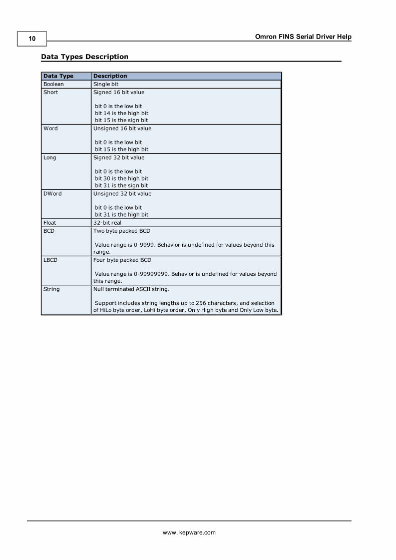
Data Types Description
Data Type DescriptionBoolean Single bitShort Signed 16 bit value
bit 0 is the low bitbit 14 is the high bitbit 15 is the sign bit
Word Unsigned 16 bit value
bit 0 is the low bitbit 15 is the high bit
Long Signed 32 bit value
bit 0 is the low bitbit 30 is the high bitbit 31 is the sign bit
DWord Unsigned 32 bit value
bit 0 is the low bitbit 31 is the high bit
Float 32-bit realBCD Two byte packed BCD
Value range is 0-9999. Behavior is undefined for values beyond thisrange.
LBCD Four byte packed BCD
Value range is 0-99999999. Behavior is undefined for values beyondthis range.
String Null terminated ASCII string.
Support includes string lengths up to 256 characters, and selectionof HiLo byte order, LoHi byte order, Only High byte and Only Low byte.
www. kepware.com
10

Omron FINS Serial Driver Help
Address DescriptionsAddress specifications vary depending on the model in use. Select a link from the following list to obtain specificaddress information for the model of interest.
C200H AddressingC500 AddressingC1000H AddressingC2000H AddressingCV500 AddressingCV1000 AddressingCV2000 AddressingCVM1-CPU01 AddressingCVM1-CPU11 AddressingCVM1-CPU21 AddressingCS1 AddressingCJ1 AddressingCJ2 Addressing
C200H AddressingThe default data types for dynamically defined tags are shown in boldwhere appropriate. For more informationon notes and restrictions, refer to BCD Support, String Support, and Array Support.
Device Type Range Data Type AccessAuxiliary Relay AR00-AR27
AR00-AR26ARxx.00-ARxx.15
Word, Short, BCDLong, DWord, LBCD,FloatBoolean
Read/Write
Auxiliary Relay as stringwith HiLo byte order
AR00.056H-AR27.002H
.l is string length, range 2 to 56chars
String Read/Write
Auxiliary Relay as stringwith LoHi byte order
AR00.056L-AR27.002L
.l is string length, range 2 to 56chars
String Read/Write
Auxiliary Relay as stringUsing Only the High Order byte of each word
AR00.028D-AR27.001D
.l is string length, range 1 to 28chars
String Read/Write
Auxiliary Relay as stringUsing Only the Low Order byte of each word
AR00.028E-AR27.001E
.l is string length, range 1 to 28chars
String Read/Write
Data Memory DM0000-DM6655DM0000-DM6654DMxxxx.00-DMxxxx.15
Word, Short, BCDLong, DWord, LBCD,FloatBoolean
Read/Write
Data Memory as stringwith HiLo byte order
DM0000.256H-DM6655.002H
.l is string length, range 2 to 256chars
String Read/Write
Data Memory as stringwith LoHi byte order
DM0000.256L-DM6655.002L
.l is string length, range 2 to 256chars
String Read/Write
Data Memory as stringUsing Only the High Order byte of each word
DM0000.128D-DM6655.001D
.l is string length, range 1 to 128chars
String Read/Write
Data Memory as stringUsing Only the Low Order byte of each word
DM0000.128E-DM6655.001E String Read/Write
www. kepware.com
11

Omron FINS Serial Driver Help
.l is string length, range 1 to 128chars
Expansion Data Memory(current bank)
EM0000-EM6143EM0000-EM6142EMxxxx.00-EMxxxx.15
Word, Short, BCDLong, DWord, LBCD,FloatBoolean
Read/Write
Expansion Data Memory(current bank) as string withHiLo byte order
EM0000.256H-EM6143.002H
.l is string length, range 2 to 256chars
String Read/Write
Expansion Data Memory(current bank) as string withLoHi byte order
EM0000.256L-EM6143.002L
.l is string length, range 2 to 256chars
String Read/Write
Expansion Data Memory(current bank) as stringUsing Only the High Order byte of each word
EM0000.128D-EM6143.001D
.l is string length, range 1 to 128chars
String Read/Write
Expansion Data Memory(current bank) as stringUsing Only the Low Order byte of each word
EM0000.128E-EM6143.001E
.l is string length, range 1 to 128chars
String Read/Write
Expansion Data Memory EM00:0000-EM07:6143EM00:0000-EM07:6142EMx:x.00-EMxx:xxxx.15
Word, Short, BCDLong, DWord, LBCD,FloatBoolean
Read/Write
Expansion Data Memory asstring with HiLo byte order
EM00:0000.256H-EM07:6143.002H
.l is string length, range 2 to 256chars
String Read/Write
Expansion Data Memory asstring with LoHi byte order
EM00:0000.256L-EM07:6143.002L
.l is string length, range 2 to 256chars
String Read/Write
Expansion Data Memory asstring Using Only the High Order byte of eachword
EM00:0000.128D-EM07:6143.001D
.l is string length, range 1 to 128chars
String Read/Write
Expansion Data Memory asstring Using Only the Low Order byte of eachword
EM00:0000.128E-EM07:6143.001E
.l is string length, range 1 to 128chars
String Read/Write
Holding Relay HR00-HR99HR00-HR98HRxx.00-HRxx.15
Word,Short, BCDLong, DWord, LBCD,FloatBoolean
Read/Write
Holding Relay as stringwith HiLo byte order
HR00.200H-HR99.002H
.l is string length, range 2 to 200chars
String Read/Write
Holding Relay as stringwith LoHi byte order
HR00.200L-HR99.002L
.l is string length, range 2 to 200chars
String Read/Write
Holding Relay as stringUsing Only the High Order byte of each word
HR00.100D-HR99.001D
.l is string length, range 1 to 100chars
String Read/Write
Holding Relay as string HR00.100E-HR99.001E String Read/Write
www. kepware.com
12

Omron FINS Serial Driver Help
Using Only the Low Orderbyte of each word .l is string length, range 1 to 100
charsInternal Relay IR000-IR511
IR000-IR510IRxxx.00-IRxxx.15
Word, Short, BCDLong, DWord, LBCD,FloatBoolean
Read/Write
Internal Relay as a stringwith HiLo byte order
IR000.256H-IR511.002H
.l is string length, range 2 to 256chars
String Read/Write
Internal Relay as a stringwith LoHi byte order
IR000.256L-IR511.002L
.l is string length, range 2 to 256chars
String Read/Write
Internal Relay as a stringUsing Only the High Order byte of each word
IR000.128D-IR511.001D
.l is string length, range 1 to 128chars
String Read/Write
Internal Relay as a stringUsing Only the Low Orderbyte of each word
IR000.128E-IR511.001E
.l is string length, range 1 to 128chars
String Read/Write
Link Relays LR00-LR63LR00-LR62LRxx.00-LRxx.15
Word, Short, BCDLong, DWord, LBCD,FloatBoolean
Read/Write
Link Relay as stringwith HiLo byte order
LR00.128H-LR63.002H
.l is string length, range 2 to 128chars
String Read/Write
Link Relay as stringwith LoHI byte order
LR00.128L-LR63.002L
.l is string length, range 2 to 128chars
String Read/Write
Link Relay as stringUsing Only the High Order byte of each word
LR00.064D-LR63.001D
.l is string length, range 1 to 64chars
String Read/Write
Link Relay as stringUsing Only the Low Orderbyte of each word
LR00.064E-LR63.001E
.l is string length, range 1 to 64chars
String Read/Write
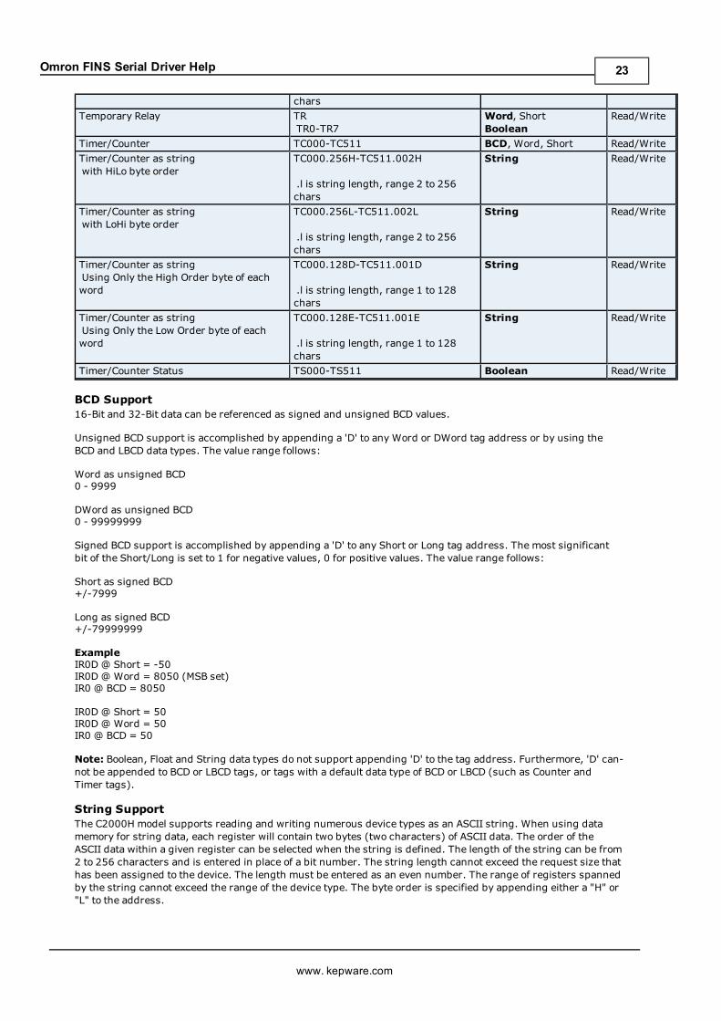
Temporary Relay TRTR0-TR7
Word, ShortBoolean
Read/Write
Timer/Counter TC000-TC511 BCD, Word, Short Read/WriteTimer/Counter as stringwith HiLo byte order
TC000.256H-TC511.002H
.l is string length, range 2 to 256chars
String Read/Write
Timer/Counter as stringwith LoHi byte order
TC000.256L-TC511.002L
.l is string length, range 2 to 256chars
String Read/Write
Timer/Counter as stringUsing Only the High Order byte of each word
TC000.128D-TC511.001D
.l is string length, range 1 to 128chars
String Read/Write
Timer/Counter as stringUsing Only the Low Orderbyte of each word
TC000.128E-TC511.001E
.l is string length, range 1 to 128chars
String Read/Write
www. kepware.com
13

Omron FINS Serial Driver Help
Timer/Counter Status TS000-TS511 Boolean Read/Write
BCD Support16-Bit and 32-Bit data can be referenced as signed and unsigned BCD values.
Unsigned BCD support is accomplished by appending a 'D' to any Word or DWord tag address or by using theBCD and LBCD data types. The value range follows:
Word as unsigned BCD0 - 9999
DWord as unsigned BCD0 - 99999999
Signed BCD support is accomplished by appending a 'D' to any Short or Long tag address. The most significantbit of the Short/Long is set to 1 for negative values, 0 for positive values. The value range follows:
Short as signed BCD+/-7999
Long as signed BCD+/-79999999
ExampleIR0D @ Short = -50IR0D @ Word = 8050 (MSB set)IR0 @ BCD = 8050
IR0D @ Short = 50IR0D @ Word = 50IR0 @ BCD = 50
Note: Boolean, Float and String data types do not support appending 'D' to the tag address. Furthermore, 'D' can-not be appended to BCD or LBCD tags, or tags with a default data type of BCD or LBCD (such as Counter andTimer tags).
String SupportThe C200H model supports reading and writing numerous device types as an ASCII string. When using datamemory for string data, each register will contain two bytes (two characters) of ASCII data. The order of theASCII data within a given register can be selected when the string is defined. The length of the string can be from2 to 256 characters and is entered in place of a bit number. The string length cannot exceed the request size thathas been assigned to the device. The length must be entered as an even number. The range of registers spannedby the string cannot exceed the range of the device type. The byte order is specified by appending either a "H" or"L" to the address.
When using one byte of ASCII data per register, the length of the string can be from 1 to 128 characters and isentered in place of a bit number. The string length times 4 cannot exceed the request size that has beenassigned to the device. The range of registers spanned by the string cannot exceed the range of the device type.The byte to use within a register is specified by appending either a "D" or "E" to the address. For more infor-mation, refer toDevice Setup.
Examples1. To address a string starting at DM1000 with a length of 100 bytes and HiLo byte order, enter:DM1000.100H
2. To address a string starting at DM1100 with a length of 78 bytes and LoHi byte order, enter:DM1100.078L
3. To address a string starting at DM2000 with a length of 55 bytes and Only the High Order byte, enter:DM2000.055D
4. To address a string starting at DM2200 with a length of 37 bytes and Only the Low Order byte, enter:DM2200.037E
Array SupportArrays are supported for all data types except Boolean. There are twomethods of addressing an array. Examplesare given using data memory locations.
www. kepware.com
14

Omron FINS Serial Driver Help
DMxxxx [rows] [cols]DMxxxx [cols] – (this method assumes "rows" is equal to one)
Rows multiplied by cols multiplied by data size in bytes cannot exceed the request size that has been assigned tothe device. Since this driver uses an ASCII protocol, there are 4 bytes for each word, short and BCD, and 8 bytesfor each DWord, long, LBCD and float. For example, a 10 X 10 array of words results in an array size of 400 bytes,which would require a request size of 512. The next smaller request size choice, 256, would be too small. Formore information, refer toDevice Setup.
Note: Use caution when modifying 32-bit values (DWord, Long, LBCD, and Float). Each address, for which thesedata types are allowed, starts at a word offset within the device. Therefore, DWords DM0 and DM1 overlap atword DM1. Thus, writing to DM0 will also modify the value held in DM1. It is recommended that these data typesbe used so that overlapping does not occur. For example, when using DWords, use DM0, DM2, DM4, and so on toprevent overlapping Words.
C500 AddressingThe default data types for dynamically defined tags are shown in boldwhere appropriate. For more informationon notes and restrictions, refer to BCD Support, String Support, and Array Support.
Device Type Range Data Type AccessData Memory DM000-DM511
DM000-DM510DMxxx.00-DMxxx.15
Word, Short, BCDLong, DWord, LBCD,FloatBoolean
Read/Write
Data Memory as stringwith HiLo byte order
DM000.256H-DM511.002H
.l is string length, range 2 to 256chars
String Read/Write
Data Memory as stringwith LoHi byte order
DM000.256L-DM511.002L
.l is string length, range 2 to 256chars
String Read/Write
Data Memory as stringUsing Only the High Order byte of eachword
DM000.128D-DM511.001D
.l is string length, range 1 to 128chars
String Read/Write
Data Memory as stringUsing Only the Low Order byte of eachword
DM000.128E-DM511.001E
.l is string length, range 1 to 128chars
String Read/Write
Holding Relay HR00-HR31HR00-HR30HRxx.00-HRxx.15
Word, Short, BCDLong, DWord, LBCD,FloatBoolean
Read/Write
Holding Relay as stringwith HiLo byte order
HR00.064H-HR31.002H
.l is string length, range 2 to 64chars
String Read/Write
Holding Relay as stringwith LoHi byte order
HR00.064L-HR31.002L
.l is string length, range 2 to 64chars
String Read/Write
Holding Relay as stringUsing Only the High Order byte of eachword
HR00.032D-HR31.001D
.l is string length, range 1 to 32chars
String Read/Write
Holding Relay as stringUsing Only the Low Orderbyte of each word
HR00.032E-HR31.001E
.l is string length, range 1 to 32chars
String Read/Write
Internal Relay IR00-IR63IR00-IR62IRxx.00-IRxx.15
Word, Short, BCDLong, DWord, LBCD,Float
Read/Write
www. kepware.com
15

Omron FINS Serial Driver Help
BooleanInternal Relay as a stringwith HiLo byte order
IR00.128H-IR63.002H
.l is string length, range 2 to 128chars
String Read/Write
Internal Relay as a stringwith LoHi byte order
IR00.128L-IR63.002L
.l is string length, range 2 to 128chars
String Read/Write
Internal Relay as a stringUsing Only the High Order byte of eachword
IR00.064D-IR63.001D
.l is string length, range 1 to 64chars
String Read/Write
Internal Relay as a stringUsing Only the Low Order byte of eachword
IR00.064E-IR63.001E
.l is string length, range 1 to 64chars
String Read/Write
Link Relays LR00-LR31LR00-LR30LRxx.00-LRxx.15
Word, Short, BCDLong, DWord, LBCD,FloatBoolean
Read/Write
Link Relays as stringwith HiLo byte order
LR00.064H-LR31.002H
.l is string length, range 2 to 64chars
String Read/Write
Link Relays as stringwith LoHi byte order
LR00.064L-LR31.002L
.l is string length, range 2 to 64chars
String Read/Write
Link Relays as stringUsing Only the High Orderbyte of each word
LR00.032D-LR31.001D
.l is string length, range 1 to 32chars
String Read/Write
Link Relays as stringUsing Only the Low Orderbyte of each word
LR00.032E-LR31.001E
.l is string length, range 1 to 32chars
String Read/Write
Temporary Relay TRTR0-TR7
Word, ShortBoolean
Read/Write
Timer/Counter TC000-TC127 BCD, Word, Short Read/WriteTimer/Counter as stringwith HiLo byte order
TC000.256H-TC127.002H
.l is string length, range 2 to 256chars
String Read/Write
Timer/Counter as stringwith LoHi byte order
TC000.256L-TC127.002L
.l is string length, range 2 to 256chars
String Read/Write
Timer/Counter as stringUsing Only the High Order byte of eachword
TC000.128D-TC127.001D
.l is string length, range 1 to 128chars
String Read/Write
Timer/Counter as stringUsing Only the Low Order byte of eachword
TC000.128E-TC127.001E
.l is string length, range 1 to 128chars
String Read/Write
Timer/Counter Status TS000-TS127 Boolean Read/Write
BCD Support16-Bit and 32-Bit data can be referenced as signed and unsigned BCD values.
Unsigned BCD support is accomplished by appending a 'D' to any Word or DWord tag address or by using theBCD and LBCD data types. The value range follows:
www. kepware.com
16

Omron FINS Serial Driver Help
Word as unsigned BCD0 - 9999
DWord as unsigned BCD0 - 99999999
Signed BCD support is accomplished by appending a 'D' to any Short or Long tag address. The most significantbit of the Short/Long is set to 1 for negative values, 0 for positive values. The value range follows:
Short as signed BCD+/-7999
Long as signed BCD+/-79999999
ExampleIR0D @ Short = -50IR0D @ Word = 8050 (MSB set)IR0 @ BCD = 8050
IR0D @ Short = 50IR0D @ Word = 50IR0 @ BCD = 50
Note: Boolean, Float and String data types do not support appending 'D' to the tag address. Furthermore , 'D' can-not be appended to BCD or LBCD tags, or tags with a default data type of BCD or LBCD (such as Counter andTimer tags).
String SupportThe C500 model supports reading and writing numerous device types as an ASCII string. When using data mem-ory for string data, each register will contain two bytes (two characters) of ASCII data. The order of the ASCIIdata within a given register can be selected when the string is defined. The length of the string can be from 2 to256 characters and is entered in place of a bit number. The string length cannot exceed the request size that hasbeen assigned to the device. The length must be entered as an even number. The range of registers spanned bythe string cannot exceed the range of the device type. The byte order is specified by appending either a "H" or "L"to the address.
When using one byte of ASCII data per register, the length of the string can be from 1 to 128 characters and isentered in place of a bit number. The string length times 4 cannot exceed the request size that has beenassigned to the device. The range of registers spanned by the string cannot exceed the range of the device type.The byte to use within a register is specified by appending either a "D" or "E" to the address. For more infor-mation, refer toDevice Setup.
Examples1. To address a string starting at DM100 with a length of 100 bytes and HiLo byte order, enter:DM100.100H
2. To address a string starting at DM110 with a length of 78 bytes and LoHi byte order, enter:DM110.078L
3. To address a string starting at DM200 with a length of 55 bytes and Only the High Order byte, enter:DM200.055D
4. To address a string starting at DM220 with a length of 37 bytes and Only the Low Order byte, enter:DM220.037E
Array SupportArrays are supported for all data types except Boolean. There are twomethods of addressing an array. Examplesare given using data memory locations.
DMxxxx [rows] [cols]DMxxxx [cols] – (this method assumes "rows" is equal to one)
Rows multiplied by cols multiplied by data size in bytes cannot exceed the request size that has been assigned tothe device. Since this driver uses an ASCII protocol, there are 4 bytes for each word, short and BCD, and 8 bytesfor each DWord, long, LBCD and float. For example, a 10 X 10 array of words results in an array size of 400 bytes,which would require a request size of 512. The next smaller request size choice, 256, would be too small. Formore information, refer toDevice Setup.
www. kepware.com
17

Omron FINS Serial Driver Help
Note: Use caution when modifying 32-bit values (DWord, Long, LBCD, and Float). Each address, for which thesedata types are allowed, starts at a word offset within the device. Therefore, DWords DM0 and DM1 overlap atword DM1. Thus, writing to DM0 will also modify the value held in DM1. It is recommended that these data typesbe used so that overlapping does not occur. For example, when using DWords, use DM0, DM2, DM4, and so on toprevent overlapping Words.
C1000H AddressingThe default data types for dynamically defined tags are shown in boldwhere appropriate. For more informationon notes and restrictions, refer to BCD Support, String Support, and Array Support.
Device Type Range Data Type AccessAuxiliary Relay AR00-AR27
AR00-AR26ARxx.00-ARxx.15
Word, Short, BCDLong, DWord, LBCD,FloatBoolean
Read/Write
Auxiliary Relay as stringwith HiLo byte order
AR00.056H-AR27.002H
.l is string length, range 2 to 56chars
String Read/Write
Auxiliary Relay as stringwith LoHi byte order
AR00.056L-AR27.002L
.l is string length, range 2 to 56chars
String Read/Write
Auxiliary Relay as stringUsing Only the High Order byte of eachword
AR00.028D-AR27.001D
.l is string length, range 1 to 28chars
String Read/Write
Auxiliary Relay as stringUsing Only the Low Order byte of eachword
AR00.028E-AR27.001E
.l is string length, range 1 to 28chars
String Read/Write
Data Memory DM0000-DM4095DM0000-DM4094DMxxxx.00-DMxxxx.15
Word, Short, BCDLong, DWord, LBCD,FloatBoolean
Read/Write
Data Memory as stringwith HiLo byte order
DM0000.256H-DM4095.002H
.l is string length, range 2 to 256chars
String Read/Write
Data Memory as stringwith LoHi byte order
DM0000.256L-DM4095.002L
.l is string length, range 2 to 256chars
String Read/Write
Data Memory as stringUsing Only the High Order byte of eachword
DM0000.128D-DM4095.001D
.l is string length, range 1 to 128chars
String Read/Write
Data Memory as stringUsing Only the Low Order byte of eachword
DM0000.128E-DM4095.001E
.l is string length, range 1 to 128chars
String Read/Write
Holding Relay HR00-HR99HR00-HR98HRxx.00-HRxx.15
Word, Short, BCDLong, DWord, LBCD,FloatBoolean
Read/Write
Holding Relay as stringwith HiLo byte order
HR00.200H-HR99.002H
.l is string length, range 2 to 200chars
String Read/Write
Holding Relay as stringwith LoHi byte order
HR00.200L-HR99.002L String Read/Write
www. kepware.com
18

Omron FINS Serial Driver Help
.l is string length, range 2 to 200chars
Holding Relay as stringUsing Only the High Order byte of eachword
HR00.100D-HR99.001D
.l is string length, range 1 to 100chars
String Read/Write
Holding Relay as stringUsing Only the Low Order byte of eachword
HR00.100E-HR99.001E
.l is string length, range 1 to 100chars
String Read/Write
Internal Relay IR000-IR255IR000-IR254IRxxx.00-IRxxx.15
Word, Short, BCDLong, DWord, LBCD,FloatBoolean
Read/Write
Internal Relay as a stringwith HiLo byte order
IR000.256H-IR255.002H
.l is string length, range 2 to 256chars
String Read/Write
Internal Relay as a stringwith LoHi byte order
IR000.256L-IR255.002L
.l is string length, range 2 to 256chars
String Read/Write
Internal Relay as a stringUsing Only the High Order byte of eachword
IR000.128D-IR255.001D
.l is string length, range 1 to 128chars
String Read/Write
Internal Relay as a stringUsing Only the Low Order byte of eachword
IR000.128E-IR255.001E
.l is string length, range 1 to 128chars
String Read/Write
Link Relays LR00-LR63LR00-LR62LRxx.00-LRxx.15
Word, Short, BCDLong, DWord, LBCD,FloatBoolean
Read/Write
Link Relays as stringwith HiLo byte order
LR00.128H-LR63.002H
.l is string length, range 2 to 128chars
String Read/Write
Link Relays as stringwith LoHi byte order
LR00.128L-LR63.002L
.l is string length, range 2 to 128chars
String Read/Write
Link Relays as stringUsing Only the High Order byte of eachword
LR00.064D-LR63.001D
.l is string length, range 1 to 64chars
String Read/Write
Link Relays as stringUsing Only the Low Order byte of eachword
LR00.064E-LR63.001E
.l is string length, range 1 to 64chars
String Read/Write
Temporary Relay TRTR0-TR7
Word, ShortBoolean
Read/Write
Timer/Counter TC000-TC511 BCD, Word, Short Read/WriteTimer/Counter as stringwith HiLo byte order
TC000.256H-TC511.002H
.l is string length, range 2 to 256chars
String Read/Write
Timer/Counter as stringwith LoHi byte order
TC000.256L-TC511.002L
.l is string length, range 2 to 256chars
String Read/Write
Timer/Counter as string TC000.128D-TC511.001D String Read/Write
www. kepware.com
19

Omron FINS Serial Driver Help
Using Only the High Order byte of eachword .l is string length, range 1 to 128
charsTimer/Counter as stringUsing Only the Low Order byte of eachword
TC000.128E-TC511.001E
.l is string length, range 1 to 128chars
String Read/Write
Timer/Counter Status TS000-TS511 Boolean Read/Write
BCD Support16-Bit and 32-Bit data can be referenced as signed and unsigned BCD values.
Unsigned BCD support is accomplished by appending a 'D' to any Word or DWord tag address or by using theBCD and LBCD data types. The value range follows:
Word as unsigned BCD0 - 9999
DWord as unsigned BCD0 - 99999999
Signed BCD support is accomplished by appending a 'D' to any Short or Long tag address. The most significantbit of the Short/Long is set to 1 for negative values, 0 for positive values. The value range follows:
Short as signed BCD+/-7999
Long as signed BCD+/-79999999
ExampleIR0D @ Short = -50IR0D @ Word = 8050 (MSB set)IR0 @ BCD = 8050
IR0D @ Short = 50IR0D @ Word = 50IR0 @ BCD = 50
Note: Boolean, Float and String data types do not support appending 'D' to the tag address. Furthermore, 'D' can-not be appended to BCD or LBCD tags, or tags with a default data type of BCD or LBCD (such as Counter andTimer tags).
String SupportThe C1000H model supports reading and writing numerous device types as an ASCII string. When using datamemory for string data, each register will contain two bytes (two characters) of ASCII data. The order of theASCII data within a given register can be selected when the string is defined. The length of the string can be from2 to 256 characters and is entered in place of a bit number. The string length cannot exceed the request size thathas been assigned to the device. The length must be entered as an even number. The range of registers spannedby the string cannot exceed the range of the device type. The byte order is specified by appending either a "H" or"L" to the address.
When using one byte of ASCII data per register, the length of the string can be from 1 to 128 characters and isentered in place of a bit number. The string length times 4 cannot exceed the request size that has beenassigned to the device. The range of registers spanned by the string cannot exceed the range of the device type.The byte to use within a register is specified by appending either a "D" or "E" to the address. For more infor-mation, refer toDevice Setup.
Examples1. To address a string starting at DM1000 with a length of 100 bytes and HiLo byte order, enter:DM1000.100H
2. To address a string starting at DM1100 with a length of 78 bytes and LoHi byte order, enter:DM1100.078L
3. To address a string starting at DM2000 with a length of 55 bytes and Only the High Order byte, enter:DM2000.055D
www. kepware.com
20

Omron FINS Serial Driver Help
4. To address a string starting at DM2200 with a length of 37 bytes and Only the Low Order byte, enter:DM2200.037E
Array SupportArrays are supported for all data types except Boolean. There are twomethods of addressing an array. Examplesare given using data memory locations.
DMxxxx [rows] [cols]DMxxxx [cols] – (this method assumes "rows" is equal to one)
Rows multiplied by cols multiplied by data size in bytes cannot exceed the request size that has been assigned tothe device. Since this driver uses an ASCII protocol, there are 4 bytes for each word, short and BCD, and 8 bytesfor each DWord, long, LBCD and float. For example, a 10 X 10 array of words results in an array size of 400 bytes,which would require a request size of 512. The next smaller request size choice, 256, would be too small. Formore information, refer toDevice Setup.
Note: Use caution when modifying 32-bit values (DWord, Long, LBCD, and Float). Each address, for which thesedata types are allowed, starts at a word offset within the device. Therefore, DWords DM0 and DM1 overlap atword DM1. Thus, writing to DM0 will also modify the value held in DM1. It is recommended that these data typesbe used so that overlapping does not occur. For example, when using DWords, use DM0, DM2, DM4, and so on toprevent overlapping Words.
C2000H AddressingThe default data types for dynamically defined tags are shown in boldwhere appropriate. For more informationon notes and restrictions, refer to BCD Support, String Support, and Array Support.
Device Type Range Data Type AccessAuxiliary Relay AR00-AR27
AR00-AR26ARxx.00-ARxx.15
Word, Short, BCDLong, DWord, LBCD,FloatBoolean
Read/Write
Auxiliary Relay as stringwith HiLo byte order
AR00.056H-AR27.002H
.l is string length, range 2 to 56chars
String Read/Write
Auxiliary Relay as stringwith LoHi byte order
AR00.056L-AR27.002L
.l is string length, range 2 to 56chars
String Read/Write
Auxiliary Relay as stringUsing Only the High Order byte of eachword
AR00.028D-AR27.001D
.l is string length, range 1 to 28chars
String Read/Write
Auxiliary Relay as stringUsing Only the Low Order byte of eachword
AR00.028E-AR27.001E
.l is string length, range 1 to 28chars
String Read/Write
Data Memory DM0000-DM6655DM0000-DM6654DMxxxx.00-DMxxxx.15
Word, Short, BCDLong, DWord, LBCD,FloatBoolean
Read/Write
Data Memory as stringwith HiLo byte order
DM0000.256H-DM6655.002H
.l is string length, range 2 to 256chars
String Read/Write
Data Memory as stringwith LoHi byte order
DM0000.256L-DM6655.002L
.l is string length, range 2 to 256chars
String Read/Write
Data Memory as stringUsing Only the High Order byte of eachword
DM0000.128D-DM6655.001D
.l is string length, range 1 to 128chars
String Read/Write
www. kepware.com
21

Omron FINS Serial Driver Help
Data Memory as stringUsing Only the Low Order byte of eachword
DM0000.128E-DM6655.001E
.l is string length, range 1 to 128chars
String Read/Write
Holding Relay HR00-HR99HR00-HR98HRxx.00-HRxx.15
Word, Short, BCDLong, DWord, LBCD,FloatBoolean
Read/Write
Holding Relay as stringwith HiLo byte order
HR00.200H-HR99.002H
.l is string length, range 2 to 200chars
String Read/Write
Holding Relay as stringwith LoHi byte order
HR00.200L-HR99.002L
.l is string length, range 2 to 200chars
String Read/Write
Holding Relay as stringUsing Only the High Order byte of eachword
HR00.100D-HR99.001D
.l is string length, range 1 to 100chars
String Read/Write
Holding Relay as stringUsing Only the Low Order byte of eachword
HR00.100E-HR99.001E
.l is string length, range 1 to 100chars
String Read/Write
Internal Relay IR000-IR255IR000-IR254IRxxx.00-IRxxx.15
Word, Short, BCDLong, DWord, LBCD,FloatBoolean
Read/Write
Internal Relay as a stringwith HiLo byte order
IR000.256H-IR255.002H
.l is string length, range 2 to 256chars
String Read/Write
Internal Relay as a stringwith LoHi byte order
IR000.256L-IR255.002L
.l is string length, range 2 to 256chars
String Read/Write
Internal Relay as a stringUsing Only the High Order byte of eachword
IR000.128D-IR255.001D
.l is string length, range 1 to 128chars
String Read/Write
Internal Relay as a stringUsing Only the Low Order byte of eachword
IR000.128E-IR255.001E
.l is string length, range 1 to 128chars
String Read/Write
Link Relays LR00-LR63LR00-LR62LRxx.00-LRxx.15
Word, Short, BCDLong, DWord, LBCD,FloatBoolean
Read/Write
Link Relays as stringwith HiLo byte order
LR00.128H-LR63.002H
.l is string length, range 2 to 128chars
String Read/Write
Link Relays as stringwith LoHi byte order
LR00.128L-LR63.002L
.l is string length, range 2 to 128chars
String Read/Write
Link Relays as stringUsing Only the High Order byte of eachword
LR00.064D-LR63.001D
.l is string length, range 1 to 64chars
String Read/Write
Link Relays as stringUsing Only the Low Order byte of eachword
LR00.064E-LR63.001E
.l is string length, range 1 to 64
String Read/Write
www. kepware.com
22
Omron FINS Serial Driver Help
charsTemporary Relay TR
TR0-TR7Word, ShortBoolean
Read/Write
Timer/Counter TC000-TC511 BCD, Word, Short Read/WriteTimer/Counter as stringwith HiLo byte order
TC000.256H-TC511.002H
.l is string length, range 2 to 256chars
String Read/Write
Timer/Counter as stringwith LoHi byte order
TC000.256L-TC511.002L
.l is string length, range 2 to 256chars
String Read/Write
Timer/Counter as stringUsing Only the High Order byte of eachword
TC000.128D-TC511.001D
.l is string length, range 1 to 128chars
String Read/Write
Timer/Counter as stringUsing Only the Low Order byte of eachword
TC000.128E-TC511.001E
.l is string length, range 1 to 128chars
String Read/Write
Timer/Counter Status TS000-TS511 Boolean Read/Write
BCD Support16-Bit and 32-Bit data can be referenced as signed and unsigned BCD values.
Unsigned BCD support is accomplished by appending a 'D' to any Word or DWord tag address or by using theBCD and LBCD data types. The value range follows:
Word as unsigned BCD0 - 9999
DWord as unsigned BCD0 - 99999999
Signed BCD support is accomplished by appending a 'D' to any Short or Long tag address. The most significantbit of the Short/Long is set to 1 for negative values, 0 for positive values. The value range follows:
Short as signed BCD+/-7999
Long as signed BCD+/-79999999
ExampleIR0D @ Short = -50IR0D @ Word = 8050 (MSB set)IR0 @ BCD = 8050
IR0D @ Short = 50IR0D @ Word = 50IR0 @ BCD = 50
Note: Boolean, Float and String data types do not support appending 'D' to the tag address. Furthermore, 'D' can-not be appended to BCD or LBCD tags, or tags with a default data type of BCD or LBCD (such as Counter andTimer tags).
String SupportThe C2000H model supports reading and writing numerous device types as an ASCII string. When using datamemory for string data, each register will contain two bytes (two characters) of ASCII data. The order of theASCII data within a given register can be selected when the string is defined. The length of the string can be from2 to 256 characters and is entered in place of a bit number. The string length cannot exceed the request size thathas been assigned to the device. The length must be entered as an even number. The range of registers spannedby the string cannot exceed the range of the device type. The byte order is specified by appending either a "H" or"L" to the address.
www. kepware.com
23

Omron FINS Serial Driver Help
When using one byte of ASCII data per register, the length of the string can be from 1 to 128 characters and isentered in place of a bit number. The string length times 4 cannot exceed the request size that has beenassigned to the device. The range of registers spanned by the string cannot exceed the range of the device type.The byte to use within a register is specified by appending either a "D" or "E" to the address. For more infor-mation, refer toDevice Setup.
Examples1. To address a string starting at DM1000 with a length of 100 bytes and HiLo byte order, enter:DM1000.100H
2. To address a string starting at DM1100 with a length of 78 bytes and LoHi byte order, enter:DM1100.078L
3. To address a string starting at DM2000 with a length of 55 bytes and Only the High Order byte, enter:DM2000.055D
4. To address a string starting at DM2200 with a length of 37 bytes and Only the Low Order byte, enter:DM2200.037E
Array SupportArrays are supported for all data types except Boolean. There are twomethods of addressing an array. Examplesare given using data memory locations.
DMxxxx [rows] [cols]DMxxxx [cols] – (this method assumes "rows" is equal to one)
Rows multiplied by cols multiplied by data size in bytes cannot exceed the request size that has been assigned tothe device. Since this driver uses an ASCII protocol, there are 4 bytes for each word, short and BCD, and 8 bytesfor each DWord, long, LBCD and float. For example, a 10 X 10 array of words results in an array size of 400 bytes,which would require a request size of 512. The next smaller request size choice, 256, would be too small. Formore information, refer toDevice Setup.
Note: Use caution when modifying 32-bit values (DWord, Long, LBCD, and Float). Each address, for which thesedata types are allowed, starts at a word offset within the device. Therefore, DWords DM0 and DM1 overlap atword DM1. Thus, writing to DM0 will also modify the value held in DM1. It is recommended that these data typesbe used so that overlapping does not occur. For example, when using DWords, use DM0, DM2, DM4, and so on toprevent overlapping Words.
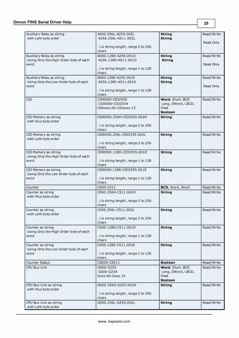
CV500 AddressingThe default data types for dynamically defined tags are shown in boldwhere appropriate. For more informationon notes and restrictions, refer to BCD Support, String Support, and Array Support.
Device Type Range Data Type AccessAction Flag AC0000-AC1023 Boolean Read OnlyAuxiliary Relay A000-A255
A000-A254
A256-A511A256-A510
A000.00-A000.15-A255.00-A255.15
A256.00-A256.15-A511.00-A511.15
Word, Short, BCDLong, DWord, LBCD,Float
Word, Short, BCDLong, DWord, LBCD,Float
Boolean
Boolean
Read/Write
Read Only
Read/Write
Read Only
Auxiliary Relay as stringwith HiLo byte order
A000.256H-A255.002HA256.256H-A511.002H
.l is string length, range 2 to 256chars
StringString
Read/Write
Read Only
www. kepware.com
24
Omron FINS Serial Driver Help
Auxiliary Relay as stringwith LoHi byte order
A000.256L-A255.002LA256.256L-A511.002L
.l is string length, range 2 to 256chars
StringString
Read/Write
Read Only
Auxiliary Relay as stringUsing Only the High Order byte of eachword
A000.128D-A255.001DA256.128D-A511.001D
.l is string length, range 1 to 128chars
StringString
Read/Write
Read Only
Auxiliary Relay as stringUsing Only the Low Order byte of eachword
A000.128E-A255.001EA256.128E-A511.001E
.l is string length, range 1 to 128chars
StringString
Read/Write
Read Only
CIO CIO0000-CIO2555CIO0000-CIO2554CIOxxxx.00-CIOxxxx.15
Word, Short, BCDLong, DWord, LBCD,FloatBoolean
Read/Write
CIO Memory as stringwith HiLo byte order
CIO0000.256H-CIO2555.002H
.l is string length, range 2 to 256chars
String Read/Write
CIO Memory as stringwith LoHi byte order
CIO0000.256L-CIO2555.002L
.l is string length, range 2 to 256chars
String Read/Write
CIO Memory as stringUsing Only the High Order byte of eachword
CIO0000.128D-CIO2555.001D
.l is string length, range 1 to 128chars
String Read/Write
CIO Memory as stringUsing Only the Low Order byte of eachword
CIO0000.128E-CIO2555.001E
.l is string length, range 1 to 128chars
String Read/Write
Counter C000-C511 BCD, Word, Short Read/WriteCounter as stringwith HiLo byte order
C000.256H-C511.002H
.l is string length, range 2 to 256chars
String Read/Write
Counter as stringwith LoHi byte order
C000.256L-C511.002L
.l is string length, range 2 to 256chars
String Read/Write
Counter as stringUsing Only the High Order byte of eachword
C000.128D-C511.001D
.l is string length, range 1 to 128chars
String Read/Write
Counter as stringUsing Only the Low Order byte of eachword
C000.128E-C511.001E
.l is string length, range 1 to 128chars
String Read/Write
Counter Status CS000-CS511 Boolean Read/WriteCPU Bus Link G000-G255
G000-G254Gxxx.00-Gxxx.15
Word, Short, BCDLong, DWord, LBCD,FloatBoolean
Read/Write
CPU Bus Link as stringwith HiLo byte order
G000.256H-G255.002H
.l is string length, range 2 to 256chars
String Read/Write
CPU Bus Link as stringwith LoHi byte order
G000.256L-G255.002L String Read/Write
www. kepware.com
25

Omron FINS Serial Driver Help
.l is string length, range 2 to 256chars
CPU Bus Link as stringUsing Only the High Order byte of eachword
G000.128D-G255.001D
.l is string length, range 1 to 128chars
String Read/Write
CPU Bus Link as stringUsing Only the Low Order byte of eachword
G000.128E-G255.001E
.l is string length, range 1 to 128chars
String Read/Write
Data Memory D0000-D8191D0000-D8190Dxxxx.00-Dxxxx.15
Word, Short, BCDLong, DWord, LBCD,FloatBoolean
Read/Write
Data Memory as stringwith HiLo byte order
D0000.256H-D8191.002H
.l is string length, range 2 to 256chars
String Read/Write
Data Memory as stringwith LoHi byte order
D0000.256L-D8191.002L
.l is string length, range 2 to 256chars
String Read/Write
Data Memory as stringUsing Only the High Order byte of eachword
D0000.128D-D8191.001D
.l is string length, range 1 to 128chars
String Read/Write
Data Memory as stringUsing Only the Low Order byte of eachword
D0000.128E-D8191.001E
.l is string length, range 1 to 128chars
String Read/Write
Data Register DR0-DR2 Word, Short, BCD* Read/WriteIndex Register IR0-IR2 Word, Short, BCD* Read/WriteStep Timer ST000-ST511 Word, Short, BCD* Read/WriteStep Timer Status STS000-STS511 Boolean Read/WriteTemporary Relay TR
TR0-TR7Word, ShortBoolean
Read/Write
Timer T000-T511 BCD, Word, Short Read/WriteTimer as stringwith HiLo byte order
T000.256H-T511.002H
.l is string length, range 2 to 256chars
String Read/Write
Timer as stringwith LoHi byte order
T000.256L-T511.002L
.l is string length, range 2 to 256chars
String Read/Write
Timer as stringUsing Only the High Order byte of eachword
T000.128D-T511.001D
.l is string length, range 1 to 128chars
String Read/Write
Timer as stringUsing Only the Low Order byte of eachword
T000.128E-T511.001E
.l is string length, range 1 to 128chars
String Read/Write
Timer Status TS000-TS511 Boolean Read/WriteTransition Flag TN000-TN511 Boolean Read/Write
*Arrays are not supported.
BCD Support16-Bit and 32-Bit data can be referenced as signed and unsigned BCD values.
www. kepware.com
26

Omron FINS Serial Driver Help
Unsigned BCD support is accomplished by appending a 'D' to any Word or DWord tag address or by using theBCD and LBCD data types. The value range follows:
Word as unsigned BCD0 - 9999
DWord as unsigned BCD0 - 99999999
Signed BCD support is accomplished by appending a 'D' to any Short or Long tag address. The most significantbit of the Short/Long is set to 1 for negative values, 0 for positive values. The value range follows:
Short as signed BCD+/-7999
Long as signed BCD+/-79999999
ExampleIR0D @ Short = -50IR0D @ Word = 8050 (MSB set)IR0 @ BCD = 8050
IR0D @ Short = 50IR0D @ Word = 50IR0 @ BCD = 50
Note: Boolean, Float and String data types do not support appending 'D' to the tag address. Furthermore, 'D' can-not be appended to BCD or LBCD tags, or tags with a default data type of BCD or LBCD (such as Counter andTimer tags).
String SupportThe CV500 model supports reading and writing numerous device types as an ASCII string. When using data mem-ory for string data, each register will contain two bytes (two characters) of ASCII data. The order of the ASCIIdata within a given register can be selected when the string is defined. The length of the string can be from 2 to256 characters and is entered in place of a bit number. The string length cannot exceed the request size that hasbeen assigned to the device. The length must be entered as an even number. The range also cannot exceed therequest size that has been assigned to the device. Since this driver uses an ASCII protocol, there are 2 bytestransmitted for each character. The range of registers spanned by the string cannot exceed the range of thedevice type. The byte order is specified by appending either a "H" or "L" to the address.
When using one byte of ASCII data per register, the length of the string can be from 1 to 128 characters and isentered in place of a bit number. The string length times 4 cannot exceed the request size that has beenassigned to the device. The range of registers spanned by the string cannot exceed the range of the device type.The byte to use within a register is specified by appending either a "D" or "E" to the address. For more infor-mation, refer toDevice Setup.
Examples1. To address a string starting at D1000 with a length of 100 bytes and HiLo byte order, enter:D1000.100H
2. To address a string starting at D1100 with a length of 78 bytes and LoHi byte order, enter:D1100.078L
3. To address a string starting at D2000 with a length of 55 bytes and Only the High Order byte, enter:D2000.055D
4. To address a string starting at D2200 with a length of 37 bytes and Only the Low Order byte, enter:D2200.037E
Array SupportArrays are supported for all data types except Boolean, Data Register, Index Register and Step Timer. There aretwomethods of addressing an array. Examples are given using data memory locations.
Dxxxx [rows] [cols]Dxxxx [cols] (this method assumes "rows" is equal to one)
Rows multiplied by cols multiplied by data size in bytes cannot exceed the request size that has been assigned tothe device. Since this driver uses an ASCII protocol, there are 4 bytes for each word, short and BCD, and 8 bytes
www. kepware.com
27

Omron FINS Serial Driver Help
for each DWord, long, LBCD and float. For example, a 10 X 10 array of words results in an array size of 400 bytes,which would require a request size of 512. The next smaller request size choice, 256, would be too small. Formore information, refer toDevice Setup.
Note: Use caution when modifying 32-bit values (DWord, Long, LBCD, and Float). Each address, for which thesedata types are allowed, starts at a word offset within the device. Therefore, DWords D0 and D1 overlap at wordD1. Thus, writing to D0 will also modify the value held in D1. It is recommended that these data types be used sothat overlapping does not occur. For example, when using DWords, use D0, D2, D4, and so on to prevent over-lapping Words.
CV1000 AddressingThe default data types for dynamically defined tags are shown in boldwhere appropriate. For more informationon notes and restrictions, refer to BCD Support, String Support, and Array Support.
Device Type Range Data Type AccessAction Flag AC0000-AC2047 Boolean Read OnlyAuxiliary Relay A000-A255
A000-A254
A256-A511A256-A510
A000.00-A000.15-A255.00-A255.15
A256.00-A256.15-A511.00-A511.15
Word, Short, BCDLong, DWord, LBCD,Float
Word, Short, BCDLong, DWord, LBCD,Float
Boolean
Boolean
Read/Write
Read Only
Read/Write
Read Only
Auxiliary Relay as stringwith HiLo byte order
A000.256H-A255.002HA256.256H-A511.002H
.l is string length, range 2 to 256chars
StringString
Read/Write
Read Only
Auxiliary Relay as stringwith LoHi byte order
A000.256L-A255.002LA256.256L-A511.002L
.l is string length, range 2 to 256chars
StringString
Read/Write
Read Only
Auxiliary Relay as stringUsing Only the High Order byte of each word
A000.128D-A255.001DA256.128D-A511.001D
.l is string length, range 1 to 128chars
StringString
Read/Write
Read Only
Auxiliary Relay as stringUsing Only the Low Orderbyte of each word
A000.128E-A255.001EA256.128E-A511.001E
.l is string length, range 1 to 128chars
StringString
Read/Write
Read Only
CIO CIO0000-CIO2555CIO0000-CIO2554CIOxxxx.00-CIOxxxx.15
Word, Short, BCDLong, DWord, LBCD,FloatBoolean
Read/Write
CIO Memory as stringwith HiLo byte order
CIO0000.256H-CIO2555.002H
.l is string length, range 2 to 256chars
String Read/Write
CIO Memory as stringwith LoHi byte order
CIO0000.256L-CIO2555.002L
.l is string length, range 2 to 256chars
String Read/Write
www. kepware.com
28

Omron FINS Serial Driver Help
CIO Memory as stringUsing Only the High Order byte of each word
CIO0000.128D-CIO2555.001D
.l is string length, range 1 to 128chars
String Read/Write
CIO Memory as stringUsing Only the Low Order byte of each word
CIO0000.128E-CIO2555.001E
.l is string length, range 1 to 128chars
String Read/Write
Counter C0000-C1023 BCD, Word, Short Read/WriteCounter as stringwith HiLo byte order
C0000.256H-C1023.002H
.l is string length, range 2 to 256chars
String Read/Write
Counter as stringwith LoHi byte order
C0000.256L-C1023.002L
.l is string length, range 2 to 256chars
String Read/Write
Counter as stringUsing Only the High Order byte of each word
C0000.128D-C1023.001D
.l is string length, range 1 to 128chars
String Read/Write
Counter as stringUsing Only the Low Order byte of each word
C0000.128E-C1023.001E
.l is string length, range 1 to 128chars
String Read/Write
Counter Status CS0000-CS1023 Boolean Read/WriteCPU Bus Link G000-G255
G000-G254Gxxx.00-Gxxx.15
Word, Short, BCDLong, DWord, LBCD,FloatBoolean
Read/Write
CPU Bus Link as stringwith HiLo byte order
G000.256H-G255.002H
.l is string length, range 2 to 256chars
String Read/Write
CPU Bus Link as stringwith LoHi byte order
G000.256L-G255.002L
.l is string length, range 2 to 256chars
String Read/Write
CPU Bus Link as stringUsing Only the High Order byte of each word
G000.128D-G255.001D
.l is string length, range 1 to 128chars
String Read/Write
CPU Bus Link as stringUsing Only the Low Order byte of each word
G000.128E-G255.001E
.l is string length, range 1 to 128chars
String Read/Write
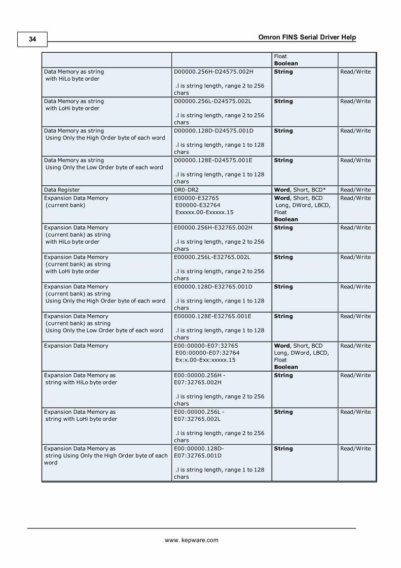
Data Memory D00000-D24575D00000-D24574Dxxxxx.00-Dxxxxx.15
Word, Short, BCDLong, DWord, LBCD,FloatBoolean
Read/Write
Data Memory as stringwith HiLo byte order
D00000.256H-D24575.002H
.l is string length, range 2 to 256chars
String Read/Write
Data Memory as stringwith LoHi byte order
D00000.256L-D24575.002L
.l is string length, range 2 to 256chars
String Read/Write
Data Memory as stringUsing Only the High Order byte of each word
D00000.128D-D24575.001D
.l is string length, range 1 to 128chars
String Read/Write
www. kepware.com
29

Omron FINS Serial Driver Help
Data Memory as stringUsing Only the Low Order byte of each word
D00000.128E-D24575.001E
.l is string length, range 1 to 128chars
String Read/Write
Data Register DR0-DR2 Word, Short, BCD* Read/WriteExpansion Data Memory(current bank)
E00000-E32765E00000-E32764Exxxxx.00-Exxxxx.15
Word, Short, BCDLong, DWord, LBCD,FloatBoolean
Read/Write
Expansion Data Memory(current bank) as stringwith HiLo byte order
E00000.256H-E32765.002H
.l is string length, range 2 to 256chars
String Read/Write
Expansion Data Memory(current bank) as stringwith LoHi byte order
E00000.256L-E32765.002L
.l is string length, range 2 to 256chars
String Read/Write
Expansion Data Memory(current bank) as stringUsing Only the High Order byte of each word
E00000.128D-E32765.001D
.l is string length, range 1 to 128chars
String Read/Write
Expansion Data Memory(current bank) as stringUsing Only the Low Order byte of each word
E00000.128E-E32765.001E
.l is string length, range 1 to 128chars
String Read/Write
Expansion Data Memory E00:00000-E07:32765E00:00000-E07:32764Ex:x.00-Exx:xxxxx.15
Word, Short, BCDLong, DWord, LBCD,FloatBoolean
Read/Write
Expansion Data Memory asstring with HiLo byte order
E00:00000.256H -E07:32765.002H
.l is string length, range 2 to 256chars
String Read/Write
Expansion Data Memory asstring with LoHi byte order
E00:00000.256L -E07:32765.002L
.l is string length, range 2 to 256chars
String Read/Write
Expansion Data Memory asstring Using Only the High Order byte of eachword
E00:00000.128D-E07:32765.001D
.l is string length, range 1 to 128chars
String Read/Write
Expansion Data Memory asstring Using Only the Low Order byte of eachword
E00:00000.128E-E07:32765.001E
.l is string length, range 1 to 128chars
String Read/Write
Index Register IR0-IR2 Word, Short, BCD* Read/WriteStep Timer ST0000-ST1023 Word, Short, BCD* Read/WriteStep Timer Status STS0000-STS1023 Boolean Read/WriteTemporary Relay TR
TR0-TR7Word, ShortBoolean
Read/Write
Timer T0000-T1023 BCD, Word, Short Read/WriteTimer as stringwith HiLo byte order
T0000.256H-T1023.002H
.l is string length, range 2 to 256chars
String Read/Write
Timer as stringwith LoHi byte order
T0000.256L-T1023.002L
.l is string length, range 2 to 256
String Read/Write
www. kepware.com
30

Omron FINS Serial Driver Help
charsTimer as stringUsing Only the High Order byte of each word
T0000.128D-T1023.001D
.l is string length, range 1 to 128chars
String Read/Write
Timer as stringUsing Only the Low Order byte of each word
T0000.128E-T1023.001E
.l is string length, range 1 to 128chars
String Read/Write
Timer Status TS0000-TS1023 Boolean Read/WriteTransition Flag TN0000-TN1023 Boolean Read/Write
*Arrays are not supported.
BCD Support16-Bit and 32-Bit data can be referenced as signed and unsigned BCD values.
Unsigned BCD support is accomplished by appending a 'D' to any Word or DWord tag address or by using theBCD and LBCD data types. The value range follows:
Word as unsigned BCD0 - 9999
DWord as unsigned BCD0 - 99999999
Signed BCD support is accomplished by appending a 'D' to any Short or Long tag address. The most significantbit of the Short/Long is set to 1 for negative values, 0 for positive values. The value range follows:
Short as signed BCD+/-7999
Long as signed BCD+/-79999999
ExampleIR0D @ Short = -50IR0D @ Word = 8050 (MSB set)IR0 @ BCD = 8050
IR0D @ Short = 50IR0D @ Word = 50IR0 @ BCD = 50
Note: Boolean, Float and String data types do not support appending 'D' to the tag address. Furthermore, 'D' can-not be appended to BCD or LBCD tags, or tags with a default data type of BCD or LBCD (such as Counter andTimer tags).
String SupportThe CV1000 model supports reading and writing numerous device types as an ASCII string. When using datamemory for string data, each register will contain two bytes (two characters) of ASCII data. The order of theASCII data within a given register can be selected when the string is defined. The length of the string can be from2 to 256 characters and is entered in place of a bit number. The string length cannot exceed the request size thathas been assigned to the device. The length must be entered as an even number. The range also cannot exceedthe request size that has been assigned to the device. Since this driver uses an ASCII protocol, there are 2 bytestransmitted for each character. The range of registers spanned by the string cannot exceed the range of thedevice type. The byte order is specified by appending either a "H" or "L" to the address.
When using one byte of ASCII data per register, the length of the string can be from 1 to 128 characters and isentered in place of a bit number. The string length times 4 cannot exceed the request size that has beenassigned to the device. The range of registers spanned by the string cannot exceed the range of the device type.The byte to use within a register is specified by appending either a "D" or "E" to the address. For more infor-mation, refer toDevice Setup.
Examples1. To address a string starting at D01000 with a length of 100 bytes and HiLo byte order, enter:D01000.100H
www. kepware.com
31

Omron FINS Serial Driver Help
2. To address a string starting at D01100 with a length of 78 bytes and LoHi byte order, enter:D01100.078L
3. To address a string starting at D02000 with a length of 55 bytes and Only the High Order byte, enter:D02000.055D
4. To address a string starting at D02200 with a length of 37 bytes and Only the Low Order byte, enter:D02200.037E
Array SupportArrays are supported for all data types except Boolean, Data Register, Index Register and Step Timer. There aretwomethods of addressing an array. Examples are given using data memory locations.
Dxxxx [rows] [cols]Dxxxx [cols] (this method assumes "rows" is equal to one)
Rows multiplied by cols multiplied by data size in bytes cannot exceed the request size that has been assigned tothe device. Since this driver uses an ASCII protocol, there are 4 bytes for each word, short and BCD, and 8 bytesfor each DWord, long, LBCD and float. For example, a 10 X 10 array of words results in an array size of 400 bytes,which would require a request size of 512. The next smaller request size choice, 256, would be too small. Formore information, refer toDevice Setup.
Note: Use caution when modifying 32-bit values (DWord, Long, LBCD, and Float). Each address, for which thesedata types are allowed, starts at a word offset within the device. Therefore, DWords D0 and D1 overlap at wordD1. Thus, writing to D0 will also modify the value held in D1. It is recommended that these data types be used sothat overlapping does not occur. For example, when using DWords, use D0, D2, D4, and so on to prevent over-lapping Words.
CV2000 AddressingThe default data types for dynamically defined tags are shown in boldwhere appropriate. For more informationon notes and restrictions, refer to BCD Support, String Support, and Array Support.
Device Type Range Data Type AccessAction Flag AC0000-AC2047 Boolean Read OnlyAuxiliary Relay A000-A255
A000-A254
A256-A511A256-A510
A000.00-A000.15-A255.00-A255.15
A256.00-A256.15-A511.00-A511.15
Word, Short, BCDLong, DWord, LBCD,Float
Word, Short, BCDLong, DWord, LBCD,Float
Boolean
Boolean
Read/Write
Read Only
Read/Write
Read Only
Auxiliary Relay as stringwith HiLo byte order
A000.256H-A255.002HA256.256H-A511.002H
.l is string length, range 2 to 256chars
StringString
Read/Write
Read Only
Auxiliary Relay as stringwith LoHi byte order
A000.256L-A255.002LA256.256L-A511.002L
.l is string length, range 2 to 256chars
StringString
Read/Write
Read Only
Auxiliary Relay as stringUsing Only the High Order byte of each word
A000.128D-A255.001DA256.128D-A511.001D
.l is string length, range 1 to 128chars
StringString
Read/Write
Read Only
Auxiliary Relay as stringUsing Only the Low Order byte of each word
A000.128E-A255.001EA256.128E-A511.001E
StringString
Read/Write
Read Only
www. kepware.com
32

Omron FINS Serial Driver Help
.l is string length, range 1 to 128chars
CIO CIO0000-CIO2555CIO0000-CIO2554CIOxxxx.00-CIOxxxx.15
Word, Short, BCDLong, DWord, LBCD,FloatBoolean
Read/Write
CIO Memory as stringwith HiLo byte order
CIO0000.256H-CIO2555.002H
.l is string length, range 2 to 256chars
String Read/Write
CIO Memory as stringwith LoHi byte order
CIO0000.256L-CIO2555.002L
.l is string length, range 2 to 256chars
String Read/Write
CIO Memory as stringUsing Only the High Order byte of each word
CIO0000.128D-CIO2555.001D
.l is string length, range 1 to 128chars
String Read/Write
CIO Memory as stringUsing Only the Low Order byte of each word
CIO0000.128E-CIO2555.001E
.l is string length, range 1 to 128chars
String Read/Write
Counter C0000-C1023 BCD, Word, Short Read/WriteCounter as stringwith HiLo byte order
C0000.256H-C1023.002H
.l is string length, range 2 to 256chars
String Read/Write
Counter as stringwith LoHi byte order
C0000.256L-C1023.002L
.l is string length, range 2 to 256chars
String Read/Write
Counter as stringUsing Only the High Order byte of each word
C0000.128D-C1023.001D
.l is string length, range 1 to 128chars
String Read/Write
Counter as stringUsing Only the Low Order byte of each word
C0000.128E-C1023.001E
.l is string length, range 1 to 128chars
String Read/Write
Counter Status CS0000-CS1023 Boolean Read/WriteCPU Bus Link G000-G255
G000-G254Gxxx.00-Gxxx.15
Word, Short, BCDLong, DWord, LBCD,FloatBoolean
Read/Write
CPU Bus Link as stringwith HiLo byte order
G000.256H-G255.002H
.l is string length, range 2 to 256chars
String Read/Write
CPU Bus Link as stringwith LoHi byte order
G000.256L-G255.002L
.l is string length, range 2 to 256chars
String Read/Write
CPU Bus Link as stringUsing Only the High Order byte of each word
G000.128D-G255.001D
.l is string length, range 1 to 128chars
String Read/Write
CPU Bus Link as stringUsing Only the Low Order byte of each word
G000.128E-G255.001E
.l is string length, range 1 to 128chars
String Read/Write
Data Memory D00000-D24575D00000-D24574Dxxxxx.00-Dxxxxx.15
Word, Short, BCDLong, DWord, LBCD,
Read/Write
www. kepware.com
33
Omron FINS Serial Driver Help
FloatBoolean
Data Memory as stringwith HiLo byte order
D00000.256H-D24575.002H
.l is string length, range 2 to 256chars
String Read/Write
Data Memory as stringwith LoHi byte order
D00000.256L-D24575.002L
.l is string length, range 2 to 256chars
String Read/Write
Data Memory as stringUsing Only the High Order byte of each word
D00000.128D-D24575.001D
.l is string length, range 1 to 128chars
String Read/Write
Data Memory as stringUsing Only the Low Order byte of each word
D00000.128E-D24575.001E
.l is string length, range 1 to 128chars
String Read/Write
Data Register DR0-DR2 Word, Short, BCD* Read/WriteExpansion Data Memory(current bank)
E00000-E32765E00000-E32764Exxxxx.00-Exxxxx.15
Word, Short, BCDLong, DWord, LBCD,FloatBoolean
Read/Write
Expansion Data Memory(current bank) as stringwith HiLo byte order
E00000.256H-E32765.002H
.l is string length, range 2 to 256chars
String Read/Write
Expansion Data Memory(current bank) as stringwith LoHi byte order
E00000.256L-E32765.002L
.l is string length, range 2 to 256chars
String Read/Write
Expansion Data Memory(current bank) as stringUsing Only the High Order byte of each word
E00000.128D-E32765.001D
.l is string length, range 1 to 128chars
String Read/Write
Expansion Data Memory(current bank) as stringUsing Only the Low Order byte of each word
E00000.128E-E32765.001E
.l is string length, range 1 to 128chars
String Read/Write
Expansion Data Memory E00:00000-E07:32765E00:00000-E07:32764Ex:x.00-Exx:xxxxx.15
Word, Short, BCDLong, DWord, LBCD,FloatBoolean
Read/Write
Expansion Data Memory asstring with HiLo byte order
E00:00000.256H -E07:32765.002H
.l is string length, range 2 to 256chars
String Read/Write
Expansion Data Memory asstring with LoHi byte order
E00:00000.256L -E07:32765.002L
.l is string length, range 2 to 256chars
String Read/Write
Expansion Data Memory asstring Using Only the High Order byte of eachword
E00:00000.128D-E07:32765.001D
.l is string length, range 1 to 128chars
String Read/Write
www. kepware.com
34
Omron FINS Serial Driver Help
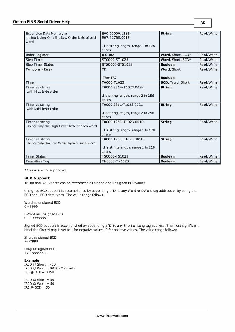
Expansion Data Memory asstring Using Only the Low Order byte of eachword
E00:00000.128E-E07:32765.001E
.l is string length, range 1 to 128chars
String Read/Write
Index Register IR0-IR2 Word, Short, BCD* Read/WriteStep Timer ST0000-ST1023 Word, Short, BCD* Read/WriteStep Timer Status STS0000-STS1023 Boolean Read/WriteTemporary Relay TR
TR0-TR7
Word, Short
Boolean
Read/Write
Timer T0000-T1023 BCD, Word, Short Read/WriteTimer as stringwith HiLo byte order
T0000.256H-T1023.002H
.l is string length, range 2 to 256chars
String Read/Write
Timer as stringwith LoHi byte order
T0000.256L-T1023.002L
.l is string length, range 2 to 256chars
String Read/Write
Timer as stringUsing Only the High Order byte of each word
T0000.128D-T1023.001D
.l is string length, range 1 to 128chars
String Read/Write
Timer as stringUsing Only the Low Order byte of each word
T0000.128E-T1023.001E
.l is string length, range 1 to 128chars
String Read/Write
Timer Status TS0000-TS1023 Boolean Read/WriteTransition Flag TN0000-TN1023 Boolean Read/Write
*Arrays are not supported.
BCD Support16-Bit and 32-Bit data can be referenced as signed and unsigned BCD values.
Unsigned BCD support is accomplished by appending a 'D' to any Word or DWord tag address or by using theBCD and LBCD data types. The value range follows:
Word as unsigned BCD0 - 9999
DWord as unsigned BCD0 - 99999999
Signed BCD support is accomplished by appending a 'D' to any Short or Long tag address. The most significantbit of the Short/Long is set to 1 for negative values, 0 for positive values. The value range follows:
Short as signed BCD+/-7999
Long as signed BCD+/-79999999
ExampleIR0D @ Short = -50IR0D @ Word = 8050 (MSB set)IR0 @ BCD = 8050
IR0D @ Short = 50IR0D @ Word = 50IR0 @ BCD = 50
www. kepware.com
35

Omron FINS Serial Driver Help
Note: Boolean, Float and String data types do not support appending 'D' to the tag address. Furthermore, 'D' can-not be appended to BCD or LBCD tags, or tags with a default data type of BCD or LBCD (such as Counter andTimer tags).
String SupportThe CV2000 model supports reading and writing numerous device types as an ASCII string. When using datamemory for string data, each register will contain two bytes (two characters) of ASCII data. The order of theASCII data within a given register can be selected when the string is defined. The length of the string can be from2 to 256 characters and is entered in place of a bit number. The string length cannot exceed the request size thathas been assigned to the device. The length must be entered as an even number. The range also cannot exceedthe request size that has been assigned to the device. Since this driver uses an ASCII protocol, there are 2 bytestransmitted for each character. The range of registers spanned by the string cannot exceed the range of thedevice type. The byte order is specified by appending either a "H" or "L" to the address.
When using one byte of ASCII data per register, the length of the string can be from 1 to 128 characters and isentered in place of a bit number. The string length times 4 cannot exceed the request size that has beenassigned to the device. The range of registers spanned by the string cannot exceed the range of the device type.The byte to use within a register is specified by appending either a "D" or "E" to the address. For more infor-mation, refer toDevice Setup.
Examples1. To address a string starting at D01000 with a length of 100 bytes and HiLo byte order, enter:D01000.100H
2. To address a string starting at D01100 with a length of 78 bytes and LoHi byte order, enter:D01100.078L
3. To address a string starting at D02000 with a length of 55 bytes and Only the High Order byte, enter:D02000.055D
4. To address a string starting at D02200 with a length of 37 bytes and Only the Low Order byte, enter:D02200.037E
Array SupportArrays are supported for all data types except Boolean, Data Register, Index Register and Step Timer. There aretwomethods of addressing an array. Examples are given using data memory locations.
Dxxxx [rows] [cols]Dxxxx [cols] (this method assumes "rows" is equal to one)
Rows multiplied by cols multiplied by data size in bytes cannot exceed the request size that has been assigned tothe device. Since this driver uses an ASCII protocol, there are 4 bytes for each word, short and BCD, and 8 bytesfor each DWord, long, LBCD and float. For example, a 10 X 10 array of words results in an array size of 400 bytes,which would require a request size of 512. The next smaller request size choice, 256, would be too small. Formore information, refer toDevice Setup.
Note: Use caution when modifying 32-bit values (DWord, Long, LBCD, and Float). Each address, for which thesedata types are allowed, starts at a word offset within the device. Therefore, DWords D0 and D1 overlap at wordD1. Thus, writing to D0 will also modify the value held in D1. It is recommended that these data types be used sothat overlapping does not occur. For example, when using DWords, use D0, D2, D4, and so on to prevent over-lapping Words.
CVM1-CPU01 AddressingThe default data types for dynamically defined tags are shown in boldwhere appropriate. For more informationon notes and restrictions, refer to BCD Support, String Support, and Array Support.
Device Type Range Data Type AccessAuxiliary Relay A000-A255
A000-A254
A256-A511A256-A510
A000.00-A000.15-A255.00-A255.15
Word, Short, BCDLong, DWord, LBCD,Float
Word, Short, BCDLong, DWord, LBCD,Float
Boolean
Read/Write
Read Only
Read/Write
Read Only
www. kepware.com
36

Omron FINS Serial Driver Help
A256.00-A256.15-A511.00-A511.15 Boolean
Auxiliary Relay as stringwith HiLo byte order
A000.256H-A255.002HA256.256H-A511.002H
.l is string length, range 2 to 256chars
StringString
Read/Write
Read Only
Auxiliary Relay as stringwith LoHi byte order
A000.256L-A255.002LA256.256L-A511.002L
.l is string length, range 2 to 256chars
StringString
Read/Write
Read Only
Auxiliary Relay as stringUsing Only the High Order byte of eachword
A000.128D-A255.001DA256.128D-A511.001D
.l is string length, range 1 to 128chars
StringString
Read/Write
Read Only
Auxiliary Relay as stringUsing Only the Low Order byte of eachword
A000.128E-A255.001EA256.128E-A511.001E
.l is string length, range 1 to 128chars
StringString
Read/Write
Read Only
CIO CIO0000-CIO2555CIO0000-CIO2554CIOxxxx.00-CIOxxxx.15
Word, Short, BCDLong, DWord, LBCD,FloatBoolean
Read/Write
CIO Memory as stringwith HiLo byte order
CIO0000.256H-CIO2555.002H
.l is string length, range 2 to 256chars
String Read/Write
CIO Memory as stringwith LoHi byte order
CIO0000.256L-CIO2555.002L
.l is string length, range 2 to 256chars
String Read/Write
CIO Memory as stringUsing Only the High Order byte of eachword
CIO0000.128D-CIO2555.001D
.l is string length, range 1 to 128chars
String Read/Write
CIO Memory as stringUsing Only the Low Order byte of eachword
CIO0000.128E-CIO2555.001E
.l is string length, range 1 to 128chars
String Read/Write
Counter C000-C511 BCD, Word, Short Read/WriteCounter as stringwith HiLo byte order
C000.256H-C511.002H
.l is string length, range 2 to 256chars
String Read/Write
Counter as stringwith LoHi byte order
C000.256L-C511.002L
.l is string length, range 2 to 256chars
String Read/Write
Counter as stringUsing Only the High Order byte of eachword
C000.128D-C511.001D
.l is string length, range 1 to 128chars
String Read/Write
Counter as stringUsing Only the Low Order byte of eachword
C000.128E-C511.001E
.l is string length, range 1 to 128chars
String Read/Write
Counter Status CS000-CS511 Boolean Read/WriteCPU Bus Link G000-G255
G000-G254Gxxx.00-Gxxx.15
Word, Short, BCDLong, DWord, LBCD,Float
Read/Write
www. kepware.com
37

Omron FINS Serial Driver Help
BooleanCPU Bus Link as stringwith HiLo byte order
G000.256H-G255.002H
.l is string length, range 2 to 256chars
String Read/Write
CPU Bus Link as stringwith LoHi byte order
G000.256L-G255.002L
.l is string length, range 2 to 256chars
String Read/Write
CPU Bus Link as stringUsing Only the High Order byte of eachword
G000.128D-G255.001D
.l is string length, range 1 to 128chars
String Read/Write
CPU Bus Link as stringUsing Only the Low Order byte of eachword
G000.128E-G255.001E
.l is string length, range 1 to 128chars
String Read/Write
Data Memory D0000-D8191D0000-D8190Dxxxx.00-Dxxxx.15
Word, Short, BCDLong, DWord, LBCD,FloatBoolean
Read/Write
Data Memory as stringwith HiLo byte order
D0000.256H-D8191.002H
.l is string length, range 2 to 256chars
String Read/Write
Data Memory as stringwith LoHi byte order
D0000.256L-D8191.002L
.l is string length, range 2 to 256chars
String Read/Write
Data Memory as stringUsing Only the High Order byte of eachword
D0000.128D-D8191.001D
.l is string length, range 1 to 128chars
String Read/Write
Data Memory as stringUsing Only the Low Order byte of eachword
D0000.128E-D8191.001E
.l is string length, range 1 to 128chars
String Read/Write
Data Register DR0-DR2 Word, Short, BCD* Read/WriteIndex Register IR0-IR2 Word, Short, BCD* Read/WriteTemporary Relay TR
TR0-TR7Word, ShortBoolean
Read/Write
Timer T000-T511 BCD, Word, Short Read/WriteTimer as stringwith HiLo byte order
T000.256H-T511.002H
.l is string length, range 2 to 256chars
String Read/Write
Timer as stringwith LoHi byte order
T000.256L-T511.002L
.l is string length, range 2 to 256chars
String Read/Write
Timer as stringUsing Only the High Order byte of eachword
T000.128D-T511.001D
.l is string length, range 1 to 128chars
String Read/Write
Timer as stringUsing Only the Low Order byte of eachword
T000.128E-T511.001E
.l is string length, range 1 to 128chars
String Read/Write
Timer Status TS000-TS511 Boolean Read/Write
*Arrays are not supported.
www. kepware.com
38

Omron FINS Serial Driver Help
BCD Support16-Bit and 32-Bit data can be referenced as signed and unsigned BCD values.
Unsigned BCD support is accomplished by appending a 'D' to any Word or DWord tag address or by using theBCD and LBCD data types. The value range follows:
Word as unsigned BCD0 - 9999
DWord as unsigned BCD0 - 99999999
Signed BCD support is accomplished by appending a 'D' to any Short or Long tag address. The most significantbit of the Short/Long is set to 1 for negative values, 0 for positive values. The value range follows:
Short as signed BCD+/-7999
Long as signed BCD+/-79999999
ExampleIR0D @ Short = -50IR0D @ Word = 8050 (MSB set)IR0 @ BCD = 8050
IR0D @ Short = 50IR0D @ Word = 50IR0 @ BCD = 50
Note: Boolean, Float and String data types do not support appending 'D' to the tag address. Furthermore, 'D' can-not be appended to BCD or LBCD tags, or tags with a default data type of BCD or LBCD (such as Counter andTimer tags).
String SupportThe CVM1-CPU01 model supports reading and writing numerous device types as an ASCII string. When usingdata memory for string data, each register will contain two bytes (two characters) of ASCII data. The order of theASCII data within a given register can be selected when the string is defined. The length of the string can be from2 to 256 characters and is entered in place of a bit number. The string length cannot exceed the request size thathas been assigned to the device. The length must be entered as an even number. The range also cannot exceedthe request size that has been assigned to the device. Since this driver uses an ASCII protocol, there are 2 bytestransmitted for each character. The range of registers spanned by the string cannot exceed the range of thedevice type. The byte order is specified by appending either a "H" or "L" to the address.
When using one byte of ASCII data per register, the length of the string can be from 1 to 128 characters and isentered in place of a bit number. The string length times 4 cannot exceed the request size that has beenassigned to the device. The range of registers spanned by the string cannot exceed the range of the device type.The byte to use within a register is specified by appending either a "D" or "E" to the address. For more infor-mation, refer toDevice Setup.
Examples1. To address a string starting at D1000 with a length of 100 bytes and HiLo byte order, enter:D1000.100H
2. To address a string starting at D1100 with a length of 78 bytes and LoHi byte order, enter:D1100.078L
3. To address a string starting at D2000 with a length of 55 bytes and Only the High Order byte, enter:D2000.055D
4. To address a string starting at D2200 with a length of 37 bytes and Only the Low Order byte, enter:D2200.037E
Array SupportArrays are supported for all data types except Boolean, Data Register and Index Register. There are twomethodsof addressing an array. Examples are given using data memory locations.
Dxxxx [rows] [cols]
www. kepware.com
39

Omron FINS Serial Driver Help
Dxxxx [cols] (this method assumes "rows" is equal to one)
Rows multiplied by cols multiplied by data size in bytes cannot exceed the request size that has been assigned tothe device. Since this driver uses an ASCII protocol, there are 4 bytes for each word, short and BCD, and 8 bytesfor each DWord, long, LBCD and float. For example, a 10 X 10 array of words results in an array size of 400 bytes,which would require a request size of 512. The next smaller request size choice, 256, would be too small. Formore information, refer toDevice Setup.
Note: Use caution when modifying 32-bit values (DWord, Long, LBCD, and Float). Each address, for which thesedata types are allowed, starts at a word offset within the device. Therefore, DWords D0 and D1 overlap at wordD1. Thus, writing to D0 will also modify the value held in D1. It is recommended that these data types be used sothat overlapping does not occur. For example, when using DWords, use D0, D2, D4, and so on to prevent over-lapping Words.
CVM1-CPU11 AddressingThe default data types for dynamically defined tags are shown in boldwhere appropriate. For more informationon notes and restrictions, refer to BCD Support, String Support, and Array Support.
Device Type Range Data Type AccessAuxiliary Relay A000-A255
A000-A254
A256-A511A256-A510
A000.00-A000.15-A255.00-A255.15
A256.00-A256.15-A511.00-A511.15
Word, Short, BCDLong, DWord, LBCD,Float
Word, Short, BCDLong, DWord, LBCD,Float
Boolean
Boolean
Read/Write
Read Only
Read/Write
Read Only
Auxiliary Relay as stringwith HiLo byte order
A000.256H-A255.002HA256.256H-A511.002H
.l is string length, range 2 to 256chars
StringString
Read/Write
Read Only
Auxiliary Relay as stringwith LoHi byte order
A000.256L-A255.002LA256.256L-A511.002L
.l is string length, range 2 to 256chars
StringString
Read/Write
Read Only
Auxiliary Relay as stringUsing Only the High Order byte of eachword
A000.128D-A255.001DA256.128D-A511.001D
.l is string length, range 1 to 128chars
StringString
Read/Write
Read Only
Auxiliary Relay as stringUsing Only the Low Order byte of eachword
A000.128E-A255.001EA256.128E-A511.001E
.l is string length, range 1 to 128chars
StringString
Read/Write
Read Only
CIO CIO0000-CIO2555CIO0000-CIO2554CIOxxxx.00-CIOxxxx.15
Word, Short, BCDLong, DWord, LBCD,FloatBoolean
Read/Write
CIO Memory as stringwith HiLo byte order
CIO0000.256H-CIO2555.002H
.l is string length, range 2 to 256chars
String Read/Write
CIO Memory as stringwith LoHi byte order
CIO0000.256L-CIO2555.002L
.l is string length, range 2 to 256chars
String Read/Write
CIO Memory as string CIO0000.128D-CIO2555.001D String Read/Write
www. kepware.com
40

Omron FINS Serial Driver Help
Using Only the High Order byte of eachword .l is string length, range 1 to 128
charsCIO Memory as stringUsing Only the Low Order byte of eachword
CIO0000.128E-CIO2555.001E
.l is string length, range 1 to 128chars
String Read/Write
Counter C0000-C1023 BCD, Word, Short Read/WriteCounter as stringwith HiLo byte order
C0000.256H-C1023.002H
.l is string length, range 2 to 256chars
String Read/Write
Counter as stringwith LoHi byte order
C0000.256L-C1023.002L
.l is string length, range 2 to 256chars
String Read/Write
Counter as stringUsing Only the High Order byte of eachword
C0000.128D-C1023.001D
.l is string length, range 1 to 128chars
String Read/Write
Counter as stringUsing Only the Low Order byte of eachword
C0000.128E-C1023.001E
.l is string length, range 1 to 128chars
String Read/Write
Counter Status CS0000-CS1023 Boolean Read/WriteCPU Bus Link G000-G255
G000-G254Gxxx.00-Gxxx.15
Word, Short, BCDLong, DWord, LBCD,FloatBoolean
Read/Write
CPU Bus Link as stringwith HiLo byte order
G000.256H-G255.002H
.l is string length, range 2 to 256chars
String Read/Write
CPU Bus Link as stringwith LoHi byte order
G000.256L-G255.002L
.l is string length, range 2 to 256chars
String Read/Write
CPU Bus Link as stringUsing Only the High Order byte of eachword
G000.128D-G255.001D
.l is string length, range 1 to 128chars
String Read/Write
CPU Bus Link as stringUsing Only the Low Order byte of eachword
G000.128E-G255.001E
.l is string length, range 1 to 128chars
String Read/Write
Data Memory D00000-D24575D00000-D24574Dxxxxx.00-Dxxxxx.15
Word, Short, BCDLong, DWord, LBCD,FloatBoolean
Read/Write
Data Memory as stringwith HiLo byte order
D00000.256H-D24575.002H
.l is string length, range 2 to 256chars
String Read/Write
Data Memory as stringwith LoHi byte order
D00000.256L-D24575.002L
.l is string length, range 2 to 256chars
String Read/Write
Data Memory as stringUsing Only the High Order byte of eachword
D00000.128D-D24575.001D
.l is string length, range 1 to 128chars
String Read/Write
Data Memory as string D00000.128E-D24575.001E String Read/Write
www. kepware.com
41

Omron FINS Serial Driver Help
Using Only the Low Order byte of eachword .l is string length, range 1 to 128
charsData Register DR0-DR2 Word, Short, BCD* Read/WriteIndex Register IR0-IR2 Word, Short, BCD* Read/WriteTemporary Relay TR
TR0-TR7Word, ShortBoolean
Read/Write
Timer T0000-T1023 BCD, Word, Short Read/WriteTimer as stringwith HiLo byte order
T0000.256H-T1023.002H
.l is string length, range 2 to 256chars
String Read/Write
Timer as stringwith LoHi byte order
T0000.256L-T1023.002L
.l is string length, range 2 to 256chars
String Read/Write
Timer as stringUsing Only the High Order byte of eachword
T0000.128D-T1023.001D
.l is string length, range 1 to 128chars
String Read/Write
Timer as stringUsing Only the Low Order byte of eachword
T0000.128E-T1023.001E
.l is string length, range 1 to 128chars
String Read/Write
Timer Status TS0000-TS1023 Boolean Read/Write
*Arrays are not supported.
BCD Support16-Bit and 32-Bit data can be referenced as signed and unsigned BCD values.
Unsigned BCD support is accomplished by appending a 'D' to any Word or DWord tag address or by using theBCD and LBCD data types. The value range follows:
Word as unsigned BCD0 - 9999
DWord as unsigned BCD0 - 99999999
Signed BCD support is accomplished by appending a 'D' to any Short or Long tag address. The most significantbit of the Short/Long is set to 1 for negative values, 0 for positive values. The value range follows:
Short as signed BCD+/-7999
Long as signed BCD+/-79999999
ExampleIR0D @ Short = -50IR0D @ Word = 8050 (MSB set)IR0 @ BCD = 8050
IR0D @ Short = 50IR0D @ Word = 50IR0 @ BCD = 50
Note: Boolean, Float and String data types do not support appending 'D' to the tag address. Furthermore, 'D' can-not be appended to BCD or LBCD tags, or tags with a default data type of BCD or LBCD (such as Counter andTimer tags).
String SupportThe CVM1-CPU11 model supports reading and writing numerous device types as an ASCII string. When usingdata memory for string data, each register will contain two bytes (two characters) of ASCII data. The order of the
www. kepware.com
42

Omron FINS Serial Driver Help
ASCII data within a given register can be selected when the string is defined. The length of the string can be from2 to 256 characters and is entered in place of a bit number. The string length cannot exceed the request size thathas been assigned to the device. The length must be entered as an even number. The range also cannot exceedthe request size that has been assigned to the device. Since this driver uses an ASCII protocol, there are 2 bytestransmitted for each character. The range of registers spanned by the string cannot exceed the range of thedevice type. The byte order is specified by appending either a "H" or "L" to the address.
When using one byte of ASCII data per register, the length of the string can be from 1 to 128 characters and isentered in place of a bit number. The string length times 4 cannot exceed the request size that has beenassigned to the device. The range of registers spanned by the string cannot exceed the range of the device type.The byte to use within a register is specified by appending either a "D" or "E" to the address. For more infor-mation, refer toDevice Setup.
Examples1. To address a string starting at D01000 with a length of 100 bytes and HiLo byte order, enter:D01000.100H
2. To address a string starting at D01100 with a length of 78 bytes and LoHi byte order, enter:D01100.078L
3. To address a string starting at D02000 with a length of 55 bytes and Only the High Order byte, enter:D02000.055D
4. To address a string starting at D02200 with a length of 37 bytes and Only the Low Order byte, enter:D02200.037E
Array SupportArrays are supported for all data types except Boolean, Data Register and Index Register. There are twomethodsof addressing an array. Examples are given using data memory locations.
Dxxxx [rows] [cols]Dxxxx [cols] (this method assumes "rows" is equal to one)
Rows multiplied by cols multiplied by data size in bytes cannot exceed the request size that has been assigned tothe device. Since this driver uses an ASCII protocol, there are 4 bytes for each word, short and BCD, and 8 bytesfor each DWord, long, LBCD and float. For example, a 10 X 10 array of words results in an array size of 400 bytes,which would require a request size of 512. The next smaller request size choice, 256, would be too small. Formore information, refer toDevice Setup.
Note: Use caution when modifying 32-bit values (DWord, Long, LBCD, and Float). Each address, for which thesedata types are allowed, starts at a word offset within the device. Therefore, DWords D0 and D1 overlap at wordD1. Thus, writing to D0 will also modify the value held in D1. It is recommended that these data types be used sothat overlapping does not occur. For example, when using DWords, use D0, D2, D4, and so on to prevent over-lapping Words.
CVM1-CPU21 AddressingThe default data types for dynamically defined tags are shown in boldwhere appropriate. For more informationon notes and restrictions, refer to BCD Support, String Support, and Array Support.
Device Type Range Data Type AccessAuxiliary Relay A000-A255
A000-A254
A256-A511A256-A510
A000.00-A000.15-A255.00-A255.15
A256.00-A256.15-A511.00-A511.15
Word, Short, BCDLong, DWord, LBCD,Float
Word, Short, BCDLong, DWord, LBCD,Float
Boolean
Boolean
Read/Write
Read Only
Read/Write
Read Only
www. kepware.com
43

Omron FINS Serial Driver Help
Auxiliary Relay as stringwith HiLo byte order
A000.256H-A255.002HA256.256H-A511.002H
.l is string length, range 2 to 256chars
StringString
Read/Write
Read Only
Auxiliary Relay as stringwith LoHi byte order
A000.256L-A255.002LA256.256L-A511.002L
.l is string length, range 2 to 256chars
StringString
Read/Write
Read Only
Auxiliary Relay as stringUsing Only the High Order byte of each word
A000.128D-A255.001DA256.128D-A511.001D
.l is string length, range 1 to 128chars
StringString
Read/Write
Read Only
Auxiliary Relay as stringUsing Only the Low Order byte of each word
A000.128E-A255.001EA256.128E-A511.001E
.l is string length, range 1 to 128chars
StringString
Read/Write
Read Only
CIO CIO0000-CIO2555CIO0000-CIO2554CIOxxxx.00-CIOxxxx.15
Word, Short, BCDLong, DWord, LBCD,FloatBoolean
Read/Write
CIO Memory as stringwith HiLo byte order
CIO0000.256H-CIO2555.002H
.l is string length, range 2 to 256chars
String Read/Write
CIO Memory as stringwith LoHi byte order
CIO0000.256L-CIO2555.002L
.l is string length, range 2 to 256chars
String Read/Write
CIO Memory as stringUsing Only the High Order byte of each word
CIO0000.128D-CIO2555.001D
.l is string length, range 1 to 128chars
String Read/Write
CIO Memory as stringUsing Only the Low Order byte of each word
CIO0000.128E-CIO2555.001E
.l is string length, range 1 to 128chars
String Read/Write
Counter C0000-C1023 BCD, Word, Short Read/WriteCounter as stringwith HiLo byte order
C0000.256H-C1023.002H
.l is string length, range 2 to 256chars
String Read/Write
Counter as stringwith LoHi byte order
C0000.256L-C1023.002L
.l is string length, range 2 to 256chars
String Read/Write
Counter as stringUsing Only the High Order byte of each word
C0000.128D-C1023.001D
.l is string length, range 1 to 128chars
String Read/Write
Counter as stringUsing Only the Low Order byte of each word
C0000.128E-C1023.001E
.l is string length, range 1 to 128chars
String Read/Write
Counter Status CS0000-CS1023 Boolean Read/WriteCPU Bus Link G000-G255
G000-G254Gxxx.00-Gxxx.15
Word, Short, BCDLong, DWord, LBCD,FloatBoolean
Read/Write
www. kepware.com
44

Omron FINS Serial Driver Help
CPU Bus Link as stringwith HiLo byte order
G000.256H-G255.002H
.l is string length, range 2 to 256chars
String Read/Write
CPU Bus Link as stringwith LoHi byte order
G000.256L-G255.002L
.l is string length, range 2 to 256chars
String Read/Write
CPU Bus Link as stringUsing Only the High Order byte of each word
G000.128D-G255.001D
.l is string length, range 1 to 128chars
String Read/Write
CPU Bus Link as stringUsing Only the Low Order byte of each word
G000.128E-G255.001E
.l is string length, range 1 to 128chars
String Read/Write
Data Memory D00000-D24575D00000-D24574Dxxxxx.00-Dxxxxx.15
Word, Short, BCDLong, DWord, LBCD,FloatBoolean
Read/Write
Data Memory as stringwith HiLo byte order
D00000.256H-D24575.002H
.l is string length, range 2 to 256chars
String Read/Write
Data Memory as stringwith LoHi byte order
D00000.256L-D24575.002L
.l is string length, range 2 to 256chars
String Read/Write
Data Memory as stringUsing Only the High Order byte of each word
D00000.128D-D24575.001D
.l is string length, range 1 to 128chars
String Read/Write
Data Memory as stringUsing Only the Low Order byte of each word
D00000.128E-D24575.001E
.l is string length, range 1 to 128chars
String Read/Write
Data Register DR0-DR2 Word, Short, BCD* Read/WriteExpansion Data Memory(current bank)
E00000-E32765E00000-E32764Exxxxx.00-Exxxxx.15
Word, Short, BCDLong, DWord, LBCD,FloatBoolean
Read/Write
Expansion Data Memory(current bank) as stringwith HiLo byte order
E00000.256H-E32765.002H
.l is string length, range 2 to 256chars
String Read/Write
Expansion Data Memory(current bank) as stringwith LoHi byte order
E00000.256L-E32765.002L
.l is string length, range 2 to 256chars
String Read/Write
Expansion Data Memory(current bank) as stringUsing Only the High Order byte of each word
E00000.128D-E32765.001D
.l is string length, range 1 to 128chars
String Read/Write
Expansion Data Memory(current bank) as stringUsing Only the Low Order byte of each word
E00000.128E-E32765.001E
.l is string length, range 1 to 128chars
String Read/Write
Expansion Data Memory E00:00000-E07:32765E00:00000-E07:32764Ex:x.00-Exx:xxxxx.15
Word, Short, BCDLong, DWord, LBCD,FloatBoolean
Read/Write
Expansion Data Memory asstring with HiLo byte order
E00:00000.256H- String Read/Write
www. kepware.com
45

Omron FINS Serial Driver Help
E07:32765.002H
.l is string length, range 2 to 256chars
Expansion Data Memory asstring with LoHi byte order
E00:00000.256L-E07:32765.002L
.l is string length, range 2 to 256chars
String Read/Write
Expansion Data Memory asstring Using Only the High Order byte of eachword
E00:00000.128D-E07:32765.001D
.l is string length, range 1 to 128chars
String Read/Write
Expansion Data Memory asstring Using Only the Low Order byte of eachword
E00:00000.128E-E07:32765.001E
.l is string length, range 1 to 128chars
String Read/Write
Index Register IR0-IR2 Word, Short, BCD* Read/WriteTemporary Relay TR
TR0-TR7Word, ShortBoolean
Read/Write
Timer T0000-T1023 BCD, Word, Short Read/WriteTimer as stringwith HiLo byte order
T0000.256H-T1023.002H
.l is string length, range 2 to 256chars
String Read/Write
Timer as stringwith LoHi byte order
T0000.256L-T1023.002L
.l is string length, range 2 to 256chars
String Read/Write
Timer as stringUsing Only the High Order byte of each word
T0000.128D-T1023.001D
.l is string length, range 1 to 128chars
String Read/Write
Timer as stringUsing Only the Low Order byte of each word
T0000.128E-T1023.001E
.l is string length, range 1 to 128chars
String Read/Write
Timer Status TS0000-TS1023 Boolean Read/Write
*Arrays are not supported.
BCD Support16-Bit and 32-Bit data can be referenced as signed and unsigned BCD values.
Unsigned BCD support is accomplished by appending a 'D' to any Word or DWord tag address or by using theBCD and LBCD data types. The value range follows:
Word as unsigned BCD0 - 9999
DWord as unsigned BCD0 - 99999999
Signed BCD support is accomplished by appending a 'D' to any Short or Long tag address. The most significantbit of the Short/Long is set to 1 for negative values, 0 for positive values. The value range follows:
Short as signed BCD+/-7999
Long as signed BCD+/-79999999
ExampleIR0D @ Short = -50
www. kepware.com
46

Omron FINS Serial Driver Help
IR0D @ Word = 8050 (MSB set)IR0 @ BCD = 8050
IR0D @ Short = 50IR0D @ Word = 50IR0 @ BCD = 50
Note: Boolean, Float and String data types do not support appending 'D' to the tag address. Furthermore, 'D' can-not be appended to BCD or LBCD tags, or tags with a default data type of BCD or LBCD (such as Counter andTimer tags).
String SupportThe CCM1-CPU21 model supports reading and writing numerous device types as an ASCII string. When usingdata memory for string data, each register will contain two bytes (two characters) of ASCII data. The order of theASCII data within a given register can be selected when the string is defined. The length of the string can be from2 to 256 characters and is entered in place of a bit number. The string length cannot exceed the request size thathas been assigned to the device. The length must be entered as an even number. The range also cannot exceedthe request size that has been assigned to the device. Since this driver uses an ASCII protocol, there are 2 bytestransmitted for each character. The range of registers spanned by the string cannot exceed the range of thedevice type. The byte order is specified by appending either a "H" or "L" to the address.
When using one byte of ASCII data per register, the length of the string can be from 1 to 128 characters and isentered in place of a bit number. The string length times 4 cannot exceed the request size that has beenassigned to the device. The range of registers spanned by the string cannot exceed the range of the device type.The byte to use within a register is specified by appending either a "D" or "E" to the address. For more infor-mation, refer toDevice Setup.
Examples1. To address a string starting at D01000 with a length of 100 bytes and HiLo byte order, enter:D01000.100H
2. To address a string starting at D01100 with a length of 78 bytes and LoHi byte order, enter:D01100.078L
3. To address a string starting at D02000 with a length of 55 bytes and Only the High Order byte, enter:D02000.055D
4. To address a string starting at D02200 with a length of 37 bytes and Only the Low Order byte, enter:D02200.037E
Array SupportArrays are supported for all data types except Boolean, Data Register and Index Register. There are twomethodsof addressing an array. Examples are given using data memory locations.
Dxxxx [rows] [cols]Dxxxx [cols] (this method assumes "rows" is equal to one)
Rows multiplied by cols multiplied by data size in bytes cannot exceed the request size that has been assigned tothe device. Since this driver uses an ASCII protocol, there are 4 bytes for each word, short and BCD, and 8 bytesfor each DWord, long, LBCD and float. For example, a 10 X 10 array of words results in an array size of 400 bytes,which would require a request size of 512. The next smaller request size choice, 256, would be too small. Formore information, refer toDevice Setup.
Note: Use caution when modifying 32-bit values (DWord, Long, LBCD, and Float). Each address, for which thesedata types are allowed, starts at a word offset within the device. Therefore, DWords D0 and D1 overlap at wordD1. Thus, writing to D0 will also modify the value held in D1. It is recommended that these data types be used sothat overlapping does not occur. For example, when using DWords, use D0, D2, D4, and so on to prevent over-lapping Words.
CS1 AddressingThe default data types for dynamically defined tags are shown in boldwhere appropriate. For more informationon notes and restrictions, refer to BCD Support, String Support, and Array Support.
Device Type Range Data Type AccessAuxiliary Relay A000-A447
A000-A446Word, Short, BCDLong, DWord, LBCD,
Read Only
www. kepware.com
47

Omron FINS Serial Driver Help
A448-A959A448-A958
A000.00-A000.15-A447.00-A447.15
A448.00-A448.15-A959.00-A959.15
Float
Word, Short, BCDLong, DWord, LBCD,Float
Boolean
Boolean
Read/Write
Read Only
Read/Write
Auxiliary Relay as stringwith HiLo byte order
A000.256H-A447.002HA448.256H-A959.002H
.l is string length, range 2 to 256chars
StringString
Read Only
Read/Write
Auxiliary Relay as stringwith LoHi byte order
A000.256L-A447.002LA448.256L-A959.002L
.l is string length, range 2 to 256chars
StringString
Read Only
Read/Write
Auxiliary Relay as stringUsing Only the High Order byte of each word
A000.128D-A447.001DA448.128D-A959.001D
.l is string length, range 1 to 128chars
StringString
Read Only
Read/Write
Auxiliary Relay as stringUsing Only the Low Order byte of each word
A000.128E-A447.001EA448.128E-A959.001E
.l is string length, range 1 to 128chars
StringString
Read Only
Read/Write
CIO CIO0000-CIO6143CIO0000-CIO6142CIOxxxx.00-CIOxxxx.15
Word, Short, BCDLong, DWord, LBCD,FloatBoolean
Read/Write
CIO Memory as stringwith HiLo byte order
CIO0000.256H-CIO6143.002H
.l is string length, range 2 to 256chars
String Read/Write
CIO Memory as stringwith LoHi byte order
CIO0000.256L-CIO6143.002L
.l is string length, range 2 to 256chars
String Read/Write
CIO Memory as stringUsing Only the High Order byte of each word
CIO0000.128D-CIO6143.001D
.l is string length, range 1 to 128chars
String Read/Write
CIO Memory as stringUsing Only the Low Order byte of each word
CIO0000.128E-CIO6143.001E
.l is string length, range 1 to 128chars
String Read/Write
Counter C0000-C4095 BCD, Word, Short Read/WriteCounter as stringwith HiLo byte order
C0000.256H-C4095.002H
.l is string length, range 2 to 256chars
String Read/Write
Counter as stringwith LoHi byte order
C0000.256L-C4095.002L
.l is string length, range 2 to 256chars
String Read/Write
Counter as stringUsing Only the High Order byte of each word
C0000.128D-C4095.001D
.l is string length, range 1 to 128chars
String Read/Write
Counter as string C0000.128E-C4095.001E String Read/Write
www. kepware.com
48

Omron FINS Serial Driver Help
Using Only the Low Order byte of each word.l is string length, range 1 to 128chars
Counter Status CS0000-CS4095 Boolean Read/Write*Data Memory D00000-D32767
D00000-D32766Dxxxxx.00-Dxxxxx.15
Word, Short, BCDLong, DWord, LBCD,FloatBoolean
Read/Write
Data Memory as stringwith HiLo byte order
D00000.256H-D32767.002H
.l is string length, range 2 to 256chars
String Read/Write
Data Memory as stringwith LoHi byte order
D00000.256L-D32767.002L
.l is string length, range 2 to 256chars
String Read/Write
Data Memory as stringUsing Only the High Order byte of each word
D00000.128D-D32767.001D
.l is string length, range 1 to 128chars
String Read/Write
Data Memory as stringUsing Only the Low Order byte of each word
D00000.128E-D32767.001E
.l is string length, range 1 to 128chars
String Read/Write
Data Register DR00-DR15DR00-DR14
Word, Short, BCDLong, DWord, LBCD,Float
Read/Write*
Expansion Data Memory(current bank)
E00000-E32767E00000-E32766Exxxxx.00-Exxxxx.15
Word, Short, BCDLong, DWord, LBCD,FloatBoolean
Read/Write
Expansion Data Memory(current bank) as stringwith HiLo byte order
E00000.256H-E32767.002H
.l is string length, range 2 to 256chars
String Read/Write
Expansion Data Memory(current bank) as stringwith LoHi byte order
E00000.256L-E32767.002L
.l is string length, range 2 to 256chars
String Read/Write
Expansion Data Memory(current bank) as stringUsing Only the High Order byte of each word
E00000.128E-E32767.001D
.l is string length, range 1 to 128chars
String Read/Write
Expansion Data Memory(current bank) as stringUsing Only the Low Order byte of each word
E00000.128E-E32767.001E
.l is string length, range 1 to 128chars
String Read/Write
Expansion Data Memory E00:00000-E12:32767E00:00000-E12:32766Ex:x.00-Exx:xxxxx.15
Word, Short, BCDLong, DWord, LBCD,FloatBoolean
Read/Write
Expansion Data Memory asstring with HiLo byte order
E00:00000.256H -E12:32767.002H
.l is string length, range 2 to 256chars
String Read/Write
Expansion Data Memory asstring with LoHi byte order
E00:00000.256L -E12:32767.002L
.l is string length, range 2 to 256chars
String Read/Write
Expansion Data Memory as E00:00000.128D- String Read/Write
www. kepware.com
49

Omron FINS Serial Driver Help
string Using Only the High Order byte of eachword
E12:32767.001D
.l is string length, range 1 to 128chars
Expansion Data Memory asstring Using Only the Low Order byte of eachword
E00:00000.128E-E12:32767.001E
.l is string length, range 1 to 128chars
String Read/Write
Holding Relay H0000-H1535H0000-H1534Hxxxx.00-Hxxxx.15
Word, Short, BCDLong, DWord, LBCD,FloatBoolean
Read/Write
Holding Relay as stringwith HiLo byte order
H0000.256H-H1535.002H
.l is string length, range 2 to 256chars
String Read/Write
Holding Relay as stringwith LoHi byte order
H0000.256L-H1535.002L
.l is string length, range 2 to 256chars
String Read/Write
Holding Relay as stringUsing Only the High Order byte of each word
H0000.128D-H1535.001D
.l is string length, range 1 to 128chars
String Read/Write
Holding Relay as stringUsing Only the Low Order byte of each word
H0000.128E-H1535.001E
.l is string length, range 1 to 128chars
String Read/Write
Index Register IR00-IR15 DWord, Long, LBCD,Float
Read/Write*
Task Flag TK00-TK31 Boolean Read OnlyTimer T0000-T4095 BCD, Word, Short Read/WriteTimer as stringwith HiLo byte order
T0000.256H-T4095.002H
.l is string length, range 2 to 256chars
String Read/Write
Timer as stringwith LoHi byte order
T0000.256L-T4095.002L
.l is string length, range 2 to 256chars
String Read/Write
Timer as stringUsing Only the High Order byte of each word
T0000.128D-T4095.001D
.l is string length, range 1 to 128chars
String Read/Write
Timer as stringUsing Only the Low Order byte of each word
T0000.128E-T4095.001E
.l is string length, range 1 to 128chars
String Read/Write
Timer Status TS0000-TS4095 Boolean Read/Write*Working Relay W000-W511
W000-W510Wxxx.00-Wxxx.15
Word, Short, BCDLong, DWord, LBCD,FloatBoolean
Read/Write
Working Relay as stringwith HiLo byte order
W000.256H-W511.002H
.l is string length, range 2 to 256chars
String Read/Write
www. kepware.com
50

Omron FINS Serial Driver Help
Working Relay as stringwith LoHi byte order
W000.256L-W511.002L
.l is string length, range 2 to 256chars
String Read/Write
Working Relay as stringUsing Only the High Order byte of each word
W000.128D-W511.001D
.l is string length, range 1 to 128chars
String Read/Write
Working Relay as stringUsing Only the Low Order byte of each word
W000.128E-W511.001E
.l is string length, range 1 to 128chars
String Read/Write
*Use caution when modifying 32-bit values such as DWord, Long, LBCD, and Float. Each address for which thesedata types are allowed starts at a word offset within the device. Therefore, DWords D0 and D1 overlap at wordD1: writing to D0 will also modify the value held in D1. It is recommended that these data types be used in orderto prevent overlapping. For example, to prevent overlapping Words, users should use D0, D2, D4, and so on forDWords. The exception to this is IR tags, which are native 32-bit values with MSB to LSB byte ordering for theCS1-series PLCs.
BCD Support16-Bit and 32-Bit data can be referenced as signed and unsigned BCD values.
Unsigned BCD support is accomplished by appending a 'D' to any Word or DWord tag address or by using theBCD and LBCD data types. The value range follows:
Word as unsigned BCD0 - 9999
DWord as unsigned BCD0 - 99999999
Signed BCD support is accomplished by appending a 'D' to any Short or Long tag address. The most significantbit of the Short/Long is set to 1 for negative values, 0 for positive values. The value range follows:
Short as signed BCD+/-7999
Long as signed BCD+/-79999999
ExampleD0D@ Short = -50D0D @ Word = 8050 (MSB set)D0 @ BCD = 8050
D0D @ Short = 50D0D @ Word = 50D0 @ BCD = 50
Note: Boolean, Float and String data types do not support appending 'D' to the tag address. Furthermore, 'D' can-not be appended to BCD or LBCD tags, or tags with a default data type of BCD or LBCD (such as Counter andTimer tags).
String SupportThe CS1 model supports reading and writing numerous device types as an ASCII string. When using data mem-ory for string data, each register will contain two bytes (two characters) of ASCII data. The order of the ASCIIdata within a given register can be selected when the string is defined. The length of the string can be from 2 to256 characters and is entered in place of a bit number. The string length cannot exceed the request size that hasbeen assigned to the device. The length must be entered as an even number. The range also cannot exceed therequest size that has been assigned to the device. Since this driver uses an ASCII protocol, there are 2 bytestransmitted for each character. The range of registers spanned by the string cannot exceed the range of thedevice type. The byte order is specified by appending either a "H" or "L" to the address.
When using one byte of ASCII data per register, the length of the string can be from 1 to 128 characters and isentered in place of a bit number. The string length times 4 cannot exceed the request size that has been
www. kepware.com
51

Omron FINS Serial Driver Help
assigned to the device. The range of registers spanned by the string cannot exceed the range of the device type.The byte to use within a register is specified by appending either a "D" or "E" to the address. For more infor-mation, refer toDevice Setup.
Examples1. To address a string starting at D01000 with a length of 100 bytes and HiLo byte order, enter:D01000.100H
2. To address a string starting at D01100 with a length of 78 bytes and LoHi byte order, enter:D01100.078L
3. To address a string starting at D02000 with a length of 55 bytes and Only the High Order byte, enter:D02000.055D
4. To address a string starting at D02200 with a length of 37 bytes and Only the Low Order byte, enter:D02200.037E
Array SupportArrays are supported for all data types except Boolean. There are twomethods of addressing an array. Examplesare given using data memory locations.
Dxxxx [rows] [cols]Dxxxx [cols] (this method assumes "rows" is equal to one)
Rows multiplied by cols multiplied by data size in bytes cannot exceed the request size that has been assigned tothe device. Since this driver uses an ASCII protocol, there are 4 bytes for each word, short and BCD, and 8 bytesfor each DWord, long, LBCD and float. For example, a 10 X 10 array of words results in an array size of 400 bytes,which would require a request size of 512. The next smaller request size choice, 256, would be too small. Formore information, refer toDevice Setup.
Writing to DR and IR RegistersDR and IR registers can be written to only when the device is in Programming Mode. If the device is in Run Modeand a write is attempted to one of these registers, the value in the device will not change. Because the write willsucceed, no error message be returned. The device's value will not change because the device is in Run Mode.
CJ1 AddressingThe default data types for dynamically defined tags are shown in boldwhere appropriate. For more informationon notes and restrictions, refer to BCD Support, String Support, and Array Support.
Device Type Range Data Type AccessAuxiliary Relay A000-A447
A000-A446
A448-A959A448-A958
A000.00-A000.15-A447.00-A447.15
A448.00-A448.15-A959.00-A959.15
Word, Short, BCDLong, DWord, LBCD,Float
Word, Short, BCDLong, DWord, LBCD,Float
Boolean
Boolean
Read Only
Read/Write
Read Only
Read/Write
Auxiliary Relay as stringwith HiLo byte order
A000.256H-A447.002HA448.256H-A959.002H
.l is string length, range 2 to 256chars
StringString
Read Only
Read/Write
Auxiliary Relay as stringwith LoHi byte order
A000.256L-A447.002LA448.256L-A959.002L
.l is string length, range 2 to 256chars
StringString
Read Only
Read/Write
Auxiliary Relay as stringUsing Only the High Order byte of each word
A000.128D-A447.001DA448.128D-A959.001D
.l is string length, range 1 to 128
StringString
Read Only
Read/Write
www. kepware.com
52

Omron FINS Serial Driver Help
charsAuxiliary Relay as stringUsing Only the Low Order byte of each word
A000.128E-A447.001EA448.128E-A959.001E
.l is string length, range 1 to 128chars
StringString
Read Only
Read/Write
CIO CIO0000-CIO6143CIO0000-CIO6142CIOxxxx.00-CIOxxxx.15
Word, Short, BCDLong, DWord, LBCD,FloatBoolean
Read/Write
CIO Memory as stringwith HiLo byte order
CIO0000.256H-CIO6143.002H
.l is string length, range 2 to 256chars
String Read/Write
CIO Memory as stringwith LoHi byte order
CIO0000.256L-CIO6143.002L
.l is string length, range 2 to 256chars
String Read/Write
CIO Memory as stringUsing Only the High Order byte of each word
CIO0000.128D-CIO6143.001D
.l is string length, range 1 to 128chars
String Read/Write
CIO Memory as stringUsing Only the Low Order byte of each word
CIO0000.128E-CIO6143.001E
.l is string length, range 1 to 128chars
String Read/Write
Counter C0000-C4095 BCD, Word, Short Read/WriteCounter Status CS0000-CS4095 Boolean Read/Write*Data Memory D00000-D32767
D00000-D32766Dxxxxx.00-Dxxxxx.15
Word, Short, BCDLong, DWord, LBCD,FloatBoolean
Read/Write
Data Memory as stringwith HiLo byte order
D00000.256H-D32767.002H
.l is string length, range 2 to 256chars
String Read/Write
Data Memory as stringwith LoHi byte order
D00000.256L-D32767.002L
.l is string length, range 2 to 256chars
String Read/Write
Data Memory as stringUsing Only the High Order byte of each word
D00000.128D-D32767.001D
.l is string length, range 1 to 128chars
String Read/Write
Data Memory as stringUsing Only the Low Order byte of each word
D00000.128E-D32767.001E
.l is string length, range 1 to 128chars
String Read/Write
Data Register DR00-DR15DR00-DR14
Word, Short, BCDLong, DWord, LBCD,Float
Read/Write*
Expansion Data Memory(current bank)
E00000-E32767E00000-E32766Exxxxx.00-Exxxxx.15
Word, Short, BCDLong, DWord, LBCD,FloatBoolean
Read/Write
Expansion Data Memory(current bank) as stringwith HiLo byte order
E00000.256H-E32767.002H
.l is string length, range 2 to 256chars
String Read/Write
Expansion Data Memory(current bank) as stringwith LoHi byte order
E00000.256L-E32767.002L
.l is string length, range 2 to 256chars
String Read/Write
www. kepware.com
53

Omron FINS Serial Driver Help
Expansion Data Memory(current bank) as stringUsing Only the High Order byte of each word
E00000.128D-E32767.001D
.l is string length, range 1 to 128chars
String Read/Write
Expansion Data Memory(current bank) as stringUsing Only the Low Order byte of each word
E00000.128E-E32767.001E
.l is string length, range 1 to 128chars
String Read/Write
Expansion Data Memory E00:00000-E12:32767E00:00000-E12:32766Ex:x.00-Exx:xxxxx.15
Word, Short, BCDLong, DWord, LBCD,FloatBoolean
Read/Write
Expansion Data Memory asstring with HiLo byte order
E00:00000.256H-E12:32767.002H
.l is string length, range 2 to 256chars
String Read/Write
Expansion Data Memory asstring with LoHi byte order
E00:00000.256L-E12:32767.002L
.l is string length, range 2 to 256chars
String Read/Write
Expansion Data Memory asstring Using Only the High Order byte of eachword
E00:00000.128D-E12:32767.001D
.l is string length, range 1 to 128chars
String Read/Write
Expansion Data Memory asstring Using Only the Low Order byte of eachword
E00:00000.128E-E12:32767.001E
.l is string length, range 1 to 128chars
String Read/Write
Holding Relay H0000-H1535H0000-H1534Hxxxx.00-Hxxxx.15
Word, Short, BCDLong, DWord, LBCD,FloatBoolean
Read/Write
Index Register IR00-IR15 DWord, Long, LBCD,Float
Read/Write*
Task Flag TK00-TK31 Boolean Read OnlyTimer T0000-T4095 BCD, Word, Short Read/WriteTimer Status TS0000-TS4095 Boolean Read/Write*Working Relay W000-W511
W000-W510Wxxx.00-Wxxx.15
Word, Short, BCDLong, DWord, LBCD,FloatBoolean
Read/Write
*Use caution when modifying 32-bit values such as DWord, Long, LBCD, and Float. Each address for which thesedata types are allowed starts at a word offset within the device. Therefore, DWords D0 and D1 overlap at wordD1: writing to D0 will also modify the value held in D1. It is recommended that these data types be used in orderto prevent overlapping. For example, to prevent overlapping Words, users should use D0, D2, D4, and so on forDWords. The exception to this is IR tags, which are native 32-bit values with MSB to LSB byte ordering for theCJ1-series PLCs.
BCD Support16-Bit and 32-Bit data can be referenced as signed and unsigned BCD values.
Unsigned BCD support is accomplished by appending a 'D' to any Word or DWord tag address or by using theBCD and LBCD data types. The value range follows:
Word as unsigned BCD0 - 9999
DWord as unsigned BCD0 - 99999999
www. kepware.com
54

Omron FINS Serial Driver Help
Signed BCD support is accomplished by appending a 'D' to any Short or Long tag address. The most significantbit of the Short/Long is set to 1 for negative values, 0 for positive values. The value range follows:
Short as signed BCD+/-7999
Long as signed BCD+/-79999999
ExampleD0D@ Short = -50D0D @ Word = 8050 (MSB set)D0 @ BCD = 8050
D0D @ Short = 50D0D @ Word = 50D0 @ BCD = 50
Note: Boolean, Float and String data types do not support appending 'D' to the tag address. Furthermore, 'D' can-not be appended to BCD or LBCD tags, or tags with a default data type of BCD or LBCD (such as Counter andTimer tags).
String SupportThe CJ1 model supports reading and writing numerous device types as an ASCII string. When using data mem-ory for string data, each register will contain two bytes (two characters) of ASCII data. The order of the ASCIIdata within a given register can be selected when the string is defined. The length of the string can be from 2 to256 characters and is entered in place of a bit number. The string length cannot exceed the request size that hasbeen assigned to the device. The length must be entered as an even number. The range also cannot exceed therequest size that has been assigned to the device. Since this driver uses an ASCII protocol, there are 2 bytestransmitted for each character. The range of registers spanned by the string cannot exceed the range of thedevice type. The byte order is specified by appending either a "H" or "L" to the address.
When using one byte of ASCII data per register, the length of the string can be from 1 to 128 characters and isentered in place of a bit number. The string length times 4 cannot exceed the request size that has beenassigned to the device. The range of registers spanned by the string cannot exceed the range of the device type.The byte to use within a register is specified by appending either a "D" or "E" to the address. For more infor-mation, refer toDevice Setup.
Examples1. To address a string starting at D01000 with a length of 100 bytes and HiLo byte order, enter:D01000.100H
2. To address a string starting at D01100 with a length of 78 bytes and LoHi byte order, enter:D01100.078L
3. To address a string starting at D02000 with a length of 55 bytes and Only the High Order byte, enter:D02000.055D
4. To address a string starting at D02200 with a length of 37 bytes and Only the Low Order byte, enter:D02200.037E
Array SupportArrays are supported for all data types except Boolean. There are twomethods of addressing an array. Examplesare given using data memory locations.
Dxxxx [rows] [cols]Dxxxx [cols] (this method assumes "rows" is equal to one)
Rows multiplied by cols multiplied by data size in bytes cannot exceed the request size that has been assigned tothe device. Since this driver uses an ASCII protocol, there are 4 bytes for each word, short and BCD, and 8 bytesfor each DWord, long, LBCD and float. For example, a 10 X 10 array of words results in an array size of 400 bytes,which would require a request size of 512. The next smaller request size choice, 256, would be too small. Formore information, refer toDevice Setup.
Writing to DR and IR Registers
www. kepware.com
55

Omron FINS Serial Driver Help
DR and IR registers can be written to only when the device is in Programming Mode. If the device is in Run Modeand a write is attempted to one of these registers, the value in the device will not change. Because the write willsucceed, no error message be returned. The device's value will not change because the device is in Run Mode.
CJ2 AddressingThe default data types for dynamically defined tags are shown in boldwhere appropriate. For more informationon notes and restrictions, refer to BCD Support, String Support, and Array Support.
Device Type Range Data Type AccessAuxiliary Relay A000-A447
A000-A446
A448-A1471A448-A1470
A10000-A11535A10000-A11534
A000.00-A000.15-A447.00-A447.15
A448.00-A448.15-A1471.00-A1471.15
A10000.00-A10000.15-A11535.00-A11535.15
Word, Short, BCDLong, DWord, LBCD,Float
Word, Short, BCDLong, DWord, LBCD,Float
Word, Short, BCDLong, DWord, LBCD,Float
Boolean
Boolean
Boolean
Read Only
Read/Write
Read Only
Read Only
Read/Write
Read Only
Auxiliary Relay as stringwith HiLo byte order
A000.256H-A447.002HA448.256H-A1471.002HA10000.256H-A11535.002H
.l is string length, range 2 to 256chars
StringStringString
Read Only
Read/Write
Read Only
Auxiliary Relay as stringwith LoHi byte order
A000.256L-A447.002LA448.256L-A1471.002LA10000.256L-A11535.002L
.l is string length, range 2 to 256chars
StringStringString
Read Only
Read/Write
Read Only
Auxiliary Relay as stringUsing Only the High Order byte of each word
A000.128D-A447.001DA448.128D-A1471.001DA10000.128D-A11535.001D
.l is string length, range 1 to 128chars
StringStringString
Read Only
Read/Write
Read Only
Auxiliary Relay as stringUsing Only the Low Order byte of each word
A000.128E-A447.001EA448.128E-A1471.001EA10000.128E-A11535.001E
.l is string length, range 1 to 128chars
StringStringString
Read Only
Read/Write
Read Only
CIO CIO0000-CIO6143CIO0000-CIO6142CIOxxxx.00-CIOxxxx.15
Word, Short, BCDLong, DWord, LBCD,FloatBoolean
Read/Write
CIO Memory as stringwith HiLo byte order
CIO0000.256H-CIO6143.002H
.l is string length, range 2 to 256chars
String Read/Write
CIO Memory as stringwith LoHi byte order
CIO0000.256L-CIO6143.002L
.l is string length, range 2 to 256chars
String Read/Write
CIO Memory as string CIO0000.128D-CIO6143.001D String Read/Write
www. kepware.com
56

Omron FINS Serial Driver Help
Using Only the High Order byte of each word.l is string length, range 1 to 128chars
CIO Memory as stringUsing Only the Low Order byte of each word
CIO0000.128E-CIO6143.001E
.l is string length, range 1 to 128chars
String Read/Write
Counter C0000-C4095 BCD, Word, Short Read/WriteCounter Status CS0000-CS4095 Boolean Read/Write*Data Memory D00000-D32767
D00000-D32766Dxxxxx.00-Dxxxxx.15
Word, Short, BCDLong, DWord, LBCD,FloatBoolean
Read/Write
Data Memory as stringwith HiLo byte order
D00000.256H-D32767.002H
.l is string length, range 2 to 256chars
String Read/Write
Data Memory as stringwith LoHi byte order
D00000.256L-D32767.002L
.l is string length, range 2 to 256chars
String Read/Write
Data Memory as stringUsing Only the High Order byte of each word
D00000.128D-D32767.001D
.l is string length, range 1 to 128chars
String Read/Write
Data Memory as stringUsing Only the Low Order byte of each word
D00000.128E-D32767.001E
.l is string length, range 1 to 128chars
String Read/Write
Data Register DR00-DR15DR00-DR14
Word, Short, BCDLong, DWord, LBCD,Float
Read/Write*
Expansion Data Memory(current bank)
E00000-E32767E00000-E32766Exxxxx.00-Exxxxx.15
Word, Short, BCDLong, DWord, LBCD,FloatBoolean
Read/Write
Expansion Data Memory(current bank) as stringwith HiLo byte order
E00000.256H-E32767.002H
.l is string length, range 2 to 256chars
String Read/Write
Expansion Data Memory(current bank) as stringwith LoHi byte order
E00000.256L-E32767.002L
.l is string length, range 2 to 256chars
String Read/Write
Expansion Data Memory(current bank) as stringUsing Only the High Order byte of each word
E00000.128D-E32767.001D
.l is string length, range 1 to 128chars
String Read/Write
Expansion Data Memory(current bank) as stringUsing Only the Low Order byte of each word
E00000.128E-E32767.001E
.l is string length, range 1 to 128chars
String Read/Write
Expansion Data Memory E00:00000-E24:32767E00:00000-E24:32766Ex:x.00-Exx:xxxxx.15
Word, Short, BCDLong, DWord, LBCD,FloatBoolean
Read/Write
Expansion Data Memory asstring with HiLo byte order
E00:00000.256H-E24:32767.002H
.l is string length, range 2 to 256chars
String Read/Write
Expansion Data Memory as E00:00000.256L- String Read/Write
www. kepware.com
57

Omron FINS Serial Driver Help
string with LoHi byte order E24:32767.002L
.l is string length, range 2 to 256chars
Expansion Data Memory asstring Using Only the High Order byte ofeach word
E00:00000.128D-E24:32767.001D
.l is string length, range 1 to 128chars
String Read/Write
Expansion Data Memory asstring Using Only the Low Order byte of eachword
E00:00000.128E-E24:32767.001E
.l is string length, range 1 to 128chars
String Read/Write
Holding Relay H0000-H1535H0000-H1534Hxxxx.00-Hxxxx.15
Word, Short, BCDLong, DWord, LBCD,FloatBoolean
Read/Write
Index Register IR00-IR15 DWord, Long, LBCD,Float
Read/Write*
Task Flag TK00-TK127 Boolean Read OnlyTimer T0000-T4095 BCD, Word, Short Read/WriteTimer Status TS0000-TS4095 Boolean Read/Write*Working Relay W000-W511
W000-W510Wxxx.00-Wxxx.15
Word, Short, BCDLong, DWord, LBCD,FloatBoolean
Read/Write
*Use caution when modifying 32-bit values such as DWord, Long, LBCD, and Float. Each address for which thesedata types are allowed starts at a word offset within the device. Therefore, DWords D0 and D1 overlap at wordD1: writing to D0 will also modify the value held in D1. It is recommended that these data types be used in orderto prevent overlapping. For example, to prevent overlapping Words, users should use D0, D2, D4, and so on forDWords. The exception to this is IR tags, which are native 32-bit values with MSB to LSB byte ordering for theCJ1-series PLCs.
BCD Support16-Bit and 32-Bit data can be referenced as signed and unsigned BCD values.
Unsigned BCD support is accomplished by appending a 'D' to any Word or DWord tag address or by using theBCD and LBCD data types. The value range follows:
Word as unsigned BCD0 - 9999
DWord as unsigned BCD0 - 99999999
Signed BCD support is accomplished by appending a 'D' to any Short or Long tag address. The most significantbit of the Short/Long is set to 1 for negative values, 0 for positive values. The value range follows:
Short as signed BCD+/-7999
Long as signed BCD+/-79999999
ExampleD0D@ Short = -50D0D @ Word = 8050 (MSB set)D0 @ BCD = 8050
D0D @ Short = 50D0D @ Word = 50D0 @ BCD = 50
www. kepware.com
58

Omron FINS Serial Driver Help
Note: Boolean, Float and String data types do not support appending 'D' to the tag address. Furthermore, 'D' can-not be appended to BCD or LBCD tags, or tags with a default data type of BCD or LBCD (such as Counter andTimer tags).
String SupportThe CJ1 model supports reading and writing numerous device types as an ASCII string. When using data mem-ory for string data, each register will contain two bytes (two characters) of ASCII data. The order of the ASCIIdata within a given register can be selected when the string is defined. The length of the string can be from 2 to256 characters and is entered in place of a bit number. The string length cannot exceed the request size that hasbeen assigned to the device. The length must be entered as an even number. The range also cannot exceed therequest size that has been assigned to the device. Since this driver uses an ASCII protocol, there are 2 bytestransmitted for each character. The range of registers spanned by the string cannot exceed the range of thedevice type. The byte order is specified by appending either a "H" or "L" to the address.
When using one byte of ASCII data per register, the length of the string can be from 1 to 128 characters and isentered in place of a bit number. The string length times 4 cannot exceed the request size that has beenassigned to the device. The range of registers spanned by the string cannot exceed the range of the device type.The byte to use within a register is specified by appending either a "D" or "E" to the address. For more infor-mation, refer toDevice Setup.
Examples1. To address a string starting at D01000 with a length of 100 bytes and HiLo byte order, enter:D01000.100H
2. To address a string starting at D01100 with a length of 78 bytes and LoHi byte order, enter:D01100.078L
3. To address a string starting at D02000 with a length of 55 bytes and Only the High Order byte, enter:D02000.055D
4. To address a string starting at D02200 with a length of 37 bytes and Only the Low Order byte, enter:D02200.037E
Array SupportArrays are supported for all data types except Boolean. There are twomethods of addressing an array. Examplesare given using data memory locations.
Dxxxx [rows] [cols]Dxxxx [cols] (this method assumes "rows" is equal to one)
Rows multiplied by cols multiplied by data size in bytes cannot exceed the request size that has been assigned tothe device. Since this driver uses an ASCII protocol, there are 4 bytes for each word, short and BCD, and 8 bytesfor each DWord, long, LBCD and float. For example, a 10 X 10 array of words results in an array size of 400 bytes,which would require a request size of 512. The next smaller request size choice, 256, would be too small. Formore information, refer toDevice Setup.
Writing to DR and IR RegistersDR and IR registers can be written to only when the device is in Programming Mode. If the device is in Run Modeand a write is attempted to one of these registers, the value in the device will not change. Because the write willsucceed, no error message be returned. The device's value will not change because the device is in Run Mode.
www. kepware.com
59

Omron FINS Serial Driver Help
Error DescriptionsThe following error/warning messages may be generated. Click on the link for a description of the message.
Address ValidationAddress '<address>' is out of range for the specified device or registerData Type '<type>' is not valid for device address '<address>'Device address '<address>' contains a syntax errorDevice address '<address>' is not supported by model '<model name>'Device address '<address>' is Read OnlyMissing addressUnable to write to '<address>' on device '<device name>'
Serial CommunicationsCommunications error on '<channel name>' [<error mask>]COMn does not existCOMn is in use by another applicationError opening COMnUnable to set comm parameters on COMn
Omron FINS Serial Device Specific MessagesDevice '<device name>' access right denied (Tag '<address>'). [Main, Sub: '<main code, subcode>']Device '<device name>' cannot accept command (Tag '<address>', Size '<bytes>'). [Main, Sub:'<main code, sub code>']Device '<device name>' cannot process command (Tag '<address>', Size '<bytes>') [Main, Sub:'<main code, sub code>']Device '<device name>' deactivated due to network settings conflict with device `<device name>'Device '<device name>' is not respondingDevice '<device name>' responded with a command format error (Tag '<address>', Size '<bytes>').[Main, Sub: '<main code, sub code>']Device '<device name>' responded with a command parameter error (Tag '<address>', Size'<bytes>'). [Main, Sub: '<main code, sub code>']Device '<device name>' responded with a communications error. [Main, Sub: '<main code, subcode>']Device '<device name>' responded with destination node error. [Main, Sub: '<main code, subcode>']Device '<device name>' responded with error '<error code>' (Tag '<address>', Size '<bytes>').[Main, Sub: '<main code, sub code>']Device '<device name>' responded with error in unit. [Main, Sub: '<main code, sub code>']Device '<device name>' responded with Fatal CPU Unit error. [End Code: '<end code>']Device '<device name>' responded with local node error. [Main, Sub: '<main code, sub code>']Device '<device name>' responded with Non-fatal CPU Unit error. [End Code: '<end code>']Device '<device name>' responded with read not possible (Tag '<address>', Size '<bytes>'). [Main,Sub: '<main code, sub code>']Device '<device name>' responded with routing table error. [Main, Sub: '<main code, sub code>']Device '<device name>' responded with write not possible (Tag '<address>', Size '<bytes>').[Main, Sub: '<main code, sub code>']The current project was created with an older version of this driver
See Also: Main and Sub Error Codes
Address ValidationThe following error/warning messages may be generated. Click on the link for a description of the message.
Address ValidationAddress '<address>' is out of range for the specified device or registerData Type '<type>' is not valid for device address '<address>'Device address '<address>' contains a syntax errorDevice address '<address>' is not supported by model '<model name>'Device address '<address>' is Read OnlyMissing address
www. kepware.com
60

Omron FINS Serial Driver Help
Unable to write to '<address>' on device '<device name>'
Address '<address>' is out of range for the specified device or registerError Type:Warning
Possible Cause:A tag address that has been specified statically references a location that is beyond the range of supported loca-tions for the device.
Solution:Verify the address is correct; if it is not, re-enter it in the client application.
Data Type '<type>' is not valid for device address '<address>'Error Type:Warning
Possible Cause:A tag address that has been specified statically has been assigned an invalid data type.
Solution:Modify the requested data type in the client application.
Device address '<address>' contains a syntax errorError Type:Warning
Possible Cause:A tag address that has been specified statically contains one or more invalid characters.
Solution:Re-enter the address in the client application.
Device address '<address>' is not supported by model '<model name>'Error Type:Warning
Possible Cause:A tag address that has been specified statically references a location that is valid for the communications protocolbut not supported by the target device.
Solution:Verify that the address is correct; if it is not, re-enter it in the client application. Also verify that the selectedmodel name for the device is correct.
Device address '<address>' is Read OnlyError Type:Warning
Possible Cause:A tag address that has been specified statically has a requested access mode that is not compatible with what thedevice supports for that address.
Solution:Change the access mode in the client application.
Missing addressError Type:Warning
www. kepware.com
61

Omron FINS Serial Driver Help
Possible Cause:A tag address that has been specified statically has no length.
Solution:Re-enter the address in the client application.
Unable to write to '<address>' on device '<device name>'Error Type:Serious
Possible Cause:1. The serial connection between the device and the Host PC is broken.2. The communications parameters for the serial connection are incorrect.3. The named device may have been assigned an incorrect Network ID.
Solution:1. Verify the cabling between the PC and the PLC device.2. Verify that the specified communications parameters match those of the device.3. Verify that the Network ID given to the named device matches that of the actual device.
Serial CommunicationsThe following error/warning messages may be generated. Click on the link for a description of the message.
Serial CommunicationsCommunications error on '<channel name>' [<error mask>]COMn does not existCOMn is in use by another applicationError opening COMnUnable to set comm parameters on COMn
Communications error on '<channel name>' [<error mask>]Error Type:Serious
Error Mask Definitions:B = Hardware break detected.F = Framing error.E = I/O error.O = Character buffer overrun.R = RX buffer overrun.P = Received byte parity error.T = TX buffer full.
Possible Cause:1. The serial connection between the device and the Host PC is bad.2. The communications parameters for the serial connection are incorrect.
Solution:1. Verify the cabling between the PC and the PLC device.2. Verify that the specified communications parameters match those of the device.
COMn does not existError Type:Fatal
Possible Cause:The specified COM port is not present on the target computer.
Solution:Verify that the proper COM port has been selected.
www. kepware.com
62

Omron FINS Serial Driver Help
COMn is in use by another applicationError Type:Fatal
Possible Cause:The serial port assigned to a device is being used by another application.
Solution:Verify that the correct port has been assigned to the channel.
Error opening COMnError Type:Fatal
Possible Cause:The specified COM port could not be opened due an internal hardware or software problem on the target com-puter.
Solution:Verify that the COM port is functional and may be accessed by other Windows applications.
Unable to set comm parameters on COMnError Type:Fatal
Possible Cause:The serial parameters for the specified COM port are not valid.
Solution:Verify the serial parameters and make any necessary changes.
Omron FINS Serial Device Specific MessagesThe following error/warning messages may be generated. Click on the link for a description of the message.
Omron FINS Serial Device Specific MessagesDevice '<device name>' access right denied (Tag '<address>'). [Main, Sub: '<main code, subcode>']Device '<device name>' cannot accept command (Tag '<address>', Size '<bytes>'). [Main, Sub:'<main code, sub code>']Device '<device name>' cannot process command (Tag '<address>', Size '<bytes>') [Main, Sub:'<main code, sub code>']Device '<device name>' deactivated due to network settings conflict with device `<device name>'Device '<device name>' is not respondingDevice '<device name>' responded with a command format error (Tag '<address>', Size '<bytes>').[Main, Sub: '<main code, sub code>']Device '<device name>' responded with a command parameter error (Tag '<address>', Size'<bytes>'). [Main, Sub: '<main code, sub code>']Device '<device name>' responded with a communications error. [Main, Sub: '<main code, subcode>']Device '<device name>' responded with destination node error. [Main, Sub: '<main code, subcode>']Device '<device name>' responded with error '<error code>' (Tag '<address>', Size '<bytes>').[Main, Sub: '<main code, sub code>']Device '<device name>' responded with error in unit. [Main, Sub: '<main code, sub code>']Device '<device name>' responded with Fatal CPU Unit error. [End Code: '<end code>']Device '<device name>' responded with local node error. [Main, Sub: '<main code, sub code>']Device '<device name>' responded with Non-fatal CPU Unit error. [End Code: '<end code>']Device '<device name>' responded with read not possible (Tag '<address>', Size '<bytes>'). [Main,Sub: '<main code, sub code>']Device '<device name>' responded with routing table error. [Main, Sub: '<main code, sub code>']
www. kepware.com
63

Omron FINS Serial Driver Help
Device '<device name>' responded with write not possible (Tag '<address>', Size '<bytes>').[Main, Sub: '<main code, sub code>']The current project was created with an older version of this driver
Device '<device name>' access right denied (Tag '<address>'). [Main, Sub:'<main code, sub code>']Error Type:Warning
Possible Cause:Refer toMain and Sub Error Codes for a description of the Main and Sub Codes. The description includes pos-sible causes.
Solution:Refer toMain and Sub Error Codes topic for a description of the Main and Sub Codes. The description includescorrections.
Device '<device name>' cannot accept command (Tag '<address>', Size'<bytes>'). [Main, Sub: '<main code, sub code>']Error Type:Warning
Possible Cause:Refer toMain and Sub Error Codes for a description of the Main and Sub Codes. The description includes pos-sible causes.
Solution:Refer toMain and Sub Error Codes topic for a description of the Main and Sub Codes. The description includescorrections.
Device '<device name>' cannot process command (Tag '<address>', Size'<bytes>'). [Main, Sub: '<main code, sub code>']Error Type:Warning
Possible Cause:Refer toMain and Sub Error Codes for a description of the Main and Sub Codes. The description includes pos-sible causes.
Solution:Refer toMain and Sub Error Codes topic for a description of the Main and Sub Codes. The description includescorrections.
Device '<device name>' deactivated due to network settings conflict withdevice '<device name>'.Error Type:Warning
Possible Cause:Refer toMain and Sub Error Codes for a description of the Main and Sub Codes. The description includes pos-sible causes.
Solution:Refer toMain and Sub Error Codes topic for a description of the Main and Sub Codes. The description includescorrections.
Device '<device name>' is not respondingError Type:Serious
www. kepware.com
64

Omron FINS Serial Driver Help
Possible Cause:1. The serial connection between the device and the Host PC is broken.2. The communications parameters for the serial connection are incorrect.3. The named device may have been assigned an incorrect Network ID.4. The response from the device took longer to receive than the amount of time specified in the Request Timeoutdevice setting.
Solution:1. Verify the cabling between the PC and the PLC device.2. Verify that the specified communications parameters match those of the device.3. Verify that the Network ID given to the named device matches that of the actual device.4. Increase the Request Timeout setting so that the entire response can be handled.
Device '<device name>' responded with a command format error (Tag'<address>', Size '<bytes>'). [Main, Sub: '<main code, sub code>']Error Type:Warning
Possible Cause:Refer toMain and Sub Error Codes for a description of the Main and Sub Codes. The description includes pos-sible causes.
Solution:Refer toMain and Sub Error Codes topic for a description of the Main and Sub Codes. The description includescorrections.
Device '<device name>' responded with a command parameter error (Tag'<address>', Size '<bytes>'). [Main, Sub: '<main code, sub code>']Error Type:Warning
Possible Cause:Refer toMain and Sub Error Codes for a description of the Main and Sub Codes. The description includes pos-sible causes.
Solution:Refer toMain and Sub Error Codes topic for a description of the Main and Sub Codes. The description includescorrections.
Device '<device name>' responded with a communications error. [Main, Sub:'<main code, sub code>']Error Type:Serious
Possible Cause:Refer toMain and Sub Error Codes for a description of the Main and Sub Codes. The description includes pos-sible causes.
Solution:Refer toMain and Sub Error Codes topic for a description of the Main and Sub Codes. The description includescorrections.
Device '<device name>' responded with destination node error. [Main, Sub:'<main code, sub code>']Error Type:Serious
Possible Cause:
www. kepware.com
65

Omron FINS Serial Driver Help
Refer toMain and Sub Error Codes for a description of the Main and Sub Codes. The description includes pos-sible causes.
Solution:Refer toMain and Sub Error Codes topic for a description of the Main and Sub Codes. The description includescorrections.
Device '<device name>' responded with error '<error code>' (Tag'<address>', Size '<bytes>'). [Main, Sub: '<main code, sub code>']Error Type:Warning
Possible Cause:Refer toMain and Sub Error Codes for a description of the Main and Sub Codes. The description includes pos-sible causes.
Solution:Refer toMain and Sub Error Codes topic for a description of the Main and Sub Codes. The description includescorrections.
Device '<device name>' responded with error in unit. [Main, Sub: '<main code,sub code>']Error Type:Serious
Possible Cause:Refer toMain and Sub Error Codes for a description of the Main and Sub Codes. The description includes pos-sible causes.
Solution:Refer toMain and Sub Error Codes topic for a description of the Main and Sub Codes. The description includescorrections.
Device '<device name>' responded with Fatal CPU Unit error. [End Code: '<endcode>']Error Type:Warning
Possible Cause:Refer toMain and Sub Error Codes for a description of the Main and Sub Codes. The description includes pos-sible causes.
Solution:Refer toMain and Sub Error Codes topic for a description of the Main and Sub Codes. The description includescorrections.
Device '<device name>' responded with local node error. [Main, Sub: '<maincode, sub code>']Error Type:Serious
Possible Cause:Refer toMain and Sub Error Codes for a description of the Main and Sub Codes. The description includes pos-sible causes.
Solution:Refer toMain and Sub Error Codes topic for a description of the Main and Sub Codes. The description includescorrections.
www. kepware.com
66

Omron FINS Serial Driver Help
Device '<device name>' responded with Non-fatal CPU Unit error. [End Code:'<end code>']Error Type:Warning
Possible Cause:Refer toMain and Sub Error Codes for a description of the Main and Sub Codes. The description includes pos-sible causes.
Solution:Refer toMain and Sub Error Codes topic for a description of the Main and Sub Codes. The description includescorrections.
Device '<device name>' responded with read not possible (Tag '<address>',Size '<bytes>'). [Main, Sub: '<main code, sub code>']Error Type:Warning
Possible Cause:Refer toMain and Sub Error Codes for a description of the Main and Sub Codes. The description includes pos-sible causes.
Solution:Refer toMain and Sub Error Codes topic for a description of the Main and Sub Codes. The description includescorrections.
Device '<device name>' responded with routing table error. [Main, Sub:'<main code, sub code>']Error Type:Serious
Possible Cause:Refer toMain and Sub Error Codes for a description of the Main and Sub Codes. The description includes pos-sible causes.
Solution:Refer toMain and Sub Error Codes topic for a description of the Main and Sub Codes. The description includescorrections.
Device '<device name>' responded with write not possible (Tag '<address>',Size '<bytes>'). [Main, Sub: '<main code, sub code>']Error Type:Warning
Possible Cause:Refer toMain and Sub Error Codes for a description of the Main and Sub Codes. The description includes pos-sible causes.
Solution:Refer toMain and Sub Error Codes topic for a description of the Main and Sub Codes. The description includescorrections.
The current project was created with an older version of this driver. Examinedevice properties to validate network parametersError Type:Warning
Possible Cause:
www. kepware.com
67

Omron FINS Serial Driver Help
The current project was created using a version of this driver that checked for network parameter conflicts dur-ing Runtime. This version only performs Runtime checks on parameters that can be changed with System Tags.All other parameters are now checked when the Device Properties are edited.
Solution:Examine the properties of each device. Change the value of any property and then change it back to its originalvalue in order to alter the property sheet. Then, click "Accept" or "OK" to validate all of the network parametersassociated with the device. Once the devices are validated, save the project.
Note:This solution will not have to be repeated. Any new devices that are added to the project will be validated auto-matically.
See Also:FINS Networks
Main and Sub Error CodesMain Codes 00-05Main Code Sub-Code Check Point Probable Cause Correction00: Normal com-pletion
00: Normal com-pletion
01: Service can-celed
N/A.
Data link status.
N/A.
1. Service was canceled.2. Service was canceled.
N/A.
1. Check the capacity of the des-tination area in the third node.2. Check the status of the datalink.
01: Local nodeerror
01: Local node notin network
02: Token timeout
03: Retries failed
04: Too manysend frames
05: Node addressrange error
06: Node addressduplication
Network statusof local node.
Maximum nodeaddress.
N/A.
Number of ena-bled sendframes.
Node address.
Node addresses.
Local node is not participatingin the network.
Token does not arrive.
Send was not possible duringthe specified number ofretries.
Cannot send because max-imum number of event framesexceeded.
Node address setting erroroccurred.
The same node address hasbeen set twice in the samenetwork.
Connect the node to the network.
Set the local node to within themaximum node address.
Execute a communications testbetween the nodes and re-exam-ine the system environment if itfails.
Check event execution on the net-work and reduce the number ofevents per cycle. Increase themaximum number of eventframes.
Check the settings of the rotaryswitches to be sure that theaddress is within range and thateach address is set only once inthe same network.
Change the address of one of thenodes with the same address.
02: Destinationnode error
01: Destinationnode not in net-work
02: Unit missing
03: Third nodemissing
INS indicator onUnit.
Instruction con-trol data.
1. Instructioncontrol data.2. Commanddata.
The destination node is not inthe network.
There is no unit with the spec-ified unit address.
1. The third node does notexist.2. Broadcasting was spec-ified.
Add the destination node to thenetwork.
Check the destination unitaddress.
1. Check the unit address of thethird node. Check the nodeaddress of the third node in the
www. kepware.com
68

Omron FINS Serial Driver Help
04: Destinationnode busy
05: Response time-out
N/A.
1. N/A.2. Instructioncontrol data.3. Error history.
The destination node is busy.
1. The message wasdestroyed by noise.2. The response monitor timeis too short.3. The send/receive framewas discarded.
send data for CMND(490).2. Specify only one node for thethird node.
Increase the number of retries orreview the system so that the des-tination node does not receive somany messages.
1. Increase the number of retriesor test communications betweennodes to see if there is too muchnoise.2. Increase the length of theresponse monitor time.3.Take appropriate measuresbased on the error history.
03: Controllererror
01: Commun-ica-tions controllererror
02: CPU Unit error
03: Controllererror
04: Unit numbererror
Unit / Board indi-cators.
CPU Unit indi-cators at des-tination node.
Board indi-cators.
Unit number.
An error occurred in the com-munications controller.
A CPU error occurred in thedestination CPU Unit.
A response was not returnedbecause an error occurred inthe Board.
The unit number was setincorrectly.
Take appropriate measuresbased on the operation manualsfor the related Units/Boards.
Clear the error from the CPU Unitbased on its operation manuals.
Check network communicationsstatus and restart the Board. Ifthe problem persists, replace theBoard.
Set the rotary switches correctly,being sure the unit numbers arewithin range and that eachnumber is used only once.
04: Serviceunsupported
01: Undefinedcommand
02: Not supportedby model/version
Command code.
Unit model andversion.
The Unit/Board does not sup-port the specified commandcode.
The command cannot beexecuted because the modelor version is incorrect.
Check the command code.
Check the model number and ver-sion.
05: Routingtable error
01: Destinationaddress settingerror
02: No routingtables
03: Routing tableerror
04: Too manyrelays
Routing table.
Routing table.
Routing table.
Network con-figuration.
The destination network ornode address is not set in therouting tables.
Relaying is not possiblebecause there are no routingtables.
There is an error in the rout-ing tables.
An attempt was made to sendto a network that was over 3networks away
Register the destination networkand node in the routing tables.
Set routing tables in the sourcenode, designation node, andrelay nodes.
Set the routing tables correctly.
Reconstruct the networks orchange the routing tables so thatcommands are sent within arange of 3 networks or less.
Main Codes 10-20Main Code Sub-Code Check Point Probable Cause Correction10: Commandformat error
01: Command toolong
Command data. The command is longer thanthe maximum permissiblelength.
Check the command format andcorrect the command data.
www. kepware.com
69

Omron FINS Serial Driver Help
02: Command tooshort
03: Elements /data don't match
04: Command for-mat error
05: Header error
Command data.
Command data.
Command data.
Routing table.
The command is shorter thanthe minimum permissiblelength.
The designated number of ele-ments differs from thenumber of write data items.
An incorrect format was used.
Either the relay table in thelocal node or the local networktable in the relay node is incor-rect.
Check the command format andcorrect the command data.
Check the number of elementsand set data for each element.
Check the command format andcorrect the command data.
Set the routing tables correctly.
11: Parametererror
01: Area clas-sification missing
02: Access sizeerror
03: Address rangeerror
04: Address rangeexceeded
06: Programmiss-ing
09: Relationalerror
0A: Duplicate dataaccess
0B: Response toolong
0C: Parametererror
Memory areacode in com-mand data.
Access sizespecification incommand data.
Starting addressin commanddata.
1. Startingaddress andnumber of ele-ments in com-mand data.2. Data linktables.
Programnumber in com-mand data.
1. Commanddata.2. Data linktable.
1. I/O access inCPU Unit.2. Data linktables.
Number of ele-ments in com-mand data.
1. Parameters incommand data.2. Data link tablefile.
The specified word does notexist in the memory area orthere is no EM Area.
The access size specificationis incorrect or an odd wordaddress is specified.
The start address in com-mand process is beyond theaccessible area.
1. The end address in com-mand process is beyond theaccessible area.2. The total number of wordsis beyond the limit.
FFFF Hex was not specified.
1. A node not set in the com-mon link parameters is set asa refresh parameter.2. A node not set in the com-mon link parameters is set asa refresh parameter.
1. Differential monitoring wasspecified during data tracingor data tracing was specifiedduring differential mon-itoring.2. The same node address isspecified more than once.
The response format is longerthan the maximum per-missible length.
1. There is an error in one ofthe parameter settings.2. There is an error in the file.
Check the memory areas andparameter codes in the commandand correct the command data.
Check the memory areas andaccess size and correct theaccess size.
Check the area being processedand set the correct range.
1. Check the area being proc-essed and set the correct range.2. Correct the data link tables.
Specify FFFF Hex.
1. Check the command data andcorrect the relationship betweenthe elements.2. Correct the data link tables.
1. Abort the current process orwait until it ends before execut-ing the command.2. Correct the data link tables.
Check the command format andcorrect the number of elements.
1. Check the command data andcorrect the parameters.2. Check the contents of the file.
www. kepware.com
70

Omron FINS Serial Driver Help
20: Read notpossible
02: Protected
03: Table missing
04: Data missing
05: Programmiss-ing
06: File missing
07: Data mismatch
N/A.
Table.
N/A.
Programnumber in com-mand data.
File name andfile device.
Contents ofmemory beingcompared.
The program area is pro-tected.
1. A table has not been reg-istered.2. There is an error in thetable.
The search data does notexist.
A non-existing programnumber has been specified.
The file does not exist at thespecified file device.
1. A data being compared isnot the same.2. A file read operation failed.
Release protection from a Pro-gramming Device and thenexecute the command.
1. Register a table.2. Correct the table.
N/A.
Check the program numbers andspecify a valid one.
Check the path and file name,and correct them.
1. Check memory contents anduse the correct data.2. Check the contents of the file.
Main Codes 21-25Main Code Sub-Code Check Point Probable Cause Correction21: Write notpossible
01: Read Only
02: Protected Can-not write data linktable
03: Cannot reg-ister
05: Programmiss-ing
06: File missing
07: File namealready exists
08: Cannot change
N/A.
1. N/A.2. PLC Setup.
1. Number offiles in filedevice.2. Number offiles open.
Programnumber in com-mand data.
File name.
File name.
Contents ofmemory beingchanged.
The specified area is ReadOnly.
1. The program area is pro-tected.2. Writing is not possiblebecause automatic data linktable generation has beenspecified.
1. The file cannot be createdbecause the limit has beenexceeded.2. The maximum number offiles has already been openedfor the system limit.
A non-existing programnumber has been specified.
The file does not exist at thespecified file device.
A file with the same namealready exists in the specifiedfile device.
The change cannot be madebecause doing so wouldcreate a problem.
If the area is protected using aswitch setting, release protectionand then execute the command.If the area is permanently ReadOnly, the command cannot beexecuted.
1. Release protection from a Pro-gramming Device and thenexecute the command.2. Change the PLC Setup so thatthe data link tables can be man-ually written.
1. Delete any unnecessary files orcreate more file memory.2. Close one or more files andthen execute the command.
Check the program numbers andspecify a valid one.
Correct the file name and thenexecute the command.
Change the name of the file beingwritten and then execute the com-mand.
N/A.
22: Not execut-able in currentmode
01: Not possibleduring execution
1. N/A.2. Data link
1. The mode is incorrect.2. The data link is operating
1. Check the mode.2. Check the status of the data
www. kepware.com
71

Omron FINS Serial Driver Help
02: Not possiblewhile running
03: Wrong PLCmode
04: Wrong PLCmode
05: Wrong PLC
06: Wrong PLCmode
07: Specified nodenot polling node
08: Step cannot beexecuted
status.
1. N/A.2. Data linkstatus.
N/A.
N/A.
N/A.
N/A.
N/A.
N/A.
1. The mode is incorrect.2. The data links are active.
The PLC is in PROGRAM mode.
The PLC is in DEBUGmode.
The PLC is in MONITORmode.
The PLC is in RUN mode.
The specified node is not thepolling node.
The mode is incorrect.
links.
1. Check the mode.2. Check the status of the datalinks.
Check the modes of the PLC andcomputer.
Check the modes of the PLC andcomputer.
Check the modes of the PLC andcomputer.
Check the modes of the PLC andcomputer.
Check node functioning as thepolling node for the network.
Check step status.
23: No suchdevice
01: File devicemissing
02: Memory miss-ing
03: Clock missing
Unit con-figuration.
N/A.
N/A.
The specified memory doesnot exist as a file device.
There is no file memory.
There is no clock.
Mount memory or format EM asfile memory.
Check the file memory to see if itis mounted.
Check the model.24: Cannot start/ stop
01: Table missing Data link tables. The data link tables have notbeen registered or they con-tain an error.
Set the data link tables.
25: Unit error 02: Memory error
03: I/O settingerror
04: Too many I/Opoints
05: CPU bus error
06: I/O duplication
07: I/O bus error
09: SYSMAC BUS /
Contents ofmemory beingprocessed.
I/O Unit con-figuration.
Number of I/O inregistered I/Otables.
CPU bus line.
Rack numbers,Unit numbers,and I/Oaddresses inPLC Setup.
I/O bus line.
SYSMAC BUS / 2
The contents of memory con-tains an error.
The registered I/O tables donot agree with the actual I/Oconfiguration.
There are too many I/O pointsand remote I/O points reg-istered.
An error occurred in datatransfer between the CPU anda CPU Bus Unit.
The same number / addresswas set more than once.
An error occurred in datatransfer between the CPU andan I/O Unit.
An error occurred in data
Transfer the correct contents tomemory.
Correct the I/O tables or the I/Oconfiguration.
Change the registered I/O tableso that it is within the limit.
Check Units, Boards, and cablesto be sure they are connected cor-rectly and then execute theERROR CLEAR command.
Check the PLC Setup and correctthe numbers / addresses so thateach is used only once.
Check Units, Boards, and cablesto be sure they are connected cor-rectly and then execute theERROR CLEAR command.
Check Units, Boards, and cables
www. kepware.com
72

Omron FINS Serial Driver Help
2 error
0A: CPU Bus Uniterror
0D: SYSMAC BUSNo. duplication
0F: Memory error
10: SYSMAC BUSterminator missing
transmissionpath.
CPU Bus Unittransmissionpath.
Word settings.
Status of mem-ory being proc-essed.
N/A.
transfer on the SYSMAC BUS /2 line.
An error occurred in datatransfer for a CPU Bus Unit.
The same word is allocatedmore than once.
A memory error has occurredin internal memory, a memorycard, or EM file memory.
Terminators have not beenset.
to be sure they are connected cor-rectly and then execute theERROR CLEAR command.
Check Units, Boards, and cablesto be sure they are connected cor-rectly and then execute theERROR CLEAR command.
Check the I/O tables and correctthe allocations.
For internal memory, write thecorrect data and then execute thecommand. For a memory card orEM file memory, the file data hasbeen destroyed. Execute the FILEMEMORY FORMAT command. Ifthe problem persists, replace thememory.
Set the terminators correctly.
Main Code 26-40Main Code Sub-Code Check Point Probable Cause Correction26: Commanderror
01: No protection
02: Incorrect pass-word
04: Protected
05: Servicealready executing
06: Servicestopped
07: No executionright
08: Settings notcomplete
09: Necessaryitems not set
Command pro-tection for pro-gram area.
N/A.
1. N/A.2. Number ofcommandsbeing executed.
N/A.
N/A.
1. LNK indicatoron Unit / Board.2. N/A.
Settingsrequired beforeexecution.
Command data.
The specified area is not pro-tected.
An incorrect password hasbeen specified.
1. The specified area is pro-tected.2. The node receiving thecommand is already proc-essing 5 commands.
The service is beingexecuted.
The service is not beingexecuted.
1. The right to execute theservice has not beenobtained.2. A response was notreturned because a buffererror occurred.
The settings required beforeexecuting the service havenot been made.
The required elements havenot been set in the commanddata.
An attempt was made to clear pro-tection on an area that is not pro-tected, i.e., there is no reason toclear protection.
Specify the correct password.
1. Clear protection from a Pro-gramming Device and thenexecute the command.2. Wait for current processing toend or force the end of a currentprocess and then execute thecommand.
Wait for the service to end orforce the end of the service andthen execute the command.
If necessary, start the service.
1. The local node is not in thedata link. Execute the commandfrom a node that is participatingin the data link.2. Restart the Board. If the prob-lem persists, replace the Board.
Make the required settings.
Check the command format andset the required elements in thecommand data.
www. kepware.com
73

Omron FINS Serial Driver Help
0A: Numberalready defined
0B: Error will notclear
Action numbersand transitionnumbers of pro-gram in pro-gram area.
Cause of errorbeing cleared.
The specified action/tran-sition number has alreadybeen registered in a previousprogram.
The cause of the error has notbeen removed.
Check the action/transitionnumbers to ones that are notbeing used and then execute thecommand.
Remove the cause of the errorand then execute ERROR CLEAR.
30: Access righterror
01: No accessright
N/A. The access right is held byanother device. (Online edit-ing is being executed fromanother node or ACCESSRIGHT ACQUIRE or ACCESSRIGHT FORCE ACQUIRE hasbeen executed by anothernode.)
Wait until the access right isreleased and then execute thecommand. ACCESS RIGHTACQUIRE or ACCESS RIGHTFORCE ACQUIRE can be executedto obtain the access right, butthis may adversely affect proc-essing by the node that pre-viously held the access right.
40: Abort 01: Serviceaborted
N/A. Service was aborted withABORT command.
FlagsThere are specific flags in the end code word (bits 6, 7, and 15) that may also be ON. The following diagram dis-plays the contents of the end code word.
If bit 6 or 7 is ON, an error has occurred in the destination CPU Unit. If this occurs, refer to the operation manualsfor the CPU Unit where the error occurred and then remove the cause of the error.
If bit 15 is ON, an error has occurred during a network relay operation. The end code contains an additional two-byte (one word) network relay error code that can be used to determine the location of the relay error. The fol-lowing diagram displays the response data of a network relay error. This information can be used to determinethe node where the error occurred so that appropriate measures may be taken.
www. kepware.com
74

Omron FINS Serial Driver Help
Index
A
Address '<address>' is out of range for the specified device or register 61Address Descriptions 11Address Validation 60
B
BCD 10Boolean 10
C
C1000H Addressing 18C2000H Addressing 21C200H Addressing 11C500 Addressing 15CJ1 Addressing 52CJ2 Addressing 56Communications error on '<channel name>' [<error mask>] 62COMn does not exist 62COMn is in use by another application 63CS1 Addressing 47CV1000 Addressing 28CV2000 Addressing 32CV500 Addressing 24CVM1-CPU11 Addressing 40CVM1-CPU21 Addressing 43
D
Data Type '<type>' is not valid for device address '<address>' 61Data Types Description 10Device '<device name>' responded with a communications error. [Main, Sub: '<main 65
www. kepware.com
75

Omron FINS Serial Driver Help
code, sub code>']Device '<device name>' access right denied (Tag '<address>'). [Main_ Sub: '<main code,sub code>']
64
Device '<device name>' cannot accept command (Tag '<address>', Size '<bytes>'). [Main,Sub: '<main code, sub code>']
64
Device '<device name>' cannot process command (Tag '<address>', Size '<bytes>'). [Main,Sub: '<main code, sub code>']
64
Device '<device name>' deactivated due to network settings conflict with device '<devicename>'
64
Device '<device name>' is not responding 64Device '<device name>' responded with a command format error (Tag '<address>', Size'<bytes>'). [Main, Sub: '<main code, sub code>']
65
Device '<device name>' responded with a command parameter error (Tag '<address>', Size'<bytes>'). [Main, Sub: '<main code, sub code>']
65
Device '<device name>' responded with destination node error. [Main, Sub: '<main code,sub code>']
65
Device '<device name>' responded with error '<error code>' (Tag '<address>', Size'<bytes>'). [Main, Sub: '<main code, sub code>']
66
Device '<device name>' responded with error in unit. [Main, Sub: '<main code, sub code>'] 66Device '<device name>' responded with Fatal CPU Unit error. [End Code: '<end code>'] 66Device '<device name>' responded with local node error. [Main, Sub: '<main code, subcode>']
66
Device '<device name>' responded with Non-fatal CPU Unit error. [End Code: '<endcode>']
67
Device '<device name>' responded with read not possible (Tag '<address>', Size '<bytes>') 67Device '<device name>' responded with routing table error. [Main, Sub: '<main code, subcode>']
67
Device '<device name>' responded with write not possible (Tag '<address>', Size '<bytes>').[Main, Sub: '<main code, sub code>']
67
Device address '<address>' contains a syntax error 61Device address '<address>' is not supported by model '<model name>' 61Device address '<address>' is Read Only 61Device ID 5Device Setup 5
E
Error Descriptions 60Error opening COMn 63
www. kepware.com
76

Omron FINS Serial Driver Help
F
FINS Networks 6Framing 62
M
Main and Sub Error Codes 68Mask 62Missing address 61Modem Setup 6
N
Network 5
O
Omron FINS Serial Device Specific Messages 63Overrun 62Overview 4
P
Parity 62
S
Serial Communications 62Short 10Supported Devices 5
www. kepware.com
77

Omron FINS Serial Driver Help
T
The current project was created with an older version of this driver. Examine device prop-erties to validate network parameters
67
U
Unable to set comm parameters on COMn 63Unable to write tag '<address>' on device '<device name>' 62
V
VM1-CPU01 Addressing 36
W
Word 10
www. kepware.com
78