FH-SMD Series - Omron Automation
23
1 3D Robot Vision System FH-SMD Series A complete solution for automating human-intensive part picking • Compact and lightweight weighing approximately 0.6 kg • High-speed detection in approximately 0.4 seconds *1 • 3 wizards for easy setup without manuals System Configuration *1. Total time for 3D measurement and 3D recognition under our specified conditions. It varies depending on the target. *2. To use STP (shielded twisted-pair) cable of category 5 or higher for Ethernet and RJ45 connector. PLC for I/O control Trigger input sensor NJ/NX/NY-series Controller (2) Vision System FH Sensor Controller FH-5050 (7) Monitor cable Touch panel cable (5) Calibration target (6) Monitor (3) Camera cable Robot (1) 3D Vision Sensor FH-SMDA-GS050B 24 VDC power supply S8VK series (4) Camera I/O cable Robot controller Handeye Calibration Target FH-XCAL-R Camera Calibration Target FH-XCAL-S HUB (1000BASE) W4S1 series Ethernet cable *2 (9) Ethernet cable *2 (8) Parallel I/O cable Robot development environment
-
Upload
khangminh22 -
Category
Documents
-
view
0 -
download
0
Transcript of FH-SMD Series - Omron Automation

1
3D Robot Vision System
FH-SMD SeriesA complete solution for automating human-intensive part picking• Compact and lightweight weighing approximately 0.6 kg• High-speed detection in approximately 0.4 seconds *1• 3 wizards for easy setup without manuals
System Configuration
*1. Total time for 3D measurement and 3D recognition under our specified conditions. It varies depending on the target.*2. To use STP (shielded twisted-pair) cable of category 5 or higher for Ethernet and RJ45 connector.
PLC for I/O control
Trigger input sensor
NJ/NX/NY-seriesController
(2) Vision System FH Sensor Controller FH-5050
(7) Monitor cableTouch panel cable
(5) Calibration target
(6) Monitor
(3) Camera cable
Robot(1) 3D Vision Sensor FH-SMDA-GS050B
24 VDC power supplyS8VK series
(4) Camera I/O cable
Robot controller
Handeye Calibration TargetFH-XCAL-R
Camera Calibration TargetFH-XCAL-S
HUB (1000BASE)W4S1 series
Ethernet cable *2(9) Ethernet cable *2
(8) Parallel I/O cable
Robot development environment

FH-SMD Series
2
Ordering Information(1) 3D Vision Sensor
(2) Sensor Controller
Note: FH-5050-10 and FH-5050-20 are not applicable.
Software Sold Separately
* This product can be installed on the FH-5050 (version 6.40 or later).
(3) Camera Cables
(4) Camera I/O Cables
Item Model
3D Vision Sensor FH-SMDA-GS050B
Item Model
Sensor Controller FH-5050
Item Model
3D Robot Vision Software Installer * FH-UM3D1
Item Descriptions Cable length Model
Straight Ethernet Cable
3 m FHV-VNBX 3M
5 m FHV-VNBX 5M
10 m FHV-VNBX 10M
Right-angle Ethernet Cable
3 m FHV-VNLBX 3M
5 m FHV-VNLBX 5M
10 m FHV-VNLBX 10M
Item Descriptions Cable length Model
Straight
3 m FH-VSDX-BX 3M
5 m FH-VSDX-BX 5M
10 m FH-VSDX-BX 10M
Right-angle
3 m FH-VSDX-LBX 3M
5 m FH-VSDX-LBX 5M
10 m FH-VSDX-LBX 10M

FH-SMD Series
3
(5) Calibration Targets
(6) Monitor
* FH Series Sensor Controllers version 5.32 or higher is required.
(7) Monitor Cables
A video signal cable and an operation signal cable are required to connect the Touch Panel Monitor.
(8) Parallel I/O Cables
*1. 2 Cables are required for all I/O signals.*2. Insert the cables length into in the model number as follows. 2 m = 2, 5 m = 5, 15 m = 15*3. Insert the cables length into in the model number as follows. 0.5 m = 050, 1 m = 100, 1.5 m = 150, 2 m = 200, 3 m = 300, 5 m = 500*4. Insert the wiring method into in the model number as follows. Phillips screw = J, Slotted screw (rise up) = E, Push-in spring = P
Refer to the XW2R Series catalog (Cat. No. G077) for details.
Item Model
Handeye Calibration Target FH-XCAL-R
Camera Calibration Target FH-XCAL-S
Item Descriptions Model
Touch Panel Monitor 12.1 inchesFor FH Sensor Controllers * FH-MT12
LCD Monitor 8.4 inches FZ-M08
Item Descriptions Cable length Model
DVI-Analog Conversion Cable for Touch Panel Monitor/LCD Monitor
2 m FH-VMDA 2M
5 m FH-VMDA 5M
10 m FH-VMDA 10M
RS-232C Cable for Touch Panel Monitor
2 m XW2Z-200PP-1
5 m XW2Z-500PP-1
10 m XW2Z-010PP-1
USB Cable for Touch Panel Monitor2 m FH-VUAB 2M
5 m FH-VUAB 5M
Signal Cable 2 m 5 m 10 mVideo signal DVI-Analog Conversion Cable Yes Yes Yes
Touch panel operation signal
USB Cable Yes Yes NoRS-232C Cable Yes Yes Yes
Item Descriptions Model
Parallel I/O Cable *1Cable length: 2m, 5m or 15m XW2Z-S013- *2
Parallel I/O Cable for Connector-terminal Conversion Unit *1Cable length: 0.5 m, 1 m, 1.5 m, 2 m, 3 m, 5 mConnector-Terminal Block Conversion Units can be connected(Terminal Blocks Recommended Products: OMRON XW2R-34G-T)
XW2Z-EE *3
Connector-Terminal Block Conversion Units, General-purpose devices XW2R-34GD-T *4

FH-SMD Series
4
(9) Recommended EtherCAT and EtherNet/IP Communications CablesUse Straight STP (shielded twisted-pair) cable of category 5 or higher with double shielding (braiding and aluminum foil tape) for EtherCAT.Use Straight or cross STP (shielded twisted-pair) cable of category 5 or higher for EtherNet/IP.Cable with Connectors
*1. Cables with standard RJ45 plugs are available in the following lengths: 0.2 m, 0.3 m, 0.5 m, 1 m, 1.5 m, 2 m, 3 m, 5 m, 7.5 m, 10 m, 15 m, 20 m.Cables with rugged RJ45 plugs are available in the following lengths: 0.3 m, 0.5 m, 1 m, 2 m, 3 m, 5 m, 10 m, 15 m.For details, refer to the Industrial Ethernet Connectors Catalog (Cat. No. G019).
*2. The lineup features Low Smoke Zero Halogen cables for in-cabinet use and PUR cables for out-of-cabinet use. Although the LSZH cable is single shielded, its communications and noise characteristics meet the standards.
*3. Cables colors are available in yellow, green, and blue.*4. For details, contact your OMRON representative.
Cables / Connectors
*1. We recommend you to use the above Cable and RJ45 Connector together.*2. We recommend you to use the above Cable and RJ45 Assembly Connector together.
Item Appearance Recommended manufacturer
Cable length (m) Model
Cable with Connectors on Both Ends (RJ45/RJ45)Standard RJ45 plugs type *1Wire Gauge and Number of Pairs: AWG26, 4-pair CableCable Sheath material: LSZH *2Cable color: Yellow *3
OMRON
0.3 XS6W-6LSZH8SS30CM-Y0.5 XS6W-6LSZH8SS50CM-Y1 XS6W-6LSZH8SS100CM-Y2 XS6W-6LSZH8SS200CM-Y3 XS6W-6LSZH8SS300CM-Y5 XS6W-6LSZH8SS500CM-Y
Cable with Connectors on Both Ends (RJ45/RJ45)Rugged RJ45 plugs type *1Wire Gauge and Number of Pairs: AWG22, 2-pair CableCable color: Light blue
OMRON
0.3 XS5W-T421-AMD-K0.5 XS5W-T421-BMD-K1 XS5W-T421-CMD-K2 XS5W-T421-DMD-K5 XS5W-T421-GMD-K10 XS5W-T421-JMD-K
Cable with Connectors on Both Ends (M12 Straight/M12 Straight)Shield Strengthening Connector cable *4M12/Smartclick ConnectorsWire Gauge and Number of Pairs: AWG22, 2-pair CableCable color: Black
OMRON
0.5 XS5W-T421-BM2-SS1 XS5W-T421-CM2-SS2 XS5W-T421-DM2-SS3 XS5W-T421-EM2-SS5 XS5W-T421-GM2-SS10 XS5W-T421-JM2-SS
Cable with Connectors on Both Ends (M12 Straight/RJ45)Shield Strengthening Connector cable *4M12/Smartclick ConnectorsRugged RJ45 plugs typeWire Gauge and Number of Pairs: AWG22, 2-pair CableCable color: Black
OMRON
0.5 XS5W-T421-BMC-SS1 XS5W-T421-CMC-SS2 XS5W-T421-DMC-SS3 XS5W-T421-EMC-SS5 XS5W-T421-GMC-SS10 XS5W-T421-JMC-SS
Item Recommended manufacturer Model
Products for EtherCAT or EtherNet/IP (1000BASE-T/100BASE-TX)Wire gauge and number of pairs: AWG24, 4-pair cable
CableHitachi Metals, Ltd. NETSTAR-C5E SAB 0.5 x 4P CP *1Kuramo Electric Co. KETH-SB *1SWCC Showa Cable Systems Co. FAE-5004 *1
RJ45 Connector Panduit Corporation MPS588-C *1
Products for EtherCAT or EtherNet/IP (100BASE-TX/10BASE-T)Wire gauge and number of pairs: AWG22, 2-pair cable
CableKuramo Electric Co. KETH-PSB-OMR *2JMACS Japan Co., Ltd. PNET/B *2
RJ45 Assembly Connector OMRON XS6G-T421-1 *2

FH-SMD Series
5
AccessoriesItem Descriptions Model
USB Memory2 GB FZ-MEM2G8 GB FZ-MEM8G
SD Card2 GB HMC-SD2914 GB HMC-SD491
Display/USB Switcher FZ-DU
---Mouse Recommended ProductsDriverless wired mouse(A mouse that requires the mouse driver to be installed is not supported.)
---
EtherCAT junction slaves
3 port Power supply voltage:20.4 to 28.8 VDC(24 VDC -15 to 20%)
Current consumption:0.08 A GX-JC03
6 port Current consumption:0.17 A GX-JC06
Industrial Switching Hubs for EtherNet/IP and Ethernet
3 port Failure detection: None Current consumption:0.08 A W4S1-03B
5 port Failure detection: NoneCurrent consumption:0.12 A
W4S1-05B
5 port Failure detection: Supported W4S1-05C

FH-SMD Series
6
Ratings and Specifications3D Vision Sensor
*1. Existing the third class groundingNote: 1. This camera cannot be used as a measuring instrument, because it is not an absolute distance. Use in combination with robot calibration.
Model FH-SMDA-GS050B
Image elements CMOS image elementsColor/Monochrome MonochromeEffective pixels 1296 (H) x 972 (V)Shutter function Electronic shutter, Shutter speeds can be set from 1 ms to 50 ms.Measurement range (X,Y,Z) 400 x 300 x 200 mmInstallation distance WD: 400 mm
Lighting for 2DLighting color blueLED class Group 2 (IEC62471)
Lighting for 3DLighting color blueLED class Group 2 (IEC62471)
Indicator Lamps
PWR: GreenLINK: GreenACT: YellowWARM UP: YellowERR: Red
External I/FFH controller connection
GigE (1000BASE-T) x 1100Base cannot be used.PoE is not available.
Power supply, Input / output
Power supply: 24 VDCI/O: -
Warming up time 15 minutes or lessSupply Voltage 21.6 VDC to 26.4 VDC (24 VDC ± 10%)Current consumption 2A max.
Vibration tolerance Oscillation frequency: 10 to 150 Hz, Half amplitude: 0.35 mm, Sweep time: 8 minute/count, Sweep count: 10, Vibration direction: X/Y/Z
Shock resistance Impact force: 150 m/s2, Test direction: up and down/front and behind/left and right
Ambient temperature range Operating: 0°C to +40°CStorage: -25 to +60°C (with no icing or condensation)
Ambient humidity range Operating and storage: 35 to 85% (with no condensation)Ambient atmosphere No corrosive gasesGrounding Class D grounding (100 or less grounding resistance) *1Dimensions 53 mm x 110 mm x 77 mm (Excluding protrusions and connectors)Degree of protection IEC60529 IP60Material Aluminium (A5052)Weight Approx. 570 g
Accessories Instruction SheetGeneral Compliance Information and Instructions for EU

FH-SMD Series
7
Sensor Controller for 3D Robot VisionModel FH-5050Controller Type Box typeParallel IO polarity NPN/PNP (common)
Main Functions
Operation Mode
Standard YesDouble Speed Multi-input No
Non-stop adjustment mode No
Multi-line random-trigger mode No
Parallel Processing YesNumber of Connectable Camera 1 (Connect to the Ethernet port.)Supported Camera FH-SMDA-GS050BPossible Number of Logging Images to Sensor Controller
Both 3D and 2D imaging: Up to 14 images3D imaging only, 2D imaging only: Up to 29 images
Possible Number of Scenes Approximately 10 scenes (Varies depending on usage conditions.)
Operating on UIUSB Mouse Yes (wired USB and driver is unnecessary type)Touch Panel Yes (RS-232C/USB connection: FH-MT12)
Setup Create the processing flow using Flow editing.Language Japanese, English
External Interface
Serial Communication RS-232C x 1
Ethernet Communication
Protocol Non-procedure (TCP/UDP)I/F 1000BASE-T x 2
EtherNet/IP Communication Yes (Target/Ethernet port)
PROFINET Communication • Yes (Slave/Ethernet port)• Conformance class A
EtherCAT Communication Yes (slave)Parallel I/O 9 inputs/22 outputsEncoder Interface Not supported.Monitor Interface DVI-I output (Analog RGB & DVI-D single link) x 1
USB I/F USB2.0 host x 2 (BUS Power: 5 V/0.5 A per port)USB3.0 host x 2 (BUS Power: 5 V/0.9 A per port)
SD Card I/F SDHC x 1
Indicator Lamps
MainPOWER: GreenERROR: RedRUN: GreenACCESS: Yellow
EthernetNET RUN1: GreenLINK/ACT1: YellowNET RUN2: GreenLINK/ACT2: Yellow
SD Card SD POWER: GreenSD BUSY: Yellow
EtherCATECAT RUN: GreenLINK/ACT IN: GreenLINK/ACT OUT: GreenECAT ERR: Red
Supply Voltage 20.4 VDC to 26.4 VDCCurrent consumption 4.2 A max.Built-in FAN Yes

FH-SMD Series
8
*1. Existing the third class grounding
Usage Environment
Ambient temperature range Operating: 0°C to +45°CStorage: -20 to +65°C (with no icing or condensation)
Ambient humidity range Operating and storage: 35 to 85% (with no condensation)Ambient atmosphere No corrosive gases
Vibration toleranceOscillation frequency: 10 to 150 Hz, Half amplitude: 0.1 mm, Acceleration: 15 m/s2
Sweep time: 8 minute/count, Sweep count: 10, Vibration direction: up and down/front and behind/left and right
Shock resistance Impact force: 150 m/s2
Test direction: up and down/front and behind/left and right
Noise immunity Fast Transient Burst
• DC power:Direct infusion: 2 kV, Pulse rising: 5 ns, Pulse width: 50 ns, Burst continuation time: 15 ms/0.75 ms, Period: 300 ms, Application time: 1 min.
• I/O line:Direct infusion: 1 kV, Pulse rising: 5 ns, Pulse width: 50 ns, Burst continuation time: 15 ms/0.75 ms, Period: 300 ms, Application time: 1 min.
Grounding Class D grounding (100 or less grounding resistance) *1
External Features
Dimensions 190 mm x 115 mm x 182.5 mmNote: Height: Including the rubber at the base.
Weight Approx. 3.4 kgDegree of protection IEC60529 IP20Case material Cover: zinc-plated steel plate, Side plate: aluminum (A6063)
Accessories
Instruction Sheet (Japanese and English): 1, Installation Instruction Manual for FH series: 1,General Compliance Information and Instructions for EU: 1, Member registration sheet: 1, Power source (FH-XCN): 1 (male),Ferrite core for camera cable: 2
Model FH-5050

FH-SMD Series
9
Camera Cable (Ethernet Cable)
Camera I/O Cables
Calibration Targets
Item Model FHV-VNBX 3M FHV-VNLBX 3M FHV-VNBX 5M FHV-VNLBX 5M FHV-VNBX 10M FHV-VNLBX 10M
Cable length 3 m 5 m 10 m
Connector type Straight connector
Right angle connector
Straight connector
Right angleconnector
Straight connector
Right angleconnector
Cable type Bending resistance cableOuter diameter 6.3 + 0.6 mm dia.Min. bending radius 38 mm
Usage environment
Ambient temperature range Operating: -30 to +80°C, Storage: -30 to +100°C (with no icing or condensation)
Ambient humidity range Operating & Storage: 0 to 93% (With no condensation)
Ambient atmosphere No corrosive gases
Vibration tolerance Oscillation frequency: 10 to 150Hz, Half amplitude: 0.35 mm, Vibration direction: X/Y/Z, Sweep time: 8 minutes/count, Sweep count: 10 times
Shock resistance Impact force: 150 m/s2, Test direction: 6 directions, three time each (up/down, front/behind, left/right)Material Mold part: Nylon, Thermoplastic polyurethane, Sheath part: Low friction PVCWeight Approx. 220 g Approx. 330 g Approx. 590 g
Item Model FH-VSDX-BX 3M FH-VSDX-LBX 3M FH-VSDX-BX 5M FH-VSDX-LBX 5M FH-VSDX-BX 10M FH-VSDX-LBX 10MCable length 3 m 5 m 10 m
Connector type Straight connector
Right angleconnector
Straight connector
Right angleconnector
Straight connector
Right angleconnector
Cable type Bending resistance cableSize AWG26Outer diameter 5.8 mm dia.Min. bending radius 35 mm
Usage environment
Ambient temperature range Operating: 0 to +80°C, Storage: -20 to +80°C (with no icing or condensation)
Ambient humidity range Operating & Storage: 0 to 93% (With no condensation)
Ambient atmosphere No corrosive gases
Vibration tolerance Oscillation frequency: 10 to 150Hz, Half amplitude: 0.35 mm, Vibration direction: X/Y/Z, Sweep time: 8 minutes/count, Sweep count: 10 times
Shock resistance Impact force: 150 m/s2, Test direction: 6 directions, three time each (up/down, front/behind, left/right)Material Shell: Zinc alloy, brass, Sheath part: oil-resistant and heat-resistant polyvinyl chlorideWeight Approx. 220 g Approx. 230 g Approx. 320 g Approx. 330 g Approx. 570 g Approx. 580 g
Model FH-XCAL-R FH-XCAL-S
Name HandEye calibration target Camera calibration targetAmbient temperature range -25 to +65°C (with no icing or condensation)Ambient humidity range 35 to 85% (with no condensation)Ambient atmosphere No corrosive gases
Vibration tolerance Oscillation frequency: 10 to 150 Hz, Half amplitude: 0.35 mm, Sweep time: 8 minute/count, Sweep count: 10, Vibration direction: X/Y/Z
Shock resistance Impact force: 150 m/s2, Test direction: up and down/front and behind/left and rightDimensions 65 mm × 55 mm × 42.4 mm 350 mm × 470 mm × 25 mmMaterial ABS AluminiumWeight Approx. 50 g Approx. 1,400 gAccessories --- ---

FH-SMD Series
10
Touch Panel Monitor
Note: FH Series Sensor Controllers version 5.32 or higher is required.
Monitor Cables
LCD Monitor
Model FH-MT12
Major Function
Display area 12.1 inchResolution 1024 (V) 768 (H)Number of color 16,700,000 colors (8 bit/color)Brightness 500cd/m2 (Typ)Contrast Ratio 600:1 (Typ)Viewing angle Left and right: each 80, upward: 80, downward: 60Backlight Unit LED, edge-lightBacklight lifetime About 100,000 hourTouch panel 4 wire resistive touch screen
External interface
Video input analog RGB
Touch panel signalUSBRS-232C
Ratings
Power supply voltage 24 VDC (21.6 to 26.4 VDC)Current consumption 0.5 A
Insulation resistance Between DC power supply and Touch Panel Monitor FG: 20 M or higher (rated voltage 250 V)
Operating environment
Ambient temperature range Operating: 0 to 50C, Storage: -20 to +65C (with no icing or condensation)Ambient humidity range Operating and Storage: 20 to 90%RH (with no icing or condensation)Ambient environment No corrosive gas
Vibration resistance 10 to 150 Hz, one-side amplitude 0.1 mm (Max. acceleration 15 m/s2)10 times for 8 minutes for each three direction
Degree of protection Panel mounting: IP65 on the frontOperation Touch pen
StructureMounting Panel mounting, VESA mountingWeight Approx. 2.6 kgMaterial Front panel: PC/PBT, Front Sheet: PET, Rear case: SUS
Model FH-VMDA (2 m) FH-VUAB (2 m) XW2Z-200PP-1 (2 m)Cable type DVI-Analog Conversion Cable USB Cable RS-232C CableVibration resistance 10 to 150 Hz, one-side amplitude 0.1 mm, 10 times for 8 minutes for each three directionAmbient Temperature Operating Condition: 0 to 50C, Storage Condition: -10 to 60C (with no icing or condensation)Ambient Humidity Operating Condition: 35 to 85%RH, Storage Condition: 35 to 85%RH (with no icing or condensation)Ambient environment No corrosive gases
Material Cable outer sheath, Connector: PVC Cable outer sheath: PVC, Connector: ABS/Ni Plating
Minimum bend radius 36 mm 25 mm 59 mmWeight Approx. 220 g Approx. 75 g Approx. 162 g
Model FZ-M08Size 8.4 inchesType Liquid crystal color TFTResolution 1,024 768 dotsInput signal Analog RGB video input, 1 channelPower supply voltage 21.6 to 26.4 VDCCurrent consumption Approx. 0.7 A max.Ambient temperature range Operating: 0 to 50 C; Storage: -25 to 65 C (with no icing or condensation)Ambient humidity range Operating and storage: 35 to 85% (with no condensation)Weight Approx. 1.2 kgAccessories Instruction Sheet and 4 mounting brackets

FH-SMD Series
11
EtherCAT Communications Specifications
* This depends on the upper limit of the master.
Item Specifications
Communications standard IEC61158 Type 12Physical layer 100 BASE-TX (IEEE802.3)Modulation Base bandBaud rate 100 MbpsTopology Depends on the specifications of the EtherCAT master.
Transmission Media Twisted-pair cable of category 5 or higher (double-shielded straight cable with aluminum tape and braiding)
Transmission Distance Distance between nodes: 100 m or lessNode address setting 00 to 99External connection terminals RJ45 2 (shielded) IN: EtherCAT input data, OUT: EtherCAT output data
Send/receive PDO data sizes
Input 56 to 280 bytes/line (including input data, status, and unused areas) Up to 8 lines can be set. *Output 28 bytes/line (including output data and unused areas) Up to 8 lines can be set. *
Mailbox data sizeInput 512 bytesOutput 512 bytes
Mailbox Emergency messages, SDO requests, and SDO informationRefreshing methods I/O-synchronized refreshing (DC)

FH-SMD Series
12
Components and Functions3D Vision Sensor
Name Description1 2D lighting unit Lighting for 2D measurement is arranged to illuminate the light.2 3D lighting unit Pattern lighting for 3D measurement is arranged to illuminate the light.3 Imaging unit Captures images.
4 Connector for camera I/O cable Use this connector when connecting the camera with a power supply using a camera I/O cable.Dedicated camera I/O cable: FH-VSDX-BX / FH-VSDX-LBX)
5 Connector for camera cable (Ethernet cable)
Use this connector when connecting the camera with a FH sensor controller using an camera cable (Ethernet cable).Dedicated camera cable (Ethernet cable): FHV-VNBX / FHV-VNLBX)
6 Operation indicator
PWR (Green) Lights while power is supplied.LINK (Green) Lights when connected with Ethernet equipment.ACT (Yellow) Blinks while communicating with an Ethernet device.WARM UP (Yellow) Lights from startup to completion of warming up. Turns off after warming up.
ERR (Red)Lights when an error occurs.For the error (system error), refer to the Camera Image Input AOS in the Vision System FH series Processing Item Function Reference Manual for 3D Robot Vision (Cat. No. Z445).
1
2
35
4
6

FH-SMD Series
13
Sensor Controller
Connector name Description
(A) SD memory card installation connector
Install the SD memory card. Do not plug or unplug the SD memory card during measurement operation. Otherwise measurement time may be affected or data may be destroyed.
(B) Ethernet connector
Connect an Ethernet device.
Connect the camera cable (Ethernet cable FHV-VNBX: sold separately) to the upper port.
(C) USB connector
Connect a USB device.Do not plug or unplug it during measurement. Otherwise measurement time may be affected or data may be destroyed.
(D) RS-232C connector Connect an external device such as a touch panel monitor.(E) DVI-I connector Connect a monitor.
(F) I/O (Parallel) connector (control lines, data lines) Connect the controller to external devices such as a sync sensor and PLC.
(G) EtherCAT address setup volume Used to set a station address (00 to 99) as an EtherCAT communication device.
(H) EtherCAT communication connector (IN) Connect the opposed EtherCAT device.
(I) EtherCAT communication connector (OUT) Connect the opposed EtherCAT device.
(J) Encoder connector Not supported.(K) Camera connector Not supported. Do not connect cameras.
(L) Power supply terminal connectorConnect a DC power supply. Wire the FH Sensor Controller independently on other devices.Wire the ground line. Be sure to ground the FH Sensor Controller alone.Use an attachment power terminal (male) for installation.
(A)
(B)
(C)
(D)
(E)(F)
(G)
(H)
(I)
(K)
(L)
(J)
Upper port : Ethernet portLower port : Ethernet port, EtherNet/IP port, and PROFINET port are sharing use.
Left ports: USB2.0Right ports: USB3.0
The USB3.0 interface has a higher bus power supply capability than the USB2.0 interface, and you can expect more stable operation with it.
Also, when used in combination with a USB3.0 device, you can expect higher transfer speed than USB2.0.Be sure to give priority to using the USB3.0 interface.

FH-SMD Series
14
LED name Description(A) POWER LED Lit while power is ON.(B) ERROR LED Lit when an error has occurred.(C) RUN LED Lit while the layout turned on output setting is displayed.(D) ACCESS LED Blinks while the internal nonvolatile memory is accessed.(E) SD POWER LED Lit while power is supplied to the SD memory card and the card is usable.(F) SD BUSY LED Blinks while the SD memory card is accessed.(G) EtherCAT RUN LED Lit while EtherCAT communications are usable.(H) EtherCAT LINK/ACT IN LED Lit when connected with an EtherCAT device, and blinks while performing communications.(I) EtherCAT LINK/ACT OUT LED Lit when connected with an EtherCAT device, and blinks while performing communications.(J) EtherCAT ERR LED Lit when EtherCAT communications have become abnormal.(K) Ethernet NET RUN1 LED Lit while Ethernet communications are usable.(L) Ethernet LINK/ACT1 LED Lit when connected with an Ethernet device, and blinks while performing communications.(M) Ethernet NET RUN2 LED Lit while Ethernet communications are usable.(N) Ethernet LINK/ACT2 LED Lit when connected with an Ethernet device, and blinks while performing communications.
(A)(B)(C)(D)(E)(F)
(G)(H)(I)(J)
(K)
(L)(M)
(N)

FH-SMD Series
15
Processing Items
Group Icon Processing Item
Measure-ment
3D Search
Using CAD data of the workpiece, this pro-cessing item registers information on surfac-es and contours that are seen from various viewpoints as a model, and then detects the position/posture of a workpiece that is most similar to the model based on the input depth map and input image. (For 3D robot vision)
Container Detection
Defines a 3D container model for detecting collision of the hand model. (For 3D robot vi-sion)
Grasp PlanningPerforms operations to enable the robot connected to the FH-series Sensor Control-ler to grasp the detected object. (For 3D ro-bot vision)
Search Used to identify the shapes and calculate the position of measurement objects.
Search IIEven if the Search processing item cannot de-tect a model, the Search II can stably detect it by creating the optimal model according to the size and rotation of the measurement object.
Flexible Search Recognizing the shapes of workpieces with variation and detecting their positions.
Sensitive SearchSearch a small difference by dividing the search model in detail, and calculating the correlation.
Shape Search III
Robust detection of positions is possible at high-speed and with high precision incorpo-rating environmental fluctuations, such as differences in individual shapes of the work-pieces, pose fluctuations, noise superimpo-sition and shielding.
ClassificationUsed when various kinds of products on the assembly line need to be sorted and identi-fied.
Edge PositionMeasure position of measurement objects according to the color change in measure-ment area.
Edge PitchDetect edges by color change in measure-ment area. Used for calculating number of pins of IC and connectors.
Scan Edge Position
Measure peak/bottom edge position of workpieces according to the color change in separated measurement area.
Scan Edge Width
Measure max/min/average width of work-pieces according to the color change in sep-arated measurement area.
Circular Scan Edge Position
Measure center axis, diameter and radius of circular workpieces.
Circular Scan Edge Width
Measure center axis, width and thickness of ring workpieces.
IntersectionCalculate approximate lines from the edge information on two sides of a square work-piece to measure the angle formed at the in-tersection of the two lines.
Color DataUsed for detecting presence and mixed va-rieties of products by using color average and deviation.
Gravity and AreaUsed to measure area, center of gravity of workpices by extracting the color to be mea-sured.
Labeling Used to measure number, area and gravity of workpieces by extracting registered color.
Precise Defect Check the defect on the object. Parameters for extraction defect can be set precisely.
Fine MatchingDifference can be detected by overlapping and comparing (matching) registered fine images with input images.
Character Inspect
Recognize character according correlation search with model image registered in [Mod-el Dictionary].
Date Verification Reading character string is verified with in-ternal date.
Model DictionaryRegister character pattern as dictionary. The pattern is used in [Character Inspec-tion].
2DCode II *1 Recognize 2D code and display where the code quality is poor.
2DCode *2 Recognize 2D code and display where the code quality is poor.
Barcode *3 Recognize barcode, verify and output de-coded characters.
OCR Recognize and read characters in images as character information.
OCR User Dictionary Register dictionary data to use for OCR.
Glue Bead Inspection
You can inspect coating of a specified color for gaps or runoffs along the coating path.
Input Image
Camera Image Input AOS *4
Loads images from the camera. (For 3D robot vision)
Measurement Image Switching
To switch the images used for measure-ment. Not input images from camera again.
Compensateimage
Position Com-pensation
Used when positions are differed. Correct measurement is performed by correcting po-sition of input images.
FilteringUsed for processing images input from cam-eras in order to make them easier to be measured.
Background Suppression
To enhance contrast of images by extracting color in specified brightness.
Brightness Correct Filter
Track brightness change of entire screen and remove gradual brightness change such as uneven brightness.
Color Gray Filter Color image is converted into monochrome images to emphasize specific color.
Extract Color Filter
Convert color image to color extracted im-age or binary image.
Anti Color Shading
To remove the irregular color/pattern by uni-formizing max.2 specified colors.
Stripes Removal Filter II
Remove the background pattern of vertical, horizontal and diagonal stripes.
Polar Transformation
Rectify the image by polar transformation. Useful for OCR or pattern inspection printed on circle.
Trapezoidal Correction Rectify the trapezoidal deformed image.
Image Subtrac-tion
The registered model image and measure-ment image are compared and only the dif-ferent pixels are extracted and converted to an image.
Advanced filter
Process the images acquired from cameras in order to make them easier to measure. This processing item consolidates existing image conversion filtering into one process-ing item and adds extra functions.
Supportmeasure-ment
3D Data Manag-er
Manages the CAD data, hand data, and grasp pose data (grasp DB data) required for picking applications. (For 3D robot vi-sion)
Camera Calibration AOS *4
Calibrates the camera (3D vision sensor) using a dedicated calibration plate. (For 3D robot vision)
HandEye Calibration
Calibrates the robot hand and camera (eye) to maintain the relationship of installation. (For3D robot vision)
Unit MacroAdvanced arithmetic processing can be easily incorporated into workflow as Unit Macro processing items.
Unit Calculation Macro
This function is convenient when the user wants to calculate a value using an original calculation formula or change the set value or system data of a processing item.
CalculationUsed when using the judge results and mea-sured values of ProcItem which are regis-tered in processing units.
Line Regression Used for calculating regression line from plural measurement coodinate.
Circle Regression
Used for calculating regression circle from plural measurement coordinate.
Trend MonitorUsed for displaying the information about re-sults on the monitor, facilitating to avoid NG and analyze causes.
Image Logging Used for saving the measurement images to the memory and USB memory.
Image Conver-sion Logging
Used for saving the measurement images in JPEG and BMP format.
Elapsed Time Used for calculating the elapsed time since the measurement trigger input.
Wait Processing is stopped only at the set time. The standby time is set by the unit of [ms].
Focus Focus setting is supported.
Iris Focus and aperture setting is supported.
Statistics Used when you need to calculate an aver-age of multiple measurement results.
Robot Data Sets and stores data related to robots.
Data SaveThe set data can be saved in the controller main unit or as scene data. The data is held even after the FH/FZ power is turned off.
Scene The specified scene is copied to the current scene.
System Information
Obtain system information (e.g., memory and disk space and I/O input signal status) of the Sensor Controller.
Group Icon Processing Item

FH-SMD Series
16
*1. 2D Codes that can be read: Data Matrix (ECC200)*2. 2D Codes that can be read: Data Matrix (ECC200), QR Code*3. Bar Codes that can be read: JAN/EAN/UPC (including add-on codes),
Code 39, Codabar (NW-7), ITF (Interleaved 2 of 5), Code 93, Code 128, GS1-128, GS1 DataBar (RSS-14 / RSS Limited / RSS Expanded), Pharmacode
*4. AOS: Active One Shot
Branch
End This ProcItem must be set up as the last pro-cessing unit of a branch.
Conditional Execution (If)
The measurement flow is divided according to the comparison result obtained using the set expressions and conditions.
Conditional Execution (Else)
Insert between the Conditional Execution (If) processing item and End If processing item. The measurement flow is divided ac-cording to the comparison result obtained using the set expressions and conditions.
LoopThe set processes are repeated until the loop count reaches the specified number, and then the next process starts.
Loop Suspen-sion
Insert between the Loop processing item and End Loop processing item. Used to stop the loop before the loop count reaches the specified number.
Select Execution (Select)
Used to set conditions. The measurement flow is divided according to the comparison result obtained using the conditions given by expressions.
Select Execution (Case)
Used to make a judgment. The measure-ment flow is divided according to the com-parison result obtained using the conditions given by expressions.
Output result
Result Output (I/O)
Output data to the external devices such as a programmable controller or a PC via PLC Link, Parallel interface, Fieldbus interface (EtherCAT, EtherNet/IP (other than mes-sage communication), PROFINET).
Result Output (Message)
Output data to the external devices such as a programmable controller or a PC with non-procedure mode via the serial interface or EtherNet/IP (message communication). This processing item allows you to save the logging data as a “.csv” file into the Sensor Controller as well.
Result Output (Parallel I/O)
Output measurement results and/or judg-ment results to the external devices such as a programmable controller or a PC via Par-allel interface.
Display result
Result Display Used for displaying the texts or the figures in the camera image.
Display Last NG Image Display the last NG images.
Display Image Hold
Processing item to retain images, including measurement results.
Group Icon Processing Item

FH-SMD Series
17
Dimensions (Unit: mm)
110
25 (Optical Axis)
14.698Four, 4.5 dia.
7787 97
Mounting screw holes
98±0.2
Connector for camera I/O cable
Connector for camera cable (Ethernet cable)
38
22 5
53
87±0.2
4-M4
64.5
31.5
15
40 (Optical Axis)
3D Vision SensorFH-SMDA-GS050B

FH-SMD Series
18
19.5143 115
2414
1
19.2 143182.5
2414
119
0
20.1
26.7 148.5
10.5
94
66.2
38.1
Four, M4 mounting holeswith a depth of 4.5 mm
Four, M4 mounting holes with a depth of 4.5 mm
Four, M3 mounting holes with a depth of 4.5 mm
Sensor ControllerFH-5050
58.3 53.5
21.0
M12
.0x1
.0
16.1
dia
.
6.3 dia.
14.6
dia
.
L *
5.0
* Cable is available in 3 m/5 m/10 m.
Camera cable (Ethernet cable, Straight)FHV-VNBXM
L * 46.0 53.5
15 dia.
6.3 dia. 5.0
21.
0 42.
2
R8.0
M12×1.0
* Cable is available in 3 m/5 m/10 m.
Camera cable (Ethernet cable, Right-angle)FHV-VNLBXM
55±5L
30
(5)(50)
(Brown)(Blue)
(Green)(Shield)
* Cable lengths (L) are 3 m/5 m/10 m.
Camera I/O Cables (Straight)FH-VSDX-BXM
55±5L
30
(5)(50)
(Brown)(Blue)
(Green)(Shield)
* Cable lengths (L) are 3 m/5 m/10 m.
Camera I/O Cables (Right-angle)FH-VSDX-LBXM

FH-SMD Series
19
Calibration Targets
17
5
65
42.4
20 dia.
20 dia.
20 dia.
55
2-M2.6X6 tapping screw
Handeye Calibration TargetFH-XCAL-R
4-C5
446
470
454
Handle THA-31SUS-No.3-3881 (X2)
4-M5
446±0.2
440(painted area)
223
4-6 dia.
326 350
6 dia.
6660
2X2-M4X8 flat head screw
326±0.2
Mounting screw holes
310(painted area)
Camera Calibration TargetFH-XCAL-S
UNFUSED PART
CABLE MARK
L(*1)
*1. Cable is available in 2m/5m.
1 2
33 34
(70) (70) (15)(30)
FUSED PART
Parallel I/O CableXW2Z-S013-

FH-SMD Series
20
322
264
161
132
180
170
10
25 5
8.5
270 26 26
306.52 7.74 7.74
130
8
3 (
51)
(19)
248
.52
17.
5 7
5 1
00
37.5
75
100
MOUNTING PLATE THICKNESS 1.6-4.8
8-M4 EFFECTIVE SCREW LENGTH6
307
249
Note:1. Panel thickness: 1.6 to 4.8 mm 2. No burr allowed
+1
0
+1 0
Panel cutout dimensions
Touch Panel MonitorFH-MT12
45
L *1
±5 45 ±5 10 ±2
17-pin DVI connector15-pinD-SUB connector
DVI-Analog Conversion Cable for Touch Panel Monitor/LCD MonitorFH-VMDA
*1. Cable is available in 2 m/5 m/10 m.
L *1
40
9-pin D-SUB connector 9-pin D-SUB connector
RS-232C Cable for Touch Panel MonitorXW2Z-PP-1
*1. Cable is available in 2 m/5 m/10 m.
11.
5 m
ax.
±0.25
45 ±5
*1
45 ±5
12
L
12 ±0.25
15
8 max. 10.5 max.
10 ±2
4-pin USB A type connector 4-pin USB B type connector
USB Cable for Touch Panel MonitorFH-VUAB
*1. Cable is available in 2 m/5 m.
(103.5)
220
(130) (90)
75 Four, M4(31.5)40
Mountable plate thickness:1.6 to 5.0 mm
(172)
230
(85.
5) (38)
(12.
5)
(129
.4)
(173
.4)
(185
)
171
7526
161
(6)
LCD MonitorFZ-M08
FH-SMD Series
21
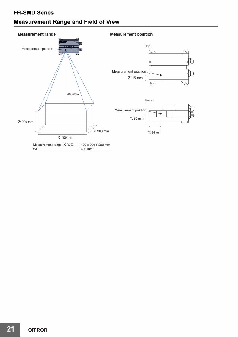
Measurement Range and Field of View
Y: 300 mm
Measurement position
400 mm
Z: 200 mm
X: 400 mm
Measurement range Measurement position
Top
Front
X: 35 mm
Measurement range (X, Y, Z)WD
400 x 300 x 200 mm400 mm
Measurement position
Measurement position
Y: 25 mm
Z: 15 mm

FH-SMD Series
22
Related ManualsMan.No. Model Manual
Z446 FH-5050/FH-SMDA-GS050B Vision System FH Series 3D Robot Vision Application Construction GuideZ436 FH-5050/FH-SMDA-GS050B Vision System FH Series Hardware Setup Manual for 3D Robot Vision
Z445 FH-5050/FH-SMDA-GS050B Vision System FH/FHV7 Series Processing Item Function Reference Manual for 3D Robot Vision
Z365 FH-5050 Vision System FH/FHV7 Series User's ManualZ341 FH-5050 Vision System FH/FHV7 Series Processing Item Function Reference ManualZ367 FH-5050 Vision System FH Series Macro Customize Functions Programming ManualZ342 FH-5050 FH/FHV7 Series User's Manual for Communications Settings
• EtherCAT® is a registered trademark and patented technology, licensed by Beckhoff Automation GmbH, Germany.• EtherNet/IPTM is a trademark of ODVA.• Microsoft® Visual Studio® and Windows are either registered trademarks or trademarks of Microsoft Corporation in the United States and/or
other countries.• QR code is the registered trademark of DENSO WAVE.• Intel and the Intel logo are trademarks of Intel Corporation in the U.S. and/or other countries.• The SD Logo is a trademark of SD-3C LLC.• Other company names and product names in this document are the trademarks or registered trademarks of their respective companies.• The product photographs and figures that are used in this catalog may vary somewhat from the actual products.• Microsoft product screen shot(s) used with permission from Microsoft Corporation.• The permission of Shutterstock.com was received for images that were used.

OMRON CANADA, INC. • HEAD OFFICEToronto, ON, Canada • 416.286.6465 • 866.986.6766 • automation.omron.com
OMRON ELECTRONICS DE MEXICO • HEAD OFFICECiudad de México • 52.55.5901.4300 • 01.800.386.6766 • [email protected]
OMRON ELECTRONICS DE MEXICO • SALES OFFICESan Pedro Garza García, N.L. • 81.12.53.7392 • 01.800.386.6766 • [email protected]
OMRON ELECTRONICS DE MEXICO • SALES OFFICEEugenio Garza Sada,León, Gto • 01.800.386.6766 • [email protected]
OMRON ELETRÔNICA DO BRASIL LTDA • HEAD OFFICESão Paulo, SP, Brasil • 55 11 5171-8920 • automation.omron.com
OMRON ARGENTINA • SALES OFFICEBuenos Aires, Argentina • +54.11.4521.8630 • +54.11.4523.8483 [email protected]
OTHER OMRON LATIN AMERICA SALES+54.11.4521.8630 • +54.11.4523.8483 • [email protected]
Authorized Distributor:
Q2988I-E3-01 Note: Specifications are subject to change. © 2021 Omron. All Rights Reserved. Printed in U.S.A.
Printed on recycled paper.
OMRON AUTOMATION AMERICAS HEADQUARTERS • Chicago, IL USA • 847.843.7900 • 800.556.6766 • automation.omron.com
Controllers & I/O • Machine Automation Controllers (MAC) • Motion Controllers• Programmable Logic Controllers (PLC) • Temperature Controllers • Remote I/O
Robotics • Industrial Robots • Mobile Robots
Operator Interfaces• Human Machine Interface (HMI)
Motion & Drives• Machine Automation Controllers (MAC) • Motion Controllers • Servo Systems• Frequency Inverters
Vision, Measurement & Identification• Vision Sensors & Systems • Measurement Sensors • Auto Identification Systems
Sensing• Photoelectric Sensors • Fiber-Optic Sensors • Proximity Sensors• Rotary Encoders • Ultrasonic Sensors
Safety • Safety Light Curtains • Safety Laser Scanners • Programmable Safety Systems • Safety Mats and Edges • Safety Door Switches • Emergency Stop Devices • Safety Switches & Operator Controls • Safety Monitoring/Force-guided Relays
Control Components • Power Supplies • Timers • Counters • Programmable Relays• Digital Panel Meters • Monitoring Products
Switches & Relays • Limit Switches • Pushbutton Switches • Electromechanical Relays• Solid State Relays
Software • Programming & Configuration • Runtime