3G3PV User's Manual - Omron eData
288
General Precautions i General Precautions Observe the following Precautions when using the SYSDRIVE Inverters and peripheral devices. This manual may include illustrations of the product with protective covers removed in order to describe the components of the product in detail. Make sure that these protective covers are on the product before use. Consult your OMRON representative when using the product after a long period of storage. Definition of Precautionary Information DANGER Indicates an imminently hazardous situation which, if not avoided, will result in death or serious injury. WARNING Indicates a potentially hazardous situation which, if not avoided, could result in death or serious injury. Caution Indicates a potentially hazardous situation which, if not avoided, may result in minor or moderate injury, or property damage. WARNING Do not touch the inside of the Inverter. Doing so may result in electric shock or injury. WARNING Wiring or inspection must be performed only after turning OFF the power sup- ply, confirming that the CHARGE indicator (or status indicator) is OFF and after waiting for the time specified on the front cover. Not doing so may result in electrical shock. WARNING Do not damage, pull on, apply stress to, place heavy objects on or pinch the cables. Doing so may result in electrical shock. WARNING Do not touch the rotating parts of the motor under operation. Doing so may result in injury. WARNING Do not modify the product. Doing so may result in injury or damage to the product. Caution Do not store, install or operate the product in the following places. Doing so may result in electrical shock, fire or damage to the product. • Locations subject to direct sunlight. • Locations subject to temperatures or humidity outside the range specified in the specifications. • Locations subject to condensation as the result of severe changes in temperature. • Locations subject to corrosive or flammable gasses. • Locations very close to combustable materials. • Locations subject to dust (especially iron dust) or salts. • Locations subject to exposure to water, oil or chemicals. • Locations subject to shock or vibrations.
-
Upload
khangminh22 -
Category
Documents
-
view
0 -
download
0
Transcript of 3G3PV User's Manual - Omron eData

General Precautions
i
General PrecautionsObserve the following Precautions when using the SYSDRIVE Inverters and peripheral devices.This manual may include illustrations of the product with protective covers removed in order todescribe the components of the product in detail. Make sure that these protective covers are on theproduct before use.
Consult your OMRON representative when using the product after a long period of storage.
Definition of Precautionary Information
DANGER Indicates an imminently hazardous situation which, if not avoided, will result in death or serious injury.
WARNING Indicates a potentially hazardous situation which, if not avoided, could result in death or serious injury.
Caution Indicates a potentially hazardous situation which, if not avoided, may result in minor or moderate injury, or property damage.
WARNING Do not touch the inside of the Inverter. Doing so may result in electric shock or injury.
WARNING
Wiring or inspection must be performed only after turning OFF the power sup-ply, confirming that the CHARGE indicator (or status indicator) is OFF and after waiting for the time specified on the front cover. Not doing so may result in electrical shock.
WARNING Do not damage, pull on, apply stress to, place heavy objects on or pinch the cables. Doing so may result in electrical shock.
WARNING Do not touch the rotating parts of the motor under operation. Doing so may result in injury.
WARNING Do not modify the product. Doing so may result in injury or damage to the product.
Caution
Do not store, install or operate the product in the following places. Doing so may result in electrical shock, fire or damage to the product.
• Locations subject to direct sunlight.
• Locations subject to temperatures or humidity outside the rangespecified in the specifications.
• Locations subject to condensation as the result of severe changes intemperature.
• Locations subject to corrosive or flammable gasses.
• Locations very close to combustable materials.
• Locations subject to dust (especially iron dust) or salts.
• Locations subject to exposure to water, oil or chemicals.
• Locations subject to shock or vibrations.

ii
CautionDo not touch the Inverters cooling fins, regenerative resistor or the motor while the power is being supplied or soon after the power is turned OFF. Doing so may result in a skinburn due to the hot surface.
Caution Do not conduct a dielectric stregth test on any part of the Inverter. Doing so may result in damage to the product or malfunction.
Caution
Take appropriate and sufficient countermeasures when installing systems in the following locations. Not doing so may result in equipment damage.
• Locations subject to static electricity or other forms of noise.
• Locations subject to strong electromagnetic fields and magneticfields.
• Locations subject to possible exposure to radio activity.
• Locations close to power supplies.

Transportation Precautions
iii
Transportation Precautions
Installation Precautions
Wiring Precautions
Caution Do not hold by front cover or panel. Instead hold by the cooling fins (heat sink) while transporting the product. Doing so may result in injury.
Caution Do not pull on the cables. Doing so may result in damge to the product or mal-function.
Caution Use the eyebolts only for transport of the Inverter. Using them to transport the Inverter and attached equipment may result in injury or malfunction.
WARNINGProvide an appropriate stopping device on the machine side to secure safety. ( A holding brake is not a stopping device for securing safety) Not doing so may result in injury.
WARNING Provide an external emergency stopping device that allows an instantaneous stop of operation and power interruption. Not doing so may result in injury.
CautionBe sure to install the product in the correct direction and provide specified clearances between the Inverter and control panel or with other devices to allow for proper cooling. Not doing so may result in fire or malfunction.
Caution Do not allow foreign objects to enter inside the product. Doing so may result in fire and malfunction.
Caution Do not apply any strong imact. Doing so may result in damage to the product or malfunction.
WARNING Wiring must be performed only after turning OFF the power supply. Not doing so may result in electrical shock.
WARNING Wiring must be performed by authorized personnel. Not doing so may result in electrical shock.
WARNING Be sur to confirm operation only after wiring the emergency stop circuit. Not doing so may result in injury.
RequiredAlways connect the ground terminals to a ground of 100 Ohm or less for 200-V AC class or 10 Ohm or less for the 400-V class. Not connecting to a proper ground may result in electrical shock or fire.

iv
Caution Install external circuit breakers and take other safety measures against shortcir-cuiting in external wiring. Not doing so may result in fire.
CautionConfirm that the rated input voltage of the Inverter is the same as the AC power supply voltage. An incorrect power supply may result in fire, injury or malfunction.
Caution Connect the Braking Resistor or Braking Resistor Unit as specified in the man-ual. Not doing so may result in fire.
Caution Be sure to wire correctly and securely. Not doing so may result in injury or damage to the product.
Caution Be sure to firmly tighten the screws on the terminal block. Not doing so may result in fire, injury or damage to the product.
Caution Do not connect an AC power source to the U,V,W output. Doing so may result in damage to the product or malfunction.
Caution Do not connect a load to the machine during auto-tuning. Not doing so may result in equipment damage.

Operation and Adjustment Precautions
v
Operation and Adjustment Precautions
WARNINGTurn ON the input power supply only after mounting the front cover, terminal covers, bottom cover, Operator and optional items. Not doing so may result in electrical shock.
WARNINGDo not remove the front cover, terminal covers, bottom cover, Operator or optional items while the power is being supplied. Doing so may result in elec-trical shock or damage to the product
WARNING Do not operate the Operator or switches with wet hands. Doing so may result in electrical shock.
WARNING Do not touch the Inverter terminals while the power is being supplied. Doing so may result in electrical shock.
WARNINGDo not come close to the machine when using the error retry function because the machine may abruptly start when stopped by an alarm. Doing so may result in injury.
WARNING
Do not come close to the machine immediately after resetting momentary power interruption to avoid an unexpected restart (if operation is set to be con-tinued in the processing selection function after momentary power is reset). Doing so may result in injury.
WARNINGProvide a separate emergency stop switch because the STOP Key on the Oper-ator is valid only when function settings are performed. Not doing so may result in injury.
WARNINGBe sure to confirm that the RUN signal is turned OFF before tuning ON the power supply, resetting the alarm or switching the LOCAL/REMOTE selector. Doing so while the RUN signal is turned ON my result in injury.
CautionBe sure to confirm permissible ranges of motors and machines before opera-tion because the Inverter speed can be easily changed from low to high. Not doing so may result in damage to the product.
Caution Provide a separate holding brake when neccessary. Not doing so may result in injury.
Caution Do not perform a signal check during operation. Doing so may result in injury or damage to the product.
Caution Do not carelessly change settings. Doing so may result in injury or damage to the product.
vi
Maintenance and Inspection Precautions
WARNING Do not touch the Inverter terminals while the power is being supplied. Doing so may result in electrical shock.
WARNING
Maintenance or inspection must be performed only after turning OFF the power supply, confirming that the CHARGE indicator (or status indicator) is OFF and after waiting for the time specified on the front cover. Not doing so may result in electrical shock.
WARNING Maintenance, inspection or parts replacement must be performed by autho-rized personnel. Not doing so may result in electrical shock or injury.
Prohibited Do not attempt to disassemble or repair the product. Doing so may result in electrical shock or injury.
Caution Carefully handle the Inverter because it uses semiconductor elements. Careless handling may result in malfunction.
CautionDo not exchange, wiring, the Operator, optional cover, disconnect connectors or replace fans while power is being supplied. Doing so may result in injury, damage to the product or malfunction.

Warning Information and Position
vii
Warning Information and PositionThere is warning information on the Inverter in the positon shown in the following illustration.
Aways read the warnings.
Warning information
Illustration shows the 3G3PV-A2004-E
Warning information position
Illustration shows the 3G3PV-B2220-E
Warning information position
WARNING
after disconnecting power supply.• Wait 5 minutes for capacitor discharge • Read manual before installing. Risk of electric shock.
AVERTISSEMENT
des condensateurs. l’allmentation. Pour permettre la décharge • Attendre 5 minutes aprés la coupure de • Lire le manual avant l’installation.
Risque de décharge électrique.

viii
Registered TrademarksThe following registered trademarks are used in this manual.
• DeviceNet is a registered trademark of the ODVA (Open DeviceNet Vendors Association,Inc.).
• MODBUS is a trademark of the AEG Schneider Automation, Inc.

ix
Contents
1 Handling Inverters .................................................................. 1-1
SYSDRIVE PV Introduction..........................................................................1-2
SYSDRIVE PV Applications ...........................................................................................1-2
SYSDRIVE PV Models ...................................................................................................1-2
Confirmations upon Delivery ........................................................................1-4
Checks............................................................................................................................1-4
Nameplate Information ...................................................................................................1-4
Component Names.........................................................................................................1-6
Exterior and Mounting Dimensions...............................................................1-8
Open Chassis Inverters (IP00) .......................................................................................1-8
Enclosed Wall-mounted Inverters (NEMA 1) ..................................................................1-8
Checking and Controlling the Installation Site ............................................1-10
Installation Site .............................................................................................................1-10
Controlling the Ambient Temperature ...........................................................................1-10
Protecting the Inverter from Foreign Matter..................................................................1-10
Installation Orientation and Space..............................................................1-11
Inverter Installation Orientation and Space................................................................... 1-11
Removing and Attaching the Terminal Cover .............................................1-12
Removing the Terminal Cover ......................................................................................1-12
Attaching the Terminal Cover........................................................................................1-12
Removing/Attaching the Digital Operator and Front Cover ........................1-13
Inverters of 18.5 kW or Less.........................................................................................1-13
Inverters of 22 kW or More ...........................................................................................1-16
2 Wiring....................................................................................... 2-1
Wiring ...........................................................................................................2-2
Connections to Peripheral Devices ..............................................................2-3
Connection Diagrams ...................................................................................2-4
Circuit descriptions .........................................................................................................2-5
Terminal Block Configuration........................................................................2-6
Wiring Main Circuit Terminals .......................................................................2-7
Applicable Wire Sizes and Closed-loop Connectors ......................................................2-7
Main Circuit Terminal functions ....................................................................................2-12
Main Circuit configurations ...........................................................................................2-13
Standard Connection Diagrams....................................................................................2-14
Wiring the Main Circuits................................................................................................2-15

x
Wiring Control Circuit Terminals................................................................. 2-22
Wire Sizes ................................................................................................................... 2-22
Control Circuit Terminal Functions ............................................................................... 2-24
Control Circuit Terminal Connections........................................................................... 2-27
Control Circuit Wiring Precautions ............................................................................... 2-28
Wiring Check.............................................................................................. 2-29
Checks ......................................................................................................................... 2-29
Installing and Wiring Option Cards............................................................. 2-30
Option Card Models and Specifications ....................................................................... 2-30
Installation .................................................................................................................... 2-30
3 Digital Operator and Modes....................................................3-1
Digital Operator ............................................................................................ 3-2
Digital Operator Keys ..................................................................................................... 3-3
Modes .......................................................................................................... 3-5
Inverter Modes ............................................................................................................... 3-5
Switching Modes ............................................................................................................ 3-6
Drive Mode ..................................................................................................................... 3-7
Quick Programming Mode.............................................................................................. 3-8
Advanced Programming Mode....................................................................................... 3-9
Verify Mode .................................................................................................................. 3-11
Autotuning Mode .......................................................................................................... 3-12
4 Trial Operation .........................................................................4-1
Cautions and Warnings ................................................................................ 4-2
Trial Operation Flowchart ............................................................................. 4-3
Trial Operation Procedures .......................................................................... 4-4
Application Confirmation ................................................................................................ 4-4
Setting the Power Supply Voltage Jumper (400-V Class Inverters of 75 kW or Higher) 4-4
Power ON....................................................................................................................... 4-4
Checking the Display Status .......................................................................................... 4-5
Basic Settings................................................................................................................. 4-6
Selecting the V/f pattern ................................................................................................. 4-7
Application Settings...................................................................................................... 4-10
No-load Operation ........................................................................................................ 4-10
Loaded Operation......................................................................................................... 4-11
Adjustment Suggestions ............................................................................ 4-13
5 Parameters ...............................................................................5-1
Parameter Descriptions................................................................................ 5-2
Description of Parameter Tables .................................................................................... 5-2
Digital Operator Display Functions and Levels ............................................ 5-3

xi
Parameters Settable in Quick Programming Mode ........................................................5-4
Parameter Tables .........................................................................................5-7
A: Setup Settings ............................................................................................................5-7
Application Parameters: b...............................................................................................5-8
Tuning Parameters: C...................................................................................................5-13
Reference Parameters: d..............................................................................................5-16
Motor Constant Parameters: E .....................................................................................5-18
Option Parameters: F ...................................................................................................5-19
Terminal Function Parameters: H.................................................................................5-20 Protection Function Parameters: L ...............................................................................5-26
N: Special Adjustments.................................................................................................5-32
Digital Operator Parameters: o .....................................................................................5-33
T: Motor Autotuning ......................................................................................................5-36
U: Monitor Parameters..................................................................................................5-37
Factory Settings that Change with the Inverter Capacity (o2-04) .................................5-44
6 Parameter Settings by Function............................................ 6-1
Application and Overload Selections............................................................6-2
Select the Overload to Suit the Application ....................................................................6-2
Frequency Reference ...................................................................................6-4
Selecting the Frequency Reference Source ...................................................................6-4
Using Multi-Step Speed Operation .................................................................................6-6
Run Command .............................................................................................6-8
Selecting the Run Command Source .............................................................................6-8
Stopping Methods.......................................................................................6-10
Selecting the Stopping Method when a Stop command is Input ..................................6-10
Using the DC Injection Brake........................................................................................6-13
Using Highslip Braking..................................................................................................6-14
Using an Emergency Stop ............................................................................................6-16
Acceleration and Deceleration Characteristics...........................................6-17
Setting Acceleration and Deceleration Times ...............................................................6-17
Preventing the Motor from Stalling During Acceleration
(Stall Prevention During Acceleration Function) ...........................................................6-19
Preventing Overvoltage During Deceleration
(Stall Prevention During Deceleration Function)...........................................................6-21
Adjusting Frequency References ...............................................................6-22
Adjusting Analog Frequency References .....................................................................6-22
Operation Avoiding Resonance (Jump Frequency Function) .......................................6-24
Speed Limit (Frequency Reference Limit Function) ...................................6-26
Limiting Maximum Output Frequency ...........................................................................6-26
Limiting Minimum Frequency........................................................................................6-26
Improved Operating Efficiency ...................................................................6-27
Field-weakening option.................................................................................................6-28
Hunting-prevention Function.........................................................................................6-29

xii
Machine Protection ....................................................................................6-30
Preventing Motor Stalling During Operation................................................................. 6-30
Detecting Motor Torque ................................................................................................ 6-30
Motor Overload Protection ........................................................................................... 6-33
Motor Overheating Protection Using PTC Thermistor Inputs ....................................... 6-35
Continuing Operation .................................................................................6-37
Restarting Automatically After Power Is Restored ....................................................... 6-37
Speed Search............................................................................................................... 6-38
Continuing Operation at Constant Speed When Frequency Reference Is Lost ........... 6-43
Restarting Operation After Transient Fault (Auto Restart Function) ............................ 6-43
Inverter Protection......................................................................................6-45
Reducing Inverter Overheating Pre-Alarm Warning Levels ......................................... 6-45
Input Terminal Functions ............................................................................ 6-46
Temporarily Switching Operation between Digital Operator
and Control Circuit Terminals ....................................................................................... 6-46
Blocking Inverter Outputs (Baseblock Commands)...................................................... 6-46
Hold Analog Frequency Using User-set Timing ........................................................... 6-47
Switching Operations between a Communications Option Card
and Control Circuit Terminals....................................................................................... 6-48
Jog Frequency Operation without Forward and Reverse Commands
(FJOG/RJOG) .............................................................................................................. 6-48
Stopping the Inverter by Notifying Programming Device Errors to the Inverter
(External Error Function) .............................................................................................. 6-49
Monitor Parameters....................................................................................6-50
Using the Analog Monitor Parameters ......................................................................... 6-50
Individual Functions ................................................................................... 6-52
Using PI Control ........................................................................................................... 6-65
Energy-saving .............................................................................................................. 6-72
Setting Motor Constant Parameters ............................................................................. 6-73
Setting the V/f Pattern .................................................................................................. 6-74
Digital Operator Functions .........................................................................6-80
Setting Digital Operator Functions ............................................................................... 6-80
Copying Parameters..................................................................................................... 6-82
Prohibiting Writing Parameters from the Digital Operator ............................................ 6-86
Setting a Password ...................................................................................................... 6-86
7 Troubleshooting ......................................................................7-1
Protective and Diagnostic Functions............................................................ 7-2
Fault Detection ............................................................................................................... 7-2
Alarm Detection.............................................................................................................. 7-7
Operation Errors............................................................................................................. 7-9 Errors During Autotuning............................................................................................. 7-10
Errors when Using the Digital Operator Copy Function ............................................... 7-11
Troubleshooting..........................................................................................7-12

xiii
If Parameters Cannot Be Set........................................................................................7-12
If the Motor Does Not Operate......................................................................................7-13
If the Direction of the Motor Rotation is Reversed ........................................................7-14
If the Motor Does Not Put Out Torque or If Acceleration Is Slow..................................7-15
If the Motor Operates Higher Than the Reference .......................................................7-15
If Motor Deceleration Is Slow........................................................................................7-15
If the Motor Overheats ..................................................................................................7-16
If peripheral devices are influenced by starting the Inverter .........................................7-16
If the Ground Fault Interrupter Operates When the Inverter Is Run .............................7-17
If There Is Mechanical Oscillation.................................................................................7-17
If the Motor Rotates Even When Inverter Output Is Stopped .......................................7-17
If 0 V Is Detected When the Fan Is Started, or the Fan Stalls ......................................7-18
If Output Frequency Does Not Rise to Frequency Reference ......................................7-18
8 Maintenance and Inspection.................................................. 8-1
Maintenance and Inspection.........................................................................8-2
Daily Inspection ..............................................................................................................8-2
Periodic Inspection .........................................................................................................8-2
Periodic Maintenance of Parts........................................................................................8-3
Cooling Fan Replacement Outline..................................................................................8-4
Removing and Mounting the Control Circuit Terminal Card ...........................................8-6
9 Specifications ......................................................................... 9-1
Standard Inverter Specifications...................................................................9-2
Specifications by Model ..................................................................................................9-2
Common Specifications ..................................................................................................9-5
Specifications of Options and Peripheral Devices........................................9-6
Options and Peripheral Devices ...................................................................9-7
Special Mounted Options................................................................................................9-9
Separately Installed Options.........................................................................................9-10
10 Inverter application Precautionspendix ............................. 10-1
Selection .......................................................................................................................10-2
Installation.....................................................................................................................10-3
Settings.........................................................................................................................10-3
Handling........................................................................................................................10-4
Motor Application Precautions....................................................................10-5
Using the Inverter for an Existing Standard Motor........................................................10-5
Using the Inverter for Special Motors ...........................................................................10-6
Power Transmission Mechanism (Speed Reducers, Belts, and Chains)......................10-6
Wiring Examples.........................................................................................10-7
Using a Braking Resistor Unit.......................................................................................10-7
Using a Braking Unit and Braking Resistor Unit ...........................................................10-7
Using a Braking Unit and Three Braking Resistor Units in Parallel ..............................10-9

xiv
Using an Analog Operator.......................................................................................... 10-10
Parameters............................................................................................... 10-11
Revision History ....................................................................................... 10-14

1Chapter 1
Handling InvertersThis chapter describes the checks required upon receiving or installing an Inverter.
SYSDRIVE PV Introduction..................................................1-2
Confirmations upon Delivery.................................................1-4
Exterior and Mounting Dimensions .......................................1-8
Checking and Controlling the Installation Site ....................1-11
Installation Orientation and Space .......................................1-12
Removing and Attaching the Terminal Cover......................1-13
Removing/Attaching the Digital Operator and Front Cover....................................................................1-14
1-2
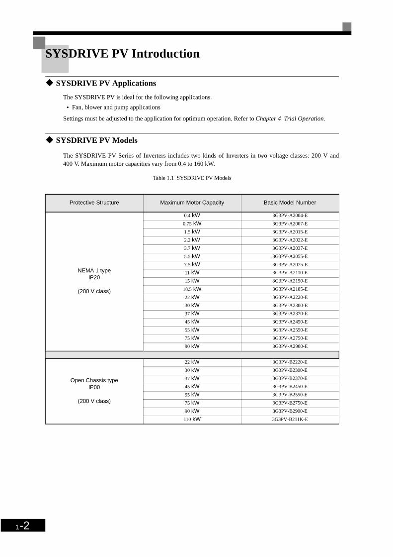
SYSDRIVE PV Introduction
SYSDRIVE PV Applications
The SYSDRIVE PV is ideal for the following applications.
• Fan, blower and pump applications
Settings must be adjusted to the application for optimum operation. Refer to Chapter 4 Trial Operation.
SYSDRIVE PV Models
The SYSDRIVE PV Series of Inverters includes two kinds of Inverters in two voltage classes: 200 V and400 V. Maximum motor capacities vary from 0.4 to 160 kW.
Table 1.1 SYSDRIVE PV Models
Protective Structure Maximum Motor Capacity Basic Model Number
NEMA 1 typeIP20
(200 V class)
0.4 kW 3G3PV-A2004-E
0.75 kW 3G3PV-A2007-E
1.5 kW 3G3PV-A2015-E
2.2 kW 3G3PV-A2022-E
3.7 kW 3G3PV-A2037-E
5.5 kW 3G3PV-A2055-E
7.5 kW 3G3PV-A2075-E
11 kW 3G3PV-A2110-E
15 kW 3G3PV-A2150-E
18.5 kW 3G3PV-A2185-E
22 kW 3G3PV-A2220-E
30 kW 3G3PV-A2300-E
37 kW 3G3PV-A2370-E
45 kW 3G3PV-A2450-E
55 kW 3G3PV-A2550-E
75 kW 3G3PV-A2750-E
90 kW 3G3PV-A2900-E
Open Chassis typeIP00
(200 V class)
22 kW 3G3PV-B2220-E
30 kW 3G3PV-B2300-E
37 kW 3G3PV-B2370-E
45 kW 3G3PV-B2450-E
55 kW 3G3PV-B2550-E
75 kW 3G3PV-B2750-E
90 kW 3G3PV-B2900-E
110 kW 3G3PV-B211K-E

SYSDRIVE PV Introduction
1-3
NEMA 1 typeIP20
400 V class
0.4 kW 3G3PV-A4004-E
0.75 kW 3G3PV-A4007-E
1.5 kW 3G3PV-A4015-E
2.2 kW 3G3PV-A4022-E
3.7 kW 3G3PV-A4037-E
4.0 kW 3G3PV-A4040-E
5.5 kW 3G3PV-A4055-E
7.5 kW 3G3PV-A4075-E
11 kW 3G3PV-A4110-E
15 kW 3G3PV-A4150-E
18.5 kW 3G3PV-A4185-E
22 kW 3G3PV-A4220-E
30 kW 3G3PV-A4300-E
37 kW 3G3PV-A4370-E
45 kW 3G3PV-A4450-E
55 kW 3G3PV-A4550-E
75 kW 3G3PV-A4750-E
90 kW 3G3PV-A4900-E
110 kW 3G3PV-A411K-E
132 kW 3G3PV-A413K-E
160 kW 3G3PV-A416K-E
Open Chassis typeIP00
(400 V class)
22 kW 3G3PV-B4220-E
30 kW 3G3PV-B4300-E
37 kW 3G3PV-B4370-E
45 kW 3G3PV-B4450-E
55 kW 3G3PV-B4550-E
75 kW 3G3PV-B4750-E
90 kW 3G3PV-B4900-E
110 kW 3G3PV-B411K-E
132 kW 3G3PV-B413K-E
160 kW 3G3PV-B416K-E
Protective Structure Maximum Motor Capacity Basic Model Number

1-4
Confirmations upon Delivery
Checks
Check the following items as soon as the Inverter is delivered.
If you find any irregularities in the above items, contact the agency from which you purchased the Inverter oryour OMRON representative immediately.
Nameplate Information
There is a nameplate attached to the side of each Inverter. The nameplate shows the model number, specifica-tions, lot number, serial number and other information on the Inverter.
Example Nameplate
The following nameplate is an example for an European Inverter: 3-phase, 200 VAC, 37 kW, IEC IP00
Fig 1.1 Nameplate
Table 1.2 Checks
Item Method
Has the correct model of Inverter been delivered?
Check the model number on the nameplate on the side of the Inverter.
Is the Inverter damaged in any way?Inspect the entire exterior of the Inverter to see if there are any scratches or other damage resulting from shipping.
Are any screws or other components loose?
Use a screwdriver or other tools to check for tightness.
Input specificationOutput specificationLot numberSerial number
Inverter model
Mass

Confirmations upon Delivery
1-5
Inverter Model Numbers
The model number of the Inverter on the nameplate indicates the specification, voltage class and maximummotor capacity of the Inverter in alphanumeric codes.
Fig 1.2 Inverter Model Numbers
TERMS
Open Chassis Type (IEC IP00) Protected so that parts of the human body cannot reach electrically charged parts from the front when theInverter is mounted in a control panel.
Enclosed Wall-mounted Type (IEC IP20, NEMA Type 1)The Inverter is structured so that the Inverter is shielded from the exterior and can thus be mounted to theinterior wall of a standard building (not necessarily enclosed in a control panel). The protective structure con-forms to the standards of NEMA 1 in the USA.Top protective cover (Fig. 1.3) has to be installed to conform with IEC IP20 and NEMA Type 1 requirements.
G3PV -A 2 037 -E
Specifications -E (European Model)
004 0.4 kW 055 5.5 kW 220 22 kW 750 75 kW
007 0.75 kW 075 7.5 kW 300 30 kW 900 90 kW
015 1.5 kW 110 11 kW 370 37 kW 11K 110 kW
022 2.2 kW 150 15 kW 450 45 kW 13K 130 kW
037 3.7 kW 185 18.5 kW 550 55 kW 16K 160 kW
040 4.0 kW
Maximum Applicable Motor Capacity
Voltage Class
2 AC-input, 3-phase, 200 V (200-V Class)
4 AC-input, 3-phase, 400 V (400-V Class)
Installation type
A Panel mounting or closed wall-mounting (IEC IP20, NEMA 1)
B Open Chassis (IEC IP00)
Series Name 3G3PV Series

1-6
Component Names
Inverter Appearance
The external appearance and component names of the Inverter are shown in Fig 1.3. The Inverter with the ter-minal cover removed is shown in Fig 1.4.
Fig 1.3 Inverter Appearance (18.5 kW or Less)
Fig 1.4 Terminal Arrangement (18.5 kW or Less)
Top protective cover (Part of Enclosed Wall-mounted Type (IEC IP20, NEMA Type 1)
Front cover
Digital Operator
Terminal cover
Mounting hole
Nameplate
Bottom protective cover
Diecast case
Charge indicator
Ground terminal
Control circuit terminals
Main circuit terminals

Confirmations upon Delivery
1-7
Inverters of 22 kW or More
The external appearance and component names of the Inverter are shown in Fig 1.5. The Inverter with the ter-minal cover removed is shown in Fig 1.6.
Fig 1.5 Inverter Appearance (22 kW or More)
Fig 1.6 Terminal Arrangement (22 kW or More)
Mounting holes
Cooling fan
Nameplate
Inverter cover
Front cover
Digital Operator
Terminal cover
Controlcircuit
terminals
Controlcircuit
terminals
Maincircuit
terminals
Ground terminal
Charge indicator
1-8
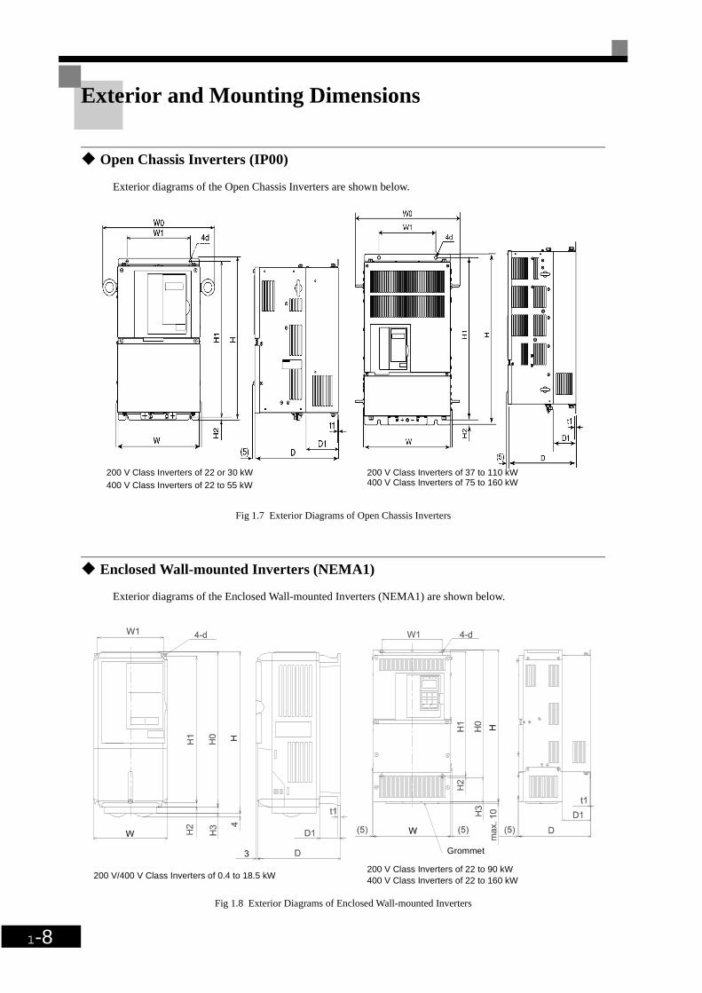
Exterior and Mounting Dimensions
Open Chassis Inverters (IP00)
Exterior diagrams of the Open Chassis Inverters are shown below.
Fig 1.7 Exterior Diagrams of Open Chassis Inverters
Enclosed Wall-mounted Inverters (NEMA1)
Exterior diagrams of the Enclosed Wall-mounted Inverters (NEMA1) are shown below.
Fig 1.8 Exterior Diagrams of Enclosed Wall-mounted Inverters
200 V Class Inverters of 22 or 30 kW400 V Class Inverters of 22 to 55 kW
200 V Class Inverters of 37 to 110 kW400 V Class Inverters of 75 to 160 kW
200 V Class Inverters of 22 to 90 kW400 V Class Inverters of 22 to 160 kW200 V/400 V Class Inverters of 0.4 to 18.5 kW
Grommet
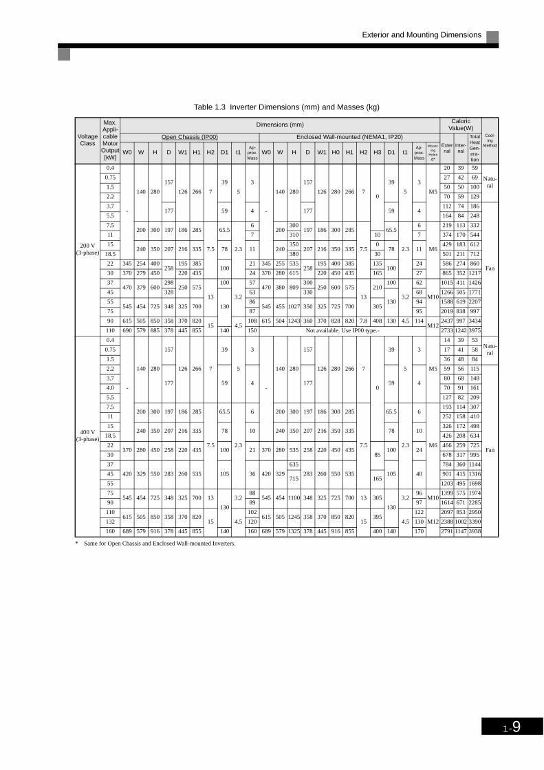
Exterior and Mounting Dimensions
1-9
* Same for Open Chassis and Enclosed Wall-mounted Inverters.
Table 1.3 Inverter Dimensions (mm) and Masses (kg)
Voltage Class
Max. Appli-cable Motor Output[kW]
Dimensions (mm)Caloric
Value(W)Cool-ing
Method
Open Chassis (IP00) Enclosed Wall-mounted (NEMA1, IP20)External
Inter-nal
Total Heat Gen-era-tion
W0 W H D W1 H1 H2 D1 t1Ap-
prox. Mass
W0 W H D W1 H0 H1 H2 H3 D1 t1Ap-
prox. Mass
Mount-ing
Holes d*
200 V(3-phase)
0.4
-
140 280
157
126 266 7
39
5
3
-
140 280
157
126 280 266 70
39
5
3
M5
20 39 59
Natu-ral
0.75 27 42 69
1.5 50 50 100
2.2 70 59 129
3.7177 59 4 177 59 4
112 74 186
Fan
5.5 164 84 248
7.5200 300 197 186 285
7.5
65.5
2.3
6200
300197 186 300 285
7.5
65.5
2.3
6
M6
219 113 332
11 7 310 10 7 374 170 544
15240 350 207 216 335 78 11 240
350207 216 350 335
078 11
429 183 612
18.5 380 30 501 211 712
22 345 254 400258
195 385100
21 345 255 535258
195 400 385 135100
24 586 274 860
30 370 279 450 220 435 24 370 280 615 220 450 435 165 27 865 352 1217
37470 379 600
298250 575
13
100
3.2
57470 380 809
300250 600 575
13
210100
3.2
62
M10
1015 411 1426
45 328
130
63 330
130
68 1266 505 1771
55545 454 725 348 325 700
86545 455 1027 350 325 725 700 305
94 1588 619 2207
75 87 95 2019 838 997
90 615 505 850 358 370 82015 4.5
108 615 504 1243 360 370 828 820 7.8 408 130 4.5 114M12
2437 997 3434
110 690 579 885 378 445 855 140 150 Not available. Use IP00 type.- 2733 1242 3975
400 V(3-phase)
0.4
-
140 280
157
126 266 7
39
5
3
-
140 280
157
126 280 266 7
0
39
5
3
M5
14 39 53Natu-
ral0.75 17 41 58
1.5 36 48 84
2.2
177 59 4 177 59 4
59 56 115
Fan
3.7 80 68 148
4.0 70 91 161
5.5 127 82 209
7.5200 300 197 186 285
7.5
65.5
2.3
6 200 300 197 186 300 285
7.5
65.5
2.3
6
M6
193 114 307
11 252 158 410
15240 350 207 216 335 78 10 240 350 207 216 350 335 78 10
326 172 498
18.5 426 208 634
22370 280 450 258 220 435 100 21 370 280 535 258 220 450 435
85100 24
466 259 725
30 678 317 995
37
420 329 550 283 260 535 105 36 420 329
635
283 260 550 535 105 40
784 360 1144
45715 165
901 415 1316
55 1203 495 1698
75545 454 725 348 325 700 13
130
3.288
545 454 1100 348 325 725 700 13 305
130
3.296
M101399 575 1974
90 89 97 1614 671 2285
110615 505 850 358 370 820
15 4.5
102615 505 1245 358 370 850 820
15395
4.5
122
M12
2097 853 2950
132 120 130 2388 1002 3390
160 689 579 916 378 445 855 140 160 689 579 1325 378 445 916 855 400 140 170 2791 1147 3938
1-10
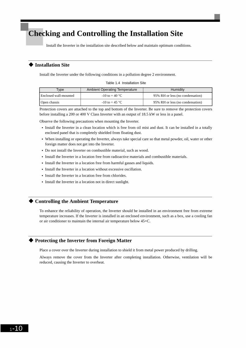
Checking and Controlling the Installation SiteInstall the Inverter in the installation site described below and maintain optimum conditions.
Installation Site
Install the Inverter under the following conditions in a pollution degree 2 environment.
Protection covers are attached to the top and bottom of the Inverter. Be sure to remove the protection coversbefore installing a 200 or 400 V Class Inverter with an output of 18.5 kW or less in a panel.
Observe the following precautions when mounting the Inverter.
• Install the Inverter in a clean location which is free from oil mist and dust. It can be installed in a totallyenclosed panel that is completely shielded from floating dust.
• When installing or operating the Inverter, always take special care so that metal powder, oil, water or otherforeign matter does not get into the Inverter.
• Do not install the Inverter on combustible material, such as wood.
• Install the Inverter in a location free from radioactive materials and combustible materials.
• Install the Inverter in a location free from harmful gasses and liquids.
• Install the Inverter in a location without excessive oscillation.
• Install the Inverter in a location free from chlorides.
• Install the Inverter in a location not in direct sunlight.
Controlling the Ambient Temperature
To enhance the reliability of operation, the Inverter should be installed in an environment free from extremetemperature increases. If the Inverter is installed in an enclosed environment, such as a box, use a cooling fanor air conditioner to maintain the internal air temperature below 45×C.
Protecting the Inverter from Foreign Matter
Place a cover over the Inverter during installation to shield it from metal power produced by drilling.
Always remove the cover from the Inverter after completing installation. Otherwise, ventilation will bereduced, causing the Inverter to overheat.
Table 1.4 Installation Site
Type Ambient Operating Temperature Humidity
Enclosed wall-mounted -10 to + 40 °C 95% RH or less (no condensation)
Open chassis -10 to + 45 °C 95% RH or less (no condensation)

Installation Orientation and Space
1-11
Installation Orientation and Space
Inverter Installation Orientation and Space
Install the Inverter vertically so as not to reduce the cooling effect. When installing the Inverter, alwaysprovide the following installation space to allow normal heat dissipation.
Fig 1.9 Inverter Installation Orientation and Space
WARNINGProvide an appropriate stopping device on the machine side to secure safety. ( A holding brake is not a stopping device for securing safety) Not doing so may result in injury.
WARNING Provide an external emergency stopping device that allows an instantaneous stop of operation and power interruption. Not doing so may result in injury.
CautionBe sure to install the product in the correct direction and provide specified clearances between the Inverter and control panel or with other devices to allow for proper cooling. Not doing so may result in fire or malfunction.
Caution Do not allow foreign objects to enter inside the product. Doing so may result in fire and malfunction.
Caution Do not apply any strong imact. Doing so may result in damage to the product or malfunction.
IMPORTANT
1. The same space is required horizontally and vertically for both Open Chassis (IP00) and Enclosed Wall-mounted (IP20, NEMA 1) Inverters.
2. Always remove the protection covers before installing a 200 or 400 V Class Inverter with an output of18.5 kW or less in a panel.Always provide enough space for suspension eye bolts and the main circuit lines when installing a 200 or400 V Class Inverter with an output of 22 kW or more in a panel.
50 mm min.
50 mm min.30 mm min.
120 mm min.
120 mm min.
Air
Air
Vertical SpaceHorizontal Space
30 mm min.

1-12
Removing and Attaching the Terminal CoverRemove the terminal cover to wire cables to the control circuit and main circuit terminals.
Removing the Terminal Cover
Inverters of 18.5 kW or Less
Loosen the screw at the bottom of the terminal cover, press in on the sides of the terminal cover in the direc-tions of arrows 1 and then lift up on the terminal in the direction of arrow 2.
Fig 1.10 Removing the Terminal Cover (Model 3G3PV-A2055-E Shown Above)
Inverters of 22 kW or More
Loosen the screws on the left and right at the top of the terminal cover, pull out the terminal cover in the direc-tion of arrow 1 and then lift up on the terminal in the direction of arrow 2.
Fig 1.11 Removing the Terminal Cover (Model 3G3PV-B2220-E Shown Above)
Attaching the Terminal Cover
When wiring the terminal block has been completed, attach the terminal cover by reversing the removal proce-dure.
For Inverters with an output of 18.5 kW or less, insert the tab on the top of the terminal cover into the grooveon the Inverter and press in on the bottom of the terminal cover until it clicks into place.
1
2
1
12
Removing/Attaching the Digital Operator and Front Cover
1-13
Removing/Attaching the Digital Operator and Front Cover
Inverters of 18.5 kW or Less
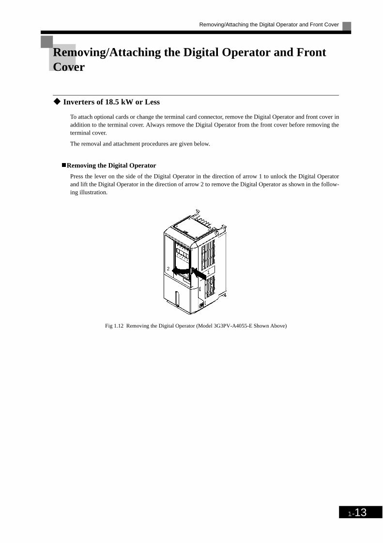
To attach optional cards or change the terminal card connector, remove the Digital Operator and front cover inaddition to the terminal cover. Always remove the Digital Operator from the front cover before removing theterminal cover.
The removal and attachment procedures are given below.
Removing the Digital Operator
Press the lever on the side of the Digital Operator in the direction of arrow 1 to unlock the Digital Operatorand lift the Digital Operator in the direction of arrow 2 to remove the Digital Operator as shown in the follow-ing illustration.
Fig 1.12 Removing the Digital Operator (Model 3G3PV-A4055-E Shown Above)
21

1-14
Removing the Front Cover
Press the left and right sides of the front cover in the directions of arrows 1 and lift the bottom of the cover inthe direction of arrow 2 to remove the front cover as shown in the following illustration.
Fig 1.13 Removing the Front Cover (Model 3G3PV-A4055-E Shown Above)
Mounting the Front Cover
After wiring the terminals, mount the front cover to the Inverter by performing the steps to remove the frontcover in reverse order.
1. Do not mount the front cover with the Digital Operator attached to the front cover; otherwise, DigitalOperator may malfunction due to imperfect contact.
2. Insert the tab of the upper part of the front cover into the groove of the Inverter and press the lower part ofthe front cover onto the Inverter until the front cover snaps shut.
Mounting the Digital Operator
After attaching the terminal cover, mount the Digital Operator onto the Inverter using the following proce-dure.
1. Hook the Digital Operator at A (two locations) on the front cover in the direction of arrow 1 as shown inthe following illustration.
2. Press the Digital Operator in the direction of arrow 2 until it snaps in place at B (two locations).
1
2

Removing/Attaching the Digital Operator and Front Cover
1-15
Fig 1.14 Mounting the Digital Operator
IMPORTANT
1. Do not remove or attach the Digital Operator or mount or remove the front cover using methods otherthan those described above, otherwise the Inverter may break or malfunction due to imperfect contact.
2. Never attach the front cover to the Inverter with the Digital Operator attached to the front cover. Imperfectcontact can result.Always attach the front cover to the Inverter by itself first and then attach the Digital Operator to the frontcover.
A
B

1-16
Inverters of 22 kW or More
For Inverters with an output of 22 kW or more, remove the terminal cover and then use the following proce-dures to remove the Digital Operator and main cover.
Removing the Digital Operator
Use the same procedure as for Inverters with an output of 18.5 kW or less.
Removing the Front Cover
Lift up at the location label 1 at the top of the control circuit terminal card in the direction of arrow 2.
Fig 1.15 Removing the Front Cover (Model 3G3PV-B2220-E Shown Above)
Attaching the Front Cover
After completing required work, such as mounting an optional card or setting the terminal card, attach thefront cover by reversing the procedure to remove it.
1. Confirm that the Digital Operator is not mounted on the front cover. Contact faults can occur if the cover isattached while the Digital Operator is mounted to it.
2. Insert the tab on the top of the front cover into the slot on the Inverter and press in on the cover until itclicks into place on the Inverter.
Attaching the Digital Operator
Use the same procedure as for Inverters with an output of 18.5 kW or less.
1
2
2Chapter 2
WiringThis chapter describes wiring terminals, main circuit terminal connections, main circuit termi-
nal wiring specifications, control circuit terminals and control circuit wiring specifications.
Wiring....................................................................................2-2
Connections to Peripheral Devices........................................2-3
Connection Diagram..............................................................2-4
Terminal Block Configuration...............................................2-6
Wiring Main Circuit Terminals .............................................2-7
Wiring Control Circuit Terminals........................................2-22
Wiring Check.......................................................................2-29
Installing and Wiring Option Cards ....................................2-30

2-2
Wiring
WARNING Wiring must be performed only after turning OFF the power supply. Not doing so may result in electrical shock.
WARNING Wiring must be performed by authorized personnel. Not doing so may result in electrical shock.
WARNING Be sure to confirm operation only after wiring the emergency stop circuit. Not doing so may result in injury.
RequiredAlways connect the ground terminals to a ground of 100 Ohm or less for 200-V AC class or 10 Ohm or less for the 400-V class. Not connecting to a proper ground may result in electrical shock or fire.
Caution Install external circuit breakers and take other safety measures against short-circuiting in external wiring. Not doing so may result in fire.
CautionConfirm that the rated input voltage of the Inverter is the same as the AC power supply voltage. An incorrect power supply may result in fire, injury or malfunction.
Caution Connect the Braking Resistor or Braking Resistor Unit as specified in the man-ual. Not doing so may result in fire.
Caution Be sure to wire correctly and securely. Not doing so may result in injury or damage to the product.
Caution Be sure to firmly tighten the screws on the terminal block. Not doing so may result in fire, injury or damage to the product.
Caution Do not connect an AC power source to the U,V,W output. Doing so may result in damage to the product or malfunction.
Caution Do not connect a load to the machine during auto-tuning. Not doing so may result in equipment damage.

Connections to Peripheral Devices
2-3
Connections to Peripheral DevicesExamples of connections between the Inverter and typical peripheral devices are shown in Fig 2.1.
Fig 2.1 Example Connections to Peripheral Devices
Power supply
Molded-casecircuit breakeror ground faultinterrupter
Magnetic con-tactor (MC)
AC reactor for powerfactor improvement
Input noise filter
Inverter
DC reactor for powerfactor improvement
Ground
Output noise filter
Ground
Motor

2-4
Connection DiagramThe connection diagram of the Inverter is shown in Fig 2.2.
When using the Digital Operator, the motor can be operated by wiring only the main circuits.
Fig 2.2 Connection Diagram
0XOWLIXQFWLRQ DQDORJXHRXWSXW WR 9
0XOWLIXQFWLRQ DQDORJXHRXWSXW WR 9
SKDVH SRZHU
WR 9 +]

Connection Diagram
2-5
Circuit Descriptions
Refer to the numbers indicated in the diagram on the previous page.
• These circuits are hazardous and are separated from accessible surfaces by protective separation.
• These circuits are separated from all other circuits by protective separation consisting of double andreinforced insulation. These circuits may be interconnected with SELV (or equivalent) or non-SELVcircuits, but not both.
• Inverter supplied by four-wire-system source (neutral grounded)These circuits are SELV (Safety Extra Low Voltage) circuits and are separated from all other circuitsby protective separation consisting of double and reinforced insulation. These circuits may only beinterconnected with other SELV (or equivalent) circuits. These circuits can be accessible or intercon-nected with other accessible SELV circuits.
• Inverter supplied by three-wire-system source (ungrounded or corner grounded)These circuits are not separated from hazardous circuits by protective separation, but only with basicinsulation. These circuits cannot be accessed and must not be interconnected with any circuits whichare accessible, unless they are isolated from accessible circuits by supplemental insulation.
IMPORTANT
1. Control circuit terminals are arranged as shown below.
2. The output current capacity of the +V terminal is 20 mA.3. Disable the stall prevention during deceleration (set parameter L3-04 to 0) when using a Braking Resis-
tor Unit. If this user parameter is not changed to disable stall prevention, the system may not stop withindeceleration time.
4. Main circuit terminals are indicated with double circles and control circuit terminals are indicated with sin-gle circles.
5. Sequence input signals S1 to S7 are labeled for sequence connections (0 V common and sinking mode)for no-voltage contacts or NPN transistors. These are the default settings. For PNP transistor sequence connections (+24V common and sourcing mode) or to provide a 24-Vexternal power supply, refer toTable 2.11.
6. The master speed frequency reference can set to input either a voltage (terminal A1) or current (terminalA2) by changing the setting of parameter H3-13. The default setting is for a voltage reference input.
7. The multi-function analog output is a dedicated meter output for an analog frequency meter, currentmeter, voltmeter, wattmeter, etc. Do not use this output for feedback control or for any other control pur-pose.
8. DC reactors to improve the input power factor built into 200 V Class Inverters for 22 to 110 kW and 400V Class Inverters for 22 to 160 kW. A DC reactor is thus an option only for Inverters for 18.5 kW or less.Remove the short bar when connecting a DC reactor to Inverters for 18.5 kW or less. Set parameter L8-01 to 1 when using an optional braking resistor unit and braking unit. When using this,a shutoff sequence for the power supply must be made using a thermal relay trip.

2-6
Terminal Block ConfigurationThe terminal arrangement for 200 V Class Inverters are shown in Fig 2.3 and Fig 2.4.
Fig 2.3 Terminal Arrangement (200 V/400 V Class Inverter for 0.4 kW shown above)
Fig 2.4 Terminal Arrangement (200 V/400 V Class Inverter for 22 kW)
Charge indicator
Ground terminal
Control circuit terminals
Main circuit terminals
Controlcircuit
terminals
Controlcircuit
terminals
Maincircuit
terminals
Ground terminal
Charge indicator

Wiring Main Circuit Terminals
2-7
Wiring Main Circuit Terminals
Applicable Wire Sizes and Closed-loop Connector
Select the appropriate wires and crimp terminals from Table 2.1 to Table 2.3. Refer to users manual
(I526-E1-) for wire sizes for Braking Resistor Units and Braking Units.
Table 2.1 200 V Class Wire Sizes
Inverter Model
3G3PV-Terminal Symbol Termial
Screws
Tightening Torque(N•m)
Possible Wire Sizes
mm2(AWG)
Recom-mended
Wire Size mm2
(AWG)
Wire Type
A2004-ER/L1, S/L2, T/L3, , 1, 2, U/T1, V/T2, W/T3 M4 1.2 to 1.5
2 to 5.5(14 to 10)
2(14)
Power cables, e.g., 600 V vinyl power cables
A2007-ER/L1, S/L2, T/L3, , 1, 2, U/T1, V/T2, W/T3 M4 1.2 to 1.5
2 to 5.5(14 to 10)
2(14)
A2015-ER/L1, S/L2, T/L3, , 1, 2, U/T1, V/T2, W/T3 M4 1.2 to 1.5
2 to 5.5(14 to 10)
2(14)
A2022-ER/L1, S/L2, T/L3, , 1, 2, U/T1, V/T2, W/T3 M4 1.2 to 1.5
2 to 5.5(14 to 10)
2(14)
A2037-ER/L1, S/L2, T/L3, , 1, 2, U/T1, V/T2, W/T3 M4 1.2 to 1.5
3.5 to 5.5(12 to 10)
3.5(12)
A2055-ER/L1, S/L2, T/L3, , 1, 2, U/T1, V/T2, W/T3 M4 1.2 to 1.5
5.5(10)
5.5(10)
A2075-ER/L1, S/L2, T/L3, , 1, 2, U/T1, V/T2, W/T3 M5 2.5
8 to 14(8 to 6)
8(8)
A2110-ER/L1, S/L2, T/L3, , 1, 2, U/T1, V/T2, W/T3 M5 2.5
14 to 22(6 to 4)
14(6)
A2150-E
R/L1, S/L2, T/L3, , 1, 2, U/T1, V/T2, W/T3
M6 4.0 to 5.030 to 38(4 to 2)
30(4)
M6 4.0 to 5.022(4)
22(4)
A2185-E
R/L1, S/L2, T/L3, , 1, 2, U/T1, V/T2, W/T3
M8 9.0 to 10.030 to 38(3 to 2)
30(3)
M6 4.0 to 5.022(4)
22(4)
A2220-EB2220-E
R/L1, S/L2, T/L3, , 1, U/T1, V/T2, W/T3, R1/L11, S1/L21, T1/L31
M8 9.0 to 10.030 to 60(3 to 1)
30(3)
3 M6 4.0 to 5.08 to 22(8 to 4)
-
M8 9.0 to 10.022 to 38(4 to 2)
22(4)
A2300-EB2300-E
R/L1, S/L2, T/L3, , 1 U/T1, V/T2, W/T3, R1/L11, S1/L21, T1/L31
M8 9.0 to 10.050 to 60(1 to 1/0)
50(1)
3 M6 4.0 to 5.08 to 22(8 to 4)
-
M8 9.0 to 10.022 to 38(4 to 2)
22(4)

2-8
* The wire thickness is set for copper wires at 75°C
A2370-EB2370-E
R/L1, S/L2, T/L3, , 1 U/T1, V/T2, W/T3, R1/L11, S1/L21, T1/L31
M10 17.6 to 22.560 to 100
(2/0 to 4/0)60
(2/0)
Power cables, e.g., 600 V vinyl
power cables
3 M8 8.8 to 10.85.5 to 22(10 to 4)
–
M10 17.6 to 22.530 to 60(2 to 2/0)
30(2)
r/l1, ∆/l2 M4 1.3 to 1.40.5 to 5.5(20 to 10)
1.25(16)
A2450-EB2450-E
R/L1, S/L2, T/L3, , 1 U/T1, V/T2, W/T3, R1/L11, S1/L21, T1/L31
M10 17.6 to 22.580 to 100
(3/0 to 4/0)80
(3/0)
3 M8 8.8 to 10.85.5 to 22(10 to 4)
–
M10 17.6 to 22.538 to 60(1 to 2/0)
38(1)
r/l1, ∆/l2 M4 1.3 to 1.40.5 to 5.5(20 to 10)
1.25(16)
A2550-EB2550-E
R/L1, S/L2, T/L3, , 1 M12 31.4 to 39.250 to 100
(1/0 to 4/0)50 × 2P
(1/0 × 2P)
U/T1, V/T2, W/T3, R1/L11, S1/L21, T1/L31 M10 17.6 to 22.5100(4/0)
100(4/0)
3 M8 8.8 to 10.85.5 to 60
(10 to 2/0)–
M10 17.6 to 22.530 to 60(3 to 4/0)
50(1/0)
r/l1, ∆/l2 M4 1.3 to 1.40.5 to 5.5(20 to 10)
1.25(16)
A2750-EB2750-E
R/L1, S/L2, T/L3, , 1 M12 31.4 to 39.280 to 125
(3/0 to 250)80 × 2P
(3/0 × 2P)
U/T1, V/T2, W/T3, R1/L11, S1/L21, T1/L31 M10 17.6 to 22.580 to 100
(3/0 to 4/0)80 × 2P
(3/0 × 2P)
3 M8 8.8 to 10.85.5 to 60
(10 to 2/0)–
M10 17.6 to 22.5100 to 200(3/0 to 400)
100(3/0)
r/l1, ∆/l2 M4 1.3 to 1.40.5 to 5.5(20 to 10)
1.25(16)
A2900-EB2900-E
R/L1, S/L2, T/L3, , 1 M12 31.4 to 39.2150 to 200
(250 to 400)150 × 2P
(250 × 2P)
U/T1, V/T2, W/T3, R1/L11, S1/L21, T1/L31 M12 31.4 to 39.2100 to 150(4/0 to 300)
100 × 2P(4/0 × 2P)
3 M8 8.8 to 10.85.5 to 60
(10 to 2/0)–
M12 31.4 to 39.260 to 150
(2/0 to 300)60 × 2P
(2/0 × 2P)
r/l1, ∆/l2 M4 1.3 to 1.40.5 to 5.5(20 to 10)
1.25(16)
B211K
R/L1, S/L2, T/L3, , 1 M12 31.4 to 39.2200 to 325
(350 to 600)
200 × 2P or 50 × 4P (350 × 2P or 1/0 ×
2P)
U/T1, V/T2, W/T3, R1/L11, S1/L21, T1/L31 M12 31.4 to 39.2150 to 325
(300 to 600)
150 × 2P or 50 × 4P (300 × 2P or 1/0 ×
4P)
3 M8 8.8 to 10.85.5 to 60
(10 to 2/0)–
M12 31.4 to 39.2150
(300)150 × 2P
(300 × 2P)
r/l1, ∆/l2 M4 1.3 to 1.40.5 to 5.5(20 to 10)
1.25(16)
Inverter Model
3G3PV-Terminal Symbol Termial
Screws
Tightening Torque(N•m)
Possible Wire Sizes
mm2(AWG)
Recom-mended
Wire Size mm2
(AWG)
Wire Type

Wiring Main Circuit Terminals
2-9
Table 2.2 400 V Class Wire Sizes
Inverter Model
3G3PV-Terminal Symbol
Termi-nal
Screws
Tightening Torque(N•m)
Possible Wire Sizes
mm2 (AWG)
Recom-mended
Wire Size mm2
(AWG)
Wire Type
A4004-ER/L1, S/L2, T/L3, , 1, 2, U/T1, V/T2, W/T3 M4 1.2 to 1.5
2 to 5.5(14 to 10)
2(14)
Power cables, e.g., 600 V vinyl power cables
A4007-ER/L1, S/L2, T/L3, , 1, 2, U/T1, V/T2, W/T3 M4 1.2 to 1.5
2 to 5.5(14 to 10)
2(14)
A4015-ER/L1, S/L2, T/L3, , 1, 2, U/T1, V/T2, W/T3 M4 1.2 to 1.5
2 to 5.5(14 to 10)
2(14)
A4022-ER/L1, S/L2, T/L3, , 1, 2, U/T1, V/T2, W/T3 M4 1.2 to 1.5
2 to 5.5(14 to 10)
2(14)
A4037-E
R/L1, S/L2, T/L3, , 1, 2, U/T1, V/T2, W/T3 M4 1.2 to 1.5
2 to 5.5(14 to 10)
3.5(12)
2(14)
A4040-E
R/L1, S/L2, T/L3, , 1, 2, U/T1, V/T2, W/T3 M4 1.2 to 1.5
2 to 5.5(14 to 10)
3.5(12)
2(14)
A4055-E
R/L1, S/L2, T/L3, , 1, 2, U/T1, V/T2, W/T3 M4 1.2 to 1.5
3.5 to 5.5(12 to 10)
3.5(12)
2 to 5.5(14 to 10)
2(14)
A4075-E
R/L1, S/L2, T/L3, , 1, 2, U/T1, V/T2, W/T3 M4 1.2 to 1.5
5.5(10)5.5(10)
3.5 to 5.5(12 to 10)
3.5(12)
A4110-E
R/L1, S/L2, T/L3, , 1, 2, U/T1, V/T2, W/T3 M5 2.5
5.5 to 14(10 to 6)
8(8)
5.5(10)
A4150-E
R/L1, S/L2, T/L3, , 1, 2, U/T1, V/T2, W/T3
M5 2.58 to 14(8 to 6)
8(8)
M5(M6)
2.5(4.0 to 5.0)
5.5 to 14(10 to 6)
5.5(10)
A4185-E
R/L1, S/L2, T/L3, , 1, 2, U/T1, V/T2, W/T3
M6 4.0 to 5.08 to 38(8 to 2)
8(8)
M6 4.0 to 5.08 to 22(8 to 4)
8(8)
A4220-EB4220-E
R/L1, S/L2, T/L3, , 1, 3, U/T1, V/T2, W/T3, R1/L11, S1/L21, T1/L31
M6 4.0 to 5.014 to 22(6 to 4)
14(6)
M8 9.0 to 10.014 to 38(6 to 2)
14(6)
A4300-EB4300-E
R/L1, S/L2, T/L3, , 1, 3, U/T1, V/T2, W/T3, R1/L11, S1/L21, T1/L31
M6 4.0 to 5.022(4)
22(4)
M8 9.0 to 10.022 to 38(4 to 2)
22(4)
A4370-EB4370-E
R/L1, S/L2, T/L3, , 1, U/T1, V/T2, W/T3, R1/L11, S1/L21, T1/L31
M8 9.0 to 10.022 to 60(4 to 1/0)
38(2)
3 M6 4.0 to 5.08 to 22(8 to 4)
-
M8 9.0 to 10.022 to 38(4 to 2)
22(4)

2-10
* The wire thickness is set for copper wires at 75°C.
A4450-EB4450-E
R/L1, S/L2, T/L3, , 1, U/T1, V/T2, W/T3, R1/L11, S1/L21, T1/L31
M8 9.0 to 10.038 to 60(2 to 1/0)
38(2)
3 M6 4.0 to 5.08 to 22(8 to 4)
-
M8 9.0 to 10.022 to 38(4 to 2)
22(4)
A4550-EB4550-E
R/L1, S/L2, T/L3, , 1, U/T1, V/T2, W/T3, R1/L11, S1/L21, T1/L31
M8 9.0 to 10.050 to 60(1 to 1/0)
50(1)
Power cables, e.g., 600 V vinyl power cables
3 M6 4.0 to 5.08 to 22(8 to 4)
-
M8 9.0 to 10.022 to 38(4 to 2)
22(4)
A4750-EB4750-E
R/L1, S/L2, T/L3, , 1 M12 31.4 to 39.260 to 100
(2/0 to 4/0)60
(2/0)
U/T1, V/T2, W/T3, R1/L11, S1/L21, T1/L31 M10 17.6 to 22.550 to 100
(1/0 to 4/0)50
(1/0)
3 M8 8.8 to 10.85.5 to 22(10 to 4)
-
M12 31.4 to 39.238 to 60(2 to 2/0)
38(2)
r/l1, ∆200/l2200, ∆400/l2400 M4 1.3 to 1.40.5 to 5.5(20 to 10)
1.25(16)
A4900-EB4900-E
R/L1, S/L2, T/L3, , 1 M12 31.4 to 39.280 to 100
(3/0 to 4/0)100(4/0)
U/T1, V/T2, W/T3, R1/L11, S1/L21, T1/L31 M10 17.6 to 22.580 to 100
(3/0 to 4/0)100(4/0)
3 M8 8.8 to 10.88 to 22 (8 to 4)
-
M12 31.4 to 39.250 to 100 (1 to 4/0)
50(1)
r/l1, ∆200/l2200, ∆400/l2400 M4 1.3 to 1.40.5 to 5.5(20 to 10)
1.25(16)
A411K-EB411K-E
R/L1, S/L2, T/L3, , 1 M12 31.4 to 39.250 to 100
(1/0 to 4/0)50 × 2P
(1/0 × 2P)
U/T1, V/T2, W/T3, R1/L11, S1/L21, T1/L33 M12 31.4 to 39.250 to 100
(1/0 to 4/0)50 × 2P
(1/0 × 2P)
3 M8 8.8 to 10.88 to 60
(8 to 2/0)-
M12 31.4 to 39.260 to 150
(2/0 to 300)600(2/0)
r/l1, ∆200/l2200, ∆400/l2400 M4 1.3 to 1.40.5 to 5.5(20 to 10)
1.25(16)
A413K-EB413K-E
R/L1, S/L2, T/L3, , 1 M12 31.4 to 39.280 to 100
(3/0 to 4/0)80 × 2P
(3/0 × 2P)
U/T1, V/T2, W/T3, R1/L11, S1/L21, T1/L33 M12 31.4 to 39.260 to 100
(2/0 to 4/0)60 × 2P
(2/0 × 2P)
3 M8 8.8 to 10.88 to 60
(8 to 2/0)-
M12 31.4 to 39.2100 to 150(4/0 to 300)
100(4/0)
r/l1, ∆200/l2200, ∆400/l2400 M4 1.3 to 1.40.5 to 5.5(20 to 10)
1.25(16)
A416K-EB416K-E
R/L1, S/L2, T/L3, , 1 M12 31.4 to 39.2100 to 200(4/0 to 400)
100 × 2P(4/0 × 2P)
U/T1, V/T2, W/T3, R1/L11, S1/L21, T1/L33 M12 31.4 to 39.280 to 200
(3/0 to 400)80 × 2P
(3/0 × 2P)
3 M8 8.8 to 10.880 to 60(8 to 2/0)
-
M12 31.4 to 39.250 to 150
(1/0 to 300)50 × 2P
(1/0 × 2P)
r/l1, ∆200/l2200, ∆400/l2400 M4 1.3 to 1.40.5 to 5.5(20 to 10)
1.25(16)
Inverter Model
3G3PV-Terminal Symbol
Termi-nal
Screws
Tightening Torque(N•m)
Possible Wire Sizes
mm2 (AWG)
Recom-mended
Wire Size mm2
(AWG)
Wire Type

Wiring Main Circuit Terminals
2-11
Table 2.3 Closed-loop Connector Sizes (JIS C2805) (200 V Class and 400 V Class)
Wire Thickness (mm2) Terminal Screws Size
0.5M3.5 1.25 to 3.5
M4 1.25 to 4
0.75M3.5 1.25 to 3.5
M4 1.25 to 4
1.25M3.5 1.25 to 3.5
M4 1.25 to 4
2
M3.5 2 to 3.5
M4 2 to 4
M5 2 to 5
M6 2 to 6
M8 2 to 8
3.5/5.5
M4 5.5 to 4
M5 5.5 to 5
M6 5.5 to 6
M8 5.5 to 8
8
M5 8 to 5
M6 8 to 6
M8 8 to 8
14M6 14 to 6
M8 14 to 8
22M6 22 to 6
M8 22 to 8
30/38 M8 38 to 8
50/60M8 60 to 8
M10 60 to 10
80M10
80 to 10
100 100 to 10
100
M12
100 to 12
150 150 to 12
200 200 to 12
325M12 x 2 325 to 12
M16 325 to 16
IMPORTANT
Determine the wire size for the main circuit so that line voltage drop is within 2% of the rated voltage. Line
voltage drop is calculated as follows:
Line voltage drop (V) = x wire resistance (W/km) x wire length (m) x current (A) x 10-33

2-12
Main Circuit Terminal Functions
Main circuit terminal functions are summarized according to terminal symbols in Table 2.4. Wire the termi-nals correctly for the desired purposes.
Table 2.4 Main Circuit Terminal Functions (200 V Class and 400 V Class)
Purpose Terminal SymbolModel: 3G3PV-
200 V Class 400 V Class
Main circuit power input
R/L1, S/L2, T/L3A2004-E to A2900-E A4004-E to A416K-E
B2220-E to B211K-E B4220-E to B416K-E
R1/L11, S1/L21, T1/L31A2220-E to A2900-E A4220-E to A416K-E
B2220-E to B211K-E B4220-E to B416K-E
Inverter outputs U/T1, V/T2, W/T3A2004-E to A2900-E A4004-E to A416K-E
B2220-E to B211K-E B4220-E to B416K-E
DC power input 1, A2004-E to A2900-E A4004-E to A416K-E
B2220-E to B211K-E B4220-E to B416K-E
DC reactor connection 1, 2 A2004-E to A2185-E A4004-E to A4185-E
Braking Unit connection 3, A2004-E to A2900-E A4220-E to A416K-E
B2220-E to B211K-E B4220-E to B416K-E
GroundA2004-E to A2900-E A4004-E to A416K-E
B2220-E to B211K-E B4220-E to B416K-E

Wiring Main Circuit Terminals
2-13
Main Circuit Configurations
The main circuit configurations of the Inverter are shown in Fig 2.5.
Table 2.5 Inverter Main Circuit Configurations
Note 1. Consult your OMRON representative before using 12-phase rectification.
200 V Class 400 V Class
Powersupply
Controlcircuits
3G3PV-A2004-E to A2185-E
Powersupply
Controlcircuits
3G3PV-A4004-E to A4185-E
3G3PV-A2220-E,A2300-E3G3PV-B2220-E,B2300-E
Powersupply
Controlcircuits
3G3PV-A4220-E to A4550-E3G3PV-B4220-E to B4550-E
Powersupply
Controlcircuits
3G3PV-A2370-E to A2900-E3G3PV-B2370-E to B211K-E
Powersupply
Controlcircuits
3G3PV-A4750-E to A416K-E3G3PV-B4750-E to B416K-E
Powersupply
Controlcircuits

2-14
Standard Connection Diagrams
Standard Inverter connection diagrams are shown in Fig 2.5. These are the same for both 200 V Class and400 V Class Inverters. The connections depend on the Inverter capacity.
Control power is supplied internally from the main circuit DC power supply for all Inverter models.
Fig 2.5 Main Circuit Terminal Connections
3G3PV-A2004-E to A2185-E,A4004-E toA4185-E
Be sure to remove the short-circuit bar before connecting the DC reactor.
3G3PV-A2220-E, A2300-E, A4220-E to A4550-E 3G3PV-B2220-E, B2300-E, B4220-E to B4550-E
The DC reactor is built in.
3G3PV-A2370-E to A2900-E3G3PV-B2370-E to B211K-E
3G3PV-A4750-E to A416K-E3G3PV-B4750-E to B416K-E
Braking Unit (optional)
Braking Resistor Unit (optional)DC reactor
(optional)
3-phase 200 VAC (400 VAC)
3-phase 200 VAC (400 VAC)
Braking ResistorUnit (optional)
Braking Unit (optional)
3-phase 200 VAC
Braking Unit (optional)
Braking ResistorUnit (optional)
3-phase 400 VAC
Braking Unit (optional)
Braking ResistorUnit (optional)

Wiring Main Circuit Terminals
2-15
Wiring the Main Circuits
This section describes wiring connections for the main circuit inputs and outputs.
Wiring Main Circuit Inputs
Observe the following precautions for the main circuit power supply input.
Installing a Molded-case Circuit Breaker
When connecting the power input terminals (R/L2, S/L2 and T/L3) and power supply via a molded-case cir-cuit breaker (MCCB) observe that the circuit breaker is suitable for the Inverter.
• Choose an MCCB with a capacity of 1.5 to 2 times the Inverter's rated current.
• For the MCCB's time characteristics, be sure to consider the Inverter's overload protection (one minute at120% of the rated output current).
• If the same MCCB is to be used for more than one Inverter, or other devices, set up a sequence, that thepowersupply will be turned OFF by a fault output, as shown below.
Fig 2.6 MCCB Installation
Installing a Ground Fault Interrupter
Inverter outputs use high-speed switching, so high-frequency leakage current is generated. Therefore, at theInverter primary side, use a ground fault interrupter to detect only the leakage current in the frequency rangethat is hazardous to humans and exclude high-frequency leakage current.
• For the special-purpose ground fault interrupter for Inverters, choose a ground fault interrupter with a sen-sitivity amperage of at least 10 mA per Inverter.
• When using a general ground fault interrupter, choose a ground fault interrupter with a sensitivity amper-age of 200 mA or more per Inverter and with an operating time of 0.1 s or more.
Installing a Magnetic Contactor
If the power supply for the main circuit is to be shut off during a sequence, a magnetic contactor can be used.
When a magnetic contactor is installed on the primary side of the main circuit to forcibly stop the Inverter,however, the regenerative braking does not work and the Inverter will coast to stop.
• The Inverter can be started and stopped by opening and closing the magnetic contactor on the primary side.Frequently opening and closing the magnetic contactor, however, may cause the Inverter to break down.Start and stop the Inverter at most once every 30 minutes.
* For 400-V class Inverters, connect a 400/200-V transformer.
Fault out-put (NC)
Power supply
Inverter

2-16
• When the Inverter is operated with the Digital Operator, automatic operation cannot be performed afterrecovery from a power interruption.
• If a Braking Unit and a Braking Resistor Unit are used, program the sequence so that the magnetic contac-tor is turned OFF by the contact of the Braking Resistor Unit's thermal overload relay.
Connecting Input Power Supply to the Terminal Block
Input power supply can be connected to any terminal R, S or T on the terminal block; the phase sequence ofinput power supply is irrelevant to the phase sequence.
Installing an AC Reactor
If the Inverter is connected to a large-capacity power transformer (600 kW or more) or the phase advancingcapacitor is switched, an excessive peak current may flow through the input power circuit, causing the con-verter unit to break down.
To prevent this, install an optional AC Reactor on the input side of the Inverter or a DC reactor to the DC reac-tor connection terminals (for units from 22 kW the DC reactor is standard).
This also improves the power factor on the power supply side.
Installing a Surge Absorber
Always use a surge absorber or diode for inductive loads near the Inverter. These inductive loads include mag-netic contactors, electromagnetic relays, solenoid valves, solenoids and magnetic brakes.
Installing a Noise Filter on Power Supply Side
Install a noise filter to eliminate noise transmitted between the power line and the Inverter.
• Correct Noise Filter Installation
Fig 2.7 Correct Power supply Noise Filter Installation.
Use a special-purpose noise filter for Inverters.Ordinary: 3G3EV-PLNFD/3G3IV-PFNEMC compatible: 3G3RV-PFI
Power supply 3G3PV
Inverter Noise filter
Other
controllers
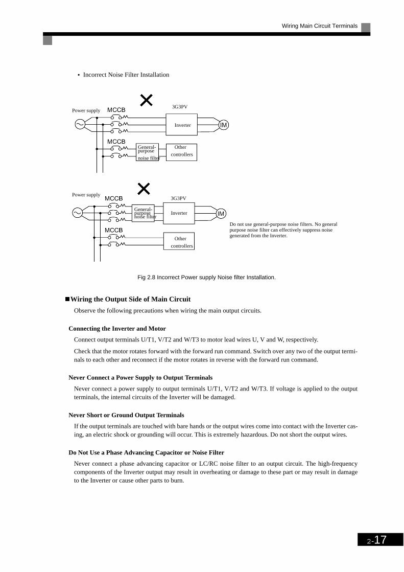
Wiring Main Circuit Terminals
2-17
• Incorrect Noise Filter Installation
Fig 2.8 Incorrect Power supply Noise filter Installation.
Wiring the Output Side of Main Circuit
Observe the following precautions when wiring the main output circuits.
Connecting the Inverter and Motor
Connect output terminals U/T1, V/T2 and W/T3 to motor lead wires U, V and W, respectively.
Check that the motor rotates forward with the forward run command. Switch over any two of the output termi-nals to each other and reconnect if the motor rotates in reverse with the forward run command.
Never Connect a Power Supply to Output Terminals
Never connect a power supply to output terminals U/T1, V/T2 and W/T3. If voltage is applied to the outputterminals, the internal circuits of the Inverter will be damaged.
Never Short or Ground Output Terminals
If the output terminals are touched with bare hands or the output wires come into contact with the Inverter cas-ing, an electric shock or grounding will occur. This is extremely hazardous. Do not short the output wires.
Do Not Use a Phase Advancing Capacitor or Noise Filter
Never connect a phase advancing capacitor or LC/RC noise filter to an output circuit. The high-frequencycomponents of the Inverter output may result in overheating or damage to these part or may result in damageto the Inverter or cause other parts to burn.
Do not use general-purpose noise filters. No generalpurpose noise filter can effectively suppress noisegenerated from the Inverter.
3G3PV
Inverter
controllers
Other
noise filter
General-purpose
Power supply
Power supply3G3PV
InverterGeneral-purposenoise filter
Other
controllers

2-18
Do Not Use an Electromagnetic Switch
Never connect an electromagnetic switch (MC) between the Inverter and motor and turn it ON or OFF duringoperation. If the MC is turned ON while the Inverter is operating, a large inrush current will be caused and theovercurrent protection in the Inverter will operate.
When using an MC to switch to a commercial power supply, stop the Inverter and motor before operating theMC. Use the speed search function if the MC is operated during operation. If measures for momentary powerinterrupts are required, use a delayed release MC.
Installing a Thermal Overload Relay
This Inverter has an electronic thermal protection function to protect the motor from overheating. If, however,more than one motor is operated with one Inverter or a multi-polar motor is used, always install a thermalrelay (THR) between the Inverter and the motor and set L1-01 to 0 (no motor protection). The sequenceshould be designed so that the contacts of the thermal overload relay turn OFF the magnetic contactor on themain circuit inputs.
Installing a Noise Filter on Output Side
Connect a noise filter to the output side of the Inverter to reduce radio noise and inductive noise.
Fig 2.9 Installing a noise filter on the output side
Countermeasures against Inductive Noise
As described previously, a noise filter can be used to prevent inductive noise from being generated on the out-put side. Alternatively, cables can be routed through a grounded metal pipe to prevent inductive noise. Keep-ing the metal pipe at least 30 cm away from the signal line considerably reduces inductive noise.
Fig 2.10 Countermeasures against Inductive noise
Inductive noise: Electromagnetic induction generates noise on the signal line, causing the controller to malfunction.Radio noise: Electromagnetic waves from the Inverter and cables cause the broadcasting radio receiver to make noise.
Signal line
Powersupply
3G3PV 3G3IV-PLF
Inverter
AM radio
Controller
NoiseFilter
Radio noise
Inductive noise
Controller
30cm min.
Signal line
Inverter
Power supply
Metal pipe 3G3PV

Wiring Main Circuit Terminals
2-19
Countermeasures Against Radio Interference
Radio noise is generated from the Inverter as well as from the input and output lines. To reduce radio noise,install noise filters on both, input and output, sides and also install the Inverter in a totally enclosed steel box.
The cable between the Inverter and the motor should be as short as possible.
Fig 2.11 Countermeasures against Radio Interference
Cable Length between Inverter and Motor
If the cable between the Inverter and the motor is long, the high-frequency leakage current will increase, caus-ing the Inverter output current to increase as well. This may affect peripheral devices. To prevent this, adjustthe carrier frequency (set in C6-01, C6-02) as shown in Table 2.6. (For details, refer to Chapter 5 ParameterTables.)
Ground Wiring
Observe the following precautions when wiring the ground line.
• Always use the ground terminal of the 200 V Inverter with a ground resistance of less than 100 W and thatof the 400 V Inverter with a ground resistance of less than 10 W.
• Do not share the ground wire with other devices, such as welding machines or power tools.
• Always use a ground wire that complies with technical standards on electrical equipment and minimize thelength of the ground wire.Leakage current flows through the Inverter. Therefore, if the distance between the ground electrode andthe ground terminal is too long, potential on the ground terminal of the Inverter will become unstable.
• When using more than one Inverter, be careful not to loop the ground wire.
Fig 2.12 Ground Wiring
Table 2.6 Cable Length between Inverter and Motor
Cable length 50 m max. 100 m max. More than 100 m
Carrier frequency 15 kHz max. 10 kHz max. 5 kHz max.
Filter
NoiseInverter
Filter
Noise
Metal pipe
Power supply
Steel box
OK NO

2-20
Connecting an optional Braking Resistor Unit (3G3IV-PLKB) and Braking Unit (3G3IV-PCDBR)
Connect the Braking Resistor Unit and Braking Unit to the Inverter as shown in the Fig 2.13.
To prevent the Unit from overheating, design the sequence to turn OFF the power supply for the thermal over-load relay trip contacts of the Unit as shown in Fig 2.13.
200 V and 400 V Class Inverters with 0.4 to 18.5 kW Output
200 V and 400 V Class Inverters with 22 kW or higher Output
Fig 2.13 Connecting the Braking Resistor Unit and Braking Unit
IMPORTANT
When using an optional Braking Unit and Braking Resistor Unit, the parameter L3-04 (Stall prevention selection during deceleration) has to be set to 0. Otherwise stall prevention is enabled and the Braking Unit will not work.
Inverter
3G3IV-PLKBBraking Resis-tor Unit
Thermal overloadrelay trip contact
3G3IV-PCD-BR BrakingUnit
Thermal protectortrip contact
1
Inverter
3G3IV-PLKBBraking ResistorUnit
Thermal overloadrelay trip contact
3G3IV-PCD-BR BrakingUnit
Thermal protectortrip contact

Wiring Main Circuit Terminals
2-21
Connecting Braking Units in Parallel
When connecting two or more Braking Units in parallel, use the wiring and connectors shown in Fig 2.14.There are connectors for selecting whether each Braking Unit is to be a Master or Slave. Select “Master” forthe first Braking Unit only and select “Slave” for all other Braking Units (i.e., from the second Unit onwards).
Fig 2.14 Connecting Braking Units in Parallel
Breaking Unit Application Precautions
When using a Braking Resistor Unit, create a sequence to detect overheating of the braking resistor.
Inverter
Braking resistor overheating con-tacts (Thermal protector contacts)
Braking resistor overheating con-tacts (Thermal protector contacts)
Braking resistor overheating con-tacts (Thermal protector contacts)
BrakingResistorUnit
BrakingResistorUnit
BrakingResistorUnit
Leve
lde
tect
or
Braking Unit #2 Braking Unit #3
Braking Unit #1
Cooling fin overheating con-tacts (thermostat contacts)
Cooling fin overheating con-tacts (thermostatic contacts)
Cooling fin overheating con-tacts (thermostatic contacts)

2-22
Wiring Control Circuit Terminals
Wire Sizes
For remote operation using analog signals, keep the control line length between the Analog Operator or oper-ation signals and the Inverter to 50 m or less and separate the lines from high-power lines (main circuits orrelay sequence circuits) to reduce induction from peripheral devices.
When setting frequencies from an external frequency setter (and not from a Digital Operator), used shieldedtwisted-pair wires and ground the shield to terminal E (G), as shown in the following diagram.
Fig 2.15
Terminal numbers and wire sizes are shown in Table 2.7.
* 1. Use shielded twisted-pair cables to input an external frequency reference. * 2. Refer to Table 2.3 Close-loop Connector Sizes (JIS C2805, 200-V and 400-V class) for suitable closed-loop crimp terminal sizes for the wires.* 3. We recommend using straight solderless terminal on signal lines to simplify wiring and improve reliability.
Table 2.7 Terminal Numbers and Wire Sizes
TerminalsTermi-
nal Screws
Tightening Torque(N•m)
Possible Wire Sizes
mm2(AWG)
Recom-mended
Wire Size
mm2(AWG)
Wire Type
FM, AC, AM, SC, A1, A2, +V, –V, SN, SC, SP, S1, S2, S3, S4, S5, S6, S7, MA, MB, MC, M1,
M2, M3, M4R+, R-, S+, S-, IG
Phoenix type
0.5 to 0.6
Single wire*3:0.14 to 2.5Stranded
wire:0.14 to 1.5(26 to 14)
0.75(18)
• Shielded, twisted-pair wire*1
• Shielded, polyethylene-cov-ered, vinyl sheath cable(KPEV-S by Hitachi Electrical Wire or equivalent)
E (G) M3.5 0.8 to 1.0 0.5 to 2*2
(20 to 14)1.25(12)
Externalfrequencyreference
0 to +10 V
4 to 20 mA
Shield terminal
Speed setting power supply, +15 V 20 mA
Master speed reference, 0 to +10 V (20 kΩ)
Master speed reference, 4 to 20 mA (250 Ω)/0 to +10 V (20 kΩ)
E (G)
2 kΩ
2 kΩ

Wiring Control Circuit Terminals
2-23
Straight Solderless Terminals for Signal Lines
Models and sizes of straight solderless terminal are shown in the following table.
Fig 2.16 Straight Solderless Terminal Sizes
Wiring Method
Use the following procedure to connect wires to the terminal block.
1. Loosen the terminal screws with a thin-slot screwdriver.
2. Insert the wires from underneath the terminal block.
3. Tighten the terminal screws firmly.
Fig 2.17 Connecting Wires to Terminal Block
Table 2.8 Straight Solderless Terminal Sizes
Wire Size mm2 (AWG) Model d1 d2 L Manufacturer
0.25 (24) AI 0.25 - 8YE 0.8 2 12.5
Phoenix Contact
0.5 (20) AI 0.5 - 8WH 1.1 2.5 14
0.75 (18) AI 0.75 - 8GY 1.3 2.8 14
1.25 (16) AI 1.5 - 8BK 1.8 3.4 14
2 (14) AI 2.5 - 8BU 2.3 4.2 14
L
Thin-slot screwdriver
Strip the end for7 mm if no sold-erless terminalis used.
Blade of screwdriver
Wires
3.5 mm max.
Blade thickness: 0.6 mm max.
Solderless terminal or wirewithout soldering
Control circuitterminal block

2-24
Control Circuit Terminal Functions
The functions of the control circuit terminals are shown in Table 2.9. Use the appropriate terminals for the cor-rect purposes.
* 1. The default settings are given for terminals S3 to S7. For a 3-wire sequence, the default settings are a 3-wire sequence for S5, multi-step speed setting 1 for S6 and multi-step speed setting 2 for S7.
Table 2.9 Control Circuit Terminals
Type No. Signal Name Function Signal Level
Se-quence input
signals
S1 Forward run/stop command Forward run when ON; stopped when OFF.
24 VDC, 8 mAPhoto coupler isolation
S2 Reverse run/stop command Reverse run when ON; stopped when OFF.
S3 External fault input*1 Fault when ON.
Functions are selected by set-ting H1-01 to H1-05.
S4 Fault reset* Reset when ON
S5Multi-step speed reference
1*1 (Master/auxiliary switch)
Auxiliary frequency ref-erence when ON.
S6Multi-step speed reference
2*1Multi-step setting 2 when ON.
S7 Jog frequency reference*1 Jog frequency when ON.
SC Sequence input common – –
Analog input
signals
+V 15 V power output 15 V power supply for analog references15 V (Max. current: 20 mA)
–V –15 V power output not used–15 V(Max. current: 20 mA)
A1 Frequency reference 0 to +10 V/100% 0 to +10 V(20 kΩ)
A2 Multi-function analog input4 to 20 mA/100%0 to +10 V/100%
Function is selected by set-ting H3-09.
4 to 20 mA(250Ω)0 to +10 V(20kΩ)
AC Analog reference common – –
E(G)Shield wire, optional ground line connection point
– –
Se-quence output signals
M1Running signal (1NO contact)
Operating when ON.
Multi-function contact outputs
Dry contactsContact capacity: 1 A max. at 250 VAC 1 A max. at 30 VDC
M2
M3Zero speed
Zero level (b2-01) or below when ON
M4
MA
Fault output signal (SPDT)Fault when CLOSED across MA and MCFault when OPEN across MB and MC
Dry contactsContact capacity: 1 A max. at 250 VAC 1 A max. at 30 VDC
MB
MC
Analog output signals
FMMulti-function analog output (frequency output)
0 to +10 V/100% fre-quency
Multi-function analog monitor 1
0 to +10 V max. ±5%2 mA max.
AC Analog common (copy) –
AMMulti-function analog output (current monitor)
5 V/Inverter's rated cur-rent
Multi-function analog monitor 2
RS-485/422
R+ communications input
For 2-wire RS-485, short R+ and S+ as well as R- and S-.
Differential input, PHC isolationR-
S+ communications output
Differential input, PHC isolationS-
IG Signal common - -

Wiring Control Circuit Terminals
2-25
DIP Switch S1 and Shunt Connector CN15
The DIP switch S1 and shunt connector CN 15 of the optional terminal board (3G3PV-PETC618120) aredescribed in this section.
Fig 2.18 DIP Switch S1 and Shunt Connector CN15
The functions of DIP switch S1 are shown in the following table.
Sinking/Sourcing Mode
The input terminal logic can be switched between sinking mode (0-V common) and sourcing mode (+24Vcommon) by using the terminals SN, SC and SP. An external power supply is also supported, providing morefreedom in signal input methods.
Table 2.10 DIP Switch S1
Name Function Setting
S1-1RS-485 and RS-422 terminating resis-tance
OFF: No terminating resistanceON: Terminating resistance of 110 Ω
S1-2 Input method for analog input A2OFF: 0 to 10 V (internal resistance: 20 kΩ)ON: 4 to 20 mA (internal resistance: 250 Ω)
* Note: Refer to Table 2.10 for S1 functions.**Note: CN15 is not available at the standard terminal board.
An optional terminal board with CN15 Shunt Connector is available.The standard setting is voltage output.
: Factory settings
Terminating resistance*Analog input A2 switch
S1CN15
ON
V
OFF
I
CN15
S1
Voltage output
Current output
Analog output switch**

2-26
Table 2.11 Sinking/Sourcing Mode and Input Signals
External Power Supply – Sinking Mode
Internal Power Supply – Sourcing Mode
Internal Power Supply – Sinking Mode
External Power Supply – Sourcing Mode

Wiring Control Circuit Terminals
2-27
Control Circuit Terminal Connections
Connections to Inverter control circuit terminals are shown in Fig 2.19.
Fig 2.19 Control Circuit Terminal Connections
FM
AM
Multi-function analog output 1
Multi-function analogoutput 2
Optional

2-28
Control Circuit Wiring Precautions
Observe the following precautions when wiring control circuits.
• Separate control circuit wiring from main circuit wiring (terminals R/L1, S/L2, T/L3, U/T1, V/T2, W/T3,
, 1, 2 and 3) and other high-power lines.
• Separate wiring for control circuit terminals MA, MB, MC, M1, M2, M3 and M4 (contact outputs) fromwiring to other control circuit terminals.
• If using an optional external power supply, it shall be a UL Listed Class 2 power supply source.
• Use twisted-pair or shielded twisted-pair cables for control circuits to prevent operating faults. Processcable ends as shown in Fig 2.20.
• Connect the shield wire to terminal E (G).
• Insulate the shield with tape to prevent contact with other signal lines and equipment.
Fig 2.20 Processing the Ends of Twisted-pair Cables
Shield sheath Armor
Connect to shield sheath ter-minal at Inverter (terminal E(G))
Insulate with tape
Do not connect here.

Wiring Check
2-29
Wiring Check
Checks
Check all wiring after wiring has been completed. Do not perform a buzzer check on control circuits. Performthe following checks on the wiring.
• Is all wiring correct?
• Have any wire clippings, screws or other foreign material been left?
• Are all screws tight?
• Are any wire ends contacting other terminals?
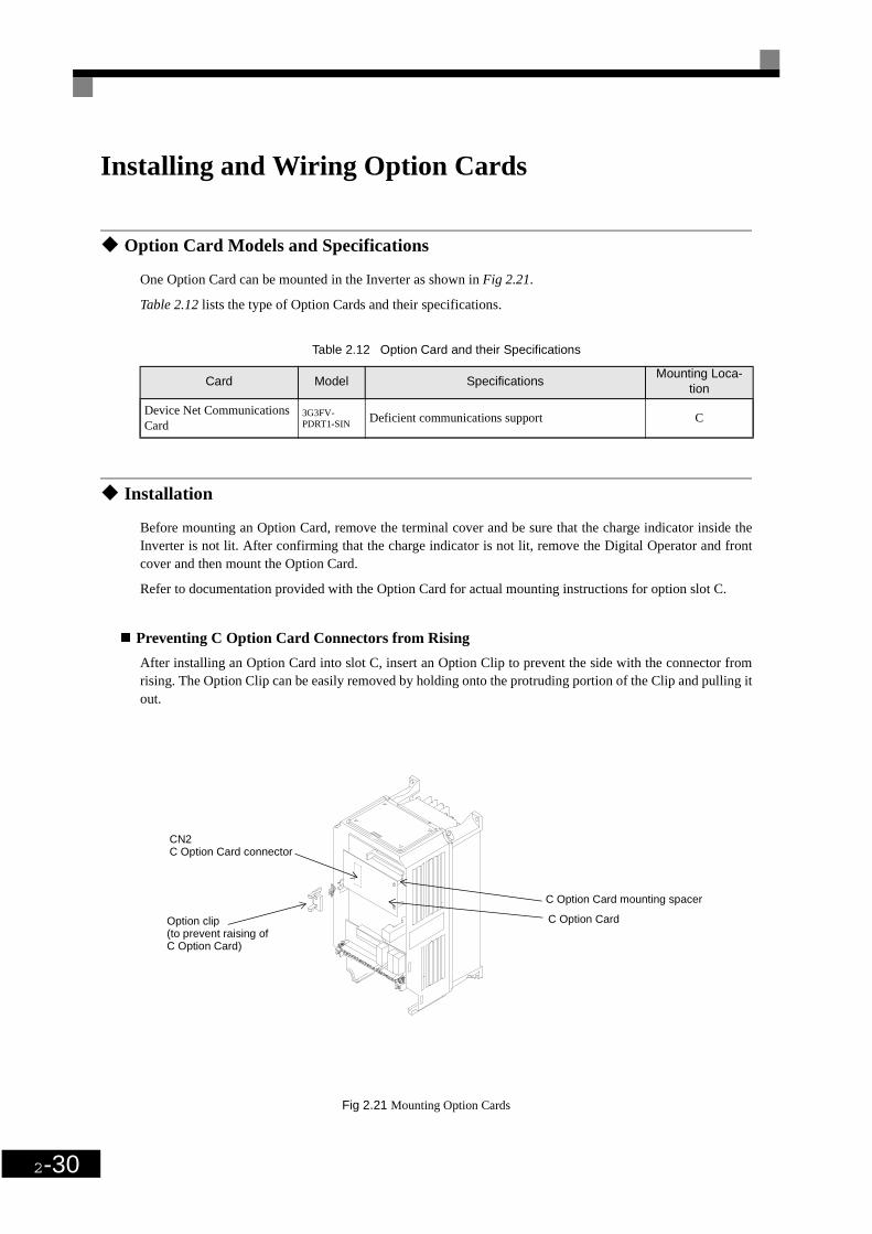
2-30
Installing and Wiring Option Cards
Option Card Models and Specifications
One Option Card can be mounted in the Inverter as shown in Fig 2.21.
Table 2.12 lists the type of Option Cards and their specifications.
Installation
Before mounting an Option Card, remove the terminal cover and be sure that the charge indicator inside theInverter is not lit. After confirming that the charge indicator is not lit, remove the Digital Operator and frontcover and then mount the Option Card.
Refer to documentation provided with the Option Card for actual mounting instructions for option slot C.
Preventing C Option Card Connectors from Rising
After installing an Option Card into slot C, insert an Option Clip to prevent the side with the connector fromrising. The Option Clip can be easily removed by holding onto the protruding portion of the Clip and pulling itout.
Fig 2.21 Mounting Option Cards
Table 2.12 Option Card and their Specifications
Card Model SpecificationsMounting Loca-
tion
Device Net Communications Card
3G3FV-PDRT1-SIN Deficient communications support C
CN2C Option Card connector
C Option Card
C Option Card mounting spacer
Option clip(to prevent raising of C Option Card)
3Chapter 3
Digital Operator andModes
This chapter describes Digital Operator displays and functions and provides an overview of
operating modes and switching between modes.
Digital Operator.....................................................................3-2
Modes ....................................................................................3-5

3-2
Digital OperatorThis section describes the displays and functions of the Digital Operator.The key names and functions ofthe Digital Operator are described below.
Fig 3.1 Digital Operator Component Names and Functions
FWD: Lit when there is a forward run commandinput.
REV: Lit when there is a reverse run commandinput.
SEQ: Lit when the run command from the controlcircuit terminal is enabled.
REF: Lit when the frequency reference from controlcircuit terminals A1 and A2 is enabled.
ALARM: Lit when an error or alarm has occurred.
Displays monitor data, parameter numbers andsettings.
DRIVE: Lit in Drive Mode.QUICK: Lit in Quick Programming Mode.ADV: Lit in Advanced Programming Mode.VERIFY: Lit in Verify Mode.AUTO : Lit in Autotuning Mode.TUNING
Keys
Execute operations such as setting user parame-ters, monitoring, jogging and autotuning.
Drive Mode Indicators
Data Display
Mode Display
Digital Operator with LED Display (3G3IV-PJVOP161)
Drive Mode Indicators
Data Display
FWD:Lit when there is a forward run command input.REV: Lit when there is a reverse run command input.SEQ:Lit when the run command from the control circuit terminal is enabled.REF:Lit when the frequency reference from control circuit terminals A1 and A2 is enabled.ALARM:Lit when an error or alarm has occurred.
Displays monitor data, parameter numbers and settings.
KeysExecute operations such as setting user parame-ters, monitoring, jogging and autotuning.
Digital Operator with LCD Display (3G3IV-PJVOP160)

Digital Operator
3-3
Digital Operator Keys
The names and functions of the Digital Operator Keys are described in Table 3.1.
Note Except in diagrams, Keys are referred to using the Key names listed in the above table.
Table 3.1 Key Functions
Key Name Function
LOCAL/REMOTE KeySwitches between operation via the Digital Operator (LOCAL) and control circuit terminal operation (REMOTE).This Key can be enabled or disabled by setting user parameter o2-01.
MENU Key Selects menu items (modes).
ESC Key Returns to the status before the DATA/ENTER Key was pressed.
JOG KeyEnables jog operation when the Inverter is being operated from the Digital Operator.
FWD/REV KeySelects the rotation direction of the motor when the Inverter is being operated from the Digital Operator.
Digit Selection/RESET KeySets the number of digits for user parameter settings.Also acts as the Reset key when a fault has occurred.
Increment KeySelects menu items, sets user parameter numbers and increments set values. Used to move to the next item or data.
Decrement KeySelects menu items, sets user parameter numbers and decrements set values. Used to move to the previous item or data.
ENTER KeyPressed to enter menu items, user parameters and set values.Also used to switch from one screen to another.
RUN KeyStarts the Inverter operation when the Inverter is being controlled by the Digital Operator.
STOP KeyStops Inverter operation.This Key can be enabled or disabled when operating from the control circuit terminal by setting user parameter o2-02.
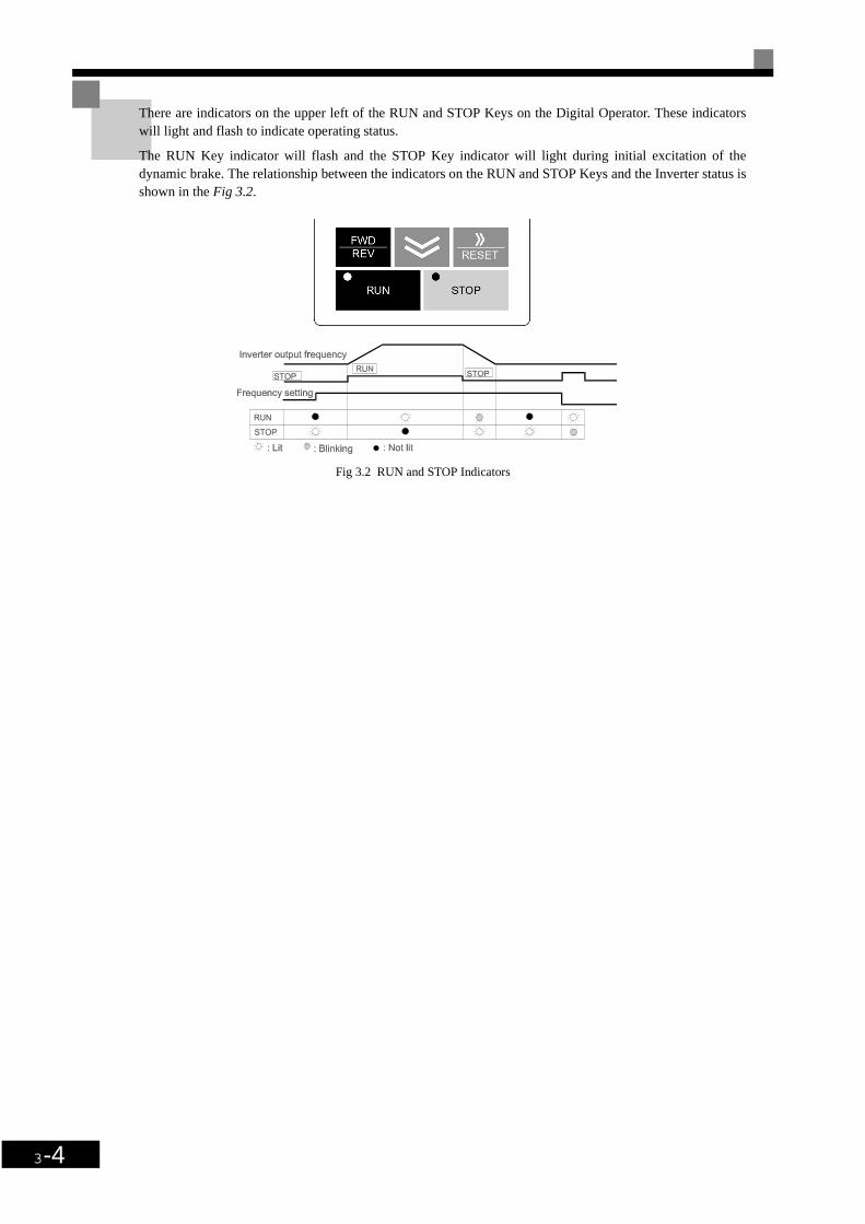
3-4
There are indicators on the upper left of the RUN and STOP Keys on the Digital Operator. These indicatorswill light and flash to indicate operating status.
The RUN Key indicator will flash and the STOP Key indicator will light during initial excitation of thedynamic brake. The relationship between the indicators on the RUN and STOP Keys and the Inverter status isshown in the Fig 3.2.
Fig 3.2 RUN and STOP Indicators

Modes
3-5
ModesThis section describes the Inverter's modes and switching between modes.
Inverter Modes
The Inverter's user parameters and monitoring functions are organized in groups called modes that make iteasier to read and set user parameters.The Inverter is equipped with 5 modes.
The 5 modes and their primary functions are shown in the Table 3.2.
*Always perform autotuning with the motor before operating using vector control. Autotuning Mode will not be displayed during operation or when an
error has occurred.
Table 3.2 Modes
Mode Primary function(s)
Drive modeThe Inverter can be run in this mode.Use this mode when monitoring values such as frequency references or output cur-rent, displaying fault information or displaying the fault history.
Quick programming modeUse this mode to reference and set the minimum user parameters to operate the Inverter (e.g., the operating environment of the Inverter and Digital Operator).
Advanced programming mode Use this mode to reference and set all user parameters.
Verify modeUse this mode to read/set user parameters that have been changed from their fac-tory-set values.
Autotuning mode*Use this mode when running a motor with unknown motor parameters in the vector control mode. The motor parameters are calculated and set automatically.This mode can also be used to measure only the motor line-to-line resistance.

3-6
Switching Modes
The mode selection display will appear when the MENU key is pressed from a monitor or setting display.Press the MENU key from the mode selection display to switch between the modes.
Press the ENTER key from the mode selection key to monitor data and from a monitor display to access thesetting display.
Fig 3.3 Mode Transitions
Power ON
Drive Mode
Q uickP rogram m ing M ode
A dvancedP rogram m ing M ode
Verify Mode
AutotuningMode
If a user constan t is changedthe num ber w ill be d isp layed.
(Operation possible)
When returning from a settingdisplay, the rightmost digitof the monitor display willflash.
Mode Selection Displays Monitor Displays Setting Displays
Lit Flashing Not lit

Modes
3-7
Drive Mode
Drive mode is the mode in which the Inverter can be operated. The following monitor displays are possible indrive mode: The frequency reference, output frequency, output current and output voltage, as well as faultinformation and the fault history.When b1-01 (Reference selection) is set to 0, the frequency can be changed from the frequency setting dis-play. Use the Increment, Decrement and Digit Selection/RESET keys to change the frequency. The userparameter will be written and the monitor display will be returned to when the ENTER key is pressed afterchanging the setting.
Example Operations
Key operations in drive mode are shown in the following figure.
Fig 3.4 Operations in Drive Mode
IMPORTANT
The display for the first monitor parameter (frequency reference) will be displayed when power is turnedON. The monitor item displayed at startup can be set in o1-02 (Monitor Selection after Power Up).
Operation cannot be started from the mode selection display.

3-8
Quick Programming Mode
In quick programming mode, the parameters required for Inverter trial operation can be monitored and set.
parameters can be changed from the setting displays. Use the Increment, Decrement and Digit Selection/RESET keys to change the frequency. The user parameter will be written and the monitor display will bereturned to when the ENTER key is pressed after changing the setting.
Refer to Chapter 5 Parameters for details on the parameters displayed in Quick Programming Mode.
Example Operations
Key operations in quick programming mode are shown in the following figure.
Fig 3.5 Operations in Quick Programming Mode
Reference selectionQuick Programming Mode
Operation Method selection
Stopping Method selection
Terminal FM Gain
Motor Protection selection
Terminal AM Gain
Decelaration stall selection
Mode Selection Display Monitor display Setting Display

Modes
3-9
Advanced Programming Mode
In advanced programming mode, all Inverter parameters can be monitored and set.
parameters can be changed from the setting displays. Use the Increment, Decrement and Digit Selection/RESET keys to change the frequency. The user parameter will be written and the display will return to moni-tor display when the ENTER key is pressed after changing the setting.
Refer to Chapter 5 Parameters for details on the parameters.
Example Operations
Key operations in advanced programming mode are shown in the following figure.
Fig 3.6 Operations in Advanced Programming Mode
Setup settingsAdvanced Programming Mode Language
Mode Selection display Function Selection Display Monitor Display Setting Display
Access level
Initialize
PI controlbox: b5-xx PI Control mode selection
Proportional Gain
PI feedback command loss detection time
Copy functions: o3-xx Copy function selection
Read permitted selection

3-10
Setting Parameters
Here, the procedure is shown to change C1-01 (Acceleration Time 1) from 10 s to 20 s.
Table 3.3 Setting User parameters in Advanced Programming Mode
Step No.
Digital Operator Display Description
1 Power supply turned ON.
2 MENU Key pressed to enter drive mode.
3MENU Key pressed to enter quick program-ming mode.
4MENU Key pressed to enter advanced pro-gramming mode.
5 ENTER pressed to access monitor display.
6Increment or Decrement Key pressed to dis-play C1-01 (Acceleration Time 1).
7ENTER Key pressed to access setting display. The setting of C1-01 (10.00) is displayed.
8Digit Selection/RESET Key pressed to move the flashing digit to the right.
9Increment Key pressed to change set value to 20.00 s.
10ENTER Key pressed to enter the set data. “END” is displayed for 10 s and then the entered value is displayed for 0.5 s.
11 The monitor display for C1-01 returns.

Modes
3-11
Verify Mode
Verify mode is used to display any parameters that have been changed from their default settings in a pro-gramming mode or by autotuning. “None” will be displayed if no settings have been changed.
Even in verify mode, the same procedures can be used to change settings as they are used in the programmingmodes. Use the Increment, Decrement and Digit Selection/RESET keys to change the frequency. The userparameter will be written and the monitor display will be returned to when the ENTER key is pressed afterchanging the setting.
Example Operations
An example of key operations is given below for when the following settings have been changed from theirdefault settings: b1-01 (Reference Selection), C1-01 (Acceleration Time 1), E1-01 (Input Voltage Setting) andE2-01 (Motor Rated Current).
Fig 3.7 Operations in Verify Mode
Mode Selection Display Monitor Display Setting Display
Verify ModeFrequency referenceselection
Acceleration time 1
Input voltage setting
Motor rated current
Frequency referenceselection
Acceleration time 1
Input voltage setting
Motor rated current

3-12
Autotuning Mode
Autotuning automatically tunes and sets the required motorparameters when operating in the open-loop orflux vector control modes. Always perform autotuning before starting operation.
When the motor can not be disconnected from the load, perform stationary autotuning. Contact your dealer toset motorparameters by calculation.
The Inverter’s autotuning function automatically determines the motor parameters, while a servo system’sautotuning function determines the size of a load, so these autotunig functions are fundamentally different.
Example of Operation
Set the motor output power (in kW) and rated current specified on the nameplate on the motor and then pressthe RUN key. The motor is automatically run and the motor line-to-line resistance measured based on thesesettings will be set.
Always set the above items. Autotuning cannot be started otherwise.
Parameters can be changed from the setting displays. Use the Increment, Decrement and Digit Selection/RESET keys to change the frequency. The parameter will be written and the display will be returned to moni-tor display when the ENTER key is pressed after changing the setting.
Fig 3.8 Operation in Autotuning Mode
IMPORTANT
If a fault occurs during autotuning, refer to Chapter 7 .
Autotuning Monitor Display Setting Display
Autotuning Motor output power
Motor rated current
Autotuning start*
Motor output power
Autotuning Stop command input
Autotuning completed
Motor rated current

4Chapter 4
Trial OperationThis chapter describes the procedures for trial operation of the Inverter and provides an example
of trial operation.
Trial Operation Flowchart .....................................................4-3
Trial Operation Procedures....................................................4-4
Adjustment Suggestions ......................................................4-13

4-2
Cautions and warnings
WARNINGTurn ON the input power supply only after mounting the front cover, terminal covers, bottom cover, Operator and optional items. Not doing so may result in electrical shock.
WARNINGDo not remove the front cover, terminal covers, bottom cover, Operator or optional items while the power is being supplied. Doing so may result in elec-trical shock or damage to the product
WARNING Do not operate the Operator or switches with wet hands. Doing so may result in electrical shock.
WARNING Do not touch the Inverter terminals while the power is being supplied. Doing so may result in electrical shock.
WARNINGDo not come close to the machine when using the error retry function because the machine may abruptly start when stopped by an alarm. Doing so may result in injury.
WARNING
Do not come close to the machine immediately after resetting momentary power interruption to avoid an unexpected restart (if operation is set to be con-tinued in the processing selection function after momentary power is reset). Doing so may result in injury.
WARNINGProvide a separate emergency stop switch because the STOP Key on the Oper-ator is valid only when function settings are performed. Not doing so may result in injury.
WARNINGBe sure to confirm that the RUN signal is turned OFF before tuning ON the power supply, resetting the alarm or switching the LOCAL/REMOTE selector. Doing so while the RUN signal is turned ON my result in injury.
CautionBe sure to confirm permissible ranges of motors and machines before opera-tion because the Inverter speed can be easily changed from low to high. Not doing so may result in damage to the product.
Caution Provide a separate holding brake when neccessary. Not doing so may result in injury.
Caution Do not perform a signal check during operation. Doing so may result in injury or damage to the product.
Caution Do not carelessly change settings. Doing so may result in injury or damage to the product.

Trial Operation Flowchart
4-3
Trial Operation FlowchartPerform trial operation according to the following flowchart. When setting the basic parameters, alwaysset C6-01 (Heavy/Normal Duty Selection) according to the application.
Fig 4.1 Trial Operation Flowchart
S TART
Insta lla tion
W iring
Set power supply voltage.*1
Turn ON power
Confirm status
Basic settings(Quick programming mode)
Select operatingmethod.
Set E1-03. V/f default: 200V/50Hz (400V/50Hz)
YES
NOStationary autotuning forline-to-line resistance only
Application settings(Advanced programming mode)
No-load operation
Loaded opera tion
O p tim um ad jus tm ents andparameter settings
END
*1. Set for 400 V Class Inverter for 75 kW or more.
Motor cable over50 m or heavy load possibly
causing motor to stall oroverload?
Check/record parameters

4-4
Trial Operation ProceduresThe procedure for the trial operation is described in order in this section.
Application Confirmation
First, confirm the application before using the Inverter. The unit is designed for using with:
• Fan, blower, pump applications
Setting the Power Supply Voltage Jumper (400 V Class Inverters of 75 kW or Higher)
Set the power supply voltage jumper after setting E1-01 (Input Voltage Setting) for 400 V Class Inverters
of 75 kW or higher. Insert the jumper into the voltage connector nearest to the actual power supply
voltage.
The jumper is factory-set to 440 V when shipped. If the power supply voltage is not 440 V, use the
following procedure to change the setting.
1. Turn OFF the power supply and wait for at least 5 minutes.
2. Confirm that the CHARGE indicator has gone out.
3. Remove the terminal cover.
4. Insert the jumper at the position for the voltage supplied to the Inverter (see Fig 4.2).
5. Return the terminal cover to its original position.
Fig 4.2 Large-capacity Inverter Connections
Power ON
Confirm all of the following items and then turn ON the power supply.
• Check that the power supply is of the correct voltage.200 V class: 3-phase 200 to 240 VDC, 50/60 Hz400 V class: 3-phase 380 to 480 VDC, 50/60 Hz
• Make sure that the motor output terminals (U, V, W) and the motor are connected correctly.
• Make sure that the Inverter control circuit terminal and the control device are wired correctly.
• Set all Inverter control circuit terminals to OFF.
• Make sure that the motor is not connected to the mechanical system (no-load status).
Power tab
Jumper (factory-set position)
CHARGE indicator
200 V class power supply
400V class power supply
Power supply input terminals

Trial Operation Procedures
4-5
Checking the Display Status
If the Digital Operator's display at the time the power is connected is normal, it will read as follows:
When an fault has occurred, the details of the fault will be displayed instead of the above display. In that case,refer to Chapter 7. The following display is an example of a display for faulty operation.
Display for normal operation The frequency reference monitor is dis-played in the data display section.
Display for fault operationThe display will differ depending on the type of fault.A low voltage alarm is shown at left.

4-6
Basic Settings
Switch to the quick programming mode (the QUICK indicator on the Digital Operation should be lit) and thenset the following parameters.
Refer to Chapter 3 Digital Operator and Modes for Digital Operator operating procedures and to Chapter 5
Parameters and Chapter 6 Parameter Settings by Function for details on the parameters.
Table 4.1 Parameters that must be set
Class l : Must be set. O : Set as required.
ClassParame-ter Num-
berName Description
Setting Range
Factory Setting
Page
l b1-01Reference selec-tion
Set the frequency reference input method.0: Digital Operator1: Control circuit terminal (analog
input)2: RS-422A/485 communications3: Option Card
0 to 3 1
5-86-4
6-466-54
l b1-02Operation method selection
Set the run command input method.0: Digital Operator1: Control circuit terminal (sequence
input)2: RS-422A/485 communications3: Option Card
0 to 3 1
5-86-8
6-466-54
O b1-03Stopping method selection
Select stopping method when stop com-mand is sent.0: Deceleration to stop1: Coast to stop2: DC braking stop 3: Coast to stop with timer
0 to 3 05-8
6-10
l C1-01Acceleration time 1
Set the acceleration time in seconds for the output frequency to climb from 0% to 100%.
0.0 to 6000.0 10.0 s5-136-17
l C1-02Deceleration time 1
Set the deceleration time in seconds for the output frequency to fall from 100% to 0%.
0.0 to 6000.0 10.0 s5-136-17
O C6-02Carrier fre-quency selection
The carrier frequency is set low if the motor cable is 50 m or longer or to reduce radio noise or leakage current.
0 to D, F F 5-15
Od1-01 to
d1-04 and d1-17
Frequency refer-ences 1 to 4 and jog frequency ref-erence
Set the required speed references for multi-step speed operation or jogging.
0 to 120.00 Hz
d1-01 to d1-04:
0.00 Hzd1-17:
6.00 Hz
5-166-6
l E1-01Input voltage set-ting
Set the Inverter's nominal input voltage in volts.
155 to 255 V (200 V class)310 to 510 V (400 V class)
200 V(200 V class)400 V(400 V class)
5-186-74

Trial Operation Procedures
4-7
Selecting the V/f pattern
• Set either one of the fixed patterns (0 to D) in E1-03 (V/f Pattern Selection) or set F in E1-03 to specify auser-set pattern as required for the motor and load characteristics in E1-04 to E1-13 in advanced program-ming mode.
• Perform autotuning for the line-to-line resistance only if the motor cable is 50 m or longer for the actualinstallation or when the load causes stalling.
l E2-01Motor rated cur-rent
Set the motor rated current. 10% to 200% of Inverter's rated current
Setting for general-purpose motor of
same capacity
as Inverter
5-196-336-73
OH4-02
and H4-05
FM and AM ter-minal output gain
Adjust when an instrument is connected to the FM or AM terminal.
0.00 to 2.50
H4-02: 1.00
H4-05: 0.50
5-24
l L1-01Motor protection selection
Set to enable or disable the motor over-load protection function using the elec-tronic thermal relay.0: Disabled1: General motor protection
0 or 1 15-266-33
O L3-04Stall prevention selection during deceleration
If using the dynamic brake option (Brak-ing Resistor Units and Braking Units), be sure to set parameter L3-04 to 0 (dis-abled).
0 to 2 15-286-21
Simple operaton of a general-pupose motorat 50 Hz: E1-03 = F (default) or 0
If E1-03 = F, the default setting in the user setting fromE1-04 to E1-13 are for 50 Hz
Table 4.1 Parameters that must be set (Continued)
Class l : Must be set. O : Set as required.
ClassParame-ter Num-
berName Description
Setting Range
Factory Setting
Page

4-8
Autotuning for Line-to-Line Resistance
Autotuning can be used to prevent control errors when the motor cable is long or the cable length has changedor when the motor and Inverter have different capacities.
To perform autotuning set parameters T1-02 and T1-04 and then press the RUN Key on the Digital Operator.The Inverter will supply power to the motor for approximately 20 seconds and the Motor Line-to-Line Resis-tance (E2-05) and cable resistance will be automatically measured
Parameter Settings for Autotuning
The following parameters must be set before autotuning.
* 1. For a parameter-output motor, set the value at the base speed.
IMPORTANT
Power will be supplied to the motor when autotuning is performed even though the motor will not turn. Do
not touch the motor until autotuning has been completed.
Table 4.2 Parameter Settings before Autotuning
Param-eter
Num-ber
Name DisplaySetting Range
Factory Setting
T1-02Motor out-put power
Set the output power of the motor in
Kilowatts.*1
10% to 200% of Inverter
rated output
Same as Inverter
rated output
T1-04Motor rated current
Set the rated current of the motor in
Amps.*1
10% to 200% of Inverter
rated current
Same as general-purpose
motor with same
capacity as Inverter

Trial Operation Procedures
4-9
Digital Operator Displays during Autotuning
The following displays will appear on the Digital Operator during autotuning.
Table 4.3 Digital Operator Displays during Autotuning
Digital Operator Display Description
Motor rated : T1-02
The autotuning start display will appear when all set-tings through T1-04 have been completed. The A.TUNE and DRIVE indicators will be lit.
Autotuning started: TUn10
Autotuning will start when the RUN Key is pressed from the autotuning start display.
Autotuning Stop command input
If the STOP Key is pressed or a measurement error occurs during autotuning and error message will be display and autotuning will be stopped. Refer to Errors during Autotuning on page 7-10.
Autotuning completed
END will be displayed after approximately 1 to 2 min-utes, indicating that autotuning has been completed.

4-10
Application Settings
Parameters are set as required in advanced programming mode (i.e., with the ADV indicator lit on the DigitalOperator). All the parameters that can be set in quick programming mode can also be displayed and set inadvanced programming mode.
Setting Examples
The following are examples of settings for applications.
• To increase the speed of a 50 Hz motor by 10%, set E1-04 to 55.0 Hz.
• To use a 0 to 10-V analog signal for a 50 Hz motor for variable-speed operation between 0 and 45 Hz (0%to 90% speed deduction), set H3-02 to 90.0%.
• To control speed between 20% and 80% to ensure smooth gear operation and limit the maximum speed ofthe machine, set d2-01 to 80.0% and set d2-02 to 20.0%.
No-load Operation
This section describes trial operation in which the motor is in no-load state, that means the machine is not con-nected to the motor. To avoid failures caused due to the wiring of the control circuit it’s recommended to usethe LOCAL mode. Press the LOCAL/REMOTE Key on the Digital Operator to change to LOCAL mode (theSEQ and REF indicators on the Digital Operator should be OFF).
Always confirm safety around the motor and machine before starting Inverter operation from the DigitalOperator. Confirm that the motor works normally and that no errors are displayed at the Inverter. For applica-tions, at which the machine only can be driven in one direction, check the motor rotation direction.
Jog Frequency Reference (d1-17, default: 6.00 Hz) can be started and stopped by pressing and releasing theJOG Key on the Digital Operator. If the external sequence prevent operation from the Digital Operator, con-firm that emergency stop circuits and machine safety mechanisms are functioning and then start operation inREMOTE mode (i.e., with a signal from the control signal terminals). The safety precautions must always betaken before starting the Inverter with the motor connected to the machine.
Both a RUN command (forward or reverse) and a frequency reference (or multi-step speed command) must
be provided to start Inverter operation.
Input these commands and reference regardless of the operation method (i.e., LOCAL of REMOTE).

Trial Operation Procedures
4-11
Loaded Operation
Connecting the Load
• After confirming that the motor has stopped completely, connect the mechanical system.
• Be sure to tighten all the screws when securing the motor shaft to the mechanical system.
Operation using the Digital Operator
• Use the Digital Operator to start operation in LOCAL mode in the same way as in no-load operation.
• If fault occurs during operation, make sure the STOP Key on the Digital Operator is easily accessible.
• At first, set the frequency reference to a low speed of one tenth the normal operating speed.
Checking Operating Status
• Having checked that the operating direction is correct and that the machine is operating smoothly at slowspeed, increase the frequency reference.
• After changing the frequency reference or the rotation direction, check that there is no oscillation or abnor-mal sound from the motor. Check the monitor display to ensure that U1-03 (Output Current) is not to high.
• Refer to Adjustment Suggestions on page 4-13 if hunting, vibration or other problems originating in thecontrol system occur.
Check and Recording Parameters
Use verify mode (i.e., when the VERIFY indicator on the Digital Operator is lit) to check parameters that havebeen changed for trial operation and record them in a parameter table.
Any parameters that have been changed by autotuning will also be displayed in verify mode.
If required, the copy function in parameters o3-01 and o3-02 displayed in advanced programming mode canbe used to copy the changed settings from the Inverter to a recording area in the Digital Operator. If changedsettings are saved in the Digital Operator, they can be easily copied back to the Inverter to speed up systemrecovery if for any reason the Inverter has to be replaced.
The following functions can also be used to manage parameters.
• Recording parameters
• Setting access levels for parameters
• Setting a password
Recording parameters (o2-03)
If o2-03 is set to 1 after completing trial operation, the settings of parameters will be saved in a separate mem-ory area in the Inverter. When the Inverter settings have been changed for any reason, the parameters can beinitialized to the settings saved in the separate memory area by setting A1-03 (Initialize) to 1110.
Parameter Access Levels (A1-01)
A1-01 can be set to 0 (monitoring-only) to prevent parameters from being changed. If A1-01 is set to 2(advanced programming) all parameters can be read or written.

4-12
Password (A1-04 and A1-05)
When the access level is set to monitoring-only (A1-01 = 0), a password can be set so that parameters will bedisplayed only when the correct password is input.
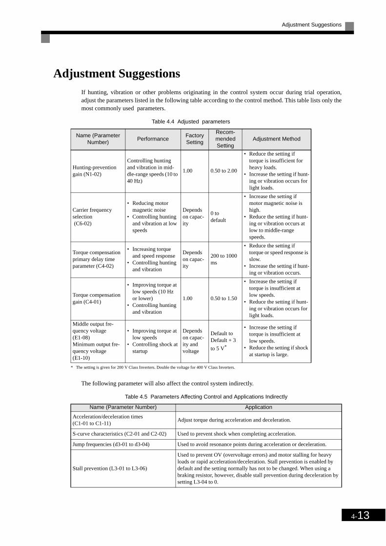
Adjustment Suggestions
4-13
Adjustment SuggestionsIf hunting, vibration or other problems originating in the control system occur during trial operation,adjust the parameters listed in the following table according to the control method. This table lists only themost commonly used parameters.
* The setting is given for 200 V Class Inverters. Double the voltage for 400 V Class Inverters.
The following parameter will also affect the control system indirectly.
Table 4.4 Adjusted parameters
Name (Parameter Number)
PerformanceFactory Setting
Recom-mended Setting
Adjustment Method
Hunting-prevention gain (N1-02)
Controlling hunting and vibration in mid-dle-range speeds (10 to 40 Hz)
1.00 0.50 to 2.00
• Reduce the setting if torque is insufficient for heavy loads.
• Increase the setting if hunt-ing or vibration occurs for light loads.
Carrier frequency selection (C6-02)
• Reducing motor magnetic noise
• Controlling hunting and vibration at low speeds
Depends on capac-ity
0 to default
• Increase the setting if motor magnetic noise is high.
• Reduce the setting if hunt-ing or vibration occurs at low to middle-range speeds.
Torque compensation primary delay time parameter (C4-02)
• Increasing torque and speed response
• Controlling hunting and vibration
Depends on capac-ity
200 to 1000 ms
• Reduce the setting if torque or speed response is slow.
• Increase the setting if hunt-ing or vibration occurs.
Torque compensation gain (C4-01)
• Improving torque at low speeds (10 Hz or lower)
• Controlling hunting and vibration
1.00 0.50 to 1.50
• Increase the setting if torque is insufficient at low speeds.
• Reduce the setting if hunt-ing or vibration occurs for light loads.
Middle output fre-quency voltage (E1-08)Minimum output fre-quency voltage (E1-10)
• Improving torque at low speeds
• Controlling shock at startup
Depends on capac-ity and voltage
Default to Default + 3
to 5 V*
• Increase the setting if torque is insufficient at low speeds.
• Reduce the setting if shock at startup is large.
Table 4.5 Parameters Affecting Control and Applications Indirectly
Name (Parameter Number) Application
Acceleration/deceleration times (C1-01 to C1-11)
Adjust torque during acceleration and deceleration.
S-curve characteristics (C2-01 and C2-02) Used to prevent shock when completing acceleration.
Jump frequencies (d3-01 to d3-04) Used to avoid resonance points during acceleration or deceleration.
Stall prevention (L3-01 to L3-06)
Used to prevent OV (overvoltage errors) and motor stalling for heavy loads or rapid acceleration/deceleration. Stall prevention is enabled by default and the setting normally has not to be changed. When using a braking resistor, however, disable stall prevention during deceleration by setting L3-04 to 0.

5Chapter 5Parameters
This chapter describes all parameters that can be set in the Inverter.
Parameter Descriptions..........................................................5-2
Digital Operation Display Functions and Levels ..................5-3
Parameter Tables ...................................................................5-7

5-2
Parameter DescriptionsThis section describes the contents of the parameters tables.
Description of Parameter Tables
Parameters tables are structured as shown below. Here, b1-01 (Frequency Reference Selection) is used as anexample.
Param-eter
Number
Name
Description Setting Range
Factory Setting
Change during Opera-
tion
Access Level
RS-422A-485 Regis-
terPage
LCD Display
b1-01
Reference selection
Set the frequency reference input method.0: Digital Operator1: Control circuit terminal
(analog input)2: RS-422A/485 communi-
cations3: Option Card
0 to 3 1 No Q 180H -
Reference Source
• Parameter Number: The number of the parameter.
• Name: The name of the parameter.
• Description: Details on the function or settings of the parameter.
• Setting Range: The setting range for the parameter.
• Factory Setting: The factory setting.
• Change during Operation: Indicates whether or not the parameter can be changed while theInverter is in operation.
Yes: Changes possible during operation.
No: Changes not possible during operation.
• Access Level: Indicates the access level in which the user parameter can be moni-tored or set.
Q: Items which can be monitored and set in either quick program-ming mode or advanced programming mode.
A: Items which can be monitored and set only in advanced pro-gramming mode.
• RS-422A/485 Register: The register number used for R-S422A/485 communications.
• Page: Reference page for more detailed information about the parameter.

Digital Operation Display Functions and Levels
5-3
Digital Operation Display Functions and LevelsThe following figure shows the Digital Operator display hierarchy for the Inverter.
MENU Drive Mode
Inverter can be operated and
its status can be displayed.
Quick Programming Mode
Minimum parameters required
for operation can be monitored
or set.
Advanced Programming Mode
All parameters can be moni-
tored or set.
Verify Mode
Parameters changed from the
default settings can be moni-
tored or set.
Autotuning Mode
Automatically sets motor parameters if autotuning data (from motor nameplate) is input for measure the line-to-line resistance.
No. Function Display Page
U1 Status Monitor Parameters Monitor 5-37
U2 Fault Trace Fault Trace 5-40
U3 Fault History Fault History 5-42
A1 Initialize Mode Initialization 5-7
A2 User set parameters NOT USED -
b1 Operation Mode Selections Sequence 5-8
b2 DC Injection Braking DC Braking 5-9
b3 Speed Search Speed Search 5-10
b5 PI Control PI Control 5-11
b8 Energy Saving Energy Saving 5-12
C1 Acceleration/Deceleration Accel/Decel 5-13
C2 S-curve Acceleration/Deceleration S-curve Accel/Decel 5-14
C4 Torque Compensation Torque Comp 5-14
C6 Carrier Frequency Carrier Freq 5-15
d1 Preset Reference Preset Reference 5-16
d2 Reference Limits Reference Limits 5-16
d3 Jump Frequencies Jump Frequencies 5-17
d6 Field Weakening Field Weakening 5-17
E1 V/f Pattern V/f Pattern 5-18
E2 Motor Setup Motor Setup 5-19
F6 Communications Option Card CP-916 Setup 5-19
H1 Multi-function Contact Inputs Digital Inputs 5-20
H2 Multi-function Contact Outputs Digital Outputs 5-21
H3 Analog Inputs Analog Inputs 5-22
H4 Multi-function Analog Outputs Analog Outputs 5-24
H5 RS-422A/485 Communications Serial Com Setup 5-25
L1 Motor Overload Motor Overload 5-26
L2 Power Loss Ridethrough PwrLoss Ridethru 5-27
L3 Stall Prevention Stall Prevention 5-28
L4 Reference Detection Ref Detection 5-29
L5 Fault Restart Fault Restart 5-29
L6 Torque Detection Torque Detection 5-30
L8 Hardware Protection Hdwe Protection 5-30
n1 Hunting Prevention Function Hunting Prev 5-32
n3 High-slip Braking High Slip 5-32
o1 Monitor Select Monitor Select 5-33
o2 Multi-function Selections Key Selections 5-35
o3 Copy Function COPY Function 5-36
T Motor Autotuning Auto-Tuning 5-36

5-4
Parameters Setable in Quick Programming Mode
The minimum parameters required for Inverter operation can be monitored and set in quick programmingmode. The parameters displayed in quick programming mode are listed in the following table. These and allother parameters, are also displayed in advanced programming mode.
Refer to the overview of modes on page 3-5 for an overview of quick programming mode.
Param-eter
Number
Name
Description Setting Range
Factory Setting
Change during Opera-
tion
Access Level
RS-422A/485 Reg-
isterLCD Display
b1-01
Reference selection Set the frequency reference input
method.0: Digital Operator1: Control circuit terminal (analog
input)2: RS-422A/485 communications3: Option Card
0 to 3 1 No Q 180H
Reference Source
b1-02
Operation method selec-
tion Set the run command input method0: Digital Operator1: Control circuit terminal (sequence
input)2: RS-422A/485 communications3: Option Card
0 to 3 1 No Q 181H
Run Source
b1-03
Stopping method selec-
tion
Select stopping method when stop command is input.0: Ramp to stop1: Coast to stop2: DC braking stop (Stops faster than
coast to stop, without regenerative operation.)
3: Coast to stop with timer (Run com-mands are disregarded during deceleration time.)
0 to 3 0 No Q 182H
Stopping Method
C1-01
Acceleration time 1 Set the acceleration time in seconds
for the output frequency to climb from 0% to 100%. 0.0 to 6000.0
10.0 s
Yes Q 200HAccel Time 1
C1-02
Deceleration time 1
Set the deceleration time in seconds for the output frequency to fall from 100% to 0%.
Yes Q 201HDecel Time 1
C6-02
Carrier fre-quency selec-
tion Select carrier wave fixed pattern.Select F to enable detailed settings using parameters C6-03 to C6-07.
1 to F 6 No Q 224H
Carrier-FreqSel

Digital Operation Display Functions and Levels
5-5
d1-01
Frequency reference 1
Set the frequency reference in the unit specified in o1-03 (frequency units for reference setting and monitor, default: Hz)
0 to 50.00
0.00 Hz
Yes Q 280H
Reference 1
d1-02
Frequency reference 2 Frequency reference when multi-step
speed command 1 is ON for a multi-function input (unit: Set in o1-03).
0.00 Hz
Yes Q 281H
Reference 2
d1-03
Frequency reference 3 Frequency reference when multi-step
speed command 2 is ON for a multi-function input (unit: Set in o1-03).
0.00 Hz
Yes Q 282H
Reference 3
d1-04
Frequency reference 4
Frequency reference when multi-step speed command 1 and 2 are ON for a multi-function input (unit: Set in o1-03).
0.00 Hz
Yes Q 283H
Reference 4
d1-17
Jog fre-quency refer-
enceFrequency reference when multi-func-tion inputs „Jog Frequency Com-mand“, „FJOG command“ or „RJOG command“ is ON (unit: Set in o1-03).
6.00 Hz
Yes Q 292HJog
Reference
E1-01
Input voltage setting
Set the Inverter input voltage in units of 1 volt. This set value will be the basis for the protection functions.
155 to 255*2
200 V*2
No Q 300H
Input Voltage
E1-03
V/F pattern selection
0 to D: Select from 14 preset patterns.F: Custom user-set patterns
(Applicable for setting E1-04 to E1-10).
0 to D, F
F No Q 302H
V/F Selection
E1-04
Max. output frequency (FMAX) 0.0 to
120.050.0 Hz
No Q 303HMax
Frequency
E1-05
Max.voltage (VMAX) 0.0 to
255.0*2
200.0 V*2
No Q 304HMax
Voltage
E1-06
Base frequency
(FA) 0.0 to 120.0
50.0 Hz
No Q 305HBase
Frequency
E1-09
Min. output frequency
(FMIN) 0.0 to 120.0
1.5 Hz No Q 308HMin.
Frequency
Param-eter
Number
Name
Description Setting Range
Factory Setting
Change during Opera-
tion
Access Level
RS-422A/485 Reg-
isterLCD Display
Frequency(Hz)
FMAX(E1-04)
FA(E1-06)(E 1-09)
FMIN(E1-10)VMIN
(E1-13)VBASE(E1-05)VMAX
Output voltage (V)

5-6
* 1. The factory setting depends on the Inverter capacity.* 2. These are values for a 200 V class Inverter. Values for a 400 V class Inverter are double.* 3. After autotuning, E1-13 will contain the same value as E1-05.* 4. The factory setting depends on the Inverter capacity. (The value for a 200 V Class Inverter for 0.4 kW is given.)* 5. The setting range is from 10% to 200% of the Inverter rated output current. (The value for a 200 V Class Inverter for 0.4 kW is given.)
E2-01
Motor rated current
Set the motor rated current in Amps.This set value becomes the base value for motor protection, torque limit and torque control. It is an input data for autotuning.
0.32 to 6.40
*5
1.90 A*4
No Q 30EHMotor Rated
FLA
H4-02
Gain (termi-nal FM)
Set the voltage level gain for multi-function analog output 1.Set the number of multiples of 10 V to be output as the 100% output for the monitor items. Voltage output from the terminals, however, have a 10 V max. meter calibration function.
0.0 to 1000.0
100% Yes Q 41EHTerminal FM
Gain
H4-05
Gain (termi-nal AM)
Set the voltage level gain for multi-function analog output 2.
0.0 to 1000.0
50% Yes Q 421HTerminal AM
Gain
L1-01
Motor protec-tion selection
Set to enable or disable the motor overload protection function using the electronic thermal relay.0: Disabled1: General-purpose motor protectionIn some applications when the Inver-ter power supply is turned off, the thermal value is reset, so even if this parameter is set to 1, protection may not be effective.
When several motors are connected to one Inverter, set to 0 and ensure that each motor is equipped with a protec-tion device.
0 or 1 1 No Q 480H
MOL Fault Select
L3-04
Stall preven-tion selection during decel-
eration
0: Disabled (Deceleration as set. If deceleration time is too short, a main circuit overvoltage may result.)
1: Enabled (Deceleration is stopped when the main circuit voltage exceeds the overvoltage level. Deceleration restarts when voltage is returned.)
2: Intelligent deceleration mode (Deceleration rate is automatically adjusted so that in Inverter can decelerate in the shortest possible time. Set deceleration time is disre-garded.)
When a braking option (Braking Resistor, Braking Resistor Unit, Brak-ing Unit) is used, always set to 0 to 2.
0 to 2 1 No Q 492H
StallP Decel Sel
Param-eter
Number
Name
Description Setting Range
Factory Setting
Change during Opera-
tion
Access Level
RS-422A/485 Reg-
isterLCD Display

Parameter Tables
5-7
Parameter Tables
A: Setup Settings
Initialize Mode: A1
Param-eter
Number
Name
Description Setting Range
Factory Setting
Change during Opera-
tion
Access Level
RS-422A/485
RegisterPage
LCD Display
A1-00
Language selection for
Digital Opera-tor display
Used to select the language displayed on the Digital Operator Display.0: English1: Japanese2: German3: French4: Italian5: Spanish6: Portugese
This parameter is not initial-ized by the initialize opera-tion.
0 to 6 0 Yes A 100H –Select Lan-
guage
A1-01
Parameter access level
Used to set the parameter access level (set/read.)0: Monitoring only (Moni-
toring drive mode and setting A1-01 and A1-04.)
2: Advanced(Parameters can be read and set in both, quick programming mode (Q) and advanced pro-gramming (A) mode.)
0 or 2 2 Yes A 101H6-6
6-31
Acces Level
A1-03
InitializeUsed to initialize the param-eters using the specified method.0: No initializing1110: Initializes using the
Parameters2220: Initializes using a
two-wire sequence. (Initializes to the factory setting.)
3330: Initializes using a three-wire sequence.
0 to 3330
0 No A 103H –Init
Parameters
A1-04
PasswordPassword input when a pass-word has been set in A1-05. This function write-protects some parameters of the ini-tialize mode.If the password is changed, A1-01 to A1-03 parameters can no longer be changed. (Programming mode param-eters can be changed.)
0 to 9999
0 No A 104H 6-86
Enter Pass-word

5-8
Application Parameters: b
The following settings are made with the application parameters (B parameters): Operation Method Selection,DC injection braking, speed searching, timer functions, dwell functions and energy saving functions.
Operation Mode Selections: b1
Param-eter
Number
Name
Description Setting Range
Factory Setting
Change during Opera-
tion
Access Level
RS-422A/485
RegisterPageLCD
Display
b1-01
Reference selection
Set the frequency reference input method.0: Digital Operator1: Control circuit terminal
(analog input)2: RS-422A/485 communi-
cations3: Option Card
0 to 3 1 No Q 180H
4-66-4
6-466-54
Reference-Source
b1-02
Operation method selec-
tion
Set the run command input method.0: Digital Operator1: Control circuit terminal
(sequence input)2:RS-422A/485 communi-
cations3: Option Card
0 to 3 1 No Q 181H
4-66-8
6-466-54Run Source
b1-03
Stopping method selec-
tion
Used to set the stopping method used when a stop command is input.0: Ramp to stop1: Coast to stop2: DC injection braking stop
(Stops faster than coast to stop, no regenerative ope-ration.)
3: Coast to stop with timer (Run commands are dis-regarded during decelera-tion.)
0 to 3 0 No Q 182H4-6
6-10
Stopping Method
b1-07
Operation selection after switching to
remote mode
Used to set the operation mode by switching to the Remote mode using the Local/Remote Key.0: Run signals that are input
during mode switching are disregarded. (Input Run signals after swit-ching the mode.)
1: Run signals become effective immediately after switching to the Remote mode.
0 or 1 0 No A 186H -
LOC/REM RUN Sel
b1-08
Run com-mand selec-
tion in programming
modes
Used to set an operation interlock in programming modes.0: Cannot operate.1: Can operate (Disabled
when Digital Operator is set to select run command (when b1-02 = 0)).
0 or 1 0 No A 187H -
RUN CMD at PRG

Parameter Tables
5-9
DC Injection Braking: b2
Param-eter
Number
Name
DescriptionSetting Range
Factory Setting
Change during Opera-
tion
Access Level
RS-422A/485Regist
erPageLCD
Display
b2-01
Zero speed level (DC
injection brak-ing starting frequency)
Used to set the frequency at which DC injection braking starts in units of Hz when deceleration to stop is selected.When b2-01 is less than E1-09, E1-09 becomes the DC injection braking starting frequency.
0.0 to 10.0
0.5 Hz No A 189H 6-10
DCInj Start Freq
b2-02
DC injection braking cur-
rentSets the DC injection brak-ing current as a percentage of the Inverter rated current.
0 to 100
50% No A 18AH6-106-13
DCInj Current
b2-03
DC injection braking time
at start
Used to set the time to per-form DC injection braking at start in units of 1 second.Used to stop coasting motor and restart it. When the set value is 0, DC injection braking at start is not per-formed.
0.00 to
10.000.00 s No A 18BH 6-13
DCInj Time@Start
b2-04
DC injection braking time
at stop
Used to set the time to per-form DC injection braking at stop in units of 1 second.Used to prevent coasting after the stop command is input. When the set value is 0.00, DC injection braking at stop is not performed.
0.00 to
10.000.50 s No A 18CH 6-10
DCInj Time@Stop

5-10
Speed Search: b3
Param-eter-
Number
Name
DescriptionSetting Range
Factory Setting
Change during Opera-
tion
Access level
RS-422A/
485 Reg-ister
PageLCD Display
b3-01
Speed search
selection (current
detection or speed calcu-
lation)
Enables/disables the speed search function for the RUN command and sets the speed search method.0:Disabled, speed calculation1: Enabled, speed calculation2: Disabled, current detection3: Enabled, current detection
Speed Calculation:When the search is started, the motor speed is calculated and acceleration/deceleration is per-formed from the calculated speed to the specified frequency (motor direction is also sear-ched).
Current Detection:The speed search is started from the frequency when power was momentarily lost and the maxi-mum frequency and the speed is detected at the search current level.
0 to 3 2 No A 191H 6-38
SPDSrch at Start
b3-02
Speed search oper-ating current
(current detection)
Sets the speed search operation current as a percentage, taking the Inverter rated current as 100%.Not usually necessary to set. When restarting is not possible with the factory settings, reduce the value.
0 to 200
120% No A 192H 6-38
SPDSrch Current
b3-03
Speed search
deceleration time (cur-rent detec-
tion)
Sets the output frequency decel-eration time during speed search in 1-second units.Set the time for deceleration from the maximum output frequency to the minimum output frequency.
0.1 to 10.0
2.0 s No A 193H 6-38
SPDScrh Dec Time
b3-05
Speed search wait time (cur-rent detec-
tion or speed calculation)
Sets the contactor operating delay time when there is a contactor on the output side of the Inverter. When a speed search is per-formed after recovering from a momentary power loss, the search operation is delayed by the time set here.
0.0 to 20.0
0.2 s No A 195H 6-38
Search Delay

Parameter Tables
5-11
PI Control: b5
Param-eter
Number
Name
DescriptionSetting Range
Factory Setting
Change during Opera-
tion
Access Level
RS-422A/485
RegisterPageLCD
Display
b5-01
PI control mode selec-
tion 0: Disabled1: Enabled
0 to 1 0 No A 1A5H 6-66
PI Mode
b5-02
Proportional gain (P) Sets P-control proportional gain
as a percentage.P-control is not performed when the setting is 0.00.
0.00 to
25.001.00 Yes A 1A6H 6-66
PI Gain
b5-03
Integral (I) time Sets I-control integral time in 1-
second units.I-control is not performed when the setting is 0.0.
0.0 to 360.0
1.0 s Yes A 1A7H 6-66PI I Time
b5-04
Integral (I) limit Sets the I-control limit as a per-
centage of the maximum output frequency.
0.0 to 100.0
100.0% Yes A 1A8H 6-66PI I Limit
b5-06
PI limit Sets the limit after PI-control as a percentage of the maximum out-put frequency.
0.0 to 100.0
100.0% Yes A 1AAH 6-66PI Limit
b5-07
PIPI offset adjustment Sets the offset after PI-control as
a percentage of the maximum output frequency.
-100.0 to
+100.00.0% Yes A 1ABH 6-66
PI Offset
b5-08
PI primary delay time parameter
Sets the time parameter for low pass filter for PI-control outputs in 1-second units.Usually not necessary to set.
0.00 to 10.00
0.00 s Yes A 1ACH 6-66PI Delay Time
b5-12
Selection of PI feedback
command loss detection
0: No detection of loss of PI feedback.
1: Detection of loss of PI feed-back.Operation continues during detection, with the mal-functioning contact not opera-ting.
2: Detection of loss of PI feed-back.Coasts to stop during detec-tion and fault contact operates.
0 to 2 0 No A 1B0H 6-66
Fb los Det Sel
b5-13
PI feedback command loss detection level
Sets the PI feedback loss detec-tion level as a percent units, with the maximum output frequency at 100%.
0 to 100
0% No A 1B1H 6-66Fb los Det Lvl
b5-14
PI feedback command loss detection time Sets the PI feedback loss detec-
tion level in s units.0.0 to 25.5
1.0 s No A 1B2H 6-66Fb los Det
Time
b5-15
PI sleep func-tion operation
levelSet the PI sleep function start level as a frequency.
0.0 to 120.0
0.0 Hz No A 1B3H 6-66PI Sleep Level
b5-16
PI sleep oper-ation delay
timeSet the delay time until the PI sleep function starts in seconds.
0.0 to 25.5
0.0 s No A 1B4H 6-66PI Sleep Time

5-12
Energy Saving: b8
* 1. The same capacity as the Inverter will be set by initializing the parameters.* 2. The factory settings depend on the Inverter capacity.
b5-17
Accel/decel time for PI ref-
erence Set the accel/decel time for PI reference in seconds.
0.0 to 25.5
0.0 s No A 1B5H 6-66PI Acc/Dec
Time
Param-eter
Number
Name
Description Setting Range
Factory Setting
Change during Opera-
tion
Access Level
RS-422A/485
RegisterPageLCD
Display
b8-01
Energy-sav-ing mode selection
Select whether to enable or dis-able energy-saving control.0: Disable1: Enable
0 or 1 0 No A 1CCH –Energy Save
Sel
b8-04
Energy-sav-ing coefficient
Set the motor rated capacity in E2-11 and adjust the value by 5% at a time until output power reaches a minimum value.
0.0 to 655.00
*1
*2 No A 1CFH –Energy Save
COEF
b8-05
Power detec-tion filter time
parameterSet the time parameter for output power detection.
0 to 2000
20 ms No A 1D0H –kW Filter Time
b8-06
Search opera-tion voltage
limiter
Set the limit value of the voltage control range during search oper-ation.Set to 0 to disable the search operation. 100% is the motor base voltage.
0 to 100
0% No A 1D1H –Search V
Limit
Param-eter
Number
Name
Description Setting Range
Factory Setting
Change during Opera-
tion
Access Level
RS-422A/485
RegisterPageLCD
Display

Parameter Tables
5-13
Autotuning Parameters: C
The following settings are made with the autotuning parameters (C parameters): Acceleration/decelerationtimes, S-curve characteristics, slip compensation, torque compensation, speed control and carrier frequencyfunctions
Acceleration/Deceleration: C1
Param-eter
Number
Name
DescriptionSetting Range
Factory Setting
Change during Opera-
tion
Access Level
RS-422A/485
RegisterPage
LCD Display
C1-01
Acceleration time 1 Sets the acceleration time to
accelerate from 0 to the maximum output frequency.
0.0 to 6000.0
10.0 s
Yes Q 200H4-6
6-17Accel Time 1
C1-02
Deceleration time 1 Sets the deceleration time to
decelerate from the maximum output frequency to 0.
Yes Q 201H4-6
6-17Decel Time 1
C1-03
Acceleration time 2 The acceleration time when the
multi-function input “accel/decel time 1” is set to ON.
Yes A 202H 6-17Accel Time 2
C1-04
Deceleration time 2 The deceleration time when the
multi-function input “accel/decel time 1” is set to ON.
Yes A 203H 6-17Decel Time 2
C1-09
Emergency stop time The deceleration time when the
multi-function input “Emergency (fast) stop” is set to ON.
No A 208H 6-16Fast Stop
Time
C1-11
Accel/decel time switch-
ing frequency
Sets the frequency for automatic acceleration/deceleration switch-ing.Below set frequency: Accel/decel time 2Above set frequency: Accel/decel time 1The multi-function input “accel/decel time 1” or “accel/decel time 2” has priority.
0.0 to 120.0
0.0 Hz No A 20AH -Acc/Dec SW
Freq

5-14
S-curve Acceleration/Deceleration: C2
Torque Compensation: C4
Param-eter-
Number
Name
DescriptionSetting Range
Factory Setting
Change during Opera-
tion
Access Level
RS-422A/485
RegisterPageLCD
Display
C2-01
S-curve characteris-tic time at accelera-tion start
When the S-curve characteristic time is set, the accel/decel times will increase by only half of the S-curve characteristic times at start and end.
The S-curve characteristic time at start and end of deceleration is fixed to 0.2 sec and can not be changed.
0.00 to
2.500.20 s No A 20BH -
SCrv Acc @ Start
C2-02
S-curve characteris-tic time at accelera-tion end
0.00 to
2.500.20 s No A 20CH -
SCrv Acc @ End
Param-eter
Number
Name
Description Setting Range
Factory Setting
Change during Opera-
tion
Access Level
RS-422A/485
RegisterPageLCD
Display
C4-01
Torque com-pensation
gain
Sets torque compensation gain as a ratio.Usually setting is not necessary.Adjust in the following circum-stances:• When the cable is long;
increase the set value.• When the motor capacity is
smaller than the Inverter capac-ity (Max. applicable motor capacity), increase the set values.
• When the motor is oscillating, decrease the set values.
Adjust the output current range at minimum speed rotation so that it does not exceed the Inverter rated output current.
0.00 to 2.50
1.00 Yes A 215H4-136-27
Torq Comp Gain
C4-02
Torque com-pensation pri-
mary delay time parame-
ter
The torque compensation delay time is set in ms units.Usually setting is not necessary.Adjust in the following circum-stances:• When the motor is oscillating,
increase the set values.• When the responsiveness of the
motor is low, decrease the set values.
0 to 10000
200 ms No A 216H4-136-27
Torq Comp Time
Run command
Output frequency
Time
ONOFF
C2-02
C2-01
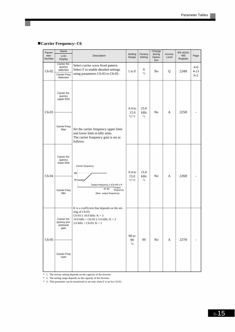
Parameter Tables
5-15
Carrier Frequency: C6
* 1. The factory setting depends on the capacity of the Inverter.* 2. The setting range depends on the capacity of the Inverter.* 3. This parameter can be monitored or set only when F is set for C6-02.
Param-eter-
Number
Name
DescriptionSetting Range
Factory Setting
Change during Opera-
tion
Access Level
RS-422A/485
RegisterPageLCD
Display
C6-02
Carrier fre-quency
selection
Select carrier wave fixed pattern.Select F to enable detailed settings using parameters C6-03 to C6-05.
1 to F 6*1
No Q 224H4-64-136-2Carrier Freq
Selection
C6-03
Carrier fre-quency
upper limit
Set the carrier frequency upper limit and lower limit in kHz units.The carrier frequency gain is set as follows:
K is a coefficient that depends on the set-ting of C6-03.C6-03 ≥ 10.0 kHz: K = 310.0 kHz > C6-03 ≥ 5.0 kHz: K = 25.0 kHz > C6-03: K = 1
0.4 to 15.0*2 *3
15.0 kHz
*1
No A 225H -
Carrier Freq Max
C6-04
Carrier fre-quency
lower limit
0.4 to 15.0*2 *3
15.0 kHz
*1
No A 226H -
Carrier Freq Min
C6-05
Carrier fre-quency pro-
portional gain
00 to 99*3
00 No A 227H -
Carrier Freq Gain
Carrier frequency
Output frequency x (C6-05) x K
(Max. output frequency)
Outputfrequency

5-16
Reference Parameters: d
Preset Reference: d1
Note The unit is set in o1-03 (frequency units of reference setting and monitor, default: 0.01 Hz).
Reference Limits: d2
Param-eter-
Number
Name
DescriptionSetting Range
Factory Setting
Change during Opera-
tion
Access Level
RS-422A/485
RegisterPageLCD
Display
d1-01
Frequency reference 1
Sets the frequency reference in the units used in o1-03.
0 to 50.00
0.00 Hz
Yes Q 280H4-76-6
Reference 1
d1-02
Frequency reference 2 The frequency reference when
multi-step speed command 1 is ON for a multi-function input.
0.00 Hz
Yes Q 281H4-76-6
Reference 2
d1-03
Frequency reference 3 The frequency reference when
multi-step speed command 2 is ON for a multi-function input.
0.00 Hz
Yes Q 282H4-76-6
Reference 3
d1-04
Frequency reference 4 The frequency reference when
multi-step speed commands 1 and 2 are ON for multi-function inputs.
0.00 Hz
Yes Q 283H4-76-6
Reference 4
d1-17
Jog fre-quency refer-
enceThe frequency reference when the jog frequency reference selec-tion, FJOG command or RJOG command is ON.
6.00 Hz
Yes Q 292H4-6
6-48Jog
Reference
Param-eter-
Number
Name
DescriptionSetting Range
Factory Setting
Change during Opera-
tion
Access Level
RS-422A/485
RegisterPageLCD
Display
d2-01
Frequency reference upper limit
Set the output frequency upper limit as a percentage of the max. output frequency.
0.0 to 110.0
100.0% No A 289H 6-26Ref Upper
Limit
d2-02
Frequency reference lower limit
Sets the output frequency lower limit as a percentage of the maxi-mum output frequency.
0.0 to 110.0
0.0% No A 28AH 6-26Ref Lower
Limit
d2-03
Master speed reference lower limit
Set the master speed reference lower limit as a percentage of the max. output frequency.
0.0 to 110.0
0.0% No A 293H 6-26Ref1 Lower
Limit

Parameter Tables
5-17
Jump Frequencies: d3
Field Weakening: d6
Parame-terNum-
ber
Name
DescriptionSetting Range
Factory Setting
Change during Opera-
tion
Access Level
RS-422A/485
RegisterPageLCD
Display
d3-01
Jump fre-quency 1
Set the center values of the jump frequencies in Hz.This function is disabled by set-ting the jump frequency to 0 Hz. Always ensure that the following applies:d3-01 ≥ d3-02 ≥ d3-03Operation in the jump frequency range is prohibited but during acceleration and deceleration, the speed changes smoothly without jumping.
0.0 to 120.0
0.0 Hz No A 294H 6-24
Jump Freq 1
d3-02
Jump fre-quency 2
0.0 Hz No A 295H 6-24
Jump Freq 2
d3-03
Jump fre-quency 3
0.0 Hz No A 296H 6-24
Jump Freq 3
d3-04
Jump fre-quency width
Sets the jump frequency band-width in Hz.The jump frequency range will be the jump frequency ± d3-04.
0.0 to 20.0
1.0 Hz No A 297H 6-24Jump
Bandwidth
Param-eter
Number
Name
DescriptionSetting Range
Factory Setting
Change during Opera-
tion
Access Level
RS-422A/485
RegisterPageLCD
Display
d6-01
Field weaken-ing level
Set the Inverter output voltage when the field weakening com-mand is input.It is enabled when the field weak-ening command is set for a multi-function input.Set the level as a percentage tak-ing the voltage set in the V/f pat-tern as 100%.
0 to 100
80% No A 2A0H 6-28
Field-Weak Lvl
d6-02
Field fre-quency
Set the lower limit in Hz of the frequency range where field con-trol is valid.The field weakening command is valid only at frequencies above this setting and only when the speed is in agreement with the current speed reference.
0.0 to 120.0
0.0 Hz No A 2A1H 6-28Field-Weak
Freq
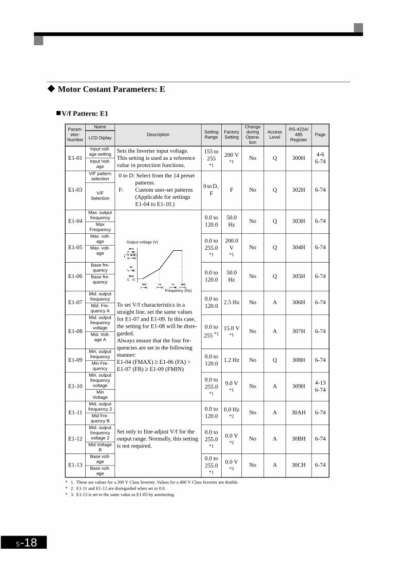
5-18
Motor Costant Parameters: E
V/f Pattern: E1
* 1. These are values for a 200 V Class Inverter. Values for a 400 V Class Inverter are double.* 2. E1-11 and E1-12 are disregarded when set to 0.0.* 3. E1-13 is set to the same value as E1-05 by autotuning.
Param-eter-
Number
Name
DescriptionSetting Range
Factory Setting
Change during Opera-
tion
Access Level
RS-422A/485
RegisterPage
LCD Diplay
E1-01
Input volt-age setting
Sets the Inverter input voltage. This setting is used as a reference value in protection functions.
155 to 255*1
200 V*1
No Q 300H4-6
6-74Input Volt-age
E1-03
V/F pattern selection
0 to D: Select from the 14 preset patterns.
F: Custom user-set patterns (Applicable for settings E1-04 to E1-10.)
0 to D, F
F No Q 302H 6-74V/F
Selection
E1-04
Max. output frequency
To set V/f characteristics in a straight line, set the same values for E1-07 and E1-09. In this case, the setting for E1-08 will be disre-garded.Always ensure that the four fre-quencies are set in the following manner:E1-04 (FMAX) ≥ E1-06 (FA) > E1-07 (FB) ≥ E1-09 (FMIN)
0.0 to 120.0
50.0 Hz
No Q 303H 6-74Max
Frequency
E1-05
Max. volt-age 0.0 to
255.0*1
200.0 V*1
No Q 304H 6-74Max. volt-age
E1-06
Base fre-quency 0.0 to
120.050.0 Hz
No Q 305H 6-74Base fre-quency
E1-07
Mid. output frequency 0.0 to
120.02.5 Hz No A 306H 6-74
Mid. Fre-quency A
E1-08
Mid. output frequency
voltage 0.0 to
255 *115.0 V
*1 No A 307H 6-74
Mid. Volt-age A
E1-09
Min. output frequency 0.0 to
120.01.2 Hz No Q 308H 6-74
Min Fre-quency
E1-10
Min. output frequency
voltage0.0 to 255.0
*1
9.0 V*1
No A 309H4-136-74Min
Voltage
E1-11
Mid. output frequency 2
Set only to fine-adjust V/f for the output range. Normally, this setting is not required.
0.0 to 120.0
0.0 Hz*2
No A 30AH 6-74Mid Fre-quency B
E1-12
Mid. output frequency voltage 2
0.0 to 255.0
*1
0.0 V*2
No A 30BH 6-74Mid Voltage
B
E1-13
Base volt-age
0.0 to 255.0
*1
0.0 V*3
No A 30CH 6-74Base volt-
age
Output voltage (V)
Frequency (Hz)

Parameter Tables
5-19
Motor Setup: E2
* 1. The factory setting depends upon the Inverter capacity. The value for a 200 V class Inverter of 0.4 kW is given.* 2. The setting range is 10% to 200% of the Inverter's rated output current. The value for a 200 V class Inverter of 0.4 kW is given.
Option Parameters: F
Communications Option Cards: F6
Param-eter-
Number
Name
DescriptionSetting Range
Factory Setting
Change during Opera-
tion
Access Level
RS-422A/485
RegisterPageLCD
Display
E2-01
Motor rated current
Sets the motor rated current.These set values will become the reference values for motor pro-tection, torque limits and torque control.This parameter is an input data for autotuning.
0.32 to 6.40
*2
1.90 A*1
No Q 30EH6-336-73Motor Rated
FLA
E2-05
Motor line-to-line resistance
Sets the motor phase-to-phase resistance in Ω units.This parameter is automatically set during autotuning.
0.000 to
65.000
9.842 Ω*1
No A 312H 6-73Term
Resistance
Param-eter-
Number
Name
DescriptionSetting Range
Factory Setting
Change during Opera-
tion
Access Level
RS-422A/485
RegisterPageLCD
Display
F6-01
DeviceNet fault opera-
tion selection
Set the stopping method for com-munications errors.0: Deceleration to stop using
deceleration time in C1-021: Coast to stop/fault detection2: Decelerates to stop using C1-
09 deceleration time/fault detection
3: Continuous operating/alarm detection
0 to 3 1 No A 3A2H -Comm Bus Flt
Sel
F6-02
Communica-tions external
fault input detection
method selec-tion
0: Fault detection during power ON
1: Fault detected during running only
0 or 1 0 No A 3A3H -
EF0 Detection
F6-03
Communica-tions external
fault input operation selection
0: Deceleration to a stop using C1-02 deceleration time/fault detection
1: Coast to stop/fault detection2: Decelerates to a stop using
C1-09 deceleration time/fault detection
3: Continuous operating/alarm detection
0 to 3 1 No A 3A4H -
EF0 Fault Action
F6-05
Displayunit selection
forCurrent moni-
tor
Sets the unit of current monitor0: Ampere1: 100%/8192
0 or 1 0 No A 3A6H -
Current Unit Sel

5-20
Terminal Function Parameters: H
The following settings are made with the terminal function parameters (H parameters): Settings for externalterminal functions.
Multi-function Digital Inputs: H1
* The values in parentheses indicate initial values when initialized in 3-wire sequence.
Multi-function Digital Input Functions
Param-eter-
Number
Name
DescriptionSetting Range
Factory Setting
Change during Opera-
tion
Access Level
RS-422A/485
RegisterPageLCD
Display
H1-01
Terminal S3 function selec-
tion Multi-function contact input 1 0 to 77 24 No A 400H -Terminal S3
Sel
H1-02
Terminal S4 function selec-
tion Multi-function contact input 2 0 to 77 14 No A 401H -Terminal S4
Sel
H1-03
Terminal S5 function selec-
tion Multi-function contact input 3 0 to 77 3 (0)* No A 402H -Terminal S5
Sel
H1-04
Terminal S6 function selec-
tion Multi-function contact input 4 0 to 77 4 (3)* No A 403H -Terminal S6
Sel
H1-05
Terminal S7 function selec-
tion Multi-function contact input 5 0 to 77 6 (4)* No A 404H -Terminal S7
Sel
Set-ting
ValueFunction Page
0 3-wire sequence (Forward/Reverse Run command) 6-9
1 Local/Remote selection (ON: Operator, OFF: parameter setting) 6-46
2 Option/Inverter selection (ON: Option Card) 6-48
3Multi-step speed reference 1When H3-05 is set to 0, this function is combined with the master/auxiliary speed switch.
6-6
4 Multi-step speed reference 2 6-6
6 Jog frequency command (higher priority than multi-step speed reference) 6-6
7 Accel/decel time 1 -
8 External baseblock NO (NO contact: Baseblock at ON) 6-46
9 External baseblock NC (NC contact: Baseblock at OFF) 6-46
F Not used (Set when a terminal is not used) -
12 FJOG command (ON: Forward run at jog frequency d1-17) 6-48
14 Fault reset (Reset when turned ON) 7-2
19 PI control disable (ON: PI control disabled) 6-67
1BParameters write enable (ON: All parameters can be written-in. OFF: All parameters other than frequency monitor are write protected.)
6-86

Parameter Tables
5-21
Multi-function Digital Outputs: H2
Multi-function Digital Output Functions
1E Analog frequency reference sample/hold 6-47
20 to 2F
External fault (Desired settings possible)Input mode: NO contact/NC contact, Detection mode: Normal/during operation
6-49
34 PI soft starter 6-67
61 External search command 1 (ON: Speed search from maximum output frequency) 6-39
62 External search command 2 (ON: Speed search from set frequency) 6-39
63 Field weakening command (ON: Field weakening control set for d6-01 and d6-02) 6-28
64 External speed search command 3 6-39
67 Communications test mode 6-64
68 High-slip braking (HSB) 6-14
69 Jog Frequency 2 –
6A Drive enable –
Param-eter
Number
Name
DescriptionSetting Range
Factory Setting
Change during Opera-
tion
Access Level
RS-422A/485
RegisterPageLCD
Display
H2-01
Terminal M1-M2 function
selection Multi-function contact output 1 0 to 38 0 No A 40BH -Term M1-M2
Sel
H2-02
Terminal M3-M4 function
selection Multi-function contact output 2 0 to 38 1 No A 40CH -Term M3-M4
Sel
Setting Value Function Page
0 During run (ON: run command is ON or voltage is being output) -
1 Zero-speed 6-26
2 Frequency agree 1 (L4-02 used.) -
3Desired frequency agree 1 (ON: Output frequency = ±L4-01, L4-02 used and during frequency agree)
-
4 Frequency (F-OUT) detection 1 (ON: +L4-01 ≥ output frequency ≥ -L4-01, L4-02 used) -
5Frequency (F-OUT) detection 2 (ON: Output frequency ≥ +L4-01 or output frequency ≤ -L4-01, L4-02 used)
-
6Inverter operation readyREADY: After initialization, no faults
-
7 During DC bus undervoltage (UV) detection -
8 During baseblock (ON: during baseblock) -
9 Frequency reference selection (ON: Frequency reference from Operator) -
A Run command selection status (ON: Run command from Operator) -
B Overtorque/undertorque detection 1 NO (NO contact: Overtorque/undertorque detection at ON) 6-31
C Loss of frequency reference (Effective when 1 is set for L4-05) 6-43
Set-ting
ValueFunction Page

5-22
Analog Inputs: H3
EFault (ON: Digital Operator communications error or fault other than CPF00 and CPF01 has occurred.)
-
F Not used. (Set when the terminals are not used.) -
10 Minor fault (ON: Alarm displayed) -
11 Fault reset command active -
17 Overtorque/undertorque detection 1 NC (NC Contact: Torque detection at OFF) 6-31
1E Restart enabled (ON: Restart enabled) 6-43
1F Motor overload (OL1, including OH3) pre-alarm (ON: 90% or more of the detection level) 6-33
38 Drive enabled –
Param-eter-
Number
Name
DescriptionSetting Range
Factory Setting
Change during Opera-
tion
Access Level
RS-422A/485
RegisterPageLCD
Display
H3-02
Gain (termi-nal A1)
Sets the frequency when 10 V is input, as a percentage of the max-imum output frequency.
0.0 to 1000
100.0% Yes A 411H 6-22Terminal A1
Gain
H3-03
Bias (terminal A1)
Sets the frequency when 0 V is input, as a percentage of the max-imum frequency.
-100.0 to
+100.00.0% Yes A 412H 6-22
Terminal A1 Bias
H3-08
Multi-function analog input terminal A2 signal level selection
0: Limit negative frequency set-tings for gain and bias settings to 0.
2: 4 to 20 mA (9-bit input).Switch current and voltage input using the switch S1 on the control panel.
0 or 2 2 No A 417H 6-22
Term A2 Sig-nal
H3-09
Multi-function analog input terminal A2
function selec-tion
Select multi-function analog input function for terminal A2. Refer to the next table.
0 to 1F 0 No A 418H 6-22
Terminal A2 Sel
H3-10
Gain (termi-nal A2)
Sets the input gain (level) when terminal 14 is 10 V (20 mA).Set according to the 100% value for the function set for H3-09.
0.0 to 1000
100.0% Yes A 419H 6-22Terminal A2
Gain
H3-11
Bias (terminal A2)
Sets the input gain (level) when terminal 14 is 0 V (4 mA).Set according to the 100% value for the function set for H3-09.
-100.0 to
+100.00.0% Yes A 41AH 6-22
Terminal A2 Bias
H3-13
Terminal A1/A2 switching
0: Use terminal A1 analog input as main speed frequency refe-rence.
1: Use terminal A2 analog input as main speed frequency refe-rence.
Effective when H3-09 is set to 2.
0 or 1 0 No A 41CH -T A1/A2 Select
Setting Value
Function Page

Parameter Tables
5-23
H3-09 Settings
Set-ting
ValueFunction Contents (100%) Page
0 Frequency bias (Add to terminal A1) Maximum output frequency 6-26
2Auxiliary frequency reference (2nd step analog)
Maximum output frequency 6-23
B PI feedback Maximum output frequency 6-67
E Motor temperature input 10 V = 100% 6-36
1F Analog input not used. -

5-24
Multi-function Analog Outputs: H4
* An analog output of 4-20 mA can not be used with the standard terminal board. Therefore an optional terminal board (with shunt connector CN15) is needed.
Param-eter
Number
Name
DescriptionSetting Range
Factory Setting
Change during Opera-
tion
Access Level
RS-422A/485
RegisterPage
LCD Dispay
H4-01
Monitor selec-tion (terminal
FM)
Sets the number of the monitor item to be output (U1-) from terminal FM.10 to 14, 28, 34, 39, 40 cannot be set.
1 to 38 2 No A 41DH 6-50Terminal FM
Sel
H4-02
Gain (termi-nal FM)
Sets the multi-function analog output 1 voltage level gain.Sets whether the monitor item output will be output in multiples of 10 V.The maximum output from the terminal is 10 V. A meter calibra-tion function is available.
0 to 1000
100% Yes Q 41EH4-7
6-50Terminal FM
Gain
H4-03
Bias (terminal FM)
Sets the multi-function analog output 1 voltage level bias.Sets output characteristic up/down parallel movement as a per-centage of 10 V.The maximum output from the terminal is 10 V. A meter calibra-tion function is available.
-110 to +110
0.0% Yes A 41FH 4-7Terminal FM
Bias
H4-04
Monitor selec-tion (terminal
AM)
Sets the number of the monitor item to be output (U1-) from terminal AM.10 to 14, 28, 34, 39, 40 cannot be set.
1 to 38 3 No A 420H4-7
6-50Terminal AM
Sel
H4-05
Gain (termi-nal AM)
Set the voltage level gain for multi-function analog output 2.Set the number of multiples of 10 V to be output as the 100% output for the monitor items. The maxi-mum output from the terminal is 10 V. A meter calibration func-tion is available.
0 to 1000
50.0% Yes Q 421H4-7
6-50Terminal AM
Gain
H4-06
Bias (terminal AM)
Sets the multi-function analog output 2 voltage level bias.Sets output characteristic up/down parallel movement as a per-centage of 10 V.The maximum output from the terminal is 10 V. A meter calibra-tion function is available.
-110.0 to
+110.00.0% Yes A 422H -
Terminal AM Bias
H4-07
Analog output 1 signal level
selection
Sets the signal output level for multi-function output 1 (terminal FM)0: 0 to +10 V output2: 4 – 20 mA*
0 or 2 0 No A 423H -AO Level Select1
H4-08
Analog output 2 signal level
selection
Sets the signal output level for multi-function output 2 (terminal AM)0: 0 to +10 V output2: 4 – 20 mA*
0 or 2 0 No A 424H -AO Level Select2

Parameter Tables
5-25
RS-422A/485 Communications: H5
* Set H5-01 to 0 to disable Inverter responses to RS-422A/485 communications.
Parame-ter
Number
Name
DescriptionSetting Range
Factory Setting
Change during Opera-
tion
Access Level
RS-422A/485
RegisterPageLCD
Display
H5-01
Station address
Set the Inverter's node address. 0 to 20*
1F No A 425H 6-54Serial Comm
Adr
H5-02
Communica-tion speed selection
Set the baud rate for 6CN RS-422A/485 communications.0: 1200 bps1: 2400 bps2: 4800 bps3: 9600 bps4: 19200 bps
0 to 4 3 No A 426H 6-54Serial Baud
Rate
H5-03
Communica-tion parity selection
Set the parity for 6CN RS-422A/485 communications.0: No parity1: Even parity2: Odd parity
0 to 2 0 No A 427H 6-54
Serial Com Sel
H5-04
Stopping method after communica-
tion error
Set the stopping method for com-munications errors.0: Deceleration to stop using
deceleration time in C1-021: Coast to stop2: Emergency stop using decele-
ration time in C1-093: Continue operation
0 to 3 3 No A 428H 6-54
Serial Fault Sel
H5-05
Communica-tion error detection selection
Set whether or not a communica-tions timeout is to be detected as a communications error.0: Do not detect.1: Detect
0 or 1* 1 No A 429H 6-54
Serial Flt Dtct
H5-06Send wait time Set the time from the Inverter
receiving data to when the Inverter starts to send.
5 to 65 5 ms No A 42AH 6-54Transmit Wait-TIM
H5-07
RTS control ON/OFF
Select to enable or disable RTS control.0: Disabled (RTS is always ON)1: Enabled (RTS turns ON only
when sending)
0 or 1 1 No A 42BH 6-54RTS Control
Sel

5-26
Protection Function Parameters: L
The following settings are made with the protection function parameters (L parameters): Motor selection func-tion, power loss ridethrough function, stall prevention function, frequency detection, torque limits and hard-ware protection.
Motor Overload: L1
Parame-ter
Number
Name
DescriptionSetting Range
Factory Setting
Change during Opera-
tion
Access Level
RS-422A/485
RegisterPage
LCD Display
L1-01
Motor protec-tion selection
Sets whether the motor overload function is enabled or disabled at electric thermal overload relay.0: Disabled1: General-purpose motor protec-
tionIn some applications when the Inverter power supply is turned off, the thermal value is reset, so even if this parameter is set to 1, protection may not be effective.
0 or 1 1 No Q 480H4-7
6-33
MOL Fault Sel
L1-02
Motor protec-tion time
parameter
Sets the electric thermal detection time in seconds units.Usually changing this setting is not necessary.The factory setting is 150% over-load for one minute. When the motor's overload resis-tance is known, also set the over-load resistance protection time for when the motor is hot started.
0.1 to5.0
1.0 min No A 481H 6-33MOL Time
Const
L1-03
Alarm opera-tion selection during motor overheating
Set H3-09 to E and select the operation when the input motor temperature (thermistor) input exceeds the alarm detection level (1.17 V).0: Decelerate to stop1: Coast to stop2: Emergency stop using the
deceleration time in C1-09.3: Continue operation (OH3 on
the Operator flashes).
0 to 3 3 No A 482H 6-35
Mtr OH Alarm Sel
L1-04
Motor over-heating opera-tion selection
Set H3-09 to E and select the operation when the motor temper-ature (thermistor) input exceeds the operation detection level (2.34 V).0: Decelerate to stop1: Coast to stop2: Emergency stop using the
deceleration time in C1-09.
0 to 2 1 No A 483H 6-35Mtr OH Fault
Sel
L1-05
Motor temper-ature input fil-
ter time parameter
Set H3-09 to E and set the primary delay time parameter for motor temperature (thermistor) inputs in seconds.
0.00 to10.00
0.20 s No A 484H 6-35
Mtr Temp Filter

Parameter Tables
5-27
Power Loss Ridethrough: L2
* 1. The factory setting depends upon the Inverter capacity. The value for a 200 V Class Inverter of 0.4 kW is given.* 2. These are values for a 200 V class Inverter. Value for a 400 V class Inverter is double.
Param-eter-
Number
Name
DescriptionSetting Range
Factory Setting
Change during Opera-
tion
Access Level
RS-422A/485
RegisterPage
LCD Display
L2-01
Momentary power loss detection
0: Disabled (main circuit under-voltage (UV) detection)
1: Enabled (Restarted when the power returns within the time for L2-02. When L2-02 is exceeded, main circuit under-voltage detection.)
2: Enabled while CPU is opera-ting. (Restarts when power returns during control operati-ons. Does not detect main cir-cuit undervoltage.)
0 to 2 0 No A 485H 6-37PwrL Selec-
tion
L2-02
Momentary power loss
ridethru timeRidethrough time, when Momen-tary Power Loss Selection (L2-01) is set to 1, in units of seconds.
0 to 25.5
0.1 s*1
No A 486H 6-37PwrL Ride-
thru t
L2-03
Min. base-block time
Sets the Inverter's minimum base-block time, when the Inverter is restarted after power loss ride-through.Sets the time to approximately 0.7 times the motor secondary circuit time parameter.When an overcurrent or overvolt-age occurs when starting a speed search or DC injection braking, increase the set values.
0.1 to 5.0
0.1 s*1
No A 487H6-376-38
PwrL Base-block t
L2-04
Voltage recov-ery time
Sets the time required to return the Inverter output voltage to nor-mal voltage at the completion of a speed search.Sets the time required to recover from 0 V to the maximum volt-age.
0.0 to5.0
0.3 s*1
No A 488H6-376-38PwrL V/F
Ramp t
L2-05
Undervoltage detection level
Sets the main circuit undervolt-age (UV) detection level (main circuit DC voltage).Usually changing this setting is not necessary.Insert an AC reactor in the Inverter input side to lower the main circuit undervoltage detec-tion level.
150 to210*2
190 V*2
No A 489H 6-37PUV Det
Level

5-28
Stall Prevention: L3
Parame-ter
Number
Name
DescriptionSetting Range
Factory Setting
Change during Opera-
tion
Access Level
RS-422A/485
RegisterPageLCD
Display
L3-01
Stall preven-tion selection during accel
0: Disabled (Acceleration as set. With a heavy load, the motor may stall.)
1: Enabled (Acceleration stop-ped when L3-02 level is excee-ded. Acceleration starts again when the current is returned.)
2: Intelligent acceleration mode (Using the L3-02 level as a basis, acceleration is automati-cally adjusted. Set accelera-tion time is disregarded.)
0 to 2 1 No A 48FH 6-19StallP Accel
Sel
L3-02
Stall preven-tion level dur-
ing accel
Effective when L3-01 is set to 1 or 2.Set as a percentage of Inverter rated current.Usually changing this setting is not necessary. The factory setting reduces the set values when the motor stalls.
0 to 200 120% No A 490H 6-19StallP Accel
Lvl
L3-04
Stall preven-tion selection during decel
0: Disabled (Deceleration as set. If deceleration time is too short, a DC-Bus overvoltage may result.)
1: Enabled (Deceleration is stop-ped when the DC-Bus voltage exceeds the overvoltage level. Deceleration restarts when voltage is returned.)
2: Intelligent deceleration mode (Deceleration rate is automati-cally adjusted so that in Inver-ter can decelerate in the shortest possible time. Set deceleration time is disregar-ded.)
When a braking option (Braking Resistor Unit and Braking Unit) is used, always set to 0.
0 to 2 1 No Q 492H4-7
6-21
StallP Decel Sel
L3-05
Stall preven-tion selection during running
0: Disabled (Runs as set. With a heavy load, the motor may stall.)
1: Deceleration time 1 (the dece-leration time for the stall pre-vention function is C1-02.)
2: Deceleration time 2 (the dece-leration time for the stall pre-vention function is C1-04.)
0 to 2 1 No A 493H 6-30
StallP Run Sel
L3-06
Stall preven-tion level dur-ing running
Effective when L3-05 is 1 or 2.Set as a percentage of the Inverter rated current.Usually changing this setting is not necessary.The factory setting reduces the set values when the motor stalls.
30 to 200
120% No A 494H 6-30StallP Run
Level

Parameter Tables
5-29
Reference Detection: L4
Fault Restart: L5
Param-eter-
Number
Name
DescriptionSetting Range
Factory Setting
Change during Opera-
tion
Access Level
RS-422A/485
RegisterPageLCD
Display
L4-01
Speed agree-ment detec-
tion level
Effective when "Desired fre-quency (ref/setting) agree 1", "Frequency detection 1" or "Fre-quency detection 2" is set for a multi-function output.
0.0 to 120.0
0.0 Hz No A 499H -Spd Agree
Level
L4-02
Speed agree-ment detec-tion width
Effective when "Frequency (speed) agree 1", "Desired fre-quency (speed) agree 1" or "Fre-quency (F-OUT) detection 1" is set for a multi-function output.
0.0 to 20.0
2.0 Hz No A 49AH -Spd Agree
Width
L4-05
Operation when fre-
quency refer-ence is missing
0: Stop (Operation follows the frequency reference.)
1: Operation continues at the fre-quency, set in parameter L4-06.
Frequency reference loss means that the frequency reference value drops over 90% in 400 ms.
0 or 1 0 No A 49DH 6-43
Ref Loss Sel
L4-06
Frequency reference
value at fre-quency refer-
ence loss
Sets the frequency reference value when the frequency refer-ence is missing
0.0 to 100.0
80% No A 4C2H -
Fref at Floss
Param-eter-
Number
Name
DescriptionSetting Range
Factory Setting
Change during Opera-
tion
Access Level
Rs-422A/485
RegisterPage
LCD Display
L5-01
Number of auto restart
attempts
Sets the number of auto restart attempts.Automatically restarts after a fault and conducts a speed search from the run frequency.
0 to 10 0 No A 49EH 6-44Num of Restarts
L5-02
Auto restart operation selection
Sets whether a fault contact out-put is activated during fault restart.0: No output (Fault contact is not
activated.)1: Output (Fault contact is acti-
vated.)
0 or 1 0 No A 49FH 6-44Restart Sel

5-30
Torque Detection: L6
Hardware Protection: L8
Parame-ter
Number
Name
DescriptionSetting Range
Factory Setting
Change during Opera-
tion
Access Level
RS-422A/485
RegisterPageLCD
Display
L6-01
Torque detec-tion selection 1
0: Overtorque/undertorque detec-tion disabled.
1: Overtorque detection only with speed agreement; opera-tion continues after overtorque (warning).
2: Overtorque detected conti-nuously during operation; ope-ration continues after overtorque (warning).
3: Overtorque detection only with speed agreement; output stopped upon detection (pro-tected operation).
4: Overtorque detected conti-nuously during operation; out-put stopped upon detection (protected operation).
5: Undertorque detection only with speed agreement; opera-tion continues after overtorque (warning).
6: Undertorque detected conti-nuously during operation; ope-ration continues after overtorque (warning).
7: Undertorque detection only with speed agreement; output stopped upon detection (pro-tected operation).
8: Undertorque detected conti-nuously during operation; out-put stopped upon detection (protected operation).
0 to 8 0 No A 4A1H 6-31
Torq Det 1 Sel
L6-02
Torque detec-tion level 1 Inverter rated current is set as
100%.0 to 300 150% No A 4A2H 6-31
Torq Det 1 Lvl
L6-03
Torque detec-tion time 1 Sets the overtorque/undertorque
detection time.0.0 to 10.0
0.1 s No A 4A3H 6-31Torq Det 1 Time
Param-eter-
Number
Name
Description Setting Range
Factory Setting
Change during Opera-
tion
Access Level
RS-422A/485
RegisterPageLCD
Display
L8-02
Overheat pre-alarm level
Sets the detection temperature for the Inverter overheat detection pre-alarm in °C.The pre-alarm detects when the cooling fin temperature reaches the set value.
50 to 130
95 °C* No A 4AEH 6-45OH Pre-alarm
Lvl

Parameter Tables
5-31
* The factory setting depends upon the Inverter capacity. The value for a 200 V Class Inverter of 0.4 kW is given.
L8-03
Operation selection after overheat pre-
alarm
Sets the operation for when the Inverter overheat pre-alarm occurs.0: Decelerate to stop in decelera-
tion time C1-02.1: Coast to stop 2: Fast stop in fast-stop time C1-
09.3: Continue operation (Monitor
display only.)A fault will be given in setting 0 to 2 and a minor fault will be given in setting 3.
0 to 3 3 No A 4AFH 6-45
OH Pre alarm Sel
L8-09
Ground pro-tection selec-
tion 0:Disabled1:Enabled
0 or 1 1 No A 4B5H -Ground Fault
Sel
L8-11
Cooling fan control delay
time
Set the time in seconds to delay turning OFF the cooling fan after the cooling fan OFF command is received.
0 to 300
60 s No A 4B7H -Fan Delay
Time
L8-12Ambient tem-
perature Set the ambient temperature.45 to
6045 °C* No A 4B8H -
Ambient Temp
L8-15
OL2 charac-teristics selec-
tion at low speeds
0: OL2 characteristics at low speeds disabled.
1: OL2 characteristics at low speeds enabled.
0 or 1 1 No A 4BBH -OL2 Sel @ L-
Spd
L8-18
Soft CLA selection 0: Disabled (gain = 0)
1: Enabled0 or 1 1 No A 4BFH -
Soft CLA Sel
Param-eter-
Number
Name
Description Setting Range
Factory Setting
Change during Opera-
tion
Access Level
RS-422A/485
RegisterPageLCD
Display

5-32
n: Special Adjustments
The following settings are made with the special adjustments parameters ( n-parameters): Hunting preventionand speed feedback detection control.
Hunting Prevention Function: n1
High-slip Braking: n3
Param-eter-
Number
Name
DescriptionSetting Range
Factory Setting
Change during Opera-
tion
Access Level
RS-422A/485
RegisterPageLCD
Display
n1-01
Hunting-pre-vention func-tion selection
0: Hunting-prevention function disabled
1: Hunting-prevention function enabled
The hunting-prevention function suppresses hunting when the motor is operating with a light load.If high response has the priority over vibration suppression, dis-able the hunting-prevention func-tion.
0 or 1 1 No A 580H 6-29
Hunt Prev Select
n1-02
Hunting-pre-vention gain
Set the hunting-prevention gain multiplication factor.Normally, there is no need to change this setting.Make the adjustments as follows:• If vibration occurs with light
load, increase the setting.• If the motor stalls, reduce the
setting.If the setting is to large, the volt-age will be to suppressed and the motor may stall.
0.00 to 2.50
1.00 No A 581H4-136-29
Hunt Prev Gain
Param-eter-
Number
Name
DescriptionSetting Range
Factory Setting
Change during Opera-
tion
Access Level
RS-422A/485
RegisterPageLCD
Display
n3-01
High-slip brak-ing decelera-tion frequency
width
Sets the frequency width for deceleration during high-slip braking in percent, taking the Maximum Frequency (E1-04) as 100%.
1 to 20 5% No A 588H -HSB Decel
Width
n3-02
High-slip brak-ing current
limit
Sets the current limit for decelera-tion during high-slip braking in percent, taking the motor rated current as 100%. The resulting limit must be 150% of the Inverter rated current or less.
100 to 200
150% No A 589H -HSB Current
Ref
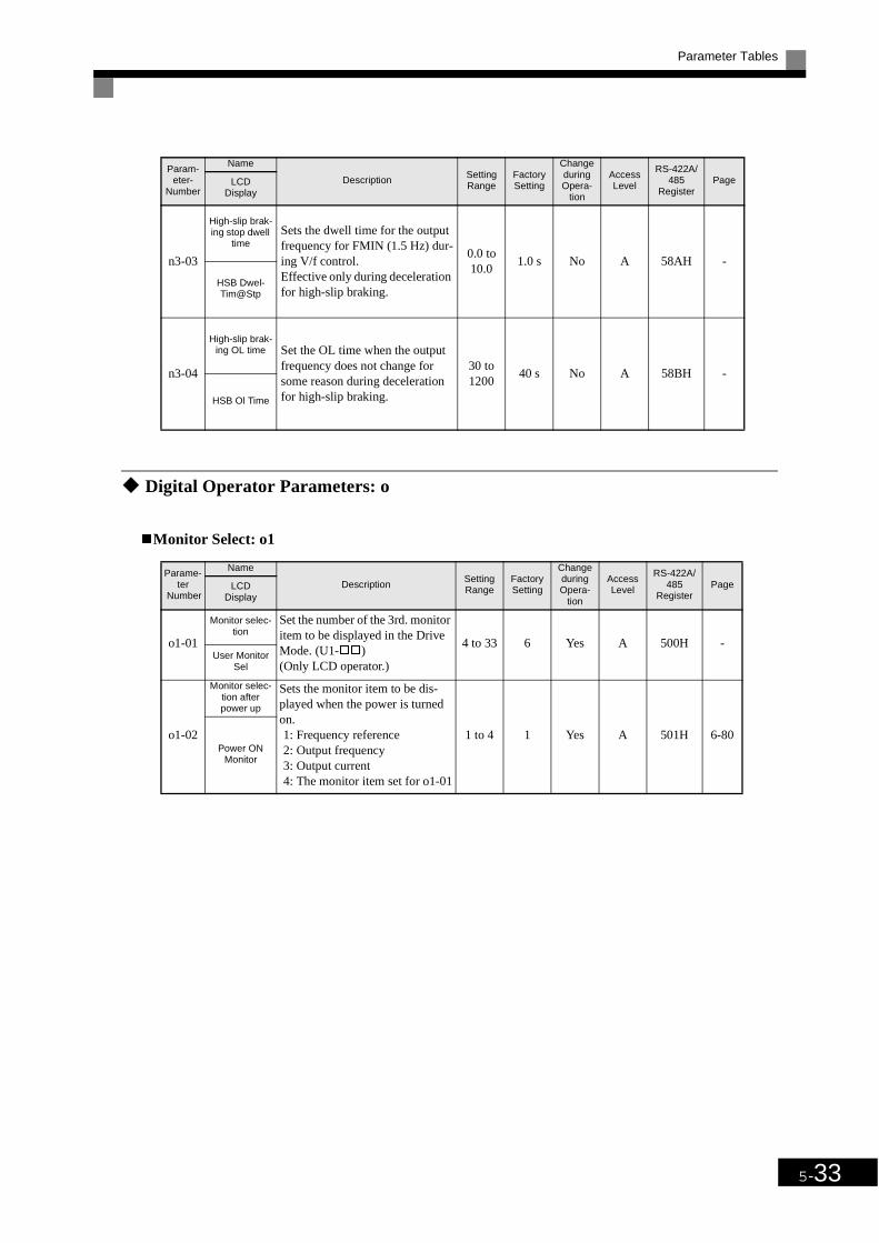
Parameter Tables
5-33
Digital Operator Parameters: o
Monitor Select: o1
n3-03
High-slip brak-ing stop dwell
timeSets the dwell time for the output frequency for FMIN (1.5 Hz) dur-ing V/f control.Effective only during deceleration for high-slip braking.
0.0 to 10.0
1.0 s No A 58AH -
HSB Dwel-Tim@Stp
n3-04
High-slip brak-ing OL time Set the OL time when the output
frequency does not change for some reason during deceleration for high-slip braking.
30 to 1200
40 s No A 58BH -
HSB Ol Time
Parame-ter
Number
Name
DescriptionSetting Range
Factory Setting
Change during Opera-
tion
Access Level
RS-422A/485
RegisterPageLCD
Display
o1-01
Monitor selec-tion
Set the number of the 3rd. monitor item to be displayed in the Drive Mode. (U1-)(Only LCD operator.)
4 to 33 6 Yes A 500H -User Monitor
Sel
o1-02
Monitor selec-tion after power up
Sets the monitor item to be dis-played when the power is turned on.1: Frequency reference2: Output frequency3: Output current4: The monitor item set for o1-01
1 to 4 1 Yes A 501H 6-80Power ON
Monitor
Param-eter-
Number
Name
Description Setting Range
Factory Setting
Change during Opera-
tion
Access Level
RS-422A/485
RegisterPageLCD
Display

5-34
o1-03
Frequency units of refer-ence setting and monitor
Sets the units that will be set and displayed for the frequency refer-ence and frequency monitor.0: 0.01 Hz units1: 0.01% units (Maximum out-
put frequency is 100%)2 to 39:r/min units (Sets the motor poles.)40 to 39999:User desired displaySet the desired values for setting and display for the max. output frequency.
Example: When the max. output frequency value is 200.0, set 12000
0 to 39999
0 No A 502H 6-80
Display Scal-ing
o1-05
LCD-Bright-ness
1: light2:3: normal4:5: dark
0 to 5 3 Yes A 509H
LCD Contrast
Parame-ter
Number
Name
Description Setting Range
Factory Setting
Change during Opera-
tion
Access Level
RS-422A/485
RegisterPageLCD
Display
Set digit number excluding the decimal point.
Set the number of digits below the decimal point to display.

Parameter Tables
5-35
Multi-function Selections: o2
Param-eter-
Number
Name
DescriptionSetting Range
Factory Setting
Change during Opera-
tion
Access Level
RS-422A/485
RegisterPageLCD
Display
o2-01
LOCAL/REMOTE key
enable/dis-able
Sets the Digital Operator Local/Remote Key0: Disabled1: Enabled (Switches between
the Digital Operator and the parameter settings.)
0 or 1 1 No A 505H 6-80Local/Remote
Key
o2-02
STOP key during control circuit terminal
operation
Sets the Stop Key in the run mode.0: Disabled (When the run com-
mand is issued from and exter-nal terminal, the Stop Key is disabled.)
1: Enabled (Effective even during run.)
0 or 1 1 No A 506H 6-80Oper STOP
Key
o2-03
Parameter ini-tial value
Clears or stores user initial val-ues.0: Stores/not set1: Begins storing (Records the
set parameters as user initial values.)
2: All clear (Clears all recorded user initial values)
When the set parameters are recorded as user initial values, 1110 will be set in A1-03.
0 to 2 0 No A 507H 6-80
User Defaults
o2-04
kVA selection Do not set unless using a control board from an Inverter with a dif-ferent capacity.
0 to FF 0* No A 508H -Inverter Model
o2-05
Frequency reference set-ting method
selection
When the frequency reference is set on the Digital Operator fre-quency reference monitor, sets whether the Enter Key is neces-sary.0: Enter Key needed1: Enter Key not needed
When set to 1, the Inverter accepts the frequency reference without Enter Key operation.
0 or 1 0 No A 509H 6-80
Operator M.O.P.
o2-06
Operation selection
when digital operator is
disconnected
Sets the operation when the Digi-tal Operator is disconnected.0: Disabled (Operation continues
even if the Digital Operator is disconnected.)
1: Enabled (OPR is detected at Digital Operator disconnec-tion. Inverter output is cut off and fault contact is operated.)
0 or 1 0 No A 50AH -
Oper Detec-tion
o2-07
Cumulative operation time
setting
Sets the cumulative operation time in hour units.Operation time is calculated from the set values.
0 to 65535
0 hr No A 50BH 6-80Elapsed Time
Set

5-36
* This setting depends on the inverter capacity.
Copy Function: o3
Parameters for the copy function are shown in the following table.
T: Motor Autotuning
The following settings are made with the motor autotuning parameters (T parameters): Settings for autotuning.
o2-08
Cumulative operation time
selection
0: Cumulative time when the Inverter power is on. (All time while the Inverter power is on is accumulated.)
1: Cumulative Inverter run time. (Only Inverter output time is accumulated.)
0 or 1 0 No A 50CH -Elapsed Time
Run
o2-09Initialize Mode
2: European specification5: PV-E specification
2 or 5 2 No A 50DH –Init Mode Sel
o2-10
Fan operation time setting
Set the initial value of the fan operation time.The operation time accumulates from the set value.
0 to 65535
0 hr No A 50EH 6-80Fan ON Time
Set
o2-12
Fault trace ini-tialize
0: Disable1: Initialize (= zero clear) after setting ”1“ o2-12 will be returned to ”0“
0 or 1 0 No A 511H -FLT Trace Init
Param-eter-
Number
Name
DescriptionSetting Range
Factory Setting
Change during Opera-
tion
Access Level
RS-422A/485
RegisterPageLCD
Display
o3-01
Copy function selection 0: Normal operation
1: READ (Inverter to Operator)2: COPY (Operator to Inverter)3: Verify (compare)
0 to 3 0 No A 515H 6-82Copy Function
Sel
o3-02
Read permis-sion selection 0: Read prohibited
1: Read permitted0 or 1 0 No A 516H 6-82
Read Allow-able
Param-eter
Number
Name
Description Setting Range
Factory Setting
Change during Opera-
tion
Access Level
RS-422A/485
RegisterPageLCD
Display
T1-02
Motor output power
Set the output power of the motor in kilowatts.
0.00 to 650.00
0.40 kW
No A 702H 4-8Mtr Rated
Power
Param-eter-
Number
Name
Description Setting Range
Factory Setting
Change during Opera-
tion
Access Level
RS-422A/485
RegisterPageLCD
Display
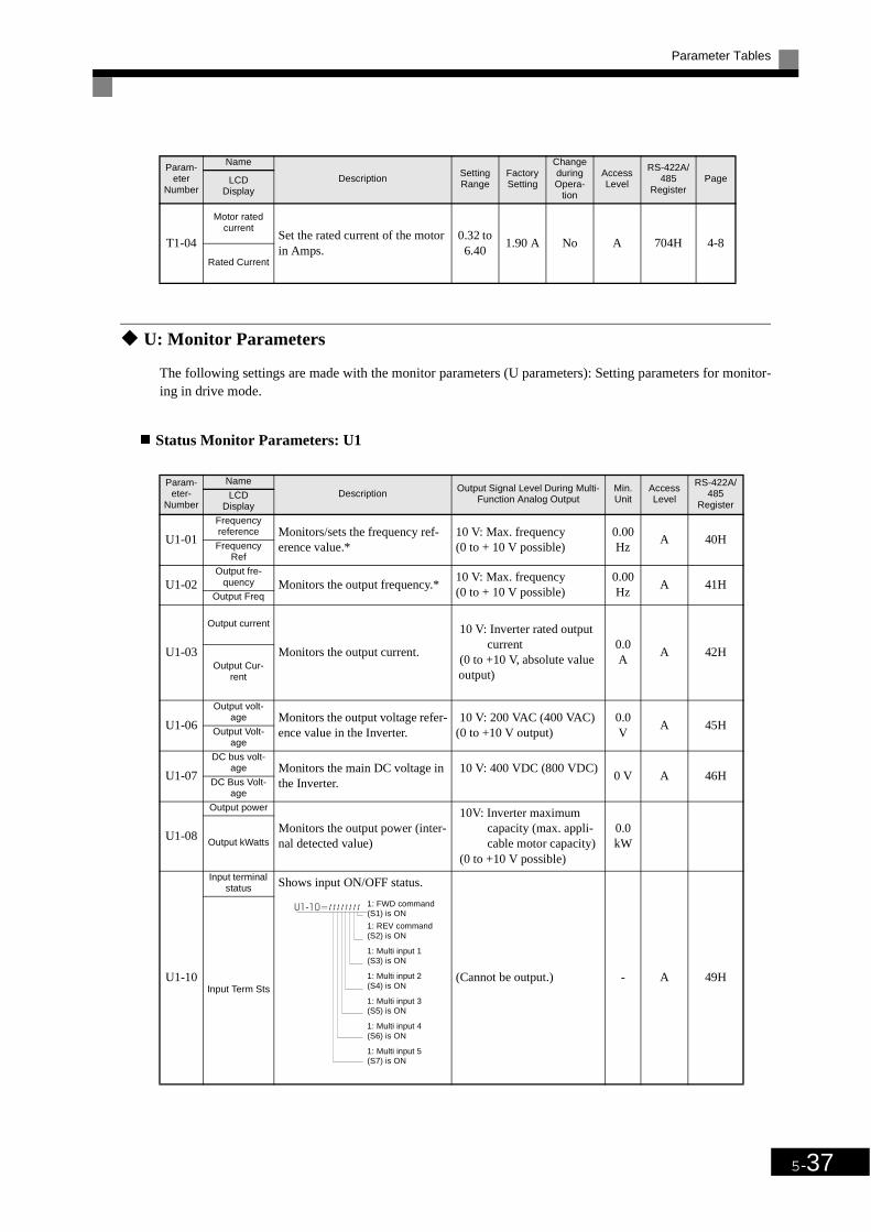
Parameter Tables
5-37
U: Monitor Parameters
The following settings are made with the monitor parameters (U parameters): Setting parameters for monitor-ing in drive mode.
Status Monitor Parameters: U1
T1-04
Motor rated current
Set the rated current of the motor in Amps.
0.32 to 6.40
1.90 A No A 704H 4-8
Rated Current
Param-eter-
Number
NameDescription Output Signal Level During Multi-
Function Analog OutputMin. Unit
Access Level
RS-422A/485
RegisterLCD
Display
U1-01
Frequency reference Monitors/sets the frequency ref-
erence value.*10 V: Max. frequency (0 to + 10 V possible)
0.00Hz
A 40HFrequency Ref
U1-02Output fre-
quency Monitors the output frequency.*10 V: Max. frequency (0 to + 10 V possible)
0.00Hz
A 41HOutput Freq
U1-03
Output current
Monitors the output current.
10 V: Inverter rated output current
(0 to +10 V, absolute value output)
0.0 A
A 42HOutput Cur-
rent
U1-06
Output volt-age Monitors the output voltage refer-
ence value in the Inverter.10 V: 200 VAC (400 VAC)
(0 to +10 V output)0.0 V
A 45HOutput Volt-age
U1-07
DC bus volt-age Monitors the main DC voltage in
the Inverter.10 V: 400 VDC (800 VDC)
0 V A 46HDC Bus Volt-age
U1-08
Output power
Monitors the output power (inter-nal detected value)
10V: Inverter maximum capacity (max. appli-cable motor capacity)
(0 to +10 V possible)
0.0 kWOutput kWatts
U1-10
Input terminal status Shows input ON/OFF status.
(Cannot be output.) - A 49HInput Term Sts
Param-eter
Number
Name
Description Setting Range
Factory Setting
Change during Opera-
tion
Access Level
RS-422A/485
RegisterPageLCD
Display
1: FWD command(S1) is ON
1: REV command(S2) is ON
1: Multi input 1(S3) is ON
1: Multi input 2(S4) is ON
1: Multi input 3(S5) is ON
1: Multi input 4(S6) is ON
1: Multi input 5(S7) is ON

5-38
U1-11
Output termi-nal status
Shows output ON/OFF status.
(Cannot be output.) - A 4AH
Output Term Sts
U1-12
Operation sta-tus
Inverter operating status.
(Cannot be output.) - A 4BH
Int Ctl Sts 1
U1-13
Cumulative operation time Monitors the total operating time
of the Inverter.The initial value and the operat-ing time/power ON time selection can be set in o2-07 and o2-08.
(Cannot be output.)0hr
A 4CHElapsed Time
U1-14
Software No. (flash mem-
ory) (Manufacturer’s ID number) (Cannot be output.) - A 4DHFLASH ID
U1-15
Terminal A1 input voltage Monitors the input voltage of the
voltage frequency reference. An input of 10 V corresponds to 100%.
10 V: 100% (10 V)(0 to + 10 V possible)
0.0% A 4EHTerm A1 Level
U1-16
Terminal A2 input voltage Monitors the input voltage of the
multi-function analog input.An input of 10 V corresponds to 100%.
10 V: 100% (10 V)(0 to +10 V possible)
0.0% A 4FHTerm A2 Level
U1-18
Motor second-ary current
(Iq)
Monitors the calculated value of the motor secondary current.The motor rated secondary cur-rent corresponds to 100%.
10 V:Motor rated secon-dary current)
(0 to +10 V output)0.0% A 51H
Mot Sec Cur-rent
U1-20
Output fre-quency after soft-starter
(SFS output)
Monitors the output frequency after the soft starter.The frequency given does not include compensations.The unit is set in o1-03.
10 V: Max. frequency (0 to + 10 V possible)
0.00Hz
A 53H
SFS Output
Param-eter-
Number
NameDescription Output Signal Level During Multi-
Function Analog OutputMin. Unit
Access Level
RS-422A/485
RegisterLCD
Display
1: Multi-functioncontact output 1(M1-M2) is ON
1: Multi-functioncontact output 2(M3-M4) is ON
Not used(Always 0)
Not used (Always 0).1: Error output(MA/AB-MC) is ON
Run
1: Zero speed
1: everse
1: Reset signal input
1: Speed agree
1: Inverter ready
1: Minor fault
1: Major fault
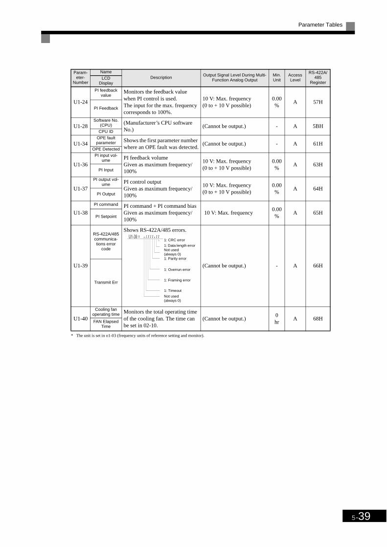
Parameter Tables
5-39
* The unit is set in o1-03 (frequency units of reference setting and monitor).
U1-24
PI feedback value
Monitors the feedback value when PI control is used.The input for the max. frequency corresponds to 100%.
10 V: Max. frequency (0 to + 10 V possible)
0.00%
A 57HPI Feedback
U1-28Software No.
(CPU) (Manufacturer’s CPU software No.)
(Cannot be output.) - A 5BHCPU ID
U1-34OPE fault parameter Shows the first parameter number
where an OPE fault was detected.(Cannot be output.) - A 61H
OPE Detected
U1-36
PI input vol-ume PI feedback volume
Given as maximum frequency/100%
10 V: Max. frequency (0 to + 10 V possible)
0.00%
A 63HPI Input
U1-37
PI output vol-ume PI control output
Given as maximum frequency/100%
10 V: Max. frequency (0 to + 10 V possible)
0.00%
A 64HPI Output
U1-38
PI command PI command + PI command biasGiven as maximum frequency/100%
10 V: Max. frequency0.00%
A 65HPI Setpoint
U1-39
RS-422A/485 communica-tions error
code
Shows RS-422A/485 errors.
(Cannot be output.) - A 66H
Transmit Err
U1-40
Cooling fan operating time Monitors the total operating time
of the cooling fan. The time can be set in 02-10.
(Cannot be output.)0hr
A 68HFAN Elapsed
Time
Param-eter-
Number
NameDescription Output Signal Level During Multi-
Function Analog OutputMin. Unit
Access Level
RS-422A/485
RegisterLCD
Display
1: CRC error
1: Data length errorNot used (always 0)1: Parity error
1: Overrun error
1: Framing error
1: Timeout
Not used (always 0)

5-40
Fault Trace: U2
Param-eter-
Number
NameDescription
Output Signal Level During Multi-Function Analog
Output
Min. Unit
Access Level
RS-422A/485
RegisterLCD Diplay
U2-01
Current fault
The content of the current fault.
(Cannot be output.)
- A 80H
Current Fault
U2-02
Previous faultThe content of the error that occurred just prior to the current fault.
- A 81H
Last Fault
U2-03
Reference fre-quency at
fault The reference frequency when the previous fault occurred.
0.00Hz
A 82HFrequency
Ref
U2-04
Output fre-quency at
fault The output frequency when the previous fault occurred.
0.00Hz
A 83H
Output Freq
U2-05
Output cur-rent at fault
The output current when the pre-vious fault occurred.
0.0 A
A 84HOutput Cur-
rent
U2-07
Output volt-age reference
at fault The output reference voltage when the previous fault occurred.
0.0 V
A 86HOutput Volt-
age
U2-08
DC bus volt-age at fault
The main current DC voltage when the previous fault occurred.
0 V A 87HDC Bus Volt-
age
U2-09
Output power at fault
The output power when the previ-ous fault occurred.
0.0 kW
A 88H
Output kWatts
U2-11
Input terminal status at fault
The input terminal status when the previous fault occurred.The format is the same as for U1-10.
- A 8AH
Input Term Sts

Parameter Tables
5-41
Note The following errors are not included in the error trace: CPF00, 01, 02, 03, UV1 and UV2.
U2-12
Output termi-nal status at
fault The output terminal status when the previous fault occurred. The format is the same as for U1-11.
(Cannot be output.)
- A 8BHOutput Term
Sts
U2-13
Operation sta-tus at fault The operating status when the
previous fault occurred. The for-mat is the same as for U1-12.
- A 8CHInverter Sta-
tus
U2-14
Cumulative operation time
at fault The operating time when the pre-vious fault occurred.
0hr
A 8DH
Elapsed Time
Param-eter-
Number
NameDescription
Output Signal Level During Multi-Function Analog
Output
Min. Unit
Access Level
RS-422A/485
RegisterLCD Diplay

5-42
Fault History: U3
Note The following errors are not recorded in the error log: CPF00, 01, 02, 03, UV1 and UV2.
Param-eter-
Number
NameDescription
Output Signal Level During Multi-Function Analog
Output
Min. Unit
Access Level
RS-422A/485
RegisterLCD Display
U3-01Last fault
The error content of 1st last fault.
(Cannot be output.)
- A 90HLast Fault
U3-02
Second last fault The error content of 2nd last
fault.- A 91H
Fault Mes-sage 2
U3-03Third last fault
The error content of 3rd last fault. - A 92HFault Mes-
sage 3
U3-04
Fourth last fault
The error content of 4th last fault. - A 93HFault Mes-
sage 4
U3-05
Cumulative operation time
at fault The total operating time when the 1st last fault occurred.
0hr
A 94HElapsed Time
1
U3-06
Accumulated time of sec-
ond fault The total operating time when the 2nd last fault occurred.
0hr
A 95HElapsed Time
2
U3-07
Accumulated time of third
fault The total operating time when the 3rd last fault occurred.
0hr
A 96HElapsed Time
3
U3-08
Accumulated time of fourth/
oldest fault The total operating time when the 4th last fault occurred.
0hr
A 97HElapsed Time
4
U3-09-
U3-14
Fifth last to 10th last faultt
The error content of the 5th to 10th fault
– A
804H805H806H807H808H809H
Fault Mes-sage ..
U3-15 –
U3-20
Accumulated time of fifth to
tenth fault
Total generating time when 5th ... 10th pevious fault occured
0hr A
80EH80FH810H811H812H813H
Elapsed Time ..

Parameter Tables
5-43
200 V and 400 V Class Inverters of 0.4 to 1.5 kW
* The settings shown are for 200 V class Inverters. The values will double for 400 V class Inverters.
200 V and 400 V Class Inverters of 2.2 to 45 kW
* The settings shown are for 200 V class Inverters. The values will double for 400 V class Inverters.
200 V Class Inverters of 55 to 110 kW and 400 V Class Inverters of 55 to 300 kW
* The settings shown are for 200 V class Inverters. The values will double for 400 V class Inverters.
ParameterNum-ber
Unit Factory Setting
E1-03 - 0 1 2 3 4 5 6 7 8 9 A B C D FE1-04 Hz 50.0 60.0 60.0 72.0 50.0 50.0 60.0 60.0 50.0 50.0 60.0 60.0 90.0 120.0 60.0
E1-05*
V 200.0 200.0 200.0 200.0 200.0 200.0 200.0 200.0 200.0 200.0 200.0 200.0 200.0 200.0 200.0
E1-06 Hz 50.0 60.0 50.0 60.0 50.0 50.0 60.0 60.0 50.0 50.0 60.0 60.0 60.0 60.0 60.0
E1-07*
Hz 2.5 3.0 3.0 3.0 25.0 25.0 30.0 30.0 2.5 2.5 3.0 3.0 3.0 3.0 3.0
E1-08*
V 15.0 15.0 15.0 15.0 35.0 50.0 35.0 50.0 19.0 24.0 19.0 24.0 15.0 15.0 15.0
E1-09 Hz 1.3 1.5 1.5 1.5 1.3 1.3 1.5 1.5 1.3 1.3 1.5 1.5 1.5 1.5 1.5
E1-10*
V 9.0 9.0 9.0 9.0 8.0 9.0 8.0 9.0 11.0 13.0 11.0 15.0 9.0 9.0 9.0
ParameterNum-ber
Unit Factory Setting
E1-03 - 0 1 2 3 4 5 6 7 8 9 A B C D FE1-04 Hz 50.0 60.0 60.0 72.0 50.0 50.0 60.0 60.0 50.0 50.0 60.0 60.0 90.0 120.0 60.0
E1-05*
V 200.0 200.0 200.0 200.0 200.0 200.0 200.0 200.0 200.0 200.0 200.0 200.0 200.0 200.0 200.0
E1-06 Hz 50.0 60.0 50.0 60.0 50.0 50.0 60.0 60.0 50.0 50.0 60.0 60.0 60.0 60.0 60.0
E1-07*
Hz 2.5 3.0 3.0 3.0 25.0 25.0 30.0 30.0 2.5 2.5 3.0 3.0 3.0 3.0 3.0
E1-08*
V 14.0 14.0 14.0 14.0 35.0 50.0 35.0 50.0 18.0 23.0 18.0 23.0 14.0 14.0 14.0
E1-09 Hz 1.3 1.5 1.5 1.5 1.3 1.3 1.5 1.5 1.3 1.3 1.5 1.5 1.5 1.5 1.5
E1-10*
V 7.0 7.0 7.0 7.0 6.0 7.0 6.0 7.0 9.0 11.0 9.0 13.0 7.0 7.0 7.0
Parameter Num-ber
Unit Factory Setting
E1-03 - 0 1 2 3 4 5 6 7 8 9 A B C D FE1-04 Hz 50.0 60.0 60.0 72.0 50.0 50.0 60.0 60.0 50.0 50.0 60.0 60.0 90.0 120.0 60.0
E1-05*
V 200.0 200.0 200.0 200.0 200.0 200.0 200.0 200.0 200.0 200.0 200.0 200.0 200.0 200.0 200.0
E1-06 Hz 50.0 60.0 50.0 60.0 50.0 50.0 60.0 60.0 50.0 50.0 60.0 60.0 60.0 60.0 60.0
E1-07*
Hz 2.5 3.0 3.0 3.0 25.0 25.0 30.0 30.0 2.5 2.5 3.0 3.0 3.0 3.0 3.0
E1-08*
V 12.0 12.0 12.0 12.0 35.0 50.0 35.0 50.0 15.0 20.0 15.0 20.0 12.0 12.0 12.0
E1-09 Hz 1.3 1.5 1.5 1.5 1.3 1.3 1.5 1.5 1.3 1.3 1.5 1.5 1.5 1.5 1.5
E1-10*
V 6.0 6.0 6.0 6.0 5.0 6.0 5.0 6.0 7.0 9.0 7.0 11.0 6.0 6.0 6.0

5-44
Factory Settings that Change with the Inverter Capacity (o2-04)
200 V Class Inverters
Param-eter-
NumberName Unit Factory Setting
- Inverter Capacity kW 0.4 0.75 1.5 2.2 3.7 5.5 7.5 11 15o2-04 kVA selection - 0 1 2 3 4 5 6 7 8
b8-04Energy-saving coeffi-cient
- 288.20 223.70 169.40 156.80 122.90 94.75 72.69 70.44 63.13
C4-02Torque compensation primary delay time
ms 200 200 200 200 200 200 200 200 200
C6-02Carrier frequency selec-
tion- 6 6 6 6 6 6 6 6 6
E2-01 Motor rated current A 1.90 3.30 6.20 8.50 14.00 19.60 26.60 39.7 53.0
E2-05Motor line-to-line resis-tance
Ω 9.842 5.156 1.997 1.601 0.771 0.399 0.288 0.230 0.138
L2-02Momentary power loss ridethru time
s 0.1 0.1 0.2 0.3 0.5 1.0 1.0 1.0 2.0
L2-03Min. baseblock (BB) time
s 0.1 0.2 0.3 0.4 0.5 0.6 0.7 0.8 0.9
L2-04 Voltage recovery time s 0.3 0.3 0.3 0.3 0.3 0.3 0.3 0.3 0.3
L8-02 Overheat pre-alarm level °C 95 95 95 95 95 95 95 95 95

Parameter Tables
5-45
Note Attach a Momentary Power Interruption Compensation Unit if compensation for power interruptions of up to 2.0 seconds is required for 200 V class Inverters with outputs of 0.4 to 11 kW.
* If C6-02 is set to 0, 1 or F and the initial value of C6-03 and C6-04 is 2.0 kHz, the initial settings for C6-02 are as follows: 2: 5.0 kHz, 3: 8.0 kHz, 4: 10 kHz, 5: 12.5 kHz and 6: 15 kHz. If the carrier frequency is set higher than the factory setting for Inverters with outputs of 7.5 kW or more, the Inverter rated current will need to be reduced.
Param-eter
NumberName Unit Factory Setting
- Inverter Capacity kW 18.5 22 30 37 45 55 75 90 110o2-04 kVA selection - 9 A B C D E F 10 11
b8-04Energy-saving coeffi-cient
- 57.87 51.79 46.27 38.16 35.78 31.35 23.10 23.10 23.10
C4-02Torque compensation primary delay time
ms 200 200 1000 1000 1000 1000 1000 1000 1000
C6-02Carrier frequency selec-tion*
- 6 6 4 3 3 3 3 3 1
E2-01 Motor rated current A 65.8 77.2 105.0 131.0 160.0 190.0 260.0 260.0 260.0
E2-05Motor line-to-line resis-tance
Ω 0.101 0.079 0.064 0.039 0.030 0.022 0.023 0.023 0.023
L2-02Momentary power loss ridethru time
s 2.0 2.0 2.0 2.0 2.0 2.0 2.0 2.0 2.0
L2-03Min. baseblock (BB) time
s 1.0 1.0 1.1 1.1 1.2 1.2 1.3 1.5 1.7
L2-04 Voltage recovery time s 0.6 0.6 0.6 0.6 0.6 1.0 1.0 1.0 1.0
L8-02 Overheat pre-alarm level °C 95 95 95 95 95 95 95 95 95

5-46
400 V Class Inverters
Param-eter-
NumberName Unit Factory Setting
- Inverter Capacity kW 0.4 0.75 1.5 2.2 3.7 4.0 5.5 7.5 11 15o2-04 kVA selection - 20 21 22 23 24 25 26 27 28 29
b8-04Energy-saving coeffi-cient
- 576.40 447.40 338.80 313.60 245.80 236.44 189.50 145.38 140.88 126.26
C4-02Torque compensation primary delay time
ms 200 200 200 200 200 200 200 200 200 200
C6-02Carrier frequency selec-
tion *- 6 6 6 6 6 6 6 6 6 6
E2-01 Motor rated current A 1.00 1.60 3.10 4.20 7.00 7.00 9.80 13.30 19.9 26.5
E2-05Motor line-to-line resis-tance
Ω 38.198 22.459 10.100 6.495 3.333 3.333 1.595 1.152 0.922 0.550
L2-02Momentary power loss ridethru time
s 0.1 0.1 0.2 0.3 0.5 0.5 0.8 0.8 1.0 2.0
L2-03Min. baseblock (BB) time
s 0.1 0.2 0.3 0.4 0.5 0.6 0.6 0.7 0.8 0.9
L2-04 Voltage recovery time s 0.3 0.3 0.3 0.3 0.3 0.3 0.3 0.3 0.3 0.3L8-02 Overheat pre-alarm level °C 95 95 95 95 95 95 95 95 95 95
Param-eter-
NumberName Unit Factory Setting
- Inverter Capacity kW 18.5 22 30 37 45 55 75 90 110 132o2-04 kVA selection - 2A 2B 2C 2D 2E 2F 30 31 32 33
b8-04Energy-saving coeffi-cient
- 115.74 103.58 92.54 76.32 71.56 67.20 46.20 41.22 36.23 33.18
C4-02Torque compensation primary delay time
ms 200 200 200 200 200 1000 1000 1000 1000 1000
C6-02Carrier frequency selec-
tion *- 6 6 4 4 4 4 3 3 3 2
E2-01 Motor rated current A 32.9 38.6 52.3 65.6 79.7 95.0 130.0 156.0 190.0 223.0
E2-05Motor line-to-line resis-tance
Ω 0.403 0.316 0.269 0.155 0.122 0.088 0.092 0.056 0.046 0.035
L2-02Momentary power loss ridethru time
s 2.0 2.0 2.0 2.0 2.0 2.0 2.0 2.0 2.0 2.0
L2-03Min. baseblock (BB) time
s 1.0 1.0 1.1 1.1 1.2 1.2 1.3 1.5 1.7 1.7
L2-04 Voltage recovery time s 0.6 0.6 0.6 0.6 0.6 1.0 1.0 1.0 1.0 1.0L8-02 Overheat pre-alarm level °C 95 95 95 95 95 100 95 110 110 110

Parameter Tables
5-47
Note Attach a Momentary Power Interruption Compensation Unit if compensation for power interruptions of up to 2.0 seconds is required for 200 V class Inverters with outputs of 0.4 to 11 kW.
* If C6-02 is set to 0, 1 or F and the initial value of C6-03 and C6-04 is 2.0 kHz, the initial settings for C6-02 are as follows: 2: 5.0 kHz, 3: 8.0 kHz, 4: 10 kHz, , 5: 12.5 kHz and 6: 15 kHz. If the carrier frequency is set higher than the factory setting for Inverters with outputs of 7.5 kW or more, the Inverter rated current will need to be reduced.
Param-eter-
NumberName Unit
Fac-tory Set-ting
- Inverter Capacity kW 160o2-04 kVA selection - 34
b8-04Energy-saving coeffi-cient
- 30.13
C4-02Torque compensation primary delay time
ms 1000
C6-02Carrier frequency selec-
tion *- 2
E2-01 Motor rated current A 270.0
E2-05Motor line-to-line resis-tance
Ω 0.029
L2-02Momentary power loss ridethru time
s 2.0
L2-03Min. baseblock (BB) time
s 1.8
L2-04 Voltage recovery time s 1.0
L8-02 Overheat pre-alarm level °C 100

6Chapter 6
Parameter Settings byfunction
Application and Overload Selections ....................................6-2
Frequency Reference.............................................................6-4
Run Command.......................................................................6-8
Stopping Methods................................................................6-10
Acceleration and Deceleration Characteristics....................6-17
Adjusting Frequency References.........................................6-22
Speed Limit (Frequency Reference Limit Function) ..........6-26
Improved Operating Efficiency...........................................6-27
Machine Protection..............................................................6-30
Continuing Operation ..........................................................6-37
Inverter Protection...............................................................6-45
Input Terminal Functions ....................................................6-46
Monitor Parameters .............................................................6-50
Individual Functions............................................................6-52
Digital Operator Functions..................................................6-80

6-2
Application and Overload Selections
Select the Overload to Suit the Application
Depending on the application, the carrier frequency can be changed. Pay attention to the following explana-tions when changing the settings.
Related Parameters
* 1. The factory settings depend on the Inverter capacity.* 2. The setting ranges depend on the Inverter capacity.* 3. Can be set and referenced only when C6-02 is set to F.
Carrier Frequency
When selecting the carrier frequency, observe the following precautions:
• Adjust the carrier frequency according to the cases shown below.If the wiring distance between Inverter and motor is long: Set the carrier frequency low. (Use the followingvalues as guidelines.
If speed and torque are inconsistent at low speeds: Set the carrier frequency low.If Inverter noise is affecting peripheral devices: Set the carrier frequency low.If leakage current from the Inverter is large: Set the carrier frequency low.If metallic noise from the motor is large: Set the carrier frequency high.
• The carrier frequency can be varied to match the output frequency, as shown in the following diagram, bysetting C6-03 (Carrier Frequency Upper Limit), C6-04 (Carrier Frequency Lower Limit) and C6-05 (Car-rier Frequency Proportional Gain).
Param-eter No.
NameDetails Setting
RangeFactory Setting
Changes During Opera-tion?
Access LevelLCD
Display
C6-02
Carrier frequency selec-tion
Select carrier wave fixed pattern.Select F to enable detailed settings using parame-ters C6-03 to C6-05.1: Catrrier 2 kHz2: Carrier 5 kHz3: Carrier 8,0 kHz4: Carrier 10.0 kHz5: Carrier 12.5 kHz6: Carrier 15 kHz
F: User set*1
1 to F 6*1 No Q
CarrierFreq Sel
C6-03
Carrier frequency upper limit
Set upper and lower carrier frequency limits in kHz.Set the carrier wave gain as shown below.In vector control method, the carrier frequency is fixed according to C6-03 (Carrier Frequency Upper Limit).
K is the coefficient determined by the set value in C6-03.C6-03 ≥ 10.0 kHz: K = 310.0 kHz > C6-03 ≥ 5.0 kHz : K = 25.0 kHz > C6-03: K = 2
2.0 to 15.0*2 *3
15.0 kHz*1
No A
CarrierFreq Max
C6-04
Carrier frequency lower limit 0.4 to
15.0*2 *3
15.0 kHz*1
No A
CarrierFreq Min
C6-05
Carrier frequency pro-portional gain
00 to 99*3
00 No A
CarrierFreq Gain
Wiring Length 50 m or less 100 m or less Over 100 m
C6-02 (carrier frequency) setting
1 to 6 (15 kHz) 1 to 4 (10 kHz) 1 to 2 (5 kHz)
Carrier frequency
Output frequency x(C6-05) x K
Output frequency
(Maximum output frequency)

Application and Overload Selections
6-3
Fig 6.1
*K is the coefficient determined by the set value in C6-03.C6-03 Š 10.0 kHz: K=310.0 kHz > C6-03 Š 5.0 kHz: K=25.0 kHz < C6-03: K=1
• To fix the carrier frequency, set C6-03 and C6-04 to the same value or set C6-05 to 0.
• If Carrier Frequency Proportional Gain (C6-05) < 6 and C6-03 < C6-04, OPE11 (Data setting error) willoccur.
Carrier Frequency and Inverter Overload Current Level
When using a 200 V Class Inverter 30 to 110 kW or a 400 V Class Inverter for 30 to 160 kW with a carrier fre-quency higher than 10 kHz, the Inverter overload level will be reduced. Even when the overload current isbelow 120%, in this case an OL2 (Inverter overload) will be detected. The Inverter overload current reductionlevel is shown below.
Fig 6.2 Overload Current Reduction Level
Carrier
Output frequency
E1-04Max. Output Frequency
Output frequency x 06-05 x K*
06-03
06-04
Overload Current Reduction Level
100%
50%
0 5 kHz 10 kHz 15 kHz

6-4
Frequency ReferenceThis section explains how to input the frequency reference.
Selecting the Frequency Reference Source
Set parameter b1-01 to select the frequency reference source.
Related Parameters
Input the Reference Frequency from the Digital Operator
When b1-01 is set to 0, you can input the reference frequency from the Digital Operator.
For details on setting the reference frequency, refer to Chapter 3 Digital Operator and Modes.
Fig 6.3 Frequency Setting Display
Inputting the Frequency Reference Using Voltage (Analog Setting)
When b1-01 is set to 1, you can input the frequency reference from control circuit terminal A1 (voltage input)or control circuit terminal A2 (voltage or current input).
Inputting Master Speed Frequency Reference Only
If inputting the master speed frequency reference only, input the voltage reference to control circuit terminalA1.
Fig 6.4 Master Speed Frequency Reference Input
Param-eter
Number
Name
DescriptionSetting Range
Factory Setting
Change during Opera-
tion
Access LevelLCD Display
b1-01
Reference selectionSet the frequency reference source
0: Digital Operator1: Control circuit terminal (analog
input)2: RS-422A/485 communications
3: Option Card
0 to 3 1 No Q
Reference Source
Inverter
A1 (Master speed frequencyreference)
+V (Power supply: 15 V,20 mA)
A2 (Auxiliary speed frequencyreference)
AC (Analog common)
2 kΩ
2 kΩ

Frequency Reference
6-5
2-Step Switching: Master/Auxiliary
If performing 2-step switching between master and auxiliary speed frequencies, input the master speed fre-quency reference to control circuit terminal A1 and input the auxiliary speed frequency reference to A2.
When terminal S3 (multi-step speed command 1) is OFF, terminal A1 (master speed frequency reference) willbe the Inverter frequency reference and when terminal S3 is ON, terminal A2 (auxiliary speed frequency refer-ence) will be the Inverter frequency reference.
Fig 6.5 Master/Auxiliary Frequency Reference Input
Setting Precautions
When inputting a voltage signal to terminal A2, observe the following precautions.
• Turn OFF pin 2 on DIP switch S1 for switching between voltage and current (factory setting is ON).
• The parameter H3-08 has to be set to 0.
Inputting Frequency Reference Using Current
When b1-01 is set to 1, you can input the frequency reference from control circuit terminal A2. Input the cur-rent (4 to 20 mA) in control circuit terminal A2.
When H3-09 (Multi-Function Analog Input Terminal A2 Signal Level Selection) is set to 0 (factory setting)he input on A2 is added to A1.
Fig 6.6 Frequency Reference Using Current
0 to 10 V input
Inverter
+V (Power supply: 15 V,20 mA)
A1 (Master speed frequencyreference)
0 to 10 V input
DIP switch S1
SC Sequence common
S3 Multi-step speedcommand 1Master/
Auxiliary
A2 (Auxiliary speed frequencyreference)
AC (Analog common)
2 kΩ
2 kΩ
2 kΩ
Inverter
+V (Power supply: 15 V, 20 mA)
A1 (Auxiliary speed frequencyreference)
A2 (Master speed frequencyreference)
AC (Analog common)
4 to 20 mA input
DIP switch S1

6-6
Setting Precautions
• When inputting a current signal to terminal A2, turn ON pin 2 on DIP switch S1 (factory setting: ON).
• The parameter H3-08 has to be set to 2 (4 - 20 mA input).
• If using terminal A2 to input the master speed reference and terminal A1 to input the auxiliary frequencyreference, set H3-13 (Terminal A1/A2 Switching) to 1.
Using Multi-Step Speed Operation
With SYSDRIVE PV series Inverters, you can change the speed to a maximum of 5 steps, using 4 frequencyreferences and one jog frequency reference.
The following example of a multi-function input terminal function shows a 9-step operation using multi-stepreferences 1 to 3 and jog frequency selection functions.
Related Parameters
To switch frequency references, set multi-step references 1 to 3 and the jog reference selection in the multi-function contact inputs.
Multi-function Contact Inputs (H1-01 to H1-05)
Combining Multi-Function References and Multi-Function Contact Inputs
You can change the selected frequency reference by combining the ON/OFF status of S4 to S7 (multi-functioncontact input terminals) to set multi-step speed commands 1 to 3 and the jog frequency selection. The follow-ing table shows the possible combinations.
* Terminal S7's jog frequency selection is given priority over multi-step speed commands.
Setting Precautions
When setting analog inputs to step 1 and step 2, observe the following precautions.
• When setting terminal A1's analog input to step 1, set b1-01 to 1 and when setting d1-01 (Frequency Ref-erence 1) to step 1, set b1-01 to 0.
• When setting terminal A2's analog input to step 2, set H3-09 to 2 (auxiliary frequency reference). Whensetting d1-02 (Frequency Reference 2) to step 2, set H3-09 to 1F (do not use analog inputs).
Terminal ParameterNumber
Set Value Details
S5 H1-03 4Multi-step speed command 1 (Also used for master speed/auxiliary speed switching when multi-function analog input H3-09 is set to 2 (auxiliary frequency reference).)
S6 H1-04 5 Multi-step speed command 2
S7 H1-05 6 Jog frequency selection (given priority over multi-step speed command)
Speed
TerminalS5 TerminalS6 TerminalS7
Selected FrequencyMulti-step Speed Com-
mand 2
Multi-step Speed Com-
mand 3
Jog Fre-quency Selec-
tion
1 OFF OFF OFF Frequency reference 1 d1-01, master speed frequency
2 ON OFF OFF Frequency reference 2 d1-02, auxiliary frequency
3 OFF ON OFF Frequency reference 3 d1-03
4 ON ON OFF Frequency reference 4 d1-04
5 - - ON* Jog frequency d1-17

Frequency Reference
6-7
Connection Example and Time Chart
The following diagram shows a time chart and control circuit terminal connection example during a 5-stepoperation.
Fig 6.7 Control Circuit Terminal During 5-step Operation
Fig 6.8 Multi-step speed command/Jog Frequency Selection Time Chart
Inverter
Forward/stop
Reverse/stop
Error reset
Fault Reset
Multi-step reference 1
Multi-step reference 2
Jog frequency
SC Sequence common
Forward/stop
Multi-step speedcommand 1
Multi-step speedcommand 2
Jog frequencyselection
Frequency reference2: Auxiliary speed fre-quency
Frequencyreference 3
Frequencyreference 4
Jog frequency
Frequencyreference
Frequency reference 1: Master speed frequency

6-8
Run CommandThis section explains input methods for the run command.
Selecting the Run Command Source
Set parameter b1-02 to select the source for the run command.
Related Parameters
Performing Operations Using a Digital Operator
When b1-02 is set to 0, you can perform Inverter operations using the Digital Operator keys (RUN, STOP,JOG and FWD/REV). For details on the Digital Operator, refer to Chapter 3 Digital Operator and Modes.
Performing Operations Using Control Circuit Terminals
When b1-02 is set to 1, you can perform Inverter operations using the control circuit terminals.
Performing Operations Using a 2-wire Sequence
The factory setting is set to a 2-wire sequence. When control circuit terminal S1 is set to ON, forward opera-tion will be performed and when S1 is turned OFF, the Inverter will stop. In the same way, when control cir-cuit terminal S2 is set to ON, reverse operation will be performed and when S2 is turned OFF, the Inverter willstop.
Fig 6.9 2-wire Sequence Wiring Example
Param-eter
Number
NameDescription Setting
RangeFactory Setting
Change during Opera-
tion
Access Level
LCD Display
b1-02
Operation method selec-tion Set the run command source.
0: Digital operator1: Control circuit terminal (sequence
input)2: RS-422A/485 communications
3: Option Card
0 to 3 1 No QRun Source
InverterForward/Stop
Reverse/Stop
Sequence common

Run Command
6-9
Performing Operations Using a 3-wire Sequence
When any parameter from H1-01 to H1-05 (multi-function contact input terminals S3 to S7) is set to 0, termi-nals S1 and S2 are used for a 3-wire sequence and the multi-function input terminal that has been set functionsas a forward/reverse run command terminal.
When the Inverter is initialized for 3-wire sequence control with A1-03, multi-function input 3 becomes theinput terminal for the forward/reverse run command.
Fig 6.10 3-wire Sequence Wiring Example
Fig 6.11 Three-wire Sequence Time Chart
Use a sequence that turns ON terminal S1 for 50 ms or longer for the run command. This will make the runcommand self-holding in the Inverter.
Stop switch(NC contact)
Operation switch(NO contact)
Run command (operates when ON)
Stop command (stopped when ON)
Forward/reverse command (multi-function input)
Sequence input common
50 ms min.
Run command
Forward/reversecommand
Motor speed
Can be either ON or OFF
OFF (stopped)
OFF (forward) ON (reverse)
Stop Forward Reverse Stop Forward
Stop command
INFO

6-10
Stopping Methods
Selecting the Stopping Method when a Stop Command is Input
There are four methods of stopping the Inverter when a stop command is input:
• Deceleration to stop
• Coast to stop
• DC braking stop
• Coast to stop with timer
Set parameter b1-03 to select the Inverter stopping method.
Related Parameters
Param-eter-
number
Name
DescriptionSetting Range
Factory Setting
Change during Opera-
tion
Access LevelLCD Display
b1-03
Stopping method selec-tion
Select stopping method when stop com-mand is sent.0: Deceleration to stop1: Coast to stop2: DC braking stop (Stops faster than coast to stop, without regenerative operation.)3: Coast to stop with timer (Run commands are ignored during deceleration time.)
0 to 3 0 No Q
Stopping Method
b2-01
Zero speed level (DC injection braking start-
ing frequency)
Set the frequency to start the DC injection braking in units of Hz when deceleration to stop is selected.DC injection braking starts from E1-09 when b2-01 < E1-09.
0.0 to 10.0
0.5 Hz No A
DCInj Start Freq
b2-02
DC injection braking cur-rent Set the DC injection braking current as a
percentage, taking the Inverter rated current as 100%.
0 to 100
50% No ADCInj Current
b2-04
DC injection braking time at stop
Set the DC injection braking time at stop.Use when stopping if rotations continue due to momentum.Set to 0.00 to disable DC injection braking time at stop.
0.00 to
10.000.50 s No A
DCInj Time @Stop

Stopping Methods
6-11
Deceleration to Stop
If the stop command is input (i.e., the run command is turned OFF) when b1-03 is set to 0, the motor deceler-ates to a stop according to the deceleration time that has been set. (Factory setting: C1-02 (Deceleration Time1))
If the output frequency when decelerating to a stop falls below b2-01, the DC injection brake will be appliedusing the DC current set in b2-02 only for the time set in b2-04.
For deceleration time settings, refer to page 6-17 Setting Acceleration and Deceleration Times.
Fig 6.12 Deceleration to Stop
Coast to Stop
If the stop command is input (i.e., the run command is turned OFF) when b1-03 is set to 1, the Inverter outputvoltage is interrupted. The motor coasts to a stop.
Fig 6.13 Coast to Stop
After the stop command is input, run commands are ignored until the Minimum Baseblock Time (L2-03) haselapsed.
Run command
Output frequency
Decelerates to stop at deceleration time
DC injection brake
DC injection brake time when
stopping (b2-04)
ON OFFRun command
Output frequency
Inverter output frequency interrupted
INFO

6-12
DC Braking Stop
After the stop command is input and the minimum baseblock time (L2-03) is elapsed, DC injection will beapplied to the motor. The applied DC injection current is programmed in parameter b2-02. The DC injectionbrake time is determined by the set value in b2-04 and the output frequency when the stop command is input.
Fig 6.14 DC Injection Braking (DB) Stop
Coast to Stop with Timer
If the stop command is input (i.e., the run command is turned OFF) when b1-03 is set to 3, the Inverter outputis interrupted to coast the motor to a stop. After the stop command is input, run commands are ignored untilthe time T has elapsed. The time T depends upon the output frequency when the stop command is input andthe deceleration time.
Fig 6.15 Coast to Stop with Timer
Lengthen the Minimum Baseblock Time (L2-03) when an overcurrent (OC) occurs during stopping.
Output frequency at stop command input
100% (maximum output frequency10%
b2-04
b2-04 x 10
DC injection brake time
Run command
Output frequency
Inverter output vo ltage inte rrupted
DC injection brake
DC injection brake tim eMinimum baseblock
time (L2-03)
ON OFF
INFO
Run command
Output frequency
Inverter output vo ltage in terrupted
Operation wait time T
Operation wait time T
Minimum output frequency 100% (Maximum output frequency)
Deceleration time(e.g., C1-02)
Minimum baseblocktime (L2-03) Output frequency at
stop command input

Stopping Methods
6-13
Using the DC Injection Brake
Set parameter b2-03 to apply DC injection to the motor, before it starts to accelerate. Applying DC injectionat start will stop the motor before starting, if it was coasting through inertia or wind mill effect.
Set b2-03 to 0 to disable the DC injection brake at start.
Set the DC injection brake current using b2-02.
Related Parameters
Inputting the DC Injection Brake Command from Control Circuit Terminals
If you set a multi-function contact input terminal (H1-) to 60 (DC injection brake command), you canapply the DC injection brake to the motor by turning ON the terminal for which the DC injection brake com-mand has been set, when the Inverter is being stopped.
The time chart for the DC injection brake is shown below.
Fig 6.16 DC Injection Brake Time Chart
Param-eter-
Number
Name
Description Setting Range
Factory Setting
Change during Opera-
tion
Access LevelLCD Display
b2-02
DC injection braking current
Set the DC Injection Braking Current as a percentage of the Inverter rated current.
0 to100
50% No A
DCInj Current
b2-03
DC injection braking time at start Used to set the time to perform DC injection braking at
start.Used to stop coasting motor and restart it. When the set value is 0, DC injection braking at start is not performed.
0.00 to
10.000.00 s No A
DCInj Time@Start
If you input the DC injection brake command from an external terminal or if the run commandand jog command are input, the DC injection brake will be disabled and operation will resume.
DC injection brake command
FRUN
Output frequency
DC injection brakeDC injection brake E1-09 b2-01

6-14
Using Highslip braking
When the system is operating, the Inverter is delivering an amount of electrical energy to the motor, thisenergy is transformed into mechanical and thermal energy.
As a generator, the motor efficiency is still high. Most of the energy returns to the Inverter as current flow.This regenerated current is stored in the DC bus capacitors, increasing the DC bus voltage. If the regeneratedenergy is bigger than the Inverter losses (10% or less) the DC bus will increase to a level where the brakingresistor starts working. If no braking resistor is installed the DC voltage will increase up to a level where theInverter operation will be stopped and an overvoltage (OV) is shown.
Related parameters
Param-eter-
Number
Name
DescriptionSetting Range
Factory Setting
Change during Opera-
tion
Access Level
RS-422A/485
RegisterLCD
Display
n3-01
High-slip brak-ing decelera-tion frequency
width
Sets the frequency width for deceleration during high-slip braking in percent, taking the Maximum Frequency (E1-04) as 100%.
1 to 20 5% No A 588HHSB Decel
Width
n3-02
High-slip brak-ing current
limit
Sets the current limit for decelera-tion during high-slip braking in percent, taking the motor rated current as 100%. The resulting limit must be 150% of the Inverter rated current or less.
100 to 200
150% No A 589HHSB Current
Ref
n3-03
High-slip brak-ing stop dwell
timeSets the dwell time for the output frequency for FMIN (1.5 Hz) dur-ing V/f control.Effective only during deceleration for high-slip braking.
0.0 to 10.0
1.0 s No A 58AH
HSB Dwel-Tim@Stp
n3-04
High-slip brak-ing OL time Set the OL time when the output
frequency does not change for some reason during deceleration for high-slip braking.
30 to 1200
40 s No A 58BH
HSB Ol Time
H1-01-
H1-05
Terminal selS3-S7
Multifunction Digital Inputs 0 to 77 No A400H
to404HTerminal sel
S3-S7
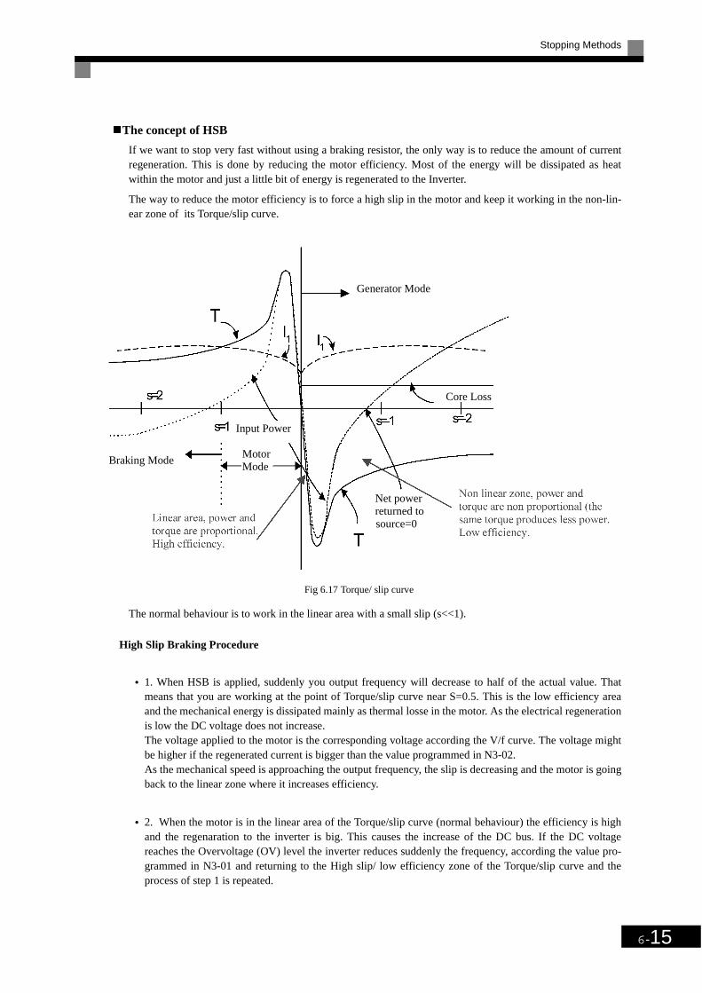
Stopping Methods
6-15
The concept of HSB
If we want to stop very fast without using a braking resistor, the only way is to reduce the amount of currentregeneration. This is done by reducing the motor efficiency. Most of the energy will be dissipated as heatwithin the motor and just a little bit of energy is regenerated to the Inverter.
The way to reduce the motor efficiency is to force a high slip in the motor and keep it working in the non-lin-ear zone of its Torque/slip curve.
Fig 6.17 Torque/ slip curve
The normal behaviour is to work in the linear area with a small slip (s<<1).
High Slip Braking Procedure
• 1. When HSB is applied, suddenly you output frequency will decrease to half of the actual value. Thatmeans that you are working at the point of Torque/slip curve near S=0.5. This is the low efficiency areaand the mechanical energy is dissipated mainly as thermal losse in the motor. As the electrical regenerationis low the DC voltage does not increase.The voltage applied to the motor is the corresponding voltage according the V/f curve. The voltage mightbe higher if the regenerated current is bigger than the value programmed in N3-02.As the mechanical speed is approaching the output frequency, the slip is decreasing and the motor is goingback to the linear zone where it increases efficiency.
• 2. When the motor is in the linear area of the Torque/slip curve (normal behaviour) the efficiency is highand the regenaration to the inverter is big. This causes the increase of the DC bus. If the DC voltagereaches the Overvoltage (OV) level the inverter reduces suddenly the frequency, according the value pro-grammed in N3-01 and returning to the High slip/ low efficiency zone of the Torque/slip curve and theprocess of step 1 is repeated.
Generator Mode
Braking Mode
Input Power
Motor Mode
Core Loss
Net power returned to
source=0

6-16
• 3. This step is not always necessary. If step 2 is not sufficient enough to stop the motor and the DC volt-age increases again, the inverter takes an other action similar like step 2.
After these steps the inverter runs during 1.5s at minimum speed and decellerates to zero following the pro-grammed ramp. This last process is to be sure that the output frequency decreases to zero so that the lineararea of the Torque/slip curve is reached.
Using an Emergency Stop
Set a multi-function input terminal (H1-) to 28 to 2B (emergency stop) to decelerate to a stop at the decel-eration time set in C1-09. If inputting the emergency stop with a NO contact, set the multi-function input ter-minal (H1-) to 28 or 2A or if inputting the emergency stop with a NC contact, set the multi-function inputterminal (H1-) to 29 or 2B.
After the emergency stop command has been input, operation cannot be restarted until the Inverter hasstopped. To cancel the emergency stop, turn OFF the run command and emergency stop command.
Related Parameters
The motor will overheat with this stopping method. Be carefull to guarantee good ventilation to themotor. Most AC motors have a thermal resistor or a clixon built in.It is strogly recommended to use the thermal resistor in case of overheating
Param-eter-
Number
Name
DescriptionSetting Range
Factory Setting
Change during Opera-
tion
Access LevelLCD Display
C1-09
Emergency stop time The deceleration time when the multi-function input “Emergency (fast) stop” is ON.This time will be used when a fault is detected, for which emergency stop was programmed.
0.0 to 6000.0
10.0 s No A
Fast Stop Time

Acceleration and Deceleration Characteristics
6-17
Acceleration and Deceleration Characteristics
Setting Acceleration and Deceleration Times
Acceleration time indicates the time to increase the output frequency from 0% to 100% of the maximum out-put frequency (E1-04). Deceleration time indicates the time to decrease the output frequency from 100% to0% of (E1-04). The factory setting of the acceleration time is C1-01 and the factory setting of the decelerationtime is C1-02.
Related Parameters
Switching Acceleration and Deceleration Time Using Multi-Function Input Terminal Com-mands
Using the SYSDRIVE PV, you can set two acceleration times and two deceleration times. When the multi-function input terminals (H1-oo) are set to 7 (acceleration/deceleration time selection 1), you can switch theacceleration/deceleration time even during operation.
The following table shows the acceleration/deceleration time switching combinations.
Param-eter
Number
Name
DescriptionSetting Range
Factory Setting
Change during Opera-
tion
Access LevelLCD Display
C1-01Acceleration time 1 Set the acceleration time to accelerate from 0 to the maxi-
mum output frequency, in 1-second units.
0.0 to 6000.0
10.0 s
Yes QAccel Time 1
C1-02Deceleration time 1 Set the deceleration time in seconds for the output fre-
quency to fall from 100% to 0%.Yes Q
Decel Time 1
C1-03Acceleration time 2 Acceleration time when multi-function input "Accelera-
tion/deceleration time selection 1" is ON.Yes A
Accel Time 2
C1-04Deceleration time 2 Deceleration time when multi-function input "Accelera-
tion/deceleration time selection 1" is ON. Yes ADecel Time 2
C1-11
Acceleration/deceleration time switching frequency
Set the frequency at which acceleration/deceleration time switches automatically.Less than set frequency: Acceleration/deceleration time 2Set frequency or above: Acceleration/deceleration time 1Multi-function inputs "Acceleration/deceleration time selection 1" and "Acceleration/deceleration time selection 2" are given priority.
0.0 to 120.0
0.0 Hz No A
Acc.Dec SW Freq
C2-01
S-curve characteristic time at acceleration start
Set the S-curve characteristic time for each part in sec-onds.When you set the S-curve characteristic time, the start time and end time S-curve characteristic time's acceleration time is lengthened by 1/2 only.
The S-curve characteristic time at start and end of deceler-ation is fixed to 0.2 sec. and can not be changed.
0.00 to 2.50
0.20 s No A
SCrv Acc@Start
C2-02
S-curve characteristic time at acceleration end
0.00 to 2.50
0.20 s No A
SCrv Dec@ End
Acceleration/Deceleration Time Selection 1 Terminal
Acceleration Time Deceleration Time
OFF C1-01 C1-02
ON C1-03 C1-04
Run command
Output frequency
Time
C2-01
C2-02
ONOFF

6-18
Switching Acceleration and Deceleration Time Automatically
Use this setting when you want to switch acceleration/deceleration time automatically using the output fre-quency.
When the output frequency reaches the set value in C1-11, the Inverter switches the acceleration/decelerationtime automatically as shown in the following diagram.
Set C1-11 to a value other than 0.0 Hz. If C1-11 is set to 0.0 Hz, the function will be disabled.
Fig 6.18 Acceleration/deceleration Time Switching Frequency
Entering S-curve Characteristics in the Acceleration and Deceleration Time
By performing acceleration using an S-curve pattern, you can reduce shock when starting the machine.
By using the SYSDRIVE PV inverter, you can set an S-curve characteristic time for each of the following: Atacceleration start and at acceleration end.
For deceleration start and deceleration end the S-curve characteristic times are fixed to 0.2 sec. They can notbe switched off or changed.
When S-curve is set, calculate acceleration/deceleration time as follows:Acceleration time = Selected acceleration time + (Acceleration start time S-curve characteristic time +
Acceleration end time S-curve characteristic time) / 2
Output frequency
Acceleration/decele-ration time switchingfrequency (C1-11)
C1-03 rate C1-01 rate C1-02 rate C1-04 rate
When output frequency ≥ C1-11, acceleration and deceleration are performed usingAcceleration/deceleration Time 1 (C1-01, C1-02).
When output frequency < C1-11, acceleration and deceleration are performed usingAcceleration/deceleration Time 2 (C1-03, C1-04).
INFO
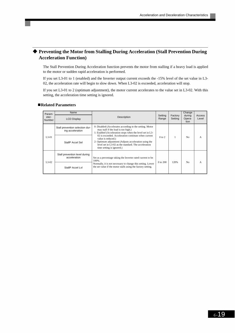
Acceleration and Deceleration Characteristics
6-19
Preventing the Motor from Stalling During Acceleration (Stall Prevention During Acceleration Function)
The Stall Prevention During Acceleration function prevents the motor from stalling if a heavy load is appliedto the motor or sudden rapid acceleration is performed.
If you set L3-01 to 1 (enabled) and the Inverter output current exceeds the -15% level of the set value in L3-02, the acceleration rate will begin to slow down. When L3-02 is exceeded, acceleration will stop.
If you set L3-01 to 2 (optimum adjustment), the motor current accelerates to the value set in L3-02. With thissetting, the acceleration time setting is ignored.
Related Parameters
Param-eter-
Number
Name
DescriptionSetting Range
Factory Setting
Change during Opera-
tion
Access LevelLCD Display
L3-01
Stall prevention selection dur-ing acceleration
0: Disabled (Accelerates according to the setting. Motor may stall if the load is too high.)
1: Enabled (Acceleration stops when the level set in L3-02 is exceeded. Acceleration continues when current value is reduced.)
2: Optimum adjustment (Adjusts acceleration using the level set in L3-02 as the standard. The acceleration time setting is ignored.)
0 to 2 1 No A
StallP Accel Sel
L3-02
Stall prevention level during acceleration Set as a percentage taking the Inverter rated current to be
100%.Normally, it is not necessary to change this setting. Lower the set value if the motor stalls using the factory setting.
0 to 200 120% No A
StallP Accel Lvl

6-20
Time Chart
The following figure shows the frequency characteristics when L3-01 is set to 1.
Fig 6.19 Time Chart for Stall Prevention During Acceleration
Setting Precautions
• If the motor capacity is small compared to the Inverter capacity or if the motor is operated using the fac-tory settings, resulting in the motor stalling, lower the value of L3-02.
• If using the motor in the parameter output range, L3-02 will be automatically lowered to prevent stalling.
• Set the parameters as a percentage taking the inverter rated current to be 100%.
Fig 6.20 Stall Prevention Level and Limit During Acceleration
Output current
Stall level duringacceleration
Time
Time
Output frequency
Output frequency is controlledto prevent the motor stalling.
Stall prevention level duringacceleration
L3-02 (Stall Prevention Level during Acceleration)
L3-02 x L3-03 (Stall Prevention Limit during Acceleration)
Output frequencyE1-06
Base Frequency (FA)

Acceleration and Deceleration Characteristics
6-21
Preventing Overvoltage During Deceleration (Stall Prevention During Decelera-tion Function)
This function automatically lengthens the deceleration time with respect to the DC-bus voltage to avoid over-voltage tripping.
Related Parameters
Setting Example
An example of stall prevention during deceleration when L3-04 is set to 1 as shown below
.
Fig 6.21 Stall Prevention During Deceleration Operation
Setting Precautions
• The stall prevention level during deceleration differs depending on the inverter rated voltage and the inputvoltage. Refer to the following table for details.
• When using the braking option (Braking Resistor Units and Braking Units), be sure to set parameter L3-04to 0.
Param-eter-
Number
Name
Description Setting Range
Factory Setting
Change during Opera-
tion
Acess LevelLCD Display
L3-04
Stall prevention selec-tion during deceleration
function selection
0: Disabled (Motor decelerates according to setting. When the deceleration time is short, there is a risk of DC bus overvol-tage (0V) occurring.)
1: Enabled (Prevents deceleration when DC bus voltage rea-ches the overvoltage level. Deceleration restarts after voltage has been restored.)
2: Optimum adjustment (Minimizes deceleration judging from DC bus voltage. The deceleration time setting is ignored.)
If using the dynamic brake option (Braking Resistor Units and Braking Units), be sure to set parameter L3-04 to 0.
0 to 2 1 No A
StallP Decel Sel
Inverter Rated/Input Voltage Stall Prevention Level during Deceleration (V)
200 V class 380
400 V classE1-01 ≥ 400 V 760
E1-01 < 400 V 660
Deceleration time controlled toprevent overvoltage
Deceleration time (set value)
Time
Output frequency

6-22
Adjusting Frequency References
Adjusting Analog Frequency References
Gain and bias are among the parameters used to adjust analog inputs.
Related Parameters
Adjusting Analog Frequency Reference Using Parameters
The frequency reference is input from the control circuit terminals using analog voltage and current.
If using frequency reference terminal A1 as an input terminal, perform adjustments using parameters H3-02and H3-03. If using multi-function analog input terminal A2 as a frequency reference terminal, performadjustments using H3-10 and H3-11.
Fig 6.22 Terminals A1 and A2 Inputs
Param-eter
Number
Name
Description Setting Range
Factory Setting
Change during Opera-
tion
Access LevelLCD Display
H3-02
Frequency reference (volt-age) terminal A1 input gain Set the frequency during 10 V input as a percentage, tak-
ing max. output frequency to be 100%.0.0 to 1000.0
100.0% Yes ATerm A1 Lvl Sel
H3-03
Frequency reference (volt-age) terminal A1 input bias Set the frequency during 0 V input as a percentage, taking
max. output frequency to be 100%.
-100.0 to
+100.00.0% Yes A
Terminal A1 Bias
H3-08
Multi-function analog input terminal A2 signal level selec-
tion 0: 0 to +10V input.2: 4 to 20 mA (9-bit input).
Switch current and voltage input using the switch S1 on the control panel.
0 or 2 2 No A
Term A2 Signal
H3-09
Multi-function analog input terminal A2 function selection Select multi-function analog input function for terminal
A2.0 to 1F 0 No A
Terminal A2 Sel
H3-10
Multi-function analog input (current) terminal A2 input
gainSet the reference capacity for each function during 10 V (20 mA) input as a percentage.Set the 100% content function selected using H3-09 to 100%.
0.0 to 1000.0
100.0% Yes A
Terminal A2 Gain
H3-11
Multi-function analog input (current) terminal A2 input
biasSet the reference capacity for each function during 0 V (4 mA) input as a percentage.Set the 100% content function selected using H3-09 to 100%.
-100.0 to
+100.00.0% Yes A
Terminal A2 BIas
Frequency reference
Terminal A1 input
Terminal A1input voltage
Frequency reference
Terminal A2 input
Terminal A2 inputvoltage (current)

Adjusting Frequency References
6-23
Adjusting Frequency Gain Using an Analog Input
When H3-09 is set to 1 (frequency gain), you can adjust the frequency gain using an analog input.
Fig 6.23 Frequency Gain Adjustment (Terminal A2 Input)
The frequency gain for terminal A1 is the sum of H3-02 and terminal A2 gain. For example, when H3-02 is setto 100% and terminal A2 is set to 5 V, the terminal A1 frequency reference will be 50%.
Adjusting Frequency Bias Using an Analog Input
When parameter H3-09 is set to 0 (add to terminal A1), the frequency equivalent to the terminal A2 input volt-age is added to A1 as a bias.
Fig 6.24 Frequency Bias Adjustment (Terminal A2 Input)
For example, if H3-02 is 100%, H3-03 is 0% and terminal A2 is set to 1 V, the frequency reference from
terminal A1 when 0 V is input to A1 will be 10%.
Frequency gain
Multi-function analog inputterminal A2 input level
Frequency reference
terminal A1 input voltage
Frequency bias
Multi-function analog inputterminal A2 input level

6-24
Operation Avoiding Resonance (Jump Frequency Function)
• This function allows the prohibition or „jumping“ of certain frequencies within the Inverter’s output fre-quency range so that the motor can operate without resonant oscillations caused by some machine systems.
• It is also used for deadband control.
Related Parameters
Param-eter-
Number
Name
DescriptionSetting Range
Factory Setting
Change during Opera-
tion
Access LevelLCD DIsplay
d3-01
Jump frequency 1
Set the frequency center value at which to prohibit set-tings.Set to 0.0 to disable the jump frequency.Make sure the settings are as follows: d3-01 ≥ d3-02 ≥ d3-03.Operation within the jump frequency range is prohibited. Changes during acceleration and deceleration are made gradually without performing jumps.
0.0 to 120.0
0.0 Hz No A
Jump Freq 1
d3-02
Jump frequency 2
0.0 Hz No A
Jump Freq 2
d3-03
Jump frequency 3
0.0 Hz No A
Jump Freq 3
d3-04
Jump frequency width Set the jump frequency width in hertz.The jump frequency range is as follows: (Jump frequency ±d3-04).
0.0 to 20.0
1.0 Hz No AJump Bandwith
Frequency reference
Terminal A1 input voltage

Adjusting Frequency References
6-25
The relationship between the output frequency and the jump frequency reference is as follows:
Fig 6.25 Jump Frequency
Setting Precautions
• Set the jump frequency according to the following formula: d3-01 ≥ d3-02 ≥ d3-03 > Analog input.
• When parameters d3-01 to d3-03 are set to 0 Hz, the jump frequency function is disabled.
Output frequency
Frequency reference descending
Jump Bandwidth d3-04
Jump frequency reference
Frequency reference ascending
Jump Bandwidth
d3-04Jump
Bandwidth d3-04
Jump freq 3 (d3-03)
Jump freq 2 (d3-02)
Jump freq 1 (d3-01)

6-26
Speed Limit (Frequency Reference Limit Function)
Limiting Maximum Output Frequency
If you do not want the motor to rotate above a given frequency, use parameter d2-01.
Set the upper limit value of the Inverter output frequency as a percentage, taking E1-04 (Maximum OutputFrequency) to be 100%.
Related Parameters
Limiting Minimum Frequency
If you do not want the motor to rotate at below a given frequency, use parameters d2-02 or d2-03.
There are two methods of limiting the minimum frequency, as follows:
• Adjust the minimum level for all frequencies.
• Adjust the minimum level for the master speed frequency (i.e., the lower levels of the jog frequency, multi-step speed frequency and auxiliary frequency will not be adjusted).
Related Parameters
Zero speed setting
If zerospeed setting is set within parameter H2-01 or H2-02, option 1 , the Inverter will operate at the set
minimumfrequency level programmed in parameter E1-09. One of the programmed outputs will close its
contact.
Param-eter-
Number
Name
DescriptionSetting Range
Factory Setting
Change during Opera-
tion
Access LevelLCD Display
d2-01
Frequency reference upper limit Set the output frequency upper limit, taking the
max. output frequency to be 100%.0.0 to 110.0
100.0% No ARef Upper Limit
Param-eter-
Number
Name
DescriptionSetting Range
Factory Setting
Change during Opera-
tion
Access LevelLCD Display
d2-02
Frequency reference lower limit Set the output frequency lower limit, taking the
base reference to be 100%.0.0 to 110.0
0.0% No ARef Lower LImit
d2-03
Master speed reference lower limit Set the master speed reference lower limit, taking
the max. output frequency to be 100%.0.0 to 110.0
0.0% No ARef1 Lower Limit

Improved Operating Efficiency
6-27
Improved Operating EfficiencyThis section explains functions for improving motor operating efficiency.
Compensating for Insufficient Torque at Start and Low-speed Operation (Torque Compensation)
The torque compensation function detects that the motor load has increased and increases the output torque.
The Torque Compensation function calculates and adjusts the motor primary loss voltage according to the out-put voltage (V) and compensates for insufficient torque at startup and during low-speed operation. Calculatethe compensation voltage as follows: Motor primary voltage loss x parameter C4-01.
Related Parameters
Adjusting Torque Compensation Gain
Normally, there is no need to make this adjustment.
Adjust the torque compensation gain under the following circumstances.
• If the cable is very long, increase the set value.
• If the (maximum applicable) motor capacity is smaller than the Inverter capacity, increase the set value.
• If the motor is vibrating, reduce the set value.
Adjust this parameter so that the output current during low-speed rotation does not exceed the Inverter’s ratedoutput current range.
Adjusting the Torque Compensation Primary Delay Time parameter
Set the torque compensation function primary delay in ms.
Normally, there is no need to make this setting. Adjust the parameter as shown below.
• If the motor is vibrating, increase the set value.
• If the motor response is low, decrease the set value.
Param-eter-
Number
Name
DescriptionSetting Range
Factory Setting
Change during Opera-
tion
Access LevelLCD Display
C4-01
Torque compensation gain
Set the torque compensation gain using the multiplication factor. Normally, there is no need to set this parameter. Adjust the torque compensation gain in the following cir-cumstances.• If the cable is very long, increase the set value.• If the (maximum applicable) motor capacity is smaller
than the Inverter capacity, increase the set value.• If the motor is vibrating, reduce the set value.Adjust this parameter so that the output current during low-speed rotation does not exceed the Inverter rated out-put current range.
0.00 to 2.50
1.00 Yes A
Torq Comp Gain
C4-02
Torque compensation primary delay time
Set the primary delay for the torque compensation function in ms.Normally, there is no need to make this setting. Adjust this parameter in the following circumstances.• If the motor is vibrating, increase the set value.• If the motor response is low, decrease the set value.
0 to 10000
200 ms No A
Torq Comp Time
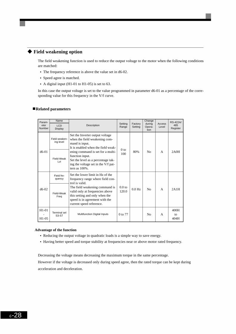
6-28
Field weakening option
The field weakening function is used to reduce the output voltage to the motor when the following conditionsare matched:
• The frequency reference is above the value set in d6-02.
• Speed agree is matched.
• A digital input (H1-01 to H1-05) is set to 63.
In this case the output voltage is set to the value programmed in parameter d6-01 as a percentage of the corre-sponding value for this frequency in the V/f curve.
Related parameters
Advantage of the function
• Reducing the output voltage in quadratic loads is a simple way to save energy.
• Having better speed and torque stability at frequencies near or above motor rated frequency.
Decreasing the voltage means decreasing the maximum torque in the same percentage.
However if the voltage is decreased only during speed agree, then the rated torque can be kept during
acceleration and deceleration.
Param-eter
Number
Name
DescriptionSetting Range
Factory Setting
Change during Opera-
tion
Access Level
RS-422A/485
RegisterLCD
Display
d6-01
Field weaken-ing level
Set the Inverter output voltage when the field weakening com-mand is input.It is enabled when the field weak-ening command is set for a multi-function input.Set the level as a percentage tak-ing the voltage set in the V/f pat-tern as 100%.
0 to 100
80% No A 2A0H
Field-Weak Lvl
d6-02
Field fre-quency
Set the lower limit in Hz of the frequency range where field con-trol is valid.The field weakening command is valid only at frequencies above this setting and only when the speed is in agreement with the current speed reference.
0.0 to 120.0
0.0 Hz No A 2A1HField-Weak
Freq
H1-01-
H1-05
Terminal selS3-S7
Multifunction Digital Inputs 0 to 77 No A400H
to404H

Improved Operating Efficiency
6-29
Hunting-prevention Function
The hunting-prevention function suppresses hunting when the motor is operating with a light load.
Related Parameters
Param-eter-
Number
Name
DescriptionSetting Range
Factory Setting
Change during Opera-
tion
Access LevelLCD
Display
N1-01
Hunting-prevention function selection
0: Hunting-prevention function disabled1: Hunting-prevention function enabled
The hunting-prevention function suppresses hunting when the motor is operating with a light load.If high response is to be given priority over vibration sup-pression, disable the hunting-prevention function.
0 or 1 1 No A
Hunt Prev Select
N1-02
Hunting-prevention gain Set the hunting-prevention gain multiplication factor.Normally, there is no need to make this setting.Make the adjustments as follows:• If vibration occurs with light load, increase the setting.• If the motor stalls, reduce the setting.If the setting is too large, the voltage will be too sup-pressed and the motor may stall.
0.00 to 2.50
1.00 No A
Hunt Prev Gain

6-30
Machine Protection
Preventing Motor Stalling During Operation
Stall prevention during operation prevents the motor from stalling by automatically lowering the Inverter'soutput frequency when a transient overload occurs while the motor is operating at a constant speed.
If the Inverter output current continues to exceed the setting in parameter L3-06 for 100 ms or longer, themotor speed is reduced. Set the enable or disable deceleration time using parameter L3-05. Set the decelera-tion time using C1-02 (Deceleration time 1) or C1-04 (Deceleration Time 2).
If the Inverter output current reaches the set value in L3-06 – 2%, the motor will accelerate again to the set fre-quency.
Related Parameters
Detecting Motor Torque
If an excessive load is placed on the machinery (overtorque) or the load is suddenly lightened (undertorque),you can output an alarm signal to multi-function output terminal M1-M2 or M3-M4.
To use the overtorque/undertorque detection function, set B or 17 (overtorque/undertorque detection NO/NC)in one of the following parameters: H2-01 and H2-02 (multi-function output terminals M1-M2 and M3-M4function selection).
The overtorque/undertorque detection level is the current level (Inverter rated output current 100%).
Param-eter-
Number
Name
DescriptionSetting Range
Factory Setting
Change during Opera-
tion
Access LevelLCD Display
L3-05
Stall prevention selec-tion during running func-
tion selection
0: Disabled (Operates according to the setting. Motor may stall when the load is large.)
1: Enabled--Deceleration time 1 (Stall prevention func-tion during operation deceleration time is set in C1-02.)
2: Enabled--Deceleration time 2 (Stall prevention func-tion during operation deceleration time is set in C1-04.)
0 to 2 1 No A
StallP Run Sel
L3-06
Stall prevention level during running
Enabled when L3-05 is set to 1 or 2. Set as a percentage, taking Inverter rated current to be 100%.Normally, there is no need to make this setting.Lower the set value if the motor stalls at the factory set-ting.
30 to 200 120% No A
StallP Run Level

Machine Protection
6-31
Related Parameters
Multi-function Output (H2-01 and H2-02)
L6-01 Set Values and LED Indicators
The relationship between alarms displayed by the Digital Operator when overtorque or undertorque isdetected and the set values in L6-01, is shown in the following table.
Param-eter-
Number
Name
DescriptionSetting Range
Factory Setting
Change during Opera-
tion
Access LevelLCD Display
L6-01
Torque detection selec-tion 1
0: Overtorque/undertorque detection disabled.1: Overtorque detection only with speed agreement; oper-
ation continues after overtorque (warning).2: Overtorque detected continuously during operation;
operation continues after overtorque (warning).3: Overtorque detection only with speed agreement; out-
put stopped upon detection (protected operation).4: Overtorque detected continuously during operation;
output stopped upon detection (protected operation).5: Undertorque detection only with speed agreement;
operation continues after overtorque (warning).6: Undertorque detected continuously during operation;
operation continues after overtorque (warning).7: Undertorque detection only with speed agreement; out-
put stopped upon detection (protected operation).8: Undertorque detected continuously during operation;
output stopped upon detection (protected operation).
0 to 8 0 No A
Torq Det Sel
L6-02
Torque detection level 1
V/f control: Inverter rated current is set as 100%. 0 to 300 150% No AToq Det 1 Lvl
L6-03Torque detection time 1
Set the overtorque/undertorque detection time.0.0 to 10.0
0.1 s No ATorq Det 1 Time
Set Value Function
BOvertorque/undertorque detection 1 NO(NO contact: Overtorque detection and undertorque detection enabled when contact is ON)
17Overtorque/undertorque detection 1 NC(NC contact: Overtorque detection and undertorque detection enabled when contact is OFF)
Set Value
FunctionLED Indicator
Overtorque/Undertorque Detection 1
0 Overtorque/undertorque detection disabled. -
1Overtorque detection only with speed matching; operation continues after overtorque (warning).
OL3 flashes
2Overtorque detected continuously during operation; operation continues after overtorque (warning).
OL3 flashes
3Overtorque detection only with speed matching; output stopped upon detec-tion (protected operation).
OL3 lit
4Overtorque detected continuously during operation; output stopped upon detection (protected operation).
OL3 lit
5Undertorque detection only with speed matching; operation continues after overtorque (warning).
UL3 flashes
6Undertorque detected continuously during operation; operation continues after overtorque (warning).
UL3 flashes
7Undertorque detection only with speed matching; output stopped upon detection (protected operation).
UL3 lit

6-32
Setting Example
The following diagram shows the time chart for overtorque and undertorque detection.
• Overtorque Detection
• Undertorque Detection
8Undertorque detected continuously during operation; output stopped upon detection (protected operation).
UL3 lit
Set Value
FunctionLED Indicator
Overtorque/Undertorque Detection 1
Motor current
L6-02
L6-03L6-03Overtorque detection 1 NO
*Overtorque detection disabled band is approximately 10% of the Inverter rated output current.
Motor current (output torque)
L6-02
L6-03L6-03Overtorque detection 1 NO
*Overtorque detection disabled band is approximately 10% of the Inverter rated output current.
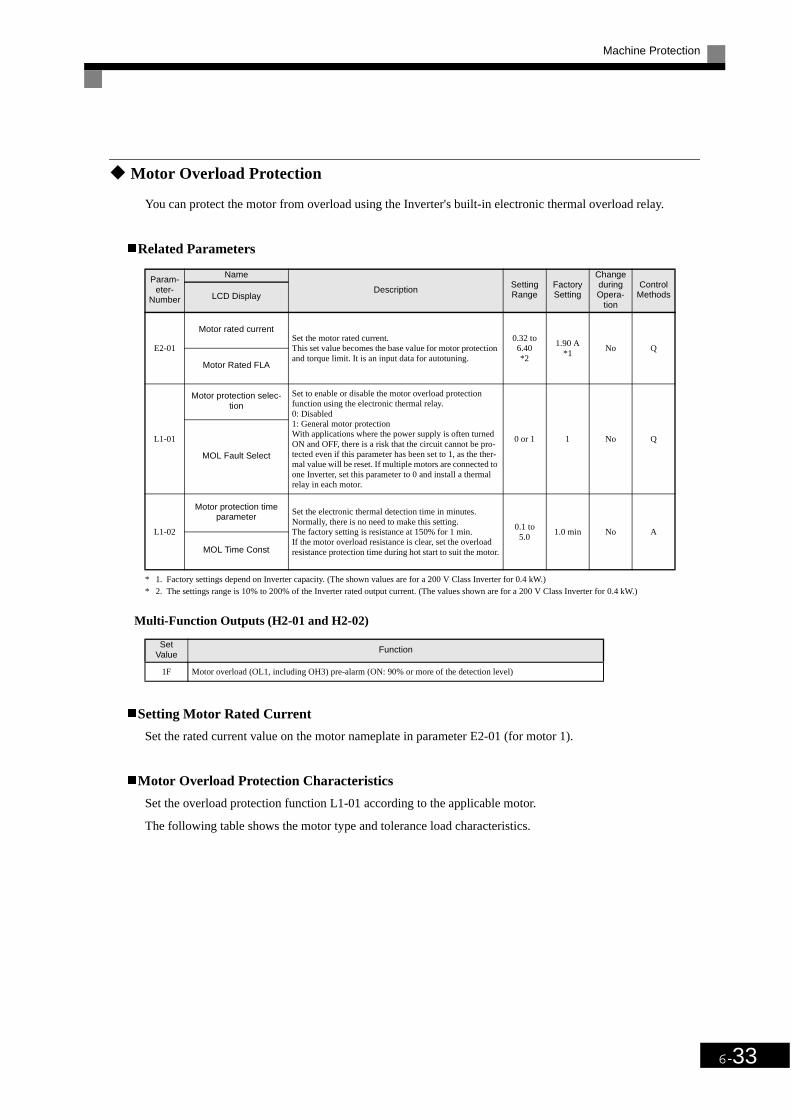
Machine Protection
6-33
Motor Overload Protection
You can protect the motor from overload using the Inverter's built-in electronic thermal overload relay.
Related Parameters
* 1. Factory settings depend on Inverter capacity. (The shown values are for a 200 V Class Inverter for 0.4 kW.)* 2. The settings range is 10% to 200% of the Inverter rated output current. (The values shown are for a 200 V Class Inverter for 0.4 kW.)
Multi-Function Outputs (H2-01 and H2-02)
Setting Motor Rated Current
Set the rated current value on the motor nameplate in parameter E2-01 (for motor 1).
Motor Overload Protection Characteristics
Set the overload protection function L1-01 according to the applicable motor.
The following table shows the motor type and tolerance load characteristics.
Param-eter-
Number
Name
DescriptionSetting Range
Factory Setting
Change during Opera-
tion
Control MethodsLCD Display
E2-01
Motor rated currentSet the motor rated current.This set value becomes the base value for motor protection and torque limit. It is an input data for autotuning.
0.32 to 6.40*2
1.90 A*1
No Q
Motor Rated FLA
L1-01
Motor protection selec-tion
Set to enable or disable the motor overload protection function using the electronic thermal relay.0: Disabled1: General motor protectionWith applications where the power supply is often turned ON and OFF, there is a risk that the circuit cannot be pro-tected even if this parameter has been set to 1, as the ther-mal value will be reset. If multiple motors are connected to one Inverter, set this parameter to 0 and install a thermal relay in each motor.
0 or 1 1 No Q
MOL Fault Select
L1-02
Motor protection time parameter
Set the electronic thermal detection time in minutes.Normally, there is no need to make this setting.The factory setting is resistance at 150% for 1 min.If the motor overload resistance is clear, set the overload resistance protection time during hot start to suit the motor.
0.1 to5.0
1.0 min No A
MOL Time Const
Set Value
Function
1F Motor overload (OL1, including OH3) pre-alarm (ON: 90% or more of the detection level)

6-34
Setting Motor Protection Operation Time
Set the motor protection operation time in L1-02.
If, after operating the motor continuously at the rated current, a 120% overload is experienced, set the (hotstart) electronic thermal protection operation time. The factory setting is resistance to 120% for 60 seconds.
The following diagram shows an example of the characteristics of the electronic thermal protection operationtime (L1-02 = 1.0 min., operation at 60 Hz, general-purpose motor characteristics, when L1-01 is set to 1)
Fig 6.26 Motor Protection Operation Time
Setting Precautions
• If multiple motors are connected to one Inverter, set parameter L1-01 to 0 (disabled). To protect the motor,install a thermal relay in the motor power cable and perform overload protection on each motor.
• With applications where the power supply is often turned ON and OFF, there is a risk that the circuit can-not be protected even if this parameter has been set to 1 (enabled), because the thermal value will be reset.
• For save overload tripping, set the set value in parameter L1-02 to a low setting.
• When using a general-purpose motor (standard motor), the cooling ability will be lowered by f1/4 (fre-quency). Consequently, the frequency may cause motor overload protection (OL1) to occur, even belowthe rated current. If operating on the rated current at a low frequency, use a special motor.
Setting the Motor Overload Pre-Alarm
If the motor overload protection function is enabled (i.e., L1-01 is set to 1) and you set H2-01 or H2-02 (multi-function output terminals M1-M2 and M3-M4 function selection) to 1F (motor overload OL1 pre-alarm), the
L1-01 Set
ValueMotor Type Tolerance Load Characteristics Cooling Ability
Electronic Thermal Operation (at 100%
Motor Load)
1General-purpose motor (standard motor)
Use this motor for operations using a commercial power supply. This motor construction yields best cooling effect when operating at 50/60 Hz.
When operating continu-ously at 50/60 Hz or less, motor overload detection (OL1) is detected. The Inverter outputs the error contact and the motor coasts to a stop.
Torq
ue (
%)
Short time 60s Rated rotation speed= 100% speed
3.7 kW max.5.5 to 15 kW
18.5 kW min.
80% ED or Frame number Max.30 min. speed of 200 LJ min.
50% ED or 30 min.
ContinuousFramenu m be rMax.speed of200 LJ
Frame number Max.speed of 160 MJ to180 LJ
Frame numberMax. speed of132 MJ
min.
Rotation speed (%)
Operating time (min.)
Cold start
Hot start
Motor current (%)E2-01 is set to 100%

Machine Protection
6-35
motor overload pre-alarm will be enabled. If the electronic thermal value reaches minimum 90% of the over-load detection level, the output terminal that has been set will be turned ON.
Motor Overheating Protection Using PTC Thermistor Inputs
Perform motor overheating protection using the thermistor temperature resistance characteristics of the PTC(Positive Temperature Coefficient) built into the windings of each motor phase.
Related Parameters
PTC Thermistor Characteristics
The following diagram shows the characteristics of the PTC thermistor temperature to the resistance value.
Fig 6.27 PTC Thermistor Temperature-Resistance Value Characteristics
Param-eter-
Number
Name
Description Setting Range
Factory Setting
Change during Opera-
tion
Access LevelLCD Display
L1-03
Alarm operation selection dur-ing motor overheating
Set H3-09 to E and select the operation when the input motor temperature (thermistor) input exceeds the alarm detection level (1.17 V).0: Decelerate to stop1: Coast to stop2: Emergency stop using the deceleration time in C1-09.3: Continue operation (OH3 on the Digital Operator
flashes).
0 to 3 3 No A
Mtr OH Alarm Sel
L1-04
Motor overheating operation selection
Set H3-09 to E and select the operation when the motor temperature (thermistor) input exceeds the operation detection level (2.34 V).0: Decelerate to stop1: Coast to stop2: Emergency stop using the deceleration time in C1-09.
0 to 2 1 No A
Mtr OH Fault Sel
L1-05
Motor temperature input filter time parameter
Set H3-09 to E and set the primary delay time parameter for motor temperature (thermistor) inputs in seconds.
0.00 to10.00
0.20 s No A
Mtr Temp Filter
Resistance (Ohms) Class F Class H
Tr: Temperature threshold value
Temperatue

6-36
Operation during Motor Overheating
Set the operation if the motor overheats in parameters L1-03 and L1-04. Set the motor temperature input filtertime parameter in L1-05. If the motor overheats, the OH3 and OH4 error codes will be displayed on the Digi-tal Operator.
Error Codes If the Motor Overheats
By setting H3-09 (Multi-function Analog Input Terminal A2 Function Selection) to E (Motor temperatureinput), you can detect alarm OH3 or OH4 using the PTC temperature-resistance characteristics and protect themotor. The terminal connections are shown in the following diagram.
Fig 6.28 Mutual Connections for Motor Overheating Protection
Setting Precautions
• When inputting a voltage signal to terminal A2, pin 2 of the DIP-switch S1 on the control terminal boardhas to be turned to OFF (A2 voltage input). The factory setting is ON (A2 current input).
• The parameter H3-08 (analog input terminal A2 signal level) has to be set to 0 (0-10V input).
Error Code Details
OH3 Inverter stops or continues to operate, according to the setting in L1-03.
OH4 Inverter stops according to the setting in L1-04.
Inverter
Multi-functioncontact input
Branch resistance 18 kΩ *1
PTC thermistor
Multi-functioncontact output
Fault contactoutput
Multi-functionPHC output
*1 The resistance value of 18 kΩ is only valid for using a 3-phase PTC with the characteristic shown on the previous page.

Continuing Operation
6-37
Continuing OperationThis section explains functions for continuing or automatically restarting Inverter operation after amomentary power loss.
Restarting Automatically After Power Is Restored
After a momentary power loss, the Inverter can be restarted automatically to continue motor operation.
To restart the Inverter after power is recovered, set L2-01 to 1 or 2.
If L2-01 is set to 1, when power is recovered within the time set in L2-02, the Inverter will restart. If the powerloss time exceeds the time set in L2-02, an alarm UV1 (main circuit undervoltage) will be detected.
If L2-01 is set to 2, when the main power supply is recovered while the control power supply (i.e., power sup-ply to the control circuit) is backed up, the Inverter will restart. Consequently, alarm UV1 (main circuit under-voltage) will not be detected.
Related Parameters
* 1. Factory settings depend on Inverter capacity. (The values shown are for a 200 V Class Inverter for 0.4 kW.)* 2. These values are for a 200 V Class Inverter. For a 400 V Class Inverter, double the values.
Setting Precautions
• Error output signals are not output during momentary power loss recovery.
• To continue Inverter operation after power has been restored, make settings so that run commands fromthe control main circuit terminal are stored even while power is suspended.
• If the momentary power loss operation selection is set to 0 (Disabled), when the momentary power lossexceeds 15 ms during operation, alarm UV1 (main circuit undervoltage) will be detected.
Param-eter-
Number
Name
DescriptionSetting Range
Factory Setting
Change during Opera-
tion
Access LevelLCD Display
L2-01
Momentary power loss detec-tion
0: Disabled (main circuit undervoltage (UV) detection)1: Enabled (Restarted when the power returns within the
time for L2-02. When L2-02 is exceeded, main circuit undervoltage detection.)
2: Enabled while CPU is operating. (Restarts when power returns during control operations. Does not detect main circuit undervoltage.)
0 to 2 0 No A
PwrL Selection
L2-02
Momentary power loss ride-thru time Ridethrough time, when momentary power loss selection
(L2-01) is set to 1.0 to 2.0 0.1 s
*1No A
PwrL Ridethru t
L2-03
Min. baseblock (BB) time Set the Inverter’s minimum baseblock time; when the Inverter is restarted after power loss ridethrough.Sets the time to approximately 0.7 times of the motor sec-ondary circuit time parameter.When an overcurrent or overvoltage occurs during a speed search or DC injection braking, increase the set values.
0.1 to 5.0 0.1 s No A
PwrL Baseblock t
L2-04
Voltage recovery time Set the time required to return the Inverter output voltage to normal voltage at the completion of a speed search.Set the time required to recover from 0 V to the maximum voltage.
0.0 to5.0 0.3 s*1 No A
PwrL V/f Ramp t
L2-05
Undervoltage (UV) detection level Sets the main circuit undervoltage (UV) detection level
(main circuit DC voltage).Usually changing this setting is not necessary.Insert an AC reactor in the Inverter input side to lower the main circuit undervoltage detection level.
150 to210*2
190 V*2
No A
PUV Det Level

6-38
Speed Search
The speed search function finds the actual speed of a motor that is coasting without control and then startssmoothly from that speed. It is also activated after momentary power loss detection when L2-01 is set toenabled.
Related Parameters
* 1. The factory setting will change when the control method is changed. (Open loop vector control factory settings are given.)* 2. Factory settings depend on Inverter capacity. (The values shown are for a 200 V Class Inverter for 0.4 kW.)
Param-eter-
Number
Name
DescriptionSetting Range
Factory Setting
Change during Opera-
tion
Access LevelLCD Display
b3-01
Speed search selection (current detection or speed calculation)
Enables/disables the speed search function for the RUN com-mand and sets the speed search method.0: Disabled, speed calculation1: Enabled, speed calculation2: Disabled, current detection3: Enabled, current detectionSpeed CalculationWhen the search is started, the motor speed is calculated and acceleration/deceleration is performed from the calculated speed to the specified frequency (motor direction is also sear-ched).Current DetectionThe speed search is started from the frequency when power was momentarily lost or the maximum frequency and the speed is detected when the set search current level is reached.
0 to 4 2*1 No A
Slip Comp Gain
b3-02
Speed search operating current (current detec-
tion)Sets the speed search operation current as a percentage, taking the Inverter rated current as 100%.Not usually necessary to set. When restarting is not possible with the factory settings, reduce the value.
0 to 200
120% No A
SpdSrch Current
b3-03
Speed search decelera-tion time (current detec-
tion)Sets the output frequency deceleration time during speed search.Set the time for deceleration from the maximum output fre-quency to the minimum output frequency.
0.1 to 10.0
2.0 s No A
SpdSrch Dec Time
b3-05
Speed search wait time (current detection or speed calculation)
Sets the contactor operating delay time when there is a contac-tor on the output side of the Inverter. When a speed search is performed after recovering from a momentary power loss, the search operation is delayed by the time set here.
0.0 to 20.0
0.2 s No A
Search Delay
L2-03
Min. baseblock time Sets the Inverter’s minimum baseblock time, when the inverter is restarted after power loss ridethrough.Sets the time to approximately 0.7 times the motor secondary circuit time parameter.If an overcurrent or undercurrent occurs when starting a speed search or DC injection braking, increase the set values.
0.1 to 5.0 0.1 s *1 No A
PwrL Baseblock t
L2-04
Voltage recovery time Sets the time required to return the Inverter output voltage to normal voltage at the completion of a speed search.Sets the time required to recover from 0 V to the maximum voltage.
0.0 to5.0 0.3 s*2 No A
PwrL V/f Ramp t

Continuing Operation
6-39
Multi-function Contact Inputs
Setting Precautions
• When both external search commands 1 and 2 are set for the multi-function contact terminals, an OPE03(invalid multi-function input selection) operation error will occur. Set either external search command 1 orexternal search command 2.
• If performing speed search using external search commands, add an external sequence so that the run com-mand and external search command are both ON. This two commands must be kept on, at least for thetime set in parameter L2-03.
• If the Inverter output is equipped with a contact, set the contact operation delay time in the Speed SearchWait Time (b3-05). The factory setting is 0.2 s. When not using the contact, you can reduce the search timeby setting 0.0 s. After waiting for the speed search wait time, the Inverter starts the speed search.
• Parameter b3-02 is a current detection speed search (current detection level for search completion). Whenthe current falls below the detection level, the speed search is viewed as completed and the motor acceler-ates or decelerates to the set frequency.
• If an overcurrent (OC) is detected when using speed search after power recovery, lengthen the MinimumBaseblock Time (L2-03).
Application Precautions for Speed Searches Using Estimated Speed
• Always perform stationary autotuning for line-to-line resistance before using speed searches based on esti-mated speeds.
• If the cable length between the motor and Inverter is changed after autotuning has been performed, per-form autotuning again.
Set Value
Function Access Level
61
External search command 1OFF: Speed search disabled (Start from lowest output frequency)ON: Speed estimation (Estimate the motor speed and start search from estimated speed)
Current detection (Start speed search from maximum output frequency)
Yes
62
External search command 2OFF: Speed search disabled (Start from lowest output frequency)ON: Speed estimation (Estimate the motor speed and start search from estimated speed) (Same operation as external
search command 1)Current detection: Start speed search from set frequency (reference frequency when search command was input).
Yes
64
External search command 3OFF: Speed search disabled (Start from lowest output frequency)ON: Speed estimation (Estimate the motor speed and start search from estimated speed) (Same operation as external
search command 1)Current detection: Start speed search from output frequency (reference frequency when search command was input).
Yes

6-40
Speed Search Selection
Set whether to enable or disable speed search at start and set the type of speed search (estimated speed or cur-rent detection) using setting b3-01. To perform speed search when inputting the run command, set b3-01 to 1or 3.
Estimated Speed Search
The time chart for estimated speed searches is shown below.
Search at Startup
The time chart for when speed search at startup and speed search to multi-function input terminals is shownbelow.
Fig 6.29 Speed Search at Startup (Estimated Speed)
Table 6.1 Search Methods
Search Name Estimated Speed Current Detection
Search Method
Estimates the motor speed when the search starts and accelerates and decelerates from the estimated speed to the set frequency. You can also search including direction of motor rota-tion.
Starts speed search from the frequency when the temporary power loss was detected or from the highest frequency and performs speed detection by watching the current level during the search.
External Speed Search Command
External search command 1 and external search command 2 become the same operation, estimating the motor speed and starting the search from the estimated speed.
External speed search command 1:Starts speed search from the maximum output frequency.External speed search command 2:Starts speed search from the frequency refer-ence set before the search command.
Application Precau-tions
Cannot be used multi-motor drives, motors two or more frames smaller than the Inverter capac-ity.
The motor may accelerate suddenly with light loads.
OFF ONRun command
Output frequency
Output current
0.7 to 1.0 s
Minimum baseblock time (L2-03) x 0.7*
Deceleration time set in b3-03
b3-02
*Lower limit set using Speed Search Wait Time (b3-05)
Set frequency reference
Note: If the stopping method is set to coast to stop and the run command turns ON in a short time, the operation may be the same as the search in case 2.
Set usingspeed detected

Continuing Operation
6-41
Speed Search after Short Baseblock (during Power Loss Recovery, etc.)
• Loss Time shorter than the Minimum Baseblock Time (L2-03)
Fig 6.30 Speed Search after Baseblock (When Estimated Speed: Loss Time Is Set in L2-03)
• Loss Time longer than the Minimum Baseblock Time (L2-03)
Fig 6.31 Speed Search after Baseblock (Estimated Speed: Loss Time > L2-03)
AC power supply ON OFF
Output current
Minimum baseblock time (L2-03) x 0.75 *1
10 ms
Start usingspeed detected
Set frequencyreference
*1. Baseblock time may be reduced by the output frequency immediately before the baseblock.
*2. After AC power supply recorvery, motor waits for the minimum Speed Search Wait Time (b3-05).
Set frequencyreference
Minimum baseblock time(L2-03)
Speed Search Wait Time(b3-05)
Note: If the frequency immediately before the baseblock is low or the power supply break time is long, operation may be the same as the search in case 1.
AC power supply ON OFF
Output frequency
Output current
Start using speed detected
10 ms
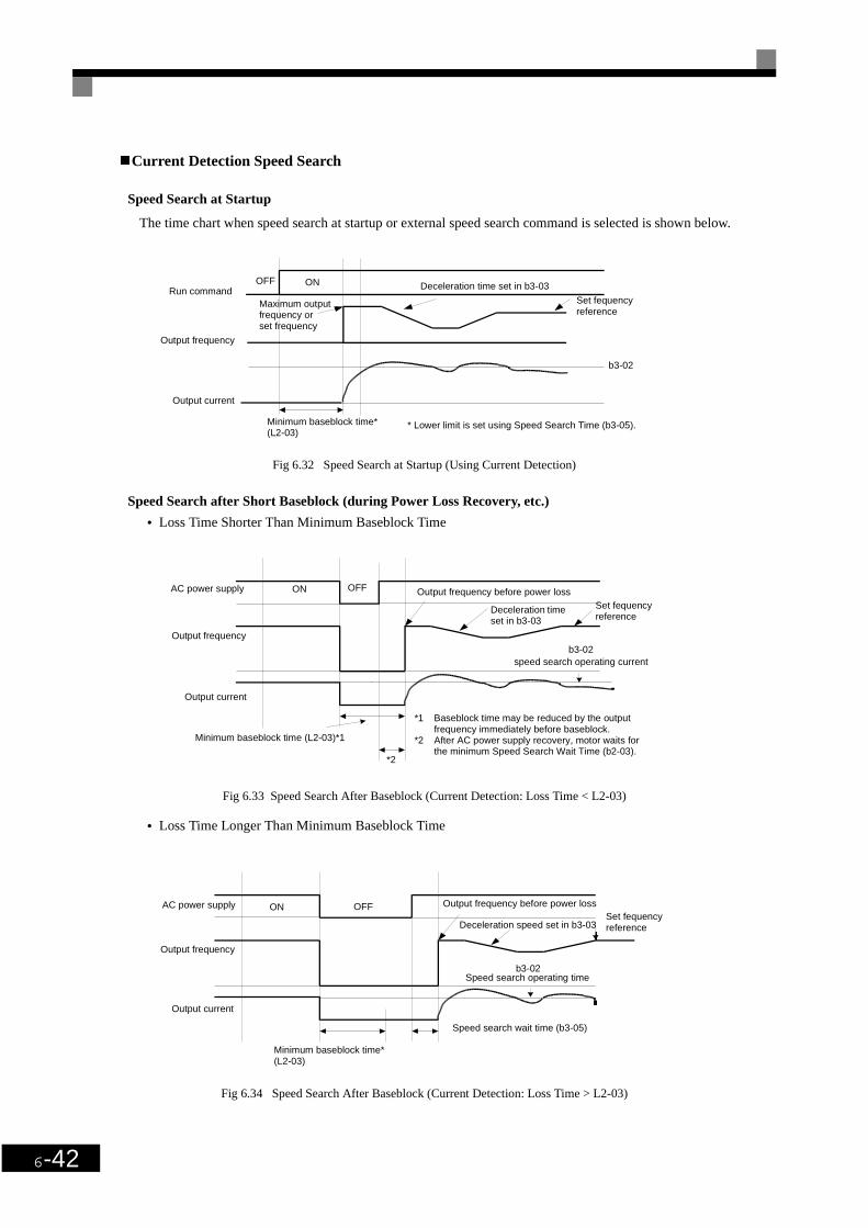
6-42
Current Detection Speed Search
Speed Search at Startup
The time chart when speed search at startup or external speed search command is selected is shown below.
Fig 6.32 Speed Search at Startup (Using Current Detection)
Speed Search after Short Baseblock (during Power Loss Recovery, etc.)
• Loss Time Shorter Than Minimum Baseblock Time
Fig 6.33 Speed Search After Baseblock (Current Detection: Loss Time < L2-03)
• Loss Time Longer Than Minimum Baseblock Time
Fig 6.34 Speed Search After Baseblock (Current Detection: Loss Time > L2-03)
OFF ONRun command
Output frequency
Output current
* Lower limit is set using Speed Search Time (b3-05).
Deceleration time set in b3-03
b3-02
Set fequency reference
Maximum output frequency or set frequency
Minimum baseblock time*(L2-03)
OFFONAC power supply
Output frequency
Output current
Set fequency reference
Minimum baseblock time (L2-03)*1
*2
Output frequency before power loss
speed search operating current
Deceleration time set in b3-03
*1 Baseblock time may be reduced by the output frequency immediately before baseblock.
*2 After AC power supply recovery, motor waits for the minimum Speed Search Wait Time (b2-03).
b3-02
Minimum baseblock time*(L2-03)
OFFONAC power supply
Output frequency
Output current
Set fequency reference
Speed search operating timeb3-02
Deceleration speed set in b3-03
Output frequency before power loss
Speed search wait time (b3-05)

Continuing Operation
6-43
Continuing Operation at parameter Speed When Frequency Reference Is Lost
The frequency reference loss detection function continues operation at reduced speed using the set value inparameter L4-06 as frequency reference value. When using an analog input as frequency reference, a fre-quency reference loss is detected, when the reference value drops over 90 % in 400 ms or less.
When the error signal during frequency reference loss is output externally, set H2-01 or H2-02 (multi-functioncontact output terminal M1-M2 and M3-M4 function selection) to C (frequency reference lost).
Related Parameters
Restarting Operation After Transient Error (Auto Restart Function)
If an Inverter error occurs during operation, the Inverter will perform self-diagnosis. If no error is detected, theInverter will automatically restart. This is called the auto restart function.
Set the number of auto restarts in parameter L5-01.
The auto restart function can be applied to the following errors. If an error not listed below occurs, the protec-tion function will operate and the auto restart function will not work.
* When L2-01 is set to 1 or 2 (continue operation during momentary power loss)
Auto Restart External Outputs
To output auto restart signals externally, set H2-01 or H2-02 (multi-function contact output terminals M1-M2and M3-M4 function selection) to 1E (auto restart).
Param-eter-
Number
Name
Description Setting Range
Factory Setting
Change during Opera-
tion
Access LevelLCD Display
L4-05
Operation when fre-quency reference is
missing
0: Stop1: Operation (L4-06*fref@loss) inverter runs with reduced speed.Frequency reference is lost: Frequency reference dropped over 90% in 400 ms.
0 or 1 0 No A
Ref Loss Sel
L4-06
Output frequency adjust-ment after freq. refer-
ence lossIf L4-05 is set to 1 and the reference is lost, inverter will run at:fout = L4-06*frefbefore lossing.
0 – 100% 80% No A
Fref at Floss
• OC (Overcurrent) • LF (Output phase failure)
• GF (Ground fault) • OL1 (Motor overload)
• PUF (Fuse blown) • OL2 (Inverter overload)
• OV (Main circuit overvoltage) • OH1 (Motor overheat)
• UV1 (Main Circuit Undervoltage, Main Circuit MC Operation Failure)* • OL3 (Overtorque)
• PF (Main circuit voltage fault)

6-44
Related Parameters
Application Precautions
• The number of auto restarts counter is reset under the following conditions:After auto restart, normal operation has continued for 10 minutes.
After the protection operation has been performed and the error has been verified and an error reset
has been input.
After the power supply is turned OFF and then ON again.
Param-eter-
Number
Name
DescriptionSetting Range
Factory Setting
Change during Opera-
tion
Access LevelLCD Display
L5-01
Number of auto restart attempts
Set the number of auto restarts attempts.Automatically restarts after a fault and conducts a speed search from the run frequency.
0 to 10 0 No ANum of Restarts
L5-02
Auto restart operation selection
Sets whether a fault contact output is activated during fault restart.0: No output (Fault contact is not activated.)1: Output (Fault contact is activated.)
0 or 1 0 No ARestart Sel

Inverter Protection
6-45
Inverter Protection
Reducing Inverter Overheat Pre-Alarm Warning Levels
The Inverter detects the temperature of the cooling fin using the thermistor and protects the Inverter fromoverheating.
The following overheating pre-alarm warnings are available: Stopping the Inverter as error protection andcontinuing operation, with the alarm OH (Radiation fin overheating) on the Digital Operator flashing.
Related Parameters
Param-eter-
Number
Name
DescriptionSetting Range
Factory Setting
Change during Opera-
tion
Access LevelLCD Display
L8-02
Overheat pre-alarm level Sets the detection temperature for the Inverter overheat detection pre-alarm in °C.The pre-alarm is detected when the cooling fin tempera-ture reaches the set value.
50 to 130 95°C No AOH Pre-Alarm Lvl
L8-03
Inverter overheat (OH) pre-alarm operation selection
Sets the operation for when the Inverter overheat pre-alarm goes ON.0: Decelerate to stop in deceleration time C1-02.1: Coast to stop2: Fast stop in fast-stop time C1-09.3: Continue operation (Monitor display only.)
A fault will be given in setting 0 to 2 and a minor fault will be given in setting 3.
0 to 3 3 No A
OH-Pre-Alarm Sel

6-46
Input Terminal Functions
Temporarily Switching Operation between Digital Operator and Control Circuit Terminals
You can switch the Inverter run command inputs and frequency reference inputs between local (i.e., DigitalOperator) and remote (input method using b1-01 and b1-02).
You can switch between local and remote by turning ON and OFF the terminals if an input from H1-01 to H1-05 (multi-function contact input terminal S3 to S7 function selection) has been set to 1 (local/remote selec-tion).
To set the control circuit terminals to remote, set b1-01 and b1-02 to 1 (Control circuit terminals).
Related Parameters
Blocking Inverter Outputs (Baseblock Commands)
Set 8 or 9 (Baseblock command NO/NC) in one of the parameters H1-01 to H1-05 (multi-function contactinput terminal S3 to S7 function selection) to perform baseblock commands using the terminal's ON/OFFoperation and prohibit Inverter output using the baseblock commands.
Clear the baseblock command to restart the operating using speed search from the frequency reference valuebefore the baseblock command was input.
Multi-function Contact Inputs (H1-01 to H1-05)
Param-eter-
Number
Name
DescriptionSetting Range
Factory Setting
Change during Opera-
tion
Access LevelLCD Display
b1-01
Reference selection Set the frequency reference input method.0: Digital Operator1: Control circuit terminal (analog input)2: RS-422A/485 communications3: Option Card
0 to 3 1 No Q
Reference Source
b1-02
Operation method selection Set the run command input method0: Digital Operator1: Control circuit terminal (sequence input)2: RS-422A/485 communications3: Option Card
0 to 3 1 No Q
Run Source
You can also perform local/remote switching using the LOCAL/REMOTE Key on the Digital Operator. Whenthe local/remote function has been set in the external terminals, the LOCAL/REMOTE Key function on theDigital Operator will be disabled.
Set Value Function
8 External baseblock NO (Normally Open contact: Baseblock when ON)
9 External baseblock NC (Normally Closed contact: Baseblock when OFF)
INFO

Input Terminal Functions
6-47
Time Chart
The time chart when using baseblock commands is shown below.
Fig 6.35 Baseblock Commands
Hold Analog Frequency Using User-set Timing
When one of H1-01 to H1-05 (multi-function contact input terminal S3 to S7 function selection) is set to 1E(sample/hold analog frequency command), the analog frequency reference will be held from 100 ms after theterminal is turned ON and and operation will continue thereafter at that frequency.
Fig 6.36 Sample/Hold Analog Frequency
Application Precautions
When setting and executing sample and hold for analog frequency references, observe the following precau-tions.
• When performing sample/hold of analog frequency reference, be sure to store reference for 100 ms mini-mum. If the sample/hold time is less than 100 ms, the frequency reference will not be held.
• The analog frequency reference that is held will be deleted when the power supply is turned OFF.
IMPORTANT
If using baseblock commands with a variable load, do not frequently input baseblock commands duringoperation, as this may cause the motor to suddenly start coasting and and may result in the motor falling orslipping.• Always use base block command when a contactor between inverter and motor is installed.
Forward operation/Stop
Baseblock commandInput Cleared
Frequency reference
Output frequency
Search from stored frequency reference
Coast to a stop
Sample/holdcommand
Analog input
Frequency reference
The analog value 100 ms after the command is turned ON is used as the frequency reference.

6-48
Switching Operations between a Communications Option Card and Control Cir-cuit Terminals
You can switch frequency reference input between the Communications Option Card and the control circuitterminals. Set one of the parameters H1-01 to H1-05 (multi-function contact input terminal S3 to S7 functionselection) to 2 (Option/Inverter selection) to enable switching reference input using the terminal ON/OFF sta-tus when the Inverter is stopped.
Setting Precautions
To switch command inputs between the Communications Option Card and the control circuit terminals, set thefollowing parameters.
• Set b1-01 (Reference Selection) to 1 (Control circuit terminal [analog input])
• Set b1-02 (Operation Method Selection to 1 (Control circuit terminal [sequence inputs])
• Set one of the parameters H1-01 to H1-05 (multi-function contact input terminal S3 to S7 function selec-tion) to 2 (Option/Inverter selection).
Jog Frequency Operation without Forward and Reverse Commands (FJOG/RJOG)
The FJOG/RJOG command functions operate the Inverter using jog frequencies by using the terminal ON/OFF operation. When using the FJOG/RJOG commands, there is no need to input the run command.
To use this function, set one of the parameters H1-01 to H1-05 (multi-function contact input terminal S3 to S7function selection) to 12 (FJOG command) or 13 (RJOG command).
Related Parameters
Multi-Function Contact Inputs (H1-01 to H1-05)
Terminal Status Frequency Reference and Run Command Selection
OFFInverter(Can be operated from frequency reference or control circuit terminal from analog input termi-nal.)
ONCommunications Option Card(Frequency reference and run command are enabled from communications Option Card.)
Param-eter-
Number
Name
DescriptionSetting Range
Factory Setting
Change during Opera-
tion
Access LevelLCD Display
d1-17
Jog frequency referenceThe frequency reference when the jog frequency reference selection, FJOG command or RJOG command is ON.
0 to 120.00
6.00 Hz Yes Q
Jog Reference
Set Value Function
12 FJOG command (ON: Forward run at jog frequency d1-17)
13 RJOG command (ON: Reverse run at jog frequency d1-17)

Input Terminal Functions
6-49
Application Precautions
• Jog frequencies using FJOG and RJOG commands are given priority over other frequency references.
• When both FJOG command and RJOG commands are ON for 500 ms or longer at the same time, theInverter stops according to the setting in b1-03 (stopping method selection).
Stopping the Inverter by Notifying Programming Device Errors to the Inverter (External Error Function)
The external error function performs the error contact output and stops the Inverter operation if the Inverterperipheral devices break down or an error occurs. The digital operator will display EFx (External error [inputterminal Sx]). The x in EFx shows the terminal number of the terminal that input the external error signal. Forexample, if an external error signal is input to terminal S3, EF3 will be displayed.
To use the external error function, set one of the values 20 to 2F in one of the parameters H1-01 to H1-05(multi-function contact input terminal S3 to S7 function selection).
Select the value to be set in H1-01 to H1-05 from a combination of any of the following three conditions.
• Signal input level from peripheral devices
• External error detection method
• Operation during external error detection
The following table shows the relationship between the combinations of conditions and the set value in H1-oo.
Note1.Set the input level to detect errors using either signal ON or signal OFF. (NO contact: External error when ON; NC contact: External error when OFF).2. Set the detection method to detect errors using either parameter detection or detection during operation.
parameter detection: Detects while power is supplied to the Inverter.Detection during operation: Detects only during Inverter operation.
Set Value
Input Level (See Note 1.)
Error Detection Method (See Note 2.)
Operation During Error Detection
NO Con-tact
NC Con-tact
Parameter Detection
Detection During
Operation
Deceler-ate to Stop
(Error)
Coast to Stop
(Error)
Emer-gency Stop
(Error)
Continue Operation (Warning)
20 Yes Yes Yes
21 Yes Yes Yes
22 Yes Yes Yes
23 Yes Yes Yes
24 Yes Yes Yes
25 Yes Yes Yes
26 Yes Yes Yes
27 Yes Yes Yes
28 Yes Yes Yes
29 Yes Yes Yes
2A Yes Yes Yes
2B Yes Yes Yes
2C Yes Yes Yes
2D Yes Yes Yes
2E Yes Yes Yes
2F Yes Yes Yes

6-50
Monitor Parameters
Using the Analog Monitor Parameters
This section explains the analog monitor parameters.
Related Parameters
Selecting Analog Monitor Items
The digital operator monitor items (U1-oo [status monitor]) are output from multi-function analog output ter-minals FM-AC and AM-AC. Refer to Chapter 5 Parameters and set the values for the part of U1-(status monitor).
Param-eter-
Number
Name
Description Setting Range
Factory Setting
Change during Opera-
tion
Access LevelLCD Display
H4-01
Monitor selection (terminal FM)
Sets the number of the monitor item to be output (U1-) at terminal FM.4,10 to 14, 28, 34, 39, 40 cannot be set.
1 to 38 2 No A
Terminal FM Sel
H4-02
Gain (terminal FM)Sets the multi-function analog output 1 (FM) voltage level gain.Sets whether the monitor item output will be output in multiples of 10 V.The maximum output from the terminal is 10 V. A meter calibration function is available.
0 ~ 100% 100% Yes Q
Terminal FM Gain
H4-03
Bias (terminal FM) Sets the multi-function analog output 1 voltage level bias.Sets output characteristic up/down parallel movement as a percentage of 10 V. The maximum output from the terminal is 10 V. A meter calibration function is available.
-110.0 ~ +110.0%
0.0% Yes A
Terminal FM Bias
H4-04
Monitor selection (terminal AM) Sets the number of the monitor item to be output (U1-
) from terminal AM. 4,10 to 14, 28, 34, 39, 40 cannot be set.
1 to 38 3 No A
Terminal AM Sel
H4-05
Gain (terminal AM)Set the voltage level gain for multi-function analog output 2.Set the number of multiples of 10 V to be output as the 100% output for the monitor items. The maimum output from the terminal is 10 V. A meter calibration function is available.
0 ~ 100% 50% Yes Q
Terminal AM Gain
H4-06
Bias (terminal AM) Set the multi-function analog output 2 voltage level bias.Sets output characteristic up/down parallel movement as a percentage of 10 V. The maximum output from the terminal is 10 V. A meter calibration function is available.
-110.0 ~ +110.0%
0.0% Yes A
Terminal AM Bias
H4-07
Analog output 1 signal level selection (FM) Sets the signal output level for multi-function output 1
(terminal FM)0: 0 to 10 V output2: 4 to 20 mA
0 or 2 0 No A
AO Level Select 1
H4-08
Analog output signal 2 level selection (AM)
Sets the signal output level for multi-function output 2 (terminal FM)0: 0 to 10 V output2: 4 to 20 mA
0 or 2 0 No AAO Level Select 2

Monitor Parameters
6-51
Adjusting the Analog Monitor Items
Adjust the output voltage for multi-function analog output terminals FM-AC and AM-AC using the gain andbias in H4-02, H4-03, H4-05 and H4-06.
Adjusting the Meter
The influence of the settings of gain and bias on the analog output channel is shown in Fig. 6.51.10 V/100% monitor output x output gain + output bias
Fig 6.37 Monitor Output Adjustment
Output voltage
Gain x 10 V
Bias x 10/100 VMonitor item

6-52
Individual FunctionsRS-422A/485 communications are configured using 1 master (PLC) and a maximum of 31 slaves. Serial com-munications between master and slave are normally started by the master and the slaves respond.
The master performs serial communications with one slave at a time. Consequently, you must set the addressof each slave before, so that the master can perform serial communications using that address. Slaves receiv-ing commands from the master perform the specified function and send a response to the master.
Fig 6.38 Example of Connections between PLC and Inverter
Communications Specifications
The RS-422A/485 communications specifications are shown in the following table.
Communications Connection Terminal
RS-422A/485 communications use the following terminals: S+, S-, R+ and R-. Set the terminating resistanceby turning ON pin 1 of switch S1 for the last Inverter only, as seen from the PLC.
Fig 6.39 Communications Connection Terminal
Item Specifications
Interface RS-422, RS-485
Communications Cycle Asynchronous (Start-stop synchronization)
Communications Parameters
Baud rate: Select from 1,200, 2,400, 4,800, 9,600 and 19,200 bps.
Data length: 8 bits fixed
Parity: Select from even, odd or none.
Stop bits: 1 bit selected
Communications Protocol RS-422A/485
Number of Connectable Units 31 units max.
SYSMAC-series PLC
Inverter Inverter Inverter
Terminating resistance (1/2W, 110 Ohms)
RS-422A or RS-485
Switch
S1OFF
12
Terminatingresistance

Individual Functions
6-53
Procedure for Communicating with the PLC
Use the following procedure to perform communications with the PLC.
1. Turn OFF the power supply and connect the communications cable between the PLC and the Inverter.
2. Turn ON the power supply.
3. Set the required communications parameters (H5-01 to H5-07) using the Digital Operator.
4. Turn OFF the power supply and check that the Digital Operator display has completely disappeared.
5. Turn ON the power supply once again.
6. Perform communications with the PLC.
IMPORTANT
1. Separate the communications cables from the main circuit cables and other wiring and power cables.2. Use shielded cables for the communications cables and use proper shield clamps3. When using RS-485 communications, connect S+ to R+ and S- to R-, on the Inverter exterior. See pic-
ture.

6-54
Related Parameters
* Set H5-01 to 0 to disable Inverter responses to RS-422A/485 communications.
RS-422A/485 communications can perform the following operations regardless of the settings in b1-01 and b1-02.
• Monitoring operation status of the inverter
• Setting and reading parameters
• Resetting errors
• Inputting multi-function commands
Param-eter
Number
Name
DescriptionSetting Range
Factory Setting
Change during Opera-
tion
Access LevelLCD Display
b1-01
Reference selection Set the frequency reference input method0: Digital Operator1: Control circuit terminal (analog input)2: RS-422A/485 communications3: Option Card
0 to 3 1 No Q
Reference Source
b1-02
Operation method selection Set the run command input method0: Digital Operator1: Control circuit terminal (sequence input)2: RS-422A/485 communications3: Option Card
0 to 3 1 No Q
RunSource
H5-01Slave address
Set the Inverter station address [hex]. 0 to 20 1F No ASerial Comm Adr
H5-02
Baud rate selectionSet the baud rate for 6CN RS-422A/485 communications.0: 1200 bps1: 2400 bps2: 4800 bps3: 9600 bps4: 19200 bps
0 to 4 3 No A
Serial Baud Rate
H5-03
Communications parity selec-tion
Set the parity for 6CN RS-422A/485 communications.0: No parity1: Even parity2: Odd parity
0 to 2 0 No ASerial Comm Sel
H5-04
Communication error detec-tion selection
Set the stopping method for communications errors.0: Deceleration to stop using deceleration time in C1-021: Coast to a stop2: Emergency stop using deceleration time in C1-023: Continue operation
0 to 3 3 No ASerial Fault Sel
H5-05
Communications error detec-tion selection
Set whether or not a communications timeout is to be detected as a communications error.0: Do not detect1: Detect
0 or 1 1 No ASerial Flt Dtct
H5-06Send wait time
Set the time from the Inverter receiving data to when the Inverter starts to send.
5 to 65 ms
5 ms No ATransmit wait TIM
H5-07
RTS control ON/OFF Select to enable or disable RTS control.0: Disabled (RTS is always ON)1: Enabled (RTS turns ON only when sending)
0 or 1 1 No ARTS Control Sel
IMPORTANT
An OR operation is performed between the multi-function commands input from the PLC and commands input from multi-function contact input terminals S3 to S7.

Individual Functions
6-55
Message Format
In RS-422A/485 communications, the master sends commands to the slave and the slave responds. The mes-sage format is configured for both sending and receiving as shown below and the length of data packets ischanged by the command (function) contents.
The space between messages must support the following:
Fig 6.40 Message Spacing
Slave Address
Set the Inverter address from 0 to 32. If you set 0, commands from the master will be broadcast (i.e., theInverter will not return responses).
Function Code
The function code specifies commands. There are three function codes, as shown below.
Data
Configure consecutive data by combining the storage register address (test code for a loopback address) andthe data the register contains. The data length changes depending on the command details.
Error Check
Errors are detected during communications using CRC-16. Perform calculations using the following method:
1. The factory setting for CRC-16 communications is usually 0, but when using the RS-422A/485 system, setthe factory setting to 1 (i.e., set all 16 bits to 1).
2. Calculate CRC-16 using MSB as slave address LSB and LSB as the MSB of the final data.
3. Also calculate CRC-16 for response messages from the slaves and compare them to the CRC-16 in theresponse messages.
Slave address (1 byte)
Function code (1 byte)
Communications data
Error check (2 bytes)
Function Code (Hexadecimal)
Function
Command Message Response Message
Min. (Bytes)
Max. (Bytes)
Min. (Bytes)
Max. (Bytes)
03H Read storage register contents 8 8 7 37
08H Loopback test 8 8 8 8
10H Write multiple storage registers 11 41 8 8
PLC to InverterInverter to PLCPLC to Inverter
Command message Response message Command messageTime (Seconds)
24 bits long 5 ms min.H5-06setting24 bits long
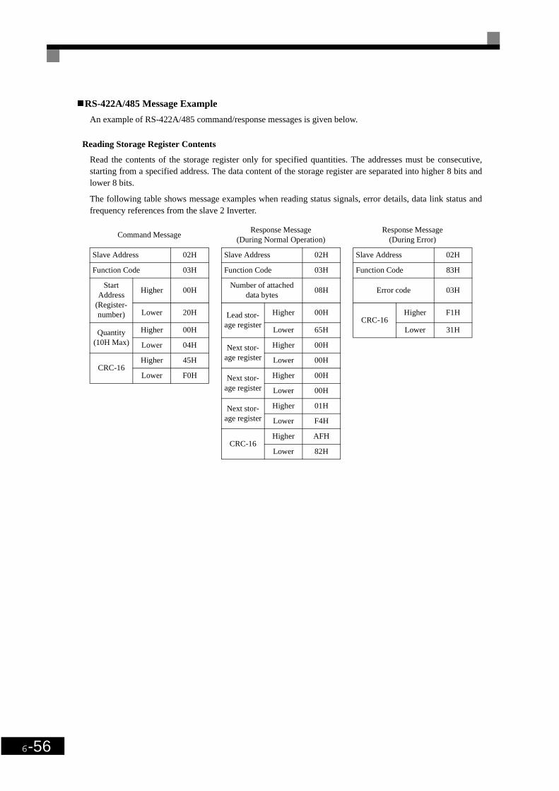
6-56
RS-422A/485 Message Example
An example of RS-422A/485 command/response messages is given below.
Reading Storage Register Contents
Read the contents of the storage register only for specified quantities. The addresses must be consecutive,starting from a specified address. The data content of the storage register are separated into higher 8 bits andlower 8 bits.
The following table shows message examples when reading status signals, error details, data link status andfrequency references from the slave 2 Inverter.
Command MessageResponse Message
(During Normal Operation)Response Message
(During Error)
Slave Address 02H Slave Address 02H Slave Address 02H
Function Code 03H Function Code 03H Function Code 83H
Start Address
(Register-number)
Higher 00HNumber of attached
data bytes08H Error code 03H
Lower 20H Lead stor-age register
Higher 00HCRC-16
Higher F1H
Quantity (10H Max)
Higher 00H Lower 65H Lower 31H
Lower 04H Next stor-age register
Higher 00H
CRC-16Higher 45H Lower 00H
Lower F0H Next stor-age register
Higher 00H
Lower 00H
Next stor-age register
Higher 01H
Lower F4H
CRC-16Higher AFH
Lower 82H

Individual Functions
6-57
Loopback Test
The loopback test returns command messages directly as response messages without changing the contents tocheck the communications between the master and slave. You can set user-defined test code and data values.
The following table shows a message example when performing a loopback test with the slave 1 Inverter.
Writing to Multiple Storage Registers
Write the specified data to the registers from the specified addresses. The written data must be consecutive,starting from the specified address in the command message: Higher 8 bits, then lower 8 bits, in storage regis-ter address order.
The following table shows an example of a message when forward operation has been set at a frequency refer-ence of 60.0 Hz in the slave 1 Inverter by the PLC.
Command MessageResponse Message
(During Normal Operation)Response Message
(During Error)
Slave address 01H Slave address 01H Slave address 01H
Function code 08H Function code 08H Function code 89H
Test CodeHigher 00H
Test CodeHigher 00H Error Code 01H
Lower 00H Lower 00HCRC-16
Higher 86H
DataHigher A5H
DataHigher A5H Lower 50H
Lower 37H Lower 37H
CRC-16Higher DAH
CRC-16Higher DAH
Lower 8DH Lower 8DH
Command MessageResponse Message
(During Normal Operation)Response Message
(During Error)
Slave Address 01H Slave Address 01H Slave Address 01H
Function Code 10H Function Code 10H Function Code 90H
Start Address
Higher 00H Start Address
Higher 00H Error code 02H
Lower 01H Lower 01HCRC-16
Higher CDH
QuantityHigher 00H
QuantityHigher 00H Lower C1H
Lower 02H Lower 02H
No. of data 04HCRC-16
Higher 10H
Lead dataHigher 00H Lower 08H
Lower 01H
Next dataHigher 02H
Lower 58H * No. of data = 2 x (quantity)
CRC-16Higher 63H
Lower 39H
IMPORTANT
Set the number of data specified using command messages as quantity of specified messages x 2. Handleresponse messages in the same way.

6-58
Data Tables
The data tables are shown below. The types of data are as follows: Reference data, monitor data and broadcastdata.
Reference Data
The reference data table is shown below. You can both read and write reference data.
Register No. Contents
0000H Reserved
0001H
Frequency reference
Bit 0 Run/stop command 1: Run 0: Stop
Bit 1 Forward/reverse operation 1: Reverse 0: Forward
Bit 2 External error 1: Error (EFO)
Bit 3 Error reset 1: Reset command
Bit 4 ComNet
Bit 5 ComCtrl
Bit 6 Multi-function input command 3
Bit 7 Multi-function input command 4
Bit 8 Multi-function input command 5
Bit 9 Multi-function input command 6
Bit A Multi-function input command 7
Bits B to F Not used
0002H Frequency reference (Set units using parameter o1-03)
0003H to 0005H Not used
0006H Not used
0007H Analog output 1 setting (0 V/0 to 11 V/726) → 10V = 660
0008H Analog output 2 setting (0 V/0 to 11 V/726) → 10V = 660
0009H
Multi-function contact output setting
Bit 0 Contact output 1 (Terminal M1-M2) 1: ON 0: OFF
Bit 1 Contact output 2 (Terminal M3-M4) 1: ON 0: OFF
Bit 2 Not used
Bits 3 to 5 Not used
Bit 6 Set error contact (terminal MA-MC) output using bit 7. 1: ON 0: OFF
Bit 7 Error contact (terminal MA-MC) 1: ON 0: OFF
Bits 8 to F Not used
000AH to 000EH Not used

Individual Functions
6-59
Note Write 0 to all unused bits. Also, do not write data to reserved registers.
Monitor Data
The following table shows the monitor data. Monitor data can only be read.
000FH
Reference selection settings
Bit 0 Not used
Bit 1 Not used
Bits 3 to B Not used
C Broadcast data terminal S5 input 1: Enabled 0: Disabled
D Broadcast data terminal S6 input 1: Enabled 0: Disabled
E Broadcast data terminal S7 input 1: Enabled 0: Disabled
F Not used
Register No. Contents
0020H
Inverter status
Bit 0 Operation 1: Operating 0: Stopped
Bit 1 Reverse operation 1: Reverse operation 0: Forward operation
Bit 2 Inverter startup complete 1: Completed 2: Not completed
Bit 3 Error 1: Error
Bit 4 Data setting error 1: Error
Bit 5 Multi-function contact output 1 (terminal M1 - M2) 1: ON 0: OFF
Bit 6 Multi-function contact output 2 (terminal M3 - M4) 1: ON 0: OFF
Bit 7 Not used
Bits 8 to F Not used
0021H
Error details
Bit 0 Overcurrent (OC) Ground fault (GF)
Bit 1 Main circuit overvoltage (OV)
Bit 2 Inverter overload (OL2)
Bit 3 Inverter overheat (OH1, OH2)
Bit 4 Not used
Bit 5 Fuse blown (PUF)
Bit 6 PI feedback reference lost (FbL)
Bit 7 External error (EF, EFO)
Bit 8 Hardware error (CPF)
Bit 9 Motor overload (OL1) or overtorque 1 (OL3) detected
Bit A Not used
Bit B Main circuit undervoltage (UV) detected
Bit CMain circuit undervoltage (UV1), control power supply error (UV2), inrush preven-tion circuit error (UV3), power loss
Bit D Missing output phase (LF)
Bit E RS-422A/485 communications error (CE)
Bit F Operator disconnected (OPR)
Register No. Contents

6-60
0022H
Data link status
Bit 0 Writing data
Bit 1 Not used
Bit 2 Not used
Bit 3 Upper and lower limit errors
Bit 4 Data integrity error
Bits 5 to F Not used
0023HFrequency ref-erence
Monitors U1-01
0024HOutput fre-quency
Monitors U1-02
0025H Output voltage reference (U1-06)
0026H Output current U1-03
0027H Output power U1-08
0028H Not used
0029H Not used
002AH Not used
002BH
Sequence input status
Bit 0 Multi-function contact input terminal S1 1: ON 0: OFF
Bit 1 Multi-function contact input terminal S2 1: ON 0: OFF
Bit 2 Multi-function contact input terminal S3 1: ON 0: OFF
Bit 3 Multi-function contact input terminal S4 1: ON 0: OFF
Bit 4 Multi-function contact input terminal S5 1: ON 0: OFF
Bit 5 Multi-function contact input terminal S6 1: ON 0: OFF
Bit 6 Multi-function contact input terminal S7 1: ON 0: OFF
Bits 7 to F Not used
Register No. Contents

Individual Functions
6-61
002CH
Inverter status
Bit 0 Operation 1: Operating
Bit 1 Zero speed 1: Zero speed
Bit 2 Frequency matching 1: Matched
Bit 3 User-defined speed matching 1: Matched
Bit 4 Frequency detection 1 1: Output frequency ≤ L4-01
Bit 5 Frequency detection 2 Output frequency ≥ L4-01
Bit 6 Inverter startup completed 1: Startup completed
Bit 7 Low voltage detection 1: Detected
Bit 8 Baseblock 1: Inverter output baseblock
Bit 9 Frequency reference mode 1: Not communication 0: Communication
Bit A Run command mode 1: Not communication 0: Communication
Bit B Overtorque detection 1: Detected
Bit C Frequency reference lost 1: Lost
Bit D Retrying error 1: Retrying
Bit E Error (including RS-422A/485 communications time-out) 1:Error occurred
Bit F RS-422A/485 communications time-out 1: Timed out
002DH
Multi-function contact output status
Bit 0 Multi-function contact output 1 (terminal M1-M2) 1: ON 0: OFF
Bit 1 Multi-function contact output 2 (terminal M3-M4): 1: ON 0: OFF
Bit 2 Not used
Bits 3 to F Not used
002EH - 0030H Not used
0031H Main circuit DC voltage
0032H - 0037H Not used
0038H PI feedback quantity (Input equivalent to 100%/Max. output frequency; 10/1%; without sign)
0039H PI input quantity (±100%/±Max. output frequency; 10/1%; with sign)
003AH PI output quantity (±100%/±Max. output frequency; 10/1%; with sign)
003BH CPU software number
003CH Flash software number
003DH
Communications error details
Bit 0 CRC error
Bit 1 Invalid data length
Bit 2 Not used
Bit 3 Parity error
Bit 4 Overrun error
Bit 5 Framing error
Bit 6 Time-out
Bits 7 to F Not used
003EH KVA setting
Register No. Contents

6-62
Note Communications error details are stored until an error reset is input (you can also reset while the Unit is operating).
Broadcast Data
The following table shows the broadcast data. You can also write this data.
Note Bit signals not defined in the broadcast operation signals use local node data signals continuously.
ENTER Command
When writing parameters to the Inverter from the PLC using RS-422A/485 communications, the parametersare temporarily stored in the parameter data area in the Inverter. To enable these parameters in the parameterdata area, use the ENTER command.
There are two types of ENTER commands: ENTER commands that enable parameter data in RAM andENTER commands that write data to EEPROM (non-volatile memory) in the Inverter at the same time asenabling data in RAM.
The following table shows the ENTER command data. ENTER command data can only be written.
The ENTER command is enabled by writing 0 to register number 0900H or 0901H.
003FH Not used
Register Address
Contents
0001H
Operation signal
Bit 0 Run command 1: Operating 0: Stopped
Bit 1 Reverse operation command 1: Reverse 0: Forward
Bits 2 and 3 Not used
Bit 4 External error 1: Error (set using H1-01)
Bit 5 Error reset 1: Reset command (set using H1-02)
Bits 6 to B Not used
Bit C Multi-function contact input terminal S5 input
Bit D Multi-function contact input terminal S6 input
Bit E Multi-function contact input terminal S7 input
Bit F Not used.
0002HFrequency ref-erence
30000/100%
Register No. Contents
0900H Write parameter data to EEPROM
0910H Parameter data is not written to EEPROM, but refreshed in RAM only.
The maximum number of times you can write to EEPROM using the Inverter is 100,000. Do not frequentlyexecute ENTER commands (0900H) written to EEPROM.The ENTER command registers are write-only. Consequently, if reading these registers, the register addresswill become invalid (Error code: 02H).
Register No. Contents
INFO

Individual Functions
6-63
Error Codes
The following table shows RS-422A/485 communications error codes.
Slave Not Responding
In the following cases, the slave will ignore the write function.
• When a communications error (overrun, framing, parity or CRC-16) is detected in the command message.
• When the slave address in the command message and the slave address in the Inverter do not agree.
• When the data that configures the message and the data time length exceeds 24 bits.
• When the command message data length is invalid.
Application Precautions
Error Code Contents
01HFunction code errorA function code other than 03H, 08H or 10H has been set by the PLC.
02HInvalid register number error• The register address you are attempting to access is not recorded anywhere.• With broadcast sending, a start address other than 0000H, 0001H or 0002H has been set.
03HInvalid quantity error• The number of data packets being read or written is outside the range 1 to 16.• In write mode, the number of data packets in the message is not No. of packets x 2.
21H
Data setting error• A simple upper limit or lower limit error has occurred in the control data or when writing parame-
ters.• When writing parameters, the parameter setting is invalid.
22H
Write mode error• Attempting to write parameters to the inverter during operation.• Attempting to write via ENTER commands during operation.• Attempting to write parameters other than A1-00 to A1-05, E1-03 or 02-04 when warning alarm
CPF03 (defective EEPROM) has occurred.• Attempting to write read-only data.
23HWriting during main circuit undervoltage (UV) error• Writing parameters to the inverter during UV (main circuit undervoltage) alarm.• Writing via ENTER commands during UV (main circuit undervoltage) alarm.
24HWriting error during parameters processingAttempting to write parameters while processing parameters in the Inverter.
If the slave address specified in the command message is 0, all slaves execute the write function, but do notreturn response messages to the master.
INFO

6-64
Self-Diagnosis
The Inverter has a built-in function for self-diagnosing the operations of serial communications interface cir-cuits. This function is called the self-diagnosis function. The self-diagnosis function connects the communica-tions parts of the send and receive terminals, receives the data sent by the Inverter and checks ifcommunications are being performed normally.
Perform the self-diagnosis function using the following procedure.
1. Turn ON the power supply to the Inverter and set 67 (communications test mode) in parameter H1-05(Terminal S7 Function Selection).
2. Turn OFF the power supply to the Inverter.
3. Perform wiring according to the following diagram while the power supply is turned OFF.
4. Turn ON the terminating resistance. (Turn ON pin 1 on DIP switch 1.)
5. Turn ON the power supply to the Inverter again.
Fig 6.41 Details of Communications Terminals
During normal operation, the Digital Operator displays the frequency reference value.
If an error occurs, a CE (RS-422A/485 communications error) alarm will be displayed on the Digital Operator,the error contact output will be turned ON and the Inverter operation ready signal will be turned OFF.

Individual Functions
6-65
Using PI Control
PI control is a method of making the feedback value (detection value) match the set target value. By combin-ing proportional control (P) and integral control (I), you can even control targets (machinery) with play time.
The characteristics of the PI control operations are given below.
PI Control Operation
To understand the differences between the PI control operations P and I, the variation in the amount of opera-tion (output frequency) is as shown in the following diagram when the deviation (i.e., the difference betweenthe target value and feedback value) is fixed.
Fig 6.42 PI Control Operation
PI Control Applications
The following table shows examples of PI control applications using the Inverter.
P control Outputs the amount of operation proportional to the deviation. You cannot, however, set thedeviation to zero using P control alone.
I control Outputs the amount of operation that integrates the deviation. Used for matching feedbackvalue to the target value.
Applica-tion
Control DetailsExample of
Sensor Used
Speed Con-trol
• Feeds back machinery speed information and matches speed to the target value.• Inputs speed information from other machinery as the target value and performs
synchronous control using the actual speed feedback.
Tachometer genera-tor
Pressure Control
Feeds back pressure information and performs parameter pressure control. Pressure sensor
Flow Rate Control
Feeds back flow rate information and controls the flow rate highly accurately. Flow rate sensor
Tempera-ture Con-trol
Feeds back temperature information and performs temperature adjustment control by rotating the fan.
• Thermocouple• Thermistor
Deviation
Amount of operation
Time
P I con tro l
I control
P control
Time

6-66
Related Parameters
Param-eter
Number
Name
DescriptionSetting Range
Factory Setting
Change during Opera-
tion
Access LevelLCD Display
b5-01
PI control mode selection
0: Disabled1: Enabled
0 or 1 0 No A
PI Mode
b5-02Proportional gain (P)
Sets P-control proportional. P-control is not performed when the setting is 0.00.
0.00 to
25.001.00 Yes A
PI Gain
b5-03Integral (I) time Sets I-control integral time.
I-control is not performed when the setting is 0.0.0.0 to 360.0
1.0 s Yes API I Time
b5-04Integral (I) limit Sets the I-control limit as a percentage of the maximum
output frequency.0.0 to 100.0
100.0% Yes API I Limit
b5-06PI limit Sets the limit after PI-control as a percentage of the maxi-
mum output frequency.0.0 to 100.0
100.0% Yes API Limit
b5-07PI offset adjustment
Sets the offset after PI-control as a percentage of the maxi-mum outut frequency.
-100.0 to
+100.00.0% Yes A
PI Offset
b5-08
PI primary delay time parame-ter Sets the time parameter for low pass filter for PI-control
outputs. Not usually necessary to set.
0.00 to 10.00
0.00 s Yes API Delay Time
b5-12
Selection of PI feedback com-mand loss detection
0: No detection of loss of PI feedback1: Detection of loss of PI feedback. Operation continues
during detection, with the malfunctioning contact not operating.
2: Detection of loss of PI feedback. Coasts to stop during detection and fault contact oprates.
0 to 2 0 No A
Fb loss Det Sel
b5-13
PI feedback command loss detection level Set the PI feedback loss detection level as a percent, with
the maximum output frequency at 100%.0 to 100 0% No A
Fb loss Det Lvl
b5-14
PI feedback command loss detection time Sets the PI feedback loss detection level in s units.
0.0 to 25.5
1.0 s No AFb loss Det Time
b5-15
PI sleep function operation level Set the PI sleep function start level as a frequency.
0.0 to 120.0
0.0 Hz No API Sleep Level
b5-16PI sleep operation delay time
Set the delay time until the PI sleep function starts.0.0 to 25.5
0.0 s No API Sleep Time
b5-17
Accel/decel time for PI refer-ence Set the accel/decel time for PI reference.
0.0 to 25.5
0.0 s No API Acc/Dec Time
H6-01
Pulse train input function selection 0: Frequency reference
1: PI feedback value2: PI target value
0 to 2 0 No APulse Input Sel
Param-eter
Number
NameDescription
Output Signal Level During Multi-Function Analog Output
Min. Unit
Access LevelLCD Display
U1-24
PI feedback value Monitors the feedback value when PI control is used.The input for the max. frequency corresponds to 100%.
10 V: Max. frequency (0 to + 10 V possible)
0.01 API Feedback
U1-36PI input volume PI feedback volume
Given as maximum frequency/100%10 V: Max. frequency (0 to + 10 V possible)
0.01% API Input
U1-37PI output volume PI control output
Given as maximum frequency/100%10 V: Max. frequency (0 to + 10 V possible)
0.01% API Output
U1-38PI command PI command + PI command bias
Given as maximum frequency/100%10 V: Max. frequency 0.01% A
PI Setpoint
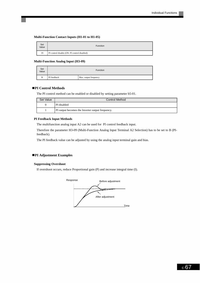
Individual Functions
6-67
Multi-Function Contact Inputs (H1-01 to H1-05)
Multi-Function Analog Input (H3-09)
PI Control Methods
The PI control method can be enabled or disabled by setting parameter b5-01.
PI Feedback Input Methods
The multifunction analog input A2 can be used for PI control feedback input.
Therefore the parameter H3-09 (Multi-Function Analog Input Terminal A2 Selection) has to be set to B (PI-feedback).
The PI feedback value can be adjusted by using the analog input terminal gain and bias.
PI Adjustment Examples
Suppressing Overshoot
If overshoot occurs, reduce Proportional gain (P) and increase integral time (I).
Set Value
Function
19 PI control disable (ON: PI control disabled)
Set Value
Function
B PI feedback Max. output frequency
Set Value Control Method
0 PI disabled
1 PI output becomes the Inverter output frequency.
Response Before adjustment
After adjustment
Time

6-68
Set a Rapidly Stabilizing Control Condition
To raPIly stabilize the control even if overshoot occurs, reduce integral time (I).
Suppressing Long-cycle Vibration
If vibration occurs with a longer cycle than the integral time (I) set value, lengthen the integral time (I) to sup-press the vibration.
Suppressing Short Cycle Vibration
If vibration occures, reduce the proportional gain (P) or increase the PI primary delay time parameter.
Setting Precautions
• In PI control, the b5-04 parameter is used to prevent the calculated integral control value from exceeding aspecified amount. When the load varies rapidly, Inverter response is delayed and the machine may be dam-aged or the motor may stall. In this case, reduce the set value to speed up Inverter response.
• The b5-06 parameter is used to prevent the arithmetic operation following the PI control calculation fromexceeding a specified amount. Set taking the maximum output frequency to be 100%.
• The b5-07 parameter is used to adjust PI control offset. Set in increments of 0.1%, taking the maximumoutput frequency to be 100%.
ResponseBefore adjustment
After adjustment
Time
Response Before adjustment
After adjustment
Time
Response Before adjustment
After adjustment
Time

Individual Functions
6-69
• Set the low pass filter time parameter for the PI control output in b5-08. Enable this parameter to preventmachinery resonance when machinery adhesive abrasion is great or rigidity is poor. In this case, set theparameter to be greater than the resonance frequency cycle. Increase this time parameter to reduce Inverterresponsiveness.
• With the Inverter, by setting an independent acceleration/deceleration time in parameter b5-17, you canincrease or decrease the PI target value using the acceleration/deceleration time. The acceleration/decele-ration function (parameter C1) that is normally used, however, is allocated after PI control, so dependingon the settings, resonance with PI control and hunting in the machinery may occur. If this happens, reduceparameter C1 until hunting does not occur and maintain the acceleration/deceleration time using b5-17.Also, you can disable the set value in b5-17 from the external terminals during operation using multi-func-tion input set value 34 (PI soft starter).

6-70
PI Control Block
The following diagram shows the PI control block in the Inverter.
Fig 6.43 PI Control Block
Opt
ion
Car
d
Ser
ial C
om
Fre
quen
cy r
efer
ence
us
ing
mul
ti-st
ep c
omm
and
Pro
port
iona
l ga
in
b5-0
2
Mul
ti-fu
nctio
n in
put P
I con
trol
ca
ncel
sig
nal i
s O
N. P
I is
OF
F u
nder
th
e fo
llow
ing
cond
ition
s:b5
-01=
0D
urin
g JO
G c
omm
and
inpu
t
PI p
rimar
y de
lay
time
para
met
erb5
-08
Out
put f
requ
ency
Term
inal
A1
Fre
quen
cy r
efer
ence
te
rmin
al A
2 P
I fee
dbac
k
I-tim
e b5
-03
I-tim
e lim
it
PI L
imit
PI l
imit
b5-0
6
Upp
er li
mit
Fm
ax x
109
%
PI
inpu
t vol
ume
(U1-
36)
PI o
ffset
(b5-
07)
PI o
utpu
t mon
itor
(U1-
37)
PI c
omm
and
(U1-
38)
Fre
quen
cy
refe
renc
e (U
1-01
)
PI S
FS C
ance
l

Individual Functions
6-71
PI Feedback Loss Detection
When performing PI control, be sure to use the PI feedback loss detection function. If PI feedback is lost, theInverter output frequency may accelerate to the maximum output frequency.
When setting b5-12 to 1 and the status of the PI feedback value detection level in b5-13 is insufficient andcontinues for the time set in b5-14, a FbL (PI feedback reference lost) alarm will be displayed on the DigitalOperator and Inverter operation will continue.
When b5-12 is set to 2, a FbL (PI feedback reference lost) error alarm will be displayed on the Digital Opera-tor, the error contact will operate and Inverter operation will be stopped.
The time chart for PI feedback loss detection (set b5-12 to 2) is shown below.
Fig 6.44 PI Feedback Loss Detection Time Chart
PI Sleep
The PI sleep function stops the Inverter when the PI target value falls below the sleep operation level (b5-15)for the sleep operation time set in parameter b5-16 or longer. The inverter operation will resume, if the PI tar-get value exceeds the sleep operation level for the time set in parameter b5-16 or longer.
When PI control is disabled, the PI sleep function is also disabled. When using the PI sleep function, selectdecelerate to stop or coast to stop as the stopping method.
The PI sleep time chart is shown below.
Fig 6.45 PI Sleep Time Chart
PI feedback value
Time
Fbl detection
Loss detection level
(b5-13)
Loss detection time(b5-14)
Loss detection time’(b5-14)
No Fbldetection
PI target value
Internal run command
External run command
OperatingOperation status output
Run command has been input
Stopped
Sleep operation level b5-15
Sleep operation delay time
Sleep operation delay time
Operation

6-72
Energy-saving
To perform energy saving, set b8-01 (Energy Saving Mode Selection) to 1.
Related parameters
* 1. The same capacity as the Inverter will be set by initializing the parameters.* 2. The factory settings depend on the Inverter capacity.
Adjusting Energy-saving Control
By the Energy Saving function the voltage for optimum motor efficiency is calculated and becomes the outputvoltage reference.
• b8-04 (Energy-saving Coefficient) is set at the factory for motor use applied to the Inverter. If the motorcapacity differs from the motor applied to the Inverter, set the motor capacity in E2-11 (Motor Rated Out-put). Also, adjust b8-04 in steps of 5 until reaches it’s minimum. The larger the energy-saving coefficient,the greater the output voltage.
• To improve response when the load fluctuates, reduce the power detection filter time parameter b8-05. Ifb8-05 is set too small. However, motor rotations, when the load is light, may become unstable.
• Motor efficiency varies due to temperature fluctuations and differences in motor characteristics. Conse-quently the motor efficiency has to be controlled. To have optimized efficiency, the search operation isused by varieting voltage. Parameter b8-06 (Search Operation Voltage Limiter) controls the range thatcontrol the voltage using the search operation. For 200 V Class Inverters, set the range to 100%/200 V andfor 400 V Class Inverters, set the range to 100%/400 V. Set to 0 to disable the search operation.
param-eter
Number
NameDetails
Setting Range
Factory Setting
Change During Opera-
tion
Access LevelLCD Display
b8-01
Energy-saving mode selec-tion Select whether to enable or disable energy-saving control.
0: Disable1: Enable
0 or 1 0 No AEnergy Save Sel
b8-04
Energy-saving coefficient Set the maximum motor efficiency value.Set the motor rated capacity in E2-11 and adjust the value by 5% at a time until output power reaches a minimum value.
0.0 to
655.00*1 *2 No AEnergy Save COEF
b8-05
Power detection filter time parameter
Set the time parameter for output power detection. 0 to 2000 20 ms No AkW Filter Time
b8-06
Search operation voltage limiter
Set the limit value of the voltage control range during search operation.Perform search operation to optimize operations using minute variations in voltage using energy-saving control. Set to 0 to disable the search operation. 100% is the motor base voltage.
0 to 100 0% No A
Search V Limit

Individual Functions
6-73
Setting Motor parameters
Normally the motor parameters are set automatically using autotuning. If autotuning does not complete nor-mally, set them manually.
Related parameters
Note The factory-set parameters are for a OMRON standard 4-pole motor.* 1. The factory settings depend on Inverter capacity (the values shown are for a 200 V Class Inverter for 0.4 kW).* 2. The setting range is 10% to 200% of the Inverter rated output current (the values shown are for a 200 V Class Inverter for 0.4 kW).
Manual Motor Parameter Setting Methods
The motor parameters settings methods are given below. To enter settings refer to the motor test report.
Motor Rated Voltage Setting
Set E2-01 to the rated current on the motor nameplate.
Motor Line-to-Line Resistance Setting
E2-05 is set automatically when performing motor line-to-line resistance autotuning. When you cannot per-form tuning, consult the motor manufacturer for the line-to-line resistance value. Calculate the resistance fromthe line-to-line resistance value in the motor test report using the following formula and then make the settingaccordingly.
• E-type insulation: [Line-to line resistance (W) at 75°C of test report] x 0.92 (W)
• B-type insulation: [Line-to line resistance (W) at 75°C of test repor]t x 0.92 (W)
• F-type insulation: [Line-to line resistance (W) at 115°C of test report] x 0.87 (W)
Param-eter
Number
Name
Description Setting Range
Factory Setting
Change during Opera-
tion
Access LevelLCD Display
E2-01
Motor rated current Sets the motor rated current. These set values will become the reference values for motor protection, torque limits and torque control. This parameter is an input data for autotuning.
0.32 to 6.40*2
1.90 A*1
No Q
Motor Rated FLA
E2-05Motor line-to-line resistance
Sets the motor phase-to-phase resistance. 0.000
to 65.000
9.842 Ω*1
No ATerm Resistance

6-74
Setting the V/f Pattern
Inverter input voltage and the V/f pattern can be set as the need arises.
Related Parameters
* 1. These are values for a 200 V Class Inverter. Values for a 400 V Class Inverter are double.* 2. The contents of parameters E1-11 and E1-12 are ignored when set to 0.00.* 3. E1-13 is set to the same value as E1-05 by autotuning.
Setting Inverter Input Voltage
Set the Inverter input voltage correctly in E1-01 to match the power supply voltage. This set value will be thestandard value for the protection function and similar functions (overvoltage level, stall trip).
Setting V/f Pattern
Set the V/f pattern in E1-03. There are two methods of setting the V/f pattern: Select one of the 14 patterntypes (set value: 0 to D) that have been set beforehand or set a user-defined V/f pattern (set value: F).
The factory setting for E1-03 is F. The contents of E1-03 when factory-set to F are the same as when E1-03 isset to 0.
Param-eter
Number
Name
DescriptionSetting Range
Factory Setting
Change during Opera-
tion
Access LevelLCD Display
E1-01Input voltage setting
Set the Inverter input voltage. This setting is used as a ref-erence value in protection functions.
155 to 255*1
200 V*1
No QInput Voltage
E1-03V/f pattern selection 0 to D: Select from the 14 preset V/f patterns.
F: Custom user-set patterns (Application for settings E1-04 to E1-10.)
0 to F F No QV/f Selection
E1-04
Max. output frequency (FMAX)
To set V/f characteristics in a straight line, set the same values for E1-07 and E1-09. In this case, the setting for E1-08 will be disregarded.Always ensure that the four frequencies are set in the fol-lowing manner:E1-04 (FMAX) ≥ E1-06 (FA)>E1-07 (FB) ≥ E1-09 (FMIN)
0.0 to 120.0
50.0 Hz No QMax Frequency
E1-05
Max. voltage (VMAX) 0.0 to 255.0
*1
200.0 V*1
No QMax voltage
E1-06Base frequency (FA) 0.0 to
120.050.0 Hz No Q
Base frequency
E1-07Mid. output frequency 0.0 to
255.0*1
2.5 Hz No AMid Frequency A
E1-08
Mid. output frequency voltage 0.0 to
120.015.0 V
*1No A
Mid Voltage A
E1-09
Min. output frequency (FMIN) 0.0 to
120.01.2 Hz No Q
Min Frequency
E1-10
Min. output frequency voltage
0.0 to 255.0
*1
9.0 V*1
No AMin Voltage
E1-11Mid. output frequency 2
Set only to fine-adjust V/f for the output range. Normally, this setting is not required.
0.0 to 120.0
0.0 Hz*2
No AMid Frequency B
E1-12
Mid. output frequency voltage 2
0.0 to 255.0
*1
0.0 V*2
No AMid Voltage B
E1-13Base voltage 0.0 to
255.0*1
0.0 V*2
No ABase Voltage
Output voltage (V)
Frequency (Hz)

Individual Functions
6-75
To select one of the existing patterns, refer to the following table.
* The torque is protected by the fully automatic torque boost function, so normally there is no need to use this pattern.
When you select these patterns, the values of parameters E1-04 to E1-10 are changed automatically. There arethree types of values for E1-04 to E1-10, depending on the Inverter capacity.
• 0.4 to 1.5 kW V/f pattern
• 2.2 to 45 kW V/f pattern
• 55 to 160 kW V/f pattern
The characteristics diagrams for each are shown in the following pages.
Characteristic ApplicationSet
ValueSpecifications
Parameter Torque Characteristic
This pattern is used in general applications. Used when the load torque is fixed, regard-less of rotation speed, for linear transport systems.
0 (F) 50 Hz specifications
1 60 Hz specifications
260 Hz specifications, voltage saturation at 50 Hz
372 Hz specifications, voltage saturation at 60 Hz
Variable torque characteristic
This pattern is used for loads with torque proportional to two or three times the rota-tion speed, such as fans and pumps.
4 50 Hz specifications,× 3 decrement
5 50 Hz specifications, × 2 decrement
6 60 Hz specifications, × 3 decrement
7 60 Hz specifications, × 2 decrement
High Startup Torque (See
Note)*
Select the high startup torque V/f pattern only in the following cases.• The wiring distance between Inverter and
motor is large (approx. 150 m min.)• A large torque is required at startup (ele-
vator loads, etc.)• An AC reactor is inserted in the Inverter
input or output.• You are operating a motor that is less
than optimum.
850 Hz specifications, medium startup torque
9 50 Hz specifications, large startup torque
A60 Hz specifications, medium startup torque
B 60 Hz specifications, large startup torque
Fixed Output Operation
This pattern is used for frequencies of 60 Hz or higher. A fixed voltage is applied.
C90 Hz specifications, voltage saturation at 60 Hz
D120 Hz specifications, voltage saturation at 60 Hz

6-76
0.4 to 1.5 kW V/f Pattern
The diagrams show characteristics for a 200-V class motor. For a 400-V class motor, multiply all voltagesby 2.
• Parameter Torque Characteristics (Set Value: 0 to 3)
• Decrement Torque Characteristics (Set Value: 4 to 7)
• High startup torque (Set value 8: to b)
• Fixed Output Operation (Set Value: C to D)
Set Value 0 50 Hz Set Value 1 60 Hz Set Value 2 60 Hz Set Value 3 72 Hz
Set Value 4 50 Hz Set Value 5 50 Hz Set Value 6 60 Hz Set Value 7 60 Hz
Set Value 8 50 Hz Set Value 9 50 Hz Set Value A 60 Hz Set Value B 60 Hz
Set Value C 90 Hz Set Value D 120 Hz
1.3 2.51.5 1.5 3 1.5 3
1.3 1.3 1.5 1.5
1.3 2.5 1.3 2.5 1.5 1.5
1.5 1.5

Individual Functions
6-77
2.2 to 45 kW V/f Pattern
The diagrams show characteristics for a 200-V class motor. For a 400-V class motor, multiply all voltagesby 2.
• Parameter Torque Characteristics (Set Value: 0 to 3)
• Decrement Torque Characteristics (Set Value: 4 to 7)
• High Startup Torque (Set Value: 8 to b)
• Fixed Output Operation (Set Value: C to D)
Set Value 0 50 Hz Set Value 1 60 Hz Set Value 2 60 Hz Set Value 3 72 Hz
Set Value 4 50 Hz Set Value 5 50 Hz Set Value 6 60 Hz Set Value 7 60 Hz
Set Value 8 50 Hz Set Value 9 50 Hz Set Value A 60 Hz Set Value B 60 Hz
Set Value C 90 Hz Set Value D 120 Hz

6-78
55 to 160 kW V/f Pattern
The diagrams show characteristics for a 200-V class motor. For a 400-V class motor, multiply all voltagesby 2.
• Parameter Torque Characteristics (Set Value: 0 to 3)
• Decrement Torque Characteristics (Set Value: 4 to 7)
• High Startup Torque (Set Value: 8 to b)
• Fixed Output Operation (Set Value: C to D)
Set Value 0 50 Hz Set Value 1 60 Hz Set Value 2 60 Hz Set Value 3 72 Hz
Set Value 4 50 Hz Set Value 5 50 Hz Set Value 6 60 Hz Set Value 7 60 Hz
Set Value 8 50 Hz Set Value 9 50 Hz Set Value A 60 Hz Set Value B 60 Hz
Set Value C 90 Hz Set Value D 120 Hz

Individual Functions
6-79
Fig 6.46 User-Set V/f Pattern
Setting Precautions
When the setting is to user-defined V/f pattern, beware of the following points.
• When changing control method, parameters E1-07 to E1-10 will change to the factory settings for that con-trol method.
• Be sure to set the four frequencies as follows:E1-04 (FMAX) ≥ E1-06 (FA) > E1-07 (FB) ≥ E1-09 (FMIN)
When E1-03 is set to F (User-defined V/f pattern), you can set parameters E1-04 to E1-10. If E1-03 is set toanything other than F, you can only refer to parameters E1-04 to E1-10. If the V/f characteristics are linear, setE1-07 and E1-09 to the same value. In this case, E1-08 will be ignored.
INFO
Output voltage (V)
Frequency (Hz)

6-80
Digital Operator Functions
Setting Digital Operator Functions
Related Parameters
Param-eter
Number
Name
Description Setting Range
Factory Setting
Change during Opera-
tion
Access LevelLCD Display
o1-02
Monitor selection after power up
Set the monitor item to be displayed when the power sup-ply is turned ON.1: Frequency reference2: Output frequency3: Output current4: The monitor item set for o1-01
1 to 4 1 Yes A
Power-ON Monitor
o1-03
Frequency units of refer-ence setting and monitor
Sets the units that will be set and displayed for the fre-quency reference and frequency monitor.0: 0.01 Hz units1: 0.01% (Maximum output frequency is
100%)2 to 39: rotation per minute (rpm) (Sets the motor
poles)40 to 39999: User desired display
Set the desired values for setting and dis-play for the max. output frequency.
Example: When the max. output frequency value is 200.0, set 12000.
0 to 39999
0 No A
Display Scaling
o2-01
LOCAL/REMOTE key enable/disable
Set the run method selection key (LOCAL/REMOTE Key) function.0: Disabled1: Enabled (Switches between the Digital Operator and
the parameter settings.)
0 or 1 1 No A
Local/Remote Key
o2-02
STOP Key during con-trol circuit terminal oper-
ationSet the STOP Key in the run mode.0: Disabled (When the run command is issued from an
external terminal, the Stop Key is disabled.)1: Enabled (Effective even during run.)
0 or 1 1 No A
Oper STOP Key
o2-03
User parameter initial value
Clears or stores user initial values.0: Stores/not set1: Begins storing (Records the set parameters as user
initial values.)2: All clear (Clears all recorded user initial values)
When the set parameters are recorded as user initial val-ues, 1110 will be set in A1-03.
0 to 2 0 No A
User Defaults
o2-05
Frequency reference setting method selection
When the frequency reference is set on the Digital Opera-tor frequency reference monitor, sets whether the Enter Key is necessary.0: Enter Key needed1: Enter Key not needed
When set to 1, the Inverter accepts the frequency reference without Enter Key operation.
0 or 1 0 No A
Operator M.O.P.
o2-07
Cumulative operation time setting Sets the cumulative operation time in hour units.
Operation time is calculated from the set values.0 to
655350 No A
Elapsed Time Set
o2-10
Fan operation time set-ting
Set the initial value of the fan operation time using hour units.The operation time accumulates from the set value.
0 to 65535
0 No AFan ON Time Set
Set digit number excluding the decimal point.
Set the number of digits below the decimal point to display.

Digital Operator Functions
6-81
Changing Frequency Reference and Display Units
Set the Digital Operator frequency reference and display units using parameter o1-03. You can change theunits for the following parameters using o1-03.
• U1-01 (Frequency Reference)
• U1-02 (Output Frequency)
• U1-05 (Motor Speed)
• U1-20 (Output Frequency after Soft Start)
• d1-01 to d1-04 and d1-17 (Frequency references)
Switching Monitors when the Power Supply Is ON
Using parameter o1-02 selects the monitor item (U1- [status monitor]) that is to be displayed on the Digi-tal Operator when the power supply is turned ON. For monitors that can be displayed, refer to U1- inChapter 5 Parameters.
Setting Precautions
Disabling the STOP Key
If b1-02 (Operation Method Selection) is set to 1, 2 or 3, the stop command from the STOP Key on the DigitalOperator is an emergency stop command.
Set o2-02 to 0 to disable emergency stop commands from the STOP Key on the Digital Operator.
Disabling the LOCAL/REMOTE Key
Set o2-01 to 0 to disable the LOCAL/REMOTE Key on the Digital Operator. If the key is disabled, you cannotuse it to switch over the frequency reference source or the RUN-command source.
Initializing Changed Parameter Values
You can save to the Inverter parameter set values that you have changed as parameter initial values. Changethe set values from the Inverter factory settings and then set o2-03 to 1.
Set A1-03 (Initialize) to 1110 to initialize the Inverter parameters using the user-set initial values in memory.To clear the user-set initial values in memory, set o2-03 to 2.
Setting the Frequency Reference using the UP and DOWN Keys without Using the Enter Key
Use this function when inputting frequency references from the Digital Operator. When o2-05 is set to 1, youcan increment and decrement the frequency reference using the UP and DOWN keys without using the Enterkey.
For example, enter the Run command using a 0 Hz reference and then continuously press the UP key to incre-ment the frequency reference by 0.01 Hz only for the first 0.5 s and then by 0.01 Hz every 80 ms for 3 s there-after. Press and hold down the UP key for 3 s minimum to reach the maximum output frequency 10 s afterthat. The frequency reference that has been set will be stored in memory 5 s after the UP or DOWN keys arereleased.
If selecting monitor parameters other than U1-01 (Frequency Reference), U1-02 (Output Frequency) and U1-03 (Output Current), first select the monitor items to be displayed in o1-01 (monitor selection) and then seto1-02 to 4.
INFO

6-82
Clearing Cumulative Operation Time
Set the cumulative operation time initial value in time units in parameter o2-07. Set o2-07 to 0 to clear U1-13(inverter Operating Time).
Clearing Inverter Cooling Fan Operation Time
Set the fan operation time initial value in time units in parameter o2-10. Set o2-10 to 0 to clear U1-40 (CoolingFan Operating Time).
Copying Parameters
The Digital Operator can perform the following three functions using the built-in EEPROM (non-volatilememory).
• Store Inverter parameter set values in the Digital Operator (READ)
• Write parameter set values stored in the Digital Operator to the Inverter (COPY)
• Compare parameter set values stored in the Digital Operator with Inverter parameters (VERIFY)
Related Parameters
Param-eter
Number
Name
Description Setting Range
Factory Setting
Change during Opera-
tion
Access LevelLCD Display
o3-01
Copy function selection 0: Normal operation1: READ (Inverter to Operator)2: COPY (Operator to Inverter)3: Verify (compare)
0 to 3 0 No ACopy Func Select
o3-02
Read permitted selec-tion 0: Read prohibited
1: Read permitted0 or 1 0 No A
Copy Allowable
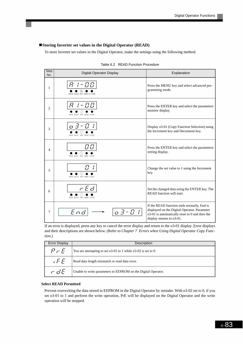
Digital Operator Functions
6-83
Storing Inverter set values in the Digital Operator (READ)
To store Inverter set values in the Digital Operator, make the settings using the following method.
If an error is displayed, press any key to cancel the error display and return to the o3-01 display. Error displaysand their descriptions are shown below. (Refer to Chapter 7 Errors when Using Digital Operator Copy Func-tion.)
Select READ Permitted
Prevent overwriting the data stored in EEPROM in the Digital Operator by mistake. With o3-02 set to 0, if youset o3-01 to 1 and perform the write operation, PrE will be displayed on the Digital Operator and the writeoperation will be stopped.
Table 6.2 READ Function Procedure
Step No.
Digital Operator Display Explanation
1Press the MENU key and select advanced pro-gramming mode.
2Press the ENTER key and select the parameters monitor display.
3Display o3-01 (Copy Function Selection) using the Increment key and Decrement key.
4Press the ENTER key and select the parameters setting display.
5Change the set value to 1 using the Increment key.
6Set the changed data using the ENTER key. The READ function will start.
7
If the READ function ends normally, End is displayed on the Digital Operator. Parameter o3-01 is automatically reset to 0 and then the display returns to o3-01.
Error Display Description
You are attempting to set o3-01 to 1 while o3-02 is set to 0.
Read data length mismatch or read data error.
Unable to write parameters to EEPROM on the Digital Operator.

6-84
Writing parameter Set Values Stored in the Digital Operator to the Inverter (COPY)
To write parameter set values stored in the Digital Operator to the Inverter, make the settings using the follow-ing method.
If an error is displayed, set the parameters again. Error displays and their descriptions are shown below. (Referto Chapter 7 Errors when Using Digital Operator Copy Function.)
Table 6.3 COPY Function Procedure
Step No.
Digital Operator Display Explanation
1Press the MENU key and select advanced pro-gramming mode.
2Press the ENTER key and select the parameters monitor display.
3Display o3-01 (Copy Function Selection) using the Increment key and Decrement key.
4Press the ENTER key and select the parameters setting display.
5Change the set value to 2 using the Increment Key.
6Set the changed data using the ENTER key. The COPY function will start.
7
If the COPY function ends normally, End is dis-played on the Digital Operator. Parameter o3-01 is automatically reset to 0 and then the dis-play returns to o3-01.
Error Display Description
Inverter product code and Inverter software number are different.
Inverter capacity with which you are trying to copy and the Inverter capacity stored in the Digital Operator are different.
The Inverter control method in which you are trying to copy and the Inverter control method stored in the Digital Operator are different.
Comparison between the parameter written to the Inverter and the parameter in the Digital Operator are different.
After copying has ended, the checksum between the sum value of the Inverter parameter and the sum value of the Digital Operator parameter are different.

Digital Operator Functions
6-85
Comparing Inverter Parameters and Digital Operator Parameter Set Values (VERIFY)
To compare Inverter parameters and Digital Operator parameter set values, make the settings using the follow-ing method.
If an error is displayed, press any key to cancel the error display and return to the o3-01 display. Error displaysand their descriptions are shown below. (Refer to Chapter 7 Errors when Using Digital Operator Copy Func-tion.)
Application Precautions
Table 6.4 VERIFY Function Procedure
Step No.
Digital Operator Display Explanation
1Press the MENU key. and select advanced pro-gramming mode.
2Press the ENTER key and select the parameters monitor display.
3Display o3-01 (Copy Function Selection) using the Increment key and Decrement key.
4Press the ENTER key and select the function setting display.
5Change the set value to 3 using the Increment key.
6Set the changed data using the ENTER key. The VERIFY function will start.
7
If the VERIFY function ends normally, End is displayed on the Digital Operator. Parameter o3-01 is automatically reset to 0 and then the display returns to o3-01.
Error Display Description
Verify error (Settings in the Digital Operator and the Inverter do not match).
When using the copy function, check that the following settings are the same between the Inverter and theDigital Operator.
• Inverter product and type• Software number• Inverter capacity and voltage• Control method
INFO

6-86
Prohibiting Writing Parameters from the Digital Operator
If you set A1-01 to 0, you can refer to and set the A1 and A2 parameter groups and refer to drive mode, usingthe Digital Operator.
If you set one of the parameters H1-01 to H1-05 (multi-function contact input terminal S3 to S7 functionselection) to 1B (write parameters permitted), you can write parameters from the digital operator when the ter-minal that has been set is ON. When the set terminal is OFF, writing parameters other than the frequency ref-erence is prohibited. You can, however, reference parameters.
Setting a Password
When a pasword is set in A1-05, if the set values in A1-04 and A1-05 do not match, you can not refer orchange the settings of parameters A1-01 to A1-03.
You can prohibit the setting and referencing of all parameters except A1-00 by using the password function incombination with setting A1-01 to 0 (Monitor only).
Related Parameters
Param-eter
Number
Name
DescriptionSetting Range
Factory Setting
Change during Opera-
tion
Access LevelLCD DIsplay
A1-01
Parameter access level Used to set the parameter access level (set/read.)0: Monitoring only (Monitoring drive mode and setting
A1-01 and A1-04.)2: ADVANCED
(Parameters can be read and set in both quick pro-gramming mode and advanced programming (A) mode.)
0 or 2 2 Yes A
Acces Level
Param-eter
Number
Name
DescriptionSetting Range
Factory Setting
Change during Opera-
tion
Access LevelLCD Display
A1-01
Parameter access levelUsed to set the parameter access level (set/read.)0: Monitoring only (Monitoring drive mode and setting
A1-01 and A1-04.)2: ADVANCED
(Parameters can be read and set in both quick pro-gramming mode and advanced programming (A) mode.)
0 or 2 2 Yes A
Acces Level
A1-04
PasswordPassword input when a password has been set in A1-05.This function write-protects some parameters of the initial-ize mode.If the password is changed, A1-01 to A1-03 parameters can no longer be changed. (Programming mode parame-ters can be changed.)
0 to 9999
0 No A
Enter Password
A1-05
Password setting Used to set a four digit number as the password.This parameter is not usually displayed. When the pass-word (A1-04) is displayed, hold down the reset key and press the Menu key and the password will be displayed.
0 to 9999 0 No A
Select password

7Chapter 7
TroubleshootingThis chapter describes the fault displays and countermeasure for the Inverter and motor prob-
lems and countermeasures.
Protective and Diagnostic Functions ...........................7-2
Troubleshooting .........................................................7-12

7-2
Protective and Diagnostic FunctionsThis section describes the alarm functions of the Inverter. The alarm functions include fault detection,alarm detection, operation error detection and autotuning error detection.
Fault Detection
When the Inverter detects a fault, the fault contact output operates and the Inverter output is shut OFF causingthe motor to coast to a stop. (The stopping method can be selected for some faults and the selected stoppingmethod will be used with these faults.) A fault code is displayed on the Digital Operator.
When a fault has occurred, refer to the following table to identify and correct the cause of the fault.
Use one of the following methods to reset the fault after restarting the Inverter:
• Set a multi-function contact input (H1-01 to H1-05) to 14 (Fault Reset) and turn ON the error reset signal.
• Press the RESET key on the Digital Operator.
• Turn the main circuit power supply OFF and then ON again.
Table 7.1 Fault Displays and Processing
Display Description Probable Causes Corrective Actions
OvercurrentThe Inverter output current exceeded the overcurrent detection level.
• A short-circuit or ground fault occurred at the Inverter output. (A short or ground fault can be caused by motor burn damage, worn insu-lation or a damaged cable.)
• The load is too large or the accelera-tion/deceleration time is too short.
• A special-purpose motor or motor with a capacity too large for the Inverter is being used.
• A magnetic switch was switched at the Inverter output.
Reset the fault after correcting its cause.
Ground FaultThe ground fault current at the Inverter output exceeded approxi-mately 50% of the Inverter rated out-put current.
A ground fault occurred at the Inverter output. (A ground fault can be caused by motor burn damage, worn insula-tion or a damaged cable.)
Reset the fault after correcting its cause.
Fuse BlownThe fuse in the main circuit is blown.
The output transistor has failed because of a short-circuit or ground fault at the Inverter output.Check whether there is a short-circuit between the following terminals. A short-circuit will damage the output transistor: U, V, W
, ← →U, V, W
Replace the Inverter after correct-ing the cause.
Main Circuit OvervoltageThe main circuit DC voltage exceeded the overvoltage detection level.200 V class: Approx. 410 V400 V class: Approx. 820 V
The deceleration time is too short and the regenerative energy from the motor is too large.
Increase the deceleration time or connect a Braking Resistor Unit and Braking Unit.
The power supply voltage is too high.Decrease the voltage so it's within specifications.

Protective and Diagnostic Functions
7-3
Main Circuit UndervoltageThe main circuit DC voltage is below the Undervoltage Detection Level (L2-05).200 V class: Approx. 190 V400 V class: Approx. 380 VMain Circuit MC Operation FailureThe MC stopped responding during Inverter operation. Applicable Inverter Capacities200 V class: 37 to 110 kW400 V class: 75 to 300 kW
• An open-phase occurred with the input power supply.
• A momentary power loss occurred.• The wiring terminals for the input
power supply are loose.• The voltage fluctuations in the input
power supply are too large.• A fault occurred in the surge pre-
vention circuit.
Reset the fault after correcting its cause.
Control Power FaultThe control power supply voltage dropped.
---
• Try turning the power supply off and on.
• Replace the Inverter if the fault continues to occur.
Inrush Prevention Circuit FaultOverheating occurred in the inrush resistor.The MC did not respond for 10 s even though the MC ON signal has been output. Applicable Inverter Capacities200 V class: 37 to 110 kW400 V class: 75 to 300 kW
• The MC in the main circuit failed.• The MC excitation coil is burned
out.
• Try turning the power supply off and on.
• Replace the Inverter if the fault continues to occur.
Main Circuit Voltage FaultThe main circuit DC voltage oscillates unusually (not when regenerating).
• An open-phase occurred in the input power supply.
• A momentary power loss occurred.• The wiring terminals for the input
power supply are loose.• The voltage fluctuations in the input
power supply are too large.• The voltage balance between phases
is bad.
Reset the fault after correcting its cause.
Output Open-phaseAn open-phase occurred at the Inverter output.
• There is a broken wire in the output cable.
• There is a broken wire in the motor-winding.
• The output terminals are loose.
Reset the fault after correcting its cause.
The motor being used has a capacity less than 5% of the Inverter's maxi-mum motor capacity.
Check the motor and Inverter capacity.
( )
Cooling Fin OverheatingThe temperature of the Inverter's cool-ing fin exceeded the setting in L8-02 or 105°C.OH: The temperature exceeded the setting in L8-02 (Stopping method can be changed by L8-03.).OH1: The temperature exceeded 100°C (Stopping method: Coast to stop).
The ambient temperature is too high. Install a cooling unit.
There is a heat source nearby. Remove the heat source.
The Inverter's cooling fan has stopped. Replace the cooling fan. (Contact our sales representative.)
Inverter's Cooling Fan Stopped The Inverter's cooling fan has stopped.
Table 7.1 Fault Displays and Processing (Continued)
Display Description Probable Causes Corrective Actions

7-4
Motor Overheating AlarmThe Inverter will stop or will continue to operate according to the setting of L1-03.
The motor has overheated.
Check the size of the load and the length of the acceleration, deceler-ation and cycle times.
Check the V/f characteristics.
Check the motor temperature input on terminals A1 and A2.
Motor Overheating FaultThe Inverter will stop according to the setting of L1-04.
The motor has overheated.
Check the size of the load and the length of the acceleration, deceler-ation and cycle times.
Check the V/f characteristics.
Check the motor temperature input on terminals A1 and A2.
Motor OverloadThe motor overload protection func-tion has operated based on the internal electronic thermal value.
The load is too heavy. The accelera-tion time, deceleration time and cycle time are too short.
Check the size of the load and the length of the acceleration, deceler-ation and cycle times.
The V/f characteristics voltage is too high or too low.
Check the V/f characteristics.
The Motor Rated Current (E2-01) is incorrect.
Check the Motor Rated Current (E2-01).
Inverter OverloadThe Inverter overload protection func-tion has operated based on the internal electronic thermal value.
The load is too heavy. The accelera-tion time, deceleration time and cycle time are too short.
Check the size of the load and the length of the acceleration, deceler-ation and cycle times.
The V/f characteristics voltage is too high or too low.
Check the V/f characteristics.
The Inverter capacity is too low.Replace the Inverter with one that has a larger capacity.
Overtorque Detected 1There has been a current greater than the setting in L6-02 for longer than the setting in L6-03.
-
• Make sure that the settings in L6-02 and L6-03 are appropri-ate.
• Check the mechanical system and correct the cause of the overtorque.
High-slip Braking OLThe output frequency did not change for longer than the time set in N3-04.
The inertia returned to the load is too large.
• Make sure the load is an inertial load.
• Set the system so that the decel-eration time that does not pro-duce 0 V is 120 s or less.
Undertorque Detected 1There has been a current less than the setting in L6-02 for longer than the setting in L6-03.
-
• Make sure that the settings in L6-02 and L6-03 are appropri-ate.
• Check the mechanical system and correct the cause of the overtorque.
Table 7.1 Fault Displays and Processing (Continued)
Display Description Probable Causes Corrective Actions

Protective and Diagnostic Functions
7-5
PI Feedback Reference LostA PI feedback reference loss was detected (b5-12 = 2) and the PI feed-back input was less than b5-13 (PI feedback loss detection level) for longer than the time set in b5-14 (PI feedback loss detection time).
- -
External fault input from Communi-cations Option Card
-Check the Communications Option Card and communications signals.
External fault (Input terminal 3)
An "external fault" was input from a multi-function input terminal (S3 to S7).
• Reset external fault inputs to the multi-function inputs.
• Remove the cause of the exter-nal fault.
External fault (Input terminal 4)
External fault (Input terminal 5)
External fault (Input terminal 6)
External fault (Input terminal 7)
Digital Operator Connection FaultThe connection to the Digital Operator was broken during operation for a RUN command from the Digital Operator.
-Check the connection to the Digi-tal Operator.
RS-422A/485 Communications ErrorA normal reception was not possible for 2 s or longer after control data was received once.
-
Check the communications devices and communications sig-nals.
Option Communications ErrorA communications error was detected during a run command or while setting a frequency reference from a Commu-nications Option Card.
-
Check the communications devices and communications sig-nals.
Digital Operator Communications Error 1Communications with the Digital Operator were not established within 5 seconds after the power was turned on.
The Digital Operator's connector isn't connected properly.
Disconnect the Digital Operator and then connect it again.
The Inverter's control circuits are faulty.
Replace the Inverter.
CPU External RAM Fault-
Try turning the power supply off and on again.
The control circuits were destroyed. Replace the Inverter.
Digital Operator Communications Error 2After communications were estab-lished, there was a communications error with the Digital Operator for more than 2 seconds.
The Digital Operator isn't connected properly.
Disconnect the Digital Operator and then connect it again.
The Inverter's control circuits are faulty.
Replace the Inverter.
Table 7.1 Fault Displays and Processing (Continued)
Display Description Probable Causes Corrective Actions

7-6
Baseblock circuit error-
Try turning the power supply off and on again.
The control circuit is damaged. Replace the Inverter.
EEPROM error-
Try turning the power supply off and on again.
The control circuit is damaged. Replace the Inverter.
CPU internal A/D converter error-
Try turning the power supply off and on again.
The control circuit is damaged. Replace the Inverter.
CPU internal A/D converter error-
Try turning the power supply off and on again.
The control circuit is damaged. Replace the Inverter.
Option Card connection error
The Option Card is not connected properly.
Turn off the power and insert the Card again.
The Inverter or Option Card is faulty.Replace the Option Card or the Inverter.
ASIC internal RAM fault-
Try turning the power supply off and on again.
The control circuit is damaged. Replace the Inverter.
Watchdog timer fault-
Try turning the power supply off and on again.
The control circuit is damaged. Replace the Inverter.
CPU-ASIC mutual diagnosis fault-
Try turning the power supply off and on again.
The control circuit is damaged. Replace the Inverter.
ASIC version fault The Inverter control circuit is faulty Replace the Inverter.
Communications Option Card A/D converter error
The Option Card is not connected properly.
Turn off the power and insert the Card again.
The Option Card's A/D converter is faulty.
Replace the Communications Option Card.
Communications Option Card self diagnostic error
Communications Option Card fault. Replace the Option Card.Communications Option Card model code error
Communications Option Card DPRAM error
Table 7.1 Fault Displays and Processing (Continued)
Display Description Probable Causes Corrective Actions

Protective and Diagnostic Functions
7-7
Alarm Detection
Alarms are detected as a type of Inverter protection function that does not operate the fault contact output. Thesystem will automatically return to its original status once the cause of the alarm has been removed.
The Digital Operator display flashes and the alarm is output at the multi-function outputs (H2-01 to H2-03).
When an alarm occurs, take appropriate countermeasures according to the table below.
Table 7.2 Alarm Displays and Processing
Display Meaning Probable causes Corrective Actions
(blink-ing)
Forward/Reverse Run Commands Input TogetherBoth the forward and reverse run com-mands have been ON for more than 0.5 s.
-
Check the sequence of the forward and reverse run commands.Since the rotational direction is unknown, the motor will be deceler-ated to a stop when this minor fault occurs.
(blink-ing)
Main Circuit UndervoltageThe following conditions occurred when there was no Run signal.• The main circuit DC voltage was
below the Undervoltage Detection Level Setting (L2-05).
• The surge current limiting contactor opened.
• The control power supply voltage when below the CUV level.
See causes for UV1, UV2 and UV3 faults in the previous table.
See corrective actions for UV1, UV2 and UV3 faults in the previous table.
(blink-ing)
Main Circuit OvervoltageThe main circuit DC voltage exceeded the overvoltage detection level.200 V class: Approx. 400 V400 V class: Approx. 800 V
The power supply voltage is too high.Decrease the voltage so it's within specifications.
(blink-ing)
Cooling Fin OverheatingThe temperature of the Inverter's cool-ing fin exceeded the setting in L8-02.
The ambient temperature is too high. Install a cooling unit.
There is a heat source nearby. Remove the heat source
The Inverter cooling fan has stopped.Replace the cooling fan. (Contact your OMRON representative.)
(blink-ing)
Inverter Overheating Pre-alarmAn OH2 alarm signal (Inverter over-heating alarm signal) was input from a multi-function input terminal (S3 to S7).
-Clear the multi-function input termi-nal's overheating alarm input.
(blink-ing)
Motor overheatingE was set for H3-09 and the motor temperature thermistor input exceeded the alarm detection level.
The motor has overheated.
Check the size of the load and the length of the acceleration, deceleration and cycle times.
Check the V/f characteristics.
Check the motor temperature input on terminals A1 and A2.
(blink-ing)
Overtorque 1There has been a current greater than the setting in L6-02 for longer than the setting in L6-03.
-
• Make sure that the settings in L6-02 and L6-03 are appropriate.
• Check the mechanical system and correct the cause of the overtorque.

7-8
External error detected for Com-munications Card other than SI-K2Continuing operation was specified for EF0 (F6-03 = 3) and an external fault was input from the Option Card.
- Remove the cause of the external fault.
(blink-ing)
External fault (Input terminal S3)
An external fault was input from a multi-function input terminal (S3 to S7).
• Reset external fault inputs to the multi-function inputs.
• Remove the cause of the external fault.
(blink-ing)
External fault (Input terminal S4)
(blink-ing)
External fault (Input terminal S5)
(blink-ing)
External fault (Input terminal S6)
(blink-ing)
External fault (Input terminal S7)
(blink-ing)
PI Feedback Reference LostA PI feedback reference loss was detected (b5-12 = 2) and the PI feed-back input was less than b5-13 (PI feedback loss detection level) for longer than the time set in b5-14 (PI feedback loss detection time).
- -
(blink-ing)
RS-422A/485 Communications ErrorNormal reception was not possible for 2 s or longer after received control data.
-Check the communication devices and signals.
(blink-ing)
Option Card Communication ErrorA communication error occurred in a mode where the run command or a frequency reference is set from a Communications Option Card.
-Check the communication devices and signals.
(blink-ing)
Communications on StandbyControl data was not normally received when power was turned ON.
-Check the communication devices and signals.
Table 7.2 Alarm Displays and Processing (Continued)
Display Meaning Probable causes Corrective Actions

Protective and Diagnostic Functions
7-9
Operation Errors
An operation error will occur if there is an invalid setting or a contradiction between two parameter settings. Itwill not be possible to start the Inverter until the parameters have been set correctly. (The alarm output andfault contact outputs will not operate.)
When an operation error has occurred, refer to the following table to identify and correct the cause of theerrors.
Table 7.3 Operation Error Displays and Incorrect Settings
Display Meaning Incorrect settings
Incorrect Inverter capacity setting
The Inverter capacity setting doesn't match the Unit. (Contact your OMRON repre-sentative.)
Parameter setting range error
The Parameter setting is outside of the valid setting range.
Multi-function input selection error
One of the following errors has been made in the multi-function input (H1-01 to H1-05) settings:• The same setting has been selected for two or more multi-function inputs.• Speed Search 1 (61, maximum output frequency) and Speed Search 2 (62. set fre-
quency) were selected at the same time.• External Baseblock NO (8) and External Baseblock NC (9) were selected at the
same time.
Option Card selection error
The Option Card was selected as the frequency reference source by setting b1-01 to 3, but an Option Card is not mounted or connected (C option).
Multi-function analog input selection error
• H3-09 = B
PI control selection error
The following settings have been made at the same time.• b5-01 (PI Control Mode Selection) has been set to a value other than 0.• b5-15 (PI Sleep Function Operation Level) has been set to a value other than 0.• b1-03 (Stopping Method Selection) has been set to 2 or 3.
V/f data setting errorParameters E1-04, E1-06, E1-07 and E1-09 do not satisfy the following conditions:• E1-04 (FMAX) ≥ E1-06 (FA) > E1-07 (FB) ≥ E1-09 (FMIN)
Parameter setting error
One of the following Parameter setting errors exists.• C6-05 (Carrier Frequency Gain) > 6, the Carrier Frequency Lower Limit (C6-04)
> the Carrier Frequency Gain(C6-05)• Upper/lower limit error in C6-03 to 05.
EEPROM write errorA verification error occurred when writing EEPROM.• Try turning the power supply off and on again.• Try setting the Parameters again.

7-10
Errors During Autotuning
The errors that can occur during autotuning are given in the following table. If an error is detected, an errorcode will be displayed on the Digital Operator. The error contact output and alarm output will not function.
* Displayed after autotuning has been completed.
Table 7.4 Errors During Autotuning
Display Meaning Probable causes Corrective Actions
Motor data error
There is an error in the data input for autotuning. There is an error in the relationship between the motor output and the motor rated current.
• Check the input data.• Check the capacity of the Inverter and
motor.
AlarmA minor fault occurred during autotun-ing . • Check the input data.
• Check wiring and the machine.• Check the load.STOP key input
The STOP Key was pressed to cancel autotuning.
Line-to-line resis-tance error
Autotuning was not completed in the specified time.The results of autotuning has exceeded the setting range for a user Parameter.
• Check the input data.• Check motor wiring.• If the motor is connected to the
machine, disconnect it.
Current detection error
The current flow exceeded the motor rated current.
Check the current detection circuit, motor wiring, current detector and installation methods.
The detected current sign was the oppo-site of what it should be.
There is a phase fault for U, V or W.
V/f settings exces-sive*
The torque reference exceeded 100% and the no-load torque exceeded 70% during autotuning.
• Check and correct the settings.• Disconnect the load from the motor.
Rated current setting
alarm* The rated current is set high.Check the input data (particularly the motor output current and motor rated current).

Protective and Diagnostic Functions
7-11
Errors when Using the Digital Operator Copy Function
The errors that can occur when using the copy function from the Digital Operator are given in the followingtable. An error code will be displayed on the Digital Operator. If a Digital Operator key is pressed when anerror code is being displayed, the display will be cleared and o3-01 will be displayed. The error contact outputand alarm output will not function.
Table 7.5 Errors during Copy Function
Func-tion
Display Meaning Probable causes Corrective Actions
Read
Digital Operator write-protected
o3-01 was set to 1 to write a Parameter when the Digital Operator was write-protected (o3-02 = 0).
Set o3-02 to 1 to enable writing Parameters with the Digital Operator.
Illegal read dataThe read data length does not agree. Repeat the read.
Check the Digital Operator cable.Replace the Digital Operator.The write data is incorrect.
Illegal write statusAn attempted write of a Parameter to EEPROM on the Digital Writer failed.
A low Inverter voltage has been detected.Repeat the read.Replace the Digital Operator.
Copy
ID not matchedThe Inverter product code or software number is different.
Use the copy function for the same product code and software number.
Inverter capacity matched
The capacity of the Inverter being copied and the capacity in the Digital Operator are different.
Use the copy function for the same Inverter capacity.
Verify error
The parameter written to the Inverter was compared with the parameter in the Digital Operator and they were different.
Retry the copy.
Checksum error
The checksum in the Inverter parame-ter area was compared with the check-sum in the Digital Operator parameter area and they were different.
Retry the copy.

7-12
TroubleshootingDue to parameter setting errors, faulty wiring and so on, the Inverter and motor may not operate asexpected when the system is started up. If that occurs, use this section as a reference and apply the appro-priate measures.
If the contents of the fault are displayed, refer to Protective and Diagnostic Functions.
If Parameters Cannot Be Set
Use the following information if an Inverter parameter cannot be set.
The display does not change when the Increment and Decrement Keys are pressed.
The following causes are possible.
The Inverter is operating (drive mode).
There are some parameters that cannot be set during operation. Turn the Inverter off and then make the set-tings.
Parameter write enable is input.
This occurs when "parameter write enable" (set value: 1B) is set for a multi-function input terminal (H1-01 toH1-05). If the parameter write enable input is OFF, the parameters cannot be changed. Turn it ON and then setthe parameters.
Passwords do not match. (Only when a password is set.)
If the parameter A1-04 (Password) and A1-05 (Password Setting) numbers are different, the parameters forthe initialize mode cannot be changed. Reset the password.
If you cannot remember the password, display A1-05 (Password Setting) by pressing the Reset/Select Key andthe Menu Key simultaneously while in the A1-04 display. Then reset the password. (Input the reset passwordin parameter A1-04.)
OPE01 through OPE11 is displayed.
The set value for the parameter is wrong. Refer to Operation Errors in this chapter and correct the setting.
CPF00 or CPF01 is displayed.
This is a Digital Operator communications error. The connection between the Digital Operator and theInverter may be faulty. Remove the Digital Operator and then re-install it.

Troubleshooting
7-13
If the Motor Does Not Operate
The motor does not operate when the RUN key on the Digital Operator is pressed.
The following causes are possible.
The operation method setting is wrong.
If parameter b1-02 (Operation Method Selection) is set to 1 (control circuit terminal), the motor will not oper-ate when the Run key is pressed. Either press the LOCAL/REMOTE key to switch to Digital Operator opera-tion or set b1-02 to 0 (Digital Operator).
The frequency reference is too low.
If the frequency reference is set below the frequency set in E1-09 (Minimum Output Frequency), the Inverterwill not operate.
Raise the frequency reference to at least the minimum output frequency.
The motor does not operate when an external operation signal is input.
The following causes are possible.
The Inverter is not in drive mode.
If the Inverter is not in drive mode, it will remain in ready status and will not start. Pressing the MENU keymakes the DRIVE indicator flash and enter the drive mode by pressing the ENTER key. The DRIVE indicatorwill light when drive mode is entered.
IMPORTANT
If the Inverter is not in drive mode, it will remain in ready status and will not start. Press the Menu Key tomake the DRIVE indicator flash and enter the drive mode by pressing the ENTER key. The DRIVE indica-tor will light when drive mode is entered.
The LOCAL/REMOTE key is enabled by setting o2-01 to 1 and disabled by setting o2-01 to 0. It is enabledwhen the drive mode is entered.
INFO
7-14
The operation method selection is wrong.
If parameter b1-02 (reference selection) is set to 0 (Digital Operator), the motor will not operate when anexternal operation signal is input. Set b1-02 to 1 (control circuit terminal) and try again.
Similarly, the motor will also not operate if the LOCAL/REMOTE key has been pressed to switch to DigitalOperator operation. In that case press the LOCAL/REMOTE key again to return to the original setting.
A 3-wire sequence is in effect.
The input method for a 3-wire sequence is different than when operating by forward/stop and reverse/stop (2-wire sequence). When 3-wire sequence is set, the motor will not operate even when an input terminal suitablefor forward run/stop and reverse run/stop is turned ON.
When using a 3-wire sequence, refer to the timing chart and input the proper signals.
When using a 2-wire sequence, set the multi-function input terminal (H1-01 through H1-05, terminals S3 toS7) to a value other than 0.
The frequency reference is too low.
If the frequency reference is set below the frequency set in E1-09 (Minimum Output Frequency), the Inverterwill not operate. Raise the frequency reference to at least the minimum output frequency.
There is a multi-function analog input setting error.
If multi-function analog input H3-09 is set to 1 (frequency gain) and if no voltage (current) is input, then thefrequency reference will be zero. Check to be sure that the set value and analog input value are correct.
The motor stops during acceleration or when a load is connected.
The load may be too heavy. The Inverter has a stall prevention function and an automatic torque boost func-tion, but the motor responsiveness limit may be exceeded if acceleration is too rapid or if the load is too heavy.Lengthen the acceleration time or reduce the load. Also consider increasing the motor capacity.
If the Direction of the Motor Rotation is Reversed
If the motor operates in the wrong direction, the motor output wiring is faulty. When the Inverter T1(U),T2(V) and T3(W) are properly connected to the motor T1(U), T2(V) and T3(W), the motor operates in a for-ward direction when a forward run command is executed. The forward direction depends on the manufacturerand the motor type, so be sure to check the specifications.
The direction of rotation can be reversed by switching two wires among U, V and W.
The LOCAL/REMOTE key is enabled by setting o2-01 to 1 and disabled by setting o2-01 to 0. It is enabledwhen the drive mode is entered.
INFO

Troubleshooting
7-15
If the Motor Does Not Put Out Torque or If Acceleration is Slow
The stall prevention level during acceleration is too low.
If the value set for L3-02 (Stall Prevention Level during Acceleration) is too low, the acceleration time will betoo long. Check to be sure that the set value is suitable.
The stall prevention level during running is too low.
If the value set for L3-06 (Stall Prevention Level during Running) is too low, the speed will drop before out-putting torque. Check to be sure that the set value is suitable.
If the Motor Operates Higher Than the Reference
Use the following information if the motor operates on a higher level than the reference.
The analog frequency reference bias setting is wrong (the gain setting is wrong).
The frequency reference bias set in parameter H3-03 is added to the frequency reference. Check to be sure thatthe set value is suitable.
A signal is being input to the frequency reference (current) terminal A1.
When 1F (frequency reference) is set for parameter H3-09 (Multi-function Analog Input Terminal A2 Func-tion Selection), a frequency corresponding to the terminal A2 input voltage (current) is added to the frequencyreference. Check to be sure that the set value and analog input value are suitable.
If Motor Deceleration is Slow
Use the following information when the motor deceleration is slow.
The deceleration time is long even when braking resistor unit and braking unit is con-nected.
The following causes are possible.
"Stall prevention during deceleration enabled" is set.
When Braking Resistor Unit and Braking Unit is connected, set parameter L3-04 (Stall Prevention Selectionduring Deceleration) to 0 (disabled). When this parameter is set to 1 (enabled, the factory setting), brakingresistor unit and the braking unit do not fully function.
The deceleration time setting is too long.
Check the deceleration time setting (parameters C1-02 and C1-04).
Motor torque is insufficient.
If the parameters are correct and there is no overvoltage fault, then the motor's power is limited. Considerincreasing the motor capacity.

7-16
If the Vertical-axis Load Drops When Brake is Applied
The sequence is incorrect. The Inverter goes into DC injection braking status for 0.5 seconds after decelerationis completed. (This is the factory-set default.)
To ensure that the brake holds, set frequency detection 2 (H2-01 = 5) for the multi-function contact output ter-minals (M1 and M2) so that the contacts will turn OFF when the output frequency is greater than L4-01 (3.0 to5.0 Hz). (The contacts will turn ON below L4-01.)
There is hysteresis in frequency detection 2 (i.e., a frequency detection width, L4-02 = 2.0 Hz) . Change thesetting to approximately 0.5 Hz if there are drops during stop. Do not use the multi-function contact output runsignal (H2-01 = 0) for the brake ON/OFF signal.
If the Motor Overheats
The load is too big.
If the motor load is too heavy and the motor is used with the effective torque exceeding the motor's ratedtorque, the motor will overheat. Reduce the load amount by either lightening the load or lengthening the accel-eration/deceleration time. Also consider increasing the motor capacity.
The ambient temperature is too high.
The motor rating is determined within a particular ambient operating temperature range. The motor will burnout if it is run continuously at the rated torque in an environment in which the maximum ambient operatingtemperature is exceeded. Lower the motor's ambient temperature to within the acceptable ambient operatingtemperature range.
The withstand voltage between the motor phases is insufficient.
When the motor is connected to the Inverter output, a surge is generated between the Inverter switching andthe motor coil. Normally the maximum surge voltage is three times the Inverter's input power supply voltage(i.e., 1,200 V for 400 V class). Be sure to use a motor with a withstand voltage between the motor phases thatis greater than the maximum surge voltage. In particular, when using a 400 V class Inverter, use a specialmotor for Inverters.
If peripheral devices like PLC’s or other are influenced by the starting or running inverter
If noise is generated by Inverter switching, implement the following countermeasures:
• Change the Inverter's Carrier Frequency Selection (C6-02) to lower the carrier frequency. This will help tosome extent by reducing the amount of internal switching.
• Install an Input Noise Filter at the Inverter's power supply input area.
• Install an Output Noise Filter at the Inverter's power supply output area.
• Use metal tubing. Electric waves can be shielded by metal, so encase the Inverter with metal (steel).
• Ground the Inverter and motor.
• Separate main circuit wiring from control wiring.

Troubleshooting
7-17
If the Ground Fault Interrupter Operates When the Inverter is Run
The Inverter performs internal switching, so there is a certain amount of leakage current. This may cause theground fault interrupter to operate and cut off the power supply. Change to a ground fault interrupter with ahigh leakage detection level (i.e., a sensitivity current of 200 mA or greater per Unit, with an operating time of0.1 s or more) or one that incorporates high frequency countermeasures (i.e., one designed for use with Invert-ers). It will also help to some extent to change the Inverter's Carrier Frequency Selection (C6-02) to lower thecarrier frequency. In addition, remember that the leakage current increases as the cable is lengthened.
If There is Mechanical Oscillation
The machinery is making unusual sounds.
The following causes are possible.
There may be resonance between the mechanical system's characteristic frequency and the carrier frequency.
If the motor is running with no problems and the machinery is oscillating with a high-pitched whine, it mayindicate that this is occurring. To prevent this type of resonance, adjust the carrier frequency with parametersC6-02 to C6-05.
There may be resonance between a machine's characteristic frequency and the output fre-quency of the Inverter.
To prevent this from occurring, either use the jump frequency functions in parameters d3-01 to d3-04 or installrubber padding on the motor base to reduce oscillation.
Oscillation and hunting are occurring.
The gain adjustment may be insufficient. Reset the gain to a more effective level by adjusting parameters C4-02 (Torque Compensation Primary Delay Time parameter) and N1-02 (Hunting Prevention Gain) in order.Lower the gain setting and raise the primary delay time setting.
Oscillation and hunting are occurring with PI control.
If there is oscillation or hunting during PI control, check the oscillation cycle and individually adjust P and Iparameters. (Refer to page 6-196)
If the Motor Rotates Even When Inverter Output is Stopped
If the motor rotates even when the Inverter output is stopped, the DC injection braking is insufficient. If themotor continues operating at low speed, without completely stopping and after a deceleration stop has beenexecuted, it means that the DC injection braking is not decelerating enough. Adjust the DC injection brakingas follows:
• Increase the parameter b2-02 (DC Injection Braking Current) setting.
• Increase the parameter b2-04 (DC Injection Braking (initial excitation) Time at Stop) setting.

7-18
If OV is Detected When a Fan is Started or Fan Stalls
Generation of OV (Over Voltage) and stalling can occur if a fan is turning when it is started. The DC injectionbraking is insufficient when starting.
This can be prevented by slowing fan rotation by DC injection braking before starting the fan. Increase theparameter b2-03 (DC injection braking time (initial excitation) at start) setting.
If Output Frequency Does Not Rise to Frequency Reference
The frequency reference is within the jump frequency range.
When the jump frequency function is used, the output frequency does not change within the jump frequencyrange. Check to be sure that the Jump Frequency (parameters d3-01 to d3-03) and Jump Frequency Width(parameter d3-04) settings are suitable.
The frequency reference upper limit has been reached.
The output frequency upper limit is determined by the following formula:Maximum Output Frequency (E1-04) × Frequency Reference Upper Limit (d2-01) / 100Check to be sure that the parameter E1-04 and d2-01 settings are suitable.

8Chapter 8
Maintenance andInspection
This chapter describes basic maintenance and inspection for the Inverter
Maintenance and Inspection........................................8-2
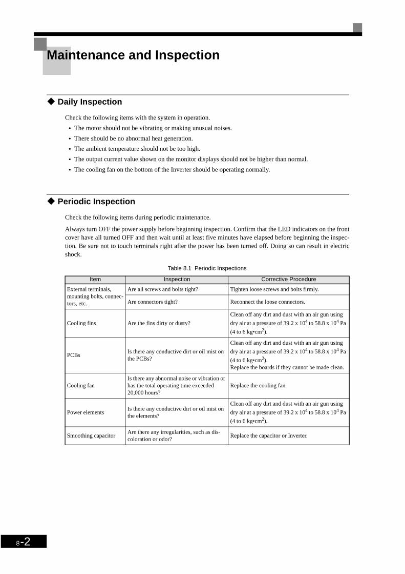
8-2
Maintenance and Inspection
Daily Inspection
Check the following items with the system in operation.
• The motor should not be vibrating or making unusual noises.
• There should be no abnormal heat generation.
• The ambient temperature should not be too high.
• The output current value shown on the monitor displays should not be higher than normal.
• The cooling fan on the bottom of the Inverter should be operating normally.
Periodic Inspection
Check the following items during periodic maintenance.
Always turn OFF the power supply before beginning inspection. Confirm that the LED indicators on the frontcover have all turned OFF and then wait until at least five minutes have elapsed before beginning the inspec-tion. Be sure not to touch terminals right after the power has been turned off. Doing so can result in electricshock.
Table 8.1 Periodic Inspections
Item Inspection Corrective Procedure
External terminals, mounting bolts, connec-tors, etc.
Are all screws and bolts tight? Tighten loose screws and bolts firmly.
Are connectors tight? Reconnect the loose connectors.
Cooling fins Are the fins dirty or dusty?
Clean off any dirt and dust with an air gun using
dry air at a pressure of 39.2 x 10⁴ to 58.8 x 10⁴ Pa
(4 to 6 kg•cm2).
PCBsIs there any conductive dirt or oil mist on the PCBs?
Clean off any dirt and dust with an air gun using
dry air at a pressure of 39.2 x 10⁴ to 58.8 x 10⁴ Pa
(4 to 6 kg•cm2).Replace the boards if they cannot be made clean.
Cooling fanIs there any abnormal noise or vibration or has the total operating time exceeded 20,000 hours?
Replace the cooling fan.
Power elementsIs there any conductive dirt or oil mist on the elements?
Clean off any dirt and dust with an air gun using
dry air at a pressure of 39.2 x 10⁴ to 58.8 x 10⁴ Pa
(4 to 6 kg•cm2).
Smoothing capacitorAre there any irregularities, such as dis-coloration or odor?
Replace the capacitor or Inverter.

Maintenance and Inspection
8-3
Periodic Maintenance of Parts
The Inverter is configured of many parts and these parts must be operating properly in order to make full useof the Inverter functions.
Among the electronic components, there are some that require maintenance depending on their usage condi-tions. In order to keep the Inverter operating normally over a long period of time, it is necessary to performperiod inspections and replace parts according to their service life.
Periodic inspection standards vary depending the Inverter's installation environment and usage conditions.The Inverter's maintenance periods are noted below. Keep them as reference.
Note The standard replacement period is based on the following usage conditions:Ambient temperature:Yearly average of 30°CLoad factor: 80% max.Operating rate: 12 hours max. per day
Table 8.2 Part Replacement Guidelines
Part Standard Replacement Period Replacement Method
Cooling fan 2 to 3 years Replace with new part.
Smoothing capacitor 5 yearsReplace with new part. (Determine need by inspection.)
Breaker relays - Determine need by inspection.
Fuses 10 years Replace with new part.
Aluminum capacitors on PCBs 5 yearsReplace with new board. (Determine need by inspection.)

8-4
Cooling Fan Replacement Outline
200 V and 400 V Class Inverters of 18.5 kW or Less
A cooling fan is attached to the bottom of the Inverter.
If the Inverter is installed using the mounting holes on the back of the Inverter, the cooling fan can be replacedwithout removing the Inverter from the installation panel.
Removing the Cooling Fan
1. Press in on the right and left sides of the fan cover in the direction of arrows 1 and then pull the fan out inthe direction of arrow 2.
2. Pull out the cable connected to the fan from the fan cover and disconnect the relay connector.
3. Open the fan cover on the left and right sides and remove the fan cover from the fan.
Fig 8.1 Cooling Fan Replacement (Inverters of 18.5 kW or Less)
Mounting the Cooling Fan
1. Attach the fan cover to the cooling fan. Be sure that the air flow direction indicated by the arrows abovefaces into the Inverter.
2. Connect the relay connector securely and place the relay connector and cable into the fan cover.
3. Mount the fan cover on the Inverter. Be sure that the tabs on the sides of the fan cover click into place onthe Inverter.
A ir flow d irection
1
1
2
Fan cove r
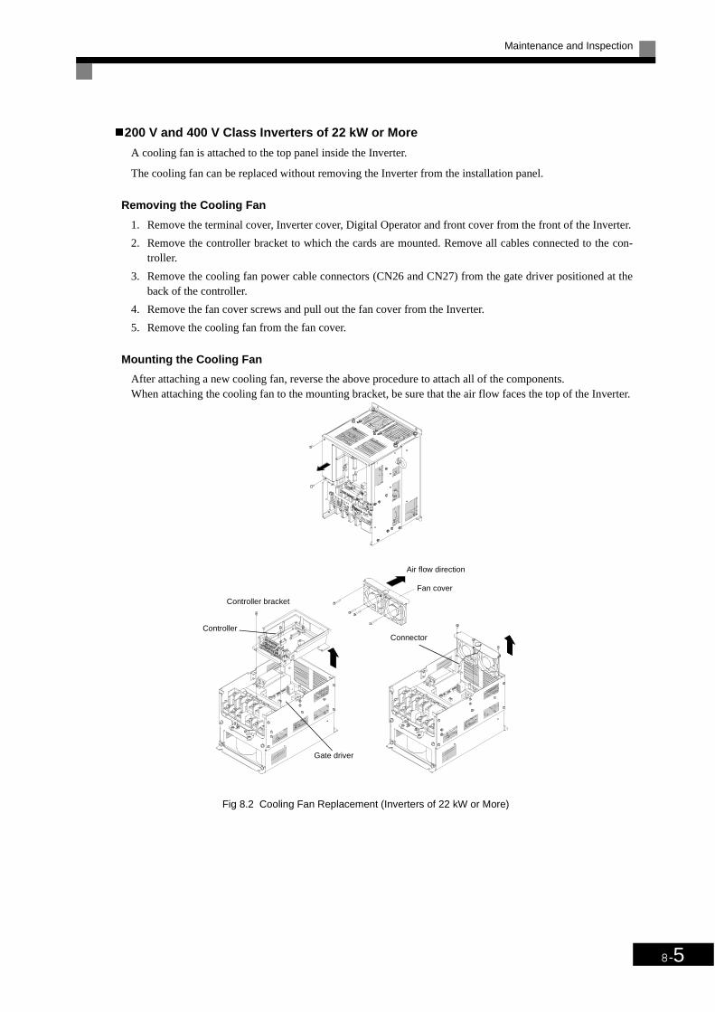
Maintenance and Inspection
8-5
200 V and 400 V Class Inverters of 22 kW or More
A cooling fan is attached to the top panel inside the Inverter.
The cooling fan can be replaced without removing the Inverter from the installation panel.
Removing the Cooling Fan
1. Remove the terminal cover, Inverter cover, Digital Operator and front cover from the front of the Inverter.
2. Remove the controller bracket to which the cards are mounted. Remove all cables connected to the con-troller.
3. Remove the cooling fan power cable connectors (CN26 and CN27) from the gate driver positioned at theback of the controller.
4. Remove the fan cover screws and pull out the fan cover from the Inverter.
5. Remove the cooling fan from the fan cover.
Mounting the Cooling Fan
After attaching a new cooling fan, reverse the above procedure to attach all of the components.When attaching the cooling fan to the mounting bracket, be sure that the air flow faces the top of the Inverter.
Fig 8.2 Cooling Fan Replacement (Inverters of 22 kW or More)
Air flow direction
Controller bracket
Controller
Gate driver
Connector
Fan cover

8-6
Removing and Mounting the Control Circuit Terminal Card
The control circuit terminal card can be removed and mounted without disconnecting the cables.
Removing the Control Circuit Terminal Card
1. Remove the Digital Operator and front cover.
2. Remove the connecting line connectors connected to FE and NC on the control circuit terminal card.
3. Loosen the mounting screws (1) on the left and right sides of the control terminals until they are free. (It isnot necessary to remove these screws completely. They are self-rising.)
4. Pull the terminal card out sideways (in direction 2) with the screws sticking out from the card.
Mounting the Control Circuit Terminal Card
Reverse the removal procedure to mount the terminal card.
Confirm that the terminal circuit card and the controller properly meet at connector CN5 before pressing in onthe card.
The connector pins may be bent if the card is forced into place, possibly preventing correct Inverter operation.
Fig 8.3 Removing the Control Circuit Terminal Card
IMPORTANT
Always confirm that the charge indicator is not lit before removing or mounting the control circuit terminalcard.
Removing and Mounting theControl Circuit Terminal Card
1
11
122

9Chapter 9
SpecificationsThis chapter describes the basic specifications of the Inverter and specifications for options and
peripheral devices.
Standard Inverter Specifications ...........................................9-2
Specifications of Options and Peripheral Devices ................9-6

9-2
Standard Inverter Specifications
Specifications by Model
Specifications are given by model in the following tables.
200V Class
* 1. The maximum applicable motor output is given for a standard 4-pole OMRON motor. When selecting the actual motor and Inverter, be sure that the Inverter's rated current is applicable for the motor's rated current.
* 2. A 3-wire transformer is required on the power supply for 12-phase rectification.
Table 9.1 200 V Class Inverters
Model Number 3G3PV- A2004 A2007 A2015 A2022 A2037 A2055 A2075 A2110 A2150 A2185 A2220 A2300 A2370 A2450 A2550 A2750 A2900
Max. applicable motor output (kW)
0.4 0.75 1.5 2.2 3.7 5.5 7.5 11 15 18.5 22 30 37 45 55 75 90
Rated output capacity (kVA)
1.2 1.6 2.7 3.7 5.7 8.8 12 17 22 27 32 44 55 69 82 110 130
Rated output current (A) 3.2 4.1 7.0 9.6 15 23 31 45 58 71 85 115 145 180 215 283 346
Max. output voltage (V)3-phase; 200, 208, 220, 230 or 240 VAC
(Proportional to input voltage.)Max. output frequency (Hz)
120 Hz max.
Rated voltage (V)Rated frequency (Hz)
3-phase, 200/208/220/230/240 VAC, 50/60 Hz
Allowable voltage fluctua-tion
+ 10%, - 15%
Allowable frequency fluc-tuation
±5%
Measures for power supply harmonics
DC reactor Optional Built in
12-phase rec-tification
Not possible Possible*2
Model Number 3G3PV- B2220 B2300 B2370 B2450 B2550 B2750 B2900 B211K
Max. applicable motor output (kW)
22 30 37 45 55 75 90 110
Rated output capacity (kVA)
32 44 55 69 82 110 130 160
Rated output current (A) 85 115 145 180 215 283 346 415
Max. output voltage (V)3-phase 200, 208, 220, 230 or 240 VAC
(Proportional to input voltage)Max. output frequency (Hz)
120 Hz max.
Rated voltage (V)Rated frequency (Hz)
3-phase, 200/208/220/230/240 VAC, 50/60 Hz
Allowable voltage fluctua-tion
+ 10%, - 15%
Allowable frequency fluc-tuation
±5%
Measures for power supply harmonics
DC reactor Built in
12-phase rec-tification
Possible*2
Out
put r
atin
gsPo
wer
sup
ply
char
acte
rist
ics
Con
trol
cha
ract
eris
tics
Out
put r
atin
gsP
ower
sup
ply
char
acte
rist
ics
Con
trol
cha
ract
eris
tics

Standard Inverter Specifications
9-3
400 V ClassTable 9.2 400 V Class Inverters
Model Number 3G3PV- A4004 A4007 A4015 A4022 A4037 A4040 A4055 A4075 A4110 A4150 A4185
Max. applicable motor output
(kW) 0.4 0.75 1.5 2.2 3.7 4.0 5.5 7.5 11 15 18.5
Rated output capacity (kVA)
1.4 1.6 2.8 4.0 5.8 6.6 9.5 13 18 24 30
Rated output current (A) 1.8 2.1 3.7 5.3 7.6 8.7 12.5 17 24 31 39Max. output voltage (V) 3-phase; 380, 400, 415, 440, 460 or 480 VAC (Proportional to input voltage.)Max. output frequency (Hz)
120 Hz max.
Rated voltage (V)Rated frequency (Hz)
3-phase, 380, 400, 415, 440, 460 or 480 VAC, 50/60 Hz
Allowable voltage fluctua-tion
+ 10%, - 15%
Allowable frequency fluc-tuation
±5%
Measures for power supply harmonics
DC reactor Optional
12-phase rec-tification
Not possible
Model Number 3G3PV- A4220 A4300 A4370 A4450 A4550 A4750 A4900 A411K A413K A416K
Max. applicable motor output (kW)
22 30 37 45 55 75 90 110 132 160
Rated output capacity (kVA)
34 46 57 69 85 110 140 160 200 230
Rated output current (A) 45 60 75 91 112 150 180 216 260 304Max. output voltage (V) 3-phase, 380, 400, 415, 440, 460 or 480 VAC (Proportional to input voltage.)
Max. output frequency (Hz)
120 Hz max.
Max. voltage (V)Rated frequency (Hz)
3-phase, 380, 400, 415, 440, 460 or 480 VAC, 50/60 Hz
Allowable voltage fluctua-tion
+ 10%, - 15%
Allowable frequency fluc-tuation
±5%
Measures for power supply harmonics
DC reactor Built in
12-phase rec-tification Possible*2
Out
put r
atin
gsPo
wer
sup
ply
char
acte
rist
ics
Con
trol
cha
ract
eris
tics
Out
put r
atin
gsPo
wer
sup
ply
char
acte
rist
ics
Con
trol
cha
ract
eris
tics

9-4
* 1. The maximum applicable motor output is given for a standard 4-pole OMRON motor. When selecting the actual motor and Inverter, be sure that the Inverter's rated current is applicable for the motor's rated current.
* 2. A 3-wire transformer is required on the power supply for 12-phase rectification.
Model Number 3G3PV- B4220 B4300 B4370 B4450 B4550 B4750 B4900 B411K B413K B416K
Max. applicable motor output (kW)
22 30 37 45 55 75 90 110 132 160
Rated output capacity (kVA)
34 46 57 69 85 110 140 160 200 230
Rated output current (A) 45 60 75 91 112 150 180 216 260 304
Max. output voltage (V) 3-phase, 380, 400, 415, 440, 460 or 480 VAC (Proportional to input voltage.)
Max. output frequency (Hz)
120 Hz max.
Max. voltage (V)Rated frequency (Hz)
3-phase, 380, 400, 415, 440, 460 or 480 VAC, 50/60 Hz
Allowable voltage fluctua-tion
+ 10%, - 15%
Allowable frequency fluc-tuation
±5%
Measures for power supply harmonics
DC reactor Built in
12-phase rec-tification Possible*2
Out
put r
atin
gsP
ower
sup
ply
char
acte
rist
ics
Con
trol
cha
ract
eris
tics

Standard Inverter Specifications
9-5
Common Specifications
The following specifications apply to both 200 V and 400 V Class Inverters.
* 1. Increase the Inverter capacity if loads exceeding these current values are expected.* 2. If applied in higher altitudes contact your OMRON representative.
Table 9.3 Common Specifications
Model Number3G3PV- Specification
Control methodSine wave PWM
V/f control
Speed control range 1:40
Speed control accuracy ±2 to 3% (25°C ± 10°C)
Frequency accuracy (tem-perature characteristics)
Digital references: ± 0.01% (-10°C to +40°C)
Analog references: ±0.1% (25°C ±10°C)
Frequency setting resolu-tion
Digital references: 0.01 Hz
Analog references: 0.05/50 Hz (10 bit no sign)
Overload capacity and
maximum current*1 120% of rated output current per minute
Frequency setting signal 0 to 10 V, 4 to 20 mA
Acceleration/Decelera-tion time
0.0 to 6000.0 s (4 selectable combinations of independent acceleration and deceleration settings)
Main control functions
Restarting for momentary power loss, speed searches, overtorque detection, 4-speed control (maximum), acceleration/decelera-tion time changes, S-curve acceleration, 3-wire sequence, autotuning, cooling fan ON/OFF control, torque compensation, jump frequencies, upper and lower limits for frequency references, DC braking for starting and stopping, high-slip braking, PI control
(with sleep function), energy-saving control, RS-422A/485 communications (19.2 kbps maximum), fault reset and function copy-ing.
Motor protection Protection by electronic thermal overload relay.
Fuse blown protection Stops for fuse blown.
Overload protection 120% of rated output current for 1 minute
Overvoltage protection200 Class Inverter: Stops when main-circuit DC voltage is above 410 V.400 Class Inverter: Stops when main-circuit DC voltage is above 820 V.
Undervoltage protection200 Class Inverter: Stops when main-circuit DC voltage is below 190 V.400 Class Inverter: Stops when main-circuit DC voltage is below 380 V.
Momentary power loss ridethru
Stops for 15 ms or more. By selecting the momentary power loss method, operation can be continued if power is restored within 2 s.
Cooling fin overheating Protection by thermistor.
Stall prevention Stall prevention during acceleration, deceleration or running.
Grounding protection Protection by electronic circuits. (50% of inverter rated current)
Charge indicator Lit when the main circuit DC voltage is approx. 50 V or more.
Protective structureEnclosed wall-mounted type (NEMA 1): 18.5 kW or less (same for 200 V and 400 V class Inverters)
Open chassis type (IP00): 22 kW or more (same for 200 V and 400 V class Inverters)
Ambient operating tem-perature
-10°C to 40°C (Enclosed wall-mounted type)–10°C to 45°C (Open chassis type)
Ambient operating humid-ity
95% max. (with no condensation)
Storage temperature - 20°C to + 60°C (short-term temperature during transportation)
Application site Indoor (no corrosive gas, dust, etc.)
Altitude 1000 m max.*2
Vibration 10 to 20 Hz, 9.8 m/s2 max.; 20 to 50 Hz, 2 m/s2 max
Con
trol
cha
ract
eris
tics
Prot
ecti
ve f
unct
ions
Env
iron
men
t

9-6
Specifications of Options and Peripheral DevicesThe following options and peripheral devices can be used for the Inverter. Select them according to theapplication.
* Use a ground fault interrupter with a current sensitivity of 200 mA minimum and an operating time of 0.1 s minimum to prevent operating errors* The interrupter must be suitable for high-frequency operation.
Example: NV series by Mitsubishi Electric Corporation (manufactured in or after 1988)EG, SG series by Fuji Electric Co., Ltd. (manufactured in or after 1984)
Table 9.4 Options and Peripheral Devices
Purpose Name Model (Code) Descriptions
Protect Inverter wiringMCCB or Ground
Fault Interrupter*Example: Mitsubishi Electrics NV Series
Always connect a breaker to the power supply line to pro-tect Inverter wiring. Use a ground fault interrupter suitable for high frequencies.
Prevents burning when a Braking Resistor is used.
Magnetic Contac-tor
Example: Fuji Electrics SC Series
Install to prevent the braking resistor from burning out when one is used. Always attach a surge absorber to the coil.
Contains switching surge
Surge Absorber DCR2-Absorbs surge from the magnetic contactor and control relays. Connect surge absorbers to all magnetic contactors and relays near the Inverter.
Isolates I/O signals Isolator DGPIsolates the I/O signals of the Inverter and is effective against inductive noise.
Improves the input power factor of the Inverter
DC ReactorAC Reactor
3G3HV-PUZDAB3G3IV-PUZBAB
Used to improve the input power factor of the Inverter. All Inverters of 22 kW or higher contain built-in DC reactors. These are optional for Inverters of 18.5 kW or less. Install DC and AC reactors for applications with a large power supply capacity (600 kVA or higher).
Reduces the affects of radio and control device noise
Input Noise Filter3G3IV-PFN3G3EV-PLNF
Reduces noise coming into the inverter from the power supply line and to reduce noise flowing from the inverter into the power supply line. Connect as close to the Inverter as possible.
Output Noise Fil-ter 3G3IV-PLF
Reduces noise generated by the inverter. Connect as close to the inverter as possible.
Enables stopping the machine in a set time
Braking Resistor Unit
3G3IV-PLKEBConsumes the regenerative motor energy with a resistor to reduce deceleration time (use rate: 10% ED).(Braking Unit is needed.)
Braking Unit 3G3IV-PCDBRBUsed with a Braking Resistor Unit to reduce the decelera-tion time of the motor.
Operates the Inverter externally
Analog Operator(small plastic Operator)
3G3IV-PJVOP95
Allows frequency reference settings and ON/OFF opera-tion control to be performed by analog references from a remote location (50 m max.).Frequency counter specifications: 60/120 Hz, 90/180Hz
Analog Operator(Standard steel-plate Operator)
3G3IV-PJVOP96(73041-0906X-)
Allows frequency reference settings and ON/OFF opera-tion control to be performed by analog references from a remote location (50 m max.).Frequency counter specifications: 75 Hz, 150 Hz, 220 Hz
Digital Operator Connection Cable
1 m cable: (3G3IV-PCN126)3 m cable: (3G3IV-PCN326-E)
Extension cable to use a Digital Operator remotely.Cable length: 1 m or 3 m
Controls an Inverter system
VS System Mod-ule
JGSM-A system controller that can be match to the automatic control system to produce an optimum system configura-tion.
Provides Inverter momentary power loss recovery time
Momentary Power Loss Recovery Unit
3G3IV-PCN26Handles momentary power losses for the control power supply for models 2.2 kW or less (maintains power for 2 s).
Sets/monitors frequen-cies and voltages exter-nally.
Scaling Meter K3TJ-V11Measurs the output voltage externally and designed for use with a PWM meter.
Power supply
MCCB or ground fault interrupter
Magnetic contactor
AC reactor to improve power factor
Inverter
Input-line noise filter
DC reactor
Ground
Ground
Output-line noise filter
Motor
Frequency
VS Operator
Zero phase reactor

Options and Peripheral Devices
9-7
Options and Peripheral DevicesThere are several types of options and peripheral devices for Inverters: Separately installed options, spe-cial options, Option Cards, and recommended separately installed options. The specifications of theseoptions are provided in these sections.
Fig. 3.1 Options and Peripheral Devices
Separately Installed Options Special Options
3G3IV-PCDBRBBraking Unit
3G3IV-PLKEBBraking Resistor Unit
3G3FV-PCN26(-E)Digital Operator Connection Cable
3G3HV-PUZDABDC Reactor
3G3IV-PJVOP95Analog Operator(small, plastic)
3G3EV-PLNFDSimple Input NoiseFilter
3G3IV-PUZBABAC Reactor
3G3IV-PFNInput Noise Filter
Power supply
3-phase, 200VAC (200-V Class)3-phase, 400VAC (400-V Class)
3-phase inductive
3G3IV-PLFOutput Noise Filter
Recommended Separately Installed Options
3G3IV-PJVOP96Analog Operator(standard, steel panels)
Recommended Separately InstalledOptions
Digital Operator3G3IV-PJVOP161 (LED) 3G3IV-PJVOP160 (LCD)
Option cards
3G3FV-PDRT1-SIN DeviceNet Communications Card
K3TJ-V11Scaling Meter

9-8
* 1. Recommended Options can be ordered from OMRON using the above model numbers.
Table 9.1 Options and Peripheral Devices
Type Name Model number Application
Special Mounted Options
Fan Unit 3G3IV-PFANReplacement fan for Inverters equipped with a cooling fan.Replace the Cooling Fan when the fan replacement time has come or a cooling fan fault (FAN) alarm has been displayed.
Separately Installed Options
Scaling Meter K3TJ-V11Connects to a multi-function analog output from the Inverter. Used to display rotational speeds of motors, line speeds, etc., in physical units.
Analog Operator (stan-dard with steel panels)
3G3IV-PJVOP96Allows frequency reference settings and ON/OFF operation control to be performed by analog references from a remote location (50 m max.).Frequency counter specifications: 75 Hz, 150 Hz, 220 Hz
Analog Operator (small, plastic)
3G3IV-PJVOP95Allows frequency reference settings and ON/OFF operation control to be performed by analog references from a remote location (50 m max.).Frequency counter specifications: 60/120 Hz, 90/180Hz
Special Options
Braking Unit 3G3IV-PCDBRBUsed with a Braking Resistor Unit to reduce the deceleration time of the motor.Not required with Inverters of 7.5 kW or less for 200-V class Inverters or for Inverters of 15 kW or less for 400-V class Inverters.
Braking Resistor Unit 3G3IV-PLKEBConsumes the regenerative motor energy with a resistor to reduce deceleration time (use rate: 10% ED).
DC Reactor 3G3HV-PUZDABUsed to control harmonics generated by the Inverter and to improve the input power fac-tor of the Inverter. All Inverters of 18.5 kW or higher contain built-in DC reactors.
Digital Operator with LCD Display
3G3IV-PJVOP160 Displays messages on a LCD.
Digital Operator with LED Display
3G3IV-PJVOP161 Display messages on a LED display. Standard in Asia and Europe.
Digital Operator Connec-tion Cable
3G3IV-PCN126 (1 m) Extension cable to use a 3G3PV-series Digital Operator remotely.Cable length: 1 m or 3 m3G3IV-PCN326-E (3 m)
Personal Computer cable 3G3IV-PCN329-EConnection cable for connecting the 3G3PV series Inverter to the SYSDrive configura-tor (software tool) on Personal Computer.
Option cardsDeviceNet Communica-tions Card
3G3FV-PDRT1-SINUsed for DeviceNet communications with a Programmable Controller or other DeviceNet master device.
7HUPLQDO FDUGV
Standard terminal card 3G3PV-PETC618140 Standard terminal card for standard operation
Optional terminal card 3G3PV-PETC618120Optional terminal card (with shunt connector CN15) for switching the analog output levels between (0-10V) or (4 to 20 mA).
Recommended Separately Installed
Options*1
AC Reactor 3G3IV-PUZBABUsed to control harmonics generated by the Inverter or when the power supply capacity is greatly larger than the Inverter’s capacity. Also used to increase the power factor.
Simple Input Noise Filter 3G3EV-PLNFDReduces noise coming into the inverter from the power supply line and to reduce noise flowing from the inverter into the power supply line. Connected to the power supply input side.
Input Noise Filter (Schaffner)
3G3IV-PFNReduces noise coming into the inverter from the power supply line and to reduce noise flowing from the inverter into the power supply line.Connected to the power supply input side.
Input Noise Filter (Schaffner) for EMC Directive
3G3RV-PFI-SE Required for the 3G3PV Inverter to meet the EMC Directive.
Input Noise Filter (Rasmi) for EMC Direc-tive
3G3RV-PFI-E Required for the 3G3PV Inverter to meet the EMC Directive.
Output Noise Filter (Tokin)
3G3IV-PLFControls noise generated by the Inverter so it does not enter the power supply. Con-nected to the motor output side.

Options and Peripheral Devices
9-9
Special Mounted Options
The special mounted options are described in this section.
Fan Unit
Replacement fan for Inverters equipped with a cooling fan.
Replace the Cooling Fan when the fan replacement time has come or a cooling fan fault (FAN) alarm has beendisplayed.
Models and Application
The standard models of Fan Units are listed in the following table.
Refer to Chapter 8 Maintenance and Inspection for the Fan Unit replacement procedure.
Inverter Replacement Cooling Fan
Voltage Class
Max. Applicable Motor Capacity
(kW)Model No. Model No. Qty Used
3-phase, 200 VAC
0.4 3G3PV-A2004
No Fan -0.75 3G3PV-A20071.5 3G3PV-A20152.2 3G3PV-A20223.7 3G3PV-A2037
3G3IV-PFAN0010411
5.5 3G3PV-A20557.5 3G3PV-A2075
211 3G3PV-A211015 3G3PV-A2150
3G3IV-PFAN001042 218.5 3G3PV-A218522 3G3PV-B2220
3G3IV-PFAN001039 230 3G3PV-B230037 3G3PV-B2370
3G3IV-PFAN001049 245 3G3PV-B245055 3G3PV-B2550
3G3IV-PFAN001052 275 3G3PV-B275090 3G3PV-B2900
3G3IV-PFAN000111 2110 3G3PV-B211K
3-phase, 400 VAC
0.4 3G3PV-A4004No Fan -0.75 3G3PV-A4007
1.5 3G3PV-A40152.2 3G3PV-A4022
3G3IV-PFAN001041 13.7 3G3PV-A40375.5 3G3PV-A40557.5 3G3PV-A4075
3G3IV-PFAN001042 211 3G3PV-A411015 3G3PV-A4150
18.5 3G3PV-A418522 3G3PV-B4220
3G3IV-PFAN001039 230 3G3PV-B430037 3G3PV-B4370
3G3IV-PFAN001044 245 3G3PV-B445055 3G3PV-B455075 3G3PV-B4750
3G3IV-PFAN001052 290 3G3PV-B4900110 3G3PV-B411K
3G3IV-PFAN001056 2132 3G3PV-B413K160 3G3PV-B416K

9-10
Separately Installed Options
The separately installed options include Scaling Meters and Analog Operators.
Scaling Meters
A Scaling Meter is attached to a multi-function analog output from the Inverter and is used to display rota-tional speeds of motors, line speeds, etc., in physical units.
Models and Application
The standard models of Scaling Meters are listed in the following table.
Note The power supply circuit is isolated from the input circuits.
Standard Specifications
The standard specifications of the Scaling Meters are listed below.
* IP51 requires that the optional K32-L49SC Drop-proof Cover is used. The protective structure is IP50 without it.
Model No. Control Power Supply DisplayK3TJ-V111R
100 to 200 VACRed LED
K3TJ-V111G Green LED
K3TJ-V116R 24 VDC, isolated (See note.)
Red LED
K3TJ-V116G Green LED
K3TJ-V11 SpecificationsSampling Period 2 times/s
Display Refresh Cycle 2 times/s
Measurement Averaging Methods Simple average or moving average
Number of Samples for Averaging 1, 2, 4, or 8 samples
Max. No. of Display Digits 4 digits (-1999 to 9999)
Display 7-segment LEDs, character height: 14.2 mm
Decimal Point Display User-set using function selection switch and up/down keys.
Scaling MethodShifting and scaling are user-set using function selection switch and up/down keys.
Scaling Range -1999 to 9999
Zero Limit Range 0 to 99 digits
Overrange Values Flashing display
Zero Suppression Supported
External Controls Present value hold (by short-circuiting terminal on front panel)
Protective Structure (conforming to IEC standards)
Front panel display: IP51*
Case: IP20Terminal section: IP00
Memory Protection Non-volatile memory

Options and Peripheral Devices
9-11
Wiring Example
A wiring example for a Scaling Meter is shown below.
Dimensions
The dimensions of a Scaling Meter are given below.
MCCB
Inverter
Analogmonitor
Analog output3-phasepowersupply
weight: 200 g
Display LED size
Recommended panelcutout dimensions
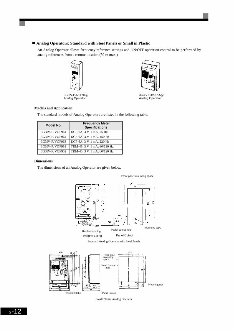
9-12
Analog Operators: Standard with Steel Panels or Small in Plastic
An Analog Operator allows frequency reference settings and ON/OFF operation control to be performed byanalog references from a remote location (50 m max.)
Models and Application
The standard models of Analog Operators are listed in the following table.
Dimensions
The dimensions of an Analog Operator are given below.
Standard Analog Operator with Steel Panels
Small Plastic Analog Operator
Model No. Frequency Meter
Specifications3G3IV-PJVOP961 DCF-6A, 3 V, 1 mA, 75 Hz
3G3IV-PJVOP962 DCF-6A, 3 V, 1 mA, 150 Hz
3G3IV-PJVOP963 DCF-6A, 3 V, 1 mA, 220 Hz
3G3IV-PJVOP951 TRM-45, 3 V, 1 mA, 60/120 Hz
3G3IV-PJVOP952 TRM-45, 3 V, 1 mA, 60/120 Hz
3G3IV-PJV0P96@ Analog Operator
3G3IV-PJV0P95@ Analog Operator
Front panel mounting space
Mounting tapsPanel cutout hole
Rubber bushing
Casemounting
Panel CutoutWeight: 1.8 kg
Weight: 0.8 kg Panel Cutout
Panel Cutouthole
mountingspace
Front panel
Mounting taps

Options and Peripheral Devices
9-13
Braking Unit
A Braking Unit is used with a Braking Resistor Unit to reduce the deceleration time of the motor. It is notrequired with Inverters of 18.5 kW or less.
Models and Application
The standard models of Braking Units are listed in the following table.
* The minimum resistance is the minimum value per Braking Unit except for Inverters of 18.5 kW or less, in which case it the minimum value per Inverter.
Inverter Braking UnitMin. Resistance*
(Ω)Voltage Class
Max. Applicable Motor Capacity (kW)
Model No. Qty Used.
200-V Class
0.4
Built-in
480.75 481.5 482.2 163.7 165.5 167.5 9.611 9.615 9.6
18.5 9.622 3G3IV-CDBR2022B 1 6.430 3G3IV-CDBR2015B 2 9.637 3G3IV-CDBR2015B 2 9.645 3G3IV-CDBR2022B 2 6.455 3G3IV-CDBR2022B 2 6.475 3G3IV-CDBR2022B 3 6.490 3G3IV-CDBR2022B 4 6.4110 3G3IV-CDBR2022B 5 6.4
400-V Class
0.4
Built-in
960.75 961.5 642.2 643.7 325.5 327.5 3211 2015 20
18.5 19.222 3G3IV-CDBR4030B 1 19.230 3G3IV-CDBR4030B 1 19.237 3G3IV-CDBR4045B 1 12.845 3G3IV-CDBR4045B 1 12.855 3G3IV-CDBR4030B 2 19.275 3G3IV-CDBR4045B 2 12.890 3G3IV-CDBR4045B 2 12.8110 3G3IV-CDBR4030B 3 19.2132 3G3IV-CDBR4045B 3 12.8160 3G3IV-CDBR4045B 4 12.8

9-14
Dimensions
The dimensions of a Braking Unit are given below.
Mounting direction
Four, M4 mounting holes
Three wire pull-out holes (with 22mm- dia, rubber bushings)
Up

Options and Peripheral Devices
9-15
Braking Resistor Unit
A Braking Resistor Unit is used to absorb the regenerative motor energy with a resistor to reduce decelerationtime (use rate: 10% ED). A 10% ED means that the 10% of the operating cycle time can be used to controlbraking (deceleration time).
Models and Application
The standard models of Braking Resistor Units are listed below.
Inverter Braking Resistor Unit
Voltage Class
Applicable Motor
Capacity (kW)
Model No.Resistor
Specifications(per Unit)
Qty UsedApprox Braking
Torque (%)
200-V Class
0.4 3G3IV-PLKEB20P7 70 W, 200 Ω 1 2200.75 3G3IV-PLKEB20P7 70 W, 200 Ω 1 1251.5 3G3IV-PLKEB21P5 260 W, 100 Ω 1 1252.2 3G3IV-PLKEB22P2 260 W, 100 Ω 1 1203.7 3G3IV-PLKEB23P7 390 W, 40 Ω 1 1255.5 3G3IV-PLKEB25P5 520 W, 30 Ω 1 1157.5 3G3IV-PLKEB27P5 780 W, 20 Ω 1 12511 3G3IV-PLKEB2011 2400 W, 13.6 Ω 1 12515 3G3IV-PLKEB2015 3000 W, 10 Ω 1 125
18.5 3G3IV-PLKEB2015 3000 W, 10 Ω 1 12522 3G3IV-PLKEB2022 4800 W, 6.8 Ω 1 12530 3G3IV-PLKEB2015 3000 W, 10 Ω 2 12537 3G3IV-PLKEB2015 3000 W, 10 Ω 2 10045 3G3IV-PLKEB2022 4800 W, 6.8 Ω 2 12055 3G3IV-PLKEB2022 4800 W, 6.8 Ω 2 10075 3G3IV-PLKEB2022 4800 W, 6.8 Ω 3 11090 3G3IV-PLKEB2022 4800 W, 6.8 Ω 4 120110 3G3IV-PLKEB2018 4800 W, 8 Ω 5 100
400-V Class
0.4 3G3IV-PLKEB40P7 70 W, 750 Ω 1 2300.75 3G3IV-PLKEB40P7 70 W, 750 Ω 1 1301.5 3G3IV-PLKEB41P5 260 W, 400 Ω 1 1252.2 3G3IV-PLKEB42P2 260 W, 250 Ω 1 1353.7 3G3IV-PLKEB43P7 390 W, 150 Ω 1 1355.5 3G3IV-PLKEB45P5 520 W, 100 Ω 1 1357.5 3G3IV-PLKEB47P5 780 W, 75 Ω 1 13011 3G3IV-PLKEB4011 1040 W, 50 Ω 1 13515 3G3IV-PLKEB4015 1560 W, 40 Ω 1 125
18.5 3G3IV-PLKEB4018 4800 W, 32 Ω 1 12522 3G3IV-PLKEB4022 4800 W, 27.2 Ω 1 12530 3G3IV-PLKEB4030 6000 W, 20 Ω 1 12537 3G3IV-PLKEB4037 9600 W, 16 Ω 1 12545 3G3IV-PLKEB4045 9600 W, 13.6 Ω 1 12555 3G3IV-PLKEB4030 6000 W, 20 Ω 2 13575 3G3IV-PLKEB4045 9600 W, 13.6 Ω 2 14590 3G3IV-PLKEB4045 9600 W, 13.6 Ω 2 100110 3G3IV-PLKEB4030 6000 W, 20 Ω 3 100132 3G3IV-PLKEB4045 9600 W, 13.6 Ω 4 140160 3G3IV-PLKEB4045 9600 W, 13.6 Ω 4 140

9-16
Dimensions
The dimensions of a Braking Resistor Unit are given below.
Voltage Class
Model No.3G3IV-
PLKEB
Dimensions Diagram
Dimensions (mm)Weight
(kg)A B C DMounting Screws
200-V Class
20P7 1 105 275 50 260 M5 × 3 3.0
21P5 1 130 350 75 335 M5 × 4 4.5
22P2 1 130 350 75 335 M5 × 4 4.5
23P7 1 130 350 75 335 M5 × 4 5.0
25P5 1 250 350 200 335 M6 × 4 7.5
27P5 1 250 350 200 335 M6 × 4 8.5
2011 2 266 543 246 340 M8 × 4 10
2015 2 356 543 336 340 M8 × 4 15
2018 2 446 543 426 340 M8 × 4 19
2022 2 446 543 426 340 M8 × 4 19
400-V Class
40P7 1 105 275 50 260 M5 × 3 3.0
41P5 1 130 350 75 335 M5 × 4 4.5
42P2 1 130 350 75 335 M5 × 4 4.5
43P7 1 130 350 75 335 M5 × 4 5.0
45P5 1 250 350 200 335 M6 × 4 7.5
47P5 1 250 350 200 335 M6 × 4 8.5
4011 2 266 543 246 340 M8 × 4 10
4015 2 356 543 336 340 M8 × 4 15
4018 2 446 543 426 340 M8 × 4 19
4022 2 446 543 426 340 M8 × 4 19
4030 2 356 956 336 740 M8 × 4 25
4037 2 446 956 426 740 M8 × 4 33
4045 2 446 956 426 740 M8 × 4 33
Dimensions Diagram 1
Mounting screw
Dimensions Diagram 2
Mounting screw

Options and Peripheral Devices
9-17
Digital Operator Connection Cable
Connected the Inverter to a Digital Operator in a remote locations. Both 1-m and 3-m Cables are available.
Models and Application
Personal computer Cable
Connect the Inverter and the Personal Computer. Only available in 3m.
Software tool SYSDrive Configurator
Software tool for programming, downloading, uploading and monitoring for OMRON Inverters.
Model No. Specifications3G3IV-PCN126 Cable length: 1 m
3G3IV-PCN326-E Cable length: 3 m
Model no. Specifications
3G3IV-PCN329-E Cable length: 3 m
Model no. Specifications
9950058/6 SYSDrive Configurator V1.2

9-18
DC Reactor
A DC Reactor is used to control harmonics generated by the Inverter. It is more effective than and can be usedin combination with an AC Reactor. It is also used to increase the power factor.
Models and Application
The standard models of DC Reactors are listed below.
Inverter DC Reactor
Voltage Class
Max. Appli-cable Motor
Capacity (kW)
Model No.Rated
Voltage(V)
Rated Current
(A)
Inductance (mH)
Loss(W)
200-V Class
0.4/0.75 3G3HV-PUZDAB5.4A8MH
DC800
5.4 8 8
1.5 to 3.7 3G3HV-PUZDAB18A3MH 18 3 18
5.5/7.5 3G3HV-PUZDAB36A1MH 36 1 22
11/153G3HV-PUZDAB72A0.5MH
72 0.5 29
18.53G3HV-PUZDAB90A0.4MH
90 0.4 45
400-V Class
0.4/0.753G3HV-PUZDAB3.2A28MH
DC800
3.2 28 9
1.5 to 2.23G3HV-PUZDAB5.7A11MH
5.7 11 11
3.73G3HV-PUZDAB12A6.3MH
12 6.3 16
5.5/7.53G3HV-PUZDAB23A3.6MH
23 3.6 27
11/153G3HV-PUZDAB33A1.9MH
33 1.9 26
18.53G3HV-PUZDAB47A1.3MH
47 1.3 42

Options and Peripheral Devices
9-19
Dimensions
The dimensions of a DC Reactor are given below.
Model 3G3HV-
PUZDAB
Dimensions Diagram
Dimensions (mm)Weight
(kg)H W W1 D D1 D2 t d1 d2
5.4A8MH 1 53 85 74 60 32 - 0.8 M4 - 0.8
18A3MH 2 76 86 60 72 55 80 1.2 M4 M5 2.0
36A1MH 2 93 105 64 92 80 90 1.6 M6 M6 3.2
72A0.5MH 2 93 105 64 112 100 105 1.6 M6 M8 4.9
90A0.4MH 2 117 133 86 105 80 120 1.6 M6 M8 6.5
3.2A28MH 1 53 85 74 60 32 - 0.8 M4 - 0.8
5.7A11MH 1 60 90 80 60 32 - 0.8 M4 - 1.0
12A6.3MH 2 76 86 60 72 55 80 1.2 M4 M5 2.0
23A3.6MH 2 93 105 64 92 80 90 1.6 M6 M5 3.2
33A1.9MH 2 93 105 64 102 90 95 1.6 M6 M6 4.0
47A1.3MH 2 100 115 72 115 90 125 1.6 M6 M6 6.0
Dimensions Diagram 1
2 mounting holesApp. screws: d1
Dimensions Diagram 2
4 mounting holesApp. screws: d1
2 mounting holes App. screws: d2

9-20
AC Reactor
An AC Reactor is used to control harmonics generated by the Inverter or when the power supply capacity isgreatly larger than the Inverter’s capacity. It is also used to increase the power factor. Select the AC Reactorfrom the following table according to the motor capacity.
Models and Application
The standard models of AC Reactors are listed in the following table.
Inverter AC Reactor
Voltage Class
Max. Appli-cable Motor
Capacity(kW)
Model No.Current
(A)Inductance
(mH)Loss(W)
200-V Class
0.4 3G3IV-PUZBAB2.5A4.2MH 2.5 4.2 15
0.75 3G3IV-PUZBAB5A2.1MH 5 2.1 15
1.5 3G3IV-PUZBAB10A1.1MH 10 1.1 25
2.2 3G3IV-PUZBAB15A0.71MH 15 0.71 30
3.7 3G3IV-PUZBAB20A0.53MH 20 0.53 35
5.5 3G3IV-PUZBAB30A0.35MH 30 0.35 45
7.5 3G3IV-PUZBAB40A0.265MH 40 0.265 50
11 3G3IV-PUZBAB60A0.18MH 60 0.18 65
15 3G3IV-PUZBAB80A0.13MH 80 0.13 75
18.5 3G3IV-PUZBAB90A0.12MH 90 0.12 90
22 3G3IV-PUZBAB120A0.09MH 120 0.09 90
30 3G3IV-PUZBAB160A0.07MH 160 0.07 100
37 3G3IV-PUZBAB200A0.05MH 200 0.05 110
45 3G3IV-PUZBAB240A0.044MH 240 0.044 125
55 3G3IV-PUZBAB280A0.038MH 280 0.038 130
400-V Class
0.4 3G3IV-PUZBAB1.3A18.0MH 1.3 18.0 15
0.75 3G3IV-PUZBAB2.5A8.4MH 2.5 8.4 15
1.5 3G3IV-PUZBAB5A4.2MH 5 4.2 25
2.2 3G3IV-PUZBAB7.5A3.6MH 7.5 3.6 35
3.7 3G3IV-PUZBAB10A2.2MH 10 2.2 43
5.5 3G3IV-PUZBAB15A1.42MH 15 1.42 50
7.5 3G3IV-PUZBAB20A1.06MH 20 1.06 50
11 3G3IV-PUZBAB30A0.7MH 30 0.7 65
15 3G3IV-PUZBAB40A0.53MH 40 0.53 90
18.5 3G3IV-PUZBAB50A0.42MH 50 0.42 90
22 3G3IV-PUZBAB60A0.36MH 60 0.36 90
30 3G3IV-PUZBAB80A0.26MH 80 0.26 95
37 3G3IV-PUZBAB90A0.24MH 90 0.24 110
45 3G3IV-PUZBAB120A0.18MH 120 0.18 130
55 3G3IV-PUZBAB150A0.15MH 150 0.15 150
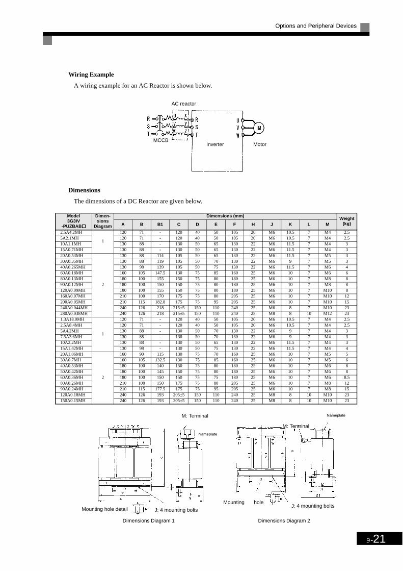
Options and Peripheral Devices
9-21
Wiring Example
A wiring example for an AC Reactor is shown below.
Dimensions
The dimensions of a DC Reactor are given below.
Model3G3IV
-PUZBAB
Dimen-sions
Diagram
Dimensions (mm) Weight(kg)A B B1 C D E F H J K L M
2.5A4.2MH
1
120 71 - 120 40 50 105 20 M6 10.5 7 M4 2.55A2.1MH 120 71 - 120 40 50 105 20 M6 10.5 7 M4 2.510A1.1MH 130 88 - 130 50 65 130 22 M6 11.5 7 M4 315A0.71MH 130 88 - 130 50 65 130 22 M6 11.5 7 M4 320A0.53MH
2
130 88 114 105 50 65 130 22 M6 11.5 7 M5 330A0.35MH 130 88 119 105 50 70 130 22 M6 9 7 M5 340A0.265MH 130 98 139 105 50 75 130 22 M6 11.5 7 M6 460A0.18MH 160 105 147.5 130 75 85 160 25 M6 10 7 M6 680A0.13MH 180 100 155 150 75 80 180 25 M6 10 7 M8 890A0.12MH 180 100 150 150 75 80 180 25 M6 10 7 M8 8120A0.09MH 180 100 155 150 75 80 180 25 M6 10 7 M10 8160A0.07MH 210 100 170 175 75 80 205 25 M6 10 7 M10 12200A0.05MH 210 115 182.8 175 75 95 205 25 M6 10 7 M10 15240A0.044MH 240 126 218 215±5 150 110 240 25 M6 8 7 M10 23280A0.038MH 240 126 218 215±5 150 110 240 25 M8 8 10 M12 231.3A18.0MH
1
120 71 - 120 40 50 105 20 M6 10.5 7 M4 2.52.5A8.4MH 120 71 - 120 40 50 105 20 M6 10.5 7 M4 2.55A4.2MH 130 88 - 130 50 70 130 22 M6 9 7 M4 37.5A3.6MH 130 88 - 130 50 70 130 22 M6 9 7 M4 310A2.2MH 130 88 - 130 50 65 130 22 M6 11.5 7 M4 315A1.42MH 130 98 - 130 50 75 130 22 M6 11.5 7 M4 420A1.06MH
2
160 90 115 130 75 70 160 25 M6 10 7 M5 530A0.7MH 160 105 132.5 130 75 85 160 25 M6 10 7 M5 640A0.53MH 180 100 140 150 75 80 180 25 M6 10 7 M6 850A0.42MH 180 100 145 150 75 80 180 25 M6 10 7 M6 860A0.36MH 180 100 150 150 75 75 180 25 M6 10 7 M6 8.580A0.26MH 210 100 150 175 75 80 205 25 M6 10 7 M8 1290A0.24MH 210 115 177.5 175 75 95 205 25 M6 10 7 M8 15120A0.18MH 240 126 193 205±5 150 110 240 25 M8 8 10 M10 23150A0.15MH 240 126 193 205±5 150 110 240 25 M8 8 10 M10 23
Dimensions Diagram 1 Dimensions Diagram 2
Inverter Motor
AC reactor
MCCB
Nameplate
M: Terminal
Mounting hole detail J: 4 mounting bolts
M: Terminal
Nameplate
Mounting holeJ: 4 mounting bolts

9-22
Input Noise Filters for EMC Directives (3G3RV-PFI, by Schaffner)
When conformance to the EMC Directives in the EC Directives is required, always use one of these Filters.The Filter is connected between the Inverter’s power supply input terminals (R/L1, S/L2, T/L3) and the powersupply.
There are holes for mounting the Noise Filters to Inverters on the top of the Noise Filters. Use these holes tosecure the Noise Filters to the Inverters.
Models and Application
The standard models of Input Noise Filters for EMC Directives are listed in the following table.
Wiring Example
A wiring example for an Input Noise Filter for EMC Directives is shown below.
Inverter Input Noise Filter for EMC Directives
Voltage ClassMax. Applicable
Motor Capacity (kW)Rated Cur-
rent (A)Model No.
Weight (kg)
Dimensions Diagram
3-phase, 200 VAC
0.410 3G3RV-PFI3010-SE 1.1
1
0.751.52.2 18 3G3RV-PFI3018-SE 1.33.7
35 3G3RV-PFI2035-SE 1.45.57.5
60 3G3RV-PFI2060-SE 3 21115
100 3G3RV-PFI2100-SE 4.9 318.522
130 3G3RV-PFI2130-SE 4.3 53037 160 3G3RV-PFI2160-SE 6 645
240 3G3RV-PFI2200-SE 11 755
3-phase, 400 VAC
0.4
10 3G3RV-PFI3010-SE 1.1
1
0.751.52.23.7
18 3G3RV-PFI3018-SE 1.34.05.57.5
35 3G3RV-PFI3035-SE 2.1 21115
60 3G3RV-PFI3060-SE 4 318.522
70 3G3RV-PFI 3070-SE 3.4 43037
130 3G3RV-PFI3130-SE 4.7 5455575 170 3G3RV-PFI3170-SE 6.0 690 200 3G3RV-PFI3200-SE 11.0 7
Inverter
Clamp coreMCCB
3-phase 200 VAC3-phase 400 VAC
Noise filter
Inverter

Options and Peripheral Devices
9-23
Dimensions
The dimensions of an Input Noise Filter (by Schaffner)for EMC Directives are given below.
M5 (Inverter mounting holes x 4)
Dimensions Diagram 1
M6 (Inverter mounting holes x 4)
Dimensions Diagram 2
M5 (Inverter mounting holes x 4)
Dimensions Diagram 3 Dimensions Diagram 4
Dimensions Diagram 5 Dimensions Diagram 6
Dimensions Diagram 7

9-24
Installation of Schaffner filters

Options and Peripheral Devices
9-25
Input Noise Filters for EMC Directives (3G3RV-PFI, by Rasmi Electronics)
When conformance to the EMC Directives in the EC Directives is required, always use one of these Filters.The Filter is connected between the Inverter’s power supply input terminals (R/L1, S/L2, T/L3) and the powersupply.
There are holes for mounting the Noise Filters to Inverters on the top of the Noise Filters. Use these holes tosecure the Noise Filters to the Inverters.
Models and Application
The standard models of Input Noise Filters for EMC Directives are listed in the following table.
Inverter Input Noise Filter for EMC Directives
Voltage ClassMax. Applicable
Motor Capacity (kW)Rated Cur-
rent (A)Model No. Dimensions
Diagram
3-phase, 200 VAC
0.410 3G3RV-PFI3010-E
1
0.751.52.2 18 3G3RV-PFI3018-E3.7
35 3G3RV-PFI2035-E5.57.5
60 3G3RV-PFI2060-E1115
100 3G3RV-PFI2100-E18.522
130 3G3RV-PFI2130-E2
3037 160 3G3RV-PFI2160-E45 200 3G3RV-PFI2200-E
3-phase, 400 VAC
0.4
10 3G3RV-PFI3010-E
1
0.751.52.23.7
18 3G3RV-PFI3018-E4.05.57.5
35 3G3RV-PFI3035-E1115
60 3G3RV-PFI3060-E18.522
70 3G3RV-PFI3070-E
2
3037
100 3G3RV-PFI3100-E4555 130 3G3RV-PFI3130-E75 170 3G3RV-PFI3170-E90 200 3G3RV-PFI3200-E

9-26
Dimensions
The dimensions of an Input Noise Filter (by Rasmi)for EMC Directives are given below.
Model3G3IVPFI
Dimen-sions
Diagram
Dimensions (mm)
L W H X Y d
3G3RV-PFI3010-E
1330 143 46 313 115 M53G3RV-PFI3018-E
3G3RV-PFI2035-E3G3RV-PFI2060-E 355 213 60 336 175 M63G3RV-PFI2100-E 408 238 80 390 205 M63G3RV-PFI2130-E
2310 90 180 295 65 M6
3G3RV-PFI2160-E 380 120 170 365 102 M63G3RV-PFI2200-E 518 130 240 498 90 M83G3RV-PFI3010-E
1330 143 46 313 115 M5
3G3RV-PFI3018-E3G3RV-PFI3035-E 355 213 51 336 175 M63G3RV-PFI3060-E 408 238 60 390 205 M63G3RV-PFI3070-E
2
329 80 220 314 55 M63G3RV-PFI3100-E
310 90 180 295 65 M63G3RV-PFI3130-E3G3RV-PFI3170-E 380 120 170 365 102 M63G3RV-PFI3200-E 518 130 240 498 90 M8
Dimension diagram 1 Dimension diagram 2

Options and Peripheral Devices
9-27
Simple Input Noise Filter
A Simple Input Noise Filter reduces noise coming into the inverter from the power supply line and to reducenoise flowing from the inverter into the power supply line. Connect the Filter to the power supply input side.
Models and Application
The standard models of Simple Input Noise Filters are listed in the following table.
Inverter Simple Input Noise Filter
Voltage Class
Max. Applicable Motor Capacity
(kW)Model No. Qty
Rated Current
(A)
200-V Class
0.4 3G3EV-PLNFD2103DY 1 10
0.75 3G3EV-PLNFD2103DY 1 10
1.5 3G3EV-PLNFD2103DY 1 10
2.2 3G3EV-PLNFD2153DY 1 15
3.7 3G3EV-PLNFD2303DY 1 30
5.5 3G3EV-PLNFD2203DY 2 40
7.5 3G3EV-PLNFD2303DY 2 60
11 3G3EV-PLNFD2303DY 3 90
15 3G3EV-PLNFD2303DY 3 90
18.5 3G3EV-PLNFD2303DY 4 120
22 3G3EV-PLNFD2303DY 4 120
400-V Class
0.4 3G3EV-PLNFD4053DY 1 5
0.75 3G3EV-PLNFD4053DY 1 5
1.5 3G3EV-PLNFD4103DY 1 10
2.2 3G3EV-PLNFD4103DY 1 10
3.7 3G3EV-PLNFD4153DY 1 15
5.5 3G3EV-PLNFD4203DY 1 20
7.5 3G3EV-PLNFD4303DY 1 30
11 3G3EV-PLNFD4203DY 2 40
15 3G3EV-PLNFD4303DY 2 60
18.5 3G3EV-PLNFD4303DY 2 60
22 3G3EV-PLNFD4303DY 3 90
30 3G3EV-PLNFD4303DY 3 90
37 3G3EV-PLNFD4303DY 4 120
45 3G3EV-PLNFD4303DY 4 120

9-28
Wiring Example
A wiring example for a Simple Input Noise Filter is shown below.
Dimensions
The dimensions of a Simple Input Noise Filter are given below.
Model3G3EV-
Dimensions Diagram
DimensionsWeight
(kg)W D Hmax A A' BMounting Screws
PLNFD2103DY
1
120 80 55 108 - 68M4 × 420 mm
0.2
PLNFD2153DY 120 80 55 108 - 68M4 × 420 mm
0.2
PLNFD2203DY 170 90 70 158 - 78M4 × 420 mm
0.4
PLNFD2303DY
2
170 110 70 - 79 98M4 × 620 mm
0.5
PLNFD4053DY 170 130 75 - 79 118M4 × 630 mm
0.3
PLNFD4103DY 170 130 95 - 79 118M4 × 630 mm
0.4
PLNFD4153DY 170 130 95 - 79 118M4 × 630 mm
0.4
PLNFD4203DY 200 145 100 - 94 133M4 × 630 mm
0.5
PLNFD4303DY 200 145 100 - 94 133M4 × 630 mm
0.6
Input Noise Filter Inverter
Dimensions Diagram 1 Dimensions Diagram 2

Options and Peripheral Devices
9-29
Input Noise Filter
An Input Noise Filter reduces noise coming into the inverter from the power supply line and to reduce noiseflowing from the inverter into the power supply line. Connect the Filter to the power supply input side.
Models and Application
The standard models of Input Noise Filters are listed in the following table.
Wiring Example
Wiring for an Input Noise Filter is the same as that for a Simple Input Noise Filter.
Inverter Input Noise Filter
Voltage Class
Max. Applicable Motor Capacity
(kW)Model No. Qty Rated (A)
200-V Class
5.5 3G3IV-PFN258L4207 1 42
7.5 3G3IV-PFN258L5507 1 55
11 3G3IV-PFN258L7534 1 75
15 3G3IV-PFN258L10035 1 100
18.5 3G3IV-PFN258L13035 1 130
22 3G3IV-PFN258L13035 1 130
30 3G3IV-PFN258L18007 1 180
37 3G3IV-PFN359P25099 1 250
45 3G3IV-PFN359P25099 1 250
55 3G3IV-PFN359P30099 1 300
75 3G3IV-PFN359P25099 2 500
90 3G3IV-PFN359P25099 2 500
110 3G3IV-PFN359P30099 2 600
400-V Class
11 3G3IV-PFN258L4207 1 42
15 3G3IV-PFN258L5507 1 55
18.5 3G3IV-PFN258L5507 1 55
22 3G3IV-PFN258L7534 1 75
30 3G3IV-PFN258L10035 1 100
37 3G3IV-PFN258L13035 1 130
45 3G3IV-PFN258L13035 1 130
55 3G3IV-PFN258L18007 1 180
75 3G3IV-PFN359P25099 1 250
90 3G3IV-PFN359P30099 1 300
110 3G3IV-PFN359P30099 1 300
132 3G3IV-PFN359P25099 2 500
160 3G3IV-PFN359P25099 2 500

9-30
Dimensions
The dimensions of an Input Noise Filter are given below.
Model 3G3IV- Dimensions Diagram
Dimensions (mm) Weight (kg)A B C D E F G H J
PFN258L42071
329 300 325 185 70 M6 45 314 4-M5 2.8
PFN258L5507 329 300 353 185 80 M6 55 314 4-M5 3.1
PFN258L7534
2
329 300 377 220 80 M6 55 314 4-M5 4
PFN258L10035 379 350 436 220 90 M10 65 364 4-M5 5.5
PFN258L13035 439 400 486 240 110 M10 80 414 4-M5 7.5
PFN258L18007 3 438 400 480 240 110 M10 80 413 4-M5 11
PFN359L250994
- - - - - - - - - 16
PFN359L30099 - - - - - - - - - 16
J (mounting screw)
Dimensions Diagram 1
J (mounting screw)
Dimensions Diagram 2
Dimensions Diagram 3
J (mounting screw)
Dimensions Diagram 4

Options and Peripheral Devices
9-31
Output Noise Filter
An Output Noise Filter controls noise generated by the Inverter so it does not affect the surrounding equip-ment. It is connected to the motor output side.
Models and Application
The standard models of Output Noise Filters are listed in the following table.
* Connect the Filters in parallel when connecting more than one Filter, and use a relay terminal block to balance the current.
Inverter Output Noise Filter
Voltage Class
Max. Applicable Motor Capacity
(kW)
Inverter Capacity
(kVA)No. Qty
Rated Current
(A)
200-V Class
0.4 1.2 3G3IV-PLF310KA 1 100.75 1.6 3G3IV-PLF310KA 1 101.5 2.7 3G3IV-PLF310KA 1 102.2 3.7 3G3IV-PLF310KA 1 103.7 5.7 3G3IV-PLF320KA 1 205.5 8.8 3G3IV-PLF350KA 1 507.5 12 3G3IV-PLF350KA 1 5011 17 3G3IV-PLF350KA 2 10015 22 3G3IV-PLF350KA 2 100
18.5 27 3G3IV-PLF350KA 2 10022 32 3G3IV-PLF350KA 3 15030 44 3G3IV-PLF350KA 3 15037 55 3G3IV-PLF3110KB 2 22045 69 3G3IV-PLF3110KB 2 22055 82 3G3IV-PLF3110KB 3 33075 110 3G3IV-PLF3110KB 4 44090 130 3G3IV-PLF3110KB 4 440110 160 3G3IV-PLF3110KB 5 550
400-V Class
0.4 1.4 3G3IV-PLF310KB 1 100.75 1.6 3G3IV-PLF310KB 1 101.5 2.8 3G3IV-PLF310KB 1 102.2 4 3G3IV-PLF310KB 1 103.7 5.8 3G3IV-PLF310KB 1 105.5 9.5 3G3IV-PLF320KB 1 207.5 13 3G3IV-PLF320KB 1 2011 18 3G3IV-PLF335KB 1 3515 24 3G3IV-PLF335KB 1 35
18.5 30 3G3IV-PLF345KB 1 4522 34 3G3IV-PLF375KB 1 7530 46 3G3IV-PLF375KB 1 7537 57 3G3IV-PLF3110KB 1 11045 69 3G3IV-PLF3110KB 1 11055 85 3G3IV-PLF375KB 2 15075 110 3G3IV-PLF3110KB 2 22090 140 3G3IV-PLF3110KB 3 330110 160 3G3IV-PLF3110KB 3 330132 200 3G3IV-PLF3110KB 4 440160 230 3G3IV-PLF3110KB 4 440

9-32
Wiring Example
A wiring example for an Output Noise Filter is shown below.
Dimensions
The dimensions of an Output Noise Filter are given below.
Model 3G3IV-
Terminal A B C D E FG
(Diameter)H
(Diameter)Weight
(kg)PLF310KA TE-K5.5 M4 140 100 100 90 70 45 7 × 4.5 4.5 0.5
PLF320KA TE-K5.5 M4 140 100 100 90 70 45 7 × 4.5 4.5 0.6
PLF350KA TE-K22 M6 260 180 180 160 120 65 7 × 4.5 4.5 2.0
PLF310KB TE-K5.5 M4 140 100 100 90 70 45 7 × 4.5 4.5 0.5
PLF320KB TE-K5.5 M4 140 100 100 90 70 45 7 × 4.5 4.5 0.6
PLF335KB TE-K5.5 M4 140 100 100 90 70 45 7 × 4.5 4.5 0.8
PLF345KB TE-K22 M6 260 180 180 160 120 65 7 × 4.5 4.5 2.0
PLF375KB TE-K22 M6 540 320 480 300 340 240 9 × 6.5 6.5 12.0
PLF3110KB TE-K60 M8 540 340 480 300 340 240 9 × 6.5 6.5 19.5
Output Noise FilterInverter

10Chapter 10
AppendixThis chapter provides precautions for the Inverter, motor and peripheral devices and also pro-
vides lists of parameters.
Inverter Application Precautions ................................10-2
Motor Application Precautions ...................................10-5
User Parameters...................................................... 10-11
Revision History.......................................................10-14

10-2
Inverter Application PrecautionsThis section provides precautions for selecting, installing, setting and handling Inverters.
Selection
Observe the following precautions in selecting an Inverter.
Installing Reactors
A large peak current will flow in the power input circuit when the Inverter is connected to a large-capacitypower transformer (600 kVA or higher) or when switching a phase capacitor. Excessive peak current candestroy the convertor section. To prevent this, install a DC or AC reactor (optional) to improve the power sup-ply power factor.
DC reactors are built into 200 V class Inverters of 22 to 110 kW and 400 V class Inverters of 22 to 160 kW.
If a thyristor convertor, such as a DC drive, is connected in the same power supply system, connect a DC orAC reactor regardless of the power supply conditions shown in the following diagram.
Fig 10.1
Inverter Capacity
When connecting special motors or multiple motors in parallel to an Inverter, select the Inverter capacity sothat the rated output current of the Inverter is minimum 1.1 times the sum of all the motor rated currents.
Initial Torque
The startup and acceleration characteristics of the motor are restricted by the overload current ratings of theInverter that is driving the motor. The torque characteristics are generally less than those required when start-ing using a normal commercial power supply. If a large initial torque is required, select an Inverter with asomewhat larger capacity or increase the capacity of both the motor and the inverter.
Emergency Stop
Although the Inverter's protective functions will stop operation when a fault occurs, the motor will not stopimmediately. Always provide mechanical stop and protection mechanisms on equipment requiring an emer-gency stop.
Options
Terminals , 1, 2, 3 are for connecting only the options specifically provided by OMRON. Neverconnect any other devices to these terminals.
Power supplycapacity(kVA)
DC or AC reactorRequired
DC or AC reactorNot required
Inverter capacity (kVA)

Inverter Application Precautions
10-3
Installation
Observe the following precautions when installing an Inverter.
Installation in Enclosures
Either install the Inverter in a clean location not subject to oil mist, air-bourne matter, dust and other contami-nants or install the Inverter in a completely enclosed panel. Provide cooling measures and sufficient panelspace so that the temperature surrounding the Inverter does not go beyond the allowable temperature. Do notinstall the Inverter on wood or other combustible materials.
Installation Direction
Mount the Inverter vertically to a wall or other vertical surface.
Settings
Observe the following precautions when making settings for an Inverter.
Upper Limits
The Digital Operator can be used to set high-speed operation up to a maximum of 120 Hz. Incorrect settingscan be dangerous. Use the maximum frequency setting functions to set upper limits. (The maximum outputfrequency is factory-set to 50 Hz.)
DC Injection Braking
The motor can overheat if the DC injection braking voltage or braking time is set to a large value.
Acceleration/Deceleration Times
The motor's acceleration and deceleration times are determined by the torque generated by the motor, the load
torque and the load's inertial moment (GD2/4). If the stall prevention functions are activated during accelera-tion or deceleration, increase the acceleration or deceleration time. The stall prevention functions will increasethe acceleration or deceleration time by the amount of time the stall prevention function is active.
To reduce the acceleration or deceleration times, increase the capacity of the motor and Inverter.

10-4
Handling
Observe the following precautions when wiring or performing maintenance for an Inverter.
Wiring Check
The Inverter will be internally damaged if the power supply voltage is applied to output terminal U, V or W.Check wiring for any mistakes before supplying power. Check all wiring and sequences carefully.
Magnetic Contactor Installation
Do not start and stop operation frequently with a magnetic contactor installed on the power supply line. Doingso can cause the Inverter to malfunction. Do not turn the Inverter ON and OFF with a magnetic contactor morethan one time every 30 minutes.
Maintenance and Inspections
After turn OFF the main circuit power supply, always confirm that the CHARGE indicator does not lit any-more before performing maintenance or inspections. The voltage remaining in the capacitor may cause elec-tric shock.
Motor Application Precautions
10-5
Motor Application Precautions
Using the Inverter for an Existing Standard Motor
When a standard motor is operated by the Inverter, power loss is slightly higher than when operated by a com-mercial power supply. Observe the following precautions when using an Inverter for an existing standardmotor.
Low Speed Range
Cooling effects diminish in the low-speed range, resulting in an increase in the motor temperature. Therefore,the motor torque should be reduced in the low-speed range whenever using a motor not mabe by OMRON. If100% torque is required continuously at low speed, consider using a special inverter or vector motor.
Installation Withstand Voltage
If the input voltage is high (440 V or higher) or the wiring distance is long, the motor insulation voltage mustbe considered. Contact your OMRON representative for details.
High-speed Operation
When using the motor at a high speed (50 Hz or more), problems may arise in dynamic balance and bearingdurability. Contact your OMRON representative for details.
Torque Characteristics
The motor may require more acceleration torque when the motor is operated with the Inverter than when oper-ated with a commercial power supply. Check the load torque characteristics of the machine to be used with themotor to set a proper V/f pattern.
Vibration
The Inverter uses a high carrier PWM to reduce motor vibration. (A parameter can be set to select low carrier,PWM modulation control as well.) When the motor is operated with the Inverter, motor vibration is almost thesame as when operated with a commercial power supply.Motor vibration may, however, become greater in the following cases.
Resonance with the Natural Frequency of the Mechanical System
Take special care when a machine that has been operated at a parameter speed is to be operated in variablespeed mode. If resonance occurs, install vibration-proof rubber on the motor base or use the frequency jumpfunction to skip any frequency resonating the machine.
Imbalanced Rotor
Take special care when the motor is operated at a higher speed (50 Hz or more).
Noise
Noise varies with the carrier frequency. At high carrier frequencies, the noise is almost the same when themotor is operated with a commercial power supply. Motor noise, however, becomes louder when the motor isoperated at a speed higher than the rated speed (50 Hz).

10-6
Using the Inverter for Special Motors
Observe the following precautions when using a special motor.
Pole-changing Motor
The rated input current of pole-changing motors differs from that of standard motors. Select, therefore, anappropriate Inverter according to the maximum input current of the motor to be used. Before changing thenumber of poles, always make sure that the motor has stopped. Otherwise, the overvoltage protective or over-current protective mechanism will be actuated, resulting in an error.
Submersible Motor
The rated input current of submersible motors is higher than that of standard motors. Therefore, always selectan Inverter by checking its rated output current. When the distance between the motor and Inverter is long, usea cable thick enough to connect the motor and Inverter to prevent motor torque reduction.
Explosion-proof Motor
When an explosion-proof motor is to be used, it must be subject to an explosion-proof test in conjunction withthe Inverter. This is also applicable when an existing explosion-proof motor is to be operated with the Inverter.Since the Inverter itself is, however, not explosion-proof, always install it in a safe place.
Gearmotor
The speed range for continuous operation differs according to the lubrication method and motor manufacturer.In particular, continuous operation of an oil-lubricated motor in the low speed range may result in burning. Ifthe motor is to be operated at a speed higher than 50 Hz, consult with the manufacturer.
Synchronous Motor
A synchronous motor is not suitable for Inverter control. If a group of synchronous motors is individuallyturned ON and OFF, synchronism may be lost.
Single-phase Motor
Do not use an Inverter for a single-phase motor. The motor should be replaced with a 3-phase motor.
Power Transmission Mechanism (Speed Reducers, Belts and Chains)
If an oil-lubricated gearbox or speed reducer is used in the power transmission mechanism, oil lubrication willbe affected when the motor operates only in the low speed range. The power transmission mechanism willmake noise and experience problems with service life and durability if the motor is operated at a speed higherthan 50 Hz.

Wiring Examples
10-7
Wiring ExamplesThis section provides wiring examples to connect a Braking Unit and other peripheral devices to the maincircuits, examples of wiring a transformer to Inverter I/O, and other aspects of Inverter wiring.
Using a Braking Resistor Unit
This example shows wiring for a Braking Resistor Unit.
3G3PV-A2004-E to 3G3PV-A2185-E (200-V class Inverters of 0.4 to 18.5 kW)3G3PV-4004-E to 3G3PV-A4185-E (400-V class Inverters of 0.4 to 18.5 kW)
Fig 10.2
* 1. A transformer is not required for 200-V class * 2. Remove the short-circuit bar (normally connected) from + 1 and
+ 2 when connecting a DC Reactor (Optional).* 3. Disable stall prevention during deceleration by setting L3-04 and
using a Braking Resistor Unit. The motor may not stop within the deceleration time if this setting is not changed.
3-phase power 200 to 230 V 50/60 Hzor 380 to 460 V 50/60 Hz
A sequence is required to turnOFF the power supply for the ther-mal overload relay trip contacts ofthe Braking Resistor Unit.
Short-circuit
DC Reactor toimprove inputpower factor
Braking Resistor overheating contacts(Thermal overload relay trip contacts)
Braking Resistor Unit *3
Inverter
Overload relay trip contactof Braking Resistor Unit
Fault contacts
Motor
200-V class Inverters: Ground to100 Ω max., 400-V class Inverters:
Ground to 10 Ω max.)
R/L1
S/L2T/L3
U/T1V/T2W/T3
MC

10-8
Using a Braking Unit and Braking Resistor Unit
This example shows wiring for a Braking Unit and Braking Resistor Unit.
3G3PV-A2220-E, 3G3PV-A2300-E (200-V class Inverters of 22 kW, 30 kW)
3-phase power 200 to 230 V 50/60
A sequence is required to turnOFF the power supply for thethermal overload relay trip con-tacts of the Braking ResistorUnit.
DC Reactorto improveinput power
Short-circuit barMCCB
Overload relay trip contactof Braking Resistor Unit
Fault contacts
Braking Unit (Optional)
Inverter
Motor
Leveldetector
Braking Resistor Unit*2 (Optional)
Braking Resistor overheat-ing contacts (Thermal overload relay
Ground to 100Ω
* 1. Remove the short-circuit bar (normally connected) from + 1 and + 2 when connecting a DC Reactor (Optional).
* 2. Disable stall prevention during deceleration by setting L3-04 and using a Braking Resistor Unit. The motor may not stop within the
deceleration time if this setting is not changed.Forward Run/Stop
Reverse Run/Stop
Braking Unit
External fault
Forward run command (forward run when ON)
Reverse run command (reverse run when ON)
R/L1
S/L2T/L3
U/T1V/T2W/T3
Forward Run/Stop

Wiring Examples
10-9
Using a Braking Unit and Three Braking Resistor Units in Parallel
This example shows wiring for using three Braking Resistor Units in parallel.
Fig 10.3
Thermal switch
* Disable stall prevention during deceleration by setting L3-04 to Resistor Unit. The motor may not stop within the deceleration time if this setting is not changed.
3-phase power 380 to 480 V 50/60 Hz
A sequence is required to turn OFF thepower supply for the thermal overload relaytrip contacts of the Braking Resistor Unit.
Ground to 10 Ω max.
Motor
Fault contact output
Thermalprotector
Thermalprotector
Thermalprotector
Braking Unit
Thermal switchMCCB
Voltagesetting
InverterU/T1
V/T2
W/T3
R/L1
S/L2
T/L3
cooling Fan
Forward run command (forward run when ON
Reverse run command (reverse run when ON)
Forward Run/Stop
Reverse Run/Stop
Braking Unit
External fault
Overload relay trip contact of Braking Resistor Unit
Fault contacts
Braking Resistor Unit
Braking Resistor Unit
Braking Resistor Unit
Lev
el
det
ect
or
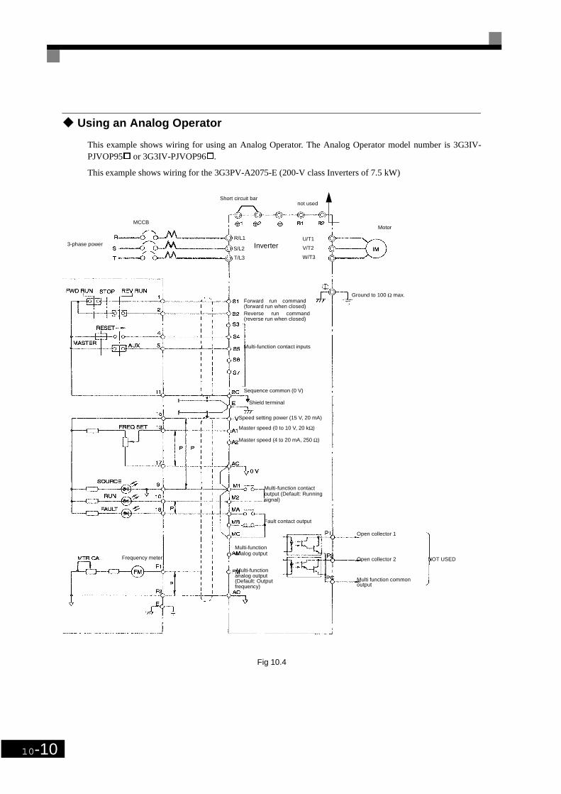
10-10
Using an Analog Operator
This example shows wiring for using an Analog Operator. The Analog Operator model number is 3G3IV-PJVOP95 or 3G3IV-PJVOP96.
This example shows wiring for the 3G3PV-A2075-E (200-V class Inverters of 7.5 kW)
Fig 10.4
MCCB
Inverter
Motor
Forward run command(forward run when closed)Reverse run command(reverse run when closed)
Multi-function contact inputs
Sequence common (0 V)
Shield terminal
Master speed (0 to 10 V, 20 kΩ)
Speed setting power (15 V, 20 mA)
Master speed (4 to 20 mA, 250 Ω)
Fault contact output
Multi-function contact output (Default: Running signal)
Frequency meter
Multi-functionanalog output
Multi-function analog output (Default: Output frequency)
R/L1
S/L2
T/L3
U/T1
V/T2
W/T3
Open collector 1
Open collector 2
Multi function commonoutput
NOT USED
Short circuit bar not used
Ground to 100 Ω max.
3-phase power

User Parameters
10-11
User ParametersFactory settings are given in the following table. These setting are for a 200 V Class Inverter of 0.4 kW setto factory set control method (open loop vector control).
Table 10.1 Parameters
No. NameFactory Setting
Setting
A1-00 Language selection for digital LED operator display 0*1
A1-01 Parameter access level 2A1-03 Initialize 0A1-04 Password 0A1-05 Password setting 0b1-01 Reference selection 1b1-02 Operation method selection 1b1-03 Stopping method selection 0b1-07 Operation selection after switching to remote mode 0b1-08 Run command selection in programming modes 0b2-01 Zero speed level (DC injection braking starting frequency) 0.5b2-02 DC injection braking current 50b2-03 DC injection braking time at start 0.00b2-04 DC injection braking time at stop 0.50b3-01 Speed search selection 2b3-02 Speed search operating current 100b3-03 Speed search deceleration time 2.0b3-05 Speed search wait time 0.2b5-01 PI control mode selection 0b5-02 Proportional gain (P) 1.00b5-03 Integral (I) time 1.0b5-04 Integral (I) limit 100.0b5-06 PI limit 100.0b5-07 PI offset adjustment 0.0b5-08 PI primary delay time 0.00b5-12 Selection of PI feedback command loss detection 0b5-13 PI feedback command loss detection level 0b5-14 PI feedback command loss detection time 1.0b5-15 PI sleep function operation level 0.0b5-16 PI sleep operation delay time 0.0b5-17 Acceleration/deceleration time for PI reference 0.0b8-01 Energy saving mode selection 0.0b8-04 Energy-saving coefficient 0b8-05 Power detection filter time 20b8-06 Search operation voltage limiter 0C1-01 Acceleration time 1 10.0C1-02 Deceleration time 1 10.0C1-03 Acceleration time 2 10.0C1-04 Deceleration time 2 10.0C1-09 Fast Stop Time 10.0C1-11 Accel/decel time switching frequency 0.0C2-01 S-curve characteristic time at acceleration start 0.20C2-02 S-curve characteristic time at acceleration end 0.20C4-01 Torque compensation gain 1.00C4-02 Torque compensation time 200C6-02 Carrier frequency selection 6*3
C6-03 Carrier Frequency Upper Limit 15.0*3
C6-04 Carrier Frequency Lower Limit 15.0*3
C6-05 Carrier Freq. Proportional Gain 00d1-01 Frequency reference 1 0.00d1-02 Frequency reference 2 0.00d1-03 Frequency reference 3 0.00d1-04 Frequency reference 4 0.00
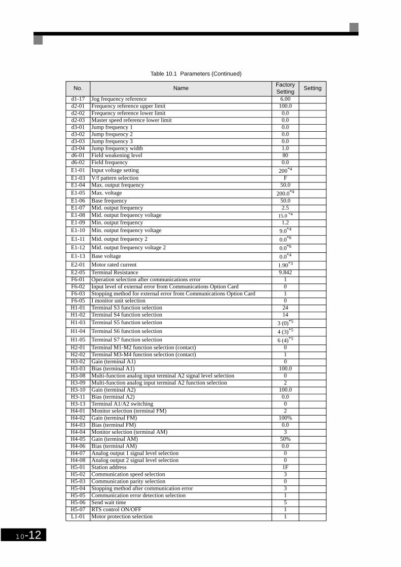
10-12
d1-17 Jog frequency reference 6.00d2-01 Frequency reference upper limit 100.0d2-02 Frequency reference lower limit 0.0d2-03 Master speed reference lower limit 0.0d3-01 Jump frequency 1 0.0d3-02 Jump frequency 2 0.0d3-03 Jump frequency 3 0.0d3-04 Jump frequency width 1.0d6-01 Field weakening level 80d6-02 Field frequency 0.0E1-01 Input voltage setting 200*4
E1-03 V/f pattern selection FE1-04 Max. output frequency 50.0E1-05 Max. voltage 200.0*4
E1-06 Base frequency 50.0E1-07 Mid. output frequency 2.5E1-08 Mid. output frequency voltage 15.0 *4
E1-09 Min. output frequency 1.2E1-10 Min. output frequency voltage 9.0*4
E1-11 Mid. output frequency 2 0.0*6
E1-12 Mid. output frequency voltage 2 0.0*6
E1-13 Base voltage 0.0*4
E2-01 Motor rated current 1.90*3
E2-05 Terminal Resistance 9.842F6-01 Operation selection after communications error 1F6-02 Input level of external error from Communications Option Card 0F6-03 Stopping method for external error from Communications Option Card 1F6-05 I monitor unit selection 0H1-01 Terminal S3 function selection 24H1-02 Terminal S4 function selection 14H1-03 Terminal S5 function selection 3 (0)*5
H1-04 Terminal S6 function selection 4 (3)*5
H1-05 Terminal S7 function selection 6 (4)*5
H2-01 Terminal M1-M2 function selection (contact) 0H2-02 Terminal M3-M4 function selection (contact) 1H3-02 Gain (terminal A1) 0H3-03 Bias (terminal A1) 100.0H3-08 Multi-function analog input terminal A2 signal level selection 0H3-09 Multi-function analog input terminal A2 function selection 2H3-10 Gain (terminal A2) 100.0H3-11 Bias (terminal A2) 0.0H3-13 Terminal A1/A2 switching 0H4-01 Monitor selection (terminal FM) 2H4-02 Gain (terminal FM) 100%H4-03 Bias (terminal FM) 0.0H4-04 Monitor selection (terminal AM) 3H4-05 Gain (terminal AM) 50%H4-06 Bias (terminal AM) 0.0H4-07 Analog output 1 signal level selection 0H4-08 Analog output 2 signal level selection 0H5-01 Station address 1FH5-02 Communication speed selection 3H5-03 Communication parity selection 0H5-04 Stopping method after communication error 3H5-05 Communication error detection selection 1H5-06 Send wait time 5H5-07 RTS control ON/OFF 1L1-01 Motor protection selection 1
Table 10.1 Parameters (Continued)
No. NameFactory Setting
Setting

User Parameters
10-13
* 1. Not initialized. (PV-E specifications: A1-00 = 0)* 2. For Inverters with a capacity of 55 kW or more: 2.00* 3. Setting range and initial setting depend on Inverter capacity.* 4. Setting for 200 V class Inverters. For 400 V class Inverters, double the value.* 5. Factory setting in the parentheses is for 3-wire sequence.* 6. The contents is ignored if the setting is 0.0.
L1-02 Motor protection time 1.0L1-03 Alarm operation selection during motor overheating 3L1-04 Motor overheating operation selection 1L1-05 Motor temperature input filter time 0.20L2-01 Momentary power loss detection 0L2-02 Momentary power loss ridethru time 0.1*3
L2-03 Min. baseblock time 0.1L2-04 Voltage recovery time 0.3L2-05 Undervoltage detection level 190*4
L3-01 Stall prevention selection during accel 1L3-02 Stall prevention level during accel 120L3-04 Stall prevention selection during decel 1L3-05 Stall prevention selection during running 1L3-06 Stall prevention level during running 120L4-01 Speed agreement detection level 0.0L4-02 Speed agreement detection width 2.0L4-05 Operation when frequency reference is missing 0L4-06 Frequency Reference for loss of Frequency Reference 80%L5-01 Number of auto restart attempts 0L5-02 Auto restart operation selection 0L6-01 Torque detection selection 1 0L6-02 Torque detection level 1 150L6-03 Torque detection time 1 0.1L8-02 Overheat pre-alarm level 95L8-03 Operation selection after overheat pre-alarm 3L8-09 Ground protection selection 1L8-11 Cooling fan control delay time 60L8-12 Ambient temperature 45L8-15 OL2 characteristics selection at low speeds 1L8-18 Soft CLA selection 1N1-01 Hunting-prevention function selection 1N1-02 Hunting-prevention gain 1.00N3-01 High-slip braking deceleration frequency width 5N3-02 High-slip braking current limit 150N3-03 High-slip braking stop dwell time 1.0N3-04 High-slip braking OL time 40o1-01 Monitor selection 6o1-02 Monitor selection after power up 1o1-03 Frequency units of reference setting and monitor 0o1-05 LCD Brightness 3o2-01 LOCAL/REMOTE key enable/disable 1o2-02 STOP key during control circuit terminal operation 1o2-03 Parameter initial value 0o2-04 kVA selection 0*3
o2-05 Frequency reference setting method selection 0o2-06 Operation selection when digital operator is disconnected 0o2-07 Cumulative operation time setting 0o2-08 Cumulative operation time selection 0o2-09 Initialize mode 5o2-10 Fan operation time setting 0o2-12 Fault trace history initialisation 0o3-01 Copy function selection 0o3-02 Read permitted selection 0
Table 10.1 Parameters (Continued)
No. NameFactory Setting
Setting
10-14
Revision HistoryA manual revision code appears as a suffix to the catalog number on the front cover of the manual.
Cat.No. I537-E2-01
Revision Code
The following table outlines the changes made to the manual during each revision. Page numbers refer to theprevious version.
Revision code Date Revised content
01 November 2001 Original production