Operation Manual for NJ-series CPU Unit - Omron
478
Machine Automation Controller CJ-series Serial Communications Units Operation Manual for NJ-series CPU Unit W494-E1-04 CJ1W-SCU22 CJ1W-SCU32 CJ1W-SCU42 Serial Communications Units
-
Upload
khangminh22 -
Category
Documents
-
view
2 -
download
0
Transcript of Operation Manual for NJ-series CPU Unit - Omron

Machine Automation Controller
CJ-series
Serial Communications Units
Operation Manual for NJ-series CPU Unit
W494-E1-04
CJ1W-SCU22CJ1W-SCU32CJ1W-SCU42
Serial Communications Units

All rights reserved. No part of this publication may be reproduced, stored in a retrieval system, or transmitted, in any form, or by any means, mechanical, electronic, photocopying, recording, or otherwise, without the prior written permission of OMRON.
No patent liability is assumed with respect to the use of the information contained herein. Moreover, because OMRON is constantly striving to improve its high-quality products, the information contained in this manual is subject to change without notice. Every precaution has been taken in the preparation of this manual. Neverthe-less, OMRON assumes no responsibility for errors or omissions. Neither is any liability assumed for damages resulting from the use of the information contained in this publication.
• Sysmac and SYSMAC are trademarks or registered trademarks of OMRON Corporation in Japan and other countries for OMRON factory automation products.
• Microsoft, Windows, Windows Vista, Excel, and Visual Basic are either registered trademarks or trademarks of Microsoft Corporation in the United States and other countries.
• EtherCAT® is registered trademark and patented technology, licensed by Beckhoff Automation GmbH, Germany.
• ODVA, CIP, CompoNet, DeviceNet, and EtherNet/IP are trademarks of ODVA.
• The SD and SDHC logos are trademarks of SD-3C, LLC.
Other company names and product names in this document are the trademarks or registered trademarks of their respective companies.
Trademarks
Copyrights
NOTE
Microsoft product screen shots reprinted with permission from Microsoft Corporation.

1
Introduction
CJ-series Serial Communications Units Operation Manual for NJ-series CPU Unit(W494)
Introduction
Thank you for purchasing an CJ-series CJ1W-SCU@2 Serial Communications Units.This manual contains information that is necessary to use with the NJ-series CPU Unit. Please readthis manual and make sure you understand the functionality and performance of the NJ-series CPUUnit before you attempt to use it in a control system.Keep this manual in a safe place where it will be available for reference during operation.
This manual is intended for the following personnel, who must also have knowledge of electrical sys-tems (an electrical engineer or the equivalent).
• Personnel in charge of introducing FA systems.
• Personnel in charge of designing FA systems.
• Personnel in charge of installing and maintaining FA systems.
• Personnel in charge of managing FA systems and facilities.
For programming, this manual is intended for personnel who understand the programming languagespecifications in international standard IEC 61131-3 or Japanese standard JIS B3503.
This manual covers the following products.
CJ-series Serial Communications Units
• CJ1W-SCU22
• CJ1W-SCU32
• CJ1W-SCU42
Intended Audience
Applicable Products

Relevant Manuals
2 CJ-series Serial Communications Units Operation Manual for NJ-series CPU Unit(W494)
Relevant Manuals
There are three manuals that provide basic information on the NJ-series CPU Units: the NJ-series CPUUnit Hardware User's Manual, the NJ-series CPU Unit Software User's Manual, and the NJ-seriesInstructions Reference Manual.Most operations are performed from the Sysmac Studio Automation Software. Refer to the Sysmac Stu-dio Version 1 Operation Manual (Cat. No. W504) for information on the Sysmac Studio. Other manuals are necessary for specific system configurations and applications.Read all of the manuals that are relevant to your system configuration and application to make the mostof the NJ-series CPU Unit.
NJ-series User’s Manuals
Basic information
Introduction to NJ-series Controllers
Setting devices and hardware
Using motion control
Using EtherCAT
Using EtherNet/IP
Using CJ-series Units
Software settings
Using motion control
Using EtherCAT
Using EtherNet/IP
Programming
Using motion control
Using EtherCAT
Using CJ-series Units
Programming error processing
Testing operation and debugging
Using motion control
Using EtherCAT
Using EtherNet/IP
Maintenance
Using EtherCAT
Using EtherNet/IP
Using CJ-series Units
NJ-
serie
s C
PU
Uni
t H
ardw
are
Use
r´s
Man
ual
NJ-
serie
s C
PU
Uni
t S
oftw
are
Use
r´s
Man
ual
NJ-
serie
s In
stru
ctio
ns
Ref
eren
ce M
anua
l
NJ-
serie
s C
PU
Uni
t Mot
ion
Con
trol
Use
r´s
Man
ual
NJ-
serie
s C
PU
Uni
t Bui
lt-in
E
ther
CA
T P
ort U
ser´
s M
anua
l
NJ-
serie
s M
otio
n C
ontr
ol
Inst
ruct
ions
Ref
eren
ce M
anua
l
NJ-
serie
s C
PU
Uni
t Bui
lt-in
E
ther
Net
/IP P
ort U
ser´
s M
anua
l
NJ-
serie
s T
roub
lesh
ootin
g M
anua
l
CJ-
serie
s S
peci
al U
nit O
pera
tion
Man
uals
for
NJ-
serie
s C
PU
Uni
t
Troubleshooting and managing
errors in an NJ-series Controller
Use the relevant manuals for references according to any error that occurs.

3
Manual Configuration
CJ-series Serial Communications Units Operation Manual for NJ-series CPU Unit(W494)
Manual Configuration
NJ-series CPU Unit Hardware User's Manual (Cat. No. W500)
Section Description
Section 1 Introduction
This section provides an introduction to the NJ-series Controllers and their features, and gives the NJ-series Controller specifications.
Section 2 System Configuration
This section describes the system configuration used for NJ-series Controllers.
Section 3 Configuration Units
This section describes the parts and functions of the configuration devices in the NJ-series Controller configuration, including the CPU Unit and Configuration Units.
Section 4 Installation and Wiring
This section describes where and how to install the CPU Unit and Configuration Units and how to wire them.
Section 5 Troubleshooting
This section describes the event codes, error confirmation methods, and corrections for errors that can occur.
Section 6 Inspection and Maintenance
This section describes the contents of periodic inspections, the service life of the Bat-tery and Power Supply Units, and replacement methods for the Battery and Power Supply Units.
AppendicesThe appendices provide the specifications of the Basic I/O Units, Unit dimensions, load short-circuit protection detection, line disconnection detection, and measures for EMC Directives.
NJ-series CPU Unit Software User's Manual (Cat. No. W501)
Section Description
Section 1 Introduction
This section provides an introduction to the NJ-series Controllers and their features, and gives the NJ-series Controller specifications.
Section 2 CPU Unit Operation
This section provides information that is necessary to use the CPU Unit, including how the CPU Unit works and the operations that it performs depending on the status of the CPU Unit.
Section 3 I/O Ports, Slave Configuration, and Unit Configuration
This section describes how to use I/O ports, how to create the slave configuration and unit configuration and how to assign functions.
Section 4 Controller Setup
This section describes the initial settings of the function modules.
Section 5 Designing Tasks
This section describes the task system and types of tasks.
Section 6 Programming
This section describes programming, including the programming languages and the variables and instructions that are used in programming.
Section 7 Checking Operation and Actual Operation
This section describes the items and procedures for checking the operation of an NJ-series Controller, including offline debugging procedures.
Section 8 CPU Unit Functions
This section describes the functionality provided by the CPU Unit.
Section 9 Communications Setup
This section describes how to go online with the CPU Unit and how to connect to other devices.
Section 10Example of Actual Application Pro-cedures
This section describes the procedures that are used to actually operate an NJ-series Controller.
Section 11Troubleshooting
This section describes the event codes, error confirmation methods, and corrections for errors that can occur.
AppendicesThe appendices provide the CPU Unit specifications, task execution times, specifica-tions of individual system-defined variables, data attribute lists, CJ-series Unit mem-ory information, CJ-series Unit memory allocation methods, and version information.

Manual Configuration
4 CJ-series Serial Communications Units Operation Manual for NJ-series CPU Unit(W494)
Sysmac Studio Version 1 Operation Manual (Cat. No. W504)
Section Description
Section 1 Introduction
This section provides an overview and lists the specifications of the Sysmac Studio and describes its features and components.
Section 2 Installation and Uninstallation
This section describes how to install and uninstall the Sysmac Studio.
Section 3 System Design
This section describes the basic concepts for designing an NJ-series System with the Sysmac Studio and the basic operating procedures.
Section 4 Programming
This section describes how to create programs with the Sysmac Studio.
Section 5 Online Connections to a Controller
This section describes how to go online with a Controller.
Section 6 Debugging
This section describes how to debug the programs online on the Controller or debug it offline with the Simulator.
Section 7 Other Functions
This section describes other functions that are supported by the Sysmac Studio, including security functions and troubleshooting functions.
Section 8 Reusing Programming
This section describes how to reuse the programs that you create with the Sysmac Studio.
Section 9 Support Software Provided with the Sysmac Studio
This section describes the Support Software that is provided with the Sysmac Studio.
Section 10 Troubleshooting
This section describes the error messages that are displayed when you check a pro-gram on the Sysmac Studio and how to correct those errors.
Appendices
The appendices describe the following:Driver Installation for Direct USB Cable ConnectionSpecifying One of Multiple Ethernet Interface CardsOnline HelpSimulation Instructions
CJ-series Serial Communications Units Operation Manual for NJ-series CPU Unit (Cat. No. W494) (this manual)
Section Description
Section 1Introduction
This section provides an introduction to the Serial Communications Units and their features. It also describes the operating procedure and the specifications of the Serial Communications Units.
Section 2Initial Settings and Allocations of Device Variables for CJ-series Unit
This section describes the data exchange between the CPU Unit and Serial Commu-nications Unit and the definitions of the device variables for CJ-series Unit.
Section 3Installation and Wiring
This section describes where and how to install the Serial Communications Unit, and how to connect and wire them.
Section 4Using Protocol Macros
This section describes the protocol macro function provided by the Serial Communi-cations Unit and the procedure for using the function.
Section 5Serial Gateway
This section describes the Serial Gateway function provided by the Serial Communi-cations Unit and the procedure for using the function.
Section 6No-protocol Mode
This section describes the No-protocol Mode function provided by the Serial Commu-nications Unit to send/receive data, and the procedure for using the function.
Section 7Using Modbus-RTU Slave Mode
This section describes the Modbus-RTU Slave Mode function provided by the Serial Communications Unit, the procedure for using the function and the details of the command responses.
Section 8Loopback Test
This section describes the loopback test function provided by the Serial Communica-tions Unit and the procedure for using the function.
Section 9Troubleshooting and Maintenance
This section describes the troubleshooting procedure, event logs and maintenance procedure for the Serial Communications Unit.
ReferenceThis section describes the details on the standard system protocols provided by the CX-Protocol and the Serial Communications Unit.
Appendix ---

5
Manual Configuration
CJ-series Serial Communications Units Operation Manual for NJ-series CPU Unit(W494)
SYSMAC CS/CJ Series Serial Communications Boards Serial Communications Units OPERATION MANUAL (Cat. No. W336)
Section Description
Section 1 Introduction
This section introduces the features, specifications, and procedures of the Serial Communications Boards and the Serial Communications Units.
Section 2Initial Settings and I/O Memory Allocations
This section describes the data exchange between the CPU Unit and the Serial Com-munications Boards/Serial Communications Units, and the I/O memory allocation.
Section 3 Installation and Wiring
This section describes how to mounting the Serial Communications Board and Serial Communications Units, and how to connect the ports to external devices.
Section 4 Using Host Link Communications
This section describes the procedure and other information required to use Host Link communications.
Section 5 Using Protocol Macros
This section describes the procedure and other information required to use the proto-col macros.
Section 6 Serial Gateway
This section describes the procedure and other information required to use the Serial Gateway.
Section 7 No-protocol Mode
This section describes the procedure and other information required to use the no-protocol mode.
Section 8 Using 1:N NT Links
This section describes the procedure and other information required to use the 1:N NT Links to Programmable Terminals
Section 9 Using Modbus-RTU Slave Mode
This section describes the procedure and other information required to use the Modbus-RTU slave mode.
Section 10 Communications Performance
This section describes the communications performance of the Serial Communica-tions Boards and the Serial Communications Units.
Section 11 Loopback Test
This section describes the procedure and other information required to conduct loop-back test.
Section 12 Troubleshooting and Maintenance
This section describes the troubleshooting and maintenance procedures for the Serial Communications Boards and the Serial Communications Unit.
Appendices ---
CX-Protocol Ver.1.9 OPERATION MANUAL (Cat. No. W344)
Section Description
Section 1 Introduction
This section introduces the Protocol Macro function, the features and specifications of the CX-Protocol, and outline of the standard system protocol.
Section 2 Installing/Uninstalling/Starting/Ending
This section outlines the functions of the CX-Protocol and describes installation pro-cedure, startup/shutdown, and the user interface for the CX-Protocol.
Section 3 Protocol Macro
This section describes details of the protocol macro functions.
Section 4 Using the Protocol Macro Function
This section describes the communications sequence and settings for the protocol macro function.
Section 5 Object Creation
This section describes how to create objects, such as projects, protocols, sequences, steps, messages, and matrices.
Section 6 Project and Protocol Editing
This section describes details of the editing of projects and protocols.
Section 7 Sequence Setting and Editing
This section describes details of the creating, setting and editing of sequences.
Section 8 Step Setting and Editing
This section describes details of the creating, setting and editing of steps.
Section 9 Setting and Editing Messages and Matrix Lists
This section describes details of the creating, setting and editing of messages and matrix lists.
Section 10 Communications PLC Setup and Online Connections
This section describes details of the communications settings and online connec-tions.

Manual Configuration
6 CJ-series Serial Communications Units Operation Manual for NJ-series CPU Unit(W494)
Section 11 Protocol Data Transferring and Printing
This section describes details of the transferring, converting, and printing of protocol data.
Section 12 Tracing and Monitoring
This section describes details of PLC memory area monitoring and the transmission line tracing.
Section 13 Error and Error Log Display
This section describes details of the displaying of errors and the error log. This func-tion cannot be used in NJ series.
Section 14 Troubleshooting
This section lists the error messages and describes their causes and remedies.
Section 15 Help
This section describes the online help services.
Appendices ---
CX-Integrator Ver.2. Operation Manual (Cat. No. W464)
Section Description
Section 1 Overview
This section provides an overview of the CX-Integrator and describes the CX-Integra-tor menus and connecitions.
Section 2 Basic Operations
This section describes the basic operations used for the CX-Integrator.
Section 3 Routing Tables
This section describes how to set the routing tables. For NJ-series, routing table is created by using Sysmac Studio instead of CX-Integrator.
Section 4 Data Links for Controller Link and SYSMAC LINK
This section describes how to set data links for Controller Link and SYSMAC LINK networks.
Section 5 Ethernet
This section describes the operations specific to Ethernet.
Section 6 DeviceNet
This section describes the settings and operations unique to DeviceNet networks including registering slaves in the master, I/O allocations, and device monitoring.
Section 7 CompoNet
This section describes the basic usage of CompoNet networks and how to set Com-poNet parameters.
Section 8 CompoWay/F
This section describes the settings and operations specific to the CompoWay/F sys-tem.
Section 9 NT Links
This section describes the settings and operations specific to the NT Link system.
Section 10 Network Testing
This section describes the operations of the network test tool.
AppendicesThis section describes the CPS files for Ethernet, Controller Link, CompoWay/F and NT Link Networks, and EDS files for DeviceNet Networks.
Section Description

7
Manual Structure
CJ-series Serial Communications Units Operation Manual for NJ-series CPU Unit(W494)
Manual Structure
The following page structure is used in this manual.
Special information in this manual is classified as follows:
Page Structure
Special Information
Precautions for Safe UsePrecautions on what to do and what not to do to ensure safe usage of the product.
Precautions for Correct UsePrecautions on what to do and what not to do to ensure proper operation and performance.
Additional InformationAdditional information to read as required.This information is provided to increase understanding or make operation easier.
4-9
4 Installation and Wiring
NJ-series CPU Unit Hardware User’s Manual (W500)
sti
nU
gni
tn
uo
M 3-
4
4
stne
nop
moC
rell
ortn
oC
gnit
cenn
oC
1-3-
4
4-3 Mounting Units
The Units that make up an NJ-series Controller can be connected simply by pressing the Units togetherand locking the sliders by moving them toward the back of the Units. The End Cover is connected in thesame way to the Unit on the far right side of the Controller.
1 Join the Units so that the connectors fit exactly.
2 The yellow sliders at the top and bottom of each Unit lock the Units together. Move the sliders
toward the back of the Units as shown below until they click into place.
Precautions for Correct UsePrecautions for Correct Use
4-3-1 Connecting Controller Components
ConnectorHook Hook holes
Slider
Lock
Release
Move the sliders toward the back until they lock into place.
Level 1 headingLevel 2 headingLevel 3 headingLevel 2 heading
A step in a procedure
Manual name
Special information
Level 3 heading
Page tab
Gives the current headings.
Indicates a procedure.
Icons indicate precautions, additional information, or reference information.
Gives the number of the main section.
This illustration is provided only as a sample. It may not literally appear in this manual.
The sliders on the tops and bottoms of the Power Supply Unit, CPU Unit, I/O Units, Special I/O Units, and CPU Bus Units must be completely locked (until they click into place) after connecting the adjacent Unit connectors.

Manual Structure
8 CJ-series Serial Communications Units Operation Manual for NJ-series CPU Unit(W494)
Note References are provided to more detailed or related information.
In this manual, "download" refers to transferring data from the Sysmac Studio to the physical Controllerand "upload" refers to transferring data from the physical Controller to the Sysmac Studio.
For the Sysmac Studio, synchronization is used to both upload and download data. Here, "synchronize"means to automatically compare the data for the Sysmac Studio on the computer with the data in thephysical Controller and transfer the data in the direction that is specified by the user.
Version InformationInformation on differences in specifications and functionality for CPU Units with different unit versionsand for different versions of the Sysmac Studio is given.
Precaution on Terminology

9
Sections in this Manual
CJ-series Serial Communications Units Operation Manual for NJ-series CPU Unit(W494)
Sections in this Manual
1 R
2 A
3 I
4
5
6
7
8
9
1 R
2 A
3 I
5
6
7
8
9
Introduction A Standard System Protocol
Initial Settings and Allocations of Device Variable for CJ-series Unit
Appendices
Installation and Wiring Index
Using Protocol Macros
Serial Gateway
No-protocol Mode
Using Modbus-RTU Slave Mode
Loopback Test
Troubleshooting and Maintenance
4

10 CJ-series Serial Communications Units Operation Manual for NJ-series CPU Unit(W494)
CONTENTS
CONTENTS
Introduction ...............................................................................................................1
Relevant Manuals ......................................................................................................2
Manual Configuration ...............................................................................................3
Manual Structure .......................................................................................................7
Sections in this Manual ............................................................................................9
CONTENTS...............................................................................................................10
Terms and Conditions Agreement.........................................................................15
Safety Precautions..................................................................................................17
Precautions for Safe Use........................................................................................22
Precautions for Correct Use...................................................................................28
Regulations and Standards....................................................................................31
Unit Versions ...........................................................................................................34
Related Manuals ......................................................................................................36
Revision History ......................................................................................................37
Section 1 Introduction
1-1 Using this Manual .................................................................................................................... 1-2
1-2 Overview................................................................................................................................... 1-3
1-3 Protocol Overview ................................................................................................................... 1-51-3-1 Protocol Macros .......................................................................................................................... 1-61-3-2 Loopback Test ............................................................................................................................. 1-61-3-3 Serial Gateway Mode.................................................................................................................. 1-61-3-4 No-protocol Mode........................................................................................................................ 1-71-3-5 Modbus-RTU Slave Mode ........................................................................................................... 1-7
1-4 Features.................................................................................................................................... 1-81-4-1 Serial Communications Units ...................................................................................................... 1-81-4-2 Protocols ..................................................................................................................................... 1-8
1-5 System Configurations ......................................................................................................... 1-101-5-1 Protocol Macro, Serial Gateway, No-protocol, or Modbus-RTU Slave ...................................... 1-10
1-6 Specifications ........................................................................................................................ 1-141-6-1 Serial Communications Unit...................................................................................................... 1-141-6-2 General Specifications .............................................................................................................. 1-15
1-7 Selecting the Serial Communications Mode ....................................................................... 1-22
1-8 Basic Operating Procedure .................................................................................................. 1-231-8-1 Overview ................................................................................................................................... 1-231-8-2 Explanation of Procedure.......................................................................................................... 1-24

11CJ-series Serial Communications Units Operation Manual for NJ-series CPU Unit(W494)
CONTENTS
Section 2 Initial Settings and Allocations of Device Variable for CJ-series Unit
2-1 Component Names and Functions ........................................................................................ 2-2
2-2 Data Exchange with the CPU Unit.......................................................................................... 2-82-2-1 Data Flow.................................................................................................................................... 2-82-2-2 How to Specify and Create Variables ....................................................................................... 2-12
2-3 Device Variable for CJ-series Unit ....................................................................................... 2-142-3-1 Allocations of Device Variable for CJ-series Unit...................................................................... 2-142-3-2 Device Variable for CJ-series Unit for System Settings ............................................................ 2-142-3-3 Device Variable for CJ-series Unit for Software Switches......................................................... 2-232-3-4 Device Variable for CJ-series Unit for Status............................................................................ 2-24
2-4 System-defined Variable ....................................................................................................... 2-34
Section 3 Installation and Wiring
3-1 Installing Serial Communications Units ................................................................................ 3-23-1-1 System Configuration Precautions ............................................................................................. 3-23-1-2 Serial Communications Unit Installation Procedure.................................................................... 3-23-1-3 Unit Handling Precautions .......................................................................................................... 3-3
3-2 Wiring ....................................................................................................................................... 3-43-2-1 Wiring Precautions ..................................................................................................................... 3-43-2-2 Port Types................................................................................................................................... 3-43-2-3 Communications Modes and Ports............................................................................................. 3-43-2-4 Connector Pin Layout ................................................................................................................. 3-53-2-5 Mounting Height and Connector Cover Dimensions................................................................... 3-63-2-6 Reducing Electrical Noise for External Wiring ............................................................................ 3-73-2-7 2-Wire and 4-Wire Connections.................................................................................................. 3-73-2-8 NT-AL001 Link Adapter Settings................................................................................................. 3-83-2-9 Connections for Protocol Macro, Serial Gateway, No-protocol Mode,
and Modbus-RTU Slave Mode.................................................................................................... 3-93-2-10 Connections in Loopback Test.................................................................................................. 3-18
3-3 RS-232C and RS-422A/485 Wiring ....................................................................................... 3-193-3-1 Recommended RS-232C Wiring Examples ............................................................................. 3-193-3-2 Recommended RS-422A/485 Wiring Examples....................................................................... 3-203-3-3 Wiring RS-232C Connectors on the CJ1W-SCU22/42............................................................. 3-223-3-4 Soldering .................................................................................................................................. 3-233-3-5 Assembling Connector Hood .................................................................................................... 3-243-3-6 Wiring RS-422A/485 Terminal-block Connectors on the CJ1W-SCU32/42.............................. 3-253-3-7 Connecting to Unit .................................................................................................................... 3-26
Section 4 Using Protocol Macros
4-1 Overview of the Protocol Macro Function............................................................................. 4-24-1-1 Protocol Macros.......................................................................................................................... 4-24-1-2 Using the Protocol Macros.......................................................................................................... 4-24-1-3 Protocol Structure....................................................................................................................... 4-44-1-4 Data Exchange Method for Link Words .................................................................................... 4-10
4-2 Device Variables for CJ-series Unit and System-defined Variables (Protocol Macro Mode).......................................................................................................... 4-134-2-1 Device Variable for CJ-series Unit for System Settings ............................................................ 4-134-2-2 Area Descriptions ..................................................................................................................... 4-154-2-3 System-defined Variable........................................................................................................... 4-214-2-4 Devices Variable for CJ-series Unit for Software Switches....................................................... 4-224-2-5 Device Variables for CJ-series Unit for Status .......................................................................... 4-244-2-6 Protocol Status ......................................................................................................................... 4-32

12 CJ-series Serial Communications Units Operation Manual for NJ-series CPU Unit(W494)
CONTENTS
4-3 Using Protocol Macros.......................................................................................................... 4-404-3-1 Executing Communications Sequences.................................................................................... 4-404-3-2 User Program Example............................................................................................................. 4-42
Section 5 Serial Gateway
5-1 Serial Gateway Overview ........................................................................................................ 5-25-1-1 Overview ..................................................................................................................................... 5-25-1-2 Operating Conditions .................................................................................................................. 5-25-1-3 Features ...................................................................................................................................... 5-35-1-4 Serial Gateway Specifications..................................................................................................... 5-4
5-2 Device Variables for CJ-series Unit and System-defined Variables (During Serial Gateway Mode)................................................................................................ 5-55-2-1 Device Variables for CJ-series Unit for System Settings............................................................. 5-55-2-2 System-defined Variable ............................................................................................................. 5-85-2-3 Device Variable for CJ-series Unit for Software Switches ........................................................... 5-95-2-4 Device Variable for CJ-series Unit for Status .............................................................................. 5-9
5-3 Using the Serial Gateway...................................................................................................... 5-125-3-1 Setting Device Variable for CJ-series Unit for System Settings and Software Switches........... 5-125-3-2 Sending Messages Using the SendCmd Instruction................................................................. 5-145-3-3 Using the Serial Gateway Function When Protocol Macros Are Executed ............................... 5-15
5-4 Protocol Conversion.............................................................................................................. 5-225-4-1 Types of Protocol Conversion.................................................................................................... 5-225-4-2 Converting to CompoWay/F ...................................................................................................... 5-235-4-3 CompoWay/F Connection Examples ........................................................................................ 5-255-4-4 Converting to Modbus-RTU....................................................................................................... 5-265-4-5 Converting to Modbus-ASCII .................................................................................................... 5-28
5-5 Serial Gateway ....................................................................................................................... 5-295-5-1 Serial Gateway Execution Timing for Protocol Macros ............................................................. 5-295-5-2 Serial Gateway Timeout Monitoring .......................................................................................... 5-315-5-3 Other Functions......................................................................................................................... 5-32
5-6 Communications Frames...................................................................................................... 5-335-6-1 CompoWay/F ............................................................................................................................ 5-335-6-2 Modbus-RTU............................................................................................................................. 5-345-6-3 Modbus-ASCII........................................................................................................................... 5-36
Section 6 No-protocol Mode
6-1 Overview................................................................................................................................... 6-26-1-1 Definition ..................................................................................................................................... 6-26-1-2 Specifications.............................................................................................................................. 6-36-1-3 Connections for No-protocol Mode ............................................................................................. 6-4
6-2 Device Variables for CJ-series Unit and System-defined Variables (No-protocol Mode)6-56-2-1 Device Variables for CJ-Series Unit for System Settings ............................................................ 6-56-2-2 System-defined Variable ............................................................................................................. 6-86-2-3 Device Variable for CJ-series Unit for Software Switches ........................................................... 6-86-2-4 Device Variable for CJ-series Unit for Status .............................................................................. 6-86-2-5 Device Variable for CJ-series Unit for Status (When Sending/Receiving Data
with SerialSend, SerialRcv, or SerialRcvNoClear Instruction) .................................................. 6-11
6-3 Using Serial Port I/O Instructions ........................................................................................ 6-126-3-1 System Settings ........................................................................................................................ 6-126-3-2 Instruction Execution Methods .................................................................................................. 6-12

13CJ-series Serial Communications Units Operation Manual for NJ-series CPU Unit(W494)
CONTENTS
Section 7 Using Modbus-RTU Slave Mode
7-1 Modbus-RTU Slave System .................................................................................................... 7-27-1-1 Modbus-RTU Slave System........................................................................................................ 7-27-1-2 Modbus-RTU Specifications ....................................................................................................... 7-27-1-3 Communicating with NJ-series CPU Units Using Modbus ......................................................... 7-3
7-2 Device Variables for CJ-series Unit and System-defined Variables (Modbus-RTU Slave Mode) ..................................................................................................... 7-57-2-1 Device Variable for CJ-series Unit for System Settings .............................................................. 7-57-2-2 System-defined Variable............................................................................................................. 7-87-2-3 Device Variable for CJ-series Unit for Software Switches........................................................... 7-87-2-4 Device Variable for CJ-series Unit .............................................................................................. 7-9
7-3 Command and Response Details......................................................................................... 7-137-3-1 Supported Modbus-RTU Commands ....................................................................................... 7-137-3-2 Command and Response Details ............................................................................................. 7-14
Section 8 Loopback Test
8-1 Executing Loopback Tests ..................................................................................................... 8-28-1-1 Overview..................................................................................................................................... 8-28-1-2 Connection Method..................................................................................................................... 8-28-1-3 Procedure ................................................................................................................................... 8-28-1-4 Indicators Used for the Loopback Test........................................................................................ 8-3
8-2 Device Variable for CJ-series Unit (Loopback Test) ............................................................. 8-48-2-1 Device Variables for CJ-Series Unit for System Settings............................................................ 8-48-2-2 Device Variables for CJ-Series Unit for Status ........................................................................... 8-5
Section 9 Troubleshooting and Maintenance
9-1 Indicator Error Displays .......................................................................................................... 9-2
9-2 Communications Status Error Notification ........................................................................... 9-39-2-1 Status Area Error Information ..................................................................................................... 9-3
9-3 Troubleshooting....................................................................................................................... 9-49-3-1 Serial Gateway (Serial Gateway or Protocol Macro Mode)......................................................... 9-49-3-2 No-protocol Mode ..................................................................................................................... 9-109-3-3 Protocol Macros........................................................................................................................ 9-169-3-4 Modbus-RTU Slave Mode......................................................................................................... 9-22
9-4 Error Logs .............................................................................................................................. 9-259-4-1 Error Log Data .......................................................................................................................... 9-259-4-2 Error Contents and Details ....................................................................................................... 9-269-4-3 Error Codes and Troubleshooting ............................................................................................. 9-28
9-5 Event Logs ............................................................................................................................. 9-309-5-1 Overview of the Event Logs...................................................................................................... 9-309-5-2 Error Table ................................................................................................................................ 9-309-5-3 Error Descriptions..................................................................................................................... 9-36
9-6 Cleaning and Inspection ....................................................................................................... 9-539-6-1 Cleaning.................................................................................................................................... 9-539-6-2 Inspection ................................................................................................................................. 9-53
9-7 Replacement Precautions..................................................................................................... 9-559-7-1 Precautions when Replacing Unit............................................................................................. 9-559-7-2 Settings after Replacing Unit .................................................................................................... 9-559-7-3 Replacing the Unit .................................................................................................................... 9-56

14 CJ-series Serial Communications Units Operation Manual for NJ-series CPU Unit(W494)
CONTENTS
A Standard System Protocol
R-1 Reading Reference Documents..............................................................................................R-3R-1-1 Using Standard System Protocols ............................................................................................. R-3R-1-2 Standard System Protocols........................................................................................................ R-6
R-2 CompoWay/F Master Protocol................................................................................................R-7R-2-1 CompoWay/F ............................................................................................................................. R-7R-2-2 Communications Specifications ................................................................................................. R-8R-2-3 Transmission Procedure............................................................................................................. R-8R-2-4 Command and Response Formats ............................................................................................ R-8R-2-5 CompoWay/F Master Protocol Sequences .............................................................................. R-12R-2-6 CompoWay/F Message Frames and PMCR(260) Operands ................................................... R-12R-2-7 Send/Receive with ASCII Conversion and with Response ...................................................... R-13R-2-8 Structure of the Protocol .......................................................................................................... R-13R-2-9 Connections ............................................................................................................................. R-38
R-3 Mitsubishi Computer Link Master(A-compatible 1C Frame, Model 1)R-41
R-3-1 Communications Specifications ............................................................................................... R-41R-3-2 Command/Response Formats ................................................................................................. R-42R-3-3 Command Frame Contents...................................................................................................... R-43R-3-4 Mitsubishi Computer Link Master Protocol Sequences............................................................ R-43R-3-5 Structure of the Protocol .......................................................................................................... R-43
R-4 V500/V520 Bar Code Reader Protocol .................................................................................R-65R-4-1 Connections ............................................................................................................................. R-65R-4-2 System Setting......................................................................................................................... R-66R-4-3 Protocol Configuration.............................................................................................................. R-67
R-5 3Z4L Laser Micrometer Protocol..........................................................................................R-78R-5-1 Connections ............................................................................................................................. R-78R-5-2 List of Operations with Laser Micrometer (5000/6000 Series) ................................................. R-81R-5-3 Protocol Configuration.............................................................................................................. R-83
R-6 Hayes Modem AT Command Protocol ...............................................................................R-117R-6-1 Protocol Configuration............................................................................................................ R-117R-6-2 Connections ........................................................................................................................... R-119R-6-3 Compatible Modems .............................................................................................................. R-119R-6-4 Modem Settings ..................................................................................................................... R-120R-6-5 Communication Errors ........................................................................................................... R-125
Appendices
A-1 Differences in Available Functions Depending on the CPU Unit (NJ or CJ Series) ..........A-2A-1-1 Functional Differences ................................................................................................................A-2A-1-2 Differences in Methods for Access from a User Program ...........................................................A-3
A-2 Version Information ...............................................................................................................A-12
Index

15
Terms and Conditions Agreement
CJ-series Serial Communications Units Operation Manual for NJ-series CPU Unit(W494)
Terms and Conditions Agreement
Exclusive WarrantyOmron’s exclusive warranty is that the Products will be free from defects in materials and workman-ship for a period of twelve months from the date of sale by Omron (or such other period expressed in writing by Omron). Omron disclaims all other warranties, express or implied.
LimitationsOMRON MAKES NO WARRANTY OR REPRESENTATION, EXPRESS OR IMPLIED, ABOUT NON-INFRINGEMENT, MERCHANTABILITY OR FITNESS FOR A PARTICULAR PURPOSE OF THE PRODUCTS. BUYER ACKNOWLEDGES THAT IT ALONE HAS DETERMINED THAT THE PRODUCTS WILL SUITABLY MEET THE REQUIREMENTS OF THEIR INTENDED USE.
Omron further disclaims all warranties and responsibility of any type for claims or expenses based on infringement by the Products or otherwise of any intellectual property right.
Buyer RemedyOmron’s sole obligation hereunder shall be, at Omron’s election, to (i) replace (in the form originally shipped with Buyer responsible for labor charges for removal or replacement thereof) the non-com-plying Product, (ii) repair the non-complying Product, or (iii) repay or credit Buyer an amount equal to the purchase price of the non-complying Product; provided that in no event shall Omron be responsible for warranty, repair, indemnity or any other claims or expenses regarding the Products unless Omron’s analysis confirms that the Products were properly handled, stored, installed and maintained and not subject to contamination, abuse, misuse or inappropriate modification. Return of any Products by Buyer must be approved in writing by Omron before shipment. Omron Companies shall not be liable for the suitability or unsuitability or the results from the use of Products in combi-nation with any electrical or electronic components, circuits, system assemblies or any other materi-als or substances or environments. Any advice, recommendations or information given orally or in writing, are not to be construed as an amendment or addition to the above warranty.
See http://www.omron.com/global/ or contact your Omron representative for published information.
OMRON COMPANIES SHALL NOT BE LIABLE FOR SPECIAL, INDIRECT, INCIDENTAL, OR CON-SEQUENTIAL DAMAGES, LOSS OF PROFITS OR PRODUCTION OR COMMERCIAL LOSS IN ANY WAY CONNECTED WITH THE PRODUCTS, WHETHER SUCH CLAIM IS BASED IN CONTRACT, WARRANTY, NEGLIGENCE OR STRICT LIABILITY.
Further, in no event shall liability of Omron Companies exceed the individual price of the Product on which liability is asserted.
Warranty, Limitations of Liability
Warranties
Limitation on Liability; Etc

Terms and Conditions Agreement
16 CJ-series Serial Communications Units Operation Manual for NJ-series CPU Unit(W494)
Omron Companies shall not be responsible for conformity with any standards, codes or regulations which apply to the combination of the Product in the Buyer’s application or use of the Product. At Buyer’s request, Omron will provide applicable third party certification documents identifying ratings and limitations of use which apply to the Product. This information by itself is not sufficient for a com-plete determination of the suitability of the Product in combination with the end product, machine, sys-tem, or other application or use. Buyer shall be solely responsible for determining appropriateness of the particular Product with respect to Buyer’s application, product or system. Buyer shall take applica-tion responsibility in all cases.
NEVER USE THE PRODUCT FOR AN APPLICATION INVOLVING SERIOUS RISK TO LIFE OR PROPERTY WITHOUT ENSURING THAT THE SYSTEM AS A WHOLE HAS BEEN DESIGNED TO ADDRESS THE RISKS, AND THAT THE OMRON PRODUCT(S) IS PROPERLY RATED AND INSTALLED FOR THE INTENDED USE WITHIN THE OVERALL EQUIPMENT OR SYSTEM.
Omron Companies shall not be responsible for the user’s programming of a programmable Product, or any consequence thereof.
Data presented in Omron Company websites, catalogs and other materials is provided as a guide for the user in determining suitability and does not constitute a warranty. It may represent the result of Omron’s test conditions, and the user must correlate it to actual application requirements. Actual perfor-mance is subject to the Omron’s Warranty and Limitations of Liability.
Product specifications and accessories may be changed at any time based on improvements and other reasons. It is our practice to change part numbers when published ratings or features are changed, or when significant construction changes are made. However, some specifications of the Product may be changed without any notice. When in doubt, special part numbers may be assigned to fix or establish key specifications for your application. Please consult with your Omron’s representative at any time to confirm actual specifications of purchased Product.
Information presented by Omron Companies has been checked and is believed to be accurate; how-ever, no responsibility is assumed for clerical, typographical or proofreading errors or omissions.
Application Considerations
Suitability of Use
Programmable Products
Disclaimers
Performance Data
Change in Specifications
Errors and Omissions

17
Safety Precautions
CJ-series Serial Communications Units Operation Manual for NJ-series CPU Unit(W494)
Safety Precautions
The following notation is used in this manual to provide precautions required to ensure safe usage of aCJ-series Serial Communications Unit. The safety precautions that are provided are extremely impor-tant to safety. Always read and heed the information provided in all safety precautions.The following notation is used.
Definition of Precautionary Information
WARNINGIndicates a potentially hazardous situation which, if not avoided, could result in death or serious injury. Additionally, there may be severe property damage.
Caution Indicates a potentially hazardous situation which, if not avoided, may result in minor or moderate injury, or property damage.
Precautions for Safe UseIndicates precautions on what to do and what not to do to ensure safe usage of the product.
Precautions for Correct UseIndicates precautions on what to do and what not to do to ensure proper operation and performance.

Safety Precautions
18 CJ-series Serial Communications Units Operation Manual for NJ-series CPU Unit(W494)
Symbols
The circle and slash symbol indicates operations that you must not do.The specific operation is shown in the circle and explained in text.This example indicates prohibiting disassembly.
The triangle symbol indicates precautions (including warnings).The specific operation is shown in the triangle and explained in text.This example indicates a precaution for electric shock.
The triangle symbol indicates precautions (including warnings).The specific operation is shown in the triangle and explained in text.This example indicates a general precaution.
The filled circle symbol indicates operations that you must do.The specific operation is shown in the circle and explained in text.This example shows a general precaution for something that you must do.

19
Safety Precautions
CJ-series Serial Communications Units Operation Manual for NJ-series CPU Unit(W494)
WARNING
During Power Supply
Do not touch any of the terminals or terminal blocks while the power is being supplied. Doing so may result in electric shock.
Do not attempt to take any Unit apart. In particular, high-voltage parts are present in the Power Supply Unit while power is supplied or immediately after power is turned OFF. Touching any of these parts may result in electric shock. There are sharp parts inside the Unit that may cause injury.
Fail-safe Measures
Provide safety measures in external circuits to ensure safety in the system if an abnormality occurs due to malfunction of the CPU Unit, other Units, or slaves or due to other external factors affecting operation. Not doing so may result in serious accidents due to incorrect operation.
Emergency stop circuits, interlock circuits, limit circuits, and similar safety measures must be provided in external control circuits.
The Controller outputs may remain ON or OFF due to deposition or burning of the output relays or destruction of the output transistors. As a countermea-sure for such problems, external safety measures must be provided to ensure safe operation of the system.
The CPU Unit will turn OFF all outputs from Basic Output Units in the follow-ing cases. The remote I/O slaves will operate according to the settings in the slaves.
• If an error occurs in the power supply
• If the power supply connection becomes faulty
• If a CPU watchdog timer error or CPU reset occurs• If a major fault level Controller error occurs
• While the CPU Unit is on standby until RUN mode is entered after the power is turned ON
External safety measures must be provided to ensure safe operation of the system in such cases.
If external power supplies for slaves or other devices are overloaded or short-circuited, the voltage will drop, outputs will turn OFF, and the system may be unable to read inputs. Provide external safety measures in controls with mon-itoring of external power supply voltage as required so that the system oper-ates safely in such a case.

Safety Precautions
20 CJ-series Serial Communications Units Operation Manual for NJ-series CPU Unit(W494)
WARNING
Fail-safe Measures
Unintended outputs may occur when an error occurs in variable memory or in memory used for CJ-series Units. As a countermeasure for such prob-lems, external safety measures must be provided to ensure safe operation of the system.
Provide measures in the communications system and user program to ensure safety in the overall system even if errors or malfunctions occur in data link communications or remote I/O communications.
If there is interference in remote I/O communications or if a major fault level error occurs, output status will depend on the products that are used.Confirm the operation that will occur when there is interference in communi-cations or a major fault level error, and implement safety measures.Correctly set all of the EtherCAT slaves.
The NJ-series Controller continues normal operation for a certain period of time when a momentary power interruption occurs. This means that the NJ-series Controller may receive incorrect signals from external devices that are also affected by the power interruption. Accordingly, take suitable actions, such as external fail-safe measures and interlock conditions, to monitor the power supply voltage of the external device as required.
You must take fail-safe measures to ensure safety in the event of incorrect, missing, or abnormal signals caused by broken signal lines, momentary power interruptions, or other causes. Not doing so may result in serious acci-dents due to incorrect operation.
Voltage and Current Inputs
Make sure that the voltages and currents that are input to the Units and slaves are within the specified ranges.Inputting voltages or currents that are outside of the specified ranges may cause accidents or fire.
Downloading
Always confirm safety at the destination before you transfer a user program, configuration data, setup data, device variables, or values in memory used for CJ-series Units from the Sysmac Studio. The devices or machines may perform unexpected operation regardless of the operating mode of the CPU Unit.

21
Safety Precautions
CJ-series Serial Communications Units Operation Manual for NJ-series CPU Unit(W494)
Caution
Application
Do not touch any Unit when power is being supplied or immediately after the power supply is turned OFF. Doing so may result in burn injury.
Wiring
Be sure that all terminal screws and cable connector screws are tightened to the torque specified in the relevant manuals. The loose screws may result in fire or malfunction.
Online Editing
Execute online editing only after confirming that no adverse effects will be caused by deviations in the timing of I/O. If you perform online editing, the task execution time may exceed the task period, I/O may not be refreshed with external devices, input signals may not be read, and output timing may change.

Precautions for Safe Use
22 CJ-series Serial Communications Units Operation Manual for NJ-series CPU Unit(W494)
Precautions for Safe Use
• Do not attempt to disassemble, repair, or modify any Units. Doing so may result in malfunction or fire.
• Do not drop any Unit or subject it to abnormal vibration or shock. Doing so may result in Unit malfunc-tion or burning.
• The sliders on the tops and bottoms of the Power Supply Unit, CPU Unit, I/O Units, and other Unitsmust be completely locked (until they click into place) after connecting the adjacent Unit connectors.
• Always connect to a ground of 100 Ω or less when installing the Units. A ground of 100 Ω or less mustbe installed when shorting the GR and LG terminals on the Power Supply Unit.
• Follow the instructions in this manual to correctly perform wiring.Double-check all wiring and switch settings before turning ON the power supply.
• Use crimp terminals for wiring.Do not connect bare stranded wires directly to terminals.
• Do not pull on the cables or bend the cables beyond their natural limit.Do not place heavy objects on top of the cables or other wiring lines. Doing so may break the cables.
• Mount terminal blocks and connectors only after checking the mounting location carefully.
• Be sure that the terminal blocks, expansion cables, and other items with locking devices are properlylocked into place.
• Always remove any dustproof labels that are on the top of the Units when they are shipped beforeyou turn ON the power supply. If the labels are not removed, heat will accumulate and malfunctionsmay occur.
• Before you connect a computer to the CPU Unit, disconnect the power supply plug of the computerfrom the AC outlet. Also, if the computer has an FG terminal, make the connections so that the FGterminal has the same electrical potential as the GR terminal on the Power Supply Unit. A differencein electric potential between the computer and Controller may cause failure or malfunction.
• If the external power supply to an Output Unit or slave has polarity, connect it with the correct polarity.If the polarity is reversed, current may flow in the reverse direction and damage the connecteddevices regardless of the operation of the Controller.
• Do not exceed the rated supply capacity of the Power Supply Units in the NJ-series Controller. Therated supply capacities are given in the NJ-series CPU Unit Hardware User's Manual (Cat. No. W500).If the capacity is exceeded, operation may stop, malfunctions may occur, or data may not be backedup normally for power interruptions.Use NJ-series Power Supply Units for both the NJ-series CPU Rack and Expansion Racks.Operation is not possible if a CJ-series Power Supply Unit is used with an NJ-series CPU Unit or anNJ-series Power Supply Unit is used with a CJ-series CPU Unit.
Disassembly and Dropping
Mounting
Installation
Wiring
Power Supply Design

23
Precautions for Safe Use
CJ-series Serial Communications Units Operation Manual for NJ-series CPU Unit(W494)
• Do not apply voltages or connect loads to the Output Units or slaves in excess of the maximum rat-ings.
• Surge current occurs when the power supply is turned ON. When selecting fuses or breakers forexternal circuits, consider the above precaution and allow sufficient margin in shut-off performance.Refer to the relevant manuals for surge current specifications. Refer to the NJ-series CPU Unit Hard-ware User's Manual (Cat. No. W500) for surge current specifications.
• If the full dielectric strength voltage is applied or turned OFF using the switch on the tester, the gener-ated impulse voltage may damage the Power Supply Unit. Use the adjustment on the tester to gradu-ally increase and decrease the voltage.
• Apply the voltage between the Power Supply Unit's L1 or L2 terminal and the GR terminal when test-ing insulation and dielectric strength.
• Do not supply AC power from an inverter or other device with a square-wave output. Internal temper-ature rise may result in smoking or burning. Always input a sinusoidal wave with the frequency that isgiven in the NJ-series CPU Unit Hardware User's Manual (Cat. No. W500).
• Install external breakers and take other safety measures against short-circuiting in external wiring.
• It takes up to approximately 10 to 20 s to enter RUN mode after the power is turned ON. During thattime, outputs will be OFF or will be the values specified in the Unit or slave settings, and externalcommunications cannot be performed. Use the RUN output on the Power Supply Unit, for example, toimplement fail-safe circuits so that external devices do not operate incorrectly.
• Configure the external circuits so that the power supply to the control system turns ON only after thepower supply to the Controller has turned ON. If the power supply to the Controller is turned ON afterthe control power supply, temporary errors may result in incorrect control system signals because theoutput terminals on Output Units may momentarily turn ON when power supply is turned ON to theController.
• If you transfer data from a backup file on an SD Memory Card to the Controller when the power sup-ply is turned ON, properly select the data groups to transfer. If the data for an unintended data groupis transferred to the Controller, it may cause the equipment to operate unpredictably.
• Check the user program, data, and parameter settings for proper execution before you use them foractual operation.
• Never turn OFF the power supply to the Controller when the BUSY indicator is flashing. While theBUSY indicator is lit, the user program and settings in the CPU Unit are being backed up in the built-in non-volatile memory. This data will not be backed up correctly if the power supply is turned OFF.Also, a major fault level Controller error will occur the next time you start operation, and operation willstop.
• Do not turn OFF the power supply or remove the SD Memory Card while SD Memory Card access isin progress (i.e., while the SD BUSY indicator flashes). Data may become corrupted, and the Control-ler will not operate correctly if it uses corrupted data. To remove the SD Memory Card from the CPUUnit while the power supply is ON, press the SD Memory Card power supply switch and wait for theSD BUSY indicator to turn OFF before you remove the SD Memory Card.
• Do not disconnect the cable or turn OFF the power supply to the Controller when downloading dataor the user program from Support Software.
• Always turn OFF the power supply to the Controller before you attempt any of the following.
• Mounting or removing I/O Units or the CPU Unit
• Assembling the Units
• Setting DIP switches or rotary switches
Turning ON the Power Supply
Actual Operation
Turning OFF the Power Supply

Precautions for Safe Use
24 CJ-series Serial Communications Units Operation Manual for NJ-series CPU Unit(W494)
• Connecting cables or wiring the system
• Connecting or disconnecting the connectors
The Power Supply Unit may continue to supply power to the rest of the Controller for a few secondsafter the power supply turns OFF. The PWR indicator is lit during this time. Confirm that the PWRindicator is not lit before you perform any of the above.
• Confirm that no adverse effect will occur in the system before you attempt any of the following.
• Changing the operating mode of the CPU Unit (including changing the setting of the OperatingMode at Startup)
• Changing the user program or settings
• Changing set values or present values
• Forced refreshing
• Always sufficiently check the safety at the connected devices before you change the settings of anEtherCAT slave or Special Unit.
• If two different function modules are used together, such as when you use CJ-series Basic OutputUnits and EtherCAT slave outputs, take suitable measures in the user program and external controlsto ensure that safety is maintained in the controlled system if one of the function modules stops. Therelevant outputs will stop if a partial fault level error occurs in one of the function modules.
• Always confirm safety at the connected equipment before you reset Controller errors with an eventlevel of partial fault or higher for the EtherCAT Master Function Module.When the error is reset, all slaves that were in any state other than Operational state due to a Con-troller error with an event level of partial fault or higher (in which outputs are disabled) will go to Oper-ational state and the outputs will be enabled.Before you reset all errors, confirm that no Controller errors with an event level of partial fault haveoccurred for the EtherCAT Master Function Module.
• Always confirm safety at the connected equipment before you reset Controller errors for a CJ-seriesSpecial Unit. When a Controller error is reset, the Unit where the Controller error with an event levelof observation or higher will be restarted.Before you reset all errors, confirm that no Controller errors with an event level of observation orhigher have occurred for the CJ-series Special Unit. Observation level events do not appear on theController Error Tab Page, so it is possible that you may restart the CJ-series Special Unit withoutintending to do so.You can check the status of the _CJB_UnitErrSta[0,0] to _CJB_UnitErrSta[3,9] error status variableson a Watch Tab Page to see if an observation level Controller error has occurred.
• The user program and initial values for the variables are stored in non-volatile memory in the CPUUnit. The present values of variables with the Retain attribute and the values of the Holding, DM, andEM Areas in the memory used for CJ-series Units are backed up by a Battery. If the Battery is notconnected or the Battery is exhausted, the CPU Unit detects a Battery-backup Memory Check Error.If that error is detected, variables with a Retain attribute are set to their initial values and the Holding,DM, and EM Areas in memory used for CJ-series Units are cleared to all zeros. Perform thoroughverifications and provide sufficient measures to ensure that the devices perform safe operation for theinitial values of the variables with Retain attributes and the resulting operation.
• Forced refreshing ignores the results of user program execution and refreshes I/O with the specifiedvalues. If forced refreshing is used for inputs for which I/O refreshing is not supported, the inputs willfirst take the specified values, but they will then be overwritten by the user program. This operationdiffers from the force-set/reset functionality of the CJ-series PLCs.
Operation
Battery Backup
Debugging

25
Precautions for Safe Use
CJ-series Serial Communications Units Operation Manual for NJ-series CPU Unit(W494)
• You cannot upload or download information for forced refreshing with the Sysmac Studio.After downloading data that contains forced refreshing, change to RUN mode and then use the Sys-mac Studio to perform the operation for forced refreshing.Depending on the difference in the forced status, the control system may operate unexpectedly.
• Do not specify the same address for the AT specification for more than one variable.Doing so would allow the same entity to be accessed with different variable names, which wouldmake the user program more difficult to understand and possibly cause programming mistakes.
• When you use data link communications, check the error information that is given in ErrSta (Control-ler Error Status) to make sure that no error has occurred in the source device. Write the user programto use the received data only if there is no error. If there is an error in the source device, the data forthe data link may contain incorrect values.
• Unexpected operation may result if inappropriate data link tables are set. Even if appropriate data linktables have been set, confirm that the controlled system will not be adversely affected before youtransfer the data link tables. The data links start automatically after the data link tables are trans-ferred.
• All CPU Bus Units are restarted when routing tables are transferred from Support Software to theCPU Unit. Confirm that the system will not be adversely affected by restarting before you transfer therouting tables.
• Tag data links will stop between related nodes while tag data link parameters are transferred duringController operation. Confirm that the system will not be adversely affected before you transfer thetag data link parameters.
• All related EtherNet/IP nodes are reset when you transfer settings for the built-in EtherNet/IP port(including IP addresses and tag data links settings). Confirm that the system will not be adverselyaffected by resetting nodes before you transfer the settings.
• If EtherNet/IP tag data links (cyclic communications) are used with a repeating hub, the communica-tions load on the network will increase. This will increase collisions and may prevent stable communi-cations. Do not use repeating hubs on networks where tag data links are used. Use an Ethernetswitch instead.
• Make sure that the communications distance, number of nodes connected, and method of connectionfor EtherCAT are within specifications.Do not connect EtherCAT communications to EtherNet/IP, a standard in-house LAN, or other net-works. An overload may cause the network to fail or malfunction.
• Malfunctions or unexpected operation may occur for some combinations of EtherCAT revisions of themaster and slaves. If you disable the revision check in the network settings, use the Sysmac Studio tocheck the slave revision settings in the master and the actual slave revisions, and then make surethat functionality is compatible in the slave manuals or other references. You can check the actualslave revisions from the Sysmac Studio or on slave nameplates.
• After you transfer the user program, the CPU Unit is restarted and communications with the Ether-CAT slaves are cut off. During that period, the slave outputs behave according to the slave settings.The time that communications are cut off depends on the EtherCAT network configuration. If theEtherCAT network configuration contains only OMRON EtherCAT slaves, communications are cut offfor a maximum of 45 seconds.Before you transfer the user program, confirm that the system will not be adversely affected.
General Communications
EtherNet/IP Communications
EtherCAT Communications

Precautions for Safe Use
26 CJ-series Serial Communications Units Operation Manual for NJ-series CPU Unit(W494)
• If the Fail-soft Operation parameter is set to stop operation, process data communications will stopfor all slaves when an EtherCAT communications error is detected in a slave. For this reason, if ServoDrives are connected, the Servos for all axes will be turned OFF. Make sure that the Fail-soft Opera-tion parameter setting results in safe operation when a device error occurs.
• EtherCAT communications are not always established immediately after the power supply is turnedON. Use the system-defined variables in the user program to confirm that communications are estab-lished before attempting control operations.
• If frames sent to EtherCAT slaves are lost due to noise or other causes, slave I/O data is not commu-nicated, and the intended operation is sometimes not achieved. If noise countermeasures arerequired, use the _EC_InDataInvalid (Input Data Disable) system-defined variable as an interlockcondition in the user program.Refer to the NJ-series CPU Unit Built-in EtherCAT Port User's Manual (Cat. No. W505) for details.The slave outputs behave according to the slave settings. Refer to the manuals for the slaves fordetails.
• When an EtherCAT slave is disconnected, communications will stop and control of the outputs will belost not only for the disconnected slave, but for all slaves connected after it. Confirm that the systemwill not be adversely affected before you disconnect a slave.
• If you disconnect the cable from an EtherCAT slave to disconnect it from the network, any currentcommunications frames may be lost. If frames are lost, slave I/O data is not communicated, and theintended operation is sometimes not achieved. Perform the following processing for a slave thatneeds to be replaced.
Program the _EC_InDataInvalid (Input Data Disable) system-defined variable as an interlock con-dition.Set the Impermissible Number of Continuous Timeouts setting in the EtherCAT master to at least2.
Refer to the NJ-series CPU Unit Built-in EtherCAT Port User's Manual (Cat. No. W505) for details.
• Confirm the axis number carefully before you perform an MC Test Run.
• The motor is stopped if communications are interrupted between the Sysmac Studio and the CPUUnit during an MC Test Run. Connect the communications cable between the computer and CPUUnit securely and confirm that the system will not be adversely affected before you perform an MCTest Run.
• Always execute the Save Cam Table instruction if you change any of the cam data from the user pro-gram in the CPU Unit or from the Sysmac Studio. If the cam data is not saved, the previous conditionwill be restored when the power is turned ON again, possibly causing unexpected machine operation.
• The positive drive prohibit input (POT), negative drive prohibit input (NOT), and home proximity input(DEC) of the Servo Drive are used by the MC Function Module as the positive limit input, negativelimit input, and home proximity input. Make sure that the signal widths for all of these input signals arelonger than the control period of the MC Function Module. If the input signal widths are shorter thanthe control period, the MC Function Module may not be able to detect the input signals, resulting inincorrect operation.
• The Battery may leak, rupture, heat, or ignite. Never short-circuit, charge, disassemble, heat, or incin-erate the Battery or subject it to strong shock.
• Dispose of any Battery that has been dropped on the floor or otherwise subjected to excessive shock.Batteries that have been subjected to shock may leak if they are used.
• UL standards require that only an experienced engineer replace the Battery. Make sure that an expe-rienced engineer is in charge of Battery replacement.
• Apply power for at least five minutes before changing the Battery. Install a new Battery within fiveminutes (at 25°C) of turning OFF the power supply. If power is not supplied for at least 5 minutes, thesaved data may be lost.
Motion Control
Battery Replacement

27
Precautions for Safe Use
CJ-series Serial Communications Units Operation Manual for NJ-series CPU Unit(W494)
• We recommend replacing the Battery with the power turned OFF to prevent the CPU Unit's sensitiveinternal components from being damaged by static electricity and to prevent malfunctions. The Bat-tery can be replaced without turning OFF the power supply. To do so, always touch a grounded pieceof metal to discharge static electricity from your body before you start the procedure.After you replace the Battery, connect the Sysmac Studio and clear the Low Battery Voltage error.
• Make sure that the required data, including the user program, configurations, settings, variables, andmemory used for CJ-series Units, is transferred to a CPU Unit that was replaced and to externallyconnected devices before restarting operation.Be sure to include the routing tables, network parameters, and other CPU Bus Unit data, which arestored in the CPU Unit.
• Dispose of the product and Batteries according to local ordinances as they apply.
• The following information must be displayed for all products that contain primary lithium batteries witha perchlorate content of 6 ppb or higher when shipped to or transported through the State of Califor-nia, USA.
Perchlorate Material - special handling may apply.See www.dtsc.ca.gov/hazardouswaste/perchlorate.
• The CPU Unit contains a primary lithium battery with a perchlorate content of 6 ppb or higher. Placethe above information on the individual boxes and shipping boxes when shipping finished productsthat contain a CPU Unit to the State of California, USA.
• When connecting RS-422A/485, always check the polarity before you make connections. The signalnames SDA/B and RDA/B do not always have the same polarity.
• Do not turn OFF the power supply while writing the protocol macro data.
• Do not connect the 5-V power supply on pin 6 of the RS-232C port on the Unit to any external deviceother than an NT-AL001 Link Adapter. Otherwise, the external device and the Serial CommunicationsUnit may be damaged.
• Use the OMRON Cables specified in this manual or make your own cables. Do not use commerciallyavailable RS-232C cables sold for personal computers. Otherwise, the external device and the SerialCommunications Unit may be damaged.
• When the Serial Gateway is executed during protocol macro execution, the communicationssequence contents and the command reception timing may suspend step transition of the communi-cations. Use the Serial Gateway send start timeout function to monitor at the command sourcewhether step transition in the communications sequence was suspended due to execution of SerialGateway. If sending of he command of each protocol does not start within the set time, either retryexecution of the command or change the communications sequence.
• When you use 2-wire RS-422A/485 communications in Protocol Macro Mode, set only modem con-trols for the transmission control parameters, and do not use RS/CS flow controls.
• An instruction error will occur if you execute the SerialSend, SerialRcv, or SerialRcvNoClear instruc-tion for a serial communications port that is in any mode other than No-protocol Mode.
Unit Replacement
Disposal
Using Serial Communications Unit

Precautions for Correct Use
28 CJ-series Serial Communications Units Operation Manual for NJ-series CPU Unit(W494)
Precautions for Correct Use
• Do not operate or store the Controller in the following locations. Operation may stop or malfunctionsmay occur.
• Locations subject to direct sunlight
• Locations subject to temperatures or humidity outside the range specified in the specifications
• Locations subject to condensation as the result of severe changes in temperature
• Locations subject to corrosive or flammable gases
• Locations subject to dust (especially iron dust) or salts
• Locations subject to exposure to water, oil, or chemicals
• Locations subject to shock or vibration
• Take appropriate and sufficient countermeasures when installing the Controller in the following loca-tions.
• Locations subject to strong, high-frequency noise
• Locations subject to static electricity or other forms of noise
• Locations subject to strong electromagnetic fields
• Locations subject to possible exposure to radioactivity
• Locations close to power lines
• Before touching a Unit, be sure to first touch a grounded metallic object in order to discharge anystatic build-up.
• Install the Controller away from sources of heat and ensure proper ventilation. Not doing so mayresult in malfunction, in operation stopping, or in burning.
• An I/O bus check error will occur and the Controller will stop if an I/O Connecting Cable's connector isdisconnected from the Rack. Be sure that the connectors are secure.
• Do not allow foreign matter to enter the openings in the Unit. Doing so may result in Unit burning,electric shock, or failure.
• Do not allow wire clippings, shavings, or other foreign material to enter any Unit. Otherwise, Unitburning, failure, or malfunction may occur. Cover the Units or take other suitable countermeasures,especially during wiring work.
• For EtherCAT and EtherNet/IP, use the connection methods and cables that are specified in the NJ-series CPU Unit Built-in EtherCAT Port User's Manual (Cat. No. W505) and the NJ-series CPU UnitBuilt-in EtherNet/IP Port User's Manual (Cat. No. W506). Otherwise, communications may be faulty.
• Use the rated power supply voltage for the Power Supply Units. Take appropriate measures to ensurethat the specified power with the rated voltage and frequency is supplied in places where the powersupply is unstable.
• Make sure that the current capacity of the wire is sufficient. Otherwise, excessive heat may be gener-ated. When cross-wiring terminals, the total current for all the terminals will flow in the wire. Whenwiring cross-overs, make sure that the current capacity of each of the wires is not exceeded.
• Do not touch the terminals on the Power Supply Unit immediately after turning OFF the power supply.Residual voltage may cause electrical shock.
• If you use reed switches for the input contacts for AC Input Units, use switches with a current capacityof 1 A or greater.If the capacity of the reed switches is too low, surge current may fuse the contacts.
Storage, Mounting, and Wiring

29
Precautions for Correct Use
CJ-series Serial Communications Units Operation Manual for NJ-series CPU Unit(W494)
• In applications that use the results of instructions that read the error status, consider the affect on thesystem when errors are detected and program error processing accordingly. For example, even thedetection of a minor error, such as Battery replacement during operation, can affect the systemdepending on how the user program is written.
• If you change the event level of a Controller error, the output status when the error occurs may alsochange. Confirm safety before you change an event level.
• When you edit the restore command file or the automatic transfer command file, do not change any-thing in the file except for the “yes” and “no” specifications for the selectable data groups. If youchange anything else in the file, the Controller may perform unexpected operation when you restoreor automatically transfer the data.
• If you replace a CPU Bus Unit or Special I/O Unit, refer to operation manual for the Unit for informa-tion on the data required for individual Units and redo the necessary settings.
• The absolute encoder home offset is backed up with a Battery in the CPU Unit.When you change the combination of the CPU Unit and Servomotor, e.g., when you add or replace aServomotor, define home again.To restore the information without changing the CPU Unit-Servomotor combination, remove the abso-lute encoder home offset from the data to restore.
• If a Task Period Exceeded error occurs, shorten the programs to fit in the task period or increase thesetting of the task period.
• Use the system-defined variable in the user program to confirm that EtherCAT communications areestablished before you attempt to execute motion control instructions. Motion control instructions arenot executed normally if EtherCAT communications are not established.
• Use the system-defined variables to monitor for errors in communications with the slaves that arecontrolled by the motion control function module. Motion control instructions are not executed nor-mally if an error occur in slave communications.
• Before you start an MC Test Run, make sure that the operation parameters are set correctly.
• Do not download motion control settings during an MC Test Run.
• Do not disconnect the EtherCAT slave cables during operation. The outputs will become unstable.
• Set the Servo Drives to stop operation if an error occurs in EtherCAT communications between theController and a Servo Drive.
• Make sure that all of the slaves to be restored are participating in the network before you reset a Net-work Configuration Verification Error, Process Data Communications Error, or Link OFF Error in theEtherCAT Master Function Module. If any slave is not participating when any of these errors is reset,the EtherCAT Master Function Module may access slave with a different node address than the spec-ified node address or the error may not be reset correctly.
Error Processing
Restoring and Automatically Transferring Data
Unit Replacement
Task Settings
Motion Control
EtherCAT Communications

Precautions for Correct Use
30 CJ-series Serial Communications Units Operation Manual for NJ-series CPU Unit(W494)
• Be sure to install a replacement Battery within two years of the production date shown on the Batterylabel.
• Turn ON the power after replacing the Battery for a CPU Unit that has been unused for a long time.Leaving the CPU Unit unused again without turning ON the power even once after the Battery isreplaced may result in a shorter Battery life.
• When you replace the Battery, use the CJ1W-BAT01 Battery Set.
• Insert the SD Memory Card all the way.
• Do not turn OFF the power supply to the Controller during SD Memory Card access. The files may becorrupted.If there is a corrupted file in the SD Memory Card, the file is automatically deleted by the restorationfunction when the power supply is turned ON.
Battery Replacement
SD Memory Cards

31
Regulations and Standards
CJ-series Serial Communications Units Operation Manual for NJ-series CPU Unit(W494)
Regulations and Standards
• EMC Directives
• Low Voltage Directive
EMC DirectiveOMRON devices that comply with EC Directives also conform to the related EMC standards so thatthey can be more easily built into other devices or the overall machine. The actual products havebeen checked for conformity to EMC standards.*Whether the products conform to the standards in the system used by the customer, however, mustbe checked by the customer. EMC-related performance of the OMRON devices that comply with ECDirectives will vary depending on the configuration, wiring, and other conditions of the equipment orcontrol panel on which the OMRON devices are installed. The customer must, therefore, perform thefinal check to confirm that devices and the overall machine conform to EMC standards.
* Applicable EMC (Electromagnetic Compatibility) standards are as follows: EMS (Electromagnetic Susceptibility): EN 61131-2 and EN 61000-6-2EMI (Electromagnetic Interference): EN 61131-2 and EN 61000-6-4 (Radiated emission: 10-m regulations)
Low Voltage DirectiveAlways ensure that devices operating at voltages of 50 to 1,000 VAC and 75 to 1,500 VDC meet therequired safety standards. The applicable directive is EN 61131-2.
Conformance to EC DirectivesThe NJ-series Controllers comply with EC Directives. To ensure that the machine or device in whichthe NJ-series Controller is used complies with EC Directives, the Controller must be installed as fol-lows:
• The NJ-series Controller must be installed within a control panel.
• You must use reinforced insulation or double insulation for the DC power supplies connected toDC Power Supply Units and I/O Units.
• NJ-series Controllers that comply with EC Directives also conform to the Common Emission Stan-dard (EN 61000-6-4). Radiated emission characteristics (10-m regulations) may vary dependingon the configuration of the control panel used, other devices connected to the control panel, wir-ing, and other conditions.You must therefore confirm that the overall machine or equipment complies with EC Directives.
Conformance to EC Directives
Applicable Directives
Concepts

Regulations and Standards
32 CJ-series Serial Communications Units Operation Manual for NJ-series CPU Unit(W494)
The CS/CJ-series PLCs conform to the Common Emission Standards (EN 61000-6-4 or EN 61131-2)of the EMC Directives. However, the noise generated from Serial Communications Board or Unit com-munications cables may not satisfy these standards. In such a case, commercially available ferritecores must be placed on the communications cable or other appropriate countermeasures must be pro-vided external to the PLC.
Recommended Ferrite CoresThe following ferrite core (data line noise filter) is recommended:
0443-164151 by Fair-Rite Products Corp.Low impedance, 25 MHz: 90 Ω, 100 MHz: 160 Ω
Recommended Mounting MethodMount the core on one turn of the communications cable, as shown in the following illustration.
Mount the cores as lost to the end of the communications cable as possible, as shown in the followingillustration.
EMI Measures for Serial Communications Boards and Units
Serial Commu-nications Unit/Board

33
Regulations and Standards
CJ-series Serial Communications Units Operation Manual for NJ-series CPU Unit(W494)
The NJ-series Controllers comply with the following shipbuilding standards. Applicability to the ship-building standards is based on certain usage conditions. It may not be possible to use the product insome locations. Contact your OMRON representative before attempting to use a Controller on aship.
• The NJ-series Controller must be installed within a control panel.
• Gaps in the door to the control panel must be completely filled or covered with gaskets or othermaterial.
• The following noise filter must be connected to the power supply line.
Noise Filter
Conformance to Shipbuilding Standards
Usage Conditions for NK and LR Shipbuilding Standards
Manufacturer ModelCosel Co., Ltd. TAH-06-683

Unit Versions
34 CJ-series Serial Communications Units Operation Manual for NJ-series CPU Unit(W494)
Unit Versions
A "unit version" has been introduced to manage CPU Units in the NJ Series according to differences infunctionality accompanying Unit upgrades.
The unit version is given on the ID information label of the products for which unit versions are man-aged, as shown below.
Example for NJ-series NJ501-@@@@ CPU Unit:
The following information is provided on the ID information label.
You can use the Unit Production Information on the Sysmac Studio to check the unit version of the CPUUnit, CJ-series Special I/O Units, CJ-series CPU Bus Units, and EtherCAT slaves. The unit versions ofCJ-series Basic I/O Units cannot be checked from the Sysmac Studio.
CPU Unit and CJ-series Units
1 Double-click CPU/Expansion Racks under Configurations and Setup in the Multiview
Explorer. Or, right-click CPU/Expansion Racks under Configurations and Setup and selectEdit from the menu.
The Unit Editor is displayed for the Controller Configurations and Setup layer.
Unit Versions
Notation of Unit Versions on Products
Item Description
Unit model Gives the model of the Unit.
Unit version Gives the unit version of the Unit.
Lot number and serial number
Gives the lot number and serial number of the Unit.
DDMYY: Lot number, @: For use by OMRON, xxxx: Serial number
"M" gives the month (1 to 9: January to September, X: October, Y: November, Z: December)
MAC address Gives the MAC address of the built-in port on the Unit.
Confirming Unit Versions with Sysmac Studio
ID information label
NJ501 - 1500 Ver.1.@@
PORT1 MAC ADDRESS: @@@@@@@@@@@@PORT2 MAC ADDRESS: @@@@@@@@@@@@
Lot No. DDMYY @ xxxx
Unit model Unit version
Lot number and serial number MAC address

35
Unit Versions
CJ-series Serial Communications Units Operation Manual for NJ-series CPU Unit(W494)
2 Right-click any open space in the Unit Editor and select Production Information.
The Production Information Dialog Box is displayed.
In this example, "Ver.1.00" is displayed next to the unit model.
The following items are displayed.
EtherCAT Slaves
1 Double-click EtherCAT under Configurations and Setup in the Multiview Explorer. Or, right-
click EtherCAT under Configurations and Setup and select Edit from the menu.
The EtherCAT Configuration Tab Page is displayed for the Controller Configurations and Setuplayer.
2 Right-click the master in the EtherCAT Configurations Editing Pane and select Display Produc-tion Information.
The Production Information Dialog Box is displayed.
The following items are displayed.Node addressType information*Serial number
* If the model number cannot be determined (such as when there is no ESI file), the vendor ID, productcode, and revision number are displayed.
Simple Display Detailed Display
CPU Unit CJ-series Units
Unit model
Unit version
Lot number
Unit model
Unit version
Lot number
Rack number, slot number, and unit number

Related Manuals
36 CJ-series Serial Communications Units Operation Manual for NJ-series CPU Unit(W494)
Related Manuals
The following manuals are related to the NJ-series Controllers. Use these manuals for reference.
Manual name Cat. No. Model numbers Application Description
NJ-series CPU Unit Hardware User's Manual
W500 NJ501-@@@@NJ301-@@@@
Learning the basic specifi-cations of the NJ-series CPU Units, including intro-ductory information, designing, installation, and maintenance. Mainly hard-ware information is pro-vided.
An introduction to the entire NJ-series system is provided along with the following information on the CPU Unit.
• Features and system configuration
• Introduction
• Part names and functions
• General specifications
• Installation and wiring
• Maintenance and inspection
Use this manual together with the NJ-series CPU Unit Software User's Manual (Cat. No. W501).
NJ-series CPU Unit Soft-ware User's Manual
W501 NJ501-@@@@NJ301-@@@@
Learning how to program and set up an NJ-series CPU Unit. Mainly software information is provided.
The following information is provided on a Con-troller built with an NJ501 CPU Unit.
• CPU Unit operation
• CPU Unit features
• Initial settings
• Programming based on IEC 61131-3 lan-guage specifications
Use this manual together with the NJ-series CPU Unit Hardware User's Manual (Cat. No. W500).
Sysmac Studio Version 1 Operation Manual
W504 SYSMAC-SE2@@@
Learning about the operat-ing procedures and func-tions of the Sysmac Studio.
Describes the operating procedures of the Sys-mac Studio.
CJ-series Serial Commu-nications Units Opera-tion Manual for NJ-series CPU Unit (this manual)
W494 CJ1W-SCU@2 Learning about the func-tions to use Serial Commu-nications Unit and Boards with NJ series configura-tion (hardware and serial communications mode). Learning about the stan-dard system protocol with OMRON components
Describes the use of Serial Communications Unit and Boards with NJ-series configuration (hardware and serial communications mode), including the usage of standard system proto-cols. Refer to the CX-Protocol Operation Manual (Cat. No. W344) for the details of functions of protocol macros made by users.
Serial Communications Boards and Serial Com-munications Units Opera-tion Manual
W336 CS1W-SCB@1-V1CS1W-SCU@1-V1CJ1W-SCU@1-V1CJ1W-SCU@2
Learning about the func-tions to use Serial Commu-nications Unit and Boards (hardware and serial com-munications mode) .
Learning about the stan-dard system protocol with OMRON components
Describes the use of Serial Communications Unit and Boards with CJ-series configuration (hardware and serial communications mode), including the usage of standard system proto-cols. Refer to the CX-Protocol Operation Manual (Cat. No. W344) for the details of functions of protocol macros made by users.
CX-Protocol Version 1.9 Operation Manual
W344 --- Learning about the use of CX-Protocol, which enables protocol macro creation.
Learning about the details of functions of protocol macros made by users.
Describes 1) the use of the CX-Protocol, and 2) details on protocol macros.
Use this manual to create protocol macros for serial communications, or to customize the stan-dard system protocol.
CX-Integrator CS/CJ/CP/NSJ-series Network Configuration Tool Operation Manual
W464 Learning how to configure networks (data links, rout-ing tables, Communica-tions Unit settings, etc.).
Describes operating procedures for the CX-Inte-grator.

37
Revision History
CJ-series Serial Communications Units Operation Manual for NJ-series CPU Unit(W494)
Revision History
A manual revision code appears as a suffix to the catalog number on the front and back covers of themanual.
Revision code Date Revised content01 July 2011 Original production
02 March 2012 Corrected errors.03 August 2012 Made changes accompanying the upgrade to unit version 2.1.
04 September 2016 Changed accessories.
Corrected mistakes.
W494-E1-04Revision code
Cat. No.

Revision History
38 CJ-series Serial Communications Units Operation Manual for NJ-series CPU Unit(W494)

1-1CJ-series Serial Communications Units Operation Manual for NJ-series CPU Unit(W494)
1
This section introduces the hardware and software functions of the Serial Communica-tions Boards and the Serial Communications Units, including the communicationsmodes, system configurations, and specifications.
1-1 Using this Manual . . . . . . . . . . . . . . . . . . . . . . . . . . . . . . . . . . . . . . . . . . . . . 1-2
1-2 Overview . . . . . . . . . . . . . . . . . . . . . . . . . . . . . . . . . . . . . . . . . . . . . . . . . . . . . 1-3
1-3 Protocol Overview . . . . . . . . . . . . . . . . . . . . . . . . . . . . . . . . . . . . . . . . . . . . . 1-51-3-1 Protocol Macros . . . . . . . . . . . . . . . . . . . . . . . . . . . . . . . . . . . . . . . . . . . . . . . . 1-6
1-3-2 Loopback Test . . . . . . . . . . . . . . . . . . . . . . . . . . . . . . . . . . . . . . . . . . . . . . . . . 1-61-3-3 Serial Gateway Mode . . . . . . . . . . . . . . . . . . . . . . . . . . . . . . . . . . . . . . . . . . . . 1-6
1-3-4 No-protocol Mode . . . . . . . . . . . . . . . . . . . . . . . . . . . . . . . . . . . . . . . . . . . . . . 1-7
1-3-5 Modbus-RTU Slave Mode . . . . . . . . . . . . . . . . . . . . . . . . . . . . . . . . . . . . . . . . 1-7
1-4 Features . . . . . . . . . . . . . . . . . . . . . . . . . . . . . . . . . . . . . . . . . . . . . . . . . . . . . 1-81-4-1 Serial Communications Units . . . . . . . . . . . . . . . . . . . . . . . . . . . . . . . . . . . . . . 1-81-4-2 Protocols . . . . . . . . . . . . . . . . . . . . . . . . . . . . . . . . . . . . . . . . . . . . . . . . . . . . . 1-8
1-5 System Configurations . . . . . . . . . . . . . . . . . . . . . . . . . . . . . . . . . . . . . . . . 1-101-5-1 Protocol Macro, Serial Gateway, No-protocol, or Modbus-RTU Slave . . . . . . 1-10
1-6 Specifications . . . . . . . . . . . . . . . . . . . . . . . . . . . . . . . . . . . . . . . . . . . . . . . . 1-141-6-1 Serial Communications Unit . . . . . . . . . . . . . . . . . . . . . . . . . . . . . . . . . . . . . 1-14
1-6-2 General Specifications . . . . . . . . . . . . . . . . . . . . . . . . . . . . . . . . . . . . . . . . . . 1-15
1-7 Selecting the Serial Communications Mode . . . . . . . . . . . . . . . . . . . . . . . 1-22
1-8 Basic Operating Procedure . . . . . . . . . . . . . . . . . . . . . . . . . . . . . . . . . . . . . 1-231-8-1 Overview . . . . . . . . . . . . . . . . . . . . . . . . . . . . . . . . . . . . . . . . . . . . . . . . . . . . 1-23
1-8-2 Explanation of Procedure . . . . . . . . . . . . . . . . . . . . . . . . . . . . . . . . . . . . . . . 1-24
Introduction

1 Introduction
1-2 CJ-series Serial Communications Units Operation Manual for NJ-series CPU Unit(W494)
1-1 Using this Manual
This manual provides information in the table below as would be required in actual applications. Youshould read Section 1 Introduction first. Then read information in the rest of the manual and relatedmanuals as required by your specific application.
Information Section Item
Overview and appearance of the Unit 1 Introduction 1-2 Overview
2-1 Component Names and Functions
Overview, features, and specifications of serial communications modes
1-3 Protocol Overview
1-4 Features
1-6 Specifications
Basic procedures and operations 1-8 Basic Operating Procedure
Selecting serial communications modes 1-7 Selecting the Serial Communications Mode
System configurations for serial commu-nications modes
1-5 System Configurations
Allocations of device variables for CJ-series Units to the Unit and related sys-tem-defined variables
2 Initial Settings and Allocations of Device Variable for CJ-series Unit
2-2 Data Exchange with the CPU Unit
2-3 Device Variable for CJ-series Unit
2-4 System-defined Variable
Installing and wiring the Unit 3 Installation and Wiring ---
Allocations of device variables for CJ-series Units in each serial communica-tions mode
4 Using Protocol Macros
5 Serial Gateway
6 No-protocol Mode
7 Using Modbus-RTU Slave Mode
8 Loopback Test
4-2 Device Variables for CJ-series Unit and System-defined Variables (Protocol Macro Mode)
5-2 Device Variables for CJ-series Unit and System-defined Variables (During Serial Gateway Mode)
6-2 Device Variables for CJ-series Unit and System-defined Variables (No-proto-col Mode)
7-2 Device Variables for CJ-series Unit and System-defined Variables (Modbus-RTU Slave Mode)
8-2 Device Variable for CJ-series Unit (Loopback Test)
Ladder diagram programming in protocol macros
4 Using Protocol Macros 4-3 Using Protocol Macros
Loopback tests for communications ports
8 Loopback Test
Troubleshooting and maintenance 9 Troubleshooting and Maintenance ---
The contents of standard system proto-cols and connection methods to OMRON components
Ref A Standard System Protocol ---
Details on the protocol macro function CX-Protocol Ver.1.9 OPERATION Manual (Cat.No. W344)

1-3
1 Introduction
CJ-series Serial Communications Units Operation Manual for NJ-series CPU Unit(W494)
1-2 Overview
1
1-2 Overview
This section gives an overview of the Serial Communications Unit.
The Serial Communications Units are CJ-series CPU Bus Units. You can mount one or more Units toan NJ-series CPU Rack or an CJ-series Expansion Rack. You can control a total of up to 16 CPU BusUnits by one CPU Unit. (Serial Communications Units is abbreviated to Units in some sections of thismanual.)
A Serial Communications Unit has two communications ports to connect with host computers, general-purpose external devices or support software. The Units allow easy expansion of ports for serial com-munications.
Models
CJ1W-SCU22 (Two RS-232C ports)
CJ1W-SCU42 (One RS-232C and One RS-422A/485 Port)
CJ1W-SCU32(Two RS-422A/485 ports)
Serial Communications Unit
RS-232C port
RS-232C port
RS-422A/485 port
RS-232C port
RS-422A/485 port
RS-422A/485 port

1 Introduction
1-4 CJ-series Serial Communications Units Operation Manual for NJ-series CPU Unit(W494)
The following serial communications modes are supported by the Serial Communications Units:Protocol Macro, No-protocol, Modbus-RTU Slave, and Loopback Test Modes. You can also connectthe devices shown in the following diagram.
There is another serial communications mode, Serial Gateway, which enables connection with thefollowing devices.
Connectable Devices
Serial Communications Unit
General-purpose external device Programming
Device Host computer
General-purpose external device
Programming Device
Host computer
NJ-series PLC
CPU Unit
message
Message
Serial Communications Unit
Protocol conversion
Modbus-RTU-compatible device (e.g., Inverter) Modbus-ASCII-compatible device (e.g., Servo)
CompoWay/F-compatible OMRON component
CompoWay/F-compatible OMRON component
Modbus-RTU-compatible device (e.g., Inverter) Modbus-ASCII-compatible device (e.g., Servo)
Protocol conversion

1-5
1 Introduction
CJ-series Serial Communications Units Operation Manual for NJ-series CPU Unit(W494)
1-3 Pro
toco
l Overview
1
1-3 Protocol Overview
A Serial Communications Unit is a CPU Bus Unit that provides RS-232C or RS-422A/485 serial com-munications ports. You can use the following five serial communications modes as required for eachserial communications port.
• Protocol Macro: For communications between PLCs and general-purpose external devices
• Serial Gateway
• No-protocol
• Modbus-RTU Slave
• Loopback Test: For testing the communications ports
The Serial Gateway can also be executed in Protocol Macro Mode.
Modbus-ASCII Slave Mode is not supported.
A connection example for each serial communications mode is shown in the following sections for aSerial Communications Unit.
Product Model number
Serial ports Serial communications mode
Protocol Macro
Loopback Test
Serial Gateway
Serial Gateway in
Protocol Macro Mode
No-protocol Modbus-RTU Slave
Serial Com-munications Unit
CJ1W-SCU22
RS-232C OK OK OK OK OK OK
RS-232C OK OK OK OK OK OK
CJ1W-SCU32
RS-422A/485 OK OK OK OK OK OK
RS-422A/485 OK OK OK OK OK OK
CJ1W-SCU42
RS-422A/485 OK OK OK OK OK OK
RS-232C OK OK OK OK OK OK
Device to be connected General-pur-pose exter-nal device
None Depends on the protocol used at the conversion des-tination
General-pur-pose exter-nal device
Host Link computer

1 Introduction
1-6 CJ-series Serial Communications Units Operation Manual for NJ-series CPU Unit(W494)
In Protocol Macro Mode. the Serial Communications Unit uses the data transfer procedures (proto-cols) that are created by CX-Protocol to communicate with general-purpose external devices. Theprotocols can be created so as to match the communications specifications (half-duplex or full-duplex, and start-stop synchronization) of external devices.
These protocols are stored in the Serial Communications Unit, and enable data to be exchangedwith general-purpose external devices simply through execution of the ExecPMCR instruction in theCPU Unit.
Standard system protocols to exchange data with OMRON devices (such as Temperature Control-lers, Intelligent Signal Processors, Bar Code Readers, and Modems) are provided as a standardfeature in the CX-Protocol and the Serial Communications Unit. You can also use CX-Protocol tochange the standard system protocols according to user requirements.
The loopback test is a testing function for communications circuits. The Serial Communications Unitcompares transmitted data and loopback data. To perform loopback tests, connect a loopback wire con-nector to the port of the Serial Communications Unit.
This loopback test is performed inside the specified serial communications port. It is not a loopback testusing the RS-232C or RS-422A/485 communications path.
The received message is automatically converted to either CompoWay/F, Modbus-RTU, or Modbus-ASCII, depending on the type of message.
CompoWay/F, Modbus-RTU, and Modbus-ASCII
1-3-1 Protocol Macros
1-3-2 Loopback Test
1-3-3 Serial Gateway Mode
Communications sequence
Protocol
General-purpose external device
Serial Communications Unit
ExecPMCR
The loopback test results are stored.
Loopback test switchLoopback test
SendCmd
CompoWay/F
CompoWay
Modbus-RTU/Modbus-ASCII command
Serial Communications Unit
Serial Gateway
CompoWay-compatible OMRON component, Modbus-RTU-, or Modbus ASCII-compatible device
Header

1-7
1 Introduction
CJ-series Serial Communications Units Operation Manual for NJ-series CPU Unit(W494)
1-3 Pro
toco
l Overview
1
1-3-4 No-protocol M
ode
No-protocol Mode enables you to receive or send data by using serial port output or input instructions.Data is sent and received by using the SerialSend, SerialRcv, and SerialRcvNoClear instructions. Usethe No-protocol Mode when the data send and receive protocols are created by the user, or when aSerial Communications Unit is connected to devices that only receive or send data, such as bar codereaders, or printers.
Modbus-RTU Slave Mode enables you to send Modbus-RTU commands from the host computer toread and write PLC memory used for CJ-series Units.
1-3-4 No-protocol Mode
1-3-5 Modbus-RTU Slave Mode
ST CR+LF
Serial Communications Unit
No-protocol
Text
SerialSendExecute data transmission
General-purpose external device
Note: Start code and end code can be specified.
Modbus-RTU
Modbus command
Serial Communications Unit

1 Introduction
1-8 CJ-series Serial Communications Units Operation Manual for NJ-series CPU Unit(W494)
1-4 Features
This section describes the features of the Serial Communications Unit and the protocols.
A total of up to 16 CPU Bus Units can be mounted on the CPU Rack or an Expansion Rack. Thetotal of 16 must include all Serial Communications Units and all other CPU Bus Units. The PLC canthus be expanded to provide additional serial ports as required by the system.
There are two types of serial communications ports: RS-232C × 2 ports and RS-232C + RS-422A/485 ports. If RS-422A/485 ports are used, general-purpose external devices are accessiblevia 1:N connection (protocol macros) without using any Link Adapter.
The main features of the protocol macro functions are described below. For details, refer to the CX-Pro-tocol Ver.1.9 Operation Manual (W344).
Wide Range of Communications ProtocolsCommunications are possible with virtually any general-purpose external device, provided it has anRS-232C or RS-422A/485 port, supports half-duplex or full-duplex communications, and supportsstart-stop synchronization.
Send Frames and Expected Receive Frames Matching SpecificationsSend frames (command + data and other send frames) and expected receive frames (response andother frames) can be created and registered according to the communications frame specificationsof the external device.
Communications-related FunctionsError check code calculations, frame length calculations during sending, and ASCII⇔Hexadecimalconversion of numeric data are supported.
Send/Receive MonitoringReceive wait monitoring, receive completion monitoring, and send completion monitoring are sup-ported. If monitoring times are exceeded, send/receive can either be terminated, or retry processingcan be performed.
Retry ProcessingSend/receive retry processing can be automatically executed when an error occurs, simply by set-ting the number of retries.
PLC Read/Write Variables in Send Frames and Expected Receive FramesYou can include variables for reading PLC memory used for CJ-series Units in the actual sendframes. You can use these as destination addresses or data when you read PLC data during send-ing. You can also include variables for writing to PLC memory used for CJ-series Units in the actualreceive frames. You can use these to write the contents of destination addresses or data to the PLCduring reception.
1-4-1 Serial Communications Units
1-4-2 Protocols
Protocol Macros

1-9
1 Introduction
CJ-series Serial Communications Units Operation Manual for NJ-series CPU Unit(W494)
1-4 Featu
res
1
1-4-2 Protocols
Switch 1:N Communications or the Data Write Destinations Using Repeat ProcessingYou can specify repeat processing (repeat counters) for send/receive processing in communicationssequences. This enables the same data to be sent by switching destination addresses during 1:Ncommunications (N = 32 max. due to restrictions in the physical layer) or to switch the PLC memoryused for CJ-series Units write destination addresses during data reception.
Next Process Switching According to Receive DataThe contents of up to 15 sets of expected receive data can be compared with the actual receive datato determine the next process.
Step Wait for Sync Signal from the PLCAt any step of the communications sequence, the next process can be made to wait until a sync sig-nal from the PLC (CPU Unit) is input. This enables processing, such as data manipulations, to beperformed in the CPU Unit during the communications sequence.
Half-duplex or Full-duplex TransmissionsThe full-duplex transmissions enable all the data received in a sequence to be accessed. Data canalso be received from a remote device while sending.
Full-duplex transmissions can be used with either RS-232C or RS-422A/485 as long as 1:1, 4-wireconnections are used. Full-duplex transmissions cannot be used with 1:N connections or 2-wire con-nections.
Clear Reception Buffer at Any TimeWith Full-duplex Mode, the reception buffer is cleared only immediately before a communicationssequence is executed. When a reception or other fault occurs, the receive data can be cleared atany time using the reception buffer clear (Flush) command.
Control ER Signal at Any TimeWith a connection to a modem, the ER signal is used to show the communications enabled status ofa Serial Communications Unit (Data Terminal Equipment (DTE)).
Improving this function has enabled the ER signal to be turned ON or OFF at any time during a com-munications sequence. This enables modem connections and disconnections to be performed by aprotocol macro.
The ER signal can also be kept ON, even after a communications sequence has been completed. Inthis case, the ER signal remains ON, even after it has been switched to a different serial communi-cations mode.

1 Introduction
1-10 CJ-series Serial Communications Units Operation Manual for NJ-series CPU Unit(W494)
1-5 System Configurations
This section explains the system configuration supported by each serial communications mode.
*1 The maximum cable length for RS-232C is 15 m. The RS-232C specification does not define any use over 19.2Kbps. Refer to the manual for the device being connected.
*2 The maximum total cable length for RS-422/485 is 500 m when an NT-AL001 Link Adapter is used. The lengthincludes branch lines. Communications distance may vary by the device being connected. Refer to the manualfor the device.
*3 The maximum length is restricted to 2 m when an NT-AL001 Link Adapter is connected.
1-5-1 Protocol Macro, Serial Gateway, No-protocol, or Modbus-RTU Slave
PLC:General-purpose external device
Connection configuration Required devices
Connected serial
communica-tions
port/Remarks
1:1
Port: RS-232C
CJ1W-SCU22 Port 1 or 2
CJ1W-SCU44 Port 2
NT-AL001 Con-verting Link Adapter
Converts between RS-232C and RS-422A/485
5-V power sup-ply
For NT-AL001 Link Adapter
Connection of a Serial Communications Unit to a device with an RS-232C or RS-422A/485 port.
RS-232C
RS-232Cinterface
NT-AL001
RS-232C RS-422A/485Resistance ON
NT-AL001Resistance ON5-V power
RS-232Cinterface
NT-AL001
RS-232C RS-422A/485Resistance ON
RS-422A/485interface
*2*3
*2*3
*1
Resistance ON

1-11
1 Introduction
CJ-series Serial Communications Units Operation Manual for NJ-series CPU Unit(W494)
1-5 System
Co
nfig
uratio
ns
1
1-5-1 Protocol M
acro, Serial G
ateway, N
o-protocol, or Modbus-R
TU
Slave
*1 With the CJ1W-SCU[]2, the maximum total cable length for RS-422/485 is 1200 m. The length when an NT-AL001Link Adapter is used is 500 m. In both cases, the length includes branch lines. Communications distance mayvary by the device being connected. Refer to the manual for the device.
*2 The maximum length is restricted to 2 m when an NT-AL001 Link Adapter is connected.
PLC:General-purpose external device
Connection configuration Required devices
Connected serial
communica-tions
port/Remarks
1:1
Port: RS-422A/485
Connection of a Serial Communications Unit to a device with an RS-232C or RS-422A/485 port
CJ1W-SCU32 Port 1 or 2
CJ1W-SCU42 Port 1
NT-AL001 Con-verting Link Adapter
Convert between RS-232C and RS-422A/485
5-V power sup-ply
For NT-AL001 Link Adapter
NT-AL001 RS-232C
RS-422A/485
Resistance ON5-V power
RS-232C interface
RS-422A/485 interface
RS-422A/485
Resistance ON Resistance ON
Resistance ON
*1
*1 *2

1 Introduction
1-12 CJ-series Serial Communications Units Operation Manual for NJ-series CPU Unit(W494)
*1 The maximum total cable length for RS-422/485 is 500 m when an NT-AL001 Link Adapter is used. The lengthincludes branch lines. Communications distance may vary by the device being connected. Refer to the manualfor the device.
*2 The maximum length is restricted to 2 m when an NT-AL001 Link Adapter is connected.
*3 The maximum branch line is 10 m.
PLC:General-purpose external device
Connection configuration Required devices
Connected serial
communica-tions
port/Remarks
1:N
Port: RS-232C
CJ1W-SCU22 Port 1 or 2
CJ1W-SCU42 Port 2
NT-AL001 Con-verting Link Adapter
Converts between RS-232C and RS-422A/485
B500-AL001 Link Adapter
For RS-422A/485 branching
5-V power sup-ply
For NT-AL001 Link Adapter
Connection of a Serial Communications Unit to devices with RS-232C or RS-422A/485 ports.
NT-AL001
RS-232C RS-422A/485Resistance ON
RS-422A/485 interface
Resistance ON
NT-AL001
RS-232C RS-422A/485
RS-422A/485 interface
Resistance ON
NT-AL001
RS-232C
RS-422A/485
Resistance ON
RS-232C interface
Resistance ON5-V power
B500-AL001
NT-AL001
RS-232C
RS-232C
RS-232C
*2 *1
*2
*1
*2
*1
*2
*3
Resistance ON

1-13
1 Introduction
CJ-series Serial Communications Units Operation Manual for NJ-series CPU Unit(W494)
1-5 System
Co
nfig
uratio
ns
1
1-5-1 Protocol M
acro, Serial G
ateway, N
o-protocol, or Modbus-R
TU
Slave
*1 The maximum total cable length for RS-422/485 is 500 m when an NT-AL001 Link Adapter is used. The lengthincludes branch lines. Communications distance may vary by the device being connected. Refer to the manualfor the device.
*2 The maximum length is restricted to 2 m when an NT-AL001 Link Adapter is connected.
*3 The maximum branch line is 10 m.
PLC:General-purpose external device
Connection configuration Required devices
Connected serial
communica-tions
port/Remarks
1:N
Port: RS-422A/485
Connection of a Serial Communications Unit to devices with RS-232C or RS422A/485 ports
CJ1W-SCU32 Port 1 or 2
CJ1W-SCU42 Port 1
NT-AL001 Con-verting Link Adapter
Converts between RS-232C and RS-422A/485
B500-AL001 Link Adapter
For RS-422A/485 branching
5-V power sup-ply
For NT-AL001 Link Adapter
RS-422A/485Resistance ON
RS-422A/485 interface
Resistance ON
RS-422A/485
RS-422A/485 interface
Resistance ON
RS-422A/485
RS-232C interface
Resistance ON5-V power
B500-AL001
NT-AL001
RS-232C
RS-232C
RS-232C
Resistance ON
Resistors ON
*1
*1
*1
*2
*3

1 Introduction
1-14 CJ-series Serial Communications Units Operation Manual for NJ-series CPU Unit(W494)
1-6 Specifications
*1 The Serial Gateway can also be executed in Protocol Macro Mode.
*2 The current consumption is for one Serial Communications Unit.When an NT-AL001 Link Adapter is connected to the Serial Communications Unit, power is supplied to the LinkAdapter from the Unit.Add a current consumption of 150 mA for each Link Adapter that is connected.The current consumption value varies by unit. Take a note of this when you replace a Unit.In the above specifications, the mark "x" indicates additional 150 mA per RS-232C port to which an NT-AL001Link Adapter is connected. A 5-V power is supplied from the port to the Adaptor.
1-6-1 Serial Communications Unit
PLC Series CJ-series
Device name Serial Communications Unit
Classification CPU Bus Unit
Model number CJ1W-SCU22 CJ1W-SCU32 CJ1W-SCU42
Serial communica-tions ports
Port 1 RS-232C RS-422A/485 RS-422A/485
Port 2 RS-232C RS-422A/485 RS-232C
Protocols Port 1 You can select Protocol Macro, Serial Gateway (*1), No-protocol, Modbus-RTU Slave, or Loopback Test for each port.Port 2
Number of mount-able Units
CPU Rack A total of up to 16 Units, including all other CPU Bus Units.
No restrictions on the mounting location.Expansion Rack
Data exchange with the CPU Unit
Ordinary refreshing of software switches and status
Data exchange with I/O port (constant data exchange with the CPU Unit)
Transfer the System Setting data from CPU Unit
Data exchange with I/O port
Data is transferred from the CPU Unit at the following times:
• When the Unit restarts or the Controller is reset, including when the power is turned ON
• When the variable Settings Change (_CJB_SCU@@P1ChgSta/_CJB_SCU@@P2ChgSta) changes to TRUE.(@@ indicates Unit numbers.)
Supporting CPU Units NJ-series CPU Units
Current consumption (*2) 280 mA + x 400 mA 360 mA + x
Weight 160 g max. 120 g max. 140 g max.

1-15
1 Introduction
CJ-series Serial Communications Units Operation Manual for NJ-series CPU Unit(W494)
1-6 Sp
ecification
s
1
1-6-2 General S
pecifications
The general specifications of the Serial Communications Units conform to those of the NJ-series CPUUnit.
Protocol Macro Function Specifications
1-6-2 General Specifications
Item Description
Number of protocols 20 max. Can be created and registered with the Protocol Support Tool (CX-Protocol).Number of sequences 1,000 max.
Per protocol Number of sequences
60 max.
Number of mes-sages
300 max.
Number of receive matrixes
100 max.
Sequence execution condition Using the CPU Unit's ExecPMCR instruction (specifying the sequence number)
Communications mode Half-duplex or full-duplex
Synchronous mode Start-stop synchronization (asynchronous mode)
Baud rate (*1) RS-232C port and RS-422A/485 ports:1,200/2,400/4,800/9,600/19,200/38,400/57,600/115,200/230,400 bps
Default setting: 9,600 bps
Communications distance (*1) RS-232C port: 15 m max.
RS-422A/485 port:
1,200 m max. (total cable length: 1,200 m max., Multidrop connections are possible. However, maximum cable length is 500 m if the NT-AL001 is used for RS-422A-485 connections.)
Connection configuration RS-232C port: 1:1 (1:N (N = 32 units max.) is possible using a Converting Link Adapter.)
RS-422A/485 port: 1:N (N = 32 units max.)
Maximum number of data exchange words between PLC and proto-col macro function
Operand setting 250 words Including the word that specifies the number of words (1 word)
Link word setting 500 words O1, O2, I1, and I2: 500 words total
Direct setting 500 words Maximum number of words per data attribute
Sequence contents (step common parameters)
Number of steps per sequence
16 max.
Transmission con-trol parameters (*2)
X-on/X-off flow, RS/CS flow, delimiter control, contention control or modem control.
Response notifica-tion method (oper-and)
(Writes the receive data in the memory area used for CJ-series Units specified in DstDat of the ExecPMCR instruction)
Writes the receive data to memory used for CJ-series Units during CPU Unit I/O refresh.
Monitoring time during send/receive processing
Receive wait, receive completion, or send completion can be monitored.
Setting range: 0.01 to 0.99 s, 0.1 to 9.9 s, 1 to 99 s, or 1 to 99 minutes
Link word setting Area in which data is exchanged between the CPU Unit and the Serial Communications Unit during Communications Unit refreshing. Two areas can be specified for each device: One for storing received data and the other for storing sent data.

1 Introduction
1-16 CJ-series Serial Communications Units Operation Manual for NJ-series CPU Unit(W494)
Step contents Commands Send only (Send), receive only (Recv), send and receive (Send&Recv), wait (Wait), reception buffer clear (Flush), ER-ON (Open), or ER-OFF (Close)
Repeat counter 1 to 255 times
Retry count 0 to 9(Only when the command is Send&Recv)
Send wait time 0.01 to 0.99 s, 0.1 to 9.9 s, 1 to 99 s, or 1 to 99 minutes(Only when the command is Send or Send&Recv)
With or without response write (operand)
Selectable either to store the received message when the receive process completes or not. (This option is used to store received data to the area specified by the DstDat of the ExecPMCR instruction.)
Next processing Select a process following to a normal end of a step from End (sequence completed), Next (proceed to the next step No.), Goto (go to the specified step No.), and Abort (interrupt the step and terminate the sequence.)
Error processing Select a process following to an error end of a step from End, Next, Goto and Abort.
Send message Data sent to the specified address when the command is Send or Send&Recv.
Consists of a header, address, length, data, error check code, and terminator.
For details, see the message unit contents on the next page.
Receive message Data sent from the specified address when the command is Recv or Send&Recv.
Receive matrix When the com-mand is Recv or Send&Recv, sets the expected receive messages (15 max.), and switches the next processing accord-ing to the message received.
Specifies the receive messages and the next pro-cessing for each of cases No. 00 to No. 15. One of the maximum 16 cases must be set to "Other" in the receive messages (i.e., other than the set received messages).
Item Description

1-17
1 Introduction
CJ-series Serial Communications Units Operation Manual for NJ-series CPU Unit(W494)
1-6 Sp
ecification
s
1
1-6-2 General S
pecifications
Item Description
Message unit contents
Header and terminator data attributes
Con-stant
ASCII data, hexadecimal data, or control code
Data attributes of addresses and data in send/receive messages
Con-stant
ASCII data, hexadecimal data, or control code (For an address, control code is not possible)
Vari-able
No conversion, conversion to ASCII data, or conversion to hexadecimal data (the read/write direction can be specified)
Desig-nation method
(X, Y)
X: Effective address (Location to read data from or to write data into)Y: Data size (1 to 1,000) (*1)
X Word designa-tion
Read word (memory used for CJ-series Units to send data)
Specify by the input variable: SrcData of the SendPMR instruction.
Set leading address + n(The linear expression aN + b, including repeat counter N, is also pos-sible for n.)
Specify the area using a link word.
Directly spec-ify the memory used for CJ-series Unit
Write word (receive data to memory used for CJ-series Units)
Specify by the in-out variable: DstData of the SendPMR instruction.
Specify the area by a link word.
Memory for CJ-series Unit direct designa-tion
Wild card * Any data or address can be received (only in receive mes-sages)
Repeat counter N

1 Introduction
1-18 CJ-series Serial Communications Units Operation Manual for NJ-series CPU Unit(W494)
*1 The baud rate and the communications distance sometimes depend on the remote device. Confirm them in theoperation manuals for the connected devices.
*2 When you use 2-wire RS-422A/485 communications in Protocol Macro Mode, set only modem controls for thetransmission control parameters, and do not use RS/CS flow controls.
*3 The data size is the number of bytes on the transmission path.
*4 The CX-Protocol can be used to register up to 96 attributes per message.
*5 A macro syntax error will occur when the protocol macro is executed if more than 31 write attributes are regis-tered in one message.
Message unitcontents
Data attributes of addresses and data in send/receive messages
Vari-ables
Y Linear expres-sion including repeat counter
aN + b a: 0 to 1000; b: 1 to 1000
N: Repeat counter value
Wild card * Can be received regardless of the length (only in receive mes-sages)
Word designa-tion
Read word (memory used for CJ-series Units to send data)
Specify by the input variable: SrcData of the SendPMR instruction.
Set leading address + n(The linear expression aN + b, including repeat counter N, is also pos-sible for n.)
Specify the area by a link word.
Directly spec-ify the memory used for CJ-series Unit
Error check codes LRC, LRC2, CRC-CCITT, CRC-16, SUM, SUM1, and SUM2 can be calculated.
Maximum length of send/receive messages
1,000 bytes. (A maximum length between 200 and 1,000 bytes can be set in the Setup Area.)
Maximum number of data attributes regis-tered in one message
96 attributes (*4)
Maximum number of write data attributes registered in one mes-sage
30 attributes (*5)
Trace function A total of up to 1,700 bytes (characters) of time-series data can be traced in send and receive messages.
Changes to the step No. and control signals such as RS and CS can also be traced.
Item Description

1-19
1 Introduction
CJ-series Serial Communications Units Operation Manual for NJ-series CPU Unit(W494)
1-6 Sp
ecification
s
1
1-6-2 General S
pecifications
Serial Gateway Specifications
*1 The reception buffer is cleared during Serial Gateway execution.You can prohibit the Serial Gateway in Protocol Macro Mode by changing the Serial Gateway Prohibit Switch(*_P#_SgwDsblCmd) to TRUE.
*2 When a timeout occurs, a command end code (0205 hex (Response Timeout)) is returned to the commandsource.
*3 When a timeout occurs, a command end code (0204 hex (Destination Busy)) is returned to the commandsource. At this time, the received command is discarded without execution of send processing.
Item Description
Conversion source Commands (received through network or CPU bus)
Conversion func-tions
The received command is sent to the Unit's serial port and is converted to the command code as follows: 2803 hex: Header removed and converted to CompoWay/F command.2804 hex: Header removed and converted to Modbus-RTU command.2805 hex: Header removed and converted to Modbus-ASCII command.
Converted format • CompoWay/F commands• Modbus-RTU commands
• Modbus-ASCII commands
Enabled serial com-munications mode
Serial Gateway Mode or Protocol Macro Mode
Queuing functions Up to five commands can be converted and then queued for processing.
Protocol macro exe-cution processing
When a command is received during protocol macro execution, the Serial Gateway is exe-cuted using an interrupt between steps in the communications sequence. If the next step is a Receive command, the Serial Gateway will not be executed until the next step. For other conditions, the interrupt is executed immediately. (*1)
Response timeout monitoring
The time is monitored from when the message converted into the specified protocol using the Serial Gateway is sent until the response is received (in Serial Gateway Mode or Pro-tocol Macro Mode). (*2)
Default: 5 s (setting range: 0.1 to 25.5 s)
Send start timeout monitoring
The time is monitored from when the command is received until it is converted into the specified protocol and starts to be sent (in Protocol Macro Mode only). (*3)
Default: 5 s (setting range: 0.1 to 25.5 s)
Send delay The time can be set from when the message is converted into another protocol using Serial Gateway conversion until the data is actually sent. (Serial Gateway or Protocol Macro Mode)
Default: 0 s (setting range: 0.01 to 300.00 s)

1 Introduction
1-20 CJ-series Serial Communications Units Operation Manual for NJ-series CPU Unit(W494)
No-protocol Specifications
* The baud rate and the communications distance sometimes depend on the remote device.
Item Description
Communications mode
Full-duplex
Baud rate (*) RS-232C port and RS-422A/485 ports:1,200/2,400/4,800/9,600/19,200/38,400/57,600/115,200/230,400 bps
Default setting: 9,600 bps
Communications distance (*)
RS-232C port: 15 m max.
RS-422A/485 port:
1,200 m max. (total cable length: 1,200 m max., Multidrop connections are possible. How-ever, maximum cable length is 500 m if the NT-AL001 is used for RS-422A-485 connec-tions.)
Messages (commu-nications frame structure)
Set either of the following six types in the Sysmac Studio or device variable for CJ-series Unit.
1. Data only (without start code or end code)
2. Start code + data
3. Data + end code
4. Start code + data + end code5. Data + CR + LF
6. Start code + data +CR + LF
You can make the following setting with the Sysmac Studio or device variable for CJ-series Unit:
Select to have the start code or not,
select to have the end code or not,
select the start code from 00 to FF hex when you set to have one,
select the end code from 00 to FF hex when you set to have one, and
set the number of receive data bytes when you set not to have the end code.
Start code None or 00 to FF hex
End code None, 00 to FF hex, or CR + LF
Number of receive data bytes during recep-tion
Set the number of receive data bytes between 1 and 256 bytes (according to the settings in Sysmac Studio or device variable for CJ-series Unit.) when frame structure 1 or 2 above is used.
Sending messages SerialSend instruction
Receiving mes-sages
SerialRcv or SerialRcvNoClear instruction
Maximum message length
Sending and receiving: Up to 259 bytes including the start code and end code (up to 256 bytes excluding start/end codes)
Data conversion No conversion
Communications protocol
None
Message delay time When the SerialSend instruction is executed, after the send delay time, the data is sent from the port.
0 to 300 s (0 to 300,000 ms)(Can be set in 10-ms units: Set in System Studio or by using a device variable for CJ-series Unit.)
Receive counter The number of data bytes (0 to 256) received at the port can be counted.
Reception buffer clear timing
SerialRcv instruction: After reading the receive data
SerialRcvNoClear instruction: When the receive data size variable (Size) is set to 0

1-21
1 Introduction
CJ-series Serial Communications Units Operation Manual for NJ-series CPU Unit(W494)
1-6 Sp
ecification
s
1
1-6-2 General S
pecifications
Modbus-RTU Specifications
* Modbus-ASCII Slave Mode is not supported.
Supported Commands
Item Description
Mode Modbus-RTU Slave Mode (*)
Baud rate 1,200/2,400/4,800/9,600/19,200/38,400/57,600/115,200/230,400 bps
Default: 19,200 bps
Data length 8 bits
Parity Odd, even, or noneDefault: Even
Stop bits Odd or even parity:1 bitNo parity: 2 bits
Address setting range
1 to 247 (broadcasting: 0)
Frame format Slave address: 1 byte
Function code: 1 byte
Data: 0 to 252 bytes
CRC code: 2 bytes
Function code (hexa-
decimal)
Function Modbus name
01 Reads multiple bits from the CIO, Work, Holding, or Auxiliary Area of memory used for CJ-series Units.
Read Coils
02 Reads multiple bits from the CIO Area of memory used for CJ-series Units.
Read Discrete Inputs
03 Reads multiple words from the DM or EM Area of memory used for CJ-series Units.
Read Holding Registers
04 Reads multiple words from the CIO, Work, Holding, or Auxiliary Area of memory used for CJ-series Units.
Read Input Registers
05 Writes a bit in memory used for CJ-series Units. Write Single Coil
06 Writes a word in the DM or EM Area of memory used for CJ-series Units.
Write Single Register
08 Executes an echoback test. Diagnostic
0F Writes multiple bits in memory used for CJ-series Units. Write Multiple Coils
10 Writes multiple words in the DM or EM Area of memory used for CJ-series Units.
Write Multiple Registers

1 Introduction
1-22 CJ-series Serial Communications Units Operation Manual for NJ-series CPU Unit(W494)
1-7 Selecting the Serial Communications Mode
• Section 7 Using
Serial Communications Mode Reference
• Host computer Creating communications frame for a host computer protocol
Protocol macro
Standard system protocol
Use a standard system protocol.
User-created protocol
Use the CX-Protocol to change a standard system protocol.
• OMRON component
Protocol macro
Protocol macro
• Section 4 Using Protocol Macros
• Section 5 Serial Gateway
• CX-Protocol Operation Manual (W344)
Connect Device
Execute using ExecPMCR instruction.Execute using SendCmd instruction.Through network
Execute using SendCmd instruction.
Through network
Serial GatewaySerial Gateway
Serial Gateway
Serial Gateway
Serial Gateway
CompoWay/F-compatible
• Modbus-com-patible device (including OMRON components)
Modbus-RTU-compatible
Modbus-ASCII-compatible
Execute using SendCmd instruction.
Through network
• General- purpose external device
Protocol (including no-protocol) used mainly for stop-start synchronous data sending and reception
Use the CX-Protocol to create a new protocol.
Protocol macro • Section 4 Using Protocol Macros
• CX-Protocol Operation Manual (W344)
• Section 6 No-protocol ModeNo-protocolSending/receiving
data in a single direction from/to a device such as a bar code reader or printer
No-protocolUser-created protocol using user program
Modbus-RTUSlave
Modbus-RTU commandssent from host Modbus-RTU Slave
Mode

1-23
1 Introduction
CJ-series Serial Communications Units Operation Manual for NJ-series CPU Unit(W494)
1-8 Basic O
peratin
g P
roced
ure
1
1-8-1 Overview
1-8 Basic Operating Procedure
An overview of the basic operating procedures for the Serial Communications Unit is provided here.There is no restriction regarding the sequence of "Programs and software settings" and "Hardware set-ting and rack assembly." These tasks may be carried out concurrently or in the reverse order.
Use Sysmac Studio to create and set programs.
For details on operations of Sysmac Studio, refer to the Sysmac Studio NJ-One Version 1.0 OperationManual (Cat. No. W504).
1-8-1 Overview
· Create and register global variables and each POU.· Create algorithm of each POU and register local variables of each POU.· Register the Unit in the Unit Configuration on the CPU/Expansion Racks screen in Configuration and Setup. · At this time, set both the device name and the unit number of the unit to be registered.· Allocate device variables for CJ-series Units to I/O ports. Allocate on the I/O Map View window. You can use one of the following three methods to allocate. 1. Select and allocate existing variables. 2. Input a new variable name. 3. Automatically create with "Create Device Variable."
· Create the Unit settings by using the Edit Special Unit Settings. · Serial communications mode · Baud rate · Make the settings for the Transmission Mode for Protocol Macro Mode (half-duplex or full-duplex), the maximum length of send/receive data, etc. (When the program is transferred, items set here will be reflected in the device variable for CJ-series Unit (for initial setting).)
· Use the rotary switch on the front panel of the Unit to set the unit number. · Set the same unit number as in the Unit Configuration settings.
· Connect the Unit and external device(s), and the CPU Unit and Sysmac Studio. When an RS-422A/485 port is used, the following setting is required. · TERM: Terminating resistance ON/OFF switch · WIRE: 2-wire or 4-wire selector switch
· Reflect the settings for the switches on the front panel of the Unit, in the Unit.
· Use the software switches and various flags of the Unit to perform serial communications. The user program controls the Unit via I/O ports by using device variables for CJ-series Unit.
· Transfer user programs, Unit Configuration and Setup, and variable information to the CPU Unit.
Transfer the user programProcedure 7
Turn ON the power to the Controller
Procedure 6
ConnectionProcedure 5
Install on RackProcedure 4
Set the unit numberProcedure 3
Create Initialization Data of the Unit
Procedure 2
Create POU and global variablesCreate Unit Configuration
Procedure 1
Prog
ram
tran
sfer
and
ope
ratio
nH
ardw
are
setti
ng a
nd R
ack
asse
mbl
yP
rogr
amm
ing
and
softw
are
setti
ngs
· Reflect the setting when one of the following events occurs. · Controller reset · At Unit restart · Restart of communications port
Reflect Unit settingProcedure 8
Main operationProcedure 9

1 Introduction
1-24 CJ-series Serial Communications Units Operation Manual for NJ-series CPU Unit(W494)
1 Create and register global variables and each POU.
2 Create algorithm for each POU and register local variables for each POU.
3 Register the Unit in the Unit Configuration on the CPU/Expansion Racks screen in Configuration
and Setup.Once this Unit is registered in the Unit Configuration, I/O ports are created automatically accord-ing to this Unit. Also set both the device name and the unit number of the unit to be registered.
4 Allocate device variables for CJ-series Unit to I/O ports.
Allocate on the I/O Map View window.You can use one of the following three methods to allocate the device variables for CJ-seriesUnit.
• Select and allocate existing variables.
• Input a new variable name.
• Automatically create with "Create Device Variable."
Set the Initialization Data of the Unit, such as the Serial Communications Mode and communicationsspecifications.
Set the initial settings on the Edit Special Unit Settings of Sysmac Studio.
1-8-2 Explanation of Procedure
Procedure 1. Create POU, Global Variables and Unit Configuration
Procedure 2. Create Initialization Data of the Unit

1-25
1 Introduction
CJ-series Serial Communications Units Operation Manual for NJ-series CPU Unit(W494)
1-8 Basic O
peratin
g P
roced
ure
1
1-8-2 Explanation of P
rocedure
Setting Example for Protocol Macro Mode
Example) Set the default (standard) communications conditions
Set "Serial Communications Mode" to the Protocol Macro Mode.
Set "Maximum Number of Bytes in Protocol Macro Send/Receive Data" to 1000 bytes.
@

1 Introduction
1-26 CJ-series Serial Communications Units Operation Manual for NJ-series CPU Unit(W494)
Setting Example for No-protocol Mode
Example) Set the default (standard) communications conditions
Send delay is set to 100 ms, start code is included (e.g., @), end code is included (CR + LF), andnumber of receive bytes is set to 100 bytes.
Additional Information
The Settings specified in the Special Unit Setup Editing screen support all the functions of thisUnit. However, when used with NJ Series, some functions of this Unit become unavailable.Please do not select functions that cannot be used. Errors will not be detected even if these func-tions are selected or set.
For functions that you cannot use with NJ series, refer to A-1 Differences in Available FunctionsDepending on the CPU Unit (NJ or CJ Series).
Set the Unit number specific for each CPU Bus Unit mounted in a CPU Rack or Expansion Rack.The Unit number must be the one registered in Unit Configurations. Set the unit number switch atthe top of the front panel to between 0 and F. Turn OFF the Controller before changing the unit num-ber setting.
Procedure 3. Set the Unit Number
2
ON
4
TERM
ERCRUN
RD2
SCU42RD1 TER1
SD2RDY
NO.UNIT
ERH
SD1
OFF
WIRE
0123456789ABCDEF
Unit number switch
CJ-series Units

1-27
1 Introduction
CJ-series Serial Communications Units Operation Manual for NJ-series CPU Unit(W494)
1-8 Basic O
peratin
g P
roced
ure
1
1-8-2 Explanation of P
rocedure
1 Align the connectors properly and then press in on the Unit to connect it.
2 Slide the sliders on the top and bottom of the Unit until they lock the Units together.
Precautions for Safe Use
If the sliders are not locked properly, the Serial Communications Units may not function correctly.
Connect this Unit and the external devices using RS-232C or RS-422A/485 cables. Also, connectthe CPU Unit and Sysmac Studio. For details on the connector pin layout and the connection meth-ods, refer to Section 3 Installation and Wiring, and refer to the relevant manuals for the externaldevices to be connected.
Types of Port for Different ModelsThe types of port for the different models of Serial Communication Units are shown in the followingtable.
When an RS-422A/485 port is used in the Serial Communications Unit, the following setting isrequired.
Procedure 4. Install on Rack
Procedure 5. Connection
Model Port 1 Port 2
CJ1W-SCU22 RS-232C RS-232C
CJ1W-SCU32 RS-422A/485 RS-422A/485
CJ1W-SCU42 RS-422A/485 RS-232C
Connector
Move the sliders toward the back until they lock into place.
Slider
Lock
Release

1 Introduction
1-28 CJ-series Serial Communications Units Operation Manual for NJ-series CPU Unit(W494)
• TERM: Terminating resistance ON/OFF switchOFF: Terminating resistance OFFON: Terminating resistance ON
• WIRE: 2-wire or 4-wire selector switch2: 2-wire; 4: 4-wire
Also perform other required processing, such as setting switches on the external device(s).
Connection Example for Protocol Macro, Serial Gateway, No-protocol Mode, and Modbus-RTU Slave Mode
Also perform other required processing, such as setting switches on the external device(s).
OFF
2ON
4TERM
WIRE
Serial Communications Unit
Serial Communications Unit
NJ-series
NJ-series
RS-232C
NT-AL001Terminating resistance
ON, 5-V powersupply required Terminating resistance
ON
RS-422A/485RS-232C
RS-422A/485
B500-AL001
Serial Communications Unit
Terminating resistance ON
General-purpose external device
RS-232C
RS-422A/485
General-purpose external device
General-purpose external device
Terminating resistance ON
General-purpose external device

1-29
1 Introduction
CJ-series Serial Communications Units Operation Manual for NJ-series CPU Unit(W494)
1-8 Basic O
peratin
g P
roced
ure
1
1-8-2 Explanation of P
rocedure
Turn on the power supply of the Controller.
An I/O Setting Check Error occurs when there is a Unit Configuration in the CPU Unit which doesnot match the actual Unit Configuration. In this case, restart the Controller in Procedure 8 to cancelthe error.
Transfer user programs, Unit Configuration and Setup, and variable information from Sysmac Studioto the CPU Unit.At this time, special function setting data is not yet transferred in this Unit.
Controller ResetReset the Controller. The System Settings specified in the Edit Special Unit Setting will be trans-ferred from the CPU Unit to the Unit.
RestartingRestart the Unit by turning the restart bit in the system-defined variable, from FALSE to TRUE. Orrestart the communications port by turning either Port 1 or 2 Setting Changing Flag to TRUE. Thenthe System Settings are transferred.
• Restart Bits (** indicates unit numbers.)
• Port 1/2 Settings Changing Flag (** indicates unit numbers.)
Execute the communications in Serial Communications Mode as set. The user program controls theUnit by using the device variables for CJ-series Unit allocated to the I/O ports corresponding to soft-ware switches and various flags.
Procedure 6. Turn ON the Power Supply of Controller
Procedure 7. Transfer the User Program
Procedure 8. Reflect Unit Settings
System-defined variable
Type R/W Name Function
_CJB_CBU**Restart BOOL RW CPU Bus Unit Restart Bits
TRUE: CPU Bus Units are restarted.
FALSE: CPU Bus Units are not restarted.
Default: FALSE
System-defined variable
Type R/W Name Function
_CJB_SCU**P1ChgSta BOOL RW Serial Communica-tions Unit ** Port 1 Set-tings Changing Flag
TRUE: Port 1 Serial Communications Port Settings will change or are changing.
FALSE: All other statuses
Default: FALSE
_CJB_SCU**P2ChgSta BOOL RW Serial Communica-tions Unit ** Port 2 Set-tings Changing Flag
TRUE: Port 2 Serial Communications Port Settings will change or are changing.
FALSE: All other statuses
Default: FALSE
Procedure 9. Main operation

1 Introduction
1-30 CJ-series Serial Communications Units Operation Manual for NJ-series CPU Unit(W494)
When a standard system protocol (provided in the Serial Communications Unit, and CX-Protocol) isexecuted
Using Standard System Protocols
1 Creating the User-defined Variable to Store Send/Receive Data
Create a word-type array variable to be set as the input parameter in input variable SrcDat, andin-out variable DstDat, of the ExecPMCR instruction. Reserve the number of array elements(size) that are required.
2 Setting the Send Data
Refer to Send Data Allocation in R-1-1 Using Standard System Protocols and set the number ofsend data words to the starting element of SrcDat and the send data to the second and subse-quent elements.
3 Coding ExecPMCR Instruction
Example) The following example shows how to use a Serial Communications Unit to read andstore the present values of E5@N Temperature Controller by using the CompoWay/F Masterstandard system protocol sequence No. 610: Variable Area Read.
If the Input condition is TRUE when the Protocol Macro Executing Flag (*_P2_PmrExecSta) isFALSE and the Network Communications Instruction Enabled Flag (_Port_isAvailable) is TRUE,communications sequence No. 610 of the standard system protocol in the Serial Communica-tions Unit is called, and data is sent and received via port 2 of the Serial Communications Unit.For the details of the above example, refer to Section 4-3-2 User Program Example.
Protocol Macros
Unit
Uses standard system protocol No. 600
ExecPMCR
CPU UnitExternal deviceExample: K3N Series
Digital Panel Meter
Input condition
Protocol Macro Executing Flag*_P2_PmrExecSta
Network Communications Instruction Enabled Flag_Port_isAvailable
InPort Port
Execute
UINT#610 SeqNo
SendData[0] SrcDat
DstDat DstDat
Busy
Done
Error
ErrorID
ErrorIDEx
RecvData[0]
ExecPMCR
ExecPMCR_instance

1-31
1 Introduction
CJ-series Serial Communications Units Operation Manual for NJ-series CPU Unit(W494)
1-8 Basic O
peratin
g P
roced
ure
1
1-8-2 Explanation of P
rocedure
4 Executing the ExecPMCR Instruction
5 Confirming Operation
Refer to CX-Protocol Ver.1.9 OPERATION MANUAL (Cat. No. W344).
• Transmission Line TracingThe data in the send/receive messages flowing over the transmission line (RS-232C or RS-422A/485) and the control codes are traced.
• I/O Memory MonitoringMonitors send/receive data and the status of the various flags.
Executing User-defined Protocols
Use the CX-Protocol to create protocols.
UnitExecPMCR
CPU Unit
CX-Protocol
External device

1 Introduction
1-32 CJ-series Serial Communications Units Operation Manual for NJ-series CPU Unit(W494)
1 Designing Protocols
Refer to Section 4 and Section 5 in the CX-Protocol Ver.1.9 OPERATION MANUAL (Cat. No.W344) for details.
a. Create a communications sequence status transition chart.
b. From the status transition chart, divide the processing contents into a sequence and steps.
c. Determine the communications sequence message contents.
2 Creating and Transferring the Project (protocol data) on CX-Protocol.
Refer to Section 1-10 of CX-Protocol Ver.1.9 OPERATION MANUAL (Cat. No. W344) for theoutline of the flow.
a. Creating a new project:Refer to 6-1 Creating a New Project and Protocol in the CX-Protocol Ver.1.9 OPERATION MAN-UAL (Cat. No. W344).
b. Creating a new communications sequence:Refer to 7-1 Creating a New Sequence and 7-2 Setting a Sequence in the CX-Protocol Ver.1.9OPERATION MANUAL (Cat. No. W344).
c. Creating steps:Refer to 8-1 Creating a New Step and 8-2 Setting a Step in the CX-Protocol Ver.1.9 OPERA-TION MANUAL (Cat. No. W344).
d. Creating messages:Refer to 9-2 Setting a Message in the CX-Protocol Ver.1.9 OPERATION MANUAL (Cat. No.W344).
e. Transferring the created project to a Unit:Refer to 11-1 Transferring and Reading Protocol Data between the Personal Computers andSerial Communications Board and Unit in the CX-Protocol Ver.1.9 OPERATION MANUAL (Cat.No. W344).After creating messages, steps can also be created by specifying message names.
3 Creating the User Program.
a. Creating User-defined Variables for Send/Receive Data Area
Create a word-type array variable to be set as the input parameter in input variable SrcDat(Send Data Area) and in-out variable DstDat (Receive Data Area) of the ExecPMCR instruction.Reserve the number of array elements (size) that are required.
b. Setting Send Data
• Specifying OperandsSet the send data to the second and subsequent elements of user-defined variable SendDataof the input parameter set up in input variable of the ExecPMCR instruction, SrcDat. Set thenumber of send data words to the starting element of SendData.
• Direct DesignationsSet the send data in the memory used for CJ-series Units specified by the read variables inthe send message.
• Specifying Link WordsSet the send data in the O1 or O2 area of the Link Word Area.
c. Coding ExecPMCR Instruction

1-33
1 Introduction
CJ-series Serial Communications Units Operation Manual for NJ-series CPU Unit(W494)
1-8 Basic O
peratin
g P
roced
ure
1
1-8-2 Explanation of P
rocedure
If the Input condition is TRUE when the Protocol Macro Executing Flag (*_P2_PmrExecSta forport 2) is FALSE and the Network Communications Instruction Enabled Flag (_Port_isAvailable)is TRUE, communications sequence No. 100 registered in the Serial Communications Unit iscalled, and data is sent and received via port 2 of the Serial Communications Unit.
Send data is sent starting from the second element of the SendData and its size (number ofwords) is specified by the first element of "SendData".
The receive data is stored in consecutive words beginning with input parameter "RecvData[1]",and the number of words actually stored in the input parameter is stored in "RecvData[0]".
d. Executing the ExecPMCR Instruction
4 Confirming operation. Refer to Section 12 Tracing and I/O Memory Monitoring in the CX-Proto-
col Ver.1.9 OPERATION MANUAL (Cat. No. W344).
• Transmission Line TracingThe data in the send/receive messages flowing over the transmission line (RS-232C or RS-422A/485) and the control codes are traced.
• I/O Memory MonitoringMonitors send/receive data and the status of the various flags.
Serial Gateway Mode• Sending commands from the Controller
Send commands by using the SendCmd instruction. For details, refer to 5-6 CommunicationsFrames.
• Sending commands from the PTExecute the PT's SAP (Smart Active Parts).
Input condition
Protocol Macro Executing Flag*_P2_PmrExecSta
Network Communications Instruction Enabled Flag_Port_isAvailable
InPort Port
Execute
UINT#100 SeqNo
SendData[0] SrcDat
DstDat
Busy
Done
Error
ErrorID
DstDat
ErrorIDEx
RecvData[0]
ExecPMCR
ExecPMCR_instance
Number of words Size of effective words (including SendData[0])
Send dataNumber of words
SendData[0]:
SendData[1]:
Receive data
Number of words Size of effective words (including RecvData[0])
Number of words
RecvData[0]:
RecvData[1]:

1 Introduction
1-34 CJ-series Serial Communications Units Operation Manual for NJ-series CPU Unit(W494)
No-protocol ModeCreating the User Program
Execute the SerialSend instruction to send the program to the external device from the Controller.
For the SerialSend instruction, include an N.O. of the Network Communications Instruction EnabledFlag (_Port_isAvailable) and an N.C. of the SerialSend Executing Flag(*_P1_NopSerialSendExecSta/*_P2_NopSerialSendExecSta) in an AND condition as the input con-dition.
Execute the SerialRcv or SerialRcvNoClear instruction to receive data at the Controller from theexternal device.
Include an N.O. input for the Reception Completed Flag (*_P1_NopRcvCompleteSta or*_P2_NopRcvCompleteSta) and an N.O. input of the Network Communications Instruction EnabledFlag (_Port_isAvailable) in an AND condition as the input condition to the SerialRcv or SerialRcvNo-Clear instruction.
Modbus-RTU Slave ModeModbus-RTU commands are sent from the host computer to the controller.
The host computer must be programmed to send the Modbus-RTU commands and receiveresponses.
Programming to send commandsand receive responses.
Host computer
Command
Serial Communications Unit

2-1CJ-series Serial Communications Units Operation Manual for NJ-series CPU Unit(W494)
2
This section describes the components of the Serial Communications Boards and theSerial Communications Units, the settings required for operation, and the memory allo-cated in the I/O memory of the CPU Unit to control and monitor communications.
2-1 Component Names and Functions . . . . . . . . . . . . . . . . . . . . . . . . . . . . . . . . 2-2
2-2 Data Exchange with the CPU Unit . . . . . . . . . . . . . . . . . . . . . . . . . . . . . . . . 2-82-2-1 Data Flow . . . . . . . . . . . . . . . . . . . . . . . . . . . . . . . . . . . . . . . . . . . . . . . . . . . . . 2-82-2-2 How to Specify and Create Variables . . . . . . . . . . . . . . . . . . . . . . . . . . . . . . 2-12
2-3 Device Variable for CJ-series Unit . . . . . . . . . . . . . . . . . . . . . . . . . . . . . . . 2-142-3-1 Allocations of Device Variable for CJ-series Unit . . . . . . . . . . . . . . . . . . . . . . 2-14
2-3-2 Device Variable for CJ-series Unit for System Settings . . . . . . . . . . . . . . . . . 2-14
2-3-3 Device Variable for CJ-series Unit for Software Switches . . . . . . . . . . . . . . . 2-232-3-4 Device Variable for CJ-series Unit for Status . . . . . . . . . . . . . . . . . . . . . . . . . 2-24
2-4 System-defined Variable . . . . . . . . . . . . . . . . . . . . . . . . . . . . . . . . . . . . . . . 2-34
Initial Settings and Allocations of Device Variable for CJ-series Unit

2 Initial Settings and Allocations of Device Variable for CJ-series Unit
2-2 CJ-series Serial Communications Units Operation Manual for NJ-series CPU Unit(W494)
2-1 Component Names and Functions
CJ-series Serial Communications Unit
ERCRUN
RD2
SCU22RD1
SD2RDY
NO.UNIT
ERH
SD1
PORT1
PORT2
0123456789ABCDEF
CJ1W-SCU22
Indicators
Unit number switch
Port 1: RS-232C
Port 2: RS-232C
PORT1(RS422/485)
2
ON
4
TERM
ERCRUN
RD2
SCU42RD1 TER1
SD2RDY
NO.UNIT
ERH
SD1
RDA-
RDA+
SDA-
SDA+
FG
OFF
WIRE
PORT2
0123456789ABCDEF
CJ1W-SCU42
Port 2: RS-232C
2-wire/4-wire switch
Indicators
Terminating resistance switchUnit number switch
Port 1: RS-422A/485 terminal-block connector
2
ON
4
TERM
ERCRUN
RD2 TER2
SCU32RD1 TER1
SD2RDY
NO.UNIT
ERH
SD1
PORT1(RS422/485)
(RS422/485)
OFF
WIRE
PORT2
0123456789ABCDEF
CJ1W-SCU32
2
ON
4
TERMOFF
WIRE
RDA-
RDA+
SDA-
SDA+
FG
RDA-
RDA+
SDA-
SDA+
FG
Terminating resistance switch (for port 2)2-wire/4-wire switch (for port 2)
Bottom view
Indicators
Unit number switch
Terminating resistance switch (for port 1)
2-wire/4-wire switch (for port 1)Port 1: RS-422A/485 terminal-block connector
Port 2: RS-422A/485 terminal-block connector

2-3
2 Initial Settings and Allocations of Device Variable for CJ-series Unit
CJ-series Serial Communications Units Operation Manual for NJ-series CPU Unit(W494)
2-1 Co
mp
on
ent N
ames an
d F
un
ction
s
2
Indicators
*1 Depending on the interval of flashing, the meaning is as follows:Protocol data being initialized: 0.3 sProtocol data initialized, or being overwritten: 1.0 sProtocol data error: 1.0 s and CPU Unit ERC indicator is flashing
*2 System settings use the device variables for CJ-series Unit determined by the unit number setting. For details,refer to 2-3-2 Device Variable for CJ-series Unit for System Settings.
*3 Only the CJ1W-SCU32/SCU42 are equipped with a TER1 indicator.
*4 Only the CJ1W-SCU32 is equipped with a TER2 indicator.
For actions required when an error occurs, refer to Section 9 Troubleshooting and Maintenance.
Unit No. Switch [UNIT No.] Set the CPU Bus Unit unit number for the Unit. Set the Unit number specific for each CPU Bus Unitmounted in a CPU Rack or Expansion Rack. The Unit number must be the one registered in UnitConfigurations. Set the unit number between 0 and F.The factory setting is for unit number 0. Turn OFF the Controller before changing the unit number set-ting.
Indicator Color Status Meaning
RUN Green Lit Operating normally.
Not lit Unit hardware error.
RDY Green Lit Protocol macro preparations are complete.
Flashing Protocol macros are being prepared. (*1)
Not lit Hardware error in Serial Communications Unit.
ERH Red Lit CPU Unit error or this Unit was not registered in the Unit Configuration.
Routing tables incorrectly registered in the Unit.
Flashing System Setup Error. (*2).
Not lit CPU Unit is operating normally and the system settings are normal.
ERC Red Lit Unit Hardware Error.
Flashing Protocol data syntax error or protocol data error (SUM error).
Not lit Unit is operating normally.
SD1 Yellow Lit Communications port 1 is being used for sending.
Not lit Communications port 1 is not being used for sending.
RD1 Yellow Lit Communications port 1 is being used for receiving.
Not lit Communications port 1 is not being used for receiving.
TER1 (*3) Yellow Lit Terminating resistance is connected internally for communications port 1.
Not lit Terminating resistance is not connected internally for communications port 1.
SD2 Yellow Lit Communications port 2 is being used for sending.
Not lit Communications port 2 is not being used for sending.
RD2 Yellow Lit Communications port 2 is being used for receiving.
Not lit Communications port 2 is not being used for receiving.
TER2 (*4) Yellow Lit Terminating resistance switch for Port 2 is ON.
Not lit Terminating resistance for Port 2 is OFF.

2 Initial Settings and Allocations of Device Variable for CJ-series Unit
2-4 CJ-series Serial Communications Units Operation Manual for NJ-series CPU Unit(W494)
RS-232C Ports
* The maximum cable length for RS-232C is 15 m. The RS-232C standard, however, does not cover baud ratesabove 19.2 Kbps. Refer to the manual for the device to be connected to confirm support.
Connector Pin Layout
*1 Pin No. 1 and the shell are connected to the ground terminal (GR) of the Power Supply Unit inside of the SerialCommunications Unit. Therefore, ground the GR of the Power Supply Unit to ground the cable shield.
*2 You can monitor the status of the RS, CS, DR, and ER signals by using the device variables for CJ-series Unit.For details, refer to 2-3-4 Device Variable for CJ-series Unit for Status. You can use the DR signal for any pur-pose specified by the user since it does not affect the system operations.
*3 Pin 6 (5 V) is required when the NT-AL001 Link Adapter is connected. For details on connection methods, referto 3-2 Wiring.
*4 The DR signal is used to monitor the signal cable. You can also use it as a CD (carrier detection) signal.
Protocol Protocol macro
Communications method
Full-duplex or half-duplex
Synchronization Start-stop synchronization (asynchronous)
Baud rate1200/2400/4800/9600/19200/38400/57600/115200/230400 bps
Connections 1:1 (1:N is possible with Link Adapters)
Transmission distance
15 m max. (*)
Interface Complies with EIA RS-232C
ProtocolNo-proto-
colSerial Gateway Modbus-RTU
Communications method
Full-duplex --- ---
Synchronous mode --- --- ---
Baud rate 1200/2400/4800/9600/19200/38400/57600/115200/230400 bps
Connection configuration
1:1 (1:N is possible with Link Adapters)
Communications distance
15 m max. (*)
Interface Complies with EIA RS-232C
Pin No.Abbrevia-
tionSignal name I/O
1 (*1) FG Shield ---
2 SD Send data Output
3 RD Receive data Input
4 (*2) RS Request to send Output
5 (*2) CS Clear to send Input
6 (*3) 5V Power supply ---
7 (*2) DR Data set ready (*4) Input
8 (*2) ER Data terminal ready Output
9 SG Signal ground ---
Shell (*1) FG Shield ---
95
16

2-5
2 Initial Settings and Allocations of Device Variable for CJ-series Unit
CJ-series Serial Communications Units Operation Manual for NJ-series CPU Unit(W494)
2-1 Co
mp
on
ent N
ames an
d F
un
ction
s
2
Precautions for Safe Use
Do not connect the Pin 6 (+5-V power supply) of the RS-232C port on the Unit to any externaldevice other than an NT-AL001 Link Adapter. Otherwise, the external device and the Serial Com-munications Unit may be damaged.Use the OMRON Cables specified in this manual or make your own cables. Do not use commer-cially available RS-232C cables sold for personal computers. Otherwise, the external device andthe Serial Communications Unit may be damaged.
The following cables are provided for connection to NT-AL001 Link Adapters. We recommend thatyou use these cables.
NT-AL001 connecting cables:
XW2Z-070T-1 (0.7 m)
XW2Z-200T-1 (2 m)
Applicable Connectors
Plug: XM3A-0921 (manufactured by OMRON) or equivalentHood: XM2S-0911-E (manufactured by OMRON) or equivalent
Recommended Cables
UL2464 AWG28 × 5P IFS-RVV-SBAWG28 × 5P IFVV-SB
UL2464-SB (MA) 5P × 28AWG (7/0.127)CO-MA-VV-SB 5P × 28AWG (7/0.127)Cable length: 15 m max.
RS-422A/485 Port
ProtocolProtocol macro
Communications method
Full-duplex or half-duplex
Synchronous mode Start-stop synchronization (asynchronous mode)
Baud rate1200/2400/4800/9600/19200/38400/57600/115200/230400 bps
Connection configuration
1:N (N: 32 Units max.)
Communications distance
500 m max. (The total combined cable length is 500m max. T-branch lines must be a maximum of 10m long.)
Interface Complies with EIA RS-485
ProtocolNo-proto-
colSerial Gateway Modbus-RTU
Communications method
Full-duplex --- ---
Synchronous mode --- --- ---
Baud rate 1200/2400/4800/9600/19200/38400/57600/115200/230400 bps
Connection configuration
1:N (N: 32 Units max.)
Communications distance
500 m max. (The total combined cable length is 500m max. T-branch lines must be a maximum of 10m long.)
Interface Complies with EIA RS-485

2 Initial Settings and Allocations of Device Variable for CJ-series Unit
2-6 CJ-series Serial Communications Units Operation Manual for NJ-series CPU Unit(W494)
Connector Pin Layout
*1 For 2-wire connections, use either pins 1 and 2 or pins 3 and 4.
*2 Pin 5 (the shield) is connected to the GR terminal on the Power Supply Unit though the Serial CommunicationsUnit. The Cable Shield can thus be grounded if you ground the GR terminal of the Power Supply Unit.
Precautions for Safe Use
The signal names SDA/B and RDA/B do not always have the same polarity as that shown above.Check the polarity of the external device before you make connections.
Applicable Connectors
Plug:FMC 1.5/5-STF-3.5AU (screwless model by Phoenix Contact) or equivalentMC1.5/5-STF-3.5AU (model with screw terminals by Phoenix Contact) or equivalent
Recommended Cables
CO-HC-ESV-3P × 7/0.2 (by Hirakawa Hewtech Corp.)Cable length: 1,200 m max. (multidrop connections)
Terminating Resistance Switch [TERM]When an RS-422/485 port is used, set the switch to ON if the Serial Communications Unit is on theend of the transmission line. Refer to Section 3 Installation and Wiring for the ON/OFF settings.
Note You can monitor the status of the terminating resistance setting with the device variables for CJ-series Unit.For details, refer to 2-3-4 Device Variable for CJ-series Unit for Status.
2-wire or 4-wire Switch [WIRE]When an RS-422A/485 port is used, set the switch to "2" when 2-wire connections are used, and setthe switch to "4" when 4-wire connections are used.For details, refer to Section 3 Installation and Wiring.
Pin No.Abbrevia-
tionSignal name I/O
1 (*1) RDA Receive data - Input
2 (*1) RDB Receive data + Input
3 (*1) SDA Send data - Output
4 (*1) SDB Send data + Output
5 (*2) FG Shield ---
Label Name Settings Factory setting
TERM Terminating resis-tance switch
ON: Terminating resistance ONOFF: Terminating resistance OFF
OFF: Terminating resistance OFF
Label Name Settings Factory setting
WIRE 2-wire or 4-wire switch 2: 2-wire4: 4-wire
2: 2-wire
1
2
3
4
5

2-7
2 Initial Settings and Allocations of Device Variable for CJ-series Unit
CJ-series Serial Communications Units Operation Manual for NJ-series CPU Unit(W494)
2-1 Co
mp
on
ent N
ames an
d F
un
ction
s
2
CJ1W-SCU22
CJ1W-SCU32
CJ1W-SCU42
Dimensions (Unit: mm)
ERCRUN
RD2
SCU22RD1
SD2RDY
NO.UNIT
ERH
SD1
PORT1
PORT2
0123456789ABCDEF
31 65
90
65
81.931
90
2
ON
4
TERM
ERCRUN
RD2 TER2
SCU32RD1 TER1
SD2RDY
NO.UNIT
ERH
SD1
PORT1(RS422/485)
(RS422/485)
OFF
WIRE
PORT2
0123456789ABCDEF
2
ON
4
TERMOFF
WIRE
RDA-
RDA+
SDA-
SDA+
FG
RDA-
RDA+
SDA-
SDA+
FG
65
81.931
90
PORT1(RS422/485)
2
ON
4
TERM
ERCRUN
RD2
SCU42RD1 TER1
SD2RDY
NO.UNIT
ERH
SD1
RDA-
RDB+
SDA-
SDB+
FG
OFF
WIRE
PORT2
0123456789ABCDEF

2 Initial Settings and Allocations of Device Variable for CJ-series Unit
2-8 CJ-series Serial Communications Units Operation Manual for NJ-series CPU Unit(W494)
2-2 Data Exchange with the CPU Unit
Data exchange between this Unit and the CPU Units uses the I/O port allocated to the Serial Communi-cations Unit or memory used for CJ-series Unit, if necessary.
For details on I/O ports, refer to 2-3 Device Variable for CJ-series Unit.
The CPU Unit and Serial Communications Unit exchange data as shown in the table and figure below.
Data exchange type
2-2-1 Data Flow
Access methods from the user program
AT specification destination
Data exchange timing Unit data type
Device variable for CJ-series Unit
I/O port (for Opera-tion Data)
During I/O refresh Software switch
Status
I/O port (for System Settings data)
When the power is turned ON, the serial communications port setting is changed, or the Unit is restarted
System Settings data
User-defined variable Memory used for CJ-series Unit
During I/O refresh Data in holding registers and other allocation areas in the Modbus-RTU Slave Mode
At I/O refresh immedi-ately after instruction execution
Send/receive data of Serial Com-munications instructions, etc.
System-defined variable --- During I/O refresh Send/receive data of Serial Port I/O instructions, etc.

2-9
2 Initial Settings and Allocations of Device Variable for CJ-series Unit
CJ-series Serial Communications Units Operation Manual for NJ-series CPU Unit(W494)
2-2 Data E
xchan
ge w
ith th
e CP
U U
nit
2
2-2-1 Data F
low
* This is executed when the Controller is reset, the serial communications port setting is changed, or the Unit isrestarted.
NJ-series CPU Unit
User program I/O port
Device variable for CJ-series Unit
Device variable for CJ-series Unit
Device variable for CJ-series Unit
User-defined variable
Serial Communications PortSettings Change Bits
CPU Bus UnitRestart Bits
Status (for port 1)
Status (for port 2)
Software switch (for port 1)
Software switch (for port 2)
Setup Area (for port 1)
Setup Area (for port 2)
Send/receive data
Instruction
AT specification
AT specification
AT specification
AT specification
For input
For output
For System Setting
System-defined Variable
Operation Data
Memory used for CJ-series Unit
System Settings data
I/O refresh
I/O refresh
Update (*)
During execution of the instruction
Serial Communications Unit
Status and software
switch data for each
communications port
Send dataReceive data
System Setup data for each
communicationsport

2 Initial Settings and Allocations of Device Variable for CJ-series Unit
2-10 CJ-series Serial Communications Units Operation Manual for NJ-series CPU Unit(W494)
Device variables for CJ-series Units are variables for which AT is specified for the I/O port explainedbelow.
The user program uses device variables for CJ-series Unit to access the Configuration Unit such asSerial Communications Unit.
For allocation of the device variables for CJ-series Unit to the I/O port, refer to How to Create User-defined Variables (P. 2-13).
I/O portAn "I/O port" is a logical interface for data exchange by a CPU Unit with a Serial CommunicationsUnit or other Configuration Unit.
An I/O port has a unique pre-defined name for each unit model and function.
An I/O port is automatically created by preparing the Unit Configuration with Sysmac Studio.
For the details of I/O ports defined for the Serial Communications Unit, refer to 2-3 Device Variablefor CJ-series Unit.
There are two types of I/O ports for the Serial Communications Unit: those for Operation Data andthose for System Settings data.
Operation Data• Software Switch for Each Communications Port
Software switch data to be output (from CPU Unit to this Unit) exists for each communicationsport.Software switch data is stored at the I/O ports for Operation Data allocated for the Serial Commu-nications Unit.The user program references data and operates switches via the device variable for CJ-seriesUnit.Data is updated during I/O refreshing.
• Status of Each Communications PortStatus data to be input (from this Unit to CPU Unit) exists for each communications port. Statusdata is stored at the I/O ports for Operation Data allocated for the Serial Communications Unit.The user program references data via the device variable for CJ-series Unit. Data is updated during I/O refreshing.
System Settings data• System Settings Data for Each Communications Port
System Settings data exists for each communications port.Configure the System Settings data using the Edit Special Unit Settings view of Sysmac Studio.You can also configure System Settings by using the device variables for CJ-series Unit (for sys-tem setting) that are AT specified to the applicable I/O ports from the user program.System Settings data is stored at the I/O ports for System Settings data allocated for the SerialCommunications Unit. System Settings data will be retained by the battery even during powerinterruptions. The data is transferred to the Serial Communications Unit and updated when the Controller isreset, the serial communications port setting is changed, or the Unit is restarted.
Device variable for CJ-series Unit

2-11
2 Initial Settings and Allocations of Device Variable for CJ-series Unit
CJ-series Serial Communications Units Operation Manual for NJ-series CPU Unit(W494)
2-2 Data E
xchan
ge w
ith th
e CP
U U
nit
2
2-2-1 Data F
low
The user program uses user-defined variables to access the storage area for the send/receive data, orholding resisters and other allocation areas in the Modbus-RTU Slave Mode, with a communicationsinstruction.
For allocation of user-defined variables, refer to How to Create User-defined Variables (P. 2-13).
These variables are allocated with specific functions pre-defined by the system.
Some are set automatically by the system and others are set and manipulated with the user program.
The Serial Communications Unit uses them to restart the Unit, change the communications setting, orrestart a serial communications port.
For details, refer to 2-4 System-defined Variable.
User-defined variable
System-defined variable

2 Initial Settings and Allocations of Device Variable for CJ-series Unit
2-12 CJ-series Serial Communications Units Operation Manual for NJ-series CPU Unit(W494)
The CPU Unit and the Serial Communications Unit exchange data via the memory within the CPU Unitused for the CJ-series Unit.
For details of the memory used for CJ-series Unit, refer to NJ-series CPU Unit Software User's Manual(W501).
The user program exchanges data using the following.
Allocate device variables for CJ-series Unit to I/O ports on the I/O Map View of Sysmac Studio.
Specify the variable name to be allocated by one of the following methods:
• Select and allocate an existing variables.
• Input a new variable name.
• Automatically create with "Create Device Variable."
The following is the configuration of variable names created with the last method: Automatic creation.
For details of the device variable for CJ-series Unit, refer to 2-3 Device Variable for CJ-series Unit.
In the explanations from here on, the device name automatically created is used as the device variablename for CJ-series Unit, for example *_P1_SgwDsblCmd.
How to Access from User Program
Data type Access method
Software switch Device variable for CJ-series Unit
Status data
System Settings data
Send/receive data of Serial Port I/O instructions in No-protocol Mode User-defined variable
Send/receive data with Protocol Macro instruction in Protocol Macro Mode
Data in allocation area in Modbus-RTU Slave Mode
Serial Communications Port Settings Change Bits, Unit Restart Bits, Net-work Communications Instruction Enabled Flag
System-defined variable
2-2-2 How to Specify and Create Variables
How to Specify Device Variable for CJ-series Unit
Name of device variable for CJ-series Unit
*_ P1_SgwDsblCmd
This is the device name when this unit is registered in the Unit Configuration. (By default, a device name is assigned from "J01" in the order of registration in the Unit Configuration.)This identifies the individual unit.
This is an I/O port name. The name indicates unit functions, statuses and parameters.

2-13
2 Initial Settings and Allocations of Device Variable for CJ-series Unit
CJ-series Serial Communications Units Operation Manual for NJ-series CPU Unit(W494)
2-2 Data E
xchan
ge w
ith th
e CP
U U
nit
2
2-2-2 How
to Specify and C
reate Variables
User-defined variables are required in the following situations.
• To specify the send/receive data of Serial Port I/O instructions in No-protocol Mode
• To specify the send/receive data with a Protocol Macro instruction in Protocol Macro Mode
• To specify the allocation area in Modbus-RTU Slave Mode
In general, user-defined variables create array variables.
An example of allocation to a user-defined variable is explained below.
Example) The Holding Registers allocation area is set in DM within the memory area for the CJ-seriesUnit in the Modbus-RTU Slave Mode, and allocated to the array variable, RegData, to updatethe 10 words, DM1000 to DM1009. Each of these 10 words can be updated separately.The user can use any desired name for the array variable names.
Set the array data type to WORD as it is set for each word.
Array elements are required for 10 words. Therefore, the array variable will be WORD RegData [10].
Allocate this array to the area starting from D1000 by using Sysmac Studio.
Use the variables that are pre-defined.
For details, refer to 2-4 System-defined Variable.
How to Create User-defined Variables
How to Specify System-defined Variables
Word address 15 bits 0 bit+0 RegData [0]
RegData [1]RegData [2]
:RegData [9]
+1+2:
+9
Set the starting address to D1000
For 10 words
AAA status
BBB status
:
:
:
:
YYY status
ZZZ status
RegData [0]
RegData [1]
RegData [8]
RegData [9]
D1000
D1009
10 words

2 Initial Settings and Allocations of Device Variable for CJ-series Unit
2-14 CJ-series Serial Communications Units Operation Manual for NJ-series CPU Unit(W494)
2-3 Device Variable for CJ-series Unit
The function of each device variable for CJ-series Unit is explained in this section.
The following explanations use variables names automatically created on the I/O Map View of SysmacStudio.
With the NJ series, the following three types of data in the Operation Data and System Settings data ofthe Serial Communications Unit are pre-defined as the I/O ports.
Allocate device variables for CJ-series Unit to I/O ports to use.
• System Settings (to set the modes, communications specifications, and other settings for the SerialCommunications Unit.)
• Software switch (for the CPU Unit to instruct the Serial Communications Unit to execute various func-tions)
• Status (to indicate the status of the Serial Communications Unit or error information)
The following subsections explain each type of data for the device variables for CJ-series Unit for SerialCommunications Unit.
For the device variable names for CJ-series Unit and the addresses of the Operation Data and the Sys-tem Settings data, refer to A-1-2 Differences in Methods for Access from a User Program.
These device variables for CJ-series Unit are used for System Settings. They are used to set themodes, communications specifications, and other settings for the Serial Communications Unit. Thedata is transferred from the CPU Unit to the Serial Communications Unit when the Controller is reset,the serial communications port setting is changed, or the Unit is restarted.
Precautions for Safe Use
Before restarting the Serial Communications Unit after any of the System Settings are changed,thoroughly confirm the safety of the target device for connection.
2-3-1 Allocations of Device Variable for CJ-series Unit
2-3-2 Device Variable for CJ-series Unit for System Settings

2-15
2 Initial Settings and Allocations of Device Variable for CJ-series Unit
CJ-series Serial Communications Units Operation Manual for NJ-series CPU Unit(W494)
2-3 Device V
ariable fo
r CJ-series U
nit
2
2-3-2 Device V
ariable for CJ-series U
nit for System
Settings
You can use the following methods to set the Unit settings.
1 Use CX-Protocol or Special Unit Setup Editing screen of Sysmac Studio.
2 Use a user program.
If it is necessary to change the System Settings while the user program is executed, use the user pro-gram to change the System Settings.
Correct the settings, and make the new setting valid.
Restart the Unit, or change the Port 1/2 Settings Change Flag to TRUE, to make the new setting valid.For the system-defined variable for each flag, refer to 2-4 System-defined Variable.
The usage of the System Settings differs according to the serial communications mode. For details,refer to the sections that explain the application when used in each serial communication mode.
Precautions for Correct UsePrecautions for Correct Use
When you make Unit settings using Edit Special Unit Settings view of the Unit Configuration onSystem Studio, always enable User settings whenever the default settings for port communica-tions conditions are not used. Otherwise, any changes on the communications setting such asbaud rate will be invalid.
System Setting Procedure
Protocol Macro Mode: → Section 4
Serial Gateway: → Section 5
No-protocol Mode: → Section 6
Modbus-RTU Mode: → Section 7
Loopback Test: → Section 8
Specify use of User settings here.
If you do not specify user settings, all settings for the serial communications mode will be ignored

2 Initial Settings and Allocations of Device Variable for CJ-series Unit
2-16 CJ-series Serial Communications Units Operation Manual for NJ-series CPU Unit(W494)
*_ in a device variable name for CJ-series Unit corresponds to the device name of this Unit.
By default, a device name is assigned from "J01" in the order of registration in the Unit Configuration.
This identifies the individual unit.
All Serial Communications Modes
List of Device Variable for CJ-series Unit for System Settings
Device variable for CJ-series UnitType R/W Name Function
Port 1 Port 2
*_P1_PortCfg *_P2_PortCfg WORD RW Port Settings Bit 15: User-specified Set-ting Inclusion (*1)
Bits 08 to 11: Serial Com-munications Mode
Bit 04: Start bits
Bit 03: Data length
Bit 02: Stop bits
Bit 01: Parity (Yes/No)
Bit 00: Parity (Even/Odd)
*_P1_SerSetCfg *_P2_SerSetCfg BOOL RW User-specified Setting Inclu-sion
FALSE: Default
TRUE: User settings
Default: FALSE
There is no specific device variable for CJ-series Unit to reference the serial communica-tions mode.
When you set this set-ting, set to bits 08 to 11 of *_P1_PortCfg.
There is no specific device variable for CJ-series Unit to reference the serial communica-tions mode.
When you set this set-ting, set to bits 08 to 11 of *_P2_PortCfg.
Bit string
RW Serial Commu-nications Mode
Serial Communications
Mode
3 hex: No-protocol
6 hex: Protocol macro
9 hex: Serial Gateway
A hex: Modbus-RTU slave
F hex: Loopback test
Default: 0
*_P1_StartBitCfg *_P2_StartBitCfg BOOL RW Start Bits 1 start bit is always used regardless of whether the setting is FALSE/TRUE.
FALSE: 1 bit
TRUE: 1 bit
Default: FALSE
*_P1_DatBitCfg *_P2_DatBitCfg BOOL RW Data Length FALSE: 7 bits
TRUE: 8 bits
Default: FALSE
*_P1_StopBitCfg *_P2_StopBitCfg BOOL RW Stop Bits FALSE: 2 bits
TRUE: 1 bit
Default: FALSE

2-17
2 Initial Settings and Allocations of Device Variable for CJ-series Unit
CJ-series Serial Communications Units Operation Manual for NJ-series CPU Unit(W494)
2-3 Device V
ariable fo
r CJ-series U
nit
2
2-3-2 Device V
ariable for CJ-series U
nit for System
Settings
*1 When the default settings are used, the Baud Rate, Start Bits, Data Length, Stop Bits, Parity Yes/No, and Parity Even/Oddsettings are disabled. To set these items to values other than the default, apply user settings.The default settings used for No-protocol Mode, Protocol macro, Serial Gateway Mode and Loopback Test Mode are asfollows: Baud Rate: 9,600 bps, Start Bits: 1 bit, Data Length: 7 bits, Parity: Even, and Stop Bits: 2 bits (when the serialcommunications mode is either Host Link, Protocol macro, Serial Gateway, or Loopback Test).The default settings used for Modbus-RTU Slave Mode are as follows: Baud Rate: 19,200 bps, Data Length: 8 bits, Parity:Even, and Stop Bits: 1 bit.
*2 Do not set undefined settings and baud rates that are not supported by the Serial Communications Mode. A SystemSetup error will occur. Settings of 1 and 2 are reserved for the system and should not be used.
*_P1_ParityYNCfg *_P2_ParityYNCfg BOOL RW Parity FALSE: Yes
TRUE: No
Default: FALSE
*_P1_ParityBitCfg *_P2_ParityBitCfg BOOL RW Parity Even/Odd
FALSE: Even
TRUE: Odd
Default: FALSE
*_P1_BaudrateCfg *_P2_BaudrateCfg USINT RW Baud Rate (unit: bps) (*2)
0: 9,600
3: 1,200
4: 2,400
5: 4,800
6: 9,600
7: 19,200
8: 38,400
9: 57,600
10: 115,200
11: 230,400
Default: 0
Device variable for CJ-series UnitType R/W Name Function
Port 1 Port 2

2 Initial Settings and Allocations of Device Variable for CJ-series Unit
2-18 CJ-series Serial Communications Units Operation Manual for NJ-series CPU Unit(W494)
Protocol Macro Mode
Device variable for CJ-series UnitType R/W Name Function
Port 1 Port 2
*_P1_SendDelayCfg *_P2_SendDelayCfg WORD RW Send Delay Settings
Bit 15: Send delay time
Bits 00 to 14: Send delay time (user-specified)
*_P1_SendDelaySetCfg *_P2_SendDelaySetCfg BOOL RW Send Delay Time
FALSE: Default (0 ms)
TRUE: User settings
There is no specific device variable for CJ-series Unit to set the send delay setting range.
When you reference this setting, set to bits 00 to 14 of *_P1_SendDelayCfg.
There is no specific device variable for CJ-series Unit to set the send delay setting range.
When you reference this setting, set to bits 00 to 14 of *_P2_SendDelayCfg.
Bit string
RW Send Delay Time (user-specified)
0 to 300 s (0 to 300,000 ms)
(0000 to 7530 hex; 0 to 30,000 decimal) [Unit: 10 ms]
*_P1_HlkCTSCtlCfg *_P2_HlkCTSCtlCfg BOOL RW CTS Control (*1)
FALSE: No
TRUE: Yes
Default: FALSE
*_P1_PmrSgwTimeoutCfg *_P2_PmrSgwTimeoutCfg WORD RW Serial Gateway Timeout Moni-toring Time Setting
08 to 15: Serial Gateway response timeout monitor-ing time
00 to 07: Serial Gateway send start timeout moni-toring time
*_P1_PmrSgwRespTimeoutCfg
*_P2_PmrSgwRespTimeoutCfg
USINT RW Serial Gateway Response Tim-eout Monitor-ing Time
0: 5 s (default)
Range: 1 to 255
0.1 to 25.5 s [Unit: 100 ms]
*_P1_PmrSgwSendTimeoutCfg
*_P2_PmrSgwSendTimeoutCfg
USINT RW Serial Gateway Send Start Tim-eout Monitor-ing Time
0: 5 s (default)
Range: 1 to 255
0.1 to 25.5 s [Unit: 100 ms]
*_P1_PmrTransCfg *_P2_PmrTransCfg WORD RW Protocol macro Transmission Settings
Bit 15: Protocol macro transmission method
Bit 03: Clearing/holding the contents of the recep-tion buffer in full-duplex mode
Bit 02: Link word specifi-cation data exchange method
*_P1_PmrTransTypCfg *_P2_PmrTransTypCfg BOOL RW Protocol macro Transmission method
FALSE: Half-duplex (default)
TRUE: Full-duplex

2-19
2 Initial Settings and Allocations of Device Variable for CJ-series Unit
CJ-series Serial Communications Units Operation Manual for NJ-series CPU Unit(W494)
2-3 Device V
ariable fo
r CJ-series U
nit
2
2-3-2 Device V
ariable for CJ-series U
nit for System
Settings
*1 When CTS control is enabled, the request to send signal (RTS) turns ON and the transmission starts after the clear tosend signal (CTS) turns ON. When CTS control is disabled, the request to send signal (RTS) turns ON and the transmis-sion starts without checking whether the clear to send signal (CTS) is ON.
*2 Set to 200 when value of 200 or below is specified, or 1,000 when value of 1,000 or above is specified.
*_P1_PmrRBufClrCfg *_P2_PmrRBufClrCfg BOOL RW Clearing/Hold-ing the Con-tents of the Reception Buffer in Full-duplex Mode
FALSE: Clear (default)
TRUE: Hold
*_P1_PmrLkChAccessCfg *_P2_PmrLkChAccessCfg BOOL RW Link Word specification Data Exchange Method
FALSE: On-request I/O refreshing (default)
TRUE: Continuous I/O refreshing
*_P1_PmrMaxDatSzCfg *_P2_PmrMaxDatSzCfg USINT RW Maximum Number of Bytes in Proto-col Macro Send/Receive Data
Range 200 to 1,000 bytes (*2)
Device variable for CJ-series UnitType R/W Name Function
Port 1 Port 2

2 Initial Settings and Allocations of Device Variable for CJ-series Unit
2-20 CJ-series Serial Communications Units Operation Manual for NJ-series CPU Unit(W494)
Serial Gateway Mode
* When CTS control is enabled, the request to send signal (RTS) turns ON and the transmission starts after the clear to sendsignal (CTS) turns ON. When CTS control is disabled, the request to send signal (RTS) turns ON and the transmissionstarts without checking whether the clear to send signal (CTS) is ON.
Device variable for CJ-series UnitType R/W Name Function
Port 1 Port 2
*_P1_SendDelayCfg *_P2_SendDelayCfg WORD RW Send Delay Settings
Bits serve the functions described below.
Bit 15: Send delay time
Bits 00 to 14: Send delay Time (user-specified)
*_P1_SendDelaySetCfg *_P2_SendDelaySetCfg BOOL RW Send Delay Time
FALSE: Default (0 ms)
TRUE: User settings
There is no specific device variable for CJ-series Unit to reference the send delay setting range.
When you set this set-ting, set to bits 00 to 14 of *_P1_SendDelayCfg.
There is no specific device variable for CJ-series Unit to reference the send delay setting range.
When you set this set-ting, set to bits 00 to 14 of *_P2_SendDelayCfg.
Bit string
RW Send Delay Time (User-specified)
0 to 300 s (0 to 300,000 ms)
(0000 to 7530 hex; 0 to 30,000 decimal) [Unit: 10 ms]
*_P1_HlkCTSCtlCfg *_P2_HlkCTSCtlCfg BOOL RW CTS Control (*) FALSE: No
TRUE: Yes
*_P1_PmrSgwTimeoutCfg *_P2_PmrSgwTimeoutCfg WORD RW Serial Gateway Timeout Moni-toring Time Setting
Bits serve the functions described below.
08 to 15: Serial Gateway response timeout monitor-ing time
00 to 07: Serial Gateway send start timeout moni-toring time
*_P1_PmrSgwRespTimeoutCfg
*_P2_PmrSgwRespTimeoutCfg
USINT RW Serial Gateway Response Tim-eout Monitor-ing Time
0: 5 s (default)
Data range: 1 to 255
0.1 to 25.5 s [Unit: 100 ms]
*_P1_PmrSgwSendTimeoutCfg
*_P2_PmrSgwSendTimeoutCfg
USINT RW Serial Gateway Send Start Tim-eout Monitor-ing Time
0: 5 s (default)
Range: 1 to 255
0.1 to 25.5 s [Unit: 100 ms]

2-21
2 Initial Settings and Allocations of Device Variable for CJ-series Unit
CJ-series Serial Communications Units Operation Manual for NJ-series CPU Unit(W494)
2-3 Device V
ariable fo
r CJ-series U
nit
2
2-3-2 Device V
ariable for CJ-series U
nit for System
Settings
No-protocol Mode
* When CTS control is enabled, the request to send signal (RTS) turns ON and the transmission starts after the clear to sendsignal (CTS) turns ON. When CTS control is disabled, the request to send signal (RTS) turns ON and the transmissionstarts without checking whether the clear to send signal (CTS) is ON.
Device variable for CJ-series UnitType R/W Name Function
Port 1 Port 2
*_P1_SendDelayCfg *_P2_SendDelayCfg WORD RW Send Delay Settings
Bits serve the functions described below.
Bit 15: Send delay timer
Bits 00 to 14: Send delay Time (user-specified)
*_P1_SendDelaySetCfg
*_P2_SendDelaySetCfg
BOOL RW Send Delay Time
0: Default (0 ms)
1: User settings
There is no specific device variable for CJ-series Unit to reference the send delay setting range.
When you set this set-ting, set to bits 00 to 14 of *_P1_SendDelayCfg.
There is no specific device variable for CJ-series Unit to reference the send delay setting range.
When you set this set-ting, set to bits 00 to 14 of *_P2_SendDelayCfg.
Bit string
RW Send Delay Time (User-specified)
0 to 300 s (0 to 300,000 ms)
(0000 to 7530 hex; 0 to 30,000 decimal) [Unit: 10 ms]
*_P1_HlkCTSCtlCfg *_P2_HlkCTSCtlCfg BOOL RW CTS Control (*) FALSE: No
TRUE: Yes
*_P1_NopCfg *_P2_NopCfg WORD RW No-Protocol Settings
Bit 12: No-protocol start code inclusion setting
Bit 09: No-protocol CR + LF specification setting
Bit 08: No-protocol end code inclusion setting
Bits 00 to 07: Number of receive data bytes in no-protocol mode
*_P1_NopStartCodeYNCfg
*_P2_NopStartCodeYNCfg
BOOL RW No-Protocol Start Code Inclusion Set-ting
TRUE: Yes
FALSE: No (default)
*_P1_NopCRLFCfg *_P2_NopCRLFCfg BOOL RW No-Protocol CR + LF Specifica-tion Setting
End code
P@_NopCRLFCfg/ P@_NopEndCodeYNCfg:
00: No (specify number of receive data bytes)
01: Yes
10: CR + LF specified
11: Prohibited
*_P1_NopEndCodeYNCfg
*_P2_NopEndCodeYNCfg
BOOL RW No-Protocol End Code Inclusion Set-ting
*_P1_NopRcvDatSzCfg
*_P2_NopRcvDatSzCfg
USINT RW Number of Receive Data Bytes in No-protocol Mode
0 (default): 256 bytes
Range: 1 to 255 bytes
*_P1_NopStartCodeCfg *_P2_NopStartCodeCfg USINT RW No-protocol Start Code
Range: 0 to 255
*_P1_NopEndCodeCfg *_P2_NopEndCodeCfg USINT RW No-protocol End Code
Range: 0 to 255

2 Initial Settings and Allocations of Device Variable for CJ-series Unit
2-22 CJ-series Serial Communications Units Operation Manual for NJ-series CPU Unit(W494)
Modbus-RTU Slave Mode
Device variable for CJ-series UnitType R/W Name Function
Port 1 Port 2
*_P1_MbsSlavAdrCfg *_P2_MbsSlavAdrCfg USINT RW Modbus-RTU Slave Address
Range: 1 to 247
Default: 0
*_P1_MbsCoilsAreaCfg *_P2_MbsCoilsAreaCfg BYTE RW Coils Alloca-tion Area
16#00: CIO (default)
16#B0: CIO
16#B1: WR
16#B2: HR
16#B3: AR
*_P1_MbsRegAreaCfg *_P2_MbsRegAreaCfg WORD RW Modbus-RTU Settings
Bits 08 to 15 Input Regis-ters Area allocation area
Bits 00 to 07 Holding Reg-isters Area allocation area
*_P1_MbsInRegAreaCfg
*_P2_MbsInRegAreaCfg
BYTE RW Input Registers Allocation Area
16#00: CIO (default)
16#B0: CIO
16#B1: WR
16#B2: HR
16#B3: AR
*_P1_MbsHdRegAreaCfg
*_P2_MbsHdRegAreaCfg
BYTE RW Holding Regis-ters Allocation Area
16#00: DM (default)
16#82: DM
16#50 to 5C: EM bank 0 to bank C
16#A0 to AC: EM bank 0 to bank C

2-23
2 Initial Settings and Allocations of Device Variable for CJ-series Unit
CJ-series Serial Communications Units Operation Manual for NJ-series CPU Unit(W494)
2-3 Device V
ariable fo
r CJ-series U
nit
2
2-3-3 Device V
ariable for CJ-series U
nit for Softw
are Sw
itches
(Output from the CPU Unit to Serial Communications Unit)
The software switches are used for loopback tests, aborts in Protocol Macro Mode, releasing wait sta-tus, etc. For the details on the software switch functions, refer to Section 5 Serial Gateway and Section8 Loopback Test.
* The One-shot Trace Switch and Continuous Trace Switch are used for the Serial Communications Unit only when you exe-cute traces from the CX-Protocol in Protocol Macro Mode. Do not manipulate these switches from a user program.
2-3-3 Device Variable for CJ-series Unit for Software Switches
List of Device Variables for CJ-series Unit for Software Switches
Device variable for CJ-series UnitType R/W Name Function
Port 1 Port 2
*_P1_SoftSw *_P2_SoftSw BYTE RW Soft Switches Bit 06: Loopback test switch
Bit 04: Serial gateway pro-hibit switch
Bit 03: Abort switch
Bit 02: One-shot trace switch
Bit 01: Continuous trace switch
Bit 00: Wait release switch
*_P1_LbtTestTrigCmd *_P2_LbtTestTrigCmd BOOL RW Loopback Test Switch (Loop-back Tests)
TRUE: Start
FALSE: Stop
*_P1_SgwDsblCmd *_P2_SgwDsblCmd BOOL RW Serial Gateway Prohibit Switch (Protocol Mac-ros)
TRUE→FALSE: Permitted
FALSE→TRUE: Prohib-ited
*_P1_PmrAbtCmd *_P2_PmrAbtCmd BOOL RW Abort Switch (Protocol Mac-ros)
TRUE: Abort
FALSE: Aborted
*_P1_Pmr1ShotTraceCmd
*_P2_Pmr1ShotTraceCmd
BOOL RW One-shot Trace Switch (*)(Protocol Mac-ros)
TRUE: Start
FALSE: Stop
*_P1_PmrContTraceCmd
*_P2_PmrContTraceCmd
BOOL RW Continuous Trace Switch (*)(Protocol Mac-ros)
TRUE: Start
FALSE: Stop
*_P1_PmrWaitRlsCmd *_P2_PmrWaitRlsCmd BOOL RW Wait Release Switch (Proto-col Macros)
TRUE: Release wait
FALSE: Wait released
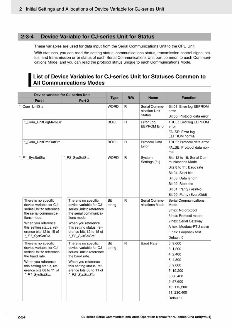
2 Initial Settings and Allocations of Device Variable for CJ-series Unit
2-24 CJ-series Serial Communications Units Operation Manual for NJ-series CPU Unit(W494)
These variables are used for data input from the Serial Communications Unit to the CPU Unit.
With statuses, you can read the setting status, communications status, transmission control signal sta-tus, and transmission error status of each Serial Communications Unit port common to each Communi-cations Mode, and you can read the protocol status unique to each Communications Mode.
2-3-4 Device Variable for CJ-series Unit for Status
List of Device Variables for CJ-series Unit for Statuses Common to All Communications Modes
Device variable for CJ-series UnitType R/W Name Function
Port 1 Port 2
*_Com_UnitSta WORD R Serial Commu-nication Unit Status
Bit 01: Error log EEPROM error
Bit 00: Protocol data error
*_Com_UnitLogMemErr BOOL R Error Log EEPROM Error
TRUE: Error log EEPROM error
FALSE: Error log EEPROM normal
*_Com_UnitPmrDatErr BOOL R Protocol Data Error
TRUE: Protocol data error
FALSE: Protocol data nor-mal
*_P1_SysSetSta *_P2_SysSetSta WORD R System Settings (*1)
Bits 12 to 15: Serial Com-munications Mode
Bits 8 to 11: Baud rate
Bit 04: Start bits
Bit 03: Data length
Bit 02: Stop bits
Bit 01: Parity (Yes/No)
Bit 00: Parity (Even/Odd)
There is no specific device variable for CJ-series Unit to reference the serial communica-tions mode.
When you reference this setting status, ref-erence bits 12 to 15 of *_P1_SysSetSta.
There is no specific device variable for CJ-series Unit to reference the serial communica-tions mode.
When you reference this setting status, ref-erence bits 12 to 15 of *_P2_SysSetSta.
Bit string
R Serial Commu-nications Mode
Serial Communications Mode
3 hex: No-protocol
6 hex: Protocol macro
9 hex: Serial Gateway
A hex: Modbus-RTU slave
F hex: Loopback test
Default: 0
There is no specific device variable for CJ-series Unit to reference the baud rate.
When you reference this setting status, ref-erence bits 08 to 11 of *_P1_SysSetSta.
There is no specific device variable for CJ-series Unit to reference the baud rate.
When you reference this setting status, ref-erence bits 08 to 11 of *_P2_SysSetSta.
Bit string
R Baud Rate 0: 9,600
3: 1,200
4: 2,400
5: 4,800
6: 9,600
7: 19,200
8: 38,400
9: 57,600
10: 115,200
11: 230,400
Default: 0

2-25
2 Initial Settings and Allocations of Device Variable for CJ-series Unit
CJ-series Serial Communications Units Operation Manual for NJ-series CPU Unit(W494)
2-3 Device V
ariable fo
r CJ-series U
nit
2
2-3-4 Device V
ariable for CJ-series U
nit for Status
*_P1_StartBitSta *_P2_StartBitSta BOOL R Start Bits (Always 1 bit)
FALSE: 1 bit
TRUE: 1 bit
(1 bit for both FALSE and TRUE)
*_P1_DatBitSta *_P2_DatBitSta BOOL R Data Length (7 bits/8 bits)
FALSE: 7 bits
TRUE: 8 bits
*_P1_StopBitSta *_P2_StopBitSta BOOL R Stop Bits (2 bits/1 bit)
FALSE: 2 bits
TRUE: 1 bit
*_P1_ParityYNSta *_P2_ParityYNSta BOOL R Parity (Yes/No) FALSE: Yes
TRUE: No
*_P1_ParityBitSta *_P2_ParityBitSta BOOL R Parity (Even/Odd)
FALSE: Even
TRUE: Odd
*_P1_HwSetSta *_P2_HwSetSta WORD R Hardware Set-tings
Bit 15: RS-422/485 setting status
Bit 14: RS-232C setting status
Bit 13: Terminating resis-tance setting status
Bit 01: System Setup error
Bit 00: Port operating sta-tus
*_P1_Ser485Sta *_P2_Ser485Sta BOOL R RS-422/485 setting Status
Port types of each port
*_P@_Ser485Sta/*_P@_Ser232Sta:
00: No port
01: RS232C
10: RS422A/485
11: This status does not exist.
*_P1_Ser232Sta *_P2_Ser232Sta BOOL R RS-232C set-ting Status
*_P1_TermSta *_P2_TermSta BOOL R Terminating Resistance Setting Status
TRUE: Terminating resis-tance ON
FALSE: Terminating resis-tance OFF
*_P1_SysSetupErr *_P2_SysSetupErr BOOL R System Setup Error
TRUE: System Setup error
FALSE: System Setup normal
*_P1_OperatingSta *_P2_OperatingSta BOOL R Port Operating Status
TRUE: Port operating
FALSE: Port stopped
*_P1_TransCtlSta *_P2_TransCtlSta WORD R Communica-tions Status
Bit 10: Remote Unit busy
Bit 08: Local Unit busy
Bit 07: DTR (ER) signal
Bit 06: DSR (DR) signal
Bit 04: CTS (CS) signal
Bit 03: RTS (RS) signal
*_P1_RmtBusySta *_P2_RmtBusySta BOOL R Remote Unit Busy
TRUE: Remote Unit busy (Flow control)
FALSE: Remote Unit ready to receive
Device variable for CJ-series UnitType R/W Name Function
Port 1 Port 2

2 Initial Settings and Allocations of Device Variable for CJ-series Unit
2-26 CJ-series Serial Communications Units Operation Manual for NJ-series CPU Unit(W494)
*_P1_LclBusySta *_P2_LclBusySta BOOL R Local Unit Busy TRUE: Local Unit busy (Flow control)
FALSE: Local Unit ready to receive
*_P1_SigERSta *_P2_SigERSta BOOL R ER signal TRUE: High
FALSE: Low
*_P1_SigDRSta *_P2_SigDRSta BOOL R DR signal TRUE: High
FALSE: Low
*_P1_SigCSSta *_P2_SigCSSta BOOL R CS signal TRUE: High
FALSE: Low
*_P1_SigRSSta *_P2_SigRSSta BOOL R RS signal TRUE: High
FALSE: Low
*_P1_TransErrSta *_P2_TransErrSta WORD R Transmission Error Status
Bit 15: Transmission error (*2)
Bit 14: Tfs (send finished monitoring time) exceeded (*3)
Bit 13: Tfr (receive fin-ished monitoring time) exceeded (*3)
Bit 12: Tr (receive wait monitoring time) exceeded (*3)
Bits 08 to 11: Number of retries (*3)
Bit 07: FCS check error
Bit 06: Command error (*3)
Bit 05: Timeout error
Bit 04: Overrun error
Bit 03: Framing error
Bit 02: Parity error
*_P1_TransErr *_P2_TransErr BOOL R Transmission error (*2)
TRUE: Transmission error
FALSE: No transmission error
*_P1_TfsErr *_P2_TfsErr BOOL R Tfs (Send Fin-ished Monitor-ing Time) Exceeded (*3)
TRUE: Tfr (send finished monitoring time) exceeded
FALSE: Normal
*_P1_TfrErr *_P2_TfrErr BOOL R Tfr (Receive Finished Moni-toring Time) Exceeded (*3)
TRUE: Tfr (receive fin-ished monitoring time) exceeded
FALSE: Normal
*_P1_TrErr *_P2_TrErr BOOL R Tr (Receive Wait Monitor-ing Time) Exceeded (*3)
TRUE: Tr (receive wait monitoring time) exceeded
FALSE: Normal
Device variable for CJ-series UnitType R/W Name Function
Port 1 Port 2

2-27
2 Initial Settings and Allocations of Device Variable for CJ-series Unit
CJ-series Serial Communications Units Operation Manual for NJ-series CPU Unit(W494)
2-3 Device V
ariable fo
r CJ-series U
nit
2
2-3-4 Device V
ariable for CJ-series U
nit for Status *1 The current settings for the port are read. For details on the contents that are read, refer to List of Device Variable for CJ-
series Unit for System Settings on page 2-16. If a System Settings error occurs, the default settings will be read.
*2 If any of the error bits 00 to 14 becomes TRUE in the Protocol Macro Mode but then communications are recovered withinthe specified number of retries, the bit will be changed to FALSE. The bit will remain TRUE if recovery is not possiblewithin the specified number of retries.
*3 Used only with protocol macros. Not used with any other serial communications mode.
*4 Used with Protocol Macro or Serial Gateway Mode.This bit is changed to TRUE if an error occurs in the transmission path with the Serial Gateway.With Modbus-RTU Slave Mode, this bit is changed to TRUE if there is a CRC check error.
*5 Used with Protocol Macro or Serial Gateway Mode.This bit is changed to TRUE if a send start timeout or response timeout occurs with the Serial Gateway.
*6 Not used with Loopback Test Mode. This bit also changes to TRUE if more than 259 bytes of unread data is stored in thereception buffer during No-protocol Mode.
*7 Not used with Loopback Test Mode.
There is no specific device variable for CJ-series Unit to reference the number of retries.
When you reference the number of retries, refer to bits 08 to 11 of *_P1_TransErrSta.
There is no specific device variable for CJ-series Unit to reference the number of retries.
When you reference the number of retries, refer to bits 08 to 11 of *_P2_TransErrSta.
Bit string
R Number of Retries (*3)
Range: 0 to 9
*_P1_FCSErr *_P2_FCSErr BOOL R FCS Check Error (*4)
TRUE: FCS check error
FALSE: FCS check nor-mal
*_P1_CmdErr *_P2_CmdErr BOOL R Command Error (*3)
TRUE: Command error
FALSE: No command error
*_P1_TimeoutErr *_P2_TimeoutErr BOOL R Timeout Error (*5)
TRUE: Timeout (protocol macros: Tfs, Tfr, or Tr) error or Serial Gateway send/response timeout
FALSE: Normal
*_P1_OverRunErr *_P2_OverRunErr BOOL R Overrun Error (*6)
TRUE: Overrun error
FALSE: Normal
*_P1_FramingErr *_P2_FramingErr BOOL R Framing Error (*7)
TRUE: Framing error
FALSE: Normal
*_P1_ParityErr *_P2_ParityErr BOOL R Parity Error (*7) TRUE: Parity error
FALSE: Normal
Device variable for CJ-series UnitType R/W Name Function
Port 1 Port 2

2 Initial Settings and Allocations of Device Variable for CJ-series Unit
2-28 CJ-series Serial Communications Units Operation Manual for NJ-series CPU Unit(W494)
Protocol Macro Mode
List of Device Variables for CJ-series Unit for Statuses Specific to Each Communications Mode (Protocol Statuses)
Device variable for CJ-series UnitType R/W Name Function
Port 1 Port 2
*_P1_PmrSta *_P2_PmrSta WORD R Protocol Macro Operating Sta-tus
Bit 15: Protocol macro executing flag
Bit 14: Step end error
Bit 13: Abort flag
Bit 12: Tracing flag
Bit 11: Sequence end completion flag
Bit 10: Sequence abort completion flag
Bit 09: Sequence wait flag
Bit 08: Serial Gateway prohibited flag (protocol macros)
Bits 00 to 03: Protocol macro error code
*_P1_PmrExecSta *_P2_PmrExecSta BOOL R Protocol Macro Executing Flag
This flag is changed to TRUE when a ExecP-MCR instruction (sequence) is executed.
The flag remains FALSE when execution fails.
When the sequence is completed and receive data is written, the flag is changed to FALSE after all the receive data has been written to I/O mem-ory.
This flag is changed to FALSE when the sequence is completed (either when it is ended by End, or when it is ended by Abort).
*_P1_PmrStepErr *_P2_PmrStepErr BOOL R Step End Error This flag is changed to TRUE when a step ends abnormally.
It remains FALSE if the step ends normally as a result of a retry.
TRUE: Step ended abnor-mally
FALSE: Step ended nor-mally

2-29
2 Initial Settings and Allocations of Device Variable for CJ-series Unit
CJ-series Serial Communications Units Operation Manual for NJ-series CPU Unit(W494)
2-3 Device V
ariable fo
r CJ-series U
nit
2
2-3-4 Device V
ariable for CJ-series U
nit for Status
*_P1_PmrAbtSta *_P2_PmrAbtSta BOOL R Abort Flag This flag is changed to TRUE when processing is ended by using the abort switch from the user pro-gram.
When the abort switch is turned ON at the end of a sequence, the sequence may end with either End or Abort status.
*_P1_PmrTracingSta *_P2_PmrTracingSta BOOL R Tracing Flag This flag is changed to TRUE while time series data for send and receive messages is traced with an instruction from the CX-Protocol.
*_P1_PmrSeqEndSta *_P2_PmrSeqEndSta BOOL R Sequence End Completion Flag
This flag is changed to TRUE when a sequence is completed for the next process or for an error process with an End com-mand.
Note When a sequencehas ended normally,setting End (Abortwhen the sequencehas ended abnor-mally) enables thisflag to determinewhether or not thesequence executionhas ended normally.
TRUE: Sequence ended
FALSE: Sequence not ended
*_P1_PmrSeqAbtSta *_P2_PmrSeqAbtSta BOOL R Sequence Abort Comple-tion Flag
This flag is changed to TRUE when a sequence is ended for the next process or for an error processing with an Abort command.
TRUE: Sequence aborted
FALSE: Sequence not aborted
*_P1_PmrSeqWaitSta *_P2_PmrSeqWaitSta BOOL R Sequence Wait Flag
This flag is changed to TRUE when a sequence is in the waiting state due to the WAIT command.
Waiting is released when the Wait Release Switch is changed to TRUE in the user program, and the sequence will move to the next step.
Device variable for CJ-series UnitType R/W Name Function
Port 1 Port 2

2 Initial Settings and Allocations of Device Variable for CJ-series Unit
2-30 CJ-series Serial Communications Units Operation Manual for NJ-series CPU Unit(W494)
*_P1_PmrSgwProhSta *_P2_PmrSgwProhSta BOOL R Serial Gateway Prohibited Flag (Protocol Mac-ros)
This flag is changed to TRUE when the Serial Gateway function (mode) is prohibited due to the status of the Serial Gate-way Prohibit Switch in the user program.
This flag is changed to FALSE when the Serial Gateway is permitted.
There is no specific device variable for CJ-series Unit to reference the Protocol Macro Error Code.
When you reference the code, refer to bits 00 to 03 of *_P1_PmrSta.
There is no specific device variable for CJ-series Unit to reference the Protocol Macro Error Code.
When you reference the code, refer to bits 00 to 03 of *_P2_PmrSta.
Bit string
R Protocol Macro Error Code
0: No error
2: Sequence No. error
3: Data read/write area exceeded error
4: Protocol data syntax error
*_P1_PmrCommSeqNoSta
*_P2_PmrCommSeqNoSta
UINT R Communica-tions Sequence No.
Range: 0 to 999
*_P1_PmrExecNoSta *_P2_PmrExecNoSta WORD R Executed Step and Case No.
Bits 08 to 11: Executed Step No. (code)
Bits 00 to 03: Executed Reception Case No. (code)
*_P1_PmrStepNoCodeSta
*_P2_PmrStepNoCodeSta
USINT R Executed Step No. (Code)
Range: 0 to 15
*_P1_PmrRcvCaseNoCodeSta
*_P2_PmrRcvCaseNoCodeSta
USINT R Executed Reception Case No. (Code)
Range: 0 to 15
*_P1_PmrRcvCaseNoFlgSta[0-15]
*_P2_PmrRcvCaseNoFlgSta[0-15]
BOOL R Executed Reception Case No. Stor-age Flag
0 to 15: Correspond to bits 00 to 15
*_P1_PmrStepNoFlgSta[0-15]
*_P2_PmrStepNoFlgSta[0-15]
BOOL R Executed Step No. Storage Flag
0 to 15: Correspond to bits 00 to 15
*_P1_PmrRepCntSta *_P2_PmrRepCntSta WORD R Repeat Counter
Bits 08 to 15: Repeat Counter Setting Value
Bits 00 to 07: Repeat Counter Present Value
*_P1_PmrSetRepCntSta
*_P2_PmrSetRepCntSta
USINT R Repeat Counter Set-ting Value
The number of times a step is repeated is set in these bits.
Range: 0 to 255
*_P1_PmrCurRepCntSta
*_P2_PmrCurRepCntSta
USINT R Repeat Counter Present Value
The Repeat Counter Vari-able N is set.
The value is cleared when the sequence execution starts, when the STUP instruction is executed, or at restarts.
Range: 0 to 255
Device variable for CJ-series UnitType R/W Name Function
Port 1 Port 2

2-31
2 Initial Settings and Allocations of Device Variable for CJ-series Unit
CJ-series Serial Communications Units Operation Manual for NJ-series CPU Unit(W494)
2-3 Device V
ariable fo
r CJ-series U
nit
2
2-3-4 Device V
ariable for CJ-series U
nit for Status
Loopback Tests
Device variable for CJ-series UnitType R/W Name Function
Port 1 Port 2
*_P1_LbtSta *_P2_LbtSta WORD R Loopback Test Status
Bit 15: Error
Bit 08: DTR check error
Bit 07: CTS check error
Bit 05: Timeout error
Bit 04: Parity error
Bit 03: Overrun error
Bit 02: Framing error
Bit 00: Comparison error
*_P1_LbtErrSta *_P2_LbtErrSta BOOL R Error TRUE: Error
FALSE: Normal
*_P1_LbtDRErr *_P2_LbtDRErr BOOL R DTR Check Error
TRUE: DSR (DR) signal check error
FALSE: Normal
*_P1_LbtCSErr *_P2_LbtCSErr BOOL R CTS Check Error
TRUE: CTS (CS) signal check error
FALSE: Normal
*_P1_LbtTimeoutErr *_P2_LbtTimeoutErr BOOL R Timeout Error TRUE: Timeout error
FALSE: Normal
*_P1_LbtParityErr *_P2_LbtParityErr BOOL R Parity Error TRUE: Parity error
FALSE: Normal
*_P1_LbtOverRunErr *_P2_LbtOverRunErr BOOL R Overrun Error TRUE: Overrun error
FALSE: Normal
*_P1_LbtFramingErr *_P2_LbtFramingErr BOOL R Framing Error TRUE: Framing error
FALSE: Normal
*_P1_LbtCmpErr *_P2_LbtCmpErr BOOL R Comparison Error
TRUE: Comparison error
FALSE: Normal
*_P1_LbtTestCntSta *_P2_LbtTestCntSta UINT R Test Execution Count
The test execution count is cleared at startup. If the number of tests is counted to 65,535, the value of the count will remain at 65,535, but testing will continue.
*_P1_LbtTestErrCntSta *_P2_LbtTestErrCntSta UINT R Test Error Count
The test execution count is cleared at startup. If the number of tests is counted to 65,535, the value of the count will remain at 65,535, but testing will continue.

2 Initial Settings and Allocations of Device Variable for CJ-series Unit
2-32 CJ-series Serial Communications Units Operation Manual for NJ-series CPU Unit(W494)
No-protocol Mode
Device variable for CJ-series UnitType R/W Name Function
Port 1 Port 2
*_P1_NopSta *_P2_NopSta WORD R No-protocol Mode Status
Bit 07: Reception Overflow Flag
Bit 06: Reception Com-pleted Flag
Bit 05: SerialSend Execut-ing Flag
*_P1_NopRcvOvfSta *_P2_NopRcvOvfSta BOOL R Reception Overflow Flag
TRUE: Unit received more than the specified number of bytes
FALSE: Unit did not receive more than the specified number of bytes
*_P1_NopRcvCompleteSta
*_P2_NopRcvCompleteSta
BOOL R Reception Completed Flag
TRUE: Reception com-pleted
FALSE: No reception or reception in progress
*_P1_NopSerialSendExecSta
*_P2_NopSerialSendExecSta
BOOL R SerialSend Executing Flag
TRUE: Executing
FALSE: Not executing
*_P1_NopRcvCntSta *_P2_NopRcvCntSta UINT R Reception Counter (Num-ber of Receive Data Bytes)
Counts the number of received data bytes that have not been read from 0 to 256 (0 to 256 bytes).
If an end code is present, counts the number of unread data bytes up to the end code.

2-33
2 Initial Settings and Allocations of Device Variable for CJ-series Unit
CJ-series Serial Communications Units Operation Manual for NJ-series CPU Unit(W494)
2-3 Device V
ariable fo
r CJ-series U
nit
2
2-3-4 Device V
ariable for CJ-series U
nit for Status
Modbus-RTU Slave Mode
Device variable for CJ-series UnitType R/W Name Function
Port 1 Port 2
*_P1_MbsCmdRxCntSta *_P2_MbsCmdRxCntSta UINT R Number of Nor-mally Received Commands
The number of normal Modbus-RTU commands received from the commu-nications port is stored.
*_P1_MbsRespTxCntSta *_P2_MbsRespTxCntSta UINT R Number of Nor-mally Sent Responses
The number of normal Modbus-RTU responses sent to the communica-tions port is stored.
*_P1_MbsTxErrCnt *_P2_MbsTxErrCnt UINT R Number of Overrun Errors, Framing Errors, and Parity Errors (Trans-mission errors)
The number of overrun errors, framing errors, and parity errors that occur is stored.
*_P1_MbsCRCErrCnt *_P2_MbsCRCErrCnt UINT R Number of CRC Errors (Transmission errors)
The number of CRC errors that occur is stored.
*_P1_MbsCmdErrCnt *_P2_MbsCmdErrCnt UINT R Number of Command For-mat Errors (Ille-gal Function Codes and Ille-gal Addresses)
The number of illegal func-tion codes and illegal addresses/data in received Modbus- RTU commands is stored.

2 Initial Settings and Allocations of Device Variable for CJ-series Unit
2-34 CJ-series Serial Communications Units Operation Manual for NJ-series CPU Unit(W494)
2-4 System-defined Variable
Serial Communications Unit Port 1/2 Settings Changing Flag and Restart Bits are allocated to the fol-lowing system-defined variables.
Port 1 and Port 2 Settings Changing FlagYou can use an Out instruction or another instruction from the program to change these flags toTRUE to change communications settings and restart the Serial Communications Unit ports. Afteryou change the settings and restart the communications port, the flag will automatically be changedto FALSE.
These flags are used both to change the communications port settings and to restart the communi-cations port at the same time. Accordingly, in cases where these flags are changed to TRUE only torestart a communications port by using an Out instruction or another instruction, you can changethese flags to TRUE without changing the port system settings.
List of System-defined Variables (** corresponds to the unit number.)
RestartYou can restart the Serial Communications Unit by one of the following methods.
• Issue a ResetUnit instruction to restart from the program.
• Restart from a system-defined variable.Change the following bits to TRUE and then back to FALSE.
List of System-defined Variables (** corresponds to the unit number.)
System-defined variable Type R/W Name Function
_CJB_SCU**P1ChgSta BOOL RW Serial Communications Unit
**, Port 1 Settings Chang-ing Flag
TRUE: Port 1 Communications Unit Port Settings Change
FALSE: All other statuses
Default: FALSE
_CJB_SCU**P2ChgSta BOOL RW Serial Communications Unit
**, Port 2 Settings Chang-ing Flag
TRUE: Port 2 Communications Unit Port Settings Change
FALSE: All other statuses
Default: FALSE
System-defined variable Type R/W Name Function
_CJB_CBU**Restart BOOL RW CPU Bus Unit Restart Bits TRUE: CPU Bus Units are restarted.
FALSE: CPU Bus Units are not restarted.
Default: FALSE

2-35
2 Initial Settings and Allocations of Device Variable for CJ-series Unit
CJ-series Serial Communications Units Operation Manual for NJ-series CPU Unit(W494)
2-4 System
-defin
ed V
ariable
2
Variables Related to the SerialSend, SerialRcv, and SerialRcvNoClear Instructions in No-protocol Mode
System-defined variable Description
_Port_isAvailable Network Communications Instruction Enabled Flag
TRUE when execution of SerialSend, SerialRcv, SerialRcvNoClear, and other net-work communications instructions (such as SendCmd and ExecPMCR) is enabled.

2 Initial Settings and Allocations of Device Variable for CJ-series Unit
2-36 CJ-series Serial Communications Units Operation Manual for NJ-series CPU Unit(W494)

3-1CJ-series Serial Communications Units Operation Manual for NJ-series CPU Unit(W494)
3
This section describes how to mount Serial Communications Units, and how to connectthe ports to external devices.
3-1 Installing Serial Communications Units . . . . . . . . . . . . . . . . . . . . . . . . . . . 3-23-1-1 System Configuration Precautions . . . . . . . . . . . . . . . . . . . . . . . . . . . . . . . . . 3-2
3-1-2 Serial Communications Unit Installation Procedure . . . . . . . . . . . . . . . . . . . . . 3-2
3-1-3 Unit Handling Precautions . . . . . . . . . . . . . . . . . . . . . . . . . . . . . . . . . . . . . . . . 3-3
3-2 Wiring . . . . . . . . . . . . . . . . . . . . . . . . . . . . . . . . . . . . . . . . . . . . . . . . . . . . . . . 3-43-2-1 Wiring Precautions . . . . . . . . . . . . . . . . . . . . . . . . . . . . . . . . . . . . . . . . . . . . . 3-43-2-2 Port Types . . . . . . . . . . . . . . . . . . . . . . . . . . . . . . . . . . . . . . . . . . . . . . . . . . . . 3-4
3-2-3 Communications Modes and Ports . . . . . . . . . . . . . . . . . . . . . . . . . . . . . . . . . 3-4
3-2-4 Connector Pin Layout . . . . . . . . . . . . . . . . . . . . . . . . . . . . . . . . . . . . . . . . . . . 3-53-2-5 Mounting Height and Connector Cover Dimensions . . . . . . . . . . . . . . . . . . . . 3-6
3-2-6 Reducing Electrical Noise for External Wiring . . . . . . . . . . . . . . . . . . . . . . . . . 3-7
3-2-7 2-Wire and 4-Wire Connections . . . . . . . . . . . . . . . . . . . . . . . . . . . . . . . . . . . . 3-73-2-8 NT-AL001 Link Adapter Settings . . . . . . . . . . . . . . . . . . . . . . . . . . . . . . . . . . . 3-8
3-2-9 Connections for Protocol Macro, Serial Gateway, No-protocol Mode, and Modbus-RTU Slave Mode . . . . . . . . . . . . . . . . . . . . . . . . . . . . . . . . . . . . . . . . 3-9
3-2-10 Connections in Loopback Test . . . . . . . . . . . . . . . . . . . . . . . . . . . . . . . . . . . . 3-18
3-3 RS-232C and RS-422A/485 Wiring . . . . . . . . . . . . . . . . . . . . . . . . . . . . . . . 3-193-3-1 Recommended RS-232C Wiring Examples . . . . . . . . . . . . . . . . . . . . . . . . . . 3-19
3-3-2 Recommended RS-422A/485 Wiring Examples . . . . . . . . . . . . . . . . . . . . . . 3-203-3-3 Wiring RS-232C Connectors on the CJ1W-SCU22/42 . . . . . . . . . . . . . . . . . 3-22
3-3-4 Soldering . . . . . . . . . . . . . . . . . . . . . . . . . . . . . . . . . . . . . . . . . . . . . . . . . . . . 3-23
3-3-5 Assembling Connector Hood . . . . . . . . . . . . . . . . . . . . . . . . . . . . . . . . . . . . . 3-243-3-6 Wiring RS-422A/485 Terminal-block
Connectors on the CJ1W-SCU32/42 . . . . . . . . . . . . . . . . . . . . . . . . . . . . . . . 3-253-3-7 Connecting to Unit . . . . . . . . . . . . . . . . . . . . . . . . . . . . . . . . . . . . . . . . . . . . . 3-26
Installation and Wiring

3 Installation and Wiring
3-2 CJ-series Serial Communications Units Operation Manual for NJ-series CPU Unit(W494)
3-1 Installing Serial Communications Units
• Set a unique Unit number for each CPU Bus Unit to be installed in the CPU Rack or Expansion Rack.Set the unit number switch at the top of the front panel to between 0 and F. Turn OFF the Controllerbefore setting the unit number.
• A maximum of 10 Serial Communications Units can be connected to a CPU Rack or ExpansionRack. In total 16 Units can be mounted to a CPU Unit as long as no other CPU Bus Unit is mounted.
Use the following steps to mount or remove Serial Communications Units.
1 Align the connectors properly and then press in on the Unit to connect it.
2 Slide the sliders on the top and bottom of the Unit until they lock the Units together.
3-1-1 System Configuration Precautions
3-1-2 Serial Communications Unit Installation Procedure
HookConnector
Hook holes
Slider
Move the sliders toward the back until they lock into place.
LockRelease

3-3
3 Installation and Wiring
CJ-series Serial Communications Units Operation Manual for NJ-series CPU Unit(W494)
3-1 Installin
g S
erial Co
mm
un
ication
s Un
its
3
3-1-3 Unit H
andling Precautions
Precautions for Safe Use
If the sliders are not locked properly, the Serial Communications Units may not function correctly.
To remove the Unit, move the sliders to the release position and then pull the Units gently apart.
• Always turn OFF the NJ-series before you mount or remove a Serial Communications Unit or youconnect or disconnect cables to/from the Serial Communications Unit.
• Place the port connecting cables in a different duct from those for high-voltage lines or power lines toprevent the effects of electrical noise from these lines.
• Prevent wire clippings, cutting chips or other materials from getting inside the Unit. They could causescorching, failure, and malfunction. Pay particular attention to this during installation and take mea-sures such as covering with a cover.
• If the Unit was shipped from the factory with the dust protection label on top of the unit, be sure toremove that label before switching ON the power. The label prevents heat dissipation and couldcause a malfunction.
• If a serial port is not used, leave the port cover on the port to prevent the entrance of dust.
3-1-3 Unit Handling Precautions
2
ON
4
TERM
RD2SD2RDY
NO.UNIT
ERH
OFF
WIRE
0123456789ABCDEF
ERCRUNSCU41
RD1 TER1SD1
PORT1(RS422/485)
PORT2
Remove label after wiring.
Port cover

3 Installation and Wiring
3-4 CJ-series Serial Communications Units Operation Manual for NJ-series CPU Unit(W494)
3-2 Wiring
• Before you connect or disconnect the communications cables, always make sure that the Controllerpower is turned OFF.
• Tighten the communications connector screws firmly with your fingers.• You can connect Serial Communications Units to various devices. For compatibility, refer to the oper-
ation manuals for the devices to be connected.
The following port types are provided on the Serial Communications Units.
The following sections describe the connection methods used for each serial communications modeand Serial Communications Unit port.
The following table shows the relationship between the communications ports and the communicationsmodes for the Serial Communications Unit.
* You can be use the NT-AL001 Link Adapter to convert RS-232C to RS-422A/485 and vice versa to enable 1:Ncommunications.
3-2-1 Wiring Precautions
3-2-2 Port Types
Model Port 1 Port 2
CJ1W-SCU22 RS-232C RS-232C
CJ1W-SCU32 RS-422A/485 RS-422A/485
CJ1W-SCU42 RS-422A/485 RS-232C
3-2-3 Communications Modes and Ports
Communications mode RS-232C RS-422A/485
1:1 1:N (*) 1:1 4-wire 1:N 4-wire 1:1 2-wire 1:N 2-wire
Protocol Macros Yes Yes Yes Yes Yes Yes
Serial Gateway Yes Yes Yes Yes Yes Yes
No-protocol Yes Yes Yes Yes No No
Modbus-RTU Slave Yes Yes Yes Yes Yes Yes

3-5
3 Installation and Wiring
CJ-series Serial Communications Units Operation Manual for NJ-series CPU Unit(W494)
3-2 Wirin
g
3
3-2-4 Connector P
in Layout
RS-232C PortsThis layout applies to the following ports: ports 1 and 2 of the CJ1W-SCU22 and port 2 of the CJ1W-SCU42.
Refer to 2-1 Component Names and Functions.
RS-422A/485 Port: Ports 1 and 2 on CJ1W-SCU32, or Port 1 on CJ1W-SCU42
Connector Pin Layout
Note When the 2-wire connections are used, use either pins 1 and 2, or pins 6 and 8.
Refer to 2-1 Component Names and Functions.
The internal circuits are shown below.
* Terminating Resistance Turn OFF the terminating resistance switch or externally attach terminating resistance as required by the specifi-cations of the remote device.
3-2-4 Connector Pin Layout
Pin Abbreviation Signal name I/O
1 FG Shield ---
2 SD Send data Output
3 RD Receive data Input
4 RS Request to send Output
5 CS Clear to send Input
6 5V Power supply ---
7 DR Data set ready Input
8 ER Data terminal ready Output
9 SG Signal ground ---
Shell FG Shield ---
Pin No. Symbol Signal name I/O
1 RDA Receive data − Input
2 RDB Receive data + Input
3 SDA Send data − Output
4 SDB Send data + Output
5 FG Shield ---
1
2
3
4
5
Pin 2 RDB(+)
Pin 1 RDA(−)
Pin 4 SDB(+)
Pin 3 SDA(−)
Receiver
Driver
2-wire/4-wire switch
Terminating resistance: 120 Ω (*)
Terminating resistance switch

3 Installation and Wiring
3-6 CJ-series Serial Communications Units Operation Manual for NJ-series CPU Unit(W494)
Precautions for Safe Use
The signal names SDA/B and RDA/B do not always have the same polarity as that shown above.Check the polarity of the external device before you make connections.
Additional Information
The RS-422A/485 port on the CJ1W-SCU32/42 has a failsafe function built into the receiver toprevent reading incorrect signals when the RDA and RDB pins are open or shorted.
When you mount the Serial Communications Unit, make sure to provide space for the mounting heightand connector cover dimensions shown below.
Note The mounting heights shown above are applicable when the attached connectors, connectorcovers, and recommended cables are used. The mounting height may differ when other connec-tors, connector covers, and cables are used. Take into account the connectors, connector cov-ers, and the minimum bending radius of the cables to determine the mounting height.
3-2-5 Mounting Height and Connector Cover Dimensions
65150
Serial Communications UnitCJ1W-SCU22
65125
65150
CJ1W-SCU32 Serial Communications Unit
Cable connector
CJ1W-SCU42 Serial Communications Unit

3-7
3 Installation and Wiring
CJ-series Serial Communications Units Operation Manual for NJ-series CPU Unit(W494)
3-2 Wirin
g
3
3-2-6 Reducing E
lectrical Noise for E
xternal Wiring
Observe the following precautions for external wiring.
• When multi-conductor signal cable is used, avoid use of I/O wires and other control wires in the samecable.
• If wiring racks are running in parallel, allow at least 300 mm between the racks.
• If you place the I/O wiring and power cables in the same duct, shield them from each other withgrounded steel sheet metal.
The transmission circuits for 2-wire and 4-wire connections are different, as shown in the following dia-gram.
3-2-6 Reducing Electrical Noise for External Wiring
3-2-7 2-Wire and 4-Wire Connections
Communications cables
Low-current cables
Power supply and general control circuit wiring
Power lines
300 mm min.
Ground to 100 Ω or less.
Control cables
Power cables 300 mm min.
Communications cables
Power supply and general control circuit wiring Power lines
200 mm min.
Ground to 100 Ω or less.
Steel sheet metal
Example of 4-Wire Connections
Example of 2-Wire Connections
2/4-wire switch (DPDT)
Unit
2/4-wire switch (DPDT)
UnitNot connected
Other Unit Other UnitOther UnitOther Unit

3 Installation and Wiring
3-8 CJ-series Serial Communications Units Operation Manual for NJ-series CPU Unit(W494)
Precautions for Correct UsePrecautions for Correct Use
• Use the same transmission circuit (2-wire or 4-wire) for all nodes.
• Do not use 4-wire connections when the 2/4-wire switch on the Unit is set to 2-wire.
• In Protocol Macro Mode, do not use full-duplex transmissions when the 2/4-wire switch on theUnit is set to 2-wire. Otherwise, the data sent from the Serial Communications Unit will bedirectly returned as receive data. In this case, the Unit cannot determine whether the data inthe reception buffer is its own send data or the data received from a remote node, and thuscannot perform receive processing properly. To avoid this problem, always use half-duplextransmissions with a 2-wire setting. You can use either half-duplex or full-duplex transmissionswith a 4-wire setting.
The NT-AL001 Link Adapter has a DIP switch to set RS-422A/485 communications conditions. Whenyou connect the Unit in any serial communications modes, refer to the DIP switch settings shown in thefollowing table.
3-2-8 NT-AL001 Link Adapter Settings
Pin Function Factory setting
1 Not used. Always set this pin to ON. ON
2 Built-in terminating resistance setting
ON: Connects terminating resistance. OFF: Disconnects terminating resistance.
ON
3 2/4-wire setting
2-wire: Set both pins to ON. 4-wire: Set both pins to OFF.
OFF
4 OFF
5 Transmission mode (setting)
Constant transmission: Set both pins to OFF.
Transmission performed when CS signal in RS-232C interface is at high level: Set pin 5 to OFF and pin 6 to ON.
Transmission performed when CS signal in RS-232C interface is at low level: Set pin 5 to ON and pin 6 to OFF.
ON
6 OFF

3-9
3 Installation and Wiring
CJ-series Serial Communications Units Operation Manual for NJ-series CPU Unit(W494)
3-2 Wirin
g
3
3-2-9 Connections for P
rotocol Macro, S
erial Gatew
ay, No-protocol M
ode, and Modbus-R
TU
Slave M
ode
This section describes the connections for Protocol Macro, Serial Gateway, and No-protocol Mode. Upto 32 Boards or Units can be used for 1:N connections.
Note 1 The maximum cable length for RS-232C is 15 m. The RS-232C standard, however, does notcover baud rates above 19.2 kbps. Refer to the manual for the device to be connected to con-firm support.
2 The total cable length for RS-422A/485 systems, including branch cables, is 500 m max. whenNT-AL001 Link Adapters are used. The baud rate and the communications distance some-times depend on the remote device. Confirm the baud rates and communications distancesupported by connected devices.
3 Here, the maximum cable length is limited to 2 m when an NT-AL001 Link Adapter is con-nected.
4 Branch lines must be a maximum of 10 m long.
3-2-9 Connections for Protocol Macro, Serial Gateway, No-protocol Mode, and Modbus-RTU Slave Mode
Port Config-uration
Schematic diagram
RS-232C 1:1
RS-232C 1:N
Resistance ON
NT-AL001Resistance ON
NT-AL001
RS-232C
RS-232Cinterface
RS-232C RS-422A/485
RS-232Cinterface
NT-AL001
RS-232C RS-422A/485Resistance ON
RS-422A/485interface
5-V power
NT-AL001
RS-232C
RS-232C
RS-422A/485
NT-AL001
RS-232C
RS-422A/485
Resistance ON
B500-AL001
Resistance ON
Resistance ON
Resistance ON
NT-AL001 NT-AL001
RS-232C
RS-232C
RS-232CResistance ON 5-V power
Resistance ON
RS-422A/485
RS-422A/485 interface
RS-422A/485 interface
RS-232C interface

3 Installation and Wiring
3-10 CJ-series Serial Communications Units Operation Manual for NJ-series CPU Unit(W494)
Note 1 The maximum cable length for RS-232C is 15 m. The RS-232C standard, however, does notcover baud rates above 19.2 Kbps. Refer to the manual for the device connected to confirmsupport.
2 The total cable length for RS-422A/485 systems, including branch cables, is 1,200 m max. Thetotal cable length for RS-422A/485 systems, including branch cables, is 500 m max. when NT-AL001 Link Adapters are used. The baud rate and the communications distance sometimesdepend on the remote device. Confirm the baud rates and communications distance sup-ported by connected devices.
3 Here, the maximum cable length is limited to 2 m when an NT-Link Adapter is connected.
4 Branch lines must be a maximum of 10 m long.
Port Config-uration
Schematic diagram
RS-422A/485
1:1
RS-422A/485
1:N
RS-422A/485
RS-232C interface
RS-422A/485 interface
NT-AL001RS-232C
Resistance ON 5-V power
RS-422A/485
RS-422A/485
RS-422A/485
Resistance ON
B500-AL001-E
Resistance ON
Resistance ON
Resistance ON
NT-AL001
RS-232C
RS-232C
RS-232CResistance ON 5-V power
Resistance ON
RS-422A/485
RS-232C interface
RS-422A/485 interface
RS-422A/485 interface

3-11
3 Installation and Wiring
CJ-series Serial Communications Units Operation Manual for NJ-series CPU Unit(W494)
3-2 Wirin
g
3
3-2-9 Connections for P
rotocol Macro, S
erial Gatew
ay, No-protocol M
ode, and Modbus-R
TU
Slave M
ode
Connection diagrams are provided in the following subsections. OMRON recommends the use ofshielded, twisted-pair cables for actual wiring to enhance noise resistance. For details on wiring meth-ods, refer to 3-3 RS-232C and RS-422A/485 Wiring.
Connections to E5CK Temperature Controller
Connections to Personal Computer
Connecting RS-232C Ports 1:1
Serial Communications Unit
RS-232C Shield
OMRON E5CK Temperature Controller
RS-232C: Terminal BlockTerminal
Signal PinSignal
D-sub, 9-pin connector (male)
FGSDRDRSCSDRERSG
SDRDSG
123456789
10111213141516171819202122232425
FGSDRDRSCSDRSGCD
ST2
RT
ER
CI
ST1
123456789
FGSDRDRSCS5VDRERSG
Computer RS-232C port

3 Installation and Wiring
3-12 CJ-series Serial Communications Units Operation Manual for NJ-series CPU Unit(W494)
Connections to Personal Computer with RS-CS Flow Control
Using NT-AL001 Link Adapters
* We recommend you use the following NT-AL001 Link Adapter Connecting Cables to connect to NT-AL001 LinkAdapters.
XW2Z-070T-1: 0.7 mXW2Z-200T-1: 2 m
• IBM PC/AT or Compatible Computers • DOS/V or Compatible Computers
12345678910111213141516171819202122232425
Computer
Serial CommunicationsUnit
RS-232C portFGSDRDRSCSDRSGCD
ST2
RT
ER
CI
ST1
123456789
FGSDRDRSCS5VDRERSG
123456789
Computer
RDSDERSGDRRSCS
123456789
FGSDRDRSCS5VDRERSG
Serial CommunicationsUnit
RS-232C port
NT-AL001 Link Adapter
RS-232C InterfaceRS-232C
Interface
SignalPin
DIP Switch SettingsPin 1: ONPin 2: ON (terminating resistance)Pin 3: OFF (4-wire)Pin 4: OFFPin 5: OFFPin 6: OFF
NT-AL001 Link AdapterRS-232CShield
(*) PinPinPin SignalSignalSignal Signal
Serial Communications Unit Computer
RS-422A
D-sub, 9-pin connector (male)
DIP Switch SettingsPin 1: ONPin 2: ON (terminating resistance)Pin 3: OFF (4-wire)Pin 4: OFFPin 5: OFFPin 6: ON
D-sub, 9-pin connector (male)
Terminal block
RS-232CSignal Pin
FG
SDRDRSCS
DRERSG
FGSDRDRSCS5VDRERSG
NC
SDRD
RSCS5VDRERSG
NCSDRDRSCS5VDRERSG
5-V power
(+) (-)

3-13
3 Installation and Wiring
CJ-series Serial Communications Units Operation Manual for NJ-series CPU Unit(W494)
3-2 Wirin
g
3
3-2-9 Connections for P
rotocol Macro, S
erial Gatew
ay, No-protocol M
ode, and Modbus-R
TU
Slave M
ode
Connections to a Modem
Modem
Serial Communica-tions Unit RS-232C port
FGSDRDRSCS5VDRERSG
FGSDRDRSCSDRSGCD
ST2
RT
ER
CI
ST1

3 Installation and Wiring
3-14 CJ-series Serial Communications Units Operation Manual for NJ-series CPU Unit(W494)
* We recommend you use the following NT-AL001 Link Adapter Connecting Cables to connect to NT-AL001 LinkAdapters.
XW2Z-070T-1: 0.7 mXW2Z-200T-1: 2 m
1:N Connections Using RS-232C Ports
Signal Pin
Serial Communications Unit
RS-232CShield (*)
NT-AL001
Device that supportsRS-422A/485 communications (2-wire)
DIP SWPin 1: ONPin 2: ON (terminating resistance)Pin 3: ON (2-wire)Pin 4: ONPin 5: OFFPin 6: ON
RS-232C interface
Terminal block
SignalPin Signal Pin
D-sub, 9-pin connector (male) D-sub, 9-pin
connector (male)
Device that supports RS-422A/485 communications (2-wire)
Signal
Signal
RS-422A/485 interface
RS-422A/485 interface
Signal Pin
Serial Communications Unit NT-AL001
Device that supports RS-422A/485 communications (4-wire)
RS-422A/485 interface
RS-422AShield
DIP SWPin 1: ONPin 2: ON Terminating resistancePin 3: OFF 4-wirePin 4: OFFPin 5: OFFPin 6: ON
Terminal block
Signal PinSignalPin
D-sub, 9-pin connector (male)
D-sub, 9-pin connector (male)
Signal
Signal
RS-232CShield
(*)
RS-422A/485 interface
RS-232C interface Device that supports
RS-422A/485 communications (4-wire)
FGSD
RDRSCS5VDRERSG
NCSDRDRSCS5VDRERSG
FGSDRDRSCS5VDRERSG
NCSDRDRSCS5VDRERSG

3-15
3 Installation and Wiring
CJ-series Serial Communications Units Operation Manual for NJ-series CPU Unit(W494)
3-2 Wirin
g
3
3-2-9 Connections for P
rotocol Macro, S
erial Gatew
ay, No-protocol M
ode, and Modbus-R
TU
Slave M
ode
1:1 Connections Using RS-422A/485 Ports
A(−)B(+)
Terminal block connector
Signal Pin
Serial Communications Unit
Device that supports RS-422A/485 communications (2-wire) Serial Communications Unit
Device that supports RS-422A/485 communications (4-wire)
Shield Signal Signal Pin Shield SignalRS-422A/485 in-terface
RS-422A/485 in-terface
RS-422A/485 in-terface
12345
RDARDBSDASDBFG
SDASDBRDARDB
12345
RDARDBSDASDBFG
Terminal block connector
RS-422A/485 in-terface
1 2345
RDARDBSDASDBFG
FGSDRDRSCS
DRERSG
RS-422A
RS-232C1 2 3 4 5 678
GRDSG
SDBSDARDBRDACSBCSA
1 2 3 4 5 6 7 89
RS-232RS-422
NCSDRDRSCS5VDRERSG
DIP Switch SettingsSW1-1: ONSW1-2: ON (terminating resistance)SW1-3: OFFSW1-4: OFFSW1-5: OFFSW1-6: OFF
Terminal block connector
(+) 5-V power
(-)
NT-AL001 Link Adapter
RS-232C Interface
SignalPinPinPin
SignalSignalSignal
Serial Communications Unit Computer
D-sub, 9-pin connector (male)
Shield
RS-422A/485 in-terface

3 Installation and Wiring
3-16 CJ-series Serial Communications Units Operation Manual for NJ-series CPU Unit(W494)
1:N Connections Using RS-422A/485 Ports
12345
RDARDBSDASDBFG
A(−)B(+)
A(−)B(+)
Terminal block connector
RS-422A/ 485 Inter-face
Serial Communications Unit
PinSignal RS-422A/ 485 Inter-face
RS-422A/ 485 Inter-face
Signal
Signal
Device that supports RS-422A/485 communications (2-wire)
Device that supports RS-422A/485 communications (2-wire)
Terminal block connector
RS-422A/ 485 Inter-face
Serial Communications Unit
Shield
Device that supports RS-422A/485 communications (4-wire)
Device that supports RS-422A/485 communications (4-wire)
RS-422A/ 485 Inter-face
RS-422A/ 485 Inter-face
PinSignal Signal
Signal
1 2345
RDARDBSDASDBFG
RS-422A
RS-422A
SDASDBRDARDB
SDASDBRDARDB

3-17
3 Installation and Wiring
CJ-series Serial Communications Units Operation Manual for NJ-series CPU Unit(W494)
3-2 Wirin
g
3
3-2-9 Connections for P
rotocol Macro, S
erial Gatew
ay, No-protocol M
ode, and Modbus-R
TU
Slave M
ode
Terminal block connector
4-wireTerminatingresistance: ON
Terminal blockDIP switch pin 1-2: OFF (terminating resistance)Other pins as given below.
Terminalblock
DIP Switch SettingsSW1-1: ONSW1-2: ON (terminating resistance)SW1-3: OFFSW1-4: OFFSW1-5: OFFSW1-6: ON
Signal Pin
Serial Communications Unit
RS-422A/485 in-terface
Signal Pin
D-sub, 9-pin connector (male)
Signal
(+) 5-V power
(-)
D-sub, 9-pin connector (male)
RS-232C Interface
Pin Signal Shield
RS-232C Interface
ShieldSignal PinPin Signal Signal
Shield
12345
RDARDBSDASDBFG
NT-AL001
RS-232C
RS-232C
RS-422A
FGSDRDRSCS
DRERSG
12345678
GRDSG
SDBSDARDBRDACSBCSA
123456789
RS-232RS-422
NCSDRDRSCS5VDRERSG
NT-AL001
FGSDRDRSCS
DRERSG
12345678
GRDSG
SDBSDARDBRDACSBCSA
123456789
RS-232RS-422
NCSDRDRSCS5VDRERSG
(+) 5-V power
(-)

3 Installation and Wiring
3-18 CJ-series Serial Communications Units Operation Manual for NJ-series CPU Unit(W494)
Connect the communications ports as shown below.
3-2-10 Connections in Loopback Test
RS-422A/485 port
RDARDBSDASDBFG
1 2 3 45
Pin SignalPin Signal
SDRDRSCSFGDRER
RS-232C port

3-19
3 Installation and Wiring
CJ-series Serial Communications Units Operation Manual for NJ-series CPU Unit(W494)
3-3 RS
-232C an
d R
S-422A
/485 Wirin
g
3
3-3-1 Recom
mended R
S-232C
Wiring E
xamples
3-3 RS-232C and RS-422A/485 Wiring
It is recommended that RS-232C cables be connected as described below especially when the SerialCommunications Unit is used in an environment where it is likely to be subject to electrical noise.
1 Always use shielded twisted-pair cables as communications cables.
2 Combine signal wires and SG (signal ground) wires in a twisted-pair cable. At the same time,
bundle the SG wires to each of the connectors on the Serial Communications Unit and theremote device.
3 Connect the shield of the communications cable to the Shell (FG) terminal of the RS-232C con-
nector on the Serial Communications Unit. At the same time, ground the ground (GR) terminalof the Power Supply Unit on the CPU Rack or Expansion Rack to 100 Ω or less.
The Shell (FG) is internally connected to the ground terminal (GR) on the Power Supply Unit viathe CPU Rack or Expansion Rack. Therefore, ground the ground terminal (GR) on the PowerSupply Unit to ground the FG. There is conductivity between the Shell (FG) and Pin 1 (FG). Tominimize contact resistance between the Shield and the FGs and improve noise resisance, con-nect the two FGs, i.e., Shell and Pin 1, to Shield.
A connection example is shown below.
Example:Twisted-pair Cable Connecting SD-SG, RD-SG, RTS-SG, and CTS-SG Terminals
3-3-1 Recommended RS-232C Wiring Examples
Recommended cable model Manufacturer
UL2464 AWG28x5P IFS-RVV-SB (UL-approved) AWG28x5P IFVV-SB (Not UL-approved)
Fujikura Ltd.
UL2464-SB (MA) 5Px28AWG (7/0.127) (UL-approved) CO-MA-VV-SB 5Px28AWG (7/0.127) (Not UL-approved)
Hitachi Cable, Ltd.
Serial Communications Unit Remote device
Actual Wiring Example
SG signal wires
Bundle the SG wires.
Aluminum foil
XM2S-0911-E
Pin Signal
Shell
Shield
Signal
Twist the shaded lines to make them thinner and connect to Pin No. 1 (FG). Cover this section with heat-shrink tube to avoid contact with other sections.
SDRDRSCSSGFGFG
RDSDCSRSSGFG

3 Installation and Wiring
3-20 CJ-series Serial Communications Units Operation Manual for NJ-series CPU Unit(W494)
Recommended RS-422A/485 CableWe recommend the following wiring method to ensure transmission quality.
1 Always use shielded twisted-pair cables as communications cables.
2 Connect the shield of the communications cable to the Shell (FG) of the RS-422A/485 connec-
tor on the Serial Communications Unit. At the same time, ground the ground (GR) terminal ofthe Power Supply Unit on the CPU Rack or Expansion Rack to 100 Ω or less.
3 Always turn ON the terminating resistance at the end node of the RS-422A/485 line.
Precautions for Correct UsePrecautions for Correct Use
Always ground the shield only at the Unit end. You may damage the device if you ground bothends of the shield due to the potential difference between the ground terminals.
3-3-2 Recommended RS-422A/485 Wiring Examples
Model Manufacturer
CO-HC-ESV-3Px7/0.2 Hirakawa Hewtech Corp.
ERCRUN
RD2
SCU22RD1
SD2RDY
NO.UNIT
ERH
SD1
PORT1
PORT2
01
23456789ABC
GR
Power Supply Unit
Ground the GR terminal to ground the Shell (FG).
Hood and GR are internally connected.
Ground to 100 Ω or less.
Serial Communications Unit

3-21
3 Installation and Wiring
CJ-series Serial Communications Units Operation Manual for NJ-series CPU Unit(W494)
3-3 RS
-232C an
d R
S-422A
/485 Wirin
g
3
3-3-2 Recom
mended R
S-422A
/485 Wiring E
xamples
Connection examples are shown with the following diagrams.
2-wire Connections
4-wire Connections
Note The FG terminal on the Serial Communications Unit is internally connected to the ground ter-minal (GR) on the Power Supply Unit via the CPU Rack or Expansion Rack. Therefore,ground the ground terminal (GR) on the Power Supply Unit to ground the FG.
RDARDBSDASDBFG
12345
A(−)B(+)FG
Serial Communications Unit
Pin Remote deviceSignal
Signal
Shield
RDARDBSDASDBFG
12345
RDARDBSDASDBFG
Serial Communications Unit
Pin
Remote device
Signal Signal
Shield
Serial Communications Unit
Pin
Remote device
Remote device
Signal Signal
Signal
RDARDBSDASDBFG
12345
SDASDBRDARDBFG
RS-422
SDASDBRDARDBFG
RS-422
2
ON
4
TERM
ERCRUN
RD2 TER2
SCU32RD1 TER1
SD2RDY
NO.UNIT
ERH
SD1
PORT1(RS422/485)
(RS422/485)
OFF
WIRE
PORT2
01
23456789ABC
2
ON
4
TERMOFF
WIRE
RDA-
RDA+
SDA-
SDA+
FG
RDA-
RDA+
SDA-
SDA+
FG
GR
Power Supply Unit Serial Communications Unit
If you ground the GR terminal, the shell or FG terminal is also grounded.
Ground to 100 Ω or less. The shell or FG terminal and GR terminal are internally connected.

3 Installation and Wiring
3-22 CJ-series Serial Communications Units Operation Manual for NJ-series CPU Unit(W494)
Use the following steps to wire connectors.
See the following diagrams for the length of the cable portion to be cut in each step.
Shield Connected to Shell (FG)
1 Cut the cable to the required length.
2 Remove the specified length of the sheath from the cable by using a knife. Be careful not to
scratch the braided shield.
3 Trim off the braided shield by using scissors so that the remaining shield length is 10 mm.
4 Remove the insulation from each conductor by using a stripper so that the exposed conductor
length is 5 mm.
5 Fold back the braided shield.
6 Wrap aluminum foil tape around the folded shield.
Shield Not Connected to Shell (FG)
1 Cut the cable to the required length.
3-3-3 Wiring RS-232C Connectors on the CJ1W-SCU22/42
Cable Preparation
25 mm (RS-422A)40 mm (RS-232C)
10 mm
5 mm
Aluminum foil tape

3-23
3 Installation and Wiring
CJ-series Serial Communications Units Operation Manual for NJ-series CPU Unit(W494)
3-3 RS
-232C an
d R
S-422A
/485 Wirin
g
3
3-3-4 Soldering
2 Remove the specified length of the sheath from the cable by using a knife. Be careful not to
scratch the braided shield.
3 Trim off all the braided shield by using scissors.
4 Remove the insulation from each conductor by using a stripper so that the exposed conductor
length is 5 mm.
5 Wrap adhesive tape around the conductor from which the braided shield was removed.
1 Place heat-shrinking tubes over all wires.
2 Temporarily solder each conductor to the corresponding connector terminals.
3 Completely solder each conductor.
3-3-4 Soldering
25 mm (RS-422A)40 mm (RS-232C)
5 mm
Adhesive tape
Soldering iron
Heat-shrinking tubeInside diameter: 1.5 mm, l = 10
1 mm
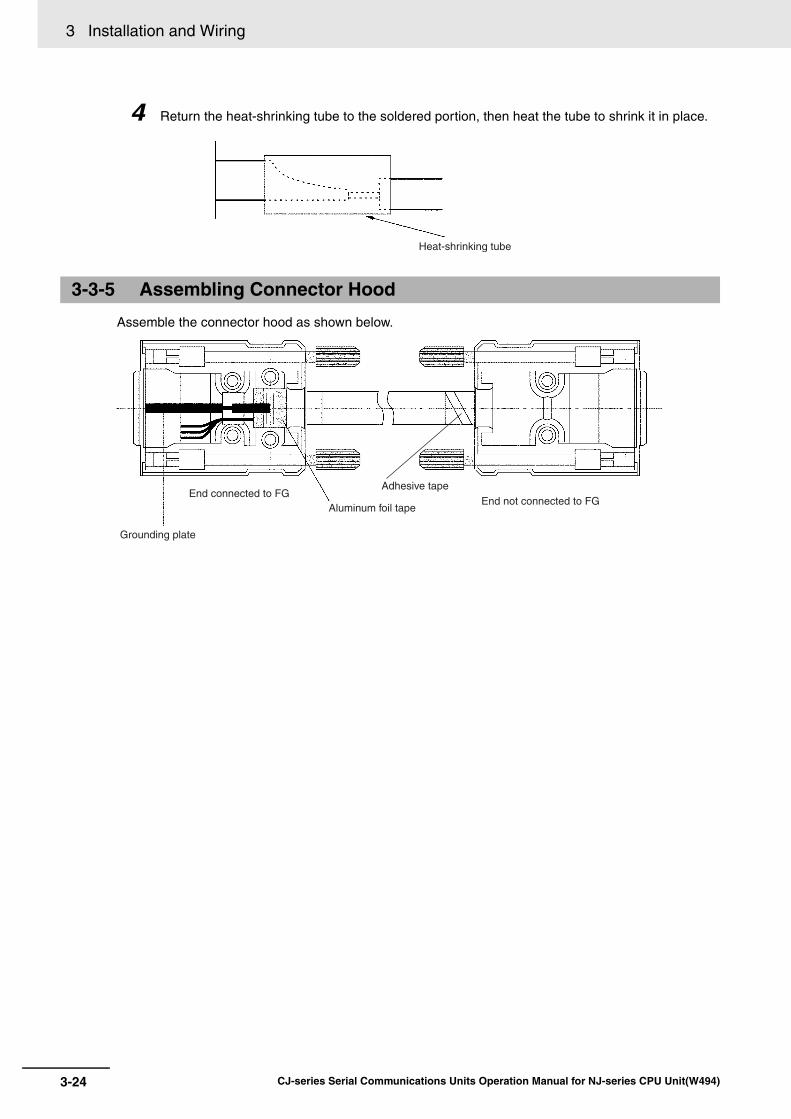
3 Installation and Wiring
3-24 CJ-series Serial Communications Units Operation Manual for NJ-series CPU Unit(W494)
4 Return the heat-shrinking tube to the soldered portion, then heat the tube to shrink it in place.
Assemble the connector hood as shown below.
3-3-5 Assembling Connector Hood
Heat-shrinking tube
End connected to FGAluminum foil tape
Grounding plate
End not connected to FGAdhesive tape

3-25
3 Installation and Wiring
CJ-series Serial Communications Units Operation Manual for NJ-series CPU Unit(W494)
3-3 RS
-232C an
d R
S-422A
/485 Wirin
g
3
3-3-6 Wiring R
S-422A
/485 Terminal-block C
onnectors on the CJ1W
-SC
U32/42
Applicable ConnectorsUse one of the following connectors.
Note To connect two wires to one terminal, use the terminal-block connector with screw terminalsand connect the two wires to one terminal with or without ferrules designed for two wires.
Wiring Procedure for Screwless TerminalsUse the following wiring procedure for terminal-block connectors with screwless terminals.
1 Remove 30 to 50 mm of the sheath from the cable. Be careful not to damage the braided shield.
2 Carefully remove the shield and twist it.
Carefully trim away any unnecessary cable packing and conductors.
3 Strip the signal lines to the correct length for the ferrules.
Cover the exposed signal wires with electrician's tape or a heat-shrinking tube.
4 Connect the ferrules to the ends of the signal lines and shields, and crimp them with a crimping
tool.
• Recommended Ferrules AI Series made by Phoenix Contact Signal wires: AI0.25-8BU (product number 3201364) FG wire: AI0.75-10GY (product number 3201288)
• CRIMPFOX Crimping Pliers XUD6 made by Phoenix Contact (product number 1204436)
3-3-6 Wiring RS-422A/485 Terminal-block Connectors on the CJ1W-SCU32/42
Manufacturer and model Comments
Phoenix Contact
FMC1.5/5-STF-3.5AU
Screwless terminals (provided with Unit)
Phoenix Contact
MC1.5/5-STF-3.5AU
Screw terminals
Purchase separately from the manufacturer.
30 to 50 mm

3 Installation and Wiring
3-26 CJ-series Serial Communications Units Operation Manual for NJ-series CPU Unit(W494)
5 Connect the signal lines and shield to the terminal block on the RS-422A/485. Press each line
all the way to the back of its hole as shown below. When you insert wires without ferrules, holddown the orange knob with a small flat-blade screw driver or similar object.
6 Connect the connector with the communications cable attached to it to the connector on the
Unit. Then tighten the screws to secure the connector to the Unit. Recommended tightening torque: 0.2 to 0.3 N⋅m
CJ1W-SCU22
CJ1W-SCU32/42
3-3-7 Connecting to Unit
Tighten the screws firmly with your fingers.
65125
65150
CJ1W-SCU32 Serial Communications Unit
Cable connector
CJ1W-SCU42 Serial Communications Unit

4-1CJ-series Serial Communications Units Operation Manual for NJ-series CPU Unit(W494)
4
This section describes the procedure and other information required to use protocolmacros.
4-1 Overview of the Protocol Macro Function . . . . . . . . . . . . . . . . . . . . . . . . . . 4-24-1-1 Protocol Macros . . . . . . . . . . . . . . . . . . . . . . . . . . . . . . . . . . . . . . . . . . . . . . . . 4-2
4-1-2 Using the Protocol Macros . . . . . . . . . . . . . . . . . . . . . . . . . . . . . . . . . . . . . . . . 4-2
4-1-3 Protocol Structure . . . . . . . . . . . . . . . . . . . . . . . . . . . . . . . . . . . . . . . . . . . . . . 4-44-1-4 Data Exchange Method for Link Words . . . . . . . . . . . . . . . . . . . . . . . . . . . . . 4-10
4-2 Device Variables for CJ-series Unit and System-defined Variables (Protocol Macro Mode) . . . . . . . . . . . . . . . . . . . . . . . . . . . . . . . . . . . . . . . . 4-134-2-1 Device Variable for CJ-series Unit for System Settings . . . . . . . . . . . . . . . . . 4-13
4-2-2 Area Descriptions . . . . . . . . . . . . . . . . . . . . . . . . . . . . . . . . . . . . . . . . . . . . . 4-15
4-2-3 System-defined Variable . . . . . . . . . . . . . . . . . . . . . . . . . . . . . . . . . . . . . . . . 4-214-2-4 Devices Variable for CJ-series Unit for Software Switches . . . . . . . . . . . . . . 4-22
4-2-5 Device Variables for CJ-series Unit for Status . . . . . . . . . . . . . . . . . . . . . . . . 4-24
4-2-6 Protocol Status . . . . . . . . . . . . . . . . . . . . . . . . . . . . . . . . . . . . . . . . . . . . . . . 4-32
4-3 Using Protocol Macros . . . . . . . . . . . . . . . . . . . . . . . . . . . . . . . . . . . . . . . . 4-404-3-1 Executing Communications Sequences . . . . . . . . . . . . . . . . . . . . . . . . . . . . 4-404-3-2 User Program Example . . . . . . . . . . . . . . . . . . . . . . . . . . . . . . . . . . . . . . . . . 4-42
Using Protocol Macros

4 Using Protocol Macros
4-2 CJ-series Serial Communications Units Operation Manual for NJ-series CPU Unit(W494)
4-1 Overview of the Protocol Macro Function
The Protocol Macro Function can control the various devices that have communications interfaces andare connected via a RS-232C or RS-422A/485. It executes data communications sequences (proto-cols) set for each device and specified by ExecPMCR instructions in the user program.
Standard system protocols to control OMRON devices (such as Digital Controllers and TemperatureControllers) are provided in the Serial Communications Unit.
By using the Protocol Support Tool called the CX-Protocol, you can create new protocols for commer-cially available measuring instruments and devices, and modify the standard system protocols. Thestandard system protocols are also provided with the CX-Protocol.
For details on the use of the CX-Protocol and the protocol macros, refer to the CX-Protocol Ver.1.9OPERATION MANUAL (Cat. No. W344).
The following three methods are available to use the protocol macros.
Using the Standard System ProtocolsIt is possible to connect OMRON devices and the NJ-series CPU Unit by specifying the sequencenumber of the standard system protocols in the Protocol Macro instruction (ExecPMCR). The sys-tem protocols are prepared in the Serial Communications Unit and CX-Protocol.
Note The devices for which standard system protocols are provided are listed below. For details,refer to Ref A Standard System ProtocolBar Code Readers (V500/V520), Laser Micrometers (3Z4L), Hayes Modem AT Command,and digital temperature controllers (E5@N etc.) that support the CompoWay/F protocol.
4-1-1 Protocol Macros
4-1-2 Using the Protocol Macros
CPU Unit * Send/receive messages are stored in the area one or more words after the send data address or the receive data address specified in the ExecPMCR instruction.Sequence
number Sequence No. specification
Standard system protocolSequence No. 001
Step 0Messages
Memory used for CJ-series Units
I/O refreshing
Shared memory
OMRON devices
Step 1
Serial Communications Unit
ExecPMCR

4-3
4 Using Protocol Macros
CJ-series Serial Communications Units Operation Manual for NJ-series CPU Unit(W494)
4-1 Overview
of th
e Pro
toco
l Macro
Fu
nctio
n
4
4-1-2 Using the P
rotocol Macros
Modifying Standard System ProtocolsWhen you connect OMRON devices, if there is no standard system protocol or you wish to modifypart of the protocol, use the CX-Protocol to modify the standard system protocol, transfer this as aseparate communications sequence to the Serial Communications Unit, and execute the ExecP-MCR instruction.
Creating a New ProtocolWhen you connect a general-purpose external device that has an RS-232C or RS-422A/485 port,use the CX-Protocol to create a new protocol that contains the communications specifications for thegeneral-purpose external device, transfer these specifications to the Serial Communications Unit,and execute the ExecPMCR instruction.
Modifying and transferring standard system protocols
Modified standard system protocol Command execution Send, Recv, Send&Recv
RS-232C or RS-422A/485
General-purpose external device
CPU Unit
Sequence number
Memory used for CJ-series Units
Sequence No. specification
I/O refreshing
Shared memory
Step 0Messages
Serial Communications Unit
Step 1
Step 2
ExecPMCR
Creating and transferring a new protocol
Newly created protocolCPU Unit
Sequence number
Memory used for CJ-series Units
Sequence No. specification
I/O refreshing
Shared memory
Step 0Messages
Serial Communications Unit
General-purpose external device
RS232C or RS-422A/485
Step 1
Step 2
Command execution Send, Recv, Send&RecvExecPMCR

4 Using Protocol Macros
4-4 CJ-series Serial Communications Units Operation Manual for NJ-series CPU Unit(W494)
In this manual, the protocol structure is explained in simple terms, and examples are given of theuse of the ExecPMCR instruction during control of OMRON devices by using standard system proto-cols. For details on the protocols, the modification method for standard system protocols, and thecreation method for new sequences, refer to the CX-Protocol Ver.1.9 OPERATION MANUAL (Cat.No. W344).
Protocols consist of communications sequences. A sequence consists of steps. These steps can berepeated, or they can be branched or ended depending on the responses received. A step consists of acommand, send/receive messages, processing results, and the next process (which depends on theprocessing results).
A protocol consists of processing sequences (such as reading the process value for a TemperatureController) for a general-purpose external device. A sequence consists of a group of steps, each ofwhich consists of a send/receive/control command, send/receive message, processing result, and anext step that depends on the processing results.
For example, with a sequence that reads the process value for a Temperature Controller, the sequencesends the send message for the connected Temperature Controller (a character string in which the Pro-cess Value Read command is inserted between the header + address and the check code + terminator)and receives the receive message (a character string in which the Process Value Read commandresponse is inserted between the header + address and the check code + terminator).
4-1-3 Protocol Structure
Communicationssequence
Example: Reading the process values for a Temperature Controller
Transmission of process value reading message and reception of response message
Step 0
Messages
Step 1
Protocol
NJ-SeriesCPU Unit
CJ-SeriesSerialCommunications Unit
Command
SEND(send)
RECV(receive)
Send message (Example: Process Value Read command)
Header Address Send data Check code Terminator
Receive message (Example: Response)
00 RX00 FCS
RS-232C or RS-422A/485
Header Address Send data Check code Terminator
00 RX01 FCS
General-purpose external device

4-5
4 Using Protocol Macros
CJ-series Serial Communications Units Operation Manual for NJ-series CPU Unit(W494)
4-1 Overview
of th
e Pro
toco
l Macro
Fu
nctio
n
4
4-1-3 Protocol S
tructure
Depending on the response received, this function can either choose to resend the same send mes-sage (retry processing), or to perform the next process (for example, read the process value for a Tem-perature Controller with a different address).
*1 You can use the Send, Recv, Send&Recv, Wait, Flush (reception buffer clear), Open (ER-ON), or Close (ER-OFF) command.
*2 Three types of reception matrix are available to switch the processing, depending on whether the messagesare send messages, receive (wait) messages, or multiple receive (wait) messages. Unlike sequences, thesematrixes are managed as lists.
Sequence Parameters
Parameter Meaning
Transmission control parame-ters
Control methods, such as flow control
Link words Settings for words shared between the PLC and the Serial Communications Unit
Monitoring time Monitoring time for send/receive processing
Response notification method Timing for writing received data to memory used for CJ-series Units in the PLC
One protocol
Sequence No. 000 to 999 (60 sequences max./protocol)
Transmission control parameterLink word settingSend/receive processing monitoring time
Response notification method 15 steps max.
Step 0Step 1
One-step structureWith the Send, Recv, Send&Recv command
Command (*1)
• Next step
• To specified step
• Sequence end
• Sequence interrupt
Error processingHeader Address TerminatorData Check
Messages (*2)
With the Wait, Flush, Open, or Close command
Message list (*2)Send message list
Receive message list
Reception matrix list (*2)Reception matrix
Case No. 15
Repeated
N (no)
N (error)Normal end
Command (*1)
Next process
Next process
Case No. 00
Receive message
Header Address TerminatorData Check
15 steps max.
Step 0Step 1
Y
Next process

4 Using Protocol Macros
4-6 CJ-series Serial Communications Units Operation Manual for NJ-series CPU Unit(W494)
Step Parameters
Precautions for Correct UsePrecautions for Correct Use
We recommend programming retry processing at any device that sends commands in case ofnoise or other factors result in transmission errors.
Parameter Meaning
Command One of the following: Send, Recv, Send&Recv, Wait, Flush, Open, or Close
Messages Send message The message sent for Send.
Receive message The expected message for Recv.
Send message and receive message
Both the message sent and the expected receive message for Send&Recv.
Reception matrix A group of expected messages that you can use to switch to different next processes when Send or Send&Recv is used.
Repeat counter The number of times to repeat the step (0 to 255). The repeat counter can be used to change send/receive messages.
Retry count Used for Send&Recv to retry the command for errors (0 to 9).
Send wait time Used for SEND or Send&Recv to create a wait time before data is sent.
Response write enable (for operand specification)
Specifies whether or not to write the received data to memory.
Next process Specifies the next step or to end the sequence when the current step is completed normally.
Error processing Specifies the next step or to end the sequence when the current step ends in an error.

4-7
4 Using Protocol Macros
CJ-series Serial Communications Units Operation Manual for NJ-series CPU Unit(W494)
4-1 Overview
of th
e Pro
toco
l Macro
Fu
nctio
n
4
4-1-3 Protocol S
tructure
Example: Variable Area Read (Sequence No. 610) Sequence for CompoWay/F Master Protocol
Standard System Protocol Example
Level Item Setting
Sequence Link words ---
Transmission control parameters
Modem control
Response notification method
Scan
Receive Wait Monitoring Time Tr
3s
Receive Finished Monitor-ing Time Tfr
3s
Send Finished Monitoring Time Tfs
3s
Steps Step number 00
Repeat counter Reset/001
Command Send&Recv
Retry count 3
Send wait time ---
Send message SD MEM_R
Receive message RV MEM_R
Response write enable Write
Next process End
Error process Abort
Send message
SD MEM_R
Header <h> STX
Terminator <t> ETX
Error check code <c> LRC (horizontal parity) (0) (1 byte of BIN)
Length <l> ---
Address <a> $ (R (1), 2)
Message edited
* Refer to A) outside the table for the message structure after MRC/SRC.
<h> + <a> + "00" + "0" + "0101" + $ ~ (R (2), 2)
+ $ (R (2), 2) + $ ~ (R (3), 4) + $ ~ (R (4), 4) + <t> + <c>
Receive message
RV MEM_R
Header <h> STX
Terminator <t> ETX
Error check code <c> LRC (horizontal parity) (0) (1 byte of BIN)
Length <l> ---
Address <a> $ (R (1), 2)
Message edited
* Refer to B) outside the table for the message structure after MRC/SRC.
<h> + <a> + "00" + (*, 2) + "0101" + & (W (1), 4)
+ & (W (2), *) + <t> + <c>
Node No. SID MRC/SRC Variable typeSubaddress
Read start address Number of elementsBit number
Node No. End code MRC/SRC Response codeSubaddress
Read data (for number of elements)

4 Using Protocol Macros
4-8 CJ-series Serial Communications Units Operation Manual for NJ-series CPU Unit(W494)
A) Structure of Variable Area Read (MRC/SRC: 0101)* send message
B) Structure of Variable Area Read (MRC/SRC: 0101)* receive message
* MRC/SRC (0101) represents the Variable Area Read service available via CompoWay/F communication.
Detailed Example of CompoWay/F MessageCompoWay/F communication protocol for digital temperature controller E5@N
Send message
Receive message
For message details, refer to the E5CN/E5AN/E5EN/E5GN Digital Temperature Controllers Commu-nications Manual (Basic Type) (Cat. No. H158).
MRC SRC Variable type Read start address Bit number Number of elements
0 1 0 1 0 0
2 2 2 4 2 4
MRC SRC Response code Read data (for number of elements)
0 1 0 1
2 2 4 Number of elements × 8 or 4
BCC
1
Text
Node No. Subaddress SID Command text
STX 0 0 0 ETX
1 2 2 1 1
BCC calculation range
STX
Text
Node No. Subaddress End code Command text BCC
0 0 ETX
1 2 2 2 1 1
BCC calculation range

4-9
4 Using Protocol Macros
CJ-series Serial Communications Units Operation Manual for NJ-series CPU Unit(W494)
4-1 Overview
of th
e Pro
toco
l Macro
Fu
nctio
n
4
4-1-3 Protocol S
tructure
The NJ-series PLCs provide standard system protocols to enable communications with OMRON com-ponents without creating communications sequences. You can execute the sequences in the standardsystem protocols merely executing ExecPMCR instruction after specifying the sequence number andcommand data.
Processing for communications line problems during communications for the standard system protocolsare set to normal settings, as shown in the following table. If these settings are not suitable to the appli-cation or if improvements are desired, use the CX-Protocol to modify the following settings in therequired sequences. For details on the use of the CX-Protocol, refer to the CX-Protocol Ver.1.9 OPER-ATION MANUAL (Cat. No. W344). Refer to the standard protocol file that are included in the CX-Proto-col for the settings in the standard system protocols.
Setting Device Variables for CJ-series Unit (For Use of Standard System Protocol)
Device variable for CJ-series UnitType R/W
Name and function
FunctionPort 1 Port 2
*_P1_PortCfg *_P2_PortCfg WORD RW Port Settings
Bit 15: Commu-nications parameters
Bits 08 to 11: Serial commu-nications mode
Bits 00 to 04: Communica-tions parame-ters
Set serial communications mode to Protocol Macro Mode.
Set to match the parame-ters of the external device.
*_P1_BaudrateCfg *_P2_BaudrateCfg USINT RW Baud Rate Set to match the baud rate of the external device.
*_P1_PmrTransTypCfg *_P2_PmrTransTypCfg BOOL RW Protocol macro Transmission method
Set to FALSE to specify half-duplex.
TRUE: Full-duplex
FALSE: Half-duplex (default)
*_P1_PmrMaxDatSzCfg *_P2_PmrMaxDatSzCfg UINT RW Maximum Number of Bytes in Proto-col Macro Send/Receive Data
Set to 1,000 bytes.
Handling Communications Problems for Standard System Protocols

4 Using Protocol Macros
4-10 CJ-series Serial Communications Units Operation Manual for NJ-series CPU Unit(W494)
Link word specification is a method that specifies the storage location of send/receive data when youexecute communications sequence by using the protocol macros (method that specifies area to sharedata between the CPU Unit and Unit).
On-request I/O RefreshingLink words are refreshed between the CPU Unit and Unit at every CPU Unit cycle.
The actual refresh timing with the CPU Unit, however, does not correspond to whenever the I/O isrefreshed. I/O refresh is performed at the next I/O refreshing after the CPU Unit receives a requestfrom the Unit (according to the Send/Receive command executed in the communications sequence,and it does not synchronized with the CPU Unit cycle). This is called on-request I/O refreshing.
Level Item Possible changes in settings
Sequence parameters
Transmission control parameters
Setting change unnecessary.
Link words
Response notifica-tion method
Receive Wait Moni-toring Time Tr
The monitoring times are set to 3 seconds for most sequences. The set-tings are different for send-only and receive-only sequences, as well as for sequences that require time for responses.Receive Finished
Monitoring Time Tfr
Send Finished Moni-toring Time Tfs
Step parame-ters
Repeat counter Setting change unnecessary.
Command
Retry count The retry count is generally set to 3 retries (4 tries total) for sequences that use the Send&Recv command. Different settings are used for sequences that have other commands.
Send wait time Setting change unnecessary.
Send message
Receive message
Response write enable
Next process
Error process
4-1-4 Data Exchange Method for Link Words

4-11
4 Using Protocol Macros
CJ-series Serial Communications Units Operation Manual for NJ-series CPU Unit(W494)
4-1 Overview
of th
e Pro
toco
l Macro
Fu
nctio
n
4
4-1-4 Data E
xchange Method for Link W
ords
When a Send command is executed ((1) in the above diagram), the read processing of data thatuses variables from the memory addresses used CJ-series Unit in the CPU Unit specified for the linkwords is performed in the next I/O refreshing (2). The send message is compiled based on this data(3), and then, the message is sent (4).
As a result, the actual send timing of the messages is not when the Send command is executed, butwhen the next I/O refreshing with the CPU Unit occurs.
Continuous I/O RefreshingI/O refreshing with the CPU Unit is continuously executed during execution of the ExecPMCRinstruction, regardless of the request from the Unit. When the Send/Receive command is executed,the data from within the Unit is accessed and exchanged. This method is called continuous I/Orefreshing and is set by using a device variable for CJ-series Unit.
CPU Unit and the Unit for Continuous I/O refreshing is executed at the same timing as that of theCPU Unit, in the same way as the On-request I/O refreshing.
When a Send command is executed in a step, the send message is compiled immediately based ondata read from the Unit, and the message is sent. Therefore, the actual message transmission isperformed immediately when the Send command is executed, without waiting for the next I/Orefreshing between the CPU Unit and the Unit.
The Recv command operation is similar. When the receive data is stored in the Unit, Receive com-mand execution is completed. The data received is stored in the user-defined variable area at thenext I/O refresh with the CPU Unit.
CPU Unit
User program
User-defined variables
Receive data
Send data
Unit
Step 0Step 1 (send)
(2)
(1)
Exe
cutio
n
IN
OUT
Receive data
Send data
I1
O1
Read and compile message
(4) SendR (O1, 2)
Link word 1
ExecPMCR
Communications sequence
This refresh timing is the next I/O refreshing when there is a request from the Unit. (Send/Receive command is executed within the communications sequence.)
(1) to (4) are performed in order for the processing within this dotted line.
Send message according to Send command
ExecPMCR
CPU UnitUser program
User-defined variables
Receive data
Send data
Unit
Step 0Step 1 (send)
(2)
(1)
Exe
cutio
n in
stru
ctio
n
IN
OUT
Receive data
Send data
I1
O1
Read, compile message
(3) SendR (O1, 2)
Link word 1
Communications sequence
(1) to (4) are performed in order for the processing within this dotted line.
Send message according to Send command
The refresh timing continuously refreshes I/O regardless of any request from the Unit (using Send/Receive commands in the communications sequence).

4 Using Protocol Macros
4-12 CJ-series Serial Communications Units Operation Manual for NJ-series CPU Unit(W494)
Additional Information
If continuous I/O refreshing is specified for the data exchange method for link words, I/O refresh-ing is executed during the execution of protocol macros between the CPU Unit and the Unit with-out synchronizing with the execution of Send/Receive commands. Therefore it is necessary topay attention to the data exchange method at the start and end of the protocol macros.
(1) The new data may not be sent by the Send command in a protocol macro that is executedimmediately after the send data in memory in the CPU Unit is updated.The send data is transferred to the Unit in the I/O refresh period before it will be sent by theSend command.
(2) Data received by a Receive command in a protocol macro may not be reflected in the receivedata area of the CPU Unit if execution of the protocol macro is terminated immediately afterthe Receive command. If the protocol macro is still executed during the I/O refresh period after the data is receivedby the Receive command, the receive data will be refreshed in the memory of the CPU Unit.
"Continuous I/O refreshing" in the Data exchange method for link words is suitable for applica-tions in which Send/Receive commands are executed repeatedly in the one protocol macro(ExecPMCR instruction).If data in the CPU Unit is to be sent with a Send command in the next ExecPMCR instruction orreceive data for a Receive command is to be reflected in the CPU Unit and then the protocolmacro ended, use the "on-request I/O refreshing" setting.

4-13
4 Using Protocol Macros
CJ-series Serial Communications Units Operation Manual for NJ-series CPU Unit(W494)
4-2 Device V
ariables fo
r CJ-series U
nit an
d S
ystem-d
efined
Variab
les(P
roto
col M
acro M
od
e)
4
4-2-1 Device V
ariable for CJ-series U
nit for System
Settings
4-2 Device Variables for CJ-series Unit and System-defined Variables (Protocol Macro Mode)
This section describes the device variables for CJ-series Unit and system-defined variables used in theProtocol Macro Mode.
Use the device variables for CJ-series Unit shown below to perform System Settings when you use theSerial Communications Unit in Protocol Macro Mode.
4-2-1 Device Variable for CJ-series Unit for System Settings
Device variable for CJ-series UnitType R/W Name Function
Port 1 Port 2
*_P1_PortCfg *_P2_PortCfg WORD RW Port Settings Bit 15: User-specified set-ting inclusion (*)
Bits 08 to 11: Serial com-munications mode (6 hex: Protocol macro)
Bit 04: Start bits
Bit 03: Data length
Bit 02: Stop bits
Bit 01: Parity (Yes/No)
Bit 00: Parity (Even/Odd)
*_P1_SerSetCfg *_P2_SerSetCfg BOOL RW User-specified Setting Inclu-sion
FALSE: Default
TRUE: User settings
Default: FALSE
There is no specific device variable for CJ-series Unit to reference the serial communica-tions mode.
When you set this set-ting, set to bits 08 to 11 of *_P1_PortCfg.
There is no specific device variable for CJ-series Unit to reference the serial communica-tions mode.
When you set this set-ting, set to bits 08 to 11 of *_P2_PortCfg.
Bit string
RW Serial Commu-nications Mode
Serial communications mode
3 hex: No-protocol
6 hex: Protocol macro
9 hex: Serial Gateway
A hex: Modbus-RTU slave
F hex: Loopback test
Default: 0
*_P1_StartBitCfg *_P2_StartBitCfg BOOL RW Start Bits Always 1 bit regardless of whether the setting is FALSE/TRUE.
FALSE: 1 bit
TRUE: 1 bit
Default: FALSE
*_P1_DatBitCfg *_P2_DatBitCfg BOOL RW Data Length FALSE: 7 bits
TRUE: 8 bits
Default: FALSE
*_P1_StopBitCfg *_P2_StopBitCfg BOOL RW Stop Bits FALSE: 2 bits
TRUE: 1 bit
Default: FALSE

4 Using Protocol Macros
4-14 CJ-series Serial Communications Units Operation Manual for NJ-series CPU Unit(W494)
*_P1_ParityYNCfg *_P2_ParityYNCfg BOOL RW Parity FALSE: Yes
TRUE: No
Default: FALSE
*_P1_ParityBitCfg *_P2_ParityBitCfg BOOL RW Parity Even/Odd
FALSE: Even
TRUE: Odd
Default: FALSE
*_P1_BaudrateCfg *_P2_BaudrateCfg USINT RW Baud Rate (unit: bps)
0: 9600, 3: 1200, 4: 2400
5: 4800, 6: 9600, 7: 19200
8: 38400, 9: 57600
10: 115200, 11: 230400
Default: 0
*_P1_PmrSgwTimeoutCfg *_P2_PmrSgwTimeoutCfg WORD RW Serial Gateway Timeout Moni-toring Time Setting
08 to 15: Serial Gateway response timeout monitor-ing time
00 to 07: Serial Gateway send start timeout moni-toring time
*_P1_PmrSgwRespTimeoutCfg
*_P2_PmrSgwRespTimeoutCfg
USINT RW Serial Gateway Response Tim-eout Monitor-ing Time
0: 5 s (default)
Range: 1 to 255
0.1 to 25.5 s [Unit: 100 ms]
*_P1_PmrSgwSendTimeoutCfg
*_P2_PmrSgwSendTimeoutCfg
USINT RW Serial Gateway Send Start Tim-eout Monitor-ing Time
0: 5 s (default)
Range: 1 to 255
0.1 to 25.5 s [Unit: 100 ms]
*_P1_PmrTransCfg *_P2_PmrTransCfg WORD RW Protocol macro Transmission Settings
Bit 15: Protocol Macro transmission method
Bit 03: Clearing/holding the contents of the recep-tion buffer in full-duplex mode
Bit 02: Link word specifi-cation data exchange tim-ing method
*_P1_PmrTransTypCfg *_P2_PmrTransTypCfg BOOL RW Protocol macro Transmission method
FALSE: Half-duplex (default)
TRUE: Full-duplex
*_P1_PmrRBufClrCfg *_P2_PmrRBufClrCfg BOOL RW Clearing/Hold-ing the Con-tents of the Reception Buffer in Full-duplex Mode
FALSE: Clear (default)
TRUE: Hold
*_P1_PmrLkChAccessCfg
*_P2_PmrLkChAccessCfg
BOOL RW Link Word Specification Data
Exchange Method
FALSE: On-request I/O refreshing (default)
TRUE: Continuous I/O refreshing
Device variable for CJ-series UnitType R/W Name Function
Port 1 Port 2

4-15
4 Using Protocol Macros
CJ-series Serial Communications Units Operation Manual for NJ-series CPU Unit(W494)
4-2 Device V
ariables fo
r CJ-series U
nit an
d S
ystem-d
efined
Variab
les(P
roto
col M
acro M
od
e)
4
4-2-2 Area D
escriptions
* When the default settings are used, the Baud Rate, Start Bits, Data Length, Stop Bits, Parity Yes/No, and ParityEven/Odd, settings are disabled. To specify settings for these items to the settings other than the default, applyuser settings.The default settings are Baud Rate: 9,600 bps, Start Bits: 1 bit, Data Length: 7 bits, Parity: Even parity and StopBits: 2 bits.
User-specified Setting InclusionThe setting for the port settings determines if the default settings or user settings will be used forport 1 and port 2. Be sure to use the same settings as the RS-232C port on the external devicesconnected in Protocol Macro Mode.
FALSE: default, TRUE: user settings
If the default port settings are specified, the settings of bits 00 to 04 will be ignored.
The default settings used are as follows: Baud Rate: 9,600 bps, Start Bits: 1 bit, Data Length: 7 bits,Parity: Even, and Stop Bits: 2 bits.
If user port settings are specified, set bits 00 to 04 and the baud rate.
Serial Communications ModeSet the serial communications mode to 6 hex to use Protocol Macro Mode.
Start Bits, Data Length, Stop Bits, Parity, and Baud RateIf user settings are specified for the port settings, the number of Start Bits, Data Length, number ofStop Bits, Parity, and Baud Rate must be set. The Start Bits setting, however, will be ignored and 1start bit will always be used.
Serial Gateway Response Timeout Monitoring TimeThe response timeout condition is monitored when a command is converted to the specified protocoland sent. 0: 5 (default), Setting range: 1 to 255 (0.1 to 25.5 s)The response monitoring time is 5 s when this setting is set to default. Or, the user can specify it inthe range 0.1 to 25.5 s by setting between 1 and 255.
If a timeout occurs, the command end code (0205 hex (Response Timeout)) is returned to the com-mand source. If a response is received after a timeout, however, the message is converted andreturned to the command source.
Serial Gateway Send Start Timeout Monitoring TimeWhen the Unit converts commands to the specified protocol and send them during execution of pro-tocol macros, the timeout condition is monitored from when the command is received until the com-mand starts to be sent in the specified protocol. 0: 5 (default), Setting range: 1 to 255 (0.1 to 25.5 s)The send start monitoring time is 5 s when this setting is set to default. Or, the user can specify it inthe range 0.1 to 25.5 s by setting between 1 and 255.
*_P1_PmrMaxDatSzCfg *_P2_PmrMaxDatSzCfg UINT RW Maximum Number of Bytes in Proto-col Macro Send/Receive Data
200 to 1,000 bytes
Set 1,000 bytes when standard system protocol is used.
4-2-2 Area Descriptions
Device variable for CJ-series UnitType R/W Name Function
Port 1 Port 2

4 Using Protocol Macros
4-16 CJ-series Serial Communications Units Operation Manual for NJ-series CPU Unit(W494)
If a timeout occurs, a command end code (0204 hex (Remote node busy)) is returned to the com-mand source. The send processing is not executed and the received command is discarded.
Protocol Macro Transmission MethodSet half-duplex (FALSE) or full-duplex (TRUE) depending on the transmission mode for the externaldevice.
Additional Information
Half-duplex: Allows data to be sent between two Units in only one direction at any one time.
Full-duplex: Allows data to be exchanged both ways between two Units at the same time.
With half-duplex transmissions, the reception buffer is cleared immediately before the sequenceis executed and immediately after Send completion (Send or Send&Recv command). Therefore,the data received before and during Send execution cannot be received as receive data by thenext Recv command.
Precautions for Correct UsePrecautions for Correct Use
When you use Send with half-duplex transmission, there is a time lag, t1, between data sendprocessing completion and Send completion. Therefore, if there is a rapid response from theremote device and a response is returned for Send after data is sent (communications or othercommand) and before Send is completed, the response during that time cannot be received byusing half-duplex transmissions. If this problem occurs, use the full-duplex transmissions.Also, if the external device is connected by using 2-wire connections from an RS-422A/485 port(Refer to 3-3-2 Recommended RS-422A/485 Wiring Examples), send and receive data cannotboth be on the same transmission line at the same time. This will create an additional lag time,t2, or 150 μs. If responses are received quickly from the external device, i.e., faster than t1 +t2,create a send delay at the external device or take other measures to allow for the lag times.
Time Lag t1
Baud rate (bps) Time lag (μs)
1,200 1,116
2,400 578
4,800 288
9,600 144
19,200 73
38,400 36
57,600 24
115,200 12
230,400 6
orA B A B
A B
Send operation
Data send processing
Data cannot be received during this time.
Rapid response
Data reception
Reception buffer cleared
t1 t2 = 150 μs
Time lags (see following table)

4-17
4 Using Protocol Macros
CJ-series Serial Communications Units Operation Manual for NJ-series CPU Unit(W494)
4-2 Device V
ariables fo
r CJ-series U
nit an
d S
ystem-d
efined
Variab
les(P
roto
col M
acro M
od
e)
4
4-2-2 Area D
escriptions
With full-duplex mode, the reception buffer is cleared immediately before the sequence is executed.While Recv and Send commands are executed, data is input into the reception buffer and is used asthe protocol macro data.
*1 With full-duplex, you can use RS-232C or RS-422A/485 (1:1 and 4-wire connections) can be used. You cannotuse RS-422A/485 1:N or 2-wire connections.
*2 The Flush command can be used at any time to clear the reception buffer.
*3 Although the received data is discarded until completion of Send execution, it is reflected in the character trace.
Transmission mode
Time reception buffer cleared
Data reception Character trace
Timing chart (example)
Half-duplex Immediately before communications sequence execution and immediately after Send comple-tion by the Send or Send&Recv com-mand
From Send completion to Recv comple-tion, Send com-pletion to immediately before Send execution
All during trace execution
Full-duplex(*1)
Immediately before communications sequence execution(*2)
All during com-munications sequence exe-cution
All during trace execution
Communicationssequence
Reception buffer cleared
Data reception
Character trace
RecvSendRecv
(*3)
Communicationssequence
Reception buffer cleared (*3)
Data reception
Character trace
RecvSendRecv

4 Using Protocol Macros
4-18 CJ-series Serial Communications Units Operation Manual for NJ-series CPU Unit(W494)
Clearing/Holding the Contents of the Reception Buffer in Full-duplex ModeSet to either clear or hold the contents of the reception buffer when the protocol macro starts.
FALSE: ClearWhen set to clear, the contents of the reception buffer will be cleared when the protocol macro isexecuted.
TRUE: HoldWhen set to hold, the contents of the reception buffer will not be lost if data acquisition fails afterexecution of the protocol macro.
This enables you to hold the data in the reception buffer received in the previous communicationssequence after you switch the communications sequence during full-duplex communications.
This function prevents loss of data during full-duplex communications.
Data Exchange Method for Link WordsSet to perform I/O refresh upon request or continuously, as follows:
FALSE: On-request I/O refreshing (Immediate refresh mode)Data exchange is performed during I/O refresh when a refresh request is sent to the CPU Unit foreach Send/Receive command that is executed. A time delay will occur after the Send command isexecuted until the actual message is sent when this method is used.
TRUE: Continuous I/O refreshing (Cyclic refresh mode)During protocol macro execution, I/O refreshing is continuously performed with the CPU Unit, thedata in the link word area is refreshed from the CPU Unit, and the data in the Unit is accessed dur-ing Send/Receive command execution. When the Send command is executed with this method, youcan send the actual message immediately.
Maximum Number of Bytes in Protocol Macro Send/Receive DataYou can set bytes from 200 bytes to a maximum of 1,000 bytes.
Any setting below 200 bytes will be treated as 200 bytes; any setting above 1,000 bytes will betreated as 1,000 bytes.
Set this value to the maximum 1,000 bytes when you use the standard system protocol.
Additional Information
Flow Control and Maximum Number of Send/Receive Data Words
There is a 2.5 KB reception buffer for each serial port in the Serial Communications Unit.
When flow control is used, initiate flow control after receiving about 2 KB, and then release con-trol after processing all but 0.5 KB of receive data.
The Unit can store up to 1,000 bytes (500 words) of data for each Recv command if 2 KB ofreceive data is first stored in the buffer and 1,000 bytes is set as the maximum number ofsend/receive data bytes.

4-19
4 Using Protocol Macros
CJ-series Serial Communications Units Operation Manual for NJ-series CPU Unit(W494)
4-2 Device V
ariables fo
r CJ-series U
nit an
d S
ystem-d
efined
Variab
les(P
roto
col M
acro M
od
e)
4
4-2-2 Area D
escriptions
Half-duplex CommunicationsWith NJ-series half-duplex protocol macro communications, flow control can be released by turningON the RTS (RS) signal (CTS (CS) signal at the Remote Unit) while the Recv command is executed.
Note Signal names used are those at the Serial Communications Unit.
1 With protocol macro communications in half-duplex mode, the RTS (RS) signal is ON only while
the Receive command is being executed.
2 The receive data (RD signal) from the remote device is initially stored in the reception buffer.
3 The data in the reception buffer is analyzed, and a search is performed for data matching an
expected message registered with the Receive command.
4 When matching data is found, the RTS (RS) signal is turned OFF. The search starts after the
final data is received. It takes between 100 μs and 4 ms from the start of the search until theRTS (RS) signal turns OFF.
5 While the Send command is being executed, and while the ExecPMCR instruction is not being
executed, the RTS (RS) signal stays OFF and receive data is discarded.
RS/CS Flow Control
ExecPMCR instructionExecPMCR instruction
Command
SD signal
RD signal
RTS (RS) signal
RTS (RS) turned OFF after 0.1 to 4 ms
RTS (RS) signal ON while Receive command is executed.
Data received before Send is completed is discarded.
Data received while the ExecPMCR instruction is not being executed is discarded (controlled by turning OFF the RTS (RS) signal).The OFF status of the RTS (RS) signal is maintained after execution of the ExecPMCR instruction.

4 Using Protocol Macros
4-20 CJ-series Serial Communications Units Operation Manual for NJ-series CPU Unit(W494)
Full-duplex ModeThere is a 2.5 KB reception buffer for each serial port in full-duplex mode of NJ-series ProtocolMacro Mode. When flow control is used, initiate flow control after receiving about 2 KB, and thenrelease control after processing all but 0.5 KB of receive data. The Unit can store up to 1,000 bytes(500 words) of data for each Receive command if 2 KB of receive data is first stored in the buffer and1,000 bytes (03E8 hex) is set as the maximum number of send/receive data bytes.
Note Signal names used are those at the Serial Communications Unit.
1 With full-duplex protocol macro communications, the RTS (RS) signal is turned OFF when 2 KB
of data is in the reception buffer (i.e., with 0.5 KB remaining).
2 The receive data (RD signal) from the remote device is stored in the reception buffer.
3 The data in the reception buffer is analyzed, and a search is performed for data matching an
expected message registered with the Recv command.
4 When matching data is found, all the previous data is deleted from the reception buffer.
5 When the amount of data stored in the reception buffer decreases to less than 0.5 KB (i.e., more
than 2 KB remaining), the RTS (RS) signal will turn ON.
6 Data that is received while the ExecPMCR instruction is not being executed is discarded.
7 In full-duplex mode, the data left over after the analysis performed with the last Recv command
and any subsequent data received while the ExecPMCR instruction is stopped is discarded.During this interval, you cannot use RS flow control.
Receive Receive ReceiveSend Send
ExecPMCR instruction ExecPMCR instruction
SD signal
RD signal
RTS (RS) signal
RS turned ON when only0.5 KB in buffer.
RTS (RS) signal turned OFF when 2 KB of data accumulates in reception buffer.
Data received from the end of the last Recv command until the next ExecPMCR execution is discarded. The RTS (RS) signal does not operate.
Command

4-21
4 Using Protocol Macros
CJ-series Serial Communications Units Operation Manual for NJ-series CPU Unit(W494)
4-2 Device V
ariables fo
r CJ-series U
nit an
d S
ystem-d
efined
Variab
les(P
roto
col M
acro M
od
e)
4
4-2-3 System
-defined Variable
Port 1 and Port 2 Port Settings Changing FlagsYou can use an Out instruction or other instruction in the program to turn these bits from FALSE toTRUE to change communications settings and restart the Serial Communications Unit ports. Afteryou change the settings and restart the communications port, the flag will automatically change toFALSE.
These flags are used both to change the communications port settings and to restart the communi-cations port at the same time. Accordingly, in cases where these flags are turned from FALSE toTRUE only to restart a communications port by using an Out instruction or other instruction, you canturn these flags from FALSE to TRUE without changing the system settings of the device variablesfor CJ-series Unit.
List of System-defined Variables (** corresponds to the unit number.)
4-2-3 System-defined Variable
System-defined variable Type R/W Name Function
_CJB_SCU**P1ChgSta BOOL RW Serial Communications Unit ** Port 1 Settings Changing Flag
TRUE: Port 1 Communications Unit Port Settings Change
FALSE: All other statuses
Default: FALSE
_CJB_SCU**P2ChgSta BOOL RW Serial Communications Unit ** Port 2 Settings Changing Flag
TRUE: Port 2 Communications Unit Port Settings Change
FALSE: All other statuses
Default: FALSE

4 Using Protocol Macros
4-22 CJ-series Serial Communications Units Operation Manual for NJ-series CPU Unit(W494)
The device variables can be used to execute various commands for the Serial Communications Unit.
List of Areas
4-2-4 Devices Variable for CJ-series Unit for Software Switches
Device variable for CJ-series UnitType R/W Name Function
Port 1 Port 2
*_P1_SoftSw *_P2_SoftSw BYTE RW Soft Switches Bit 04: Serial Gateway Prohibit Switch
Bit 03: Abort Switch
Bit 02: One-shot Trace Switch
Bit 01: Continuous Trace Switch
Bit 00: Wait Release Switch
*_P1_SgwDsblCmd *_P2_SgwDsblCmd BOOL RW Serial Gateway Prohibit Switch (Protocol Mac-ros)
TRUE→FALSE: Not pro-hibited
FALSE→TRUE: Prohib-ited
*_P1_PmrAbtCmd *_P2_PmrAbtCmd BOOL RW Abort Switch (Protocol Mac-ros)
TRUE: Abort
FALSE: Aborted
*_P1_Pmr1ShotTraceCmd
*_P2_Pmr1ShotTraceCmd
BOOL RW One-shot Trace Switch (Proto-col Macros) (*1)
TRUE: Start
FALSE: Stop
*_P1_PmrContTraceCmd
*_P2_PmrContTraceCmd
BOOL RW Continuous Trace Switch (Protocol Mac-ros) (*1)
TRUE: Start
FALSE: Stop
*_P1_PmrWaitRlsCmd *_P2_PmrWaitRlsCmd BOOL RW Wait Release Switch (Proto-col Macros)
TRUE: Release Wait
FALSE: Wait released

4-23
4 Using Protocol Macros
CJ-series Serial Communications Units Operation Manual for NJ-series CPU Unit(W494)
4-2 Device V
ariables fo
r CJ-series U
nit an
d S
ystem-d
efined
Variab
les(P
roto
col M
acro M
od
e)
4
4-2-4 Devices V
ariable for CJ-series U
nit for Softw
are Sw
itches
Software Switch DescriptionsThe Software Switches function as described in the following table.
*1 The Software Switches will also be initialized at the following times: when the Controller is reset, when theoperating mode is changed between PROGRAM and RUN Modes, when the Unit is restarted, or when thecommunications port is restarted.After the variable is set, the Software Switch will be reset (cleared) at the timing indicated in "Reset" in theabove table for each area.
*2 If both of the trace switches for one-shot trace and continuous trace are changed to TRUE, the one for whichthe switch was changed first is executed. (The other one does not start until its trace switch changes to FALSEand then back to TRUE after another trace operation is completed.) If both of the switches change to TRUEsimultaneously, the Continuous Trace will take priority.When the trace buffer becomes full, the Unit will clear it.The CPU Unit will manipulate the One-shot Trace Switch and Continuous Trace Switch when trace operationsare performed from the CX-Protocol. Do not manipulate these switches from a user program.
NameDevice vari-able for CJ-series Unit
MeaningTiming
Initialize Set Reset
Serial Gate-way Prohibit Switch (Pro-tocol Macros)
*_P1_SgwDsblCmd *_P2_SgwDsblCmd
The Serial Gateway (Mode) is prohib-ited during protocol macro processing when this Switch changes from FALSE to TRUE.
The Serial Gateway is no longer prohib-ited when the Switch is changed from TRUE to FALSE.
Controller reset (*1)
Manipulated by user
Manipulated by user
Abort Switch (Protocol Macros)
*_P1_PmrAbtCmd *_P2_PmrAbtCmd
Protocol macro processing will be aborted when the switch changes from FALSE to TRUE. Processing may be completed if the Switch is changed too late.
Manipulated by user
Manipulated by user
One-shot Trace Switch (Protocol Macros) (*2)
*_P1_Pmr1ShotTeanceCmd *_P2_Pmr1ShotTeanceCmd
The CX-Protocol will start a one-shot trace when the Switch changes from FALSE to TRUE. The trace is ended when the Switch is changed from TRUE to FALSE.
Manipulated by CX-Proto-col
At end of one-shot trace
Continuous Trace Switch (Protocol Macros) (*2)
*_P1_PmrContTranceCmd *_P2_PmrContTranceCmd
The CX-Protocol will start a continuous trace when the Switch changes from FALSE to TRUE. The trace is ended when the Switch is changed from TRUE to FALSE.
Manipulated by CX-Proto-col
Manipulated by CX-Proto-col
Wait Release Switch (Pro-tocol Macros)
*_P1_PmrWaitRlsCmd *_P2_PmrWaitRlsCmd
Standby status for the Wait command will be released when the switch changes from FALSE to TRUE.
Manipulated by user
At end of Wait com-mand

4 Using Protocol Macros
4-24 CJ-series Serial Communications Units Operation Manual for NJ-series CPU Unit(W494)
These variable are used for data input from the Serial Communications Unit to the CPU Unit.
You can reference the Serial Communications Unit port settings status, communications status, thetransmission control signal status, and the transmission error status.
4-2-5 Device Variables for CJ-series Unit for Status
Device variable for CJ-series UnitType R/W Name Function
Port 1 Port 2
*_Com_UnitSta WORD R Serial Commu-nication Unit Status
Bit 01: Error log EEPROM error
Bit 00: Protocol data error
*_Com_UnitLogMemErr BOOL R Error Log EEPROM Error
TRUE: Error log EEPROM error
FALSE: Error log EEPROM normal
*_Com_UnitPmrDatErr BOOL R Protocol Data Error
TRUE: Protocol data error
FALSE: Protocol data nor-mal
*_P1_SysSetSta *_P2_SysSetSta WORD R System Set-tings (*1)
Bits 12 to 15: Serial com-munications mode
Bits 8 to 11: Baud rate
Bit 04: Start bits
Bit 03: Data length (*1)
Bit 02: Stop bits (*1)
Bit 01: Parity (Yes/No) (*1)
Bit 00: Parity (Even/Odd) (*1)
There is no specific device variable for CJ-series Unit to reference the serial communica-tions mode.
When you reference this setting status, ref-erence bits 12 to 15 of *_P1_SysSetSta.
There is no specific device variable for CJ-series Unit to reference the serial communica-tions mode.
When you reference this setting status, ref-erence bits 12 to 15 of *_P2_SysSetSta.
Bit string
R Serial Commu-nications Mode
Serial communications mode
3 hex: No-protocol
6 hex: Protocol macro
9 hex: Serial Gateway
A hex: Modbus-RTU slave
F hex: Loopback test
Default: 0
There is no specific device variable for CJ-series Unit to reference the baud rate.
When you reference this setting status, ref-erence bits 08 to 11 of *_P1_SysSetSta.
There is no specific device variable for CJ-series Unit to reference the baud rate.
When you reference this setting status, ref-erence bits 08 to 11 of *_P2_SysSetSta.
Bit string
R Baud Rate 0: 9600, 3: 1200, 4: 2400
5: 4800, 6: 9600, 7: 19200
8: 38400, 9: 57600
10: 115200, 11: 230400
Default: 0
*_P1_StartBitSta *_P2_StartBitSta BOOL R Start Bits (always 1 bit)
FALSE: 1 bit
TRUE: 1 bit
(1 bit for both FALSE and TRUE.)
*_P1_DatBitSta *_P2_DatBitSta BOOL R Data Length (7 bits/8 bits)
FALSE: 7 bits
TRUE: 8 bits
*_P1_StopBitSta *_P2_StopBitSta BOOL R Stop Bits (2 bits/1 bit)
FALSE: 2 bits
TRUE: 1 bit
*_P1_ParityYNSta *_P2_ParityYNSta BOOL R Parity (Yes/No) FALSE: Yes
TRUE: No

4-25
4 Using Protocol Macros
CJ-series Serial Communications Units Operation Manual for NJ-series CPU Unit(W494)
4-2 Device V
ariables fo
r CJ-series U
nit an
d S
ystem-d
efined
Variab
les(P
roto
col M
acro M
od
e)
4
4-2-5 Device V
ariables for CJ-series U
nit for Status
*_P1_ParityBitSta *_P2_ParityBitSta BOOL R Parity (Even/Odd)
FALSE: Even
TRUE: Odd
*_P1_HwSetSta *_P2_HwSetSta WORD R Hardware Settings
Bit 15: RS-422/485 setting status
Bit 14: RS-232C setting
Bit 13: Terminating resis-tance setting status
Bit 01: System Setup error
Bit 00: Port operating sta-tus
*_P1_Ser485Sta *_P2_Ser485Sta BOOL R RS-422/485 Setting Status
Port types of each port
*_P@_Ser485Sta/
*_P@_Ser232Sta:
00: No port
01: RS232C
10: RS422A/485
11: This status does not exist.
*_P1_Ser232Sta *_P2_Ser232Sta BOOL R RS-232C Set-ting Status
*_P1_TermSta *_P2_TermSta BOOL R Terminating Resistance Setting Status
TRUE: Terminating resis-tance ON
FALSE: Terminating resis-tance OFF
*_P1_SysSetupErr *_P2_SysSetupErr BOOL R System Setup error
TRUE: System Setup error
FALSE: System Setup normal
*_P1_OperatingSta *_P2_OperatingSta BOOL R Port Operating Status
TRUE: Port operating
FALSE: Port stopped
*_P1_TransCtlSta *_P2_TransCtlSta WORD R Communica-tions Status
Bit 10: Remote Unit busy
Bit 08: Local Unit busy
Bit 07: DTR (ER) signal
Bit 06: DSR (DR) signal
Bit 04: CTS (CS) signal
Bit 03: RTS (RS) signal
*_P1_RmtBusySta *_P2_RmtBusySta BOOL R Remote Unit Busy
TRUE: Remote Unit busy (Flow control)
FALSE: Remote Unit ready to receive
*_P1_LclBusySta *_P2_LclBusySta BOOL R Local Unit Busy
TRUE: Local Unit busy (Flow control)
FALSE: Local Unit ready to receive
*_P1_SigERSta *_P2_SigERSta BOOL R ER signal TRUE: High
FALSE: Low
*_P1_SigDRSta *_P2_SigDRSta BOOL R DR signal TRUE: High
FALSE: Low
*_P1_SigCSSta *_P2_SigCSSta BOOL R CS signal TRUE: High
FALSE: Low
*_P1_SigRSSta *_P2_SigRSSta BOOL R RS signal TRUE: High
FALSE: Low
Device variable for CJ-series UnitType R/W Name Function
Port 1 Port 2

4 Using Protocol Macros
4-26 CJ-series Serial Communications Units Operation Manual for NJ-series CPU Unit(W494)
*_P1_TransErrSta *_P2_TransErrSta WORD R Transmission Error Status
Bit 15: Transmission error (*4)
Bit 14: Tfs (send finished monitoring time) exceeded
Bit 13: Tfr (receive fin-ished monitoring time) exceeded
Bit 12: Tr (receive wait monitoring time) exceeded
Bits 08 to 11: Number of retries
Bit 07: FCS check error
Bit 06: Command error
Bit 05: Timeout error
Bit 04: Overrun error
Bit 03: Framing error
Bit 02: Parity error
*_P1_TransErr *_P2_TransErr BOOL R Transmission error (*2)
TRUE: Transmission error
FALSE: No transmission error
*_P1_TfsErr *_P2_TfsErr BOOL R Tfs (Send Fin-ished Monitor-ing Time) Exceeded
TRUE: Tfr (send finished monitoring time) exceeded
FALSE: Normal
*_P1_TfrErr *_P2_TfrErr BOOL R Tfr (Receive Finished Moni-toring Time) Exceeded
TRUE: Tfr (receive fin-ished monitoring time) exceeded
FALSE: Normal
*_P1_TrErr *_P2_TrErr BOOL R Tr (Receive Wait Monitor-ing Time) Exceeded
TRUE: Tr (receive wait monitoring time) exceeded
FALSE: Normal
There is no specific device variable for CJ-series Unit to reference the number of retries.
When you reference the number of retries, refer to bits 08 to 11 of *_P1_TransErrSta.
There is no specific device variable for CJ-series Unit to reference the number of retries.
When you reference the number of retries, refer to bits 08 to 11 of *_P2_TransErrSta.
Bit string
R Number of Retries
Range: 0 to 9
*_P1_FCSErr *_P2_FCSErr BOOL R FCS Check Error (*3)
TRUE: FCS check error
FALSE: FCS check nor-mal
*_P1_CmdErr *_P2_CmdErr BOOL R Command Error
TRUE: Command error
FALSE: No command error
*_P1_TimeoutErr *_P2_TimeoutErr BOOL R Timeout Error (*4)
TRUE: Timeout (protocol macros: Tfs, Tfr, or Tr) error or Serial Gateway send/response timeout
FALSE: Normal
Device variable for CJ-series UnitType R/W Name Function
Port 1 Port 2

4-27
4 Using Protocol Macros
CJ-series Serial Communications Units Operation Manual for NJ-series CPU Unit(W494)
4-2 Device V
ariables fo
r CJ-series U
nit an
d S
ystem-d
efined
Variab
les(P
roto
col M
acro M
od
e)
4
4-2-5 Device V
ariables for CJ-series U
nit for Status
*1 The current settings for the port are read. For details on the contents that are read refer to 4-2-1 Device Vari-able for CJ-series Unit for System Settings on page 4-15. In the case operation is made using default settingsdue to System Setup error, those settings are read.
*2 If any of the error bits 00 to 14 becomes TRUE in the Protocol Macro Mode but then communications arerecovered within the specified number of retries, the bit will become FALSE. The bit will remain TRUE if recov-ery is not possible within the specified number of retries.
*3 Used with Protocol Macro or Serial Gateway Mode.This bit becomes TRUE if an error occurs in the transmission path with the Serial Gateway.
*4 This bit becomes TRUE if a send start timeout or response timeout occurs with the Serial Gateway.
*_P1_OverRunErr *_P2_OverRunErr BOOL R Overrun Error TRUE: Overrun error
FALSE: Normal
*_P1_FramingErr *_P2_FramingErr BOOL R Framing Error TRUE: Framing error
FALSE: Normal
*_P1_ParityErr *_P2_ParityErr BOOL R Parity Error TRUE: Parity error
FALSE: Normal
Device variable for CJ-series UnitType R/W Name Function
Port 1 Port 2

4 Using Protocol Macros
4-28 CJ-series Serial Communications Units Operation Manual for NJ-series CPU Unit(W494)
Status Area Descriptions
NameDevice vari-able for CJ-series Unit
MeaningTiming
Initialize Set Reset
Error Log EEPROM Error
*_Com_UnitLogMemErr
If a write to EEPROM fails for the error log, it is assumed the EEPROM is beyond its service life and this flag changes to TRUE. At the same time, the ERC indicator will also light. Although this has no effect on communications and other functions, replace the Unit promptly for ease of main-tenance.
Controller reset (*)
At error When power is cycled
Protocol Data Error
*_Com_UnitPmrDatErr
This variable changes to TRUE if an error is detected in the protocol data checksum when the Controller is reset.
At the same time, RDY and ERC indica-tors will flash. This error may occur if the communications connector becomes dis-connected or the CPU Unit power is turned OFF during protocol data transfer. Use the CX-Protocol to transfer protocol data again.
At error When the error is cleared after protocol data is resent
System Setup error
*_P1_SysSetupErr *_P2_SysSetupErr
This variable changes to TRUE if a Sys-tem Setup error occurs. After changing the System Settings, reset or restart the Con-troller, or restart the port.
At error Controller reset (*)
Port Operat-ing Status
*_P1_OperatingSta *_P2_OperatingSta
This variable changes to TRUE when the port can operate correctly.
It changes to FALSE when protocol macro data is being transferred.
At error After proto-col data is transferred
Remote Unit Busy
*_P1_RmtBusySta *_P2_RmtBusySta
This variable indicates the receive status of a Remote Unit when Xon/Xoff flow con-trol or RS/CS flow control is set in the transmission control parameters. When Xon/Xoff flow control is set, the reception buffer is cleared when the sequence starts, so the status area is set to Remote Unit ready to receive (FALSE)
TRUE: Remote Unit busy (Reception is disabled because the reception buffer is full.)
FALSE: Remote Unit ready to receive (Reception is enabled.)
When status is read
After busy status is released

4-29
4 Using Protocol Macros
CJ-series Serial Communications Units Operation Manual for NJ-series CPU Unit(W494)
4-2 Device V
ariables fo
r CJ-series U
nit an
d S
ystem-d
efined
Variab
les(P
roto
col M
acro M
od
e)
4
4-2-5 Device V
ariables for CJ-series U
nit for Status
Local Unit Busy
*_P1_LclBusySta *_P2_LclBusySta
This variable indicates the receive status of the Local Unit (Unit) during Recv when Xon/Xoff flow control is set in the transmis-sion control parameters.
TRUE: Local Unit busy (Reception is dis-abled because the reception buffer is more than 4/5 (= 2 K bytes or more).)
FALSE: Local Unit ready to receive (Reception is enabled because the recep-tion buffer is less than 1/5 (= 0.5 K bytes or less).)
This area is cleared when the Controller is reset, at port restart by the Port Settings changing flags (Auxiliary Area), or when the next sequence is started.
Controller reset (*)
When status is read
After busy status is released
Transmission Control Sig-nal Status
[ER] *_P1_SigERSta *_P2_SigERSta [DR] *_P1_SigDRSta *_P2_SigDRSta [CS] *_P1_SigCSSta *_P2_SigCSSta [RS] *_P1_SigRSSta *_P2_SigRSSta
The status of each transmission control signal (DTR (ER), DSR (DR), CTS (CS), RTS (RS)) for each port is always read.
TRUE: High, FALSE: Low
When status is read
When status is read
Transmission Error Status
*_P1_TransErrSta *_P2_TransErrSta
When an error occurs during transmission, the corresponding flag (in bits 02 to 07 or 12 to 15) changes to TRUE.
The number of retries is stored in bits 08 to 11.
Note 1 The Transmission Error Flag (bit15) changes to TRUE only whenthe protocol macro has moved toerror processing due to an error inbits 00 to 14.
2 The number of retries in bits 08 to11 is not equal to the number oftimes processing is performedwhen an error occurs. It is the setnumber of retries.
When communications are restored by protocol macro retry processing, the error in bits 02 to 07 or 12 to 15 is stored. The Transmission Error Flag (bit 15), however, will remain FALSE.
If another error occurs during retry pro-cessing, the status of the bit that indicates the cause is held.
At error When sequence begins
NameDevice vari-able for CJ-series Unit
MeaningTiming
Initialize Set Reset

4 Using Protocol Macros
4-30 CJ-series Serial Communications Units Operation Manual for NJ-series CPU Unit(W494)
* The flags will also be initialized at the following times: when the Controller is reset, when the operating mode ischanged between PROGRAM and RUN Modes, when the Unit is restarted, or when the communications port isrestarted. After the variable is set, the status area will be reset (cleared) at the timing indicated in "Reset" in theabove table for each area.
Additional Information
With the protocol macros, each port has a reception buffer that will hold 2.5 KB max. The Unitcan use the reception buffer to hold a large quantity of data when it is received at once, or whenthe communications sequence is in Wait status.
If the Unit receives data when the reception buffer is full, the receive data will overwrite the2.5 KB of previously received data in the buffer. Therefore, always use flow control when the Unitreceives a large amount of data in Protocol Macro Mode.
Hardware Settings
*_P1_HwSetSta *_P2_HwSetSta
The following are read in port setting sta-tus:
1. The serial communications modes and communications specifications set in the Setup Area (*_P1_PortCfg and *_P2_PortCfg)
2. The ports and the terminating resis-tance hardware settings
3. System settings errors, and Port Oper-ating/Stopped Flags
In Protocol Macro Mode, the port will be stopped if a protocol data error occurs while protocol data is transferred.
If there is no protocol data error after the protocol data has been transferred, the flag will be changed to TRUE.
Controller reset (*)
When status is read
When the error is cleared after protocol data is resent
NameDevice vari-able for CJ-series Unit
MeaningTiming
Initialize Set Reset

4-31
4 Using Protocol Macros
CJ-series Serial Communications Units Operation Manual for NJ-series CPU Unit(W494)
4-2 Device V
ariables fo
r CJ-series U
nit an
d S
ystem-d
efined
Variab
les(P
roto
col M
acro M
od
e)
4
4-2-5 Device V
ariables for CJ-series U
nit for Status
Additional Information
Overrun Errors, Framing Errors, Parity Errors and Error Flags
If an overrun error, framing error, or parity error is detected when the protocol macros is used,the receive data will be stored in the buffer with the error status included. The correspondingerror flags will change to TRUE the following conditions are met.
Data which matches the expected receive message includes error information
When Recv is executed, the expected receive message is searched for in the reception buffer. Ifthe error information is included in the received data, the corresponding error flags will change toTRUE.
The following example shows when 100 bytes of data is received that matched an expectedreceive message.
Data which does not match the expected receive message includes error information
If error information is included in data that do not match an expected receive message, the datawill simply be discarded and the error flag will remain unchanged. For trace information, all errordetails in the reception buffer will be stored within capacity for the trace data.
The following example shows when a parity error occurs for data that does not match anexpected receive message.
Error Flag ON100 bytes
P: Parity error
(P)
(P)
Error flags remain unchanged
Data discarded
(P)
(P)
<h>
<t>

4 Using Protocol Macros
4-32 CJ-series Serial Communications Units Operation Manual for NJ-series CPU Unit(W494)
The information shown in the following table is input from the Unit to the Protocol Status Words inthe CPU Unit.
4-2-6 Protocol Status
Device variable for CJ-series UnitType R/W Name Function
Port 1 Port 2
*_P1_PmrSta *_P2_PmrSta WORD R Protocol Macro Operating Sta-tus
Bit 15: Protocol Macro Executing Flag
Bit 14: Step End Error
Bit 13: Abort Flag
Bit 12: Tracing Flag
Bit 11: Sequence End Completion Flag
Bit 10: Sequence Abort Completion Flag
Bit 09: Sequence Wait Flag
Bit 08: Serial Gateway Prohibited Flag (protocol macros)
Bits 00 to 03: Protocol Macro Error Code
*_P1_PmrExecSta *_P2_PmrExecSta BOOL R Protocol Macro Executing Flag
This flag changes to TRUE when a ExecP-MCR instruction (sequence) is executed. The flag remains FALSE when execution fails.
When the sequence is completed and receive data is written, the flag is changed to FALSE after all the receive data is writ-ten to I/O memory.
This flag is changed to FALSE when the sequence is completed (either when it is ended by End, or when it is ended by Abort).
*_P1_PmrStepErr *_P2_PmrStepErr BOOL R Step End Error This flag is changed to TRUE when a step ended abnormally.
It remains FALSE if the step ends normally as a result of a retry.
TRUE: Step ended abnor-mally
FALSE: Step ended nor-mally

4-33
4 Using Protocol Macros
CJ-series Serial Communications Units Operation Manual for NJ-series CPU Unit(W494)
4-2 Device V
ariables fo
r CJ-series U
nit an
d S
ystem-d
efined
Variab
les(P
roto
col M
acro M
od
e)
4
4-2-6 Protocol S
tatus
*_P1_PmrAbtSta *_P2_PmrAbtSta BOOL R Abort Flag This flag is changed to TRUE when processing is ended by using the Abort Switch from the user pro-gram. When the Abort Switch is turned ON at the end of a sequence, the sequence may end with either End or Abort status.
*_P1_PmrTracingSta *_P2_PmrTracingSta BOOL R Tracing Flag This flag is changed to TRUE while time series data for send and receive messages is traced with an instruction from the CX-Protocol.
*_P1_PmrSeqEndSta *_P2_PmrSeqEndSta BOOL R Sequence End Completion Flag
This flag is changed to TRUE when a sequence is completed for the next process or for an error process with an End com-mand.
Note When a sequenceends normally, set-ting End (Abortwhen the sequenceends abnormally)enables this flag tobe used to deter-mine whether or notthe sequence execu-tion ended normally.
TRUE: Sequence ended
FALSE: Sequence not ended
*_P1_PmrSeqAbtSta *_P2_PmrSeqAbtSta BOOL R Sequence Abort Comple-tion Flag
This flag is changed to TRUE when a sequence is ended for the next process or for an error processing with an Abort command.
TRUE: Sequence aborted
FALSE: Sequence not aborted
*_P1_PmrSeqWaitSta *_P2_PmrSeqWaitSta BOOL R Sequence Wait Flag
This flag is changed to TRUE when a sequence is waiting due to the Wait command.
Waiting is released when the Wait Release Switch changes from FALSE to TRUE in the user pro-gram, and the sequence will move to the next step.
Device variable for CJ-series UnitType R/W Name Function
Port 1 Port 2

4 Using Protocol Macros
4-34 CJ-series Serial Communications Units Operation Manual for NJ-series CPU Unit(W494)
*_P1_PmrSgwProhSta *_P2_PmrSgwProhSta BOOL R Serial Gateway Prohibited Flag (Protocol Mac-ros)
This flag is set to TRUE when the Serial Gateway function (Mode) is prohib-ited due to the status of the Serial Gateway Pro-hibit Switch in the user program.
This flag is set to FALSE when the Serial Gateway is not prohibited.
There is no specific device variable for CJ-series Unit to reference the Protocol Macro Error Code.
When you reference the code, refer to bits 00 to 03 of *_P1_PmrSta.
There is no specific device variable for CJ-series Unit to reference the Protocol Macro Error Code.
When you reference the code, refer to bits 00 to 03 of *_P2_PmrSta.
Bit string
R Protocol Macro Error Code
0: No error
2: Sequence No. error
3: Data read/write area exceeded error
4: Protocol data syntax error
*_P1_PmrCommSeqNoSta
*_P2_PmrCommSeqNoSta
UINT R Communica-tions Sequence No.
Range: 0 to 999
*_P1_PmrExecNoSta *_P2_PmrExecNoSta WORD R Executed Step and Case No.
Bits 08 to 11: Executed Step No. (code)
Bits 00 to 03: Executed Reception Case No. (code)
*_P1_PmrStepNoCodeSta
*_P2_PmrStepNoCodeSta
USINT R Executed Step No. (Code)
Range: 0 to 15
*_P1_PmrRcvCaseNoCodeSta
*_P2_PmrRcvCaseNoCodeSta
USINT R Executed Reception Case No. (Code)
Range: 0 to 15
*_P1_PmrRcvCaseNoFlgSta[0-15]
*_P2_PmrRcvCaseNoFlgSta[0-15]
BOOL R Executed Reception Case No. Stor-age Flag
0 to 15: Correspond to bits 00 to 15
*_P1_PmrStepNoFlgSta[0-15]
*_P2_PmrStepNoFlgSta[0-15]
BOOL R Executed Step No. Storage Flag
0 to 15: Correspond to bits 00 to 15
Device variable for CJ-series UnitType R/W Name Function
Port 1 Port 2

4-35
4 Using Protocol Macros
CJ-series Serial Communications Units Operation Manual for NJ-series CPU Unit(W494)
4-2 Device V
ariables fo
r CJ-series U
nit an
d S
ystem-d
efined
Variab
les(P
roto
col M
acro M
od
e)
4
4-2-6 Protocol S
tatus
* When the repeat counter is used to read words and 0 is read, 0 will be stored and the step will be skipped.
*_P1_PmrRepCntSta *_P2_PmrRepCntSta WORD R Repeat Counter
Bits 08 to 15: Repeat Counter Setting Value
Bits 00 to 07: Repeat Counter Present Value
*_P1_PmrSetRepCntSta
*_P2_PmrSetRepCntSta
USINT R Repeat Counter Set-ting Value (*)
The number of times a step is repeated is set in this variable.
Range: 0 to 255
*_P1_PmrCurRepCntSta
*_P2_PmrCurRepCntSta
USINT R Repeat Counter Present Value (*)
The Repeat Counter vari-able N is set.
The value is cleared when the sequence execution starts, when the STUP instruction is executed, and at restarts. Range: 0 to 255
Device variable for CJ-series UnitType R/W Name Function
Port 1 Port 2

4 Using Protocol Macros
4-36 CJ-series Serial Communications Units Operation Manual for NJ-series CPU Unit(W494)
Protocol Status Area Descriptions
NameDevice variable for
CJ-series UnitMeaning
Timing
Initialize Set Reset
Protocol Macro Exe-cuting Flag
*_P1_PmrExecSta
*_P2_PmrExecSta
This flag is changed to TRUE when a ExecP-MCR instruction (sequence) is executed. The flag remains FALSE when execution fails.
When the sequence is completed and the receive data is written, the flag is changed to FALSE after all the receive data is written to the memory used for CJ-series Unit.
This flag is changed to FALSE when the sequence is completed (either when it is ended by End, or when it is ended by Abort).
Note When the scan response notificationmethod is set for the sequence, first acheck is made to see if the received datawas written to the memory used for CJ-series Unit before the Protocol MacroExecuting Flag is changed to FALSE.
Controller reset (*)
When instruc-tion is executing
When instruc-tion exe-cution is completed
Step End Error
*_P1_PmrStepErr
*_P2_PmrStepErr
This flag is changed to TRUE when a step ended abnormally. It remains FALSE if the step ends normally as a result of a retry.
TRUE: Step ended abnormallyFALSE: Step ended normally
When ver-ification error occurs after receiving
When sequence starts
Abort Flag *_P1_PmrAbtSta
*_P2_PmrAbtSta
This flag is changed to FALSE when process-ing is ended by using the Abort Switch from the user program. When the Abort Switch is changed to TRUE at the end of a sequence, the sequence may end with either End or Abort status.
When a forced abort occurs
When sequence starts
Tracing Flag *_P1_PmrTracingSta
*_P2_PmrTracingSta
This flag is changed to TRUE while time-series data for send and receive messages is traced with an instruction from the CX-Protocol.
When trace begins
When sequence starts, and when trace ends.
Sequence End Com-pletion Flag
*_P1_PmrSeqEndSta
*_P2_PmrSeqEndSta
This flag is changed to TRUE when a sequence is completed for the next process or for an error process with an End command.
When a sequence ends normally, setting End (Abort when the sequence ends abnormally) enables this flag to be used to determine whether or not the sequence execution ended normally.
TRUE: Sequence endedFALSE: Sequence not ended
When sequence ends.
When sequence starts
Sequence Abort Com-pletion Flag
*_P1_PmrSeqAbtSta
*_P2_PmrSeqAbtSta
This flag is changed to TRUE when a sequence is ended for the next process or for an error processing with an Abort command.
TRUE: Sequence abortedFALSE: Sequence not aborted
When sequence aborts
When sequence starts

4-37
4 Using Protocol Macros
CJ-series Serial Communications Units Operation Manual for NJ-series CPU Unit(W494)
4-2 Device V
ariables fo
r CJ-series U
nit an
d S
ystem-d
efined
Variab
les(P
roto
col M
acro M
od
e)
4
4-2-6 Protocol S
tatus
Sequence Wait Flag
*_P1_PmrSeqWaitSta
*_P2_PmrSeqWaitSta
This flag is changed to TRUE when a sequence is waiting due to the Wait command.
Waiting is released when the Wait Release Switch is changed from FALSE to TRUE in the user program, and the sequence will move to the next step.
Note Make sure to set the Wait ReleaseSwitch from FALSE to TRUE from theuser program.
Controller reset (*)
When Wait com-mand is executing
When Wait Release Switch is ON, and when sequence starts
Serial Gate-way Prohib-ited Flag (Protocol Macros)
*_P1_PmrSgwProhSta
*_P2_PmrSgwProhSta
This flag is changed to TRUE when the Serial Gateway (Mode) is prohibited due to the status of the Serial Gateway Prohibit Switch in the user program. This flag is changed to FALSE when the Serial Gateway is not prohibited.
When instruc-tion is executing
When instruc-tion exe-cution is completed
Protocol Macro Error Code
Bits 00 to 03 of *_P1_PmrSta and *_P2 _PmrSta
The contents of the error codes are shown in the following table.
No codes other than the above are used.
When an error occurs, the error code is held until the next sequence starts.
The error code is cleared when the Unit is restarted, or when the next sequence execu-tion starts.
At error When sequence starts
Communi-cations Sequence No.
*_P1_PmrCommSeqNoSta
*_P2_PmrCommSeqNoSta
The current communications sequence num-ber is set when the sequence execution starts. The number is set even when a sequence number error (Error Code: 2) occurs.
When sequence starts
None
Executed Step No. (Code)
*_P1_PmrStepNoCodeSta
*_P2_PmrStepNoCodeSta
Step numbers 0 to 15 (0 to F hex) for which execution is complete are stored.
When step is executed
When sequence starts
NameDevice variable for
CJ-series UnitMeaning
Timing
Initialize Set Reset
Code Error contentsProtocol macro
execution
0 No error Executed
2
Sequence No. Error
The sequence number specified by the ExecPMCR instruction does not exist in the Unit.
Not exe-cuted
3
Data Read/Write Area Exceeded Error
When data is written or read to the CPU Unit, the specified area range was exceeded.
Execution stops after the error occurs
4
Protocol Data Syntax Error
A code that cannot be executed occurs while the protocol macro was executed. (Example: A header comes after a terminator.)

4 Using Protocol Macros
4-38 CJ-series Serial Communications Units Operation Manual for NJ-series CPU Unit(W494)
* The flags will also be initialized at the following times:When the Controller is reset, when the operating mode is changed between PROGRAM and RUN Modes, whenthe Unit is restarted, or when the communications port is restarted. After the variable is set, each area will bereset (cleared) at the timing indicated in "Reset" in the above table.
Executed Reception Case No. (Code)
*_P1_PmrRcvCaseNoCodeSta
*_P2_PmrRcvCaseNoCodeSta
Reception matrix case numbers 0 to 15 (0 to F hex) for which reception is complete are stored. The number is cleared when the sequence execution starts, and at restarts.
The Executed Reception Case No. is stored only when the reception matrix is set by using the Recv or Send&Recv command. If a recep-tion matrix is not set, the case number will be set to 0 (cleared) when another command is executed.
Controller reset (*)
When matrix is received
When sequence starts
Executed Reception Case No. Storage Flag
*_P1_PmrRcvCaseNoFlgSta
*_P2_PmrRcvCaseNoFlgSta
The bits (00 to 15) which correspond to the reception matrix case number No.0 to 15 are set to TRUE. These flags are cleared when the sequence is started, when restarted, and at every step execution.
The Executed Reception Case No. Storage Flag in the bit that corresponds to the stored case number will be changed to TRUE only when the reception matrix is set for the Recv or Send&Recv command. If a reception matrix is not set, or when other command is executed, the case number will be set to FALSE (cleared).
When matrix is received
When sequence starts
Executed Step No. Storage Flag
*_P1_PmrStepNoFlgSta
*_P2_PmrStepNoFlgSta
The bits 00 to 15 which correspond to the exe-cuted steps are changed to TRUE. Once a bit has been set, it is held as TRUE during the sequence and after the sequence is com-pleted.
When step is executed
When sequence starts
Repeat Counter Setting Value
*_P1_PmrSetRepCntSta
*_P2_PmrSetRepCntSta
The number of times a step is repeated is set. When step starts
When sequence starts
Repeat Counter Present Value
*_P1_PmrCurRepCntSta
*_P2_PmrCurRepCntSta
The repeat counter variable N is set. The value is cleared when the sequence execution starts, and at restarts.
The present value N varies according to the method used to specify the initial value.
• Reset: The variable N is set to 0 when the step starts, and the step is executed accord-ing to the set number of times.
• Hold: The variable N for the present value is held when the step starts, and the step is executed according to the set number of times.
Note If the Repeat Counter Setting Value is setto read word R( ), and 0 is read, then 0will be stored and this step will beskipped (the next process setting will beignored), and the sequence will move tothe next step (+ 1). For details, refer tothe CX-Protocol Ver.1.9 OPERATIONMANUAL (Cat. No. W344).
When repeat counter is refreshed
When sequence starts
NameDevice variable for
CJ-series UnitMeaning
Timing
Initialize Set Reset

4-39
4 Using Protocol Macros
CJ-series Serial Communications Units Operation Manual for NJ-series CPU Unit(W494)
4-2 Device V
ariables fo
r CJ-series U
nit an
d S
ystem-d
efined
Variab
les(P
roto
col M
acro M
od
e)
4
4-2-6 Protocol S
tatus
Precautions for Correct UsePrecautions for Correct Use
Data read/write area exceeded error will occur in the Protocol Status if an EM bank that does notexist is specified in the Protocol Macro Mode.

4 Using Protocol Macros
4-40 CJ-series Serial Communications Units Operation Manual for NJ-series CPU Unit(W494)
4-3 Using Protocol Macros
Use the ExecPMCR instructions to execute communications sequences.
The ExecPMCR instruction is supported by the NJ-series CPU Unit. For details on the ExecPMCRinstruction, refer to the NJ-series Instructions Reference Manual (Cat. No. W502).
When a ExecPMCR instruction is executed, the communications sequence specified in SeqNo is exe-cuted from the serial port (physical port) of the device with the unit number specified in Port.
At first, define the send data array SendData[] and receive data array RecvData[] as user-defined vari-ables, and send the send data stored following SendData[1] for the number of words specified in Send-Data[0]. The receive data is stored following RecvData[1]. The number of elements in the receive datais stored in RecvData[0].
If reception processing fails, the data following RecvData[1] (the number of words specified in Recv-Data[0]) specified before execution of the ExecPMCR instruction, is read from the reception buffer andstored again following RecvData[1]. This ensures that the current data will not be cleared to 0 and thatthe previous receive data will be maintained when receptions fail.
Port (Port Specification)Specifies the port at which communications sequences are to be executed using a _sPORT (struc-ture) variable.
SeqNo (Communications Sequence No.)Specifies the communications sequence No. (000 to 999) in decimal numbers.
4-3-1 Executing Communications Sequences
ExecPMCR Instruction Specifications
Variable Name DetailsData type
Valid rangeFactory setting
Port Destination Port Specification
Destination Port Spec-ification
_sPORT --- ---
UnitNo Unit Number Unit number of Serial Communications Unit
_eUnitNo _CBU_No00 to _CBU_No15
_CBU_No00
PhysicPortNo Serial Port No. Serial port number of Serial Communica-tions Unit
USINT 1, 2 1
ExecPMCR
Execute Done
Port Busy
SeqNo Error
SrcDat ErrorID
DstDat
ErrorIDEx
DstDat
Execute Execution conditions
Port Port specification
SeqNo Communications sequence No.
SrcDat Send data array starting element
DstDat Receive data array starting ele-ment

4-41
4 Using Protocol Macros
CJ-series Serial Communications Units Operation Manual for NJ-series CPU Unit(W494)
4-3 Usin
g P
roto
col M
acros
4
4-3-1 Executing C
omm
unications Sequences
SrcDat (Send Data Array Starting Element)Specifies the word array starting element of the Send Area. Although the size is set for word arraySendData[0] (user-defined variable), set a value that includes the storage area of that size.
DstDat (Send Data Array Starting Element)Specifies the word array starting element of the Receive Area. Although the size is set for word arrayRecvData[0] (user-defined variable), set a value that includes the storage area of that size.
SendData[0]
SendData[1]
SendData[Size-1]
: (Size-1)ch
Size
SendData[0]
SendData[1]
SendData[Size-1]
: (Size-1)ch
Size

4 Using Protocol Macros
4-42 CJ-series Serial Communications Units Operation Manual for NJ-series CPU Unit(W494)
The following diagram shows an example in which sequence number 610 (Variable Area Read) of theCompoWay/F Master Protocol is executed by using the protocol for an OMRON component connectedto port 1 (RS-422A/485) of the CJ-series Serial Communications Unit.
Connections
Setting User-defined VariablesDefine input variable SrcDat (Send Data Area) and output variable DstDat (Receive Data Area) ofExecPMCR instruction.
User-defined variable of Send Data Area
Variable name: SendData, Data type: ARRAY[0..4] OF WORD (five words)
User-defined variable of Receive Data Area
Variable name: RecvData, Data type: ARRAY[0..3] OF WORD (four words)
The details of send/receive word allocation for Sequence No. 610 (Variable Area Read) are shownbelow.
In this example, the details of send data SendData[] and receive data RecvData[] are as shown below.
4-3-2 User Program Example
Send data Word data array Receive data Word data array
SendData[0] Number of send data words RecvData[0] Number of receive data words
SendData[1] Not used Node No. RecvData[1] Response code
SendData[2] Variable type RecvData[2] Receive data
SendData[3] Read start address RecvData[3] Receive data
SendData[4] Number of elements
Serial Communications UnitUnit number 2
RS-422A/485
Send data
Receive dataTemperature
Controller E5@NNode No. 00
TemperatureController E5@N
Node No. 01
TemperatureController E5@N
Node No. 03
Specifies the Temperature Controller Node No., sends the Present Value Read commandsend data, and receives the present value set in the response in the specified word.

4-43
4 Using Protocol Macros
CJ-series Serial Communications Units Operation Manual for NJ-series CPU Unit(W494)
4-3 Usin
g P
roto
col M
acros
4
4-3-2 User P
rogram E
xample
Send data Word data array
Receive data Word data array
Operand Settings for the ExecPMCR InstructionReading and storing the present value of the node No. 03 E5@N.
Variable ItemDescription of this
exampleValue
SendData[0] Number of send data words Data of 5 words of Send-Data[0] to SendData[4] are sent.
WORD#16#0005
SendData[1] Node No. Node No. 3. WORD#16#0003
SendData[2] Variable type + higher 1 byte of read start address
In this Present Value Read, the variable type is BYTE#16#C0 and read start address is WORD#16#00.
WORD#16#C000
SendData[3] Lower 1 byte of read start address + fixed value of BYTE#16#00
WORD#16#0000
SendData[4] Number of elements The number of element is 1. WORD#16#0001
Variable ItemDescription of this
exampleValue
RecvData[0] Number of receive data words
Data of 4 words of Recv-Data[0] to RecvData[3] are received.
WORD#16#0004
RecvData[1] Response code WORD#16#0000 is returned for normal end.
---
RecvData[2] Receive data The lower 2 bytes of the present values of the tem-perature controller are returned.
---
RecvData[3] The higher 2 bytes of the present values of the tem-perature controller are returned.
---
Execute
Port
SeqNo
SrcDat
DstDat
InPort
0
SendData[0]
RecvData[0]
ExecPMCR
Done
Busy
Error
ErrorID
ErrorIDEx
DstDat
Input variable Function Setting value
Execute The operation SendCmd is exe-cuted when 1 is set.
---
Port The destination is specified by using the Unit number and serial port number.
InPort.UnitNo = _eUnitNo#_CBU_No02
InPort.PhysicPortNo = USINT#1
SeqNo Communications sequence No. 0
SrcDat The starting element of the user-defined variable (array) that store the command data to be sent is specified.
SendData[0]
DstDat The starting element of the user-defined variable (array) that store the data to be received is specified.
RecvData[0]

4 Using Protocol Macros
4-44 CJ-series Serial Communications Units Operation Manual for NJ-series CPU Unit(W494)
In the following example, sequence number 610 (Variable Area Read) of a CompoWay/F Master (Vari-able Area Read) is executed by the ExecPMCR instruction and the present value that was read uponsuccessful completion of the sequence is transferred to another user-defined variable (defined as Tmp-Data here).
Unit Settings
* Make sure the settings match the corresponding settings at the destination.
The default settings are Baud Rate: 9,600 bps, Start Bits: 1 bit, Data Length: 7 bits, Parity: Even parityand Stop Bits: 2 bits.
Example of User Program Creation
Name Setting target Setting
Unit Configuration CPU/Expansion Racks in Configuration and Setup of Sysmac Studio
Mount CJ1W-SCU42 in slot 0 of the CPU Rack.
Device name of this unit SCU
Unit number Unit number switch and Unit Configuration (CPU/Expansion Racks in Configuration and Setup of Sysmac Studio)
Unit number 2
Serial Communications Mode
System Settings data Protocol Macro Mode
Port setting Default (*)

4-45
4 Using Protocol Macros
CJ-series Serial Communications Units Operation Manual for NJ-series CPU Unit(W494)
4-3 Usin
g P
roto
col M
acros
4
4-3-2 User P
rogram E
xample
LD
System-defined variable
User-defined variables (To be defined before or when creating a program)
* When HR, DM, or EM is specified as an allocated address (AT) for user-defined variables, set the RetentionSpecification to Retained. When CIO/WR is specified, set it to No-retained.
NameData type
Factory setting
Comments Details
_Port_isAvailable BOOL --- Network Communica-tions Instruction Enabled Flag
This flag becomes TRUE when there are internal logic ports available, FALSE when there is no internal logic port available.
Name Data type Factory settingAllocated address
(AT)Details
OperatingEnd BOOL False --- Process completed
Trigger BOOL False --- Execution conditions
Operating BOOL False --- Processing
InPort _sPORT UnitNo:=_CBU_No00, PhysicPortNo:=0)
--- Port setting
SendData ARRAY[0..4] OF WORD
[5(16#0)] --- Send data
RecvData ARRAY[0..3] OF WORD
[4(16#0)] %D200 (*) Receive data
TmpData DINT 0 --- Present value of E5@N
RS_instance RS --- --- ---
ExecPMCR_instance ExecPMCR --- --- ---

4 Using Protocol Macros
4-46 CJ-series Serial Communications Units Operation Manual for NJ-series CPU Unit(W494)
Device variables for CJ-series Unit (To be created on the I/O Map View window after the unit configuration is created)
NameData type
Factory setting
Allocated address (AT)
Comments Details
SCU_P1_PmrExecSta
BOOL --- IOBus://rack#0/slot#0/P1_PmrSta/P1_PmrExecSta
Port 1: Protocol Macro Exe-cuting Flag
This flag becomes TRUE when a ExecPMCR instruction (sequence) is executed.
This flag becomes FALSE when the sequence is completed (either when it is ended by End, or when it is ended by Abort).
SCU_P1_PmrSeqEndSta
BOOL --- IOBus://rack#0/slot#0/P1_PmrSta/P1_PmrSeqEndSta
Port 1: Sequence End Com-pletion Flag
The flag becomes TRUE when a sequence is com-pleted for the next pro-cess or for an error process with an End command.
SCU_P1_PmrSeqAbtSta
BOOL --- IOBus://rack#0/slot#0/P1_PmrSta/P1_PmrSeqAbtSta
Port 1: Sequence Abort Com-pletion Flag
The flag becomes TRUE when a sequence is ended for the next pro-cess or for an error pro-cessing with an Abort command.

4-47
4 Using Protocol Macros
CJ-series Serial Communications Units Operation Manual for NJ-series CPU Unit(W494)
4-3 Usin
g P
roto
col M
acros
4
4-3-2 User P
rogram E
xample
Program Example
Determining the ExecPMCR instruction execution completion
ExecPMCR instruction execution
Processing at normal end
Trigger reception
Communications parameters settings
Inline ST
Inline ST
ExecPMCR_instance.Done
Trigger
Operating
1 InPort.UnitNo :=_eUnitNo#_CBU_No02; //Serial Communications Unit, Unit number 22 InPort.PhysicPortNo:=USINT#1; //Port number 13 SendData[0] :=WORD#16#0005;4 SendData[1] :=WORD#16#0003;5 SendData[2] :=WORD#16#C000;6 SendData[3] :=WORD#16#0000; 7 SendData[4] :=WORD#16#0001;8 RecvData[0] :=WORD#16#0004;
Operating
SCU_P1_PmrExecSta SCU_P1_PmrSeqEndSta
SCU_P1_PmrSeqAbtSta
ExecPMCR_instance
InPort PortExecute
UINT#610 SeqNoSendData[0] SrcDat
DstDat
BusyDone
ErrorErrorID
ErrorIDExRecvData[0]
_Port_isAvailable SCU_P1_PmrExecSta ExecPMCR_instance.Busy OperatingRS_instance
RS
OperatingEndSet Q1Reset1
OperatingEnd
ExecPMCR_instance.Error
1 //Processing at normal end2 TmpData:=DWORD_TO_DINT(SHL(WORD_TO_DWORD(3 RecvData[3]), 16) OR WORD_TO_DWORD(RecvData[2]) );
Inline ST1 //Processing at an error completion2 ;
Processing at an error completionExecPMCR_instance.Error
SCU_P1_PmrExecSta
ExecPMCR

4 Using Protocol Macros
4-48 CJ-series Serial Communications Units Operation Manual for NJ-series CPU Unit(W494)
ST
System-defined variable
User-defined variables (To be defined before or when creating a program)
* When HR, DM, or EM is specified as an allocated address (AT) for user-defined variables, set the RetentionSpecification to Retained. When CIO/WR is specified, set it to No-retained.
NameData type
Factory setting
Comments Details
_Port_isAvailable BOOL --- Network Communica-tions Instruction Enabled Flag
This flag becomes TRUE when there are internal logic ports available, FALSE when there is no internal logic port available.
Name Data type Factory settingAllocated address
(AT)Details
State INT 0 --- Transition status
Trigger BOOL False --- Execution conditions
InPort _sPORT (UnitNo:=_CBU_No00, PhysicPortNo:=0)
--- Port setting
SendData ARRAY[0..4] OF WORD
[5(16#0)] --- Send data
RecvData ARRAY[0..3] OF WORD
[4(16#0)] %D200 (*) Receive data
End_ExecPMCR BOOL False --- ExecPMCR instruc-tion execution com-pletion
TmpData DINT 0 --- Present value of E5@N
RS_instance RS --- --- ---
ExecPMCR_instance ExecPMCR --- --- ---
F_TRIG_instance F_TRIG --- --- ---

4-49
4 Using Protocol Macros
CJ-series Serial Communications Units Operation Manual for NJ-series CPU Unit(W494)
4-3 Usin
g P
roto
col M
acros
4
4-3-2 User P
rogram E
xample
Device variables for CJ-series Unit (To be created on the I/O Map View window after the unit configuration is created)
NameData type
Factory setting
Allocated address (AT)
Comments Details
SCU_P1_PmrExecSta
BOOL --- IOBus://rack#0/slot#0/P1_PmrSta/P1_PmrExecSta
Port 1: Protocol Macro Exe-cuting Flag
This flag becomes TRUE when a ExecPMCR instruction (sequence) is executed.
This flag becomes FALSE when the sequence is completed for the next process or for an error process with an Abort command.
SCU_P1_PmrSeqEndSta
BOOL --- IOBus://rack#0/slot#0/P1_PmrSta/P1_PmrSeqEndSta
Port 1: Sequence End Com-pletion Flag
The flag becomes TRUE when a sequence is com-pleted for the next pro-cess or by an error processing End com-mand.
SCU_P1_PmrSeqAbtSta
BOOL --- IOBus://rack#0/slot#0/P1_PmrSta/P1_PmrSeqAbtSta
Port 1: Sequence Abort Com-pletion Flag
The flag becomes TRUE when a sequence is ended for the next pro-cess or for an error pro-cessing with an Abort command.

4 Using Protocol Macros
4-50 CJ-series Serial Communications Units Operation Manual for NJ-series CPU Unit(W494)
Program Example//Trigger reception
IF ( State = INT#0 ) THEN
IF (( Trigger
= TRUE ) AND ( _Port_isAvailable = TRUE ) AND ( SCU_P1_PmrExecSta <> TRUE ) AND ( ExecPMCR_instance.Busy <> TRUE )) THEN
State := INT#1;
END_IF;
END_IF;
//Communication parameters settings and ExecPMCR instruction initialization
IF ( State = INT#1 ) THEN
InPort.UnitNo := _eUnitNo#_CBU_No02; //Serial Communications Unit, Unit number 2
InPort.PhysicPortNo := = USINT#1; //Port number 1
SendData[0] := WORD#16#0005;
SendData[1] := WORD#16#0003;
SendData[2] := WORD#16#C000;
SendData[3] := WORD#16#0000;
SendData[4] := WORD#16#0001;
RecvData[0] := WORD#16#0004;
ExecPMCR_instance( Execute := FALSE, //ExecPMCR instruction initialization
DstDat := RecvData[0] ); //Dummy
State := INT#2;
END_IF;
//ExecPMCR instruction execution
IF ( State = INT#2 ) THEN
ExecPMCR_instance(
Execute := TRUE,
Port := InPort,
SeqNo := UINT#610,
SrcDat := SendData[0],
DstDat := RecvData[0] );
F_TRIG_instance(SCU_P1_PmrExecSta , End_ExecPMCR );
IF( End_ExecPMCR = TRUE ) THEN
End_ExecPMCR := FALSE;
State := INT#3;
END_IF;

4-51
4 Using Protocol Macros
CJ-series Serial Communications Units Operation Manual for NJ-series CPU Unit(W494)
4-3 Usin
g P
roto
col M
acros
4
4-3-2 User P
rogram E
xample
IF ( ExecPMCR_instance.Error = TRUE ) THEN
State := INT#5;
END_IF;
END_IF;
//Checking for ExecPMCR instruction execution completion
IF ( State = INT#3 ) THEN
IF( SCU_P1_PmrSeqEndSta = TRUE ) THEN
State := INT#4;
END_IF;
IF( SCU_P1_PmrSeqAbtSta = TRUE ) THEN
State := INT#5;
END_IF;
END_IF;
IF ( State = INT#4 ) THEN
//Processing at normal end
TmpData := DWORD_TO_DINT( SHL( WORD_TO_DWORD( RecvData[3]), 16) OR WORD_TO_DWORD( RecvData[2] ));
State := INT#0;
END_IF;
IF ( State = INT#5 ) THEN
//Processing at error completion
State := INT#0;
END_IF;
Sequenceexecuted
Sequence completed Sequence re-executed
Downward differentiation ofSCU_P1_PmrExecSta(Protocol Macro Executing Flag)
1
0
1
0
1
0
1
0
1 cycle
Set present values of RecvData[2][3] to TmpData
Execution of processing at error completion
*_P1_PmrExecSta(Protocol Macro Executing Flag)
When the sequence ends normally:SCU_P1_PmrSeqEndSta(Sequence End Completion Flag)
When the sequence ends abnormally:SCU_P1_PmrSeqAbtSta(Sequence Abort Completion Flag) orExecPMCR_instance.Error(Instruction Error Completion Flag)

4 Using Protocol Macros
4-52 CJ-series Serial Communications Units Operation Manual for NJ-series CPU Unit(W494)
Additional Information
Usage of Receive Data Area before execution of ExecPMCR instruction
When the ExecPMCR instruction is executed, the reception buffer is cleared to 0 immediatelybefore the communications sequence is executed.
Accordingly, a user program that routinely reads present value data, such as the one shownbelow, would clear the present value data to 0 if data could not be retried due to a receptionerror, etc.
This means that data corresponding to the first m words in the Receive Area has a function toread from the memory used for CJ-series Unit of the CPU Unit immediately before the communi-cations sequence is executed and set again, so that the last receive data will be retained even ifa reception error occurs.
This ensures that the present value data will not be cleared to 0 and that the previous receivedata will be maintained when receptions fail.
Specify m representing the number of data words to be retained. (If 0 or 1 is specified, the lastreceive data will not be retained and all data will be cleared to 0.)
Example: Protocol that executes communications sequence once and ExecPMCR instruction totake in receive data continuously or periodically in the user program.
When the Serial Communications Unit is as follows:
Device name: SCU
Unit number: 0
Port number: 1
Receive Data Area Function
Receive Data Area is used according to the following procedure.
(1) When the ExecPMCR instruction is executed, 250 words of the reception buffer in the SerialCommunications Unit are cleared.
The Receive Area is not retained
Always TRUE Flag
ExecPMCR
m words
InPort610
SendData[0]
RecvData[0]
If the receive attempt fails, the applicable value is stored
Receptionbuffer
Set
_Port_isAvailable(Network CommunicationsInstruction Enabled Flag)
SCU_P1_PmrExecSta(Protocol MacroExecuting Flag)
ExecPMCR_instance.Busy
Communicationssequence
Receive Area The cleared value is stored
RecvData[1] onward
Receptionbuffer Clear
Recv
Failure
The Receive Area is retained
Communicationssequence
Receive AreaThe set value is stored
RecvData[1] onward
Receptionbuffer
Recv
Failure
Set
Clear
ExecPMCR

4-53
4 Using Protocol Macros
CJ-series Serial Communications Units Operation Manual for NJ-series CPU Unit(W494)
4-3 Usin
g P
roto
col M
acros
4
4-3-2 User P
rogram E
xample
(2) Before you execute the communications sequence, copy the data in the user-defined vari-ables for CJ-series memory starting from RecvData[1] with the size specified with Recv-Data[0] -1, and overwrite the data to the reception buffer (excluding the first word). Thisbecomes the initial value of the reception buffer, and the results of Recv command executionare waited for.If the contents of the reception buffer exceeds the contents of the number of words specifiedin RecvData[0] (or the whole area if the number of words is specified as 00), the value in thereception buffer stays at the initial value of 16#0000.
(3) The data that is received as a result of Recv command execution will be stored in the recep-tion buffer (excluding the first word) from the specified first word (offset) and will be verifiedagainst the expected receive messages. If writing the response data is not specified, thereceive data will be saved in the reception buffer and will not be stored in the CPU Unit.
(4) If writing the response data is specified, the data in the reception buffer up to the last data(excluding the first word), will be stored in the memory area used for CJ-series Units fromRecvData[1] onwards. The data stored for the number of words (including RecvData[0]) up tothe last word will be saved. Whenever the number of data words stored exceeds the maxi-mum, the number of words in RecvData[0] will be updated.
(5) Steps 3 and 4 are repeated until the protocol macro operation is completed.
Additional Information
Processing When a Sequence Ends AbnormallyAs shown in the following examples, if End is set when a sequence ends normally and Abort isset when a sequence ends abnormally, it is possible to determine whether each sequence endednormally or abnormally by using the Sequence End Completion Flag and the Sequence AbortCompletion Flag.
Reception buffer
Overwrites initial value
User-definedvariable
No. of words specified here
User-definedvariable
Set
CPU Unit
Serial Communications Unit Reception
buffer
After ExecPMCRinstruction is executed the internal processing buffer is cleared
Stores receive data
Write response specified
Stored from the specified first word
OffsetReceive data
Overwrites receive dataRecv
Changed
No. of words stored is updated.
SendData[0]
SendData[1]
SendData[4]
RecvData[0]
RecvData[1]
RecvData[4]

4 Using Protocol Macros
4-54 CJ-series Serial Communications Units Operation Manual for NJ-series CPU Unit(W494)
Note The Step End Error is used to see whether error processing was executed for an individual step in asequence, and not for the overall steps. Therefore, as shown in Example 2 above, after the Unit executeserror processing during a sequence (step No. 00), the flag will remain ON, even if the next step ends nor-mally. Be sure to understand that it is not always possible to use this flag to determine whether the overallsequence ended abnormally.
Example 1
Sequence
Error
Sequence ended abnormally
Step No. 01
Error
Sequence ended abnormally
Sequence ended normally
Example 2
Sequence
Step No. 01 Step No. 02
Error
Sequence ended abnormally
Sequence ended normally
Sequence ended normally
When the sequence ends normally
Sequence executed
Sequence completed
Sequence re-executed
Protocol Macro Executing Flag
Sequence End Completion Flag
Step End Error
Error processing for step No. 00
Step End Error
When the sequence ends normally
When the sequence ends abnormally
Sequence Abort Completion Flag
When the sequence ends abnormally
Sequence executed
Sequence completed
Sequence re-executed
Protocol Macro Executing Flag
Sequence executed
Sequence completed
Sequence re-executed
Protocol Macro Executing Flag
Step End Error
Sequence Abort Completion Flag
Sequence executed
Sequence completed
Sequence re-executed
Protocol Macro Executing Flag
Step End Error
Error processing for step No. 00
Sequence End Completion Flag
Step No. 00 Step No. 00
Error

4-55
4 Using Protocol Macros
CJ-series Serial Communications Units Operation Manual for NJ-series CPU Unit(W494)
4-3 Usin
g P
roto
col M
acros
4
4-3-2 User P
rogram E
xample
Precautions for Safe Use
You can use the Abort Switch to abort the sequence that is being executed. After changing theAbort switch from FALSE to TRUE from the user program, the system change the switch fromTRUE to FALSE after the abort processing is completed. Do not attempt to force the AbortSwitch to stay TRUE by using a user program or other Support Software.

4 Using Protocol Macros
4-56 CJ-series Serial Communications Units Operation Manual for NJ-series CPU Unit(W494)

5-1CJ-series Serial Communications Units Operation Manual for NJ-series CPU Unit(W494)
5
This section provides an overview of the Serial Gateway, information on I/O memoryallocations, and procedures to use the functions. Information on protocol conversion,routing table requirements, and communications frames is also provided. The SerialGateway can be used only for Unit Ver. 1.2 or later.
5-1 Serial Gateway Overview . . . . . . . . . . . . . . . . . . . . . . . . . . . . . . . . . . . . . . . . 5-25-1-1 Overview . . . . . . . . . . . . . . . . . . . . . . . . . . . . . . . . . . . . . . . . . . . . . . . . . . . . . 5-2
5-1-2 Operating Conditions . . . . . . . . . . . . . . . . . . . . . . . . . . . . . . . . . . . . . . . . . . . . 5-25-1-3 Features . . . . . . . . . . . . . . . . . . . . . . . . . . . . . . . . . . . . . . . . . . . . . . . . . . . . . . 5-3
5-1-4 Serial Gateway Specifications . . . . . . . . . . . . . . . . . . . . . . . . . . . . . . . . . . . . . 5-4
5-2 Device Variables for CJ-series Unit and System-defined Variables (During Serial Gateway Mode) . . . . . . . . . . . . . . . . . . . . . . . . . . . . . . . . . . . 5-55-2-1 Device Variables for CJ-series Unit for System Settings . . . . . . . . . . . . . . . . . 5-55-2-2 System-defined Variable . . . . . . . . . . . . . . . . . . . . . . . . . . . . . . . . . . . . . . . . . 5-8
5-2-3 Device Variable for CJ-series Unit for Software Switches . . . . . . . . . . . . . . . . 5-9
5-2-4 Device Variable for CJ-series Unit for Status . . . . . . . . . . . . . . . . . . . . . . . . . . 5-9
5-3 Using the Serial Gateway . . . . . . . . . . . . . . . . . . . . . . . . . . . . . . . . . . . . . . 5-125-3-1 Setting Device Variable for CJ-series Unit for System Settings and
Software Switches . . . . . . . . . . . . . . . . . . . . . . . . . . . . . . . . . . . . . . . . . . . . . 5-12
5-3-2 Sending Messages Using the SendCmd Instruction . . . . . . . . . . . . . . . . . . . 5-14
5-3-3 Using the Serial Gateway Function When Protocol Macros Are Executed . . . . . . . . . . . . . . . . . . . . . . . . . . . . . . . . . . . . . . . . . . . . . . . . . . . . 5-15
5-4 Protocol Conversion . . . . . . . . . . . . . . . . . . . . . . . . . . . . . . . . . . . . . . . . . . 5-225-4-1 Types of Protocol Conversion . . . . . . . . . . . . . . . . . . . . . . . . . . . . . . . . . . . . 5-22
5-4-2 Converting to CompoWay/F . . . . . . . . . . . . . . . . . . . . . . . . . . . . . . . . . . . . . . 5-23
5-4-3 CompoWay/F Connection Examples . . . . . . . . . . . . . . . . . . . . . . . . . . . . . . . 5-255-4-4 Converting to Modbus-RTU . . . . . . . . . . . . . . . . . . . . . . . . . . . . . . . . . . . . . . 5-26
5-4-5 Converting to Modbus-ASCII . . . . . . . . . . . . . . . . . . . . . . . . . . . . . . . . . . . . . 5-28
5-5 Serial Gateway . . . . . . . . . . . . . . . . . . . . . . . . . . . . . . . . . . . . . . . . . . . . . . . 5-295-5-1 Serial Gateway Execution Timing for Protocol Macros . . . . . . . . . . . . . . . . . 5-29
5-5-2 Serial Gateway Timeout Monitoring . . . . . . . . . . . . . . . . . . . . . . . . . . . . . . . . 5-31
5-5-3 Other Functions . . . . . . . . . . . . . . . . . . . . . . . . . . . . . . . . . . . . . . . . . . . . . . . 5-32
5-6 Communications Frames . . . . . . . . . . . . . . . . . . . . . . . . . . . . . . . . . . . . . . 5-335-6-1 CompoWay/F . . . . . . . . . . . . . . . . . . . . . . . . . . . . . . . . . . . . . . . . . . . . . . . . . 5-33
5-6-2 Modbus-RTU . . . . . . . . . . . . . . . . . . . . . . . . . . . . . . . . . . . . . . . . . . . . . . . . . 5-345-6-3 Modbus-ASCII . . . . . . . . . . . . . . . . . . . . . . . . . . . . . . . . . . . . . . . . . . . . . . . . 5-36
Serial Gateway

5 Serial Gateway
5-2 CJ-series Serial Communications Units Operation Manual for NJ-series CPU Unit(W494)
5-1 Serial Gateway Overview
The messages (commands) that are received are automatically converted into the corresponding proto-col and then sent via serial communications. The responses are also automatically converted. Thisfunction can convert messages into the following protocols. • CompoWay/F• Modbus-RTU• Modbus-ASCII
The Serial Gateway is enabled under the following conditions.• When Serial Gateway Mode is set as the serial communications mode.• When Protocol Macro Mode is set as the serial communications mode, and the Serial Gateway Pro-
hibit Switch is OFF. (The serial gateway is also enabled during execution of ExecPMCR instructions.)
5-1-1 Overview
5-1-2 Operating Conditions
2803
2804
2805
Header
Header
Header
CompoWay/F command
Modbus-RTU command
Modbus-ASCII command
CompoWay/F command
Modbus-RTU command
Modbus-ASCII command
Serial Communications Unit
The Serial Gateway is enabled under the following conditions.• In Serial Gateway Mode• In Protocol Macro Mode with the Serial Gateway Prohibit Switch turned OFF
Message (via network or CPU bus) RS-232C or RS-422A/485

5-3
5 Serial Gateway
CJ-series Serial Communications Units Operation Manual for NJ-series CPU Unit(W494)
5-1 Serial G
ateway O
verview
5
5-1-3 Features
The Serial Gateway enables flexible access to CompoWay/F-compatible OMRON components onthe network (PT and PLC's CPU Unit).
The Serial Gateway enables flexible access to Modbus-RTU Slave-compatible devices on the net-work (PLC's CPU Unit and personal computer).
The Serial Gateway function can also be executed in the Protocol Macro Mode. (While the Serial Com-munications Mode is set to Protocol Macro Mode, change the Serial Gateway Prohibit Switches*_P1_SgwDsblCmd and *_P2_SgwDsblCmd to TRUE to prohibit and to FALSE to enable.)
5-1-3 Features
Flexible Access CompoWay/F-compatible OMRON Component
Flexible Access Modbus-RTU Slave-compatible Device
Serial Gateway Supported in Protocol Macro Mode
Modbus command
Serial
Serial Communications Unit
Communications Unit
Modbus-RTU Slave-compatible devices

5 Serial Gateway
5-4 CJ-series Serial Communications Units Operation Manual for NJ-series CPU Unit(W494)
Precautions for Safe Use
If the Serial Gateway is executed for the port that is set for Loopback Test Mode, an undefinedcommand response (end code: 0401 hex) will be returned.
5-1-4 Serial Gateway Specifications
Item Details
Conversion source Command (received via network or CPU bus)
Conversion func-tions
• Received commands are converted according to the following values before sending to the serial port of the Unit. 2803 hex: Removes header and converts to CompoWay/F command 2804 hex: Removes header and converts to Modbus-RTU command 2805 hex: Removes header and converts to Modbus-ASCII command
After conversion • CompoWay/F commands
• Modbus-RTU commands
• Modbus-ASCII commands
Supported serial communications modes
Serial Gateway Mode or Protocol Macro Mode
Queuing Up to five commands can be converted and then queued for processing.
Processing during protocol macro exe-cution
When a command is received during execution of a protocol macro, the Serial Gateway is executed as an interrupt between steps in the communications sequence. If the next step is a receive command, however, the Serial Gateway will not be executed and will be delayed. Under all other conditions, the serial gateway is executed immediately.
Note The reception buffer is cleared during Serial Gateway execution.
Note You can prohibit the Serial Gateway function during the Protocol Macro Mode by changing *_P1_SgwDsblCmd and *_P2_SgwDsblCmd (Serial Gateway Prohibit Switch (Protocol Macros)) from FALSE to TRUE.
Response timeout monitoring
The time is monitored from when a message converted to another protocol by using the Serial Gateway is sent until a response is received (enabled in Serial Gateway mode or protocol macro mode).Default: 5 s; Setting range: 0.1 to 25.5 s
Note If a response is received after a timeout, it is converted and returned to the com-mand source.
Send start timeout monitoring
The time is monitored after a command is received and converted into another protocol until transmission starts (protocol macro mode only).Default: 5 s; Setting range: 0 to 25.5 s
Note If a timeout occurs, the send processing is not executed and the received commandis discarded.
Send delay You can use the Serial Gateway to set the time after protocol conversion until actual data is sent (Serial Gateway Mode or Protocol Macro Mode only).
Default: 0 s; Setting range: 0 to 300 s

5-5
5 Serial Gateway
CJ-series Serial Communications Units Operation Manual for NJ-series CPU Unit(W494)
5-2 Device V
ariables fo
r CJ-series U
nit an
d S
ystem-d
efined
Variab
les (Du
ring
Serial G
ateway M
od
e)
5
5-2-1 Device V
ariables for CJ-series U
nit for System
Settings
5-2 Device Variables for CJ-series Unit and System-defined Variables (During Serial Gateway Mode)
This section describes the device variables for CJ-series Unit and system-defined variables used in theSerial Gateway Mode.
Use the device variables for CJ-series Unit shown below to perform System Settings when you use theSerial Communications Unit in Serial Gateway Mode.
5-2-1 Device Variables for CJ-series Unit for System Settings
Device variable for CJ-series UnitType R/W Name Function
Port 1 Port 2
*_P1_PortCfg *_P2_PortCfg WORD RW Port Settings Bit 15: User-specified set-ting inclusion (*1)
Bits 08 to 11: Serial com-munications mode (9hex: Serial Gateway Mode)
Bit 04: Start bits
Bit 03: Data length
Bit 02: Stop bits
Bit 01: Parity (Yes/No)
Bit 00: Parity (Even/Odd)
*_P1_SerSetCfg *_P2_SerSetCfg BOOL RW User-specified Setting Inclu-sion
FALSE: Default
TRUE: User settings
Default: FALSE
There is no specific device variable for CJ-series Unit to reference the serial communica-tions mode.
When you set this set-ting, set to bits 08 to 11 of *_P1_PortCfg.
There is no specific device variable for CJ-series Unit to reference the serial communica-tions mode.
When you set this set-ting, set to bits 08 to 11 of *_P2_PortCfg.
Bit string
RW Serial Commu-nications Mode
Serial communications mode
3 hex: No-protocol
6 hex: Protocol macro
9 hex: Serial Gateway
A hex: Modbus-RTU slave
F hex: Loopback test
Default: 0
*_P1_StartBitCfg *_P2_StartBitCfg BOOL RW Start Bits Always 1 bit regardless of whether the setting is FALSE/TRUE.
FALSE: 1 bit
TRUE: 1 bit
Default: FALSE
*_P1_DatBitCfg *_P2_DatBitCfg BOOL RW Data Length FALSE: 7 bits
TRUE: 8 bits
Default: FALSE
*_P1_StopBitCfg *_P2_StopBitCfg BOOL RW Stop Bits FALSE: 2 bits
TRUE: 1 bit
Default: FALSE

5 Serial Gateway
5-6 CJ-series Serial Communications Units Operation Manual for NJ-series CPU Unit(W494)
*_P1_ParityYNCfg *_P2_ParityYNCfg BOOL RW Parity FALSE: Yes
TRUE: No
Default: FALSE
*_P1_ParityBitCfg *_P2_ParityBitCfg BOOL RW Parity Even/Odd
FALSE: Even
TRUE: Odd
Default: FALSE
*_P1_BaudrateCfg *_P2_BaudrateCfg USINT RW Baud Rate (unit: bps)
0: 9600, 3: 1200, 4: 24005: 4800, 6: 9600, 7: 192008: 38400, 9: 5760010: 115200, 11: 230400
Default: 0
*_P1_SendDelayCfg *_P2_SendDelayCfg WORD RW Send Delay Settings
The bits serve the func-tions described below.
Bit 15: Send delay time
Bits 00 to 14: Send delay (user-specified)
*_P1_SendDelaySetCfg *_P2_SendDelaySetCfg BOOL RW Send Delay Time
0: Default (0 ms)
1: User settings
There is no specific device variable for CJ-series Unit to reference the send delay setting range.
When you set this set-ting, set to bits 00 to 14 of *_P1_SendDelayCfg.
There is no specific device variable for CJ-series Unit to reference the send delay setting range.
When you set this set-ting, set to bits 00 to 14 of *_P2_SendDelayCfg.
Bit string
RW Send Delay (User-speci-fied)
0 to 300 s (0 to 300,000 ms)
(0000 to 7530 hex; 0 to 30,000 decimal) [Unit: 10 ms]
*_P1_HlkCTSCtlCfg *_P2_HlkCTSCtlCfg BOOL RW CTS Control (*2)
FALSE: No
TRUE: Yes
*_P1_PmrSgwTimeoutCfg *_P2_PmrSgwTimeoutCfg WORD RW Serial Gateway Timeout Moni-toring Time Settings
The bits serve the func-tions described below.
08 to 15: Serial Gateway response timeout monitor-ing time
00 to 07: Serial Gateway send start timeout moni-toring time
*_P1_PmrSgwRespTimeoutCfg
*_P2_PmrSgwRespTimeoutCfg
USINT RW Serial Gateway Response Tim-eout Monitor-ing Time
0: 5 s (default)
Data range: 1 to 255
0.1 to 25.5 s [Unit: 100 ms]
*_P1_PmrSgwSendTimeoutCfg
*_P2_PmrSgwSendTimeoutCfg
USINT RW Serial Gateway Send Start Tim-eout Monitor-ing Time
0: 5 s (default)
Range: 1 to 255
0.1 to 25.5 s [Unit: 100 ms]
Device variable for CJ-series UnitType R/W Name Function
Port 1 Port 2

5-7
5 Serial Gateway
CJ-series Serial Communications Units Operation Manual for NJ-series CPU Unit(W494)
5-2 Device V
ariables fo
r CJ-series U
nit an
d S
ystem-d
efined
Variab
les (Du
ring
Serial G
ateway M
od
e)
5
5-2-1 Device V
ariables for CJ-series U
nit for System
Settings
*1 When the default settings are used, the Baud Rate, Start Bits, Data Length, Stop Bits, Parity Yes/No, and ParityEven/Odd settings are disabled. To specify settings other than the default settings, apply user settings.Default settings are Baud Rate: 9,600 bps, Start Bits: 1 bit, Data Length: 7 bits, Parity: Even parity and StopBits: 2 bits.
*2 With CTS control, turn ON the request to send (RTS) signal before the Serial Communications Unit starts tosend, and be sure the clear to send (CTS) signal is ON before the Serial Communications Unit sends data.When there is no CTS control, turn ON the request to send (RTS) signal before the Serial CommunicationsUnit starts to send, and then send data without checking the clear to send (CTS) signal.
User-specified Setting InclusionSet whether to make the user-specified settings for port 1 or port 2. Enter the same settings asthose for the RS-232C port of general-purpose external devices connected by using a protocolmacro.
FALSE: Default; TRUE: User settingsWhen the default is set, the following details are set for the port and bits 00 to 04 do not need to beset separately.Baud Rate: 9,600 bps; Start Bits: 1 bit; Data Length: 7 bits; Parity: Even; Stop Bits: 2 bitsWhen user settings are specified, set bits 00 to 04 and the Baud Rate.
Setting example: 0900 hex: Serial Gateway Mode, using default settings for Port Settings and BaudRate.
Serial Communications ModeSerial Gateway Mode is used, so set to 9 hex.
Start Bits, Data Length, Stop Bits, Parity, Baud RateSet these bits if the port setting is set to user settings. The start bit is always 1 bit regardless of itssetting.
Do no set a Baud Rate higher than 12. Doing so will result in a system error and operation will pro-ceed using the default setting (9,600 bps). Do not set 1 or 2 hex, which are reserved for the system.
Send Delay (user-specified)After the command is received by the Unit and converted to the specified protocol, it is not trans-ferred immediately, but sent after the delay time is set within the following range:
0 to 30,000 [Unit: 10 ms]: 0 to 300 s (0 to 300,000 ms)
CTS ControlWhen CTS control is enabled, the request to send signal (RTS) turns ON and the transmissionstarts after the clear to send signal (CTS) turns ON. When CTS control is disabled, the request tosend signal (RTS) turns ON and the transmission starts without checking whether the clear to sendsignal (CTS) is ON.
Serial Gateway Response Timeout Monitoring TimeAfter a command is converted to the specified protocol and sent, the response timeout is monitored.
0: 5 s (default), Setting range: 1 to 255 (0.1 to 25.5 s)
The response monitoring time is 5 s when set to the default setting, or can be a user-specified timeset in the range 0.1 to 25.5 s by setting between 1 and 255.
If a timeout occurs, the command end code (0205 hex (Response Timeout)) is returned to the com-mand source. If a response is received after a timeout, however, the message is converted andreturned to the command source.

5 Serial Gateway
5-8 CJ-series Serial Communications Units Operation Manual for NJ-series CPU Unit(W494)
Serial Gateway Send Start Timeout Monitoring TimeWhen a command is converted to the specified protocol and sent during protocol macro execution,the time is monitored from when the command is received until it starts to be sent in the convertedprotocol.
0: 5 s (default), Setting range: 1 to 255 (0.1 to 25.5 s)
The send start monitoring time is 5 s when set to the default setting, or can be a user-specified timeset in the range 0.1 to 25.5 s by setting between 1 and 255.
If a timeout occurs, a command end code (0204hex (Remote node busy)) is returned to the com-mand source. Send processing will not be executed and the received command will be discarded.
Port 1 and Port 2 Setting Changing FlagsIt is possible to change communications settings and restart the Serial Communications Unit portsby changing these flags from FALSE to TRUE with an Out instruction. These flags will automaticallyturn to FALSE when the settings are changed and the communications ports are restarted.
These flags are used both to change the communications port settings and to restart the communi-cations port at the same time. Accordingly, in cases where these flags are changed to TRUE only torestart a communications port by using an Out instruction or other instruction, you can change theseflags to TRUE without changing the System Settings of the device variable for CJ-series Unit.
List of System-defined Variables (** corresponds to the unit number.)
5-2-2 System-defined Variable
System-defined variable Type R/W Name Function
_CJB_SCU**P1ChgSta BOOL RW Serial Communi-cations Unit Port 1, Settings Chang-ing Flag
TRUE: Port 1 Communications Unit Port Settings Change
FALSE: All other statuses
Default: FALSE
_CJB_SCU**P2ChgSta BOOL RW Serial Communi-cations Unit Port 2, Settings Chang-ing Flag
TRUE: Port 2 Communications Unit Port Settings Change
FALSE: All other statuses
Default: FALSE

5-9
5 Serial Gateway
CJ-series Serial Communications Units Operation Manual for NJ-series CPU Unit(W494)
5-2 Device V
ariables fo
r CJ-series U
nit an
d S
ystem-d
efined
Variab
les (Du
ring
Serial G
ateway M
od
e)
5
5-2-3 Device V
ariable for CJ-series U
nit for Softw
are Sw
itches
These variable are used for data output from the CPU Unit to the Serial Communications Unit.
These variables are not available in the Serial Gateway Mode.
Use the device variables for CJ-series Unit shown below when you use the Serial Gateway functionwhile executing the protocol macros during the Protocol Macro Mode.
These variables are used for data input from the Serial Communications Unit to the CPU Unit.
Use these variables to reference the port settings, the communications status, the transmission controlsignal status, and the transmission error status of the Serial Communications Unit.
5-2-3 Device Variable for CJ-series Unit for Software Switches
Device variable for CJ-series UnitType R/W Name Function
Port 1 Port 2
*_P1_SgwDsblCmd *_P2_SgwDsblCmd BOOL RW Serial Gateway Prohibit Switch (Protocol Mac-ros)
TRUE→FALSE: Not pro-hibited
FALSE→TRUE: Prohib-ited
5-2-4 Device Variable for CJ-series Unit for Status
Device variable for CJ-series UnitType R/W Name Function
Port 1 Port 2
*_Com_UnitSta WORD R Serial Commu-nication Unit Status
Bit 01: Error log data error
Bit 00: Protocol data error
*_Com_UnitLogMemErr BOOL R Error Log EEPROM Error
TRUE: Error log EEPROM error
FALSE: Error log EEPROM normal
*_Com_UnitPmrDatErr BOOL R Protocol Data Error
TRUE: Protocol data error
FALSE: Protocol data nor-mal
*_P1_SysSetSta *_P2_SysSetSta WORD R System Set-tings (*)
Bits 12 to 15: Serial com-munications mode
Bits 8 to 11: Baud rate
Bit 04: Start bits
Bit 03: Data length
Bit 02: Stop bits
Bit 01: Parity (Yes/No)
Bit 00: Parity (Even/Odd)
There is no specific device variable for CJ-series Unit to reference the serial communica-tions mode.
When you reference this setting status, ref-erence bits 12 to 15 of *_P1_SysSetSta.
There is no specific device variable for CJ-series Unit to reference the serial communica-tions mode.
When you reference this setting status, ref-erence bits 12 to 15 of *_P2_SysSetSta.
Bit string
R Serial Commu-nications Mode
Serial communications mode
3 hex: No-protocol
6 hex: Protocol macro
9 hex: Serial Gateway
A hex: Modbus-RTU slave
F hex: Loopback test
Default: 0

5 Serial Gateway
5-10 CJ-series Serial Communications Units Operation Manual for NJ-series CPU Unit(W494)
There is no specific device variable for CJ-series Unit to reference the baud rate.
When you reference this setting status, ref-erence bits 08 to 11 of *_P1_SysSetSta.
There is no specific device variable for CJ-series Unit to reference the baud rate.
When you reference this setting status, ref-erence bits 08 to 11 of *_P2_SysSetSta.
Bit string
R Baud Rate 0: 9600
3: 1200
4: 2400
5: 4800
6: 9600
7: 19200
8: 38400
9: 57600
10: 115200
11: 230400
Default: 0
*_P1_StartBitSta *_P2_StartBitSta BOOL R Start Bits (Always 1 bit)
FALSE: 1 bit
TRUE: 1 bit
(1 bit for both FALSE and TRUE.)
*_P1_DatBitSta *_P2_DatBitSta BOOL R Data Length (7 bits/8 bits)
FALSE: 7 bits
TRUE: 8 bits
*_P1_StopBitSta *_P2_StopBitSta BOOL R Stop Bits (2 bits/1 bit)
FALSE: 2 bits
TRUE: 1 bit
*_P1_ParityYNSta *_P2_ParityYNSta BOOL R Parity (Yes/No) FALSE: Yes
TRUE: No
*_P1_ParityBitSta *_P2_ParityBitSta BOOL R Parity (Even/Odd)
FALSE: Even
TRUE: Odd
*_P1_HwSetSta *_P2_HwSetSta WORD R Hardware Set-tings
Bit 15: RS-422/485 setting status
Bit 14: RS-232C setting status
Bit 13: Terminating resis-tance setting status
Bit 01: System Settings error
Bit 0: Port operating status
*_P1_Ser485Sta *_P2_Ser485Sta BOOL R RS-422/485 Setting Status
Port types of each port
*_P@_Ser485Sta/*_P@_Ser232Sta:
00: No port
01:RS232C
10: RS422A/485
11: This status does not exist.
*_P1_Ser232Sta *_P2_Ser232Sta BOOL R RS-232C Set-ting Status
*_P1_TermSta *_P2_TermSta BOOL R Terminating Resistance Setting Status
TRUE: Terminating resis-tance ON
FALSE: Terminating resis-tance OFF
*_P1_SysSetupErr *_P2_SysSetupErr BOOL R System Setup Error
TRUE: System Settings error
FALSE: System Settings normal
*_P1_OperatingSta *_P2_OperatingSta BOOL R Port Operating Status
TRUE: Port operating
FALSE: Port stopped
Device variable for CJ-series UnitType R/W Name Function
Port 1 Port 2

5-11
5 Serial Gateway
CJ-series Serial Communications Units Operation Manual for NJ-series CPU Unit(W494)
5-2 Device V
ariables fo
r CJ-series U
nit an
d S
ystem-d
efined
Variab
les (Du
ring
Serial G
ateway M
od
e)
5
5-2-4 Device V
ariable for CJ-series U
nit for Status
* The current settings for the port are read. For details on the read contents, refer to 5-2-1 Device Variables for CJ-series Unit for System Settings. If a System Settings error occurs, the default settings will be read.
*_P1_TransCtlSta *_P2_TransCtlSta WORD R Communica-tions Status
Bit 10: Remote Unit busy
Bit 08: Local Unit busy
Bit 07: DTR (ER) signal
Bit 06: DSR (DR) signal
Bit 04: CTS (CS) signal
Bit 03: RTS (RS) signal
*_P1_RmtBusySta *_P2_RmtBusySta BOOL R Remote Unit Busy
TRUE: Remote Unit busy (Flow control)
FALSE: Remote Unit ready to receive
*_P1_LclBusySta *_P2_LclBusySta BOOL R Local Unit Busy TRUE: Local Unit busy (Flow control)
FALSE: Local Unit ready to receive
*_P1_SigERSta *_P2_SigERSta BOOL R ER Signal TRUE: High
FALSE: Low
*_P1_SigDRSta *_P2_SigDRSta BOOL R DR Signal TRUE: High
FALSE: Low
*_P1_SigCSSta *_P2_SigCSSta BOOL R CS Signal TRUE: High
FALSE: Low
*_P1_SigRSSta *_P2_SigRSSta BOOL R RS Signal TRUE: High
FALSE: Low
*_P1_TransErrSta *_P2_TransErrSta WORD R Transmission Error Status
Bit 15: Transmission error
Bit 07: FCS check error
Bit 05: Timeout
Bit 04: Overrun error
Bit 03: Framing error
Bit 02: Parity error
*_P1_TransErr *_P2_TransErr BOOL R Transmission Error
TRUE: Transmission error
FALSE: No transmission error
*_P1_FCSErr *_P2_FCSErr BOOL R FCS Check Error
TRUE: FCS check error
FALSE: FCS check nor-mal
*_P1_TimeoutErr *_P2_TimeoutErr BOOL R Timeout Error TRUE: Timeout (protocol macros: Tfs, Tfr, or Tr)
error or Serial Gateway
send/response timeout
FALSE: Normal
*_P1_OverRunErr *_P2_OverRunErr BOOL R Overrun Error TRUE: Overrun error
FALSE: Normal
*_P1_FramingErr *_P2_FramingErr BOOL R Framing Error TRUE: Framing error
FALSE: Normal
*_P1_ParityErr *_P2_ParityErr BOOL R Parity Error TRUE: Parity error
FALSE: Normal
Device variable for CJ-series UnitType R/W Name Function
Port 1 Port 2

5 Serial Gateway
5-12 CJ-series Serial Communications Units Operation Manual for NJ-series CPU Unit(W494)
5-3 Using the Serial Gateway
Use of the Serial Gateway basically only requires setting of the device variables for CJ-series Unit forSystem Settings and Software Switches.
Set the device variables for CJ-series Unit for System Settings shown below.
5-3-1 Setting Device Variable for CJ-series Unit for System Settings and Software Switches
Using Serial Gateway Alone
Device variable for CJ-series UnitType R/W Name Function
Port 1 Port 2
*_P1_PortCfg *_P2_PortCfg WORD RW Port Settings Serial communications mode (bits 11 to 08): 9 hex: (Serial Gateway Mode)
Bits 00 to 04: Set the serial communications conditions to match the protocol at the conversion destination.
*_P1_BaudrateCfg *_P2_BaudrateCfg USINT RW Baud Rate (unit: bps)
Baud rate: Set to match the protocol at the conver-sion destination.
*_P1_SendDelayCfg *_P2_SendDelayCfg WORD RW Send Delay Settings
Bit 15: Send delay time
Bits 00 to 14: Send delay (user-specified)
*_P1_HlkCTSCtlCfg *_P2_HlkCTSCtlCfg BOOL RW CTS Control FALSE: No
TRUE: Yes
*_P1_PmrSgwRespTimeoutCfg
*_P2_PmrSgwRespTimeoutCfg
USINT RW Serial Gateway Response Tim-eout Monitor-ing Time
0: 5 s (default)
Data range: 1 to 255
0.1 to 25.5 s [Unit: 100 ms]

5-13
5 Serial Gateway
CJ-series Serial Communications Units Operation Manual for NJ-series CPU Unit(W494)
5-3 Usin
g th
e Serial G
ateway
5
5-3-1 Setting D
evice Variable for C
J-series Unit for S
ystem S
ettings and Softw
are Sw
itches
Set the CJ-series Unit device variables for System Settings shown below.
Use the following flag to check whether a Serial Gateway response timeout or send start timeoutoccurred.
Using Serial Gateway with Protocol Macros
Device variable for CJ-series UnitType R/W Name Function
Port 1 Port 2
*_P1_PortCfg *_P2_PortCfg WORD RW Port Set-tings
Serial communica-tions mode (bits 11 to 08): 6 hex: (Protocol Macro Mode)
Bits 00 to 04: Set the serial communica-tions conditions to match the protocol at the conversion desti-nation.
*_P1_BaudrateCfg *_P2_BaudrateCfg USINT RW Baud Rate (unit: bps)
Baud rate: Set to match the protocol at the conversion desti-nation.
*_P1_SendDelayCfg *_P2_SendDelayCfg WORD RW Send Delay Settings
Bit 15: Send delay time
Bits 00 to 14: Send delay (user-specified)
*_P1_HlkCTSCtlCfg *_P2_HlkCTSCtlCfg BOOL RW CTS Con-trol
FALSE: No
TRUE: Yes
*_P1_PmrSgwRespTimeoutCfg *_P2_PmrSgwRespTimeoutCfg USINT RW Serial Gateway Response Timeout Monitor-ing Time
0: 5 s (default)
Data range: 1 to 255
0.1 to 25.5 s [Unit: 100 ms]
*_P1_PmrSgwSendTimeoutCfg *_P2_PmrSgwSendTimeoutCfg USINT RW Serial Gateway Send Start Tim-eout Mon-itoring Time
0: 5 s (default)
Range: 1 to 255
0.1 to 25.5 s [Unit: 100 ms]
Device variable for CJ-series UnitType R/W Name Function
Port 1 Port 2
*_P1_TimeoutErr *_P2_TimeoutErr BOOL R Timeout Error
TRUE: Timeout FALSE: Normal

5 Serial Gateway
5-14 CJ-series Serial Communications Units Operation Manual for NJ-series CPU Unit(W494)
Use the device variable for CJ-series Unit for Software Switches shown below to set the Serial Gate-way to the Not prohibited status.
The Not prohibited/Prohibited status for the Serial Gateway can be checked by the following flag.
You can use the SendCmd (command send) instruction on the CPU Unit user program to send mes-sages.
Example: Send a CompoWay/F message to a CompoWay/F-compatible OMRON component con-nected to the Serial Communications Unit via a serial network.
For details on the SendCmd instruction, refer to the NJ-series Instructions Reference Manual (Cat. No.W502).
Device variable for CJ-series UnitType R/W Name Function
Port 1 Port 2
*_P1_SgwDsblCmd *_P2_SgwDsblCmd BOOL RW Serial Gateway Prohibit Switch (Protocol Macros)
TRUE→FALSE: Not prohibited
FALSE→TRUE: Pro-hibited
Device variable for CJ-series UnitType R/W Name Function
Port 1 Port 2
*_P1_PmrSgwProhSta *_P2_PmrSgwProhSta BOOL R Serial Gateway Prohib-ited Flag (Protocol Macros)
This flag is set to TRUE when the user program prohibits the Serial Gateway func-tion (Mode) by con-trolling the status of the Serial Gateway Prohibit Switch.
This flag is set to FALSE when the Serial Gateway is not prohibited.
5-3-2 Sending Messages Using the SendCmd Instruction
CompoWay/F CommandRS-485 (CompoWay/F)
SendCmd instruction
CompoWay/F Command 2803Header
Message
CPU Unit
Serial Communications Unit
CompoWay/F-compatible OMRON component
Protocol conversion

5-15
5 Serial Gateway
CJ-series Serial Communications Units Operation Manual for NJ-series CPU Unit(W494)
5-3 Usin
g th
e Serial G
ateway
5
5-3-3 Using the S
erial Gatew
ay Function W
hen Protocol M
acros Are E
xecuted
The following user program example shows how to return the Serial Gateway to the not prohibited sta-tus after the ExecPMCR instruction is executed and the sequence is completed. (This example usesport number 1 of a Serial Communications Unit with unit number 2. Note that in this example, thesequence number specified by the ExecPMCR instruction is not specifically indicated.)
Unit Settings
* Make sure the settings match the corresponding settings at the destination.
The default settings are Baud Rate: 9,600 bps, Start Bits: 1 bit, Data Length: 7 bits, Parity: Even par-ity and Stop Bits: 2 bits.
LD
System-defined variable
User-defined variables (To be defined before or when creating a program)
5-3-3 Using the Serial Gateway Function When Protocol Macros Are Executed
Name Setting target Setting
Unit Configuration CPU/Expansion Racks in Con-figuration and Setup of Sys-mac Studio
Mount CJ1W-SCU22 in slot 0 of the CPU Rack.
Device name of this unit SCU
Unit number Unit number switch and Unit Configuration (CPU/Expan-sion Racks in Configuration and Setup of Sysmac Studio)
Unit number 2
Serial Communications Mode System Settings data Protocol Macro Mode
Port setting Default (*)
Name Data type Factory setting
Comments Details
_Port_isAvailable BOOL --- Network Communi-cations Instruction Enabled Flag
This flag becomes TRUE when there are internal logic ports available. This flag becomes FALSE when there is no inter-nal logic port available.
Name Data type Factory setting Allocated address
(AT)
Details
OperatingEnd BOOL False --- Process completed
Trigger BOOL False --- Execution conditions
Operating BOOL False --- Processing
InPort _sPORT (UnitNo:=_CBU_No00, PhysicPortNo:=0)
--- Port setting
SendData ARRAY[0..4] OF WORD
[5(16#0)] --- Send data

5 Serial Gateway
5-16 CJ-series Serial Communications Units Operation Manual for NJ-series CPU Unit(W494)
* When HR, DM, or EM is specified as an allocated address (AT) for user-defined variables, set the RetentionSpecification to Retained. When CIO/WR is specified, set it to No-retained.
Device variables for CJ-series Unit (To be created on the I/O Map View window after the unit configuration is created)
RecvData ARRAY[0..3] OF WORD
[4(16#0)] %D200 (*) Receive data
RS_instance RS --- --- ---
ExecPMCR_instance ExecPMCR --- --- ---
Name Data type Factory setting
Allocated address (AT)
Comments Details
SCU_P1_PmrExecSta
BOOL --- IOBus://rack#0/slot#0/P1_PmrSta/P1_PmrExecSta
Port 1: Protocol Macro Execut-ing Flag
This flag becomes TRUE when an ExecPMCR instruc-tion (sequence) is executed.
This flag becomes FALSE when the sequence is com-pleted (either when it is ended by End, or when it is ended by Abort).
SCU_P1_PmrSeqEndSta
BOOL --- IOBus://rack#0/slot#0/P1_PmrSta/P1_PmrSeqEndSta
Port 1: Sequence End Completion Flag
This flag becomes TRUE when a sequence is com-pleted for the next pro-cess or for an error process with an End command.
SCU_P1_PmrSeqAbtSta
BOOL --- IOBus://rack#0/slot#0/P1_PmrSta/P1_PmrSeqAbtSta
Port 1: Sequence Abort Completion Flag
This flag becomes TRUE when a sequence is ended for the next process or error processing with an Abort command.
SCU_P1_SgwDsblCmd
BOOL --- IOBus://rack#0/slot#0/P1_SoftSw/P1_SgwDsblCmd
Port 1: Serial Gateway Pro-hibit Switch
When this switch is changed from TRUE to FALSE, Serial Gateway function is not prohibited.
SCU_P1_PmrSgwProhSta
BOOL --- IOBus://rack#0/slot#0/P1_PmrSta/P1_PmrSgwProhSta
Port 1: Serial Gateway Prohib-ited Flag
This flag is set to TRUE when the Serial Gateway function (mode) is prohibited.
This flag is set to FALSE when the Serial Gateway is not prohibited.
Name Data type Factory setting Allocated address
(AT)
Details

5-17
5 Serial Gateway
CJ-series Serial Communications Units Operation Manual for NJ-series CPU Unit(W494)
5-3 Usin
g th
e Serial G
ateway
5
5-3-3 Using the S
erial Gatew
ay Function W
hen Protocol M
acros Are E
xecuted
Program Example
Trigger
_Port_isAvailable SCU_P1_PmrExecSta ExecPMCR_instance.Busy SCU_P1_PmrSgwProhSta
SCU _P1_SgwDsblCmd
Determining the ExecPMCR instruction execution completion
Parameter setting of ExecPMCR instruction
ExecPMCR instruction execution
Serial Gateway not prohibited (at normal end)
Serial Gateway prohibition setting
Start condition check
ExecPMCR_instance.Done
ExecPMCR_instance
ExecPMCRExecute
PortSeqNoSrcDat
DstDat
Done
BusyError
ErrorID
DstDat
Inportxxx
SendData[0]
RecvData[0]ErrorIDEx
OperatingEnd
Operating
ExecPMCR_instance.Error
SCU_P1_PmrExecSta SCU _P1_SgwDsblCmdSCU_P1_PmrSeqEndSta
Serial Gateway not prohibited (at an error completion)
SCU_P1_PmrExecSta SCU _P1_SgwDsblCmdSCU_P1_PmrSeqAbtSta
ExecPMCR_instance.Error
Operating
Operating
RS_instance
OperatingEnd
RSSet Q1
Reset1
1 InPort.UnitNo := _eUnitNo#_CBU_No02; //Serial Communications Unit, Unit number 22 InPort.PhysicPortNo := USINT#1; //Port number 13 SendData[0] := WORD#16#xxxx;4 SendData[1] := WORD#16#xxxx;5 SendData[2] := WORD#16#xxxx;6 SendData[3] := WORD#16#xxxx;7 SendData[4] := WORD#16#xxxx;8 RecvData[0] := WORD#16#xxxx;
R
R
S

5 Serial Gateway
5-18 CJ-series Serial Communications Units Operation Manual for NJ-series CPU Unit(W494)
ST
System-defined variable
User-defined variables (To be defined before or when creating a program)
* When HR, DM, or EM is specified as an allocated address (AT) for user-defined variables, set the RetentionSpecification to Retained. When CIO/WR is specified, set it to No-retained.
Name Data type Factory setting
Comments Details
_Port_isAvailable BOOL --- Network Communi-cations Instruction Enabled Flag
This flag becomes TRUE when there are internal logic ports available. This flag becomes FALSE when there is no inter-nal logic port available.
Name Data type Factory setting Allocated address
(AT)
Details
Trigger BOOL --- --- Execution conditions
LastTrigger BOOL --- --- Trigger value of previ-ous task period
State INT 0 --- State transition
End_ExecPMCR BOOL False --- End of protocol macro execution
FTrig_PmrExecSta BOOL --- --- Protocol Macro Execut-ing Flag changing to FALSE
InPort _sPORT (UnitNo:=_CBU_No00, PhysicPortNo:=0)
--- Port setting
SendData ARRAY[0..4] OF WORD
[5(16#0)] --- Send data
RecvData ARRAY[0..3] OF WORD
[4(16#0)] %D200 (*) Receive data
ExecPMCR_instance ExecPMCR --- --- ---
F_TRIG_instance F_TRIG --- --- ---

5-19
5 Serial Gateway
CJ-series Serial Communications Units Operation Manual for NJ-series CPU Unit(W494)
5-3 Usin
g th
e Serial G
ateway
5
5-3-3 Using the S
erial Gatew
ay Function W
hen Protocol M
acros Are E
xecuted
Device variables for CJ-series Unit (To be created on the I/O Map View window after the unit configuration is created)
Name Data type Factory setting
Allocated address (AT)
Comments Details
SCU_P1_PmrExecSta
BOOL --- IOBus://rack#0/slot#0/P1_PmrSta/P1_PmrExecSta
Port 1: Protocol Macro Execut-ing Flag
This flag becomes TRUE when an ExecPMCR instruc-tion (sequence) is executed.
This flag becomes FALSE when the sequence is com-pleted (either when it is ended by End, or when it is ended by Abort).
SCU_P1_PmrSeqEndSta
BOOL --- IOBus://rack#0/slot#0/P1_PmrSta/P1_PmrSeqEndSta
Port 1: Sequence End Completion Flag
This flag becomes TRUE when a sequence is com-pleted for the next pro-cess or for an error process with an End command.
SCU_P1_PmrSeqAbtSta
BOOL --- IOBus://rack#0/slot#0/P1_PmrSta/P1_PmrSeqAbtSta
Port 1: Sequence Abort Completion Flag
This flag becomes TRUE when a sequence is ended for the next process or for an error processing with an Abort com-mand.
SCU_P1_SgwDsblCmd
BOOL --- IOBus://rack#0/slot#0/P1_SoftSw/P1_SgwDsblCmd
Port 1: Serial Gateway Pro-hibit Switch
When this switch is changed from TRUE to FALSE, Serial Gateway function is not prohibited.
SCU_P1_PmrSgwProhSta
BOOL --- IOBus://rack#0/slot#0/P1_PmrSta/P1_PmrSgwProhSta
Port 1: Serial Gateway Prohib-ited Flag
This flag is set to TRUE when the Serial Gateway function (mode) is prohibited.
This flag is set to FALSE when the Serial Gateway is not prohibited.

5 Serial Gateway
5-20 CJ-series Serial Communications Units Operation Manual for NJ-series CPU Unit(W494)
Program Example//Serial Gateway prohibition setting
IF ( State = INT#0 ) THEN
IF (( Trigger = TRUE ) AND (LastTrigger=FALSE)) THEN
SCU_P1_SgwDsblCmd := TRUE; //Serial Gateway prohibited
State := INT#1;
END_IF;
LastTrigger := Trigger;
END_IF;
//Start condition check
IF ( State = INT#1 ) THEN
IF (( _Port_isAvailable = TRUE ) AND ( SCU_P1_PmrExecSta <> TRUE ) AND ( SCU_P
1_PmrSgwProhSta = TRUE ) AND ( ExecPMCR_instance.Busy <> TRUE )) THEN
State := INT#2;
END_IF;
END_IF;
//Communication parameters settings and ExecPMCR instruction initialization
IF ( State = INT#2 ) THEN
InPort.UnitNo := _eUnitNo#_CBU_No02; //Serial Communications Unit, Unit number 2
InPort.PhysicPortNo := USINT#1; //Port number 1
SendData[0] := WORD#16#xxxx;
SendData[1] := WORD#16#xxxx;
SendData[2] := WORD#16#xxxx;
SendData[3] := WORD#16#xxxx;
SendData[4] := WORD#16#xxxx;
RecvData[0] := WORD#16#xxxx;
ExecPMCR_instance( Execute := FALSE , //ExecPMCR instruction initialization
DstDat := RecvData[0] ); //Dummy
State := INT#3
END_IF;
//ExecPMCR instruction execution
IF ( State = INT#3 ) THEN
ExecPMCR_instance( Execute := TRUE,
Port := InPort,
SeqNo := xxx,
SrcDat := SendData[0],
DstDat := RecvData[0] );

5-21
5 Serial Gateway
CJ-series Serial Communications Units Operation Manual for NJ-series CPU Unit(W494)
5-3 Usin
g th
e Serial G
ateway
5
5-3-3 Using the S
erial Gatew
ay Function W
hen Protocol M
acros Are E
xecuted
//Detecting Protocol Macro Executing Flag changing to FALSE
F_TRIG_instance(SCU_P1_PmrExecSta , FTrig_PmrExecSta );
IF( FTrig_PmrExecSta = TRUE ) THEN
End_ExecPMCR := TRUE;
END_IF;
IF ( ExecPMCR_instance.Done = TRUE ) AND ( End_ExecPMCR = TRUE ) THEN
End_ExecPMCR := FALSE;//Clearing the workpiece indicating end of execution of the protocol macro
State := INT#4;
END_IF;
IF ( ExecPMCR_instance.Error = TRUE ) THEN
State := INT#6;
END_IF;
END_IF;
//Checking for ExecPMCR instruction execution completion
IF ( State = INT#4 ) THEN
IF( SCU_P1_PmrSeqEndSta = TRUE ) THEN
State := INT#5;
END_IF;
IF( SCU_P1_PmrSeqAbtSta = TRUE ) THEN
State := INT#6;
END_IF;
END_IF;
//Serial Gateway not prohibited (at normal end)
IF ( State = INT#5 ) THEN
SCU_P1_SgwDsblCmd:= FALSE; //Serial Gateway not prohibited
State := INT#0;
END_IF;
//Serial Gateway not prohibited (at error completion)
IF ( State = INT#6 ) THEN
SCU_P1_SgwDsblCmd := FALSE; //Serial Gateway not prohibited
State := INT#0;
END_IF;

5 Serial Gateway
5-22 CJ-series Serial Communications Units Operation Manual for NJ-series CPU Unit(W494)
5-4 Protocol Conversion
5-4-1 Types of Protocol Conversion
Type of con-version
Frame before conversion Processing at Unit
Protocol after conversion
(using serial communica-
tions)
Target (device to be connected)Destination
addressCommand Data
Converting to CompoWay/F
Serial port number on Unit
2803 hex CompoWay/F command
CompoWay/F command is sent to serial port after its header is removed.
CompoWay/F command
OMRON Compo-nent (e.g., Temper-ature Controller, Digital Panel Indi-cator, or Smart Sensor)
Converting to Modbus-RTU
2804 hex Modbus-RTU command
Modbus-RTU command is sent to serial port after its header is removed.
Modbus-RTU command
Modbus-RTU Slave-compatible device (including OMRON 3G3MX2, 3G3RX, and 3G3JX Inverters)
Converting to Modbus-ASCII
2805 hex Modbus-ASCII command
Modbus-ASCII command is sent to serial port after its header is removed.
Modbus-ASCII command
Modbus-ASCII Slave-compatible device (e.g., tem-perature controller, indicator, or power monitor)

5-23
5 Serial Gateway
CJ-series Serial Communications Units Operation Manual for NJ-series CPU Unit(W494)
5-4 Pro
toco
l Co
nversion
5
5-4-2 Converting to C
ompoW
ay/F
It is possible to access OMRON Components connected to a PLC via a serial network from the PLCCPU Unit or PT by using CompoWay/F commands.
• Sent message: Header + Command code 2803 hex + CompoWay/F command
• Message after conversion: CompoWay/F command
CompoWay/F Slave Components
5-4-2 Converting to CompoWay/F
Component Model series
Temperature Con-trollers
Thermac NEO E5GN (G components)
E5CN
E5EN
E5AN
Thermac R E5AR
E5ER
Module type Temperature Controllers
E5ZN
Timer/Counters Timers/Counters H8GN (G components)
Digital Panel Indica-tors
Voltage/Current Panel Meters K3HB-X
High-speed Response Digi-tal Panel Meters
K3HB-S
Load Cell, mv Meters K3HB-V
Rotary/Pulse Meters K3HB-R
Time Interval Meters K3HB-P
Integration/Addition/Subtrac-tion Pulse Meters
K3HB-C
Temperature Panel Meters K3HB-H
Compact Digital Panel Meters K3GN
Smart Sensors ZX Communications Interface Units
ZX-SF11
Cam Positioners --- 3F88L-160, 3F88L-162
Safety Controllers --- F3SX
Message
Header CompoWay/F command2803
(Via network or CPU bus)
CompoWay/F command
CompoWay/F command
(RS-232C or RS-422A/485)
CPU Unit (SendCmd in-struction) or PT (Programmable Terminal)
CompoWay/F command encapsulated using command 2803 hex
Serial Com-munications Unit
CompoWay/F-compatible OMRON Component

5 Serial Gateway
5-24 CJ-series Serial Communications Units Operation Manual for NJ-series CPU Unit(W494)
Sending Messages Using SendCmd Instructions in CPU Unit's User Program(The Unit converts the messages to CompoWay/F protocol)
Note 1 The header contains the following information.
• Remote destination network address (DNA): Network address to specify actual remotePocasset 0 (local network).
• Remote destination node address (DA1): Node address to specify actual remote Pocas-set 0 (communications within local PLC).
• Remote destination unit address (DA2):Unit address of serial communications port. An appropriate value is calculated and setas follows:When port 1 is used: Unit address = BYTE#16#80 + BYTE#16#04 × Unit number (hexa-decimal)When port 2 is used: Unit address = BYTE#16#81 + BYTE#16#04 × Unit number (hexa-decimal)
2 The contents of the CompoWay/F command enclosed in the message that is sent is as fol-lows: Node number + subaddress + SID + command text (ASCII must be used.)STX, ETX+BCC are not required when sending commands. They are added automaticallyfor serial communications.
System Configuration
CPU Bus-to-Serial Details
From the CPU Unit, it is possible to access OMRON components that are connected to the Serial Communications Unit via a serial network (CompoWay/F).
2803Header
FINS message
RS-485 (CompoWay/F)
CPU Unit
Serial Communications Unit
SendCmd
Protocol conversion
CompoWay/F command
CompoWay/F command
CompoWay/F-compatible OMRON component

5-25
5 Serial Gateway
CJ-series Serial Communications Units Operation Manual for NJ-series CPU Unit(W494)
5-4 Pro
toco
l Co
nversion
5
5-4-3 Com
poWay/F
Connection E
xamples
Connection diagrams are provided here. OMRON recommends the use of shielded twisted-pair cablesfor actual wiring to enhance noise resistance. For details on wiring methods, refer to 3-3 RS-232C andRS-422A/485 Wiring.
Connection Example with E5CK Digital Controller
Note Be sure to connect a terminating resistance of between 100 and 125Ω (1/2W) to the termi-nals of the remote devices at either end of the RS-422A/485 transmission path. (Set the ter-minating resistance of this Unit by using Terminating resistance ON/OFF switch located onthe front panel of the Unit.
5-4-3 CompoWay/F Connection Examples
1:1 Connection Example Using RS-232C Port
1:1 RS-485 Connection Example Using RS-422A/485 Port
Signal name Pin No.
Serial Communications Unit
RS-232C shield wire
Example: E5CK (OMRON Digital Controller)RS-232C: Terminal Block
Terminal No. Signal name
D-Sub 9-pin (Cable connector type: Male)
A(−)B(+)
12345
RDARDBSDASDBFG
Terminal block connector
Serial Communications Unit
Pin No. Shield wire
RS-422A/485 interface
Signal name
Signal name
RS-422A/485 interface
Component with RS-422A/485 communications function (2-wire method)

5 Serial Gateway
5-26 CJ-series Serial Communications Units Operation Manual for NJ-series CPU Unit(W494)
Note Be sure to connect a terminating resistance of between 100 and 125Ω(1/2W) to the terminalsof the remote devices at either end of the RS-422A/485 transmission path. (Set the terminat-ing resistance on this Unit by using Terminating resistance ON/OFF switch located on thefront panel of the Unit.
It is possible to access Modbus-RTU Slave-compatible devices (including OMRON inverters) that areconnected to a PLC via a serial network (Modbus-RTU) from a PLC or PT by sending Modbus-RTUcommands.
• Sent message: header + command code 2804 hex + Modbus-RTU command
• Message after conversion: Modbus-RTU command
Examples of Modbus-RTU Slave OMRON Devices
1:N RS-485 Connection Example Using RS-422A/485 Port
5-4-4 Converting to Modbus-RTU
Type Model series
Inverters 3G3MX2
3G3RX
3G3JX
Temperature Controllers E5CN
EJ1
12345
RDARDBSDASDBFG
A(−)B(+)
A(−)B(+)
Terminal block connector
RS-422A/ 485 Inter-face
Serial Communications Unit
PinSignal RS-422A/ 485 Inter-face
RS-422A/ 485 Inter-face
Signal
Signal
Device that supports RS-422A/485 communications (2-wire)
Device that supports RS-422A/485 communications (2-wire)
Header Modbus-RTU command2804
(Via network or CPU bus)
Modbus-RTU command
Modbus-RTU command
(RS-232C or RS-422A/485)
CPU Unit (Send-Cmd instruction) or PT (Program-mable Terminal) Modbus-RTU command encapsulated using
command 2804 hex
Serial Communi-cations Unit
Modbus-RTU Slave-compatible device (OMRON Inverter, etc.)

5-27
5 Serial Gateway
CJ-series Serial Communications Units Operation Manual for NJ-series CPU Unit(W494)
5-4 Pro
toco
l Co
nversion
5
5-4-4 Converting to M
odbus-RT
U
Sending Messages Using SendCmd Instructions in CPU Unit's User ProgramThe Unit converts the messages to Modbus-RTU protocol for in this operation.
Note 1 The header contains the following information.
• Remote destination network address (DNA): Network address to specify actual remotePocasset 0 (local network).
• Remote destination node address (DA1): Node address to specify actual remote Pocas-set 0 (communications within local PLC).
• Remote unit address (DA2): Unit address of serial communications port. An appropriate value is calculated and setas follows:When port 1 is used: Unit address = BYTE#16#80 + BYTE#16#04 × Unit number (hexa-decimal)When port 2 is used: Unit address = BYTE#16#81 + BYTE#16#04 × Unit number (hexa-decimal)
2 The contents of the Modbus-RTU command enclosed in the message that is sent is as fol-lows: Slave address (binary) + FUNCTION code (binary) + Communications data (binary)Start and CRC+End are not required when sending commands. They are added automati-cally for serial communications.
System Configuration
CPU Bus-to-Serial Details
From the CPU Unit, it is possible to access OMRON Inverters that are connected to the Serial Communi-cations Unit via a serial network (Modbus-RTU).
2804
Serial Communications Unit
CPU Unit
Header
SendCmd instruction
Message
RS-485 (Modbus-RTU)
Protocol conversion
Modbus-RTU command
Modbus-RTU command
Modbus-RTU Slave device (e.g, OMRON Inverter)

5 Serial Gateway
5-28 CJ-series Serial Communications Units Operation Manual for NJ-series CPU Unit(W494)
It is possible to send Modbus-ASCII commands to access Modbus-ASCII Slave devices that are con-nected to a PLC via a serial network (Modbus-ASCII).
• Sent message: header + command code 2805 hex + Modbus-ASCII command
• Message after conversion: Modbus-ASCII command
Sending Messages Using SendCmd Instructions in CPU Unit's User ProgramThe Unit converts the messages to Modbus-ASCII protocol for this operation.
Note 1 The header contains the following information.
• Remote destination network address (DNA): Network address to specify actual remotePocasset 0 (local network).
• Remote destination node address (DA1): Node address to specify actual remote Pocas-set 0 (communications within local PLC).
• Remote unit address (DA2): Unit address of serial communications port. An appropriate value is calculated and setas follows:When port 1 is used: Unit address = BYTE#16#80 + BYTE#16#04 × Unit number (hexa-decimal)When port 2 is used: Unit address = BYTE#16#81 + BYTE#16#04 × Unit number (hexa-decimal)
2 The contents of the Modbus-ASCII command enclosed in the message that is sent is asfollows: Slave address (ASCII) + FUNCTION code (ASCII) + Communications data (ASCII)The header ":" (3A hex) and LRC+CR/LF are not required when sending commands. Theyare added automatically for serial communications.
5-4-5 Converting to Modbus-ASCII
System Configuration
CPU Bus-to-Serial Details
From the CPU Unit on the same controller, it is possible to access the Modbus-ASCII Slave-com-patible devices that are connected to the Serial Communications Unit via a serial network (Mod-bus-ASCII).
2805
message
Header Modbus-ASCII command
(Via network or CPU bus)
Modbus-ASCII command
Modbus-ASCII command
(RS-232C or RS-422A/485)
CPU Unit (SendCmd instruction)
Modbus-ASCII command encapsulated using command 2805 hex
Serial Com-munications Unit
Modbus-ASCII Slave-compatible device
2805Header
SendCmd
Modbus-ASCII command
Modbus-ASCII command
Serial Communications Unit
Message
RS-485 (Modbus-ASCII)
CPU Unit
Protocol conversion
Modbus-ASCII Slave device

5-29
5 Serial Gateway
CJ-series Serial Communications Units Operation Manual for NJ-series CPU Unit(W494)
5-5 Serial G
ateway
5
5-5-1 Serial G
ateway E
xecution Tim
ing for Protocol M
acros
5-5 Serial Gateway
The execution timing for the Serial Gateway during execution of protocol macros is described here. Theoperation when the command is received with the Serial Gateway enabled during Protocol Macro Modeis as follows:
• Next step contains the Receive command: Priority is given to the Receive command, and the SerialGateway is executed in the next step. The reception buffer is cleared during transfer processing usingthe Serial Gateway. Therefore, when the command is received, and the command in the followingstep is the Receive command, the Receive command takes priority over the Serial Gateway.
• Next step contains any command except the Receive command (Send, Send&Recv, Wait, Flush,Open, or Close): Priority is given to the Serial Gateway, for which conversion, transmission, andresponse reception processing is executed using interrupts between steps. The Serial Gateway isexecuted using interrupts between steps. The interrupts are not executed within a step. (Therefore,the Serial Gateway is never executed after the Send command in a Send&Recv command.)
The processing flowchart is as follows:
The details of the processing flow are as follows:
Protocol Macro Priority over Serial GatewayWhen the Serial Gateway is enabled during protocol macro mode and a command is received and ifthe command in the next step is a Receive command, this next step will be executed without execu-tion of conversion, transmission, and response reception processing for the Serial Gateway.
After the step containing the Receive command is completed, if the next step contains any com-mand except the Receive command (Send, Send&Recv, Wait, Flush, Open, or Close), the protocolmacro communications sequence is temporarily suspended before the next step is executed, andthe FINS command conversion and transmission is executed on an interrupt between steps usingthe Serial Gateway.
Until the response is received, the command in the step is not executed. After the response isreceived, the protocol macro is resumed, and execution is started from the communicationssequence step that was suspended.
The step that is executing when a command is received is not interrupted. Therefore, if the Waitcommand is executing, the Serial Gateway will not be executed.
5-5-1 Serial Gateway Execution Timing for Protocol Macros
Serial Gateway enabled, command received
Any command except Receive
Receive command
The next queued step is executed.
Command in next step
Receive command takes priority, and the next step is executed.
Serial Gateway takes priority and conversion, transmission, and re-sponse reception processing is exe-cuted on an interrupt between steps.

5 Serial Gateway
5-30 CJ-series Serial Communications Units Operation Manual for NJ-series CPU Unit(W494)
Immediate Execution of Serial GatewayWhen the Serial Gateway is enabled during Protocol Macro Mode and a command is received, andif the command in the next step is any command except the Receive command (Send, Send&Recv,Wait, Flush, Open, or Close), the protocol macro communications sequence is temporarily sus-pended before the next step is executed, and the Serial Gateway is used to execute command con-version and transmission on an interrupt between steps.
Until the response is received, the command within the next step is not executed. After the responseis received, the protocol macro is resumed, and execution is started from the communicationssequence step that was suspended.
Precautions for Safe Use
If a multiple-frame command protocol macro is sent during protocol macro execution, set theSerial Gateway Mode status to Prohibited. To do so, make configuration with the*_P1_SgwDsblCmd and *_P2_SgwDsblCmd (Serial Gateway Prohibit Switch (Protocol Mac-ros)).Otherwise, a message converted using Serial Gateway will interrupt between steps of the exe-cuting protocol macro, and may occur in between frames of the multiple-frame command.
A multiple-frame command is a command in which the protocol macro command text is dividedinto multiple frames that are sent in series.
ReceptionCommand
Receive
Step n+1
Step n
Sequence temporarily suspended
Step n+2 Sequence resumes
Send
Send&Recv
(The next step is a Receive command, so the Receive command is executed and the Serial Gateway waits.)
(The next step is a Send command (not Receive) so the Serial Gateway is executed.)
CompoWay/F or other command
CompoWay/F or other response

5-31
5 Serial Gateway
CJ-series Serial Communications Units Operation Manual for NJ-series CPU Unit(W494)
5-5 Serial G
ateway
5
5-5-2 Serial G
ateway T
imeout M
onitoring
The Serial Gateway supports the following two timeout monitoring functions. These functions monitorthe reception processing time of the remote device and the wait time of the Serial Gateway during exe-cution of a protocol macro.
Response Timeout Monitoring (Serial Gateway Mode/Protocol Macro Mode)During Serial Gateway Mode or Protocol Macro Mode, the time is monitored from when the mes-sage converted into the specified protocol by Serial Gateway is sent until a response is receivedfrom the remote device. (The default is 5 s. The setting range for a user-specified value is between0.1 and 25.5 s. Use *_P1_PmrSgwRespTimeoutCfg and *_P2_PmrSgwRespTimeoutCfg (SerialGateway Response Timeout Monitoring Time) to set.
If a response is not received at the serial communications port within the set time, an error responseis returned to the command source.
If a response is received after the timeout has occurred, however, the response received for eachprotocol is discarded and a response is not returned to the command source.
If a Serial Gateway response timeout occurs, *_P1_TimeoutErr and *_P2_TimeoutErr (TimeoutError) will become TRUE. Therefore, if the end code is 0205 hex and *_P1_TimeoutErr and*_P2_TimeoutErr (Timeout Error) are TRUE a Serial Gateway response timeout occurred.
Send Start Timeout Monitoring (Protocol Macro Mode Only)During Protocol Macro Mode, the time from when the command is received until it is converted andstarts to send can be monitored. (The default is 5 s. The setting range for a user-specified value isbetween 0.1 and 25.5 s. Use *_P1_PmrSgwSendTimeoutCfg and *_P2_PmrSgwSendTimeoutCfg(Serial Gateway Send Start Timeout Monitoring Time) to set.
If the transmission does not start within the set monitoring time after reception of the command, anerror response is returned to the command source. At this time, the received command is discardedwithout execution of send processing.
Step transition is suspended either because the next step is a Receive command or the currentcommand is executing (Wait command, Send&Receive command, Receive command, etc.).
5-5-2 Serial Gateway Timeout Monitoring
Command received
Command source:Command
Receive
Time
FINS error response 0205 hex (Response timeout)
Unit: Serial Gateway
Remote device:
Received response is discardedProtocol conver-sion/trans-mission
Send in specified protocol
Response timeout monitoring time
Receive processing
Actual response received after timeout
Command source:
Unit:Protocol macro sequence
TimeStep n+1
Remote device:
Response received
Step n
Any command except Receive
Receive execution when next step at remote device contains Receive command
Command received
Serial Gateway execution when next step does not contain a Receive com-mand
Receive command
Shift to Serial Gateway
Serial Gateway execution timing
Send start timeout monitoring (monitors this time)
Send in specified protocol
Serial Gateway execution (protocol conver-sion/transmission)
Receive processing
Protocol macro sequence resumes

5 Serial Gateway
5-32 CJ-series Serial Communications Units Operation Manual for NJ-series CPU Unit(W494)
If a Serial Gateway send start timeout occurs, *_P1_TimeoutErr and *_P2_TimeoutErr (TimeoutError) become TRUE.
Precautions for Safe Use
When the Serial Gateway is executed during protocol macro execution, the communicationssequence contents and the command reception timing may suspend step transition of the com-munications sequence (when the next step is a command other than a Receive command, theSerial Gateway will be executed by interruption of the sequence before the next step, and thestep transition will be suspended).Use the Serial Gateway send start timeout monitoring function to monitor at the commandsource whether step transition in the communications sequence was suspended due to execu-tion of Serial Gateway. If sending of the command of each protocol does not start within the settime, either retry execution of the command or change the communications sequence.
Serial Gateway Send Delay (Serial Gateway Mode/Protocol Macro Mode)Use the send delay function to prevent immediate transfer of a command to the serial port after thecommand is received by the Serial Communications Unit and converted into the specified protocol.With this function, the converted command is sent to the serial port after a set time. (The default is 0s, and the setting range for user-specified value is 0 to 300 s.)
Use bits 00 to 14 of *_P1_SendDelayCfg and *_P2_SendDelayCfg (Send Delay Settings) to set thetime.
For example, use the send delay function to prevent loss of send frames when receive processing atthe connected device does not provide sufficient speed.
Serial Gateway Message QueuingThe Serial Communications Unit can hold processing on standby for up to five commands for theSerial Gateway. If a sixth command is received at the serial port, a error response will be returned tothe source of the command.
5-5-3 Other Functions
Command Send delay
Send Receive processing
Time
Command received
Command source:
Unit:
Remote device:
Conversion

5-33
5 Serial Gateway
CJ-series Serial Communications Units Operation Manual for NJ-series CPU Unit(W494)
5-6 Co
mm
un
ication
s Fram
es
5
5-6-1 Com
poWay/F
5-6 Communications Frames
Command Frame
Note CompoWay/F commands use ASCII code as the transmission code. Therefore, be sure to useASCII code for the CompoWay/F command after the command code 2803 hex (from node numberto text) when using SendCmd or another instruction.Example: If the CompoWay/F command MRC SRC is "01" or "02" (where the quotation marks (" ")indicate ASCII characters), treat 0, 1, 0, and 2 as ASCII characters. Therefore, set "01" as 3031hex (not 01 hex), and "02" as 3032 hex (not 02 hex).Further, to write the CompoWay/F command to the command storage area by using SendCmd inframe order (without creating empty bytes), the SID component of the CompoWay/F commandrequires 1 byte of ASCII as 30 hex, so set the subsequent components in one byte each.
5-6-1 CompoWay/F
Frame before Conversion
Header Command
CompoWay/F (See note.)
MRC SRC
00 hex 28 03 Node No.(× 101)(× 102)(ASCII code2 bytes)
Sub-address"00"(ASCII code3030 hex)etc.
SID"0"(ASCIIcode30 hex)
Command(MRC, SRC)(ASCII code4 bytes)
Text (ASCII code)
CompoWay/F
STX (02 hex)
Node No.(× 101)(× 102)(ASCII code2 bytes)
Sub-address"00"(ASCII code3030 hex)etc.
BCCETX(03 hex)
Text(ASCII code)
Command(MRC, SRC)(ASCII code4 bytes)
SID"0"(ASCIIcode30 hex)
Frame after Conversion
Etc.Remote network address (DNA)
Remote node address (DA1)
Remote unit address (DA2)
Serial port allocated address
or local network address
or local network node address
Serial port unit address

5 Serial Gateway
5-34 CJ-series Serial Communications Units Operation Manual for NJ-series CPU Unit(W494)
Response Frame
Command Frame
Note The silent interval in the Modbus-RTU frame is automatically generated by the Serial Communi-cations Unit.
5-6-2 Modbus-RTU
Frame before Conversion
CompoWay/F (See note.)
Command end code
CommandHeader
Frame after Conversion
CompoWay/F
STX (02 hex)
Node No.(× 101)(× 102)(ASCII code2 bytes)
Remote networkaddress (DNA)
Remote node address (DA1)
SRCMRC MRES SRES
Serial port allocated address
00 hex Serial port unit address
0328 Node No.(× 101)(× 102)(ASCII code2 bytes)
Sub-address"00"(ASCII code3030 hex)etc.
Command(MRC, SRC)(ASCII code4 bytes)
End code(ASCII code2 bytes)
Response (MRES, SRES)(ASCII code4 bytes)
Text (ASCII code)
Sub-address"00"(ASCII code 3030 hex) etc.
Command(MRC, SRC)(ASCII code4 bytes)
Text(ASCII code)
Response (MRES, SRES)(ASCII code4 bytes)
ETX(03 hex)
BCCEnd code(ASCII code2 bytes)
Remote unit address (DA2) etc.
User-speci-fied
User-speci-fied
Frame before Conversion
Header
Frame after Conversion
Command
Remote network address (DNA)
Remote node address (DA1)
Remote unit address (DA2)
Etc. MRC SRC
Serial port allocated address
00 hex Serial port unit address
28 04
or local network address
or local network node address
Modbus-RTU frame
Start (silent interval of 3.5 characters) (See note.)
Slave address (1 byte)
FUNCTION code (1 byte)
Communications data (n bytes)
Error check CRC (1 byte)
End (silent interval of 3.5 characters)(See note.)
Modbus-RTU (command section only)
Slave address (1 byte)
FUNCTION code(1 byte)
Communications data (n bytes)

5-35
5 Serial Gateway
CJ-series Serial Communications Units Operation Manual for NJ-series CPU Unit(W494)
5-6 Co
mm
un
ication
s Fram
es
5
5-6-2 Modbus-R
TU
Response Frame
Frame before Conversion
Header
Modbus-RTU frame
Start (silent interval of 3.5 characters)(See note.)
End (silent interval of 3.5 characters)(See note.)
Slave address (1 byte)
Command
FUNCTION code (1 byte)
Communications data (n bytes)
Error check CRC (1 byte)
Command end code
Frame after Conversion
Modbus-RTU (command section only)
FUNCTION code (1 byte)
Slave address (1 byte)
SRESMRESSRCRemote network address (DNA)
Remote node address (DA1)
Remote unit address (DA2)
MRC
04Serial port allocated address
00 hex Serial port unit address
28
or local network address
or local network node address
Etc.
User-speci-fied
User-speci-fied
Communica-tions data (n bytes)

5 Serial Gateway
5-36 CJ-series Serial Communications Units Operation Manual for NJ-series CPU Unit(W494)
Command Frame
Response Frame
5-6-3 Modbus-ASCII
Frame before Conversion
Header Command
Remote network address (DNA)
Remote node address (DA1)
Remote unit address (DA2)
MRC
Serial port allocated address
00 hex Serial port unit addressor local
network address
28 05
or local network node address
Modbus-ASCII (command section only)
Slave address (ASCII code 2 characters: 2 bytes)
FUNCTION code(ASCII code 2 characters: 2 bytes)
Communications data (ASCII code n characters)
Header ":" (ASCII code 3A hex)
FUNCTION code(ASCII code 2 characters: 2 bytes)
CR (0D hex)
Modbus-ASCII frame
Communications data (ASCII code n characters)
LF (0A hex)
Slave address (ASCII code 2 characters: 2 bytes)
Frame after Conversion
SRCEtc.
LRC (2 ASCII characters: 2 bytes)
Frame before Conversion
Modbus-ASCII frame
Header ":" (ASCII code 3A hex)
Slave address (ASCII code 2 characters: 2 bytes)
Remote network address (DNA)
FUNCTION code(ASCII code 2 characters: 2 bytes)
Communications data (ASCII code n characters)or error code
CR (0D hex)
CommandHeader
Remote node address (DA1)
28 05
Remote unit address (DA2)
LF (0A hex)
Command end code
or local network address
or local network node address
Serial port allocated address
SRC Modbus-ASCII (command section only)
MRES SRES
Slave address (ASCII code 2 characters: 2 bytes)
MRC
Frame after Conversion
00 hex Serial port unit address
FUNCTION code(ASCII code 2 characters: 2 bytes)
Communications data (ASCII code n characters)or error code
Etc.
User-speci-fied
User-speci-fied
LRC (2 ASCII characters: 2 bytes)

6-1CJ-series Serial Communications Units Operation Manual for NJ-series CPU Unit(W494)
6
6-1 Overview . . . . . . . . . . . . . . . . . . . . . . . . . . . . . . . . . . . . . . . . . . . . . . . . . . . . . 6-26-1-1 Definition . . . . . . . . . . . . . . . . . . . . . . . . . . . . . . . . . . . . . . . . . . . . . . . . . . . . . 6-2
6-1-2 Specifications . . . . . . . . . . . . . . . . . . . . . . . . . . . . . . . . . . . . . . . . . . . . . . . . . . 6-3
6-1-3 Connections for No-protocol Mode . . . . . . . . . . . . . . . . . . . . . . . . . . . . . . . . . 6-4
6-2 Device Variables for CJ-series Unit and System-defined Variables (No-protocol Mode) . . . . . . . . . . . . . . . . . . . . . . . . . . . . . . . . . . . . 6-56-2-1 Device Variables for CJ-Series Unit for System Settings . . . . . . . . . . . . . . . . . 6-56-2-2 System-defined Variable . . . . . . . . . . . . . . . . . . . . . . . . . . . . . . . . . . . . . . . . . 6-8
6-2-3 Device Variable for CJ-series Unit for Software Switches . . . . . . . . . . . . . . . . 6-8
6-2-4 Device Variable for CJ-series Unit for Status . . . . . . . . . . . . . . . . . . . . . . . . . . 6-86-2-5 Device Variable for CJ-series Unit for Status (When
Sending/Receiving Data with SerialSend, SerialRcv, or SerialRcvNoClear Instruction) . . . . . . . . . . . . . . . . . . . . . . . . . . . . . . . . . . . . . . . . . . . . . . . . . . . 6-11
6-3 Using Serial Port I/O Instructions . . . . . . . . . . . . . . . . . . . . . . . . . . . . . . . . 6-126-3-1 System Settings . . . . . . . . . . . . . . . . . . . . . . . . . . . . . . . . . . . . . . . . . . . . . . . 6-12
6-3-2 Instruction Execution Methods . . . . . . . . . . . . . . . . . . . . . . . . . . . . . . . . . . . . 6-12
No-protocol Mode

6 No-protocol Mode
6-2 CJ-series Serial Communications Units Operation Manual for NJ-series CPU Unit(W494)
6-1 Overview
Use No-protocol Mode to send and receive data using Serial Port I/O instructions (SerialSend, Serial-Rcv, and SerialRcvNoclear) without conversion or a specific protocol. In No-protocol Mode, communi-cations procedures, such as retry processing, data format conversion, and processing branchingaccording to the receive data are not performed.
No-protocol Mode enables single-directional data exchange with any general-purpose external devicewith an RS-232C port or RS-422A/485 port by using the SerialSend, SerialRcv, and SerialRcvNoclearinstructions. In No-protocol Mode, it is possible to send and receive data easily, such as data input froma bar code reader or data output to a printer.
Addition of a start code at the beginning of the data, and end code at the end of the data (or specifyingthe number of receive data bytes) is possible before sending/receiving.
No-protocol Mode is supported for RS-422A/485 if the 4-wire method is used.
Additional Information
The SerialRcv instruction clears the receive buffer after it reads the receive data. The Serial-RcvNoClear instruction does not clear the receive buffer after it reads the receive data. The Seri-alRcvNoClear instruction is suitable for applications in which data is received consecutively atshort intervals and you do not want to miss any data.
Version Information
A Serial Communications Unit with unit version 2.1 or later, a CPU Unit with unit version 1.03 orlater, and Sysmac Studio version 1.04 or higher are required to use the SerialRcvNoClearinstruction.
6-1-1 Definition
RS-232C or RS-422A/485
General-purpose external device with serial port (e.g, bar code reader or printer)
Serial Communications Unit
CPU Unit
SerialSend,SerialRcv

6-3
6 No-protocol Mode
CJ-series Serial Communications Units Operation Manual for NJ-series CPU Unit(W494)
6-1 Overview
6
6-1-2 Specifications
Send/Receive Message Frames for No-protocol Communications
6-1-2 Specifications
Item Description
Communications mode
Full-duplex
Messages (commu-nications frame structure)
Set either of the following types in the Device Variable for CJ-series Unit for system set-tings
1. Data only (without start code or end code)
2. Start code + data3. Data + end code
4. Start code + data + end code
5. Data + CR + LF6. Start code + data +CR + LF
Set in Device Variable for CJ-Series Unit for system settings (With/without a start code, with/without an end code, setting 00 to FF hex for when using a start code, setting 00 to FF hex for when using an end code, and set the number of receive data bytes for when not using an end code.)
Start code None, or 00 to FF hex
End code None, 00 to FF hex, or CR + LF
Number of receive data bytes during reception
Set the number of receive data bytes between 1 and 256 bytes using Sysmac Studio or device variables for CJ-series Unit when frame structure 1 or 2 above is used.
Sending messages SerialSend instruction
Receiving mes-sages
SerialRcv or SerialRcvNoClear instruction
Maximum message length
Sending and receiving: Up to 259 bytes including the start code and end code (up to 256 bytes excluding start/end codes)
Data conversion No conversion
Communications protocol
None
Send delay time When the SerialSend instruction is executed and the send delay time elapses, the data is sent from the port.
0 to 300 s (0 to 300,000 ms)(Setting in increments of 10 ms. Set with *_P1_SendDelayCfg and *_ P2_SendDelayCfg (Send Delay Settings).)
Receive counter Counts the number of data bytes (0 to 256) received at the port.
Reception buffer clear timing
SerialRcv instruction: After reading the receive data
SerialRcvNoClear instruction: When the receive data size variable (Size) is set to 0
Start Code
End code
No Yes CR+LF
No
Yes
Data
256 bytes max.
Data
256 bytes max.
Data
256 bytes max.
Data
256 bytes max.
Data
256 bytes max.
Data
256 bytes max.

6 No-protocol Mode
6-4 CJ-series Serial Communications Units Operation Manual for NJ-series CPU Unit(W494)
Additional Information
• If there are multiple start codes, the first start code is enabled.
• If there are multiple end codes, the first end code is enabled.
• If the end code overlaps with the send/receive data and causes data reception to be inter-rupted, use CR+LF as the end code.
• If the send delay is set when you send SerialSend instruction (No-protocol Mode), data can besent when the send delay time is elapsed after execution of the SerialSend instruction, asshown below.
For details on the SerialSend instructions, refer to the NJ-series Instructions Reference Man-ual (Cat. No. W502).
Precautions for Safe Use
If the system executes a no-protocol instruction to a serial communications port which is set for aSerial Communications Mode other than No-protocol Mode, an instruction error will occur.
Connection diagrams are provided here. OMRON recommends the use of shielded twisted-pair cablesfor actual wiring to enhance noise resistance. For details on wiring methods, refer to 3-3 RS-232C andRS-422A/485 Wiring.
RS-232C Connections to a Barcode Reader
6-1-3 Connections for No-protocol Mode
Send delay
SerialSend instruction
Send
Time
SignalFG 1SD 2RD 3RS 4CS 5DR 7ER 8SG 9
Pin1 S D2 R D3 R S4 C S6 E R7 S G8 +5 V
D-sub 9-pin female connectorV520-RH21-6 Barcode Reader
DIN 8-pin connectorV509-W012 Cable
SG+5 V
+5 V
External Power SupplyExample: 82S-0305
100 VAC
Serial Communications Unit
Pin Signal
Serial Communications Unit/Board
V520-RH21-6Barcode ReaderV509-W012
Extension Cable

6-5
6 No-protocol Mode
CJ-series Serial Communications Units Operation Manual for NJ-series CPU Unit(W494)
6-2 Device V
ariables fo
r CJ-series U
nit an
d S
ystem-d
efined
Variab
les (No
-pro
toco
l Mo
de)
6
6-2-1 Device V
ariables for CJ-S
eries Unit for S
ystem S
ettings
6-2 Device Variables for CJ-series Unit and System-defined Variables (No-protocol Mode)
This section explains the device variables for CJ-series Unit and system-defined variables used in theNo-protocol Mode.
Use the device variables for CJ-series Unit shown below to perform System Settings when you use theSerial Communications Unit in No-protcol Mode.
6-2-1 Device Variables for CJ-Series Unit for System Settings
Device variable for CJ-series UnitType R/W Name Function
Port 1 Port 2
*_P1_PortCfg *_P2_PortCfg WORD RW Port Setting Bit 15: User-specified set-ting inclusion (*1)
Bits 08 to 11: Serial Com-munications Mode (3hex: No-protocol Mode)
Bit 04: Start bits
Bit 03: Data length
Bit 02: Stop bits
Bit 01: Parity (Yes/No)
Bit 00: Parity (Even/Odd)
*_P1_SerSetCfg *_P2_SerSetCfg BOOL RW User-specified Setting Inclu-sion
FALSE: Default
TRUE: User settings
Default: FALSE
There is no specific device variable for CJ-series Unit to reference the serial communica-tions mode.
When you configure this setting, set to bits 08 to 11 of *_P1_ PortCfg.
There is no specific device variable for CJ-series Unit to reference the serial communica-tions mode.
When you configure this setting, set to bits 08 to 11 of *_P2 _ PortCfg.
Bit string
RW Serial Commu-nications Mode
Serial communications mode
3 hex: No-protocol
6 hex: Protocol macro
9 hex: Serial Gateway
A hex: Modbus-RTU slave
F hex: Loopback test
Default: 0
*_P1_StartBitCfg *_P2_StartBitCfg BOOL RW Start Bits 1 start bit is always used regardless of whether the setting is FALSE/TRUE.
FALSE: 1 bit
TRUE: 1 bit
Default: FALSE
*_P1_DatBitCfg *_P2_DatBitCfg BOOL RW Data Length FALSE: 7 bits
TRUE: 8 bits
Default: FALSE
*_P1_StopBitCfg *_P2_StopBitCfg BOOL RW Stop Bits FALSE: 2 bits
TRUE: 1 bit
Default: FALSE

6 No-protocol Mode
6-6 CJ-series Serial Communications Units Operation Manual for NJ-series CPU Unit(W494)
*_P1_ParityYNCfg *_P2_ParityYNCfg BOOL RW Parity (Yes/No) FALSE: Yes
TRUE: No
Default: FALSE
*_P1_ParityBitCfg *_P2_ParityBitCfg BOOL RW Parity (Even/Odd)
FALSE: Even
TRUE: Odd
Default: FALSE
*_P1_BaudrateCfg *_P2_BaudrateCfg USINT RW Baud Rate (unit: bps)
0: 9600 3: 1200 4: 2400
5: 4800 6: 9600 7: 19200
8: 38400 9: 57600
10: 115200
11: 230400
Default: 0
*_P1_SendDelayCfg *_P2_SendDelayCfg WORD RW Send Delay Setting
Bit 15: Send delay time
Bits 00 to 14: Send delay setting range
*_P1_SendDelaySetCfg
*_P2_SendDelaySetCfg
BOOL RW Send Delay Time
FALSE: Default (0 ms)
TRUE: User settings
There is no specific device variable for CJ-series Unit to reference the send delay setting range.
When you configure this setting, set to bits 00 to 14 of *_P1_SendDelayCfg.
There is no specific device variable for CJ-series Unit to reference the send delay setting range.
When you configure this setting, set to bits 00 to 14 of *_P2_SendDelayCfg.
Bit string
RW Send delay set-ting range
0 to 300 s (0 to 300,000 ms)
(0000 to 7530 hex; 0 to 30,000 decimal) [Unit: 10 ms]
*_P1_HlkCTSCtlCfg *_P2_HlkCTSCtlCfg BOOL RW CTS Control (*2)
FALSE: No
TRUE: Yes
Default: FALSE
*_P1_NopStartCodeCfg *_P2_NopStartCodeCfg USINT RW No-protocol Start Code
Range: 0 to 255
*_P1_NopEndCodeCfg *_P2_NopEndCodeCfg USINT RW No-protocol End Code
Range: 0 to 255
*_P1_NopCfg *_P2_NopCfg WORD RW No-protocol Settings
Bit 12: No-protocol start code inclusion setting
Bit 09: No-protocol CR + LF specification setting
Bit 08: No-protocol end code inclusion setting
Bits 00 to 07: Number of received data bytes in No-protocol Mode
*_P1_NopStartCodeYNCfg
*_P2_NopStartCodeYNCfg
BOOL RW No-protocol Start Code Inclusion Set-ting
TRUE: Yes
FALSE: No (default)
Device variable for CJ-series UnitType R/W Name Function
Port 1 Port 2

6-7
6 No-protocol Mode
CJ-series Serial Communications Units Operation Manual for NJ-series CPU Unit(W494)
6-2 Device V
ariables fo
r CJ-series U
nit an
d S
ystem-d
efined
Variab
les (No
-pro
toco
l Mo
de)
6
6-2-1 Device V
ariables for CJ-S
eries Unit for S
ystem S
ettings
*1 When the default settings are used, the Baud Rate, Start Bits, Data Length, Stop Bits, Parity Yes/No and ParityEven/Odd settings are disabled. To specify settings for these items to the settings other than the default, selectUser settings.Default settings are Baud Rate: 9,600 bps, Start Bits: 1 bit, Data Length: 7 bits, Parity: Even parity and StopBits: 2 bits.
*2 When CTS control is enabled, the request to send signal (RTS) turns ON and the transmission starts after theclear to send signal (CTS) turns ON. When CTS control is disabled, the request to send signal (RTS) turns ONand the transmission starts without checking whether the clear to send signal (CTS) is ON.
*_P1_NopCRLFCfg *_P2_NopCRLFCfg BOOL RW No-Protocol CR + LF Specifica-tion Setting
End code
P*_NopCRLFCfg/ P*_NopEndCodeYNCfg
00: No (specify number of receive data bytes)
01: Yes
10: CR + LF specified
11: Prohibited
*_P1_NopEndCodeYNCfg
*_P2_NopEndCodeYNCfg
BOOL RW No-protocol End Code Inclusion Set-ting
*_P1_NopRcvDatSzCfg
*_P2_NopRcvDatSzCfg
USINT RW Number of Received Data Bytes in No-protocol Mode
0: 256 bytes (default)
Range: 1 to 255 bytes
Device variable for CJ-series UnitType R/W Name Function
Port 1 Port 2

6 No-protocol Mode
6-8 CJ-series Serial Communications Units Operation Manual for NJ-series CPU Unit(W494)
Port 1/2 Settings Changing FlagYou can change communications settings and restart the Serial Communications Unit port bychanging these bits from FALSE to TRUE in an Out instruction or other instruction. After you changethe settings and restart the communications port, the flag will automatically changes to FALSE.
These flags are used both to change the communications port settings and to restart the communi-cations port. If you want to perform only restarting a communications port, change these flags toTRUE in instructions such as Out instruction without changing the System Settings of the devicevariable for CJ-series Unit.
List of System-defined Variables (** within the system-defined variable is the Unit number)
Variables Related to the SerialSend, SerialRcv, and SerialRcvNoClear Instructions in No-protocol Mode
These variable are used for data output from the CPU Unit to the Serial Communications Unit.
These variables are not available in the No-protocol Mode.
These variable are used for data input from the Serial Communications Unit to the CPU Unit.
Use these variables to reference the port settings, the communication status, the transmission controlsignal status, and the transmission error status of the Serial Communications Unit.
6-2-2 System-defined Variable
System-defined variable Type R/W Name Function
_ CJB_SCU **P1ChgSta BOOL RW Serial Communications Unit **, Port 1 Settings Changing Flag
1: Changing Port 1 Communica-tions Unit Port Settings
0: All other statuses
Default: 0
_CJB_SCU**P2ChgSta BOOL RW Serial Communications Unit **, Port 2 Settings Changing Flag
1: Changing Port 2 Communica-tions Unit Port Settings
0: All other statuses
Default: 0
System-defined variable Description
_Port_isAvailable Network Communications Instruction Enabled Flag
TRUE when execution of SerialSend, SerialRcv, SerialRcvNoClear, and other net-work communications instructions (such as SendCmd and ExecPMCR) is enabled.
6-2-3 Device Variable for CJ-series Unit for Software Switches
6-2-4 Device Variable for CJ-series Unit for Status
Device variable for CJ-series UnitType R/W Name Function
Port 1 Port 2
*_Com_UnitLogMemErr BOOL R Error Log EEPROM Error
TRUE: Error log EEPROM error
FALSE: Error log EEPROM normal

6-9
6 No-protocol Mode
CJ-series Serial Communications Units Operation Manual for NJ-series CPU Unit(W494)
6-2 Device V
ariables fo
r CJ-series U
nit an
d S
ystem-d
efined
Variab
les (No
-pro
toco
l Mo
de)
6
6-2-4 Device V
ariable for CJ-series U
nit for Status
*_P1_SysSetSta *_P2_SysSetSta WORD R System Set-tings (*1)
Bits 12 to 15: Serial com-munications mode
Bits 8 to 11: Baud rate
Bit 04: Start bits
Bit 03: Data length
Bit 02: Stop bits
Bit 01: Parity (Yes/No)
Bit 00: Parity (Even/Odd)
There is no specific device variable for CJ-series Unit to reference the serial communica-tions mode.
When you reference this setting status, ref-erence bits 12 to 15 of *_P1_SysSetSta.
There is no specific device variable for CJ-series Unit to reference the serial communica-tions mode.
When you reference this setting status, ref-erence bits 12 to 15 of *_P2_SysSetSta.
Bit string
R Serial Commu-nications Mode
Serial communications mode
3 hex: No-protocol
6 hex: Protocol macro
9 hex: Serial Gateway
A hex: Modbus-RTU slave
F hex: Loopback test
Default: 0
There is no specific device variable for CJ-series Unit to reference the baud rate.
When you reference this setting status, ref-erence bits 08 to 11 of *_P1_SysSetSta.
There is no specific device variable for CJ-series Unit to reference the baud rate.
When you reference this setting status, ref-erence bits 08 to 11 of *_P2_SysSetSta.
Bit string
R Baud Rate 0: 9600
3: 1200
4: 2400
5: 4800
6: 9600
7: 19200
8: 38400
9: 57600
10: 115200
11: 230400
Default: 0
*_P1_StartBitSta *_P2_StartBitSta BOOL R Start Bits (Always 1 bit)
FALSE: 1 bit
TRUE: 1 bit
(1 start bit is always used regardless of whether the setting is FALSE/TRUE.)
*_P1_DatBitSta *_P2_DatBitSta BOOL R Data Length(7 bits/8 bits)
FALSE: 7 bits
TRUE: 8 bits
*_P1_StopBitSta *_P2_StopBitSta BOOL R Stop Bits (2 bits/1 bit)
FALSE: 2 bits
TRUE: 1 bit
*_P1_ParityYNSta *_P2_ParityYNSta BOOL R Parity (Yes/No) FALSE: Yes
TRUE: No
*_P1_ParityBitSta *_P2_ParityBitSta BOOL R Parity (Even/Odd)
FALSE: Even
TRUE: Odd
*_P1_HwSetSta *_P2_HwSetSta WORD R Hardware Set-tings
Bit 15: RS-422/485 setting status
Bit 14: RS-232C setup status
Bit 13: Terminating resis-tance setting status
Bit 01: System Setup error
Bit 0: Port operating status
Device variable for CJ-series UnitType R/W Name Function
Port 1 Port 2

6 No-protocol Mode
6-10 CJ-series Serial Communications Units Operation Manual for NJ-series CPU Unit(W494)
*_P1_Ser485Sta *_P2_Ser485Sta BOOL R RS-422/485 Setting Status
Port types of each port
*_P_Ser485Sta/*_P*_Ser232Sta
00: No port
01: RS232C
10: RS422A/485
11: This status does not exist.
*_P1_Ser232Sta *_P2_Ser232Sta BOOL R RS-232C Set-ting Status
*_P1_TermSta *_P2_TermSta BOOL R Terminating Resistance Setting Status
TRUE: Terminating resis-tance ON
FALSE: Terminating resis-tance OFF
*_P1_SysSetupErr *_P2_SysSetupErr BOOL R System Setup error
TRUE: System Setup error
FALSE: System Setup normal
*_P1_OperatingSta *_P2_OperatingSta BOOL R Port Operating Status
TRUE: Port operating
FALSE: Port stopped
*_P1_TransCtlSta *_P2_TransCtlSta WORD R Communica-tions Status
Bit 10: Remote Unit busy
Bit 08: Local Unit busy
Bit 07: DTR (ER) signal
Bit 06: DSR (DR) signal
Bit 04: CTS (CS) signal
Bit 03: RTS (RS) signal
*_P1_RmtBusySta *_P2_RmtBusySta BOOL R Remote Unit Busy
TRUE: Remote Unit busy (Flow control)
FALSE: Remote Unit ready to receive
*_P1_LclBusySta *_P2_LclBusySta BOOL R Local Unit Busy TRUE: Local Unit busy (Flow control)
FALSE: Local Unit ready to receive
*_P1_SigERSta *_P2_SigERSta BOOL R DTR (ER) sig-nal
TRUE: High
FALSE: Low
*_P1_SigDRSta *_P2_SigDRSta BOOL R DSR (DR) sig-nal
TRUE: High
FALSE: Low
*_P1_SigCSSta *_P2_SigCSSta BOOL R CTS (CS) sig-nal
TRUE: High
FALSE: Low
*_P1_SigRSSta *_P2_SigRSSta BOOL R RTS (RS) sig-nal
TRUE: High
FALSE: Low
*_P1_TransErrSta *_P2_TransErrSta WORD R Transmission Error Status
Bit 15: Transmission error
Bit 04: Overrun error
Bit 03: Framing error
Bit 02: Parity error
*_P1_TransErr *_P2_TransErr BOOL R Transmission error
TRUE: Transmission error
FALSE: No transmission error
*_P1_OverRunErr *_P2_OverRunErr BOOL R Overrun Error (*2)
TRUE: Overrun error
FALSE: Normal
Device variable for CJ-series UnitType R/W Name Function
Port 1 Port 2

6-11
6 No-protocol Mode
CJ-series Serial Communications Units Operation Manual for NJ-series CPU Unit(W494)
6-2 Device V
ariables fo
r CJ-series U
nit an
d S
ystem-d
efined
Variab
les (No
-pro
toco
l Mo
de)
6
6-2-5 Device V
ariable for CJ-series U
nit for Status (W
hen Sending/R
eceiving D
ata with S
erialSend, S
erialRcv, or S
erialRcvN
oClear Instruction)
*1 The current settings for the port are read. For details on the read contents, refer to 6-2-1 Device Variables forCJ-Series Unit for System Settings. If a System Setup error occurs, the default settings will be read.
*2 The status becomes TRUE when 260 bytes or more is stored in the reception buffer.
Precautions for Correct UsePrecautions for Correct Use
Reception Buffer Clear Timing in No-protocol Mode:
The reception buffer is cleared after the SerialRcv instruction is executed for the serial communi-cations port of the Unit. Therefore, you cannot repeatedly use the SerialRcv instruction toreceive data in several steps. With the SerialRcvNoClear instruction, the reception buffer is notcleared after the instruction is executed, so you can receive data in several steps.
*_P1_FramingErr *_P2_FramingErr BOOL R Framing Error TRUE: Framing error
FALSE: Normal
*_P1_ParityErr *_P2_ParityErr BOOL R Parity Error TRUE: Parity error
FALSE: Normal
6-2-5 Device Variable for CJ-series Unit for Status (When Sending/Receiving Data with SerialSend, SerialRcv, or SerialRcvNoClear Instruction)
Device variable for CJ-series UnitType R/W Name Function
Port 1 Port 2
*_P1_NopSta *_P2_NopSta WORD R No-protocol Mode Status
Bit 07: Reception Overflow Flag
Bit 06: Reception Com-pleted Flag
Bit 05: SerialSend Execut-ing Flag
*_P1_NopRcvOvfSta *_P2_NopRcvOvfSta BOOL R Reception Overflow Flag
1: Unit received more than the specified number of bytes
0: Unit did not receive more than the specified number of bytes
*_P1_NopRcvCompleteSta
*_P2_NopRcvCompleteSta
BOOL R Reception Completed Flag
TRUE: Reception com-pleted
FALSE: No reception or reception in progress
*_P1_NopSerialSendExecSta
*_P2_NopSerialSendExecSta
BOOL R SerialSend Executing Flag
TRUE: Executing
FALSE: Not executed
*_P1_NopRcvCntSta *_P2_NopRcvCntSta UINT R Reception Counter (Num-ber of Receive Data Bytes)
Counts the number of received data bytes that have not been read from 0 to 256 (0 to 256 bytes). If an end code is present, counts the number of unread data bytes up to the end code.
Device variable for CJ-series UnitType R/W Name Function
Port 1 Port 2

6 No-protocol Mode
6-12 CJ-series Serial Communications Units Operation Manual for NJ-series CPU Unit(W494)
6-3 Using Serial Port I/O Instructions
Perform system settings by using Sysmac Studio.
Use the SerialSend, SerialRcv, or SerialRcvNoClear instruction. Programming examples are providedbelow.
Send the no-protocol command to the OMRON bar code reader V500-R521C2 connected to serial port2 of the Serial Communications Unit (unit number 0, device name 'Barcode'). The command sent is thescene number acquisition command '@READ.'
The send data is the content of the array variable SendDat[]. There is no start code and the end code is16#OD (CR).
Unit Settings
* Make sure the settings match the corresponding settings at the destination.
6-3-1 System Settings
6-3-2 Instruction Execution Methods
Sending from Controller to External Device
Name Setting target Setting
Unit Configuration CPU/Expansion Racks in Configuration and Setup of Sysmac Studio
Mount CJ1W-SCU22 in slot 0 of the CPU Rack.
Device name of this unit Barcode
Unit number Unit number switch and Unit Configuration (CPU/Expan-sion Racks in Configuration and Setup of Sysmac Studio)
Unit number: 0
Serial Communications Mode System Settings data No-protocol Mode
Port setting Default (*)
No-protocol End Code D
No-protocol Start Code inclu-sion
No
No-protocol End Code inclu-sion
Yes (Specify a desired end code.)
Serial Communication UnitUnit number 0
Serial port 2
Send command
Bar code reader

6-13
6 No-protocol Mode
CJ-series Serial Communications Units Operation Manual for NJ-series CPU Unit(W494)
6-3 Usin
g S
erial Po
rt I/O In
structio
ns
6
6-3-2 Instruction Execution M
ethods
The default settings are Baud Rate: 9,600 bps, Start Bits: 1 bit, Data Length: 7 bits, Parity: Even parityand Stop Bits: 2 bits.
Send Data SettingBreak the character string '@READ' into individual characters and store the character codes as arrayelements in SendDat[].
In other words, BYTE#16#40(@) is stored in SendDat[0] and BYTE#16#52(R) in SendDat[1]. This pro-cessing uses the StringToAry instruction.
LD
System-defined variable
User-defined variables (To be defined before or when creating a program)
Device variables for CJ-series Unit (To be created on the I/O Map View window after the unit configuration is created)
NameData type
Factory setting
Comments Details
_Port_isAvailable BOOL --- Network Communications Instruction Enabled Flag
This flag is TRUE when there are internal logical ports available, FALSE when there is no internal logical port available.
Name Data type Factory setting
Allo-cated
address (AT)
Details
OperatingEnd BOOL False --- Process completed
Trigger BOOL False --- Execution conditions
Operating BOOL False --- Processing
InPort _sPORT (UnitNo:=_CBU_No00, PhysicPortNo:=0)
--- Port specification
SendDat ARRAY[0..4] OF BYTE
[5(16#0)] --- Send data
RS_instance RS --- --- ---
SerialSend_instance SerialSend --- --- ---
NameData type
Factory setting
Allocated address (AT)
Comments Details
Barcode_P2_NopSerialSendExecSta
BOOL --- IOBus://rack#0/slot# 0/P2_NopSta/P2_NopSerialSendExec-Sta
Port 2:
SerialSend Execut-ing Flag
This flag is TRUE while execution of the instruction is in progress.
BYTE data type arraySendDat[0] BYTE#16#40
STRING data type StringToAry SendDat[1] BYTE#16#52'@READ' SendDat[2] BYTE#16#45
SendDat[3] BYTE#16#41SendDat[4] BYTE#16#44

6 No-protocol Mode
6-14 CJ-series Serial Communications Units Operation Manual for NJ-series CPU Unit(W494)
Program Example
ST
System-defined variable
NameData type
Factory setting
Comments Details
_Port_isAvailable BOOL --- Network Communications Instruction Enabled Flag
This flag is TRUE when there are internal logical ports available, FALSE when there is no internal logical port available.
Determining the SerialSend instruction execution completion
SerialSend instruction execution
Processing at normal end
Trigger reception
Communications parameters settings
SerialSend_instance.Done
Trigger
OperatingSerialSend_instance
InPort PortExecute
SendDat[0] SrcDatUINT#5 SendSize
BusyDone
ErrorErrorID
ErrorIDEx
_Port_isAvailable Barcode_P2_NopSerialSendExecSta SerialSend_instance.Busy Operating
Operating
RS_instance
OperatingEnd
RSSet Q1Reset1
OperatingEnd
SerialSend_instance.Error
Operating SerialSend_instance.Done
Inline ST
Inline ST
1 StringToAry(In:='@READ',AryOut:=SendDat[0]); //Preparation of SendDat[]2 InPort.UnitNo :=_eUnitNo#_CBU_No00; //Serial Communications Unit, Unit number 03 InPort.PhysicPortNo:=USINT#2; //Serial port 2
1 //Processing at normal end2 ;
Processing at error endOperating SerialSend_instance.Error Inline ST
1 //Processing at error end2 ;
SerialSend

6-15
6 No-protocol Mode
CJ-series Serial Communications Units Operation Manual for NJ-series CPU Unit(W494)
6-3 Usin
g S
erial Po
rt I/O In
structio
ns
6
6-3-2 Instruction Execution M
ethods
User-defined variables (To be defined before or when creating a program)
Device variables for CJ-series Unit (To be created on the I/O Map View window after the unit configuration is created)
Program Example//Detection of rising edge of trigger
IF ( (Trigger=TRUE) AND (LastTrigger=FALSE) AND (_Port_isAvailable=TRUE) AND (Barcorde_P2_NopSerialSendExecSta =FALSE) AND (SerialSend_instance.Busy=FALSE)) THEN
OperatingStart:=TRUE;
Operating:=TRUE;
END_IF;
LastTrigger := Trigger;
//Communication parameters settings and SerialSend instruction initialization
IF (OperatingStart=TRUE) THEN
SerialSend_instance(Execute:=FALSE); //Instance initialization
StringToAry(In:='@READ', AryOut:=SendDat[0]);
InPort.UnitNo := _eUnitNo#_CBU_No00; //Serial Communications Unit, Unit number 0
InPort.PhysicPortNo := USINT#2; //Serial port 2
OperatingStart:=FALSE;
END_IF;
//SerialSend instruction execution
IF (Operating=TRUE) THEN
SerialSend_instance(
Execute:=TRUE,
Port := InPort, //Port specification
SrcDat := SendDat[0] //Send data
Name Data type Factory settingAllocated address
(AT)Details
Trigger BOOL False --- Execution conditions
LastTrigger BOOL False --- Trigger value of previ-ous task period
OperatingStart BOOL False --- Start processing
Operating BOOL False --- Processing
InPort _sPORT (UnitNo:=_CBU_No00, PhysicPortNo:=0)
--- Port specification
SendDat ARRAY[0..4] OF BYTE [5(16#0)] --- Send data
SerialSend_instance SerialSend --- --- ---
NameData type
Factory setting
Allocated address (AT)
Comments Details
Barcode_P2_NopSerialSendExecSta
BOOL --- IOBus://rack#0/slot# 0/P2_NopSta/P2_NopSerialSendExec-Sta
Port 2:
SerialSend Execut-ing Flag
This flag is TRUE while execution of the instruction is in progress.

6 No-protocol Mode
6-16 CJ-series Serial Communications Units Operation Manual for NJ-series CPU Unit(W494)
SendSize := UINT#5 ); //Send data size
IF (SerialSend_instance.Done = TRUE) THEN
//Processing at normal end
Operating := FALSE;
END_IF;
IF (SerialSend_instance.Error = TRUE) THEN
//Processing at error end
Operating := FALSE;
END_IF;
END_IF;
Acquire the read result of the OMRON bar code reader V500-R521C2 connected to serial port 2 of theSerial Communications Unit of the CJ Series (unit number 0, device name 'Barcode').
The receive data is stored in the array variable RecvDat[]. There is no start code and the end code is16#OD (CR).
Unit Settings
* Make sure the settings match the corresponding settings at the destination.
Receiving by Controller from External Device
Name Setting target Setting
Unit Configuration CPU/Expansion Racks in Configuration and Setup of Sysmac Studio
Mount CJ1W-SCU22 in slot 0 of the CPU Rack.
Device name of this unit Barcode
Unit number Unit number switch and Unit Configuration (CPU/Expansion Racks in Configuration and Setup of Sysmac Studio)
Unit number: 0
Serial Communications Mode
System Settings data No-protocol Mode
Port setting Default (*)
No-protocol End Code D
No-protocol Start Code inclusion
No
No-protocol End Code inclusion
Yes (Specify a desired end code.)
Serial Communications UnitUnit number 0
Serial port 2
Acquisition of read result
Bar code reader

6-17
6 No-protocol Mode
CJ-series Serial Communications Units Operation Manual for NJ-series CPU Unit(W494)
6-3 Usin
g S
erial Po
rt I/O In
structio
ns
6
6-3-2 Instruction Execution M
ethods
The default settings are Baud Rate: 9,600 bps, Start Bits: 1 bit, Data Length: 7 bits, Parity: Even parityand Stop Bits: 2 bits.
Processing of receive dataThe data stored in RecvDat[] is a bit string consisting of character codes that correspond to the individ-ual character values of the bar code. One array element of RecvDat[] corresponds to one bar codecharacter. First, the characters are converted to the character string RecvStringDat by using the Ary-ToString instruction. Next, RecvStringDat is converted to the ULINT integer code by using theSTRING_TO_ULINT instruction.
LD
System-defined variable
User-defined variables (To be defined before or when creating a program)
Device variables for CJ-series Unit (To be created on the I/O Map View window after the unit configuration is created)
NameData type
Factory setting
Comments Details
_Port_isAvailable BOOL --- Network Communications Instruction Enabled Flag
This flag is TRUE when there are internal logical ports available, FALSE when there is no internal logical port available.
Name Data type Factory settingAllocated address
(AT)Details
OperatingEnd BOOL False --- Process completed
Trigger BOOL False --- Execution conditions
Operating BOOL False --- Processing
InPort _sPORT UnitNo:=_CBU_No00, PhysicPortNo:=0)
--- Port specification
RecvDat ARRAY[0..12] OF BYTE
[13(16#0)] --- Receive data
RecvSize UINT 0 --- Receive data size
RecvStringDat STRING[255] '' --- Bar code (string)
Code ULINT 0 --- Bar code (integer)
RS_instance RS --- --- ---
SerialRcv_instance SerialRcv --- --- ---
NameData type
Fac-tory setting
Allocated address (AT)
Comments Details
Barcode_P2_Nop RcvCompleteSta
BOOL --- IOBus://rack#0/slot# 0/P2_NopSta/P2_NopRcvCompleteSta
Port 2: Reception Completed Flag
This flag is TRUE when the receiving is complete.
BYTE data type array STRING data type ULINT typeRecvDat[0] BYTE#16#34 AryToString RecvStringDat STRING_TO_ULINT Code RecvDat[1] BYTE#16#39 '4901 ' ULINT#4901RecvDat[2] BYTE#16#30 RecvDat[3] BYTE#16#31

6 No-protocol Mode
6-18 CJ-series Serial Communications Units Operation Manual for NJ-series CPU Unit(W494)
Program Example
Determining the SerialRcv instruction execution completion
SerialRcv instruction execution
Processing at normal end
Trigger reception
Communications parameters settings
SerialRcv_instance.Done
Trigger
OperatingSerialRcv_instance
InPort PortExecute
UINT#13
RecvDat[0] RecvDat[0]
RecvSize
SizeDstDat
BusyDone
ErrorErrorID
ErrorIDExRcvSize
_Port_isAvailable Barcode_P2_NopRcvCompleteSta SerialRcv_instance.Busy Operating
Operating
RS_instance
OperatingEnd
RSSet Q1Reset1
OperatingEnd
SerialRcv_instance.Error
Operating SerialRcv_instance.Done
Inline ST
Inline ST
1 InPort.UnitNo :=_eUnitNo#_CBU_No00; //Serial Communications Unit, Unit number 02 InPort.PhysicPortNo:=USINT#2; //Serial port 2
1 //Processing at normal end2 ;
Processing at error endOperating SerialRcv_instance.Error Inline ST
1 //Processing at error end2 ;
SerialRcv
AryToString
STRING_TO_ULINT
EN
EN
ENO
ENO
In
In
SizeRecvDat[0]
RecvSizeRecvStringDat
CodeRecvStringDat

6-19
6 No-protocol Mode
CJ-series Serial Communications Units Operation Manual for NJ-series CPU Unit(W494)
6-3 Usin
g S
erial Po
rt I/O In
structio
ns
6
6-3-2 Instruction Execution M
ethods
ST
System-defined variable
User-defined variables (To be defined before or when creating a program)
Device variables for CJ-series Unit (To be created on the I/O Map View window after the unit configuration is created)
Program Example//Detection of rising edge of trigger
IF ( (Trigger=TRUE) AND (LastTrigger=FALSE) AND (_Port_isAvailable=TRUE) AND (Barcorde_P2_NopRcvCompleteSta =TRUE) AND (SerialRcv_instance.Busy=FALSE) ) THEN
OperatingStart:=TRUE;
Operating:=TRUE;
END_IF;
LastTrigger := Trigger;
//Communication parameters settings and SerialRcv instruction initialization
NameData type
Factory setting
Comments Details
_Port_isAvailable BOOL --- Network Communications Instruction Enabled Flag
This flag is TRUE when there are internal logical ports available, FALSE when there is no internal logical port available.
Name Data type Factory setting
Allo-cated
address (AT)
Details
Trigger BOOL False --- Execution conditions
LastTrigger BOOL False --- Trigger value of previ-ous task period
OperatingStart BOOL False --- Start processing
Operating BOOL False --- Processing
InPort _sPORT (UnitNo:=_CBU_No00, PhysicPortNo:=0)
--- Port specification
RecvDat ARRAY [0..12] OF BYTE
[13(16#0)] --- Receive data
RecvSize UINT 0 --- Receive data size
RecvStringDat STRING[255] '' --- Bar code (string)
Code ULINT 0 --- Bar code (integer)
SerialRcv_instance SerialRcv --- --- ---
NameData type
Fac-tory
settingAddress Comments Details
Barcode_P2_NopRcvCompleteSta
BOOL --- IOBus://rack#0/slot# 0/P2_NopSta/P2_NopRcvCompleteSta
Port 2: Reception Completed Flag
This flag is TRUE when the receiving is complete.

6 No-protocol Mode
6-20 CJ-series Serial Communications Units Operation Manual for NJ-series CPU Unit(W494)
IF (OperatingStart=TRUE) THEN
SerialRcv_instance(
Execute:=FALSE, //Instance initialization
Port := InPort, //Port specification
Size := UINT#13, //Receive data size
DstDat := RecvDat[0], //Receive data
RcvSize => RecvSize); //Size of actually received data
InPort.UnitNo := _eUnitNo#_CBU_No00; //Serial Communications Unit, Unit number 0
InPort.PhysicPortNo := USINT#2; //Serial port 2
OperatingStart:=FALSE;
END_IF;
//SerialRcv instruction execution
IF (Operating=TRUE) THEN
SerialRcv_instance(
Execute:=TRUE, //Start condition
Port := InPort, //Port specification
Size := UINT#13, //Receive data size
DstDat := RecvDat[0], //Receive data
RcvSize => RecvSize); //Size of actually received data
IF (SerialRcv_instance.Done = TRUE) THEN
//Processing at normal end
RecvStringDat := AryToString(In := RecvDat[0], Size := RecvSize); //Conversion of character codes to character string
Code:=STRING_TO_ULINT(RecvStringDat); //Conversion of character string to integer
Operating := FALSE;
END_IF;
IF (SerialRcv_instance.Error = TRUE) THEN
//Processing at error end
Operating := FALSE;
END_IF;
END_IF;

6-21
6 No-protocol Mode
CJ-series Serial Communications Units Operation Manual for NJ-series CPU Unit(W494)
6-3 Usin
g S
erial Po
rt I/O In
structio
ns
6
6-3-2 Instruction Execution M
ethods
Additional Information
n
Flags Related to Instructions Addressed to Serial Communications Units
The changes and processing timing of flags related to instructions addressed to Units (Seri-alSend and SerialRcv instructions) are shown below.
SerialSend Instruction
Note Internally, the SerialSend instruction uses a command. Instruction processing is thereforeperformed in peripheral servicing. To achieve this, sometimes multiple cycles are requiredafter the instruction is executed to process the send.
SerialRcv Instruction
Note Internally, the SerialRcv instruction uses a command. Instruction processing is therefore per-formed in peripheral servicing. To achieve this, sometimes multiple cycles are required afterthe instruction is executed until the received data is stored in I/O memory.
Additional Information
Refer to the NJ-series Instructions Reference Manual (Cat. No. W502) for details on the instruc-tions that are used in No-protocol Mode (SerialSend, SerialRcv, and SerialRcvNoClear).
CPU Unit
_Port_isAvailable (Network Communications Instruction Enabled Flag)
SerialSendInstruction executed.
Serial Communications Unit
*_P1_NopSerialSendExecSta and *_P2_NopSerialSendExecSta (SerialSend Executing Flag)
Send processingSend processing
CPU Unit
Port reception processing Reception processing
*_P1_NopRcvCompleteSta and *_P2_NopRcvCompleteSta (Reception Completed Flag)
Serial Communications Unit
SerialRcv instructionInstruction executed.
_Port_isAvailable (Network Communications Instruction Enabled Flag)
Writing to I/O memory in the CPU UnitWrite processing

6 No-protocol Mode
6-22 CJ-series Serial Communications Units Operation Manual for NJ-series CPU Unit(W494)

7-1CJ-series Serial Communications Units Operation Manual for NJ-series CPU Unit(W494)
7
This section describes the procedure and other information required to use Modbus-RTU Slave Mode.
7-1 Modbus-RTU Slave System . . . . . . . . . . . . . . . . . . . . . . . . . . . . . . . . . . . . . . 7-27-1-1 Modbus-RTU Slave System . . . . . . . . . . . . . . . . . . . . . . . . . . . . . . . . . . . . . . . 7-2
7-1-2 Modbus-RTU Specifications . . . . . . . . . . . . . . . . . . . . . . . . . . . . . . . . . . . . . . 7-2
7-1-3 Communicating with NJ-series CPU Units Using Modbus . . . . . . . . . . . . . . . 7-3
7-2 Device Variables for CJ-series Unit and System-defined Variables (Modbus-RTU Slave Mode) . . . . . . . . . . . . . . . . . . . . . . . . . . . . . . . . . . . . . . 7-57-2-1 Device Variable for CJ-series Unit for System Settings . . . . . . . . . . . . . . . . . . 7-57-2-2 System-defined Variable . . . . . . . . . . . . . . . . . . . . . . . . . . . . . . . . . . . . . . . . . 7-8
7-2-3 Device Variable for CJ-series Unit for Software Switches . . . . . . . . . . . . . . . . 7-8
7-2-4 Device Variable for CJ-series Unit . . . . . . . . . . . . . . . . . . . . . . . . . . . . . . . . . . 7-9
7-3 Command and Response Details . . . . . . . . . . . . . . . . . . . . . . . . . . . . . . . . 7-137-3-1 Supported Modbus-RTU Commands . . . . . . . . . . . . . . . . . . . . . . . . . . . . . . 7-137-3-2 Command and Response Details . . . . . . . . . . . . . . . . . . . . . . . . . . . . . . . . . 7-14
Using Modbus-RTU Slave Mode

7 Using Modbus-RTU Slave Mode
7-2 CJ-series Serial Communications Units Operation Manual for NJ-series CPU Unit(W494)
7-1 Modbus-RTU Slave System
A Modbus-RTU Slave System can be used to send Modbus-RTU commands from a host computer(e.g. personal computer) to read and write the memory used for CJ-series Unit of the CPU Unit of theNJ-series Controller.
Host-initiated CommunicationsCommunications in a Modbus-RTU Slave System are started by the host computer.
The host computer sends a command to the controller. The controller processes the command andreturns a response to the host computer. This process is repeated, allowing the host computer tomonitor and control controller operation.
Additional Information
Only the Modbus-RTU Slave Mode is supported. The Modbus-ASCII Slave Mode is not sup-ported by the Serial Communications Units.
*1 Modbus-ASCII Mode is not supported.
*2 The data length is fixed at 8 bits and cannot be changed by the user.
*3 The number of stop bits is automatically determined by the parity and cannot be set by the user.
*4 The address cannot be set to 0. In commands, 0 is used for broadcast commands.
7-1-1 Modbus-RTU Slave System
7-1-2 Modbus-RTU Specifications
Item Description
Mode Modbus-RTU Slave Mode (*1)
Baud rate 1,200/2,400/4,800/9,600/19,200/38,400/57,600/115,200/230,400 bps
Default: 19,200 bps
Data length 8 bits (*2)
Parity Odd, even, or noneDefault: Even
Stop bits Odd or even parity:1 bitNo parity: 2 bits (*3)
Address setting range
1 to 247 (broadcasting: 0) (*4)
Frame format Slave address: 1 byte
Function code: 1 byte
Data: 0 to 252 bytes
CRC code: 2 bytes
Host computer NJ-series ControllerCommand
Response

7-3
7 Using Modbus-RTU Slave Mode
CJ-series Serial Communications Units Operation Manual for NJ-series CPU Unit(W494)
7-1 Mo
dbu
s-RT
U S
lave System
7
7-1-3 Com
municating w
ith NJ-series C
PU
Units U
sing Modbus
There are four data models that are defined for Modbus.
Settings in the device variable for CJ-series Unit for System Settings are used to allocate each area ofthese data models in the memory used for CJ-series Unit of the NJ-series CPU Unit for use by theSerial Communications Unit.
Modbus data model areas Allocated CJ Unit memory of NJ-series CPU Unit
1 Discrete Inputs: CIO Area (fixed)
2 Coils: CIO, Work, Holding, or Auxiliary Area
3 Input Registers: CIO, Work, Holding, or Auxiliary Area
4 Holding Registers: DM or EM Area
The Modbus-RTU command that accesses a specific Modbus data model is used to read and writememory areas used for CJ-series Unit in the NJ-series CPU Unit. It is also necessary to allocate user-defined variables when accessing the memory used for CJ-series Unit from the user program. Fordetails on creating user-defined variables, refer to 2-2-2 How to Specify and Create Variables.
Refer to 7-2 Device Variables for CJ-series Unit and System-defined Variables (Modbus-RTU SlaveMode) for the setting allocation areas using system settings.
Refer to 7-3 Command and Response Details for details on Modbus-RTU commands.
Precautions for Safe Use
System Settings become valid when the Controller is reset, when the Serial CommunicationsUnit is restarted, or when the port is restarted. If any of the allocations are changed, reset theController or restart the Serial Communications Unit or port after the safety of the connectiondestination is confirmed.
7-1-3 Communicating with NJ-series CPU Units Using Modbus
Modbus Data Models
Discrete Inputs
Coils
Input Registers
Holding Registers
123:
123:
123:
123:
CIO
WR
HR
DM
012:
012:
012:
012:
EM 012:
Modbus-RTU command
Modbus Commands
Read Coils
Read Discrete Inputs
Read Holding Registers
Read Input Registers
Write Single Coil
Write Single Register
Write Multiple Coils
Write Multiple Registers
User-defined variable
User program
NJ-series CPU Unit Serial Communications Unit
Memory used for CJ-series Unit
Use the settings of device variables for CJ-series Unit for System Settings to allocate the area for each data model except for discrete inputs.

7 Using Modbus-RTU Slave Mode
7-4 CJ-series Serial Communications Units Operation Manual for NJ-series CPU Unit(W494)
Additional Information
Addresses in Modbus data models start from 1, but addresses specified in Modbus-RTU com-mands and addresses in the NJ-series CPU Unit start from 0. Refer to Allocation Areas for Coils,Input Registers, and Holding Registers in 7-2 Device Variables for CJ-series Unit and System-defined Variables (Modbus-RTU Slave Mode) for details on the I/O memory area addresses inNJ-series PLCs that are allocated to Modbus data models (Coils, Input Registers, and HoldingRegisters), addresses in Modbus data models, and addresses specified in Modbus-RTU com-mands.

7-5
7 Using Modbus-RTU Slave Mode
CJ-series Serial Communications Units Operation Manual for NJ-series CPU Unit(W494)
7-2 Device V
ariables fo
r CJ-series U
nit an
d S
ystem-d
efined
Variab
les (Mo
dbu
s-RT
U S
lave Mo
de)
7
7-2-1 Device V
ariable for CJ-series U
nit for System
Settings
7-2 Device Variables for CJ-series Unit and System-defined Variables (Modbus-RTU Slave Mode)
This section describes the device variables for CJ-series Unit and system-defined variables used in theModbus-RTU Slave Mode.
The Serial Communications Unit uses the following device variables for CJ-series Unit to perform Sys-tem Settings when Modbus-RTU Slave communications are used.
7-2-1 Device Variable for CJ-series Unit for System Settings
Device variable for CJ-series Unit Type R/W Name Function
Port 1 Port 2
*_P1_PortCfg *_P2_PortCfg WORD RW Port Settings Bit 15: User-specified setting inclu-sion (*)
Bits 08 to 11: Serial communica-tions mode
(A hex: Modbus-RTU Slave)
Bit 01: Parity (Yes/No)
Bit 00: Parity (Even/Odd)
*_P1_SerSetCfg *_P2_SerSetCfg BOOL RW User-speci-fied Setting Inclusion
FALSE: Default
TRUE: User settings
Default: FALSE
There is no specific device variable for CJ-series Unit to ref-erence the serial communications mode.
When you set this setting, set to bits 08 to 11 of *_P1_PortCfg.
There is no specific device variable for CJ-series Unit to reference the serial communications mode.
When you set this setting, set to bits 08 to 11 of *_P2_PortCfg.
Bit string RW Serial Com-munications Mode
Serial communications mode
3 hex: No-protocol
6 hex: Protocol Macro
9 hex: Serial Gateway
A hex: Modbus-RTU Slave
F hex: Loopback Test
Default: 0
*_P1_ParityYNCfg *_P2_ParityYNCfg BOOL RW Parity FALSE: Yes
TRUE: No
Default: FALSE
*_P1_ParityBitCfg *_P2_ParityBitCfg BOOL RW Parity Even/Odd
FALSE: Even
TRUE: Odd
Default: FALSE

7 Using Modbus-RTU Slave Mode
7-6 CJ-series Serial Communications Units Operation Manual for NJ-series CPU Unit(W494)
* When default settings are specified, settings of the Baud Rate, Parity Yes/No and Parity Even/Odd settings are disabled. Tospecify settings other than the default settings, apply user settings.The default settings are Baud Rate: 19,200 bps, Data Length: 8 bits, Parity: Even, and Stop Bits: 1 bit.
*_P1_BaudrateCfg *_P2_BaudrateCfg USINT RW Baud Rate (unit: bps)
0: 19,200
3: 1,200
4: 2,400
5: 4,800
6: 9,600
7: 19,200
8: 38,400
9: 57,600
10: 115,200
11: 230,400
Default: 0
*_P1_MbsSlavAdrCfg *_P2_MbsSlavAdrCfg USINT RW Modbus- RTU Slave Address
Range: 1 to 247
Default: 0
*_P1_MbsCoilsAreaCfg *_P2_MbsCoilsAreaCfg
BYTE RW Coils Alloca-tion Area
16#00: CIO area (default)
16#B0: CIO area
16#B1: Work area
16#B2: Holding area
16#B3: Auxiliary area
*_P1_MbsRegAreaCfg *_P2_MbsRegAreaCfg WORD RW MODBUS-RTU Set-tings
Bits 08 to 15: Input Registers Allo-cation Area
Bits 00 to 07: Holding Registers Allocation Area
*_P1_MbsInRegAreaCfg
*_P2_MbsInRegAreaCfg
BYTE RW Input Regis-ters Alloca-tion Area
16#00: CIO area (default)
16#B0: CIO area
16#B1: Work area
16#B2: Holding area
16#B3: Auxiliary area
*_P1_MbsHdRegAreaCfg
*_P2_MbsHdRegAreaCfg
BYTE RW Holding Registers Allocation Area
16#00: DM area (default)
16#82: DM area
16#50 to 5C: EM bank 0 to bank C
16#A0 to AC: EM bank 0 to bank C
Device variable for CJ-series Unit Type R/W Name Function
Port 1 Port 2

7-7
7 Using Modbus-RTU Slave Mode
CJ-series Serial Communications Units Operation Manual for NJ-series CPU Unit(W494)
7-2 Device V
ariables fo
r CJ-series U
nit an
d S
ystem-d
efined
Variab
les (Mo
dbu
s-RT
U S
lave Mo
de)
7
7-2-1 Device V
ariable for CJ-series U
nit for System
Settings
User-specified Setting InclusionThe port settings determine if the default settings or user settings will be used for port 1 and port 2.Be sure to use the same settings as the communications port on the host computer connected viathe Modbus-RTU slave network.
FALSE: Default TRUE: User setting
If the default port settings are specified, then the setting of bits 00 and 01 and the baud rate (nextword) will be ignored.
The default settings used are as follows: Baud Rate: 19,200 bps, Start Bits: 1 bit, Data Length: 8bits, Parity: Even, and Stop Bits: 1 bit.
If user port settings are specified, set bits 00 and 01 and set the baud rate (next word).
Serial Communications ModeSet the Serial Communications Mode to A hex to use Modbus-RTU slave Slave Mode.
Parity and Baud RateIf user settings are specified for the port settings, the parity and baud rate must be set.
Modbus-RTU Slave AddressSet the Modbus-RTU slave address between 1 and 247 in Hex (between 1 and F7 hex).
Allocation Areas for Coils, Input Registers, and Holding RegistersYou can set the memory used for CJ-series Unit of the CPU Unit of the NJ-series Controller that cor-responds to the Modbus data models (Coils, Input Registers, and Holding Registers). The DiscreteInputs data model is always allocated to the CIO Area.
It is also necessary to allocate user-defined variables to access the memory used for CJ-series Unitfrom the user program. For details on creating user-defined variables, refer to 2-2-2 How to Specifyand Create Variables.
Modbus data model Modbus addressAddress specified in Modbus-RTU com-
mands
Corresponding NJ-series CPU Unit
address
Allocation area setting (in DM System Set-
tings)
Discrete Inputs 1 to 5120 0 to 5119 CIO 0 to CIO 319 (bits 0 to 5119)
CIO Area (fixed: there is no system setting)
Coils 1 to 65536 0 to 65535 CIO 0 to CIO 4095 (*1)(bits 0 to 65535)
CIO Area (default)
1 to 8192 0 to 8191 W0 to W511(bits 0 to 8191)
Work Area
1 to 8192 0 to 8191 H0 to H511(bits 0 to 8191)
Holding Area
1 to 15360 0 to 15359 A0 to A959(bits 0 to 15359)
Auxiliary Area
Input Registers 1 to 6144 0 to 6143 CIO 0 to CIO 6143 CIO Area (default)
1 to 512 0 to 511 W0 to W511 Work Area
1 to 512 0 to 511 H0 to H511 Holding Area
1 to 960 0 to 959 A0 to A959 Auxiliary Area
Holding Registers (*2) 1 to 32768 0 to 32767 D0 to D32767 DM Area (default)
1 to 32768 0 to 32767 E@_0 to E@_32767 EM Area bank @

7 Using Modbus-RTU Slave Mode
7-8 CJ-series Serial Communications Units Operation Manual for NJ-series CPU Unit(W494)
Additional Information
Addresses in Modbus data models start from 1, but addresses specified in Modbus-RTU com-mands and addresses in the NJ-series Controller start from 0. Refer to the above table whenspecifying addresses in applications.
Port 1/2 Settings Changing FlagYou can use an Out instruction or another instruction from the program to turn these flags to TRUE tochange communications settings and restart the Serial Communications Unit ports. After you changethe settings and restart the communications port, the flag will automatically be turned to FALSE.
Note These flag are used both to change the communications port settings and to restart the com-munications port at the same time. Accordingly, in cases where these flags are changed to TRUE only to restart a communica-tions port by using an Out instruction or another instruction, change these flags to TRUEwithout changing the System Settings of the device variable for CJ-series Unit.
List of System-defined Variables (** within the system-defined variable is the Unit number)
These variables are used for data exchange from the CPU Unit to the Serial Communications Unit[output].
These variables are not available in the Modbus-RTU Slave Mode.
7-2-2 System-defined Variable
System-defined variable
Type R/W Name Function
_CJB_SCU**P1ChgSta BOOL RW Serial Com-munications Unit ** Port 1 Settings Changing Flags
TRUE: Port 1 Serial Communications Port Settings Change
FALSE: All other statuses
Default: FALSE
_CJB_SCU**P2ChgSta BOOL RW Serial Com-munications Unit ** Port2 Settings Changing Flags
TRUE: Port 2 Serial Communications Port Settings Change
FALSE: All other statuses
Default: FALSE
7-2-3 Device Variable for CJ-series Unit for Software Switches

7-9
7 Using Modbus-RTU Slave Mode
CJ-series Serial Communications Units Operation Manual for NJ-series CPU Unit(W494)
7-2 Device V
ariables fo
r CJ-series U
nit an
d S
ystem-d
efined
Variab
les (Mo
dbu
s-RT
U S
lave Mo
de)
7
7-2-4 Device V
ariable for CJ-series U
nit
These variables are used for data exchange [input] from the Serial Communications Unit to the CPUUnit [input].
These variables are used to reference the port settings, the communication status, the transmissioncontrol signal status, and the transmission error status settings of the Serial Communications Unit.
7-2-4 Device Variable for CJ-series Unit
Device variable for CJ-series UnitType R/W Name Function
Port 1 Port 2
*_Com_UnitSta WORD R Serial Com-munication Unit Status
Bit 01: Error log EEPROM error
Bit 00: Protocol data error
*_Com_UnitLogMemErr BOOL R Error Log EEPROM Error
TRUE: Error log EEPROM error
FALSE: Error log EEPROM normal
*_Com_UnitPmrDatErr BOOL R Protocol Data Error
TRUE: Protocol data error
FALSE: Protocol data normal
*_P1_SysSetSta *_P2_SysSetSta WORD R System Set-tings (*1)
Bits 12 to 15: Serial communica-tions mode
Bits 8 to 11: Baud rate
Bit 04: Start bits
Bit 03: Data length
Bit 02: Stop bits
Bit 01: Parity (Yes/No)
Bit 00: Parity (Even/Odd)
There is no specific device variable for CJ-series Unit to ref-erence the serial communications mode.
When you refer-ence this setting sta-tus, reference bits 12 to 15 of *_P1_SysSetSta.
There is no specific device variable for CJ-series Unit to ref-erence the serial communications mode.
When you refer-ence this setting sta-tus, reference bits 12 to 15 of *_P2_SysSetSta.
Bit string R Serial Com-munications Mode
Serial communications mode
3 hex: No-protocol
6 hex: Protocol Macro
9 hex: Serial Gateway
A hex: Modbus-RTU Slave
F hex: Loopback Test
Default: 0
There is no specific device variable for CJ-series Unit to ref-erence the baud rate.
When you refer-ence this setting sta-tus, reference bits 08 to 11 of *_P1_SysSetSta.
There is no specific device variable for CJ-series Unit to ref-erence the baud rate.
When you refer-ence this setting sta-tus, reference bits 08 to 11 of *_P2_SysSetSta.
Bit string R Baud Rate 0: 9,600
3: 1,200
4: 2,400
5: 4,800
6: 9,600
7: 19,200
8: 38,400
9: 57,600
10: 115,200
11: 230,400
Default: 0
*_P1_StartBitSta *_P2_StartBitSta BOOL R Start Bits (always 1 bit)
FALSE: 1 bit
TRUE: 1 bit
(1 bit for both FALSE and TRUE.)
*_P1_DatBitSta *_P2_DatBitSta BOOL R Data Length (7 bits/8 bits)
FALSE: 7 bits
TRUE: 8 bits

7 Using Modbus-RTU Slave Mode
7-10 CJ-series Serial Communications Units Operation Manual for NJ-series CPU Unit(W494)
*_P1_StopBitSta *_P2_StopBitSta BOOL R Stop Bits (2 bits/1 bit)
FALSE: 2 bits
TRUE: 1 bit
*_P1_ParityYNSta *_P2_ParityYNSta BOOL R Parity (Yes/No)
FALSE: Yes
TRUE: No
*_P1_ParityBitSta *_P2_ParityBitSta BOOL R Parity (Even/Odd)
FALSE: Even
TRUE: Odd
*_P1_HwSetSta *_P2_HwSetSta WORD R Hardware Settings
Bit 15: RS-422/485 setting status
Bit 14: RS-232C setting status
Bit 13: Terminating resistance set-ting status
Bit 01: System Setup error
Bit 0: Port operating status
*_P1_Ser485Sta *_P2_Ser485Sta BOOL R RS-422/485 Setting Sta-tus
Port types of each port
*_P_Ser485Sta/*_P_Ser232Sta:
00: No port
01: RS232C
10: RS422A/485
11: This status does not exist.
*_P1_Ser232Sta *_P2_Ser232Sta BOOL R RS-232C Setting Sta-tus
*_P1_TermSta *_P2_TermSta BOOL R Terminating Resistance Setting Sta-tus
TRUE: Terminating resistance ON
FALSE: Terminating resistance OFF
*_P1_SysSetupErr *_P2_SysSetupErr BOOL R System Setup error
TRUE: System Setup error
FALSE: System Setup normal
*_P1_OperatingSta *_P2_OperatingSta BOOL R Port Operat-ing Status
TRUE: Port operating
FALSE: Port stopped
*_P1_TransCtlSta *_P2_TransCtlSta WORD R Communica-tions Status
Bit 10: Remote Unit busy (*2)
Bit 08: Local Unit busy (*3)
Bit 07: DTR (ER) signal
Bit 06: DSR (DR) signal
Bit 04: CTS (CS) signal
Bit 03: RTS (RS) signal
*_P1_RmtBusySta *_P2_RmtBusySta BOOL R Remote Unit Busy (*2)
TRUE: Remote Unit busy (Flow control)
FALSE: Remote Unit ready to receive
*_P1_LclBusySta *_P2_LclBusySta BOOL R Local Unit Busy (*3)
TRUE: Local Unit busy (Flow con-trol)
FALSE: Local Unit ready to receive
*_P1_SigERSta *_P2_SigERSta BOOL R ER signal TRUE: High
FALSE: Low
*_P1_SigDRSta *_P2_SigDRSta BOOL R DR signal TRUE: High
FALSE: Low
*_P1_SigCSSta *_P2_SigCSSta BOOL R CS signal TRUE: High
FALSE: Low
*_P1_SigRSSta *_P2_SigRSSta BOOL Rl RS signal TRUE: High
FALSE: Low
Device variable for CJ-series UnitType R/W Name Function
Port 1 Port 2

7-11
7 Using Modbus-RTU Slave Mode
CJ-series Serial Communications Units Operation Manual for NJ-series CPU Unit(W494)
7-2 Device V
ariables fo
r CJ-series U
nit an
d S
ystem-d
efined
Variab
les (Mo
dbu
s-RT
U S
lave Mo
de)
7
7-2-4 Device V
ariable for CJ-series U
nit
*1 The current settings for the port are read. For details on the read contents, refer to 7-2-1 Device Variable forCJ-series Unit for System Settings. If a System Setup error occurs, the default settings will be read.
*2 The status of this bit is not fixed in the Modbus-RTU Slave Mode.
*3 Always FALSE in the Modbus-RTU Slave Mode.
*4 In the Modbus-RTU Slave Mode, this bit is changed to TRUE if a CRC check error has occurred.
Error Log EEPROM ErrorThis bit will be set to TRUE if an error occurs in reading or writing the error log stored in EEPROM onthe assumption that the EEPROM has reached its useful life. At the same time, the ERC indicatorwill also light.
*_P1_TransErrSta *_P2_TransErrSta WORD R Transmis-sion Error Status
Bit 15: Transmission error
Bit 07: FCS check error
Bit 04: Overrun error
Bit 03: Framing error
Bit 02: Parity error
*_P1_TransErr *_P2_TransErr BOOL R Transmis-sion Error
TRUE: Transmission error
FALSE: No transmission error
*_P1_FCSErr *_P2_FCSErr BOOL R FCS Check Error (*4)
TRUE: FCS check error
FALSE: FCS check normal
*_P1_OverRunErr *_P2_OverRunErr BOOL R Overrun Error
TRUE: Overrun error
FALSE: Normal
*_P1_FramingErr *_P2_FramingErr BOOL R Framing Error
TRUE: Framing error
FALSE: Normal
*_P1_ParityErr *_P2_ParityErr BOOL R Parity Error TRUE: Parity error
FALSE: Normal
*_P1_MbsCmdRxCntSta
*_P2_MbsCmdRxCntSta
UINT R Number of Normally Received Commands
The number of normal Modbus-RTU commands received from the communications port is stored.
*_P1_MbsRespTxCntSta
*_P2_MbsRespTxCntSta
UINT R Number of Normally Sent Responses
The number of normal Modbus-RTU responses sent to the com-munications port is stored.
*_P1_MbsTxErrCnt *_P2_MbsTxErrCnt UINT R Number of Overrun Errors, Framing Errors, and Parity Errors (Transmis-sion Errors)
The number of overrun errors, framing errors, and parity errors that occurred is stored.
*_P1_MbsCRCErrCnt *_P2_MbsCRCErrCnt UINT R Number of CRC Errors (Transmis-sion Errors)
The number of CRC errors that occurred is stored.
*_P1_MbsCmdErrCnt *_P2_MbsCmdErrCnt UINT R Number of Command Format Errors (Ille-gal Function Codes and Illegal Addresses)
The number of illegal function codes and illegal addresses/data in received Modbus-RTU commands is stored.
Device variable for CJ-series UnitType R/W Name Function
Port 1 Port 2

7 Using Modbus-RTU Slave Mode
7-12 CJ-series Serial Communications Units Operation Manual for NJ-series CPU Unit(W494)
Protocol Data ErrorThis bit will be set to TRUE if a checksum error is detected in the protocol data when the Controlleris reset. At the same time, the ERC indicator will flash. The checksum is checked for all serial com-munications modes.
The operation of Modbus-RTU Slave communications is not affected by protocol data error.
Port Setting Status (System Settings and Hardware Settings)The system settings for the following items will be stored: Serial Communications Mode and Communi-cations Specifications, Hardware Settings for Port Types and Terminating Resistance ON/OFF, SystemSettings Error, Port Operating/Stopped Status. The Port Operating Status will always be TRUE for Mod-bus-RTU Slave Mode.
Communications StatusThe flow control and buffer statuses are shown.
These statuses are not used in the Modbus-RTU Slave Mode.
These bits are cleared when the Controller is reset or when a port is restarted using the Port 1/Port2 Port Settings Change Bits.
Communications StatusThe status of the following transmission control signals is stored: DTR signal, DSR signal, CTS sig-nal, and RTS signal (TRUE: High, FALSE: Low).
Transmission Error StatusThe Transmission Error Flag (bit 15) will be changed to TRUE if any of the following flags is changedto TRUE: CRC error (bit 07), Overrun Error (bit 04), Framing Error (bit 03), or Parity Error (bit 02).
Number of Normally Received CommandsThe number of normal Modbus-RTU commands received from the communications port is stored.
Number of Normally Sent ResponsesThe number of normal Modbus-RTU responses sent to the communications port is stored.
Number of Overrun Errors, Framing Errors, and Parity Errors The number of overrun errors, framing errors, and parity errors that occurred is stored.
Number of CRC ErrorsThe number of CRC errors that occurred is stored.
Number of Command Format ErrorsThe number of illegal function codes and illegal addresses in received Modbus-RTU commands isstored.
Additional Information
The above counters (Number of Normally Received Commands, Number of Normally SentResponses, Number of Transmission Errors and Number of Command Format Errors) arecleared to 0 when the Controller is reset. Counting will stop if they reach 65,535.

7-13
7 Using Modbus-RTU Slave Mode
CJ-series Serial Communications Units Operation Manual for NJ-series CPU Unit(W494)
7-3 Co
mm
and
and
Resp
on
se Details
7
7-3-1 Supported M
odbus-RT
U C
omm
ands
7-3 Command and Response Details
The Modbus-RTU Slave Mode of the Serial Communications Unit supports the following Modbus-RTUcommands.
The frame format used in Modbus-RTU Slave Mode is as follows:
* The CRC code is given in the order of low byte to high byte.
Additional Information
• Set the slave address to 0 for a broadcast command. Responses are not returned for broad-cast commands.
• Modbus data models are allocated to the memory used for CJ-series Unit by the System Set-tings. System settings are read when the Controller is reset, when the Serial CommunicationsUnit is restarted, or when the port is restarted.
Precautions for Correct UsePrecautions for Correct Use
Create a program for retry processing on the host computer (e.g. personal computer) for a trans-mission error or other communications errors.
7-3-1 Supported Modbus-RTU Commands
Function code (hexadecimal)
Function Modbus name
01 Reads multiple bits from the CIO, Work, Holding, or Auxiliary Area of the memory used for CJ-series Unit
Read Coils
02 Reads multiple bits from the CIO Area of the memory used for CJ-series Unit
Read Discrete Inputs
03 Reads multiple words from the DM or EM Area of the memory used for CJ-series Unit
Read Holding Registers
04 Reads multiple words from the CIO, Work, Holding, or Auxiliary Area of the memory used for CJ-series Unit
Read Input Registers
05 Writes a bit in the memory used for CJ-series Unit
Write Single Coil
06 Writes a word in the DM or EM Area of the memory used for CJ-series Unit.
Write Single Register
08 Executes an echoback test. Diagnostic
0F Writes multiple bits in the memory used for CJ-series Unit
Write Multiple Coils
10 Writes multiple words in the DM or EM Area of the memory used for CJ-series Unit
Write Multiple Registers
Slave address Function code Data CRC
1 byte 1 byte 0 to 252 bytes 2 bytes (*)
7 Using Modbus-RTU Slave Mode
7-14 CJ-series Serial Communications Units Operation Manual for NJ-series CPU Unit(W494)
FunctionReads multiple bits from the CIO, Work, Holding, or Auxiliary Area of the memory used for CJ-seriesUnit.
Command
* The address depends on the area that is allocated.
Response
* N=Quantity of Registers
Reading 19 Bits from CIO 0001.04 to CIO 0002.06
Note Unused bits are filled with zeros.
Note The subscript numbers in the shaded boxes indicate the TRUE/FALSE (1/0) status of the bitsthat are read.
7-3-2 Command and Response Details
Read Coils
Length Data
Function Code 1 byte 01 hex
Starting Address 2 bytes 0000 to FFFF hex (*)
Quantity of Coils 2 bytes 0001 to 03E8 hex (1 to 1000)
Length Data
Function Code 1 byte 01 hex
Byte Count 1 byte N (*)
Coil Status n byte n = N or N+1
Request Response
Data Data
Function Code 01 hex Function Code 01 hex
Starting Address (H) 00 hex Byte Count 03 hex
Starting Address (L) 14 hex Coil Status 27 to 20 CD hex
Quantity of Coils (H) 00 hex Coil Status 35 to 28 6B hex
Quantity of Coils (L) 13 hex Coil Status 38 to 36 05 hex
15 14 13 12 11 10 9 8 7 6 5 4 3 2 1 0
CIO 0 15 14 13 12 11 10 9 8 7 6 5 4 3 2 1 0
CIO 1 31 1 30 0 29 1 28 1 27 1 26 1 25 0 24 0 23 1 22 1 21 0 20 1 19 18 17 16
CIO 2 47 46 45 44 43 42 41 40 39 38 1 37 0 36 1 35 0 34 1 33 1 32 0
CIO 3 63 62 61 60 59 58 57 56 55 54 53 52 51 50 49 48

7-15
7 Using Modbus-RTU Slave Mode
CJ-series Serial Communications Units Operation Manual for NJ-series CPU Unit(W494)
7-3 Co
mm
and
and
Resp
on
se Details
7
7-3-2 Com
mand and R
esponse Details
FunctionReads multiple bits from the CIO Area of the memory used for CJ-series Unit.
Command
Response
* N=Quantity of Registers
Reading 19 Bits from CIO 0001.04 to CIO 0002.06
Note Unused bits are filled with zeros.
Note The subscript numbers in the shaded boxes indicate the TRUE/FALSE (1/0) status of the bitsthat are read.
Read Discrete Inputs
Length Data
Function Code 1 byte 02 hex
Starting Address 2 bytes 0000 to 13FF hex
Quantity of Coils 2 bytes 0001 to 03E8 hex (1 to 1000)
Length Data
Function Code 1 byte 02 hex
Byte Count 1 byte N (*)
Coil Status n byte n = N or N+1
Request Response
Data Data
Function Code 02 hex Function Code 02 hex
Starting Address (H) 00 hex Byte Count 03 hex
Starting Address (L) 14 hex Coil Status 27 to 20 CD hex
Quantity of Coils (H) 00 hex Coil Status 35 to 28 6B hex
Quantity of Coils (L) 13 hex Coil Status 38 to 36 05 hex
15 14 13 12 11 10 9 8 7 6 5 4 3 2 1 0
CIO 0 15 14 13 12 11 10 9 8 7 6 5 4 3 2 1 0
CIO 1 31 1 30 0 29 1 28 1 27 1 26 1 25 0 24 0 23 1 22 1 21 0 20 1 19 18 17 16
CIO 2 47 46 45 44 43 42 41 40 39 38 1 37 0 36 1 35 0 34 1 33 1 32 0
CIO 3 63 62 61 60 59 58 57 56 55 54 53 52 51 50 49 48

7 Using Modbus-RTU Slave Mode
7-16 CJ-series Serial Communications Units Operation Manual for NJ-series CPU Unit(W494)
FunctionReads multiple words from the DM or EM Area of the memory used for CJ-series Unit.
Command
* The address depends on the area that is allocated.
Response
* N = Quantity of Registers
Reading 3 Words from DM 1000 to DM 1002
Read Holding Registers
Length Data
Function Code 1 byte 03 hex
Starting Address 2 bytes 0000 to 7FFF hex (*)
Quantity of Regis-ters
2 bytes 0001 to 007D hex
Length Data
Function Code 1 byte 03 hex
Byte Count 1 byte N × 2 (*)
Register Value N × 2 bytes
Request Response
Data Data
Function Code 03 hex Function Code 03 hex
Starting Address (H) 03 hex Byte Count 06 hex
Starting Address (L) E8 hex Register Value (H) DM1000 AB hex
Quantity of Registers (H) 00 hex Register Value (L) DM1000 12 hex
Quantity of Registers (L) 03 hex Register Value (H) DM1001 56 hex
Register Value (L) DM1001 78 hex
Register Value (H) DM1002 97 hex
Register Value (L) DM1002 13 hex
15 14 13 12 11 10 9 8 7 6 5 4 3 2 1 0
DM1000 A B 1 2
DM1001 5 6 7 8
DM1002 9 7 1 3

7-17
7 Using Modbus-RTU Slave Mode
CJ-series Serial Communications Units Operation Manual for NJ-series CPU Unit(W494)
7-3 Co
mm
and
and
Resp
on
se Details
7
7-3-2 Com
mand and R
esponse Details
FunctionReads multiple words from the CIO, Work, Holding, or Auxiliary Area of the memory used for CJ-series Unit.
Command
* The address depends on the area that is allocated.
Response
* N = Quantity of Registers
Reading 3 Words from DM 1000 to DM 1002
Read Input Registers
Length Data
Function Code 1 byte 04 hex
Starting Address 2 bytes 0000 to 17FF hex (*)
Quantity of Regis-ters
2 bytes 0001 to 007D hex
Length Data
Function Code 1 byte 04 hex
Byte Count 1 byte N × 2 (*)
Register Value N × 2 bytes
Request Response
Data Data
Function Code 04 hex Function Code 04 hex
Starting Address (H) 03 hex Byte Count 06 hex
Starting Address (L) E8 hex Register Value (H) DM1000 AB hex
Quantity of Registers (H) 00 hex Register Value (L) DM1000 12 hex
Quantity of Registers (L) 03 hex Register Value (H) DM1001 56 hex
Register Value (L) DM1001 78 hex
Register Value (H) DM1002 97 hex
Register Value (L) DM1002 13 hex
15 14 13 12 11 10 9 8 7 6 5 4 3 2 1 0
DM1000 A B 1 2
DM1001 5 6 7 8
DM1002 9 7 1 3

7 Using Modbus-RTU Slave Mode
7-18 CJ-series Serial Communications Units Operation Manual for NJ-series CPU Unit(W494)
FunctionWrites a bit in the memory used for CJ-series Unit.
Command
* The address depends on the area that is allocated.
Response
Writing 1 (ON) to CIO 0002.02
Note The subscript number in the shaded box indicates the TRUE/FALSE (1/0) status of the bitthat is read.
Write Single Coil
Length Data
Function Code 1 byte 05 hex
Output Address 2 bytes 0000 to FFFF hex (*)
Output Value 2 bytes 0000 hex (OFF) or FF00 (ON)
Length Data
Function Code 1 byte 05 hex
Output Address 2 bytes 0000 to FFFF hex
Output Value 2 bytes 0000 hex or FF00
Request Response
Data Data
Function Code 05 hex Function Code 05 hex
Output Address (H) 00 hex Output Address (H) 00 hex
Output Address (L) 22 hex Output Address (L) 22 hex
Output Value (H) FF hex Output Value (H) FF hex
Output Value (L) 00 hex Output Value (L) 00 hex
15 14 13 12 11 10 9 8 7 6 5 4 3 2 1 0
CIO 0 15 14 13 12 11 10 9 8 7 6 5 4 3 2 1 0
CIO 1 31 1 30 0 29 1 28 1 27 1 26 1 25 0 24 0 23 1 22 1 21 0 20 1 19 18 17 16
CIO 2 47 46 45 44 43 42 41 40 39 38 1 37 0 36 1 35 0 34 1 33 1 32 0
CIO 3 63 62 61 60 59 58 57 56 55 54 53 52 51 50 49 48

7-19
7 Using Modbus-RTU Slave Mode
CJ-series Serial Communications Units Operation Manual for NJ-series CPU Unit(W494)
7-3 Co
mm
and
and
Resp
on
se Details
7
7-3-2 Com
mand and R
esponse Details
FunctionWrites multiple words in the DM or EM Area of the memory used for CJ-series Unit.
Command
* The address depends on the area that is allocated.
Response
Writing 3AC5 Hex to DM2000
Write Single Register
Length Data
Function Code 1 byte 06 hex
Register Address 2 bytes 0000 to 7FFF hex (*)
Register Value 2 bytes 0000 to FFFF hex
Length Data
Function Code 1 byte 06 hex
Register Address 2 bytes 0000 to 7FFF hex
Register Value 2 bytes 0000 to FFFF hex
Request Response
Data Data
Function Code 06 hex Function Code 06 hex
Register Address (H) 07 hex Register Address (H) 07 hex
Register Address (L) D0 hex Register Address (L) D0 hex
Register Value (H) 3A hex Register Value (H) 3A hex
Register Value (L) C5 hex Register Value (L) C5 hex
15 14 13 12 11 10 9 8 7 6 5 4 3 2 1 0
DM2000 3 A C 5
DM2001
DM2002

7 Using Modbus-RTU Slave Mode
7-20 CJ-series Serial Communications Units Operation Manual for NJ-series CPU Unit(W494)
FunctionExecutes an echoback test. Send data will be returned.
Command
* From 2 to 125 (2 to 7D hex) bytes can be specified.
Response
* Same as Data in Command.
Sending A537 Hex
FunctionWrites multiple bits in the memory used for CJ-series Unit. Allocated memory is in the CIO Area(fixed).
Command
Diagnostic
Length Data
Function Code 1 byte 08 hex
Sub-function Code 2 bytes 0000 hex
Data N × 2 bytes (*) ---
Length Data
Function Code 1 byte 08 hex
Sub-function Code 2 bytes 0000 hex
Data N × 2 bytes (*) ---
Request Response
Data Data
Function Code 06 hex Function Code 06 hex
Sub-function Code (H) 00 hex Sub-function Code (H) 00 hex
Sub-function Code (L) 00 hex Sub-function Code (L) 00 hex
Data (H) A5 hex Data (H) A5 hex
Data (L) 37 hex Data (L) 37 hex
Write Multiple Coils
Length Data
Function Code 1 byte 0F hex
Starting Address 2 bytes 0000 to FFFF hex
Quantity of Output 2 bytes 0001 to 03E8 hex
Byte Count 1 byte N
Output Value n byte n = N or N + 1

7-21
7 Using Modbus-RTU Slave Mode
CJ-series Serial Communications Units Operation Manual for NJ-series CPU Unit(W494)
7-3 Co
mm
and
and
Resp
on
se Details
7
7-3-2 Com
mand and R
esponse Details
Response
Writing 10 Bits Starting from CIO 0001.04 (xxxx xx11 1100 1101)
Note The subscript numbers in the shaded boxes indicate the TRUE/FALSE (1/0) status of the cor-responding bits. Other bits in the same word are set to FALSE.
FunctionWrites multiple words in the DM or EM Area of the memory used for CJ-series Unit.
Command
* N = Number of write bytes
Length Data
Function Code 1 byte 0F hex
Starting Address 2 bytes 0000 to FFFF hex
Quantity of Output 2 bytes 0001 to 07B0 hex
Request Response
Data Data
Function Code 0F hex Function Code 0F hex
Starting Address (H) 00 hex Starting Address (H) 00 hex
Starting Address (L) 14 hex Starting Address (L) 13 hex
Quantity of Output (H) 00 hex Quantity of Output (H) 00 hex
Quantity of Output (L) 0A hex Quantity of Output (L) 0A hex
Byte Count 02 hex
Output Value (H) 3A hex
Output Value (L) 01 hex
15 14 13 12 11 10 9 8 7 6 5 4 3 2 1 0
CIO 0 15 14 13 12 11 10 9 8 7 6 5 4 3 2 1 0
CIO 1 31 0 30 0 29 0 28 1 27 0 26 0 25 1 24 1 23 1 22 0 21 1 20 0 19 0 18 0 17 0 16 0
Write Multiple Registers
Length Data
Function Code 1 byte 10 hex
Starting Address 2 bytes 0000 to 7FFF hex
Quantity of Regis-ters
2 bytes 0001 to 007B hex
Byte Count 1 byte 2 × N (*)
Registers Value N × 2 bytes value

7 Using Modbus-RTU Slave Mode
7-22 CJ-series Serial Communications Units Operation Manual for NJ-series CPU Unit(W494)
Response
Writing 3AC5 and 9713 Hex to 2 Words, DM1000 and DM1001
Length Data
Function Code 1 byte 10 hex
Starting Address 2 bytes 0000 to 17FF hex
Quantity of Regis-ters
2 bytes 0001 to 007B hex
Request Response
Data Data
Function Code 10 hex Function Code 10 hex
Starting Address (H) 03 hex Starting Address (H) 03 hex
Starting Address (L) E8 hex Starting Address (L) E8 hex
Quantity of Registers (H) 00 hex Quantity of Registers (H) 00 hex
Quantity of Registers (L) 02 hex Quantity of Registers (L) 02 hex
Byte Count 04 hex
Registers Value (H) 3A hex
Registers Value (L) C5 hex
Registers Value (H) 97 hex
Registers Value (L) 13 hex
15 14 13 12 11 10 9 8 7 6 5 4 3 2 1 0
DM1000 3 A C 5
DM1001 9 7 1 3
Error Format
Length Data
Function Code 1 byte Function code + 80 hex
Exception Code 1 byte Error code
Error code
Name Description
01 Illegal function • There is an error in the specified function code.
• A function code not supported by the Serial Com-munications Unit was specified.
02 Illegal data address • There is an error in the specified starting address.
• The combination of the specified starting address and data length (quantity of registers/coils) exceeds the valid range.
• The specified data length (quantity of regis-ters/coils) exceeds the valid range.
• The specified data length (quantity of regis-ters/coils) differs from the actual data length.
• Less than 4 bytes of data was received.
03 Illegal data value • There is an error in the specified data. (The data for the Write Single Coil Command is not 0000 hex or FF00 hex.)
04 Slave device failure • Reading or writing could not be performed because an error occurred in the CPU Unit.

8-1CJ-series Serial Communications Units Operation Manual for NJ-series CPU Unit(W494)
8
This section describes the procedure and other information required to conduct loop-back tests to check the serial ports.
8-1 Executing Loopback Tests . . . . . . . . . . . . . . . . . . . . . . . . . . . . . . . . . . . . . . 8-28-1-1 Overview . . . . . . . . . . . . . . . . . . . . . . . . . . . . . . . . . . . . . . . . . . . . . . . . . . . . . 8-2
8-1-2 Connection Method . . . . . . . . . . . . . . . . . . . . . . . . . . . . . . . . . . . . . . . . . . . . . 8-2
8-1-3 Procedure . . . . . . . . . . . . . . . . . . . . . . . . . . . . . . . . . . . . . . . . . . . . . . . . . . . . 8-28-1-4 Indicators Used for the Loopback Test . . . . . . . . . . . . . . . . . . . . . . . . . . . . . . . 8-3
8-2 Device Variable for CJ-series Unit (Loopback Test) . . . . . . . . . . . . . . . . . . 8-48-2-1 Device Variables for CJ-Series Unit for System Settings . . . . . . . . . . . . . . . . . 8-4
8-2-2 Device Variables for CJ-Series Unit for Status . . . . . . . . . . . . . . . . . . . . . . . . . 8-5
Loopback Test

8 Loopback Test
8-2 CJ-series Serial Communications Units Operation Manual for NJ-series CPU Unit(W494)
8-1 Executing Loopback Tests
The loopback test is a testing function for a communications circuit. The Serial Communications Unitcompares transmitted data and loopback data. To perform loopback tests, connect a loop backwire con-nector to the port of Serial Communications Unit.
Make the connections according to the type of port, as shown in the following diagrams.
RS-232C Port
RS-422A/485 Port
The loopback test is performed using the procedure shown below.
1 Connect the connector of the port to be used to execute the loopback test. See 8-1-2 Connec-
tion Method for details.
2 Set the serial communications mode to Loopback Test (F hex) using the applicable CJ-series
Unit Device Variables for System Setting. Refer to 8-2-1 Device Variables for CJ-Series Unit forSystem Settings.
3 Set the following communication settings for the loopback test in the Device Variables for CJ-
Series Unit for System Settings: Baud Rate, Stop Bits, Parity, and Data Length. For details, referto 8-2-1 Device Variables for CJ-Series Unit for System Settings.
8-1-1 Overview
8-1-2 Connection Method
8-1-3 Procedure
Loopback testLoopback test switch
The loopback test results are stored.
Serial Communications Unit
Pin Signal
2
3
4
51
8
7
SD
RD
RTS
CTSFG
DTR
DSR
Pin Signal 1
2
3
4
RDA
RDB
SDA
SDB

8-3
8 Loopback Test
CJ-series Serial Communications Units Operation Manual for NJ-series CPU Unit(W494)
8-1 Execu
ting
Lo
op
back Tests
8
8-1-4 Indicators Used for the Loopback Test
4 Reconnect the Controller power, restart the Serial Communications Unit (change the system-
defined variable _CJB_CBU**Restart to TRUE), or restart the serial port (change the system-defined variable _CJB_SCU**P1ChgSta or _CJB_SCU**P2ChgSta to TRUE).
5 Set the Loopback Test Switch of the Software Switch to TRUE.
To end the test, set the switch to FALSE.
*_P1_LbtTestTrigCmd for port 1 *_P2_LbtTestTrigCmd for port 2
Refer to 2-3-3 Device Variable for CJ-series Unit for Software Switches.
6 Use the loopback status to check the results.
Refer to 8-2-2 Device Variables for CJ-Series Unit for Status.
When the test is being executed, the indicators shown below will flash. Use the Loopback Test Status inthe Protocol Status to check whether or not the test is executed normally.
Port 1: SD1/RD1 indicatorPort 2: SD2/RD2 indicator
System-defined variable Type R/W Name Function
_CJB_CBU**Restart BOOL RW CPU Bus Unit Restart Bits(** indicates the unit number (00-15).)
The CPU Bus Unit restarts when the variable changes to TRUE. (The sys-tem will restore the variable to FALSE after restart.)
The number at the end of each sys-tem-defined variable corresponds to the Unit No.
_CJB_SCU**P1ChgSta_CJB_SCU**P2ChgSta
BOOL RW Serial Communica-tions Unit **, Port 1/2 Settings Changing Flag(** indicates the unit number (00-15).)
• The flag changes to TRUE when changing the setting of the corre-sponding port or executing a Serial Port Setting Change instruction.
• The flag returns to FALSE when an event is sent from the Serial Unit when settings are changed.
• It is also possible for the user to set the flag to TRUE and notify the Serial Unit change in serial port setting.
8-1-4 Indicators Used for the Loopback Test

8 Loopback Test
8-4 CJ-series Serial Communications Units Operation Manual for NJ-series CPU Unit(W494)
8-2 Device Variable for CJ-series Unit (Loopback Test)
This section describes the device variable for CJ-series Unit used in the loopback test.
8-2-1 Device Variables for CJ-Series Unit for System Settings
Device variable for CJ-series UnitType R/W Name Function
Port 1 Port 2
*_P1_PortCfg *_P2_PortCfg WORD RW Port Setting Bit 15: User-specified set-ting inclusion (*)
Bits 08 to 11: Serial com-munications mode (F hex: Loopback test)
Bit 04: Start bits
Bit 03: Data length
Bit 02: Stop bits
Bit 01: Parity (Yes/No)
Bit 00: Parity (Even/Odd)
*_P1_SerSetCfg *_P2_SerSetCfg BOOL RW User-specified Setting Inclu-sion
FALSE: Default
TRUE: User settings
Default: FALSE
There is no specific device variable for CJ-series Unit to refer-ence the serial commu-nications mode.
When you set this set-ting, set to bits 08 to 11 of *_P1_PortCfg.
There is no specific device variable for CJ-series Unit to refer-ence the serial commu-nications mode.
When you set this set-ting, set to bits 08 to 11 of *_P2_PortCfg.
Bit string
RW Serial Commu-nications Mode
Serial communications mode
3 hex: No-protocol
6 hex: Protocol macro
9 hex: Serial Gateway
A hex: Modbus-RTU slave
F hex: Loopback test
Default: 0
*_P1_StartBitCfg *_P2_StartBitCfg BOOL RW Start Bits 1 start bit is always used regardless of whether the setting is FALSE/TRUE.
FALSE: 1 bit
TRUE: 1 bit
Default: FALSE
*_P1_DatBitCfg *_P2_DatBitCfg BOOL RW Data Length FALSE: 7 bits
TRUE: 8 bits
Default: FALSE
*_P1_StopBitCfg *_P2_StopBitCfg BOOL RW Stop Bits FALSE: 2 bits
TRUE: 1 bit
Default: FALSE
*_P1_ParityYNCfg *_P2_ParityYNCfg BOOL RW Parity FALSE: Yes
TRUE: No
Default: FALSE
*_P1_ParityBitCfg *_P2_ParityBitCfg BOOL RW Parity Even/Odd
FALSE: Even
TRUE: Odd
Default: FALSE

8-5
8 Loopback Test
CJ-series Serial Communications Units Operation Manual for NJ-series CPU Unit(W494)
8-2 Device V
ariable fo
r CJ-series U
nit (L
oo
pb
ack Test)
8
8-2-2 Device V
ariables for CJ-S
eries Unit for
Status
* When the default settings are used, the Baud Rate, Start Bits, Data Length, Stop Bits, Parity Yes/No, and ParityEven/Odd settings are disabled. To specify settings for these items to the settings other than the default, applyuser settings.Default settings are Baud Rate: 9,600 bps, Start Bits: 1 bit, Data Length: 7 bits, Parity: even parity and Stop Bits:2 bits.
You can read information concerning the loopback test status. If an error occurs, the device variable forCJ-series Unit shown below will become TRUE.
*_P1_BaudrateCfg *_P2_BaudrateCfg USINT RW Baud Rate (unit: bps)
0: 9600
3:1200
4: 2400
5: 4800
6: 9600
7: 19200
8: 38400
9: 57600
10: 115200
11: 230400
Default: 0
8-2-2 Device Variables for CJ-Series Unit for Status
Device variable for CJ-series UnitType R/W Name Function
Port 1 Port 2
*_P1_LbtSta *_P2_LbtSta WORD R Loopback Test Status
Bit 15: Error
Bit 08: DTR check error
Bit 07: CTS check error
Bit 05: Timeout error
Bit 04: Parity error
Bit 03: Overrun error
Bit 02: Framing error
Bit 00: Comparison error
*_P1_LbtErrSta *_P2_LbtErrSta BOOL R Error TRUE: Error
FALSE: Normal
*_P1_LbtDRErr *_P2_LbtDRErr BOOL R DTR Check Error
TRUE: DTR check error
FALSE: Normal
*_P1_LbtCSErr *_P2_LbtCSErr BOOL R CTS Check Error
TRUE: CTS check error
FALSE: Normal
*_P1_LbtTimeoutErr *_P2_LbtTimeoutErr BOOL R Timeout Error TRUE: Timeout error
FALSE: Normal
*_P1_LbtParityErr *_P2_LbtParityErr BOOL R Parity Error TRUE: Parity error
FALSE: Normal
*_P1_LbtOverRunErr *_P2_LbtOverRunErr BOOL R Overrun Error TRUE: Overrun error
FALSE: Normal
*_P1_LbtFramingErr *_P2_LbtFramingErr BOOL R Framing Error TRUE: Framing error
FALSE: Normal
Device variable for CJ-series UnitType R/W Name Function
Port 1 Port 2

8 Loopback Test
8-6 CJ-series Serial Communications Units Operation Manual for NJ-series CPU Unit(W494)
*_P1_LbtCmpErr *_P2_LbtCmpErr BOOL R Comparison Error
TRUE: Comparison error
FALSE: Normal
*_P1_LbtTestCntSta *_P2_LbtTestCntSta UINT R Test Execution Count
The test execution count is cleared at startup. If the number of tests is counted to 65535, the value of the count will remain at 65535, but testing will con-tinue.
*_P1_LbtTestErrCntSta *_P2_LbtTestErrCntSta UINT R Test Error Count
The test error count is cleared at startup. If the number of tests is counted to 65535, the value of the count will remain at 65535, but testing will con-tinue.
Device variable for CJ-series UnitType R/W Name Function
Port 1 Port 2

9-1CJ-series Serial Communications Units Operation Manual for NJ-series CPU Unit(W494)
9
This section describes the troubleshooting and maintenance procedures for the SerialCommunications Unit.
9-1 Indicator Error Displays . . . . . . . . . . . . . . . . . . . . . . . . . . . . . . . . . . . . . . . . . 9-2
9-2 Communications Status Error Notification . . . . . . . . . . . . . . . . . . . . . . . . . 9-39-2-1 Status Area Error Information . . . . . . . . . . . . . . . . . . . . . . . . . . . . . . . . . . . . . 9-3
9-3 Troubleshooting . . . . . . . . . . . . . . . . . . . . . . . . . . . . . . . . . . . . . . . . . . . . . . . 9-49-3-1 Serial Gateway (Serial Gateway or Protocol Macro Mode) . . . . . . . . . . . . . . . 9-49-3-2 No-protocol Mode . . . . . . . . . . . . . . . . . . . . . . . . . . . . . . . . . . . . . . . . . . . . . 9-10
9-3-3 Protocol Macros . . . . . . . . . . . . . . . . . . . . . . . . . . . . . . . . . . . . . . . . . . . . . . . 9-16
9-3-4 Modbus-RTU Slave Mode . . . . . . . . . . . . . . . . . . . . . . . . . . . . . . . . . . . . . . . 9-22
9-4 Error Logs . . . . . . . . . . . . . . . . . . . . . . . . . . . . . . . . . . . . . . . . . . . . . . . . . . . 9-259-4-1 Error Log Data . . . . . . . . . . . . . . . . . . . . . . . . . . . . . . . . . . . . . . . . . . . . . . . . 9-259-4-2 Error Contents and Details . . . . . . . . . . . . . . . . . . . . . . . . . . . . . . . . . . . . . . 9-26
9-4-3 Error Codes and Troubleshooting . . . . . . . . . . . . . . . . . . . . . . . . . . . . . . . . . 9-28
9-5 Event Logs . . . . . . . . . . . . . . . . . . . . . . . . . . . . . . . . . . . . . . . . . . . . . . . . . . 9-309-5-1 Overview of the Event Logs . . . . . . . . . . . . . . . . . . . . . . . . . . . . . . . . . . . . . . 9-30
9-5-2 Error Table . . . . . . . . . . . . . . . . . . . . . . . . . . . . . . . . . . . . . . . . . . . . . . . . . . . 9-309-5-3 Error Descriptions . . . . . . . . . . . . . . . . . . . . . . . . . . . . . . . . . . . . . . . . . . . . . 9-36
9-6 Cleaning and Inspection . . . . . . . . . . . . . . . . . . . . . . . . . . . . . . . . . . . . . . . 9-539-6-1 Cleaning . . . . . . . . . . . . . . . . . . . . . . . . . . . . . . . . . . . . . . . . . . . . . . . . . . . . . 9-53
9-6-2 Inspection . . . . . . . . . . . . . . . . . . . . . . . . . . . . . . . . . . . . . . . . . . . . . . . . . . . 9-53
9-7 Replacement Precautions . . . . . . . . . . . . . . . . . . . . . . . . . . . . . . . . . . . . . . 9-559-7-1 Precautions when Replacing Unit . . . . . . . . . . . . . . . . . . . . . . . . . . . . . . . . . 9-55
9-7-2 Settings after Replacing Unit . . . . . . . . . . . . . . . . . . . . . . . . . . . . . . . . . . . . . 9-559-7-3 Replacing the Unit . . . . . . . . . . . . . . . . . . . . . . . . . . . . . . . . . . . . . . . . . . . . . 9-56
Troubleshooting and Maintenance

9 Troubleshooting and Maintenance
9-2 CJ-series Serial Communications Units Operation Manual for NJ-series CPU Unit(W494)
9-1 Indicator Error Displays
Indicators Possible cause Remedy
RUN ERC ERH RDY
Lit Not lit Not lit Lit The Serial Communications Unit started normally. ---
Not lit Lit --- --- The Serial Communications Unit is found to be faulty (by the hardware self-diagnostic function).
If the ERC indicator lights when the Serial Communications Unit is mounted to another CPU Unit, replace the Unit.
Not lit Not lit Lit --- There is more than one identical unit number within the same CPU Unit.
An initial recognition error occurred (the Serial Com-munications Unit was not correctly recognized by the CPU Unit).
Assign a unique unit number to each CPU Unit on the CPU Rack and Expansion Racks.
After correcting the unit number setting, cycle the power to the Controller.
If the ERH indicator lights up when the Serial Communications Unit is mounted to another CPU Unit, replace the Unit.
Not lit Lit Lit --- An initial recognition error occurred (the Serial Com-munications Unit was not correctly recognized by the CPU Unit).
If the ERC and ERH indicators light when the Serial Communications Unit is mounted to another CPU Unit, replace the Unit.
Not lit Not lit Not lit Not lit The Power Supply Unit power supply reception is not normal.
The Serial Communications Unit is not correctly secured to the next Unit.
The Serial Communications Unit is not mounted in an appropriate slot.
The Serial Communications Unit is faulty.
Check the power supply voltage and supply the correct electric power to the Unit.
Firmly secure the Unit.
Mount the Unit in an appropriate slot.
If all the indicators are not lit when the Serial Communications Unit is mounted to another CPU Unit, replace the Unit.
Lit --- Flash-ing
--- A system setup error occurred. Correct the System Settings, reset or restart the Controller, or restart the port.
Lit Lit --- --- The error log EEPROM is faulty. If the problem persists even if the power supply is cycled, replace the Unit.
Lit --- Lit --- An error (such as a CPU Unit WDT error) occurred in the CPU Unit.
A CPU Unit service monitoring error occurred.
A bus error occurred.
Eliminate the cause of the error. If the error persists, replace the CPU Unit.
Check the operating environment and elimi-nate the cause of the error. (Check to be sure that the problem is not caused by another CPU Bus Unit with the same unit number.)
Check the operating environment and elimi-nate the cause of the error.
Firmly secure the Unit.

9-3
9 Troubleshooting and Maintenance
CJ-series Serial Communications Units Operation Manual for NJ-series CPU Unit(W494)
9-2 Co
mm
un
ication
s Statu
s Erro
r No
tification
9
9-2-1 Status A
rea Error Inform
ation
9-2 Communications Status Error Notification
This section describes the error information for the Device Variables for CJ-series Unit for status.
When an error occurs, the corresponding flag is set to TRUE.
9-2-1 Status Area Error Information
Device variable for CJ-series Unit Flag name Possible cause Remedy
Port 1 Port 2
*_Com_UnitLogMemErr Error Log EEPROM Error
The error log EEPROM is faulty.
If the problem persists even if the power supply is cycled, replace the Unit.
*_Com_UnitPmrDatErr Protocol Data Error A protocol data checksum error occurred.
If the error persists when protocol data is retransmitted, replace the Unit.
*_P1_SysSetupErr *_P2_SysSetupErr System Setup error A System Setup error occurred.
Correct the System Settings, reset the Controller, or restart the Unit.
*_P1_RmtBusySta *_P1_RmtBusySta Remote Unit Busy The Remote Unit is in reception buffer busy sta-tus when flow control is set for the protocol.
Cancel the communications with the Remote Unit until this flag is set to FALSE.
*_P1_LclBusySta *_P2_LclBusySta Local Unit Busy The local Unit is in recep-tion buffer busy status.
Increase the transmission interval to reduce transmission load to the Remote Unit for which flow control is set.

9 Troubleshooting and Maintenance
9-4 CJ-series Serial Communications Units Operation Manual for NJ-series CPU Unit(W494)
9-3 Troubleshooting
Responses Returned to the Command Source
Conversion Failure
9-3-1 Serial Gateway (Serial Gateway or Protocol Macro Mode)
Error conditions Cause Remedy
Unit status Serial communications
mode
Indicator display
Command end code sent to
command source
Confirmation of device variable for CJ-series
Unit, etc.
The Unit can-not convert the received (via CPU bus) command into any of the pro-tocols.
The serial commu-nications mode is set to a mode other than Serial Gateway Mode or Protocol Macro Mode.
--- Bits 12 to 15 (Serial communi-cations mode) of *_P1(orP2)_SysSetSta are set to a value other than 9 hex or 6 hex.
Serial commu-nications mode is not set correctly.
Set bits 08 to 11 (Serial communications mode) of *_P1(orP2)_PortCfg either to 9 hex (Serial Gateway Mode) or 6 hex (Protocol Macro Mode).
NT Link, loop-back test, or No-protocol Mode
0401 hex (undefined command)
2 hex, F hex, or 3 hex
Serial Gate-way com-mand was sent.
Host Link --- 0205 hex (response tim-eout), etc.
0 hex or 5 hex
The Unit can-not convert the received (via CPU bus) command into any of the pro-tocols.
The serial commu-nications mode is set to Serial Gate-way or Protocol Macro Mode.
The SD@ indi-cators do not flash at all. (Communica-tions were not electrically established.)
0205 hex (response tim-eout), etc.
--- A hardware error occurred.
Conduct a loopback test in LoopbackTest Mode to check the transmission lines. If an error occurs dur-ing the test, replace the Unit.
The SD@ indi-cators do not flash.
0202 hex (no Unit)
or
0401 hex (undefined command)
--- The com-mand destina-tion address is not specified correctly.
Correct the command desti-nation address specifica-tion, and then resend the message.
The serial commu-nications mode is set to Serial Gate-way or Protocol Macro Mode.
The SD@ indi-cators do not flash at all.
2605 hex (ser-vice executing)
--- The serial communica-tions port received a sixth com-mand when five com-mands are still waiting for pro-cessing.
Add retry processing on the command source for response code 2605 hex.

9-5
9 Troubleshooting and Maintenance
CJ-series Serial Communications Units Operation Manual for NJ-series CPU Unit(W494)
9-3 Trou
blesh
oo
ting
9
9-3-1 Serial G
ateway (S
erial Gatew
ay or Protocol M
acro M
ode)
Conversion Successful but Transmission Failed
Error conditions Cause Remedy
Unit status Serial communica-tions mode
Indicator display
Command end code sent to
command source
Confirmation of device variable for CJ-series
Unit, etc.
The Unit con-verted the received (via CPU bus) command, but could not send the command to the remote device after conversion.
Serial commu-nications mode is set to Protocol Macro Mode.
The SD@ indi-cators do not flash at all.
0204 hex (Remote node busy)
*_P1(orP2)_TimeoutErr (Timeout Error) is set to TRUE.
A Serial Gateway send start timeout occurred.
(The converted command will be discarded without being sent).
The command was received by the Unit, but the step transition in the communica-tions sequence of the protocol macro is sus-pended for either of the following reasons.
• The next step is a Receive com-mand.
• The Wait com-mand is being executed.
Correct the communica-tions sequence.
Alternatively, adjust *_P1(orP2)_PmrSgwSendTimeoutCfg (Serial Gateway Send Start Timeout Moni-toring Time), as required.
2607 hex (transmission command error (no right to exe-cute service))
*_P1(orP2)_PmrSgwProhSta (Serial Gateway Prohibited Flag (Protocol Mac-ros)) is TRUE (Prohibited sta-tus).
The Serial Gate-way is prohibited.
Change *_P1(orP2)_SgwDsblCmd (Serial Gateway Prohibit Switch (Protocol Macros)) to FALSE.
0205 hex (response time-out), etc.
*_P1(orP2)_HlkCTSCtlCfg (CTS Control) is TRUE but *_P1(orP2)_SigCSSta(CS signal) is FALSE.
CTS control is set to TRUE(Yes) but the RTS (RS) sig-nal from the remote device was not input to the CTS (CS) sig-nal of the Local Unit.
Perform either of the follow-ing:
Loop the RTS (RS)-CTS (CS) signals of the Local Unit.
Disable CTS control.
Input the RTS (RS) signal from the Remote Unit to the CTS (CS) signal of the Local Unit and use CTS control.

9 Troubleshooting and Maintenance
9-6 CJ-series Serial Communications Units Operation Manual for NJ-series CPU Unit(W494)
Transmission Successful but Response from Remote Device Not Received
Error conditions Cause Remedy
Unit status Serial communica-tions mode
Indicator display
Command end code sent to command
source
Confirmation of device
variable for CJ-series Unit,
etc.
The converted command could be sent to the remote device but a normal response is not received from the remote device.
The serial communica-tions mode is set to Serial Gateway or Protocol Macro Mode.
The SD@ indi-cators flash but the RD@ does not flash.
0205 hex (response tim-eout).
*_P1(orP2)_TimeoutErr (Tim-eout Error) is set to TRUE.
A Serial Gateway response timeout occurred and you cannot receive the response data after the timeout. Either of the following causes is possible.
Perform the following reme-dies.
A remote device that can receive the command after conversion does not exist at the specified command desti-nation address.
Check the device at the specified command desti-nation address.
The sent com-mand frame is illegal.
Revise the command frame to be converted.
The communica-tions conditions and baud rate settings for the serial communi-cations path do not match the settings at the remote device.
Revise the system settings and at the remote device.
Cable connec-tions are incor-rect or faulty.
The terminating resistance switch setting is not cor-rect for RS-422A/485 port.
Adapters such as the NT-AL001 are incorrectly wired or termi-nating resis-tance is not set correctly.
• Check the wiring.
• Turn ON the terminating resistance switch at two end locations (remote device or Unit) and turn OFF the terminating resistance switch of all other Units.
A command was sent in a protocol not understood by the remote device.
Check the command speci-fications of the remote device and the source of command conversion.
A hardware error occurred in the remote device.
Replace the remote device.

9-7
9 Troubleshooting and Maintenance
CJ-series Serial Communications Units Operation Manual for NJ-series CPU Unit(W494)
9-3 Trou
blesh
oo
ting
9
9-3-1 Serial G
ateway (S
erial Gatew
ay or Protocol M
acro M
ode)
The converted command could be sent to the remote device but a normal response is not received from the remote device.
The serial communica-tions mode is set to Serial Gateway or Protocol Macro Mode.
Either the SD@ or RD@ indicator flashes.
0205 hex (response tim-eout).
*_P1(orP2)_TimeoutErr (Tim-eout Error) is set to TRUE.
The response from the remote device was too fast and the data received by the Unit was discarded.
Delay the response from the remote device.
The SD@ indi-cators flash, but a response is not always returned.
0205 hex (response tim-eout) occurs sometimes.
*_P1(orP2)_TransErr, *_P1(orP2)_ OverRunErr, *_P1(orP2)_FramingErr, *_P1(orP2)_ParityErr
(Transmission Error, Overrun Error, Framing Error, or Parity Error) is TRUE.
A hardware error occurred in the reception circuit of the Unit.
Conduct a loopback test in serial communications mode to check the trans-mission lines. If an error occurs during the test, replace the Unit.
The RD@/SD@ indicators flash, but a response is not always returned.
A transmission error occurred due to noise.
Use shielded twisted-pair cables.
Lay power lines separately by using ducts.
Increase the number of resends at the command source.
Perform communications retry if required.
Error conditions Cause Remedy
Unit status Serial communica-tions mode
Indicator display
Command end code sent to command
source
Confirmation of device
variable for CJ-series Unit,
etc.

9 Troubleshooting and Maintenance
9-8 CJ-series Serial Communications Units Operation Manual for NJ-series CPU Unit(W494)
Response Received from Remote Device but Error Remains
Error conditions Cause Remedy
Unit status Serial communica-tions mode
Indicator display
Command end code
sent to command
source
Confirma-tion of device
variable for CJ-series Unit, etc.
A normal end code is returned from the remote device, but there is no response data after the end code.
The serial communica-tions mode is set to Serial Gateway or Protocol Macro Mode.
The RD@/SD@ indicators all flash.
0000 hex --- The command requires a response, but the command after conversion does not require a response (e.g., broadcasting)
Check the specifications of the command to be con-verted.
A response was received from the remote device after a response time-out error was received for a converted command that was sent to the remote device.
0205 hex (response timeout), etc.
*_P1(orP2)_TimeoutErr (Timeout Error) is set to TRUE.
A Serial Gateway response timeout occurred, but the response data was received normally after the timeout.
This occured because the *_P1(orP2)_PmrSgwRespTimeoutCfg (Serial Gateway Response Timeout Monitoring Time) set-ting is too short.
Set a longer time for *_P1(orP2)_PmrSgwRespTimeoutCfg (Serial Gateway Response Timeout Monitor-ing Time).
An error end code was returned to the transmission source.
0206 hex (transmis-sion line error)
*_P1(orP2)_FCSErr (FCS Check Error) or *_P1(orP2)_ParityErr (Parity Error) is TRUE.
Either of the following errors occurred in the protocol after conver-sion.Conversion to Com-poWay/F command: BCC error or parity error
Conversion to Mod-bus-RTU command: CRC error or parity error
Conversion to Mod-bus-ASCII command: CRC error or check-sum error
Conversion to Host Link command: FCS error or parity error
Use shielded twisted-pair cables.
Lay power lines separately by using ducts.
Increase the number of resends at the command source.
Perform communications retry as required.
Other error end code
--- The Serial Gateway was executed, but the error completion occurred.
Perform error processing based on the following table of Cause and Countermea-sure by Command End Code.

9-9
9 Troubleshooting and Maintenance
CJ-series Serial Communications Units Operation Manual for NJ-series CPU Unit(W494)
9-3 Trou
blesh
oo
ting
9
9-3-1 Serial G
ateway (S
erial Gatew
ay or Protocol M
acro M
ode)
Cause and Countermeasure by Command End Code
Main response code (hex)
Sub response code (hex) Check point Possible cause Remedy
Value Details Value Details
00 Normal end 00 Normal end --- --- ---
04 Destination busy
*_P1(orP2)_TimeoutErr (Timeout Error)
The Serial Gateway function cannot be executed by interrupt-ing the macro between protocol macro steps.
Retry the command or correct the com-munications sequence.
02 Destination error
05 Response timeout at command source side
*_P1(orP2)_TimeoutErr (Timeout Error)
When the message frame is damaged by noise.
If *_P1(orP2)_TimeoutErr is TRUE, assume that the command source gener-ated a response timeout.
• Check the noise condition by an inter-node test.
• Increase the number of resends at the command source.
• Perform communications retry if required.
Instruction control data
Response monitor-ing time is short.
Set a longer parameter value for response monitoring time.
Error log read Discarding of send and receive frame
Take the correct action after checking the error log.
Serial gate-way response timeout
*_P1(orP2)_TimeoutErr (Timeout Error)
Serial Gateway Response Timeout occurred.
If *_P1(orP2)_TimeoutErr is set to TRUE, assume that the Serial Gateway gener-ated a response timeout and take the appropriate actions.
06 Transmis-sion line error
*_P1(orP2)_FCSErr (FCS Check Error) or *_P1(orP2)_ParityErr (Parity Error)
• Conversion to CompoWay/F com-mand: BCC error or parity error
• Conversion to Mod-bus-RTU com-mand: CRC error or parity error
• Conversion to Mod-bus-ASCII com-mand: CRC error or checksum error
Use shielded twisted-pair cables.
Lay power lines separately by using ducts.
Increase the number of resends at the command source.
Perform communications retry as required.
10 Command format error
01 Command packet too long
Command data Command length is long.
Set the command data correctly by refer-ring to the command format.
02 Insufficient command length
Command data Command length is short.
Set the command data correctly by refer-ring to the command format.
11 Parameter error
0C Parameter error
Parameters in com-mand data
Parameter is not set correctly.
Set the parameters again, this time cor-rectly, after you check the command data.
26 Command error
05 Service exe-cuting
--- Service executing (The serial communi-cations port received a sixth command when five commands are still waiting for processing.)
Add retry processing on the command source for response code 2605 hex.
07 No right to execute ser-vice
Serial Gateway pro-hibited or not
*_P1(orP2)_PmrSgwProhSta (Serial Gate-way Prohibited Flag (Protocol Macros)) is set to TRUE.
While the Serial Gateway is prohibited, set *_P1(orP2)_SgwDsblCmd (Serial Gateway Prohibit Switch (Protocol Mac-ros)) from TRUE to FALSE.

9 Troubleshooting and Maintenance
9-10 CJ-series Serial Communications Units Operation Manual for NJ-series CPU Unit(W494)
Reception Failure (SerialRcv or SerialRcvNoClear)
9-3-2 No-protocol Mode
Error conditions Confirmation of device variable for CJ-series Unit, etc.
Cause Remedy
Serial communications
mode
Indicator display
Status and other
conditions
The serial commu-nications mode is set to a mode other than No-protocol Mode
--- --- Bits 12 to 15 (Serial communica-tions mode) of *P1(orP2)_SysSetSta are set to a value other than 3 hex.
The serial communi-cations mode is not set correctly.
---
The Serial communica-tions mode is set to any of the following modes: Proto-col Macro Mode, Serial Gateway Mode, Mod-bus-RTU Slave Mode, Loopback Test Mode.
--- --- When the Seri-alRcv or Seri-alRcvNoClear instruction is executed
Command end code such as 0401 hex (unde-fined command) is returned.
The serial communi-cations mode is not set correctly.
Set bits 08 to 11 (Serial communica-tions mode) of *_P1(orP2)_PortCfg to 3 hex (No-proto-col Mode).

9-11
9 Troubleshooting and Maintenance
CJ-series Serial Communications Units Operation Manual for NJ-series CPU Unit(W494)
9-3 Trou
blesh
oo
ting
9
9-3-2 No-protocol M
ode
The serial commu-nications mode is set to No-protocol Mode.
--- --- --- A hardware error occurred.
Conduct a loopback test in serial commu-nications mode to check the transmis-sion lines. If an error occurs during the test, replace the Unit.
--- --- The cables are not connected correctly.
The setting of the 2/4-wire switch for the RS-422A/485 port does not match the actual wiring.
The wiring of adapt-ers such as the NT-AL001 is incorrect.
Check the wiring.
Check the setting of the 2/4-wire switch.
Wire all nodes by using the 4-wire method.
--- *_P1(orP2)_HlkCTSCtlCfg (CTS Control) is TRUE, but *_P1(orP2)_SigCSSta (CS signal) is FALSE.
CTS control is set, but the Remote Unit's RTS (RS) sig-nal is not input in the Local Unit's CTS (CS) signal.
Perform either of the following:
• Loop the RTS (RS) -CTS (CS) signals of the Local Unit.
• Disable CTS con-trol.
• Input the RTS (RS) signal from Remote Unit to the CTS (CS) signal of the Local Unit and use CTS control.
The RD@ indi-cators flash but communi-cations are not always possi-ble.
A transmis-sion error occurred.
*_P1(orP2)_TransErr (Transmis-sion Error) or *_P1(orP2)_OverRunErr (Overrun Error) is TRUE.
The settings in the System Settings such as baud rate and frame format do not match those of the remote device. The baud rate is out-side the permissible range, or the bits such as stop bits are misaligned.
Correct the System Settings.
Revise the remote device settings and program (e.g., baud rate, frame format)
Error conditions Confirmation of device variable for CJ-series Unit, etc.
Cause Remedy
Serial communications
mode
Indicator display
Status and other
conditions

9 Troubleshooting and Maintenance
9-12 CJ-series Serial Communications Units Operation Manual for NJ-series CPU Unit(W494)
The serial commu-nications mode is set to No-protocol Mode.
--- With Unit: The SerialRcv or SerialRcvNo-Clear instruc-tion was executed, but data was not received.
The Error output variable from the SerialRcv or SerialRcvNoClear instruction is TRUE.
• This instruction was executed when the Serial Communications Mode was not No-protocol Mode.
• _Port_isAvailable is set to FALSE.
• The value of Port.UnitNo or Port.PhysicPortNo is out of the valid range.
• The Serial Com-munications Unit is not mounted at the specified Unit number.
• The value of Store-Size is out of valid range.
• The value of Store-Size exceeds the size in DstDat[].
• This instruction was executed while the unit was restarting.
• Review the set-tings in the Serial-Rcv or SerialRcvNoClear instruction.
• Review the pro-gram for instances where the causes specified on the left might occur.
Command end code: 2201 hex (not possi-ble during execu-tion) was returned.
If the SerialRcv or SerialRcvNoClear instruction was exe-cuted, the operation is disabled because the port is busy receiving data.
Insert an AND in the input condition for a Network Communi-cations Instruction Enabled Flag (_Port_isAvailable).
Command end code: 2202 hex (not possi-ble while stopped) was returned. Exe-cution is not possible while the protocol is switched.
Insert an AND in the input condition for an N.C. of the Serial Communications Unit's Port 1/2 Set-tings Changing Flag (_CJB_SCU**P1(orP2)ChgSta: Unit num-ber **).
Error conditions Confirmation of device variable for CJ-series Unit, etc.
Cause Remedy
Serial communications
mode
Indicator display
Status and other
conditions

9-13
9 Troubleshooting and Maintenance
CJ-series Serial Communications Units Operation Manual for NJ-series CPU Unit(W494)
9-3 Trou
blesh
oo
ting
9
9-3-2 No-protocol M
ode
The serial commu-nications mode is set to No-protocol Mode.
--- --- Overrun Error
*_P1(orP2)_OverRunErr is TRUE.
The reception buffer received more than 259 bytes of data before the SerialRcv or SerialRcvNo-Clear instruction was executed.
Cycle the power or restart the Unit and clear the reception buffer.
The Overrun Error Flag is turned to FALSE when the reception buffer is cleared.
--- The Reception Overflow Flag is ON.
*_P1(orP2)_NopRcvOvfSta is TRUE.
After reception was completed (after the Reception Com-pleted Flag turned ON), further data was received (1 byte or more).
After data reception is completed (i.e., after the Reception Completed Flag changes to TRUE), execute the Serial-Rcv or SerialRcvNo-Clear instruction again.
--- The Reception Completed Flag is OFF.
*_P1(orP2)_NopRcvCompleteSta is FALSE.
Reception for the SerialRcv or Serial-RcvNoClear instruc-tion was not completed. One of the following is the cause.
---
The start code/end code setting is incor-rect.
Revise the settings for the Start Code/End Code in *_P1(orP2)_NopStartCodeCfg (No-proto-col Start Code), *_P1(orP2)_NopEndCodeCfg (No-proto-col End Code).
No data was received.
The specified number of data bytes was not received.
Revise the specified number of receive data bytes in *_P1(orP2)_NopRcvDatSzCfg (Number of Receive Data Bytes in No-protocol Mode).
Overrun error (The reception buffer received more than 259 bytes of data before the Serial-Rcv or Serial-RcvNoClear instruction was executed.)
Cycle the power or restart the Unit to clear the reception buffer.
The Overrun Error Flag is turned to FALSE when the reception buffer is cleared.
--- --- A hardware error occurred in the reception circuit of the Unit.
Conduct a loopback test in serial commu-nications mode to check the transmis-sion lines. If an error occurs during the test, replace the Unit.
Error conditions Confirmation of device variable for CJ-series Unit, etc.
Cause Remedy
Serial communications
mode
Indicator display
Status and other
conditions

9 Troubleshooting and Maintenance
9-14 CJ-series Serial Communications Units Operation Manual for NJ-series CPU Unit(W494)
Transmission Failure (SerialSend Instruction)
Error conditions Confirmation of device variable for CJ-series Unit, etc.
Cause Remedy
Serial communications
mode
Indicator display
Status and other conditions
Serial communica-tions mode is No-protocol Mode.
--- --- Bits 12 to 15 (Serial communica-tions mode) of *P1(orP2)_SysSetSta are set to a value other than 3 hex.
The serial commu-nications mode is not set correctly.
---
Protocol Macro Mode, Serial Gateway Mode, Mod-bus-RTU Slave Mode or Loop-back Test Mode
--- --- During execu-tion of the Seri-alSend instruction
Command end code such as 0401 hex (unde-fined command) is returned.
The serial commu-nications mode is not set correctly.
Set bits 08 to 11 (Serial communica-tions mode) of *_P1(orP2)_PortCfg to 3 hex (No-protocol Mode).
The serial commu-nications mode is set to No-protocol Mode.
The SD@ indi-cators do not flash at all. (Communica-tions were not electrically established.)
--- --- A hardware error occurred.
Set the serial commu-nications mode to Loopback Test Mode and check the trans-mission lines. If an error occurs during the test, replace the Unit.
--- --- The cables are not connected cor-rectly.
The setting of the 2/4-wire switch for the RS-422A/485 port does not match the actual wiring.
The wiring of adapters such as the NT-AL001 is incorrect.
Check the wiring.
Check the setting of the 2/4-wire switch.
Wire all nodes by using the 4-wire method.
--- *_P1(orP2)_HlkCTSCtlCfg (CTS Control) is ON, but *_P1(orP2)_SigCSSta (CS signal) is FALSE.
CTS control is set, but the Remote Unit's RTS (RS) signal is not input in the Local Unit's CTS (CS) signal.
Perform either of the following:
Loop the RTS (RS)-CTS (CS) signals of the Local Unit.
Disable CTS control.
Input the RTS (RS) signal from the Remote Unit to the CTS (CS) signal of the Local Unit and use CTS control.
The SD@ indi-cators flash but communica-tions are not always possi-ble.
A transmission error occurred.
*_P1(orP2)_TransErr (Transmis-sion error) or *_P1(orP2)_OverRunErr (Overrun Error) is TRUE.
The settings in the System Settings such as baud rate and frame format do not match those of the remote device. The baud rate is outside the permissible range, or the bits such as stop bits are mis-aligned.
Correct the system settings.
Revise the remote device settings and program (e.g., baud rate, frame format)

9-15
9 Troubleshooting and Maintenance
CJ-series Serial Communications Units Operation Manual for NJ-series CPU Unit(W494)
9-3 Trou
blesh
oo
ting
9
9-3-2 No-protocol M
ode
The serial commu-nications mode is set to No-protocol Mode.
--- The SerialSend instruction was executed, but sending was not executed.
The output variable Error of the SerialSend instruction is TRUE.
• This instruction was executed when the Serial Communica-tions Mode was not No-protocol Mode.
• _Port_isAvailable is set to FALSE.
• The value of Port.UnitNo or Port.Phys-icPortNo is out of the valid range.
• The Serial Com-munications Unit is not mounted at the specified Unit number.
• The value of SendSize is out of valid range.
• The value of SendSize exceeds the size in SrcDat[].
• This instruction was executed while the unit was restarting.
• Review the setting contents for the SerialSend instruc-tion.
• Review the pro-gram for instances where the causes specified on the left might occur.
Command end code: 2201 hex (not possible dur-ing execution) was returned.
If the SerialSend instruction was executed, the operation is dis-abled because the port was busy while sending.
Insert an AND in the input condition for an N.C. of the Seri-alSend Executing Flag (*_P1(orP2)_NopSerialSendExecSta).
Command end code: 2202 hex (not possible while stopped) was returned. Execu-tion is not possible while the protocol is switched by using the SerialSetUp instruction.
Insert an AND in the input condition for an N.C. of the Serial Communications Unit's Port Settings Change Bit (_CJB_SCU**P1(orP2)ChgSta: Unit num-ber **).
--- --- A hardware error occurred in the transmission cir-cuit.
Conduct a loopback test in serial commu-nications mode to check the transmis-sion lines. If an error occurs during the test, replace the Unit.
Error conditions Confirmation of device variable for CJ-series Unit, etc.
Cause Remedy
Serial communications
mode
Indicator display
Status and other conditions

9 Troubleshooting and Maintenance
9-16 CJ-series Serial Communications Units Operation Manual for NJ-series CPU Unit(W494)
Note 1 The System Settings can not be changed unless the power supply is cycled, the Unit is restarted, or theport is restarted. Refer to 1-8 Basic Operating Procedure for details.
2 For details on the protocol macros, refer to the CX-Protocol Ver.1.9 OPERATION MANUAL (Cat. No.W344).
9-3-3 Protocol Macros
Error conditions Cause Remedy
Serial communica-tions mode
Indicator display
Statusinformation, etc.
Confirmation of device variable for CJ-series Unit, etc.
Serial com-munications mode is not set to proto-col macro.
--- --- Bits 12 to 15 (Serial communications mode) of *P1(orP2)_SysSetSta are set to a value other than 6 hex.
Serial communications mode is not set correctly.
Set bits 08 to 11 (Serial communications mode) of *_P1(orP2)_PortCfg to 6 hex (Protocol Macro).
The SD@/RD@ indicators do not flash at all. (Communica-tions was not electrically established.)
The ExecPMCR instruction is exe-cuted, but *_P1(orP2)_PmrExecSta (Protocol Macro Executing Flag) is not set to TRUE.
As ExecPMCR instruc-tion execution condi-tions, *_P1(orP2)_PmrExecSta (Protocol Macro Executing Flag) is used as N.O.
The program is incorrect. As ExecPMCR instruction execution conditions, use *_P1(orP2)_PmrExecSta (Protocol Macro Executing Flag) as N.C.
The output variable Error of the ExecPMCR instruction is TRUE.
• This instruction was exe-cuted when the Serial Communications Mode was not Protocol Macro Mode.
• The value of _Port_isAvailable is set to FALSE.
• The value of SeqNo is out of valid range.
• The value of Port.UnitNo or Port.PhysicPortNo is out of the valid range.
• The Serial Communica-tions Unit is not mounted at the specified Unit num-ber.
• The value of SrcDat[0] exceeds the size in Src-Dat[].
• The value of DstDat[0] exceeds the size in Dst-Dat[].
• The value of SrcDat[0] or DstDat[0] exceeds 250 words.
• The user-defined variable of DstDat[] is not AT spec-ified.
• The AT specified address of the user-defined vari-able of DstDat[] does not match the address speci-fied in the protocol macro.
• Check the ExecPMCR instruction I/O variable settings for errors.
• Review the program for instances where the causes specified on the left might occur.

9-17
9 Troubleshooting and Maintenance
CJ-series Serial Communications Units Operation Manual for NJ-series CPU Unit(W494)
9-3 Trou
blesh
oo
ting
9
9-3-3 Protocol M
acros
Note 1 The System Settings can not be changed unless the power supply is cycled, the Unit is restarted, or theport is restarted. Refer to 1-8 Basic Operating Procedure for details.
2 For details on the protocol macros, refer to the CX-Protocol Ver.1.9 OPERATION MANUAL (Cat. No.W344).
Error conditions Cause Remedy
Serial communica-tions mode
Indicator display
Statusinformation, etc.
Confirmation of device variable for CJ-series Unit, etc.
Serial com-munications mode is set to protocol macro.
The SD@/RD@ indicators do not flash at all. (Communica-tions was not electrically established.)
The ExecPMCR instruction is exe-cuted, but *_P1(orP2)_PmrExecSta (Protocol Macro Executing Flag) is not set to TRUE.
Bits 00 to 03 (Protocol macro error code) of *_P1(orP2)_PmrSta are set to 2 hex (Sequence No. error).
The sequence number specified in the ExecPMCR instruction input variable SeqNo is a value other than 000 to 999 in decimal nota-tion.
The specified communica-tions sequence number does not exist in the proto-col data.
Set the ExecPMCR instruc-tion input variable SeqNo to a value between 000 to 999 in decimal notation.
Check whether the commu-nications sequence number is correct.
Bits 00 to 03 (Protocol macro error code) of *_P1(orP2)_PmrSta are set to 4 hex (Proto-col data syntax error).
The protocol data in the Unit is incorrect.
Use CX-Protocol to correct and transfer the protocol data.
As ExecPMCR instruc-tion execution condi-tions, the Network Communications Instruction Enabled Flag (_Port_isAvailable) is used as N.C.
The program is incorrect. As ExecPMCR instruction execution conditions, set the Network Communications Instruction Enabled Flag (_Port_isAvailable) to an N.O.
*_P1(orP2)_OperatingSta (Port Operating Status) remains FALSE (Port stopped).
Protocol data is being trans-ferred, or a SUM value error occurred.
Wait for the transfer of pro-tocol data to finish or use CX-Protocol to transfer the protocol data.
*_P1(orP2)_PmrExecSta (Protocol Macro Executing Flag) is set to TRUE when the SendPMR instruction is exe-cuted, but data can not be prop-erly sent or received.
Send processing is not executed.
The send wait time specified in communications sequence step units is too long.
Use CX-Protocol to check whether the send wait time is correctly set.
*_P1(orP2)_RmtBusySta (Remote Unit Busy) is set to TRUE (Remote Unit busy).
The CTS (CS) signal from the Remote Unit cannot be set to TRUE (the Remote Unit remains in busy status) because the transmission control parameter RS/CS Flow Control is set to "yes".
Release the Remote Unit busy status to enable the Local Unit CTS (CS) signal to set to TRUE.
*_P1(orP2)_PmrSeqWaitSta (Sequence Wait Flag) is set to TRUE (Sequence wait sta-tus).
Wait command can not be canceled.
Review the program so that *_P1(orP2)_PmrWaitRlsCmd (Wait Release Switch) is changed to TRUE.
The SD@/RD@ indicators do not flash at all. (Communica-tions was not electrically established.)
*_P1(orP2)_PmrExecSta (Protoc-col Macro Execut-ing Flag) either is changed to ON momentarily when the ExecP-MCR instruction is executed, or it is not changed to ON at all.
*_P1(orP2)_PmrAbtCmd (Abort Switch) is force-set.
Abort Switch is force-set. Release the Abort Switch.

9 Troubleshooting and Maintenance
9-18 CJ-series Serial Communications Units Operation Manual for NJ-series CPU Unit(W494)
Note 1 The System Settings can not be changed unless the power supply is cycled, the Unit is restarted, or theport is restarted. Refer to 1-8 Basic Operating Procedure for details.
2 For details on the protocol macros, refer to the CX-Protocol Ver.1.9 OPERATION MANUAL (Cat. No.W344).
Error conditions Cause Remedy
Serial communica-tions mode
Indicator display
Statusinformation, etc.
Confirmation of device variable for CJ-series Unit, etc.
Serial com-munications mode is set to protocol macro.
The SD@/RD@ indicators flash, but the Unit cannot perform com-munications.
*_P1(orP2)_PmrSeqAbtSta (Sequence Abort Completion Flag) is set to TRUE.
The sequence is aborted (the step is interrupted).
Protocol macro data is not set correctly.
The system settings such as the baud rate and frame for-mat differ from those of the Remote Unit.
Use CX-Protocol transmis-sion line trace to check whether the protocol data and System Settings are correct.
*_P1(orP2)_PmrExecSta (Protocol Macro Executing Flag) remains ON when the ExecPMCR instruc-tion is executed without setting the monitoring time in sequence units.
The sequence is run-ning and does not end (in receive status).
Send data was transmitted, but there is no response from the Remote Unit.
The contents of *_P1(orP2)_SysSetSta (System Settings) do not match those of the Remote Unit.
The baud rate is outside the allowable range, or there are bit errors due to mis-matched stop bits and so on.
Review the System Set-tings.
Review the Remote Unit settings and the program (including the baud rate, frame format, and so on).
• *_P1(orP2)_TransErr (Transmission error) is set to TRUE.
• The error for any of the P1(orP2)_TransErrSta bits 0 to 14 is set to TRUE.
The wiring is faulty.
The setting of the 2/4-wire switch for the RS-422A/485 port does not match the actual wiring.
The wiring of adapters such as the NT-AL001 is faulty.
Check the wiring.
Set the terminating resis-tance switch of the Unit and remote unit at the end to ON. Set the terminating resistance of other units to OFF.
--- This is a hardware error. Set bits 08 to 11 (Serial communications mode) of *_P1(orP2)_PortCfg to F hex (Loopback Test), con-nect the connector wired for a loopback test, then set *_P1(orP2)_LbtTestTrigCmd to TRUE to conduct a loop-back test.
The test data is reflected in *_P1(orP2)_PmrSta.
If an error occurs during the test, replace the Unit.
(The loopback test result is also reflected in *_P1(orP2)_LbtSta.)
The SD@/RD@ indicators flash, but the Unit cannot perform com-munications or a communi-cations error sometimes occurs.
A transmission error occurs.
• *_P1(orP2)_TransErrSta (Transmission Error Status) is set to TRUE.
• The error for any of bits 0 to 14 is set to TRUE.
The system settings such as the baud rate and frame for-mat differ from those of the Remote Unit. The baud rate is outside the allowable range, or there are bit errors due to mismatched stop bits and so on.
Review the system settings.
Review the Remote Unit settings and the program (including the baud rate, frame format, and so on).

9-19
9 Troubleshooting and Maintenance
CJ-series Serial Communications Units Operation Manual for NJ-series CPU Unit(W494)
9-3 Trou
blesh
oo
ting
9
9-3-3 Protocol M
acros
Note 1 The System Settings can not be changed unless the power supply is cycled, the Unit is restarted, or theport is restarted. Refer to 1-8 Basic Operating Procedure for details.
2 For details on the protocol macros, refer to the CX-Protocol Ver.1.9 OPERATION MANUAL (Cat. No.W344).
Error conditions Cause Remedy
Serial communica-tions mode
Indicator display
Statusinformation, etc.
Confirmation of device variable for CJ-series Unit, etc.
Serial com-munications mode is set to protocol macro.
The SD@/RD@ indicators flash, but the Unit cannot perform com-munications or a communi-cations error sometimes occurs.
A transmission error occurs.
The contents of *_P1(orP2)_SysSetSta (System Settings) do not match those of the Remote Unit.
The Setup Area settings such as the baud rate and frame format differ from those of the Remote Unit. The baud rate is outside the allowable range, or there are bit errors due to mis-matched stop bits and so on.
Review the Setup Area set-tings.
Review the Remote Unit settings and the program (including the baud rate, frame format, and so on).
Data is received through CX-Pro-tocol transmission line trace, but the protocol macros behave as if no data is received.
--- Because response from the Remote Unit in half-duplex mode is received too fast, the data received from the time the data send process-ing was completed until the Send operation was com-pleted is discarded.
Use full-duplex mode.
The Remote Unit sometimes returns no response to sent data. The Unit receives responses by per-forming retries.
--- The transmission timing is too fast for the Remote Unit to receive data.
Set or increase the trans-mission wait time (time to await data transmission) in step units.
A transmission error sometimes occurs.
• *_P1(orP2)_TransErr (Transmission error) is set to TRUE.
• The error for any of bits 0 to 14 is set to TRUE.
The wiring is faulty.
The RS-422A/485 port ter-minating resistance setting is incorrect.
Adapters such as the NT-AL001 are incorrectly wired, or the terminating resis-tance setting is incorrect.
• Check the wiring.
• Set the terminating resis-tance switch of the Unit and remote unit at the end to ON. Set the terminating resistance of other units to OFF.
A communications error fre-quently occurs due to noise and so on.
Use shielded twisted pair cables.
House the communications cables in a different duct from those for power lines and so on.
Review the operating envi-ronment to prevent noise problems.
Program retry processing for communications if nec-essary.
The RDY and ERC indica-tors flash (ERR/ALM).
--- *_Com_UnitPmrDatErr (Protocol Data Error) is set to TRUE.
The protocol macro data SUM value is abnormal.
Use CX-Protocol to transfer the correct protocol data.
The RDY indi-cator is lit and the ERC indi-cator flashes (ERR/ALM).
--- Bits 00 to 03 (Protocol macro error code) of *_P1(orP2)_PmrSta are set to a value other than 0 hex. (An error occurred)
An error was detected in the protocol macros, which makes operation impossi-ble.
Refer to Remedy for Each ErrorIDEx Code.

9 Troubleshooting and Maintenance
9-20 CJ-series Serial Communications Units Operation Manual for NJ-series CPU Unit(W494)
The following table shows the measures to correct the errors indicated by the ExecPMCR instructionoutput variable ErrorIDEx (Communications Response Code).
Remedy for Each ErrorIDEx Code
Value Error details Remedy
16#00001106 The SeqNo values are the communica-tions sequence numbers that are not reg-istered.
Correct the communications sequence number or add a sequence by using CX-Protocol.
16#00002201 This instruction is being executed. TRUE corresponds to the value for Busy.
Add an N.C. for *_P1(orP2)_PmrExecSta (Protocol Macro Executing Flag).
16#00002202 Execution is not possible because the protocol is being switched.
Add an N.C. for _CJB_SCU**P1ChgSta (Serial Communi-cations Unit **, Port1 Settings Changing Flag)
16#00002401 A SUM error occurred with the protocol macro data, or the data is being trans-ferred.
Use CX-Protocol to transfer the correct protocol macro (communications sequence) data.

9-21
9 Troubleshooting and Maintenance
CJ-series Serial Communications Units Operation Manual for NJ-series CPU Unit(W494)
9-3 Trou
blesh
oo
ting
9
9-3-3 Protocol M
acros
The following table shows the measures to correct the errors indicated in bits 00 to 03 (Error code) of*_P1(or P2)_PmrSta.
Note For details on the protocol macros, refer to the CX-Protocol Ver.1.9 OPERATION MANUAL (Cat.No. W344).
Remedy for Each Protocol Macro Error Code
Error code
Indicator Error details Cause Remedy
0 Hex No display Normal --- ---
1 Hex No display Reserved --- ---
2 Hex No display Sequence num-ber error
The communications sequence number specified in the ExecPMCR instruction's SeqNo oper-and which is not registered.
Correct the communications sequence num-ber.
Use CX-Protocol to register the specified communications sequence number.
3 Hex ERC: FlashingERR/ALM: Flashing
Data read/write range error
The data range of the specified area is exceeded when data is written to or read from the CPU Unit.
For operand specification:
Check the in-out variable settings for the ExecPMCR instruction.
For direct specification of link words:
Use CX-Protocol to check the specified range.
4 Hex ERC: FlashingERR/ ALM: Flashing
Protocol data syn-tax error
There is a code that cannot be executed during protocol execu-tion.
Check the following items and correct the problem.
• Check whether the total specified number of link words in the area (O1, O2, I1, I2) exceeds 500 words.
• The same area with link word specification is used by both ports 1 and 2.
• A write instruction with constant specifica-tion is specified.
• An interrupt notification is specified at the Unit.
• There are more than 30 write attributes set for one message.
• The length of a send/receive message is set to 0 bytes.
• The length of a send/receive message is longer than the maximum send/receive message bytes setting.
• No messages are registered for matrix reception.
• Both RTS/CTS flow control and Xon/Xoff flow control are set for the same transmis-sion line.

9 Troubleshooting and Maintenance
9-22 CJ-series Serial Communications Units Operation Manual for NJ-series CPU Unit(W494)
Note The system settings can not be changed unless the power supply is cycled, the Unit is restarted,or the port is restarted. Refer to 1-8 Basic Operating Procedure for details.
9-3-4 Modbus-RTU Slave Mode
Error conditions Confirmation of device variable
for CJ-series Unit, etc.
Cause Remedy
Serial communications
mode
Indicator status
Statusinformation,
etc.
Serial communi-cations mode is not set to Modbus-RTU Slave Mode.
--- --- Bits 12 to 15 (Serial communications mode) of *_P1(orP2)_SysSetSta are set to a value other than A hex.
Serial communica-tions mode is not set correctly.
Set bits 08 to 11 (Serial com-munications mode) of *_P1(orP2)_PortCfg to A hex (Modbus-RTU Slave Mode).
Serial communi-cations mode is set to Modbus-RTU Slave Mode.
The SD@/RD@ indicators do not flash at all. (Com-munications were not electrically established.)
--- --- Cables are incorrectly connected.
The RS-422A/485 port setting (2-wire or 4-wire) is incorrect.
Adapters such as the NT-AL001 are incor-rectly wired or set.
Check the wiring.
Check the setting of the 2/4-wire switch.
Wire all nodes by using the 4-wire method.
Commands are not sent from the host.
Reset the serial port at the host, and rewrite the program.
A hardware error occurred.
Set bits 08 to 11 (Serial com-munications mode) of *_P1(orP2)_PortCfg to Loop-back Tast Mode and conduct a loopback test by setting *_P1(orP2)_LbtTestTrigCmd to TRUE. The test data is reflected in *_P1(orP2)_LbtSta.
If an error occurs during the test, replace the Unit.
The RD@ indica-tors flash, but the response was not returned from the host.
The SD@ indicator does not flash at all. (Communica-tions were electri-cally established.)
There is no transmission error.
• *_P1(orP2)_TransErrSta (Transmission Error Status) is set to 0000 hex.
• The settings in *_P1(orP2)_SysSet Sta (System Set-ting) do not match the settings for those of the remote device.
*_P1(orP2)_MbsSlavAdrCfg (Modbus-RTU Slave Address) of the Unit does not corre-spond to the settings for the remote device.
The command format and data length of the data sent from the host are incorrect.
• Correct the setting in *_P1(orP2)_MbsSlavAdrCfg (Modbus-RTU Slave Address).
• Correct the command frame (destination Modbus slave address) and the program.

9-23
9 Troubleshooting and Maintenance
CJ-series Serial Communications Units Operation Manual for NJ-series CPU Unit(W494)
9-3 Trou
blesh
oo
ting
9
9-3-4 Modbus-R
TU
Slave M
ode
Note The system settings can not be changed unless the power supply is cycled, the Unit is restarted,or the port is restarted. Refer to 1-8 Basic Operating Procedure for details.
Error conditions Confirmation of device variable
for CJ-series Unit, etc.
Cause Remedy
Serial communications
mode
Indicator status
Statusinformation,
etc.
Serial communi-cations mode is set to Modbus-RTU Slave Mode.
The RD@ indica-tors flash, but the response was not returned from the host.
The SD@ indicator does not flash at all. (Communica-tions were electri-cally established.)
There is no transmission error.
--- Cables are incorrectly connected.
The RS-422A/485 port setting (2-wire or 4-wire) is incorrect.
Adapters such as the NT-AL001 are incor-rectly wired or set.
Check the wiring.
This is a transmission circuit hardware error.
Conduct a loopback test to check the transmission lines. If an error occurs during the test, replace the Unit.
The destination Mod-bus slave address in the command frame is set to 0, i.e., it is set for a broadcast.
Correct the destination Mod-bus slave address in the com-mand frame.
There is a transmission error.
*_P1(orP2)_TransErr (Transmission error) is set to TRUE, or any of *_P1(orP2)_OverRunErr (Overrun Error), *_P1(orP2)_FramingErr (Framing Error), *_P1(orP2)_ParityErr (Parity Error), *_P1(orP2)_FCSErr (FCS Check Error) is set to TRUE.
The communications conditions and baud rate do not match the settings at the host.
Review the System Settings, the host's settings and pro-gram (such as commands and frame format) based on the response contents, and the transmission error codes in *_P1(orP2)_TransErrSta (Transmission Error Status).
There is noise interfer-ence.
Use shielded twisted-pair cables.
Lay power lines separately by using ducts.
Review the installation envi-ronment to reduce noise inter-ference.
There is an error in the CRC code appended to the host command frame.
Append the correct CRC code.

9 Troubleshooting and Maintenance
9-24 CJ-series Serial Communications Units Operation Manual for NJ-series CPU Unit(W494)
Note The system settings can not be changed unless the power supply is cycled, the Unit is restarted,or the port is restarted. Refer to 1-8 Basic Operating Procedure for details.
Error conditions Confirmation of device variable
for CJ-series Unit, etc.
Cause Remedy
Serial communications
mode
Indicator status
Statusinformation,
etc.
Serial communi-cations mode is set to Modbus-RTU Slave Mode.
The RD@/SD@ indicators flash, and an error response was returned to the host.
There is no transmission error.
*_P1(orP2)_TransErrSta (Transmission Error Status) is set to 0000 hex.
A command was sent from the host with incorrect parameters.
Review the host's settings and program (such as param-eter settings) based on the response contents.
There is a transmission error.
*_P1(orP2)_TransErr (Transmission error) is set to TRUE, or any of *_P1(orP2)_OverRunErr (Overrun Error), *_P1(orP2)_FramingErr (Framing Error), *_P1(orP2)_ParityErr (Parity Error), *_P1(orP2)_FCSErr (FCS Check Error) is set to TRUE.
The communications conditions and baud rate do not match the settings at the host.
Review the System Settings, the host's settings and pro-gram (such as commands and frame format) based on the response contents, and the transmission error codes in *_P1(orP2)_TransErrSta (Transmission Error Status).
The RD@/SD@ indicators flash, but sometimes there is no response returned.
There is a transmission error some-times.
*_P1(orP2)_TransErr (Transmission error) is set to TRUE, or any of *_P1(orP2)_OverRunErr (Overrun Error), *_P1(orP2)_FramingErr (Framing Error), *_P1(orP2)_ParityErr (Parity Error), *_P1(orP2)_FCSErr (FCS Check Error) is set to TRUE.
The baud rate is out-side the allowable range, and the stop bits do not match, which causes the bits to be out of alignment.
Review the System Settings.
Review the host's settings and program (such as baud rate and frame format).
There is a transmission error some-times.
Terminating resis-tance switch (TERM ON/OFF) status
Cables are incorrectly connected.
The RS-422A/485 port terminating resis-tance setting is incor-rect.
Adapters such as the NT-AL001 are incor-rectly wired or the ter-minating resistance is incorrectly set.
Check the wiring.
Turn ON the terminating resistance at two last loca-tions (host side or Unit side). Turn OFF the terminating resistance of other Units.
There is a transmission error some-times.
*_P1(orP2)_TransErrSta (Transmission Error Status) is not set to 0000 hex.
Transmission errors occur that are caused by noise interference.
Use shielded twisted-pair cables.
Lay power lines separately by using ducts.
Review the installation envi-ronment to reduce noise inter-ference.
Programming retry process-ing for communications if nec-essary.

9-25
9 Troubleshooting and Maintenance
CJ-series Serial Communications Units Operation Manual for NJ-series CPU Unit(W494)
9-4 Erro
r Lo
gs
9
9-4-1 Error Log D
ata
9-4 Error Logs
The error log function records the errors detected in the Serial Communications Unit together with thetime that the error occurred.
You can read or clear the recorded results (error logs) by using CX-Integrator. For the operation to con-firm the error log by using CX-Integrator, refer to the CX-Integrator Ver.2.@ OPERATION MANUAL (Cat.No. W464).
ErrorDescription of the error that occurred.
Detailed InformationDetailed information used in the troubleshooting of each error that occurred.
For the error descriptions and detailed information, refer to 9-4-2 Error Contents and Details.
Time of ErrorThe time the error occurred is recorded including the year (rightmost two digits), month, day, hour,minute and second.
Additional Information
The Serial Communications Unit uses the time information read from the CPU Unit.
If the time cannot be read from the CPU Unit, the time of the error in the error log will berecorded as all zeros.
If the built-in clock time is not set correctly, the time recorded in the error log will be incorrect.When the error log is read, the time will be irregular.
RAM Error Log DataFor every error that occurs, one record is logged in the RAM error log table in the Unit for up to 64 errors.
EEPROM Error Log DataRecords of errors that are particularly serious are logged in both the RAM error log table and theEEPROM error log table in the Unit when they occur. The contents of errors logged in the EEPROMerror log table remain even if the power to the Unit is turned OFF or the Unit is restarted. The con-tents of the EEPROM error log table are automatically read to the RAM error log table when theController is reset. One record is logged in the EEPROM error log table for each error that occurs forup to 32 errors max.
Once the stored data reaches the upper limit (64 records in the case of RAM or 32 records in thecase of EEPROM), the oldest record will be deleted every time a new record is stored.
9-4-1 Error Log Data
Structure of Error Log Data
Error Log Data Storage Location

9 Troubleshooting and Maintenance
9-26 CJ-series Serial Communications Units Operation Manual for NJ-series CPU Unit(W494)
9-4-2 Error Contents and Details
Error code Error contents Details Stored in EEPROMFirst byte Second byte
0001 Hex CPU Unit watchdog timer error
Always 00 Hex Always 00 Hex Yes
0002 Hex CPU Unit service monitor-ing error
Monitoring time (Unit: 1 ms) Yes
0006 Hex Other CPU Unit errors Bit 11: The unit number is not included in the Unit Configura-tion in the CPU Unit.
Other bits not used.
Yes
000F Hex CPU Unit initial processing error
Always 00 Hex Always 00 Hex Yes
0011 Hex CPU Unit initial processing error
Not fixed Not fixed Yes
0012 Hex CPU Unit memory error 01 Hex: Read error
02 Hex: Write error
03 Hex: Routing tables
05 Hex: System Settings Data for the Unit
No
0108 Hex Send not possible because Unit is not detected
Event Send/Receive Errors
Commands:Send source network address < 80Bit 15: OFFBits 08 to 14: Send source network addressBits 00 to 07: Send source node address
Send source network address ≥ 80Bit 15: OFFBits 08 to 14: 00Bits 00 to 07: Send source network address
Responses:Send destination network address < 80
Bit 15: ONBits 08 to 14: Send destination network addressBits 00 to 07: Send destination node address
Send destination network address ≥ 80Bit 15: ONBits 08 to 14: 00Bits 00 to 07: Send destination network address
No
010B Hex Send not possible due to CPU Unit error
No
010D Hex Send not possible due to remote address setting error
No
010E Hex Send not possible because routing tables are not set properly
No
0112 Hex Send not possible due to header setting error
No
0117 Hex Internal reception buffer full No
0118 Hex Illegal packet discarded No
011B Hex Parity error 01 Hex: Port 1
02 Hex: Port 2
Always 00 Hex No
011C Hex Framing error No
011D Hex Overrun error No
011E Hex FCS check error No
021A Hex Setting table logic error Always 00 Hex 03 Hex: Routing tables
05 Hex: System Settings Data for the Unit
No

9-27
9 Troubleshooting and Maintenance
CJ-series Serial Communications Units Operation Manual for NJ-series CPU Unit(W494)
9-4 Erro
r Lo
gs
9
9-4-2 Error C
ontents and Details
0300 Hex Parameter packet dis-carded
Same contents as event send/receive errors. No
0301 Hex Protocol macro operation error
01 Hex: Port 1
02 Hex: Port 2
Protocol macro error code No
0302 Hex Illegal protocol packet dis-carded.
01 Hex: Port 1
02 Hex: Port 2
Always 00 Hex No
0601 Hex Unit error Check the operating environment. Yes
0602 Hex Special Unit Memory Error 01 Hex: Read error
02 Hex: Write error
06 Hex: Error log
07 Hex: Protocol data
No
Error code Error contents Details Stored in EEPROMFirst byte Second byte

9 Troubleshooting and Maintenance
9-28 CJ-series Serial Communications Units Operation Manual for NJ-series CPU Unit(W494)
9-4-3 Error Codes and Troubleshooting
Error code
Troubleshooting Serial communications mode
Protocol Macro
Serial Gateway
No-protocol
Loop-back Test
Modbus-RTU
Slave
0001 Hex Replace the CPU Unit. Yes Yes Yes Yes Yes
0002 Hex Check the operating environment. Yes Yes Yes Yes Yes
0006 Hex Check the unit number setting.
Recreate the Unit Configuration.
Yes Yes Yes Yes Yes
000F Hex Check the operating environment. Yes Yes Yes Yes Yes
0011 Hex Check the operating environment. Yes Yes Yes Yes Yes
0012 Hex Check the relevant data. Yes Yes Yes Yes Yes
0014 Hex Check the operating environment. Yes Yes Yes Yes Yes
0108 Hex Check the unit number setting. Yes Yes Yes Yes Yes
010B Hex Refer to the CPU Unit's operation manual to eliminate the cause of the error.
If the error persists, replace the CPU Unit.
Yes Yes Yes Yes Yes
010D Hex Set the destination address in the routing tables. Yes Yes Yes Yes Yes
010E Hex Set the destination address in the routing tables. Yes Yes Yes Yes Yes
0112 Hex Make sure to use the command addresses. No No No No No
0117 Hex Increase the number of retries or correct the sys-tem so that communications do not jam.
Yes Yes Yes Yes Yes
0118 Hex Check whether there is a node sending irregular data.
Yes No Yes Yes Yes
011B Hex Correct the transmission method and baud rate settings.
Check for noise interference.
No Yes Yes No Yes
011C Hex Correct the transmission method and baud rate settings.
Check for noise interference.
No Yes Yes No Yes
011D Hex Correct the transmission method and baud rate settings.
No Yes Yes No Yes
011E Hex Correct the transmission method and baud rate settings.
Check for noise interference.
Check whether the FCS calculation method is correct.
No Yes No No Yes
021A Hex Reset the relevant table. Yes Yes Yes Yes Yes
0300 Hex Conduct a loopback test, and eliminate the cause of the error.
Yes Yes Yes Yes Yes
0301 Hex Refer to the Remedy for Each Protocol Macro Error Code on page 9-21 to eliminate the cause of the error.
Yes No No No No
0302 Hex A new command is received during command processing. Correct the applications at the host computer.
No No No No No
0601 Hex Check the operating environment. Yes Yes Yes Yes Yes
0602 Hex Depending on the error details, delete the error log and transfer protocol macro data. If the error persists, replace the Unit.
Yes Yes Yes Yes Yes

9-29
9 Troubleshooting and Maintenance
CJ-series Serial Communications Units Operation Manual for NJ-series CPU Unit(W494)
9-4 Erro
r Lo
gs
9
9-4-3 Error C
odes and Troubleshooting
0111 Hex Command too long No Yes No No No
0122 Hex Service cannot be executed in current serial communications mode and was discarded.
No Yes No No No
0107 Hex There is no remote device. No Yes No No No
Error code
Troubleshooting Serial communications mode
Protocol Macro
Serial Gateway
No-protocol
Loop-back Test
Modbus-RTU
Slave

9 Troubleshooting and Maintenance
9-30 CJ-series Serial Communications Units Operation Manual for NJ-series CPU Unit(W494)
9-5 Event Logs
You use the same methods to manage all of the events that occur on the NJ-series Controller. (Theevents include errors and information.) You can use the Sysmac Studio or an NS-series PT to confirmcurrent Controller events and the logs of events that have occurred. These logs are called event logs.Controller errors that occur for this Unit are also reported as events in the NJ-series CPU Unit.
Refer to the NJ-series CPU Unit Software User's Manual (Cat. No. W501) for details on the event logsin an NJ-series CPU Unit. Refer to the NJ-series Troubleshooting Manual (Cat. No. W503) for details onController errors, confirmation methods, and corrections.
To use an NS-series PT to check events, connect the PT to the built-in EtherNet/IP port on the CPUUnit.
The errors that may occur for this Unit are listed below. Event levels are given in the table as follows:
Maj: Major fault level
Prt: Partial fault level
Min: Minor fault level
Obs: Observation
Info: Information
Refer to the NJ-series Troubleshooting Manual (Cat. No. W503) for all of the event codes that mayoccur in an NJ-series Controller.
9-5-1 Overview of the Event Logs
9-5-2 Error Table
NJ-series CPU Unit
Event logs
Event source
Sysmac Studio
NS-series PT
CJ-series Units
Backup battery
Create User-defined Error instruction:
SetAlarm
Create User-defined Information
instruction: SetInfo
User program
Or
PLC Function Module
Motion Control Function Module
EtherCAT Master Function Module
EtherNet/IP Function Module
Errors in Special Units
EtherCAT slave
Check current Controller
events and the event log
of past events.
Check current Controller
events and the event log
of past events.

9-31
9 Troubleshooting and Maintenance
CJ-series Serial Communications Units Operation Manual for NJ-series CPU Unit(W494)
9-5 Even
t Lo
gs
9
9-5-2 Error Table
Event code Event name Meaning Assumed causeLevel
ReferenceMaj Prt Min Obs Info
04740000 hex Error Log Data Error
An error occurred in the error log data.
• There is a source of noise nearby.
• Non-volatile memory failure
√ page 9-37
14800000 hex Protocol Data Error
A protocol data checksum error has occurred.
• The communications connec-tor with the CX-Protocol was disconnected or the power sup-ply to the Controller was inter-rupted during transfer of the protocol data from the CX-Pro-tocol.
• The Serial Communications Unit failed.
√ page 9-37
34A40000 hex System Setup Error
There is an error in the system settings for the Serial Com-munications Unit.
• There is an error in the system settings for the Serial Commu-nications Unit.
√ page 9-38
04750000 hex DTR Check Error
An error was found during the DTR check.
• Loopback test jig failure.
• Noise
• The communications circuits in the Serial Communications Unit are faulty.
√ page 9-38
04760000 hex CTS Check Error
An error was found during the CTS check.
• Loopback test jig failure.
• Noise
• The communications circuits in the Serial Communications Unit are faulty.
√ page 9-39
54A80000 hex Command Error
A command error occurred.
• The constant in the expected receive message that is set in the protocol macro is different from the constant in the mes-sage that was received.
√ page 9-40
54A90000 hex Sequence Abort Com-pleted
The sequence was ended by an Abort setting for the next processing or error processing.
• The protocol macro data is not set correctly. The baud rate, frame format, or other system setting does not agree with the remote node.
√ page 9-40

9 Troubleshooting and Maintenance
9-32 CJ-series Serial Communications Units Operation Manual for NJ-series CPU Unit(W494)
54AA0000 hex Protocol Macro Error
An error occurred in the protocol macro.
• Sequence No. Error: An unreg-istered number was specified for SeqNo (communications sequence number) of the ExecPMCR instruction (no indi-cators light).
• Data read/write area exceeded error: The specified area range was exceeded when data was written to or read from the CPU Unit. (The ERC indicator and ERR/ALM indicator will flash.)
• Protocol data syntax error: There was a code that cannot be executed during protocol execution. (The ERC indicator and ERR/ALM indicator will flash.)
• The total of the areas speci-fied for link words O1, O2, I1, and I2 exceeded 500 words.
• The same link word is used by both ports 1 and 2.
• Writing was specified with a constant.
• Interrupt notification was specified for a Serial Commu-nications Unit.
• Thirty one or more items were set for the write attribute data for one message.
• A length of 0 bytes was speci-fied for a message that was sent or received.
• The length of a message to be sent or received exceeds the maximum send/receive bytes.
• A message is not registered for matrix reception.
• The transmission control is set to both RTS/CTS flow control and Xon/Xoff flow control.
√ page 9-41
64A00000 hex Tfs (Send Finished Monitoring Time) Exceeded
The time required to complete a send operation exceeded the Send Finished Monitoring Time.
• Noise
• The monitor time is shorter than the actual completion time.
√ page 9-42
64A10000 hex Tfr (Receive Finished Monitoring Time) Exceeded
The time required to complete a reception operation exceeded the Receive Finished Monitoring Time.
• Noise
• The monitoring time is shorter than the actual completion time.
√ page 9-42
64A20000 hex Tr (Receive Wait Monitor-ing Time) Exceeded
The receive waiting time exceeded the Receive Wait Moni-toring Time.
• Noise
• The monitoring time is shorter than the actual completion time.
√ page 9-43
Event code Event name Meaning Assumed causeLevel
ReferenceMaj Prt Min Obs Info

9-33
9 Troubleshooting and Maintenance
CJ-series Serial Communications Units Operation Manual for NJ-series CPU Unit(W494)
9-5 Even
t Lo
gs
9
9-5-2 Error Table
64A30000 hex FCS Check Error
One of the following errors occurred in the converted pro-tocol at the serial gateway.
• When converting to CompoWay/F command: BCC error
• When converting to Modbus-RTU command: CRC error
• When converting to Modbus-ASCII command: CRC error
• When converting to Host Link FINS command: FCS error
Protocol Macros
• The check code attached to the received mes-sage does not match the check code that was calculated from the received mes-sage.
• Noise
• There was a mistake in the CRC code that was attached to the command frame.
√ page 9-43
64A40000 hex Timeout Error
A timeout error occurred.
• The steps in the communica-tions sequence of a protocol macro are not progressing.
• There is no remote device to receive the command.
• The command frame is incor-rect.
• The remote device is not using the same serial com-munications settings.
• Wiring is not correct or termi-nating resistance is not set correctly.
• The remote device could not interpret the protocol com-mand.
• The response from the remote device was sent too soon.
• The response timeout moni-toring time of the serial gate-way is too short.
• The loopback test jig failed.
• The communications circuits in the Serial Communica-tions Unit are faulty.
• A serial gateway interrupted processing between protocol macro steps.
• Noise occurred.
• The Serial Communications Mode setting is incorrect.
√ page 9-44
Event code Event name Meaning Assumed causeLevel
ReferenceMaj Prt Min Obs Info

9 Troubleshooting and Maintenance
9-34 CJ-series Serial Communications Units Operation Manual for NJ-series CPU Unit(W494)
64A50000 hex Comparison Error
A comparison error occurred.
• Loopback test jig failure.
• Noise
• The communications circuits in the Serial Communications Unit are faulty.
√ page 9-46
64A60000 hex Reception Overflow
More than the spec-ified amount of receive data was received in No-pro-tocol Mode.
• One or more bytes of data was received after the completion the reception.
√ page 9-46
64A70000 hex Command Format Error
An illegal function code or address was specified in a received Modbus-RTU command.
• An illegal function code, address, or data was specified in a received Modbus-RTU command.
√ page 9-47
84680000 hex Transmis-sion Error
A transmission error occurred.
• One of the following errors occurred.
• Tfs (Send Finished Monitor-ing Time) Exceeded
• Tfr (Receive Finished Moni-toring Time) Exceeded
• Tr (Receive Wait Monitoring Time) Exceeded
• FCS Check Error
• Command Error
• Timeout Error
• Overrun Error
• Framing Error
• Parity Error
√ page 9-47
84690000 hex Overrun Error
An overrun occurred.
• In Serial Gateway Mode or Pro-tocol Macro Mode:
• The reception circuits in the Serial Communications Unit are faulty.
• A transmission error occurred due to noise or other factors.
• No-protocol Mode:
• The reception buffer received more than 259 bytes of data before the SerialRcv/Serial-RcvNoClear instruction was executed.
• During Loopback Test
• Loopback test jig failure.
• Noise
• The communications circuits in the Serial Communica-tions Unit are faulty.
√ page 9-48
846A0000 hex Framing Error
A frame error occurred.
• In Serial Gateway Mode or Pro-tocol Macro Mode:
• The reception circuits in the Serial Communications Unit are faulty.
• A transmission error occurred due to noise or other factors.
• During Loopback Test
• Loopback test jig failure.
• Noise
• The communications circuits in the Serial Communica-tions Unit are faulty.
√ page 9-49
Event code Event name Meaning Assumed causeLevel
ReferenceMaj Prt Min Obs Info

9-35
9 Troubleshooting and Maintenance
CJ-series Serial Communications Units Operation Manual for NJ-series CPU Unit(W494)
9-5 Even
t Lo
gs
9
9-5-2 Error Table
846B0000 hex Parity Error A parity error occurred.
• In Serial Gateway Mode or Pro-tocol Macro Mode:
• The reception circuits in the Serial Communications Unit are faulty.
• A transmission error occurred due to noise or other factors.
• During Loopback Test
• Loopback test jig failure.
• Noise
• The communications circuits in the Serial Communica-tions Unit are faulty.
√ page 9-50
846C0000 hex Overrun Error, Fram-ing Error, or Parity Error (Transmis-sion Error)
An overrun error, framing error, or parity error occurred.
• The communications conditions and baud rate settings do not match the host.
• Noise or other external interfer-ence.
• The baud rate is outside the allowable range or there are bit errors due to different stop bit settings or other parameters.
• The communications cable wir-ing is faulty.
• Terminating resistance is not set correctly for the RS-422A/485 ports.
• Wiring is faulty or terminating resistance is not set correctly on an NT-AL001 or other Adapter.
√ page 9-51
846D0000 hex Transmis-sion Error (CRC Error)
A CRC error occurred.
• Noise
• CRC calculation method does not match the device.
√ page 9-52
Event code Event name Meaning Assumed causeLevel
ReferenceMaj Prt Min Obs Info

9 Troubleshooting and Maintenance
9-36 CJ-series Serial Communications Units Operation Manual for NJ-series CPU Unit(W494)
This section describes the information that is given for individual errors.
The items that are used to describe individual errors (events) are described in the following copy of anerror table.
*1 One of the following:Major fault: Major fault levelPartial fault: Partial fault levelMinor fault: Minor fault levelObservationInformation
*2 One of the following:Automatic recovery: Normal status is restored automatically when the cause of the error is removed.Error reset: Normal status is restored when the error is reset after the cause of the error is removed.Cycle the power supply: Normal status is restored when the power supply to the Controller is turned OFF and then backON after the cause of the error is removed.Controller reset: Normal status is restored when the Controller is reset after the cause of the error is removed.Depends on cause: The recovery method depends on the cause of the error.
*3 One of the following:System: System event logAccess: Access event log
*4 One of the following:Continues: Execution of the user program will continue.Stops: Execution of the user program stops.Starts: Execution of the user program starts.
9-5-3 Error Descriptions
Controller Error Descriptions
Event name Gives the name of the error. Event code Gives the code of the error.
Meaning Gives a short description of the error.
Source Gives the source of the error. Source details Gives details on the source of the error.
Detection timing
Tells when the error is detected.
Error attributes Level Tells the level of influence on con-trol.*1
Recovery Gives the recov-ery method.*2
Log category Tells which log the error is saved in.*3
Effects User program Tells what will hap-pen to execution of the user pro-gram.*4
Operation Provides special information on the operation that results from the error (event).
System-defined variables
Variable Data type Name
Lists the variable names, data types, and meanings for system-defined variables that provide direct error notification, that are directly affected by the error, or that contain settings that cause the error.
Cause and cor-rection
Assumed cause Correction Prevention
Lists the possible causes, corrections, and preventive measures for the error.
Attached information
This is the attached information that is displayed by the Sysmac Studio or an NS-series PT.
Precautions/Remarks
Provides precautions, restrictions, and supplemental information.
Error Descriptions

9-37
9 Troubleshooting and Maintenance
CJ-series Serial Communications Units Operation Manual for NJ-series CPU Unit(W494)
9-5 Even
t Lo
gs
9
9-5-3 Error D
escriptions
Event name Error Log Data Error Event code 04740000 hex
Meaning An error occurred in the error log data.
Source PLC Function Module Source details CJ-series Unit Detection timing
Continuously
Error attributes Level Minor fault Recovery Cycle the power supply.
Log category System
Effects User program Continues. Operation The Unit will stop if the error was detected in the self check when the power supply was cycled or the Controller was reset. Operation continues if the error occurs during operation.
System-defined variables
Variable Data type Name
None --- ---
Cause and correction
Assumed cause Correction Prevention
There is a source of noise nearby. Implement noise countermeasures. Use the Unit away from sources of noise.
Non-volatile memory failure If the above cause does not apply, replace the Unit.
None
Attached information
None
Precautions/Remarks
None
Event name Protocol Data Error Event code 14800000 hex
Meaning A protocol data checksum error has occurred.
Source PLC Function Module Source details CJ-series Unit Detection timing
At power ON or Controller reset
Error attributes Level Minor fault Recovery Cycle the power supply or reset the Controller.
Log category System
Effects User program Continues. Operation The Serial Communications Unit will not operate in Proto-col Macro Mode. This error has no affect on operation in Host Link mode.
System-defined variables
Variable Data type Name
None --- ---
Cause and correction
Assumed cause Correction Prevention
The communications connector with the CX-Protocol was disconnected or the power supply to the Controller was interrupted during transfer of the protocol data from the CX-Protocol.
Transfer the protocol data again from the CX-Protocol.
Do not interrupt the power supply to the Controller during transfer of proto-col data.
The Serial Communications Unit failed.
If this error occurs after transferring the protocol data again, replace the Serial Communications Unit.
None
Attached information
None
Precautions/Remarks
None

9 Troubleshooting and Maintenance
9-38 CJ-series Serial Communications Units Operation Manual for NJ-series CPU Unit(W494)
Event name System Setup Error Event code 34A40000 hex
Meaning There is an error in the system settings for the Serial Communications Unit.
Source PLC Function Module Source details CJ-series Unit Detection timing
At power ON or Controller reset
Error attributes Level Minor fault Recovery Cycle the power supply or reset the Controller.
Log category System
Effects User program Continues. Operation Operation will be performed using the default setting for the baud rate if there is an error in the baud rate setting. Communications are not possible if there is an error in other system settings.
System-defined variables
Variable Data type Name
None --- ---
Cause and correction
Assumed cause Correction Prevention
There is an error in the system set-tings for the Serial Communications Unit.
Check the system settings for the Serial Communications Unit and cor-rect any problems.
Make the correct system settings for the Serial Communications Unit.
Attached information
Attached information 1: Port number where error was detected
Precautions/Remarks
None
Event name DTR Check Error Event code 04750000 hex
Meaning An error was found during the DTR check.
Source PLC Function Module Source details CJ-series Unit Detection timing
During loopback test
Error attributes Level Observation Recovery --- Log category System
Effects User program Continues. Operation Not affected.
System-defined variables
Variable Data type Name
None --- ---
Cause and correction
Assumed cause Correction Prevention
Loopback test jig failure. Correct any mistakes in wiring the loopback test jig.
Check the wiring of the loopback test jig.
Noise Implement noise countermeasures. Use the Unit away from sources of noise. Implement noise countermea-sures.
The communications circuits in the Serial Communications Unit are faulty.
Replace the Unit. None
Attached information
Attached information 1: Port number where error was detected
Precautions/Remarks
None

9-39
9 Troubleshooting and Maintenance
CJ-series Serial Communications Units Operation Manual for NJ-series CPU Unit(W494)
9-5 Even
t Lo
gs
9
9-5-3 Error D
escriptions
Event name CTS Check Error Event code 04760000 hex
Meaning An error was found during the CTS check.
Source PLC Function Module Source details CJ-series Unit Detection timing
During loopback test
Error attributes Level Observation Recovery --- Log category System
Effects User program Continues. Operation Not affected.
System-defined variables
Variable Data type Name
None --- ---
Cause and correction
Assumed cause Correction Prevention
Loopback test jig failure. Correct any mistakes in wiring the loopback test jig.
Check the wiring of the loopback test jig.
Noise Implement noise countermeasures. Use the Unit away from sources of noise. Implement noise countermea-sures.
The communications circuits in the Serial Communications Unit are faulty.
Replace the Unit. None
Attached information
Attached information 1: Port number where error was detected
Precautions/Remarks
None

9 Troubleshooting and Maintenance
9-40 CJ-series Serial Communications Units Operation Manual for NJ-series CPU Unit(W494)
Event name Command Error Event code 54A80000 hex
Meaning A command error occurred.
Source PLC Function Module Source details CJ-series Unit Detection timing
After serial com-munications start
Error attributes Level Observation Recovery --- Log category System
Effects User program Continues. Operation Not affected.
System-defined variables
Variable Data type Name
None --- ---
Cause and correction
Assumed cause Correction Prevention
The constant in the expected receive message that is set in the protocol macro is different from the constant in the message that was received.
Correct the expected receive mes-sage that is set in the protocol macro or the message that is sent by the remote node so that the constant in the message is the same.
Set the system so that the expected receive messages that are set in the protocol macros agree with the mes-sages that are sent by the remote nodes.
Attached information
Attached information 1: Port number where error was detected
Precautions/Remarks
None
Event name Sequence Abort Completed Event code 54A90000 hex
Meaning The sequence was ended by an Abort setting for the next processing or error processing.
Source PLC Function Module Source details CJ-series Unit Detection timing
At protocol macro execution
Error attributes Level Observation Recovery --- Log category System
Effects User program Continues. Operation Not affected.
System-defined variables
Variable Data type Name
None --- ---
Cause and correction
Assumed cause Correction Prevention
The protocol macro data is not set correctly. The baud rate, frame format, or other system setting does not agree with the remote node.
Check if the protocol data and system settings are set correctly with a trans-mission line trace from the CX-Proto-col.
Correctly set the protocol macro data. Make sure that the baud rate, frame format, and other system settings are the same as for the remote nodes.
Attached information
Attached information 1: Port number where error was detected
Precautions/Remarks
None

9-41
9 Troubleshooting and Maintenance
CJ-series Serial Communications Units Operation Manual for NJ-series CPU Unit(W494)
9-5 Even
t Lo
gs
9
9-5-3 Error D
escriptions
Event name Protocol Macro Error Event code 54AA0000 hex
Meaning An error occurred in the protocol macro.
Source PLC Function Module Source details CJ-series Unit Detection timing
At protocol macro execution
Error attributes Level Observation Recovery --- Log category System
Effects User program Continues. Operation Not affected.
System-defined variables
Variable Data type Name
None --- ---
Cause and correction
Assumed cause Correction Prevention
Sequence No. Error: An unregistered number was specified for SeqNo (communications sequence number) of the ExecPMCR instruction (no indi-cators light).
Correct the communications sequence number. Register a sequence with the specified number from the CX-Protocol.
Specify a registered sequence num-ber.
Data read/write area exceeded error: The specified area range was exceeded when data was written to or read from the CPU Unit. (The ERC indicator and ERR/ALM indicator will flash.)
• For operand specification, review the SrcDat[ ] and DstDat[ ] arrays for the ExecPMCR instruction.
• If a link word or direct specification is used, review the specification range from the CX-Protocol.
Do not exceed the specified area range when you write data to or read from the CPU Unit.
Protocol data syntax error: There was a code that cannot be executed dur-ing protocol execution. (The ERC indi-cator and ERR/ALM indicator will flash.)
• The total of the areas specified for link words O1, O2, I1, and I2 exceeded 500 words.
• The same link word is used by both ports 1 and 2.
• Writing was specified with a con-stant.
• Interrupt notification was specified for a Serial Communications Unit.
• Thirty one or more items were set for the write attribute data for one message.
• A length of 0 bytes was specified for a message that was sent or received.
• The length of a message to be sent or received exceeds the maximum send/receive bytes.
• A message is not registered for matrix reception.
• The transmission control is set to both RTS/CTS flow control and Xon/Xoff flow control.
Check to see if any of the conditions that are given as causes exits and correct any problems.
Check to see if any of the conditions that are given as causes apply.
Attached information
Attached information 1: Port number where error was detected
Precautions/Remarks
None

9 Troubleshooting and Maintenance
9-42 CJ-series Serial Communications Units Operation Manual for NJ-series CPU Unit(W494)
Event name Tfs (Send Finished Monitoring Time) Exceeded Event code 64A00000 hex
Meaning The time required to complete a send operation exceeded the Send Finished Monitoring Time.
Source PLC Function Module Source details CJ-series Unit Detection timing
After serial com-munications start
Error attributes Level Observation Recovery --- Log category System
Effects User program Continues. Operation Not affected.
System-defined variables
Variable Data type Name
None --- ---
Cause and correction
Assumed cause Correction Prevention
Noise Implement noise countermeasures. Use the Unit away from sources of noise. Implement noise countermea-sures.
The monitor time is shorter than the actual completion time.
Adjust the monitor time to match the actual completion time.
Adjust the monitor time to match the actual completion time.
Attached information
Attached information 1: Port number where error was detected
Precautions/Remarks
None
Event name Tfr (Receive Finished Monitoring Time) Exceeded Event code 64A10000 hex
Meaning The time required to complete a reception operation exceeded the Receive Finished Monitoring Time.
Source PLC Function Module Source details CJ-series Unit Detection timing
After serial com-munications start
Error attributes Level Observation Recovery --- Log category System
Effects User program Continues. Operation Not affected.
System-defined variables
Variable Data type Name
None --- ---
Cause and correction
Assumed cause Correction Prevention
Noise Implement noise countermeasures. Use the Unit away from sources of noise. Implement noise countermea-sures.
The monitoring time is shorter than the actual completion time.
Adjust the monitoring time to match the actual completion time.
Adjust the monitoring time to match the actual completion time.
Attached information
Attached information 1: Port number where error was detected
Precautions/Remarks
None

9-43
9 Troubleshooting and Maintenance
CJ-series Serial Communications Units Operation Manual for NJ-series CPU Unit(W494)
9-5 Even
t Lo
gs
9
9-5-3 Error D
escriptions
Event name Tr (Receive Wait Monitoring Time) Exceeded Event code 64A20000 hex
Meaning The receive waiting time exceeded the Receive Wait Monitoring Time.
Source PLC Function Module Source details CJ-series Unit Detection timing
After serial com-munications start
Error attributes Level Observation Recovery --- Log category System
Effects User program Continues. Operation Not affected.
System-defined variables
Variable Data type Name
None --- ---
Cause and correction
Assumed cause Correction Prevention
Noise Implement noise countermeasures. Use the Unit away from sources of noise. Implement noise countermea-sures.
The monitoring time is shorter than the actual completion time.
Adjust the monitoring time to match the actual completion time.
Adjust the monitoring time to match the actual completion time.
Attached information
Attached information 1: Port number where error was detected
Precautions/Remarks
None
Event name FCS Check Error Event code 64A30000 hex
Meaning One of the following errors occurred in the converted protocol at the serial gateway.
• When converting to CompoWay/F command: BCC error
• When converting to Modbus-RTU command: CRC error
• When converting to Modbus-ASCII command: CRC error
• When converting to Host Link FINS command: FCS error
Protocol Macros
• The check code attached to the received message does not match the check code that was calculated from the received message.
Source PLC Function Module Source details CJ-series Unit Detection timing
After serial com-munications start
Error attributes Level Observation Recovery --- Log category System
Effects User program Continues. Operation Not affected.
System-defined variables
Variable Data type Name
None --- ---
Cause and correction
Assumed cause Correction Prevention
Noise Implement noise countermeasures. Increase the setting for the number of resends in the device that sent the command.If required, perform retry processing for communications.
Use the Unit away from sources of noise. Implement noise countermea-sures. Increase the setting for the number of resends in the device that sends the command.If required, perform retry processing for communications.
There was a mistake in the CRC code that was attached to the command frame.
Attach the correct CRC code. Attach the correct CRC code.
Attached information
Attached information 1: Port number where error was detected
Precautions/Remarks
None

9 Troubleshooting and Maintenance
9-44 CJ-series Serial Communications Units Operation Manual for NJ-series CPU Unit(W494)
Event name Timeout Error Event code 64A40000 hex
Meaning A timeout error occurred.
Source PLC Function Module Source details CJ-series Unit Detection timing
After serial com-munications start
Error attributes Level Observation Recovery --- Log category System
Effects User program Continues. Operation Not affected.
System-defined variables
Variable Data type Name
None --- ---
Cause and correction
Assumed cause Correction Prevention
In Protocol Macro Mode (the SD@ indicator does not flash at all): The Serial Communications Unit received a command, but the step transition of the protocol macro communications sequence is suspended for one of the following reasons.
• The next step is a RECEIVE com-mand.
• A WAIT command is presently in execution.
Review the communications sequence. Or, program retry process-ing in the device that sent the com-mand when response code 0204 hex is received. If necessary, adjust the Serial Gateway Send Start Timeout Monitoring Time in the *_P1_PmrSgwSendTimeoutCfg or *_P2_PmrSgwSendTimeoutCfg device variable.
Perform countermeasures in advance.
In Serial Gateway Mode or Protocol Macro Mode (the SD@ indicator flashes, but the RD@ does not flash):
• There is no remote device to receive the command after conver-sion at the specified destination address.
• The sent command frame is illegal.
• The settings for the communica-tions conditions and baud rate of the serial communications path do not match the remote device.
• The communications cable wiring is faulty or incorrect, the terminating resistance settings of the RS-424A/485 port are incorrect, or the adapter wiring or terminating resis-tance settings for the NT-AL001 are incorrect.
• The protocol of the sent command was unable to be interpreted by the remote device.
• Remote device hardware failure
• Check the device at the specified destination address.
• Review the command frame to con-vert.
• Review the system settings and the settings of the remote device.
• Check the communications cable connections. Turn ON the terminat-ing resistance (with the terminating resistance ON/OFF switch) at both ends (at the remote device or at the Unit).
• Check the command specifications of the remote device and conver-sion source.
• Replace the remote device.

9-45
9 Troubleshooting and Maintenance
CJ-series Serial Communications Units Operation Manual for NJ-series CPU Unit(W494)
9-5 Even
t Lo
gs
9
9-5-3 Error D
escriptions
Cause and correction
Assumed cause Correction Prevention
In Serial Gateway Mode or Protocol Macro Mode (RD@/SD@ indicator flashes):
• The response from the remote device was too fast, and the data received by the Serial Communica-tions Unit was discarded.
• The Serial Gateway Response Tim-eout Monitoring Time for the *_P1_PmrSgwRespTimeoutCfg or *_P2_PmrSgwRespTimeoutCfg device variable is too short.
• Delay the remote device response.
• Set a longer Serial Gateway Response Timeout Monitoring Time in the *_P1_PmrSgwRespTimeoutCfg or *_P2_PmrSgwRespTimeoutCfg device variable.
Perform countermeasures in advance.
During Loopback Test
• Loopback test jig failure.
• Noise
• The communications circuits in the Serial Communications Unit are faulty.
• Correct any mistakes in wiring the loopback test jig.
• Implement noise countermeasures.
• Replace the Unit.
• Check the wiring of the loopback test jig.
• Use the Unit away from sources of noise. Implement noise counter-measures.
A serial gateway cannot interrupt pro-cessing between protocol macro steps.
Perform retry processing for sending commands or review the communica-tions sequence.
Perform countermeasures in advance.
If the message frame is corrupted due to noise, a response timeout occurred at the FINS send source if the *_P1_TimeoutErr or *_P2_TimeoutErr device variable is FALSE.
Check the noise conditions between nodes. Increase the setting for the number of resends in the device that sent the command. If required, per-form retry processing for communica-tions.
A no-protocol instruction was exe-cuted when No-protocol Mode was not set.
Set the serial communications mode to 3 hex (No-protocol Mode).
Attached information
Attached information 1: Port number where error was detected
Precautions/Remarks
None

9 Troubleshooting and Maintenance
9-46 CJ-series Serial Communications Units Operation Manual for NJ-series CPU Unit(W494)
Event name Comparison Error Event code 64A50000 hex
Meaning A comparison error occurred.
Source PLC Function Module Source details CJ-series Unit Detection timing
During Loopback Test
Error attributes Level Observation Recovery --- Log category System
Effects User program Continues. Operation Not affected.
System-defined variables
Variable Data type Name
None --- ---
Cause and correction
Assumed cause Correction Prevention
Loopback test jig failure. Correct any mistakes in wiring the loopback test jig.
Check the wiring of the loopback test jig.
Noise Implement noise countermeasures. Use the Unit away from sources of noise. Implement noise countermea-sures.
The communications circuits in the Serial Communications Unit are faulty.
Replace the Unit. None
Attached information
Attached information 1: Port number where error was detected
Precautions/Remarks
None
Event name Reception Overflow Event code 64A60000 hex
Meaning More than the specified amount of receive data was received in No-protocol Mode.
Source PLC Function Module Source details CJ-series Unit Detection timing
During No-proto-col Mode
Error attributes Level Observation Recovery --- Log category System
Effects User program Continues. Operation Not affected.
System-defined variables
Variable Data type Name
None --- ---
Cause and correction
Assumed cause Correction Prevention
One or more bytes of data was received after the completion the reception.
Execute the SerialRcv/SerialRcvNo-Clear instruction again after the Reception Completed Flag changes to TRUE.
Review the communications period with the remote device.
Attached information
Attached information 1: Port number where error was detected
Precautions/Remarks
None

9-47
9 Troubleshooting and Maintenance
CJ-series Serial Communications Units Operation Manual for NJ-series CPU Unit(W494)
9-5 Even
t Lo
gs
9
9-5-3 Error D
escriptions
Event name Command Format Error Event code 64A70000 hex
Meaning An illegal function code or address was specified in a received Modbus-RTU command.
Source PLC Function Module Source details CJ-series Unit Detection timing
During Modbus-RTU Slave Mode
Error attributes Level Observation Recovery --- Log category System
Effects User program Continues. Operation Not affected.
System-defined variables
Variable Data type Name
None --- ---
Cause and correction
Assumed cause Correction Prevention
An illegal function code, address, or data was specified in a received Mod-bus-RTU command.
Check the format of the Modbus-RTU command and correct the Modbus-RTU command at the device that sent the Modbus-RTU command.
Check the format of the Modbus-RTU command to create a Modbus-RTU command.
Attached information
Attached information 1: Port number where error was detected
Precautions/Remarks
None
Event name Transmission Error Event code 84680000 hex
Meaning A transmission error occurred.
Source PLC Function Module Source details CJ-series Unit Detection timing
After serial com-munications start
Error attributes Level Observation Recovery --- Log category System
Effects User program Continues. Operation Not affected.
System-defined variables
Variable Data type Name
None --- ---
Cause and correction
Assumed cause Correction Prevention
One of the following errors occurred.
• Tfs (Send Finished Monitoring Time) Exceeded
• Tfr (Receive Finished Monitoring Time) Exceeded
• Tr (Receive Wait Monitoring Time) Exceeded
• FCS Check Error
• Command Error
• Timeout Error
• Overrun Error
• Framing Error
• Parity Error
See which error occurs from the Sys-mac Studio or an NS-series PT and take suitable measures.
Refer to the measures for the errors listed as causes to prevent the errors from occurring.
Attached information
Attached information 1: Port number where error was detected
Precautions/Remarks
In Protocol Macro Mode, this error does not occur if communications recover within the specified number of retries.

9 Troubleshooting and Maintenance
9-48 CJ-series Serial Communications Units Operation Manual for NJ-series CPU Unit(W494)
Event name Overrun Error Event code 84690000 hex
Meaning An overrun occurred.
Source PLC Function Module Source details CJ-series Unit Detection timing
After serial com-munications start
Error attributes Level Observation Recovery --- Log category System
Effects User program Continues. Operation Not affected.
System-defined variables
Variable Data type Name
None --- ---
Cause and correction
Assumed cause Correction Prevention
In Serial Gateway Mode or Protocol Macro Mode:
• The reception circuits in the Serial Communications Unit are faulty.
• A transmission error occurred due to noise or other factors.
• Perform a loopback test in the serial communications mode and check the transmission lines. If an error occurs during testing, replace the Serial Communications Unit.
• Implement noise countermeasures. Increase the setting for the number of resends in the device that sent the command. If required, perform retry processing for communica-tions.
Perform countermeasures in advance.
No-protocol Mode:
• The reception buffer received more than 259 bytes of data before the SerialRcv/SerialRcvNoClear instruction was executed.
Cycle the power supply, reset the Controller, or restart the Unit and clear the receive buffer.
During Loopback Test
• Loopback test jig failure.
• Noise
• The communications circuits in the Serial Communications Unit are faulty.
• Correct any mistakes in wiring the loopback test jig.
• Implement noise countermeasures.
• Replace the Unit.
• Check the wiring of the loopback test jig.
• Use the Unit away from sources of noise. Implement noise counter-measures.
Attached information
Attached information 1: Port number where error was detected
Precautions/Remarks
After an overrun error occurs, you can return the Overrun Error Flag for the Serial Communications Unit to FALSE by cycling the power supply, resetting the Controller, restarting the Serial Communications Unit, or restarting the port.

9-49
9 Troubleshooting and Maintenance
CJ-series Serial Communications Units Operation Manual for NJ-series CPU Unit(W494)
9-5 Even
t Lo
gs
9
9-5-3 Error D
escriptions
Event name Framing Error Event code 846A0000 hex
Meaning A frame error occurred.
Source PLC Function Module Source details CJ-series Unit Detection timing
After serial com-munications start
Error attributes Level Observation Recovery --- Log category System
Effects User program Continues. Operation Not affected.
System-defined variables
Variable Data type Name
None --- ---
Cause and correction
Assumed cause Correction Prevention
In Serial Gateway Mode or Protocol Macro Mode:
• The reception circuits in the Serial Communications Unit are faulty.
• A transmission error occurred due to noise or other factors.
• Perform a loopback test in the serial communications mode and check the transmission lines. If an error occurs during testing, replace the Serial Communications Unit.
• Implement noise countermeasures. Increase the setting for the number of resends in the device that sent the command. If required, perform retry processing for communica-tions.
Perform countermeasures in advance.
During Loopback Test
• Loopback test jig failure.
• Noise
• The communications circuits in the Serial Communications Unit are faulty.
• Correct any mistakes in wiring the loopback test jig.
• Implement noise countermeasures.
• Replace the Unit.
• Check the wiring of the loopback test jig.
• Use the Unit away from sources of noise. Implement noise counter-measures.
Attached information
Attached information 1: Port number where error was detected
Precautions/Remarks
None

9 Troubleshooting and Maintenance
9-50 CJ-series Serial Communications Units Operation Manual for NJ-series CPU Unit(W494)
Event name Parity Error Event code 846B0000 hex
Meaning A parity error occurred.
Source PLC Function Module Source details CJ-series Unit Detection timing
After serial com-munications start
Error attributes Level Observation Recovery --- Log category System
Effects User program Continues. Operation Not affected.
System-defined variables
Variable Data type Name
None --- ---
Cause and correction
Assumed cause Correction Prevention
In Serial Gateway Mode or Protocol Macro Mode:
• The reception circuits in the Serial Communications Unit are faulty.
• A transmission error occurred due to noise or other factors.
• Perform a loopback test in the serial communications mode and check the transmission lines. If an error occurs during testing, replace the Serial Communications Unit.
• Implement noise countermeasures. Increase the setting for the number of resends in the device that sent the command. If required, perform retry processing for communica-tions.
Perform countermeasures in advance.
During Loopback Test
• Loopback test jig failure.
• Noise
• The communications circuits in the Serial Communications Unit are faulty.
• Correct any mistakes in wiring the loopback test jig.
• Implement noise countermeasures.
• Replace the Unit.
• Check the wiring of the loopback test jig.
• Use the Unit away from sources of noise. Implement noise counter-measures.
Attached information
Attached information 1: Port number where error was detected
Precautions/Remarks
None

9-51
9 Troubleshooting and Maintenance
CJ-series Serial Communications Units Operation Manual for NJ-series CPU Unit(W494)
9-5 Even
t Lo
gs
9
9-5-3 Error D
escriptions
Event name Overrun Error, Framing Error, or Parity Error (Transmis-sion Error)
Event code 846C0000 hex
Meaning An overrun error, framing error, or parity error occurred.
Source PLC Function Module Source details CJ-series Unit Detection timing
During Modbus-RTU Slave Mode
Error attributes Level Observation Recovery --- Log category System
Effects User program Continues. Operation Not affected.
System-defined variables
Variable Data type Name
None --- ---
Cause and correction
Assumed cause Correction Prevention
The communications conditions and baud rate settings do not match the host.
Review the system settings, host set-tings, and programming, including the command format and response for-mat, based on *_P1_TransErrSta and *_P2_TransErrSta (Transmission Error Status).
Perform countermeasures in advance.
Noise or other external interference. • Use shielded twisted-pair cables for the communications cables.
• Wire the communications cables in separate ducts from power lines.
• Check the environment for noise.
• If required, perform retry processing for communications.
The baud rate is outside the allowable range or there are bit errors due to dif-ferent stop bit settings or other parameters.
• Review the system settings.
• Review the baud rate and other host settings, and the programming, including the command format and response format.
• The communications cable wiring is faulty.
• Terminating resistance is not set correctly for the RS-422A/485 ports.
• Wiring is faulty or terminating resis-tance is not set correctly on an NT-AL001 or other Adapter.
• Check the communications cable connections.
• Turn ON the terminating resistance (with the terminating resistance ON/OFF switch) at both ends (at the host).
Attached information
Attached information 1: Port number where error was detected
Precautions/Remarks
You can check the number of transmission errors (i.e., overrun errors, framing errors, and parity errors) in the *_P1_MbsTxErrCnt and *_P2_MbsTxErrCnt device variables.

9 Troubleshooting and Maintenance
9-52 CJ-series Serial Communications Units Operation Manual for NJ-series CPU Unit(W494)
Event name Transmission Error (CRC Error) Event code 846D0000 hex
Meaning A CRC error occurred.
Source PLC Function Module Source details CJ-series Unit Detection timing
After serial com-munications start
Error attributes Level Observation Recovery --- Log category System
Effects User program Continues. Operation Not affected.
System-defined variables
Variable Data type Name
None --- ---
Cause and correction
Assumed cause Correction Prevention
Noise Implement noise countermeasures. Use the Unit away from sources of noise. Implement noise countermea-sures.
CRC calculation method does not match the device.
Correct the CRC calculation method in the user application to match the Modbus specifications.
Set the CRC calculation method in the user application to match the Modbus specifications.
Attached information
Attached information 1: Port number where error was detected
Precautions/Remarks
You can check the number of transmission errors (i.e., CRC errors) in the *_P1_MbsCRCErrCnt and *_P2_MbsCRCErrCnt device variables.

9-53
9 Troubleshooting and Maintenance
CJ-series Serial Communications Units Operation Manual for NJ-series CPU Unit(W494)
9-6 Clean
ing
and
Insp
ection
9
9-6-1 Cleaning
9-6 Cleaning and Inspection
Use the cleaning and inspection methods described here for regular maintenance of the devices.
To keep the Serial Communications Unit in optimum condition, regularly clean the Unit, as follows:• Wipe the surface of the Unit with a soft, dry cloth.• If you cannot remove any dirt with a dry cloth, moisten the cloth with a mild detergent diluted to 2%,
and squeeze out any excess moisture before you wipe the Unit.• Do not adhere materials, such as gum, vinyl, or tape to the Unit for long periods of time. This may
cause scratches on the device. Remove any adhered materials when you clean the Unit.
Precautions for Correct UsePrecautions for Correct Use
Never use benzene, paint thinner, or other volatile solvents, and do not use chemically treatedcloths.
To keep the Unit in optimum condition, you must perform regular inspections. Normally, inspect thedevices once every six months or every year. Inspect the devices at more regular intervals when they areused in environments subject to high temperatures, high humidity, or high dust levels.
Prepare the following materials before you perform any inspections.
Materials Required Daily
For daily inspection, a cross slot screwdriver, flat-blade screwdriver, tester (or digital voltmeter),industrial strength alcohol, and all-cotton cloth are required.
Materials Required Occasionally
For some inspections, a synchroscope, a pen oscilloscope, a temperature gage, and a hydroscopewill be required.
9-6-1 Cleaning
9-6-2 Inspection
Materials for Inspection

9 Troubleshooting and Maintenance
9-54 CJ-series Serial Communications Units Operation Manual for NJ-series CPU Unit(W494)
Inspect the following items to check whether the Unit is within the specified criterion during operation. Ifthe installation and operating environment of the Unit is not within the criterion, improve the ambientoperating environment and readjust the device.
Inspection Items
Item Details Criterion Inspection materials
Operating environment
Check the ambient temperature and the temperature of the control panel.
0 to 55°C Temperature gage
Check the ambient humidify and the humid-ity of the control panel.
10% to 90% RH (no condensation or icing)
Hydroscope
Check for accumulated dust. No dust Visual inspection
Installation Check that the Unit is mounted securely. Securely mount the Unit.
---
Check for loose screws on the communica-tions cables.
Securely tighten screws.
Cross slot screwdriver
Check for damaged communications cables.
Cables should be fully intact.
Visual inspection

9-55
9 Troubleshooting and Maintenance
CJ-series Serial Communications Units Operation Manual for NJ-series CPU Unit(W494)
9-7 Rep
lacemen
t Precau
tion
s
9
9-7-1 Precautions w
hen Replacing U
nit
9-7 Replacement Precautions
A malfunction of the Serial Communications Unit may affect the operation of remote communicationsdevices, so be sure to perform repairs or replace the faulty Unit promptly. Prepare a spare Serial Com-munications Unit to replace a faulty one, so that you can restore functionality without delay.
Observe the following precautions when you replace the Serial Communications Unit.
• Always turn OFF the power to the controller before you replace the Unit.
• Be sure to check that the replacement Unit is not defective.
• If the defective Unit is to be dispatched to the manufacturer for repair, be sure to include documenta-tion that states the nature of the fault in as much detail as possible, and send this to your nearestOMRON branch or sales office.
If the contacts are defective, clean the contacts with a clean all-cotton cloth moistened with industrial-strength alcohol. Remove any cloth particles before you mount the Unit.
Precautions for Correct UsePrecautions for Correct Use
Turn OFF the power to all serial external devices when you replace the Unit to prevent malfunc-tions.
After you replace the Serial Communications Unit, make sure that wiring and settings, such as hard-ware switch settings, the system settings, and protocol macro data are the same as the Unit that wasreplaced.
Precautions for Safe Use
• If the CPU Unit is to be replaced, transfer the data before you replace the Unit by using Sys-mac Studio and start operation. If the relationship between the program and the status of vari-ables with retained attributes is not maintained, unexpected malfunctions may result.
• The System Settings of the Serial Communications Unit are saved in device variables for CJ-series Unit of the CPU Unit. If the CPU Unit is to be replaced, either transfer the System Set-tings data before you replace the CPU Unit by using the Sysmac Studio or reset the SystemSettings.
9-7-1 Precautions when Replacing Unit
9-7-2 Settings after Replacing Unit

9 Troubleshooting and Maintenance
9-56 CJ-series Serial Communications Units Operation Manual for NJ-series CPU Unit(W494)
1 Turn OFF the power to the controller to which the Serial Communications Unit to be replaced is
mounted, and to all external devices that are connected via a serial network.
2 Disconnect the communications cables connected to the Serial Communications Unit to be
replaced, and also remove the Unit.
3 Before you mount the replacement Unit, set the following hardware switches to the same set-
tings of the Unit that was mounted before.
• Unit number setting switch
• Terminating resistance switch (RS-422A/485 ports)
• 2-wire or 4-wire switch (RS-422A/485 ports)
4 Turn ON the power of the CPU Unit to which the replacement Serial Communications Unit is
mounted, and to all external devices that are connected via a serial network, and start systemoperation.
5 Check the indicators and status display and confirm that system operation is normal.
Using protocols separately designed with CX-Protocol
1 Connect CX-Protocol to the CPU Unit to which the replacement Serial Communications Unit is
mounted, and switch the operating mode to PROGRAM Mode.
2 Save the protocol macro data by using the CX-Protocol. Refer to the CX-Protocol Ver.1.9
OPERATION MANUAL (Cat. No. W344) for details.
3 Turn OFF the power to the CPU Unit to which the Serial Communications Unit to be replaced is
mounted, and to all external devices that are connected via a serial network.
4 Disconnect the communications cables connected to the Serial Communications Unit to be
replaced, and also remove the Unit.
5 Before you mount the replacement Unit, set the following hardware switches to the same set-
tings of the Unit that was mounted before.
• Unit number setting switch
• Terminating resistance switch (RS-422A/485 ports)
• 2-wire or 4-wire switch (RS-422A/485 ports)
6 Turn ON the power of the CPU Unit to which the replacement Serial Communications Unit is
mounted, and to all external devices that are connected via a serial network.
7 Switch the operating mode of the CPU Unit to PROGRAM Mode, and use the CX-Protocol to
transfer the protocol macro data to the Unit. Refer to the CX-Protocol Ver.1.9 OPERATIONMANUAL (Cat. No. W344) for details.
8 Switch the operating mode of the CPU Unit to RUN Mode, and start system operation.
9 Check the indicators and status display and confirm that system operation is normal.
9-7-3 Replacing the Unit

R-1
ef
CJ-series Serial Communications Units Operation Manual for NJ-series CPU Unit(W494)
Ref
This section provides details on the standard system protocols provided with the CX-Protocol and the Serial Communications Units.By referring to the usage of protocol macros in 4-3, set the in-out variables for ExecPMCRinstructions (Protocol Macro instructions) based on the send/receive data word allocationsshown in the reference documents.
R-1 Reading Reference Documents . . . . . . . . . . . . . . . . . . . . . . . . . . . . . . . . . . R-3R-1-1 Using Standard System Protocols . . . . . . . . . . . . . . . . . . . . . . . . . . . . . . . . . . R-3
R-1-2 Standard System Protocols . . . . . . . . . . . . . . . . . . . . . . . . . . . . . . . . . . . . . . . R-6
R-2 CompoWay/F Master Protocol . . . . . . . . . . . . . . . . . . . . . . . . . . . . . . . . . . . R-7R-2-1 CompoWay/F . . . . . . . . . . . . . . . . . . . . . . . . . . . . . . . . . . . . . . . . . . . . . . . . . . R-7
R-2-2 Communications Specifications . . . . . . . . . . . . . . . . . . . . . . . . . . . . . . . . . . . . R-8R-2-3 Transmission Procedure . . . . . . . . . . . . . . . . . . . . . . . . . . . . . . . . . . . . . . . . . R-8
R-2-4 Command and Response Formats . . . . . . . . . . . . . . . . . . . . . . . . . . . . . . . . . R-8
R-2-5 CompoWay/F Master Protocol Sequences . . . . . . . . . . . . . . . . . . . . . . . . . . R-12R-2-6 CompoWay/F Message Frames and PMCR(260) Operands . . . . . . . . . . . . . R-12
R-2-7 Send/Receive with ASCII Conversion and with Response . . . . . . . . . . . . . . R-13
R-2-8 Structure of the Protocol . . . . . . . . . . . . . . . . . . . . . . . . . . . . . . . . . . . . . . . . R-13R-2-9 Connections . . . . . . . . . . . . . . . . . . . . . . . . . . . . . . . . . . . . . . . . . . . . . . . . . . R-38
R-3 Mitsubishi Computer Link Master (A-compatible 1C Frame, Model 1) . . . . . . . . . . . . . . . . . . . . . . . . . . . . . . . . . . . . . . . . . . . . . . . . . . . . . R-41R-3-1 Communications Specifications . . . . . . . . . . . . . . . . . . . . . . . . . . . . . . . . . . . R-41
R-3-2 Command/Response Formats . . . . . . . . . . . . . . . . . . . . . . . . . . . . . . . . . . . . R-42
R-3-3 Command Frame Contents . . . . . . . . . . . . . . . . . . . . . . . . . . . . . . . . . . . . . . R-43R-3-4 Mitsubishi Computer Link Master Protocol Sequences . . . . . . . . . . . . . . . . . R-43
R-3-5 Structure of the Protocol . . . . . . . . . . . . . . . . . . . . . . . . . . . . . . . . . . . . . . . . R-43
R-4 V500/V520 Bar Code Reader Protocol . . . . . . . . . . . . . . . . . . . . . . . . . . . . R-65R-4-1 Connections . . . . . . . . . . . . . . . . . . . . . . . . . . . . . . . . . . . . . . . . . . . . . . . . . . R-65
R-4-2 System Setting . . . . . . . . . . . . . . . . . . . . . . . . . . . . . . . . . . . . . . . . . . . . . . . . R-66R-4-3 Protocol Configuration . . . . . . . . . . . . . . . . . . . . . . . . . . . . . . . . . . . . . . . . . . R-67
R-5 3Z4L Laser Micrometer Protocol . . . . . . . . . . . . . . . . . . . . . . . . . . . . . . . . R-78R-5-1 Connections . . . . . . . . . . . . . . . . . . . . . . . . . . . . . . . . . . . . . . . . . . . . . . . . . . R-78
R-5-2 List of Operations with Laser Micrometer (5000/6000 Series) . . . . . . . . . . . . R-81
R-5-3 Protocol Configuration . . . . . . . . . . . . . . . . . . . . . . . . . . . . . . . . . . . . . . . . . . R-83
R-6 Hayes Modem AT Command Protocol . . . . . . . . . . . . . . . . . . . . . . . . . . . R-117
A Standard System Protocol

A Standard System Protocol
R-2 CJ-series Serial Communications Units Operation Manual for NJ-series CPU Unit(W494)
R-6-1 Protocol Configuration . . . . . . . . . . . . . . . . . . . . . . . . . . . . . . . . . . . . . . . . . R-117
R-6-2 Connections . . . . . . . . . . . . . . . . . . . . . . . . . . . . . . . . . . . . . . . . . . . . . . . . R-119
R-6-3 Compatible Modems . . . . . . . . . . . . . . . . . . . . . . . . . . . . . . . . . . . . . . . . . . R-119R-6-4 Modem Settings . . . . . . . . . . . . . . . . . . . . . . . . . . . . . . . . . . . . . . . . . . . . . R-120
R-6-5 Communication Errors . . . . . . . . . . . . . . . . . . . . . . . . . . . . . . . . . . . . . . . . R-125

R-3
A Standard System Protocol
CJ-series Serial Communications Units Operation Manual for NJ-series CPU Unit(W494)
R-1 R
eadin
g R
eference D
ocu
men
tsR
efR
-1-1 Using S
tandard System
Protocols
R-1 Reading Reference Documents
The section below provides information on the standard system protocols provided with the CX-Protocoland the Serial Communications Units.
Standard system protocols can be executed merely by specifying the sequences number to be exe-cuted in the second operand of PMCR(260) and settings the data described in the appendices in theproper format starting at the word specified with the third operand of PMCR(260). The data received asa response to executing the sequence will be automatically stored starting at the word specified withthe fourth operand of PMCR(260).
Procedure
1 Set the sequence number as a hexadecimal value in the second operand of PMCR(260).
2 In the Send Data Word Allocation (3rd Operand), indicate the data format starting from the S
Operand of the PMCR instruction. Set data of this format starting from S.
3 In the Receive Data Word Allocation (4th Operand), indicate the data format starting from the D
Operand of the PMCR instruction. Data of this format will be stored starting from D.If there is no particular specification, set 0000 Hex as the initial value in D+0.
ExampleThe following data would be used to execute sequence number 600 in the CompoWay/F MasterProtocol for a transmission with ASCII conversion (no response).
R-1-1 Using Standard System Protocols
NJ Series
Offset Contents (data format) Data
Number of receive data words (4 digits Hex)
0003 to 00FA Hex (3 to 250 decimal)DstDat[0]
The response code will be stored in hexadecimalform.
The data from just after the response code until just before the ETX will be converted from ASCII to hexadecimal and stored here.
Response code (4 digits Hex)
Receive data (4-digit Hex)
Send Data Allocation (SrcDat [ ] of ExecPMCR instruction) Receive Data Allocation (DstDat [ ] of ExecPMCR instruction)
Offset Contents (data format) Data
Number of send data words(4 digits Hex)
0005 to 00FA Hex (5 to 250 decimal)SrcDat[0]
(Undefined) Node No. (2 digits BCD)
00 to 99
MRC(2 digits Hex)
SRC(2 digits Hex)
Set the command code for the required service
Number of send bytes (4 digits Hex)
Number of data bytes from the next byte after the command code (MRC, SRC) until the byte just before the ETX. 0000 to 0492
Send data (4-digit Hex) The data specified in hexadecimal here will be converted to ASCII and the number of bytes specified in S+3 will be sent.
SrcDat[1]
SrcDat[2]
SrcDat[3]
SrcDat[4]on
DstDat[1]
DstDat[2]on
Communications sequence number 600
ExecPMCR
Execute Done
Port Busy
SeqNo Error
SrcDat ErrorID
DstDat
ErrorIDEx
DstDat
ExecPMCR_instance

A Standard System Protocol
R-4 CJ-series Serial Communications Units Operation Manual for NJ-series CPU Unit(W494)
The explanations of the standard system protocol below assume use of the protocol with the CS/CJSeries.
If the NJ Series is used, change the applicable items as specified below.
Send Data Allocation
CS/CJ Series
Reading explanations of the standard system protocol
NJ Offset Contents (data format) DataCS/CJ Offset
SrcDat[0] Number of send data words (4 digits Hex)
0005 to 00FA Hex (5 to 250 decimal) S+0
SrcDat[1] (Undefined) Node No. (2 digits BCD)
00 to 99 S+1
SrcDat[2] MRC (2 digits Hex)
SRC(2 digits Hex)
Set the command code for the required service S+2
SrcDat[3] Number of send bytes (4 digits Hex)
Number of data bytes from the next byte after the command code (MRC, SRC) until the byte just before the ETX. 0000 to 0492
S+3
SrcDat[4] on
Send data (4-digit Hex) The data specified in hexadecimal here will be con-verted to ASCII and the number of bytes specified in S+3 will be sent.
S+4 on
Response code
Receive data
Receive data storage words
Number of receive data words+0
+1
+2
PMCR
#0258
S
D
Offset Contents (data format) Data
Number of receive data words(4 digits Hex)
0003 to 00FA Hex (3 to 250 decimal)D+0
The response code will be stored in hexadecimalform.
D+1
The data from just after the response code until just before the ETX will be converted from ASCII to hexadecimal and stored here.
D+2
Response code (4 digits Hex)
Receive data (4-digit Hex)
(Undefined) Node No.
Number of send bytes
Send data
First word ofsend data
Number of send data words+0
+1
+2
+3
+4
on
on
(Undefined) SRC
Offset Contents (data format) Data
Number of send data words(4 digits Hex)
0005 to 00FA Hex (5 to 250 decimal)S+0
(Undefined) Node No. (2 digits BCD)
00 to 99S+1
MRC(2 digits Hex)
SRC(2 digits Hex)
Set the command code for the required serviceS+2
Number of send bytes (4 digits Hex)
Number of data bytes from the next byte after the command code (MRC, SRC) until the byte just before the ETX. 0000 to 0492
S+3
Send data (4-digit Hex) The data specified in hexadecimal here will be converted to ASCII and the number of bytes specified in S+3 will be sent.
S+4on
on
Communications sequence number 600 (0258 Hex)
Send Data Word Allocation (3rd Operand)
Receive Data Word Allocation (4th Operand)

R-5
A Standard System Protocol
CJ-series Serial Communications Units Operation Manual for NJ-series CPU Unit(W494)
R-1 R
eadin
g R
eference D
ocu
men
tsR
efR
-1-1 Using S
tandard System
Protocols
Receive Data Allocation
Difference between CS/CJ Series and NJ Series
NJ Offset Contents (data format) DataCS/CJ Offset
DstDat[0] Number of receive data words (4 digits Hex)
0003 to 00FA Hex (3 to 250 decimal) D+0
DstDat[1] Response code (4 digits Hex) The response code will be stored in hexadecimal form.
D+1
DstDat[2] on
Receive data (4-digit Hex) The data from just after the response code until just before the ETX will be converted from ASCII to hexadecimal and stored here.
D+2 on
CS/CJ Series NJ Series
Names of PLC Series CS/CJ Series NJ Series
Serial Communica-tions Unit/Board
CS1W-SCB21-V1/-SCB41-V1/-SCU21-V1/-SCU31-V1
CJ1W-SCU21-V1/-SCU31-V1/-SCU41-V1
CJ1W-SCU22/-SCU32/-SCU42
CJ1W-SCU22/-SCU32/-SCU42
Instruction name PMCR ExecPMCR
Sequence No. setting 2nd operand Input variable: SeqNo
Send data setting 3rd operand or operand S Input variable: SrcDat
Receive data setting 4th operand or operand D In-out variable: DstDat
First word of send data S Input variable: User-defined array variable set in SrcDat (Example: SendData [0:x])
Send data S+0, S+1, onward Input variable: Actual data area in the user-defined array variable set in SrcDat (Example: SendData [0], SendData [1], SendData [3], etc.)
First word of receive data
D In-out variable: User-defined array variable set in DstDat (Example: RecvData [0:x])
Receive data D+0, D+1, onward In-out variable: Actual data area in the user-defined array variable set in DstDat (Example: RecvData [0], RecvData [1], RecvData [2], etc.)
Offset of send data +0, +1, onward Input variable: First element, second element, etc., of the array of the user-defined variable set in SrcDat
Offset of receive data +0, +1, onward In-out variable: First element, second element, etc., of the array of the user-defined variable set in DstDat

A Standard System Protocol
R-6 CJ-series Serial Communications Units Operation Manual for NJ-series CPU Unit(W494)
The following 5 standard system protocols are provided with the CX-Protocol, Serial CommunicationsBoards, and Serial Communications Unit.
R-1-2 Standard System Protocols
Protocol name Function
CompoWay/F Master Protocol for sending CompoWay/F commands as a Master to OMRON CompoWay/F slave components and receiving responses.
Mitsubishi Computer Link Master Protocol for sending Computer Link commands to Mitsubishi PLCs (Sequencer CPU) used as slaves and receiving responses.
V500/V520 Bar Code Reader Protocol for controlling a Bar Code Reader via the Communications Board. Proce-dures for controlling the Bar Code Reader in remote mode, reading the data that has been read by the Bar Code Reader, and reading/writing operating parameters.
3Z4L Laser Micrometer Protocol for controlling a Laser Micrometer via the Communications Board. Proce-dures for controlling the Laser Micrometer in remote mode, reading measured data, and writing/reading operating parameters.
Hayes modem AT commands Protocol for controlling a Hayes modem (AT commands) via the Communications Board. Procedures for initialization of the modem, dialing, data transmission, switch-ing to escape mode, and disconnecting the line.

R-7
A Standard System Protocol
CJ-series Serial Communications Units Operation Manual for NJ-series CPU Unit(W494)
R-2 C
om
po
Way/F
Master P
roto
col
Ref
R-2-1 C
ompoW
ay/F
R-2 CompoWay/F Master Protocol
The CompoWay/F Master Protocol is used to send CompoWay/F commands with the CS/CJ-seriesPLC serving as the host (master).
CompoWay/F is a united communication protocol used by OMRON's components for general-purposeserial communications. A host computer or a PLC can function as a host (master) to send Compo-Way/F commands (message frames) to OMRON components, which function as slaves. The compo-nents will return responses to these commands. Using CompoWay/F commands, the host canread/write data, settings, and operating status to control the operation of the components.
CompoWay/F has the following features.
• The same message frame format is used, eliminating the need for special protocols for each compo-nent. Just by changing commands, etc., serial communications with various components can be eas-ily performed.
The CompoWay/F Master Protocol is provided as a standard system protocol to enable the CS/CJ-series PLC to execute read/write sequences for CompoWay/F commands.
System Configuration for Standard System Protocol
R-2-1 CompoWay/F
RS-232C Connections
CS/CJ-series PLC: Host
CompoWay/F response
CompoWay/F command
RS-232COMRON CompoWay/F component: Slave
RS-422A/485 Connections
CS/CJ-series PLC: Host
CompoWay/F response
CompoWay/F command
RS-422A/485
OMRON CompoWay/F components: Slaves

A Standard System Protocol
R-8 CJ-series Serial Communications Units Operation Manual for NJ-series CPU Unit(W494)
The PLC or host computer serving as the master sends a command and the component serving as theslave returns a response for the command message contained in the command. One response mes-sage is returned for each command message. The movement of command and response messages isshown below.
Note In the following diagrams "Hex" indicates hexadecimal values. Values in quotation marks, suchas "00" indicate ASCII characters.
Command Frame
Response Frame
Note 1 Data is not saved in the response if there is a command frame error (i.e., if the end code isnot 00 or 0F).
2 Other values are possible for the subaddress and SID.
R-2-2 Communications Specifications
Item Specification
Transmission path con-nections
Multipoint
Communications RS-232C, RS-422A/485, 4-wire half-duplex, 2-wire half-duplex
Synchronization Start-stop
Baud rate 1,200/2,400/4,800/9,600/19,200/38,400 bpsDefault: 9,600 bps
Transmitted code ASCII
Data length 7 bits or 8 bits (Default: 7 bits)Note: A 7-bit code is used with 0 added to the beginning.
Stop bits 1 bit or 2 bits (Default: 2 bits)
Error detection Vertical parity (none, even, or odd) (Default: Even)BCC (block check character)**: Start-stop Sync Data Configuration for Protocol MacrosLRC, 1 byte, equivalent to binary
R-2-3 Transmission Procedure
R-2-4 Command and Response Formats
Master (PLC or host computer)
Slave (component)
Command message
Response message
Node No. Subaddress Command Text
1 byte 2 bytes 2 bytes 1 byte 1 byte 1 byte
Data"00" "0"
Node No. Subaddress End code Response Text
1 byte 2 bytes 2 bytes 2 bytes 1 byte 1 byte
Data(See note.)
"00" "00"

R-9
A Standard System Protocol
CJ-series Serial Communications Units Operation Manual for NJ-series CPU Unit(W494)
R-2 C
om
po
Way/F
Master P
roto
col
Ref
R-2-4 C
omm
and and Response F
ormats
Command Frame Contents
Response Frame Contents
* The end codes are described in the following table.
Item Meaning
STX A code, 02 Hex, indicating the beginning of a communications frame (text). This code must always be set as the first byte.
Node number The node number identifies the destination of the command frame. Specify "XX" to broadcast a transmission. There will be no response made to a broadcast.
Subaddress Set "00" for most components. Other values must be set for special components.
SID Set "0" for most components. Other values must be set for special components.
Command text The body of the command. Refer to the command text for individual sequences.
MRC and SRC The command code specifies the service to be used. Refer to the command codes for individual sequences.
ETX A code, 03 Hex, indicating the end of text.
BCC The block check character (horizontal parity, 1 byte display). The character is an exclusive OR of all data from just after the STX to the ETX.
Item Meaning
STX A code, 02 Hex, indicating the beginning of a communications frame (text). This code must always be set as the first byte.
Node number The node number identifies the destination of the command frame. "XX" is speci-fied to broadcast a transmission. There will be no response made to a broadcast.
Subaddress "00" for most components. Other values must be set for special components.
End code (*) The results of executing the command frame.
Note: The response code (MRES and SRES) indicates the results for the com-mand code; the end code indicates the results for the command frame. These are not the same.
Response text The body of the response. Refer to the response text for individual sequences.
MRES and SRES The response code specifies the results of processing the service requested by the command code. Refer to the response codes for individual sequences.
ETX A code, 03 Hex, indicating the end of text.
BCC The block check character (horizontal parity, 1 byte display). The character is an exclusive OR of all data from just after the STX to the ETX.

A Standard System Protocol
R-10 CJ-series Serial Communications Units Operation Manual for NJ-series CPU Unit(W494)
ExampleThe command and response frames for a K3N@-series Intelligent Signal Processor are shownbelow.
Command Frame
Response Frame
End code Name Meaning
"00" Normal end The command frame was processed normally without any of the fol-lowing errors.
"0F" Command error The specified command could not be executed. Refer to the response code for more information.
"10" Parity error A parity error was detected for one of the characters that was received.
"11" Framing error A framing error was detected for one of the characters that was received.
"12" Overrun error A overrun error was detected for one of the characters that was received.
"13" BCC error The BCC for the receive frame was incorrect.
"14" Format error An illegal command or illegal character was received in the command and text (characters other than ASCII 0 to 9 or A to F).
"16" Subaddress error The receive frame contained an illegal subaddress or header.
"18" Frame length error The receive frame was too long.
Node No.Command text
Data
Subaddress
Command Command code
Data contents
VARIABLE AREA READ "01" "01" Variable type Address "00" No. of ele-ments
VARIABLE AREA WRITE "01" "02" Variable type Address "00" No. of ele-ments
Write data
PARAMETER AREA READ "02" "01" Parameter type
Address No. of elements Write data
PARAMETER AREA WRITE "02" "02" Parameter type
Address No. of elements
PROCESSOR STATUS READ "05" "03"
CONTROLLER STATUS READ "06" "01"
ECHOBACK TEST "08" "01" Test data
OPERATION COMMAND "30" "05" Command code
"00" "0"
Node No. Subaddress End codeResponse text
Data
Command code
Response code
"00"

R-11
A Standard System Protocol
CJ-series Serial Communications Units Operation Manual for NJ-series CPU Unit(W494)
R-2 C
om
po
Way/F
Master P
roto
col
Ref
R-2-4 C
omm
and and Response F
ormats
Example: VARIABLE AREA READThe following command and text is used to read the present value, maximum value, minimum value,and status of the Intelligent Signal Processor.
Command Text
1 Variable Type
2 First Read Address
Specify the address of the data to be read in 4 digits Hex.
3 Number of Elements: 4 Digits Hex
Note If "0000" is specified, nothing will be read and a normal end will be returned. A parametererror will occur for any settings other than "0000" and "0001."
Response Text
1 Response Code: MRES, SRES
2 Read Data
The specified data is returned in 8 digits of hexadecimal data.
Variable type Contents
"C0" Present value, maximum value, minimum value, status, and comparison value
Number of elements Process
"0001" Read the data and end normally.
Response code Meaning
"0000" Normal end
"1001" Command too long
"1002" Command too short
"1100" Parameter error
"1101" Area type error
"1103" First address range error
"2203" Operating error
4 bytes2 bytes 2 bytes2 bytes 4 bytes
Variable type
First read addressNo. of elements
"00" "00" "00" "0001""C0"
8 bytes2 bytes 2 bytes 4 bytes
Response code Read data"01" "01"

A Standard System Protocol
R-12 CJ-series Serial Communications Units Operation Manual for NJ-series CPU Unit(W494)
The CompoWay/F Master Protocol provides 18 communications sequences that can be used for the fol-lowing:
• Converting to ASCII data or not converting to ASCII data
• Sending to a specified Unit or broadcasting
• Specifying with the command code or specifying with the subaddress and SID.
The relationship between the CompoWay/F command and response frames and the operands ofPMCR(260) is shown below, using communications sequence No. 600 as an example.
Command Frame
Response Frame
R-2-5 CompoWay/F Master Protocol Sequences
R-2-6 CompoWay/F Message Frames and PMCR(260) Operands
Communications sequence No. 600 (0258 Hex)
Node No.
Command Send data
Variable type
First read address
PMCR(260) Instruction
Number of send data words
(Undefined) Node number
Number of send bytes
Send data
S
S+1
S+2
S+3
S+4
S+5
S+6
SubaddressNo. of elements
#0258
"00" "0" "01" "00""01" "C0" "0000" "0001"
Node No.
Response code
(Read data)Response code
Receive data
PMCR(260) Instruction
Number of receive data words
Response code
Receive data
D
D+1
D+2
D+3
Subaddress End code
Receive data
"00" "01" "01"
#0258

R-13
A Standard System Protocol
CJ-series Serial Communications Units Operation Manual for NJ-series CPU Unit(W494)
R-2 C
om
po
Way/F
Master P
roto
col
Ref
R-2-7 S
end/Receive w
ith AS
CII C
onversion and with R
esponse
The following three communications sequences are available for send/receive with ASCII conversionand response.
The following table shows the structure of the CompoWay/F Master Protocol.
R-2-7 Send/Receive with ASCII Conversion and with Response
Sequence No.
Send sequence Receive sequence
600 (0258) Send word order: Rightmost to leftmost Receive word order: Leftmost to rightmost
606 (025E) Send word order: Leftmost to rightmost Receive word order: Leftmost to rightmost
607 (025F) Send word order: Rightmost to leftmost Receive word order: Rightmost to leftmost
R-2-8 Structure of the Protocol
Sequence No.
Communications sequence name
Function Ladder interface
Send word allocation
Receive word allocation
600 (0258) Send with ASCII conver-sion, with response
Send in order from right-most to leftmost word.
Receive in order from leftmost to rightmost word.
Converts the specified data beginning with the command code (MRC, SRC) to ASCII and sends it to the specified Unit. The response is converted to hexadecimal and stored starting at the specified word.
Yes Yes
601 (0259) Broadcast with ASCII conversion, no response
A broadcast version of sequence No. 600. No responses are received.
Yes No
602 (025A) Send with no conversion and with response
Sends specified data beginning with the command code to the specified Unit. The response is stored starting at the specified word. This is the same as sequence No. 600 without data conversion and can be used when conversion is not required.
Yes Yes
603 (025B) Broadcast with no con-version and no response
A broadcast version of sequence No. 602. No responses are received.
Yes No
604 (025C) General-purpose send with no conversion and with response
Sends specified data beginning with the subaddress and SID to the specified Unit. The response is stored starting at the spec-ified word. This sequence can be used whenever it is necessary to specify the sub-address or SID.
Yes Yes
1 2 3 4
5 6 7 8
Send data words Send frame
"12" "34" "56" "78"Rightmost word
Leftmost word 1 2 3 4
5 6 7 8
Receive data wordsReceive frame
"12" "34" "56" "78"Rightmost word
Leftmost word
1 2 3 4
5 6 7 8
Send data words Send frame
"56" "78" "12" "34"Rightmost word
Leftmost word
1 2 3 4
5 6 7 8
Receive data wordsReceive frame
"12" "34" "56" "78"Rightmost word
Leftmost word
1 2 3 4
5 6 7 8
Send data words Send frame
"12" "34" "56" "78"Rightmost word
Leftmost word
1 2 3 4
5 6 7 8
Receive data wordsReceive frame
"12" "34" "56" "78"Rightmost word
Leftmost word

A Standard System Protocol
R-14 CJ-series Serial Communications Units Operation Manual for NJ-series CPU Unit(W494)
605 (025D) General-purpose broad-cast with no conversion and no response
A broadcast version of sequence No. 604. No responses are received.
Yes No
606 (025E) Send/receive with ASCII conversion and with response
Send: Leftmost to right-most word order
Receive: Leftmost to rightmost word order
Converts specified data beginning with the command code (MRC, SRC) into ASCII and sends it to the specified Unit. The response is converted into hexadecimal and stored starting at the specified word.
Yes Yes
607 (025F) Send/receive with ASCII conversion and with response
Send: Rightmost to left-most word order
Receive: Rightmost to leftmost word order
Converts specified data beginning with the command code (MRC, SRC) into ASCII and sends it to the specified Unit. The response is converted into hexadecimal and stored starting at the specified word.
Yes Yes
610 (0262) Variable area read Reads the contents of the specified number of elements from the address of the speci-fied variable type from the specified node number and stores the data starting at the specified word.
Yes Yes
611 (0263) Variable area write Writes the contents of the specified number of elements from the address of the speci-fied variable type to the specified node number.
Yes Yes
612 (0264) Variable area broadcast send
Writes the specified number of elements from the address of the specified variable type using a broadcast.
Yes No
613 (0265) Variable area fill Writes the same data from the address of the specified variable type to the specified node number.
Yes Yes
614 (0266) Variable area broadcast send
Writes the same data from the address of the specified variable type using a broad-cast.
Yes No
615 (0267) Parameter area read Reads the contents of the specified number of elements from the address of the speci-fied parameter area from the specified node number and stores the data starting at the specified word.
Yes Yes
616 (0268) Parameter area write Writes the contents of the specified number of elements from the address of the speci-fied parameter area to the specified node number.
Yes Yes
617 (0269) Parameter area broad-cast write
Writes the specified number of elements from the address of the specified parame-ter area using a broadcast address.
Yes No
618 (026A) Unit properties read Reads the Controller/component model and communications buffer size from the specified node and stores the data starting at the specified word.
Yes Yes
619 (026B) Unit status read Reads the Controller/component status from the specified node and stores the data starting at the specified word.
Yes Yes
Sequence No.
Communications sequence name
Function Ladder interface
Send word allocation
Receive word allocation

R-15
A Standard System Protocol
CJ-series Serial Communications Units Operation Manual for NJ-series CPU Unit(W494)
R-2 C
om
po
Way/F
Master P
roto
col
Ref
R-2-8 S
tructure of the Protocol
Note The hexadecimal equivalents of sequences numbers are given in parentheses.
Sequence No. 600 can be used for the normal CompoWay/F Master function (ASCII conversion, speci-fied unit, and specification from command code).
Refer to the communications specifications for the OMRON CompoWay/F component to which thecommand is being sent and set the command code and required data starting at the words specified forthe 3rd operand of PMCR(260), and execute the PMCR command.
The relationship between the CompoWay/F command and response frames and the operands ofPMCR(260) is described next.
• Send word order: Rightmost to leftmost
• Receive word order: Leftmost to rightmost
This sequence converts the specified data beginning with the command code to ASCII and sends it tothe specified Unit. The response is converted to hexadecimal and stored starting at the specified word.
Send Data Word Allocation (3rd Operand of PMCR(260))
Set the number of send bytes to twice the number of bytes in memory. This is necessary becausethe data is converted to ASCII data before being sent.
Frames are created and sent starting from the rightmost to leftmost word of the address in I/O memory.
620 (026C) Echoback test Executes an echoback test at the specified node.
Yes Yes
621 (026D) Operation command Remotely stops/starts operations of the device at the specified node number.
Yes Yes
Send with ASCII Conversion, with Response: (Sequence No. 600 (Hex 0258))
Offset Contents (data format) Data
+0 Number of send data words (4 digits Hex) 0005 to 00FA Hex (5 to 250 decimal)
+1 (Undefined) Node No. (2 digits BCD)
00 to 99
+2 MRC (2 digits Hex) SRC (2 digits Hex) Set the command code for the required service
+3 Number of send bytes (4 digits Hex) Number of data bytes from the next byte after the command code until the byte just before the ETX. 0000 to 03D8 Hex (0 to 984 decimal)
+4 on
Send data (4-digit Hex) The data specified in hexadecimal here will be converted to ASCII and the number of send bytes specified in S+3 will be sent in order of rightmost to leftmost.
Sequence No.
Communications sequence name
Function Ladder interface
Send word allocation
Receive word allocation
Send data
First word of send data
Number of send data words+0
+1
+2
+3
+4on
(Undefined)
MRC SRC
Number of send bytes
Node No.
1 2 3 4
5 6 7 8
Send data words Send frame
"12" "34" "56" "78"Rightmost word
Leftmost word

A Standard System Protocol
R-16 CJ-series Serial Communications Units Operation Manual for NJ-series CPU Unit(W494)
Receive Data Word Allocation (4th Operand of PMCR(260))
Received frames are stored starting from the leftmost to rightmost word of the address in I/O mem-ory.
Example: The following example illustrates reading the present value from a K3N@-series Intelli-gent Signal Processor.
Sequence No. 600 (Send with ASCII Conversion, with Response) is used. The specified data begin-ning with the command code is converted ASCII and sent to the Intelligent Signal Processor with thespecified node number. The response is converted to hexadecimal and stored starting at the speci-fied word.
The command frame (command code 01 01) for reading the present value for a K3N@-@@@@-FLK1/2/3/4/5/6 Intelligent Signal Processor is shown below. The following data is specified in theoperands for PMCR(260).
• Rightmost byte of S+1: Node number (2 digits BCD)
• S+2: Command code: MRC + SRC = "0101"
• S+4 on: Send data = Variable type + first read address + 00 + number of elements.
Data in shaded portions is specified in the PMCR(260) instruction.
Note A first read address of 0000 specifies the present value. An address of 0001 specifies themaximum value; 0002, the minimum value; and 0003, the status.
Offset Contents (data format) Data
+0 Number of receive data words (4 digits Hex) 0003 to 00FA Hex (3 to 250 decimal)
+1 Response code (4 digits Hex) The response code of CompoWay/F command will be stored in hexadecimal form.
+2on
Receive data (4-digit Hex) The data from just after the response code until just before the ETX will be converted from ASCII to hexadecimal and stored here in order of left-most to rightmost.
STX Node No. Subad-dress
SID Command code Send data ETX BCC
MRC SRC Variable type
First read address (Note)
Always 00
No. of ele-ments
(02 Hex) (×101) (×101) 00 0 01 01 C0 0000 00 0001 (03 Hex)
Receive data storage words
Number of receive data words+0
+1
+2on
Response code
Receive data
5 6 7 8
1 2 3 4
Rightmost word
Leftmost word
Receive data wordsReceive frame
"12" "34" "56" "78"
CS/CJ-series PLC
CompoWay/F responseRead data = present value
CompoWay/F commandVARIABLE AREA READCommand code: 01 01First read address
Intelligent Signal Processor K3N@-@@@@-FLK1/2/3/4/5/6

R-17
A Standard System Protocol
CJ-series Serial Communications Units Operation Manual for NJ-series CPU Unit(W494)
R-2 C
om
po
Way/F
Master P
roto
col
Ref
R-2-8 S
tructure of the Protocol
The response frame is shown below. The response code and receive data are stored according tothe operands for PMCR(260) as follows:
• D+1: Response code
• D+2 on: Receive data
Data in shaded portions is stored at the location specified by the operand in the PMCR(260) instruc-tion.
Note 1 Response Codes
2 The read data is returned as 4-digit hexadecimal as follows: F0019999 to 00099999 Hex.
The 3rd and 4th operands of the PMCR(260) instruction are specified as follows.
Send Data Word Allocation (3rd Operand of PMCR(260))
Receive Data Word Allocation (4th Operand of PMCR(260))
STX Node No. Subad-dress
End code
Command code Response code Receive data ETX BCC
MRC SRC (Note 1) Read data (Note 2)
(02 Hex) (×101) (×101) 01 01 00 00 0000 (03 Hex)
Response code Meaning
"0000" Normal end
"1001" Command too long
"1002" Command too short
"1100" Parameter error
"1101" Area type error
"1103" First address range error
"2203" Operating error
Offset Contents (data format) Data
+0 Number of send data words (4 digits Hex) 0007 Hex
+1 (Undefined) Node No. (2 digits BCD)
0000 Hex
+2 MRC (2 digits Hex) SRC (2 digits Hex) 0101 Hex
+3 Number of send bytes (4 digits BCD) 000C Hex
+4 Send data (12 digits Hex) C000 Hex
+5 0000 Hex
+6 0001 Hex
Offset Contents (data format) Data
+0 Number of receive data words (4 digits Hex) Stored at reception (0004 Hex)
+1 Response code (4 digits Hex) The response code will be stored in hexadecimal form.
The normal end response code is 0000.
+2 Receive data (8 digits Hex) The 4 bytes of read data is stored.
+3

A Standard System Protocol
R-18 CJ-series Serial Communications Units Operation Manual for NJ-series CPU Unit(W494)
This sequence converts the specified data beginning with the command code to ASCII and broadcastsit. No responses are received.
Send Data Word Allocation (3rd Operand of PMCR(260))
Note 1 Set the number of send bytes to twice the number of bytes in memory. This is necessarybecause the data is converted to ASCII data before being sent.
2 When hexadecimal data is converted to ASCII data, data is sent starting from the senddata word with the largest offset. This is done because user programs handle data in 4-byte units.
Receive Data Word Allocation (4th Operand of PMCR(260))None. (Specify a dummy value for the operand, such as #0000.)
Broadcast with ASCII Conversion, No Response(Sequence No. 601 (Hex 0259))
Offset Contents (data format) Data
+0 Number of send data words (4 digits Hex) 0005 to 00FA Hex (5 to 250 decimal)
+1 (Undefined) (0000 Hex) ---
+2 MRC (2 digits Hex) SRC (2 digits Hex)
Set the command code for the required service
+3 Number of send bytes (4 digits Hex) Number of data bytes from the next byte after the command code until the byte just before the ETX. 0000 to 03D8 Hex (0 to 984 decimal)
+4 on
Send data (4-digit Hex) The data specified in hexadecimal here will be converted to ASCII and the number of send bytes specified in S+3 will be sent.
Send data
First word of send data
Number of send data words+0
+1
+2
+3
+4on
(Undefined)
MRC SRC
Number of send bytes
1 2 3 4
5 6 7 8
Send data words Send frame
"56" "78" "12" "34"

R-19
A Standard System Protocol
CJ-series Serial Communications Units Operation Manual for NJ-series CPU Unit(W494)
R-2 C
om
po
Way/F
Master P
roto
col
Ref
R-2-8 S
tructure of the Protocol
This sequence sends the specified data beginning with the command code to the specified Unit. Theresponse is stored starting at the specified word. No conversions are performed on the send andreceive data.
Send Data Word Allocation (3rd Operand of PMCR(260))
Receive Data Word Allocation (4th Operand of PMCR(260))
Send with No Conversion and with Response(Sequence No. 602 (Hex 025A))
Offset Contents (data format) Data
+0 Number of send data words (4 digits Hex) 0005 to 00FA Hex (5 to 250 decimal)
+1 (Undefined) Node No. (2 digits BCD)
00 to 99
+2 MRC (2 digits Hex) SRC (2 digits Hex) Set the command code for the required service
+3 Number of send bytes (4 digits Hex) Number of data bytes from the next byte after the command code until the byte just before the ETX. 0000 to 01EC Hex (0 to 492 decimal)
+4 on
Send data The data specified in hexadecimal here is not con-verted and the number of send bytes specified in S+3 is sent.
+0 +1
+2 +3
+4 +5
+6 etc.
Offset Contents (data format) Data
+0 Number of receive data words (4 digits Hex) 0003 to 00FA Hex (3 to 250 decimal)
+1 Response code (4 digits Hex) The response code will be stored in hexadecimal form when the response code is other than 0000.
+2on
Receive data (Hex) The data from just after the response code until just before the ETX is stored here without conver-sion.
+0 +1
+2 +3
+4 +5
+6 etc.
Send data
First word of send data
Number of send data words+0
+1
+2
+3
+4on
(Undefined)
MRC SRC
Number of send bytes
Node No.
Receive data storage words
Number of receive data words+0
+1
+2
on
Response code
Receive data

A Standard System Protocol
R-20 CJ-series Serial Communications Units Operation Manual for NJ-series CPU Unit(W494)
This sequence broadcasts the specified data beginning with the command code. No responses arereceived and no conversions are performed on the send data.
Send Data Word Allocation (3rd Operand of PMCR(260))
Receive Data Word Allocation (4th Operand of PMCR(260))None. (Specify a dummy value for the operand, such as #0000.)
Broadcast with No Conversion and No Response(Sequence No. 603 (Hex 025B))
Offset Contents (data format) Data
+0 Number of send data words (4 digits Hex) 0005 to 00FA Hex (5 to 250 decimal)
+1 (Undefined) ---
+2 MRC (2 digits Hex) SRC (2 digits Hex) Set the command code for the required service
+3 Number of send bytes (4 digits Hex) Number of data bytes from the next byte after the command code until the byte just before the ETX. 0000 to 01EC Hex (0 to 492 decimal)
+4 on
Send data The data specified in hexadecimal here is not con-verted and the number of send bytes specified in S+3 is sent.
+0 +1
+2 +3
+4 +5
+6 etc.
Send data
First word of send data
Number of send data words+0
+1
+2
+3
+4on
(Undefined)
MRC SRC
Number of send bytes

R-21
A Standard System Protocol
CJ-series Serial Communications Units Operation Manual for NJ-series CPU Unit(W494)
R-2 C
om
po
Way/F
Master P
roto
col
Ref
R-2-8 S
tructure of the Protocol
This sequence sends the specified data beginning with the subaddress and SID to the specified Unit.The response is stored starting at the specified word. No conversions are performed on the send andreceive data.
Send Data Word Allocation (3rd Operand of PMCR(260))
Receive Data Word Allocation (4th Operand of PMCR(260))
General-purpose Send with No Conversion and with Response(Sequence No. 604 (Hex 025C))
Offset Contents (data format) Data
+0 Number of send data words (4 digits Hex) 0006 to 00FA Hex (6 to 250 decimal)
+1 (Undefined) (00 Hex) Node No. (2 digits BCD)
00 to 99
+2 (Undefined) (00 Hex) Subaddress (2 digits Hex)
Specify the subaddress of the device being com-municated with.
+3 (Undefined) (000 Hex)
SID (1 digit Hex) Set the service ID of the required service (e.g., retries).
+4 Number of send bytes (4 digits Hex) Number of data bytes from the MCR until the byte just before the ETX. 0000 to 01EA Hex (0 to 490 decimal)
+5 on
Send data The data specified in hexadecimal here is not con-verted and the number of send bytes specified in S+5 is sent.
+0 +1
+2 +3
+4 +5
+6 etc.
Offset Contents (data format) Data
+0 Number of receive data words (4 digits Hex) 0003 to 00FA Hex (3 to 250 decimal)
+1 Response code (4 digits Hex) The response code will be stored in hexadecimal form when the response code is other than 0000.
+2on
Receive data The data from just after the response code until just before the ETX is stored here without conver-sion.
+0 +1
+2 +3
+4 +5
+6 etc.
Send data
First word of send data
Number of send data words+0
+1
+2
+3
+4
+5on
(Undefined)
(Undefined)
Number of send bytes
(Undefined) SID
Node No.
Subaddress
Receive data storage words
Number of receive data words+0
+1
+2on
Response code
Response data

A Standard System Protocol
R-22 CJ-series Serial Communications Units Operation Manual for NJ-series CPU Unit(W494)
This sequence broadcasts the specified data beginning with the subaddress and SID. No responsesare received and no conversions are performed on the send data.
Send Data Word Allocation (3rd Operand of PMCR(260))
Receive Data Word Allocation (4th Operand of PMCR(260))None. (Specify a dummy value for the operand, such as #0000.)
General-purpose Broadcast with No Conversion and No Response(Sequence No. 605 (Hex 025D))
Offset Contents (data format) Data
+0 Number of send data words (4 digits Hex) 0006 to 00FA Hex (6 to 250 decimal)
+1 (Undefined) (0000 Hex) ---
+2 (Undefined) (00 Hex) Subaddress (2 digits Hex)
Specify the subaddress of the device being com-municated with.
+3 (Undefined) (000 Hex)
SID (1 digit Hex) Set the service ID of the required service (e.g., retries).
+4 Number of send bytes (4 digits Hex) Number of data bytes from the MCR until the byte just before the ETX. 0000 to 01EA Hex (0 to 490 decimal)
+5 on
Send data The data specified in hexadecimal here is not con-verted and the number of send bytes specified in S+5 is sent.
+0 +1
+2 +3
+4 +5
+6 etc.
Send data
First word of send data
Number of send data words+0
+1
+2
+3
+4
+5on
(Undefined)
(Undefined)
Number of send bytes
(Undefined) SID
Subaddress

R-23
A Standard System Protocol
CJ-series Serial Communications Units Operation Manual for NJ-series CPU Unit(W494)
R-2 C
om
po
Way/F
Master P
roto
col
Ref
R-2-8 S
tructure of the Protocol
• Send word order: Leftmost to rightmost
• Receive word order: Leftmost to rightmost
This sequence converts the specified data beginning with the command code (MRC, SRC) to ASCIIand sends it to the specified Unit. The response is converted to hexadecimal and stored starting at thespecified word.
Send Data Word Allocation (3rd Operand of PMCR(260))
Set the number of send bytes to twice the number of bytes in memory. This is necessary becausethe data is converted to ASCII data before being sent. The frames are created and sent in orderfrom the leftmost word to rightmost word of the I/O memory address.
Send/Receive with ASCII Conversion, with Response:(Sequence No. 606 (Hex 025E))
Offset Contents (data format) Data
+0 Number of send data words (4 digits Hex) 0005 to 00FA hex (5 to 250 decimal)
+1 (Undefined) Node No. (2 digits BCD)
00 to 99
+2 MRC (2 digits hex) SRC (2 digits hex) Set the command code for the required service
+3 Number of send bytes (4 digits hex) Number of data bytes from the next byte after the command code (MRC, SRC) until the byte just before the ETX. 0000 to 03D8 hex (0 to 984 decimal)
Note: The data is converted to ASCII in the com-munications line, so the number of data bytes is doubled from S+4 and onwards.
+4 on
Send data (4 digits hex) The data specified in hexadecimal here will be converted to ASCII and the number of send bytes specified in S+3 will be sent in word order from the leftmost to the rightmost word.
Send data
First word of send data
Number of send data words+0
+1
+2
+3
+4on
(Undefined)
Number of send bytes
MRC SRC
Node No.
1 2 3 4
5 6 7 8
Rightmost word
Leftmost word
Send data words Send frame
"56" "78" "12" "34"

A Standard System Protocol
R-24 CJ-series Serial Communications Units Operation Manual for NJ-series CPU Unit(W494)
Receive Data Word Allocation (4th Operand of PMCR(260))
The received frames are stored in order from the leftmost word to rightmost word of the I/O memoryaddress.
Offset Contents (data format) Data
+0 Number of receive data words (4 digits hex) 0003 to 00FA Hex (3 to 250 decimal)
+1 Response code (4 digits hex) The CompoWay/F command response code will be stored in hexadecimal code
+2on
Receive data (4 digits hex) The data from just after the response code until just before the ETX is converted from ASCII to hexadecimal and stored in order from the leftmost word to the rightmost word.
Receive data storage words
+0
+1
+2on
Number of receive data words
Response code
Receive data
1 2 3 4
5 6 7 8
Receive data wordsReceive frame
"12" "34" "56" "78" Rightmost word
Leftmost word

R-25
A Standard System Protocol
CJ-series Serial Communications Units Operation Manual for NJ-series CPU Unit(W494)
R-2 C
om
po
Way/F
Master P
roto
col
Ref
R-2-8 S
tructure of the Protocol
• Send word order: Rightmost to leftmost
• Receive word order: Rightmost to leftmost
This sequence converts the specified data beginning with the command code (MRC, SRC) to ASCIIand sends it to the specified Unit. The response is converted to hexadecimal and stored starting at thespecified word.
Send Data Word Allocation (3rd Operand of PMCR(260))
Set the number of send bytes to twice the number of bytes in memory. This is necessary becausethe data is converted to ASCII data before being sent. The frames are created and sent in orderfrom the rightmost word to leftmost word of the I/O memory address.
Send/Receive with ASCII Conversion with Response(Sequence No. 607 (Hex 025F))
Offset Contents (data format) Data
+0 Number of send data words (4 digits hex) 0005 to 00FA hex (5 to 250 decimal)
+1 (Undefined) Node No. (2 digits BCD)
00 to 99
+2 MRC (2 digits hex) SRC (2 digits hex) Set the command code for the required service
+3 Number of send bytes (4 digits hex) Number of data bytes from the next byte after the command code (MRC, SRC) until the byte just before the ETX. 0000 to 03D8 hex (0 to 984 decimal)
Note: The data is converted to ASCII in the com-munications line, so the number of data bytes is doubled from S+4 and onwards.
+4 on
Send data (4 digits hex) The data specified in hexadecimal here will be converted to ASCII and the number of send bytes specified in S+3 will be sent in word order from the rightmost to the leftmost word.
Send data
First word of send data
Number of send data words+0
+1
+2
+3
+4on
(Undefined)
Number of send bytes
MRC SRC
Node No.
1 2 3 4
5 6 7 8
Rightmost word
Leftmost word
Send data words Send frame
"12" "34" "56" "78"

A Standard System Protocol
R-26 CJ-series Serial Communications Units Operation Manual for NJ-series CPU Unit(W494)
Receive Data Word Allocation (4th Operand of PMCR(260))
The received frames are stored in order from the rightmost word to leftmost word of the I/O memoryaddress.
This sequence reads the contents of the specified number of elements from the address of the speci-fied variable type from the specified node number and stores the data starting at the specified word.
Send Data Word Allocation (3rd Operand of PMCR(260))
Offset Contents (data format) Data
+0 Number of receive data words 0003 to 00FA Hex (3 to 250 decimal)
+1 Response code (4 digits hex) The CompoWay/F command response code is stored in hexadecimal code.
+2 on
Receive data (4 digits hex) The data from just after the response code until just before the ETX is converted from ASCII to hexadecimal and stored in order from the right-most word to the leftmost word.
Variable Area Read(Sequence No. 610 (Hex 0262))
Offset Contents (data format) Data
+0 Number of send data words Always 0005 hex (5 decimal)
+1 (Undefined) Node No. (2 digits BCD)
00 to 99
+2 Variable type (2 digits hex)
Set the area type (2 digits) and the first read address (6 digits). The leftmost 16 bits of the first read word specify the address and the rightmost 8 bits specify the bit location. Set the rightmost 8 bits to 00 when bit access is not required.
+3 First read address (6 digits BCD)
+4 Number of elements (4 digits BCD) Set the number of elements to read.
Receive data storage words
+0
+1
+2on
Number of receive data words
Response code
Receive data
1 2 3 4
5 6 7 8
Receive data wordsReceive frame
"12" "34" "56" "78"Rightmost word
Leftmost word
Number of elements
First word of send data
Number of send data words+0
+1
+2
+3
+4
(Undefined)
First read address
Variable type
Node No.

R-27
A Standard System Protocol
CJ-series Serial Communications Units Operation Manual for NJ-series CPU Unit(W494)
R-2 C
om
po
Way/F
Master P
roto
col
Ref
R-2-8 S
tructure of the Protocol
Receive Data Word Allocation (4th Operand of PMCR(260))
The received frames are stored in order from the leftmost word to the rightmost word of the I/Omemory address.
Offset Contents (data format) Data
+0 Number of receive data words 0003 to 00FA Hex (3 to 250 decimal)
+1 Response code (4 digits hex) The CompoWay/F command response code is stored in hexadecimal code.
+2 on
Receive data (4 digits hex) The read data is stored.
Receive data storage words
+0
+1
+2on
Number of receive data words
Response code
Receive data
1 2 3 4
5 6 7 8
Receive data wordsReceive frame
"12" "34" "56" "78"Rightmost word
Leftmost word

A Standard System Protocol
R-28 CJ-series Serial Communications Units Operation Manual for NJ-series CPU Unit(W494)
This sequence writes the contents of the specified number of elements from the address of the speci-fied variable type to the specified node number.
Send Data Word Allocation (3rd Operand of PMCR(260))
Set the number of bytes to write to twice the number of send data in memory. This is necessarybecause the data is converted to ASCII data before being written. When hexadecimal data is con-verted to ASCII data, data in the first write address +0 and +1 is stored in I/O memory in order fromthe leftmost word to rightmost word and the data is sent starting from the send data word with thelargest offset. This is done because user programs handle data in 2-word (4-byte) units.
Receive Data Word Allocation (4th Operand of PMCR(260))
Variable Area Write(Sequence No. 611 (Hex 0263))
Offset Contents (data format) Data
+0 Number of send data words 0007 to 00FA hex (7 to 250 decimal)
+1 (Undefined) Node No. (2 digits BCD)
00 to 99
+2 Variable type (2 digits hex)
Set the area type (2 digits) and the first write address (6 digits). The leftmost byte of the first write address speci-fies the address and the rightmost byte specifies the bit location. Set the rightmost byte to 00 when bit access is not required.
+3 First write address (6 digits BCD)
+4 Number of elements (4 digits BCD) Set the number of elements to write.
+5 Number of bytes to write (4 digits hex) Set the number of bytes to send in the communications line.
Note: The data is converted to ASCII in the communica-tions line, so the number of data bytes is doubled from S+6 and onwards.
+6
on
Write data Set the data to write from the first write address.
Offset Contents (data format) Data
+0 Number of receive data words Always 0002 hex (2 decimal)
+1 Response code (4 digits hex) The CompoWay/F command response code is stored in hexadecimal code.
Write data
First word of send data
Number of send data words+0
+1
+2
+3
+6on
(Undefined)
First write address
Variable type
Node No.
Number of elements+4
Number of bytes to write+5
0 0 0 30 0 0 20 0 0 10 0 0 0
4
3
2
1
0 0 0 0 0 0 0 1 0 0 0 3
1 2 3 4
0 0 0 2
Send data wordsSend frame
Receive data storage words
+0
+1
Number of receive data words
Response code

R-29
A Standard System Protocol
CJ-series Serial Communications Units Operation Manual for NJ-series CPU Unit(W494)
R-2 C
om
po
Way/F
Master P
roto
col
Ref
R-2-8 S
tructure of the Protocol
This sequence writes the specified number of elements from the address of the specified variable typeusing a broadcast.
Send Data Word Allocation (3rd Operand of PMCR(260))
Set the number of bytes to write to twice the number of send data in memory. This is necessarybecause the data is converted to ASCII data before being written. When hexadecimal data is con-verted to ASCII data, data in the first write address +0 and +1 is stored in I/O memory in order fromthe leftmost word to the rightmost word and the data is sent starting from the send data word withthe largest offset. This is done because user programs handle data in 2-word (4-byte) units.
Receive Data Word Allocation (4th Operand of PMCR(260))None. (Specify a dummy value for the operand, such as #0000.)
Variable Area Broadcast Send(Sequence No. 612 (Hex 0264))
Offset Contents (data format) Data
+0 Number of send data words 0007 to 00FA hex (7 to 250 decimal)
+1 (Undefined) ---
+2 Variable type (2 digits hex)
Set the area type (2 digits) and the first write address (6 digits). The leftmost byte of the first write address speci-fies the address and the rightmost byte specifies the bit location. Set the rightmost byte to 00 when bit access is not required.
+3 First write address (6 digits BCD)
+4 Number of elements (4 digits BCD) Set the number of elements to write.
+5 Number of bytes to write (4 digits hex) Set the number of bytes to write to send.
Note: The data is converted to ASCII in the communica-tions line, so the number of data bytes is doubled from S+6 and onwards.
+6
on
Write data Set the data to write from the first write address.
Number of bytes to write
First word of send data
(Undefined)+1
+2
+3 First write address
Variable type
+4 Number of elements
+5
Number of send data words+0
Write data+6on
0 0 0 30 0 0 20 0 0 10 0 0 0
4
3
2
1
0 0 0 0 0 0 0 1 0 0 0 3
1 2 3 4
0 0 0 2
Send data wordsSend frame

A Standard System Protocol
R-30 CJ-series Serial Communications Units Operation Manual for NJ-series CPU Unit(W494)
This sequence writes the same data from the address of the specified variable type to the specifiednode number.
Send Data Word Allocation (3rd Operand of PMCR(260))
Receive Data Word Allocation (4th Operand of PMCR(260))
Variable Area Fill(Sequence No. 613 (Hex 0265))
Offset Contents (data format) Data
+0 Number of send data words Always 0006 hex (6 decimal)
+1 (Undefined) Node No. (2 digits BCD)
00 to 99
+2 Variable type (2 digits hex)
Set the area type (2 digits) and the first write address (6 digits). The leftmost byte of the first write address speci-fies the address and the rightmost byte specifies the bit location. Set the rightmost byte to 00 when bit access is not required.
+3 First write address (6 digits BCD)
+4 Number of elements (4 digits BCD) Set the number of elements to write.
+5 Number of bytes to write (4 digits hex) Set the write data.
Offset Contents (data format) Data
+0 Number of receive data words Always 0002 hex (2 decimal)
+1 Response code (4 digits hex) The CompoWay/F command response code is stored in hexadecimal code.
Number of bytes to write
First word of send data
Number of send data words+0
+1
+2
+3
(Undefined)
First write address
Variable type
Node No.
+4 Number of elements
+5
Receive data storage words
+0
+1
Number of receive data words
Response code

R-31
A Standard System Protocol
CJ-series Serial Communications Units Operation Manual for NJ-series CPU Unit(W494)
R-2 C
om
po
Way/F
Master P
roto
col
Ref
R-2-8 S
tructure of the Protocol
This sequence writes the same data from the address of the specified variable type using a broadcast.
Send Data Word Allocation (3rd Operand of PMCR(260))
Receive Data Word Allocation (4th Operand of PMCR(260))None. (Specify a dummy value for the operand, such as #0000.)
This sequence reads the contents of the specified number of elements from the address of the speci-fied parameter area from the specified node number and stores the data starting at the specified word.
Send Data Word Allocation (3rd Operand of PMCR(260))
Variable Area Broadcast Send(Sequence No. 614 (Hex 0266))
Offset Contents (data format) Data
+0 Number of send data words Always 0006 hex (6 decimal)
+1 (Undefined) ---
+2 Variable type (2 digits hex)
Set the area type (2 digits) and the first write address (6 digits). The leftmost byte of the first write address speci-fies the address and the rightmost byte specifies the bit location. Set the rightmost byte to 00 when bit access is not required.
+3 First write address (6 digits BCD)
+4 Number of elements (4 digits BCD) Set the number of elements to write.
+5 Write data (4 digits hex) Set the write data.
Parameter Area Read(Sequence No. 615 (Hex 0267))
Offset Contents (data format) Data
+0 Number of send data words Always 0005 hex (5 decimal)
+1 (Undefined) Node No. (2 digits BCD)
00 to 99
+2 Parameter type (4 digits hex) Set the parameter type.
+3 First read address (4 digits hex) Set the first read address.
+4 Number of elements (4 digits hex) Set the number of elements to read.(The leftmost bit in the number of elements is always 1.)
Write data
First word of send data
(Undefined)+1
+2
+3 First write address
Variable type
+4 Number of elements
+5
Number of send data words+0
Number of elements
First word of send data
Number of send data words+0
+1
+2
+3
+4
(Undefined)
First read address
Parameter type
Node No.

A Standard System Protocol
R-32 CJ-series Serial Communications Units Operation Manual for NJ-series CPU Unit(W494)
Receive Data Word Allocation (4th Operand of PMCR(260))
The received frames are stored in order from the leftmost word to the rightmost word of the I/Omemory address.
Offset Contents (data format) Data
+0 Number of receive data words 0006 to 00FA Hex (6 to 250 decimal)
+1 Response code (4 digits hex) The CompoWay/F command response code is stored in hexadecimal code.
+2 Parameter type (4 digits hex) The parameter type is stored in hexadecimal code.
+4 First read address (4 digits hex) The first read address is stored in hexadecimal code.
+5on
Read data (4 digits hex) The read data is stored.
+0
+1
+2 Parameter type
First read address
Number of elements
Number of receive data words
Response code
+3
+4
Receive data storage words
Read data+5on
1 2 3 4
5 6 7 8
Receive data wordsReceive frame
"12" "34" "56" "78"Rightmost word
Leftmost word

R-33
A Standard System Protocol
CJ-series Serial Communications Units Operation Manual for NJ-series CPU Unit(W494)
R-2 C
om
po
Way/F
Master P
roto
col
Ref
R-2-8 S
tructure of the Protocol
This sequence writes the contents of the specified number of elements from the address of the speci-fied parameter area to the specified node number.
Send Data Word Allocation (3rd Operand of PMCR(260))
Set the number of bytes to write to twice the of the actual number of send data bytes. This is neces-sary because the data is converted to ASCII data before being written. When hexadecimal data isconverted to ASCII data, data in the first write address +0 and +1 is stored in I/O memory in orderfrom the leftmost word to the rightmost word and the data is sent starting from the send data wordwith the largest offset. This is done because user programs handle data in 2-word (4-byte) units.
Receive Data Word Allocation (4th Operand of PMCR(260))
Parameter Area Write(Sequence No. 616 (Hex 0268))
Offset Contents (data format) Data
+0 Number of send data words 0007 to 00FA Hex (7 to 250 decimal)
+1 (Undefined) Node No. (2 digits BCD)
00 to 99
+2 Parameter type (4 digits hex) Set the parameter type.
+3 First write address (4 digits hex) Set the first write address.
+4 Number of elements (4 digits hex) Set the number of elements to write.
(The leftmost bit in the number of elements is always 1.)
+5 Number of bytes to write (4 digits hex) Set the number of bytes of write data to send in hexa-decimal code.
+6on
Write data Set the data to write from the first write address.
Offset Contents (data format) Data
+0 Number of receive data words Always 0002 Hex (2 decimal)
+1 Response code (4 digits hex) The CompoWay/F command response code is stored in hexadecimal code.
Write data
First word of send data
Number of send data words+0
+1
+2
+3
(Undefined) Node No.
+4
Number of bytes to write+5
Parameter type
First write address
Number of elements
+6on
0 0 0 30 0 0 20 0 0 10 0 0 0
4
3
2
1
0 0 0 0 0 0 0 1 0 0 0 3
1 2 3 4
0 0 0 2
Send data wordsSend frame
Receive data storage words
+0
+1
Number of receive data words
Response code

A Standard System Protocol
R-34 CJ-series Serial Communications Units Operation Manual for NJ-series CPU Unit(W494)
This sequence writes the specified number of elements from the address of the specified parameterarea using a broadcast.
Send Data Word Allocation (3rd Operand of PMCR(260))
Set the number of bytes to write to twice the of the actual number of send data bytes. This is neces-sary because the data is converted to ASCII data before being written. When hexadecimal data isconverted to ASCII data, data in the first write address +0 and +1 is stored in I/O memory in orderfrom the leftmost word to the rightmost word and the data is sent starting from the send data wordwith the largest offset. This is done because user programming handles data in 2-word (4-byte)units.
Receive Data Word Allocation (4th Operand of PMCR(260))None. (Specify a dummy value for the operand, such as #0000.)
Parameter Area Broadcast Send(Sequence No. 617 (Hex 0269))
Offset Contents (data format) Data
+0 Number of send data words 0007 to 00FA Hex (7 to 250 decimal)
+1 (Undefined) ---
+2 Parameter type (4 digits hex) Set the parameter type in hexadecimal code.
+3 First write address (4 digits hex) Set the first write address in hexadecimal code.
+4 Number of elements (4 digits hex) Set the number of elements to write in hexadeci-mal code.
(The leftmost bit in the number of elements is always 1.)
+5 Number of bytes to write (4 digits hex) Set the number of bytes of write data to send in hexadecimal code.
+6on
Write data Set the data to write from the first write address.
Write data
First word of send data
(Undefined)+1
+2
+3
+4 Number of elements
+5
Number of send data words+0
Parameter type
First write address
Number of bytes to write
+6on
0 0 0 30 0 0 20 0 0 10 0 0 0
4
3
2
1
0 0 0 0 0 0 0 1 0 0 0 3
1 2 3 4
0 0 0 2
Send data wordsSend frame

R-35
A Standard System Protocol
CJ-series Serial Communications Units Operation Manual for NJ-series CPU Unit(W494)
R-2 C
om
po
Way/F
Master P
roto
col
Ref
R-2-8 S
tructure of the Protocol
This sequence reads the Controller/component model and communications buffer size from the speci-fied node and stores the data starting at the specified word.
Send Data Word Allocation (3rd Operand of PMCR(260))
Receive Data Word Allocation (4th Operand of PMCR(260))
This sequence reads the Controller/component status from the specified node and stores the datastarting at the specified word.
Send Data Word Allocation (3rd Operand of PMCR(260))
Unit Properties Read(Sequence No. 618 (Hex 026A))
Offset Contents (data format) Data
+0 Number of send data words Always 0002 hex (2 decimal)
+1 (Undefined) Node No. (2 digits BCD)
00 to 99
Offset Contents (data format) Data
+0 Number of receive data words Always 0006 Hex (6 decimal)
+1 Response code (4 digits hex) The CompoWay/F command response code is stored in hexadecimal code.
+2 Model number (10 digits hex) The model number is stored in hexadecimal code.
+3
+4 (Undefined)
+5 Buffer size (4 digits hex) The send/receive buffer size is stored in hexadeci-mal code.
Controller Status Read(Sequence No. 619 (Hex 026B))
Offset Contents (data format) Data
+0 Number of send data words Always 0002 hex (2 decimal)
+1 (Undefined) Node No. (2 digits BCD)
00 to 99
First word of send data
Number of send data words+0
+1 (Undefined) Node No.
Receive data storage words
+0
+1
+2 Model number
Number of receive data words
Response code
+3
+4
+5 Buffer size
(Undefined)
First word of send data
Number of send data words+0
+1 (Undefined) Node No.

A Standard System Protocol
R-36 CJ-series Serial Communications Units Operation Manual for NJ-series CPU Unit(W494)
Receive Data Word Allocation (4th Operand of PMCR(260))
This sequence executes an echoback test at the specified node.
Send Data Word Allocation (3rd Operand of PMCR(260))
Receive Data Word Allocation (4th Operand of PMCR(260))
Offset Contents (data format) Data
+0 Number of receive data words 0003 to 00FA hex (3 to 250 decimal)
+1 Response code (4 digits hex) The CompoWay/F command response code is stored in hexadecimal code.
+2 Run status (2 digits hex)
The run status, error status, and other status infor-mation is stored in hexadecimal code.
+3on
Error status, etc.
Echoback Test(Sequence No. 620 (Hex 026C))
Offset Contents (data format) Data
+0 Number of send data words 0004 to 00FA Hex (4 to 250 decimal)
+1 (Undefined) Node No. (2 digits BCD)
00 to 99
+2 Number of bytes to send (4 digits hex) 0001 to 007A Hex (1 to 122 decimal)Set the number of data bytes for the test.
+3
on
Test data The test data is sent.
Offset Contents (data format) Data
+0 Number of receive data words 0003 to 00FA hex (3 to 250 decimal)
+1 Response code (4 digits hex) The CompoWay/F command response code is stored in hexadecimal code.
+2 on
Test data The test data is stored.
Receive data storage words
+0
+1+2
Error status, etc.
Number of receive data words
Response code
+3on
Run status
First word of send data
Number of send data words+0
+1 (Undefined) Node No.Number of bytes to send+2
Test data+3on
Receive data storage words
+0
+1
+2on
Test data
Number of receive data words
Response code

R-37
A Standard System Protocol
CJ-series Serial Communications Units Operation Manual for NJ-series CPU Unit(W494)
R-2 C
om
po
Way/F
Master P
roto
col
Ref
R-2-8 S
tructure of the Protocol
This sequence remotely stops/starts operations of the device at the specified node number.
Send Data Word Allocation (3rd Operand of PMCR(260))
Receive Data Word Allocation (4th Operand of PMCR(260))
Operation Command(Sequence No. 621 (Hex 026D))
Offset Contents (data format) Data
+0 Number of send data words 0004 to 00FA Hex (4 to 250 decimal)
+1 (Undefined)(00 hex)
Node No. (2 digits BCD)
00 to 99
+2 Number of bytes to send (4 digits hex) Set the number of bytes to send for related infor-mation (Set to 0002 hex when there is no related information.)
+3 Command code(2 digits hex)
Set the command code and related information.
+4on
Related information
Offset Contents (data format) Data
+0 Number of receive data words 0003 to 00FA hex (3 to 250 decimal)
+1 Response code (4 digits hex) The CompoWay/F command response code is stored in hexadecimal code.
+2 Command code (2 digits hex)
The command code and related information are stored.
+3on
Related information
First word of send data
Number of send data words+0
+1 (Undefined) Node No. Number of bytes to send+2
Related information+4on
+3 Command code
Receive data storage words
+0
+1
+2on
Command code
Number of receive data words
Response code
Related information

A Standard System Protocol
R-38 CJ-series Serial Communications Units Operation Manual for NJ-series CPU Unit(W494)
Connection methods between a Serial Communications Board or Unit and the K3N@-series IntelligentSignal Processor are shown below.
RS-232C• RS-232C connections are one-to-one.
• The max. cable length is 15 m. Use OMRON RS-232C optical interface (Z3RN) when extend-ing the transmission line beyond 15 m.
• Use shielded, twisted-pair cable.
R-2-9 Connections
FG
SG
SD
RD
RTS
CTS
DSR
DTR
RS-232C
Serial Communications Unit/Board
Shielded wire
Abbrevi-ation
TX
RX
FG
SG
SD
RD
RTS
CTS
DSR
DTR
RS-232C
1
3
2
3
4
5
6
20
Intelligent Signal Processor
Pin No.
Abbrevi-ation MAX232C or equivalent
9
2
3
4
5
7
8
Pin No.
K3N@-@@@@-FLK1
RS-232C
Abbrevi-ation
Pin No.
RS-232CPin No.
Abbrevi-ation
MAX232C or equivalent
Shielded wireK3N@-@@@@-FLK4
Serial Communications Unit/Board
SGSD
RDRTSCTSDSRDTR
5
27864
29
3
457
8
SGSD
RDRTSCTSDSR
DTR
TX
RX
Intelligent Signal Processor
7
FG 1/Shell
1/Shell

R-39
A Standard System Protocol
CJ-series Serial Communications Units Operation Manual for NJ-series CPU Unit(W494)
R-2 C
om
po
Way/F
Master P
roto
col
Ref
R-2-9 C
onnections
RS-422 4-wire Connections• RS-422 connections can be one-to-one, or one-to-N when a 3G2A9-AL001 Link Adapter is
used. A maximum of 32 Serial Communications Boards and Unit can be connected in one-to-N systems.
• The total cable length can be 500 m max.
• Use shielded, twisted-pair cable.
• Be sure to turn ON the terminating resistance switches only at the device at each end of thetransmission line.
CJ1W-SCU@1-V1
CJ1W-SCU@2
RS-485 2-wire Connections• RS-485 connections can be one-to-one or one-to-N. A maximum of 32 Serial Communica-
tions Units/Boards can be connected in one-to-N systems.
• The total cable length can be 500 m max.
• Use shielded, twisted-pair cable.
• Be sure to turn ON the terminating resistance switches only at the device at each end of thetransmission line.
RS-422
Abbreviation
Shell
Ab-brevi-ation
Pin No.
Shielded wire
Intelligent Signal Processor
220 Ω
220 Ω
SN751177N or equivalent
The terminating resistance (220 Ω) is set with the terminal block switch.
Terminal block switch
Serial Commu-nications Board/Unit
6
8
1
2
Set the 2-/4-wire switch to the 4-wire setting.
Turn ON the terminat-ing resistance switch.
Shielded wire
RS-422Intelligent Signal Processor
Abbreviation
SDA
SDB
RDA
RDB
SG
PinNo.
9
5
6
1
3
Serial Communications Board/UnitRS-422
Abbreviation
RDA
RDB
SDA
SDB
FG
1
2
3
4
5
The terminating resistance (220 Ω) is set with the terminal block switch.
220 ΩTerminal
block switch
SN751177Nor equivalent
6.8V220 Ω
Set the 2-/4-wire switch to the 4-wire setting.Turn ON the terminating resistance switch.

A Standard System Protocol
R-40 CJ-series Serial Communications Units Operation Manual for NJ-series CPU Unit(W494)
CJ1W-SCU@1-V1
Note SYSMAC BUS Wired Remote I/O devices cannot be connected.
CJ1W-SCU@2
Intelligent Signal Processor Turn OFF all terminal block switches except at the end-station.
PinNo.
RS-485
Abbreviation
Shielded wire
Shielded wire
Intelligent Signal Processor end-station
SN751177N or equivalent
Ter-minal
Ab-breviation
220 Ω
220 Ω
Terminal block switch
Terminal block switch ON
Terminal block switch ON at the end station.
Set the 2-/4-wire switch to the 2-wire setting.
Turn ON the terminat-ing resistance switch.
Shell
1
2 +
+
Serial Communications Board/Unit
Ab-brevi-ation
RS-485Intelligent Signal Processor end-station
Shielded wire
Shielded wire
RS-485
Intelligent Signal ProcessorTurn OFF all terminal blockswitches except at the end-station.
AbbreviationPinNo.
19
18
Serial Communications Board/UnitRS-485
220 ΩTerminal
block witch
47k
220 ΩTerminal block
switch ON
Terminal block switch ON at the end station.
SN751177Nor equivalent
47k
4.7k
4.7k
6.8V
AbbreviationPinNo.
19
18
5V
Abbreviation
SDA
SDB
FG
3
4
5
Set the 2-/4-wire switch to the 2-wire setting.Turn ON the terminating resistance switch.

R-41
A Standard System Protocol
CJ-series Serial Communications Units Operation Manual for NJ-series CPU Unit(W494)
R-3 M
itsub
ishi C
om
pu
ter Lin
k Master
(A-co
mp
atible 1C
Fram
e, Mo
del 1)
Ref
R-3-1 C
omm
unications Specifications
R-3 Mitsubishi Computer Link Master(A-compatible 1C Frame, Model 1)
The Mitsubishi Computer Link Master (A-compatible 1C frame, model 1) Protocol is used to send user-specified or specific (e.g., Device Memory Read/Write) Computer Link commands using the A-compat-ible 1C frame model 1 control protocol from a CS/CJ-series PLC (CPU Unit) connected through RS-232C or RS-422A to a Mitsubishi PLC (Sequencer CPU Module installed in a Computer Link Module).This protocol enables the OMRON PLC to be used as the host (master) to remotely executeRUN/STOP for or read/write the device memory of a Mitsubishi A/QnA/Q-series PLC that is connectedeither serially or on a MELSECNET/Ethernet network.
R-3-1 Communications Specifications
Item Specifications
Protocol Computer Link, A-compatible 1C frame, model 1
Transmission path connec-tion
Multi-point
Host (OMRON CS/CJ-series PLC): Mitsubishi Sequencer CPU Module1:1, 1:n (n = 32 max), m:n (m+n = 32 max)
Note 1: Specifying the PLC number enables access of the specified Sequencer CPU Mod-ule on the MELSECNET or Ethernet network.
Note 2: Sending data using slave-initiated communications (on-demand function) from the Sequence CPU Unit to the Host is not supported.
Communications method RS-232C, RS-422A (4-wire, half-duplex)
Synchronization method Start-stop synchronization
Transmission code ASCII
Data length 7, 8 bits
Note: 8-bit units with "0" added to the beginning of the 7-bit code
Stop bits 1, 2 bits
Error detection method Horizontal parity (none, 1 bit)
Serial Communications Unit/Board
CPU Unit PMCR(260)
Executing standard system Computer Link Master Protocol
Computer Link Unit
RS-232C or RS-422A (Computer Link)
Mitsubishi PLC
OMRON CS/CJ-series PLC
Computer Link command

A Standard System Protocol
R-42 CJ-series Serial Communications Units Operation Manual for NJ-series CPU Unit(W494)
Note In the following diagrams "hex" indicates hexadecimal values. Values in quotation marks, suchas "00" indicate ASCII characters.
Command Frame
Response Frame• Normal Response Type 1
• Normal Response Type 2
• Error Response
R-3-2 Command/Response Formats
ENQ05 hex
2 bytes
Checksum
PLC No. Characters (text)
@@ hex @@ hex @@ hex @@ hex
1 byte 2 bytes 2 bytes 2 bytes 1 byte
30 hex
Station No.
Command code
Transmission delay
STXPLC No. Characters (text) ETX Checksum
1 byte 1 byte 1 byte 1 byte 1 byte
03 hex
1 byte 1 byte 1 byte
02 hex @@ hex @@ hex @@ hex @@ hex
Station No.
ACKPLC No.
06 hex
1 byte 1 byte 1 byte 1 byte
@@ hex @@ hex @@ hex @@ hex
1 byte
Station No.
2 bytes
02 hex
1 byte 1 byte 1 byte 1 byte
@@ hex @@ hex @@ hex @@ hex
1 byte
NAKPLC No. Error code
Station No.

R-43
A Standard System Protocol
CJ-series Serial Communications Units Operation Manual for NJ-series CPU Unit(W494)
R-3 M
itsub
ishi C
om
pu
ter Lin
k Master
(A-co
mp
atible 1C
Fram
e, Mo
del 1)
Ref
R-3-3 C
omm
and Frame C
ontents
The Mitsubishi Computer Link Master Protocol provides the following 19 communications sequences.
The following table shows the structure of the Mitsubishi Computer Link Master (A-compatible 1Cframe, model 1) Protocol.
• Sending User-specified Commands
R-3-3 Command Frame Contents
Item Contents
Control code ENQ (05 hex) for A-compatible 1C frames, model 1.
Station No. This number distinguishes the remote destination Computer Link Module.Setting range: 00 to 1 F hex (0 to 31 decimal), or FF hex (255 decimal) using global function. Set in 2 digits hexadecimal.
PLC No. This number distinguishes the remote destination Sequencer CPU Module. Set in 2 digits hexadec-imal.
Accessing Sequencer CPU Module (local station) that is directly connected to the host using serial communications: All FF hex (255 decimal)
Accessing Sequencer CPU Module (local station) on the MELSECNET or Ethernet network that is not directly connected to the host using serial communications:01 to 40 hex (1 to 64 decimal) or 00 hex (0 decimal).
Command code Specify the processing command to read/write device memory and execute remote RUN/STOP of the Mitsubishi Sequencer CPU Module at the remote destination.
Transmission delay This is the delay until a response is returned from the remote destination Computer Link Module. The Transmission delay is not supported by this protocol, and 0 hex (0 ms) is set in the command frame automatically.
Device type Set the following device type characters in ASCII.
All characters except T/C: X, Y, M, L, S, B, F, M, D, W, R, D
T/C characters: TS (contact), TC (coil), CS (contact), CC (coil), TN (PV), CN (PV)
Device address Specify the addresses for specified device types in hexadecimal.
Device points Specify the number of bits for bit data and the number of words for word data in hexadecimal.
R-3-4 Mitsubishi Computer Link Master Protocol Sequences
R-3-5 Structure of the Protocol
Sequence No. (HEX)
Communications sequence name
Computer Link command
Function
800 (0320)
Send/receive user-specified Com-puter Link com-mands with ASCII conversion
User-specified Converts the text data of a user-specified Computer Link command into ASCII and sends to the Mitsubishi Computer Link Module with the specified station number (and the PLC number that follows). The response data is converted into hexadecimal and stored in the CS/CJ-series CPU Unit starting from the specified word.
801 (0321)
Send/receive user-specified Com-puter Link com-mands without conversion
User-specified Sends the text data of a user-specified Computer Link command to the Mitsubishi Computer Link Module with the specified station number (and the PLC number that follows) without converting into ASCII. The response data is stored in the CS/CJ-series CPU Unit starting from the specified word without converting into hexadeci-mal.

A Standard System Protocol
R-44 CJ-series Serial Communications Units Operation Manual for NJ-series CPU Unit(W494)
• Sending Device Read/Write Commands Common to ACPU
Sequence No. (HEX)
Communications sequence name
Computer Link command
Device type Function
802 (0322)
Device memory batch read as word data (all device types except T/C)
WR (Device memory batch read as word data)
Device other than Timer/Counter
Reads the word data for the number of device points starting from the specified device address for the specified device type (except T, C) in the Mitsubishi Computer Link Module with the spec-ified station number (and the PLC number that follows), converts the data into hexadecimal, and stores it starting from the specified word + 2 in the CS/CJ-series CPU Unit.
803 (0323)
Device memory batch read as word data (T/C device type)
Timer/Counter (T, C)
Reads the word (PV) data for the number of device points starting from the specified device address for the specified device type (T, C) in the Mitsubishi Computer Link Module with the specified station number (and the PLC number that follows), converts the data into hexadeci-mal, and stores it starting from the specified word + 2 in the CS/CJ-series CPU Unit.
804 (0324)
Device memory fill as word data (all device types except T/C)
WW (Device memory fill as word data)
Device other than Timer/Counter
Writes the word data starting from the specified word + 6 in the CS/CJ-series CPU Unit to the number of device points starting from the speci-fied device address for the specified device type (except T, C) in the Mitsubishi Computer Link Module with the specified station number (and the PLC number that follows).
805 (0325)
Device memory fill as word data (T/C device type)
Timer/Counter (T, C)
Writes the word (PV) data starting from the specified word + 6 in the CS/CJ-series CPU Unit to the number of device points starting from the specified device address for the specified device type (T, C) in the Mitsubishi Computer Link Mod-ule with the specified station number (and the PLC number that follows).
806 (0326)
Device memory batch read as bit data (all device types except T/C)
BR (Device memory batch read as bit data)
Device other than Timer/Counter
Reads the bit data for the number of device points starting from the specified device address for the specified device type (except T, C) in the Mitsubishi Computer Link Module with the spec-ified station number (and the PLC number that follows), converts the data into hexadecimal, and stores it starting from the specified word + 2 in the CS/CJ-series CPU Unit.
807 (0327)
Device memory batch read as bit data (T/C device type)
Timer/Counter (T, C)
Reads the bit (PV) data for the number of device points starting from the specified device address for the specified device type (T, C) in the Mitsub-ishi Computer Link Module with the specified station number (and the PLC number that fol-lows), converts the data into hexadecimal, and stores it starting from the specified word + 2 in the CS/CJ-series CPU Unit.
808 (0328)
Device memory fill as bit data (all device types except T/C)
BW (Device memory fill as bit data)
Device other than Timer/Counter
Writes the bit data starting from the specified word + 6 in the CS/CJ-series CPU Unit to the number of device points starting from the speci-fied device address for the specified device type (except T, C) in the Mitsubishi Computer Link Module with the specified station number (and the PLC number that follows).
809 (0329)
Device memory fill as bit data (T/C device type)
Timer/Counter (T, C)
Writes the bit (PV) data starting from the speci-fied word + 6 in the CS/CJ-series CPU Unit to the number of device points starting from the specified device address for the specified device type (T, C) in the Mitsubishi Computer Link Mod-ule with the specified station number (and the PLC number that follows).

R-45
A Standard System Protocol
CJ-series Serial Communications Units Operation Manual for NJ-series CPU Unit(W494)
R-3 M
itsub
ishi C
om
pu
ter Lin
k Master
(A-co
mp
atible 1C
Fram
e, Mo
del 1)
Ref
R-3-5 S
tructure of the Protocol
• Sending Device Read/Write Commands Common to AnA/AnU CPU
Sequence No. (HEX)
Communications sequence name
Computer Link command
Device type Function
810 (032A)
Device memory batch read as word data (all device types except T/C)
QR (Device memory batch read as word data)
Device other than Timer/Counter
Reads the word data for the number of device points starting from the specified device address for the specified device type (except T, C) in the Mitsubishi Computer Link Module with the spec-ified station number (and the PLC number that follows), converts the data into hexadecimal, and stores it starting from the specified word + 2 in the CS/CJ-series CPU Unit.
811 (032B)
Device memory batch read as word data (T/C device type)
Timer/Counter (T, C)
Reads the word (PV) data for the number of device points starting from the specified device address for the specified device type (T, C) in the Mitsubishi Computer Link Module with the specified station number (and the PLC number that follows), converts the data into hexadeci-mal, and stores it starting from the specified word + 2 in the CS/CJ-series CPU Unit.
812 (032C)
Device memory fill as word data (all device types except T/C)
QW (Device memory fill as word data)
Device other than Timer/Counter
Writes the word data starting from the specified word + 7 in the CS/CJ-series CPU Unit to the number of device points starting from the speci-fied device address for the specified device type (except T, C) in the Mitsubishi Computer Link Module with the specified station number (and the PLC number that follows).
813 (032D)
Device memory fill as word data (T/C device type)
Timer/Counter (T, C)
Writes the word (PV) data starting from the specified word + 7 in the CS/CJ-series CPU Unit to the number of device points starting from the specified device address for the specified device type (T, C) in the Mitsubishi Computer Link Mod-ule with the specified station number (and the PLC number that follows).
814 (032E)
Device memory batch read as bit data (all device types except T/C)
JR (Device memory batch read as bit data)
Device other than Timer/Counter
Reads the bit data for the number of device points starting from the specified device address for the specified device type (except T, C) in the Mitsubishi Computer Link Module with the spec-ified station number (and the PLC number that follows), converts the data into hexadecimal, and stores it starting from the specified word + 2 in the CS/CJ-series CPU Unit.
815 (032F)
Device memory batch read as bit data (T/C device type)
Timer/Counter (T, C)
Reads the bit (PV) data for the number of device points starting from the specified device address for the specified device type (T, C) in the Mitsub-ishi Computer Link Module with the specified station number (and the PLC number that fol-lows), converts the data into hexadecimal, and stores it starting from the specified word + 2 in the CS/CJ-series CPU Unit.
816 (0330)
Device memory fill as bit data (all device types except T/C)
JW (Device memory fill as bit data)
Device other than Timer/Counter
Writes the bit data starting from the specified word + 7 in the CS/CJ-series CPU Unit to the number of device points starting from the speci-fied device address for the specified device type (except T, C) in the Mitsubishi Computer Link Module with the specified station number (and the PLC number that follows).
817 (0331)
Device memory fill as bit data (T/C device type)
Timer/Counter (T, C)
Writes the bit (PV) data starting from the speci-fied word + 7 in the CS/CJ-series CPU Unit to the number of device points starting from the specified device address for the specified device type (T, C) in the Mitsubishi Computer Link Mod-ule with the specified station number (and the PLC number that follows).

A Standard System Protocol
R-46 CJ-series Serial Communications Units Operation Manual for NJ-series CPU Unit(W494)
• Sending Commands Common to ACPU
The values in parentheses are hexadecimal.
This sequence converts the text data of a user-specified Computer Link command into ASCII andsends to the Mitsubishi Computer Link Module with the specified station number (and the PLC numberthat follows). The response data is converted into hexadecimal and stored in the CS/CJ-series CPUUnit starting from the specified word.
Send Data Word Allocation (3rd Operand of PMCR(260))
Receive Data Word Allocation (4th Operand of PMCR(260))
Sequence No. (HEX)
Communications sequence name
Computer Link command
Function
818 (0332)
Loopback test TT (Loopback test)
Executes a loopback test at the Mitsubishi Computer Link Module with the specified station number (and the PLC number that fol-lows). (E.g, if the data starting from the specified word + 3 is sent from the host, the Computer Link Module will return the data unchanged to the host.)
Send/Receive User-specified Computer Link Commands, with ASCII Conversion(Sequence No. 800 (Hex 0320)) Command Code: User-specified
Offset Contents (data format) Data
+0 Number of send data words (4 digits hex) 0004 to 00FA hex (4 to 250 decimal)
+1 Station No. (2 digits hex)
PLC No. (2 digits hex)
Station No.: 00 to FF hexPLC No.: 00 to FF hex
+2 Command (4 digits hex) Specify the service command code to be used in ASCII.
+3 Number of send bytes (4 digits hex) 0000 to 007A hex (0 to 122 decimal)Specify the number of text data bytes for the com-munications line (i.e., twice the number of text bytes in S+4 onwards)
+4on
Text data Set the text data for the command. The specified hexadecimal data will be converted into ASCII and sent.
Offset Contents (data format) Data
+0 Number of receive data words 0002 to 00FA hex (2 to 250 decimal)
+1 Station No. (2 digits hex)
PLC No. (2 digits hex)
Station No: 00 to FF hexPLC No.: 00 to FF hex
+2on
Receive data (4 digits hex) Any receive data is converted into hexadecimal and stored.
Number of send bytes
Number of send data words+0
+1
+2
PLC No.
+3
+4on
Station No.
Command
Text data
First word of send data
Receive datastorage words
Number of receive data words+0
+1 PLC No.
+2on
Station No.
Receive data

R-47
A Standard System Protocol
CJ-series Serial Communications Units Operation Manual for NJ-series CPU Unit(W494)
R-3 M
itsub
ishi C
om
pu
ter Lin
k Master
(A-co
mp
atible 1C
Fram
e, Mo
del 1)
Ref
R-3-5 S
tructure of the Protocol
This sequence sends the text data of a user-specified Computer Link command to the Mitsubishi Com-puter Link Module with the specified station number (and the PLC number that follows) without convert-ing into ASCII. The response data is stored in the CS/CJ-series CPU Unit starting from the specifiedword without converting into hexadecimal.
Send Data Word Allocation (3rd Operand of PMCR(260))
Receive Data Word Allocation (4th Operand of PMCR(260))
Send/Receive User-specified Computer Link Commands without Conversion (Sequence No. 801 (Hex 0321)) Command Code: User-specified
Offset Contents (data format) Data
+0 Number of send data words (4 digits hex) 0004 to 00FA hex (4 to 250 decimal)
+1 Station No. (2 digits hex)
PLC No. (2 digits hex)
Station No.: 00 to FF hexPLC No.: 00 to FF hex
+2 Command (4 digits hex) Specify the service command code to be used in ASCII.
+3 Number of send bytes (4 digits hex) 0000 to 007A hex (0 to 122 decimal)Note: The hexadecimal data is sent as is on the communication line, so specify the actual number of bytes of text data in S+5 onwards.
+4on
Text data Specify the text data for the command. The speci-fied hexadecimal data will be sent as is.
Offset Contents (data format) Data
+0 Number of receive data bytes 0002 to 00FA hex (2 to 250 decimal)
+1 Station No. (2 digits hex)
PLC No. (2 digits hex)
Station No: 00 to FF hexPLC No.: 00 to FF hex
+2on
Receive data (4 digits hex) Any receive data is converted into hexadecimal and stored.
Number of send bytes
Number of send data words+0
+1
+2
PLC No.
+3
+4on
Station No.
Command
Text data
First word of send data
Receive datastorage words
Number of receive data words+0
+1 PLC No.
+2on
Station No.
Receive data

A Standard System Protocol
R-48 CJ-series Serial Communications Units Operation Manual for NJ-series CPU Unit(W494)
This sequence reads the word data for the number of device points starting from the specified deviceaddress for the specified device type (except T, C) in the Mitsubishi Computer Link Module with thespecified station number (and the PLC number that follows), converts the data into hexadecimal, andstores it starting from the specified word + 2 in the CS/CJ-series CPU Unit.
Send Data Word Allocation (3rd Operand of PMCR(260))
Receive Data Word Allocation (4th Operand of PMCR(260))
Device Memory Batch Read as Word data (Any Device Type Except T/C)(Sequence No. 802 (Hex 0322)) (Command Code: WR)
Offset Contents (data format) Data
+0 Number of send data words (4 digits hex) Always 0005 hex (5 decimal)
+1 Station No. (2 digits hex)
PLC No. (2 digits hex)
Station No.: 00 to FF hexPLC No.: 00 to FF hex
+2 (Undefined) Device type (2 digits hex)
Set the device type (1 character) in ASCII.
+3 Device No. (4 digits hex) Set the first read address of the device to read.
+4 (Undefined) Number of Device points (2 digits hex)
Set the device points to read.
Offset Contents (data format) Data
+0 Number of receive data words 0003 to 00FA hex (2 to 250 decimal)
+1 Station No. (2 digits hex)
PLC No. (2 digits hex)
Station No.: 00 to FF hexPLC No.: 00 to FF hex
+2on
Read data (4 digits hex) Stores the number read data converted into hexa-decimal.
Device No.
Number of send data words+0
+1
+2PLC No.
+3
+4
Station No.
(Undefined)
(Undefined)
Device type
First word of send data
Device points
Receive datastorage words
Number of receive data words+0
+1 PLC No.
+2on
Station No.
Read data

R-49
A Standard System Protocol
CJ-series Serial Communications Units Operation Manual for NJ-series CPU Unit(W494)
R-3 M
itsub
ishi C
om
pu
ter Lin
k Master
(A-co
mp
atible 1C
Fram
e, Mo
del 1)
Ref
R-3-5 S
tructure of the Protocol
This sequence reads the word (PV) data for the number of device points starting from the specifieddevice address for the specified device type (T, C) in the Mitsubishi Computer Link Module with thespecified station number (and the PLC number that follows), converts the data into hexadecimal, andstores it starting from the specified word + 2 in the CS/CJ-series CPU Unit.
Send Data Word Allocation (3rd Operand of PMCR(260))
Receive Data Word Allocation (4th Operand of PMCR(260))
Device Memory Batch Read as Word Data (T/C Device Type) (Sequence No. 803 (Hex 0323)) (Command Code: WR)
Offset Contents (data format) Data
+0 Number of send data words (4 digits hex) Always 0005 hex (5 decimal)
+1 Station No. (2 digits hex)
PLC No. (2 digits hex)
Station No.: 00 to FF hexPLC No.: 00 to FF hex
+2 Device type (4 digits hex) Set the device type (2 characters) in ASCII.
+3 (Undefined) Device No. (3 digits hex)
Set the first read address of the device to read.
+4 (Undefined) Device points (2 digits hex)
Set the device points to read.
Offset Contents (data format) Data
+0 Number of receive data words 0003 to 00FA hex (2 to 250 decimal)
+1 Station No. (2 digits hex)
PLC No. (2 digits hex)
Station No.: 00 to FF hexPLC No.: 00 to FF hex
+2on
Read data (4 digits hex) Stores the number read data converted into hexa-decimal.
+0
+1
+2
+3
+4
(Undefined)
Number of send data words
PLC No.Station No.
Device type
(Undefined)
Device No.
First word of send data
Device points
Receive datastorage words
Number of receive data words+0
+1 PLC No.
+2on
Station No.
Read data

A Standard System Protocol
R-50 CJ-series Serial Communications Units Operation Manual for NJ-series CPU Unit(W494)
This sequence writes the word data starting from the specified word + 6 in the CS/CJ-series CPU Unitto the number of device points starting from the specified device address for the specified device type(except T, C) in the Mitsubishi Computer Link Module with the specified station number (and the PLCnumber that follows).
Send Data Word Allocation (3rd Operand of PMCR(260))
Receive Data Word Allocation (4th Operand of PMCR(260))
Device Memory Fill as Word Data (Any Device Type Except T/C)(Sequence No. 804 (Hex 0324)) (Command Code: WW)
Offset Contents (data format) Data
+0 Number of send data words (4 digits hex) 0007 to 00FA hex (7 to 250 decimal)
+1 Station No. (2 digits hex)
PLC No. (2 digits hex)
Station No.: 00 to FF hexPLC No.: 00 to FF hex
+2 (Undefined) Device type (2 digits hex)
Set the device type (1 character) in ASCII.
+3 Device No. (4 digits hex) Set the first write address of the write data.
+4 (Undefined) Device points (2 digits hex)
Set the device points to write.
+5 Number of send data bytes (4 digits hex) Specify the number of text data bytes for the com-munications line (i.e., twice the number of text bytes in S+6 onwards)
+6on
Write data (4 digits hex) Set the write data.
Offset Contents (data format) Data
+0 Number of receive data words 0002 or 0003 hex (2 or 3 decimal)
+1 Station No. (2 digits hex)
PLC No. (2 digits hex)
Station No.: 00 to FF hexPLC No.: 00 to FF hex
+2 Error code (2 digits hex)
(Undefined) Stores the error code converted to hexadecimal. No error code is stored for normal completion.
Number of send data words+0
+1
+5
PLC No.Station No.
Number of send data bytes
+2 Device type(Undefined)Device No.+3
+4 (Undefined)
+6on
Write data
First word of send data
Device points
Receive datastorage words
Number of receive data words+0
+1 PLC No.
+2
Station No.
Error code (Undefined)

R-51
A Standard System Protocol
CJ-series Serial Communications Units Operation Manual for NJ-series CPU Unit(W494)
R-3 M
itsub
ishi C
om
pu
ter Lin
k Master
(A-co
mp
atible 1C
Fram
e, Mo
del 1)
Ref
R-3-5 S
tructure of the Protocol
This sequence writes the word (PV) data starting from the specified word + 6 in the CS/CJ-series CPUUnit to the number of device points starting from the specified device address for the specified devicetype (T, C) in the Mitsubishi Computer Link Module with the specified station number (and the PLCnumber that follows).
Send Data Word Allocation (3rd Operand of PMCR(260))
Receive Data Word Allocation (4th Operand of PMCR(260))
Device Memory Fill as Word Data (T/C Device Type) (Sequence No. 805 (Hex 0325)) (Command Code: WW)
Offset Contents (data format) Data
+0 Number of send data words (4 digits hex) 0007 to 00FA hex (7 to 250 decimal)
+1 Station No. (2 digits hex)
PLC No. (2 digits hex)
Station No.: 00 to FF hexPLC No.: 00 to FF hex
+2 Device type (4 digits hex) Set the device type (2 characters) in ASCII.
+3 (Unde-fined)
Device No. (3 digits hex) Set the first write address of the write data.
+4 (Undefined) Device points (2 digits hex)
Set the device points to write.
+5 Number of send data bytes (4 digits hex) Specify the number of text data bytes for the com-munications line (i.e., twice the number of text bytes in S+6 onwards)
+6on
Write data (4 digits hex) Set the write data.
Offset Contents (data format) Data
+0 Number of receive data words 0002 or 0003 hex (2 or 3 decimal)
+1 Station No. (2 digits hex)
PLC No. (2 digits hex)
Station No.: 00 to FF hexPLC No.: 00 to FF hex
+2 Error code (2 digits hex)
(Undefined) Stores the error code converted to hexadecimal. No error code is stored for normal completion.
+0
+1
+2
+3
+4
+5
+6on
Number of send data words
PLC No.Station No.
Number of send data bytes
Device No.Device type
(Undefined)
(Undefined)
Write data
First word of send data
Device points
Receive datastorage words
Number of receive data words+0
+1 PLC No.
+2
Station No.
Error code (Undefined)

A Standard System Protocol
R-52 CJ-series Serial Communications Units Operation Manual for NJ-series CPU Unit(W494)
This sequence reads the bit data for the number of device points starting from the specified deviceaddress for the specified device type (except T, C) in the Mitsubishi Computer Link Module with thespecified station number (and the PLC number that follows), converts the data into hexadecimal, andstores it starting from the specified word + 2 in the CS/CJ-series CPU Unit.
Send Data Word Allocation (3rd Operand of PMCR(260))
Receive Data Word Allocation (4th Operand of PMCR(260))
Device Memory Batch Read as Bit Data (All Device Types Except T/C) (Sequence No. 806 (Hex 0326)) (Command Code: BR)
Offset Contents (data format) Data
+0 Number of send data words (4 digits hex) Always 0005 hex (5 decimal)
+1 Station No. (2 digits hex)
PLC No. (2 digits hex)
Station No.: 00 to FF hexPLC No.: 00 to FF hex
+2 (Undefined) Device type (2 digits hex)
Set the device type (1 character) in ASCII.
+3 Device No. (4 digits hex) Set the first read address of the device to read.
+4 (Undefined) Device points (2 digits hex)
Set the device points to read.
Offset Contents (data format) Data
+0 Number of receive data words 0003 to 00FA hex (3 to 250 decimal)
+1 Station No. (2 digits hex)
PLC No. (2 digits hex)
Station No.: 00 to FF hexPLC No.: 00 to FF hex
+2on
Read data (4 digits hex) Stores the number read data converted into hexa-decimal.
Device No.
Number of send data words+0
+1
+2PLC No.
+3
+4
Station No.
(Undefined)
(Undefined)
Device type
First word of send data
Device points
Receive datastorage words
Number of receive data words+0
+1 PLC No.
+2on
Station No.
Read data

R-53
A Standard System Protocol
CJ-series Serial Communications Units Operation Manual for NJ-series CPU Unit(W494)
R-3 M
itsub
ishi C
om
pu
ter Lin
k Master
(A-co
mp
atible 1C
Fram
e, Mo
del 1)
Ref
R-3-5 S
tructure of the Protocol
This sequence reads the bit (PV) data for the number of device points starting from the specified deviceaddress for the specified device type (T, C) in the Mitsubishi Computer Link Module with the specifiedstation number (and the PLC number that follows), converts the data into hexadecimal, and stores itstarting from the specified word + 2 in the CS/CJ-series CPU Unit.
Send Data Word Allocation (3rd Operand of PMCR(260))
Receive Data Word Allocation (4th Operand of PMCR(260))
Device Memory Batch Read as Bit Data (T/C Device Type) (Sequence No. 807 (Hex 0327)) (Command Code: BR)
Offset Contents (data format) Data
+0 Number of send data words (4 digits hex) Always 0005 hex (5 decimal)
+1 Station No. (2 digits hex)
PLC No. (2 digits hex)
Station No.: 00 to FF hexPLC No.: 00 to FF hex
+2 Device type (4 digits hex) Set the device type (2 characters) in ASCII.
+3 (Undefined) Device No. (3 digits hex)
Set the first read address of the device to read.
+4 (Undefined) Device points (2 digits hex)
Set the device points to read.
Offset Contents (data format) Data
+0 Number of receive data words 0003 to 00FA hex (3 to 250 decimal)
+1 Station No. (2 digits hex)
PLC No. (2 digits hex)
Station No.: 00 to FF hexPLC No.: 00 to FF hex
+2on
Read data (4 digits hex) Stores the number read data converted into hexa-decimal.
+0
+1
+2
+3
+4
(Undefined)
Number of send data words
PLC No.Station No.
Device type
(Undefined)
Device No.
First word of send data
Device points
Receive datastorage words
Number of receive data words+0
+1 PLC No.
+2on
Station No.
Read data

A Standard System Protocol
R-54 CJ-series Serial Communications Units Operation Manual for NJ-series CPU Unit(W494)
This sequence writes the bit data starting from the specified word + 6 in the CS/CJ-series CPU Unit tothe number of device points starting from the specified device address for the specified device type(except T, C) in the Mitsubishi Computer Link Module with the specified station number (and the PLCnumber that follows).
Send Data Word Allocation (3rd Operand of PMCR(260))
Receive Data Word Allocation (4th Operand of PMCR(260))
Device Memory Fill as Bit Data (All Device Types Except T/C) (Sequence No. 808 (Hex 0328)) (Command Code: BW)
Offset Contents (data format) Data
+0 Number of send data words (4 digits hex) 0007 to 00FA hex (7 to 250 decimal)
+1 Station No. (2 digits hex)
PLC No. (2 digits hex)
Station No.: 00 to FF hexPLC No.: 00 to FF hex
+2 (Undefined) Device type (2 digits hex)
Set the device type (2 characters) in ASCII.
+3 Device No. (4 digits hex) Set the first write address of the write data.
+4 (Unde-fined)
Device points (3 digits hex) Set the device points to write.
+5 Number of send data bytes (4 digits hex) Specify the number of text data bytes for the com-munications line (i.e., twice the number of text bytes in S+6 onwards)
+6on
Write data (4 digits hex) Set the write data.
Offset Contents (data format) Data
+0 Number of receive data words 0003 to 00FA hex (3 to 250 decimal)
+1 Station No. (2 digits hex)
PLC No. (2 digits hex)
Station No.: 00 to FF hexPLC No.: 00 to FF hex
+2on
Read data (4 digits hex) Stores the number read data converted into hexa-decimal.
+0
+1
+3
+4
+5
+2
+6on
Number of send data words
PLC No.Station No.
Number of send data bytes
Device type(Undefined)Device No.
(Undefined)
Write data
First word of send data
Device points
Receive datastorage words
Number of receive data words+0
+1 PLC No.
+2on
Station No.
Read data

R-55
A Standard System Protocol
CJ-series Serial Communications Units Operation Manual for NJ-series CPU Unit(W494)
R-3 M
itsub
ishi C
om
pu
ter Lin
k Master
(A-co
mp
atible 1C
Fram
e, Mo
del 1)
Ref
R-3-5 S
tructure of the Protocol
This sequence writes the bit (PV) data starting from the specified word + 6 in the CS/CJ-series CPUUnit to the number of device points starting from the specified device address for the specified devicetype (T, C) in the Mitsubishi Computer Link Module with the specified station number (and the PLCnumber that follows).
Send Data Word Allocation (3rd Operand of PMCR(260))
Receive Data Word Allocation (4th Operand of PMCR(260))
Device Memory Fill as Bit Data (T/C Device Type) (Sequence No. 809 (Hex 0329)) (Command Code: BW)
Offset Contents (data format) Data
+0 Number of send data words (4 digits hex) 0007 to 00FA hex (7 to 250 decimal)
+1 Station No. (2 digits hex)
PLC No. (2 digits hex)
Station No.: 00 to FF hexPLC No.: 00 to FF hex
+2 Device type (4 digits hex) Set the device type (2 characters) in ASCII.
+3 (Unde-fined)
Device No. (3 digits hex) Set the first write address of the write data.
+4 (Unde-fined)
Device points (3 digits hex) Set the device points to write.
+5 Number of send data bytes (4 digits hex) Specify the number of text data bytes for the com-munications line (i.e., twice the number of text bytes in S+6 onwards)
+6on
Write data (4 digits hex) Set the write data.
Offset Contents (data format) Data
+0 Number of receive data words 0002 hex or 0003 hex (2 or 3 decimal)
+1 Station No. (2 digits hex)
PLC No. (2 digits hex)
Station No.: 00 to FF hexPLC No.: 00 to FF hex
+2 Error code (2 digits hex)
(Undefined) Stores the error code converted to hexadecimal. No error code is stored for normal completion.
+0
+1
+3
+4
+5
+2
+6on
Number of send data words
PLC No.Station No.
Number of send data bytes
Device No.Device type
(Undefined)
(Undefined)
Write data
First word of send data
Device points
Receive datastorage words
Number of receive data words+0
+1 PLC No.
+2
Station No.
Error code (Undefined)

A Standard System Protocol
R-56 CJ-series Serial Communications Units Operation Manual for NJ-series CPU Unit(W494)
This sequence reads the word data for the number of device points starting from the specified deviceaddress for the specified device type (except T, C) in the Mitsubishi Computer Link Module with thespecified station number (and the PLC number that follows), converts the data into hexadecimal, andstores it starting from the specified word + 2 in the CS/CJ-series CPU Unit.
Send Data Word Allocation (3rd Operand of PMCR(260))
Receive Data Word Allocation (4th Operand of PMCR(260))
Device Memory Batch Read as Word Data (All Device Types Except T/C) (Sequence No. 810 (Hex 032A)) (Command Code: QR)
Offset Contents (data format) Data
+0 Number of send data words (4 digits hex) Always 0006 hex (6 decimal)
+1 Station No. (2 digits hex)
PLC No. (2 digits hex)
Station No.: 00 to FF hexPLC No.: 00 to FF hex
+2 (Undefined) Device type (2 digits hex)
Set the device type (1 character) in ASCII.
+3 Device No. (6 digits hex) Set the first read address of the device to read.
+4 (Undefined)
+5 (Undefined) Device points (2 digits hex)
Set the device points to read.
Offset Contents (data format) Data
+0 Number of receive data words 0003 to 00FA hex (3 to 250 decimal)
+1 Station No. (2 digits hex)
PLC No. (2 digits hex)
Station No.: 00 to FF hexPLC No.: 00 to FF hex
+2on
Read data (4 digits hex) Stores the number read data converted into hexa-decimal.
Number of send data words+0
+1
+5
PLC No.Station No.
(Undefined)
+2 Device type(Undefined)Device No.+3
+4 (Undefined)
First word of send data
Device points
Receive datastorage words
Number of receive data words+0
+1 PLC No.
+2on
Station No.
Read data

R-57
A Standard System Protocol
CJ-series Serial Communications Units Operation Manual for NJ-series CPU Unit(W494)
R-3 M
itsub
ishi C
om
pu
ter Lin
k Master
(A-co
mp
atible 1C
Fram
e, Mo
del 1)
Ref
R-3-5 S
tructure of the Protocol
This sequence reads the word (PV) data for the number of device points starting from the specifieddevice address for the specified device type (T, C) in the Mitsubishi Computer Link Module with thespecified station number (and the PLC number that follows), converts the data into hexadecimal, andstores it starting from the specified word + 2 in the CS/CJ-series CPU Unit.
Send Data Word Allocation (3rd Operand of PMCR(260))
Receive Data Word Allocation (4th Operand of PMCR(260))
Device Memory Batch Read as Word Data (T/C Device Type) (Sequence No. 811 (Hex 032B)) (Command Code: QR)
Offset Contents (data format) Data
+0 Number of send data words (4 digits hex) Always 0006 hex (6 decimal)
+1 Station No. (2 digits hex)
PLC No. (2 digits hex)
Station No.: 00 to FF hexPLC No.: 00 to FF hex
+2 Device type (4 digits hex) Set the device type (2 characters) in ASCII.
+3 Device No. (5 digits hex) Set the first read address of the device to read.
+4 (Undefined)
+5 (Undefined) Device points (2 digits hex)
Set the device points to read.
Offset Contents (data format) Data
+0 Number of receive data words 0003 to 00FA hex (3 to 250 decimal)
+1 Station No. (2 digits hex)
PLC No. (2 digits hex)
Station No.: 00 to FF hexPLC No.: 00 to FF hex
+2on
Read data (4 digits hex) Stores the number read data converted into hexa-decimal.
Device No.
Number of send data words+0
+1
+3
PLC No.
+4
+5
Station No.
Device type+2
(Undefined)
(Undefined)
First word of send data
Device points
Receive datastorage words
Number of receive data words+0
+1 PLC No.
+2on
Station No.
Read data

A Standard System Protocol
R-58 CJ-series Serial Communications Units Operation Manual for NJ-series CPU Unit(W494)
This sequence writes the word data starting from the specified word + 7 in the CS/CJ-series CPU Unitto the number of device points starting from the specified device address for the specified device type(except T, C) in the Mitsubishi Computer Link Module with the specified station number (and the PLCnumber that follows).
Send Data Word Allocation (3rd Operand of PMCR(260))
Receive Data Word Allocation (4th Operand of PMCR(260)
Device Memory Fill as Word Data (All Device Types Except T/C) (Sequence No. 812 (Hex 032C)) (Command Code: QW)
Offset Contents (data format) Data
+0 Number of send data words (4 digits hex) 0008 to 00FA hex (8 to 250 decimal)
+1 Station No. (2 digits hex)
PLC No. (2 digits hex)
Station No.: 00 to FF hexPLC No.: 00 to FF hex
+2 (Undefined) Device type (2 digits hex)
Set the device type (1 character) in ASCII.
+3 Device No. (6 digits hex) Set the first write address of the write data.
+4 (Undefined)
+5 (Undefined) Device points (2 digits hex)
Set the device points to write.
+6 Number of send data bytes (4 digits hex) Specify the number of text data bytes for the com-munications line (i.e., twice the number of text bytes in S+7 onwards)
+7on
Write data (4 digits hex) Set the write data.
Offset Contents (data format) Data
+0 Number of receive data words 0002 hex or 0003 hex (2 or 3 decimal)
+1 Station No. (2 digits hex)
PLC No. (2 digits hex)
Station No.: 00 to FF hexPLC No.: 00 to FF hex
+2 Error code (2 digits hex)
(Undefined) Stores the error code converted to hexadecimal. No error code is stored for normal completion.
+0
+1
+5
+2
+3
+4
+6
+7on
Number of send data words
PLC No.Station No.
Number of send data bytes
Device type(Undefined)Device No.
Write data
First word of send data
(Undefined)
(Undefined) Device points
Receive datastorage words
Number of receive data words+0
+1 PLC No.
+2
Station No.
Error code (Undefined)

R-59
A Standard System Protocol
CJ-series Serial Communications Units Operation Manual for NJ-series CPU Unit(W494)
R-3 M
itsub
ishi C
om
pu
ter Lin
k Master
(A-co
mp
atible 1C
Fram
e, Mo
del 1)
Ref
R-3-5 S
tructure of the Protocol
This sequence writes the word (PV) data starting from the specified word + 7 in the CS/CJ-series CPUUnit to the number of device points starting from the specified device address for the specified devicetype (T, C) in the Mitsubishi Computer Link Module with the specified station number (and the PLCnumber that follows).
Send Data Word Allocation (3rd Operand of PMCR(260))
Receive Data Word Allocation (4th Operand of PMCR(260)
Device Memory Fill as Word Data (T/C Device Type) (Sequence No. 813 (Hex 032D)) (Command Code: QW)
Offset Contents (data format) Data
+0 Number of send data words (4 digits hex) 0008 to 00FA hex (8 to 250 decimal)
+1 Station No. (2 digits hex)
PLC No. (2 digits hex)
Station No.: 00 to FF hexPLC No.: 00 to FF hex
+2 Device type (4 digits hex) Set the device type (2 characters) in ASCII.
+3 Device No. (5 digits hex) Set the first write address of the write data.
+4 (Undefined)
+5 (Undefined) Device points (2 digits hex)
Set the device points to write.
+6 Number of send data bytes (4 digits hex) Specify the number of text data bytes for the com-munications line (i.e., twice the number of text bytes in S+7 onwards)
+7on
Write data (4 digits hex) Set the write data.
Offset Contents (data format) Data
+0 Number of receive data words 0002 hex or 0003 hex (2 or 3 decimal)
+1 Station No. (2 digits hex)
PLC No. (2 digits hex)
Station No.: 00 to FF hexPLC No.: 00 to FF hex
+2 Error code (2 digits hex)
(Undefined) Stores the error code converted to hexadecimal. No error code is stored for normal completion.
+0
+1
+5
+2
+3
+4
+6
+7on
Number of send data words
PLC No.Station No.
Number of send data bytes
Device type
Device No.
Write data
First word of send data
(Undefined)
(Undefined) Device points
Receive datastorage words
Number of receive data words+0
+1 PLC No.
+2
Station No.
Error code (Undefined)

A Standard System Protocol
R-60 CJ-series Serial Communications Units Operation Manual for NJ-series CPU Unit(W494)
This sequence reads the bit data for the number of device points starting from the specified deviceaddress for the specified device type (except T, C) in the Mitsubishi Computer Link Module with thespecified station number (and the PLC number that follows), converts the data into hexadecimal, andstores it starting from the specified word + 2 in the CS/CJ-series CPU Unit.
Send Data Word Allocation (3rd Operand of PMCR(260))
Receive Data Word Allocation (4th Operand of PMCR(260))
Device Memory Batch Read as Bit Data (All Device Types Except T/C) (Sequence No. 814 (Hex 032E)) (Command Code: JR)
Offset Contents (data format) Data
+0 Number of send data words (4 digits hex) Always 0006 hex (6 decimal)
+1 Station No. (2 digits hex)
PLC No. (2 digits hex)
Station No.: 00 to FF hexPLC No.: 00 to FF hex
+2 (Undefined) Device type (2 digits hex)
Set the device type (1 character) in ASCII.
+3 Device No. (6 digits hex) Set the first read address of the device to read.
+4 (Undefined)
+5 (Undefined) Device points (2 digits hex)
Set the device points to read.
Offset Contents (data format) Data
+0 Number of receive data words 0003 to 00FA hex (3 to 250 decimal)
+1 Station No. (2 digits hex)
PLC No. (2 digits hex)
Station No.: 00 to FF hexPLC No.: 00 to FF hex
+2on
Read data (4 digits hex) Stores the number read data converted into hexa-decimal.
Number of send data words+0
+1
+5
PLC No.Station No.
(Undefined)
+2 Device type(Undefined)Device No.+3
+4 (Undefined)
First word of send data
Device points
Receive datastorage words
Number of receive data words+0
+1 PLC No.
+2on
Station No.
Read data

R-61
A Standard System Protocol
CJ-series Serial Communications Units Operation Manual for NJ-series CPU Unit(W494)
R-3 M
itsub
ishi C
om
pu
ter Lin
k Master
(A-co
mp
atible 1C
Fram
e, Mo
del 1)
Ref
R-3-5 S
tructure of the Protocol
This sequence reads the bit (PV) data for the number of device points starting from the specified deviceaddress for the specified device type (T, C) in the Mitsubishi Computer Link Module with the specifiedstation number (and the PLC number that follows), converts the data into hexadecimal, and stores itstarting from the specified word + 2 in the CS/CJ-series CPU Unit.
Send Data Word Allocation (3rd Operand of PMCR(260))
Receive Data Word Allocation (4th Operand of PMCR(260))
Device Memory Batch Read as Bit Data (T/C Device Type) (Sequence No. 815 (Hex 032F)) (Command Code: JR)
Offset Contents (data format) Data
+0 Number of send data words (4 digits hex) Always 0006 hex (6 decimal)
+1 Station No. (2 digits hex)
PLC No. (2 digits hex)
Station No.: 00 to FF hexPLC No.: 00 to FF hex
+2 Device type (4 digits hex) Set the device type (1 character) in ASCII.
+3 Device No. (5 digits hex) Set the first read address of the device to read.
+4 (Undefined)
+5 (Undefined) Device points (2 digits hex)
Set the device points to read.
Offset Contents (data format) Data
+0 Number of receive data words 0003 to 00FA hex (3 to 250 decimal)
+1 Station No. (2 digits hex)
PLC No. (2 digits hex)
Station No.: 00 to FF hexPLC No.: 00 to FF hex
+2on
Read data (4 digits hex) Stores the number read data converted into hexa-decimal.
Device No.
Number of send data words+0
+1
+3
PLC No.
+4
+5
Station No.
Device type+2
(Undefined)
(Undefined)
First word of send data
Device points
Receive datastorage words
Number of receive data words+0
+1 PLC No.
+2on
Station No.
Read data

A Standard System Protocol
R-62 CJ-series Serial Communications Units Operation Manual for NJ-series CPU Unit(W494)
This sequence writes the bit data starting from the specified word + 7 in the CS/CJ-series CPU Unit tothe number of device points starting from the specified device address for the specified device type(except T, C) in the Mitsubishi Computer Link Module with the specified station number (and the PLCnumber that follows).
Send Data Word Allocation (3rd Operand of PMCR(260))
Receive Data Word Allocation (4th Operand of PMCR(260)
Device Memory Fill as Bit Data (All Device Types Except T/C) (Sequence No. 816 (Hex 0330)) (Command Code: JW)
Offset Contents (data format) Data
+0 Number of send data words (4 digits hex) 0008 to 00FA hex (8 to 250 decimal)
+1 Station No. (2 digits hex)
PLC No. (2 digits hex)
Station No.: 00 to FF hexPLC No.: 00 to FF hex
+2 (Undefined) Device type (2 digits hex)
Set the device type (1 character) in ASCII.
+3 Device No. (6 digits hex) Set the first write address of the write data.
+4 (Undefined)
+5 (Undefined) Device points (2 digits hex)
Set the device points to write.
+6 Number of send data bytes (4 digits hex) Specify the number of text data bytes for the com-munications line (i.e., twice the number of text bytes in S+7 onwards)
+7on
Write data (4 digits hex) Set the write data.
Offset Contents (data format) Data
+0 Number of receive data words 0002 hex or 0003 hex (2 or 3 decimal)
+1 Station No. (2 digits hex)
PLC No. (2 digits hex)
Station No.: 00 to FF hexPLC No.: 00 to FF hex
+2 Error code (2 digits hex)
(Undefined) Stores the error code converted to hexadecimal. No error code is stored for normal completion.
+0
+1
+5
+2
+3
+4
+6
+7on
Number of send data words
PLC No.Station No.
Number of send data bytes
Device type(Undefined)Device No.
Write data
First word of send data
(Undefined)
(Undefined) Device points
Receive datastorage words
Number of receive data words+0
+1 PLC No.
+2
Station No.
Error code (Undefined)

R-63
A Standard System Protocol
CJ-series Serial Communications Units Operation Manual for NJ-series CPU Unit(W494)
R-3 M
itsub
ishi C
om
pu
ter Lin
k Master
(A-co
mp
atible 1C
Fram
e, Mo
del 1)
Ref
R-3-5 S
tructure of the Protocol
This sequence writes the bit (PV) data starting from the specified word + 7 in the CS/CJ-series CPUUnit to the number of device points starting from the specified device address for the specified devicetype (T, C) in the Mitsubishi Computer Link Module with the specified station number (and the PLCnumber that follows).
Send Data Word Allocation (3rd Operand of PMCR(260))
Receive Data Word Allocation (4th Operand of PMCR(260)
Device Memory Fill as Bit Data (T/C Device Type) (Sequence No. 817 (Hex 0331)) (Command Code: JW)
Offset Contents (data format) Data
+0 Number of send data words (4 digits hex) 0008 to 00FA hex (8 to 250 decimal)
+1 Station No. (2 digits hex)
PLC No. (2 digits hex)
Station No.: 00 to FF hexPLC No.: 00 to FF hex
+2 Device type (4 digits hex) Set the device type (2 characters) in ASCII.
+3 Device No. (5 digits hex) Set the first write address of the write data.
+4 (Undefined)
+5 (Undefined) Device points (2 digits hex)
Set the device points to write.
+6 Number of send data bytes (4 digits hex) Specify the number of text data bytes for the com-munications line (i.e., twice the number of text bytes in S+7 onwards)
+7on
Write data (4 digits hex) Set the write data.
Offset Contents (data format) Data
+0 Number of receive data words 0002 hex or 0003 hex (2 or 3 decimal)
+1 Station No. (2 digits hex)
PLC No. (2 digits hex)
Station No.: 00 to FF hexPLC No.: 00 to FF hex
+2 Error code (2 digits hex)
(Undefined) Stores the error code converted to hexadecimal. No error code is stored for normal completion.
+0
+1
+5
+2
+3
+4
+6
+7on
Number of send data words
PLC No.Station No.
Number of send data bytes
Device type
Device No.
Write data
First word of send data
(Undefined)
(Undefined) Device points
Receive datastorage words
Number of receive data words+0
+1 PLC No.
+2
Station No.
Error code (Undefined)

A Standard System Protocol
R-64 CJ-series Serial Communications Units Operation Manual for NJ-series CPU Unit(W494)
This sequence executes a loopback test at the Mitsubishi Computer Link Module with the specified sta-tion number (and the PLC number that follows). (E.g, if the data starting from the specified word + 3 issent from the host, the Computer Link Module will return the data unchanged to the host.)
Send Data Word Allocation (3rd Operand of PMCR(260))
Receive Data Word Allocation (4th Operand of PMCR(260)
Loopback Test (Sequence No. 818 (Hex 0332)) (Command Code: TT)
Offset Contents (data format) Data
+0 Number of send data words (4 digits hex) Always 0005 hex (5 decimal)
+1 Station No. (2 digits hex)
PLC No. (2 digits hex)
Station No.: 00 to FF hexPLC No.: 00 to FF hex
+2 (Undefined) Data length (2 digits hex)
Set the number of bytes of loopback data in S+3 onwards.
+3on
Loopback data Set the loopback data to send.
Offset Contents (data format) Data
+0 Number of receive data words 0002 to 00FA hex (2 to 250 decimal)
+1 Station No. (2 digits hex)
PLC No. (2 digits hex)
Station No.: 00 to FF hexPLC No.: 00 to FF hex
+2 Data length (2 digits hex)
The data length for the loopback data is stored.
+3on
Loopback data The loopback data is stored unchanged.
+0
+1
+2
+3on
Number of send data words
PLC No.Station No.
Data length(Undefined)Loopback data
First word of send data
+0
+1
+2
+3on
Number of receive data words
PLC No.Station No.
Data lengthLoopback data
Receive datastorage words

R-65
A Standard System Protocol
CJ-series Serial Communications Units Operation Manual for NJ-series CPU Unit(W494)
R-4 V
500/V520 B
ar Co
de R
eader
Pro
toco
lR
efR
-4-1 Connections
R-4 V500/V520 Bar Code Reader Protocol
The V500/V520 Bar Code Reader Protocol is used to remotely make various settings or control the BarCode Reader connected the Serial Communications Unit/Board via RS-232C cable.
The connections for using the V500/V520 Bar Code Reader Protocol are shown below.
V500 Connections
R-4-1 Connections
100 VAC
V500-C11ID Controller
V509-W040Reader Cable
Reader
CS/CJ-series
RS-232C port
Serial Communications Board (CS Series only)Serial Communications Unit (CS/CJ Series)
V520-R12@
Signal Name
Serial Communications Unit/Board:D-sub 9 pin female
V500-C11:D-sub 9 pin female
FGSDRDRSCSDRERSG
Pin No.
12345789
Signal Name
FGSDRDRSCSDRERSG
Pin No.
12345789

A Standard System Protocol
R-66 CJ-series Serial Communications Units Operation Manual for NJ-series CPU Unit(W494)
V520 Connections
Shown below are the system settings of the V500-C11 and V520-R121 when this protocol is used.
Additional Information
The portions enclosed by boxes are used for this protocol.
V500-C11• BCR Functions
• Host Interface
R-4-2 System Setting
Read trigger
Read control method
Prefix
Suffix
Bar code output
RS-232C port
Reader
Signal Name
Signal NamePin No. Pin No.
V509-W011Reader Cable
V520-R121
Serial Communications Unit/Board: D-sub 9 pin female
V520-R121: D-sub 9 pin female
FG
SD
RD
RTS
CTS
DSR
DTR
SG
SD
RDRTSCTS
DTR
SG
Serial Communications Board(CS Series only)Serial Communications Unit(CS/CJ Series)
1
2
3
4
5
7
8
9
1
2
3
4
6
7
PLC PS
"READ SIGNAL INPUT", "ONLINE READ COMMAND"
"SINGLE READ", "CONTINUOUS READ"
NONE, "STX"
"ETX" , "CR "
"OUTPUT" , "NO OUTPUT"

R-67
A Standard System Protocol
CJ-series Serial Communications Units Operation Manual for NJ-series CPU Unit(W494)
R-4 V
500/V520 B
ar Co
de R
eader
Pro
toco
lR
efR
-4-3 Protocol C
onfiguration
V520-R121
The configuration of the V500/V520 Bar Code Reader Protocol is shown below.
Start code
Stop code
Operation mode
Data output mode
R-4-3 Protocol Configuration
Sequence No.
Communications sequence name
Function Ladder interface
Send word allocation
Receive word allocation
350 (015E) BCR read start Instructs the Reader to start a BCR read. No No
351 (015F) BCR read stop Instructs the Reader to stop a BCR read. No No
352 (0160) Data read Data read by the Reader is received and saved in the receive words.
No Yes
353 (0161) Complete data read Instructs the Reader to start a read. After the data read by the Reader is received and saved to the receive words, reading is stopped.
No Yes
354 (0162) BCR function write (V500)
Writes the operation mode and read func-tions.
Yes No
355 (0163) BCR function read (V500)
Reads the operation mode and read func-tions.
No Yes
356 (0164) Log data output request (V500)
Requests output of log data sent to host. Yes Yes
357 (0165) Preset data set (V500) Writes preset data. Yes No
358 (0166) BCR connection confir-mation (V500)
Confirms if the Reader is correctly set. No No
359 (0167) Log data clear (V500) Clear log data. No No
360 (0168) Continuous data read (scan) (V500)
Performs the following operations repeat-edly: starts reading, receives data read by the Reader, saves the data to the receive words by the scan method.
No Yes
361 (0169) Continuous data read (interrupt) (V500) (*)
Performs the following operations repeat-edly: starts reading, receives data read by the Reader, saves the data to the receive words by the interrupt method (interrupt No.100).
No Yes
362 (016A) BCR initialize Clears the log, confirms BCR connection, and sets BCRs.
Yes No
363 (016B) Continuous data read (scan) (V520)
Performs the following operations repeat-edly: starts reading, receives data read by the Reader, saves the data to the receive words by the scan method.
No Yes
NONE, "STX"
"ETX" , "CR"
External trigger, host trigger
1-shot, continuous

A Standard System Protocol
R-68 CJ-series Serial Communications Units Operation Manual for NJ-series CPU Unit(W494)
* Sequences No. 361 and No. 364 (Continuous Data Read with Interrupt) are not supported by the CS1W-SCU@@(-V1) andCJ1W-SCU@@(-V1) Serial Communications Units. A protocol syntax error will occur if an attempt is made to execute eithersequence with the Serial Communications Unit.
Note The hexadecimal equivalents of sequences numbers are given in parentheses.
Ladder Interface SettingsYES: User settings are required for the 3rd and 4th operands of PMCR(260).NO: Send word allocation: Set the constant 0000 for the 3rd operand (S).
Receive word allocation: Set the constant 0000 for the 4th operand (D).
This sequence instructs the Bar Code Reader to start reading.
Send Data Word Allocation 3rd Operand of PMCR(260))None.
Receive Data Word Allocation (4th Operand of PMCR(260))None.
This sequence instructs the Bar Code Reader to stop reading.
Send Data Word Allocation (3rd Operand of PMCR(260))None.
Receive Data Word Allocation (4th Operand of PMCR(260))None.
364 (016C) Continuous data read (interrupt) (V520) (*)
Performing the following operations repeat-edly: starts reading, receives data read by the Reader, saves the data to the receive words by the interrupt method (interrupt No.100).
No Yes
365 (016D) General-purpose com-mand 1
Used to send data of a specified data length, and receive only ACK as the receive data.
Yes No
366 (016E) General-purpose com-mand 2
Used to send data of a specified data length, and receive ACK together with the return of other receive data. The frame for-mat of the receive data, however, has to contain STX and ETX.
Yes Yes
BCR Read Start (Sequence No. 350 (Hex 015E))
BCR Read Stop (Sequence No. 351 (Hex 015F))
Sequence No.
Communications sequence name
Function Ladder interface
Send word allocation
Receive word allocation

R-69
A Standard System Protocol
CJ-series Serial Communications Units Operation Manual for NJ-series CPU Unit(W494)
R-4 V
500/V520 B
ar Co
de R
eader
Pro
toco
lR
efR
-4-3 Protocol C
onfiguration
This sequence receives read data and saves it to the receive data storage words.
Send Data Word Allocation (3rd Operand of PMCR(260))None.
Receive Data Word Allocation (4th Operand of PMCR(260))
Additional Information
The reception wait time is not set for this sequence.
This sequence instructs the Bar Code Reader to start reading, receives the data read by the Bar CodeReader, stores the data in the receive data storage words, and then instructs the Reader to stop read-ing.
Send Data Word Allocation (3rd Operand of PMCR(260))None.
Receive Data Word Allocation (4th Operand of PMCR(260))It is similar to sequence No. 352 (Data read).
Additional Information
The reception wait time is not set for this sequence.
Data Read (Sequence No. 352 (Hex 0160))
Offset Contents (data format) Data
+0 Number of receive data words (4 digits Hex)
0002 to 0011 (2 to 17 decimal)
+1 to +16 Read data (ASCII) 30 ('0') to 39 ('9'), 41 ('A') to 5A ('Z'), 3F ('?') Up to 32 characters in ASCII
Complete Data Read (Sequence No. 353 (Hex 0161))
Read data
Read data
+0
+1
+2
+3
+4
+15
+16
Number of receive data wordsReceive data storage words
Read data
Read data
Read data
Read data

A Standard System Protocol
R-70 CJ-series Serial Communications Units Operation Manual for NJ-series CPU Unit(W494)
This sequence sets the operation mode and read functions in the Bar Code Reader.
Send Data Word Allocation (3rd Operand of PMCR(260))
Note Selecting the values marked with asterisks is required for this protocol.
Receive Data Word Allocation (4th Operand of PMCR(260))None.
BCR Function Write (V500) (Sequence No. 354 (Hex 0162))
Offset Contents (data format) Data
+0 Number of send data words (4 digits Hex)
0007 (fixed)
+1 Operation mode (ASCII 1 character)
41 ('A'): ONLINE*42 ('B'): ONLINE CONTROL
In-zone control (ASCII 1 character)
*41 ('A'): ON42 ('B'): OFF
+2 Bar code type (ASCII 1 character)
41 ('A'): JAN42 ('B'): NW7 NORMAL43 ('C'): NW7 SMALL44 ('D'): NW7 HEX45 ('E'): CODE39 NORMAL46 ('F'): CODE39 ST/SP OUTPUT47 ('G'): 2 of 5 (ITF)48 ('H'): CODE12849 ('I'): CODE934A ('J'): 2 of 5 (3BAR)4B ('K'): 2 of 5 (5BAR)
+3 Number of digits (2 digits BCD)
00 to 3200: Any number of digits allowed.
+4 Modulus check (ASCII 1 character)
41 ('A'): No-check42 ('B'): Modulus 10 (all bar codes)43 ('C'): Modulus 11 (except JAN)44 ('D'): Modulus 16 (NW7 only)45 ('E'): Modulus 43 (CODE39 only)46 ('F'): Modulus 47 (CODE93 only)47 ('G'): Modulus 103 (CODE128 only)
+5 Number of matches (1 digit BCD)
1 to 5
Multistep labels (1 digit BCD)
1 to 4
+6 Buzzer (ASCII 1 character)
41 ('A'): ON for normal read42 ('B'): ON for no-read43 ('C'): OFF
Polygon mode(ASCII 1 character)
41 ('A'): Normal (continuous rotating)42 ('B'): In-zone startup
Number of matches
Operation mode In-zone control
+0
+1
+2
+3
+4
+5
+6
Number of send data wordsFirst word of send data
(Undefined)Bar code type
(Undefined)
Number of digits(Undefined)
(Undefined)Modulus check
Multistep labels
Horizontal controlBuzzer

R-71
A Standard System Protocol
CJ-series Serial Communications Units Operation Manual for NJ-series CPU Unit(W494)
R-4 V
500/V520 B
ar Co
de R
eader
Pro
toco
lR
efR
-4-3 Protocol C
onfiguration
This sequence reads the settings of functions in the Bar Code Reader.
Send Data Word Allocation (3rd Operand of PMCR(260))None.
Receive Data Word Allocation (4th Operand of PMCR(260))
BCR Function Read (V500) (Sequence No. 355 (Hex 0163))
Offset Contents (data format) Data
+0 Number of receive data words (4 digits Hex)
0007 (fixed)
+1 Operation mode (ASCII 1 character)
41 ('A'): ONLINE42 ('B'): ONLINE CONTROL
In-zone control (ASCII 1 character)
41 ('A'): ON42 ('B'): OFF
+2 Bar code type (ASCII 1 character)
41 ('A'): JAN42 ('B'): NW7 NORMAL43 ('C'): NW7 SMALL44 ('D'): NW7 HEX45 ('E'): CODE39 NORMAL46 ('F'): CODE39 ST/SP Output47 ('G'): 2 of 5 (ITF)48 ('H'): CODE12849 ('I'): CODE934A ('J'): 2 of 5 (3BAR)4B ('K'): 2 of 5 (5BAR)
+3 Number of digits (2 digits BCD)
00 to 32
+4 Modulus check (ASCII 1 character)
41 ('A'): No-check42 ('B'): Modulus 10 (all bar codes)43 ('C'): Modulus 11 (except JAN)44 ('D'): Modulus 16 (NW7 only)45 ('E'): Modulus 43 (CODE39 only)46 ('F'): Modulus 47 (CODE93 only)47 ('G'): Modulus 103 (CODE128 only)
+5 Number of matches (1 digit BCD)
1 to 5
Multistep labels (1 digit BCD)
1 to 4
+6 Buzzer (ASCII 1 character)
41 ('A'): ON for normal read42 ('B'): ON for no-read43 ('C'): OFF
Horizontal control mode (ASCII 1 character)
41 ('A'): Normal (continuous rotating)42 ('B'): In-zone startup
Number of matches.
Operation mode In-zone control
+0
+1
+2
+3
+4
+5
+6
Number of receive data wordsReceive data storage words
(Undefined)Bar code type
(Undefined)
Number of digits(Undefined)
(Undefined)Modulus check
Multistep labels.
Horizontal controlBuzzer

A Standard System Protocol
R-72 CJ-series Serial Communications Units Operation Manual for NJ-series CPU Unit(W494)
This sequence requests output of the log data sent to host.
Send Data Word Allocation (3rd Operand of PMCR(260))
Receive Data Word Allocation (4th Operand of PMCR(260))
Additional Information
No retries are performed for this sequence.
Log Data Output Request (V500) (Sequence No. 356 (Hex 0164))
Offset Contents (data format) Data
+0 Number of send data words (4 digits Hex)
0002 (fixed)
+1 Number of data (2 digits BCD) 01 to 99
Offset Contents (data format) Data
+0 Number of receive data words (4 digits Hex)
0001 to 00FA (1 to 250 decimal)
+1 to +249
Log data (ASCII) Log data with the number of designated data is stored includ-ing the separator GS (1D).If the log data (including separator) exceeds 498 bytes, only 498 bytes are stored.
(Undefined) Number of data
+0
+1
Number of send data wordsFirst word of send data
Log data
Log data
+0
+1
+2
+248
+249
Number of receive data wordsFirst word of receive data
Log data
Log data

R-73
A Standard System Protocol
CJ-series Serial Communications Units Operation Manual for NJ-series CPU Unit(W494)
R-4 V
500/V520 B
ar Co
de R
eader
Pro
toco
lR
efR
-4-3 Protocol C
onfiguration
This sequence sets preset data.
Send Data Word Allocation (3rd Operand of PMCR(260))
Receive Data Word Allocation (4th Operand of PMCR(260))None.
Preset Data Set (V500) (Sequence No. 357 (Hex 0165))
Offset Contents (data format) Data
+0 Number of send data words (4 digits Hex)
18N+2 (N is number of presets 1 to 5)
+1 Number of presets (1 digit BCD)
1 to 5
+2 Preset data No. (1 digit BCD)
1 to 5
+3 Data length (2 digits BCD)
01 to 32
+4 to +19 Preset data (ASCII) Combination of the following ASCII characters and up to 32 characters maximum:30 ('0') to 39 ('9')41 ('A') to 5A ('Z'), 3F ('?')The area that is not used is undefined
+20 to +91
Store repeatedly the contents of words with offsets +2 to +19 the same number of times as the number of presets (N)
First word of
(Undefined) Number of data
+0
+1
+2
+3
+4
+5
+18
+19
+(18N+2)
+(18N+3)
+(18N+4)
+(18N+5)
+(18N+18)
+(18N+19)
Number of send data wordssend data
Preset data
(Undefined) Number of presets
Preset data
(Undefined) Preset data No.
(Undefined) Preset data No.
Preset data
Preset data
Preset data
(Undefined) Number of data
Preset data
Preset data
Preset data

A Standard System Protocol
R-74 CJ-series Serial Communications Units Operation Manual for NJ-series CPU Unit(W494)
This sequence confirms whether the Bar Code Reader is connected correctly or not.
Send Data Word Allocation (3rd Operand of PMCR(260))None.
Receive Data Word Allocation (4th Operand of PMCR(260))None.
This sequence clears the log data.
Send Data Word Allocation (3rd Operand of PMCR(260))None.
Receive Data Word Allocation (4th Operand of PMCR(260))None.
This sequence performs the following operations repeatedly: Instructs the Bar Code Reader to startreading and receives the data read by the Bar Code Reader. The scan notification method is used forthe receive data.
Send Data Word Allocation (3rd Operand of PMCR(260))None.
Receive Data Word Allocation (4th Operand of PMCR(260))Receive data word allocation is similar to that of sequence No. 352 (Data read).
Additional Information
• Since this sequence repeats itself within the sequence, once it is executed, it remains in theexecution state until cancelled.
• Even if execution is cancelled, the Bar Code Reader still keeps reading. Execute sequenceNo. 351 (BCR read stop) to end the sequence.
• The reception wait time is not set for this sequence.
This sequence performs the following operations repeatedly: Instruct the Bar Code Reader to startreading and receives the data read by the Bar Code Reader. The interrupt notification method is usedfor the receive data and the interrupt No. is 100.
Send Data Word Allocation (3rd Operand of PMCR(260))None.
Receive Data Word Allocation (4th Operand of PMCR(260))The receive data word allocation similar to that of sequence No. 352 (data read).
BCR Connection Confirmation (V500) (Sequence No. 358 (Hex 0166))
Log Data Clear (V500) (Sequence No. 359 (Hex 0167))
Continuous Data Read (Scan) (V500) (Sequence No. 360 (Hex 0168))
Continuous Data Read (Interrupt) (V500) (Sequence No. 361 (Hex 0169))

R-75
A Standard System Protocol
CJ-series Serial Communications Units Operation Manual for NJ-series CPU Unit(W494)
R-4 V
500/V520 B
ar Co
de R
eader
Pro
toco
lR
efR
-4-3 Protocol C
onfiguration
Additional Information
• Since this sequence repeats itself within the sequence, once it is executed, it remains in theexecution state until cancelled.
• Even if execution is cancelled, the Bar Code Reader keeps reading. Execute sequence No.351 (BCR read stop) to end the sequence.
• The reception wait time is not set for this sequence.
Precautions for Correct UsePrecautions for Correct Use
Sequences No. 361 and No. 364 (Continuous Data Read with Interrupt) are not supported by theCS1W-SCU@@(-V1) and CJ1W-SCU@@(-V1) Serial Communications Units. A protocol macrosyntax error will occur if an attempt is made to execute either sequence with a Serial Communi-cations Unit.
This sequence clears the log data, confirms BCR connection and sets the BCR functions.
Send Data Word Allocation (3rd Operand of PMCR(260))The send data word allocation is similar to that of sequence No. 354 (BCR Function Set).
Receive Data Word Allocation (4th Operand of PMCR(260))None.
This sequence performs the following operations repeatedly: instructs the Bar Code Reader to startreading and receives the data read by the Bar Code Reader. The scan notification method is used forthe receive data.
Send Data Word Allocation (3rd Operand of PMCR(260))None.
Receive Data Word Allocation (4th Operand of PMCR(260))The receive data word allocation is similar to that of sequence No. 352 (Data Read).
Additional Information
• Since this sequence repeats itself within the sequence, once it is executed, it remains in theexecution state until cancelled.
• Even if execution is cancelled, the bar code still keeps reading. Execute sequence No. 351(BCR Read Stop) to end the sequence.
• The reception wait time is not set for this sequence.
BCR Initialize (V500) (Sequence No. 362 (Hex 016A))
Continuous Data Read (Scan) (V520) (Sequence No. 363 (Hex 016B))

A Standard System Protocol
R-76 CJ-series Serial Communications Units Operation Manual for NJ-series CPU Unit(W494)
This sequence performs the following operations repeatedly: Instructs the Bar Code Reader to startreading and receives the data read by the Bar Code Reader. The interrupt notification method is usedfor the receive data and the interrupt No. is 100.
Send Data Word Allocation (3rd Operand of PMCR(260))None.
Receive Data Word Allocation (4th Operand of PMCR(260))The send data word allocation is similar to that of sequence No. 352 (Data Read).
Additional Information
• Since this sequence repeats itself within the sequence, once it is executed, it remains in theexecution state until cancelled.
• Even if execution is cancelled, the bar code still keeps reading. Execute sequence No. 351(BCR Read Stop) to end the sequence.
• The reception wait time is not set for this sequence.
Precautions for Correct UsePrecautions for Correct Use
• Sequences No. 361 and No. 364 (Continuous Data Read with Interrupt) are not supported bythe CS1W-SCU@@(-V1) and CJ1W-SCU@@(-V1) Serial Communications Units. A protocolmacro syntax error will occur if an attempt is made to execute either sequence with a SerialCommunications Unit.
This general-purpose command is used to send data with a specified data length, and receive backonly ACK. STX and ETX are automatically attached to the send data.
Send Data Word Allocation (3rd Operand of PMCR(260))
Receive Data Word Allocation (4th Operand of PMCR(260))None.
Continuous Data Read (Interrupt) (V520) (Sequence No. 364 (Hex 016C))
General-purpose Command 1 (Sequence No. 365 (Hex 016D))
Offset Contents (data format) Data
+0 Number of send data words (4 digits Hex)
0003 to 00FA (3 to 250 decimal)
+1 Send data byte length (4 digits Hex)
0001 to 01F0 (1 to 496 decimal)The byte length of the send data excluding STX and ETX.
+2 to +249
Send data (ASCII) Describe send data up to 496 bytes (max.) by ASCII.
Send data
Send data
+0
+1
+2
+3
+248
+249
Number of send data words First word of send data
Send data
Send data
Send data byte length

R-77
A Standard System Protocol
CJ-series Serial Communications Units Operation Manual for NJ-series CPU Unit(W494)
R-4 V
500/V520 B
ar Co
de R
eader
Pro
toco
lR
efR
-4-3 Protocol C
onfiguration
This general-purpose command is used to send data with a specified data length, and receive backACK in addition to other receive data. The frame format of the receive data, however, has to containSTX and ETX. STX and ETX are automatically attached to the send data.
Send Data Word Allocation (3rd Operand of PMCR(260))
Receive Data Storage Word Allocation (4th Operand of PMCR(260))
Additional Information
Shown below is the receive data frame format. The reception data without ACK, STX, and ETX isstored.
General-purpose Command 2 (Sequence No. 366 (Hex 016E))
Offset Contents (data format) Data
+0 Number of send data words (4 digits Hex)
0003 to 00FA (3 to 250 decimal)
+1 Send data byte length (4 digits Hex)
0001 to 01F0 (1 to 496 decimal)The byte length of the send data excluding STX and ETX.
+2 to +128
Send data (ASCII) Set send data up to 496 bytes (max.) by ASCII.
Offset Contents (data format) Data
+0 Number of receive data words (4 digits Hex)
0001 to 00FA (1 to 250 decimal)
+1 to +249
Receive data (ASCII) Up to 498 bytes of ASCII receive data are stored.
Send data
Send data
+0
+1
+2
+3
+248
+249
Number of send data words First word of send data
Send data
Send data
Send data byte length
Receive data
Receive data
+0
+1
+2
+248
+249
Number of receive data wordsFirst word of receive data
Receive data
Receive data
Receive data (498 bytes max.)
ACK
STX ETX

A Standard System Protocol
R-78 CJ-series Serial Communications Units Operation Manual for NJ-series CPU Unit(W494)
R-5 3Z4L Laser Micrometer Protocol
The 3Z4L Laser Micrometer Protocol is used to remotely make various settings or control the LaserMicrometer connected to the Serial Communications Unit/Board via RS-232C cable.
The connections for the 3Z4L Laser Micrometer Protocol are shown below.
RS-232C Connection
Shown below are the settings of 3Z4L-3000, 3Z4L-4000-series DIP switches required to use the systemprotocol sequences.
3Z4L-3000 Series• DIP Switch 1
R-5-1 Connections
DIP Switch Settings
No. Setting Status
1 Baud rate ON/OFF
2 ON/OFF
3 Handshaking procedure ON/OFF
4 RS-232C interface use selection
ON/OFF
5 ON/OFF
6 ON/OFF
Sensor
Signal cable
ControllerRS-232C Port
FG SD RD RTS CTS DSR DTR SG
1 2 3 4 5 7 8 9
Pin No.
Serial Communications Unit/Board: D-sub 9 pin (female)
Controller: D-sub 25 pin (female)
Signal name
FG TXD RXD RTS CTS DSR SG DTR
1 2 3 4 5 6 7 20
Pin No. Signal name
Serial Communications Board(CS Series only)Serial Communications Unit(CS/CJ Series)
PLC PS
RS-232C

R-79
A Standard System Protocol
CJ-series Serial Communications Units Operation Manual for NJ-series CPU Unit(W494)
R-5 3Z
4L L
aser Micro
meter P
roto
col
Ref
R-5-1 C
onnections
• DIP Switch 2
• DIP Switch 3
3Z4L-4000 Series• DIP Switch 1
• DIP Switch 2
No. Setting Status
1 Selection for measure-ment section
ON/OFF
2 ON/OFF
3 ON/OFF
4 ON/OFF
5 Setting of minimum read value
ON/OFF
6 ON/OFF
7 Setting of transparent body measurement func-tion
ON/OFF
8 Setting of simultaneous measurement function
ON/OFF
No. Setting Status
1 Setting of measurement function by 2 measure-ment instruments
ON/OFF
2 ON/OFF
3 ON/OFF
4 ON/OFF
5 Error data exclusion function
ON/OFF
6 Multistep selection function ON/OFF
No. Setting Status
1 Baud rate ON/OFF
2 ON/OFF
3 Hand-shake procedure ON/OFF
4 Delimiter ON/OFF
5 ON/OFF
6 RS-232C interface use selection
ON/OFF
7 ON/OFF
8 ON/OFF
No. Setting Status
1 Selection for measure-ment section
ON/OFF
2 ON/OFF
3 ON/OFF
4 ON/OFF
5 Setting of minimum read value
ON/OFF
6 ON/OFF
7 Display unit ON/OFF
8 External command set-ting
ON/OFF
Set these settings according to the sensor connected.
Set these settings for 4 digits in the decimal por-tion.
This protocol does not sup-port the error data exclusion function
Set these settings according to the sensor connected.
Set these settings for 4 digits in the decimal por-tion.

A Standard System Protocol
R-80 CJ-series Serial Communications Units Operation Manual for NJ-series CPU Unit(W494)
Delimiter Control Code Setting3Z4L-4000 SeriesThe delimiter control codes must be set on DIP switch SW1 for the 3Z4L-4000 Series. Turn off pins4 and 5 to set the delimiter code control setting in the sequence to CR+LF. See the setting forCR+LF in the following diagram.
Turn OFF
Turn OFF (to use as a general-purpose interface)
Turn ON (to use as a general-purpose interface)
Delimiter Setting
Delimiter
Pin
Pin 4
Pin 5
HandshakingON: Control (recognize DRT input)OFF: 3-wire method (non-protocol)
Baud Rate
Baud rate
Pin
Pin 1
Pin 2
OFF OFF
OFF
ON
ONOFF
CR+LF CR LF
OFF
OFF OFF
OFFON
ON
ON
ON
1200 2400 4800 9600
1 2 3 4 5 6 7 8

R-81
A Standard System Protocol
CJ-series Serial Communications Units Operation Manual for NJ-series CPU Unit(W494)
R-5 3Z
4L L
aser Micro
meter P
roto
col
Ref
R-5-2 List of O
perations with Laser M
icrometer (5000/6000 S
eries)
3Z4L-3000 SeriesThe delimiter control code does not need to be set on the DIP switch for the 3Z4L-3000 Series.
The High-speed 3Z4L-3000-series Meters must have the delimiter control codes set using the mem-ory switches. Set both the send and receive codes to CR+LF.
The configuration of the 3Z4L Laser Micrometer Protocol for the 5000 and 6000 Series is shown below.
R-5-2 List of Operations with Laser Micrometer (5000/6000 Series)
Sequence No.
Communications sequence name Operation
5000 Series 6000 Series
400 (0190) 3Z4L clear Yes Yes
401 (0191) Memory switch set No*1 No*1
402 (0192) mm unit set Yes Yes
403 (0193) E unit set Yes Yes
404 (0194) Calibration set No No
405 (0195) Calibration release Yes Yes
406 (0196) Program number set (3000-series) No*1 Yes
407 (0197) Measurement condition set (3000-series) No No
408 (0198) Measurement condition release (3000-series) No No
409 (0199) Measurement condition list request (3000-series) No No
410 (019A) Single run measurement start (3000-series) No Yes
411 (019B) Zero run measurement start (3000-series) Yes Yes
412 (019C) Continuous measurement start (scan) (3000-series) No Yes
413 (019D) Continuous measurement start (interrupt) (3000-series) No Yes
414 (019E) Measurement termination (3000-series) No Yes
415 (019F) Data request (3000-series) No Yes
Turn OFF
Turn OFF (to use as a general-purpose interface)
Turn ON (to use as a general-purpose interface)
Handshaking
ON: Control (recognize DRT input)OFF: 3-wire method (non-protocol)
Baud Rate
Baud rate
Pin
Pin 1
Pin 2
1200 2400 4800 9600
OFF ON
OFF OFF
OFF
ON
ON
ON
1 2 3 4 5 6

A Standard System Protocol
R-82 CJ-series Serial Communications Units Operation Manual for NJ-series CPU Unit(W494)
The hexadecimal equivalents of sequences numbers are given in parentheses.*1 Normal responses will be returned for these sequences for 5000-series and 6000-series Laser Micrometers,
but no processing will be performed.
*2 This sequence will be processed the same as sequence No. 425 AVG move (H) times set for 5000-seriesLaser Micrometers.
*3 Memory switch settings will be ignored for these sequences for 5000-series and 6000-series Laser Microme-ters.
*4 This sequence will be processed the same as sequence No. 411 Zero run measurement start for 5000-seriesLaser Micrometers.
416 (01A0) Statistic processing execution (3000-series) Yes Yes
417 (01A1) Statistic processing non-execution (3000-series) Yes Yes
418 (01A2) All statistic memory clear (3000-series) Yes Yes
419 (01A3) Statistic memory clear (3000-series) Yes Yes
420 (01A4) Statistic result request (3000-series) No No
421 (01A5) Memory switch set 1 (3000-series) No*1 No*1
422 (01A6) Memory switch set 2 (3000-series) No*1 No*1
423 (01A7) Simple AVG times set (3000-series) Yes Yes
424 (01A8) AVG move interval set (3000-series) Yes Yes
425 (01A9) AVG move (H) times set (3000-series) Yes Yes
426 (01AA) AVG move (L) times set (3000-series) Yes*2 No
427 (01AB) Automatic detection set (3000-series) No No
428 (01AC) Automatic detection release (3000-series) Yes Yes
429 (01AD) Automatic detection list request (3000-series) Yes Yes
430 (01AE) 3Z4L initialize (3000-series) Yes*3 Yes*3
431 (01AF) Measurement condition set (4000-series) No No
432 (01B0) Measurement condition release (4000-series) No No
433 (01B1) Measurement condition list request (4000-series) No No
434 (01B2) Single run measurement start (4000-series) Yes No
435 (01B3) Deflection measurement start (4000-series) Yes*4 No
436 (01B4) Continuous measurement start (scan) (4000-series) Yes No
437 (01B5) Continuous measurement start (interrupt) (4000-series) Yes No
438 (01B6) Measurement termination (4000-series) Yes No
439 (01B7) Data request (4000-series) Yes No
440 (01B8) Forced positive zero (4000-series) Yes Yes
441 (01B9) Forced negative zero (4000-series) Yes Yes
442 (01BA) Forced zero release (4000-series) Yes Yes
443 (01BB) 3Z4L initialize (4000-series) Yes*3 Yes*3
444 (01BC) General-purpose command 1 Yes Yes
445 (01BD) General-purpose command 2 Yes Yes
446 (01BE) High calibration set No No
447 (01BF) Low calibration set No No
Sequence No.
Communications sequence name Operation
5000 Series 6000 Series

R-83
A Standard System Protocol
CJ-series Serial Communications Units Operation Manual for NJ-series CPU Unit(W494)
R-5 3Z
4L L
aser Micro
meter P
roto
col
Ref
R-5-3 P
rotocol Configuration
The configuration of the 3Z4L Laser Micrometer Protocol is shown below.
R-5-3 Protocol Configuration
Sequence No.
Communications sequence name
Function Ladder interface
Send word allocation
Receive word alloca-
tion
400 (0190) 3Z4L clear Resets errors, data, analog output, deci-sion result and places the Laser Micrometer into standby.
No No
401 (0191) Memory switch set Sets memory switches and the area for the work position LED.
Yes No
402 (0192) mm unit set Sets the display unit to mm. No No
403 (0193) E unit set Sets the display unit to E. No No
404 (0194) Calibration set Calibrates the Laser Micrometer.
Calibration setting release.
Yes No
405 (0195) Calibration release Releases the calibration of the Laser Micrometer.
No No
406 (0196) Program number set (3000-series)
Switches the program number to a speci-fied number.
Yes No
407 (0197) Measurement condition set (3000-series)
Sets measurement conditions. Yes No
408 (0198) Measurement condition release (3000-series)
Releases measurement conditions that have been set.
Yes No
409 (0199) Measurement condition list request (3000-series)
Requests the measurement conditions that have been set and other settings.
No Yes
410 (019A) Single run measurement start (3000-series)
When the sample measurement condi-tion is from 1 to 999, performs a single run measurement and requests the mea-surement results.
No Yes
411 (019B) Zero run measurement start (3000-series)
If the sample measurement condition is zero, starts a zero run measurement.
No No
412 (019C) Continuous measurement start (scan) (3000-series)
Starts a continuous measurement. The scan notification method is used for receive data.
No Yes
413 (019D) Continuous measurement start (interrupt (*2)) (3000-series)
Starts a continuous measurement. The interrupt notification method is used for receive data.
No Yes
414 (019E) Measurement termination (3000-series)
Terminates a continuous measurement. No No (*1)
415 (019F) Data request (3000-series) Requests display data in the idle mea-surement status or the latch data gener-ated by the measurement command.
No Yes
416 (01A0) Statistic processing execution (3000-series)
Lights the statistic processing LED and processes the statistics.
No No
417 (01A1) Statistic processing non-execu-tion (3000-series)
Turns OFF the statistic processing LED. Statistics are not processed.
No No
418 (01A2) All statistic memory clear (3000-series)
Clears statistic processing memories of all programs.
No No
419 (01A3) Statistic memory clear (3000-series)
Clears statistic processing memories of program under display.
No No
420 (01A4) Statistic result request (3000-series)
Requests statistic processing result. No Yes
421 (01A5) Memory switch set 1 (3000-series)
Sets memory switches. Yes No

A Standard System Protocol
R-84 CJ-series Serial Communications Units Operation Manual for NJ-series CPU Unit(W494)
422 (01A6) Memory switch set 2 (3000-series)
Sets memory switches. Yes No
423 (01A7) Simple AVG times set (3000-series)
Taking the simple average as the averag-ing method, sets the averaging times per measurement interval 4.
Yes No
424 (01A8) AVG move interval set (3000-series)
Taking the average move as the averag-ing method, sets the measurement inter-val number.
Yes No
425 (01A9) AVG move (H) times set (3000-series)
Taking the average move and high-speed data output as the averaging method, sets the averaging times per measure-ment interval 4.
Yes No
426 (01AA) AVG move (L) times set (3000-series)
Taking the average move and low-speed data output as the averaging method, sets the averaging times per measure-ment interval 4.
Yes No
427 (01AB) Automatic detection set (3000-series)
Sets work automatic detection function. Yes No
428 (01AC) Automatic detection release (3000-series)
Releases the settings of work automatic detection function.
No No
429 (01AD) Automatic detection list request (3000-series)
Requests the settings of work automatic detection function.
No Yes
430 (01AE) 3Z4L initialize (3000-series) Clears the 3Z4L, sets the mm unit, sets the memory switches, does not pro-cesses statistics, and clears all statistic memory in sequence.
Yes No
431 (01AF) Measurement condition set (4000-series)
Sets measurement conditions. Yes No
432 (01B0) Measurement condition release (4000-series)
Releases measurement conditions that have been set.
Yes No
433 (01B1) Measurement condition list request (4000-series)
Requests the measurement conditions that have been set and other settings.
No Yes
434 (01B2) Single run measurement start (4000-series)
When the sample measurement condi-tion is from 1 to 999, performs a single run measurement and requests the mea-surement results.
No Yes
435 (01B3) Deflection measurement start (4000-series)
Starts a deflection measurement. No No
436 (01B4) Continuous measurement start (scan) (4000-series)
Starts a continuous measurement. The scan notification method is used for receive data.
No Yes
437 (01B5) Continuous measurement start (interrupt (*2)) (4000-series)
Starts a continuous measurement. The interrupt notification method is used for receive data.
No Yes
438 (01B6) Measurement termination (4000-series)
Terminates continuous measurement. No No (*1)
439 (01B7) Data request (4000-series) Requests measurement data in the idle measurement status or the latch data generated by the measurement com-mand.
No Yes
440 (01B8) Forced positive zero (4000-series)
Sets the forced zero direction to positive (+).
No No
441 (01B9) Forced negative zero (4000-series)
Sets the forced zero direction to negative (–).
No No
Sequence No.
Communications sequence name
Function Ladder interface
Send word allocation
Receive word alloca-
tion

R-85
A Standard System Protocol
CJ-series Serial Communications Units Operation Manual for NJ-series CPU Unit(W494)
R-5 3Z
4L L
aser Micro
meter P
roto
col
Ref
R-5-3 P
rotocol Configuration *1 Depends on the measurement contents.
*2 Interrupt notification is only supported by the serial communications board (CS1W-SCB21-V1/SCB41-V1). (A protocol syn-tax error will occur with the Serial Communications Units (CS1W-SCU@@(-V1) and CJ1W-SCU@@(-V1)).Do not set an EM bank as the receive storage word for interrupt notification. A protocol syntax error will occur if an EMbank is set.
Note The hexadecimal equivalents of sequences numbers are given in parentheses.
Ladder Interface SettingsYES: User settings are required for the 3rd and 4th operands of PMCR(260).NO: Send word allocation: Set the constant 0000 for the 3rd operand (S).
Receive word allocation: Set the constant 0000 for the 4th operand (D).
442 (01BA) Forced zero release (4000-series)
Releases the forced zero direction. No No
443 (01BB) 3Z4L initialize (4000-series) Clears the 3Z4L, sets the mm unit, and clears the switches unit settings in sequence.
Yes No
444 (01BC) General-purpose command 1 Used to send data of a specified data length, and receive only OK as the receive data.
Yes No
445 (01BD) General-purpose command 2 Used to send data of a specified data length, and receive data other than OK.
Yes Yes
446 (01BE) High calibration set Sets the Laser Micrometer's high calibra-tion.
Yes No
447 (01BF) Low calibration set Sets the Laser Micrometer's low calibra-tion.
Yes No
Sequence No.
Communications sequence name
Function Ladder interface
Send word allocation
Receive word alloca-
tion
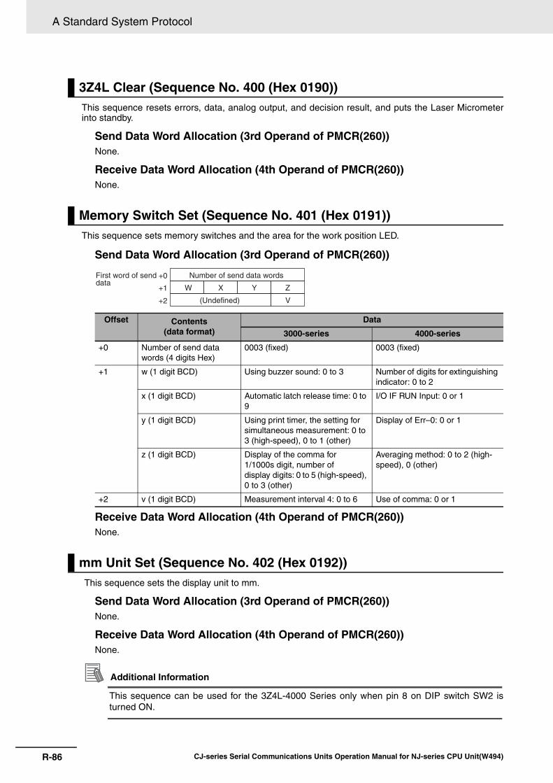
A Standard System Protocol
R-86 CJ-series Serial Communications Units Operation Manual for NJ-series CPU Unit(W494)
This sequence resets errors, data, analog output, and decision result, and puts the Laser Micrometerinto standby.
Send Data Word Allocation (3rd Operand of PMCR(260))None.
Receive Data Word Allocation (4th Operand of PMCR(260))None.
This sequence sets memory switches and the area for the work position LED.
Send Data Word Allocation (3rd Operand of PMCR(260))
Receive Data Word Allocation (4th Operand of PMCR(260))None.
This sequence sets the display unit to mm.
Send Data Word Allocation (3rd Operand of PMCR(260))None.
Receive Data Word Allocation (4th Operand of PMCR(260))None.
Additional Information
This sequence can be used for the 3Z4L-4000 Series only when pin 8 on DIP switch SW2 isturned ON.
3Z4L Clear (Sequence No. 400 (Hex 0190))
Memory Switch Set (Sequence No. 401 (Hex 0191))
Offset Contents (data format)
Data
3000-series 4000-series
+0 Number of send data words (4 digits Hex)
0003 (fixed) 0003 (fixed)
+1 w (1 digit BCD) Using buzzer sound: 0 to 3 Number of digits for extinguishing indicator: 0 to 2
x (1 digit BCD) Automatic latch release time: 0 to 9
I/O IF RUN Input: 0 or 1
y (1 digit BCD) Using print timer, the setting for simultaneous measurement: 0 to 3 (high-speed), 0 to 1 (other)
Display of Err–0: 0 or 1
z (1 digit BCD) Display of the comma for 1/1000s digit, number of display digits: 0 to 5 (high-speed), 0 to 3 (other)
Averaging method: 0 to 2 (high-speed), 0 (other)
+2 v (1 digit BCD) Measurement interval 4: 0 to 6 Use of comma: 0 or 1
mm Unit Set (Sequence No. 402 (Hex 0192))
First word of send data
Number of send data words+0
+1
+2
W
(Undefined)
X Y Z
V

R-87
A Standard System Protocol
CJ-series Serial Communications Units Operation Manual for NJ-series CPU Unit(W494)
R-5 3Z
4L L
aser Micro
meter P
roto
col
Ref
R-5-3 P
rotocol Configuration
This sequence sets the display unit to E.
Send Data Word Allocation (3rd Operand of PMCR(260))None.
Receive Data Word Allocation (4th Operand of PMCR(260))None.
Additional Information
This sequence can be used for the 3Z4L-4000 Series only when pin 8 on DIP switch SW2 isturned ON.
This sequence calibrates the Laser Micrometer.
Send Data Word Allocation (3rd Operand of PMCR(260))
E Unit Set (Sequence No. 403 (Hex 0193))
Calibration Set (Sequence No. 404 (Hex 0194))
Offset Contents (data format) Data
+0 Number of send data words (4 digits Hex)
0007 (fixed)
+1 HC gauge dimension (Decimal portion) (4 digits BCD)
0000 to 9999
+2 HC gauge dimension (integer portion) (3 digits BCD)
000 to 999
+3 HC gauge dimension (Sign)(ASCII 1 character)
if +: 20(' ')if –: 2D('–')
+4 to +6 LC gauge dimensions Same as HC gauge dimensions
First word of send data
Number of send data words+0
+1
+2
+3
+4
+5
+6
Decimal portion
(Undefined) Decimal integer portion
Sign
Decimal portion
(Undefined)
(Undefined) (Decimal integer portion)
Sign (Undefined)
High calibration gauge dimension
Low calibration gauge dimension
4 5 6 7
0 1 2 3
2 D 0 0
+1
+2
+3
Example –123.4567

A Standard System Protocol
R-88 CJ-series Serial Communications Units Operation Manual for NJ-series CPU Unit(W494)
Additional Information
• Use sequences No. 446 (High calibration set) and No. 447 (Low calibration set) to calibrate theLaser Micrometer. If this sequence (No. 404) is used, both the high and low calibration gaugesmust be set, and the high calibration and low calibration gauges cannot be exchanged.
• The HC gauge dimension and LC gauge dimension must be set with 3 digits for the integerportion and 4 digits for the decimal portion.
Receive Data Word Allocation (4th Operand of PMCR(260))None.
This sequence releases the calibration of the Laser Micrometer.
Send Data Word Allocation (3rd Operand of PMCR(260))None.
Receive Data Word Allocation (4th Operand of PMCR(260))None.
Additional Information
In this sequence, you cannot separately release both high and low calibration.
This sequence switches the program number to a specified number.
Send Data Word Allocation (3rd Operand of PMCR(260))
Receive Data Word Allocation (4th Operand of PMCR(260))None.
Additional Information
Retry processing is not performed for this sequence.
Calibration Release (Sequence No. 405 (Hex 0195))
Program Number Set (3000-series) (Sequence No. 406 (Hex 0196))
Offset Contents (data format) Data
+0 Number of send data words (4 digits Hex) 0002 (fixed)
+1 Program number (1 digit BCD) 0 to 9
First word of send data
Number of send data words+0
+1 (Undefined) Program number (1 digit BCD)

R-89
A Standard System Protocol
CJ-series Serial Communications Units Operation Manual for NJ-series CPU Unit(W494)
R-5 3Z
4L L
aser Micro
meter P
roto
col
Ref
R-5-3 P
rotocol Configuration
This sequence sets measurement conditions. Conditions to be set can be selected by setting Yes/Noflags.
Send Data Word Allocation (3rd Operand of PMCR(260))
Measurement Condition Set (3000-series) (Sequence No. 407 (Hex 0197))
First word of send data
Number of send data words+0
+1
+2
+3
+4
+5
+6
+7
+8
+9
+10
+11
+12
+13
+14
+15
+16
+17+18
+19
+20
+21
+22
+23
+24
+25
+26
+27
+28
+29
(Unused)
(Undefined)
(Undefined) Integer portion
Sign (Undefined)
Decimal portion
Decimal portion
(Undefined) Integer portion
Sign (Undefined)
Decimal portion
(Undefined) Integer portion
Sign (Undefined)
Decimal portion
(Undefined) Integer portion
Decimal portion
Sign (Undefined)
(Undefined) Integer portion
Decimal portion
Sign (Undefined)
(Undefined) Integer portion
Decimal portion
Sign (Undefined)
(Undefined) Integer portion
Decimal portion
Sign (Undefined)
(Undefined) Integer portion
Sign (Undefined)
Segment number (SG)
Measurement interval number (M)
Lower limit value (LL)
Upper limit value (LH)
Multistep selection limit value (L1)
Multistep selection limit value (L3)
Multistep selection limit value (L2)
Multistep selection limit value (L4)
Multistep selection limit value (L5)
Multistep selection limit value (L6)

A Standard System Protocol
R-90 CJ-series Serial Communications Units Operation Manual for NJ-series CPU Unit(W494)
Offset Contents (data format) Data
+0 Number of send data words (4 digits Hex)
0036 (0054 decimal) (fixed)
+1 Unused Undefined
+2 to +4 Segment number (ASCII 6 characters)
Combination of 31('1') to 36('6'), 20(' ')
+5 Measurement interval number (1 digit BCD)
1 to 4
+6 Lower limit value (decimal portion) (4 digits BCD)
0000 to 9999
+7 Lower limit value (Integer portion) (3 digits BCD)
000 to 999
+8 Lower limit value (Sign) (ASCII 1 character)
if +: 20(' ')if –: 2D('–')
+9 to +11 Upper limit value Same as lower limit values
+12 to +14
Multistep selection limit value (L1)
Same as lower limit values
+15 to +17
Multistep selection limit value (L2)
Same as lower limit values
+18 to +20
Multistep selection limit value (L3)
Same as lower limit values
+21 to +23
Multistep selection limit value (L4)
Same as lower limit values
+24 to +26
Multistep selection limit value (L5)
Same as lower limit values
+30
+31
+32
+33
+34
+35
+36
+37
+38
+39
+40
+41
+42
+43
+44
+45
+46
+47
+48
+49
+50
+51
+52
+53
(Undefined) Integer portion
Sign (Undefined)
(Undefined)
(Undefined)
Decimal portion
(Undefined) Integer portion
Sign (Undefined)
(Undefined)
(Undefined)
(Undefined)
(Undefined)
(Unused)
(Unused)
0
0
0
0
0
0
0
0
Decimal portion
(PRT)
(SMP)
Reference value (REF)
Analog output scale number (SCL)
Offset classification (OF)
Offset value
Data output conditions (PR)
Sample measurement classification
Schedule output timer
Sample measurement pulse
Setting Yes/No flags
4 5 6 7
0 1 2 3
2 D 0 0
+6
+7
+8
Example –123.4567

R-91
A Standard System Protocol
CJ-series Serial Communications Units Operation Manual for NJ-series CPU Unit(W494)
R-5 3Z
4L L
aser Micro
meter P
roto
col
Ref
R-5-3 P
rotocol Configuration
Receive Data Word Allocation (4th Operand of PMCR(260))None.
+27 to +29
Multistep selection limit value (L6)
Same as lower limit values
+30 to +32
Reference value Same as lower limit values
+33 Analog output scale number (1 digit BCD)
1 to 3
+34 to +35
Offset classification (ASCII 3 characters)
4F4620 ("OF"), 4F4D20 ("OM")
+36 to +38
Offset value Same as lower limit values
+39 Data output conditions (1 digit BCD)
0 to 6
+40 Scheduled output timer (3 digits BCD)
000 to 999
+41 Sample measurement pulse(3 digits BCD)
000 to 999
+42 to +43
Sample measurement classifica-tion (ASCII 3 characters)
415647 ("AVG"), 4D4158 ("MAX") 4D494E ("MIN"), 524E47 ("RNG")
+44 to +45
Unused Undefined
+46 Yes/No for segment setting (1 digit BCD)
Set: 1 (SG)
Don't set: 0
+47 Yes/No for measurement interval number setting (1 digit BCD)
Set: 1 (M)
Don't set: 0
+48 Yes/No for upper/lower limit value setting (1 digit BCD)
Set: 1 (LL,LH)
Don't set: 0
+49 Yes/No for multistep selection limit value (1 digit BCD)
Set: 1 (L1,L2,L3,L4,L5,L6)
Don't set: 0
+50 Yes/No for reference setting (1 digit BCD)
Set: 1 (REF,SCL)
Don't set: 0
+51 Yes/No for offset value setting (1 digit BCD)
Set: 1 (OF or OM)
Don't set: 0
+52 Yes/No for data output condition setting (1 digit BCD)
Set: 1 (PR,PRT)
Don't set: 0
+53 Yes/No for sample measurement pulse setting(1 digit BCD)
Set: 1 (SMP, MAX or MIN or RNG or AVG)
Don't set: 0
Offset Contents (data format) Data

A Standard System Protocol
R-92 CJ-series Serial Communications Units Operation Manual for NJ-series CPU Unit(W494)
Additional Information
• This sequence cannot be used to set the error lower limit (EL), error upper limit (EH), errorexclusion counter (CNT) of the error data exclusion function (centerless grinder function).
• The following settings must be made together with this sequence; they cannot be set sepa-rately.
Lower limit, upper limitMultistep selection limitReference value, analog output scale numberData output conditions, scheduled print timer
• The limit value, reference value, and offset value can be set to 3 digits for the integer portionand to 4 digits for the decimal portion.
This sequence releases the measurement conditions that have been set.
Send Data Word Allocation (3rd Operand of PMCR(260)) Send data word allocation is similar to that of sequence No. 407 (Measurement Condition Set).However, only the setting Yes/No flags at +46 to +53 from the send data leading word can be used.
Receive Data Word Allocation (4th Operand of PMCR(260))None.
Additional Information
• The following conditions are used when the measurement conditions are released: Segmentbecomes 1, measurement interval becomes 1, the number of sample measurement pulsesbecomes 1.
• The following conditions cannot be released with this sequence: error lower limit (EL), errorupper limit (EH), error exclusion counter (CNT) of the error data exclusion function (centerlessgrinder function).
• The following settings cannot be released separately using this sequence.Lower limit, Upper limitMultistep selection limitReference value, analog output scale numberData output conditions, scheduled print timer
This sequence requests the measurement condition settings that have been set and other settings.
Send Data Word Allocation (3rd Operand of PMCR(260))None.
Measurement Condition Release (3000-series) (Sequence No. 408 (Hex 0198))
Measurement Condition List Request (3000-series) (Sequence No. 409 (Hex 0199))

R-93
A Standard System Protocol
CJ-series Serial Communications Units Operation Manual for NJ-series CPU Unit(W494)
R-5 3Z
4L L
aser Micro
meter P
roto
col
Ref
R-5-3 P
rotocol Configuration
Receive Data Word Allocation (4th Operand of PMCR(260))
First word of send data
Number of receive data words+0
+1
+2
+3
+4
+5
+6
+7
+8
+9
+10
+11
+12
+13
+14
+15
+16
+17
+18
+19
+20
+21
+22
+23
+24
+25
+26
+27
+28
+29
(Undefined)
(Undefined) Integer portion
Sign (Undefined)
Decimal portion
Decimal portion
(Undefined) Integer portion
Sign (Undefined)
Decimal portion
(Undefined) Integer portion
Sign (Undefined)
Decimal portion
(Undefined) Integer portion
Decimal portion
Sign (Undefined)
(Undefined) Integer portion
Decimal portion
Sign (Undefined)
(Undefined) Integer portion
Decimal portion
Sign (Undefined)
(Undefined) Integer portion
Decimal portion
Sign (Undefined)
(Undefined) Integer portion
Sign (Undefined)
(Undefined) Program number (P)
Segment number (SG)
Measurement interval number (M)
Lower limit value (LL)
Upper limit value (LH)
Multistep selection limit value (L1)
Multistep selection limit value (L2)
Multistep selection limit value (L3)
Multistep selection limit value (L4)
Multistep selection limit value (L5)
Multistep selection limit value (L6)
+30
+31
+32
+33
+34
+35
+36
+37
+38
+39
+40
+41
+42
+43
+44
+45
(Undefined) Integer portion
Sign (Undefined)
(Undefined)
(Undefined)
Decimal portion
(Undefined) Integer portion
Sign (Undefined)
(Undefined)
(Undefined)
(Undefined)
Decimal portion
(PRT)
(SMP)
(Undefined)
Reference value (REF)
Analog output scale number (SCL)
Offset classification (OF)
Offset value (LH)
Data output condition (PR)
Sample measurement classification
Statistical processing calculation classification
Scheduled output timer
Sample measurement pulse

A Standard System Protocol
R-94 CJ-series Serial Communications Units Operation Manual for NJ-series CPU Unit(W494)
Additional Information
This sequence cannot be used to request the lower limit (EL), error upper limit (EH), error exclu-sion counter (CNT) of the error data exclusion function (centerless grinder function).
Offset Contents (data format) Data
+0 Number of receive data words (4 digits Hex)
002E (0046 decimal) (fixed)
+1 Program number (1 digit BCD)
0 to 9
+2 to +4 Segment number (ASCII 6 characters)
Combination of 31('1') to 36('6'), 20(' ')
+5 Measurement interval number (1 digit BCD)
1 to 4
+6 Lower limit value (Decimal portion) (4 digits BCD)
0000 to 9999
+7 Lower limit value (Integer portion) (3 digits BCD)
000 to 999
+8 Lower limit value (Sign) (BIN) If +: 0 If – : F
+9 to +11 Upper limit value Same as lower limit values
+12 to +14
Multistep selection limit value (L1) Same as lower limit values
+15 to +17
Multistep selection limit value (L2) Same as lower limit values
+18 to +20
Multistep selection limit value (L3) Same as lower limit values
+21 to +23
Multistep selection limit value (L4) Same as lower limit values
+24 to +26
Multistep selection limit value (L5) Same as lower limit values
+27 to +29
Multistep selection limit value (L6) Same as lower limit values
+30 to +32
Reference value Same as lower limit values
+33 Analog output scale number (1 digit BCD)
1 to 3
+34 to +35
Offset classification (ASCII 3 char-acters)
4F4620 ("OF"), 4F4D20 ("OM")
+36 to +38
Offset value Same as lower limit values
+39 Data output condition (1 digit BCD)
0 to 6
+40 Scheduled output timer (3 digits BCD)
000 to 999
+41 Sample measurement pulse(3 digits BCD)
000 to 999
+42 to +43
Sample measurement classification (ASCII 3 characters)
415647 ("AVG"), 4D4158 ("MAX") 4D494E ("MIN"), 524E47 ("RNG")
+44 to +45
Statistical processing calculation classification (ASCII 3 characters)
535420 ("ST"), 4E5354 ("NST")
4 5 6 7
0 1 2 3
F 0 0 0
+6
+7
+8
Example –123.4567

R-95
A Standard System Protocol
CJ-series Serial Communications Units Operation Manual for NJ-series CPU Unit(W494)
R-5 3Z
4L L
aser Micro
meter P
roto
col
Ref
R-5-3 P
rotocol Configuration
When the sample measurement condition is from 1 to 999, this sequence performs a single run mea-surement and requests the measurement results.
Send Data Word Allocation (3rd Operand of PMCR(260))None.
Receive Data Word Allocation (4th Operand of PMCR(260))
If the sample measurement condition is zero, a zero run measurement is started.
Send Data Word Allocation (3rd Operand of PMCR(260))None.
Receive Data Word Allocation (4th Operand of PMCR(260))None.
Single Run Measurement Start (3000-series) (Sequence No. 410 (Hex 019A))
Offset Contents (data format) Data
+0 Number of receive data words (4 digit Hex)
With no reference setting: 0006With reference setting: 0009
+1 Program number (1 digit BCD)
0 to 9
+2 Decision result (ASCII 2 characters)
With no limit setting: 0000
With limit setting: 2B4E ("+N"), 4F4B ("OK"), 2D4E ("–N")
+3 Measurement value (decimal portion) (4 digits BCD)
0000 to 9999
+4 Measurement value (integer por-tion) (3 digits BCD)
000 to 999
+5 Measurement value (Sign) (BIN) If +: 0
If –: F
+6 to +8 Deviation value Same as measurement value*The deviation will be stored in this area only when reference setting is made.
Zero Run Measurement Start (3000-series) (Sequence No. 411 (Hex 019B))
Receive data storage words
Number of receive data words+0
+1
+2
+3
+4
+5
+6
+7
+8
Decimal portion
(Undefined) Integer portion
Sign
Decimal portion
(Undefined)
(Undefined) Integer portion
Sign (Undefined)
(Undefined)
Decision resultProgram number
Measurement value
Deviation value
4 5 6 7
0 1 2 3
F 0 0 0
+3
+4
+5
Example –123.4567

A Standard System Protocol
R-96 CJ-series Serial Communications Units Operation Manual for NJ-series CPU Unit(W494)
Additional Information
The zero run measurement keeps measuring until sequence No. 414 (Measurement Termina-tion) is executed.
A continuous measurement is started. The scan notification method is used for the receive data.
Send Data Word Allocation (3rd Operand of PMCR(260))None.
Receive Data Word Allocation (4th Operand of PMCR(260))The receive data word allocation is similar to that of sequence No. 410 (Single Run MeasurementStart).
Additional Information
• Since this sequence repeats itself within the sequence, once it is executed, it remains in theexecution state until cancelled.
• Even if execution is cancelled, the Laser Micrometer still keeps measuring. Execute sequenceNo. 414 (Measurement Termination) to end the sequence.
A continuous measurement is started. The interrupt notification method is used for the receive data andthe interrupt No. is 101.
Send Data Word Allocation (3rd Operand of PMCR(260))None.
Receive Data Word Allocation (4th Operand of PMCR(260))The receive data word allocation is similar to that of sequence No. 410 (Single Run MeasurementStart).
Additional Information
• Since this sequence repeats itself within the sequence, once it is executed, it remains in theexecution state until cancelled.
• Even if execution is cancelled, the Laser Micrometer still keeps measuring. Execute sequenceNo. 414 (Measurement Termination) to end the sequence.
Precautions for Correct UsePrecautions for Correct Use
Sequences No. 413 and No. 437 (Continuous Measurement Start with Interrupt) not supportedby the CS1W-SCU@@(-V1) and CJ1W-SCU@@(-V1) Serial Communications Units. A protocolsyntax error will occur if an attempt is made to execute either sequence with a Serial Communi-cations Unit.Do not set an EM bank as the receive storage word for interrupt notification. A protocol syntaxerror will occur if an EM bank is set.
Continuous Measurement Start (Scan) (3000-series) (Sequence No. 412 (Hex 019C))
Continuous Measurement Start (Interrupt) (3000-series) (Sequence No. 413 (Hex 019D))

R-97
A Standard System Protocol
CJ-series Serial Communications Units Operation Manual for NJ-series CPU Unit(W494)
R-5 3Z
4L L
aser Micro
meter P
roto
col
Ref
R-5-3 P
rotocol Configuration
This sequence terminates a continuous measurement.
Send Data Word Allocation (3rd Operand of PMCR(260))None.
Receive Data Word Allocation (4th Operand of PMCR(260))For continuous measurement: Not availableFor Zero Run Measurement:The receive data word allocation is similar to that of sequence No. 410 (Single Run MeasurementStart).
Additional Information
This sequence may be aborted if it is executed during continuous measurements. Measure-ments will be terminated even if the sequence is aborted. This occurs because this sequencewas executed while the Laser Micrometer was sending measurement results. The chances thatthe sequence will be aborted are higher if the scheduled data output value is set to a lower value.
This sequence requests display data in the idle measurement status or the latch data generated by themeasurement command.
Send Data Word Allocation (3rd Operand of PMCR(260))None.
Receive Data Word Allocation (4th Operand of PMCR(260))The receive data word allocation is similar to that of sequence No. 410 (Single Run MeasurementStart).
This sequence lights the statistic processing LED and implements the statistic processing.
Send Data Word Allocation (3rd Operand of PMCR(260))None.
Receive Data Word Allocation (4th Operand of PMCR(260))None.
This sequence turns the statistic processing LED off and does not carry out the statistic processing.
Send Data Word Allocation (3rd Operand of PMCR(260))None.
Receive Data Word Allocation (4th Operand of PMCR(260))None.
Measurement Termination (3000-series) (Sequence No. 414 (Hex 019E))
Data Request (3000-series) (Sequence No. 415 (Hex 019F))
Statistic Processing Execution (3000-series) (Sequence No. 416 (Hex 01A0))
Statistic Processing Non-execution (3000-series) (Sequence No. 417 (Hex 01A1))

A Standard System Protocol
R-98 CJ-series Serial Communications Units Operation Manual for NJ-series CPU Unit(W494)
This sequence clears statistic processing memories of all programs.
Send Data Word Allocation (3rd Operand of PMCR(260))None.
Receive Data Word Allocation (4th Operand of PMCR(260))None.
This sequence clears statistic processing memories of the program under display.
Send Data Word Allocation (3rd Operand of PMCR(260))None.
Receive Data Word Allocation (4th Operand of PMCR(260))None.
This sequence requests the statistic processing results.
Send Data Word Allocation (3rd Operand of PMCR(260))None.
Receive Data Word Allocation (4th Operand of PMCR(260))
All Statistic Memory Clear (3000-series) (Sequence No. 418 (Hex 01A2))
Statistic Processing Memory Clear (3000-series) (Sequence No. 419 (Hex 01A3))
Statistic Result Request (3000-series) (Sequence No. 420 (Hex 01A4))
Receive data storage words
Number of receive data words+0
+1
+2
+3
+4
+5
+6
+7
+8
+9
+10
+11
+12
+13
+14
+15
+16
+17
+18
Decimal portion
(Undefined) Integer portion
Sign
Decimal portion
(Undefined)
(Undefined) Integer portion
Sign (Undefined)
(Undefined)
Decimal portion
(Undefined) Integer portion
Sign (Undefined)
Decimal portion
(Undefined) Integer portion
Sign (Undefined)
Decimal portion
(Undefined) Integer portion
Sign (Undefined)
(Undefined)
Program number (P)
Number of statistic data (N)
Average value (AVG)
Maximum value (MAX)
Minimum value (MIN)
Range (R)
Standard deviation (SD)

R-99
A Standard System Protocol
CJ-series Serial Communications Units Operation Manual for NJ-series CPU Unit(W494)
R-5 3Z
4L L
aser Micro
meter P
roto
col
Ref
R-5-3 P
rotocol Configuration
Additional Information
The number of digits of the Decimal portion is fixed to 4 digits. If a deviation calculation results ina value with 5 decimal places, it will be stored with one digit overflowing into the integer portion.Examples: The value -0.1234 is stored as follows:
Area of decimal portion: 1234; Area of integer portion: 0000; Sign area: F000The value -0.12345 is stored as follows:Area of decimal portion: 2345; Area of integer portion: 0001; Sign area: F000
Offset Contents (data format)
Data
+0 Number of receive data words (4 digits Hex)
0013 (0019 decimal) (fixed)
+1 Program number (1 digit BCD) 0 to 9
+2 to +3 Number of statistic data (6 digits BCD)
000000 to 999999
+4 Average value (decimal portion) (4 digits BCD)
0000 to 9999
+5 Average value (integer portion) (4 digits BCD)
000 to 999
+6 Average value (Sign) (BIN) If +: 0If –: F
+7 to +9 Maximum value Same as average value
+10 to +12
Minimum value Same as average value
+13 to +15
Range Same as average value
+16 to +18
Standard deviation Same as average value
4 5 6 7
0 1 2 3
F 0 0 0
+4
+5
+6
Example –123.4567

A Standard System Protocol
R-100 CJ-series Serial Communications Units Operation Manual for NJ-series CPU Unit(W494)
This sequence sets memory switches.
Send Data Word Allocation (3rd Operand of PMCR(260))
Receive Data Word Allocation (4th Operand of PMCR(260))None.
Additional Information
• Memory switches cannot be set when DIP switch SW3, pin 5 of the Laser Micrometer is notturned ON.
• The setting (y, z) of RS-232C takes effect when the power supply is turned back ON.
Memory Switch Set 1 (3000-series, High-speed Type) (Sequence No. 421 (Hex 01A5))
OffsetContents
(data format)Data
+0 Number of send data words (4 digits Hex)
0003 (fixed)
+1 w (1 digits BCD) 0: For single run or zero run measurement start displaying '---.'
1: For single run or zero run measurement start displaying the previous measured value
x (1 digit BCD) 0: Perform single run measurement to the RUN signal of I/O IF
1: Repeat measurement while the RUN signal of I/O IF is input
y (1 digit BCD) *0: RS-232C Delimiter CR+LF
1: RS-232C Delimiter CR
2: RS-232C Delimiter LF
z (1 digit BCD) 0: RS-232C no parity check
1: RS-232C odd parity check
2: RS-232C even parity check
+2 v (1 digit BCD) 0: Displaying 'Err-0'
1: Displaying '0'
Note Settings marked with asterisks are required for this protocol.
First word of send data
Number of send data words+0
+1
+2
W
(Undefined)
X Y Z
V

R-101
A Standard System Protocol
CJ-series Serial Communications Units Operation Manual for NJ-series CPU Unit(W494)
R-5 3Z
4L L
aser Micro
meter P
roto
col
Ref
R-5-3 P
rotocol Configuration
This sequence sets memory switches.
Send Data Word Allocation (3rd Operand of PMCR(260))
Receive Data Word Allocation (4th Operand of PMCR(260))None.
Additional Information
Memory switches cannot be set when DIP switch SW3, pin 5 of the Laser Micrometer is notturned ON.
Memory Switch Set 2 (3000-series, High-speed Type) (Sequence No. 422 (Hex 01A6))
Offset Contents (data format) Data
+0 Number of send data words (4 digits Hex)
0003 (fixed)
+1 w (1 digit BCD) 0: Work automatic detection is not performed
1: Work automatic detection is performed Diameter detection method (1 scan)
2: Work automatic detection is performed Diameter detection method (8 scan)
3: Work automatic detection is performed Position detection method (1 scan)
x (1 digit BCD) For expansion 0 (fixed)
y (1 digit BCD) For expansion 0 (fixed)
z (1 digit BCD) For expansion 0 (fixed)
+2 v (1 digit BCD) *0: Error data exclusion function is not used
1: Error data exclusion function is used
Note Settings marked with asterisks are required for this protocol.
First word of send data
Number of send data words+0
+1
+2
W
(Undefined)
X Y Z
V

A Standard System Protocol
R-102 CJ-series Serial Communications Units Operation Manual for NJ-series CPU Unit(W494)
This sequence uses the simple average as the averaging method and sets the averaging times permeasurement interval 4.
Send Data Word Allocation (3rd Operand of PMCR(260))
Receive Data Word Allocation (4th Operand of PMCR(260))None.
Additional Information
This sequence cannot be used when DIP switch SW3, pin 5 of the Laser Micrometer is notturned ON.
This sequence uses the average move as the averaging method and sets the measurement intervalnumber.
Send Data Word Allocation (3rd Operand of PMCR(260))
Receive Data Word Allocation (4th Operand of PMCR(260))None.
Additional Information
This sequence cannot be used when DIP switch SW3, pin 5 of the Laser Micrometer is notturned ON.
Simple AVG Times Set (3000-series, High-speed Type) (Sequence No. 423 (Hex 01A7))
Offset Contents (data format) Data
+0 Number of send data words (4 digits Hex) 0002 (fixed)
+1 Number of averaging times (4 digits BCD) 1 to 2048
AVG Move Interval Set (3000-series, High-speed Type) (Sequence No. 424 (Hex 01A8))
Offset Contents (data format) Data
+0 Number of send data words (4 digits Hex) 0002 (fixed)
+1 Measurement interval number (1 digit BCD) 1 to 4
First word of send data
+0
+1 Number of averaging times
Number of send data words
First word of send data
Number of send data words+0
+1 (Undefined) Measurement interval number

R-103
A Standard System Protocol
CJ-series Serial Communications Units Operation Manual for NJ-series CPU Unit(W494)
R-5 3Z
4L L
aser Micro
meter P
roto
col
Ref
R-5-3 P
rotocol Configuration
This sequence uses the average move and high-speed data output as the averaging method and setsthe averaging times per measurement interval 4.
Send Data Word Allocation (3rd Operand of PMCR(260))
Receive Data Word Allocation (4th Operand of PMCR(260))None.
Additional Information
This sequence cannot be used when DIP switch SW3, pin 5 of the Laser Micrometer is notturned ON.
This sequence uses the average move and low-speed data output as the averaging method and setsthe averaging times per measurement interval 4.
Send Data Word Allocation (3rd Operand of PMCR(260))
Receive Data Word Allocation (4th Operand of PMCR(260))None.
Additional Information
• This sequence cannot be used when DIP switch SW3, pin 5 of the Laser Micrometer is notturned ON.
• This sequence will be processed the same as sequence No. 425 AVG move (H) times set for5000-series Laser Micrometers.
AVG Move (H) Times Set (3000-series, High-speed Type) (Sequence No. 425 (Hex 01A9))
Offset Contents (data format) Data
+0 Number of send data words (4 digits Hex) 0002 (fixed)
+1 Number of averaging times (4 digits BCD) 16 to 2048 (32 to 2048 for 5000/6000 Series)
AVG Move (L) Times Set (3000-series, High-speed Type) (Sequence No. 426 (Hex 01AA))
Offset Contents (data format) Data
+0 Number of send data words (4 digits Hex) 0002 (fixed)
+1 Number of averaging times (4 digits BCD) 32 to 2048
First word of send data
Number of send data words+0
+1 Number of averaging times
First word of send data
Number of send data words+0
+1 Number of averaging times

A Standard System Protocol
R-104 CJ-series Serial Communications Units Operation Manual for NJ-series CPU Unit(W494)
This sequence sets the work automatic detection function.
Send Data Word Allocation (3rd Operand of PMCR(260))
Receive Data Word Allocation (4th Operand of PMCR(260))None.
Additional Information
• This sequence cannot be used when DIP switch SW3, pin 5 of the Laser Micrometer is notturned ON.
• The detection lower and upper limit must be set with 3 digits for the integer portion and 4 digitsfor the decimal portion.
This sequence releases the setting of work automatic detection function.
Send Data Word Allocation (3rd Operand of PMCR(260))None.
Receive Data Word Allocation (4th Operand of PMCR(260))None.
Automatic Detection Set (3000-series, High-speed Type) (Sequence No. 427 (Hex 01AB))
Offset Contents (data format) Data
+0 Number of send data words (4 digits Hex)
0009 (fixed)
+1 Number of measurements(3 digits BCD)
001 to 999
+2 Invalid time (4 digits BCD) 0001 to 9999
+3 Detection lower limit (decimal portion) (4 digits BCD)
0000 to 9999
+4 Detection lower limit (integer portion) (3 digits BCD)
000 to 999
+5 Detection lower limit (Sign) (ASCII 1 character)
If +: 20 (' ') If –: 2D ('–')
+6 to +8 Detection upper limit Same as detection lower limit
Automatic Detection Release (3000-series, High-speed Type) (Sequence No. 428 (Hex 01AC))
Receive data storage words
Number of send data words+0
+1
+2
+3
+4
+5
+6
+7
+8
(Undefined)
Invalid time
Decimal portion
(Undefined) Integer portion
Sign (Undefined)
Decimal portion
(Undefined) Integer portion
Sign (Undefined)
The number of measuring times
Detection lower limit
Detection upper limit
4 5 6 7
0 1 2 3
2 D 0 0
+3
+4
+5
Example –123.4567

R-105
A Standard System Protocol
CJ-series Serial Communications Units Operation Manual for NJ-series CPU Unit(W494)
R-5 3Z
4L L
aser Micro
meter P
roto
col
Ref
R-5-3 P
rotocol Configuration
Additional Information
This sequence cannot be used when DIP switch SW3, pin 5 of the Laser Micrometer is notturned ON.
This sequence requests the settings of work automatic detection function.
Send Data Word Allocation (3rd Operand of PMCR(260))None.
Receive Data Word Allocation (4th Operand of PMCR(260))
Additional Information
This sequence cannot be used when DIP switch SW3, pin 5 of the Laser Micrometer is notturned ON.
Automatic Detection List Request (3000-series, High-speed Type) (Sequence No. 429 (Hex 01AD))
Offset Contents (data format) Data
+0 Number of receive data words (4 digits Hex)
0009 (fixed)
+1 The number of measuring times (3 digits BCD)
000 to 999
+2 Invalid time (4 digits BCD) 0001 to 9999
+3 Detection lower limit (decimal portion) (4 digits BCD)
0000 to 9999
+4 Detection lower limit (integer portion) (3 digits BCD)
000 to 999
+5 Detection lower limit (Sign) (BIN) If +: 0If –: F
+6 to +8 Detection upper limit Same as detection lower limit
Receive data storage words
Number of receive data words+0
+1
+2
+3+4
+5
+6
+7
+8
(Undefined)
Invalid time
Decimal portion
(Undefined) Integer portion
Sign (Undefined)
Decimal portion
(Undefined) Integer portion
Sign (Undefined)
The number of measuring times
Detection lower limit
Detection upper limit
4 5 6 7
0 1 2 3
F 0 0 0
+3
+4
+5
Example –123.4567

A Standard System Protocol
R-106 CJ-series Serial Communications Units Operation Manual for NJ-series CPU Unit(W494)
This sequence clears the 3Z4L, sets the mm unit, sets memory switches, does not process statistics,and clears the statistic memory in sequence.
Send Data Word Allocation (3rd Operand of PMCR(260))The send data word allocation is similar to that of sequence No. 401 (Memory Switch Set)
Receive Data Word Allocation (4th Operand of PMCR(260))None.
Additional Information
Memory switch settings will be ignored for this sequence for 5000-series and 6000-series LaserMicrometers.
This sequence sets measurement conditions. Conditions to be set can be selected by setting Yes/Noflags.
Send Data Word Allocation (3rd Operand of PMCR(260))
3Z4L Initialize (3000-series) (Sequence No. 430 (Hex 01AE))
Measurement Condition Set (4000-series) (Sequence No. 431 (Hex 01AF))
First word of send data
Number of send data words+0
+1
+2
+3
+4
+5
+6
+7
+8
+9
+10
+11
+12
+13
+14
+15
+16
+17
+18
+19
+20+21
+22
+23
+24
(Undefined)
Decimal portion
(Undefined) Integer portion
Sign (Undefined)
(Undefined)
Decimal portion
(Undefined) Integer portion
Sign (Undefined)
Decimal portion
(Undefined) Integer portion
Sign (Undefined)
(Undefined)
(Unused)
(Unused)
(Unused)
(Undefined)
(Undefined)
(Undefined)
0
0
0
0
0
0
(PRT)
Segment number (SG)
Measurement interval number (M)
Lower limit value (LL)
Upper limit value (LH)
Reference value (REF)
Analog output scale number (SCL)
Data output conditions (PR)
Number of seconds for latch timer (RLT)
Setting Yes/No flags
Data output timer (BCD 3 digits)

R-107
A Standard System Protocol
CJ-series Serial Communications Units Operation Manual for NJ-series CPU Unit(W494)
R-5 3Z
4L L
aser Micro
meter P
roto
col
Ref
R-5-3 P
rotocol Configuration
Receive Data Word Allocation (4th Operand of PMCR(260))None.
Offset Contents (data format) Data
+0 Number of send data words (4 digits Hex)
0019 (0025 decimal) (fixed)
+1 Segment number (1 digit BCD) 1 to 5
+2 Measurement interval number (1 digit BCD)
1 to 7
+3 Lower limit value (Decimal por-tion) (4 digits BCD)
0000 to 9999
+4 Lower limit value (integer por-tion) (3 digits BCD)
000 to 999
+5 Lower limit value (Sign) (ASCII 1 character)
If +: 20 (' ') If –: 2D ('–')
+6 to +8 Upper limit value Same as lower limit value
+9 to +11 Reference value Same as lower limit value
+12 Analog output scale number (1 digit BCD)
0 to 3
+13 to +15
Unused
+16 Data output conditions (1 digit BCD)
0 to 6
+17 Data output timer value (3 digits BCD)
000 to 999
+18 Number of seconds for latch timer (2 digits BCD)
00 to 99
+19 Yes/No for segment setting (1 digit BCD)
Set: 1(SG)Don't set: 0
+20 Yes/No for measurement inter-val number setting (1 digit BCD)
Set: 1(M)Don't set: 0
+21 Yes/No for upper/lower limit value setting (1 digit BCD)
Set: 1(LL, LH)Don't set: 0
+22 Yes/No for reference setting (1 digit BCD)
Set: 1(REF, SCL)Don't set: 0
+23 Yes/No for data output condition setting (1 digit BCD)
Set: 1(PR, PRT)Don't set: 0
+24 Yes/No for latch timer setting (1 digit BCD)
Set: 1(RLT)Don't set: 0
Example –123.4567
4 5 6 7
0 1 2 3
2 D 0 0
+3
+4
+5

A Standard System Protocol
R-108 CJ-series Serial Communications Units Operation Manual for NJ-series CPU Unit(W494)
Additional Information
• The following settings must be made together with this sequence; they cannot be set sepa-rately.
Lower limit, upper limitReference value, analog output scale numberData output conditions, data output timer
• The limit value and reference value can be set to 3 digits for the integer portion and to 4 digitsfor the decimal portion.
This sequence clears the measurement conditions that have been set.
Send Data Word Allocation (3rd Operand of PMCR(260))The send data word allocation is similar to that of sequence No. 431 (Measurement Condition Set).However, only the setting Yes/No flags at +19 to +24 from the send data leading word can be used.
Receive Data Word Allocation (4th Operand of PMCR(260))None.
Additional Information
• The following conditions are used when the measurement conditions are released: Segmentbecomes 1 and the measurement interval becomes 1.
• The following settings cannot be cleared separately using this sequence. They all must becleared at the same time.
Lower limit, Upper limitData output conditions, Scheduled print timer
• The scale (SCL) and data output timer (PRT) cannot be cleared.
• This sequence can be used for the 3Z4L-4000 Series only when pin 8 on DIP switch SW2 isturned ON.
This sequence requests the measurement condition settings that have been set and other settings.
Send Data Word Allocation (3rd Operand of PMCR(260))None.
Measurement Condition Release (4000-series) (Sequence No. 432 (Hex 01B0))
Measurement Condition List Request (4000-series) (Sequence No. 433 (Hex 01B1))

R-109
A Standard System Protocol
CJ-series Serial Communications Units Operation Manual for NJ-series CPU Unit(W494)
R-5 3Z
4L L
aser Micro
meter P
roto
col
Ref
R-5-3 P
rotocol Configuration
Receive Data Word Allocation (4th Operand of PMCR(260))
Additional Information
This sequence can be used for the 3Z4L-4000 Series only when pin 8 on DIP switch SW2 isturned ON.
Offset Contents (data format) Data
+0 Number of receive data words (4 digits Hex)
0013 (0019 decimal) (fixed)
+1 Segment number (1 digit BCD) 1 to 5
+2 Measurement interval number (1 digit BCD)
1 to 7
+3 Lower limit value (Decimal por-tion) (4 digits BCD)
0000 to 9999
+4 Lower limit value (Integer por-tion) (3 digits BCD)
000 to 999
+5 Lower limit value (Sign) (BIN) If +: 0If –: F
+6 to +8 Upper limit value Same as lower limit value
+9 to +11 Reference value Same as lower limit value
+12 Analog output scale number (1 digit BCD)
0 to 3
+13 to +15
Forced zero number (ASCII 5 characters)
5A45524F2B ("ZERO+") 4E4F524D20 ("NORM ") 5A45524F2D ("ZERO–")
+16 Data output condition (1 digit BCD)
0 to 6
+17 Data output timer value (3 digits BCD)
000 to 999
+18 Number of seconds for latch timer (2 digits BCD)
00 to 99
Receive data storage words
Number of receive data words+0
+1
+2
+3
+4
+5
+6
+7
+8
+9
+10
+11
+12
+13
+14
+15
+16
+17
+18
(Undefined)
Decimal portion
(Undefined) Integer portion
Sign (Undefined)
(Undefined)
Decimal portion
(Undefined) Integer portion
Decimal portion
(Undefined) Integer portion
(Undefined)
(Undefined)
(Undefined)
(PRT)
Sign (Undefined)
Sign (Undefined)
(Undefined)
(Undefined)
Segment number (SG)
Measurement interval number (M)
Lower limit value (LL)
Upper limit value (LH)
Reference value (REF)
Analog output scale number (SCL)
Data output condition (PR)
Number of seconds for latch timer (RLT)
Data output timer (BCD 3 digits)
Forced zero number (ZERO+)
4 5 6 7
0 1 2 3
F 0 0 0
+3
+4
+5
Example –123.4567

A Standard System Protocol
R-110 CJ-series Serial Communications Units Operation Manual for NJ-series CPU Unit(W494)
When the sample measurement condition is from 1 to 999, this sequence performs a single run mea-surement and requests the measurement results.
Send Data Word Allocation (3rd Operand of PMCR(260))None.
Receive Data Word Allocation (4th Operand of PMCR(260))
Single Run Measurement Start (4000-series) (Sequence No. 434 (Hex 01B2))
Offset Contents (data format) Data
+0 Number of receive data words (4 digits Hex)
With no reference setting: 0005
With reference setting: 0008
+1 Decision result (ASCII 2 characters)
With no limit setting: 0000
With limit setting: 2B4E ("+N"), 4F4B ("OK"), 2D4E ("–N")
+2 Measurement value (decimal portion) (4 digits BCD)
0000 to 9999
+3 Measurement value (integer por-tion) (3 digits BCD)
000 to 999
+4 Measurement value (Sign) (BIN) If +: 0
If –: F
+5 to +7 Deviation value Same as measurement value
*The deviation will be stored in this area only when reference setting is made.
Receive data storage words
Number of receive data words+0
+1
+2
+3
+4
+5
+6
+7
Decimal portion
(Undefined) Integer portion
Sign (Undefined)
Decimal portion
(Undefined) Integer portion
Sign (Undefined)
Decision result
Measurement value
Deviation value
4 5 6 7
0 1 2 3
F 0 0 0
+2
+3
+4
Example –123.4567

R-111
A Standard System Protocol
CJ-series Serial Communications Units Operation Manual for NJ-series CPU Unit(W494)
R-5 3Z
4L L
aser Micro
meter P
roto
col
Ref
R-5-3 P
rotocol Configuration
This sequence starts a deflection measurement.
Send Data Word Allocation (3rd Operand of PMCR(260))None.
Receive Data Word Allocation (4th Operand of PMCR(260))None.
Additional Information
• The deflection measurement keeps measuring until sequence No. 438 (Measurement Termi-nation) is executed.
• This sequence will be processed the same as sequence No. 411 Zero run measurement startfor 5000-series Laser Micrometers.
This sequence starts a continuous measurement. The scan notification method is used for the receivedata.
Send Data Word Allocation (3rd Operand of PMCR(260))None.
Receive Data Word Allocation (4th Operand of PMCR(260))The receive data word allocation is similar to that of sequence No. 434 (Single Run MeasurementStart).
Additional Information
• Since this sequence repeats itself within the sequence, once it is executed, it remains in theexecution state until cancelled.
• Even if execution is cancelled, the Laser Micrometer still keeps measuring. Execute sequenceNo. 438 (Measurement Termination) to end the sequence.
Deflection Measurement Start (4000-series) (Sequence No. 435 (Hex 01B3))
Continuous Measurement Start (Scan) (4000-series) (Sequence No. 436 (Hex 01B4))

A Standard System Protocol
R-112 CJ-series Serial Communications Units Operation Manual for NJ-series CPU Unit(W494)
This sequence starts a continuous measurement. The interrupt notification method is used for thereceive data and the interrupt No. is 101.
Send Data Word Allocation (3rd Operand of PMCR(260))None.
Receive Data Word Allocation (4th Operand of PMCR(260))The receive data word allocation is similar to that of sequence No. 434 (Single Run MeasurementStart).
Additional Information
• Since this sequence repeats itself within the sequence, once it is executed, it remains in theexecution state until cancelled.
• Even if execution is cancelled, the Laser Micrometer still keeps measuring. Execute sequenceNo. 438 (Measurement Termination) to end the sequence.
Precautions for Correct UsePrecautions for Correct Use
• Sequences No. 413 and No. 437 (Continuous Measurement Start with Interrupt) are not sup-ported by the CS1W-SCU@@(-V1) and CJ1W-SCU@@(-V1) Serial Communications Units. Aprotocol syntax error will occur if an attempt is made to execute either sequence with a SerialCommunications Unit.Do not set an EM bank as the receive storage word for interrupt notification. A protocol syntaxerror will occur if an EM bank is set.
This sequence terminates continuous measurement.
Send Data Word Allocation (3rd Operand of PMCR(260))None.
Receive Data Word Allocation (4th Operand of PMCR(260))For continuous measurement: None.
For Deflection Measurement:The receive data word allocation is similar to that of sequence No. 434 (Single Run MeasurementStart).
Additional Information
This sequence may be aborted if it is executed during continuous measurements. Measure-ments will be terminated even if the sequence is aborted. This occurs because this sequencewas executed while the Laser Micrometer was sending measurement results. The chances thatthe sequence will be aborted are higher if the scheduled data output value is set to a lower value.
Continuous Measurement Start (Interrupt) (4000-series) (Sequence No. 437 (Hex 01B5))
Continuous Measurement Termination (4000-series) (Sequence No. 438 (Hex 01B6))

R-113
A Standard System Protocol
CJ-series Serial Communications Units Operation Manual for NJ-series CPU Unit(W494)
R-5 3Z
4L L
aser Micro
meter P
roto
col
Ref
R-5-3 P
rotocol Configuration
This sequence requests display data in the idle measurement status or latch data generated by themeasurement command.
Send Data Word Allocation (3rd Operand of PMCR(260))None.
Receive Data Word Allocation (4th Operand of PMCR(260))The receive data word allocation is similar to that of sequence No. 434 (Single Run MeasurementStart).
This sequence sets the forced zero direction to positive (+)
Send Data Word Allocation (3rd Operand of PMCR(260))None.
Receive Data Word Allocation (4th Operand of PMCR(260))None.
This sequence sets the forced zero direction to negative (–)
Send Data Word Allocation (3rd Operand of PMCR(260))None.
Receive Data Word Allocation (4th Operand of PMCR(260))None.
This sequence releases the forced zero direction.
Send Data Word Allocation (3rd Operand of PMCR(260))None.
Receive Data Word Allocation (4th Operand of PMCR(260))None.
Data Request (4000-series) (Sequence No. 439 (Hex 01B7))
Forced Positive Zero (4000-series) (Sequence No. 440 (Hex 01B8))
Forced Negative Zero (4000-series) (Sequence No. 441 (Hex 01B9))
Forced Zero Release (4000-series) (Sequence No. 442 (Hex 01BA))

A Standard System Protocol
R-114 CJ-series Serial Communications Units Operation Manual for NJ-series CPU Unit(W494)
This sequence clears the 3Z4L, sets the mm unit, and sets memory switches in sequence.
Send Data Word Allocation (3rd Operand of PMCR(260))The send data word allocation is similar to that of sequence No. 401 (Memory Switch Set).
Receive Data Word Allocation (4th Operand of PMCR(260))None.
Additional Information
Memory switch settings will be ignored for this sequence for 5000-series and 6000-series LaserMicrometers.
This general-purpose command is used to send data with a specified data length, and receive backonly OK. The terminator (CR) is automatically attached to the send data.
Send Data Word Allocation (3rd Operand of PMCR(260))
Receive Data Word Allocation (4th Operand of PMCR(260))None.
3Z4L Initialize (4000-series) (Sequence No. 443 (Hex 01BB))
General-purpose Command 1 (4000-series) (Sequence No. 444 (Hex 01BC))
Offset Contents (data format) Data
+0 Number of send data words (4 digits Hex)
0003 to 00FA (3 to 250 decimal)
+1 Send data byte length (4 digits Hex) 0001 to 01F0 (1 to 496 decimal)The number of bytes of send data excluding the terminator (CR)
+2 to +249
Send data (ASCII) Send data up to 496 bytes maximum
First word of send data
Number of send data words+0
+1
+2
+3
+248
+249
Send data
Send data byte length
Send data
Send data
••
Send data CR

R-115
A Standard System Protocol
CJ-series Serial Communications Units Operation Manual for NJ-series CPU Unit(W494)
R-5 3Z
4L L
aser Micro
meter P
roto
col
Ref
R-5-3 P
rotocol Configuration
This general-purpose command is used to send data with a specified data length, and receive backreceive data other than OK. The terminator (CR) is automatically attached to the send data.
Send Data Word Allocation (3rd Operand of PMCR(260))
Receive Data Word Allocation (4th Operand of PMCR(260))
General-purpose Command 2 (4000-series) (Sequence No. 445 (Hex 01BD))
Offset Contents (data format) Data
+0 Number of send data words (4 digits Hex) 0003 to 00FA (3 to 250 decimal)
+1 Send data byte length (4 digits Hex) 0001 to 01F0 (1 to 496 decimal)The number of bytes of send data excluding the terminator (CR)
+2 to +249
Send data (ASCII) Send data up to 496 bytes maximum
Specify in ASCII.
Offset Contents (data format) Data
+0 Number of receive data words (4 digits BCD)
0001 to 00FA (1 to 250 decimal)
+1 to +249
Receive data (ASCII) Receive data up to 498 bytes maximum
Stored in ASCII.
First word of send data
Number of send data words+0
+1
+2
+3
+128
+249
Send data
Send data byte length
Send data
Send data
••
Send data
Receive data storage words
Number of receive data words+0
+1
+2
+126
+249
Receive data
Receive data
Receive data
Receive data
••

A Standard System Protocol
R-116 CJ-series Serial Communications Units Operation Manual for NJ-series CPU Unit(W494)
This sequence sets the Laser Micrometer's high calibration.
Send Data Word Allocation (3rd Operand of PMCR(260))The allocation is similar to that of sequence No. 404 (Calibration Set) except that the LC gaugedimension in words +4 to +6 are not used.
Receive Data Word Allocation (4th Operand of PMCR(260))None.
Additional Information
• Use sequences No. 446 (High calibration set) and No. 447 (Low calibration set) to calibrate theLaser Micrometer. If sequence No. 404 (Calibration Set) is used, both the high and low calibra-tion gauges must be set, and the high calibration and low calibration gauges cannot beexchanged.
• The HC gauge dimension must be set with 3 digits for the integer portion and 4 digits for thedecimal portion.
This sequence sets the Laser Micrometer's low calibration.
Send Data Word Allocation (3rd Operand of PMCR(260))The allocation is similar to that of sequence No. 404 (Calibration Set) except that the HC gaugedimension in words +1 to +3 are not used.
Receive Data Word Allocation (4th Operand of PMCR(260))None.
Additional Information
• Use sequences No. 446 (High calibration set) and No. 447 (Low calibration set) to calibrate theLaser Micrometer. If sequence No. 404 (Calibration Set) is used, both the high and low calibra-tion gauges must be set, and the high calibration and low calibration gauges cannot beexchanged.
• The LC gauge dimension must be set with 3 digits for the integer portion and 4 digits for thedecimal portion.
High Calibration Set (Sequence No. 446 (Hex 01BE))
Low Calibration Set (Sequence No. 447 (Hex 01BF))

R-117
A Standard System Protocol
CJ-series Serial Communications Units Operation Manual for NJ-series CPU Unit(W494)
R-6 H
ayes Mo
dem
AT
Co
mm
and
Pro
toco
lR
efR
-6-1 Protocol C
onfiguration
R-6 Hayes Modem AT Command Protocol
The Hayes Modem AT Command Protocol is used to remotely make various settings or control a Hayesmodem connected to the Serial Communications Unit/Board via RS-232C cable.
The configuration of the Hayes Modem AT Command Protocol is shown below.
*1 Refer to sequences No. 561, No. 571, and No. 581 for dialing operations.
R-6-1 Protocol Configuration
Sequence No.
Communications sequence name
Function Ladder interface
Send word allocation
Receive word allocation
550 (0226) Initialize modem (general-purpose)
Initializes the modem connected to the Serial Communications Unit/Board. The ini-tialization command is set in the words specified for the 3rd operand of PMCR(260).
Yes No
560 (0230)570 (023A)580 (0244)
Initialize modem (specialized)
Initializes certain OMRON Modems. No No
561 (0231)571 (023B)581 (0245)
Dial Dials from the modem connected to the Serial Communications Unit/Board. AT commands and telephone numbers are set in the words specified for the 3rd operand of PMCR(260). This sequence can be used only for certain OMRON modems.
Yes No
552 (0228) Password After the line is connected, the password sent from the other exchange is verified to confirm that the line is connected to the desired exchange. The normal value of a password is set in the words specified for the 3rd operand of PMCR(260).
Yes No
553 (0229) Data send/receive(general purpose sequence)
Sends arbitrary data to the exchange to which the line is connected. Send data is set in the words specified for the 2nd oper-and of PMCR(260). Receive data is stored in the words specified for the 4th operand of PMCR(260).
Yes Yes
554 (022A) Escape Shifts the modem to escape mode (the condition in which command input is avail-able during data communications). The escape code is fixed to "+++"
No No
555 (022B) Hang up After shifting to escape mode, the line is disconnected.
No No
562 (0232)572 (023C)582 (0246)
Initialize and dial Executes continuously from initialization to dialling operations for certain OMRON Modems.
Yes (*1) No
590 (024E) Escape to hang up Executes continuously from shifting to the escape mode to hanging up.
No No

A Standard System Protocol
R-118 CJ-series Serial Communications Units Operation Manual for NJ-series CPU Unit(W494)
Note The hexadecimal equivalents of sequences numbers are given in parentheses.
Ladder Interface SettingsYES: User settings are required for the 3rd and 4th operands of PMCR(260).NO: Send word allocation: Set the constant #0000 for the 3rd operand (S).
Receive word allocation: Set the constant #0000 for the 4th operand (D).

R-119
A Standard System Protocol
CJ-series Serial Communications Units Operation Manual for NJ-series CPU Unit(W494)
R-6 H
ayes Mo
dem
AT
Co
mm
and
Pro
toco
lR
efR
-6-2 Connections
The connections when using the Hayes Modem AT Command Protocol is shown below.
RS-232C Connection
Although most of the sequences in this protocol can be used regardless of modem, the sequences Ini-tialize Modem (specialized) and Dial can be used only for the following Modems:
• MD24FB10V (OMRON Modem)
• MD144FB5V (OMRON Intelligent Modem): No longer manufactured
• ME1414BIII, ME2814BII (OMRON FAX/DATA Modem)
For other modems, perform a modem initialization using the sequence No. 550, Initialize modem (gen-eral-purpose) and dial using the sequence No. 553, Data Send/Receive (general purpose sequence).
R-6-2 Connections
R-6-3 Compatible Modems
Modem Telephone line Modem
Serial Communications Board(CS Series only)Serial Communications Unit(CS/CJ Series)
FGSDRDRTSCTS5VDSRDTRSG
FGSDRDRTSCTSDSRSGCD
ST2
RT
DTR
CI
ST1
Modem: D-sub 25-pin (female)
Serial Communications Board/Unit D-sub 9-pin (female) 1
6
59

A Standard System Protocol
R-120 CJ-series Serial Communications Units Operation Manual for NJ-series CPU Unit(W494)
When this protocol is used, it is required that the modem connected to the Serial CommunicationsUnit/Board be initialized to the following conditions:
Additional Information
• It is recommended that, in addition to the above settings, the abort timer should be set so thatcommunications are cut off if a communications error happened due to incidents such ascable disconnection between the Serial Communications Unit/Board and modem. The aborttimer is set to 10 minutes for the modem initialization (specialized) (Sequences No. 560,No. 570, No. 580: Initialize Modem (Specialized)). Refer to modem's manual for further infor-mation about abort timers.
• The data format of the modem (baud rate, data length, parity, stop bit) is set by AT commandsissued from a device connected to the modem. Its settings should conform to communicationsconditions of the device which issues AT commands. Therefore when communications aremade between the modem and Serial Communications Unit/Board, it is required that commu-nications conditions should be set by issuing AT commands from the Serial CommunicationsUnit/Board.
• Modem settings become invalid if the power supply is turned off and must be set again. How-ever, a memory backup function can be used to protect settings so that even after the powersupply to the modem is turned off, it can communicate with the previous setting conditions.Refer to the modem manual for how to save settings.
For Initialize Modem (specialized), the modem initialization command is built in as message data. How-ever, for Initialize Modem (general-purpose), the command must be specified in the send data forPMCR(260). The PMCR instruction operand and send data word settings are specified below for whenInitialize Modem (general-purpose) (Sequence No. 550) is executed.
Setting Example for Modem Initialization Command• MD24FB10V Using Sequence #550 (OMRON)
R-6-4 Modem Settings
Command echo No
Result code display format Numeric format
Speed display, busy/dialling tone detection at connec-tion
Baud rate display enabled, busy and dialling tone detection enabled.
Error correction data compression display Error correction/data compression display enabled
MNP setting Error correction provided (auto-reliable mode)
MNP class setting MNP class 4
V.42 compression, Error correction Not enabled
Flow control between terminal modems Not enabled
ER signal control Always ON
Escape code +
OPR 1 (Communications port settings)
OPR 2 #0226 (Sequence No. 550)
OPR 3 Address S for first word containing initialization command character string
OPR 4 None (Set #0000)
S+0 Number of words from address set for operand 2 to end of data 4 digits Hex
S+1 Number of bytes for send data (initialization command) 4 digits Hex
S+2 :S+n
Send data (initialization command)(Fill data to left for odd numbers of bytes)
ASCII

R-121
A Standard System Protocol
CJ-series Serial Communications Units Operation Manual for NJ-series CPU Unit(W494)
R-6 H
ayes Mo
dem
AT
Co
mm
and
Pro
toco
lR
efR
-6-4 Modem
Settings
The following command is set in the words specified by the 3rd operand of PMCR(260).
ATE0V0X4\V2\N3%C0*C0\X1&M0S26=10
Additional Information
Turn ON pin 4 of DIP switches SW3 for this Modem (ER signal always ON).
MD144FB5V (OMRON, No longer manufactured.)The following command is set in the words specified by the second operand of PMCR(260).
ATE0V0X4\V2\N3%C0*C0\Q0&M0&D0%B9600S26=10
ME1414BIII/ME2814BII (OMRON)The following command is set in the words specified by the second operand of PMCR(260).
AT\J1B8E0V0S0=1X4\V2\N3&M0%C0&D0&E0\X1S26=10
Additional Information
Turn ON DIP switch SW3 in the rear of the Modem.
To dial a telephone numbers for the OMRON ME1414BIII/ME2814BII Modems using sequences No.561, 571, 581, set the dialling command and telephone number in the words specified by the 3rd oper-and of PMCR(260). However, for other Modems, make the following settings for the sequence No. 553,Data Send/Receive (general purpose sequence).
This is an example of telephone number settings for the above mentioned 4 OMRON Modems.
Dial (Sequences No. 561 (Hex 0231), No. 571 (Hex 023B), and No. 581 (Hex 0245))
Character string length of modem initialization command (bytes)Code length of PMCR(260) when it is used (words)
A T E 0 V 0 X 4 \ V 2 \ N 3 % C 0 * C 0 \ X 1 & M 0 S 2 6 = 1 0
00200012
Character string length of modem initialization command (bytes)Code length of PMCR(260) when it is used (words)
A T E 0 V 0 X 4 \ V 2 \ N 3 % C 0 * C 0 \ Q 0 & M 0 & D 0 % B 9
00290017
6 0 0 S 2 6 = 1 0
Character string length of modem initialization command (bytes)Code length of PMCR(260) when it is used (words)
A T \ J 1 B 8 E 0 V 0 S 0 = 1 X 4 \ V 2 \ N 3 & M 0 % C 0 & D 0
002C0018
& E 0 \ X 1 S 2 6 = 1 0

A Standard System Protocol
R-122 CJ-series Serial Communications Units Operation Manual for NJ-series CPU Unit(W494)
Operand and Send Data Word Settings of PMCR(260)
Setting ExampleIf telephone number is 03-0123-4567
Additional Information
• This example uses a tone line. Change ATDT to ATDP for pulse lines.
• Fill the telephone number to the left in the words if the character string length of the diallingoperation is an odd number of bytes.
A password can be verified by executing sequence No. 552 of this protocol. It is required to set inadvance the value of the password in the words specified by the third operand of PMCR(260).
Operand and Send Data Word Settings of PMCR(260)
OPR 2 MD24FB10V #0231
MD144FB5V #023B
ME1414BIII/ME2814BII #0245
OPR 3 First address S of send data (dialling operation)
OPR 4 None (Set #0000)
S+0 Number of words from address set for operand 2 to end of data 4 digits Hex
S+1 Number of bytes of send data (dialling operation) 4 digits Hex
S+2 :S+n
Send data (dialling operation)(Fill data to left for odd numbers of bytes)
ASCII
Password (Sequence No. 552 (Hex 0228))
OPR 2 #0228
OPR 3 Address S of first word where the password is set
OPR4 None (Set #0000)
S+0 Number of words from address set for operand 3 to end of data 4 digits Hex
S+1 Number of bytes of comparison data (normal value of password) 4 digits Hex
S+2 :S+n
Comparison value (password normal value)(Fill data to left for odd numbers of bytes)
ASCII
Character string length of dialling operation sent to modem (bytes)Code length of PMCR(260) when it is used (words)
0010000A 4154
A T
4454
D T
3033
0 3
2D30
– 0
3132
1 2
332D
3 –
3435
4 5
3637
6 7
Code length of PMCR(260) when it is used (words)Character string length of dialling operation sent to modem (bytes)
000B0008 4154
A T
4454
D T
3031
0 1
2D32
– 2
3334
3 4
3500
5 @

R-123
A Standard System Protocol
CJ-series Serial Communications Units Operation Manual for NJ-series CPU Unit(W494)
R-6 H
ayes Mo
dem
AT
Co
mm
and
Pro
toco
lR
efR
-6-4 Modem
Settings
Setting ExampleWhen password is OMRON-CO.
Password Verification OperationThe number of retries is 3 for password verification.
Data Send/Receive can be executed using sequence No. 553. The send data sent to another exchangeis set in the words specified by the 3rd operand of PMCR(260). Data received by the PLC is stored inthe words specified by the 4th operand of PMCR(260).
Data Send/Receive (Sequence No. 553 (Hex 0229))
Code length of PMCR(260) when it is used (words)Character string length of password sent to modem (bytes)
00080006 4F4D
O M
524F
R O
4E2D
N –
434F
C O
PLCPersonal computer (remote exchange)
Password verification (starting #552)
Dispatching character string
(Retry up to 3 times)
Receiving password
Verifying password
Verification result
Terminating process
Password
Receiving character string
Issuing password
"Password: "
When Protocol Macro Execution Flag turns ON:
Port 1: CIO 190915 for the Serial Communica-tions Board and CIO 1500 + 25 x unit number +9, bit 15 for Serial Communications Units.
Port 2: CIO 191915 for the Serial Communica-tions Board and CIO 1500 + 25 x unit number +19, bit 15 for Serial Communications Units.
NG
OK

A Standard System Protocol
R-124 CJ-series Serial Communications Units Operation Manual for NJ-series CPU Unit(W494)
Operand and Send/Receive Data Word Settings of PMCR(260)
Setting ExampleWhen send data is THIS IS SAMPLE.
A maximum of 200 bytes (including the CR) can be received. When the received data is RETURNOK, the content stored in the receive words is as follows:
Additional Information
An error will occur if the reception data is not received within 90 seconds after the data is sent.
Shifting to the escape mode can be made using sequence No. 554. No setting is necessary for thissequence.
Additional Information
The character string to shift the online mode to the escape mode (i.e., the escape code) is '+' formodem settings.
The hang up command (to disconnect the line) can be executed using sequence No. 555. No setting isnecessary for this sequence.
OPR 2 #0229
OPR 3 First address C1 of the words where send data is set
OPR 4 First address C2 of the words where receive data is stored
• Send Data Words
C1+0 Number of words from address set for operand 2 to end of data 4 digits Hex
C1+1 Number of bytes of send data 4 digits Hex
C1+2 :C1+n
Send data (dialling operation)(Fill data to left for odd numbers of bytes)
ASCII
• Receive Data Storage Words
C2+0 Number of bytes of receive data 4 digits Hex
C2+1 :C2+n
Receive data (dialling operation)(Fill data to left for odd numbers of bytes)
ASCII
Escape (Sequence No. 554 (Hex 022A))
Hang Up (Sequence No. 555 (Hex 022B))
Character string length of send data sent to modem (bytes)Code length of PMCR(260) when it is used (words)
000E0009 5448
T H
4953
I S
2049
I
5320
S
5341
S A
4D50
M P
4C45
L E
Length of received character string (words)
0006 5245
R E
5455
T U
524E
R N
204F
O
4B00
K

R-125
A Standard System Protocol
CJ-series Serial Communications Units Operation Manual for NJ-series CPU Unit(W494)
R-6 H
ayes Mo
dem
AT
Co
mm
and
Pro
toco
lR
efR
-6-5 Com
munication E
rrors
Three result codes are monitored after an AT command is sent to the modem. When a result code isreturned, it will be checked. If the code is not the normal result code ("OK", "CONNECT 9600/REL4","CONNECT 2400/REL4", in words), after a fixed time of waiting to send, the following retry processingwill be repeated 2 times to send the AT command again and waiting for another result code.The receive monitoring time and send wait time for each sequence are shown below.
Note The hexadecimal equivalents of sequences numbers are given in parentheses.
R-6-5 Communication Errors
Sequence No.
Sequence name Receive monitoring time
Send wait time for retries
550 (0226) Initialize modem (general-purpose) 10 s 1 s
560 (0230) Initialize modem (specialized) 10 s 1 s
570 (023A)
580 (0244)
561 (0231) Dial 90 s 90 s
571 (023B)
581 (0245)
552 (0228) Password None 3 s
553 (0229) Data send/receive (general-purpose) 90 s None
554 (022A) Escape 10 s 1.5 s (after first try)
555 (022B) Hang up 10 s 1.5 s (after first try)
562 (0232) Initialize and dial 90s Initializing: 1 sDialling: 90 s572 (023C)
582 (0246)
590 (024E) Escape to hang up 10 s 1.5 s (after first try)

A Standard System Protocol
R-126 CJ-series Serial Communications Units Operation Manual for NJ-series CPU Unit(W494)

A-1
pp
CJ-series Serial Communications Units Operation Manual for NJ-series CPU Unit(W494)
Ap
p
A-1 Differences in Available Functions Depending on the CPU Unit (NJ or CJ Series) . . . . . . . . . . . . . . . . . . . . . . . . . . . . . . . . . . . . . . . . . . . . . . . . . . . . . . . A-2A-1-1 Functional Differences . . . . . . . . . . . . . . . . . . . . . . . . . . . . . . . . . . . . . . . . . . . A-2
A-1-2 Differences in Methods for Access from a User Program . . . . . . . . . . . . . . . . A-3
A-2 Version Information . . . . . . . . . . . . . . . . . . . . . . . . . . . . . . . . . . . . . . . . . . . A-12
Appendices

Appendices
A-2 CJ-series Serial Communications Units Operation Manual for NJ-series CPU Unit(W494)
A-1 Differences in Available Functions Depending on the CPU Unit (NJ or CJ Series)
Some of the specifications when a Serial Communications Unit is connected to a CJ-series CPU Unitare different from the specifications when the Serial Communications Unit is connected to an NJ-seriesCPU Unit. A list of these differences is provided below.
There are differences in function support, function names, and specifications between when a SerialCommunications Unit is connected to a CJ-series CPU Unit and when the Serial Communications Unitis connected to an NJ-series CPU Unit.
The following function cannot be used when the Serial Communications Unit is connected to an NJ-series CPU Unit.
• Interrupt notification
The names of the following functions are different between when a Serial Communications Unit is con-nected to a CJ-series CPU Unit and when the Serial Communications Unit is connected to an NJ-seriesCPU Unit. The corresponding names are listed in the following table.
* An NJ-series CPU Unit with unit version 1.03 or later and Sysmac Studio version 1.04 or higher are required.
The following specification is different between when a Serial Communications Unit is connected to aCJ-series CPU Unit and when the Serial Communications Unit is connected to an NJ-series CPU Unit.Be sure to use this function in the correct operating mode for your CPU Unit.
A-1-1 Functional Differences
Unsupported Functions
Functions with Different Names
ItemSerial Communications Unit connected
to a CJ-series CPU UnitSerial Communications Unit connected
to an NJ-series CPU Unit
Backup functions Simple backup function SD Memory Card backup function*
Backup with PLC backup tool Sysmac Studio Controller backup func-tion*
Functions with Different Specifications
ItemSerial Communications Unit con-nected to a CJ-series CPU Unit
Serial Communications Unit con-nected to an NJ-series CPU Unit
Protocol Macro tracing Tracing operates when the CPU Unit is in MONITOR mode.
Tracing operates when the CPU Unit is in RUN mode. The NJ-series CPU Units sup-port the following tasks.

A-3
Appendices
CJ-series Serial Communications Units Operation Manual for NJ-series CPU Unit(W494)
A-1 D
ifferences in
Availab
le Fu
nctio
ns
Dep
end
ing
on
the C
PU
Un
it (NJ o
r CJ S
eries)A
pp
A-1-2 D
ifferences in Methods for A
ccess from a U
ser Program
If this Unit is used with an NJ-series CPU Unit, the user program uses device variables for CJ-seriesUnit that specify the AT specification for the memory used for CJ-series Unit to use the Serial Com-munications Unit functions.
Corresponding information regarding words, bit positions and device variables for CJ-series Unitwhen a CJ-series CPU Unit is used is shown below.
The following shows the relationship between the start addresses of the words allocated in CIO Areaor in DM Area and Unit numbers.Start address of the CPU Bus Unit CIO area: n = 1500 + Unit number × 25 (Unit number: 0 to 15)Start address of the CPU Bus Unit DM area: m = D30000 + Unit number × 100 (Unit number: 0 to15)
Device variables for CJ-series Unit for Software Switches and statuses are allocated to this area asAT specification.
The CIO Area between words n to n+8 and words n+10 to n+18 are used by all communicationsmodes.The CIO Area between words n+9 to n+14 and words n+19 to n+24 are individually defined for eachcommunications mode. Use them according to the definition in the communications mode to beused.
Example:
• Protocol Macro Mode
The device variable for CJ-series Unit that corresponds to bit 15 of n+9 is *_ P1_PmrExecSta (Pro-tocol Macro Executing Flag).
• Loopback Test Mode
The device variable for CJ-series Unit that corresponds to bit 15 of n+9 is *_ P1_LbtErrSta (Error).
A-1-2 Differences in Methods for Access from a User Program
CPU Bus Unit Words Allocated in CIO Area

Appendices
A-4 CJ-series Serial Communications Units Operation Manual for NJ-series CPU Unit(W494)
The CIO Area Used by All Communications ModesWords n to n+8 and words n+10 to n+18
n = CIO 1500 + 25 × unit number (word)
CJ-series I/O memory Address NJ-series device variable for CJ-series Unit
Word No.Bit No.
Variable nameMeaning
Port 1 Port 2 Port 1 Port 2
n 15 to 08 *_P2_SoftSw Port 2: Software Switch
15 --- Reserved
14 *_P2_LbtTestTrigCmd Port 2: Loopback Test Switch (Loop-back Tests)
13 --- Reserved
12 *_P2_SgwDsblCmd Port 2: Serial Gateway Prohibit Switch (Protocol Macros)
11 *_P2_PmrAbtCmd Port 2: Abort Switch (Protocol Mac-ros)
10 *_P2_Pmr1ShotTraceCmd Port 2: One-shot Trace Switch (Proto-col Macros)
09 *_P2_PmrContTraceCmd Port 2: Continuous Trace Switch (Protocol Macros)
08 *_P2_PmrWaitRlsCmd Port 2: Wait Release Switch (Proto-col Macros)
07 to 00 *_P1_SoftSw Port 1: Software Switch
07 --- Reserved
06 *_P1_LbtTestTrigCmd Port 1: Loopback Test Switch (Loop-back Tests)
05 --- Reserved
04 *_P1_SgwDsblCmd Port 1: Serial Gateway Prohibit Switch (Protocol Macros)
03 *_P1_PmrAbtCmd Port 1: Abort Switch (Protocol Mac-ros)
02 *_P1_Pmr1ShotTraceCmd Port 1: One-shot Trace Switch (Proto-col Macros)
01 *_P1_PmrContTraceCmd Port 1: Continuous Trace Switch (Protocol Macros)
00 *_P1_PmrWaitRlsCmd Port 1: Wait Release Switch (Proto-col Macros)
n+1 15 to 00 *_Com_UnitSta Serial Communication Unit Status
15 to 02 --- Reserved
01 *_Com_UnitLogMemErr Error Log EEPROM Error
00 *_Com_UnitPmrDatErr Protocol Data Error
n+2 15 to 00 --- Reserved
n+3 15 to 00 --- Reserved
n+4 15 to 00 --- Reserved

A-5
Appendices
CJ-series Serial Communications Units Operation Manual for NJ-series CPU Unit(W494)
A-1 D
ifferences in
Availab
le Fu
nctio
ns
Dep
end
ing
on
the C
PU
Un
it (NJ o
r CJ S
eries)A
pp
A-1-2 D
ifferences in Methods for A
ccess from a U
ser Program
n = CIO 1500 + 25 × unit number (word)
CJ-series I/O memory Address NJ-series device variable for CJ-series Unit
Word No.Bit No.
Variable nameMeaning
Port 1 Port 2 Port 1 Port 2
n+5 n+15 15 to 00 *_P1_SysSetSta *_P2_SysSetSta System Settings
15 to 12 Bit 15 to 12 of *_P1_SysSetSta
Bit 15 to 12 of *_P2_SysSetSta
Serial Communications Mode
11 to 08 Bit 11 to 8 of *_P1_SysSetSta
Bit 11 to 8 of *_P2_SysSetSta
Baud Rate
07 to 05 --- --- Reserved
04 *_P1_StartBitSta *_P2_StartBitSta Start Bits
03 *_P1_DatBitSta *_P2_DatBitSta Data Length
02 *_P1_StopBitSta *_P2_StopBitSta Stop Bits
01 *_P1_ParityYNSta *_P2_ParityYNSta Parity (Yes/No)
00 *_P1_ParityBitSta *_P2_ParityBitSta Parity (Even/Odd)
n+6 n+16 15 to 00 *_P1_HwSetSta *_P2_HwSetSta Hardware Settings
15 *_P1_Ser485Sta *_P2_Ser485Sta RS-422/485 Setting Status
14 *_P1_Ser232Sta *_P2_Ser232Sta RS-232C Setting Status
13 *_P1_TermSta *_P2_TermSta Terminating Resistance Setting Sta-tus
12 to 02 --- --- Reserved
01 *_P1_SysSetupErr *_P2_SysSetupErr System Setup error
00 *_P1_OperatingSta *_P2_OperatingSta Port Operating Status
n+7 n+17 15 to 00 *_P1_TransCtlSta *_P2_TransCtlSta Communications Status
15 to 11 --- --- Reserved
10 *_P1_RmtBusySta *_P2_RmtBusySta Remote Unit Busy
09 --- --- Reserved
08 *_P1_LclBusySta *_P2_LclBusySta Local Unit Busy
07 *_P1_SigERSta *_P2_SigERSta ER signal
06 *_P1_SigDRSta *_P2_SigDRSta DR signal
05 --- --- Reserved
04 *_P1_SigCSSta *_P2_SigCSSta CS signal
03 *_P1_SigRSSta *_P2_SigRSSta RS signal
02 to 00 --- --- Reserved

Appendices
A-6 CJ-series Serial Communications Units Operation Manual for NJ-series CPU Unit(W494)
n+8 n+18 15 to 00 *_P1_TransErrSta *_P2_TransErrSta Transmission Error Status
15 *_P1_TransErr *_P2_TransErr Transmission error
14 *_P1_TfsErr *_P2_TfsErr Tfs (Send Finished Monitoring Time) Exceeded
13 *_P1_TfrErr *_P2_TfrErr Tfr (Receive Finished Monitoring Time) Exceeded
12 *_P1_TrErr *_P2_TrErr Tr (Receive Wait Monitoring Time) Exceeded
11 to 08 Bit 11 to 08 of *_P1_TransErrSta
Bit 11 to 08 of *_P2_TransErrSta
Retry Count
07 *_P1_FCSErr *_P2_FCSErr FCS Check Error
06 *_P1_CmdErr *_P2_CmdErr Command Error
05 *_P1_TimeoutErr *_P2_TimeoutErr Timeout Error
04 *_P1_OverRunErr *_P2_OverRunErr Overrun Error
03 *_P1_FramingErr *_P2_FramingErr Framing Error
02 *_P1_ParityErr *_P2_ParityErr Parity Error
01, 00 --- --- Reserved
CJ-series I/O memory Address NJ-series device variable for CJ-series Unit
Word No.Bit No.
Variable nameMeaning
Port 1 Port 2 Port 1 Port 2

A-7
Appendices
CJ-series Serial Communications Units Operation Manual for NJ-series CPU Unit(W494)
A-1 D
ifferences in
Availab
le Fu
nctio
ns
Dep
end
ing
on
the C
PU
Un
it (NJ o
r CJ S
eries)A
pp
A-1-2 D
ifferences in Methods for A
ccess from a U
ser Program
The CIO Area defined individually for each Communications ModeWords n+9 to n+14 and words n+19 to n+24
• Protocol Macro Mode
n = CIO 1500 + 25 × unit number (word)
* Names used in CJ-Series
CJ-series I/O memory Address NJ-series device variable for CJ-series Unit
Word No.Bit No.
Variable nameMeaning
Port 1 Port 2 Port 1 Port 2
n+9 n+19 15 to 00 *_P1_PmrSta *_P2_PmrSta Protocol Macro Operating Status
15 *_P1_PmrExecSta *_P2_PmrExecSta Protocol Macro Executing Flag
14 *_P1_PmrStepErr *_P2_PmrStepErr Step End Error (Step Error Process-ing Executing Flag (*))
13 *_P1_PmrAbtSta *_P2_PmrAbtSta Abort Flag
12 *_P1_PmrTracingSta *_P2_PmrTracingSta Tracing Flag
11 *_P1_PmrSeqEndSta *_P2_PmrSeqEndSta Sequence End Completion Flag
10 *_P1_PmrSeqAbtSta *_P2_PmrSeqAbtSta Sequence Abort Completion Flag
09 *_P1_PmrSeqWaitSta *_P2_PmrSeqWaitSta Sequence Wait Flag
08 *_P1_PmrSgwProhSta *_P2_PmrSgwProhSta Serial Gateway Prohibited Flag (Pro-tocol Macros)
07 to 04 --- --- Reserved
03 to 00 Bit 03 to 00 of *_P1_PmrSta
Bit 03 to 00 of *_P2_PmrSta
Protocol Macro Operating Status
n+10 n+20 15 to 00 *_P1_PmrCommSeqNoSta
*_P2_PmrCommSeqNoSta
Communications Sequence No.
n+11 n+21 15 to 00 *_P1_PmrExecNoSta *_P2_PmrExecNoSta Executed Step and Case No.
15 to 12 --- --- Reserved
11 to 08 *_P1_PmrStepNoCodeSta
*_P2_PmrStepNoCodeSta
Executed Step No. (Code)
07 to 04 --- --- Reserved
03 to 00 *_P1_PmrRcvCaseNoCodeSta
*_P2_PmrRcvCaseNoCodeSta
Executed Reception Case No. (Code)
n+12 n+22 15 to 00 *_P1_PmrRcvCaseNoFlgSta
*_P2_PmrRcvCaseNoFlgSta
Executed Reception Case No. Stor-age Flag
n+13 n+23 15 to 00 *_P1_PmrStepNoFlgSta
*_P2_PmrStepNoFlgSta
Executed Step No. Storage Flag
n+14 n+24 15 to 00 *_P1_PmrRepCntSta *_P2_PmrRepCntSta Repeat Counter
n+14 n+24 15 to 08 *_P1_PmrSetRepCntSta
*_P2_PmrSetRepCntSta
Repeat Counter Setting Value
n+14 n+24 07 to 00 *_P1_PmrCurRepCntSta
*_P2_PmrCurRepCntSta
Repeat Counter Present Value

Appendices
A-8 CJ-series Serial Communications Units Operation Manual for NJ-series CPU Unit(W494)
• Loopback Test
n = CIO 1500 + 25 × unit number (word)
• No-protocol Mode
n = CIO 1500 + 25 × unit number (word)
* Names used in CJ-Series
CJ-series I/O memory Address NJ-series device variable for CJ-series Unit
Word No.Bit No.
Variable nameMeaning
Port 1 Port 2 Port 1 Port 2
n+9 n+19 15 to 00 *_P1_LbtSta *_P2_LbtSta Loopback Test Status
15 *_P1_LbtErrSta *_P2_LbtErrSta Error
14 to 09 --- --- Reserved
08 *_P1_LbtDRErr *_P2_LbtDRErr DTR Check Error
07 *_P1_LbtCSErr *_P2_LbtCSErr CTS Check Error
06 --- --- Reserved
05 *_P1_LbtTimeoutErr *_P2_LbtTimeoutErr Timeout Error
04 *_P1_LbtParityErr *_P2_LbtParityErr Parity Error
03 *_P1_LbtOverRunErr *_P2_LbtOverRunErr Overrun Error
02 *_P1_LbtFramingErr *_P2_LbtFramingErr Framing Error
01 --- --- Reserved
00 *_P1_LbtCmpErr *_P2_LbtCmpErr Comparison Error
n+10 n+20 15 to 00 *_P1_LbtTestCntSta *_P2_LbtTestCntSta Test Execution Count
n+11 n+21 15 to 00 *_P1_LbtTestErrCntSta
*_P2_LbtTestErrCntSta
Test Error Count
n+12to
n+14
n+22to
n+24
15 to 00 --- --- Reserved
CJ-series I/O memory Address NJ-series device variable for CJ-series Unit
Word No.Bit No.
Variable nameMeaning
Port 1 Port 2 Port 1 Port 2
n+9 n+19 15 to 00 *_P1_NopSta *_P2_NopSta No-protocol Mode Status
15 to 08 --- --- Reserved
07 *_P1_NopRcvOvfSta *_P2_NopRcvOvfSta Reception Overflow Flag
06 *_P1_NopRcvCompleteSta
*_P2_NopRcvCompleteSta
Reception Completed Flag
05 *_P1_NopSerialSendExecSta
*_P2_NopSerialSendExecSta
SerialSend Executing Flag (TXDU Executing Flag (*))
n+10 n+20 15 to 00 *_P1_NopRcvCntSta *_P2_NopRcvCntSta Reception Counter (Number of Receive Data Bytes)

A-9
Appendices
CJ-series Serial Communications Units Operation Manual for NJ-series CPU Unit(W494)
A-1 D
ifferences in
Availab
le Fu
nctio
ns
Dep
end
ing
on
the C
PU
Un
it (NJ o
r CJ S
eries)A
pp
A-1-2 D
ifferences in Methods for A
ccess from a U
ser Program
• Modbus-RTU Slave Mode
n = CIO 1500 + 25 × unit number (word)
m = D30000 + 100 × unit number (word)
CJ-series I/O memory Address NJ-series device variable for CJ-series Unit
Word No.Bit No.
Variable nameMeaning
Port 1 Port 2 Port 1 Port 2
n+9 n+19 15 to 00 *_P1_MbsCmdRxCntSta
*_P2_MbsCmdRxCntSta
Number of Normally Received Com-mands
n+10 n+20 15 to 00 *_P1_MbsRespTxCntSta
*_P2_MbsRespTxCntSta
Number of Normally Sent Responses
n+11 n+21 15 to 00 *_P1_MbsTxErrCnt *_P2_MbsTxErrCnt Number of Overrun Errors, Framing Errors, and Parity Errors (Transmis-sion Errors)
n+12 n+22 15 to 00 *_P1_MbsCRCErrCnt *_P2_MbsCRCErrCnt Number of CRC Errors (Transmission Errors)
n+13 n+23 15 to 00 *_P1_MbsCmdErrCnt *_P2_MbsCmdErrCnt Number of Command Format Errors (Illegal Function Codes and Illegal Addresses)
n+14 n+24 15 to 00 --- --- Reserved
DM Area Words Allocated to CPU Bus Unit
CJ-series I/O memory Address NJ-Series device variable for CJ-series Unit
Word No.Bit No.
Variable nameMeaning
Port 1 Port 2 Port 1 Port 2
m m+10 15 to 00 *_P1_PortCfg *_P2_PortCfg Port Settings
15 *_P1_SerSetCfg *_P2_SerSetCfg User-specified Setting Inclusion
14 to 12 --- --- Reserved
11 to 08 Bits 08 to 11 of *_P1_PortCfg
Bits 08 to 11 of *_P2_PortCfg
Port Settings
07 to 05 --- --- Reserved
04 *_P1_StartBitCfg *_P2_StartBitCfg Start Bits
03 *_P1_DatBitCfg *_P2_DatBitCfg Data Length
02 *_P1_StopBitCfg *_P2_StopBitCfg Stop Bits
01 *_P1_ParityYNCfg *_P2_ParityYNCfg Parity Yes/No
00 *_P1_ParityBitCfg *_P2_ParityBitCfg Parity Even/Odd
m+1 m+11 15 to 08 --- --- Reserved
07 to 00 *_P1_BaudrateCfg *_P2_BaudrateCfg Baud Rate
m+2 m+12 15 to 00 *_P1_SendDelayCfg *_P2_SendDelayCfg Send Delay Settings
15 *_P1_SendDelaySetCfg *_P2_SendDelaySetCfg Send Delay Time
14 to 00 Bit 14 to 00 of *_P1_SendDelayCfg
Bit 14 to 00 of *_P2_SendDelayCfg
Send Delay Settings
m+3 m+13 15 to 00 *_P1_HlkCfg *_P2_HlkCfg Host-Link Protocol Setting
15 *_P1_HlkCTSCtlCfg *_P2_HlkCTSCtlCfg CTS Control
14 *_P1_HlkProcCfg *_P2_HlkProcCfg 1: N/1:1 Protocol Setting
13 to 11 --- --- Reserved
10 to 08 Bits 08 to 10 of *_P1_HlkCfg
Bits 08 to 10 of *_P2_HlkCfg
Host-Link Protocol Setting
07 to 00 *_P1_HlkUnitNoCfg *_P2_HlkUnitNoCfg Host Link Unit Number

Appendices
A-10 CJ-series Serial Communications Units Operation Manual for NJ-series CPU Unit(W494)
m = D30000 + 100 × unit number (word)
* Names used in CJ-Series
CJ-series I/O memory Address NJ-series device variable for CJ-series Unit
Word No.Bit No.
Variable nameMeaning
Port 1 Port 2 Port 1 Port 2
m+4 m+14 15 to 08 *_P1_NopStartCodeCfg
*_P2_NopStartCodeCfg
No-protocol Start Code
07 to 00 *_P1_NopEndCodeCfg
*_P2_NopEndCodeCfg
No-protocol End Code
m+5 m+15 15 to 00 *_P1_NopCfg *_P2_NopCfg No-protocol Settings
15 to 13 --- --- Reserved
12 *_P1_NopStartCodeYNCfg
*_P2_NopStartCodeYNCfg
No-protocol Start Code Inclusion Setting
11 to 10 --- --- Reserved
09 *_P1_NopCRLFCfg *_P2_NopCRLFCfg No-protocol CR+LF Specification Setting
08 *_P1_NopEndCodeYNCfg
*_P2_NopEndCodeYNCfg
No-Protocol End Code Inclusion Set-ting
07 to 00 *_P1_NopRcvDatSzCfg
*_P2_NopRcvDatSzCfg
Number of Received Data Bytes in No-protocol Mode
m+6 m+16 15 to 08 *_P1_MbsSlavAdrCfg *_P2_MbsSlavAdrCfg Modbus-RTU Slave Address
07 to 03 --- --- Reserved
02 to 00 *_P1_NtlMaxUnitNoCfg
*_P2_NtlMaxUnitNoCfg
1:N NT Links Maximum Unit Number
m+7 m+17 15 to 00 *_P1_PmrSgwTimeoutCfg
*_P2_PmrSgwTimeoutCfg
Serial Gateway Timeout Monitoring Time Setting
15 to 08 *_P1_PmrSgwRespTimeoutCfg
*_P2_PmrSgwRespTimeoutCfg
Serial Gateway Response Timeout Monitoring Time
07 to 00 *_P1_PmrSgwSendTimeoutCfg
*_P2_PmrSgwSendTimeoutCfg
Serial Gateway Send Start Timeout Monitoring Time
m+8 m+18 15 to 00 *_P1_PmrTransCfg *_P2_PmrTransCfg Protocol macro Transmission Set-tings
15 *_P1_PmrTransTypCfg *_P2_PmrTransTypCfg Protocol macro Transmission method
14 to 04 --- --- Reserved
03 *_P1_PmrRBufClrCfg *_P2_PmrRBufClrCfg Clearing/Holding the Contents of the Reception Buffer in Full-duplex Mode
02 *_P1_PmrLkChAccessCfg
*_P2_PmrLkChAccessCfg
Link Word Specification Data Exchange Method (Link Word Speci-fication Data Exchange Method Tim-ing (*))
01 to 00 --- --- Reserved
m+9 m+19 15 to 00 *_P1_PmrMaxDatSzCfg
*_P2_PmrMaxDatSzCfg
Maximum Number of Bytes in Proto-col Macro Send/Receive Data

A-11
Appendices
CJ-series Serial Communications Units Operation Manual for NJ-series CPU Unit(W494)
A-1 D
ifferences in
Availab
le Fu
nctio
ns
Dep
end
ing
on
the C
PU
Un
it (NJ o
r CJ S
eries)A
pp
A-1-2 D
ifferences in Methods for A
ccess from a U
ser Program
m = D30000 + 100 × unit number (word)
CJ-series I/O memory Address NJ-series device variable for CJ-series Unit
Word No.Bit No.
Variable nameMeaning
Port 1 Port 2 Port 1 Port 2
m+20 m+30 15 to 08 --- --- Reserved
07 to 00 *_P1_MbsCoilsAreaCfg
*_P2_MbsCoilsAreaCfg
Coils Allocation Area
m+21 m+31 15 to 00 *_P1_MbsRegAreaCfg *_P2_MbsRegAreaCfg Modbus-RTU Settings
15 to 08 *_P1_MbsInRegAreaCfg
*_P2_MbsInRegAreaCfg
Input Registers Allocation Area
07 to 00 *_P1_MbsHdRegAreaCfg
*_P2_MbsHdRegAreaCfg
Holding Registers Allocation Area
m+22to
m+24
m+32to
m+34
15 to 00 --- --- Reserved
m+25 m+35 15 to 00 *_P1_NopIrqCfg *_P2_NopIrqCfg No-protocol Interrupt Notification Set-tings
15 to 08 *_P1_NopIrqTskNoCfg
*_P2_NopIrqTskNoCfg
External Interrupt Task Number
07 to 05 --- --- Reserved
04 *_P1_NopIrqYNCfg *_P2_NopIrqYNCfg External Interrupt Task Starting Set-ting
03 to 01 --- --- Reserved
00 *_P1_NopRBufClrCfg *_P2_NopRBufClrCfg Reception Buffer Clear
m+26to
m+29
m+36to
m+39
15 to 00 --- --- Reserved

Appendices
A-12 CJ-series Serial Communications Units Operation Manual for NJ-series CPU Unit(W494)
A-2 Version Information
This section gives the functions that were added or changed for each unit version of the CPU Unit.
Additions and Changes to Functional SpecificationsThe following table gives the unit version of the Serial Communications Units, the unit version of theCPU Units and the Sysmac Studio version for each addition or change to the functional specifica-tions.
Function Speci-fications
Addi-tion/change
ReferenceUnit version of Serial Commu-nications Unit
Unit version of CPU Unit
Sysmac Studio version
SerialRcvNo-Clear instruction
Addition Section 6 2.1 1.03 1.04

Index-1CJ-series Serial Communications Units Operation Manual for NJ-series CPU Unit(W494)
IIndex

Index-2 CJ-series Serial Communications Units Operation Manual for NJ-series CPU Unit(W494)
Index
Index
Numerics
2-wire or 4-wire Switch [WIRE] .............................1-28, 2-62-wire/4-wire .................................................................. 3-73Z4L .................................................................... 4-2, R-785V ...........................................................................2-4, 3-5
A
Abort Switch (Protocol Macros) ..........................2-23, 4-22Allocated DM Area ........................................................A-9Allocation Areas for Coils .............................................. 7-7Applicable Connector ....................................2-5, 2-6, 3-25Assumed cause ........................................................... 9-31AT specification ........................................................... 2-10AT specification destination ........................................... 2-8Auxiliary Area .......................................................7-3, 7-13
B
Basic Operating Procedure ......................................... 1-23Baud rate .............1-15, 1-20, 2-17, 4-14, 5-6, 6-6, 7-6, 8-5Bits ..............................................................1-29, 2-34, 8-3
C
CIO area ....................................................... 7-3, 7-13, A-3Clearing/Holding the Contents of the Reception Buffer in
Full-duplex Mode ....................................2-19, 4-14, 4-18Coils Allocation Area ..................................................... 7-6Command Error ..................................................9-31, 9-40Command Format Error .....................................9-34, 9-47Communications condition ...................................1-25, 3-8Communications distance ..................................1-15, 1-20Communications sequence ..................................4-4, 4-10Comparison Error ...............................................9-34, 9-46CompoWay/F ........................................................5-2, 5-33CompoWay/F Master .................................................... R-7CompoWay/F Slave Component ................................. 5-23Connection .................................................................... 3-9Connection configuration ............................................. 1-15Connector Pin Layout ......................................2-4, 2-6, 3-5Continuous I/O refreshing .........................2-19, 4-11, 4-18Continuous Trace Switch ............................................. 2-23Continuous Trace Switch (Protocol Macros) ............... 4-22Controller error ............................................................ 9-30Controller reset ..........................................1-14, 2-14, 4-23Converting to CompoWay/F ........................................ 5-23Converting to Modbus-ASCII ....................................... 5-28Converting to Modbus-RTU ......................................... 5-26CPU Unit service monitoring error .......................9-2, 9-26CPU Unit watchdog timer error ................................... 9-26CPU Unit WDT error ...................................................... 9-2Create Device Variable .......................................1-24, 2-12
CS ..........................................................................2-4, 3-5CS signal ..................................................................... 2-26CTS (CS) signal .......................................................... 4-19CTS Check Error ................................................9-31, 9-39CTS Control ................................ 2-18, 2-20, 2-21, 5-6, 6-6CX-Integrator ............................................................... 9-25CX-Protocol ............................................................1-6, 4-2
D
Data Exchange Method for Link Words ....................... 4-18Data exchange with the CPU Unit ................................. 2-8Data Length .................................. 2-16, 4-13, 5-5, 6-5, 8-4Device name .......................................................1-24, 2-12Device variable for CJ-series Unit ...............2-8, 2-10, 2-12Diagnostic ...........................................................1-21, 7-20Dimensions .................................................................... 2-7Direct Designation ....................................................... 1-32Direct setting ............................................................... 1-15DM ........................................................................7-3, 7-13DM area .........................................................................A-3DR ..........................................................................2-4, 3-5DR signal ..............................................................2-4, 2-26DstDat ................................................................1-30, 4-41DTR Check Error ................................................9-31, 9-38
E
E5@N .............................................................1-30, 4-2, 4-8Edit Special Unit Settings ..........................1-23, 1-24, 2-10EM ........................................................................7-3, 7-13End code ..............................................................1-20, 6-2ER ..........................................................................2-4, 3-5ER signal ..............................................................1-9, 2-26ERC ............................................................................... 9-2ERH ............................................................................... 9-2Error Log Data Error ...........................................9-31, 9-37Event ........................................................................... 9-30Event code .................................................................. 9-31Event level ................................................................... 9-30Event Log .................................................................... 9-30Event name ................................................................. 9-31ExecPMCR instruction ........................ 1-6, 1-15, 4-2, 4-40Executing Loopback Test ............................................... 8-2
F
FCS Check Error ................................................9-33, 9-43FG ..........................................................................2-4, 3-5Framing Error .....................................................9-34, 9-49
H
Half-duplex/Full-duplex ................................................ 1-23

Index-3CJ-series Serial Communications Units Operation Manual for NJ-series CPU Unit(W494)
Index
I
Hayes Modem AT Command ....................................R-117Holding ................................................................. 7-3, 7-13Holding Registers Allocation Area ................................ 7-6
I
I/O Map .............................................................. 2-12, 2-14I/O port ............................................................... 2-10, 2-14Indicator ........................................................................ 2-3Input Registers Allocation Area ..................................... 7-6
L
Link word setting ......................................................... 1-15Link Word Specification Data Exchange Method 2-19, 4-14Loopback Test ............................................................... 1-6Loopback Test Switch .......................................... 2-23, 8-2
M
Maximum Number of Bytes in Protocol Macro Send/Receive Data ................ 4-15, 4-18
Maximum number of data exchange words ................ 1-15Memory used for CJ-series Unit ................... 1-8, 1-21, 2-8Messages (communications frame structure) ............. 1-20Mitsubishi Computer Link Master ................................R-41Modbus data model ............................................... 7-3, 7-7Modbus- RTU Slave Address ........................................ 7-6Modbus-ASCII ...................................................... 5-2, 5-36Modbus-RTU ........................................................ 5-2, 5-34MODBUS-RTU Settings ................................................ 7-6Modbus-RTU Slave ....................................................... 7-2Modbus-RTU Slave Address ................................ 7-7, 9-22Modbus-RTU Slave Mode ............................................. 1-7Modbus-RTU Slave OMRON Device .......................... 5-26
N
Network address ................................................ 5-24, 5-28Network Communications Instruction
Enabled Flag .......................................... 1-30, 1-33, 1-34Node address ..................................................... 5-24, 5-28No-Protocol CR + LF Specification ...................... 2-21, 6-7No-protocol End Code ......................................... 2-21, 6-6No-Protocol End Code Inclusion .......................... 2-21, 6-7No-protocol Mode ......................................................... 1-7No-Protocol Settings ............................................ 2-21, 6-6No-protocol Start Code ........................................ 2-21, 6-6No-Protocol Start Code Inclusion ........................ 2-21, 6-6NT-AL001 ............................................................. 1-10, 3-8Number of Command Format Errors .......................... 7-12Number of CRC Errors ................................................ 7-12Number of mountable Units ........................................ 1-14Number of Normally Received Commands ................. 7-12Number of Normally Sent Responses ........................ 7-12Number of receive data bytes during reception ... 1-20, 6-3Number of Receive Data Bytes in
No-protocol Mode .............................................. 2-21, 6-7
O
One-shot Trace Switch ....................................... 2-23, 4-22On-request I/O Refreshing ........................ 2-19, 4-10, 4-18Operand setting .......................................................... 1-15Operation Data ................................................... 2-10, 2-14Overrun Error ..................................................... 9-34, 9-48Overrun Error, Framing Error, or Parity Error
(Transmission Error) ........................................ 9-35, 9-51
P
Parity ..................................... 2-17, 4-14, 5-6, 6-6, 7-5, 8-4Parity (Even/Odd) .................. 2-17, 4-14, 5-6, 6-6, 7-5, 8-4Parity Error ......................................................... 9-35, 9-50PMCR(260) ...................................................................R-3Port Settings ......................... 2-16, 4-13, 5-5, 6-5, 7-5, 8-4Port Settings Changing Flag .........1-29, 4-21, 5-8, 6-8, 7-8Port1/Port2 ........................................................... 1-14, 2-2Power OFF retention ................................................... 2-10Processing When a Sequence Ends Abnormally ....... 4-53Protocol Data Error ................................... 4-24, 9-31, 9-37Protocol Macro ....................................................... 1-6, 4-2Protocol Macro Error .......................................... 9-32, 9-41Protocol Macro Transmission Method ....... 2-18, 4-14, 4-16Protocol macro Transmission Settings ............... 2-18, 4-14
R
RD .......................................................................... 2-4, 3-5RD1/2 ..................................................................... 2-3, 8-3RDA/B .................................................................... 2-6, 3-5RDY ............................................................................... 9-2Read Coils .................................................. 1-21, 7-3, 7-14Read Discrete Inputs .................................. 1-21, 7-3, 7-15Read Holding Registers .............................. 1-21, 7-3, 7-16Read Input Registers .................................. 1-21, 7-3, 7-17Receive counter ................................................... 1-20, 6-3Receive Data Area .................................... 1-32, 4-42, 4-52Reception buffer clear timing ............................... 1-20, 6-3Reception Overflow ............................................ 9-34, 9-46Recommended cable ...........................2-5, 2-6, 3-19, 3-20Recommended RS-232C Wiring Example .................. 3-19Recommended RS-422A/485 Wiring Example ........... 3-20Response timeout monitoring ..................... 1-19, 5-4, 5-31RS .......................................................................... 2-4, 3-5RS signal ..................................................................... 2-26RS/CS Flow Control .................................................... 4-19RS-232C ................................................................ 2-4, 3-4RS-422A/485 ......................................................... 2-5, 3-4RTS (RS) signal .......................................................... 4-19RUN .............................................................................. 9-2
S
SD1 ............................................................................... 8-3SD1/2 ..................................................................... 2-3, 8-3SDA/B .................................................................... 2-6, 3-5Send Data Area ................................................. 1-32, 4-42

Index-4 CJ-series Serial Communications Units Operation Manual for NJ-series CPU Unit(W494)
Index
Send delay ...........................................................1-19, 5-4Send delay function ..................................................... 5-32Send Delay Settings ................... 2-18, 2-20, 2-21, 5-6, 6-6Send Delay Time ........................ 2-18, 2-20, 2-21, 5-6, 6-6Send Start Timeout Monitoring ...................1-19, 5-4, 5-31SendCmd instruction ................................................... 5-14SeqNo ......................................................................... 4-40Sequence Abort Completed ...............................9-31, 9-40Sequence number ................................................. 4-2, R-3Serial Communications instruction ................................ 2-8Serial communications port ......................................... 1-14Serial Communications Unit ...................................1-3, 1-4Serial Communications Unit Port Settings
Changing Flag .......................................................... 2-34Serial Gateway .......................................................1-6, 5-2Serial Gateway Prohibit Switch
(Protocol Macros) ........................... 2-23, 4-22, 5-9, 5-14Serial Gateway Response Timeout Monitoring
Time ................................................ 2-18, 2-20, 4-14, 5-6Serial Gateway Send Start Timeout Monitoring
Time ................................................ 2-18, 2-20, 4-14, 5-6Serial Gateway Timeout Monitoring
Time Settings .................................. 2-18, 2-20, 4-14, 5-6Serial Port I/O instruction .............................................. 6-2SerialRcv or SerialRcvNoClear instruction ...........1-34, 6-2SerialSend ............................................................1-34, 6-2SG ..........................................................................2-4, 3-5Soft Switches ......................................................2-23, 4-22Software switch ....................................................2-8, 2-14Specifying Link Word ................................................... 1-32Specifying Operand ..................................................... 1-32SrcDat ................................................................1-30, 4-41Standard system protocol ...................................... 4-2, R-3Start Bits ....................................... 2-16, 4-13, 5-5, 6-5, 8-4Start code .............................................................1-20, 6-2Status ..........................................................1-14, 2-8, 2-12Stop Bits ....................................... 2-16, 4-13, 5-5, 6-5, 8-4Sysmac Studio ...................................................1-23, 6-12System Settings data .................................................. 2-10System Setup Error ............................................9-31, 9-38System-defined variable ..............................2-8, 2-11, 2-34
T
TER1/2 .......................................................................... 2-3TERM:Terminating resistance ON/OFF switch ............ 1-28Terminating resistance ................................................ 1-28Terminating Resistance Switch [TERM] ........................ 2-6Tfr (Receive Finished Monitoring Time)
Exceeded .........................................................9-32, 9-42Tfs (Send Finished Monitoring Time)
Exceeded .........................................................9-32, 9-42Time reception buffer cleared ...................................... 4-17Timeout Error ............................................5-31, 9-33, 9-44Tr (Receive Wait Monitoring Time) Exceeded ....9-32, 9-43Transmission control parameter ...........................1-15, 4-5Transmission Error .............................................9-34, 9-47Transmission Error (CRC Error) .........................9-35, 9-52Transmission Error Status ..................................4-29, 7-12
U
Unit address .......................................................5-24, 5-28Unit Configuration ...............................................1-24, 2-12Unit No. Switch .............................................................. 2-3Unit number ......................................... 1-14, 1-26, 2-3, 3-2Unit number setting switch .................................1-26, 9-56Unit with the same unit number ..................................... 9-2Use No-protocol Mode .................................................. 6-2User program .....................................................2-11, 4-42User-defined variable ..................................2-8, 2-11, 2-13User-specified Setting
Inclusion ............................. 2-16, 4-13, 5-5, 6-5, 7-5, 8-4
V
V500/V520 ........................................................... 4-2, R-65
W
Wait Release Switch (Protocol Macros) .............2-23, 4-22WIRE: 2-wire or 4-wire selector switch ........................ 1-28Work .....................................................................7-3, 7-13Write Multiple Coils ......................................1-21, 7-3, 7-20Write Multiple Registers ..............................1-21, 7-3, 7-21Write Single Coil ..........................................1-21, 7-3, 7-18Write Single Register ...................................1-21, 7-3, 7-19


Authorized Distributor:
In the interest of product improvement, specifications are subject to change without notice.
Cat. No. W494-E1-04 0916
© OMRON Corporation 2011-2016 All Rights Reserved.
OMRON Corporation Industrial Automation Company
OMRON ELECTRONICS LLC2895 Greenspoint Parkway, Suite 200 Hoffman Estates, IL 60169 U.S.A.Tel: (1) 847-843-7900/Fax: (1) 847-843-7787
Regional HeadquartersOMRON EUROPE B.V.Wegalaan 67-69, 2132 JD HoofddorpThe NetherlandsTel: (31)2356-81-300/Fax: (31)2356-81-388
Contact: www.ia.omron.comKyoto, JAPAN
OMRON ASIA PACIFIC PTE. LTD.No. 438A Alexandra Road # 05-05/08 (Lobby 2), Alexandra Technopark, Singapore 119967Tel: (65) 6835-3011/Fax: (65) 6835-2711
OMRON (CHINA) CO., LTD.Room 2211, Bank of China Tower, 200 Yin Cheng Zhong Road, PuDong New Area, Shanghai, 200120, ChinaTel: (86) 21-5037-2222/Fax: (86) 21-5037-2200