Axial Fans Series Catalog - Omron Europe
74
Axial Fans Series Catalog
-
Upload
khangminh22 -
Category
Documents
-
view
1 -
download
0
Transcript of Axial Fans Series Catalog - Omron Europe

Axial Fans Series Catalog
2 Axial Fans Series Catalog
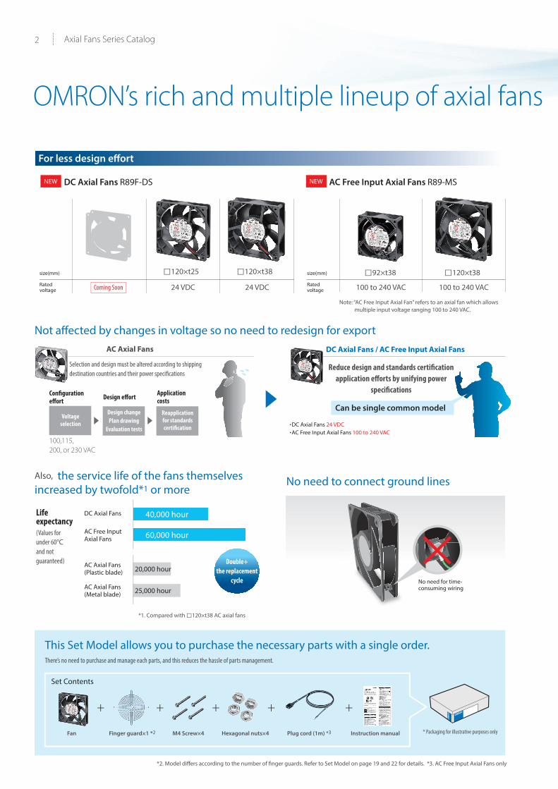
OMRON’s rich and multiple lineup of axial fans
□120×t25 □92×t38□120×t38 □120×t38
(Values for under 60°C and not guaranteed)
Not affected by changes in voltage so no need to redesign for export
Also, the service life of the fans themselves increased by twofold*1 or more
No need to connect ground lines
This Set Model allows you to purchase the necessary parts with a single order.
Life expectancy
DC Axial Fans
AC Free Input Axial Fans
40,000 hour
60,000 hour
20,000 hour
25,000 hour
AC Axial Fans (Plastic blade)
AC Axial Fans (Metal blade)
There’s no need to purchase and manage each parts, and this reduces the hassle of parts management.
Selection and design must be altered according to shipping destination countries and their power specifications
Reduce design and standards certification application efforts by unifying power
specifications
*2. Model differs according to the number of finger guards. Refer to Set Model on page 19 and 22 for details. *3. AC Free Input Axial Fans only
*1. Compared with □120×t38 AC axial fans
Fan Finger guard×1 *2 M4 Screw×4 Hexagonal nuts×4 Plug cord (1m) *3 Instruction manual
Double+ the replacement
cycle
+ + + + +
For less design effort
AC Axial Fans DC Axial Fans / AC Free Input Axial Fans
Set Contents
Design effortConfiguration effort
Application costs
Voltage selection
Design changePlan drawing
Evaluation tests
Reapplication for standards certification
100,115,200, or 230 VAC
.DC Axial Fans 24 VDC
.AC Free Input Axial Fans 100 to 240 VAC
Can be single common model
DC Axial Fans R89F-DS AC Free Input Axial Fans R89-MS
* Packaging for illustrative purposes only
×No need for time-consuming wiring
Coming Soon
NEW NEW
+ + + +
size(mm) size(mm)
Ratedvoltage
Ratedvoltage24 VDC 24 VDC 100 to 240 VAC 100 to 240 VAC
Note: “AC Free Input Axial Fan” refers to an axial fan which allows multiple input voltage ranging 100 to 240 VAC.

3
OMRON’s rich and multiple lineup of axial fans
Conserves energy by responding to temperatures inside the panel
For economy type
For environmental resistance
For less mounting effort
AC Axial Fans R87F/R87T R87F Plastic blade type
AC Axial Fans R87T Metal blade type
Box Fan R87B
Electronic Thermostat E5L Series
□80×t25
Mist resistanceWide range of
operating temperatures
□80×t25
□80×t38
□80×t38
□92×t25
□120×t38
□120×t25
φ150×t38
□120×t38
φ150×t55
All-in-one structure makes it easier to install accessories
Just open the cover to replace
the filter
Metal blade models deliver high environmental resistance
Flow Rate · Size · Noise LargeSmall
Also available are water/dust-resistant models
Fan can be turned on when
temperatures inside the panel
go up and turned off when they
go down
Conventional models Box Fan
OFF
ON
Just open the cover to replace
□120×t38 □120×t38 □120×t38 Simply mount with screws
Many parts
100, 115, 200, 230 VAC
100, 115, 200 , or 230 VAC100, 115, 200 , or 230 VAC
100, 115, 200 , or 230 VAC
100, 115, 200 , or 230 VAC
100, 115, 200 , or 230 VAC
100, 115, 200 , or 230 VAC
100, 115, 200 , or 230 VAC
100, 115, 200 , or 230 VAC
100, 115, 200 , or 230 VAC
100, 115, 200, or 230 VAC
□120×t38
100, 115, 200, or 230 VAC 100, 115, 200, or 230 VAC 100, 115, 200, or 230 VAC
size(mm)
size(mm)
size(mm)
Ratedvoltage
Ratedvoltage
Ratedvoltage
size(mm)
Rated voltage

4 Axial Fans Series Catalog
Select the optimal fan to resolve issues regarding temperatures inside the panelIf the temperature inside the panel increases, the lives of devices and parts inside the panel will be reduced and malfunctions
could result.Particularly devices and parts that generate heat are greatly aff ected by heat.
Panel cooling and Fan selection are extremely important to long-term usage of the panel and parts inside the panel.
Temperatures in the panel go up, leading to device failure
Device service life is shortened, leading to additional replacement eff ort
Without the right fan...
Control devices has a service life.
As a general rule, control devices cease to perform properly (i.e. reach the end
of their service lives) as their electrolytic capacitors wear out over time, before
finally becoming inoperable. Continuing to use control devices past the end
of their service lives may render the devices themselves inoperable when you
power them on. This can cause unexpected facility stoppages.
Continuing to use control devices while they are hot may lead to their early
failure.
Service life (h)
a
10°C
a2
40 50 60 Temperature (°C)
The service life is reduced by half for each 10 °C rise in temperature.
Relationship between service life of a electrolytic capacitor and temperature

5
Selecting Fans
OMRON’s Value Design products can improve airfl ow through uniform sizingBoost the reliability of your devices by evening out heat radiation
1 Check the heating values of devices and the panel (kW).
Check the heating value of each device located in the control panel and then fi nd the total heating value.
2 ΔT of devices and panel: Allowable temperature rise (°C)
ΔT can be obtained by subtracting the device ambient temperature, T1 from the allowable internal temperature, T2.
Note: As a guideline, you can make the calculation with a value of 10°C.(Use the more severe condition.)
3 Calculate Q, the required fl ow rate (m3/min).
Q(m3/min) = 50×W/ΔT
As a general rule, factoring in the system impedance, select a Fan with a maximum fl ow rate of 1.3 to 2 times the calculated required fl ow rate (Q).
As a rough guide, 1.3 times for a small system impedance, 1.5 times for medium, and 2 times for large.
As the fl ow rate increases, noise increases. If the Fan is used in an environment where noise is a problem, select a Fan with a lower fl ow rate.
System impedance
Represents the degree of airfl ow obstruction. Because system impedance is infl uenced by airfl ow, obstacles, and layout, cooling
effi ciency may vary while using fans with the same fl ow rate.
Additionally
Previously NowDiff erences in heights and depths create hot spots. The unifi ed heights and depths help reduce hot spots.
Hot spot Hot spot reduced.
Reducing the temperature inside the panel increases product reliability,decreases the failure rate, and lengthens life expectancies.
4 Select the size of the required Fan based on the maximum fl ow rate.

6
Com
mon
Product list
DC
Axial F
anA
C A
xial Fan
Plastic blade
AC
Axial F
an M
etal bladeA
ccessoriesB
ox Fan
Related product
Attachm
ent / Filter
AC Free Input Axial Fan
AC Free Input Axial Fans
Series Size (mm) ModelPower supply
voltage (V)
Rotational speed
Safety standardsTerminal
type PageCompliant standards Certified standards
CE mark UL CSA
R89F Fans with Plastic Blades
92 × 92 × t38
R89F-MS0938HP 100 to 240 VAC High Yes Yes Yes Terminals
only
20
R89F-MS0938LP 100 to 240 VAC Low Yes Yes Yes Terminals
only
120 × 120 × t38
R89F-MS1238HP 100 to 240 VAC High Yes Yes Yes Terminals
only 21
Plug Cords R89F-PC-@
---
--- Yes ---
---
49
Finger Guards R87F-FG@ --- --- --- 51
Filters R87F-FL@(S) --- --- --- 52

7
Com
mon
Product list
DC
Axial F
anA
C A
xial Fan
Plastic blade
AC
Axial F
an M
etal bladeA
ccessoriesB
ox Fan
Attachm
ent / Filter
AC Free Input Axial Fan
Related product
DC Axial Fans
Series Size (mm) ModelPower supply
voltage (V)
Rotational speed
Safety standardsTerminal
type PageCompliant standards Certified standards
CE mark UL CSA
R89FFans withPlasticBlades
120 × 120 × t25
R89F-DS1225H 24 VDC High Yes Yes Yes Lead wires only
23
R89F-DS1225L 24 VDC Low Yes Yes Yes Lead wires only
120 × 120 × t38
R89F-DS1238H 24 VDC High Yes Yes Yes Lead wires only
24
R89F-DS1238L 24 VDC Low Yes Yes Yes Lead wires only
Finger Guards R87F-FG@---
--- --- ------
51
Filters R87F-FL@(S) --- --- --- 52
8
Com
mon
Product list
DC
Axial F
anA
C A
xial Fan
Plastic blade
AC
Axial F
an M
etal bladeA
ccessoriesB
ox Fan
Related product
Attachm
ent / Filter
AC Free Input Axial Fan
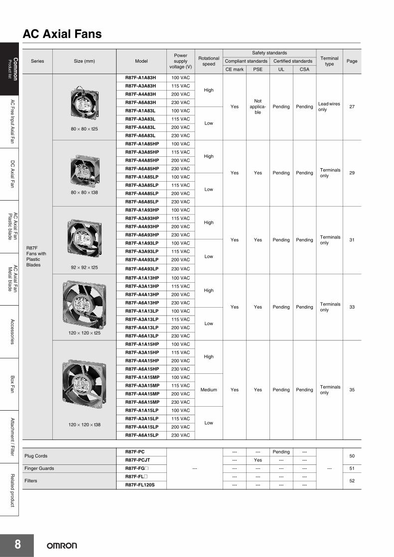
AC Axial Fans
Series Size (mm) ModelPower supply
voltage (V)
Rotational speed
Safety standardsTerminal
typePageCompliant standards Certified standards
CE mark PSE UL CSA
R87FFans with Plastic Blades
80 × 80 × t25
R87F-A1A83H 100 VAC
High
YesNot
applica-ble
Pending PendingLead wires only
27
R87F-A3A83H 115 VAC
R87F-A4A83H 200 VAC
R87F-A6A83H 230 VAC
R87F-A1A83L 100 VAC
LowR87F-A3A83L 115 VAC
R87F-A4A83L 200 VAC
R87F-A6A83L 230 VAC
80 × 80 × t38
R87F-A1A85HP 100 VAC
High
Yes Yes Pending PendingTerminalsonly
29
R87F-A3A85HP 115 VAC
R87F-A4A85HP 200 VAC
R87F-A6A85HP 230 VAC
R87F-A1A85LP 100 VAC
LowR87F-A3A85LP 115 VAC
R87F-A4A85LP 200 VAC
R87F-A6A85LP 230 VAC
92 × 92 × t25
R87F-A1A93HP 100 VAC
High
Yes Yes Pending PendingTerminalsonly
31
R87F-A3A93HP 115 VAC
R87F-A4A93HP 200 VAC
R87F-A6A93HP 230 VAC
R87F-A1A93LP 100 VAC
LowR87F-A3A93LP 115 VAC
R87F-A4A93LP 200 VAC
R87F-A6A93LP 230 VAC
120 × 120 × t25
R87F-A1A13HP 100 VAC
High
Yes Yes Pending PendingTerminalsonly
33
R87F-A3A13HP 115 VAC
R87F-A4A13HP 200 VAC
R87F-A6A13HP 230 VAC
R87F-A1A13LP 100 VAC
LowR87F-A3A13LP 115 VAC
R87F-A4A13LP 200 VAC
R87F-A6A13LP 230 VAC
120 × 120 × t38
R87F-A1A15HP 100 VAC
High
Yes Yes Pending PendingTerminalsonly
35
R87F-A3A15HP 115 VAC
R87F-A4A15HP 200 VAC
R87F-A6A15HP 230 VAC
R87F-A1A15MP 100 VAC
MediumR87F-A3A15MP 115 VAC
R87F-A4A15MP 200 VAC
R87F-A6A15MP 230 VAC
R87F-A1A15LP 100 VAC
LowR87F-A3A15LP 115 VAC
R87F-A4A15LP 200 VAC
R87F-A6A15LP 230 VAC
Plug CordsR87F-PC
---
--- --- Pending ---
---
50R87F-PCJT --- Yes --- ---
Finger Guards R87F-FG@ --- --- --- --- 51
FiltersR87F-FL@ --- --- --- ---
52R87F-FL120S --- --- --- ---

AC Axial Fans
9
Com
mon
Product list
DC
Axial F
anA
C A
xial Fan
Plastic blade
AC
Axial F
an M
etal bladeA
ccessoriesB
ox Fan
Attachm
ent / Filter
AC Free Input Axial Fan
Related product
Series Size (mm) ModelPower supply
voltage (V)
Rotational speed
Safety standardsTerminal
typePageCompliant standards Certified standards
CE mark PSE UL CSA
R87TFans with Metal Blades
80 × 80 × t25
R87T-A1A83H 100 VAC
High YesNot
applica-ble
Pending ---Lead wires only
37
R87T-A3A83H 115 VAC
R87T-A4A83H 200 VAC
R87T-A6A83H 230 VAC
80 × 80 × t38
R87T-A1A85H 100 VAC
High YesNot
applica-ble
Pending ---Lead wires only
39
R87T-A3A85H 115 VAC
R87T-A4A85H 200 VAC
R87T-A6A85H 230 VAC
120 × 120 × t38
R87T-A1A15HP 100 VAC
High
Yes Yes Pending ---Terminalsonly
41
R87T-A3A15HP 115 VAC
R87T-A4A15HP 200 VAC
R87T-A6A15HP 230 VAC
R87T-A1A15MP 100 VAC
MediumR87T-A3A15MP 115 VAC
R87T-A4A15MP 200 VAC
R87T-A6A15MP 230 VAC
150 dia. × t38
R87T-A1A05H 100 VAC
High YesNot
applica-ble
Pending ---Lead wires only
43
R87T-A3A05H 115 VAC
R87T-A4A05H 200 VAC
R87T-A6A05H 230 VAC
150 dia. × t55
R87T-A1A07H 100 VAC
High YesNot
applica-ble
Pending ---Lead wires only
45
R87T-A3A07H 115 VAC
R87T-A4A07H 200 VAC
R87T-A6A07H 230 VAC
120 × 120 × t38
R87T-A1A15H-WR 100 VAC
High YesNot
applica-ble
cUL pending
---Lead wires only
47
R87T-A3A15H-WR 115 VAC
R87T-A4A15H-WR 200 VAC
R87T-A6A15H-WR200 to 230
VAC

10
Com
mon
Product list
DC
Axial F
anA
C A
xial Fan
Plastic blade
AC
Axial F
an M
etal bladeA
ccessoriesB
ox Fan
Related product
Attachm
ent / Filter
AC Free Input Axial Fan
Box Fans
* An R87B Box Fan consists of an AC Axial-flow Fan in a square mounting attachment.The safety standards apply to the AC Axial-flow Fan in the Box Fan. For details, refer to the safety standards for the AC Axial-flow Fan. The model number of the AC Axial-flow Fan in the Box Fan can be determined from the model number of the Box Fan as follows:
Series Size (mm) ModelPower supply
voltage (V)
Rotational speed
Safety standards*Terminal
type PageCompliant standards Certified standards
CE mark PSE UL CSA
R87BBox Fans
R87B-FA1A15HPF(R) 100 VAC
High
--- --- --- ---
Termi-nalsonly
56
R87B-FA3A15HPF(R) 115 VAC
R87B-FA4A15HPF(R) 200 VAC
R87B-FA6A15HPF(R) 230 VAC
R87B-FA1A15LPF(R) 100 VAC
LowR87B-FA3A15LPF(R) 115 VAC
R87B-FA4A15LPF(R) 200 VAC
R87B-FA6A15LPF(R) 230 VAC
R87B-TA1A15HPF(R) 100 VAC
High
--- --- --- ---
R87B-TA3A15HPF(R) 115 VAC
R87B-TA4A15HPF(R) 200 VAC
R87B-TA6A15HPF(R) 230 VAC
R87B-TA1A15MPF(R) 100 VAC
MediumR87B-TA3A15MPF(R) 115 VAC
R87B-TA4A15MPF(R) 200 VAC
R87B-TA6A15MPF(R) 230 VAC
R87B-FA1A16HPF(R)2 100 VAC
High
--- --- --- ---
Termi-nalsonly
58
R87B-FA3A16HPF(R)2 115 VAC
R87B-FA4A16HPF(R)2 200 VAC
R87B-FA6A16HPF(R)2 230 VAC
R87B-FA1A16LPF(R)2 100 VAC
LowR87B-FA3A16LPF(R)2 115 VAC
R87B-FA4A16LPF(R)2 200 VAC
R87B-FA6A16LPF(R)2 230 VAC
R87B-TA1A16HPF(R)2 100 VAC
High
--- --- --- ---
R87B-TA3A16HPF(R)2 115 VAC
R87B-TA4A16HPF(R)2 200 VAC
R87B-TA6A16HPF(R)2 230 VAC
R87B-TA1A16MPF(R)2 100 VAC
MediumR87B-TA3A16MPF(R)2 115 VAC
R87B-TA4A16MPF(R)2 200 VAC
R87B-TA6A16MPF(R)2 230 VAC
R87B-FA1A16HPF(R)3 100 VAC
High
--- --- --- ---
Termi-nalsonly
60
R87B-FA3A16HPF(R)3 115 VAC
R87B-FA4A16HPF(R)3 200 VAC
R87B-FA6A16HPF(R)3 230 VAC
R87B-FA1A16LPF(R)3 100 VAC
LowR87B-FA3A16LPF(R)3 115 VAC
R87B-FA4A16LPF(R)3 200 VAC
R87B-FA6A16LPF(R)3 230 VAC
R87B-TA1A16HPF(R)3 100 VAC
High
--- --- --- ---
R87B-TA3A16HPF(R)3 115 VAC
R87B-TA4A16HPF(R)3 200 VAC
R87B-TA6A16HPF(R)3 230 VAC
R87B-TA1A16MPF(R)3 100 VAC
MediumR87B-TA3A16MPF(R)3 115 VAC
R87B-TA4A16MPF(R)3 200 VAC
R87B-TA6A16MPF(R)3 230 VAC
Attachments R87B-N@--- --- --- --- --- --- 62
Replacement Filter R87B-PF01
R87B-FA1A15HPF → R87F-A1A15HPThe model number of the Axial-flow Fan can be determined by extracting the underlined portions from the model number of the Box Fan as shown.

11
Com
mon
Applications
Attachm
ent / Filter
DC
Axial F
anA
C A
xial Fan
Plastic blade
AC
Axial F
an M
etal bladeA
ccessoriesB
ox Fan
AC
Free Input Axial Fan
Related product
Applications for Axial Fans
Axial Fans can perform stable cleaning in a variety of purposes and locations.
Note: Water-resistant fans are recommended for vending machines and show-cases.
■ Control Panels ■ Machine Tools
■ Measurement Devices ■ Medical Devices
■ Solder Fume Suction Equipment ■ Vending Machines and Showcases

12
Com
mon
Safety P
recautionsA
ttachment / F
ilterD
C A
xial Fan
AC
Axial F
an P
lastic bladeA
C A
xial Fan
Metal blade
Accessories
Box F
anR
elated productA
C Free Input A
xial Fan
Safety Precautions for All Axial FansWarning Indications
Meaning of Product Safety Symbols
Warning
Indicates a potentially hazardous situation that, if not avoided, could result in serious injury or death. Additionally there may be significant property damage.
CautionIndicates a potentially hazardous situation that, if not avoided, could result in minor or moderate injury or property damage.
Precautionsfor Safe Use
Supplementary comments on what to do or avoid doing to use the product safely.
Precautionsfor Correct
Use
Supplementary comments on what to do or avoid doing to prevent failure to operate, malfunction, or undesirable effects on product performance.
Used to prohibit touching certain portions of the device under specific conditions because of the possibility of injuries.
Used for general prohibitions for which there is no specific symbol.
Used to indicate prohibition when there is a risk of minor injury from electrical shock or other source if the product is disassembled.
Used for general mandatory action precautions for which there is no specified symbol.
WARNING
Do not touch the blades. Doing so may result in injury. Always mount the optional Finger Guard when there is any possibility that a person may touch the fan blade.
Do not use the Box Fan with the Finger Guard removed.Make sure that power is turned OFF before performing any action that requires touching the blades, such as inspections or filter replacement.
CAUTION
Do not hold the Fan by its power lines, or pull the power lines with excessive force. Injury may occasionally occur if the Fan falls.
Do no insert objects into the rotating parts of the Fan. Fan failure may occasionally result in property damage or minor injury.
Do not allow the Fan to be subjected to shock, such as falling, otherwise the service life and performance characteristics of the Fan will be adversely affected. Precision-type ball bearings are used to hold the shaft of the Fan. Do not use the Fan outside the rated temperature range or above the rated voltage. Do not use the Fan outside the operating temperature range and allowable voltage fluctuation range. Do not touch the motor section during operation or immediately after stopping operation.
Do not use the Fan where subject to flammable or explosive gas. Otherwise, minor injury from explosion may occasionally occur.
Do not attempt to disassemble, repair, or modify the Fan. Property damage or minor injury may occasionally occur due to electric shock, fire, or Fan failure.
Unexpected operation of the Fan after, for example, the Fan has stopped due to contact failure, due to the operation of overheating protection (thermal protection), or due to operation of restraint burnout protection, may result in minor injury.Make sure that the power is turned OFF before performing any action that requires touching the blades, such as inspections.Do not wire the power lines of the Fan in series with those of other Fans or devices. Wire the devices in parallel. Fan failure may occasionally result in property damage or minor injury.
Be sure to secure the Fan with the mounting bolts. Not doing so may result in injury due to the Fan falling. Use M4 bolts to mount the Fan.The recommended tightening torque is as follows.R87@: 0.44 N·mR89F: 0.78 N·mProvide measures, such as circuit-breaker fuses, on the power supply lines of devices that are using Axial Fans. Short-circuiting of the Fan may adversely affect other devices.
Axial Fan
Power lines connected in series
Otherdevice Axial Fan
Power lines connected in parallel
Otherdevice

Safety Precautions for All Axial Fans
13
Com
mon
Safety P
recautionsA
ttachment / F
ilterD
C A
xial Fan
AC
Axial F
an P
lastic bladeA
C A
xial Fan
Metal blade
Accessories
Box F
anA
C Free Input A
xial FanR
elated product
Do not install or store the Fan in the following environments.• Locations subject directly to water (except for water-resistant
Fans)• Locations subject directly to oil• Locations subject directly to vibration or shock• Locations subject to strong static electricity or harmonics• Locations subject to excessive dust or metallic powder• Locations subject to direct sunlight• Locations subject to condensation or icing• Locations subject to corrosive gases (particularly sulfide and
ammonia gases)
1. Check the direction of the airflow before installing the Fan. The direction of the airflow is indicated with an arrow on the Fan frame. The arrow points in the direction that the air flows.
2. Refer to the panel cutout dimensions in each datasheet to cut a hole in the installation device and secure the Fan with bolts.
3. The Fan is intended for cooling and air circulation. Do not use it for other purposes.
4. Dispose of the Fan as industrial waste.5. Ensure that no organic solvents or alkaline chemicals are in
contact with plastic parts of the Fan, otherwise cracks, swelling, or dissolution may result.
6. When using the Fan as a CE-compliant product, use in an environment below the display temperature of “T@@” indicated on the product label.
7. When using the following model, ensure EMC conformity by using a power supply line cable no longer than 30 m.In addition, do not connect to a DC distribution network.Applicable model: R89F-DS@ Series
8. Secure the cover of the Box Fan with the mounting bolts. If the cover is loose, vibration may cause it to come off.
9. Do not remove the cover while the Box Fan is operating.
Leakage Flux• Leakage flux from an Axial Fan may distort the image on nearby
CRT screens. Measures to prevent this problem include:
1. Keeping CRTs at least 30 cm away from the Axial Fan.2. Shielding the Axial Fan side with metal mesh.
The leakage flux from a Fan with metal blades is less than with plastic blades. The leakage flux distribution curves are shown below as examples.
R87T and Other AC Axial Fans
Precautions for Safe Use
Precautions for Correct Use
Precautions for Correct Use
Inlet
Dimensions
Leakage flux distribution
Outlet
Dimensions
Leakage flux distribution
A B C D E F G H I J K L M
Leak
age
flux
(mT
)
Measurement point
4
3
2
1
0A B C D E F G H I J K L M
A B C D E F H I J K L M G
Leak
age
flux
(mT
)
Measurement point
Leakage flux = 0
4
3
2
1
0A B C D E F G H I J K L M

Safety Precautions for All Axial Fans
14
Com
mon
Safety P
recautionsA
ttachment / F
ilterD
C A
xial Fan
AC
Axial F
an P
lastic bladeA
C A
xial Fan
Metal blade
Accessories
Box F
anR
elated productA
C Free Input A
xial Fan
Noise Countermeasures• The cooling effect and noise levels of Axial Fans are greatly
affected by the mounting conditions. Take the points listed below into account when installing the Fans.
• Maintain as much clearance as possible between the Fan inlet and the cooled object. (If the cooled object occupies about the same surface area as the Fan on a flat surface, a distance of approximately 10 cm is appropriate.)
• The diameter of the Fan installation hole (D2) should be larger than the diameter of the Fan (D1).D1:Fan installation hole diameterD2:Fan diameterD1 > D2
Cooling Effect• Avoid rapid changes in air flow
direction or air-flow cross-section which reduce the cooling effect.
• When installing the Fan, keep the clearance at the outlet side as small as possible. (If there is a large clearance at the outlet side, it may not be possible to obtain a sufficient cooling effect.)
Axial Fan Installation• The Fan can be mounted with bolts through only one flange
(single-flange mounting) or with through-bolts through both flanges (double-flange mounting). Take care not to distort the frame when using double-flange mounting. The appropriate tightening torques are indicated below.R87@: 0.44 N·mR89F: 0.78 N·m
Box Fan Installation• As shown in the figure, line the Box Fan up with the screw holes,
insert it into the panel cut-out, and firmly secure it with the enclosed mounting bolts and nuts.
• The cover can be mounted either upward or downward. Use whichever direction is convenient.
Precautions for Building Fans into EquipmentAlways mount the optional Finger Guard when there is any possibility that a person may touch the Fan blade.• Mount a protective shield or screen, or the optional Finger Guard
to the Axial Fan installation.• Do not use a Box Fan with the Finger Guard removed. Injury may
occur as a result of touching the Fan blade.• There are various types of optional R87F-FG Finger Guards
available. Select the one that suits the size of the Axial Fan.• Always turn OFF the power and confirm that the Fan blade has
stopped turning before starting to conduct an inspection, replace the filter, etc. Injury may occur as a result of touching the Fan blade.
Fan
Distance
Cooled object
D1D2
Fan Panel
Fan Panel
Fan
L (ideally zero (0))
Panel
Single-flange mounting Double-flange mounting
Panelcut-out
Hexagonalnut
Plain washer
Plainwasher
Handle screwCover
Spring washer
Mountingbolts(included) x 2

15
Com
mon
Technical G
uideA
ttachment / F
ilterD
C A
xial Fan
AC
Axial F
an P
lastic bladeA
C A
xial Fan
Metal blade
Accessories
Box F
anA
C Free Input A
xial FanR
elated product
Technical Explanation for Axial FansSelecting a FanProcedure(1) Estimate the amount of heat generated (W) inside the
Unit.(2) Set the maximum permitted temperature rise limit (ΔT)
inside the Unit.
(3) Calculate the required flow rate.
(4) Estimate the system impedance from the air flow through the Unit or from previous data.
(5) Select the Fan according to the P - Q characteristics.(6) Measure the temperature rise in an installed Unit.(7) Reappraise the Fan if the measured cooling effect is
insufficient.
The procedure to select a Fan is described above. It is difficult, however, to obtain the actual system impedance.In general, therefore, select a Fan with a maximum flow rate of from 1.3 to 2 times the flow rate required.
As a rough guide, 1.3 times for a small system impedance, 1.5 times for medium, and 2 times for large.
Reconsider the Fan if the cooling effect is insufficient after the selected fan has been installed in the Unit and the temperature rise has been measured.
Electronic Thermostat Connection ExampleConnection example
* The sensor should be installed directly to the measurement target or toward the top of the panel.
T1 T2
ΔT = T2 − T1
Power supply
T1: Temperature of the inlet air (°C).T2: Temperature of the outlet air (°C).
Q = flow rate (m3/min.) ΔT = permitted temperature rise limit (°C) (Normally between 8 to 10°C.) W = amount of heat generated (kW)
Q =50 WΔT
m3/min
ΔP: Pressure drop (Pa) K: Unit constant n: Coefficient determined by air flow n=1: laminar flow n=2: turbulent flow (n=2 is the normal value.)
ΔP = KQn
E52-THE-E5L *
E5L
9
10
14
13
124
Control Panels

Com
mon
Technical G
uideA
ttachment / F
ilterD
C A
xial Fan
AC
Axial F
an P
lastic bladeA
C A
xial Fan
Metal blade
Accessories
Box F
anR
elated productA
C Free Input A
xial Fan
Technical Explanation for Axial Fans
16
Explanation of TermsNominal ValueThe average value of data based on actual measurements. Nominal values cannot be treated as rated values.
Flow Rate: Q (m /min.)The volume of air discharged by the Fan in a unit of time.
Static Pressure: Ps (Pa)The pressure difference across the front to the back of the Fan generated by the discharged air, which is unaffected by air flow speed.
Maximum Flow Rate: Q max. (m /min.)The volume of air discharged by the Fan when the static pressure is adjusted to zero (Pa) at the flow measurement unit.
Maximum Static Pressure: Ps max. (Pa)The pressure difference inside and outside the Unit when the flow rate is adjusted to zero (0 m3/min.) at the flow measurement unit. This would be the pressure in front of the Unit when the front of the fan was completely sealed.
System ImpedanceThe flow resistance inside a mounted Axial Fan caused by the density of parts and shape of the flow path.
Impedance ProtectionA method of preventing burning damage when the motor is restricted from rotating by setting the motor winding impedance (AC resistance) to a value giving a temperature rise in the windings below the temperature at which burning occurs.
Thermal ProtectionA method of preventing burning damage when the motor is restricted from rotating by setting a thermal element to interrupt operation before the motor reaches a temperature at which burning occurs.
Current Blocking FunctionA method of preventing burning damage when the motor is restricted from rotating by periodically shutting down the motor winding current in order to ensure the motor temperature rise is below the temperature at which burning occurs.
Power Supply Lead Wire Reverse Connection Pro-tectionThis function prevents problems with the fan even if the positive/negative lead wire of the power supply is connected in reverse.
3
P P
Fan
Same as water level
P P+Ps
Fan
Ps
(1) The air pressure across the front to the back of the Fan does not change when the Fan is stopped.
(2) Static pressure (Ps) is generated at the front of the Fan when it rotates.
3
P P+ Ps max.
Fan
Maximum value of difference Ps max.

Technical Explanation for Axial Fans
17
Com
mon
Technical G
uideA
ttachment / F
ilterD
C A
xial Fan
AC
Axial F
an P
lastic bladeA
C A
xial Fan
Metal blade
Accessories
Box F
anA
C Free Input A
xial FanR
elated product
Further InformationFlow Rate and Static PressureThe characteristic graphs provided for each of the models represent the average of actual measurement data obtained under the measurement conditions given below. They are provided as reference for determining the Fan most suitable for the type of cooling required; the actual characteristics may differ from the values represented in the graphs. The graphs are not intended to guarantee these characteristic values.
A simple explanation of the flow rate/static pressure characteristics and the methods of measuring them is given below.
Note: The following symbols are used in the graph below for the flow rate/static pressure characteristics model:
Maximum Static Pressure, Ps max. (flow rate = 0):Fully close the damper. Take the pressure difference between chamber B and ambient pressure (Ps). The maximum value of the pressure difference (Ps) is the maximum static pressure (Ps max).
Intermediate Region, (Q, Ps): Adjust the auxiliary blower to change the static pressure (Ps). Measure the pressure difference between chamber A and chamber B (Pd). Calculate the flow rate (Q).
Maximum Flow Rate, Q max. (static pressure = 0): Fully open the damper and adjust the auxiliary blower to set the static pressure to zero (0). Measure the pressure difference between chamber A and chamber B (Pd). Take the flow rate (Q) calculated at this point as the maximum flow rate (Q max.).
Fan Operating Point:A Fan installed in equipment operates near the point where the Fan characteristic curve crosses the system impedance curve.
Note: The maximum flow rate and maximum static pressure do not indicate the Fan operating point when it is installed in equipment. However, these characteristics are important for comparing Fan performances and for selecting Fans.
Measurement Conditions for R87@ Series
Number of Fans
tested
Ambient conditions Measurement device
5Temperature:23 ±2°CHumidity: 65% ±5%
Measurement was performed using the multi-nozzle double chamber method based on AMCA (Air Moving Condition Association, U.S.A.) Standards 270 to 274.
Ps Pd
Measured fan
Air Air
Chamber B Chamber A
Chamber selector Mesh to smooth flow Damper Auxiliary blower Nozzle
M
Mesh to smooth flow
Manometer to measure static pressure (digital pressure-gauge on machine)
Manometer to measure static pressure (digital pressure-gauge on machine) Measure pressure difference across nozzle (difference between chamber A and B pressures) and calculate air flow rate.
Fan operating point when installed in machine
Intermediate range (Q, Ps)
Measurement point
Max. pressure: Ps max.
System impedance of unit
Max. flow rate: Q max.
Flow rate: Q (m3/min)
Sta
tic p
ress
ure:
Ps
(Pa)
Flow Rate Measurement Device Flow Rate/Static Pressure Characteristic Model

Com
mon
Technical G
uideA
ttachment / F
ilterD
C A
xial Fan
AC
Axial F
an P
lastic bladeA
C A
xial Fan
Metal blade
Accessories
Box F
anR
elated productA
C Free Input A
xial Fan
Technical Explanation for Axial Fans
18
Serial and Parallel Fan OperationThe characteristics of two identical Fans operated in series or parallel are determined as shown in the following diagrams.
Serial Operation:
Parallel Operation:
Noise MeasurementsMeasurements are performed according to JIS B 8346 (Noise Level Measurement Method for Blowers and Compressors).
R87F: Measurement is performed at a position 1.5 m above the center line from the air inlet.
R89F: Measurement is performed at a position 1 m away from the air inlet.
Cooling EffectUse the location and number of heat-generating elements to determine which is more efficient, blowing air out or blowing air in.
Service LifeThe service life of an Axial Fan is generally determined by the bearings. The following diagram is a simple, mechanical illustration of the Fan structure. The Fan blade will turn smoothly if the bearings are in normal condition. When there is an abnormality in the bearings, however, the friction between the shaft and the bearings will increase until the blade eventually stops turning.This is the definition of a Fan's service life.
Flow rate Q
P2
P1
2 units
1 unit
System impedance
Pressure increase
P2 1.5P1
Sta
tic p
ress
ure
1 unit
2 units System impedance
Flow rate increase
Q1
P
Q2 2Q1
Q2 Flow rate
Sta
tic p
ress
ure
Fan
1.5 m
Microphone
Measurement with R87F
Heat generation
Heat generation
Heat generation
Heat generation
● Blowing Air Out ● Blowing Air In
Many Heat-generating Elements in Various Locations
The pressure inside the box decreases, so dust can easily enter through other openings.
Heat-generating Elements in One Location
The pressure inside the box increases, preventing dust from easily enter through other openings.
Fan blade
Bearing
A mechanical illustration of the Axial Fan structure

19
Attachm
ent / Filter
Com
mon
DC
Axial F
anA
C A
xial Fan
Plastic blade
AC
Axial F
an M
etal bladeA
ccessoriesB
ox Fan
AC Free Input Axial FanR
elated product
AC Free Input Axial Fans
R89F-MReducing required design work through unified power supply voltage• Reduced time spent on replacement thanks to a longer service
life.• Selection of free voltage input 100 to 240 VAC models.• Available in set packages (including finger guards, plug cords,
and mounting screws).• CE marking compliant, and certified compliant with various
standards including UL and CSA.
Model Number StructureModel Number Legend
Ordering InformationAC Free Input Axial Fans Options (Order Separately)
Note: Mounting screws are not provided.
Set Model
Safety PrecautionsRefer to the Safety Precautions for All Axial Fans on page 12 to 14.
1. Basic series 3. Frame shape 5. Frame thickness 7. Terminal typeR89F Plastic Blade Series S Square 38 38 P Terminals *
* A Plug Cord (R89F-PC) is required for models with terminals.
2. Rated voltage 4. Frame 6. Rotational speed 8. Delivered configurationM 100 to 240 VAC 09 92 × 92 H High speed No marking Standard
12 120 × 120 L Low speed S1 Finger guard + Screw and nut set +Plug cord *S2
* Refer to Set Model on page 19 and 25 for details.
Note: These tables show only how to read model numbers. They do not indicate which products are available. Refer to Ratings and Ordering Information when ordering.
For the most recent information on models that have been certified for safety standards, refer to your OMRON website.Be sure to read the Safety Precautions for All Axial
Fans on page 12.
R89F-M@@@@@@@-@@1 2 3 4 5 6 7 8
Series Size (mm) Speed Model Page
R89F-M series
92 × 92 × t38 High R89F-MS0938HP 20
92 × 92 × t38 Low R89F-MS0938LP 20
120 × 120 × t38 High R89F-MS1238HP 21
Name Model Page
Plug Cord R89F-PC-@ 49
Finger Guard R87F-FG@ 51
Filter R87F-FL@(S) 52
Model Set Contents
R89F-MS0938HP-S1 Fan, Finger guard × 1, M4 Screw (55 mm) × 4 and nut set × 4, Plug cord (1 m)
R89F-MS0938LP-S1 Fan, Finger guard × 1, M4 Screw (55 mm) × 4 and nut set × 4, Plug cord (1 m)
R89F-MS1238HP-S1 Fan, Finger guard × 1, M4 Screw (55 mm) × 4 and nut set × 4, Plug cord (1 m)
R89F-MS0938HP-S2 Fan, Finger guard × 2, M4 Screw (55 mm) × 4 and nut set × 4, Plug cord (1 m)
R89F-MS0938LP-S2 Fan, Finger guard × 2, M4 Screw (55 mm) × 4 and nut set × 4, Plug cord (1 m)
R89F-MS1238HP-S2 Fan, Finger guard × 2, M4 Screw (55 mm) × 4 and nut set × 4, Plug cord (1 m)

Attachm
ent / Filter
Com
mon
DC
Axial F
anA
C A
xial Fan
Plastic blade
AC
Axial F
an M
etal bladeA
ccessoriesB
ox Fan
Related product
AC Free Input Axial Fan
R89F-M
20
R89F-MS0938@ AC Free Input Axial Fans (92 × 92 × t38 mm)
Ratings and Ordering Information
* An asterisk (*) indicates a nominal value.
Characteristics
Dimensions (Unit: mm)
ItemRated
voltage
Permitted voltage
fluctuation range
Frequency[Hz]
Rated current[A] *
Rated input[W] *
Rated rotational
speed[r/min-1] *
Maximum flow rate
[m3/min] *
Maximum static
pressure[Pa] *
Noise[dB] *Model
R89F-MS0938HP 100 to 240 VAC 90 to 264 V 50/60 0.08 4.5 3850 1.5 90 40
R89F-MS0938LP 100 to 240 VAC 90 to 264 V 50/60 0.06 3.0 3100 1.18 56 33
Motor type Brushless DC motor
Terminal type Terminals
Insulation class Class E (UL class A)
Insulation resistance 10 MΩ min. (at 500 VDC)Between lead wire conductor and frame
Insulation withstand voltage
1,500 VAC (1 minute)Between input terminal and frame
Ambient operating temperature -20 to 75°C (with no icing)
Ambient storage temperature -30 to +75°C (no icing)
Ambient humidity 20% to 85%
Protection Restraint burnout protection (Current blocking function)
MaterialsFrame PBT/PC alloy (UL94V-0)
Blades PBT/PC alloy (UL94V-0)
Bearings Ball bearings
Weight Approx. 250 g
Compliant standardsEN/IEC 60950 (CE marking compliant)EAC, RCMPSE
Certified standards UL: UL507 (Recognition), C22.2 No.113
Flow Rate and Static Pressure Characteristics (Reference Value)
Note: For details on measurement conditions, refer to Flow Rate and Static Pressure on page 17.
R89F-MS0938HP R89F-MS0938LP
20
40
60
80
100
00 0.4 0.8 1.2 1.6
100-240 V50/60 Hz
Sta
tic p
ress
ure
Ps
(Pa)
Flow rate: Q (m3/min)
100-240 V50/60 Hz
20
40
50
60
10
00 0.4 0.8 1.2 1.6
Sta
tic p
ress
ure
Ps
(Pa)
Flow rate: Q (m3/min)
Eight, 4.3±0.3 dia.
Direction of airflowDirection of rotation
92±0.5
82.5±0.3
38±0.5
(4)(4)
92±0.5
82.5±0.3
82.5±0.3
82.5±0.3
90.5
90.5
97 dia.
82.5±0.3
82.5±0.3
90.5
90.5
105 dia.
Four, 4.5 dia.Four, 4.5 dia.
OutletInlet
Panel Cutouts
OptionsName Model Page
Plug Cord R89F-PC-@ 49
Finger Guard R87F-FG90 51

R89F-M
21
Attachm
ent / Filter
Com
mon
DC
Axial F
anA
C A
xial Fan
Plastic blade
AC
Axial F
an M
etal bladeA
ccessoriesB
ox Fan
AC Free Input Axial FanR
elated product
R89F-MS1238@ AC Free Input Axial Fans (120 × 120 × t38 mm)
Ratings and Ordering Information
* An asterisk (*) indicates a nominal value.
Characteristics
Dimensions (Unit: mm)
ItemRated
voltage
Permitted voltage
fluctuation range
Frequency[Hz]
Rated current[A] *
Rated input[W] *
Rated rotational
speed[r/min-1] *
Maximum flow rate
[m3/min] *
Maximum static
pressure[Pa] *
Noise[dB] *Model
R89F-MS1238HP 100 to 240 VAC 90 to 264 V 50/60 0.08 4.4 3250 3.0 84 42
Motor type Brushless DC motor
Terminal type Terminals
Insulation class Class E (UL class A)
Insulation resistance 10 MΩ min. (at 500 VDC)Between lead wire conductor and frame
Insulation withstand voltage
1,500 VAC (1 minute)Between input terminal and frame
Ambient operating temperature -20 to 75°C (with no icing)
Ambient storage temperature -30 to +75°C (no icing)
Ambient humidity 20% to 85%
Protection Restraint burnout protection(Current blocking function)
MaterialsFrame PBT/PC alloy (UL94V-0)
Blades PPHOX (UL94V-1)
Bearings Ball bearings
Weight Approx. 290 g
Compliant standardsEN/IEC 60950 (CE marking compliant)EAC, RCMPSE
Certified standards UL: UL507 (Recognition), C22.2 No.113
Flow Rate and Static Pressure Characteristics (Reference Value)
Note: For details on measurement conditions, refer to Flow Rate and Static Pressure on page 17.
R89F-MS1238HP
10
20
30
40
60
50
90
70
80
00 431 2
100-240 V50/60 Hz
Sta
tic p
ress
ure
Ps
(Pa)
Flow rate: Q (m3/min)
Direction of rotation Direction of airflow
Eight, 4.3±0.3 dia.
104.8±0.3
120±0.8
104.8±0.3
120±0.8
38±0.5
(6) (6)
Four, 4.5 dia. Four, 4.5 dia.104.8±0.3
118
118
118
104.8±0.3
104.8±0.3 104.8±0.3
118
135 dia.127 dia.
OutletInletPanel Cutouts
OptionsName Model Page
Plug Cord R89F-PC-@ 49
Finger Guard R87F-FG120 51
Filter R87F-FL120(S) 52

22
Attachm
ent / Filter
Com
mon
DC
Axial Fan
AC
Axial F
an P
lastic bladeA
C A
xial Fan
Metal blade
Accessories
Box F
anR
elated productA
C Free Input A
xial Fan
DC Axial Fans
R89F-DReducing required design work through unified power supply voltage• Reduced time spent on replacement thanks to a longer service life.• Selection of low-voltage input 24 VDC models.• Available in set packages (including finger guards and mounting
screws).• CE marking compliant, and certified compliant with various
standards including UL and CSA.
Model Number StructureModel Number Legend
Ordering InformationDC Axial Fans Options (Order Separately)
Note: Mounting screws are not provided.
Set Model
Safety PrecautionsRefer to the Safety Precautions for All Axial Fans on page 12 to 14.
1. Basic series 3. Frame shape 5. Frame thickness 7. Terminal typeR89F Plastic Blade Series S Square 25 25 No marking Lead wires
38 38
2. Rated voltage 4. Frame 6. Rotational speed 8. Delivered configurationD 24 VDC 12 120 × 120 H High speed No marking Standard
L Low speed S1Finger guard + Screw and nut set *S2
* Refer to Set Model on page 22 and 25 for details.
Note: These tables show only how to read model numbers. They do not indicate which products are available. Refer to Ratings and Ordering Information when ordering.
For the most recent information on models that have been certified for safety standards, refer to your OMRON website.
Be sure to read the Safety Precautions for All Axial Fans on page 12.
R89F-D@@@@@@@-@@1 2 3 4 5 6 7 8
Series Size (mm) Speed Model Page
R89F-D series
120 × 120 × t25 High R89F-DS1225H 23
120 × 120 × t25 Low R89F-DS1225L 23
120 × 120 × t38 High R89F-DS1238H 24
120 × 120 × t38 Low R89F-DS1238L 24
Name Model Page
Finger Guard R87F-FG@ 51
Filter R87F-FL@(S) 52
Model Set Contents
R89F-DS1225H-S1 Fan, Finger guard × 1, M4 Screw (40 mm) × 4 and nut set × 4
R89F-DS1225L-S1 Fan, Finger guard × 1, M4 Screw (40 mm) × 4 and nut set × 4
R89F-DS1238H-S1 Fan, Finger guard × 1, M4 Screw (55 mm) × 4 and nut set × 4
R89F-DS1238L-S1 Fan, Finger guard × 1, M4 Screw (55 mm) × 4 and nut set × 4
R89F-DS1225H-S2 Fan, Finger guard × 2, M4 Screw (40 mm) × 4 and nut set × 4
R89F-DS1225L-S2 Fan, Finger guard × 2, M4 Screw (40 mm) × 4 and nut set × 4
R89F-DS1238H-S2 Fan, Finger guard × 2, M4 Screw (55 mm) × 4 and nut set × 4
R89F-DS1238L-S2 Fan, Finger guard × 2, M4 Screw (55 mm) × 4 and nut set × 4

R89F-D
23
Attachm
ent / Filter
Com
mon
DC
Axial Fan
AC
Axial F
an P
lastic bladeA
C A
xial Fan
Metal blade
Accessories
Box F
anA
C Free Input A
xial FanR
elated product
R89F-DS1225@ DC Axial Fans (120 × 120 × t25 mm)
Ratings and Ordering Information
* An asterisk (*) indicates a nominal value.
Characteristics
Dimensions (Unit: mm)
ItemRated
voltage
Permitted voltage
fluctuation range
Frequency[Hz]
Rated current[A] *
Rated input[W] *
Rated rotational
speed[r/min-1] *
Maximum flow rate
[m3/min] *
Maximum static
pressure[Pa] *
Noise[dB] *Model
R89F-DS1225H 24 VDC 20.4 to 27.6 V --- 0.47 11.28 4100 3.68 120 51
R89F-DS1225L 24 VDC 12 to 27.6 V --- 0.17 4.08 2850 2.5 64 40
Motor type Brushless DC motor
Terminal type Lead wires
Insulation class Class E (UL class A)
Insulation resistance 10 MΩ min. (at 500 VDC)Between lead wire conductor and frame
Insulation withstand voltage
500 VAC (1 minute)Between lead wire conductor and frame
Ambient operating temperature -20 to +70°C (no icing)
Ambient storage temperature -30 to +70°C (no icing)
Ambient humidity 20% to 85%
Protection
Restraint burnout protection(Current blocking function)Power supply lead wire reverse polarity protection
MaterialsFrame PBT/ABS alloy (UL94V-0)
Blades PPHOX (UL94V-1)
Bearings Ball bearings
Weight Approx. 280 g
Compliant standardsEN/IEC 60950 (CE marking compliant)EACRCM
Certified standards UL: UL507 (Recognition)CSA: C22.2 No.113
Flow Rate and Static Pressure Characteristics (Reference Value)
Note: For details on measurement conditions, refer to Flow Rate and Static Pressure on page 17.
R89F-DS1225H R89F-DS1225L
321
20
40
60
4
80
100
120
140
00
24 V
20.4 V
27.6 V
Sta
tic p
ress
ure
Ps
(Pa)
Flow rate: Q (m3/min)
27.6 V
24 V
12 V
20
40
60
80
00 1 2 3
Sta
tic p
ress
ure
Ps
(Pa)
Flow rate: Q (m3/min)
25.0
(5)(5)
(10)
104.8±0.3
119±0.5
104.8±0.3
119±0.5
300 +300
+10
Direction of rotation Direction of airflow
Eight, 4.3±0.3 dia.
Lead wiresAWG24UL1007
104.8±0.3
117
117 117
104.8±0.3
104.8±0.3 104.8±0.3
117
134 dia.126 dia.
Four, 4.5 dia.Four, 4.5 dia.
OutletInletPanel Cutouts
OptionsName Model Page
Finger Guard R87F-FG120 51
Filter R87F-FL120(S) 52

Attachm
ent / Filter
Com
mon
DC
Axial Fan
AC
Axial F
an P
lastic bladeA
C A
xial Fan
Metal blade
Accessories
Box F
anR
elated productA
C Free Input A
xial Fan
R89F-D
24
R89F-DS1238@ DC Axial Fans (120 × 120 × t38 mm)
Ratings and Ordering Information
* An asterisk (*) indicates a nominal value.
Characteristics
Dimensions (Unit: mm)
ItemRated
voltage
Permitted voltage
fluctuation range
Frequency[Hz]
Rated current[A] *
Rated input[W] *
Rated rotational
speed[r/min-1] *
Maximum flow rate
[m3/min] *
Maximum static
pressure[Pa] *
Noise[dB] *Model
R89F-DS1238H 24 VDC 20.4 to 27.6 V --- 0.5 12 3600 3.88 135 49
R89F-DS1238L 24 VDC 14 to 27.6 V --- 0.11 2.64 1950 2.1 39.6 32
Motor type Brushless DC motor
Terminal type Lead wires
Insulation class Class E (UL class A)
Insulation resistance 10 MΩ min. (at 500 VDC)Between lead wire conductor and frame
Insulation withstand voltage
500 VAC (1 minute)Between lead wire conductor and frame
Ambient operating temperature -20 to +70°C (no icing)
Ambient storage temperature -30 to +70°C (no icing)
Ambient humidity 20% to 85%
Protection
Restraint burnout protection(Current blocking function)Power supply lead wire reverse polarity protection
MaterialsFrame PBT/ABS alloy (UL94V-0)
Blades PPHOX (UL94V-1)
Bearings Ball bearings
Weight Approx. 330 g
Compliant standardsEN/IEC 60950 (CE marking compliant)EACRCM
Certified standards UL: UL507 (Recognition)CSA: C22.2 No.113
Flow Rate and Static Pressure Characteristics (Reference Value)
Note: For details on measurement conditions, refer to Flow Rate and Static Pressure on page 17.
R89F-DS1238H R89F-DS1238L
24 V
20.4 V
27.6 V
180
100
140
120
160
80
60
20
40
50 1 2 3 4 60
Sta
tic p
ress
ure
Ps
(Pa)
Flow rate: Q (m3/min)
10
20
30
40
60
50
70
00 31 2
27.6 V
24 V
14 V
Sta
tic p
ress
ure
Ps
(Pa)
Flow rate: Q (m3/min)
Direction of rotation Direction of airflow
Eight, 4.3±0.3 dia.
(5)(5)
(10)
104.8±0.3
119±0.8
104.8±0.3
38±0.5119±0.8
300 +300
Lead wiresAWG24UL1007
104.8±0.3 104.8±0.3
104.8±0.3117 117
117 117
104.8±0.3
134 dia.126 dia.
Four, 4.5 dia.Four, 4.5 dia.
OutletInletPanel Cutouts
OptionsName Model Page
Finger Guard R87F-FG120 51
Filter R87F-FL120(S) 52

R89F
25
Attachm
ent / Filter
Com
mon
DC
Axial Fan
AC
Axial F
an P
lastic bladeA
C A
xial Fan
Metal blade
Accessories
Box F
anAC Free Input Axial Fan
Related product
Set Model• Select the optimum size for a variety of control panels.• All required parts can be ordered as a set, ideal for fan replacement.• All required maintenance parts are included in one box, requiring less space and reduced parts management work.
R89F-@@@@@@@@-S1 *Only applicable for DC Axial Fans and AC Free Input Axial Fans.
R89F-@@@@@@@@-S2 *Only applicable for DC Axial Fans and AC Free Input Axial Fans.
Set Contents
* AC Free Input Axial Fan only
All required parts included
in one box
Fan Finger Guard × 1 Plug Cord (1 m)
M4 screws × 4 Hexagonal nuts × 4 Instruction manual * Packaging for illustrative purposes only.
* AC Free Input Axial Fan only
All required parts included
in one box
Set ContentsFan Finger Guard × 2
M4 screws × 4
Plug Cord (1 m)
Hexagonal nuts × 4 Instruction manual * Packaging for illustrative purposes only.

26
Attachm
ent / Filter
Com
mon
DC
Axial F
anA
C A
xial Fan P
lastic bladeA
C A
xial Fan M
etal bladeA
ccessoriesB
ox Fan
Related product
AC
Free Input Axial Fan
AC Axial Fans
R87F/R87TOptimum Cooling with a Comprehensive Lineup of Axial Fans• Low noise level, long service life, and resistance to the
environment.• Shaft supported by ball bearings for highly-reliable operation.• Plastic-bladed models (44 type) and metal-bladed models
(28 type) included in series.• R87T-A@A15H-WR Water-resistant AC Axial Fans
(IP X7 degree of protection) added to series.Note: The compliant standards and certified safety standards depend on the
product. Check the information in Characteristics.
Model Number StructureModel Number Legend
Note: 1. A Plug Cord (R87F-PC) is available as an option for models with terminals.2. These tables show only how to read product markings. They do not indicate which products are available. Refer to “Ratings and Ordering
Information” when ordering.
Ordering InformationAvailable ModelsAC Axial Fans Options (Order Separately)
Note: Mounting screws are not provided.
Safety PrecautionsRefer to the Safety Precautions for All Axial Fans on page 12 to 14.
For the most recent information on models that have been certified for safety standards, refer to your OMRON website.
Be sure to read the Safety Precautions for All Axial Fans on page 12.
1 2 3 4 5 6 7
9: 92 × 921: 120 × 1200: 150 dia.
3: 255: 387: 55
8
R87 -
1. Basic series
R87F: Plastic bladeR87T: Metal blade
2. Rated voltageA1: 100 VACA3: 115 VACA4: 200 VACA6: 230 VAC
3. Frame materialA: Die-cast aluminum
4. Frame size8: 80 × 80
5. Frame thickness
6. Rotational speed
H: HighM: MediumL: Low
7. Terminal type
No marking: Lead wiresP: Terminals (See note 1.)
-
8. TypeNo marking: Standard WR: Water-resistant
Series Size (mm) Model Page
R87F (plastic blades)
80 × 80 × t25 R87F-A@A83 27
80 × 80 × t38 R87F-A@A85 29
92 × 92 × t25 R87F-A@A93 31
120 × 120 × t25 R87F-A@A13 33
120 × 120 × t38 R87F-A@A15 35
R87T (metal blades)
80 × 80 × t25 R87T-A@A83 37
80 × 80 × t38 R87T-A@A85 39
120 × 120 × t38 R87T-A@A15 41
150-dia. × t38 R87T-A@A05 43
150-dia. × t55 R87T-A@A07 45
120 × 120 × t38 R87T-A@A15H-WR 47
Product name Model Page
Plug Cord R87F-PC 50
Finger Guard R87F-FG@ 51
Filter R87F-FL@(S) 52

R87F/R87T
27
Attachm
ent / Filter
Com
mon
DC
Axial F
anA
C A
xial Fan P
lastic bladeA
C A
xial Fan
Metal blade
Accessories
Box F
anA
C Free Input A
xial FanR
elated product
R87F-A@A83 Axial Fans with Lead Wires (80 × 80 × t25 mm)
SpecificationsRatings and Ordering InformationNote: An asterisk (*) indicates a nominal value.
Characteristics
ItemRated
voltage(V)
Permittedvoltage
fluctuationrange (%)
Frequency(Hz)
Rated current (A) *
Rated input (W) *
Rated rotational
speed (r/min) *
Maximum flow rate
(m3/min) *
Maximum static
pressure (Pa) *
Noise (dB) *
Model 50 Hz 60 Hz 50 Hz 60 Hz 50 Hz 60 Hz 50 Hz 60 Hz 50 Hz 60 Hz 50 Hz 60 HzR87F-A1A83H 100 VAC
85% to 110% rated voltage 50/60
0.097 0.080
7 6 2,600 3,000 0.6 0.7 39.2 53.9 32 36R87F-A3A83H 115 VAC 0.085 0.070
R87F-A4A83H 200 VAC 0.048 0.041
R87F-A6A83H 230 VAC 0.046 0.039
R87F-A1A83L 100 VAC
85% to 110% rated voltage 50/60
0.063 0.055
5 4 1,900 2,100 0.4 0.5 19.5 23.5 28 30R87F-A3A83L 115 VAC 0.055 0.048
R87F-A4A83L 200 VAC 0.033 0.030
R87F-A6A83L 230 VAC 0.028 0.024
Motor type Single-phase shading coil induction motor (2-pole, open type)
Terminal type Lead wires
Insulation classIEC class B (130°C)UL class A (105°C)CSA class A (105°C)
Insulation resistance 100 MΩ min. (at 500 VDC) between all power supply connections and uncharged metal parts.
Insulation withstand voltage 2,000 VAC (1 minute) between all power supply connections and uncharged metal parts.
Ambient operating temperature −30 to 70°C (no icing)
Ambient storage temperature −40 to 85°C (no icing)
Ambient humidity 25% to 85%
Protection Impedance protection
Materials Frame: Die-cast aluminum Blades: Glass polycarbonate
Bearings Ball bearings
Weight Approx. 230 g
Compliant standards EN/IEC 60335 (CE marking compliant)
Certified standards UL/CSA

R87F/R87T
28
Attachm
ent / Filter
Com
mon
DC
Axial F
anA
C A
xial Fan P
lastic bladeA
C A
xial Fan
Metal blade
Accessories
Box F
anR
elated productA
C Free Input A
xial Fan
Flow Rate and Static Pressure Characteristics (Reference Values)
Note: For details on measurement conditions, refer to Flow Rate and Static Pressure on page 17.
Dimensions (Unit: mm)
Panel Cutouts
Options
R87F-A@A15
R87F-A@A83H R87F-A@A83L
Names Model PageFinger Guard R87F-FG80 51
Filter R87F-FL80 52
60 Hz
50 Hz
Sta
tic p
ress
ure:
Ps
(Pa)
Flow rate: Q (m3/min)
10
20
30
40
50
60
00 0.2 0.4 0.6
Sta
tic p
ress
ure:
Ps
(Pa)
Flow rate: Q (m3/min)
10
20
30
40
00 0.2 0.4 0.6
60 Hz
50 Hz
3±0.33±0.3
Eight, 4.3 dia.
71.5±0.3
80±0.5
71.5±0.3
80±0.5
3000.3 sq
25±0.5
Direction of flowDirection of rotation
6
M4 screw: 0.7 pitch
Screw hole for grounding
Four, 4.5 dia. Four, 4.5 dia.
71.5±0.377 71.5±0.3
71.5±0.3
77
71.5±0.3
90 dia. 77 dia.
Outlet Inlet
In the interest of product improvement, specifications are subject to change without notice.
ALL DIMENSIONS SHOWN ARE IN MILLIMETERS.To convert millimeters into inches, multiply by 0.03937. To convert grams into ounces, multiply by 0.03527.

R87F/R87T
29
Attachm
ent / Filter
Com
mon
DC
Axial F
anA
C A
xial Fan P
lastic bladeA
C A
xial Fan
Metal blade
Accessories
Box F
anA
C Free Input A
xial FanR
elated product
R87F-A@A85 AC Axial Fans with Terminals (80 × 80 × t38 mm)
SpecificationsRatings and Ordering InformationNote: An asterisk (*) indicates a nominal value.
Characteristics
ItemRated
voltage(V)
Permittedvoltage
fluctuationrange (%)
Frequency(Hz)
Rated current (A) *
Rated input (W) *
Rated rotational
speed (r/min) *
Maximum flow rate
(m3/min) *
Maximum static
pressure (Pa) *
Noise (dB) *
Model 50 Hz 60 Hz 50 Hz 60 Hz 50 Hz 60 Hz 50 Hz 60 Hz 50 Hz 60 Hz 50 Hz 60 HzR87F-A1A85HP 100 VAC
85% to 110% rated voltage
50/60
0.140 0.115
10 9 2,700 3,200 0.8 0.9 42.1 58.8 32 36R87F-A3A85HP 115 VAC 0.120 0.100
R87F-A4A85HP 200 VAC 0.080 0.060
R87F-A6A85HP 230 VAC 0.060 0.050
R87F-A1A85LP 100 VAC85% to 110% rated voltage
50/60
0.090 0.080
7 6 2,200 2,500 0.6 0.7 25.0 32.0 26 29R87F-A3A85LP 115 VAC 0.080 0.070
R87F-A4A85LP 200 VAC 0.050 0.040
R87F-A6A85LP 230 VAC 0.040 0.040
Motor type Single-phase shading coil induction motor (2-pole, open type)
Terminal type Terminals
Insulation classIEC class B (130°C)UL class A (105°C)CSA class A (105°C)
Insulation resistance 100 MΩ min. (at 500 VDC) between all power supply connections and uncharged metal parts.
Insulation withstand voltage 2,000 VAC (1 minute) between all power supply connections and uncharged metal parts.
Ambient operating temperature −30 to 70°C (no icing)
Ambient storage temperature −40 to 85°C (no icing)
Ambient humidity 25% to 85%
Protection Impedance protection
Materials Frame: Die-cast aluminum Blades: Glass polycarbonate
Bearings Ball bearings
Weight Approx. 280 g
Compliant standards PSE, EN/IEC 60335 (CE marking compliant)
Certified standards UL/CSA

R87F/R87T
30
Attachm
ent / Filter
Com
mon
DC
Axial F
anA
C A
xial Fan P
lastic bladeA
C A
xial Fan
Metal blade
Accessories
Box F
anR
elated productA
C Free Input A
xial Fan
Flow Rate and Static Pressure Characteristics (Reference Values)
Note: For details on measurement conditions, refer to Flow Rate and Static Pressure on page 17.
Dimensions (Unit: mm)
Panel Cutouts
Options
R87F-A@A85HP R87F-A@A85LP
Name Model PagePlug Cord R87F-PC 50
Finger Guard R87F-FG80 51
Filter R87F-FL80 52
10
20
30
40
50
60
00 0.2 0.4 0.6 0.8 1.0
Sta
tic p
ress
ure:
Ps
(Pa)
Flow rate: Q (m3 /min)
60 Hz
50 Hz
0.25 0.5 0.75 1
88.3
78.5
68.6
58.8
49.0
39.2
29.4
19.6
9.8
0
60 Hz
50 Hz
Sta
tic p
ress
ure:
Ps
(Pa)
Flow rate: Q (m3 /min)
Direction of rotation
Eight, 4.3 dia.
71.5±0.3
80±0.5
3±0.3 3±0.371.5±0.3
80±0.5 38±0.5
Direction of flow
5.8
M4 screw: 0.7 pitch
8 2.8
Screw hole for grounding
Terminal shape
Faston #110 terminal(or equivalent)
Four, 4.5 dia. Four, 4.5 dia.
71.5±0.377 71.5±0.3
71.5±0.3
77
71.5±0.3
90 dia. 77 dia.
Outlet Inlet
In the interest of product improvement, specifications are subject to change without notice.
ALL DIMENSIONS SHOWN ARE IN MILLIMETERS.To convert millimeters into inches, multiply by 0.03937. To convert grams into ounces, multiply by 0.03527.

R87F/R87T
31
Attachm
ent / Filter
Com
mon
DC
Axial F
anA
C A
xial Fan P
lastic bladeA
C A
xial Fan
Metal blade
Accessories
Box F
anA
C Free Input A
xial FanR
elated product
R87F-A@A93 AC Axial Fans with Terminals (92 × 92 × t25 mm)
SpecificationsRatings and Ordering InformationNote: An asterisk (*) indicates a nominal value.
Characteristics
ItemRated
voltage(V)
Permittedvoltage
fluctuationrange (%)
Frequency(Hz)
Rated current (A) *
Rated input (W) *
Rated rotational
speed (r/min) *
Maximum flow rate
(m3/min) *
Maximum static
pressure (Pa) *
Noise (dB) *
Model 50 Hz 60 Hz 50 Hz 60 Hz 50 Hz 60 Hz 50 Hz 60 Hz 50 Hz 60 Hz 50 Hz 60 HzR87F-A1A93HP 100 VAC
85% to 110% rated voltage 50/60
0.150 0.130
13 11 2,550 3,050 0.9 1.0 49.0 68.6 33 36R87F-A3A93HP 115 VAC 0.125 0.100
R87F-A4A93HP 200 VAC 0.070 0.060
R87F-A6A93HP 230 VAC 0.055 0.050
R87F-A1A93LP 100 VAC
85% to 110% rated voltage 50/60
0.100 0.085
7 6 1,900 2,200 0.7 0.8 24.5 34.3 29 32R87F-A3A93LP 115 VAC 0.090 0.075
R87F-A4A93LP 200 VAC 0.050 0.043
R87F-A6A93LP 230 VAC 0.045 0.040
Motor type Single-phase shading coil induction motor (2-pole, open type)
Terminal type Terminals
Insulation classIEC class B (130°C)UL class A (105°C)CSA class A (105°C)
Insulation resistance 100 MΩ min. (at 500 VDC) between all power supply connections and uncharged metal parts.
Insulation withstand voltage 2,000 VAC (1 minute) between all power supply connections and uncharged metal parts.
Ambient operating temperature −30 to 70°C (no icing)
Ambient storage temperature −40 to 85°C (no icing)
Ambient humidity 25% to 85%
Protection Impedance protection
Materials Frame: Die-cast aluminum Blades: Glass polycarbonate
Bearings Ball bearings
Weight Approx. 300 g
Compliant standards PSE, EN/IEC 60335 (CE marking compliant)
Certified standards UL/CSA

R87F/R87T
32
Attachm
ent / Filter
Com
mon
DC
Axial F
anA
C A
xial Fan P
lastic bladeA
C A
xial Fan
Metal blade
Accessories
Box F
anR
elated productA
C Free Input A
xial Fan
Flow Rate and Static Pressure Characteristics (Reference Values)v
Note: For details on measurement conditions, refer to Flow Rate and Static Pressure on page 17.
Dimensions (Unit: mm)c
Options
R87F-A@A93HP R87F-A@A93LP
Name Model PagePlug Cord R87F-PC 50
Finger Guard R87F-FG90 51
Filter R87F-FL90 52
Sta
tic p
ress
ure:
Ps
(Pa)
Flow rate: Q (m3/min)
60 Hz
50 Hz
10
20
30
40
50
60
70
00 0.2 0.4 0.6 0.8 1.0
60 Hz
50 Hz
10
20
30
50
40
00 0.2 0.4 0.6 0.8 1.0
Sta
tic p
ress
ure:
Ps
(Pa)
Flow rate: Q (m3/min)
7.8
M4 screw: 0.7 pitch
9
2.8
Six, 4.3 dia.
Two, 3.2±0.15 dia.
4±0.34±0.3
25±0.5
92±0.5
82.5±0.3
92±0.5
82.5±0.3
Direction of flowDirection of rotation
Screw hole for grounding
Terminal shape
Faston #110 terminal(or equivalent)
Four, 4.5 dia. Four, 4.5 dia.82.5±0.3
89
82.5±0.3
82.5±0.3 82.5±0.389
98 dia. 89 dia.
Outlet Inlet
Panel cutting reference dimensions (note 3 mounting holes)
Panel Cutouts
In the interest of product improvement, specifications are subject to change without notice.
ALL DIMENSIONS SHOWN ARE IN MILLIMETERS.To convert millimeters into inches, multiply by 0.03937. To convert grams into ounces, multiply by 0.03527.

R87F/R87T
33
Attachm
ent / Filter
Com
mon
DC
Axial F
anA
C A
xial Fan P
lastic bladeA
C A
xial Fan
Metal blade
Accessories
Box F
anA
C Free Input A
xial FanR
elated product
R87F-A@A13 AC Axial Fans with Terminals (120 × 120 × t25 mm)
SpecificationsRatings and Ordering InformationNote: An asterisk (*) indicates a nominal value.
Characteristics
ItemRated
voltage(V)
Permittedvoltage
fluctuationrange (%)
Frequency(Hz)
Rated current (A) *
Rated input (W) *
Rated rotational
speed (r/min) *
Maximum flow rate
(m3/min) *
Maximum static
pressure (Pa) *
Noise (dB) *
Model 50 Hz 60 Hz 50 Hz 60 Hz 50 Hz 60 Hz 50 Hz 60 Hz 50 Hz 60 Hz 50 Hz 60 Hz
R87F-A1A13HP 100 VAC
85% to 110% rated voltage 50/60
0.180 0.150
14 12 2,400 2,800 1.9 2.2 44 42 39 43R87F-A3A13HP 115 VAC 0.160 0.130
R87F-A4A13HP 200 VAC 0.090 0.075
R87F-A6A13HP 230 VAC 0.080 0.070
R87F-A1A13LP 100 VAC
85% to 110% rated voltage 50/60
0.140 0.120
12 10 1,700 2,000 1.3 1.5 20 24 32 34R87F-A3A13LP 115 VAC 0.130 0.110
R87F-A4A13LP 200 VAC 0.080 0.060
R87F-A6A13LP 230 VAC 0.060 0.050
Motor type Single-phase shading coil induction motor (2-pole, open type)
Terminal type Terminals
Insulation classIEC class B (130°C)UL class A (105°C)CSA class A (105°C)
Insulation resistance 100 MΩ min. (at 500 VDC) between all power supply connections and uncharged metal parts.
Insulation withstand voltage 2,000 VAC (1 minute) between all power supply connections and uncharged metal parts.
Ambient operating temperature –30 to 70°C (no icing)
Ambient storage temperature –40 to 85°C (no icing)
Ambient humidity 25% to 85%
Protection Impedance protection
Materials Frame: Die-cast aluminum Blades: Glass polycarbonate
Bearings Ball bearings
Weight Approx. 350 g
Compliant standards PSE, EN/IEC 60335 (CE marking compliant)
Certified standards cULus

R87F/R87T
34
Attachm
ent / Filter
Com
mon
DC
Axial F
anA
C A
xial Fan P
lastic bladeA
C A
xial Fan
Metal blade
Accessories
Box F
anR
elated productA
C Free Input A
xial Fan
Flow Rate and Static Pressure Characteristics (Reference Values)
Note: For details on measurement conditions, refer to Flow Rate and Static Pressure on page 17.
Dimensions (Unit: mm)
Panel Cutouts
Options
R87F-A@A13HP R87F-A@A13LP
Name Model Page
Plug Cord R87F-PC 50
Finger Guard R87F-FG120 51
Filter R87F-FL120(S) 52
60 Hz
50 Hz
50
40
30
20
10
00 0.4 0.8 1.2 1.6 2.0 2.4
Sta
tic p
ress
ure:
Ps
(Pa)
Flow rate: Q (m3/min)
60 Hz
50 Hz
10
20
30
40
50
00 0.4 0.8 1.2 1.6 2.0 2.4
Sta
tic p
ress
ure:
Ps
(Pa)
Flow rate: Q (m3/min)
Eight, 4.3 dia.
Direction of flow
Direction of rotation
0.50.5
104.8±0.3
119.5±0.5
104.8±0.3
119.5±0.5
8
4±0.34±0.3
25±0.5
6
11
2.8
9.2
M4 screw: 0.7 pitch
9
2.8
Screw hole for grounding
Terminal shape
Faston #110 terminal(or equivalent)
Four, 4.5 dia. Four, 4.5 dia.104.8±0.3
104.8±0.3
116
104.8±0.3
116 104.8±0.3
126 dia. 116 dia.
Outlet Inlet
In the interest of product improvement, specifications are subject to change without notice.
ALL DIMENSIONS SHOWN ARE IN MILLIMETERS.To convert millimeters into inches, multiply by 0.03937. To convert grams into ounces, multiply by 0.03527.

R87F/R87T
35
Attachm
ent / Filter
Com
mon
DC
Axial F
anA
C A
xial Fan P
lastic bladeA
C A
xial Fan
Metal blade
Accessories
Box F
anA
C Free Input A
xial FanR
elated product
R87F-A@A15 AC Axial Fans with Terminals (120 × 120 × t38 mm)
SpecificationsRatings and Ordering InformationNote: An asterisk (*) indicates a nominal value.
Characteristics
ItemRated
voltage (V)
Permittedvoltage
fluctuationrange (%)
Frequency(Hz)
Rated current (A) *
Rated input (W) *
Rated rotational
speed (r/min) *
Maximum flow rate
(m3/min) *
Maximum static
pressure (Pa) *
Noise (dB) *
Model 50 Hz 60 Hz 50 Hz 60 Hz 50 Hz 60 Hz 50 Hz 60 Hz 50 Hz 60 Hz 50 Hz 60 Hz
R87F-A1A15HP 100 VAC
85% to 110%rated voltage 50/60
0.230 0.200
15 14 2,750 3,200 2.7 3.1 93 80 42 46R87F-A3A15HP 115 VAC 0.190 0.170
R87F-A4A15HP 200 VAC 0.110 0.100
R87F-A6A15HP 230 VAC 0.090 0.080
R87F-A1A15MP 100 VAC
85% to 110%rated voltage 50/60
0.220 0.180
15 14 2,450 2,700 2.2 2.5 64 64 39 42R87F-A3A15MP 115 VAC 0.180 0.160
R87F-A4A15MP 200 VAC 0.110 0.090
R87F-A6A15MP 230 VAC 0.090 0.080
R87F-A1A15LP 100 VAC
85% to 110%rated voltage 50/60
0.170 0.150
11 10 2,100 2,250 2.0 2.1 44 44 36 38R87F-A3A15LP 115 VAC 0.140 0.120
R87F-A4A15LP 200 VAC 0.080 0.070
R87F-A6A15LP 230 VAC 0.070 0.060
Motor type Single-phase shading coil induction motor (2-pole, open type)
Terminal type Terminals
Insulation classIEC class B (130°C)UL class A (105°C)CSA class A (105°C)
Insulation resistance 100 MΩ min. (at 500 VDC) between all power supply connections and uncharged metal parts.
Insulation withstand voltage 2,000 VAC (1 minute) between all power supply connections and uncharged metal parts.
Ambient operating temperature −30 to 70°C (no icing)
Ambient storage temperature −40 to 85°C (no icing)
Ambient humidity 25% to 85%
Protection Impedance protection
Materials Frame: Die-cast aluminum Blades: Glass polycarbonate
Bearings Ball bearings
Weight Approx. 540 g
Compliant standards PSE, EN/IEC 60335 (CE marking compliant)
Certified standards cULus

R87F/R87T
36
Attachm
ent / Filter
Com
mon
DC
Axial F
anA
C A
xial Fan P
lastic bladeA
C A
xial Fan
Metal blade
Accessories
Box F
anR
elated productA
C Free Input A
xial Fan
Flow Rate and Static Pressure Characteristics (Reference Values)
Note: For details on measurement conditions, refer to Flow Rate and Static Pressure on page 17.
Dimensions (Unit: mm)
Panel Cutouts
Options
R87F-A@A15HP R87F-A@A15MP R87F-A@A15LP
Name Model Page
Plug Cord R87F-PC 50
Finger Guard R87F-FG120 51
Filter R87F-FL120(S) 52
100
80
60
40
20
Sta
tic p
ress
ure:
Ps
(Pa)
0 0.8 1.6 2.4 3.2Flow rate: Q (m3/min)
60 Hz
50 Hz
100
80
60
40
20
0 0.8 1.6 2.4 3.2
60 Hz
50 Hz
Sta
tic p
ress
ure:
Ps
(Pa)
Flow rate: Q (m3/min)
60 Hz
50 Hz
100
80
60
40
20
0 0.8 1.6 2.4 3.2
Sta
tic p
ress
ure:
Ps
(Pa)
Flow rate: Q (m3/min)
11
M4 screw: 0.7 pitch
9
2.8
104.8±0.3
104.8±0.3
119.5±0.538±0.5
119.5±0.5
4±0.3 4±0.3
9
2.8
8
0.50.5 11
Direction of flow Direction of rotation
Eight, 4.3 dia.Screw hole for grounding
Terminal shape
Faston #110 terminals(or equivalent)
Four, 4.5 dia. Four, 4.5 dia.104.8±0.3 104.8±0.3
104.8±0.3104.8±0.3116
116
126 dia. 116 dia.
Outlet Inlet
In the interest of product improvement, specifications are subject to change without notice.
ALL DIMENSIONS SHOWN ARE IN MILLIMETERS.To convert millimeters into inches, multiply by 0.03937. To convert grams into ounces, multiply by 0.03527.

R87F/R87T
37
Attachm
ent / Filter
Com
mon
DC
Axial F
anA
C A
xial Fan
Plastic blade
AC
Axial Fan
Metal blade
Accessories
Box F
anA
C Free Input A
xial FanR
elated product
R87T-A@A83 AC Axial Fans with Lead Wires (80 × 80 × t25 mm)
SpecificationsRatings and Ordering InformationNote: An asterisk (*) indicates a nominal value.
Characteristics
ItemRated
voltage(V)
Permittedvoltage
fluctuationrange (%)
Frequency(Hz)
Rated current
(A)*
Rated input (W)*
Rated rotational
speed (r/min)*
Maximum flow rate (m3/min)*
Maximum static
pressure (Pa)*
Noise (dB)*
Model 50 Hz 60 Hz 50 Hz 60 Hz 50 Hz 60 Hz 50 Hz 60 Hz 50 Hz 60 Hz 50 Hz 60 HzR87T-A1A83H 100 VAC
85% to 110% rated voltage 50/60
0.180 0.150
12 11 2,500 3,000 0.5 0.6 34.0 49.0 33 36R87T-A3A83H 115 VAC 0.150 0.130
R87T-A4A83H 200 VAC 0.087 0.075
R87T-A6A83H 230 VAC 0.075 0.065
Motor type Single-phase shading coil induction motor (2-pole, open type)
Terminal type Lead wires
Insulation class IEC class B (130°C)UL class A (105°C)
Insulation resistance 100 MΩ min. (at 500 VDC) between all power supply connections and uncharged metal parts.
Insulation withstand voltage 2,000 VAC (1 minute) between all power supply connections and uncharged metal parts.
Ambient operating temperature −20 to 70°C (no icing)
Ambient storage temperature −40 to 85°C (no icing)
Ambient humidity 25% to 85%
Protection Impedance protection
Materials Frame Die-cast aluminum
Blades Steel plate (black coating)
Bearings Ball bearings
Weight Approx. 330 g
Standards EN/IEC 60335 (CE marking compliant)
Certified standards UL

R87F/R87T
38
Attachm
ent / Filter
Com
mon
DC
Axial F
anA
C A
xial Fan
Plastic blade
AC
Axial Fan
Metal blade
Accessories
Box F
anR
elated productA
C Free Input A
xial Fan
Flow Rate and Static Pressure Characteristics (Reference Values)
Note: For details on measurement conditions, refer to Flow Rate and Static Pressure on page 17.
Dimensions (Unit: mm)
Panel Cutouts
Options
R87T-A@A83H
Name Model PageFinger Guard R87F-FG80 51
Filter R87F-FL80 52
Sta
tic p
ress
ure:
Ps
(Pa)
Flow rate: Q (m3/min)
60 Hz
50 Hz
10
20
30
40
50
00 0.2 0.4 0.6
Direction of flowDirection of rotation
Eight, 4.5 dia.300
0.3 sq
71.5±0.3
80±0.5
71.5±0.3
80±0.5
26.5 max.
3±0.3 3±0.3
25±0.5
M4 screw: 0.7 pitch
5.5
Screw hole for grounding
Four, 4.5 dia. Four, 4.5 dia.
71.5±0.377 71.5±0.3
71.5±0.3
77
71.5±0.3
90 dia. 77 dia.
Outlet Inlet
In the interest of product improvement, specifications are subject to change without notice.
ALL DIMENSIONS SHOWN ARE IN MILLIMETERS.To convert millimeters into inches, multiply by 0.03937. To convert grams into ounces, multiply by 0.03527.

R87F/R87T
39
Attachm
ent / Filter
Com
mon
DC
Axial F
anA
C A
xial Fan
Plastic blade
AC
Axial Fan
Metal blade
Accessories
Box F
anA
C Free Input A
xial FanR
elated product
R87T-A@A85 AC Axial Fans with Lead Wires (80 × 80 × t38 mm)
SpecificationsRatings and Ordering InformationNote: An asterisk (*) indicates a nominal value.
Characteristics
ItemRated
voltage(V)
Permittedvoltage
fluctuationrange (%)
Frequency(Hz)
Rated current (A) *
Rated input (W) *
Rated rotational
speed (r/min) *
Maximum flow rate
(m3/min) *
Maximum static
pressure (Pa) *
Noise (dB) *
Model 50 Hz 60 Hz 50 Hz 60 Hz 50 Hz 60 Hz 50 Hz 60 Hz 50 Hz 60 Hz 50 Hz 60 HzR87T-A1A85H 100 VAC
85% to 110% rated voltage 50/60
0.180 0.160
12 10 2,800 3,300 0.80 0.90 42 58 37 40R87T-A3A85H 115 VAC 0.155 0.135
R87T-A4A85H 200 VAC 0.085 0.075
R87T-A6A85H 230 VAC 0.080 0.070
Motor type Single-phase shading coil induction motor (2-pole, open type)
Terminal type Lead wires
Insulation class IEC class B (130°C)UL class A (105°C)
Insulation resistance 100 MΩ min. (at 500 VDC) between all power supply connections and uncharged metal parts.
Insulation withstand voltage 2,000 VAC (1 minute) between all power supply connections and uncharged metal parts.
Ambient operating temperature −20 to 70°C (no icing)
Ambient storage temperature −40 to 85°C (no icing)
Ambient humidity 25% to 85%
Protection Impedance protection
Materials Frame: Die-cast aluminum Blades: Steel plate (black coating)
Bearings Ball bearings
Weight Approx. 440 g
Compliant standards EN/IEC 60335 (CE marking compliant)
Certified standards UL

R87F/R87T
40
Attachm
ent / Filter
Com
mon
DC
Axial F
anA
C A
xial Fan
Plastic blade
AC
Axial Fan
Metal blade
Accessories
Box F
anR
elated productA
C Free Input A
xial Fan
Flow Rate and Static Pressure Characteristics (Reference Values)
Note: For details on measurement conditions, refer to Flow Rate and Static Pressure on page 17.
Dimensions (Unit: mm)
Panel Cutouts
Options
R87T-A@A85H
Name Model PageFinger Guard R87F-FG80 51
Filter R87F-FL80 52
Sta
tic p
ress
ure:
Ps
(Pa)
Flow rate: Q (m3/min)
60 Hz
50 Hz
10
20
30
40
50
60
00 0.2 0.4 0.6 0.8 1.0
Direction of flow
Eight, 4.5 dia.
71.5±0.3
71.5±0.3
80±0.5
3±0.3 3±0.3
38±0.580±0.5
3000.3 sq
Direction of rotation
5.8
M4 screw: 0.7 pitch
Screw hole for grounding
Four, 4.5 dia. Four, 4.5 dia.
71.5±0.377 71.5±0.3
71.5±0.3
77
71.5±0.3
90 dia. 77 dia.
Outlet Inlet
In the interest of product improvement, specifications are subject to change without notice.
ALL DIMENSIONS SHOWN ARE IN MILLIMETERS.To convert millimeters into inches, multiply by 0.03937. To convert grams into ounces, multiply by 0.03527.

R87F/R87T
41
Attachm
ent / Filter
Com
mon
DC
Axial F
anA
C A
xial Fan
Plastic blade
AC
Axial Fan
Metal blade
Accessories
Box F
anA
C Free Input A
xial FanR
elated product
R87T-A@A15 AC Axial Fans with Terminals (120 × 120 × t38 mm)
SpecificationsRatings and Ordering InformationNote: An asterisk (*) indicates a nominal value.
Characteristics
ItemRated
voltage(V)
Permittedvoltage
fluctuationrange (%)
Frequency(Hz)
Rated current (A) *
Rated input (W) *
Rated rotational
speed (r/min) *
Maximum flow rate
(m3/min) *
Maximum static
pressure (Pa) *
Noise (dB) *
Model 50 Hz 60 Hz 50 Hz 60 Hz 50 Hz 60 Hz 50 Hz 60 Hz 50 Hz 60 Hz 50 Hz 60 Hz
R87T-A1A15HP 100 VAC
85% to 110% rated voltage 50/60
0.240 0.210
17 16 2,700 3,100 2.6 2.9 80 62 42 46R87T-A3A15HP 115 VAC 0.210 0.180
R87T-A4A15HP 200 VAC 0.120 0.110
R87T-A6A15HP 230 VAC 0.110 0.090
R87T-A1A15MP 100 VAC
85% to 110% rated voltage 50/60
0.170 0.150
12 11 2,350 2,600 1.8 2.1 42 40 36 40R87T-A3A15MP 115 VAC 0.140 0.120
R87T-A4A15MP 200 VAC 0.080 0.070
R87T-A6A15MP 230 VAC 0.070 0.060
Motor type Single-phase shading coil induction motor (2-pole, open type)
Terminal type Terminals
Insulation class IEC class B (130°C)UL class A (105°C)
Insulation resistance 100 MΩ min. (at 500 VDC) between all power supply connections and uncharged metal parts.
Insulation withstand voltage 2,000 VAC (1 minute) between all power supply connections and uncharged metal parts.
Ambient operating temperature −20 to 70°C (no icing)
Ambient storage temperature −40 to 85°C (no icing)
Ambient humidity 25% to 85%
Protection Impedance protection
Materials Frame: Die-cast aluminum Blades: Steel plate (black coating)
Bearings Ball bearings
Weight Approx. 540 g
Compliant standards PSE, EN/IEC 60335 (CE marking compliant)
Certified standards cULus
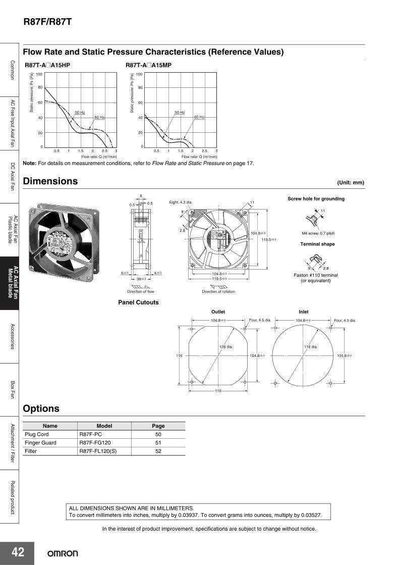
R87F/R87T
42
Attachm
ent / Filter
Com
mon
DC
Axial F
anA
C A
xial Fan
Plastic blade
AC
Axial Fan
Metal blade
Accessories
Box F
anR
elated productA
C Free Input A
xial Fan
Flow Rate and Static Pressure Characteristics (Reference Values)v
Note: For details on measurement conditions, refer to Flow Rate and Static Pressure on page 17.
Dimensions (Unit: mm)
Panel Cutouts
Options
R87T-A@A15HP R87T-A@A15MP
Name Model Page
Plug Cord R87F-PC 50
Finger Guard R87F-FG120 51
Filter R87F-FL120(S) 52
Sta
tic p
ress
ure:
Ps
(Pa)
Flow rate: Q (m3/min)
60
80
100
0
20
40
0.5 2.5 321.51
50 Hz60 Hz
Sta
tic p
ress
ure:
Ps
(Pa)
Flow rate: Q (m3/min)
20
40
60
80
100
00.5 1 1.5 2 2.5 3
50 Hz60 Hz
Direction of rotation
Eight, 4.3 dia.
Direction of flow
104.8±0.3
119.5±0.5
119.5±0.5
104.8±0.3
11
2.8
9
8
0.50.5
4±0.34±0.3
38±0.5
11
M4 screw: 0.7 pitch
9 2.8
Screw hole for grounding
Terminal shape
Faston #110 terminal(or equivalent)
Four, 4.5 dia. Four, 4.5 dia.104.8±0.3
104.8±0.3
116
104.8±0.3
116 104.8±0.3
126 dia. 116 dia.
Outlet Inlet
In the interest of product improvement, specifications are subject to change without notice.
ALL DIMENSIONS SHOWN ARE IN MILLIMETERS.To convert millimeters into inches, multiply by 0.03937. To convert grams into ounces, multiply by 0.03527.

R87F/R87T
43
Attachm
ent / Filter
Com
mon
DC
Axial F
anA
C A
xial Fan
Plastic blade
AC
Axial Fan
Metal blade
Accessories
Box F
anA
C Free Input A
xial FanR
elated product
R87T-A@A05 AC Axial Fans with Lead Wires (150-dia. × t38 mm)
SpecificationsRatings and Ordering InformationNote: An asterisk (*) indicates a nominal value.
Characteristics
ItemRated
voltage(V)
Permittedvoltage
fluctuationrange (%)
Frequency(Hz)
Rated current (A) *
Rated input (W) *
Rated rotational
speed (r/min) *
Maximum flow rate
(m3/min) *
Maximum static
pressure (Pa) *
Noise (dB) *
Model 50 Hz 60 Hz 50 Hz 60 Hz 50 Hz 60 Hz 50 Hz 60 Hz 50 Hz 60 Hz 50 Hz 60 HzR87T-A1A05H 100 VAC
85% to 110% rated voltage 50/60
0.550 0.460
50 48 2,650 3,100 4.8 5.7 104 107 56 58R87T-A3A05H 115 VAC 0.470 0.390
R87T-A4A05H 200 VAC 0.260 0.220
R87T-A6A05H 230 VAC 0.220 0.190
Motor type Single-phase shading coil induction motor (2-pole, open type)
Terminal type Lead wires
Insulation class IEC class B (130°C)UL class A (105°C)
Insulation resistance 100 MΩ min. (at 500 VDC) between all power supply connections and uncharged metal parts.
Insulation withstand voltage 2,000 VAC (1 minute) between all power supply connections and uncharged metal parts.
Ambient operating temperature −20 to 70°C (no icing)
Ambient storage temperature −40 to 85°C (no icing)
Ambient humidity 25% to 85%
Protection Thermal protection
Materials Frame: Die-cast aluminum Blades: Steel plate (mat black baked coating)
Bearings Ball bearings
Weight Approx. 840 g
Compliant standards EN/IEC 60335 (CE marking compliant)
Certified standards UL

R87F/R87T
44
Attachm
ent / Filter
Com
mon
DC
Axial F
anA
C A
xial Fan
Plastic blade
AC
Axial Fan
Metal blade
Accessories
Box F
anR
elated productA
C Free Input A
xial Fan
Flow Rate and Static Pressure Characteristics (Reference Value)
Note: For details on measurement conditions, refer to Flow Rate and Static Pressure on page 17.
Dimensions (Unit: mm)
Panel Cutouts
Options
R87T-A@A05H
Name Model PageFinger Guard R87F-FG150 51
Sta
tic p
ress
ure:
Ps
(Pa)
Flow rate: Q (m3 /min)
50 Hz
20
40
60
80
100
120
0 0 1.0 2.0 3.0 4.0 5.0 6.0
60 Hz
7
Ground Screw Section
6±0.3 6±0.3
38±0.5
146 dia. 144 dia.
Direction of flow
175±1.5
Four, 4.3 dia.151 dia.
Direction of rotation
3000.5 sq
162±0.3
162±0.3
146 dia.
Two, 4.5 dia.
Outlet and Inlet
In the interest of product improvement, specifications are subject to change without notice.
ALL DIMENSIONS SHOWN ARE IN MILLIMETERS.To convert millimeters into inches, multiply by 0.03937. To convert grams into ounces, multiply by 0.03527.

R87F/R87T
45
Attachm
ent / Filter
Com
mon
DC
Axial F
anA
C A
xial Fan
Plastic blade
AC
Axial Fan
Metal blade
Accessories
Box F
anA
C Free Input A
xial FanR
elated product
R87T-A@A07 AC Axial Fans with Lead Wires (150-dia. × t55 mm)
SpecificationsRatings and Ordering InformationNote: An asterisk (*) indicates a nominal value.
Characteristics
ItemRated
voltage(V)
Permittedvoltage
fluctuationrange (%)
Frequency(Hz)
Rated current (A) *
Rated input (W) *
Rated rotational
speed (r/min) *
Maximum flow rate
(m3/min) *
Maximum static
pressure (Pa) *
Noise (dB) *
Model 50 Hz 60 Hz 50 Hz 60 Hz 50 Hz 60 Hz 50 Hz 60 Hz 50 Hz 60 Hz 50 Hz 60 HzR87T-A1A07H 100 VAC
85% to 110% rated voltage 50/60
0.480 0.420
43 40 2,800 3,250 5.0 5.8 118 88 52 56R87T-A3A07H 115 VAC 0.420 0.370
R87T-A4A07H 200 VAC 0.240 0.210
R87T-A6A07H 230 VAC 0.210 0.190
Motor type Single-phase shading coil induction motor (2-pole, open type)
Terminal type Lead wires
Insulation class IEC class B (130°C)UL class A (105°C)
Insulation resistance 100 MΩ min. (at 500 VDC) between all power supply connections and uncharged metal parts.
Insulation withstand voltage 2,000 VAC (1 minute) between all power supply connections and uncharged metal parts.
Ambient operating temperature −20 to 70°C (no icing)
Ambient storage temperature −40 to 85°C (no icing)
Ambient humidity 25% to 85%
Protection Thermal protection
Materials Frame: Die-cast aluminum Blades: Steel plate (black coating)
Bearings Ball bearings
Weight Approx. 1,200 g
Compliant standards EN/IEC 60335 (CE marking compliant)
Certified standards UL

R87F/R87T
46
Attachm
ent / Filter
Com
mon
DC
Axial F
anA
C A
xial Fan
Plastic blade
AC
Axial Fan
Metal blade
Accessories
Box F
anR
elated productA
C Free Input A
xial Fan
Flow Rate and Static Pressure Characteristics (Reference Value)
Note: For details on measurement conditions, refer to Flow Rate and Static Pressure on page 17.
Dimensions (Unit: mm)
Panel Cutouts
Options
R87T-A@A07H
Name Model PageFinger Guard R87F-FG150 51
50 Hz
60 Hz
20
40
60
80
100
120
140
00 1 2 3 4 5 6 7
Sta
tic p
ress
ure:
Ps
(Pa)
Flow rate: Q (m3/min)
175±1.5
Four, 4.3 dia.
150±0.5 dia.
6±0.3 6±0.3
55±0.5
146 dia. 144 dia.
3000.5 sq
Direction of flow Direction of rotation
162±0.3
7
Ground Screw Section
162±0.3
146 dia.
Two, 4.5 dia.
Outlet and Inlet
In the interest of product improvement, specifications are subject to change without notice.
ALL DIMENSIONS SHOWN ARE IN MILLIMETERS.To convert millimeters into inches, multiply by 0.03937. To convert grams into ounces, multiply by 0.03527.

R87F/R87T
47
Attachm
ent / Filter
Com
mon
DC
Axial F
anA
C A
xial Fan
Plastic blade
AC
Axial Fan
Metal blade
Accessories
Box F
anA
C Free Input A
xial FanR
elated product
R87T-A@A15H-WR Water-resistant AC Axial Fans with Lead Wires (120 × 120 × t38 mm)
SpecificationsRatings and Ordering InformationNote: An asterisk (*) indicates a nominal value.
Characteristics
ItemRated
voltage(V)
Permittedvoltage
fluctuationrange (%)
Frequency(Hz)
Rated current(A) *
Rated input (W) *
Rated rotational
speed(r/min) *
Maximum flow rate
(m3/min) *
Maximum static
pressure (Pa) *
Noise (dB) *
Model 50 Hz 60 Hz 50 Hz 60 Hz 50 Hz 60 Hz 50 Hz 60 Hz 50 Hz 60 Hz 50 Hz 60 HzR87T-A1A15H-WR 100 VAC
85% to 110% rated voltage 50/60
0.350 0.280
22 202,550 2,900 2.7 3.2 75.0 80.0 42 46
R87T-A3A15H-WR 115 VAC 0.300 0.240
R87T-A4A15H-WR 200 VAC 0.170 0.135
R87T-A6A15H-WR 200 to 230 VAC 0.145 0.115 15 to 22
Motor type Single-phase shading coil induction motor (2-pole, open type)
Terminal type Lead wires
Insulation classIEC class B (130°C)UL class A (105°C)CSA class A (105°C)
Insulation resistance 100 MΩ min. (at 500 VDC) between all power supply connections and uncharged metal parts.
Insulation withstand voltage 2,000 VAC (1 minute) between all power supply connections and uncharged metal parts.
Degree of protection IP X7
Ambient operating temperature −40 to 70°C (no icing)
Ambient storage temperature −40 to 85°C (no icing)
Ambient humidity 95% max.
Protection Impedance protection
Materials Frame Die-cast aluminum
Black coating
Blades Zinc die-cast
Bearings Ball bearings
Weight Approx. 650 g
Standards EN/IEC 60335 (CE marking compliant)
Certified standards CUL

R87F/R87T
48
Attachm
ent / Filter
Com
mon
DC
Axial F
anA
C A
xial Fan
Plastic blade
AC
Axial Fan
Metal blade
Accessories
Box F
anR
elated productA
C Free Input A
xial Fan
Flow Rate and Static Pressure Characteristics (Reference Values)
Note: For details on measurement conditions, refer to Flow Rate and Static Pressure on page 17.
Dimensions (Unit: mm)
Panel Cutouts
OptionsName Model Page
Finger Guard R87F-FG120 51
Filter R87F-FL120(S) 52
50 Hz
60 Hz
80
60
40
20
0 0 1.0 2.0 3.0
Sta
tic p
ress
ure
Ps
(Pa)
Flow rate Q (m3/min)
R87T-A@A15H-WR
Direction of flow Direction of rotationEight, 4.3 dia.M4 × 0.7
double sems screw
1,000UL1333 AWG22
Lead wire groove(coated with sealant)
119.5±0.5
104.8±0.3
4±0.34±0.3
38±0.5
119.5±0.5
104.8±0.3
11
M4 screw: 0.7 pitch
Ground Screw Section
104.8±0.3
104.8±0.3
115
104.8±0.3
115 104.8±0.3
126 dia. 115 dia.
Four, 4.5 dia. Four, 4.5 dia.
Outlet Inlet
In the interest of product improvement, specifications are subject to change without notice.
ALL DIMENSIONS SHOWN ARE IN MILLIMETERS.To convert millimeters into inches, multiply by 0.03937. To convert grams into ounces, multiply by 0.03527.

Accessories
49
Attachm
ent / Filter
Com
mon
DC
Axial F
anA
C A
xial Fan
Plastic blade
AC
Axial F
an M
etal bladeA
ccessoriesP
lug Cord
Box F
anA
C Free Input A
xial FanR
elated product
R89F-PC Plug Cord
Ratings and Ordering Information
Dimensions (Unit: mm)
Note: This Plug Cord is used for Axial Fans with terminals.
Cable length Model Weight
1 m R89F-PC Approx. 38 g
2 m R89F-PC-20 Approx. 74 g
R89F-PC Rating: 3 A, 250 V
UL-certified / Electrical Appliances and Materials Safety Act-compliant
Pre-soldered end
R89F-PC L=1000
R89F-PC-20 L=2100
L
20 4 17
10
15.58
4
50±5
10±2
+50-0
+100-0
R89F-PC
In the interest of product improvement, specifications are subject to change without notice.
ALL DIMENSIONS SHOWN ARE IN MILLIMETERS.To convert millimeters into inches, multiply by 0.03937. To convert grams into ounces, multiply by 0.03527.

Accessories
50
Attachm
ent / Filter
Com
mon
DC
Axial F
anA
C A
xial Fan
Plastic blade
AC
Axial F
an M
etal bladeA
ccessoriesP
lug Cord
Box F
anR
elated productA
C Free Input A
xial Fan
R87F-PC Plug Cord
Ratings and Ordering Information
Dimensions (Unit: mm)
Note: This Plug Cord is used for Axial Fans with terminals.
Cord length Model number Weight (g)1 m R87F-PC 39
2 m R87F-PC-20 69
R87F-PC Rating: 250 VAC, 3 A
UL-certified Plug Cord
15.5±0.5
9±0.5 7.5±0.5
18±0.5
(8)
1,00023.5±0.5
R87F-PC
Connectable to Faston #110 terminals (or equivalent).
In the interest of product improvement, specifications are subject to change without notice.
ALL DIMENSIONS SHOWN ARE IN MILLIMETERS.To convert millimeters into inches, multiply by 0.03937. To convert grams into ounces, multiply by 0.03527.

Accessories
51
Attachm
ent / Filter
Com
mon
DC
Axial F
anA
C A
xial Fan
Plastic blade
AC
Axial F
an M
etal bladeA
ccessoriesF
inger Guard
Box F
anA
C Free Input A
xial FanR
elated product
R87F-FG Finger Guards
Ratings and Ordering Information Applicable Axial Fans
Note: Finger Guards reduce the flow rate by approximately 2% to 5%.
Dimensions (Unit: mm)
Material: steel, Joints: spot welded, Surface: nickel-chrome plated
Size Model number Weight (g)150 dia. R87F-FG150 Approx. 58
120 × 120 R87F-FG120 Approx. 45
92 × 92 R87F-FG90 Approx. 25
80 × 80 R87F-FG80 Approx. 20
AC Axial FanFinger Guard
Size Model150 dia. R87T-A@A0 Series R87F-FG150
120 × 120
R89F-DS1225@ seriesR89F-DS1238@ seriesR89F-MS1238HP R87F-FG120R87F-A@A1 SeriesR87T-A@A1 Series
92 × 92 R89F-MS0938@P series R87F-FG90
92 × 92 R87F-A@A9 Series R87F-FG90
80 × 80 R87F-A@A8 SeriesR87T-A@A8 Series R87F-FG80
162.6
22 dia.
27 dia.
6
5.5
6
R87F-FG150
5.6
105±0.5
105±0.5
Four, 4.6±0.3 dia.
R87F-FG120
Four, 4.6 dia.
5
82.4
82.4
R87F-FG90
71.5
71.55.5
Four, 4.6+0.2 0 dia.
R87F-FG80
In the interest of product improvement, specifications are subject to change without notice.
ALL DIMENSIONS SHOWN ARE IN MILLIMETERS.To convert millimeters into inches, multiply by 0.03937. To convert grams into ounces, multiply by 0.03527.
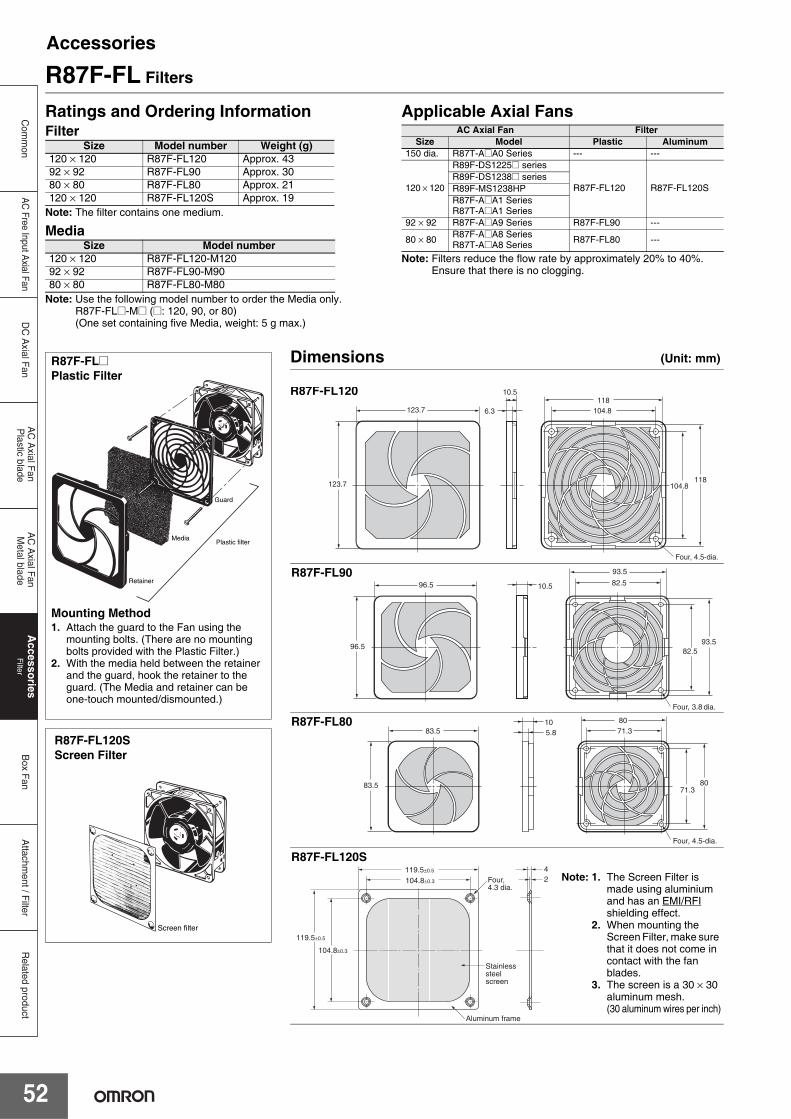
Accessories
52
Attachm
ent / Filter
Com
mon
DC
Axial F
anA
C A
xial Fan
Plastic blade
AC
Axial F
an M
etal bladeA
ccessoriesF
ilterB
ox Fan
Related product
AC
Free Input Axial Fan
R87F-FL Filters
Ratings and Ordering InformationFilter
Note: The filter contains one medium.
Media
Note: Use the following model number to order the Media only.R87F-FL@-M@ (@: 120, 90, or 80) (One set containing five Media, weight: 5 g max.)
Applicable Axial Fans
Note: Filters reduce the flow rate by approximately 20% to 40%. Ensure that there is no clogging.
Size Model number Weight (g)120 × 120 R87F-FL120 Approx. 4392 × 92 R87F-FL90 Approx. 3080 × 80 R87F-FL80 Approx. 21120 × 120 R87F-FL120S Approx. 19
Size Model number120 × 120 R87F-FL120-M12092 × 92 R87F-FL90-M9080 × 80 R87F-FL80-M80
AC Axial Fan FilterSize Model Plastic Aluminum
150 dia. R87T-A@A0 Series --- ---
120 × 120
R89F-DS1225@ series
R87F-FL120 R87F-FL120SR89F-DS1238@ seriesR89F-MS1238HPR87F-A@A1 SeriesR87T-A@A1 Series
92 × 92 R87F-A@A9 Series R87F-FL90 ---
80 × 80 R87F-A@A8 SeriesR87T-A@A8 Series R87F-FL80 ---
Plastic filter
Guard
Media
Retainer
R87F-FL@Plastic Filter
Mounting Method1. Attach the guard to the Fan using the
mounting bolts. (There are no mounting bolts provided with the Plastic Filter.)
2. With the media held between the retainer and the guard, hook the retainer to the guard. (The Media and retainer can be one-touch mounted/dismounted.)
Screen filter
R87F-FL120SScreen Filter
Dimensions (Unit: mm)
123.7
123.7
10.5
Four, 4.5-dia.
104.8118
6.3
104.8118
R87F-FL120
96.5
96.5 82.5
93.5
Four, 3.8 dia.
10.5
82.593.5
R87F-FL90
83.5
83.5 71.380
Four, 4.5-dia.
5.810
71.380
R87F-FL80
2 4
Aluminum frame
Stainless steel screen
Four, 4.3 dia.
119.5±0.5
119.5±0.5
104.8±0.3
104.8±0.3
R87F-FL120SNote: 1. The Screen Filter is
made using aluminium and has an EMI/RFI shielding effect.
2. When mounting the Screen Filter, make sure that it does not come in contact with the fan blades.
3. The screen is a 30 × 30 aluminum mesh.(30 aluminum wires per inch)

Accessories
53
Attachm
ent / Filter
Com
mon
DC
Axial F
anA
C A
xial Fan
Plastic blade
AC
Axial F
an M
etal bladeA
ccessoriesF
ilterB
ox Fan
AC
Free Input Axial Fan
Related product
In the interest of product improvement, specifications are subject to change without notice.
ALL DIMENSIONS SHOWN ARE IN MILLIMETERS.To convert millimeters into inches, multiply by 0.03937. To convert grams into ounces, multiply by 0.03527.

54
Attachm
ent / Filter
Com
mon
DC
Axial F
anA
C A
xial Fan
Plastic blade
AC
Axial F
an M
etal bladeA
ccessoriesB
ox FanR
elated productA
C Free Input A
xial Fan
Box Fan
R87BComprehensive Lineup of Single, Double, and Triple Axial Fans with Easy One-step Mounting • Mounts in a square cutout and conceals the hole-cut to
simplify installation work.• Cover can be set to open either upward or downward for
convenience in confined spaces.• Enhanced accessories (finger guard, filter, plug cord,
mounting screws).• Optional Replacement Filter and Vent Attachment.• The lineup includes Single, Double, and Triple Box Fans
with eight models with plastic blades and eight models with metal blades.
Model Number StructureModel Number Legend
Attachment
Options and Accessories
Note: These tables show only how to read model numbers. They do not indicate which products are available. Refer to “Ratings and Ordering Information” when placing an order.
* “In” is the direction of external air flowing in.“Out” is the direction of internal air flowing out.
Ordering Information
Be sure to read the Safety Precautions for All Axial Fans on page 12.
Number Category Symbol Meaning of symbol
1
Fan (blade material)
FTN
R87F Axial Fan (with plastic blades)R87T Axial Fan (with metal blades)No fan
Optional parts P Options and accessories
2 Power supply classification
A1A3A4A6
100 VAC115 VAC200 VAC230 VAC
3 Speed classification
HML
High speedMiddle speedLow speed
4 Airflow direction *
NoneR
InOut
5 Number of fansNone23
123
6 Part type F Filter
7 Reference number 01 ---
1 2 3 4 5
R87B-@@@A15@PF@@
1 5
R87B-N@
1 76
R87B-P@@@
Type Numberof fans Model Accessories
Plastic bladesHigh speed
1 R87B-FA@A15HPF(R)
FilterFinger guardPlug cordMounting bolts
2 R87B-FA@A15HPF(R)2
3 R87B-FA@A15HPF(R)3
Plastic bladesLow speed
1 R87B-FA@A15LPF(R)
2 R87B-FA@A15LPF(R)2
3 R87B-FA@A15LPF(R)3
Metal bladesHigh speed
1 R87B-TA@A15HPF(R)
2 R87B-TA@A15HPF(R)2
3 R87B-TA@A15HPF(R)3
Metal bladesMedium speed
1 R87B-TA@A15MPF(R)
2 R87B-TA@A15MPF(R)2
3 R87B-TA@A15MPF(R)3
Attachment
For 1 R87B-N FilterFinger guardMounting screws
For 2 R87B-N2
For 3 R87B-N3
Replacement Filter Any R87B-PF01 Set of two filters

R87B
55
Attachm
ent / Filter
Com
mon
DC
Axial F
anA
C A
xial Fan
Plastic blade
AC
Axial F
an M
etal bladeA
ccessoriesB
ox FanA
C Free Input A
xial FanR
elated product
Ratings and Ordering Information
Note: The rated current is the total for all fans. * The compliant standards and certified standards apply to the listed Axial Fans.
Safety PrecautionsRefer to the Safety Precautions for All Axial Fans on page 12 to 14.
Item Model R87B-F R87B-T
Motor type Single-phase shading coil induction motor (2-pole, open type)
Terminal type Terminals
Insulation classIEC class B (130°C)UL class A (105°C)CSA class A (105°C)
IEC class B (130°C)UL class A (105°C)
Insulation resistance 100 MΩ min. (at 500 VDC)Between all power supply connection parts and non-current carrying metal parts
Dielectric strength 2,000 VAC for 1 min Between all power supply connection parts and non-current carrying metal parts
Ambient operating temperature −30 to 70°C (with no icing) −20 to 70°C (with no icing)
Storage temperature −40 to 85°C (with no icing)
Ambient humidity 25% to 85%
Protection Impedance protection
MaterialsFrame Die-cast aluminum
Blades Glass polycarbonate Steel plate (black coating)
Bearings Ball bearings
Compliant standards* PSE, EN/IEC 60335 (CE self-declaration)
Certified standards* cULus
In the interest of product improvement, specifications are subject to change without notice.
ALL DIMENSIONS SHOWN ARE IN MILLIMETERS.To convert millimeters into inches, multiply by 0.03937. To convert grams into ounces, multiply by 0.03527.

Attachm
ent / Filter
Com
mon
DC
Axial F
anA
C A
xial Fan
Plastic blade
AC
Axial F
an M
etal bladeA
ccessoriesB
ox FanR
elated productA
C Free Input A
xial Fan
R87B
56
R87B-@A@A15@PF(R) Single Box Fan
Ratings and Ordering InformationAirflow Direction: In
Note: An asterisk (*) indicates a nominal value.
Airflow Direction: Out
Note: An asterisk (*) indicates a nominal value.• The data in this table comes from measurements that were taken with the filter and cover attached.• The model number of the AC Axial Fan in the Box Fan can be determined from the model number of the Box Fan as follows:
ItemRated
voltage(V)
Permittedvoltage
fluctuationrange (%)
Frequency(Hz)
Rated rotational
speed (r/min) *
Maximum flow rate
(m3/min) *
Maximum static
pressure (Pa) *
Noise (dB) * Weight
Model 50 Hz 60 Hz 50 Hz 60 Hz 50 Hz 60 Hz 50 Hz 60 Hz
R87B-FA1A15HPF 100 VAC
85% to 110% rated voltage 50/60 2,700 3,100 1.3 1.5 86 85 49 52
Approx. 1,120 g
R87B-FA3A15HPF 115 VAC
R87B-FA4A15HPF 200 VAC
R87B-FA6A15HPF 230 VAC
R87B-FA1A15LPF 100 VAC
85% to 110% rated voltage 50/60 2,100 2,200 0.9 1.0 43 42 42 43
R87B-FA3A15LPF 115 VAC
R87B-FA4A15LPF 200 VAC
R87B-FA6A15LPF 230 VAC
R87B-TA1A15HPF 100 VAC
85% to 110% rated voltage 50/60 2,700 3,000 1.1 1.3 70 63 45 48
Approx. 1,150 g
R87B-TA3A15HPF 115 VAC
R87B-TA4A15HPF 200 VAC
R87B-TA6A15HPF 230 VAC
R87B-TA1A15MPF 100 VAC
85% to 110% rated voltage 50/60 2,400 2,700 0.8 0.9 41 40 41 44
R87B-TA3A15MPF 115 VAC
R87B-TA4A15MPF 200 VAC
R87B-TA6A15MPF 230 VAC
ItemRated
voltage(V)
Permittedvoltage
fluctuationrange (%)
Frequency(Hz)
Rated rotational
speed (r/min) *
Maximum flow rate
(m3/min) *
Maximum static
pressure (Pa) *
Noise (dB) * Weight
Model 50 Hz 60 Hz 50 Hz 60 Hz 50 Hz 60 Hz 50 Hz 60 Hz
R87B-FA1A15HPFR 100 VAC
85% to 110% rated voltage 50/60 2,700 3,100 1.3 1.5 86 85 49 52
Approx. 1,120 g
R87B-FA3A15HPFR 115 VAC
R87B-FA4A15HPFR 200 VAC
R87B-FA6A15HPFR 230 VAC
R87B-FA1A15LPFR 100 VAC
85% to 110% rated voltage 50/60 2,100 2,200 0.9 1.0 43 42 42 43
R87B-FA3A15LPFR 115 VAC
R87B-FA4A15LPFR 200 VAC
R87B-FA6A15LPFR 230 VAC
R87B-TA1A15HPFR 100 VAC
85% to 110% rated voltage 50/60 2,700 3,000 1.1 1.3 70 63 45 48
Approx. 1,150 g
R87B-TA3A15HPFR 115 VAC
R87B-TA4A15HPFR 200 VAC
R87B-TA6A15HPFR 230 VAC
R87B-TA1A15MPFR 100 VAC
85% to 110% rated voltage 50/60 2,400 2,700 0.8 0.9 41 40 41 44
R87B-TA3A15MPFR 115 VAC
R87B-TA4A15MPFR 200 VAC
R87B-TA6A15MPFR 230 VAC
R87B-FA1A15HPF→R87F-A1A15HP
The model number of the Axial Fan can be determined by extracting the underlined portions from the model number of the Box Fan as shown.

R87B
57
Attachm
ent / Filter
Com
mon
DC
Axial F
anA
C A
xial Fan
Plastic blade
AC
Axial F
an M
etal bladeA
ccessoriesB
ox FanA
C Free Input A
xial FanR
elated product
Dimensions (Unit: mm)
Panel Cutout Dimensions
180±0.3
170±0.1
157104.8±0.15
180±0.3
Two, 6 dia.
8.6 64.5
170±0.1
160±1
Two, 6 dia.
160±1
In the interest of product improvement, specifications are subject to change without notice.
ALL DIMENSIONS SHOWN ARE IN MILLIMETERS.To convert millimeters into inches, multiply by 0.03937. To convert grams into ounces, multiply by 0.03527.

Attachm
ent / Filter
Com
mon
DC
Axial F
anA
C A
xial Fan
Plastic blade
AC
Axial F
an M
etal bladeA
ccessoriesB
ox FanR
elated productA
C Free Input A
xial Fan
R87B
58
R87B-@A@A15@PF(R)2 Double Box Fan
Ratings and Ordering InformationAirflow Direction: In
Note: An asterisk (*) indicates a nominal value.
Airflow Direction: Out
Note: An asterisk (*) indicates a nominal value.• The data in this table comes from measurements that were taken with the filter and cover attached.• The model number of the AC Axial Fan in the Box Fan can be determined from the model number of the Box Fan as follows:
ItemRated
voltage (V)
Permitted voltage
fluctuation range (%)
Frequency(Hz)
Rated rotational
speed (r/min) *
Maximum flow rate
(m3/min) *
Maximum static pressure
(Pa) *
Noise (dB) * Weight
Model 50 Hz 60 Hz 50 Hz 60 Hz 50 Hz 60 Hz 50 Hz 60 Hz
R87B-FA1A15HPF2 100 VAC85% to 110% rated voltage
50/60 2,700 3,100 2.6 3.0 82 45 55 56
Approx. 1,800 g
R87B-FA3A15HPF2 115 VAC
R87B-FA4A15HPF2 200 VAC
R87B-FA6A15HPF2 230 VAC
R87B-FA1A15LPF2 100 VAC85% to 110% rated voltage
50/60 2,100 2,200 2.0 2.1 44 42 45 46R87B-FA3A15LPF2 115 VAC
R87B-FA4A15LPF2 200 VAC
R87B-FA6A15LPF2 230 VAC
R87B-TA1A15HPF2 100 VAC85% to 110% rated voltage
50/60 2,700 3,000 2.5 2.9 68 63 49 52
Approx. 1,800 g
R87B-TA3A15HPF2 115 VAC
R87B-TA4A15HPF2 200 VAC
R87B-TA6A15HPF2 230 VAC
R87B-TA1A15MPF2 100 VAC85% to 110% rated voltage
50/60 2,400 2,700 1.6 1.8 41 43 44 47R87B-TA3A15MPF2 115 VAC
R87B-TA4A15MPF2 200 VAC
R87B-TA6A15MPF2 230 VAC
ItemRated
voltage (V)
Permitted voltage
fluctuation range (%)
Frequency(Hz)
Rated rotational
speed (r/min) *
Maximum flow rate
(m3/min) *
Maximum static pressure
(Pa) *
Noise (dB) * Weight
Model 50 Hz 60 Hz 50 Hz 60 Hz 50 Hz 60 Hz 50 Hz 60 Hz
R87B-FA1A15HPFR2 100 VAC85% to 110% rated voltage
50/60 2,700 3,100 2.6 3.0 82 45 55 56
Approx. 1,800 g
R87B-FA3A15HPFR2 115 VAC
R87B-FA4A15HPFR2 200 VAC
R87B-FA6A15HPFR2 230 VAC
R87B-FA1A15LPFR2 100 VAC85% to 110% rated voltage
50/60 2,100 2,200 2.0 2.1 44 42 45 46R87B-FA3A15LPFR2 115 VAC
R87B-FA4A15LPFR2 200 VAC
R87B-FA6A15LPFR2 230 VAC
R87B-TA1A15HPFR2 100 VAC85% to 110% rated voltage
50/60 2,700 3,000 2.5 2.9 68 63 49 52
Approx. 1,800 g
R87B-TA3A15HPFR2 115 VAC
R87B-TA4A15HPFR2 200 VAC
R87B-TA6A15HPFR2 230 VAC
R87B-TA1A15MPFR2 100 VAC85% to 110% rated voltage
50/60 2,400 2,700 1.6 1.8 41 43 44 47R87B-TA3A15MPFR2 115 VAC
R87B-TA4A15MPFR2 200 VAC
R87B-TA6A15MPFR2 230 VAC
R87B-FA1A15HPF→R87F-A1A15HP
The model number of the Axial Fan can be determined by extracting the underlined portions from the model number of the Box Fan as shown.

R87B
59
Attachm
ent / Filter
Com
mon
DC
Axial F
anA
C A
xial Fan
Plastic blade
AC
Axial F
an M
etal bladeA
ccessoriesB
ox FanA
C Free Input A
xial FanR
elated product
Dimensions (Unit: mm)
Panel Cutout Dimensions
305±0.4
258.2
295±0.4
158 max.104.8±0.15180±0.3
170±0.3
Four,6 dia. 8.6 64.5
295±0.1
285±1
160±1
170±0.1
Four, 6 dia.
In the interest of product improvement, specifications are subject to change without notice.
ALL DIMENSIONS SHOWN ARE IN MILLIMETERS.To convert millimeters into inches, multiply by 0.03937. To convert grams into ounces, multiply by 0.03527.

Attachm
ent / Filter
Com
mon
DC
Axial F
anA
C A
xial Fan
Plastic blade
AC
Axial F
an M
etal bladeA
ccessoriesB
ox FanR
elated productA
C Free Input A
xial Fan
R87B
60
R87B-@A@A15@PF(R)3 Triple Box Fan
Ratings and Ordering InformationAirflow Direction: In
Note: An asterisk (*) indicates a nominal value.
Airflow Direction: Out
Note: An asterisk (*) indicates a nominal value.• The data in this table comes from measurements that were taken with the filter and cover attached.• The model number of the AC Axial Fan in the Box Fan can be determined from the model number of the Box Fan as follows:
ItemRated
voltage (V)
Permitted voltage
fluctuation range (%)
Frequency(Hz)
Rated rotational
speed (r/min) *
Maximum flow rate
(m3/min) *
Maximum static pressure
(Pa) *
Noise (dB) * Weight
Model 50 Hz 60 Hz 50 Hz 60 Hz 50 Hz 60 Hz 50 Hz 60 Hz
R87B-FA1A15HPF3 100 VAC
85% to 110% rated voltage 50/60 2,700 3,100 3.9 4.5 82 60 56 58
Approx. 2,700 g
R87B-FA3A15HPF3 115 VAC
R87B-FA4A15HPF3 200 VAC
R87B-FA6A15HPF3 230 VAC
R87B-FA1A15LPF3 100 VAC
85% to 110% rated voltage 50/60 2,100 2,200 2.9 3.1 40 39 47 48
R87B-FA3A15LPF3 115 VAC
R87B-FA4A15LPF3 200 VAC
R87B-FA6A15LPF3 230 VAC
R87B-TA1A15HPF3 100 VAC
85% to 110% rated voltage 50/60 2,700 3,000 3.8 4.0 68 63 50 53
Approx. 2,800 g
R87B-TA3A15HPF3 115 VAC
R87B-TA4A15HPF3 200 VAC
R87B-TA6A15HPF3 230 VAC
R87B-TA1A15MPF3 100 VAC
85% to 110% rated voltage 50/60 2,400 2,700 2.4 2.8 41 40 45 48
R87B-TA3A15MPF3 115 VAC
R87B-TA4A15MPF3 200 VAC
R87B-TA6A15MPF3 230 VAC
ItemRated
voltage (V)
Permitted voltage
fluctuation range (%)
Frequency(Hz)
Rated rotational
speed (r/min) *
Maximum flow rate
(m3/min) *
Maximum static pressure
(Pa) *
Noise (dB) * Weight
Model 50 Hz 60 Hz 50 Hz 60 Hz 50 Hz 60 Hz 50 Hz 60 Hz
R87B-FA1A15HPFR3 100 VAC
85% to 110% rated voltage 50/60 2,700 3,100 3.9 4.5 82 60 56 58
Approx. 2,700 g
R87B-FA3A15HPFR3 115 VAC
R87B-FA4A15HPFR3 200 VAC
R87B-FA6A15HPFR3 230 VAC
R87B-FA1A15LPFR3 100 VAC
85% to 110% rated voltage 50/60 2,100 2,200 2.9 3.1 40 39 47 48
R87B-FA3A15LPFR3 115 VAC
R87B-FA4A15LPFR3 200 VAC
R87B-FA6A15LPFR3 230 VAC
R87B-TA1A15HPFR3 100 VAC
85% to 110% rated voltage 50/60 2,700 3,000 3.8 4.0 68 63 50 53
Approx. 2,800 g
R87B-TA3A15HPFR3 115 VAC
R87B-TA4A15HPFR3 200 VAC
R87B-TA6A15HPFR3 230 VAC
R87B-TA1A15MPFR3 100 VAC
85% to 110% rated voltage 50/60 2,400 2,700 2.4 2.8 41 40 45 48
R87B-TA3A15MPFR3 115 VAC
R87B-TA4A15MPFR3 200 VAC
R87B-TA6A15MPFR3 230 VAC
R87B-FA1A15HPF→R87F-A1A15HP
The model number of the Axial Fan can be determined by extracting the underlined portions from the model number of the Box Fan as shown.

R87B
61
Attachm
ent / Filter
Com
mon
DC
Axial F
anA
C A
xial Fan
Plastic blade
AC
Axial F
an M
etal bladeA
ccessoriesB
ox FanA
C Free Input A
xial FanR
elated product
Dimensions (Unit: mm)
Panel Cutout Dimensions
430±0.5
394.2
420±0.5
158 dia.104.8±0.15180±0.3
170±0.3
Four,6 dia.
8.6 64.5
420±0.1
410±1
160±1
170±0.1
Four, 6 dia.
In the interest of product improvement, specifications are subject to change without notice.
ALL DIMENSIONS SHOWN ARE IN MILLIMETERS.To convert millimeters into inches, multiply by 0.03937. To convert grams into ounces, multiply by 0.03527.

R87B
62
Com
mon
DC
Axial F
anA
C A
xial Fan
Plastic blade
AC
Axial F
an M
etal bladeA
ccessoriesB
ox Fan
Related product
Attachm
ent / FilterA
C Free Input A
xial Fan
R87B-N@/R87B-PF Optional Parts
R87B-PF01 (Replacement Filter)
Ratings and Ordering Information
Filter Performance
• Pay careful attention to clogging in the filter. A clogged filter will prevent the Fan from providing a cooling effect.
Replacing the Filter1. Turn OFF the power, wait approximately one minute, and then
open the cover. Remove the filter, replace it with a new filter, close the cover, and then firmly tighten the handle screw. This completes the filter replacement.
2. As a general guide to the replacement frequency, check the color of the filter regularly and replace it when the color shows a noticeable change.
3. It is recommended that the filter be replaced soon after the color changes noticeably in order to maintain the Fan's performance. (Replacement Filter: R87B-PF01)
R87B-N@ (Attachment)Single Box Triple Box
Double Box
Note: The panel cut-out dimensions are the same as those for the Box Fan.
180±0.3
170±0.1
157180±0.3
Two, 6-dia. holes
8.618.4
430±0.5
394.2
420±0.5
158 max.180±0.3170±0.3
Four, 6-dia. holes
8.618.4
305±0.4
258.2
295±0.4
158 max.180±0.3
170±0.3
Four, 6-dia. holes 8.6
18.4 Ratings and Ordering InformationModel Item Type WeightR87B-N Single Approx. 570 g
R87B-N2 Double Approx. 1,100 g
R87B-N3 Triple Approx. 1,700 g
Model Item Qty. Weight (grams per filter)
R87B-PF01 2 6
1010
129
140
Heat resistance
(°C)
Filtration wind
velocity (m/s)
Pressure drop (Pa) Dust removal
(%)
Dust suction amount (g/mm2)
Initial Final
100 2.5 49 70 70 min. 300

R87B
63
Com
mon
DC
Axial F
anA
C A
xial Fan
Plastic blade
AC
Axial F
an M
etal bladeA
ccessoriesB
ox Fan
Attachm
ent / FilterA
C Free Input A
xial FanR
elated product
Accessories
Note: The Finger Guard and Filter are to be assembled into the Box Fan.
Model Item Mounting bolts (M4)
Hexagonal nuts (M4)
Plain washers
Spring washers
Cable with plug
Finger Guard (See note.)
Filter (See note.)
R87B-@A@A1@@PF(R)(Single, with fan) 2 2 4 2 1 2 1
R87B-@A@A1@@PF(R)2(Double, with fan) 4 4 8 4 2 4 2
R87B-@A@A1@@PF(R)3(Triple, with fan) 4 4 8 4 3 6 3
R87B-N(Single, without fan) 2 2 4 2 None 1 1
R87B-N2(Double, without fan) 4 4 8 4 None 2 2
R87B-N3(Triple, without fan) 4 4 8 4 None 3 3
In the interest of product improvement, specifications are subject to change without notice.
ALL DIMENSIONS SHOWN ARE IN MILLIMETERS.To convert millimeters into inches, multiply by 0.03937. To convert grams into ounces, multiply by 0.03527.

64
Attachm
ent / Filter
Com
mon
DC
Axial F
anA
C A
xial Fan
Plastic blade
AC
Axial F
an M
etal bladeA
ccessoriesB
ox Fan
Related product
E5L
AC
Free Input Axial Fan
Electronic Thermostat
E5LIdeal for Simple Built-in Control.• A high switching capacity of 10 A at 250 VAC enables
direct load switching.• A sensor is provided to enable immediate application.• Sockets with finger protection (PTF14A-E) or without
finger protection (PTF14A) can be used.• Simple operation and settings. Even simpler with digital
models.
Model Number StructureModel Number Legend
Ordering InformationElectronic ThermostatsE5L-A@
E5L-C@
Note: The E5L-C is not available with a set temperature range of 0 to 50°C.
Options (Order Separately)Mounting Brackets
Note: This Mounting Brackets is provided with the Electronic Thermostat.
Sockets
1 2E5L-@@
1. Setting and Indication MethodsA: Analog setting, no displayC: Digital setting, display
2. Set temperature −30-20 : −30 to +20°C0-50 : 0 to +50°C0-100 : 0 to +100°C100-200 : +100 to +200°C
Size Type Control method Control output Model
45 × 35 mm Plug-in ON/OFF operation Relay
E5L-A -30-20E5L-A 0-50E5L-A 0-100E5L-A 100-200
Size Type Control method Control output Model
45 × 35 mm Plug-in ON/OFF operation RelayE5L-C -30-20E5L-C 0-100E5L-C 100-200
ModelY92H-10
Type Model
Front-connecting SocketPTF14APTF14A-E

E5L
65
Attachm
ent / Filter
Com
mon
DC
Axial F
anA
C A
xial Fan
Plastic blade
AC
Axial F
an M
etal bladeA
ccessoriesB
ox Fan
AC
Free Input Axial Fan
Related product
E5L
Ratings and CharacteristicsRatings
Note: Do not use the output from an Inverter as the power supply.
Characteristics
*1.The accuracy of the accessory thermistor is not included.*2. Industrial electromagnetic environment (EN/IEC 61326-1 Table 2)
Item Model E5L-A@ E5L-C@Power supply voltage 100 to 240 VAC, 50/60 Hz
Operating voltage range 85% to 110% of the rated supply voltage
Power consumption Approx. 3 VA
Inputs Element-interchangeable thermistor
Control method ON/OFF control
Control output SPDT contacts, 250 VAC, 10 A, cosφ = 1 (resistive load) SPST-NO contacts, 250 VAC, 10 A, cosφ = 1 (resistive load)
Setting method Analog setting Digital settings using keys on front panel
Indication method No display LCD digital display (character height: 12 mm)
Other functions• Setting protection (key protection)• Input shift• Direct/reverse operation
Ambient temperature −10 to 55°C (with no icing or condensation)
Ambient humidity 25% to 85%
Storage temperature −25°C to 65°C (with no icing or condensation)
Item Model E5L-A@ E5L-C@Indication accuracy --- ±(1°C + 1 digit) max.*1
Setting accuracy --- ±(1°C + 1 digit) max.*1
Hysteresis
−30 to 20°C models: Approx. 0.5 to 2.5°C (variable)0 to 50°C models: Approx. 0.5 to 4°C (variable)0 to 100°C models: Approx. 0.5 to 4°C (variable)100 to 200°C models: Approx. 0.7 to 4°C (variable)
1 to 9°C (in increments of 1°C)
Repeat accuracy 1% FS max. ---
Minimum scale (standard scale)
−30 to 20°C models and 0 to 50°C models: 5°C0 to 100°C models and 100 to 200°C models: 10°C ---
Influence of temperature ---
±((1% of PV or 2°C, whichever is greater) +1 digit) max.Influence of voltage ---
Influence of EMS.(at EN61326-1) ---
Sampling period --- 2 s
Insulation resistance 100 MΩ max. (at 500 VDC)
Dielectric strength2,810 VAC, 50/60 Hz for 1 min (between charged terminals and uncharged metallic parts, between power supply terminals and input terminals, between power supply terminals and output terminals, and between input terminals and output terminals)
Vibration (malfunction) Frequency of 10 to 55 Hz, 0.5-mm double amplitude for 10 min each in X, Y, and Z directions
Vibration (destruction) Frequency of 10 to 55-Hz, 0.75-mm double amplitude for 2 h each in X, Y, and Z directions
Shock (malfunction) 150 m/s2, 3 times each in 6 directions 100 m/s2, 3 times each in 6 directions
Shock (destruction) 300 m/s2, 3 times each in 6 directions
Electrical life expectancy (control output relay) 100,000 operations min (at maximum applicable load)
Memory protection --- Non-volatile memory (100,000 write operations)
Weight (Thermostat) Approx. 80 g (Thermostat only)
Degree of protection Front panel: IP40, Terminals: IP00
Approved standards ---
Conformed standards EN 61010-1 (IEC 61010-1), Pollution Degree 2, Overvoltage Category II
EMC Directives
EMI: EN61326-1*2
Radiated EMI: EN55011 Group1 ClassAConducted EMI: EN55011 Group1 ClassAEMS: EN61326-1*2
Electrostatic discharge immunity: EN61000-4-2Electromagnetic field strength immunity: EN61000-4-3Burst noise immunity: EN61000-4-4Conducted disturbance immunity: EN61000-4-6Surge immunity: EN61000-4-5Voltage dip and power interruption immunity: EN6100-4-11

E5L
66
Attachm
ent / Filter
Com
mon
DC
Axial F
anA
C A
xial Fan
Plastic blade
AC
Axial F
an M
etal bladeA
ccessoriesB
ox Fan
Related product
E5L
AC
Free Input Axial Fan
External Connections
Note: For thermistor wiring, separate the input power supply and load lines as much as possible to avoid the influence of inductive noise.
Nomenclature
Dimensions (Unit: mm)
Thermostats
E5L-A@ E5L-C@
* Control output Heating load: Terminals 8 and 12Cooling load: Terminals 4 and 12
Be careful of the cooling load contacts, because they will be electrically charged even when the E5L input power supply is OFF.
* Control outputs: Terminals 8 and 12Use the keys on the front panel to set direct/reverse operation.
250 VAC, 10 A
Control output*
Input power supply: 100 to 240 VAC
Element-interchangeable Thermistor
250 VAC, 10 A
Control output*
Input power supply: 100 to 240 VAC
Element-interchangeable Thermistor
Hysteresis adjuster (DIFF.)
Operation indicator
Temperature dial
Operation Indicator
Operation indicator
Output status
Heating load Cooling loadLit red. ON OFF
Not lit. OFF ON
E5L-A@
Mode Key Down Key Up Key
Operation indicator
Set value indicator
Protection indicator
Process value and set value display
Operation Indicator: ON
Set Value Indicator: SVLit when the set value is displayed.
Setting Protection Indicator: Lit when setting protection is set.
Operation indicator
Output status
Reverse operation Direct operation
Lit ON ON
Not lit OFF OFF
E5L-C@
6.464
75.0
(4.6)45
35
E5L-A@
6.464
70.4
45
35
E5L-C@

E5L
67
Attachm
ent / Filter
Com
mon
DC
Axial F
anA
C A
xial Fan
Plastic blade
AC
Axial F
an M
etal bladeA
ccessoriesB
ox Fan
AC
Free Input Axial Fan
Related product
E5L
Wiring Connection Sockets (Order Separately)
AccessoriesE52-THE-E5L Element-interchangeable Thermistor
Temperature Sensors (Order Separately)E52-THE5A, E52-THE6D, and E52-THE6F Temperature Sensors can be ordered separately. For details, refer to an OMRON Web site.
DimensionsTerminal
Arrangement and Internal Connections
Mounting Hole Dimensions
Included with the following models: −30 to 20°C, 0 to 50°C, and 0 to 100°C.
Temperature Range
Note: PVC cable is heat resistant from −40 to 105°C.PTFE cable is heat resistant from −40 to 250°C.
* Use a 0 to 100°C thermistor for 0 to 50°C applications.
Tolerance
Included with 100 to 200°C Models.
Y92H-10 Mounting Brackets (Two)
30 max.
45.5 max.
78.5 max.
Two, 4.5 x 6 mounting holes
8
35.4
3.47±0.2
14, M3.5 x 8 Sems screws
7±0.2
33 max.
45.5 max.
78.5 max.
Two, 4.5 x 6 mounting holes
14, M3.5 x 8 Sems screws
8
35.5
3.4
PTF14A PTF14A-E Socket with Finger Protection
8
11 10 912
1314
7 6 5
4 3 2 1
(TOP VIEW)
68±0.3
36±0.2
Two, M4 or 4.5-dia. holes
(TOP VIEW)Note: Can be mounted to
a DIN Track.
Color code PVC cable (12/0.18)(5.5-dia.)
1030
50030
Temperature range
Color code
Nominal resistance
Thermistor constant Lead wires
−30 to 20°C Blue 6 kΩ (0°C) 3,390 K Heat-resistant PVC cable0 to 100°C* Black 6 kΩ (0°C) 3,390 K
100 to 200°C Yellow 0.55 kΩ (200°C) 4,300 K PTFE
Measured temperature Tolerance−30 to 100°C ±2°C max.
100 to 200°C Measured temperature ±2% max.
Color code
1015 60
50030
5-dia. max.PTFE cable (7/0.2)
63.726.9
1.6
4.5
10.3
Note: Included with product.If a mounting bracket is missing or damaged, order a new bracket separately.

E5L
68
Attachm
ent / Filter
Com
mon
DC
Axial F
anA
C A
xial Fan
Plastic blade
AC
Axial F
an M
etal bladeA
ccessoriesB
ox Fan
Related product
E5L
AC
Free Input Axial Fan
Operating the E5L-C@
Set temperature1. Press the Key to enter the Set Temperature Mode.
2. Press the and Keys to set the temperature. The display will continue to change for as long as the key is held down.
Note: The default setting is the lowest temperature in the range.
Setting the Hysteresis1. Press the Key to enter the Hysteresis Mode.
2. Press the and Keys to set the value. Each time the key is pressed, the setting will change by 1°C. The setting will not continue to change even if the key is held down. The key must be released after each change. The hysteresis can be set from 1 to 9°C, in increments of 1°C.
Note: The default setting is 1°C.
Setting the Temperature Input Shift1. Press the Key for at least 3 s to enter the Temperature Input
Shift Mode.
2. Press the and Keys to set the value. Each time the key is pressed, the setting will change by 1°C. The setting will not continue to change as the key is held down. The key must be released after each change. The input shift can be set from −9 to 9°C, in increments of 1°C.
Note: 1. The default setting is 0°C.2. The control output turns OFF while this setting is being
made.
Setting Direct or Reverse Operation1. Press the Key for at least 3 s to enter the Direct/Reverse
Selection Mode.2. Press the and Keys to set the value. Direct operation can
be set by pressing the Key, and reverse operation can be set
by pressing the Key.Note: 1. The default setting is for reverse operation.
2. The control output turns OFF while this setting is being made.
Process value
Power ON
Set temperature display
Process value display
Setting Protection
Press the Key for at least 3 s.
Press the Key for less than 1 s.
Temperature Input Shift Direct/Reverse Operation
Set temperature
Hysteresis
Control stops.
Press the and Keys for at least 1 s.
Press the and Keys for at least 1 s.
Press the and Keys for at least 1 s. Press the Key for at least 3 s.
Press the Key for at least 3 s.
Press the Key for less than 1 s.
Press the Key for less than 1 s.
Hysteresis Display
+1°C
+5°C
+9°C
OFF
Power ON
Set temperature example: -5°C
−4°C
OFF
Power ONHysteresis (1°C set)
Example: 64°C
Set temperature: 65°C
Con
trol
out
put (
rela
y)
Con
trol
out
put (
rela
y)
Hysteresis (1°C set)
Reverse Operation (Heating Control) Direct Operation (Cooling Control)
Input shift display Thermistor measured temperature
Tempera-ture dis-
play
(No shift) 25°C 25°C
(+9°C shift) 25°C 34°C
(-9°C shift) 25°C 16°C
Direct/reverse operation Display
Reverse operation
Direct operation

E5L
69
Attachm
ent / Filter
Com
mon
DC
Axial F
anA
C A
xial Fan
Plastic blade
AC
Axial F
an M
etal bladeA
ccessoriesB
ox Fan
AC
Free Input Axial Fan
Related product
E5L
Setting Protection1. Setting Protection (Process Value Display)
Press the and Keys simultaneously while the process value is being displayed to change to the setting protection state.
2. Setting Protection (Set Temperature Display)From the Setting Protection (process value display) Mode, press the and Keys simultaneously to change to the setting protection (set temperature display) state.
3. From the Setting Protection (set temperature display) Mode, press the and Keys simultaneously to return to the process value display with no setting protection.
Note: 1. Setting protection disables key operations to prevent the settings from being changed accidentally. will be lit while protection is in effect.
2. Protection will be maintained even when the power supply is turned OFF and ON.
Error Displays and CausesE5L-A@When a thermistor disconnection occurs, the built-in relay operates at the OFF side (when NO contacts are used).
E5L-C@When an error occurs, the display shows the error code. Take the necessary measures, referring to the following table.
Note: 1. Errors are not displayed while settings are being changed, except for memory errors. The control output status will be as shown in the above table while the set temperature or hysteresis is being set. The control output will be OFF while the temperature input shift or direct/reverse operation setting is being set. Key operations will be possible when an error occurs, except for a memory error.
2. The setting protection indicator ( ) and set value indicator ("SV") will be continued even when settings are protected, except when a memory error occurs.
Display example Display
Process value display
Set temperature display
ThermistorNO contacts
(Terminal numbers 8 and 12)* Heating load
NC contacts (Terminal numbers 4 and 12)
* Cooling loadDisconnection OFF ON
Short-circuit OFF ON
Display Meaning Cause Control output
FFF (lit) Overflow The process value is higher than the set temperature range.
Reverse operation: OFFDirect operation: ON
--- (lit) Underflow The process value is lower than the set temperature range
Reverse operation: ONDirect operation: OFF
FFF (flashing) Thermistor short-circuited The thermistor is short-circuited. Reverse operation: OFF
Direct operation: OFF
--- (flashing) Thermistor disconnected The thermistor is disconnected. Reverse operation: OFF
Direct operation: OFF
E11 (lit) Memory error The thermostat has failed. OFF

E5L
70
Attachm
ent / Filter
Com
mon
DC
Axial F
anA
C A
xial Fan
Plastic blade
AC
Axial F
an M
etal bladeA
ccessoriesB
ox Fan
Related product
E5L
AC
Free Input Axial Fan
Safety Precautions
Do not touch the terminals while power is being supplied. Doing so may occasionally result in minor injury due to electric shock.
Do not allow pieces of metal, wire clippings, or fine metallic shavings or filings from installation to enter the Product. Doing so may occasionally result in electric shock, fire, or malfunction.
Do not use the Product where subject to flammable or explosive gas. Otherwise, minor injury from explosion may occasionally occur.
Never disassemble, modify, or repair the Product or touch any of the internal parts. Minor electric shock, fire, or malfunction may occasionally occur.
If the output relays are used past their life expectancy, contact fusing or burning may occasionally occur. Always consider the application conditions and use the output relays within their rated load and electrical life expectancy. The life expectancy of output relays varies considerably with the output load and switching conditions.
Tighten the terminal screws to between 0.74 and 0.90 N·m. Loose screws may occasionally result in fire.
Set the parameters and wiring of the Product so that they are suitable for the system being controlled. Unexpected operation may occasionally result in property damage or accidents.
A malfunction in the Product may occasionally make control operations impossible or prevent alarm outputs, resulting in property damage. To maintain safety in the event of malfunction of the Product, take appropriate safety measures, such as installing a monitoring device on a separate line.
Be sure to observe the following precautions to prevent failure to operate, malfunction, or adverse effects on the performance and functions of the Thermostat. Not doing so may occasionally result in unexpected events.1. The Product is designed for indoor use only.
Do not use the Product outdoors or in any of the following locations.
• Locations directly subject to heat radiated from heating equipment
• Locations subject to water or oil• Locations subject to direct sunlight• Locations subject to dust or corrosive gas (in particular, sulfide
gas and ammonia gas)• Locations subject to sudden or extreme temperature changes • Locations subject to icing or condensation• Locations subject to vibration or shock
2. Use and store the Product within the rated temperature and humidity ranges. Provide forced cooling if required.
3. To allow heat to escape, do not block the area around the Product.
4. Be sure to wire the Product properly with the correct terminal polarity.
5. Use the specified size of crimped terminals for wiring (M3.5, width of 6.8 mm or less). To connect bare wires to the terminals, use copper wires with a gauge of AWG24 to AWG14 (equal to a cross-sectional area of 0.205 to 2.081 mm2). (The stripping length is 5 to 6 mm.) Do not connect more than two wires or two crimp terminals to one terminal. When connecting two wires, they must be of the same size and type.
6. Do not connect anything to terminals that are not used.7. Allow as much space as possible between the Thermostat and
devices that generate powerful high frequencies or surges. Separate the wiring to the Thermostat from high-voltage or high-current lines, and do not place the wiring to the Thermostat in parallel with or in the same wiring paths as power lines.
8. Use this Product within the rated load and power supply specifications.
9. Turn ON the power supply at least 30 minutes prior to starting control operations.
10. A switch or circuit breaker must be provided close to the Thermostat. The switch or circuit breaker must be within easy reach of the operator, and must be marked as a disconnecting means for the Thermostat.
11. Do not use paint thinner or similar solvents to clean the Thermostat. Use standard grade alcohol.
12. Design the system (e.g., the control panel) considering the 2.5 second of delay between turning ON the Thermostat and stabilization of the Thermostat's output.
CAUTION Precautions for Safe Use

E5L
71
Attachm
ent / Filter
Com
mon
DC
Axial F
anA
C A
xial Fan
Plastic blade
AC
Axial F
an M
etal bladeA
ccessoriesB
ox Fan
AC
Free Input Axial Fan
Related product
E5L
Mounting the Thermostat1. Using the PTF14A Socket or PTF14A-E Socket with Finger
Protection, mount the Thermostat to the bracket (Y92H-10) that is provided.
2. The structure does not allow the case to be removed. Do not apply excessive force when mounting the Thermostat.
Settings1. E5L-A@ Temperature Dial• The temperature dial has some backlash. To adjust the
temperature more accurately, turn the dial clockwise when adjusting the temperature.
• Do not change the setting of the temperature dial more than 20 times.
• Do not attempt to turn the dial past the range of the setting scale. Applying excessive force may damage the Thermostat.
2. E5L-A@ Hysteresis Dial• This dial can be used to set hysteresis for the ON/OFF operation.
Turn the dial clockwise to increase the hysteresis and counterclockwise to reduce the hysteresis. Increase the hysteresis to extend the life of the relay by preventing relay chattering caused by the control output turning ON and OFF frequently.
• Do not change the setting of the temperature dial more than 20 times.
Mounting the Thermistor• Select a location for the temperature sensor of the thermistor
where the temperature distribution of sensing objects will not be changed by installation.
• Insert the temperature sensor as far in as possible.• When measuring fluid temperature, the thermistor should be
installed against the current. Before mounting, take factors such as the bending moment of inertia and vibration into consideration.
• Do not apply mechanical force to the temperature-sensing part of the thermistor.
• The E52-THE@@ Thermistor can be used for applications that require metal protective tubing. Consult with your OMRON representative.
Other Precautions• Do not use the E5L-C@ if the front sheet is peeling or torn.• Use appropriate tools to disassemble the Thermostat for disposal.
Precautions for Correct Use
(98.6)
(4.6)(4.6)
(98.6)
Mount BracketsY92H-10
Mount BracketsY92H-10
E5L+PTF14A E5L+PTF14A-E

MEMO
72

Terms and Conditions AgreementRead and understand this catalog.
Please read and understand this catalog before purchasing the products. Please consult your OMRON representative if you have any questions or comments.
Warranties.(a) Exclusive Warranty. Omron’s exclusive warranty is that the Products will be free from defects in materials and workmanship
for a period of twelve months from the date of sale by Omron (or such other period expressed in writing by Omron). Omron disclaims all other warranties, express or implied.
(b) Limitations. OMRON MAKES NO WARRANTY OR REPRESENTATION, EXPRESS OR IMPLIED, ABOUT NON-INFRINGEMENT, MERCHANTABILITY OR FITNESS FOR A PARTICULAR PURPOSE OF THE PRODUCTS. BUYER ACKNOWLEDGES THAT IT ALONE HAS DETERMINED THAT THE PRODUCTS WILL SUITABLY MEET THE REQUIREMENTS OF THEIR INTENDED USE.
Omron further disclaims all warranties and responsibility of any type for claims or expenses based on infringement by the Products or otherwise of any intellectual property right. (c) Buyer Remedy. Omron’s sole obligation hereunder shall be, at Omron’s election, to (i) replace (in the form originally shipped with Buyer responsible for labor charges for removal or replacement thereof) the non-complying Product, (ii) repair the non-complying Product, or (iii) repay or credit Buyer an amount equal to the purchase price of the non-complying Product; provided that in no event shall Omron be responsible for warranty, repair, indemnity or any other claims or expenses regarding the Products unless Omron’s analysis confirms that the Products were properly handled, stored, installed and maintained and not subject to contamination, abuse, misuse or inappropriate modification. Return of any Products by Buyer must be approved in writing by Omron before shipment. Omron Companies shall not be liable for the suitability or unsuitability or the results from the use of Products in combination with any electrical or electronic components, circuits, system assemblies or any other materials or substances or environments. Any advice, recommendations or information given orally or in writing, are not to be construed as an amendment or addition to the above warranty.
See http://www.omron.com/global/ or contact your Omron representative for published information.
Limitation on Liability; Etc.OMRON COMPANIES SHALL NOT BE LIABLE FOR SPECIAL, INDIRECT, INCIDENTAL, OR CONSEQUENTIAL DAMAGES, LOSS OF PROFITS OR PRODUCTION OR COMMERCIAL LOSS IN ANY WAY CONNECTED WITH THE PRODUCTS, WHETHER SUCH CLAIM IS BASED IN CONTRACT, WARRANTY, NEGLIGENCE OR STRICT LIABILITY.
Further, in no event shall liability of Omron Companies exceed the individual price of the Product on which liability is asserted.
Suitability of Use.Omron Companies shall not be responsible for conformity with any standards, codes or regulations which apply to the combination of the Product in the Buyer’s application or use of the Product. At Buyer’s request, Omron will provide applicable third party certification documents identifying ratings and limitations of use which apply to the Product. This information by itself is not sufficient for a complete determination of the suitability of the Product in combination with the end product, machine, system, or other application or use. Buyer shall be solely responsible for determining appropriateness of the particular Product with respect to Buyer’s application, product or system. Buyer shall take application responsibility in all cases.
NEVER USE THE PRODUCT FOR AN APPLICATION INVOLVING SERIOUS RISK TO LIFE OR PROPERTY OR IN LARGE QUANTITIES WITHOUT ENSURING THAT THE SYSTEM AS A WHOLE HAS BEEN DESIGNED TO ADDRESS THE RISKS, AND THAT THE OMRON PRODUCT(S) IS PROPERLY RATED AND INSTALLED FOR THE INTENDED USE WITHIN THE OVERALL EQUIPMENT OR SYSTEM.
Programmable Products.Omron Companies shall not be responsible for the user’s programming of a programmable Product, or any consequence thereof.
Performance Data.Data presented in Omron Company websites, catalogs and other materials is provided as a guide for the user in determining suitability and does not constitute a warranty. It may represent the result of Omron’s test conditions, and the user must correlate it to actual application requirements. Actual performance is subject to the Omron’s Warranty and Limitations of Liability.
Change in Specifications.Product specifications and accessories may be changed at any time based on improvements and other reasons. It is our practice to change part numbers when published ratings or features are changed, or when significant construction changes are made. However, some specifications of the Product may be changed without any notice. When in doubt, special part numbers may be assigned to fix or establish key specifications for your application. Please consult with your Omron’s representative at any time to confirm actual specifications of purchased Product.
Errors and Omissions.Information presented by Omron Companies has been checked and is believed to be accurate; however, no responsibility is assumed for clerical, typographical or proofreading errors or omissions.

Authorized Distributor:
In the interest of product improvement, specifications are subject to change without notice.
Cat. No. X076-E1-03 1218 (1207)
© OMRON Corporation 2007-2018 All Rights Reserved.
OMRON Corporation Industrial Automation Company
OMRON ELECTRONICS LLC2895 Greenspoint Parkway, Suite 200 Hoffman Estates, IL 60169 U.S.A.Tel: (1) 847-843-7900/Fax: (1) 847-843-7787
Regional HeadquartersOMRON EUROPE B.V.Wegalaan 67-69, 2132 JD HoofddorpThe NetherlandsTel: (31)2356-81-300/Fax: (31)2356-81-388
Contact: www.ia.omron.comKyoto, JAPAN
OMRON ASIA PACIFIC PTE. LTD.No. 438A Alexandra Road # 05-05/08 (Lobby 2), Alexandra Technopark, Singapore 119967Tel: (65) 6835-3011/Fax: (65) 6835-2711
OMRON (CHINA) CO., LTD.Room 2211, Bank of China Tower, 200 Yin Cheng Zhong Road, PuDong New Area, Shanghai, 200120, China CSM_3_1_0419Tel: (86) 21-5037-2222/Fax: (86) 21-5037-2200