JM AEROFOIL - FANS SUPERLITE
87
FANS Fans SUPERLITE - JM AEROFOIL 3 CONTENTS Page JM Aerofoil 3-18 JM High Temperature 19-26 JM Bifurcated 27-32 Series 33 Bifurcated 33-36 MaXfan 37-42 JM Accessories 43-47 SLR SuperLite Cased Fans 48-52 JM Plate Fans 53-57 SuperLite Plate Fans 58-61 Tube (ILC) Fans 62-70 Box Fan - SingleBox Fans 71-76 Box Fan - TwinBox Fans 77-80 Box Fan - Copford Units 81-92 ERU - e 3 co Star 93-99 Roof Unit - DSM and DSC 100-112 Roof Unit - SuperLite 113-120 Notes
-
Upload
khangminh22 -
Category
Documents
-
view
0 -
download
0
Transcript of JM AEROFOIL - FANS SUPERLITE

FANS Fans SU
PER
LITE
- J
M A
ER
OFO
IL
3
CONTENTS Page
JM Aerofoil 3-18JM High Temperature 19-26JM Bifurcated 27-32Series 33 Bifurcated 33-36MaXfan 37-42JM Accessories 43-47SLR SuperLite Cased Fans 48-52JM Plate Fans 53-57SuperLite Plate Fans 58-61Tube (ILC) Fans 62-70Box Fan - SingleBox Fans 71-76Box Fan - TwinBox Fans 77-80Box Fan - Copford Units 81-92ERU - e3co Star 93-99Roof Unit - DSM and DSC 100-112Roof Unit - SuperLite 113-120
Notes

FANS SuperLite - JM Aerofoil
4
• 315mm to 1000mm diameter
• Volume flows of up to 20 m3/s
• Static pressures up to 800 Pa
• High energy efficiency
• Low installed noise levels
• Motor protection IP55
• All casings are hot dipped galvanised
• Overheat protection is fitted as standard
• Inverter controllable
SIZES31JM - (315mm) to 100JM - (1000mm) Larger sizes up to 2800mm diameter are also available
FAN PERFORMANCE
All fans are tested to the latest internationally recognised standard IS05801 Part 1 (1997), installation category D (AMCA approved) for aerodynamic performance and BS848 Part 2 (1985) for acoustic performance. Coupled with a wide range of fan diameters, the adjustable pitch Aerofoil impeller gives the exact performance required, with a non overloading fan characteristic.
IMPELLERS
A unique high efficiency aerofoil section blade with a purposely smoothed hub and clamp plate for adjustable pitch angle availability.
The Fläkt Woods impellers are all high pressure die cast to offer thin aerofoil sections for low generation of noise. Every cast aluminium component is X-ray examined using Real Time Radiography inspection prior to assembly. The maximum pitch angles shown allow for speed control by frequency inverter (3ph only).
MOTORS
All motors are totally enclosed air stream rated class F insulation. Constructed from aluminium or cast iron as standard with special ‘T’ slot or pad mounted fixings. Single speed motors are suitable for speed control by voltage regulation where indicated. Three phase motors are suitable for use with frequency inverters. Two speed motors where available are pole change type. Suitable for horizontal through to vertical shaft operation. Supplied IP55, with removable drain plugs.
Sealed for life bearings lubricated with wide temperature range grease. The BT and CT frames are fitted with overheat protection thermostat as standard. 80-160 frame motors are fitted with Thermistor OHP. These motors are suitable for inverter speed control down to 20% of full speed and where within scope incorporate IE2 compliant motors.
ELECTRICAL SUPPLY
220 - 240V / 50Hz / 1 Ph 380 - 420V / 50Hz / 3 Ph
TEMPERATURE RANGE
-40°C to 50°C as standard. (All motors are not suitable for starting at temperatures lower than -20°C.). When fans are operating in excess of 50°C they should be run at full speed only, fans can be operated up to 70°C with appropriate deration of motors.
Most standard 3 Ph fans can be offered for a one off emergency operation at 200˚C for 2 hours.
CASINGS
JM Aerofoil fans are available in either a long cased form, complete with an externally mounted pre-wired electrical terminal box, or short cased for duct or plate installation. Casings are spun from sheet steel with integral pre-drilled and radiused inlet flanges. The galvanised finish gives a high resistance to corrosion and is ideal for external as well as internal use.
ACCESSORIES
Silencers, mounting feet, vibration isolators, matching flanges, Ffexible connectors, air operated non return dampers, guards, bell mouth inlets. Electronic and transformer type speed controllers and frequency inverters. For a full range please see pages 43 - 47.
SU
PER
LITE
- J
M A
ER
OFO
IL

SU
PER
LITE
- J
M A
ER
OFO
IL
5
1 Phase 3 Phase
FANS SuperLite - JM Aerofoil 31JM - 35JM
Performance Data
Sound pressure levels quoted are average dBA at 3m distance over a sphere, under free field conditions and are presented for comparative purposes only. When fans are operating in excess of 50°C they should be run at full speed only. For Short cased fans please omit the prefix from the product number and state S-type on enquiries/orders. Product numbers shown are for Long cased fans. Wiring diagrams can be found on pages 17 - 18. Bold text denotes next day delivery available if ordered by 4pm.
The fan noise levels shown are for the specified operating point. When an electronic controller is incorporated, a magnetic note may occur. FWL recommend using an auto transformer speed controller. Fans are supplied at catalogue stated angle. Should you wish for the pitch angle to be adjusted, we would be happy to offer a quotation.
B Type 1 diameter length - 7 to 10 dBA. C Type 1 diameter length - 12 to 15 dBA. For full acoustic details and resistance to airflow for type C see publications SP01.
Electrical Data
12
3
4
56
7
8
12
3
4
56
7
8
Ref Product Code
Speed rev/min Motor Product
Number
Pitch Angle
(˚)
Rating (kW)
Full Load Current
(A)
Starting Current
(A)
Wiring Diagram
Ref
Speed Controller Sound Level dBA
220-240V/50Hz/1 Ph Electronic Transformer
1 31JM/16/4/5/... 1420 BT4 DX321460 40 0.095 0.8 1.3 CD1705 ME1.1 MT1.1.5 44
3 31JM/16/2/5/... 2840 BT9 DX321202 24-28 0.48 3.1 6.7 CD1705 N/A N/A 61
2 35JM/16/4/5/... 1420 BT4 DX361460 40 0.13 1.0 1.8 CD1705 ME1.1 MT1.1.5 49
4 35JM/16/2/5/... 2840 CT9 JL361205 32-34 1 6.8 21 CD1705 N/A N/A 64
380-420V/50Hz/3 Ph Transformer Inverter
5 31JM/16/4/5/... 1420 BT4 DX341460 40 0.13 0.50 1.1 CD2416 MT3.1 FWX1 44
7 31JM/16/2/5/... 2840 BT9 DX341202 34 0.58 1.5 5.7 CD2416 N/A FWX1 61
6 35JM/16/4/5/... 1420 BT5 DX381460 40 0.18 0.6 1.9 CD2416 MT3.1 FWX1 49
8 35JM/16/2/5/... 2735 80 EE381274 8-40 1.32 2.79 14.62 CD2416 N/A FWX2 63
Ref Product Code
m3/s at Pa (Static)
0 50 100 150 200 250 300 400
1 31JM/16/4/5/... 0.62 0.57
3 31JM/16/2/5/... 1.07 0.97 0.92 0.86 0.82 0.72 0.70 0.51
2 35JM/16/4/5/... 1.01 0.86 0.64
4 35JM/16/2/5/... 1.80 1.75 1.68 1.61 1.55 1.46 1.38 1.16
5 31JM/16/4/5/... 0.68 0.55
7 31JM/16/2/5/... 1.20 1.14 1.09 1.03 0.97 0.90 0.82
6 35JM/16/4/5/... 1.02 0.87 0.64
8 35JM/16/2/5/... 2.03 1.96 1.89 1.82 1.74 1.64 1.54 1.28
1 - 31JM/16/4/5/36 3 - 31JM/16/2/5/28
2 - 35JM/16/4/5/40 4 - 35JM/16/2/5/34
5 - 31JM/16/4/5/40 7 - 31JM/16/2/5/34
6 - 35JM/16/4/5/40 8 - 35JM/16/2/5/40

SU
PER
LITE
- J
M A
ER
OFO
IL
6
FANS SuperLite - JM Aerofoil 31JM - 35JM
Dimensions - 31 JM Aerofoil
Dimensions - 35 JM Aerofoil
Size Frame C K Weight kg Fan
315BT4/5/9 330 245 21
CT5/9 375 289 27
Size Frame C K Weight kg Fan
355
BT4/5 330 245 22
BT9 375 289 23
CT5 330 245 24
CT9 375 289 28
80 375 289 31
All dimensions shown in mm
All dimensions shown in mm

SU
PER
LITE
- J
M A
ER
OFO
IL
7
1 Phase 3 Phase
FANS SuperLite - JM Aerofoil 40JM - 45JM
Performance Data
Sound pressure levels quoted are average dBA at 3m distance over a sphere, under free field conditions and are presented for comparative purposes only. When fans are operating in excess of 50°C they should be run at full speed only. For Short cased fans please omit the prefix from the product number and state S-type on enquiries/orders. Product numbers shown are for Long cased fans. Wiring diagrams can be found on pages 17 - 18. Bold text denotes next day delivery available if ordered by 4pm.
The fan noise levels shown are for the specified operating point. When an electronic controller is incorporated, a magnetic note may occur. FWL recommend using an auto transformer speed controller. Fans are supplied at catalogue stated angle. Should you wish for the pitch angle to be adjusted, we would be happy to offer a quotation.
B Type 1 diameter length - 7 to 10 dBA. C Type 1 diameter length - 12 to 15 dBA. For full acoustic details and resistance to airflow for type C see publications SP01.
Electrical Data
6
7
9
10
11
8
1
2 3
4
5
Ref Product Code
m3/s at Pa (Static)
0 50 100 150 200 250 300 400 500 600
1 40JM/16/4/5/… 1.50 1.31 1.07
4 40JM/16/2/5/… 1.92 1.87 1.81 1.75 1.69 1.61 1.54 1.35 1.10
2 45JM/16/4/5/… 1.82 1.62 1.41 1.13
3 45JM/16/4/5/… 2.19 1.96 1.67
5 45JM/16/2/5/… 2.13 2.05 1.99 1.91 1.84 1.77 1.68 1.50 1.29 1.01
6 40JM/16/4/5/… 1.50 1.32 1.07
9 40JM/16/2/5/… 2.59 2.51 2.43 2.35 2.26 2.17 2.08 1.86 1.61
7 45JM/16/4/5/… 1.99 1.77 1.51 1.22
8 45JM/16/4/5/… 2.20 1.96 1.68
10 45JM/16/2/5/… 2.71 2.64 2.56 2.48 2.40 2.32 2.23 2.04 1.81
11 45JM/20/2/6/… 3.88 3.80 3.72 3.63 3.55 3.46 3.37 3.18 2.96 2.71
1 - 40JM/16/4/5/40 3 - 45JM/16/4/5/40 5 - 45JM/16/2/5/14
2 - 45JM/16/4/5/30 4 - 40JM/16/2/5/22
6 - 40JM/16/4/5/40 8 - 45JM/16/4/5/40 10 - 45JM/16/2/5/20
7 - 45JM/16/4/5/34 9 - 40JM/16/2/5/32 11 - 45JM/20/2/6/34
6
7
9
10
11
8
1
2 3
4
5
Ref Product Code
Speed rev/min Motor Product
Number
Pitch Angle
(˚)
Rating (kW)
Full Load Current
(A)
Starting Current
(A)
Wiring Diagram
RefSpeed Controller
Sound Level dBA
220-240V/50Hz/1 Ph Electronic Transformer
1 40JM/16/4/5/… 1420 BT9 DX411452 40 0.32 2.2 5 CD1705 ME1.3 MT1.5 52
4 40JM/16/2/5/… 2840 CT9 JL411203 18-22 1 6.8 21 CD1705 N/A N/A 66
2 45JM/16/4/5/… 1420 BT9 JL461452 24-30 0.32 2.2 5 CD1705 ME1.3 MT1.5 52
3 45JM/16/4/5/… 1420 CT5 DX461466 40 0.39 2.9 5.6 CD1705 ME1.3 MT1.5 56
5 45JM/16/2/5/… 2840 CT9 JL461201 10-14 1 6.8 21 CD1705 N/A N/A 66
380-420V/50Hz/3 Ph Transformer Inverter
6 40JM/16/4/5/… 1420 BT9 DX431452 40 0.29 1 3 CD2420 MT3.1 FWX1 52
9 40JM/16/2/5/… 2730 80 EE431273 8-32 1.73 3.59 18.31 CD2416 N/A FWX1 67
7 45JM/16/4/5/… 1420 BT9 JL481452 8-34 0.39 1.3 3.9 CD2420 N/A FWX1 52
8 45JM/16/4/5/… 1420 CT5 DX481460 40 0.53 1.8 4.9 CD2420 MT3.2 FWX1 56
10 45JM/16/2/5/… 2730 80 EE481272 8-20 1.73 3.59 18.31 CD2416 N/A FWX1 67
11 45JM/20/2/6/… 2850 100L EE481275 8-34 3.6 7.1 45.58 CD2416 N/A FWX2 71

SU
PER
LITE
- J
M A
ER
OFO
IL
8
FANS SuperLite - JM Aerofoil 40JM - 45JM
Dimensions - 40 JM Aerofoil
Size Frame C K Weight kg Fan
400
BT4/5 330 245 24
BT9 375 290 25
CT5 330 245 26
CT9 375 289 30
Dimensions - 45 JM Aerofoil
Size Frame C K Weight kg Fan
450
BT9 375 290 26
CT5 330 245 28
CT9 375 290 32
80 375 289 37
100L 520 434 54
All dimensions shown in mm
All dimensions shown in mm

SU
PER
LITE
- J
M A
ER
OFO
IL
9
1 Phase 3 Phase
FANS SuperLite - JM Aerofoil 50JM
Performance Data
Sound pressure levels quoted are average dBA at 3m distance over a sphere, under free field conditions and are presented for comparative purposes only. When fans are operating in excess of 50°C they should be run at full speed only. For Short cased fans please omit the prefix from the product number and state S-type on enquiries/orders. Product numbers shown are for Long cased fans. Wiring diagrams can be found on pages 17 - 18. Bold text denotes next day delivery available if ordered by 4pm.
The fan noise levels shown are for the specified operating point. When an electronic controller is incorporated, a magnetic note FWL recommend using an auto transformer speed controller. Fans are supplied at catalogue stated angle. Should you wish for the pitch angle to be adjusted, we would be happy to offer a quotation.
B Type 1 diameter length - 7 to 10 dBA. C Type 1 diameter length - 12 to 15 dBA. For full acoustic details and resistance to airflow for type C see publications SP01.
Electrical Data
Ref Product Code
m3/s at Pa (Static)
0 50 100 150 200 250 300 400 500 600
2 50JM/16/4/5/… 2.42 2.19 1.95 1.66
4 50JM/16/4/5/… 2.93 2.66 2.36 1.99
1 50JM/20/4/6/… 1.84 1.68 1.52 1.30
3 50JM/20/4/6/… 2.61 2.42 2.20 1.94 1.62
6 50JM/16/4/5/… 2.54 2.30 2.04 1.75
9 50JM/16/4/5/… 3.02 2.75 2.43
5 50JM/20/4/6/… 1.84 1.68 1.52 1.30
7 50JM/20/4/6/… 2.37 2.19 1.98 1.75 1.42
8 50JM/20/4/6/… 2.88 2.69 2.45 2.16
10 50JM/20/2/6/… 4.32 4.23 4.16 4.08 4.00 3.91 3.83 3.65 3.43 3.20
11 50JM/20/2/6/… 5.56 5.46 5.37 5.27 5.16 5.05 4.96 4.73 4.49 4.23
1 - 50JM/20/4/6/20 3 - 50JM/20/4/6/32
2 - 50JM/16/4/5/28 4 - 50JM/16/4/5/38
5 - 50JM/20/4/6/20 7 - 50JM/20/4/6/28 9 - 50JM/16/4/5/40 11 - 50JM/20/2/6/34
6 - 50JM/16/4/5/30 8 - 50JM/20/4/6/38 10 - 50JM/20/2/6/24
Ref Product Code
Speed rev/min Motor Product
Number
Pitch Angle
(˚)
Rating (kW)
Full Load Current
(A)
Starting Current
(A)
Wiring Diagram
RefSpeed Controller
Sound Level dBA
220-240V/50Hz/1 Ph Electronic Transformer
2 50JM/16/4/5/… 1420 CT5 DX511464 24-28 0.52 3.9 7.8 CD1705 ME1.6 MT1.5 57
4 50JM/16/4/5/… 1420 CT9 JL511460 32-38 0.68 4.8 11 CD1705 ME1.6 MT1.5 59
1 50JM/20/4/6/… 1420 BT9 DX511455 16-20 0.32 2.2 5 CD1705 ME1.3 MT1.5 53
3 50JM/20/4/6/… 1420 CT5 DX511466 32 0.52 3.9 7.8 CD1705 ME1.6 MT1.5 56
380-420V/50Hz/3 Ph Transformer Inverter
6 50JM/16/4/5/… 1420 CT5 DX531460 30 0.54 1.8 4.9 CD2420 MT3.2 FWX1 57
9 50JM/16/4/5/… 1385 80 EE531474 8-40 0.9 1.92 9.78 CD2416 N/A FWX1 60
5 50JM/20/4/6/… 1420 BT9 JL531456 8-20 0.39 1.3 3.9 CD2420 N/A FWX1 53
7 50JM/20/4/6/… 1420 CT5 DX531462 28 0.54 1.8 4.8 CD2420 MT3.2 FWX1 56
8 50JM/20/4/6/… 1385 80 EE531478 8-40 0.9 1.92 9.78 CD2416 N/A FWX1 59
10 50JM/20/2/6/… 2850 100L EE531273 8-28 4.6 8.88 61.27 CD2416 N/A FWX4 72
11 50JM/20/2/6/… 2865 112M EE531274 8-34 6.05 11.6 76.65 CD2417 N/A FWX5 75

SU
PER
LITE
- J
M A
ER
OFO
IL
10
FANS SuperLite - JM Aerofoil 50JM
Dimensions - 50 JM Aerofoil
Size Frame C K Weight kg Fan
500
BT5 330 235 27
BT9 375 280 28
CT5 330 235 30
CT9 375 280 34
80 375 289 39
100L 520 434 59
112M 520 434 77
All dimensions shown in mm

SU
PER
LITE
- J
M A
ER
OFO
IL
11
1 Phase 3 Phase
FANS SuperLite - JM Aerofoil 56JM - 63JM
Performance Data
Sound pressure levels quoted are average dBA at 3m distance over a sphere, under free field conditions and are presented for comparative purposes only. When fans are operating in excess of 50°C they should be run at full speed only. For Short cased fans please omit the prefix from the product number and state S-type on enquiries/orders. Product numbers shown are for Long cased fans. Wiring diagrams can be found on pages 17 - 18. Bold text denotes next day delivery available if ordered by 4pm.
The fan noise levels shown are for the specified operating point. When an electronic controller is incorporated, a magnetic note may occur. FWL recommend using an auto transformer speed controller. Fans are supplied at catalogue stated angle. Should you wish for the pitch angle to be adjusted, we would be happy to offer a quotation.
B Type 1 diameter length - 7 to 10 dBA. C Type 1 diameter length - 12 to 15 dBA. For full acoustic details and resistance to airflow for type C see publications SP01.
Electrical Data
1 - 63JM/20/6/6/22 3 - 56JM/16/4/5/20 5 - 56JM/20/4/6/28
2 - 63JM/20/6/6/30 4 - 63JM/20/4/6/16 6 - 56JM/16/4/5/32
7 - 63JM/20/6/6/30 9 - 56JM/16/4/5/28 11 - 63JM/20/4/6/20 13 - 56JM/20/2/6/24
8 - 56JM/16/4/5/24 10 - 56JM/20/4/6/32 12 - 63JM/20/4/6/32
Ref Product Code
m3/s at Pa (Static)
0 50 100 150 200 250 300 400 500 600
3 56JM/16/4/5/… 2.74 2.50 2.24 1.93 1.46
6 56JM/16/4/5/… 3.76 3.46 3.15 2.81 2.38
5 56JM/20/4/6/... 3.47 3.25 3.01 2.74 2.43
1 63JM/20/6/6/... 2.57 2.23 1.78
2 63JM/20/6/6/... 3.25 2.85 2.32
4 63JM/20/4/6/… 3.12 2.98 2.80 2.58 2.30 1.95 1.38
8 56JM/16/4/5/… 3.09 2.83 2.56 2.27 1.85
9 56JM/16/4/5/… 3.44 3.16 2.88 2.55 2.12
10 56JM/20/4/6/… 3.80 3.57 3.31 3.03 2.70
13 56JM/20/2/6/… 6.33 6.25 6.16 6.05 5.98 5.85 5.77 5.53 5.30 5.03
7 63JM/20/6/6/… 3.24 2.86 2.33
11 63JM/20/4/6/… 3.77 3.57 3.37 3.14 2.89 2.55
12 63JM/20/4/6/… 5.40 5.12 4.87 4.56 4.23 3.83
Ref Product Code
Speed rev/min Motor Product
Number
Pitch Angle
(˚)
Rating (kW)
Full Load Current
(A)
Starting Current
(A)
Wiring Diagram
RefSpeed Controller
Sound Level dBA
220-240V/50Hz/1 Ph Electronic Transformer
3 56JM/16/4/5/… 1420 CT5 JL571453 18-20 0.52 3.9 7.8 CD1705 ME1.6 MT1.5 57
6 56JM/16/4/5/… 1420 CT9 DX571456 32 0.97 6.7 13.5 CD1705 ME1.6 MT1.8 58
5 56JM/20/4/6/... 1420 CT9 DX571459 28 0.97 6.7 13.5 CD1705 ME1.6 MT1.8 58
1 63JM/20/6/6/... 900 CT5 JL641651 16-22 0.29 2.3 4.1 CD1705 ME1.3 MT1.5 49
2 63JM/20/6/6/... 900 CT9 JL641652 26-30 0.53 0.38 6.8 CD1705 ME1.6 MT1.8 52
4 63JM/20/4/6/… 1420 CT9 DX641453 16 0.97 6.7 13.5 CD1705 ME1.6 MT1.8 61
380-420V/50Hz/3 Ph Transformer Inverter
8 56JM/16/4/5/… 1420 CT5 JL591452 16-24 0.54 1.8 4.9 CD2417 MT3.2 FWX1 57
9 56JM/16/4/5/… 1385 80 EE591473 8-30 0.9 1.92 9.78 CD2416 N/A FWX1 60
10 56JM/20/4/6/… 1425 90S EE591478 8-36 1.32 2.84 15.6 CD2416 N/A FWX2 62
13 56JM/20/2/6/… 2865 112M EE591271 8-22 6.05 11.6 76.56 CD2417 N/A FWX5 73
7 63JM/20/6/6/… 900 CT9 JL661652 26-30 0.5 1.5 4.5 CD2420 MT3.2 FWX1 50
11 63JM/20/4/6/… 1425 90S EE661473 8-22 1.32 2.84 15.6 CD2416 N/A FWX2 60
12 63JM/20/4/6/… 1405 100L EE661474 8-36 2.64 5.49 30.62 CD2416 N/A FWX3 64

SU
PER
LITE
- J
M A
ER
OFO
IL
12
FANS SuperLite - JM Aerofoil 56JM - 63JM
Dimensions - 56 JM Aerofoil
Dimensions - 63 JM Aerofoil
Size Frame C K Weight kg Fan
560
CT5/9 375 289 3880 375 289 4190L 520 434 56
112M 520 434 80
Size Frame C D K Weight kg Fan
630
BT5/9 375 403 289 48CT5/9 375 403 289 52
90L 520 403 434 73100L 520 403 434 75112 520 403 434 83
Size Frame C D K Weight kg Fan
630132 520 440 432 156160 625 440 537 206180 711 440 619 293
All dimensions shown in mm
All dimensions shown in mm
All dimensions shown in mm

SU
PER
LITE
- J
M A
ER
OFO
IL
13
FANS SuperLite - JM Aerofoil 71JM - 80JM
Performance Data
Sound pressure levels quoted are average dBA at 3m distance over a sphere, under free field conditions and are presented for comparative purposes only. When fans are operating in excess of 50°C they should be run at full speed only. For Short cased fans please omit the prefix from the product number and state S-type on enquiries/orders. Product numbers shown are for Long cased fans. Wiring diagrams can be found on pages 17 - 18.
Bold text denotes next day delivery available if ordered by 4pm.
The fan noise levels shown are for the specified operating point. When an electronic controller is incorporated, a magnetic note may occur. FWL recommend using an auto transformer speed controller. Fans are supplied at catalogue stated angle. Should you wish for the pitch angle to be adjusted, we would be happy to offer a quotation. B Type 1 diameter length - 7 to 10 dBA. C Type 1 diameter length - 12 to 15 dBA. For full acoustic details and resistance to airflow for type C see publications SP01.
Electrical Data
3
4
3
4
71 JM 80 JM
1 - 71JM/20/6/6/18 3 - 71JM/20/4/6/24
2 - 71JM/20/6/6/36 4 - 71JM/20/4/6/36
5 - 80JM/20/6/6/26 7 - 80JM/25/4/9/22
6 - 80JM/20/6/6/36 8 - 80JM/25/4/9/28
Ref Product Code
Speed rev/min Motor
380-420V/50Hz/3 PhSound Level dBA
Product Number
Pitch Angle
(˚)
Motor Rating (kW)
Full Load Current
(at 400V) (A)
Starting Current
(at 400V) (A)
Wiring Diagram
Ref
Speed Controller
Transformer Inverter
1 71JM/20/6/6/… 900 CT9 JL741652 16-18 0.5 1.5 4.5 CD2420 MT3.2 FWX1 53
2 71JM/20/6/6/… 905 90L EE741673 8-30 1.32 3.13 13.07 CD2416 N/A FWX2 57
3 71JM/20/4/6/… 1440 100L EE741471 8-30 3.6 7.29 40.11 CD2416 N/A FWX4 65
4 71JM/20/4/6/… 1410 112M EE741474 8-36 4.4 8.7 57.3 CD2417 N/A FWX5 68
5 80JM/20/6/6/… 905 90L EE831671 8-24 1.32 3.13 13.07 CD2416 N/A FWX2 59
6 80JM/20/6/6/… 925 112M EE831672 8-36 2.64 6.18 26.5 CD2417 N/A FWX4 63
7 80JM/25/4/9/… 1410 112M EE831475 8-22 4.8 9.69 49.53 CD2417 N/A FWX5 70
8 80JM/25/4/9/… 1455 132S EE831478 8-28 6.6 12.5 76.65 CD2417 N/A FWX5 71
Ref Product Code
m3/s at Pa (Static)
0 50 100 150 200 250 300 400
1 71JM/20/6/6/… 3.29 2.97 2.54
2 71JM/20/6/6/… 5.47 4.89 4.23
3 71JM/20/4/6/… 6.49 6.24 6.00 5.76 5.51 5.25 4.92
4 71JM/20/4/6/… 8.75 8.41 8.03 7.66 7.24 6.81 6.34
5 80JM/20/6/6/… 6.48 5.83 5.20 4.48
6 80JM/20/6/6/… 7.92 7.32 6.55 5.49
7 80JM/25/4/9/… 8.42 8.16 7.91 7.62 7.38 7.05 6.75 5.98
8 80JM/25/4/9/… 10.07 9.84 9.54 9.24 8.93 8.61 8.21 7.35

SU
PER
LITE
- J
M A
ER
OFO
IL
14
FANS SuperLite - JM Aerofoil 71JM - 80JM
Dimensions - 71 JM Aerofoil
Size Frame C K Weight kg Fan
710
CT5 375 259 54
CT9 375 259 54
90L 520 434 75
100L 520 434 77
112M 520 434 100
Dimensions - 80 JM Aerofoil
Size Frame C D J K Weight kg Fan
800
90L 520 488 10 404 82
112 520 488 10 404 96
112M 520 488 10 402 109
132 520 480 12 434 166
132S 520 525 12 400 163
All dimensions shown in mm
All dimensions shown in mm

SU
PER
LITE
- J
M A
ER
OFO
IL
15
FANS SuperLite - JM Aerofoil 90JM - 100JM
Performance Data
Sound pressure levels quoted are average dBA at 3m distance over a sphere, under free field conditions and are presented for comparative purposes only. When fans are operating in excess of 50°C they should be run at full speed only. For Short cased fans please omit the prefix from the product number and state S-type on enquiries/orders. Product numbers shown are for Long cased fans. Wiring diagrams can be found on pages 17 - 18. Bold text denotes next day delivery available if ordered by 4pm.
The fan noise levels shown are for the specified operating point. When an electronic controller is incorporated, a magnetic note may occur. FWL recommend using an auto transformer speed controller. Fans are supplied at catalogue stated angle. Should you wish for the pitch angle to be adjusted, we would be happy to offer a quotation.
B Type 1 diameter length - 7 to 10 dBA. C Type 1 diameter length - 12 to 15 dBA. For full acoustic details and resistance to airflow for type C see publications SP01.
Electrical Data
90 JM 100 JM
1 - 90JM/25/8/9/32 3 - 90JM/25/6/9/24 5 - 90JM/25/4/9/32
2 - 90JM/25/6/6/32 4 - 90JM/25/4/9/24
6 - 100JM/25/8/9/22 8 - 100JM/25/4/6/22 10 - 100JM/25/4/9/28
7 - 100JM/25/6/6/18 9 - 100JM/25/4/9/22
Ref Product Code
Speed rev/min Motor
380-420V/50Hz/3 PhSound Level dBA
Product Number
Pitch Angle
(˚)
Motor Rating (kW)
Full Load Current
(at 400V) (A)
Starting Current
(at 400V)(A)
Wiring Diagram
Ref
Speed Controller
Transformer Inverter
1 90JM/25/8/9/… 685 112M EE931872 8-36 1.8 4.51 19.22 CD2417 N/A FWX3 57
2 90JM/25/6/6/… 925 112M EE933672 8-32 2.64 6.18 26.5 CD2417 N/A FWX4 66
3 90JM/25/6/9/… 925 112M EE931672 8-24 2.64 6.18 26.5 CD2417 N/A FWX4 63
4 90JM/25/4/9/… 1455 132M EE931473 8-24 9 17.1 102 CD2417 N/A FWX6 77
5 90JM/25/4/9/… 1440 160M EE931476 8-32 13.2 25.3 136 CD2417 N/A FWD8 76
6 100JM/25/8/9/… 685 112M EE131872 8-26 1.8 4.51 19.22 CD2417 N/A FWX3 62
7 100JM/25/6/6/… 925 112M EE133672 8-22 2.64 6.18 26.5 CD2417 N/A FWX4 69
8 100JM/25/4/6/… 1455 132M EE133472 8-22 9 17.1 102 CD2417 N/A FWD7 79
9 100JM/25/4/9/… 1440 160M EE131479 8-22 13.2 25.3 136 CD2417 N/A FWD8 85
10 100JM/25/4/9/… 1440 160L EE131475 8-28 18 34.8 178 CD2417 N/A FWD9 81
Ref Product Code
m3/s at Pa (Static)
0 50 100 150 200 250 300 400 500
1 90JM/25/8/9/… 7.50 6.74 5.91
2 90JM/25/6/6/… 9.83 9.06 8.20 7.20
3 90JM/25/6/9/… 8.58 8.12 7.63 7.14 6.55 5.78
4 90JM/25/4/9/… 12.40 12.11 11.84 11.53 11.24 10.95 10.64 9.93 9.15
5 90JM/25/4/9/… 15.53 15.22 14.86 14.46 14.09 13.71 13.33 12.46 11.51
6 100JM/25/8/9/… 8.36 7.39 6.35
7 100JM/25/6/6/… 9.52 8.79 7.93 6.95 5.80
8 100JM/25/4/6/… 16.48 15.87 15.35 14.80 14.20 13.59 13.02 11.66 9.98
9 100JM/25/4/9/… 17.70 17.22 16.79 16.31 15.88 15.40 14.94 13.88 12.72
10 100JM/25/4/9/… 20.98 20.53 20.07 19.59 19.10 18.61 18.10 17.00 15.76

SU
PER
LITE
- J
M A
ER
OFO
IL
16
FANS SuperLite - JM Aerofoil 90JM - 100JM
Dimensions - 90 JM Aerofoil
Dimensions - 100 JM Aerofoil
Size Frame C D J K Weight kg Fan
900112M 520 538 10 444 101
132S/M 520 575 12 440 206160M 625 575 12 545 252
Size Frame C D J K Weight kg Fan
1000
112M 520 588 10 444 113132/M 520 625 12 440 200160M 625 625 12 545 260160L 711 625 12 629 295
All dimensions shown in mm
All dimensions shown in mm

SU
PER
LITE
- M
AX
FAN
PLU
S
41
FANS SuperLite - MaXfan Plus
Performance Data
Sound pressure levels quoted are average dBA at 3m distance over a sphere, under free field conditions and are presented for comparative purposes only.
Wiring diagrams can be found on page 42.
Rubber anti-vibration mounts can be used, but only if the mounts are below the fan and the temperature at the anti-vibration mount is less that 80˚C.
Bold text denotes next day delivery available if ordered by 4pm.
The fan noise levels shown are for the specified operating point. When an electronic controller is incorporated, a magnetic note may occur. FWL recommend using an auto transformer speed controller. Fans are supplied at catalogue stated angle. Should you wish for the pitch angle to be adjusted, we would be happy to offer a quotation.
Electrical Data
Product Code
m3/s at Pa (Static)
0 200 400 600 800 1000
63 MaXfan Plus 7.21 6.88 6.51 6.03 5.52 4.82
Product Code
Speed rev/min Motor Product
Number
Motor Rating (kW)
380-420V/50Hz/3 PhSound Level dBA
Full Load Current
(at 400V) (A)
Starting Current
(at 400V) (A)
Wiring Diagram
Ref
Speed Controller
63 MaXfan Plus 1440 112 EQ661495 9.6 19.38 99.06 CD1343 FWDP7 79

SU
PER
LITE
- M
AX
FAN
PLU
S
42
FANS SuperLite - MaXfan Plus
Dimensions
Product Code Motor A B C D E H L M N P S T V W Weight
(kg)
63 MaXfan Plus 112 630 724 1040 403 3 690 580 630 10 400 12 12 50 954 155
CD1343
Fan
Wiring Diagrams
All dimensions shown in mm

SU
PER
LITE
- J
M A
CC
ESSO
RIE
S
43
FANS SuperLite - JM Aerofoil Accessories
Suitable for fan ØA
Product Number
C
Weight (kg)
Matching Flange
Flexible Connector
Matching Flange
Flexible Connector
315 DA408238 AS040315 110 1.1 3.3
355 DA501351 AS040355 110 1.3 3.9
400 DA074913 AS040400 110 1.5 4.5
450 DA501353 AS040450 110 1.7 5
500 DA074914 AS040500 110 2 5.5
560 DA501355 AS040560 110 2.3 6.8
630 DA074915 AS040630 160 3 7.5
710 DA074916 AS040710 160 3.2 8.1
800 74917 AS040800 160 3.6 9.1
900 404841 AS040900 160 4.1 10.4
1000 74918 AS041000 160 4.6 11.6
Note: Flexible connection weight includes two matching flanges. Suitable for up to 600°C emergency operation for 2 hours and 200°C continuous.
JM Matching Flange and Flexible Connector
Product Code
Product Number G L M N P T V W
315 DA408199 175 265 315 10 200 10 20 60
355 DA408200 200 305 355 10 225 10 20 60
400 DA408201 225 350 400 10 250 12 20 60
450 DA408202 255 400 450 10 280 12 20 60
500 DA408203 290 450 500 10 315 12 25 65
560 DA408204 330 510 560 10 355 12 25 65
630 DA243495 375 580 630 10 400 14 25 65
710 DA245874 415 660 710 10 440 14 25 80
800 245024 485 750 800 12 510 14 25 80
800 249468 485 750 800 1 510 14 25 80
900 249467 491 850 900 12 518 14 25 60
900 249258 491 850 900 12 518 14 25 60
1000 249464 547 950 1000 10 574 15 25 60
1000 249255 547 950 1000 12 574 15 25 60
Suitable for fan ØA
Product Number C D Weight
(kg)
315 414942 225 – 8
355 414943 225 – 9
400 414944 225 17 10
450 414945 225 39 12
500 414473 225 75 16
560 414474 225 125 18
630 414475 225 176 20
710 414476 225 210 23
800 414477 225 270 27
900 414478 225 305 31
1000 414479 225 345 36
Note: Suitable for up to 400°C emergency operation and 200°C continuous.
Bold text denotes next day delivery available if ordered by 4pm.
JM Mounting Feet
JM Damper
All dimensions shown in mm
All dimensions shown in mm
All dimensions shown in mm

SU
PER
LITE
- J
M A
CC
ESSO
RIE
S
44
FANS SuperLite - JM Aerofoil Accessories
JM Bellmouth Inlet - fan with flanged inlet only
Suitable for fan ØA
Product Number C D Weight
(kg)
315 408593 65 379 1
355 248950 85 423 1.2
400 74880 80 480 1.5
450 248952 95 536 2
500 74881 87 600 3.2
560 248953 100 668 4
630 74882 108 757 4.8
710 74883 126 857 5.4
800 74884 134 957 6.8
900 404842 150 1077 8
1000 74885 167 1199 17.8
Controller - Inverter
Controller - Electronic
All dimensions shown in mm
All dimensions shown in mm
All dimensions shown in mm
Type Product Number A B C D
ME1.1 DA410289 104 83 55 40
ME1.3 DA410290 148 87 62 47
ME1.6 DA410291 148 87 62 47
ME1.12 DA414855 210 180 81 65
Type Product Number A B C Weight
(kg)
FWX1 430412 420 242 195 14.2
FWX2 430413 420 242 195 14.2
FWX3 430414 420 242 195 14.2
FWX4 430415 420 242 195 14.2
FWX5 430416 420 242 195 14.2
FWX6 430417 420 242 195 14.2
FWD7 416522 480 242 260 23
FWD8 416523 480 242 260 23
FWD9 416524 480 242 260 23
Bold text denotes next day delivery available if ordered by 4pm.

SU
PER
LITE
- J
M A
CC
ESSO
RIE
S
45
FANS SuperLite - JM Aerofoil Accessories
Type I and Type
II
Impeller Side
L & S
Motor Side
S Type
(BT, CT & F22)
Type III
Motor Side
S Type
(D132 & D160)
Type IV
Bellmouth & L Type
Motor Side
Suitable for fan ØA Type C Weight
(kg)
315 l 137 1.2
315 lV 30 0.5
355 l 137 1.4
355 lV 30 0.5
400 l 137 1.6
400 lV 30 0.6
450 l 137 1.8
450 lI 137 1.6
450 lV 30 0.6
500 l 137 2
500 lI 137 1.8
500 lV 30 0.7
560 l 137 2.2
560 lI 137 2
560 lV 50 1
630 l 137 2.8
630 lI 137 2.6
630 lII 350 3
630 lV 50 1.2
710 l 137 3.2
710 lI 137 3
710 lII 350 3.4
710 lV 50 1.4
800 l 137 3.5
800 lI 137 3.3
800 lII 350 3.9
800 lV 50 1.5
900 l 137 4.2
900 lI 137 4.2
900 lII 310 4.8
900 lV 50 1.7
1000 l 137 5
1000 lI 137 4.8
1000 lII 310 5.6
1000 lV 50 2
JM - Guard
Type II guards have a Ø220 hole cut out of centre.
All dimensions shown in mm
Controller - Transformer
All dimensions shown in mm
Type Number Product A B C D E
Max. Weight
(kg)
MT1.1.5 402008 205 115 100 98 140 2.1
MT1.5 423099 255 170 140 155 194 5.5
MT1.8 402009 325 300 185 255 255 8
MT3.1 402011 255 170 140 155 194 7.7
MT3.2 402012 325 300 175 255 255 12.8
Bold text denotes next day delivery available if ordered by 4pm.

SU
PER
LITE
- J
M A
CC
ESSO
RIE
S
46
FANS SuperLite - JM Aerofoil Accessories
Silencer
Bore Dia. mm (D)
Acoustic Performance dB(A) – Octave Band Mid Frequency – Hz dBA Reduction
63 125 250 500 1K 2K 4K 8K B Type C Type
315 1 2 4 9 11 10 9 7 -7 to 10 -12 to 15
355 1 2 4 10 12 10 9 7 -7 to 10 -12 to 15
400 2 3 5 10 13 11 9 8 -7 to 10 -12 to 15
450 2 3 6 12 13 11 10 6 -7 to 10 -12 to 15
500 2 3 6 13 14 10 10 5 -7 to 10 -12 to 15
315 2 5 5 9 18 20 18 15 -7 to 10 -12 to 15
355 2 5 6 9 18 22 19 16 -7 to 10 -12 to 15
400 2 6 6 10 19 24 20 17 -7 to 10 -12 to 15
450 2 4 7 13 20 23 22 17 -7 to 10 -12 to 15
500 2 3 8 16 21 22 21 17 -7 to 10 -12 to 15
560 2 4 7 14 14 19 10 7 -7 to 10 -12 to 15
630 2 5 7 15 13 8 9 8 -7 to 10 -12 to 15
710 3 5 7 15 13 9 9 8 -7 to 10 -12 to 15
800 3 5 8 16 12 9 9 8 -7 to 10 -12 to 15
900 3 5 10 17 13 11 10 8 -7 to 10 -12 to 15
1000 4 5 11 16 11 10 8 9 -7 to 10 -12 to 15
560 3 5 8 16 20 18 19 15 -7 to 10 -12 to 15
630 3 5 8 15 19 16 14 12 -7 to 10 -12 to 15
710 3 5 8 15 19 15 14 12 -7 to 10 -12 to 15
800 4 5 8 16 19 15 14 13 -7 to 10 -12 to 15
900 4 5 9 17 19 15 14 13 -7 to 10 -12 to 15
1000 5 5 11 18 19 15 14 13
Bore Dia. mm (D)
Product Number B C J Weight (kg)
315 SB211401 415 315 M8 10
355 SB221401 455 355 M8 12
400 SB241401 500 400 M10 15
450 SB251401 600 450 M10 20
500 SB271401 650 500 M10 25
560 SB281401 710 560 M10 30
630 SB301401 780 630 M10 35
710 SB311401 860 710 M10 44
800 SB331401 1000 800 M10 55
900 SB341401 1100 900 M12 70
1000 SB351401 1200 1000 M12 82
The above silencers give the following approximate dBA reductions:
B Type 1 diameter length - 7 to 10 dBA. C Type 1 diameter length - 12 to 15 dBA. For full acoustic details and resistance to airflow for type C see publications SP01.
Bold text denotes next day delivery available if ordered by 4pm.
All dimensions shown in mm

SU
PER
LITE
- J
M A
CC
ESSO
RIE
S
47
FANS SuperLite - JM Aerofoil Accessories
Enclosed Spring Vibration Isolators
TypeLoad range
per mounting (kg)
Product Number A B C D E F G H J K
ES20/10/ZSB Purple 10 503008 76 38 60 54 48 66 3 M8 40 6.5
ES20/15/ZSB Yellow 15 503009 76 38 60 54 48 66 3 M8 40 6.5
ES20/20/ZSB Grey 20 503010 76 38 60 54 48 66 3 M8 40 6.5
ES25/60/7SB Green 60 503015 110 70 90 85 78 94 6 M10 60 9
ES25/100/ZSB Blue 100 503016 110 70 90 85 78 94 6 M10 60 9
All dimensions shown in mm
Befestigungsschraube Hwird mitgeliefert
Note: These vibration isolators are not suitable for use with JM Aerofoil HT category 300/1 and 400/2 series smoke venting fans - please use spring isolators.
Type Load range per mounting (kg)
Product Number A B C E F H J K L
63.105.40 0-4 267321 64 43 2 20 50 M6 - - -
63.105.60 0-9 267322 64 43 2 20 50 M6 - - -
19.100.Yellow 5-28 267336 80 45 5 32 57 M8 41 12 9
19.100.Blue 9-50 267337 80 45 5 32 57 M8 41 12 9
19.101.Blue 23-180 267345 95 60 5 45 71 M10 56 14 9
19.101.Red 35-280 267346 95 60 5 45 71 M10 56 14 9
19.102.Red 48-400 267352 150 86 6 70 115 M12 82 22 11
Rubber in Shear Vibration Isolators
All dimensions shown in mm
Bold text denotes next day delivery available if ordered by 4pm.

• 315mm to 630mm diameter
• Volume flow up to 5m3/s
• Static pressures up to 625 Pa
• Ideal replacement fan
• Speed controllable
• Flange to flange fitting capability
• Operating temperature from -30ºC to 70ºC
SIZES
315, 350, 400, 450, 500, 560 and 630
ELECTRICAL SUPPLY
230 / 50Hz / 1 Ph
FEATURE AND CONSTRUCTIONS
A unique multiple mounting design that offers maximum flexibility for plug and play installations reducing time and cost to install.
A durable paint-over-galvanized steel construction (white paint as standard) allows these fans to be used in many locations for various applications.
Utilising external rotor motors, all speed controllable, that offer a compact solution – ideal for retrofit applications regardless of where fan is to be replaced!
With integral accessories, all parts for the complete solution are provided as a simple component.
The optimum fans solution for most HEVAC applications.
IMPELLERS
Metal impellers on all sizes
MOTOR
External rotor motor with class F installation
TEMPERATURE
Operating temperature ranging from -30°C to 70°C
ELECTRICAL CONNECTION
The motors are fitted with an out going cable. The electrical connection can be made by an IP55 terminal box mounted on the side of the fan.
AIR PERFORMANCE CURVES
The fans were tested in accordance to DIN 24163 and conducted with an inlet cone, without protection guard
ACCESSORIES
Electronic speed controllers and flexible connectors available for all sizes 315-630mm
Horizontal mounting and vertical mounting kit available
FANS SuperLite - Cased Fans
SU
PER
LITE
- C
ASED
FA
NS
48
The NEW SuperLite SLR
now available
S tocked and available
next day, L ight industrial
axial alternative,
R eplacement for all
major fan manufacturers

49
SU
PER
LITE
- C
ASED
FA
NS
CASED SuperLite - Cased FansFANS
Performance Data
SL(R, H or V) 315mm - 500mm
0
50
100
150
200
250
300
350
0 0.5 1 1.5 2 2.5
Volume Flow (m /s)
Sta
tic P
ress
ure
(Pa)
315350400450500
3
SL(R, H or V) 560mm - 630mm
0
100
200
300
400
500
600
700
0 1 2 3 4 5
Sta
tic P
ress
ure
(Pa)
560
630
6
Volume Flow (m /s)3
Please contact Fläkt Woods if you would like to select along the dotted line
Please contact Fläkt Woods if you would like to select along the dotted line

50
SU
PER
LITE
- C
ASED
FA
NS
CASED SuperLite - Cased FansFANS
Electrical Details
All dimensions shown in mm
Product Code
Speed rev/min
Product Number
220-240V/50Hz/1ph Speed Controllers
Total LpA
@ 3mMotor Rating (kW)
Full Load Current
(at 230v) (A)
Starting Current
(at 230v) (A)
Product Code
Part Number
SLR315
1315
BZ490014
0.14 0.65 1.24 ME1.1 DA410289 53SLV315 BZ490000
SLH315 BZ490001
SLR355
1330
BZ490015
0.22 0.95 2.19 ME1.1 DA410289 56SLV355 BZ490002
SLH355 BZ490003
SLR400
1335
BZ490016
0.32 1.40 2.38 ME1.3 DA410290 59SLV400 BZ490004
SLH400 BZ490005
SLR450
1310
BZ490017
0.60 3.00 6.30 ME1.3 DA410290 58SLV450 BZ490006
SLH450 BZ490007
SLR500
1260
BZ490018
0.67 3.30 6.60 ME1.6 DA410291 59SLV500 BZ490008
SLH500 BZ490009
SLR560
1140
BZ490019
1.15 5.10 9.18 ME1.6 DA410291 61SLV560 BZ490010
SLH560 BZ490011
SLR630
1365
BZ490020
2.10 9.30 27.90 ME1.12 DA414855 60SLV630 BZ490012
SLH630 BZ490013
Sound power levels are non-ducted, measured at mid point on the fan characteristic. Sound pressure levels quoted are average dBA at 3m distance over a sphere, under free field conditions and are presented for comparative purposes only.
For accessories please see pages 43 - 47 for further information.
Bold text denotes next day delivery available if ordered by 4pm.
For wiring diagrams please enquire.
Drawing and Dimensions - SLR
Product Number ØA ØB C D S T H Weight
(Kg)
BZ490014 319 383 150 159.5 8 10 355 8
BZ490015 358 438 150 179 8 10 395 9
BZ490016 406 486 165 203 8 12 450 12
BZ490017 453 533 165 226.5 8 12 500 15
BZ490018 506 596 165 253 12 12 560 19
BZ490019 560 650 210 280 12 12 620 24
BZ490020 633 723 220 316.5 12 12 690 39

SU
PER
LITE
- C
ASED
FA
NS
CASED SuperLite - Cased Fans
51
FANS
D
F
G
J (C
RS)
ØH
B E
C (CRS)
Ø A
I
Drawing and Dimensions - Vertical (Optional)
Product Code
Product Number A B C D E F G H I J Weight
(Kg)
SLV315 BZ490000 313 220 399 438 233.5 452 315 384 25 265 10
SLV355 BZ490002 353 220 441 480 233.5 493 355 440 25 305 12
SLV400 BZ490004 398 235 498 538 248 556 400 286 25 350 15
SLV450 BZ490006 448 235 547 587 248 598 450 534 25 400 18.5
SLV500 BZ490008 498 235 608 648 248 653 500 594 25 450 23
SLV560 BZ490010 558 280 668 708 303.5 711 560 650 30 510 28
SLV630 BZ490012 628 290 738 778 313.5 783 630 722 30 580 45
All dimensions shown in mm
IH
J (CRS)
G
F
E
B
D
C (CRS)
ØA
Drawing and Dimensions - Horizontal (Optional)
Product Code
Product Number A B C D E F G H I J Weight
(Kg)
SLH315 BZ490001 313 220 197 247 411 425 315 219 192 265 10
SLH355 BZ490003 353 220 197 247 460 472 355 240 220 305 12
SLH400 BZ490005 398 235 212 262 512 530 400 269 243 350 15
SLH450 BZ490007 448 235 212 262 579 571 450 312 267 400 18.5
SLH500 BZ490009 498 235 212 262 624 626 500 324 297 450 23
SLH560 BZ490011 558 280 257 307 679 682 560 354 325 510 28
SLH630 BZ490013 628 290 267 217 750 755 630 630 361 580 45

SU
PER
LITE
- C
ASED
FA
NS
CASED SuperLite - Cased Fans
52
FANS
Virtual Installation - Horizontal
Flange to flange
Flange to flexible connector
Flange to ducting
Please note: mounting accessories available for SLV and SLH range only.
Virtual Installation - Vertical
Flange to flange Flange to flexible connector
Flange to ducting
Please note: mounting accessories available for SLV and SLH range only.
Flexible Connectors (including clips)
Product Code
Product Number
315 AS040315
355 AS040355
400 AS040400
450 AS040450
500 AS040500
560 AS040560
630 AS040630

FANS SuperLite - JM Plate Mounted
54
SU
PER
LITE
- J
M P
LATE
MO
UN
TED
• 315mm - 630mm diameter
• Volume flow up to 4.1 m3/s
• Static pressures up to 175 Pa
• Motor protection IP55
• Speed controllable
• Supplied fully assembled
• Full range of accessories
• Inverter speed controllable
• Overheat protection fitted as standard on single phase motors
SIZES
31JMP - (315mm) to 63JMP - (630mm)
FAN PERFORMANCE
Coupled with the above fan diameters the speed controllable motor allows the exact performance required to be obtained.
IMPELLERS
A unique high efficiency aerofoil section blade. The Fläkt Woods impellers are all high pressure die cast to offer thin aerofoil sections for low generation of noise.
Every cast aluminium component is X-ray examined using Real Time Radiography inspection prior to assembly. The maximum pitch angles shown allow for speed control by frequency inverter.
MOTORS
All motors are totally enclosed airstream rated class F insulation. Constructed from aluminium as standard with special pad fixings. Suitable for horizontal through to vertical shaft operation.
Supplied IP55 with removable drain plugs. These motors are suitable for inverter speed control down to 20% of full speed.
ELECTRICAL SUPPLY
220 - 240V / 50Hz / 1 Ph 380 - 420V / 50Hz / 3 Ph
TEMPERATURE RANGE
-40°C to 50°C as standard.
Fans can be continuously operated at temperatures up to 70°C. Whilst these fans are operating in excess of 50°C fans should be run at full speed only.
PLATES
Manufactured from mild steel with powder coat finish, fans are supplied as standard with motor side guard.
ACCESSORIES
Louvre shutter, Motor side guard, Bell mouth inlet and Electronic transformer and inverter type speed controllers. For a full range of accessories please see page 56.

SU
PER
LITE
- J
M P
LATE
MO
UN
TED
55
FANS SuperLite - JM Plate Mounted
Performance Data
Electrical Data
Product Code
Speed rev/min Motor Product
NumberPitch Angle
Motor Rating (kW)
Full Load Current
(at 230V) (A)
Starting Current
(at 230V) (A)
Wiring Diagram
Ref
Speed Controller Sound Level dBA
Electronic Transformer
220-240V/50Hz/1 Ph
31JMP/16/4/5/... 1420 BT4 DT315410 40 0.095 0.8 1.3 CDW2100 ME1.3 MT1.1.5 45
35JMP/16/4/5/... 1440 BT4 DT355410 34 0.13 1.0 1.8 CDW2100 ME1.3 MT1.1.5 47
40JMP/16/4/5/... 1440 BT9 DT405410 40 0.32 2.2 5.0 CDW2100 ME1.3 MT1.5 54
45JMP/16/4/5/... 1440 CT5 DT455410 40 0.52 3.9 7.8 CDW2100 ME1.6 MT1.5 58
50JMP/16/4/5/... 1440 CT5 DT505410 30 0.52 3.9 7.8 CDW2100 ME1.6 MT1.5 62
56JMP/16/4/5/... 1440 CT9 DT565411 30 0.97 6.7 13.5 CDW2100 ME1.6 MT1.8 66
63JMP/20/4/3/... 1420 CT9 DT635411 24 0.97 6.7 13.5 CDW2100 ME1.6 MT1.8 70
380-420V/50Hz/3 Ph Transformer Inverter
45JMP/16/4/5/... 1440 CT5 DT455430 40 0.54 1.8 4.9 CD2410 MT3.2 FWX1 58
50JMP/16/4/5/... 1440 CT5 DT505430 30 0.54 1.8 4.9 CD2410 MT3.2 FWX1 62
56JMP/16/4/5/... 1385 CT9 EP565430 30 0.9 1.92 9.78 CD2416 MT3.7 FWX2 66
63JMP/20/4/3/... 1385 CT9 EP635430 24 0.9 1.92 9.78 CD2416 MT3.7 FWX2 70
Product Code
Sound Power Levels (dB) Sound Pressure
Level dBA
In Octave Band Centre Frequency - Hz
63 125 250 500 1K 2K 4K 8K
315 mmInlet 57 69 63 62 59 57 53 47 44
Outlet 64 68 64 62 59 57 55 49 45
355 mmInlet 61 73 67 66 63 61 57 51 48
Outlet 68 72 68 66 63 61 59 53 47
400 mmInlet 63 71 71 75 71 66 62 57 55
Outlet 76 76 72 73 69 66 63 60 54
450 mmInlet 67 75 75 79 75 70 66 61 59
Outlet 80 80 76 77 74 70 67 64 58
500 mmInlet 70 78 78 82 78 73 69 64 62
Outlet 83 83 79 80 76 73 70 67 58
560 mmInlet 74 82 82 86 82 77 73 68 66
Outlet 87 87 83 84 80 77 74 71 61
630 mmInlet 78 86 86 90 86 81 77 72 70
Outlet 91 91 87 87 84 81 78 75 64
Bold text denotes next day delivery available if ordered by 4pm.
Sound pressure levels quoted are average dBA at 3m distance over a sphere, under free field conditions and are presented for comparative purposes only.
Product Code
m3/s at Pa (Static)
25 50 75 100 125 150 175
31JMP/16/4/5/... 0.58 0.51 0.44
35JMP/16/4/5/... 0.79 0.72 0.65
40JMP/16/4/5/... 1.39 1.29 1.17 0.9
45JMP/16/4/5/... 1.95 1.82 1.69 1.55 1.36
50JMP/16/4/5/... 2.32 2.2 2.06 1.92 1.75
56JMP/16/4/5/... 3.2 3.08 2.95 2.8 2.65 2.47 2.27
63JMP/20/4/3/... 3.93 3.78 3.6 3.41 3.25 3 2.7
45JMP/16/4/5/... 1.89 1.82 1.69 1.55 1.4
50JMP/16/4/5/... 2.32 2.2 2.06 1.92 1.75
56JMP/16/4/5/... 3.2 3.08 2.95 2.8 2.65 2.47 2.27
63JMP/20/4/3/... 3.93 3.78 3.6 3.41 3.25 3 2.7
Sound Levels
Wiring diagrams can be found on page ]57

SU
PER
LITE
- J
M P
LATE
MO
UN
TED
56
FANS SuperLite - JM Plate Mounted
Dimensions
Product Code
Motor Range A B C D E F G Weight
(kg)
31JMP/16/4/5/40 BT4 315 425 375 400 100 263 18 10
35JMP/16/4/5/34 BT4 355 475 425 450 100 256 20 11
40JMP/16/4/5/40 BT9 400 520 470 495 100 295 22 14
45JMP/16/4/5/40 CT5 450 585 535 560 100 268 24 17
50JMP/16/4/5/30 CT5 500 650 600 625 110 259 26 18
56JMP/16/4/5/30CT9 560 715 665 690 110 299 28 23
80 560 715 665 690 110 299 28 28
63JMP/16/4/3/24CT9 630 780 735 755 110 306 23 26
80 630 780 735 755 110 306 23 31
Aluminium frames, plastic shutters. Shutters must be separated from the fan mounting plane by the following minimum distances:
Up to 500mm Ø – 150mm 560 to 630mm Ø – 200mm
Note that under some combinations of fan speed and wind the shutters vanes may become unstable. This is more likely to occur at reduced fan speed.
All dimensions shown in mm
Controller - Electronic Controller - Transformer
Type Product Number A B C Weight
(kg)
FWX1 430412 420 242 195 14.2
All dimensions shown in mm
All dimensions shown in mm
Type Product Number A B C D
ME1.3 DA410290 148 87 62 47
ME1.6 DA410291 148 87 62 47
Inverter
Type Number Product A B C D E
Max. Weight
(kg)
MT1.1.5 402008 205 115 100 98 140 2.1
MT1.5 423099 255 170 140 155 194 5.5
MT1.8 402009 325 300 185 255 255 8
MT3.1 402011 255 170 140 155 194 7.7
MT3.2 402012 325 300 175 255 255 12.8
MT3.7 402013 425 300 235 255 355 26
Bold text denotes next day delivery available if ordered by 4pm.
All dimensions shown in mm

SU
PER
LITE
- J
M P
LATE
MO
UN
TED
57
FANS SuperLite - JM Plate Mounted
Wiring Diagrams
Fan
CDW2100
CD2410Fan
L1 L2E
THREE PHASE SUPPLY
L3
U1 V1 W1 U2 W2 V2E
FAN TERMINAL BLOCK
L3L1 L2PE N PE U V W PE Z UZ TK TK
MT3.x TRANSFORMERSPEED CONTROLLER
230VACOUTPUT
NOTE: IF FAN HAS A BUILT IN THERMOSTAT, WIRE K, K OF THE FANBACK ACROSS TK TERMINALS. IF NOT PLEASE CONNECT A LINK AS SHOWN.
N
StarOverheat Protection
S S = ThermistorsK K = Thermostat
U1 V1 W1 U2 W2 V2
U(L1)
V(L2)
W(L3)
CD2410Fan and Transformer Controller
CD2416

58
• 315mm to 630mm diameter
• Volume flow up to 3.2 m3/s
• Static pressures up to 130 Pa
• Low profile
• Suitable for a wide range of applications
• Can be installed in a variety of positions
• Insulation class F
• Motor protection by thermal contacts
• Speed is variable using auto transformers
SIZES
315, 350, 400, 450, 500, 560 and 630
ELECTRICAL SUPPLY
230V / 50Hz / 1 Ph
FEATURES AND CONSTRUCTION
High efficiency axial fans are used wherever large air volumes must be conveyed against low up to medium pressure.
High efficiency axial fans with square inlet cone are used for ventilating restaurants, gymnasiums, conference rooms, workshops, warehouses, swimming pools and greenhouses.
IMPELLERS
The high efficiency axial fans have aerodynamically profiled blades made of metal. Blades are mounted directly to the rotor of the external rotor motor.
All motors have voltage controllable external rotor motors protection class IP54 with protection against humidity, thermal contact embedded in the windings.
ELECTRICAL CONNECTION
An IP55 Terminal Box is attached to the back of the motor. Customer connection is made at this Terminal Box.
AIR PERFORMANCE CURVES
The performance curves for these fan types have been measured in mounting position A (free inlet; free outlet) and show the pressure increase ∆pfa as a function of the air flow; version with inlet cone and without protection guards.
ACCESSORIES
Electronic speed controllers and cowls only are available.
FANS SuperLite - Plate Fans
SU
PER
LITE
- P
LATE
FA
NS

Electrical Data
SU
PER
LITE
- P
LATE
FA
NS
315-500
CASED SuperLite - Plate Fans
59
FANS
Performance Data
0
50
100
150
200
250
300
350
0 0.5 1 1.5 2 2.5
Volume Flow (m /s)3
Sta
tic P
ress
ure
(Pa) PF SL 315-4
PF SL 350-4
PF SL 400-4
PF SL 450-4
PF SL 500-4
560-630
0
100
200
300
400
500
600
700
0 1 2 3 4 5 6
Sta
tic P
ress
ure
(Pa)
PF SL 560-4PF SL 630-4
Volume Flow (m /s)3
Product Code
Speed rev/min
Product Number
220-240V/50Hz/1ph Speed Controllers
Total LpA
@ 3mMotor Rating (kW)
Full Load Current
(at 230v) (A)
Starting Current
(at 230v) (A)
Product Code
Part Number
PF SL 315-4 1315 PF315104 0.14 0.65 1.24 ME1.1 DA410289 53
PF SL 350-4 1330 PF350104 0.22 0.95 2.19 ME1.1 DA410289 56
PF SL 400-4 1335 PF400104 0.32 1.40 2.38 ME1.3 DA410290 59
PF SL 450-4 1310 PF450104 0.60 3.00 6.30 ME1.3 DA410290 58
PF SL 500-4 1260 PF500104 0.67 3.30 6.60 ME1.6 DA410291 59
PF SL 560-4 1140 PF560104 1.15 5.10 9.18 ME1.6 DA410291 61
PF SL 630-4 1365 PF630104 2.10 9.30 27.90 ME1.12 DA414855 59
Please contact Fläkt Woods if you would like to select along the dotted line
Please contact Fläkt Woods if you would like to select along the dotted line
Bold text denotes, next day delivery available if ordered by 4pm.
For wiring diagrams please enquire.

SU
PER
LITE
- P
LATE
FA
NS
CASED SuperLite - Plate Fans
60
FANS
Sound Levels
Product Code
Product Number
Acoustic Performance (LwA) Octave Band Centre Frequency - HZ Total LpA
@ 3m125 250 500 1K 2K 4K 8K
PF SL 315-4 PF315104 68 64 64 64 63 55 69 53
PF SL 350-4 PF350104 71 67 67 67 66 58 72 56
PF SL 400-4 PF400104 74 70 70 70 69 61 75 59
PF SL 450-4 PF450104 61 67 73 73 73 71 57 58
PF SL 500-4 PF500104 74 70 70 70 69 61 75 59
PF SL 560-4 PF560104 65 71 74 76 75 71 62 61
PF SL 630-4 PF630104 73 72 71 71 69 61 76 60
Drawing and Dimensions
Product Number Size B a b c D E F H Weight
(Kg)
PF315104 315 85 82 11 86 317 430 380 9 6
PF350104 350 72 86 12 112 358 485 435 9 6
PF400104 400 50 86 12 133 403 540 490 9 6.8
PF450104 450 55 100 14 168 452 575 535 11 13
PF500104 500 36 120 16 187 504 655 615 11 18
PF560104 560 72 120 16 152 560 725 675 11 20
PF630104 630 36 150 20 187 635 805 750 11 36
H
øD E
Bb
Fac
Sound power levels are non-ducted, measured at mid point on the fan characteristic. Sound pressure levels quoted are average dBA at 3m distance over a sphere, under free field conditions and are presented for comparative purposes only.
All dimensions shown in mm

FANS SuperLite - Plate FansSU
PER
LITE
- P
LATE
FA
NS
61
Cowl Only
Product Number Size A B C D E Weight
(kg)
RA315104 315 555 340 90 380 9 6.5
RA350104 350 675 380 90 435 9 8.5
RA400104 400 765 460 90 490 9 12
RA450104 450 765 460 90 535 11 12
RA500104 500 995 550 120 615 11 18
RA560104 560 995 550 120 675 11 18
RA630104 630 1115 650 120 750 11 25
RA710106 710 1115 650 120 810 14.5 25
RA800106 800 1410 750 100 910 14.5 30
RA100108 1000 1650 750 80 1110 14.5 40
Speed Controllers
Product Code
Product Number A B C D
ME1.1 DA410289 104 83 55 40
ME1.3 DA410290 148 87 62 47
ME1.6 DA410291 148 87 62 47
ME1.12 DA414855 210 180 81 65
BC
A Sq
D
D
Ø E= =
==
Bold text denotes next day delivery available if ordered by 4pm.
All dimensions shown in mm
All dimensions shown in mm

SIZES
100, 125, 150, 160, 200, 250 and 315
FEATURES AND CONSTRUCTION
The casings of sizes 100 - 315 are equipped with an attractive, impact resistant and hardly inflammable plastic casing with integrated IP44 terminal box and guide vane. The impeller up to 250 is made of plastic. The impeller of the 315 is made of galvanised steel.
INSTALLATION
Rigid folded spiral-seam ducts (Spiro), flexible aluminium or plastic ducts with standardised diameter can be used.
ELECTRICAL SUPPLY
230V / 50Hz / 1 Ph
WIRING
Insulation class F with additional moisture protection impregnation and thermal contacts which are connected in series with the windings of the motor.
ACCESSORIES
The range of accessories include duct clamps, dampers, silencers, mounting brackets and electronic speed controllers (please see pages 69 - 70).
FANS SuperLite Tube Fans - Plastic
SU
PER
LITE
- T
UB
E F
AN
S P
LASTI
C
• 100mm to 315mm diameter
• Volume flow up to 0.5 m3/s
• Static pressures up to 720 Pa
• Plastic cased fan
• Low noise levels
• Completely corrosion resistant
• Easy electrical connection via terminal box
• Backward curved impeller
• Insulation class F
• Motor protection by thermal contacts
• Speed is 100% infinitely variable using auto transformers or electronic control
62

FANS SuperLite - Tube Fans PlasticSU
PER
LITE
- T
UB
E F
AN
S P
LASTI
C
63
Performance Data
Electrical Data
Product Code
Product Number
220-240V/50Hz/1Ph Speed Control
Speed (RPM)
Motor (kW)
Full Load Current
(A)
Product Code
Product Number
ILC - PS100L TF100022 2480 0.065 0.3 ME1.1 DA410289
ILC - PS125L TF125022 2415 0.065 0.3 ME1.1 DA410289
ILC - PS150 TF150022 2400 0.07 0.3 ME1.1 DA410289
ILC - PS160L TF160022 2440 0.115 0.49 ME1.1 DA410289
ILC - PS200L TF200022 2540 0.16 0.7 ME1.1 DA410289
ILC - PS250L TF250022 2560 0.16 0.65 ME1.1 DA410289
ILC - PS315L TF315022 2390 0.3 1.3 ME1.3 DA410290
0
100
200
300
400
500
600
700
800
0 0.1 0.2 0.3 0.4 0.5 0.6
Volume m³/s
Sta
tic
pre
ssure
(Pa) ILC - PS100L
ILC - PS125L
ILC - PS160LILC - PS200LILC - PS250LILC - PS315L
ILC - PS150
Bold text denotes, next day delivery available if ordered by 4pm.
For wiring diagrams please enquire.

SU
PER
LITE
- T
UB
E F
AN
S P
LASTI
C
FANS SuperLite - Tube Fans Plastic
64
Product Code
Product Number
Sound Power Levels (dB) In Octave Band Centre Frequency - HzTotal dBA
@ 3m125 250 500 1K 2K 4K 8K
ILC - PS100L TF100022
Casing 33 42 44 47 44 38 27 30
Inlet Side 43 54 57 56 54 51 41 41
Outlet Side 42 53 54 54 53 49 40 39
ILC - PS125L TF125022
Casing 33 42 44 47 44 38 27 30
Inlet Side 43 55 58 57 56 51 41 42
Outlet Side 42 53 55 56 54 49 40 40
ILC - PS150 TF150022
Casing 33 40 43 43 44 32 23 28
Inlet Side 40 54 55 55 54 50 41 40 Outlet Side 37 49 47 51 52 49 39 36
ILC - PS160L TF160022
Casing 41 43 51 50 47 39 30 34
Inlet Side 45 58 61 63 62 59 50 47
Outlet Side 43 55 55 60 62 58 50 45
ILC - PS200L TF200022
Casing 41 46 54 51 48 41 31 36
Inlet Side 50 60 65 64 64 59 49 49
Outlet Side 50 59 58 62 64 58 49 47
ILC - PS250L TF250022
Casing 40 45 52 48 46 40 31 34
Inlet Side 50 60 61 63 61 58 47 47
Outlet Side 49 58 58 62 62 57 47 46
ILC - PS315L TF315022
Casing 41 49 51 51 50 47 38 63
Inlet Side 44 56 63 64 65 62 55 49
Outlet Side 44 56 63 64 65 61 58 49
Sound Data
Drawing and Dimensions
A
B
C C
D D
E
F
A
B
C C
D D
E
F
Product Code
Product Number A B C D E F Weight
(Kg)
100L TF100022 160 220 100 30 97.6 245 2.4
125L TF125022 160 220 124 30 97.5 245 2.4
150 TF150022 170 230 149 30 135.7 340.5 3
160L TF160022 170 230 159 30 135.7 340.5 3.2
200L TF200022 170 230 199 30 135.7 340.5 3.7
250L TF250022 170 230 249 30 135.7 340.5 3.7
315L TF315022 215 275 314 30 160.7 405 5.8
Sound power levels are non-ducted, measured at mid point on the fan characteristic. Sound pressure levels quoted are average dBA at 3m distance over a sphere, under free field conditions and are presented for comparative purposes only.
All dimensions shown in mm

66
• 100mm to 400mm diameter
• Volume flow up to 1.45 m3/s
• Static pressures up to 910 Pa
• Casing made of galvanized sheet steel
• Backward curved impeller
• Easy electrical connection via terminal box
• Insulation class F
• Motor protection by thermal contacts
• Speed is 100% infinitely variable using auto transformers or electronic control
SIZES
100, 125, 150, 160, 200, 250, 315, 355 and 400
FEATURES AND CONSTRUCTION
The casings of sizes 100 - 400 are manufactured of galvanized sheet steel. The fans are driven by an external rotor motor, protection class IP44/54, fitted in the centrifugal impeller.
INSTALLATION
Rigid folded spiral-seam ducts (Spiro), flexible aluminium or plastic ducts with standardised diameter can be used.
ELECTRICAL SUPPLY
230V / 50Hz / 1 Ph
WIRING
Insulation class F with additional moisture protection impregnation and thermal contacts which are connected in series with the windings of the motor.
ACCESSORIES
The range of accessories include duct clamps, dampers, silencers, mounting brackets and electronic speed controllers (please see pages 69 - 70).
FANS SuperLite Tube Fans - Metal
SU
PER
LITE
- T
UB
E F
AN
S M
ETA
L

SU
PER
LITE
- T
UB
E F
AN
S M
ETA
LCASED SuperLite - Tube Fans Metal
67
FANS
Product Code
Product Number
220-240V/50Hz/1Ph Speed Control
Speed (RPM)
Motor (kW)
Full Load Current
(A)
Product Code
Product Number
ILC - MS100L TF100012 2470 0.065 0.3 ME1.1 DA410289
ILC - MS125L TF125012 2480 0.065 0.3 ME1.1 DA410289
ILC - MS150L TF150012 2520 0.11 0.47 ME1.1 DA410289
ILC - MS160L TF160012 2500 0.11 0.47 ME1.1 DA410289
ILC - MS200L TF200012 2410 0.17 0.5 ME1.1 DA410289
ILC - MS250L TF250012 2470 0.165 0.7 ME1.1 DA410289
ILC - MS315L TF315012 2440 0.3 1.3 ME1.3 DA410290
ILC - MS355L TF355012 2340 0.61 2.6 ME1.3 DA410290
ILC - MS400LE TF400011 1350 0.7 3.3 ME1.6 DA410291
Performance Data
Electrical Data
0
100
200
300
400
500
600
700
800
900
1000
0 0.2 0.4 0.6 0.8 1 1.2 1.4 1.6
Volume m³/s
Stat
ic p
ress
ure
(Pa)
ILC - MS100LILC - MS125LILC - MS150LILC - MS160LILC - MS200LILC - MS250LILC - MS315LILC - MS355LILC - MS400LE
Bold text denotes, next day delivery available if ordered by 4pm.
For wiring diagrams please enquire.

SU
PER
LITE
- T
UB
E F
AN
S M
ETA
L
CASED SuperLite - Tube Fans Metal
68
FANS
Sound Data
Drawing and Dimensions
Product Code
Product Number
Sound Power Levels (dB) In Octave Band Centre Frequency - HzTotal dBA
@ 3m125 250 500 1K 2K 4K 8K
ILC - MS100L TF100012
Casing 36 42 41 42 41 33 26 27
Inlet Side 45 53 56 57 54 51 41 41
Outlet Side 44 54 56 57 55 50 40 41
ILC - MS125L TF125012
Casing 36 42 42 43 43 36 28 28
Inlet Side 48 53 56 59 56 52 43 42
Outlet Side 47 55 56 58 56 53 42 42
ILC - MS150L TF150012
Casing 45 47 47 46 43 39 30 32
Inlet Side 51 59 63 62 62 54 46 47
Outlet Side 51 59 59 61 59 53 44 45
ILC - MS160L TF160012
Casing 45 47 47 46 43 39 30 32
Inlet Side 51 59 63 62 62 54 46 47
Outlet Side 51 59 59 61 59 53 44 45
ILC - MS200L TF200012
Casing 42 49 48 49 46 40 32 33
Inlet Side 50 61 63 64 62 57 50 48
Outlet Side 47 57 58 62 62 57 50 46
ILC - MS250L TF250012
Casing 43 45 47 51 48 44 34 34
Inlet Side 48 59 65 65 63 58 49 49
Outlet Side 49 59 59 63 63 58 49 47
ILC - MS315L TF315012
Casing 41 49 51 51 50 47 38 36
Inlet Side 47 59 68 69 67 66 61 53
Outlet Side 46 58 62 68 68 65 63 52
ILC - MS355L TF355012
Casing 46 56 57 61 58 55 40 44
Inlet Side 56 69 69 70 65 63 55 54
Outlet Side 57 60 69 72 70 66 60 55
ILC - MS400LE TF400011
Casing 48 56 57 56 52 47 39 41
Inlet Side 57 69 69 67 64 59 52 43
Outlet Side 56 69 72 74 71 63 55 56
A
B
C D
E F
Product Code
Product Number A B C D E F Weight
Kg
100L TF100012 136 186 242 100 25 25 2.6
125L TF125012 140 190 242 125 25 25 2.6
150L TF150012 140 190 341 150 25 25 3.7
160L TF160012 195 245 341 160 25 25 3.4
200L TF200012 180 230 341 200 25 25 4.2
250L TF250012 180 230 341 250 30 30 5.5
315L TF315012 195 255 402 315 30 30 6
355L TF355012 320 395 490 355 40 35 14
400LE TF400011 See below 31
230 200 170
12
62
5
56
4
40
0
40600
40
333
66
2
Sound power levels are non-ducted, measured at mid point on the fan characteristic. Sound pressure levels quoted are average dBA at 3m distance over a sphere, under free field conditions and are presented for comparative purposes only.
All dimensions shown in mm

SU
PER
LITE
- T
UB
E F
AN
S A
CC
ESSO
RIE
SCASED SuperLite - Tube Fans
Accessories
69
FANS
Duct Clamps
Dampers
Silencers
Product Code
Product Number D
CP-FL100D CP100000 100
CP-FL125D CP125000 125
CP-FL150D CP150000 150
CP-FL160D CP160000 160
CP-FL200D CP200000 200
CP-FL250D CP250000 250
CP-FL315D CP315000 315
CP-FL355D CP355000 355
CP-FL400D CP400000 400
Product Code
Product Number Dia L
ABS100D BS100000 100 96
ABS125D BS125000 125 96
ABS150D BS150000 150 96
ABS160D BS160000 160 96
ABS200D BS200000 200 113
ABS250D BS250000 250 113
ABS315D BS315000 315 113
ABS355D BS355000 355 113
ABS400D BS400000 400 113
Product Code
Product Number Dia Height Weight
(kg)
BDER-30-010-030 SL000345 100 200 2.4
BDER-30-010-060 SL000344 100 200 4.1
BDER-30-010-090 SL000343 100 200 6.6
BDER-30-010-120 SL000342 100 200 9.5
BDER-30-012-030 SL000341 125 225 2.6
BDER-30-012-090 SL000339 125 225 7.6
BDER-30-012-120 SL000338 125 225 11
BDER-30-016-030 SL000333 160 260 2.9
BDER-30-016-060 SL000332 160 260 5.8
BDER-30-016-090 SL000331 160 260 9
BDER-30-016-120 SL000330 160 260 13
BDER-30-020-060 SL000328 200 300 7
BDER-30-020-090 SL000327 200 300 10
BDER-30-020-120 SL000326 200 300 14
BDER-30-025-060 SL000324 250 355 8.6
BDER-30-025-090 SL000323 250 355 12.2
BDER-30-025-120 SL000322 250 355 18
70� D
L
outs
ide
Heightbbb
ccc
Ordering key
Sound absorbers BDER-30-bbb-ccc
Size (bbb)
Length (ccc)
All dimensions shown in mm
All dimensions shown in mm
All dimensions shown in mm
Bold text denotes next day delivery available if ordered by 4pm.

SU
PER
LITE
- T
UB
E F
AN
S A
CC
ESSO
RIE
S
CASED SuperLite - Tube Fans Accessories
70
FANS
Mounting Brackets
Speed Controllers
Product Code
Product Number a b c
ILC-MB100-125 MB100125 240 270 47
ILC-MB150-250 MB150250 240 270 47
ILC-MB315 MB315000 375 405 47
Product Code
Product Number A B C D
ME1.1 DA410289 104 83 55 40
ME1.3 DA410290 148 87 62 47
ME1.6 DA410291 148 87 62 47
b
a
6.5 x 18.5
c
All dimensions shown in mm
All dimensions shown in mm
Bold text denotes next day delivery available if ordered by 4pm.

• 125mm to 400mm diameter
• Volume flow up to 0.7 m3/s
• Static pressures up to 530 Pa
• Extremely flat construction
• Low noise
• Installed in any position
• High pressure and volume output
• Easy cleaning and maintenance
• Easy electrical connection via IP44 terminal box
• Speed is 100% infinitely variable using auto transformers or electronic control
SIZES
125, 150, 160, 200, 250, 315, 355 and 400
ELECTRICAL SUPPLY
230V / 50Hz / 1 Ph
CASING
Casing is made of galvanized sheet steel. The inlayed 40mm thick rockwool plates has a high a sound attenuating effect. The covering lid can easily be unscrewed, to gain access for cleaning and maintenance. The motor is removable together with the impeller and spiral scroll.
IMPELLERS
The external rotor motors are in accordance with protection class IP44/54, with moisture protection impregnation and thermal overload contacts. The impellers are forward curved with double inlet and forward curved with single inlet.
ELECTRICAL CONNECTION
The electrical connection can be made via an IP44/IP54 terminal box
MOTOR
Motor protection by thermal contacts
INSTALLATION
Rigid folded spiral-seam ducts (Spiro), flexible aluminium or plastic ducts with standardized diameter can be used. SingleBoxes can be installed in any positions.
PERFORMANCE CURVES
The performance curves for these fan types have been measured in mounting position D (installed on the pressure side and open on the suction side) and show the total pressure increase ∆ pt as a function of the air flow. The dynamic pressure ∆ pd2 refers to the flange cross section at the outlet side of the fan.
ACCESSORIES The range of accessories include duct clamps, dampers, silencers and electronic speed controllers.
FANS SuperLite - Box Fans SingleBox
SU
PER
LITE
- B
OX
FA
NS S
ING
LEB
OX
72

SU
PER
LITE
- B
OX
FA
NS S
ING
LEB
OX
CASED SuperLite - Box Fans SingleBox
73
FANS
Performance Data
Product Code
Product Number
220-240V/50Hz/1ph Speed Control
Speed (RPM)
Motor (kW)
Full Load Current
(A)
Product Code
Product Number
SB SL 125E1 ZE125001 1990 0.1 0.43 MT1.1.5 DA402008
SB SL 150E1 ZE150001 1800 0.125 0.54 MT1.1.5 DA402008
SB SL 160E1 ZE160001 1800 0.125 0.54 MT1.1.5 DA402008
SB SL 200E1 ZE200001 1440 0.21 0.9 MT1.1.5 DA402008
SB SL 250E2 ZE250002 2130 0.32 1.4 MT1.5 DA423099
SB SL 315E1 ZE315001 1360 0.55 2.6 MT1.5 DA423099
SB SL 355E1 ZE355001 1320 0.6 3 MT1.5 DA423099
SB SL 400E1 ZE400001 1300 0.83 4 MT1.5 DA423099
Electrical Data
0
100
200
300
400
500
600
Volume m³/s
Sta
tic p
ress
ure
(Pa) SB SL 125E1
SB SL 150/160E1SB SL 200E1SB SL 250E2SB SL 315E1SB SL 355E1SB SL 400E1
0 0.1 0.2 0.3 0.4 0.5 0.6 0.7 0.8
Bold text denotes next day delivery available if ordered by 4pm.
For wiring diagrams please enquire.

SU
PER
LITE
- B
OX
FA
NS S
ING
LEB
OX
CASED SuperLite - Box Fans SingleBox
74
FANS
Sound Levels
Product Code
Product Number
Sound Power Levels (dB) In Octave Band Centre Frequency - HzTotal dBA
@ 3m125 250 500 1K 2K 4K 8K
SB SL 125E1 ZE125001
inlet side 34 36 34 33 29 28 23 20
outlet side 48 55 55 57 57 54 45 42
casing 32 34 33 29 28 26 22 18
SB SL 150E1 ZE150001
inlet side 39 41 40 39 38 36 31 26
outlet side 45 54 57 63 64 59 53 47
casing 40 38 35 34 33 29 23 23
SB SL 160E1 ZE160001
inlet side 39 41 40 39 38 36 31 26
outlet side 45 54 57 63 64 59 53 47
casing 40 38 35 34 33 29 23 23
SB SL 200E1 ZE200001
inlet side 49 47 44 45 42 40 33 32
outlet side 53 59 62 65 67 62 56 50
casing 43 42 38 36 33 28 23 26
SB SL 250E2 ZE250002
inlet side 50 51 48 46 46 45 36 35
outlet side 51 60 64 70 71 66 61 54
casing 48 46 41 39 39 34 27 30
SB SL 315E1 ZE315001
inlet side 49 50 44 45 47 44 36 34
outlet side 58 64 67 67 66 64 54 52
casing 52 51 43 37 31 26 24 34
SB SL 355E1 ZE355001
inlet side 50 51 42 46 48 47 37 35
outlet side 60 64 67 67 66 63 54 52
casing 47 49 40 39 36 29 26 31
SB SL 400E1 ZE400001
inlet side 53 54 49 51 51 52 45 39
outlet side 62 63 66 70 68 68 61 54
casing 51 53 47 41 37 31 26 35
Sound power levels are non-ducted, measured at mid point on the fan characteristic. Sound pressure levels quoted are average dBA at 3m distance over a sphere, under free field conditions and are presented for comparative purposes only.

SU
PER
LITE
- B
OX
FA
NS S
ING
LEB
OX
CASED SuperLite - Box Fans SingleBox
75
FANS
Drawings and Dimensions
A
B
C
D E
F
G
H
IK L
J
Product Size A B C D E F G H I J K L Weight
Kg
SB SL 125E1 460 360 340 170 170 125 170 260 390 320 9 25 11
SB SL 150E1 460 360 340 170 170 150 185 260 390 320 9 25 12.5
SB SL 160E1 460 360 340 170 170 160 185 260 390 320 9 25 12.5
SB SL 200E1 490 390 365 182.5 182.5 200 200 315 420 345 9 25 14
SB SL 250E2 490 390 465 232.5 232.5 250 175 315 420 445 9 25 18.5
SB SL 315E1 680 580 595 210.0 385 315 227.5 425 610 575 9 25 40
SB SL 355E1 680 580 595 230.0 365 335 227.5 425 610 575 9 25 40
SB SL 400E1 680 650 645 250.0 295 400 250 475 610 625 9 25 46
A
B
C
D E
F
G
H
IK L
J
Duct Clamps
Product Code
Product Number D
CP-FL100D CP100000 100
CP-FL125D CP125000 125
CP-FL150D CP150000 150
CP-FL160D CP160000 160
CP-FL200D CP200000 200
CP-FL250D CP250000 250
CP-FL315D CP315000 315
CP-FL355D CP355000 355
CP-FL400D CP400000 400 70� D
All dimensions shown in mm
All dimensions shown in mm
Bold text denotes next day delivery available if ordered by 4pm.

SU
PER
LITE
- B
OX
FA
NS S
ING
LEB
OX
CASED SuperLite - Box Fans SingleBox
76
FANS
Dampers
Silencers
Controller - Transformers
Product Code
Product Number Dia L
ABS100D BS100000 100 96
ABS125D BS125000 125 96
ABS150D BS150000 150 96
ABS160D BS160000 160 96
ABS200D BS200000 200 113
ABS250D BS250000 250 113
ABS315D BS315000 315 113
ABS355D BS355000 355 113
ABS400D BS400000 400 113
Product Code
Product Number Dia Height Weight
(kg)
BDER-30-010-030 SL000345 100 200 2.4
BDER-30-010-060 SL000344 100 200 4.1
BDER-30-010-090 SL000343 100 200 6.6
BDER-30-010-120 SL000342 100 200 9.5
BDER-30-012-030 SL000341 125 225 2.6
BDER-30-012-090 SL000339 125 225 7.6
BDER-30-012-120 SL000338 125 225 11
BDER-30-016-030 SL000333 160 260 2.9
BDER-30-016-060 SL000332 160 260 5.8
BDER-30-016-090 SL000331 160 260 9
BDER-30-016-120 SL000330 160 260 13
BDER-30-020-060 SL000328 200 300 7
BDER-30-020-090 SL000327 200 300 10
BDER-30-020-120 SL000326 200 300 14
BDER-30-025-060 SL000324 250 355 8.6
BDER-30-025-090 SL000323 250 355 12.2
BDER-30-025-120 SL000322 250 355 18
L
outs
ide
Heightbbb
ccc
Ordering key
Sound absorbers BDER-30-bbb-ccc
Size (bbb)
Length (ccc)
All dimensions shown in mm
All dimensions shown in mm
All dimensions shown in mm
Type Number Product A B C D E
Max. Weight
(kg)
MT1.1.5 402008 205 115 100 98 140 2.1
MT1.5 423099 255 170 140 155 194 5.5
Bold text denotes next day delivery available if ordered by 4pm.

FANS SuperLite - Box Fans TwinBox
• 125mm - 400mm diameter spigot sizes
• Volume flow up to 0.74m3/s
• Static pressures up to 370 Pa
• Spigots with double lip neoprene seals
as standard
• Forward curved impellers
• Acoustically lined box
• External Terminal Box
• Robust construction
• Suitable for either horizontal or vertical
(air up) mounting
• Low noise levels at higher pressures
• Operation up to 70°C
• Standard Auto-changeover facility in the
event of fan failure
INTRODUCTION
Often modern building designs restrict the space available to install ventilation equipment. In these situations the size of the ductwork is limited and often the fan itself has to be mounted in ceiling voids close to the building occupants. These restrictions mean that fans need to be compact, reliable and quiet in operation.
The Fläkt Woods TwinBox units have been specifically designed to meet these requirements. The TwinBox offers 100% Standby, with automatic changeover, in the event of fan failure.
SIZES
Twin 125, Twin 150, Twin 200, Twin 250, Twin 315, Twin 355, Twin 400 All sizes refer to circular inlet and outlet connections.
CONSTRUCTION
Casings are manufactured from pre-galvanised sheet steel and are carefully designed to provide a strong and rigid casing.
TwinBox units incorporate an internal shutter arrangement to prevent recirculation through the standby fan.
Units are designed for duct mounting within the building, for external mounting (weatherproof) refer to Copford range or contact the Colchester office.
MOTORS
The motor is mounted within the centrifugal impeller to form a compact unit, powered by a single phase 220 - 240V, 50Hz motor, giving silent and virtually vibration free running, operating at temperatures of up to a maximum of between 40°C and 70°C (depending on model). All motors are manufactured in accordance with BS5000 and incorporate thermal overload protection, they are maintenance free, with sealed for life bearings offering an expected life L10 of 40000 hours.
ELECTRICAL SUPPLY
220 - 240V / 50Hz / 1 Ph
WIRING/CONTROLS
All units are fully speed controllable using Fläkt Woods standard speed controllers. TwinBox units are fitted with a surface mounted Terminal box. Changeover panels are available (ACRC4, or ACRDC4 where duty share is required).
SERVICING
The top panel of each unit can be removed for inspection and maintenance. The fan assembly can also be easily removed for cleaning purposes. The units can be inverted if bottom access is required.
ACCESSORIES
Speed controllers, electric heater batteries, panel filter cassettes, and silencers.
MOUNTING
Suitable for both horizontal and vertical (air up) mounting only.
SU
PER
LITE
- B
OX
FA
NS T
WIN
BO
X
78

SU
PER
LITE
- B
OX
FA
NS T
WIN
BO
XCASED SuperLite - Box Fans
TwinBox
79
FANS
Performance Data
Sound power levels are non-ducted, measured at mid point on the fan characteristic. Sound pressure levels quoted are average dBA at 3m distance over a sphere, under free field conditions and are presented for comparative purposes only.
Electrical Data
Sound Data
Product Code
Sound Power Levels (dB) In Octave Band Centre Frequency - Hz Total dBA
@ 3m125 250 500 1K 2K 4K 8K
TB SL 125 54 48 39 38 32 31 29 24
TB SL 150 56 49 40 39 35 34 33 25
TB SL 200 59 58 50 45 43 41 39 33
TB SL 250 61 59 54 47 45 43 42 35
TB SL 315 63 59 52 52 51 48 42 37
TB SL 355 62 57 51 51 49 48 43 36
TB SL 400 65 62 55 54 52 50 45 39
Product Code
Product Number
220-240V/50Hz/1ph Speed Control
Speed (RPM)
Motor (kW)
Full Load Current
(A)
Product Code
Product Number
TB SL 125 DH125202 2560 0.08 0.3 MT1.1.5 DA402008
TB SL 150 DH150202 2530 0.08 0.36 MT1.1.5 DA402008
TB SL 200 DH200202 2250 0.16 0.73 MT1.1.5 DA402008
TB SL 250 DH250202 2450 0.27 1.17 MT1.5 DA423099
TB SL 315 DH315202 1370 0.68 3 MT1.5 DA423099
TB SL 355 DH355202 1360 0.72 3.15 MT1.8 DA402009
TB SL 400 DH400202 1350 0.72 3.2 MT1.8 DA402009
Bold text denotes next day delivery available if ordered by 4pm.

SU
PER
LITE
- B
OX
FA
NS T
WIN
BO
X
Dimensions
CASED SuperLite - Box Fans TwinBox
80
FANS
Accessories are fitted to units using Solid Duct Fasteners (SDF – Size).
Heaters 9kW and above are made of 3kW elements therefore can be connected to 3 Ph supply.
Panel Filter (GU3)
Electric Heater BatteryTransformer Speed Control
Product Code A B C D ∆ E F G Weight
(kg)
TB SL 125 466 482 287 125 240 158 542 17.25
TB SL 150 466 482 287 150 240 158 542 17.25
TB SL 200 516 542 386 200 270 194 592 25.9
TB SL 250 516 542 386 250 270 195 628 27.3
TB SL 315 661 880 587 315 440 288 773 71.3
TB SL 355 661 880 587 355 440 288 773 69
TB SL 400 661 880 587 400 440 288 773 69
Type Number Product A B C D E
Max. Weight
(kg)
MT1.1.5 402008 205 115 100 98 140 2.1
MT1.5 423099 255 170 140 155 194 5.5
MT1.8 402009 325 300 185 255 255 8
Product Code
Product Number øA B C D Weight
(kg)Press. loss Pa
@ Mid flow
TB SL 125 DH125001 125 200 122 200 3 16
TB SL 150 DH150001 150 200 122 200 2 28
TB SL 200 DH200001 200 245 122 245 3 48
TB SL 250 DH250001 250 295 122 295 4 68
TB SL 315 DH315001 315 345 122 345 5 111
TB SL 355 DH355001 355 395 122 395 6 121
TB SL 400 DH400001 400 445 122 445 8 77
Product Code
Product Number øA Weight
(kg)Press. loss Pa
@ Mid flowMin Airflow
m3/s
WEHB-125/1kW DH125051 125 4 5 0.03
WEHB-150/1.5kW DH150051 150 4 15 0.04
WEHB-200/2kW DH200051 200 6 15 0.07
WEHB-250/2.5kW DH250051 250 7 20 0.1
WEHB-315/3kW DH315051 315 8 30 0.16
WEHB-355/6kW DH355051 355 10 30 0.2
WEHB-400/9kW DH400051 400 11 22 0.26
For silencers, please see page 169 - 170
All dimensions shown in mmAll dimensions shown in mm
All dimensions shown in mmAll dimensions shown in mm
Bold text denotes next day delivery available if ordered by 4pm.

FANS SuperLite - Box Fans Copford Range
82
SU
PER
LITE
- B
OX
FA
NS C
OPFO
RD
RA
NG
E
• Speed control available
• Volume flow up to 8.65 m3/s
• Pressure development up to 780 Pa
• Available in Direct or Belt driven
• Available with IE2 motors on request
• Can be either duct or roof mounted • All wiring work completed in factory • Automatic shutters pivoted in semi-
shrouded fan outlets, preventing recirculation of air
MOUNTING
ROOF MOUNTED UNITS - TYPE DR AND BR (SF OR PF)
Manufactured from mill finish aluminium alloy. Air is discharged to atmosphere through a deep-set single louvred plenum or louvred plenum with birdguard protection and anti-moisture drain points. Electrical isolators are fitted as standard. Duct connections can be provided in a variety of positions and sizes.
DUCT MOUNTED UNITS - TYPE DD AND BD (SF OR PF)
Manufactured from pre-galvanised sheet steel, arranged for horizontal air discharge.
Aluminium units are available - please enquire.
Electrical isolators are available on request. Duct connections can be provided in a variety of positions and sizes.
FANS
The fans are double inlet, double width type using a forward curve impeller fitted within a scroll and either directly connected or through a belt drive to their individual motors. SF units include a single fans, while PF units have duty/standby fans mounted in parallel.
SERVICING
The fan assembly can be easily removed from the casing for cleaning and maintenance purposes, with swing access.
MOTORS
The motors are manufactured to BS5000. On direct driven units anti-vibration mounts are fitted between the motor mounting arms and impeller scroll. Overheat protection is a standard fitment to direct drive single phase motors. Belt driven units have the mounts fitted between a common fan base frame and the unit casing.
ELECTRICAL SUPPLY
220 - 240V / 50Hz / 1 Ph 380 - 420V / 50Hz / 3 Ph
NOISE LEVELS
All units are acoustically lined as standard
CODE BREAKDOWN
D - Direct drive B - Belt drive R - Roof mounted D - Duct mounted
PF - Parallel Fan SF - Single Fan A - Unlined AL - Acoustically Lined (standard)
EXAMPLE: DRSF-A Direct drive - roof mounted single fan - unlined

SU
PER
LITE
- B
OX
FA
NS C
OPFO
RD
RA
NG
E
83
FANSSuperLite - Box Fans
Copford Range Direct Drive
Performance Data
Sound power levels are non-ducted, measured at mid point on the fan characteristic.
The fan noise levels shown are for the specified operating point. When an electronic controller is incorporated, a magnetic note (enhanced motor noise) can occur - particularly if the fan is operating at speeds well below maximum. For noise sensitive applications FWL recommend using an auto transformer speed controller. Wiring diagrams can be found on pages 91 - 92.
Electrical Data
Performance and sound data derived from tests with our Fläkt Woods certified laboratory.
Product Code
220-240V/50Hz/1 Ph
Nominal Speed RPM
Motor (kW)
Full Load Current
(at 230V) (A)
Starting Current
(at 230V) (A)
DRPF/DDPF 1A (AL) or DRSF/DDSF 1A (AL) 2000 0.068 0.5 2.8
DRPF/DDPF 2A (AL) or DRSF/DDSF 2A (AL) 1275 0.155 0.9 4
DRPF/DDPF 3A (AL) or DRSF/DDSF 3A (AL) 1275 0.28 1.2 5.4
DRPF/DDPF 4A (AL) or DRSF/DDSF 4A (AL) 1350 0.47 2.1 8
DRPF/DDPF 5A (AL) or DRSF/DDSF 5A (AL) 1350 0.68 3.2 14
DRPF/DDPF 6A (AL) or DRSF/DDSF 6A (AL) 940 0.53 2.5 13.6
DRPF/DDPF 7A (AL) or DRSF/DDSF 7A (AL) 1400 1.2 5.4 27.4
DRPF/DDPF 8A (AL) or DRSF/DDSF 8A (AL) 900 1.8 8.5 19.5
DRPF/DDPF 8/4A (AL) or DRSF/DDSF 8/4A (AL) 1250 1.45 6.7 15
DRPF/DDPF 8/6A (AL) or DRSF/DDSF 8/6A (AL) 900 1 5 12.1
Sound Data
Product CodeSound Power Levels (dB) In Octave Band Centre Frequency - Hz
Break out Sound Level dBA @ 3m
63 125 250 500 1K 2K 4K 8K Lined
DRPF/DDPF 1A (AL) or DRSF/DDSF 1A (AL) 67 65 62 58 52 49 46 44 39
DRPF/DDPF 2A (AL) or DRSF/DDSF 2A (AL) 67 65 58 50 50 48 46 44 36
DRPF/DDPF 3A (AL) or DRSF/DDSF 3A (AL) 68 66 59 49 51 49 47 45 37
DRPF/DDPF 4A (AL) or DRSF/DDSF 4A (AL) 72 70 63 53 55 53 51 49 41
DRPF/DDPF 5A (AL) or DRSF/DDSF 5A (AL) 74 72 65 55 57 55 53 51 43
DRPF/DDPF 6A (AL) or DRSF/DDSF 6A (AL) 79 75 73 69 68 67 61 59 53
DRPF/DDPF 7A (AL) or DRSF/DDSF 7A (AL) 89 85 75 74 76 76 72 66 61
DRPF/DDPF 8A (AL) or DRSF/DDSF 8A (AL) 77 77 75 77 75 74 71 66 60
DRPF/DDPF 8/4A (AL) or DRSF/DDSF 8/4A (AL) 79 79 78 74 76 74 71 65 60
DRPF/DDPF 8/6A (AL) or DRSF/DDSF 8/6A (AL) 73 73 74 74 75 73 69 64 59

SU
PER
LITE
- B
OX
FA
NS C
OPFO
RD
RA
NG
E
84
FANSSuperLite - Box Fans
Copford Range Direct Drive
Product Code
Dimensions Unit (AL)
Weight kgA B C D E
DDSF1.A(AL) 340 452 210 175 100 11
DDSF2.A(AL) 470 525 260 225 150 13
DDSF3.A(AL) 490 600 330 230 150 19
DDSF4.A(AL) 580 700 390 350 200 32
DDSF5.A(AL) 620 800 440 400 325 42
DDSF6.A(AL) 620 800 440 450 350 42
DDSF7.A(AL) 620 800 440 450 350 42
DDSF 8A (AL) 800 1000 575 700 400 73
DDSF 8/4A (AL) 800 1000 575 700 400 66
DDSF 8/6A (AL) 800 1000 575 700 400 66
Single Fan Duct Mounting - Model DDSF
Twin Fan Duct Mounting - Model DDPF
Product Code
Dimensions Unit (AL)
Weight kgA B C D E
DDPF1A(AL) 530 450 260 175 100 20
DDPF2A(AL) 740 525 310 250 150 25
DDPF3A(AL) 740 600 380 250 150 37
DDPF4A(AL) 900 700 440 350 200 52
DDPF5A(AL) 1000 800 490 400 325 61
DDPF6A(AL) 1000 800 490 450 350 75
DDPF7A(AL) 1000 800 490 450 350 75
DDPF8A (AL) 1375 1150 625 700 400 130
DDPF8/4A (AL) 1375 1150 625 700 400 117
DDPF8/4A (AL) 1375 1150 625 700 400 117
Mounting Brackets and Flexible Connectors are available as optional extras, please contact Fläkt Woods for a quotation. Wiring diagrams references can be found on pages 91 - 92.
All dimensions shown in mm
All dimensions shown in mm

SU
PER
LITE
- B
OX
FA
NS C
OPFO
RD
RA
NG
E
85
Product Code
Dimensions Upstand Dimensions
A B C D E F GUnit (AL) Weight
kg
Width Length
External Internal External Internal
DRSF1A (AL) 340 500 250 150 100 150 330 17 320 270 310 260
DRSF2A (AL) 470 700 340 225 150 150 460 22 450 400 440 390
DRSF3A (AL) 490 700 390 250 150 150 480 25 470 420 460 410
DRSF4A (AL) 580 800 450 300 200 150 570 40 560 510 550 500
DRSF5A (AL) 620 950 550 400 300 155 610 58 600 550 590 540
DRSF6A (AL) 620 1050 550 400 300 155 610 70 600 550 590 540
DRSF7A (AL) 620 1050 550 400 300 155 610 70 600 550 590 540
DRSF8A (AL) 800 1150 625 600 400 150 1150 92 780 680 1130 1030
DRSF8/4A (AL) 800 1150 625 600 400 150 1150 83 780 680 1130 1030
DRSF8/6A (AL) 800 1150 625 600 400 150 1150 83 780 680 1130 1030
FANSSuperLite - Box Fans
Copford Range Direct Drive
Single Fan Roof Mounting Unit - Model DRSF
Twin Fan Roof Mounting Unit - Model DRPF
Mounting Brackets and Flexible Connectors are available as optional extras, please contact Fläkt Woods for a quotation. Wiring diagrams references can be found on pages 91 - 92.
Product Code
Dimension Upstand Dimensions
A B C D EUnit (AL) Weight
kg
Width Length
External Internal External Internal
DRPF 1A (AL) 670 500 250 150 100 17 650 500 480 330
DRPF 2A (AL) 750 700 340 225 150 22 730 580 680 530
DRPF 3A (AL) 750 700 390 250 150 25 730 580 680 530
DRPF 4A (AL) 850 800 450 300 200 40 830 630 780 580
DRPF 5A (AL) 1000 950 550 500 250 58 980 780 930 730
DRPF 6A (AL) 1050 1050 550 600 300 70 1030 830 1030 830
DRPF 7A (AL) 1050 1050 550 600 300 70 1030 830 1030 830
DRPF 8A (AL) 1100 1100 600 700 350 122 1080 880 1080 880
DRPF 8/4A (AL) 1100 1100 600 700 350 110 1080 880 1080 880
DRPF 8/6A (AL) 1100 1100 600 700 350 110 1080 880 1080 880
All dimensions shown in mm
All dimensions shown in mm

SU
PER
LITE
- B
OX
FA
NS C
OPFO
RD
RA
NG
E
86
FANSSuperLite - Box Fans
Copford Range Belt Drive
SpeedOctave Band Correction
Lw dBA63 125 250 500 1K 2K 4K 8K
900 59 70 58 60 63 61 58 54 72 47
1000 60 71 60 62 64 63 61 57 74 49
1100 62 73 62 63 65 65 60 57 75 50
1200 63 74 66 64 67 67 62 59 77 52
1300 65 75 69 65 69 69 65 64 78 54
1400 67 74 75 67 70 72 69 66 80 57
1500 69 72 78 68 71 72 71 67 81 58
1600 71 71 80 70 72 72 71 67 83 58
1700 74 72 80 72 73 74 72 68 84 59
1800 75 73 85 72 74 77 75 72 87 62
1900 77 74 86 72 74 78 77 74 88 64
2000 79 74 87 73 75 78 78 75 89 64
2100 80 75 87 75 76 79 79 76 90 65
2200 81 75 88 77 76 80 80 76 90 66
Copford Unit Size 6
SpeedOctave Band Correction
Lw dBA63 125 250 500 1K 2K 4K 8K
800 65 71 63 65 66 63 61 55 75 50
900 65 75 65 67 69 67 65 59 78 53
1000 66 77 67 68 72 68 68 62 80 55
1100 67 79 70 69 74 70 69 64 82 57
1200 70 81 73 72 75 72 72 67 84 59
1300 81 82 76 72 77 74 74 69 87 61
1400 75 82 79 76 79 77 76 71 87 63
1500 75 81 82 77 80 78 77 73 88 64
1600 76 81 85 78 81 79 78 75 89 66
1700 79 81 86 79 82 80 80 76 90 67
Copford Unit Size 7
Motor selection, kW, take motor rating value on nearest broken line to the right of air duty point.
Example: Duty required - 3.5 m3/sec at 400 Pa - Duct Mounted Unit Selections - BDPF-10A, 900 rev/min, 0.55kW Unit Code - BDPF-10AL/900/0.55 (acoustically lined)
Average dBA ratings measured hemispherically under free field conditions at 3m from the unit. Lw is the sound power level in dB Ref. 1pW

SU
PER
LITE
- B
OX
FA
NS C
OPFO
RD
RA
NG
E
87
FANSSuperLite - Box Fans
Copford Range Belt Drive
Wiring diagrams references can be found on pages 91-92.
Copford Unit Size 8
Copford Unit Size 9
Motor selection, kW, take motor rating value on nearest broken line to the right of air duty point.
Example: Duty required - 3.5 m3/sec at 400 Pa - Duct Mounted Unit Selections - BDPF-10A, 900 rev/min, 0.55kW Unit Code - BDPF-10AL/900/0.55 (acoustically lined)
Average dBA ratings measured hemispherically under free field conditions at 3m from the unit. Lw is the sound power level in dB Ref. 1pW
SpeedOctave Band Correction
Lw dBA63 125 250 500 1K 2K 4K 8K
800 72 74 69 74 75 72 69 65 81 59
900 73 77 71 75 76 75 72 68 83 60
1000 76 79 73 76 79 77 75 72 86 63
1100 79 81 76 77 82 79 77 73 88 65
1200 82 83 78 78 83 82 79 75 90 67
1300 85 85 82 80 84 84 81 77 92 69
1400 86 86 85 82 87 85 82 79 94 71
1500 89 85 85 82 87 86 83 80 94 71
SpeedOctave Band Correction
Lw dBA63 125 250 500 1K 2K 4K 8K
500 72 69 68 67 67 64 61 56 76 51
600 76 73 72 71 71 70 67 61 81 56
700 79 78 76 76 74 74 71 66 85 60
800 82 81 79 79 78 77 75 71 88 63
900 83 83 81 80 80 80 77 74 90 65
1000 84 86 83 83 82 81 79 76 92 67
1100 84 89 85 85 84 84 82 80 94 70
1200 86 91 87 85 84 82 83 80 95 70

SU
PER
LITE
- B
OX
FA
NS C
OPFO
RD
RA
NG
E
88
FANSSuperLite - Box Fans
Copford Range Belt Drive
Copford Unit Size 10
Copford Unit Size 11
SpeedOctave Band Correction
Lw dBA63 125 250 500 1K 2K 4K 8K
500 72 68 70 68 67 64 59 53 77 51
600 76 73 72 73 70 67 64 58 81 55
700 78 77 74 77 73 71 66 61 84 58
800 80 81 76 80 76 73 70 64 86 61
900 80 84 79 82 77 75 73 68 88 63
1000 81 87 81 82 80 78 76 70 91 65
1100 82 88 82 83 80 79 77 72 91 66
SpeedOctave Band Correction
Lw dBA63 125 250 500 1K 2K 4K 8K
400 74 69 71 68 64 61 57 52 78 49
500 76 76 75 73 69 66 62 58 82 54
600 78 81 76 78 74 70 67 63 85 59
700 79 84 78 80 77 71 69 67 88 61
800 81 87 82 83 81 76 74 71 91 65
900 83 89 86 85 84 78 77 73 93 68
1000 86 90 90 87 85 79 76 75 95 69
SpeedOctave Band Correction
Lw dBA63 125 250 500 1K 2K 4K 8K
400 75 72 73 68 67 64 60 54 79 52
500 79 78 78 75 72 72 67 62 84 58
600 81 84 81 79 76 76 72 67 88 62
700 85 86 83 84 80 79 75 71 91 66
800 88 89 85 87 83 81 79 74 94 69
900 90 91 88 89 85 84 82 77 96 71
1000 92 92 90 90 87 85 85 80 98 73
Copford Unit Size 12

SU
PER
LITE
- B
OX
FA
NS C
OPFO
RD
RA
NG
E
89
FANSSuperLite - Box Fans
Copford Range Belt Drive
4 Pole Motors (1500 rev/min nominal.)
Single Fan Duct Mounting Unit - Sizes 6-12
Motor Rating (kW)
Speed
220-240V/50Hz/1 Ph 440V/50Hz/3 Ph
Full Load
Current
Starting Current
(A) Single Fan
Starting Current*
(A) Twin Fan
Full Load
Current
Starting Current
(A) Single Fan
Starting Current
(A) Twin Fan
0.25 1380 1.9 8.0 8.0 x 2 0.7 3.6 3.6 x 2
0.37 1380 2.8 10.1 10.1 x 2 1 5.2 5.2 x 2
0.55 1400 3.9 14.8 14.8 x 2 1.5 7.8 7.8 x 2
0.75 1400 5.1 20.4 20.4 x 2 1.9 11.4 11.4 x 2
1.1 1400 6.9 30.4 30.4 x 2 2.7 16.2 16.2 x 2
1.5 1400 9.1 40 40 x 2 3.5 21.0 21.0 x 2
2.2 1420 4.7 32.9 32.9 x 2
3 1420 6.3 44.1 44.1 x 2
4 1440 8.2 57.4 57.4 x 2
5.5 1440 10.9 76.3 76.3 x 2
7.5 1440 14.5 101.5 101.5 x 2
11 1460 21.1 147.7 147.7 x 2
15 1460 28.3 198.1 198.1 x 2
Product Code
Dimensions Unit (AL) Weight kgA B C D E
BDSF6A (AL) 550 1000 480 500 325 70
BDSF7A (AL) 675 1175 590 625 370 95
BDSF8A (AL) 835 1450 675 785 460 135
BDSF9A (AL) 1035 1500 765 985 460 160
BDSF10A (AL) 1200 2000 1100 1100 800 260
BDSF11 (AL) 1200 2000 1100 1100 800 270
BDSF12A (AL) 1200 2000 1100 1100 800 300
Product Code
Dimensions Unit (AL) Weight kgA B C D E
BDPF6A (AL) 850 1000 480 650 250 128
BDPF7A (AL) 1100 1175 540 762 305 155
BDPF8A (AL) 1250 1450 675 900 400 200
BDPF9A (AL) 1500 1500 765 1000 457 264
BDPF10A (AL) 2100 2000 1100 1500 600 505
BDPF11A (AL) 2100 2000 1100 1500 600 525
BDPF12A (AL) 2100 2000 1100 1500 600 590
Twin Fan Duct Mounting Unit - Sizes 6-12
*Momentarily both fans will start (initial start only)
All dimensions shown in mm
All dimensions shown in mm
Mounting Brackets and Flexible Connectors are available as optional extras, please contact Fläkt Woods for a quotation.

SU
PER
LITE
- B
OX
FA
NS C
OPFO
RD
RA
NG
E
90
FANSSuperLite - Box Fans
Copford Range Belt Drive
Single Roof Mounting Unit - Sizes 6-12
Twin Roof Mounting Unit - Sizes 6-12
Product Code
Dimensions Upstand Dimensions
A B C D E F G Weight Unit (AL)
Width Length
External Internal External Internal
BRSF6A(AL) 550 1100 525 300 415 150 1100 60 530 380 1080 930
BRSF7A(AL) 675 1175 625 430 540 150 1120 80 655 505 1100 950
BRSF8A(AL) 835 1450 725 590 610 150 1450 105 815 665 1430 1280
BRSF9A(AL) 1035 1550 825 790 670 150 1550 125 1015 865 1530 1380
BRSF10A(AL) 1300 2100 1100 1050 900 150 2100 220 1280 1080 2080 1880
BRSF11A(AL) 1300 2100 1100 1050 900 150 2100 230 1280 1080 2080 1880
BRSF12A(AL) 1300 2100 1100 1050 900 150 2100 260 1280 1080 2080 1880
Product Code
Dimensions Upstand Dimensions
A B C D E Weight Unit (AL)
Width Length
External Internal External Internal
BRPF-6A (AL) 900 1100 500 500 250 103 880 730 1080 930
BRPF-7A (AL) 1150 1175 600 762 305 131 1130 930 1155 955
BRPF-8A (AL) 1450 1450 700 900 400 195 1430 1230 1430 1230
BRPF-9A (AL) 1550 1550 800 1000 450 227 1530 1330 1530 1330
BRPF10A (AL) 2100 2100 1100 1500 800 430 2080 1880 2080 1830
BRPF11A (AL) 2100 2100 1100 1500 800 450 2080 1880 2080 1830
BRPF12A (AL) 2100 2100 1100 1500 800 510 2080 1880 2080 1830
All dimensions shown in mm
All dimensions shown in mm
Mounting Brackets and Flexible Connectors are available as optional extras, please contact Fläkt Woods for a quotation.

SU
PER
LITE
- B
OX
FA
NS C
OPFO
RD
RA
NG
E
91
FANSSuperLite - Box Fans
Copford Range
Wiring Diagrams
Changeover Panel
Single Phase Supply
Parallel Fan Unit
Isolators when fitted
Fan 1Fan 2
Airflow Switch 1
Airflow Switch 2
N 4 3 2 1 L E
7 6 5 4 3 2 1 E
Changeover Panel
Single Phase Supply
Speed Controller 1
Speed Controller 2
Parallel Fan Unit
Isolators when fitted
Fan 1Fan 2
Airflow Switch 1
Airflow Switch 2
N 4 3 2 1 L E
UZ U Z N L E
UZ U Z N L E
7 6 5 4 3 2 1 E
CD2430
Changeover Panel
Single Phase Supply
Parallel Fan Unit
Isolators when fitted
Fan 1Fan 2
Airflow Switch 1
Airflow Switch 2
N 4 3 2 1 L E
7 6 5 4 3 2 1 E
Changeover Panel
Single Phase Supply
Speed Controller 1
Speed Controller 2
Parallel Fan Unit
Isolators when fitted
Fan 1Fan 2
Airflow Switch 1
Airflow Switch 2
N 4 3 2 1 L E
UZ U Z N L E
UZ U Z N L E
7 6 5 4 3 2 1 E

SU
PER
LITE
- B
OX
FA
NS C
OPFO
RD
RA
NG
E
92
Single Fan Unit
FANSSuperLite - Box Fans
Copford Range Belt Drive
Wiring Diagrams
Three Phase Auto-Changeover Panel (Airflow)
12 Amps maximumChangeover via airflow switches within twin fan unit12 hour duty shareRemote enableCommon fail volt free contactsFan Run, fail indicator lamps
SEE DRG No. ACR3/ACRD3FOR MAINS SUPPLY
AND FAN CONNECTIONS
ACRD3
L1 F1ENL2 L3 7 8 9
VOLT
FR
EE C
ON
TAC
TSR
EMO
TE S
TOP
STAR
T(S
UPP
LIED
LIN
KED
)
VOLT
FR
EE C
ON
TAC
TSFO
R C
OM
MO
N F
AIL
IND
ICAT
ION
S2
TERMINALS FORBMS CONNECTION
F2 S1
Three Phase

FANS SuperLite ERU - e3co Star
94
SU
PER
LITE
- E
NER
GY R
EC
OVER
Y E
3C
O S
TAR
• Energy Recovery Unit
• 6 models in range
• Volume flow up to 1.00 m3/s
• Thermal Efficiency up to 70%
• Side-by-side deck format
• Speed controllable
• Full BMS communication
• EC Motors: SFP as low as 0.21 w / l/s
SIZESSizes 1 to 6 available
APPLICATIONMedium efficiency, high performance self regulating ventilation and energy recovery for office and industrial applications. Thermal efficiency up to 70 % (EN308), in compliance with ErP 2009/125/EC directive Air filtration and temperature control included Compact, plug n’ play units complete with integrated BMS communications.
RANGEAvailable in 6 models, the e3co Star range covers flow rates from 300 to 3600 m3/h (0.08 to 1.00m3/s). e3co Star range is available in 3 variants: ERU with plate heat exchanger and filters fitted ERU with plate heat exchanger, fitters and post heated fitted (water or electric) ERU with plate heat exchanger, fitters and post heated plus pre heater (electric).
ELECTRICAL SUPPLY
220 - 240V / 50Hz / 1 Ph
FAN AND MOTORS
Complete with direct driven centrifugal fans; single or double inlet with forward curved impeller blades. Direct driven via EC (Electronically Commutated) motors with high-performance, thermal protection and built in speed control. EC technology is an ecological solution guaranteeing low energy consumption and better management and control of the operating point (air flows can be controlled from 30 to 100 %).
CONTROLS• User friendly interface - colour touch screen • Fast and easy commissioning - saving time on site • Pre-configured controls; Variable Air Volume, Constant Air Volume and Constant Pressure options • Plug and play solution • Full BMS capability as standard, using an open
table version of the MODBUS protocol - easy to integrate controls
HEAT EXCHANGER
Medium efficiency cross-flow heat exchanger core with aluminium plates is EUROVENT certified. Efficiency up to than 70 % (EN 308) under typical operating conditions as stated below: Fresh air: -5°C/90 % RH Return air 20°C/50 % RH Automatic defrost function is included to protect the heat exchanger core from the risk of freezing. An optional electric pre-heater (frost heater) is also available as part of frost protection strategy.
FILTERS
Filters are included to provide protection to other components (i.e. exchanger/fans). Media is mounted within runners for easy fitting/removal. The e3co Star unit is equipped with G4 grade filter media fitted to the fresh air intake and return air intake. F7 and F9 grade filter media can be fitted if desired and are available as optional accessories
BENEFITS AND FEATURES
Integrated ventilation control can be accessed via our HMI (display panel), which uses touch screen technology, BMS communication uses a MODBUS protocol is via an RS485 port. Alternatively, the built-in Ethernet port can be used. 100 % bypass via integral damper is fitted with servomotors controlled automatically by built-in controls which can provide FREE-COOLING and NIGHT-COOLING functions. Wide choice of airflow control scenarios are available to optimise energy consumption. Temperature probes are included to monitor supply air, exhaust air and external temperature. An integrated de-icing sensor is included to protect the hot water coil (where heater is fitted). Electric heaters are complete with a manual reset safety thermostat to protect the electric heater elements. Programmable scheduler function is included to allow users to customise their own operating schedule. Weekly, date period or single date schedule options are available.
Pressure switches are used within the control of air flows for each fan, and provide fan fail alarms, both locally (on the HMI) and to the BMS. INSTALLATION
Side-by-Side format - designed to be compact. Low profile - suitable for mounting in ceiling voids. Indoor or outdoor (when weather roof and weather cowls accessories fitted).
ACCESSORIESFull range available, including filter media upgrade, flexible connectors, silencers, mounting feet, HMI extension cables, 3-port valuve and atcuator, optional pre-heater, PIR occupancy sensor and inlet damper and actuator. For further information please enquire.

SU
PER
LITE
- E
NER
GY R
EC
OVER
Y U
NIT
S E
3C
O S
TAR
95
FANSSuperLite
ERU - e3co Star
Performance Data
Technical Data
Note: Performance data is shown at maximum running speed for each unit size.
400
0
50
100
150
200
250
300
350
Sta
tic P
ress
ure
(Pa)
0 0.2 0.4 0.6 0.8 1 1.2 Volume Flow (m /s) 3
Size 1 Size 2 Size 3 Size 4 Size 5 Size 6
Size 1 Size 2 Size 3 Size 4 Size 5 Size 6
Fan Data
Max Installed Power: Watts input 175 x2 171 x2 465 x2 450 x2 750 x2 1000 x2
Nominal Running speed: rpm 2150 1740 1640 1085 1030 880
Fan Motor FLC: amps (note 1) 1.3 x 2 1.3 x 2 3.0 x 2 2.8 x 2 3.4 x 2 1.7 x 2
Fan Motor IP rating 44 44 54 54 54 54
Motor Insulation class B B B B B B
Unit Data
Max Running temperature: °C +40 +40 +40 +40 +40 +40
Min Running temperature: °C (note 2) -10 -10 -10 -10 -10 -10
Electrical Supply: V/Ph/Hz (note 3) 230/1/50 230/1/50 230/1/50 230/1/50 230/1/50 415/3/50
Electrical Supply: V/Ph/Hz (note 4) 230/1/50 415/3/50 415/3/50 415/3/50 415/3/50 415/3/50
Thermal Recovery Performance
Recovered Thermal Power: kW (note 5) 2.5 3.6 6.1 7.1 11.0 16.0
Air “off” temperature: °C 9.9 10.0 8.2 8.3 9.3 9.4
Condensate rate: l/h 0.5 0.8 0.9 1.1 2.1 3.1
Filters
Supply / Exhaust Air Filter class (note 6) G4 G4 G4 G4 G4 G4

SU
PER
LITE
- E
NER
GY R
EC
OVER
Y U
NIT
S E
3C
O S
TAR
96
FANSSuperLite
ERU - e3co Star
ESFP: Electric Pre-Heater Data (Frost Protection)
Note 7: Nominal Power based on nominal airflow per unit Note 8: Stated Unit Max current rating includes Fan FLC and Electric Post-Heater rating Note 9: Heater “off” temperature is based on air entering the pre-heater at -10°C at nominal airflow Air pressure loss for Pre-Heater is between 2 and 5 Pa
ESHE: Electric Post-Heater Data
Note 10: Stated Unit Max current rating includes Fan FLC, but excludes the Electric Pre-Heater rating Note 11: Heater “on” temperature is based air “off” temperature of Plate Heat Exchanger at nominal airflow Note 12: Heater “off” temperatures are stated at nominal airflow Air pressure loss for Pre-Heater is between 2 and 5 Pa
HWLP: Hot Water Coil (Post Heater) 82°C / 71°C
Heater “off” temperature is based on following conditions: nominal air “on” value of 7°C ; Nominal airflow Values refer to the following conditions: Water Flow and Return temperatures of 82/71°C; Nominal Airflow
HWLG: Hot Water Coil (Post Heater) 45°C / 35°C
Heater “off” temperature is based on following conditions: nominal air “on” value of 7°C ; Nominal airflow Values refer to the following conditions: Water Flow and Return temperatures of 45/35°C; Nominal airflow
Electro Valve Kits
Actuator Motors used within all Electro Valve Kits are suitable for an electrical supply AC 24 V Motors are designed to be controlled via a DC 0…10 V signal to provide proportional control. All actuator motors include an Actuator Return Spring
Size 1 Size 2 Size 3 Size 4 Size 5 Size 6
Nominal Power: kW (note 7) 0.85 1.24 2.1 2.7 3.9 5.6
Max Rated Power: kW 0.90 1.50 2.1 3.0 5.0 6.0
Supply Voltage: V 230 230 230 400 400 400
Supply Phase Ph 1 1 1 3 3 3
Proportional Control Yes Yes Yes Yes Yes Yes
Heater Absorbed Current: amps 3.9 6.52 9.13 7.5 12.5 8.64
Max Absorbed Current: amps (note 8) 6.5 9.12 15.13 13.1 19.3 12.04
Duct Connection Diameter 200 250 315 315 400 500
Heater “off” temperature: °C (note 9) -5 -5 -5 -5 -5 -5
Size 1 Size 2 Size 3 Size 4 Size 5 Size 6
Nominal Power: kW 2.7 3.9 7.0 8.7 12.6 17.9
Max Rated Power: kW 2.7 4.3 7.0 9.5 13.6 19.0
Supply Voltage: V 230 415 415 415 415 415
Supply Phase Ph 1 3 3 3 3 3
Proportional Control Yes Yes Yes Yes Yes Yes
Heater Absorbed Current: amps 11.7 6.3 10.1 13.7 19.6 27.4
Max Unit Absorbed Current: amps (note 10) 14.3 8.8 16.1 19.3 26.4 30.8
Heater “on” temperature: °C (note 11) 9.9 10.0 8.2 8.3 9.3 9.4
Heater “off” temperature: °C (note 12) 25 24.1 20.9 23.2 22.7 23.3
Size 1 Size 2 Size 3 Size 4 Size 5 Size 6
Number of Rows 1 1 1 1 1 1
Nominal Power: kW 2.8 4.7 8.1 9.6 14.1 22.8
Heater “off” temperature: °C 23.7 26.2 24.5 24.9 25.1 27.4
Air Side Pressure loss : Pa 21 19 29 25 29 41
Water Side Pressure loss : KPa 1.0 5.0 15.0 4.0 9.0 5.0
Water Side Flow Rate : l/s 0.06 0.10 0.18 0.21 0.31 0.50
Pipe Conn. sizes: ø DN / inches 15 / ½” 15 / ½” 15 / ½” 25 / 1” 25 / 1” 25 / 1”
Proportional Control Yes Yes Yes Yes Yes Yes
Size 1 Size 2 Size 3 Size 4 Size 5 Size 6
Valve Model : 1 row (82°C / 71°C) ESMPVA-025 ESMPVA-040 ESMPVA-100 ESMPVA-100 ESMPVA-160 ESMPVA-250
Kvs Value (m3/h) 0.25 0.4 1 1 1.6 2.5
Pipe Conn. sizes: ø DN 15 15 15 25 25 25
Valve Model : 2 row (45°C / 35°C) ESMPVA-025 ESMPVA-040 ESMPVA-100 ESMPVA-100 ESMPVA-160 ESMPVA-160
Kvs Value (m3/h) 0.25 0.4 1 1 1.6 1.6
Pipe Conn. sizes: ø DN 15 15 25 25 25 25
Size 1 Size 2 Size 3 Size 4 Size 5 Size 6
Number of Rows 2 2 2 2 2 2
Nominal Power: kW 2.7 4.3 8.1 8.9 14.3 17.4
Heater “off” temperature: °C 22.8 24.8 24.6 23.7 25.3 22.6
Air Side Pressure loss : Pa 41 37 64 48 65 71
Water Side Pressure loss : KPa 3.0 10.0 5.0 8.0 9.0 15.0
Water Side Flow Rate : l/s 0.06 0.10 0.19 0.21 0.34 0.42
Pipe Conn. sizes: ø DN / inches 15 / ½” 15 / ½” 25 / 1” 25 / 1” 25 / 1” 25 / 1”
Proportional Control Yes Yes Yes Yes Yes Yes

SU
PER
LITE
- E
NER
GY R
EC
OVER
Y U
NIT
S E
3C
O S
TAR
97
FANSSuperLite
ERU - e3co Star
Duty Speed Options, Noise Levels and SFP/Power Saving Data
Model Speeds
% of
Duty
Inlet Sound Power Levels (LwA)Breakout
dB(A) @ 3m
SFPPower Saving
%
Power Saving (Watts)
63 Hz 125 Hz 250 Hz 500 Hz 1 KHz 2 KHz 4 KHz 8 KHz Total LwA
Size 1
Boost Max 42 54 50 46 42 43 37 20 57 29 0.88 - -
75% 75% 42 53 48 43 41 40 34 <20 55 27 0.79 58% 199
60% 60% 36 46 42 38 37 33 28 <20 49 21 0.55 78% 270
45% 45% 32 37 33 34 31 28 <20 <20 41 <20 0.37 91% 313
Trickle Min 28 33 29 29 24 <20 <20 <20 37 <20 0.27 97% 335
Size 2
Boost Max 39 48 50 43 41 43 37 <20 54 31 0.88 - -
75% 75% 35 43 44 37 36 37 30 <20 48 25 0.58 58% 198
60% 60% 29 38 38 31 31 31 23 <20 43 <20 0.40 78% 268
45% 45% 28 31 30 24 23 23 <20 <20 35 <20 0.25 91% 311
Trickle Min 27 24 22 <20 <20 <20 <20 <20 30 <20 0.17 97% 333
Size 3
Boost Max 42 47 40 36 42 40 34 <20 50 30 0.70 - -
75% 75% 43 43 36 34 41 38 32 <20 48 28 0.62 58% 538
60% 60% 37 38 30 29 35 31 24 <20 42 22 0.43 78% 729
45% 45% 31 29 27 26 29 24 <20 <20 36 <20 0.28 91% 845
Trickle Min 25 33 28 <20 <20 <20 <20 <20 35 <20 0.20 97% 905
Size 4
Boost Max 44 45 40 43 46 43 34 <20 52 25 0.72 - -
75% 75% 41 40 35 39 42 38 28 <20 47 21 0.50 58% 520
60% 60% 39 35 30 36 37 34 23 <20 44 <20 0.34 78% 706
45% 45% 31 27 23 32 31 25 <20 <20 37 <20 0.22 91% 818
Trickle Min 29 25 22 20 <20 <20 <20 <20 31 <20 0.18 97% 876
Size 5
Boost Max 45 47 40 42 49 43 32 <20 53 29 0.68 - -
75% 75% 41 42 34 39 44 36 25 <20 48 25 0.50 58% 867
60% 60% 38 43 34 36 40 31 <20 <20 46 25 0.35 78% 1176
45% 45% 28 30 25 32 33 24 <20 <20 38 <20 0.25 91% 1363
Trickle Min 31 28 23 23 22 <20 <20 <20 34 <20 0.18 97% 1460
Size 6
Boost Max 55 52 42 48 48 45 34 <20 58 33 0.75 - -
75% 75% 52 46 36 43 43 39 27 <20 54 28 0.52 58% 1156
60% 60% 48 41 31 39 38 34 21 <20 50 23 0.36 78% 1568
45% 45% 40 32 25 33 33 <20 <20 <20 42 21 0.25 91% 1818
Trickle Min 32 25 <20 25 21 <20 <20 <20 34 <20 0.18 97% 1946
Right Hand (SS-R) Left Hand (SS-L)
(Access Side)
(Access Side)
RA
SA
FA
EA
SA
RA
EA
FA
Configurations
FA = Fresh Air EA = Exhaust Air RA = Return Air SA = Supply Air

SU
PER
LITE
- E
NER
GY R
EC
OVER
Y U
NIT
S E
3C
O S
TAR
98
FANSSuperLite
ERU - e3co Star
Drawing and Dimensions
A A B
S
C
50
H
32
21
L F
W
K
J 12
P
Q
E E
D
M
N 20
DN 15
33
58
Size A B C D E F H J K L M N P Q S W Weight Kg
1 170 310 180 677 140 32.4 380 1128 550 1100 684 855 68 69 200 650 67
2 237.5 425 215 728 200 42.4 400 928 800 1200 734 905 68 103 250 900 92
J
K
W
12
20
E
D
M
N
45
E P
Q
58
DN 25
G
L
G
F
C
S 50
138
A B A 21
H
Size A B C D E F G H J K L M N P Q S W Weight Kg
3 295 540 230 807 227 62.4 463 430 1428 1030 1400 834 887 83 120 315 1130 121
4 289 522 285 960 215 62.4 562 570 1682 992.7 1650 980 1068.5 113.6 120 400 1100 172
5 312.8 573.7 450 1250 244 62.4 711 750 2122 1092.7 2090 1270 1359 123.6 200 400 1200 262
6 358 658.5 425 1250 244 62.4 711 750 2122 1262.7 2090 1270 1359 123.6 200 500 1375 300
All dimensions shown in mm

99
FANS SuperLite ERU - e3co Star
SU
PER
LITE
- R
OO
F EX
TRA
CT
UN
ITS
99
1 2 3 4 5 e3co-Star 1 SS-R e3ssential Control option e3nhanced HW/HE e3lite HW/HE
1 - Medium Thermal Efficiency unit (up to 70%) - complete with automatic control and “Cross Flow” Plate Heat Exchanger
2 - Unit Model Code Examples:
1 Unit size = 1 (0.12 m3/s) e3co-Star 1 5 Unit size = 5 (0.65 m3/s) e3co-Star 5
3 - Unit Configuration Options: SS-R Side-by-Side format (access and controls on right side) SS-L Side-by-Side format (access and controls on left side)
4 - Unit Version Options:
e3ssential Unit with NO coils fitted e3nhanced HW Hot water coil (POST Heater) plus appropriate controls fitted e3nhanced HE Electric heater (POST Heater) plus appropriate controls fitted e3lite HW Unit with Electric PRE-Heater and hot water POST Heater plus controls e3lite HE Unit with Electric PRE-Heater and Electric POST heater plus controls
5 - Controls: VAV Variable Air Volume - Trickle and Boost VAV AQ Variable Air Volume - + Air Quality (CO2) Sensor CAV Constant Air Volume COP Constant Pressure
All motors are EC type
Silencer Information
Product Coding Guide
bbb
ccc
ø
Ordering key
Sound absorbers BDER-30-bbb-ccc
Size (bbb)
Length (ccc)
Dia (mm)
Length (mm)
Size-length Code
bbb-ccc
Silencer # mm
Attenuation, dB
63Hz 125Hz 250Hz 500Hz 1KHz 2KHz 4KHz 8KHz
200 600 BDER-30-020-060 300 -1 -3 -7 -14 -20 -26 -15 -7
200 900 BDER-30-020-090 300 -2 -3 -9 -24 -30 -36 -20 -9
200 1200 BDER-30-020-120 300 -3 -5 -14 -30 -37 -46 -25 -12
250 600 BDER-30-025-060 355 0 -2 -7 -12 -18 -23 -10 -5
250 900 BDER-30-025-090 355 -2 -2 -8 -19 -25 -32 -12 -6
250 1200 BDER-30-025-120 355 -2 -4 -11 -25 -30 -39 -14 -10
315 600 BDER-30-031-060 415 0 -2 -7 -10 -15 -20 -7 -4
315 900 BDER-30-031-090 415 -1 -2 -7 -16 -22 -24 -10 -6
315 1200 BDER-30-031-120 415 -2 -4 -10 -22 -28 -30 -12 -9
400 900 BDER-30-040-090 500 -1 -2 -6 -13 -19 -16 -8 -6
400 1200 BDER-30-040-120 500 -2 -4 -8 -18 -25 -20 -10 -8
500 900 BDER-30-050-090 630 -1 -1 -5 -11 -14 -12 -9 -6
500 1200 BDER-30-050-120 630 -1 -3 -7 -16 -20 -15 -10 -7

FANS SuperLite - Roof Extract Units
100
SU
PER
LITE
- R
OO
F EX
TRA
CT
UN
ITS
• 200mm - 760mm diameter
• Volume flow up to 9.2 m3/s
• Static pressures up to 1000 Pa
• Four fan types allowing versatility of performance
• Rugged fibre glass construction casings
• Completely assembled units
• Mounting angle up to 30˚ slope
• Three types of mounting
• Wide range of motor options
• Commonality of appearance
• Full range of accessories available
• Inverter controllable
SIZES
DSM: 200, 250, 330, 400, 500, 630 and 760 diameter DSC: 200, 250, 330, 400, 500 and 630mm diameter. Larger sizes are available please enquire for further details DSJ Cowls are also available for use with our JM fans. These are available to suit the following sizes: 315, 400, 450 and 500mm diameter
FAN PERFORMANCE
Wide performance ranges are obtained by using 3 impeller designs to suit all types of applications. DPI units for input, volume flow is reduced by 10% compared with corresponding DSP figures and are supplied without anti-backdraught shutters.
IMPELLERS
DSP/DPI: Impeller is as used in 2101GP fan. Product often used in low pressure applications DSM/DSC: For higher pressure development, purpose designed mixed flow (DSM) and centrifugal (DSC) impellers are available DSJ: Roof unit available with JM Aerofoil impeller. Please contact your local SuperLite distributor for further details
MOTORS
All motors are totally enclosed and are rated to class F. Most motors are suitable for inverter speed control down to 20% of full speed and are IE2 where within scope.
ELECTRICAL SUPPLY
220 - 240V / 50Hz / 1 Ph 380 - 420V / 50Hz / 3 Ph
TEMPERATURE RANGE
-40°C to 50°C without shutters -20°C to 50°C with shutters (All motors are not suitable for starting at temperatures lower than -20°C)
CASINGS
The cowls are manufactured from cold pressed fibre glass which offers long life in the severest weather conditions. The colouring contains an ultra violet stabiliser which ensures the cowls will not fade due to sunlight. Standard colourant: BS 5252 10 A05 (Goosewing Grey). The units are fully assembled, and leave our works in sturdy packaging. This allows quick and easy installation on site. Three methods of mounting, curb for a flat roof, purlin for a sloping roof or wall mounting (by using a Fläkt Woods adaptor). Suitable for mounting up to 30˚ from horizontal.
ACCESSORIES
Bird guards, soaker sheets, inlet guards, purlin boxes, acoustic curbs, local isolators, electronic and transformer type speed controllers and frequency inverters. For a full range of accessories please see pages 109 - 112.

SU
PER
LITE
- R
OO
F EX
TRA
CT
UN
ITS
101
FANS SuperLite - DSM Roof Extract Unit
Performance Data
Electrical Data
Product Code
Speed rev/min
m3/s at Pa (Static)
0 50 125 200 250 375 500 750
DSM/200 1300 0.22 0.1
DSM/250 1300 0.53 0.4 0.22
DSM/330 1300 1.05 0.9 0.67 0.4 0.22
DSM/400 1380 1.8 1.65 1.45 1.2 1.05 0.6
DSM/500 1400 4.1 4.0 3.78 3.55 3.37 2.9 2.4 1.1
DSM/630 920 4.55 4.23 3.7 3.15 2.74 1.76 0.62
DSM/760 960 9.2 8.9 8.3 7.6 7.2 6.1 4.95 2.45
Product Code
Speed rev/min Motor
220-240V/50Hz/1 Ph
Sound Levels dBA
Product Number
Motor Rating (kW)
Full Load Current
(at 230V) (A)
Starting Current
(at 230V) (A)
Wiring Diagram
Ref
Speed Controller
Electronic Transformer
DSM200 1300 BT4 WE162163 0.055 0.4 0.8 CD2405 N/A N/A 45
DSM250 1300 BT4 DE182163 0.095 0.8 1.3 CD2405 ME1.1 MT1.1.5 51
DSM330 1300 BT5 DE232163 0.21 1.9 2.3 CD2405 ME1.3 MT1.5 56
DSM400 1380 CT5 DE242164 0.52 3.9 7.8 CD2405 ME1.6 MT1.5 61
DSM500 1400 F22 WE272164 2.3 12.3 48 CD2405 N/A MT1.12 71
Product Code
Speed rev/min Motor
380-420V/50Hz/3 Ph
Sound Levels dBA
Product Number
Motor Rating (kW)
Full Load Current
(at 400V) (A)
Starting Current
(at 400V) (A)
Wiring Diagram
Ref
Speed Controller
Transformer Inverter
DSM200 1300 BT4 WE162362 0.040 0.2 0.6 CD2408 N/A FWX1 45
DSM250 1300 BT4 WE182362 0.13 0.5 1.1 CD2408 MT3.1 FWX1 51
DSM330 1300 BT9 WE232363 0.29 1.0 3.0 CD2407 MT3.1 FWX1 56
DSM400 1380 CT5 WE242364 0.53 1.8 4.9 CD2408 MT3.2 FWX1 61
DSM500 1400 100L EW272364 2.64 5.49 30.82 CD2416 N/A FWX4 71
DSM630 920 100L EW303362 1.8 4.23 18.55 CD2416 N/A FWX4 66
DSM760 960 132M EW323365 6.6 14.7 81.92 CD2417 N/A FWX6 75
Bold text denotes next day delivery available if ordered by 4pm.

SU
PER
LITE
- R
OO
F EX
TRA
CT
UN
ITS
102
FANSSuperLite - DSC
Roof Extract Unit
Performance Data
Electrical Data
Product Code
Speed rev/min
m3/s at Pa (Static)
0 50 125 200 250 500 750
DSC/200 1350 0.32 0.22 0.053
DSC/250 1350 0.66 0.55 0.38 0.15
DSC/330 1350 1.3 1.19 1 0.8 0.65
DSC/400 1350 2.5 2.4 2.2 2 1.85 1
DSC/500 1400 5.1 5 4.7 4.5 4.3 3.5 2.5
DSC/630 940 6.6 6.3 5.9 5.5 5.2 3.3
Sound pressure levels quoted are average dBA at 3m distance over a sphere, under free field conditions and are presented for comparative purposes only.
Product Code
Speed rev/min Motor
380-420V/50Hz/3 PhSound Levels dBA
Product Number
Motor Rating (kW)
Full Load Current
(at 400V) (A)
Starting Current
(at 400V) (A)
Wiring Diagram
Ref
Speed Controller
Transformer Inverter
DSC200 1350 BT4 WL162362 0.040 0.2 0.6 CD2416 N/A FWX1 48
DSC250 1350 BT5 WL182363 0.18 0.7 1.8 CD2408 MT3.1 FWX1 54
DSC330 1350 CT5 WL232364 0.54 1.8 4.9 CD2410 MT3.2 FWX1 60
DSC400 1350 80 LW242363 1.27 2.66 14.63 CD2416 N/A FWX2 66
DSC500 1400 112M LW272364 4.8 9.69 49.53 CD2417 N/A FWX4 72
DSC630 940 132M LW303365 4.8 10.9 56.76 CD2417 N/A FWX5 70
Product Code
Speed rev/min Motor
220-240V/50Hz/1 Ph
Sound Levels dBA
Product Number
Motor Rating (kW)
Full Load Current
(at 230V) (A)
Starting Current
(at 230V) (A)
Wiring Diagram
Ref
Speed Controller
Electronic Transformer
DSC200 1350 BT4 WL162163 0.055 0.4 0.8 CD2405 N/A N/A 48
DSC250 1350 BT5 DL182163 0.16 1.1 2.2 CD2405 ME1.3 MT1.5 54
DSC330 1350 CT5 DL232163 0.45 4.2 6 CD2405 ME1.6 MT1.5 60
DSC400 1350 CT9 DL242163 1.2 7.8 18.7 CD2405 ME1.12 MT1.8 66
The fan noise levels shown are for the specified operating point. When an electronic controller is incorporated, a magnetic note (enhanced motor noise) can occur - particularly if the fan is operating at speeds well below maximum. For noise sensitive applications FWL recommend using an auto transformer speed controller. For larger sizes please enquire. Wiring diagrams can be found on pages 104 - 107.
Bold text denotes, next day delivery available if ordered by 4pm.

SU
PER
LITE
- R
OO
F EX
TRA
CT
UN
ITS
103
FANSSuperLite
Roof Extract Units
Dimensions and Drawings
Product Code Motor
DSM
A B C D Weight (kg)
DSM200 BT4 450 480 280 250 16
DSM250 BT4 525 600 310 325 20
DSM330 BT5/BT9 600 710 355 400 26
DSM400 CT5 700 820 400 500 33
DSM500 F22 900 1030 475 700 64
DSM500 100L 900 1030 475 700 69
DSM630 100L 1050 1300 550 800 86
DSM760 132 1250 1700 710 1000 129
Product Code Motor
DSC
A B C D Weight (kg)
DSC200 BT4 450 480 280 250 17
DSC250 BT5 525 600 310 325 22
DSC330 CT5 600 710 355 400 28
DSC400 CT9 700 820 400 500 35
DSC400 80 700 820 400 500 40
DSC500 112M 900 1030 475 700 73
DSC630 132M 1050 1300 550 800 109
All dimensions shown in mm
All dimensions shown in mm

SU
PER
LITE
- R
OO
F EX
TRA
CT
UN
ITS
104
FANSSuperLite
Roof Extract Units
Wiring Diagrams
Fan
CD2405
Fan + Transformer Controller

SU
PER
LITE
- R
OO
F EX
TRA
CT
UN
ITS
105
FANSSuperLite
Roof Extract Units
Wiring Diagrams
CD2407
Fan
Fan + Transformer Controller

SU
PER
LITE
- R
OO
F EX
TRA
CT
UN
ITS
106
FANSSuperLite
Roof Extract Units
CD2408
Wiring Diagrams
Fan
U1 V1 W1 U2 W2 V2EFAN
RED
(U
1)
WIRES FROM MOTOR
CLOCKWISE ROTATION
WH
ITE
(V1)
B
LACK (W
1)
RED
(U
2)
WH
ITE
(V2)
B
LACK (W
2)
DELTA
U1 V1 W1 U2 W2 V2EFAN
RED
(U
1)
WIRES FROM MOTOR
THREE PHASE SUPPLY
CLOCKWISE ROTATION
WH
ITE
(V1)
B
LACK (W
1)
RED
(U
2)
WH
ITE
(V2)
B
LACK (W
2)
STAR
(V>340)(v<260)
L1 L2E L3N
L1 L2E L3N
U V W TK TKMT3.x SPEED CONTROLLER
NOTE: CONNECT FAN'S THERMOSTATACROSS CONTROLLERS TK TERMINALS. IF FAN HAS NO THERMOSTAT CONNECT LINK ACROSS TK'S AS SHOWN.
THREE PHASE SUPPLY
L1 L2E L3N
L1 L2E L3N
U V W TK TKMT3.x SPEED CONTROLLER
Fan + Transformer Controller

SU
PER
LITE
- R
OO
F EX
TRA
CT
UN
ITS
107
FANSSuperLite
Roof Extract Unit
Wiring DiagramsCD2410
High Speed
Low Speed
U1 V1 W1 V2 U2 W2
U(L1)
V(L2)
W(L3)
U1 V1 W1 V2 U2 W2
U(L1)
V(L2)
W(L3)
Fan
CD2416
StarOverheat Protection
S S = ThermistorsK K = Thermostat
U1 V1 W1 U2 W2 V2
U(L1)
V(L2)
W(L3)
CD2417
Normal Delta
For ACDE rotation interchange supply leads L1 & L2
Additional circuits when fitted
Thermal protection A/C Heaters
S S = ThermistorsK K = Thermostat
H H = Heaters
U1 V1 W1 V2 U2 W2
U(L1)
V(L2)
W(L3)

SU
PER
LITE
- W
ALL
EX
TRA
CT
108
FANSSuperLite
Wall Extract
Performance Data
Introduction
Fläkt Woods Wall Units represent another part of the flexibility and family concept of the Colchester Roof Unit Range.
The DSP, DSM, DSC units are readily converted to the wall mounted WDP, WDM, WDC by means of a wall adaptor and louvre shutters. Performance Data may be taken from page 81 (DSP), 82 (DSM), and 83 (DSC).
The adaptor has been load tested to ensure a generous structural factor of safety enabling it to withstand all normally encountered weather conditions.
The wall unit is secured to the adaptor by stainless steel screws.
Specification
Wall Adaptor
The adaptor is moulded in ultra violet stabilised polyester resin, glass reinforced, rendered fire retardant to BS.476: Part 7.
Colourant to BS.4800:08B-21 is built in.
Shutters
An attractive unit with rigid PVC vanes and aluminium frame. Operated by fan pressure, shutters are enclosed when fan stops. These replace the roof unit shutters.
Fan performance loss is small but varies with fan type, size and duty pressure.
Shutters should only be used with the two higher fan speeds in each size.
Dimensions and Drawings
Fan Size A B C D E G H JWeight
(Wall Adaptor) kg
WDP 250, WDM 200, WDC 200 480 347 285 168 45 270 600 355 2.4
WDP315/355, WDM 250,WDC 250 600 383 385 181 22 310 670 455 2.8
WDP 400, WDM 330, WDC 330 710 435 435 194 18 350 750 505 3.4
WDP 450/500, WDM 400, WDC 400 820 495 535 212 0 400 850 605 4
Wall Unit Max. Volume m3/s
Max. Static Pressure Pa
WDP 1.65 140
WDM 1.8 400
WDC 2.5 500
All dimensions shown in mm

SU
PER
LITE
- A
CO
USTI
C C
UR
BS
109
FANSSuperLite
Acoustic Curbs
Dim
WAC10 WAC11 WAC12 WAC13 WAC14 WAC15 WAC16
DSM
20
0
DSC
20
0
DSM
25
0
DSC
25
0
DVM
25
0
DVC
25
0
DVP 3
55
DSM
33
0
DSC
33
0
DVM
33
0
DVC
33
0
DVP 4
00
DSM
40
0
DSC
40
0
DVM
40
0
DVC
40
0
DVP 4
50
/5
00
DSM
50
0
DSC
50
0
DVM
50
0
DVC
50
0
DVP6
30
DSM
63
0
DSC
63
0
DVM
63
0
DVC
63
0
DVP 1
70
/8
00
DSM
76
0
DSC
76
0
DVM
76
0
DVC
76
0
DVP 1
00
0
A 708 813 875 918 888 953 993 943 1023 1073 1053 1143 1208 1228 1348 1428 1478 1558 1648
B 500 575 60 615 650 750 840
C 420 495 570 670 870 1020 1220
D 420 495 570 670 870 1020 1220
E 708 813 875 918 888 953 993 943 1023 1073 1053 1143 1208 1228 1348 1428 1478 1558 1648
FMax 330 405 435 446 480 580 670
Min 50 55 85 96 60 90 110
GMax 658 758 820 863 803 868 908 847 927 977 993 1083 1148 1138 1258 1338 1368 1448 1538
Min 378 408 470 513 453 518 558 497 577 627 573 663 728 648 768 848 808 888 978
H 480 600 600 470 710 710 530 920 920 630 1030 1030 780 1300 1260 950 1700 1560 1180
J 150 20 250 350 550 650 850
K 250 325 400 500 700 800 1000
L 75 75 75 75 75 100 100
M 500 600 600 700 900 1200 1500
N 75 75 75 75 100 100 100
P 984 784 784 884 1140 1440 1740
R 575 675 675 775 1000 1300 1600
S 260 320 320 360 450 800 980
Weights 18kg 25kg 31kg 37kg 55kg 74kg 109kg
Curb Weights Recess
25kg 33kg 38kg 37kg 70kg 100kg 147kg
Dimensions and Drawings
All dimensions shown in mm

SU
PER
LITE
- R
OO
F EX
TRA
CT
UN
ITS
110
FANSSuperLite - Roof Unit
Accessories
Dimensions and Weights
DSP DVPDSM
DVM DVC A B C D E F G HDSC
250 200 345 520 475 250 8 360 272 134
315250 250 250 420 595 550 320 8 435 272 134
355 355
400 400 330 330 330 495 670 625 200 12 510 272 134
450 450400 400 400 595 770 725 250 12 610 302 164
500 500
630 630 500 500 500 792 970 925 230 16 810 322 184
710 710630 630 630 942 1120 1075 210 20 960 642 204
800 800
1000 1000 760 760 760 1140 1320 1275 250 20 1160 352 214
Anti-backdraught Shutters
Shutters are of aluminium and are an optional extra. Synthetic rubber buffers are provided to ensure quiet operation. Use of shutters does not reduce fan unit performance, but will improve weathering under extreme conditions.
Inlet Guard
A flat square wire guard can be supplied to close off the opening in a ceiling slab. See unit drawing. Fixings not supplied.
Bird Guards
Guards can be provided to prevent entry of birds via air discharge openings. Fixings supplied.
Burglar Bars
Robustly manufactured in steel, with double row of steel bars for extra security.
Motorised Dampers
To meet requirements where heat loss is critical - motorised dampers mount into the ceiling opening.
Manufactured in aluminium with opposed multi-leaf blades, supplied complete with motor.
Prefabricated Metal Upstand
Where it is not convenient to form a timber or concrete upstand, Fläkt Woods can provide a preformed pre-galvanised steel curb.
All dimensions shown in mm

SU
PER
LITE
- R
OO
F EX
TRA
CT
UN
ITS
111
FANSSuperLite - Roof Unit
Accessories
Product Code DSJ
Product Number
DSJ
Product Code DSP
Product Code
DSM/DSC
Product Number
DSM/DSCA B C Weight
(kg)
250 200 AS16265 345 520 272 7.2
315 DA502969 315/355 250 DA502969 420 595 272 8.8
355/400 DA502970 400 330 DA502970 495 670 272 10.3
450/500 DA502971 450/500 400 DA502971 595 770 302 16.2
630 500 792 970 322 22.6
710/800 630 942 1120 342 34.5
1000 760 1140 1320 352 42.7
Purlin Box – Roof Extract Units
Other Units – Roof Extract Units
High Temperature Units
Roof Input Units
Fan Type - ASP Input Units
• Three alternatives • Part assembled for easy installation • For flat or pitched roof • Fresh air input • Recirculation for heat recovery • Filtration • Heating • Adjustable air distribution
Fan Type - DPI
• Plate fan powered roof input unit • Suitable for curb or purlin mounting • Basic fan details as DSP unit (less shutters) • Performance offered is 90% of DSP volume flow
Fan Type - DMI
• Mixed flow roof input unit • Suitable for curb or purlin mounting • Basic fan details as DSM unit (less shutters) • Available in 3 sizes, 500, 700 and 1000mm only
Fan Type - MF-TAF Input Units
• Mixed flow roof input unit • Units suitable for flat roof or sloping roof • Bird guards are fitted as standard • Filters can be disposable synthetic fibre or glass fibre, washable foam, 25mm or 50mm thickness • Units available without fans • Available for wall mounting
Fan Type - DVA
• Vertical discharge • 4 unit sizes up to 500mm to 1000mm • Volume flow up to 10m3/s • Air pressure up to 500 Pa available • Incorporating Fläkt Woods H.T. Aerofoil Fans
All dimensions shown in mm

SU
PER
LITE
- R
OO
F EX
TRA
CT
UN
ITS
112
FANSSuperLite - Roof Unit
Accessories
Speed Controller - Electronic
Type Product Number A B C D
ME1.1 DA410289 104 83 55 40
ME1.3 DA410290 148 87 62 47
ME1.6 DA410291 148 87 62 47
ME1.12 DA414855 210 180 81 65
Speed Controller - Transformer
Type Number Product A B C D E
Max. Weight
(kg)
MT1.1.5 402008 205 115 100 98 140 2.1
MT1.5 423099 255 170 140 155 194 5.5
MT1.8 402009 325 300 185 255 255 8
MT1.12 402010 325 300 185 255 255 15.6
MT3.1 402011 255 170 140 155 194 7.7
MT3.2 402012 325 300 175 255 255 12.8
All dimensions shown in mm
All dimensions shown in mm
Accessories
Inverter
Type Product Number A B C Weight
(kg)
FWX1 430412 420 242 195 14.2
FWX2 430413 420 242 195 14.2
FWX3 430414 420 242 195 14.2
FWX4 430415 420 242 195 14.2
FWX5 430416 420 242 195 14.2
FWX6 430417 420 242 195 14.2
FWD7 416522 480 242 260 23
FWD8 416523 480 242 260 23
FWD9 416524 480 242 260 23
Bold text denotes, next day delivery available if ordered by 4pm.
All dimensions shown in mm

114
FANS SuperLite - Roof Units
• 315mm to 630mm diameter
• Volume flow up to 2.85 m3/s
• Static pressures up to 105 Pa
• Horizontal discharge
• Installation class F
• High efficiency axial impellers
• Motor Protection by thermal contacts
• P rotection class IP44
• Speed is 100% infinitely variable using auto transformers or electrical control
• Complete with bird guard and backdraught shutter
SIZE
315, 355, 400, 450, 500, 560 and 630
ELECTRICAL SUPPLY
315mm to 630mm: 230V / 50Hz / 1 Ph 710mm to 1000mm: 400V / 50Hz / 3 Ph
FEATURES AND CONSTRUCTION
The roof units are used for ventilation of department stores, supermarkets, factories, swimming pools, kitchens, dining halls, warehouses, garages, farms and stables. The fans are suitable for mounting on a flat or tilted roof of up to 30 degrees. The units have a horizontal discharge for less polluted air.
The weather cowls are made from UV stabilised glass reinforced polyester to ensure a rigid, lightweight and corrosion free, weather resistant unit.
The high efficiency axial fans have aerodynamically profiled blades made of metal. Blades are mounted directly to the rotor of the external rotor motor.
All motors have voltage controllable external rotor motors protection class IP54 with protection against humidity, thermal contact embedded in the windings.
ELECTRICAL CONNECTION
An IP44 Terminal Box is attached to the back of the motor. Customer connection is made at this Terminal Box.
ACCESSORIES
A full range of accessories are available including:
Electronic speed controllers Soaker sheets Purlin bboxes
SU
PER
LITE
- R
OO
F U
NIT
S

CASED SuperLite - Roof Units
115
FANSSU
PER
LITE
- R
OO
F U
NIT
S
Performance Data
0
50
100
150
200
250
300
350
0 0.5 1 1.5 2 2.5
Sta
tic P
ress
ure
(Pa)
SLR 315
SLR 350
SLR 400
SLR 450
SLR 500
Volume Flow (m3/s)
Electrical Data
Product Code
Speed rev/min
Product Number
220-240V/50Hz/1ph Speed Controllers
Motor Rating (kW)
Full Load Current
(A)
Starting Current
(A)
Product Code
Part Number
RFSL315 1315 SL315104 0.14 0.65 1.24 ME1.1 DA410289
RFSL350 1330 SL350104 0.22 0.95 2.19 ME1.1 DA410289
RFSL400 1335 SL400104 0.32 1.40 2.38 ME1.3 DA410290
RFSL450 1310 SL450104 0.60 3.00 6.30 ME1.3 DA410290
RFSL500 1260 SL500104 0.67 3.30 6.60 ME1.6 DA410291
RFSL560 1140 SL560104 1.15 5.10 9.18 ME1.6 DA410291
RFSL630 1365 SL630104 2.10 9.30 27.90 ME1.12 DA414855
380-420V/50Hz/3ph
RFSL710 835 SL710106 0.87 1.8 5.04 MT3.7 402013
RFSL800 845 SL800106 1.3 2.6 7.54 MT3.7 402013
RFSL1000 680 SL100108 2.05 4.4 14.96 MT3.7 402013
0
100
200
300
400
500
600
700
0 1 2 3 4 5 6 7 8 9
Sta
tic P
ress
ure
(Pa)
SLR 560SLR 630SLR710SLR 800SLR 1000
Volume Flow (m3/s)
Please contact Fläkt Woods if you would like to select along the dotted line
Bold text denotes next day delivery available if ordered by 4pm.
For wiring diagrams please enquire.
Please contact Fläkt Woods if you would like to select along the dotted line
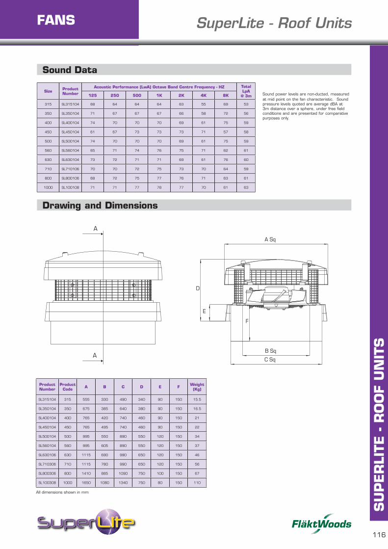
116
SU
PER
LITE
- R
OO
F U
NIT
S
CASED SuperLite - Roof UnitsFANS
Sound Data
Size Product Number
Acoustic Performance (LwA) Octave Band Centre Frequency - HZ Total LpA
@ 3m125 250 500 1K 2K 4K 8K
315 SL315104 68 64 64 64 63 55 69 53
350 SL350104 71 67 67 67 66 58 72 56
400 SL400104 74 70 70 70 69 61 75 59
450 SL450104 61 67 73 73 73 71 57 58
500 SL500104 74 70 70 70 69 61 75 59
560 SL560104 65 71 74 76 75 71 62 61
630 SL630104 73 72 71 71 69 61 76 60
710 SL710106 70 70 72 75 73 70 64 59
800 SL800106 68 72 75 77 76 71 63 61
1000 SL100108 71 71 77 78 77 70 61 63
Drawing and Dimensions
Product Number
Product Code A B C D E F Weight
(Kg)
SL315104 315 555 330 490 340 90 150 15.5
SL350104 350 675 385 640 380 90 150 16.5
SL400104 400 765 420 740 460 90 150 21
SL450104 450 765 495 740 460 90 150 22
SL500104 500 995 550 890 550 120 150 34
SL560104 560 995 605 890 550 120 150 37
SL630106 630 1115 690 990 650 120 150 46
SL710306 710 1115 780 990 650 120 150 56
SL800306 800 1410 885 1090 750 100 150 67
SL100308 1000 1650 1080 1340 750 80 150 110
B Sq
C Sq
E
D
A Sq
F
A
A
Sound power levels are non-ducted, measured at mid point on the fan characteristic. Sound pressure levels quoted are average dBA at 3m distance over a sphere, under free field conditions and are presented for comparative purposes only.
B Sq
C Sq
E
D
A Sq
F
A
A
All dimensions shown in mm

Purlin Mount Dimensions
117
SU
PER
LITE
- R
OO
F U
NIT
SCASED SuperLite - Roof UnitsFANS
Product Number Size A B C D E F
SL315104 315 555 440 510 340 90 225
SL350104 350 675 620 680 380 90 240
SL400104 400 765 720 780 460 90 240
SL450104 450 765 720 780 460 90 240
SL500104 500 995 860 900 550 120 250
SL560104 560 995 860 900 550 120 250
SL630106 630 1115 900 950 650 120 260
Purlin Box Outline Dimensions
Product Number Size A B C D E F G
PB315104 315 350 220 445 515 615 380 9
PB350104 350 400 240 625 680 780 435 9
PB400104 400 510 240 730 780 880 490 9
PB450104 450 510 240 730 780 880 535 11
PB500104 500 620 250 865 910 1050 615 11
PB560104 560 620 250 865 910 1050 675 11
PB630106 630 780 260 900 950 1080 750 11
A
A
ED
A Sq
B Sq
C Sq
F
B
D Sq
C Sq
A Sq
E Sq
F
F Ø G
B
D Sq
C Sq
A Sq
E Sq
F
F Ø G
All dimensions shown in mm
All dimensions shown in mm

CASED SuperLite - Roof Units
SU
PER
LITE
- A
XIA
L FA
NS
118
FANS
SU
PER
LITE
- R
OO
F U
NIT
S
Soaker Sheet Dimensions
C
A
E
D F
B
Please enter dimensions measured as accurately as possible in mm, 4 profiles shown for illustration, sheets may be wider.
Once completed please return to your SuperLite Distributor who will be happy to provide you with a selection and quote by return.
A = Profile cover width (centre to centre of outside crowns) ..................................B = Depth of corrugations ...............................................................................C = Pitch (centre to centre of crowns) ..............................................................D = Pan width ...............................................................................................E = Crown width .............................................................................................F = Base flute width ........................................................................................Total number of crowns per sheet ....................................................................
Colour ..........................................................................................................
Additional comments ......................................................................................
Note: Profile suggestions are made in good faith based upon information provided. Final acceptance of any suggested profile must always remain the responsibility of the customer. All information or details are intended as a guide only. No responsibility whatsoever will be accepted for any mis-identified or unsuitable profiles following acceptance of a suggested profile. Soaker sheets are made to order and are therefore non refundable.
Controller - Electronic Controller - Transformer
All dimensions shown in mm
All dimensions shown in mm
Type Number Product A B C D E
Max. Weight
(kg)
MT1.5 423099 255 170 140 155 194 5.5
MT3.7 402013 425 300 235 255 355 26
Product Code
Product Number A B C D
ME1.1 DA410289 104 83 55 40
ME1.3 DA410290 148 87 62 47
ME1.6 DA410291 148 87 62 47
ME1.12 DA414855 210 180 81 65
Bold text denotes, next day delivery available if ordered by 4pm.

Cowl Only - Pressure Drops
119
SU
PER
LITE
- R
OO
F U
NIT
SCASED SuperLite - Roof UnitsFANS
600
500
400
300
200
100
00 0.5 1 1.5 2 2.5
450
400
350
300
250
200
150
100
50
00 0.5 1 1.5 2 2.5 3 3.5
0 1 2 3 4 5
350
300
250
200
150
100
50
0
Typical resistance when used as terminal onlySize 315/350
Typical resistance when used as terminal onlySize 500/560
Extract
Input
Extract
Input
Extract
Input
Typical resistance when used as terminal only400/450

CASED SuperLite - Roof Units
SU
PER
LITE
- A
XIA
L FA
NS
120
FANS
SU
PER
LITE
- R
OO
F U
NIT
S
200
180
160
140
120
100
80
60
40
20
00 1 2 3 4 5 6
250
200
150
100
50
0
0 1 2 3 4 5 6 7 8
0
10
20
30
40
50
60
70
80
90
0 1 2 3 4 5 6 7 8 9
Cowl Only - Pressure Drops
Typical resistance when used as terminal only
Size 630/710
Typical resistance when used as terminal only
Size 800
Typical resistance when used as terminal only
Size 1000
Extract
Input
Extract
Input
Extract
Input