Brushless DC Axial fans - Pelonis Technologies
76
BRUSHLESS DC AXIAL FANS I N T E L L I G E N T M O T I O N S E R I E S PELONISTECHNOLOGIES.COM
-
Upload
khangminh22 -
Category
Documents
-
view
0 -
download
0
Transcript of Brushless DC Axial fans - Pelonis Technologies

BRUSHLESS DC AXIAL FANS I N T E L L I G E N T M O T I O N S E R I E S
PELO
NIS
TECH
NOL
OGIE
S.CO
M
Intelligent Motion Controls include tachometer, rotation detection, life detection, pulse width modulation, automatic temperature control, current limit control, constant speed control, multiple alarm connections, and others. Various controls can also be pro-grammed for custom output.
FEATURES & SPECIFICATIONS■ Sizes from 25mm to 172mm■ 5V, 12V, 24V, 48V, or custom nominal voltages■ Dual Ball Bearings■ Auto Restart■ Locked Rotor Protection■ IP51, IP54, IP56, and up to IP67 Dust & Moisture Protection■ Operating Temp -10°C to +70°C■ Operating Life 70,000 hours■ RoHS Compliant■ UL, cUL, CE
APPLICATIONSHVACCompact ElectronicsMedical DevicesIndustrial AutomationAerospace & DefenseAutomotive Products
The Intelligent Motion series Brushless DC Axial Fans are well suited for applications that require high performance, maximum environmental protection, and customized control from a compact cooling device.
For additional information or for assistance with your application, contact us at [email protected].
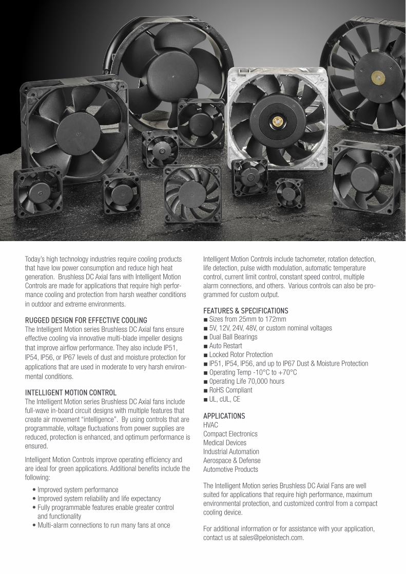
Today’s high technology industries require cooling products that have low power consumption and reduce high heat generation. Brushless DC Axial fans with Intelligent Motion Controls are made for applications that require high perfor-mance cooling and protection from harsh weather conditions in outdoor and extreme environments.
RUGGED DESIGN FOR EFFECTIVE COOLINGThe Intelligent Motion series Brushless DC Axial fans ensure effective cooling via innovative multi-blade impeller designs that improve airflow performance. They also include IP51, IP54, IP56, or IP67 levels of dust and moisture protection for applications that are used in moderate to very harsh environ-mental conditions.
INTELLIGENT MOTION CONTROLThe Intelligent Motion series Brushless DC Axial fans include full-wave in-board circuit designs with multiple features that create air movement “intelligence”. By using controls that are programmable, voltage fluctuations from power supplies are reduced, protection is enhanced, and optimum performance is ensured.
Intelligent Motion Controls improve operating efficiency andare ideal for green applications. Additional benefits include thefollowing:
• Improved system performance • Improved system reliability and life expectancy • Fully programmable features enable greater control and functionality • Multi-alarm connections to run many fans at once
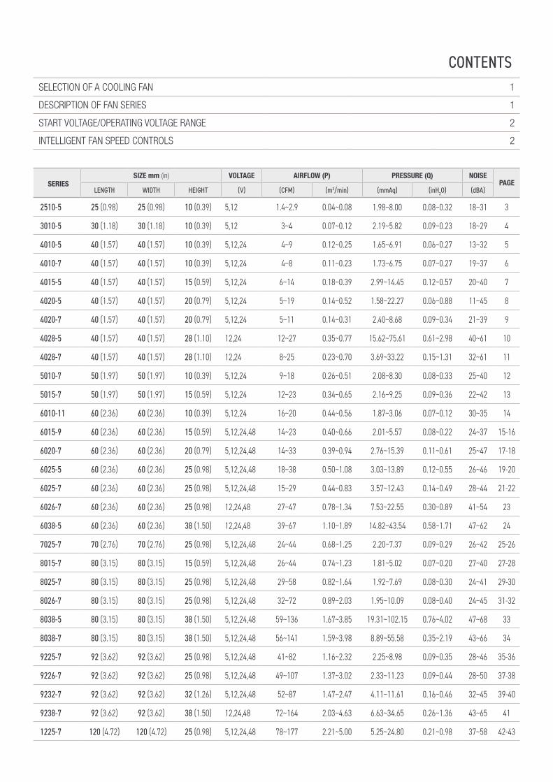
SERIESSIZE mm (in) VOLTAGE AIRFLOW (P) PRESSURE (Q) NOISE
PAGELENGTH WIDTH HEIGHT (V) (CFM) (m3/min) (mmAq) (inH2O) (dBA)
2510-5 25 (0.98) 25 (0.98) 10 (0.39) 5,12 1.4~2.9 0.04~0.08 1.98~8.00 0.08~0.32 18~31 3
3010-5 30 (1.18) 30 (1.18) 10 (0.39) 5,12 3~4 0.07~0.12 2.19~5.82 0.09~0.23 18~29 4
4010-5 40 (1.57) 40 (1.57) 10 (0.39) 5,12,24 4~9 0.12~0.25 1.65~6.91 0.06~0.27 13~32 5
4010-7 40 (1.57) 40 (1.57) 10 (0.39) 5,12,24 4~8 0.11~0.23 1.73~6.75 0.07~0.27 19~37 6
4015-5 40 (1.57) 40 (1.57) 15 (0.59) 5,12,24 6~14 0.18~0.39 2.99~14.45 0.12~0.57 20~40 7
4020-5 40 (1.57) 40 (1.57) 20 (0.79) 5,12,24 5~19 0.14~0.52 1.58~22.27 0.06~0.88 11~45 8
4020-7 40 (1.57) 40 (1.57) 20 (0.79) 5,12,24 5~11 0.14~0.31 2.40~8.68 0.09~0.34 21~39 9
4028-5 40 (1.57) 40 (1.57) 28 (1.10) 12,24 12~27 0.35~0.77 15.62~75.61 0.61~2.98 40~61 10
4028-7 40 (1.57) 40 (1.57) 28 (1.10) 12,24 8~25 0.23~0.70 3.69~33.22 0.15~1.31 32~61 11
5010-7 50 (1.97) 50 (1.97) 10 (0.39) 5,12,24 9~18 0.26~0.51 2.08~8.30 0.08~0.33 25~40 12
5015-7 50 (1.97) 50 (1.97) 15 (0.59) 5,12,24 12~23 0.34~0.65 2.16~9.25 0.09~0.36 22~42 13
6010-11 60 (2.36) 60 (2.36) 10 (0.39) 5,12,24 16~20 0.44~0.56 1.87~3.06 0.07~0.12 30~35 14
6015-9 60 (2.36) 60 (2.36) 15 (0.59) 5,12,24,48 14~23 0.40~0.66 2.01~5.57 0.08~0.22 24~37 15-16
6020-7 60 (2.36) 60 (2.36) 20 (0.79) 5,12,24,48 14~33 0.39~0.94 2.76~15.39 0.11~0.61 25~47 17-18
6025-5 60 (2.36) 60 (2.36) 25 (0.98) 5,12,24,48 18~38 0.50~1.08 3.03~13.89 0.12~0.55 26~46 19-20
6025-7 60 (2.36) 60 (2.36) 25 (0.98) 5,12,24,48 15~29 0.44~0.83 3.57~12.43 0.14~0.49 28~44 21-22
6026-7 60 (2.36) 60 (2.36) 25 (0.98) 12,24,48 27~47 0.78~1.34 7.53~22.55 0.30~0.89 41~54 23
6038-5 60 (2.36) 60 (2.36) 38 (1.50) 12,24,48 39~67 1.10~1.89 14.82~43.54 0.58~1.71 47~62 24
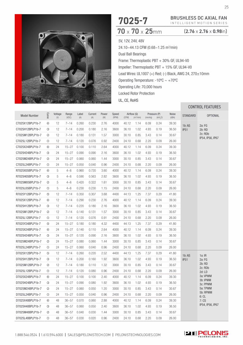
7025-7 70 (2.76) 70 (2.76) 25 (0.98) 5,12,24,48 24~44 0.68~1.25 2.20~7.37 0.09~0.29 26~42 25-26
8015-7 80 (3.15) 80 (3.15) 15 (0.59) 5,12,24,48 26~44 0.74~1.23 1.81~5.02 0.07~0.20 27~40 27-28
8025-7 80 (3.15) 80 (3.15) 25 (0.98) 5,12,24,48 29~58 0.82~1.64 1.92~7.69 0.08~0.30 24~41 29-30
8026-7 80 (3.15) 80 (3.15) 25 (0.98) 5,12,24,48 32~72 0.89~2.03 1.95~10.09 0.08~0.40 24~45 31-32
8038-5 80 (3.15) 80 (3.15) 38 (1.50) 5,12,24,48 59~136 1.67~3.85 19.31~102.15 0.76~4.02 47~68 33
8038-7 80 (3.15) 80 (3.15) 38 (1.50) 5,12,24,48 56~141 1.59~3.98 8.89~55.58 0.35~2.19 43~66 34
9225-7 92 (3.62) 92 (3.62) 25 (0.98) 5,12,24,48 41~82 1.16~2.32 2.25~8.98 0.09~0.35 28~46 35-36
9226-7 92 (3.62) 92 (3.62) 25 (0.98) 5,12,24,48 49~107 1.37~3.02 2.33~11.23 0.09~0.44 28~50 37-38
9232-7 92 (3.62) 92 (3.62) 32 (1.26) 5,12,24,48 52~87 1.47~2.47 4.11~11.61 0.16~0.46 32~45 39-40
9238-7 92 (3.62) 92 (3.62) 38 (1.50) 12,24,48 72~164 2.03~4.63 6.63~34.65 0.26~1.36 43~65 41
1225-7 120 (4.72) 120 (4.72) 25 (0.98) 5,12,24,48 78~177 2.21~5.00 5.25~24.80 0.21~0.98 37~58 42-43
CONTENTSSELECTION OF A COOLING FAN 1
DESCRIPTION OF FAN SERIES 1
START VOLTAGE/OPERATING VOLTAGE RANGE 2
INTELLIGENT FAN SPEED CONTROLS 2
CONTENTS
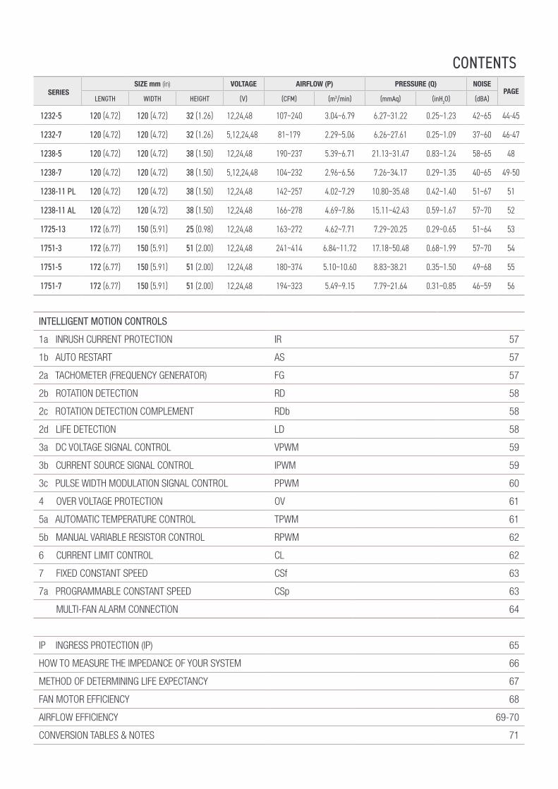
INTELLIGENT MOTION CONTROLS
1a INRUSH CURRENT PROTECTION IR 57
1b AUTO RESTART AS 57
2a TACHOMETER (FREQUENCY GENERATOR) FG 57
2b ROTATION DETECTION RD 58
2c ROTATION DETECTION COMPLEMENT RDb 58
2d LIFE DETECTION LD 58
3a DC VOLTAGE SIGNAL CONTROL VPWM 59
3b CURRENT SOURCE SIGNAL CONTROL IPWM 59
3c PULSE WIDTH MODULATION SIGNAL CONTROL PPWM 60
4 OVER VOLTAGE PROTECTION OV 61
5a AUTOMATIC TEMPERATURE CONTROL TPWM 61
5b MANUAL VARIABLE RESISTOR CONTROL RPWM 62
6 CURRENT LIMIT CONTROL CL 62
7 FIXED CONSTANT SPEED CSf 63
7a PROGRAMMABLE CONSTANT SPEED CSp 63
MULTI-FAN ALARM CONNECTION 64
IP INGRESS PROTECTION (IP) 65
HOW TO MEASURE THE IMPEDANCE OF YOUR SYSTEM 66
METHOD OF DETERMINING LIFE EXPECTANCY 67
FAN MOTOR EFFICIENCY 68
AIRFLOW EFFICIENCY 69-70
CONVERSION TABLES & NOTES 71
SERIESSIZE mm (in) VOLTAGE AIRFLOW (P) PRESSURE (Q) NOISE
PAGELENGTH WIDTH HEIGHT (V) (CFM) (m3/min) (mmAq) (inH2O) (dBA)
1232-5 120 (4.72) 120 (4.72) 32 (1.26) 12,24,48 107~240 3.04~6.79 6.27~31.22 0.25~1.23 42~65 44-45
1232-7 120 (4.72) 120 (4.72) 32 (1.26) 5,12,24,48 81~179 2.29~5.06 6.26~27.61 0.25~1.09 37~60 46-47
1238-5 120 (4.72) 120 (4.72) 38 (1.50) 12,24,48 190~237 5.39~6.71 21.13~31.47 0.83~1.24 58~65 48
1238-7 120 (4.72) 120 (4.72) 38 (1.50) 5,12,24,48 104~232 2.96~6.56 7.26~34.17 0.29~1.35 40~65 49-50
1238-11 PL 120 (4.72) 120 (4.72) 38 (1.50) 12,24,48 142~257 4.02~7.29 10.80~35.48 0.42~1.40 51~67 51
1238-11 AL 120 (4.72) 120 (4.72) 38 (1.50) 12,24,48 166~278 4.69~7.86 15.11~42.43 0.59~1.67 57~70 52
1725-13 172 (6.77) 150 (5.91) 25 (0.98) 12,24,48 163~272 4.62~7.71 7.29~20.25 0.29~0.65 51~64 53
1751-3 172 (6.77) 150 (5.91) 51 (2.00) 12,24,48 241~414 6.84~11.72 17.18~50.48 0.68~1.99 57~70 54
1751-5 172 (6.77) 150 (5.91) 51 (2.00) 12,24,48 180~374 5.10~10.60 8.83~38.21 0.35~1.50 49~68 55
1751-7 172 (6.77) 150 (5.91) 51 (2.00) 12,24,48 194~323 5.49~9.15 7.79~21.64 0.31~0.85 46~59 56
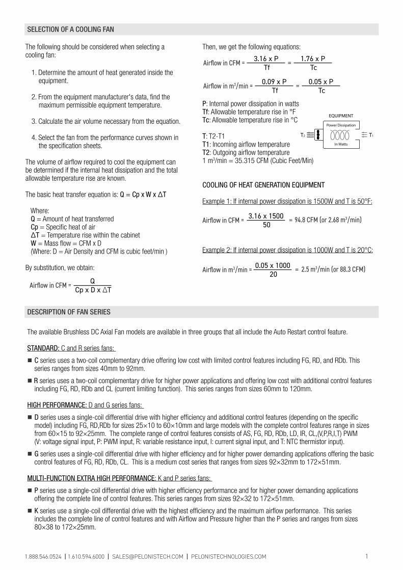
Then, we get the following equations:
P: Internal power dissipation in wattsTf: Allowable temperature rise in °FTc: Allowable temperature rise in °C
T: T2-T1T1: Incoming airflow temperatureT2: Outgoing airflow temperature1 m3/min = 35.315 CFM (Cubic Feet/Min)
COOLING OF HEAT GENERATION EQUIPMENT
Example 1: If internal power dissipation is 1500W and T is 50°F:
Example 2: If internal power dissipation is 1000W and T is 20°C:
The following should be considered when selecting a cooling fan:
1. Determine the amount of heat generated inside the equipment.
2. From the equipment manufacturer's data, find the maximum permissible equipment temperature.
3. Calculate the air volume necessary from the equation.
4. Select the fan from the performance curves shown in the specification sheets.
The volume of airflow required to cool the equipment can be determined if the internal heat dissipation and the total allowable temperature rise are known.
The basic heat transfer equation is: Q = Cp x W x ΔT
Where: Q = Amount of heat transferred Cp = Specific heat of air ΔT = Temperature rise within the cabinet W = Mass flow = CFM x D (Where: D = Air Density and CFM is cubic feet/min )
By substitution, we obtain:
DESCRIPTION OF FAN SERIES
The available Brushless DC Axial Fan models are available in three groups that all include the Auto Restart control feature.
STANDARD: C and R series fans:
■ C series uses a two-coil complementary drive offering low cost with limited control features including FG, RD, and RDb. This series ranges from sizes 40mm to 92mm.
■ R series uses a two-coil complementary drive for higher power applications and offering low cost with additional control features including FG, RD, RDb and CL (current limiting function). This series ranges from sizes 60mm to 120mm.
HIGH PERFORMANCE: D and G series fans:
■ D series uses a single-coil differential drive with higher efficiency and additional control features (depending on the specific model) including FG, RD,RDb for sizes 25×10 to 60×10mm and large models with the complete control features range in sizes from 60×15 to 92×25mm. The complete range of control features consists of AS, FG, RD, RDb, LD, IR, CL,(V,P,R,I,T) PWM (V: voltage signal input, P: PWM input, R: variable resistance input, I: current signal input, and T: NTC thermistor input).
■ G series uses a single-coil differential drive with higher efficiency and for higher power demanding applications offering the basic control features of FG, RD, RDb, CL. This is a medium cost series that ranges from sizes 92×32mm to 172×51mm.
MULTI-FUNCTION EXTRA HIGH PERFORMANCE: K and P series fans:
■ P series use a single-coil differential drive with higher efficiency performance and for higher power demanding applications offering the complete line of control features. This series ranges from sizes 92×32 to 172×51mm.
■ K series use a single-coil differential drive with the highest efficiency and the maximum airflow performance. This series includes the complete line of control features and with Airflow and Pressure higher than the P series and ranges from sizes 80×38 to 172×25mm.
SELECTION OF A COOLING FAN
QCp x D x ΔT
Airflow in CFM =
3.16 x PTf
Airflow in CFM = 1.76 x PTc =
0.09 x PTf
Airflow in m3/min = 0.05 x PTc =
3.16 x 150050
Airflow in CFM = = 94.8 CFM (or 2.68 m3/min)
0.05 x 100020
Airflow in m3/min = = 2.5 m3/min (or 88.3 CFM)
1.888.546.0524 | 1.610.594.6000 | [email protected] | PELONISTECHNOLOGIES.COM 1
EQUIPMENT
T2 T1
In Watts
Power Dissipation
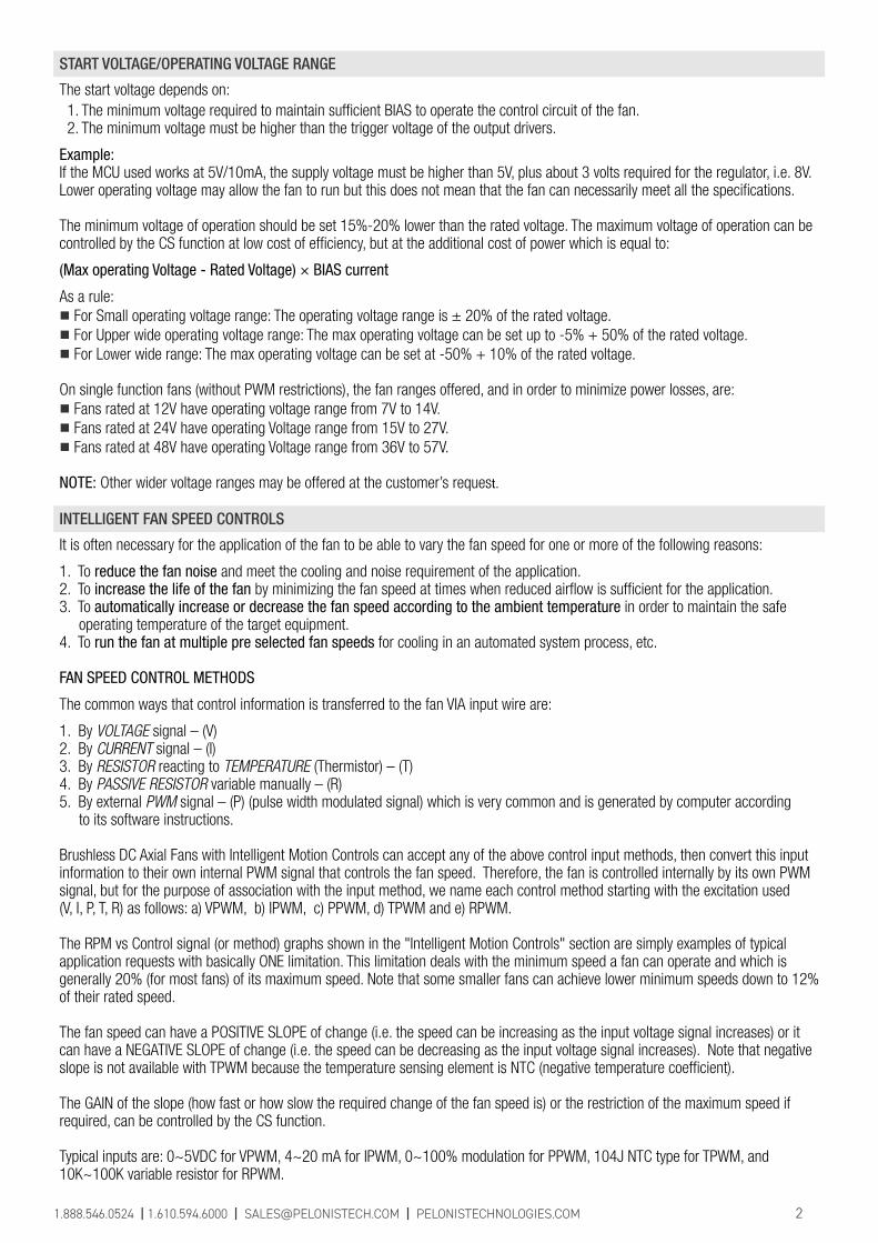
START VOLTAGE/OPERATING VOLTAGE RANGE
The start voltage depends on: 1. The minimum voltage required to maintain sufficient BIAS to operate the control circuit of the fan. 2. The minimum voltage must be higher than the trigger voltage of the output drivers.
Example: If the MCU used works at 5V/10mA, the supply voltage must be higher than 5V, plus about 3 volts required for the regulator, i.e. 8V. Lower operating voltage may allow the fan to run but this does not mean that the fan can necessarily meet all the specifications.
The minimum voltage of operation should be set 15%-20% lower than the rated voltage. The maximum voltage of operation can be controlled by the CS function at low cost of efficiency, but at the additional cost of power which is equal to:
(Max operating Voltage - Rated Voltage) × BIAS current
As a rule: ■ For Small operating voltage range: The operating voltage range is ± 20% of the rated voltage. ■ For Upper wide operating voltage range: The max operating voltage can be set up to -5% + 50% of the rated voltage.■ For Lower wide range: The max operating voltage can be set at -50% + 10% of the rated voltage.
On single function fans (without PWM restrictions), the fan ranges offered, and in order to minimize power losses, are:■ Fans rated at 12V have operating voltage range from 7V to 14V.■ Fans rated at 24V have operating Voltage range from 15V to 27V.■ Fans rated at 48V have operating Voltage range from 36V to 57V.
NOTE: Other wider voltage ranges may be offered at the customer’s request.
INTELLIGENT FAN SPEED CONTROLS
It is often necessary for the application of the fan to be able to vary the fan speed for one or more of the following reasons:
1. To reduce the fan noise and meet the cooling and noise requirement of the application.2. To increase the life of the fan by minimizing the fan speed at times when reduced airflow is sufficient for the application.3. To automatically increase or decrease the fan speed according to the ambient temperature in order to maintain the safe operating temperature of the target equipment.4. To run the fan at multiple pre selected fan speeds for cooling in an automated system process, etc.
FAN SPEED CONTROL METHODS
The common ways that control information is transferred to the fan VIA input wire are:
1. By VOLTAGE signal – (V)2. By CURRENT signal – (I)3. By RESISTOR reacting to TEMPERATURE (Thermistor) – (T)4. By PASSIVE RESISTOR variable manually – (R) 5. By external PWM signal – (P) (pulse width modulated signal) which is very common and is generated by computer according to its software instructions.
Brushless DC Axial Fans with Intelligent Motion Controls can accept any of the above control input methods, then convert this input information to their own internal PWM signal that controls the fan speed. Therefore, the fan is controlled internally by its own PWM signal, but for the purpose of association with the input method, we name each control method starting with the excitation used (V, I, P, T, R) as follows: a) VPWM, b) IPWM, c) PPWM, d) TPWM and e) RPWM.
The RPM vs Control signal (or method) graphs shown in the "Intelligent Motion Controls" section are simply examples of typicalapplication requests with basically ONE limitation. This limitation deals with the minimum speed a fan can operate and which is generally 20% (for most fans) of its maximum speed. Note that some smaller fans can achieve lower minimum speeds down to 12% of their rated speed.
The fan speed can have a POSITIVE SLOPE of change (i.e. the speed can be increasing as the input voltage signal increases) or it can have a NEGATIVE SLOPE of change (i.e. the speed can be decreasing as the input voltage signal increases). Note that negative slope is not available with TPWM because the temperature sensing element is NTC (negative temperature coefficient).
The GAIN of the slope (how fast or how slow the required change of the fan speed is) or the restriction of the maximum speed if required, can be controlled by the CS function.
Typical inputs are: 0~5VDC for VPWM, 4~20 mA for IPWM, 0~100% modulation for PPWM, 104J NTC type for TPWM, and 10K~100K variable resistor for RPWM.
1.888.546.0524 | 1.610.594.6000 | [email protected] | PELONISTECHNOLOGIES.COM 2
CONTROL FEATURES
Model Number
Curve
Voltage(V)
Range(VDC)
Label(A)
Current(A)
Power(W)
Speed(RPM)
Airflow (Q)(CFM) (m3/min)
Pressure (P)(mmAq) (inH
2O)
Noise(dBA)
STANDARD OPTIONAL
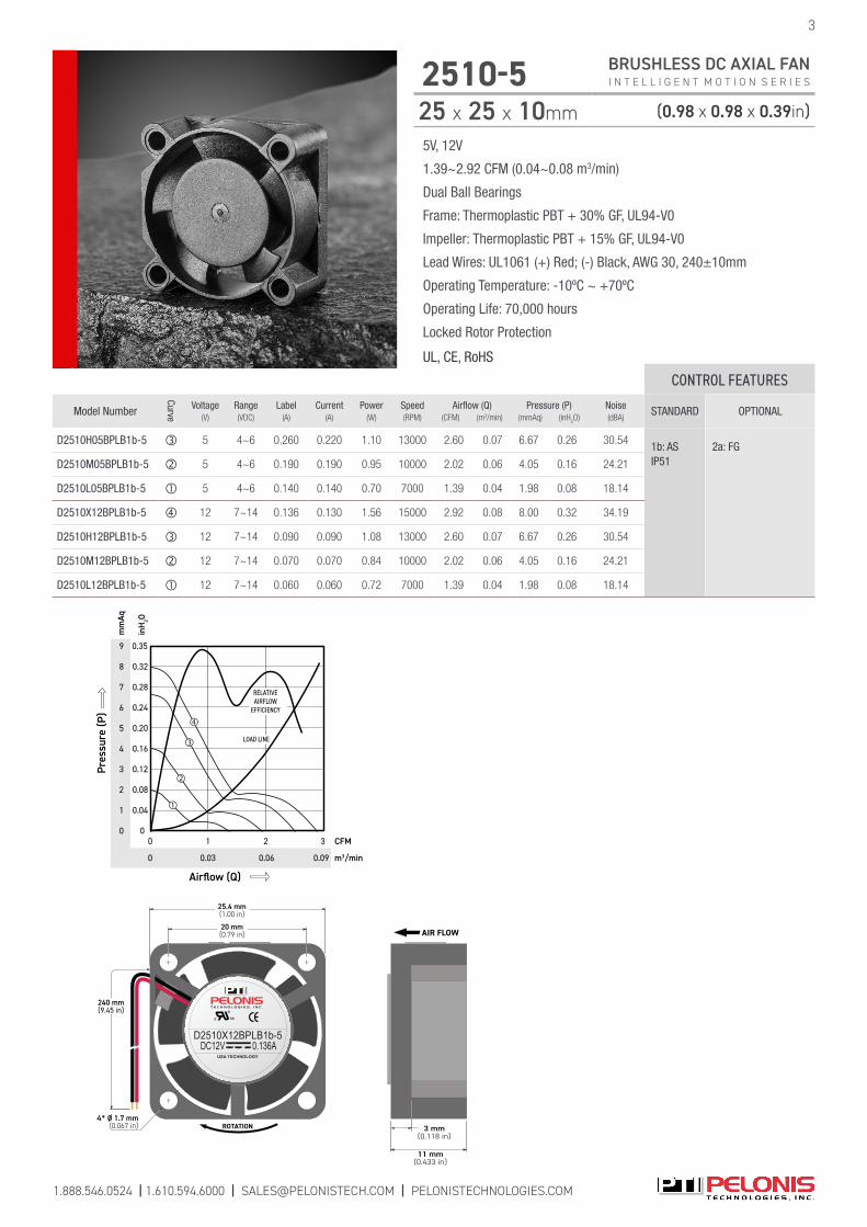
D2510H05BPLB1b-5 5 4~6 0.260 0.220 1.10 13000 2.60 0.07 6.67 0.26 30.54 1b: AS IP51
2a: FG
D2510M05BPLB1b-5 5 4~6 0.190 0.190 0.95 10000 2.02 0.06 4.05 0.16 24.21
D2510L05BPLB1b-5 5 4~6 0.140 0.140 0.70 7000 1.39 0.04 1.98 0.08 18.14
D2510X12BPLB1b-5 12 7~14 0.136 0.130 1.56 15000 2.92 0.08 8.00 0.32 34.19
D2510H12BPLB1b-5 12 7~14 0.090 0.090 1.08 13000 2.60 0.07 6.67 0.26 30.54
D2510M12BPLB1b-5 12 7~14 0.070 0.070 0.84 10000 2.02 0.06 4.05 0.16 24.21
D2510L12BPLB1b-5 12 7~14 0.060 0.060 0.72 7000 1.39 0.04 1.98 0.08 18.14
1.888.546.0524 | 1.610.594.6000 | [email protected] | PELONISTECHNOLOGIES.COM
5V, 12V
1.39~2.92 CFM (0.04~0.08 m3/min)
Dual Ball Bearings
Frame: Thermoplastic PBT + 30% GF, UL94-V0
Impeller: Thermoplastic PBT + 15% GF, UL94-V0
Lead Wires: UL1061 (+) Red; (-) Black, AWG 30, 240±10mm
Operating Temperature: -10ºC ~ +70ºC
Operating Life: 70,000 hours
Locked Rotor Protection
UL, CE, RoHS
2510-5 BRUSHLESS DC AXIAL FAN I N T E L L I G E N T M O T I O N S E R I E S
25 x 25 x 10mm (0.98 x 0.98 x 0.39in)
3
c US
USA TECHNOLOGY
D2510X12BPLB1b-5DC12V 0.136A
ROTATION4* Ø 1.7 mm
(0.067 in)
240 mm(9.45 in)
20 mm(0.79 in)
25.4 mm(1.00 in)
11 mm(0.433 in)
3 mm(0.118 in)
AIR FLOW
9
8
7
6
5
4
3
2
1
0
0.35
0.32
0.28
0.24
0.20
0.16
0.12
0.08
0.04
0
mm
Aq
m3/min
inH
2O
Airflow (Q)
CFM
0
2 3
0.06 0.090.03
0
RELATIVEAIRFLOW
EFFICIENCY
Pres
sure
(P)
1
LOAD LINE

1.888.546.0524 | 1.610.594.6000 | [email protected] | PELONISTECHNOLOGIES.COM
4
3010-5 BRUSHLESS DC AXIAL FAN I N T E L L I G E N T M O T I O N S E R I E S
30 x 30 x 10mm (1.18 x 1.18 x 0.39in)
5V, 12V
2.65~4.23 CFM (0.07~0.12 m3/min)
Dual Ball Bearings
Frame: Thermoplastic PBT + 30% GF, UL94-V0
Impeller: Thermoplastic PBT + 15% GF, UL94-V0
Lead Wires: UL1061 (+) Red; (-) Black, AWG 28, 240±10mm
Operating Temperature: -10ºC ~ +70ºC
Operating Life: 70,000 hours
Locked Rotor Protection
UL, CE, RoHS
CONTROL FEATURES
Model Number
Curve
Voltage(V)
Range(VDC)
Label(A)
Current(A)
Power(W)
Speed(RPM)
Airflow (Q)(CFM) (m3/min)
Pressure (P)(mmAq) (inH
2O)
Noise(dBA)
STANDARD OPTIONAL
D3010H05BPLB1b-5 5 4~6 0.200 0.190 1.08 10000 4.23 0.12 5.82 0.23 28.53 1b: AS IP51
2a: FG
D3010M05BPLB1b-5 5 4~6 0.170 0.150 0.84 8000 3.47 0.10 3.95 0.16 24.16
D3010L05BPLB1b-5 5 4~6 0.130 0.100 0.48 6000 2.65 0.07 2.19 0.09 17.68
D3010H12BPLB1b-5 12 7~14 0.100 0.090 1.08 10000 4.23 0.12 5.82 0.23 28.53
D3010M12BPLB1b-5 12 7~14 0.090 0.070 0.84 8000 3.47 0.10 3.95 0.16 24.16
D3010L12BPLB1b-5 12 7~14 0.050 0.040 0.48 6000 2.65 0.07 2.19 0.09 17.68
6
5
4
3
2
1
0
0.24
0.20
0.16
0.12
0.08
0.04
0
mm
Aq
m3/min
inH
2O
Airflow (Q)
CFM
0
2 4
0.03
0
Pres
sure
(P)
1 3 5
LOAD LINE
RELATIVEAIRFLOW
EFFICIENCY
0.06 0.09 0.11 0.14
c US
USA TECHNOLOGY
D3010H12BPLB1b-5DC12V 0.100A
ROTATION4* Ø 1.7 mm
(0.067 in)
240 mm(9.45 in)
24 mm(0.94 in)
30 mm(1.18 in)
11 mm(0.433 in)
3 mm(0.118 in)
AIR FLOW

CONTROL FEATURES
Model Number
Curve
Voltage(V)
Range(VDC)
Label(A)
Current(A)
Power(W)
Speed(RPM)
Airflow (Q)(CFM) (m3/min)
Pressure (P)(mmAq) (inH
2O)
Noise(dBA)
STANDARD OPTIONAL
D4010Y05BPLP1b-5 5 4~6 0.400 0.320 1.60 9000 8.81 0.25 6.91 0.27 32.00 1b: ASIP51
2a: FG 2b: RDD4010X05BPLP1b-5 5 4~6 0.280 0.220 1.10 7500 7.34 0.21 4.80 0.19 27.20
D4010H05BPLP1b-5 5 4~6 0.200 0.150 0.75 6600 6.46 0.18 3.72 0.15 23.90
D4010M05BPLP1b-5 5 4~6 0.130 0.100 0.50 5500 5.38 0.15 2.58 0.10 19.20
D4010L05BPLP1b-5 5 4~6 0.100 0.080 0.40 4400 4.31 0.12 1.65 0.06 13.30
D4010Y12BPLP1b-5 12 7~14 0.180 0.140 1.68 9000 8.81 0.25 6.91 0.27 32.00
D4010X12BPLP1b-5 12 7~14 0.140 0.100 1.20 7500 7.34 0.21 4.80 0.19 27.20
D4010H12BPLP1b-5 12 7~14 0.130 0.090 1.08 6600 6.46 0.18 3.72 0.15 23.90
D4010M12BPLP1b-5 12 7~14 0.060 0.050 0.60 5500 5.38 0.15 2.58 0.10 19.20
D4010L12BPLP1b-5 12 7~14 0.040 0.032 0.38 4400 4.31 0.12 1.65 0.06 13.30
D4010Y24BPLP1b-5 24 15~27 0.130 0.070 1.68 9000 8.81 0.25 6.91 0.27 32.00
D4010X24BPLP1b-5 24 15~27 0.060 0.050 1.20 7500 7.34 0.21 4.80 0.19 27.20
D4010Y05BPLP1b-5 24 15~27 0.050 0.040 0.96 6600 6.46 0.18 3.72 0.15 23.90
1.888.546.0524 | 1.610.594.6000 | [email protected] | PELONISTECHNOLOGIES.COM
5V, 12V, 24V
4.31~8.81 CFM (0.12~0.25 m3/min)
Dual Ball Bearings
Frame: Thermoplastic PBT + 30% GF, UL94-V0
Impeller: Thermoplastic PBT + 15% GF, UL94-V0
Lead Wires: UL1007 (+) Red; (-) Black, AWG 26, 280±10mm
Operating Temperature: -10ºC ~ +70ºC
Operating Life: 70,000 hours
Locked Rotor Protection
UL, CE, RoHS
4010-5 BRUSHLESS DC AXIAL FAN I N T E L L I G E N T M O T I O N S E R I E S
40 x 40 x 10mm (1.57 x 1.57 x 0.39in)
5
c US
USA TECHNOLOGY
D4010X12BPLB1b-5DC12V 0.140A
ROTATION4* Ø 3.5 mm
(0.137 in)
32 mm(1.26 in)
40 mm(1.57 in)
280 mm(11.02 in)
10.3 mm(0.406 in)
AIR FLOW7
5
4
3
2
1
0
0.28
0.20
0.16
0.12
0.08
0.04
0
mm
Aq
m3/min
inH
2O
Airflow (Q)
CFM
0
4 8
0.23 0.250.11
0
Pres
sure
(P)
2 6 9
LOAD LINE
RELATIVEAIRFLOW
EFFICIENCY
6
3 71 5
0.24
0.200.09 0.170.06 0.140.03

1.888.546.0524 | 1.610.594.6000 | [email protected] | PELONISTECHNOLOGIES.COM
6
4010-7 BRUSHLESS DC AXIAL FAN I N T E L L I G E N T M O T I O N S E R I E S
40 x 40 x 10mm (1.57 x 1.57 x 0.39in)
5V, 12V, 24V
3.87~8.03 CFM (0.11~0.23 m3/min)
Dual Ball Bearings
Frame: Thermoplastic PBT + 30% GF, UL94-V0
Impeller: Thermoplastic PBT + 15% GF, UL94-V0
Lead Wires: UL1007 (+) Red; (-) Black, AWG 26, 280±10mm
Operating Temperature: -10ºC ~ +70ºC
Operating Life: 70,000 hours
Locked Rotor Protection
UL, CE, RoHS
CONTROL FEATURES
Model Number
Curve
Voltage(V)
Range(VDC)
Label(A)
Current(A)
Power(W)
Speed(RPM)
Airflow (Q)(CFM) (m3/min)
Pressure (P)(mmAq) (inH
2O)
Noise(dBA)
STANDARD OPTIONAL
C4010Y05BPLP1b-7 5 4~6 0.303 0.280 1.40 9000 8.03 0.23 6.75 0.27 36.811b: AS IP51
2a: FG 2b: RDC4010X05BPLP1b-7 5 4~6 0.199 0.190 0.95 7500 6.91 0.20 4.60 0.18 32.07
C4010H05BPLP1b-7 5 4~6 0.170 0.150 0.75 6600 5.80 0.16 3.66 0.14 28.29
C4010M05BPLP1b-7 5 4~6 0.100 0.100 0.50 5500 4.82 0.14 2.69 0.11 24.17
C4010L05BPLP1b-7 5 4~6 0.060 0.060 0.30 4400 3.87 0.11 1.73 0.07 19.39
C4010Y12BPLP1b-7 12 7~14 0.143 0.140 1.68 9000 8.03 0.23 6.75 0.27 36.811b: AS IP51
2a: FG 2b: RD3c: PPWM
C4010X12BPLP1b-7 12 7~14 0.110 0.090 1.08 7500 6.91 0.20 4.60 0.18 32.07
C4010H12BPLP1b-7 12 7~14 0.094 0.062 0.74 6600 5.80 0.16 3.66 0.14 28.29
C4010M12BPLP1b-7 12 7~14 0.080 0.051 0.61 5500 4.82 0.14 2.69 0.11 24.17
C4010L12BPLP1b-7 12 7~14 0.070 0.032 0.38 4400 3.87 0.11 1.73 0.07 19.39
C4010H24BPLP1b-7 24 15~27 0.100 0.060 1.44 9000 8.03 0.23 6.75 0.27 36.81
C4010M24BPLP1b-7 24 15~27 0.080 0.054 1.30 8000 7.37 0.21 5.23 0.21 34.97
C4010L24BPLP1b-7 24 15~27 0.060 0.040 0.96 7000 6.13 0.17 4.22 0.17 30.44
D4010H12BPLP1b-7 12 7~14 0.110 0.062 0.74 6600 5.80 0.16 3.66 0.14 28.29
D4010M12BPLP1b-7 12 7~14 0.080 0.051 0.61 5500 4.82 0.14 2.69 0.11 24.17
D4010L12BPLP1b-7 12 7~14 0.070 0.032 0.38 4400 3.87 0.11 1.73 0.07 19.39
D4010H24BPLP1b-7 24 15~27 0.100 0.060 1.44 9000 8.03 0.23 6.75 0.27 36.81
D4010M24BPLP1b-7 24 15~27 0.080 0.054 1.30 8000 7.37 0.21 5.23 0.21 34.97
D4010L24BPLP1b-7 24 15~27 0.060 0.040 0.96 7000 6.13 0.17 4.22 0.17 30.44
7
5
4
3
2
1
0 0
mm
Aq
m3/min
inH
2O
Airflow (Q)
CFM4 80
Pres
sure
(P)
2 6 9
LOAD LINE
RELATIVEAIRFLOW
EFFICIENCY6
3 71 5
0 0.23 0.250.11 0.200.09 0.170.06 0.140.03
0.28
0.20
0.16
0.12
0.08
0.04
0.24
c US
USA TECHNOLOGY
D4010H24BPLP1b-7DC24V 0.100A
ROTATION
4* Ø 3.4 mm(0.134 in)
280 mm(11.02 in)
32 mm(1.26 in)
40 mm(1.57 in)
10.4 mm(0.409 in)
AIR FLOW

1.888.546.0524 | 1.610.594.6000 | [email protected] | PELONISTECHNOLOGIES.COM
5V, 12V, 24V
6.30~13.85 CFM (0.18~0.39 m3/min)
Dual Ball Bearings
Frame: Thermoplastic PBT + 30% GF, UL94-V0
Impeller: Thermoplastic PBT + 15% GF, UL94-V0
Lead Wires: UL1007 (+) Red; (-) Black, AWG 26, 280±10mm
Operating Temperature: -10ºC ~ +70ºC
Operating Life: 70,000 hours
Locked Rotor Protection
UL, CE, RoHS
4015-5 BRUSHLESS DC AXIAL FAN I N T E L L I G E N T M O T I O N S E R I E S
40 x 40 x 15mm (1.57 x 1.57 x 0.59in)
7
32 mm(1.26 in)
40 mm(1.57 in)
280 mm(11.0 in)
32 mm(1.26 in)
40 mm(1.57 in)
ROTATION
c US
USA TECHNOLOGY
D4015X12BPLP1b-5DC12V 0.250A
4-Ø3.5(0.18 in)
15.0 mm(0.59 in)
AIRFLOW
RELATIVEAIRFLOW
EFFICIENCY
3
0.24
0.12
0 0
mm
Aq
m3/min
inH
2O
Airflow (Q)
CFM
0 0.34
0
Pres
sure
(P)
6
9 0.35
12 0.47
15 0.59
0.17 0.250.08
9
0.42
126 153
LOAD LINE
���
�
�
CONTROL FEATURES
Model Number
Curve
Voltage(V)
Range(VDC)
Label(A)
Current(A)
Power(W)
Speed(RPM)
Airflow (Q)(CFM) (m3/min)
Pressure (P)(mmAq) (inH
2O)
Noise(dBA)
STANDARD OPTIONAL
D4015X05BPLP1b-5 5 4~6 0.450 0.400 2.00 9000 11.33 0.32 9.67 0.38 34.90 1b: AS IP51
2a: FG 2b: RDD4015H05BPLP1b-5 5 4~6 0.370 0.250 1.25 7000 8.81 0.25 5.85 0.23 28.30
D4015M05BPLP1b-5 5 4~6 0.250 0.180 0.90 6000 7.55 0.21 4.30 0.17 24.30
D4015L05BPLP1b-5 5 4~6 0.210 0.150 0.75 5000 6.30 0.18 2.99 0.12 19.60
D4015Y12BPLB1b-5 12 7~14 0.290 0.230 2.76 11000 13.85 0.39 14.45 0.57 40.10
D4015X12BPLP1b-5 12 7~14 0.250 0.190 2.28 9000 11.33 0.32 9.67 0.38 34.90
D4015H12BPLP1b-5 12 7~14 0.170 0.110 1.32 7000 8.81 0.25 5.85 0.23 28.30
D4015M12BPLP1b-5 12 7~14 0.150 0.090 1.08 6000 7.55 0.21 4.30 0.17 24.30
D4015L12BPLP1b-5 12 7~14 0.120 0.065 0.78 5000 6.30 0.18 2.99 0.12 19.60
D4015Y24BPLB1b-5 24 15~27 0.170 0.130 3.12 11000 13.85 0.39 14.45 0.57 40.10
D4015X24BPLP1b-5 24 15~27 0.120 0.090 2.16 9000 11.33 0.32 9.67 0.38 34.90
D4015Y05BPLP1b-5 24 15~27 0.100 0.055 1.32 7000 8.81 0.25 5.85 0.23 28.30

1.888.546.0524 | 1.610.594.6000 | [email protected] | PELONISTECHNOLOGIES.COM
8
4020-5 BRUSHLESS DC AXIAL FAN I N T E L L I G E N T M O T I O N S E R I E S
40 x 40 x 20mm (1.57 x 1.57 x 0.79in)
5V, 12V, 24V
4.94~18.53 CFM (0.14~0.52 m3/min)
Dual Ball Bearings
Frame: Thermoplastic PBT + 30% GF, UL94-V0
Impeller: Thermoplastic PBT + 15% GF, UL94-V0
Lead Wires: UL1007 (+) Red; (-) Black, AWG 26, 280±10mm
Operating Temperature: -10ºC ~ +70ºC
Operating Life: 70,000 hours
Locked Rotor Protection
UL, CE, RoHSCONTROL FEATURES
Model Number
Curve
Voltage(V)
Range(VDC)
Label(A)
Current(A)
Power(W)
Speed(RPM)
Airflow (Q)(CFM) (m3/min)
Pressure (P)(mmAq) (inH
2O)
Noise(dBA)
STANDARD OPTIONAL
C4020Y05BPLP1b-5 5 4~6 0.420 0.410 2.05 9500 11.73 0.33 8.93 0.35 33.501b: AS IP51
2a: FG 2b: RD
C4020X05BPLP1b-5 5 4~6 0.390 0.380 1.90 8500 10.50 0.30 7.15 0.28 30.60
C4020H05BPLP1b-5 5 4~6 0.300 0.250 1.25 7000 8.65 0.24 4.85 0.19 25.20
C4020M05BPLP1b-5 5 4~6 0.180 0.170 0.85 5500 6.79 0.19 2.99 0.12 19.30
C4020L05BPLP1b-5 5 4~6 0.130 0.120 0.60 4000 4.94 0.14 1.58 0.06 11.00
C4020Z12BPLB1b-5 12 7~14 0.420 0.370 4.44 15000 18.53 0.52 22.27 0.88 45.40
C4020Y12BPLP1b-5 12 7~14 0.220 0.210 2.52 10000 12.35 0.35 9.90 0.39 34.80
C4020X12BPLP1b-5 12 7~14 0.160 0.160 1.92 8500 10.50 0.30 7.15 0.28 30.60
C4020H12BPLP1b-5 12 7~14 0.120 0.120 1.44 7000 8.65 0.24 4.85 0.19 25.20
C4020M12BPLP1b-5 12 7~14 0.070 0.070 0.84 5500 6.79 0.19 2.99 0.12 19.30
C4020L12BPLP1b-5 12 7~14 0.050 0.050 0.60 4000 4.94 0.14 1.58 0.06 11.00
C4020Z24BPLP1b-5 24 15~27 0.210 0.180 4.32 15000 18.53 0.52 22.27 0.88 45.40
C4020Y24BPLP1b-5 24 15~27 0.110 0.110 2.64 10000 12.35 0.35 9.90 0.39 34.80
C4020X24BPLP1b-5 24 15~27 0.080 0.080 1.92 8500 10.50 0.30 7.15 0.28 30.60
C4020H24BPLP1b-5 24 15~27 0.060 0.060 1.44 7000 8.65 0.24 4.85 0.19 25.20
D4020Y05BPLP1b-5 5 4~6 0.420 0.410 2.05 9500 11.73 0.33 8.93 0.35 33.50
D4020X05BPLP1b-5 5 4~6 0.390 0.380 1.90 8500 10.50 0.30 7.15 0.28 30.60
D4020H05BPLP1b-5 5 4~6 0.300 0.250 1.25 7000 8.65 0.24 4.85 0.19 25.20
D4020M05BPLP1b-5 5 4~6 0.180 0.170 0.85 5500 6.79 0.19 2.99 0.12 19.30
D4020L05BPLP1b-5 5 4~6 0.130 0.120 0.60 4000 4.94 0.14 1.58 0.06 11.00
D4020Z12BPLB1b-5 12 7~14 0.420 0.370 4.44 15000 18.53 0.52 22.27 0.88 45.40
D4020Y12BPLP1b-5 12 7~14 0.220 0.210 2.52 10000 12.35 0.35 9.90 0.39 34.80
D4020X12BPLP1b-5 12 7~14 0.160 0.160 1.92 8500 10.50 0.30 7.15 0.28 30.60
D4020H12BPLP1b-5 12 7~14 0.120 0.120 1.44 7000 8.65 0.24 4.85 0.19 25.20
D4020M12BPLP1b-5 12 7~14 0.070 0.070 0.84 5500 6.79 0.19 2.99 0.12 19.30
D4020L12BPLP1b-5 12 7~14 0.050 0.050 0.60 4000 4.94 0.14 1.58 0.06 11.00
D4020Z24BPLB1b-5 24 15~27 0.210 0.180 4.32 15000 18.53 0.52 22.27 0.88 45.40
D4020Y24BPLP1b-5 24 15~27 0.110 0.110 2.64 10000 12.35 0.35 9.90 0.39 34.80
D4020X24BPLP1b-5 24 15~27 0.080 0.080 1.92 8500 10.50 0.30 7.15 0.28 30.60
D4020H24BPLP1b-5 24 15~27 0.060 0.060 1.44 7000 8.65 0.24 4.85 0.19 25.20
25
20
15
10
5
0
0.98
0.79
0.59
0.39
0.20
0
mm
Aq
m3/min
inH
2O
Airflow (Q)
CFM
0
10
0.42 0.570.28
0
Pres
sure
(P)
5 20
LOAD LINE
0.14
15
RELATIVEAIRFLOW
EFFICIENCY
c US
USA TECHNOLOGY
C4020H05BPLP1b-5DC5V 0.30A
ROTATION4* Ø 4.0 mm
(0.157 in)
280 mm(11.02 in)
32 mm(1.26 in)
40 mm(1.57 in)
20 mm(0.79 in)
AIR FLOW

1.888.546.0524 | 1.610.594.6000 | [email protected] | PELONISTECHNOLOGIES.COM
5V, 12V, 24V
4.92~10.88 CFM (0.14~0.31 m3/min)
Dual Ball Bearings
Frame: Thermoplastic PBT + 30% GF, UL94-V0
Impeller: Thermoplastic PBT + 15% GF, UL94-V0
Lead Wires: UL1007 (+) Red; (-) Black, AWG 26, 280±10mm
Operating Temperature: -10ºC ~ +70ºC
Operating Life: 70,000 hours
Locked Rotor Protection
UL, CE, RoHS
4020-7 BRUSHLESS DC AXIAL FAN I N T E L L I G E N T M O T I O N S E R I E S
40 x 40 x 20mm (1.57 x 1.57 x 0.79in)
9
c US
USA TECHNOLOGY
C4020Y24BPLP1b-7DC24V 0.12A
ROTATION
4* Ø 4.0 mm(0.157 in)
280 mm(11.02 in)
32 mm(1.26 in)
40 mm(1.57 in)
20 mm(0.79 in)
AIR FLOW10
8
6
4
2
0
0.35
0.31
0.24
0.16
0.08
0
mm
Aq
m3/min
inH
2O
Airflow (Q)
CFM8
0.28 0.340.23
0
Pres
sure
(P)
4 12
LOAD LINE
0.11
10
RELATIVEAIRFLOW
EFFICIENCY
9
7
5
3
1
0.39
0.28
0.20
0.12
0.04
62
0 0.170.06
CONTROL FEATURES
Model Number
Curve
Voltage(V)
Range(VDC)
Label(A)
Current(A)
Power(W)
Speed(RPM)
Airflow (Q)(CFM) (m3/min)
Pressure (P)(mmAq) (inH
2O)
Noise(dBA)
STANDARD OPTIONAL
C4020H05BPLP1b-7 5 4~6 0.320 0.220 1.10 7000 8.21 0.23 5.74 0.23 32.381b: AS IP51
2a: FG 2b: RD IP56, IP67
C4020M05BPLP1b-7 5 4~6 0.170 0.140 0.70 5500 6.64 0.19 3.87 0.15 27.14
C4020L05BPLP1b-7 5 4~6 0.110 0.083 0.42 4000 4.92 0.14 2.40 0.09 20.78
C4020Y12BPLP1b-7 12 7~14 0.310 0.160 1.92 9000 10.88 0.31 8.68 0.34 39.18
C4020X12BPLP1b-7 12 7~14 0.168 0.140 1.68 8000 9.81 0.28 6.98 0.27 36.27
C4020H12BPLP1b-7 12 7~14 0.140 0.100 1.20 7000 8.21 0.23 5.74 0.23 32.38
C4020M12BPLP1b-7 12 7~14 0.100 0.062 0.74 5500 6.64 0.19 3.87 0.15 27.14
C4020L12BPLP1b-7 12 7~14 0.050 0.040 0.48 4000 4.92 0.14 2.40 0.09 20.78
C4020Y24BPLP1b-7 24 15~27 0.120 0.095 2.28 9000 10.88 0.31 8.68 0.34 39.18
C4020X24BPLP1b-7 24 15~27 0.096 0.072 1.73 8000 9.81 0.28 6.98 0.27 36.27
C4020H24BPLP1b-7 24 15~27 0.072 0.051 1.22 7000 8.21 0.23 5.74 0.23 32.38
D4020H05BPLP1b-7 5 4~6 0.320 0.220 1.10 7000 8.21 0.23 5.74 0.23 32.381b: AS IP51
2a: FG 2b: RD 3c: PPWMIP56, IP67
D4020M05BPLP1b-7 5 4~6 0.170 0.140 0.70 5500 6.64 0.19 3.87 0.15 27.14
D4020L05BPLP1b-7 5 4~6 0.110 0.083 0.42 4000 4.92 0.14 2.40 0.09 20.78
D4020Y12BPLP1b-7 12 7~14 0.310 0.160 1.92 9000 10.88 0.31 8.68 0.34 39.18
D4020H12BPLP1b-7 12 7~14 0.140 0.100 1.20 7000 8.21 0.23 5.74 0.23 32.38
D4020M12BPLP1b-7 12 7~14 0.100 0.062 0.74 5500 6.64 0.19 3.87 0.15 27.14
D4020L12BPLP1b-7 12 7~14 0.050 0.040 0.48 4000 4.92 0.14 2.40 0.09 20.78
D4020H24BPLP1b-7 24 15~27 0.130 0.045 1.08 7000 8.21 0.23 5.74 0.23 32.38
D4020M24BPLP1b-7 24 15~27 0.100 0.030 0.72 5500 6.64 0.19 3.87 0.15 27.14
D4020L24BPLP1b-7 24 15~27 0.060 0.020 0.48 4000 4.92 0.14 2.40 0.09 20.78

1.888.546.0524 | 1.610.594.6000 | [email protected] | PELONISTECHNOLOGIES.COM
10
4028-5 BRUSHLESS DC AXIAL FAN I N T E L L I G E N T M O T I O N S E R I E S
40 x 40 x 28mm (1.57 x 1.57 x 1.10in)
12V, 24V
12.40~27.28 CFM (0.35~0.77 m3/min)
Dual Ball Bearings
Frame: Thermoplastic PBT + 30% GF, UL94-V0
Impeller: Thermoplastic PBT + 15% GF, UL94-V0
Lead Wires: UL1007 (+) Red; (-) Black, AWG 26, 280±10mm
Operating Temperature: -10ºC ~ +70ºC
Operating Life: 70,000 hours
Locked Rotor Protection
UL, CE, RoHS
CONTROL FEATURES
Model Number
Curve
Voltage(V)
Range(VDC)
Label(A)
Current(A)
Power(W)
Speed(RPM)
Airflow (Q)(CFM) (m3/min)
Pressure (P)(mmAq) (inH
2O)
Noise(dBA)
STANDARD OPTIONAL
D4028Z12BPLB1b-5 12 7~13.2 1.170 1.060 12.72 22000 27.28 0.77 75.61 2.98 60.80 1b: AS IP51
2a: FG 2b: RD3a: VPWM3c: PPWMIP54, IP56, IP67
D4028Y12BPLB1b-5 12 7~13.2 0.770 0.730 8.76 19000 23.56 0.67 56.39 2.22 56.80
D4028X12BPLB1b-5 12 7~13.2 0.680 0.640 7.68 17000 21.08 0.60 45.15 1.77 55.30
D4028H12BPLB1b-5 12 7~13.2 0.520 0.490 5.88 15000 18.60 0.53 35.15 1.38 51.40
D4028M12BPLB1b-5 12 7~13.2 0.420 0.380 4.56 13000 16.12 0.46 26.40 1.04 47.50
D4028L12BPLB1b-5 12 7~13.2 0.290 0.260 3.12 10000 12.40 0.35 15.62 0.61 40.20
D4028Z24BPLB1b-5 24 15~26.4 0.572 0.520 12.48 22000 27.28 0.77 75.61 2.98 60.80
D4028Y24BPLB1b-5 24 15~26.4 0.355 0.320 7.68 19000 23.56 0.67 56.39 2.22 56.80
D4028X24BPLB1b-5 24 15~26.4 0.280 0.255 6.12 17000 21.08 0.60 45.15 1.77 55.30
D4028H24BPLB1b-5 24 15~26.4 0.210 0.189 4.54 15000 18.60 0.53 35.15 1.38 51.40
D4028M24BPLB1b-5 24 15~26.4 0.155 0.138 3.31 13000 16.12 0.46 26.40 1.04 47.50
D4028L24BPLB1b-5 24 15~26.4 0.093 0.088 2.11 10000 12.40 0.35 15.62 0.61 40.20
80
60
40
20
0
2.76
2.36
1.57
0.79
0
mm
Aq
m3/min
inH
2O
Airflow (Q)
CFM20
0.71 0.850.57
0
Pres
sure
(P)
10 30
LOAD LINE
0.28
25
RELATIVEAIRFLOW
EFFICIENCY70
50
30
10
3.15
1.97
1.18
0.39
155
0 0.420.14
32 mm(1.26 in)
40 mm(1.57 in)
280 mm(11.02 in)
ROTATION
32 mm(1.26 in)
40 mm(1.57 in)
c US
USA TECHNOLOGY
D4028Y24BPLB1b-5DC24V 0.0.355A
4- Ø 3.5 mm(0.138 in)
4.0 mm(0.16 in)
28.0 mm(1.10 in)
CONTROL FEATURES
Model Number
Curve
Voltage(V)
Range(VDC)
Label(A)
Current(A)
Power(W)
Speed(RPM)
Airflow (Q)(CFM) (m3/min)
Pressure (P)(mmAq) (inH
2O)
Noise(dBA)
STANDARD OPTIONAL
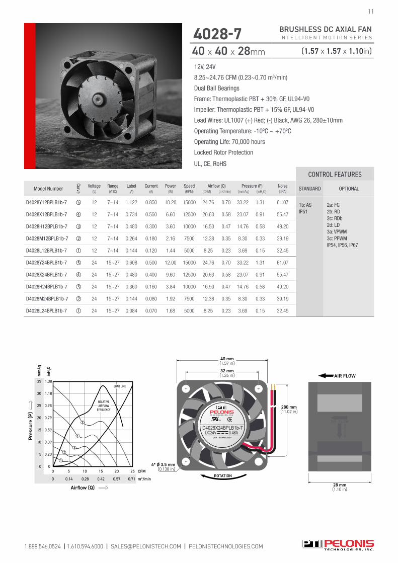
D4028Y12BPLB1b-7 12 7~14 1.122 0.850 10.20 15000 24.76 0.70 33.22 1.31 61.07 1b: AS IP51
2a: FG 2b: RD 2c: RDb 2d: LD 3a: VPWM3c: PPWMIP54, IP56, IP67
D4028X12BPLB1b-7 12 7~14 0.734 0.550 6.60 12500 20.63 0.58 23.07 0.91 55.47
D4028H12BPLB1b-7 12 7~14 0.480 0.300 3.60 10000 16.50 0.47 14.76 0.58 49.20
D4028M12BPLB1b-7 12 7~14 0.264 0.180 2.16 7500 12.38 0.35 8.30 0.33 39.19
D4028L12BPLB1b-7 12 7~14 0.144 0.120 1.44 5000 8.25 0.23 3.69 0.15 32.45
D4028Y24BPLB1b-7 24 15~27 0.608 0.500 12.00 15000 24.76 0.70 33.22 1.31 61.07
D4028X24BPLB1b-7 24 15~27 0.480 0.400 9.60 12500 20.63 0.58 23.07 0.91 55.47
D4028H24BPLB1b-7 24 15~27 0.360 0.160 3.84 10000 16.50 0.47 14.76 0.58 49.20
D4028M24BPLB1b-7 24 15~27 0.144 0.080 1.92 7500 12.38 0.35 8.30 0.33 39.19
D4028L24BPLB1b-7 24 15~27 0.084 0.070 1.68 5000 8.25 0.23 3.69 0.15 32.45
1.888.546.0524 | 1.610.594.6000 | [email protected] | PELONISTECHNOLOGIES.COM
12V, 24V
8.25~24.76 CFM (0.23~0.70 m3/min)
Dual Ball Bearings
Frame: Thermoplastic PBT + 30% GF, UL94-V0
Impeller: Thermoplastic PBT + 15% GF, UL94-V0
Lead Wires: UL1007 (+) Red; (-) Black, AWG 26, 280±10mm
Operating Temperature: -10ºC ~ +70ºC
Operating Life: 70,000 hours
Locked Rotor Protection
UL, CE, RoHS
4028-7 BRUSHLESS DC AXIAL FAN I N T E L L I G E N T M O T I O N S E R I E S
40 x 40 x 28mm (1.57 x 1.57 x 1.10in)
11
c US
USA TECHNOLOGY
D4028X24BPLB1b-7DC24V 0.48A
ROTATION
4* Ø 3.5 mm(0.138 in)
280 mm(11.02 in)
32 mm(1.26 in)
40 mm(1.57 in)
28 mm(1.10 in)
AIR FLOW35
25
15
5
0
1.18
0.98
0.59
0.20
0
mm
Aq
m3/min
inH
2O
Airflow (Q)
CFM15
0.57 0.710.42
0
Pres
sure
(P)
5 25
LOAD LINE
0.14
20
RELATIVEAIRFLOW
EFFICIENCY
30
20
10
1.38
0.79
0.39
10
0 0.28
1.888.546.0524 | 1.610.594.6000 | [email protected] | PELONISTECHNOLOGIES.COM
12
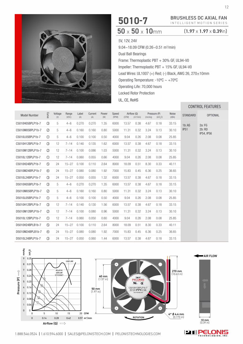
5010-7 BRUSHLESS DC AXIAL FAN I N T E L L I G E N T M O T I O N S E R I E S
50 x 50 x 10mm (1.97 x 1.97 x 0.39in)
5V, 12V, 24V
9.04~18.09 CFM (0.26~0.51 m3/min)
Dual Ball Bearings
Frame: Thermoplastic PBT + 30% GF, UL94-V0
Impeller: Thermoplastic PBT + 15% GF, UL94-V0
Lead Wires: UL1007 (+) Red; (-) Black, AWG 26, 270±10mm
Operating Temperature: -10ºC ~ +70ºC
Operating Life: 70,000 hours
Locked Rotor Protection
UL, CE, RoHS
CONTROL FEATURES
Model Number
Curve
Voltage(V)
Range(VDC)
Label(A)
Current(A)
Power(W)
Speed(RPM)
Airflow (Q)(CFM) (m3/min)
Pressure (P)(mmAq) (inH
2O)
Noise(dBA)
STANDARD OPTIONAL
C5010H05BPLP1b-7 5 4~6 0.270 0.270 1.35 6000 13.57 0.38 4.67 0.18 33.15 1b: AS IP51
2a: FG 2b: RD IP54, IP56
C5010M05BPLP1b-7 5 4~6 0.160 0.160 0.80 5000 11.31 0.32 3.24 0.13 30.10
C5010L05BPLP1b-7 5 4~6 0.100 0.100 0.50 4000 9.04 0.26 2.08 0.08 25.85
C5010H12BPLP1b-7 12 7~14 0.140 0.135 1.62 6000 13.57 0.38 4.67 0.18 33.15
C5010M12BPLP1b-7 12 7~14 0.100 0.086 1.03 5000 11.31 0.32 3.24 0.13 30.10
C5010L12BPLP1b-7 12 7~14 0.060 0.055 0.66 4000 9.04 0.26 2.08 0.08 25.85
C5010H24BPLP1b-7 24 15~27 0.100 0.110 2.64 8000 18.09 0.51 8.30 0.33 40.11
C5010M24BPLP1b-7 24 15~27 0.080 0.080 1.92 7000 15.83 0.45 6.36 0.25 36.65
C5010L24BPLP1b-7 24 15~27 0.050 0.055 1.32 6000 13.57 0.38 4.67 0.18 33.15
D5010H05BPLP1b-7 5 4~6 0.270 0.270 1.35 6000 13.57 0.38 4.67 0.18 33.15
D5010M05BPLP1b-7 5 4~6 0.160 0.160 0.80 5000 11.31 0.32 3.24 0.13 30.10
D5010L05BPLP1b-7 5 4~6 0.100 0.100 0.50 4000 9.04 0.26 2.08 0.08 25.85
D5010H12BPLP1b-7 12 7~14 0.140 0.130 1.56 6000 13.57 0.38 4.67 0.18 33.15
D5010M12BPLP1b-7 12 7~14 0.100 0.080 0.96 5000 11.31 0.32 3.24 0.13 30.10
D5010L12BPLP1b-7 12 7~14 0.060 0.050 0.60 4000 9.04 0.26 2.08 0.08 25.85
D5010H24BPLB1b-7 24 15~27 0.100 0.110 2.64 8000 18.09 0.51 8.30 0.33 40.11
D5010M24BPLB1b-7 24 15~27 0.080 0.080 1.92 7000 15.83 0.45 6.36 0.25 36.65
D5010L24BPLP1b-7 24 15~27 0.050 0.060 1.44 6000 13.57 0.38 4.67 0.18 33.15
9
8
7
6
5
4
3
2
1
0
0.35
0.31
0.28
0.24
0.20
0.16
0.12
0.08
0.04
0
mm
Aq
m3/min
inH
2O
Airflow (Q)
CFM
0
15 20
0.42 0.570.28
0
Pres
sure
(P)
10
LOAD LINE
5
0.14
RELATIVEAIRFLOW
EFFICIENCY
c US
USA TECHNOLOGY
C5010H12BPLP1b-7DC12V 0.14A
ROTATION4* Ø 4.4 mm
(0.173 in)
270 mm(10.63 in)
40 mm(1.57 in)
50 mm(1.97 in)
10 mm(0.39 in)
AIR FLOW

1.888.546.0524 | 1.610.594.6000 | [email protected] | PELONISTECHNOLOGIES.COM
5V, 12V, 24V
12.03~22.80 CFM (0.34~0.65 m3/min)
Dual Ball Bearings
Frame: Thermoplastic PBT + 30% GF, UL94-V0
Impeller: Thermoplastic PBT + 15% GF, UL94-V0
Lead Wires: UL1007 (+) Red; (-) Black, AWG 26, 270±10mm
Operating Temperature: -10ºC ~ +70ºC
Operating Life: 70,000 hours
Locked Rotor Protection
UL, CE, RoHS
5015-7 BRUSHLESS DC AXIAL FAN I N T E L L I G E N T M O T I O N S E R I E S
50 x 50 x 15mm (1.97 x 1.97 x 0.59in)
13
c US
USA TECHNOLOGY
C5015H24BPLP1b-7DC24V 0.10A
ROTATION4* Ø 4.4 mm
(0.173 in)
270 mm(10.63 in)
40 mm(1.57 in)
50 mm(1.97 in)
15 mm(0.59 in)
AIR FLOW10
8
7
6
5
4
3
2
1
0
0.39
0.35
0.28
0.24
0.20
0.16
0.12
0.08
0.04
0
mm
Aq
m3/min
inH
2O
Airflow (Q)
CFM
0
20 25
0.57 0.710.28
0
Pres
sure
(P)
10
LOAD LINE
5
0.14
9
0.32
15
0.42
RELATIVEAIRFLOW
EFFICIENCY
CONTROL FEATURES
Model Number
Curve
Voltage(V)
Range(VDC)
Label(A)
Current(A)
Power(W)
Speed(RPM)
Airflow (Q)(CFM) (m3/min)
Pressure (P)(mmAq) (inH
2O)
Noise(dBA)
STANDARD OPTIONAL
C5015H05BPLP1b-7 5 4~6 0.300 0.300 1.50 6000 18.04 0.51 4.86 0.19 32.401b: AS IP51
2a: FG 2b: RD IP54, IP56, IP67
C5015M05BPLP1b-7 5 4~6 0.240 0.240 1.20 5000 15.04 0.43 3.38 0.13 27.60
C5015M05BPLP1b-7 5 4~6 0.160 0.160 0.80 4000 12.03 0.34 2.16 0.09 21.80
C5015Y12BPLP1b-7 12 7~14 0.400 0.350 4.20 8000 22.80 0.65 9.25 0.36 41.50
C5015X12BPLP1b-7 12 7~14 0.260 0.250 3.00 7000 21.05 0.60 6.62 0.26 36.40
C5015H12BPLP1b-7 12 7~14 0.160 0.160 1.92 6000 18.04 0.51 4.86 0.19 32.40
C5015M12BPLP1b-7 12 7~14 0.120 0.110 1.32 5000 15.04 0.43 3.38 0.13 27.60
C5015L12BPLP1b-7 12 7~14 0.080 0.080 0.96 4000 12.03 0.34 2.16 0.09 21.80
C5015Y24BPLP1b-7 24 15~27 0.200 0.180 4.32 8000 22.80 0.65 9.25 0.36 41.50
C5015X24BPLP1b-7 24 15~27 0.150 0.130 3.12 7000 21.05 0.60 6.62 0.26 36.40
C5015H24BPLP1b-7 24 15~27 0.100 0.082 1.97 6000 18.04 0.51 4.86 0.19 32.40
C5015M24BPLP1b-7 24 15~27 0.060 0.060 1.44 5000 15.04 0.43 3.38 0.13 27.60
C5015L24BPLP1b-7 24 15~27 0.040 0.040 0.96 4000 12.03 0.34 2.16 0.09 21.80
D5015H05BPLP1b-7 5 4~6 0.300 0.300 1.50 6000 18.04 0.51 4.86 0.19 32.40
D5015M05BPLP1b-7 5 4~6 0.240 0.240 1.20 5000 15.04 0.43 3.38 0.13 27.60
D5015L05BPLP1b-7 5 4~6 0.160 0.160 0.80 4000 12.03 0.34 2.16 0.09 21.80
D5015Y12BPLP1b-7 12 7~14 0.400 0.400 3.96 8000 22.80 0.65 9.25 0.36 41.50
D5015X12BPLP1b-7 12 7~14 0.260 0.260 2.76 7000 21.05 0.60 6.62 0.26 36.40
D5015H12BPLP1b-7 12 7~14 0.160 0.160 1.80 6000 18.04 0.51 4.86 0.19 32.40
D5015M12BPLP1b-7 12 7~14 0.120 0.120 1.20 5000 15.04 0.43 3.38 0.13 27.60
D5015L12BPLP1b-7 12 7~14 0.080 0.080 0.96 4000 12.03 0.34 2.16 0.09 21.80
D5015Y24BPLP1b-7 24 15~27 0.200 0.200 4.08 8000 22.80 0.65 9.25 0.36 41.50
D5015X24BPLP1b-7 24 15~27 0.150 0.150 2.88 7000 21.05 0.60 6.62 0.26 36.40
D5015H24BPLP1b-7 24 15~27 0.100 0.100 1.92 6000 18.04 0.51 4.86 0.19 32.40
D5015M24BPLP1b-7 24 15~27 0.060 0.060 1.44 5000 15.04 0.43 3.38 0.13 27.60
D5015L24BPLP1b-7 24 15~27 0.040 0.040 0.96 4000 12.03 0.34 2.16 0.09 21.80

1.888.546.0524 | 1.610.594.6000 | [email protected] | PELONISTECHNOLOGIES.COM
14
6010-11 BRUSHLESS DC AXIAL FAN I N T E L L I G E N T M O T I O N S E R I E S
60 x 60 x 10mm (2.36 x 2.36 x 0.39in)
5V, 12V, 24V
13.82~19.87 CFM (0.39~0.56 m3/min)
Dual Ball Bearings
Frame: Thermoplastic PBT + 30% GF, UL94-V0
Impeller: Thermoplastic PBT + 15% GF, UL94-V0
Lead Wires: UL1007 (+) Red; (-) Black, AWG 26, 270±10mm
Operating Temperature: -10ºC ~ +70ºC
Operating Life: 70,000 hours
Locked Rotor Protection
UL, CE, RoHS
CONTROL FEATURES
Model Number
Curve
Voltage(V)
Range(VDC)
Label(A)
Current(A)
Power(W)
Speed(RPM)
Airflow (Q)(CFM) (m3/min)
Pressure (P)(mmAq) (inH
2O)
Noise(dBA)
STANDARD OPTIONAL
C6010H05BPLP1b-11 5 4~6 0.310 0.230 1.15 4000 17.28 0.49 2.31 0.09 32.07 1b: AS IP51
2a: FG 2b: RD IP54, IP56
C6010M05BPLP1b-11 5 4~6 0.200 0.190 0.95 3600 15.55 0.44 1.87 0.07 29.70
C6010L05BPLP1b-11 5 4~6 0.180 0.154 0.77 3200 13.82 0.39 1.48 0.06 24.91
C6010H12BPLP1b-11 12 7~14 0.280 0.180 2.16 4600 19.87 0.56 3.06 0.12 35.04
C6010M12BPLP1b-11 12 7~14 0.170 0.120 1.44 4000 17.28 0.49 2.31 0.09 32.07
C6010L12BPLP1b-11 12 7~14 0.130 0.090 1.08 3600 15.55 0.44 1.87 0.07 29.70
C6010H24BPLP1b-11 24 15~27 0.150 0.120 2.88 4600 19.87 0.56 3.06 0.12 35.04
C6010M24BPLP1b-11 24 15~27 0.100 0.074 1.78 4000 17.28 0.49 2.31 0.09 32.07
C6010L24BPLP1b-11 24 15~27 0.060 0.060 1.44 3600 15.55 0.44 1.87 0.07 29.70
D6010H12BPLP1b-11 12 7~14 0.280 0.180 2.16 4600 19.87 0.56 3.06 0.12 35.04
D6010M12BPLP1b-11 12 7~14 0.170 0.120 1.44 4000 17.28 0.49 2.31 0.09 32.07
D6010L12BPLP1b-11 12 7~14 0.130 0.090 1.08 3600 15.55 0.44 1.87 0.07 29.70
D6010H24BPLP1b-11 24 15~27 0.150 0.120 2.88 4600 19.87 0.56 3.06 0.12 35.04
D6010M24BPLP1b-11 24 15~27 0.100 0.074 1.78 4000 17.28 0.49 2.31 0.09 32.07
D6010L24BPLP1b-11 24 15~27 0.060 0.060 1.44 3600 15.55 0.44 1.87 0.07 29.70
4
3
2
1
0
0.16
0.12
0.08
0.04
0
mm
Aq
m3/min
inH
2O
Airflow (Q)
CFM
0
10
0.42 0.570.28
0
Pres
sure
(P)
5 20
LOAD LINE
0.14
15
RELATIVEAIRFLOW
EFFICIENCY
c US
USA TECHNOLOGY
C6010H05BPLP1b-11DC05V 0.31A
ROTATION
4* Ø 4.4 mm(0.173 in)
270 mm(10.63 in)
50 mm(1.97 in)
60 mm(2.36 in)
10.5 mm(0.41 in)
AIR FLOW

1.888.546.0524 | 1.610.594.6000 | [email protected] | PELONISTECHNOLOGIES.COM
15
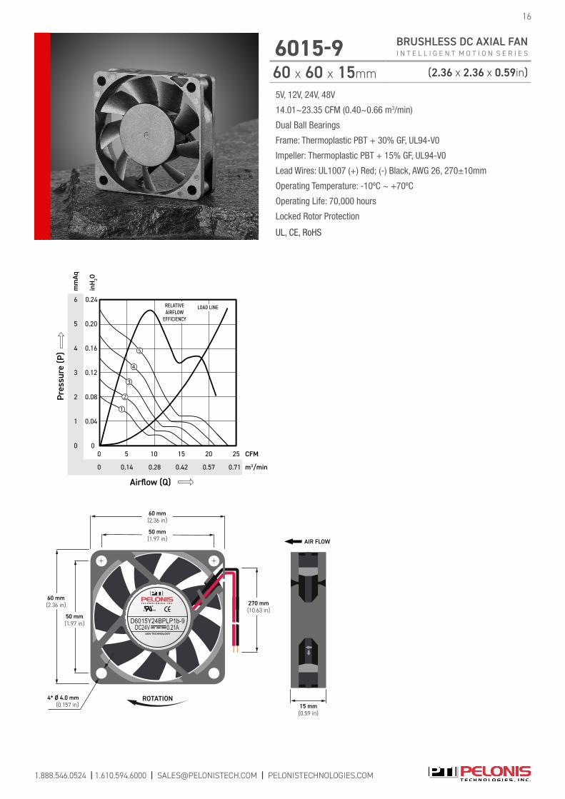
6015-9 BRUSHLESS DC AXIAL FAN I N T E L L I G E N T M O T I O N S E R I E S
60 x 60 x 15mm (2.36 x 2.36 x 0.59in)
5V, 12V, 24V, 48V
14.01~23.35 CFM (0.40~0.66 m3/min)
Dual Ball Bearings
Frame: Thermoplastic PBT + 30% GF, UL94-V0
Impeller: Thermoplastic PBT + 15% GF, UL94-V0
Lead Wires: UL1007 (+) Red; (-) Black, AWG 26, 270±10mm
Operating Temperature: -10ºC ~ +70ºC
Operating Life: 70,000 hours
Locked Rotor Protection
UL, CE, RoHS
CONTROL FEATURES
Model Number
Curve
Voltage(V)
Range(VDC)
Label(A)
Current(A)
Power(W)
Speed(RPM)
Airflow (Q)(CFM) (m3/min)
Pressure (P)(mmAq) (inH
2O)
Noise(dBA)
STANDARD OPTIONAL
C6015H05BPLP1b-9 5 4~6 0.620 0.440 2.20 4000 18.68 0.53 3.57 0.14 30.60 1b: AS IP51
2a: FG 2b: RD 2c: RDb 6: CL IP54, IP56
C6015M05BPLP1b-9 5 4~6 0.380 0.320 1.60 3500 16.34 0.46 2.73 0.11 27.40
C6015L05BPLP1b-9 5 4~6 0.250 0.210 1.05 3000 14.01 0.40 2.01 0.08 23.60
C6015Y12BPLP1b-9 12 7~14 0.460 0.330 3.96 5000 23.35 0.66 5.57 0.22 36.70
C6015X12BPLP1b-9 12 7~14 0.240 0.198 2.38 4500 21.01 0.59 4.51 0.17 33.40
C6015H12BPLP1b-9 12 7~14 0.190 0.160 1.92 4000 18.68 0.53 3.57 0.14 30.60
C6015M12BPLP1b-9 12 7~14 0.130 0.110 1.32 3500 16.34 0.46 2.73 0.11 27.40
C6015L12BPLP1b-9 12 7~14 0.110 0.090 1.08 3000 14.01 0.40 2.01 0.08 23.60
C6015Y24BPLP1b-9 24 15~27 0.210 0.150 3.60 5000 23.35 0.66 5.57 0.22 36.70
C6015X24BPLP1b-9 24 15~27 0.140 0.120 2.88 4500 21.01 0.59 4.51 0.17 33.40
C6015H24BPLP1b-9 24 15~27 0.110 0.090 2.16 4000 18.68 0.53 3.57 0.14 30.60
C6015M24BPLP1b-9 24 15~27 0.080 0.070 1.68 3500 16.34 0.46 2.73 0.11 27.40
C6015L24BPLP1b-9 24 15~27 0.070 0.060 1.44 3000 14.01 0.40 2.01 0.08 23.60
C6015Y48BPLP1b-9 48 36~57 0.100 0.070 2.88 5000 23.35 0.66 5.57 0.22 36.70
C6015X48BPLP1b-9 48 36~57 0.070 0.060 2.40 4500 21.01 0.59 4.51 0.17 33.40
D6015H05BPLP1b-9 5 4~6 0.620 0.440 2.20 4000 18.68 0.53 3.57 0.14 30.60 1b: AS IP51
1a: IR2a: FG 2b: RD 2c: RDb 2d: LD 3a: VPWM 3b: IPWM 3c: PPWM 5a: TPWM 5b: RPWM 6: CL 7: CS IP54, IP56
D6015M05BPLP1b-9 5 4~6 0.380 0.320 1.60 3500 16.34 0.46 2.73 0.11 27.40
D6015L05BPLP1b-9 5 4~6 0.250 0.210 1.05 3000 14.01 0.40 2.01 0.08 23.60
D6015Y12BPLP1b-9 12 7~14 0.460 0.330 3.96 5000 23.35 0.66 5.57 0.22 36.70
D6015X12BPLP1b-9 12 7~14 0.240 0.198 2.38 4500 21.01 0.59 4.51 0.17 33.40
D6015H12BPLP1b-9 12 7~14 0.190 0.160 1.92 4000 18.68 0.53 3.57 0.14 30.60
D6015M12BPLP1b-9 12 7~14 0.130 0.110 1.32 3500 16.34 0.46 2.73 0.11 27.40
D6015L12BPLP1b-9 12 7~14 0.110 0.090 1.08 3000 14.01 0.40 2.01 0.08 23.60
D6015Y24BPLP1b-9 24 15~27 0.210 0.150 3.60 5000 23.35 0.66 5.57 0.22 36.70
D6015X24BPLP1b-9 24 15~27 0.140 0.120 2.88 4500 21.01 0.59 4.51 0.17 33.40
D6015H24BPLP1b-9 24 15~27 0.110 0.090 2.16 4000 18.68 0.53 3.57 0.14 30.60
D6015M24BPLP1b-9 24 15~27 0.080 0.070 1.68 3500 16.34 0.46 2.73 0.11 27.40
D6015L24BPLP1b-9 24 15~27 0.070 0.060 1.44 3000 14.01 0.40 2.01 0.08 23.60
D6015Y48BPLP1b-9 48 36~57 0.100 0.070 2.88 5000 23.35 0.66 5.57 0.22 36.70
D6015X48BPLP1b-9 48 36~57 0.070 0.060 2.40 4500 21.01 0.59 4.51 0.17 33.40
50 mm(1.97 in)
60 mm(2.36 in)
270 mm(10.63 in)
4* Ø 4.0 mm(0.157 in)
ROTATION
50 mm(1.97 in)
60 mm(2.36 in)
c US
USA TECHNOLOGY
D6015Y24BPLP1b-9DC24V 0.21A
AIR FLOW
15 mm(0.59 in)
6
5
3
1
0
0.24
0.20
0.16
0.08
0
mm
Aq
m3/min
inH
2O
Airflow (Q)
CFM
0
10
0.42 0.710.28
0
Pres
sure
(P)
5 25
LOAD LINE
0.14
15
RELATIVEAIRFLOW
EFFICIENCY
0.57
20
4
2
0.12
0.04
16
6015-9 BRUSHLESS DC AXIAL FAN I N T E L L I G E N T M O T I O N S E R I E S
60 x 60 x 15mm (2.36 x 2.36 x 0.59in)
5V, 12V, 24V, 48V
14.01~23.35 CFM (0.40~0.66 m3/min)
Dual Ball Bearings
Frame: Thermoplastic PBT + 30% GF, UL94-V0
Impeller: Thermoplastic PBT + 15% GF, UL94-V0
Lead Wires: UL1007 (+) Red; (-) Black, AWG 26, 270±10mm
Operating Temperature: -10ºC ~ +70ºC
Operating Life: 70,000 hours
Locked Rotor Protection
UL, CE, RoHS
1.888.546.0524 | 1.610.594.6000 | [email protected] | PELONISTECHNOLOGIES.COM

1.888.546.0524 | 1.610.594.6000 | [email protected] | PELONISTECHNOLOGIES.COM
17
6020-7 BRUSHLESS DC AXIAL FAN I N T E L L I G E N T M O T I O N S E R I E S
60 x 60 x 20mm (2.36 x 2.36 x 0.79in)
5V, 12V, 24V, 48V
13.80~33.33 CFM (0.39~0.94 m3/min)
Dual Ball Bearings
Frame: Thermoplastic PBT + 30% GF, UL94-V0
Impeller: Thermoplastic PBT + 15% GF, UL94-V0
Lead Wires: UL1007 (+) Red; (-) Black, AWG 24, 270±10mm
Operating Temperature: -10ºC ~ +70ºC
Operating Life: 70,000 hours
Locked Rotor Protection
UL, CE, RoHS
CONTROL FEATURES
Model Number
Curve
Voltage(V)
Range(VDC)
Label(A)
Current(A)
Power(W)
Speed(RPM)
Airflow (Q)(CFM) (m3/min)
Pressure (P)(mmAq) (inH
2O)
Noise(dBA)
STANDARD OPTIONAL
C6020X12BPLP1b-7 12 7~14 0.310 0.230 2.76 5600 24.30 0.69 8.53 0.34 39.161b: AS IP51
2a: FG 2b: RD 2c: RDb 6: CL IP54, IP56, IP67
C6020H12BPLP1b-7 12 7~14 0.220 0.168 2.02 4800 20.82 0.59 6.26 0.25 35.14
C6020M12BPLP1b-7 12 7~14 0.160 0.120 1.44 4000 17.36 0.49 4.36 0.17 30.37
C6020L12BPLP1b-7 12 7~14 0.110 0.075 0.90 3200 13.80 0.39 2.76 0.11 24.50
C6020Y24BPLP1b-7 24 15~27 0.220 0.220 5.28 6400 27.63 0.78 11.03 0.43 42.46
C6020X24BPLP1b-7 24 15~27 0.180 0.153 3.67 5600 24.30 0.69 8.53 0.34 39.16
C6020H24BPLP1b-7 24 15~27 0.140 0.087 2.09 4800 20.82 0.59 6.26 0.25 35.14
C6020M24BPLP1b-7 24 15~27 0.100 0.070 1.68 4000 17.36 0.49 4.36 0.17 30.37
C6020L24BPLP1b-7 24 15~27 0.070 0.035 0.84 3200 13.80 0.39 2.76 0.11 24.50
R6020X05BPLP1b-7 5 4~6 0.900 0.550 2.75 5600 24.30 0.69 8.53 0.34 39.16
R6020H05BPLP1b-7 5 4~6 0.640 0.450 2.25 4800 20.82 0.59 6.26 0.25 35.14
R6020M05BPLP1b-7 5 4~6 0.450 0.320 1.60 4000 17.36 0.49 4.36 0.17 30.37
R6020L05BPLP1b-7 5 4~6 0.220 0.190 0.95 3200 13.80 0.39 2.76 0.11 24.50
R6020Y12BPLP1b-7 12 7~14 0.380 0.370 4.44 6400 27.63 0.78 11.03 0.43 42.46
R6020X12BPLP1b-7 12 7~14 0.310 0.230 2.76 5600 24.30 0.69 8.53 0.34 39.16
R6020H12BPLP1b-7 12 7~14 0.220 0.168 2.02 4800 20.82 0.59 6.26 0.25 35.14
R6020M12BPLP1b-7 12 7~14 0.160 0.120 1.44 4000 17.36 0.49 4.36 0.17 30.37
R6020L12BPLP1b-7 12 7~14 0.110 0.075 0.90 3200 13.80 0.39 2.76 0.11 24.50
R6020Y24BPLP1b-7 24 15~27 0.220 0.220 5.28 6400 27.63 0.78 11.03 0.43 42.461b: ASIP51
2a: FG 2b: RD 2c: RDb IP54, IP56, IP67
R6020X24BPLP1b-7 24 15~27 0.180 0.153 3.67 5600 24.30 0.69 8.53 0.34 39.16
R6020H24BPLP1b-7 24 15~27 0.140 0.087 2.09 4800 20.82 0.59 6.26 0.25 35.14
R6020M24BPLP1b-7 24 15~27 0.100 0.070 1.68 4000 17.36 0.49 4.36 0.17 30.37
R6020L24BPLP1b-7 24 15~27 0.070 0.040 0.96 3200 13.80 0.39 2.76 0.11 24.50
D6020X12BPLP1b-7 12 7~14 0.310 0.200 2.40 5600 24.30 0.69 8.53 0.34 39.161b: ASIP51
1a: IR2a: FG 2b: RD 2c: RDb 2d: LD 3a: VPWM 3b: IPWM 3c: PPWM 5a: TPWM 5b: RPWM 6: CL 7: CS IP54, IP56, IP67
D6020H12BPLP1b-7 12 7~14 0.220 0.155 1.86 4800 20.82 0.59 6.26 0.25 35.14
D6020M12BPLP1b-7 12 7~14 0.160 0.108 1.30 4000 17.36 0.49 4.36 0.17 30.37
D6020L12BPLP1b-7 12 7~14 0.110 0.056 0.67 3200 13.80 0.39 2.76 0.11 24.50
D6020Z24BPLP1b-7 24 15~27 0.304 0.270 6.48 7500 33.33 0.94 15.39 0.61 46.83
D6020Y24BPLP1b-7 24 15~27 0.245 0.200 4.80 6400 27.63 0.78 11.03 0.43 42.46
D6020X24BPLP1b-7 24 15~27 0.180 0.121 2.90 5600 24.30 0.69 8.53 0.34 39.16
D6020H24BPLP1b-7 24 15~27 0.140 0.072 1.73 4800 20.82 0.59 6.26 0.25 35.14
D6020M24BPLP1b-7 24 15~27 0.100 0.055 1.32 4000 17.36 0.49 4.36 0.17 30.37
D6020L24BPLP1b-7 24 15~27 0.070 0.035 0.84 3200 13.80 0.39 2.76 0.11 24.50
D6020Z48BPLP1b-7 48 36~57 0.150 0.140 6.72 7500 33.33 0.94 15.39 0.61 46.83
D6020Y48BPLP1b-7 48 36~57 0.132 0.102 4.90 6400 27.63 0.78 11.03 0.43 42.46
D6020X48BPLP1b-7 48 36~57 0.100 0.070 3.36 5600 24.30 0.69 8.53 0.34 39.16
D6020H48BPLP1b-7 48 36~57 0.060 0.050 2.40 4800 20.82 0.59 6.26 0.25 35.14
D6020M48BPLP1b-7 48 36~57 0.040 0.040 1.92 4000 17.36 0.49 4.36 0.17 30.37
D6020L48BPLP1b-7 48 36~57 0.025 0.025 1.20 3200 13.80 0.39 2.76 0.11 24.50

c US
USA TECHNOLOGY
R6020H05BPLP1b-7DC05V 0.64A
ROTATION
4* Ø 4.4 mm(0.173 in)
270 mm(10.63 in)
50 mm(1.97 in)
60 mm(2.36 in)
20 mm(0.79 in)
AIR FLOW
16
12
8
4
0
0.63
0.55
0.31
0.16
0
mm
Aq
m3/min
inH
2O
Airflow (Q)
CFM
0
20
0.71 0.990.57
0
Pres
sure
(P)
10 35
LOAD LINE
0.28
25
0.85
30
14
10
6
2
0.39
0.24
0.08
0.47
155
0.420.14
RELATIVEAIRFLOW
EFFICIENCY
18
6020-7 BRUSHLESS DC AXIAL FAN I N T E L L I G E N T M O T I O N S E R I E S
60 x 60 x 20mm (2.36 x 2.36 x 0.79in)
5V, 12V, 24V, 48V
13.80~33.33 CFM (0.39~0.94 m3/min)
Dual Ball Bearings
Frame: Thermoplastic PBT + 30% GF, UL94-V0
Impeller: Thermoplastic PBT + 15% GF, UL94-V0
Lead Wires: UL1007 (+) Red; (-) Black, AWG 24, 270±10mm
Operating Temperature: -10ºC ~ +70ºC
Operating Life: 70,000 hours
Locked Rotor Protection
UL, CE, RoHS
1.888.546.0524 | 1.610.594.6000 | [email protected] | PELONISTECHNOLOGIES.COM

1.888.546.0524 | 1.610.594.6000 | [email protected] | PELONISTECHNOLOGIES.COM
5V, 12V, 24V, 48V
17.78~38.09 CFM (0.50~1.08 m3/min)
Dual Ball Bearings
Frame: Thermoplastic PBT + 30% GF, UL94-V0
Impeller: Thermoplastic PBT + 15% GF, UL94-V0
Lead Wires: UL1007 (+) Red; (-) Black, AWG 24, 270±10mm
Operating Temperature: -10ºC ~ +70ºC
Operating Life: 70,000 hours
Locked Rotor Protection
UL, CE, RoHS
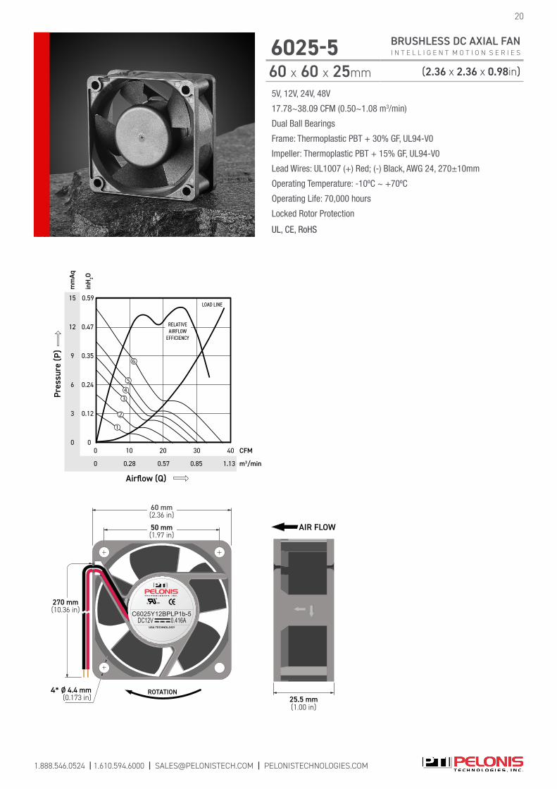
6025-5 BRUSHLESS DC AXIAL FAN I N T E L L I G E N T M O T I O N S E R I E S
60 x 60 x 25mm (2.36 x 2.36 x 0.98in)
19
CONTROL FEATURES
Model Number
Curve
Voltage(V)
Range(VDC)
Label(A)
Current(A)
Power(W)
Speed(RPM)
Airflow (Q)(CFM) (m3/min)
Pressure (P)(mmAq) (inH
2O)
Noise(dBA)
STANDARD OPTIONAL
C6025Y12BPLP1b-5 12 7~14 0.416 0.300 3.60 6500 33.02 0.94 10.44 0.41 41.801b: AS IP51
2a: FG 2b: RD 2c: RDb 6: CL IP54, IP56, IP67
C6025X12BPLP1b-5 12 7~14 0.286 0.230 2.76 6000 30.48 0.86 8.90 0.35 39.80
C6025H12BPLP1b-5 12 7~14 0.247 0.190 2.28 5500 27.94 0.79 7.48 0.29 37.50
C6025M12BPLP1b-5 12 7~14 0.156 0.140 1.68 4500 22.86 0.65 5.01 0.20 32.30
C6025L12BPLP1b-5 12 7~14 0.104 0.090 1.08 3500 17.78 0.50 3.01 0.12 25.70
C6025Y24BPLP1b-5 24 15~27 0.182 0.180 4.32 6500 33.02 0.94 10.44 0.41 41.80
C6025X24BPLP1b-5 24 15~27 0.143 0.135 3.24 6000 30.48 0.86 8.90 0.35 39.80
C6025H24BPLP1b-5 24 15~27 0.117 0.110 2.64 5500 27.94 0.79 7.48 0.29 37.50
C6025M24BPLP1b-5 24 15~27 0.091 0.070 1.68 4500 22.86 0.65 5.01 0.20 32.30
C6025L24BPLP1b-5 24 15~27 0.061 0.050 1.20 3500 17.78 0.50 3.03 0.12 25.70
R6025X05BPLP1b-5 5 4~6 0.884 0.800 4.00 6000 30.48 0.86 8.90 0.35 39.80
R6025H05BPLP1b-5 5 4~6 0.728 0.575 2.88 5500 27.94 0.79 7.48 0.29 37.50
R6025M05BPLP1b-5 5 4~6 0.416 0.315 1.57 4500 22.86 0.65 5.01 0.20 32.30
R6025L05BPLP1b-5 5 4~6 0.286 0.220 1.10 3500 17.78 0.50 3.03 0.12 25.70
R6025Y12BPLP1b-5 12 7~14 0.416 0.300 3.60 6500 33.02 0.94 10.44 0.41 41.80
R6025X12BPLP1b-5 12 7~14 0.286 0.230 2.76 6000 30.48 0.86 8.90 0.35 39.80
R6025H12BPLP1b-5 12 7~14 0.247 0.190 2.28 5500 27.94 0.79 7.48 0.29 37.50
R6025M12BPLP1b-5 12 7~14 0.156 0.140 1.68 4500 22.86 0.65 5.01 0.20 32.30
R6025L12BPLP1b-5 12 7~14 0.104 0.090 1.08 3500 17.78 0.50 3.03 0.12 25.70
R6025Y24BPLP1b-5 24 15~27 0.182 0.180 4.32 6500 33.02 0.94 10.44 0.41 41.80
R6025X24BPLP1b-5 24 15~27 0.143 0.135 3.24 6000 30.48 0.86 8.90 0.35 39.80
R6025H24BPLP1b-5 24 15~27 0.117 0.110 2.64 5500 27.94 0.79 7.48 0.29 37.50
R6025M24BPLP1b-5 24 15~27 0.091 0.070 1.68 4500 22.86 0.65 5.01 0.20 32.30
R6025L24BPLP1b-5 24 15~27 0.061 0.050 1.20 3500 17.78 0.50 3.03 0.12 25.70
D6025Y12BPLP1b-5 12 7~14 0.416 0.280 3.36 6500 33.02 0.94 10.44 0.41 41.801b: ASIP51
1a: IR2a: FG 2b: RD 2c: RDb 2d: LD 3a: VPWM 3b: IPWM 3c: PPWM 5a: TPWM 5b: RPWM 6: CL 7: CS IP54, IP56, IP67
D6025X12BPLP1b-5 12 7~14 0.286 0.220 2.64 6000 30.48 0.86 8.90 0.35 39.80
D6025H12BPLP1b-5 12 7~14 0.247 0.180 2.16 5500 27.94 0.79 7.48 0.29 37.50
D6025M12BPLP1b-5 12 7~14 0.156 0.135 1.62 4500 22.86 0.65 5.01 0.20 32.30
D6025L12BPLP1b-5 12 7~14 0.104 0.090 1.08 3500 17.78 0.50 3.03 0.12 25.70
D6025Y24BPLB1b-5 24 15~27 0.182 0.180 4.32 7500 38.09 1.08 13.89 0.55 45.60
D6025X24BPLP1b-5 24 15~27 0.143 0.130 3.12 6000 30.48 0.86 8.90 0.35 39.80
D6025H24BPLP1b-5 24 15~27 0.117 0.100 2.40 5500 27.94 0.79 7.48 0.29 37.50
D6025M24BPLP1b-5 24 15~27 0.091 0.070 1.68 4500 22.86 0.65 5.01 0.20 32.30
D6025L24BPLP1b-5 24 15~27 0.061 0.050 1.20 3500 17.78 0.50 3.03 0.12 25.70
D6025Y48BPLB1b-5 48 36~57 0.085 0.090 4.32 7500 38.09 1.08 13.89 0.55 45.60
D6025X48BPLP1b-5 48 36~57 0.073 0.070 3.36 6000 30.48 0.86 8.90 0.35 39.80
D6025H48BPLP1b-5 48 36~57 0.060 0.060 2.88 5500 27.94 0.79 7.48 0.29 37.50
D6025M48BPLP1b-5 48 36~57 0.042 0.042 2.02 4500 22.86 0.65 5.01 0.20 32.30
D6025L48BPLP1b-5 48 36~57 0.034 0.034 1.63 3500 17.78 0.50 3.03 0.12 25.70
15
12
6
0
0.59
0.47
0.24
0
mm
Aq
m3/min
inH
2O
Airflow (Q)
CFM
0
20
1.130.57
0
Pres
sure
(P)
10 40
LOAD LINE
0.28
RELATIVEAIRFLOW
EFFICIENCY
0.85
30
9
3
0.35
0.12
c US
USA TECHNOLOGY
C6025Y12BPLP1b-5DC12V 0.416A
ROTATION4* Ø 4.4 mm(0.173 in)
270 mm(10.36 in)
50 mm(1.97 in)
60 mm(2.36 in)
25.5 mm(1.00 in)
AIR FLOW
5V, 12V, 24V, 48V
17.78~38.09 CFM (0.50~1.08 m3/min)
Dual Ball Bearings
Frame: Thermoplastic PBT + 30% GF, UL94-V0
Impeller: Thermoplastic PBT + 15% GF, UL94-V0
Lead Wires: UL1007 (+) Red; (-) Black, AWG 24, 270±10mm
Operating Temperature: -10ºC ~ +70ºC
Operating Life: 70,000 hours
Locked Rotor Protection
UL, CE, RoHS
6025-5 BRUSHLESS DC AXIAL FAN I N T E L L I G E N T M O T I O N S E R I E S
60 x 60 x 25mm (2.36 x 2.36 x 0.98in)
20
1.888.546.0524 | 1.610.594.6000 | [email protected] | PELONISTECHNOLOGIES.COM
5V, 12V, 24V, 48V
15.41~29.17 CFM (0.44~0.83 m3/min)
Dual Ball Bearings
Frame: Thermoplastic PBT + 30% GF, UL94-V0
Impeller: Thermoplastic PBT + 15% GF, UL94-V0
Lead Wires: UL1007 (+) Red; (-) Black, AWG 24, 270±10mm
Operating Temperature: -10ºC ~ +70ºC
Operating Life: 70,000 hours
Locked Rotor Protection
UL, CE, RoHS
1.888.546.0524 | 1.610.594.6000 | [email protected] | PELONISTECHNOLOGIES.COM
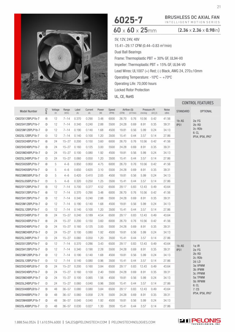
6025-7 BRUSHLESS DC AXIAL FAN I N T E L L I G E N T M O T I O N S E R I E S
60 x 60 x 25mm (2.36 x 2.36 x 0.98in)
21
CONTROL FEATURES
Model Number
Curve
Voltage(V)
Range(VDC)
Label(A)
Current(A)
Power(W)
Speed(RPM)
Airflow (Q)(CFM) (m3/min)
Pressure (P)(mmAq) (inH
2O)
Noise(dBA)
STANDARD OPTIONAL
C6025X12BPLP1b-7 12 7~14 0.370 0.290 3.48 6000 26.70 0.76 10.56 0.42 41.561b: AS IP51
2a: FG 2b: RD 2c: RDb 6: CL IP54, IP56, IP67
C6025H12BPLP1b-7 12 7~14 0.340 0.240 2.88 5500 24.28 0.69 8.91 0.35 39.31
C6025M12BPLP1b-7 12 7~14 0.190 0.140 1.68 4500 19.81 0.56 5.99 0.24 34.13
C6025L12BPLP1b-7 12 7~14 0.140 0.100 1.20 3500 15.41 0.44 3.57 0.14 27.86
C6025X24BPLP1b-7 24 15~27 0.200 0.150 3.60 6000 26.70 0.76 10.56 0.42 41.56
C6025H24BPLP1b-7 24 15~27 0.160 0.125 3.00 5500 24.28 0.69 8.91 0.35 39.31
C6025M24BPLP1b-7 24 15~27 0.100 0.080 1.92 4500 19.81 0.56 5.99 0.24 34.13
C6025L24BPLP1b-7 24 15~27 0.060 0.050 1.20 3500 15.41 0.44 3.57 0.14 27.86
R6025X05BPLP1b-7 5 4~6 0.950 0.950 4.75 6000 26.70 0.76 10.56 0.42 41.56
R6025H05BPLP1b-7 5 4~6 0.650 0.620 3.10 5500 24.28 0.69 8.91 0.35 39.31
R6025M05BPLP1b-7 5 4~6 0.420 0.410 2.05 4500 19.81 0.56 5.99 0.24 34.13
R6025L05BPLP1b-7 5 4~6 0.320 0.250 1.25 3500 15.41 0.44 3.57 0.14 27.86
R6025Y12BPLP1b-7 12 7~14 0.700 0.377 4.52 6500 29.17 0.83 12.43 0.49 43.64
R6025X12BPLP1b-7 12 7~14 0.370 0.290 3.48 6000 26.70 0.76 10.56 0.42 41.56
R6025H12BPLP1b-7 12 7~14 0.340 0.240 2.88 5500 24.28 0.69 8.91 0.35 39.31
R6025M12BPLP1b-7 12 7~14 0.190 0.140 1.68 4500 19.81 0.56 5.99 0.24 34.13
R6025L12BPLP1b-7 12 7~14 0.140 0.100 1.20 3500 15.41 0.44 3.57 0.14 27.86
R6025Y24BPLP1b-7 24 15~27 0.240 0.189 4.54 6500 29.17 0.83 12.43 0.49 43.64
R6025X24BPLP1b-7 24 15~27 0.200 0.150 3.60 6000 26.70 0.76 10.56 0.42 41.56
R6025H24BPLP1b-7 24 15~27 0.160 0.125 3.00 5500 24.28 0.69 8.91 0.35 39.31
R6025M24BPLP1b-7 24 15~27 0.100 0.080 1.92 4500 19.81 0.56 5.99 0.24 34.13
R6025L24BPLP1b-7 24 15~27 0.060 0.050 1.20 3500 15.41 0.44 3.57 0.14 27.86
D6025X12BPLP1b-7 12 7~14 0.370 0.286 3.43 6500 29.17 0.83 12.43 0.49 43.641b: ASIP51
1a: IR2a: FG 2b: RD 2c: RDb 2d: LD 3a: VPWM 3b: IPWM 3c: PPWM 5a: TPWM 5b: RPWM 6: CL 7: CS IP54, IP56, IP67
D6025H12BPLP1b-7 12 7~14 0.340 0.190 2.28 5500 24.28 0.69 8.91 0.35 39.31
D6025M12BPLP1b-7 12 7~14 0.190 0.140 1.68 4500 19.81 0.56 5.99 0.24 34.13
D6025L12BPLP1b-7 12 7~14 0.140 0.080 0.96 3500 15.41 0.44 3.57 0.14 27.86
D6025X24BPLB1b-7 24 15~27 0.200 0.160 3.84 6500 29.17 0.83 12.43 0.49 43.64
D6025H24BPLP1b-7 24 15~27 0.160 0.100 2.40 5500 24.28 0.69 8.91 0.35 39.31
D6025M24BPLP1b-7 24 15~27 0.100 0.065 1.56 4500 19.81 0.56 5.99 0.24 34.13
D6025L24BPLP1b-7 24 15~27 0.060 0.040 0.96 3500 15.41 0.44 3.57 0.14 27.86
D6025X48BPLB1b-7 48 36~57 0.080 0.080 3.84 6500 29.17 0.83 12.43 0.49 43.64
D6025H48BPLP1b-7 48 36~57 0.060 0.058 2.78 5500 24.28 0.69 8.91 0.35 39.31
D6025M48BPLP1b-7 48 36~57 0.040 0.040 1.92 4500 19.81 0.56 5.99 0.24 34.13
D6025L48BPLP1b-7 48 36~57 0.030 0.027 1.30 3500 15.41 0.44 3.57 0.14 27.86

5V, 12V, 24V, 48V
15.41~29.17 CFM (0.44~0.83 m3/min)
Dual Ball Bearings
Frame: Thermoplastic PBT + 30% GF, UL94-V0
Impeller: Thermoplastic PBT + 15% GF, UL94-V0
Lead Wires: UL1007 (+) Red; (-) Black, AWG 24, 270±10mm
Operating Temperature: -10ºC ~ +70ºC
Operating Life: 70,000 hours
Locked Rotor Protection
UL, CE, RoHS
1.888.546.0524 | 1.610.594.6000 | [email protected] | PELONISTECHNOLOGIES.COM
22
6025-7 BRUSHLESS DC AXIAL FAN I N T E L L I G E N T M O T I O N S E R I E S
60 x 60 x 25mm (2.36 x 2.36 x 0.98in)
14
12
6
0
0.55
0.47
0.24
0
mm
Aq
m3/min
inH
2O
Airflow (Q)
CFM
0
20
0.850.57
0
Pres
sure
(P)
10 30
LOAD LINE
0.28
10
2
0.39
0.08
8 0.31
4 0.16
RELATIVEAIRFLOW
EFFICIENCY
c US
USA TECHNOLOGY
R6025X05BPLP1b-7DC05V 0.95A
ROTATION
4* Ø 4.4 mm(0.173 in)
270 mm(10.63 in)
50 mm(1.97 in)
60 mm(2.36 in)
25 mm(0.98 in)
AIR FLOW

1.888.546.0524 | 1.610.594.6000 | [email protected] | PELONISTECHNOLOGIES.COM
12V, 24V, 48V
27.39~47.40 CFM (0.78~1.34 m3/min)
Dual Ball Bearings
Frame: Thermoplastic PBT + 30% GF, UL94-V0
Impeller: Thermoplastic PBT + 15% GF, UL94-V0
Lead Wires: UL1007 (+) Red; (-) Black, AWG 24, 270±10mm
Operating Temperature: -10ºC ~ +70ºC
Operating Life: 70,000 hours
Locked Rotor Protection
UL, CE, RoHS
6026-7 BRUSHLESS DC AXIAL FAN I N T E L L I G E N T M O T I O N S E R I E S
60 x 60 x 25mm (2.36 x 2.36 x 0.98in)
23
c US
USA TECHNOLOGY
C5015H24BPLP1b-7DC24V 0.10A
ROTATION4* Ø 4.4 mm
(0.173 in)
270 mm(10.63 in)
40 mm(1.57 in)
50 mm(1.97 in)
15 mm(0.59 in)
AIR FLOW10
8
7
6
5
4
3
2
1
0
0.39
0.35
0.28
0.24
0.20
0.16
0.12
0.08
0.04
0
mm
Aq
m3/min
inH
2O
Airflow (Q)
CFM
0
20 25
0.57 0.710.28
0
Pres
sure
(P)
10
LOAD LINE
5
0.14
9
0.32
15
0.42
RELATIVEAIRFLOW
EFFICIENCY
CONTROL FEATURES
Model Number
Curve
Voltage(V)
Range(VDC)
Label(A)
Current(A)
Power(W)
Speed(RPM)
Airflow (Q)(CFM) (m3/min)
Pressure (P)(mmAq) (inH
2O)
Noise(dBA)
STANDARD OPTIONAL
C6026H12BPLP1b-7 12 7~14 0.460 0.430 5.16 6800 35.81 1.01 12.87 0.51 46.40 1b: AS, IP51 IP54, IP56, IP67
C6026M12BPLP1b-7 12 7~14 0.440 0.400 4.80 6200 32.65 0.93 10.70 0.42 44.601b: AS, IP51
2a: FG, 2b: RD, 2c: RDb IP54, IP56, IP67C6026L12BPLP1b-7 12 7~14 0.260 0.240 2.88 5200 27.39 0.78 7.53 0.30 41.20
C6026H24BPLP1b-7 24 15~27 0.260 0.240 5.76 6800 35.81 1.01 12.87 0.51 46.40 1b: AS, IP51 IP54, IP56, IP67
C6026M24BPLP1b-7 24 15~27 0.230 0.220 5.28 6200 32.65 0.93 10.70 0.42 44.601b: AS, IP51
2a: FG, 2b: RD, 2c: RDb IP54, IP56, IP67C6026L24BPLP1b-7 24 15~27 0.150 0.130 3.12 5200 27.39 0.78 7.53 0.30 41.20
D6026Z12BPLB1b-7 12 7~13.2 0.920 0.850 10.20 9000 47.40 1.34 22.55 0.89 54.101b: AS, IP51 1a: IR
2a: FG
2b: RD 2c: RDb 2d: LD 3a: VPWM 3b: IPWM 3c: PPWM 5a: TPWM 5b: RPWM 6: CL 7: CS IP54, IP56, IP67
D6026Y12BPLB1b-7 12 7~13.2 0.720 0.650 7.80 8300 43.71 1.24 19.18 0.76 51.10
D6026X12BPLB1b-7 12 7~13.2 0.480 0.430 5.16 7600 40.03 1.13 16.08 0.63 49.80
D6026H12BPLP1b-7 12 7~14 0.460 0.380 4.56 6800 35.81 1.01 12.87 0.51 46.40
D6026M12BPLP1b-7 12 7~14 0.440 0.300 3.60 6200 32.65 0.93 10.70 0.42 44.60
D6026L12BPLP1b-7 12 7~14 0.260 0.200 2.40 5200 27.39 0.78 7.53 0.30 41.20
D6026Z24BPLB1b-7 24 15~26.4 0.480 0.450 10.80 9000 47.40 1.34 22.55 0.89 54.10
D6026Y24BPLB1b-7 24 15~26.4 0.380 0.350 8.40 8300 43.71 1.24 19.18 0.76 51.10
D6026X24BPLB1b-7 24 15~26.4 0.320 0.280 6.72 7600 40.03 1.13 16.08 0.63 49.80
D6026H24BPLP1b-7 24 15~27 0.260 0.190 4.56 6800 35.81 1.01 12.87 0.51 46.40
D6026M24BPLP1b-7 24 15~27 0.230 0.155 3.72 6200 32.65 0.93 10.70 0.42 44.60
D6026L24BPLP1b-7 24 15~27 0.150 0.105 2.52 5200 27.39 0.78 7.53 0.30 41.20
D6026Z48BPLB1b-7 48 36~57 0.265 0.235 11.28 9000 47.40 1.34 22.55 0.89 54.10
D6026Y48BPLB1b-7 48 36~57 0.220 0.182 8.74 8300 43.71 1.24 19.18 0.76 51.10
D6026X48BPLB1b-7 48 36~57 0.150 0.135 6.48 7600 40.03 1.13 16.08 0.63 49.80
D6026H48BPLP1b-7 48 36~57 0.110 0.098 4.70 6800 35.81 1.01 12.87 0.51 46.40
D6026M48BPLP1b-7 48 36~57 0.098 0.090 4.32 6200 32.65 0.93 10.70 0.42 44.60
D6026L48BPLP1b-7 48 36~57 0.070 0.064 3.07 5200 27.39 0.78 7.53 0.30 41.20

1.888.546.0524 | 1.610.594.6000 | [email protected] | PELONISTECHNOLOGIES.COM
24
6038-5 BRUSHLESS DC AXIAL FAN I N T E L L I G E N T M O T I O N S E R I E S
60 x 60 x 38mm (2.36 x 2.36 x 1.50in)
12V, 24V, 48V
38.89~66.67 CFM (1.10~1.89 m3/min)
Dual Ball Bearings
Frame: Thermoplastic PBT + 30% GF, UL94-V0
Impeller: Thermoplastic PBT + 15% GF, UL94-V0
Lead Wires: UL1007 (+) Red; (-) Black, AWG 24, 270±10mm
Operating Temperature: -10ºC ~ +70ºC
Operating Life: 70,000 hours
Locked Rotor Protection
UL, CE, RoHS
CONTROL FEATURES
Model Number
Curve
Voltage(V)
Range(VDC)
Label(A)
Current(A)
Power(W)
Speed(RPM)
Airflow (Q)(CFM) (m3/min)
Pressure (P)(mmAq) (inH
2O)
Noise(dBA)
STANDARD OPTIONAL
D6038Y12BPLB1b-5 12 7~14 1.450 1.200 14.40 11000 61.12 1.73 36.59 1.44 56.80 1b: ASIP51
1a: IR2a: FG 2b: RD 2c: RDb 2d: LD 3a: VPWM 3b: IPWM 3c: PPWM 5a: TPWM 5b: RPWM 6: CL 7: CS IP54, IP56, IP67
D6038X12BPLB1b-5 12 7~14 1.080 0.900 10.80 10000 55.56 1.57 30.24 1.19 55.80
D6038H12BPLB1b-5 12 7~14 0.830 0.690 8.28 9000 50.00 1.42 24.49 0.96 53.10
D6038M12BPLB1b-5 12 7~14 0.590 0.490 5.88 8000 44.45 1.26 19.35 0.76 49.90
D6038L12BPLB1b-5 12 7~14 0.420 0.350 4.20 7000 38.89 1.10 14.82 0.58 46.80
D6038Z24BPLB1b-5 24 15~27 0.950 0.790 18.96 12000 66.67 1.89 43.54 1.71 62.00
D6038Y24BPLB1b-5 24 15~27 0.680 0.570 13.68 11000 61.12 1.73 36.59 1.44 56.80
D6038X24BPLB1b-5 24 15~27 0.550 0.460 11.04 10000 55.56 1.57 30.24 1.19 55.80
D6038H24BPLB1b-5 24 15~27 0.420 0.350 8.40 9000 50.00 1.42 24.49 0.96 53.10
D6038M24BPLB1b-5 24 15~27 0.300 0.250 6.00 8000 44.45 1.26 19.35 0.76 49.90
D6038L24BPLB1b-5 24 15~27 0.210 0.180 4.32 7000 38.89 1.10 14.82 0.58 46.80
D6038Z48BPLB1b-5 48 36~57 0.480 0.400 19.20 12000 66.67 1.89 43.54 1.71 62.00
D6038Y48BPLB1b-5 48 36~57 0.360 0.300 14.40 11000 61.12 1.73 36.59 1.44 56.80
D6038X48BPLB1b-5 48 36~57 0.280 0.230 11.04 10000 55.56 1.57 30.24 1.19 55.80
D6038H48BPLB1b-5 48 36~57 0.220 0.180 8.64 9000 55.00 1.42 24.49 0.96 53.10
D6038M48BPLB1b-5 48 36~57 0.160 0.130 6.24 8000 44.45 1.26 19.35 0.46 49.90
D6038L48BPLB1b-5 48 36~57 0.130 0.100 4.80 7000 38.89 1.10 14.82 0.58 46.80
50
35
20
10
0
1.97
1.77
0.79
0.39
0
mm
Aq
m3/min
inH
2O
Airflow (Q)
CFM
0
40
1.42 1.981.13
0
Pres
sure
(P)
20 70
LOAD LINE
0.57
50
1.70
60
45
25
15
5
0.98
0.59
0.20
1.38
3010
0.850.28
30
40 1.57
1.18
RELATIVEAIRFLOW
EFFICIENCY
50 mm(1.97 in)
60 mm(2.36 in)
50 mm(1.97 in)
60 mm(2.36 in)
ROTATION
c US
USA TECHNOLOGY
D6038Z24BPLB1b-5 DC24V 0.95A
4- Ø 4.5 mm(0.16 in)
270 mm(10.63 in)
38 mm(1.50 in)
AIR FLOW
AIR FLOW
ROTA
TIO
N
1.888.546.0524 | 1.610.594.6000 | [email protected] | PELONISTECHNOLOGIES.COM
25
7025-7 BRUSHLESS DC AXIAL FAN I N T E L L I G E N T M O T I O N S E R I E S
70 x 70 x 25mm (2.76 x 2.76 x 0.98in)
5V, 12V, 24V, 48V
24.10~44.13 CFM (0.68~1.25 m3/min)
Dual Ball Bearings
Frame: Thermoplastic PBT + 30% GF, UL94-V0
Impeller: Thermoplastic PBT + 15% GF, UL94-V0
Lead Wires: UL1007 (+) Red; (-) Black, AWG 24, 270±10mm
Operating Temperature: -10ºC ~ +70ºC
Operating Life: 70,000 hours
Locked Rotor Protection
UL, CE, RoHS
CONTROL FEATURES
Model Number
Curve
Voltage(V)
Range(VDC)
Label(A)
Current(A)
Power(W)
Speed(RPM)
Airflow (Q)(CFM) (m3/min)
Pressure (P)(mmAq) (inH
2O)
Noise(dBA)
STANDARD OPTIONAL
C7025X12BPLP1b-7 12 7~14 0.260 0.230 2.76 4000 40.12 1.14 6.09 0.24 39.301b: AS IP51
2a: FG 2b: RD 2c: RDb IP54, IP56, IP67
C7025H12BPLP1b-7 12 7~14 0.200 0.180 2.16 3600 36.10 1.02 4.93 0.19 36.50
C7025M12BPLP1b-7 12 7~14 0.180 0.131 1.57 3000 30.10 0.85 3.43 0.14 30.67
C7025L12BPLP1b-7 12 7~14 0.120 0.076 0.92 2400 24.10 0.68 2.20 0.09 26.00
C7025X24BPLP1b-7 24 15~27 0.100 0.110 2.64 4000 40.12 1.14 6.09 0.24 39.30
C7025H24BPLP1b-7 24 15~27 0.090 0.090 2.16 3600 36.10 1.02 4.93 0.19 36.50
C7025M24BPLP1b-7 24 15~27 0.060 0.060 1.44 3000 30.10 0.85 3.43 0.14 30.67
C7025L24BPLP1b-7 24 15~27 0.050 0.040 0.96 2400 24.10 0.68 2.20 0.09 26.00
R7025X05BPLP1b-7 5 4~6 0.960 0.720 3.60 4000 40.12 1.14 6.09 0.24 39.30
R7025H05BPLP1b-7 5 4~6 0.590 0.563 2.82 3600 36.10 1.02 4.93 0.19 36.50
R7025M05BPLP1b-7 5 4~6 0.420 0.322 1.61 3000 30.10 0.85 3.43 0.14 30.67
R7025L05BPLP1b-7 5 4~6 0.230 0.230 1.15 2400 24.10 0.68 2.20 0.09 26.00
R7025Y12BPLP1b-7 12 7~14 0.350 0.307 3.68 4400 44.13 1.25 7.37 0.29 41.80
R7025X12BPLP1b-7 12 7~14 0.290 0.230 2.76 4000 40.12 1.14 6.09 0.24 39.30
R7025H12BPLP1b-7 12 7~14 0.220 0.180 2.16 3600 36.10 1.02 4.93 0.19 36.50
R7025M12BPLP1b-7 12 7~14 0.140 0.131 1.57 3000 30.10 0.85 3.43 0.14 30.67
R7025L12BPLP1b-7 12 7~14 0.120 0.076 0.91 2400 24.10 0.68 2.20 0.09 26.00
R7025Y24BPLP1b-7 24 15~27 0.180 0.180 4.32 4400 44.13 1.25 7.37 0.29 41.80
R7025X24BPLP1b-7 24 15~27 0.140 0.110 2.64 4000 40.12 1.14 6.09 0.24 39.30
R7025H24BPLP1b-7 24 15~27 0.120 0.090 2.16 3600 36.10 1.02 4.93 0.19 36.50
R7025M24BPLP1b-7 24 15~27 0.080 0.060 1.44 3000 30.10 0.85 3.43 0.14 30.67
R7025L24BPLP1b-7 24 15~27 0.060 0.040 0.96 2400 24.10 0.68 2.20 0.09 26.00
D7025X12BPLP1b-7 12 7~14 0.260 0.220 2.52 4400 44.13 1.25 7.37 0.29 41.801b: ASIP51
1a: IR2a: FG 2b: RD 2c: RDb 2d: LD 3a: VPWM 3b: IPWM 3c: PPWM 5a: TPWM 5b: RPWM 6: CL 7: CS IP54, IP56, IP67
D7025H12BPLP1b-7 12 7~14 0.200 0.160 1.92 3600 36.10 1.02 4.93 0.19 36.50
D7025M12BPLP1b-7 12 7~14 0.180 0.110 1.32 3000 30.10 0.85 3.43 0.14 30.67
D7025L12BPLP1b-7 12 7~14 0.120 0.080 0.96 2400 24.10 0.68 2.20 0.09 26.00
D7025X24BPLP1b-7 24 15~27 0.100 0.100 2.40 4000 40.12 1.14 6.09 0.24 39.30
D7025H24BPLP1b-7 24 15~27 0.090 0.080 1.92 3600 36.10 1.02 4.93 0.19 36.50
D7025M24BPLP1b-7 24 15~27 0.060 0.050 1.20 3000 30.10 0.85 3.43 0.14 30.67
D7025L24BPLP1b-7 24 15~27 0.050 0.040 0.96 2400 24.10 0.68 2.20 0.09 26.00
D7025X48BPLP1b-7 48 36~57 0.070 0.060 2.88 4000 40.12 1.14 6.09 0.24 39.30
D7025H48BPLP1b-7 48 36~57 0.060 0.050 2.40 3600 36.10 1.02 4.93 0.19 36.50
D7025M48BPLP1b-7 48 36~57 0.040 0.030 1.44 3000 30.10 0.85 3.43 0.14 30.67
D7025L48BPLP1b-7 48 36~57 0.030 0.020 0.96 2400 24.10 0.68 2.20 0.09 26.00

c US
USA TECHNOLOGY
C7025X12BPLP1b-7DC12V 0.26A
ROTATION
4* Ø 4.4 mm(0.173 in)
270 mm(10.63 in)
61.5 mm(2.42 in)
70 mm(2.76 in)
25 mm(0.984 in)
AIR FLOW
8
6
4
2
0
0.31
0.28
0.16
0.08
0
mm
Aq
m3/min
inH
2O
Airflow (Q)
CFM
0
30
0.99 1.270.85
0
Pres
sure
(P)
20 45
LOAD LINE
0.57
35
RELATIVEAIRFLOW
EFFICIENCY
1.13
40
7
5
3
1
0.20
0.12
0.04
0.24
2510
0.710.28
15
0.42
5
0.14
26
7025-7 BRUSHLESS DC AXIAL FAN I N T E L L I G E N T M O T I O N S E R I E S
70 x 70 x 25mm (2.76 x 2.76 x 0.98in)
5V, 12V, 24V, 48V
24.10~44.13 CFM (0.68~1.25 m3/min)
Dual Ball Bearings
Frame: Thermoplastic PBT + 30% GF, UL94-V0
Impeller: Thermoplastic PBT + 15% GF, UL94-V0
Lead Wires: UL1007 (+) Red; (-) Black, AWG 24, 270±10mm
Operating Temperature: -10ºC ~ +70ºC
Operating Life: 70,000 hours
Locked Rotor Protection
UL, CE, RoHS
1.888.546.0524 | 1.610.594.6000 | [email protected] | PELONISTECHNOLOGIES.COM
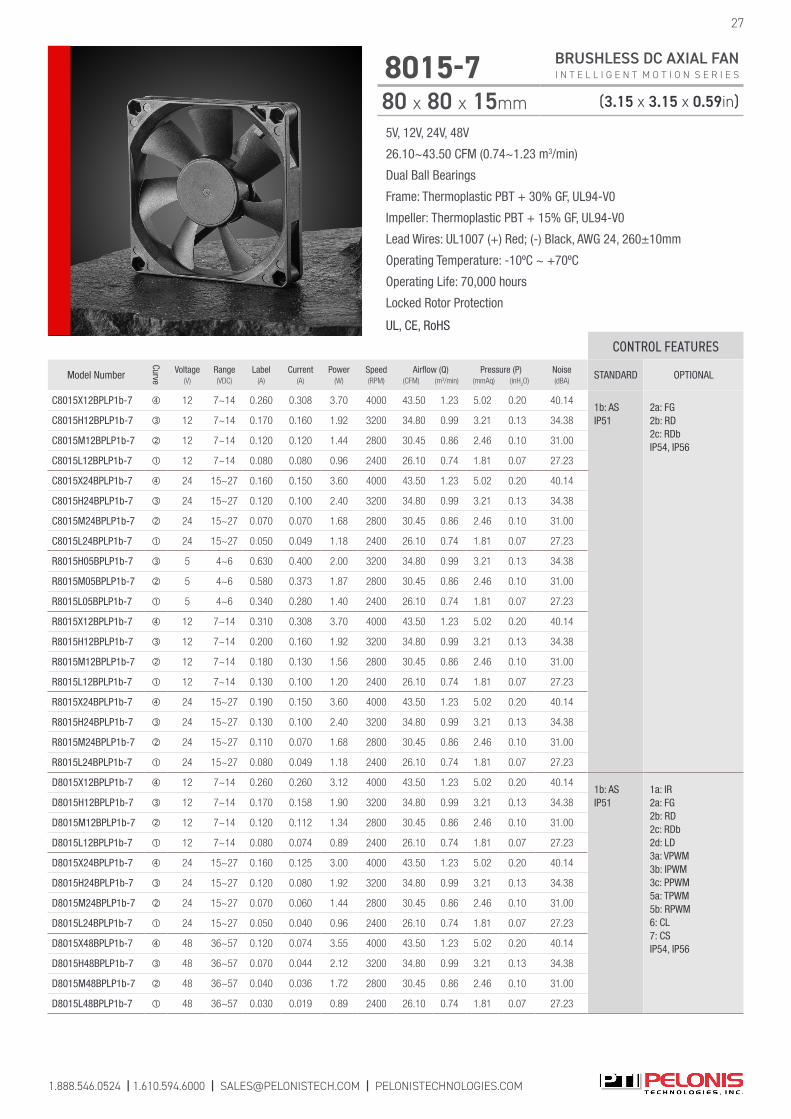
5V, 12V, 24V, 48V
26.10~43.50 CFM (0.74~1.23 m3/min)
Dual Ball Bearings
Frame: Thermoplastic PBT + 30% GF, UL94-V0
Impeller: Thermoplastic PBT + 15% GF, UL94-V0
Lead Wires: UL1007 (+) Red; (-) Black, AWG 24, 260±10mm
Operating Temperature: -10ºC ~ +70ºC
Operating Life: 70,000 hours
Locked Rotor Protection
UL, CE, RoHS
1.888.546.0524 | 1.610.594.6000 | [email protected] | PELONISTECHNOLOGIES.COM
27
8015-7 BRUSHLESS DC AXIAL FAN I N T E L L I G E N T M O T I O N S E R I E S
80 x 80 x 15mm (3.15 x 3.15 x 0.59in)
CONTROL FEATURES
Model Number
Curve
Voltage(V)
Range(VDC)
Label(A)
Current(A)
Power(W)
Speed(RPM)
Airflow (Q)(CFM) (m3/min)
Pressure (P)(mmAq) (inH
2O)
Noise(dBA)
STANDARD OPTIONAL
C8015X12BPLP1b-7 12 7~14 0.260 0.308 3.70 4000 43.50 1.23 5.02 0.20 40.141b: AS IP51
2a: FG 2b: RD 2c: RDb IP54, IP56
C8015H12BPLP1b-7 12 7~14 0.170 0.160 1.92 3200 34.80 0.99 3.21 0.13 34.38
C8015M12BPLP1b-7 12 7~14 0.120 0.120 1.44 2800 30.45 0.86 2.46 0.10 31.00
C8015L12BPLP1b-7 12 7~14 0.080 0.080 0.96 2400 26.10 0.74 1.81 0.07 27.23
C8015X24BPLP1b-7 24 15~27 0.160 0.150 3.60 4000 43.50 1.23 5.02 0.20 40.14
C8015H24BPLP1b-7 24 15~27 0.120 0.100 2.40 3200 34.80 0.99 3.21 0.13 34.38
C8015M24BPLP1b-7 24 15~27 0.070 0.070 1.68 2800 30.45 0.86 2.46 0.10 31.00
C8015L24BPLP1b-7 24 15~27 0.050 0.049 1.18 2400 26.10 0.74 1.81 0.07 27.23
R8015H05BPLP1b-7 5 4~6 0.630 0.400 2.00 3200 34.80 0.99 3.21 0.13 34.38
R8015M05BPLP1b-7 5 4~6 0.580 0.373 1.87 2800 30.45 0.86 2.46 0.10 31.00
R8015L05BPLP1b-7 5 4~6 0.340 0.280 1.40 2400 26.10 0.74 1.81 0.07 27.23
R8015X12BPLP1b-7 12 7~14 0.310 0.308 3.70 4000 43.50 1.23 5.02 0.20 40.14
R8015H12BPLP1b-7 12 7~14 0.200 0.160 1.92 3200 34.80 0.99 3.21 0.13 34.38
R8015M12BPLP1b-7 12 7~14 0.180 0.130 1.56 2800 30.45 0.86 2.46 0.10 31.00
R8015L12BPLP1b-7 12 7~14 0.130 0.100 1.20 2400 26.10 0.74 1.81 0.07 27.23
R8015X24BPLP1b-7 24 15~27 0.190 0.150 3.60 4000 43.50 1.23 5.02 0.20 40.14
R8015H24BPLP1b-7 24 15~27 0.130 0.100 2.40 3200 34.80 0.99 3.21 0.13 34.38
R8015M24BPLP1b-7 24 15~27 0.110 0.070 1.68 2800 30.45 0.86 2.46 0.10 31.00
R8015L24BPLP1b-7 24 15~27 0.080 0.049 1.18 2400 26.10 0.74 1.81 0.07 27.23
D8015X12BPLP1b-7 12 7~14 0.260 0.260 3.12 4000 43.50 1.23 5.02 0.20 40.141b: ASIP51
1a: IR2a: FG 2b: RD 2c: RDb 2d: LD 3a: VPWM 3b: IPWM 3c: PPWM 5a: TPWM 5b: RPWM 6: CL 7: CS IP54, IP56
D8015H12BPLP1b-7 12 7~14 0.170 0.158 1.90 3200 34.80 0.99 3.21 0.13 34.38
D8015M12BPLP1b-7 12 7~14 0.120 0.112 1.34 2800 30.45 0.86 2.46 0.10 31.00
D8015L12BPLP1b-7 12 7~14 0.080 0.074 0.89 2400 26.10 0.74 1.81 0.07 27.23
D8015X24BPLP1b-7 24 15~27 0.160 0.125 3.00 4000 43.50 1.23 5.02 0.20 40.14
D8015H24BPLP1b-7 24 15~27 0.120 0.080 1.92 3200 34.80 0.99 3.21 0.13 34.38
D8015M24BPLP1b-7 24 15~27 0.070 0.060 1.44 2800 30.45 0.86 2.46 0.10 31.00
D8015L24BPLP1b-7 24 15~27 0.050 0.040 0.96 2400 26.10 0.74 1.81 0.07 27.23
D8015X48BPLP1b-7 48 36~57 0.120 0.074 3.55 4000 43.50 1.23 5.02 0.20 40.14
D8015H48BPLP1b-7 48 36~57 0.070 0.044 2.12 3200 34.80 0.99 3.21 0.13 34.38
D8015M48BPLP1b-7 48 36~57 0.040 0.036 1.72 2800 30.45 0.86 2.46 0.10 31.00
D8015L48BPLP1b-7 48 36~57 0.030 0.019 0.89 2400 26.10 0.74 1.81 0.07 27.23
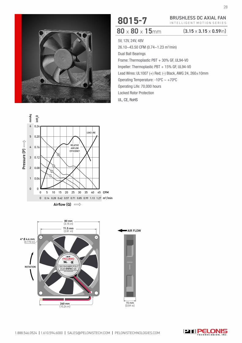
c US
USA TECHNOLOGY
C8015H24BPLP1b-7DC24V 0.12A
4* Ø 4.4 mm(0.173 in)
260 mm(10.24 in)
71.5 mm(2.81 in)
80 mm(3.15 in)
ROTATION
15 mm(0.59 in)
AIR FLOW
6
4
2
0 0
mm
Aq
m3/min
inH
2O
Airflow (Q)
CFM
0
300
Pres
sure
(P)
20 45
LOAD LINE
35
RELATIVEAIRFLOW
EFFICIENCY
40
5
3
1
2510 155
0.99 1.270.850.57 1.130.710.28 0.420.14
0.16
0.08
0.20
0.12
0.04
0.24
5V, 12V, 24V, 48V
26.10~43.50 CFM (0.74~1.23 m3/min)
Dual Ball Bearings
Frame: Thermoplastic PBT + 30% GF, UL94-V0
Impeller: Thermoplastic PBT + 15% GF, UL94-V0
Lead Wires: UL1007 (+) Red; (-) Black, AWG 24, 260±10mm
Operating Temperature: -10ºC ~ +70ºC
Operating Life: 70,000 hours
Locked Rotor Protection
UL, CE, RoHS
28
8015-7 BRUSHLESS DC AXIAL FAN I N T E L L I G E N T M O T I O N S E R I E S
80 x 80 x 15mm (3.15 x 3.15 x 0.59in)
1.888.546.0524 | 1.610.594.6000 | [email protected] | PELONISTECHNOLOGIES.COM
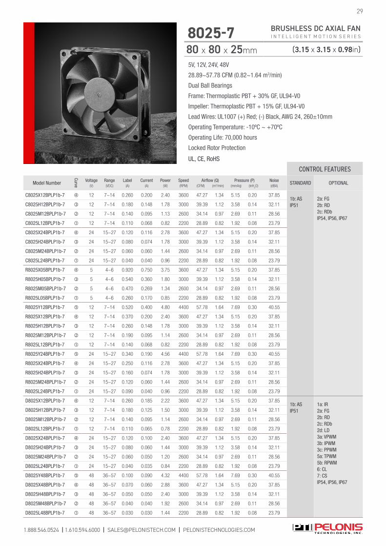
5V, 12V, 24V, 48V
28.89~57.78 CFM (0.82~1.64 m3/min)
Dual Ball Bearings
Frame: Thermoplastic PBT + 30% GF, UL94-V0
Impeller: Thermoplastic PBT + 15% GF, UL94-V0
Lead Wires: UL1007 (+) Red; (-) Black, AWG 24, 260±10mm
Operating Temperature: -10ºC ~ +70ºC
Operating Life: 70,000 hours
Locked Rotor Protection
UL, CE, RoHS
1.888.546.0524 | 1.610.594.6000 | [email protected] | PELONISTECHNOLOGIES.COM
29
8025-7 BRUSHLESS DC AXIAL FAN I N T E L L I G E N T M O T I O N S E R I E S
80 x 80 x 25mm (3.15 x 3.15 x 0.98in)
CONTROL FEATURES
Model Number
Curve
Voltage(V)
Range(VDC)
Label(A)
Current(A)
Power(W)
Speed(RPM)
Airflow (Q)(CFM) (m3/min)
Pressure (P)(mmAq) (inH
2O)
Noise(dBA)
STANDARD OPTIONAL
C8025X12BPLP1b-7 12 7~14 0.260 0.200 2.40 3600 47.27 1.34 5.15 0.20 37.851b: AS IP51
2a: FG 2b: RD 2c: RDb IP54, IP56, IP67
C8025H12BPLP1b-7 12 7~14 0.180 0.148 1.78 3000 39.39 1.12 3.58 0.14 32.11
C8025M12BPLP1b-7 12 7~14 0.140 0.095 1.13 2600 34.14 0.97 2.69 0.11 28.56
C8025L12BPLP1b-7 12 7~14 0.110 0.068 0.82 2200 28.89 0.82 1.92 0.08 23.79
C8025X24BPLP1b-7 24 15~27 0.120 0.116 2.78 3600 47.27 1.34 5.15 0.20 37.85
C8025H24BPLP1b-7 24 15~27 0.080 0.074 1.78 3000 39.39 1.12 3.58 0.14 32.11
C8025M24BPLP1b-7 24 15~27 0.060 0.060 1.44 2600 34.14 0.97 2.69 0.11 28.56
C8025L24BPLP1b-7 24 15~27 0.040 0.040 0.96 2200 28.89 0.82 1.92 0.08 23.79
R8025X05BPLP1b-7 5 4~6 0.920 0.750 3.75 3600 47.27 1.34 5.15 0.20 37.85
R8025H05BPLP1b-7 5 4~6 0.540 0.360 1.80 3000 39.39 1.12 3.58 0.14 32.11
R8025M05BPLP1b-7 5 4~6 0.470 0.269 1.34 2600 34.14 0.97 2.69 0.11 28.56
R8025L05BPLP1b-7 5 4~6 0.260 0.170 0.85 2200 28.89 0.82 1.92 0.08 23.79
R8025Y12BPLP1b-7 12 7~14 0.520 0.400 4.80 4400 57.78 1.64 7.69 0.30 40.55
R8025X12BPLP1b-7 12 7~14 0.370 0.200 2.40 3600 47.27 1.34 5.15 0.20 37.85
R8025H12BPLP1b-7 12 7~14 0.260 0.148 1.78 3000 39.39 1.12 3.58 0.14 32.11
R8025M12BPLP1b-7 12 7~14 0.190 0.095 1.14 2600 34.14 0.97 2.69 0.11 28.56
R8025L12BPLP1b-7 12 7~14 0.140 0.068 0.82 2200 28.89 0.82 1.92 0.08 23.79
R8025Y24BPLP1b-7 24 15~27 0.340 0.190 4.56 4400 57.78 1.64 7.69 0.30 40.55
R8025X24BPLP1b-7 24 15~27 0.250 0.116 2.78 3600 47.27 1.34 5.15 0.20 37.85
R8025H24BPLP1b-7 24 15~27 0.160 0.074 1.78 3000 39.39 1.12 3.58 0.14 32.11
R8025M24BPLP1b-7 24 15~27 0.120 0.060 1.44 2600 34.14 0.97 2.69 0.11 28.56
R8025L24BPLP1b-7 24 15~27 0.090 0.040 0.96 2200 28.89 0.82 1.92 0.08 23.79
D8025X12BPLP1b-7 12 7~14 0.260 0.185 2.22 3600 47.27 1.34 5.15 0.20 37.851b: ASIP51
1a: IR2a: FG 2b: RD 2c: RDb 2d: LD 3a: VPWM 3b: IPWM 3c: PPWM 5a: TPWM 5b: RPWM 6: CL 7: CS IP54, IP56, IP67
D8025H12BPLP1b-7 12 7~14 0.180 0.125 1.50 3000 39.39 1.12 3.58 0.14 32.11
D8025M12BPLP1b-7 12 7~14 0.140 0.095 1.14 2600 34.14 0.97 2.69 0.11 28.56
D8025L12BPLP1b-7 12 7~14 0.110 0.065 0.78 2200 28.89 0.82 1.92 0.08 23.79
D8025X24BPLP1b-7 24 15~27 0.120 0.100 2.40 3600 47.27 1.34 5.15 0.20 37.85
D8025H24BPLP1b-7 24 15~27 0.080 0.060 1.44 3000 39.39 1.12 3.58 0.14 32.11
D8025M24BPLP1b-7 24 15~27 0.060 0.050 1.20 2600 34.14 0.97 2.69 0.11 28.56
D8025L24BPLP1b-7 24 15~27 0.040 0.035 0.84 2200 28.89 0.82 1.92 0.08 23.79
D8025Y48BPLP1b-7 48 36~57 0.100 0.090 4.32 4400 57.78 1.64 7.69 0.30 40.55
D8025X48BPLP1b-7 48 36~57 0.070 0.060 2.88 3600 47.27 1.34 5.15 0.20 37.85
D8025H48BPLP1b-7 48 36~57 0.050 0.050 2.40 3000 39.39 1.12 3.58 0.14 32.11
D8025M48BPLP1b-7 48 36~57 0.040 0.040 1.92 2600 34.14 0.97 2.69 0.11 28.56
D8025L48BPLP1b-7 48 36~57 0.030 0.030 1.44 2200 28.89 0.82 1.92 0.08 23.79

5V, 12V, 24V, 48V
28.89~57.78 CFM (0.82~1.64 m3/min)
Dual Ball Bearings
Frame: Thermoplastic PBT + 30% GF, UL94-V0
Impeller: Thermoplastic PBT + 15% GF, UL94-V0
Lead Wires: UL1007 (+) Red; (-) Black, AWG 24, 260±10mm
Operating Temperature: -10ºC ~ +70ºC
Operating Life: 70,000 hours
Locked Rotor Protection
UL, CE, RoHS
c US
USA TECHNOLOGY
C8025X12BPLP1b-7DC12V 0.26A
ROTATION
4* Ø 4.4 mm(0.173 in)
260 mm(10.24 in)
71.5 mm(2.81 in)
80 mm(3.15 in)
25 mm(0.98 in)
AIR FLOW
8
6
4
2
0 0
mm
Aq
m3/min
inH
2O
Airflow (Q)
CFM
0
30
1.13 1.700.85
0
Pres
sure
(P)
10 60
LOAD LINE
0.28
40
RELATIVEAIRFLOW
EFFICIENCY
1.42
50
7
5
3
1
20
0.57
0.16
0.08
0.20
0.12
0.04
0.24
0.28
0.31
30
8025-7 BRUSHLESS DC AXIAL FAN I N T E L L I G E N T M O T I O N S E R I E S
80 x 80 x 25mm (3.15 x 3.15 x 0.98in)
1.888.546.0524 | 1.610.594.6000 | [email protected] | PELONISTECHNOLOGIES.COM
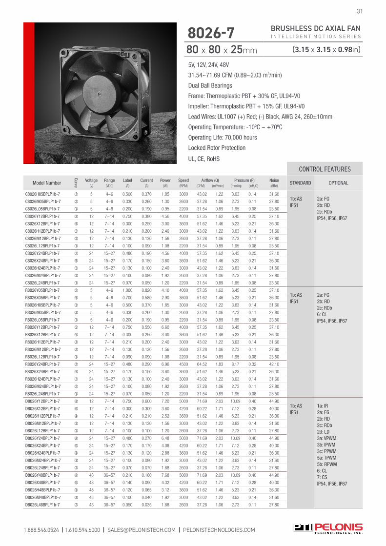
5V, 12V, 24V, 48V
31.54~71.69 CFM (0.89~2.03 m3/min)
Dual Ball Bearings
Frame: Thermoplastic PBT + 30% GF, UL94-V0
Impeller: Thermoplastic PBT + 15% GF, UL94-V0
Lead Wires: UL1007 (+) Red; (-) Black, AWG 24, 260±10mm
Operating Temperature: -10ºC ~ +70ºC
Operating Life: 70,000 hours
Locked Rotor Protection
UL, CE, RoHS
1.888.546.0524 | 1.610.594.6000 | [email protected] | PELONISTECHNOLOGIES.COM
31
8026-7 BRUSHLESS DC AXIAL FAN I N T E L L I G E N T M O T I O N S E R I E S
80 x 80 x 25mm (3.15 x 3.15 x 0.98in)
CONTROL FEATURES
Model Number
Curve
Voltage(V)
Range(VDC)
Label(A)
Current(A)
Power(W)
Speed(RPM)
Airflow (Q)(CFM) (m3/min)
Pressure (P)(mmAq) (inH
2O)
Noise(dBA)
STANDARD OPTIONAL
C8026H05BPLP1b-7 5 4~6 0.500 0.370 1.85 3000 43.02 1.22 3.63 0.14 31.601b: AS IP51
2a: FG 2b: RD 2c: RDb IP54, IP56, IP67
C8026M05BPLP1b-7 5 4~6 0.330 0.260 1.30 2600 37.28 1.06 2.73 0.11 27.80
C8026L05BPLP1b-7 5 4~6 0.200 0.190 0.95 2200 31.54 0.89 1.95 0.08 23.50
C8026Y12BPLP1b-7 12 7~14 0.750 0.380 4.56 4000 57.35 1.62 6.45 0.25 37.10
C8026X12BPLP1b-7 12 7~14 0.300 0.250 3.00 3600 51.62 1.46 5.23 0.21 36.30
C8026H12BPLP1b-7 12 7~14 0.210 0.200 2.40 3000 43.02 1.22 3.63 0.14 31.60
C8026M12BPLP1b-7 12 7~14 0.130 0.130 1.56 2600 37.28 1.06 2.73 0.11 27.80
C8026L12BPLP1b-7 12 7~14 0.100 0.090 1.08 2200 31.54 0.89 1.95 0.08 23.50
C8026Y24BPLP1b-7 24 15~27 0.480 0.190 4.56 4000 57.35 1.62 6.45 0.25 37.10
C8026X24BPLP1b-7 24 15~27 0.170 0.150 3.60 3600 51.62 1.46 5.23 0.21 36.30
C8026H24BPLP1b-7 24 15~27 0.130 0.100 2.40 3000 43.02 1.22 3.63 0.14 31.60
C8026M24BPLP1b-7 24 15~27 0.100 0.080 1.92 2600 37.28 1.06 2.73 0.11 27.80
C8026L24BPLP1b-7 24 15~27 0.070 0.050 1.20 2200 31.54 0.89 1.95 0.08 23.50
R8026Y05BPLP1b-7 5 4~6 1.000 0.820 4.10 4000 57.35 1.62 6.45 0.25 37.101b: AS IP51
2a: FG 2b: RD 2c: RDb6: CLIP54, IP56, IP67
R8026X05BPLP1b-7 5 4~6 0.700 0.580 2.90 3600 51.62 1.46 5.23 0.21 36.30
R8026H05BPLP1b-7 5 4~6 0.500 0.370 1.85 3000 43.02 1.22 3.63 0.14 31.60
R8026M05BPLP1b-7 5 4~6 0.330 0.260 1.30 2600 37.28 1.06 2.73 0.11 27.80
R8026L05BPLP1b-7 5 4~6 0.200 0.190 0.95 2200 31.54 0.89 1.95 0.08 23.50
R8026Y12BPLP1b-7 12 7~14 0.750 0.550 6.60 4000 57.35 1.62 6.45 0.25 37.10
R8026X12BPLP1b-7 12 7~14 0.300 0.250 3.00 3600 51.62 1.46 5.23 0.21 36.30
R8026H12BPLP1b-7 12 7~14 0.210 0.200 2.40 3000 43.02 1.22 3.63 0.14 31.60
R8026M12BPLP1b-7 12 7~14 0.130 0.130 1.56 2600 37.28 1.06 2.73 0.11 27.80
R8026L12BPLP1b-7 12 7~14 0.090 0.090 1.08 2200 31.54 0.89 1.95 0.08 23.50
R8026Y24BPLP1b-7 24 15~27 0.480 0.290 6.96 4500 64.52 1.83 8.17 0.32 42.10
R8026X24BPLP1b-7 24 15~27 0.170 0.150 3.60 3600 51.62 1.46 5.23 0.21 36.30
R8026H24BPLP1b-7 24 15~27 0.130 0.100 2.40 3000 43.02 1.22 3.63 0.14 31.60
R8026M24BPLP1b-7 24 15~27 0.100 0.080 1.92 2600 37.28 1.06 2.73 0.11 27.80
R8026L24BPLP1b-7 24 15~27 0.070 0.050 1.20 2200 31.54 0.89 1.95 0.08 23.50
D8026Y12BPLP1b-7 12 7~14 0.750 0.600 7.20 5000 71.69 2.03 10.09 0.40 44.901b: ASIP51
1a: IR2a: FG 2b: RD 2c: RDb 2d: LD 3a: VPWM 3b: IPWM 3c: PPWM 5a: TPWM 5b: RPWM 6: CL 7: CS IP54, IP56, IP67
D8026X12BPLP1b-7 12 7~14 0.300 0.300 3.60 4200 60.22 1.71 7.12 0.28 40.30
D8026H12BPLP1b-7 12 7~14 0.210 0.210 2.52 3600 51.62 1.46 5.23 0.21 36.30
D8026M12BPLP1b-7 12 7~14 0.130 0.130 1.56 3000 43.02 1.22 3.63 0.14 31.60
D8026L12BPLP1b-7 12 7~14 0.100 0.100 1.20 2600 37.28 1.06 2.73 0.11 27.80
D8026Y24BPLP1b-7 24 15~27 0.480 0.270 6.48 5000 71.69 2.03 10.09 0.40 44.90
D8026X24BPLP1b-7 24 15~27 0.170 0.170 4.08 4200 60.22 1.71 7.12 0.28 40.30
D8026H24BPLP1b-7 24 15~27 0.130 0.120 2.88 3600 51.62 1.46 5.23 0.21 36.30
D8026M24BPLP1b-7 24 15~27 0.100 0.080 1.92 3000 43.02 1.22 3.63 0.14 31.60
D8026L24BPLP1b-7 24 15~27 0.070 0.070 1.68 2600 37.28 1.06 2.73 0.11 27.80
D8026Y48BPLP1b-7 48 36~57 0.210 0.160 7.68 5000 71.69 2.03 10.09 0.40 44.90
D8026X48BPLP1b-7 48 36~57 0.140 0.090 4.32 4200 60.22 1.71 7.12 0.28 40.30
D8026H48BPLP1b-7 48 36~57 0.120 0.065 3.12 3600 51.62 1.46 5.23 0.21 36.30
D8026M48BPLP1b-7 48 36~57 0.100 0.040 1.92 3000 43.02 1.22 3.63 0.14 31.60
D8026L48BPLP1b-7 48 36~57 0.050 0.035 1.68 2600 37.28 1.06 2.73 0.11 27.80
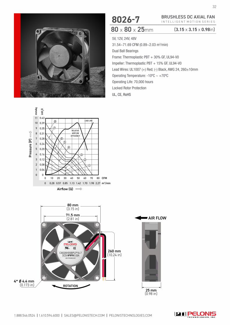
c US
USA TECHNOLOGY
C8026H05BPLP1b-7DC5V 0.50A
ROTATION4* Ø 4.4 mm
(0.173 in)
260 mm(10.24 in)
71.5 mm(2.81 in)
80 mm(3.15 in)
25 mm(0.98 in)
AIR FLOW
11
9
8
6
4
2
0 0
mm
Aq
m3/min
inH
2O
Airflow (Q)
CFM
0
40 70
1.98 2.27
0
Pres
sure
(P)
20 50 80
LOAD LINE
RELATIVEAIRFLOW
EFFICIENCY
10
30 6010
1.700.85 1.420.57 1.130.28
7
5
3
1
0.16
0.08
0.20
0.12
0.04
0.24
0.35
0.28
0.39
0.31
0.43
5V, 12V, 24V, 48V
31.54~71.69 CFM (0.89~2.03 m3/min)
Dual Ball Bearings
Frame: Thermoplastic PBT + 30% GF, UL94-V0
Impeller: Thermoplastic PBT + 15% GF, UL94-V0
Lead Wires: UL1007 (+) Red; (-) Black, AWG 24, 260±10mm
Operating Temperature: -10ºC ~ +70ºC
Operating Life: 70,000 hours
Locked Rotor Protection
UL, CE, RoHS
32
8026-7 BRUSHLESS DC AXIAL FAN I N T E L L I G E N T M O T I O N S E R I E S
80 x 80 x 25mm (3.15 x 3.15 x 0.98in)
1.888.546.0524 | 1.610.594.6000 | [email protected] | PELONISTECHNOLOGIES.COM
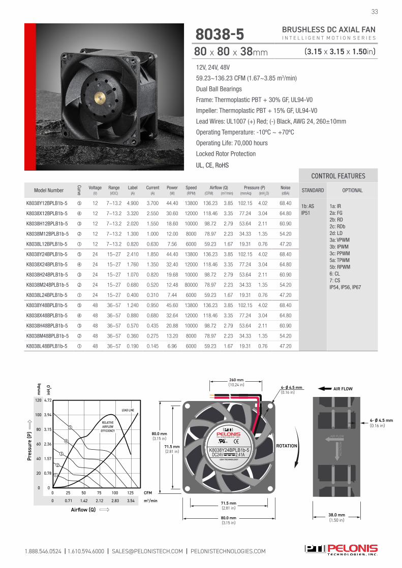
1.888.546.0524 | 1.610.594.6000 | [email protected] | PELONISTECHNOLOGIES.COM
12V, 24V, 48V
59.23~136.23 CFM (1.67~3.85 m3/min)
Dual Ball Bearings
Frame: Thermoplastic PBT + 30% GF, UL94-V0
Impeller: Thermoplastic PBT + 15% GF, UL94-V0
Lead Wires: UL1007 (+) Red; (-) Black, AWG 24, 260±10mm
Operating Temperature: -10ºC ~ +70ºC
Operating Life: 70,000 hours
Locked Rotor Protection
UL, CE, RoHS
8038-5 BRUSHLESS DC AXIAL FAN I N T E L L I G E N T M O T I O N S E R I E S
80 x 80 x 38mm (3.15 x 3.15 x 1.50in)
33
ROTATION71.5 mm(2.81 in)
80.0 mm(3.15 in)
80.0 mm(3.15 in)
71.5 mm(2.81 in)
c US
USA TECHNOLOGY
K8038Y24BPLB1b-5DC24V 2.41A
4- Ø 4.5 mm(0.16 in)
260 mm(10.24 in)
38.0 mm(1.50 in)
AIR FLOW
4- Ø 4.5 mm(0.16 in)
AIR FLOW
ROTA
TIO
N
120
80
40
0
4.72
3.94
1.57
0
mm
Aq
m3/min
inH
2O
Airflow (Q)
CFM
0
75
2.12 3.541.42
0
Pres
sure
(P)
25
LOAD LINE
100
RELATIVEAIRFLOW
EFFICIENCY
2.83
125
100
60
20
2.36
0.78
3.15
50
0.71
CONTROL FEATURES
Model Number
Curve
Voltage(V)
Range(VDC)
Label(A)
Current(A)
Power(W)
Speed(RPM)
Airflow (Q)(CFM) (m3/min)
Pressure (P)(mmAq) (inH
2O)
Noise(dBA)
STANDARD OPTIONAL
K8038Y12BPLB1b-5 12 7~13.2 4.900 3.700 44.40 13800 136.23 3.85 102.15 4.02 68.40 1b: ASIP51
1a: IR2a: FG 2b: RD 2c: RDb 2d: LD 3a: VPWM 3b: IPWM 3c: PPWM 5a: TPWM 5b: RPWM 6: CL 7: CS IP54, IP56, IP67
K8038X12BPLB1b-5 12 7~13.2 3.320 2.550 30.60 12000 118.46 3.35 77.24 3.04 64.80
K8038H12BPLB1b-5 12 7~13.2 2.020 1.550 18.60 10000 98.72 2.79 53.64 2.11 60.90
K8038M12BPLB1b-5 12 7~13.2 1.300 1.000 12.00 8000 78.97 2.23 34.33 1.35 54.20
K8038L12BPLB1b-5 12 7~13.2 0.820 0.630 7.56 6000 59.23 1.67 19.31 0.76 47.20
K8038Y24BPLB1b-5 24 15~27 2.410 1.850 44.40 13800 136.23 3.85 102.15 4.02 68.40
K8038X24BPLB1b-5 24 15~27 1.760 1.350 32.40 12000 118.46 3.35 77.24 3.04 64.80
K8038H24BPLB1b-5 24 15~27 1.070 0.820 19.68 10000 98.72 2.79 53.64 2.11 60.90
K8038M24BPLB1b-5 24 15~27 0.680 0.520 12.48 80000 78.97 2.23 34.33 1.35 54.20
K8038L24BPLB1b-5 24 15~27 0.400 0.310 7.44 6000 59.23 1.67 19.31 0.76 47.20
K8038Y48BPLB1b-5 48 36~57 1.240 0.950 45.60 13800 136.23 3.85 102.15 4.02 68.40
K8038X48BPLB1b-5 48 36~57 0.880 0.680 32.64 12000 118.46 3.35 77.24 3.04 64.80
K8038H48BPLB1b-5 48 36~57 0.570 0.435 20.88 10000 98.72 2.79 53.64 2.11 60.90
K8038M48BPLB1b-5 48 36~57 0.360 0.275 13.20 8000 78.97 2.23 34.33 1.35 54.20
K8038L48BPLB1b-5 48 36~57 0.190 0.145 6.96 6000 59.23 1.67 19.31 0.76 47.20
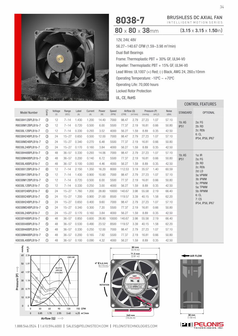
1.888.546.0524 | 1.610.594.6000 | [email protected] | PELONISTECHNOLOGIES.COM
34
8038-7 BRUSHLESS DC AXIAL FAN I N T E L L I G E N T M O T I O N S E R I E S
80 x 80 x 38mm (3.15 x 3.15 x 1.50in)
12V, 24V, 48V
56.27~140.67 CFM (1.59~3.98 m3/min)
Dual Ball Bearings
Frame: Thermoplastic PBT + 30% GF, UL94-V0
Impeller: Thermoplastic PBT + 15% GF, UL94-V0
Lead Wires: UL1007 (+) Red; (-) Black, AWG 24, 260±10mm
Operating Temperature: -10ºC ~ +70ºC
Operating Life: 70,000 hours
Locked Rotor Protection
UL, CE, RoHS
CONTROL FEATURES
Model Number
Curve
Voltage(V)
Range(VDC)
Label(A)
Current(A)
Power(W)
Speed(RPM)
Airflow (Q)(CFM) (m3/min)
Pressure (P)(mmAq) (inH
2O)
Noise(dBA)
STANDARD OPTIONAL
R8038H12BPLB1b-7 12 7~14 1.430 1.200 14.40 7000 98.47 2.79 27.23 1.07 57.101b: ASIP51
2a: FG 2b: RD 2c: RDb 6: CL IP54, IP56, IP67
R8038M12BPLB1b-7 12 7~14 0.720 0.500 6.00 5500 77.37 2.19 16.81 0.66 50.80
R8038L12BPLB1b-7 12 7~14 0.330 0.293 3.52 4000 56.27 1.59 8.89 0.35 42.50
R8038H24BPLB1b-7 24 15~27 0.650 0.500 12.00 7000 98.47 2.79 27.23 1.07 57.10
R8038M24BPLB1b-7 24 15~27 0.340 0.270 6.48 5500 77.37 2.19 16.81 0.66 50.80
R8038L24BPLB1b-7 24 15~27 0.170 0.160 3.84 4000 56.27 1.59 8.89 0.35 42.50
R8038H48BPLB1b-7 48 36~57 0.330 0.293 14.06 7000 98.47 2.79 27.23 1.07 57.101b: ASIP51
1a: IR2a: FG 2b: RD 2c: RDb 2d: LD 3a: VPWM 3b: IPWM 3c: PPWM 5a: TPWM 5b: RPWM 6: CL 7: CS IP54, IP56, IP67
R8038M48BPLB1b-7 48 36~57 0.200 0.140 6.72 5500 77.37 2.19 16.81 0.66 50.80
R8038L48BPLB1b-7 48 36~57 0.100 0.093 4.46 4000 56.27 1.59 8.89 0.35 42.50
K8038X12BPLB1b-7 12 7~14 2.150 1.350 16.20 8000 112.53 3.19 35.57 1.40 60.59
K8038H12BPLB1b-7 12 7~14 1.430 0.900 10.80 7000 98.47 2.79 27.23 1.07 57.10
K8038M12BPLB1b-7 12 7~14 0.720 0.500 6.00 5500 77.37 2.19 16.81 0.66 50.80
K8038L12BPLB1b-7 12 7~14 0.330 0.250 3.00 4000 56.27 1.59 8.89 0.35 42.50
K8038Y24BPLB1b-7 24 15~27 1.760 1.200 28.80 10000 140.67 3.98 55.58 2.19 66.40
K8038X24BPLB1b-7 24 15~27 1.200 0.900 21.60 8500 119.57 3.39 40.15 1.58 62.20
K8038H24BPLB1b-7 24 15~27 0.650 0.400 9.60 7000 98.47 2.79 27.23 1.07 57.10
K8038M24BPLB1b-7 24 15~27 0.340 0.300 7.20 5500 77.37 2.19 16.81 0.66 50.80
K8038L24BPLB1b-7 24 15~27 0.170 0.160 3.84 4000 56.27 1.59 8.89 0.35 42.50
K8038Y48BPLB1b-7 48 36~57 0.850 0.600 28.80 10000 140.67 3.98 55.58 2.19 66.40
K8038X48BPLB1b-7 48 36~57 0.530 0.490 23.52 8500 119.57 3.39 40.15 1.58 62.20
K8038H48BPLB1b-7 48 36~57 0.330 0.250 12.00 7000 98.47 2.79 27.23 1.07 57.10
K8038M48BPLB1b-7 48 36~57 0.200 0.165 7.92 5500 77.37 2.19 16.81 0.66 50.80
K8038L48BPLB1b-7 48 36~57 0.100 0.090 4.32 4000 56.27 1.59 8.89 0.35 42.50
60
50
30
10
0
2.36
1.97
1.57
0.79
0
mm
Aq
m3/min
inH
2O
Airflow (Q)
CFM
0
60
2.55 4.251.70
0
Pres
sure
(P)
30 150
LOAD LINE
0.85
90
RELATIVEAIRFLOW
EFFICIENCY
3.40
120
40
20
1.18
0.39
c US
USA TECHNOLOGY
K8038Y48BPLB1b-7DC48V 0.85A
4* Ø 4.4 mm(0.173 in)
260 mm(10.24 in)
71.5 mm(2.81 in)
80 mm(3.15 in)
ROTATION
38 mm(1.50 in)
AIR FLOW
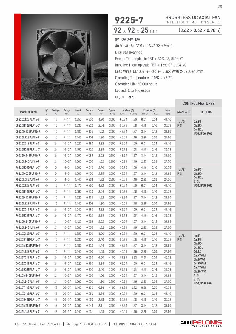
5V, 12V, 24V, 48V
40.91~81.81 CFM (1.16~2.32 m3/min)
Dual Ball Bearings
Frame: Thermoplastic PBT + 30% GF, UL94-V0
Impeller: Thermoplastic PBT + 15% GF, UL94-V0
Lead Wires: UL1007 (+) Red; (-) Black, AWG 24, 260±10mm
Operating Temperature: -10ºC ~ +70ºC
Operating Life: 70,000 hours
Locked Rotor Protection
UL, CE, RoHS
1.888.546.0524 | 1.610.594.6000 | [email protected] | PELONISTECHNOLOGIES.COM
35
9225-7 BRUSHLESS DC AXIAL FAN I N T E L L I G E N T M O T I O N S E R I E S
92 x 92 x 25mm (3.62 x 3.62 x 0.98in)
CONTROL FEATURES
Model Number
Curve
Voltage(V)
Range(VDC)
Label(A)
Current(A)
Power(W)
Speed(RPM)
Airflow (Q)(CFM) (m3/min)
Pressure (P)(mmAq) (inH
2O)
Noise(dBA)
STANDARD OPTIONAL
C9225X12BPLP1b-7 12 7~14 0.350 0.350 4.20 3600 66.94 1.90 6.01 0.24 41.161b: AS IP51
2a: FG 2b: RD 2c: RDb IP54, IP56, IP67
C9225H12BPLP1b-7 12 7~14 0.230 0.220 2.64 3000 55.78 1.58 4.18 0.16 35.73
C9225M12BPLP1b-7 12 7~14 0.180 0.135 1.62 2600 48.34 1.37 3.14 0.12 31.99
C9225L12BPLP1b-7 12 7~14 0.140 0.108 1.30 2200 40.91 1.16 2.25 0.09 27.56
C9225X24BPLP1b-7 24 15~27 0.220 0.180 4.32 3600 66.94 1.90 6.01 0.24 41.16
C9225H24BPLP1b-7 24 15~27 0.150 0.120 2.88 3000 55.78 1.58 4.18 0.16 35.73
C9225M24BPLP1b-7 24 15~27 0.090 0.084 2.02 2600 48.34 1.37 3.14 0.12 31.99
C9225L24BPLP1b-7 24 15~27 0.060 0.055 1.32 2200 40.91 1.16 2.25 0.09 27.56
R9225H05BPLP1b-7 5 4~6 0.800 0.540 2.70 3000 55.78 1.58 4.18 0.16 35.731b: AS IP51
2a: FG 2b: RD 2c: RDb6: CLIP54, IP56, IP67
R9225M05BPLP1b-7 5 4~6 0.600 0.450 2.25 2600 48.34 1.37 3.14 0.12 31.99
R9225L05BPLP1b-7 5 4~6 0.440 0.264 1.32 2200 40.91 1.16 2.25 0.09 27.56
R9225X12BPLP1b-7 12 7~14 0.470 0.360 4.32 3600 66.94 1.90 6.01 0.24 41.16
R9225H12BPLP1b-7 12 7~14 0.290 0.220 2.64 3000 55.78 1.58 4.18 0.16 35.73
R9225M12BPLP1b-7 12 7~14 0.220 0.135 1.62 2600 48.34 1.37 3.14 0.12 31.99
R9225L12BPLP1b-7 12 7~14 0.140 0.108 1.30 2200 40.91 1.16 2.25 0.09 27.56
R9225X24BPLP1b-7 24 15~27 0.240 0.180 4.32 3600 66.94 1.90 6.01 0.24 41.16
R9225H24BPLP1b-7 24 15~27 0.170 0.120 2.88 3000 55.78 1.58 4.18 0.16 35.73
R9225M24BPLP1b-7 24 15~27 0.120 0.084 2.02 2600 48.34 1.37 3.14 0.12 31.99
R9225L24BPLP1b-7 24 15~27 0.080 0.055 1.32 2200 40.91 1.16 2.25 0.09 27.56
D9225X12BPLP1b-7 12 7~14 0.350 0.300 3.60 3600 66.94 1.90 6.01 0.24 41.161b: ASIP51
1a: IR2a: FG 2b: RD 2c: RDb 2d: LD 3a: VPWM 3b: IPWM 3c: PPWM 5a: TPWM 5b: RPWM 6: CL 7: CS IP54, IP56, IP67
D9225H12BPLP1b-7 12 7~14 0.230 0.200 2.40 3000 55.78 1.58 4.18 0.16 35.73
D9225M12BPLP1b-7 12 7~14 0.180 0.120 1.44 2600 48.34 1.37 3.14 0.12 31.99
D9225L12BPLP1b-7 12 7~14 0.140 0.090 1.08 2200 40.91 1.16 2.25 0.09 27.56
D9225Y24BPLP1b-7 24 15~27 0.252 0.250 6.00 4400 81.81 2.32 8.98 0.35 45.73
D9225X24BPLP1b-7 24 15~27 0.220 0.160 3.84 3600 66.94 1.90 6.01 0.24 41.16
D9225H24BPLP1b-7 24 15~27 0.150 0.100 2.40 3000 55.78 1.58 4.18 0.16 35.73
D9225M24BPLP1b-7 24 15~27 0.090 0.065 1.56 2600 48.34 1.37 3.14 0.12 31.99
D9225L24BPLP1b-7 24 15~27 0,060 0.050 1.20 2200 40.91 1.16 2.25 0.09 27.56
D9225Y48BPLP1b-7 48 36~57 0.142 0.130 6.24 4400 81.81 2.32 8.98 0.35 45.73
D9225X48BPLP1b-7 48 36~57 0.080 0.080 3.84 3600 66.94 1.90 6.01 0.24 41.16
D9225H48BPLP1b-7 48 36~57 0.060 0.060 2.88 3000 55.78 1.58 4.18 0.16 35.73
D9225M48BPLP1b-7 48 36~57 0.050 0.044 2.11 2600 48.34 1.37 3.14 0.12 31.99
D9225L48BPLP1b-7 48 36~57 0.040 0.031 1.48 2200 40.91 1.16 2.25 0.09 27.56
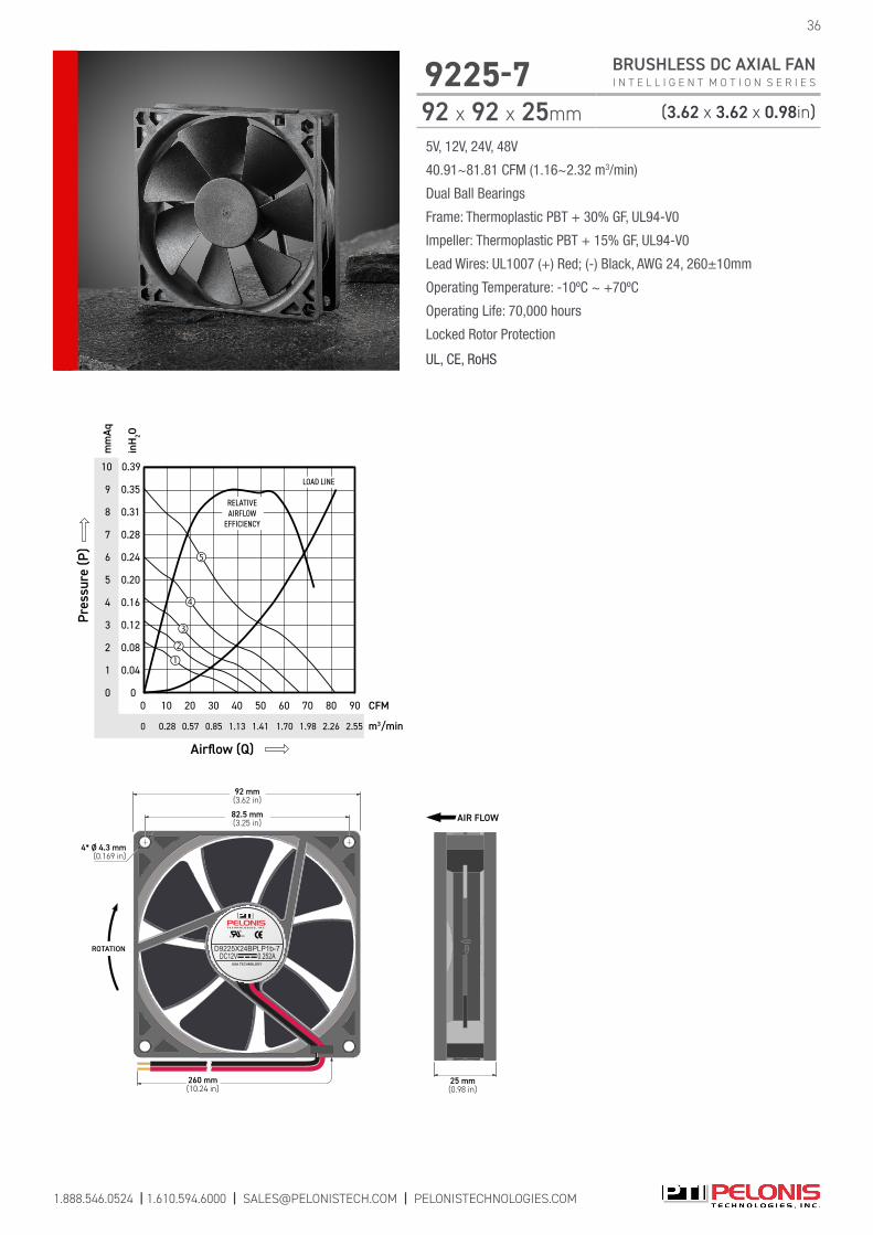
c US
USA TECHNOLOGY
D9225X24BPLP1b-7DC12V 0.252A
4* Ø 4.3 mm(0.169 in)
260 mm(10.24 in)
82.5 mm(3.25 in)
92 mm(3.62 in)
ROTATION
25 mm(0.98 in)
AIR FLOW
10
7
4
2
0
0.39
0.35
0.16
0.08
0
mm
Aq
m3/min
inH
2O
Airflow (Q)
CFM
0
40
1.98 2.551.70
0
Pres
sure
(P)
20 90
LOAD LINE
1.13
70
2.26
80
9
5
3
1
0.20
0.12
0.04
0.28
3010
1.410.57
6
8 0.31
0.24
RELATIVEAIRFLOW
EFFICIENCY
50 60
0.850.28
5V, 12V, 24V, 48V
40.91~81.81 CFM (1.16~2.32 m3/min)
Dual Ball Bearings
Frame: Thermoplastic PBT + 30% GF, UL94-V0
Impeller: Thermoplastic PBT + 15% GF, UL94-V0
Lead Wires: UL1007 (+) Red; (-) Black, AWG 24, 260±10mm
Operating Temperature: -10ºC ~ +70ºC
Operating Life: 70,000 hours
Locked Rotor Protection
UL, CE, RoHS
36
9225-7 BRUSHLESS DC AXIAL FAN I N T E L L I G E N T M O T I O N S E R I E S
92 x 92 x 25mm (3.62 x 3.62 x 0.98in)
1.888.546.0524 | 1.610.594.6000 | [email protected] | PELONISTECHNOLOGIES.COM
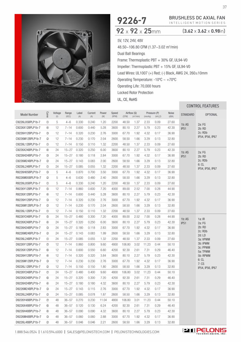
5V, 12V, 24V, 48V
48.50~106.80 CFM (1.37~3.02 m3/min)
Dual Ball Bearings
Frame: Thermoplastic PBT + 30% GF, UL94-V0
Impeller: Thermoplastic PBT + 15% GF, UL94-V0
Lead Wires: UL1007 (+) Red; (-) Black, AWG 24, 260±10mm
Operating Temperature: -10ºC ~ +70ºC
Operating Life: 70,000 hours
Locked Rotor Protection
UL, CE, RoHS
1.888.546.0524 | 1.610.594.6000 | [email protected] | PELONISTECHNOLOGIES.COM
37
9226-7 BRUSHLESS DC AXIAL FAN I N T E L L I G E N T M O T I O N S E R I E S
92 x 92 x 25mm (3.62 x 3.62 x 0.98in)
CONTROL FEATURES
Model Number
Curve
Voltage(V)
Range(VDC)
Label(A)
Current(A)
Power(W)
Speed(RPM)
Airflow (Q)(CFM) (m3/min)
Pressure (P)(mmAq) (inH
2O)
Noise(dBA)
STANDARD OPTIONAL
C9226L05BPLP1b-7 5 4~6 0.330 0.240 1.20 2200 48.50 1.37 2.33 0.09 27.601b: AS IP51
2a: FG 2b: RD 2c: RDbIP54, IP56, IP67
C9226X12BPLP1b-7 12 7~14 0.600 0.440 5.28 3600 80.10 2.27 5.79 0.23 42.30
C9226H12BPLP1b-7 12 7~14 0.320 0.230 2.76 3000 67.70 1.92 4.32 0.17 36.90
C9226M12BPLP1b-7 12 7~14 0.230 0.170 2.04 2600 58.50 1.66 3.29 0.13 32.80
C9226L12BPLP1b-7 12 7~14 0.150 0.110 1.32 2200 48.50 1.37 2.33 0.09 27.60
C9226X24BPLP1b-7 24 15~27 0.320 0.250 6.00 3600 80.10 2.27 5.79 0.23 42.301b: AS IP51
2a: FG 2b: RD 2c: RDb6: CLIP54, IP56, IP67
C9226H24BPLP1b-7 24 15~27 0.180 0.118 2.84 3000 67.70 1.92 4.32 0.17 36.90
C9226M24BPLP1b-7 24 15~27 0.143 0.083 2.00 2600 58.50 1.66 3.29 0.13 32.80
C9226L24BPLP1b-7 24 15~27 0.085 0.055 1.32 2200 48.50 1.37 2.33 0.09 27.60
R9226H05BPLP1b-7 5 4~6 0.870 0.700 3.50 3000 67.70 1.92 4.32 0.17 36.90
R9226M05BPLP1b-7 5 4~6 0.630 0.480 2.40 2600 58.50 1.66 3.29 0.13 32.80
R9226L05BPLP1b-7 5 4~6 0.330 0.240 1.20 2200 48.50 1.37 2.33 0.09 27.60
R9226Y12BPLP1b-7 12 7~14 0.860 0.600 7.20 4000 89.00 2.52 7.00 0.28 44.90
R9226X12BPLP1b-7 12 7~14 0.600 0.440 5.28 3600 80.10 2.27 5.79 0.23 42.30
R9226H12BPLP1b-7 12 7~14 0.320 0.230 2.76 3000 67.70 1.92 4.32 0.17 36.90
R9226M12BPLP1b-7 12 7~14 0.230 0.170 2.04 2600 58.50 1.66 3.29 0.13 32.80
R9226L12BPLP1b-7 12 7~14 0.150 0.110 1.32 2200 48.50 1.37 2.33 0.09 27.60
R9226Y24BPLP1b-7 24 15~27 0.480 0.300 7.20 4000 89.00 2.52 7.00 0.28 44.901b: ASIP51
1a: IR2a: FG 2b: RD 2c: RDb 2d: LD 3a: VPWM 3b: IPWM 3c: PPWM 5a: TPWM 5b: RPWM 6: CL 7: CS IP54, IP56, IP67
R9226X24BPLP1b-7 24 15~27 0.320 0.250 6.00 3600 80.10 2.27 5.79 0.23 42.30
R9226H24BPLP1b-7 24 15~27 0.180 0.118 2.83 3000 67.70 1.92 4.32 0.17 36.90
R9226M24BPLP1b-7 24 15~27 0.143 0.083 1.99 2600 58.50 1.66 3.29 0.13 32.80
R9226L24BPLP1b-7 24 15~27 0.085 0.055 1.32 2200 48.50 1.37 2.33 0.09 27.60
D9226Y12BPLP1b-7 12 7~14 0.860 0.800 9.60 4800 106.80 3.02 11.23 0.44 50.10
D9226X12BPLP1b-7 12 7~14 0.600 0.550 6.60 4200 92.30 2.61 7.31 0.29 46.40
D9226H12BPLP1b-7 12 7~14 0.320 0.320 3.84 3600 80.10 2.27 5.79 0.23 42.30
D9226M12BPLP1b-7 12 7~14 0.230 0.230 2.76 3000 67.70 1.92 4.32 0.17 36.90
D9226L12BPLP1b-7 12 7~14 0.150 0.150 1.80 2600 58.50 1.66 3.29 0.13 32.80
D9226Y24BPLP1b-7 24 15~27 0.480 0.400 9.60 4800 106.80 3.02 11.23 0.44 50.10
D9226X24BPLP1b-7 24 15~27 0.320 0.300 7.20 4200 92.30 2.61 7.31 0.29 46.40
D9226H24BPLP1b-7 24 15~27 0.180 0.180 4.32 3600 80.10 2.27 5.79 0.23 42.30
D9226M24BPLP1b-7 24 15~27 0.143 0.115 2.76 3000 67.70 1.92 4.32 0.17 36.90
D9226L24BPLP1b-7 24 15~27 0.085 0.078 1.87 2600 58.50 1.66 3.29 0.13 32.80
D9226Y48BPLP1b-7 48 36~57 0.270 0.230 11.04 4800 106.80 3.01 11.23 0.44 50.10
D9226X48BPLP1b-7 48 36~57 0.120 0.130 6.24 4200 92.30 2.61 7.31 0.29 46.40
D9226H48BPLP1b-7 48 36~57 0.090 0.090 4.32 3600 80.10 2.27 5.79 0.23 42.30
D9226M48BPLP1b-7 48 36~57 0.060 0.060 2.88 3000 67.70 1.92 4.32 0.17 36.90
D9226L48BPLP1b-7 48 36~57 0.046 0.046 2.21 2600 58.50 1.66 3.29 0.13 32.80
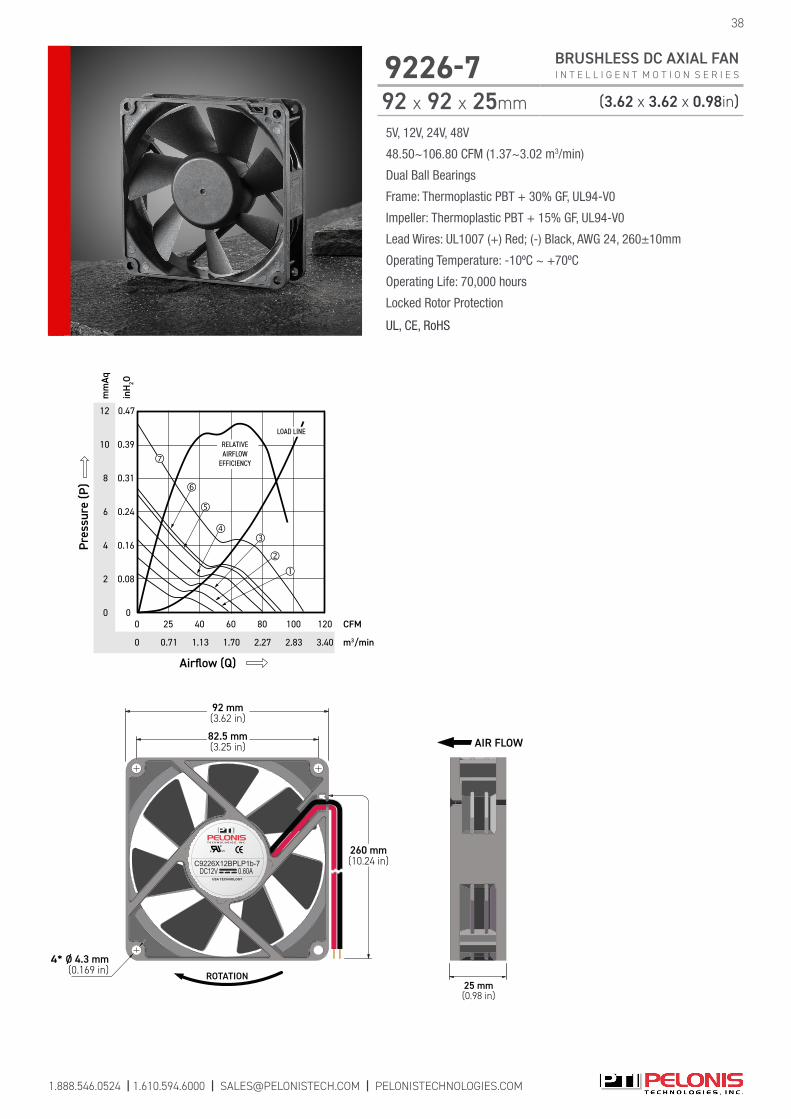
c US
USA TECHNOLOGY
C9226X12BPLP1b-7DC12V 0.60A
ROTATION
4* Ø 4.3 mm(0.169 in)
260 mm(10.24 in)
82.5 mm(3.25 in)
92 mm(3.62 in)
25 mm(0.98 in)
AIR FLOW
12
8
4
0
0.47
0.39
0.16
0
mm
Aq
m3/min
inH
2O
Airflow (Q)
CFM
0
80
2.27 3.401.70
0
Pres
sure
(P)
25
LOAD LINE
100
RELATIVEAIRFLOW
EFFICIENCY
2.83
120
10
6
2
0.24
0.08
0.31
40
0.71
60
1.13
5V, 12V, 24V, 48V
48.50~106.80 CFM (1.37~3.02 m3/min)
Dual Ball Bearings
Frame: Thermoplastic PBT + 30% GF, UL94-V0
Impeller: Thermoplastic PBT + 15% GF, UL94-V0
Lead Wires: UL1007 (+) Red; (-) Black, AWG 24, 260±10mm
Operating Temperature: -10ºC ~ +70ºC
Operating Life: 70,000 hours
Locked Rotor Protection
UL, CE, RoHS
38
9226-7 BRUSHLESS DC AXIAL FAN I N T E L L I G E N T M O T I O N S E R I E S
92 x 92 x 25mm (3.62 x 3.62 x 0.98in)
1.888.546.0524 | 1.610.594.6000 | [email protected] | PELONISTECHNOLOGIES.COM

5V, 12V, 24V, 48V
52.01~87.38 CFM (1.47~2.47 m3/min)
Dual Ball Bearings
Frame: Thermoplastic PBT + 30% GF, UL94-V0
Impeller: Thermoplastic PBT + 15% GF, UL94-V0
Lead Wires: UL1007 (+) Red; (-) Black, AWG 24, 260±10mm
Operating Temperature: -10ºC ~ +70ºC
Operating Life: 70,000 hours
Locked Rotor Protection
UL, CE, RoHS
1.888.546.0524 | 1.610.594.6000 | [email protected] | PELONISTECHNOLOGIES.COM
39
9232-7 BRUSHLESS DC AXIAL FAN I N T E L L I G E N T M O T I O N S E R I E S
92 x 92 x 32mm (3.62 x 3.62 x 1.26in)
CONTROL FEATURES
Model Number
Curve
Voltage(V)
Range(VDC)
Label(A)
Current(A)
Power(W)
Speed(RPM)
Airflow (Q)(CFM) (m3/min)
Pressure (P)(mmAq) (inH
2O)
Noise(dBA)
STANDARD OPTIONAL
R9232H05BPLB1b-7 5 4~6 1.404 0.750 3.75 3250 67.62 1.91 6.95 0.27 38.231b: AS IP51
2a: FG 2b: RD 2c: RDb 6: CL IP54, IP56, IP67
R9232M05BPLB1b-7 5 4~6 1.001 0.600 3.00 2900 60.33 1.71 5.53 0.22 35.30
R9232L05BPLB1b-7 5 4~6 0.559 0.400 2.00 2500 52.01 1.47 4.11 0.16 31.52
R9232Y12BPLB1b-7 12 7~14 1.040 0.720 8.64 4200 87.38 2.47 11.61 0.46 44.89
R9232X12BPLB1b-7 12 7~14 0.741 0.564 6.77 3750 78.02 2.21 9.25 0.36 41.94
R9232H12BPLB1b-7 12 7~14 0.494 0.300 3.60 3250 67.62 1.91 6.95 0.27 38.23
R9232M12BPLB1b-7 12 7~14 0.325 0.250 3.00 2900 60.33 1.71 5.53 0.22 35.30
R9232L12BPLB1b-7 12 7~14 0.234 0.170 2.04 2500 52.01 1.47 4.11 0.16 31.52
R9232Y24BPLB1b-7 24 15~27 0.520 0.330 7.92 4200 87.38 2.47 11.61 0.46 44.89
R9232X24BPLB1b-7 24 15~27 0.364 0.280 6.72 3750 78.02 2.21 9.25 0.36 41.94
R9232H24BPLB1b-7 24 15~27 0.260 0.160 3.84 3250 67.62 1.91 6.95 0.27 38.23
R9232M24BPLB1b-7 24 15~27 0.182 0.140 3.36 2900 60.33 1.71 5.53 0.22 35.30
R9232L24BPLB1b-7 24 15~27 0.143 0.104 2.50 2500 52.01 1.47 4.11 0.16 31.52
R9232Y48BPLB1b-7 48 36~57 0.209 0.200 9.60 4200 87.38 2.47 11.61 0.46 44.89
R9232X48BPLB1b-7 48 36~57 0.143 0.140 6.72 3750 78.02 2.21 9.25 0.36 41.94
R9232H48BPLB1b-7 48 36~57 0.104 0.104 4.99 3250 67.62 1.91 6.95 0.27 38.23
R9232M48BPLB1b-7 48 36~57 0.078 0.078 3.74 2900 60.33 1.71 5.53 0.22 35.30
R9232L48BPLB1b-7 48 36~57 0.052 0.052 2.50 2500 52.01 1.47 4.11 0.16 31.52
G9232Y12BPLB1b-7 12 7~14 1.040 0.638 7.66 4200 87.38 2.47 11.61 0.46 44.891b: ASIP51
2a: FG 2b: RD 2c: RDb 6: CL IP54, IP56, IP67
G9232X12BPLB1b-7 12 7~14 0.741 0.510 6.12 3750 78.02 2.21 9.25 0.36 41.94
G9232H12BPLB1b-7 12 7~14 0.494 0.330 3.96 3250 67.62 1.91 6.95 0.27 38.23
G9232M12BPLB1b-7 12 7~14 0.325 0.210 2.52 2900 60.33 1.71 5.53 0.22 35.30
G9232L12BPLB1b-7 12 7~14 0.234 0.130 1.56 2500 52.01 1.47 4.11 0.16 31.52
G9232Y24BPLB1b-7 24 15~27 0.520 0.320 7.68 4200 87.38 2.47 11.61 0.46 44.89
G9232X24BPLB1b-7 24 15~27 0.364 0.220 5.28 3750 78.02 2.21 9.25 0.36 41.94
G9232H24BPLB1b-7 24 15~27 0.260 0.160 3.84 3250 67.62 1.91 6.95 0.27 38.23
G9232M24BPLB1b-7 24 15~27 0.182 0.120 2.88 2900 60.33 1.71 5.53 0.22 35.30
G9232L24BPLB1b-7 24 15~27 0.143 0.076 1.82 2500 52.01 1.47 4.11 0.16 31.52
G9232Y48BPLB1b-7 48 36~57 0.209 0.161 7.73 4200 87.38 2.47 11.61 0.46 44.89
G9232X48BPLB1b-7 48 36~57 0.143 0.110 5.28 3750 78.02 2.21 9.25 0.36 41.94
G9232H48BPLB1b-7 48 36~57 0.104 0.080 3.84 3250 67.62 1.91 6.95 0.27 38.23
G9232M48BPLB1b-7 48 36~57 0.078 0.060 2.88 2900 60.33 1.71 5.53 0.22 35.30
G9232L48BPLB1b-7 48 36~57 0.052 0.038 1.82 2500 52.01 1.47 4.11 0.16 31.52

5V, 12V, 24V, 48V
52.01~87.38 CFM (1.47~2.47 m3/min)
Dual Ball Bearings
Frame: Thermoplastic PBT + 30% GF, UL94-V0
Impeller: Thermoplastic PBT + 15% GF, UL94-V0
Lead Wires: UL1007 (+) Red; (-) Black, AWG 24, 260±10mm
Operating Temperature: -10ºC ~ +70ºC
Operating Life: 70,000 hours
Locked Rotor Protection
UL, CE, RoHS
c US
USA TECHNOLOGY
G9232Y12BPLB1b-7DC12V 1.04A
4* Ø 4.3 mm(0.169 in)
260 mm(10.24 in)
82.5 mm(3.25 in)
92 mm(3.62 in)
ROTATION32 mm(1.26 in)
AIR FLOW12
9
8
6
4
2
0
0.47
0.35
0.31
0.24
0.16
0.08
0
mm
Aq
m3/min
inH
2O
Airflow (Q)
CFM
0
40 70
1.98 2.27
0
Pres
sure
(P)
20 50 80
LOAD LINE
RELATIVEAIRFLOW
EFFICIENCY
11
30 6010
0.43
1.700.85 1.420.57 1.130.28
7
5
3
1
0.28
0.20
0.12
0.04
10 0.39
90
2.55
40
9232-7 BRUSHLESS DC AXIAL FAN I N T E L L I G E N T M O T I O N S E R I E S
92 x 92 x 32mm (3.62 x 3.62 x 1.26in)
CONTROL FEATURES
Model Number
Curve
Voltage(V)
Range(VDC)
Label(A)
Current(A)
Power(W)
Speed(RPM)
Airflow (Q)(CFM) (m3/min)
Pressure (P)(mmAq) (inH
2O)
Noise(dBA)
STANDARD OPTIONAL
P9232Y12BPLB1b-7 12 8~14 1.040 0.638 7.66 4200 87.38 2.47 11.61 0.46 44.891b: AS IP51
1a: IR2a: FG 2b: RD 2c: RDb 2d: LD 3a: VPWM 3b: IPWM 3c: PPWM 5a: TPWM 5b: RPWM 6: CL 7: CS IP54, IP56, IP67
P9232X12BPLB1b-7 12 8~14 0.741 0.510 6.12 3750 78.02 2.21 9.25 0.36 41.94
P9232H12BPLB1b-7 12 8~14 0.494 0.330 3.96 3250 67.62 1.91 6.95 0.27 38.23
P9232M12BPLB1b-7 12 8~14 0.325 0.210 2.52 2900 60.33 1.71 5.53 0.22 35.30
P9232L12BPLB1b-7 12 8~14 0.234 0.130 1.56 2500 52.01 1.47 4.11 0.16 31.52
P9232Y24BPLB1b-7 24 15~27 0.520 0.320 7.68 4200 87.38 2.47 11.61 0.46 44.89
P9232X24BPLB1b-7 24 15~27 0.364 0.220 5.28 3750 78.02 2.21 9.25 0.36 41.94
P9232H24BPLB1b-7 24 15~27 0.260 0.160 3.84 3250 67.62 1.91 6.95 0.27 38.23
P9232M24BPLB1b-7 24 15~27 0.182 0.120 2.88 2900 60.33 1.71 5.53 0.22 35.30
P9232L24BPLB1b-7 24 15~27 0.143 0.076 1.82 2500 52.01 1.47 4.11 0.16 31.52
P9232X12BPLB1b-7 48 36~57 0.209 0.161 7.73 4200 87.38 2.47 11.61 0.46 44.89
P9232X12BPLB1b-7 48 36~57 0.143 0.110 5.28 3750 78.02 2.21 9.25 0.36 41.94
P9232X12BPLB1b-7 48 36~57 0.104 0.080 3.84 3250 67.62 1.91 6.95 0.27 38.23
P9232X12BPLB1b-7 48 36~57 0.078 0.060 2.88 2900 60.33 1.71 5.53 0.22 35.30
P9232X12BPLB1b-7 48 36~57 0.052 0.038 1.82 2500 52.01 1.47 4.11 0.16 31.52
1.888.546.0524 | 1.610.594.6000 | [email protected] | PELONISTECHNOLOGIES.COM
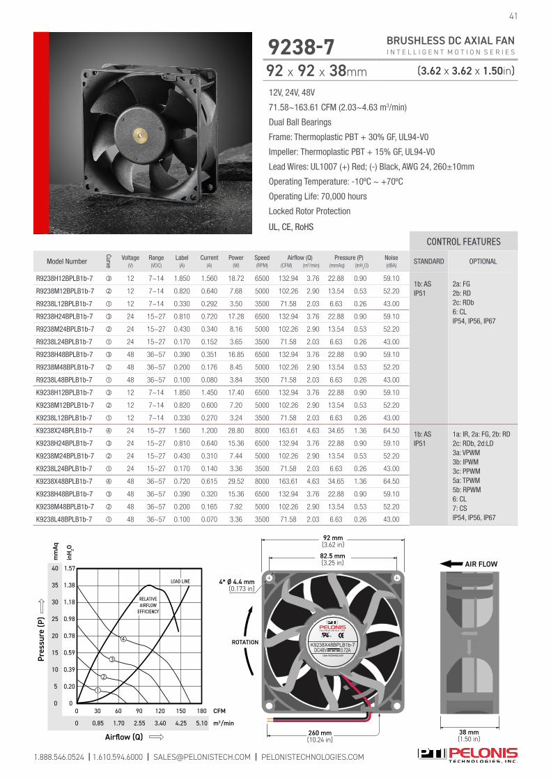
1.888.546.0524 | 1.610.594.6000 | [email protected] | PELONISTECHNOLOGIES.COM
41
9238-7 BRUSHLESS DC AXIAL FAN I N T E L L I G E N T M O T I O N S E R I E S
92 x 92 x 38mm (3.62 x 3.62 x 1.50in)
12V, 24V, 48V
71.58~163.61 CFM (2.03~4.63 m3/min)
Dual Ball Bearings
Frame: Thermoplastic PBT + 30% GF, UL94-V0
Impeller: Thermoplastic PBT + 15% GF, UL94-V0
Lead Wires: UL1007 (+) Red; (-) Black, AWG 24, 260±10mm
Operating Temperature: -10ºC ~ +70ºC
Operating Life: 70,000 hours
Locked Rotor Protection
UL, CE, RoHS
CONTROL FEATURES
Model Number
Curve
Voltage(V)
Range(VDC)
Label(A)
Current(A)
Power(W)
Speed(RPM)
Airflow (Q)(CFM) (m3/min)
Pressure (P)(mmAq) (inH
2O)
Noise(dBA)
STANDARD OPTIONAL
R9238H12BPLB1b-7 12 7~14 1.850 1.560 18.72 6500 132.94 3.76 22.88 0.90 59.101b: AS IP51
2a: FG 2b: RD 2c: RDb 6: CL IP54, IP56, IP67
R9238M12BPLB1b-7 12 7~14 0.820 0.640 7.68 5000 102.26 2.90 13.54 0.53 52.20
R9238L12BPLB1b-7 12 7~14 0.330 0.292 3.50 3500 71.58 2.03 6.63 0.26 43.00
R9238H24BPLB1b-7 24 15~27 0.810 0.720 17.28 6500 132.94 3.76 22.88 0.90 59.10
R9238M24BPLB1b-7 24 15~27 0.430 0.340 8.16 5000 102.26 2.90 13.54 0.53 52.20
R9238L24BPLB1b-7 24 15~27 0.170 0.152 3.65 3500 71.58 2.03 6.63 0.26 43.00
R9238H48BPLB1b-7 48 36~57 0.390 0.351 16.85 6500 132.94 3.76 22.88 0.90 59.10
R9238M48BPLB1b-7 48 36~57 0.200 0.176 8.45 5000 102.26 2.90 13.54 0.53 52.20
R9238L48BPLB1b-7 48 36~57 0.100 0.080 3.84 3500 71.58 2.03 6.63 0.26 43.00
K9238H12BPLB1b-7 12 7~14 1.850 1.450 17.40 6500 132.94 3.76 22.88 0.90 59.10
K9238M12BPLB1b-7 12 7~14 0.820 0.600 7.20 5000 102.26 2.90 13.54 0.53 52.20
K9238L12BPLB1b-7 12 7~14 0.330 0.270 3.24 3500 71.58 2.03 6.63 0.26 43.00
K9238X24BPLB1b-7 24 15~27 1.560 1.200 28.80 8000 163.61 4.63 34.65 1.36 64.50 1b: ASIP51
1a: IR, 2a: FG, 2b: RD 2c: RDb, 2d:LD 3a: VPWM 3b: IPWM 3c: PPWM 5a: TPWM 5b: RPWM 6: CL 7: CS IP54, IP56, IP67
K9238H24BPLB1b-7 24 15~27 0.810 0.640 15.36 6500 132.94 3.76 22.88 0.90 59.10
K9238M24BPLB1b-7 24 15~27 0.430 0.310 7.44 5000 102.26 2.90 13.54 0.53 52.20
K9238L24BPLB1b-7 24 15~27 0.170 0.140 3.36 3500 71.58 2.03 6.63 0.26 43.00
K9238X48BPLB1b-7 48 36~57 0.720 0.615 29.52 8000 163.61 4.63 34.65 1.36 64.50
K9238H48BPLB1b-7 48 36~57 0.390 0.320 15.36 6500 132.94 3.76 22.88 0.90 59.10
K9238M48BPLB1b-7 48 36~57 0.200 0.165 7.92 5000 102.26 2.90 13.54 0.53 52.20
K9238L48BPLB1b-7 48 36~57 0.100 0.070 3.36 3500 71.58 2.03 6.63 0.26 43.00
c US
USA TECHNOLOGY
K9238X48BPLB1b-7DC48V 0.72A
4* Ø 4.4 mm(0.173 in)
260 mm(10.24 in)
82.5 mm(3.25 in)
92 mm(3.62 in)
ROTATION
38 mm(1.50 in)
AIR FLOW40
20
5
0
1.57
1.38
0.39
0
mm
Aq
m3/min
inH
2O
Airflow (Q)
CFM
0
120
3.40 5.102.55
0
Pres
sure
(P)
60
LOAD LINE
150
RELATIVEAIRFLOW
EFFICIENCY
4.25
180
35
10
0.59
0.20
0.98
90
1.70
15
1.1830
0.78
0.85
30
25
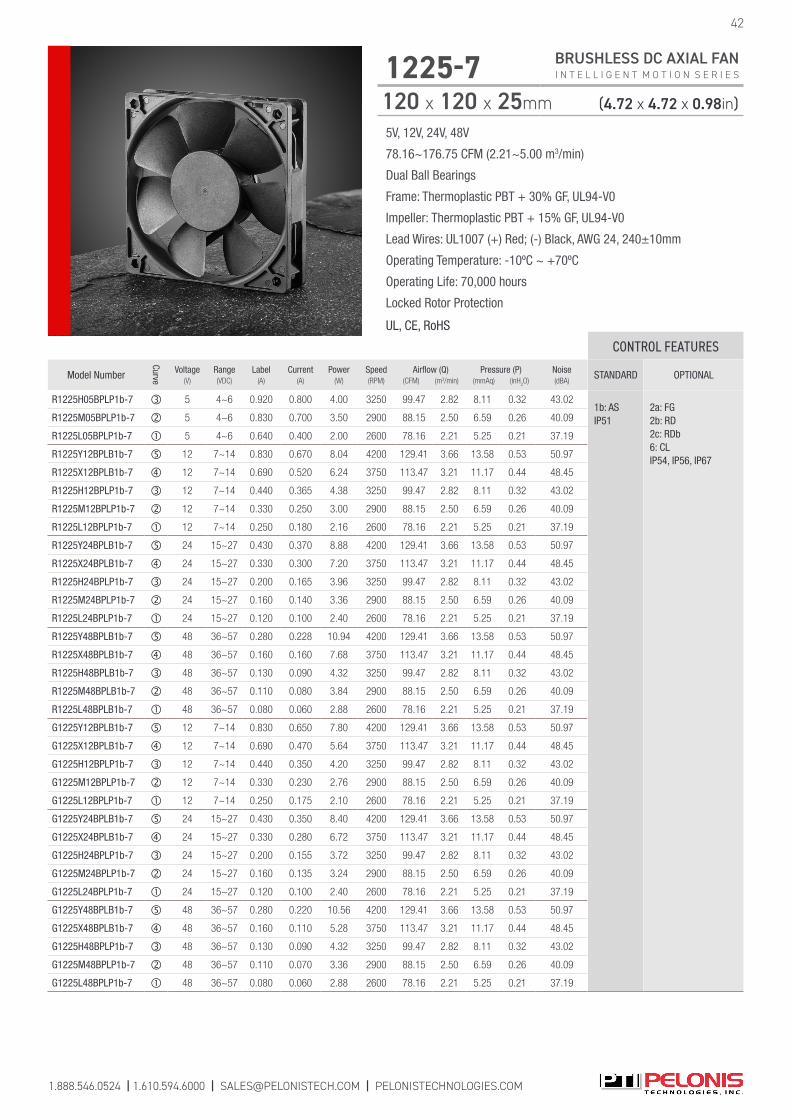
1.888.546.0524 | 1.610.594.6000 | [email protected] | PELONISTECHNOLOGIES.COM
5V, 12V, 24V, 48V
78.16~176.75 CFM (2.21~5.00 m3/min)
Dual Ball Bearings
Frame: Thermoplastic PBT + 30% GF, UL94-V0
Impeller: Thermoplastic PBT + 15% GF, UL94-V0
Lead Wires: UL1007 (+) Red; (-) Black, AWG 24, 240±10mm
Operating Temperature: -10ºC ~ +70ºC
Operating Life: 70,000 hours
Locked Rotor Protection
UL, CE, RoHS
1225-7 BRUSHLESS DC AXIAL FAN I N T E L L I G E N T M O T I O N S E R I E S
120 x 120 x 25mm (4.72 x 4.72 x 0.98in)
42
CONTROL FEATURES
Model Number
Curve
Voltage(V)
Range(VDC)
Label(A)
Current(A)
Power(W)
Speed(RPM)
Airflow (Q)(CFM) (m3/min)
Pressure (P)(mmAq) (inH
2O)
Noise(dBA)
STANDARD OPTIONAL
R1225H05BPLP1b-7 5 4~6 0.920 0.800 4.00 3250 99.47 2.82 8.11 0.32 43.021b: ASIP51
2a: FG 2b: RD 2c: RDb 6: CL IP54, IP56, IP67
R1225M05BPLP1b-7 5 4~6 0.830 0.700 3.50 2900 88.15 2.50 6.59 0.26 40.09
R1225L05BPLP1b-7 5 4~6 0.640 0.400 2.00 2600 78.16 2.21 5.25 0.21 37.19
R1225Y12BPLB1b-7 12 7~14 0.830 0.670 8.04 4200 129.41 3.66 13.58 0.53 50.97
R1225X12BPLB1b-7 12 7~14 0.690 0.520 6.24 3750 113.47 3.21 11.17 0.44 48.45
R1225H12BPLP1b-7 12 7~14 0.440 0.365 4.38 3250 99.47 2.82 8.11 0.32 43.02
R1225M12BPLP1b-7 12 7~14 0.330 0.250 3.00 2900 88.15 2.50 6.59 0.26 40.09
R1225L12BPLP1b-7 12 7~14 0.250 0.180 2.16 2600 78.16 2.21 5.25 0.21 37.19
R1225Y24BPLB1b-7 24 15~27 0.430 0.370 8.88 4200 129.41 3.66 13.58 0.53 50.97
R1225X24BPLB1b-7 24 15~27 0.330 0.300 7.20 3750 113.47 3.21 11.17 0.44 48.45
R1225H24BPLP1b-7 24 15~27 0.200 0.165 3.96 3250 99.47 2.82 8.11 0.32 43.02
R1225M24BPLP1b-7 24 15~27 0.160 0.140 3.36 2900 88.15 2.50 6.59 0.26 40.09
R1225L24BPLP1b-7 24 15~27 0.120 0.100 2.40 2600 78.16 2.21 5.25 0.21 37.19
R1225Y48BPLB1b-7 48 36~57 0.280 0.228 10.94 4200 129.41 3.66 13.58 0.53 50.97
R1225X48BPLB1b-7 48 36~57 0.160 0.160 7.68 3750 113.47 3.21 11.17 0.44 48.45
R1225H48BPLB1b-7 48 36~57 0.130 0.090 4.32 3250 99.47 2.82 8.11 0.32 43.02
R1225M48BPLB1b-7 48 36~57 0.110 0.080 3.84 2900 88.15 2.50 6.59 0.26 40.09
R1225L48BPLB1b-7 48 36~57 0.080 0.060 2.88 2600 78.16 2.21 5.25 0.21 37.19
G1225Y12BPLB1b-7 12 7~14 0.830 0.650 7.80 4200 129.41 3.66 13.58 0.53 50.97
G1225X12BPLB1b-7 12 7~14 0.690 0.470 5.64 3750 113.47 3.21 11.17 0.44 48.45
G1225H12BPLP1b-7 12 7~14 0.440 0.350 4.20 3250 99.47 2.82 8.11 0.32 43.02
G1225M12BPLP1b-7 12 7~14 0.330 0.230 2.76 2900 88.15 2.50 6.59 0.26 40.09
G1225L12BPLP1b-7 12 7~14 0.250 0.175 2.10 2600 78.16 2.21 5.25 0.21 37.19
G1225Y24BPLB1b-7 24 15~27 0.430 0.350 8.40 4200 129.41 3.66 13.58 0.53 50.97
G1225X24BPLB1b-7 24 15~27 0.330 0.280 6.72 3750 113.47 3.21 11.17 0.44 48.45
G1225H24BPLP1b-7 24 15~27 0.200 0.155 3.72 3250 99.47 2.82 8.11 0.32 43.02
G1225M24BPLP1b-7 24 15~27 0.160 0.135 3.24 2900 88.15 2.50 6.59 0.26 40.09
G1225L24BPLP1b-7 24 15~27 0.120 0.100 2.40 2600 78.16 2.21 5.25 0.21 37.19
G1225Y48BPLB1b-7 48 36~57 0.280 0.220 10.56 4200 129.41 3.66 13.58 0.53 50.97
G1225X48BPLB1b-7 48 36~57 0.160 0.110 5.28 3750 113.47 3.21 11.17 0.44 48.45
G1225H48BPLP1b-7 48 36~57 0.130 0.090 4.32 3250 99.47 2.82 8.11 0.32 43.02
G1225M48BPLP1b-7 48 36~57 0.110 0.070 3.36 2900 88.15 2.50 6.59 0.26 40.09
G1225L48BPLP1b-7 48 36~57 0.080 0.060 2.88 2600 78.16 2.21 5.25 0.21 37.19

5V, 12V, 24V, 48V
78.16~176.75 CFM (2.21~5.00 m3/min)
Dual Ball Bearings
Frame: Thermoplastic PBT + 30% GF, UL94-V0
Impeller: Thermoplastic PBT + 15% GF, UL94-V0
Lead Wires: UL1007 (+) Red; (-) Black, AWG 24, 240±10mm
Operating Temperature: -10ºC ~ +70ºC
Operating Life: 70,000 hours
Locked Rotor Protection
UL, CE, RoHS
1.888.546.0524 | 1.610.594.6000 | [email protected] | PELONISTECHNOLOGIES.COM
CONTROL FEATURES
Model Number
Curve
Voltage(V)
Range(VDC)
Label(A)
Current(A)
Power(W)
Speed(RPM)
Airflow (Q)(CFM) (m3/min)
Pressure (P)(mmAq) (inH
2O)
Noise(dBA)
STANDARD OPTIONAL
P1225Y12BPLB1b-7 12 8~14 0.830 0.650 7.80 4200 129.41 3.66 13.58 0.53 50.971b: AS IP51
1a: IR2a: FG 2b: RD 2c: RDb 2d: LD 3a: VPWM 3b: IPWM 3c: PPWM 5a: TPWM 5b: RPWM 6: CL 7: CS IP54, IP56, IP67
P1225X12BPLB1b-7 12 8~14 0.690 0.470 5.64 3750 113.47 3.21 11.17 0.44 48.45
P1225H12BPLP1b-7 12 8~14 0.440 0.350 4.20 3250 99.47 2.82 8.11 0.32 43.02
P1225M12BPLP1b-7 12 8~14 0.330 0.230 2.76 2900 88.15 2.50 6.59 0.26 40.09
P1225L12BPLP1b-7 12 8~14 0.250 0.175 2.10 2600 78.16 2.21 5.25 0.21 37.19
P1225Y24BPLB1b-7 24 15~27 0.430 0.300 7.20 4200 129.41 3.66 13.58 0.53 50.97
P1225X24BPLB1b-7 24 15~27 0.330 0.230 5.52 3750 113.47 3.21 11.17 0.44 48.45
P1225H24BPLP1b-7 24 15~27 0.200 0.155 3.72 3250 99.47 2.82 8.11 0.32 43.02
P1225M24BPLP1b-7 24 15~27 0.160 0.125 3.00 2900 88.15 2.50 6.59 0.26 40.09
P1225L24BPLP1b-7 24 15~27 0.120 0.100 2.40 2600 78.16 2.21 5.25 0.21 37.19
P1225Y48BPLB1b-7 48 36~57 0.280 0.168 8.06 4200 129.41 3.66 13.58 0.53 50.97
P1225X48BPLB1b-7 48 36~57 0.160 0.110 5.28 3750 113.47 3.21 11.17 0.44 48.45
P1225H48BPLP1b-7 48 36~57 0.130 0.090 4.32 3250 99.47 2.82 8.11 0.32 43.02
P1225M48BPLP1b-7 48 36~57 0.110 0.070 3.36 2900 88.15 2.50 6.59 0.26 40.09
P1225L48BPLP1b-7 48 36~57 0.080 0.055 2.64 2600 78.16 2.21 5.25 0.21 37.19
K1225Y12BPLB1b-7 12 8~14 1.770 1.473 17.68 5500 169.12 4.79 22.28 0.88 57.03
K1225X12BPLB1b-7 12 8~14 1.334 1.168 14.02 5200 159.89 4.53 19.91 0.78 55.99
K1225H12BPLB1b-7 12 8~14 1.002 0.740 8.88 4700 143.38 4.06 16.42 0.65 53.74
K1225Y24BPLB1b-7 24 15~27 0.848 0.680 16.32 5800 176.75 5.00 24.80 0.98 58.23
K1225X24BPLB1b-7 24 15~27 0.725 0.613 14.71 5200 159.89 4.53 19.91 0.78 55.99
K1225H24BPLB1b-7 24 15~27 0.557 0.400 9.60 4700 143.38 4.06 16.42 0.65 53.74
K1225Y48BPLB1b-7 48 36~57 0.529 0.380 18.24 5800 176.75 5.00 24.80 0.98 58.23
K1225X48BPLB1b-7 48 36~57 0.379 0.310 14.88 5200 159.89 4.53 19.91 0.78 55.99
K1225H48BPLB1b-7 48 36~57 0.295 0.210 10.08 4700 143.38 4.06 16.42 0.65 53.74
c US
USA TECHNOLOGY
K1225Y24BPLB1b-7DC12V 0.848A
4* Ø 4.4 mm(0.173 in)
240 mm(9.45 in)
105.4 mm(4.15 in)
120 mm(4.72 in)
ROTATION
25 mm(0.98 in)
AIR FLOW30
20
10
0
1.18
0.98
0.39
0
mm
Aq
m3/min
inH
2O
Airflow (Q)
CFM
0
120
3.40 5.102.55
0
Pres
sure
(P)
30 150
RELATIVEAIRFLOW
EFFICIENCY
4.25
180
25
15
5
0.59
0.20
0.79
60
0.85
90
1.70
LOAD LINE
1225-7 BRUSHLESS DC AXIAL FAN I N T E L L I G E N T M O T I O N S E R I E S
120 x 120 x 25mm (4.72 x 4.72 x 0.98in)
43

1.888.546.0524 | 1.610.594.6000 | [email protected] | PELONISTECHNOLOGIES.COM
12V, 24V, 48V
107.49~239.93 CFM (3.04~6.79 m3/min)
Dual Ball Bearings
Frame: Thermoplastic PBT + 30% GF, UL94-V0
Impeller: Thermoplastic PBT + 15% GF, UL94-V0
Lead Wires: UL1007 (+) Red; (-) Black, AWG 24, 240±10mm
Operating Temperature: -10ºC ~ +70ºC
Operating Life: 70,000 hours
Locked Rotor Protection
UL, CE, RoHS
1232-5 BRUSHLESS DC AXIAL FAN I N T E L L I G E N T M O T I O N S E R I E S
120 x 120 x 32mm (4.72 x 4.72 x 1.26in)
44
CONTROL FEATURES
Model Number
Curve
Voltage(V)
Range(VDC)
Label(A)
Current(A)
Power(W)
Speed(RPM)
Airflow (Q)(CFM) (m3/min)
Pressure (P)(mmAq) (inH
2O)
Noise(dBA)
STANDARD OPTIONAL
R1232Y12BPLB1b-5 12 7~14 1.924 1.498 17.98 4200 172.22 4.88 16.49 0.65 54.431b: AS IP51
2a: FG 2b: RD 2c: RDb 6: CL IP54, IP56, IP67
R1232X12BPLB1b-5 12 7~14 1.200 1.056 12.67 3750 154.41 4.37 13.13 0.52 51.63
R1232H12BPLB1b-5 12 7~14 0.858 0.600 7.20 3250 134.21 3.80 9.77 0.38 47.92
R1232M12BPLB1b-5 12 7~14 0.624 0.420 5.04 2900 119.87 3.39 7.78 0.31 44.90
R1232L12BPLB1b-5 12 7~14 0.468 0.280 3.36 2600 107.49 3.04 6.27 0.25 42.07
R1232Y24BPLB1b-5 24 15~27 0.858 0.640 15.36 4200 172.22 4.88 16.49 0.65 54.43
R1232X24BPLB1b-5 24 15~27 0.676 0.532 12.76 3750 154.41 4.37 13.13 0.52 51.63
R1232H24BPLB1b-5 24 15~27 0.416 0.310 7.44 3250 134.21 3.80 9.77 0.38 47.92
R1232M24BPLB1b-5 24 15~27 0.273 0.220 5.28 2900 119.87 3.39 7.78 0.31 44.90
R1232L24BPLB1b-5 24 15~27 0.221 0.182 4.37 2600 107.49 3.04 6.27 0.25 42.07
R1232Y48BPLB1b-5 48 36~57 0.377 0.348 16.70 4200 172.22 4.88 16.49 0.65 54.43
R1232X48BPLB1b-5 48 36~57 0.273 0.257 12.36 3750 154.41 4.37 13.13 0.52 51.63
R1232H48BPLB1b-5 48 36~57 0.195 0.176 8.45 3250 134.21 3.80 9.77 0.38 47.92
R1232M48BPLB1b-5 48 36~57 0.143 0.126 6.05 2900 119.87 3.39 7.78 0.31 44.90
R1232L48BPLB1b-5 48 36~57 0.104 0.090 4.32 2600 107.49 3.04 6.27 0.25 42.07
G1232Y12BPLB1b-5 12 7~14 1.924 1.150 13.80 4200 172.22 4.88 16.49 0.65 54.43
G1232X12BPLB1b-5 12 7~14 1.200 0.820 9.84 3750 154.41 4.37 13.13 0.52 51.63
G1232H12BPLB1b-5 12 7~14 0.858 0.550 6.60 3250 134.21 3.80 9.77 0.38 47.92
G1232M12BPLB1b-5 12 7~14 0.624 0.390 4.68 2900 119.87 3.39 7.78 0.31 44.90
G1232L12BPLB1b-5 12 7~14 0.486 0.250 3.00 2600 107.49 3.04 6.27 0.25 42.07
G1232Y24BPLB1b-5 24 15~27 0.858 0.530 12.72 4200 172.22 4.88 16.49 0.65 54.43
G1232X24BPLB1b-5 24 15~27 0.676 0.380 9.12 3750 154.41 4.37 13.13 0.52 51.63
G1232H24BPLB1b-5 24 15~27 0.416 0.250 6.00 3250 134.21 3.80 9.77 0.38 47.92
G1232M24BPLB1b-5 24 15~27 0.273 0.180 4.32 2900 119.87 3.39 7.78 0.31 44.90
G1232L24BPLB1b-5 24 15~27 0.221 0.135 3.24 2600 107.49 3.04 6.27 0.25 42.07
G1232Y48BPLB1b-5 48 36~57 0.377 0.288 13.82 4200 172.22 4.88 16.49 0.65 54.43
G1232X48BPLB1b-5 48 36~57 0.273 0.220 10.56 3750 154.41 4.37 13.13 0.52 51.63
G1232H48BPLB1b-5 48 36~57 0.195 0.143 6.86 3250 134.21 3.80 9.77 0.38 47.92
G1232M48BPLB1b-5 48 36~57 0.143 0.110 5.28 2900 119.87 3.39 7.78 0.31 44.90
G1232L48BPLB1b-5 48 36~57 0.104 0.080 3.84 2600 107.49 3.04 6.27 0.25 42.07
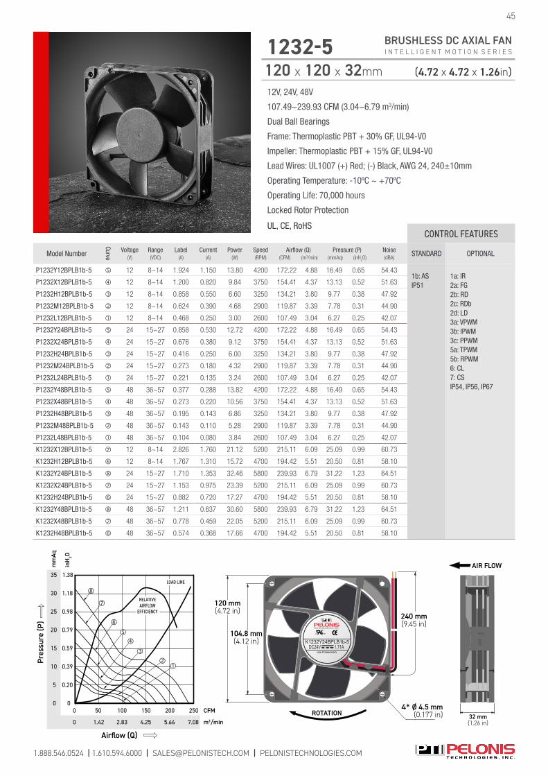
12V, 24V, 48V
107.49~239.93 CFM (3.04~6.79 m3/min)
Dual Ball Bearings
Frame: Thermoplastic PBT + 30% GF, UL94-V0
Impeller: Thermoplastic PBT + 15% GF, UL94-V0
Lead Wires: UL1007 (+) Red; (-) Black, AWG 24, 240±10mm
Operating Temperature: -10ºC ~ +70ºC
Operating Life: 70,000 hours
Locked Rotor Protection
UL, CE, RoHS
1.888.546.0524 | 1.610.594.6000 | [email protected] | PELONISTECHNOLOGIES.COM
45
1232-5 BRUSHLESS DC AXIAL FAN I N T E L L I G E N T M O T I O N S E R I E S
120 x 120 x 32mm (4.72 x 4.72 x 1.26in)
CONTROL FEATURES
Model Number
Curve
Voltage(V)
Range(VDC)
Label(A)
Current(A)
Power(W)
Speed(RPM)
Airflow (Q)(CFM) (m3/min)
Pressure (P)(mmAq) (inH
2O)
Noise(dBA)
STANDARD OPTIONAL
P1232Y12BPLB1b-5 12 8~14 1.924 1.150 13.80 4200 172.22 4.88 16.49 0.65 54.431b: AS IP51
1a: IR2a: FG 2b: RD 2c: RDb 2d: LD 3a: VPWM 3b: IPWM 3c: PPWM 5a: TPWM 5b: RPWM 6: CL 7: CS IP54, IP56, IP67
P1232X12BPLB1b-5 12 8~14 1.200 0.820 9.84 3750 154.41 4.37 13.13 0.52 51.63
P1232H12BPLB1b-5 12 8~14 0.858 0.550 6.60 3250 134.21 3.80 9.77 0.38 47.92
P1232M12BPLB1b-5 12 8~14 0.624 0.390 4.68 2900 119.87 3.39 7.78 0.31 44.90
P1232L12BPLB1b-5 12 8~14 0.468 0.250 3.00 2600 107.49 3.04 6.27 0.25 42.07
P1232Y24BPLB1b-5 24 15~27 0.858 0.530 12.72 4200 172.22 4.88 16.49 0.65 54.43
P1232X24BPLB1b-5 24 15~27 0.676 0.380 9.12 3750 154.41 4.37 13.13 0.52 51.63
P1232H24BPLB1b-5 24 15~27 0.416 0.250 6.00 3250 134.21 3.80 9.77 0.38 47.92
P1232M24BPLB1b-5 24 15~27 0.273 0.180 4.32 2900 119.87 3.39 7.78 0.31 44.90
P1232L24BPLB1b-5 24 15~27 0.221 0.135 3.24 2600 107.49 3.04 6.27 0.25 42.07
P1232Y48BPLB1b-5 48 36~57 0.377 0.288 13.82 4200 172.22 4.88 16.49 0.65 54.43
P1232X48BPLB1b-5 48 36~57 0.273 0.220 10.56 3750 154.41 4.37 13.13 0.52 51.63
P1232H48BPLB1b-5 48 36~57 0.195 0.143 6.86 3250 134.21 3.80 9.77 0.38 47.92
P1232M48BPLB1b-5 48 36~57 0.143 0.110 5.28 2900 119.87 3.39 7.78 0.31 44.90
P1232L48BPLB1b-5 48 36~57 0.104 0.080 3.84 2600 107.49 3.04 6.27 0.25 42.07
K1232X12BPLB1b-5 12 8~14 2.826 1.760 21.12 5200 215.11 6.09 25.09 0.99 60.73
K1232H12BPLB1b-5 12 8~14 1.767 1.310 15.72 4700 194.42 5.51 20.50 0.81 58.10
K1232Y24BPLB1b-5 24 15~27 1.710 1.353 32.46 5800 239.93 6.79 31.22 1.23 64.51
K1232X24BPLB1b-5 24 15~27 1.153 0.975 23.39 5200 215.11 6.09 25.09 0.99 60.73
K1232H24BPLB1b-5 24 15~27 0.882 0.720 17.27 4700 194.42 5.51 20.50 0.81 58.10
K1232Y48BPLB1b-5 48 36~57 1.211 0.637 30.60 5800 239.93 6.79 31.22 1.23 64.51
K1232X48BPLB1b-5 48 36~57 0.778 0.459 22.05 5200 215.11 6.09 25.09 0.99 60.73
K1232H48BPLB1b-5 48 36~57 0.574 0.368 17.66 4700 194.42 5.51 20.50 0.81 58.10
c US
USA TECHNOLOGY
K1232Y24BPLB1b-5DC24V 1.71A
ROTATION4* Ø 4.5 mm
(0.177 in)
240 mm(9.45 in)
104.8 mm(4.12 in)
120 mm(4.72 in)
32 mm(1.26 in)
AIR FLOW35
20
10
0
1.38
1.18
0.39
0
mm
Aq
m3/min
inH
2O
Airflow (Q)
CFM
0
150
4.25 7.082.83
0
Pres
sure
(P)
50
LOAD LINE
200
RELATIVEAIRFLOW
EFFICIENCY
5.66
250
30
15
5
0.59
0.20
0.79
1.42
100
25 0.98

5V, 12V, 24V, 48V
80.96~178.59 CFM (2.29~5.06 m3/min)
Dual Ball Bearings
Frame: Thermoplastic PBT + 30% GF, UL94-V0
Impeller: Thermoplastic PBT + 15% GF, UL94-V0
Lead Wires: UL1007 (+) Red; (-) Black, AWG 24, 240±10mm
Operating Temperature: -10ºC ~ +70ºC
Operating Life: 70,000 hours
Locked Rotor Protection
UL, CE, RoHS
1.888.546.0524 | 1.610.594.6000 | [email protected] | PELONISTECHNOLOGIES.COM
1232-7 BRUSHLESS DC AXIAL FAN I N T E L L I G E N T M O T I O N S E R I E S
120 x 120 x 32mm (4.72 x 4.72 x 1.26in)
46
CONTROL FEATURES
Model Number
Curve
Voltage(V)
Range(VDC)
Label(A)
Current(A)
Power(W)
Speed(RPM)
Airflow (Q)(CFM) (m3/min)
Pressure (P)(mmAq) (inH
2O)
Noise(dBA)
STANDARD OPTIONAL
R1232H05BPLB1b-7 5 4~6 1.400 1.200 6.00 3250 101.08 2.86 9.76 0.38 43.321b: AS IP51
2a: FG 2b: RD 2c: RDb 6: CL IP54, IP56, IP67
R1232M05BPLB1b-5 5 4~6 0.980 0.900 4.50 2900 90.28 2.56 7.79 0.31 40.09
R1232L05BPLB1b-5 5 4~6 0.720 0.715 3.58 2600 80.96 2.29 6.26 0.25 37.49
R1232Y12BPLB1b-7 12 7~14 1.120 0.700 8.40 4200 131.45 3.72 16.34 0.64 49.71
R1232X12BPLB1b-7 12 7~14 0.770 0.520 6.24 3750 117.21 3.32 13.00 0.51 46.69
R1232H12BPLB1b-7 12 7~14 0.540 0.410 4.92 3250 101.08 2.86 9.76 0.38 43.32
R1232M12BPLB1b-7 12 7~14 0.410 0.290 3.48 2900 90.28 2.56 7.79 0.31 40.09
R1232L12BPLB1b-7 12 7~14 0.260 0.240 2.88 2600 80.96 2.29 6.26 0.25 37.49
R1232Y24BPLB1b-7 24 15~27 0.530 0.380 9.12 4200 131.45 3.72 16.34 0.64 49.71
R1232X24BPLB1b-7 24 15~27 0.390 0.260 6.24 3750 117.21 3.32 13.00 0.51 46.69
R1232H24BPLB1b-7 24 15~27 0.240 0.190 4.56 3250 101.08 2.86 9.76 0.38 43.32
R1232M24BPLB1b-7 24 15~27 0.160 0.155 3.72 2900 90.28 2.56 7.79 0.31 40.09
R1232L24BPLB1b-7 24 15~27 0.130 0.125 3.00 2600 80.96 2.29 6.26 0.25 37.49
R1232Y48BPLB1b-7 48 36~57 0.280 0.216 10.37 4200 131.45 3.72 16.34 0.64 49.71
R1232X48BPLB1b-7 48 36~57 0.210 0.170 8.16 3750 117.21 3.32 13.00 0.51 46.69
R1232H48BPLB1b-7 48 36~57 0.140 0.115 5.52 3250 101.08 2.86 9.76 0.38 43.32
R1232M48BPLB1b-7 48 36~57 0.130 0.096 4.61 2900 90.28 2.56 7.79 0.31 40.09
R1232L48BPLB1b-7 48 36~57 0.110 0.080 3.84 2600 80.96 2.29 6.26 0.25 37.49
G1232Y12BPLB1b-7 12 7~14 1.120 0.700 8.40 4200 131.45 3.72 16.34 0.64 49.71
G1232X12BPLB1b-7 12 7~14 0.770 0.510 6.12 3750 117.21 3.32 13.00 0.51 46.69
G1232H12BPLB1b-7 12 7~14 0.540 0.330 3.96 3250 101.08 2.86 9.76 0.38 43.32
G1232M12BPLB1b-7 12 7~14 0.410 0.270 3.24 2900 90.28 2.56 7.79 0.31 40.09
G1232L12BPLB1b-7 12 7~14 0.260 0.187 2.24 2600 80.96 2.29 6.26 0.25 37.49
G1232Y24BPLB1b-7 24 15~27 0.530 0.330 7.92 4200 131.45 3.72 16.34 0.64 49.71
G1232X24BPLB1b-7 24 15~27 0.390 0.240 5.76 3750 117.21 3.32 13.00 0.51 46.69
G1232H24BPLB1b-7 24 15~27 0.240 0.176 4.22 3250 101.08 2.86 9.76 0.38 43.32
G1232M24BPLB1b-7 24 15~27 0.160 0.130 3.12 2900 90.28 2.56 7.79 0.31 40.09
G1232L24BPLB1b-7 24 15~27 0.130 0.110 2.64 2600 80.96 2.29 6.26 0.25 37.49
G1232Y48BPLB1b-7 48 36~57 0.280 0.170 8.16 4200 131.45 3.72 16.34 0.64 49.71
G1232X48BPLB1b-7 48 36~57 0.210 0.143 6.86 3750 117.21 3.32 13.00 0.51 46.69
G1232H48BPLB1b-7 48 36~57 0.140 0.100 4.80 3250 101.08 2.86 9.76 0.38 43.32
G1232M48BPLB1b-7 48 36~57 0.130 0.080 3.84 2900 90.28 2.56 7.79 0.31 40.09
G1232L48BPLB1b-7 48 36~57 0.110 0.070 3.36 2600 80.96 2.29 6.26 0.25 37.49

1.888.546.0524 | 1.610.594.6000 | [email protected] | PELONISTECHNOLOGIES.COM
47
1232-7 BRUSHLESS DC AXIAL FAN I N T E L L I G E N T M O T I O N S E R I E S
120 x 120 x 32mm (4.72 x 4.72 x 1.26in)
5V, 12V, 24V, 48V
80.96~178.59 CFM (2.29~5.06 m3/min)
Dual Ball Bearings
Frame: Thermoplastic PBT + 30% GF, UL94-V0
Impeller: Thermoplastic PBT + 15% GF, UL94-V0
Lead Wires: UL1007 (+) Red; (-) Black, AWG 24, 240±10mm
Operating Temperature: -10ºC ~ +70ºC
Operating Life: 70,000 hours
Locked Rotor Protection
UL, CE, RoHSCONTROL FEATURES
Model Number
Curve
Voltage(V)
Range(VDC)
Label(A)
Current(A)
Power(W)
Speed(RPM)
Airflow (Q)(CFM) (m3/min)
Pressure (P)(mmAq) (inH
2O)
Noise(dBA)
STANDARD OPTIONAL
P1232Y12BPLB1b-7 12 8~14 1.120 0.700 8.40 4200 131.45 3.72 16.34 0.64 49.711b: AS IP51
1a: IR2a: FG 2b: RD 2c: RDb 2d: LD 3a: VPWM 3b: IPWM 3c: PPWM 5a: TPWM 5b: RPWM 6: CL 7: CS IP54, IP56, IP67
P1232X12BPLB1b-7 12 8~14 0.770 0.510 6.12 3750 117.21 3.32 13.00 0.51 46.69
P1232H12BPLB1b-7 12 8~14 0.540 0.330 3.96 3250 101.08 2.86 9.76 0.38 43.32
P1232M12BPLB1b-7 12 8~14 0.410 0.250 3.00 2900 90.28 2.56 7.79 0.31 40.09
P1232L12BPLB1b-7 12 8~14 0.260 0.187 2.24 2600 80.96 2.29 6.26 0.25 37.49
P1232Y24BPLB1b-7 24 15~27 0.530 0.330 7.92 4200 131.45 3.72 16.34 0.64 49.71
P1232X24BPLB1b-7 24 15~27 0.390 0.240 5.76 3750 117.21 3.32 13.00 0.51 46.69
P1232H24BPLB1b-7 24 15~27 0.240 0.176 4.22 3250 101.08 2.86 9.76 0.38 43.32
P1232M24BPLB1b-7 24 15~27 0.160 0.130 3.12 2900 90.28 2.56 7.79 0.31 40.09
P1232L24BPLB1b-7 24 15~27 0.130 0.110 2.64 2600 80.96 2.29 6.26 0.25 37.49
P1232Y48BPLB1b-7 48 36~57 0.280 0.170 8.16 4200 131.45 3.72 16.34 0.64 49.71
P1232X48BPLB1b-7 48 36~57 0.210 0.143 6.86 3750 117.21 3.32 13.00 0.51 46.69
P1232H48BPLB1b-7 48 36~57 0.140 0.100 4.80 3250 101.08 2.86 9.76 0.38 43.32
P1232M48BPLB1b-7 48 36~57 0.130 0.080 3.84 2900 90.28 2.56 7.79 0.31 40.09
P1232L48BPLB1b-7 48 36~57 0.110 0.070 3.36 2600 80.96 2.29 6.26 0.25 37.49
K1232X12BPLB1b-7 12 8~14 1.397 1.397 16.76 5200 162.97 4.61 25.04 0.99 57.60
K1232H12BPLB1b-7 12 8~14 1.106 1.100 13.20 4700 147.30 4.17 20.46 0.81 54.35
K1232Y24BPLB1b-7 24 15~27 0.896 0.896 21.50 5800 178.59 5.06 27.61 1.09 59.74
K1232X24BPLB1b-7 24 15~27 0.683 0.683 16.39 5200 162.97 4.61 25.04 0.99 57.60
K1232H24BPLB1b-7 24 15~27 0.574 0.574 13.78 4700 147.30 4.17 20.46 0.81 54.35
K1232Y48BPLB1b-7 48 36~57 0.622 0.608 29.18 5800 178.59 5.06 27.61 1.09 59.74
K1232X48BPLB1b-7 48 36~57 0.414 0.414 19.87 5200 162.97 4.61 25.04 0.99 57.60
K1232H48BPLB1b-7 48 36~57 0.316 0.316 15.17 4700 147.3 4.17 20.46 0.81 54.35
240 mm(9.45 in)
104 mm(4.09 in)
120 mm(4.72 in)
104 mm(4.09 in)
120 mm(4.72 in)
ROTATION
c US
USA TECHNOLOGY
K1232X12BPLB1b-7 DC12V 1.397A
32 mm(1.26 in)
AIRFLOW
5.0 ± 0.3 mm(0.20 in)
30
5
0
mm
Aq
m3/min
inH
2O
Airflow (Q)
CFM
0
1000
Pres
sure
(P)
50
LOAD LINE
150
RELATIVEAIRFLOW
EFFICIENCY
200
25
10
15
20
1.18
0.39
0.59
0.20
0.79
0.98
0
4.252.83 5.661.42

1.888.546.0524 | 1.610.594.6000 | [email protected] | PELONISTECHNOLOGIES.COM
12V, 24V, 48V
190.31~236.83 CFM (5.39~6.71 m3/min)
Dual Ball Bearings
Frame: Thermoplastic PBT + 30% GF, UL94-V0
Impeller: Thermoplastic PBT + 15% GF, UL94-V0
Lead Wires: UL1007 (+) Red; (-) Black, AWG 24, 240±10mm
Operating Temperature: -10ºC ~ +70ºC
Operating Life: 70,000 hours
Locked Rotor Protection
UL, CE, RoHS
1238-5 BRUSHLESS DC AXIAL FAN I N T E L L I G E N T M O T I O N S E R I E S
120 x 120 x 38mm (4.72 x 4.72 x 1.50in)
48
CONTROL FEATURES
Model Number
Curve
Voltage(V)
Range(VDC)
Label(A)
Current(A)
Power(W)
Speed(RPM)
Airflow (Q)(CFM) (m3/min)
Pressure (P)(mmAq) (inH
2O)
Noise(dBA)
STANDARD OPTIONAL
K1238X12BPLB1b-5 12 8~14 2.513 2.100 25.20 5200 212.57 6.02 24.38 0.96 61.89 1b: AS IP51
1a: IR,2a: FG, 2b: RD 2c: RDb, 2d: LD 3a: VPWM 3b: IPWM 3c: PPWM 5a: TPWM 5b: RPWM 6: CL 7: CS IP54, IP56, IP67
H1238H12BPLB1b-5 12 8~14 1.846 1.650 19.80 4700 190.31 5.39 21.13 0.83 57.78
K1238Y24BPLB1b-5 24 15~27 1.733 1.200 28.80 5500 224.58 6.36 28.29 1.11 63.63
K1238X24BPLB1b-5 24 15~27 1.110 0,950 22.80 5200 212.57 6.02 24.38 0.96 61.89
K1238H24BPLB1b-5 24 15~27 0.938 0.680 16.32 4700 190.31 5.39 21.13 0.83 57.78
K1238Y48BPLB1b-5 48 36~57 0.826 0.610 29.28 5800 236.83 6.71 31.47 1.24 65.02
K1238X48BPLB1b-5 48 36~57 0.602 0.510 24.48 5200 212.57 6.02 24.38 0.96 61.89
K1238H48BPLB1b-5 48 36~57 0.520 0.355 17.04 4700 190.31 5.39 21.13 0.83 57.78
240 mm(9.45 in)
104.8 mm(4.12 in)
120 mm(4.72 in)
ROTATION
104.8 mm(4.12 in)
120 mm(4.72 in)
c US
USA TECHNOLOGY
K1238Y24BPLB1b-5DC24V 1.733A
38 mm(1.50 in)
AIRFLOW
5.0 mm(0.19 in)
35
10
0 0
mm
Aq
m3/min
inH
2O
Airflow (Q)
CFM
0
1500
Pres
sure
(P)
50
LOAD LINE
200
RELATIVEAIRFLOW
EFFICIENCY
250
30
5
100
15
20
25
1.38
1.18
0.39
0.59
0.20
0.79
0.98
4.25 7.082.83 5.661.42

1.888.546.0524 | 1.610.594.6000 | [email protected] | PELONISTECHNOLOGIES.COM
49
CONTROL FEATURES
Model Number
Curve
Voltage(V)
Range(VDC)
Label(A)
Current(A)
Power(W)
Speed(RPM)
Airflow (Q)(CFM) (m3/min)
Pressure (P)(mmAq) (inH
2O)
Noise(dBA)
STANDARD OPTIONAL
R1238H05BPLB1b-7 5 4~6 2.220 1.600 8.00 3250 130.45 3.69 11.14 0.44 46.131b: AS IP51
2a: FG 2b: RD 2c: RDb 6: CL IP54, IP56, IP67
R1238M05BPLB1b-7 5 4~6 1.610 1.300 6.50 2900 115.24 3.26 8.81 0.35 42.96
R1238L05BPLB1b-7 5 4~6 1.200 0.961 4.81 2600 104.46 2.96 7.26 0.29 39.83
R1238Y12BPLB1b-7 12 7~14 1.770 1.267 15.20 4200 167.66 4.75 17.92 0.71 52.99
R1238X12BPLB1b-7 12 7~14 1.440 0.822 9.86 3750 150.71 4.27 15.17 0.60 50.32
R1238H12BPLB1b-7 12 7~14 0.860 0.510 6.12 3250 130.45 3.69 11.14 0.44 46.13
R1238M12BPLB1b-7 12 7~14 0.640 0.400 4.80 2900 115.24 3.26 8.81 0.35 42.96
R1238L12BPLB1b-7 12 7~14 0.410 0.300 3.60 2600 104.46 2.96 7.26 0.29 39.83
R1238Y24BPLB1b-7 24 15~27 0.850 0.580 13.92 4200 167.66 4.75 17.92 0.71 52.99
R1238X24BPLB1b-7 24 15~27 0.630 0.460 11.04 3750 150.71 4.27 15.17 0.60 50.32
R1238H24BPLB1b-7 24 15~27 0.370 0.300 7.20 3250 130.45 3.69 11.14 0.44 46.13
R1238M24BPLB1b-7 24 15~27 0.290 0.238 5.71 2900 115.24 3.26 8.81 0.35 42.96
R1238L24BPLB1b-7 24 15~27 0.180 0.160 3.84 2600 104.46 2.96 7.26 0.29 39.83
R1238Y48BPLB1b-7 48 36~57 0.540 0.350 16.80 4200 167.66 4.75 17.92 0.71 52.99
R1238X48BPLB1b-7 48 36~57 0.300 0.220 10.56 3750 150.71 4.27 15.17 0.60 50.32
R1238H48BPLB1b-7 48 36~57 0.180 0.150 7.20 3250 130.45 3.69 11.14 0.44 46.13
R1238M48BPLB1b-7 48 36~57 0.140 0.110 5.28 2900 115.24 3.26 8.81 0.35 42.96
R1238L48BPLB1b-7 48 36~57 0.120 0.080 3.84 2600 104.46 2.96 7.26 0.29 39.83
G1238Y12BPLB1b-7 12 7~14 1.770 1.150 13.80 4200 167.66 4.75 17.92 0.71 52.991b: ASIP51
2a: FG 2b: RD 2c: RDb 6: CL IP54, IP56, IP67
G1238X12BPLB1b-7 12 7~14 1.440 0.750 9.00 3750 150.71 4.27 15.17 0.60 50.32
G1238H12BPLB1b-7 12 7~14 0.860 0.500 6.00 3250 130.45 3.69 11.14 0.44 46.13
G1238M12BPLB1b-7 12 7~14 0.640 0.380 4.56 2900 115.24 3.26 8.81 0.35 42.96
G1238L12BPLB1b-7 12 7~14 0.410 0.290 3.48 2600 104.46 2.96 7.26 0.29 39.83
G1238Y24BPLB1b-7 24 15~27 0.850 0.500 12.00 4200 167.66 4.75 17.92 0.71 52.99
G1238X24BPLB1b-7 24 15~27 0.630 0.420 10.08 3750 150.71 4.27 15.17 0.60 50.32
G1238H24BPLB1b-7 24 15~27 0.370 0.290 6.96 3250 130.45 3.69 11.14 0.44 46.13
G1238M24BPLB1b-7 24 15~27 0.290 0.200 4.80 2900 115.24 3.26 8.81 0.35 42.96
G1238L24BPLB1b-7 24 15~27 0.180 0.150 3.60 2600 104.46 2.96 7.26 0.29 39.83
G1238Y48BPLB1b-7 48 36~57 0.540 0.260 12.48 4200 167.66 4.75 17.92 0.71 52.99
G1238X48BPLB1b-7 48 36~57 0.300 0.210 10.08 3750 150.71 4.27 15.17 0.60 50.32
G1238H48BPLB1b-7 48 36~57 0.180 0.135 6.48 3250 130.45 3.69 11.14 0.44 46.13
G1238M48BPLB1b-7 48 36~57 0.140 0.105 5.04 2900 115.24 3.26 8.81 0.35 42.96
G1238L48BPLB1b-7 48 36~57 0.120 0.077 3.70 2600 104.46 2.96 7.26 0.29 39.83
1238-7 BRUSHLESS DC AXIAL FAN I N T E L L I G E N T M O T I O N S E R I E S
120 x 120 x 38mm (4.72 x 4.72 x 1.50in)
5V, 12V, 24V, 48V
104.46~231.53 CFM (2.96~6.56 m3/min)
Dual Ball Bearings
Frame: Thermoplastic PBT + 30% GF, UL94-V0
Impeller: Thermoplastic PBT + 15% GF, UL94-V0
Lead Wires: UL1007 (+) Red; (-) Black, AWG 24, 240±10mm
Operating Temperature: -10ºC ~ +70ºC
Operating Life: 70,000 hours
Locked Rotor Protection
UL, CE, RoHS
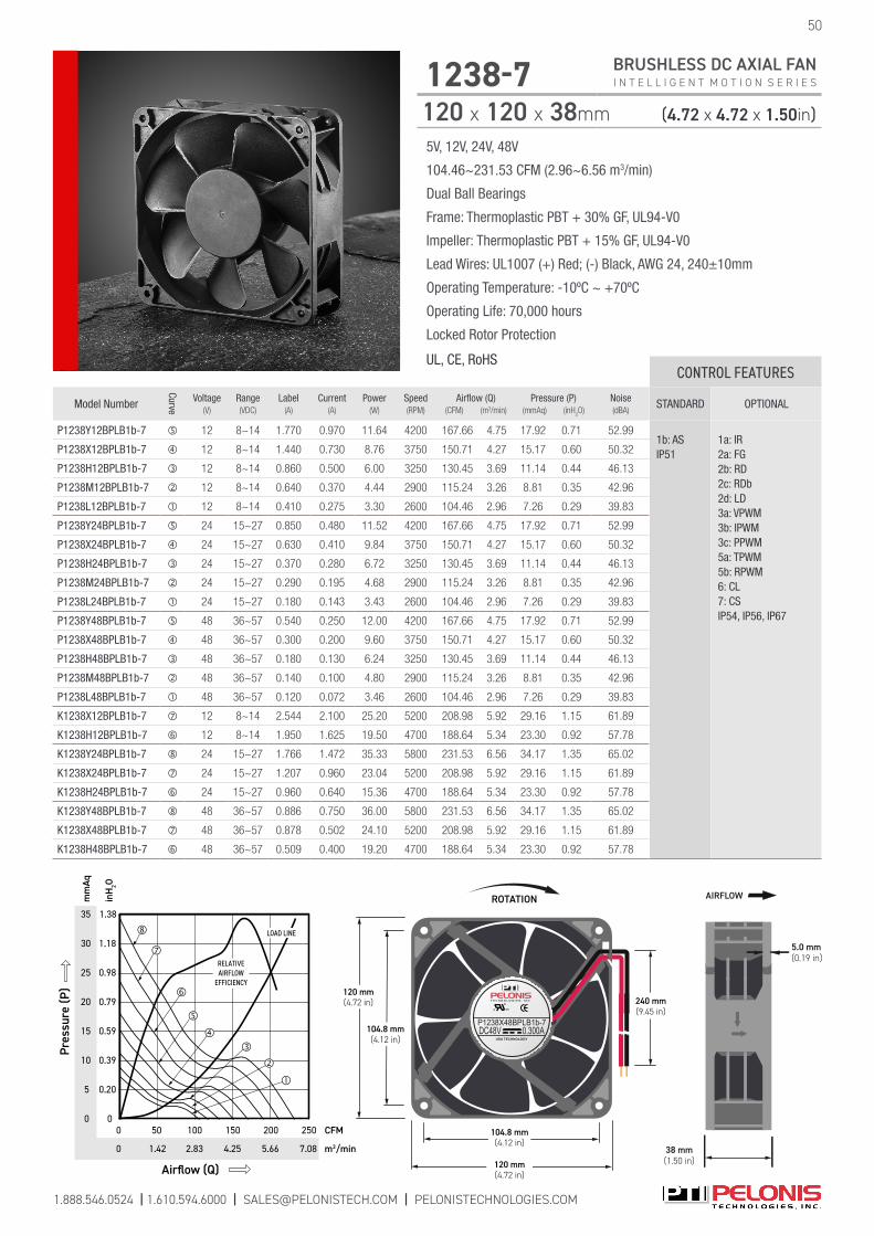
1.888.546.0524 | 1.610.594.6000 | [email protected] | PELONISTECHNOLOGIES.COM
50
1238-7 BRUSHLESS DC AXIAL FAN I N T E L L I G E N T M O T I O N S E R I E S
120 x 120 x 38mm (4.72 x 4.72 x 1.50in)
5V, 12V, 24V, 48V
104.46~231.53 CFM (2.96~6.56 m3/min)
Dual Ball Bearings
Frame: Thermoplastic PBT + 30% GF, UL94-V0
Impeller: Thermoplastic PBT + 15% GF, UL94-V0
Lead Wires: UL1007 (+) Red; (-) Black, AWG 24, 240±10mm
Operating Temperature: -10ºC ~ +70ºC
Operating Life: 70,000 hours
Locked Rotor Protection
UL, CE, RoHSCONTROL FEATURES
Model Number
Curve
Voltage(V)
Range(VDC)
Label(A)
Current(A)
Power(W)
Speed(RPM)
Airflow (Q)(CFM) (m3/min)
Pressure (P)(mmAq) (inH
2O)
Noise(dBA)
STANDARD OPTIONAL
P1238Y12BPLB1b-7 12 8~14 1.770 0.970 11.64 4200 167.66 4.75 17.92 0.71 52.991b: AS IP51
1a: IR2a: FG 2b: RD 2c: RDb 2d: LD 3a: VPWM 3b: IPWM 3c: PPWM 5a: TPWM 5b: RPWM 6: CL 7: CS IP54, IP56, IP67
P1238X12BPLB1b-7 12 8~14 1.440 0.730 8.76 3750 150.71 4.27 15.17 0.60 50.32
P1238H12BPLB1b-7 12 8~14 0.860 0.500 6.00 3250 130.45 3.69 11.14 0.44 46.13
P1238M12BPLB1b-7 12 8~14 0.640 0.370 4.44 2900 115.24 3.26 8.81 0.35 42.96
P1238L12BPLB1b-7 12 8~14 0.410 0.275 3.30 2600 104.46 2.96 7.26 0.29 39.83
P1238Y24BPLB1b-7 24 15~27 0.850 0.480 11.52 4200 167.66 4.75 17.92 0.71 52.99
P1238X24BPLB1b-7 24 15~27 0.630 0.410 9.84 3750 150.71 4.27 15.17 0.60 50.32
P1238H24BPLB1b-7 24 15~27 0.370 0.280 6.72 3250 130.45 3.69 11.14 0.44 46.13
P1238M24BPLB1b-7 24 15~27 0.290 0.195 4.68 2900 115.24 3.26 8.81 0.35 42.96
P1238L24BPLB1b-7 24 15~27 0.180 0.143 3.43 2600 104.46 2.96 7.26 0.29 39.83
P1238Y48BPLB1b-7 48 36~57 0.540 0.250 12.00 4200 167.66 4.75 17.92 0.71 52.99
P1238X48BPLB1b-7 48 36~57 0.300 0.200 9.60 3750 150.71 4.27 15.17 0.60 50.32
P1238H48BPLB1b-7 48 36~57 0.180 0.130 6.24 3250 130.45 3.69 11.14 0.44 46.13
P1238M48BPLB1b-7 48 36~57 0.140 0.100 4.80 2900 115.24 3.26 8.81 0.35 42.96
P1238L48BPLB1b-7 48 36~57 0.120 0.072 3.46 2600 104.46 2.96 7.26 0.29 39.83
K1238X12BPLB1b-7 12 8~14 2.544 2.100 25.20 5200 208.98 5.92 29.16 1.15 61.89
K1238H12BPLB1b-7 12 8~14 1.950 1.625 19.50 4700 188.64 5.34 23.30 0.92 57.78
K1238Y24BPLB1b-7 24 15~27 1.766 1.472 35.33 5800 231.53 6.56 34.17 1.35 65.02
K1238X24BPLB1b-7 24 15~27 1.207 0.960 23.04 5200 208.98 5.92 29.16 1.15 61.89
K1238H24BPLB1b-7 24 15~27 0.960 0.640 15.36 4700 188.64 5.34 23.30 0.92 57.78
K1238Y48BPLB1b-7 48 36~57 0.886 0.750 36.00 5800 231.53 6.56 34.17 1.35 65.02
K1238X48BPLB1b-7 48 36~57 0.878 0.502 24.10 5200 208.98 5.92 29.16 1.15 61.89
K1238H48BPLB1b-7 48 36~57 0.509 0.400 19.20 4700 188.64 5.34 23.30 0.92 57.78
240 mm(9.45 in)
104.8 mm(4.12 in)
120 mm(4.72 in)
ROTATION
104.8 mm(4.12 in)
120 mm(4.72 in)
c US
USA TECHNOLOGY
P1238X48BPLB1b-7DC48V 0.300A
38 mm(1.50 in)
AIRFLOW
5.0 mm(0.19 in)
35
10
0 0
mm
Aq
m3/min
inH
2O
Airflow (Q)
CFM
0
1500
Pres
sure
(P)
50
LOAD LINE
200
RELATIVEAIRFLOW
EFFICIENCY
250
30
5
100
15
20
25
1.38
1.18
0.39
0.59
0.20
0.79
0.98
4.25 7.082.83 5.661.42

1.888.546.0524 | 1.610.594.6000 | [email protected] | PELONISTECHNOLOGIES.COM
51
1238-11 PL BRUSHLESS DC AXIAL FAN I N T E L L I G E N T M O T I O N S E R I E S
120 x 120 x 38mm (4.72 x 4.72 x 1.50in)
12V, 24V, 48V
141.98~257.34 CFM (4.02~7.29 m3/min)
Dual Ball Bearings
Frame: Thermoplastic PBT + 30% GF, UL94-V0
Impeller: Thermoplastic PBT + 15% GF, UL94-V0
Lead Wires: UL1007 (+) Red; (-) Black, AWG 24, 255±10mm
Operating Temperature: -10ºC ~ +70ºC
Operating Life: 70,000 hours
Locked Rotor Protection
UL, CE, RoHS
CONTROL FEATURES
Model Number
Curve
Voltage(V)
Range(VDC)
Label(A)
Current(A)
Power(W)
Speed(RPM)
Airflow (Q)(CFM) (m3/min)
Pressure (P)(mmAq) (inH
2O)
Noise(dBA)
STANDARD OPTIONAL
P1238X12BPLB1b-11 12 8~14 6.500 5.000 60.00 5500 244.03 6.91 31.91 1.26 66.001b: AS IP51
1a: IR2a: FG 2b: RD 2c: RDb 2d: LD 3a: VPWM 3b: IPWM 3c: PPWM 5a: TPWM 5b: RPWM 6: CL 7: CS IP54, IP56, IP67
P1238H12BPLB1b-11 12 8~14 3.500 3.000 36.00 4800 212.97 6.03 24.30 0.96 62.00
P1238M12BPLB1b-11 12 8~14 1.950 1.500 18.00 4000 177.47 5.02 16.88 0.66 57.00
P1238L12BPLB1b-11 12 8~14 1.240 0.950 11.40 3200 141.98 4.02 10.80 0.42 51.00
P1238X24BPLB1b-11 24 15~27 3.000 2.500 60.00 5500 244.03 6.91 31.91 1.26 66.00
P1238H24BPLB1b-11 24 15~27 1.450 1.350 32.40 4800 212.97 6.03 24.30 0.96 62.00
P1238M24BPLB1b-11 24 15~27 0.820 0.750 18.00 4000 177.47 5.02 16.88 0.66 57.00
P1238L24BPLB1b-11 24 15~27 0.500 0.450 10.80 3200 141.98 4.02 10.80 0.42 51.00
P1238Y48BPLB1b-11 48 36~57 1.600 1.400 67.20 5800 257.34 7.29 35.48 1.40 67.00
P1238X48BPLB1b-11 48 36~57 1.250 1.150 55.20 5500 244.03 6.91 31.91 1.26 66.00
P1238H48BPLB1b-11 48 36~57 0.820 0.750 36.00 4800 212.97 6.03 24.30 0.96 62.00
P1238M48BPLB1b-11 48 36~57 0.450 0.410 19.68 4000 177.47 5.02 16.88 0.66 57.00
P1238L48BPLB1b-11 48 36~57 0.280 0.245 11.76 3200 141.98 4.02 10.80 0.42 51.00
c US
USA TECHNOLOGY
P1238X24BPLB1b-11DC24V 3.00A
ROTATION
Ø4.50(0.18 in)
255 mm(10.00 in)
105 mm(4.13 in)
120 mm(4.72 in)
105 mm(4.13 in)
120 mm(4.72 in)
38 mm(1.50 in)
AIR FLOW
5.0 ± 0.2 mm(0.16 in)
40
35
20
10
0
1.57
1.38
1.18
0.79
0.39
0
mm
Aq
m3/min
inH
2O
Airflow (Q)
CFM
0
125 200
4.96 6.37
0
Pres
sure
(P)
75 150 225
LOAD LINE
RELATIVEAIRFLOW
EFFICIENCY
100 17550
4.252.12 3.541.42 2.830.71
25
15
5
0.98
0.59
0.20
250
7.08
25
5.67
30

1.888.546.0524 | 1.610.594.6000 | [email protected] | PELONISTECHNOLOGIES.COM
12V, 24V, 48V
165.75~277.75 CFM (4.69~7.86 m3/min)
Dual Ball Bearings
Frame: Aluminum
Impeller: Thermoplastic PBT + 15% GF, UL94-V0
Lead Wires: UL1007 (+) Red; (-) Black, AWG 24, 240±10mm
Operating Temperature: -10ºC ~ +70ºC
Operating Life: 70,000 hours
Locked Rotor Protection
UL, CE, RoHS
1238-11 AL BRUSHLESS DC AXIAL FAN I N T E L L I G E N T M O T I O N S E R I E S
120 x 120 x 38mm (4.72 x 4.72 x 1.50in)
52
CONTROL FEATURES
Model Number
Curve
Voltage(V)
Range(VDC)
Label(A)
Current(A)
Power(W)
Speed(RPM)
Airflow (Q)(CFM) (m3/min)
Pressure (P)(mmAq) (inH
2O)
Noise(dBA)
STANDARD OPTIONAL
K1238M12BALA1b-11 12 8~14 3.250 2.400 28.80 4200 188.15 5.33 19.47 0.77 60.001b: AS IP51
1a: IR2a: FG 2b: RD 2c: RDb 2d: LD 3a: VPWM 3b: IPWM 3c: PPWM 5a: TPWM 5b: RPWM 6: CL 7: CS IP54, IP56, IP67
K1238L12BALA1b-11 12 8~14 2.500 1.850 22.20 3700 165.75 4.69 15.11 0.59 56.70
K1238Y24BALA1b-11 24 15~27 3.770 2.600 62.40 5800 259.83 7.36 37.13 1.46 68.40
K1238X24BALA1b-11 24 15~27 2.990 1.900 45.60 5200 232.95 6.60 29.84 1.17 65.50
K1238H24BALA1b-11 24 15~27 2.210 1.600 38.40 4700 210.55 5.96 24.38 0.96 62.90
K1238M24BALA1b-11 24 15~27 1.690 1.200 28.80 4200 188.15 5.33 19.47 0.77 60.00
K1238L24BALA1b-11 24 15~27 1.300 0.950 22.80 3700 165.75 4.69 15.11 0.59 56.70
K1238Z48BALA1b-11 48 36~57 2.340 1.700 81.60 6200 277.75 7.86 42.43 1.67 70.10
K1238Y48BALA1b-11 48 36~57 1.880 1.300 62.40 5800 259.83 7.36 37.13 1.46 68.40
K1238X48BALA1b-11 48 36~57 1.490 1.000 48.00 5200 232.95 6.60 29.84 1.17 65.50
K1238H48BALA1b-11 48 36~57 1.100 0.800 38.40 4700 210.55 5.96 24.38 0.96 62.90
K1238M48BALA1b-11 48 36~57 0.840 0.600 28.80 4200 188.15 5.33 19.47 0.77 60.00
K1238L48BALA1b-11 48 36~57 0.650 0.475 22.80 3700 165.75 4.69 15.11 0.59 56.70
ROTATION
Ø4.50(0.18 in)
240 mm(9.45 in)
105 mm(4.13 in)
120 mm(4.72 in)
c US
USA TECHNOLOGY
K1238Y24BALA1b-11 DC24V 3.77A
105 mm(4.13 in)
120 mm(4.72 in)
38 mm(1.50 in)
AIR FLOW
5.0 ± 0.2 mm(0.16 in)
CFM250 300
45
20
5
0
1.57
0
mm
Aq
m3/min
inH
2O
Airflow (Q)
200
8.50
0
Pres
sure
(P)
100
LOAD LINE
RELATIVEAIRFLOW
EFFICIENCY
40
10
150
15
30
50
25
35
0 4.25 7.082.83 5.661.42
1.77
1.18
0.39
0.59
0.20
0.79
0.98
1.38
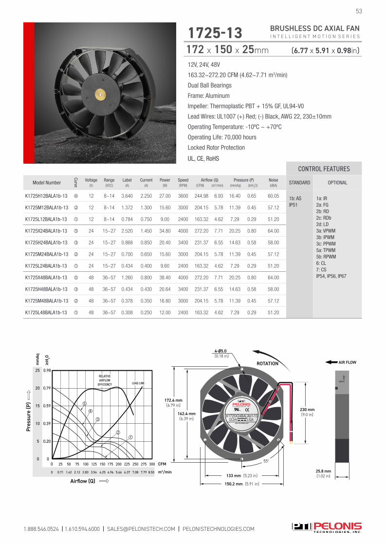
1.888.546.0524 | 1.610.594.6000 | [email protected] | PELONISTECHNOLOGIES.COM
53
1725-13 BRUSHLESS DC AXIAL FAN I N T E L L I G E N T M O T I O N S E R I E S
172 x 150 x 25mm (6.77 x 5.91 x 0.98in)
12V, 24V, 48V
163.32~272.20 CFM (4.62~7.71 m3/min)
Dual Ball Bearings
Frame: Aluminum
Impeller: Thermoplastic PBT + 15% GF, UL94-V0
Lead Wires: UL1007 (+) Red; (-) Black, AWG 22, 230±10mm
Operating Temperature: -10ºC ~ +70ºC
Operating Life: 70,000 hours
Locked Rotor Protection
UL, CE, RoHS
CONTROL FEATURES
Model Number
Curve
Voltage(V)
Range(VDC)
Label(A)
Current(A)
Power(W)
Speed(RPM)
Airflow (Q)(CFM) (m3/min)
Pressure (P)(mmAq) (inH
2O)
Noise(dBA)
STANDARD OPTIONAL
K1725H12BALA1b-13 12 8~14 3.640 2.250 27.00 3600 244.98 6.93 16.40 0.65 60.05 1b: AS IP51
1a: IR2a: FG 2b: RD 2c: RDb 2d: LD 3a: VPWM 3b: IPWM 3c: PPWM 5a: TPWM 5b: RPWM 6: CL 7: CS IP54, IP56, IP67
K1725M12BALA1b-13 12 8~14 1.372 1.300 15.60 3000 204.15 5.78 11.39 0.45 57.12
K1725L12BALA1b-13 12 8~14 0.784 0.750 9.00 2400 163.32 4.62 7.29 0.29 51.20
K1725X24BALA1b-13 24 15~27 2.520 1.450 34.80 4000 272.20 7.71 20.25 0.80 64.00
K1725H24BALA1b-13 24 15~27 0.868 0.850 20.40 3400 231.37 6.55 14.63 0.58 58.00
K1725M24BALA1b-13 24 15~27 0.700 0.650 15.60 3000 204.15 5.78 11.39 0.45 57.12
K1725L24BALA1b-13 24 15~27 0.434 0.400 9.60 2400 163.32 4.62 7.29 0.29 51.20
K1725X48BALA1b-13 48 36~57 1.260 0.800 38.40 4000 272.20 7.71 20.25 0.80 64.00
K1725H48BALA1b-13 48 36~57 0.434 0.430 20.64 3400 231.37 6.55 14.63 0.58 58.00
K1725M48BALA1b-13 48 36~57 0.378 0.350 16.80 3000 204.15 5.78 11.39 0.45 57.12
K1725L48BALA1b-13 48 36~57 0.308 0.250 12.00 2400 163.32 4.62 7.29 0.29 51.20
ROTATION
c US
USA TECHNOLOGY
K1725X24BALAb1-13DC24V 2.52A
162.4 mm(6.39 in)
172.4 mm(6.79 in)
133 mm (5.23 in)
150.2 mm (5.91 in)
230 mm(9.0 in)
4-Ø5.0(0.18 in)
550
25.8 mm(1.02 in)
AIR FLOW
25
10
0
0.98
0.79
0.20
0
mm
Aq
m3/min
inH
2O
Airflow (Q)
CFM
0
225
6.37 8.504.25
0
Pres
sure
(P)
75 275
7.79
300
20
5
0.59
2.12
150
15
0.39
20050 250125 17525 100
5.663.54 7.081.42 4.962.830.71
LOAD LINE
RELATIVEAIRFLOW
EFFICIENCY

1.888.546.0524 | 1.610.594.6000 | [email protected] | PELONISTECHNOLOGIES.COM
12V, 24V, 48V
241.46~413.93 CFM (6.84~11.72 m3/min)
Dual Ball Bearings
Frame: Aluminum
Impeller: Thermoplastic PBT + 15% GF, UL94-V0
Lead Wires: UL1007 (+) Red; (-) Black, AWG 22, 220±10mm
Operating Temperature: -10ºC ~ +70ºC
Operating Life: 70,000 hours
Locked Rotor Protection
UL, CE, RoHS
1751-3 BRUSHLESS DC AXIAL FAN I N T E L L I G E N T M O T I O N S E R I E S
172 x 150 x 51mm (6.77 x 5.91 x 2.00in)
54
CONTROL FEATURES
Model Number
Curve
Voltage(V)
Range(VDC)
Label(A)
Current(A)
Power(W)
Speed(RPM)
Airflow (Q)(CFM) (m3/min)
Pressure (P)(mmAq) (inH
2O)
Noise(dBA)
STANDARD OPTIONAL
P1751H12BALA1b-3 12 8~14 3.200 3.000 36.00 4500 310.45 8.79 28.40 1.12 62.701b: AS IP51
1a: IR2a: FG 2b: RD 2c: RDb 2d: LD 3a: VPWM 3b: IPWM 3c: PPWM 5a: TPWM 5b: RPWM 6: CL 7: CS IP54, IP56, IP67, IP68
P1751M12BALA1b-3 12 8~14 2.600 2.400 28.80 4000 275.95 7.81 22.44 0.88 59.60
P1751L12BALA1b-3 12 8~14 1.700 1.500 18.00 3500 241.46 6.84 17.18 0.68 57.10
P1751Z24BALA1b-3 24 15~27 4.000 3.300 79.20 6000 413.93 11.72 50.48 1.99 70.10
P1751Y24BALA1b-3 24 15~27 2.800 2.500 60.00 5500 379.44 10.74 42.42 1.67 68.00
P1751X24BALA1b-3 24 15~27 2.200 2.000 48.00 5000 344.94 9.76 35.06 1.38 65.20
P1751H24BALA1b-3 24 15~27 1.600 1.500 36.00 4500 310.45 8.79 28.40 1.12 62.70
P1751M24BALA1b-3 24 15~27 1.260 1.100 26.40 4000 275.95 7.81 22.44 0.88 59.60
P1751L24BALA1b-3 24 15~27 0.850 0.750 18.00 3500 241.46 6.84 17.18 0.68 57.10
P1751Z48BALA1b-3 48 36~57 2.000 1.680 80.64 6000 413.93 11.72 50.48 1.99 70.10
P1751Y48BALA1b-3 48 36~57 1.400 1.300 62.40 5500 379.44 10.74 42.42 1.67 68.00
P1751X48BALA1b-3 48 36~57 1.050 0.950 45.60 5000 344.94 9.76 35.06 1.38 65.20
P1751H48BALA1b-3 48 36~57 0.800 0.730 35.04 4500 310.45 8.79 28.40 1.12 62.70
P1751M48BALA1b-3 48 36~57 0.600 0.520 24.96 4000 275.95 7.81 22.44 0.88 59.60
P1751L48BALA1b-3 48 36~57 0.420 0.370 17.76 3500 241.46 6.84 17.18 0.68 57.10
c US
USA TECHNOLOGY
P1751H12BALA1b-3DC12V 3.200A
220 mm(8.66 in)
ROTATION
150 mm(5.90 in)
133.51 mm(5.25 in)
162 mm(6.37 in)
171.8 mm(6.76 in)
4-Ø4.3(0.17 in)
2-55050.8 mm(2.0 in)
AIRFLOW
Lorem ipsum
30
0
0.39
0
mm
Aq
m3/min
inH 2O
Airflow (Q)
CFM
0
400300
14.168.50
0
Pres
sure
(P)
500
10
1.58
1.97
2.83
40
50
1.18
60 2.36
5.66
100 200
11.33
LOAD LINE�
�
�
�
�
�
RELATIVE
AIRFLOW
EFFICIENCY
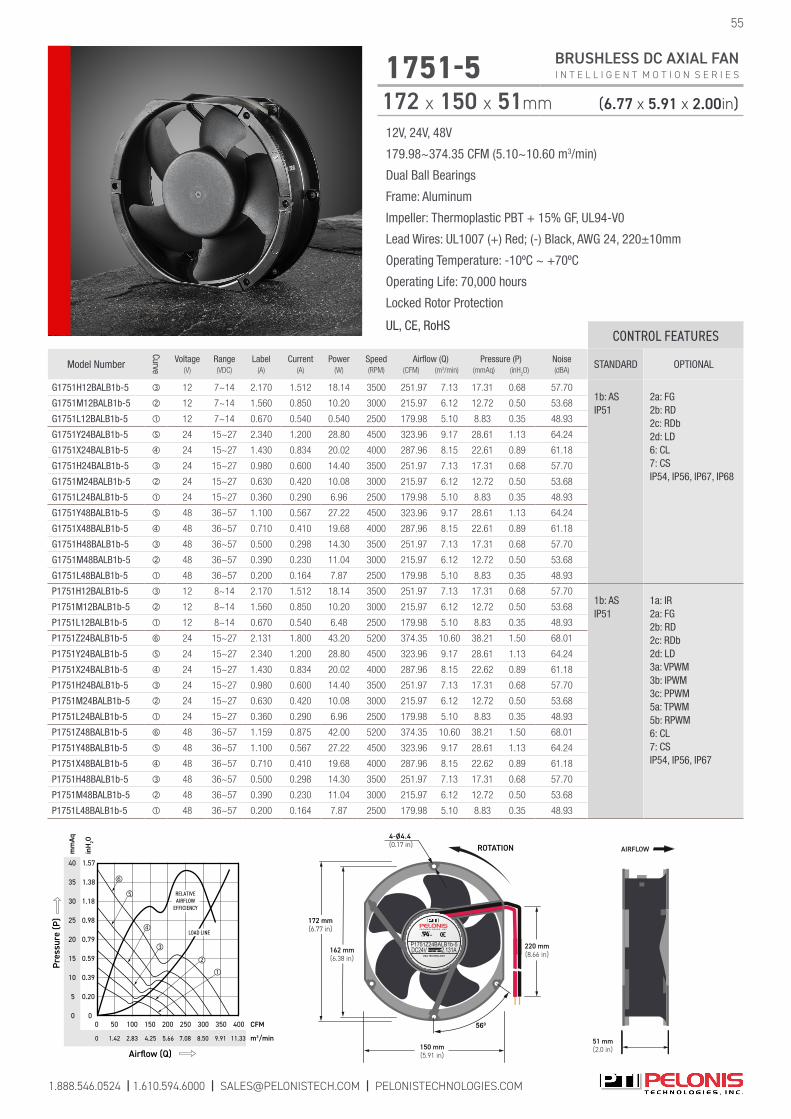
1.888.546.0524 | 1.610.594.6000 | [email protected] | PELONISTECHNOLOGIES.COM
12V, 24V, 48V
179.98~374.35 CFM (5.10~10.60 m3/min)
Dual Ball Bearings
Frame: Aluminum
Impeller: Thermoplastic PBT + 15% GF, UL94-V0
Lead Wires: UL1007 (+) Red; (-) Black, AWG 24, 220±10mm
Operating Temperature: -10ºC ~ +70ºC
Operating Life: 70,000 hours
Locked Rotor Protection
UL, CE, RoHS
1751-5 BRUSHLESS DC AXIAL FAN I N T E L L I G E N T M O T I O N S E R I E S
172 x 150 x 51mm (6.77 x 5.91 x 2.00in)
55
CONTROL FEATURES
Model Number
Curve
Voltage(V)
Range(VDC)
Label(A)
Current(A)
Power(W)
Speed(RPM)
Airflow (Q)(CFM) (m3/min)
Pressure (P)(mmAq) (inH
2O)
Noise(dBA)
STANDARD OPTIONAL
G1751H12BALB1b-5 12 7~14 2.170 1.512 18.14 3500 251.97 7.13 17.31 0.68 57.701b: AS IP51
2a: FG2b: RD 2c: RDb 2d: LD 6: CL 7: CS IP54, IP56, IP67, IP68
G1751M12BALB1b-5 12 7~14 1.560 0.850 10.20 3000 215.97 6.12 12.72 0.50 53.68
G1751L12BALB1b-5 12 7~14 0.670 0.540 0.540 2500 179.98 5.10 8.83 0.35 48.93
G1751Y24BALB1b-5 24 15~27 2.340 1.200 28.80 4500 323.96 9.17 28.61 1.13 64.24
G1751X24BALB1b-5 24 15~27 1.430 0.834 20.02 4000 287.96 8.15 22.61 0.89 61.18
G1751H24BALB1b-5 24 15~27 0.980 0.600 14.40 3500 251.97 7.13 17.31 0.68 57.70
G1751M24BALB1b-5 24 15~27 0.630 0.420 10.08 3000 215.97 6.12 12.72 0.50 53.68
G1751L24BALB1b-5 24 15~27 0.360 0.290 6.96 2500 179.98 5.10 8.83 0.35 48.93
G1751Y48BALB1b-5 48 36~57 1.100 0.567 27.22 4500 323.96 9.17 28.61 1.13 64.24
G1751X48BALB1b-5 48 36~57 0.710 0.410 19.68 4000 287.96 8.15 22.61 0.89 61.18
G1751H48BALB1b-5 48 36~57 0.500 0.298 14.30 3500 251.97 7.13 17.31 0.68 57.70
G1751M48BALB1b-5 48 36~57 0.390 0.230 11.04 3000 215.97 6.12 12.72 0.50 53.68
G1751L48BALB1b-5 48 36~57 0.200 0.164 7.87 2500 179.98 5.10 8.83 0.35 48.93
P1751H12BALB1b-5 12 8~14 2.170 1.512 18.14 3500 251.97 7.13 17.31 0.68 57.701b: AS IP51
1a: IR2a: FG 2b: RD 2c: RDb 2d: LD 3a: VPWM 3b: IPWM 3c: PPWM 5a: TPWM 5b: RPWM 6: CL 7: CS IP54, IP56, IP67
P1751M12BALB1b-5 12 8~14 1.560 0.850 10.20 3000 215.97 6.12 12.72 0.50 53.68
P1751L12BALB1b-5 12 8~14 0.670 0.540 6.48 2500 179.98 5.10 8.83 0.35 48.93
P1751Z24BALB1b-5 24 15~27 2.131 1.800 43.20 5200 374.35 10.60 38.21 1.50 68.01
P1751Y24BALB1b-5 24 15~27 2.340 1.200 28.80 4500 323.96 9.17 28.61 1.13 64.24
P1751X24BALB1b-5 24 15~27 1.430 0.834 20.02 4000 287.96 8.15 22.62 0.89 61.18
P1751H24BALB1b-5 24 15~27 0.980 0.600 14.40 3500 251.97 7.13 17.31 0.68 57.70
P1751M24BALB1b-5 24 15~27 0.630 0.420 10.08 3000 215.97 6.12 12.72 0.50 53.68
P1751L24BALB1b-5 24 15~27 0.360 0.290 6.96 2500 179.98 5.10 8.83 0.35 48.93
P1751Z48BALB1b-5 48 36~57 1.159 0.875 42.00 5200 374.35 10.60 38.21 1.50 68.01
P1751Y48BALB1b-5 48 36~57 1.100 0.567 27.22 4500 323.96 9.17 28.61 1.13 64.24
P1751X48BALB1b-5 48 36~57 0.710 0.410 19.68 4000 287.96 8.15 22.62 0.89 61.18
P1751H48BALB1b-5 48 36~57 0.500 0.298 14.30 3500 251.97 7.13 17.31 0.68 57.70
P1751M48BALB1b-5 48 36~57 0.390 0.230 11.04 3000 215.97 6.12 12.72 0.50 53.68
P1751L48BALB1b-5 48 36~57 0.200 0.164 7.87 2500 179.98 5.10 8.83 0.35 48.93
220 mm(8.66 in)
ROTATION
162 mm(6.38 in)
172 mm(6.77 in)
560
150 mm(5.91 in)
c US
USA TECHNOLOGY
P1751Z24BALB1b-5DC24V 2.131A
4-Ø4.4(0.17 in)
51 mm(2.0 in)
AIRFLOW
35
10
0
1.38
1.18
0.20
0
mm
Aq
m3/min
inH
2O
Airflow (Q)
CFM
0
300
8.50 11.335.66
0
Pres
sure
(P)
150 350
9.91
400
30
5
0.59
0.79
2.83
250
15
0.98
20
25
0.39
40 1.57
4.25
100
1.42
20050
7.08
LOAD LINE
RELATIVEAIRFLOW
EFFICIENCY
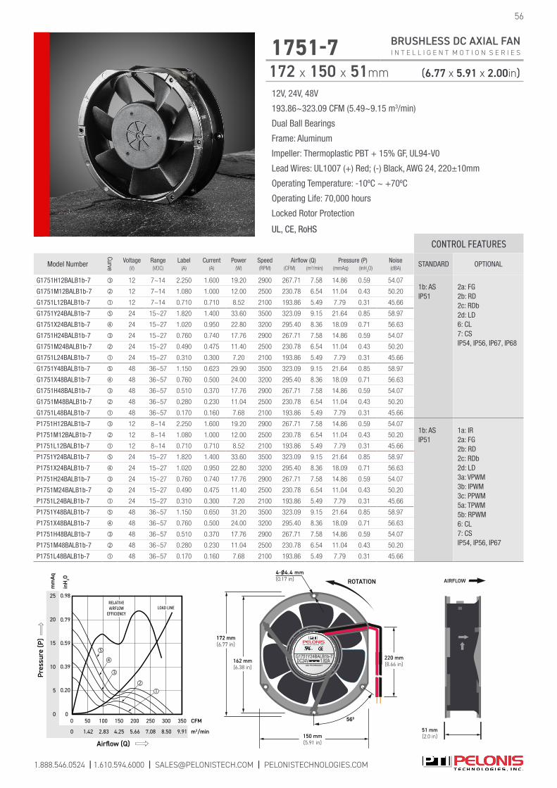
1.888.546.0524 | 1.610.594.6000 | [email protected] | PELONISTECHNOLOGIES.COM
12V, 24V, 48V
193.86~323.09 CFM (5.49~9.15 m3/min)
Dual Ball Bearings
Frame: Aluminum
Impeller: Thermoplastic PBT + 15% GF, UL94-V0
Lead Wires: UL1007 (+) Red; (-) Black, AWG 24, 220±10mm
Operating Temperature: -10ºC ~ +70ºC
Operating Life: 70,000 hours
Locked Rotor Protection
UL, CE, RoHS
1751-7 BRUSHLESS DC AXIAL FAN I N T E L L I G E N T M O T I O N S E R I E S
172 x 150 x 51mm (6.77 x 5.91 x 2.00in)
56
CONTROL FEATURES
Model Number
Curve
Voltage(V)
Range(VDC)
Label(A)
Current(A)
Power(W)
Speed(RPM)
Airflow (Q)(CFM) (m3/min)
Pressure (P)(mmAq) (inH
2O)
Noise(dBA)
STANDARD OPTIONAL
G1751H12BALB1b-7 12 7~14 2.250 1.600 19.20 2900 267.71 7.58 14.86 0.59 54.071b: AS IP51
2a: FG2b: RD 2c: RDb2d: LD 6: CL 7: CS IP54, IP56, IP67, IP68
G1751M12BALB1b-7 12 7~14 1.080 1.000 12.00 2500 230.78 6.54 11.04 0.43 50.20
G1751L12BALB1b-7 12 7~14 0.710 0.710 8.52 2100 193.86 5.49 7.79 0.31 45.66
G1751Y24BALB1b-7 24 15~27 1.820 1.400 33.60 3500 323.09 9.15 21.64 0.85 58.97
G1751X24BALB1b-7 24 15~27 1.020 0.950 22.80 3200 295.40 8.36 18.09 0.71 56.63
G1751H24BALB1b-7 24 15~27 0.760 0.740 17.76 2900 267.71 7.58 14.86 0.59 54.07
G1751M24BALB1b-7 24 15~27 0.490 0.475 11.40 2500 230.78 6.54 11.04 0.43 50.20
G1751L24BALB1b-7 24 15~27 0.310 0.300 7.20 2100 193.86 5.49 7.79 0.31 45.66
G1751Y48BALB1b-7 48 36~57 1.150 0.623 29.90 3500 323.09 9.15 21.64 0.85 58.97
G1751X48BALB1b-7 48 36~57 0.760 0.500 24.00 3200 295.40 8.36 18.09 0.71 56.63
G1751H48BALB1b-7 48 36~57 0.510 0.370 17.76 2900 267.71 7.58 14.86 0.59 54.07
G1751M48BALB1b-7 48 36~57 0.280 0.230 11.04 2500 230.78 6.54 11.04 0.43 50.20
G1751L48BALB1b-7 48 36~57 0.170 0.160 7.68 2100 193.86 5.49 7.79 0.31 45.66
P1751H12BALB1b-7 12 8~14 2.250 1.600 19.20 2900 267.71 7.58 14.86 0.59 54.071b: AS IP51
1a: IR2a: FG2b: RD 2c: RDb2d: LD 3a: VPWM 3b: IPWM 3c: PPWM 5a: TPWM 5b: RPWM 6: CL 7: CS IP54, IP56, IP67
P1751M12BALB1b-7 12 8~14 1.080 1.000 12.00 2500 230.78 6.54 11.04 0.43 50.20
P1751L12BALB1b-7 12 8~14 0.710 0.710 8.52 2100 193.86 5.49 7.79 0.31 45.66
P1751Y24BALB1b-7 24 15~27 1.820 1.400 33.60 3500 323.09 9.15 21.64 0.85 58.97
P1751X24BALB1b-7 24 15~27 1.020 0.950 22.80 3200 295.40 8.36 18.09 0.71 56.63
P1751H24BALB1b-7 24 15~27 0.760 0.740 17.76 2900 267.71 7.58 14.86 0.59 54.07
P1751M24BALB1b-7 24 15~27 0.490 0.475 11.40 2500 230.78 6.54 11.04 0.43 50.20
P1751L24BALB1b-7 24 15~27 0.310 0.300 7.20 2100 193.86 5.49 7.79 0.31 45.66
P1751Y48BALB1b-7 48 36~57 1.150 0.650 31.20 3500 323.09 9.15 21.64 0.85 58.97
P1751X48BALB1b-7 48 36~57 0.760 0.500 24.00 3200 295.40 8.36 18.09 0.71 56.63
P1751H48BALB1b-7 48 36~57 0.510 0.370 17.76 2900 267.71 7.58 14.86 0.59 54.07
P1751M48BALB1b-7 48 36~57 0.280 0.230 11.04 2500 230.78 6.54 11.04 0.43 50.20
P1751L48BALB1b-7 48 36~57 0.170 0.160 7.68 2100 193.86 5.49 7.79 0.31 45.66
220 mm(8.66 in)
ROTATION
162 mm(6.38 in)
172 mm(6.77 in)
560
150 mm(5.91 in)
c US
USA TECHNOLOGY
G1751Y24BALB1b-7DC24V 1.82A
4-Ø4.4 mm(0.17 in)
51 mm(2.0 in)
AIRFLOW
10
0 0
mm
Aq
m3/min
inH
2O
Airflow (Q)
CFM3000
Pres
sure
(P)
150 350
5
250
15
20
25
100 20050
LOAD LINERELATIVEAIRFLOW
EFFICIENCY
0 8.505.66 9.912.83 4.251.42 7.08
0.20
0.59
0.79
0.98
0.39

1a IR INRUSH CURRENT PROTECTION OPTIONAL CONTROL FEATUREWith the Inrush Current Protection (IR) Control, when the power switch is turned on to supply current to the fan, the current is zero and starts to increase gradually until the fan has achieved its maximum speed at the rated current. The maximum current at startup is equal to the free-running current (or less when the rotor stays locked at startup). The fan will achieve the rated speed within 10 seconds. This built-in Control contains no external wire. End Result Benefit: Protects from Current surges.
I(A)
Rated Current
t10 sect0
1b AS AUTO RESTART STANDARD CONTROL FEATUREThe Auto Restart (AS) Control feature ensures that the fan will automatically restart if the blade is blocked and then released. When the rotor is locked, the fan current is reduced to zero and the fan tries to restart every 5 seconds. This is a built-in Control with no external wire. End Result Benefit: Protects automatically if the blade gets blocked.
2a FG TACHOMETER (FREQUENCY GENERATOR) OPTIONAL CONTROL FEATUREThe Frequency Generator (FG) Control is an open collector output type. It provides a square wave signal if the open collector is connected to a “PULL UP” resistor and is powered by the power supply voltage which is compatible with the input of the reading device (such as TTL input of the computer etc.). The maximum collector voltage may be up to 72V DC and the maximum collector current is 10mA. The reading device’s power supply must have the same ground potential as the fan. The FG Control is an external YELLOW wire. End Result Benefit: Monitors the fan's running speed.
FREERUNNING
t
4 sec4 sec 1 sec
LOCKED ROTOR
RatedCurrent
Rated Current
I = < 2x
I(A)
FGSignal
Vcc
0.5V
FAN RUNNING FAN STOPPEDt
FGSignal
Vcc
0.5V
FAN RUNNING FAN STOPPEDt
OPEN COLLECTOR OUTPUT
V+ (FAN POWER SUPPLY)
USER’S Supply = 72V max
READING DEVICEINPUT
VccRx Vcc
Imax=10mA Rx
Vc External RFG/RD/RDb/LD
NPNQ1FAN
1.888.546.0524 | 1.610.594.6000 | [email protected] | PELONISTECHNOLOGIES.COM 57
I N T E L L I G E N T M O T I O N C O N T R O L S

2b RD ROTATION DETECTION OPTIONAL CONTROL FEATUREThe Rotation Detection (RD) Control is an open collector type. It contains the same hardware as the Frequency Generator Control 2a. The output signal is LOW when the fan is rotating and is set HIGH when the fan is stopped or is powered OFF. The RD Control is an external GRAY wire. End Result Benefit: Indicates if the blade is rotating (LOW signal).
2c RDb ROTATION DETECTION COMPLEMENT OPTIONAL CONTROL FEATUREThe Rotation Detector Complement (RDb) Control is an open collector type with the same hardware as the Frequency Generator Control 2a. The output signal is HIGH when the fan is rotating and is set LOW when the fan is stopped or is powered OFF. This output can be connected in parallel to the RDb of an array of fans that ends at a single alarm device to warn when any fan has stopped (see the Multi-Fan Alarm Connection on page 63). The RDb Control is an external VIOLET wire. End Result Benefit: Indicates if the blade is rotating (HIGH signal).
RDbSignal
Vcc RDb Signal
0.5V
RUNNING RUNNINGSTOPPEDt
2d LD LIFE DETECTION OPTIONAL CONTROL FEATUREThe Life Detection (LD) Control is an open collector type with the same hardware as the Frequency Generator Control 2a. The output signal is HIGH when the fan is rotating normally and it is LOW when the fan is turning below 70% of its rated target speed. Slow rotation may indicate aging or wear of the fan or reduced power supply voltage. The LD Control is a BROWN external wire.End Result Benefit: Indicates if the blade is rotating (HIGH signal).
RPM
100%RPM
70%RPM
LDSignal
< 0.5Vt
Vcc
2e LDb LIFE DETECTION COMPLEMENT OPTIONAL CONTROL FEATURE
This function is the complement of the LD Control applied in one fan.End Result Benefit: Indicates if the blade is rotating (LOW signal).
RDSignal
Vcc RD Signal
0.5V
RUNNING RUNNINGSTOPPEDt
1.888.546.0524 | 1.610.594.6000 | [email protected] | PELONISTECHNOLOGIES.COM 58
I N T E L L I G E N T M O T I O N C O N T R O L S

* Select from Mode A, Mode B, or Mode C, or specify required function.
3a VPWM DC VOLTAGE SIGNAL CONTROL OPTIONAL CONTROL FEATUREThe DC Voltage Signal (VPWM) Control adjusts the speed when applying an external DC Voltage signal. This voltage input “Vin” may have any value from 1V to 20V (standard value is 1V to 5V). The blower speed will vary linearly and is proportional to the % change of the “Vin” value, corresponding to the same % change of the maximum speed.
The Constant Speed (CS), Inrush Current Protection (IR), and Current Limit (CL) controls are included. The part number is followed by additional identification entry such as V 1 5 20 100 C 500: This means the fan speed will be 1,000 RPM (20%) at 1V and 5,000 RPM (100%) at 5V. The fan will maintain the minimum speed if Vin < 1V and it will stop if Vin < 0.5V (Mode “C” operation). The maximum fan speed is 5,000 RPM, and the stop point is typically set at 20% of the maximum. The VPWM Control is an external WHITE wire. (See Mode A, B, C) Slope: 1,000 RPM/Volt. End Result Benefit: Controls speed via an external DC voltage signal.
3b IPWM CURRENT SOURCE SIGNAL CONTROL OPTIONAL CONTROL FEATUREThe Current Source Signal (IPWM) Control adjusts the speed by applying an external Current Source Signal. This current input “Iin” may have any value from 4 mA to 50 mA, (standard value is 4 to 20mA). The fan speed will vary linearly and is proportional to the % change of the Iin value, corresponding to the same % change of the maximum speed.
The Constant Speed (CS), Inrush Current Protection (IR), and Current Limit (CL) controls are included. The part number is followed by additional identification entry such as I 4 20 20 100 A 500. This means that the fan speed will be 1,000 RPM (20%) at 4mA and 5,000 RPM (100%) at 20mA. The fan will maintain the minimum speed if Iin < 4mA (Mode “A” operation). The maximum fan speed is 5,000 RPM. The IPWM Control is an external WHITE wire. (See Mode A, B, C) Slope: 266 RPM/mA. End Result Benefit: Controls speed via an external Current source signal.
1 2 3 4 5 6 1 2 3 4 5 6 0
Mode A Mode B Mode C
1 2 3 4 5 6 0
VPWM-pos-slope 2008/7/16RPM: 882 to 5000Vs: 1.8 to 10 VoltsVPWM 1.8 10 18 100 A 500MODE: TYPE- A change @: -0.2 VST 12% 1.65 D 0.2 F 2 C
VPWM-pos-slope 2008/7/16RPM: 882 to 5000Vs: 1.8 to 10 VoltsMODE: TYPE- B change @: 1.78 VVPWM 1.8 10 18 100 B 500ST 12% 1.65 D 0.2 F 2 C
VPWM-pos-slope 2008/7/16RPM: 882 to 5000Vs: 1.8 to 10 VoltsVPWM 1.8 10 18 100 C 500MODE: TYPE- C change @: 0.8 VST 12% 1.65 D 0.2 F 2 C
RED (+)
WHITE
BLACK (-)Vpwm (0~5VDC)
VPWM Wiring Diagram
Vin (Volts) Vin (Volts)Vin (Volts)
6000
5000
4000
3000
2000
1000
0
6000
5000
4000
3000
2000
1000
0
6000
5000
4000
3000
2000
1000
00
RPM
RPM
RPM
FAN
* Select from Mode A, Mode B, or Mode C, or specify required function.
RED (+)
WHITE
BLACK (-)Iin (4~20mA)
IPWMRPM: 1000 ~ 5000I in: 4.0 ~ 20.0mAMODE: TYPE-A Stop @: 0.0mAIPWM 4 20 20 100 A 500
IPWM Wiring Diagram
IPWMRPM: 1000 ~ 5000I in: 4.0 ~ 20.0mAMODE: TYPE-B Stop @: 4.0mAIPWM 4 20 20 100 B 500
IPWMRPM: 1000 ~ 5000I in: 4.0 ~ 20.0mAMODE: TYPE-C Stop @: 1.96mAIPWM 4 20 20 100 C 500
I in (mA) I in (mA)I in (mA)
Mode A Mode B Mode C
6000
5000
4000
3000
2000
1000
0
6000
5000
4000
3000
2000
1000
0
6000
5000
4000
3000
2000
1000
05 10 15 20 250 5 10 15 20 250 5 10 15 20 250
RPM
RPM
RPM
FAN
1.888.546.0524 | 1.610.594.6000 | [email protected] | PELONISTECHNOLOGIES.COM 59
I N T E L L I G E N T M O T I O N C O N T R O L S

3c PPWM PULSE WIDTH MODULATION SIGNAL CONTROL OPTIONAL CONTROL FEATUREThe Pulse Width Modulation Signal (PPWM) Control adjusts the speed by applying a pulse width modulated signal. The frequency may be in the range of 30 Hz to 30 KHz. The maximum pulse height “HIGH” may be from 3V to 10V. The maximum pulse height “LOW” is 0.4V. The fan speed will vary linearly and is proportional to the % change of the Duty Cycle value, corresponding to the same % change of the maximum speed.
The Constant Speed (CS), Inrush Current Protection (IR), and Current Limit (CL) controls are included. The part number is followed by additional identification entry such as P 25 80 25 80 C 393 Cs320. This means that the fan speed will be 1,000 RPM (25%) at 25% Duty Cycle and 3,200 RPM (80%) at 80% Duty Cycle. Furthermore, the fan will maintain the minimum speed if the Duty Cycle is less than 25% (Mode “A” operation). The maximum possible fan speed is 4,000 RPM. (See Mode A, B, C) Slope: 36.4 RPM/%P-WM. End Result Benefit: Controls speed by applying a PWM signal 30Hz to 30KHz.
Mode A Mode B Mode C
%PPWM %PPWM%PPWM
PPWM-pos-slope 2008/7/15RPM: 988 to 3200%PPWM 24.7% to 80.0%MODE: TYPE- A change @: -2.0%PPWM 24.8 80 25 80 A 320 CN-010-012ST 12% 1.65 D 0.2 F 2 C - CN-010-012
PPWM-pos-slope 2008/7/15RPM: 988 to 3200%PPWM 24.7% to 80.0%MODE: TYPE- B change @: 25.0%PPWM 24.8 80 25 80 B 320 CN-010-012ST 12% 1.65 D 0.2 F 2 C - CN-010-012
PPWM-pos-slope 2008/7/15RPM: 988 to 3200%PPWM 24.7% to 80.0%MODE: TYPE- C change @: 10.0%PPWM 24.8 80 25 80 C 320 CN-010-012ST 12% 1.65 D 0.2 F 2 C - CN-010-012
RED (+)
BLUE (PWM)
BLACK (-)
Pulse LOW < 0.4VDC
PPWM Wiring Diagram
Pulse HIGH (3~10VDC)
fpwm (30Hz~30KHz)
3000
3500
1500
2000
2500
0
500
1000
3000
3500
1500
2000
2500
0
500
1000
3000
3500
1500
2000
2500
0
500
1000
0% 10% 20% 30% 40% 50% 60% 70% 80% 90% 100% 0% 10% 20% 30% 40% 50% 60% 70% 80% 90% 100% 0% 10% 20% 30% 40% 50% 60% 70% 80% 90% 100%
RPM
RPM
RPM
FAN
* Select from Mode A, Mode B, or Mode C, or specify required function.
1.888.546.0524 | 1.610.594.6000 | [email protected] | PELONISTECHNOLOGIES.COM 60
I N T E L L I G E N T M O T I O N C O N T R O L S

* Select from Mode A, Mode B, or Mode C, or specify required function.
4 OV OVER VOLTAGE PROTECTION OPTIONAL CONTROL FEATUREThis Over-Voltage Protection (OV) Control detects the power supply voltage and allows operation up to the rated maximum operating voltage. Typically, the maximum operating voltage is 20% over the specified rated voltage (unless otherwise specified).
If the power supply voltage increases over the 20% limit, the fan will stop running and the power supply current will be reduced to essentially zero. The maximum over-voltage protection range is twice the value of the rated voltage. For example, if the rated voltage is 24V, the maximum voltage that can be applied accidentally is 48V. The same applies to a 12V blower; the maximum applied over-voltage is 24V. The OV Control comes built-in with no external wire. End Result Benefit: Protects from power supply over-voltage.
5a TPWM AUTOMATIC TEMPERATURE CONTROL OPTIONAL CONTROL FEATUREWhen the Automatic Temperature (TPWM) Control is applied, the upper and lower temperatures may be selected as well as the choice of maintaining the minimum RPM below the minimum temperature chosen. The Constant Speed (CS), Inrush Current Protection (IR), and Current Limit (CL) controls are included.
The NTC thermistor is a 104J (100K @ 25 °C) type and is included with the fan (either “built-in” or external). The part number is followed by additional identification entry such as T 16 40 20 100 A 500. This means that the fan speed will be 1,000 RPM (20%) at 16 °C and 5,000 RPM (100%) at 40 °C. The fan will maintain the minimum speed of 1,000 RPM below the temperature of 16 °C (Mode “A” operation). For safety reasons, if the NTC thermistor is OPEN or SHORTED, the fan will run at its maximum speed. The TPWM Control is an external GREEN wire. Mode A, B, and C show the three available modes of control. End Result Benefit: Controls speed automatically via a temperature sensor.
RPM
RatedRPM
20V 48V (Rated Voltage) 72V Vsupply
OVFUNCTION
@72V
Mode A Mode B Mode C
Temperature (Degrees C) Temperature (Degrees C)Temperature (Degrees C)
TPWM (ntc to GND) 07/16/08RPM: 1000 to 5000MODE: ATPWM (ntc to GND) 15 40 20 100 A 500Temp.(°C) 15.0 to 40.0ST 6% 1.65 D 0.2 F 1 A - CN-010-021
TPWM (ntc to GND) 07/16/08RPM: 1000 to 5000MODE: BTPWM (ntc to GND) 15 40 20 100 B 500Temp.(°C) 15.0 to 40.0ST 6% 1.65 D 0.2 F 1 A - CN-010-021
TPWM (ntc to GND) 07/16/08RPM: 1000 to 5000MODE: C Stop @: 5 °CTPWM (ntc to GND) 15 40 20 100 C 500Temp.(°C) 15.0 to 40.0ST 6% 1.65 D 0.2 F 1 A - CN-010-021
RED (+)GREEN
BLACK (-)
NTC Thermistor(internal or external)
TPWM Wiring Diagram
6000
5000
4000
3000
2000
1000
0
7000
20 25 30 35 40 45 50151050
6000
5000
4000
3000
2000
1000
0
7000
20 25 30 35 40 45 50151050
6000
5000
4000
3000
2000
1000
0
7000
RPM
RPM
RPM
20 25 30 35 40 45 50151050
FAN
1.888.546.0524 | 1.610.594.6000 | [email protected] | PELONISTECHNOLOGIES.COM 61
I N T E L L I G E N T M O T I O N C O N T R O L S
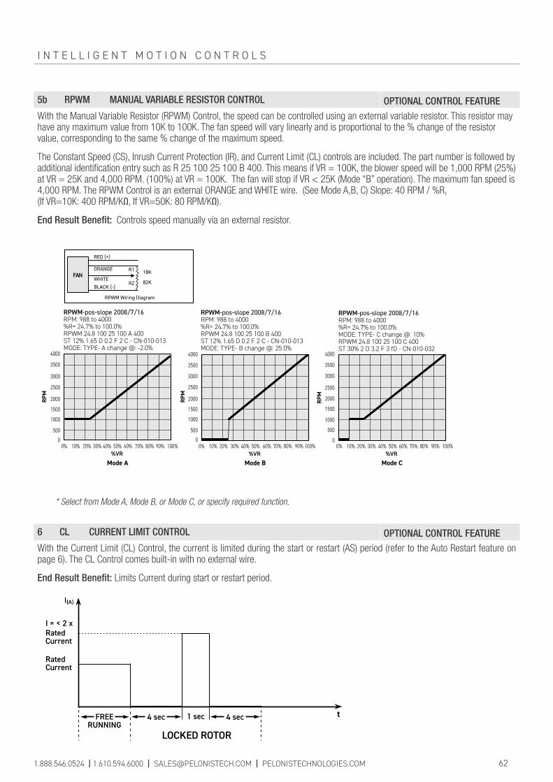
5b RPWM MANUAL VARIABLE RESISTOR CONTROL OPTIONAL CONTROL FEATUREWith the Manual Variable Resistor (RPWM) Control, the speed can be controlled using an external variable resistor. This resistor may have any maximum value from 10K to 100K. The fan speed will vary linearly and is proportional to the % change of the resistor value, corresponding to the same % change of the maximum speed.
The Constant Speed (CS), Inrush Current Protection (IR), and Current Limit (CL) controls are included. The part number is followed by additional identification entry such as R 25 100 25 100 B 400. This means if VR = 100K, the blower speed will be 1,000 RPM (25%) at VR = 25K and 4,000 RPM. (100%) at VR = 100K. The fan will stop if VR < 25K (Mode “B” operation). The maximum fan speed is 4,000 RPM. The RPWM Control is an external ORANGE and WHITE wire. (See Mode A,B, C) Slope: 40 RPM / %R, (If VR=10K: 400 RPM/KΩ, If VR=50K: 80 RPM/KΩ).
End Result Benefit: Controls speed manually via an external resistor.
* Select from Mode A, Mode B, or Mode C, or specify required function.
6 CL CURRENT LIMIT CONTROL OPTIONAL CONTROL FEATUREWith the Current Limit (CL) Control, the current is limited during the start or restart (AS) period (refer to the Auto Restart feature on page 6). The CL Control comes built-in with no external wire.
End Result Benefit: Limits Current during start or restart period.
RatedCurrent
Rated Current
I = < 2 x
LOCKED ROTOR
4 sec 1 sec t
FREE
RUNNING4 sec
Mode A Mode B Mode C%VR %VR%VR
RED (+)
WHITE
BLACK (-)
18K
RPWM Wiring Diagram
82K
RPWM-pos-slope 2008/7/16RPM: 988 to 4000%R= 24.7% to 100.0%RPWM 24.8 100 25 100 A 400ST 12% 1.65 D 0.2 F 2 C - CN-010-013MODE: TYPE- A change @: -2.0%
RPWM-pos-slope 2008/7/16RPM: 988 to 4000%R= 24.7% to 100.0%RPWM 24.8 100 25 100 B 400ST 12% 1.65 D 0.2 F 2 C - CN-010-013MODE: TYPE- B change @: 25.0%
RPWM-pos-slope 2008/7/16RPM: 988 to 4000%R= 24.7% to 100.0%MODE: TYPE- C change @: 10%RPWM 24.8 100 25 100 C 400ST 30% 2 D 3.2 F 3 fD - CN-010-032
R1
R2
3000
3500
4000
1500
2000
2500
0
500
1000
3000
3500
4000
1500
2000
2500
0
500
1000
3000
3500
4000
1500
2000
2500
0
500
1000
0% 10% 20% 30% 40% 50% 60% 70% 80% 90% 100% 0% 10% 20% 30% 40% 50% 60% 70% 80% 90% 100% 0% 10% 20% 30% 40% 50% 60% 70% 80% 90% 100%
ORANGE
RPM
RPM
RPM
FAN
1.888.546.0524 | 1.610.594.6000 | [email protected] | PELONISTECHNOLOGIES.COM 62
I N T E L L I G E N T M O T I O N C O N T R O L S
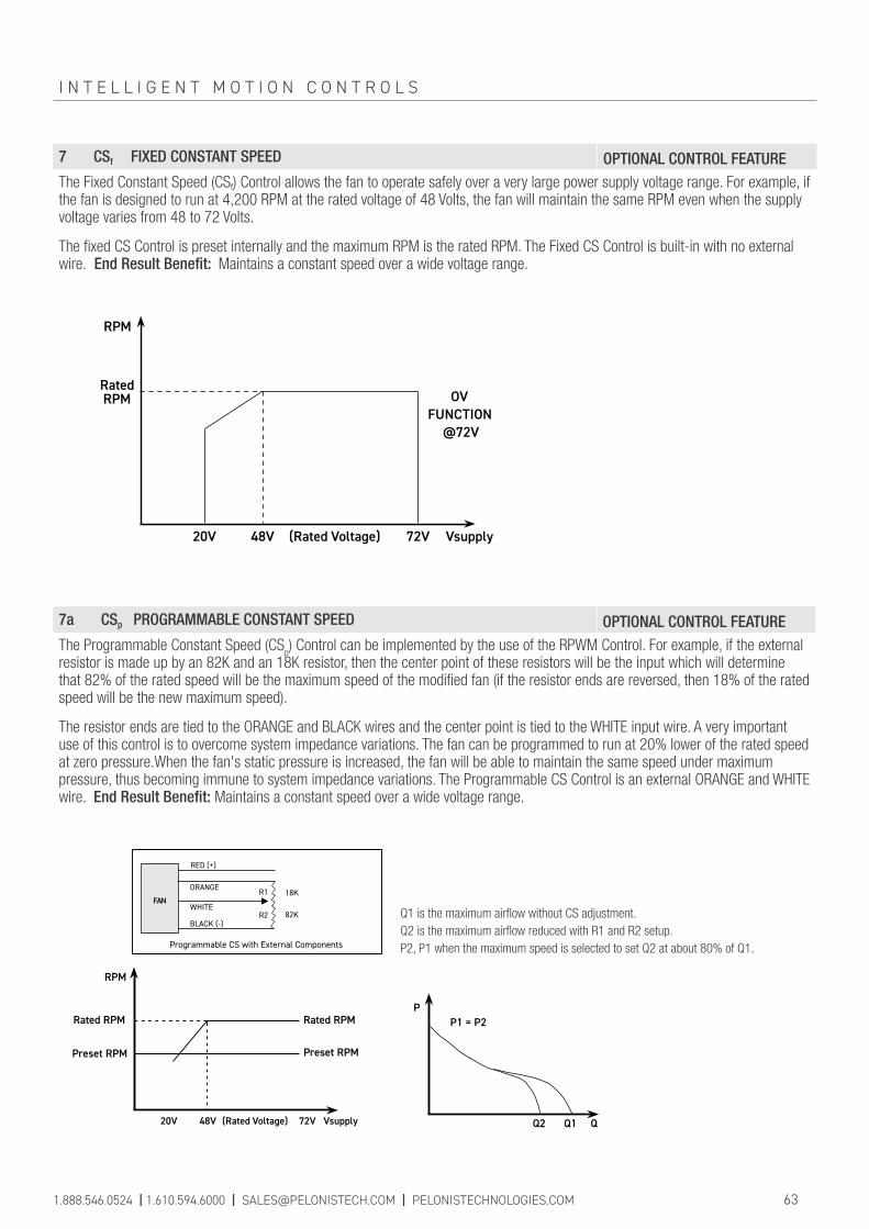
7 CSf FIXED CONSTANT SPEED OPTIONAL CONTROL FEATUREThe Fixed Constant Speed (CSf) Control allows the fan to operate safely over a very large power supply voltage range. For example, if the fan is designed to run at 4,200 RPM at the rated voltage of 48 Volts, the fan will maintain the same RPM even when the supply voltage varies from 48 to 72 Volts.
The fixed CS Control is preset internally and the maximum RPM is the rated RPM. The Fixed CS Control is built-in with no external wire. End Result Benefit: Maintains a constant speed over a wide voltage range.
RPM
RatedRPM
20V 48V (Rated Voltage) 72V Vsupply
OVFUNCTION
@72V
7a CSp PROGRAMMABLE CONSTANT SPEED OPTIONAL CONTROL FEATUREThe Programmable Constant Speed (CS
p) Control can be implemented by the use of the RPWM Control. For example, if the external
resistor is made up by an 82K and an 18K resistor, then the center point of these resistors will be the input which will determine that 82% of the rated speed will be the maximum speed of the modified fan (if the resistor ends are reversed, then 18% of the rated speed will be the new maximum speed).
The resistor ends are tied to the ORANGE and BLACK wires and the center point is tied to the WHITE input wire. A very important use of this control is to overcome system impedance variations. The fan can be programmed to run at 20% lower of the rated speed at zero pressure.When the fan's static pressure is increased, the fan will be able to maintain the same speed under maximum pressure, thus becoming immune to system impedance variations. The Programmable CS Control is an external ORANGE and WHITE wire. End Result Benefit: Maintains a constant speed over a wide voltage range.
PP1 = P2
QQ2 Q1
RED (+)
ORANGE
WHITE
BLACK (-)
18K
Programmable CS with External Components
R1
R2 82K
RPM
Rated RPM
Preset RPM
20V 48V (Rated Voltage) 72V Vsupply
Rated RPM
Preset RPM
FAN
Q1 is the maximum airflow without CS adjustment.Q2 is the maximum airflow reduced with R1 and R2 setup.P2, P1 when the maximum speed is selected to set Q2 at about 80% of Q1.
1.888.546.0524 | 1.610.594.6000 | [email protected] | PELONISTECHNOLOGIES.COM 63
I N T E L L I G E N T M O T I O N C O N T R O L S

MULTI-FAN ALARM CONNECTION OPTIONAL CONTROL FEATUREWhen multiple fans are used in an application, it is critical to monitor the proper running state of the fans. It is practical to have a single alarm (sound or light) that will indicate when any of the fans have stopped running.
Every fan can include the Rotation Detector Complement (RDb) Control in order to combine the multi-alarm function to a single alarm indicator. The diagram below shows how to connect the multi-alarm any number of fans of any model equipped with the RDb Control cascaded (maximum 100 fans).
NOTE: If the engineer wants to connect to a voltage higher than 35V for his alarm signal, an R2 resistor may be added. If the fans have the Life Detection (LD) Control output and one fan runs below 70% of its rated speed, the alarm will be activated.
End Result Benefit: Monitors the running state of multiple fans.
Fan #1 Fan #2 Fan #n
Vcc1 Vcc2 Vccn
RDb1 RDb2 RDbn
LEDINDICATOR
R2
R1
Vmax = 35VImax = 10mA
1.888.546.0524 | 1.610.594.6000 | [email protected] | PELONISTECHNOLOGIES.COM 64
I N T E L L I G E N T M O T I O N C O N T R O L S

IP51 (standard) : Limited protection from dust and condensation.
IP54 (optional) : Protection from dust and water spray from any direction.
IP56 (optional) : Protection from dust and high pressure water jets from any direction.
IP67 (optional) : Total protection from dust and water immersion.
IP68 (optional) : Total protection from dust and water submersion.
Ingress Protection (IP) indicates the level of protection against intrusion from dust and moisture.
1.888.546.0524 | 1.610.594.6000 | [email protected] | PELONISTECHNOLOGIES.COM 65
INGRESS PROTECTION (IP)

HOW TO MEASURE THE IMPEDANCE OF YOUR SYSTEM
The measurement of the system's impedance and the selection of the appropriate fan can be illustrated by the following example:
Let us use a series 1232 blower with the following PQ characteristics:
A. Calculate the airflow through your system by applying the blower in your system and by measuring the incoming and outgoing airflow temperatures as follows:
Where: P = Input power into your system (e.g. 1000W) T2 = Outgoing airflow temperature in °C (e.g. 59.1°C) T1 = Incoming airflow temperature in °C (e.g. 20°C) Then, calculate the test result: Airflow = 45 CFM
B. Refer to the PQ characteristic of the fan or blower to determine the static pressure of your system at the measured airflow. The pressure can be determined from the PQ graph above to be 6 mmAq, for the calculated airflow in A of 45 CFM.
C. From the temperature specifications of your equipment, calculate the temperature difference T2-T1 where: T1 is the typical room temperature (e.g. 25° C) and T2 is the maximum allowable operating temperature of the equipment (e.g. 60° C). Therefore, T2-T1= 35° C. Assuming that you are powering your system with 1000W, necessary airflow can be calculated using the formula shown in A as follows:
D. For the purposes of the example used here, the appropriate fan to be selected for this application should be able to deliver a minimum of 50.3 CFM at a minimum static pressure of 6mmAq. For safety reasons and to allow for higher room temperature, referring to the product catalog, we can select model P1232Y that can deliver 64 CFM at 6 mmAq with 4200 RPM, or model P1238X that can deliver 63 CFM at 6 mmAq with 3650 RPM. We can further consider the noise level and product life. In this case, model P1238X will be the optimum solution for the system outlined in the above example (See also "SELECTION OF A COOLING FAN" on page 1 and "AIRFLOW EFICIENCY OF A FAN MOTOR" on pages 67-69).
1.888.546.0524 | 1.610.594.6000 | [email protected] | PELONISTECHNOLOGIES.COM 66
1.76 x PT2 - T1
1.76 x 100035
= 50.3 CFM
Airflow in CFM =
Airflow in CFM =
5350
4539
31
21
10Stat
ic P
ress
ure
(mm
Aq)
Airflow (CFM)
P1232Y12BACB7b PQ Characteristics
30
50
20
10
40
60
2020 40 5010
P/Q Graph
0
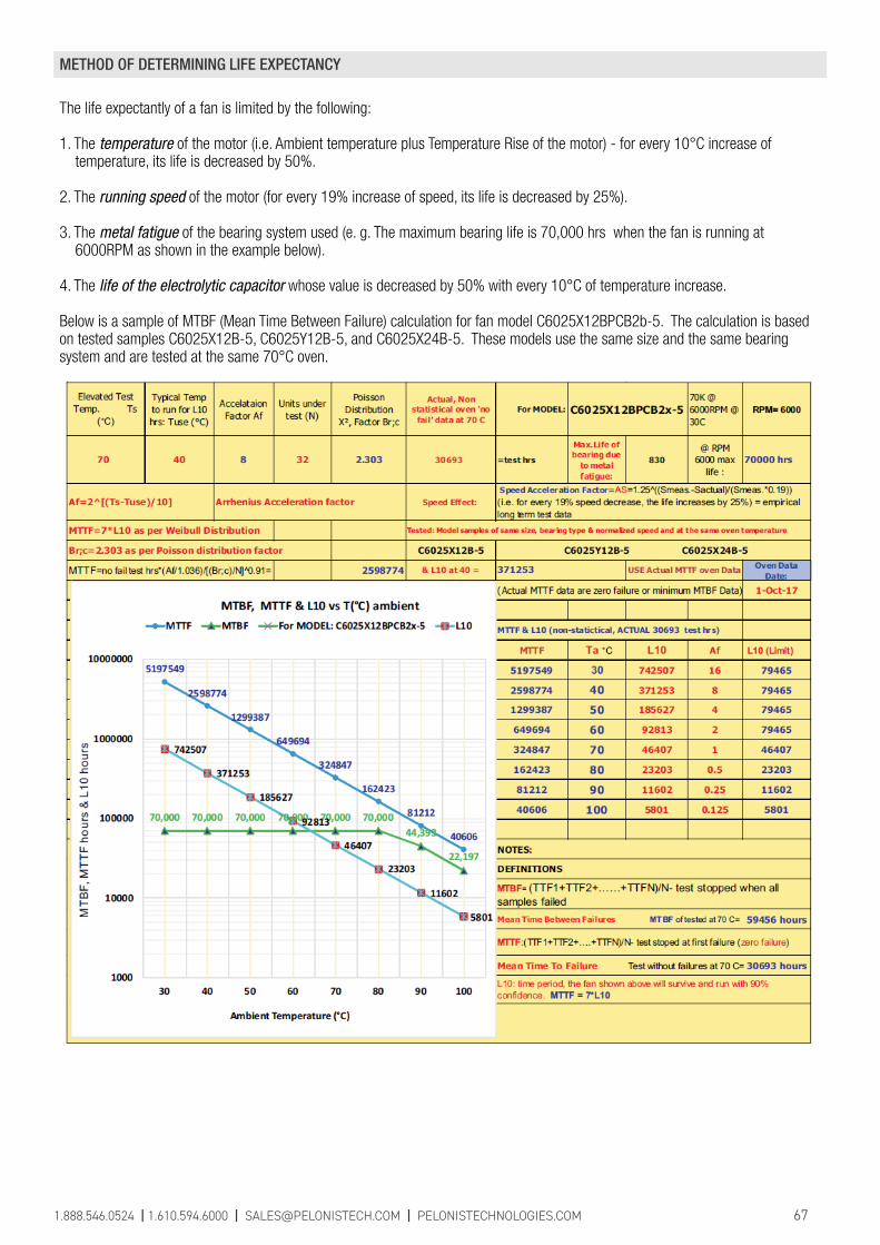
METHOD OF DETERMINING LIFE EXPECTANCY
The life expectantly of a fan is limited by the following:
1. The temperature of the motor (i.e. Ambient temperature plus Temperature Rise of the motor) - for every 10°C increase of temperature, its life is decreased by 50%.
2. The running speed of the motor (for every 19% increase of speed, its life is decreased by 25%).
3. The metal fatigue of the bearing system used (e. g. The maximum bearing life is 70,000 hrs when the fan is running at 6000RPM as shown in the example below).
4. The life of the electrolytic capacitor whose value is decreased by 50% with every 10°C of temperature increase.
Below is a sample of MTBF (Mean Time Between Failure) calculation for fan model C6025X12BPCB2b-5. The calculation is based on tested samples C6025X12B-5, C6025Y12B-5, and C6025X24B-5. These models use the same size and the same bearing system and are tested at the same 70°C oven.
1.888.546.0524 | 1.610.594.6000 | [email protected] | PELONISTECHNOLOGIES.COM 67

FAN MOTOR EFFICIENCY
The efficiency of a system is defined as η = Out Power / Input power
In the case of a motor, the incoming power in horsepower terms is expressed in electric power of watts equivalent to 746 W/hp (watts/horsepower) and the output power is in units or energy/second.
In the case of fans, the efficiency of the fan motor is measured in 2 different ways:
A. (η = P*Q / W) = (Pressure*Air Volume / Input Power) = (Output Power / Input Power) Where: P*Q is air flow power expressed in Watts if P is in Pascal (Pa), Q is the airflow in m³/sec and the Input Power is expressed in Watts.
The figure of efficiency varies according to the operating point of the fan. When there is no obstacle in the airflow (i.e. free air condition), we have the maximum airflow but the pressure presented to the airflow is zero. As a result, no actual benefit is provided and at this point the efficiency is zero. Likewise, when the airflow is totally blocked by closing the exhaust opening of the fan in which case we have the maximum pressure but zero airflow, the system's efficiency is also zero.
Below is a typical efficiency graph for fan model G1751H24B-5 indicating that the fan motor's efficiency for all the points from zero airflow-max pressure and zero pressure-max airflow.
The units of measurement are:
Pressure in Pa (Pascal) Air Volume: Q in m/second Input power is expressed in Watts [η = P*Q/W * 100%]
The above fan has peak airflow efficiency of 36.88% running at 3553 RPM and delivering 250.70 CFM. The free air, air volume of this fan is 280.1 CFM
B. (η = Pt*Q / W), where: Pt = Ps + Pd Where: Ps = Static Pressure Pd = m*V2/2 = dynamic pressure of the airflow m = density of the air in kg/m3
V = is the airvelocity through the Blow Area in m/s Blow area S in m² is the air exhaust area including the hub area. V = Q/S = Air volume / Blow area (where Air Volume Q is expressed in m / second) Therefore Pt = Ps + m*V2/2 = Ps + [m*(Q/S)2]/2
1.888.546.0524 | 1.610.594.6000 | [email protected] | PELONISTECHNOLOGIES.COM 68
Air Volume (CFM)150
Total Static PressureG1751H24B-5 (P*Q)/W
% A
irflo
w E
ffici
ency
Airflow Efficiency
25
35
20
30
5
15
0
10
40
250100 20050 300
0
7.78.1
15.0
14.5
19.7
20.0
22.0
21.3
23.1
21.0
30.8
27.0
34.7
28.3
25.2
35.8 36.4
26.4
19.5
0
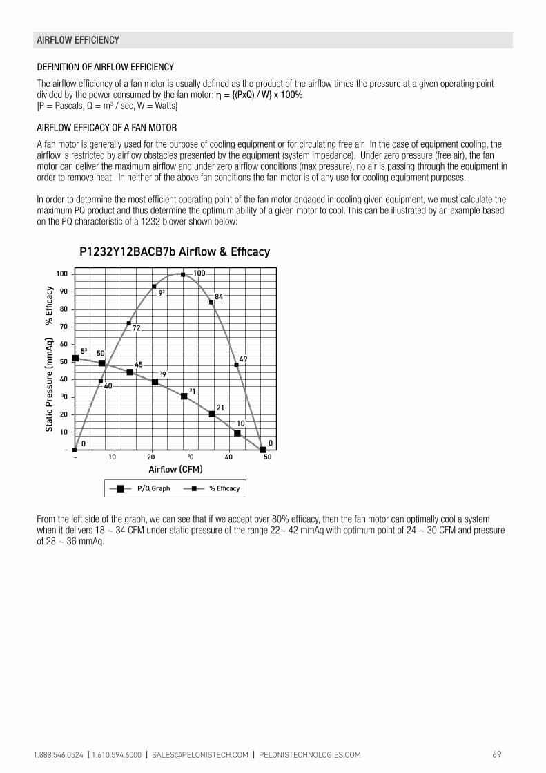
AIRFLOW EFFICIENCY
DEFINITION OF AIRFLOW EFFICIENCY
The airflow efficiency of a fan motor is usually defined as the product of the airflow times the pressure at a given operating point divided by the power consumed by the fan motor: η = {(PxQ) / W} x 100%[P = Pascals, Q = m3 / sec, W = Watts]
AIRFLOW EFFICACY OF A FAN MOTOR
A fan motor is generally used for the purpose of cooling equipment or for circulating free air. In the case of equipment cooling, the airflow is restricted by airflow obstacles presented by the equipment (system impedance). Under zero pressure (free air), the fan motor can deliver the maximum airflow and under zero airflow conditions (max pressure), no air is passing through the equipment in order to remove heat. In neither of the above fan conditions the fan motor is of any use for cooling equipment purposes.
In order to determine the most efficient operating point of the fan motor engaged in cooling given equipment, we must calculate the maximum PQ product and thus determine the optimum ability of a given motor to cool. This can be illustrated by an example based on the PQ characteristic of a 1232 blower shown below:
From the left side of the graph, we can see that if we accept over 80% efficacy, then the fan motor can optimally cool a system when it delivers 18 ~ 34 CFM under static pressure of the range 22~ 42 mmAq with optimum point of 24 ~ 30 CFM and pressure of 28 ~ 36 mmAq.
1.888.546.0524 | 1.610.594.6000 | [email protected] | PELONISTECHNOLOGIES.COM 69
Stat
ic P
ress
ure
(mm
Aq)
% E
ffica
cy
Airflow (CFM)
P/Q Graph % Efficacy
P1232Y12BACB7b Airflow & Efficacy
50
30
10
70
90
40
20
60
80
100
20 30 40 5010
100
84
0
40
5053
4539
31
21
10
0
49
93
72

AIRFLOW EFFICIENCY
THE (PQ/W) CRITERION
In general, assuming materials used for DC fan motor production by manufactures is similar, and, assuming no significant construction shortcomings which will mainly have a bearing on the product life, the most important criterion remains the product's performance during its life span.
The fan motor's performance can be visualized by its PQ graph shown below:
The higher the P and the higher the Q of a fan motor of a given size, the more airflow will be driven into the system to achieve better cooling results. However, at what cost is this accomplished? In order to appreciate the motor's performance, one must consider the product of P times Q result divided by the power that the product consumes. The lower the power dissipation for the highest possible PQ can characterize the fan motor's performance. If we were to draw a line from the maximum point of P and the maximum point of Q, we could easily determine the shaded area to be (PxQ)/2. We could then define as performance criterion the (PxQ)/W which represents twice the shaded area divided by the consumed power.
One can argue that the power dissipation at maximum Q is lower than the power dissipated at maximum P for an axial fan motor, but for comparison reasons, this point becomes of less importance. It must also be noted that in the case of a blower type fan motor at maximum P, the power consumption is less than at maximum Q point. The higher the PQ/W, the better the fan motor's performance.
THE (RPM/W) CRITERION
One other way to detect if the fan motor is properly designed and can perform under the lowest running temperature rise conditions is to check the ratio of RPM increase over the consumed power increase. As a rule, to increase the RPM by 10%, one needs to increase the power by about 30%. A well-designed fan motor will always stay below the 30% of power increase or else the motor is over driven, which will result in premature failure. To maintain this criterion, one needs to increase the silicon steel size or reduce the PQ performance of the product, or else the high running motor temperature will de rate the life of the product. Higher RPM/W means a more efficient and better designed fan motor.
WHY ARE THE (PQ/W) AND (RPM/W) CRITERIA IMPORTANT?
Both of the above mentioned criteria are important and their value should be the highest possible because:■ They indicate how good the performance is for the running power cost.■ They indicate the lowest running temperature (which is proportional to the power input), which is inversely proportional to the product life. As a rule of thumb, the product life is reduced by 1/2 for every 10°C increase of its running temperature.
1.888.546.0524 | 1.610.594.6000 | [email protected] | PELONISTECHNOLOGIES.COM 70
PQ Characteristics of a typical fan motor
PMAX
QMAX
Q
PxQ Area
P

STATIC PRESSURE CONVERSION TABLE
Pa (=N/m2) mmH2O = mmAq inH2O Kgf/cm2 bar
1 1.0197 x 10⁻¹ 4.017 x 10⁻³ 1.0197 x 10⁻⁵ 1 x 10⁻⁵
9.80665 1 3.939 x 10⁻² 1 x 10⁻⁴ 9.80665 x 10⁻⁵
1.3332 x 10² 1.3619 x 10 1 1.3595 x 10⁻³ 1.3332 x 10⁻³
9.80665 x 10⁴ 104 3.937 x 10² 1 9.80665 x 10⁻¹
1 x 10⁵ 1.0197 x 10⁴ 4.018 x 10² 1.01972 1
AIR FLOW CONVERSION TABLE
m3/min CFM L/s L/min1 3.531 x 10 1.666 x 10 1 x 10³
2.831 x 10⁻² 1 4.720 x 10⁻¹ 2.831 x 10
6 x 10⁻² 2.118 1 6 x 10
1 x 10⁻³ 3.531 x 10⁻² 1.666 x 10² 1
FAHRENHEIT/CELSIUS/KELVIN CONVERSION TABLE
Fahrenheit to Celsius Celsius to Fahrenheit Celsius to KelvinºC = (5/9) * (ºF-32) ºF = (ºC * (9/5)) + 32 K = ºC + 273.15
NOTES:
71
CONVERSION TABLES
1.888.546.0524 | 1.610.594.6000 | [email protected] | PELONISTECHNOLOGIES.COM