INSTALLATION MANUAL - HVLS Industrial Ceiling Fans ...
32
HVLS INSTALLATION MANUAL
-
Upload
khangminh22 -
Category
Documents
-
view
0 -
download
0
Transcript of INSTALLATION MANUAL - HVLS Industrial Ceiling Fans ...

HVLS
INSTALLATION MANUAL

Contents
BEFORE YOU BEGIN
AUTHENTICITY
LEGACY
INSTALLATION
REFERENCE
Safety & PrecautionsFan PlacementTools NeededIn The BoxPre-Installation Checklist
3-56-78910
11-131415161820
1921222324
Step 1: MountingStep 2: Retention SystemStep 3: Motor AssemblyStep 4: Control PanelStep 5: Guy WiresStep 6: Blades
ElectricalDaisy ChainingFire PanelMaintenanceTroubleshooting
In a world full of impersonators, be an original. We invented the ceiling fan, and we stand behind our products.
The Hunter legacy is not only about quality—it’s about longevity. We invented the ceiling fan. We build fans that last, fans that are designed as fans. We design our fans while considering each person in the process—from the installer to the owner.
!

3
BEFORE YOU BEGIN SAFETY & PRECAUTIONS
Important Safety InformationTo prevent SERIOUS INJURY, DEATH, and PROPERTY DAMAGE, you should read, understand, and follow the warnings and instructions in this manual before installing or operating the fan.
FIRE, ELECTRIC SHOCK AND CRUSH HAZARDS.TO PREVENT SERIOUS INJURY OR DEATH:
• ALWAYS mount fan directly from building structure that can withstand double the maximum hanging fan weight and install the Retention Cable.
• BEFORE installing or servicing your fan, ALWAYS disconnect the power by turning off the circuit breaker or breakers to the fan locations. If you cannot lock the circuit breakers in the off position, securely fasten a prominent warning device, such as a tag, to the electrical panel.
• All wiring must be in accordance with national and local electrical codes, including ANSI/NFPA 70. If you are unfamiliar with wiring or are in doubt, consult a qualified electrician.
• DO NOT install fan to be used in the presences of flammable vapors and gasses or in environments where combustible dust is present.
• DO NOT bend the blades or blade holders when installing or cleaning the fan.• DO NOT insert foreign objects in between rotating fan blades.
Installation, adjustment, repair, or maintenance must be performed by qualified personnel.Follow all safety practices and instructions during the installation, operation, and servicing of the fan. Failure to apply these safety practices could result in death or serious injury. If you do not understand the instructions, please call our Technical Department at 1-844-593-FANS (3267) for guidance.
Always check federal, state, and local codes before installing fan.Code compliance is the responsibility of the installer. Check all relevant codes to make sure that all product certifications, product listings, and building regulations are met.
Professional installation practice requires following local utility company guidelines for connecting to AC mains. This unit is for professional use only and is not required to comply with EN 61000-3-2:2006. This fan conforms to ANSI/UL standard 507, Electric Fans and is certified to CSA STD C22.2 No. 113, Fans & Ventilators.
READ AND SAVE THESE INSTRUCTIONS. This manual must always be kept with the fan and should remain with the fan if it is transferred or sold. Always give manual to fan owner following installation.
5007479
!

4
BEFORE YOU BEGIN SAFETY & PRECAUTIONS!
TO PREVENT SERIOUS INJURY OR DEATH:
• BEFORE installing or servicing your fan, ALWAYS disconnect the power by turning off the circuit breaker or breakers, to the fan locations and confirm Lockout/Tagout procedures are in place. If you cannot lock the circuit breakers in the off position, securely fasten a prominent warning device, such as a tag, to the electrical panel.
• All wiring must be in accordance with national and local electrical codes, including ANSI/NFPA 70. If you are unfamiliar with wiring or in doubt, consult a qualified electrician.
• Do not use an extension cord with fan.• Do not remove covers while power is on.• Do not use improper voltage source.
All fan controls and incoming power should be installed only by qualified technicians familiar with the requirements of the National Electrical Code and local codes. Failure to follow these guidelines will void the manufacturer’s warranty.
All electrical controls are configured at the factory and are ready to use. No user adjustments are available. Follow the included installation instructions when installing this device to ensure proper operation. Do not make any changes to any part of the fan without first consulting Hunter Industrial. Installation is to be in accordance with ANSI/NFPA 70: National Electrical Code and local codes.
The user is responsible for compliance with all international and National Electrical Code requirements with respect to grounding of all equipment. Many of the parts of this unit operate at line voltage.
Before installing, servicing, or cleaning the unit, switch power off at the service panel, lock the service disconnecting means, and confirm Lockout/Tagout procedures are in place to prevent power from being switched on accidentally. When the service disconnect means cannot be locked, securely fasten a prominent warning sign, such as a tag, to the service panel.
To reduce the risk of electric shock, serious injury, and death, only use this unit as intended by the manufacturer. If you have any questions, call our Technical Department at 1-844-593-FANS (3267).
ELECTRIC SHOCK HAZARD
5007479
5
Weight and Torque ConsiderationsAlways mount fan directly to building structure that can withstand approximately double (2x) the maximum hanging weight of the fan.
The maximum fan hanging weight and torque is as follows:MAXIMUM HANGING WEIGHT TORQUE
24’ Titan 212 lbs. 75 ft lbs.
24’ ECO 150 lbs. 75 ft lbs.
14’ XP 135 lbs. 75 ft lbs.
If there is any uncertainty about the potential for the building structure to withstand double the maximum hanging weight of the fan, a professional structural engineer should perform a thorough evaluation of the building prior to purchasing the fans. Hunter Industrial provides guidelines for mounting fans; however, it is the sole responsibility of the building owner and installer to ensure the safety of the mounting system and retention cable, the building structure is sound, and the installation complies with all federal, state, and local codes.
To prevent serious injury or death, ALWAYS attach the Retention Cable to the fan motor and secure to the building structure on EVERY fan.The Retention Cable, if installed per Hunter Industrial specifications, can limit the distance the fan could fall in the unlikely event of mounting system failure. Failure to install and to secure the retention cable will void your warranty.
Always use Personal Protective Equipment You should always wear Personal Protective Equipment, such as a Hard Hat, Safety Glasses, and a Fall Harness when installing industrial fans.
ServiceIf the fan does not operate properly using the procedures in this manual, remove all power to the unit and contact our Technical Department for further assistance at 1-844-593-FANS (3267).
Damaged EquipmentNever operate or install any fans or fan accessories that appear to be damaged. Failure to follow this instruction can result in death, serious injury or equipment damage.
To reduce the risk of personal injury, do not bend the blades or blade holders when installing or cleaning the fan.
Do not insert foreign objects in between rotating fan blades.
Mark the Floor to Alert PersonnelWhen mounting a fan in an area where materials could be elevated and contact the rotating fan blades, be sure to mark or rope off the area of install.
BEFORE YOU BEGIN SAFETY & PRECAUTIONS!
CRUSH HAZARD
6
BEFORE YOU BEGIN FAN PLACEMENT!
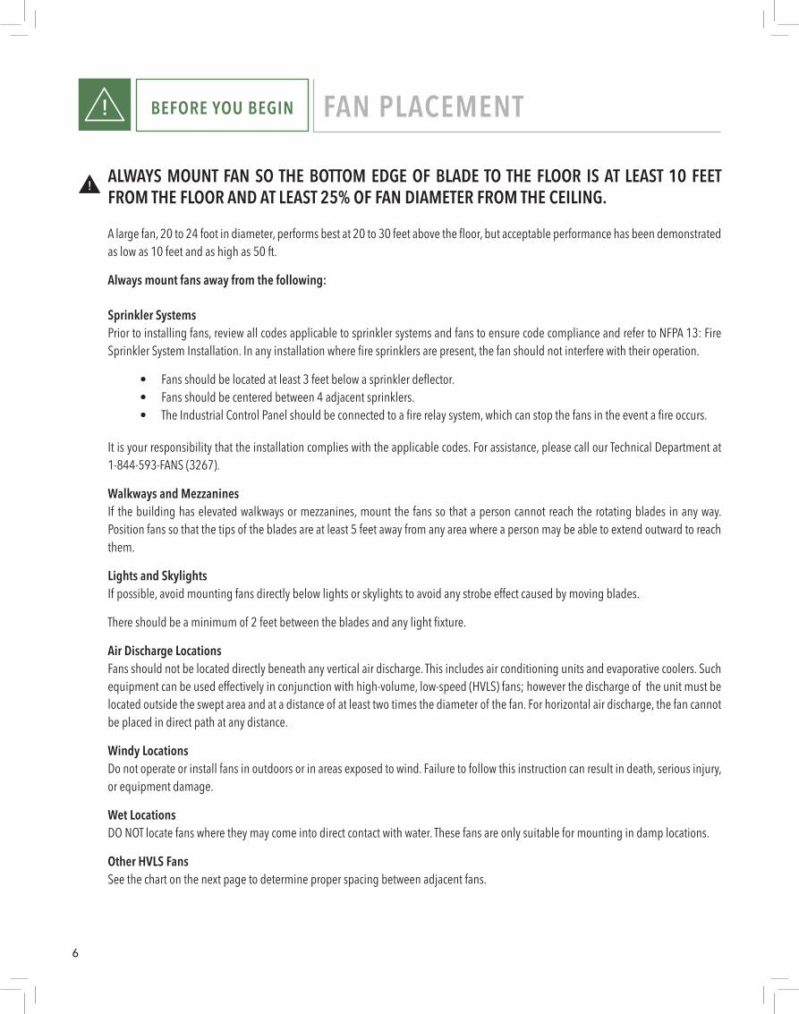
ALWAYS MOUNT FAN SO THE BOTTOM EDGE OF BLADE TO THE FLOOR IS AT LEAST 10 FEET FROM THE FLOOR AND AT LEAST 25% OF FAN DIAMETER FROM THE CEILING.
A large fan, 20 to 24 foot in diameter, performs best at 20 to 30 feet above the floor, but acceptable performance has been demonstrated as low as 10 feet and as high as 50 ft.
Always mount fans away from the following:
Sprinkler Systems Prior to installing fans, review all codes applicable to sprinkler systems and fans to ensure code compliance and refer to NFPA 13: Fire Sprinkler System Installation. In any installation where fire sprinklers are present, the fan should not interfere with their operation.
• Fans should be located at least 3 feet below a sprinkler deflector. • Fans should be centered between 4 adjacent sprinklers. • The Industrial Control Panel should be connected to a fire relay system, which can stop the fans in the event a fire occurs.
It is your responsibility that the installation complies with the applicable codes. For assistance, please call our Technical Department at 1-844-593-FANS (3267).
Walkways and Mezzanines If the building has elevated walkways or mezzanines, mount the fans so that a person cannot reach the rotating blades in any way. Position fans so that the tips of the blades are at least 5 feet away from any area where a person may be able to extend outward to reach them.
Lights and Skylights If possible, avoid mounting fans directly below lights or skylights to avoid any strobe effect caused by moving blades.
There should be a minimum of 2 feet between the blades and any light fixture.
Air Discharge LocationsFans should not be located directly beneath any vertical air discharge. This includes air conditioning units and evaporative coolers. Such equipment can be used effectively in conjunction with high-volume, low-speed (HVLS) fans; however the discharge of the unit must be located outside the swept area and at a distance of at least two times the diameter of the fan. For horizontal air discharge, the fan cannot be placed in direct path at any distance.
Windy LocationsDo not operate or install fans in outdoors or in areas exposed to wind. Failure to follow this instruction can result in death, serious injury, or equipment damage.
Wet LocationsDO NOT locate fans where they may come into direct contact with water. These fans are only suitable for mounting in damp locations.
Other HVLS FansSee the chart on the next page to determine proper spacing between adjacent fans.
7
BEFORE YOU BEGIN FAN PLACEMENT!
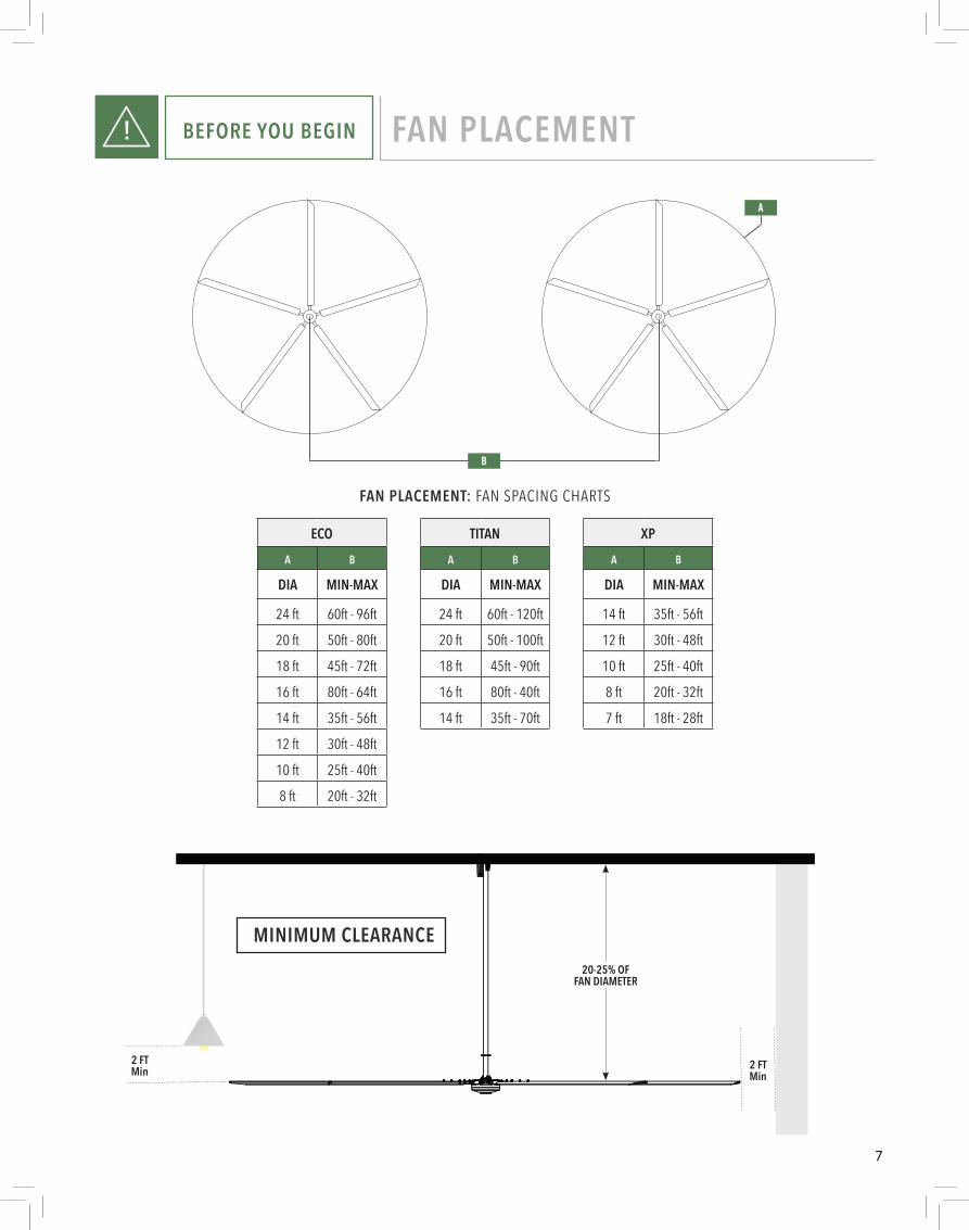
FAN PLACEMENT: FAN SPACING CHARTS
ECOA B
DIA MIN-MAX
24 ft 60ft - 96ft
20 ft 50ft - 80ft
18 ft 45ft - 72ft
16 ft 80ft - 64ft
14 ft 35ft - 56ft
12 ft 30ft - 48ft
10 ft 25ft - 40ft
8 ft 20ft - 32ft
TITANA B
DIA MIN-MAX
24 ft 60ft - 120ft
20 ft 50ft - 100ft
18 ft 45ft - 90ft
16 ft 80ft - 40ft
14 ft 35ft - 70ft
XPA B
DIA MIN-MAX
14 ft 35ft - 56ft
12 ft 30ft - 48ft
10 ft 25ft - 40ft
8 ft 20ft - 32ft
7 ft 18ft - 28ft
2 FTMin
2 FTMin
20-25% OF FAN DIAMETER
MINIMUM CLEARANCE
B
A

8
BEFORE YOU BEGIN TOOLS NEEDED!
Metric Combination Wrench Set (10mm - 19mm)
Metric (Deep & Short) Socket and Ratchet Set
Standard (Deep & Short) Socket and Ratchet Set Metric Allen Wrench Set
Metric Allen Socket Set
Tape Measure
Magnetic Level (Magnetic post level recommended)
Torque Wrench
Wire Rope Cutters (optional)
Phillips and Flat Head Screwdrivers
#10 to #14 AWG Strippers (optional)
Multimeter (optional)
Cat5 Termination Tools (optional)
Cat5 Tester (recommended)
9
a)
c)
b)
a)
c)
b)
a)
e)
c) d)a) b)
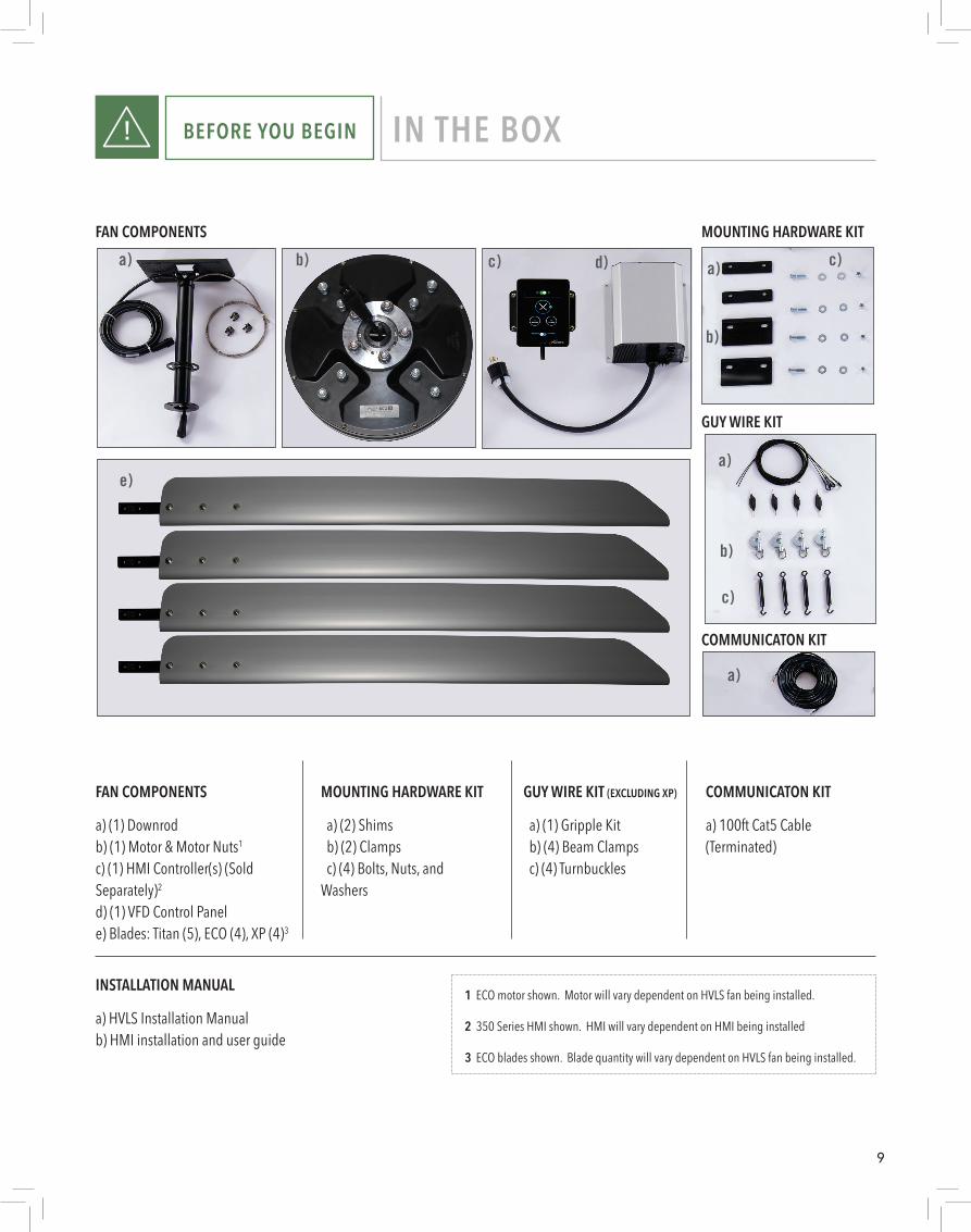
FAN COMPONENTS MOUNTING HARDWARE KIT
GUY WIRE KIT
COMMUNICATON KIT
a) 100ft Cat5 Cable (Terminated)
COMMUNICATON KIT
a) (1) Gripple Kit b) (4) Beam Clamps c) (4) Turnbuckles
GUY WIRE KIT (EXCLUDING XP)
a) (2) Shims b) (2) Clamps c) (4) Bolts, Nuts, and Washers
MOUNTING HARDWARE KITFAN COMPONENTS
a) (1) Downrodb) (1) Motor & Motor Nuts1
c) (1) HMI Controller(s) (Sold Separately)2
d) (1) VFD Control Panele) Blades: Titan (5), ECO (4), XP (4)3
a) HVLS Installation Manualb) HMI installation and user guide
INSTALLATION MANUAL
BEFORE YOU BEGIN IN THE BOX!
1 ECO motor shown. Motor will vary dependent on HVLS fan being installed.
2 350 Series HMI shown. HMI will vary dependent on HMI being installed
3 ECO blades shown. Blade quantity will vary dependent on HVLS fan being installed.
10
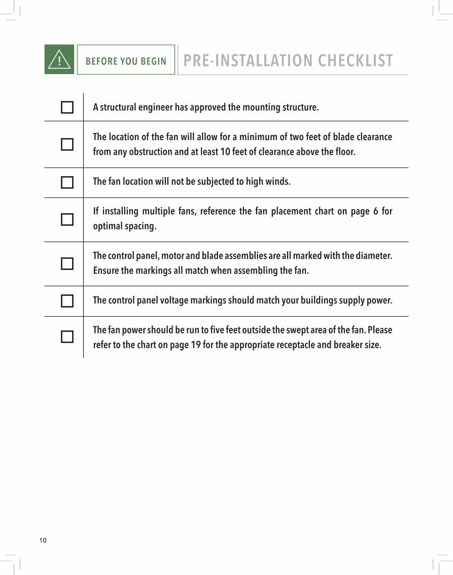
BEFORE YOU BEGIN PRE-INSTALLATION CHECKLIST!
A structural engineer has approved the mounting structure.
The location of the fan will allow for a minimum of two feet of blade clearance from any obstruction and at least 10 feet of clearance above the floor.
The fan location will not be subjected to high winds.
If installing multiple fans, reference the fan placement chart on page 6 for optimal spacing.
The control panel, motor and blade assemblies are all marked with the diameter. Ensure the markings all match when assembling the fan.
The control panel voltage markings should match your buildings supply power.
The fan power should be run to five feet outside the swept area of the fan. Please refer to the chart on page 19 for the appropriate receptacle and breaker size.
11
INSTALLATION STEP 1: MOUNTING
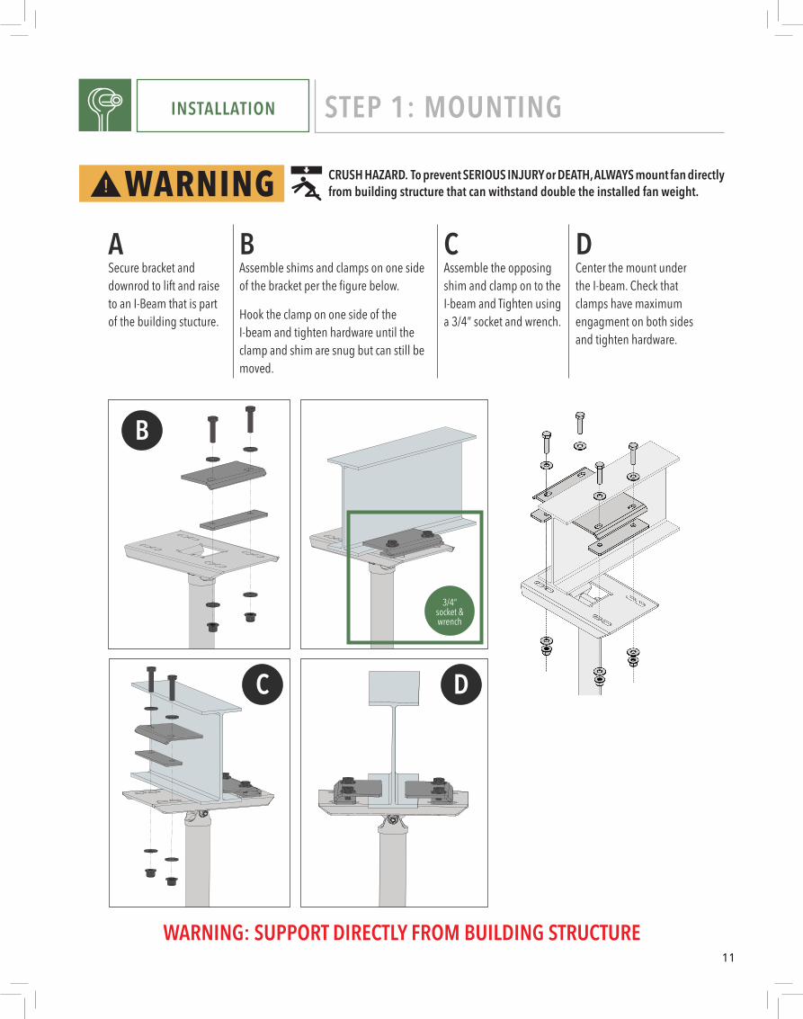
CRUSH HAZARD. To prevent SERIOUS INJURY or DEATH, ALWAYS mount fan directly from building structure that can withstand double the installed fan weight.
ASecure bracket and downrod to lift and raise to an I-Beam that is part of the building stucture.
BAssemble shims and clamps on one side of the bracket per the figure below.
Hook the clamp on one side of the I-beam and tighten hardware until the clamp and shim are snug but can still be moved.
CAssemble the opposing shim and clamp on to the I-beam and Tighten using a 3/4” socket and wrench.
DCenter the mount under the I-beam. Check that clamps have maximum engagment on both sides and tighten hardware.
WARNING: SUPPORT DIRECTLY FROM BUILDING STRUCTURE
3/4”socket & wrench
B
C D
12
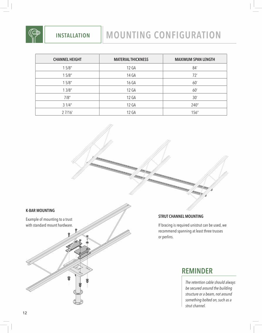
STRUT CHANNEL MOUNTING
If bracing is required unistrut can be used, we recommend spanning at least three trusses or perlins.
K-BAR MOUNTING
Example of mounting to a trust with standard mount hardware.
REMINDERThe retention cable should always be secured around the building structure or a beam, not around something bolted on, such as a strut channel.
INSTALLATION MOUNTING CONFIGURATION
CHANNEL HEIGHT MATERIAL THICKNESS MAXIMUM SPAN LENGTH
1 5/8” 12 GA 84’1 5/8” 14 GA 72’1 5/8” 16 GA 60’1 3/8” 12 GA 60’7/8” 12 GA 30’
3 1/4” 12 GA 240”2 7/16’ 12 GA 156”
13
INSTALLATION STEP 1: MOUNTING
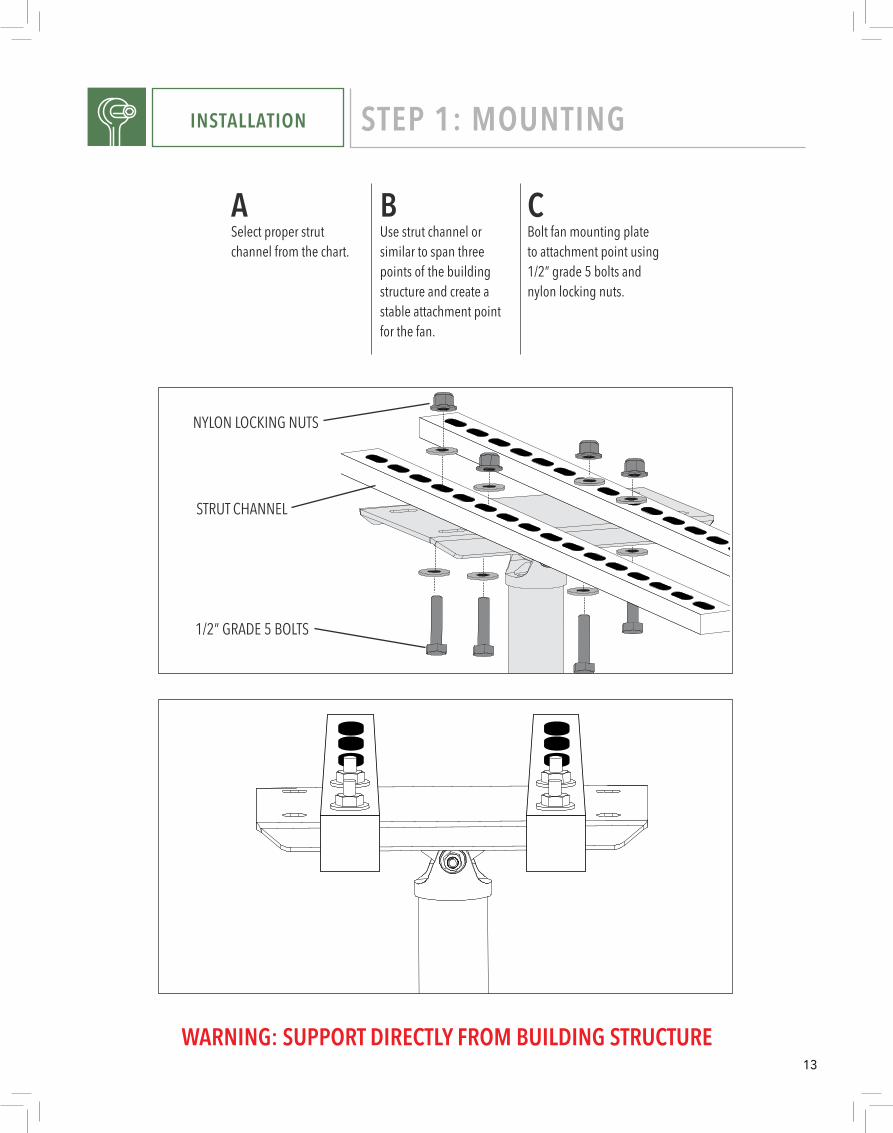
CSTRUT CHANNEL
NYLON LOCKING NUTS
1/2” GRADE 5 BOLTS
WARNING: SUPPORT DIRECTLY FROM BUILDING STRUCTURE
ASelect proper strut channel from the chart.
BUse strut channel or similar to span three points of the building structure and create a stable attachment point for the fan.
CBolt fan mounting plate to attachment point using 1/2” grade 5 bolts and nylon locking nuts.
14
INSTALLATION STEP 2: RETENTION SYSTEM
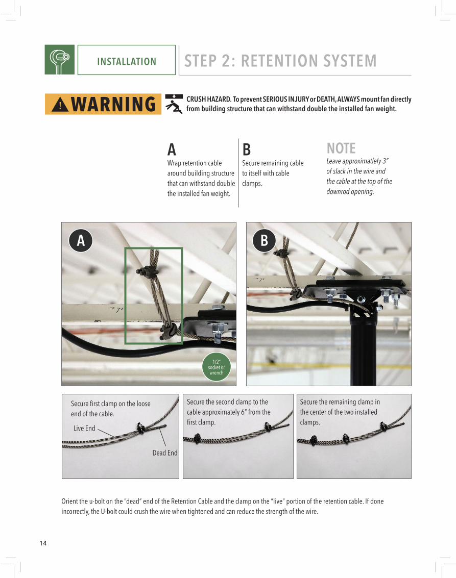
Secure first clamp on the loose end of the cable.
Secure the remaining clamp in the center of the two installed clamps.
Secure the second clamp to the cable approximately 6” from the first clamp.
Orient the u-bolt on the “dead” end of the Retention Cable and the clamp on the “live” portion of the retention cable. If done incorrectly, the U-bolt could crush the wire when tightened and can reduce the strength of the wire.
Dead End
Live End
BSecure remaining cable to itself with cable clamps.
AWrap retention cable around building structure that can withstand double the installed fan weight.
NOTELeave approximatlely 3” of slack in the wire and the cable at the top of the downrod opening.
1/2”socket or wrench
CRUSH HAZARD. To prevent SERIOUS INJURY or DEATH, ALWAYS mount fan directly from building structure that can withstand double the installed fan weight.
A B
15
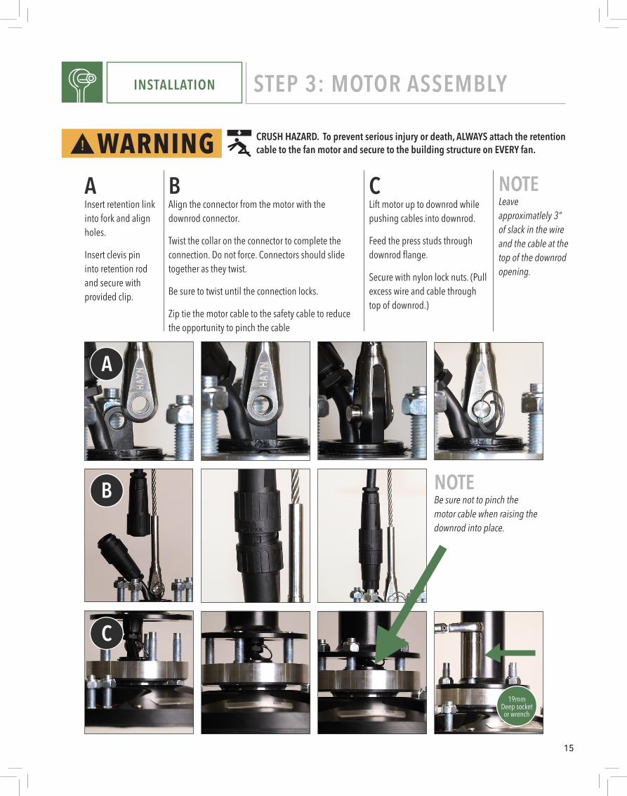
INSTALLATION STEP 3: MOTOR ASSEMBLY
NOTEBe sure not to pinch the motor cable when raising the downrod into place.
CLift motor up to downrod while pushing cables into downrod.
Feed the press studs through downrod flange.
Secure with nylon lock nuts. (Pull excess wire and cable through top of downrod.)
AInsert retention link into fork and align holes.
Insert clevis pin into retention rod and secure with provided clip.
BAlign the connector from the motor with the downrod connector.
Twist the collar on the connector to complete the connection. Do not force. Connectors should slide together as they twist.
Be sure to twist until the connection locks.
Zip tie the motor cable to the safety cable to reduce the opportunity to pinch the cable
NOTELeave approximatlely 3” of slack in the wire and the cable at the top of the downrod opening.
19mmDeep socket
or wrench
CRUSH HAZARD. To prevent serious injury or death, ALWAYS attach the retention cable to the fan motor and secure to the building structure on EVERY fan.
A
B
C
16
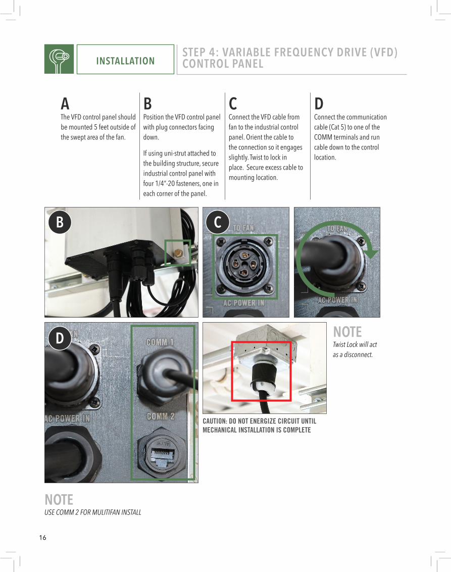
INSTALLATIONSTEP 4: VARIABLE FREQUENCY DRIVE (VFD) CONTROL PANEL
NOTETwist Lock will act as a disconnect.
CAUTION: DO NOT ENERGIZE CIRCUIT UNTIL MECHANICAL INSTALLATION IS COMPLETE
BPosition the VFD control panel with plug connectors facing down.
If using uni-strut attached to the building structure, secure industrial control panel with four 1/4”-20 fasteners, one in each corner of the panel.
CConnect the VFD cable from fan to the industrial control panel. Orient the cable to the connection so it engages slightly. Twist to lock in place. Secure excess cable to mounting location.
DConnect the communication cable (Cat 5) to one of the COMM terminals and run cable down to the control location.
AThe VFD control panel should be mounted 5 feet outside of the swept area of the fan.
B
D
C
NOTEUSE COMM 2 FOR MULITIFAN INSTALL
17
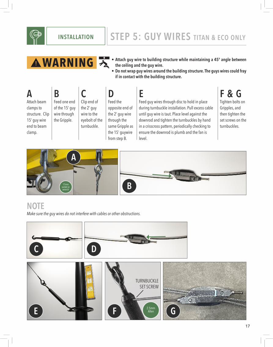
INSTALLATION STEP 5: GUY WIRES TITAN & ECO ONLY
NOTEMake sure the guy wires do not interfere with cables or other obstructions.
17mmsocket or wrench
TURNBUCKLESET SCREW
2.5mmAllen
• Attach guy wire to building structure while maintaining a 45° angle between the ceiling and the guy wire.
• Do not wrap guy wires around the building structure. The guys wires could fray if in contact with the building structure.
AAttach beam clamps to structure. Clip 15’ guy wire end to beam clamp.
BFeed one end of the 15’ guy wire through the Gripple.
CClip end of the 2’ guy wire to the eyebolt of the turnbuckle.
DFeed the opposite end of the 2’ guy wire through the same Gripple as the 15’ guywire from step B.
F & GTighten bolts on Gripples, and then tighten the set screws on the turnbuckles.
EFeed guy wires through disc to hold in place during turnbuckle installation. Pull excess cable until guy wire is taut. Place level against the downrod and tighten the turnbuckles by hand in a crisscross pattern, periodically checking to ensure the downrod is plumb and the fan is level.
A
C
E F G
D
B
18
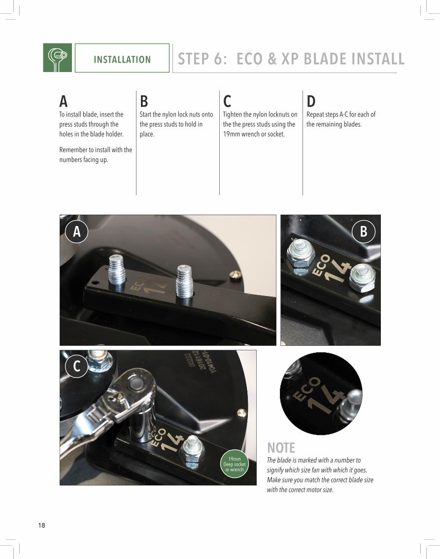
NOTEThe blade is marked with a number to signify which size fan with which it goes. Make sure you match the correct blade size with the correct motor size.
INSTALLATION STEP 6: ECO & XP BLADE INSTALL
19mmDeep socket
or wrench
BStart the nylon lock nuts onto the press studs to hold in place.
CTighten the nylon locknuts on the the press studs using the 19mm wrench or socket.
DRepeat steps A-C for each of the remaining blades.
ATo install blade, insert the press studs through the holes in the blade holder.
Remember to install with the numbers facing up.
A
C
B
19
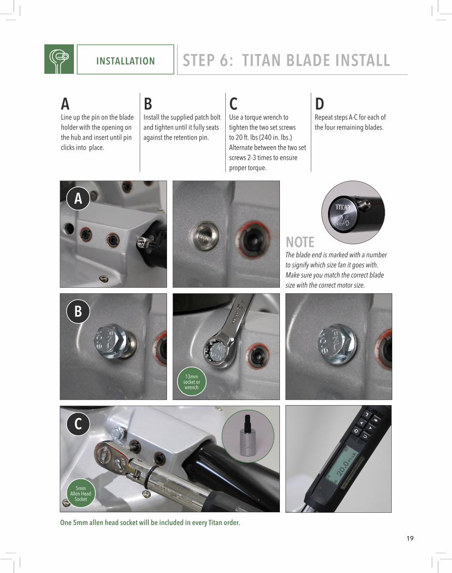
BInstall the supplied patch bolt and tighten until it fully seats against the retention pin.
CUse a torque wrench to tighten the two set screws to 20 ft. lbs (240 in. lbs.) Alternate between the two set screws 2-3 times to ensure proper torque.
DRepeat steps A-C for each of the four remaining blades.
ALine up the pin on the blade holder with the opening on the hub and insert until pin clicks into place.
NOTEThe blade end is marked with a number to signify which size fan it goes with. Make sure you match the correct blade size with the correct motor size.
INSTALLATION STEP 6: TITAN BLADE INSTALL
5mm Allen Head
Socket
One 5mm allen head socket will be included in every Titan order.
A
B
C
13mm socket or wrench

20
TITAN AMP DRAWFAN DIAMETER 220V / 1PH RECOMMENDED
BREAKER SIZE 220V / 3 PH RECOMMENDED BREAKER SIZE 480V / 3PH RECOMMENDED
BREAKER SIZE
24 ft 8.2A 15A 4.3A 10A 3A 5A20 ft 7.2A 10A 4.0A 10A 2.6A 5A18 ft 7.8A 10A 4.1A 10A 2.4A 5A16 ft 7.2A 10A 3.8A 5A 1.8A 5A14 ft 5.4A 10A 2.8A 5A 1.2A 5A
REFERENCE TITAN ELECTRICAL
Do not use extension cord with fan.Do not remove covers while power is on.Do not use improper voltage source.
21
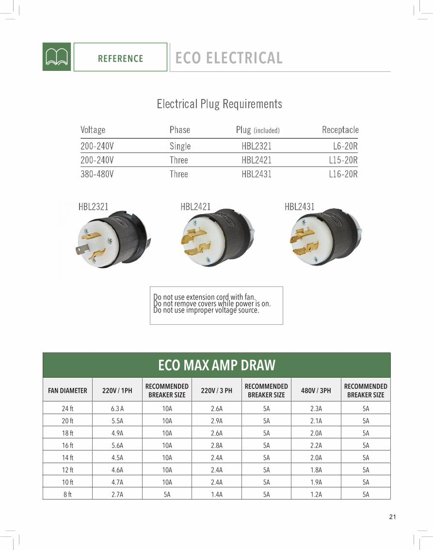
REFERENCE ECO ELECTRICAL
Do not use extension cord with fan.Do not remove covers while power is on.Do not use improper voltage source.
ECO MAX AMP DRAWFAN DIAMETER 220V / 1PH RECOMMENDED
BREAKER SIZE 220V / 3 PH RECOMMENDED BREAKER SIZE 480V / 3PH RECOMMENDED
BREAKER SIZE
24 ft 6.3 A 10A 2.6A 5A 2.3A 5A20 ft 5.5A 10A 2.9A 5A 2.1A 5A18 ft 4.9A 10A 2.6A 5A 2.0A 5A16 ft 5.6A 10A 2.8A 5A 2.2A 5A14 ft 4.5A 10A 2.4A 5A 2.0A 5A12 ft 4.6A 10A 2.4A 5A 1.8A 5A10 ft 4.7A 10A 2.4A 5A 1.9A 5A8 ft 2.7A 5A 1.4A 5A 1.2A 5A

22
Breaker Size Chart
Electrical Plug RequirementsVoltage110-120V
ReceptacleL5-15R
PlugL5-15P
A Plug and Receptacle are included with each fan.
XP AMP DRAWFAN DIAMETER 110V RECOMMENDED BREAKER SIZE
14 ft 7.5A 10A12 ft 8.4A 15A10 ft 9.1A 15A8 ft 5.2A 10A7 ft 6.7A 10A
REFERENCE XP ELECTRICAL
Do not use extension cord with fan.Do not remove covers while power is on.Do not use improper voltage.
23
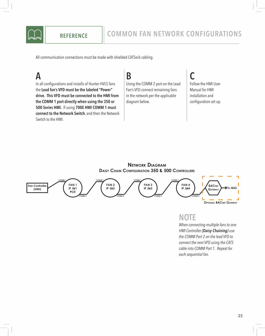
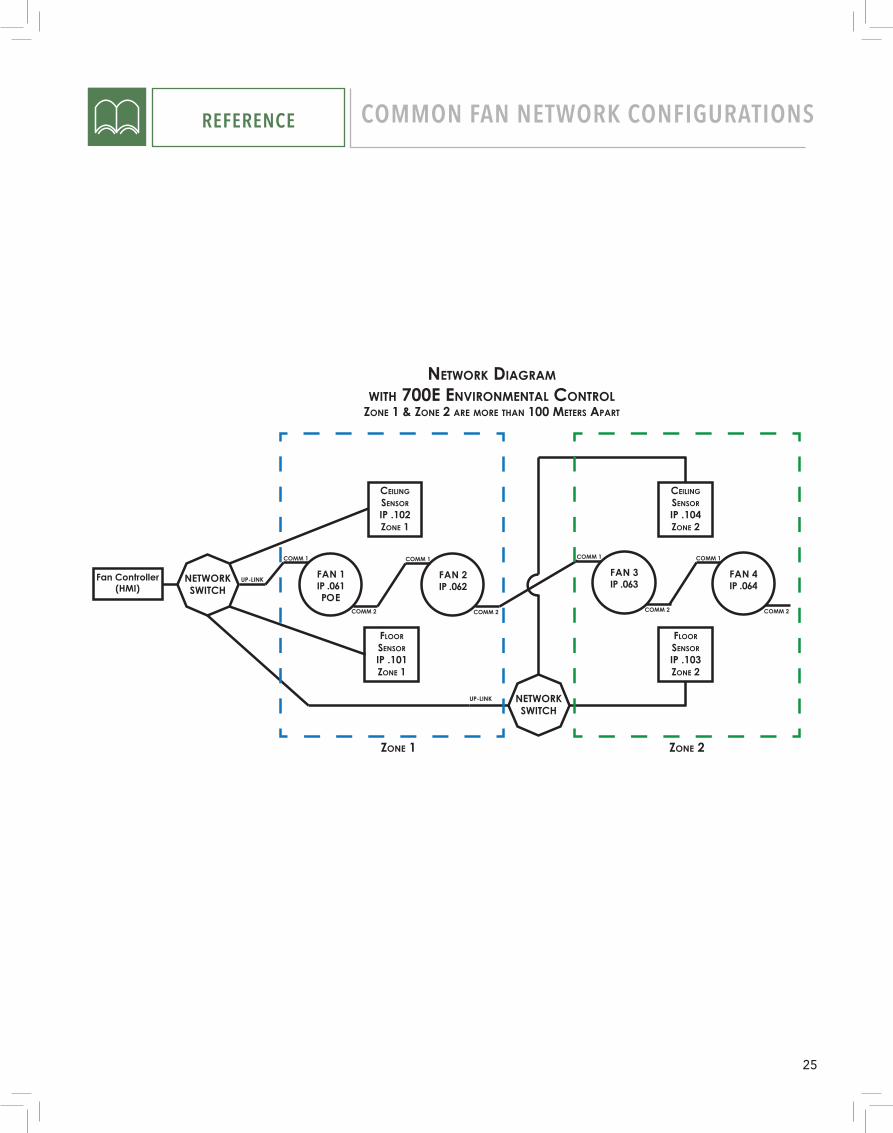
AIn all configurations and installs of Hunter HVLS fans the Lead fan’s VFD must be the labeled “Power” drive. This VFD must be connected to the HMI from the COMM 1 port directly when using the 350 or 500 Series HMI. If using 700E HMI COMM 1 must connect to the Network Switch, and then the Network Switch to the HMI.
BUsing the COMM 2 port on the Lead Fan’s VFD connect remaining fans in the network per the applicable diagram below.
CFollow the HMI User Manual for HMI installation and configuration set up.
REFERENCE COMMON FAN NETWORK CONFIGURATIONS
All communication connections must be made with shielded CAT5e/6 cabling.
NETWORKSWITCH
UP-LINKFan Controller(HMI)
FAN 1IP .061POE
COMM 1
COMM 2
FAN 2IP .062
COMM 1
COMM 2
FAN 4IP .064
COMM 1
COMM 2
FAN 3IP .063
COMM 1
COMM 2
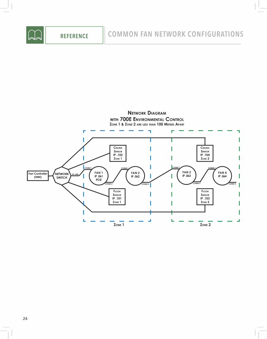
FLOORSENSORIP .101ZONE 1
CEILINGSENSORIP .102ZONE 1
FLOORSENSORIP .103ZONE 2
CEILINGSENSORIP .104ZONE 2
ZONE 2ZONE 1
NETWORK DIAGRAMWITH 700E ENVIRONMENTAL CONTROLZONE 1 & ZONE 2 ARE LESS THAN 100 METERS APART
NETWORKSWITCH
UP-LINK
NETWORKSWITCH
UP-LINKFan Controller(HMI)
FAN 1IP .061POE
COMM 1
COMM 2
FAN 2IP .062
COMM 1
COMM 2
FAN 4IP .064
COMM 1
COMM 2
FAN 3IP .063
COMM 1
COMM 2
FLOORSENSORIP .101ZONE 1
CEILINGSENSORIP .102ZONE 1
FLOORSENSORIP .103ZONE 2
CEILINGSENSORIP .104ZONE 2
ZONE 2ZONE 1
NETWORK DIAGRAMWITH 700E ENVIRONMENTAL CONTROL
ZONE 1 & ZONE 2 ARE MORE THAN 100 METERS APART
NETWORK DIAGRAMDAISY CHAIN CONFIGURATION 350 & 500 CONTROLLERS
Fan Controller(HMI)
FAN 1IP .061POE
COMM 1
COMM 2
FAN 2IP .062
COMM 1
COMM 2
FAN 4IP .064
COMM 1
COMM 2
FAN 3IP .063
COMM 1
COMM 2
BACNETGATEWAY TO BAS
OPTIONAL BACNET GATEWAY
NOTEWhen connecting multiple fans to one HMI Controller (Daisy Chaining) use the COMM Port 2 on the lead VFD to connect the next VFD using the CAT5 cable into COMM Port 1. Repeat for each sequential fan.
24
NETWORKSWITCH
UP-LINKFan Controller(HMI)
FAN 1IP .061POE
COMM 1
COMM 2
FAN 2IP .062
COMM 1
COMM 2
FAN 4IP .064
COMM 1
COMM 2
FAN 3IP .063
COMM 1
COMM 2
FLOORSENSORIP .101ZONE 1
CEILINGSENSORIP .102ZONE 1
FLOORSENSORIP .103ZONE 2
CEILINGSENSORIP .104ZONE 2
ZONE 2ZONE 1
NETWORK DIAGRAMWITH 700E ENVIRONMENTAL CONTROLZONE 1 & ZONE 2 ARE LESS THAN 100 METERS APART
NETWORKSWITCH
UP-LINK
NETWORKSWITCH
UP-LINKFan Controller(HMI)
FAN 1IP .061POE
COMM 1
COMM 2
FAN 2IP .062
COMM 1
COMM 2
FAN 4IP .064
COMM 1
COMM 2
FAN 3IP .063
COMM 1
COMM 2
FLOORSENSORIP .101ZONE 1
CEILINGSENSORIP .102ZONE 1
FLOORSENSORIP .103ZONE 2
CEILINGSENSORIP .104ZONE 2
ZONE 2ZONE 1
NETWORK DIAGRAMWITH 700E ENVIRONMENTAL CONTROL
ZONE 1 & ZONE 2 ARE MORE THAN 100 METERS APART
NETWORK DIAGRAMDAISY CHAIN CONFIGURATION 350 & 500 CONTROLLERS
Fan Controller(HMI)
FAN 1IP .061POE
COMM 1
COMM 2
FAN 2IP .062
COMM 1
COMM 2
FAN 4IP .064
COMM 1
COMM 2
FAN 3IP .063
COMM 1
COMM 2
BACNETGATEWAY TO BAS
OPTIONAL BACNET GATEWAY
REFERENCE COMMON FAN NETWORK CONFIGURATIONS
25
NETWORKSWITCH
UP-LINKFan Controller(HMI)
FAN 1IP .061POE
COMM 1
COMM 2
FAN 2IP .062
COMM 1
COMM 2
FAN 4IP .064
COMM 1
COMM 2
FAN 3IP .063
COMM 1
COMM 2
FLOORSENSORIP .101ZONE 1
CEILINGSENSORIP .102ZONE 1
FLOORSENSORIP .103ZONE 2
CEILINGSENSORIP .104ZONE 2
ZONE 2ZONE 1
NETWORK DIAGRAMWITH 700E ENVIRONMENTAL CONTROLZONE 1 & ZONE 2 ARE LESS THAN 100 METERS APART
NETWORKSWITCH
UP-LINK
NETWORKSWITCH
UP-LINKFan Controller(HMI)
FAN 1IP .061POE
COMM 1
COMM 2
FAN 2IP .062
COMM 1
COMM 2
FAN 4IP .064
COMM 1
COMM 2
FAN 3IP .063
COMM 1
COMM 2
FLOORSENSORIP .101ZONE 1
CEILINGSENSORIP .102ZONE 1
FLOORSENSORIP .103ZONE 2
CEILINGSENSORIP .104ZONE 2
ZONE 2ZONE 1
NETWORK DIAGRAMWITH 700E ENVIRONMENTAL CONTROL
ZONE 1 & ZONE 2 ARE MORE THAN 100 METERS APART
NETWORK DIAGRAMDAISY CHAIN CONFIGURATION 350 & 500 CONTROLLERS
Fan Controller(HMI)
FAN 1IP .061POE
COMM 1
COMM 2
FAN 2IP .062
COMM 1
COMM 2
FAN 4IP .064
COMM 1
COMM 2
FAN 3IP .063
COMM 1
COMM 2
BACNETGATEWAY TO BAS
OPTIONAL BACNET GATEWAY
REFERENCE COMMON FAN NETWORK CONFIGURATIONS
26
REFERENCE COMMON FAN NETWORK CONFIGURATIONS
AA
BB
CC
DD
EE
FF
8 8
7 7
6 6
5 5
4 4
3 3
2 2
1 1
DRAWN
CHK'D
APPV
'D
MFG
Q.A
UNLESS O
THERWISE SPEC
IFIED:
DIM
ENSIO
NS A
RE IN M
ILLIMETERS
SURFAC
E FINISH:
TOLERA
NC
ES: LIN
EAR:
AN
GULA
R:
FINISH:
DEBURR A
ND
BREA
K SHARP
EDG
ES
NA
ME
SIGN
ATURE
DA
TE
MA
TERIAL:
DO
NO
T SCA
LE DRA
WIN
GREVISIO
N
TITLE:
DW
G N
O.
SCA
LE:1:5SHEET 1 O
F 1
A3
WEIG
HT:
Mitsu Enclosure A
ssy Current (w
ithout fire relay)A
A
BB
CC
DD
EE
FF
8 8
7 7
6 6
5 5
4 4
3 3
2 2
1 1
DRAWN
CHK'D
APPV
'D
MFG
Q.A
UNLESS O
THERWISE SPEC
IFIED:
DIM
ENSIO
NS A
RE IN M
ILLIMETERS
SURFAC
E FINISH:
TOLERA
NC
ES: LIN
EAR:
AN
GULA
R:
FINISH:
DEBURR A
ND
BREA
K SHARP
EDG
ES
NA
ME
SIGN
ATURE
DA
TE
MA
TERIAL:
DO
NO
T SCA
LE DRA
WIN
GREVISIO
N
TITLE:
DW
G N
O.
SCA
LE:1:5SHEET 1 O
F 1
A3
WEIG
HT:
Mitsu Enclosure A
ssy Current (w
ithout fire relay)
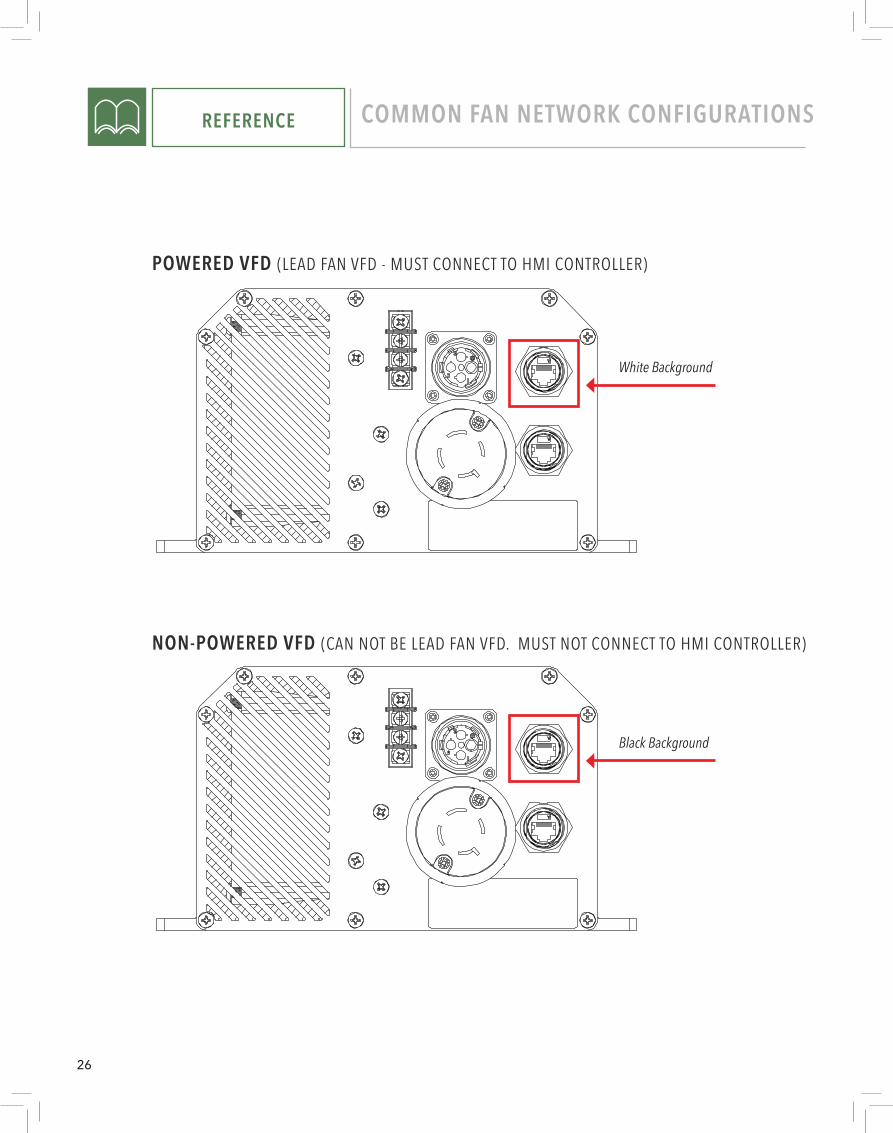
POWERED VFD (LEAD FAN VFD - MUST CONNECT TO HMI CONTROLLER)
NON-POWERED VFD (CAN NOT BE LEAD FAN VFD. MUST NOT CONNECT TO HMI CONTROLLER)
Black Background
White Background
27
REFERENCE FIRE PANEL (FIELD WIRING)
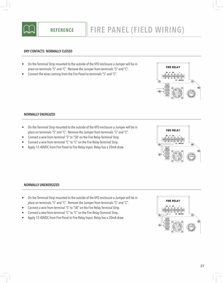
DRY CONTACTS: NORMALLY CLOSED
SC
SAC
FIRE RELAYSB +-
12 - 40VDC
4
A
123
B B
A
2 134
DO NOT SCALE DRAWING
fire relay sb
SHEET 1 OF 1
UNLESS OTHERWISE SPECIFIED:
SCALE: 1:5 WEIGHT:
REVDWG. NO.
BSIZE
TITLE:
Hunter Fan Co.NAME DATE
COMMENTS:
Q.A.
MFG APPR.
ENG APPR.
CHECKED
DRAWN
FINISH
MATERIAL
INTERPRET GEOMETRICTOLERANCING PER:
DIMENSIONS ARE IN MMTOLERANCES:ANGULAR: MACH .1 BEND 1TWO PLACE DECIMAL .25THREE PLACE DECIMAL .025
PROPRIETARY AND CONFIDENTIALTHE INFORMATION CONTAINED IN THISDRAWING IS THE SOLE PROPERTY OFHUNTER FAN CO., MEMPHIS, TN. ANY REPRODUCTION IN PART OR AS A WHOLEWITHOUT THE WRITTEN PERMISSION OFHUNTER FAN CO., MEMPHIS, TN. IS PROHIBITED.
REV DATE DESCRIPTION
EXP. NO: -8862
• On the Terminal Strip mounted to the outside of the VFD enclosure a Jumper will be in place on terminals “S” and “C”. Remove the Jumper from terminals “S” and “C”.
• Connect the wires coming from the Fire Panel to terminals “S” and “C”.
NORMALLY UNENERGIZED
S
C
SAC
FIRE RELAYSB +-
12 - 40VDC
4
A
123
B B
A
2 134
DO NOT SCALE DRAWING
Fire Relay SB
SHEET 1 OF 1
UNLESS OTHERWISE SPECIFIED:
SCALE: 1:5 WEIGHT:
REVDWG. NO.
BSIZE
TITLE:
Hunter Fan Co.NAME DATE
COMMENTS:
Q.A.
MFG APPR.
ENG APPR.
CHECKED
DRAWN
FINISH
MATERIAL
INTERPRET GEOMETRICTOLERANCING PER:
DIMENSIONS ARE IN MMTOLERANCES:ANGULAR: MACH .1 BEND 1TWO PLACE DECIMAL .25THREE PLACE DECIMAL .025
PROPRIETARY AND CONFIDENTIALTHE INFORMATION CONTAINED IN THISDRAWING IS THE SOLE PROPERTY OFHUNTER FAN CO., MEMPHIS, TN. ANY REPRODUCTION IN PART OR AS A WHOLEWITHOUT THE WRITTEN PERMISSION OFHUNTER FAN CO., MEMPHIS, TN. IS PROHIBITED.
REV DATE DESCRIPTION
EXP. NO: -8862
• On the Terminal Strip mounted to the outside of the VFD enclosure a Jumper will be in place on terminals “S” and “C”. Remove the Jumper from terminals “S” and “C”.
• Connect a wire from terminal “S” to “SB” on the Fire Relay Terminal Strip• Connect a wire from terminal “C” to “C” on the Fire Relay Terminal Strip.• Apply 12-40VDC from Fire Panel to Fire Relay Input. Relay has a 20mA draw.
NORMALLY ENERGIZED
• On the Terminal Strip mounted to the outside of the VFD enclosure a Jumper will be in place on terminals “S” and “C”. Remove the Jumper from terminals “S” and “C”.
• Connect a wire from terminal “S” to “SA” on the Fire Relay Terminal Strip.• Connect a wire from terminal “C” to “C” on the Fire Relay Terminal Strip.• Apply 12-40VDC from Fire Panel to Fire Relay Input. Relay has a 20mA draw.
S
C
SAC
FIRE RELAYSB +-
12 - 40VDC
4
A
123
B B
A
2 134
DO NOT SCALE DRAWING
Fire Relay SA
SHEET 1 OF 1
UNLESS OTHERWISE SPECIFIED:
SCALE: 1:5 WEIGHT:
REVDWG. NO.
BSIZE
TITLE:
Hunter Fan Co.NAME DATE
COMMENTS:
Q.A.
MFG APPR.
ENG APPR.
CHECKED
DRAWN
FINISH
MATERIAL
INTERPRET GEOMETRICTOLERANCING PER:
DIMENSIONS ARE IN MMTOLERANCES:ANGULAR: MACH .1 BEND 1TWO PLACE DECIMAL .25THREE PLACE DECIMAL .025
PROPRIETARY AND CONFIDENTIALTHE INFORMATION CONTAINED IN THISDRAWING IS THE SOLE PROPERTY OFHUNTER FAN CO., MEMPHIS, TN. ANY REPRODUCTION IN PART OR AS A WHOLEWITHOUT THE WRITTEN PERMISSION OFHUNTER FAN CO., MEMPHIS, TN. IS PROHIBITED.
REV DATE DESCRIPTION
EXP. NO: -8862
28
REFERENCE FIRE PANEL (FIELD WIRING)
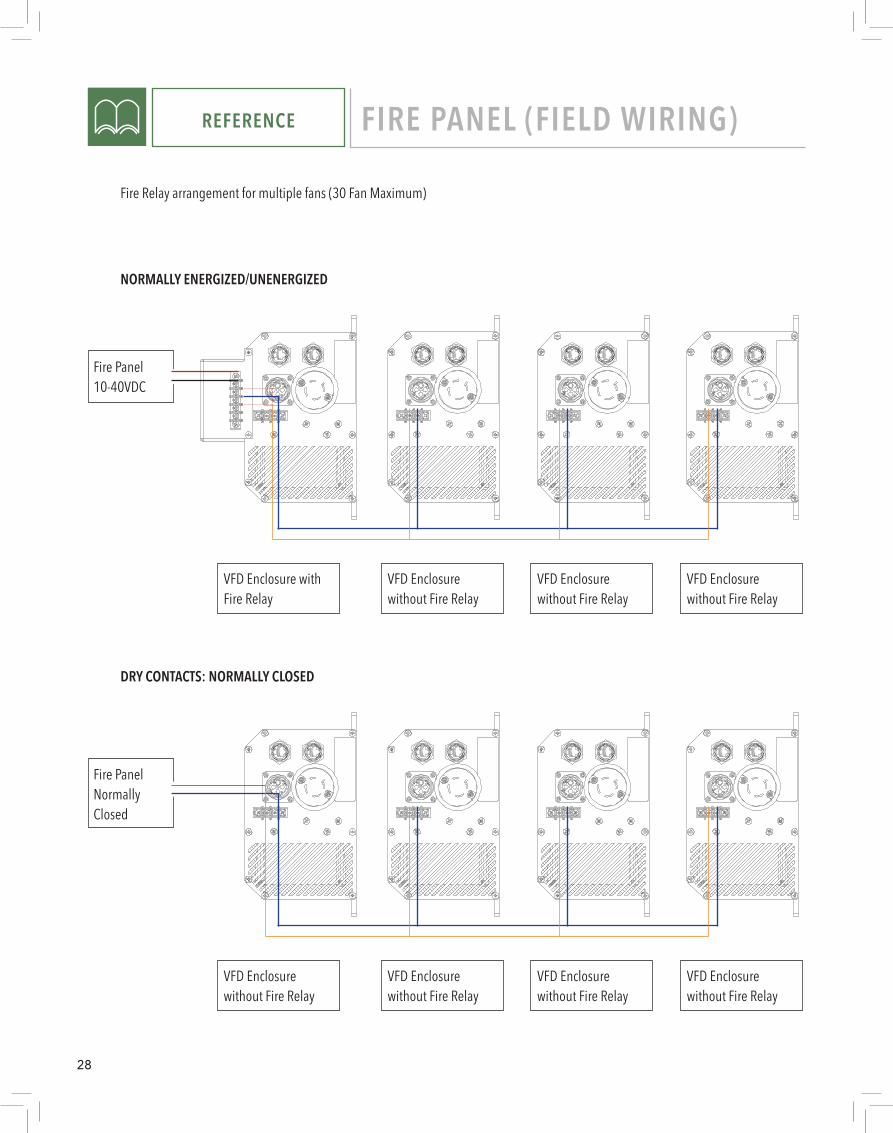
Fire Relay arrangement for multiple fans (30 Fan Maximum)
NORMALLY ENERGIZED/UNENERGIZED
A A
B B
C C
D D
E E
F F
8
8
7
7
6
6
5
5
4
4
3
3
2
2
1
1
DRAWN
CHK'D
APPV'D
MFG
Q.A
UNLESS OTHERWISE SPECIFIED:DIMENSIONS ARE IN MILLIMETERSSURFACE FINISH:TOLERANCES: LINEAR: ANGULAR:
FINISH: DEBURR AND BREAK SHARP EDGES
NAME SIGNATURE DATE
MATERIAL:
DO NOT SCALE DRAWING REVISION
TITLE:
DWG NO.
SCALE:1:5 SHEET 1 OF 1
A3
WEIGHT:
Mitsu Enclosure Assy Current Alex
A A
B B
C C
D D
E E
F F
8
8
7
7
6
6
5
5
4
4
3
3
2
2
1
1
DRAWN
CHK'D
APPV'D
MFG
Q.A
UNLESS OTHERWISE SPECIFIED:DIMENSIONS ARE IN MILLIMETERSSURFACE FINISH:TOLERANCES: LINEAR: ANGULAR:
FINISH: DEBURR AND BREAK SHARP EDGES
NAME SIGNATURE DATE
MATERIAL:
DO NOT SCALE DRAWING REVISION
TITLE:
DWG NO.
SCALE:1:5 SHEET 1 OF 1
A3
WEIGHT:
Mitsu Enclosure Assy Current (without fire relay)A A
B B
C C
D D
E E
F F
8
8
7
7
6
6
5
5
4
4
3
3
2
2
1
1
DRAWN
CHK'D
APPV'D
MFG
Q.A
UNLESS OTHERWISE SPECIFIED:DIMENSIONS ARE IN MILLIMETERSSURFACE FINISH:TOLERANCES: LINEAR: ANGULAR:
FINISH: DEBURR AND BREAK SHARP EDGES
NAME SIGNATURE DATE
MATERIAL:
DO NOT SCALE DRAWING REVISION
TITLE:
DWG NO.
SCALE:1:5 SHEET 1 OF 1
A3
WEIGHT:
Mitsu Enclosure Assy Current (without fire relay)
VFD Enclosure without Fire Relay
VFD Enclosure without Fire Relay
VFD Enclosure without Fire Relay
VFD Enclosure with Fire Relay
Fire Panel 10-40VDC
DRY CONTACTS: NORMALLY CLOSED
A A
B B
C C
D D
E E
F F
8
8
7
7
6
6
5
5
4
4
3
3
2
2
1
1
DRAWN
CHK'D
APPV'D
MFG
Q.A
UNLESS OTHERWISE SPECIFIED:DIMENSIONS ARE IN MILLIMETERSSURFACE FINISH:TOLERANCES: LINEAR: ANGULAR:
FINISH: DEBURR AND BREAK SHARP EDGES
NAME SIGNATURE DATE
MATERIAL:
DO NOT SCALE DRAWING REVISION
TITLE:
DWG NO.
SCALE:1:5 SHEET 1 OF 1
A3
WEIGHT:
Mitsu Enclosure Assy Current (without fire relay)A A
B B
C C
D D
E E
F F
8
8
7
7
6
6
5
5
4
4
3
3
2
2
1
1
DRAWN
CHK'D
APPV'D
MFG
Q.A
UNLESS OTHERWISE SPECIFIED:DIMENSIONS ARE IN MILLIMETERSSURFACE FINISH:TOLERANCES: LINEAR: ANGULAR:
FINISH: DEBURR AND BREAK SHARP EDGES
NAME SIGNATURE DATE
MATERIAL:
DO NOT SCALE DRAWING REVISION
TITLE:
DWG NO.
SCALE:1:5 SHEET 1 OF 1
A3
WEIGHT:
Mitsu Enclosure Assy Current (without fire relay)A A
B B
C C
D D
E E
F F
8
8
7
7
6
6
5
5
4
4
3
3
2
2
1
1
DRAWN
CHK'D
APPV'D
MFG
Q.A
UNLESS OTHERWISE SPECIFIED:DIMENSIONS ARE IN MILLIMETERSSURFACE FINISH:TOLERANCES: LINEAR: ANGULAR:
FINISH: DEBURR AND BREAK SHARP EDGES
NAME SIGNATURE DATE
MATERIAL:
DO NOT SCALE DRAWING REVISION
TITLE:
DWG NO.
SCALE:1:5 SHEET 1 OF 1
A3
WEIGHT:
Mitsu Enclosure Assy Current (without fire relay)
VFD Enclosure without Fire Relay
VFD Enclosure without Fire Relay
VFD Enclosure without Fire Relay
VFD Enclosure without Fire Relay
Fire Panel Normally Closed

29
REFERENCE MAINTENANCE
TO PREVENT SERIOUS INJURY OR DEATH:
• BEFORE performing maintenance or service, ALWAYS disconnect the power by turning off the circuit breaker or breakers to the fan locations and confirm Lockout/Tagout procedures are in place.
• If you cannot lock the circuit breakers in the off position, securely fasten a prominent warning device, such as a tag, to the electrical panel.
• Do not remove covers while power is on.
Blade CleaningDepending on the commercial application, dust or other particulates can build up on the fan blades over time. At least every 12 months, a maintenance person or skilled trade professional, who has experience using a lift, should clean the blades using a rag or sponge and hot water or regular cleaning solutions. DO NOT use chlorine or any chemicals containing chlorine or the blades may be damaged.
Retention System CheckEach fan is installed with a retention system. Every 12 months, check that the retention cable is properly attached to the building struc-ture. Inspect the visible portions of the retention cable for damage, including fraying.
The retention cable is an important part of the safety system and protects users in the unlikely event of a catastrophic situation. It is critical for fan owners to ensure that it is intact and properly secured.
Replacement PartsPlease call 1-844-593-FANS (3267) for replacement parts.
ServiceIf the fan does not operate properly using the procedures in this manual, follow Lock-Out, Tag-Out procedures for your facility and lockout all power to the unit and contact our Technical Department for further assistance at 1-844-593-FANS (3267).
ELECTRIC SHOCK HAZARD
30
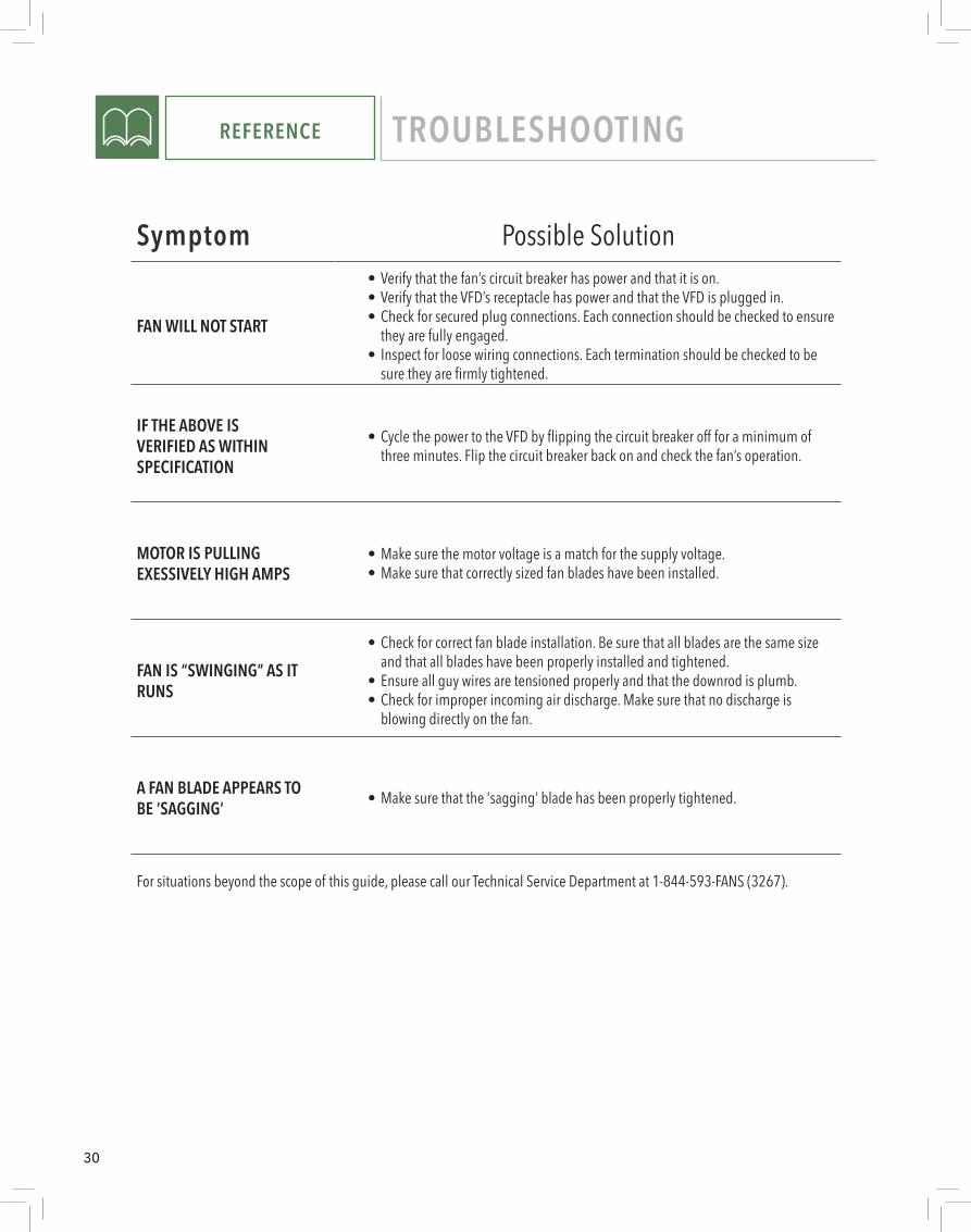
REFERENCE TROUBLESHOOTING
Symptom Possible Solution
FAN WILL NOT START
• Verify that the fan’s circuit breaker has power and that it is on.• Verify that the VFD’s receptacle has power and that the VFD is plugged in.• Check for secured plug connections. Each connection should be checked to ensure
they are fully engaged.• Inspect for loose wiring connections. Each termination should be checked to be
sure they are firmly tightened.
IF THE ABOVE ISVERIFIED AS WITHINSPECIFICATION
• Cycle the power to the VFD by flipping the circuit breaker off for a minimum of three minutes. Flip the circuit breaker back on and check the fan’s operation.
MOTOR IS PULLINGEXESSIVELY HIGH AMPS
• Make sure the motor voltage is a match for the supply voltage.• Make sure that correctly sized fan blades have been installed.
FAN IS “SWINGING” AS ITRUNS
• Check for correct fan blade installation. Be sure that all blades are the same size and that all blades have been properly installed and tightened.
• Ensure all guy wires are tensioned properly and that the downrod is plumb.• Check for improper incoming air discharge. Make sure that no discharge is
blowing directly on the fan.
A FAN BLADE APPEARS TOBE ‘SAGGING’ • Make sure that the ‘sagging’ blade has been properly tightened.
For situations beyond the scope of this guide, please call our Technical Service Department at 1-844-593-FANS (3267).

31

180 Threet Industrial StreetSmyrna, TN 13167
1-844-591-FANS (3267)TECHNICAL DEPARTMENT: 1-844-593-FANS (3267)
HUNTERFAN.COM/INDUSTRIAL
©2020 Hunter Fan Company. All rights reserved. | Rev1192021