Calciclastic submarine fans: An integrated overview
44
Calciclastic submarine fans: An integrated overview Aitor Payros ⁎ , Victoriano Pujalte Department of Stratigraphy and Paleontology, Faculty of Science and Technology, University of the Basque Country, P.O. Box 644, E-48080 Bilbao, Spain Received 24 January 2007; accepted 25 September 2007 Available online 5 October 2007 Abstract Calciclastic submarine fans are rare in the stratigraphic record and no bona fide present-day analogue has been described to date. Possibly because of that, and although calciclastic submarine fans have long intrigued deep-water carbonate sedimentologists, they have largely been overlooked by the academic and industrial communities. To fill this gap we have compiled and critically reviewed the existing sedimentological literature on calciclastic submarine fans, thus offering an updated view of this type of carbonate slope sedimentary system. Calciclastic submarine fans range in length from just a few to more than 100 km. Three different types can be distinguished: (1) Coarse-grained, small-sized (b 10 km) fans, which are characterized by the abundance of calcirudites and the scarcity of mud. They have relatively long leveed channels and small radial lobes. (2) Medium-grained, medium-sized fans are typified by the abundance of calcarenites and lesser amounts of calcirudites and mud. They have a tributary network of slope gullies, which merge to form a leveed channel that opens to the main depositional site, characterized by extensive lobes and/or sheets, which eventually pass into basinal deposits through a narrow fan-fringe area. These fans are between 10 and 35 km in length. (3) Fine-grained, large- sized fans are rich in calcarenites and mud, but poor in calcirudites. They have wide and long slope channels that feed very extensive calciturbiditic sheets, the total length always exceeding 50 km and generally being close to 100 km. In terms of grain-size distribution the three fan types compare well with sand/gravel-rich, mud/sand-rich and mud-rich siliciclastic submarine fans, respectively. However, they show notable differences in terms of size and sedimentary architecture, a reflection of the different behaviour of their respective sediment gravity flows. Most calciclastic submarine fans were formed on low-angle slopes and were sourced from distally steepened carbonate ramps subjected to high-energy currents. Under these conditions shallow-water loose grainy sediments were transferred to the ramp slope and eventually funnelled into the submarine fan by sediment gravity flows. These conditions seem to have been more easily met on leeward margins in which the formation of reefs was hampered by cool waters, nutrient enrichment or oligophoty. Another circumstance that contributes to the transfer of shallow-water sediments to the distal ramp slope is a low sea level, forcing the carbonate factory closer to the slope break and destabilizing sediments by increased pore-water pressure. However, the most important factor controlling the development of calciclastic submarine fans was the existence of an efficient funnelling mechanism forcing sediment gravity flows to merge downslope and build up a point-sourced sedimentary accumulation. In most cases this occurred through a major slope depression associated with tectonic structures, an inherited topography, or large-scale mass failures. © 2007 Elsevier B.V. All rights reserved. Keywords: sediment gravity flow deposit; calciclastic submarine fan; carbonate slope; carbonate ramp; facies model; controlling factors Available online at www.sciencedirect.com Earth-Science Reviews 86 (2008) 203 – 246 www.elsevier.com/locate/earscirev ⁎ Corresponding author. Tel.: +34 946 015 427; fax: +34 946 013 500. E-mail address: [email protected] (A. Payros). 0012-8252/$ - see front matter © 2007 Elsevier B.V. All rights reserved. doi:10.1016/j.earscirev.2007.09.001
-
Upload
metaaprendizaje -
Category
Documents
-
view
0 -
download
0
Transcript of Calciclastic submarine fans: An integrated overview

Available online at www.sciencedirect.com
6 (2008) 203–246www.elsevier.com/locate/earscirev
Earth-Science Reviews 8
Calciclastic submarine fans: An integrated overview
Aitor Payros ⁎, Victoriano Pujalte
Department of Stratigraphy and Paleontology, Faculty of Science and Technology,University of the Basque Country, P.O. Box 644, E-48080 Bilbao, Spain
Received 24 January 2007; accepted 25 September 2007Available online 5 October 2007
Abstract
Calciclastic submarine fans are rare in the stratigraphic record and no bona fide present-day analogue has been described todate. Possibly because of that, and although calciclastic submarine fans have long intrigued deep-water carbonate sedimentologists,they have largely been overlooked by the academic and industrial communities. To fill this gap we have compiled and criticallyreviewed the existing sedimentological literature on calciclastic submarine fans, thus offering an updated view of this type ofcarbonate slope sedimentary system.
Calciclastic submarine fans range in length from just a few to more than 100 km. Three different types can be distinguished:(1) Coarse-grained, small-sized (b10 km) fans, which are characterized by the abundance of calcirudites and the scarcity of mud.They have relatively long leveed channels and small radial lobes. (2) Medium-grained, medium-sized fans are typified by theabundance of calcarenites and lesser amounts of calcirudites and mud. They have a tributary network of slope gullies, which mergeto form a leveed channel that opens to the main depositional site, characterized by extensive lobes and/or sheets, which eventuallypass into basinal deposits through a narrow fan-fringe area. These fans are between 10 and 35 km in length. (3) Fine-grained, large-sized fans are rich in calcarenites and mud, but poor in calcirudites. They have wide and long slope channels that feed veryextensive calciturbiditic sheets, the total length always exceeding 50 km and generally being close to 100 km. In terms of grain-sizedistribution the three fan types compare well with sand/gravel-rich, mud/sand-rich and mud-rich siliciclastic submarine fans,respectively. However, they show notable differences in terms of size and sedimentary architecture, a reflection of the differentbehaviour of their respective sediment gravity flows.
Most calciclastic submarine fans were formed on low-angle slopes and were sourced from distally steepened carbonate rampssubjected to high-energy currents. Under these conditions shallow-water loose grainy sediments were transferred to the ramp slopeand eventually funnelled into the submarine fan by sediment gravity flows. These conditions seem to have been more easily met onleeward margins in which the formation of reefs was hampered by cool waters, nutrient enrichment or oligophoty. Anothercircumstance that contributes to the transfer of shallow-water sediments to the distal ramp slope is a low sea level, forcing thecarbonate factory closer to the slope break and destabilizing sediments by increased pore-water pressure. However, the mostimportant factor controlling the development of calciclastic submarine fans was the existence of an efficient funnelling mechanismforcing sediment gravity flows to merge downslope and build up a point-sourced sedimentary accumulation. In most cases thisoccurred through a major slope depression associated with tectonic structures, an inherited topography, or large-scale mass failures.© 2007 Elsevier B.V. All rights reserved.
Keywords: sediment gravity flow deposit; calciclastic submarine fan; carbonate slope; carbonate ramp; facies model; controlling factors
⁎ Corresponding author. Tel.: +34 946 015 427; fax: +34 946 013 500.E-mail address: [email protected] (A. Payros).
0012-8252/$ - see front matter © 2007 Elsevier B.V. All rights reserved.doi:10.1016/j.earscirev.2007.09.001

204 A. Payros, V. Pujalte / Earth-Science Reviews 86 (2008) 203–246
Contents
1. Introduction . . . . . . . . . . . . . . . . . . . . . . . . . . . . . . . . . . . . . . . . . . . . . . . . . . . . . . 2042. Definitions and terminology . . . . . . . . . . . . . . . . . . . . . . . . . . . . . . . . . . . . . . . . . . . . . 2053. Database . . . . . . . . . . . . . . . . . . . . . . . . . . . . . . . . . . . . . . . . . . . . . . . . . . . . . . . 2064. General sedimentary characteristics of CSF systems . . . . . . . . . . . . . . . . . . . . . . . . . . . . . . . . . 210
4.1. Sedimentary components of CSF systems . . . . . . . . . . . . . . . . . . . . . . . . . . . . . . . . . . . 2104.2. Facies in CSF systems . . . . . . . . . . . . . . . . . . . . . . . . . . . . . . . . . . . . . . . . . . . . . 2114.3. Size and shape of CSFs . . . . . . . . . . . . . . . . . . . . . . . . . . . . . . . . . . . . . . . . . . . . 2114.4. Environments and facies associations in CSF systems. . . . . . . . . . . . . . . . . . . . . . . . . . . . . . 211
4.4.1. Outer platform to upper slope tributary gullies and channels. . . . . . . . . . . . . . . . . . . . . 2184.4.2. Main feeder channel and/or canyon . . . . . . . . . . . . . . . . . . . . . . . . . . . . . . . . . 2184.4.3. Unconfined lobes and/or sheets. . . . . . . . . . . . . . . . . . . . . . . . . . . . . . . . . . . . 2184.4.4. Peripheral fan fringe . . . . . . . . . . . . . . . . . . . . . . . . . . . . . . . . . . . . . . . . . 220
4.5. Timing of sedimentation and evolution of CSFs. . . . . . . . . . . . . . . . . . . . . . . . . . . . . . . . 2205. Facies models . . . . . . . . . . . . . . . . . . . . . . . . . . . . . . . . . . . . . . . . . . . . . . . . . . . . . 221
5.1. Existing CSF models and basis for new versions . . . . . . . . . . . . . . . . . . . . . . . . . . . . . . . 2215.2. Coarse-grained, small-sized CSF facies model. . . . . . . . . . . . . . . . . . . . . . . . . . . . . . . . . 225
5.2.1. Overall character . . . . . . . . . . . . . . . . . . . . . . . . . . . . . . . . . . . . . . . . . . . 2255.2.2. Channelized feeder system . . . . . . . . . . . . . . . . . . . . . . . . . . . . . . . . . . . . . . 2265.2.3. Unconfined lobes/sheets . . . . . . . . . . . . . . . . . . . . . . . . . . . . . . . . . . . . . . . 227
5.3. Medium-grained, medium-sized CSF facies model . . . . . . . . . . . . . . . . . . . . . . . . . . . . . . 2275.3.1. Overall character . . . . . . . . . . . . . . . . . . . . . . . . . . . . . . . . . . . . . . . . . . . 2275.3.2. Channelized feeder system . . . . . . . . . . . . . . . . . . . . . . . . . . . . . . . . . . . . . . 2285.3.3. Unconfined lobes/sheets . . . . . . . . . . . . . . . . . . . . . . . . . . . . . . . . . . . . . . . 228
5.4. Fine-grained, large-sized CSF facies model . . . . . . . . . . . . . . . . . . . . . . . . . . . . . . . . . . 2285.4.1. Overall character . . . . . . . . . . . . . . . . . . . . . . . . . . . . . . . . . . . . . . . . . . . 2285.4.2. Channelized feeder system . . . . . . . . . . . . . . . . . . . . . . . . . . . . . . . . . . . . . . 2285.4.3. Unconfined sheets . . . . . . . . . . . . . . . . . . . . . . . . . . . . . . . . . . . . . . . . . . 229
6. Settings and controlling factors . . . . . . . . . . . . . . . . . . . . . . . . . . . . . . . . . . . . . . . . . . . . 2296.1. Source area . . . . . . . . . . . . . . . . . . . . . . . . . . . . . . . . . . . . . . . . . . . . . . . . . . 229
6.1.1. Sediment grain-size in the source area . . . . . . . . . . . . . . . . . . . . . . . . . . . . . . . . 2296.1.2. Type of sediments and environmental conditions in the source area . . . . . . . . . . . . . . . . . 2296.1.3. Type of sedimentary system . . . . . . . . . . . . . . . . . . . . . . . . . . . . . . . . . . . . . 2336.1.4. Windwardness/leewardness of the source area . . . . . . . . . . . . . . . . . . . . . . . . . . . . 2336.1.5. Evolution of the source area . . . . . . . . . . . . . . . . . . . . . . . . . . . . . . . . . . . . . 2336.1.6. Summary . . . . . . . . . . . . . . . . . . . . . . . . . . . . . . . . . . . . . . . . . . . . . . . 233
6.2. Slope declivity . . . . . . . . . . . . . . . . . . . . . . . . . . . . . . . . . . . . . . . . . . . . . . . . . 2346.3. Sea level . . . . . . . . . . . . . . . . . . . . . . . . . . . . . . . . . . . . . . . . . . . . . . . . . . . . 2346.4. Tectonism . . . . . . . . . . . . . . . . . . . . . . . . . . . . . . . . . . . . . . . . . . . . . . . . . . . 235
7. Criteria to identify CSF deposits . . . . . . . . . . . . . . . . . . . . . . . . . . . . . . . . . . . . . . . . . . . 2378. Comparison with siliciclastic submarine fans . . . . . . . . . . . . . . . . . . . . . . . . . . . . . . . . . . . . . 2379. Conclusions . . . . . . . . . . . . . . . . . . . . . . . . . . . . . . . . . . . . . . . . . . . . . . . . . . . . . . 239Acknowledgements . . . . . . . . . . . . . . . . . . . . . . . . . . . . . . . . . . . . . . . . . . . . . . . . . . . . . 240References . . . . . . . . . . . . . . . . . . . . . . . . . . . . . . . . . . . . . . . . . . . . . . . . . . . . . . . . . 240
1. Introduction
The realization that hydrocarbon reservoirs may occurin deep-water facies substantially increased the interestof geologists in slope clastic depositional systems. Theirunderstanding has improved considerably since the
pioneering studies of the late sixties and early seventies.A general siliciclastic submarine fan model was devel-oped first (e.g. Normark, 1970; Mutti and Ricci Lucchi,1972; Walker, 1978), which was later modified to includegrain size variables (e.g. fine-grained versus coarse-grained systems; mud-, mud/sand-, sand-, and gravel-rich

205A. Payros, V. Pujalte / Earth-Science Reviews 86 (2008) 203–246
systems) and enlarged to accommodate apron and rampsystems (e.g. Stow, 1985; Shanmugan and Moila, 1988;Reading and Richards, 1994; Galloway, 1998; Bouma,2000). Calciclastic slope systems can also host hydrocar-bon accumulations or act as conduits through whichhydrocarbon-rich fluids migrate to shelfal host rocks (e.g.Enos and Moore, 1983; Saller et al., 1989; Coniglio andDix, 1992), and are thus potentially of economic im-portance. Also, since they are in most cases sourced fromcoeval carbonate platforms, they may provide informa-tion about the sedimentary nature and the depositionalevolution of the adjacent shallow-water setting (e.g.Everts, 1991; Reijmer and Everaars, 1991; Reijmer et al.,1991). Unfortunately, knowledge of calciclastic slopesystems has always lagged behind that of siliciclasticsystems. With some notable exceptions (e.g. Cook et al.,1972), pioneering studies on calciclastic slope systemswere usually carried out based on the model derived fromsiliciclastic submarine fans (e.g. Price, 1977; Reinhardt,1977; Bosellini et al., 1981). However, it was later notedthat many calciclastic slope systems are organized in verydifferent ways, mostly because resedimented carbonatesediments are generally line-sourced and not point-sourced (e.g. Colacicchi and Baldanza, 1986). Thus, theso-called slope apron and base-of-slope apron modelswere developed for calciclastic slope systems (Mullinsand Cook, 1986). These two models have proved suc-cessful in helping to understand and predict depositionalprocesses and architectures in many ancient and moderncalciclastic slope settings. Yet, several calciclastic rockunits formed in slope environments have resisted suchinterpretations and have proved to fit the submarinefan model better. Unfortunately, no bona fide present-dayanalogue of calciclastic submarine fans (CSFs) has beenfound to date.
As a consequence of their rarity, CSFs have generallybeen ignored in most academic, research and industrialmatters, but for the same reason they have intrigued manydeep-water carbonate sedimentologists. Yet, many ques-tions regarding CSFs still remain unsolved. For example,Cook and Mullins (1983) wondered about the conditionsnecessary for the formation of CSFs, and Tucker andWright (1990) stated that, although CSFs seem to fitsiliciclastic submarine fan models, additional data gainedthrough new case studies could make it necessary tomodify and adapt such facies models for the potentialpeculiarities of CSFs. Furthermore, Coniglio and Dix(1992) suggested that resolving these uncertainties aboutCFSs could demonstrate that such systems are morecommon than generally recognized.
The number of well-documented ancient calciclasticsubmarine fans (CSFs) has grown over the last three
decades. Thus, the current inventory, despite still beingsmall, encompasses practically the whole Phanerozoicand extends worldwide, although most CSFs are Meso-Cenozoic in age and are located in southern Europe(Fig. 1 and Table 1). Hence, it seems reasonable to updateand improve our knowledge of CSF systems. To this end,literature on CSFs was compiled and reviewed, and as aresult a database of reliably identified CSFs was created.The sedimentological information was then analysed andsorted in order to develop facies models. The geologicalsetting in which CSFs formed was also analysed, eitherby taking heed of the information provided in the originalsources or by undertaking the search for additional data inother publications. Based on this, deciphering the con-trolling factors for the formation of CSFs was attempted,as well as elucidating why these systems appear to beso scarce. With the aim of putting CSFs into a generalperspective, some aspects of carbonate shelves and slopeapron systems were also considered, as well as data fromsiliciclastic submarine fans.
2. Definitions and terminology
Clastic slope systems are mostly made up of sedimentgravity flow deposits. The frequent misuse of terminol-ogy has led to confusion over different types of sedimentgravity flow deposits, which are commonly different partsof a continuum of genetically related processes and faciesrather than separate ones (e.g. Shanmugan, 1996, 1997,2002; Dasgupta, 2003). At the risk of oversimplification,it can be stated that the most common deposits in mostclastic slope systems are turbidites, which are the depositsof both high and low-density turbulent turbidity flows,and debrites, either clast or matrix-supported, which arethe deposits of laminar debris flows.
According to Mutti and Normark (1987, p. 4), “aturbidite system is a body of genetically related mass-flowsediments deposited in stratigraphic continuity. Systemsare commonly bounded, above and below, by mud-stones … or by submarine erosional unconformities”. Aturbidite complex refers to a basin-fill succession and iscomposed of several turbidite systems that are stackedone upon the other. It must be borne in mind, however,that turbidite systems and complexes are made up of notonly turbidites, but also other sediment gravity flowdeposits (see Mutti et al., 1999).
Submarine fans, also known as deep-sea fans, aredistinctive constructional features on the sea floor thatdevelop seawards of a single sediment source or beyond amain cross-slope supply route, such as a canyon, gully ortrough at the base-of-slope (definition adapted from Stowet al., 1996). Submarine fans can be subdivided into three

Fig. 1. Geographic (A) and chronostratigraphic (B) distribution of the 21 point-sourced CSF case studies analysed in this study. Circled numberscorrespond to CSFs as ordered in Table 1, where further stratigraphic details on each CSF (lithostratigraphic unit, thickness, extent, composition) canbe found. An enlarged circum-Mediterranean map is shown (circled in A) as most CSFs are located in that area. The stratigraphic distribution of CSFsis inclined towards the most recent portion of the Phanerozoic, probably due to better and more complete preservation of sedimentary systems.
206 A. Payros, V. Pujalte / Earth-Science Reviews 86 (2008) 203–246
areas: a channelled inner/upper fan, a mid fan consistingof branching channels which feed a depositional lobe, andan unchannelled smooth outer/lower fan which gradesinto the basin plain.
The term calciclastic (Braunstein, 1961) refers tocalcium carbonate containing sediments, removed from apre-existing source, transported some distance, and thenredeposited. It can also be applied to mixed carbonate-siliciclastic sediments providing the former componentsare clearly dominant. Thus, it is the proper term to refer topredominantly carbonate sediments transported across asubmarine slope and accumulated at its base by sedimentgravity flows. In this context, calciclastic turbidites aregenerally referred to as calciturbidites. Despite theallochthonous character of calciclastic sediment gravityflow deposits, the classification of Dunham (1962) andEmbry and Klovan (1971) can be used when referring to
textural aspects. Calciclastic bed thickness terminology isthat of Ingram (1954).
All things considered, calciclastic submarine fans areaccumulations of carbonate sediment gravity flowdeposits at base of slope fed by a single feeder channel(i.e. point-sourced). They are mostly made up ofcalciturbidites and debrites, but other types of calciclasticsediment gravity flow deposits and even hemipelagicsediments commonly occur. Generally, the calciclasticsediments involved in sediment gravity flows are sourcedfrom approximately coeval shallow-water carbonateplatforms.
3. Database
Awealth of information on slope calciclastic accumula-tions is available either in specific or general publications.

Table 1Compendium of the most significant stratigraphic characteristics of ancient point-sourced CSFs
References Unit, age, location No. of fans Thickness Extent ain lithology
1. Price (1977). Meterizia Fm,Jurassic, Greece.
One system. 275 m. Length ∼20 km. ostly oobiopeloidal calcarenites with commonuddy interbeds; mixed calcirudites.
2. (Ferry, 1979; Savaryand Ferry, 2004).
Aures–Cluse calcarenites,Cretaceous, France.
One system. 45 m. Length and width: ∼25 km. ioclastic packstones and grainstones; marlynterbeds are common; some mud- andlast-supported calcirudites.
3. (Cook and Egbert,1981; Cook, 1983;Cook and Mullins, 1983).
Hales Fm, Cambrian–Ordovician, USA.
One system. 150 m. Unspecified length;several km wide.
alcirudites, calcarenites, calcisiltites;uddy interbeds occur.
4. Ruiz-Ortiz (1983). Toril Fm(middle and upper parts),Jurassic, Spain.
One system. 250 m. Unspecified length;width ∼12 km.
oidal calcarenites with common marlynterbeds; some intraclastic conglomerates.
5. Wright and Wilson (1984). Cabo Carvoeiro(formerly Brenha) Fm,Jurassic, Portugal.
One system. ∼300 m. Length ∼12 km;unspecified width.
andy oopeloidal grainstones; muddy interbedsccur; calcarenites ∼90%.
6. Gökten (1986). Konakyazi Fm,Palaeocene, Turkey.
Two successivesystems.
Complex:1640 m;systems:∼400 m.
Medium sized. ixed bioclastic and siliciclastic calcarenites;uddy interbeds occur; calcarenites ∼40%.
7. (Watts and Garrison,1986; Watts, 1987, 1990).
Sumeini Gr, Maqam Fm, CMember, Triassic, Oman.
Two coeval complexes(several systemsin each?).
455 m(up to 800 m?)(systems∼50 m each?).
Length: 5–10 km; width:generally b3 km,but up to 5 km.
ntraformational calcirudites,oidal calcarenites; mudstone interbeds.
8. (Bernoulli, 1988;Di Giulio et al., 2001).
Ternate Fm, Eocene, Italy. One system? 260 m. Length N8.5 km (if that value isassumed to represent the 85%,the total length would be 10 km
ioclastic and lithic calcarenites andalcirudites; subordinate marls.
9. (Cooper, 1989,1990; Brookfield et al., 2006).
Guweyza Fm,Jurassic, Oman.
Three successivesystems.
Complex:300 m;systems: 50 m.
Length: 120 km; width: 60 km. ine-grained ooidal grainstones andackstones with muddy intercalations.
10. (Arnaud andArnaud-Vanneau,1989; Jacquin et al., 1991;Hunt and Tucker, 1993a,b).
Borne Fm,Cretaceous, France.
One system. 200–300 m. Length: 30–40 km;width: 20–30 km.
ell-sorted bioclastic grainstones withudstone intercalations.
11. Ben Yaïch et al. (1991). Izzarene Fm,Jurassic – Cretaceous,Morocco.
One system. 150 m. Length: 11 km. arbonate conglomerates and calcarenites;uddy interbeds occur.
12. (Mitchell et al., 1994;Lehmann et al., 1995;Brett and Baird, 2002).
Dolgeville Fm,Ordovician, USA.
One system? 47 m. Length: ∼90 km;width: 10–20 km.
ine-grained calcarenites alternating withalcisiltites and calcilutites.
(continued on next page)
207A.Payros,
V.Pujalte
/Earth-Science
Review
s86
(2008)203–246
M
MmBicCm
Oi
So
Mm
Io
).
Bc
Fp
Wm
Cm
Fc

Table 1 (continued )
References Unit, age, location No. of fans Thickness Extent Main lithology
13. (Bernecker et al., 1997;Holdgate et al., 2000;Gallagher et al., 2001;Wallace et al., 2002).
Subsurface AlbacoreSubgroup(Seaspray Gr, middle part),Miocene, Australia.
One system? ∼300(?) m. Length and width N50 km(if that size is assumed torepresent the 85%, the totalsize would be ∼60 km).
Fine-grained mixed siliciclastic and bioclasticpackstones and wackestones; marly interbeds.
14. Van Konijnenburget al. (1999).
Monte Corvo Fm,Cretaceous, Italy.
One system. 220 m. b20 km (assuming that the truelength was the 85%: ∼17 km).
Mostly skeletal pack- to grainstones intercalatedwith mudstones and wackestones;some intraclastic breccias.
15. Betzler et al. (1999, 2000). Subsurface sequences Land M, Miocene, Bahamas.
Two systems. Complex:∼250 m;systems:∼100 m.
Length: ∼15 km; width: ∼8 km. Skeletal pack- to grainstones intercalatedwith wackestones.
16. Braga et al. (2001). Azagador Mb, Turre Fm,Miocene, Spain.
Four(?) systems,some coeval.
Complex:∼120 m;systems:∼40 m.
Length: ∼5 km; width: ∼1 km. Sandy bioclastic calcirudites and coarse-grainedcalcarenites; little sandy silt and silty marlintercalated.
17. Bersezio et al. (2002). Puriac Fm,Cretaceous, France.
Three systems. Complex:530 m;systems:100–200 m.
Length: N2 km; width: ∼10 km. Oobioclastic calcarenites, some calcirudites, marls.
18. Vigorito et al. (2005). Isili Fm, Miocene, Italy. Two systems. Complex:80 m; systems:30 m.
Length: ∼7 km; width: ∼2 km. Bioclastic calcirudites and calcarenites devoidof muddy fractions.
19. Savary (2005). Baronnies calcarenites,Cretaceous, France.
One system. 39 m. Length: 20 km;unspecified width.
Fine-grained bioclastic calcarenitesand calcisiltites; marls intercalated.
20. Vigorito et al. (2006). Sassari A–F units,Miocene, Italy.
3 carbonate systems(A, D, F), 3 mixedcarbonate-siliciclasticunits (B, C, E).
Complex:300 m;systems: 20 to70 m.
Length: N5 km; width: 2–4 km. Coarse sand to cobble-sized bioclasticrudstones and floatstones withsubordinate packstones andgrainstones; sandstones; little sandy siltintercalated.
21. Payros et al. (2007). Anotz Fm, Eocene, Spain. Three (four?) systems. Complex:1200 m;systems: 25 to300 m.
Length: ∼15–20 km;width: N8 km; area N90 km2.
Bioclastic calcarenites; muddy interbeds andcalciruditic deposits occur(calciclastic sediment ∼50%).
208A.Payros,
V.Pujalte
/Earth-Science
Review
s86
(2008)203–246

209A. Payros, V. Pujalte / Earth-Science Reviews 86 (2008) 203–246
Some of these accumulations are referred to as “fans”, butthis term has commonly been used in a rather vague wayinvolving any type of calciclastic slope system. Therefore,first it was necessary to compile and review the pub-lications in which calciclastic fan deposits are described orreferred to. In order to make an initial selection, only thosepeer-reviewed works published for specialized interna-tional readers have been considered. Thus, publications on37 possible CSFs were compiled. The selected works werethen analysed and the information was complemented byexamining more recent literature on the same systems and/or units. This procedure led to the rejection of 16 of thosepublications (Table 2).
Table 2Sedimentary units/systems, at times thought to be CSFs, rejected from the p
Unit Reasons to be included in thepreliminary CSF database
Appalachian Cambrian deposits(USA).
Originally classified as CSF (Reinhardt,
Jurassic Vajont Fm in Italy. Originally interpreted as a complex of codeep-sea fans (Bosellini et al., 1981).
Permian slope deposits in Texas(USA)
Attributed to possible CSFs (Cook, 1983Feeley, 1991; Montgomery, 1996).
Cambrian Onyx Cave (USA) Originally classified as CSF (Lash and FCarbonifeours Calico Bluff Fm,
Alaska (USA).Originally classified as CSF (Cook et al.
Great Bahama and Exumacarbonate channels and fans.
Originally classified as CSFs (Droxler etRavenne et al., 1988; Ravenne, 2002).
Jurassic slope deposits inMorocco described by Hazlettand Warme (1988).
Cited as an example of CSF bySavary and Ferry (2004).
Jurassic/Cretaceous carbonatebreccias in the Vocontian basin(France).
Interpreted as channel fills and fans byJoseph et al. (1988).
Triassic sediment gravity flowdeposits in Nevada (USA).
Attributed to the inner and middle portioof a CSF by Elison and Speed (1988).
Permian Zinc Hill carbonatebody in California (USA).
Lobe-shaped body ruled out to pertainto a line-sourced slope apron (Stevens et
Cambrian and Ordovician slopedeposits from Kazakhstan.
Originally classified as CSFs (Cook et a
Paleogene slope deposits inAlicante (Spain).
Originally classified as CSFs (Everts, 19and Everts, 1992; Geel et al., 1998; Gee
Arabian Aptian slope depositsof the Salil Fm.
Described using terminology of CSFs (efans with large-scale channels and lobes)Masse et al. (1998) and Hillgärtner et al.
Oligo-Miocene slope deposits inthe Carnarvon Basin describedby Cathro et al. (2003).
Cited as an example of CSF by Vigoritoet al. (2005).
Carboniferous Tripon Pass Fm(USA).
Originally classified as a CSF(Trexler et al., 2003).
Cretaceous limestones of thePietraroia Plattenkalk (Italy).
Interpreted as sediment gravity-flow depaccumulated in a submarine channel(Carannante et al., 2006).
Table 1 shows the main stratigraphic characteristics ofthe 21 sedimentary units that can confidently be classifiedas representative of CSF systems and, therefore,constitute the database for this study. Information onsome of the case studies has been published only once.Others have attracted the attention of researchers morethan once and several publications have been produced.In such cases, the results obtained by different groups ofresearchers are to some extent contradictory and, hence,only the common characteristics have been considered forthis study. It must be noted, however, that doubt hassometimes been cast on some of the case studies includedin the database. For example, the Cambrian–Ordovician
resent study
Reasons for rejection from thefinal CSF database
1977). Poorly described case study. Unsuitable for this study.
alescent Re-interpreted as a line-sourced slope apron(Zempolich and Erba, 1999).
; Leary and Uncertain classification as CSF. Other authors preferthe apron model (Hobson et al., 1985; Mazzullo, 1994).
ilock, 1984). Poorly described case study. Unsuitable for this study., 1987). Poorly described case study. Unsuitable for this study.
al., 1987; Poorly described case studies. Unsuitable for this study.
CSFs not mentioned in the original work. Detailsin the original work do not allow further interpretation.
Re-interpreted as the product of in situ brecciationand transportation by storm waves and currents(Seguret et al., 2001; Bouchette et al., 2001;also see Savary, 2005).
ns Most of the deposits are siliciclastic.
al., 1989).Available data do not support re-interpretation as a CSF.
l., 1991). Poorly described case study. Unsuitable for this study.
91; Roepl, 2000).
Poorly described case studies. Unsuitable for this study.
.g. slopeby(2003).
No reference to CSFs in the original sources.Details in the original sources do not allowfurther re-interpretations.CSFs not mentioned in the original work. Detailsin the original work do not allow further interpretation.
Poorly described case study. Unsuitable for this study.
osits Unclear depositional setting, earlier considered aslagoon, intraplatform basin or slope deposits(see references in Carannante et al., 2006). Details inthe original sources do not allow furtherre-interpretations.

210 A. Payros, V. Pujalte / Earth-Science Reviews 86 (2008) 203–246
Hales Fm was considered as a CSF by Cook and Egbert(1981), Cook (1983) and Cook and Mullins (1983), butTucker and Wright (1990, p. 275) later stated that “thefans appear to form more of a talus wedge, however, andare not discrete entities like siliciclastic fans, fed by onemajor canyon”. Unfortunately, Tucker and Wright (1990)did not provide any additional data to support their re-classification and, therefore, the original CSF interpreta-tion is retained here for the Hales Fm.
A similar ambiguous situation arises for the (sub)Recent (i.e. Pleistocene) slope canyons and related car-bonate deposits off South Australia, which otherwisewould be the only candidates for possible Recent CSFs.Here, Passlow (1997) documented calciclastic gravityflow deposits on abyssal fans at the mouth of slopecanyons. Furthermore, these deposits were taken asmodern analogues of Miocene CSF deposits reportedby Bernecker et al. (1997) in the subsurface strata offsoutheast Australia. More recently Mitchell et al. (2007a,b) have described themarine geology of the Bass Canyon,which is thought to be the feeder system of anotherabyssal fan. However, it has not been unequivocallydetermined yet whether the Australian Quaternarydeposits form true isolated fans or, instead, constitute alaterally continuous slope-apron (also see Conolly andVon der Borch, 1967; Von der Borch and Hughes-Clarke,1993; Boreen and James, 1993; Smith and Gallagher,2003; Exon et al., 2005; Hill et al., 2005).
4. General sedimentary characteristics of CSFsystems
4.1. Sedimentary components of CSF systems
Two main lithologies generally co-occur in CSFs,calciclastic sediments and muds (Table 1). Major com-ponents of calciclastic beds are loose carbonate allochemsderived from shallow-water areas. The most commongrain type is skeletal, but ooids and peloids occur as well.Carbonate lithoclasts and intraclasts are generally lessabundant, but locally they may account for high pro-portions of the calciclastic deposits. In some cases, thecalciclastic components are mixed with minor amounts ofsiliciclastic grains. Calciclastic components range in sizefrom fine to coarse. Sand-sized grains (diameter 0.064–2 mm) are the most common, so that most calciclasticbeds can be classified as calcarenites (packstones andgrainstones); however, silt-sized calcisiltites, with graindiameters 0.064–0.004 mm, and rudite-sized calciruditesor rudstones, with a grain diameter larger than 2 mm, canbe locally abundant in certain CSFs. Mixtures of differentsized calciclastic grains are very common. In most cases
this is due to the high intragranular porosity and flat shapeof many bioclasts, which results in coarse-grained skeletalparticles with reduced bulk density and increased buoy-ancy, and hence hydrodynamic behaviour within sedi-ment gravity flows equivalent to that of finer-grainedcompact and/or spherical particles (Eberli, 1991). Muddybeds are composed of either pure carbonate (mudstonesand wackestones) or are mixed with very fine-grainedsiliciclastic sediment (marls). Muddy deposits inter-bedded between calciclastic deposits occur in mostCSFs. In addition, certain parts in some CSF systemsmay be mostly composed of muddy deposits. However, afew CSFs are completely devoid of mud (e.g. Vigoritoet al., 2005, 2006). Mixtures of the muddy and calciclasticgrain-size classes occur as well, being commonly rep-resented as floatstones in which the muddy fraction actsas matrix.
Although the proportion of calciclastic to muddysediment has seldom been calculated in CSF deposits, thisrelationship varies considerably down depositional dip(coarser-grained sediments in the proximal parts, finer-grained in the distal ones) and also along depositionalstrike (e.g. Van Konijnenburg et al., 1999). Wright andWilson (1984) provided calciclastic:mud values thatrange from 1:2 to 4:1 in different slices of the successionstudied in the Portuguese Cabo Carvoeiro Fm. Consid-ering the thickness of those slices, a total calciclasticcontent of 90% can be calculated. However, this value isprobably not representative of the whole Cabo CarvoeiroCSF system, as the estimate is based on a single verticalsuccession and the proportion of calciclastic deposits mayvary laterally. In fact, approximately half of the CaboCarvoeiro succession corresponds to channel-fill depositsalmost exclusively composed of calciclastic sediment.However, no data on adjacent levee/overbank deposits,generally with higher mud content, was provided. If onlydata from the laterally more homogeneous lobe and outerfan deposits is considered, the calciclastic content in theCabo Carvoeiro CSF is 57%. Gökten (1986) indicatedthat the calciclastic/mud ratio in the Turkish KonakyaziCSF ranged between 0.1 and 1. Given the thicknesses ofthe different intervals, a total calciclastic content ofapproximately 40% is estimated here. However, the innerpart of the CSF complex, where the largest amount ofcoarse-grained sediments generally accumulates, ismissing and therefore the true value for the whole CSFcould be higher. Vigorito et al. (2005, 2006) showed thatthe Italian Isili and Sassari CSFs were completely devoidof mud, so that a calciclastic content of 100% is implicit.The most detailed information on calciclastic sedimentcontent and distribution in CSFs was provided by Payroset al. (2007) from the Pyrenean Anotz Fm. They showed

211A. Payros, V. Pujalte / Earth-Science Reviews 86 (2008) 203–246
that the calciclastic content varies from 90% to 20% inthe different environments of the Anotz CSF systems(Table 3). Furthermore, they calculated the extent andsediment thickness of those environments and concludedthat the total calciclastic sediment content was 50%.
4.2. Facies in CSF systems
The two lithologies described above, muddy andcalciclastic, represent two major groups of facies. Themuddy deposits generally contain remains of open marinebenthonic and/or planktonic organisms and, hence,indicate low-energy deep-marine conditions. Therefore,when evenly bedded, these deposits are considered as theresult of background hemipelagic sedimentation. Occa-sionally, however, the muddy deposits appear contortedand disrupted in laterally discontinuous masses, clearlythe result of downslope sliding and slumping processes.
Calciclastic facies are highly variable and theyrepresent different types of sediment gravity flow deposits(Table 3). However, they can be grouped into four majortypes: (1) tabular beds composed of laminated, fine-grained calcarenites and calcisiltites, which are common-ly interbedded with hemipelagic deposits, are interpretedas the deposits of low-density turbidity currents; (2)irregular, erosive-based mixtures of calcirudites andcoarse-grained calcarenites, commonly displaying normalor inverse-to-normal grading, are thought to be the resultof high-density turbidity currents beneath which hyper-concentrated debris-flows developed; (3) disorganized,poorly-sorted rudstones with calcarenitic matrix formedby intergranular frictional freezing of high-concentrationdebris flows; and (4) chaotic, structureless mixtures ofcalciclastic sediments and mud, which characterizematrix-supported floatstones, are regarded as the depositsof muddy debris flows. A more detailed description andinterpretation of the calciclastic deposits in terms of sedi-ment transport processes is beyond the scope of thisreview, and the reader is referred to either the originalpapers in Table 3 or general facies descriptions of sedi-ment gravity flow deposits (e.g. Mutti and Ricci Lucchi,1972; Pickering et al., 1986; Ghibaudo, 1992).
4.3. Size and shape of CSFs
It has long been recognized that, when compared withsiliciclastic submarine fans, CSFs are of much smallersize. Maybe because of that, they have commonly beenreferred to as small-sized systems. However, Table 1shows that the length of CSFs is highly variable, from afew to more than one hundred kilometres. Width is alsovariable, although it is generally shorter than length. In
many cases a length to width relationship of approxi-mately 2:1 can be obtained, which suggests that mostCSFs tend to be elongated. However, a few CSFs seem tobe equidimensional and therefore they had a radial form.None of the CSFs in Table 1 were larger in width than inlength. Therefore, for the purposes of this study, whenonly the width of the system was provided in the refer-ence articles, it has been assumed that the length of thoseCSFs was, at least, the same size.
The thickness of individual CSF systems varies fromtens to hundreds of metres. CSF complexes are generallyone order of magnitude thicker, varying between approxi-mately one hundred of metres and more than 1000m. Thethickest CSF complexes contain CSF systems separatedby thick hemipelagic intervals, whereas in the thinnestCSF complexes CSF systems are stacked one on the otherand bounded by erosional unconformities.
4.4. Environments and facies associations inCSF systems
The environments identified in each of the CSF sys-tems are listed in Table 3, together with a brief descriptionof their main facies associations and their surface area andthickness. When the spatial relationship between differentenvironments was established on the basis of their relativeposition in vertical successions, they are listed in as-cending stratigraphic order. If the different environmentswere recognized in lateral transition, they have been listedfrom proximal to distal.
It is clear from the data in Table 3 that in general termsthe environments identified in CSFs are the same as thosein siliciclastic submarine fans. Thus, despite the contrast-ing terminology used by different authors over the threedecades of research, it can be concluded that all cal-ciclastic sediments accumulated in one, or more, of thefollowing four major CSF environments: (1) downslopecoalescing outer platform to upper slope channels andgullies that form part of a tributary system; (2) a mainfeeder conduit, either a canyon or a leveed channel(equivalent to the inner fan of Normark, 1970; Mutti andRicci Lucchi, 1972; Walker, 1978); (3) a nonconfinedzone, beyond the mouth of the main feeder channel,characterized by lobes and/or sheets, which are generallycrossed by minor distributary channels in their proximalparts (equivalent to the middle fan); and (4) a peripheralzone in which the transition to the basin plain occurs(equivalent to the outer fan). Not all the CSFs in Table 3contain deposits of the four major environments, in somecases because only certain parts of the CSFs are preservedor were studied, but in other cases because some of theenvironments were not identified in intact CSFs, whichsuggests that they actually did not exist.

Table 3Compendium of the most significant sedimentological characteristics of ancient point-sourced CSFs
References Fan type Environments Facies Dimensions Long-term evolution
1. Price (1977). JurassicMeterizia fan.
(1) Inner fan erosive feederchannel; (2) middle fan;(3) outer fan?
(1) Channel-shaped, clast-supported,inverse to normally graded calciruditicdebrites and high-density calciturbidites;thinning-and fining-upward cycles.(2) Massive, thick-bedded calciturbiditesseparated by thin micrites. (3) Thin-bedded calciturbidites interbedded withpelagic mudstone.
(1) Wide and shallow channels, 20–30 mthick. (2, 3) Unspecified.
Progradation.
2. (Ferry, 1979;Savary and Ferry,2004).
Cretaceousbase of slopeAures–Cluse fan
(1) Roches de Aures linear feederchannel; (2) Pas-de-la-Clusesinuous distributary channels;(3) Pas-de-la-Cluse lobe.
(1) Backstepping complex fill by massivecoarse-grained calciturbidites. (2) Erosive-based concave-plane asymmetric bodiescomposed in the lower part of obliquecoarse-grained calciturbidites inclinedtowards the steepest channel margin andcapped by spillover calciturbidites thatform a positive relief above the centre ofthe channels, displaying a general fining-upward trend. (3) Mounded bodycomposed of sheet-like fine-grained Taecalciturbidites that are grouped in slightlyerosive flat shallow channels; one blanketcomposed of mm to cm thick fine-grainedcalciturbidites.
(1) 1 km wide, 40 m thick. (2) Individualunits up to 10 m deep, up to 80 m wide, upto 7 m thick; composite thickness ∼18 m.(3) Individual units up to 2 m deep, severalkilometres wide, up to 5 m thick;composite thickness ∼15 m.
Progradation followed bylateral accretion as the fanspread out and backstepped.
3. (Cook andEgbert, 1981;Cook, 1983;Cook andMullins, 1983).
Cambrian–OrdovicianHales fan.
(1) Basin plain; (2) outer fannonchannelled lobe sheets;(3) braided distributary channels;(4) slope channels.
(1) Thin-bedded calciturbiditesinterbedded with hemipelagic mudstones.(2) Thickening-and coarsening-upwardcycles, ∼2 m thick, of tabularcalciturbidites. (3) Laterally and verticallycoalescing units of channelized clast-supported debrites and high-densitycalciturbidites organized in thinning andfining-upward cycles, which gradelaterally into and are interbedded withthin-bedded ripple-laminatedcalciturbidites. (4) Disorganized debritesin channel-shaped bodies; slide and slumpdeposits.
(1) Unspecified. (2) 10–20 m thick.(3) 30–50 m thick; channels 1–5 m deep and20–100 m wide. (4) 100 m thick;channels 10–15 m deep and 500 m wide.
Progradation.
4. Ruiz-Ortiz(1983).
Jurassic base ofslope, lowefficiency,suprafan-likeToril fan.
(1) Canyon; (2) distributarychannels, (3) lobes;(4) basin plain.
(1) Thick clast- and mud-supporteddebrites. (2) Thinning- and fining-upwardcycles of clast-supported, inverse tonormally graded high-densitycalciturbidites; interchannel thin-beddedcalciturbidites. (3) Thickening- andcoarsening-upward cycles ofcalciturbidites. (4) Limestones and marlswith some calciturbidites.
(1) 50 m thick, 3 km wide. (2) 100 mthick, 12 km wide. (3) 100 m thick, 12 kmwide. (4) Unspecified.
Retrogradation.
212A.Payros,
V.Pujalte
/Earth-Science
Review
s86
(2008)203–246

5. Wright andWilson (1984).
Jurassic CaboCarvoeiro fan.
(1) Basin plain; (2) outer fanlobes; (3) distributary braidedchannels; (4) feeder channel.
(1) Alternating mudstones and tabularcalciturbidites (2:1 ratio). (2) Alternatingcalciturbidites and mudstones (1:1.3 ratio)describing metre-scale coarsening-upwardsequences. (3) Erosive-based packages ofamalgamated debrites and thick-beddedlenticular high-density calciturbidites,some cross-bedded, with interbedded siltsdescribing thinning-up sequences(4:1 ratio). (4) Erosive-based packages ofamalgamated thick-bedded lenticularhigh-density calciturbidites, some cross-bedded, and debrites.
(1) 36 m thick. (2) 32 m thick. (3) 55 mthick. (4) 150–200 m thick.
Progradation.
6. Gökten (1986). Palaeocene highefficiencyKonakyazi fans.
(1) Outer fan; (2) proximalsuprafan lobe.
(1) Fine-grained and thin-beddedcalciturbidites intercalated withinmudstones (25–40% calciturbidites);coarsening and thickening-up sequences.(2) Medium-bedded calciturbidites, someof them channelized, with muddy interbeds(∼50% calciturbidites); coarsening- andthickening-up sequences and fining andthinning-up sequences.
Unspecified. Systems: unspecified;complex: progradation.
7. (Watts andGarrison, 1986;Watts, 1987,1990).
TriassicSumeini-MaqamC fans.
(1) Inner-to mid-fan channels withpossibly leveed margins; (2) mid-toouter-fan lobes crossed by minorchannels.
(1) Channelized thick-bedded lenticulardebrites and calciturbidites describingfining- and thinning-up sequences. (2)Medium-bedded tabular calciturbiditesorganized in indistinct coarsening- andthickenning-up sequences; some fining-and thinning-up sequences.
(1) Individual channel bodies less than 1 kmwide, less than 3 km long, ∼25 m thick.(2) Individual lobe units ∼25 m thick; radius∼1–4 km.
Southern fan: aggradation;northern fan: retrogradation.
8. (Bernoulli, 1988;Di Giulio et al.,2001).
Eocene lowefficiencysuprafan-likeTernate fan.
(1) Suprafan lobe; (2) ephemeralsuprafan channels andinterchannel areas.
(1) Parallel-bedded calciturbidites withsubordinate hemipelagic marls. (2) Cross-cutting erosive-based packages oflenticular debrites grading up intocalciturbidites adjacent to thin-beddedcalciturbidites and hemipelagic marls.
(1) Unspecified. (2) Up to12 m deep channels.
Progradation.
9. (Cooper, 1989,1990; Brookfieldet al., 2006).
Jurassic poorlyorganizedlongitudinalGuweyza fans.
(1) Slope topographicdepressions; (2) sheets.
(1) High-density, thick beddedcalciturbidites and some debrites definingfining- and thinning-upward sequences;slump deposits. (2) High- and low-densitytabular calciturbidites with muddyinterbeds.
(1) Slope depressions ∼7 m deep, 1–5 kmwide. (2) Tens of km long and wide, up to∼50 m thick; individual beds 280 km2 inextent and 1–5 km3 in volume.
Systems 1 and 2: none;system 3: retrogradation.
10. (Arnaud andArnaud-Vanneau,1989; Jacquinet al., 1991; Huntand Tucker,1993a,b).
Cretaceous basinfloor and slopeBorne fan.
(1) Erosive slope gullies andcanyons; (2) feeder channel andoverbank areas; (3) distributarychannels; (4) sheet mound lobes.
(1) Massive debrites and calciturbidites. (2)Cross-cutting packages of debrites, slumpsand coarse-grained calciturbiditesorganized in fining- and thinning-upwardsequences; hemipelagic mudstone withfine-grained limestones and rare coarse-grained channel-fill deposits. (3) Thick-bedded coarse-grained calciturbiditesshowing wide erosional surface cuts.
(1) Gullies several hectometres wide; canyon10 km in length and incised ∼100 m into theunderlying deposits. (2) Area: 1–2 km wide,8 km long, ∼150 m thick. (3, 4) Cycles:5–10 m thick; area: 20–30 km wide,100–200 m thick.
Progradation.
(continued on next page)
213A.Payros,
V.Pujalte
/Earth-Science
Review
s86
(2008)203–246

Table 3 (continued )
References Fan type Environments Facies Dimensions Long-term evolution
(4) Tabular calciturbidites andmarls arranged in thickeningand coarsening-upward cyclesthat in some cases are capped byerosive-based coarse-grained deposits.
11. Ben Yaïch et al.(1991).
Jurassic–Cretaceous lowefficiency(type II)suprafan-likeIzzarene fan.
(1) Large and shallow channelsand overbank areas; (2) braidedchannels; (3) lobe.
(1) Amalgamated thick-bedded tabulardebrites and high-density calciturbidites;thin-bedded calciturbidites and marls.(2) Cross-cutting packages of amalgamatedlenticular debrites and high-densitycalciturbidites organized in thinning- andfining-upward sequences. (3) Laterallyextensive high- and low-densitycalciturbidites and marls, organized incoarsening- and thickening-upwardsequences.
(1) 150 m thick. (2) 40 m thick.(3) 150 m thick.
Retrogradation.
12. (Mitchell et al.,1994; Lehmannet al., 1995; Brettand Baird, 2002).
OrdovicianDolgeville fan.
(1) Feeder channels; (2) sheets. (1) Breccias, slumps and channel-shapedcalciturbidites. (2) Thin-bedded and fine-grained tabular calciturbidites rhythmicallyinterbedded with dark shales (1:1 ratio inproximal areas; 1:2 ratio in distal areas).
(1) Individual channels up to 3 m thick.(2) Individual beds laterally continuous forup to some hundreds of metres; total lengthN80 km, width N10 km, thickness 47 m.
Progradation followed byretrogradation.
13. (Berneckeret al., 1997;Holdgate et al.,2000; Gallagheret al., 2001;Wallace et al.,2002).
MioceneAlbacore slopefan.
(1) Four downslope mergingfeeder channels and canyons;(2) broad, flat sheets.
(1) Coarse-grained bioclastic packstonesand fine-grained plankton-rich packstones(outer shelf to upper slope autochthonousdeposits); allochthonous bioclastic materialaccumulated in laterally accreting beds.(2) Low-density bioclastic calciturbidites.
(1) Tens of km long, 10–15 km wide, up to700 m deep. (2) Radius around 50(?) km.
Progradation.
14. VanKonijnenburget al. (1999).
CretaceousMonte Corvomud-poor, lowefficiency basinfloor fan.
Depositional channel-leveesystem: (1) channel axis;(2) levees.
(1) Broad, flat, sheetlike or slightlychannelized fine- to medium-grainedskeletal thick-bedded calciturbidites(packstones and grainstones) intercalatedwith 2–5 cm-thick mudstones; commonamalgamation; channelized clast-supported intraclastic breccias, up to15 m thick, at the upper part. (2) Mostlypelagic limestones, with minor amounts ofcalciturbidites (more abundant in the right-hand levee).
(1) Sheetlike calciturbidites tens to morethan 100 m wide; breccia channels 100–200 m wide; maximum thickness 220 m;minimum length 5 km; total width ∼6 km.(2) Left-hand levee few metres thick; right-hand levee 70 m thick and more than 2 kmwide. Whole system ∼20 km long.
Progradation.
15. Betzler et al.(1999, 2000).
Miocene L andM fans.
(1) Feeder channel;(2) mounded lobes.
(1) Medium-to thick-beddedcalciturbidites. (2) Coarsening-upwardpackages of lensoidal calciturbidites.
(1) 40 m deep, 600 m wide. (2) Individuallobes up to 1 km wide, 20–30 m thick;composite thickness ∼100 m, width ∼7–8 km, length 8 km.
Progradational turbiditebodies with complex lateralshift along depositionalstrike due to bottomcurrents.
16. Braga et al.(2001).
MioceneAzagador fans.
(1) Platform canyons; (2)distributary leveed channels;(3) lobes.
(1) Outer platform bioclastic calcareniteand calcirudite beds steeply dippingtowards the channel centre. (2) Channel
(1) Tens to hundreds of metres wide, upto 20 m thick. (2) ∼5 m thick and tens tohundreds of metres wide channels; levees
Unspecified for each system,but lobes are progradational;the main depositional site of
214A.Payros,
V.Pujalte
/Earth-Science
Review
s86
(2008)203–246

axes: amalgamated thick-beddedmultilateral and multistorey coarse-grained lensoidal calciturbidites arrangedin fining-upward packages and exhibitinglateral accretion features; levees:amalgamated laterally persistent coarse-grained calciturbidites with slightlylensoidal shape, alternating with fine tomedium sands, and with an overall finingand thinning-upward stacking pattern.(3) Laterally persistent coarse-grainedplane-convex calciturbidites.
tens of metres wide. (3) Up to 40 m thickand 1 km wide.
the complex shifted alongstrike due to tectonicinfluence.
17. Bersezio et al.(2002).
Cretaceous baseof slope, lowefficiency Puriacfans.
(1) Channels; (2) sheet-shapedlobes; (3) basin plain.
(1) Erosive-based concave-plane packagesof coarse-grained debrites and high-densitycalciturbidites arranged in thinning andfining-upward sequences and gradinglaterally into sequences dominated bylow-density calciturbidites. (2) Tabularbodies of low- and medium-densitycalciturbidites arranged in thickening-upward sequences, in some cases cappedby slumps or debrites. (3) Plane-parallellow- and medium-density calciturbiditesthat constitute tabular packages.
(1) Hundreds of metres wide, metres to tensof metres thick. (2) Hundreds of metres wide,up to 15 m thick. (3) Some kilometres wide,up to tens of metres thick.
Systems: retrogradation;complex: progradationfollowed by retrogradation.
18. Vigorito et al.(2005).
Miocene Isilifans.
(1) Erosive tributary channels;(2) mixed erosive-depositionalleveed channel; (3) distributarychannels and sheet-like (fan A)and lobate (fan B) proximal fan.
(1) Intersecting erosive-based concave-plane bodies of coarse-grained debritesand high-density calciturbidites, showinga massive, trough-stratified or complexarchitecture and a crude fining upwardtrend. (2) Channel axis: nested erosive-based units of trough-stratified verycoarse-grained high-density calciturbidites;right-hand channel margin: collapsemegabreccias and lateral accretion bars,which are composed of sigmoidal verycoarse-grained calciturbidites; levees:coarse-grained calciturbidites continuousfor several hundreds of metres into thechannel margin and correlatable with theupper portion of the channel-axis units.(3) Thin-bedded coarse-grained, commonlycross-stratified calciturbidites; in fan Bthey form several planar-convex bodies,which are dissected by radially divergingsmall-scale depositional and mixed erosive/depositional channels filled up bymassive and trough-stratified calciturbidites.
(1) Tens of metres wide and up to 15 m deepchannels; tributary belt 1–2 km across.(2) Individual channel-axis units up to 5 mthick; total channel-axis fill 3.5 km long,500 m wide, 80 m thick; lateral bars (right-hand channel-margin) up to 300 m long and15 m high; right-hand levee 5–15 m high,80 m wide, back-levee slope 5–10°, innerslope 25°; left-hand levee 5 m high,250 m wide, back-levee slope 5–12°,inner slope 20°. (3) lobate bodies up to300 m long, 200 m wide, 4 m high;distributary channels 10–50 m wide andup to 5 m deep; total thicknesses decreasedowndip from 15 to 1 m (fan A) and from5 to 1 m (fan B); total length 2 km andwidth 1.5 km.
Complex: progradation.
19. Savary (2005). Cretaceous base-of-slopeBaronnies fan.
(1) Narrow feeder channel;(2) channelized proximal lobe;(3) medial lobe; (4) distal lobe.
(1) Unspecified. (2) Erosive-based concave-plane packages of amalgamated poorlysorted turbidites (Ta-e, Tab-e).
(1) Unspecified. (2) Narrow (metre-scale)and shallow (metre to decimetre-scale)channels; composite thickness: 32 m.
Unspecified.
(continued on next page)
215A.Payros,
V.Pujalte
/Earth-Science
Review
s86
(2008)203–246

Table 3 (continued )
References Fan type Environments Facies Dimensions Long-term evolution
(3) Amalgamated decimetre to centimetrethick turbidites (Tb abundant);soft-sediment deformation breccias.(4) Alternating hemipelagic marls,well-sorted turbidites and soft-sedimentdeformation breccias; occasionallyturbidites are amalgamated.
(3) total thickness: 39 m. (4) Individualpackages longer than 100 m alongdepositional strike; total thickness: 12 m.
20. Vigorito et al.(2006).
Miocene Sassarichannel
Mixed erosive-depositionalchannel-levee: (1) channel axis;(2) right-hand channel margin;(3) left-hand levee.
(1) Tabular and cross-stratified complexescomposed of boulder to coarse-sand-sizedturbidites and separated by erosive surfaces;complex architecture built by intersection,overlap and juxtaposition of multipleminor-order channel bodies; megabrecciabeds formed through collapse of channelcomplexes; (2) Lateral bars composed ofsand to cobble-sized turbidites that drape/onlap the channel margin and passtowards the channel axis into clinostratifiedunits; (3) Pebbly rudstones and floatstonesand rare grainstones and packstones.
(1) 800 m wide; N225 m thick; megabrecciabeds up to 40 m thick with blocks up toseveral tens of metres wide; (2) Up to 20 mhigh with 30° steep foresets; (3) 50 m high;inner levee 100–150 m wide with stratasloping 35° towards the channel axis;back-levee 350–400 m wide with stratadipping 8–12° outwards.
Unspecified,but shallowing up.
21. Payros et al.(2007).
Eocene base ofslope, low-efficiency Anotzfans.
(1) Upper slope tributarygullies; (2) depositional leveedbraided channel; (3) lobes/sheetscrossed in proximal areas bydistributary channels; (4) lobefringe.
(1) Concave-plane erosive-based bodiesof irregularly amalgamated high-densitycalciturbidites encased in hemipelagicmarls, commonly slumped. (2) Channelaxis: nested erosive-based units composedof debrites and high-density calciturbiditesand capped by alternations of thin-beddedcalciturbidites and hemipelagic marls,defining crude thinning- and fining-upwardsequences (total calciclastic content: 90%);levees: hemipelagic muddy limestoneswith intercalations of thin-beddedcalciturbidites, commonly slumped(total calciclastic content: 25%).(3) Proximal areas: mounded muddydebrites onlapped by tabular and plane-convex calciturbidites that definethickening- and coarsening-upwardpackages and are capped by erosive-based, channel-shaped bodies of debritesand high-density calciturbidites;distal areas: flat-based calciturbiditicbodies separated by hemipelagic intervals(total calciclastic content: 65%).(4) Hemipelagic marls with intercalationsof thin-bedded low-density calciturbidites(total calciclastic content: 20%).
(1) Individual gullies N3.5 km long, 300 mwide, 15 m thick; total thickness N100 m.(2) Individual channel-axis units 50 m wideand 10 m thick; total channel-axis 5 km long,N500 m wide, up to 100 m thick; levees:∼1 km wide, 100 m thick. (3) Individuallobe/sheet bodies N2.5 km long, b2 km wide,up to 20 m thick; total length 8 km,width N7.5 km, thickness up to 300 m.(4) 3 km long, up to 300 m thick.
Systems: slight progradation;complex: progradation withlateral shift along depositionalstrike due to tectonic influence.
216A.Payros,
V.Pujalte
/Earth-Science
Review
s86
(2008)203–246

Fig. 2. (A) Field sketch of a major channel eroding outer platform deposits and filled later, once it was abandoned, at three successive stages(Azagador CSF by Braga et al., 2001, their Fig. 5, in Sedimentology; IAS©2001, reprinted by permission of Blackwell and the authors, whosepermission is required for further use). (B) Outcrop sketch of an upper slope succession of the Anotz Fm, showing erosive, multi-episodic gully-fillamalgamated calciturbidites (C) embedded in hemipelagic deposits, both evenly bedded (H) and slumped (S). Stratigraphic top to the right andpalaeocurrent directed away from the observer (from Payros et al., 2007, their Fig. 6, in Sedimentology; IAS©2007, reprinted by permission ofBlackwell and the authors, whose permission is required for further use). (C) Interpreted seismic line and carbonate content distribution through large-scale slope canyons of the Albacore CSF (redrawn from Wallace et al., 2002, their Fig. 10, in the AAPG Bulletin; AAPG©2002, reprinted bypermission of the AAPG and the authors, whose permission is required for further use).
217A. Payros, V. Pujalte / Earth-Science Reviews 86 (2008) 203–246

218 A. Payros, V. Pujalte / Earth-Science Reviews 86 (2008) 203–246
4.4.1. Outer platform to upper slope tributary gulliesand channels
The outer platform to upper slope sediment-transfersystem was characterized in five CSFs by close-spacedchannels or gullies, which formed a tributary network thatcoalesced downslope and funnelled calciclastic sedimentefficiently (Hales, Guweyza, Borne, Isili and Anotz CSFs,respectively numbered 3, 9, 10, 18 and 21 in Table 3). Theouter platform canyons associated to the MioceneAzagador CSFs (Braga et al., 2001) probably representsimilar features (Fig. 2A). Debrites, slumps, slides andhigh-density calciturbidites are the most common depos-its within such gullies and channels (Fig. 2B).
4.4.2. Main feeder channel and/or canyonLeveed channels with braided axes are common
features in CSFs (Jacquin et al., 1991; Van Konijnenburget al., 1999; Braga et al., 2001; Vigorito et al., 2005, 2006;Payros et al., 2007) (Fig. 3). They were probably formedby the coalescence of the upper slope tributary gullies andchannels. Debrites and high-density calciturbidites orga-nized in thinning and fining-upward packages weredominant within the channel axes (Fig. 3C), whereashemipelagic muddy deposits and/or finer-grained calci-turbidites accumulated on the marginal levees. A mainfeeder braided channel seems to be a common feature ofother CSFs, even though such channels were not so welldescribed. For example, braided channel-axis depositswere reported from the Palaeozoic Hales CSF in USA(Cook and Egbert, 1981; Cook and Mullins, 1983), theJurassic Cabo Carvoeiro CSF in Portugal (Wright andWilson, 1984, their units 6 and 7) and the CretaceousIzzarene CSF in Morocco (Ben Yaïch et al., 1991).Finally, Savary and Ferry (2004) mentioned that theBarremian Pas-de-la-Cluse lobe (southeastern France)was fed by a narrow linear feeder channel that crops out inthe Rocher des Aures area, but no further details wereprovided. In the same area, Savary (2005) stated that theBaronnies CSF was fed via narrow channels, but thesefeatures were not described.
On the contrary, large-scale erosive canyons seem tobe rare as major slope feeder systems and that some of thefeatures interpreted as slope canyons could actually beupper slope gullies cannot be ignored. Possible canyon-fill debrites were recognized in the Jurassic Toril fan(Ruiz-Ortiz, 1983). A 10 km-long erosive feature feedingbase-of-slope lobes in the Cretaceous Borne Fm wasinterpreted as a slope canyon (Jacquin et al., 1991).Betzler et al. (1999, 2000) described 600 m wide and40 m deep canyons in the Bahamian Miocene strata.Larger true canyons (tens of kilometres long and wide, upto 700 m deep; see Fig. 2C) have been recognized in the
subsurface Miocene Albacore CSF offshore southeastAustralia (Bernecker et al., 1997; Holdgate et al., 2000;Gallagher et al., 2001; Wallace et al., 2002). Such deeplyincised channels are thought to be the result of thecombination of a major sea-level fall and increasedupwelling (Gallagher et al., 2001), which led to strongerosion produced by frequent mass-wasting failures andby-passing sediment gravity flows. Similar to the latter,the possible Pleistocene CSFs offshore South Australiawere fed via gigantic slope canyons. It is important tonote, however, that these were features inherited fromPleistocene lowstand times and that their formation wasnot directly related to the processes leading to CSFconstruction (Conolly and Von der Borch, 1967; Von derBorch and Hughes-Clarke, 1993; Boreen and James,1993; Passlow, 1997; Smith and Gallagher, 2003; Smithand Gallagher, 2003; Exon et al., 2005; Hill et al., 2005;Mitchell et al., 2007a,b). Therefore, large-scale canyonsseem to be rare and only form under very specialcircumstances.
4.4.3. Unconfined lobes and/or sheetsUnconfined deposits accumulate down current of the
main feeder channels (Fig. 4A). In the most proximalzone of the unconfined area, such deposits are traversedby minor distributary channels, which are filled up withlensoidal, concave-plane coarse-grained calciclasticdeposits (Fig. 4B). In most cases the unconfined depositsoccur as thick accumulations of clustered and amalgam-ated calciturbidites, separated by hemipelagic and/or fine-grained calciclastic deposits. Their geometry has seldombeen precisely described, but both mounded lobes and flatsheets occur. On the one hand, mounded positivedepositional topographies have been documented in theBahamian subsurfaceMiocene CSFs (Betzler et al., 1999,2000), the Barremian Pas-de-la-Cluse lobe (Savary andFerry, 2004; Fig. 4A) and in the Fan B system of theMiocene Isili Complex (Vigorito et al., 2005), whereplanar-convex bodies are up to 300 m long, 200 m wideand 4 m high. In addition, crude coarsening-upwardsequences (Fig. 4A), regarded as indicative of lobe bodiesby analogy with siliciclastic counterparts, have beenreported in many laterally extensive, unconfined depositsof CSF successions, although these sequences are poorlydeveloped in most cases (e.g. Cook and Mullins, 1983;Ruiz-Ortiz, 1983; Wright and Wilson, 1984; Ben Yaïchet al., 1991; Braga et al., 2001; Bersezio et al., 2002;Savary and Ferry, 2004; Vigorito et al., 2005; Payroset al., 2007).
On the other hand, unconfined sheet-like geometrieswere documented in the Jurassic Guweyza CSF (Cooper,1989; Brookfield et al., 2006), in the Ordovician

Fig. 3. Examples of the complex sedimentary architecture displayed by channel-fill deposits. (A) Outcrop sketch showing a large-scale obliquesection across the Italian Miocene Sassari channel. Channel-fill units bounded by sharp erosive surfaces (thick lines) record successive erosional-depositional events (redrawn from Vigorito et al., 2006, their Fig. 9 in Sedimentary Geology; Elsevier©2006, reprinted by permission of Elsevier andthe authors, whose permission is required for further use). (B) Outcrop sketch of the channel-margin deposits of the Sassari channel, showing leveegeometry in the lowermost unit and clinostratified channel-margin bar deposits in the uppermost unit (redrawn from Vigorito et al., 2006, their Fig. 14in Sedimentary Geology; Elsevier©2006, reprinted by permission of Elsevier and the authors, whose permission is required for further use).(C) Detailed cross section of the channel-fill deposits of the Anotz CSF, showing ten crosscutting units characterized by fining and thinning-upwardsequences (arrows) with debrites at their base, irregularly amalgamated calciturbidites in the middle part and capped, where preserved, by alternatinghemipelagic marls and tabular calciturbidites (adapted from Payros et al., 2007, their Fig. 7 in Sedimentology; IAS©2007, reprinted by permission ofBlackwell and the authors, whose permission is required for further use).
219A. Payros, V. Pujalte / Earth-Science Reviews 86 (2008) 203–246

Fig. 4. (A) Three-dimensional architecture of the 45 m thick Pas-de-la-Cluse depositional lobe (after Savary and Ferry, 2004, their Fig. 5, inSedimentary Geology; Elsevier©2004, reprinted by permission of Elsevier and the authors, whose permission is required for further use). Threecalciclastic units were differentiated, respectively representing a mounded lobe composed of sheet-like, fine-grained calciturbidites locally eroded byflat channels (Unit 1), a system of laterally migrating sinuous asymmetric distributary channels filled with coarse-grained calcarenites (Unit 2), andsigmoids formed by lateral accretion of debrites and calciturbidites (Unit 3). These three units are arranged in a coarsening-upward trend, the first twounits recording the progradational character of the CSF lobe, whereas the third unit suggests lateral shift of the main depositional site. (B) Internalstructure of a distributary channel of the Azagador CSF complex, showing an erosive base and lateral accretion features (based on Braga et al., 2001,their Fig. 12, in Sedimentology; IAS©2001, reprinted by permission of Blackwell and the authors, whose permission is required for further use).
220 A. Payros, V. Pujalte / Earth-Science Reviews 86 (2008) 203–246
Dolgeville CSF (Mitchell et al., 1994; Lehmann et al.,1995; Brett and Baird, 2002), in the Miocene AlbacoreCSF (Bernecker et al., 1997; Holdgate et al., 2000;Gallagher et al., 2001; Wallace et al., 2002), and in Fan Afrom the Isili CSF Complex (Vigorito et al., 2005).
Plan geometries of the unconfined calciclastic bodiesvary from almost equidimensional lobes in the MioceneIsili Fan B (Vigorito et al., 2005) to elongate bodies, a fewkilometres long in a downdip direction, in the EoceneAnotz lobe/sheet deposits (Payros et al., 2007).
4.4.4. Peripheral fan fringeFan-fringe deposits are characterized by unconfined
thin-bedded, low-density calciturbidites interbedded withbasin-plain deposits and showing no apparent verticalarrangement of facies.
4.5. Timing of sedimentation and evolution of CSFs
The few cases in which timing of sedimentation inCSFs has been studied in detail provide inconclusiveresults. Jacquin et al. (1991) and Savary and Ferry (2004)proposed that calciclastic deposition was diachronous intwo Barremian fans of the Vocontian basin, starting first
in lobes and with channel infilling occurring later. Thistiming was based on either sequence stratigraphic con-cepts or the depositional architecture of the CSFs, but nochronostratigraphic evidence was provided. Instead,biostratigraphic age dating of three successive EoceneCSF systems from the Pyrenees led Payros et al. (2007) tosuggest that sedimentation could be considered as coevalthroughout each fan system, from the upper slope gulliesthrough the leveed channel and lobe/sheet zone, into thelobe fringe.
The vertical arrangement of deposits from differentenvironments allows the long-term evolution of CSFs tobe established (e.g. Fig. 4A). Table 3 shows that a slightlyprogradational character appears to be the most commonevolution both at the fan-system and fan-complex scale,although some aggradational and retrogradational evolu-tions have also been reported. In addition to the generalprogradational, aggradational or retrogradational evolu-tion, some CSFs also underwent complex lateral migra-tions. Thus, Betzler et al. (1999) reported that theMiocene Bahamian CSFs migrated laterally as a con-sequence of bottom currents that flowed along the base ofthe slope. Braga et al. (2001) and Payros et al. (2007)showed that the depocentre of CSFs could migrate

221A. Payros, V. Pujalte / Earth-Science Reviews 86 (2008) 203–246
laterally due to the synchronous tectonic deformation ofthe basin in which they developed. Finally, Savary andFerry (2004) demonstrated that authocyclic processesalone can be responsible for complex evolutions in CSFs.They showed that the Barremian Pas-de-la-Cluse lobeexperienced a final stage of lateral accretion because itspositive topography prevented the transport of sedimentto more distal sites (Fig. 4A, Unit 3).
The most common progradational evolution probablyresulted from a large quantity of calciclastic sedimentbeing supplied to the basin. In fact, although estimates ofsedimentation-rate in CSFs have rarely been provided,most of the available data show relatively high values(Fig. 5). Thus, Bernecker et al. (1997) indicated that thesedimentation rate in the Miocene Albacore CSF offAustralia was 22–25 cm/ky, and Payros et al. (2007)obtained a maximum sedimentation rate of 20 cm/ky inthe Eocene Anotz CSF systems; however, when thewhole Anotz CSF complex is considered (includingmarly intervals between CSF systems), this valuedecreases to 17.6 cm/ky. A similar value of 18 cm/kywas obtained by Eberli et al. (2002; see their Fig. 5) fromthe Bahamian Miocene CSFs described by Betzler et al.(1999, 2000). A slightly lower value can be reckoned forother two CSFs. Thus, the maximum thickness of theOrdovician Dolgeville CSF is 47 m (Brett and Baird,2002) and it accumulated in approximately 400 ky (Joyet al., 2000; their Fig. 4), which results in a sedimentationrate of 12 cm/ky. Similarly, the Eocene Ternate CSF,which is 260 m thick, was active for approximately2.5 my, providing a rate of sedimentation of 10.4 cm/ky(Di Giulio et al., 2001).
However, sedimentation rate was considerably lowerin three further CSFs. For example, according to Duarteet al. (2004), the formation of the 300 m thick CaboCarvoeiro CSF extended from the Hildoceras bifrons tothe Leioceras opalinum Jurassic ammonite zones, aninterval that lasted 6.5 my (Grandstein et al., 2004). Thesedata suggest a sedimentation rate of only 4.5 cm/ky forthe Cabo Carvoeiro CSF. Similarly, Vigorito et al. (2006)showed that the Sassari channel, which accumulated300 m thick deposits, was active during late Burdigalianto Serravallian times (6.59 my; Grandstein et al., 2004),providing a sedimentation rate of 4.5 cm/ky. The rate ofsedimentation was even lower in the Upper CretaceousMonte Corvo CSF (2.31 cm/ky; Van Konijnenburg et al.,1999). However, it must be noted that mostly the channel-levee system are preserved in these three CSFs. By-passing high-energy flows are dominant in those parts ofthe CSFs and, therefore, sedimentation and preservationrates are the lowest. The Pyrenean Anotz CSF is useful toillustrate such circumstance, since sedimentation rate
varies from 20 cm/ky in lobe areas to 5.0–6.7 cm/kywithin channel systems (Payros et al., 2007). Similarly,sedimentation rates within the Recent Bass Canyon offsoutheast Australia are also comparatively low, rangingfrom 0.8–1.0 to 2.6 cm/ky (Mitchell et al., 2007b).
5. Facies models
5.1. Existing CSF models and basis for new versions
Most CSFs compiled in Table 3 were interpreted usingfacies models developed from and for siliciclasticsubmarine fans. However, the following discussion byTucker andWright (1990, p. 273) questions their validity:“the few ancient carbonate submarine fan formationsappear to show identical facies and facies sequences totheir siliciclastic analogues, so that the siliciclastic fanfacies model can be used for predicting facies distributionon carbonate fans. It may well be that with more detailedwork and the recognition of other carbonate submarinefans, some differences will emerge so that the existing fanfacies model will need to be modified for carbonates”.Later, Coniglio and Dix (1992, p. 367) added, “In theprevious older submarine fan models, suprafan lobes are amajor structural component. However, reappraisal ofsiliciclastic facies associations based on multichannelseismic facies analysis illustrates that channel-feeding-lobe fan systems do not characterize a general fan model.In light of this, future investigations of carbonate sub-marine fan systems need to be cognizant of channel–levee complexes, stacked thick sandy turbidites, synse-dimentary deformed sediment, and debrites. Carbonatesubmarine fan systems may prove to be more common inthe rock record than is generally recognized”. Followingon from these comments, existing facies models used forand developed from CSFs will be reviewed and the needand basis for new facies models will be discussed in thissection.
CSFs have generally been compared to low-efficiency,type II and/or suprafan-like siliciclastic submarine fanmodels of Mutti and Normark (1987). In fact, among theCSF types compiled in Table 3, there is just one casestudy (Konakyazi fan; Gökten, 1986) specifically con-sidered to be of the high-efficiency type. The reason tojustify the former interpretation is that, when three-dimensional data on CSF facies distribution wasavailable, proximal lobe/sheet deposits appear attachedto feeder channels and that they generally grade into fanfringe deposits very rapidly (i.e. in a few kilometres). Thisled to the assumption that most calciclastic sedimentswere retained in proximal CSF areas because sedimentgravity flows did not travel far into the basin. According

Fig. 5. Sedimentation rates of ancient point-sourced CSFs compared to those of other carbonate slope systems and siliciclastic submarine fans. Datawere directly obtained from the referred sources when available. When not, sedimentation rates were calculated from thicknesses and age date(adapted to absolute durations in Grandstein et al., 2004) provided in the original sources.
222 A. Payros, V. Pujalte / Earth-Science Reviews 86 (2008) 203–246
to Colacicchi and Monaco (1994), this would be a resultof the low transport capacity of calciclastic sedimentgravity flows, as they have very high internal friction
because of the angular shape of the carbonate grains andtheir hydrated laminar clay mineral content, which mayprovide some lubricating action, is low.

223A. Payros, V. Pujalte / Earth-Science Reviews 86 (2008) 203–246
On the other hand, many of the CSFs in Table 3 werereferred to as sand-rich or mud-poor systems. In fact, mostmodern classifications of siliciclastic submarine fans payspecial attention to the coarse to fine-grained sedimentratio, which influences the size of the system (i.e. large inmud-rich systems, small in gravel-rich systems) and thecharacteristics of the environments therein (e.g. Stow,1985; Shanmugan andMoila, 1988; Reading andRichards,1994; Galloway, 1998; Bouma, 2000; Mattern, 2005).
Although the calciclastic/muddy sediment ratio hasseldombeen calculated for CSF systems (see Section 4.1),a qualitative estimation of the abundance of calcirudites,calcarenites and muddy deposits has been attempted herebased on the facies descriptions in the original works(main lithology in Table 1 and facies in Table 3), theresults being plotted in the triangular diagram in Fig. 6A.Three groups arise from this: (1) a small group of CSFs
Fig. 6. Classification of the 21 point-sourced CSF case studies according tocorrespond to CSFs as ordered in Tables 1 and 3. CSFs numbered 3 and 6 arfrom the combination of grain size distribution and lateral extent: (1) coarseand (3) fine-grained, large-sized CSFs.
(numbered 7, 16, 18 and 20 in Tables 1 and 3)characterized by the abundance of coarse-grained calcir-udites, the scarcity of fine-grained calcarenites, and thealmost complete absence of muddy deposits; (2) the mostnumerous group, characterized by CSFs in whichcalcarenites dominate, finer and coarser-grained depositsoccur in variable amounts, and muddy interbeds arecommon; and (3) another small group of CSFs (numbered9, 12 and 13 in Tables 1 and 3) characterized by theabundance of fine-grained calcarenites and calcisiltites,the scarcity of coarse-grained calcirudites, and the abun-dance of muddy interbeds.
In order to check the validity of grouping by quali-tative coarse-to-fine estimates, two additional but closelyrelated characteristics were considered, the first beingsize (length and thickness) of the CSF systems, and thesecond being the degree of development of the different
their grain size distribution (A) and dimensions (B). Circled numberse not plotted in B as their size is unknown. Three distinct groups result-grained, small-sized CSFs; (2) medium-grained, medium-sized CSFs;

224 A. Payros, V. Pujalte / Earth-Science Reviews 86 (2008) 203–246
environments in each type of CSF. Fig. 6B shows that,similar to siliciclastic submarine fans, the finer-grainedthe CSF system, the longer it is. Furthermore, the CSFsthat can be grouped by grain size can also be grouped onthe basis of length. Thus, the four coarse-grained(predominantly calciruditic) CSF systems in Fig. 6A aresmall sized (less than 10 km in length); 12 out of the 14medium-grained (mostly calcarenitic) CSF systems aremedium sized, their length ranging between 10 and 35 km(the size of the additional two medium-grained CSFs isunknown); and the remaining three fine-grained (finecalcarenitic and calcisiltitic) CSF systems are large sized,exceeding 50 km in length (more than 100 km in onecase). The meaning of thickness is not so clear. The fourcoarse-grained and small-sized CSF systems are relativelythin (less than 100 m thick). Most medium-grained andmedium-sized are comparatively thick (between 100 and300 m in thickness), but two show a thickness similar tothat of coarse-grained and small-sized CSF systems(CSFs numbered 2 and 19 in Table 1 and in Fig. 6B).Finally, two of the fine-grained, large-sized CSF systemsare similar in thickness to coarse-grained, small-sized
Fig. 7. Sedimentary environments recognized in the 21 point-sourced CSF casand 3. One cross (+) in a column indicates that the heading environment waprobably the most distinctive (considering its extent and thickness); three cdistinctive; double hyphen (–) indicates that the heading environment was nheading environments does not exist in the CSF. The three groups that result froccur and which is the most distinctive.
CSF systems, but one (CSF numbered 13 in Table 1 andin Fig. 6B) is similar to medium-grained, medium-sizedCSF systems; it must be mentioned, however, that it is notclear whether the latter represents only one CSF systemor, rather, a CSF complex, in which case the thickness ofthe integrating individual CSF systems would obviouslybe smaller and more in accordance with that of the otherfine-grained, large-sized CSFs. In conclusion, thicknessdoes not seem to be a useful characteristic to differentiateCSF types and it is therefore thought to reflect, in allprobability, local supply and subsidence rates.
The differentiation of CSF groups on the basis of thedegree of development of their major environments isnot straightforward (Fig. 7). However, the three groupsdefined above can still be identified as truly separateentities. Three of the four coarse-grained, small-sizedCSFs share the characteristic that the main feeder channelis the best developed feature, and are characterized byvery small lobes (b2 km long; b40 m thick) in the midfan area. The medium-grained, medium-sized CSFs havechannel–levee feeder systems that grade distally intowell-developed lobe or sheet depozones, which constitute
e studies. Reference numbers correspond to CSFs as ordered in Tables 1s identified; two crosses (++) indicate that the heading environment isrosses (+++) show that the heading environment is certainly the mostot described or is not preserved; the null symbol (Ø) indicates that theom Fig. 6 can also be distinguished on the basis of which environments

225A. Payros, V. Pujalte / Earth-Science Reviews 86 (2008) 203–246
the main depositional site in most cases. The three fine-grained, large-sized CSFs have downslope mergingslope channels but lack a single major feeder system,and extensive distal sheets, which cover hundreds orthousands of square kilometres, are the main depositionalareas.
All things considered, it can be assumed that thethree groups of CSFs distinguished here represent trulydifferentiated natural entities. Hence, three faciesmodels will be developed here (Figs. 8, 9 and 10).The medium-grained, medium-sized CSF facies modelseems well founded and supported by detailed casestudies. The coarse-grained, small-sized CSF faciesmodel and the fine-grained, large-sized CSF faciesmodel are based on a reduced number of case studiesand, therefore, could be subject to change as new casestudies are described. It must be noted, however, that itis natural that transitions between the three models mayoccur. Just like other facies models, the CSF modelsserve as a framework for description and for the deduc-tion of characteristics that are not observable. There-
Fig. 8. Facies model for coarse-grained, small-sized CSFs. (1) Upper slopefeeder channel with a braided axis; (3) Mounded lobe.
fore, the models proposed here are intended to be seenas conceptual frameworks.
5.2. Coarse-grained, small-sized CSF facies model
5.2.1. Overall characterCoarse-grained, small-sized CSF systems are charac-
terized by the abundance of coarse-grained calcirudites, thescarcity of fine-grained sediments, and the almost completelack of muddy deposits (Fig. 6A). The lack of mud and thecoarse-grained character of the sediment involved in theconstruction of these CSFs seem to largely control theirgeneral characteristics, since sediment gravity flows trans-porting coarse-grained sediments that lack mud are intrin-sically of high energy but low transport efficiency. Hence,coarse-grained, small-sized CSF systems are character-ized by the deposition ofmost of the sediment in proximalareas under high-energy conditions, whereas distal fanareas are poorly developed (Figs. 7 and 8). This is themain reason why coarse-grained CSF systems are small,generally less than 10 km in length (Figs. 6B and 8).
cut by erosive tributary gullies; (2) Mixed erosive/depositional leveed

Fig. 9. Facies model for medium-grained, medium-sized CSFs. (1) Upper slope cut by erosive tributary gullies. (2) Depositional channel–leveesystem with a braided axis. (3) Lobes/sheets. (4) Fan fringe.
226 A. Payros, V. Pujalte / Earth-Science Reviews 86 (2008) 203–246
5.2.2. Channelized feeder systemThe outer shelf to upper slope, which is crossed by
tributary gullies, forms a belt up to 2 km across (Fig. 2A).Gully width varies from tens to hundreds of metres, andgully depth from 10 to 20 m. They are filled either byautochthonous outer shelf coarse-grained calcarenites andcalcirudites or by high-energy calciturbidites and debrites.Cross stratification is a common feature in these deposits,which attests to frequent by-passing currents.
The leveed feeder channel is the most importantfeature in coarse-grained, small-sized CSF systems, sinceit is the largest part of the systems (up to 5 km long) andcontains the thickest sediment accumulation (up to 80 m)(Figs. 3A–B and 8). Vigorito et al. (2005, 2006) showedthat the leveed channel is of the mixed erosive-depositional type. The channel axis, which is less than1 km and usually less than 500 m wide (Fig. 3A), istypified by very coarse-grained high-density calciturbi-dites arranged in erosive-based fining and thinning-upward packages, up to 5 m thick, that represent thefilling-up of diverging and intersecting courses within abraided system. Megabreccia beds, formed through the
collapse of early-cemented deposits, are also quitecommon.
Some channel margins are characterized by coarse-grained bars, up to 20 m high, with sigmoidal, lateralaccretion cross stratification (Fig. 3B). According toVigorito et al. (2006) these lateral bars form undersustained flow conditions in periods characterized by ahigh rate of deposition on channel margins and by-pass toerosional regimes in the axial portion of the channel. Inthe two Italian CSF channels described by Vigorito et al.(2005, 2006) lateral bars only formed on the right-handmargin of the channel (looking downcurrent) due to theCoriolis-force tilt-effect in the Northern hemisphere.Levees are mostly composed of amalgamated, laterallypersistent coarse-grained calciturbidites, although finer-grained calcarenites occur as well. Levee deposits seem tobe correlatable with the upper portion of channel-axisunits. Vigorito et al. (2005, 2006) demonstrated that thelevees of two ItalianMiocene channels were 5–50m highand 100–400 m wide, with an inner levee sloping around20–30° and an outer levee dipping 5–10° (Fig. 3B), theright-hand levee being higher and the left-hand levee

Fig. 10. Facies model for fine-grained, large-sized CSFs. (1) Erosive channels; (2) extensive sheets.
227A. Payros, V. Pujalte / Earth-Science Reviews 86 (2008) 203–246
wider. They considered that the asymmetry of the leveedchannels, with increased deposition on the right-handmargin, was probably driven by the deflection of theflows to the right owing to the Coriolis force, whichwould have favoured overspilling processes in the right-hand flank of the channel. However, they acknowledgedthat in some cases this asymmetry might also have beencaused by the tectonically induced sinuousity of thechannel, which would have resulted in increaseddeposition on the inner channel margin.
5.2.3. Unconfined lobes/sheetsLobes tend to be circular, with radii generally smaller
than 2 km (Fig. 8). Their thicknesses are of only a few tensof metres (always thinner than 50 m), with a gradualbasinwards decrease. Laterally-persistent, medium-bed-ded, coarse-grained calciturbidites with plane-convexshapes are most common and are stacked in upwards-thickening and coarsening trends. Lobe deposits aregenerally dissected by radially diverging depositional andmixed erosive-depositional distributary channels whichappear in cross section as fining-upward lensoidal
packages of coarse-grained calciturbidites, frequentlywith cross stratification and lateral accretion features(Fig. 4B).
Lobe deposits pass very abruptly into basinal deposits,so that fan fringe areas are poorly developed in coarse-grained, small-sized CSFs.
5.3. Medium-grained, medium-sized CSF facies model
5.3.1. Overall characterMedium-grained, medium-sized CSF systems are
characterized by the abundance of calcarenites, whichco-occur with lesser amounts of calcirudites and muddydeposits (Fig. 6A). Such a mixture of grain sizes allows awell-developed sorting of sediments, from coarse-grainedin proximal areas to fine-grained in distal ones, as theenergy of sediment gravity flows decreases downslope.Hence, medium-grained, medium-sized CSFs show well-developed inner-, middle- and outer-fan environments(Figs. 7 and 9). The length of theses CSFs is generally afew tens of kilometres, varying between 10 and 35 km(Figs. 6B and 9).

228 A. Payros, V. Pujalte / Earth-Science Reviews 86 (2008) 203–246
5.3.2. Channelized feeder systemThe tributary gullies are incised into upper slope
hemipelagic deposits (Figs. 2B and 9). They are generallyshallow, reaching up to several hundreds of metres inwidth but only a few tens of metres in depth. In plan viewthey are straight linear features extending downslope forseveral kilometres. Although their precise location on theupper slope seems to be random, they tend to mergedownslope. Gully fills can be either multi-storey orsimple scour-and-fill features. They appear as erosivebased, concave-plane packages of calciturbidites anddebrites with no preferred vertical arrangement of facies.Gullied upper slope successions in medium-grained,medium-sized CSFs are about 100 m thick.
Downslope coalescence of the upper slope gulliesleads to the formation of depositional channel–leveesystems at the base of the slope (Fig. 9). These channelsare up to 8 km in length and have a central axis, about1 km wide, along which the main sediment gravity flowsare funnelled. Accordingly, the axis of the lower slopefeeder channel is a high-energy location. The mostcommon deposits, varying between 80 and 100%, aredebrites and high-density calciturbidites clustered inerosive-based, fining-upward packages, a few tens ofmetres thick and several tens of metres wide, which arelaterally and vertically interconnected (Fig. 3C). In somecases thin-bedded low-density calciturbidites and hemi-pelagic sediments are preserved between successivedowncutting packages, which attest to transitory low-energy conditions within the channel axis. All thesecharacteristics are indicative of braided feeder channels.The total thickness of channel-axis deposits variesbetween tens and a few hundreds of metres.
The channel-axis deposits grade laterally into adjacentlevee deposits that are composed of variably alternatinghemipelagic deposits (c. 75%) and thin-bedded calcitur-bidites (c. 25%), which make up to 100 m thicksuccessions. In addition, these deposits may containsome coarse-grained intercalations which are the result ofoverspill processes. The length of the levees is probablythe same as that of the channel axis, and their width isapproximately 1–2 km. Unfortunately, the precise lateralrelationship of channel-axis and levee deposits has neverbeen accurately established; neither has the synsedimen-tary topographic difference between the channel bottomand the adjacent levees, the only estimate being of about50 m in the Pyrenean Anotz CSF (Payros et al., 2007). Onthe other hand, Van Konijnenburg et al. (1999) showedthat the right-hand levee of the Italian Monte Corvochannel was thicker and contained more calciturbiditesthan the left-hand one. Such asymmetry could be theresult of increased overspilling processes on the right-
hand channel margin owing to the Coriolis force, as seenin siliciclastic submarine fans (e.g. Nakajima et al., 1998).
5.3.3. Unconfined lobes/sheetsThe lobe/sheet is the largest depositional site in
medium-grained, medium-sized CSFs either either fromthe viewpoint of surface area (up to 10 km in length andwidth), or thickness (from tens to hundreds of metres)(Figs. 7 and 9; Table 3). It is assumed that sedimentgravity flows underwent a hydraulic jump and/or a flowexpansion at the transition from the braided channel to thebase of the slope and that, consequently, sediment gravityflows deposited most of their sedimentary load at thispoint (Fig. 4A). Despite flow expansion, the most proxi-mal part of such lobes or sheets is still crossed by small,radially diverging and branching distributary channels.They are filled with high-density calciturbidites, whichmay display cross-bedding and/or lateral accretion fea-tures and describe fining-upward cycles. However, themost common deposits in lobe/sheet areas are medium-sized tabular calciturbidites. They typically form slightlymounded or sheet-like packages with an elongated shapeseveral hundreds of metres wide and a few kilomentreslong. In vertical section these packages are a few tens ofmetres thick and display crude coarsening and thickening-upward sequences. The total calciclastic content is about60%.
Fan fringe deposits are mostly composed of hemi-pelagic deposits with c. 30% of low-density, thin-bedded,tabular calciturbidites. The lateral extent of this area hasseldom been reported. In the Anotz CSF Payros et al.(2007) estimated that the peripheral fan fringe facies beltwas 3 km in length.
5.4. Fine-grained, large-sized CSF facies model
5.4.1. Overall characterFine-grained, large-sized CSF systems are character-
ized by the abundance of fine-grained calcarenites andmuddy sediments, and the almost complete lack of cal-ciruditic deposits (Fig. 6A). Thus, the calciclastic gravityflows that supplied such sediments could have been ofcomparatively high transport efficiency and, consequent-ly, could have travelled long distances before depositingtheir sedimentary load. Hence, themain accumulation lociof fine-grained CSFs are located comparatively far awayfrom the source areas and, therefore, they are large sized,exceeding 50 km in length (Fig. 6B).
5.4.2. Channelized feeder systemThe feeder system is composed of slope channels
several kilometres in width and in length (Fig. 10). In

229A. Payros, V. Pujalte / Earth-Science Reviews 86 (2008) 203–246
general they are just a few metres deep, but in theAustralian Miocene Albacore CSF they are up to severalhundreds of metres deep (Table 3, Fig. 2C; Berneckeret al., 1997; Holdgate et al., 2000; Gallagher et al., 2001;Wallace et al., 2002). The slope channels are filled withdebrites, slumps and high-density calciturbidites orga-nized in a fining and thinning-upward sequence. Inaddition, laterally accreted calciturbidites accumulated inthe Albacore channels.
5.4.3. Unconfined sheetsThe slope channels converged at the base of the slope,
where they opened basinwards. Although sedimentgravity flows expanded and decelerated at the mouth ofthose channels, they could still continue transporting fine-grained sediment due to their high transport efficiency.Thus, the sedimentary load was transported furtherbasinwards, where it accumulated as extensive, thin-bedded low-density calciturbidites (Fig. 10). Thesedeposits, commonly intercalated with hemipelagics,formed sheet-like sediment bodies tens of kilometres inlength and width and up to 50 m in thickness. Thecalciturbidites, which do not show any vertical arrange-ment of facies, gradually decrease in abundance from50% in proximal areas to 30% in distal zones, progres-sively passing into basinal deposits.
6. Settings and controlling factors
The paucity of well-documented CSFs shows that thistype of depositional system is relatively rare, and suggeststhat a special setting, or a special conjunction ofconditions, is needed to allow the formation of CSFs.Indeed, Cook and Mullins (1983, p. 591) wondered,“What sedimentologic and tectonic conditions areconducive to fan development in carbonate provinces?Do these conditions resemble those for clastic-fandevelopment or do carbonate provinces have uniquerequirements?”
Two essential requirements must be met (Payroset al., 2007): first, a sustained calciclastic supply;second, physiographic conditions that produce thedownslope funnelling of calciclastic sediment gravityflows. On the other hand, Richards et al. (1998) statedthat the type of clastic system that develops on marineslopes depends on three main factors: (1) the rate, typeand source of sediment supply; (2) sea-level fluctua-tions; and (3) regional basin tectonics. Such character-istics have not always been provided in the CSFliterature and additional information has been com-piled and reviewed here (extra references in Table 4).In the following sections the source area, the declivity
of the slope, sea-level stand, and the tectonic con-ditions under which CSFs formed will be discussed.
6.1. Source area
6.1.1. Sediment grain-size in the source areaA simple relationship between a source carbonate
system and a CSF can be established on the basis of grainsize. Coarse-grained, small-sized CSFs were sourcedfrom shallow-water carbonate areas in which coarse-grained sediment was produced and transported basin-wards, whereas fine-grained, large-scale CSFs weresourced predominantly with fine-grained shallow-watersediments. This simple relationship has further implica-tions. Most CSFs developed at the base of carbonateslopes, in water depths ranging from 100 to 1000 m withan average around 600 m (Table 4). The only notableexceptions are the fine-grained, large-sized CSF dis-cussed above, that extended far away from slopes. This isbecause the finer-grained the sediment is, the furthersediment gravity flows can travel, as demonstrated inmany recent carbonate slopes (e.g., Andresen et al., 2003;Rendle-Bühring and Reijmer, 2005; Reijmer and Andre-sen, 2007). Hence, the location of the main CSFdepozone, either close to or far away from the slope,depends on the grain size of the sediment involved in thegravity flows and, therefore, on the sediment produced inand transported from the source area.
6.1.2. Type of sediments and environmental conditionsin the source area
The composition of carbonate sediments produced inthe source area, inherently linked to environmentalconditions, is another important feature that controls theformation and evolution of CFSs. A notable feature is thatchlorozoan, framework-building biota (i.e. reef builders)are extremely rare in the source area (Table 4). Instead,grainy (bioclastic, ooidal, and/or peloidal) accumulationsare dominant. Furthermore, ten of the CSF source areascontain foramol, bryomol, rhodalgal and/or foralgal faciesassociations that allow their classification as heterozoanand/or temperate-like carbonate systems, and this numbercould even be higher if the controversial rudistids weredefinitely proved to be representative of heterozoanassociations (see Carannante et al., 1995, 1997, 1999;Philip and Gari, 2005). The possible Quaternary CSFs offSouth Australia are also sourced from temperate or cool-water carbonate source areas. The abscence of frameworkbuilders and abundance of heterozoan-like source areascould be explained if reef growth could have beenhampered by adverse environmental conditions such asthe influence of cool-water currents, nutrient enrichment,

Table 4Setting of ancient point-sourced CSFs. In addition to the main information sources, further details on specific characteristics were obtained from the additional references in brackets
References Fan(s) Depth; slope declivity Source area; sediments in source area Sea level Tectonic setting
1. Price (1977). JurassicMeterizia fan.
Unspecified; unspecified. Unrimmed carbonate platform (Strimbes Fm inthe Pelagonian platform); ooidal shoals andbioclastic calcarenites close to the shelf break.
Unspecified. Rifted continental margin with a fault-bounded embayment; transform faults(e.g. Sperchios fault) orthogonal toplatform margin (Robertson et al., 1991).
2. (Ferry, 1979;Savary and Ferry,2004).
Cretaceous baseof slope Aures–Cluse fan.
300–500 m (Wilpshaar andLeereveld, 1994); 8–10°(?).
Progradational Bas-Vivarais carbonateplatform; rudist-bearing lithosomes in the innerplatform and bioclastic shoals in the outerplatform (Masse, 1993; Fenerci-Masse et al.,2005).
Unspecified rising stage;long-term, 2nd-orderregression (Jacquin et al.,1998).
Post-rift extensional basin; slopeembayment produced by transcurrentfaults (e.g. Nimes and Cevennes faults)oriented orthogonal to the platform margin.
3. (Cook and Egbert,1981; Cook, 1983;Cook and Mullins,1983).
Cambrian–OrdovicianHales fan.
Unspecified; unspecified. Progradational distally steeped nonrimmedramp (Goodwin Fm); cross-bedded coarse-grained skeletal calcarenites (Gillett, 1983).
Lowstand (Cook and Taylor,1987; Cook et al., 1991)
Continental margin on backarc basin.
4. Ruiz-Ortiz (1983). Jurassic baseof slope, lowefficiency,suprafan-likeToril fan.
Less than 1000–1500 m,probably 150–200 m(and certainly b500 m)(Molina et al., 1999a);unspecified.
Progradational carbonate ramp (Lorente andSierra del Pozo Fms; see Oloriz et al., 2002);Oobioclastic shoals.
Lowstand (Molina et al.,1999b) during long-termregression (see alsoOloriz et al., 2002).
Rifted margin; slope valley producedby down faulting perpendicular to theshelf break.
5. Wright and Wilson(1984).
Jurassic CaboCarvoeiro fan.
N100–150 m; unspecified. Leeward margin of the prograding high-energyBerlengas–Farilhoes carbonate platform;similar to the distally steepened, nutrient-enriched (i.e. heterozoan-like) Candeiros rampon the opposite basin margin? see (Azêredo,1998; Azêredo et al., 2002; Duarte et al., 2004);oobiopeloidal shoals.
Long-term, 2nd-orderregression (see alsoDuarte et al., 2004).
Rifted intracratonic basin; shallow-watercarbonate ramp formed on an upliftedbasement block during active tectonism(see also Kullberg et al., 2001;Terrinha et al., 2002; Carvalho et al., 2005).
6. Gökten (1986). Palaeocene highefficiencyKonakyazi fans.
700 m; unspecified. Unspecified shelf-margin; bioclasts andpossibly reefs.
Unspecified. Sedimentary basin related toarc-trench system.
7. (Watts andGarrison, 1986;Watts, 1987,1990).
Triassic Sumeini-Maqam C fans.
Unspecified; gentle slope. Windward shelf margin with a distallysteepened slope; ooidal shoals.
Lowstand. Continental margin dissected by transformfaults; submarine channels follow transformfault scarps perpendicular to the platformmargin; fans grew during phases offault movement.
8. (Bernoulli, 1988;Di Giulio et al.,2001).
Eocene lowefficiencysuprafan-likeTernate fan.
Upper bathyal (Herb, 1976),attributed to 600–1000 mbut probably less than 500 m(Ito and Clift, 1998);unspecified.
Unspecified type of carbonate shelf, completelyeroded now, but inferred component grains pointto a distally-steepened ramp geometry (Pomar,2001; Wilson and Vecsei, 2005) (probablysimilar to the coeval Calcare di Nago Fm in theneighbouring progradational, leeward(?) Lessinicarbonate ramp; see (Bassi, 1998, 2005; Bosellini,1998); coralline algae, larger foraminifera(nummulitids, orthophragminids), bryozoans,echinoderms, minor corals (i.e. foralgal).
Lowstand. Active margin of foreland basin; unclearwhether under compressive or extensionalregime.
230A.Payros,
V.Pujalte
/Earth-Science
Review
s86
(2008)203–246

9. (Cooper, 1989,1990; Brookfieldet al., 2006).
Jurassic poorlyorganizedlongitudinalGuweyza fans.
1000 m; unspecified. Drowned leeward(?) carbonate ramp (Sahtan Grat Saih Hatat); ooidal shoals (see Pratt andSmewing, 1990; Watts, 1990; Rousseau et al.,2005).
Long-term regression(see Pratt and Smewing,1990; Rousseau et al.,2005).
Block-faulted rifted margin; faultsperpendicular to the shelf break (see Prattand Smewing, 1990; Watts, 1990;Rousseau et al., 2005).
10. (Arnaud andArnaud-Vanneau,1989; Jacquinet al., 1991;Hunt and Tucker,1993a,b).
Cretaceousbasin floor andslope Borne fan.
300–500 m (Wilpshaar andLeereveld, 1994; Bievre andQuesne, 2004); precedingdistal slope up to 5°,steepening to 20° in thesubsequent upper slope zone.
Leeward margin of a progradational distallysteepened high-energy carbonate ramp(preceding unit: Pierre Jaune de Neuchâtel Fm;coeval(?) and subsequent unit: Glandasse Fm);coarse-grained bioclastic, peloidal and ooidalshoals.
Sea level fall and lowstandduring a long-term,2nd-order regression.
Post-rift extensional basin; shelf break ontop of and parallel to the active Menéeand Cléry normal faults; active sedimentgravity flows during periods of activefaulting.
11. Ben Yaïch et al.(1991).
Jurassic–Cretaceous lowefficiency (type II)suprafan-likeIzzarene fan.
Unspecified. Progradational carbonate platform (distallysteepened ramp?) (Bou Rhenja Fm);oobiopeloidal shoals (Cattaneo, 1991).
Lowstand during along-term, 2nd-orderregression (see alsoCattaneo, 1991;Favre et al., 1991).
Rift basin; horsts and grabens bounded bynormal faults parallel to the shelf break;transform faults perpendicular to the shelfbreak (see also Cattaneo, 1991).
12. (Mitchell et al.,1994; Lehmannet al., 1995; Brettand Baird, 2002).
OrdovicianDolgeville fan.
500 m (Cisne et al., 1982;Jacobi and Mitchell, 2002);relatively steep.
Leeward margin (Brett et al., 2004) of atemperate-like (Brookfield, 1988; Lavoie, 1995)high-energy ramp (Rust and Steuben Fms);skeletal (mostly crinoidal) shoals.
Lowstand. Cratonic margin of the Taconic forelandbasin oversteepened by movements alongnormal faults.
13. (Bernecker et al.,1997; Holdgateet al., 2000;Gallagher et al.,2001; Wallaceet al., 2002).
MioceneAlbacoreslope fan.
∼500 m; 2–11°. Leeward margin of a progradational temperate,high-energy nonrimmed carbonate shelf;carbonate bioclasts (benthic foraminifers,bryozoa, echinoderms, molluscs, spongespicules, red algae), planktonic foraminiferaltests, quartz.
Long-term regression. Passive continental margin under slightlycompressive conditions; the basindeveloped in the axial part of afailed rift valley and was flanked byshallow shelves (see also Dickinson et al.,2001).
14. Van Konijnenburget al. (1999).
CretaceousMonte Corvomud-poor, lowefficiency basinfloor fan.
Shallower than 1500 m(Kuhnt, 1990); 2–5°(Van Konijnenburg, 1997).
Temperate Latium–Abruzzi carbonate ramp(Carbone and Sirna, 1981; Carannante et al.,1997, 1999; see also Simone et al., 2003),probably similar to the leeward margin of theprogradational distally steepened high-energyMaiela carbonate ramp in the adjacent Apuliaplatform (Orfento Fm; Eberli et al., 1993;Mutti et al., 1996); skeletal (mostly rudistid)sand waves (Carbone and Sirna, 1981;Carannante et al., 1997, 1999; Mutti et al.,1996; Vecsei, 1998).
Lowstand(?) during along-term regression (seealso Mutti et al., 1996;Carannante et al., 1999).
Complex extensional basin withfault-bounded horsts and grabenssurrounded by compressive domains(Carbone and Sirna, 1981;Montanari et al., 1989; Marchegiani et al.,1999; Bigi and Pisani, 2005).
15. Betzler et al.(1999, 2000).
Miocene Land M fans.
∼700 m for the slightlyyounger sequence I(authors' own calculationbased on Fig. 6 byBetzler et al., 2000); 4°.
Leeward margin of a progradationaldistally steepened carbonate ramp(Great Bahama Bank); unspecified.
Lowstand intervals duringa long-term, 2nd-orderregression.
Passive margin relatively close to thetectonically active Bahamian forelandbasin (Masaferro et al., 1999, 2002).
16. Braga et al.(2001).
MioceneAzagador fan.
Unspecified; unspecified. Narrow high-energy temperate carbonateramp; mixed bioclastic-siliclastic shoalswith basinward-directed cross-beddingstructures (leeward margin?).
Fourth-order lowstandwithin a 3rd-order lowstand.
Small pull-apart basin bounded bystrike-slip faults (see also Jonk andBiermann, 2002); tectonic uplift of thebasin margin produced a submarine swell.
(continued on next page)
231A.Payros,
V.Pujalte
/Earth-Science
Review
s86
(2008)203–246

Table 4 (continued )
References Fan(s) Depth; slope declivity Source area; sediments in source area Sea level Tectonic setting
17. Bersezio et al.(2002).
Cretaceous baseof slope, lowefficiencyPuriac fans.
Unspecified; unspecified. Progradational grainy shelf evolving intorimmed platform, completely eroded now(eastward extension of the narrow,high-energy, heterozoan Provence distallysteepened ramp; see Masse and Philip,1981; Philip, 1993; Philip and Gari,2005); bioclastic and ooidal shoals,rudist banks.
Not explicitly stated,but lowstand conditions areimplicit (Bersezio et al.,2002, p. 29).
Compressive intracratonic basin (Philip,1993); sediment gravity flows were relatedto episodes of tectonic uplift of thesource area.
18. Vigorito et al.(2005).
MioceneIsili fans.
Few hundreds of metres;10–20°.
Small high-energy unrimmed temperateshelf; coarse-grained bioclastic (rhodoliths,bivalves, bryozoans, benthic foraminifers,barnacles) sheets (see also Cherchi et al., 2000).
Probably lowstand. Rift basin with carbonate platforms andtroughs on fault-bounded highs and lowsrespectively; sediment gravity flows werefunnelled along lows; they probablyoccurred during periods of tectonic activity.
19. Savary (2005). Cretaceousbase-of-slopeBaronnies fan.
300–500 m (Wilpshaarand Leereveld, 1994);unspecified.
Progradational Bas–Vivarais carbonateplatform; rudist-bearing lithosomes in theinner platform and bioclastic shoals in theouter platform (Masse, 1993;Fenerci-Masse et al., 2005).
Unspecified rising stage;long-term, 2nd-orderregression (Jacquin et al.,1998).
Post-rift extensional basin; slopeembayment produced by transcurrent faults(e.g. Nimes and Cevennes faults) orientedorthogonal to the platform margin (also seeFerry, 1979).
20. Vigorito et al.(2006).
MioceneSassari channel.
A few hundreds of metres(∼100 m); unspecified.
Rhodalgal-type platform (ramp?),with carbonate factory located inopen-shelf circalittoral settings at30–80 m water depth; rhodoliths,bivalves, bryozoans, echinoids.
Successive sea-level fallsproduced each of thechannel-fill units.
Active post-rift extensional basin; an activefault controlled the location and the trendof the channel systems.
21. Payros et al.(2007).
Eocene baseof slope,low-efficiencyAnotz fans.
400–500 m; ∼2°. Progradational narrow, high-energydistally steepened carbonate ramp(Beriain Fm); bioclastic (mostly largerforaminifers and red algae; i.e. oligophotic,foralgal) shoals with basinward-directedcross-bedding structures (leeward margin?).
Lowstand periods duringa long-term, 2nd-orderregression (Pujalte et al.,2000).
Tectonically uplifting cratonic margin ofthe South Pyrenean foreland basin;basinward tilting of the basin marginswitched on sediment gravity flows, whichwere funnelled along a slope valleyproduced by the Pamplona fault, orientedperpendicular to the margin.
232A.Payros,
V.Pujalte
/Earth-Science
Review
s86
(2008)203–246

233A. Payros, V. Pujalte / Earth-Science Reviews 86 (2008) 203–246
oligophoty, increased Ca2+ concentration and reducedMg/Ca ratio, and/or high atmospheric CO2 levels (e.g.James, 1997; Pomar et al., 2004; Wilson and Vecsei,2005).
Obviously, shallow-water grainy deposits can be moreeasily transported basinwards than organically-bounddeposits. Furthermore, heterozoan-like carbonate sandshave little diagenetic potential and they are less prone toearly cementation than chlorozoan deposits (e.g. James,1997), thus increasing their potential for offshelf transport.
6.1.3. Type of sedimentary systemThe lack of framework builders largely determined the
type of sedimentary system in the source area. At leastnineteen CSFs were sourced from unrimmed carbonateshelves, thirteen of which corresponded to ramps, and tenhad distally steepened slopes (sensu Read, 1985;Burchette and Wright, 1992). The possible QuaternaryCSFs off South Australia are also sourced from distally-steepened ramps. The genetic link between CSF systemsand distally steepened ramps was early noted by Cook(1983).
Distally-steepened ramps are typified by relativelyhigh rates of carbonate sediment production at their outerpart, which results in coarse-grained grainy accumulationsbasinwards from which ramp slopes form (Read, 1985;Burchette and Wright, 1992; James, 1997; Pomar, 2001;Pomar et al., 2004). Therefore, the outer part of distallysteepened ramps offers a calciclastic sediment stocklocated close to the slope break. Thus, under favourableconditions, part of the outer ramp sediments could easilybe transferred to the slope,where they could be involved insediment gravity flows that would eventually buildcalciclastic slope sedimentary accumulations.
6.1.4. Windwardness/leewardness of the source areaAs stated above, all the CSF source areas are charac-
terized by grainy (bioclastic, ooidal, and/or peloidal) ac-cumulations, most of which show abundant cross-beddingstructures that demonstrate the effect of high-energystorm, tidal and/or longshore drift currents (Table 4). Inseven cases such high-energy conditions were explicitlyrelated to the location of the CSF source areas on leewardmargins. In other cases the orientation of the margin isunclear, but abundant cross-bedded deposits show thathigh-energy currents were persistently directed towardsthe basin, which might suggest that they also formed onleeward margins (Braga et al., 2001; Bassi, 2005; Payroset al., 2007). Only one case study (CSF numbered 7 inTable 4) is regarded as having developed on a windwardmargin. Similarly, the Quaternary Bass Canyon offSoutheast Australia is mostly fed by the so-called Bass
Cascade, a dense marine current caused by dominantwesterlies.
It is concluded here that the transport of carbonatesediment from the outer ramp to the ramp slope wasfacilitated during periods when the outer ramp was sweptby high-energy currents. Obviously, if these currents weredirected towards the basin, as occurs on leeward margins,large amounts of loose particles could have beencollectively shed off the ramp to the slope.
6.1.5. Evolution of the source areaAll the source areas underwent long-term prograda-
tional evolution, which is in fact typical on leewardmargins.
It is clear that the transfer of outer ramp sediment to thedistal slope is more likely to occur when the rate ofsediment production is high enough to exceed accom-modation so that surpluses have to be exported basin-wards, leading to the progradation of the ramp. Theprogradational character of the source area also seems tohave controlled the evolution of most CSFs: the largeamount of shallow-water sediment exported to the slopedetermined the most common progradational character ofthe CSFs. Different evolutions of CSFs and theirrespective source areas were only described in two casestudies (retrogradational Toril and Izzarene CSFs withprogradational source areas; Tables 3 and 4).
6.1.6. SummaryCSFs are only formed at the base of gently dipping
distally steepened carbonate ramps. The grain-size ofthe sediment in, and transported from, the source areadetermined the type of CSF (coarse-grained, small-sized;medium-grained, medium-sized; fine-grained, large-sizedCSFs). Transfer of ramp sediments to the distal slope, andtherefore formation of CSFs, was facilitated whenshallow-water grainy accumulations were affected byhigh-energy currents, a common situation when rampsprograded on leeward margins. All these circumstancesare favoured under cool/temperate, nutrient-enriched and/or oligophotic conditions, which hinder the developmentof typical chlorozoan framework systems but are con-ducive to heterozoan-like grainy systems. Such a rela-tionship between slope calciclastic systems and sourceareas could explain the lack of reliably identified RecentCSFs. As shown by Burchette and Wright (1992), Wrightand Burchette (1998) and Pomar (2001), modern distallysteepened ramps in tropical and subtropical settings areless common (or, at least, less known) than flat-topped,frame-rimmed carbonate shelves because environmentalconditions inmost present day low-latitude, shallow-waterseas do not seem to be optimum for the formation of

234 A. Payros, V. Pujalte / Earth-Science Reviews 86 (2008) 203–246
progradational distally steepened ramps. Therefore, CSFsystems have not developed in these settings. However,Recent distally steepened ramps are common in temperateseas and could be better sites for the development of CSFs.Thus, the possible CSFs off the distally steepened tem-perate ramps in South Australia are the only candidates formodern examples reported so far (Conolly and Von derBorch, 1967; Von der Borch and Hughes-Clarke, 1993;Boreen and James, 1993; Bernecker et al., 1997; Passlow,1997; Exon et al., 2005; Hill et al., 2005; Mitchell et al.,2007a,b).
6.2. Slope declivity
Where determined, the carbonate ramp distal slopes onwhich CSFs formed had quite gentle declivities (alwaysb10° and generally b5°). The possible Quaternary CSFsoff South Australia also formed on gently dipping slopes(locally up to 7° but generally b5°; Conolly and Von derBorch, 1967; Von der Borch and Hughes-Clarke, 1993;Boreen and James, 1993; Bernecker et al., 1997; Passlow,1997; Exon et al., 2005; Hill et al., 2005; Mitchell et al.,2007a,b). Such low angle carbonate slopes seem to havebeen fundamental for the formation of CSFs, becausehigher angles would probably result in slope apronsystems.
As shown above, most of the CSFs in Table 4 formedadjacent to distally steepened ramps from which shallow-water calciclastic sediments were shed to the slope byhigh-energy currents. Once grainy sediment-laden cur-rents entered the distal slope, they could transform intofluidal sediment gravity flows (i.e. turbidity currents) andbe funnelled basinwards via gullies. It is thought thatdespite the initial line source of the sediment gravityflows, the gentle physiographic profile of distally-steepened ramp slopes allowed the fluidal turbiditycurrents to eventually converge in the topographicallylowest areas. Therefore, downslope-directed gullies couldcoalesce and form a dendritic tributary system, as dostreams in fluviatile systems. In fact, the similarities offlow behaviour between fluvial and turbiditic systemshave previously been highlighted by several authors (e.g.Clark et al., 1992; Klaucke and Hesse, 1996). Hence,gullies on low angle ramp slopes can eventually join at thebase of the ramp slope and form a major feeder channelthat may give rise to a point-sourced CSF.
In contrast, rimmed shelves are commonly flat toppedand typified by organically bounded, rigid buildups (e.g.modern coral reefs), basinwards of which steep slopesoccur (Read, 1985; Pomar, 2001). This type of sedimen-tary setting favours the development of calciclastic slopeaprons (Mullins and Cook, 1986) for two main reasons:
(1) Due to their inherently coherent nature, reefal bound-stones are prone to linear mass wasting failures that pro-duce sediment gravity flows with a plastic rheology (e.g.rock falls, slidings or debris flows), which tend to movestraight downslope until they “freeze” when they reach aflat area or find a topographic obstacle. Instead, resedi-mentation of reefal sediments seldom produces fluidalsediment gravity flows, such as turbidity currents, thatcould easily be deflected by and channelled along slopedepressions. (2) The steeper the slope, the straighter thepathway of sediment gravity flows (Clark et al., 1992), sothat in steep slopes off rimmed-shelves gullies do notmerge downwards into major channels and gravity flowsdeposit their sediment at any point of the base of the slope.In accordance with these considerations, Tucker andWright (1990, p. 273) noted that CSFs and rimmedplatforms are mutually exclusive: “the apparent absenceof modern and paucity of ancient carbonate fans wouldappear to be due to the fact that sediment is supplied toslopes from the whole length of a platformmargin (so thata talus apron dominates along the lower slope) rather thanfrom several point sources spaced at substantial distancesalong the margin, which could supply material to discretesubmarine fans. The predominance of aprons could be aresult of the steepmarginal scarpment which characterizesmost platform margins in the Bahamas–Caribbean areaand the absence of major canyons cutting right back to theshallow-water platform itself”.
6.3. Sea level
The preceding discussions suggest that point-sourcedCSFs cannot form on steep slopes adjacent to rimmedshelves, but they can form on gently dipping distal slopesoff high-energy ramps. However, resedimented calciclas-tic accumulations in most distally steepened ramps createslope aprons, not CSFs (Burchette and Wright, 1992;Wright and Burchette, 1998). Therefore, some other ad-ditional factor(s) must control the development of CSFs.Sea level and its possible involvement is investigated inthis section.
Thirteen of the listed CSFs formed during third-ordersea-level lowstands and seven of them occurred as eventsincluded in the context of longer-term regressions(Table 4). Four additional CSFs also formed duringlong-term regressions, but unfortunately their positionwithin short-order sea-level cycles was not specified. Theonly known exception to the relationship between CSFformation and regressive conditions is the Meterizia CSF(1 in Table 4). Scherreiks (2000) stated that the intervalspanning the Late Triassic and Early Jurassic was charac-terized in southern Greece by a high sea level stillstand

235A. Payros, V. Pujalte / Earth-Science Reviews 86 (2008) 203–246
during a 2nd-order cycle of sea-level change, and thatsimilar conditions probably prevailed in the area of theMeterizia CSF.
Two main factors account for the relationship betweenCSFs and sea-level lowstands. On the one hand, sea-levelfalls are known to produce pore-water overpressure andincrease the shear stress of shallow-water marine sedi-ments, favouring downslope failures (Hilbrecht, 1989;Spence and Tucker, 1997). On the other hand, unlike thecase of rimmed platforms, shallow-water sediment pro-duction is generally not interrupted in distally steepenedramps during lowstands, because the shallow-waterproductive zone can shift basinwards (Wright andBurchette, 1998). Such a migration results in a prograda-tion that brings the sediment production zone close to theramp slope. Furthermore, a reduced accommodationspace in shallow-water settings during lowstands mayenhance off-ramp sediment dispersion via the increasedaction of high-energy currents on loose grains. Conse-quently, during lowstands shallow-water ramp sedimentscan be more easily transported to the distal slope, wherethey can accumulate temporarily but can later be includedin sediment gravity flows. All these processes are morelikely during long-term second-order regressions, whenthird-order sea-level falls are enhanced, being of greateramplitude and lasting longer, and the aforementionedprocesses more intense (e.g. Jacquin et al., 1991; Betzleret al., 2000; Pujalte et al., 2000).
6.4. Tectonism
Some of the CSFs discussed in this paper are known tobe lateral equivalents of coeval carbonate slope aprons.This demonstrates that a distally steepened carbonateramp subjected to the restrictive conditions discussedabove is still capable of producing both CSFs and apronsalong its slope. Therefore, some additional local factorsmust ultimately be responsible for the formation of CSFs.Given that most CSFs developed on tectonically activebasin margins (Table 4), the tectonic influence will bediscussed below.
In many cases the slope depressions that funnelledcalciclastic sediment gravity flows into CSFs (e.g.submarine valleys and channels) were induced by tectonicstructures. Thus, Watts (1987) showed that the location ofTriassic CSFs in Oman was controlled by transform faultsperpendicular to the slope break (Fig. 11A). A similarfault-controlled location was proposed for the MeteriziaCSF (Price, 1977), the Toril CSF (Ruiz-Ortiz, 1983), thefeeder channels of the Jurassic Guweyza CSFs (Cooper,1989, 1990), the Izzarene CSF (Ben Yaïch et al., 1991),the Isili channel (Vigorito et al., 2005) and the Anotz
CSFs (Payros et al., 2007; Fig. 11D). In other cases,synsedimentary tectonic structures did not directly controlwhere CSFs formed, but were still crucial for theirformation. For example, normal faults controlled theshape of the basins in which some CSF formed (e.g. theAlbacore and the Sassari CSFs, and possibly the Aures–Cluse CSF; Table 4 and Fig. 11E–F). This tectonicallycontrolled configuration favoured the confluence ofsediment gravity flows derived from opposite marginsof the basin at the base of the slopes and eventually led tothe formation of point-sourced CSFs. Therefore, in elevenof the CSFs compiled herein tectonically-controlledseafloor topography was responsible for the downslopefunnelling of calciclastic sediment gravity flows. Al-though a direct tectonic influence has not been proven, asimilar relationship is also likely in other CSFs, since theactivity of synsedimentary faults on the area in whichsuch CSFs were located is well established (CSFsnumbered 5, 10, 12, 14 and 16 in Table 4; Fig. 11C).
The relationship between tectonism and possibleQuaternary CSFs offshore South Australia is unclear.Hill et al. (2005) stated that the shape and configuration ofthe Murray Canyons are frequently controlled by faultsand zones of structural weakness in the underlying olderformations. On the other hand, Mitchell et al. (2007a,b)said that tectonics is unlikely to be of significance for therecent development of the Bass Canyon, due to the stablenature of the continental margin. However, it must benoted that normal faults controlled the elongated shape ofthe basin in which the Bass Canyon is located (samesituation as in Fig. 11E).
In conclusion, the evidence strongly suggests thatslope depressions formed by tectonic structures cangreatly favour the location of CSFs by funnelling cal-ciclastic gravity flows into a single feeder channel. How-ever, it must be stressed that in a few cases the leadingmechanism that favoured the downslope funnelling ofcalciclastic sediment gravity flows was not the influenceof synsedimentary tectonic structures. For instance, theCabo Carvoeiro CSF succeeded a precursor siliciclasticsubmarine fan once the uplifted source area becameflooded and covered with shallow-water carbonate sedi-ments (Wright and Wilson, 1984; Duarte et al., 2004). Inthis case the seafloor topography inherited from earliertimes was the main factor that caused the downslopefunnelling of calciclastic sediment gravity flows andfavoured the formation of the CSF. Similarly, most of thepossible CSFs offshore South Australia were fed via slopecanyons inherited from Pleistocene lowstand times(Conolly and Von der Borch, 1967; Von der Borch andHughes-Clarke, 1993; Boreen and James, 1993; Passlow,1997; Smith and Gallagher, 2003; Smith and Gallagher,

Fig. 11. Schematic palaeogeographical sketches of selected examples that illustrate synsedimentary tectonic influence on CSF development (not toscale) (light grey: shallow-water areas; dark grey: basinal areas). (A) and (B) show that calciclastic sediment gravity flows can be funnelled parallel toand along depressions caused by different types of faults (other examples with similar configurations are those numbered 1, 4, 9 and 20 in Table 4).However, (C) and (D) show that some CSFs were oriented at high angle with respect to synsedimentary faults (other examples with similarconfigurations are those numbered 5, 11, 12 and 14 in Table 4). (E) and (F) illustrate two case studies in which calciclastic sediment gravity flowsconverged on and followed the axes of grabens. All examples are based on references given in Table 4.
236 A. Payros, V. Pujalte / Earth-Science Reviews 86 (2008) 203–246
2003; Exon et al., 2005; Hill et al., 2005; Mitchell et al.,2007a,b). Hence, it seems reasonable to conclude that,although tectonic structures may significantly facilitatethe formation of CSFs, they are not absolutely essential.What is indispensable is that calciclastic sediment gravityflows converge on and are funnelled along large-scaleslope depressions. Such depressions can be created by
different types of processes, among which synsedimen-tary tectonism is probably the most common but othercircumstances, such as topography inherited fromprevious systems or created by mass failure events, canalso lead to effective results. In the absence of appropriateslope depressions, calciclastic slope aprons would be amore likely result.

237A. Payros, V. Pujalte / Earth-Science Reviews 86 (2008) 203–246
7. Criteria to identify CSF deposits
The correct interpretation of CSF successions isproblematic for two main reasons. This could partlyaccount for the low number of case studies that have beendescribed. The first difficulty is to distinguish deep-watercalciclastic deposits from shallow-water carbonate plat-form accumulations. In fact, on the basis of their graintype, some of the CSF deposits were formerly interpretedas shallowwater (seeWright andWilson, 1984;Watts andGarrison, 1986; Watts, 1987; Payros et al., 2007).
Two lines of evidence, sedimentological and petrolog-ical, provide the clue to the resedimented nature of CSFdeposits. The former corresponds to the sedimentologicalfeatures of the calciclastic beds, with characteristics thatclearly suggest the episodic occurrence of high-energygravity flows in otherwise quiet, deep-water envi-ronments. Thus, calciclastic beds are commonly erosivebased, show grain imbrication, normal and inversegrading, Bouma sequences, or they have an unorganizedmuddy matrix, but appear interbedded with hemipelagicmarls and mudstones. The petrological evidence istwofold. First, calciclastic beds are typically made up ofa mixture of carbonate particles derived from inner andouter ramp settings, and frompelagic settling (e.g. plankticforaminifers), showing that they are not in situ accumula-tions; second, shallow-water derived allochems arecommonly fragmented, indicating that they sufferedharsh transport.
Once the deep-water nature of calciclastic deposits isfirmly established, the difficulty of distinguishing be-tween CSF and slope-apron systems occurs. Obviously,the main difference is the isolated character of CSFs andthe laterally continuous, linear shape of slope-apronsystems. Unfortunately, palaeogeographical data are notalways available, and other criteria are needed to assessthe type of calciclastic slope system correctly. Mullins andCook (1986) provided the criteria for the recognition ofcalciclastic slope-apron deposits. Thus, the differenceswith the characteristics of CSF deposits provided aboveallow the distinction of the two slope systems. The maindifferences are the following.
Firstly, Mullins and Cook (1986) pointed out theabundance of debris flow deposits (e.g. breccias, debrites)in slope aprons. Instead, most calciclastic sediment inCSFs is turbiditic calcarenite, and breccias and debrites aresubordinate components. Secondly, slope-apron depositsare dominated by sheet-like deposits, whereas channelizeddeposits are common in CSFs for two main reasons:(1) CSFs are fed by just one or few large-scale, leveedchannels whose axes are furrowed by minor braidedchannels; and (2) the proximal lobe/sheet zone is crossed
by abundant small-scale distributary channels. Thirdly,slope-apron deposits lack any internal organisation, whilecalciclastic deposits in CSFs are comparatively wellorganized, both laterally and vertically. Thus, calciclasticsediment is more abundant in the feeder channel axes andin the lobe/sheet depozone, whereas it is less significant inlevee/overbank and fan fringe areas. Moreover, fining andthinning-upward successions are very common within theCSF channel deposits (Fig. 3C), and coarsening andthickening-up sequences, despite being poorly developed,have been observed in many lobe/sheet successions(Fig. 4A).
Although available data are scarce, sedimentation ratesin CSF systems are generally higher than in slope-aprons(Fig. 5). This difference is even more evident when onlyancient (i.e. compacted) calciclastic slope systems arecompared. Thus, overall sedimentation rate in ancientslope aprons does not appear to have reached 10 cm/ky,whereas in ancient CSFs it was always higher. Thisexcludes case studies in which sedimentation rates areonly available from the feeder channel, a zone in whichthe erosive effect of frequent by-passing sediment gravityflows leads to lower sedimentation-rate estimates. Thehigher sedimentation rate in CSFs is due to their point-sourced nature and the line-sourced, dispersed nature ofslope aprons, so that in CSFs all the calciclastic sedimentderived from a given catchment area is funnelled througha main feeder channel and ends up accumulating in areduced area at the base of the slope.
8. Comparison with siliciclastic submarine fans
As previously suggested by other authors (e.g. Ruiz-Ortiz, 1983; Wright and Wilson, 1984; Coniglio and Dix,1992), the general sedimentary characteristics of CSFs arequite similar to those of classical facies models derivedfrom point-sourced siliciclastic deep-sea fans. Particularlythe sand-rich siliciclastic submarine fan model (sensuReading and Richards, 1994) wasmost commonly quotedas a valid reference point for CSFs. However, the revisionprovided in this study shows that CSFs are more variedthan previously thought.
Based on the proportion of sand and gravel-sizedsediment content, only the four coarse-grained, small-sized CSFs reported herein would fit in the sand and/orgravel-rich siliciclastic submarine fan models typified bysand or coarser sediment percentages exceeding 70%(Reading and Richards, 1994).
Medium-grained and medium-sized CSFs share manyfeatures with muddier siliciclastic submarine fan models.For instance, leveed channels are common features inmany CSFs, and such feeder systems are typical of mud/
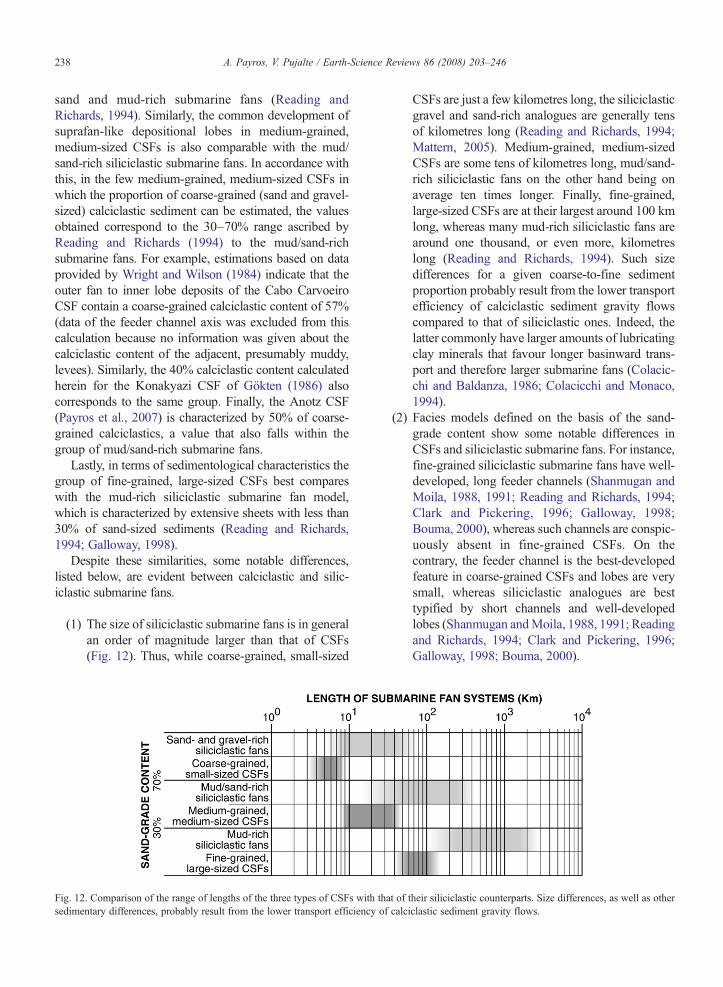
238 A. Payros, V. Pujalte / Earth-Science Reviews 86 (2008) 203–246
sand and mud-rich submarine fans (Reading andRichards, 1994). Similarly, the common development ofsuprafan-like depositional lobes in medium-grained,medium-sized CSFs is also comparable with the mud/sand-rich siliciclastic submarine fans. In accordance withthis, in the few medium-grained, medium-sized CSFs inwhich the proportion of coarse-grained (sand and gravel-sized) calciclastic sediment can be estimated, the valuesobtained correspond to the 30–70% range ascribed byReading and Richards (1994) to the mud/sand-richsubmarine fans. For example, estimations based on dataprovided by Wright and Wilson (1984) indicate that theouter fan to inner lobe deposits of the Cabo CarvoeiroCSF contain a coarse-grained calciclastic content of 57%(data of the feeder channel axis was excluded from thiscalculation because no information was given about thecalciclastic content of the adjacent, presumably muddy,levees). Similarly, the 40% calciclastic content calculatedherein for the Konakyazi CSF of Gökten (1986) alsocorresponds to the same group. Finally, the Anotz CSF(Payros et al., 2007) is characterized by 50% of coarse-grained calciclastics, a value that also falls within thegroup of mud/sand-rich submarine fans.
Lastly, in terms of sedimentological characteristics thegroup of fine-grained, large-sized CSFs best compareswith the mud-rich siliciclastic submarine fan model,which is characterized by extensive sheets with less than30% of sand-sized sediments (Reading and Richards,1994; Galloway, 1998).
Despite these similarities, some notable differences,listed below, are evident between calciclastic and silic-iclastic submarine fans.
(1) The size of siliciclastic submarine fans is in generalan order of magnitude larger than that of CSFs(Fig. 12). Thus, while coarse-grained, small-sized
Fig. 12. Comparison of the range of lengths of the three types of CSFs withsedimentary differences, probably result from the lower transport efficiency
CSFs are just a few kilometres long, the siliciclasticgravel and sand-rich analogues are generally tensof kilometres long (Reading and Richards, 1994;Mattern, 2005). Medium-grained, medium-sizedCSFs are some tens of kilometres long, mud/sand-rich siliciclastic fans on the other hand being onaverage ten times longer. Finally, fine-grained,large-sized CSFs are at their largest around 100 kmlong, whereas many mud-rich siliciclastic fans arearound one thousand, or even more, kilometreslong (Reading and Richards, 1994). Such sizedifferences for a given coarse-to-fine sedimentproportion probably result from the lower transportefficiency of calciclastic sediment gravity flowscompared to that of siliciclastic ones. Indeed, thelatter commonly have larger amounts of lubricatingclay minerals that favour longer basinward trans-port and therefore larger submarine fans (Colacic-chi and Baldanza, 1986; Colacicchi and Monaco,1994).
(2) Facies models defined on the basis of the sand-grade content show some notable differences inCSFs and siliciclastic submarine fans. For instance,fine-grained siliciclastic submarine fans have well-developed, long feeder channels (Shanmugan andMoila, 1988, 1991; Reading and Richards, 1994;Clark and Pickering, 1996; Galloway, 1998;Bouma, 2000), whereas such channels are conspic-uously absent in fine-grained CSFs. On thecontrary, the feeder channel is the best-developedfeature in coarse-grained CSFs and lobes are verysmall, whereas siliciclastic analogues are besttypified by short channels and well-developedlobes (Shanmugan andMoila, 1988, 1991; Readingand Richards, 1994; Clark and Pickering, 1996;Galloway, 1998; Bouma, 2000).
that of their siliciclastic counterparts. Size differences, as well as otherof calciclastic sediment gravity flows.

239A. Payros, V. Pujalte / Earth-Science Reviews 86 (2008) 203–246
(3) Siliciclastic submarine fans are generally suppliedvia a deeply incised slope canyon, whereas inCSFs such features are rare. Instead, sedimenttransfer to the CSFs generally occurs along upperslope gullies that merge downslope. Thus, mostsiliciclastic submarine fans are fed from a pointsource, while calciclastic fans are initially fedfrom a line source, although the converging flowslead to a final point source. As explained above,these differences imply that CSFs form only onthe slopes of distally steepened carbonate ramps,while siliciclastic submarine fans do not seemto be related to any single type of sedimentarysystem in the source area.
(4) Sedimentation rates are considerably lower inCSFs than in siliciclastic submarine fans (Fig. 5).This difference probably stems from the fact thatCSFs are only supplied with shallow marinesediments swept off the ramp by marine currents.On the contrary, siliciclastic submarine fans may befed in a similar way but also, and most importantly,they generally receive sediments from directterrestrial input through rivers that discharge tothe sea and are connected to slope canyons.
(5) The character of siliciclastic submarine fans isstrongly controlled by the slope gradient: the lowerthe gradient, the finer-grained and larger thesiliciclastic submarine fan (Shanmugan andMoiola, 1988, 1991; Reading and Richards, 1994;Galloway, 1998; Bouma, 2000). However, such arelationship does not apply to CSFs, and the type ofCSF seems to be only related to the grain size of thesediment available in the source area.
(6) Many authors (Shanmugan and Moiola, 1988,1991; Reading and Richards, 1994; Galloway,1998; Mutti et al., 1999; Bouma, 2000; Mattern,2005) have pointed out that coarse-grained silici-clastic submarine fans form on tectonically activemargins, whereas fine-grained fans are generallyassociated with passive margins. In the case ofCSFs, all fine, medium and coarse-grained systemswere formed on tectonically active margins.
9. Conclusions
Calciclastic submarine fans are comparatively rare inthe stratigraphic record and no bona fide present-dayanalogue has been found to date, the only candidatesreported so far being Quaternary slope deposits off SouthAustralia. According to the literature search carried outherein, over the last three decades thirty-seven Phanero-zoic calciclastic slope units have been considered as, or
described using the terminology of, calciclastic submarinefans. However, after a thorough sedimentological reviewonly 21 indisputably fit such an interpretation.
Four of the CSFs are coarse-grained, calcirudite beingdominant andmud absent, and small-sized, less than 10 kmin length. A leveed feeder channel is the main depozone inthese CSFs, while lobes are generally small and poorlydeveloped. Fourteen out of the 21 CSFs are medium-grained, calcarenite being dominant but calcirudites andmud being present, and medium-sized, 10–35 km inlength. They are typified by a tributary network of smallslope gullies, which merge to form a major leveed channelthat opens to the main depositional site, characterized byextensive lobes and/or sheets, which eventually pass intobasinal deposits through a narrow fan-fringe area. Finally,another three CSFs are fine-grained, calcarenites and mudbeing dominant and calcirudites practically absent, andlarge-sized, 50–120 km in length. Extensive calciturbiditicsheets fed through large slope channels constitute theirmost important sedimentary feature.
When compared with siliciclastic submarine fans, thethree types of CSFs show coarse-to-fine sediment ratiossimilar to those in sand/gravel-rich, mud/sand-rich andmud-rich siliciclastic submarine fans, respectively. How-ever, CSFs are one order of magnitude smaller and shownotable differences in terms of sedimentary architecture.These differences probably stem from the differentbehaviour of calciclastic and siliciclastic sediment-gravityflows, the larger amount of lubricating clays in the latterfavouring longer basinward sediment transport. Othersignificant difference is that siliciclastic submarine fansare generally fed across a slope canyon, whereas CSFs areinitially line-sourced and it is only when upper slopegullies merge downslope that the point-sourced CSFsystem develops. This implies that an intra-slopesediment gravity flow funnelling mechanism is neededto form CSFs. In most of the case studies analysed hereinfavourable conditions were created by tectonicallyinduced downslope-directed depressions, which acted asconduits across which sediment gravity flows werefunnelled. However, it is thought that other circumstances(e.g. inherited topography or mass failures) leading to asimilar slope configuration may be equally effective. Inthe absence of such a funnelling mechanism calciclasticslope aprons are a more likely slope sedimentary system.
The fact that most of the CSFs formed under a certaincombination of geological conditions shows that, inaddition to an efficient intra-slope funnelling mechanism,other requirements are necessary for their formation.Thus, most of the calciclastic submarine fans were formedon low-angle slopes and sourced from distally steepenedcarbonate ramps subjected to high-energy currents. These

240 A. Payros, V. Pujalte / Earth-Science Reviews 86 (2008) 203–246
conditions seem to have been more easily met on leewardmargins subjected to environmental conditions thathampered the formation of reefs (i.e. cool waters, nutrientenrichment, oligophoty, etc.). Basinwards transfer ofshallow-water sediments mainly occurred during sea-level lowstands, when overpressured pore-waters desta-bilized sediments and the carbonate factory was broughtcloser to the slope break.
Acknowledgements
Research funded by Projects CGL2005-02770/BTE(Department of Science and Technology, Spanish Gov-ernment) and 9/UPV00121.310-1455/2002 (Universityof the Basque Country). Dr. C.E. Mitchell (University atBuffalo, The State University of New York, USA) kindlyprovided valuable information on the Dolgeville Fm, andso did Dr. L.V. Duarte (Universidade de Coimbra,Portugal) on the Cabo Carvoeiro Fm, and Dr. S.J.Gallagher (University of Melbourne, Australia) on theAlbacore Gr. Thanks to Drs. A. Arnaud-Vanneau and H.Arnaud for guiding the first author to the Borne Fmduring the 1992 “Platform margins” congress and field-trip. Thanks are due to Carl Sheaver for his assistancewith the English language. Two anonymous reviewersprovided insightful comments that helped improve theoriginal manuscript. We are grateful to the followingpublishers for permission to use copyrighted material:Elsevier (Figs. 3A, B and 4A), Blackwell (Figs. 2A, B,3C, 4B and quotations in Sections 3, 5.1 and 6.2), andAAPG (Fig. 2C and quotation in Section 6). We are alsoindebted to their respective authors for their consent touse their material.
References
Andresen, N., Reijmer, J.J.G., Droxler, A.W., 2003. Timing anddistribution of calciturbidites around a deeply submerged carbon-ate platform in a seismically active setting (Pedro Bank, NorthernNicaragua Rise, Caribbean Sea). Int. J. Earth Sci. 92, 573–592.
Arnaud, H., Arnaud-Vanneau, A., 1989. Séquences de dépôt etvariations du niveau relatif de la mer au Barrémien et à l'Aptieninférieur dans les massifs subalpins septentrionaux et le Jura (SEde la France). Bull. Soc. Geol. Fr. 8, 651–660.
Azêredo, A.C., 1998. Geometry and facies dynamics of MiddleJurassic carbonate ramp sandbodies, west-central Portugal. In:Wright, V.P., Burchette, T.P. (Eds.), Carbonate Ramps. Geol. Soc.London, Spec. Publ., vol. 149, pp. 281–314.
Azêredo, A.C., Wright, V.P., Ramalho, M.M., 2002. The Middle-LateJurassic forced regression and disconformity in central Portugal:eustatic, tectonic and climatic effects on a carbonate ramp system.Sedimentology 49, 1339–1370.
Bassi, D., 1998. Coralline algal facies and their palaeoenvironments inthe Late Eocene of Northern Italy (Calcare di Nago, Trento). Facies39, 179–202.
Bassi, D., 2005. Larger foraminiferal and coralline algal facies in anUpper Eocene storm-influenced, shallow-water carbonate platform(Colli Berici, north-eastern Italy). Palaeogeogr. Palaeoclim.Palaeoecol. 226, 17–35.
Ben Yaïch, A., Hervouët, Y., Duée, G., 1991. Les turbidites calcairesdu passage Jurassique–Crétacé du Rif externe occidental(Maroc): processus et contrôle de dépôt. Bull. Soc. Geol. Fr.162, 841–850.
Bernecker, T., Partridge, A.D., Webb, J.A., 1997. Mid-Late Tertiarydeep-water temperate carbonate deposition, offshore GippslandBasin, Southeastern Australia. In: James, N.P., Clarke, J.A.D. (Eds.),Cool-water Carbonates. SEPM Spec. Publ., vol. 56, pp. 221–236.
Bernoulli, D., 1988. Ternate formation, a Late Eocene bioclasticsubmarine fan of the Lombardian Basin (Southern Alps). AAPGBull. 72, 988.
Bersezio, R., Barbieri, P., Mozzi, R., 2002. Redeposited limestones inthe Upper Cretaceous succession of the Helvetic Argentera Massifat the Italy–France border. Eclogae Geol. Helv. 95, 15–30.
Betzler, C., Reijmer, J.J., Bernet, K., Eberli, G., Anselmetti, F.V., 1999.Sedimentary patterns and geometries of the Bahamian outercarbonate ramp (Miocene–Lower Pliocene, Great Bahama Bank).Sedimentology 46, 1127–1143.
Betzler, C., Pfeiffer, M., Saxena, S., 2000. Carbonate shedding andsedimentary cycles of a distally steepened carbonate ramp(Miocene, Great Bahama Bank). Int. J. Earth Sci. 89, 140–153.
Bigi, S., Pisani, P.C., 2005. From a deformed peri-Tethyan carbonateplatform to a fold-and-thrust belt: a example from the centralApennines (Italy). J. Struct. Geol. 27, 523–539.
Bievre, G., Quesne, D., 2004. Synsedimentary collapse on a carbonateplatform margin (lower Barremian, southern Vercors, SE France).Geodiversitas 26, 169–184.
Boreen, T.D., James, N.P., 1993. Holocene sediment dynamics on acool-water carbonate shelf: Otway, southeastern Australia. J. Sedim.Petrol. 63, 574–588.
Bosellini, F.R., 1998. Diversity, composition and structure of LateEocene shelf-edge coral associations (Nago Limestone, northernItaly). Facies 39, 203–226.
Bosellini, A., Masetti, D., Sarti, M., 1981. A Jurassic “tongue of theocean” infilled with oolitic sands: the Belluno Trough, VenetianAlps, Italy. Mar. Geol. 44, 59–95.
Bouchette, F., Seguret, M., Moussine-Pouchkine, A., 2001. Coarsecarbonate breccias as a result of water-wave cyclic loading(uppermost Jurassic–South-East Basin, France). Sedimentology 48,767–789.
Bouma, A.H., 2000. Coarse-grained and fine-grained turbidite systemsas end member models: applicability and dangers. Mar. Pet. Geol.17, 137–143.
Braga, J.C., Martin, J.M., Wood, J.L., 2001. Submarine lobes andfeeder channels of redeposited, temperate carbonate and mixedsiliciclastic–carbonate platform deposits (Vera Basin, Almeria,southern Spain). Sedimentology 48, 99–116.
Braunstein, J., 1961. Calciclastic and siliciclastic. AAPGBull. 45, 2017.Brett, C.E., Baird, G.C., 2002. Revised stratigraphy of the Trenton
Group in its type area, central New York State: sedimentology andtectonics of a Middle Ordovician shelf-to-basin succession. Phys.Chem. Earth 27, 231–263.
Brett, C.E., McLaughlin, P.I., Cornell, S.R., Baird, G.C., 2004.Comparative sequence stratigraphy of two classic UppeerOrdovician successions, Trenton Shelf (New York–Ontario) andLexington Platform (Kentucky–Ohio): implications for eustasyand local tectonism in eastern Laurentia. Palaeogeogr. Palaeoclim.Palaeoecol. 210, 295–329.

241A. Payros, V. Pujalte / Earth-Science Reviews 86 (2008) 203–246
Brookfield, M.E., 1988. A mid-Ordovician temperate carbonate shelf—the Black River and Trenton Limestone Groups of southern Ontario,Canada. Sediment. Geol. 60, 137–153.
Brookfield, M.E., Blechsmidt, I., Hannigan, R., Coniglio, M.,Simonson, B., Wilson, G., 2006. Sedimentology and geochemistryof extensive very coarse deepwater submarine fan sediments in theMiddle Jurassic of Oman, emplaced by giant tsunami triggered bysubmarine mass flows. Sediment. Geol. 192, 75–98.
Burchette, T.P., Wright, V.P., 1992. Carbonate ramp depositionalsystems. Sediment. Geol. 79, 3–57.
Carannante, G., Cherchi, A., Simone, L., 1995. Chlorozoan versusforamol lithofacies in Upper Cretaceous rudist limestones.Palaeogeogr. Palaeoclim. Palaeoecol. 119, 137–154.
Carannante, G., Graziano, R., Ruberti, D., Simone, L., 1997. UpperCretaceous temperate-type open shelves from northern (Sardinia)and southern (Apennines–Apulia) Mesozoic Tethyan margins. In:James, N.P., Clarke, J.A.D. (Eds.), Cool-water Carbonates. SEPMSpec. Publ., vol. 56, pp. 308–325.
Carannante, G., Graziano, R., Pappone, G., Ruberti, D., Simone, L.,1999. Depositional system and response to sea level oscillations ofthe Senonian rudist-bearing carbonate shelves: examples fromcentral Mediterranean areas. Facies 40, 1–24.
Carannante, G., Signore, M., Vigorito, M., 2006. Vertebrate-richPlattenkalk of Pietraroia (Lower Cretaceous, Southern Apennines,Italy): a new model. Facies 52, 555–577.
Carbone, F., Sirna, G., 1981. Upper Cretaceous reef models fromRocca di Cave and adjacent areas in Latium, central Italy. In:Toomey, D.F. (Ed.), European Fossil Reef Models. SEPM Spec.Publ., vol. 30, pp. 427–445.
Cathro, D.L., Austin Jr., J.A., Moss, G.D., 2003. Progradation along adeeply submerged Oligocene–Miocene heterozoan carbonateshelf: how sensitive are clinoforms to sea level variations.AAPG Bull. 87, 1547–1574.
Carvalho, J., Matias, H., Torres, L., Manupella, G., Pereira, R.,Mendes-Victor, L., 2005. The structural and sedimentary evolutionof the Arruda and Lower Tagus sub-basins, Portugal. Mar. Pet.Geol. 22, 427–453.
Cattaneo, G., 1991. Évolution sédimentaire et paléogéographie duJrassique supérieur et du Crétacé basal de l'avant-pays rifain oriental(Maroc). Bull. Soc. Geol. Fr. 162, 69–78.
Cherchi, A., Murru, M., Simone, L., 2000. Miocene carbonatefactories in the syn-rift Sardinian Graben Subbasins (Italy). Facies43, 223–240.
Cisne, J.L., Karig, D.E., Rabe, B.D., Hay, B.J., 1982. Topography andtectonics of the Taconic outer trench slope as revealed throughgradient analysis of fossil assemblages. Lethaia 15, 229–246.
Clark, J.D., Pickering, K.T., 1996. Architectural elements and growthpatterns of submarine channels: application to hydrocarbon explo-ration. AAPG Bull. 80, 194–221.
Clark, J.D., Kenyon, N.H., Pickering, K.T., 1992. Quantitativeanalysis of the geometry of submarine channels: implications forthe classification of submarine fans. Geology 20, 633–636.
Colacicchi, R., Baldanza, A., 1986. Carbonate turbidites in a Mesozoicpelagic basin: scaglia formations, Apennines — comparison withsiliciclastic depositional models. Sediment. Geol. 48, 81–105.
Colacicchi, R., Monaco, P., 1994. Pure carbonate gravity flow depositsof the scaglia basin compared with central Apennine siliciclastics(Marnoso–Arenacea and Laga): analogies and differences. Mem.Sci. Geol. 46, 23–41.
Coniglio, M., Dix, G.R., 1992. Carbonate slopes. In: Walker, R.G.,James, N.P. (Eds.), Facies models: Response to Sea-level Changes.Geol. Assoc. Canada, Newfoundland, pp. 349–374.
Conolly, J.R., Von der Borch, C.C., 1967. Sedimentation andphysiography of the sea floor south of Australia. Sediment. Geol. 1,181–220.
Cook, H.E., 1983. Ancient carbonate platform margins, slopes andbasins. In: Cook, H.E., Hine, A.C., Mullins, H.T. (Eds.), PlatformMargin and Deep-water Carbonates. SEPM Short Course, vol. 12,pp. 5.1–5.189.
Cook, H.E., Egbert, R.M., 1981. Carbonate submarine fan facies alonga Paleozoic prograding continental margin, western United States.AAPG Bull. 65, 913.
Cook, H.E., Mullins, H.T., 1983. Basin margin. In: Scholle, P.A.,Bebout, D.G., Moore, C.H. (Eds.), Carbonate DepositionalEnvironments. AAPG Mem., vol. 33, pp. 539–617.
Cook, H.E., Taylor, M.E., 1987. Stages in evolution of Paleozoiccarbonate platform and basin margin types — Western UnitedStates passive continental margin. AAPG Bull. 71, 542–543.
Cook, H.E., McDaniel, P.N., Mountjoy, E.W., Pray, L.C., 1972.Allochthonous carbonate debris flows at Devonian bank (“reef”)margins, Alberta, Canada. Bull. Can. Pet. Geol. 20, 439–497.
Cook, H.E., Magoon, L.B., Stanley, R.G., Casas, A., 1987.Carbonate submarine fans and aprons in Frontier Region:carboniferous Calico Buff Formation, east-central Alaska.AAPG Bull. 71, 542.
Cook, H.E., Taylor, M.E., Zhemshuzhnikov, S.V., Apollonov, M.K.,Ergaliev, G.K., Sargaskaev, Z.S., Dubinina, S.V., 1991. Compar-ative development of the western United States and southernKazakhstan, Soviet Union: two Early Paleozoic carbonate passivemargins. AAPG Bull. 75, 360.
Cooper, D.J.W., 1989. A longitudinal carbonate fan from the Jurassicof the Oman Mountains: the Guweyza Limestone Formation of theHamrat ad Duru. Sediment. Geol. 61, 253–275.
Cooper, D.J.W., 1990. Sedimentary evolution and paleogeographicalreconstruction of the Mesozoic continental rise in Oman: evidencefrom the Hamrat Duru Group. Spec. Publ. - Geol. Soc. Lond. 49,161–187.
Dasgupta, P., 2003. Sediment gravity flow— the conceptual problem.Earth-Sci. Rev. 62, 265–281.
Dickinson, J.A., Wallace, M.W., Holdgate, G.R., Daniels, J., Gallagher,S.J., Thomas, L., 2001. Neogene tectonics in SE Australia:implications for petroleum systems. APPEA J. 41, 37–52.
Di Giulio, A., Carrapa, B., Fantoni, R., Gorla, L., Valdisturlo, A.,2001. Middle Eocene to Early Miocene sedimentary evolution ofthe western Lombardian segment of the South Alpine foredeep(Italy). Int. J. Earth Sci. 90, 534–548.
Droxler, A.W., Vandenbroucke, M., Fabre, M., Cartwright, R.A.,Schlager, W., 1987. Source rock potential of fine sedimentdeposited in Eleuthera and San Salvador deep-sea carbonatefans, Bahamas. AAPG Bull. 71, 550.
Duarte, L.V., Wright, V.P., Fernandez-Lopez, S., Elmi, S., Krautter,M., Azêredo, A., Henriques, M.H., Rodrigues, R., Perilli, N., 2004.Early Jurassic carbonate evolution in the Lusitanian Basin(Portugal): facies, sequence stratigraphy and cyclicity. In: Duarte,L.V., Henriques, M.H. (Eds.), Field Trip Guidebook. Carbonifer-ous and Jurassic Carbonate Platforms of Iberia. IAS 23rd Meeting,Coimbra, Portugal, vol. 1, pp. 47–71.
Dunham, J., 1962. Classification of carbonate rocks according todepositional textures. In: Ham, W.E. (Ed.), Classification ofCarbonate Rocks. AAPG Mem., vol. 1, pp. 108–121.
Eberli, G.P., 1991. Calcareous turbidites and their relationship to sea-level fluctuations and tectonism. In: Einsele, G., Ricken, W.,Seilacher, A. (Eds.), Cycles and Events in Stratigraphy. Springer-Verlag, Berlin, pp. 340–359.

242 A. Payros, V. Pujalte / Earth-Science Reviews 86 (2008) 203–246
Eberli, G.P., Bernoulli, D., Sanders, D., Vecsei, A., 1993. Fromaggradation to progradation: the Maiella platform, Abruzzi, Italy.In: Simo, T., Scott, R.W., Masse, J.P. (Eds.), Atlas of CretaceousCarbonate Platforms. AAPG Mem., vol. 56, pp. 213–232.
Eberli, G.P., Anselmetti, F.S., Kroon, D., Sato, T., Wright, J.D., 2002.The chronostratigraphic significance of seismic reflections alongthe Bahamas Transect. Mar. Geol. 185, 1–17.
Elison, M.W., Speed, R.C., 1988. Triassic flysch of the Fencemakerallochthon, East Range, Nevada: fan facies and provenance. GSABull. 100, 185–199.
Enos, P., Moore, C.H., 1983. Fore-reef slope. In: Scholle, P.A., Bebout,D.G., Moore, C.H. (Eds.), Carbonate Depositional Environments.AAPG Mem., vol. 33, pp. 507–538.
Embry, A.F., Klovan, J.E., 1971. A late Devonian reef tract onnortheastern Banks Island, northwest territories. Bull. Can. Pet.Geol. 19, 730–781.
Everts, A.J.W., 1991. Interpreting compositional variations ofcalciturbidites in relation to platform-stratigraphy: an examplefrom the Paleogene of SE Spain. Sediment. Geol. 71, 231–242.
Exon, N.F., Hill, P.J., Mitchell, C., Post, A., 2005. Nature and origin ofthe submarine Albany canyons off southwest Australia. Austral.J. Earth Sci. 52, 101–115.
Favre, P., Stampfli, G., Wildi, W., 1991. Jurassic sedimentary recordand tectonic evolution of the nortwestern corner of Africa.Palaeogeogr. Palaeoclim. Palaeoecol. 87, 53–73.
Fenerci-Masse, M., Masse, J.P., Pernarcic, E., 2005. Quantitativestratigraphy of rudist limestones and its bearing on spatialorganisation of rudist communities: the Late Barremian, Urgonian,sequences of Provence (SE France). Palaeogeogr. Palaeoclim.Palaeoecol. 215, 265–284.
Ferry, S., 1979. Les turbidites bioclastiques: mode de transport dusable calcaire des plates-formes Urgoniennes a la cuvetteVocontienne (SE de la France). Geobios, Mem. Spec. 3,149–158.
Gallagher, S.J., Smith, A.J., Jonasson, K., Wallace, M.W., Holdgate,G.R., Daniels, J., Taylor, D., 2001. The Miocene palaeoenviron-mental and palaeoceanographic evolution of the Gippsland Basin,southeast Australia: a record of Southern Ocean change.Palaeogeogr. Palaeoclim. Palaeoecol. 172, 53–80.
Galloway, W.E., 1998. Siliciclastic slope and base-of-slope deposi-tional systems: component facies, stratigarphic architecture, andclassification. AAPG Bull. 82, 569–595.
Geel, T., 2000. Recognition of stratigraphic sequences in carbonateplatform and slope deposits: empirical models based on micro-facies analysis of Palaeogene deposits in southeastern Spain.Palaeogeogr. Palaeoclim. Palaeoecol. 155, 211–238.
Geel, T., Roep, T.B., Van Hinte, J.E., 1998. Eocene tectono-sedimentary patterns in the Alicante region (southeastern Spain).In: De Graciansky, P.C., Hardenbol, J., Jacquin, T., Vail, P.R.(Eds.), Mesozoic and Cenozoic Sequence Stratigraphy of Europe-an Basins. SEPM Spec. Publ., vol. 60, pp. 289–302.
Ghibaudo, G., 1992. Subaequeous sediment gravity flow deposits:practical criteria for their field description and classification.Sedimentology 39, 423–454.
Gillett, S.L., 1983. Major, through-going stylolites in the LowerOrdovician Doodwin Limestone, southern Nevada: petrographywith dating from paleomagnetism. J. Sediment. Petrol. 53, 209–219.
Gökten, Y.E., 1986. Paleocene carbonate turbidites of the Sarkislaregion, Turkey: their significance in an orogenic basin. Sediment.Geol. 49, 143–165.
Grandstein, F.M., Ogg, J.G., Smith, A.G., 2004. A Geologic TimeScale 2004. Cambridge Univ. Press, Cambridge.
Hazlett, B.H., Warme, J.E., 1988. Shelf-to-basin resedimentedcarbonates of the southern margin of the Jurassic central HighAtlas trough, Morocco. AAPG Bull. 72, 1006.
Herb, R., 1976. Das Alter der eozanen Sedimente im suwestlichenVaresotto (Norditalian). Eclogae Geol. Helv. 69, 821–825.
Hilbrecht, H., 1989. Redeposition of Late Cretaceous pelagicsediments controlled by sea-level fluctuations. Geology 17,1072–1075.
Hill, P.J., De Deckker, P., Exon, N.F., 2005. Geomorphology andevolution of the gigantic Murray canyons on the Australiansouthern margin. Aust. J. Earth Sci. 52, 117–136.
Hillgärtner, H., Van Buchem, F.S.P., Gaumet, F., Razin, P., Pittet, B.,Grötsch, J., Droste, H., 2003. The Barremian–Aptian evolution ofthe eastern Arabian carbonate platform margin (northern Oman).J. Sediment. Res. 73, 756–773.
Hobson, J.P., Caldwell, C.D., Toomey, D., 1985. Early Permian deep-water allochthonous limestone facies and reservoir, west Texas.AAPG Bull. 68, 2130–2147.
Holdgate, G.R., Wallace, M.W., Daniels, J., Gallagher, S.J., Keene, J.B.,Smith, A.J., 2000. Controls on Seaspray Group sonic velocities inthe Gippsland Basin — a multidisciplinary approach to the canyonseismic velocity problem. APPEA J. 40, 295–313.
Hunt, D., Tucker, M.E., 1993a. Sequence stratigraphy of carbonateshelves with an example from the mid-Cretaceous (Urgonian) ofsoutheast France. In: Posamentier, H.W., Summerhayes, C.P., Haq,B.U., Allen, G.P. (Eds.), Sequence Stratigraphy and FaciesAssociations. IAS Spec. Publ., vol. 18, pp. 307–341.
Hunt, D., Tucker, M.E., 1993b. The Middle Cretaceous Urgonianplatform of southeastern France. In: Simo, T., Scott, R.W.,Masse, J.P. (Eds.), Atlas of Cretaceous Carbonate Platforms.AAPG Mem., vol. 56, pp. 409–453.
Ingram, R.L., 1954. Terminology for the thickness of stratification andparting units in sedimentary rocks. GSA Bull. 65, 937–938.
Ito, G., Clift, P.D., 1998. Subsidence and growth of Pacific Cretaceousplateaus. Earth Planet. Sci. Lett. 161, 85–100.
Jacobi, R.D., Mitchell, C.E., 2002. Geodynamical interpretation of amajor unconformity in the Taconic Foredeep: slide scar or onlapunconformity? Phys. Chem. Earth 27, 169–201.
Jacquin, T., Arnaud-Vanneau, A., Arnaud, H., Ravenne, C., Vail, P.R.,1991. Systems tracts and depositional sequences in a carbonatesetting: study of continuous outcrops from platform to basin at thescale of seismic lines. Mar. Pet. Geol. 8, 122–139.
Jacquin, T., Rusciadelli, G., Amedro, F., DeGraciansky, P.C.,Magniez-Jannin, F., 1998. The northAtlantic cycle: an overview of 2nd-ordertransgressive/regressive facies cycles in the Lower Cretaceous ofwestern Europe. In: De Graciansky, P.C., Hardenbol, J., Jacquin, T.,Vail, P.R. (Eds.), Mesozoic and Cenozoic Sequence Stratigraphy ofEuropean basins. SEPM Spec. Publ., vol. 60, pp. 397–409.
James, J., 1997. The cool-water carbonate depositional realm. In:James, N.P., Clarke, J.A.D. (Eds.), Cool-water Carbonates. SEPMSpec. Publ., vol. 56, pp. 1–20.
Jonk, R., Biermann, C., 2002. Deformation in Neogene sediments ofthe Sorbas and Vera basins (SE Spain): constraints on simple-sheardeformation and rigid body rotation along major strike-slip faults.J. Struct. Geol. 24, 963–977.
Joseph, P., Beaudoin, B., Sempere, T., Maillart, J., 1988. Vallées sous-marines et systèmes d'épandages carbonates du Berriasienvocontien (Alpes méridionales françaises). Bull. Soc. Geol. Fr. 3,363–374.
Joy, M.P., Mitchell, C.E., Adhya, S., 2000. Evidence of a tectonicallydriven sequence succession in the Middle Ordovician Taconicforedeep. Geology 28, 727–730.

243A. Payros, V. Pujalte / Earth-Science Reviews 86 (2008) 203–246
Klaucke, I., Hesse, R., 1996. Fluvial features in the deep-sea: newinsights from the glacigenic submarine drainage system of theNorthwest Atlantic Mid-Ocean Channel in the Labrador Sea.Sediment. Geol. 106, 223–234.
Kuhnt, W., 1990. Agglutinated foraminifera of Western MediterraneanUpper Cretaceous pelagic limestones (Umbrian Apennines, Italy,and Betic Cordillera, Southern Spain). Micropaleontology 36,297–330.
Kullberg, J.C., Oloriz, F., Marques, B., Caetano, P.S., Rocha, R.B.,2001. Flat-pebble conglomerates: a local marker for Early Jurassicseismicity related to syn-rift tectonics in the Sesimbra area(Lusitanian Basin, Portugal). Sediment. Geol. 139, 49–70.
Lash, G.G., Filock, J.R., 1984. Paleozoic carbonate deep-sea fansedimentation: evidence for Late Cambrian regression. AAPGBull. 68, 1922.
Lavoie, D., 1995. A Late Ordovician high-energy temperate-watercarbonate ramp, southern Quebec, Canada: implications for LateOrdovician oceanography. Sedimentology 42, 95–116.
Leary, D.A., Feeley,M.H., 1991. Seismic expression and sedimentologiccharacteristics of a Permian (Wolfcampian) carbonate submarine fan,Midland Basin, west Texas. In: Weimer, P., Link, M.H. (Eds.),Seismic Facies and Sedimentary Processes of Submarine Fans andTurbidite Systems. Springer-Verlag, New York, pp. 303–315.
Lehmann, D., Brett, C.E., Cole, R., Baird, G., 1995. Distalsedimentation in a peripheral foreland basin: Ordovician blackshales and associated flysch of the western Taconic foreland, NewYork State and Ontario. GSA Bull. 107, 708–724.
Marchegiani, L., Bertotti, G., Cello, G., Deiana, G., Mazzoli, S., Tondi,E., 1999. Pre-orogenic tectonics in the Umbria–Marche sector of theAfro-Adriatic continental margin. Tectonophysics 315, 123–143.
Masaferro, J.L., Bulnes, M., Poblet, J., Eberli, G.P., 1999. Episodicfolding inferred from syntectonic carbonate sedimentation: theSantaren anticline, Bahamas foreland. Sediment. Geol. 146,11–24.
Masaferro, J.L., Poblet, J., Bulnes, M., Eberli, G.P., Dixon, T.H.,McClay, K., 2002. Palaeogene–Neogene/present day(?) growthfolding in the Bahamian foreland of the Cuban fold and thrust belt.J. Geol. Soc. (Lond.) 156, 617–631.
Masse, J.P., 1993. Valanginian–Early Aptian carbonate platformsfrom Provence, southeastern France. In: Simo, T., Scott, R.W.,Masse, J.P. (Eds.), Atlas of Cretaceous Carbonate Platforms.AAPG Mem., vol. 56, pp. 363–374.
Masse, J.P., Philip, J., 1981. Cretaceous coral–rudist buildups ofFrance. In: Toomey, D.F. (Ed.), European Fossil Reef Models.SEPM Spec. Publ., vol. 30, pp. 399–426.
Masse, J.P., Borgomano, J., Al Maskiry, S., 1998. A platform-to-basintransition for Lower Aptian carbonates (Shuaiba Formation) of thenortheastern Jebel Akhdar (Sultanate of Oman). Sediment. Geol.119, 297–309.
Mattern, F., 2005. Ancient sand-rich submarine fans: depositionalsystems, models, identification, and analysis. Earth-Sci. Rev. 70,167–202.
Mazzullo, S.J., 1994. Lithification and porosity evolution in Permianperiplatform limestones, Midland Basin, Texas. Carbonates andEvaporites 9, 151–171.
Mitchell, C.E., Goldman, D., Delano, J.W., Samson, S.D., Bergström,S.M., 1994. Temporal and spatial distribution of biozones andfacies relative to geochemically correlated K-bentonites in theMiddle Ordovician Taconic foredeep. Geology 22, 715–718.
Mitchell, J.K., Holdgate, G.R., Wallace, M.W., 2007a. Pliocene–Pleistocene history of the Gippsland basin outer shelf and canyonheads, Southeast Australia. Aust. J. Earth Sci. 54, 49–64.
Mitchell, J.K., Holdgate, G.R., Wallace, M.W., Gallagher, S.J., 2007b.Marine geology of the Quaternary Bass Canyon system, southeastAustralia: a cool-water carbonate system. Mar. Geol. 237, 71–96.
Molina, J.M., O'Dogherty, L., Sandoval, J., Vera, J.A., 1999a. Jurassicradiolarites in a Tethyan continental margin (Subbetic, southernSpain): palaeobathymetric and biostratigraphic considerations.Palaeogeogr. Palaeoclim. Palaeoecol. 150, 309–330.
Molina, J.M., Ruiz-Ortiz, P.A., Vera, J.A., 1999b. A review ofpolyphase karstification in extensional tectonic regimes: Jurassicand Cretaceous examples, Betic Cordillera, southern Spain.Sediment. Geol. 129, 71–84.
Montanari, A., Chan, L.S., Alvarez, W., 1989. Synsedimentarytectonics on the Late Cretaceous–Early Tertiary pelagic basin ofthe northern Apennines, Italy. In: Crevello, P.D., Wilson, J.L.,Sarg, J.F., Read, J.F. (Eds.), Controls on Carbonate Platform andBasin Development. SEPM Spec. Publ., vol. 44, pp. 379–399.
Montgomery, S.L., 1996. Permian “Wolfcamp” limestone reservoirs:Powell Ranch field, Eastern Midland Basin. AAPG Bull. 80,1349–1365.
Mullins, H.T., Cook, H.E., 1986. Carbonate slope apron models:alternatives to the submarine fan model for paleoenvironmentalanalysis and hydrocarbon exploration. Sediment. Geol. 48, 37–79.
Mutti, E., Normark, W.R., 1987. Comparing examples of modern andancient turbidite systems: problems and concepts. In: Leggett, J.K.,Zuffa, G.G. (Eds.), Marine Clastic Sedimentology: Concepts andCase Studies. Graham and Trotman, London, pp. 1–38.
Mutti, E., Ricci Lucchi, F., 1972. Le torbiditi dell'Appenninosettentrionale: introduzione all'analisi di facies. Mem. Soc. Geol.Ital. 11, 161–199.
Mutti, M., Bernoulli, D., Eberli, G.P., Vecsei, A., 1996. Depositionalgeometries and facies associations in an Upper Cretaceousprograding carbonate platform margin (Orfento supersequence,Maiella, Italy). J. Sediment. Res. 66, 749–765.
Mutti, E., Tinterri, R., Remacha, E., Mavilla, N., Angella, S., Fava,L., 1999. An introduction to the analysis of ancient turbiditebasins from an outcrop perspective. AAPG contin. educ. coursenote ser. 39.
Nakajima, T., Satoh, M., Okamura, Y., 1998. Channel–levee complexes,terminal deep-sea fan and sediment wave fields associated with theToyama deep-sea channel system in the Japan Sea. Mar. Geol. 147,25–41.
Normark, W.R., 1970. Growth patterns of deep-sea fans. AAPG Bull.54, 2170–2195.
Oloriz, F., Linares, A., Goy, A., Sandoval, J., Caracuel, J.E.,Rodriguez-Tovar, F.J., Tavera, J.M., 2002. Jurassic, The BeticCordillera and Balearic Islands. In: Gibbons, W., Moreno, T.(Eds.), The Geology of Spain. Geol. Soc., London, pp. 235–253.
Passlow, V., 1997. Slope sedimentation and shelf to basin sedimenttransfer: accol-water carbonate example from the Otway margin,southeastern Australia. In: James, N.P., Clarke, J.A.D. (Eds.),Cool-water Carbonates. SEPM Spec. Publ., vol. 56, pp. 107–125.
Payros, A., Pujalte, V., Orue-Etxebarria, X., 2007. A point-sourcedcalciclastic submarine fan complex (Eocene Anotz Formation,western Pyrenees): facies architecture, evolution and controllingfactors. Sedimentology 54, 137–168.
Philip, J., 1993. Late Cretaceous carbonate-siliciclastic platforms ofProvence, Southeastern France. In: Simo, T., Scott, R.W., Masse,J.P. (Eds.), Atlas of Cretaceous Carbonate Platforms. AAPGMem., vol. 56, pp. 375–385.
Philip, J.M., Gari, J., 2005. Late Cretaceous heterozoan carbonates:palaeoenvironmental setting, relationships with rudist carbonates(Provence, south-east France). Sediment. Geol. 175, 315–337.

244 A. Payros, V. Pujalte / Earth-Science Reviews 86 (2008) 203–246
Pickering, K.T., Stow, D., Watson, M., Hiscott, R., 1986. Deep-waterfacies, processes and models: a review and classification schemefor modern and ancient sediments. Earth-Sci. Rev. 23, 75–174.
Pomar, L., 2001. Types of carbonate platforms: a genetic approach.Basin Res. 13, 313–334.
Pomar, L., Brandano, M., Westphal, H., 2004. Environmental factorsinfluencing skeletal grain sediment associations: a critical reviewof Miocene examples from the western Mediterranean. Sedimen-tology 51, 627–651.
Pujalte, V., Robles, S., Orue-Etxebarria, X., Baceta, J.I., Payros, A.,Larrizea, I.F., 2000. Uppermost Cretaceous–Middle Eocene strata ofthe Basque–Cantabrian region and western Pyrenees: a sequencestratigraphic perspective. Rev. Soc. Geol. Esp. 13, 191–211.
Pratt, B.R., Smewing, J.D., 1990. Early Cretaceous platform-marginconfiguration and evolution in the central Oman mountains,Arabian peninsula. AAPG Bull. 77, 225–244.
Price, I., 1977. Deposition and derivation of clastic carbonates on aMesozoic continental margin, Othris, Greece. Sedimentology 24,529–546.
Ravenne, C., 2002. Stratigraphy and Oil: A Review (part 1);Exploration and Seismic Stratigraphy: Observation and Descrip-tion. Oil and Gas Sci. Technol. — Rev. IFP, vol. 57, pp. 211–250.
Ravenne, C., Vially, R., LeQuellec, P., Valery, P., 1988. Deep clasticcarbonate deposits of the Bahamas: comparison with Mesozoicoutcrops of the Vercors and the Vocontian Trough. In: Bally, A.W.(Ed.), Atlas of Seismic Stratigraphy. AAPG Studies in Geology,vol. 27(2), pp. 104–139.
Read, J.F., 1985. Carbonate platform faciesmodels. AAPGBull. 69, 1–21.Reading, H.G., Richards, M., 1994. Turbidite systems in deep-water
basin margins classified by grain size and feeder system. AAPGBull. 78, 792–822.
Reijmer, J.J.G., Everaars, J.S.L., 1991. Carbonate platform faciesreflected in carbonate basin facies (Triassic, northern calcareousAlps, Austria). Facies 25, 253–278.
Reijmer, J.J.G., Andresen, N., 2007. Mineralogy and grain sizevariations along two carbonate margin-to-basin transects (PedroBank, Northern Nicaragua Rise). Sediment. Geol. 198, 327–350.
Reijmer, J.J.G., Ten Kate, W.G.H.Z., Sprengrer, A., Schlager, W.,1991. Calciturbidte composition related to exposure and floodingof a carbonate platform (Triassic, eastern Alps). Sedimentology 38,1059–1074.
Reinhardt, J., 1977. Cambrian off-shelf sedimentation, CentralAppalachians. In: Cook, H.E., Enos, P. (Eds.), DeepwaterCarbonate Environments. SEPM Spec. Publ., vol. 25, pp. 83–112.
Rendle-Bühring, R.H., Reijmer, J.J.G., 2005. Controls on grain-sizepatterns in periplatform carbonates: marginal setting versus glacio-eustacy. Sediment. Geol. 175, 99–113.
Richards, M., Bowman, M., Reading, H., 1998. Submarine-fansystems I: characterization and stratigraphic prediction. Mar. Pet.Geol. 15, 689–717.
Robertson, A.H.F., Clift, P.D., Degnan, P.J., Jones, G., 1991. Palaeogeo-graphic and palaeotectonic evolution of the Eastern MediterraneanNeotethys. Palaeogeogr. Palaeoclim. Palaeoecol. 87, 289–343.
Roep, T.B., Everts, A.J., 1992. Pillow-beds: a new type of seismites?An example form an Oligocene turbidite fan complex, Alicante,Spain. Sedimentology 39, 711–724.
Rousseau, M., Dromart, G., Garcia, J.P., Atrops, F., Guillocheau, F.,2005. Jurassic evolution of the Arabian carbonate platform edge inthe central Oman Mountains. J. Geol. Soc. (Lond.) 162, 349–362.
Ruiz-Ortiz, P.A., 1983. A carbonate submarine fan in a fault-controlledbasin of the Upper Jurassic, Betic Cordillera, southern Spain.Sedimentology 30, 33–48.
Saller, A.H., Barton, J.W., Barton, R.E., 1989. Slope sedimentationassociated with a vertically building shelf, Bone Spring Formation,Mescallero Escarpe Fields, southeastern New Mexico. In:Crevello, P.D., Wilson, J.L., Sarg, J.F., Read, J.F. (Eds.), Controlson Carbonate Platform and Basin Development. SEPM Spec.Publ., vol. 44, pp. 275–288.
Savary, B., 2005. Calcareous turbidity current emplacement as aninitiation mechanism for substrate brecciation and deformation. In:Hodgson, D.M., Flint, S.S. (Eds.), Submarine Slope Systems:Processes and Products. Geol. Soc. London, Spec. Publ., vol. 244,pp. 207–220.
Savary, B., Ferry, S., 2004. Geometry and petrophysical parameters ofa calcarenitic turbidite lobe (Barremian–Aptian, Pas-de-la-Cluse,France). Sediment. Geol. 168, 281–304.
Scherreiks, R., 2000. Platform margin and oceanic sedimentation in adivergent and convergent plate setting (Jurassic, Pelagonian Zone,NE Evvoia, Greece). Int. J. Earth Sci. 89, 90–107.
Seguret, M., Moussine-Pouchkine, A., Gabaglia, G.R., Bouchette, F.,2001. Storm deposits and storm-generated coarse carbonatebreccias on a pelagic outer shelf (South-East Basin, France).Sedimentology 48, 231–254.
Shanmugan, G., 1996. High-density turbidity currents: are they sandydebris flows? J. Sediment. Res. 66, 2–10.
Shanmugan, G., 1997. The Bouma sequence and the turbidite mindset. Earth-Sci. Rev. 42, 201–229.
Shanmugan, G., 2002. Ten turbidite myths. Earth-Sci. Rev. 58, 311–341.Shanmugan, G., Moila, R.J., 1988. Submarine fans: characteristics,
models, classification, and reservoir potential. Earth-Sci. Rev. 24,383–428.
Shanmugan, G., Moila, R.J., 1991. Types of submarine fan lobes:models and implications. AAPG Bull. 75, 156–179.
Simone, L., Carannante, G., Ruberti, D., Sirna, M., Sirna, G., Laviano,A., Tropeano, M., 2003. Development of rudist lithosomes in theConiacian–Lower Campanian carbonate shelves of central-south-ern Italy: high-energy vs low-energy settings. Palaeogeogr.Palaeoclim. Palaeoecol. 200, 5–29.
Smith, A.J., Gallagher, S.J., 2003. The Recent foraminifera and faciesof the Bass Canyon: a temperate submarine canyon in Gippsland,Australia. J. Micropaleontol. 22, 63–83.
Spence, G.H., Tucker, M.E., 1997. Genesis of limestone megabrecciasand their significance in carbonate sequence stratigraphic models:a review. Sedim. Geol. 112, 163–193.
Stevens, C.H., Lico, M.S., Stone, P., 1989. Lower Permian sedimentgravity-flow sequence, eastern California. Sediment. Geol. 64, 1–12.
Stow, D.A.V., 1985. Deep-sea clastics: where are we and where are wegoing? In: Brenchley, P.J., Williams, B.P.J. (Eds.), Sedimentology:Recent Developments and Applied Aspects. Geol. Soc. London,Spec Publ., vol. 18, pp. 67–93.
Stow, D.A.V., Reading, H.G., Collinson, J.D., 1996. Deep seas, In:Reading, H.G. (Ed.), Sedimentary Environments: Processes, Faciesand Stratigraphy, 3rd edition. Blackwell, Oxford, pp. 395–453.
Terrinha, P., Ribeiro, C., Kullberg, J.C., Lopes, C., Rocha, R., Ribeiro,A., 2002. Compressive episodes and faunal isolation duringrofting, Southwest Iberia. J. Geol. 110, 101–113.
Trexler Jr., J.H., Cashman, P.H., Cole, J.C., Snyder,W.S., Tosdal, R.M.,Davydov, V.I., 2003. Widespread effects of middle Mississippiandeformation in the Great Basin of western North America. GSABull. 115, 1278–1288.
Tucker, M.E., Wright, V.P., 1990. Carbonate Sedimentology. Black-well, Oxford.
Van Konijnenburg, J.H., 1997. Sedimentology and stratigraphicarchitecture of a Cretaceous to Lower Tertiary carbonate base-of-

245A. Payros, V. Pujalte / Earth-Science Reviews 86 (2008) 203–246
slope succession, Gran Sasso d'Italia, Central Apennines, Italy.PhD Thesis No. 12361, Eidgenössische Technische HhochschuleZürich, Switzerland.
Van Konijnenburg, J.H., Bernoulli, D., Mutti, M., 1999. Stratigraphicarchitecture of a Lower Cretaceous–Lower Tertiary carbonatebase-of-slope succession: Gran Sasso d'Italia (Central Apennines,Italy). In: Harris, P.M., Saller, A.H., Simo, J.A. (Eds.), Advances inCarbonate Sequence Stratigraphy: Application to Reservoirs,Outcrops and Models. SEPM Spec. Publ., vol. 63, pp. 291–315.
Vecsei, A., 1998. Bioclastic sediment lobes on a supply dominatedUpper Cretaceous carbonate platform margin, Montagna dellaMaiella, Italy. Sedimentology 45, 473–487.
Vigorito, M., Murru, M., Simone, L., 2005. Anatomy of a submarinechannel system and related fan in a foramol/rhodalgal carbonatesedimentary setting: a case study from the Miocene syn-riftSardinia Basin, Italy. Sediment. Geol. 174, 1–30.
Vigorito, M., Murru, M., Simone, L., 2006. Architectural patterns in amultistorey mixed carbonate-siliciclastic submarine channel, PortoTorresBasin,Miocene, Sardinia, Italy. Sediment. Geol. 186, 213–236.
Von der Borch, C.C., Hughes-Clarke, J.E., 1993. Slope morphologyadjacent to the cool-water carbonate shelf of South Australia:GLORIA and Sea beam imaging. Aust. J. Earth Sci. 40, 57–64.
Wallace, M.W., Holdgate, G.R., Daniels, J., Gallagher, S.J., Smith, A.,2002. Sonic velocity, submarine canyons, and burial diagenesis inOligocene–Holocene cool-water carbonates, Gippsland Basin,southeast Australia. AAPG Bull. 86, 1593–1607.
Walker, R.G., 1978. Deep-water sandstone facies and ancientsubmarine fans: models for exploration for stratigraphic traps.AAPG Bull. 62, 932–966.
Watts, K.F., 1987. Triassic carbonate submarine fans along the Arabianplatform margin, Sumeini Group, Oman. Sedimentology 34, 43–71.
Watts, K.F., 1990. Mesozoic carbonate slope facies marking theArabian platform margin in Oman: depositional history, morphol-ogy and palaeogeography. In: Robertson, A.H.F., Searle, M.P.,Ries, A.C. (Eds.), The Geology and Tectonics of the Oman Region.Geol. Soc. London, Spec. Publ., vol. 49, pp. 139–159.
Watts, K.F., Garrison, R.E., 1986. Sumeini Group, Oman: evolution ofa Mesozoic carbonate slope on a south Tethyan continental margin.Sediment. Geol. 48, 107–168.
Wilpshaar, M., Leereveld, H., 1994. Palaeoenvironmental change inthe Early Cretaceous Vocontian Trough (SE France) reflected bydinoflagellate cysts. Rev. Palaeobot. Palynol. 84, 121–128.
Wilson, M.E.J., Vecsei, A., 2005. The apparent paradox of abundantforamol facies in low latitudes: their environmental significanceand effect on platform development. Earth-Sci. Rev. 69, 133–168.
Wright, V.P.,Wilson, R.C.L., 1984. A carbonate submarine-fan sequencefrom the Jurassic of Portugal. J. Sediment. Petrol. 54, 394–412.
Wright, V.P., Burchette, T.P., 1998. Carbonate ramps. Spec. Publ. —Geol. Soc. Lond. 149 465 pp.
Zempolich, W.G., Erba, E., 1999. Sedimentologic and chemostrati-graphic recognition of third-order sequences in resedimentedcarbonate: the middle Jurassic Vajont limestone, Venetian Alps,Italy. In: Harris, P.M., Saller, A.H., Simo, J.A. (Eds.), Advances inCarbonate Sequence Stratigraphy: Application to Reservoirs,Outcrops and Models. SEPM Spec. Publ., vol. 63, pp. 291–315.
References cited in Fig. 5
Agirrezabala, L.M., Garcia-Mondejar, J., 1994. A coarse-grainedturbidite system with morphotectonic control (Middle Albian,Ondarroa, northern Iberia). Sedimentology 41, 383–407.
Browne, G.H., Slatt, R.M., 2002. Outcrop and behind-outcropcharacterizations of a Late Miocene slope fan system, Mt.Messenger Formation, New Zealand. AAPG Bull. 86, 841–862.
Clift, P.D., Robertson, A.H.F., 1990. Deep-water basins within theMesozoic carbonate platform of Argolis, Greece. J. Geol. Soc.(Lond.) 147, 825–836.
Cotillon, P., Rousselle, B., Courtinat, B., Crumiere, J.P., 1994. Evolutionof sediment fluxes from the Middle Miocene to Present at ODP Site817 (Townsville Basin, northeastern Australia) as a record ofregional paleogeographic events. Mar. Geol. 121, 265–291.
De Vay, J.C., Risch, D., Scott, E., Thomas, C., 2000. A Mississippi-sourced Middle Miocene (M4), fine-grained abyssal plain fancomplex, Northeastern Gulf of Mexico. In: Bouma, A.H., Stone,C.G. (Eds.), Fine-grained Turbidite Systems. AAPG Mem. 72 —SEPM Spec. Publ., vol. 68, pp. 221–236.
Dowdeswell, J.A., Siegert, M.J., 1999. Ice-sheet numerical modelingand marine geophysical measurement of glacier-derived sedimen-tation on the Eurasian Arctic continental margins. GSA Bull. 111,1080–1097.
Eberli, G.P., 1987. Carbonate turbidite sequences deposited in rift-basins of the Jurassic Tethys Ocean (eastern Alps, Switzerland).Sedimentology 34, 363–388.
Gervais, A., Mulder, T., Savoye, B., Gonthier, E., 2006. Sedimentdistribution and evolution of sedimentary processes in a smallsandy turbidite system (Golo system, Mediterranean Sea):implications for various geometries based on core framework.Geo-Mar. Lett. 26, 373–395.
Immenhauser, A., Van der Kooij, B., Van Vliet, A., Schlager, W., 2001.An ocean-facing Aptian–Albian carbonate margin, Oman. Sedi-mentology 48, 1187–1207.
Kähler, G., Stow, D.A.V., 1998. Turbidites and contourites of thePalaeogene Lefkara Formation, southern Cyprus. Sediment. Geol.115, 215–231.
McNeill, D.F., 2005. Accumulation rates from well-dated Neogenecarbonate platforms and margins. Sediment. Geol. 175, 73–87.
Mikkelsen, N., Maslin, M., Giraudeau, J., Showers, W., 1997.Biostratigraphy and sedimentation rates of the Amazon fan. In:Flood, R.D., Piper, D.J.W., Klaus, A., Peterson, L.C. (Eds.), Proc.ODP. Sci. Res., vol. 155, pp. 577–594.
Miller, R.P., Heller, P.L., 1994. Depositional framework and controlson mixed carbonate-siliciclastic gravity flows: Pennsylvanian–Permian shelf to basin transect, south-western Great Basin, USA.Sedimentology 41, 1–20.
Normark, W.R., Piper, D.J.W., Sliter, R., 2006. Sea-level and tectoniccontrol of middle to late Pleistocene turbidite systems in Santamonica Basin, offshore California. Sedimentology 53, 867–897.
Oms, O., Dinares-Turell, J., Remacha, E., 2003. Magnetic stratigraphyfrom deep clastic turbidites: an example from the Eocene HechoGroup (southern Pyrenees). Stud. Geophys. Geod. 47, 275–288.
Payros, A., Pujalte, V., Orue-Etxebarria, X., 1999. The South PyreneanEocene carbonate megabreccias revisited: new interpretation basedon evidence from the Pamplona Basin. Sediment. Geol. 125,165–194.
Pujalte, V., Baceta, J.I., Orue-Etxebarria, X., Payros, A., 1998.Paleocene strata of the Basque Country, western Pyrenees, northernSpain: facies and sequence development in a deep-water starvedbasin. In: De Graciansky, P.C., Hardenbol, J., Jacquin, T., Vail, P.R.(Eds.), Mesozoic and Cenozoic Sequence Stratigraphy of EuropeanBasins. SEPM Spec. Publ., vol. 60, pp. 311–325.
Remacha, E., Fernandez, L.P., Maestro, E., 2005. The transition betweensheet-like lobe and basin-plain turbidites in the Hecho basin (South-Central Pyrenees, Spain). J. Sediment. Res. 75, 798–819.

246 A. Payros, V. Pujalte / Earth-Science Reviews 86 (2008) 203–246
Scheibner, C., Kuss, J., Marzouk, A.M., 2000. Slope sediments ofPaleocene ramp-to-basin transition in NE Egypt. Int. J. Earth Sci.88, 708–724.
Schlager, W., Reijmer, J.J.G., Droxler, A., 1994. Highstand sheddingof carbonate platforms. J. Sediment. Res. 64, 270–281.
Spezzaferri, S., Mutti, M., Spiegler, D., 2001. Integrated planktonicforaminifera, Bolboforma and carbon isotope stratigraphy in a mid/early late Miocene carbonate ramp setting from the Acreide area(Sicily). Mar. Micropaleontol. 43, 223–238.
Troedson, A.L., Davies, P.J., 2001. Contrasting facies patterns insubtropical and temperate continental slope sediments: inferencesfrom east Australia late Quaternary records.Mar. Geol. 172, 265–285.
Uenzelmann-Neben, G., 1998. Neogene sedimentation history of theCongo Fan. Mar. Pet. Geol. 15, 635–650.
Wang, P., 1999. Response of western Pacific marginal seas to glacialcycles: paleoceanographic and sedimentological features. Mar.Geol. 156, 5–39.
Whalen, M.T., Eberli, G.P., Van Buchem, F.S.P., Mountjoy, E.W.,Homewood, P.W., 2000. Bypass margins, basin-restricted wedges,and platform-to-basin correlation, Upper Devonian, CanadianRocky Mountains: Implications for sequence stratigraphy ofcarbonate platform systems. J. Sediment. Res. 70, 913–936.