Causes and Treatment Measures of Submarine Pipeline Free ...
21
Journal of Marine Science and Engineering Review Causes and Treatment Measures of Submarine Pipeline Free-Spanning Bo Zhang 1 , Rui Gong 1 , Tao Wang 2 and Zhuo Wang 1, * 1 College of Mechanical and Electrical Engineering, Harbin Engineering University, Harbin 150001, China; [email protected] (B.Z.); [email protected] (R.G.) 2 School of MechanicalEngineering, Hebei University of Technology, Tianjin 300401, China; [email protected] * Correspondence: [email protected] Received: 19 March 2020; Accepted: 28 April 2020; Published: 8 May 2020 Abstract: Submarine pipelines, as arteries for offshore oil and gas transportation, play a particularly important role in the exploitation of offshore oil and gas resources. Since the world’s first submarine pipelines were laid in the Gulf of Mexico, numerous failures have been caused by pipeline free-spanning. This paper provides a review of the causes and treatment measures for the free span of submarine pipeline. Various factors cause the free span of submarine pipelines, including wave flow scouring, fluctuations in seabed topography, residual stress or thermal stress of pipelines, and human activities. The scour of the wave current is the main factor affecting free span; the research on sediment starting and equilibrium depth during scour is reviewed in-depth. For the span treatment of submarine pipelines, the main measures available at present include the re-digging trench burying, structural support, covering bionic water plants, and choke plate self-burying. For each, the principle, advantages, disadvantages, and research are discussed. This review provides a convenient resource for understanding the causes of submarine free-spanning pipelines and choosing suitable treatment measures. Keywords: oil and gas transportation; submarine pipelines; free-spanning; causes; treatment measures; scour 1. Introduction Energy is the material basis for the development of human society. All countries in the world have experienced a stage of promoting the development of society through the extensive use of fossil energy. During this period, human society has developed tremendously, and human civilization, in the fields of natural sciences and humanities, has reached unprecedented heights [1]. However, due to excessive pursuit of development speed, human exploitation and use of fossil fuels have aggravated the global warming effect of the earth and caused serious air pollution. With the excessive exploitation of fossil energy, human beings are facing an unprecedented energy crisis [2]. Therefore, the development of the use of new energy to alleviate the pressure on fossil energy is urgently required. With the improvement of exploration technology, a large number of oil and gas resources buried in the ocean have been discovered [3]. Since Brown and Root laid the world’s first submarine pipelines in the Gulf of Mexico in 1954, the total length of submarine pipelines laid in countries around the world has reached more than 100,000 km [4]. However, due to the harsh and complex marine environment, the application of submarine pipelines faces enormous challenges. The pipelines laid on the seabed often have overhangs due to the ups and downs of the seabed topography, the movement of the seabed, the scour of the seabed by currents and waves, the abnormal tidal currents and storms, and the residual stress and thermal J. Mar. Sci. Eng. 2020, 8, 329; doi:10.3390/jmse8050329 www.mdpi.com/journal/jmse
-
Upload
khangminh22 -
Category
Documents
-
view
3 -
download
0
Transcript of Causes and Treatment Measures of Submarine Pipeline Free ...
Journal of
Marine Science and Engineering
Review
Causes and Treatment Measures of SubmarinePipeline Free-Spanning
Bo Zhang 1, Rui Gong 1, Tao Wang 2 and Zhuo Wang 1,*1 College of Mechanical and Electrical Engineering, Harbin Engineering University, Harbin 150001, China;
[email protected] (B.Z.); [email protected] (R.G.)2 School of MechanicalEngineering, Hebei University of Technology, Tianjin 300401, China;
[email protected]* Correspondence: [email protected]
Received: 19 March 2020; Accepted: 28 April 2020; Published: 8 May 2020�����������������
Abstract: Submarine pipelines, as arteries for offshore oil and gas transportation, play a particularlyimportant role in the exploitation of offshore oil and gas resources. Since the world’s first submarinepipelines were laid in the Gulf of Mexico, numerous failures have been caused by pipelinefree-spanning. This paper provides a review of the causes and treatment measures for the freespan of submarine pipeline. Various factors cause the free span of submarine pipelines, includingwave flow scouring, fluctuations in seabed topography, residual stress or thermal stress of pipelines,and human activities. The scour of the wave current is the main factor affecting free span; the researchon sediment starting and equilibrium depth during scour is reviewed in-depth. For the spantreatment of submarine pipelines, the main measures available at present include the re-diggingtrench burying, structural support, covering bionic water plants, and choke plate self-burying.For each, the principle, advantages, disadvantages, and research are discussed. This review provides aconvenient resource for understanding the causes of submarine free-spanning pipelines and choosingsuitable treatment measures.
Keywords: oil and gas transportation; submarine pipelines; free-spanning; causes; treatmentmeasures; scour
1. Introduction
Energy is the material basis for the development of human society. All countries in the world haveexperienced a stage of promoting the development of society through the extensive use of fossil energy.During this period, human society has developed tremendously, and human civilization, in the fieldsof natural sciences and humanities, has reached unprecedented heights [1]. However, due to excessivepursuit of development speed, human exploitation and use of fossil fuels have aggravated the globalwarming effect of the earth and caused serious air pollution. With the excessive exploitation of fossilenergy, human beings are facing an unprecedented energy crisis [2]. Therefore, the development of theuse of new energy to alleviate the pressure on fossil energy is urgently required.
With the improvement of exploration technology, a large number of oil and gas resources buriedin the ocean have been discovered [3]. Since Brown and Root laid the world’s first submarine pipelinesin the Gulf of Mexico in 1954, the total length of submarine pipelines laid in countries around theworld has reached more than 100,000 km [4].
However, due to the harsh and complex marine environment, the application of submarinepipelines faces enormous challenges. The pipelines laid on the seabed often have overhangs due tothe ups and downs of the seabed topography, the movement of the seabed, the scour of the seabedby currents and waves, the abnormal tidal currents and storms, and the residual stress and thermal
J. Mar. Sci. Eng. 2020, 8, 329; doi:10.3390/jmse8050329 www.mdpi.com/journal/jmse
J. Mar. Sci. Eng. 2020, 8, 329 2 of 21
stress of the pipelines [5]. Submarine pipelines with major free spans, if not treated in time, may leadto fatigue damage or strength damage to the pipelines, causing oil and gas leakage, resulting in hugeeconomic losses and major marine pollution accidents. Submarine pipeline free-spanning has becomeone of the major risks and hazards in the development of marine oil and gas resources [6]. Therefore,studying the formation mechanism and treatment measures of free-spanning pipelines is essential [7].
In this paper, the causes of submarine pipelines free-spanning are first summarized. The currentresearch status of wave scour, which is the most common cause of submarine pipeline free-spanning,is introduced. Then, the various methods in the governance of pipeline free-spanning are introduced.
2. Causes of Submarine Pipeline Free-Spanning
Free-spanning refers to the suspended pipeline section where there is no direct contact between thesubmarine pipelines and the seabed surface for some reason [8]. Many factors cause the free-spanning ofsubmarine pipelines. The main reasons include the scour of ocean current, uneven seabed topography,human activities, and residual or thermal stress. Table 1 summarizes the failure accidents caused bythe free-spanning of submarine pipelines that have occurred throughout history.
Table 1. Failure accidents caused by spanning of submarine pipelines.
Year Place Reason Consequence
1964–1965 U.S. offshore water pipelines Impact of Hurricane Betsy Pipelines moved
1996 U.S. offshore water pipelines Impact of Hurricane Flossy Non-buried pipelines moves
1997The Zeepipe IIA pipelines inthe Norwegian sector of the
North SeaWave scouring
Exceeding the maximum span,threatening
security operations
2001 Daixi landing pipelines Scouring leads toinsufficient depth Ship drag anchor damage
2002 Yubei Oilfield Wave scouring Pipe fatigue fracture
2003–2009 Chengdao Oilfield Wave scouring Pipe rupture, causing oil andgas leaks
2009 Ledong gas field Pipelines climbingand scouring
Exceeding the maximum span,threatening
security operations
2010 Huizhou Natural GasSubmarine Pipelines Scouring Pipe fatigue cracking
Table 1 shows that the submarine pipeline free-spanning caused by wave scouring is the mostimportant cause of failure of submarine oil and gas pipelines. Therefore, reviewing the mechanismsand research status of pipelines scouring is necessary.
A trend in the offshore oil and gas pipelines industry is the planning and installation of submarinepipelines in areas where the terrain of the deep ocean floor is increasingly irregular. The uneventopography of the sea floor is an important reason for the overhang of the pipelines. This type ofpipeline includes new pipelines that pass through uneven seabeds in the Mediterranean and North Seaand deep-water pipelines that cross the uneven continental slope of the Gulf of Mexico [9], the gaspipelines from Tunisia to Italy, the Maghreb gas pipelines from Algeria to Spain across the Strait ofGibraltar, the Troll and Haltenpipe gas pipelines from the North Sea to Norway, and the Fensfjordenon the Norwegian coast. Pipelines constructed in these areas experience a series of continuous freespans, and pipelines engineers face significant challenges in establishing safe and economical designand installation solutions [10,11].
2.1. Free-Spanning of Sea Pipelines Caused by Wave Current Scouring
Submarine-laid pipelines introduce local disturbances in wave flow and offshore flow. When flowaffects the pipelines, local velocity fields and pressure gradients are created between the upstream

J. Mar. Sci. Eng. 2020, 8, 329 3 of 21
and downstream of the pipelines. If the sea floor is permeable, that is, sandy, this pressure gradientpromotes seepage under the pipelines. This seepage tends to drag sand particles. If there is enoughenergy, the sand under the pipelines can be washed away. This is the beginning of scour under thepipelines. Scouring occurs when the pressure gradient on both sides of the pipe exceeds the stabilizingforces that keep the sediment in place: gravity, particle friction, and the submerged weight of thecovered pipe. The initial scour may be local, including a length that is several times shorter than thediameter of the pipe, or it may be global. The former case is typically scouring caused by a steadystream of water, and the latter is classified as tunnel erosion [12].
Arnold [13] and Demars [14] analyzed submarine pipelines accidents of the Mississippi Riverdelta and the Gulf of Mexico in the United States, respectively. They found that pipeline free-spanningcaused by scour is one of the main causes of submarine pipeline failure. Through theoretical analysis,model experiment, and numerical simulation, scholars around the world have extensively researchedthe sediment initiation and equilibrium depth of the scour of submarine pipelines.
In terms of scour initiation, two main methods are used to evaluate whether the seabed at thebottom of the submarine pipelines will scour. One is based on the pressure gradient analysis on bothsides of the counter current and back flow of the seabed at the bottom of the pipelines, and the otheris based on the critical velocity point of the water quality at which the movement of sand particlesstarts [15].
Zang et al. [16] performed equilibrium stress analysis on sediment particles under the action ofconstant flow and wave alone. The sediment initiation formula was obtained. The critical condition ofsediment initiation under the action of constant flow is shown in Equation (1):[
v2
gD(1− n)(s− 1)
]Cr
≥γ
λA∆Cp(1)
and the critical condition formula of sediment starting under wave action is shown in Equation (2).
v2
gD(1− n)(s− 1)≥
γ
λA∆Cp
[1− exp
(−0.018K1.5
)](2)
here g is the acceleration due to gravity, D is the outer diameter of the pipe, n is the porosity of thesand, s is the relative specific gravity of the sand with respect to water, v is the critical velocity, ∆Cp isthe pressure difference coefficient before and after the pipelines, λA is the correlation coefficient; γ isthe angle between the pipeline axis and the sea floor, and K is in the Keulegan–Carpenter number,which is defined as:
Kc =UmT
D(3)
here Um is the maximum horizontal velocity of the wave water point near the bottom of the tube, T isthe wave period.
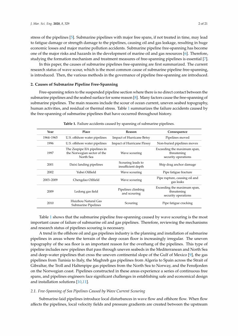
Sediment initiation is the first step in the whole scour process. Sumer [17] divided the pipingphenomenon in the initial stage of pipelines scouring into two stages by studying the details of scouring.In the first stage, when the incoming stream acts for a period of time, the seepage force of water inthe seabed begins to be greater than the floating weight of particles, and the surface of sand beginsto uplift. In the second stage, piping occurs, that is, a mixture of water and sand will gush out thepiping. The piping process is shown in Figure 1a–c. Previous studies on sediment initiation generallysimplified the seabed surface as a rigid impermeable boundary, ignoring the influence of seepageon the mobility of bed particles. To reveal the physical law of sediment initiation in the early stageof scour of free-spanning pipelines, Xia [18] analyzed the influence of seepage force generated bywave seepage in the boundary layer on sediment starting. Zhen [19] proposed a numerical simulationmethod that couples the shear stress sediment transport turbulence model with the porous seabedmodel. Studies showed that as the vortex around the pipe periodically forms and falls off, the bottom
J. Mar. Sci. Eng. 2020, 8, 329 4 of 21
of the sea generates oscillations and residual excess pore pressure. In some cases, the vertical gradientof the superpose pressure (seepage force) significantly affects the fluidity of the bed particles aroundthe pipe. Mattioli et al. used numerical calculations to study the turbulence and vortices of the localscour of submarine pipelines laid on a non-cohesive sandy sea floor under the action of stable waterflow. The numerical model uses the level set technique to solve the Navier–Stokes equation. The modelpredicts the behavior of moving sediment through two components of drift force and lift force [20].
J. Mar. Sci. Eng. 2019, 7, x FOR PEER REVIEW 4 of 21
seepage on the mobility of bed particles. To reveal the physical law of sediment initiation in the early stage of scour of free-spanning pipelines, Xia [18] analyzed the influence of seepage force generated by wave seepage in the boundary layer on sediment starting. Zhen [19] proposed a numerical simulation method that couples the shear stress sediment transport turbulence model with the porous seabed model. Studies showed that as the vortex around the pipe periodically forms and falls off, the bottom of the sea generates oscillations and residual excess pore pressure. In some cases, the vertical gradient of the superpose pressure (seepage force) significantly affects the fluidity of the bed particles around the pipe. Mattioli et al. used numerical calculations to study the turbulence and vortices of the local scour of submarine pipelines laid on a non-cohesive sandy sea floor under the action of stable water flow. The numerical model uses the level set technique to solve the Navier–Stokes equation. The model predicts the behavior of moving sediment through two components of drift force and lift force [20].
(a)the current acts for piping
(b)The surface of the sand began to swell
(c)The mixture of water and sand gushed out
Figure 1. Sediment initiation during the initial scour phase. (a)The current acts for piping, (b)The surface of the sand began to swell, (c)The mixture of water and sand gushed out.
Research on the scour balance depth started in the 1960s. From the late 1980s until the 1990s, Sumer et al. [21–26] and Chiew et al. [27–30] extensively examined the scour of the seabed around submarine pipelines. Myrhaug et al. [31] studied the formula for the depth and width of the scour pit under the action of random waves and the depth of the scour pit around the pile. Kumar et al. [32] analyzed the relationship between the maximum scour depth of submarine pipelines on the viscous sea floor and the consistency of clay using wave tank experiments. Yan et al. [33] analyzed the scour stability of submarine pipelines when buried in a certain depth of soil and exposed on the seabed surface. The maximum scour depth at scour equilibrium was calculated under two conditions. Feng [34] used a large-scale flume experiment to study the scouring of silt around the pile under the action of waves and flow alone, and waves and flow together. A formula for calculating the maximum scour depth was derived. According to the different water flow conditions, the scour problem can be divided into two types: clean water scour (θ < θcr) and live bed scour (θ > θcr), where θ is the Shields parameter of the sediment particles and θcr is the critical Shields parameter [35–37]. The scouring mechanism under clear water conditions is different from that under live bed conditions. Dey et al. [38] and Moncada et al. [39] conducted pipe-scouring experiments under clean water and live bed conditions, respectively. Dey et al. [40] established a semi-theoretical calculation model for the maximum depth of clean water scour under a pipeline, and studied the effect of upward seepage on the depth of clean water scour under the pipeline through experiments. Ibrahim and Nalluri [41] analyzed experimental results and reported that in the case of clean water scouring, no scouring away from the pipeline occurs; in the case of moving bed scouring, the entire bottom bed will scour. This laid the foundation for future research on scouring issues.
For submarine pipelines laid in shallow coastal waters, the effect of waves on local erosion of submarine pipelines cannot be ignored. The two-dimensional pipeline scour problem under the action of waves is different from the pipeline scour problem under the action of currents. This is mainly reflected in vortex shedding occurring in front of and behind the pipeline under the action of waves. This causes the scour to develop back and forth toward the pipeline. The KC number is an important parameter representing the range of motion of water particles. A large KC indicates that the water particle has a large range of motion, which causes a large range of local scour around the pipeline. A small KC number indicates that the water particle has a small range of motion, which causes a small range of pipeline erosion. Many experiments have been conducted on wave-induced
Figure 1. Sediment initiation during the initial scour phase. (a) The current acts for piping,(b) The surface of the sand began to swell, (c) The mixture of water and sand gushed out.
Research on the scour balance depth started in the 1960s. From the late 1980s until the 1990s,Sumer et al. [21–26] and Chiew et al. [27–30] extensively examined the scour of the seabed aroundsubmarine pipelines. Myrhaug et al. [31] studied the formula for the depth and width of the scour pitunder the action of random waves and the depth of the scour pit around the pile. Kumar et al. [32]analyzed the relationship between the maximum scour depth of submarine pipelines on the viscous seafloor and the consistency of clay using wave tank experiments. Yan et al. [33] analyzed the scour stabilityof submarine pipelines when buried in a certain depth of soil and exposed on the seabed surface.The maximum scour depth at scour equilibrium was calculated under two conditions. Feng [34] useda large-scale flume experiment to study the scouring of silt around the pile under the action of wavesand flow alone, and waves and flow together. A formula for calculating the maximum scour depthwas derived. According to the different water flow conditions, the scour problem can be divided intotwo types: clean water scour (θ < θcr) and live bed scour (θ > θcr), where θ is the Shields parameterof the sediment particles and θcr is the critical Shields parameter [35–37]. The scouring mechanismunder clear water conditions is different from that under live bed conditions. Dey et al. [38] andMoncada et al. [39] conducted pipe-scouring experiments under clean water and live bed conditions,respectively. Dey et al. [40] established a semi-theoretical calculation model for the maximum depth ofclean water scour under a pipeline, and studied the effect of upward seepage on the depth of cleanwater scour under the pipeline through experiments. Ibrahim and Nalluri [41] analyzed experimentalresults and reported that in the case of clean water scouring, no scouring away from the pipelineoccurs; in the case of moving bed scouring, the entire bottom bed will scour. This laid the foundationfor future research on scouring issues.
For submarine pipelines laid in shallow coastal waters, the effect of waves on local erosion ofsubmarine pipelines cannot be ignored. The two-dimensional pipeline scour problem under the actionof waves is different from the pipeline scour problem under the action of currents. This is mainlyreflected in vortex shedding occurring in front of and behind the pipeline under the action of waves.This causes the scour to develop back and forth toward the pipeline. The KC number is an importantparameter representing the range of motion of water particles. A large KC indicates that the waterparticle has a large range of motion, which causes a large range of local scour around the pipeline.A small KC number indicates that the water particle has a small range of motion, which causes a smallrange of pipeline erosion. Many experiments have been conducted on wave-induced scour under
J. Mar. Sci. Eng. 2020, 8, 329 5 of 21
pipelines [42–44]. Sume et al. [45] found through experiments that the local maximum depth of thepipeline and the KC number have the following relationship:
SD
= 0.1√
KC (4)
here S is the scour depth and D is the pipe diameter. This shows that the KC number is the main factoraffecting the local scour depth of subsea pipelines under the action of waves.
Studies on the scouring of submarine pipelines have mainly linked the formation of scouringto the pressure gradient on both sides of the pipeline. Mattioli et al. [46,47] used particle trackingtechnology (PTV) to study the motion and evolution of particles caused by water waves around acylinder on a rigid or erodible ocean floor. They also analyzed the flow field around the pipeline underdifferent KC numbers, and reported that the vortex structure around the pipeline may be combinedwith the pressure gradient and play an important role in the process of erosion.
Chang et al. [48] used the Navier–Stokes equation and Suagorinsky sub-grid model to simulatethe development and change in scour in the process of pipelines subsidence. They found that the depthof scour under the pipelines gradually increased with the decrease in pipelines subsidence velocity.When the subsidence velocity was sufficient, the scour pit depth could reach more than 1D. Li andCheng [49] proposed a mathematical model based on potential flow theory to simulate the scour ofsubmarine pipelines under the action of unidirectional flow. After verification, this model can be usedto predict the scour depth under the condition of clear water scour.
Most of the research on scouring of submarine pipelines has focused on sandy seabeds, whereasresearch on scouring of pipelines on cohesive soils is lacking. No complete formula exists for predictingthe scour depth of pipes on the viscous sea floor. In 2015, Postacchini and Brocchini analyzed theinfluence of the amount of clay in the seabed on the depth of pipeline erosion by collating the collecteddata. For the first time, they tried to establish a prediction formula for the depth of pipeline erosionwhen the clay content is low, laying the foundation for future research on the scouring depth ofpipelines on the viscous sea floor [50].
Many scholars have conducted many experimental studies and numerical calculations to predicterosion under pipelines [51–54]. In addition to traditional methods, artificial intelligence methods havebeen applied to pipeline erosion prediction, such as artificial neural networks (ANNs), machine learningmethods, adaptive neural fuzzy inference systems (ANFIS), and genetic programming (GP) [55–58].
Many scholars have summarized the relevant research results and work experience with pipelineoverhang. Bijker et al. [59] reviewed the origin and role of scour-induced free-crossing as theself-descending process of submarine pipelines. The single-span development is described anddiscussed from the aspects of initial embedding, scouring start, scouring development rate, relevantstopping standards, multi-span formation, and critical free-span development. Sumer et al. [60]reviewed the research progress of pipe perimeter scour under non-cohesive sediment. The reviewwas divided into four parts: two-dimensional scouring, three-dimensional scouring, the influence ofscouring on the force and vibration of the pipeline, and a mathematical model of the scouring process.More than 60 works were included in the review. Drago et al. [61] discussed more than 30 yearsof research and development achievements and project experience, summarized the underwaterenvironment and current conditions near the overhang pipeline, and discussed the occurrence anddevelopment of overhang. In addition, they summarized the design method of free-spanning pipelinesand some pipelines inspection experiences.
The free-spanning of submarine pipelines caused by ocean current is one of the main causes ofsubmarine oil and gas pipelines failure. Therefore, many scholars have completed large amounts ofresearch on this issue. Factors affecting pipelines scour include the initial buried depth of the pipelines,particle size of sediment, diameter of the pipelines, KC number, clay content, wave and flow effects,etc. [62–67]. Because influencing factors are numerous and complex, current research is generallyaimed at one or a specific number of factors which is a certain deviation from actual engineering.
J. Mar. Sci. Eng. 2020, 8, 329 6 of 21
2.2. Free-Spanning of Sea Pipe Caused by Other Reasons
2.2.1. Free-Spanning of Sea Pipe Caused by Seabed Relief
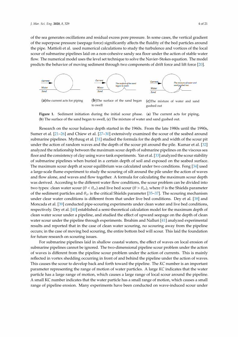
In the process of laying submarine pipelines, some regions will have considerable changes insubmarine topography. This type of free span shows different spanning forms due to the differences intopography and geology of the route area [68,69], as shown in Figure 2.
J. Mar. Sci. Eng. 2019, 7, x FOR PEER REVIEW 6 of 21
2.2. Free-Spanning of Sea Pipe Caused by Other Reasons
2.2.1. Free-Spanning of Sea Pipe Caused by Seabed Relief
In the process of laying submarine pipelines, some regions will have considerable changes in submarine topography. This type of free span shows different spanning forms due to the differences in topography and geology of the route area [68,69], as shown in Figure 2.
(a) Overhangs formed by uneven seabed
(b) Sectional overhangs caused by topographic relief
(c) Free-spanning formed by pipeline climbing
(d) Free-spanning formed by connection with offshore platform riser
Figure 2. Different free-spanning forms caused by seabed topography differences. (a) Overhangs formed by uneven seabed, (b) Sectional overhangs caused by topographic relief, (c) Free-spanning formed by pipeline climbing, (d) Free-spanning formed by connection with offshore platform riser.
Wen et al. [70] measured the abandoned submarine pipelines in the Yellow River delta and found that the topography of the seabed strongly influenced the span of the pipelines. Therefore, the choice of the laying route of the submarine pipelines is crucial. Finding a completely flat laying route is usually impossible. However, a suitable pipeline route can be chosen to minimize the number and lengths of free spans [71]. When laying pipelines on the sea floor with complicated and changeable terrain, the unevenness of the sea floor must be analyzed in advance [72]. Then, the uneven routing areas should be preprocessed, which can greatly reduce the design cost and shorten the pipeline laying period.
2.2.2. Free-Spanning of Sea Pipe Caused by Residual or Thermal Stress
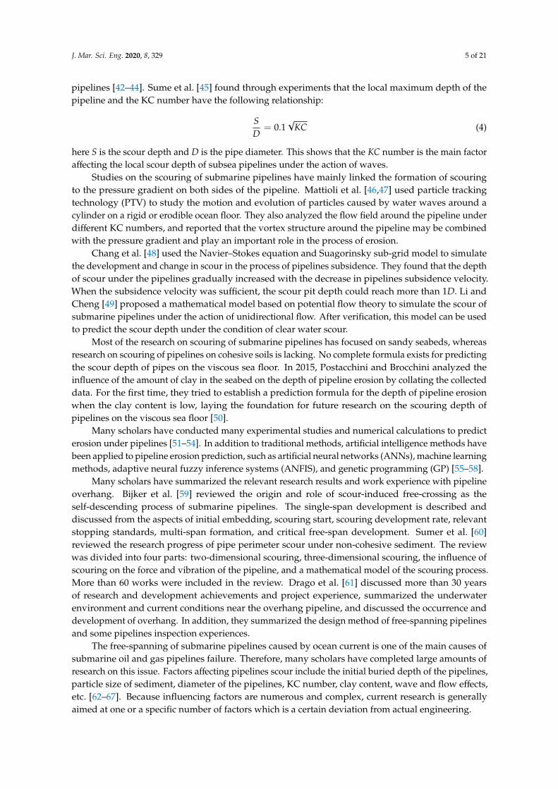
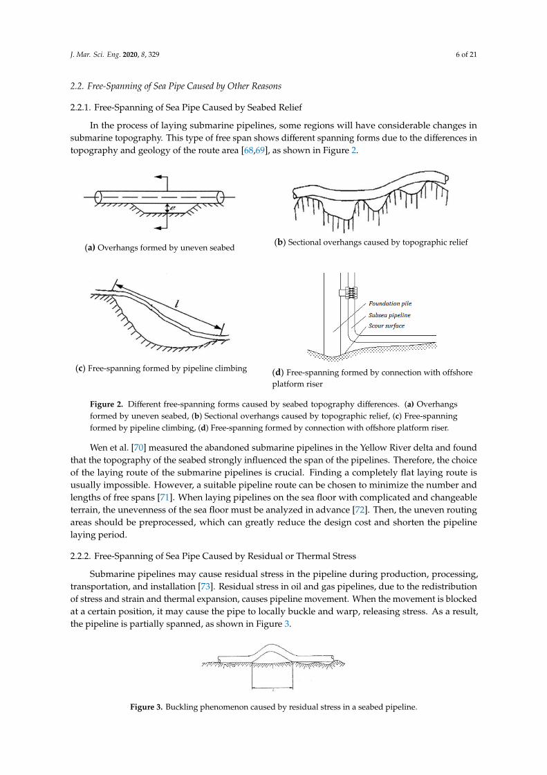
Submarine pipelines may cause residual stress in the pipeline during production, processing, transportation, and installation [73]. Residual stress in oil and gas pipelines, due to the redistribution of stress and strain and thermal expansion, causes pipeline movement. When the movement is blocked at a certain position, it may cause the pipe to locally buckle and warp, releasing stress. As a result, the pipeline is partially spanned, as shown in Figure 3.
Figure 3. Buckling phenomenon caused by residual stress in a seabed pipeline.
Figure 2. Different free-spanning forms caused by seabed topography differences. (a) Overhangsformed by uneven seabed, (b) Sectional overhangs caused by topographic relief, (c) Free-spanningformed by pipeline climbing, (d) Free-spanning formed by connection with offshore platform riser.
Wen et al. [70] measured the abandoned submarine pipelines in the Yellow River delta and foundthat the topography of the seabed strongly influenced the span of the pipelines. Therefore, the choiceof the laying route of the submarine pipelines is crucial. Finding a completely flat laying route isusually impossible. However, a suitable pipeline route can be chosen to minimize the number andlengths of free spans [71]. When laying pipelines on the sea floor with complicated and changeableterrain, the unevenness of the sea floor must be analyzed in advance [72]. Then, the uneven routingareas should be preprocessed, which can greatly reduce the design cost and shorten the pipelinelaying period.
2.2.2. Free-Spanning of Sea Pipe Caused by Residual or Thermal Stress
Submarine pipelines may cause residual stress in the pipeline during production, processing,transportation, and installation [73]. Residual stress in oil and gas pipelines, due to the redistributionof stress and strain and thermal expansion, causes pipeline movement. When the movement is blockedat a certain position, it may cause the pipe to locally buckle and warp, releasing stress. As a result,the pipeline is partially spanned, as shown in Figure 3.
J. Mar. Sci. Eng. 2019, 7, x FOR PEER REVIEW 6 of 21
2.2. Free-Spanning of Sea Pipe Caused by Other Reasons
2.2.1. Free-Spanning of Sea Pipe Caused by Seabed Relief
In the process of laying submarine pipelines, some regions will have considerable changes in submarine topography. This type of free span shows different spanning forms due to the differences in topography and geology of the route area [68,69], as shown in Figure 2.
(a) Overhangs formed by uneven seabed
(b) Sectional overhangs caused by topographic relief
(c) Free-spanning formed by pipeline climbing
(d) Free-spanning formed by connection with offshore platform riser
Figure 2. Different free-spanning forms caused by seabed topography differences. (a) Overhangs formed by uneven seabed, (b) Sectional overhangs caused by topographic relief, (c) Free-spanning formed by pipeline climbing, (d) Free-spanning formed by connection with offshore platform riser.
Wen et al. [70] measured the abandoned submarine pipelines in the Yellow River delta and found that the topography of the seabed strongly influenced the span of the pipelines. Therefore, the choice of the laying route of the submarine pipelines is crucial. Finding a completely flat laying route is usually impossible. However, a suitable pipeline route can be chosen to minimize the number and lengths of free spans [71]. When laying pipelines on the sea floor with complicated and changeable terrain, the unevenness of the sea floor must be analyzed in advance [72]. Then, the uneven routing areas should be preprocessed, which can greatly reduce the design cost and shorten the pipeline laying period.
2.2.2. Free-Spanning of Sea Pipe Caused by Residual or Thermal Stress
Submarine pipelines may cause residual stress in the pipeline during production, processing, transportation, and installation [73]. Residual stress in oil and gas pipelines, due to the redistribution of stress and strain and thermal expansion, causes pipeline movement. When the movement is blocked at a certain position, it may cause the pipe to locally buckle and warp, releasing stress. As a result, the pipeline is partially spanned, as shown in Figure 3.
Figure 3. Buckling phenomenon caused by residual stress in a seabed pipeline. Figure 3. Buckling phenomenon caused by residual stress in a seabed pipeline.

J. Mar. Sci. Eng. 2020, 8, 329 7 of 21
Generally, avoiding pipeline span caused by residual stress or thermal stress is difficult, and theprecautionary measures are complicated.
2.2.3. Free-Spanning of Sea Pipe Caused by Human Activities
Human activity is another one of the reasons for the span of submarine pipelines. Channel excavation,sand excavation, land reclamation, and bridge pier construction near the submarine pipelineconsiderably influence the hydrological conditions around the pipeline, which destroys the balance ofsediment erosion and deposition. To some extent, the natural law of the original seabed or riverbed ischanged, resulting in the free span of the pipelines. In the vicinity of human activities, the anchorageof ships, trawling of fishing boats, and household garbage may pose a threat to the safe operation ofsubmarine pipelines.
3. Treatment Methods of Submarine Pipeline Free-Spanning
After the laying or operation of the submarine pipeline, if spanning occurs due to the erosion ofthe current, residual stress, or thermal stress, and the span exceeds the allowable length. The span ofthe pipeline then causes fatigue damage due to vortex-induced vibration under the action of the oceancurrent [74,75]. In addition, the span pipeline loses its landfill. If it is impacted by falling objects oranchors, it is more vulnerable to damage. The spanned pipeline is directly exposed on the sea floorsurface, which can interfere with the trawl of fishing boats, tow, and even to be displaced or buckledunder towing. To ensure the safety of pipeline operations and prevent oil and gas leaks, appropriatemethods should be adopted to mitigate and manage the free span of the pipeline. At present, the mainmethods for free span treatment of submarine pipelines include: re-ditching and burying methods,structural support method, rock throwing, cement briquette, and covering with artificial grass.
3.1. Re-Digging and Burying
The method of re-ditching and burying involves re-ditching and filling the span of the pipelineusing subsea-trenching equipment. The research on subsea trenching machinery began in the late1940s. Since the first jet skid was used in the submarine oil and gas pipeline in the Gulf of Mexico inNorth America in 1946, various types of trenching equipment have been developed [76]. According tothe different principles, re-digging ditches can be divided into the jet ditching method and mechanicalditching method.
3.1.1. Jet Ditching Method
The jet trencher sprays the soil at the bottom of the pipe with high-pressure water to form a trenchunder the pipe. When the suspended length of the pipeline exceeds the critical value, it will sink tothe bottom of the ditch under its own gravity. Water flow is then used to back silt the pipeline tocreate landfill [77]. At first, the exploitation of marine oil and gas resources was mainly concentratedin offshore areas. The soil in these areas is dominated by soft silt and the working water depth isshallow. Therefore, jet trenchers were mainly used at first. The first generation jet trencher has a simplemechanical structure, as shown in Figure 4.
J. Mar. Sci. Eng. 2019, 7, x FOR PEER REVIEW 7 of 21
Generally, avoiding pipeline span caused by residual stress or thermal stress is difficult, and the precautionary measures are complicated.
2.2.3. Free-Spanning of Sea Pipe Caused by Human Activities
Human activity is another one of the reasons for the span of submarine pipelines. Channel excavation, sand excavation, land reclamation, and bridge pier construction near the submarine pipeline considerably influence the hydrological conditions around the pipeline, which destroys the balance of sediment erosion and deposition. To some extent, the natural law of the original seabed or riverbed is changed, resulting in the free span of the pipelines. In the vicinity of human activities, the anchorage of ships, trawling of fishing boats, and household garbage may pose a threat to the safe operation of submarine pipelines.
3. Treatment Methods of Submarine Pipeline Free-Spanning
After the laying or operation of the submarine pipeline, if spanning occurs due to the erosion of the current, residual stress, or thermal stress, and the span exceeds the allowable length. The span of the pipeline then causes fatigue damage due to vortex-induced vibration under the action of the ocean current [74,75]. In addition, the span pipeline loses its landfill. If it is impacted by falling objects or anchors, it is more vulnerable to damage. The spanned pipeline is directly exposed on the sea floor surface, which can interfere with the trawl of fishing boats, tow, and even to be displaced or buckled under towing. To ensure the safety of pipeline operations and prevent oil and gas leaks, appropriate methods should be adopted to mitigate and manage the free span of the pipeline. At present, the main methods for free span treatment of submarine pipelines include: re-ditching and burying methods, structural support method, rock throwing, cement briquette, and covering with artificial grass.
3.1. Re-Digging and Burying
The method of re-ditching and burying involves re-ditching and filling the span of the pipeline using subsea-trenching equipment. The research on subsea trenching machinery began in the late 1940s. Since the first jet skid was used in the submarine oil and gas pipeline in the Gulf of Mexico in North America in 1946, various types of trenching equipment have been developed [76]. According to the different principles, re-digging ditches can be divided into the jet ditching method and mechanical ditching method.
3.1.1. Jet Ditching Method
The jet trencher sprays the soil at the bottom of the pipe with high-pressure water to form a trench under the pipe. When the suspended length of the pipeline exceeds the critical value, it will sink to the bottom of the ditch under its own gravity. Water flow is then used to back silt the pipeline to create landfill [77]. At first, the exploitation of marine oil and gas resources was mainly concentrated in offshore areas. The soil in these areas is dominated by soft silt and the working water depth is shallow. Therefore, jet trenchers were mainly used at first. The first generation jet trencher has a simple mechanical structure, as shown in Figure 4.
Figure 4. First generation jet trencher. Figure 4. First generation jet trencher.
J. Mar. Sci. Eng. 2020, 8, 329 8 of 21
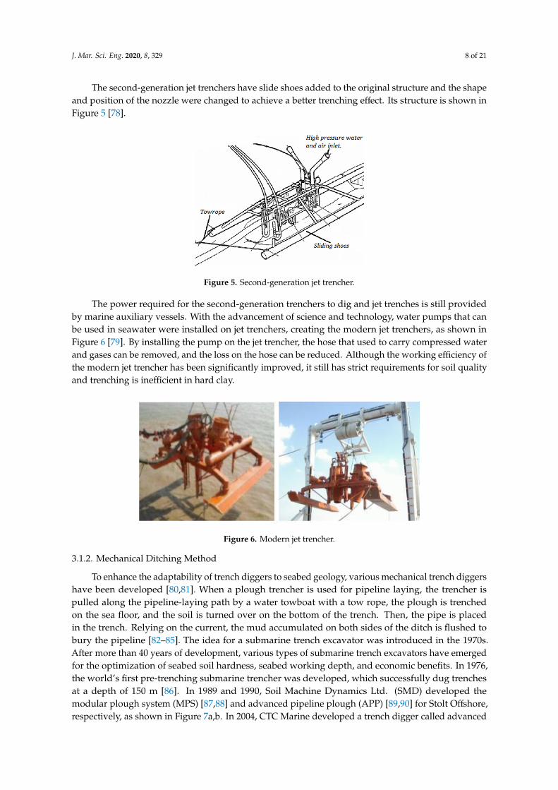
The second-generation jet trenchers have slide shoes added to the original structure and the shapeand position of the nozzle were changed to achieve a better trenching effect. Its structure is shown inFigure 5 [78].
J. Mar. Sci. Eng. 2019, 7, x FOR PEER REVIEW 8 of 21
The second-generation jet trenchers have slide shoes added to the original structure and the shape and position of the nozzle were changed to achieve a better trenching effect. Its structure is shown in Figure 5 [78].
Figure 5. Second-generation jet trencher.
The power required for the second-generation trenchers to dig and jet trenches is still provided by marine auxiliary vessels. With the advancement of science and technology, water pumps that can be used in seawater were installed on jet trenchers, creating the modern jet trenchers, as shown in Figure 6 [79]. By installing the pump on the jet trencher, the hose that used to carry compressed water and gases can be removed, and the loss on the hose can be reduced. Although the working efficiency of the modern jet trencher has been significantly improved, it still has strict requirements for soil quality and trenching is inefficient in hard clay.
Figure 6. Modern jet trencher.
3.1.2. Mechanical Ditching Method
To enhance the adaptability of trench diggers to seabed geology, various mechanical trench diggers have been developed [80,81]. When a plough trencher is used for pipeline laying, the trencher is pulled along the pipeline-laying path by a water towboat with a tow rope, the plough is trenched on the sea floor, and the soil is turned over on the bottom of the trench. Then, the pipe is placed in the trench. Relying on the current, the mud accumulated on both sides of the ditch is flushed to bury the pipeline [82–85]. The idea for a submarine trench excavator was introduced in the 1970s. After more than 40 years of development, various types of submarine trench excavators have emerged for the optimization of seabed soil hardness, seabed working depth, and economic benefits. In 1976, the world’s first pre-trenching submarine trencher was developed, which successfully dug trenches at a depth of 150 m [86]. In 1989 and 1990, Soil Machine Dynamics Ltd. (SMD) developed the modular plough system (MPS) [87,88] and advanced pipeline plough (APP) [89,90] for Stolt Offshore, respectively, as shown in Figure 7a,b. In 2004, CTC Marine developed a trench digger called advanced multi-pass plough (AMP) [91,92]. As shown in Figure 7c, this trench digger has the addition of a high-pressure injection system similar to that of a jet trench digger, which can reduce
Figure 5. Second-generation jet trencher.
The power required for the second-generation trenchers to dig and jet trenches is still providedby marine auxiliary vessels. With the advancement of science and technology, water pumps that canbe used in seawater were installed on jet trenchers, creating the modern jet trenchers, as shown inFigure 6 [79]. By installing the pump on the jet trencher, the hose that used to carry compressed waterand gases can be removed, and the loss on the hose can be reduced. Although the working efficiency ofthe modern jet trencher has been significantly improved, it still has strict requirements for soil qualityand trenching is inefficient in hard clay.
J. Mar. Sci. Eng. 2019, 7, x FOR PEER REVIEW 8 of 21
The second-generation jet trenchers have slide shoes added to the original structure and the shape and position of the nozzle were changed to achieve a better trenching effect. Its structure is shown in Figure 5 [78].
Figure 5. Second-generation jet trencher.
The power required for the second-generation trenchers to dig and jet trenches is still provided by marine auxiliary vessels. With the advancement of science and technology, water pumps that can be used in seawater were installed on jet trenchers, creating the modern jet trenchers, as shown in Figure 6 [79]. By installing the pump on the jet trencher, the hose that used to carry compressed water and gases can be removed, and the loss on the hose can be reduced. Although the working efficiency of the modern jet trencher has been significantly improved, it still has strict requirements for soil quality and trenching is inefficient in hard clay.
Figure 6. Modern jet trencher.
3.1.2. Mechanical Ditching Method
To enhance the adaptability of trench diggers to seabed geology, various mechanical trench diggers have been developed [80,81]. When a plough trencher is used for pipeline laying, the trencher is pulled along the pipeline-laying path by a water towboat with a tow rope, the plough is trenched on the sea floor, and the soil is turned over on the bottom of the trench. Then, the pipe is placed in the trench. Relying on the current, the mud accumulated on both sides of the ditch is flushed to bury the pipeline [82–85]. The idea for a submarine trench excavator was introduced in the 1970s. After more than 40 years of development, various types of submarine trench excavators have emerged for the optimization of seabed soil hardness, seabed working depth, and economic benefits. In 1976, the world’s first pre-trenching submarine trencher was developed, which successfully dug trenches at a depth of 150 m [86]. In 1989 and 1990, Soil Machine Dynamics Ltd. (SMD) developed the modular plough system (MPS) [87,88] and advanced pipeline plough (APP) [89,90] for Stolt Offshore, respectively, as shown in Figure 7a,b. In 2004, CTC Marine developed a trench digger called advanced multi-pass plough (AMP) [91,92]. As shown in Figure 7c, this trench digger has the addition of a high-pressure injection system similar to that of a jet trench digger, which can reduce
Figure 6. Modern jet trencher.
3.1.2. Mechanical Ditching Method
To enhance the adaptability of trench diggers to seabed geology, various mechanical trench diggershave been developed [80,81]. When a plough trencher is used for pipeline laying, the trencher ispulled along the pipeline-laying path by a water towboat with a tow rope, the plough is trenchedon the sea floor, and the soil is turned over on the bottom of the trench. Then, the pipe is placedin the trench. Relying on the current, the mud accumulated on both sides of the ditch is flushed tobury the pipeline [82–85]. The idea for a submarine trench excavator was introduced in the 1970s.After more than 40 years of development, various types of submarine trench excavators have emergedfor the optimization of seabed soil hardness, seabed working depth, and economic benefits. In 1976,the world’s first pre-trenching submarine trencher was developed, which successfully dug trenchesat a depth of 150 m [86]. In 1989 and 1990, Soil Machine Dynamics Ltd. (SMD) developed themodular plough system (MPS) [87,88] and advanced pipeline plough (APP) [89,90] for Stolt Offshore,respectively, as shown in Figure 7a,b. In 2004, CTC Marine developed a trench digger called advanced

J. Mar. Sci. Eng. 2020, 8, 329 9 of 21
multi-pass plough (AMP) [91,92]. As shown in Figure 7c, this trench digger has the addition of ahigh-pressure injection system similar to that of a jet trench digger, which can reduce the cuttingforce and cope with viscous sands via high-pressure injection on the cutting surface of the ploughbody. In 2006, SMD developed the latest generation of trencher, the variable multi-pass plough (VMP),as shown in Figure 7d. This trencher adopts hi-tow point technology and has variable stroke [93].
J. Mar. Sci. Eng. 2019, 7, x FOR PEER REVIEW 9 of 21
the cutting force and cope with viscous sands via high-pressure injection on the cutting surface of the plough body. In 2006, SMD developed the latest generation of trencher, the variable multi-pass plough (VMP), as shown in Figure 7d. This trencher adopts hi-tow point technology and has variable stroke [93].
(a) Structure diagram of MPS trencher
(b) Structure diagram of APP trencher
(c) Structure diagram of AMP trencher
(d) VMP trencher
Figure 7. Mechanical trenchers of the modular plough system. Abbreviations: MPS, modular plough system; APP, advanced pipeline plough; AMP, advanced multi-pass plough; VMP, variable multi-pass plough. (a) Structure diagram of MPS trencher, (b) Structure diagram of APP trencher, (c) Structure diagram of AMP trencher, (d) VMP trencher.
3.2. Structural Support Methods
The structural support method is implemented by installing a support structure below a span pipeline; thereby, reducing the span length and ensuring the safety of the spanning pipeline. At present, the main structural support methods include grouting bag support, underwater pile support, and throwing stone support.
3.2.1. Grouting Bag Support Method
The grouting bag method involves placing a supporting shell membrane on the surface of the sea floor and then injecting mud into the grouting bag using the grouting equipment on the mother ship to complete the support of the span section of the pipeline [94]. The advantages of this method include simple and easy construction, high economic benefits, and no damage to the pipeline. The disadvantage is that, over time, the scouring action of waves and currents may cause the grouting bag to sink. After sinking, it no longer provides support for the spanned pipeline. Found Ocean, a British company, is the world’s largest offshore construction and grouting company that provides design, manufacturing, and installation services for various types of grouting bags. Figure 8 (a) shows Found Ocean’s J-type grouting bag, which was successfully assembled with remote operated vehicle (ROV) at a depth of 1244 meters underwater. Figure 8 (b) depicts a schematic diagram of a grouting bag laying device invented by Wang et al. [95] in 2015, and Figure 8 (c) depicts the grouting bag laying device invented by Song et al. [96] in 2016.
Figure 7. Mechanical trenchers of the modular plough system. Abbreviations: MPS, modular ploughsystem; APP, advanced pipeline plough; AMP, advanced multi-pass plough; VMP, variable multi-passplough. (a) Structure diagram of MPS trencher, (b) Structure diagram of APP trencher, (c) Structurediagram of AMP trencher, (d) VMP trencher.
3.2. Structural Support Methods
The structural support method is implemented by installing a support structure below a spanpipeline; thereby, reducing the span length and ensuring the safety of the spanning pipeline.At present, the main structural support methods include grouting bag support, underwater pilesupport, and throwing stone support.
3.2.1. Grouting Bag Support Method
The grouting bag method involves placing a supporting shell membrane on the surface of the seafloor and then injecting mud into the grouting bag using the grouting equipment on the mother ship tocomplete the support of the span section of the pipeline [94]. The advantages of this method includesimple and easy construction, high economic benefits, and no damage to the pipeline. The disadvantageis that, over time, the scouring action of waves and currents may cause the grouting bag to sink.After sinking, it no longer provides support for the spanned pipeline. Found Ocean, a British company,is the world’s largest offshore construction and grouting company that provides design, manufacturing,and installation services for various types of grouting bags. Figure 8a shows Found Ocean’s J-typegrouting bag, which was successfully assembled with remote operated vehicle (ROV) at a depth of1244 m underwater. Figure 8b depicts a schematic diagram of a grouting bag laying device invented byWang et al. [95] in 2015, and Figure 8c depicts the grouting bag laying device invented by Song et al. [96]in 2016.
J. Mar. Sci. Eng. 2020, 8, 329 10 of 21
J. Mar. Sci. Eng. 2019, 7, x FOR PEER REVIEW 10 of 21
(a) Single J grouting bag
(b) Grout bag laying installation
(c) Grout bag-laying mechanism
Figure 8. Installation services for various types of grouting bags. (a) Single J grouting bag, (b) Grout bag laying installation, (c) Grout bag-laying mechanism.
3.2.2. Underwater Pile Support Method
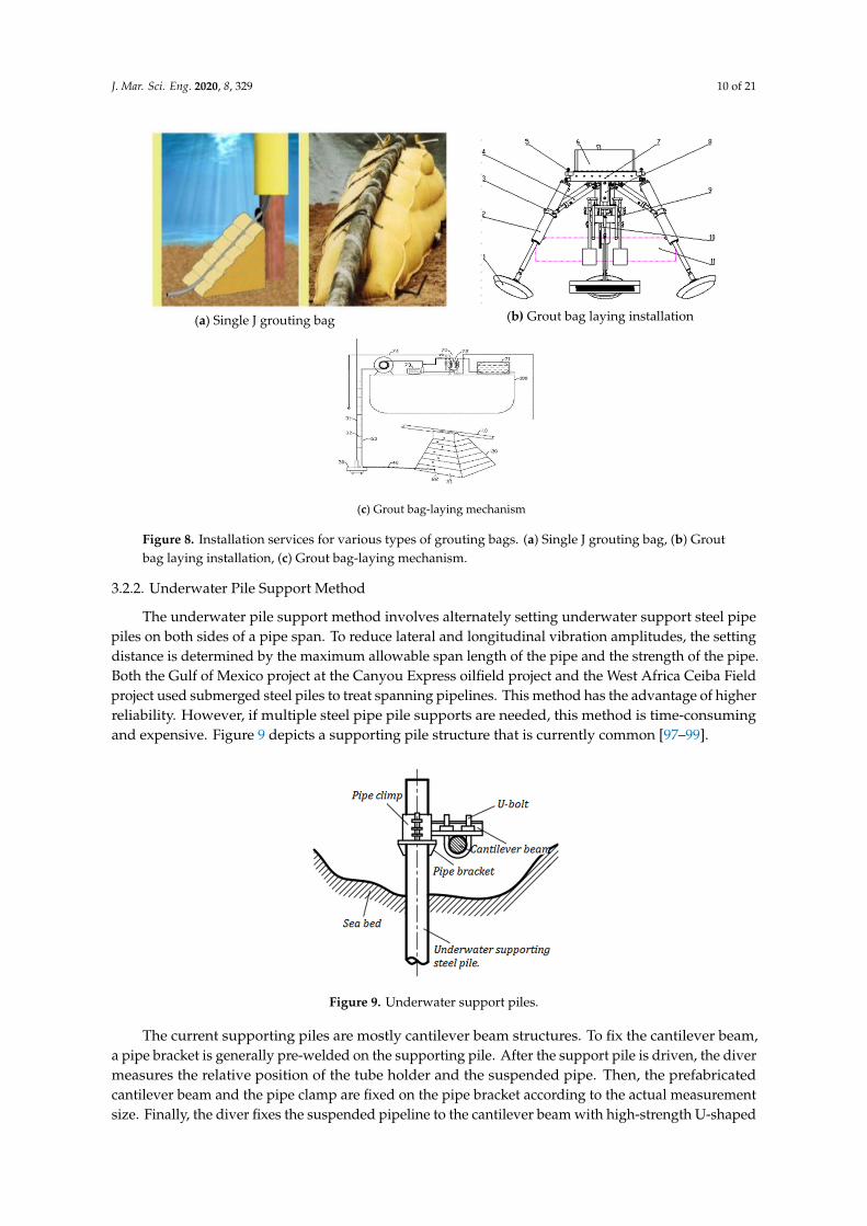
The underwater pile support method involves alternately setting underwater support steel pipe piles on both sides of a pipe span. To reduce lateral and longitudinal vibration amplitudes, the setting distance is determined by the maximum allowable span length of the pipe and the strength of the pipe. Both the Gulf of Mexico project at the Canyou Express oilfield project and the West Africa Ceiba Field project used submerged steel piles to treat spanning pipelines. This method has the advantage of higher reliability. However, if multiple steel pipe pile supports are needed, this method is time-consuming and expensive. Figure 9 depicts a supporting pile structure that is currently common [97–99].
Figure 9. Underwater support piles.
The current supporting piles are mostly cantilever beam structures. To fix the cantilever beam, a pipe bracket is generally pre-welded on the supporting pile. After the support pile is driven, the diver measures the relative position of the tube holder and the suspended pipe. Then, the
Figure 8. Installation services for various types of grouting bags. (a) Single J grouting bag, (b) Groutbag laying installation, (c) Grout bag-laying mechanism.
3.2.2. Underwater Pile Support Method
The underwater pile support method involves alternately setting underwater support steel pipepiles on both sides of a pipe span. To reduce lateral and longitudinal vibration amplitudes, the settingdistance is determined by the maximum allowable span length of the pipe and the strength of the pipe.Both the Gulf of Mexico project at the Canyou Express oilfield project and the West Africa Ceiba Fieldproject used submerged steel piles to treat spanning pipelines. This method has the advantage of higherreliability. However, if multiple steel pipe pile supports are needed, this method is time-consumingand expensive. Figure 9 depicts a supporting pile structure that is currently common [97–99].
J. Mar. Sci. Eng. 2019, 7, x FOR PEER REVIEW 10 of 21
(a) Single J grouting bag
(b) Grout bag laying installation
(c) Grout bag-laying mechanism
Figure 8. Installation services for various types of grouting bags. (a) Single J grouting bag, (b) Grout bag laying installation, (c) Grout bag-laying mechanism.
3.2.2. Underwater Pile Support Method
The underwater pile support method involves alternately setting underwater support steel pipe piles on both sides of a pipe span. To reduce lateral and longitudinal vibration amplitudes, the setting distance is determined by the maximum allowable span length of the pipe and the strength of the pipe. Both the Gulf of Mexico project at the Canyou Express oilfield project and the West Africa Ceiba Field project used submerged steel piles to treat spanning pipelines. This method has the advantage of higher reliability. However, if multiple steel pipe pile supports are needed, this method is time-consuming and expensive. Figure 9 depicts a supporting pile structure that is currently common [97–99].
Figure 9. Underwater support piles.
The current supporting piles are mostly cantilever beam structures. To fix the cantilever beam, a pipe bracket is generally pre-welded on the supporting pile. After the support pile is driven, the diver measures the relative position of the tube holder and the suspended pipe. Then, the
Figure 9. Underwater support piles.
The current supporting piles are mostly cantilever beam structures. To fix the cantilever beam,a pipe bracket is generally pre-welded on the supporting pile. After the support pile is driven, the divermeasures the relative position of the tube holder and the suspended pipe. Then, the prefabricatedcantilever beam and the pipe clamp are fixed on the pipe bracket according to the actual measurementsize. Finally, the diver fixes the suspended pipeline to the cantilever beam with high-strength U-shaped

J. Mar. Sci. Eng. 2020, 8, 329 11 of 21
bolts. This method is mainly manual and difficult for divers. For the treatment of deep-water spanpipelines, the operation by divers is more difficult.
3.2.3. Riprap Support Method
Stone throwing is one of the most traditional free-span governance measures for subsea pipelines.It has been widely used in the development of offshore oil and gas resources around the world [100–102]and has broad application prospects. Under extreme hydrodynamic loading conditions, stabilizinglarge diameter subsea natural gas pipelines has proven to be a challenge in northwestern Australia.The tropical storms that affect the area between November and April each year can produce waveheights of more than 30 m and storm currents of 2 m/s or more. Therefore, at shallow water depths,usually below 40–60 m, submarine pipelines may be subject to very high hydrodynamic loads,which may cause significant lateral movement. To reduce the risk of mechanical damage to the pipelinedue to excessive lateral movement, mined and graded rock is usually poured onto the pipeline as asecondary stabilization solution.
In the Ormen Lange project in Norway, the rubble method was adopted to govern the free-span ofa submarine pipe [103]. The stone throw method fills the scour pit by throwing crushed stones into thespan section of the pipeline, thus supporting the pipeline and reducing the length of the pipeline span.The method is simple in construction and does not require engineering design. During construction,only the concrete position of the riprap must be determined according to the investigation results.For shallow water pipeline span, the diver can directly complete riprap operations. However, a riprapguide device must be used in deep water, otherwise the debris may drift away from the designateddrop site due to the action of waves and currents. When the water depth exceeds 100 m, due tothe large riprapping diversion device, a crane with a certain lifting capacity is required for onsiteinstallation [104].
3.3. Covering Bionic Water Plant Method
Bionic aquatic plant technology on the seabed is a kind of anti-scour measure developed on thebasis of marine bionics [105]. The bionic anti-scour system includes bionic seaweed, bionic seaweedinstallation base pad, a specifically designed submarine anchorage device, and other parts, as shownin Figure 10.
J. Mar. Sci. Eng. 2019, 7, x FOR PEER REVIEW 11 of 21
prefabricated cantilever beam and the pipe clamp are fixed on the pipe bracket according to the actual measurement size. Finally, the diver fixes the suspended pipeline to the cantilever beam with high-strength U-shaped bolts. This method is mainly manual and difficult for divers. For the treatment of deep-water span pipelines, the operation by divers is more difficult.
3.2.3. Riprap Support Method
Stone throwing is one of the most traditional free-span governance measures for subsea pipelines. It has been widely used in the development of offshore oil and gas resources around the world [100–102] and has broad application prospects. Under extreme hydrodynamic loading conditions, stabilizing large diameter subsea natural gas pipelines has proven to be a challenge in northwestern Australia. The tropical storms that affect the area between November and April each year can produce wave heights of more than 30 m and storm currents of 2 m/s or more. Therefore, at shallow water depths, usually below 40–60 m, submarine pipelines may be subject to very high hydrodynamic loads, which may cause significant lateral movement. To reduce the risk of mechanical damage to the pipeline due to excessive lateral movement, mined and graded rock is usually poured onto the pipeline as a secondary stabilization solution.
In the Ormen Lange project in Norway, the rubble method was adopted to govern the free-span of a submarine pipe [103]. The stone throw method fills the scour pit by throwing crushed stones into the span section of the pipeline, thus supporting the pipeline and reducing the length of the pipeline span. The method is simple in construction and does not require engineering design. During construction, only the concrete position of the riprap must be determined according to the investigation results. For shallow water pipeline span, the diver can directly complete riprap operations. However, a riprap guide device must be used in deep water, otherwise the debris may drift away from the designated drop site due to the action of waves and currents. When the water depth exceeds 100 m, due to the large riprapping diversion device, a crane with a certain lifting capacity is required for onsite installation [104].
3.3. Covering Bionic Water Plant Method
Bionic aquatic plant technology on the seabed is a kind of anti-scour measure developed on the basis of marine bionics [105]. The bionic anti-scour system includes bionic seaweed, bionic seaweed installation base pad, a specifically designed submarine anchorage device, and other parts, as shown in Figure 10.
Figure 10. Bionic aquatic plant action mechanism.
After the bionic grass and its mounting mat are firmly anchored at a predetermined position on the sea floor where erosion needs to be prevented or controlled, the bottom water flows over this bionic water grass. Due to the flexible viscous damping effect of the bionic grass, the flow velocity is reduced, which slows down the scouring effect of the water on the sea floor. Due to the decrease in the flow velocity and the obstruction created by the bionic aquatic plants, the sediment entrained in the water stream is continuously deposited on the bionic aquatic plant installation mat under the action of
Figure 10. Bionic aquatic plant action mechanism.
After the bionic grass and its mounting mat are firmly anchored at a predetermined position onthe sea floor where erosion needs to be prevented or controlled, the bottom water flows over this bionicwater grass. Due to the flexible viscous damping effect of the bionic grass, the flow velocity is reduced,which slows down the scouring effect of the water on the sea floor. Due to the decrease in the flowvelocity and the obstruction created by the bionic aquatic plants, the sediment entrained in the waterstream is continuously deposited on the bionic aquatic plant installation mat under the action of gravity,gradually forming seabed sandbars enhanced by bionic grass. As such, the scour of the sea floornear the submarine pipeline is suppressed [106]. When using bionic waterweed technology to treat

J. Mar. Sci. Eng. 2020, 8, 329 12 of 21
submarine overhang pipelines, the scoured trenches at the bottom of the pipeline need to be backfilledfirst with sand and gravel. After leveling, the bionic waterweed is installed on the backfill layer. Bionicwater grass technology has achieved good results in the management of submarine spanning pipelinesin Shengli Chengdao Oilfield and Nanpu Oilfield [107]. Li et al. [108,109] invented a new floatingcurtain-descaling device that can slow down the flow rate of water. When the water-carrying sedimentflows through the sand window, the flow rate decreases and the sediment can be deposited under theaction of gravity, thus covering the pipe.
3.4. Self-Embedding Choke Plate Method
Due to the high cost of trench-digging equipment, the self-burial of sea pipes has been studied.Pipes laid on the sandy seabed gradually sink due to erosion after a period of time. Since the 1980s,experimental studies and theoretical analyses on the sinking and self-burying of sea pipes havebeen conducted. Through numerical simulation, Cheng and Chew concluded that the choke platesignificantly increases the pressure on the upstream surface of the pipeline and reduces the pressureon the back basement of the pipeline [110]. Hulsbergen et al. studied the scour effect of submarinepipelines with the addition of baffle, and concluded that adding baffle above submarine pipelinescan increase the scour depth and width of ocean currents on the seabed. Hulsbergen et al. [111,112]and Gokce et al. [113] studied the impact of choke plate on pipeline scour under unidirectional flowand wave action, respectively, and found that the depth of pipeline scour increased with additionalchoke plates. Yang [114] studied the scour of the seabed after installing rigid and flexible baffle platesunder the action of waves and current through physical experiments. Through physical model tests,Han et al. [115] compared the pressure distribution and scour pit around submarine pipelines withflexible choke plates, rigid choke plates, and open flow plates installed under the action of unidirectionalconstant flow. Zhang et al. [116] examined the influence of choke plates on submarine pipelines under awave environment by combining numerical simulation and experiments, and proposed that the increasein choke plate height could increase the maximum horizontal wave force, while the maximum verticalwave force gradually decreased. Chiew [117,118] studied the impact of the installation orientationof the choke plate on the scour of submarine pipelines under unidirectional flow. Jiang et al. [119]simulated and analyzed submarine pipelines arranged at angles of 30◦, 60◦, and 90◦ for open-flow platesubmarine pipelines, baffle plates, and seawater flow direction, and found that an baffle installationangle of 60◦ is the most conducive to the sinking and self-burying of pipelines. The choke platewas designed by a Dutch company (SPS) and developed in the United States. The first field testwas conducted in the North Sea in 1998. A standard choke plate consists of a fin and a template.The structure of the choke plate is shown in Figure 11. The vertical fin can significantly changethe distribution of the flow field around the pipe; thus, accelerating the self-burying process of thepipe. In 2003, China cooperated with an American choke plate company as well as a Dutch company(Advanced Consultancy Romke Bijker, ACRB), to apply choke plate technology in the Hangzhou Baypipeline project [120]. This technology has been proven to have good economic benefits and producean environmental protection effect.
J. Mar. Sci. Eng. 2019, 7, x FOR PEER REVIEW 12 of 21
gravity, gradually forming seabed sandbars enhanced by bionic grass. As such, the scour of the sea floor near the submarine pipeline is suppressed [106]. When using bionic waterweed technology to treat submarine overhang pipelines, the scoured trenches at the bottom of the pipeline need to be backfilled first with sand and gravel. After leveling, the bionic waterweed is installed on the backfill layer. Bionic water grass technology has achieved good results in the management of submarine spanning pipelines in Shengli Chengdao Oilfield and Nanpu Oilfield [107]. Li et al. [108,109] invented a new floating curtain-descaling device that can slow down the flow rate of water. When the water-carrying sediment flows through the sand window, the flow rate decreases and the sediment can be deposited under the action of gravity, thus covering the pipe.
3.4. Self-Embedding Choke Plate Method
Due to the high cost of trench-digging equipment, the self-burial of sea pipes has been studied. Pipes laid on the sandy seabed gradually sink due to erosion after a period of time. Since the 1980s, experimental studies and theoretical analyses on the sinking and self-burying of sea pipes have been conducted. Through numerical simulation, Cheng and Chew concluded that the choke plate significantly increases the pressure on the upstream surface of the pipeline and reduces the pressure on the back basement of the pipeline [110]. Hulsbergen et al. [111,112] studied the scour effect of submarine pipelines with the addition of baffle, and concluded that adding baffle above submarine pipelines can increase the scour depth and width of ocean currents on the seabed. Hulsbergen et al. [113] and Gokce et al. [114] studied the impact of choke plate on pipeline scour under unidirectional flow and wave action, respectively, and found that the depth of pipeline scour increased with additional choke plates. Yang [115] studied the scour of the seabed after installing rigid and flexible baffle plates under the action of waves and current through physical experiments. Through physical model tests, Han et al. [116] compared the pressure distribution and scour pit around submarine pipelines with flexible choke plates, rigid choke plates, and open flow plates installed under the action of unidirectional constant flow. Zhang et al. [117] examined the influence of choke plates on submarine pipelines under a wave environment by combining numerical simulation and experiments, and proposed that the increase in choke plate height could increase the maximum horizontal wave force, while the maximum vertical wave force gradually decreased. Chiew [118,119] studied the impact of the installation orientation of the choke plate on the scour of submarine pipelines under unidirectional flow. Jiang et al. [120] simulated and analyzed submarine pipelines arranged at angles of 30°, 60°, and 90° for open-flow plate submarine pipelines, baffle plates, and seawater flow direction, and found that an baffle installation angle of 60° is the most conducive to the sinking and self-burying of pipelines. The choke plate was designed by a Dutch company (SPS) and developed in the United States. The first field test was conducted in the North Sea in 1998. A standard choke plate consists of a fin and a template. The structure of the choke plate is shown in Figure 11. The vertical fin can significantly change the distribution of the flow field around the pipe; thus, accelerating the self-burying process of the pipe. In 2003, China cooperated with an American choke plate company as well as a Dutch company (Advanced Consultancy Romke Bijker, ACRB), to apply choke plate technology in the Hangzhou Bay pipeline project [121]. This technology has been proven to have good economic benefits and produce an environmental protection effect.
Figure 11. Installation and structure of a choke plate.
Figure 11. Installation and structure of a choke plate.
J. Mar. Sci. Eng. 2020, 8, 329 13 of 21
3.5. Self-Buried Subsea Pipes Caused by Seabed Liquefaction
In engineering practice, the liquefaction of soils under dynamic loads, such as waves andearthquakes and especially non-cohesive sand, is a widespread phenomenon [121–123]. Since liquefiedsoil behaves as a liquid, it does not have any carrying capacity to support any structure built uponit. Therefore, the pipeline will sink under its own gravity, which is another principle of pipelineself-burial. There are two types of liquefaction mechanisms for the sea floor: transient liquefactionand residual liquefaction. The transient liquefaction of the subsea foundation is mainly related to thephase lag between the dynamic pore pressure on the ocean floor and the dynamic pressure caused bythe propagation of the ocean floor waves. Residual liquefaction is mainly caused by the increase insoil pore pressure under waves or seismic load. With the increase in soil pore pressure, the effectivestress of contact between soil particles gradually decreases. When the contact effective stress is zero,the soil liquefies.
Based on engineering experience, some scholars proposed methods to evaluate soil liquefactionsensitivity using soil property parameters [124–127]. The experience-based prediction method forsoil liquefaction sensitivity is only a qualitative analysis, only indicating the possibility of soilliquefaction. Regarding the study of quantitative soil liquefaction criteria, Okusa [128] first proposeda one-dimensional liquefaction criterion based on vertical effective stress. Based on this, Tsai [129]extended it to three-dimensional situations. Yamazaki [130], and others, proposed a liquefactionstandard based on dynamic pore pressure, which Jeng [131] extended to the three-dimensionalcase. Nataraja [132] analyzed the failure cases of the seabed foundation, improved the liquefactionanalysis method caused by earthquakes, and analyzed the relationship between wave-induced seabedliquefaction and wave period, water depth, and seabed strength. Subsea liquefaction cannot only befound in buried pipes, but also an important cause of instability of marine structures such as buriedpipelines [133].
3.6. Other Governance Methods
Many treatment methods are available for submarine spanning pipelines. In addition to theabove several methods, engineers and technicians have formulated many new treatment schemes fordifferent types of spanning, different seabed topographies, and different seabed soil properties, such asthe blowing mud settlement method, the flexible hose bond method, the cement compaction method,and so on.
Liu [134] introduced a new method of mud blowing sedimentation for sea pipes by analyzingthe suspended section of a submarine pipeline in the Ledong gas field. By using a high-pressurewater gun to scour the sediment in the mud section of the pipe on the top of the “hill”, the suspendedsection of the pipe gradually settles. Finally, the free-spanning length of the pipeline is reduced and thefree-spanning section of the pipeline is treated effectively. This method is suitable for seabed surfaceswith soft sediment. Lin et al. [135] described a method for processing the suspended span of a sea pipebased on jet flow. They introduced the steps to apply this method to the treatment of three types ofsuspended span sea pipe: L-type, U-type, and W-type. The flexible hose bond method is suitable for thebond section of offshore platforms and submarine horizontal pipelines, as well as the situations wherethe seabed topography fluctuates markedly. When this treatment plan is implemented, the suspendedsection of the pipeline must be removed, and the hose must be redesigned and installed according tothe current seabed status after scouring. Due to the flexible nature of the hose, it can change with thechange in the terrain during lying, and has good anti-fatigue failure characteristics [136]. However,the pipeline must be shut down during the implementation of the plan. When the free-spanning heightis very low, about a few centimeters, heavy ballasts can be used to cover the pipeline to avoid theoccurrence of vortex-induced vibration. When the height of the suspended pipe is large, the overlayingof heavy ballast on the suspended pipe is likely to cause bending deformation of the pipe [137], so thismethod is no longer used.
J. Mar. Sci. Eng. 2020, 8, 329 14 of 21
In shallow waters, the sea floor is active, involving sand, strong currents, and moderate waveactivity. Extensive sand wave fields have been found in the southern North Sea, the South China Sea,and the Persian Gulf. The migration of sand waves causes buried pipelines to be exposed. The burialdepth below the sand wave groove envelope can increase the risk of pipeline exposure and freedevelopment. Therefore, a suitable trenching depth can be selected to reduce the risk of pipelineexposure. However, due to cost considerations, limited dredging of intersecting sand wave peaks incritical areas is often used in engineering to perform system corrections, or wait-and-see methods areadopted if direct danger is not anticipated. Intervening quickly when problems arise can provide hugebenefits. This method requires a reliable assessment of the evolution of the bed and the dynamic loadthat the pipeline should bear [138].
3.7. Comparative Analysis of Various Governance Methods
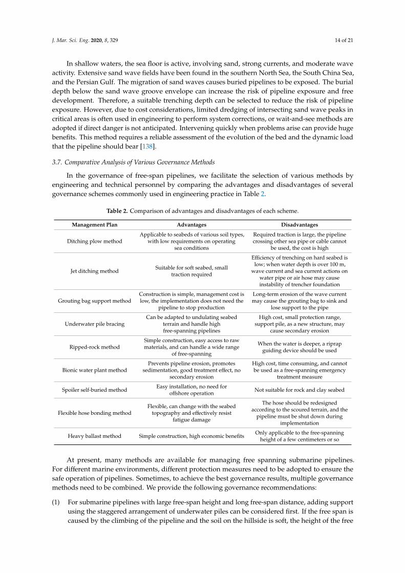
In the governance of free-span pipelines, we facilitate the selection of various methods byengineering and technical personnel by comparing the advantages and disadvantages of severalgovernance schemes commonly used in engineering practice in Table 2.
Table 2. Comparison of advantages and disadvantages of each scheme.
Management Plan Advantages Disadvantages
Ditching plow methodApplicable to seabeds of various soil types,
with low requirements on operatingsea conditions
Required traction is large, the pipelinecrossing other sea pipe or cable cannot
be used, the cost is high
Jet ditching method Suitable for soft seabed, smalltraction required
Efficiency of trenching on hard seabed islow; when water depth is over 100 m,
wave current and sea current actions onwater pipe or air hose may causeinstability of trencher foundation
Grouting bag support methodConstruction is simple, management cost islow, the implementation does not need the
pipeline to stop production
Long-term erosion of the wave currentmay cause the grouting bag to sink and
lose support to the pipe
Underwater pile bracingCan be adapted to undulating seabed
terrain and handle highfree-spanning pipelines
High cost, small protection range,support pile, as a new structure, may
cause secondary erosion
Ripped-rock methodSimple construction, easy access to rawmaterials, and can handle a wide range
of free-spanning
When the water is deeper, a riprapguiding device should be used
Bionic water plant methodPrevents pipeline erosion, promotes
sedimentation, good treatment effect, nosecondary erosion
High cost, time consuming, and cannotbe used as a free-spanning emergency
treatment measure
Spoiler self-buried method Easy installation, no need foroffshore operation Not suitable for rock and clay seabed
Flexible hose bonding methodFlexible, can change with the seabed
topography and effectively resistfatigue damage
The hose should be redesignedaccording to the scoured terrain, and the
pipeline must be shut down duringimplementation
Heavy ballast method Simple construction, high economic benefits Only applicable to the free-spanningheight of a few centimeters or so
At present, many methods are available for managing free spanning submarine pipelines.For different marine environments, different protection measures need to be adopted to ensure thesafe operation of pipelines. Sometimes, to achieve the best governance results, multiple governancemethods need to be combined. We provide the following governance recommendations:
(1) For submarine pipelines with large free-span height and long free-span distance, adding supportusing the staggered arrangement of underwater piles can be considered first. If the free span iscaused by the climbing of the pipeline and the soil on the hillside is soft, the height of the free
J. Mar. Sci. Eng. 2020, 8, 329 15 of 21
span can first be reduced using blown mud to subsidize the sea pipe, and then treating it with thestructural support method.
(2) When laying pipelines on the seabed with large water flow speed and soft soil, bionic waterweedcover can be used to prevent pipeline erosion, or a baffle plate can be installed on the pipeline topromote the pipeline to self-bury.
(3) For the free span of long length but small diameter pipelines, the trenches can be re-ditched orthe ballasting method can be used for heavy objects;
(4) For short-distance, free crossing pipelines in shallow waters, throw-filled crushed stone orgrouting bag support can be used reasonably.
(5) For the transition between the offshore platform riser and the submarine horizontal pipeline,a flexible hose crossover can be used.
(6) For pipelines near offshore platforms, sandbags should be used to backfill all the spans of thepipeline, and then the pipelines should be covered with cement briquettes to improve the abilityof the cover to resist erosion and external impact.
In the actual treatment of free spanning pipelines, we need to comprehensively consider factorssuch as the depth of the seawater, the nature of the subsea soil, the cost of treatment, and the effect ofthe treatment to select the best treatment solution.
4. Conclusions
The purpose of this study was to summarize and analyze the causes of submarine suspendedspan pipelines and the available treatment measures. Submarine pipelines are indispensable in theexploitation of offshore oil and gas resources. Since the 1950s, numerous reports have been publishedabout submarine pipeline damage caused by scouring and free-spanning. According to MineralsManagement Set (MMS) statistics of submarine pipeline failure accidents in the Gulf of Mexico from1967 to 1987, a total of 690 submarine pipeline failure accidents occurred in 20 years, with an averageannual failure accident of 35 cases [139]. Wang [140] investigated 61 submarine pipelines in China’sChengdao Oilfield and found that only five pipelines were not scour and suspended, accounting foronly 8%. These data illustrate the need for in-depth research on the causes and treatment measures forthe free span of subsea pipelines.
The reasons for the free span of submarine pipelines include the scour of wave flow, the fluctuationof seabed topography, residual stress, or thermal stress of pipelines, and human activities, amongwhich the scour caused by waves and currents is the most important. The study of scour initiation andmaximum depth is crucial for the prevention and treatment of scour of submarine pipelines. Due tothe many and complex factors affecting scour, the current research is limited by the research means,observation, and measuring instruments. We are not yet able to fully consider all the influencingfactors, so only reasonable simplified methods can be adopted for analysis and prediction.
At present, the submarine suspended span pipeline treatment methods mainly include there-digging trench burying method, structural support method, bionic water plant method, choke plateself-burying method, flexible hose bridging method, and heavy ballast method. Although manyexperts and scholars have formulated and implemented many pipeline free-span management methods,the most effective protection measures have not yet been found. Current treatment methods generallyhave disadvantages such as high cost and a large amount of underwater operation by divers. With theexploration of oil and gas resources in deeper waters, management measures with a high degree ofautomation and good economic benefits are required.
Author Contributions: Conceptualization, B.Z.; methodology, R.G.; formal analysis, T.W.; writing—original draftpreparation, Z.W. All authors have read and agreed to the published version of the manuscript.
Funding: This research was funded by National Natural Science Foundation of China (NNSFC), grant number:51879063 and 51479043. The views expressed here are those of the authors alone.
Conflicts of Interest: The authors declare no conflict of interest.

J. Mar. Sci. Eng. 2020, 8, 329 16 of 21
References
1. Ding, M.; Zhou, Y.G. On the ecological civilization dimension of human society development. Theor. Front.2009, 23, 16–18.
2. Zheng, Y.H.; Guo, H.D.; Wu, S.C. Analysis of China’s energy status and its development strategies. City2018, 1, 35–42.
3. Zhang, W.; He, N.X. Strategic analysis of offshore oil and gas resources development. Innov. Appl. Sci. Technol.2016, 13, 122–126.
4. Jin, W. L Analysis of submarine pipeline failure causes and countermeasures T7. Sci. Technol. Bull. 2004,20, 529–533.
5. Ba, J.B. Causes and prevention measures of submarine pipeline suspension. China New Technol. New Prod.2013, 2, 64–65.
6. Wilson, G. Free span threats. World Pipelines 2016, 16, 51–52.7. Ma, X.D. Analysis of free suspension span of submarine pipeline. Shanxi Archit. 2018, 44, 64–65.8. Dong, W.Y. Preventive Management of Suspended Section of Submarine Pipeline; Ocean Engineering Society of
China: Taiyuan, China, 2011; pp. 431–439.9. Bartolini, L.; Crea, C.; Marchionni, L.; Vitali, L. Advanced Analysis and Design Tools for Offshore Pipeline in
Operation. In Proceedings of the ASME 2011 30th International Conference on Ocean, Offshore and ArcticEngineering, Rotterdam, The Netherlands, 19–24 June 2011; Volume 4.
10. Mork, K.; Verley, R.; Bruschi, R. Troll Oil Pipeline: Calibration of Safety Factors for Cross-Flow Vibrations ofSpans on Very Uneven Seabed’s. In Proceedings of the International Conference on Offshore Mechanics andArctic Engineering, Copenhagen, Denmark, 18–22 Jun 1995; pp. 439–447.
11. Moshagen, H.; Verley, R.; Bruschi, R.; Solemsli, O. The Multi-span Project: Project Background and Summary.In Proceedings of the 16th International Conference on Offshore Mechanics and Arctic Engineering v.5:PipelineTechnology, Yokohama, Japan, 13–17 April 1997; pp. 1–6.
12. Colicchio, G.; Mattioli, M.; Lugni, C.; Brocchini, M. Numerical investigation of the scouring around pipelines.In Proceedings of the 12th Numerical Towing Tank Symposium, Cortona, Italy, 4–6 October 2009; pp. 44–49.
13. Herbich, J.B. Offshore Pipeline Design Elements; Marcel Dekker Inc.: New York, NY, USA, 1981.14. Demars, R.K. Measurement of Wave Induced Pressures and Stresses in a Sand bed. Mar. Geotechnol. 1983,
6, 29–59. [CrossRef]15. Liu, J.L. Evaluation of treatment methods for submarine pipeline scour and free suspension. In Proceedings
of the 15th China Ocean (shore) Engineering Symposium (I) Ocean Engineering Society of China: OceanEngineering Branch of Ocean Society of China, Taiyuan, China, 7–11 August 2011; p. 4.
16. Zang, Z.; Cheng, L.; Zhao, M. A numerical model for onset of scour below offshore pipelines. Coast. Eng.2009, 56, 458–466. [CrossRef]
17. Sumer, B.M.; Truelsen, C.; Sichmann, T. Onset of scour below pipelines and self-burial. Coast. Eng. 2001,42, 313–335. [CrossRef]
18. Xia, L. Sediment Starting under Wave Action and Local Scouring Around Submarine Pipelines; Zhejiang University:Hangzhou, China, 2006.
19. Zhen, Y. Effect of seepage flow on sediment incipient motion around a free spanning pipeline. Coast. Eng.2019, 143, 50–62.
20. Mattioli, M.; Mancinelli, A.; Colicchio, G.; Brocchini, M. Scouring below pipelines: The role of vorticity andturbulence. In Proceedings of the ASME Fluids Engineering Division Summer Conference 2010, Montreal,QC, Canada, 1–5 August 2010; Volume 2, pp. 265–267.
21. Sumer, B.M.; Jensen, H.R.; Mao, Y. Effect of lee-wake on scour below pipelines in current. J. Waterw. PortCoast. Ocean Eng. 1998, 114, 599–614. [CrossRef]
22. Jensen, B.L.; Sumer, B.M. Flow around and forces on a pipeline near a scoured bed in steady current arcticengineering. J. Offsh. Mech. Arct. Eng. 1990, 112, 206–213. [CrossRef]
23. Sumer, B.M.; Fredsoe, J. Onset of scour below a pipeline exposed to waves. Int. J. Offsh. Polar Eng. 1991,1, 189–194.
24. Sumer, B.M.; Fredsoe, J. Wave scour around structures. Adv. Coast. Ocean Eng. 1997, 4, 191–248.25. Sumer, B.M. Scour around coastal structures: A summary of recent research. Coast. Eng. 2001, 44, 153–190.
[CrossRef]

J. Mar. Sci. Eng. 2020, 8, 329 17 of 21
26. Sumer, B.M.; Fredsoe, J. The Mechanics of Scour in the Marine Environment; World Scientific: Singapore, 2002.27. Chiew, Y.M. Mechanics of local scour around submarine pipeline. J. Hydraul. Eng. 1989, 116, 515–529.
[CrossRef]28. Chiew, Y.M. Prediction of maximum scour depth at submarine pipelines. J. Hydraul Eng. 1991, 117, 452–466.
[CrossRef]29. Brors, B. Numerical modelling of flow and scour at pipelines. J. Hydraul. Eng. 1999, 125, 511–523. [CrossRef]30. Smith, H.D.; Foster, D.L. Modelling of flow around a cylinder over a scoured bed. J. Waterw. Port Coast.
Ocean Eng. 2005, 131, 14–24. [CrossRef]31. Myrhaug, D.; Rue, H. Scour below pipelines and vertical piles in random waves. Coast. Eng. 2003, 48, 227–242.
[CrossRef]32. Kumar, A.; Neelamani, S.; Narasimha, S. Wave pressures and uplift forces on and scour around submarine
pipeline in clayey soil. Ocean Eng. 2003, 30, 271–295. [CrossRef]33. Yan, T.; Li, P.; Li, G.X. Study on the scour stability of submarine pipelines in buried North Sea area. J. Qingdao
Ocean Univ. 1999, 19, 721–726.34. Feng, X.X. Model of Silty Soil Response under Marine Hydrodynamic Conditions. Ph.D. Thesis,
Qingdao Ocean University, Qingdao, China, 2000.35. Johnson, P.A. Reliability-based pier scour engineering. J. Hydraul. Eng. 1992, 118, 1344–1357. [CrossRef]36. Melville, B.W. Live-bed scour at bridge piers. J. Hydraul. Eng. 1984, 110, 1234–1247. [CrossRef]37. Sheppard, D.M.; Miller, W. Live-bed local pier scour experiments. J. Hydraul. Eng. 2006, 132, 635–642.
[CrossRef]38. Dey, S.; Singh, N.P. Clear-water scour below underwater pipelines under steady flow. J. Hydraul. Eng. 2008,
134, 588–600. [CrossRef]39. Moncada-M, A.T.; Aguirre-Pe, J. Scour below pipeline in river crossings. J. Hydraul. Eng. 1999, 125, 953–958.
[CrossRef]40. Dey, S.; Singh, N.P. Clear-water scour depth below under-water pipelines. J Hydro-Environ. Res. 2007,
1, 157–162. [CrossRef]41. Ibrahim, A.; Nalluri, C. Scour prediction around marine pipelines. In Proceedings of the International
Conference on Offshore Mechanics and Arctic Engineering, New York, NY, USA, 3–6 November 1986;Volume 3, pp. 679–684.
42. Mousavi, M.E.; Yeganeh-Bakhtiary, A.; Enshaei, N. The equivalent depth of wave-induced scour aroundoffshore pipelines. J. Offshore Mech. Arct. Eng. 2009, 131, 021601. [CrossRef]
43. Xu, J.; Li, G.; Dong, P.; Shi, J. Bedform evolution around a submarine pipeline and its effects on wave-inducedforces under regular waves. Ocean Eng. 2010, 37, 304–313. [CrossRef]
44. Mao, Y. The Interaction between a Pipeline and an Erodible Bed. Ph.D. Thesis, Institute of Hydrodynamicsand Hydraulics Engineering, Technical University of Denmark, Lyngby, Denmark, 1986.
45. Sumer, B.M. Scour below pipelines in waves. J. Waterw. Port Coast. Ocean Eng. 1990, 116, 307–323. [CrossRef]46. Mattioli, M.; Alsina, J.M.; Mancinelli, A.; Miozzi, M.; Brocchini, M. Experimental investigation of the nearbed
dynamics around a submarine pipeline laying on different types of seabed: The interaction between turbulentstructures and particles. Adv. Water Res. 2012, 48, 31–46. [CrossRef]
47. Mattioli, M.; Mancinelli, A.; Brocchini, M. Experimental investigation of the wave-induced flow around asurface-touching cylinder. J. Fluids Struct. 2013, 37, 62–87. [CrossRef]
48. Cheng, L.; Li, F. Modeling of local scour below a sagging pipeline. Coast. Eng. 2003, 45, 189–210. [CrossRef]49. Li, F.J.; Liang, C. Numerical model for local scour under offshore pipeline. J. Hydraul. Eng. 1999, 125, 400–406.
[CrossRef]50. Postacchini, P.; Brocchini, M. Scour depth under pipelines placed on weakly cohesive soils. Appl. Ocean Res.
2015, 52, 73–79. [CrossRef]51. Hansen, E.A.; Fredsøe, J.; Ye, M. Two-dimensional scour below pipelines. In International Offshore Mechanics
and Arctic Engineering. Symposium. 5; ASME: New York, NY, USA, 1986; pp. 670–678.52. Kjeldsen, S.P.; Gjørsvik, O.; Bringaker, K.G.; Jacobsen, J. Local scour near offshore pipelines. In Proceedings
of the 2nd International Conference on Port and Ocean Engineering under Arctic Conditions, University ofIceland, Reykjavik, Iceland, 27–30 August 1973; pp. 308–331.
53. Maza, J.A. Introduction to River Engineering, Advanced Course on Water Resources Management; Universita´Italiana per Stranieri: Perugia, Italy, 1987.

J. Mar. Sci. Eng. 2020, 8, 329 18 of 21
54. Myrhaug, D.; Ong, M.C.; Føien, H.; Gjengedal, C.; Leira, B.J. Scour below pipelines and around vertical pilesdue to second-order random waves plus a current. Ocean Eng. 2009, 36, 605–616. [CrossRef]
55. Azamathulla, H.M.D.; Guven, A.; Demir, Y.K. Linear genetic programming to scour below submergedpipeline. Ocean Eng. 2011, 38, 995–1000. [CrossRef]
56. Azamathulla, H.M.D.; Zakaria, N.A. Prediction of scour below submerged pipeline crossing a river usingANN. IWA Water Sci. Technol. 2011, 63, 2225–2230. [CrossRef]
57. Etemad-Shahidi, A.; Yasa, R.; Kazeminezhad, M.H. Prediction of wave-induced scour depth under submarinepipelines using machine learning approach. Appl. Ocean Res. 2011, 33, 54–59. [CrossRef]
58. Najafzadeh, M.; Gholam-Abbas, B. Prediction of pipeline scour depth in clear-water and live-bed conditionsusing group method of data handling. Neural Comput. Appl. 2014, 24, 629–635. [CrossRef]
59. Bijker, R.; Staub, C.; Bruschi, R.; Silvis, F. Scour-induced Free Spans. In Proceedings of the Offshore TechnologyConference, Houston, TX, USA, 6–9 May 1991.
60. Sumer, B.M.; Fredsøe, J. A Review of Wave/Current-Induced Scour Around Pipelines Coastal Engineering.In Proceedings of the 23rd International Conference on Coastal Engineering, Venice, Italy, 4–9 October 1992.
61. Drago, M.; Mattioli, M.; Bruschi, R.; Vitali, L. Insights on the design of free-spanning pipelines. Philos. Trans.R. Soc. A Math. Phys. Eng. Sci. 2015, 373, 20140111. [CrossRef] [PubMed]
62. Zhou, C.; Li, G.; Dong, P. An experimental study of seabed responses around a marine pipeline under waveand current conditions. Ocean Eng. 2011, 38, 226–234. [CrossRef]
63. Zhang, J.; Sun, G.M.; Wang, L.Q. Study on scour start of submarine pipeline under the combined action ofwave and current. Port Eng. Technol. 2017, 54, 23–27.
64. Cai, C.L.; Zhang, Y.B.; Hu, B. Factors influencing the scour effect of seabed pipeline in East China Sea.Offshore Pet. 2013, 33, 96–100.
65. Liu, D.J.; Huang, P.Y.; Hu, T.J. Influencing factors of seabed oil pipeline scour in zhoushan shidao Zhuhai,ningbo. Front. Mar. Geol. 2014, 30, 39–44.
66. Zang, Z.P. Research on the equilibrium depth and time scale of submarine pipeline scour under theaction of oblique current. In Proceedings of the 18th China Ocean (Shore) Engineering Symposium (II),Ocean Engineering Society of China, Zhoushan, China, September 2017.
67. Liu, Y.Y.; Lv, L.; Zheng, M.Z. Analysis of seabed stability and local scour of submarine pipeline under waveflow. J. Zhejiang Univ. 2012, 46, 1135–1142.
68. Feng, H.; Wang, Y.H.; Wang, J. Treatment of submarine pipeline suspension span and its applicability analysis.China Shipbuild. Ind. 2012, 53, 74–81.
69. Pan, X.G. Causes and prevention of submarine pipeline suspension. China Ship Insp. 2005, 10, 68–69.70. Wen, S.P.; Xu, J.S.; Hu, G.H. A field investigation on the effects of background erosion on the free span
development of a submarine pipeline. J. Ocean Univ. China 2015, 14, 621–628. [CrossRef]71. Fyrileiv, O. Update design procedure for free spanning pipelines DNV-RP-F105: Multi-mode response.
In Proceedings of the International Conference on Offshore Mechanics & Arctic Engineering, Hamburg,Germany, 4–9 June 2006; pp. 57–64.
72. Zhao, D.; Li, X.F.; Feng, X.H. Analysis of submarine pipeline unevenness. Ship Sci. Technol. 2014, 36, 112–116.73. Xie, Y.; Ma, X.F.; Ning, H.F. Formation and failure mechanism of submarine suspension pipeline. Oil Gas
Storage Transp. 2017, 36, 1436–1442.74. Zuo, R. Study on the suspended transverse-vortex-induced vibration response of deep-water submarine
pipeline. Electron. Fabr. 2013, 4, 183–188.75. Xu, J.; Shi, Z.D.; Zhang, K. Analysis and study on fatigue life of suspended submarine pipeline. Offshore Pet.
2009, 29, 80–84.76. Shao, W.C.; Xia, X.X. Submarine pipeline embedding machine and its application. Zhejiang Water Conserv.
Sci. Technol. 2005, 3, 41–43.77. Wang, L.; Xing, P.; Wang, Y.Z. Design of Plough for Submarine Free Span Pipeline Laying. Oil Field Equip.
2013, 42, 14–17.78. Li, S.G. Research on Floating Towpipe Technology in Intertidal Waters. Master’s Thesis, Tianjin University,
Tianjin, China, 2007.79. Grinsted, T.W.; Reece, A.R. Pipeline or Cable Plough. U.S. Patent 4,802,793, 7 February 1989.80. Zhang, G.G. Introduction of world-renowned underwater trenching machinery design and construction
company and machine type. Ocean Technol. 1990, 2, 5–64.
J. Mar. Sci. Eng. 2020, 8, 329 19 of 21
81. Zhang, G.G. Trench plough for submarine pipeline and its design analysis. Oil Gas Storage Transp. 1989,2, 32–38.
82. Kang, L.S. Method and equipment for trench excavation and burial of submarine pipeline. Ocean Eng. 1992,10, 10–18.
83. Gong, H.Y.; Wang, L.Q.; Xing, X.D. Plough body modeling and soil cracking of subsea plough trench-digger.J. Mech. Eng. 2012, 48, 135–140.
84. Guo, Z.H.; Zhou, D.Y.; Zhou, Z.L. Simulation study on mechanical properties of tillage components withdifferent soil contact surfaces. Chin. J. Mech. Eng. 2010, 46, 71–75. [CrossRef]
85. Chen, C.Y.; Chen, L.G.; Wang, X.Z. Parameter design of double-wing tilling plough. Chin. J. Agric. Mach.2000, 31, 27–29.
86. Brown, R.; Palmer, A. Submarine pipeline trenching by multipass ploughs. In Proceedings of the OffshoreTechnology Conference, Houston, TX, USA, 6–9 May 1985.
87. Voldsund, T.A. Modelling and Control of Offshore Ploughing Operations. Master’s Thesis, NorwegianUniversity of Science and Technology, Trondheim, Norway, 2007.
88. Hydrovision, S.M.D. Introduction to SMD Hydrovision; SMD Hydrovision, Place Published: Newcastle upon Tyne,UK, 2004.
89. Lauder, K.D. Variation of tow force with velocity during offshore ploughing in granular materials.Can. Geotech. J. 2012, 49, 1244–1255. [CrossRef]
90. CTC. Datasheet-APP-REV02LH EB/OLD.2019. Available online: http://www.ctcmarine.com/page/520/
TrenchersPloughs#9900476 (accessed on 1 May 2019).91. Cathie, D. Pipeline and Cable Plough Stability in Soft Clays. In Proceedings of the Offshore Site Investigation
and Geotechnics: Confronting New Challenges and Sharing Knowledge, London, UK, 11–13 September 2007.92. Vessel & ROV News. SMD Hydrovision Unveils AMP500 Plough [EB/OL]. Available online: http://www.
oilpubs.com/oso/article.asp?v1=1134 (accessed on 1 May 2019).93. CTC Marine Projects. VMP Technical Specification [EB/OL]. Available online: http://www.ctcmarine.com
(accessed on 1 May 2019).94. Tang, X.X.; Hu, G.H. Comprehensive treatment of suspended span of submarine oil pipeline. Oil Gas Field
Surf. Eng. 2011, 30, 38–39.95. Wang, Z.; Hu, C.Y. Research on Grouting Bag Laying Device for Suspended Span Treatment of Submarine Pipeline;
Harbin University of Engineering: Harbin, China, 2016.96. Song, C.N.; Zhang, Y.T.; Miao, C.S. Treatment Method of Submarine Pipeline Suspension Span.
CN106015736A, 12 October 2016.97. Ye, H.B.; Song, C.N.; Cui, N. Principle and construction technology of cantilever beam support method.
Oil Gas Storage Transp. 2014, 33, 86–88.98. Ma, K.M. Application of structural support design in submarine pipeline suspension governance.
Pet. Chem. Equip. 2017, 20, 47–50.99. Ni, Z.Z.; Liu, G.; Yuan, Z.H. Study on treatment methods of offshore suspended span of submarine pipeline.
Chem. Eng. Equip. 2017, 10, 99–100.100. Chamizo, D.J.; Campbell, D.R.; Jas, E.P. Rock Berm Design for Pipeline Stability. In Proceedings of the
ASME 2012 31st International Conference of Ocean, Offshore and Arctic Engineering, Rio de Janeiro, Brazil,1–6 July 2012.
101. CIRIA. The Rock Manual—The Use of Rock in Hydraulic Engineering, 2nd ed.; C683; CIRIA: London, UK, 2007;ISBN 978-0-86017-683.
102. Hinwood, J.B.; Lipski, W. Failure Modes of Rock Berms for Offshore Pipeline Protection. In Proceedings ofthe International Society of Offshore and Polar Engineers, Kitakyushu, Japan, 26–31 May 2002; pp. 32–37.
103. Olso, E.; Nyhus, B.; OStby, E. Assessment of Fracture Integrity for Trawl Impact of the Ormen LangeSFD Pipelines. In Proceedings of the ASME International Conference on Ocean, Honolulu, HI, USA,31 May–5 June 2009; pp. 841–850.
104. Sun, Q.; Yu, C.L.; Feng, X.W. Research and application of partial ripping stone for suspension span treatmentof deepwater submarine pipelines. Pet. Eng. Constr. 2016, 42, 14–19.
105. Song, D.J. Analysis of reasons and countermeasures for the suspension of submarine pipeline lying.Digit. Commun. World 2017, 10, 84–89.

J. Mar. Sci. Eng. 2020, 8, 329 20 of 21
106. Liu, J.K.; Zhang, Z.F. Application of bionic water plant in suspension protection of submarine pipeline.Pet. Eng. Constr. 2009, 35, 20–22.
107. Liu, J.K.; Zhang, Z.F. Application of bionic scour prevention system in chengdao oilfield. China Offshore Platf.2008, 23, 36–38.
108. Li, Y.H.; Yu, G.L. Experimental Study on Angle of Slant of Flexible Permeability Promoting Silt FloatingCurtain. J. Shanghai Jiaotong Univ. 2009, 3, 169–172.
109. Li, Y.H.; Chen, Q.Q.; Yu, G.L. Research progress and prospect of silt promotion and anti-erosion technologyon beach. Coast. Eng. 2007, 4, 27–34.
110. Cheng, L.; Chew, L.W. Modelling of flow around a near-bed pipeline with a spoiler. Oceaning 2003,30, 1595–1611. [CrossRef]
111. Hulsbergen, C.H. Spoilers for stimulated self-Burial of submarine pipelines. In Proceedings of the OffshoreTechnology Conference, Houston, TX, USA, 5–8 May 1984; pp. 441–444.
112. Hulsbergen, C.H.; Bijker, R. Effect of spoilers on submarine pipeline stability. In Proceedings of the OffshoreTechnology Conference, Houston, TX, USA, 1–4 May 1989; pp. 337–350.
113. Gokce, K.T.; Gunbak, A.R. Self-burial and stimulated self-burial of pipelines by waves. In Proceedings ofthe 1st International Conference on Offshore and Polar Engineering II, Edinburgh, UK, 11–16 August 1991;pp. 301–307.
114. Yang, L.P. Research on Submarine Pipeline Scour and Protection under Wave Action; Ocean university of China:Qingdao, China, 2012.
115. Han, Y. Comparative experimental study on protection of submarine pipeline by rigid choke plate andflexible guide plate. In Proceedings of the China Branch of International Water Engineering and ResearchAssociation: China Hydraulic Power Engineering Society, Xi’an, China, September 2009.
116. Zhang, Z.Y.; Ruan, X.J. Research on the influence of diversion deflector on the submarine pipeline under theaction of waves. Ocean Eng. 2012, 30, 90–96.
117. Chiew, Y.M. Effect of spoilers on scour at submarine pipelines. J. Hydraul. Eng. 1992, 118, 1311–1317.[CrossRef]
118. Chiew, Y.M. Effect of spoilers on wave-induced scour at submarine pipelines. J. Waterw. Port Coast. Ocean Eng.1993, 119, 417–429. [CrossRef]
119. Jiang, W.Q.; Jiang, H.J.; Yang, F. Influence of diversion plate on submarine pipeline sinking and self-buryingand vortex vibration. J. China Univ. Pet. 2018, 42, 147–152.
120. Lai, H.; Ye, Y.C.; Wei, Y.J. A preliminary study on the evolution process of scour and self-burial of submarinepipelines in hangzhou bay. Oceanography 2011, 29, 65–71.
121. Castro, G. Liquefaction of Sands; Harvard Soil Mechanics Series No.81.1969; Harvard University: Cambridge,MA, USA, 1969.
122. Kramer, S.L. Triggering liquefaction flow slides in coastal soil deposits. Eng. Geol. 1988, 26, 17–31. [CrossRef]123. Kramer, S.L.; Seed, H.B. Initiation of soil liquefaction under static loading conditions. J. Geotech. Eng. 1988,
114, 412–430. [CrossRef]124. Boulanger, R.W.; Idriss, I.M. Liquefaction susceptibility criteria for silts and clays. J. Geotech. Geoenviron. Eng.
2006, 132, 1413–1426. [CrossRef]125. Bray, D.J.; Sancio, R.B. Assessment of the liquefaction susceptibility of fine-grained soils. J. Geotech. Geoenviron.
Eng. 2006, 132, 1165–1177. [CrossRef]126. Muhunthan, B.; Worthen, D.L. Critical state framework for liquefaction of fine grained soils. Eng. Geol. 2011,
117, 2–11. [CrossRef]127. Seed, H.B.; Idriss, I.M. Ground Motions and Soil Liquefaction during Earthquakes; Technical Report; Earthquake
Engineering Research Institute: Berkerlay, CA, USA, 1979.128. Okusa, S. Wave-induced stress in unsaturated submarine sediments. Geotechnique 1985, 35, 517–532.
[CrossRef]129. Tsai, C.P. Wave-induced liquefaction potential in a porous seabed in front of a breakwater. Ocean Eng. 1995,
22, 1–18. [CrossRef]130. Zen, K.; Yamazaki, H. Oscillatory pore pressure and liquefaction in seabed induced by ocean waves.
Soils Found. 1990, 30, 147–161. [CrossRef]131. Jeng, D.-S. Wave-Induced Seabed Response in Front of a Breakwater. Ph.D. Thesis, University of Western
Australia, Perth, Australia, 1997.

J. Mar. Sci. Eng. 2020, 8, 329 21 of 21
132. Nataraja, M.S.; Gill, H.S. Ocean wave-induced liquefaction analysis. J. Geotech. Eng. 1983, 109, 573–590.[CrossRef]
133. Ishihara, K. Liquefaction and flow failure during earthquakes. Geotechnique 1993, 43, 349–416. [CrossRef]134. Liu, Z.F. Governance of suspended span section of submarine pipeline in ledong gas field. In Proceedings of
the 2009 Academic Conference on Ocean Engineering (Part II), Xiamen, China, November 2009.135. Lin, S.Q.; Ye, Y.B.; Qi, B.B. Research on treatment method of suspended span of sea pipe based on jet flow.
Mech. Eng. 2018, 5, 170–172.136. Yun, D. History Effects for Deepwater S-Lay of Pipelines. In Proceedings of the ASME International
Conference on Offshore Mechanics & Arctic Engineering, Cancun, Mexico, 8–13 June 2003; Volume 126,pp. 833–841.
137. Summer, L.; Yang, H.; Deng, H.X. Analysis of submarine pipeline suspension span and recommendedpractice of unequal seabed treatment. China Shipbuild. 2008, 49, 523–528.
138. Bruschi, R.; Drago, M.; Bughi, S.; Gianfelici, F. In-place stability and integrity of offshore pipelines crossing orresting on active bedforms or loose or soft soils. J. Pipeline Eng. 2014, 13, 167–199.
139. She, W.W. Research on the Mechanism of Ecological Silt Promotion and Scour Prevention Near the UnderwaterPipeline; Shanghai Jiaotong University: Shanghai, China, 2010.
140. Yu, G.L.; Chen, Q.Q.; Li, Y.H. Development status and trend of anti-scour protection technology for submarinepipelines. Water Resour. Hydropower Technol. 2007, 11, 30–33.
© 2020 by the authors. Licensee MDPI, Basel, Switzerland. This article is an open accessarticle distributed under the terms and conditions of the Creative Commons Attribution(CC BY) license (http://creativecommons.org/licenses/by/4.0/).