EXPLORER PIPELINE SYSTEM
599
EMERGENCY RESPONSE ACTION PLAN EXPLORER PIPELINE SYSTEM EXPLORER PIPELINE SYSTEM Prepared for: Explorer Pipeline Company 6120 South Yale Ave. Tulsa, Oklahoma 74136, Prepared by: Response Management Associates, Inc. 6620 Cypresswood Drive, Suite 200 Spring, TX 77379 (281) 320-9796 Phone (281) 320-9700 Fax www.rmaworld.com e R n l R n n l R eg nse A lan ERAP Emergency Response Action Plan ERAP ___ __ __ ___ ___ __ _________ _________ _________________________________________________________________________________________ ___ __ __ ___ ___ __ _________ _________ _________________________________________________________________________________________ l sp l Re Oil Spill Response P a a Plan - ERAP-1 P R E N S R P SE EXPLORER PIPELINE SYSTEM o a t s i on a A i © Response Management Associates, © Response Management Associates, . . Inc. Inc. e U U R se a T R se : Revised Date: AUGUST 1 2013 e 2 2 a ve r 2007 Issue Date: November 2007 PHMSA 000015360
-
Upload
khangminh22 -
Category
Documents
-
view
0 -
download
0
Transcript of EXPLORER PIPELINE SYSTEM

EMERGENCY RESPONSE ACTION PLAN EXPLORER PIPELINE SYSTEM
EXPLORER PIPELINE
SYSTEM
Prepared for:
Explorer Pipeline Company 6120 South Yale Ave.
Tulsa, Oklahoma 74136,
Prepared by: Response Management Associates, Inc.
6620 Cypresswood Drive, Suite 200 Spring, TX 77379
(281) 320-9796 Phone (281) 320-9700 Fax
www.rmaworld.com
e R n l R n n l Re g nse A lan ERAPEmergency Response Action Plan ERAP___ __ __ ___ ___ __ _________ __________________________________________________________________________________________________
___ __ __ ___ ___ __ _________ __________________________________________________________________________________________________
l sp l Re Oil Spill Response P a a Plan -ERAP- 1 P R E N SR P S EEXPLORER PIPELINE SYSTEM o a t s i on a A i © Response Management Associates, © Response Management Associates, . . Inc. Inc. e U U R se a T R se : Revised Date: AUGUST 1 2013 e 2 2 a ve r 2007Issue Date: November 2007
PHMSA 000015360

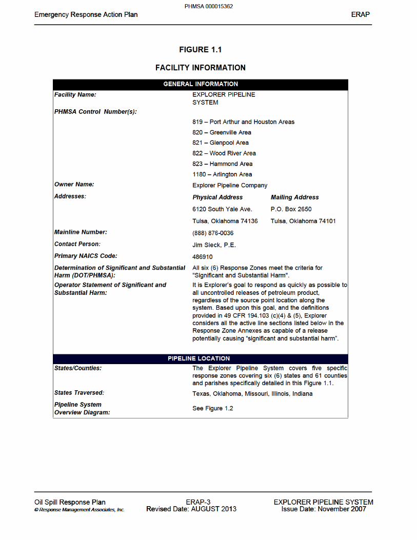

FIGURE 2.1
INTERNAL NOTIFICATION SEQUENCE(Phone references are provided in Figure 2.2)
e R n l R n n l Re g nse A lan ERAPEmergency Response Action Plan ERAP___ __ __ ___ ___ __ _________ __________________________________________________________________________________________________
___ __ __ ___ ___ __ _________ __________________________________________________________________________________________________
l sp l Re Oil Spill Response P a a Plan -ERAP- 4 P R E N SR P S EEXPLORER PIPELINE SYSTEM o a t s i on a A i © Response Management Associates, © Response Management Associates, . . Inc. Inc. e U U R se a T R se : Revised Date: AUGUST 1 2013 e 2 2 a ve r 2007Issue Date: November 2007
PHMSA 000015363


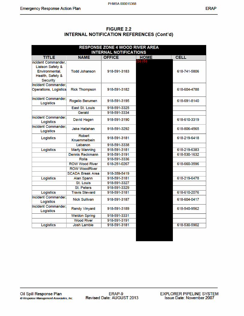


FIGURE 2.4
EXTERNAL NOTIFICATION FLOWCHART
e R n l R n n l Re g nse A lan ERAPEmergency Response Action Plan ERAP___ __ __ ___ ___ __ _________ __________________________________________________________________________________________________
___ __ __ ___ ___ __ _________ __________________________________________________________________________________________________
l sp l Re Oil Spill Response P a a Plan -ERAP- 8 8 18 I T X P Y MEXPLORER PIPELINE SYSTEM o a t s i on a A i © Response Management Associates, © Response Management Associates, . . Inc. Inc. e U U R se a T R se : Revised Date: AUGUST 1 2013 e 2 r 2 a ve r 2007Issue Date: November 2007
PHMSA 000015377


FIGURE 2.5
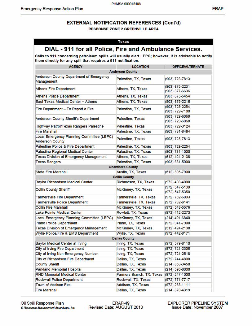
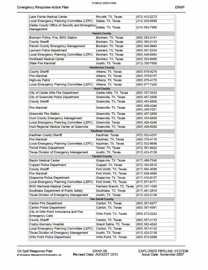
EXTERNAL NOTIFICATION REFERENCES (Cont'd)
e R n l R n n l Re g nse A lan ERAPEmergency Response Action Plan ERAP___ __ __ ___ ___ __ _________ __________________________________________________________________________________________________
___ __ __ ___ ___ __ _________ __________________________________________________________________________________________________
l sp l Re Oil Spill Response P a a Plan -ERAP- 0 0 20 I T X P Y MEXPLORER PIPELINE SYSTEM o a t s i on a A i © Response Management Associates, © Response Management Associates, . . Inc. Inc. e U U R se a T R se : Revised Date: AUGUST 1 2013 e 2 r 2 a ve r 2007Issue Date: November 2007
PHMSA 000015379


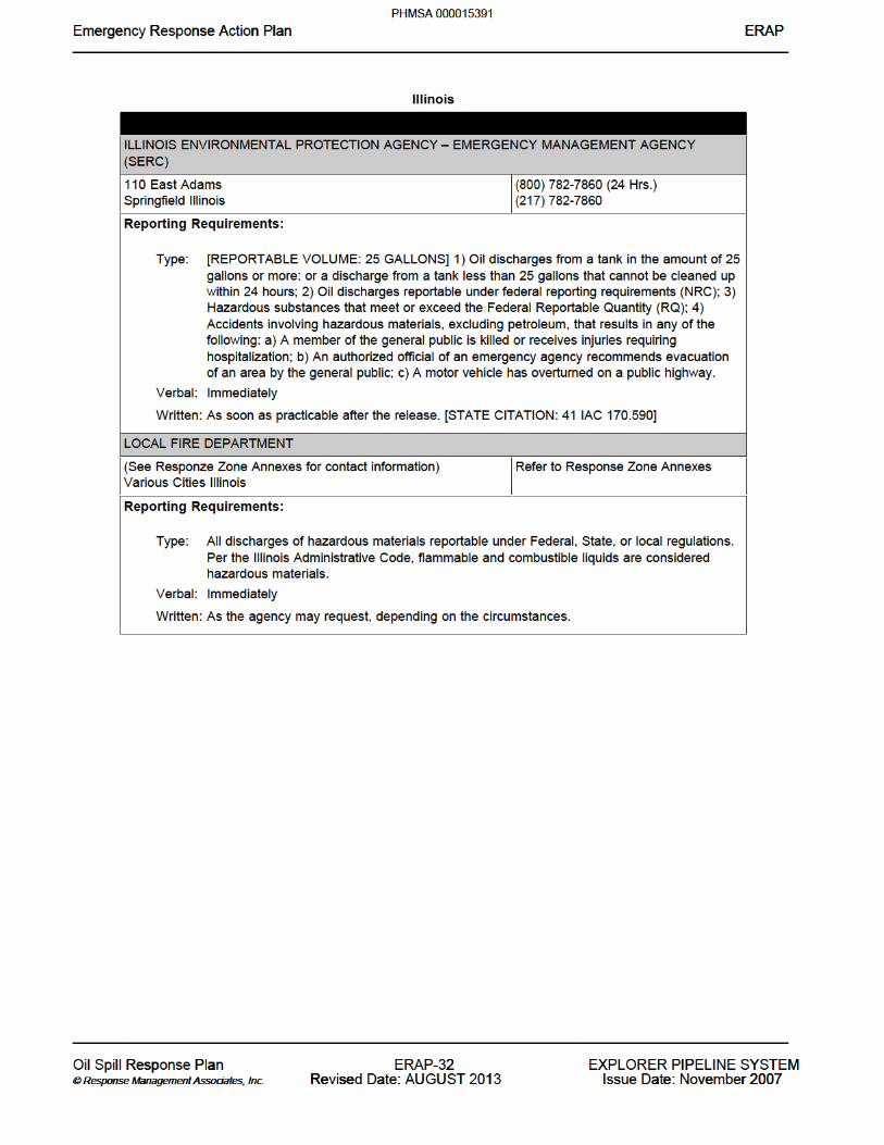
Illinois
e R n l R n n l Re g nse A lan ERAPEmergency Response Action Plan ERAP___ __ __ ___ ___ __ _________ __________________________________________________________________________________________________
___ __ __ ___ ___ __ _________ __________________________________________________________________________________________________
l sp l Re Oil Spill Response P a a Plan -ERAP- 1 1 31 I T X P Y MEXPLORER PIPELINE SYSTEM o a t s i on a A i © Response Management Associates, © Response Management Associates, . . Inc. Inc. e U U R se a T R se : Revised Date: AUGUST 1 2013 e 2 r 2 a ve r 2007Issue Date: November 2007
PHMSA 000015390

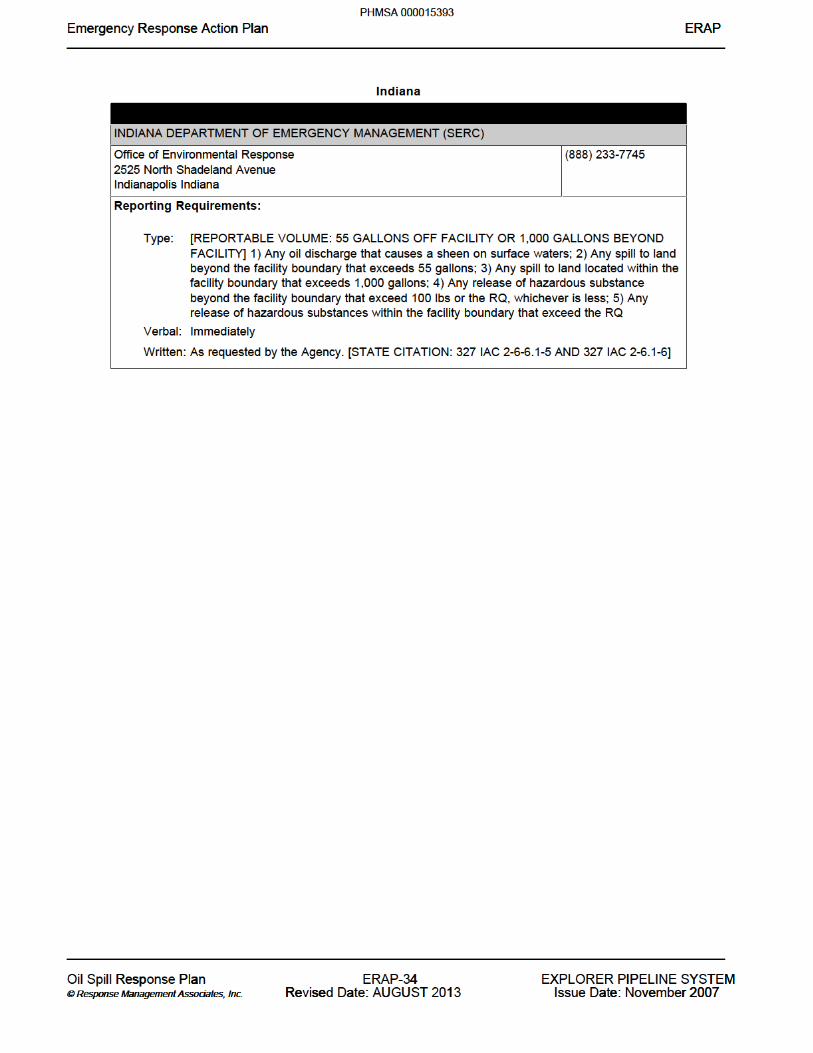
Indiana
e R n l R n n l Re g nse A lan ERAPEmergency Response Action Plan ERAP___ __ __ ___ ___ __ _________ __________________________________________________________________________________________________
___ __ __ ___ ___ __ _________ __________________________________________________________________________________________________
l sp l Re Oil Spill Response P a a Plan -ERAP- 3 3 33 I T X P Y MEXPLORER PIPELINE SYSTEM o a t s i on a A i © Response Management Associates, © Response Management Associates, . . Inc. Inc. e U U R se a T R se : Revised Date: AUGUST 1 2013 e 2 r 2 a ve r 2007Issue Date: November 2007
PHMSA 000015392

Missouri
e R n l R n n l Re g nse A lan ERAPEmergency Response Action Plan ERAP___ __ __ ___ ___ __ _________ __________________________________________________________________________________________________
___ __ __ ___ ___ __ _________ __________________________________________________________________________________________________
l sp l Re Oil Spill Response P a a Plan -ERAP- 5 5 35 I T X P Y MEXPLORER PIPELINE SYSTEM o a t s i on a A i © Response Management Associates, © Response Management Associates, . . Inc. Inc. e U U R se a T R se : Revised Date: AUGUST 1 2013 e 2 r 2 a ve r 2007Issue Date: November 2007
PHMSA 000015394


Oklahoma
e R n l R n n l Re g nse A lan ERAPEmergency Response Action Plan ERAP___ __ __ ___ ___ __ _________ __________________________________________________________________________________________________
___ __ __ ___ ___ __ _________ __________________________________________________________________________________________________
l sp l Re Oil Spill Response P a a Plan -ERAP- 7 7 37 I T X P Y MEXPLORER PIPELINE SYSTEM o a t s i on a A i © Response Management Associates, © Response Management Associates, . . Inc. Inc. e U U R se a T R se : Revised Date: AUGUST 1 2013 e 2 r 2 a ve r 2007Issue Date: November 2007
PHMSA 000015396


Texas
e R n l R n n l Re g nse A lan ERAPEmergency Response Action Plan ERAP___ __ __ ___ ___ __ _________ __________________________________________________________________________________________________
___ __ __ ___ ___ __ _________ __________________________________________________________________________________________________
l sp l Re Oil Spill Response P a a Plan -ERAP- 9 9 39 I T X P Y MEXPLORER PIPELINE SYSTEM o a t s i on a A i © Response Management Associates, © Response Management Associates, . . Inc. Inc. e U U R se a T R se : Revised Date: AUGUST 1 2013 e 2 r 2 a ve r 2007Issue Date: November 2007
PHMSA 000015398


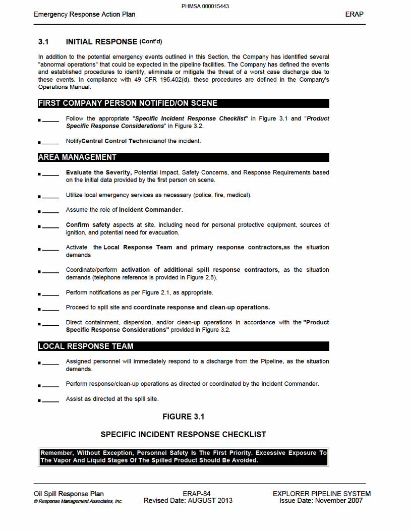

INITIAL RESPONSE ______ Take appropriate personal protective measures
______ Call for medical assistance if an injury has occurred.
______ Notify Area Management of the incident.
______ Eliminate possible sources of ignition in the near vicinity of the spill.
______ Take necessary fire response actions.
______ Advise personnel in the area of any potential threat and/or initiate evacuation procedures.
______ Identify/Isolate the source and minimize the loss of product.
______ Restrict access to the spill site and adjacent area as the situation demands. Take additional
steps necessary to minimize any threat to health and safety.
______ Use testing and sampling equipment to determine potential safety hazards, as the situation
demands.
______ Verify the type of product and quantity released.
All personnel are reminded that outsiders other than emergency services will not be allowed in the area during the time of an emergency, and that statements issued to the media or other interested parties should be given by designated Company Management. Be courteous with media representatives and direct them to the designated spokesman.
e R n l R n n l Re g nse A lan ERAPEmergency Response Action Plan ERAP___ __ __ ___ ___ __ _________ __________________________________________________________________________________________________
___ __ __ ___ ___ __ _________ __________________________________________________________________________________________________
l sp l Re Oil Spill Response P a a Plan -ERAP- 5 5 85 I T X P Y MEXPLORER PIPELINE SYSTEM o a t s i on a A i © Response Management Associates, © Response Management Associates, . . Inc. Inc. e U U R se a T R se : Revised Date: AUGUST 1 2013 e 2 r 2 a ve r 2007Issue Date: November 2007
PHMSA 000015444

FIGURE 3.1
SPECIFIC INCIDENT RESPONSE CHECKLIST (Cont'd)
LINE BREAK OR LEAK, SPECIFIC RESPONSE ______Check for pressure corresponding to the scheduled flow rate. If in doubt, shut it down
______If discrepancies occur, locate the area affected. If in doubt, shut it down
______Verify the leak’s presence with aerial patrol, landowners, or employees.
______Shut down pumping equipment.
______The Central Control Technician shall notify Area Management and the Director, Field Operations
that operations are shut-down.
______Send personnel to close upstream and downstream block valves, paying attention to the terrain
and hydraulic location of the leak. Check valve positions on both sides of the leak to make certain they are closed.
______Mitigate spreading of the product, as the situation demands. Potential containment strategies
include:
Boom Earthen dike/berm Ditching
______Spreading sorbent material over the spill.
______Prevent the spill from entering the waterways, sewer, etc. to the greatest extent possible.
______Determine the direction and expected duration of spill movement. Refer to the maps in Section 6.0.
______If located within containment area, ensure that drainage valve(s) is “closed”.
______If the spill escapes the containment area, review the location of socio-economic and
environmentally sensitive areas identified in Section 6.0 and the ACP. Determine which of these may be threatened by the spill and direct the response operation to these locations. Initiate protection and recovery actions.
______Qualified personnel should utilize LEL meter, O2 meter, proper colormetric indicator tubes, such as
Drager, and/or other air sampling measurements to assure that areas are safe to enter for continued response operations. Refer to Vapor Cloud Specific Response, later in this Figure, if flammable vapors are detected.
e R n l R n n l Re g nse A lan ERAPEmergency Response Action Plan ERAP___ __ __ ___ ___ __ _________ __________________________________________________________________________________________________
___ __ __ ___ ___ __ _________ __________________________________________________________________________________________________
l sp l Re Oil Spill Response P a a Plan -ERAP- 6 6 86 I T X P Y MEXPLORER PIPELINE SYSTEM o a t s i on a A i © Response Management Associates, © Response Management Associates, . . Inc. Inc. e U U R se a T R se : Revised Date: AUGUST 1 2013 e 2 r 2 a ve r 2007Issue Date: November 2007
PHMSA 000015445
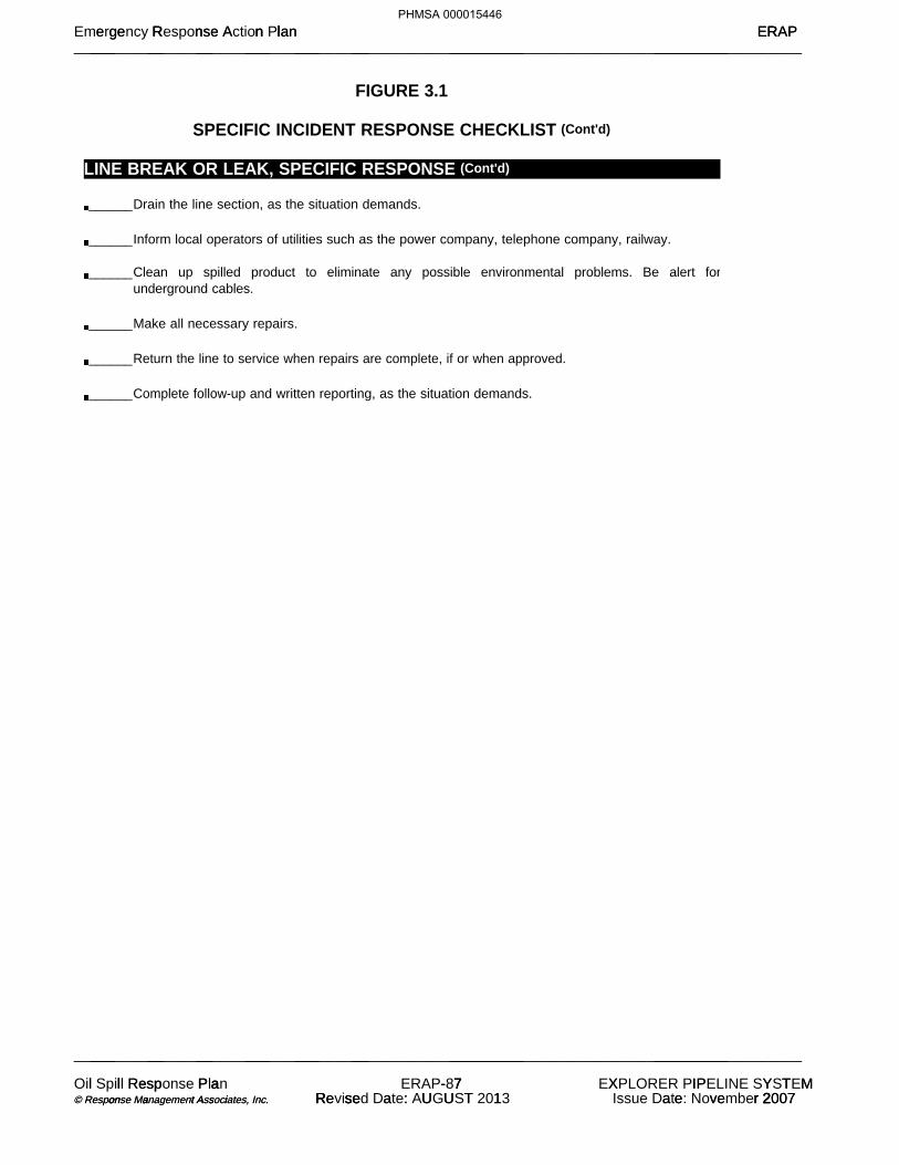
FIGURE 3.1
SPECIFIC INCIDENT RESPONSE CHECKLIST (Cont'd)
LINE BREAK OR LEAK, SPECIFIC RESPONSE (Cont'd)
______Drain the line section, as the situation demands.
______Inform local operators of utilities such as the power company, telephone company, railway.
______Clean up spilled product to eliminate any possible environmental problems. Be alert for
underground cables.
______Make all necessary repairs.
______Return the line to service when repairs are complete, if or when approved.
______Complete follow-up and written reporting, as the situation demands.
e R n l R n n l Re g nse A lan ERAPEmergency Response Action Plan ERAP___ __ __ ___ ___ __ _________ __________________________________________________________________________________________________
___ __ __ ___ ___ __ _________ __________________________________________________________________________________________________
l sp l Re Oil Spill Response P a a Plan -ERAP- 7 7 87 I T X P Y MEXPLORER PIPELINE SYSTEM o a t s i on a A i © Response Management Associates, © Response Management Associates, . . Inc. Inc. e U U R se a T R se : Revised Date: AUGUST 1 2013 e 2 r 2 a ve r 2007Issue Date: November 2007
PHMSA 000015446

FIGURE 3.1
SPECIFIC INCIDENT RESPONSE CHECKLIST (Cont'd)
STORAGE TANK LEAK, SPECIFIC RESPONSE ______ Shut down all tank farm product movement operations and isolate the tank.
______ The Central Control Technician shall notify Area Management and the Director, Field Operations
that operations are shut-down.
______ Ensure that the containment area drainage valve(s) is “closed”.
______ If possible, block drainage of spilled material from traveling offsite.
______ Determine the direction and expected duration of spill movement. Refer to the maps in Section
6.0.
______ If the spill escapes the containment area, review the location of socio-economic and
environmentally sensitive areas identified in Section 6.0 and the ACP. Determine which of these may be threatened by the spill and direct the response to these locations. Initiate protection and recovery actions.
______ Qualified personnel should utilize LEL meter, O2 meter, proper colormetric indicator tubes, such
as Drager, and/or other air sampling measurements to assure that areas are safe to enter for continued response operations. Refer to Vapor Cloud Specific Response, later in this Figure, if flammable vapors are detected.
______ Stop all traffic in hazardous area (inside and outside of property boundaries), as the situation
demands.
______ Inform local operators of utilities such as the power company, telephone company, railway.
______ Remove product from containment area (at a sump or in a low area) with an explosion proof
pump, oil skimmer, and/or vacuum truck w/ skimmer attachments.
______ If applicable, process remaining product through the separator system.
______ Clean up product spill to eliminate any possible environmental problems. Be alert for underground
utilities, lines, etc.
______ Stockpile waste for eventual disposal.
______ Make all necessary repairs. Return the line/tank to service when repairs are complete and
tested.
______ Complete follow-up and written reporting, as the situation demands.
e R n l R n n l Re g nse A lan ERAPEmergency Response Action Plan ERAP___ __ __ ___ ___ __ _________ __________________________________________________________________________________________________
___ __ __ ___ ___ __ _________ __________________________________________________________________________________________________
l sp l Re Oil Spill Response P a a Plan -ERAP- 8 8 88 I T X P Y MEXPLORER PIPELINE SYSTEM o a t s i on a A i © Response Management Associates, © Response Management Associates, . . Inc. Inc. e U U R se a T R se : Revised Date: AUGUST 1 2013 e 2 r 2 a ve r 2007Issue Date: November 2007
PHMSA 000015447


FIGURE 3.1
SPECIFIC INCIDENT RESPONSE CHECKLIST (Cont'd)
EXPLOSIONS AND/OR FIRE, SPECIFIC RESPONSE (Cont'd)
TANK FIRES Fixed Roof - Cone Roof Tank Fires ______ Evacuate products.
______ Position two or more water nozzles on dikes to cool tanks.
______ Employ fire pump nozzles to cool adjacent tank and appurtenances.
External Floating Roof - Open Floating Roof Tank Fires - Roof Floating ______ Pump product into tank to raise the roof and prevent hot spots.
______ Cool sides of the tank and appurtenances with water from the nozzles on the dike.
External Floating Roof - Open Floating Roof Tank Fires - Roof on Legs ______ Cool tank with water.
______ Cool adjacent tanks and appurtenances with water.
Internal Floating Roof - Covered Floating Roof Tank Fires EXTERNAL FIRE AT THE VENTS ______ Cool burning vents with water.
______ Extinguish burning points from the ground.
______ Cool adjacent tank and appurtenances with water.
e R n l R n n l Re g nse A lan ERAPEmergency Response Action Plan ERAP___ __ __ ___ ___ __ _________ __________________________________________________________________________________________________
___ __ __ ___ ___ __ _________ __________________________________________________________________________________________________
l sp l Re Oil Spill Response P a a Plan -ERAP- 0 0 90 I T X P Y MEXPLORER PIPELINE SYSTEM o a t s i on a A i © Response Management Associates, © Response Management Associates, . . Inc. Inc. e U U R se a T R se : Revised Date: AUGUST 1 2013 e 2 r 2 a ve r 2007Issue Date: November 2007
PHMSA 000015449

FIGURE 3.1
SPECIFIC INCIDENT RESPONSE CHECKLIST (Cont'd)
EXPLOSIONS AND/OR FIRE, SPECIFIC RESPONSE (Cont'd)
INTERNAL FIRE, CONE ROOF INTACT ______Cool roof and sides with water.
______Pump out all fuel, but do not land internal floating roof to create a vapor space underneath the roof.
______Cool adjacent tanks and appurtenances with water.
INTERNAL FIRE, CONE ROOF DESTROYED ______Pump out all fuel, but do not land internal floating roof to create a vapor space underneath the roof.
______Cool tank with water.
______Cool adjacent tanks and appurtenanceswith water.
Tank Rupture ______Evacuate tanks which share the dike.
______Assist the deployment of fire department equipment.
Explosions ______Empty the tank.
______Disconnect the electrical power leading to the tank.
______Use Mobile Twin Agent System to extinguish any ground fires.
______When the Fire Department arrives, spray the shell above the liquid level to cool the shell.
______Cool adjacent tanks and pipes.
______Extinguish the fire.
e R n l R n n l Re g nse A lan ERAPEmergency Response Action Plan ERAP___ __ __ ___ ___ __ _________ __________________________________________________________________________________________________
___ __ __ ___ ___ __ _________ __________________________________________________________________________________________________
l sp l Re Oil Spill Response P a a Plan -ERAP- 1 1 91 I T X P Y MEXPLORER PIPELINE SYSTEM o a t s i on a A i © Response Management Associates, © Response Management Associates, . . Inc. Inc. e U U R se a T R se : Revised Date: AUGUST 1 2013 e 2 r 2 a ve r 2007Issue Date: November 2007
PHMSA 000015450

FIGURE 3.1
SPECIFIC INCIDENT RESPONSE CHECKLIST (Cont'd)
EXPLOSIONS AND/OR FIRE, SPECIFIC RESPONSE (Cont'd) Piping System Failure to a Burning Tank ______ Close all valves at the piping manifolds outside the fire wall.
______ Use earth-movers to contain the fire.
Ground Fires ______ Close off the fuel source.
______ Kill the fire with the extinguishers on hand.
______ Cool adjacent tanks and appurtenances.
e R n l R n n l Re g nse A lan ERAPEmergency Response Action Plan ERAP___ __ __ ___ ___ __ _________ __________________________________________________________________________________________________
___ __ __ ___ ___ __ _________ __________________________________________________________________________________________________
l sp l Re Oil Spill Response P a a Plan -ERAP- 2 2 92 I T X P Y MEXPLORER PIPELINE SYSTEM o a t s i on a A i © Response Management Associates, © Response Management Associates, . . Inc. Inc. e U U R se a T R se : Revised Date: AUGUST 1 2013 e 2 r 2 a ve r 2007Issue Date: November 2007
PHMSA 000015451

FIGURE 3.1
SPECIFIC INCIDENT RESPONSE CHECKLIST (Cont'd)
VAPOR CLOUD (from a massive spill, line rupture, etc.), SPECIFIC RESPONSE ______The person who discovers the vapor cloud will sound the alarm and notify the supervisor on duty
and vacate the area.
______ Use an LEL/O2 meter to estimate the area affected by the flammable vapor.
______Erect a windsock.
______Remember: The only proper action in the presence of a vapor cloud is to get away from
it. Shut off electrical equipment if safe to do so, and if shutting off the equipment will not create a spark.
______All personnel will report to the evacuation muster point for roll call and further instructions. Muster
points are identified in the evacuation plan, separately maintained.
______After all personnel have been accounted for, the Area Manager, and/or the appropriate Supervisor
will initiate the following actions as deemed necessary: 1. Shut down transfer operations. 2. Evacuation of adjacent property. 3. Only the Fire Department will be permitted to enter the Facility.
______Contact the appropriate agencies and potentially affected neighbors (refer to Figure 2.5).
______ In an automobile, approach upwind and keep out of the area of danger.
______ Immediately evacuate if LEL readings exceed 10%.
______Remove all ignition sources.
______Continue to monitor vapor spread.
______Erect DANGER and NO SMOKING signs.
______Request assistance from local authorities to establish roadblocks if flammable vapors extend
over highway or traveled road.
e R n l R n n l Re g nse A lan ERAPEmergency Response Action Plan ERAP___ __ __ ___ ___ __ _________ __________________________________________________________________________________________________
___ __ __ ___ ___ __ _________ __________________________________________________________________________________________________
l sp l Re Oil Spill Response P a a Plan -ERAP- 3 3 93 I T X P Y MEXPLORER PIPELINE SYSTEM o a t s i on a A i © Response Management Associates, © Response Management Associates, . . Inc. Inc. e U U R se a T R se : Revised Date: AUGUST 1 2013 e 2 r 2 a ve r 2007Issue Date: November 2007
PHMSA 000015452

FIGURE 3.1
SPECIFIC INCIDENT RESPONSE CHECKLIST (Cont'd)
VAPOR CLOUD (from a massive spill, line rupture, etc.), SPECIFIC RESPONSE (Cont'd) ______Continually monitor vapor intensity and spread.
______Remember that H2S and other hydrocarbons can numb the sense of smell, therefore never rely
on smell.
______Once the vapor cloud has been cleared, respond to the cause of the incident as outlined in the
other specific response guides.
e R n l R n n l Re g nse A lan ERAPEmergency Response Action Plan ERAP___ __ __ ___ ___ __ _________ __________________________________________________________________________________________________
___ __ __ ___ ___ __ _________ __________________________________________________________________________________________________
l sp l Re Oil Spill Response P a a Plan -ERAP- 4 4 94 I T X P Y MEXPLORER PIPELINE SYSTEM o a t s i on a A i © Response Management Associates, © Response Management Associates, . . Inc. Inc. e U U R se a T R se : Revised Date: AUGUST 1 2013 e 2 r 2 a ve r 2007Issue Date: November 2007
PHMSA 000015453

FIGURE 3.1
SPECIFIC INCIDENT RESPONSE CHECKLIST (Cont'd)
e R n l R n n l Re g nse A lan ERAPEmergency Response Action Plan ERAP___ __ __ ___ ___ __ _________ __________________________________________________________________________________________________
___ __ __ ___ ___ __ _________ __________________________________________________________________________________________________
l sp l Re Oil Spill Response P a a Plan -ERAP- 5 5 95 I T X P Y MEXPLORER PIPELINE SYSTEM o a t s i on a A i © Response Management Associates, © Response Management Associates, . . Inc. Inc. e U U R se a T R se : Revised Date: AUGUST 1 2013 e 2 r 2 a ve r 2007Issue Date: November 2007
PHMSA 000015454
(b) (7)(F)

FIGURE 3.1
SPECIFIC INCIDENT RESPONSE CHECKLIST (Cont'd)
e R n l R n n l Re g nse A lan ERAPEmergency Response Action Plan ERAP___ __ __ ___ ___ __ _________ __________________________________________________________________________________________________
___ __ __ ___ ___ __ _________ __________________________________________________________________________________________________
l sp l Re Oil Spill Response P a a Plan -ERAP- 6 6 96 I T X P Y MEXPLORER PIPELINE SYSTEM o a t s i on a A i © Response Management Associates, © Response Management Associates, . . Inc. Inc. e U U R se a T R se : Revised Date: AUGUST 1 2013 e 2 r 2 a ve r 2007Issue Date: November 2007
PHMSA 000015455
(b) (7)(F)

FIGURE 3.1
SPECIFIC INCIDENT RESPONSE CHECKLIST (Cont'd)
NATURAL DISASTER (Tornado, Severe Storms, Hurricanes and Earthquakes), SPECIFIC RESPONSE TORNADO ______ Be Aware of Changing Weather Conditions
1. Torndao watch-conditions are right for the formation of a tornado.
2. Tornado warning-a tornado has been sighted but is not in the area at this time.
3. Tornado alert-a tornado has been sighted in the immediate area- take cover immediately.
______ If Severe Weather Conditions Threaten
1. Announce over company radio or by cellular phone.
2. Alert all personnel of condition.
3. Tornado alert-a tornado has been sighted in the immediate area- take cover immediately.
4. If time does not permit, seek shelter in low level area away from glass.
5. Make certain that all personnel are aware of the condition.
6. The Central Control Technician will shutdown (5 minutes) safely, notifying Area Manager, if
time permits.
7. If times does not permit, the last person to leave the operations room will hit the
emergency shutdown (ESD) switch, thereby shutting off all electrical power.
8. Stay in shelter until "all clear" has been issued.
______ Immediately After the Storm
1. Account for all personnel.
2. Survey for damages.
3. Initiate team for any repairs.
4. Refer to this Plan for additional response guidance regarding fires, spills, etc., as needed.
e R n l R n n l Re g nse A lan ERAPEmergency Response Action Plan ERAP___ __ __ ___ ___ __ _________ __________________________________________________________________________________________________
___ __ __ ___ ___ __ _________ __________________________________________________________________________________________________
l sp l Re Oil Spill Response P a a Plan -ERAP- 7 7 97 I T X P Y MEXPLORER PIPELINE SYSTEM o a t s i on a A i © Response Management Associates, © Response Management Associates, . . Inc. Inc. e U U R se a T R se : Revised Date: AUGUST 1 2013 e 2 r 2 a ve r 2007Issue Date: November 2007
PHMSA 000015456

FIGURE 3.1
SPECIFIC INCIDENT RESPONSE CHECKLIST (Cont'd)
NATURAL DISASTER (Tornado, Severe Storms, Hurricanes and Earthquakes), SPECIFIC RESPONSE (Cont'd)
HURRICANE Anytime a hurricane is between Port Arthur and 80° West longitude and 20° North latitude, a hurricane preparedness meeting will be held to review necessary actions.
______ Determine Presence and Direction
1. Monitor weather reports.
2. Call U.S. Weather Bureau.
3. Determine which stations of operations the hurricanes will most likely hit and confirm the
plan of action.
______ Secure Operations Before Hurricane Hits
1. Leave several feet of product in all tanks to prevent flotation. The recommended liquid level
in tanks which could be subjected to winds in excess of tank design wind velocity (100 mph) is as follows: Open Floating Roof Tanks A liquid level of 10-12 feet below the top of the tank will permit the liquid head plus the roof seal system to provide additional resistance to tank shell buckling. A complete full tank is not recommended under severe wind conditions because the wind loading on the tank shell will cause movement of the shell. This movement will create waves which could be 2-3 feet high (under extreme conditions) and could cause damage to the roof, seals, ladder, or tank gauging system. Additionally, with the roof at the recommended location, the potential for damage to the roof and seals will be minimized if the wind is accompanied by heavy rain, as the tank shell will help break the wind so as not to blow the water to one side of the roof. Cone Roof Tanks A liquid level equal to 2/3 of full will permit the liquid head to provide additional resistance to tank shell buckling.
2. Establish a suitable time for employees to go home, or evacuate, to protect their families.
3. Arrange for a specific time and location for employees to call-in to Tulsa to confirm safe.
4. Secure loose objects which may become missiles in a storm.
5. Protect irreplaceable records.
e R n l R n n l Re g nse A lan ERAPEmergency Response Action Plan ERAP___ __ __ ___ ___ __ _________ __________________________________________________________________________________________________
___ __ __ ___ ___ __ _________ __________________________________________________________________________________________________
l sp l Re Oil Spill Response P a a Plan -ERAP- 8 8 98 I T X P Y MEXPLORER PIPELINE SYSTEM o a t s i on a A i © Response Management Associates, © Response Management Associates, . . Inc. Inc. e U U R se a T R se : Revised Date: AUGUST 1 2013 e 2 r 2 a ve r 2007Issue Date: November 2007
PHMSA 000015457

FIGURE 3.1
SPECIFIC INCIDENT RESPONSE CHECKLIST (Cont'd)
NATURAL DISASTER (Tornado, Severe Storms, Hurricanes and Earthquakes), SPECIFIC RESPONSE (Cont'd)
HURRICANE (Cont'd)
6. Fill all gasoline tanks in parked automobiles.
7. Warn employees at home.
8. Board or tape windows on the side of the hurricanes approach.
9. Store drinking water in available containers.
10. Store provisions that don't require cooking.
11. Locate first aid kits.
12. Monitor hurricane's progress.
13. Disconnect electrical source as required.
14. Empty sumps, fix lids shut, and sand bag if able.
15. Review status of tank roof and dike drains.
______ During the Storm
1. Huddle in your shelter.
2. Listen to weather reports.
3. Don't let the lull fool you, since it is only temporary. You are in the eye of the storm. The
wind sometimes renews from the opposite direction.
______ After the Storm
1. Give aid to the injured.
2. Avoid downed wires.
3. Employees meet, as planned, for a roll call.
4. Survey damage and begin repairs.
5. Develop plan to move in people and equipment for clean-up. Secure housing and office
space with communications.
e R n l R n n l Re g nse A lan ERAPEmergency Response Action Plan ERAP___ __ __ ___ ___ __ _________ __________________________________________________________________________________________________
___ __ __ ___ ___ __ _________ __________________________________________________________________________________________________
l sp l Re Oil Spill Response P a a Plan -ERAP- 9 9 99 I T X P Y MEXPLORER PIPELINE SYSTEM o a t s i on a A i © Response Management Associates, © Response Management Associates, . . Inc. Inc. e U U R se a T R se : Revised Date: AUGUST 1 2013 e 2 r 2 a ve r 2007Issue Date: November 2007
PHMSA 000015458

FIGURE 3.1
SPECIFIC INCIDENT RESPONSE CHECKLIST (Cont'd)
NATURAL DISASTER (Tornado, Severe Storms, Hurricanes and Earthquakes), SPECIFIC RESPONSE (Cont'd) EARTHQUAKE Before the Quake (Review Periodically) ______ Survey the pipeline right-of-way by helicopter and on foot if necessary to investigate potential soil
liquefaction and land slide sites.
______
Secure or relocate loose objects in the control room or warehouse that may fall on personnel.
______
Maintain fully supplied first aide kit.
______
Train local personnel in location of EPL block valves and pipeline.
During the Quake ______
Stay indoors, duck under heavy object such as a desk or brace yourself in a doorway - avoid windows.
______ If driving, attempt to keep vehicle away from overhead objects/structures if possible, stop vehicle
and drop to the seat or floor.
______
Avoid overhead power lines if possible.
After the Quake (actions dependent upon severity and damage assessment) ______
Shut-down pipeline, isolate stations to extent possible.
______
Disconnect electrical power source and shut off natural gas, supplying station offices if damaged.
______ Local employees dispatched to close block valves should be very cautious of power lines near
block valves.
______
Check communication phones/radio. Local generator may be useful to connect to EPL's radio if tower remains standing.
______
Evacuate station facilities depending upon initial damage assessment.
e R n l R n n l Re g nse A lan ERAPEmergency Response Action Plan ERAP___ __ __ ___ ___ __ _________ __________________________________________________________________________________________________
___ __ __ ___ ___ __ _________ __________________________________________________________________________________________________
l sp l Re Oil Spill Response P a a Plan -ERAP- 0 0 100 P R E N R P S EXPLORER PIPELINE SYSTEM
o a t s i on a A i © Response Management Associates, © Response Management Associates, . . Inc. Inc. e U U R se a T R se : Revised Date: AUGUST 1 2013 e 2 r 2 a ve r 2007Issue Date: November 2007
PHMSA 000015459

FIGURE 3.1
SPECIFIC INCIDENT RESPONSE CHECKLIST (Cont'd)
NATURAL DISASTER (Tornado, Severe Storms, Hurricanes and Earthquakes), SPECIFIC RESPONSE (Cont'd)
EARTHQUAKE (Cont'd) ______Area Manager to establish an initial central meeting place. The initial site utilized to be
communicated to the Central Control Technician. Local employees should make contact with Central Control Technician for instructions and to give their status.
______Fill available containers with drinking water as soon as possible.
______Other Area's will respond to assist through the Response Team.
______Affected local employees need to verify safety of their families and secure their homes before
reporting to EPL facilities - unaffected employees should report to EPL for assignment as soon as possible.
______EPL facilities must be thoroughly inspected before the pipeline is restarted - including station
piping, tanks, and pipeline. Fly pipeline right-of-way in affected area and slowly repressure line after inspection indicates start-up is possible.
______EPL will very likely be left to our own resources for the first few days after major earthquake. We
will rely on "importing" response personnel and equipment as necessary to support emergency response and repair activities.
e R n l R n n l Re g nse A lan ERAPEmergency Response Action Plan ERAP___ __ __ ___ ___ __ _________ __________________________________________________________________________________________________
___ __ __ ___ ___ __ _________ __________________________________________________________________________________________________
l sp l Re Oil Spill Response P a a Plan -ERAP- 0 0 101 P R E N R P S EXPLORER PIPELINE SYSTEM
o a t s i on a A i © Response Management Associates, © Response Management Associates, . . Inc. Inc. e U U R se a T R se : Revised Date: AUGUST 1 2013 e 2 r 2 a ve r 2007Issue Date: November 2007
PHMSA 000015460

FIGURE 3.1
SPECIFIC INCIDENT RESPONSE CHECKLIST (Cont'd)
MEDICAL EMERGENCY, SPECIFIC RESPONSE ______ Apply appropriate first aid for both injury and shock, exercising care not to cause further injury.
______ If victim is unconscious and not breathing, immediately apply artificial respiration (if trained in
CPR) and continue without interruption until natural breathing is restored or relieved by another trained CPR personnel or other qualified medical personnel. AEDs are available at each area office and Tulsa Company Headquarters for use by trained personnel.
______Call for ambulance or other medical evacuation resources, if appropriate.
______Notify hospital of patient arrival and extent of injury.
______Complete follow-up and written reporting, as the situation demands.
e R n l R n n l Re g nse A lan ERAPEmergency Response Action Plan ERAP___ __ __ ___ ___ __ _________ __________________________________________________________________________________________________
___ __ __ ___ ___ __ _________ __________________________________________________________________________________________________
l sp l Re Oil Spill Response P a a Plan -ERAP- 0 0 102 P R E N R P S EXPLORER PIPELINE SYSTEM
o a t s i on a A i © Response Management Associates, © Response Management Associates, . . Inc. Inc. e U U R se a T R se : Revised Date: AUGUST 1 2013 e 2 r 2 a ve r 2007Issue Date: November 2007
PHMSA 000015461

FIGURE 3.1
SPECIFIC INCIDENT RESPONSE CHECKLIST (Cont'd)
e R n l R n n l Re g nse A lan ERAPEmergency Response Action Plan ERAP___ __ __ ___ ___ __ _________ __________________________________________________________________________________________________
___ __ __ ___ ___ __ _________ __________________________________________________________________________________________________
l sp l Re Oil Spill Response P a a Plan -ERAP- 0 0 103 P R E N R P S EXPLORER PIPELINE SYSTEM
o a t s i on a A i © Response Management Associates, © Response Management Associates, . . Inc. Inc. e U U R se a T R se : Revised Date: AUGUST 1 2013 e 2 r 2 a ve r 2007Issue Date: November 2007
PHMSA 000015462
(b) (7)(F)

FIGURE 3.1
SPECIFIC INCIDENT RESPONSE CHECKLIST (Cont'd)
PUBLIC RELATIONS/MEDIA, SPECIFIC RESPONSE Guidelines
The Area Supervisor or employee acting in his/her place will limit comments to confirmation of the emergency and statements helpful to the protection of persons and property.
For any further statement, the Area Supervisor or employee acting in his/her place will ask the media to contact the President and CEO or the Director of Operations. (Refer to Figure 2.2 for contact information.)
The President and CEO, Director of Operations, General Counsel or other designee will notify the news media consultants. (Refer to Figure 2.5 for contact information.)
Statements to the Media by Authorized Headquarters Personnel
Confirm the nature of the emergency.
Do not speculate.
Disclose only facts. Do not speculate on damages. Do not discuss cause.
Verify injuries.
Do not report the names of the injured until the families receive notification. Do not report the nature of the injuries.
Report steps taken to handle the emergency.
Coordinate factual information with the fire and police departments, as well as any other agencies, or individuals involved.
Issue a follow up release, if deemed necessary.
Tank Farm Media Communications Sites Locations 1 and 2 refer to sites chosen in the event of a Minor or Medium Level Emergency and a Major Emergency, respectively.
Arlington 1. Old gravel terminal entrance road approxoimately75 yards due north of South Highway 157 South
and Calloway Cemetery Road.
e R n l R n n l Re g nse A lan ERAPEmergency Response Action Plan ERAP___ __ __ ___ ___ __ _________ __________________________________________________________________________________________________
___ __ __ ___ ___ __ _________ __________________________________________________________________________________________________
l sp l Re Oil Spill Response P a a Plan -ERAP- 0 0 104 P R E N R P S EXPLORER PIPELINE SYSTEM
o a t s i on a A i © Response Management Associates, © Response Management Associates, . . Inc. Inc. e U U R se a T R se : Revised Date: AUGUST 1 2013 e 2 r 2 a ve r 2007Issue Date: November 2007
PHMSA 000015463

FIGURE 3.1
SPECIFIC INCIDENT RESPONSE CHECKLIST (Cont'd)
PUBLIC RELATIONS/MEDIA, SPECIFIC RESPONSE (Cont’d)
Port Arthur 1. Market Basket – across the road from the Port Arthur Tank Farm; or2. Holiday Inn – located on Hwy. 69 ¼ mile south of Hwy. 365. Approximately 4 miles from the tank
farm.
Glenpool 1. Feeder road off of Hwy. 75 and 120; or2. Back entrance of the Glenpool Tank Farm on 131st street where contractors park vehicles.
Greenville 1. West side of Greenville Tank Farm property at the pipe rack; or2. Intersection of Hwy. 66 and 36 – church parking lot on the north side – Caddo Mills (2 miles from
the tank farm).
Grapevine 1. Back entrance of Explorer Southlake Tank Farm on Continental Blvd; or2. Grapevine school parking lot on the east side of Hwy. 26 – across highway from Grapevine Station.
Wood River 1. Hartford Park – corner of S. Delmar Avenue and W. Seventh Street (Hartford, Illinois); or2. Dads Club Park (South Roxana, IL) corner of Roxana Street and Daniel Boone Street.
Hammond 1. On the west end of the Explorer Pipeline property outside of the fenced area in the open area ½ mile
west of the tank farm entrance; or2. Courtyard by Marriot southwest corner of Kennedy Avenue and I-80/I-94 7730 Corinne Drive
Hammond, IN 46323.
e R n l R n n l Re g nse A lan ERAPEmergency Response Action Plan ERAP___ __ __ ___ ___ __ _________ __________________________________________________________________________________________________
___ __ __ ___ ___ __ _________ __________________________________________________________________________________________________
l sp l Re Oil Spill Response P a a Plan -ERAP- 0 0 105 P R E N R P S EXPLORER PIPELINE SYSTEM
o a t s i on a A i © Response Management Associates, © Response Management Associates, . . Inc. Inc. e U U R se a T R se : Revised Date: AUGUST 1 2013 e 2 r 2 a ve r 2007Issue Date: November 2007
PHMSA 000015464

FIGURE 3.2
e R n l R n n l Re g nse A lan ERAPEmergency Response Action Plan ERAP___ __ __ ___ ___ __ _________ __________________________________________________________________________________________________
___ __ __ ___ ___ __ _________ __________________________________________________________________________________________________
l sp l Re Oil Spill Response P a a Plan -ERAP- 0 0 106 P R E N R P S EXPLORER PIPELINE SYSTEM
o a t s i on a A i © Response Management Associates, © Response Management Associates, . . Inc. Inc. e U U R se a T R se : Revised Date: AUGUST 1 2013 e 2 r 2 a ve r 2007Issue Date: November 2007
PHMSA 000015465

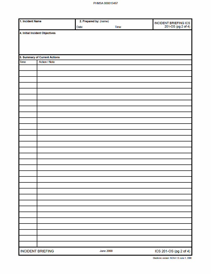


INCIDENT BRIEFING (ICS FORM 201-OS)
Purpose. The Incident Briefing form provides the Unified Command (and the Command and General Staffsassuming command of the incident) with basic information regarding the response situation and the resourcesallocated to the incident. It is also a permanent record of the initial incident response.
Preparation. This briefing form is prepared under the direction of the initial Incident Commander for presentationto the Unified Command. This form can be used for managing the response during the initial period until thebeginning of the first operational period for which an Incident Action Plan (IAP) is prepared. The information fromthe ICS form 201-OS can be used as the starting point for other ICS forms or documents.- Page 1 (Map/Sketch) may transition immediately to the Situation Map.- Page 2 (Summary of Current Actions) may be used to continue tracking the response actions and as the initialinput to the ICS form 215-OS and the ICS form 232-OS.- Page 3 (Current Organization) may transition immediately to the Organization List (ICS form 203-OS) and/orOrganization Chart (ICS form 207-OS).- Page 4 (Resources Summary) may be used to continue tracking resources assigned to the incident and as inputto individual T-Cards (ICS form 219) or other resource tracking system.
Distribution. After the initial briefing of the Unified Command and General Staff members, the Incident Briefingform is duplicated and distributed to the Command Staff, Section Chiefs, Branch Directors, Division/GroupSupervisors, and appropriate Planning and Logistics Section Unit Leaders. The sketch map and summary ofcurrent action portions of the briefing form are given to the Situation Unit while the Current Organization andResources Summary portion are given to the Resources Unit. All completed original forms MUST be given to theDocumentation Unit.
Instructions
Enter the name assigned to the incident.
Enter the name and position of the person completing the form.Enter date prepared (month, day, year).Enter time prepared (24-hour clock).
Show the total Area of Operations, the incident site, overflight results,trajectories, impacted shorelines, or other graphics depicting situationand response status on a sketch or attached map.
Enter short, clear, concise statements of the objectives for managing theinitial response.
Item Title
Incident Name
Prepared ByDateTime
Map/Sketch
Initial IncidentObjectives
Item #
1.
2.
3.
4.
5.
6.
Summary of CurrentActions
Current Organization
Enter the actions taken in response to the incident, including the time,and note any significant events or specific problem areas.
Enter, on the organization chart, the names of the individuals assigned toeach position. Modify the chart as necessary, using additional boxes inthe space provided under the Sections. Two blank lines are provided inthe Unified Command section for adding other agencies or groupsparticipating in the Unified Command and/or for multiple ResponsibleParties.
PHMSA 000015470

NOTE: Additional pages may be added to ICS form 201-OS if needed
Item #
7.
Item Title
Resources Summary
Resource Needed
Time OrderedResource Identifier
ETAOn-SceneLocation /Assignment /Status
Instructions
Enter the following information about the resources allocated to theincident:Description of the resource needed (e.g., open water boom, skimmer,vac truck, etc.).Time ordered (24-hour clock).Identifier for the resource (e.g., radio call-sign, vessel name, vendorname, license plate, etc.).Estimated time for the resource to arrive at the staging area."X" upon the resource’s arrival.Location of the resource, the actual assignment, and the status of theresource (if other than working).
PHMSA 000015471


INCIDENT OBJECTIVES (ICS FORM 202-OS)
Purpose. The Incident Objectives form describes the basic incident strategy, control objectives, and providesweather, tide and current information, and safety considerations for use during the next operational period. TheAttachments list at the bottom of the form also serves as a table of contents for the Incident Action Plan.
Preparation. The Incident Objectives form is completed by the Planning Section following each formal PlanningMeeting conducted in preparing the Incident Action Plan.
Distribution. The Incident Objectives form will be reproduced with the IAP and given to all supervisory personnelat the Section, Branch, Division/Group, and Unit levels. All completed original forms MUST be given to theDocumentation Unit.
Enter the name assigned to the incident.
Enter the time interval for which the form applies. Record the start andend date and time.
Enter clear, concise statements of the objectives for managing theresponse. These objectives usually apply for the duration of theincident.
Incident Name
Operational Period
Overall IncidentObjective(s)
1.
2.
3.
Instructions
NOTE: ICS form 202-OS, Incident Objectives, serves as part of theIncident Action Plan (IAP) (not complete until attachments areincluded).
Item TitleItem #
4. Enter short, clear, concise statements of the objectives for the incidentresponse for this operational period. Include alternatives.
Objectives for specifiedOperational Period
5.
6.
7.
8.
9.
10.
Safety Message for thespecifiedOperational Period
Weather
Tides/Currents
Sunrise/Sunset
Attachments
Prepared By
Enter information such as known safety hazards and specificprecautions to be observed during this operational period. If available,a safety message should be referenced and attached. At the bottom ofthis box, enter the location where approved Site Safety Plan isavailable for review.
Attach a sheet with the observed and predicted weather.
Attach a sheet with the predicted tide and current information for thespecified operational period.
Enter predicted times for sunrise and/or sunset (local time, 24-hourclock) during the specified operational period.
Mark an “X” in boxes for forms attached to the IAP.
Enter the name of the Planning Section Chief completing the form.
Enter the Date (month, day, year) and Time (24-hour clock) the formwas prepared.
Date/Time
PHMSA 000015473


ORGANIZATION ASSIGNMENT LIST (ICS FORM 203-OS)
Purpose. The Organization Assignment List provides ICS personnel with information on the units that arecurrently activated and the names of personnel staffing each position/unit. It is used to complete the IncidentOrganization Chart (ICS form 207-OS) which is posted on the Incident Command Post display. An actualorganization will be event-specific. Not all positions need to be filled. The size of the organization is dependenton the magnitude of the incident and can be expanded or contracted as necessary.
Preparation. The Resources Unit prepares and maintains this list under the direction of the Planning SectionChief.
Distribution. The Organization Assignment List is duplicated and attached to the Incident Objectives form (ICSform 202-OS) and given to all recipients of the Incident Action Plan. All completed original forms MUST be givento the Documentation Unit.
Instructions
Enter the name assigned to the incident.
Enter the time interval for which the form applies. Record the start andend date and time.
Enter the names of the Incident Commander and Staff. Use at leastthe first initial and last name.
Enter the agency names and the names of their representatives. Useat least the first initial and last name.
Enter the name of personnel staffing each of the listed positions. Useat least the first initial and last name. For Units, indicate Unit Leaderand for Divisions/Groups indicate Division/Group Supervisor. Use anadditional page if more than three branches are activated. If there is ashift change during the specified operational period, list both names,separated by a slash.
Item Title
Incident Name
Operational Period
Incident Commanderand Staff
Agency Representative
Item #
1.
2.
3.
4.
5.thru8.
Prepared ByDateTime
9. Enter the name and position of the person completing the form.Enter date prepared (month, day, year).Enter time prepared (24-hour clock).
PHMSA 000015475


ASSIGNMENT LIST (ICS FORM 204-OS)
Special Note. The Assignment List, ICS form 204-OS submits assignments at the level of Divisions and Groups.The Assignment List Attachment, ICS form 204a-OS shows more specific assignment information, if needed. Theneed for an ICS form 204a-OS is determined by the Planning and Operations Section Chiefs during theOperational Planning Worksheet (ICS form 215-OS) development.
Purpose. The Assignment List(s) informs Division and Group supervisors of incident assignments. Once theassignments are agreed to by the Unified Command and General Staff, the assignment information is given tothe appropriate Divisions and Groups.
Preparation. The Assignment List is normally prepared by the Resources Unit, using guidance from the IncidentObjectives (ICS form 202-OS), Operational Planning Worksheet (ICS form 215-OS), and the Operations SectionChief. The Assignment List must be approved by the Planning Section Chief. When approved, it is included aspart of the Incident Action Plan (IAP). Specific instructions for individual Task Forces / Strike Teams may beentered on an ICS form 204a-OS for dissemination to the field, but not included in the IAP.
Distribution. The Assignment List is duplicated and attached to the Incident Objectives and given to allrecipients of the Incident Action Plan. In some cases, assignments may be communicated viaradio/telephone/fax. All completed original forms MUST be given to the Documentation Unit.
Instructions
A separate sheet is used for each Division or Group. The identificationletter of the Division is entered in the form title. Also enter the number(roman numeral) assigned to the Branch.
Enter the name assigned to the incident.
Enter the time interval for which the form applies. Record the start andend date and time.
Enter the Branch designator.
Enter the Division/Group designator.
Enter the name of the Operations Chief, applicable Branch Director,and Division Supervisor.
Item Title
Incident Name
Operational Period
Branch
Division/Group
Operations Personnel
Item #
1.
2.
3.
4.
5.
PHMSA 000015477

Item #
6.
7.
Item Title
Resources AssignedThis Period
Strike Team / TaskForce / ResourceIdentifierLeaderContact Information
Number of Persons
Special Notes /RemarksAssignment ListAttachment
Assignments
Instructions
Each line in this field may have a separate Assignment List Attachment(ICS form 204a-OS). Enter the following information about theresources assigned to Division or Group for this period:List identifier
Leader namePrimary means of contacting this person (e.g., radio, phone, pager,etc.). Be sure to include area code when listing a phone number.Total number of personnel for the strike team, task force, or singleresource assigned.Special notes or directions, specific to this strike team, task force, orsingle resource.Enter an "X" check if an Assignment List Attachment (ICS form204a-OS) will be prepared and attached. The need for an ICS form204a-OS is determined by the Planning and Operations Section Chiefsduring the Operational Planning Worksheet (ICS form 215-OS)development.
Provide a statement of the tactical objectives to be achieved within theoperational period by personnel assigned to this Division or Group.
8.
9.
10.
11.
Special Instructions forDivision/Group
Communications
Prepared By
Date/Time
Approved By
Date/Time
Enter a statement noting any safety problems, specific precautions tobe exercised, or other important information.
Enter specific communications information (including emergencynumbers) for this division /group. If radios are being used, enterfunction (command, tactical, support, etc.), frequency, system, andchannel from the Incident Radio Communications Plan (ICS form205-OS). Note: Phone numbers should include area code.
Enter the name of the person completing the form, normally theResources Unit Leader.Enter the Date (month, day, year) and Time (24-hour clock) the formwas prepared.Enter the name of the person approving the form, normally thePlanning Section Chief.Enter the Date (month, day, year) and Time (24-hour clock) the formwas approved.
PHMSA 000015478


ASSIGNMENT LIST ATTACHMENT (ICS FORM 204a-OS)
Special Note. This form is an optional attachment, which can be used in conjunction with the Assignment List,ICS form 204-OS. The ICS form 204-OS is used to give assignments to Divisions and Groups; the ICS form204a-OS provides more specific assignment information, when needed. If there is a check, then there will be oneICS form 204a-OS for each Strike Team / Task Force / Resource Identifier listed in Item 6 of ICS form 204-OSand marked with a check (•) in the last column. The need for an ICS form 204a-OS is determined by the Planningand Operations Section Chiefs during the Operational Planning Worksheet (ICS form 215-OS) development.
Purpose. The Assignment List Attachment informs field personnel of specific incident assignment information.Once the Unified Command and General Staff agree to the Group / Division assignments, the specific assignmentinformation is given to the appropriate Strike Team or Task Force Leaders.
Preparation. The Assignment List Attachment form is normally prepared by the Resources Unit under thedirection of the Planning and Operations Section Chiefs using guidance from the Incident Objectives (ICS form202-OS) and the Operational Planning Worksheet (ICS form 215-OS).
Distribution. The Assignment List Attachment is duplicated and distributed to the Group or Division supervisorfor communication to individual Task Forces and Strike Teams. In some cases, assignments may becommunicated via radio, phone, or computer. All completed original forms MUST be given to the DocumentationUnit.
Instructions
Enter the name assigned to the incident.
Enter the time interval for which the form applies. Record the start andend date and time.
Enter the Branch designator.
Enter the Division/Group designator.
Enter the Identifier of the Strike Team / Task Force / Resource.
Enter the name of the Strike Team / Task Force leader.
Enter the location of the assignment for the Strike Team / Task Force.
Item Title
Incident Name
Operational Period
Branch
Division/Group
Strike Team / TaskForce / ResourceIdentifier
Leader
Assignment Location
Item #
1.
2.
3.
4.
5.
6.
7.
NOTE: A separate sheet is used for each Strike Team or Task Force.
Provide special instructions, as needed, to highlight site-specific workassignments.
Enter a description, quantity, and comments for special equipmentand/or supplies needed for this assignment.
Work AssignmentSpecial Instructions (ifany) [OPS]
Special Equipmentand/or SuppliesNeeded for Assignment(if any) [OPS]
8.
9.
PHMSA 000015480

Item #
10.
Item Title
Special EnvironmentalConsiderations (if any)[PSC]
Instructions
Enter any special environmental considerations specific to this location(e.g., presence of endangered species, archeological sites, sensitivehabitats to be avoided, etc.). If needed, reference the Resources atRisk Summary (ICS form 232-OS) for further information.
Enter any safety considerations specific to this location. For example,presence of dangerous wildlife, possibility of hazardous materials in thearea, rough terrain issues, etc. Enter the location where the ApprovedSite Safety Plan is available for review.
"X" the appropriate box for any attachments.
Special Site-SpecificSafety Considerations[SO]
Additional Attachments(as needed)
11.
12.
Enter the name of the person completing the form, normally theResources Unit Leader.Enter the Date (month, day, year) and Time (24-hour clock) the formwas prepared.
Prepared By
Date/Time
13.
PHMSA 000015481


INCIDENT RADIO COMMUNICATIONS PLAN (ICS FORM 205-OS)
Special Note. This form, ICS 205-OS, is used to provide, in one location, information on all radio frequencyassignments down to the Division/Group level for each operational period; whereas, the Communications List,ICS 205a-OS is used to list methods of contact for personnel assigned to the incident (radio frequencies, phonenumbers, pager numbers, etc.),
Purpose. The Incident Radio Communications Plan is a summary of information obtained from the RadioRequirements Worksheet (ICS form 216) and the Radio Frequency Assignment Worksheet (ICS form 217).Information from the Radio Communications Plan on frequency assignments is normally noted on the appropriateAssignment List (ICS form 204-OS).
Preparation. The Incident Radio Communications Plan is prepared by the Communications Unit Leader andgiven to the Planning Section Chief. Detailed instructions on the preparation of this form may be found in ICSPublication 223-5, Communications Unit Position Manual.
Distribution. The Incident Radio Communications Plan is duplicated and given to all recipients of the IncidentObjectives form, including the Incident Communications Center. Information from the plan is placed onAssignment Lists. All completed original forms MUST be given to the Documentation Unit.
Instructions
Enter the name assigned to the incident.
Enter the time interval for which the form applies. Record the start andend date and time.
Enter the following information about radio channel use:
Radio cache system(s) assigned and used on the incident.Radio channel numbers assigned.Function each channel is assigned (e.g., command, support, divisiontactical, and ground-to-air).Radio frequency tone number assigned to each specified function (e.g.,153.400)ICS organization assigned to each of the designated frequencies (e.g.,Branch I, Division A).This section should include narrative information regarding specialsituations.
Enter the name of the Communications Unit Leader preparing the form.
Item Title
Incident Name
Operational Period
Basic Radio ChannelUseSystemChannelFunction
Frequency
Assignment
Remarks
Prepared By
Item #
1.
2.
3.
4.
Enter date (month, day, year) and time prepared (24-hour clock).Date/Time
PHMSA 000015483


COMMUNICATIONS LIST (ICS FORM 205a-OS)
Special Note. This optional form is used in conjunction with the Incident Radio Communications Plan, ICS form205-OS. Whereas the ICS form 205-OS is used to provide information on all radio frequencies down to theDivision/Group level, the Communications List, ICS form 205a-OS, lists methods of contact for personnelassigned to the incident (radio frequencies, phone numbers, pager numbers, etc.), and functions as an incidentdirectory.
Purpose. The Communications List records methods of contact for personnel on scene.
Preparation. The Communications List can be filled out during check-in and is maintained and distributed byCommunications Unit personnel.
Distribution. The Communications List is distributed within the ICS and posted, as necessary. All completedoriginal forms MUST be given to the Documentation Unit.
Instructions
Enter the name assigned to the incident.
Enter the time interval for which the form applies. Record the start andend date and time.
Enter the communications methods assigned and used for eachassignment.
Enter the ICS organizational assignment.Enter the name of the contact person for the assignment.Enter the radio frequency, telephone number(s), etc. for eachassignment.
Enter the name of the Communications Unit Leader preparing theform.
Item Title
Incident Name
Operational Period
Basic LocalCommunicationsInformationAssignmentNameMethod(s) of contact
Prepared By
Item #
1.
2.
3.
4.
Enter date (month, day, year) and time prepared (24-hour clock).Date/Time
PHMSA 000015485


MEDICAL PLAN (ICS FORM 206-OS)
Purpose. The Medical Plan provides information on incident medical aid stations, transportation services,hospitals, and medical emergency procedures.
Preparation. The Medical Plan is prepared by the Medical Unit Leader and reviewed by the Safety Officer.
Distribution. The Medical Plan may be attached to the Incident Objectives (ICS form 202-OS), or informationfrom the plan pertaining to incident medical aid stations and medical emergency procedures may be taken fromthe plan and noted on the Assignment List (ICS form 204-OS) or on the Assignment List Attachment (ICS form204a-OS). All completed original forms MUST be given to the Documentation Unit.
Instructions
Enter the name assigned to the incident.
Enter the time interval for which the form applies. Record the start andend date and time.
Enter name, location, and telephone number of the medical aidstation(s) (e.g., Cajon Staging Area, Cajon Camp Ground) and indicateif paramedics are located at the site.
List name and address of ambulance services. Provide phone numberand indicate if ambulance company has paramedics.
List hospitals that could serve this incident. Enter hospital name,address, phone number, the travel time by air and ground from theincident to the hospital, and indicate if the hospital has a burn centerand/or a helipad.
Note any special emergency instructions for use by incident personnel.
Item Title
Incident Name
Operational Period
Medical Aid Stations
Transportation
Hospitals
Medical EmergencyProcedures
Item #
1.
2.
3.
4.
5.
6.
Enter the name of the Medical Unit Leader preparing the form.Enter date (month, day, year) and time prepared (24-hour clock).
Enter the name of the Safety Officer who must review the plan.Enter date (month, day, year) and time reviewed (24-hour clock).
Prepared ByDate/Time
Reviewed ByDate/Time
7.
8.
PHMSA 000015487


INCIDENT ORGANIZATION CHART (ICS FORM 207-OS)
Purpose. The Incident Organization Chart is used to indicate what ICS organizational elements are currentlyactivated and the names of personnel staffing each element. The attached chart is an example of the kind ofOrganizational Chart used in the ICS. An actual organization will be event-specific. Not all positions need to befilled. The size of the organization is dependent on the magnitude of the incident and can be expanded orcontracted as necessary. Personnel responsible for managing organizational positions are listed in each box asappropriate.
Preparation. The Incident Organization Chart is prepared by the Resources Unit and posted along with otherdisplays at the Incident Command Post. The ICS form 207 may best be used as a wall-size chart for bettervisibility. A chart is completed for each operational period and updated when organizational changes occur.
Distribution. When competed, the chart is posted on the display board located at the Incident Command Post.All original forms MUST be given to the Documentation Unit.
Instructions
Enter the name assigned to the incident.
Enter the time interval for which the form applies. Record the start andend date and time.
Item Title
Incident Name
Operational Period
Item #
1.
2.
PHMSA 000015489


INCIDENT STATUS SUMMARY (ICS FORM 209-OS)
Purpose. The Status Summary:1. Is used by Situation Unit personnel for posting information on Status Boards.2. Is duplicated and provided to Command Staff members, giving them basic information for planning for the next operational period.3. Provides information to the Information Officer for preparing news media releases.4. Summarizes incident information for local and off-site coordination centers.
Preparation. The Status Summary is prepared by the Situation Unit. Resources information should be obtainedfrom the Resources Unit. It may be scheduled for presentation to the Planning Section Chief and other GeneralStaff members prior to each Planning Meeting and may be required at more frequent intervals by the UnifiedCommand or Planning Section Chief. Suggested sources of information are noted in brackets.Note: The values on the ICS form 209-OS are the best available estimates at the Time of Report (Item # 2 onform). This form is usually in high demand and should be filled out early and often. A suggested source within theICS organization is noted in brackets [ ] at the top right of each section of the form. All fields need not becompleted in order to distribute the form.Distribution. When completed, the form is duplicated and copies are distributed to the Unified Command andstaff, and all Section Chiefs, Planning Section Unit Leaders, and the Joint Information Center. It is also posted ona status board located at the ICP. All completed original forms MUST be given to the Documentation Unit.
Instructions
Enter the name assigned to the incident.
Enter the date and time interval for which the report applies. Use24-hour clock for all times. Enter time for which this informationapplies.Enter the Time (24-hour clock) the form was prepared.
Indicate whether the spill source is secured or unsecured and estimatethe remaining potential and the rate of spillage discharge or release.Enter the estimated amounts in barrels for each category. Valuesentered in the column labeled Since Last Report are from the start ofthe Period Covered by Report (Item 2) to the time entered in the Timeof Report (Item 2).
These fields are designed to account for all spilled oil whetherrecovered, evaporated, dispersed, burned, floating, or on shore. Thetotal of these estimates should approximate the total volume spilled,discharged, or released. Values for evaporation, dispersion, etc. canbe obtained from the Environmental Unit and/or the Scientific SupportCoordinator.
Item Title
Incident Name
Period Covered byReport
Time of Report
Spill Status[Ops & EUL/SSC]
Mass Balance/OilBudget
Item #
1.
2.
3.
4.
6. Shoreline Impacts[PSC/EUL/SSC]
Enter the total miles in each category for each degree of oiling.Definitions for Light, Medium, and Heavy oiling can be obtained fromthe EUL/SSC and should be consistent throughout the incident.
Enter the estimated amounts in barrels or tons for each category. Oil(bbl) is the sum of the estimate of oil in oily liquids and oil in oily solids,and is the value to be entered under "Total Recovered Oil" in Item 3.
Waste Management[Ops/Disposal]
5.
PHMSA 000015491

Item #
7.
Item Title
Wildlife Impacts[Ops/Wildlife Br.]
Safety Status[Safety Officer]
Instructions
This information is only tracked after an animal is captured. Indicatethe actual number of oiled wildlife in each category. Use numbers inparentheses to indicate the subtotal of threatened / endangeredspecies included in the numbers given.
Indicate the number of serious injuries. Values entered in the columnlabeled Since Last Report are from the start of the Period Covered byReport (Item 2) to the time entered in the Time of Report (Item 2).
Indicate the number of each type of resource in each status category.There are blank lines below each general type of resource foradditional equipment.Ordered but not yet arrived/available.Arrived on scene, stored in staging, not assigned to any task, availablefor use.Assigned to a specific task.Not working and not assigned to any task (e.g., skimmer beingrepaired, boom broken, personnel off-duty for rest).
Indicate, by agency, the numbers of personnel assigned. There areblank lines for additional personnel, as needed.
Use this area for any special notes or other information related to thisreporting period. This could include financial/cost information, specificendangered species notes, significant events that occurred, etc.
Equipment Resources[RUL]
OrderedAvailable/Staged
AssignedOut of Service
Personnel Resources[RUL]
Special Notes
8.
9.
10.
Enter name and title of the person preparing the form, normally theSituation Unit Leader.
Prepared By11.
PHMSA 000015492


STATUS CHANGE (ICS FORM 210-OS)
Purpose. The Status Change form is used to record status change information received on resources assignedto the incident.
Preparation. The form is completed by radio/telephone operators who receive status change information fromindividual resources, Task Forces, Strike Teams, and Division/Group Supervisors. Status information could alsobe reported by Staging Area and Helibase Managers or fixed-wing facilities.
Distribution. The original is given to the Resources Unit, and the Communications Unit retains a second copy.All completed original forms MUST be given to the Documentation Unit.
Instructions
Enter the name assigned to the incident.
Enter the time interval for which the form applies. Record the start andend date and time.
Enter the Personnel/Resource Name or Identifier.
Check the new status of the personnel or resource.
Enter the location or status from which the resource is changing.
Enter the location or status to which the resource is changing.
Enter time of change (24-hour clock).
Use this area for other information.
Enter name and title of the person preparing the form.Enter date (month, day, year) and time prepared (24-hour clock).
Enter name and title of the person in the Resources Unit processingthe form.Enter date (month, day, year) and time processed (24-hour clock).
Item Title
Incident Name
Operational Period
Personnel/ResourceName or I.D.
New Status
FROM Location orStatus
TO Location or Status
Time of Location /Status Change
Comments
Prepared ByDate/Time
Processed byResources UnitDate/Time
Item #
1.
2.
3.
4.
5.
6.
7.
8.
9.
10.
PHMSA 000015494
CHECK-IN LIST1 INCIDENT NAME 2 CHECK-IN LOCATION
BASE CAMP
CHECK-IN INFORMATIONSTAGING AREA ICP RESOURCES HELIBASE
3 DATE/TIME
4 LIST PERSONNEL (OVERHEAD) BY AGENCY & NAME -OR- LIST EQUIPMENT BY THE FOLLOWING FORMAT:
SINGLET/FS/T
KIND TYPE ID NO /NAME
5 6 7 8 9 10 11 12 13 14 15 16
ORDER/REQUESTNUMBER
DATE/TIMECHECK-IN
LEADER'SNAME
TOTAL NOPERSONNEL
MANIFEST
YES NO
CREWWEIGHT
ORINDIVIDUALS
WEIGHT
HOMEBASE
DEPARTUREPOINT
METHOD OFTRAVEL
INCIDENTASSIGNMENT
OTHERQUALIFICATION
SENT TORESOURCES
TIME/INT
17ICS 211 PAGE _____ of _____ 18 PREPARED BY (NAME AND POSITION) USE BACK FOR REMARKS OR COMMENTS
Electronic version: NOAA 1.0 June 1, 2000
PHMSA 000015495

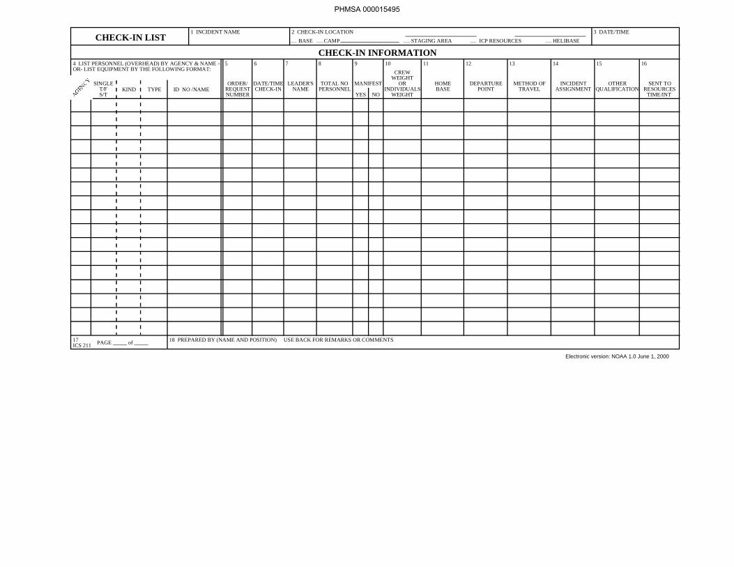
CHECK-IN LIST (ICS FORM 211)
Purpose. Personnel and equipment arriving at the incident can check in at various incident locations. Check-inconsists of reporting specific information which is recorded on the form.
Preparation. The Check-In List is initiated at a number of incident locations including staging areas, base camps,helibases, and ICP. Managers at these locations record the information and give it to the Resources Unit as soonas possible.
Distribution. Check-In Lists are provided to both the Resources Unit and the Finance Section. The ResourcesUnit maintains a master list of all equipment and personnel that have reported to the incident. All completedoriginal forms MUST be given to the Documentation Unit.
Instructions
Enter the name assigned to the incident.
Enter an "X" in the box indicating where the resource or personchecked in.
Enter the date (e.g., 09/17/1996) and time (e.g., 1530) prepared.
Use this section to list agency three-letter designator and individualnames for all overhead personnel. When listing equipment, usethree-letter designator, indicate if resource is a single resource, taskforce or strike team; enter kind of resource (letter for single resource,1-3 for Strike Team); enter type of resource (1-4), and designated id.no.
Item Title
Incident Name
Check-in
Date / Time Prepared
List Personnel(Overhead) by Agency& Name
Item #
1.
2.
3.
4.
Order number will be assigned by Agency dispatching the resources orpersonnel to the incident.
Self explanatory.
Self explanatory.
Enter total number of personnel in strike teams, task forces or manningsingle resources. Include leaders.
Order / RequestNumber
Date / Time Check-In
Leader’s Name
Total NumberPersonnel
5.
6.
7.
8.
Indicate if a manifest was prepared by entering "Yes" or "No" in the field.Manifest9.
Self explanatory.
Location at which the resource / individual is normally assigned.
Location from which resource / individual departed for thisincident.
Means of travel to incident (bus, truck, engine, personal vehicle, etc.)
Crew Weight orIndividual’s Weight
Home Base
Departure Point
Method of Travel
10.
11.
12.
13.
PHMSA 000015496

14.
15.
16.
17.
Incident Assignment
Other Qualifications
Sent to
Page
Assignment at time of dispatch.
List any other ICS position the individual has been trained to fill.
Enter initials and time that the info. Pertaining to that entry was sent tothe Resources Unit.
Indicate page no. and no. of pages being used for Check-In at thislocation.
PHMSA 000015497
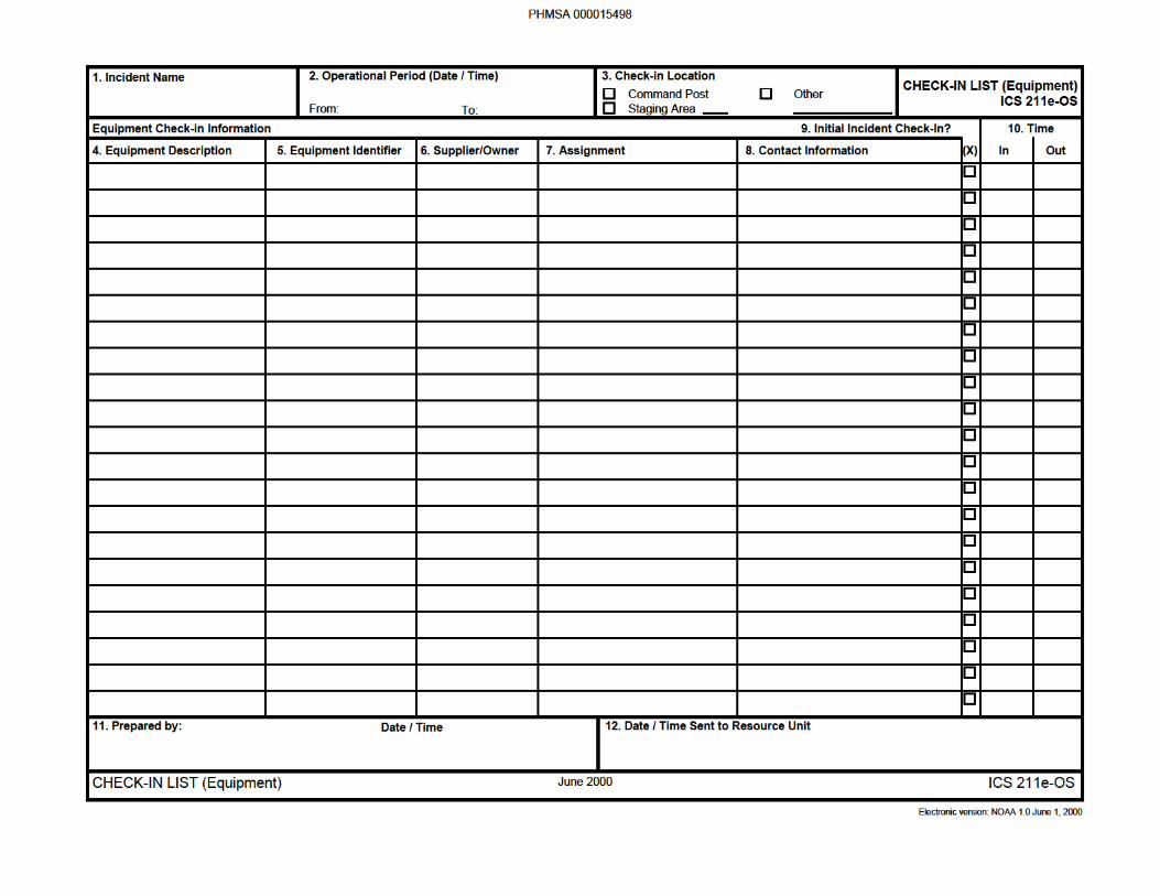

CHECK-IN LIST Equipment (ICS FORM 211e-OS)
Special Note. This form is used for equipment check-in only.
Purpose. Equipment arriving at the incident can check in at various incident locations. Check-in consists ofreporting specific information that is recorded on the form.
Preparation. The Check-In List is initiated at a number of incident locations including staging areas, base,camps, helibases, and ICP. Managers at these locations record the information and give it to the Resources Unitas soon as possible.
Distribution. Check-In Lists are provided to both the Resources Unit and the Finance/Administration Section.The Resources Unit maintains a master list of all equipment and personnel that have reported to the incident. Allcompleted original forms MUST be given to the Documentation Unit.
Instructions
Enter the name assigned to the incident.
Enter the time interval for which the form applies. Record the start andend date and time.
Check the box for the location where the equipment was checked in.
Enter a description of the equipment (e.g., 36" open water boom,skimmer, vac truck, etc.).
Item Title
Incident Name
Operational Period
Check-in Location
Equipment Description
Item #
1.
2.
3.
4.
Equipment Identifier
Supplier/Owner
Assignment
Contact Information
Initial IncidentCheck-in?
5.
6.
7.
8.
9.
Enter the Identifier for the equipment (e.g., radio call-sign, vessel name,vendor name, license plate, etc.).
Enter the supplier/owner of the equipment.
Work assignment, if known. Arriving equipment may not have anassignment at time of check-in.
Enter the contact information for the person operating equipment.
Check if this is the first time the equipment has been checked in.
Enter the time the equipment is checked in and/or out (24-hour clock).
Enter name and title of the person preparing the form.Enter date (month, day, year) and time prepared (24-hour clock).
Enter date (month, day, year) and time (24-hour clock) the form is sent tothe Resources Unit.
Time In/Out
Prepared ByDate/Time
Date/Time Sent toResources Unit
10.
11.
12.
PHMSA 000015499


CHECK-IN LIST Personnel (ICS FORM 211p-OS)
Special Note. This form is used for personnel check-in only.
Purpose. Personnel arriving at the incident can be checked in at various incident locations. Check-in consists ofreporting specific information that is recorded on the form.
Preparation. The Check-In List is initiated at a number of incident locations including staging areas, base,camps, helibases, and ICP. Managers at these locations record the information and give it to the Resources Unitas soon as possible.
Distribution. Check-In Lists are provided to both the Resources Unit and the Finance/Administration Section.The Resources Unit maintains a master list of all equipment and personnel that have reported to the incident. Allcompleted original forms MUST be given to the Documentation Unit.
Instructions
Enter the name assigned to the incident.
Enter the time interval for which the form applies. Record the start andend date and time.
Check the box for the check-in location.
Enter the name of the person.
Enter the company or agency with which the individual is associated.
Item Title
Incident Name
Operational Period
Check-in Location
Name
Company/Agency
Item #
1.
2.
3.
4.
5.
Enter ICS Section and assignment, if known, and note any otherICS qualifications, if needed.
Enter the contact information for the person.
Check if this is the first time a person has checked in for this incident.
ICS Section /Assignment / Quals.
Contact Information
Initial IncidentCheck-in?
6.
7.
8.
9.
10.
11.
Time In/Out
Prepared ByDate/Time Prepared
Date/Time Sent toResources Unit
Enter the time the person checks in and/or out (24-hour clock).
Enter name and title of the person preparing the form.Enter date (month, day, year) and time prepared (24-hour clock).
Enter date (month, day, year) and time (24-hour clock) the form is sentto the Resources Unit.
PHMSA 000015501


General Message (ICS FORM 213-OS)
Purpose. The General Message is used by: Incident personnel to record incoming messages which cannot be orally transmitted to the intended recipients; Command Post and other incident personnel to transmit messages to the Incident Communications Center fortransmission via radio or telephone to the addressee; Incident personnel to send any message or notification to incident personnel which requires a hard-copy delivery; Incident personnel to place resource orders.
Preparation. This form is prepared by any incident personnel needing to transmit a hard-copy message. Therecipient should send a timely reply to the originator, as necessary.
Distribution. Upon completion, the General Message may be hand-carried to the addressee or to the incidentCommunications Center for transmission. Originator retains a copy of the form. All completed original formsMUST be given to the Documentation Unit.
Instructions
Enter the name assigned to the incident.
Enter the date and time of message origination.
Enter name and ICS position of message recipient.
Enter name and ICS position of message sender.
Indicate the message subject.
Enter message.
This section to be used by the unit/person who receives the messageto reply to your message.
Enter name and position of person replying to this message.Enter date (month, day, year) and time of reply (24-hour clock).
Item Title
Incident Name
Date and Time ofMessage
To
From
Subject
Message
Reply
Signature/PositionDate/Time of reply
Item #
1.
2.
3.
4.
5.
6.
7.
8.
PHMSA 000015503


UNIT LOG (ICS FORM 214-OS)
Special Note. ICS Form 214-OS is used to log activities for an entire unit, whereas the ICS form 214a-OS isdesigned for individual use.
Purpose. The Unit Log records details of unit activity, including strike team activity. These logs provide the basicreference from which to extract information for inclusion in any after-action report.
Preparation. A Unit Log is initiated and maintained by Command Staff members, Division/Group Supervisors, AirOperations Groups, Strike Team/Task Force Leaders, and Unit Leaders. Completed logs are submitted tosupervisors who forward them to the Documentation Unit.
Distribution. The Documentation Unit maintains a file of all Unit Logs. All completed original forms MUST begiven to the Documentation Unit.
Instructions
Enter the name assigned to the incident.
Enter the time interval for which the form applies. Record the start andend date and time.
Enter the title of the organizational unit or resource designator (e.g.,Facilities Unit, Safety Officer, Strike Team).
Enter the name and ICS Position of the individual in charge of the Unit.
Item Title
Incident Name
Operational Period
Unit Name/Designators
Unit Leader
Item #
1.
2.
3.
4.
List the name, position, and home base of each member assigned tothe unit during the operational period.
Enter the time and briefly describe each significant occurrence or event(e.g., task assignments, task completions, injuries, difficultiesencountered, etc.)
Enter name and title of the person completing the log. Provide log toimmediate supervisor, at the end of each operational period.
Personnel Assigned
Activity Log
Prepared By
5.
6.
7.
Enter date (month, day, year) and time prepared (24-hour clock).Date/Time
PHMSA 000015506


INDIVIDUAL LOG (ICS FORM 214a-OS)
Special Note. This optional ICS form 214a-OS is a log for individual use, and ICS form 214-OS is designed tolog activities for an entire unit.
Purpose. The Individual Log, while not required, records details of each individual’s activities. These logsprovide a basic reference from which to extract information for inclusion in any after-action report.
Preparation. An Individual Log can be initiated and maintained by each member of the ICS. Completed logs areforwarded to supervisors who provide copies to the Documentation Unit.
Distribution. The Documentation Unit maintains a file of all Individual Logs. The original of each log MUST besubmitted to the Documentation Unit.
Instructions
Enter the name assigned to the incident.
Enter the time interval for which the form applies. Record the start andend date and time.
Enter the name of the individual.
Enter the ICS Section to which the individual is assigned.
Enter the assignment or location for the individual.
Enter the time and briefly describe each significant occurrence or event(e.g., task assignments, task completions, injuries, difficultiesencountered, etc.)
Enter name and title of the person completing the log. Provide log toimmediate supervisor, at the end of each operational period.
Item Title
Incident Name
Operational Period
Individual Name
ICS Section
Assignment/Location
Activity Log
Prepared By
Item #
1.
2.
3.
4.
5.
6.
7.
Enter date (month, day, year) and time prepared (24-hour clock).Date/Time
PHMSA 000015508


OPERATIONAL PLANNING WORKSHEET (ICS FORM 215-OS)
Purpose. This form communicates to the Resources Unit the resources needed as a result of decisions madeduring the Tactics and Planning meetings. The Worksheet is used by the Resources Unit to complete theAssignment List (ICS form 204-OS) and by the Logistics Section Chief for ordering resources. The worksheetmay also be used by the Resources Unit Leader to complete the Assignment List Attachment(s) (ICS form204a-OS), if the Operations and Planning Section Chiefs deem it necessary.
Preparation. This form is initiated at the Tactics Meeting and modified and finalized at the Planning Meeting. Forease of use, the form should be enlarged to poster size. This form is principally crafted by the Operations andPlanning Section Chiefs. When decisions are reached, the appropriate resource information should be recordedon the form. Use additional sheets, as needed.
Distribution. When the work assignments and accompanying resource allocations are agreed to, the form isdistributed to the Resources Unit to help prepare Assignment Lists (ICS form 204-OS) and any neededAssignment List Attachment(s) (ICS form 204a-OS). The Planning Section will use a copy of this worksheet forpreparing resource requests for the next operational period. All completed original forms MUST be given to theDocumentation Unit.
Instructions
Enter the name assigned to the incident.
Enter the time interval for which the form applies. Record the start andend date and time.
Enter the Division/Group or other Location Identifier (e.g., Division A -Segment 1, On-water Group 1, Air Group 1, etc.).
Enter the specific work assignments given to each Division/Group(e.g., on-water skimming, Shoreline Cleanup Assessment Team,shoreline cleanup crews, conduct overflights, etc.).
Complete resource description. Enter the number of resourcesrequired "Req." and the number of resources available "Have" toperform the work assignment. The number of resources needed"Need" is the difference between "Req." and "Have."
Provide any additional information needed for this work assignment.
Item Title
Incident Name
Operational Period
Division/Group orLocation
Work Assignments
Resource/Equipment
Notes/Remarks
Item #
1.
2.
3.
4.
5.
6.
Enter the specific location the "needed" resources are to report for thework assignments (staging area, etc.)
Enter time resources are requested to arrive at reporting location(24-hour clock).
Reporting Location
Requested Arrival Time
7.
8.
9. Assignment ListAttachment 204aNeeded
"X" this box if the Planning and Operations Section Chiefs determinethat special instructions are needed for a specific Strike Team, TaskForce, or single resource (e.g., work assignment, equipment,environmental considerations, or site-specific safety considerations).
PHMSA 000015510

Instructions
Enter the total number of resources required. Add all of the "Req."fields above.
Enter the total number of resources on hand. Add all of the "Have"fields above.
The Total Resources Needed is the difference between the TotalResources Required and the Total Resources On Hand.
Enter name and title of the person preparing the form.Enter date (month, day, year) and time prepared (24-hour clock).
Item Title
Total ResourcesRequired
Total Resources OnHand
Total ResourcesNeeded
Prepared ByDate/Time
Item #
10.
11.
12.
13.
PHMSA 000015511

2. DATERADIO REQUIREMENTS WORKSHEET
1. INCIDENT NAME 3. TIME
4. BRANCH 5. AGENCY 6. OPERATIONAL PERIOD 7. TACTICAL FREQUENCY
8. DIVISION/GROUP
AGENCY
9. AGENCY
AGENCY
DIVISION/GROUP
AGENCY
DIVISION/GROUP
AGENCY
DIVISION/GROUP
IDNO.
RADIORQMTS
AGENCYID
NO.RADIORQMTS
AGENCYID
NO.RADIORQMTS
AGENCYID
NO.RADIORQMTS
PAGE 10. PREPARED BY (COMMUNICATIONS UNIT)216 ICS 3-82
NFES 1339 Electronic version: NOAA 1.0 June 1, 2000
PHMSA 000015512

RADIO REQUIREMENTS WORKSHEET (ICS FORM 216)
Purpose. The Radio Requirements Worksheet is used to develop the total number of personal portable radiosrequired for each Division/Group and Branch. It provides a listing of all units assigned to each Division, and thusdepicts the total incident radio needs.
Initiation of Form. The worksheet is prepared by the Communications Unit for each operational period and canonly be completed after specific resource assignments are made and designated on Assignment Lists. Thisworksheet need not be used if the Communications Unit Leader can easily obtain the information directly fromAssignment Lists.
Distribution. The worksheet is for internal use by the Communications Unit and therefore there is no distributionof the form.
Instructions
Enter the name assigned to the incident.
Enter date prepared (e.g., 09/17/1996).
Enter time prepared (e.g., 1530).
Enter the Branch number (I, II, etc.) for which radio requirements arebeing prepared.
Enter the three-letter designator of the agency staffing the BranchDirector position (e.g., VNC, CDF, ANF, LFD, etc.).
Enter the time interval for which the assignment applies (e.g.,9/17/96-0600 to 9/18/96-0600).
Enter the radio frequency to be used by the Branch Director tocommunicate with each Division/Group Supervisor in the Branch.
Enter for each Division/Group in the Branch the Division/Groupidentifier (A, B, etc.) and the agency assigned (e.g., LAC, VNC, etc.).
Item Title
Incident Name
Date
Time Prepared
Branch
Agency
Operational Period
Tactical Frequency
Division/Group
Item #
1.
2.
3.
4.
5.
6.
7.
8.
List all units assigned to each Division/Group. Record the agencydesignator, unit or resource identification, and total number of radiosneeded for each unit or resource.
Enter the name and position of the person completing the worksheet.
Agency/ID No./RadioRequirements
Prepared By
9.
10.
PHMSA 000015513


RADIO FREQUENCY ASSIGNMENT WORKSHEET (ICS FORM 217)
Purpose. The Radio Frequency Assignment Worksheet is used by the Communications Unit Leader to assist indetermining frequency allocations.
Preparation. Cache radio frequencies available to the incident are listed on the form. Major agency frequenciesassigned to the incident should be added to the bottom of the worksheet.
Distribution. The worksheet, prepared by the Communications Unit, is for internal use.
Instructions
Enter the name assigned to the incident.
Enter date prepared (e.g., 09/17/1996).
Enter the time interval for which the assignment applies (e.g.,9/17/96-0600 to 9/18/96-0600).
List frequencies allocated for each channel for each organizationalelement activated, record the number of radios required to perform thedesignated function on the specified frequency.
Item Title
Incident Name
Date
Operational Period
Incident Organization
Item #
1.
2.
3.
4.
For each radio cache and frequency assigned, record the associatedfunction. Functional assignments are:a. Commandb. Supportc. Division tacticald. Ground-to-air
List the frequencies for each major agency assigned to the incident.Also list the function and channel number assigned.
Totals for each row and column are calculated automatically. Thisprovides the number of radios required by each organizational unit andthe number of radios using each available frequency.
Radio Data
Agency
Total Radios Required
5.
6.
7.
Enter the name and position of the person completing the worksheet.Prepared By8.
PHMSA 000015515


SUPPORT VEHICLE INVENTORY (ICS FORM 218)
Purpose. The Support Vehicle Inventory form provides an inventory of all transportation and support vehiclesassigned to the incident. The information is used by the Ground Support Unit to maintain a record of the typesand locations of vehicles on the incident. The Resources Unit uses the information to initiate and maintainstatus/resources information on these resources.
Preparation. The form is prepared by Ground Support Unit personnel at intervals specified by the GroundSupport Unit Leader.
Distribution. Initial inventory information recorded on the form should be given to the Resources Unit.Subsequent changes to the status or location of transportation and support vehicles should be provided to theResources Unit immediately.
NOTE:a. The Ground Support Unit Leader may prefer to use separate sheets for each type of support vehicle (e.g.,buses, pickups, and food tenders).b. More than one line may be used to record information on each vehicle. If this is done, separate individualvehicle entries with a heavy line.c. Several pages may be used. When this occurs, number the pages consecutively (in the number box at bottomof form).
Instructions
Enter the name assigned to the incident.
Enter date prepared (e.g., 09/17/1996).
Enter time prepared (e.g., 1530).
Record the following vehicle information:a. Specific vehicle type (e.g., bus, stakeside, etc.).b. Vehicle manufacturer name (e.g., GMC, International).c. Vehicle capacity / size (e.g., 30-person bus, 3/4 ton truck).d. Owner of vehicle (agency or private owner).e. Serial or other identification number.f. Location of vehicle.g. Time vehicle is released from incident.
Enter name of the person completing the form.
Item Title
Incident Name
Date Prepared
Time Prepared
Vehicle InformationTypeMakeCapacity/SizeOwnerID NumberLocationRelease Time
Prepared By
Item #
1.
2.
3.
4.
5.
PHMSA 000015517

AGENCY ST KIND TYPE AGENCY TF KIND TYPE I D NO /NAME
INCIDENT LOCATION TIME
NOTE
STATUS
INCIDENT LOCATION TIME
NOTE
STATUS
INCIDENT LOCATION TIME
NOTE
STATUS
INCIDENT LOCATION TIME
NOTE
STATUS
ORDER/REQUEST NO DATE/TIME CHECK IN
HOME BASE
DEPARTURE POINT
LEADER NAME
CREW ID NO /NAME (FOR STRIKE TEAMS)
NO PERSONNEL MANIFEST WEIGHT
METHOD OF TRAVEL
OTHER
DESTINATION POINT ETA
TRANSPORTATION NEEDS
OTHER
REMARKS
ORDERED DATE/TIME CONFIRMED DATE/TIME
ICS 219-2 (Rev 4/82) CREW NFES 1344
GREEN CARD STOCK (CREW)
I D NO /NAME ST
ETR
ETR
ETR
ETR
Electronic version: NOAA 1.0 June 1, 2000
PHMSA 000015518

ICS 219_2 HANDCREWSGREEN COLORED CARD
Purpose. Resource Status Cards are used by the Resources Unit to record status and location information onresources, transportation, and support vehicles and personnel. The Resource Status Cards provide a visualdisplay of the status and location of resources assigned to the incident.
Preparation. Information to be placed on the cards may be obtained from several sources including but notlimited to:
1. ICS Briefing (ICS Form 201)2. Check-In List (ICS Form 211)3. Status Change Card (ICS Form 210)4. Agency supplied information
Detailed information on preparing status cards is found in Resources Unit Position Manual (ICS 221-3).
Distribution. The cards are displayed in resource status racks where they can be easily retrieved. Cards will beretained by the Resources Unit until demobilization. At demobilization all cards MUST be turned into theDocumentation Unit.
Instructions
Number assigned by dispatching agency.
Location at which Handcrew is normally located.
Location from which Handcrew left to reach this incident.
List commonly used names or numbers to identify the crews which make up theStrike Team.
Total no. of personnel (including Leader) in Crew or Strike Team.
Was a manifest prepared for the Crew/Strike Team?
Total weight (including equipment and personal belongings) of the Crew/StrikeTeam.
Next location to which Crew/Strike Team is being sent from the incident.
Enter the appropriate method of travel (e.g., own, bus, air).
Enter the appropriate transportation needs (e.g., own, bus, air).
Choose the appropriate entry from the pop-up menu. If the item is O/S(out-of-service), enter the ETR (estimated time of return) in the ETR field belowthe Status field.
Item Title
Order/Request No.
Home Base
Departure Point
Crew ID No./Name (forStrike Teams)
No. Personnel
Manifest
Weight
Destination Point
Method of Travel
Transportation Needs
Status
PHMSA 000015519

AGENCY TYPE I D NO AGENCY TYPE MANUFACTURER I D NO
INCIDENT LOCATION TIME
NOTE
STATUS
INCIDENT LOCATION TIME
NOTE
STATUS
INCIDENT LOCATION TIME
NOTE
STATUS
INCIDENT LOCATION TIME
NOTE
STATUS
ORDER/REQUEST NO DATE/TIME CHECK IN
HOME BASE
DEPARTURE POINT
PILOT NAME
DESTINATION POINT ETA
REMARKS
ICS 219-4 (Rev 4/82) HELICOPTER NFES 1346
BLUE CARD STOCK (HELICOPTER)
NFES 1346
INCIDENT LOCATION TIME
NOTE
STATUS
INCIDENT LOCATION TIME
NOTE
STATUS
MANUFACTURERNAME/NO
ETR
ETR
ETR
ETR
ETR
ETR
Electronic version: NOAA 1.0 June 1, 2000
PHMSA 000015520
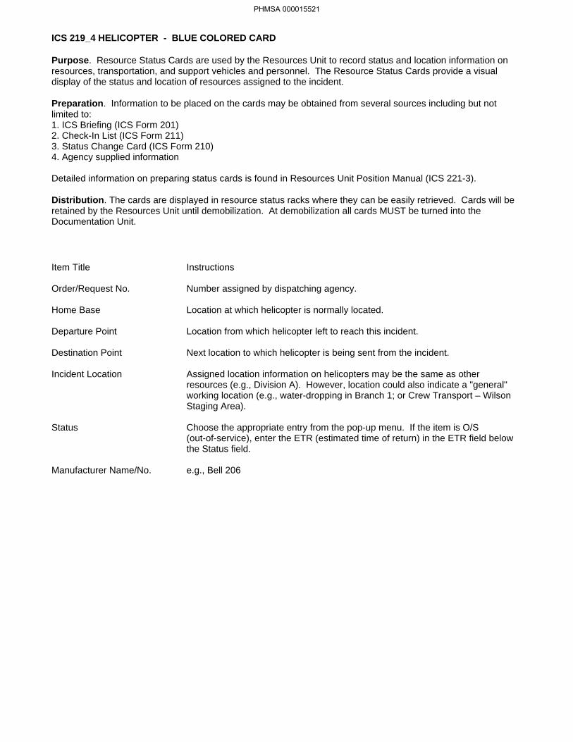
ICS 219_4 HELICOPTER - BLUE COLORED CARD
Purpose. Resource Status Cards are used by the Resources Unit to record status and location information onresources, transportation, and support vehicles and personnel. The Resource Status Cards provide a visualdisplay of the status and location of resources assigned to the incident.
Preparation. Information to be placed on the cards may be obtained from several sources including but notlimited to:1. ICS Briefing (ICS Form 201)2. Check-In List (ICS Form 211)3. Status Change Card (ICS Form 210)4. Agency supplied information
Detailed information on preparing status cards is found in Resources Unit Position Manual (ICS 221-3).
Distribution. The cards are displayed in resource status racks where they can be easily retrieved. Cards will beretained by the Resources Unit until demobilization. At demobilization all cards MUST be turned into theDocumentation Unit.
Instructions
Number assigned by dispatching agency.
Location at which helicopter is normally located.
Location from which helicopter left to reach this incident.
Next location to which helicopter is being sent from the incident.
Assigned location information on helicopters may be the same as otherresources (e.g., Division A). However, location could also indicate a "general"working location (e.g., water-dropping in Branch 1; or Crew Transport – WilsonStaging Area).
Choose the appropriate entry from the pop-up menu. If the item is O/S(out-of-service), enter the ETR (estimated time of return) in the ETR field belowthe Status field.
e.g., Bell 206
Item Title
Order/Request No.
Home Base
Departure Point
Destination Point
Incident Location
Status
Manufacturer Name/No.
PHMSA 000015521

AGENCY TYPE I D NO AGENCY TYPE MANUFACTURER I D NO
INCIDENT LOCATION TIME
NOTE
STATUS
INCIDENT LOCATION TIME
NOTE
STATUS
INCIDENT LOCATION TIME
NOTE
STATUS
INCIDENT LOCATION TIME
NOTE
STATUS
ORDER/REQUEST NO DATE/TIME CHECK IN
HOME BASE
DATE TIME RELEASED
ICS 219-6 (4/82) AIRCRAFT
ORANGE CARD STOCK (AIRCRAFT)
NFES 1348
INCIDENT LOCATION TIME
NOTE
STATUS
INCIDENT LOCATION TIME
NOTE
STATUS
INCIDENT LOCATION TIME
NOTE
STATUS
MANUFACTURERNAME/NO
ETR
ETR
ETR
ETR
ETR
ETR
ETR
Electronic version: NOAA 1.0 June 1, 2000
PHMSA 000015522

ICS 219_6 AIRCRAFT - ORANGE COLORED CARD
Purpose. Resource Status Cards are used by the Resources Unit to record status and location information onresources, transportation, and support vehicles and personnel. The Resource Status Cards provide a visualdisplay of the status and location of resources assigned to the incident.
Preparation. Information to be placed on the cards may be obtained from several sources including but notlimited to:1. ICS Briefing (ICS Form 201)2. Check-In List (ICS Form 211)3. Status Change Card (ICS Form 210)4. Agency supplied information
Detailed information on preparing status cards is found in Resources Unit Position Manual (ICS 221-3).
Distribution. The cards are displayed in resource status racks where they can be easily retrieved. Cards will beretained by the Resources Unit until demobilization. At demobilization all cards MUST be turned into theDocumentation Unit.
Instructions
Number assigned by dispatching agency.
Location at which aircraft is normally located.
Location from which aircraft left to reach this incident.
Next location to which aircraft is being sent from the incident.
Reflect the area of the incident to which aircraft is primarily assigned (e.g., Branch1).
Item Title
Order/Request No.
Home Base
Departure Point
Destination Point
Incident Location
Choose the appropriate entry from the pop-up menu. If the item is O/S(out-of-service), enter the ETR (estimated time of return) in the ETR field belowthe Status field.
e.g., Douglas DC-3
Status
Manufacturer Name/No.
PHMSA 000015523

AGENCY AGENCY TF KIND TYPE I D NO /NAME
INCIDENT LOCATION TIME
NOTE
STATUS
INCIDENT LOCATION TIME
NOTE
STATUS
INCIDENT LOCATION TIME
NOTE
STATUS
INCIDENT LOCATION TIME
NOTE
STATUS
ORDER/REQUEST NO DATE/TIME CHECK IN
HOME BASE
DEPARTURE POINT
LEADER NAME
RESOURCE ID NO S/NAMES
DESTINATION POINT ETA
REMARKS
ICS 219-7 (Rev 4/82) DOZERS NFES 1349
YELLOW CARD STOCK (DOZERS)
STTF KIND TYPE I D NOST
INCIDENT LOCATION TIME
NOTE
STATUS
ETR
ETR
ETR
ETR
ETR
Electronic version: NOAA 1.0 June 1, 2000
PHMSA 000015524

ICS 219_7 DOZERS - YELLOW COLORED CARD
Purpose. Resource Status Cards are used by the Resources Unit to record status and location information onresources, transportation, and support vehicles and personnel. The Resource Status Cards provide a visualdisplay of the status and location of resources assigned to the incident.
Preparation. Information to be placed on the cards may be obtained from several sources including but notlimited to:1. ICS Briefing (ICS Form 201)2. Check-In List (ICS Form 211)3. Status Change Card (ICS Form 210)4. Agency supplied information
Detailed information on preparing status cards is found in Resources Unit Position Manual (ICS 221-3).
Distribution. The cards are displayed in resource status racks where they can be easily retrieved. Cards will beretained by the Resources Unit until demobilization. At demobilization all cards MUST be turned into theDocumentation Unit.
Instructions
Number assigned by dispatching agency.
Location at which dozer is normally located.
Location from which dozer left to reach this incident.
List dozer numbers and Operator names for dozers in Strike Teams. Showcontractor name as appropriate.
Next location to which dozer is being sent from the incident.
Assigned location information on dozers may be the same as other resources (e.g.,Division A). However, location could also indicate a "general" working location (e.g.,Cajon Beach).
Choose the appropriate entry from the pop-up menu. If the item is O/S(out-of-service), enter the ETR (estimated time of return) in the ETR field below theStatus field.
Item Title
Order/Request No.
Home Base
Departure Point
Resource IDNumbers/Names
Destination Point
Incident Location
Status
PHMSA 000015525


AIR OPERATIONS SUMMARY (ICS FORM 220-OS)
Purpose. The Air Operations Summary provides the Air Operations Branch with the number, type, location, andspecific assignments of aircraft.
Preparation. The summary is completed by the Operations Section Chief or the Air Operations Branch Directorduring each Planning Meeting. General air resource assignment information is obtained from the OperationalPlanning Worksheet (ICS form 215-OS). Specific designators of the air resources assigned to the incident areprovided by the Air and Fixed-Wing Support Groups.
Distribution. After the summary is completed by Air Operations personnel (except item 11), the form is given tothe Air Support Group Supervisor, who completes the form by indicating the designators of the helicopters andfixed-wing aircraft assigned missions during the specified operational period. This information is provided to AirOperations personnel who, in turn, give the information to the Resources Unit. All completed original forms MUSTbe given to the Documentation Unit.
Instructions
Enter the name assigned to the incident.
Enter the time interval for which the form applies. Record the start andend date and time.
Check the block and enter the time and date when ICS form 220-OSand attachments were sent to all fixed-wing bases and helibasessupporting the incident.
List the names of those assigned to each position, and the air-air andair-ground frequencies to be used.
Enter the special instructions or information, including safety notes,hazards, and priorities for Air Operations personnel.
Enter the assigned location and function of the aircraft.
Enter the scope of work the aircraft is assigned to complete.
Indicate the number and type of fixed-wing aircraft available for thisLocation / Function.
Indicate the number and type of helicopters available for this Location /Function.
Indicate when aircraft will be available for use and when operationscommence (use 24 hour clock).
Enter the designators of the aircraft assigned. Gather information fromResources Unit, helibases, and fixed-wing bases.
Enter the base (helibase, helispot, fixed-wing base) from which eachair resource is expected to initiate operations.
Enter the total number of fixed-wing and helicopter aircraft assigned tothe incident in the Number columns. Enter the total number of eachtype of aircraft assigned in the Type columns.
List the designators and location of other support resources assignedto Air Operations.
Enter name and title of the person preparing the form.
Item Title
Incident Name
Operational Period
Distribution
Personnel andCommunications
Remarks
Location/Function
Assignment
Fixed Wing
Helicopters
Time
Aircraft Assigned
Operating Base
Totals
Air Operations SupportEquipment
Prepared By
Item #
1.
2.
3.
4.
5.
6.
7.
8.
9.
10.
11.
12.
13.
14.
15.
PHMSA 000015527


DEMOB. CHECK-OUT (ICS FORM 221-OS)
Purpose. This form provides the Planning Section information on resource releases from the incident.
Preparation. The Demobilization Unit Leader or the Planning Section initiates this form. The Demobilization UnitLeader completes the top portion of the form after the resource supervisor has given written notification that theresource is no longer needed.
Distribution. The individual resource will have the unit leader initial the appropriate box(es) in item 5 prior torelease from the incident. After completion, the form is returned to the Demobilization Unit Leader or the PlanningSection. All completed original forms MUST be given to the Documentation Unit.
Instructions
Enter the name assigned to the incident.
Enter the time interval for which the form applies. Record the start andend date and time.
Enter name of Strike Team, Unit or personnel being released.
Enter date (month, day, year) and time (24-hour clock) of anticipatedrelease.
Demobilization Unit Leader will enter an "X" in the box to the left ofthose units requiring check-out. Identified Unit Leaders are to initial tothe right to indicate release. NOTE: Blank boxes are provided for anyadditional unit requirements as needed, (e.g.,Safety Officer, Agency Rep., etc.)
Enter any additional information pertaining to demobilization or release(e.g., transportation needed, destination, etc.).
Enter name and title of the person preparing the form.Enter date (month, day, year) and time prepared (24-hour clock).
Item Title
Incident Name
Operational Period
Strike Team / Unit /Personnel Released
Release Date/Time
Strike Team / Unit /Personnel
Remarks
Prepared ByDate/Time
Item #
1.
2.
3.
4.
5.
6.
7.
PHMSA 000015529


DAILY MEETING SCHEDULE (ICS FORM 230-OS)
Purpose. The Daily Meeting Schedule records information about the daily scheduled meeting activities.
Preparation. This form is prepared by the Situation Unit Leader and coordinated through the Unified Commandfor each operational period or as needed. Commonly-held meetings are already included in the form. Additionalmeetings, as needed, can be entered onto the form in the spaces provided. Time and location for each meetingmust be entered. If any of these standard meetings are not scheduled, they should be crossed out on the form.
Distribution. After coordination with the Unified Command, the Situation Unit Leader will duplicate the scheduleand post a copy at the Situation Status Board and distribute to the Command Staff, Section Chiefs, andappropriate Unit Leaders. All completed original forms MUST be given to the Documentation Unit.
Instructions
Enter the name assigned to the incident.
Enter the time interval for which the form applies. Record the start andend date and time.
For each scheduled meeting, enter the date/time, meeting name,purpose, attendees, and location. Note: Commonly-held meetings areincluded in the form. Additional meetings, as needed, can be enteredonto the form in the spaces provided. Time and location for eachmeeting must be entered. If any of the standard meetings are notscheduled, they should be deleted from the form (normally theSituation Unit Leader).
Enter name and title of the person preparing the form, normally theSituation Unit Leader.Enter date (month, day, year) and time prepared (24-hour clock).
Item Title
Incident Name
Operational Period
Meeting Schedule
Prepared By
Date/Time
Item #
1.
2.
3.
4.
PHMSA 000015531


MEETING SUMMARY (ICS FORM 231-OS)
Purpose. The Meeting Summary provides more detailed information concerning the attendees and notes from aparticular meeting.
Preparation. This form is prepared under the direction of the facilitator of the meeting and coordinated throughthe Unified Command.
The following lists the usual facilitator for each meeting: Unified Command Meeting - Facilitated by a member of the Unified Command. Initial Incident ICS 201 Briefing - Facilitated by the initial Incident Commander. Tactics Meeting - Facilitated by the Planning Section Chief. Planning Meeting - Facilitated by the Planning Section Chief. Operations Briefing - Facilitated by the Planning Section Chief. Command Staff Meeting - Facilitated by a member of the Unified Command. Business Management Meeting - Facilitated by a member of the Unified Command. Agency Representative Meeting - Facilitated by the Liaison Officer. Press Briefing - Facilitated by the Information Officer.
Distribution. After completion and approval by Unified Command, the Situation Unit Leader will distribute a copyof the Meeting Summary to the attendees and post it at the Situation Display. All completed original forms MUSTbe given to the Documentation Unit.
Instructions
Enter the name assigned to the incident.
Enter date and time of meeting.
Enter name of meeting.
Enter location of meeting.
Enter the name and position of the meeting facilitator.
List the personnel who need to attend the meeting.
List a summary of decisions and action items addressed in themeeting.
Enter name and title of the person preparing the form.Enter date (month, day, year) and time prepared (24-hour clock).
Item Title
Incident Name
Meeting Date/Time
Meeting Name
Meeting Location
Facilitator
Attendees
Notes
Prepared ByDate/Time
Item #
1.
2.
3.
4.
5.
6.
7.
8.
PHMSA 000015533


RESOURCES AT RISK SUMMARY (ICS FORM 232-OS)
Purpose. The Resources at Risk Summary provides information about sites in the incident area which aresensitive due to environmental, archaeo-cultural, or socio-economic resources at risk, and identifiesincident-specific priorities and issues. The information recorded here may be transferred to ICS form 232a-OS,which acts as a key to the Area Contingency Plan (ACP) or Geographic Response Plan (GRP) site numbersshown on the Situation Map.
Preparation. The Environmental Unit Leader, with input from resource trustees, will complete this form for eachoperational period. It should be updated prior to the Planning Meeting.
Distribution. This form must be forwarded to the Planning Section Chief for possible inclusion in the IAP. Allcompleted original forms MUST be given to the Documentation Unit.
Instructions
Enter the name assigned to the incident.
Enter the time interval for which the form applies. Record the start andend date and time.
Enter site number, priority as it is related to degree of sensitivity, sitelocation, and description. Use the Narrative section to clarify anyissues.
Item Title
Incident Name
Operational Period
Environmentally-Sensitive Area andWildlife IssuesSite Number
Item #
1.
2.
3.
Can come from an Area Contingency Plan (ACP) or GeographicResponse Plan (GRP) or can be created during an incident.Priority specific to this incident.
Name of the site (e.g., Marsh Pt., Glacier Creek, etc.) and/or physicallocation (e.g., address, lat/long, landmarks, etc.).Environmental concerns associated with this site and season.Enter name and position of person preparing form, and the date andtime prepared. Normally would be the Environmental Unit Leader.Can come from an ACP/GRP or can be created during an incident.Priority specific to this incident.Name of the site (e.g., Marsh Pt., Glacier Creek, etc.) and/or physicallocation (e.g., address, lat/long, landmarks, etc.).Archaeo-cultural or socio-economic concerns associated with this siteand season.
PrioritySite Name and/orPhysical LocationSite Issues
Archaeo-cultural andSocio-economic Issues
Site NumberPrioritySite Name and/orPhysical LocationSite Issues
4.
5. Prepared By
Date/Time
Enter name and title of the person preparing the form (normally theEnvironmental Unit Leader).Enter date (month, day, year) and time prepared (24-hour clock).
PHMSA 000015535


ACP SITE INDEX (ICS FORM 232a-OS)
Special Note. This optional form is designed to be a key to the site numbers or site names shown on theSituation Map. The information on priorities for environmentally-sensitive areas and archaeo-cultural andsocio-economic issues from the ICS form 232-OS may be transferred to ICS form 232a-OS, which provides moreinformation on the Area Contingency Plan (ACP) or Geographic Response Plan (GRP) site numbers or namesshown on the Situation Map.
Purpose. If used, this form is posted next to the Situation Map, providing a key to the ACP/GRP sites shown onthe map.
Preparation. The Situation Unit personnel responsible for the Situation Map prepare this form, using ICS form232-OS prepared by the Environmental Unit.
Distribution. This form is posted next to the Situation Map and copies of this form should accompany anydistributed copies of the Situation Map. All completed original forms MUST be given to the Documentation Unit.
Instructions
Enter the name assigned to the incident.
Enter the time interval for which the form applies. Record the start andend date and time.
Enter site information from the Area Contingency Plan (ACP) orGeographic Response Plan (GRP) or other sources specific to thisincident.
Item Title
Incident Name
Operational Period
Index to ACP/GRPsites shown onSituation Map
Item #
1.
2.
3.
Site Number
PrioritySite Name and/orPhysical LocationAction
Status
Can come from an Area Contingency Plan (ACP) or GeographicResponse Plan (GRP) or can be created during an incident.Priority specific to this incident.Name of the site (e.g., Marsh Pt., Glacier Creek, etc.) and/or physicallocation (e.g., address, lat/long, landmarks, etc.).Actions to be taken for designated protection and collection strategiesor for other sites identified specifically for this incident.Status of site action implementation (e.g., scheduled, in progress,completed).
4. Prepared ByDate/Time
Enter name and title of the person preparing the form.Enter date (month, day, year) and time prepared (24-hour clock).
PHMSA 000015537


EXECUTIVE SUMMARY
Purpose. The Executive Summary communicates significant response issues during the current operationalperiod, summarizing the daily activities for all sections in a brief format to Senior Managers, Administrators, SeniorAgency Staff, and Civic Leaders.
Preparation. The Situation Unit Leader prepares this form with input from Section Chiefs. Final authorization isprovided by the Unified Command prior to dissemination outside the ICS organization.
Distribution. After authorization by the Unified Command, the Documentation Unit Leader will duplicate and posta copy on the Situation Status Display Board in the Command Post. Single copies may then be distributed to theUnified Command, Command Staff, Joint Information Center, and Section Chiefs. All completed original formsMUST be given to the Documentation Unit.
Instructions
Enter the name assigned to the incident.
Enter the time interval for which the form applies. Record the start andend date and time.
Operations Section Chief will summarize the tactical accomplishmentsfor the previous operational period.
Environmental Unit Leader will summarize any significant impactsidentified or mitigated during the previous operational period.
Planning Section Chief will summarize the critical actions to be carriedout during the next operational period.
Situation Unit Leader will indicate any anomalies to previous ExecutiveSummaries, special meetings, community impacts, or items of specialinterest.
Enter name and title of the person preparing the form, normally theSituation Unit Leader.Enter date (month, day, year) and time prepared (24-hour clock).
Item Title
Incident Name
Operational Period
Operations
Environmental
Planning
Other
Prepared By
Date/Time
Item #
1.
2.
3.
4.
5.
6.
7.
PHMSA 000015539


GENERAL PLAN-OS
Purpose. The General Plan form displays the progress and planned start and end dates for various incidentresponse activities. Some standard activities have been listed on the form and blank lines are provided at thebottom of the form for planning and tracking additional incident-specific activities.
Preparation. The Planning Section completes the General Plan form when requested by the Unified Command.
Distribution. The General Plan form will be given to the Unified Command and all General Staff as part of theincident summary. All completed original forms MUST be given to the Documentation Unit.
Instructions
Enter the name assigned to the incident.
Enter the name of the Planning Section Chief completing the form.
Item Title
Incident Name
Prepared By
Item #
1.
2.
3.
4.
5.
Date/Time
Operational Period
Notification
Enter the Date (month, day, year) and Time (24-hour clock) the formwas prepared.
Enter the time interval for which the form applies. Record the start andend date and time.
Enter the date and time that required notifications were completed.
Enter the date and time that the Response Initiation is completed.Enter specific dates, or day number or week number in the top row toindicate the timeframe being covered by this form. Then enter eitherdescriptive text or shading to the right of each activity to indicate thebeginning and estimated end for that activity during this incidentresponse.
Response InitiationPlan Item and Timeframe
6.
PHMSA 000015541


IAP COVER SHEET
Special Note. This optional form acts as a cover sheet for the completed Incident Action Plan (IAP) describedbelow. Two versions of this cover sheet are included; either can be used. One version includes check boxes forforms included in the IAP, while the other version leaves a large blank area for user comments or graphics.
Purpose. An Incident Action Plan (IAP) contains general control objectives reflecting the overall incident strategyand specific action plans for the next operational period. The Unified Command, Command Staff, and GeneralStaff develop the IAP. When all attachments are included, the plan:− specifies the objectives for the next operational period;− defines the work assignments for the next operational period, including extracts of site-specific safety messages (Note: the Site Safety Plan is generally a stand-alone document and is not included in the IAP);− defines the resources needed to accomplish the work order;− depicts how all response personnel are to be organized;− lists radio and telephone communications for all incident personnel;− specifies a medical plan to follow in case of a responder emergency;− identifies resources at risk.
Preparation. The Planning Section Chief compiles the IAP, with key tactical input from the Operations SectionChief. The Plan is to be completed following each Planning Meeting. The plan should be approved and signed byeach member of the Unified Command.
Distribution. Sufficient copies of the IAP will be reproduced and given to all supervisory personnel at theSection, Branch, Division/Group, and Unit Leader levels. The original IAP MUST be given to the DocumentationUnit.
Instructions
Enter the name assigned to the incident.
Enter the time interval for which the form applies. Record the start andend date and time.
Signatures of approval must be obtained from each UnifiedCommander.
Item Title
Incident Name
Operational Period
Approved by
Item #
1.
2.
3.
Mark "X" for each item that is included in the Plan.
Enter name and title of the person preparing the form.Enter date (month, day, year) and time prepared (24-hour clock).
Inclusion List (if used)
Prepared ByDate/Time
4.
PHMSA 000015543

IAP COVER SHEET
Special Note. This optional form acts as a cover sheet for the completed Incident Action Plan (IAP) describedbelow. Two versions of this cover sheet are included; either can be used. One version includes check boxes forforms included in the IAP, while the other version leaves a large blank area for user comments or graphics.
Purpose. An Incident Action Plan (IAP) contains general control objectives reflecting the overall incident strategyand specific action plans for the next operational period. The Unified Command, Command Staff, and GeneralStaff develop the IAP. When all attachments are included, the plan:− specifies the objectives for the next operational period;− defines the work assignments for the next operational period, including extracts of site-specific safety messages (Note: the Site Safety Plan is generally a stand-alone document and is not included in the IAP);− defines the resources needed to accomplish the work order;− depicts how all response personnel are to be organized;− lists radio and telephone communications for all incident personnel;− specifies a medical plan to follow in case of a responder emergency;− identifies resources at risk.
Preparation. The Planning Section Chief compiles the IAP, with key tactical input from the Operations SectionChief. The Plan is to be completed following each Planning Meeting. The plan should be approved and signed byeach member of the Unified Command.
Distribution. Sufficient copies of the IAP will be reproduced and given to all supervisory personnel at theSection, Branch, Division/Group, and Unit Leader levels. The original IAP MUST be given to the DocumentationUnit.
Instructions
Enter the name assigned to the incident.
Enter the time interval for which the form applies. Record the start andend date and time.
Signatures of approval must be obtained from each UnifiedCommander.
Item Title
Incident Name
Operational Period
Approved by
Item #
1.
2.
3.
4. Prepared ByDate/Time
Enter name and title of the person preparing the form.Enter date (month, day, year) and time prepared (24-hour clock).
PHMSA 000015545

INCIDENT INFORMATION
VESSEL/FACILITY INFORMATION AND POINTS OF CONTACT
ENVIRONMENTAL INFORMATION
INCIDENT STATUS
Collision
VESSEL SPECIFIC INFORMATION
June 2000
INITIAL INCIDENT INFORMATION INCIDENT NAME
INITIAL INCIDENT INFORMATION
Information as of:
Date Time
Fire:Flooding:
Holed:
NAME OF PERSON REPORTING THE INCIDENT
Call-Back Number(s) of person reporting the incident:
Vessel / Facility Name: Number of people onboard/on site:
Location:
Type of Vessel / Facility:
Contact / Agent: Phone:
Owner: Phone:
Phone:Operator / Charterer:
Last Port of Call: Destination: Flag:
Particulars: Length: Ft. Tonnage (Gross/Net/DWT): Draft Fwd: Aft: Year Built:
Type of Hull: Single Double Double-Bottom Double-Sided Hull Material:
Type of Propulsion: Diesel Steam Gas Turbine Nuclear Other
Petroleum Products or Crude Oil Yes No
Type of Cargo: Total Number of Tanks on Vessel:
Total Quantity: Barrels x 42= Gallons Total Capacity: Barrels
Type of Fuel: Quantity on Board: Barrels
Location: Lat/Long:
Type of Casualty: Grounding Allision Explosion Other
Number of Tanks Impacted: Total Capacity of Affected Tanks:
Material(s) Spilled: Viscosity:
Estimated Quantity Spilled: Gallons / Barrels) Classification:( Minor Medium Major
Source Secured?: Yes No If Not, Estimated Spill Rate:
Notes:
Injuries/Casualties: SAR Underway
Vessel Status: Sunk Aground Dead in Water Set and Drift:
Berthed Under Tow Estimated Time to Dock / Anchor:Enroute to Anchorage / Berth Under Own Power Estimated Time of Arrival:
Above Waterline Below Waterline At Waterline Approximate Size of Hole:
Extinguished Burning Assistance Enroute Assistance On-Scene
Dewatering Lightering Assistance Enroute Assistance On-Scene
List: Port Starboard Degrees: Trim: Bow Stern Degrees:
Wind Speed: Knots Wind Direction: Air Temperature: F° F°Water Temperature:
Wave Height: Feet Wave Direction: Conditions: Tide: Slack Flood Ebb
Current: Knots Current Direction: High Tide at: Hours
Swell Height: Feet Swell Direction: Low Tide at: Hours
Prepared By: Date / Time Prepared
Gallons / HourBarrels
Fire
Anchored
Electronic version: NOAA 1.0 June 1, 2000
PHMSA 000015546

INITIAL NOTIFICTIONINCIDENT INFORMATION
Purpose. The Incident Information form provides the Incident Commander (and the Command and General Staffassuming command of the incident) with basic information regarding the incident situation and conditions.
Preparation. The initial Incident Information form is prepared by the responder receiving the first call reportingthe incident. Subsequent updates to the form would be made by the Situation Unit.
Distribution. The initial form will be given to the Incident Commander. When updated, the Planning SectionChief will duplicate the Incident Information form and post a copy at the Situation Display in the Command Post.Single copies may then be distributed to the Command Staff, Section Chiefs, and Joint Information Bureau. Allcompleted original forms MUST be given to the Documentation Unit.
Instructions
Enter information appropriate for all relevant items.
Item Title
All items
PHMSA 000015547

OIL SPILL RESPONSE PLAN EXPLORER PIPELINE SYSTEM
EXPLORER PIPELINE SYSTEM
Prepared for:
Explorer Pipeline Company 6120 South Yale Ave.
Tulsa, Oklahoma 74136 (888) 876-0036
Prepared by: Response Management Associates, Inc.
6620 Cypresswood Drive, Suite 200 Spring, TX 77379
(281) 320-9796 Phone (281) 320-9700 Fax
www.rmaworld.com
n n u n n to wa d n u n a teForward Introduction and Plan Content___ __ __ ___ ___ __ _________ __________________________________________________________________________________________________
___ __ __ ___ ___ __ _________ __________________________________________________________________________________________________
l sp l Re Oil Spill Response P a a Plan wdFwd- 1 1 MX P I MO E I E YST MEXPLORER PIPELINE SYSTEM o a t s i on a A i © Response Management Associates, © Response Management Associates, . . Inc. Inc. e U U R se a T R se : Revised Date: AUGUST 1 2013 e 2 r 2 a ve r 2007Issue Date: November 2007
PHMSA 000015548


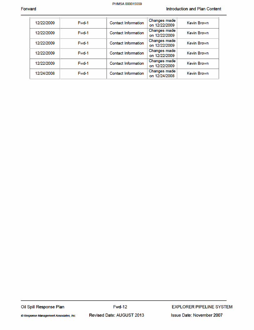


1.0 INTRODUCTION AND PLAN CONTENT 1.1 Plan Purpose/Objectives 1.2 Scope of Plan 1.3 Plan Distribution Procedures 1.4 Plan Review and Update Procedures 1.5 Regulatory Compliance Figure 1.1 Facility Information Figure 1.2 Pipeline System Overview Diagram
0 o P a o e tct t a ectio 1 0 od a an ContentSection 1.0 Introduction and Plan Content___ __ __ ___ ___ __ _________ __________________________________________________________________________________________________
___ __ __ ___ ___ __ _________ __________________________________________________________________________________________________
l sp l Re Oil Spill Response P a a Plan 11- 1 E L L L S TE I TEXPLORER PIPELINE SYSTEM o a t s i on a A i © Response Management Associates, © Response Management Associates, . . Inc. Inc. e U U R se a T R se : Revised Date: AUGUST 1 2013 e 2 2 a ve r 2007Issue Date: November 2007
PHMSA 000015561

1.1 PLAN PURPOSE/OBJECTIVES
The purpose of this Oil Spill Response Plan (Plan) is to assist Explorer Pipeline Company personnel in preparing for and responding quickly and safely to a discharge originating from the pipelines and associated facilities. The Plan provides techniques and guidelines for achieving an efficient, coordinated, and effective response to a discharge incident which may occur along the pipeline.
The specific objectives of the Plan are to:
Establish Response Teams, assign individuals to fill the positions on the teams, and define the roles and responsibilities of team members.
Define notification, activation, and mobilization procedures to be followed when a discharge occurs.
Define organizational lines of responsibility to be adhered to during a response operation.
Document equipment, manpower, and other resources available to assist with the response.
Ensure compliance with the federal, state, and local oil pollution regulations.
Ensure consistency with the National Contingency Plan and Area Contingency Plan(s)for the area of operation.
1.2 SCOPE OF PLAN
This Plan has been developed in accordance with the regulation published in 49 CFR Part 194 - Response Plans for Onshore Oil Pipelines. This Plan contains prioritized procedures for Company personnel to mitigate or prevent any discharge resulting from the operation of the pipeline. A description of the pipeline’s details is presented in Figure 1.1 with additional information provided in the sections and the appendices.
0 o P a o e tct t a ectio 1 0 od a an ContentSection 1.0 Introduction and Plan Content___ __ __ ___ ___ __ _________ __________________________________________________________________________________________________
___ __ __ ___ ___ __ _________ __________________________________________________________________________________________________
l sp l Re Oil Spill Response P a a Plan 11- 2 E L L L S TE I TEXPLORER PIPELINE SYSTEM o a t s i on a A i © Response Management Associates, © Response Management Associates, . . Inc. Inc. e U U R se a T R se : Revised Date: AUGUST 1 2013 e 2 2 a ve r 2007Issue Date: November 2007
PHMSA 000015562
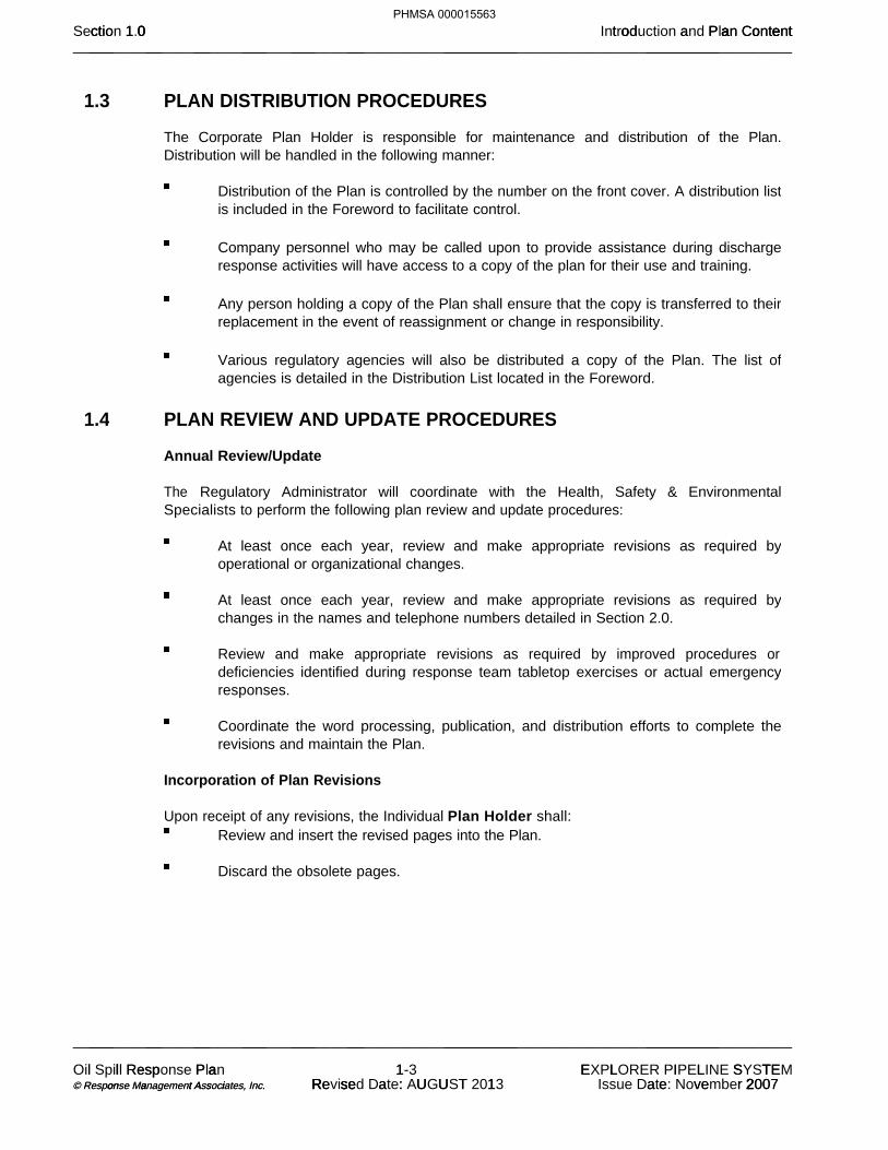
1.3 PLAN DISTRIBUTION PROCEDURES
The Corporate Plan Holder is responsible for maintenance and distribution of the Plan. Distribution will be handled in the following manner:
Distribution of the Plan is controlled by the number on the front cover. A distribution list is included in the Foreword to facilitate control.
Company personnel who may be called upon to provide assistance during discharge response activities will have access to a copy of the plan for their use and training.
Any person holding a copy of the Plan shall ensure that the copy is transferred to their replacement in the event of reassignment or change in responsibility.
Various regulatory agencies will also be distributed a copy of the Plan. The list of agencies is detailed in the Distribution List located in the Foreword.
1.4 PLAN REVIEW AND UPDATE PROCEDURES
Annual Review/Update
The Regulatory Administrator will coordinate with the Health, Safety & Environmental Specialists to perform the following plan review and update procedures:
At least once each year, review and make appropriate revisions as required by operational or organizational changes.
At least once each year, review and make appropriate revisions as required by changes in the names and telephone numbers detailed in Section 2.0.
Review and make appropriate revisions as required by improved procedures or deficiencies identified during response team tabletop exercises or actual emergency responses.
Coordinate the word processing, publication, and distribution efforts to complete the revisions and maintain the Plan.
Incorporation of Plan Revisions
Upon receipt of any revisions, the Individual Plan Holder shall:
Review and insert the revised pages into the Plan. Discard the obsolete pages.
0 o P a o e tct t a ectio 1 0 od a an ContentSection 1.0 Introduction and Plan Content___ __ __ ___ ___ __ _________ __________________________________________________________________________________________________
___ __ __ ___ ___ __ _________ __________________________________________________________________________________________________
l sp l Re Oil Spill Response P a a Plan 11- 3 E L L L S TE I TEXPLORER PIPELINE SYSTEM o a t s i on a A i © Response Management Associates, © Response Management Associates, . . Inc. Inc. e U U R se a T R se : Revised Date: AUGUST 1 2013 e 2 2 a ve r 2007Issue Date: November 2007
PHMSA 000015563

1.4 PLAN REVIEW AND UPDATE PROCEDURES (Cont'd)
Agency Revision Requirements
The Company shall revise and resubmit changes to the DOT/PHMSA Pipeline Response Plans Officer within 30 days of each change that would substantially affect the implementation of the response plan. Examples of changes in operating conditions that would cause a significant change to the Plan include:
Conditions Requiring Changes
An extension of the existing pipeline or construction of a new pipeline in a response zone not covered by the previously approved plan.
Relocation or replacement of portions of the pipeline which in any way substantially affect the information included in this Plan, such as a change in the Worst Case Discharge volume.
A change in the type of oil handled, stored, or transferred that materially alters the required response resources.
A change in the name of the Oil Spill Removal Organization (OSRO).
A material change in capabilities of the OSRO that provides equipment and personnel.
A change in emergency response procedures.
A change in the Qualified Individual.
A change in the NCP or an ACP that has significant impact on the equipment appropriate for response activities.
Any other changes that materially affect the implementation of the Plan.
As a result of post incident or drill evaluations.
DOT/PHMSA must be provided with two copies of such revisions. The Company must submit the DOT/PHMSA issued Facility Control Number with the changes (the PHMSA Control Number is listed in Figure 1.1). In addition to periodic updates, when applicable, the Facility will resubmit the response plan to DOT/PHMSA every five years from the last approval date of the Plan. Except as provided above, amendments to the following do not require approval by DOT/PHMSA:
Personnel and telephone number lists included in the Plan.
OSRO(s) change which does not result in a material change in support capabilities.
0 o P a o e tct t a ectio 1 0 od a an ContentSection 1.0 Introduction and Plan Content___ __ __ ___ ___ __ _________ __________________________________________________________________________________________________
___ __ __ ___ ___ __ _________ __________________________________________________________________________________________________
l sp l Re Oil Spill Response P a a Plan 11- 4 E L L L S TE I TEXPLORER PIPELINE SYSTEM o a t s i on a A i © Response Management Associates, © Response Management Associates, . . Inc. Inc. e U U R se a T R se : Revised Date: AUGUST 1 2013 e 2 2 a ve r 2007Issue Date: November 2007
PHMSA 000015564

1.5 REGULATORY COMPLIANCE
The development, maintenance, and use of this Plan implements company policy and addresses the following regulatory requirements and guidelines:
Federal Oil Pollution Act of 1990: U.S. DOT Final Rule for Transportation Related On-shore Facilities (49 CFR Part 194).
The response zone has been reviewed for consistency with the following plans:
National Contingency Plan (NCP)
Southwest Louisiana/Southeast Texas Contingency Plan
Houston/Galveston Area Contingency Plan
Chicago and Eastern Wisconsin Area Contingency Plan
0 o P a o e tct t a ectio 1 0 od a an ContentSection 1.0 Introduction and Plan Content___ __ __ ___ ___ __ _________ __________________________________________________________________________________________________
___ __ __ ___ ___ __ _________ __________________________________________________________________________________________________
l sp l Re Oil Spill Response P a a Plan 11- 5 E L L L S TE I TEXPLORER PIPELINE SYSTEM o a t s i on a A i © Response Management Associates, © Response Management Associates, . . Inc. Inc. e U U R se a T R se : Revised Date: AUGUST 1 2013 e 2 2 a ve r 2007Issue Date: November 2007
PHMSA 000015565


FIGURE 1.2
PIPING SYSTEM OVERVIEW
Piping Overview
0 o P a o e tct t a ectio 1 0 od a an ContentSection 1.0 Introduction and Plan Content___ __ __ ___ ___ __ _________ __________________________________________________________________________________________________
___ __ __ ___ ___ __ _________ __________________________________________________________________________________________________
l sp l Re Oil Spill Response P a a Plan 11- 11 E I E P R E N EMEXPLORER PIPELINE SYSTEM o a t s i on a A i © Response Management Associates, © Response Management Associates, . . Inc. Inc. e U U R se a T R se : Revised Date: AUGUST 1 2013 e 2 2 a ve r 2007Issue Date: November 2007
PHMSA 000015571

PHMSA 000015572

2.0 NOTIFICATION PROCEDURES 2.1 Internal Notification 2-1 Figure 2.1 Internal Notification Sequence 2-2 Figure 2.2 Internal Notification References 2-3
2.2 External Notifications 2-82.2.1 Verbal Notification Requirements 2-82.2.2 Written Notification Requirements 2-8
Figure 2.3 Notification Data Sheet 2-9 Figure 2.4 External Notification Flowchart 2-10 Figure 2.5 External Notification References 2-11
0 t f ca ce ect ctio 2 0 i i on durSection 2.0 Notification Procedures___ __ __ ___ ___ __ _________ __________________________________________________________________________________________________
___ __ __ ___ ___ __ _________ __________________________________________________________________________________________________
l sp l Re Oil Spill Response P a a Plan 22- 1 E L L L S TE I TEXPLORER PIPELINE SYSTEM o a t s i on a A i © Response Management Associates, © Response Management Associates, . . Inc. Inc. e U U R se a T R se : Revised Date: AUGUST 1 2013 e 2 2 a ve r 2007Issue Date: November 2007
PHMSA 000015573

This section is a guide for notification procedures that should be implemented immediately after discovering a discharge incident and if possible, securing the source. Internal and external notifications are described separately for clarification purposes only. All notifications are of extreme importance and must be completed in a timely manner.
2.1 INTERNAL NOTIFICATION
The following internal notifications should be made for each emergency incident to the extent that the incident demands (telephone reference is provided in Figure 2.2). In no event shall notification be delayed because the immediate supervisor is inaccessible. Authorization is given to bypass management levels if necessary to provide timely notification to appropriate management. The typical internal notification responsibilities for each person potentially involved in the initial response are as follows:
Person Discovering the Discharge
Immediately notify the Central Control Technician at (888) 876-0036. Immediately notify the local police and fire departments, as needed. Central Control Technician
Notify the local police and fire departments, if they have not been previously notified. Notify the Area Manager.Notify one of the following Supervisors:
Director of OperationsDirector of Field Operations Control Center Manager Director Health, Safety, Security & Environmental Director Engineering Manager Shipper Relations & Transportation Services Manager of Project Engineering & Right-of-Way Maintenance
Supervisor
Notify one of the following Senior Managers/Directors
President and CEODirector of OperationsVice President and General CounselVice President and CFODirector of Environmental, Health, Safety, Security and Environmental
Notify response team by dialing 918-493-5100 and entering 1-1-1 slowly when prompted, and inform the operator to activate the Explorer Pipeline response team notification system.
Senior Managers/Directors
Mobilize response team, if necessary. Notify the President and CEO, if necessary.
0 t f ca ce ect ctio 2 0 i i on durSection 2.0 Notification Procedures___ __ __ ___ ___ __ _________ __________________________________________________________________________________________________
___ __ __ ___ ___ __ _________ __________________________________________________________________________________________________
l sp l Re Oil Spill Response P a a Plan 22- 2 E L L L S TE I TEXPLORER PIPELINE SYSTEM o a t s i on a A i © Response Management Associates, © Response Management Associates, . . Inc. Inc. e U U R se a T R se : Revised Date: AUGUST 1 2013 e 2 2 a ve r 2007Issue Date: November 2007
PHMSA 000015574

FIGURE 2.1
INTERNAL NOTIFICATION SEQUENCE(Phone references are provided in Figure 2.2)
0 t f ca ce ect ctio 2 0 i i on durSection 2.0 Notification Procedures___ __ __ ___ ___ __ _________ __________________________________________________________________________________________________
___ __ __ ___ ___ __ _________ __________________________________________________________________________________________________
l sp l Re Oil Spill Response P a a Plan 22- 3 E L L L S TE I TEXPLORER PIPELINE SYSTEM o a t s i on a A i © Response Management Associates, © Response Management Associates, . . Inc. Inc. e U U R se a T R se : Revised Date: AUGUST 1 2013 e 2 2 a ve r 2007Issue Date: November 2007
PHMSA 000015575


2.2 EXTERNAL NOTIFICATIONS
External notifications are those made to entities outside of the company including federal, state and local regulatory agencies, as well as railroad and utility companies. These notifications include both verbal and written requirements.
2.2.1 Verbal Notification Requirements
Immediate internal notification is to be made in accordance with the Internal Notification Procedures found in Section 2.1 when a system operational failure or other type of incident occurs. This will allow immediate evaluation and classification of incidents and prompt immediate telephonic notification as detailed in Figure 2.4 and 2.5 to the National Response Center (NRC), state agencies, local agencies, and other federal agencies as required. The information found on the Notification Data Sheet, Figure 2.3, should be used to disseminate incident information to the appropriate agencies. For the purpose of this procedure, immediate reporting means reporting the instant a person has knowledge of an actual or suspected leak, uncontrolled release of product, any unplanned spill or other pipeline system failure. Information that causes any employee to reasonably suspect a leak or uncontrolled release of product must be immediately reported, even when the actual existence or location of a leak or release cannot yet be confirmed.
2.2.2 Written Notification Requirements
A written report is to be filed as soon as practical, but not later than 30 days after discovery of the incident to the Information Resources Manager, Office of Pipeline Safety, Pipeline and Hazardous Materials Safety Administration, US Department of Transportation. Information concerning the event shall be reported on PHMSA Form 7000-1 on-line on the PHMSA website via log-in. Paper reports are not required. This report is to be filed for all incidents reported telephonically and other incidents required to be reported in accordance with the criteria listed below. The information required for completing the 30-day written report will be furnished by the Area Offices to the DOT Regulatory Compliance Department for submission to the DOT. Any subsequent or additional information that was not reported on the initial written report must be reported to the DOT Regulatory Compliance Department by the Area Office. This information will be utilized in filing a supplemental written report to the DOT as soon as possible, but no later than 30 days after its discovery. NOTE: Refer to Figure 2.5 for any additional state written reporting requirements.
0 t f ca ce ect ctio 2 0 i i on durSection 2.0 Notification Procedures___ __ __ ___ ___ __ _________ __________________________________________________________________________________________________
___ __ __ ___ ___ __ _________ __________________________________________________________________________________________________
l sp l Re Oil Spill Response P a a Plan 22- 15 E I E P R E N EMEXPLORER PIPELINE SYSTEM o a t s i on a A i © Response Management Associates, © Response Management Associates, . . Inc. Inc. e U U R se a T R se : Revised Date: AUGUST 1 2013 e 2 2 a ve r 2007Issue Date: November 2007
PHMSA 000015587


FIGURE 2.4
EXTERNAL NOTIFICATION FLOWCHART
0 t f ca ce ect ctio 2 0 i i on durSection 2.0 Notification Procedures___ __ __ ___ ___ __ _________ __________________________________________________________________________________________________
___ __ __ ___ ___ __ _________ __________________________________________________________________________________________________
l sp l Re Oil Spill Response P a a Plan 22- 18 E I E P R E N EMEXPLORER PIPELINE SYSTEM o a t s i on a A i © Response Management Associates, © Response Management Associates, . . Inc. Inc. e U U R se a T R se : Revised Date: AUGUST 1 2013 e 2 2 a ve r 2007Issue Date: November 2007
PHMSA 000015590
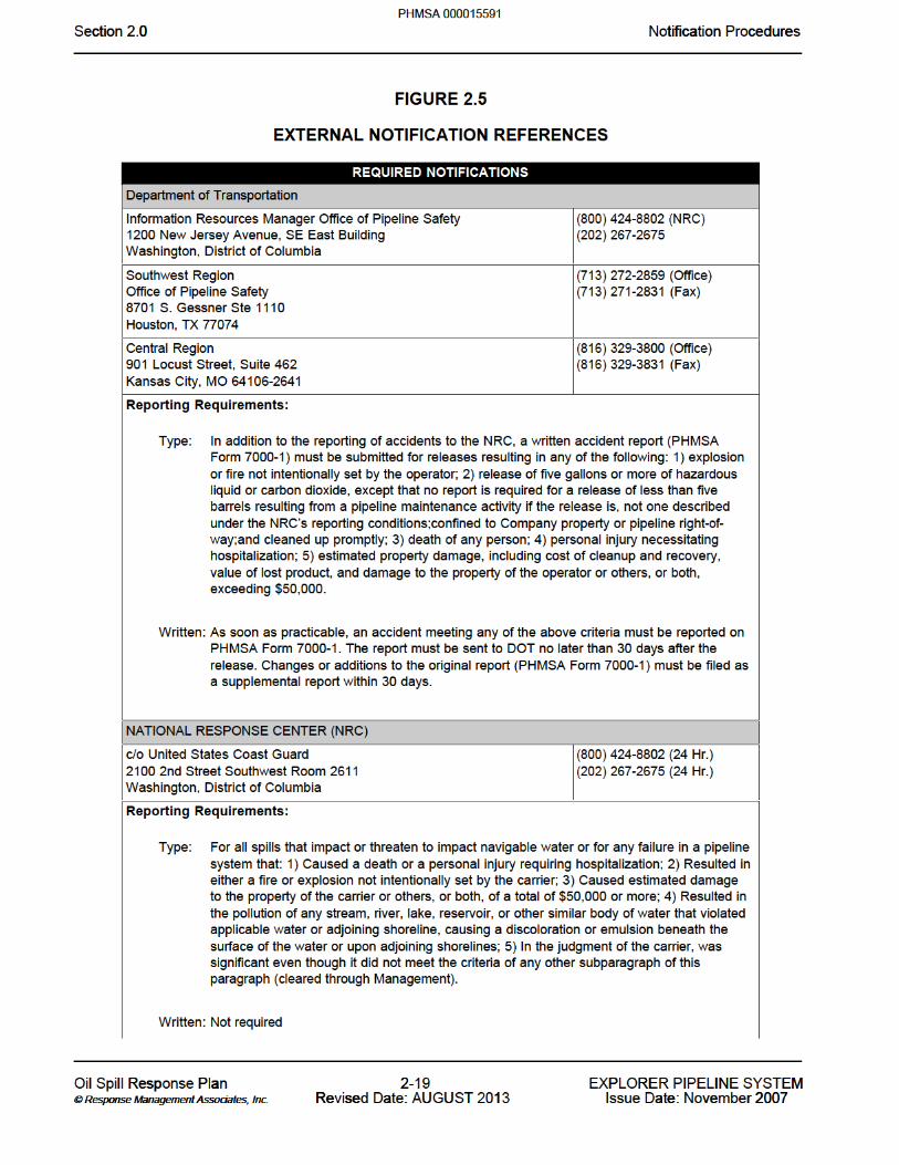


FIGURE 2.5
EXTERNAL NOTIFICATION REFERENCES (Cont'd)
0 t f ca ce ect ctio 2 0 i i on durSection 2.0 Notification Procedures___ __ __ ___ ___ __ _________ __________________________________________________________________________________________________
___ __ __ ___ ___ __ _________ __________________________________________________________________________________________________
l sp l Re Oil Spill Response P a a Plan 22- 21 E I E P R E N EMEXPLORER PIPELINE SYSTEM o a t s i on a A i © Response Management Associates, © Response Management Associates, . . Inc. Inc. e U U R se a T R se : Revised Date: AUGUST 1 2013 e 2 2 a ve r 2007Issue Date: November 2007
PHMSA 000015593


0 t f ca ce ect ctio 2 0 i i on durSection 2.0 Notification Procedures___ __ __ ___ ___ __ _________ __________________________________________________________________________________________________
___ __ __ ___ ___ __ _________ __________________________________________________________________________________________________
l sp l Re Oil Spill Response P a a Plan 22- 32 E I E P R E N EMEXPLORER PIPELINE SYSTEM o a t s i on a A i © Response Management Associates, © Response Management Associates, . . Inc. Inc. e U U R se a T R se : Revised Date: AUGUST 1 2013 e 2 2 a ve r 2007Issue Date: November 2007
PHMSA 000015604

Illinois
0 t f ca ce ect ctio 2 0 i i on durSection 2.0 Notification Procedures___ __ __ ___ ___ __ _________ __________________________________________________________________________________________________
___ __ __ ___ ___ __ _________ __________________________________________________________________________________________________
l sp l Re Oil Spill Response P a a Plan 22- 33 E I E P R E N EMEXPLORER PIPELINE SYSTEM o a t s i on a A i © Response Management Associates, © Response Management Associates, . . Inc. Inc. e U U R se a T R se : Revised Date: AUGUST 1 2013 e 2 2 a ve r 2007Issue Date: November 2007
PHMSA 000015605


Indiana
0 t f ca ce ect ctio 2 0 i i on durSection 2.0 Notification Procedures___ __ __ ___ ___ __ _________ __________________________________________________________________________________________________
___ __ __ ___ ___ __ _________ __________________________________________________________________________________________________
l sp l Re Oil Spill Response P a a Plan 22- 35 E I E P R E N EMEXPLORER PIPELINE SYSTEM o a t s i on a A i © Response Management Associates, © Response Management Associates, . . Inc. Inc. e U U R se a T R se : Revised Date: AUGUST 1 2013 e 2 2 a ve r 2007Issue Date: November 2007
PHMSA 000015607


Missouri
0 t f ca ce ect ctio 2 0 i i on durSection 2.0 Notification Procedures___ __ __ ___ ___ __ _________ __________________________________________________________________________________________________
___ __ __ ___ ___ __ _________ __________________________________________________________________________________________________
l sp l Re Oil Spill Response P a a Plan 22- 37 E I E P R E N EMEXPLORER PIPELINE SYSTEM o a t s i on a A i © Response Management Associates, © Response Management Associates, . . Inc. Inc. e U U R se a T R se : Revised Date: AUGUST 1 2013 e 2 2 a ve r 2007Issue Date: November 2007
PHMSA 000015609


Oklahoma
0 t f ca ce ect ctio 2 0 i i on durSection 2.0 Notification Procedures___ __ __ ___ ___ __ _________ __________________________________________________________________________________________________
___ __ __ ___ ___ __ _________ __________________________________________________________________________________________________
l sp l Re Oil Spill Response P a a Plan 22- 39 E I E P R E N EMEXPLORER PIPELINE SYSTEM o a t s i on a A i © Response Management Associates, © Response Management Associates, . . Inc. Inc. e U U R se a T R se : Revised Date: AUGUST 1 2013 e 2 2 a ve r 2007Issue Date: November 2007
PHMSA 000015611


Texas
0 t f ca ce ect ctio 2 0 i i on durSection 2.0 Notification Procedures___ __ __ ___ ___ __ _________ __________________________________________________________________________________________________
___ __ __ ___ ___ __ _________ __________________________________________________________________________________________________
l sp l Re Oil Spill Response P a a Plan 22- 41 E I E P R E N EMEXPLORER PIPELINE SYSTEM o a t s i on a A i © Response Management Associates, © Response Management Associates, . . Inc. Inc. e U U R se a T R se : Revised Date: AUGUST 1 2013 e 2 2 a ve r 2007Issue Date: November 2007
PHMSA 000015613


TABLE OF CONTENTS 3.0 3.1 Initial
Figure 3.1 Specific Incident Response ChecklistFigure 3.2 Flammable Liquids (Non-Polar/Water Immiscible)
3.2 Documentation of Initial
3.3 Oil Containment, Recovery and Disposal
3.4 Storage/Disposal
3.5 Sampling and Waste Analysis Procedures
3.6 Safety Awareness 3.6.1 General Response Safety 3.6.2 Air Monitoring 3.6.3 Decontamination 3.6.4 Personal Protective Equipment (PPE)
3.7 Shift-Turnover Procedure
0 sp Act ctio 3 0 Ac onsSection 3.0 Response Actions___ __ __ ___ ___ __ _________ __________________________________________________________________________________________________
___ __ __ ___ ___ __ _________ __________________________________________________________________________________________________
l sp l Re Oil Spill Response P a a Plan 33- 1 E L L L S TE I TEXPLORER PIPELINE SYSTEM o a t s i on a A i © Response Management Associates, © Response Management Associates, . . Inc. Inc. e U U R se a T R se : Revised Date: AUGUST 1 2013 e 2 2 a ve r 2007Issue Date: November 2007
PHMSA 000015617


3.1 INITIAL (Cont'd) In addition to the potential emergency events outlined in this Section, the Company has identified several "abnormal operations" that could be expected in the pipeline facilities. The Company has defined the events and established procedures to identify, eliminate or mitigate the threat of a worst case discharge due to these events. In compliance with 49 CFR 195.402(d), these procedures are defined in the Company's Operations Manual.
FIRST COMPANY PERSON NOTIFIED/ON SCENE _____ Follow the appropriate "Specific Incident Response Checklist" in Figure 3.1 and "Product
Specific Response Considerations" in Figure 3.2. _____ NotifyCentral Control Technicianof the incident.
AREA MANAGEMENT _____ Evaluate the Severity, Potential Impact, Safety Concerns, and Response Requirements based
on the initial data provided by the first person on scene. _____ Utilize local emergency services as necessary (police, fire, medical).
_____ Assume the role of Incident Commander.
_____ Confirm safety aspects at site, including need for personal protective equipment, sources of
ignition, and potential need for evacuation. _____ Activate the Local Response Team and primary response contractors,as the situation
demands _____ Coordinate/perform activation of additional spill response contractors, as the situation
demands (telephone reference is provided in Figure 2.5). _____ Perform notifications as per Figure 2.1, as appropriate.
_____ Proceed to spill site and coordinate response and clean-up operations.
_____ Direct containment, dispersion, and/or clean-up operations in accordance with the "Product
Specific Response Considerations" provided in Figure 3.2.
LOCAL RESPONSE TEAM _____ Assigned personnel will immediately respond to a discharge from the Pipeline, as the situation
demands. _____ Perform response/clean-up operations as directed or coordinated by the Incident Commander.
_____ Assist as directed at the spill site.
0 sp Act ctio 3 0 Ac onsSection 3.0 Response Actions___ __ __ ___ ___ __ _________ __________________________________________________________________________________________________
___ __ __ ___ ___ __ _________ __________________________________________________________________________________________________
l sp l Re Oil Spill Response P a a Plan 33- 3 E L L L S TE I TEXPLORER PIPELINE SYSTEM o a t s i on a A i © Response Management Associates, © Response Management Associates, . . Inc. Inc. e U U R se a T R se : Revised Date: AUGUST 1 2013 e 2 2 a ve r 2007Issue Date: November 2007
PHMSA 000015619


FIGURE 3.1
SPECIFIC INCIDENT RESPONSE CHECKLIST (Cont'd)
LINE BREAK OR LEAK, SPECIFIC RESPONSE ______ Check for pressure corresponding to the scheduled flow rate. If in doubt, shut it down
______ If discrepancies occur, locate the area affected. If in doubt, shut it down
______ Verify the leak’s presence with aerial patrol, landowners, or employees.
______ Shut down pumping equipment.
______ The Central Control Technician shall notify Area Management and the Director, Field Operations
that operations are shut-down.
______ Send personnel to close upstream and downstream block valves, paying attention to the terrain
and hydraulic location of the leak. Check valve positions on both sides of the leak to make certain they are closed.
______ Mitigate spreading of the product, as the situation demands. Potential containment strategies
include:
Boom Earthen dike/berm Ditching
______ Spreading sorbent material over the spill.
______ Prevent the spill from entering the waterways, sewer, etc. to the greatest extent possible.
______ Determine the direction and expected duration of spill movement. Refer to the maps in Section
6.0.
______ If located within containment area, ensure that drainage valve(s) is “closed”.
______ If the spill escapes the containment area, review the location of socio-economic and
environmentally sensitive areas identified in Section 6.0 and the ACP. Determine which of these may be threatened by the spill and direct the response operation to these locations. Initiate protection and recovery actions.
______ Qualified personnel should utilize LEL meter, O2 meter, proper colormetric indicator tubes, such
as Drager, and/or other air sampling measurements to assure that areas are safe to enter for continued response operations. Refer to Vapor Cloud Specific Response, later in this Figure, if flammable vapors are detected.
0 sp Act ctio 3 0 Ac onsSection 3.0 Response Actions___ __ __ ___ ___ __ _________ __________________________________________________________________________________________________
___ __ __ ___ ___ __ _________ __________________________________________________________________________________________________
l sp l Re Oil Spill Response P a a Plan 33- 5 E L L L S TE I TEXPLORER PIPELINE SYSTEM o a t s i on a A i © Response Management Associates, © Response Management Associates, . . Inc. Inc. e U U R se a T R se : Revised Date: AUGUST 1 2013 e 2 2 a ve r 2007Issue Date: November 2007
PHMSA 000015621

FIGURE 3.1
SPECIFIC INCIDENT RESPONSE CHECKLIST (Cont'd)
LINE BREAK OR LEAK, SPECIFIC RESPONSE (Cont'd)
______ Drain the line section, as the situation demands.
______ Inform local operators of utilities such as the power company, telephone company, railway.
______ Clean up spilled product to eliminate any possible environmental problems. Be alert for
underground cables.
______ Make all necessary repairs.
______ Return the line to service when repairs are complete, if or when approved.
______ Complete follow-up and written reporting, as the situation demands.
0 sp Act ctio 3 0 Ac onsSection 3.0 Response Actions___ __ __ ___ ___ __ _________ __________________________________________________________________________________________________
___ __ __ ___ ___ __ _________ __________________________________________________________________________________________________
l sp l Re Oil Spill Response P a a Plan 33- 6 E L L L S TE I TEXPLORER PIPELINE SYSTEM o a t s i on a A i © Response Management Associates, © Response Management Associates, . . Inc. Inc. e U U R se a T R se : Revised Date: AUGUST 1 2013 e 2 2 a ve r 2007Issue Date: November 2007
PHMSA 000015622

FIGURE 3.1
SPECIFIC INCIDENT RESPONSE CHECKLIST (Cont'd)
STORAGE TANK LEAK, SPECIFIC RESPONSE ______ Shut down all tank farm product movement operations and isolate the tank.
______ The Central Control Technician shall notify Area Management and the Director, Field Operations
that operations are shut-down.
______ Ensure that the containment area drainage valve(s) is “closed”.
______ If possible, block drainage of spilled material from traveling offsite
______ Determine the direction and expected duration of spill movement. Refer to the maps in Section
6.0.
______ If the spill escapes the containment area, review the location of socio-economic and
environmentally sensitive areas identified in Section 6.0 and the ACP. Determine which of these may be threatened by the spill and direct the response to these locations. Initiate protection and recovery actions.
______ Qualified personnel should utilize LEL meter, O2 meter, proper colormetric indicator tubes, such
as Drager, and/or other air sampling measurements to assure that areas are safe to enter for continued response operations. Refer to Vapor Cloud Specific Response, later in this Figure, if flammable vapors are detected.
______ Stop all traffic in hazardous area (inside and outside of property boundaries), as the situation
demands.
______ Inform local operators of utilities such as the power company, telephone company, railway.
______ Remove product from containment area (at a sump or in a low area) with an explosion proof pump,
oil skimmer, and/or vacuum truck w/ skimmer attachments.
______ If applicable, process remaining product through the separator system.
______ Clean up product spill to eliminate any possible environmental problems. Be alert for underground
utilities, lines, etc.
______ Stockpile waste for eventual disposal.
______ Make all necessary repairs. Return the line/tank to service when repairs are complete and tested.
______ Complete follow-up and written reporting, as the situation demands.
0 sp Act ctio 3 0 Ac onsSection 3.0 Response Actions___ __ __ ___ ___ __ _________ __________________________________________________________________________________________________
___ __ __ ___ ___ __ _________ __________________________________________________________________________________________________
l sp l Re Oil Spill Response P a a Plan 33- 7 E L L L S TE I TEXPLORER PIPELINE SYSTEM o a t s i on a A i © Response Management Associates, © Response Management Associates, . . Inc. Inc. e U U R se a T R se : Revised Date: AUGUST 1 2013 e 2 2 a ve r 2007Issue Date: November 2007
PHMSA 000015623
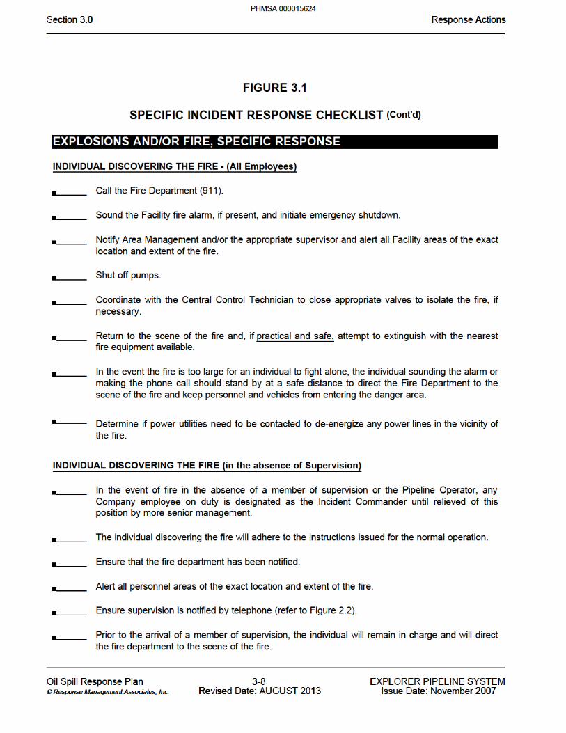

FIGURE 3.1
SPECIFIC INCIDENT RESPONSE CHECKLIST (Cont'd)
EXPLOSIONS AND/OR FIRE, SPECIFIC RESPONSE (Cont'd)
TANK FIRES Fixed Roof - Cone Roof Tank Fires ______ Evacuate products.
______ Position two or more water nozzles on dikes to cool tanks.
______ Employ fire pump nozzles to cool adjacent tank and appurtenances.
External Floating Roof - Open Floating Roof Tank Fires - Roof Floating ______ Pump product into tank to raise the roof and prevent hot spots.
______ Cool sides of the tank and appurtenances with water from the nozzles on the dike.
External Floating Roof - Open Floating Roof Tank Fires - Roof on Legs ______ Cool tank with water.
______ Cool adjacent tanks and appurtenances with water.
Internal Floating Roof - Covered Floating Roof Tank Fires EXTERNAL FIRE AT THE VENTS ______ Cool burning vents with water.
______ Extinguish burning points from the ground.
______ Cool adjacent tank and appurtenances with water.
0 sp Act ctio 3 0 Ac onsSection 3.0 Response Actions___ __ __ ___ ___ __ _________ __________________________________________________________________________________________________
___ __ __ ___ ___ __ _________ __________________________________________________________________________________________________
l sp l Re Oil Spill Response P a a Plan 33- 9 E L L L S TE I TEXPLORER PIPELINE SYSTEM o a t s i on a A i © Response Management Associates, © Response Management Associates, . . Inc. Inc. e U U R se a T R se : Revised Date: AUGUST 1 2013 e 2 2 a ve r 2007Issue Date: November 2007
PHMSA 000015625

FIGURE 3.1
SPECIFIC INCIDENT RESPONSE CHECKLIST (Cont'd)
EXPLOSIONS AND/OR FIRE, SPECIFIC RESPONSE (Cont'd)
INTERNAL FIRE, CONE ROOF INTACT ______ Cool roof and sides with water.
______ Pump out all fuel, but do not land internal floating roof to create a vapor space underneath the
roof.
______ Cool adjacent tanks and appurtenances with water.
INTERNAL FIRE, CONE ROOF DESTROYED ______ Pump out all fuel, but do not land internal floating roof to create a vapor space underneath the
roof.
______ Cool tank with water.
______ Cool adjacent tanks and appurtenanceswith water.
Tank Rupture ______ Evacuate tanks which share the dike.
______ Assist the deployment of fire department equipment.
Explosions ______ Empty the tank.
______ Disconnect the electrical power leading to the tank.
______ Use Mobile Twin Agent System to extinguish any ground fires.
______ When the Fire Department arrives, spray the shell above the liquid level to cool the shell.
______ Cool adjacent tanks and pipes.
______ Extinguish the fire.
0 sp Act ctio 3 0 Ac onsSection 3.0 Response Actions___ __ __ ___ ___ __ _________ __________________________________________________________________________________________________
___ __ __ ___ ___ __ _________ __________________________________________________________________________________________________
l sp l Re Oil Spill Response P a a Plan 33- 10 E I E P R E N EMEXPLORER PIPELINE SYSTEM o a t s i on a A i © Response Management Associates, © Response Management Associates, . . Inc. Inc. e U U R se a T R se : Revised Date: AUGUST 1 2013 e 2 2 a ve r 2007Issue Date: November 2007
PHMSA 000015626
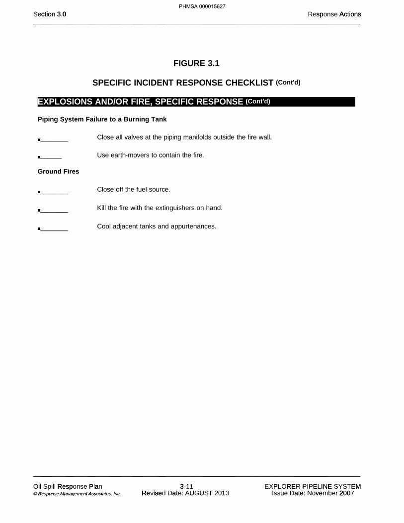
FIGURE 3.1
SPECIFIC INCIDENT RESPONSE CHECKLIST (Cont'd)
EXPLOSIONS AND/OR FIRE, SPECIFIC RESPONSE (Cont'd) Piping System Failure to a Burning Tank ______ Close all valves at the piping manifolds outside the fire wall.
______ Use earth-movers to contain the fire.
Ground Fires ______ Close off the fuel source.
______ Kill the fire with the extinguishers on hand.
______ Cool adjacent tanks and appurtenances.
0 sp Act ctio 3 0 Ac onsSection 3.0 Response Actions___ __ __ ___ ___ __ _________ __________________________________________________________________________________________________
___ __ __ ___ ___ __ _________ __________________________________________________________________________________________________
l sp l Re Oil Spill Response P a a Plan 33- 11 E I E P R E N EMEXPLORER PIPELINE SYSTEM o a t s i on a A i © Response Management Associates, © Response Management Associates, . . Inc. Inc. e U U R se a T R se : Revised Date: AUGUST 1 2013 e 2 2 a ve r 2007Issue Date: November 2007
PHMSA 000015627
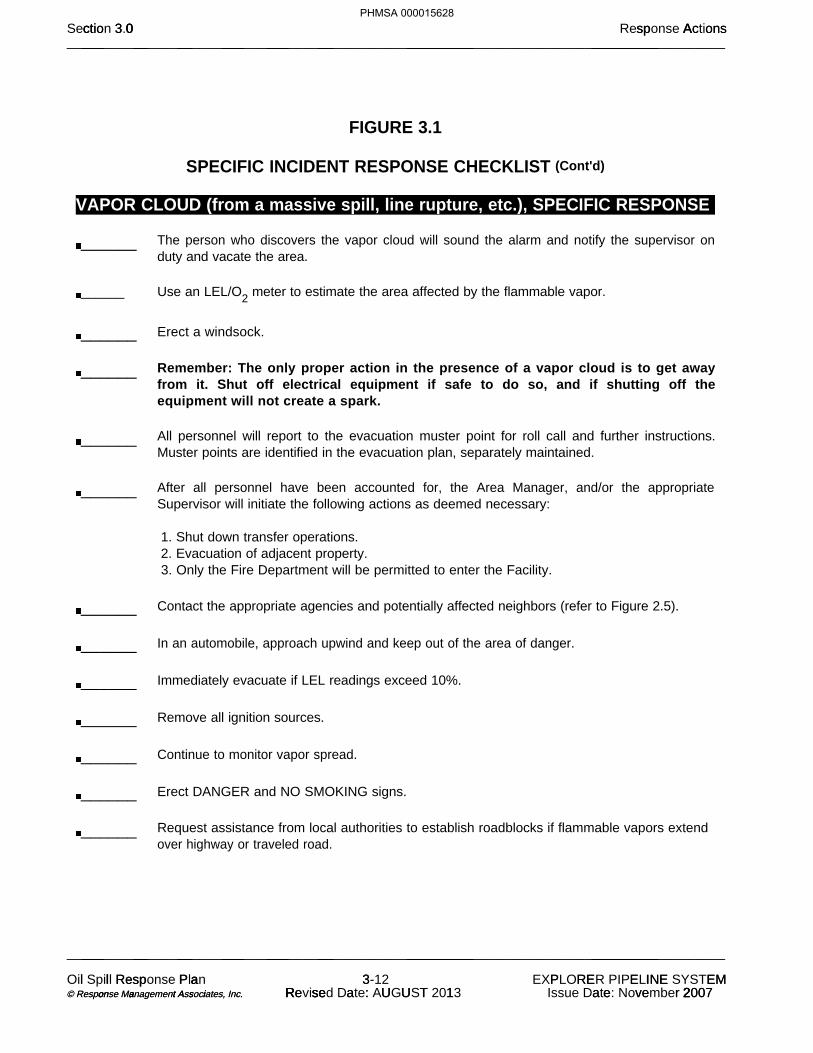
FIGURE 3.1
SPECIFIC INCIDENT RESPONSE CHECKLIST (Cont'd)
VAPOR CLOUD (from a massive spill, line rupture, etc.), SPECIFIC RESPONSE ______ The person who discovers the vapor cloud will sound the alarm and notify the supervisor on
duty and vacate the area.
______ Use an LEL/O2 meter to estimate the area affected by the flammable vapor.
______ Erect a windsock.
______ Remember: The only proper action in the presence of a vapor cloud is to get away
from it. Shut off electrical equipment if safe to do so, and if shutting off the equipment will not create a spark.
______ All personnel will report to the evacuation muster point for roll call and further instructions.
Muster points are identified in the evacuation plan, separately maintained.
______ After all personnel have been accounted for, the Area Manager, and/or the appropriate
Supervisor will initiate the following actions as deemed necessary: 1. Shut down transfer operations. 2. Evacuation of adjacent property. 3. Only the Fire Department will be permitted to enter the Facility.
______ Contact the appropriate agencies and potentially affected neighbors (refer to Figure 2.5).
______ In an automobile, approach upwind and keep out of the area of danger.
______ Immediately evacuate if LEL readings exceed 10%.
______ Remove all ignition sources.
______ Continue to monitor vapor spread.
______ Erect DANGER and NO SMOKING signs.
______ Request assistance from local authorities to establish roadblocks if flammable vapors extend
over highway or traveled road.
0 sp Act ctio 3 0 Ac onsSection 3.0 Response Actions___ __ __ ___ ___ __ _________ __________________________________________________________________________________________________
___ __ __ ___ ___ __ _________ __________________________________________________________________________________________________
l sp l Re Oil Spill Response P a a Plan 33- 12 E I E P R E N EMEXPLORER PIPELINE SYSTEM o a t s i on a A i © Response Management Associates, © Response Management Associates, . . Inc. Inc. e U U R se a T R se : Revised Date: AUGUST 1 2013 e 2 2 a ve r 2007Issue Date: November 2007
PHMSA 000015628

FIGURE 3.1
SPECIFIC INCIDENT RESPONSE CHECKLIST (Cont'd)
VAPOR CLOUD (from a massive spill, line rupture, etc.), SPECIFIC RESPONSE (Cont'd) ______ Continually monitor vapor intensity and spread.
______ Remember that H2S and other hydrocarbons can numb the sense of smell, therefore
never rely on smell.
______ Once the vapor cloud has been cleared, respond to the cause of the incident as outlined
in the other specific response guides.
0 sp Act ctio 3 0 Ac onsSection 3.0 Response Actions___ __ __ ___ ___ __ _________ __________________________________________________________________________________________________
___ __ __ ___ ___ __ _________ __________________________________________________________________________________________________
l sp l Re Oil Spill Response P a a Plan 33- 13 E I E P R E N EMEXPLORER PIPELINE SYSTEM o a t s i on a A i © Response Management Associates, © Response Management Associates, . . Inc. Inc. e U U R se a T R se : Revised Date: AUGUST 1 2013 e 2 2 a ve r 2007Issue Date: November 2007
PHMSA 000015629

FIGURE 3.1
0 sp Act ctio 3 0 Ac onsSection 3.0 Response Actions___ __ __ ___ ___ __ _________ __________________________________________________________________________________________________
___ __ __ ___ ___ __ _________ __________________________________________________________________________________________________
l sp l Re Oil Spill Response P a a Plan 33- 14 E I E P R E N EMEXPLORER PIPELINE SYSTEM o a t s i on a A i © Response Management Associates, © Response Management Associates, . . Inc. Inc. e U U R se a T R se : Revised Date: AUGUST 1 2013 e 2 2 a ve r 2007Issue Date: November 2007
PHMSA 000015630
(b) (7)(F)

FIGURE 3.1
SPECIFIC INCIDENT RESPONSE CHECKLIST (Cont'd)
0 sp Act ctio 3 0 Ac onsSection 3.0 Response Actions___ __ __ ___ ___ __ _________ __________________________________________________________________________________________________
___ __ __ ___ ___ __ _________ __________________________________________________________________________________________________
l sp l Re Oil Spill Response P a a Plan 33- 15 E I E P R E N EMEXPLORER PIPELINE SYSTEM o a t s i on a A i © Response Management Associates, © Response Management Associates, . . Inc. Inc. e U U R se a T R se : Revised Date: AUGUST 1 2013 e 2 2 a ve r 2007Issue Date: November 2007
PHMSA 000015631
(b) (7)(F)

FIGURE 3.1
SPECIFIC INCIDENT RESPONSE CHECKLIST (Cont'd)
NATURAL DISASTER (Tornado, Severe Storms, Hurricanes and Earthquakes), SPECIFIC RESPONSE Although many disasters cannot be prevented or predicted, preparation can significantly reduce losses. In the event of a severe weather condition or a natural disaster, the Area Manager or assigned designee will be the Emergency Coordinator.
TORNADO ______ Be Aware of Changing Weather Conditions
1. Torndao watch-conditions are right for the formation of a tornado.
2.
Tornado warning-a tornado has been sighted but is not in the area at this time.
3.
Tornado alert-a tornado has been sighted in the immediate area- take cover immediately.
______ If Severe Weather Conditions Threaten
1. Announce over company radio or by cellular phone.
2. Alert all personnel of condition.
3. If time permits, all personnel should assemble at an inside room in a
designated Facility for shelter.
4. If time does not permit, seek shelter in low level area away from glass.
5. Make certain that all personnel are aware of the condition.
6. The Central Control Technician will shutdown (5 minutes) safely,
notifying Area Manager, if time permits.
7. If times does not permit, the last person to leave the operations room
will hit the emergency shutdown (ESD) switch, thereby shutting off all electrical power.
8. Stay in shelter until "all clear" has been issued.
______ Immediately After the Storm
0 sp Act ctio 3 0 Ac onsSection 3.0 Response Actions___ __ __ ___ ___ __ _________ __________________________________________________________________________________________________
___ __ __ ___ ___ __ _________ __________________________________________________________________________________________________
l sp l Re Oil Spill Response P a a Plan 33- 16 E I E P R E N EMEXPLORER PIPELINE SYSTEM o a t s i on a A i © Response Management Associates, © Response Management Associates, . . Inc. Inc. e U U R se a T R se : Revised Date: AUGUST 1 2013 e 2 2 a ve r 2007Issue Date: November 2007
PHMSA 000015632

1. Account for all personnel.
2. Survey for damages.
3. Initiate team for any repairs.
4.
Refer to this Plan for additional response guidance regarding fires, spills, etc., as needed.
0 sp Act ctio 3 0 Ac onsSection 3.0 Response Actions___ __ __ ___ ___ __ _________ __________________________________________________________________________________________________
___ __ __ ___ ___ __ _________ __________________________________________________________________________________________________
l sp l Re Oil Spill Response P a a Plan 33- 17 E I E P R E N EMEXPLORER PIPELINE SYSTEM o a t s i on a A i © Response Management Associates, © Response Management Associates, . . Inc. Inc. e U U R se a T R se : Revised Date: AUGUST 1 2013 e 2 2 a ve r 2007Issue Date: November 2007
PHMSA 000015633
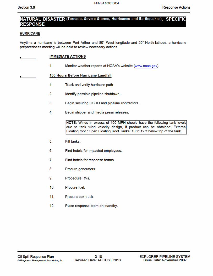


FIGURE 3.1
SPECIFIC INCIDENT RESPONSE CHECKLIST (Cont'd)
NATURAL DISASTER (Tornado, Severe Storms, Hurricanes and Earthquakes), SPECIFIC RESPONSE (Cont'd) EARTHQUAKE Before the Quake (Review Periodically) ______ Survey the pipeline right-of-way by helicopter and on foot if necessary to investigate
potential soil liquefaction and land slide sites.
______ Secure or relocate loose objects in the control room or warehouse that may fall on
personnel.
______ Maintain fully supplied first aide kit.
______ Train local personnel in location of EPL block valves and pipeline.
During the Quake ______ Stay indoors, duck under heavy object such as a desk or brace yourself in a doorway -
avoid windows.
______ If driving, attempt to keep vehicle away from overhead objects/structures if possible,
stop vehicle and drop to the seat or floor.
______ Avoid overhead power lines if possible.
After the Quake (actions dependent upon severity and damage assessment) ______ Shut-down pipeline, isolate stations to extent possible.
______ Disconnect electrical power source and shut off natural gas supplying station offices, if
damaged.
______ Local employees dispatched to close block valves should be very cautious of power
lines near block valves.
______ Check communication phones/radio. Local generator may be useful to connect to EPL's
radio if tower remains standing.
______ Evacuate station facilities depending upon initial damage assessment.
0 sp Act ctio 3 0 Ac onsSection 3.0 Response Actions___ __ __ ___ ___ __ _________ __________________________________________________________________________________________________
___ __ __ ___ ___ __ _________ __________________________________________________________________________________________________
l sp l Re Oil Spill Response P a a Plan 33- 22 E I E P R E N EMEXPLORER PIPELINE SYSTEM o a t s i on a A i © Response Management Associates, © Response Management Associates, . . Inc. Inc. e U U R se a T R se : Revised Date: AUGUST 1 2013 e 2 2 a ve r 2007Issue Date: November 2007
PHMSA 000015638

FIGURE 3.1
SPECIFIC INCIDENT RESPONSE CHECKLIST (Cont'd)
NATURAL DISASTER (Tornado, Severe Storms, Hurricanes and Earthquakes), SPECIFIC RESPONSE (Cont'd)
EARTHQUAKE (Cont'd) ______ Area Manager to establish an initial central meeting place. The initial site utilized to be
communicated to the Central Control Technician. Local employees should make contact with Central Control Technician for instructions and to give their status.
______ Fill available containers with drinking water as soon as possible.
______ Other Area's will respond to assist through the Response Team.
______ Affected local employees need to verify safety of their families and secure their homes
before reporting to EPL facilities - unaffected employees should report to EPL for assignment as soon as possible.
______ EPL facilities must be thoroughly inspected before the pipeline is restarted - including
station piping, tanks, and pipeline. Fly pipeline right-of-way in affected area and slowly repressure line after inspection indicates start-up is possible.
______ EPL will very likely be left to our own resources for the first few days after major earthquake.
We will rely on "importing" response personnel and equipment as necessary to support emergency response and repair activities.
0 sp Act ctio 3 0 Ac onsSection 3.0 Response Actions___ __ __ ___ ___ __ _________ __________________________________________________________________________________________________
___ __ __ ___ ___ __ _________ __________________________________________________________________________________________________
l sp l Re Oil Spill Response P a a Plan 33- 23 E I E P R E N EMEXPLORER PIPELINE SYSTEM o a t s i on a A i © Response Management Associates, © Response Management Associates, . . Inc. Inc. e U U R se a T R se : Revised Date: AUGUST 1 2013 e 2 2 a ve r 2007Issue Date: November 2007
PHMSA 000015639

FIGURE 3.1
SPECIFIC INCIDENT RESPONSE CHECKLIST (Cont'd)
MEDICAL EMERGENCY, SPECIFIC RESPONSE ______ Apply appropriate first aid for both injury and shock, exercising care not to cause further injury.
______ If victim is unconscious and not breathing, immediately apply artificial respiration (if trained in
CPR) and continue without interruption until natural breathing is restored or relieved by another trained CPR personnel or other qualified medical personnel. AEDs are available at each area office and Tulsa Company Headquarters for use by trained personnel.
______ Call for ambulance or other medical evacuation resources, if appropriate.
______ Notify hospital of patient arrival and extent of injury.
______ Complete follow-up and written reporting, as the situation demands.
0 sp Act ctio 3 0 Ac onsSection 3.0 Response Actions___ __ __ ___ ___ __ _________ __________________________________________________________________________________________________
___ __ __ ___ ___ __ _________ __________________________________________________________________________________________________
l sp l Re Oil Spill Response P a a Plan 33- 24 E I E P R E N EMEXPLORER PIPELINE SYSTEM o a t s i on a A i © Response Management Associates, © Response Management Associates, . . Inc. Inc. e U U R se a T R se : Revised Date: AUGUST 1 2013 e 2 2 a ve r 2007Issue Date: November 2007
PHMSA 000015640

FIGURE 3.1
SPECIFIC INCIDENT RESPONSE CHECKLIST (Cont'd)
0 sp Act ctio 3 0 Ac onsSection 3.0 Response Actions___ __ __ ___ ___ __ _________ __________________________________________________________________________________________________
___ __ __ ___ ___ __ _________ __________________________________________________________________________________________________
l sp l Re Oil Spill Response P a a Plan 33- 25 E I E P R E N EMEXPLORER PIPELINE SYSTEM o a t s i on a A i © Response Management Associates, © Response Management Associates, . . Inc. Inc. e U U R se a T R se : Revised Date: AUGUST 1 2013 e 2 2 a ve r 2007Issue Date: November 2007
PHMSA 000015641
(b) (7)(F)

FIGURE 3.1
SPECIFIC INCIDENT RESPONSE CHECKLIST (Cont'd)
PUBLIC RELATIONS/MEDIA, SPECIFIC RESPONSE Guidelines
The Area Supervisor or employee acting in his/her place will limit comments to confirmation of the emergency and statements helpful to the protection of persons and property.
For any further statement, the Area Supervisor or employee acting in his/her place will ask the media to contact the President and CEO or the Director of Operations. (Refer to Figure 2.2 for contact information.)
The President and CEO, Director of Operations, General Counsel or other designee will notify the news media consultants. (Refer to Figure 2.5 for contact information.)
Statements to the Media by Authorized Headquarters Personnel
Confirm the nature of the emergency.
Do not speculate.
Disclose only facts. Do not speculate on damages. Do not discuss cause.
Verify injuries.
Do not report the names of the injured until the families receive notification. Do not report the nature of the injuries.
Report steps taken to handle the emergency.
Coordinate factual information with the fire and police departments, as well as any other agencies, or individuals involved.
Issue a follow up release, if deemed necessary.
Tank Farm Media Communications Sites Locations 1 and 2 refer to sites chosen in the event of a Minor or Medium Level Emergency and a Major Emergency, respectively.
Port Arthur
0 sp Act ctio 3 0 Ac onsSection 3.0 Response Actions___ __ __ ___ ___ __ _________ __________________________________________________________________________________________________
___ __ __ ___ ___ __ _________ __________________________________________________________________________________________________
l sp l Re Oil Spill Response P a a Plan 33- 26 E I E P R E N EMEXPLORER PIPELINE SYSTEM o a t s i on a A i © Response Management Associates, © Response Management Associates, . . Inc. Inc. e U U R se a T R se : Revised Date: AUGUST 1 2013 e 2 2 a ve r 2007Issue Date: November 2007
PHMSA 000015642
1. Market Basket – across the road from the Port Arthur Tank Farm; or2. Holiday Inn – located on Hwy. 69 ¼ mile south of Hwy. 365. Approximately 4 miles from the tank
farm.
0 sp Act ctio 3 0 Ac onsSection 3.0 Response Actions___ __ __ ___ ___ __ _________ __________________________________________________________________________________________________
___ __ __ ___ ___ __ _________ __________________________________________________________________________________________________
l sp l Re Oil Spill Response P a a Plan 33- 27 E I E P R E N EMEXPLORER PIPELINE SYSTEM o a t s i on a A i © Response Management Associates, © Response Management Associates, . . Inc. Inc. e U U R se a T R se : Revised Date: AUGUST 1 2013 e 2 2 a ve r 2007Issue Date: November 2007
PHMSA 000015643

FIGURE 3.1
SPECIFIC INCIDENT RESPONSE CHECKLIST (Cont'd)
PUBLIC RELATIONS/MEDIA, SPECIFIC RESPONSE (Cont’d)
Glenpool 1. Feeder road off of Hwy. 75 and 120; or2. Back entrance of the Glenpool Tank Farm on 131st street where contractors park vehicles.
Greenville 1. West side of Greenville Tank Farm property at the pipe rack; or2. Intersection of Hwy. 66 and 36 – church parking lot on the north side – Caddo Mills (2 miles
from the tank farm).
Grapevine 1. Back entrance of Explorer Southlake Tank Farm on Continental Blvd; or2. Grapevine school parking lot on the east side of Hwy. 26 – across highway from Grapevine
Station.
Wood River 1. Hartford Park – corner of S. Delmar Avenue and W. Seventh Street (Hartford, Illinois); or2. Dads Club Park (South Roxana, IL) corner of Roxana Street and Daniel Boone Street.
Hammond 1. On the west end of the Explorer Pipeline property outside of the fenced area in the open area ½
mile west of the tank farm entrance; or2. Courtyard by Marriot southwest corner of Kennedy Avenue and I-80/I-94 7730 Corinne Drive
Hammond, IN 46323.
0 sp Act ctio 3 0 Ac onsSection 3.0 Response Actions___ __ __ ___ ___ __ _________ __________________________________________________________________________________________________
___ __ __ ___ ___ __ _________ __________________________________________________________________________________________________
l sp l Re Oil Spill Response P a a Plan 33- 28 E I E P R E N EMEXPLORER PIPELINE SYSTEM o a t s i on a A i © Response Management Associates, © Response Management Associates, . . Inc. Inc. e U U R se a T R se : Revised Date: AUGUST 1 2013 e 2 2 a ve r 2007Issue Date: November 2007
PHMSA 000015644

FIGURE 3.2
0 sp Act ctio 3 0 Ac onsSection 3.0 Response Actions___ __ __ ___ ___ __ _________ __________________________________________________________________________________________________
___ __ __ ___ ___ __ _________ __________________________________________________________________________________________________
l sp l Re Oil Spill Response P a a Plan 33- 29 E I E P R E N EMEXPLORER PIPELINE SYSTEM o a t s i on a A i © Response Management Associates, © Response Management Associates, . . Inc. Inc. e U U R se a T R se : Revised Date: AUGUST 1 2013 e 2 2 a ve r 2007Issue Date: November 2007
PHMSA 000015645

3.2 DOCUMENTATION OF INITIAL
It is difficult, particularly during the first few minutes of an initial response operation to think about the importance of documentation. A log should be maintained which documents the history of the events and communications that occur during the response. When recording this information, it is important to remember that the log may become instrumental in legal proceedings, therefore:
Record only facts, do not speculate.
Do not criticize the efforts and/or methods of other people/operations. Do not speculate on the cause of the spill.
Do not skip lines between entries or make erasures. If an error is made, draw a line through it, add the correct entry above or below it, and initial the change.
Record the recommendations, instructions, and actions taken by government/regulatory officials.
Document conversations (telephone or in person) with government/regulatory officials.
Request that government/regulatory officials document and sign their recommendations or orders (especially if company personnel do not agree with the suggestions, instructions, or actions).
3.3 OIL CONTAINMENT, RECOVERY AND DISPOSAL
After initial response has been taken to stop further spillage and notifications made to the required agencies, the Company will begin spill containment, recovery, and disposal operations. The Incident Commander will assess the size and hazards of the spill. The type of product, the location of the spill, and the predicted movement of the spill will be considered. Based on this assessment, additional clean-up personnel and equipment will be dispatched to the site and deployed to control and contain the spill. Boom may be deployed in waterways to contain the spill and to protect socio-economic and environmentally sensitive areas. Booms may also be used in waterways to deflect or guide the spill to locations where it can more effectively be cleaned up using skimmers, vacuum trucks, or sorbent material. Clean-up equipment and material will be used in the manner most effective for rapid and complete clean-up of all spilled product. Response and clean-up will continue until all recoverable product is removed, and the unified command of the Company Incident Commander and the Federal and/or State On-Scene Coordinators determine that further response and cleanup is no longer necessary.
0 sp Act ctio 3 0 Ac onsSection 3.0 Response Actions___ __ __ ___ ___ __ _________ __________________________________________________________________________________________________
___ __ __ ___ ___ __ _________ __________________________________________________________________________________________________
l sp l Re Oil Spill Response P a a Plan 33- 30 E I E P R E N EMEXPLORER PIPELINE SYSTEM o a t s i on a A i © Response Management Associates, © Response Management Associates, . . Inc. Inc. e U U R se a T R se : Revised Date: AUGUST 1 2013 e 2 2 a ve r 2007Issue Date: November 2007
PHMSA 000015646

3.4 STORAGE/DISPOSAL
Strict rules designed to ensure safe and secure handling of waste materials govern the Company waste disposal activities. To ensure proper disposal of recovered oil and associated debris, the following guidelines should be considered:
In the event of a product spill, Facilities have limited capacity to store recovered product and water. Separated product is pumped to frac tanks or to trucks to be carried to the Facility for processing.
Oily debris will be segregated on site and containerized for temporary storage prior to disposal in accordance with RCRA/CERCLA regulations.
Waste associated with the spill will be disposed of at Company pre-approved sites which have the necessary permits to accept the type of waste to be discharged.
The Company’s designated HS&E Specialist will coordinate activities and secure the necessary permits to ensure proper disposal or recycling of recovered product and debris.
3.5 SAMPLING AND WASTE ANALYSIS PROCEDURE
The Company’s sampling and waste analysis practices are governed by the regulations for the applicable state and the United States Environmental Protection Agency (EPA). These regulations outline methods and procedures for determining the chemical and physical characteristics of wastes generated by the Facility, including waste associated with spills, so that they may be properly stored, treated, or disposed.
3.6 SAFETY AWARENESS
It is the corporate policy of the Company to provide a safe workplace for all workers. All employees and contractors are responsible for maintaining the safety and health of all workers on the pipeline and the response operations. Prior to engaging in any spill response activity:
All contractor response personnel must be in compliance with OSHA training requirements.
All other personnel will have completed appropriate training for their position as outlined in Section 4.0.
No employee/contractor shall engage in activities which place them at risk without the appropriate protective equipment and training.
0 sp Act ctio 3 0 Ac onsSection 3.0 Response Actions___ __ __ ___ ___ __ _________ __________________________________________________________________________________________________
___ __ __ ___ ___ __ _________ __________________________________________________________________________________________________
l sp l Re Oil Spill Response P a a Plan 33- 31 E I E P R E N EMEXPLORER PIPELINE SYSTEM o a t s i on a A i © Response Management Associates, © Response Management Associates, . . Inc. Inc. e U U R se a T R se : Revised Date: AUGUST 1 2013 e 2 2 a ve r 2007Issue Date: November 2007
PHMSA 000015647

3.6 SAFETY AWARENESS (Cont'd) 3.6.1 General Response Safety
All company and contractor personnel are expected to comply with the Site Safety Plan for each spill incident.
Any concern regarding health or safety issues should be immediately addressed.
The First Responder must consider the spill site as dangerous and the local atmosphere explosive until air monitoring procedures prove that the area is safe.
The First Responder must exit the area against or across the wind if possible and must also evacuate others who are working in the area.
All injuries, no matter how minor, must be reported to the Area Management in a timely manner.
3.6.2 Air Monitoring
A Safety Monitor shall be designated who is trained in the operation of air monitoring equipment. The Incident Commander must ensure that Safety Monitors are trained and that their equipment is maintained and ready for use.
The air monitoring equipment shall be activated and checked at the location in which it is stored.
Calibration of instruments should be performed before use.
Air monitoring measurements which are to be made prior to entry into the spill area include:
Oxygen content Lower Explosive Limit (LEL) Benzene level
LEL readings above 10% require immediate evacuation of the area and elimination of ignition sources.
Oxygen readings below 19.5% require the use of air supplied respiratory protection.
0 sp Act ctio 3 0 Ac onsSection 3.0 Response Actions___ __ __ ___ ___ __ _________ __________________________________________________________________________________________________
___ __ __ ___ ___ __ _________ __________________________________________________________________________________________________
l sp l Re Oil Spill Response P a a Plan 33- 32 E I E P R E N EMEXPLORER PIPELINE SYSTEM o a t s i on a A i © Response Management Associates, © Response Management Associates, . . Inc. Inc. e U U R se a T R se : Revised Date: AUGUST 1 2013 e 2 2 a ve r 2007Issue Date: November 2007
PHMSA 000015648
3.6 SAFETY AWARENESS (Cont'd)
3.6.2 Air Monitoring (Cont'd)
After assuring that there are no hazards relating to explosion or oxygen depletion, sampling for benzene or total petroleum hydrocarbons shall dictate the appropriate respiratory devices to be used by persons entering the area as follows:
The Incident Commander is responsible for industrial hygiene monitoring in the post discovery period.
3.6.3 Decontamination
Through training programs, Facility personnel know and understand the importance of the removal of hazardous substances from their person if they are contaminated. Eyewash stations and safety showers provide a means to quickly remove gross contamination of harmful agents, including gasoline. Personnel must immediately shower and remove any clothing which is wet or otherwise contaminated. Persons should inspect themselves thoroughly before donning a fresh change of clothing. Contaminated clothing should be disposed of properly. Contaminated personal protective equipment must be washed and sanitized before re-using. The washing of contaminated equipment is performed in a “contained area” to assure that the disposal of the wash water can be handled properly. Establishing "Exclusion - Hot", "Decontamination - Decon", and "Support - Safe" zones are required to prevent the removal of contaminants from the contaminated area as well as unauthorized entry into contaminated areas.
Regardless of the decontamination facilities available, all efforts to minimize personnel exposure should be taken.
Decontamination facilities should be positioned prior to employee/ contractor entrance to areas where the potential for exposure to contamination exists. The appropriate Material Safety Data Sheets (MSDS) are available to aid health professionals treating the injured parties. MSDS are separately maintained at the Facility.
Decontamination facilities should be designed to prevent further contamination of the environment and should have a temporary storage area for items that will be reused in the contaminated area.
Particular attention should be paid to personal hygiene prior to eating, drinking, or
smoking.
0 sp Act ctio 3 0 Ac onsSection 3.0 Response Actions___ __ __ ___ ___ __ _________ __________________________________________________________________________________________________
___ __ __ ___ ___ __ _________ __________________________________________________________________________________________________
l sp l Re Oil Spill Response P a a Plan 33- 33 E I E P R E N EMEXPLORER PIPELINE SYSTEM o a t s i on a A i © Response Management Associates, © Response Management Associates, . . Inc. Inc. e U U R se a T R se : Revised Date: AUGUST 1 2013 e 2 2 a ve r 2007Issue Date: November 2007
PHMSA 000015649


3.7 SHIFT-TURONVER PROCEDURE PURPOSE
Shift turn-overs shall provide on-coming shift personnel with an accurate picture of the emergency response. Complete and accurate turn-overs contribute to clear understanding of:
● Current emergency response conditions ● Number of people on-site & primary responsibilities ● Equipment on-site ● Objectives for the next 12 hours ● Procedures,logs,and other data as required ● Regulatory agency personnel present
RESPONSIBILITIES
Personnel shall NOT assume operational duties unless they are physically and mentally fit to do so.
On-coming personnel should report a minimum of 30 minutes before shift change to ensure adequate review time with off going personnel.
PROCEDURE
The incident commander is responsible for turnover review which shall consist of the following at a minimum.
● Current emergency response conditions ❍ Number of people on-site & primary responsibilities
■ Explorer Personnel ■ Onsite ■ Tulsa
■ Contractor Personnel ■ Foremen and supervisors
■ Inspectors ❍ Equipment on-site and Staging Areas
■ Vacuum trucks ■ Frac Tanks ■ PLIDCO ■ Other needed or potentially need equipment
❍ Federal State and Local regulatory personnel ❍ Security parameters ❍ Communications equipment data and voice
DISCUSS AND EXCHANGE RESPONSIBILITIES BETWEEN SHIFT
The off-going shift is responsible for ensuring that shift personnel are fully cognizant of current operating conditions and what has been done and what remains to be done.
0 sp Act ctio 3 0 Ac onsSection 3.0 Response Actions___ __ __ ___ ___ __ _________ __________________________________________________________________________________________________
___ __ __ ___ ___ __ _________ __________________________________________________________________________________________________
l sp l Re Oil Spill Response P a a Plan 33- 35 E I E P R E N EMEXPLORER PIPELINE SYSTEM o a t s i on a A i © Response Management Associates, © Response Management Associates, . . Inc. Inc. e U U R se a T R se : Revised Date: AUGUST 1 2013 e 2 2 a ve r 2007Issue Date: November 2007
PHMSA 000015651

SHIFT CREWING BRIEFING
The oncoming shift supervisor shall conduct a crew briefing after accepting responsiblity for the shift. Briefing shall include:
● Review of the incident ● Status equipment ● Contractor assignments
RELIEFS OCCURING DURING SHIFT
Ensure that the oncoming person is knowledgeable of the conditions as if a complete shift change process had been conducted. The incident commander must be informed of the change in personnel.
EXCHANGE OF RESPONSIBILITIES
The on-coming incident commander shall signify that he/she is cognizant of incident conditions and is prepared to assume responsibility.
PREPARATIONS FOR SHIFT CHANGE
One hour before shift end the incident commander shall meet and receive an up-to-date briefing on the current status of the response,equipment issues, needs and requirements, current personnel, Explorer & Contractor, inspectors, plans in place for recovery.
0 sp Act ctio 3 0 Ac onsSection 3.0 Response Actions___ __ __ ___ ___ __ _________ __________________________________________________________________________________________________
___ __ __ ___ ___ __ _________ __________________________________________________________________________________________________
l sp l Re Oil Spill Response P a a Plan 33- 36 E I E P R E N EMEXPLORER PIPELINE SYSTEM o a t s i on a A i © Response Management Associates, © Response Management Associates, . . Inc. Inc. e U U R se a T R se : Revised Date: AUGUST 1 2013 e 2 2 a ve r 2007Issue Date: November 2007
PHMSA 000015652

TABLE OF CONTENTS 4.0 RESPONSE TEAMS 4.1 Introduction 4.2 Qualified Individual 4.3 Local Response Team (LRT) 4.4 Incident Command System (ICS) 4.5 Unified Command 4.6 Discharge Classification 4.7 ICS Roles and Responsibilities 4.7.1 Common Responsibilities 4.7.2 Section Leader Responsibilities 4.7.3 Command 4.7.3.1Incident Commander 4.7.3.2Deputy Incident Commander 4.7.3.3Public Relations, Media, Government Officials 4.7.3.4Pipeline/Facility Repair and Restart 4.7.3.5Business Interruption 4.7.3.6Liaison, Safety and Environmental 4.7.3.7Health, Safety and Environmental 4.7.3.8Regulatory Issues 4.7.4 Operations 4.7.4.1Operations Section General Functions 4.7.4.2Operations Section Chief 4.7.4.3Recovery and Protection 4.7.4.4Emergency Response 4.7.4.5Helicopter Air Operations 4.7.4.6Wildlife 4.7.5 Planning 4.7.5.1Planning Section General Functions 4.7.5.2Planning Section Chief 4.7.5.3Situation Unit 4.7.5.4GIS/Mapping 4.7.5.5Weather 4.7.6 Logistics 4.7.6.1Logistics Section General Functions 4.7.6.2Logistics Section Chief 4.7.6.3Communications 4.7.6.4Food Unit 4.7.6.5Medical 4.7.6.6Ordering 4.7.7 Finance 4.7.7.1Finance Section General Functions 4.7.7.2Finance Section Chief 4.7.7.3Humanitarian Efforts 4.7.7.4Claims 4.7.7.5Personnel, Time and Staffing 4.7.7.6Equipment Time Order/Procurement 4.7.7.7Cost Accounting 4.8 Glossary
0 mct R ectio 4 0 espon e sSection 4.0 Response Teams___ __ __ ___ ___ __ _________ __________________________________________________________________________________________________
___ __ __ ___ ___ __ _________ __________________________________________________________________________________________________
l sp l Re Oil Spill Response P a a Plan 44- 1 E L L L S TE I TEXPLORER PIPELINE SYSTEM o a t s i on a A i © Response Management Associates, © Response Management Associates, . . Inc. Inc. e U U R se a T R se : Revised Date: AUGUST 1 2013 e 2 2 a ve r 2007Issue Date: November 2007
PHMSA 000015653

4.1 INTRODUCTION
This section describes organizational features and duties of the Local Response Team and the broader Explorer Pipeline Emergency Response Team. The key to an effective emergency response is a rapid, coordinated, tiered response by the affected facility, and the Local Response Team, consistent with the magnitude of an incident. First response to an incident at the Facility is provided by the Local Response Team. The Explorer Pipeline Emergency Response Team responds, to the degree necessary, to incidents exceeding local capability. If a response exceeds the Local Response Team’s capabilities, the Local Incident Commander activates the Explorer Pipeline Emergency Response Team. These teams use the NIMS Incident Command System (ICS) to manage the emergency response activities. Because ICS is a management tool that is readily adaptable to incidents of varying magnitudes, it is typically used for all emergency incidents. Staffing levels are adjusted to meet specific response team needs based on incident size, severity and type of emergency. An explanation of ICS and the roles and responsibilities for primary members of the team are provided in Section 4.7. The USCG Incident Management Handbook (IMH) contains an in-depth description of all ICS positions, ICS development, response objectives and strategies, command responsibilities, ICS specific glossary/acronyms, resource typing, the Incident Action Plan (IAP) process and meetings. The IMH can be located at: http://www.uscg.mil/hg/nsfweb/download/IMH/IMH-2001.pdf
4.2 QUALIFIED INDIVIDUAL
It is the responsibility of the Qualified Individual (QI) or his/her designee to coordinate with the Federal On-Scene Coordinator (FOSC) and the State On-Scene Coordinator (SOSC) throughout the response, if applicable. Vital duties of the QI include:
Activate internal alarms and hazard communication systems to notify all Facility Personnel.
Notify all response personnel, as needed.
Identify the character, exact source, amount, and extent of the release, as well as the other items needed for notification.
Notify and provide necessary information to the appropriate Federal, State and Local authorities with designated response roles, including the National Response Center (NRC), State Emergency Response Commission (SERC), and local response agencies.
Assess the interaction of the spilled substance with water and/or other substances stored at the Facility and notify response personnel at the scene of that assessment.
0 mct R ectio 4 0 espon e sSection 4.0 Response Teams___ __ __ ___ ___ __ _________ __________________________________________________________________________________________________
___ __ __ ___ ___ __ _________ __________________________________________________________________________________________________
l sp l Re Oil Spill Response P a a Plan 44- 2 E L L L S TE I TEXPLORER PIPELINE SYSTEM o a t s i on a A i © Response Management Associates, © Response Management Associates, . . Inc. Inc. e U U R se a T R se : Revised Date: AUGUST 1 2013 e 2 2 a ve r 2007Issue Date: November 2007
PHMSA 000015654

4.2 QUALIFIED INDIVIDUAL (Cont'd)
Assess the possible hazards to human health and the environment due to the release. This assessment must consider both the direct and indirect effects of the release (i.e., the effects of any toxic, irritating, or asphyxiating gasses that may be generated or the effects of any hazardous surface water runoffs from water or chemical agents used to control fire and heat-induced explosion).
Assess and implement prompt removal actions to contain and remove the substance released.
Coordinate rescue and response actions as previously arranged with all response personnel.
Activate and engage in contracting with oil spill removal organizations.
Use authority to immediately access company funding to initiate cleanup activities.
Direct cleanup activities until properly relieved of this responsibility.
Arrangements are made to ensure that the QI or the Alternate Qualified Individual (AQI) is available on a 24-hour basis and is able to arrive at the Facility in a reasonable time.
The AQI shall replace the QI in the event of his/her absence and have the same responsibilities and authority.
4.3 LOCAL RESPONSE TEAM (LRT)
The first Explorer Pipeline person on scene functions as the Incident Commander until relieved by an authorized supervisor who then assumes the position of Incident Commander (IC). Transfer of command takes place as more senior management respond to the incident. For response operations within the control of the LRT, the role of IC is typically assumed and retained by Area Management. The number of positions/personnel required to staff the LRT depends on the size and complexity of the incident. The duties of each position may be performed by the IC directly or delegated as the situation demands. The IC is always responsible for directing the response activities and assumes the duties of all the primary positions until the duties can be delegated to other qualified personnel.
0 mct R ectio 4 0 espon e sSection 4.0 Response Teams___ __ __ ___ ___ __ _________ __________________________________________________________________________________________________
___ __ __ ___ ___ __ _________ __________________________________________________________________________________________________
l sp l Re Oil Spill Response P a a Plan 44- 3 E L L L S TE I TEXPLORER PIPELINE SYSTEM o a t s i on a A i © Response Management Associates, © Response Management Associates, . . Inc. Inc. e U U R se a T R se : Revised Date: AUGUST 1 2013 e 2 2 a ve r 2007Issue Date: November 2007
PHMSA 000015655

4.3 LOCAL RESPONSE TEAM (LRT) (Cont'd)
The LRT, once fully staffed, is designated to cover all aspects of a comprehensive and prolonged incident response. The number of positions/personnel required to staff the LRT depends on the size and complexity of the incident. During a prolonged response, additional personnel may be cascaded in, and more than one level within the Team may be involved to sustain 24-hour operations. Specially trained personnel from various facility/corporate locations, and various contract resources are utilized in the event of a sizeable or complex incident. The additional personnel provide support on an as-needed basis as determined by the IC. They either provide short term advisory assistance or long term support depending upon the type and duration of the incident. The additional personnel may be asked to fill roles/positions under the NIMS Incident Management System or provide other support functions as the situation demands. The LRT is basically organized according to the NIMS Incident Command System principles led by the IC. The team is composed of the following principal components:
Command Planning Finance
Operations Logistics
Figure 1 shows the structure of the LRT. The LRT should try to fill the necessary positions and request additional support from other Explorer Pipeline personnel to fill/back up all the positions as the incident may dictate. Detailed job descriptions of the primary response team positions are provided in Section 4.7.
4.4 INCIDENT COMMAND SYSTEM (ICS)
The ICS is intended to be used as an emergency management tool to aid in mitigating all types of emergency incidents. This system is readily adaptable to very small emergency incidents as well as more significant or complex emergencies. The ICS utilizes the following criteria as key operational factors.
Assigns overall authority to one individual.
Provides structured authority, roles and responsibilities during emergencies.
The system is simple and familiar and is used routinely at a variety of incidents.
Communications are structured.
There is a structured system for response and assignment of resources.
The system provides for expansion, escalation and transfer/transition of roles and
0 mct R ectio 4 0 espon e sSection 4.0 Response Teams___ __ __ ___ ___ __ _________ __________________________________________________________________________________________________
___ __ __ ___ ___ __ _________ __________________________________________________________________________________________________
l sp l Re Oil Spill Response P a a Plan 44- 4 E L L L S TE I TEXPLORER PIPELINE SYSTEM o a t s i on a A i © Response Management Associates, © Response Management Associates, . . Inc. Inc. e U U R se a T R se : Revised Date: AUGUST 1 2013 e 2 2 a ve r 2007Issue Date: November 2007
PHMSA 000015656

responsibilities.
The system allows for “Unified Command” where agency involvement at the command level is required.
Effective establishment and utilization of the ICS during response to all types of emergencies can:
Provide for increased safety.
0 mct R ectio 4 0 espon e sSection 4.0 Response Teams___ __ __ ___ ___ __ _________ __________________________________________________________________________________________________
___ __ __ ___ ___ __ _________ __________________________________________________________________________________________________
l sp l Re Oil Spill Response P a a Plan 44- 5 E L L L S TE I TEXPLORER PIPELINE SYSTEM o a t s i on a A i © Response Management Associates, © Response Management Associates, . . Inc. Inc. e U U R se a T R se : Revised Date: AUGUST 1 2013 e 2 2 a ve r 2007Issue Date: November 2007
PHMSA 000015657

4.4 INCIDENT COMMAND SYSTEM (Cont'd)
Shorten emergency mitigation time by providing more effective and organized mitigation.
Cause increased confidence and support from local, state and federal public sector emergency response personnel.
Provide a solid cornerstone for emergency planning efforts.
Section 4.7 provides a comprehensive list of every response team member’s duty assignment.
4.5 UNIFIED COMMAND
As a component of an ICS, the Unified Command (UC) is a structure that brings together the Incident Commanders of all major organizations involved in the incident to coordinate an effective response while still meeting their own responsibilities. The UC links the organizations responding to the incident and provides a forum for the Responsible Party and responding agencies to make consensus decisions. Under the UC, the various jurisdictions and/or agencies and responders may blend together throughout the organization to create an integrated response team. The ICS process requires the UC to set clear objectives to guide the on-scene response resources. Multiple jurisdictions may be involved in a response effort utilizing the UC. These jurisdictions could be represented by any combination of:
Geographic boundaries.
Government levels.
Functional responsibilities.
Statutory responsibilities.
The participants of the UC for a specific incident are determined by taking into account the specifics of the incident and existing response plans and/or decisions reached during the initial meeting of the UC. The UC may change as an incident progresses in order to account for changes in the situation. The UC is responsible for overall management of an incident. The UC directs incident activities and approves and releases resources. The UC structure is a vehicle for coordination, cooperation and communication which is essential to an effective response. UC representatives must be able to:
Agree on common incident objectives and priorities.
Have the capability to sustain a 24-hour-7-day-per-week commitment to the incident.
0 mct R ectio 4 0 espon e sSection 4.0 Response Teams___ __ __ ___ ___ __ _________ __________________________________________________________________________________________________
___ __ __ ___ ___ __ _________ __________________________________________________________________________________________________
l sp l Re Oil Spill Response P a a Plan 44- 6 E L L L S TE I TEXPLORER PIPELINE SYSTEM o a t s i on a A i © Response Management Associates, © Response Management Associates, . . Inc. Inc. e U U R se a T R se : Revised Date: AUGUST 1 2013 e 2 2 a ve r 2007Issue Date: November 2007
PHMSA 000015658

Have the authority to commit agency or company resources to the incident.
0 mct R ectio 4 0 espon e sSection 4.0 Response Teams___ __ __ ___ ___ __ _________ __________________________________________________________________________________________________
___ __ __ ___ ___ __ _________ __________________________________________________________________________________________________
l sp l Re Oil Spill Response P a a Plan 44- 7 E L L L S TE I TEXPLORER PIPELINE SYSTEM o a t s i on a A i © Response Management Associates, © Response Management Associates, . . Inc. Inc. e U U R se a T R se : Revised Date: AUGUST 1 2013 e 2 2 a ve r 2007Issue Date: November 2007
PHMSA 000015659


FIGURE 4.1
LOCAL RESPONSE TEAM 1
1 NOTE: Local Response Team personnel can assume any of these positions as deemed necessary by
the Incident Commander.
0 mct R ectio 4 0 espon e sSection 4.0 Response Teams___ __ __ ___ ___ __ _________ __________________________________________________________________________________________________
___ __ __ ___ ___ __ _________ __________________________________________________________________________________________________
l sp l Re Oil Spill Response P a a Plan 44- 10 E I E P R E N EMEXPLORER PIPELINE SYSTEM o a t s i on a A i © Response Management Associates, © Response Management Associates, . . Inc. Inc. e U U R se a T R se : Revised Date: AUGUST 1 2013 e 2 2 a ve r 2007Issue Date: November 2007
PHMSA 000015662
4.7 ICS ROLES AND RESPONSIBILITIES 4.7.1 Common Responsibilities The following is a checklist applicable to all personnel in an ICS organization: Receive assignment, including: Job assignment. Resource order number and request number. Reporting location. Travel instructions Special communications instructions. Upon arrival, check-in at designated check-in location. Receive briefing from immediate supervisor. Acquire work materials. Supervisors maintain accountability for assigned personnel. Organize and brief subordinates.
Know assigned radio frequency(s) and ensure communications equipment is operating properly.
Use clear text and ICS terminology (no codes) in all communications.
Complete forms and reports required of the assigned position and send to Documentation Section.
Maintain section records, including Section Log (ICS Form 214). Response to demobilization orders and brief subordinates regarding demobilization. 4.7.2 Section Leader Responsibilities
In ICS, a Section Leader’s responsibilities are common to all sections in all parts of the organization. Common responsibilities of Section Leaders include:
Review common responsibilities.
Receive briefing from IC, Deputy Incident Commander, or Branch Director as appropriate.
Participate in incident planning meetings as required. Determine current status of section activities. Order additional section staff as appropriate. Determine resource needs. Confirm dispatch and estimated time of arrival of staff and supplies. Assign specific duties to staff and supervise staff.
Develop and implement accountability, safety and security measures for personnel and resources.
Supervise demobilization of section, including storage of supplies. Provide Finance with a list of supplies to be replenished. Maintain Section records including Section Log (ICS Form 214).
0 mct R ectio 4 0 espon e sSection 4.0 Response Teams___ __ __ ___ ___ __ _________ __________________________________________________________________________________________________
___ __ __ ___ ___ __ _________ __________________________________________________________________________________________________
l sp l Re Oil Spill Response P a a Plan 44- 11 E I E P R E N EMEXPLORER PIPELINE SYSTEM o a t s i on a A i © Response Management Associates, © Response Management Associates, . . Inc. Inc. e U U R se a T R se : Revised Date: AUGUST 1 2013 e 2 2 a ve r 2007Issue Date: November 2007
PHMSA 000015663

4.7 ICS ROLES AND RESPONSIBILITIES (Cont'd) 4.7.3 Command
FIGURE 4.2
COMMAND
4.7.3.1 Incident Commander Field oriented IC versus a Tulsa based IC. Assess the situation and/or obtains a briefing from the prior IC. Work with Deputy IC to determine incident objectives and strategy.
0 mct R ectio 4 0 espon e sSection 4.0 Response Teams___ __ __ ___ ___ __ _________ __________________________________________________________________________________________________
___ __ __ ___ ___ __ _________ __________________________________________________________________________________________________
l sp l Re Oil Spill Response P a a Plan 44- 12 E I E P R E N EMEXPLORER PIPELINE SYSTEM o a t s i on a A i © Response Management Associates, © Response Management Associates, . . Inc. Inc. e U U R se a T R se : Revised Date: AUGUST 1 2013 e 2 2 a ve r 2007Issue Date: November 2007
PHMSA 000015664

4.7 ICS ROLES AND RESPONSIBILITIES (Cont'd) 4.7.3 Command (Cont'd) 4.7.3.1 Incident Commander (Cont'd) Establish the immediate priorities. Establish an ICP. Brief Command Staff and Section Chiefs. Review meetings and briefings. Establish an appropriate organization. Ensure planning meetings are scheduled as required. Approve and authorize the implementation of an IAP. Ensure that adequate safety measures are in place. Coordinate activity for all Command and General Staff. Coordinate with key people and officials. Approve requests for additional resources or for the release of resources. Keep agency administrator informed of incident status. Approve the use of trainees, volunteers and auxiliary personnel. Authorize release of information to the news media.
Ensure incident Status Summary (ICS Form 209-OS) is completed and forwarded to appropriate higher authority.
Order the demobilization of the incident when appropriate. Assign any of the IC roles and responsibilities to a Deputy IC as needed. 4.7.3.2 Deputy Incident Commander Tulsa based operations support. Supports the Incident Commander and provides the necessary resources.
Keeps Leadership Team, Public Relation, Media, Governmental Official representative, and Pipeline/Facility Repair and Restart representative and Business Interruption representative informed.
4.7.3.3 Public Relations, Media, Government Officials Determine from the IC if there are any limits on information release. Develop material for use in media briefings. Obtain IC approval of media releases. Inform media and conduct media briefings. Arrange for tours and other interviews or briefings that may be required. Obtain media information that may be useful to incident planning.
0 mct R ectio 4 0 espon e sSection 4.0 Response Teams___ __ __ ___ ___ __ _________ __________________________________________________________________________________________________
___ __ __ ___ ___ __ _________ __________________________________________________________________________________________________
l sp l Re Oil Spill Response P a a Plan 44- 13 E I E P R E N EMEXPLORER PIPELINE SYSTEM o a t s i on a A i © Response Management Associates, © Response Management Associates, . . Inc. Inc. e U U R se a T R se : Revised Date: AUGUST 1 2013 e 2 2 a ve r 2007Issue Date: November 2007
PHMSA 000015665

4.7 ICS ROLES AND RESPONSIBILITIES (Cont'd) 4.7.3 Command (Cont'd) 4.7.3.3 Public Relations, Media, Government Officials (Cont'd)
Maintain current information summaries and/or displays on the incident and provide information on the status of the incident to assigned personnel.
Participate in planning meetings if requested.
Advise on legal issues relating to in-situ burning, use of dispersants and other alternative response technologies.
Advise on legal issues relating to differences between Natural Resource Damage Assessment Restoration (NRDAR) and response activities.
Advise on legal issues relating to investigations. Advise on legal issues relating to finance and claims. Advise on legal issues relating to response. 4.7.3.4 Pipeline/Facility Repair and Restart Locate equipment for any necessary repairs to pipeline or facility.
Confirm documentation for equipment exists such as hydrostatic test records, MTRs, etc.
Locate qualified personnel or contractors necessary for repair. 4.7.3.5 Business Interruption
Contact any external agencies or trade associations regarding any interruptions.
Coordinate with Deputy IC over communications to Leadership Team/Board of Directors.
4.7.3.6 Liaison, Safety and Environmental Be a contact point for Agency Representatives.
Identify sensitive and obtain GIS/mapping data to recommend response priorities.
Monitor the environmental consequences of cleanup actions.
Direct Health, Safety and Security representatives and their activities for response and cleanup actions.
Maintain a list of assisting and cooperating agencies and Agency Representatives.
Assist in establishing and coordinating interagency contacts. Keep agencies supporting the incident aware of incident status.
Monitor incident operations to identify current or potential inter-organizational problems.
0 mct R ectio 4 0 espon e sSection 4.0 Response Teams___ __ __ ___ ___ __ _________ __________________________________________________________________________________________________
___ __ __ ___ ___ __ _________ __________________________________________________________________________________________________
l sp l Re Oil Spill Response P a a Plan 44- 14 E I E P R E N EMEXPLORER PIPELINE SYSTEM o a t s i on a A i © Response Management Associates, © Response Management Associates, . . Inc. Inc. e U U R se a T R se : Revised Date: AUGUST 1 2013 e 2 2 a ve r 2007Issue Date: November 2007
PHMSA 000015666

4.7 ICS ROLES AND RESPONSIBILITIES (Cont'd) 4.7.3 Command (Cont'd) 4.7.3.6 Liaison, Safety and Environmental (Cont'd)
Participate in planning meetings, providing current resource status, including limitations and capability of assisting agency resources.
Coordinate response resource needs for NRDAR activities with the OPS during oil and HAZMAT responses.
Coordinate response resource needs for incident investigation activities with the OPS.
Direct Health, Safety and Security representatives and their activities for response and cleanup actions.
Ensure that all required agency forms, reports and documents are completed prior to demobilization.
Coordinate activities of visiting dignitaries. Participate in planning meetings. Identify hazardous situations associated with the incident. Review the IAP for safety implications. Exercise emergency authority to stop and prevent unsafe acts. Investigate accidents that have occurred within the incident area. Review and approve the medical plan. Coordinate plans with natural resource trustee agencies.
Develop the Site Safety Plan and publish Site Safety Plan Summary (ICS Form 208) as required.
4.7.3.7 Health, Safety and Environmental
Monitor check-in sheets daily to ensure that all Agency Representatives are identified.
Carry out the directives of the Liaison, Safety and Environmental for response or recovery efforts.
Support all safety and environmental programs with responders.
Keep Liaison, Safety and Environmental informed to response, monitor cleanup and support disposal plans.
Help coordinate sampling activities or transport environmental resources to location(s) for sampling or inspections.
Work with Liaison, Safety and Environmental and IC to confirm ICS structure is in place.
4.7.3.8 Regulatory Issues
Support Liaison, Safety and Environmental and Health, Safety and Security activities.
0 mct R ectio 4 0 espon e sSection 4.0 Response Teams___ __ __ ___ ___ __ _________ __________________________________________________________________________________________________
___ __ __ ___ ___ __ _________ __________________________________________________________________________________________________
l sp l Re Oil Spill Response P a a Plan 44- 15 E I E P R E N EMEXPLORER PIPELINE SYSTEM o a t s i on a A i © Response Management Associates, © Response Management Associates, . . Inc. Inc. e U U R se a T R se : Revised Date: AUGUST 1 2013 e 2 2 a ve r 2007Issue Date: November 2007
PHMSA 000015667

4.7 ICS ROLES AND RESPONSIBILITIES (Cont'd) 4.7.4 Operations
FIGURE 4.3
OPERATIONS SECTION
4.7.4.1 Operations Section General Functions
Responsible for managing tactical operations at the incident site directed toward reducing the immediate hazard, saving lives and property, establishing situational control and restoring normal operations.
Directs and coordinates all incident tactical operations. Executes the IAP. 4.7.4.2 Operations Section Chief Develop operations portion of IAP. Brief and assign Operations Section personnel in accordance with the IAP. Supervise Operations Section. Determine need and request additional resources.
Review suggested list of resources to be released and initiate recommendation for release of resources.
Assemble and disassemble strike teams assigned to the Operations Section.
Report information about special activities, events and occurrences to the IC.
Respond to resource requests in support of NRDAR activities. 4.7.4.3 Recovery and Protection Brief Operations Section on response efforts. Prepare and provide clean-up and recover efforts.
Prepare and provide assistance with booms dikes, and underflow dams locations.
4.7.4.4 Emergency Response
0 mct R ectio 4 0 espon e sSection 4.0 Response Teams___ __ __ ___ ___ __ _________ __________________________________________________________________________________________________
___ __ __ ___ ___ __ _________ __________________________________________________________________________________________________
l sp l Re Oil Spill Response P a a Plan 44- 16 E I E P R E N EMEXPLORER PIPELINE SYSTEM o a t s i on a A i © Response Management Associates, © Response Management Associates, . . Inc. Inc. e U U R se a T R se : Revised Date: AUGUST 1 2013 e 2 2 a ve r 2007Issue Date: November 2007
PHMSA 000015668

Provide and oversee initial implementation of response measures.
Brief operations on initial response measures, such as closure of valves, earthen dikes, etc.
0 mct R ectio 4 0 espon e sSection 4.0 Response Teams___ __ __ ___ ___ __ _________ __________________________________________________________________________________________________
___ __ __ ___ ___ __ _________ __________________________________________________________________________________________________
l sp l Re Oil Spill Response P a a Plan 44- 17 E I E P R E N EMEXPLORER PIPELINE SYSTEM o a t s i on a A i © Response Management Associates, © Response Management Associates, . . Inc. Inc. e U U R se a T R se : Revised Date: AUGUST 1 2013 e 2 2 a ve r 2007Issue Date: November 2007
PHMSA 000015669

4.7 ICS ROLES AND RESPONSIBILITIES (Cont'd) 4.7.4 Operations (Cont'd) 4.7.4.5 Helicopter Air Operations Determine what aircraft/helicopters are available for use. Coordinate aerial inspections with Operations. 4.7.4.6 Wildlife Minimize wildlife losses during response.
Assist the appropriate wildlife trustee in organizing and coordinating rescue.
Identify and maintain evidence tagging, transportation, veterinary services, treatment and rehab.
4.7.5 Planning
FIGURE 4.4
PLANNING SECTION
4.7.5.1 Planning Section General Functions
Responsible for gathering, evaluating and disseminating tactical information and intelligence critical to the incident.
Maintaining incident documentation and providing documentation services. Preparing and documenting IAPs. Conducting long-rang and/or contingency planning. Developing alternative strategies. Tracking resources assigned to the incident. Developing plans for waste disposal. Developing plans for demobilization. 4.7.5.2 Planning Section Chief Collect and process situation information about the incident.
0 mct R ectio 4 0 espon e sSection 4.0 Response Teams___ __ __ ___ ___ __ _________ __________________________________________________________________________________________________
___ __ __ ___ ___ __ _________ __________________________________________________________________________________________________
l sp l Re Oil Spill Response P a a Plan 44- 18 E I E P R E N EMEXPLORER PIPELINE SYSTEM o a t s i on a A i © Response Management Associates, © Response Management Associates, . . Inc. Inc. e U U R se a T R se : Revised Date: AUGUST 1 2013 e 2 2 a ve r 2007Issue Date: November 2007
PHMSA 000015670

Supervise preparation of the IAP.
0 mct R ectio 4 0 espon e sSection 4.0 Response Teams___ __ __ ___ ___ __ _________ __________________________________________________________________________________________________
___ __ __ ___ ___ __ _________ __________________________________________________________________________________________________
l sp l Re Oil Spill Response P a a Plan 44- 19 E I E P R E N EMEXPLORER PIPELINE SYSTEM o a t s i on a A i © Response Management Associates, © Response Management Associates, . . Inc. Inc. e U U R se a T R se : Revised Date: AUGUST 1 2013 e 2 2 a ve r 2007Issue Date: November 2007
PHMSA 000015671

4.7 ICS ROLES AND RESPONSIBILITIES (Cont'd) 4.7.5 Planning (Cont'd) 4.7.5.2 Planning Section Chief (Cont'd) Provide input to the IC and the OPS in preparing the IAP. Chair planning meetings and participate in other meetings as required.
Reassign out-of-service personnel already on-site to ICS organizational positions as appropriate.
Establish information requirements and reporting schedules for Planning Section Units (e.g., Resources, Situation Units).
Determine the need for any specialized resources in support of the incident.
If requested, assemble and disassemble Strike Teams and Task Forces not assigned to Operations.
Establish special information collection activities as necessary (e.g., weather, environmental, toxics, etc.).
Assemble information on alternative strategies. Provide periodic predictions on incident potential. Report any significant changes in incident status. Compile and assist situation unit display incident status information.
Oversee preparation and implementation of the Incident Demobilization Plan.
Incorporate plans (e.g., Traffic, Medical, Communications, and Site Safety) into IAP.
4.7.5.3 Situation Unit Prepare and maintain situation data. Post or display situation data. Provide status reports to appropriate requesters within IC. 4.7.5.4 GIS/Mapping
Gather and compile GIS data and maps to reflect projected paths or other incident mapping as necessary.
Monitor USAs/HCAs for potential impacts and reflect locations on maps.
Communicate any downstream impact areas to Liaison, Safety and Environmental, and Operations.
4.7.5.5 Weather Gather all pertinent weather information from all appropriate sources. Provide briefing on weather observations and forecasts to proper personnel.
0 mct R ectio 4 0 espon e sSection 4.0 Response Teams___ __ __ ___ ___ __ _________ __________________________________________________________________________________________________
___ __ __ ___ ___ __ _________ __________________________________________________________________________________________________
l sp l Re Oil Spill Response P a a Plan 44- 20 E I E P R E N EMEXPLORER PIPELINE SYSTEM o a t s i on a A i © Response Management Associates, © Response Management Associates, . . Inc. Inc. e U U R se a T R se : Revised Date: AUGUST 1 2013 e 2 2 a ve r 2007Issue Date: November 2007
PHMSA 000015672

4.7 ICS ROLES AND RESPONSIBILITIES (Cont'd) 4.7.6 Logistics
FIGURE 4.5
LOGISTICS SECTION
4.7.6.1 Logistics Section General Functions
Responsible for all support requirements needed to facilitate effective and efficient incident management including ordering resources from off-incident locations.
Ordering, obtaining, maintaining and accounting for essential personnel, equipment and supplies.
Providing communication planning and resources. Setting up food services. Setting up and maintaining incident facilities. Providing support transportation. Providing medical services to incident personnel. 4.7.6.2 Logistics Section Chief Plan the organization of the Logistics Section. Assign work locations and preliminary work tasks to Section personnel.
Notify the Resources Unit of the Logistics Section units activated including names and locations of assigned personnel.
Assemble and brief Branch Directors and Section Leaders. Participate in preparation of the IAP.
Identify service and support requirements for planned and expected operations.
Provide input to and review the Communications Plan, Medical Plan and Traffic Plan.
Coordinate and process requests for additional resources. Review the IAP and estimate Section needs for the next operational period.
0 mct R ectio 4 0 espon e sSection 4.0 Response Teams___ __ __ ___ ___ __ _________ __________________________________________________________________________________________________
___ __ __ ___ ___ __ _________ __________________________________________________________________________________________________
l sp l Re Oil Spill Response P a a Plan 44- 21 E I E P R E N EMEXPLORER PIPELINE SYSTEM o a t s i on a A i © Response Management Associates, © Response Management Associates, . . Inc. Inc. e U U R se a T R se : Revised Date: AUGUST 1 2013 e 2 2 a ve r 2007Issue Date: November 2007
PHMSA 000015673

4.7 ICS ROLES AND RESPONSIBILITIES (Cont'd) 4.7.6 Logistics (Cont'd) 4.7.6.2 Logistics Section Chief (Cont'd) Advise on current service and support capabilities. Prepare service and support capabilities. Prepare service and support elements of the IAP. Estimate future service and support requirements. Receive Incident Demobilization Plan from Planning Section.
Recommend release of Section resources in conformity with Incident Demobilization Plan.
Ensure the general welfare and safety of Logistics Section personnel. 4.7.6.3 Communications
Responsible for developing and maintaining plans for effective use of incident communications.
Coordinate mobile communications trailer. 4.7.6.4 Food Unit Responsible for determining feeding requirements at all incident locations. Determine number of people and responders to feed. 4.7.6.5 Medical Coordinate emergency medical services necessary for response. 4.7.6.6 Ordering Coordinate ordering and purchasing of equipment with Finance Section.
Assist the appropriate wildlife trustee in organizing and coordinating rescue.
4.7.7 Finance
FIGURE 4.6
FINANCE SECTION
0 mct R ectio 4 0 espon e sSection 4.0 Response Teams___ __ __ ___ ___ __ _________ __________________________________________________________________________________________________
___ __ __ ___ ___ __ _________ __________________________________________________________________________________________________
l sp l Re Oil Spill Response P a a Plan 44- 22 E I E P R E N EMEXPLORER PIPELINE SYSTEM o a t s i on a A i © Response Management Associates, © Response Management Associates, . . Inc. Inc. e U U R se a T R se : Revised Date: AUGUST 1 2013 e 2 2 a ve r 2007Issue Date: November 2007
PHMSA 000015674

0 mct R ectio 4 0 espon e sSection 4.0 Response Teams___ __ __ ___ ___ __ _________ __________________________________________________________________________________________________
___ __ __ ___ ___ __ _________ __________________________________________________________________________________________________
l sp l Re Oil Spill Response P a a Plan 44- 23 E I E P R E N EMEXPLORER PIPELINE SYSTEM o a t s i on a A i © Response Management Associates, © Response Management Associates, . . Inc. Inc. e U U R se a T R se : Revised Date: AUGUST 1 2013 e 2 2 a ve r 2007Issue Date: November 2007
PHMSA 000015675

4.7 ICS ROLES AND RESPONSIBILITIES (Cont'd) 4.7.7 Finance (Cont'd) 4.7.7.1 Finance Section General Functions Responsible for all financial and cost analysis aspects of an incident. 2 Administering any contract negotiation. Providing cost analysis as it pertains to the Incident Action Plan. Maintaining cost associated with the incident. Tracking personnel and equipment time. Addressing compensation for injury or damage to property issues. 4.7.7.2 Finance Section Chief Attend planning meetings as required. Manage all financial aspects of an incident. Determine if VISA increases of cash will be required for response. Provide financial and cost analysis information as requested. Gather pertinent information from briefings with responsible agencies.
Develop an operating plan for the Finance Section; fill supply and support needs.
Meet with assisting and cooperating agency representatives as needed.
Maintain daily contact with agency(s) administrative headquarters on Finance matters.
Ensure that all personnel time records are accurately completed and transmitted according to policy.
Provide financial input to demobilization planning.
Ensure that all obligation documents initiated at the incident are properly prepared and completed.
Brief administrative personnel on all incident-related financial issues needing attention or follow-up prior to leaving incident.
4.7.7.3 Humanitarian Efforts
Coordinate with Food Unit of any humanitarian efforts for persons impacted by incident.
2 NOTE: Not all incidents require a separate Finance Section. In cases that require only one specific function (e.g., Cost Accounting), this service may be provided by a member of the Planning Section.
0 mct R ectio 4 0 espon e sSection 4.0 Response Teams___ __ __ ___ ___ __ _________ __________________________________________________________________________________________________
___ __ __ ___ ___ __ _________ __________________________________________________________________________________________________
l sp l Re Oil Spill Response P a a Plan 44- 24 E I E P R E N EMEXPLORER PIPELINE SYSTEM o a t s i on a A i © Response Management Associates, © Response Management Associates, . . Inc. Inc. e U U R se a T R se : Revised Date: AUGUST 1 2013 e 2 2 a ve r 2007Issue Date: November 2007
PHMSA 000015676


TABLE OF CONTENTS
5.0 5.1 Emergency Response Communications Plan 5.2 Incident Action Plan 5.3 Site Safety Plan Figure 5.1 ICS Form 201-OS Figure 5.2 ICS IAP Cover Figure 5.3 ICS Form 202-OS Figure 5.4 ICS Form 203-OS Figure 5.5 ICS Form 204-OS
Figure 5.6 ICS Form 205-OS
Figure 5.7 ICS Form 206-OS
Figure 5.8 ICS Form 207-OS
Figure 5.9 ICS Form 209-OS
Figure 5.10 ICS Form 214
Figure 5.11 ICS Form 218
Figure 5.12 ICS Form 220
Figure 5.13 ICS Form 232-OS
Figure 5.14 Site Safety Plan
0 o n ict e n gctio 5 0 espon Plann gSection 5.0 Response Planning___ __ __ ___ ___ __ _________ __________________________________________________________________________________________________
___ __ __ ___ ___ __ _________ __________________________________________________________________________________________________
l sp l Re Oil Spill Response P a a Plan 55- 1 E L L L S TE I TEXPLORER PIPELINE SYSTEM o a t s i on a A i © Response Management Associates, © Response Management Associates, . . Inc. Inc. e U U R se a T R se : Revised Date: AUGUST 1 2013 e 2 2 a ve r 2007Issue Date: November 2007
PHMSA 000015679
5.1 EMERGENCY RESPONSE COMMUNICATIONS PLAN
PURPOSE
Emergency Communications are critical to the overall success of mitigating any emergency incident.
As such, Explorer personnel must be able to manage the tactical and operational information required to perform their duties. In addition, protect information quality, enhance efficiency, and ensure safety of Explorer personnel during the emergency.
SCOPE
This procedure applies to all employees who may be called upon as emergency responders to an Explorer emergency operating condition.
GENERAL BACKGROUND INFORMATION
Emergency Operating Conditions at Explorer Pipeline Company are identified in the Central Control Room Emergency Operating Procedures and in the Field Emergency Operating Procedures and include a variety of conditions concerning safety and integrity of the pipeline. In response to the oil spill in Alaska in 1989, the Pipeline Industry in general refers to Corporate emergency response plans as Oil Spill Response Plan. The regulation provides direction on the types of Information that Pipeline Operators should have in preparation for an emergency spill event.
A unique parameter for Pipeline Operators is the physical length of the pipeline. A Pipeline crosses multiple states, counties, reions, fire & police departments, requiring extraordinary effort by the operators to keep all parties informed and educated about liquid petroleum pipelines. The Hazardous Awareness program provides training and education to individuals who are affected by the pipeline from emergency response personnel and excavators to individual home owners.
In an effort to better coordinate with Federal and State agencies that might participate in an incident Explorer Pipeline is adopting the National Incident Management System (NIMS) of emergency response and will be utilizing forms for incident management.
Incident Commander - Unplanned Incident
Follow all First Responder actions per Emergency Response Action Plan.
● Notify CCT ● Call local 911 ● Secure Scene
Establish Incident Command
Fill-out form ICS-201
0 o n ict e n gctio 5 0 espon Plann gSection 5.0 Response Planning___ __ __ ___ ___ __ _________ __________________________________________________________________________________________________
___ __ __ ___ ___ __ _________ __________________________________________________________________________________________________
l sp l Re Oil Spill Response P a a Plan 55- 2 E L L L S TE I TEXPLORER PIPELINE SYSTEM o a t s i on a A i © Response Management Associates, © Response Management Associates, . . Inc. Inc. e U U R se a T R se : Revised Date: AUGUST 1 2013 e 2 2 a ve r 2007Issue Date: November 2007
PHMSA 000015680

INCIDENT COMMANDER
Using information from the 201 brief all responding personnel with the following information:
● Current situation ❍ Time & Date ❍ Mile post and any additional information on location (field,HCA,creek) ❍ Exposures ❍ Safety Concerns ❍ Map of incident area ❍ Personnel present and assigned duties ❍ Personnel on their way ❍ Current and planned actions ❍ Current on-scene assignments ❍ Resources needed ❍ Facilities (commander area) ❍ Incident potential ❍ Current weather conditions ❍ Identify next briefing time
NOTE: Briefing times of an actual product release incident may need to take place hourly untill all primary personnel are in place and product is contained.
Establish set briefing times twice daily once ICS full complement of personnel is present.
NOTE: A briefing set for morning approximately 2 hours after daylight allows for shift change and establishment of accomplishments and challenges from previous shift. Afternoon briefing should typically be held approximately 3 pm, so IF additional resources are needed before "Close of Business" they can be acquired more easily.
Each briefing
● Emphasis safety ● Emphasis security;site,documents,communications,pictures ● Emphasis importance of chain of command reporting at each briefing ● Reemphasis daily sign-up sheet requirements ● State daily objectives ● Check coordination efforts with contractors
Functional position Leaders/Commanders
Each Functional Position Leader shall coordinate with personnel reporting to the Leader to fill out a 201 one hour before each scheduled ICS briefing:
FUNCTIONAL POSITION LEADER
Brief team members on incident and shift objectives
Gather data to support implementation of objectives
0 o n ict e n gctio 5 0 espon Plann gSection 5.0 Response Planning___ __ __ ___ ___ __ _________ __________________________________________________________________________________________________
___ __ __ ___ ___ __ _________ __________________________________________________________________________________________________
l sp l Re Oil Spill Response P a a Plan 55- 3 E L L L S TE I TEXPLORER PIPELINE SYSTEM o a t s i on a A i © Response Management Associates, © Response Management Associates, . . Inc. Inc. e U U R se a T R se : Revised Date: AUGUST 1 2013 e 2 2 a ve r 2007Issue Date: November 2007
PHMSA 000015681

Review resource requirements; current; needed
Review daily site and area specific safety & security requirements with employees/contractors
Check coordination and key activities of employees/contractors
Check communication devices; charged, numbers, etc of team members
Identify location of yourself as functional leader for shift
Plan next steps and objectives
Answer questions
Briefing Incident Commander 30 minutes before scheduled briefing for Tulsa and Field personnel on 201 planning and data.
0 o n ict e n gctio 5 0 espon Plann gSection 5.0 Response Planning___ __ __ ___ ___ __ _________ __________________________________________________________________________________________________
___ __ __ ___ ___ __ _________ __________________________________________________________________________________________________
l sp l Re Oil Spill Response P a a Plan 55- 4 E L L L S TE I TEXPLORER PIPELINE SYSTEM o a t s i on a A i © Response Management Associates, © Response Management Associates, . . Inc. Inc. e U U R se a T R se : Revised Date: AUGUST 1 2013 e 2 2 a ve r 2007Issue Date: November 2007
PHMSA 000015682


FIGURE 5.1
INCIDENT BRIEFING
0 o n ict e n gctio 5 0 espon Plann gSection 5.0 Response Planning___ __ __ ___ ___ __ _________ __________________________________________________________________________________________________
___ __ __ ___ ___ __ _________ __________________________________________________________________________________________________
l sp l Re Oil Spill Response P a a Plan 55- 7 E L L L S TE I TEXPLORER PIPELINE SYSTEM o a t s i on a A i © Response Management Associates, © Response Management Associates, . . Inc. Inc. e U U R se a T R se : Revised Date: AUGUST 1 2013 e 2 2 a ve r 2007Issue Date: November 2007
PHMSA 000015685

FIGURE 5.1
INCIDENT BRIEFING (Cont'd)
0 o n ict e n gctio 5 0 espon Plann gSection 5.0 Response Planning___ __ __ ___ ___ __ _________ __________________________________________________________________________________________________
___ __ __ ___ ___ __ _________ __________________________________________________________________________________________________
l sp l Re Oil Spill Response P a a Plan 55- 8 E L L L S TE I TEXPLORER PIPELINE SYSTEM o a t s i on a A i © Response Management Associates, © Response Management Associates, . . Inc. Inc. e U U R se a T R se : Revised Date: AUGUST 1 2013 e 2 2 a ve r 2007Issue Date: November 2007
PHMSA 000015686

FIGURE 5.1
INCIDENT BRIEFING (Cont'd)
0 o n ict e n gctio 5 0 espon Plann gSection 5.0 Response Planning___ __ __ ___ ___ __ _________ __________________________________________________________________________________________________
___ __ __ ___ ___ __ _________ __________________________________________________________________________________________________
l sp l Re Oil Spill Response P a a Plan 55- 9 E L L L S TE I TEXPLORER PIPELINE SYSTEM o a t s i on a A i © Response Management Associates, © Response Management Associates, . . Inc. Inc. e U U R se a T R se : Revised Date: AUGUST 1 2013 e 2 2 a ve r 2007Issue Date: November 2007
PHMSA 000015687

FIGURE 5.1
INCIDENT BRIEFING (Cont'd)
0 o n ict e n gctio 5 0 espon Plann gSection 5.0 Response Planning___ __ __ ___ ___ __ _________ __________________________________________________________________________________________________
___ __ __ ___ ___ __ _________ __________________________________________________________________________________________________
l sp l Re Oil Spill Response P a a Plan 55- 10 E I E P R E N EMEXPLORER PIPELINE SYSTEM o a t s i on a A i © Response Management Associates, © Response Management Associates, . . Inc. Inc. e U U R se a T R se : Revised Date: AUGUST 1 2013 e 2 2 a ve r 2007Issue Date: November 2007
PHMSA 000015688

FIGURE 5.2
ICS IAP COVER
0 o n ict e n gctio 5 0 espon Plann gSection 5.0 Response Planning___ __ __ ___ ___ __ _________ __________________________________________________________________________________________________
___ __ __ ___ ___ __ _________ __________________________________________________________________________________________________
l sp l Re Oil Spill Response P a a Plan 55- 11 E I E P R E N EMEXPLORER PIPELINE SYSTEM o a t s i on a A i © Response Management Associates, © Response Management Associates, . . Inc. Inc. e U U R se a T R se : Revised Date: AUGUST 1 2013 e 2 2 a ve r 2007Issue Date: November 2007
PHMSA 000015689

FIGURE 5.3
INCIDENT OBJECTIVES
0 o n ict e n gctio 5 0 espon Plann gSection 5.0 Response Planning___ __ __ ___ ___ __ _________ __________________________________________________________________________________________________
___ __ __ ___ ___ __ _________ __________________________________________________________________________________________________
l sp l Re Oil Spill Response P a a Plan 55- 12 E I E P R E N EMEXPLORER PIPELINE SYSTEM o a t s i on a A i © Response Management Associates, © Response Management Associates, . . Inc. Inc. e U U R se a T R se : Revised Date: AUGUST 1 2013 e 2 2 a ve r 2007Issue Date: November 2007
PHMSA 000015690

FIGURE 5.4
ORGANIZATION ASSIGNMENT LIST
0 o n ict e n gctio 5 0 espon Plann gSection 5.0 Response Planning___ __ __ ___ ___ __ _________ __________________________________________________________________________________________________
___ __ __ ___ ___ __ _________ __________________________________________________________________________________________________
l sp l Re Oil Spill Response P a a Plan 55- 13 E I E P R E N EMEXPLORER PIPELINE SYSTEM o a t s i on a A i © Response Management Associates, © Response Management Associates, . . Inc. Inc. e U U R se a T R se : Revised Date: AUGUST 1 2013 e 2 2 a ve r 2007Issue Date: November 2007
PHMSA 000015691

FIGURE 5.5
0 o n ict e n gctio 5 0 espon Plann gSection 5.0 Response Planning___ __ __ ___ ___ __ _________ __________________________________________________________________________________________________
___ __ __ ___ ___ __ _________ __________________________________________________________________________________________________
l sp l Re Oil Spill Response P a a Plan 55- 14 E I E P R E N EMEXPLORER PIPELINE SYSTEM o a t s i on a A i © Response Management Associates, © Response Management Associates, . . Inc. Inc. e U U R se a T R se : Revised Date: AUGUST 1 2013 e 2 2 a ve r 2007Issue Date: November 2007
PHMSA 000015692

FIGURE 5.5
ASSIGNMENT LIST (Cont'd)
0 o n ict e n gctio 5 0 espon Plann gSection 5.0 Response Planning___ __ __ ___ ___ __ _________ __________________________________________________________________________________________________
___ __ __ ___ ___ __ _________ __________________________________________________________________________________________________
l sp l Re Oil Spill Response P a a Plan 55- 15 E I E P R E N EMEXPLORER PIPELINE SYSTEM o a t s i on a A i © Response Management Associates, © Response Management Associates, . . Inc. Inc. e U U R se a T R se : Revised Date: AUGUST 1 2013 e 2 2 a ve r 2007Issue Date: November 2007
PHMSA 000015693
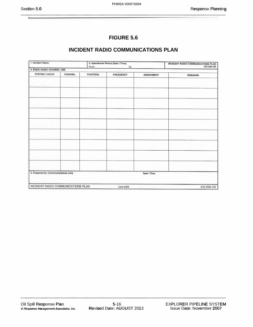
FIGURE 5.6
INCIDENT RADIO COMMUNICATIONS PLAN
0 o n ict e n gctio 5 0 espon Plann gSection 5.0 Response Planning___ __ __ ___ ___ __ _________ __________________________________________________________________________________________________
___ __ __ ___ ___ __ _________ __________________________________________________________________________________________________
l sp l Re Oil Spill Response P a a Plan 55- 16 E I E P R E N EMEXPLORER PIPELINE SYSTEM o a t s i on a A i © Response Management Associates, © Response Management Associates, . . Inc. Inc. e U U R se a T R se : Revised Date: AUGUST 1 2013 e 2 2 a ve r 2007Issue Date: November 2007
PHMSA 000015694

FIGURE 5.7
MEDICAL PLAN
0 o n ict e n gctio 5 0 espon Plann gSection 5.0 Response Planning___ __ __ ___ ___ __ _________ __________________________________________________________________________________________________
___ __ __ ___ ___ __ _________ __________________________________________________________________________________________________
l sp l Re Oil Spill Response P a a Plan 55- 17 E I E P R E N EMEXPLORER PIPELINE SYSTEM o a t s i on a A i © Response Management Associates, © Response Management Associates, . . Inc. Inc. e U U R se a T R se : Revised Date: AUGUST 1 2013 e 2 2 a ve r 2007Issue Date: November 2007
PHMSA 000015695

FIGURE 5.8
INCIDENT ORGANIZATION
0 o n ict e n gctio 5 0 espon Plann gSection 5.0 Response Planning___ __ __ ___ ___ __ _________ __________________________________________________________________________________________________
___ __ __ ___ ___ __ _________ __________________________________________________________________________________________________
l sp l Re Oil Spill Response P a a Plan 55- 18 E I E P R E N EMEXPLORER PIPELINE SYSTEM o a t s i on a A i © Response Management Associates, © Response Management Associates, . . Inc. Inc. e U U R se a T R se : Revised Date: AUGUST 1 2013 e 2 2 a ve r 2007Issue Date: November 2007
PHMSA 000015696

FIGURE 5.9
INCIDENT STATUS SUMMARY
0 o n ict e n gctio 5 0 espon Plann gSection 5.0 Response Planning___ __ __ ___ ___ __ _________ __________________________________________________________________________________________________
___ __ __ ___ ___ __ _________ __________________________________________________________________________________________________
l sp l Re Oil Spill Response P a a Plan 55- 19 E I E P R E N EMEXPLORER PIPELINE SYSTEM o a t s i on a A i © Response Management Associates, © Response Management Associates, . . Inc. Inc. e U U R se a T R se : Revised Date: AUGUST 1 2013 e 2 2 a ve r 2007Issue Date: November 2007
PHMSA 000015697

FIGURE 5.10
UNIT LOG
0 o n ict e n gctio 5 0 espon Plann gSection 5.0 Response Planning___ __ __ ___ ___ __ _________ __________________________________________________________________________________________________
___ __ __ ___ ___ __ _________ __________________________________________________________________________________________________
l sp l Re Oil Spill Response P a a Plan 55- 20 E I E P R E N EMEXPLORER PIPELINE SYSTEM o a t s i on a A i © Response Management Associates, © Response Management Associates, . . Inc. Inc. e U U R se a T R se : Revised Date: AUGUST 1 2013 e 2 2 a ve r 2007Issue Date: November 2007
PHMSA 000015698

UNIT LOG(Cont'd)
0 o n ict e n gctio 5 0 espon Plann gSection 5.0 Response Planning___ __ __ ___ ___ __ _________ __________________________________________________________________________________________________
___ __ __ ___ ___ __ _________ __________________________________________________________________________________________________
l sp l Re Oil Spill Response P a a Plan 55- 21 E I E P R E N EMEXPLORER PIPELINE SYSTEM o a t s i on a A i © Response Management Associates, © Response Management Associates, . . Inc. Inc. e U U R se a T R se : Revised Date: AUGUST 1 2013 e 2 2 a ve r 2007Issue Date: November 2007
PHMSA 000015699

FIGURE 5.11
0 o n ict e n gctio 5 0 espon Plann gSection 5.0 Response Planning___ __ __ ___ ___ __ _________ __________________________________________________________________________________________________
___ __ __ ___ ___ __ _________ __________________________________________________________________________________________________
l sp l Re Oil Spill Response P a a Plan 55- 22 E I E P R E N EMEXPLORER PIPELINE SYSTEM o a t s i on a A i © Response Management Associates, © Response Management Associates, . . Inc. Inc. e U U R se a T R se : Revised Date: AUGUST 1 2013 e 2 2 a ve r 2007Issue Date: November 2007
PHMSA 000015700
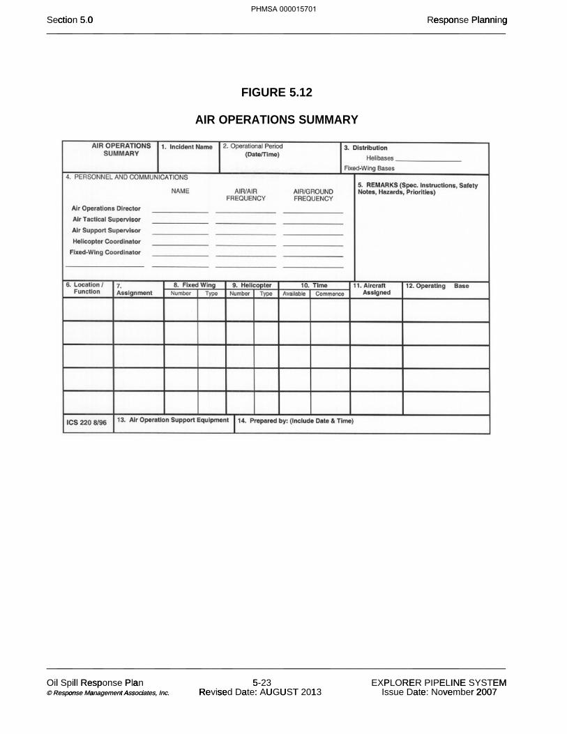
FIGURE 5.12
AIR OPERATIONS SUMMARY
0 o n ict e n gctio 5 0 espon Plann gSection 5.0 Response Planning___ __ __ ___ ___ __ _________ __________________________________________________________________________________________________
___ __ __ ___ ___ __ _________ __________________________________________________________________________________________________
l sp l Re Oil Spill Response P a a Plan 55- 23 E I E P R E N EMEXPLORER PIPELINE SYSTEM o a t s i on a A i © Response Management Associates, © Response Management Associates, . . Inc. Inc. e U U R se a T R se : Revised Date: AUGUST 1 2013 e 2 2 a ve r 2007Issue Date: November 2007
PHMSA 000015701
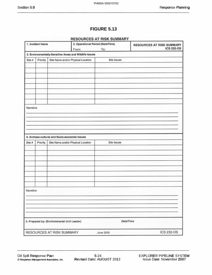
FIGURE 5.13
0 o n ict e n gctio 5 0 espon Plann gSection 5.0 Response Planning___ __ __ ___ ___ __ _________ __________________________________________________________________________________________________
___ __ __ ___ ___ __ _________ __________________________________________________________________________________________________
l sp l Re Oil Spill Response P a a Plan 55- 24 E I E P R E N EMEXPLORER PIPELINE SYSTEM o a t s i on a A i © Response Management Associates, © Response Management Associates, . . Inc. Inc. e U U R se a T R se : Revised Date: AUGUST 1 2013 e 2 2 a ve r 2007Issue Date: November 2007
PHMSA 000015702
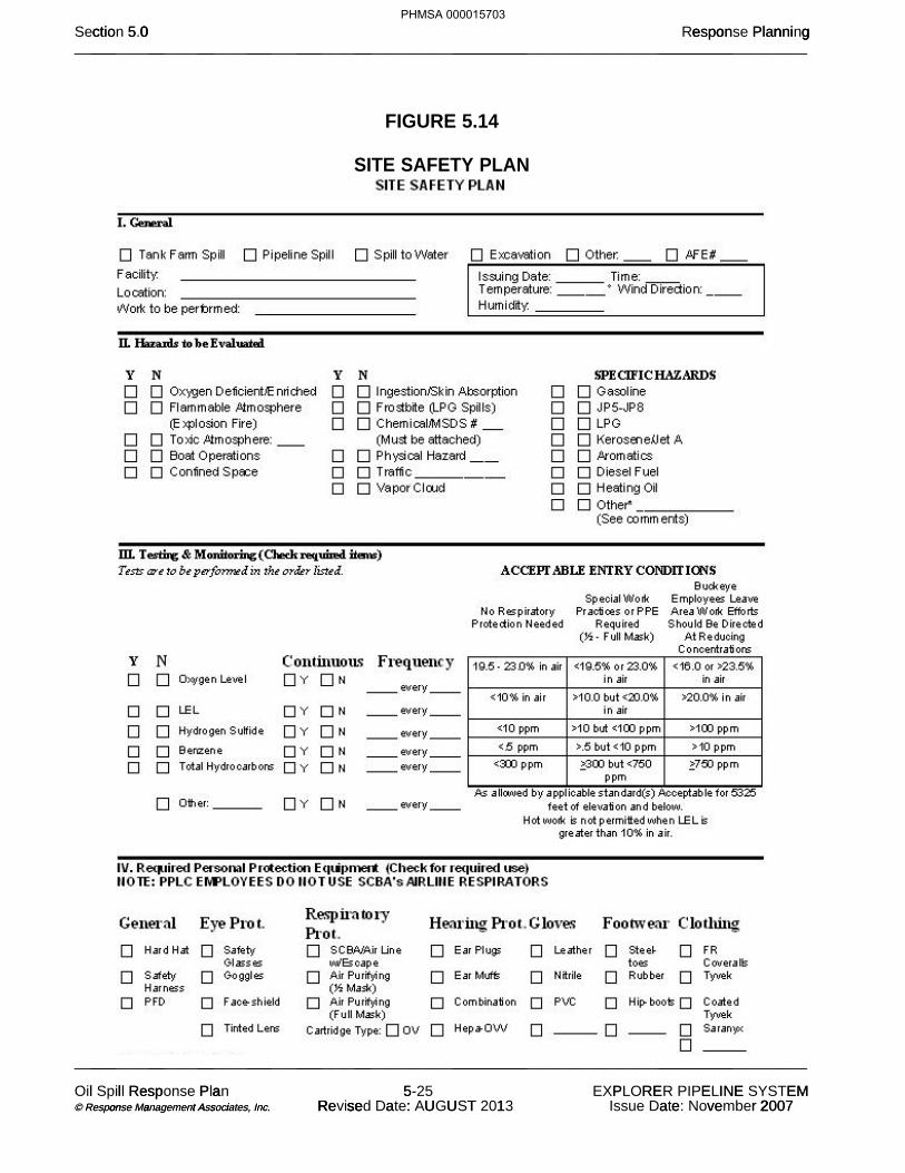
FIGURE 5.14
SITE SAFETY PLAN
0 o n ict e n gctio 5 0 espon Plann gSection 5.0 Response Planning___ __ __ ___ ___ __ _________ __________________________________________________________________________________________________
___ __ __ ___ ___ __ _________ __________________________________________________________________________________________________
l sp l Re Oil Spill Response P a a Plan 55- 25 E I E P R E N EMEXPLORER PIPELINE SYSTEM o a t s i on a A i © Response Management Associates, © Response Management Associates, . . Inc. Inc. e U U R se a T R se : Revised Date: AUGUST 1 2013 e 2 2 a ve r 2007Issue Date: November 2007
PHMSA 000015703

0 o n ict e n gctio 5 0 espon Plann gSection 5.0 Response Planning___ __ __ ___ ___ __ _________ __________________________________________________________________________________________________
___ __ __ ___ ___ __ _________ __________________________________________________________________________________________________
l sp l Re Oil Spill Response P a a Plan 55- 26 E I E P R E N EMEXPLORER PIPELINE SYSTEM o a t s i on a A i © Response Management Associates, © Response Management Associates, . . Inc. Inc. e U U R se a T R se : Revised Date: AUGUST 1 2013 e 2 2 a ve r 2007Issue Date: November 2007
PHMSA 000015704

0 o n ict e n gctio 5 0 espon Plann gSection 5.0 Response Planning___ __ __ ___ ___ __ _________ __________________________________________________________________________________________________
___ __ __ ___ ___ __ _________ __________________________________________________________________________________________________
l sp l Re Oil Spill Response P a a Plan 55- 27 E I E P R E N EMEXPLORER PIPELINE SYSTEM o a t s i on a A i © Response Management Associates, © Response Management Associates, . . Inc. Inc. e U U R se a T R se : Revised Date: AUGUST 1 2013 e 2 2 a ve r 2007Issue Date: November 2007
PHMSA 000015705

0 o n ict e n gctio 5 0 espon Plann gSection 5.0 Response Planning___ __ __ ___ ___ __ _________ __________________________________________________________________________________________________
___ __ __ ___ ___ __ _________ __________________________________________________________________________________________________
l sp l Re Oil Spill Response P a a Plan 55- 28 E I E P R E N EMEXPLORER PIPELINE SYSTEM o a t s i on a A i © Response Management Associates, © Response Management Associates, . . Inc. Inc. e U U R se a T R se : Revised Date: AUGUST 1 2013 e 2 2 a ve r 2007Issue Date: November 2007
PHMSA 000015706
TABLE OF CONTENTS 6.0 SPILL IMPACT CONSIDERATIONS 6.1 Critical Areas to Protect 6.2 Environmental/Socio-economic Sensitivities 6.3 Wildlife Protection and Rehabilitation 6.3.1 Wildlife Rescue 6.3.2 Search and Rescue - Points to Consider 6.4 Staging Areas
6.5 Containment and Recovery of Spilled Product6.5.1 Spill on Land6.5.2 Spill on Lake or Pond6.5.3 Spill on Small to Medium Size Streams6.5.4 Spill on Large Streams and Rivers6.5.5 Spill in Urban AreasFigure 6.1 On-Water Response Flowchart
6.6 Vulnerability Analysis 6.7 Alternative Response Strategies Figure 6.2 Environmental Sensitivity Maps
0 m a C act a ctio 6 0 pi n rati sSection 6.0 Spill Impact Considerations___ __ __ ___ ___ __ _________ __________________________________________________________________________________________________
___ __ __ ___ ___ __ _________ __________________________________________________________________________________________________
l sp l Re Oil Spill Response P a a Plan 66- 1 E L L L S TE I TEXPLORER PIPELINE SYSTEM o a t s i on a A i © Response Management Associates, © Response Management Associates, . . Inc. Inc. e U U R se a T R se : Revised Date: AUGUST 1 2013 e 2 2 a ve r 2007Issue Date: November 2007
PHMSA 000015707


6.2 ENVIRONMENTAL/SOCIO-ECONOMIC SENSITIVITIES (Cont'd) The environmental and socio-economic sensitivities in the vicinity of the Pipeline have been
broken down into specific categories and identified in this Section. To further clarify the location of the sensitive areas of concern references to published Area Contingency Plans and Environmental Sensitivity Maps are also provided in this section.
In addition, the following high consequence areas (HCA) are listed in the HCA segment report
0 m a C act a ctio 6 0 pi n rati sSection 6.0 Spill Impact Considerations___ __ __ ___ ___ __ _________ __________________________________________________________________________________________________
___ __ __ ___ ___ __ _________ __________________________________________________________________________________________________
l sp l Re Oil Spill Response P a a Plan 66- 3 E L L L S TE I TEXPLORER PIPELINE SYSTEM o a t s i on a A i © Response Management Associates, © Response Management Associates, . . Inc. Inc. e U U R se a T R se : Revised Date: AUGUST 1 2013 e 2 2 a ve r 2007Issue Date: November 2007
PHMSA 000015709
(b) (7)(F)

0 m a C act a ctio 6 0 pi n rati sSection 6.0 Spill Impact Considerations___ __ __ ___ ___ __ _________ __________________________________________________________________________________________________
l sp l Re Oil Spill Response P a a Plan 66- 4 E L L L S TE I TEXPLORER PIPELINE SYSTEM o a t s i on a A i © Response Management Associates, © Response Management Associates, . . Inc. Inc. e U U R se a T R se : Revised Date: AUGUST 1 2013 e 2 2 a ve r 2007Issue Date: November 2007
PHMSA 000015710
(b) (7)(F)


0 m a C act a ctio 6 0 pi n rati sSection 6.0 Spill Impact Considerations___ __ __ ___ ___ __ _________ __________________________________________________________________________________________________
o a t s i on a A i © Response Management Associates, © Response Management Associates, . . Inc. Inc. e U U R se a T R se : Revised Date: AUGUST 1 2013 e 2 2 a ve r 2007Issue Date: November 2007
PHMSA 000015712
(b) (7)(F)

0 m a C act a ctio 6 0 pi n rati sSection 6.0 Spill Impact Considerations___ __ __ ___ ___ __ _________ __________________________________________________________________________________________________
___ __ __ ___ ___ __ _________ __________________________________________________________________________________________________
l sp l Re Oil Spill Response P a a Plan 66- 7 E L L L S TE I TEXPLORER PIPELINE SYSTEM o a t s i on a A i © Response Management Associates, © Response Management Associates, . . Inc. Inc. e U U R se a T R se : Revised Date: AUGUST 1 2013 e 2 2 a ve r 2007Issue Date: November 2007
PHMSA 000015713
(b) (7)(F)

0 m a C act a ctio 6 0 pi n rati sSection 6.0 Spill Impact Considerations___ __ __ ___ ___ __ _________ __________________________________________________________________________________________________
___ __ __ ___ ___ __ _________ __________________________________________________________________________________________________
l sp l Re Oil Spill Response P a a Plan 66- 8 E L L L S TE I TEXPLORER PIPELINE SYSTEM o a t s i on a A i © Response Management Associates, © Response Management Associates, . . Inc. Inc. e U U R se a T R se : Revised Date: AUGUST 1 2013 e 2 2 a ve r 2007Issue Date: November 2007
PHMSA 000015714
(b) (7)(F)

0 m a C act a ctio 6 0 pi n rati sSection 6.0 Spill Impact Considerations
___ __ __ ___ ___ __ _________ __________________________________________________________________________________________________
l sp l Re Oil Spill Response P a a Plan 66- 9 E L L L S TE I TEXPLORER PIPELINE SYSTEM o a t s i on a A i © Response Management Associates, © Response Management Associates, . . Inc. Inc. e U U R se a T R se : Revised Date: AUGUST 1 2013 e 2 2 a ve r 2007Issue Date: November 2007
PHMSA 000015715
(b) (7)(F)

l sp l Re Oil Spill Response P a a Plan 66- 10 E I E P R E N EMEXPLORER PIPELINE SYSTEM o a t s i on a A i © Response Management Associates, © Response Management Associates, . . Inc. Inc. e U U R se a T R se : Revised Date: AUGUST 1 2013 e 2 2 a ve r 2007Issue Date: November 2007
PHMSA 000015716
(b) (7)(F)


0 m a C act a ctio 6 0 pi n rati sSection 6.0 Spill Impact Considerations___ __ __ ___ ___ __ _________ __________________________________________________________________________________________________
___ __ __ ___ ___ __ _________ __________________________________________________________________________________________________
l sp l Re Oil Spill Response P a a Plan 66- 12 E I E P R E N EMEXPLORER PIPELINE SYSTEM o a t s i on a A i © Response Management Associates, © Response Management Associates, . . Inc. Inc. e U U R se a T R se : Revised Date: AUGUST 1 2013 e 2 2 a ve r 2007Issue Date: November 2007
PHMSA 000015718
(b) (7)(F)

6.3 WILDLIFE PROTECTION AND REHABILITATION
The Company will work with Federal, State, and local agency personnel to provide labor and transportation to retrieve, clean, and rehabilitate birds and wildlife affected by an oil spill, as necessary. Oversight of the Company's wildlife preservation activities and coordination with Federal, State, and Local agencies during an oil spill is the responsibility of the Incident Commander. Special consideration should be given to the protection and rehabilitation of endangered species and other wildlife and their habitat in the event of an oil spill and subsequent response. Jurisdictional authorities should be notified and worked with closely on all response/clean-up actions related to wildlife protection and rehabilitation. Laws with significant penalties are in place to ensure appropriate protection of these species.
6.3.1 Wildlife Rescue
The Company will work with Federal, State, and Local agency personnel to provide labor
___ __ __ ___ ___ __ _________ __________________________________________________________________________________________________
l sp l Re Oil Spill Response P a a Plan 66- 13 E I E P R E N EMEXPLORER PIPELINE SYSTEM o a t s i on a A i © Response Management Associates, © Response Management Associates, . . Inc. Inc. e U U R se a T R se : Revised Date: AUGUST 1 2013 e 2 2 a ve r 2007Issue Date: November 2007
PHMSA 000015719
(b) (7)(F)

and transportation to retrieve, clean, and rehabilitate wildlife affected by an oil spill, as the situation demands. The following are items which should be considered for wildllife rescue and rehabilitation during a spill response:
Bird relocation can be accomplished using a variety of deterrents, encouraging birds to avoid areas of spilled oil. Bird relocation can be accomplished by utilizing deterrent methods including:
Use of visual stimuli, such as inflatable bodies, owls, stationary figures, or
helium balloons, etc. Use of auditory stimuli, such as propane cannons, recorded sounds, or shell
crackers. Use of herding with aircraft, boats, vehicles, or people (as appropriate). Use of capture and relocation.
6.3.2 Search and Rescue - Points to Consider
The Company's involvement should be limited to offering assistance as needed or requested by the agencies.
Prior to initiating any organized search and rescue plan, authorization must be
obtained from the appropriate federal/state agency.
0 m a C act a ctio 6 0 pi n rati sSection 6.0 Spill Impact Considerations___ __ __ ___ ___ __ _________ __________________________________________________________________________________________________
___ __ __ ___ ___ __ _________ __________________________________________________________________________________________________
l sp l Re Oil Spill Response P a a Plan 66- 14 E I E P R E N EMEXPLORER PIPELINE SYSTEM o a t s i on a A i © Response Management Associates, © Response Management Associates, . . Inc. Inc. e U U R se a T R se : Revised Date: AUGUST 1 2013 e 2 2 a ve r 2007Issue Date: November 2007
PHMSA 000015720

6.3 WILDLIFE PROTECTION AND REHABILITATION (Cont'd) 6.3.2 Search and Rescue - Points to Consider (Cont'd)
Initial search and rescue efforts, if needed, should be left up to the appropriate agencies. They have the personnel, equipment, and training to immediately begin capturing contaminated wildlife.
With or without authorization it must be anticipated that volunteer citizens will aid distressed/contaminated wildlife of their own. It is important to communicate that it may be illegal to handle wildlife without express authority from appropriate agencies. Provisions should be made to support an appropriate rehabilitator, however, no support should be given to any unauthorized volunteer rescue efforts.
The regulatory agencies and response personnel should be provided the name and location of a qualified rehabilitator in the event contaminated wildlife is captured.
Resources and contacts that can assist with wildlife rescue and rehabilitation are provided in Section 2.0. This list includes:
Outside rehabilitation organizations Local regulatory agencies Other resources
6.4 STAGING AREAS When establishing personnel and equipment staging areas for a response to a Pipeline discharge, the following criteria should be evaluated:
Access to waterborne equipment launching facilities and/or land equipment. Access to open space for staging/deployment of heavy equipment and personnel.
Access to public services utilities (electricity, potable water, public phone, restroom and washroom facilities, etc.).
Access to the environmental and socio-economically sensitive areas which are projected for impact.
0 m a C act a ctio 6 0 pi n rati sSection 6.0 Spill Impact Considerations___ __ __ ___ ___ __ _________ __________________________________________________________________________________________________
___ __ __ ___ ___ __ _________ __________________________________________________________________________________________________
l sp l Re Oil Spill Response P a a Plan 66- 15 E I E P R E N EMEXPLORER PIPELINE SYSTEM o a t s i on a A i © Response Management Associates, © Response Management Associates, . . Inc. Inc. e U U R se a T R se : Revised Date: AUGUST 1 2013 e 2 2 a ve r 2007Issue Date: November 2007
PHMSA 000015721

6.5 CONTAINMENT AND RECOVERY OF SPILLED PRODUCT
General descriptions of various specific response techniques that may be applied during a response effort are discussed below. The Company responders are free to use all or any combination of these methods as incident conditions require, provided they meet the agency approval, appropriate safety standards and other requirements relative to the situation encountered. Data was obtained from reports, manuals and pamphlets prepared by the American Petroleum Institute, Environmental Protection Agency and the United States Coast Guard. The most effective cleanup of a product spill will result from an integrated combination of clean-up methods. Each operation should complement and assist related operations and not merely transfer spillage problems to areas where they could be more difficult to handle.
The spill should be assessed as soon as possible to determine the source, extent and location of travel. Terrain and other physical conditions downgradient of the spill site will determine the methods of control at a point in advance of the moving product. Often, the bulk of a spill can be contained at a single location or a few key locations in the immediate vicinity of the source point. When possible, the execution of this type of initial containment strategy helps confine a spill to a relatively limited area.
6.5.1 Spill on Land (Soil Surfaces)
Confinement Methods
Product can be trapped in ditches and gullies by earth dams. Where excavating machinery is available, dams can be bulldozed to contain lakes of product. Dams, small and large, should be effectively employed to protect priority areas such as inlets to drains, sewers, ducts and watercourses. These can be constructed of earth, sandbags, absorbents, planks or any other effective method. If time does not permit a large dam, many small ones can be made, each one holding a portion of the spill as it advances. The terrain will dictate the placement of the dams. If the spill is minor, natural dams or earth absorption will usually stop the product before it advances a significant distance. Cleanup is the main concern in such situations. In situations where vapors from a spill present a clear and present danger to property or life (possible ignition because of passing automobiles, nearby houses, or work vehicles approaching the area), spraying the surface of the spill with dispersant will greatly reduce the release of additional vapors from the product. This method is especially adapted to gasoline spills on soil surfaces.
Removal Methods
The recovery and removal of free product from soil surfaces is a difficult job. The best approaches at present seem to be:
Removal with suction equipment to tank truck if concentrated in volumes
large enough to be picked up. Channels can be formed to drain pools of product into storage pits. The suction equipment can then be used.
0 m a C act a ctio 6 0 pi n rati sSection 6.0 Spill Impact Considerations___ __ __ ___ ___ __ _________ __________________________________________________________________________________________________
___ __ __ ___ ___ __ _________ __________________________________________________________________________________________________
l sp l Re Oil Spill Response P a a Plan 66- 16 E I E P R E N EMEXPLORER PIPELINE SYSTEM o a t s i on a A i © Response Management Associates, © Response Management Associates, . . Inc. Inc. e U U R se a T R se : Revised Date: AUGUST 1 2013 e 2 2 a ve r 2007Issue Date: November 2007
PHMSA 000015722
6.5 CONTAINMENT AND RECOVERY OF SPILLED PRODUCT (Cont'd)
6.5.1 Spill on Land (Soil Surfaces)
Removal Methods (Cont'd)
Small pockets may have to be dipped up by hand.
If practicable after removal of the bulk of the spill, controlled burning presents the possibility of a fast, simple, and inexpensive method of destruction of the remainder of the product. If all other options have been executed and the site is still unsafe for further activity because explosive vapors persist, the vapors may need to be intentionally ignited to prevent an accumulation sufficient to become an explosive mixture, provided the other requirements of these guidelines for controlled burning are met.
Intentional ignition to remove released product should be utilized only if all of the following conditions are met:
Other steps and procedures have been executed and a determination has been made that this is the safest remaining method of control.
Intentional burning will not unduly damage pipelines, adjacent property, or the environment.
Controlled burning is permitted by government authorities. Local government authorities to be contacted may include city council, county board of commissioners, city or county fire chiefs, the county forestry commission or fire tower, and the local environmental protection agency. In seeking permission from these authorities, be prepared to convince them that adequate safety precautions have been and will be taken during the operation.
Controlled burning is conducted with the consent of local land owners.
Safety must always be a prime consideration when considering controlled burning of product. Sparks and heat radiation from large fires can start secondary fires and strong winds make fire control difficult. There must be no danger of the fire spreading beyond control limits. All persons must be at a safe distance from the edge of the inflammable area. Remember that all burning must be controlled burning.
0 m a C act a ctio 6 0 pi n rati sSection 6.0 Spill Impact Considerations___ __ __ ___ ___ __ _________ __________________________________________________________________________________________________
___ __ __ ___ ___ __ _________ __________________________________________________________________________________________________
l sp l Re Oil Spill Response P a a Plan 66- 17 E I E P R E N EMEXPLORER PIPELINE SYSTEM o a t s i on a A i © Response Management Associates, © Response Management Associates, . . Inc. Inc. e U U R se a T R se : Revised Date: AUGUST 1 2013 e 2 2 a ve r 2007Issue Date: November 2007
PHMSA 000015723

6.5 CONTAINMENT AND RECOVERY OF SPILLED PRODUCT (Cont'd)
6.5.2 Spill on Lake or Pond (Calm or Slow-Moving Water)
Confinement Methods
A lake or pond offers the best conditions for removal of product from water. Although the removal is no easy task, the lake or pond presents the favorable conditions of low or no current and low or no waves. The movement of product on a lake or pond is influenced mainly by wind. The product will tend to concentrate on one shore, bank or inlet. Booms should be set up immediately to hold the product in the confined area in the event of a change in wind direction. If the spill does not concentrate itself on or near a shore (no wind effect), then a sweeping action using boats and floating booms will be necessary. The essential requirement for this operation is that it be done very slowly. The booms should be moved at not more than 40 feet per minute. Once the slick is moved to a more convenient location (near shore), the normal operations of removal should begin. If the slick is small and thin (rainbow effect) and not near the shoreline, an absorbent boom instead of a regular boom should be used to sweep the area very slowly and absorb the slick. The product may not have to be moved to the shoreline.
Removal Methods
If the confined slick is thick enough, regular suction equipment may be used first; however, in most instances, a floating skimmer should be used. If the floating skimmer starts picking up excess water (slick becomes thin), drawing the boom closer to the bank as product is removed will also keep film of product thicker. However, when the slick becomes too thin, the skimmer should be stopped and an absorbent applied (with a boat if necessary) to remove the final amounts. The floating skimmer (if speed is a must) or hand skimmers (if water is shallow enough) or both can be used to pick up the product-soaked absorbent. Before pumping the product-soaked absorbent with a floating skimmer, ensure that the absorbent in question can be pumped and will not harm the pump. Several types are nonabrasive to pump internals. If the floating skimmer is used first, the product-soaked absorbent/water mixture should be pumped into a tank truck. A better method of retrieving the product-soaked absorbent is to draw it in as close to the shore as possible with the booms used to confine the product initially. The absorbent can then be hand skimmed from the water surface and placed in drums, on plastic sheets or in lined roll-off boxes. It should then be disposed of by acceptable means.
0 m a C act a ctio 6 0 pi n rati sSection 6.0 Spill Impact Considerations___ __ __ ___ ___ __ _________ __________________________________________________________________________________________________
___ __ __ ___ ___ __ _________ __________________________________________________________________________________________________
l sp l Re Oil Spill Response P a a Plan 66- 18 E I E P R E N EMEXPLORER PIPELINE SYSTEM o a t s i on a A i © Response Management Associates, © Response Management Associates, . . Inc. Inc. e U U R se a T R se : Revised Date: AUGUST 1 2013 e 2 2 a ve r 2007Issue Date: November 2007
PHMSA 000015724

6.5 CONTAINMENT AND RECOVERY OF SPILLED PRODUCT (Cont'd)
6.5.2 Spill on Lake or Pond (Calm or Slow-Moving Water) (Cont'd)
Removal Methods (Cont'd)
The final rainbow on the surface can be removed with additions of more absorbent.
6.5.3 Spill on Small to Medium Size Streams (Fast-Flowing Creeks)
Confinement Methods
The techniques used for product containment on fast-flowing shallow streams are quite different from the ones used on lakes, ponds, or other still bodies of water. The containment and removal processes require a calm stretch of water to allow the product to separate onto the surface of the water. If a calm stretch of water does not exist naturally, a deep slow-moving area should be created by damming. The dam can be constructed by using sandbags, planks or earth. If a dam is required, it should be situated at an accessible point where the stream has high enough banks. The dam should be constructed soundly and reinforced to support the product and water pressure.
Underflow dam - The underflow dam is one method that can be used, especially on small creeks. The water is released at the bottom, of the dam using a pipe or pipes which are laid during construction of the dam. The flow rate through the pipe must be sufficient to keep the dam from overflowing. One method is to lay the pipe at an angle through the dam (while dam is being constructed) so that the height of the downstream end of the pipe will determine the height the water will rise behind the dam.
Overflow dam – Another method of containment is the overflow type dam. The dam is constructed so that water flows over the dam, but a deep pool is created which slows the surface velocity of the water. Therefore, the condition of a calm stretch of water is met. The overflow dam may be used where larger flow rates (medium size creeks) of water are involved. With this type dam, a separate barrier (floating or stationary boom) must be placed across the pool created by the dam. The separate barrier arrests the surface layer of product. At the same time, the water is flowing under the barrier and over the top of the dam. The barrier should be placed at an angle of 45 % across the pool to decrease the effective water velocity beneath it. Also, it helps to concentrate the product at the bank and not all along the barrier. A second barrier should be placed approximately 10 to 15 feet downstream of the first one as a secondary back-up.
0 m a C act a ctio 6 0 pi n rati sSection 6.0 Spill Impact Considerations___ __ __ ___ ___ __ _________ __________________________________________________________________________________________________
___ __ __ ___ ___ __ _________ __________________________________________________________________________________________________
l sp l Re Oil Spill Response P a a Plan 66- 19 E I E P R E N EMEXPLORER PIPELINE SYSTEM o a t s i on a A i © Response Management Associates, © Response Management Associates, . . Inc. Inc. e U U R se a T R se : Revised Date: AUGUST 1 2013 e 2 2 a ve r 2007Issue Date: November 2007
PHMSA 000015725

6.5 CONTAINMENT AND RECOVERY OF SPILLED PRODUCT (Cont'd)
6.5.3 Spill on Small to Medium Size Streams (Fast-Flowing Creeks) (Cont'd)
Confinement Methods (Cont'd)
The stationary boom type barrier should be made of wood planks or other suitable material. The stationary boom should be soundly constructed and sealed against the bank. The ends of the planks can be buried in the banks of the stream and timber stakes driven into the stream bed for support as needed. The necessary length of the boom will be approximately 1-1/2 times the width of the waterway. The plank boom should extend six to eight inches deep into the water and about two inches or higher above the water level. If the increase in velocity under the stationary boom is causing release of trapped product, it should be moved upward slightly. At no time should barrier be immersed more than 20% of the depth of the pool at the barrier location; that is, if the pool created by damming is three feet deep, do not exceed an immersion depth of seven inches with the barrier at the position the barrier is installed. Another method used with the underflow dam is having the pipe or pipes sized to carry only a portion of the flow needed. The pipe would be placed at the bottom of the dam and level with the creek bed. The remaining flow of the creek could be siphoned or preferably pumped around the dam from a point away from the dam and from the deepest portion of the pool. The pumping or siphoning can be controlled to maintain the desired water level at the dam. The key is the removal of water through or around the dam at the lowest point in the basin. This prevents the oil from escaping with the released water. A floating boom can be used in place of the stationary type if the created pool’s size (bank to bank) and depth will permit. Since changing the depth and/or length of a standard floating boom in a small stream is difficult, the use of the separation of product and water. The advantages of using a floating boom are the speed of deployment and the fact that there is no need for additional support as with the stationary boom.
Multiple Impoundments since emergency built dams (either underflow or overflow) are seldom perfect, a series of dams is usually required. The first one or two will trap the bulk and the ones that are downstream will trap the last traces of product. Precautions should be taken to ensure that the foundations of emergency dams are not washed away by the released water. If earth is used to construct an overflow dam, a layer of earth-filled bags should be placed on top of the dam so erosion will not take place.
0 m a C act a ctio 6 0 pi n rati sSection 6.0 Spill Impact Considerations___ __ __ ___ ___ __ _________ __________________________________________________________________________________________________
___ __ __ ___ ___ __ _________ __________________________________________________________________________________________________
l sp l Re Oil Spill Response P a a Plan 66- 20 E I E P R E N EMEXPLORER PIPELINE SYSTEM o a t s i on a A i © Response Management Associates, © Response Management Associates, . . Inc. Inc. e U U R se a T R se : Revised Date: AUGUST 1 2013 e 2 2 a ve r 2007Issue Date: November 2007
PHMSA 000015726

6.5 CONTAINMENT AND RECOVERY OF SPILLED PRODUCT (Cont'd)
6.5.3 Spill on Small to Medium Size Streams (Fast-Flowing Creeks) (Cont'd)
Removal Methods
Once the containment dams are constructed, the problem or removal of the product from the water surface should be the prime consideration. The removal must be continuous or else build-up of product behind the dams or booms might lead to product escaping the traps. The type of removal procedures used depends largely on the amount of product being trapped in a given span of time, if the amount of product moving down the stream is of sufficient quantity, the first dam or fixed boom would quite possibly trap enough for the floating skimmer to work efficiently. The skimmer will pump the product and possibly some water to a tank truck or other holding tank. Separated water may be released from the bottom of the tank truck if it becomes necessary. The absorbents could then be used at downstream dams or booms. It is inadvisable to place an absorbent in the stream prior to or at the first dam in anticipation of the arriving product. Let the product accumulate at the first dam and use the floating skimmer to recover the product. Disposal of gross amount of product-soaked absorbent would not then be a problem. Follow directions on use of each absorbent. Some are designed to be placed on water before product arrives; others are intended only to be placed on the product after it accumulates on the water. Plastic sheets should be used to place the product- soaked absorbent on as it is hand skimmed from the water. Alternatively, the material may be placed in drums or lined roll-off boxes. The containment and removal of spilled product on small to medium fast-flowing streams might require a combination of underflow or overflow dams, fixed booms, skimmers, and absorbents, to ensure a complete cleanup.
6.5.4 Spill on Large Streams and Rivers
Confinement Methods
The containment techniques differ considerably on large streams and rivers versus small streams. First, the smooth calm area of water necessary for product-water separation must be found along the stream or river rather than making one as with small streams. Floating booms (rather than fixed booms or dams) must be used to trap the surfaced product. Local conditions of current and wind must be considered when selecting the site for the boom. A point with a low water velocity near the bank, sufficient depth to operate the product removal equipment, and good access are required. The fact that wind may tend to concentrate the product against one bank must be considered. A smooth, undisturbed area of water is required immediately upstream of the boom to
0 m a C act a ctio 6 0 pi n rati sSection 6.0 Spill Impact Considerations___ __ __ ___ ___ __ _________ __________________________________________________________________________________________________
___ __ __ ___ ___ __ _________ __________________________________________________________________________________________________
l sp l Re Oil Spill Response P a a Plan 66- 21 E I E P R E N EMEXPLORER PIPELINE SYSTEM o a t s i on a A i © Response Management Associates, © Response Management Associates, . . Inc. Inc. e U U R se a T R se : Revised Date: AUGUST 1 2013 e 2 2 a ve r 2007Issue Date: November 2007
PHMSA 000015727

6.5 CONTAINMENT AND RECOVERY OF SPILLED PRODUCT (Cont'd)
6.5.4 Spill on Large Streams and Rivers (Cont'd)
Confinement Methods (Cont'd)
ensure that the product has opportunity to separate out onto the surface. The boom should be positioned where the current is at a minimum. It is more effective to boom at a wide, slow position than on a narrow, fast stretch of water. If the boom are positioned straight across a river or stream, at right angles to the flow, surface water tends to dive beneath the barrier (boom) when current velocities exceed about ½ knot (0.8 ft./sec.). However, if the current of the entire river is ½ knot or less, then a boom can be positioned straight across the river or large stream, but angled slightly in relation of the banks. By placing the boom at an angle to the banks, product on the surface is diverted along the boom to the side of the river. The current velocity is usually much slower near the river bank than in the center and the product will move along the boom toward the bank for removal. A water-tight seal between the bank and the boom is essential. A secondary boom should be set up immediately downstream of the first one to capture the amounts that escape the upstream boom. A boom can be employed parallel to the river flow at the bank to form the seal with the booms used to trap the product. Where the current velocity of the chosen site exceeds ½ knot, the boom should be positioned in two smooth curves from a point of maximum velocity (usually the center of the river) to both banks. However, this double-boom required product to be removed from both sides of the river. To determine the appropriate angle of boom placement and support (mooring) needed to hold the booms in position, the current velocity should be measured by timing a floating object which is 80% submerged over a distance of 100 feet. A time of 60 seconds over this distance indicates a water current of approximately 1 knot. For currents from 1 to 2.5 knots (1.7 to 4.2 ft./sec.), the more the boom will have to be angled acute to the bank. The length of the boom will have to be such to reach the center of the river. For currents between ½ and 1 knot (0.8 and 1.7 ft./sec.), the angle of employment can be enlarged. The major load on the boom is taken by the terminal moorings, particularly the one in the center of the river. However, intermediate moorings are also required both to maintain the smooth curve of the boom to prevent breaking of the boom and to assist with preventing skirt deflection. The intermediate moorings are preferably positioned every 25 feet and must be adjusted to avoid the formation of indentations in the boom
0 m a C act a ctio 6 0 pi n rati sSection 6.0 Spill Impact Considerations___ __ __ ___ ___ __ _________ __________________________________________________________________________________________________
___ __ __ ___ ___ __ _________ __________________________________________________________________________________________________
l sp l Re Oil Spill Response P a a Plan 66- 22 E I E P R E N EMEXPLORER PIPELINE SYSTEM o a t s i on a A i © Response Management Associates, © Response Management Associates, . . Inc. Inc. e U U R se a T R se : Revised Date: AUGUST 1 2013 e 2 2 a ve r 2007Issue Date: November 2007
PHMSA 000015728

6.5 CONTAINMENT AND RECOVERY OF SPILLED PRODUCT (Cont'd)
6.5.4 Spill on Large Streams and Rivers (Cont'd)
Confinement Methods (Cont'd)
profile. These trap product in pockets, prevent its deflection to the bank, and also encourage diving currents. The moorings’ ropes should be five times the water depth. In certain situations, it might be advantageous to position booms to deflect the approaching spilled product to a slower moving area. Naturally, additional booms would have to be positioned around this slower moving area prior to deflecting the product to the area. This approach has been used along rivers which have lagoons, etc., with a very low current action. The recovery would take place in the lagoons and not along the river bank.
Removal Methods
The product collected upstream of the floating booms in a large stream or river should be removed from the water surface as it accumulates. Regular suction equipment, a floating skimmer, and/or absorbents (including absorbent booms) should be used to remove the product as appropriate to the quantity being trapped in a given span of time. If the amount moving down the stream is of sufficient quantity, the primary floating boom would possibly trap enough for the floating skimmer to work efficiently. The skimmer will pump the product and some water to a tank truck or other holding tank. The absorbents would then be used upstream of the secondary boom to absorb the underflow from the primary boom. An absorbent boom can also be placed between the primary and secondary booms to help the other absorbents control the underflow from the primary boom. It is best to hand skim the saturated absorbents and place on plastic sheets. However, if the absorbent used can be pumped after product absorption and speed of removal is a necessity, the floating skimmer can be used to remove the product-soaked absorbent. The disadvantage of pumping the product-soaked absorbent to a truck is the volume that will accumulate (skimmer will pump excess water) and the disposal problems associated with the large water/product-soaked absorbent mixture. Spill on Stream which Flows into Lake or Pond In certain locations where streams (small and large ones) flow into lakes or ponds at relatively short distances, it is conceivable that a spill could reach the lake before containment and recovery operations are set up. If time permits for containment operations to be set up on the stream in question, it then would be handled as
0 m a C act a ctio 6 0 pi n rati sSection 6.0 Spill Impact Considerations___ __ __ ___ ___ __ _________ __________________________________________________________________________________________________
___ __ __ ___ ___ __ _________ __________________________________________________________________________________________________
l sp l Re Oil Spill Response P a a Plan 66- 23 E I E P R E N EMEXPLORER PIPELINE SYSTEM o a t s i on a A i © Response Management Associates, © Response Management Associates, . . Inc. Inc. e U U R se a T R se : Revised Date: AUGUST 1 2013 e 2 2 a ve r 2007Issue Date: November 2007
PHMSA 000015729

6.5 CONTAINMENT AND RECOVERY OF SPILLED PRODUCT (Cont'd)
6.5.4 Spill on Large Streams and Rivers (Cont'd)
described above depending upon the stream size involved. However, if product in the stream is near the lake site or if product is flowing into the lake with a significant amount yet to arrive, a different containment should be employed.
Confinement Methods Product on a stream flowing into a lake should be boomed as close to the entrance as possible. The boom should be positioned on the lake at an angle to the residential stream current so as to direct the surface water to a slower moving area. The area where the product is being deflected should be enclosed by booms to contain it. An additional boom for sweeping the product to the bank will be required. This area of containment should not have a current velocity of more than 1/2 knot (0.8 ft./sec.), preferably less.
Removal Methods The removal of product from the lake or pond’s surface would be handled as described earlier. For sizable releases, collected product will usually be pumped into tank trucks and transported to a storage facility. Tank trucks are available at several locations throughout.
6.5.5 Spill in Urban Area
Oil spills in urban areas can greatly impact recreational use, human health, wildlife habitat(s), and potential beach or park closures. Manmade structures along waterways require unique protection strategies. Manmade structures could include vertical shore protection structures such as seawalls, piers, and bulkheads, as well as riprap revetments and groins, breakwaters, and jetties. Vertical structures can be constructed of concrete, wood, and corrugated metal. They usually extend below the water surface, although seawalls can have beaches or riprap in front of them. These structures are very common along developed shores, particularly in harbors, marinas, and residential areas. The range in degree of exposure to waves and currents varies widely, from very low in dead-end canals, to very high on offshore breakwaters. Boat wakes can generate wave energy in otherwise sheltered areas. Maintaining shipping or other kinds of vessel traffic through navigation channels or waterways during a spill response is a difficult consideration because there is usually economic and political pressure to re-establish normal operations as soon as possible. This consideration extends to vehicular traffic through urban areas. Deploying booms and
0 m a C act a ctio 6 0 pi n rati sSection 6.0 Spill Impact Considerations___ __ __ ___ ___ __ _________ __________________________________________________________________________________________________
___ __ __ ___ ___ __ _________ __________________________________________________________________________________________________
l sp l Re Oil Spill Response P a a Plan 66- 24 E I E P R E N EMEXPLORER PIPELINE SYSTEM o a t s i on a A i © Response Management Associates, © Response Management Associates, . . Inc. Inc. e U U R se a T R se : Revised Date: AUGUST 1 2013 e 2 2 a ve r 2007Issue Date: November 2007
PHMSA 000015730

6.5 CONTAINMENT AND RECOVERY OF SPILLED PRODUCT (Cont'd)
6.5.5 Spill in Urban Area (Cont'd)
skimmers or constructing recovery sites can conflict with such traffic for several days. Also, passage of deep-draft vessels through the waterway can suddenly change water level and flow or create wakes, causing booms to fail. For these reasons, recovery efforts must be coordinated through the Unified Command to ensure the cooperation of all parties involved.
Note: All facility response personnel have been informed that detergents or other surfactants are prohibited for use on water and that dispersants can only be used with the approval of the Regional Response Team and TX TGLO.
0 m a C act a ctio 6 0 pi n rati sSection 6.0 Spill Impact Considerations___ __ __ ___ ___ __ _________ __________________________________________________________________________________________________
___ __ __ ___ ___ __ _________ __________________________________________________________________________________________________
l sp l Re Oil Spill Response P a a Plan 66- 25 E I E P R E N EMEXPLORER PIPELINE SYSTEM o a t s i on a A i © Response Management Associates, © Response Management Associates, . . Inc. Inc. e U U R se a T R se : Revised Date: AUGUST 1 2013 e 2 2 a ve r 2007Issue Date: November 2007
PHMSA 000015731

FIGURE 6.1
ON-WATER RESPONSE FLOWCHART
0 m a C act a ctio 6 0 pi n rati sSection 6.0 Spill Impact Considerations___ __ __ ___ ___ __ _________ __________________________________________________________________________________________________
___ __ __ ___ ___ __ _________ __________________________________________________________________________________________________
l sp l Re Oil Spill Response P a a Plan 66- 26 E I E P R E N EMEXPLORER PIPELINE SYSTEM o a t s i on a A i © Response Management Associates, © Response Management Associates, . . Inc. Inc. e U U R se a T R se : Revised Date: AUGUST 1 2013 e 2 2 a ve r 2007Issue Date: November 2007
PHMSA 000015732

6.6 VULNERABILITY ANALYSIS
The thorough examination of published Area Contingency Plans (ACPs) was conducted to identify sensitive areas in all the response zones. The Environmental Sensitivity Maps located in Figure 6.2 identify sensitive areas along the pipeline. The appropriate Area Contingency Plan maps are also included to provide more detailed information on sensitivities and possible potential response options.
6.7 ALTERNATIVE RESPONSE STRATEGIES
There are no pre-approved response options for inland spills within the United States. Any plans to use dispersants or in situ burn by the Company will be submitted to the Federal On-Scene Coordinator for Regional Response Team approval prior to such action being taken.
0 m a C act a ctio 6 0 pi n rati sSection 6.0 Spill Impact Considerations___ __ __ ___ ___ __ _________ __________________________________________________________________________________________________
___ __ __ ___ ___ __ _________ __________________________________________________________________________________________________
l sp l Re Oil Spill Response P a a Plan 66- 27 E I E P R E N EMEXPLORER PIPELINE SYSTEM o a t s i on a A i © Response Management Associates, © Response Management Associates, . . Inc. Inc. e U U R se a T R se : Revised Date: AUGUST 1 2013 e 2 2 a ve r 2007Issue Date: November 2007
PHMSA 000015733

0 m a C act a ctio 6 0 pi n rati sSection 6.0 Spill Impact Considerations___ __ __ ___ ___ __ _________ __________________________________________________________________________________________________
___ __ __ ___ ___ __ _________ __________________________________________________________________________________________________
l sp l Re Oil Spill Response P a a Plan 66- 28 E I E P R E N EMEXPLORER PIPELINE SYSTEM o a t s i on a A i © Response Management Associates, © Response Management Associates, . . Inc. Inc. e U U R se a T R se : Revised Date: AUGUST 1 2013 e 2 2 a ve r 2007Issue Date: November 2007
PHMSA 000015734


Maps and detailed tables have been redacted in accordance with the Freedom of Information Act exemption 7f.
PHMSA 000015736

A RESPONSE RESOURCES A.1 Company Owned Response Equipment A.2 Other Company Resources A.3 Contract Resources A.4 Cooperative/Mutual Aid Resources A.5 Experts and Consultants A.6 Volunteers A.7 Communications Figure A.1 Company Owned Spill Response Equipment Figure A.2 Contracted Response Resources Figure A.3 Revised USCG OSRO Classifications Figure A.4 OSRO Contracts
i A u cep n R e cep dix nse esourcesAppendix A Response Resources___ __ __ ___ ___ __ _________ __________________________________________________________________________________________________
___ __ __ ___ ___ __ _________ __________________________________________________________________________________________________
l sp l Re Oil Spill Response P a a Plan A- 1 1 L L S TE I TL L EXPLORER PIPELINE SYSTEM o a t s i on a A i © Response Management Associates, © Response Management Associates, . . Inc. Inc. e U U R se a T R se : Revised Date: AUGUST 1 2013 e 2 2 a ve r 2007Issue Date: November 2007
PHMSA 000015737

RESPONSE EQUIPMENT / RESOURCES The following sections outline the various response equipment/resources available along the Pipeline, other Company facilities, Oil Spill Removal Organizations, and other outside resources.
A.1 COMPANY RESPONSE EQUIPMENT
Company owned spill response equipment is staged at the major tank farms which are located at Port Arthur, Houston, Greenville, Glenpool, Wood River and Hammond. This equipment is maintained according to manufacturer’s recommendations by Company personnel. An equipment summary detailing locations, type and amount stored in response trailers and other miscellaneous spill locations is listed in Figure A.1. The Company also has contracts in place with Oil Spill Removal Organizations and other clean-up contractors that are capable of responding to all discharges along the Pipeline. Figure A.2 lists the contracted Oil Spill Removal Organizations. The Qualified Individual has the authority to activate other Company resources or that of private contractors and other experts and consultants as the situation demands. All Pipeline personnel who might be involved in an oil spill have been informed that detergents or other surfactants are prohibited from being used on an oil spill in the water and that dispersants can only be used with the approval of the Regional Response Team, the interagency group composed of federal and state agency representatives that coordinates oil spill response.
A.2 OTHER COMPANY RESOURCES
Additional Company spill response equipment and manpower resources are not available to supplement the response operation, however third party contractors will be activated on an as needed basis.
A.3 CONTRACT RESOURCES
In the event of a discharge which is beyond the initial response capabilities of the Local Response Team, contract manpower and equipment resources can be obtained through Oil Spill Removal Organization(s) (OSRO). These OSROs can provide manpower and containment/clean-up equipment for the response operation.
The resources will be secured from a Company approved contractor. Area Management will typically handle notification/implementation of these resources. Figure A.2 provides a quick reference to the Oil Spill Removal Organizations and details their response capability and estimated response times. Telephone reference is provided in Figure 2.5. (Note: The Company will ensure that each OSRO has a comprehensive maintenance program and applicable training / drills programs in place at contract renewal.)
A.4 COOPERATIVE/MUTUAL AID RESOURCES The Company is a member of the Sabine Chiefs Association.
i A u cep n R e cep dix nse esourcesAppendix A Response Resources___ __ __ ___ ___ __ _________ __________________________________________________________________________________________________
___ __ __ ___ ___ __ _________ __________________________________________________________________________________________________
l sp l Re Oil Spill Response P a a Plan A- 2 2 L L S TE I TL L EXPLORER PIPELINE SYSTEM o a t s i on a A i © Response Management Associates, © Response Management Associates, . . Inc. Inc. e U U R se a T R se : Revised Date: AUGUST 1 2013 e 2 2 a ve r 2007Issue Date: November 2007
PHMSA 000015738

A.5 EXPERTS AND CONSULTANTS
The Company maintains a relationship with various environmental and technical consultants that can provide support in the event of an emergency incident. These consultants can provide expertise and support in the areas of emergency response management, environmental services, site assessment, permitting, waste treatment, recycling, dewatering, hazardous waste disposal, and remediation.
A.6 VOLUNTEERS
Volunteers will not be utilized by the Company for the response operations. All volunteers will be referred to the Federal Regional Response Team.
A.7 COMMUNICATIONS
Effective and efficient communications systems are essential for emergency response at every level. The communications system will be utilized to gather information and current status reports as well as to provide coordination and direction to widely separated work groups involved in search, containment/diversion, repair, traffic control, public control or evacuation, and restoration.
Lines of communication between the Incident Commander, Local Response Team and Company Emergency Response Team members are demonstrated in the organization charts provided in Figures 4.1 and 4.2. Communication of the overall spill response operation between the Company and the responsible government agencies in the Federal Regional Response Team (RRT) will occur between the Incident Commander and the Federal On-Scene Coordinator.
A.7.1 Central Communications System
Prearranged communication channels are of the utmost importance in dealing with Company emergencies. The notification procedures and telephone contacts documented in Section 2.0 will be reviewed in accordance with the earlier documented updating procedures. The predetermined communications channels include the following:
A list of emergency telephone numbers for internal management and emergency response personnel (Figures 2.2 and 2.5).
A list of emergency telephone numbers for various external resources such as the fire and police department, medical, and regulatory agencies (Figure 2.5).
A list of emergency telephone numbers for contract (Figure 2.5).
i A u cep n R e cep dix nse esourcesAppendix A Response Resources___ __ __ ___ ___ __ _________ __________________________________________________________________________________________________
___ __ __ ___ ___ __ _________ __________________________________________________________________________________________________
l sp l Re Oil Spill Response P a a Plan A- 3 3 L L S TE I TL L EXPLORER PIPELINE SYSTEM o a t s i on a A i © Response Management Associates, © Response Management Associates, . . Inc. Inc. e U U R se a T R se : Revised Date: AUGUST 1 2013 e 2 2 a ve r 2007Issue Date: November 2007
PHMSA 000015739

A.7 COMMUNICATIONS(Cont'd) A.7.2 Communications Equipment
Field communications during a spill response to a small or medium discharge will be handled via the existing Company communications network. This network will utilize existing radios, telephones, cellular phones, fax machines, and computers and will be maintained by Company personnel. In the event of a Worst Case Discharge, field communications will be enhanced with other Company and contract resources as the situation demands.
A.7.3 Tulsa Phone System for ICS/Incident Management Room
Explorer Pipeline's phone system takes advantage of our existing data network to carry voice traffic.
The system has redundancy at several levels to provide reliable services. The new system makes available much more calling resources to Tulsa and our tank farm facilities. All phone lines and resources are available company wide. This greatly reduces the chance of someone not being able to make a call because of all lines being in use.
The phones can be moved from desk to desk within any facility without intervention by IT personnel. Users may unplug their phone from the network and walk into another office and plug their phone onto the network at another point. The phone will come back up and all functions will follow the set to its new place in the network.
If needed soft phones may be configured onto user laptops. A high quality headset is recommended for use of your laptop as a phone. The soft phone can then become an extension shared with the user's regular desk set. This will allow virtually all phone functions to be made available through VPN connections to our network.
With soft phone technology our SME's can be made available through their primary contact paths and with the same set of calling features they use daily. It is the almost the same as if the person were sitting at their desk.
A.7.4 Communications Types
Radios - Handheld and vehicle mounted radio sets are the most effective means of communication for the field response operation. The units are battery operated, multi-channeled, and have a typical range that will cover the area of the response operation. Additional radio sets and battery packs/charges will be necessary in the event of a prolonged response operation.
Telephone (Conventional) - Conventional land line telephones are the most effective means of communication for regulatory and advisory notifications during a spill response operation. Additional telephone lines can be installed in the event of a prolonged response operation.
Telephone (Cellular) - Cellular telephones allow for added mobility and response
i A u cep n R e cep dix nse esourcesAppendix A Response Resources___ __ __ ___ ___ __ _________ __________________________________________________________________________________________________
___ __ __ ___ ___ __ _________ __________________________________________________________________________________________________
l sp l Re Oil Spill Response P a a Plan A- 4 4 L L S TE I TL L EXPLORER PIPELINE SYSTEM o a t s i on a A i © Response Management Associates, © Response Management Associates, . . Inc. Inc. e U U R se a T R se : Revised Date: AUGUST 1 2013 e 2 2 a ve r 2007Issue Date: November 2007
PHMSA 000015740

effectiveness. Cellular phones are commonly maintained by certain Company personnel. Additional cellular phones can be secured in the event of a prolonged response operation. Most response team members carry a cellular phone.
FAX Machines - FAX machines allow for a rapid transfer of information/documentation such as status reports/updates, written notifications, and purchase orders.
Computers - Computers are commonly used in networks which allow access to various other locations and company personnel. Computers also speed the consolidation of information and preparation of a written report.
i A u cep n R e cep dix nse esourcesAppendix A Response Resources___ __ __ ___ ___ __ _________ __________________________________________________________________________________________________
___ __ __ ___ ___ __ _________ __________________________________________________________________________________________________
l sp l Re Oil Spill Response P a a Plan A- 5 5 L L S TE I TL L EXPLORER PIPELINE SYSTEM o a t s i on a A i © Response Management Associates, © Response Management Associates, . . Inc. Inc. e U U R se a T R se : Revised Date: AUGUST 1 2013 e 2 2 a ve r 2007Issue Date: November 2007
PHMSA 000015741


Note1: The contracted OSROs listed here supply the necessary personnel and equipment to continue
operation and staff an oil spill removal organization for the first 7 days of the response.
Note2: Classification ratings taken from the USCG’s internet site
www.uscg.mil/hg/g-m/nmc/response/#OSRO
i A u cep n R e cep dix nse esourcesAppendix A Response Resources___ __ __ ___ ___ __ _________ __________________________________________________________________________________________________
___ __ __ ___ ___ __ _________ __________________________________________________________________________________________________
l sp l Re Oil Spill Response P a a Plan A- 9 9 L L S TE I TL L EXPLORER PIPELINE SYSTEM o a t s i on a A i © Response Management Associates, © Response Management Associates, . . Inc. Inc. e U U R se a T R se : Revised Date: AUGUST 1 2013 e 2 2 a ve r 2007Issue Date: November 2007
PHMSA 000015745

FIGURE A.3
REVISED USCG OSRO CLASSIFICATIONSThe USCG has classified OSROs according to their response capabilities, within each Captain of the Port (COTP) zone, for vessels and for facilities in four types of environments. Response capabilities are rated MM, W1, W2, or W3 as described below.
i A u cep n R e cep dix nse esourcesAppendix A Response Resources___ __ __ ___ ___ __ _________ __________________________________________________________________________________________________
___ __ __ ___ ___ __ _________ __________________________________________________________________________________________________
l sp l Re Oil Spill Response P a a Plan A- 10 10 P R E N R P L STEXPLORER PIPELINE SYSTEM o a t s i on a A i © Response Management Associates, © Response Management Associates, . . Inc. Inc. e U U R se a T R se : Revised Date: AUGUST 1 2013 e 2 2 a ve r 2007Issue Date: November 2007
PHMSA 000015746

FIGURE A.3
REVISED USCG OSRO CLASSIFICATIONS (Cont'd) The USCG has classified OSROs according to their response capabilities, within each Captain of the Port (COTP) zone, for vessels and for facilities in four types of environments. Response capabilities are rated MM, W1, W2, or W3 as described below.
i A u cep n R e cep dix nse esourcesAppendix A Response Resources___ __ __ ___ ___ __ _________ __________________________________________________________________________________________________
___ __ __ ___ ___ __ _________ __________________________________________________________________________________________________
l sp l Re Oil Spill Response P a a Plan A- 11 11 P R E N R P L STEXPLORER PIPELINE SYSTEM o a t s i on a A i © Response Management Associates, © Response Management Associates, . . Inc. Inc. e U U R se a T R se : Revised Date: AUGUST 1 2013 e 2 2 a ve r 2007Issue Date: November 2007
PHMSA 000015747

FIGURE A.3
OSRO CLASSIFICATIONS (Cont'd) The USCG has classified OSROs according to their response capabilities, within each Captain of the Port (COTP) zone, for vessels and for facilities in four types of environments. Response capabilities are rated MM, W1, W2, or W3 as described below.
i A u cep n R e cep dix nse esourcesAppendix A Response Resources___ __ __ ___ ___ __ _________ __________________________________________________________________________________________________
___ __ __ ___ ___ __ _________ __________________________________________________________________________________________________
l sp l Re Oil Spill Response P a a Plan A- 12 12 P R E N R P L STEXPLORER PIPELINE SYSTEM o a t s i on a A i © Response Management Associates, © Response Management Associates, . . Inc. Inc. e U U R se a T R se : Revised Date: AUGUST 1 2013 e 2 2 a ve r 2007Issue Date: November 2007
PHMSA 000015748

FIGURE A.4
OSRO CONTRACTSNo Files have been uploaded
i A u cep n R e cep dix nse esourcesAppendix A Response Resources___ __ __ ___ ___ __ _________ __________________________________________________________________________________________________
___ __ __ ___ ___ __ _________ __________________________________________________________________________________________________
l sp l Re Oil Spill Response P a a Plan A- 13 13 P R E N R P L STEXPLORER PIPELINE SYSTEM o a t s i on a A i © Response Management Associates, © Response Management Associates, . . Inc. Inc. e U U R se a T R se : Revised Date: AUGUST 1 2013 e 2 2 a ve r 2007Issue Date: November 2007
PHMSA 000015749
B WORST CASE DISCHARGE ANALYSIS AND SCENARIOS INTRODUCTION RESPONSE ZONE 1 PORT ARTHUR AND HOUSTON AREAS Worst Case Discharge RESPONSE ZONE 1 PORT ARTHUR AND HOUSTON AREAS Planning Volume Calculations RESPONSE ZONE 2 GREENVILLE AREA Worst Case Discharge RESPONSE ZONE 2 GREENVILLE AREA Planning Volume Calculations RESPONSE ZONE 3 GLENPOOL AREA Worst Case Discharge RESPONSE ZONE 3 GLENPOOL AREA Planning Volume Calculations RESPONSE ZONE 4 WOOD RIVER AREA Worst Case Discharge RESPONSE ZONE 4 WOOD RIVER AREA Planning Volume Calculations RESPONSE ZONE 5 HAMMOND AREA Worst Case Discharge RESPONSE ZONE 5 HAMMOND AREA Planning Volume Calculations RESPONSE ZONE 6 ARLINGTON AREA Worst Case Discharge RESPONSE ZONE 6 ARLINGTON AREA Planning Volume Calculations
i B se r r sp n o r l rp dix o ase a e a s a osAppendix B Worst Case Discharge Analysis and Scenarios___ __ __ ___ ___ __ _________ __________________________________________________________________________________________________
___ __ __ ___ ___ __ _________ __________________________________________________________________________________________________
l sp l Re Oil Spill Response P a a Plan B- 1 1 L L S TE I TL L EXPLORER PIPELINE SYSTEM o a t s i on a A i © Response Management Associates, © Response Management Associates, . . Inc. Inc. e U U R se a T R se : Revised Date: AUGUST 1 2013 e 2 2 a ve r 2007Issue Date: November 2007
PHMSA 000015750


Maximum Historic Discharge
An analysis of Explorer Pipeline’s 6 response zones was conducted using Worst Case Discharges (WCD) for the pipeline and tank from our spill model. Explorer Pipeline’s spill model indicates the WCDs were larger than the actual historical releases, with one exception.
In 2007, Explorer purchased the Eagle Pipeline system that had been owned and operated by Sinclair from 1948 to 1970, ARCO from 1970 to 1994 and CITGO from 1994 to 2007. There was a documented release in 1956 on the 10-inch pipeline in Hill County, Texas. There were limited details from the previous owners on the details of the release that occurred over 50-years prior. However with current technology, especially remote operation capabilities, Explorer Pipeline’s spill model indicates a worst case release in this same location on the 10-inch pipeline in Hill County, Texas would be 932 barrels. Therefore, the WCD for Zone 6 are current based on our spill model.
Zone 1 – In 2007 6,568 barrels was released from a 28-inch pipeline outside of Huntsville, Texas.
Zone 2 – In 2000 13,436 barrel was released from a 28-inch pipeline outside of Greenville, Texas.
Zone 3 – In 1973 42,243 barrel was released from overfilling a storage tank, but was contained in a dike in Glenpool, Oklahoma.
Zone 4 – In 2009 252 barrel was released from a pipeline launcher in Wood River, Illinois.
Zone 5 – I n 1974 3,192 barrel was released from overfilling a storage tank, but was contained in a dike in Hammond, Indiana.
Zone 6 – In 1956 3,170 barrel was released from a 10-inch pipeline from third party damage in Hill County, Texas.
i B se r r sp n o r l rp dix o ase a e a s a osAppendix B Worst Case Discharge Analysis and Scenarios___ __ __ ___ ___ __ _________ __________________________________________________________________________________________________
___ __ __ ___ ___ __ _________ __________________________________________________________________________________________________
l sp l Re Oil Spill Response P a a Plan B- 3 3 L L S TE I TL L EXPLORER PIPELINE SYSTEM o a t s i on a A i © Response Management Associates, © Response Management Associates, . . Inc. Inc. e U U R se a T R se : Revised Date: AUGUST 1 2013 e 2 2 a ve r 2007Issue Date: November 2007
PHMSA 000015752


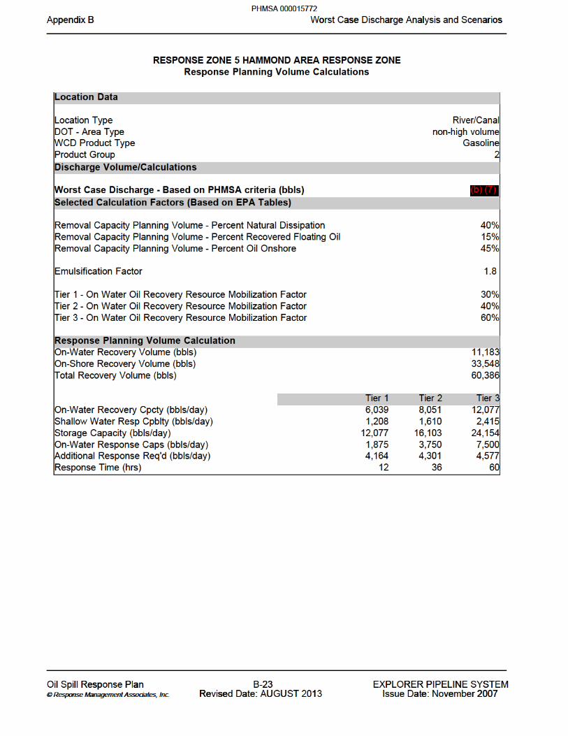


C EMERGENCY PRE-PLANNING C.1 Leak Detection Systems C.2 Discharge Prevention Systems
i C m np n r e cy n gp dix e gAppendix C Emergency Pre-planning___ __ __ ___ ___ __ _________ __________________________________________________________________________________________________
___ __ __ ___ ___ __ _________ __________________________________________________________________________________________________
l sp l Re Oil Spill Response P a a Plan -C- 1 1 P R E N R P L STEXPLORER PIPELINE SYSTEM o a t s i on a A i © Response Management Associates, © Response Management Associates, . . Inc. Inc. e U U R se a T R se : Revised Date: AUGUST 1 2013 e 2 2 a ve r 2007Issue Date: November 2007
PHMSA 000015777

EMERGENCY PRE-PLANNING Leak detection and discharge prevention is accomplished through safe operating procedures and maintenance procedures outlined in the Company Operations and Maintenance (O&M) Manual. The Company O&M Manual is designed to meet the requirements found in Title 49, Code of Federal Regulations, Part 195, Transportation of Hazardous Liquids by Pipeline.
C.1 LEAK DETECTION SYSTEMS Leak detection systems utilized along the pipeline include:
C.2 DISCHARGE PREVENTION SYSTEMS
Pipeline pump stations and breakout tank farms are designed in a manner that maximizes the containment of leaks on-site and deters the migration of leaks off-site. Discharge prevention is accomplished through the following measures:
Breakout storage tanks are provided secondary containment (berms) large enough to withhold the capacity, of the tank or capacity of the largest single tank located in the berm, plus freeboard for precipitation.
Berms are installed with manual operating, open-and-closed design valves to prevent the outward flow of stormwater or leaks from the berm area.
Various retention ponds, drainage ditches, swales, etc. are used to help contain leaks and prevent off-site migration.
Pipelines, terminals, tanks and related structures have grounding systems to reduce the possibility of accidental ignition due to lightning.
Discharge prevention is also accomplished through the use of general housekeeping procedures and leak inspection systems.
i C m np n r e cy n gp dix e gAppendix C Emergency Pre-planning___ __ __ ___ ___ __ _________ __________________________________________________________________________________________________
___ __ __ ___ ___ __ _________ __________________________________________________________________________________________________
l sp l Re Oil Spill Response P a a Plan -C- 2 2 P R E N R P L STEXPLORER PIPELINE SYSTEM o a t s i on a A i © Response Management Associates, © Response Management Associates, . . Inc. Inc. e U U R se a T R se : Revised Date: AUGUST 1 2013 e 2 2 a ve r 2007Issue Date: November 2007
PHMSA 000015778
(b) (7)(F)
(b) (7)(F)

Remote pump stations are equipped with vapor monitors.
i C m np n r e cy n gp dix e gAppendix C Emergency Pre-planning___ __ __ ___ ___ __ _________ __________________________________________________________________________________________________
___ __ __ ___ ___ __ _________ __________________________________________________________________________________________________
l sp l Re Oil Spill Response P a a Plan -C- 3 3 P R E N R P L STEXPLORER PIPELINE SYSTEM o a t s i on a A i © Response Management Associates, © Response Management Associates, . . Inc. Inc. e U U R se a T R se : Revised Date: AUGUST 1 2013 e 2 2 a ve r 2007Issue Date: November 2007
PHMSA 000015779

APPENDIX D
TRAINING AND DRILLS
D.1 Response Team Training
Oil Spill Response Plan Review
HAZWOPER (29 CFR 1910.120) Incident Command System Training Records Training Records Maintenance Contractor Training Training Qualifications
D.2 Response Team Exercises
Quarterly QI Notification Exercise
Annual Equipment Deployment Exercise Annual Response Team Tabletop Exercise Government-Initiated Unannounced Exercise Area Exercises Exercise Documentation
D.3 Purpose of Review and Evaluation
Outline of Review
Detection Notification Assessment/Evaluation Mobilization Response - Strategy Response - Resources Used Response - Effectiveness Command Structure Measurement Government Relations Public Relations
i D n n p n Tr l se vi d vap dix T ai n and st d xerc se e d va uatiAppendix D Training and Drills & Post Incident/Exercise Review and Evaluation___ __ __ ___ ___ __ _________ __________________________________________________________________________________________________
___ __ __ ___ ___ __ _________ __________________________________________________________________________________________________
l sp l Re Oil Spill Response P a a Plan -D- 1 1 P R E N R P L STEXPLORER PIPELINE SYSTEM o a t s i on a A i © Response Management Associates, © Response Management Associates, . . Inc. Inc. e U U R se a T R se : Revised Date: AUGUST 1 2013 e 2 2 a ve r 2007Issue Date: November 2007
PHMSA 000015780

D.1 RESPONSE TEAM TRAINING
The Company provides training related to discharge prevention, testing and response, including measures to repair pipeline ruptures and mitigate discharges. The training methods address oil discharges from the pipeline from several perspectives: human health and safety, rupture control and repair operations, pollution control, and overall management of the emergency. The competency of each training program is closely monitored by the Training Section through observation of and/or participation in actual training sessions. Through the various training methods described below The Company's training program is intended to ensure the following results:
That all personnel know:
Their responsibilities under the Plan.
The name, address and procedures for contacting the operator on a 24-hour basis.
The name of, and procedures for contacting the Qualified Individual on a 24-hour basis.
That all reporting personnel know:
The pipelines and response zone details for the affected area (Response Zones Annexes).
The telephone number of the National Response Center and other required notifications (Section 2.0).
The notification process. (Section 2.0).
That all response personnel know:
The characteristics and hazards of the oil discharged (Section 3.0 and Appendix H - MSDS).
The conditions that is likely to worsen emergencies, including the consequences of pipeline malfunctions, and the appropriate corrective actions.
The steps necessary to control any accidental discharge of oil and to minimize the potential for fire, explosion, toxicity or environmental damage (Section 3.0).
The proper firefighting procedures and use of equipment, fire suits, and breathing apparatus (Section 3.0). Only trained persons will be utilized. Explorer personnel are only trained on the use of Ansul 30# units for small incipent fires.
Oil Spill Response Plan Review
All Response Team Members should review their Oil Spill Response Plan whenever their job position or responsibilities change under the Plan. A copy of this Plan will be available at all times to Team Members.
i D n n p n Tr l se vi d vap dix T ai n and st d xerc se e d va uatiAppendix D Training and Drills & Post Incident/Exercise Review and Evaluation___ __ __ ___ ___ __ _________ __________________________________________________________________________________________________
___ __ __ ___ ___ __ _________ __________________________________________________________________________________________________
l sp l Re Oil Spill Response P a a Plan -D- 2 2 P R E N R P L STEXPLORER PIPELINE SYSTEM o a t s i on a A i © Response Management Associates, © Response Management Associates, . . Inc. Inc. e U U R se a T R se : Revised Date: AUGUST 1 2013 e 2 2 a ve r 2007Issue Date: November 2007
PHMSA 000015781


D.2 RESPONSE TEAM EXERCISES (Cont'd)
Quarterly QI Notification Exercise
Scope: Exercise communication between pipeline personnel and the QI(s) and/or designated alternate(s). At least once each year, one of the notification exercises should be conducted during non-business hours.
Objective: Contact must be made with a QI or designated alternate, as identified in the Plan.
General: All personnel receiving notification shall respond to the notification and verify their receipt of the notification. Personnel who do not respond should be contacted to determine whether or not they received the notification.
Annual Equipment Deployment Exercise (for operator and/or OSRO equipment)
Scope:Demonstrate ability to deploy spill response equipment identified in the OSRP.
- May consist entirely of operator owned equipment, or a combination of OSRO and
operator equipment.
- The number of equipment deployment exercises conducted should be such that equipment and personnel assigned to each response zone are exercised at least one a year. If the same personnel and equipment respond to multiple zones, they need only exercise once per year. If different personnel and equipment response to various response zones, each must participate in an annual equipment deployment exercise.
Objective:Demonstrate personnel’s ability to deploy and operate response equipment. Ensure that the response equipment is in proper working order.
General:The Facility may take credit for actual equipment deployment to a spill, or for training sessions, as long as the activities are properly documented.
Annual Response Team Tabletop Exercise
Scope: Exercise the response team's organization, communication, and decision- making in managing a spill response. Each team identified within the plan must conduct an annual Response Team Tabletop Exercise.
Objective: Exercise the response team in a review of the following:
- Knowledge of the Plan.
- Proper notifications.
- Communications system.
- Ability to access an OSRO.
- Coordination of internal spill response personnel.
i D n n p n Tr l se vi d vap dix T ai n and st d xerc se e d va uatiAppendix D Training and Drills & Post Incident/Exercise Review and Evaluation___ __ __ ___ ___ __ _________ __________________________________________________________________________________________________
___ __ __ ___ ___ __ _________ __________________________________________________________________________________________________
l sp l Re Oil Spill Response P a a Plan -D- 6 6 P R E N R P L STEXPLORER PIPELINE SYSTEM o a t s i on a A i © Response Management Associates, © Response Management Associates, . . Inc. Inc. e U U R se a T R se : Revised Date: AUGUST 1 2013 e 2 2 a ve r 2007Issue Date: November 2007
PHMSA 000015785

- Review of the transition from a local team to a regional team.
i D n n p n Tr l se vi d vap dix T ai n and st d xerc se e d va uatiAppendix D Training and Drills & Post Incident/Exercise Review and Evaluation___ __ __ ___ ___ __ _________ __________________________________________________________________________________________________
___ __ __ ___ ___ __ _________ __________________________________________________________________________________________________
l sp l Re Oil Spill Response P a a Plan -D- 7 7 P R E N R P L STEXPLORER PIPELINE SYSTEM o a t s i on a A i © Response Management Associates, © Response Management Associates, . . Inc. Inc. e U U R se a T R se : Revised Date: AUGUST 1 2013 e 2 2 a ve r 2007Issue Date: November 2007
PHMSA 000015786

D.2 RESPONSE TEAM EXERCISES (Cont'd)
Annual Response Team Tabletop Exercise (Cont’d)
- Ability to effectively coordinate response activity with the National Response
System (NRS) Infrastructure.
- Ability to access information in the Area Contingency Plan.
General: A minimum of one Response Team Tabletop Exercise in a triennial cycle will involve a Worst-Case Discharge scenario.
Government-Initiated Unannounced Exercise
Scope:Demonstrate ability to respond to a worst case discharge spill event.
Objective: Designated emergency response team members should demonstrate adequate knowledge of their Response Plan and the ability to organize, communicate, coordinate, and respond in accordance with that plan.
General: Maximum of 20 unannounced PHMSA exercises conducted annually for the pipeline industry as a whole. A single owner or operator will not be required to participate in a PHMSA-initiated unannounced exercise, if they have already participated in one within the previous 36 months.
Area Exercises
Objective: The purpose of the area exercise is to exercise the entire response community in a particular area. An area is defined as “that geographic area for which a separate and distinct Area Contingency Plan has been prepared, as described in OPA 90.” The response community includes the federal, state, and local government and industry. The area exercises are designed to exercise the government and industry interface for spill response.
General:The goal is to ensure that all areas of the country are exercised triennially. All of the area exercises will be developed by an exercise design team. The exercise design team is comprised of representatives from the federal, state, and local government and industry. A lead plan holder would lead each area exercise. The lead plan holder is the organization (government or industry) that holds the primary plan that is exercised in the area exercise. The lead plan holder would have the final word on designing the scope and scenario of the exercise.
i D n n p n Tr l se vi d vap dix T ai n and st d xerc se e d va uatiAppendix D Training and Drills & Post Incident/Exercise Review and Evaluation___ __ __ ___ ___ __ _________ __________________________________________________________________________________________________
___ __ __ ___ ___ __ _________ __________________________________________________________________________________________________
l sp l Re Oil Spill Response P a a Plan -D- 8 8 P R E N R P L STEXPLORER PIPELINE SYSTEM o a t s i on a A i © Response Management Associates, © Response Management Associates, . . Inc. Inc. e U U R se a T R se : Revised Date: AUGUST 1 2013 e 2 2 a ve r 2007Issue Date: November 2007
PHMSA 000015787

D.2 RESPONSE TEAM EXERCISES (Cont'd)
Exercise Documentation
All exercises should be documented and maintained at the Region Office; documentation should specify:
- The type of exercise;
- Date and time of the exercise;
- A description of the exercise;
- The objectives met in the exercise;
- The components of the response plan exercised; and
- Lessons learned.
Exercise documentation should be kept on file for the required length of time depending on the regulating agency (three (3) years for the U.S. Coast Guard and five (5) years for the Pipeline and Hazardous Materials Safety Administration and the U.S. Environmental Protection Agency).
D.3 PURPOSE OF REVIEW AND EVALUATION
This section provides procedures and information useful to responders for post incident/exercise review and evaluation. Post incident/exercise reviews should be conducted in a timely manner following an incident/exercise. The Plan should be evaluated to determine its usefulness during the incident/exercise and appropriate revisions should be made. All incident/exercise documentation should be included in the Plan evaluation process.
Outline of Review
Given below are items a team composed of outside people knowledgeable in spill response and key members of the response teams should examine. These questions are intended as guidelines only; many other questions are likely to be appropriate at each stage of a critique.
Detection
- Was the spill detected promptly?
- How was it detected?
- By whom?
- Could it have been detected earlier? How?
- Are any instruments or procedures available to consider which might aid in spill
detection?
i D n n p n Tr l se vi d vap dix T ai n and st d xerc se e d va uatiAppendix D Training and Drills & Post Incident/Exercise Review and Evaluation___ __ __ ___ ___ __ _________ __________________________________________________________________________________________________
___ __ __ ___ ___ __ _________ __________________________________________________________________________________________________
l sp l Re Oil Spill Response P a a Plan -D- 9 9 P R E N R P L STEXPLORER PIPELINE SYSTEM o a t s i on a A i © Response Management Associates, © Response Management Associates, . . Inc. Inc. e U U R se a T R se : Revised Date: AUGUST 1 2013 e 2 2 a ve r 2007Issue Date: November 2007
PHMSA 000015788

D.3 PURPOSE OF REVIEW AND EVALUATION (Cont'd)
Outline of Review (Cont'd)
Notification
- Were proper procedures followed in notifying government agencies? Were notifications prompt?
- Was management notified promptly?
- Was management response appropriate?
- Was the Pipeline owner/operator notified promptly? If so, why, how, and who? If not,
why not?
Assessment/Evaluation
- Was the magnitude of the problem assessed correctly at the start?
- What means were used for the assessment?
- Are any guides or aids needed to assist spill evaluation?
- What sources of information were available on winds and on water currents?
- Is our information adequate?
- Was this information useful (and used) for spill trajectory forecasts? Were such forecasts realistic?
- Do we have adequate information on product properties?
- Do we need additional information on changes of product properties with time, i.e., as a result of weathering and other processes?
Mobilization
- What steps were taken to mobilize spill countermeasures?
- What resources were used?
- Was mobilization prompt?
i D n n p n Tr l se vi d vap dix T ai n and st d xerc se e d va uatiAppendix D Training and Drills & Post Incident/Exercise Review and Evaluation___ __ __ ___ ___ __ _________ __________________________________________________________________________________________________
___ __ __ ___ ___ __ _________ __________________________________________________________________________________________________
l sp l Re Oil Spill Response P a a Plan -D- 0 1 10 I MX P LI MEXPLORER PIPELINE SYSTEM o a t s i on a A i © Response Management Associates, © Response Management Associates, . . Inc. Inc. e U U R se a T R se : Revised Date: AUGUST 1 2013 e 2 2 a ve r 2007Issue Date: November 2007
PHMSA 000015789

D.3 PURPOSE OF REVIEW AND EVALUATION (Cont'd)
Mobilization (Cont'd)
- Could it have been speeded up or should it have been?
- What about mobilization of manpower resources?
- Was the local spill cooperative used appropriately?
- How could this be improved?
- Was it appropriate to mobilize the Pipeline owner/operator resources and was this promptly initiated?
- What other corporate resources are available and have they been identified and used adequately?
Response - Strategy
- Is there an adequate spill response plan for the location?
- Is it flexible enough to cope with unexpected spill events?
- Does the plan include clear understanding of local environmental sensitivities?
- What was the initial strategy for response to this spill?
- Is this strategy defined in the spill plan?
- How did the strategy evolve and change during this spill and how were these changes implemented?
- What caused such changes?
- Are there improvements needed? More training?
Response – Resources Used
- What resources were mobilized?
- How were they mobilized?
- How did resource utilization change with time? Why?
i D n n p n Tr l se vi d vap dix T ai n and st d xerc se e d va uatiAppendix D Training and Drills & Post Incident/Exercise Review and Evaluation___ __ __ ___ ___ __ _________ __________________________________________________________________________________________________
___ __ __ ___ ___ __ _________ __________________________________________________________________________________________________
l sp l Re Oil Spill Response P a a Plan -D- 1 1 11 I MX P LI MEXPLORER PIPELINE SYSTEM o a t s i on a A i © Response Management Associates, © Response Management Associates, . . Inc. Inc. e U U R se a T R se : Revised Date: AUGUST 1 2013 e 2 2 a ve r 2007Issue Date: November 2007
PHMSA 000015790

D.3 PURPOSE OF REVIEW AND EVALUATION (Cont'd)
Response – Resources Used (Cont'd)
- Were resources used effectively?
Contractors
Government agencies
Company resources
Cooperatives
Volunteers
Consultants
Other (e.g. bird rescue centers)
- What changes would have been useful?
- Do we have adequate knowledge of resource availability?
- Do we have adequate knowledge of waste disposal capabilities?
Response - Effectiveness
- Was containment effective and prompt?
- How could it have been improved?
- Should the location or the local cooperative have additional resources for containment?
- Was recovery effective and prompt?
- How could it have been improved?
- Should the location or the local cooperative have additional resources for recovery of spilled product?
- Was contaminated equipment disposed of promptly and safely?
- Was there adequate in-house product separation, recovery, and disposal?
- How could it have been improved?
- Was there adequate outside disposal resources available?
i D n n p n Tr l se vi d vap dix T ai n and st d xerc se e d va uatiAppendix D Training and Drills & Post Incident/Exercise Review and Evaluation___ __ __ ___ ___ __ _________ __________________________________________________________________________________________________
___ __ __ ___ ___ __ _________ __________________________________________________________________________________________________
l sp l Re Oil Spill Response P a a Plan -D- 2 1 12 I MX P LI MEXPLORER PIPELINE SYSTEM o a t s i on a A i © Response Management Associates, © Response Management Associates, . . Inc. Inc. e U U R se a T R se : Revised Date: AUGUST 1 2013 e 2 2 a ve r 2007Issue Date: November 2007
PHMSA 000015791

D.3 PURPOSE OF REVIEW AND EVALUATION (Cont'd)
Command Structure
- Who was initially in charge of spill response?
- What sort of organization was initially set up?
- How did this change with time? Why?
- What changes would have been useful?
- Was there adequate surveillance?
- Should there be any changes?
- Were communications adequate?
- What improvements are needed? Hardware, procedures, etc.
- Was support from financial services adequate? Prompt?
- Should there be any changes?
- Is more planning needed?
- Should financial procedures be developed to handle such incidents?
Measurement
- Was there adequate measurement or estimation of the volume of product spilled?
- Was there adequate measurement or estimation of the volume of product recovered?
- Was there adequate measurement or estimation of the volume of product disposed of?
- Should better measurement procedures be developed for either phase of operations?
- If so, what would be appropriate and acceptable?
Government Relations
- What are the roles and effects of the various government agencies which were involved?
- Was there a single focal point among the government agencies for contact?
i D n n p n Tr l se vi d vap dix T ai n and st d xerc se e d va uatiAppendix D Training and Drills & Post Incident/Exercise Review and Evaluation___ __ __ ___ ___ __ _________ __________________________________________________________________________________________________
___ __ __ ___ ___ __ _________ __________________________________________________________________________________________________
l sp l Re Oil Spill Response P a a Plan -D- 3 1 13 I MX P LI MEXPLORER PIPELINE SYSTEM o a t s i on a A i © Response Management Associates, © Response Management Associates, . . Inc. Inc. e U U R se a T R se : Revised Date: AUGUST 1 2013 e 2 2 a ve r 2007Issue Date: November 2007
PHMSA 000015792

D.3 PURPOSE OF REVIEW AND EVALUATION (Cont'd)
Government Relations (Cont'd)
- Should there have been better focus of communications to the agencies?
- Were government agencies adequately informed at all stages?
- Were too many agencies involved?
- Are any changes needed in procedures to manage government relations?
- Examples of affected U.S. agencies (there may be others):
U.S. Coast Guard
Environmental Protection Agency
National Oceanic and Atmospheric Administration
Dept of Fish and Wildlife
State Parks
Harbors and Marinas
States
Cities
Counties
- Was there adequate agreement with the government agencies on disposal methods?
- Was there adequate agreement with the government agencies on criteria for cleanup?
- How was this agreement developed?
- Were we too agreeable with the agencies in accepting their requests for specific action items (e.g., degree of cleanup)?
- Should there be advance planning of criteria for cleanup, aimed at specific local environmentally sensitive areas? (Such criteria should probably also be designed for different types of product.)
Public Relations
- How were relations with the media handled?
- What problems were encountered?
- Are improvements needed?
- How could public outcry have been reduced? Was it serious?
- Would it be useful to undertake a public information effort to "educate" reporters about product and effects to it if spilled?
- These areas should be investigated shortly after the incident to assure that actions taken are fresh in peoples' minds.
i D n n p n Tr l se vi d vap dix T ai n and st d xerc se e d va uatiAppendix D Training and Drills & Post Incident/Exercise Review and Evaluation___ __ __ ___ ___ __ _________ __________________________________________________________________________________________________
___ __ __ ___ ___ __ _________ __________________________________________________________________________________________________
l sp l Re Oil Spill Response P a a Plan -D- 4 1 14 I MX P LI MEXPLORER PIPELINE SYSTEM o a t s i on a A i © Response Management Associates, © Response Management Associates, . . Inc. Inc. e U U R se a T R se : Revised Date: AUGUST 1 2013 e 2 2 a ve r 2007Issue Date: November 2007
PHMSA 000015793

E.1 Overview
E.2 Waste Classification
E.3 Waste Handling
E.4 Waste Storage
E.5 Waste Disposal
Figure E-1 Comparative Evaluation of Oil Spill Transfer Systems
Figure E-2 Temporary Storage Methods
Figure E-3 Oily Waste Separation and Disposal Methods
i E l Pp n D o ap dix sposal Appendix E Disposal Plan___ __ __ ___ ___ __ _________ __________________________________________________________________________________________________
___ __ __ ___ ___ __ _________ __________________________________________________________________________________________________
l sp l Re Oil Spill Response P a a Plan E- 1 1 L L S TE I TL L EXPLORER PIPELINE SYSTEM o a t s i on a A i © Response Management Associates, © Response Management Associates, . . Inc. Inc. e U U R se a T R se : Revised Date: AUGUST 1 2013 e 2 2 a ve r 2007Issue Date: November 2007
PHMSA 000015794

E.1 OVERVIEW
A major oil spill response would generate significant quantities of waste materials ranging from oily debris and sorbent materials to sanitation water and used batteries. All these wastes need to be classified and segregated (i.e., oily, liquid, etc.), transported from the site, and treated and/or disposed of at approved disposal sites. Each of these activities demands that certain health and safety precautions be taken, which are strictly controlled by federal and state laws and regulations. This section provides an overview of the applicable state regulations governing waste disposal, and a discussion of various waste classification, handling, transfer, storage, and disposal techniques. It is the responsibility of the Environmental Unit to manage waste disposal needs during an oil spill cleanup.
E.2 WASTE CLASSIFICATION
Oily - Liquid Wastes Oily liquid wastes (i.e., oily water and emulsions) that would be handled, stored, and disposed of during response operations are very similar to those handled during routine storage and transfer operations. The largest volume of oily liquid wastes would be produced by recovery operations (e.g., through the use of vacuum devices or skimmers). In addition, oily water and emulsions would be generated by vehicle operations (e.g., spent motor oils, lubricants, etc.), and equipment cleaning operations. Non-Oily - Liquid Wastes Response operations would also produce considerable quantities of non-oily liquid wastes. Water and other non-oily liquid wastes would be generated by the storage area and stormwater collection systems equipment cleaning (i.e., water contaminated with cleaning agents), and office and field operations (i.e., sewage, construction activities). Solid Wastes A solid waste is defined as any discarded material provided that it is not specifically excluded under the regulations. These exclusions cover materials such as domestic sewage and mixtures of sewage discharged through a sewer system or industrial wastewater point source discharges. A discarded material is any material which is abandoned (disposed of, burned or incinerated) or accumulated, stored or treated prior to being abandoned. A discarded material is also any material recycled or any material considered inherently wastelike. Recycled material is considered solid waste when used in a manner constituting disposal, placed on land or burned for energy recovery. A solid waste may be considered a hazardous waste. A solid waste, as defined above, may be a hazardous waste if it is not excluded from regulation and is either a listed hazardous waste or exhibits the characteristics of a hazardous waste. A solid waste exhibits the characteristics of a hazardous waste if it exceeds the thresholds established in determining the following:
1) ignitability2) corrosivity3) reactivity
i E l Pp n D o ap dix sposal Appendix E Disposal Plan___ __ __ ___ ___ __ _________ __________________________________________________________________________________________________
___ __ __ ___ ___ __ _________ __________________________________________________________________________________________________
l sp l Re Oil Spill Response P a a Plan E- 2 2 L L S TE I TL L EXPLORER PIPELINE SYSTEM o a t s i on a A i © Response Management Associates, © Response Management Associates, . . Inc. Inc. e U U R se a T R se : Revised Date: AUGUST 1 2013 e 2 2 a ve r 2007Issue Date: November 2007
PHMSA 000015795

4) toxicity
i E l Pp n D o ap dix sposal Appendix E Disposal Plan___ __ __ ___ ___ __ _________ __________________________________________________________________________________________________
___ __ __ ___ ___ __ _________ __________________________________________________________________________________________________
l sp l Re Oil Spill Response P a a Plan E- 3 3 L L S TE I TL L EXPLORER PIPELINE SYSTEM o a t s i on a A i © Response Management Associates, © Response Management Associates, . . Inc. Inc. e U U R se a T R se : Revised Date: AUGUST 1 2013 e 2 2 a ve r 2007Issue Date: November 2007
PHMSA 000015796

E.2 WASTE CLASSIFICATION (Cont'd)
Solid Wastes (Cont'd)
A solid waste may also become a hazardous waste if it is mixed with a listed hazardous waste or, in the case of any other waste (including mixtures), when the waste exhibits any of the characteristics identified above. Oily - Solid/Semi-Solid Wastes Oily solid/semi-solid wastes that would be generated by containment and recovery operations include damaged or worn-out booms, disposable/soiled equipment, used sorbent materials, saturated soils, contaminated beach sediments, driftwood, and other debris. Non-Oily - Solid/Semi-Solid Wastes Non-oily solid/semi-solid wastes would be generated by emergency construction operations (e.g., scrap, wood, pipe, and wiring) and office and field operations (i.e., refuse). Vessel, vehicle, and aircraft operations also produce solid wastes.
E.3 WASTE HANDLING
A primary concern in the handling of recovered oil and oily debris is contaminating unaffected areas or recontaminating already cleaned areas. Oily wastes generated during the response operations would need to be separated by type and transferred to temporary storage areas and/or transported to incineration or disposal sites. Proper handling of oil and oily wastes is imperative to ensure personnel health and safety. Safety Considerations Care shall be taken to avoid or minimize direct contact with oily wastes. All personnel handling or coming into contact with oily wastes shall wear protective clothing. A barrier cream can be applied prior to putting on gloves to further reduce the possibility of oily waste absorption. Safety goggles shall be worn by personnel involved in waste handling activities where splashing might occur. Any portion of the skin exposed to oily waste should be washed with soap and water as soon as possible. Decontamination zones should be set up during response operations to ensure personnel are treated for oil exposure. Waste Transfer During response operations, it may be necessary to transfer recovered oil and oily debris from one point to another several times before the oil and oily debris are ultimately recycled, incinerated or disposed of at an appropriate disposal site. Depending on the location of response operations, any or all of the following transfer operations may occur:
From portable or vessel-mounted skimmers into flexible bladder tanks, storage tanks of the skimming vessel itself, or a barge.Directly into the storage tank of a vacuum device.From a skimming vessel or flexible bladder to a barge.
i E l Pp n D o ap dix sposal Appendix E Disposal Plan___ __ __ ___ ___ __ _________ __________________________________________________________________________________________________
___ __ __ ___ ___ __ _________ __________________________________________________________________________________________________
l sp l Re Oil Spill Response P a a Plan E- 4 4 L L S TE I TL L EXPLORER PIPELINE SYSTEM o a t s i on a A i © Response Management Associates, © Response Management Associates, . . Inc. Inc. e U U R se a T R se : Revised Date: AUGUST 1 2013 e 2 2 a ve r 2007Issue Date: November 2007
PHMSA 000015797

i E l Pp n D o ap dix sposal Appendix E Disposal Plan___ __ __ ___ ___ __ _________ __________________________________________________________________________________________________
___ __ __ ___ ___ __ _________ __________________________________________________________________________________________________
l sp l Re Oil Spill Response P a a Plan E- 5 5 L L S TE I TL L EXPLORER PIPELINE SYSTEM o a t s i on a A i © Response Management Associates, © Response Management Associates, . . Inc. Inc. e U U R se a T R se : Revised Date: AUGUST 1 2013 e 2 2 a ve r 2007Issue Date: November 2007
PHMSA 000015798

E.3 WASTE HANDLING (Cont'd)
From a vacuum device storage tank to a frac tank.
From a frac tank to a tank truck.
From a tank truck to a processing system (e.g., oil/water separator).
From a processing system to a recovery system and/or incinerator.
Directly into impermeable bags that, in turn, are placed in impermeable containers.
From containers to trucks.
There are four general classes of transfer systems that may be employed to affect oily waste transfer operations:
Pumps: Rotary pumps, such as centrifugal pumps, may be used when transferring large volumes of oil, but they may not be appropriate for pumping mixtures of oil and water. The extreme shearing action of centrifugal pumps tends to emulsify oil and water, thereby increasing the viscosity of the mixture and causing low, inefficient transfer rates. The resultant emulsion would also be more difficult to separate into oil and water fractions. Lobe or "positive displacement" pumps work well on heavy, viscous oils, and do not emulsify the oil/water mixture. Double-acting piston and double acting diaphragm pumps are reciprocating pumps that may also be used to pump oily wastes.
Vacuum Systems: A vacuum truck may be used to transfer viscous oils but they usually pick up a very high water/oil ratio.
Belt/Screw Conveyors: Conveyors may be used to transfer oily wastes containing a large amount of debris. These systems can transfer weathered debris laden oil either horizontally or vertically for short distances (i.e., 10 feet) but are bulky and difficult to set up and operate.
Wheeled Vehicles: Wheeled vehicles may be used to transfer liquid wastes or oily debris to storage or disposal sites. These vehicles have a limited transfer volume (i.e., 100 barrels) and require good site access.
Figure E-1 provides a comparative evaluation of 16 types of transfer systems that could be available for transfer operations.
E.4 WASTE STORAGE
Interim storage of recovered oil, oily and non-oily waste would be considered to be an available means of holding the wastes until a final management method is selected. In addition, the segregation of wastes according to type would facilitate the appropriate method of disposal. The storage method used would depend upon:
The type and volume of material to be stored.
The duration of storage.
Access.
i E l Pp n D o ap dix sposal Appendix E Disposal Plan___ __ __ ___ ___ __ _________ __________________________________________________________________________________________________
___ __ __ ___ ___ __ _________ __________________________________________________________________________________________________
l sp l Re Oil Spill Response P a a Plan E- 6 6 L L S TE I TL L EXPLORER PIPELINE SYSTEM o a t s i on a A i © Response Management Associates, © Response Management Associates, . . Inc. Inc. e U U R se a T R se : Revised Date: AUGUST 1 2013 e 2 2 a ve r 2007Issue Date: November 2007
PHMSA 000015799

> E.4 WASTE STORAGE Cont'd
During an oil spill incident, the volume of oil that can be recovered and dealt with effectively depends upon the available storage capacity. Typical short-term storage options are summarized in Figure E-2. The majority of these options can be used either onshore or offshore. If storage containers such as bags or drums are used, the container must be clearly marked with the proper DOT marking to indicate the type of material/waste contained and/or the ultimate disposal option. Fuel barges may be the best option for temporary storage of oil recovered in open waters and frac tanks for inland spills. Depending on size, these vessels may be able to hold up to 6,000 barrels of oil and water and frac tanks may hold up to 500 to 550 barrels. The barge deck can be used as a platform for operating oil spill clean-up equipment and storing containment boom. Steel or rubber tanks can be used to store oil recovered near the shoreline. To facilitate offloading, demulsifiers may be used to break emulsions prior to placing the recovered substance into the barges or storage tanks. Use of any site for storage is dependent on the approval of the local authorities. The following elements affect the choice of a potential storage site:
Geology. Ground water. Soil. Flooding. Surface water. Slope. Covered material. Capacity. Climate factors. Land use. Toxic air emissions. Security. Access. Public contact.
i E l Pp n D o ap dix sposal Appendix E Disposal Plan___ __ __ ___ ___ __ _________ __________________________________________________________________________________________________
___ __ __ ___ ___ __ _________ __________________________________________________________________________________________________
l sp l Re Oil Spill Response P a a Plan E- 7 7 L L S TE I TL L EXPLORER PIPELINE SYSTEM o a t s i on a A i © Response Management Associates, © Response Management Associates, . . Inc. Inc. e U U R se a T R se : Revised Date: AUGUST 1 2013 e 2 2 a ve r 2007Issue Date: November 2007
PHMSA 000015800

E.4 WASTE STORAGE (Cont'd)
Temporary storage sites should use the best achievable technology to protect the environment and human health. They should be set up to prevent leakage, contact, and subsequent absorption of oil by the soil. The sites should be bermed (1 to 1.5 meters high) and double lined with plastic or visqueen sheets 6-10 millimeters or greater in thickness, without joints, prior to receiving loose and bagged debris. The edges of the sheet should be weighted with stones or earth to prevent damage by wind, and the sheet should be placed on a sand layer or an underfelt thick enough to prevent piercing. A reinforced access area for vehicles at the edge of the site should be provided. In addition, the oily debris should be covered by secured visqueen or tarps and an adequate stormwater runoff collection system for the size and location of the site would be utilized. Additionally, the sites should be at least 3 meters above mean sea level. debris can be hauled to approved temporary storage sites in visqueen lined trucks or other vehicles. Burnable, non-burnable, treatable and re-usable materials can be placed in well defined separate areas at temporary storage sites. When the last of the oily debris leaves a temporary storage site, the ground protection would be removed and disposed of with the rest of the oily debris. Any surrounding soil which has become contaminated with oil would also be removed for disposal or treatment. If the soils were removed for treatment, they may be replaced if testing proves acceptable levels have been achieved. Treatment and remediation is encouraged when feasible. The temporary storage should be returned to its original condition.
E.5 WASTE DISPOSAL
Techniques for Disposal of Recovered Oil Recovery, reuse, and recycling are the best choices for remediation of a spill, thereby reducing the amount of oily debris to be bermed onsite or disposed of at a solid waste landfill. Treatment is the next best alternative, but incineration and burning for energy recovery have more options within the state. There are some limitations and considerations in incinerating for disposal. Environmental quality of incineration varies with the type and age of the Facility. Therefore, when incineration becomes an option during an event, local air quality authorities would be contacted for advice about efficiency and emissions of facilities within their authority. Approval of the local air authorities is a requirement for any incineration option. Landfilling is the last option. Final disposal at a solid or dangerous waste landfill is the least environmentally sound method of dealing with a waste problem such as oily debris. During an oil spill incident, the Company would consult with the proper regulating agency to identify the acceptable disposal methods and sites appropriately authorized to receive such wastes. The Company maintains a list of approved disposal sites that satisfy local, state, and federal regulations and company requirements. This identification of suitable waste treatment and disposal sites would be prepared by the Environmental Unit in the form of an Incident which must be authorized by the U.S. Coast Guard and/or the EPA. An Incident Disposal Plan would include predesignated interim storage sites, segregation strategies, methods of treatment and disposal for various types of debris, and the locations/contacts of all treatment and disposal site selections. Onsite treatment/disposal is preferred.
i E l Pp n D o ap dix sposal Appendix E Disposal Plan___ __ __ ___ ___ __ _________ __________________________________________________________________________________________________
___ __ __ ___ ___ __ _________ __________________________________________________________________________________________________
l sp l Re Oil Spill Response P a a Plan E- 8 8 L L S TE I TL L EXPLORER PIPELINE SYSTEM o a t s i on a A i © Response Management Associates, © Response Management Associates, . . Inc. Inc. e U U R se a T R se : Revised Date: AUGUST 1 2013 e 2 2 a ve r 2007Issue Date: November 2007
PHMSA 000015801

E.5 WASTE DISPOSAL (Cont'd)
Techniques for Disposal of Recovered Oil (Cont'd) In order to obtain the best overall Incident Disposal Plan, a combination of methods should be used. There is no template or combination of methods that can be used in every spill situation. Each incident should be reviewed carefully to ensure that an appropriate combination of disposal methods is employed.
The different types of wastes generated during response operations would require different disposal methods. To facilitate the disposal of wastes, they should be separated by type for temporary storage, transport and disposal. Figure E-3 lists some of the options that would be available to segregate oily wastes. The figure also depicts methods that may be employed to separate free and/or emulsified water from the oily liquid waste.
The following is a brief discussion of some disposal techniques available for recovered oil and oily debris. Recycling This technique entails removing water from the oil and blending the oil with uncontaminated oil. Recovered oil can be shipped to refineries provided that it is exempt from hazardous waste regulations. There it can be treated to remove water and debris, and then blended and sold as a commercial product. The Company’s designated HS&E Specialist or Director HS&E is responsible for ensuring that all waste materials be disposed of at an internally approved disposal site. Incineration This technique entails the complete destruction of the recovered oil by high temperature thermal oxidation reactions. There are licensed incineration facilities as well as portable incinerators that may be brought to a spill site. Incineration may require the approval of the local Air Pollution Control Authority. Factors to consider when selecting an appropriate site for onsite incineration would include:
Proximity to recovery locations. Access to recovery locations. Adequate fire control. Approval of the local air pollution control authorities.
In Situ Burning/Open Burning Burning techniques entail igniting oil or oiled debris and allowing it to burn under ambient conditions. These disposal techniques are subject to restrictions and permit requirements established by federal, state and local laws. They would not be used to burn PCBs, waste oil containing more than 1,000 parts per million of halogenated solvents, or other substances regulated by the EPA. Permission for in situ burning may be difficult to obtain when the burn takes
i E l Pp n D o ap dix sposal Appendix E Disposal Plan___ __ __ ___ ___ __ _________ __________________________________________________________________________________________________
___ __ __ ___ ___ __ _________ __________________________________________________________________________________________________
l sp l Re Oil Spill Response P a a Plan E- 9 9 L L S TE I TL L EXPLORER PIPELINE SYSTEM o a t s i on a A i © Response Management Associates, © Response Management Associates, . . Inc. Inc. e U U R se a T R se : Revised Date: AUGUST 1 2013 e 2 2 a ve r 2007Issue Date: November 2007
PHMSA 000015802

place near populated areas.
i E l Pp n D o ap dix sposal Appendix E Disposal Plan___ __ __ ___ ___ __ _________ __________________________________________________________________________________________________
___ __ __ ___ ___ __ _________ __________________________________________________________________________________________________
l sp l Re Oil Spill Response P a a Plan E- 10 10 P R E N R P L STEXPLORER PIPELINE SYSTEM o a t s i on a A i © Response Management Associates, © Response Management Associates, . . Inc. Inc. e U U R se a T R se : Revised Date: AUGUST 1 2013 e 2 2 a ve r 2007Issue Date: November 2007
PHMSA 000015803

E.5 WASTE DISPOSAL (Cont'd)
In Situ Burning/Open Burning (Cont'd) As a general rule, in situ burning would be appropriate only when atmospheric conditions will allow the smoke to rise several hundred feet and rapidly dissipate. Smoke from burning oil will normally rise until its temperature drops to equal the ambient temperature. Afterwards, it will travel in a horizontal direction under the influence of prevailing winds.
Landfill Disposal This technique entails burying the recovered oil in an approved landfill in accordance with regulatory procedures. Landfill disposal of free liquids is prohibited by federal law in the United States. With local health department approval, non-burnable debris which consists of oiled plastics, gravel and oiled seaweed, kelp, and other organic material may be transported to a licensed, lined, approved municipal or private landfill and disposed of in accordance with the landfill guidelines and regulations. Landfill designation would be planned only for those wastes that have been found to be unacceptable by each of the other disposal options (e.g., waste reduction, recycling, energy recovery). Wastes would be disposed of only at Company-approved disposal facilities. The HS&E Specialist or Director HS&E is responsible for ensuring that all waste materials are disposed of at a Company internally approved disposal site. Disposal at a non-approved facility would require approval by the HS&E Specialist or Director HS&E prior to sending any waste to such a facility.
i E l Pp n D o ap dix sposal Appendix E Disposal Plan___ __ __ ___ ___ __ _________ __________________________________________________________________________________________________
___ __ __ ___ ___ __ _________ __________________________________________________________________________________________________
l sp l Re Oil Spill Response P a a Plan E- 11 11 P R E N R P L STEXPLORER PIPELINE SYSTEM o a t s i on a A i © Response Management Associates, © Response Management Associates, . . Inc. Inc. e U U R se a T R se : Revised Date: AUGUST 1 2013 e 2 2 a ve r 2007Issue Date: November 2007
PHMSA 000015804

FIGURE E-1
COMPARATIVE EVALUATION OF OIL SPILL TRANSFER SYSTEMS
i E l Pp n D o ap dix sposal Appendix E Disposal Plan___ __ __ ___ ___ __ _________ __________________________________________________________________________________________________
___ __ __ ___ ___ __ _________ __________________________________________________________________________________________________
l sp l Re Oil Spill Response P a a Plan E- 12 12 P R E N R P L STEXPLORER PIPELINE SYSTEM o a t s i on a A i © Response Management Associates, © Response Management Associates, . . Inc. Inc. e U U R se a T R se : Revised Date: AUGUST 1 2013 e 2 2 a ve r 2007Issue Date: November 2007
PHMSA 000015805


APPENDIX G
STATE REQUIREMENTS
i G t ep n e tp dix a u remeAppendix G State Requirements___ __ __ ___ ___ __ _________ __________________________________________________________________________________________________
___ __ __ ___ ___ __ _________ __________________________________________________________________________________________________
l sp l Re Oil Spill Response P a a Plan G- 1 1 1 I MX P MEXPLORER PIPELINE SYSTEM o a t s i on a A i © Response Management Associates, © Response Management Associates, . . Inc. Inc. e U U R se a T R se : Revised Date: AUGUST 1 2013 e 2 2 a ve r 2007Issue Date: November 2007
PHMSA 000015809

APPENDIX H MATERIAL SAFETY DATA SHEET(S)
i H i f ep n e D (p dix a e al S e a tAppendix H Material Safety Data Sheet(s)___ __ __ ___ ___ __ _________ __________________________________________________________________________________________________
___ __ __ ___ ___ __ _________ __________________________________________________________________________________________________
l sp l Re Oil Spill Response P a a Plan -H- 1 1 P R E N R P L STEXPLORER PIPELINE SYSTEM o a t s i on a A i © Response Management Associates, © Response Management Associates, . . Inc. Inc. e U U R se a T R se : Revised Date: AUGUST 1 2013 e 2 2 a ve r 2007Issue Date: November 2007
PHMSA 000015810

DOT/PHMSA 49 CFR Part 194 Cross Reference Texas Oil Spill Prevention and Response Act of 199131 TAC Section 19.12 through 19.13 Cross Reference
o r e r e u y r ss H r 4e lat r ss Re eren 9 ar 1Regulatory Cross Reference DOT/PHMSA 49 CFR Part 194___ __ __ ___ ___ __ _________ __________________________________________________________________________________________________
___ __ __ ___ ___ __ _________ __________________________________________________________________________________________________
l sp l Re Oil Spill Response P a a Plan r eoss e erenceCross Reference- 1 P Y MO E I E T MEXPLORER PIPELINE SYSTEM o a t s i on a A i © Response Management Associates, © Response Management Associates, . . Inc. Inc. e U U R se a T R se : Revised Date: AUGUST 1 2013 e 2 2 a ve r 2007Issue Date: November 2007
PHMSA 000015811


RESPONSE ZONE 1 Response Zone Annex
Oil Spill Response Plan © Response Management Associates, Inc.
Response Zone 1-1 Revised Date: AUGUST 2013
EXPLORER PIPELINE SYSTEM Issue Date: November 2007
RESPONSE ZONE INFORMATION
RESPONSE ZONE CONTACT INFORMATION
Owner Name: Explorer Pipeline Company
Addresses: Physical Address Mailing Address Explorer Pipeline Company Explorer Pipeline Company 6120 South Yale Ave. P.O. Box 2650 Tulsa, Oklahoma 74136 Tulsa, Oklahoma 74101
24 Hour Emergency Contact Phone Numbers: (888) 876-0036 (24 Hours)
Qualified Individuals NAME OFFICE OTHER
Rick Wright 918-591-3122 713-823-2955
Alt. Qualified Individuals NAME OFFICE OTHER
Alicia Westfall 918-591-3103 281-954-1239
Other NAME OFFICE OTHER
Conroe 918-591-3388 Galena Park 918-591-3392 Grapeland 918-591-3384 Hankamer 918-591-3394 Houston 918-591-3121 Huntsville 918-591-3386 Pasadena 918-591-3221 Port Arthur 918-591-3101 Port Neches 918-591-3396 GATX Sample Point 918-591-3392 Bryan 918-591-3307 Plantersville 918-591-3305 North Houston 918-591-3303 Washburn 918-591-3299 Wynnewood 918-591-3301 North Pasadena 918-591-3297 Aaron Peltier 918-591-3127 713-252-1997 Alan Frazier 918-591-3107 409-963-4852 Amanda Havard 918-591-3231 832-401-3056 Brent Kilpatrick 918-591-3231 713-689-8667 CK Nimitz 918-591-3287 936-465-2082 David Emfinger 918-591-3286 936-524-7457 David Jarvis 918-591-3231 713-689-8734
PHMSA 000015820
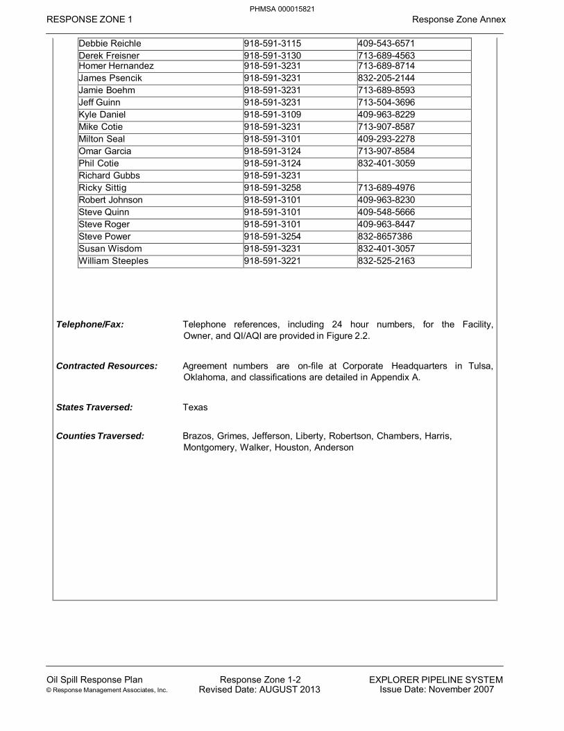
RESPONSE ZONE 1 Response Zone Annex
Oil Spill Response Plan © Response Management Associates, Inc.
Response Zone 1-2 Revised Date: AUGUST 2013
EXPLORER PIPELINE SYSTEM Issue Date: November 2007
Debbie Reichle 918-591-3115 409-543-6571 Derek Freisner 918-591-3130 713-689-4563 Homer Hernandez 918-591-3231 713-689-8714 James Psencik 918-591-3231 832-205-2144 Jamie Boehm 918-591-3231 713-689-8593 Jeff Guinn 918-591-3231 713-504-3696 Kyle Daniel 918-591-3109 409-963-8229 Mike Cotie 918-591-3231 713-907-8587 Milton Seal 918-591-3101 409-293-2278 Omar Garcia 918-591-3124 713-907-8584 Phil Cotie 918-591-3124 832-401-3059 Richard Gubbs 918-591-3231 Ricky Sittig 918-591-3258 713-689-4976 Robert Johnson 918-591-3101 409-963-8230 Steve Quinn 918-591-3101 409-548-5666 Steve Roger 918-591-3101 409-963-8447 Steve Power 918-591-3254 832-8657386 Susan Wisdom 918-591-3231 832-401-3057 William Steeples 918-591-3221 832-525-2163
Telephone/Fax: Telephone references, including 24 hour numbers, for the Facility,
Owner, and QI/AQI are provided in Figure 2.2.
Contracted Resources: Agreement numbers are on-file at Corporate Headquarters in Tulsa, Oklahoma, and classifications are detailed in Appendix A.
States Traversed: Texas
Counties Traversed: Brazos, Grimes, Jefferson, Liberty, Robertson, Chambers, Harris, Montgomery, Walker, Houston, Anderson
PHMSA 000015821


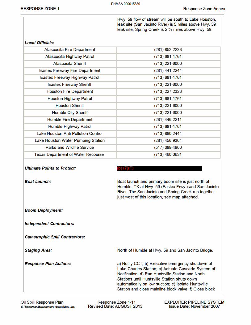


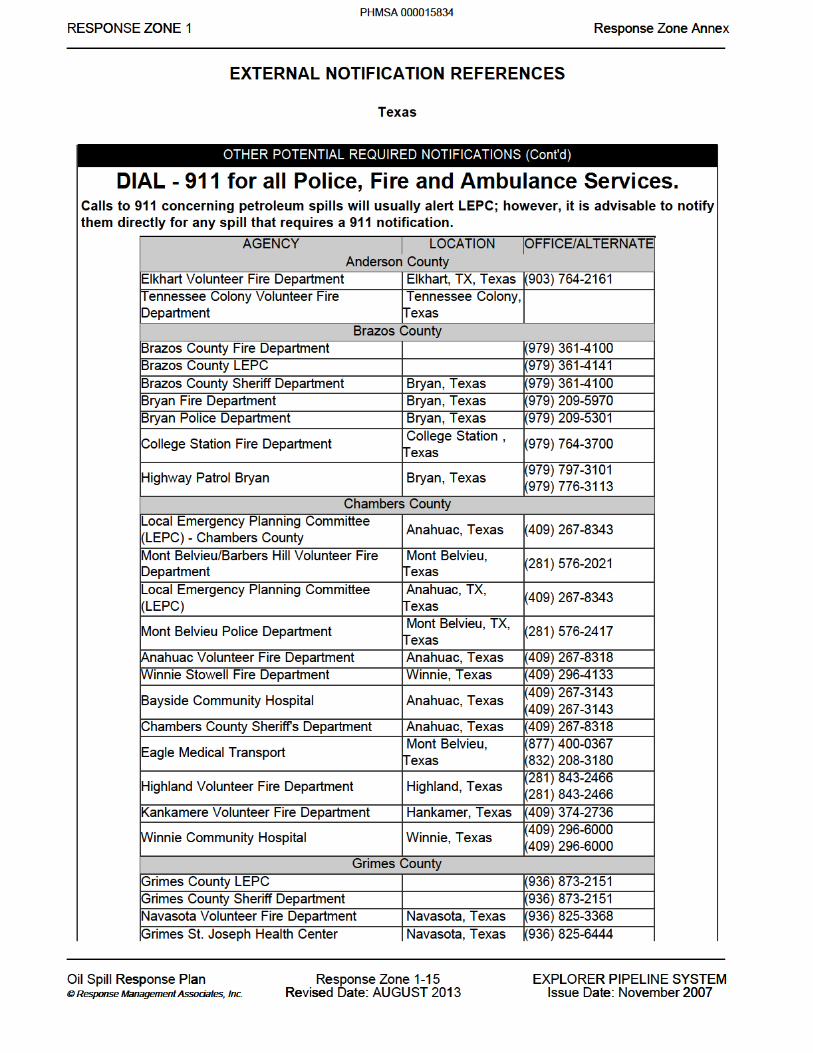


RESPONSE ZONE 2 Response Zone Annex
Oil Spill Response Plan © Response Management Associates, Inc.
Response Zone 2-1 Revised Date: AUGUST 2013
EXPLORER PIPELINE SYSTEM Issue Date: November 2007
RESPONSE ZONE INFORMATION
RESPONSE ZONE CONTACT INFORMATION
Owner Name: Explorer Pipeline Company
Addresses: Physical Address Mailing Address Explorer Pipeline Company Explorer Pipeline Company 6120 South Yale Ave. P.O. Box 2650 Tulsa, Oklahoma 74136 Tulsa, Oklahoma 74101
24 Hour Emergency Contact Phone Numbers: (888) 876-0036 (24 Hours)
Qualified Individuals NAME OFFICE OTHER
Carlos Denton 918-591-3142 214-532-7640
Alt. Qualified Individuals NAME OFFICE OTHER
Doug Lee 918-591-3143 214-709-3738
Other NAME OFFICE OTHER
ROW Greenville 918-591-3144 Bonham 918-591-3360 Coalgate 918-591-3356 Durant 918-591-3358 Greenville 918-591-3141 Mabank 918-591-3380 Palestine 918-591-3382 Richardson 918-591-3376 Darren Strege 918-591-3285 214-728-4526 Eric Lewis 918-591-3288 580-436-7949 Holly Nesler 918-591-3141 214-534-5187 Josh Payne 918-591-3141 214-862-8592 Terry Lollar 918-591-3141 214-864-1209 Todd Hackney 918-591-3148 903-274-6928 Tony Thomason 918-591-3144 214-289-7087
Telephone/Fax: Telephone references, including 24 hour numbers, for the Facility, Owner, and QI/AQI are provided in Figure 2.2.
Contracted Resources: Agreement numbers are on-file at Corporate Headquarters in Tulsa,
PHMSA 000015839

RESPONSE ZONE 2 Response Zone Annex
Oil Spill Response Plan @ Response Management Associates, Inc.
Response Zone 2-2 Revised Date: AUGUST 2013
EXPLORER PIPELINE SYSTEM Issue Date: November 2007
Oklahoma, and classifications are detailed in Appendix A.
States Traversed: Texas and Oklahoma
Counties Traversed: Anderson, Henderson, Van Zandt, Kaufman, Hunt, Coal, Pontotoc
PHMSA 000015840


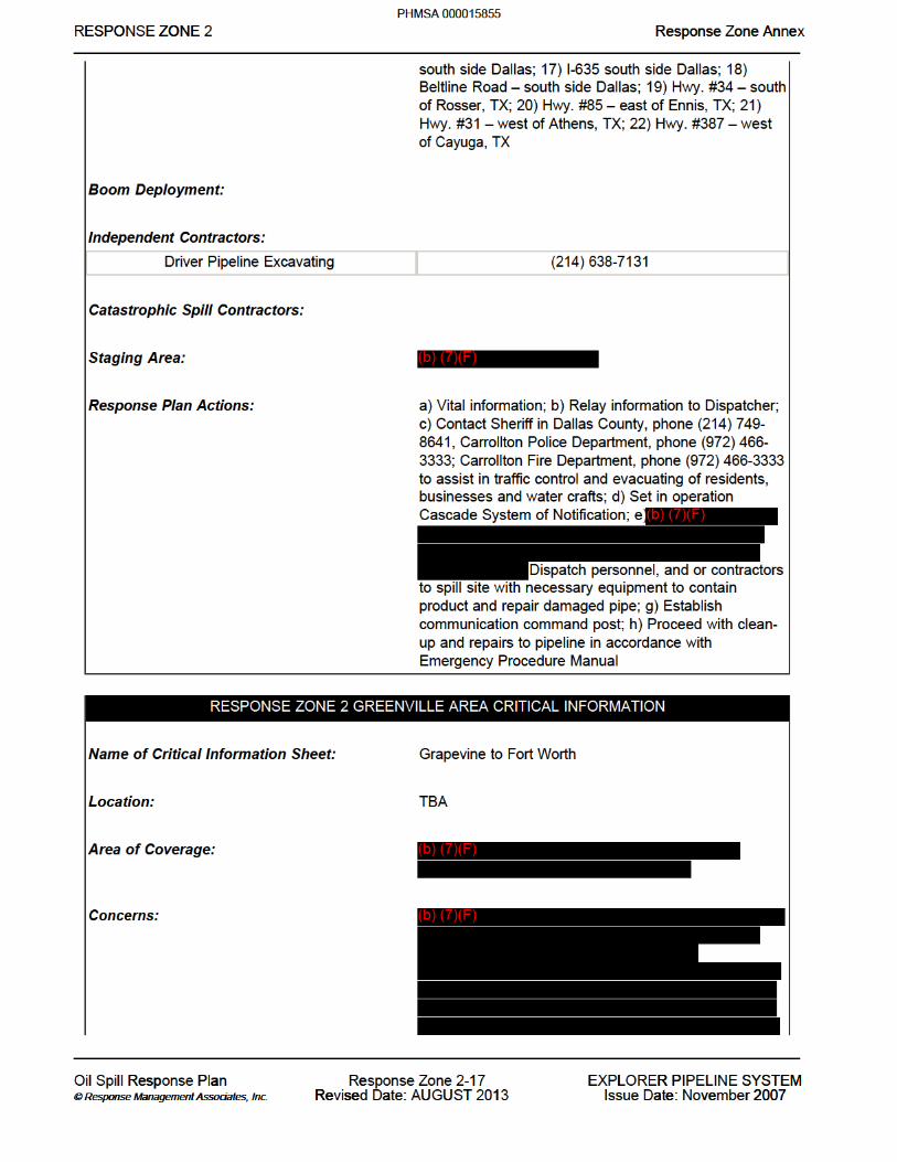
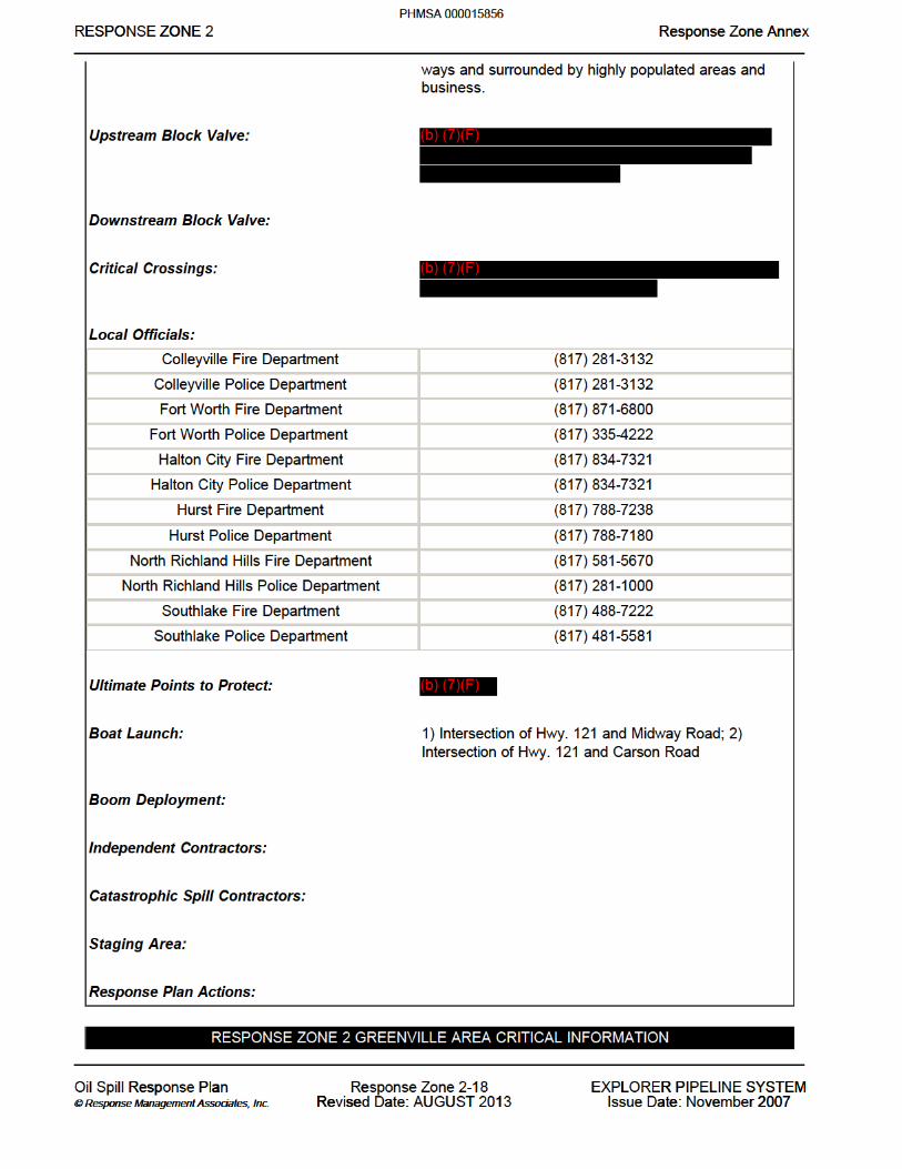


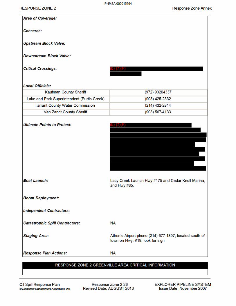


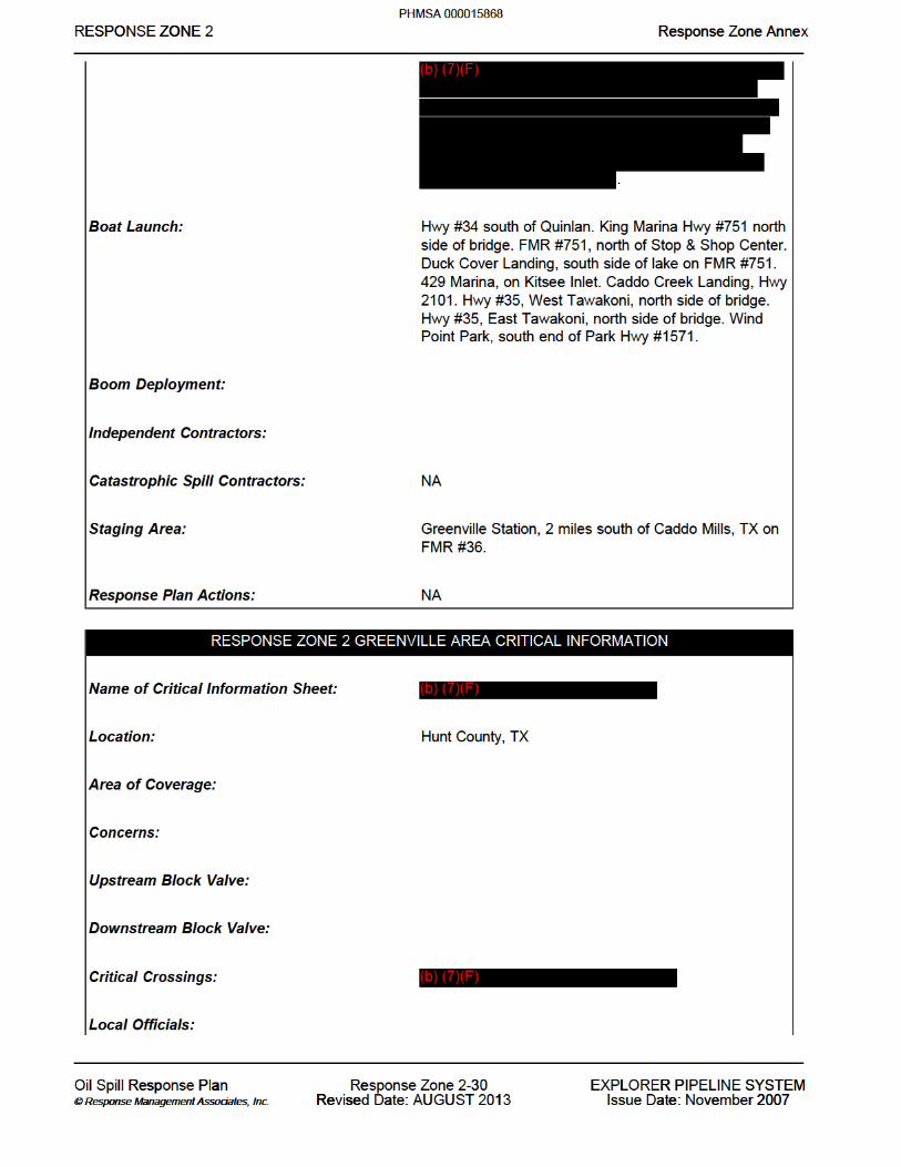


RESPONSE ZONE 3 Response Zone Annex
Oil Spill Response Plan © Response Management Associates, Inc.
Response Zone 3-1 Revised Date: AUGUST 2013
EXPLORER PIPELINE SYSTEM Issue Date: November 2007
RESPONSE ZONE INFORMATION
RESPONSE ZONE CONTACT INFORMATION
Owner Name: Explorer Pipeline Company
Addresses: Physical Address Mailing Address Explorer Pipeline Company Explorer Pipeline Company 6120 South Yale Ave. P.O. Box 2650 Tulsa, Oklahoma 74136 Tulsa, Oklahoma 74101
24 Hour Emergency Contact Phone Numbers: (888) 876-0036 (24 Hours)
Qualified Individuals
NAME OFFICE OTHER Tom Graves 918-291-5262 918-637-4084
Alt. Qualified Individuals NAME OFFICE OTHER
Chad Roggendorff 918-591-3263 918-698-1083
Other NAME OFFICE OTHER
ROW Glenpool 918-591-3264 Claremore 918-591-3348 Glenpool 918-291-5250 Holdenville 918-591-3354 Joplin 918-591-3344 Mount Vernon 918-591-3342 Okmulgee 918-591-3352 Springfield 918-591-3340 Vinita 918-591-3346 West Tulsa 918-591-3350 Bryan Hendricks 918-591-3261 Dennis Crutchfield 918-591-3261 Dennis Roling 918-591-3289 918-638-8808 Dennis Smith 918-591-3290 918-638-8807 John Stock 918-291-5264 918-728-1672 John Mobley 918-591-3261 918-640-3570 Ken Washington 918-591-3291 417-268-8743 Marvin Jackson 918-591-3261 918-638-8809 Paul Spangler 918-591-3270 918-728-1673 Steve Osceola 918-591-3261 Steven Brewer 918-291-5266 918-698-1095
PHMSA 000015884

RESPONSE ZONE 3 Response Zone Annex
Oil Spill Response Plan © Response Management Associates, Inc.
Response Zone 3-2 Revised Date: AUGUST 2013
EXPLORER PIPELINE SYSTEM Issue Date: November 2007
Telephone/Fax: Telephone references, including 24 hour numbers, for the Facility, Owner, and QI/AQI are provided in Figure 2.2.
Contracted Resources: Agreement numbers are on-file at Corporate Headquarters in Tulsa, Oklahoma, and classifications are detailed in Appendix A.
States Traversed: Oklahoma and Missouri
Counties Traversed: Pontotoc, Hughes, Okfuskee, Okmulgee, Tulsa, Creek, Wagoner, Rogers, Mayes, Craig, Delaware, Ottawa, Newton, Jasper, Lawrence, Dade, Green, Polk
PHMSA 000015885


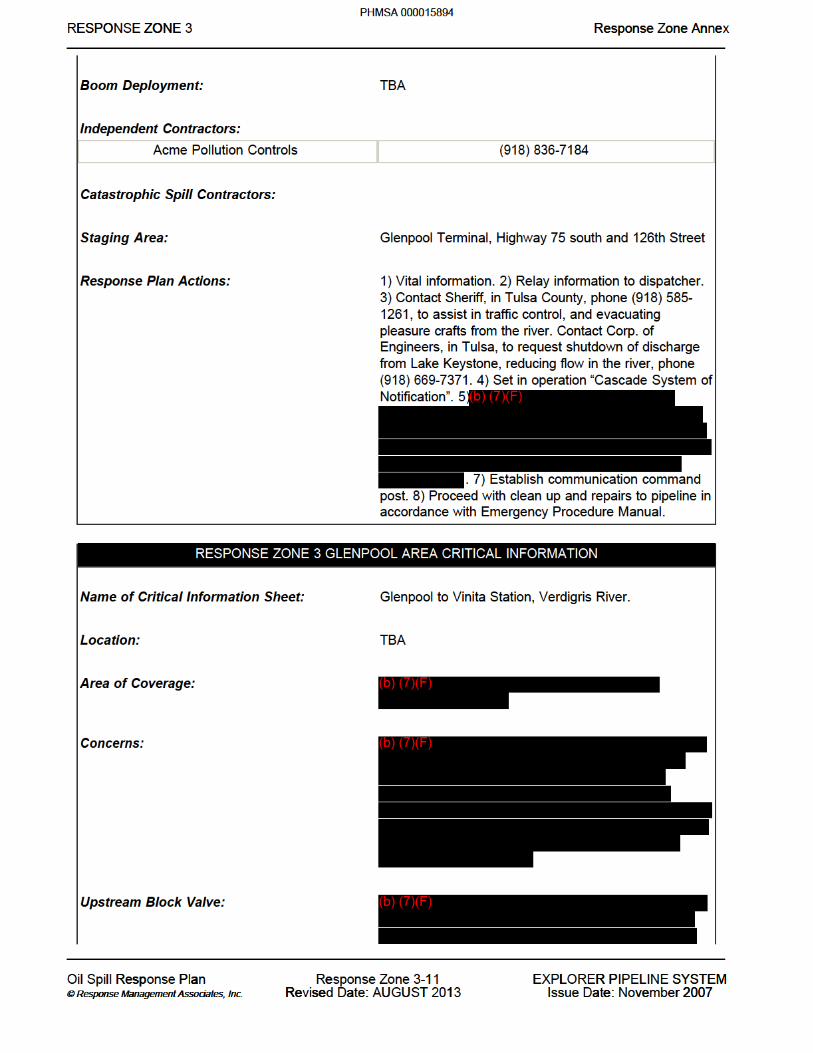


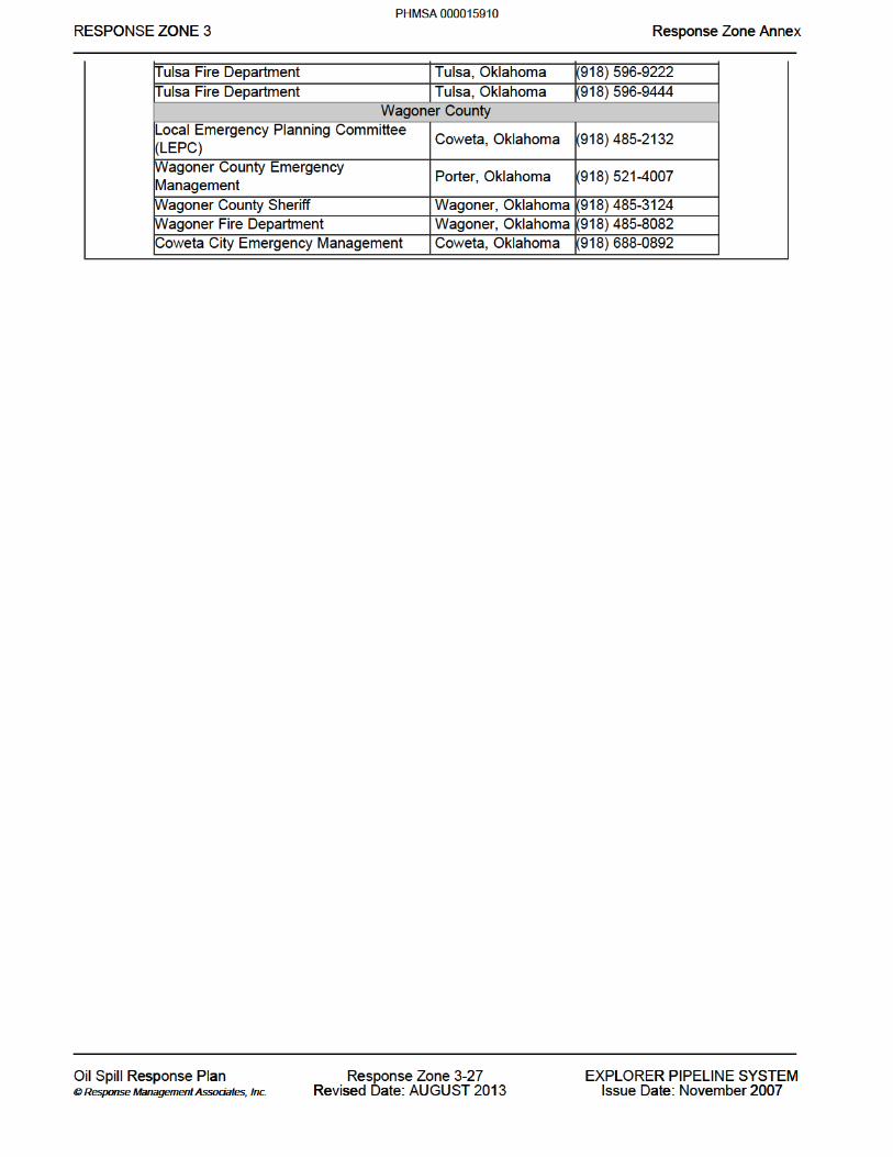

RESPONSE ZONE 4 Response Zone Annex
Oil Spill Response Plan © Response Management Associates, Inc.
Response Zone 4-1 Revised Date: AUGUST 2013
EXPLORER PIPELINE SYSTEM Issue Date: November 2007
RESPONSE ZONE INFORMATION
RESPONSE ZONE CONTACT INFORMATION
Owner Name: Explorer Pipeline Company
Addresses: Physical Address Mailing Address Explorer Pipeline Company Explorer Pipeline Company 6120 South Yale Ave. P.O. Box 2650 Tulsa, Oklahoma 74136 Tulsa, Oklahoma 74101
24 Hour Emergency Contact Phone Numbers: (888) 876-0036 (24 Hours)
Qualified Individuals NAME OFFICE OTHER
Rick Thompson 918-591-3182 618-604-4788
Alt. Qualified Individuals NAME OFFICE OTHER
Todd Johanson 918-591-3183 618-741-5806
Other NAME OFFICE OTHER
SCADA Break Area 918-359-5419 ROW WoodRiver East St. Louis 918-591-3325 Gerald 918-591-3334 Lebanon 918-591-3338 Rolla 918-591-3336 St. Louis 918-591-3327 St. Peters 918-591-3329 Weldon Spring 918-591-3331 Wood River 918-591-3191 ROW Wood River 618-251-0267 618-660-3596 Alan Spann 918-591-3181 618-219-6478 David Hagen 918-591-3190 618-610-3319 Dennis Reckmann 918-591-3191 618-530-1632 Jake Hallahan 918-591-3292 618-806-4565 Marty Manning 918-591-3181 618-219-6383 Nick Sullivan 918-591-3187 618-604-0417 Randy Vinyard 918-591-3189 618-540-9562 Robert Kruemmelbein 918-591-3181 618-219-6418 Rogelio Berumen 918-591-3195 618-691-8140 Travis Steward 918-591-3181 618-610-2076
PHMSA 000015911

RESPONSE ZONE 4 Response Zone Annex
Oil Spill Response Plan © Response Management Associates, Inc.
Response Zone 4-2 Revised Date: AUGUST 2013
EXPLORER PIPELINE SYSTEM Issue Date: November 2007
Telephone/Fax: Telephone references, including 24 hour numbers, for the Facility, Owner, and QI/AQI are provided in Figure 2.2.
Contracted Resources: Agreement numbers are on-file at Corporate Headquarters in Tulsa, Oklahoma, and classifications are detailed in Appendix A.
States Traversed: Missouri and Illinois
Counties Traversed: Polk, Dallas, Laclede, Camden, Pulaski, Maries, Gasconade, Franklin, St. Charles, Madison, Macoupin, Montgomery, Christian, St. Clair
PHMSA 000015912


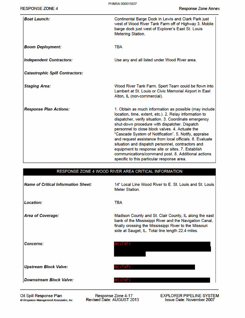


RESPONSE ZONE 5 Response Zone Annex
Oil Spill Response Plan © Response Management Associates, Inc.
Response Zone 5-1 Revised Date: AUGUST 2013
EXPLORER PIPELINE SYSTEM Issue Date: November 2007
RESPONSE ZONE INFORMATION
RESPONSE ZONE CONTACT INFORMATION
Owner Name: Explorer Pipeline Company
Addresses: Physical Address Mailing Address Explorer Pipeline Company Explorer Pipeline Company 6120 South Yale Ave. P.O. Box 2650 Tulsa, Oklahoma 74136 Tulsa, Oklahoma 74101
24 Hour Emergency Contact Phone Numbers: (888) 876-0036 (24 Hours)
Qualified Individuals NAME OFFICE OTHER
John Majewski 918-591-3203 219-712-4460
Alt. Qualified Individuals NAME OFFICE OTHER
Sue Holifield 918-591-3203 219-939-4104
Other NAME OFFICE OTHER
ROW Hammond 918-591-3204 Decatur 918-591-3323 Griffith 918-591-3317 Hammond 918-591-3201 Schererville Jct 918-591-3319 Chatsworth 918-591-3321 Christopher Meyer 918-591-3207 219-808-4842 Ed Drebes 918-591-3294 219-712-0133 Gordon Hill 918-591-3201 219-381-9260 Kevin Dommer 918-591-3201 219-381-9263 Mark Lorenzi 918-591-3201 Randy Hartge 918-591-3201 219-712-4574
Telephone/Fax: Telephone references, including 24 hour numbers, for the Facility, Owner, and QI/AQI are provided in Figure 2.2.
Contracted Resources: Agreement numbers are on-file at Corporate Headquarters in Tulsa, Oklahoma, and classifications are detailed in Appendix A.
States Traversed: Illinois and Indiana
PHMSA 000015935

RESPONSE ZONE 5 Response Zone Annex
Oil Spill Response Plan @ Response Management Associates, Inc.
Response Zone 5-2 Revised Date: AUGUST 2013
EXPLORER PIPELINE SYSTEM Issue Date: November 2007
Counties Traversed: Christian, Macon, Dewitt, Mclean, Ford, Livingston, Iroquois, Kankakee, Will, Lake
PHMSA 000015936


RESPONSE ZONE 6 Response Zone Annex
Oil Spill Response Plan © Response Management Associates, Inc.
Response Zone 6-1 Revised Date: AUGUST 2013
EXPLORER PIPELINE SYSTEM Issue Date: November 2007
RESPONSE ZONE INFORMATION
RESPONSE ZONE CONTACT INFORMATION
Owner Name: Explorer Pipeline Company
Addresses: Physical Address Mailing Address Explorer Pipeline Company Explorer Pipeline Company 6120 South Yale Ave. P.O. Box 2650 Tulsa, Oklahoma 74136 Tulsa, Oklahoma 74101
24 Hour Emergency Contact Phone Numbers: (24 Hours)
Qualified Individuals NAME OFFICE OTHER
John Patterson 918-591-3162 214-532-7532
Alt. Qualified Individuals NAME OFFICE OTHER
Stan Flahaut 918-591-3163 817-689-3068
Other NAME OFFICE OTHER
Arlington 918-591-3160 Fort Worth Delivery 918-591-3390 Ross 918-591-3315 Waco 918-591-3313 Lake Creek 918-591-3311 Hearne 918-591-3309 Carrollton Jct. 918-591-3374 Dallas 918-591-3370 DFW 918-591-3366 FW Chevron NA FW Meter 918-591-3364 Grapevine 918-591-3368 Irving 918-591-3372 Jeramy Welch 918-591-3173 214-532-9546 Marvin Dennis 918-591-3170 214-709-7850 Rodney Burton 918-591-3174 214-532-7533
Telephone/Fax: Telephone references, including 24 hour numbers, for the Facility, Owner,
and QI/AQI are provided in Figure 2.2.
PHMSA 000015949

RESPONSE ZONE 6 Response Zone Annex
Oil Spill Response Plan @ Response Management Associates, Inc.
Response Zone 6-2 Revised Date: AUGUST 2013
EXPLORER PIPELINE SYSTEM Issue Date: November 2007
Contracted Resources:
States Traversed:
Counties Traversed:
Agreement numbers are on-file at Corporate Headquarters in Tulsa, Oklahoma, and classifications are detailed in Appendix A. Texas and Oklahoma Carter, Cooke, Dallas, Denton, Falls, Garvin, Hill, Johnson, Love, McClain, Me Lennan, Tarrant
PHMSA 000015950


RESPONSE ZONE INFORMATION
O eE O ZO E nESPO E ZONE Response one AnRESPONSE ZONE 6 Response Zone Annex___ __ __ ___ ___ __ _________ __________________________________________________________________________________________________
___ __ __ ___ ___ __ _________ __________________________________________________________________________________________________
l sp l Re Oil Spill Response P a a Plan e Response Zone 6-7 7 X P Y MO E LI E EXPLORER PIPELINE SYSTEM o a t s i on a A i © Response Management Associates, © Response Management Associates, . . Inc. Inc. e U U R se a T R se : Revised Date: AUGUST 1 2013 e 2 2 a ve r 2007Issue Date: November 2007
PHMSA 000015955