WSA Explorer
88
Index i09 Issue 06.2016 WSA Explorer Original instructions Water cooled liquid chillers 400V / ~3 / 50Hz
-
Upload
khangminh22 -
Category
Documents
-
view
1 -
download
0
Transcript of WSA Explorer

Index i09Issue 06.2016
WSA ExplorerOriginal instructions Water cooled liquid chillers 400V / ~3 / 50Hz

2 EN/06.2016/i09 © STULZ S.p.A. – all rights reserved
WSA ExplOrEr OriginAl inStructiOnS
A B O U T S T U L ZCustomer focus, entrepreneurial spirit and technological expertise – these have formed the basis for the successful growth of STULZ.
In 1971 we began specializing in the development and production of precision air conditioning units and chillers. That's a wealth of experience gathered over 40 years and from many thousands of projects that we have implemented worldwide. We have systems and solutions of all sizes and with the most diverse requirements - take advantage of our know-how.
Founded in Hamburg in 1947, today STULZ has a presence in over 140 countries. The STULZ Group has STULZ subsidiaries in 17 countries, 7 production plants in Europe, the USA, India and 2 in China and more than 140 exclusive sales and service partners on all continents. The family-owned company employs a workforce of over 5,300 all over the world.
StulZ S.p.A.via torricelli, 337067 Valeggio Sul Mincio Verona - italy

3 © STULZ S.p.A. – all rights reserved EN/06.2016/i09
WSA ExplOrEr OriginAl inStructiOnS
WSA Explorer – High quality liquid chiller made in italy
Dear Customer,
Thank you for purchasing a STULZ chiller.It is the result of many years of research and design studies, as well as a fine matching of materials and technologies to obtain a high quality chiller. The CE mark guarantees that the STULZ products fulfill the requirements of the European Machinery Directive for safety.The level of quality is permanently checked at every phase, from design to production and makes STULZ products synonymous of SAFETY, QUALITY and RELIABILITY.
For any questions or requests concerning products by STULZ SpA, please contact our Aftersales at telephone 0039 045 6331615fax 0039 045 6331635email [email protected]
Or visit our website for more information about our products and services:www.stulz.it

4 EN/06.2016/i09 © STULZ S.p.A. – all rights reserved
WSA ExplOrEr OriginAl inStructiOnS
table of contents1. introduction ...........................................................................................6
1.1 Introduction .............................................................................................................................................. 61.2 Warranty ...................................................................................................................................................... 61.3 Safety ............................................................................................................................................................ 7
1.3.1 Symbols used in the manual .................................................................................................................................. 7
1.3.2 Labels .................................................................................................................................................................................... 7
1.3.3 Safety Instructions ....................................................................................................................................................... 9
1.3.4 Handling refrigerants ................................................................................................................................................. 9
1.3.5 Safety and environmental requirement .......................................................................................................10
2. residual risk ........................................................................................122.1 Transport and installation .............................................................................................................122.2 Start-up ....................................................................................................................................................122.3 Operation ................................................................................................................................................122.4 Maintenance .........................................................................................................................................132.5 Dismantling ............................................................................................................................................132.6 Safety Data ............................................................................................................................................13
3. transport/ Storage ...............................................................................153.1 Delivery of units ..................................................................................................................................153.2 Storage .....................................................................................................................................................163.3 Transport .................................................................................................................................................16
3.3.1 Transport protection ...............................................................................................................................................16
3.3.2 Centre of gravity .........................................................................................................................................................20
4. Description ..........................................................................................224.1 Type Code ..............................................................................................................................................224.2 Intended use .........................................................................................................................................234.3 Chiller Design .......................................................................................................................................23
4.3.1 General .............................................................................................................................................................................23
4.3.2 Versions............................................................................................................................................................................23
4.3.3 Refrigerant Circuit .....................................................................................................................................................23
4.3.4 Compressor ...................................................................................................................................................................24
4.3.5 Evaporator ......................................................................................................................................................................24
4.3.6 Condenser ......................................................................................................................................................................24
4.3.7 Electrical Cabinet .......................................................................................................................................................24
4.3.8 Sensors ............................................................................................................................................................................24
4.3.9 C2020 ..............................................................................................................................................................................25
4.4 Piping diagrams ..................................................................................................................................254.4.1 Legend .............................................................................................................................................................................26
4.5 Hydraulic diagrams ...........................................................................................................................314.5.1 Legend .............................................................................................................................................................................31
5. technical Data .....................................................................................355.1 Application limits ..............................................................................................................................35
5.1.1 Storage conditions ..................................................................................................................................................35
5.1.2 Operating conditions ...............................................................................................................................................35
5.2 Chilled water quality .........................................................................................................................375.2.1 Glycol correction factors ........................................................................................................................................37
5.3 Pressure Drops ....................................................................................................................................385.4 Head pressure available ...............................................................................................................395.5 Technical Data .....................................................................................................................................415.6 Dimensional drawings ....................................................................................................................52

5 © STULZ S.p.A. – all rights reserved EN/06.2016/i09
WSA ExplOrEr OriginAl inStructiOnS
Subjet to change without notice
5.7 Electrical connection data ............................................................................................................566. installation ...........................................................................................57
6.1 Positioning ..............................................................................................................................................576.1.1 Minimum distance from obstacles or other chillers ............................................................................58
6.1.2 Distance of installation of several units ......................................................................................................58
6.2 Weight on the supports .................................................................................................................596.3 Refrigerant circuit ..............................................................................................................................626.4 External water circuit ......................................................................................................................626.5 Water connection ..............................................................................................................................646.6 Filling and bleeding air ..................................................................................................................656.7 Electrical connection .......................................................................................................................666.8 Opening the electric cabinet .....................................................................................................666.9 Position of the electrical connections ..................................................................................676.10 Pump control .....................................................................................................................................68
6.10.1 System with external pump .............................................................................................................................68
7. commissioning ....................................................................................697.1 Preparation .............................................................................................................................................697.2 First Startup ...........................................................................................................................................69
7.2.1 Oil pre-heating ..............................................................................................................................................................70
7.2.2 Commissioning of the chilled water circuit ................................................................................................70
7.2.3 Commissioning of the refrigerant circuit .....................................................................................................71
8. Maintenance ........................................................................................738.1 Safety instructions .............................................................................................................................73
8.1.1 Warning notes ...............................................................................................................................................................73
8.2 Maintenance intervals .....................................................................................................................738.3 Refrigerant Circuit ..............................................................................................................................74
8.3.1 Refrigerant charge .....................................................................................................................................................74
8.3.2 Quantity .............................................................................................................................................................................75
8.3.3 Tightness of refrigerant circuit ...........................................................................................................................75
8.3.4 Purity ...................................................................................................................................................................................75
8.3.5 Exchange of filter drier ...........................................................................................................................................75
8.3.6 HP switch .........................................................................................................................................................................76
8.3.7 LP switch...........................................................................................................................................................................76
8.3.8 Expansion valve ............................................................................................................................................................77
8.3.9 Compressor .....................................................................................................................................................................77
8.4 Air circuit ..................................................................................................................................................798.4.1 Condenser .......................................................................................................................................................................79
8.4.2 Condenser Fan .............................................................................................................................................................79
8.4.3 Filter ....................................................................................................................................................................................79
8.5 Evaporator circuit ................................................................................................................................798.5.1 Tightness .........................................................................................................................................................................80
8.5.2 Evaporator ......................................................................................................................................................................80
8.5.3 Differential pressure switch ................................................................................................................................80
8.6 Electric circuit ......................................................................................................................................808.6.1 Powerboard ...................................................................................................................................................................80
8.7 Unit in general ......................................................................................................................................809. Malfunction ..........................................................................................8210. Dismantling and disposal .....................................................................8411. cE declaration of conformity ...............................................................8512. Options ................................................................................................86

6 EN/06.2016/i09 © STULZ S.p.A. – all rights reserved
WSA ExplOrEr OriginAl inStructiOnS
1. introduction
1.1 introduction
These operating instructions contain basic information which is to be complied with for instal-lation, operation and maintenance. They must therefore be read and complied with by the fitter and the responsible trained staff/operators before assembly and commissioning. All procedures detailed in the manual, including tasks for installation, commissioning and maintenance must only be performed by suitable trained and qualified personnel. They must be permanently avail-able at the place where the system is used.
The manufacturer will not be liable for any injury or damage caused by incorrect installation, commissioning, operation or maintenance resulting from a failure to follow the procedures and instructions detailed in the manual.
1.2 Warranty
The warranty is limited to free replacement and shipping of any faulty part, or sub-assembly which has failed due to poor quality or manufacturing errors. All claims must be supported by evidence that the failure has occurred within the warranty period, and that the chiller has been operated within the designed parameters specified.
All warranty claims must specify the model and serial number of the chiller. This information is printed on the name plate, fitted on the door from the electrical cabinet. The warranty will be invalid in case of any modification on the chiller which is not written approved from STULZ.
To claim any warranty purpose the following conditions need to be satisfied:The initial startup of the chiller has to be carried out by trained personnel authorized from STULZ. Only STULZ approved spare parts and liquids are allowed to be used.All scheduled maintenance operations described in this manual must be performed accordingly by trained and qualified personnel. Not fulfilling at least one these conditions will automatically void the warranty.
7 © STULZ S.p.A. – all rights reserved EN/06.2016/i09
WSA ExplOrEr OriginAl inStructiOnS
1.3 Safety
1.3.1 Symbols used in the manual
DAngEr Risk of death or injury to the operator
WArning Risk of damage to the unit
inFOrMAtiOn Important information, use note
ESD cAutiOn Risk of damage to electronic components
1.3.2 labels
Label recalling the instruction manual.
Location: on the side of the powerboard.
Entrance of the hydraulic circuit of
the chiller (intet of the chiller).
Location: next to the inlet fitting of
the hydraulic circuit.
Exit of the hydraulic circuit of the
chiller (outlet of the chiller).
Location: next to the outlet fitting
of the hydraulic circuit.
Evaporator drain.Location: next to the taps to empty
the evaporators.
Hot surface.Location: in the proximity of the input / output pipes of condensers (under the
protective casing) and on the compressors. With equipped antifreeze option,
even in the proximity of the heaters around the evaporator and the steel
hydraulic piping.

400/3/50 V
45 bar
85 °C
239/150,5 A
195 kW (W15L35)
45 °C
C1=16,5 - C2=16,5 kg
R410A1900 kg
Tensione nominale - Rated voltage - Nennspannung - Tension nominale
PS HP (Max pressione ammissibile HP - Max allowable pressure HP - Max zulässiger Druck HP - Pression maximum admise HP)
TS MAX (Refrigerante - Refrigerant - Kaltemittel - Refrigerant)
Avviamento/marcia - Starting/run current - Anlaufstrom/Nennstrom - Démarrage/marcheResa nom. - Cooling cap. - Kalteleistung - Puissance nominalePotenza Assorbita - Input power - Leistungsaufnahme - Puissance absorbée
TSS (Max temp. Di stoccaggio - Max Storage temp. - Max Lagertemperatur - Temp. Max d'emmagasinage)
Carica gas - Filling capacity - Fullmenge - Charge de gaz
Refrigerante tipo - Refrigerant type - Kaltemittel - Refrigerant typePeso - Weight - Gewicht - Poids
89,6 kW (W25L45)
Contiene gas fluorurati ad effetto serra disciplinati dal protocollo di Kyoto - Device containing HFC fluids causing greenhouse effect regulated by Kyoto protocol - Das Gerät erhält wie vom Kyoto-Protokoll geregelte Fluorkohlenwasserstoffe Treibhausgasen - Dispositif contenant fluides HFC à effet de serre disciplinés par le protocole de Kyoto
REFRIGERATORE DI LIQUIDO - LIQUID COOLER - KUHLANLAGE - REFROIDISSEUR DE LIQUIDE
SERIE - SERIES - SERIE - SERIE
DATA - DATE - DATUM - DATE
WPAR044207ZFT0 7035N°0000408788
07/11/12
MODELLO - MODEL - TYP - MODELE
MADE IN ITALY
ORDINE - ORDER - ORDER - COMMANDER 2120002673
-10 °CTS MIN (Refrigerante - Refrigerant - Kaltemittel - Refrigerant)
26 barPS LP (Max pressione ammissibile LP - Max allowable pressure LP - Max zulässiger Druck LP - Pression maximum admise LP)
IICAT PEDModulo valutazione - Evaluation Module - Bewertungsverfahren - Procédure d'évaluation A1
0035
8 EN/06.2016/i09 © STULZ S.p.A. – all rights reserved
WSA ExplOrEr OriginAl inStructiOnS
Discharge of the safety valves of the chiller.Location: in the proximity of the refrigerant discharges of the safety valves.
The chiller is identified by the nameplate shown on the left.
The identification nameplate also shows the serial number of
the unit, it is important to know the label as it is essential to get
assistance or any information concerning the unit described in
this manual.
Location: on the side of the powerboard.
lifting point.Location: near the lifting points on the base frame of the unit.
ground point.Location: on the structure, close to properly designed holes.

9 © STULZ S.p.A. – all rights reserved EN/06.2016/i09
WSA ExplOrEr OriginAl inStructiOnS1.3.3 Safety instructions
inFOrMAtiOn
This cooling unit contains fluorinated greenhouse gas covered by the Kyoto protocol
In these STULZ chillers the refrigerant R134a is used. Refrigerants are volatile or highly volatile fluorinated hydrocarbons which are liquefied under pressure. They are incombustible and not hazardous to health when used as intended.
DAngEr
• Works have to be carried out by competent staff only• Observance of the regulations for accident prevention• Stay out of danger when lifting and setting off the unit• Secure the unit to avoid the risk of overturning• Safety devices may not be bypassed• Respect the corresponding EN- and IEC standards for the electrical connection of the unit
and observe the conditions of the power supply companies• Switch off the voltage from the unit when working on it• The unit must be earthed
WArning
• The unit may only be used to cool water according to the Stulz specification.• Observe the national regulations of the country where the unit will be installed• The refrigerant circuit contains refrigerant and refrigerating plant oil, observe professional
disposal for maintenance and when setting the unit out of service• Cooling water additives have an acidic effect on skin and eyes, wear safety glasses and
safety gloves• Observe personal protective equipment when working on the refrigerant circuit
inFOrMAtiOn
• Respect material compatibility in the whole hydraulic circuit• The male triangular wrench is to be placed in a visible location in the immediate vicinity of
the unit
1.3.4 Handling refrigerants
According to EN 378, refrigerants are divided in groups in respect of health and safety.
• Adherence to the regulations by law and guide-lines• Execution only by competent staff• Responsibility for correct disposal of refrigerant and system parts is incumbent on the
operator• Refrigerants have a narcotic effect when inhaled in high concentrations.• The room is to be evacuated immediately if high concentrations of refrigerant suddenly occur.
The room may only be entered again after adequate ventilation.

10 EN/06.2016/i09 © STULZ S.p.A. – all rights reserved
WSA ExplOrEr OriginAl inStructiOnS
• If unavoidable work is required in the presence of a high concentration of refrigerant, breath-ing apparatus must be worn. This does not mean simple filter masks. Comply with breathing protection data sheet.
• Safety glasses and safety gloves are to be worn.• Do not eat, drink or smoke at work.• Liquid refrigerant must not get onto the skin (risk of burns).• Only use in well ventilated areas.• Do not inhale refrigerant vapours.• Warn against intentional misuse.• It is absolutely essential to comply with the first aid measures if accidents occur.• Refrigerants containing FCs contribute to the global warming and with this to climate changes.
The FCs must therefore be disposed of in accordance with the regulations, i.e. only by compa-nies specially qualified and licensed as recognised disposal companies for refrigerants.
1.3.5 Safety and environmental requirement
The following requirements relate to the operation of refrigerating plants within the European Community.
• The used components must correspond to the pressure equipment guide-line EC/97/23 and EN 378 part 1-4.
• Independent of the design, the equipment and inspection before the delivery, also the opera-tor of such plants has duties according to EN 378 and national regulations.
• This concerns the installation, the operation and the repeated inspection:• Installation: according to EN 378• Operation: Determination of emergency measures (accidents, malfunctions)
Creation of an abbreviated instruction and notification (template page)1. A unit protocol must be kept.2. To be stored in the proximity of the unit3. Access for competent staff in case of repairs and repeated inspection must be ensured.
• Repeated inspection: according to EN 378 The operator is responsible for the execution.
The operator must ensure that all maintenance, inspection and assembly work is carried out by authorised and qualified specialist staff who have made an in-depth study of the operating instructions. It is absolutely essential to comply with the procedure for shutting down the system described in the operating instructions. Before maintenance work, the unit must be switched off at the main switch and a warning sign displayed to prevent unintentional switching-on.
First aid measures• If health problems occur during or after handling fluorinated hydrocarbons, a doctor is to be
consulted immediately.• The doctor is to be informed that the work involved the use of fluorinated hydrocarbons.• In the case of acute effects, the casualty is to be brought into the fresh air as quickly as
possible.• Splashes of fluorinated hydrocarbons in the eyes can be blown out or fanned out by an assis-
tant. Then rinse with water.
independent conversion and manufacture of replacement partsThe system may only be converted or modified after consultation with STULZ. Original replace-

11 © STULZ S.p.A. – all rights reserved EN/06.2016/i09
WSA ExplOrEr OriginAl inStructiOnS
ment parts and replacement parts/accessories authorised by STULZ are an aid to safety.
unacceptable operating methodsThe operating safety of the system is only guaranteed when it is used as intended. The limit val-ues stipulated in the technical data must not be exceeded under any circumstances.

12 EN/06.2016/i09 © STULZ S.p.A. – all rights reserved
WSA ExplOrEr OriginAl inStructiOnS
2. residual risk
2.1 transport and installation
Area Danger risk preventative measures
Under the unit Faulty lifting system of the unit causing its fall.
Bruises, trauma. Keep away from the danger area while handling the unit
Beside the unit Support of the unit unstable or inadequate causing its tipping.
Bruises, trauma. Make sure the unit support is adequate to its weight, is stable and level. Wear protective equipments (helmet, gloves, safety shoes)
In the lower part of the unit
Sharp edges, built-in parts Cuts, contusions, burns, forma-tion of acid vapours
Keep away from the danger area while handling the unit. Wear protective equip-ments (helmet, gloves, safety shoes)
Electrical box Connection cable under volt-age, sharp edge of openings for the cable introduction
Electric shock, cable damage at positioning
Check and make sure the unit is de-en-ergized. Stand on isolated ground. Take care that sharp edges are always protect-ed by rubber grommets. Wear protective equipments (helmet, gloves, safety shoes)
2.2 Start-up
Area Danger risk preventative measures
In the lower part of the unit, refrigerant piping
Defective filling line for refrig-erant, leaks in the refrigerant piping, closed stop valves, defective safety valve
Discharge of refrigerant under high pressure, burns in case of contact to the skin, formation of acid vapours with open flames
Open stop valves.Wear safety glasses and gloves
In the lower part of the unit, water piping
Leaks in the water lines, closed stop valves
Discharge of water under high pressure, contact with the skin of ethylen glycol, irritation of eyes and respiratory system by glycol vapours, increased risk of electric shock in combination with electricity, risk of slipping
Open stop valves.Wear rubber gloves, ethylen glycol is adsorbed by the skin Avoid swallowing water with glycol additives
Electrical box Short circuit Electric arc, acid vapours Retighten terminal connections, Wear protective gloves
2.3 Operation
Area Danger risk preventative measures
In the lower part of the unit, refrigerant piping
Leaks in the refrigerant piping, defective safety valve/high pressure switch, fire
Discharge of refrigerant under high pressure, explosion of pipe sections, formation of acid vapours with open flames
In case of fire wear protective mask
Hot gas line The line can take a tempera-ture up to 70°C
Burn in case of contact to the skin
Wear safety gloves. Cover lower arms with clothing
Electrical alimentation Falsely dimensioned cables or protection devices
Short-circuit, fire, acid vapours Correctly design alimentation cables and protection elements. Wear protective mask

13 © STULZ S.p.A. – all rights reserved EN/06.2016/i09
WSA ExplOrEr OriginAl inStructiOnS
2.4 Maintenance
Area Danger risk preventative measures
At the lower part of the unit, refrigerant piping
Leaks in the refrigerant piping, defective safety valve/high pressure switch
Discharge of refrigerant under high pressure, burns in case of contact to skins, formation of acid vapours with open flame
Wear safety glasses and gloves
Pressure lines, compressor
Heat Burns in case of contact to the skin
Wear safety gloves. Avoid contact to hot unit parts
Fin heat exchanger, air side
Sharp edges, fins Injuries by cutting Wear safety gloves
Electrical box Live components, supposed to be voltage-free
Electric shock 1. Disconnect mains2. prevent reconnection3. test for absence of harmful voltages4. ground and short circuit L1, L2, L3
conductor in electric cabinet5. Cover or close off nearby live
componentsTo energize apply these procedures in reverse order
2.5 Dismantling
Area Danger risk preventative measures
Refrigerant piping Soldering off or cutting the refrigerant pipes still under pressure
Discharge of refrigerant under high pressure, burns in case of contact to the skin
Depressurize pipes before disconnecting them. Wear safety glasses and gloves
Water piping Unscrewing the water pipes still under pressure
Discharge of water under high pressure, contact with the skin of ethylen glycol, increased risk of electric shock in com-bination with electricity, risk of slipping
Drain of cooling water by drain valve. Wear rubber gloves
Electrical box Live electrical alimentation cable
Electric shock Check de-energized state of the alimen-tation before dismantling, wear safety gloves
2.6 Safety Data
Safety data of the refrigerant
1. Identification of the substance / preparation
Identification of preparation
STAR COLD 134a
Recommended uses Refrigerant
2. Composition/Information on ingredients
Tetrafluoroethane (C2H2F4)
CAS No. 811-97-2CE No.: 212-377-0Concentration: 100%
WArning
please, refer to the specific “Safety Data Sheet” of refrigerant gas

14 EN/06.2016/i09 © STULZ S.p.A. – all rights reserved
WSA ExplOrEr OriginAl inStructiOnS
Safety data of the oil
1. Identification of the substance / preparation
Identification of preparation BITZER BSE170 lubricant oil
Product Description Polyol Ester
Product Code 11867339 Ester
Intended use Synthetic refrigeration compressor oil
Company Name CPI Corporation Pty Ltd148 Old Pittwater Road, Brookvale NSW 2100, Australia
2. Hazards identification Hazard Classification: Non hazardous substance. Non-dangerous good. No special warning labels are required. Does not contain any hazardous ingredients at or above regu-lated thresholds
The product contains no known carcinogens. Classified in accordance with Approved Criteria for Classifying
Hazardous Substances NOHSC:
1008 and according to Australian Dangerous Goods Code.
Note: This material should not be used for any other purpose than the intended use in Section 1 withoutexpert advice. Health studies have shown that chemical exposure may cause potential human health riskswhich may vary from person to person.
WArning
please, refer to the specific “Safety Data Sheet” of lubrificant oil

DA
TA: 0
7/11
/201
2
MA
TRIC
OLA
: 000
0408
788
MO
DE
LLO
: WP
AR
0442
07ZF
T0 7
035
ALI
ME
NTA
ZIO
NE
: 400
/3/5
0
Ord
.Pro
d. 2
1200
0267
3
WPA
R04
4207
ZFT0
703
500
0040
8788
2120
0026
73
MODELLO/MODEL: WPAR044207ZFT0 7035 S.N.: 0000408788ALIMENTAZIONE/POWER SUPPLY: 400 /3/50
LOTTO/LOT: 2120002673 DATA/DATE: 07/11/2012
NOTE/NOTES:
ITEM
maximum storage temperature
45 °C
TSS:
15 © STULZ S.p.A. – all rights reserved EN/06.2016/i09
WSA ExplOrEr OriginAl inStructiOnS
3. transport/ Storage
3.1 Delivery of units
To assure a persistent quality and reliability, all chillers are tested and inspected before leaving the factory. The chillers are completely assembled when shipped and contain refrigerant under pressure. It is also possible to ship the chillers without refrigerant gas. In this case the refrigerant is substituted be nitrogen.
The chiller units must always be transported upright.
inFOrMAtiOn
The refrigerant circuit is filled with R134a refrigerant ready to use
The chiller is labelled as follows: • STULZ Logo• STULZ order number • Type of unit • Packing piece – content• Warning symbols
inFOrMAtiOn
• Due to the pre-filled refrigerant, the unit is marked as transport of dangerous goods• The refrigerant is non-toxic and non-flammable• For special shipping indication, please contact the corresponding sales department • Special transport regulations must be checked country specifically
inFOrMAtiOn
When delivery is accepted, the unit is to be checked against consignment papers for completeness and checked for external damage which is to be recorded on the conseignment papers in the presence of the freight forwarder. • You receive the consignment papers with the delivery of the chiller• The shipment is made ex works, in case of shipment damages, please assert your claim
directly towards the carrier.

16 EN/06.2016/i09 © STULZ S.p.A. – all rights reserved
WSA ExplOrEr OriginAl inStructiOnS
3.2 Storage
If you put the unit into intermediate storage before the installation, the following measures have to be carried out to protect the unit from damage and corrosion:• Make sure that the water connections are provided with protective hoods. If the intermediate
storage exceeds 2 months, we recommend filling the pipes with nitrogen.• The temperature at the storage point should not be higher than 45°C and not lower than
–5°C, and the site should not be exposed to direct sunlight.• The storage point must be indoor.• The unit should be packaged before the storage to avoid the risk of damage and corrosion.• The unit should be stored in a location with minimum activity to reduce the risk of accidental
physical damage. • A periodic inspection is highly recommended. If your chiller contains refrigerant gas during the
storage period you also have to consider the current F-Gas regulations and EN 378.
3.3 transport
The STULZ chillers can be lifted and moved by lifting devices with ropes or belts. There are lift-ing plates attached to the base frame for this purpose. The lifting plates are standard wise sup-plied and installed on the chiller. In case of shipping in container, the plates can be removed to save movement space. Check the specific manual to re-install the plates.The drawings on the following pages show the dimensions for the lifting points and the position of the centre of gravity.
inFOrMAtiOn
The rope forces are higher than the weight forces according to the geometry. Due to the risk of scratching the side planking we advise not to use chains.
WArning
All the chillers are designed to be lifted and moved with empty hydraulic circuit
3.3.1 transport protection
The standard packaging of the chiller is bubble wrap around the chiller and at the top.
WArning
The standard packaging is not suitable for transport by sea or by air

17 © STULZ S.p.A. – all rights reserved EN/06.2016/i09
WSA ExplOrEr OriginAl inStructiOnS
WSA 160
LIFTING
2473
3000 821 434 2237
2278
3893
45.0°
4255
5.0° 5.0°
Spacer
RopeShakles
Lifting plate

18 EN/06.2016/i09 © STULZ S.p.A. – all rights reserved
WSA ExplOrEr OriginAl inStructiOnS
LIFT
ING
45.0
°
3892.9
624
1011
2473
2237
2278
3000
5.0°
5.0°
4635
WSA 220
LIFT
ING
45.0
°45
.0°
2440
844
2440
811
2473
2237
2278
424
3217
6959
5.0°
5.0 °
WSA 250, WSA 280, WSA 300

19 © STULZ S.p.A. – all rights reserved EN/06.2016/i09
WSA ExplOrEr OriginAl inStructiOnS
LIFT
ING
821
434
8119
2466
2237
2278
3000
864
3000
45.0
°45
.0°
3893
100
5.0°
5.0°
LIFT
ING
45.0
°45
.0°
3888
247312
82
3016
30
0030
16
1669
1198
3
2237
2278
10
0
5.0°
5 .0°
WSA 320, WSA 360, WSA 380 WSA 480, WSA 640
20 EN/06.2016/i09 © STULZ S.p.A. – all rights reserved
WSA ExplOrEr OriginAl inStructiOnS
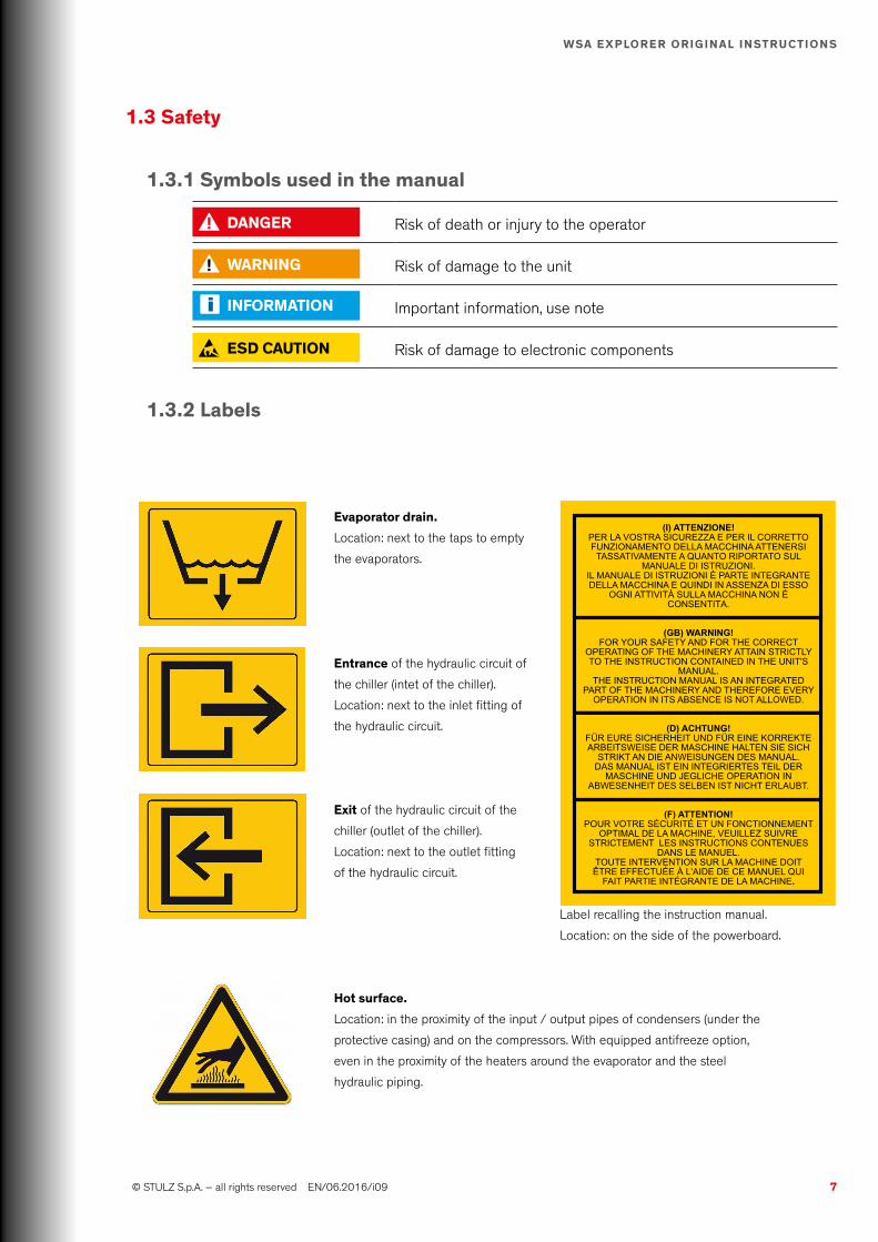
3.3.2 centre of gravityCentre of gravity
Reference point
x y
z
x y
zx y
z
x y
z
x y
z
x y
z
8 fans
12 fans
Base without pump
WSA 160 WSA 220
x 1250 mm 1240 mm
y 1700 mm 1900 mm
z 880 mm 870 mm
F.c. without pump
WSA 160 WSA 220
x 1250 mm 1240 mm
y 1700 mm 1900 mm
z 1065 mm 1053 mm
Base without pump
WSA 250 WSA 280 WSA 300
x 1210 mm 1210 mm 1210 mm
y 3100 mm 3120 mm 3120 mm
z 940 mm 940 mm 940 mm
F.c. + 2 pumps
WSA 160 WSA 220 WSA 220
x 1483 mm 1483 mm 1483 mm
y 3271 mm 3292 mm 3292 mm
z 1137 mm 1137 mm 1137 mm

21 © STULZ S.p.A. – all rights reserved EN/06.2016/i09
WSA ExplOrEr OriginAl inStructiOnS
x
y
z
x
y
z
x y
z
x y
z
x y
z
16 fans
24 fans
Centre of gravity
Reference point
Base without pump
WSA 320 WSA 360 WSA 380 WSA 440
x 1280 mm 1240 mm 1240 mm 1210 mm
y 3820 mm 3870 mm 3990 mm 4110 mm
z 900 mm 890 mm 870 mm 1050 mm
F.c. + 2 pumps
WSA 320 WSA 360 WSA 380 WSA 440
x 1569 mm 1520 mm 1520 mm 1483 mm
y 4030 mm 4083 mm 4209 mm 4336 mm
z 1089 mm 1077 mm 1053 mm 1271 mm
Base without pump
WSA 480 WSA 640
x 1230 mm 1240 mm
y 5780 mm 5790 mm
z 950 mm 940 mm
F.c. + 2 pumps
WSA 480 WSA 640
x 1320 mm 1331 mm
y 6179 mm 6190 mm
z 969 mm 959 mm
22 EN/06.2016/i09 © STULZ S.p.A. – all rights reserved
WSA ExplOrEr OriginAl inStructiOnS
4. Description
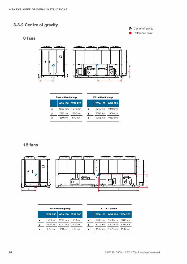
4.1 type code
The type code represents the variant of your chiller unit and can be found on the nameplate located on the inner side of the electric cabinet. You can decode the type code by the following table.
inFOrMAtiOn
Please be aware that not every combination of these values is possible.
Air cooled ScrewSW
A3°digitconfiguration
A axial fans
3
2
0
4°digit
5°digit
6°digit
cooling capacity
160 376 kW (1) 320 738 kW (1)
220 482 kW (1) 360 844 kW (1)
250 567 kW (1) 380 911 kW (1)
280 630 kW (1) 440 1032 kW (1)
300 672 kW (1) 480 1122 kW (1)
(1) at 50 Hz, W7L35 640 1260 kW (1)
27°digitEvaporation temperature
1 Outlet water > 15°C
2 Outlet water ≤ 15°C (standard)
8°digit cVersion
c chiller
D chiller with treated MCH coils
F Free Cooling
g Free Cooling + Epoxy condensing coils
i Free Cooling + Cataphoresis condensing coils
n9°digitnoise level
n Standard
S Low Noise
10°digit Apower Supply
A 400V / ~3 / 50Hz
B 460V / ~3 / 60Hz
n11°digitHydraulic circuit
0 No pumps
1 n°1 pump standard
2 n°2 pumps standard
3 n°1 pump with inverter
4 n°2 pumps with inverter
12°digit 0Heat recovery
0 none
D partial recovery (t.b.d.)
t total recovery (t.b.d.)
0
0
0
Options
(change accordingly to the selected options)13°digit
14°digit
15°digit
2°digit
1°digit

23 © STULZ S.p.A. – all rights reserved EN/06.2016/i09
WSA ExplOrEr OriginAl inStructiOnS
4.2 intended use
This chiller is intended for the chilled water production and for the chilled water control. TThechiller is designed for outdoor installation on the roof of a building or at the ground level. Any use beyond this is not intended. STULZ is not liable for any damage resulting from such misuse. The operator alone bears the risk. The chiller must not be used for the warming of water.
4.3 chiller Design
4.3.1 general
The chillers of the Explorer WSA series with screw compressors exist in 5 construction sizes which differ by their dimensions and cooling capacity. The chiller consists of two separate refrig-erant circuits with one semi-hermetic screw compressors in each circuit, a single shell & tube evaporator, air cooled condensers and an electronic expansion valves in each refrigerant circuit.After assembling the chiller each unit is pressure tested, evacuated and fully factory charged with R134a and oil in each of the independent refrigerant circuits. The end of line test also includes an operational test with water flowing through the evaporator to ensure that each refrigerant circuit operates correctly.
4.3.2 Versions
The standard version for water cooled chillers with screw compressors has a unit designation which takes the following pattern: WSA _ _ _ 2 CN _ . There is one more version which will be described in the following.
Free cooling VersionThe free cooling version is available for all the sizes. This Version additionally contains free cool-ing coils positioned directly in front of the condensers and therefore in W-shape. .During free cooling mode two motor-driven 2-way-valve directs the water volume completely through the free cooling coils.
low noise version With the low noise version of the Explorer WSA chillers you have the possibility to reduce the noise emissions to up to –10dB.There are two main sources which are responsible for the noise. One is the fan section and the other one is the compressors. To reduce the noise caused by the fans the fan speed of the low noise version is reduced by changing the electrical connections from delta to star. This occurs in a reduction of the fan speed of approx. 30%. To reduce the noise emitted by the compressors they are installed in a completely insulated compressor compartment.
4.3.3 refrigerant circuit
Two independent refrigerant circuits are provided. Each circuit uses copper refrigerant pipes that are formed on computer controlled bending machines where possible to reduce the number of single point of failures and to provide a reliable and leak resistant system. An electronic expansion valve is also a part of the standard equipment as well as a filter dryer

24 EN/06.2016/i09 © STULZ S.p.A. – all rights reserved
WSA ExplOrEr OriginAl inStructiOnS
with replaceable cartridge and a sight glass with humidity indication.
Each refrigerant circuit disposes of the following safety devices: low pressure switchA low pressure switch is installed in each cooling circuit. It will be activated when the pressure inside the cooling circuit drops down to 0.4 barg. The compressors of the circuit will be turned off and an alarm signal is shown on the electronic control display. The pressure switch needs to be reset manually. High pressure switchA high pressure switch is installed in each cooling circuit. It will be activated when the pressure inside the cooling circuit exceeds 20.5 barg. The compressors of the circuit will be turned off and an alarm signal is shown on the electronic control display. The pressure switch needs to be reset manually.Safety valveA safety valve is installed in each cooling circuit. It is positioned on the pressure side of the compressor. The safety valve will be activated when the pressure in the cooling circuit exceeds the max. value of 24 barg. (Whether the chiller is operating or not.) In this case the safety valve opens and the refrigerant will exit.
4.3.4 compressor
The chiller has semi-hermetic screw compressors equipped with internal capacity control. The single compressor can be partializzed stepless from 25% to 100%. In each unit there is one compressor per cooling circuit and can be separately switched on, off and partializzed.The compressor contains a crankcase heater.
4.3.5 Evaporator
The Explorer WSA is equipped with a shell & tube heat exchanger made with copper pipes and steel shell. Fully insulated with 10 mm of thermal insulator.Victaulic® connections as standard in the inlet and outlet of the water circuit.
4.3.6 condenser
The air cooled condensers are MicroChannel condensers completely made of aluminium real-ized in W-shape modules. With having this type of condenser you avoid high pressure drops, increase the heat transfer coefficient and reduce the amount of refrigerant needed. For the free cooling model the MicroChannel is treated with a cataphoresis treatment which is available for the base version as option.
4.3.7 Electrical cabinet
The electrical cabinet is divided into a load section and a control section. In the door in front of the control section you will find a touch display with a transparent protection panel. The load section contains a power switch operable from the outside which locks the cabinet door when switched on. The protection degree of the electrical cabinet is IP54.
4.3.8 Sensors
25 © STULZ S.p.A. – all rights reserved EN/06.2016/i09
WSA ExplOrEr OriginAl inStructiOnS
The following sensors are installed in the chiller as standardfor each refrigerant circuit:
For each circuit:• high and low pressure switch to guarantee the safety• high and low pressure transducer to manage the compressors and the EEV• sensor for discharge and suction gas temperature (PTC) to manage the compressors
and the EEV
chilled water circuit:• sensor for inlet and outlet water temperature (PTC) to manage the set-point• differential pressure switch to guarantee the safety of the unit• sensor for freezing temperature (PTC) to guarantee the safety of the unit
Air temperatures:• sensor for outdoor temperature (PTC) to manage the free cooling
4.3.9 c2020
A graphical touch display is connected to the STULZ C2020 and installed in the door of the electrical cabinet. It is able to show the information about the operation conditions, the status of the unit and all the alarms. It is accessible from the outside. All features are password protected.
inFOrMAtiOn
To get more information about the C2020 please refer to the separate controller manual
4.4 piping diagrams

26 EN/06.2016/i09 © STULZ S.p.A. – all rights reserved
WSA ExplOrEr OriginAl inStructiOnS
4.4.1 legend
nomenc. Symbol Meaning nomenc. Symbol Meaning
Bc Condenser VSc Safety valve with spring loading
cO M Compressor in Water inlet
PT Pressure Transducer TCE Electronic expansion valve
EV Evaporator Out Water outlet
Fg Refrigerant filter ruH
Manual valve
TT Temperature trasmitter rl Liquid receiver
PSL Pressure limiter, low Disconnectable joint
PZHH High pressure switch Insulation
PD-ZAL Low pressure switch Refrigerant line
rg General valve Actuating line

27 © STULZ S.p.A. – all rights reserved EN/06.2016/i09
WSA ExplOrEr OriginAl inStructiOnS
Stan
dard
circ
uit d
iagr
am. C
heck
MAn
uAl
pAr
t iia
for a
ny c
hang
es.
CO
1
1/4
1/4
RG
1
VSC
1M
1
CO
2
1/4
1/4
RG
2
VSC
2M
2
BC4
BC3
PZHH 1
PSL 1
PZHH 2
MT1
3M
T12
MT1
1M
T10
MT1
7M
T16
MT1
5M
T14
1/4
PSL 2
FG1
RU
1
RL1
VSC
1
TCE 1
FG2
RU
2
RL2
TCE 2
VSC
2
HH
PT 1PT 2
BC1
BC2
TT 1TT 2
PT 3PT 4
SHEL
L &
TUBE
SEV
APO
RAT
OR
WAT
ER O
UT
WAT
ER IN
RE
PDZA
L3
TT 4TT 7
PT 1PT 2
PDZA
L1
PDZA
L2
--061ASW - - - - -1° 2° 3° 4° 5° 6° 7° 9°
-8° 10° 11° 12° 13° 14°
022-
15°

MT1
2M
T11
MT1
0
MT1
6M
T15
MT1
4
MT2
4M
T23
MT2
2
MT2
0M
T19
MT1
8
FG1
RU
1
RL1
VSC
1
TCE 1
FG2
RU
2
RL2
TCE 2
VSC
2
BC6
BC7
BC8
HH
PT 1PT 2
CO
1
1/4
1/4
RG
1
VSC
1M
1
CO
2
1/4
1/4
RG
2
VSC
2M
2PZ
HH 1PS
L 1PZ
HH 2
1/4
PSL 2
BC5
BC1
BC2
BC3
BC4
TT 1TT 2
PT 3PT 4
SHEL
L &
TUBE
SEV
APO
RAT
OR
WAT
ER O
UT
WAT
ER IN
RE
PDZA
L3
TT 4TT 7
PT 1PT 2
PDZA
L1
PDZA
L2
--052ASW - - - - -1° 2° 3° 4° 5° 6° 7° 9°
-8° 10° 11° 12° 13° 14°
082003
-15°
28 EN/06.2016/i09 © STULZ S.p.A. – all rights reserved
WSA ExplOrEr OriginAl inStructiOnSSt
anda
rd c
ircui
t dia
gram
. Che
ck M
Anu
Al p
Art
iia fo
r any
cha
nges
.

FG1
RU
1
RL1
VSC
1
TCE 1
FG2
RU
2
RL2
TCE 2
VSC
2
BC6
BC7
BC8
HH
PT 1PT 2
MT1
3M
T12
MT1
1M
T10
MT1
7M
T16
MT1
5M
T14
MT2
5M
T24
MT2
3M
T22
MT2
1M
T20
MT1
9M
T18
CO
1
1/4
1/4
RG
1
VSC
1M
1
CO
2
1/4
1/4
RG
2
VSC
2M
2PZ
HH 1PS
L 1PZ
HH
2
1/4
PSL 2
BC5
BC1
BC2
BC3
BC4
TT 1TT 2
PT 3PT 4
SHEL
L &
TUBE
SEV
APO
RAT
OR
WAT
ER O
UT
WAT
ER IN
RE
PDZA
L3
TT 4TT 7
PT 1PT 2
PDZA
L1
PDZA
L2
--023ASW - - - - -1° 2° 3° 4° 5° 6° 7° 9°
-8° 10° 11° 12° 13° 14°
063083004044
-15°
29 © STULZ S.p.A. – all rights reserved EN/06.2016/i09
WSA ExplOrEr OriginAl inStructiOnS

30 EN/06.2016/i09 © STULZ S.p.A. – all rights reserved
WSA ExplOrEr OriginAl inStructiOnS
FG1
RU
1
RL1
VSC
1
BC1
BC2
FG2
RU
2
RL2
VSC
2
BC3
BC4
BC5
BC6
BC7
BC8
BC9
BC10
BC11
BC12
HH
PT 1PT 2
MT1
3M
T12
MT1
1M
T10
MT2
0M
T21
MT1
9M
T18
MT2
9M
T28
MT2
7M
T26
MT3
3M
T32
MT3
1M
T30
MT2
5M
T24
MT2
3M
T22
MT1
7M
T16
MT1
5M
T14
TT 1TT 2
PT 3PT 4
SHEL
L &
TUBE
SEV
APO
RAT
OR
WAT
ER O
UT
WAT
ER IN
RE
PDZA
L3
TT 4TT 7
PT 1PT 2
CO
1
1/4
1/4
RG
1
VSC
1M
1
CO
2
1/4
1/4
RG
2
VSC
2M
2PZ
HH 1PS
L 1PZ
HH
2
1/4
PSL 2
PDZA
L1
TCE 1
PDZA
L2
TCE 2
--084ASW - - - - -1° 2° 3° 4° 5° 6° 7° 9°
-8° 10° 11° 12° 13° 14°
046-
15°

31 © STULZ S.p.A. – all rights reserved EN/06.2016/i09
WSA ExplOrEr OriginAl inStructiOnS
nomenc. Symbol Meaning nomenc. Symbol Meaning
Bc Exchanger in Water inlet
MMotorized valve Out Water outlet
PT Pressure Transducer ruH
Manual valve
EV Evaporator rE Heaters
M Pump Check valve
TT Temperature trasmitter Disconnectable joint
PD-ZAL Low pressure switch Insulation
rg General valve Water line
4.5 Hydraulic diagrams
4.5.1 legend
inFOrMAtiOn
See the diagrams in "4.4 Piping diagrams" at page 25

32 EN/06.2016/i09 © STULZ S.p.A. – all rights reserved
WSA ExplOrEr OriginAl inStructiOnS
-----ASW - - - - -1° 2° 3° 4° 5° 6° 7° 9°
C8° 10° 11° 12° 13° 14°
GI
-15°
M
M
BC1 BC2 BC4 BC3
MT13MT12MT11MT10
MT17MT16MT15MT14
TT3
TT5
SHELL & TUBESEVAPORATOR
WATER OUT
WATER IN
RE
PDZAL
TT4 TT
7
M
M
BC1 BC2 BC3 BC4 BC5BC6BC7BC8
MT12MT11MT10
MT16MT15MT14
MT24MT23MT22
MT20MT19MT18
TT3
TT5
SHELL & TUBESEVAPORATOR
WATER OUT
WATER IN
RE
PDZAL
TT4 TT
7
WSA 160-220
WSA 250-280-300
Stan
dard
circ
uit d
iagr
am. C
heck
MAn
uAl
pAr
t iia
for a
ny c
hang
es.
With Free cooling

33 © STULZ S.p.A. – all rights reserved EN/06.2016/i09
WSA ExplOrEr OriginAl inStructiOnS
WSA 320-360-380-440
WSA 480-640
M
M
BC1 BC2 BC3 BC4 BC5BC6BC7BC8
TT3
MT13MT12MT11MT10
MT17MT16MT15MT14
MT25MT24MT23MT22
MT21MT20MT19MT18
TT5
SHELL & TUBESEVAPORATOR
WATER OUT
WATER IN
RE
PDZAL
TT4 TT
7
M
M
BC1 BC2 BC3 BC4
MT18 MT20
BC5 BC6
MT32 MT30
BC11BC12 BC9BC10
MT24 MT22
BC7BC8
TT3
TT5
MT13MT12MT11MT10
MT20MT21MT19MT18
MT29MT28MT27MT26
MT33MT32MT31MT30
MT25MT24MT23MT22
MT17MT16MT15MT14
SHELL & TUBESEVAPORATOR
WATER OUT
WATER IN
RE
PDZAL
TT4 TT
7
Stan
dard
circ
uit d
iagr
am. C
heck
MAn
uAl
pAr
t iia
for a
ny c
hang
es.

34 EN/06.2016/i09 © STULZ S.p.A. – all rights reserved
WSA ExplOrEr OriginAl inStructiOnS
-----ASW - 0 - - -1° 2° 3° 4° 5° 6° 7° 9°
-8° 10° 11° 12° 13° 14°
-15°
MM
H H
M
H H
SHELL & TUBESEVAPORATOR
WATER OUT
WATER IN
RE
PDZAL
TT4 TT
7
SHELL & TUBESEVAPORATOR
WATER OUT
WATER IN
RE
PDZAL
TT4 TT
7
SHELL & TUBESEVAPORATOR
WATER OUT
WATER IN
RE
PDZAL
TT4 TT
7
MM
H H
M
H H
SHELL & TUBESEVAPORATOR
WATER OUT
WATER IN
RE
PDZAL
TT4 TT
7
SHELL & TUBESEVAPORATOR
WATER OUT
WATER IN
RE
PDZAL
TT4 TT
7
SHELL & TUBESEVAPORATOR
WATER OUT
WATER IN
RE
PDZAL
TT4 TT
7
MM
H H
M
H H
SHELL & TUBESEVAPORATOR
WATER OUT
WATER IN
RE
PDZAL
TT4 TT
7
SHELL & TUBESEVAPORATOR
WATER OUT
WATER IN
RE
PDZAL
TT4 TT
7
SHELL & TUBESEVAPORATOR
WATER OUT
WATER IN
RE
PDZAL
TT4 TT
7
-----ASW - 1 - - -1° 2° 3° 4° 5° 6° 7° 9°
-8° 10° 11° 12° 13° 14°
-15°
3
-----ASW - 2 - - -1° 2° 3° 4° 5° 6° 7° 9°
-8° 10° 11° 12° 13° 14°
-15°
4
Stan
dard
circ
uit d
iagr
am. C
heck
MAn
uAl
pAr
t iia
for a
ny c
hang
es.
Without pumps
With no.1 pump Or no.1 pump + no.1 inverter
With no.2 pump Or no.2 pump + no.1 inverter

35 © STULZ S.p.A. – all rights reserved EN/06.2016/i09
WSA ExplOrEr OriginAl inStructiOnS
5. technical Data
5.1 Application limits
The STULZ Explorer WSA units are provided for operations within the following ranges:
Setting of the safety devices
High pressure limiter 21.5 barg
Safety high pressure limiter 20.0 barg
Low pressure switch 0.4 barg
High pressure safety valve 24 barg
DAngEr
Install upstream of the chiller adequate protection against indirect contact, respecting the requirements of CEI 64-8, unless other specification by local regulations.
5.1.1 Storage conditions
temperature -5°C ÷ +45°C
Humidity 5 ÷ 95 % rel. h.
5.1.2 Operating conditions
type of network TT; TN-S ; TN-C-S
Voltage 400 V / 3ph / 50Hz ; PE
Voltage tolerance ± 10 %
Frequency tolerance ± 1 %
rated ultimate short- circuit breaking capacity 25 kA
temperature difference 4 - 8 K
Max. glycol content ethylenic 40 %
propilenic 45 %
AB
cD
E F
H
g
-5 0 5 10 15 20 25
-40-18
+5
Special request
Standard Version
Standar Version + heating elements + glycol
Standar Version + heating elements + glycol + wind stop
Low temperature version (LT)
LT version + heating elements + glycol
LT version + heating elements + glycol + wind stop
High temperature version (HT)
HT version + heating elements + glycol
HT version + heating elements + glycol + wind stop
DTW - Delivery water temperature (∆T 5°C)
AT
- Am
bien
t Tem
pera
ture
(°C
)
Min outdoor temperature -18°C (optionally -40°C)
Max outdoor temperature +45°C (optionally +55°C)
Min chilled water inlet temp. -5°C
Max chilled water inlet temp. +15°C (optionally +25°C)
Max chilled water pressure 10 bar

36 EN/06.2016/i09 © STULZ S.p.A. – all rights reserved
WSA ExplOrEr OriginAl inStructiOnS
Standard version @50 HzA B c D E F g H
WSA160 50 55 52 55 -6 -10 -10 48
WSA220 46 53 50 53 -10 -10 -10 44
WSA250 51 56 53 55 -4 -10 -10 49
WSA280 49 55 52 54 -6 -10 -10 47
WSA300 47 54 51 53 -8 -10 -10 45
WSA320 51 56 53 55 -6 -10 -10 49
WSA360 48 54 51 54 -8 -10 -10 46
WSA380 47 54 51 53 -7 -10 -10 45
WSA440 45 52 49 52 -10 -10 -10 42
WSA480 50 56 53 55 -5 -10 -10 48
WSA640 - - 51 54 -10 -10 - 45
low noise version @50 HzA B c D E F g H
WSA160 44 51 48 50 -6 -10 -10 44
WSA220 39 47 45 48 -10 -10 -10 37
WSA250 45 52 49 51 -4 -10 -10 43
WSA280 42 50 48 50 -6 -10 -10 41
WSA300 39 48 46 48 -8 -10 -10 38
WSA320 44 52 48 51 -6 -10 -10 40
WSA360 41 50 47 49 -8 -10 -10 39
WSA380 39 49 46 49 -7 -10 -10 37
WSA440 36 46 44 47 -10 -10 -10 35
WSA480 44 52 48 51 -5 -10 -10 42
WSA640 - - 45 50 -10 -10 - 37
Free cooling version @50 HzA B c D E F g H
WSA160 47 53 49 53 -6 -10 -10 45
WSA220 43 50 47 50 -10 -10 -10 41
WSA250 48 54 51 53 -4 -10 -10 45
WSA280 46 53 50 52 -6 -10 -10 43
WSA300 43 51 48 51 -8 -10 -10 42
WSA320 47 54 51 53 -6 -10 -10 45
WSA360 44 52 49 51 -8 -10 -10 43
WSA380 43 52 49 51 -7 -10 -10 41
WSA440 41 49 46 49 -10 -10 -10 39
WSA480 47 54 50 53 -5 -10 -10 45
WSA640 - - 49 50 -10 -10 - 42

37 © STULZ S.p.A. – all rights reserved EN/06.2016/i09
WSA ExplOrEr OriginAl inStructiOnS
5.2 chilled water quality
inFOrMAtiOn
The following limits for the water circuit may not be exceeded
DAngEr
For outlet water temperatures lower or equal to +5°C and environments with temperatures lower than 0°C, use non freezing mixture approved by STULZ
Feature Minimum value
Maximum value
pH(*) 7,0 8,0
Total hardness(*) °F 13 35
Conductivity(*) µS/cm 200 350
Alcalinity (HCO3)(*) mg/L 200 300
(*) Considering water at temperature +20°C
DAngEr
The chiller must not be used in conditions outside the limits specified in the nameplate
5.2.1 glycol correction factors
inFOrMAtiOn
In case glycol has to be added, the technical data described in this paragraph shall be adjusted according to the coefficients shown in the following table.
percentage of ethylene glycol percentage of propylene glycol
10% 20% 30% 40% 10% 20% 30% 40%
Freezing temperature [°C] -3.9 -8.9 -15.6 -23.4 -3.3 -7.8 -12.2 -20.6
cooling capacityCorrection factors on the technical data sheets
0.997 0.990 0.984 0.977 0.993 0.985 0.974 0.962
power consumption 0.999 0.997 0.996 0.994 0.999 0.996 0.993 0.989
Flow of fluid to be cooled 1.014 1.033 1.068 1.117 0.989 1.009 1.017 1.040
pressure drop on the fluid to be cooled side 1.07 1.16 1.30 1.48 1.04 1.14 1.23 1.37
38 EN/06.2016/i09 © STULZ S.p.A. – all rights reserved
WSA ExplOrEr OriginAl inStructiOnS
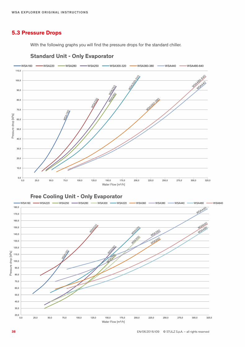
5.3 pressure Drops
With the following graphs you will find the pressure drops for the standard chiller.
Standard unit - Only Evaporator
50,0
60,0
70,0
80,0
90,0
100,0
110,0
WSA160 WSA220 WSA280 WSA250 WSA300-320 WSA360-380 WSA440 WSA480-640
0,0
10,0
20,0
30,0
40,0
0,0 25,0 50,0 75,0 100,0 125,0 150,0 175,0 200,0 225,0 250,0 275,0 300,0 325,0
WSA
160
WSA
220
WSA
250
WSA
280
WSA
300-
320
WSA360-3
80
WSA480-6
40
WSA440
50,0
60,0
70,0
80,0
90,0
100,0
110,0
WSA160 WSA220 WSA280 WSA250 WSA300-320 WSA360-380 WSA440 WSA480-640
0,0
10,0
20,0
30,0
40,0
0,0 25,0 50,0 75,0 100,0 125,0 150,0 175,0 200,0 225,0 250,0 275,0 300,0 325,0
Water Flow [m³/h]
Pres
sure
dro
p [k
Pa]
90,0
100,0
110,0
120,0
130,0
140,0
150,0
160,0
170,0
180,0WSA160 WSA220 WSA250 WSA280 WSA300 WSA320 WSA360 WSA380 WSA440 WSA480 WSA640
20,0
30,0
40,0
50,0
60,0
70,0
80,0
0,0 25,0 50,0 75,0 100,0 125,0 150,0 175,0 200,0 225,0 250,0 275,0 300,0 325,0
WSA
160
WSA
220
WSA25
0
WSA
280
WSA300
WSA320
WSA360WSA380
WSA640
WSA480
WSA440
90,0
100,0
110,0
120,0
130,0
140,0
150,0
160,0
170,0
180,0WSA160 WSA220 WSA250 WSA280 WSA300 WSA320 WSA360 WSA380 WSA440 WSA480 WSA640
20,0
30,0
40,0
50,0
60,0
70,0
80,0
0,0 25,0 50,0 75,0 100,0 125,0 150,0 175,0 200,0 225,0 250,0 275,0 300,0 325,0
Free cooling unit - Only Evaporator
Water Flow [m³/h]
Pres
sure
dro
p [k
Pa]

39 © STULZ S.p.A. – all rights reserved EN/06.2016/i09
WSA ExplOrEr OriginAl inStructiOnS
Water Flow [m³/h]
200
225
250
275
300
325
350
375
50
75
100
125
150
175
50 75 100 125 150 175 200 225 250 275 300 325
WSA280
WSA250
WSA300
WSA320
WSA380
WSA360
WSA440WSA480
WSA640
275
300
325
350
375
400
425
450
475
100
125
150
175
200
225
250
50 75 100 125 150 175 200 225 250 275 300 325
WSA250
WSA280
WSA300WSA320
WSA360
WSA380
WSA440
WSA480
WSA250 WSA280 WSA300 WSA320 WSA360 WSA380 WSA440 WSA480 WSA640
WSA250 WSA280 WSA300 WSA320 WSA360 WSA380 WSA440 WSA480 WSA640
StAnDArD Version - 1 or 2 pump(s)
Ht Versions - 1 or 2 pump(s)
Water Flow [m³/h]
Pres
sure
dro
p [k
Pa]
Water Flow [m³/h]
Pres
sure
dro
p [k
Pa]
5.4 Head pressure available

40 EN/06.2016/i09 © STULZ S.p.A. – all rights reserved
WSA ExplOrEr OriginAl inStructiOnS
150
175
200
225
250
275
300
325
350
0
25
50
75
100
125
150
50 75 100 125 150 175 200 225 250 275 300 325
WSA250-280
WSA300
WSA320
WSA360
WSA380
WSA440
WSA640
WSA480
225
250
275
300
325
350
375
400
425
450
475
500
25
50
75
100
125
150
175
200
225
50 75 100 125 150 175 200 225 250 275 300 325
WSA440W
SA250
WSA280
WSA300
WSA320
WSA380
WSA360
WSA480
WSA250-280 WSA300 WSA320 WSA360 WSA380 WSA440 WSA480 WSA640
WSA250-280 WSA300 WSA320 WSA360 WSA380 WSA440 WSA480 WSA640
FrEE cOOling Versions - 1 or 2 pump(s)
FrEE cOOling Ht Versions - 1 or 2 pump(s)
Water Flow [m³/h]
Pres
sure
dro
p [k
Pa]
Water Flow [m³/h]
Pres
sure
dro
p [k
Pa]

41 © STULZ S.p.A. – all rights reserved EN/06.2016/i09
WSA ExplOrEr OriginAl inStructiOnS
Stan
dard
dat
a sh
eet.
Che
ck M
Anu
Al p
Art
iia fo
r any
cha
nges
.
5.5 technical DataWSA-160 WSA-160-Sl WSA-160-Fc
gEn
ErAl
Cooling Capacity kW 376 360 366
Power Consumption W7L35 kW 121 122 126
Free Cooling capacity W10L (see below) kW n.a. n.a. 376
Pressure Sound level @10m dB(A) 69 61 69
Power Sound level dB(A) 97 89 97
HYD
rAu
lic
Water flow m³/h 64 62 64,4
Pressure drops kPa 44 32 44,01
Water circuit content, unit side t.b.d. t.b.d. t.b.d.
Coolant Liquid Type Water - max 40% glycol
Inlet Temperature °C 12 12 12
Outlet Temperature °C 7 7 7
rEF
rig
ErAn
t Refrigerant gas Type R134a
Refrigerant charge kg 67 + 67
Refrigerant Circuit n° 2
Oil charge 22 + 22
cO
Mpr
ESSO
rS
Compressors n° 2 x Semi-Hermetic Double Screw
Partialization % 12,5 ... 100 12,5…100 12,5…100
Power consumption W7L35 kW 105 105 110
Absorbed current W7L35 A 34,4 20 34,4
Max power consumption kW 176 176 176
Max absorbed current A 288 288 288
FAn
S
Axial Fans n° 8 8 8
Fan flow m³/h 148820 111280 122250
Power Consumption W7L35 kW 16 10 16
Absorbed current W7L35 A 34,4 20 34,4
Power consumption kW 17,6 17,6 17,6
Max absorbed current A 37,8 37,8 37,8
F.c
.
Temperature of total FC °C n.a. n.a. 0,5
Flow of fluid to be cooled m³/h n.a. n.a. 65
Pressure drop kPa n.a. n.a. 46
un
it D
AtA
Power supply V/ph/Hz 400 / 3 / 50
Operating current t.b.d. t.b.d. t.b.d.
Max absorbed current A 336 336 336
Starting current A 586 586 586
Height x Width x Depth mm 2473 x 2278 x 4240
EER 3,1 2,94 2,91
ESEER (ISO14511) 4,43 4,59 4,33
IPLV 4,35 4,63 4,23
Evaporator water (in/out) 12/7 °C; condenser air (in) 35 °C;Average sound pressure level at 10 m distance; unit in a free field on a reflective surface.According to ISO 3744. Unit at full capacity. Pump contribution is not considered.*In case of applications with an output fluid temperature below +5 °C, please contact the manufacturer.30% Glycol-Water solution. Evaporator solution IN/OUT= 15/10 °C; Condenser air 30 °CAverage sound pressure level, at 10m distance, unit in a free field on a reflective surface. Unit at full capacity. According to ISO 3744. Pumps contribution is not considered.* In case of applications with output fluid temperature below 0°C, please contact the manufacturer
Fc

42 EN/06.2016/i09 © STULZ S.p.A. – all rights reserved
WSA ExplOrEr OriginAl inStructiOnSSt
anda
rd d
ata
shee
t. C
heck
MAn
uAl
pAr
t iia
for a
ny c
hang
es.
Evaporator water (in/out) 12/7 °C; condenser air (in) 35 °C;Average sound pressure level at 10 m distance; unit in a free field on a reflective surface.According to ISO 3744. Unit at full capacity. Pump contribution is not considered.*In case of applications with an output fluid temperature below +5 °C, please contact the manufacturer.30% Glycol-Water solution. Evaporator solution IN/OUT= 15/10 °C; Condenser air 30 °CAverage sound pressure level, at 10m distance, unit in a free field on a reflective surface. Unit at full capacity. According to ISO 3744. Pumps contribution is not considered.* In case of applications with output fluid temperature below 0°C, please contact the manufacturer
Fc
WSA-220 WSA-220-Sl WSA-220-Fcg
EnEr
Al
Cooling Capacity kW 482 442 469
Power Consumption W7L35 kW 164 175 172
Free Cooling capacity W10L (see below) kW n.a. n.a. 472
Pressure Sound level @10m dB(A) 70,5 62,6 70,5
Power Sound level dB(A) 98,5 90,6 98,5
HYD
rAu
lic
Water flow m³/h 83 76 82,7
Pressure drops kPa 35 33 34,75
Water circuit content, unit side t.b.d. t.b.d. t.b.d.
Coolant Liquid Type Water - max 40% glycol
Inlet Temperature °C 12 12 12
Outlet Temperature °C 7 7 7
rEF
rig
ErAn
t Refrigerant gas Type R134a
Refrigerant charge kg 86 +86
Refrigerant Circuit n° 2
Oil charge dm³ 22 + 22
cO
Mpr
ESSO
rS
Compressors n° 2
Partialization % 12,5 ... 100 12,5…100 12,5…100
Power consumption W7L35 kW 148 148 156
Absorbed current W7L35 A 243 243 253,9
Max power consumption kW 220 220 220
Max absorbed current A 364 364 364
FAn
S
Axial Fans n° 8 8 8
Fan flow m³/h 144240 99570 120127
Power Consumption W7L35 kW 16 10 16
Absorbed current W7L35 A 34,4 20 34,4
Power consumption kW 17,6 17,6 17,6
Max absorbed current A 37,8 37,8 37,8
F.c
.
Temperature of total FC °C n.a. n.a. -2
Flow of fluid to be cooled m³/h n.a. n.a. 81
Pressure drop kPa n.a. n.a. 72
un
it D
AtA
Power supply V/ph/Hz 400 / 3 / 50
Operating current t.b.d. t.b.d. t.b.d.
Max absorbed current A 412 412 412
Starting current A 750 750 750
Height x Width x Depth mm 2473 x 2278 x 4240
EER 2,94 2,52 2,72
ESEER (ISO14511) 4,65 4,64 4,39
IPLV 4,55 4,57 4,43

43 © STULZ S.p.A. – all rights reserved EN/06.2016/i09
WSA ExplOrEr OriginAl inStructiOnS
Stan
dard
dat
a sh
eet.
Che
ck M
Anu
Al p
Art
iia fo
r any
cha
nges
.
Evaporator water (in/out) 12/7 °C; condenser air (in) 35 °C;Average sound pressure level at 10 m distance; unit in a free field on a reflective surface.According to ISO 3744. Unit at full capacity. Pump contribution is not considered.*In case of applications with an output fluid temperature below +5 °C, please contact the manufacturer.30% Glycol-Water solution. Evaporator solution IN/OUT= 15/10 °C; Condenser air 30 °CAverage sound pressure level, at 10m distance, unit in a free field on a reflective surface. Unit at full capacity. According to ISO 3744. Pumps contribution is not considered.* In case of applications with output fluid temperature below 0°C, please contact the manufacturer
Fc
WSA-250 WSA-250-Sl WSA-250-Fcg
EnEr
AlCooling Capacity kW 568 534 552
Power Consumption W7L35 kW 178 183 185
Free Cooling capacity W10L (see below) kW n.a. n.a. 552
Pressure Sound level @10m dB(A) 69,3 61,4 69,3
Power Sound level dB(A) 97,3 89,4 97,3
HYD
rAu
lic
Water flow m³/h 97 92 97,4
Pressure drops kPa 36 31 35,56
Water circuit content, unit side t.b.d. t.b.d. t.b.d.
Coolant Liquid Type Water - max 40% glycol 0 0
Inlet Temperature °C 12 12 12
Outlet Temperature °C 7 7 7
rEF
rig
ErAn
t Refrigerant gas Type R134a R134a R134a
Refrigerant charge kg 101 + 101
Refrigerant Circuit n° 2
Oil charge 19 + 19
cO
Mpr
ESSO
rS
Compressors n° 2 x Semi-Hermetic Double Screw
Partialization % 12,5 ... 100 12,5…100 12,5…100
Power consumption W7L35 kW 154 154 161
Absorbed current W7L35 A 51,6 30 51,6
Max power consumption kW 392 392 392
Max absorbed current A 240 240 240
FAn
S
Axial Fans n° 12 12 12
Fan flow m³/h 215045 147655 177851
Power Consumption W7L35 kW 24 15 24
Absorbed current W7L35 A 51,6 30 51,6
Power consumption kW 26,4 26,4 26,4
Max absorbed current A 56,8 56,8 56,8
F.c
.
Temperature of total FC °C n.a. n.a. 0,5
Flow of fluid to be cooled m³/h n.a. n.a. 95
Pressure drop kPa n.a. n.a. 23
un
it D
AtA
Power supply V/ph/Hz 400 / 3 / 50
Operating current t.b.d. t.b.d. t.b.d.
Max absorbed current A 459 459 459
Starting current A 875 875 875
Height x Width x Depth mm 2473 x 2278 x 6960
EER 3,18 2,91 2,99
ESEER (ISO14511) 4,52 4,65 4,5
IPLV 4,48 4,7 4,35

44 EN/06.2016/i09 © STULZ S.p.A. – all rights reserved
WSA ExplOrEr OriginAl inStructiOnSSt
anda
rd d
ata
shee
t. C
heck
MAn
uAl
pAr
t iia
for a
ny c
hang
es.
Evaporator water (in/out) 12/7 °C; condenser air (in) 35 °C;Average sound pressure level at 10 m distance; unit in a free field on a reflective surface.According to ISO 3744. Unit at full capacity. Pump contribution is not considered.*In case of applications with an output fluid temperature below +5 °C, please contact the manufacturer.30% Glycol-Water solution. Evaporator solution IN/OUT= 15/10 °C; Condenser air 30 °CAverage sound pressure level, at 10m distance, unit in a free field on a reflective surface. Unit at full capacity. According to ISO 3744. Pumps contribution is not considered.* In case of applications with output fluid temperature below 0°C, please contact the manufacturer
Fc
WSA-280 WSA-280-Sl WSA-280-Fcg
EnEr
Al
Cooling Capacity kW 631 589 594
Power Consumption W7L35 kW 203 212 212
Free Cooling capacity W10L (see below) kW -- -- 611
Pressure Sound level @10m dB(A) 69,6 69,6 69,6
Power Sound level dB(A) 97,7 89,8 97,7
HYD
rAu
lic
Water flow m³/h 108 101 108,2
Pressure drops kPa 38 37 38,25
Water circuit content, unit side t.b.d. t.b.d. t.b.d.
Coolant Liquid Type Water - max 40% glycol
Inlet Temperature °C 12 12 12
Outlet Temperature °C 7 7 7
rEF
rig
ErAn
t Refrigerant gas Type R134a
Refrigerant charge kg 112 + 112
Refrigerant Circuit n° 2
Oil charge 19 + 19
cO
Mpr
ESSO
rS
Compressors n° 2 x Semi-Hermetic Double Screw
Partialization % 12,5 ... 100 12,5…100 12,5…100
Power consumption W7L35 kW 179 179 187
Absorbed current W7L35 A 51,6 30 51,6
Max power consumption kW 262 262 262
Max absorbed current A 428 428 428
FAn
S
Axial Fans n° 12 12 12
Fan flow m³/h 215045 147655 177851
Power Consumption W7L35 kW 24 15 24
Absorbed current W7L35 A 51,6 30 51,6
Power consumption kW 26,4 26,4 26,4
Max absorbed current A 56,8 56,8 56,8
F.c
.
Temperature of total FC °C -0,7
Flow of fluid to be cooled m³/h 105
Pressure drop kPa 27
un
it D
AtA
Power supply V/ph/Hz 400 / 3 / 50
Operating current t.b.d. t.b.d. t.b.d.
Max absorbed current A 495 495 495
Starting current A 946 946 946
Height x Width x Depth mm 2473 x 2278 x 6960
EER 3,11 2,77 2,81
ESEER (ISO14511) 4,58 4,66 4,39
IPLV 4,58 4,71 4,3

45 © STULZ S.p.A. – all rights reserved EN/06.2016/i09
WSA ExplOrEr OriginAl inStructiOnS
Stan
dard
dat
a sh
eet.
Che
ck M
Anu
Al p
Art
iia fo
r any
cha
nges
.
Evaporator water (in/out) 12/7 °C; condenser air (in) 35 °C;Average sound pressure level at 10 m distance; unit in a free field on a reflective surface.According to ISO 3744. Unit at full capacity. Pump contribution is not considered.*In case of applications with an output fluid temperature below +5 °C, please contact the manufacturer.30% Glycol-Water solution. Evaporator solution IN/OUT= 15/10 °C; Condenser air 30 °CAverage sound pressure level, at 10m distance, unit in a free field on a reflective surface. Unit at full capacity. According to ISO 3744. Pumps contribution is not considered.* In case of applications with output fluid temperature below 0°C, please contact the manufacturer
Fc
WSA-300 WSA-300-Sl WSA-300-Fcg
EnEr
AlCooling Capacity kW 673 627 652
Power Consumption W7L35 kW 226 239 237
Free Cooling capacity W10L (see below) kW -- -- 660
Pressure Sound level @10m dB(A) 69,6 69,6 69,6
Power Sound level dB(A) 97,7 89,8 97,7
HYD
rAu
lic
Water flow m³/h 115 107 115,4
Pressure drops kPa 35 28 35,4
Water circuit content, unit side t.b.d. t.b.d. t.b.d.
Coolant Liquid Type Water - max 40% glycol
Inlet Temperature °C 12 12 12
Outlet Temperature °C 7 7 7
rEF
rig
ErAn
t Refrigerant gas Type R134a
Refrigerant charge kg 119 + 119
Refrigerant Circuit n° 2
Oil charge 19 + 19
cO
Mpr
ESSO
rS
Compressors n°2 x Semi-Hermetic
Double ScrewPartialization % 12,5 ... 100 12,5…100 12,5…100
Power consumption W7L35 kW 202 202 212
Absorbed current W7L35 A 51,6 30 51,6
Max power consumption kW 262 262 262
Max absorbed current A 428 428 428
FAn
S
Axial Fans n° 12 12 12
Fan flow m³/h 215045 147655 177851
Power Consumption W7L35 kW 24 15 24
Absorbed current W7L35 A 51,6 30 51,6
Power consumption kW 26,4 26,4 26,4
Max absorbed current A 56,8 56,8 56,8
F.c
.
Temperature of total FC °C -1,7
Flow of fluid to be cooled m³/h 113
Pressure drop kPa 31
un
it D
AtA
Power supply V/ph/Hz 400 / 3 / 50
Operating current t.b.d. t.b.d. t.b.d.
Max absorbed current A 495 495 495
Starting current A 946 946 946
Height x Width x Depth mm 2473 x 2278 x 6960
EER 2,97 2,61 2,76
ESEER (ISO14511) 4,45 4,49 4,34
IPLV 4,45 4,52 4,29

46 EN/06.2016/i09 © STULZ S.p.A. – all rights reserved
WSA ExplOrEr OriginAl inStructiOnSSt
anda
rd d
ata
shee
t. C
heck
MAn
uAl
pAr
t iia
for a
ny c
hang
es.
Evaporator water (in/out) 12/7 °C; condenser air (in) 35 °C;Average sound pressure level at 10 m distance; unit in a free field on a reflective surface.According to ISO 3744. Unit at full capacity. Pump contribution is not considered.*In case of applications with an output fluid temperature below +5 °C, please contact the manufacturer.30% Glycol-Water solution. Evaporator solution IN/OUT= 15/10 °C; Condenser air 30 °CAverage sound pressure level, at 10m distance, unit in a free field on a reflective surface. Unit at full capacity. According to ISO 3744. Pumps contribution is not considered.* In case of applications with output fluid temperature below 0°C, please contact the manufacturer
Fc
WSA-320 WSA-320-Sl WSA-320-Fcg
EnEr
Al
Cooling Capacity kW 739 689 721
Power Consumption W7L35 kW 237 245 247
Free Cooling capacity W10L (see below) kW -- -- 740
Pressure Sound level @10m dB(A) 70,6 70,6 70,6
Power Sound level dB(A) 98,7 90,8 98,7
HYD
rAu
lic
Water flow m³/h 127 118 126,8
Pressure drops kPa 43 33 42,77
Water circuit content, unit side t.b.d. t.b.d. t.b.d.
Coolant Liquid Type Water - max 40% glycol
Inlet Temperature °C 12 12 12
Outlet Temperature °C 7 7 7
rEF
rig
ErAn
t Refrigerant gas Type R134a
Refrigerant charge kg 131 + 131
Refrigerant Circuit n° 2
Oil charge 30 + 30
cO
Mpr
ESSO
rS
Compressors n°2 x Semi-Hermetic
Double ScrewPartialization % 12,5 ... 100 12,5…100 12,5…100
Power consumption W7L35 kW 205 205 215
Absorbed current W7L35 A 68,8 40 68,8
Max power consumption kW 310 310 310
Max absorbed current A 560 560 560
FAn
S
Axial Fans n° 16 16 16
Fan flow m³/h 278715 186770 224542
Power Consumption W7L35 kW 32 20 32
Absorbed current W7L35 A 68,8 40 68,8
Power consumption kW 35,2 35,2 35,2
Max absorbed current A 75,7 75,7 75,7
F.c
.
Temperature of total FC °C 0
Flow of fluid to be cooled m³/h 127
Pressure drop kPa 45
un
it D
AtA
Power supply V/ph/Hz 400 / 3 / 50
Operating current t.b.d. t.b.d. t.b.d.
Max absorbed current A 646 646 646
Starting current A 802 802 802
Height x Width x Depth mm 2473 x 2278 x 8080
EER 3,12 2,81 2,92
ESEER (ISO14511) 4,53 4,64 4,44
IPLV 4,37 4,57 4,28

47 © STULZ S.p.A. – all rights reserved EN/06.2016/i09
WSA ExplOrEr OriginAl inStructiOnS
Stan
dard
dat
a sh
eet.
Che
ck M
Anu
Al p
Art
iia fo
r any
cha
nges
.
Evaporator water (in/out) 12/7 °C; condenser air (in) 35 °C;Average sound pressure level at 10 m distance; unit in a free field on a reflective surface.According to ISO 3744. Unit at full capacity. Pump contribution is not considered.*In case of applications with an output fluid temperature below +5 °C, please contact the manufacturer.30% Glycol-Water solution. Evaporator solution IN/OUT= 15/10 °C; Condenser air 30 °CAverage sound pressure level, at 10m distance, unit in a free field on a reflective surface. Unit at full capacity. According to ISO 3744. Pumps contribution is not considered.* In case of applications with output fluid temperature below 0°C, please contact the manufacturer
Fc
WSA-360 WSA-360-Sl WSA-360-Fcg
EnEr
AlCooling Capacity kW 845 780 822
Power Consumption W7L35 kW 271 283 283
Free Cooling capacity W10L (see below) kW -- -- 835
Pressure Sound level @10m dB(A) 70,8 70,8 70,8
Power Sound level dB(A) 98,9 91 98,9
HYD
rAu
lic
Water flow m³/h 145 134 145
Pressure drops kPa 32 28 32,24
Water circuit content, unit side t.b.d. t.b.d. t.b.d.
Coolant Liquid Type Water - max 40% glycol
Inlet Temperature °C 12 12 12
Outlet Temperature °C 7 7 7
rEF
rig
ErAn
t Refrigerant gas Type R134a
Refrigerant charge kg 149 + 149
Refrigerant Circuit n° 2
Oil charge 30 + 30
cO
Mpr
ESSO
rS
Compressors n°2 x Semi-Hermetic
Double ScrewPartialization % 12,5 ... 100 12,5…100 12,5…100
Power consumption W7L35 kW 239 239 251
Absorbed current W7L35 A 68,8 40 68,8
Max power consumption kW 350 350 350
Max absorbed current A 620 620 620
FAn
S
Axial Fans n° 16 16 16
Fan flow m³/h 278715 186770 224542
Power Consumption W7L35 kW 32 20 32
Absorbed current W7L35 A 68,8 40 68,8
Power consumption kW 35,2 35,2 35,2
Max absorbed current A 75,7 75,7 75,7
F.c
.
Temperature of total FC °C -1,5
Flow of fluid to be cooled m³/h 144
Pressure drop kPa 52
un
it D
AtA
Power supply V/ph/Hz 400 / 3 / 50
Operating current t.b.d. t.b.d. t.b.d.
Max absorbed current A 706 706 706
Starting current A 861 861 861
Height x Width x Depth mm 2473 x 2278 x 8080
EER 3,12 2,75 2,91
ESEER (ISO14511) 4,76 4,78 4,55
IPLV 4,6 4,68 4,46

48 EN/06.2016/i09 © STULZ S.p.A. – all rights reserved
WSA ExplOrEr OriginAl inStructiOnSSt
anda
rd d
ata
shee
t. C
heck
MAn
uAl
pAr
t iia
for a
ny c
hang
es.
Evaporator water (in/out) 12/7 °C; condenser air (in) 35 °C;Average sound pressure level at 10 m distance; unit in a free field on a reflective surface.According to ISO 3744. Unit at full capacity. Pump contribution is not considered.*In case of applications with an output fluid temperature below +5 °C, please contact the manufacturer.30% Glycol-Water solution. Evaporator solution IN/OUT= 15/10 °C; Condenser air 30 °CAverage sound pressure level, at 10m distance, unit in a free field on a reflective surface. Unit at full capacity. According to ISO 3744. Pumps contribution is not considered.* In case of applications with output fluid temperature below 0°C, please contact the manufacturer
Fc
WSA-380 WSA-380-Sl WSA-380-Fcg
EnEr
Al
Cooling Capacity kW 912 851 888
Power Consumption W7L35 kW 294 307 306
Free Cooling capacity W10L (see below) kW -- -- 879
Pressure Sound level @10m dB(A) 70,8 70,8 70,8
Power Sound level dB(A) 98,9 91 98,9
HYD
rAu
lic
Water flow m³/h 156 146 156,4
Pressure drops kPa 38 36 38,07
Water circuit content, unit side t.b.d. t.b.d. t.b.d.
Coolant Liquid Type Water - max 40% glycol
Inlet Temperature °C 12 12 12
Outlet Temperature °C 7 7 7
rEF
rig
ErAn
t Refrigerant gas Type R134a
Refrigerant charge kg 161 + 161
Refrigerant Circuit n° 2
Oil charge 30 + 30
cO
Mpr
ESSO
rS
Compressors n°2 x Semi-Hermetic
Double ScrewPartialization % 12,5 ... 100 12,5…100 12,5…100
Power consumption W7L35 kW 262 262 273
Absorbed current W7L35 A 68,8 40 68,8
Max power consumption kW 350 350 350
Max absorbed current A 620 620 620
FAn
S
Axial Fans n° 16 16 16
Fan flow m³/h 288480 199135 240253
Power Consumption W7L35 kW 32 20 32
Absorbed current W7L35 A 68,8 40 68,8
Power consumption kW 35,2 35,2 35,2
Max absorbed current A 75,7 75,7 75,7
F.c
.
Temperature of total FC °C -1,3
Flow of fluid to be cooled m³/h 151
Pressure drop kPa 64
un
it D
AtA
Power supply V/ph/Hz 400 / 3 / 50
Operating current t.b.d. t.b.d. t.b.d.
Max absorbed current A 706 706 706
Starting current A 861 861 861
Height x Width x Depth mm 2473 x 2278 x 8080
EER 3,1 2,77 2,91
ESEER (ISO14511) 4,65 4,67 4,41
IPLV 4,56 4,65 4,42

49 © STULZ S.p.A. – all rights reserved EN/06.2016/i09
WSA ExplOrEr OriginAl inStructiOnS
Stan
dard
dat
a sh
eet.
Che
ck M
Anu
Al p
Art
iia fo
r any
cha
nges
.
Evaporator water (in/out) 12/7 °C; condenser air (in) 35 °C;Average sound pressure level at 10 m distance; unit in a free field on a reflective surface.According to ISO 3744. Unit at full capacity. Pump contribution is not considered.*In case of applications with an output fluid temperature below +5 °C, please contact the manufacturer.30% Glycol-Water solution. Evaporator solution IN/OUT= 15/10 °C; Condenser air 30 °CAverage sound pressure level, at 10m distance, unit in a free field on a reflective surface. Unit at full capacity. According to ISO 3744. Pumps contribution is not considered.* In case of applications with output fluid temperature below 0°C, please contact the manufacturer
Fc
WSA-440 WSA-440-Sl WSA-440-Fcg
EnEr
AlCooling Capacity kW 1032 958 1004
Power Consumption W7L35 kW 354 379 370
Free Cooling capacity W10L (see below) kW -- -- 1004
Pressure Sound level @10m dB(A) 71,7 71,7 71,7
Power Sound level dB(A) 99,8 91,8 99,8
HYD
rAu
lic
Water flow m³/h 177 164 177,1
Pressure drops kPa 32 42 31,99
Water circuit content, unit side t.b.d. t.b.d. t.b.d.
Coolant Liquid Type Water - max 40% glycol
Inlet Temperature °C 12 12 12
Outlet Temperature °C 7 7 7
rEF
rig
ErAn
t Refrigerant gas Type R134a
Refrigerant charge kg 183 + 183
Refrigerant Circuit n° 2
Oil charge 30 + 30
cO
Mpr
ESSO
rS
Compressors n°2 x Semi-Hermetic
Double ScrewPartialization % 12,5 ... 100 12,5…100 12,5…100
Power consumption W7L35 kW 322 322 337
Absorbed current W7L35 A 68,8 40 68,8
Max power consumption kW 408 408 408
Max absorbed current A 640 640 640
FAn
S
Axial Fans n° 16 16 16
Fan flow m³/h 288480 199135 240253
Power Consumption W7L35 kW 32 20 32
Absorbed current W7L35 A 68,8 40 68,8
Power consumption kW 35,2 35,2 35,2
Max absorbed current A 75,7 75,7 75,7
F.c
.
Temperature of total FC °C -3
Flow of fluid to be cooled m³/h 173
Pressure drop kPa 80
un
it D
AtA
Power supply V/ph/Hz 400 / 3 / 50
Operating current t.b.d. t.b.d. t.b.d.
Max absorbed current A 726 726 726
Starting current A 992 992 992
Height x Width x Depth mm 2473 x 2278 x 8080
EER 2,91 2,52 2,72
ESEER (ISO14511) 4,66 4,59 4,3
IPLV 4,55 4,53 4,41

50 EN/06.2016/i09 © STULZ S.p.A. – all rights reserved
WSA ExplOrEr OriginAl inStructiOnSSt
anda
rd d
ata
shee
t. C
heck
MAn
uAl
pAr
t iia
for a
ny c
hang
es.
Evaporator water (in/out) 12/7 °C; condenser air (in) 35 °C;Average sound pressure level at 10 m distance; unit in a free field on a reflective surface.According to ISO 3744. Unit at full capacity. Pump contribution is not considered.*In case of applications with an output fluid temperature below +5 °C, please contact the manufacturer.30% Glycol-Water solution. Evaporator solution IN/OUT= 15/10 °C; Condenser air 30 °CAverage sound pressure level, at 10m distance, unit in a free field on a reflective surface. Unit at full capacity. According to ISO 3744. Pumps contribution is not considered.* In case of applications with output fluid temperature below 0°C, please contact the manufacturer
Fc
WSA-480 WSA-480-Sl WSA-480-Fcg
EnEr
Al
Cooling Capacity kW 1122 1053 1088
Power Consumption W7L35 kW 351 363 366
Free Cooling capacity W10L (see below) kW -- -- 1100
Pressure Sound level @10m dB(A) 72,6 72,6 72,6
Power Sound level dB(A) 100,7 92,8 100,7
HYD
rAu
lic
Water flow m³/h 193 181 192,5
Pressure drops kPa 41 181 40,68
Water circuit content, unit side t.b.d. t.b.d. t.b.d.
Coolant Liquid Type Water - max 40% glycol
Inlet Temperature °C 12 12 12
Outlet Temperature °C 7 7 7
rEF
rig
ErAn
t Refrigerant gas Type R134a
Refrigerant charge kg 198 + 198
Refrigerant Circuit n° 2
Oil charge 30 + 30
cO
Mpr
ESSO
rS
Compressors n° 2 x Semi-Hermetic Double Screw
Partialization % 12,5 ... 100 12,5…100 12,5…100
Power consumption W7L35 kW 303 303 318
Absorbed current W7L35 A 103 60 103
Max power consumption kW 444 444 444
Max absorbed current A 720 720 720
FAn
S
Axial Fans n° 24 24 24
Fan flow m³/h 418070 280155 336812
Power Consumption W7L35 kW 48 30 48
Absorbed current W7L35 A 103 60 103
Power consumption kW 52,8 52,8 52,8
Max absorbed current A 113,5 113,5 113,5
F.c
.
Temperature of total FC °C 0
Flow of fluid to be cooled m³/h 189
Pressure drop kPa 44
un
it D
AtA
Power supply V/ph/Hz 400 / 3 / 50
Operating current t.b.d. t.b.d. t.b.d.
Max absorbed current A 844 844 844
Starting current A 1134 1134 1134
Height x Width x Depth mm 2473 x 2278 x 11920
EER 3,19 2,9 2,97
ESEER (ISO14511) 4,64 4,72 4,49
IPLV 4,47 4,67 4,32

51 © STULZ S.p.A. – all rights reserved EN/06.2016/i09
WSA ExplOrEr OriginAl inStructiOnS
Stan
dard
dat
a sh
eet.
Che
ck M
Anu
Al p
Art
iia fo
r any
cha
nges
.
Evaporator water (in/out) 12/7 °C; condenser air (in) 35 °C;Average sound pressure level at 10 m distance; unit in a free field on a reflective surface.According to ISO 3744. Unit at full capacity. Pump contribution is not considered.*In case of applications with an output fluid temperature below +5 °C, please contact the manufacturer.30% Glycol-Water solution. Evaporator solution IN/OUT= 15/10 °C; Condenser air 30 °CAverage sound pressure level, at 10m distance, unit in a free field on a reflective surface. Unit at full capacity. According to ISO 3744. Pumps contribution is not considered.* In case of applications with output fluid temperature below 0°C, please contact the manufacturer
Fc
WSA-640 WSA-640-Sl WSA-640-Fcg
EnEr
AlCooling Capacity kW 1260 1167 1225
Power Consumption W7L35 kW 431 453 451
Free Cooling capacity W10L (see below) kW -- -- 1237
Pressure Sound level @10m dB(A) 74 74 74
Power Sound level dB(A) 102 94,1 102
HYD
rAu
lic
Water flow m³/h 216 200 216,2
Pressure drops kPa 49 200 49,2
Water circuit content, unit side t.b.d. t.b.d. t.b.d.
Coolant Liquid Type Water - max 40% glycol
Inlet Temperature °C 12 12 12
Outlet Temperature °C 7 7 7
rEF
rig
ErAn
t Refrigerant gas Type R134a
Refrigerant charge kg 223 + 223
Refrigerant Circuit n° 2
Oil charge 32 + 32
cO
Mpr
ESSO
rS
Compressors n° 2 x Semi-Hermetic Double Screw
Partialization % 12,5 ... 100 12,5…100 12,5…100
Power consumption W7L35 kW 383 383 403
Absorbed current W7L35 A 103 60 103
Max power consumption kW 554 554 554
Max absorbed current A 894 894 894
FAn
S
Axial Fans n° 24 24 24
Fan flow m³/h 418070 280155 336812
Power Consumption W7L35 kW 48 30 48
Absorbed current W7L35 A 103 60 103
Power consumption kW 52,8 52,8 52,8
Max absorbed current A 113,5 113,5 113,5
F.c
.
Temperature of total FC °C -1,3
Flow of fluid to be cooled m³/h 213
Pressure drop kPa 51
un
it D
AtA
Power supply V/ph/Hz 400 / 3 / 50
Operating current t.b.d. t.b.d. t.b.d.
Max absorbed current A 1018 1018 1018
Starting current A 1488 1488 1488
Height x Width x Depth mm 2473 x 2278 x 11920
EER 2,92 2,57 2,72
ESEER (ISO14511) 4,53 4,53 4,4
IPLV 4,48 4,52 4,32

52 EN/06.2016/i09 © STULZ S.p.A. – all rights reserved
WSA ExplOrEr OriginAl inStructiOnS
5.6 Dimensional drawings
L
H
L
H
E
D
C
BA
Øevap
D
C
BA
FØevap
Standard - low noise
WSA 160, 220
Free cooling
Dimensions [mm] Weight [kg]
H l D A B c E F Ø evap transport (2) Operating (2)
Standard - Low Noise units without pumps Standard HT Standard HT
WSA 160 2473 2278 4255 1232 1837 423 -- -- 6” Victaulic® 4898 4918 5092 5112
WSA 220 2473 2278 4635 1389 1837 423 -- -- 6” Victaulic® 5043 5083 5226 5266
Free Cooling without pumps
WSA 160 2473 2278 4255 1232 960 423 154 358 6” Victaulic® 5748 6118 5768 6138
WSA 220 2473 2278 4635 1422 960 423 154 358 6” Victaulic® 5973 6013 6354 6394
(1) for each pump (2) For standard version

53 © STULZ S.p.A. – all rights reserved EN/06.2016/i09
WSA ExplOrEr OriginAl inStructiOnS
L
H
D
C
BA
Øevap
C
BA
Øevap F
LE
F
BA
Øevap
C
LE
WSA 250, 280, 300
Standard - low noise without pump(s)
Free cooling without pump(s)
Standard - low noise - Free cooling with 1 or 2 pump(s)
(1) for each pump (2) For standard version
Dimensions [mm] Weight [kg]
H l D A B c E F Ø evap transport (2) Operating (2)
Standard - Low Noise units without pumps Standard HT Standard HT
WSA 250 2473 2278 6960 1321 2962 423 -- -- 6” Victaulic® 6251 6263 6549 6561
WSA 280 2473 2278 6960 1321 2962 423 -- -- 6” Victaulic® 6285 6325 6583 6623
WSA 300 2473 2278 6960 1321 2962 423 -- -- 6” Victaulic® 6379 6668 6419 6708
Free Cooling without pumps
WSA 250 2473 2278 6960 1321 3832 423 175 391 6” Victaulic® 7786 7798 8371 8383
WSA 280 2473 2278 6960 1321 3832 423 175 391 6” Victaulic® 7821 7861 8406 8446
WSA 300 2473 2278 6960 1321 3832 423 175 391 6” Victaulic® 7914 7954 8491 8531
Standard - Low Noise - Free Cooling with 1 or 2 pumps
WSA 250 2473 2278 6960 1321 3937 423 175 359 6” Victaulic® +177(1) +177(1) +197(1) +197(1)
WSA 280 2473 2278 6960 1321 3937 423 175 359 6” Victaulic® +186(1) +186(1) +205(1) +205(1)
WSA 300 2473 2278 6960 1321 3937 423 175 359 6” Victaulic® +237(1) +237(1) +260(1) +260(1)

54 EN/06.2016/i09 © STULZ S.p.A. – all rights reserved
WSA ExplOrEr OriginAl inStructiOnS
L
H
D
C
BA
Øevap
LE
C
Øevap
A B
F
F
Øevap
A B
C
LE
Dimensions [mm] Weight [kg]
H l D A B c E F Ø evap transport (2) Operating (2)
Standard - Low Noise units without pumps Standard HT Standard HT
WSA 320 2473 2278 8120 1321 2962 423 -- -- 6” Victaulic® 7637 7697 7926 7986
WSA 360 2473 2278 8120 1425 2910 474 -- -- 8” Victaulic® 7921 7981 8413 8473
WSA 380 2473 2278 8880 1825 2910 474 -- -- 8” Victaulic® 8212 8272 8704 8764
WSA 440 2473 2278 8880 1825 2910 474 -- -- 8” Victaulic® 8532 8592 8983 9043
Free Cooling without pumps
WSA 320 2473 2278 8120 1321 4845 423 265 428 6” Victaulic® 9333 9393 9976 10036
WSA 360 2473 2278 8120 1425 4741 474 188 377 8” Victaulic® 9618 9678 10464 10524
WSA 380 2473 2278 8880 1825 5141 474 170 377 8” Victaulic® 10068 10128 10958 11018
WSA 440 2473 2278 8880 1825 5141 474 170 377 8” Victaulic® 10390 10450 11239 11299
Standard - Low Noise - Free Cooling with 1 or 2 pumps
WSA 320 2473 2278 8120 1321 4845 423 265 428 6” Victaulic® +236(1) +236(1) +260(1) +260(1)
WSA 360 2473 2278 8120 1425 4741 474 188 377 8” Victaulic® +236(1) +236(1) +260(1) +260(1)
WSA 380 2473 2278 8880 1825 5141 474 170 377 8” Victaulic® +247(1) +247(1) +270(1) +270(1)
WSA 440 2473 2278 8880 1825 5141 474 170 377 8” Victaulic® +247(1) +247(1) +270(1) +270(1)
Standard - low noise without pump(s)
WSA 320, 360, 380, 440
Free cooling without pump(s)
Standard - low noise - Free cooling with 1 or 2 pump(s)
(1) for each pump (2) For standard version

55 © STULZ S.p.A. – all rights reserved EN/06.2016/i09
WSA ExplOrEr OriginAl inStructiOnS
L
H
D
C
BA
Øevap
FØevap
LE BA
C
FØevap
LE BA
C
Dimensions [mm] Weight [kg]
H l D A B c E F Ø evap transport (2) Operating (2)
Standard - Low Noise units without pumps Standard HT Standard HT
WSA 480 2473 2278 11983 1698 2910 518 -- -- 8” Victaulic® 9799 9859 10250 10310
WSA 640 2473 2278 11983 1698 2910 518 -- -- 8” Victaulic® 10100 n.a. 10551 n.a.
Free Cooling without pumps
WSA 480 2473 2278 11983 1698 t.b.d. 518 t.b.d. t.b.d. 8” Victaulic® 12045 12105 13027 13087
WSA 640 2473 2278 11983 1698 t.b.d. 518 t.b.d. t.b.d. 8” Victaulic® 12346 n.a. 13328 n.a.
Standard - Low Noise - Free Cooling with 1 or 2 pumps
WSA 480 2473 2278 11983 1698 t.b.d. 518 t.b.d. t.b.d. 8” Victaulic® +300(1) +300(1) +330(1) +330(1)
WSA 640 2473 2278 11983 1698 t.b.d. 518 t.b.d. t.b.d. 8” Victaulic® +300(1) n.a. +330(1) n.a.
WSA 480, 640
Standard - low noise without pump(s)
Free cooling without pump(s)
Standard - low noise - Free cooling with 1 or 2 pump(s)
(1) for each pump (2) For standard version

56 EN/06.2016/i09 © STULZ S.p.A. – all rights reserved
WSA ExplOrEr OriginAl inStructiOnS
5.7 Electrical connection data
Common input section on the general lock door switch and signals connector.
input lug size
Model general lock door Signal
WSA 160 M10 Mini fit
WSA 220 M10 Mini fit
WSA 250 M10 Mini fit
WSA 280 M10 Mini fit
WSA 300 M10 Mini fit
WSA 320 M10 Mini fit
WSA 360 M10 Mini fit
WSA 380 M10 Mini fit
WSA 440 M10 Mini fit
WSA 480 M10 Mini fit
WSA 640 M10 Mini fit

57 © STULZ S.p.A. – all rights reserved EN/06.2016/i09
WSA ExplOrEr OriginAl inStructiOnS
6. installation
6.1 positioning
inFOrMAtiOn
Respect the relevant requirements for installation according to national regulations and EN 378.
Check that the installation site is appropriated for the unit weight, which you can read in the technical data in “5.5 Technical Data” at page 41. The chiller unit is designed for indoor instal-lation on a horizontal level base. For an even weight distribution, a base plate made of concrete is necessary.
• The unit should not be placed, related to the wind direction, behind heat emitting devices (e.g. chimneys) or sources of dirt and airborne chemicals (e.g. exhalation outlet hoods). Greasy and floating particles contained in the air are otherwise deposited at the condenser fins and reduce the heat transmission.
• Installation sites, which are subject to heavy snow-drifts, are unsuitable in the same way as sites where inundations can take place and a high sun exposure is present.
• For locations where outer influences might affect the airflow, an enclosure or louvre is recom-mended. Please consider negative impacts on the airflow by near obstacles.
• Further make sure that the site does not encourage a short-circuit of air from the air discharge to the condenser intake by aerodynamically disadvantageous conditions.
• If the unit is installed near walls or vertical obstacles, please make sure these do not exceed the maximum height of 1.10 m.
• When selecting the installation site take into account the necessary clearances for the mainte-nance and the air flow. Keep a clearance of 1.0 m to the back of the unit, 1.3 m to the left and right side and at least 1.35 m to the electrical cabinet.
• Above the fans a clearance of 5 m is required.• If the unit is positioned in an area which is accessible to unauthorized persons, it is recom-
mended to take steps for preventing vandalism and accidental damage.• To avoid possible noise and vibration transmission the use of anti vibration mounts (option) is
recommended.
After installing the chiller check its horizontal alignment using a spirit level.

1,35 mm
1000 mm
1,3 mm
1,3 mm
1,35mm
1,3 mm 1,3 mm
1,3 mm 1,3 mm
1,3 mm 1,3 mm
1,35mm
1,35mm
1,0mm
58 EN/06.2016/i09 © STULZ S.p.A. – all rights reserved
WSA ExplOrEr OriginAl inStructiOnS
6.1.1 Minimum distance from obstacles or other chillers
6.1.2 Distance of installation of several units

59 © STULZ S.p.A. – all rights reserved EN/06.2016/i09
WSA ExplOrEr OriginAl inStructiOnS
6.2 Weight on the supports
WSA 220
WSA 160
p1 p2 p3 p4
Without pump, without tank 24% 21% 27% 21%
p1 p2 p3 p4
Without pump, without tank 24% 21% 27% 21%

60 EN/06.2016/i09 © STULZ S.p.A. – all rights reserved
WSA ExplOrEr OriginAl inStructiOnS
WSA 320, WSA 360, WSA 440
WSA 250, WSA 280, WSA 300
p1 p2 p3 p4 p5 p6 p7 p8
Without pump, without tank 11% 12% 11% 17% 16% 10% 13% 10%
p1 p2 p3 p4 p5 p6 p7 p8
Without pump, without tank 11% 12% 11% 17% 16% 10% 13% 10%
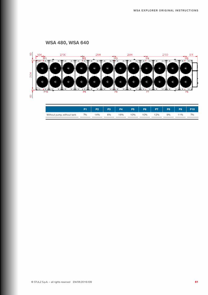
61 © STULZ S.p.A. – all rights reserved EN/06.2016/i09
WSA ExplOrEr OriginAl inStructiOnS
WSA 480, WSA 640
p1 p2 p3 p4 p5 p6 p7 p8 p9 p10
Without pump, without tank 7% 14% 6% 16% 10% 10% 12% 9% 11% 7%

62 EN/06.2016/i09 © STULZ S.p.A. – all rights reserved
WSA ExplOrEr OriginAl inStructiOnS
6.3 refrigerant circuit
As a protection against over pressure the refrigerant circuit is equipped with a safety valve on the pressure side of the compressor. When attaching any pipework to a relief valve the pipes must be of a sufficient diameter so as not to cause resistance to the operation of the valve. For critical or complex installations refer to EN 378, unless it is not specified by local regulations, the internal diameter can be calculated using the following formula:
D5 = 1.447 x l
D: Minimum pipe internal diameter in centimetresl: Length of pipe in meters
6.4 External water circuit
The evaporator water circuit of the chiller contains an evaporator, a differential pressure switch, temperature sensors in the inlet and outlet, a pressure gauge and vent valves. For a detailed overview, please take a look at the circuit diagram in chapter “4.5 Hydraulic dia-grams” at page 31.On the evaporator side a frost protection sensor measures the temperature of the liquid and reports it to the controller in which a threshold for an antifreeze alarm is defined. This value is adjusted on 4°C in the factory. Below this water inlet temperature it releases a frost protection management by the controller, which may lead to an antifreeze alarm. The adjusted value of 4°C can be modified and has to be adapted to the local conditions (glycol content).
If the water temperature passes under 5°C or if the outside temperature is less than 2.5°C, we recommend to add the following quantities of Ethylen glycol (indicated as percentage of weight of the water quantity):
Ethylenic glycol
External temp. %
from +5 to -5°C 10
from -5 to -10°C 20
from -10 to -15°C 28
from -15 to -20°C 35
from -20 to -25°C 40
inFOrMAtiOn
Establish the required water/glycol mixture outside of the chilled water circuit and fill the circuit later.
WArning
Do not add any other fluids or additives to the filling liquid except those provided. Do not mix any products and/or additives of different brands

63 © STULZ S.p.A. – all rights reserved EN/06.2016/i09
WSA ExplOrEr OriginAl inStructiOnS
For additional freeze protection at low ambient temperatures consider using the optional electri-cal heaters.
The following additional components are necessary for the external hydraulic circuit:• Suitable connection pipes according to the drawings in this chapter.• Stop off valves upstream the chiller to be able to take the chiller unit out of the chilled water
circuit in case of repair works without having to drain the entire circuit.• Air relief valve at the highest point of the circuit.• Filling valve at the lowest point of the circuit.• Mesh strainer in the chilled water inlet with mesh size of 1600 μm.• An appropriate insulation of the pipework to prevent condensate formation.
If the chiller is not provided with the following components, the external hydraulic circuit must be equipped with them additionally:• Circulating pump with sufficient delivery height according to the minimum and maximum flow
rates and corresponding pressure drop which can be found in chapter "5.4 Technical Data" at page 41.
• Expansion tank with safety valve to ensure a possibility of expansion for the liquid at temper-ature variations. The expansion tank must be dimensioned in such a way that the water circuit volume can increase by 2% without draining off liquid through the safety valve.
• Storage tank as an accumulator for heat energy to reduce the on/off cycles of the compressor. A storage tank is recommended if the water volume of the water circuit is less than 10 liters/kW cooling capacity. The storage tank should be lined out with thermic insulation.
WArning
The heat load should not be less than half the minimum cooling capacity of the unit.
In addition to the differential pressure switch, a flow switch can be installed in the outlet of the hydraulic circuit as an additional protection device for the evaporator, measuring whether the fluid is circulating.
DAngEr
The discharge of the safety valve must be positioned in a proposed area so that the leaving fluid will not endanger persons.
Evaporator drain connection of the safety valves 3/4" G male
Another criterion for the external water circuit is the water quality. Please check chapter “5.2 Chilled water quality” at page 37 for detailed information about water quality requirements. The most sensible component in respect of pollution and corrosion is the evaporator, whose heat transmission ability decreases in this case. The water should be free from solid particles. For this purpose we recommend the installation of a fine mesh strainer upstream the evaporator.

64 EN/06.2016/i09 © STULZ S.p.A. – all rights reserved
WSA ExplOrEr OriginAl inStructiOnS
Furthermore, the installation of pipe compensators in the chilled water inlet and outlet are recommended.
Inlet Outlet
Symbol Meaning Symbol Meaning
Water line Pipe compensator
Water shut-off valve Mesh strainer
If you connect two or more chillers in parallel, we recommend installing regulating valves to keep the pressure drop of each unit equally high.
Inlet
Outlet
For connecting the units to the external system remove the protective hoods from the water pipes.
6.5 Water connection
inFOrMAtiOn
To avoid any misunderstandings:the designation "water inlet" and "water outlet" are chosen, seen from the chiller.At the water outlet, the chilled water is provided from the chiller.
The connection piping should consist of P235 or similar steel, as the water piping in the chiller, to avoid the risk of corrosion at the transition to the external piping. The connection is carried out in the shape of Victaulic® connections.

65 © STULZ S.p.A. – all rights reserved EN/06.2016/i09
WSA ExplOrEr OriginAl inStructiOnS
We recommend the following good practice:• install a water bypass to be able to carry out work at the chiller (without having to disconnect it
from the pipework)• connect the pipe with adequate supports, so that it weight is not borne by the chiller• install adequate anti-vibration pipe joints to avoid the transmission of structure-borne noise• in the evaporator side, insulate the pipes of the external system, if they come into contact with
external air, to prevent the influence of heat from the ambient air as well as possible
WArning
The connection piping must be connected to the chilled water lines of the chiller free of mechanical stress.
inFOrMAtiOn
For the dimensions and positions of the hydraulic connections, see "5.6 Dimensional drawings" at page 52
6.6 Filling and bleeding air
Open the vent valves. See the exact location of the vent valves in the hydraulic scheme. A standard chiller provides vent valves at the evaporator and condensers.Check whether the stop valves in the supply line are open . Connect the pump for filling the circuit to the provided filling point. See the exact location of the filling point in the hydraulic scheme. Begin filling the water circuit. As soon as liquid comes out of a vent valve for several seconds, this can be closed.
WArning
If the planned filling of water contains glycol, connect filling hoses to the vent valves, to catch the discharging mixture and dispose of it separately.
External exchanger
internalexchanger
WArning
Once the circuit is filled, the freeze protection function is essential. Check if the circulation pumps are supplied with power and if they are properly connected to the controller. Furthermore, make sure that the valves of all pumps are set OPEN.

66 EN/06.2016/i09 © STULZ S.p.A. – all rights reserved
WSA ExplOrEr OriginAl inStructiOnS
6.7 Electrical connection
WArning
The electric cables must be only connected by an authorized specialist.The connection terminals are designed for copper cables.
• Ensure that the electric cables are de-energized and the unit is turned off.• Ensure an appropriate isolation of all sources of supply to the unit.• The unit must dispose of an effective earthing.• These units are provided for 400V/3Ph/50 Hz.• No additional controls should be installed in the control panel.• According to EN 60204 the operator is responsible to install current protection devices
between the supply conductors and the power supply connection of the unit.• Consider local regulations for the electrical wiring.
WArning
Do not touch electronical components, without taking care of protective ESD measures.
6.8 Opening the electric cabinet
The switched ON main switch prevents opening the doors of the power section (2 doors). Only, if the main switch is in position "0" you can open the doors of the power section.The doors of the electric cabinet can be opened by the key which is delivered with the chiller.
Double bit 3-5 key

67 © STULZ S.p.A. – all rights reserved EN/06.2016/i09
WSA ExplOrEr OriginAl inStructiOnS
6.9 position of the electrical connections
The electrical connection lines can be introduced into the electric cabinet from the bottom. The position of the opening for the wires can be adjusted within the range of the panel shown in the following views.
Cuttable removable
pannel
Lower view, front side
Cuttable removable
pannel
The power supply system on site and the pre-fuses must be designed for the total current of the unit (“5.5 Technical Data” at page 41). Make sure that the power supply corresponds to the indications on the rating plate and that the tolerances according to the “5.1 Application limits” at page 35 are not exceeded.
Route the electric cable into the electric cabinet from below and connect the PE conductor at the PE rail and the three phases to the main switch, in accordance with the wiring diagram (part of the unit documentation). Use a cable gland on the bottom panel to fix the cable.
Connect the ground cable to the base of the chiller using on the designated position identi-fied by the grounding symbol.Use screw with a minimum diameter Ø 8 mm. The cable must contain a terminal lug.
WArning
Make sure that the phase rotation is correct, the rotating field has to turn right!
The compressor is dependent on correct phase rotation. The sense of rotation will be checked at the factory before dispatch. An inverse rotating field would damage the compressor.The asymmetry of phase between the conductors may amount to 2% maximal.To determine the asymmetry of phase measure the voltage difference between the phase con-ductors (L1-L2, L2- L3, L1-L3) and calculate the average value of the measured voltages. With a voltage supply of 400V/3Ph/50 Hz, the maximum deviation to the average value of the voltag-es may not exceed 8 V .
Alternatively, you can check the phase rotation by using the controller. For this, close the electri-cal cabinet and turn the main switch to position I. If the phase rotation is incorrect, the controller display shows an alarm symbol.

68 EN/06.2016/i09 © STULZ S.p.A. – all rights reserved
WSA ExplOrEr OriginAl inStructiOnS
After fixing the phase rotation, make sure that the unit is turned OFF.
The electronic control board provides digital outputs for alarm signals and status of the unit. The assignment of outputs to different alarms and status data can be configured in the controller unit. The default configuration is shown in the specific wiring diagram of the unit.
inFOrMAtiOn
The digital inputs of the controller board are disabled by default. If needed, enable them in the software. For more information please check the controller manual.
6.10 pump control
The unit’s microprocessor controls internal and external pumps, as well as monitoring a pump alarm.
6.10.1 System with external pump
Choose a power switch and a contactor in respect of the pump capacity. A power switch and a contactor can be located in the electrical box.
WArning
If you do not explicitly order the load outlet option, the power to the external pumps cannot be supplied by the main switch on the unit as the main switch is only designed for the current consumption of the standard unit itself. The pump must be individually provided with safety elements.
Design the wiring between the controller and the contactor with reference to the connection diagram for the controller and the wiring between the pump and power switch according to the manufacturer’s notes.
69 © STULZ S.p.A. – all rights reserved EN/06.2016/i09
WSA ExplOrEr OriginAl inStructiOnS
7. commissioning
WArning
• The unit must be installed and connected in accordance with the chapter "6 Installation" at page 57, before initial commissioning.
• Only authorized personnel must commission the unit
7.1 preparation
WArning
• Power supply of the customer must be switched off• Check that the unit main-switch is in OFF position
inspect for visible damages which can affect proper operation of the chiller, and in particular:• check for transport/handling/installation damages• check that all components are installed in a proper way and are correctly fixed• check if the insulations are correctly installed and without damages• corrosions• verify that all documents are available (manual part I°, part II° and electronic controller manual)check the refrigerant circuit: connect your own gauges and check the tightness of the refrig-erant circuits according to the outside temperature of the refrigerant pressure. In case off leak-age please contact the manufacturecheck compressor oil level see “8.3.9 Compressor” at page 71 check correct power connection cabling. Be sure that all the connections are correctly installed and fixed (see “6.8 Electrical connection” at page 60 ). Verify the earth connections (see “6.10 Position of the electrical connections” at page 61 ).check water system. Verify the flow direction is according the IN/OUT connections on the refrigerator (see “5.5 Dimensional drawings” at page 45 ).• check the hydraulic connection• check if the water system is filled up with water/glycol and the glycol concentration according
to the “6.4 External water circuit” at page 56 • ensure that all valves are open• check if there is a water filter in the inlet of the unit, its size and cleanness.
7.2 First Startup
• Open the electrical compartment door of the unit using the key provided.• Check whether all power switches and control-circuit fuses in the electrical section of the unit
are switched OFF.• Re-tighten all screw connections in the electric cabinet.• Verify the smooth function of the contactors.

70 EN/06.2016/i09 © STULZ S.p.A. – all rights reserved
WSA ExplOrEr OriginAl inStructiOnS
WArning
All power switches are already set or adjusted by the manufacturer. Do not turn the adjustment screw.
• Switch on the control-circuit fuses. The compressor power switches may not be switched on.• Switch on the chiller unit at the master switch
The crankcase heater and the controller are now supplied with power, so you can use it for adjustments.
7.2.1 Oil pre-heating
To pre-heat the oil, the chiller must be supplied with voltage, the circuit breakers of the com-pressors must be switched off for safety reasons. In normal operation of the chiller, the oil heater is always in operation when the compressor is switched off. The control (Start/Stop key on the controller) should also remain switched off during the oil pre-heating.
According to the specification of the compressor manufacturer the oil must have a minimum temperature of 20°C and be at least 20 K above the ambient temperature. Above an ambient temperature of 10°C the oil pre-heating should be launched 8 hours before the first start of the compressor. Below an ambient temperature of 10°C, the chiller requires an oil pre-heating time of 24 hours.
Below an air ambient temperature of -5 ° C, the side of the compressor where the oil separator is located, should be insulated. The insulation can be removed 10 minutes after the compressor start.
7.2.2 commissioning of the chilled water circuit
WArning
Ensure that the water system has been sufficiently filled and that all stop valves are open.
With external pump:• check the sense of rotation and start the pump• check that the water flow guaranteed by the pump respect the nominal flow rate indicated in
the data sheet of the chiller• check that the inlet-outlet temperature difference (ΔT) is between 4 and 8K (with all the com-
pressors running at the maximum power)• check the correct functionality of the differential pressure switch or the flow switch (option)
turning off the pump and check if the chiller is turned off• keep the pump running for 8 hours and clean the implemented filter (recommended part of
the external circuit) after this lapse of timeWith internal pump:• check at the pressure gauge that the pressure delivered by the pump is aligned to the data
sheet of the chiller and the pump is working within its performance curve limits• check the correct functionality of the differential pressure switch or the flow switch (option)
turning off the pump (use the contactor in the electrical cabinet) and checking if the chiller is

71 © STULZ S.p.A. – all rights reserved EN/06.2016/i09
WSA ExplOrEr OriginAl inStructiOnS
turned off• keep the pump running for 8 hours and clean the implemented filter (recommended part of
the external circuit) after this lapse of time
7.2.3 commissioning of the refrigerant circuit
• Switch on the circuit breakers of the compressors.• Adjust the desired set point of the water temperature in the controller• Start the chiller unit by pressing the Start/Stop-key on the controller.• Check after 20 minutes operation, whether gas bubbles are visible in the sight glass of the liq-
uid line. If this is the case, refrigerant might have escaped by a leak. Check the circuit on leakages, eliminate them and fill the circuit with R134a in accordance to the chapter “8 Maintenance” at page 73.
• Check the current consumption of the compressors comparing it with the values in the techni-cal data.
• Check the oil level at compressors respects the right level. The oil sight glass is installed at the compressor. The oil level should be between the lower quarter and the upper quarter of the sight glass.
• Connect gauges at the high pressure and low pressure side and verify by reading the pres-sures, that the saturation temperatures for evaporation (low pressure side) and condensation (high pressure side), which correspond to the measured pressures, are within the following tol-erances during the operation. High pressure side: max. 7 K above the water intake temperature of the condenser low pressure side: 3 to 7 K beneath the chilled water flow temperature The pressure gauges feature a scale on the innermost ring indicating the saturation tempera-tures belonging to the pressures.
Example: Measured on the high pressure side: 13 bar (rel.) (= 14 bar abs.) corresponding saturation tem-perature at the dew point according to scale for R134a: 52,5°C measured air intake tempera-ture at the condenser: 35°C tcond - tair = 52.5°c - 35°c = 17.5 K ok measured on the low pressure side: 2.5 bar (rel.) (= 3.5 bar abs.) corresponding saturation tem-perature at the dew point according to scale for R134a: 5.0°C measured flow water temperature at the evaporator outlet: 12°C tflow - tevap = 12°c - 5,0°c = 7 K ok If the tolerances (18 K at the condenser, 7 K at the evaporator) are exceeded, there is a problem of heat transmission. The probable cause is the pollution of the heat exchange surfaces. Also the super-heating may be set too high.

Run time Pause
Cycle time
on
off
72 EN/06.2016/i09 © STULZ S.p.A. – all rights reserved
WSA ExplOrEr OriginAl inStructiOnS
compressor operationAccording to the compressors manufacturer specifications the following present parameters must be kept:
Value description time
Minimum runtime of compressor: 300s
Minimum pause time of compressor: 300s
Minimum cicle time of compressor: 600s

73 © STULZ S.p.A. – all rights reserved EN/06.2016/i09
WSA ExplOrEr OriginAl inStructiOnS
8. Maintenance
8.1 Safety instructions
All maintenance work is to be carried out under strict compliance with the country-specific accident prevention regulations. In particular we refer to the accident prevention regulations for electrical installations, refrigerating machines and equipment. Non-compliance with the safety instructions can endanger people and the environment.Maintenance work is only to be carried out on the units by authorized and qualified specialist staff.
WArning
Work on the system must always only be carried out when it is shut down. To do this, the unit must be switched off at the controller and at the master switch. A "DO NOT SWITCH ON" warning sign must be displayed.
DAngEr
In case of VSD compressors, wait five minutes after the OFF position of the main switch before start doing any operation in the electrical cabinet. (Discharges of the capacitors)
Live electrical components are to be switched to de-energized and checked to ensure that they are in the de-energized state.Some verifications must be effected with the unit in operation (measuring the current, pressures, temperatures). In such a case the unit must only be switched on at the master switch after all mechanical connections have been carried out.
8.1.1 Warning notes
• When the master switch is turned ON and the controller is stopped the power contactors are live, even if the components are not operating.
• At the fan contactors, dangerous voltages occur. Do not open the unit within the first 5 min-utes after disconnection of all phases. Be sure that the unit is being isolated.
• The electronics housing of the fan motor can get hot. • The fans have an overrun time after the unit is stopped. (Risk of injury)
8.2 Maintenance intervals
Description Six month One year Five year
refrigerant circuit
Check the sigh glass
Oil level in of the compressors
Operation of the heaters on the compressor crankcases

74 EN/06.2016/i09 © STULZ S.p.A. – all rights reserved
WSA ExplOrEr OriginAl inStructiOnS
Description Six month One year Five year
Check for fugue
Tightness of the refrigerant circuit
Check the high pressure safety switch
Check the high pressure and low pressure switch
Sobstitute the pressure relief valve (Directive 97/23/CE)
Air circuit
Clean the W-modules
Check the mounting, operation and balancing of fans
Water circuit
Clean the water filter
Check the level of the fluid to be cooled
Check the presence of air
Check and repair any leaks
Check and repair the fault insulation of pipes
Check the connections
Check the efficency of the differential pressure switch
Check the efficency of the flow swich (options)
Check the cleanliness of the evaporator water side
Electric circuit
Check for abnormal consumption
Check the tightness of all terminals
Check the cleanliness and integrity of the contatctors
Check the connections of the pressure switches
unit in general
Check the absence of abnormal vibration
Check the absence of abnormal noise
8.3 refrigerant circuit
8.3.1 refrigerant charge
To be checked: sight glass, LP switchAn insufficient charge causes the formation of bubbles in the sight glass (at full load) or in extreme cases the triggering of the LP switch. An operation with an insufficient refrigerant quan-tity over a longer period leads to a reduction of cooling capacity and to high super-heating tem-peratures, which have a disadvantageous effect on the compressor lifetime.If a leak is detected:• evacuate all the refrigerant gas and dispose it according to the national regulation• repair the leak• do a pressure test by nitrogen• extract the nitrogen by the vacuum pump (not by the compressor!) to approximately 0 barg• fill with refrigerant gas according to name plate of the chiller for type and weight

75 © STULZ S.p.A. – all rights reserved EN/06.2016/i09
WSA ExplOrEr OriginAl inStructiOnS
inFOrMAtiOn
R134a must be charged in a liquid state.
8.3.2 Quantity
To be checked: charge of refrigerantAn overfilling of the circuit makes the condensation pressure rise and by that the power con-sumption of the compressor increases. In the extreme case the HP-switch triggers.
8.3.3 tightness of refrigerant circuit
To be checked: pipes, connections, valvesAccording to article 3 of the EC regulation No. 842/2006 the operator must check the refrig-erant circuit of the chiller every 6 months for leaks. In the chillers described here, no more than 400 kg (2 x 200 kg) refrigerant R134a are used.After repairing a leak, the refrigeration circuit must be checked on tightness within one month.The following information must be recorded by the operator in writing:• quantity and type of the used refrigerant• refilled refrigerant quantity• recycled refrigerant quantity• companies or persons which have carried out maintenance• dates and results of inspections
8.3.4 purity
To be checked: sight glass, filter drierBubbles in the sight glass indicate that the charge is unsufficient or that the filter drier is clogged.A pollution of the filter drier, whose origin task is to clear the refrigerant from impurities and humidity, can be detected by a temperature difference upstream and downstream the filter drier.
Compare the colour indicator in the centre of the sight glass with the outer ring scale.• Green or purple to blue ok• Yellow or rose to red humidity critical
With too much humidity in the circuit, the expansion valve can freeze. In addi-tion to this the compressor oil, which comes in touch with the refrigerant, takes up humidity and loses its ability to lubricate.Take an oil sample, determine the humidity content and exchange the oil in case of excessive humidity content.In this case the refrigerant must be completely evacuated and recharged by new refrigerant according to the above described evacuation instruction.
8.3.5 Exchange of filter drier
To be checked: filter drier, shut-off valve RU1-RG2

76 EN/06.2016/i09 © STULZ S.p.A. – all rights reserved
WSA ExplOrEr OriginAl inStructiOnS
To exchange the filter drier it is sufficient to evacuate the pipe section in which the filter drier is installed. Close the shut-off valve (RU1 or RU2, see “4.4 Piping diagrams” at page 25). The expansion valve is closed when the compressors are switched off. By the service valve on the lid of the fil-ter drier, you can evacuate the refrigerant from the section now. Remove eight M8 screws at the front side of the filter and pull out the cartridge. Introduce a new cartridge and refill the evacuated refrigerant.Open the shut off valves RU1 and RU2.
Adjustment screw
Adjustment lock
HP switch with reset button
LP switch with automatic reset
8.3.6 Hp switch
To be checked: high pressure switchWhen the High pressure limiter triggers, the compressor is switched off without delay. Before the restart and after the elimina-tion of the error, the HP switch must be reset by pressing the reset button. You can change the action value only after having removed the adjustment lock. Turning the adjustment screw counter-clock-wise reduces the action value.
A check of the tripping function of the high pressure limiter (e.g. by cutting down the condenser fan and forcing a high pressure) is not possible without changing the action value, as there are, on behalf of the C2020 electronic controller, further monitoring functions via the high pressure sensor, which intervenes in the compressor control (high pressure management, compressor envelope control). A change of the action value (e.g. by reduction), however, bears the risk that this one is not exactly readjusted after the check has been executed. The scale on the case does not provide sufficient accuracy.
8.3.7 lp switch
To be checked: low pressure switch, shut-off valves RU1-RU2Check the correct function of the low pressure switch by stepwise closing the shut-off valve RU1-RU2 on the refrigerant circuit, while the compressors are running. Check by means of the low pres-sure gauge in the compressor section, whether the low pressure switch trips at 0,4 bar. When the LP switch trips, the compressor is switched off without delay. If the pressure switch has tripped too early (e.g. at 2,0 bar), you can reduce the threshold by turning counter-clockwise the adjustment screw on the top side of the pressure switch after having removed the adjustment lock.
During the compressor pause delay (see “7.2 First Startup” at page 69) stepwise open the shut-off valves RU1-RU2 until you reach a suction pressure threshold + 0,5 bar (check by suction pressure gauge). If the LP switch still trips after the elapsed evaluation delay and after having reached the calculated suction pressure (1,6 bar), you must turn the adjustment screw counter-clockwise to reduce the pressure hysteresis.

77 © STULZ S.p.A. – all rights reserved EN/06.2016/i09
WSA ExplOrEr OriginAl inStructiOnS
8.3.8 Expansion valve
The refrigerant circuit is equipped with a electronic expansion valve, which controls the super-heating in the evaporator. The super-heating is adjusted to 5 K at the factory and may not be modified. Check the super-heating set-point. Check the super-heating by the C2020 electronic controller. If the super-heating is for a longer time below 3 K or above 7 K, the function of the expansion valve is faulty.
Compare the suction gas temperature measured by the valve sensor, with the value of a refer-ence sensor at the suction line. If the super-heating still diverges significantly from the set-point and you can find no deviation at the verifications, probably the control module of the valve is defective and must be replaced.
The expansion valve can freeze, if the humidity in the refrigerant circuit is excessive. Check the sight glass.
WArning
Do not thaw by soldering flame, danger of explosion! Thaw with moist warm cloth. Check the sight glass.
8.3.9 compressor
To be checked: compressor, crankcase heaterIn the screw compressor, there are three main components which require inspection and mainte-nance. The integrated oil filter is maintenance-free.pressure relief valveThe pressure relief valve has a response pressure difference of 28 bar and is maintenance-free. Repeated opening of the valve due to abnormal operating conditions, however, may result in steady leakage. This can be detected by a reduced output and a high discharge gas tempera-ture. If is this the case, replace the valve.check valveTo protect the compressor against reverse rotation during standstill a check valve is installed under the discharge shut-off valve resp. below the pipe connection. If the compressor runs in reverse direction for more than approximately 5 sec. after the cut-off, the valve may be defective and must be replaced. A reverse rotation of the compressor can be detected by an abnormal sound.roller bearingThe screw compressors are equipped with fatigue endurable roller bearings. The bearings can be checked by means of a sound analysis. If the bearings must replaced, also the rotors, the housing and the discharge flange should be checked visually. In case of severe scores or abnor-mal abrasion, a major overhaul of the compressor or its replacement is advisable .auxiliary contactor in the electric cabinet. For the 140W heater the ohmic resistance should approximately be 1,1 kOhm, 1,3 kOhm for the 120W heater and 1,8 kOhm for the 90W heater.

78 EN/06.2016/i09 © STULZ S.p.A. – all rights reserved
WSA ExplOrEr OriginAl inStructiOnS
component inspection interval replacement interval
Pressure relief valve only if damage is suspected 100.000 h
Check valve 5.000 h * 20.000 ... 40.000 h
Roller bearing 10.000 h 50.000 h
* at least yearly checked
Oil levelCheck the oil level at the oil sight glass. During unit idleness the oil level should not be below the lower quarter (bottom line) and not rise above the upper line during operation.
Oil heaterCheck the oil heater function by switching off the fuse for the oil heater in the electric cabinet and by measuring the ohmic resistance at the terminals in the electric cabinet. For the 300W heater the ohmic resistance should approximately be 180 Ohm and 260 Ohm for the 200W heater.
Oil fillingContact technical support for the requirements of the oil used;• never mix different oil types!• clean the piping completely before changing the oil type.Topping up of up to 20-30% of the total quantity of oil contained in the compressor is allowed. For larger quantities, contact technical support.
If there have been losses of oil, these must be replaced by topping up oil.1. Take a clean, dry, transparent container (with volume calibration) and fill it with at least twice
the amount of the required oil.2. Shut off the compressor on the discharge side and on the suction side.3. Evacuate the refrigerant from the compressor and collect it, until atmospheric pressure is
reached. Only if a completely oil change is required, drain the oil in the compressor through the oil drain plug (1) into a collecting device and dispose it according to the regulations in force.
4. Connect the clean oil container by a pipe to the oil service valve (2) in the lower middle section of the compressor.
5. Open the oil service valve and lift the oil container so that the oil flows into the compressor by gravity.
6. Fill in the required quantity of oil. Ensure that the supply line is always below the oil level. (to avoid the introduction of air bubbles in the pipe) The oil level should be in the lower quarter of the oil sight glass (3).
(1) oil drain plug
suction line connections
hot gas line connections

79 © STULZ S.p.A. – all rights reserved EN/06.2016/i09
WSA ExplOrEr OriginAl inStructiOnS
8.4 Air circuit
8.4.1 condenser
To be checked: condenser coilsThe air-cooled condenser consists of a microchannel coil with aluminium fins. Through the microchannel coil flows outside air which is eventually polluted. Particles of polluted air may set-tle at the fins and reduce the heat transmission the same as raise the air resistance. This could probably identified by a increase of the fan current.The heat exchanger can be cleaned by pressurized air or steam blasting (maximum 2 bar) which has to be blown to the normal air flow direction along the fins.
WArning
• Do not bend the fins during such an operation, in order not to limit the exchange efficiency and increase the pressure drop on the air side.
• Do not use chemicals, these could cause corrosion at the coils.
8.4.2 condenser Fan
To be checked: fansThe bearings of the fans are lifetime lubricated and do not need maintenance. Check the opera-tion current. An increased operation current indicates either a higher air resistance by a clogged condenser coil or a winding short circuit in the fan motor.
8.4.3 Filter
To be checked: air filtersThe filters (optional) are made of metal, therefore they can be washed with water, once removed from their seats.
8.5 Evaporator circuit
(2) oil service valve
max. oil temperature sensor
(3) oil sight glass
oil heater oil level sensor
7. Close the oil service valve, open the shut-off valves of the compressor and recharge the col-lected refrigerant into the refrigerant circuit.

80 EN/06.2016/i09 © STULZ S.p.A. – all rights reserved
WSA ExplOrEr OriginAl inStructiOnS
• Be sure that the cooling medium respect the limits and specifications required (see “5.2 Chilled water quality” at page 37).
• Check the cleanliness and wash with water if deemed necessary• Check for any leaks and for proper tightening of fittings• Check the presence of air in the water circuit. In case bleed the circuit following the instruc-
tions given in paragraph “6.6 Filling and bleeding air” at page 65
8.5.1 tightness
Check the water circuit visually for tightness. Beyond that a level indication at the storage tank, if existent, can give information about changes of the water quantity. A lack of water in the circuit is replaced by air, which reduces the heat capacity of the chilled water circuit and is detrimental to the pump.
8.5.2 Evaporator
To be checked: evaporator, inlet/outlet/antifreeze probesCheck the water side pollution of the tube evaporator by comparing the chilled water inlet tem-perature to the chilled water outlet temperature. If the difference is less than 3 K, it indicates a limited heat transmission and thus pollution.Another possibility to verify this consists in the comparison of the chilled water outlet temper-ature with the saturated evaporation temperature (by measuring the suction pressure at the low pressure side of the compressor). If this difference exceeds 7 K, the evaporator is probably polluted.In this case the evaporator has to be cleaned chemically by authorized staff.In case of exchanging the antifreeze heater in the evaporator the water glycol mixture must be evacuated and collected.
8.5.3 Differential pressure switch
To be checked: differential pressure switchCheck the correct function of the differential pressure switch by stepwise closing a shut-off valve on the inlet of the cooling water circuit, while the compressors are not running.
8.6 Electric circuit
To be checked: power board, electric components, motor• Check for any faults in the current consumption of the engines.
8.6.1 powerboard
The powerboard is provided with a forced cooling system consisting of two ventilated grids with filter. Check for proper operation of the fans and the efficiency of the filters. If necessary, pro-ceed replacing the faulty parts.
8.7 unit in general
To be checked: whole the chiller

81 © STULZ S.p.A. – all rights reserved EN/06.2016/i09
WSA ExplOrEr OriginAl inStructiOnS
• Clean the unit’s inside with a vacuum cleaner. Clean pipes simplify the search for leaks. • Check the pipes, the compressor and the condenser for a tight seat. Vibrations of pipes and
circuit components can result in leaks. • Check also the insulation of the water piping. Condensing air humidity on cold water pipes
means a loss of cooling capacity.• Check for loose parts that cause an increase in noise and vibration.

82 EN/06.2016/i09 © STULZ S.p.A. – all rights reserved
WSA ExplOrEr OriginAl inStructiOnS
9. Malfunctionproblem possible cause recommended action
generals
The chiller does not start up and the electronic control is off
No power supply Restore power supply
Main switch open Move the main switch to position I
No power supply to the electronic controlCheck the voltage of the power cables to the control. Restore or repair the wiring
Electric control faulty Contact the Stulz service centre
The control works but the display is off
Cable between control and display disconnected Reconnect the cable
Cable between control and display broken Replace the cable
Faulty display Contact the Stulz service centre
The control works but the chiller does not start up
Missing external enabling signal (stand-by state displayed)Restore the signal wiring. Provide the external enabling signal
Failures prevent the unit from workingCheck any alarms on the display (see below). Contact the Stulz service centre
Electric control faulty Contact the Stulz service centre
Display alarms
CP X thermic
X compressor fault Replace the compressor
Failure of the power supply circuit of the X compressor (cables, remote control switch, ...)
Replace the faulty component
Failure to the thermal breaker of the X compressor Replace the protection device
Fan X thermic
Faulty X fan Replace the fan
Failure of the power supply circuit of the X fan (cables, remote control switch, ...)
Replace the faulty component
Failure to the thermal breaker of the X fan Replace the protection device
Pump X thermic
X pump failure Replace the pump
Failure of the power supply circuit of the X pump (cables, remote control switch, ...)
Replace the faulty component
Failure to the thermal breaker of the X pump Replace the protection device
EEV X windingFailure of the motor winding of the X electronic expansion valve
Replace the expansion valve
EEV X serial communicationProblems in the communication between electronic control and X expansion valve
Contact the Stulz service centre
High press. group X
Power supply failure/ failure of a condensing fan of X circuit Repair the power supply to the fan/replace the fan
Faulty speed control of condensing fans of X circuit
Lack of signal from the electronic control: restore wiring or replace the electronic control or replace the phase cut control module.
Faulty signal from the electronic control: contact the Stulz service centre
Failure of the phase cut control modul: replace
Dirty condenser/air filter (optional) of the X circuit Clean the condenser/air filter (optional)
Air recirculation on the condenser of X circuitRemove obstacles close to the condenser. Comply with the clearances indicated in paragraph 5.3
Faulty high pressure switch of X circuit Contact the Stulz service centre
Clogged filter-drier of the X circuitThrough the fluid level sight glass of the circuit X check for moisture or bubbles in the refrigerant. Contact the Stulz service centre
Excessive refrigerant gas charge resulting from a circuit X top up after a repair
Contact the Stulz service centre
Outside air temperature beyond the limits permitted Contact the Stulz service centre

83 © STULZ S.p.A. – all rights reserved EN/06.2016/i09
WSA ExplOrEr OriginAl inStructiOnS
problem possible cause recommended action
Low press. group X
Leaks of refrigerant in the circuit X Contact the Stulz service centre
Faulty low pressure switch of X circuit Contact the Stulz service centre
Clogged filter-drier of the X circuitThrough the fluid level sight glass of the circuit X check for moisture or bubbles in the refrigerant. Contact the Stulz service centre
Partially closed tap on the fluid line of X circuit Completely open the tap
Failure to the expansion valve of the X circuit Contact the Stulz service centre
Frozen expansion valve of the x circuit Check moisture through the fluid level sight glass of the X circuit Contact the Stulz service centre
Low flow of fluid to be cooled
Check the fluid level in the storage tank and, if necessary, top up
Check for hydraulic circuit problems (failure of pumps, closed taps...). Repair if necessary
High disch. temp. X
Too high temperature of the compressor refrigerant flow See the alarm “High press. group X”
Wrong calibration of the discharge temperature probe of the X circuit
Check with a reference thermometer. Contact the Stulz service centre for re-calibration
High/max temperature
Insufficient cooling capacity compared to the thermal load Reduce the thermal load or increase the number of chillers
Dirty filter of the fluid to be cooled Clean the filter
Dirty evaporator Contact the Stulz service centre
Poor calibration of the temperature probe on the water flowCheck with a reference thermometer. Contact the Stulz service centre for re-calibration
Poor refrigerant charge on one or both circuits Contact the Stulz service centre
Failure of one or more compressorsCheck to see if other alarms appear on the display. Contact the Stulz service centre
Low amount of fluid to be cooledCheck the fluid level in the storage tank and, if necessary, top up
Low/min temperature
Low flow of fluid to be cooledCheck for hydraulic circuit problems (failure of pumps, closed taps...). Repair if necessary
Poor calibration of the temperature probe on the water flowCheck with a reference thermometer. Contact the Stulz service centre for re-calibration
Malfunction of the antifreeze heaters (optional) Check and repair or replace
Inadequate fluid to be cooled to the minimum outdoor temperature
Contact the Stulz service centre to defrost the evaporator. Add glycol in the fluid to be cooled in a proportion suitable for the outdoor temperature.
Evap. fluid flow
Low flow of fluid to be cooledCheck for hydraulic circuit problems (failure of pumps, closed taps...). Repair if necessary
Air in the hydraulic circuit Repair leaks, fill and vent the system
Failure of the differential pressure switch or of the flow gauge (optional)
Check and if needed repair the wiring or replace the component
X probeX temperature probe/wrong pressure calibration Contact the Stulz service centre for re-calibration
X temperature probe/ disconnected or faulty pressure Reconnect or replace the probe
S13 comm. errorAbnormal communication between the electronic control and the expansion board of I/O controls
Contact the Stulz service centre
S13 software versionThe software version with which the expansion board of I/O controls is programmed do not comply with that of the control
Contact the Stulz service centre
Upd setup S13 failedError in writing a parameter on the expansion board of I/O controls by the electronic control
Contact the Stulz service centre
Wrong phaseLack of or too low voltage of one or more phases
Check and take appropriate measures to restore the power supply to the limits permitted
Wrong phase sequenceInvert two phases in the connection of the main power supply to the chiller

84 EN/06.2016/i09 © STULZ S.p.A. – all rights reserved
WSA ExplOrEr OriginAl inStructiOnS
10. Dismantling and disposalThe decommissioning of the chillers must be carried out by experienced and qualified person-nel for the operations required.
DAngEr
ExplOSiOn HAZArD: in carrying out any operation specified in this chapter avoid any open flames near the refrigerant pipes when the cooling system is under pressure.Do not bring open flames near damaged or perforated pipes as the refrigerant gas vapours, mixed with the oil of the compressor, may ignite producing toxic gases.
1. Turn the chiller to the SYSTEM OFF mode by touching the ON-OFF button on the touchscreen.2. Turn the main switch to 0.3. Disconnect the power supply from the power cables and prevent any voltage reset.4. Open the protective panels of the powerboard and disconnect the power cables.5. Drain the cooling circuit recovering both the refrigerant and the lubricating oil.
WArning
Do not dispose of the cooling gas into the atmosphere. The cooling gas must be recovered by a qualified refrigerator technician and, if not reused, sent to an authorized disposal centre.Even the PVE oil of the compressor must be recovered and sent to an authorized disposal centre. Since the oil forms a mixture with the refrigerant it can not be disposed of as common lubricating oil.
6. Unplug the unit from the water circuit after closing the shut-off valves and drain the water from the hydraulic circuit of the chiller.
WArning
If you use water additives (glycol), even water must be recovered and disposed of safely, avoiding to disperse it into the environment or into the sewage system.
7. handle the unit as described in paragraph “3.3 Transport” at page 168. Dispose of the unit according to local regulations on disposal and safety regulations in force
at the installation site. It is advisable to contact a specialized recycling company. Basically, the unit contains the following raw materials: aluminium (exchangers and condensers); copper (exchangers, refrigerant pipes and electric cables), galvanized steel and iron (evaporator and condensers, panels and metal frames); rubber (water pipes).
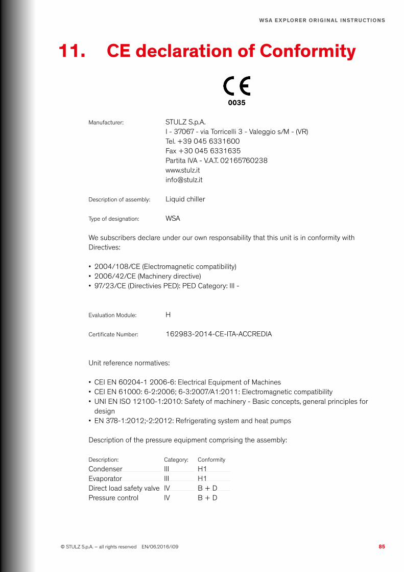
85 © STULZ S.p.A. – all rights reserved EN/06.2016/i09
WSA ExplOrEr OriginAl inStructiOnS
11. cE declaration of conformity
0035
Manufacturer: STULZ S.p.A.I - 37067 - via Torricelli 3 - Valeggio s/M - (VR)Tel. +39 045 6331600Fax +30 045 6331635Partita IVA - V.A.T. 02165760238www.stulz.it [email protected]
Description of assembly: Liquid chiller
Type of designation: WSA
We subscribers declare under our own responsability that this unit is in conformity with Directives:
• 2004/108/CE (Electromagnetic compatibility)• 2006/42/CE (Machinery directive)• 97/23/CE (Directivies PED): PED Category: III -
Evaluation Module: H
Certificate Number: 162983-2014-CE-ITA-ACCREDIA
Unit reference normatives:
• CEI EN 60204-1 2006-6: Electrical Equipment of Machines• CEI EN 61000: 6-2:2006; 6-3:2007/A1:2011: Electromagnetic compatibility• UNI EN ISO 12100-1:2010: Safety of machinery - Basic concepts, general principles for
design• EN 378-1:2012;-2:2012: Refrigerating system and heat pumps
Description of the pressure equipment comprising the assembly:
Description: Category: Conformity
Condenser III H1Evaporator III H1Direct load safety valve IV B + DPressure control IV B + D

86 EN/06.2016/i09 © STULZ S.p.A. – all rights reserved
WSA ExplOrEr OriginAl inStructiOnS
12. OptionsHere are reported the specific information regarding installation, commissioning and Main-tenance for the options available on the chiller.
12.1 Quick Start (with upS)
The Quick Start option allows to restore full cooling capacity of the chiller within 5 minutes by the restoration of the power supply, in case of electrical blackout.The options requires an UPS (Uninterruptible Power Supply) to keep electrical supplied the electronic controller and the sliding valve of the compressor to permit them to return in starting position, saving time at the restart of the chiller.The UPS is installed into the electrical cabinet of the chiller.
installation
inFOrMAtiOn
At first start is necessary to connect two wires from the Battery to the Electronic Board.
Check the electrical wiring diagram and the label on the chiller to correctly activate the UPS system.
commissioning
• Be sure that the installation operation are correctly completed• Check that all the connections are complying the electrical diagram
Maintenance
WArning
The orange wires in the electrical cabinet can be under tension also with main switch in Off position.
• clean all the ventilation slots• in case of malfunctions, please contact the STULZ staff.
inFOrMAtiOn
If a operation is required on the electronic controller main-board, is necessary to open the specific switch to cut out the electricity.

87 © STULZ S.p.A. – all rights reserved EN/06.2016/i09
WSA ExplOrEr OriginAl inStructiOnS

www.stulz.it
STULZ Top Service – more than fast emergency assistance
HEADQUARTERS HAMBURG GERMANY Tel. +49 040 / 5585-238 [email protected]
STULZ S.P.A. ITALY Valeggio sul Mincio (VR) Tel. +39 045 / 6331615 [email protected]
OTHER AREAS on
www.stulz.com
EN
/06.
2016
/i09
©
STU
LZ S
.p.A
. – S
ubje
t to
chan
ge w
ithou
t not
ice
Maintenance Test CenterAdvice Service-PortalTechnical Implementation Climate Customized
For general questions about our products and services, you can reach us on weekdays from 8 – 18 at phone 0039 045 6331615.
Or contact directly our representative in your area: