LOS ALAMOS SCIENTIFIC LABORATORY - Gamma Explorer
272
LAMS-2607 CIC-14”REPORTCOLLECTION REPRODUCTION con LOS ALAMOS SCIENTIFIC LABORATORY OFTHEUNIVERSITY OFCALIFORNIA o LOSALAMOS NEW MEXICO THE lVY SYSTEM . . . I
-
Upload
khangminh22 -
Category
Documents
-
view
3 -
download
0
Transcript of LOS ALAMOS SCIENTIFIC LABORATORY - Gamma Explorer

LAMS-2607
CIC-14”REPORTCOLLECTIONREPRODUCTION
con
LOS ALAMOS SCIENTIFIC LABORATORYOF THEUNIVERSITYOF CALIFORNIAo LOSALAMOS NEW MEXICO
THE lVY SYSTEM
. .
. I

LEGAL NOTICE
l%isreportwas preparedas an accountofGovern-ment sponsoredwork. NeithertheUnitedStates,northeCommission,noranypersonactingon behalfoftheCom-mission:
A. Makesanywarranty orrepresentation,expressedor implied,withrespecttotheaccuracy,completeness,orusefulnessoftheinformationcontainedinthisreport,orthattheuseofanyinformation,apparatus,method,or pro-cessdisclosedinthisreportmay notinfringeprivatelyownedrights;or
B. Assumes any liabilitieswithrespecttotheuseof,or fordamagesresultingfrom theuseofanyinforma-tion,apparatus,method,or processdtsclosedinthisre-port.
As usedintheabove,“personactingonbehalfof theCommission”includesany employeeor contractoroftheCommission,oremployeeofsuchcontractor,totheextentthatsuchemployeeor contractoroftheCommission,oremployeeof such contractorprepares,disseminates,orprovidesaccessto,anyinformationpursuantto hisem-ploymentorcontractwiththeCommission,orhisemploy-mentwithsuchcontractor.
PrintedinUSA Price$3.50. Avatlablefrom the
OfficeofTechnicalServicesU. S.DepartmentofCommerceWashington25,D. C.

LAMS-2607MATHEMATICS AND COMPUTERS(TID-4500,16thEd.)
II
LOS ALAMOS SCIENTIFIC LABORATORYOF THE UNIVERSITYOF CALIFORNIA LOSALAMOS NEW MEXICO
REPORT WRITTEN August1961
REPORT DISTRIBUTED: October6,1961
THE F/Y SYSTEM
by
ForrestW. BrinkleyBengtG. Carlson
ChesterS. Kazek,Jr.ClarenceE. LeeZaneC. Motteler
MANUAL EDITOR: ZaneC. Motteler
ContractW-7405-ENG. 36 withtheU. S.AtomicEnergyCommission
All LAMS reports are informal documents, ueually prepared for a special pur-pose aid primarily prepared for uee wfttdn the Laheratory rather than forgeneral distribution. TM report hae net been edited, reviewed, or verifiedfor aoouracy. All LAMS reports exprese the views of the authors ae of thetime they were written and do net nec.essarfly reflect the epinions of the LoeAlamos Scientific Laboratory or the final opinion of tbe authors on the subject.
-1-
ABOUT THIS REPORT
This official electronic version was created by scanning the best available paper or microfiche copy of the original report at a 300 dpi resolution. Original color illustrations appear as black and white images. For additional information or comments, contact: Library Without Walls Project Los Alamos National Laboratory Research Library Los Alamos, NM 87544 Phone: (505)667-4448 E-mail: [email protected]

H!rY

ABSTRACT
IVY, an algebraic coding system for the IBM 7090 and 7030 elec-
1 tronic da’taprocessing machines, i.sdescribed. A sample code is first
illustrated for purposes of familiarization. The general features of the
I IVY system are then discussed in the Inixoduction. Tne body of the text
discusses card types, the entry of data, remarks, and calling sequences,
I and the formats for writing code in the IVY algebraic language. Finally,
I subroutines incorporated in the IVY system and error indications given by
I the system are described, and some coding exxnples are shown. The final
I chapter is composed of tables for reference purposes. The appendices dis-
1 cuss more sophisticated coding techniques and the longhand coding conven-
1 tions for the 7090 and 7030.
-3-

Ivy DATE7317417517617717817S160
PAGE NAME PROBLEM26 JUNE I J$EhBLI$W DI$T PR$)DUCT Dl$ T P RI#) D
Line No. I 2 72 CODE
I
2
3
4
5
6
7
8
9
10
II
12
13
14
Is
16
17
18
19
20
21
22
23
I
II—
I
I
I
II
H
I
III
* ❑ JOEABL$W,A7-5360~212 D4TTOII02HIOOOO0
s (0), A(O), X(4), L(3), R(2)
D A0(7) =2.15, 3.0), .223 +1, 5.732.-2.71,-.032-1, .7S6,
B@(7) =9.2222,.0D063, 2.575, -. 057-I,-33.233-5, Z3I6I7,.43,
FL6W, SUER, T(1)
R RI= CRP. (OIjTh PRODUCT=) 1.0.1.7 .2.SSS
R [email protected] 13FATHEATW13&VECT@RSAARE A NOT AEQUAL. $$$
c FLOW ACOOE.ACONVERTS A AND ~ GOES ATO A SUBR&JTINE .
A SWR2, I
I
I
I
II
I
I
I
II
( [1 I lFLIiIW, (s p,$AP: $R02,2), ($ P,suBR:AO($w): 613($ w]: T($wA)+I),
I
I
I
I
I
I
I
I
I
I.
F,’($ P,LI)
.:g ($? $PR: SF, RI(SWP): $PI, T($WA)+ 1) ,($P, SLD), -. .
: ‘-kxi
61
LI , ($P, $PR: $P, R2($WP)), ($P, $LD), $E. FL~W, ---
I r+-Oxlt
I] A $WR2,2 — IJ
1 SUOR. X4, $D(4), $DI, XI, $D2=X2. $D3=X3, $D4=0,
I Xl=$iI(X4+l, $WC), X2=$ Z(X4+2, $WC), I(LI)XI-X2=NZ, X2=$ Z(X4+I, SWA), X3=$Z(X4+2. $WA),
.L2, $D4=$M+$Z(X2+I)% $Z(X3+I),
X2=X2+ 1, X3=X3+1, Xl= Xl-1, (L2) Xl= Ni!,
I p xl =$ Z(X4+3), Sz(xl) :$D4,i
I
I
I
I
I
I
I
I
I
I
I
I
I
I I
I II I
I I
I III— -—
L3, XI. A=$DI, X2. A=$D2, X3.A=5D3, (X4+5) ,
Ll, X4=X4-I, (L3),a-
)
A $RD2, I
I
I
I
I
I
I
I
I
I
I
II
I
I
I
I
II
I
I
I
I
I
I
I
A SIMPLE AND COMPLETE IVY CODE
-4-

PREFACE
The facing page illustrates a complete, though trivial, code in
the IVY language, for finding the dot product of two vectors. This is
included at the start of the manual in order to familiarize the reader im-
mediately with the appearance of a finished IVY code. As the discussion
in the manual proceeds, the reader can occasionsll.yrefer back b this
example for enlightenment on some of the techniques discussed. FinaX1.y,
in Chapter 8, a discussion of the organization and philosophy of this
code wild.occur, a discussion which applies to any IVY code regardless of
its length.
-5-


ACKNOWLEIXXMENTS
The editor is indebted to Ben@
Forrest Brinkley, and Clarence Lee for
this manual, much of
helpful suggestions;
Sue Vandervoort,
the final draft;
the examples and
for
and
which was done on
to Justine Stehl,
Carlson, Chester Kazek, Jr.,
their careful proof reading of
their own time, and for their many
for producing the IVY tree; to
typing the rough draft;
to Bea Hindman, for her
drawing the illustration.
to Grace Cole, for typing
excellent job in lettering
-7-


CONTENTS
Abstract
A Simple and Complete IVY Code
Preface
Acknowledgements
Table of Contents
Introduction
Chapter 1.
Chapter 2.
Chapter 3.
Chapter k.
Chapter ~.
Chapter 6.
Chapter 7.
Chapter 8.
Chapter 9.
Preliminary Remarks
Coding Forms and Types of Cards
Definition and I.aadingof Data, Remarks, andCalling Sequence Blocks
The IVY Algebraic Language
Flow of Control, Calling Sequences, and theExecute Statement
IVY Subroutines
IVY Error Indications
Coding Examples
Summary and Tables
Appendix 1. Manipulating the Symbol Table
Appendix 2. The 7090 Ion@and Instruction Set
Appendix 3.The 7030 Imnghand Instruction Set
Index
Page
34
5
7
911
17
21
43
68
97
118
1’37
162
185
203
210
239
264
-9-


INTRODUCTION
The coding system described in this manual, the IVY system, repre-
sents a considerable extension, sophistication, and simplification of ear-
lier attempts by the authors on the design of an efficient and practical
coding system for both the casual and experienced programmer. Frequently
an individual, usually called a “programmer” or “code+’in this manual,
concerned with the solution of a complicated problem, must resort to the
use of computers. For such people IVY was designed. Detailed knowledge
of the behavior of various different computers is not required, but, if
available, it can be applied when ~ fancy
by an experienced programmer conversant with
are warranted. However, it is believed that
in mathematical physics amenable to computer
coding techniques (presumably
a particular class of machines)
the vast ma~ority of problems
solution can be solved ade-
quately, almost in their entirety, in the simple algebraic language sup-
pliedby IVY.
The IVY system is a load-and-go, one-pass compiler-assembler con-
sisting of an algebraic language which can be used on any of a class of
computers for which the system is designed, as well as facilities for cod-
ing in the language of
run. The main purpose
the particular computer on which a program is being
of the system is to simplify and expedite the
-11-

programming of problems and the debugging of resulting codes, the schedul.
ing of machine time in installations with two or more types of machines,
the exchange of codes, and the use of these at other installations.
Another purpose of the system is to provide a load-and-go compiler which
gives the programmer closer touch with the computer hardware, besides
supplying numerous other new and uniqye features, many of which have never
before been offered in any system of this type.
The IVY algebraic coding system has been designed for coders who
are somewhat familiar with electronic computers and programming tech-
niques, but who do not have a detailed knowledge of a particular computer.
The algebra itself is written in a system called machine algebra, as
opposed to FORTRAN and other algebraic coding systems which simulate
~algebra, that is, the algebra of equations and formulas in the
traditional mathematical.sense. This machine algebra is a system similar
to display algebra except in conventions regarding the use of parentheses.
In addition, the coder is allowed (and often required) to specify actual
index registers (unlike FORTRAN), to utilize a “store-address’’feature,
and to construct loops and sequences of code fully as complex as those
possible in longhand coding, without the many restrictions imposed by
FORTRAN-like systems. A code in the IVY algebraic language will be ac-
cepted, unchanged, by any computer for which IVY is available.
As previously mentioned, a longhand coding system is available in
IVY, which allows the entry of ~ instructions in the instruction set of
the particular machine being used, following IVY addressing conventions.
-12-

Of course, use of this feature will make an IVY
machines of a different type. Nevertheless, in
code incompatible with
practice such longhand
portions of a code are usually short, and a separate set of longhand
cards can be produced for each computer, and one set substituted for
another when one changes computers. For the programmer who is interested
only in longhand coding for a particular machine, IVY
load-and-go longhand coding system.
The “IVY” system consists essentially of three
program (#IJl),the assembly program (@P) and various
punch, tape manipulation, etc.). Only that portion of
presents a fast
parts: the loading
subroutines (print,
IVY currently in
use is in core memory at any one time;
other packages as needed. Thus all but
available to the problem program. Core
a master control program calls in
a few thousand words of core are
storage is never taken up by un-
converted code, which, instead, is written on a tape designated by the
programmer at initial loading time. Once a progrsm is debugged, this tape
may be saved and used to load the program whenever it is run thereafter,
saving some machine time, since this tape contains a condensed version
the code. This tape will in general not be interchangeable among
machines of different type for which IVY is available, since the con-
densed code on the tape is in a partially assembled form.
Each IVY deck begins with an “S” or “start” card,
IVY for a new program. (IVY programs can be
in the card reader or on a BCD tape prepared
stacked one
by off-line
of
which initializes
behind another
card-to-tape
-13-
1

equipment). This “S” card also contains specificationsof the basic quan-
tities of the particular program, such as the number of independent “store
address” quantities, the number of index registers desired (which maybe
more than the particular machine contains, in which case the extra index
registers are simulated with a slight loss of efficiency), the number of
formulas desired, and the maximum number of branch references within a
formula. Following the “S” card, cards controlling the definitions and
loading of data, remarks, and calling sequence entries, may occur. The
instruction cards are normally at the end of a deck. Preceding, and in-
termixed with, the instruction cards are “A” or “assemble” cards which
control the writing of the code on tape and its subsequent conversion
into machine language. The code may be followed by an “X” or “execute”
card, which specifies the formula set at which execution starts.
The chief advsntage of IVY, aside from its simplicity, is that no
preliminary processing is necessary, such as obtaining binary cards from
a separate assembly program. Thus, not only is the assembly process im-
mediately under the programmer’s control at all times, but also the
source deck and object deck are one and the same. Corrections can be
made in the source deck without the necessity of a tedious reassembly to
obtain a new object deck. Furthermore, because of a unique new type of
coding form, one comes closer than ever before to punching cards directly
from the flow chart. And finally, IVY contains a feature which enables
one to obtain a listing of his code if desired, at the loading time.
During its one-pass examination of the source deck IVY detects a
-14.

great many different types of errors. If a detectable error occurs, IVY
prints out the contents of the card on which the error occurred, one or
more symbols to aid in localizing the error on the card, and a number.
This number can be looked up in a table which is available at the console
of each machine for which IVY is available, and which will be distributed
to manual holders separately from this manual. The table entry gives an
exact description of the error. It is in the detection and treatment of
errors that one of the chief advantages of IVY occurs. If errors are de-
tected in code, for instance, the programmer is still permitted to exe-
cute his progrsm up to that point where the first executed error was de-
tected. From this point a transfer is made to IVY, which prints out a
comment to the effect that execution cannot proceed further, and gives
some indication as to where this point is located. Similarly, if a data
block has been defined or loaded incorrectly, references to this block
are replaced
run, obtains
but also the
by similar transfers. Thus the programmer, in a debugging
not only information on coding errors detectable by IVY,
results of executing the problem code to the point of the
first error encountered in execution, allowing him to ferret out both
coding errors and logical errors in one and the same run. As far as is.— .— .
known, IVY is the first programming system ever designed to allow this
feature. Of course it is possible that errors detected may be of such
a magnitude as to make compilation impossible, in which case IVY will
suppress execution. However, it must be asserted that errors of such
magnitude seldom occur, and that IVY is unique in failing to penalize
-15-

programmers for minor programming errors, by allowing execution when
possible. (No claim can be made that ald possible detectable errors are
caught, since to do this would require an impractically long program.
Hopefully a useful balance between detectable and non-detectable errors
has been maintained.)
The IVY system and its features, as outlined in this Introduction,
are discussed in detail in subsequent chapters, with special.emphasis on
the algebraic system and its conventions. A knowledge of the algebraic
addressing conventions is necessary to code in one of the particular longh-
and systems, which therefore are described in appendices at the end of
the manual, briefly but completely, and in a manner assuming some famil-
iarity with earlier chapters, and, of course, the particular computers
being utilized.
-16-
CHAPTER 1
PRELIMINARY REMARKS
Character set. The character set used by IVY is the well-known
Hollerith set, i.e., the character set used by FORTRAN, which is avail-
able on the IBM 026 punch. This set consists of the alphabetic upper-
case characters, the numbers O-9, and a few punctuation marks and special
characters. Limited as it is, this character set will be used until such
time, if ever, as extended character set keypunches (IBM 9210) become
generaUy available. For reference purposes, the Hollerith set consists
of the characters O (numeric zero), 1) 2y 3P 49 53 69 79 89 9)Aj B> c,
D, E, F, G, H, I, J, K, L, M, N, ~ (alphabetic “@”), P, Q, R, S, T, U, V,
w, x, Y, z, +, -, *, /,=9 ‘, ●9 :> #$ ($ )~ co-$ and bl-a**
Symbols. IVY symbols and symbolic names (with the exception of
a few special symbols mentioned later) must consist only of alphabetic
characters, that is, of the characters A, B, C,...jZ. Symbols may be of
any length up to 6 characters. Examples: MB, SAM, =, c, pm,
vEL@Y.
Special symbols. Certain symbols for internal IVY subroutines,
-17-

data blocks, and operation conventions, start with the character “$”,
which is not available as a symbol for IVY remarks, data, or code. Two
of these symbols, $LD and @l?j were encountered in the Introduction.
All “$” symbols will.be discussed and defined as the need arises; a
table of “@” symbols appears in Chapter 9, page 187. Note that only
these internal IVY symbols begin with “$”: ~ symbol defined by the
programmer must begin with an alphabetic character.
In addition, the programmer may define symbols for certain numbered
quantities and numbered blocks on the “S” card (see below, page 26), e.g.,
Al, A2, etc. for stored addresses (page 28); Xl, X2,..., for index regis-
ters (page 28); Ll, Ii?,...,for internal brsnch references (page 28); as
well as numbered blocks beginning with an alphabetic symbol as defined
above, used only to represent
29).
*The Svmbol Table. All
remarks and calling sequence blocks (page
nrozrammer-defined swnbols are placed inthe IVY symbol table. T%s ta~le-consists of two ~arts: (1)-a twenty-six entry table, with each entry corresponding to one letter of thealphabet, which is always in core, and (2) a variable length table hav-ing one entry for each symbol of two or more characters, which is con-structed by IVY as the symbols are defined. Each entry of these tablescontains the following items of information: the symbol itself, in BCD;two addresses used by IVY for searching purposes; and a control word,containing a count of the items of information in the block, a flag in-dicating what type of information is loaded, and the base address of theblock minus one. Once constructed, the symbol table is always in core,available to both IVY and the problem program. With the exercise of duecaution, the problem program may consult and alter the symbol table atwill, using conventions described in Appendix 1.
*Paragraphs marked with “*” and single-spaced, while informative, arenot essential to the understanding of the IVY system, and can beskipped if desired.
-18-

The Order of Definition of Symbols. Since IVY is a one-pass pro-
gram, all symbols must be defined before they may appear in the defini-
tion of another symbol and before they are referred to by code. Symbols
can be defined on “S”, “D”, and “R” cards, described on pages 2G,15,and 61.
Furthermore, all symbols must be defined before ~code is converted,
regardless of whether the code refers to the symbols or not. Since the
symbol table is loaded in core immediately preceding converted code, the
symbol table must be full to avoid destroying code with new entries.
All symbols must be defined on “S”, “D”, or “R” cards except for
symbols consisting of a single alphabetic character, other than the spe-
cial symbols “A”, “X”, and “L” (pages 28-29 ). Single-character symbols
never need be defined since IVY always contains the 26-entry table for
the single alphabetic characters. Note that by a symbol being defined
is meant that the symbol must be entered in the table, although it need
not have been assigned an address, value, or length unless the conver-
sion of code or definition of another symbol requires such assignment.
(For detailed instructions on defining and/or assigning values to sym-
bols, see pages 45-61.)
*The Role of the Control Word in Error Detection. By examining
the flag of the control word for a symbol, mentioned above, page 18,XVY detects such obvious errors as attempting to perform arithmetic-oncode and remark blocks and attempting to transfer to data or remarkblocks from the problem program. If the entire control word is zero,meaning a symbol has been defined but the block has not been loadedsuch errors as referring to the block in arithmetic instructions an~
*Detailed discussions of the symbol table and control word formats, ofinterest only to the more-than-casual coder, will be found in Appendix 1and in the various appendices relating to particular machines for whichIVY is available.
-19-

attempting to define another symbol in terms of this one can be dis-covered. References to undefined symbols are, of course, easily de-tected because of the absence of the symbol from the symbol table.Ordinarily these errors are not of such magnitude as to inhibit com-pilation of the problem program, and whenever this is true, executionis allowed to proceed to that point where the code is first affectedby such an error.
-20-

cHAPrER 2
CODING FORMS AND TYPES OF CARDS
Coding Forms. There are two forms available for IVY programming. The
first form is divided into one column for tie control punch (described later
in this chapter) and 71 columns for the entry of information, with the
last eight columns left for program identification. The contents of the
program identification columns are not available to the program. The
second form is similar to the first, and in addition it contains guide
lines in the margins for drawing arrows, to mark flow of control, thus
Wing the coding sheet, in essence, a flow chart. These mOWS ~e ~t
punched on the cards, but are merely intended as a convenience to aid
the programmer in reading
follow and understand the
lessen, if not eliminate,
his code, and in making it
flow of the program. This
the need for flow charts.
for
the
the
Control Punches. The first column of IVY cards
easier for others to
feature should also
is always reserved
the control punch. The function of the control punch is to des+gnate
type of information found on the cards, and to give instructions to
compiler, or both. A card containing a blank in column 1 is assumed
-21-
.

to be a continuation of the previous card and to contain the same type
of information. Certain types of cards may not have a continuation card
following them; this is noted, when applicable, in the following descrip-
tion of the particular card types. The continuation of “R”~ “K”) or “T”
cards if any, must contain a blank in column 1} as explained below.
Identification Card. An “identificationcard” must precede any
code which produces off-line output for printing, punching, or plotting
on the SC-4020. For consistency this card should precede all IVY decks.
(This card is the standard ID for the m 7090, as adopted bY the ~s
Alamos Scientific Laboratory and described in a buUetin distributed to
7090 users dated April 14, 1961.) The function of this card is to iden-
tify any off-line output (listings, cards, microfilm, etc.) with the pro-
grammer’s name and telephone nwber~ so that it can easi- be seParated
from other programmers! output and delivered to the individual concerned.
To aid the operator in logging, the contents of this card are printed
on-line.
The format of the Identification Card is as follows:
COLUMN
1
2
3
4
5-7
8-26
27-30
*
*
*
*
PUNCH
(Produces BCD print ID)
or blank (* if BCD off-l=i-nepunching is done)
or blank (* if binary off-ldme
or blank (* if 4020 tape is to
punching is done)
be prepared)
maximum time in minutes
programmer’s name and phone number
coder’s number
-22-

COLUMN (continued)
31-33
34-36
37-B
39
40
42
44
45
46
47-48
73-80
MCP control cards.
name of code
group for which
category number
problem is done
2 (for IVY codes)
G if debugging, H if production
machine used (Iocal conventions are used)
o
0
0
number of tapesfor this cod@
used exclusively by and
programmers name
These cards may be
on the 7030 if IVY is run under MCP. In this
required only in decks run
case these cards must pre-
cede any deck run on the 7030. These cards may be included in q IVY
deck on ~ machine, however, and if not needed, will be ignored.
The purpose of these cards, all of which have a “B” in column 1, is
to define input-output units in a symbolic manner; MCP then assigns abso-
lute units to these symbolic numbers well in advance of the time the pro-
grem is run, so that tapes can be mounted properly, etc. These cards
*The systems tape, standard print output tape, etc., are not included inthis count.
-23=

must be the first ones present in any IVY deck which is run on the 7030;
and, as mentioned above, can be removed for 7090 runs if desired.
The various “B” c=ds required are as follows:
A. Job Card.
12 910B 1$J B, IDENTIFICATION
Any identification desired, e.g., name and phone number, can be—a~er the operation “J@B.”-
B. Type-of-Problem Card.112 9110
B I rv-YG@,
This card merely specifiesand will assemble and go.
Iocal conventions must be observed.
that the problem coming up is in IVY
placed
language
c. Input-Output Definition Cards. One of these cards must be entered
for each tape unit the programmer uses outside the system, i.e., fortape units other than the standard input-output tapes used by IVY.The format for these cards is as follows:
112 9]10 &169
B II~DNAMEI
where:1.
I~D,T=,EXIT,CHANNEL, NUMBER,M4DE,DENSlTY,DIS+SITI@~~
“I~DNAME” represents any symbol of from one to six alphabetic
characters, used by MCP to
ment stated on the card.
2.
3*
in length
signed by
“I@D,” “TAPE,”
be synonymous with the input-output
and “EXIT” occur as illustrated.
require-
“CHANNEL” is any symbol from one to six alphabetic characters
specifying some channel, the absolute address of which is as-
MCP. Different symbols wi12 be assigned different channel
addresses. If the “CHANNEL” field is null, it is assumed that the channel
-24-

assignments of tape units are irrelevant, and MCP assigns any free tape
unit regardless of channel.
4. “NUMBER” iS the IVY tape number in hexadecimal (lt2~3~...~9~A~
B,C,D,E,F). See page 120.
5. “M@DE” may specify either “@DD,” for odd parity, or “ECC,” for
odd parity @US ECC
6. “DENSITY”
density. This must
tape in the calling
checking.
is either “HD,” for high density, or’’LD,”for low
agree with the density, if any, requested for the
sequence to “$TP,” the tape program. See page 122.
7. “DISP@@N”
any case;“ “CSAVE,” for
“ISAVE,” for “save tape
“save tape reels in any
may be “NSAVE,” for “do not save tape reels
“save tape reels only if job is complete;”
reels only if job is incomplete; or “SAVE,”
case.”
in
for
8. “REF” is an octal nunber corresponding to the hexadecimal tape
number in 4 above.
D. Reel Cards. A reel card must immediately follow the “I@D” card towhich it refers, or another reel card referring to the same unitand channel. The format is:
1 2B REEL, R1,R2,”””,etc.
where10 “REEL” is the pseudo-operation defining this type of card.
2. “Ri“ represents a symbol up to eight characters in length; the
first three are not part of the reel identification, but specify whether
the tape is labeled or not and whether the tape is protected (ring out)
or unprotected. The remaining 5 characters agree with the identification
shown on the physical reel. Thus Ri may be:
-23-

If
be
Pm Xxxxx
PUL xxxw
NUlxxxxx
an’’R~’is null, a
entered for each
protected, labelled
protected, unlabeled
unprotected, labelled
labelled, unprotected tape is assumed. An “Ri” must
reel of the tape desired, even if only one reel is
used. All reels are labelled automaticallyby MCP.
the reader is referred to the MCP manual.
In general the programmer need not worry about
For further details,
punching the MCP
control cards, since the 7030 run request sheet is used by the operators
to punch the necessary “B” cards. These cards are placed in front of the
deck, which is then run. Iocal conventions are important in the use of
these cards and should be studied by the programmer interested in running
on the 7030.
Start Card. A “start card” must precede eve~ IVY code, behind any
“*” or “B” cards. This card performs the following functions:
1. Erases the symbol table of the previous code, if any, and ini-
tializes IVY for a
loading to initial
2. Sets the
start card and all
new code in such ways as setting base addresses for
values, etc.
print trigger on, which causes the contents of the
cards following it to be printed on-line, until a
“print suppress” card is encountered (see page 30).
3. Defines the maximum number of formulas in one formula set, num-
bers of independent store-address expressions, references within formulas,
index registers, and numbered remark symbols used by the code.
-26-

The format of the Start Card is as follows:
Col. 1 CO1. 2-72
s I (N,)JA(N2),L(N3),x(N&),s~#L, (N5),s~~PL2(N~)>*.*Here’!Ni’’represents a decimal number which cannot be symbolized,
and ’~YMB#L,’’represents any legal symbol (from one ta six alphabetic char-.1.
acters except the symbols A, L, or
by a continuation card.
The fields on this card will
where necessary, to indicate where
x). The “S” card cannot be followed
now be explained, with page references,
further discussion of the concepts in-
troduced by consideration of this card may be found:
1. (Nl): N, is the maximum number of formulas which will appear
in any formula set of the IVY code introduced by the “S” card. Briefly,— —
IVY codes are always &ivided into one or more subsets called formula
sets, and each formula set contains one or more subdivisions called for-
mulas. Within a formula set, the code can flow at will among the formu-
las, but direct branching between a formula in one formula set and a for-
mula in another set is not allowed. Formula sets are to be thought of
as almost independent packages of a code, to be entered from another
formula set only by branching to the start of the set, and not to one of
its formulas. (For further discussion, see page 114). Thus, if Ml is
the number of formulas in the first formula set, M2 in the second set,
.... ~ in the nth set, then N, = max (Ml, M2,‘*”,%). This entry
causes a table to be constructed,(N1 + 25)words in length, to aid the
compiler in assigning addresses to branches between formulas. The
minimum value N, can have is O.
-27-

2. A(N2): The symbol “A” is always reserved for the “store address”
symbol, even if no “store address” expressions are used in a code. If no
“store address” expressions are used, the entry A(0) must still be present
on the “S” card. If, however, the coder wishes to use “store address” ex-
pressions (whichareusually helpful when working with multi-dimensional
arrays), “N2” specifies the maximum number of independent “store address”
expressions in any formula of the program. (For further enlightenment
see pages T~-’78.) This entry causes a table, N2 words in length, to be
constructed for the use of the compiler in setting up “store addxess” in-
structions in machine language.
39 L(N3): The symbol “L” is always reserved for internal branch
references (Ll, L2,..o) within formulas. If no internal branch references
are used, N =3
O,and L(0) must occur on the “S” card. N3 is the maximum
number of internal references within formulas, i.e.y if J, i$ the number
of references in the first
then N = ma (Jly J2y0..~3
pages 97-102.) This entry
strutted, to aid
to “L” entries.
4. X(N4):
formula, J2 in the second,..., JM in the Mthy
JM). (For discussion of “L” entries see
causes a table(N i-2~)in length to be con-3
the compiler in assigning addresses to
N3 canbe at most 51Z.
The symbol “X” is always reserved for
branches referring
index registers.
,IN4!1 specifies the number of index registers used in the program. The
first N4 consecutive index registers, Xl, X2,...j XN4 must be used, ~
any combination of N4 different registers. Regardless of the machine
used, IVY index registers always modi~ by addition, or appear to do so;
-28-

furthermore, IVY index registers are always positive, and even on Stretch
(except inlonghand coding) must nottske on negative values. This entry
causes a table N4 in len@h to be constructed to aid the compiler in simu-
lating extra index registers, if N4 happens to be larger than the n~ber
of index registers available on the particular computer, and a second
table, also N4 in length, for aid in the computation of index branches.
N4 must be at least 1 but may be no larger than 256. For more discussion
on index registers see pages 89-93.
59 SYMB@L1(N5): The remaining entries on the “S” card are option-
al (the first four listed above are mandatory) and specify numbered sym-
bols which may be assigned only to remark blocks or calling sequence
blocks. The symbol specified may be any symbol consisting of from one
to six alphabetic characters except the symbols A, X, and L, which, as
noted above, are always reserved for special.purposes. “N “5
is the num-
ber of symbols which will begin with the alphabetic characters and end
with one of the numbers 1, 2,..., Ns: SYMB@Ll, SYMB@2,..., SYl@LN5.
Each of the blocks corresponding to these numbered symbols must be
loaded separately on “R” or “K” cards (see below). A group of numbered
symbols beginning with the same alphabetic symbol must all address the
same type of information; that is, the symbols of a numbered block R,
namely RI, R2,..., RN,must all address either remarks or calling sequence—
information,but not both. The number of numbered symbols allowed is
obviously restricted to the remaining columns of the “S” card, since no
continuation is allowed.
-29-

The discussion of the “S” card is now complete.
emphasized that the “S” card must not be followed by a
i.e., another “S” card or a card with the first column
sary information must be included on the one “S” card.
also note that much of the information discussed above
Again it must be
continuation card,
blank. All neces-
The reader should
will be discussed
in detail later. As a man once remarked when presented with the IVY sys-
tem, “The lS1 card is supposed to
will probably be the last one you
lesson here is clear: although an
be the first card in your code, but it
write down on the coding sheet.” The
IVY deck must be ordered in a specific
manner, quite often the order of coding will not correspond to the order
of the deck, or to the order of treatment of topics in this manual.—
Print cards. These cards, the purpose of which is to turn the
print trigger on or off, may occur anywhere in
print trigger is on, all.cards willbe printed
thus allowing’the coder to obtain a listing of
gram. A card with “P” in column 1, and column
an IVY code. If the
until it is turned off,
all or part of this pro-
2 blank, turns the print
trigger on; “S” in column 2 (for “suppress”) turns the trigger off. Re-
call, as remarked on page 26, that an “S” card also turns the print trig-
ger on. Thus, once a listing is obtained, on subsequent runs a “PS”
card should follow the “S” card to suppress any unnecessary listing.
The listing wiU appear off-line unless key 35 is down (7090) or binary
key 63 is down (7030).
Comment cards.
whatsoever in an IVY
The “comment cards,” which may occur anywhere
deck, are announced by a “C” punch in column 1.
-30-
These cards are ignored by IVY for assembly purposes, except that their
contents will be printed if the print trigger is on. Any printable com-
ment may be punched on a “C” card; generally, of course, these comments
are of an informational nature, describing the subsequent code for the
benefit of anyone (including the coder) who might want to read it. C1!11
cards may be followed by any number of continuation cards with a “’C”or
“blank” in column 1.
Definition cards. After the “B,” “*,” and “S” cards the “defini-
tion cards” must occur. These cards, which have a “D” punch in column 1,
are used to define symbols for data blocksj psrsmeters~ and formula sets.
Formula names, however, should not be defined on “D” cards; these symbols
are defined by their occurrence on “I” or “L” cards, described in Chap-
ters 4 and 5 and in Appendices 2 and 3. Recall the distinction between
formulas and forrm,ilasets, discussed previously on page28. A detailed
description of the allowed formats on “D” cards is given in Chapter 3,
pages 43-57 . “D” cards may be followed by any number of continuation
cards ~th a “D” or “bl.a&” in column 10
Remark cards. “Remark cards” provide a means for entering BCD in-
formation into core for printing comments on a listing, punching comments
on cards, or for use as format statements for printing. Ordinarily re-
mark cards should occur next after “D” cards in an IVY deck. Symbols may
be defined on remark cards, remark blocks may be loaded, or a block of
fixed length maybe set up so that a remark may be constructed in it
later using the character manipulation program described in Chapter 6,
-31-

pages 154.156 Remark blocks may be named tith numbered symbols entered
on the “S” card (page 29) or with ordinary alphabetic symbols which
have not been previously defined otherwise. A description of the for-
mat of remark cards occurs in Chapter 3) pages 61-64 ● Remarks for use
as format statements are described in Chapter 6, pages 132-I&5. The first
card of a remark must have an “R” punch in column 1, because it is on
this card that the symbol is defined; continuation cards, if any, are
allowed, and must have a “blank” in column 1.
Calling sequence cards. “Calling sequence cards” are used for
entering calling sequence information into core; calling sequence infor-
mation may also be entered directly on instruction cards. However, the
option of using calling sequence cards is allowed because of the flexi-
bility of such a system: like remarks,cd.ling sequence blocks can be
defined without being loaded, so that values for them can be computed
later in the code (see pages 182-184) for examples. Variable celling se.
quences, or calling sequences whose length depends on a parameter, may
be defined; and a previously defined and loaded calling sequence can
easily be altered. None of these operations is possible with calling
sequences which occur on instruction cards. Discussions of the usage
of calling sequences occur throughout this manual, e.g., Chapter 5,
pageslo~-llo,~d Chapter 8, pages lT6-l&. Calling sequences for Parti-
cular IVY subroutines are discussed in Chapter 6. The actual format of
calling sequence cards is described in Chapter 3, pages 64-67. As
with remark cards, continuations of calling sequence cards g contain
-32-

“bI@” in column 1; the first
appears, must have a “K” punch
card, on which the symbol of the block
in column 1. Unlike remark cards, however,
the symbol on a “K” card must have
into the symbol table; that is, it
by an entry on the “S” card, ~ an
been previously defined, i.e., entered
must be either a numbered symbol defined
alphabetic symbol defined by its appear-
ance on a “D” card. (See Chapter 3, pages 47-48.)
Instructions to operator card. Cards of this type contain an “~”
column 1 and may not be followed by continuation cards. The “~” card,
in
in
columns 1 to 72, may contain any comment, interpreted
the operator. When an “~” card is encountered by the
causes the following to take place:
as an instruction to
loading program, it
1. Theterthe
2. The
contents of the”d” card are printed on-line (using the prin-on the IBM 7090 &d machines without a typewriter, usingtypewriter on machines which have one attached, such as the7030)●
machine then stops or waits, and a gong is sounded on ma-chines which have one attached.
3. The operator presumably reads the instructions, carries themout, and presses an appropriate button (“start” on the 7090-type machines, “console signal” on the 7030), and IVY regainscontrol and proceeds.
If the coder’s program currently has control, the same functions may
be performed by using the IVY subroutine’’$@P’)describedin Chapter 6,
pages 151-152.
Tape control cad. The purpose of the “tape control card” is to allow
the programmer to read or write information on a binary, high- orlow-density
tape under control of the loading program. The same thing may also be done
internally by using the IVY subroutine’@P,’’describedin Chapter 6, pages
121-126.
-33-

A tape control card has a “T”
if any, must have a “blank” in
sequence to @P, consisting of
punch in column 1, and continuation cards,
column 1. The “T” card contains a calling
various items of information separated by
colons. These items are as follows (“H” is a hexadecimal digit, 1 ~H~C
on the 7090, 1 ~ H~F on the 7030):
$HDH
@IJ)H
$RWH
@!3?H
@LH
@?TH
$BBH,p
$BFH,p
@BH, P
@FH,P
@DH,AD(@A)+P:AE(#w)
@RH,AD(@A)+P:AE(@W)
@DH,AD(@A)+p
MEANING
set tape “H” to high density
set tape “H” to low density
rewind tape “H”
write end-of-file
rewind and unload
write end-of-tape
on tape “H”
tape’k”
record, tape “H”
backspace tape “H” through“P” records
backspace tape “H” through“P” files
forward space tape “H” through“P” records
forward space tape “H” through“P” files
read from tape “H” the record withID= C(AD(@A)+P) into blockAE
write a record on tape “H” withID=C(AD(~WA)+P from block AE
last entry only: compare ID ofcurrent record on tape “H” withcontents of AD($WA)+P. “$CSI”is set to O if not equal, 1 ifequal.
-3J+-

In all of the above, “P” stands for “parameter algebra,” which is
explained at the beginning of Chapter 3. Other notation is explained in
Chapter 5, pages 103-llQ and the calling sequence for’)#N?’isfully dis-
cussed in Chapter 6, pages 122-125. Page120 contains a table showing cor-
respondence between the tape number “H” as used above and tape and channel
numbers on the 7090 and 7030. Below is an example of a “T” card and its
continuation,whichwrites two blocks on tape, and reads in a third from
another tape:
T@W3:@WR3,@@A)+l :SN(@):#WR3,AX($WA)+3:ST(@) :$RW3:
l#RW2:@B2,4:#RD2,FNP(@A)WE:m(#W):
Assembly card. The “assembly card,” which has an “A” punch in
column 1, and for which no continuations are permitted, is required to
be present in an IVY program. Once this card is encountered it is
assumed that all symbols (except those for formulas) have been defined,
on “D,”“S,” and “R” cards. The purpose of the “A” card is to cause
the instruction and/or longhand cards which follow it to be compressed
and written in a specified file of a specified tape, or to read in and
assemble instruction and/or longhand cards which have been previously
written by an “A” card. Note that the “A” card differs quite markedly
from the “T” card: The “T” card is used for writing or reading data;
the “A” card is used to control assembly, and writes only unconverted
instructions, and when reading, converts simultaneously into machine
language. The use of “T” cards is optional, whereas “A” cards sre re-
- in order for the assemblY to Proceed ProPerlY*
—
The two formats

for “A” cards are as follows:
1. preceding code: The card
Al@RN,F
causes the instructions on cards following to be writtenon tape “N,” where “N” is a hexadecimal digit (1 ~ N < Cor F; see “T” cards), in the file number specified byq’F,”a decimal numbero If N = O, a special systems tape isused, equivalent to N = A.
2. following code: The card
Al@lDN,F
causes the unconverted code in file “F” of tape “N” tobe read into core and converted to machine language.
An “A” card of type “l” will write instructions on tape Until
another “A” card or an “X” card (see below, pages 39-40) is encountered.
The smallest unit of code which may be written using “A” cards is a
formula set. In general it is best to write a long code in as many
files as possible, one formula set per file, since, if several files
contain part of the code which have been debugged, it is not necessary
to read in the cards again for these particular files. One need only re-
write and re-load the undebugged portions of the code; the rest may be
read from tape using Al#RD cards.
read and assembled in its entirety
a portion of the code which occurs
A completely debugged
from tape. Noke that
in a certain file, it
code may be
in re-writing
cannot be re-
written in the same file (unless it occurs in the last file on tape)
without destroying some subsequent information; it must be rewritten
in a file beyond the last previously written file. Tapes mitten under
-36-

the control of
using the same
the “A” card may not be used interchangeably smong machines
types of tape units (e.g., the 7090 and 7030) since they
contain partially assembled code. Files of a tape may also be read and
assembled under program control, using the IVY subroutine “~, “ de.
scribed in Cha~ter 6, ~ages 119-120.
Instruction cards. “Instruction cards,” which have an “I” in
column 1 and may be followed by any number of continuation cards with “I”
or “blank” in column 1, are used to load IVY algebraic code. The format
of these cards, and the IVY algebraic language itself, are discussed in
Chapters 4 and 5. “I” cards must be precededby ~’A”cards, writing U~ts
of the code containing one or more formula sets on tape, and may be fol-
lowed by other “A” cards or “X” cards, as
All symbols for data, remarks, etc., must
the first instruction block is assembled,
described below, pages 119-120.
have been defined by the time
regardless of whether or not
the block in question refers
loaded into core immediately
been completed, subsequently
to these symbols, since instructions are
above the symbol table; if the table has not
defined symbols will destroy the first in-
structions of the code. Blocks of “I” cards must not contain “D,” “R,”
ttIt“K, T,“ “@,” or “E” cards; in other words, all cards containing infor-
mation not pertinent to instructions and their assembly must have been
loaded before any instruction blocks, or must be loaded after the first
“x” card.
Imghand cards. These cards, which have an “L” punch in column 1
and may be followed by any number of continuation cards with “L” or
-37-

“blank” in column 1, are used for the entry of longhand instructions for
a particular machine, as opposed to the “I” cards which enter the alge-
braic instructions valid on all machines. The formats of “L” cards are
described in the appendices appropriate to the machines under considera-
tion.
Binary deck cards. These cards, identified by an “F” in cOIUmn
1, are used to load a relocatable column binary deck. The relocatable
cards must, of course, contain instructions in the set of the particular
machine being used, and must be in the ProPer relocatable format for
that machine. The chief purpose of the “F” card is to allow a programmer
to load a previously coded subroutine, not a complete codes The format
of the “F: card is as follows:
Fl:J@B,M:#&L
“AD” is a symbol for the formula set representedby thebinary deck; “M” is the n~f~rds (if any) reservedfor data before the subroutine> in decimal; ~d “L” is thenumber of words (if any) reserved for data after the sub-routine, in decimal. The purpose of the latter two entriesis to take care that space is allowed for data blocks usedby the subroutine for which no cards are loaded, such as,for instance, blocks definedby use of “BSS” or %ES” inthe SAP and FAP systems. This is not necessary ordinarilyon the 7050, since space for blocks defined by “DR*’or“DRZ” is reserved by the use of special conventions onthe binary cards.
Continuation cards are obviously not appropriate for “F”
cards: IVY assumes that the cards following the “F” card are relocat-
able binary cards with 7 and 9 punches in column 1, and that the Ist
non-relocatable card following is an IVY card with a non-blank punch
in column 1.
-9-

The “F” card has been included primarily as a feature intended to
simplifi the transition from other coding systems to IVY; thus, subrou-
tines available in relocatable form can be loaded in this manner until
such time as they become available in IVY language. In no sense is IVY
to be considered merely a relocatable loader: IVY recognizes only relo-
catable cards, and none of the other types of the large class of cards
handled by the FORTRAN BSS loader.
It is the programmer’s responsibility, then, to set up calling
sequences to these relocatable routines correctly in the IVY language.
Normally such subroutines should be self-contained, i.e., they should
not refer to other subroutines, and should carry with them their own data
and erasable blocks. If this is not done, then the programmer must exer-
cise extreme care in the use of the subroutine. F$RTRAN, which can be
used to produce relocatable routines which refer to outside data blocks o
and to other subroutines, stores data backwards in memory, at the time
of this writing, while IVY stores data forwards. This difference should
always be borne in mind when using a routine produced by F@RTRAN.
Execute card. The “execute card,” with an “X” punch in column 1,
is the IVY transition card; its detection causes IVY to transfer control
to the programmer’s code. Its format is as follows:
xpD
where “AD” is the symbol for a formula set which must havebeen converted by means of an “A” card (or the routine’~”)before the “X” card is encountered. If columns 2-72 of the“X” card are blank, it is assumed that the programmer hasentered the loading progrsm “@n” from his code, and control
-39-

is returned to the first instruction following the pro-gram’s “@D” calling sequence. An “X” card with columns2-72 blank is illegal if the programmer has not entered‘$ID”from his code. Normally,’~~’is entered to readdata from “E” cards, described below.
Enter data cards. These cards, with an “E” punch in column 1,
may be followed by any number of continuation cards marked by “E” or
“blank” in column 1, and are used to enter data in blocks which have
been previously defined on “D” cards. Normally “E” cards occur after
the program’s first “X” card,which transfers control to a specified for-
mula set;’’@D”is then entered to read the “E” cards, which must be
followed by an “X” card with blanks in columns 2-72 to return control to
the ’~LD’’callingsequence. The format for “E” cards is described in
Chapter 3, pages 57-59.
*a?!2?E4” It has been the intention of this chapter to describe. the various types of cards used in an IVY deck, and as much as possible
the order of discussion of these cards has been the order of an IVY deckat loading time. When possible, the card format has been described; inmany cases, however, the reader has been referred ahead to those por-tions of the manual which describe the format of the card in questionin more detail than can be attempted this early. In setting up an IVYdeck for assembly, the programmer should keep one idea paramount: thatIVY is a load-and-go, one pass system, meaning that every card is ex-amined once and only once. Therefore, the order of loading is somewhatrestricted in that symbols must be defined prior to their occurrence incode and calling sequences, making it necessary to place the “S,” “D,”and “R” cards in that order at the beginning of the deck. All symbolsmust be defined, i.e., entered in the symbol table, before any “K,” “I,”“L,“ or “F” cards occur, since the information loaded from these cardsoccupies space immediately above the symbol table, and any subsequentattempts to define symbols (treated and detected as errors) would des-troy part of the information loaded by these cards.
++Becauseof the distinctionbetween formu~ sets ~d formu~s,as sets and subsets of a program, formula set names must be defined on“D” cards, whereas formula names are defined by their appearance on “I”or“L” cards and should not be defined on “D” cards. Thus, for instance,
-40-
subroutines referred to by a number of formula sets should be definedas formula sets, since formulas can refer only to formula sets or toother formulas within the same set, All “I” or “L” cards must be wit.ten on tape and assembled ~~ “A” cards, the usual procedure beingto write each formula set in a separate file. This makes it possibleto avoid reloading the entire deck for a second assembly, when none,or only a few, of the formula sets contain errors.
*Finally, after assembly of one or more formula sets, the “X”card transfers control to one of these sets and execution of the coder’sprogram begins. At any time the program can re-enter’$ID”to load newdata from “E” cards and regain control from an “X” card with columns2-72 bh~. The program also may use other IVY subroutines, such as‘#AP’%oassemble a new formula set, and various input-output routinesfor printing, punching, and the manipulation of tapes.
+Yl!ableI gives a summary of card types for quick reference, giv-ing page numbers of descriptions and other useful information.
-41-

TABLE I
Table of Card Types
FORMAT ON CONTINUATIONCOL. 1 PAGES AIJOJED? PURPOSE
*
B
s
P
D
R
K
$
T
A
I
L
F
x
E
c
22-23 No
23-26 NO
26-30 NO
30 NO
43-57 Yes “D” or “blank”
61-64 Yes “blank” only
6&67 Yes “blank” only
33 NO
33-35 Yes ‘blank” only
35-37 NO
68-117 Yes “I” or “blank”
Appendices 2,3 Yes “L” or “blank”
38-39 NO
39-40 NO
57-59 Yes “E” or “blank”
30-31 Yes “C” or “blank”
Identification of off-line output
Assignment of 1/0 on 7030
Start, define essential quantities
Set print trigger on or off
Define and/or load symbols
Define and/or load remarks
Define and/or load calllng se-quence blocks
Instructions to operator
Tape manipulation under loadercontrol
Write or read and assemble in-structions
Load algebraic instructions
Load longhand instructions
bad relocatable binary deck
Transfer control to program
Load data
Comment
-42-

CHAPTER 3
DEFINITION AND LQADING OF DATA, REMMUC3, AND
CAIUNG SEQUENCE BLOCKS
Definition and loading of parameters. A parameter, as referred to
throughout this manual, is defined as a fixed point integer, the value of
which remains constant throughout an assembly, and which is used to define
such things as the dimensions of a block, conditions on whether assembly
or loading of a block is to take place, and so on. The value of a param-
eter may, of course, vary from one assembly to another, but once defined
for a given assembly, it must remain constant throughout the assembly.
Since the notion of a parsmeter is the foundation of the whole IVY system,
and the algebra of parameters is a cornerstone, the definition of param-
eters, followed by a discussion of parameter algebra, sh~ occupy us
first in this chapter.
Since, as a rule, the entire assembly depends on the values of
parmeters, these quantities should be defined on the first “D” card or
cards after the “S” card. In different assemblies these “parameter
cards” can be changed for another set in order to change the dimensions
of various arrays, change some of the conditional assembly statements,
-43-

etc. Some simple parameter definitions are illustrated below:
DIGE= 2, AX= 15, BS(2) = 1,3,TH= 6, FINr(Bs2) = 5, 6, 12
The first two symbols are defined as single parameters, the numbers 2
and 15. BS is defined as two parameters 1 and 3. When any block,
parameter or not, is defined as being a vector or array N in length, N
numbers must follow to load the block completely. More about this point
later. TH is then singly defined, and finally FINT is defined as having
length BS2, which is 3, and three numbers are loaded. Note that in the
case of the parameters and data, the n~ element of an array AD is ad-
dressed by writing ADn, where n must be a number and cannot be symbol-
ized. However, the first element of a block may be addressed by using
the symbol with no number, so that, using the above example, one may call
on the number 2 by writing GE instead of GE1, though the latter is also
allowed. Similarly the symbol BS alone would address the number 1, the
symbol FINT alone would address the number 5.
Dimensions of multi-dimensional blocks can be symbolized by param-
eters defined in the above manner, or may be defined by fixed point num-
bers when dimensions never vary, or by parameter algebra, discussed be-
low. New parameters may also be defined in terms of previous parameters,
numbers, or parameter algebra involving Previously defined par~eters.
Examples of this appear in the next section.
Parameter algebra. Parameter algebra is defined as fixed point
integer algebra free of parentheses. The operations in this algebra, as
-44-
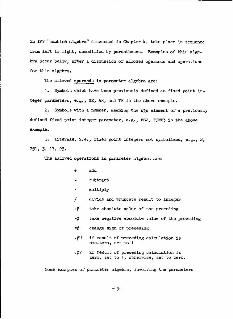
in IVY “machine algebra” discussed in Chapter 4, take place in sequence
from left to right, unmodified by parentheses. Examples of this alge-
bra occur below, after a discussion of allowed operands and operations
for this algebra.
The allowed operands in parameter algebra are:
1. Symbols which have been previously defined as fixed point in-
teger parameters, e.g., GE, AX, and TH in the above example.
2. Symbols with a number, meaning the n~ element of a previously
defined fixed point integer parameter, e.g., BS2, FINI’3in the above
example.
3* Literals, i.e., fixed point integers not symbolized, e.g., 2,
251, 3, 17, 23.
The allowed operations in parameter algebra are:
+
*
/
+$
-$*$
●@
●SV
add
subtract
multiply
divide and truncate result to integer
take absolute value of the preceding
take negative absolute value of the preceding
change sign of preceding
if result of preceding calculation isnon-zero, set to 1
if result of preceding calculation iszero, set to 1; otherwise, set to zero.
Some examples of parameter algebra, involving the parameters
-45-

defined in the example in the previous section, are as follows:
EXAMPLE
TH+3
Ax + GE*BS2
Ax/TH+2
Ax+Bs2/TH
-2WH+AX. @
-2WH-I-AX.@
FINT3*FINT-AX*$
TH-AX+~
RESULT
9
51 (multiplicationbyBS2 times AC%E:operations from left to right)
4 (result of division is 2)
3
1
0
-45
9
Examples of definition of new parameters using parameter algebra involv-
ing previously defined parameters:
D@W=GE-AX*BS2,N!l?T=AMP+3#, PRT(GE+l) = AW’IH, O, FINT2-BS2/GEj
Thus we note that the value of a parameter, as well as the dimensions of
a block containing more than one parameter, can be defined by using
parameter algebra involving previously defined parameters. Other ex-
smples of parameter algebra wilJ occur in examples following treatment
of the definition and loading of data and remark blocks.
The definition of symbols and loading of data. As remarked in
Chapter 2, the definition of symbols (simply by their occurrence) and
the loading of data may both be accomplished on “D” cards. One example
of both symbol definition and loading is the case of parameters dis-
cussed in the previous section. We now come to the section covering
-46-

the definition of other symbols without any loading being associated, as
well as the definition of data blocks whose length may depend on pre-
viously defined parameters, and finally, the loading of these data blocks,
which may occur from “D” or “E” cards. Data blocks may, of course, be
left empty, to be filled by results calculated in the programmer’s code.
Entries on “D” and “E” cards are separated by corns. Since con-
tinuation cards are allowed for both “D” and “E” cards, an entry may be
continued from one card to the next; however, certain rules must be ob-
served in this continuation:
1. Symbols and literals (i.e., numbers) cannot be continuedfrom one card to the next, but must be complete on onecard.
2. Entries within parentheses may not be continued from onecard to the next, but must be complete on one card, in-cluding the right parenthesis.
For the moment, these two simple rules win suffice. Note that param-
eter algebra may be continued from one card to the next, providing that
symbols and literals are not split, and that the algebra is not within
parentheses.
Symbol definition. A symboltiich occurs by itself between commas
on a “D” card is placed in the symbol table, and thus defined. No address
or other information is attached to the symbol table entry. It is in
this manner that the names of formula sets and non-numbered symbols for
calling sequence blocks must be defined. Example:
DIAGM, TDMT, L@IC, FSA,FSB, FSC,
As was remarked on page19, symbols consisting of a single
-47-

alphabetic character need not be defined in this manner, since IVY
always contains a table of the single character symbols.
Array definition. Arrays are defined on a “D” card by the ap-
pearance between commas of the symbol for the array followed by one or
more (up to fifteen) parsmeter algebra expressions for the dimensions,
enclosed in parentheses and separated by commas. No data are loaded for
a block defined in this manner; however, an address is assigned and
space is set aside for the array, which is now tagged as “data” in the
symbol table. Example (using parameters defined in earlier exsmples in
this chapter):
DIAVECT(N’IT),BMUUI(3,GE+I, ZYTH), CVEC(5), D~L(2,5,GE),
In this example we note that the dimensions of an array can be defined
by symbols, Iiterals, or parameter algebra. The advantage of being able
to symbolize the dimensions of an array is that by defining parameters
properly, an array can always be assembled with the exact dimensions
needed in a particular run. FORTRAN and similar systems do not allow
array dimensions to be symbolized, and hence the programmer must allow
space for the maximum size of an array, sometimes leading to storage
problems, since usually all arrays do not simultaneously assume maximum
size: one array may be smaller when another is larger. In IVY no such
problem exists. By symbolizing dimensions, array sizes can be tailored
to fit the particular input being used. In examining the above example,
and looking back in the chapter to the examples on parameters, we see
that AVECT is a vector 36 numbers long, BMULT is a 3 X 3 X 12 array,
-48-

CVEC is a vector of length 5, IEvSULis an array 2 X 5 X 2 long.
In the event that one or more of the expressions for the dimen-
sions of an array is zero, the array has length zero. A block legally
defined in this manner is called a suppressed block. A block maybe
suppressed, for instance, when it is not being used at all in a particu-
lar assembly. When this is done, no error indication is given, and the
assembly proceeds, replacing references to the block with references to
the location of zero, and suppressing any “store” references to the
block. The assumption is that since the block is suppressed, the portion
of the code containing references to it will not be executed anyhow, or
that replacement of the symbol by the address of zero is acceptable. Of
course,.in subsequent runs the coder may re-define the parameters used
in computing dimensions of the block so that it is no longer suppressed.
If one or more of the expressions for the dimensions of an array
is negative, an error indication is given, since obviously an array can-
not have negative length or a negative dimension. Any references to
such a data block in the code will be replaced by transfers which return
control to IVY.
Ioading of data on “D” cards. In addition to defining blocks as
described above, loading may also be specified on “D” cards, by following
the symbol and its dimensions, if any, with an equal sign and a number of
expressions which load the block completely. These expressions are sep-
arated by commas. In the section on parameters, we have seen a number of
examples of this, for instance:
-49-

DIGE=2, AX=15, BS(2) = 1,3, TH=6, FINT(BS2)=5, 6, 12
Here the symbols are defined by their occurrence and then loaded tith the
number or numbers to the right of the equal sign, in this case fixed point
integers. We have also noted that symbols for fixed point quantities can
be loaded using parameter algebra.
Besides fixed point numbers and parameter algebra, an array can be
defined using a variety of expressions. The general case can be symbol-
ized as follows:
S~@L(plj p2}““”,PN) = Q,, ~,”.=, ~
where ’!P~’represents parameter algebra for the itJ dimension, and the “~”
are expressions which cause the block to be loaded completely. \The’ “----
be any of the following expressions:
1.
2.
3*
DIXPL(2).(B)77653,-62713,RST(3).256,-7212,(B)1371,FNP=XPU?+769
A fixed point integer, that is, a string of decimal digits,preceded, if desired, by a sign and the value of which mustbe less than 227 on the 7C90, 2% on the 7030.12, -15792132
Parameter algebra, that is, parentheses-free algebra involv-ing fixed point literals and symbols for fixed point numbers.
Octal fixed point integers, defined by prefixing an octalinteger with a “B” in Parentheses* Once a symbol ‘asbeen loaded by an expression of this type it can appear ina parameter algebra expression. Octal numbers as such can-not appear in parameter algebra because this algebra mustbe parentheses free. Octal numbers are restricted to thesame magnitudes as fixed point numbers, given above. Oncethe “B” occurs. all numbers thereafter for the same arrayare considered octal until overruled by some other entry.Example:
-50-
IntLy

In this case 77653, -62713, and 1371 are octal. 256,-7212,and 769 are decimal.
4. Boolean words, defined by prefixing an unsigned octal numberwith a “W” in parentheses. A Boolean word is used in logi-cal or Boolean arithmetic and may fill the ent re machine
kword; thus a Boolean word must be less than 23 on the 7090and 264 on the 7030. Boolean words cannot be used in param-eter algebra, but only in the machine algebra described inChapter 4 (see ;a~es9j-96). The prefix “W” operates in thesame manner as B , that is, all numbers entered thereafterfor the same array are considered Boolean until overruled bysome other entry. Example:
D@xx(3)=(w)457620001713, 76253I3, 963, AYX(2)=(B)76632, (w)75931,
In the above, 457620001713 and 762313 are Boolean, while 963is fixed point, because it contains a digit greater than 7.In the loading of AYX we see the “(W)” overruling the “(B)”on the first entry. Note that Boolean numbers are always un-signed.
5. Fixed point decimal numbers may also be entered by prefixingthem with “A” in parentheses, in the case where a “B” or “W”is operative and the fixed point number does not contain adigit greater than 7. Like the latter, “A” holds for thesame array until overruled. Example:
D@W(3) = (B)70707, 17231, (A)26513
70707 and 17231 are octal numbers and 26513 is decimal.
6. Floating point numbers may be entered using the following se-quence of characters: a sign (optional), a string of from1 to 16 decimal digits containing a decimal point, followedby another sign and a fixed point number representing the ex-ponent (optional). By “exponent” is meant the power of tenby which the expression is to be multiplied. For example:
D@JIccD(2,2) = 3.1415926535, -2.742653-7, 500.263+12, -210732,
All the numbers above are legal floating point numbe s. Floatipoint numbers N are restricted to approximately 10-$ <N<1O P
on the 7090, 10-307 < N < 103°7 on the 7030.
7. Zeroes may be inserted by prefixing a parameter algebra ex-pression with “Z” in parentheses. The number of zeros
-51-

specified by the algebraic expression is entered. If noparameter algebra is given, the remainder of the block isfilled with zeros. For example:
DIACDX(20,30)=2.7123, 5.7561, (Z), ARPX(N’IT)= (Z)~-3, 5.23, 6.51, 7.32
Two numbers are entered in “ACDX’*and the remainder of the blockis set to zero. All but the last three locations of “ARPX” areset to zero, then the remaining three non-zero numbers areloaded. In both cases, loading is complete, as required.
8. A given number of locations maybe skipped (without beingset to zero) by the entry “S” in parentheses followed bya parameter algebra expression. The “skip” feature is writtenin the same manner as the “zero” feature. For example:
DIACDY(NTl) = 3, 6, 12, (S), ACDA(21) = 2.o, (S) 19, 3.561,
9. A number, once entered, may be re eated a specified number!l-&--of times by following it with R in parentheses and param-
eter algebra telling the number of repetitions desired.As with “Z” and “S,!’if no parameter algebra is given, orifthe result of the algebra is zero, the number is repeateduntil the end of the block. For example:
DIACDB(5) = 2.7653+6, (R), ACDC(NTT)=205617, 9.986301-10, (R)~-3,8.653,
In “ACDB”, the entire block is filled with one number; however,only a portion of “AClX!”is filled with the repeated number9.986301-10. As always, loading is complete. The last N num-bers loaded into a block may be repeated M times by the entry“N(R)M” between commas, as illustrated below:
D[BBCX(25) = 3,2,1,5,4 (R) 5,6.513, ...
The numbers 3, 2, 1, 5 are entered six times; the last numberof the block is 6.513.
10. Any number of linear interpolants maybe entered betweentwo floating point numbers by placing between them an “I”in parentheses followed by p&%ameter algebra specifyingthe number of interpolants desired. Note that this entrymay be used only with floating point numbers. For example:
DIAcDD(626) = 1.0, (1) 623,625.0, 7.363-1I,
-52- ‘

The 623 interpolants 2.0, 3.0, .... 624.o are entered in “ACDD”between the two numbers shown.
11. A block may be loaded with multiples of a fixed pointnumber by the entry of “M” in parentheses followed byparameter algebra specif~ng the number for which mul-tiples are desired. If the block has dimension “P,”the multiples of a specified number “N” entered are:O, N, 2N, 3N, .... (P-1)N. Only the entry for mul-tiples may occur if it occur= all in the loading ofan array. Examples:
DIACDXM(30)=(M)20,BMULXA(5)=(M)2,LWXB(GE)=(M)5)
BMU13A(GE+1)=(M)3,BMUITB(2WH)=(M)GE+1,
The multiples defined by this exemple are the same as would beobtained by writing
D\AcDxM(30) = 0,20,40,60,...,~0, DMUXA(5)=0,2,4,6,8,etc.
This example computes what we shall call the index multiples ofthe arrays ACDX, DMUL, and EMUIL’,which were defined in pre-vious examples of this chapter. For further discussion see be-low, page 54, and examples in Chapter 8, pages 168-169. By use ofthe “(M)” entry one can also load the multiples of a number Iplus a second number J. The entry’’J(M)I”will enter the num-bers J, J+I, J+2*I, J+3*I, etc., to the end of the block named.Thus, for instance, one might enter the 476 consecutive nmbers25, 26, 27, .... 499,500 by the following entry:
DICPDAL(426)=25(M)1,...
12. A group of floating point numbers all having the same ex-ponent may be entered without writing the exponent morethan once, by preceding them with an “E” in parenthesesfollowed by the exponent, in fixed decimal representa-tion (Parameter algebra is not allowed). For example,the following two entries are equivalent:
Dlm(6)=3.512+6,-2.7I3+6,9.9I&6,2o.251+6,-3.3216+6,2.51 5+6,
DIHFNT(6)=(E)+6,3.512,-2.713,9.916,20.251,-3.3216,2.515,
The exponent specified by the “E” entry is effective until it isoverruled by a different “E” entry, a fixed point number, afloating point number with an explicitly stated exponent, or thedefinition of another symbol.
-53-
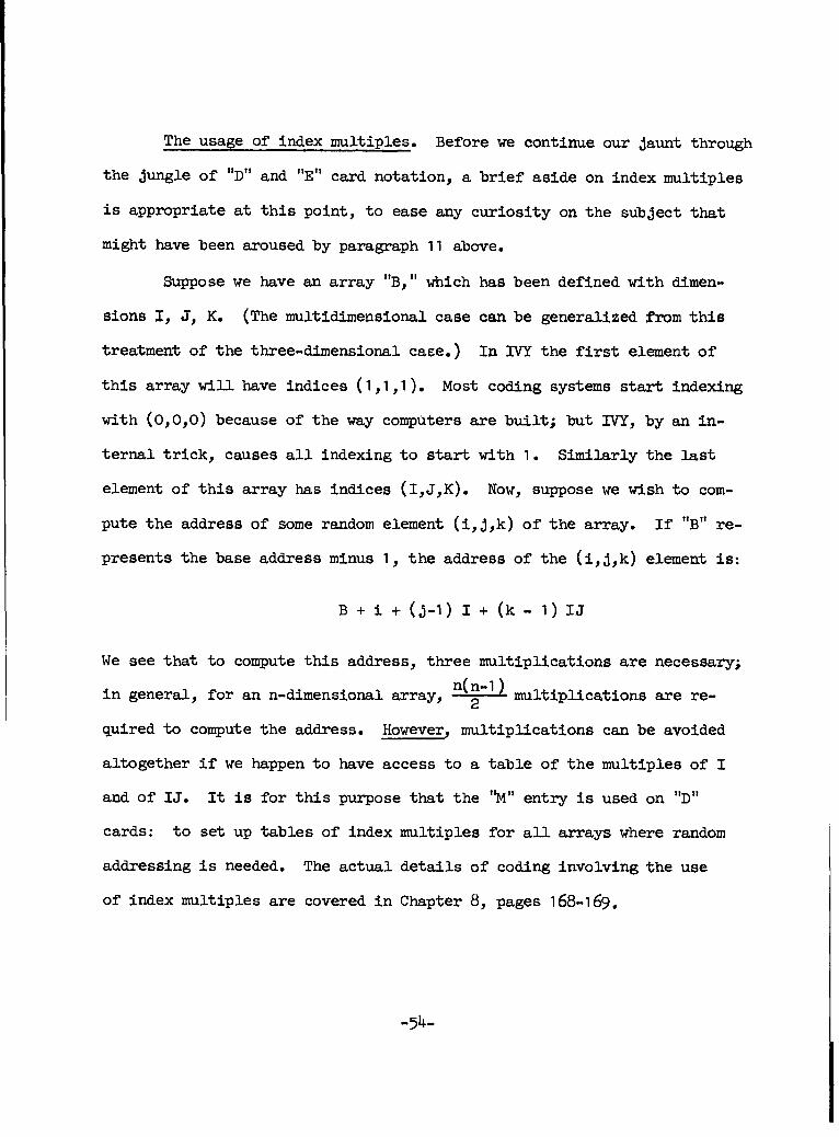
The usage of index multiples. Before we continue our jaunt through
the jungle of “D” and “E” card notation, a brief aside on index multiples
is appropriate at this point, to ease any curiosity on the subject that
might
sions
have been aroused by paragraph 11 above.
Suppose we have am array “B,” which has been defined with dimen-
1, J, K. (The multidimensional case canbe generalized from this
treatment of the three-dimensional case.) In IVY the first element of
this array will have indices (1,1,1). Most coding systems start indexing
with (0,0,0) because of the way computers are built; but IVYj by an in-
ternal trick, causes all indexing to start with 1. Similarly the last
element of this array has indices (I,J,K). Now, suppose we wish to com-
pute the
presents
address of some random element (i,j,k) of the array. If “B” re-
the base address minus 1, the address of the (i,j,k) element is:
B+i+(j-l)I+(k-l)IJ
We see that to compute this address, three multiplications are
- multip~cationsin general, for an n-dimensional array, ~
necessary;
are re-C
quired to compute the address. However, multiplications
altogether if we happen to have access to a table of the
and of IJ. It is for this purpose that the “M” entry is
can be avoided
multiples of I
used on “D”
cards: to set up tables of index
addressing is needed. The act~l
of index multiples are covered in
multiples for all arrays where random
details of coding involving the use
Chapter8, pages 168-169.
-54-

Other entries allowed on “D” cards. Besides defining symbols and
blocks, with the options of loading mentioned above, two other types of
entries are permitted on “D” cards: one to set up equivalent blocks, and
the second to skip certain definitions under parameter control.
1. Equivalent blocks are two blocks of data which share the same
memory locations and have the same dimensions, but which have different
symbols. Tne use of equivalence is a means to conserve storage by using
the ssme area for a second array when the need for the first has disap-
peared. A second block is defined as equivalent to a previously defined
block by prefixing its symbol with an asterisk (*) and following it with
an equal sign followed by the first symbol. The second symbol must not
have been previously defined. A symbol which has once appeared on the
left of an equivalence may not appear on the right of a subsequent equi-
valence statement; i.e., equivalence chains are not allowed. However,
two or more symbols may be defined as equivalent to the same symbol. The
example which follows is based on previous block definitions given as
examples in this chapter:
l)l+@Acl)E.Acl)D,*ACDF=GE,*ACDH=GE, *ACDG=U,
so that “ACDE” is a vector 626 in length, “ACDF” and “ACDH” both repre-
sent the same parameter “GE,” and “AClXl”is a block with dimensions (3,
GE+l, 2+$TH)sharing storage with “RMULT.”
2. The ~~ feature allows the programmer to skip certain defini-
tions of symbols, or to define a symbol in one of several ways, under
.55-

pareneter control. This is effected by placing “@” in parentheses, fol-
lowed by a parameter algebra expression and an equal sign with one of
eight conditions. If the condition is met, the definitions following the
comma are skipped until another “@” is encountered between commas. The
general format is as follows:
(@) P=c, ... (definitions) .... @J. ...
where “P” represents a parameter algebra expression and “C” represents one
of the conditions:
c CONDITION
ZorO
NZ
Lz
ZL
GZ
%
P
M
jump if expression is zero
jump if expression is non-zero
jump if expression is less than zero
jump if expression is zero or less
jump if expression is greater than zero
jump if expression is zero or greater
jump if expression is plus
jump if expression is minus
If the condition is met, the definitions following the comma are skipped
until the “,$J,” is encountered. If the condition is not met, the defini-
tions are handled in a normal manner. For example:
Dl(@) GE-2=0, ACDH(’5,7,11),*ACDL=13MU~,@J,
Dl(@) 2WH-7=ZG,ACDJ(2*NTr,GE+1 ),@, (@)2wrH-7=Lz,
D lAcDJ(2wIH-7,GE+l), $J,
-56-

Here we see that the definitions of “ACDH” and “ACDI” are skipped if GE
Is equal to 2, and that the definition of “ACDJ” takes on one of two
forms depending on the value of “W’TH-7.”
The loading of data on “E” cards. Data may also be loaded from “E”
cards, but one should bear in mind that all symbols appearing on “E” cards
must have been previously defined on “D” cards, and the dimensions of any
blocks loaded from “E” cards must also have been previously defined.
Thus on “E” cards only the symbol for the block can appear to the left of
an equal sign, since the dimensions are known. The expressions allowed
on the right of the equal sign are the same as those allowed on “D” cards.
For example, the following “E” card will.load two blocks defined in ex-
amples of “D” cards earlier in this chapter:
EIBMULT = 2.56312-13, (1)25,9.6732153-2, (R)3, (S),CVEC=l.,2.,3.,h.,11.72,
Note that as on “D” cards, loading must be complete. The “(S)” in the
expression for “BMUIll”guarantees this.
The “jump” feature is also allowed on “E” cards in order to skip
the loading of a certain block or to load it in one of two or more alter-
native ways. The “equivalence”feature is not allowed unless the symbol
to the left of the equal sign has been defined by its appearance on a “D”
card sarisdimensions, since the “E” card is merely a loading card, and not
one on which symbols can be defined. In other words, no symbol can make
its first appearance on an “E” card. For example, the-entry “WXCMT=BMULT”
is permissible since “TIMI’”has occurred on an earlier “D” card in this
chapter, without dimensions. “*BMUIT=AVECT” is not legal since “EMULT”
-57-

has already been defined with dimensions and hence assigned a location
in core. “*AcDK=~” is not le~l since “ACDK” has not occurred at all
on a previous “D” card.
Double-stored data. An entry for loading double-stored data is per-
mitted on “E” cards; this entry is not allowed on “D” cards. Double-
stored data is data each word of which contains two numbers paired in
the single memory location. The high-order portion, called the c#antit~
or simply “Q,” can be a signe~ fixed or floating point number. The low-
order portion, called the ~ or “T,” is an unsigned fixed-point integer
15which must be less than 2 . The exact length of the tag in bits can be
specified by parameter algebra. The IVY algebraic language has special
formats for handling double-stored data, discussed in Chapter 4, pages
79-8o . Double-stored data has many uses, the chief being in mesh-type
problems for solving differential equations. For instance, in boundary
value problems, the boundary points can be labeled with tags having dif-
ferent values from the tags at interior points. In hydrodynamics codes,
points corresponding to different substances can be identified by their
tags, and so on. The format for loading double-stored data is as follows:
SYMB@L(Q.P) = El, E2,...,~, SYMB@L(T.P) = F,, F2,...,FN
where the “Q” signals that the “Q” portion of the block is to be loaded,
and “P” represents parameter algebra whose value gives the tag length in
bits. The “Ei” are expressions for fixed or floating point numbers which
completely load the block. “T” now signals that the tag portion is to be
loaded, “P” being the same expression for the length of the tag as
-5$-

I
appeared in the first parentheses. The “Fi” are expressions for unsigned
fixed point integers which completely load the block. For example:
EIAVECT(Q.3)=~.32132-2,4.71531-l,(I)N’IT-3,2.1532+2,AVECT(T.3)=
El(B)1,2,3,7,6,5,4,2,1,7,(R),BMuU(T.GE+2)=TH,TH+~,TH+2,15,14,
E112, 3, 5, (S),
We thus note that AVECT is loaded with a tag 3 bits in length, and that
both the “Q” and “T” portions are loaded completely. “BMUL!T,”a block
which has been loaded previously, is now defined to have a tag GE+2, or
4, bits long, and the tag portion is then loaded. This is possible only
when a block contains floating point numbers: the block can be loaded
on a “D” or “E” card with floating point numbers without specifying “Q”
and the tag length, and the tag can then be loaded on “E” cards in the
normal way.
=“ Before proceeding to the study of remark and calling se-
quence cards, a sumary of the treatment of “D” and “E” cards is needed.
This summary, for review purposes as well as for quick reference, is
given in Table II.
-59-

COL. 1
D
TABLE II
SUMMARY OF ENTRIES ALLOWED ON “D” AND “E” CARDS
FORMATS AND EXPLANATION:
1. “SYMB$L1“ is entered in symbol table.
2. “SYMB~Ld?
“ is entered in symbol table, assignedan ad ess, and allotted 11 12 ... IN words of core.
3. “SYMB@L “2
is entered inand 10 ded with Q.
4. ,,=@4,t is handled asing must be complete.of the following:
a.
b.
c.
d.
e.
f.
g-
h.
i.
J.
k.
Fixed point numberparameter algebra.
symbol table, assigned address,
case 2 and also loaded. Ioad-“Q” and the “Ei” maybe any
( sign and decimal digits) or
Floating point number (sign, digits with decimalpoint, * exp. if desired).
(B)N1, N2,...NI, N2, etc., areintegers until (B) overruled.
(W)MI, M$,...M , M , etc., arewords un il (W) ov&ruled.
~&&~2~~~~1 /A~&~t&~e~ .
octal fixed point
Boolean octal
fixed point decimal
(Z)P insert P zeroes. “P” represents parsmeteralgebra. Proceed to end of block if P=O.
(R)P repeat last entry P times.
(S)P skip P words.
(I)P insert P interpolants
(M)P insert multiples of Pto end of block.
between 2 fl. pt. numbers
(o, P, 2P, 3P,...,)
(E)kN the following fl. pt. numbers all have ex-ponent = * N until overruled.
All names except remark names, numbered symbols and formulanames must be defined on “D” cards.
-60-

TABLE II (Continued)
I
I
COL. 1
D
E
of two
FORMATS AND EXPLANATION
*SYMB@Li = SYMB@Lj,(@) P=C,...definition@...@
1. SYMB@L. equivalent to S~@Lj providing S~@Lj is definedand wa% not defined by another “*” statement.
2. If parameter algebra “P” satisfies one of the conditions“c” (Z or O, NZ, M, GZ, ZL, ZG, P, M) definitions areskipped.
SYMB@L1 SYMB@L2(Q.P) = Q1,Q2,009~, ~~L5= ‘1’ ‘2’”””;pN’(T.P)= T1, T2,..., ~
Used for loading previously defined blocks. Iaading must becomplete.
10 “Pi’’and’~i’’areany of the expressions under “4” above.
2. ‘Ti’’areunsigned fixed point numbers.
3* “Q.p” and “T.P” mean “qyantity” and “tag” of DS number,IIrlP = tag length in bits.
Jump and equivalence can also be used on “E” cards, equivalencewith some restrictions.
The definition and loading of remarks. Remarks are usually for one
purposes: first, to provide comments and headings for output listi-
ngs and cards; and second, to provide format statements for printing,
punching, and microfilm output. In this section we will consider only re-
marks for comment purposes. Remarks for use as format statements are de-
scribed in Chapter 6, pages 132-14Z By using “R” cards and their contin-
uations, if necessary, remark blocks can be defined and/or loaded; the
“R” card for remarks is thus analogous in function to the “D” card for
data. However, no great parallel
punched. An “R” card must always
is found in the way these cards are
begin with a symbol which is called the
-6I-

“name” of the remark. Only one name can appear on an “R” card. If a re-
mark is too long to fit on a single card, it may be continued on the next
card providing the continuation card has a blank in column 1. (This
point was first made in Chapter 2.)
The general format of an “R” card is as follows:
1. “R” in column 1.
2. Symbol or name of remark. This maybe any legal symbol ornumbered symbol.
3. Optitlnal: after the symbol, a parameter algebra expressionin parentheses. The value of this expression is takenbyIVY to be the number of characters in the remark, so thatIVY will set aside this amount of space for the remark.
4. An equal sign, followed by any group of Hollerith charac-ters, which may fi31 any number of cards. The number ofcharacters in the remark must not exceed the number definedby the entry of “3” if this option is used.
5. In three consecutive columns, the characters @#@to signal theend of the remark. rd~ need not appear if the remark is ter-minated by the end of a card.
The remark as stored in core consists of all characters, taken in
order, from the first character to the right of the equal sign to the
last character to the left of $$$. These characters will be printed if
the symbol of the remark is specified in a calling sequence to “@R,”
the print routine (page 131). By using the characters 1$ in two
consecutive columns in a remark, the remark may be printed on two or more
lines: the portion of the remark following $@ will be printed on the
next line below the portion preceding @@. The characters $& are not
printed. Examples of remark entries:
-62-

N(YI’ES
R I RL =W~CES”~AA~~~~SA@FtiS@@~S~$@ 1, 2
R I REM(NTT*3+GE) = @#$ 3
R I R2 = THIS%S’A”@#%’W@’’LINE%MARK$$@ 4
R I R3 (3627) = c@NsmucmD%wH%@@ws@#”@@# 5
R I REMB=BESSEL%UNCTIONS”CCM?UTED%Y%ECURSION’’FORMULA.“ SEE”ANY%A33LE%O%
I ERIFYAACCURACY* ~j$! 6
Notes:
1. The following conventions should be observed to make the coding
sheets appear unambiguous to the keypuncher: “blank” is represented by
the carat “’’”;n blanks are represented by the number “n” in a box: ~
Alphabetic “I” must be written with
it from numeric “l”; alphabetic “@”
numeric zero; and alphabetic “E” is
ber two.
bars or dotted (“i”) to distinguish
is slashed to distinguish it from
slashed to distinguish it from num-
2. Our first remark is an illustration of a simple heading, the
name of which is a numbered symbol presumably defined on the “S” card.
3* In this case, space is assigned for a remark having NIT*3+GE or
110 characters. No characters are loaded. It is presumed that a remark
will later be constructed in the space, for instance, by “@CM,” the
character manipulation subroutine described in Chapter 6, pages 154-156.
4. In R2 we see the
If printed, this remark
THIS IS A
TW$4LINEREMARK
# convention for printing a remark on two lines.
wi2J_appear as fo120ws:
-63-

5* Space for 3627 characters is reserved. 27 of these are loaded,
namely, the comment and its $@ spacing control. Note that to avoid con-
fusion, the $!@and $$?$are separated by a blink. 3600 spaces remain in
a block; a 60 x 60 character graph could, for instance, be constructed
in the remaining portion of this remark block using “$X.”
6. An example of a remark which is continued onto a second card.
Note that the continuation card has a blank in column 1, as reqpired.
The loading of calling sequence blocks. Calling sequence blocks,
for the use of subroutines, are loaded from “K” cards. As has been re-
marked previously, the symbol assigned to a calling sequence block must
have been previously defined, either by its occurrence on a “D” card or
by its occurrence in the naming of a numbered block on an “S” card. Con-
tinuations of a “K” card must have “blank” in column 1 since the symbol
of the block is assigned on the “K” card. The general format of a “K”
card is as follows:
K]SYMB@(P) = (..calling sequence information...)
where, of course, the calling sequence information enclosed in Paren-
theses may be continued onto subsequent cards if necessary. “SYMB@L” re-
presents any legal, previously defined symbol or numbered symbol. The
optional entry “(P)” is parameter algebra defining the length of the
calling sequence in mchine words. Inside the parentheses to the right
of the equal sign may occur any number of calling sequence word entries,
separated by colons. The information in each entry between colons is
stored into one full word of the machine being used. The calling
-64-
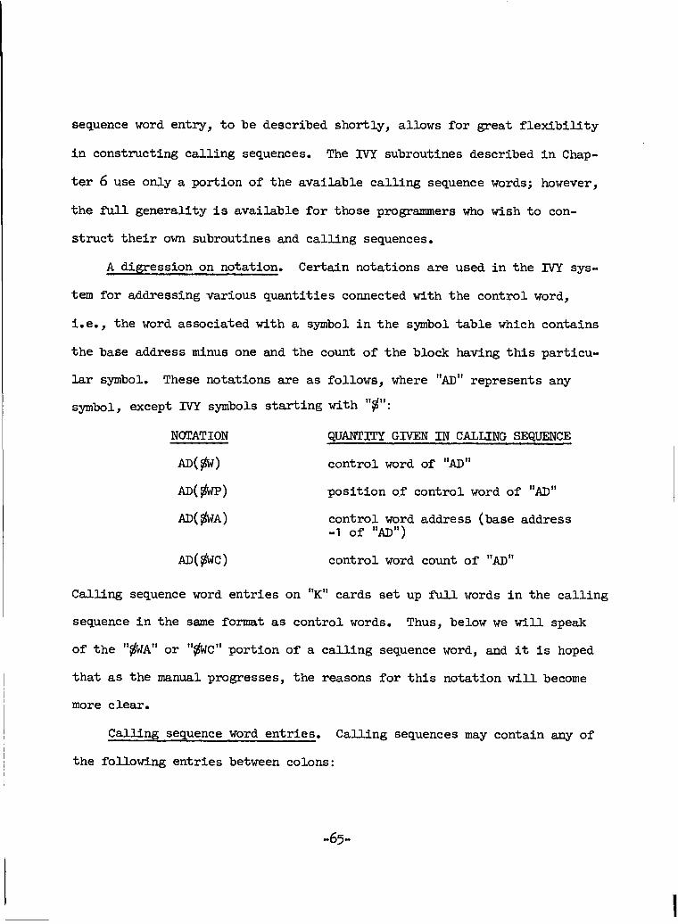
sequence word entry, to
in constructing calling
be described shortly, allows for great flexibility
sequences. The IVY subroutines described in Chap-
ter 6 use only a portion of the available calling sequence
the full generality is available for those programmers who
struct their own subroutines and calling sequences.
A digression on notation. Certain notations are used
words; however,
wish to con-
in the IVY sys-
tem for addressing various quantities connected with the control word,
i.e., the word associated with a symbol in the symbol table which contains
the base address minus one and the count of the block having this particu-
lar symbol. These notations are as follows, where “AD” represents any
s~bol, except IVY swbols sta~ing with “?”:
NOTATION QUANTITY GIVXN IN CALLING SEQUENCE
AD(@) control word of “AD”
AD(~wP) position of control word of “AD”
AI)(@WA) control word-1 of “~”)
AD(~wc) control word
address (base
count of “AD”
address
Calling sequence word entries on “K” cards set up full words in the calling
sequence in the same format as control words. Thus, below we will speak
of the “@WA” or “@WC” portion of a calling sequence word, and it is hoped
that
more
as the manual progresses, the reasons for this notation will become
clear.
CalMng sequence word entries. Calling sequences may contain any of
the following entries between colons:
-65-

1. ~XXX, where “XXX” represents one, two, or three alphanumericcharacters. The core BCD (octal) equivalent of these char-acters, exclusive of the “~,” is placed in the “@WC” portionof the calling sequence word. A table of hollerith charac-ters and their BCD octal equivalents follows:
TABIE III
HOLLERITH CHARACTERS AND OCTAL EQUIVALENTS
Character BCD Character BCD Character BCD
o1
234
60010203040506071011
HIJKLM
zPQ
30
?!4243u45464750
xYz+
7=1
677071
E54611314
33
A 21 R 51B 22 s 62 ~;c 23 T 63D 24 u 64 ) 34E 25 v 65 73F 26 w 66 &ank 00G 27
2. AD(@)+P, where “AD” represents any legal symbol, numberedor not, and “+P” represents parameter algebra. The controlword associated with “AD,” as modified by parameter algebra,is placed in the entire calling sequence word.
3a. AD(~WP), where “AD” represents any legal symbol, numberedor not. The location of the control word of “AD” is placedin the “@WA” portion of the calling sequence word.
b. KD(@WC)+P, where “~” is the above and “+p” i.s any parameter
algebra. The count of the control word of “AD,” as modifiedby the parameter algebra, is placed in the “@A” Portion ofthe calling sequence word.
-66-

II
1
!
II
C. AD($WA)+P. Same as “fi” except the address of the controlword of “AD” is used. 1.
d. AD(P), where “AD” is any legal non-numbered symbol and “P”is parameter algebra. The contents of location AD($WA)+Pare placed in the calling sequence word.
e. P, i.e., parameter algebra. The ’resultof the algebra isplaced in the calling sequence w&d.
I
4a. Anentry of type 1, followed by a comma snd an entry of type>> ~~ ~ 3C is allowed.
b. An entry of type 1 followed by a’comma and by an entry oftype ~ is allowed, providing the number addressed is fixedpoint and less than 218, or by an entry of type je prov”d-ing the result of the parameter ~lgebra is less than 2lb.
Chapter 6 is rife with examples of calling sequences to the various
IVY subroutines. Only one example will be given here: suppose we wishI
to enter “$TP,” the tape program, internally. If we use the same callingI
sequence covered in the example in Chapter ~ (page 35) on “T” cards, as-
signing it the name “TAPE” (which we
vious occurrence on a “D” card), the
as follows:
presume has been
“K” ca{d calling
I
defined by its pre-
sequence appears
I
KTAPE=(@lW3:@fR3,GE(@A)+l :SN(@):@&3,AX(@A)+3:ST(7W) :$RW3:
l~RW2:@B2,4:@D2,17iP(@A)+ GE:FRNB(#W))
INote that, as on “R” cards, the parameter a~gebra expressing the length
,of the calling sequence is optional. If th{s algebra is given, the call-
ing sequence need not be completely filled, and entries can be computed
by the programmer, if desired. Examples of $his technique appear in
Chapter 8, pages 182-184.I,,
II
-67.. ~I
I
I

CHAPIER 4
THE IVY AIGEBRAIC LANGUAGE
The IVY algebraic language, or machine algebra, iS capable of han-
dling expressions in floating point, fixed point, Boolean, or index re-
gister algebra, as well as the simple parameter algebra already discussed
in Chapter 3. We will consider these types of algebra in succession,
with examples. Index branching will be covered along with index algebra
and Chapter 5 will consider other types of branching. A SUmmaI’y of
machine algebra appears in Chapter 9) Pages 190-195.
The operation “=” is permitted in all classes of algebra except
parameter algebra, and means the following: “evaluate the expression to
the right of the ‘.’ sign, and place the result in the location specified
on the left of the ‘=’ sign.” In other words, expressions such as
B =B+l
are allowed and make sense with this definition of “=”. This statement
means “increment the number in location ‘Bt by one.” With this pre-
liminary remark we shall launch ourselves into a discussion of the var-
ious types of algebra.
-68-

Floating point algebra. The follo
floating point algebra:
OPERATION
+
*
*
/
//
+?
-7
*$
.$R
.$CX
NCY1’E
1
2
3
.$CA
.@
NU3!ES:
1. The expression for the exponexparameter algebra. For exampl
B**2, B**(GE + 1),
2. Reciprocal divide differs fror
the denominator appears first,equivalent. See pages 72-73.
-69-
lg operations are permitted in
MEANING
add
subtract
multiply
raise to a power
divide
reciprocal divide
take abs. value of preceding
take neg. abs. valueof precedingchange sign of preceding
take square root of preceding
convert exponent minus oneof preceding result to fixedpoint integer. (Integerpart of log2 [result]).
convert preceding result tofixed point integer.
if result of preceding is+0, settol.
If result of preceding is= O, set to 1; otherwiseset to O.
following “*,” must be in
+(+F(2qH)
egular divide only in that
Thus, “C//B” and “B/C” are

.
3. This operation is valid only when the preceding result ispositive. If an attempt is made to take the square rootof a negative number, an indicator is set which may betested by entering the IVY subroutine “$!?T”(Chapter 6,pages 128-I3o .)
Parenthesis conventions. Floating point algebra, unlike parameter
algebra, may contain parentheses, for one of two purposes: first, to
contain a modifier of a symbol, or second, to contain units of the alge-
bra. The second use will be described here; the first will.be encoun-
tered later in the section on modifiers (pages 74-84).
As in parameter
operations proceed in
observe the following
and its equivalent in
algebra, if parentheses are ~cking altogether~
simple sequence from left to right. For example,
equation in machine algebra without parentheses
display algebra:
MACHINE DISPIAY
RI = C=*2 - 4.0Wl+W3.#R - C2/2.OWl, r, = m-ca.c2 1
The
one
equation shown is an attempt to use the quadratic formula to find
root of a quadratic equation with real roots. Correctly written,
with parentheses, the equations appear as follows:
MACHINE DISPLAY
m-c,RI = C=*2-(4.0WI*C3) .#R-C2/(2.~Cl), .rI=2C1
Note that the purpose of parentheses in machine algebra is to localize
the operations so that they do not affect the result of the previous
-70-

computation. When a left parenthesis is encountered, a new level of
operation commences in which the algebra Within parentheses is performed,
with the convention that each operation within parentheses is performed
on the preceding result only as far back as the left parenthesis. The
above example might be diagramed as follows:
Level O:
z
R1-Result Adr.
s
&Res.lt Adr. Continue
Level 1:
c“mp”-~ “’ “’
Level 2: *F--I*] Ea-+%$1Ten levels, i.e., ten sets of parentheses within parentheses, are allowed
in IVY. Thus one can evaluate quite complicated expressions in the
machine algebra, for example:
MACHINE
2.0 + (c1*(c-(3+TH))) +c3H2
Note: To avoid confusion, bracketscan be used on coding sheetsas parentheses, however.
11[
if
However, it should be pointed out that
DISPLAY
(2+C1C23+TH + C3)2
u]“ and “curly” brackets “ “desired. They will be punched
this example can be written with
only one set of parentheses, as follows:
C-(fiTH)++Cl +
In general most equations can be optimized
theses occur, by moving multiplications
-71-
and
2.0 + cy*2
so that a minimum of paren-
exponentiation to the

beginning of the equation and by using the “reciprocal divide” (//) in-
struction. Below is the quadratic formula, optimized in this fashion,
and evaluation of the polynomial P~= d1y3 +d2y2+dy+3
algebra:
Thus, note
one set of
RI = 2.@Cl//C2*2-(4*ClW3).#R-C2
P4 = D1*Y+D2*Y+D3*Y+D4
that the quadratic formula cannot be optimized
parentheses, while polynomial evaluation needs
d4) in machine
for better than
no parentheses
whatsoever. A peculiarity of the “//” operation should be noted here:
everything to the left of “//” is the denominator of the fraction being
computed; everything to the right is the numerator. Thus parentheses are
not needed to enclose either expression, and the field of the square root
operation (in this case) need not be enclosed in parentheses since its
field of operation is assumedto start to the right of the “//.”
A further advantage of the “//” operation becomes apparent if one
considers the evaluation of continued fractions; for instance, in display
algebra, the expression
y=~
d+ef+g
This quantity can be written in machine algebra in either of the follow-
ing ways:
Y = ((F + G//E)
We note that the first
i-D//C)+H//B, or Y = B/(H -I-(C/D + (E/(F+G))))
expression, using
-72-
the reciprocal divide

instruction, has two less sets of parentheses than the second. Generally,
algebraic expressions containing fractions with complicated denominators
can be
ter 8,
evaluated more efficiently using the “//” instruction. See Chap-
pages 163-164, for further discussion.
Operands which may appear in a floating point expression. We
have seen above a number of allowed operands in the examples given. Be-
low is a complete list of the operands which may appear:
1. Any symbol for a
and/or loaded as a floating
first element of the block.
2. Any symbol as in
IVY to mean the nth element—
single word or array which has been defined
point number, interpreted by IVY to mean the
“l” followed by a number n, interpreted by
of the block.
3. Any floating point literal, i.e., a string of digits contain-
ing a decimal point and which may be followed by an exponent. The nota-
tion here is the same as the notation for loading floating point numbers
on “D” and “E” cards, except that in literals the decimal point must
occur between two digits, and not at the beginning or end of the number.
Examples: 2.o, 3.1415926535, 500.62-3, 256.15+2, etc. Illegal: 2, 2.,
.2, etc.
4. Any parameter algebra expression (including a single symbol
or a single fixed point literal)
Some further examples of machine
clarify the above list.
may occur following
algebra and display
the operation “**.”
algebra follow, to
-73-

MACHINE ALGEBRA DISPIAY AIGEBRA
Y=z - 3.w(z-6.53) Y = (z-3) (z-6.53)
AREA=R**3*4.@+3.1415926535/3.04
A=~fir3
AREAT = B1 + B2W.7H
DFUV = U1*VI + (U-V2)
D =B+ C+@
D_ B+~+(C+#)
CPUV1 = U&V3-(U3*V2)
D=Z1-Yl**2+(Z2-Y&2 )+ (Z3-Y3~2).#R
YS1 = AX+ (2.WBX)*AXor AX + BX~2
‘t=’~(bl +b2)h
+ (U3W3) U“v=uv+ ‘2V2 + ‘3V3
d=lb;~l
d= Ibl + ICI
(u+ = U2V3 - U3V2
fd= (Z1-yl)2 + (Z2-Y2)2 + (Z3 -Y3)2
+ (BX**2) Y; = a: + 2axbx + b: or (ax + bx)2
We note that in many of the above expressions, more parentheses are needed
in the machine algebra than in the display algebra counterparts. However,
quite often in general equations fewer parentheses are needed in machine
algebra than in display algebra. In a complete code, quite frequently the
number of parentheses used will usually be less than the number needed in
display algebra.
Address modifiers. Any symbol in a floating point expression
may be followed by a modifier in parentheses. ‘Thepurpose of these modi-
fiers is to do one of the following:
A. To modify the address of a block in some ways, e.g., by mems
of parameter algebra, contents of an index register. or stored address.
B. To specify a particular arithmetic such as fixed point or
-74-

Boolean. Floating
modifiers is used!
text, e.g., by the
point algebra
or unless the
occurrence of
is always assumed unless one of these
arithmetic desired is obvious from con-
a fixed point literal or an index regis-
ter symbol in the expression.
c. To cause an address to be interpreted in.a particular way, as
for instance to address the “Q” portion of a double stored number.
D. To cause only a portion of the quantity addressed to be used,
such as the sign only or the magnitude only.
E. To cause all or part of the control word of a symbol to be
used instead of the data addressed by the symbol.
F. To cause the contents of two locations to be swapped.
For the sake of completeness, all modifiers allowed in IVY algebra
will be discussed here. Many of these are appropriate only in fixed
point or Boolean algebra. A summary appears in Chapter 9, page 1930
These modifiers will.now be discussed in turn and the conventions illus-
trated by exsmples.
A. A symbol may be modified by parameter algebra alone, parsm-
eter algebra plus an index register, as follows (where P represents any
parsmeter algebra, Xn represents an index register symbol, An represents
a store address symbol) and SYMBOL (#WA) is the control word address of
the block:
AIGEBRAIC FORM ADDRESS CCMPILED
SYMB@L(P) SYMB@L(#WA) + P
SYMB~L(Xn + P) SYMB~L(#WA) + P modifiedby C(Xn)
-75-

AIGEBRAIC FORM (continued) ADDRESS COMPILED
SYMB@L(Xn) SYMB@L(@WA) modified W C(Xn)
S~@L(An) An
SYMB~L(Xn i-An) An
*C(X.) (“the contents of X=”) provides a dynamic
modified by C(Xn)
address modification;theLLC(Xn)may be changed titwill during execution of a program, thusdynamically stepping through an array or calling sequence. The C(Xn)are added to the specified address in order.to perform this modifi-cation. On the 7090, this addition is simulated, and how this isdone is of no concern here; the 7090 programmer can safely assume thathis index registers add as surely as do those of the 7030. In the IVYsystem, index registers always contain positive values and are notallowed to assume negative values, even on the 7030, which allowssigned value fields. The extra fields of the 7030 index register arenot accessible to the programmer unless he uses longhand code.
The “store address” feature allows the algebraic coder the unique
privilege of storing addresses, if he so desires. That is, he can
first compute the address he wishes to use, assigning to it one of the
“An” symbols, and then by placing it in parentheses as a modifier, in
a later expression, cause a “store address” to insert the calculated
expression. Thus the symbol modified
any symbol could be used, although in
addressed by “An” is generally used.
address is as follows:
An.m = F
SY@L(Xn+ An) = ...
● .* + SYMB@L(An) * ...
... (“An” occurs “m” times)
by an “An” expression is a dummy;
practice the symbol for the block
The format for computing a stored
I
-76-

That is, An is entered followed by a period and one or more digits which
give the number of times “An” occurs in the expressions following. The
letter “F” represents a fixed point expression for the address. The code
which follows must contain “m” symbols modified by “An”. Once these “m”
symbols have occurred, the same “An” is
a different address. Since only a very
necessary to encompass a given sequence
use each “An“ as its field of operation
available to be re-used to store
few distinct “An’s” are usually
of code, one can quite easily re-
is completed, and thus reduce
considerably the number of “A” symbols specified on the “S” card (page 26).
The number of “A” symbols specified should be minimized by adopting the
above practice of re-using an “An” as soon as its field of action is com-
pleted. This is what is meant by “independent” store address expressions
mentioned in Chapter 2, page 28. Note that “An” entries are “formula-
limited,” that is, once an “An” is
must appear in the same formula.
The following exsmple
sione This is a segment of
not yet been discussed. By
this exsmple will be clear.
should
defined, all symbols modified by it
serve to illustrate the above discus-
an actual code, and many details in it have
the end of Chapter 5, all the techniques of
-77-

Line No. NOTESc MIX h CR&SS A SECTIONS
2 Ill I MX.X9,($J) MXS=O,*I=XI. *S= X2, *M= X3, 11111@3
4
5
6
7
8
9
10
II
12
13II
—M(I, MM), S= MS(M), (LI)S=O, @
II AI.3=C($W)+CXX(M), 1111@-D
1(1, CXX2), C(I+AI)=O, (I), @
*L2,1= MN(S), TI=MOV(S)*EV+I.0,
11111@
1!(L3)TI .M,I
j TIzMO(S,M,WTI, A2,1 nC($W)+CXXU),
*I (I,cxx2), c(I+AI)s T[*c(I+A2)+c(x+ AI), (x),
(LI)MO(S)Z M,*
S= S+ I,(LZ),
LI, (M), (L4)ICT=NZ,*
($P, $PR: $F, FMI($WP): $A,C($WP): HM:GM),It h
4111 L’$(xg+l)tJ
15 L3, ($P, $$P: EP2($WP))~
... , ,,
(B I
@
@ I
Ill
Ill,!0
1.
2.
3.
4.
Here we see the “*” convention, which we first encountered on“D” cards (page 55), used here to define new symbols for in-dex registers. Index registers are the only quantities forwhich this is allowed on “I” cards. Note also the use of the“@” or “jump” feature, originally discussed in connectionwith data (page 55). If the condition fo120wing the’’(#J)”en-try is satisfied, the formula or formula set is not assembled.No second “@’’between commas is needed. This feature is use-ful in case a particular formula is not used in an assembly,i.e., is not entered if the condition is satisfied. See page 104.
Expressions for Al and A2 are computed.
Index registers plus modifiers Al and A2 occur in theseexpressions.
Here we see modification by index registers alone.
The above exsmple will also serve as an example for
which wild.be described in this chapter and the next.
other techniques
B. In an expression consisting entirely of symbols, and where the
-78-
L

type of arithmetic is not obvious from
gister symbols occur); if algebra other
context (no literals or index re-
than floating point is desired,
one of the modifiers “A” for fixed point or “B” for Boolean must be placed
within parentheses, separated from the modifier of type A by a comma,
after the expression to the left of the equal sign. The formats are as
follows:
SYMB@L(MA, A) = ... (fixed point e~ression)
SYMB@L(MA, B) = ... (Boolean expression)
where MA is a modifier of type A (i.e., a parameter algebra expression,
index register, etc.) and “A” denotes fixed point arithmetic following the
!!=II9 and “B” denotes Boolean. Whenever one of these modifiers is present,
modifier “MA” must occur. For example, if we wish to compute a value for
a single fixed point quantity “CE,” if the expression the right of the “=”
is unambiguous, we can write
CE= ... (expression)
but if the expression is ambiguous, we must write
CE(l, A) = ... (expression)
The “A” and “B” modifiers can appear only to the left of an equal sign.
c. Modifiers for dealing with double stored numbers can occur only
to the
comma,
in the
right of an equal sign, and are added inside parentheses, after a
in the ssme manner as modifiers of type B. These modifiers appear
following format, where “MA” represents a modifier of type A,
which must be present, and where “P” represents any parsmeter algebra:
-79-

FORMAT EXPLANATION
SYMB@L(MA,Q.p) “Q” portion of DS number having taglength P
SY@L(MA,M. P) Magnitude (absolute value) of “Q”
SYMB@L(MA,T.P) “T” portion, length P, of DS number.
Note that since the “T” portion of a double-stored number is unsigned,
the magnitude (“M”) modifier always unambiguously means the magnitude of
the “Q” portion. Also recall that the “Q” portion may be either fixed or
floating point, so that “SYMB@L(MA,Q.P)“ and “SYMB@L(MASM.p)”are ~big-
uous expressions, and if fixed point algebra iS desired~ the “A” modifier
described above must be used left of the ayual sign to specify arithmetic.
However, “T” is always fixed point and defines an expression as fixed
point unless other arithmetic is
follow. In the section on fixed
examples:
EXAMPLES
specified. Exsmples of these modifiers
point algebra we wild.encounter further
NOTES
SN(X1+3) = AGT(X2,T.3).$CA*FN(x2)/3e15621-06 1
AF(X3+GE+17) = Rm(l,Q.5)//cx(N1+3) - CRyZ(2,Q07) 2
NUTES: 1. In this example the use of “T” in a floating point expressionis permitted, since the quantity is followed by the opera-tion “$CA” which converts it to a floating point number.
2. The “Q” portion of two numbers having different tag lengthsare used in this algebra.
If it is desired to compute the “Q” or “T” portion of the qUtitY
to the left of the equal sign, one must use expression modifiers, described
below on pages 83-84.
-80-

D. Modifiers of type D are used to impose the sign of a quantity
on the result of the previous calculation, or to ensure that only the
magnitude (absolute value) of a quantity takes part in an operation, and
in one case, to save the remainder of a division or the low-order part of
any floating point operation, for double precision purposes. Type Dmodi-
fiers can occur only to the right of an equal sign. These modifiers are
as follows:
FORMAT
~@L(MAIM)
+~$L(MAp$)
-~@L(MA,#)
*~@L(MAjl)
SYMS@L(MA,R)
EXPLANATION
use magnitude of addressed quantity
impose sign of addressed quantity onprevious result
impose negative of sign of addressedquantity on previous result
multiply sign of addressed quantityby sign of previous result
save the low order part of the resultof this operation in the IVY location“~csl” -
An example of the magnitude modifier “M” is shown in line 8 of the coding
example on page 78. Other examples:
EXAMME
RxN(xlWE?)= GFG(X3)**3+GE(1,#)
AFG = ALPHA(X3+N) + B(X2)*~(Xl+Al,jj)
SUMY=AB(X1+l,R) +AC(X1+l)+ AD(xl+l)EMG(X5+3+GE) = SRN(X2+1,R)-SRT(X2+1) + #/FNT3
-81-
NOTE
1
2
3
4
NCYI’ES: 1.
2.
3.
4.
E.
The sign of GE1 is attached to the result of the previousoperation.
The signs of STV(X1+A1) and the preceding result are multi-plied, and this resulting sign is attached to that result.If the signs are alike, “+” will result; if unlike, “-” wi12.resuit.
The low order part of the floating point result of this cal-culation is stored in “#CSl,” from which it may be obtainedfor double precision work. We recall.that on the 7090, botha high-and low-order part are carried in all.floating pointoperations; on the 7030, the “R” is a signal to executedouble precision operations followed by a “store low order”instruction to “@CS1.” The “R” modifier, if at all.possible,should always occur as near to the beginning of the expres-sion as possible in order to speed compilation.
In this case, the remainder of the division, if any, isstored in “~CSl” once the operation (division) has been com-pleted.
Address modifiers of type E cause the symbol to be interpreted
so that the operand becomes all or part of the control word, or the ad-
dress of the control word, associated with that symbol. Ordinarily these
modifiers are used only with fixed point and index arithmetic. All of
these modifiers except “@Wl?”are allowed either to the left or to the
right of an equal sign. Type E modifiers are as follows:
MODIFIER FORMA!I! OPERAND GIVEN
_@L(@) control word
SYMB~L(~WA) control word address
SYMB~L(@C ) control word count
EM@L( @P) position of control word
-62-

Note that no other modifiers
the control word modifiers.
in the computation of stored
of any type may appear in parentheses with
The chief use of control word modifiers is
addresses (see lines 4
on page ~), for which “~W” is ordinarily used; the
register values, using “$WA,” “$WC,” and “@lP”; and
volving the symbol table. Examples of these latter
the sections of this chapter
and in Appendix 1.
F. The swap modifier
dealing with index
“S” always appears
and
and 8 of the example
computation uf index
in manipulations in-
two uses are found in
fixed point algebra,
to the right of an equal
sign and must follow a type A modifier. The format is as follows:
SYMB@L1(MA) =
The contents of the two locations
No arithmetic is permitted to the
Expression modifiers. Two
fiers, may be appended to the end
SYMB@L2(MA,S)
are simply swapped, i.e., interchanged.
right of the equal sign.
modifiers, known as expression modi-
of an expression in order to specify
that the result is to be stored in the “Q” or “T” portion of the quantity
which appears to the left of the equal sign. These modifiers appear as
follows, where “MA” represents a modifier of type A which may or may not
be present, and where “P” represents any parameter algebra:
SYMB~L(MA) = (expression).j!!Q.P
SWOL(MA) = (expression)[email protected]
Ordinarily the modifier “.$T.P” should follow only fixed point expres-
sions. “.$Q.P” may follow either fixed or floating point expressions,
-83-

since the “Q” portion of a double-stored number may be either fixed or
floating point.
Special symbols addressable by IVY algebra. Four of the special
“~” symbols in IVY represent data blocks and maybe addressed byalge-
braic code. All of these except “@” may be modified by modifiers of
all types. However, the control word modifiers have a somewhat differ-
ent meaning when attached to “~CS” and “@Z”; this is covered in Chap-
ter 5 in the section on calHng sequences, pages 108-110.These special
symbols and their meanings and usage are as follows:
1. @M. This symbol may occur only to the right of an equal
sign, without modifiers. It means, “repeat the quantity to the left of
the equal sign.” For exsmple, the following two expressions are equi-
valent:
AD(X2+GW3) = AD(X2+GE*3)*SN( X3+2)/FN’3
and
AD(X2+GE*3) = @*SN(X3i-2)/FN5
2. #CS. This symbol represents the “caUing sequence data
block” and may appear on either side of an equal.sign, with or without
modifiers. Generally “#CS” is used to convey information to, or to re-
ceive information from, a subroutine. We have already encountered
another use of this block: the low order part of a double precision
result is stored in the location “~CS1.” The “@CS” block is twenty
words long and can be used the same as any data block except that it
should be recalJ.edthat the contents of “$CS” are destroyed by some
-84-

subroutines. Further discussions of “@CS” are found in Chapter 6,
pages 127-129.
3. @z. This symbol, which must always have at least a modifier
of type A, may occur on eitherside of an equal sign. It simp~y means
“supply an address of zero.” Its chief use is in store address expres-
sions of the form
#z(xn+~n, M2)
where the symbol is unimportant, since “An” is the address actually used,
and in subroutines, to refer to entries in a calling sequence, in the
form
@Z(Xn+N, M2).
(“M2” represents either a nu~ field or some type of legal modifier other
than type A.) The usage of “~Z” for the latter purpose is discussed
in Chapter 5, pages 108-110.
4“ @) $w @B~ “““)@Z. These 27 special symbols are shared by
subroutines and are used for internal data. A complete description of
their usage is given in Chapter 5, pages 110-112.
50 IL. The “@L”symbolsprovideaccess to certain special con-
stants and addresses used by IVY. The symbols address the following in-
formation: @Ll = FAC (first address for code); @2 = FAD
for data); ~L3 = NIA (next loading address for code); @!
block address for data); #L5 = 709010 if machine is 7090,
(first address
= NBA (next
703010if 7030;
jh% = number of remark characters per word. #Ll, @i2, ~L5 and #L6 are
-85-

available for testing purposes only. #L3 and #~ may be altered with dis-
cretion, as described in Appendix 1, pages 203-20g.
Statement separation and continuation. As one can observe from
examining the example on page78, IVY statements in the algebraic language
are separated by commas. There may be any number of statements on a card,
of up to 71 characters in length. An algebraic statement can be con-
tinued from one card to the next provided that symbols, literals, symbol
modifiers in parentheses, expression modifiers, and operations of more
than one character (“~j” “+$,” etc.) are complete on one card. These
items which cannot be split from one card to the next are called units
of an expression; thus we can say that expressions can be continued from
one card to the next provided that units of the expression are complete
on one card.
*Blzmks occurring in expressions are always ignored, as we can seeby again referring to the e~ple. Thus blanks may be used, if desired,to separate units of the expression for easier reading. The carat’’’’”isused to denote blank spaces on the coding sheet; if more than one blankis desired, the notation is to write the number “n” of blanks enclosedin a box, thus: ~. Note that oneneed notusethese conventions torepresent blanks occurring at the end of the card. In general, blanksare totally ignored on every type of IVY card except the remark cardwhere they form part of the input data.
Fixed point algebra. The same operations are allowed in fixed
point algebra as in floating point algebra, with some changes in meaning
caused by the peculiar nature of fixed point algebra. These differences
are as follows:
-86-

OPERATION
/
//
.pcx
.$CA
.$R
MEANING
divide, and truncate quotient to integer.
reciprocal divide, and truncate quotientto integer.
convert fixed point number to expon nt of?floating point number, i.e., give 2 ‘esult)
in floating point.
convert fixed point number to floatingpoint number.
take square root, and truncate result tointeger.
These differences are, of course, occasioned by the difference between
floating and fixed point arithmetic. Fixed point arithmetic is the
arithmetic of integers; hence the difference in the divide instructions.
The same operands, with the exception of literals, and with the
addition of symbols for “K” blocks (page 18~, are allowed in fixed point
algebra as in floating point. Literals, of course, must be fixed point
decimal numbers, i.e., a string of digits not containing a decimal
point. In addition, symbols for index registers are allowed in fixed
point algebra; when these symbols are used, the contents of the index
register are used as an operand. When an index register appears in an
expression, there are two modes of operation: immediate and direct.
The “direct” mode is signalled by the modifier “A.” When the “A” is
missing, immediate algebra is assumed; that is, the expression is
assumed to be parameter algebra and is computed according to the values
of the parameters loaded at the start of the deck.
-87-

The same address and expression modifiers are allowed in fixed
point algebra as in floating point algebra. The same conventions are
also used for parentheses, the continuation of statements from one card
to the next, and the use of special “~” symbols.
The following examples of, and notes oqfixed point algebra
should serve to illustrate all necessary conventions.
EXAMPLE N(YTE
ARX(X1+3,A) = VDBC(X3,M) +RX3/AGT5*# 1
AD(l,A) = X3*VXC1 + PAR2 2
AE = x5 + GEwH/3 3
FRN(X2) = 3 + ART(X1)*56-SRTN(X2,@).@A. $Qe5 4
A3.6 =AD(@w) +ADX(XI) +AD@x2) 5
INDEX = Xl - VRN(~WC) 6
NW3!ES:
1.
2.
3*
We note that in this example the “A” modifier is used to spe-cify fixed point arithmetic, since the expression, containingonly symbols, is ambiguous. Also note the use of the “magni-tude” modifier and of %$tl to ch~ge the sign of the t?Xp?X?SSiOIh
In this second example the “A” modifier is used in a differentsense, since the expression contains a symbol for an index re-gister and hence is unambiguous. The “A” is a signal that thealgebra is “direct” or “dynamic,” i.e., the computed values ofthe symbols at the time of execution indicated are used in thealgebra.
Here again the eqression involves the contents of an indexregister, but since the “A” is not specified, the arithmeticis assumed to be “immediate” or “static,” i.e., the values ofthe specified parameters at the time of assembly are used inthe algebra. This is done by placing the operands directly
-88-

into machine instructions, by using immediate arithmeticon the 7030 and immediate-type instructions such as “TXI”on the 7090.
4. In this fixed point expression the “A” is not needed sincethe occurrence of fixed point literals makes it unambiguous.Note that the expression is converted to floating point andthen stored in the “Q” portion of the double-stored block“FRN,“ having tag length 5.
5. This is an exsmple of the computation of a stored address.Recall that other examples of this were shown in the codingexample given on page 78. The usual expression for astored address includes the control word of a block (fromwhich the base adtiess is obtained) modified by the addi-tion of one or more index multiples under the control ofindex registers. The philosophy of this technique is dis-cussed in detail in Chapter 8, pages 168-169.
6. This is an example of an immediate indexing operation inwhich the control word count is subtracted from the con-tents of the index register.
Index register algebra. Although index registers, as we have seen,
can appear in fixed point algebra, true index register algebra differs
considerably
noted by the
equal sign.
from fixed point algebra. Index register algebra is re-
occurrence of an index register symbol to the left of the
The operation set for index register algebra is as follows:
OPERATION
+
.7X
Thus we see that the operation set for index
stricted. However, under most circumstances
-89-
MEANING
add
subtract
if previous resultis negative, set to 1
arithmetic is quite re-
the operation, “*,” for

instance, is not needed since tables of index multiples can be constructed
on “D” cards and used in index arithmetic; and constructing index multi-
ples (done automatically by IVY) is the chief reason for the existence of
a “multiply” operation. If it is desired to load an index from a more
complicated expression, one can first use fixed point algebra to compute
the expression, and then load the index from the location where the re-
sult was stored.
It has been remarked before that index register contents are re-
stricted to positive, non-zero values. Tie purpose of the “.@X” instruc.
tion is to keep the index register contents positive by guaranteeing
that if the result of an expression is negative, a positive result of 1
willbe substituted. The magnitude of index register expressions must
be less than 215 18
on the 7090 and 2 on the 7030. Note that if the re-
15suit exceeds these bounds, the number given will be truncated modulo 2
or 2’8 as the case may be.
One modifier is allowed left of the equal sign in index register
expressions: “A” separated from the index register symbol by a period.
The purpose of this “A” is the same as in fixed point algebra when in-
dex registers are present, to specify “direct” arithmetic. Index regis-
ter algebra is always “immediate” if the “A” is not present. Of course,
here as elsewhere, the apel.lations“direct” and “immediate” apply only
to units of the expression other than index register symbols. In either
fixed point or index algebra, the contents of the index register at exe-
cution time form the operand.
-90-

Some examples of index register algebra follow:
EXAMPLE NOTE
xl =X1+1 1
X3.A = AD+3 2
x3 =GE+3 3
X2.A = AE-INDEX.#X 4
NOTES:
1. The contents of index 1 are incremented by 1.
2. In this case, direct algebra is specified by the “A.” Thecontents of “AD” at execution time are incremented by 3and placed in index register 3. Note that “N)” is the sym-bol for a rather complicated expression illustrated in thesection on fixed point algebra. This example thus showshow a dynsmic loading of an index register can be performed.
3* Immediate algebra is assumed here, which means that the con-tents of GE at compiling time, plus 3, are placed in indexregister 2.
4. Here the arithmetic is performed in the direct or dynamicsense, and the index register contents are set to 1 if theresult is negative.
Renaming of an index register. An index register may be renamed
at any point in the code by the use of the “*” convention which was
originally discussed in connection with data blocks on page55.
Usually an index register will be renamed to a single-letter symbol to
save the necessity of writing the two or more characters associated
with every “Xn” symbol. If it is desired to use a symbol of two letters
or more to rename an index register, the symbol should of course have
-91-●
been defined by its appearance on a “D” card. The format for renaming
an index register is as fo120ws:
*~@L = Xn,
where “SMB@L” represents any single letter symbol (except A, X, or L),
or any symbol of more than one letter which has been previously defined
on a “D” card, i.e., entered
Using what we now know,
index loop. An index loop is
in the symbol table.
let us construct’a simple example of an
specified by placing the values between
which the index is to run, separated by a CO=~ in parentheses afier
the name of the index register, at the beginning of a looPo The end of
the loop is denoted by p~cing the index register symbol in parentheses.
We have encountered other examples of index loops in the example on
page 78, lines 5, 9, and 3-12. The following loop is for the simple
PWOse of constructing the dot product “D” of two vectors “VA” and
“V-B,“ each having three components:
II*I = Xl, D
or, equivalently,
II*I =Xl, D
At least one of the limits of
= 0,1(1,3), D = D +VA(I)*VB(I),(I),...
= 0,1(3,1), D = D +VB(I)*VA(I),(I),...
an index loop must be 1. The other maybe
represented by a literal, as above) or by a s~bol~ as in the e~Ple
on page 78, or by a parameter algebra expression. The operation is per-
formed for the first value of the index, and then the loop is reiterated
after the index has been increased or decreased by 1, until the index
-92-,
I
reaches the final value. If it is desired to construct a loop for which
one of the limits is not 1, or for which the index increment is not 1, or
where the index is to run between computed (as opposed to parameter)
values, other techniques must be used, utilizing the “L “ entry. Examplesn
of this appear in Chapter 5, page 99, and Chapter 8, pages 169-171.
Boolean algebra. Boolean algebra is used for performing logical
operations by obtaining a result involving a bit-by-bit comparison of
two or more operands.
OPERATION
+
*
t
.$U
●*
The set of Boolean operations is as follows:
N(X?E MEANING
1 logical add, sometimes called“inclusive ‘or’”
2 logical multiply, sometimescalled “and”
3 take one’s complement of preceding
4 give 1 if result is # O
4 give O if result # O, otherwisegive 1.
NCYJ?.ES:
1. The inclusive “or” of two binary numbers is obtained by compar-ing the numbers bit-by-bit, and setting the corresponding bitof the result to 1 if either or both operand bits are 1, andto zero otherwise. For example, the inclusive “or” of101101011101 and 001011100101 is 101111111101.
2. The “and” of two binary numbers is obtained by comparing thenumbers bit-by-bit, and setting the corresponding bit of theresult to 1 if both bits are 1, and to zero otherwise. The“and” of the two numbers given above is 001001000101. Notethat the Boolean sum of the exclusive “or” and the “and” isthe inclusive “or.”
-93-

3*
4.
One
The lls complement of a binary number is obtained by replacingall 1‘s with zeros, and all zeros with 1‘s. For instance, the1’s complements of the two numbers in note 1 are 010010100010and 110100011010.
These two operations are the same asfixed and floating point.
can represent the Boolean operations
the corresponding ones in
graphically, as is illust-
rated below, assuming we have two intersecting regions “A” and “B.”
The result of the operation is the shaded area. We might say that the
area common to both regions corresponds to the
hers which are equal to 1, and the rest of the
differing bits of the binary number. The area
responds to the bits of both numbers which are
bits of both binary num-
area corresponds to the
outside the regions cor-
zero.
A+B A*B A’
From these illustrations a few identities of Boolean algebra become evi-
dent. For instance, the exclusive “or” of two numbers is equal to the
logical sum of the “and” of the first number and the complement of the
second, and the “and” of the second number with the complement of the
first. That is, the fo120wing expression produces the exclusive “or”:
-94-

Y(l,B) =V*(W’) + (W*(V’))
The exclusive “or” of two binary numbers is obtained by comparing the two
numbers
the two
note 1,
and
In this
bit-by-bit, and setting corresponding bit of the result to 1 if
bits differ, and to zero otherwise. If we use the two numbers of
page 93, this can be verified for a particular case:
101101011101 (exclusive “or”) 001011100101 = 100110111000
1011O1O111O1*(OO1OI11OO1O11)+ (OO1O111OO1O1*(1O11O1O111O11)) =
10I101O111O1*11O1OOO11O1O+
100100011000+ 000011000000
(001011100101*0100’
= 100110111000.
case, both results
no proof is offered here.
between Boolean operations
0100010) =
are the same. In general this is true, although
Many other similarly interesting relationships
can be discovered by studying the diagrams.
It is possible to obtain sixteen possible results by combining two numbers
using the IVY set of Boolean operations; these sixteen results make up the
entire set
The
1.
2.
of sixteen so-called logical connective.
following further observations apply to the Boolean set:
The operations “+” and tl*ttare Commutative and associative~
i.e., B+C=C+B, B*C = C*B, and~(B*C) = (~B)*C, etc.
The operation “*” is distributive over “+,” and “+!’is distributive over “*,” i.e.,
D + B*C = ~C+(B++C);
IMB+C= D + C*(B + C).
The “and” (logical product) of twoone bits than either number unless
-95-
numbers contains lessboth numbers are equal;

the inclusive “or” (logical sum) of two numbers containsmore one bits than either number unless both numbers areequal. The “and” and inclusive “or” of equal numbersare equal to the two numbers; the exclusive “or” of equalnumbers in zero.
Boolean expressions must always be denoted by the “B” modifier
to the left of the equal sign. The algebra to the right of the equal
sign may contain symbols for Boolean blocks or Boolean literals. Or-
dinarily Boolean expressions should not contain symbols for non-Boolean
quantities unless great care is exercised. While some very useful com-
putations can be carried out by violating this rule, such computations
usually will not work on all machines for which IVY is available, since
the formats of internal words differ. For example, on the 7090, the
following two expressions are equivalent and would compile the same se-
quence of instructions:
ADF(l,A) = AXCG(3+X3) .$CX
and
ADF(l,B) = AxCG(3+x3)*377000000000,uF(I,A) = Al)F/(2**27)- 129,*
whereas on the 7030, the latter expression will definitely not do the
same as the former, because of the differing word lengths and floating
point formats on the two machines.
*In the last expression, “@l” can be used instead of “ADF” on the rightof the equal sign, if desired.
-96-

CHAFFER‘j
FIOW OF CONTROL, CALLING SEQUENCES, AND THE EXECUTE STATEMENT
L-entries. “L-entry” is the term applied to the use of a numbered
“k” symbol for branching purposes. An “L-entry” may be used for both
conditional and unconditional branching. In the algebraic language the
entry point is marked by the occurrence of an “In” symbol between commas
(for longhand conventions see Appendices 2 and 3). Unconditional branch-
ing to the statement
by the occurrence of
immediately following this entry point is specified
the same “Ln” symbol in parentheses between commas.
This branching may be performed in either a forward or backward direction,
thus:
....(h) (,~~. algebra)...7
Ln,....(algebra)...J
●..*.,
1
flow of control
......(Ln)....(algebra)...
An entry of “Ln” between commas for a particular value of
only once in a given formula. Conditional branching to a
“n” can occur
given “In” entry
is specified by the entry of “h” in parentheses, followed by a modifier,
-97-

if
the
the
necessary, specifying the tme of algebra used in the e~ression tO
right of the right parenthesis. If the given condition is satisfied,
branch is performed. Otherwise, control proceeds to the next algebraic
expression. The general format is as follows:
,(b, M)Algebra = C,
where
1. “h” represents the entry to which branching is to beperformed.
2. “M” represents one of the modifiers “A” (for fixedpoint), or “B” (for Boolean), if necessary to spe-cify the type of algebra to be performed in thefollowing expression. “M” and the comma precedingit may be omitted if the algebra is unambiguousaccording to the tenets of Chapter 4.
3* “Algebra” represents any machine algebra expression.
4. “C” represents one of the following conditions:
c
ZorONZGZ
IzZ.GZLPM
CONDITION
branch if resultbranch if resultbranch if result
than zerobranch if resultbranch if resultbranch if resultbranch if resultbranch if result
is zerois not zerois greater
is less than zerois zero or greateris zero or lessis plusis minus
Examples. An examination of the coding example in Chapter 4,
page 78, will reveal an unconditional branch on line 11, and conditional
branches on lines 3, 7, 10, and 12. The “Ln” entries to which branching
is performed are on lines 6, 12, 14, and 15. Note how the flow of control
-98-

is marked by arrows.
The following example also makes use
“Ln” branching. This exsmple performs the
of conditional and unconditional
matrix multiplication of the
I X J matrix “MA” times the J X I matrix “MB” and stores the I X I result
into “MC.”
LineNo. I 2 I 72 CODENOTES
I c MATRIXnMULTIPLY AROUTINE
2 II I XI =1, X2=I, X3=I, K(I,A)=I* J,M(l,A)=I!t*2, 11111I
3
4
5
6
7
8
9
10 I
IWms :
1.
2.
+LI, MC(X3) =0,
L2, MC(X3)=$M+@A(Xl) *MB(X2)), II1-
XI=XI+I, X2= X2+I, (L2,A)XI-K=*L,
I - —X3= X3+ I, (L3,A)X3-M=G* +
XI.A:XI-K+I, (L4)XI-I=GZ,
XI= I,(LI),
. L4, X2=X2-J, (Ll),I
I I L3,... ( Code continues)
2
3
3,4
5
6
6 I
6
I
All three index registers used in the code are initialized to 10The quantities “K” and “M” are computed for later use in indexcomparison, since, as we recall, the operations “*” md “+++”are not allowed in index algebra. The “A” modifier is neces-sary in both since the algebra is smbiguous. There sre noliterals present to distinguish the expressions from floatingpoint.
The current element of matrix “MC” is initialized to zerobefore computation begins, since the result is computed in acumulative fashion.
-99-

3* The current element of matrix “MC” is increased by theproducts of the appropriate elements of “MA” and “MB.”Then the “MA” index, Xl, is increased by I, and the“MB” index, X2, by 1, since we are proceeding througha row of “MA” and a column of “MB.” Note that the in-crement of Xl is by a parameter, and X2 by a literal;hence both operations are immediate and the “.A” modi-fier is not needed.
4. We proceed back to increment “MC” again if the row of“MA” is not yet exhausted. Note that the “.A” modifieris used here to specify direct, or dynamic, index alge-bra in the test of Xl since “K” is a computed quantity.
5* If the row of “MA” is exhausted, the index for “MC” isincremented by 1. (We are computing “MC” column-wise).If “MC” is exhausted, exit is made to “L3.” Note againthe use of “.At’to specify dynamic index algebra.
6. Xl is now incremented backwards so that “MA(X1)” willstart the next row in “MA.” If “MA” is exhausted, westart over at its beginning but proceed to the nextcolumn in “MB.” If “MA” is not exhausted, we proceedto its next row, but use the ssme column of “MB.” Notethat the “.A” modifier is not used when 1 and J are in-volved, since these quantities are parameters, beingarray dimensions, and hence can be used in immediatearithmetic.
It should be noted that the above example is included for illust-
rative purposes only, and is not intended to demonstrate the best pos-
sible technique for multiplying two matrices. The method illustrated is
used only because it is a familiar one.
Restrictions on L-entries. As has been mentioned before, L-entries
are purely local entities within a formula. Branching from ofleformula
to another by means of L-entries is prohibited. An L-entry in a formula
to which no branch is performed, and a branch to a non-existent L-entry
are detected as errors, and a diagnostic printout is performed. If exe-
cution reaches the point where a branch to a non-existent L-entry occurs,
-1oo-
and the branch is successful, IVY takes control, prints a comment to the
effect that execution cannot proceed beyond this point, and selects the
card reader or off-line tape in an attempt to process the next job, if any.
Pathfinder branching. Pathfinder branching is a means of controlled
entry to subroutines,when a subroutine is entered from several points in
the code and return must be made to whichever point that performed the
entry. This is done by using the pathfinder register, called “~P.” When
a pathfinder branch is made, the location from which the branch occurs is
stored in the pathfinder. The subroutine, then, can load the contents of
the pathfinder into some available index register and return by branching
using this index register. The format for a pathfinder branch to an L-
entry subroutine is as follows:
Note
“Izl”
,(~P,Ln)j
that the pathfinder branch is unconditional. The subroutine named
begins with the entry:
,Ln.xm,
where “Xm” is the symbol for the index register into which the pathfinder
contents are loaded. The subroutine then ends with the entry
,(xm+l),
where “Xm” is the same index register which was loaded with the pathfin-
der contents. This entry causes control to return to the expression
-1o1-

I“ollowingthe pathfinder branch to the subroutine.
Examples of a pathfinder branch and subroutine.
several points in a formula we calculate a quantity “Y”
Suppose that at
and we wish to
evaluate a polynomial “Z” of
efficient of the polynomial
of the variable in the block
might look as follows:
Nth degree for this “Y.” Assume the co-
are stored in order of decreasing powers
“c.“ If the subroutine is called “L5,”it
1111I L5.X4,3=0 11111XI (I,N), Z=Z*Y+C(XI), (XI),
I H-+ .xit-- (X4+1), 11111
The contents of the pathfinder are placed in X4. The polynomial is then
set to zero initially, and then each time through the loop, it is multi-
plied by “Y” and increased by the next coefficient. After the evalua-
tion loop is completed, the exit is performed to (X4-+1). Note also that
the exit from a subroutine must be unconditional.
Formulas and formula branching. As has been remarked previously,
a formula is a subset of a formula set. The name of a formula is de-
fined solely by its appearance on an “I” card and must not have been de-
fined on a “D” card. The format for entry of a formula name is the same
as for an
depending
L-entry, namely,
,F@M, or, [email protected],
on whether or not the formula is entered by a pathfinder
branch. “F@M” represents any legal symbol not previously defined, and
-102-

“xn”any
take any
free index register. Similarly, branches to a formula entry may
of the following forms:
BRANCH TYPE
,(F@?M), unconditional
,(F@4jM)Algebra = C, conditional
,(#P,F@M), pathfinder
A formula may be a subroutine accessible to any formula within the same
formula set, just as an L-entry can be a subroutine within any formula.
An example of a formula which is a subroutine is the formula “MX” of the
example in Chapter 4.,page 78. This formula
and we see that
turn is made by
,(@P,Mx),
the contents of the pathfinder
the usual entry
is entered by the instruction
Formula sets.
the name of a formula
,(X9+I),
are
The name of a formula set is
by the fact that it has been
A formula set consists of one or more formulas.
lection of formubs, a formula set may contain a
entry to its various formulas, as well as one or
formula
sets is
sets. The format of a formula set entry
the same as for formulas, namely:
-103-
pkced in X9, and re-
distinguished from
defined on a “D” card.
In addition to its col-
short code controlling
more branches to other
and branches to formula

ENTRY
,FS,
,FS.Xn,
BRANCH
,(FS,M)Algebra
,(FS),
,(@P,FS),
TYPE
= c, conditional
unconditional
pathfinder
There are no restrictions on branches
may be forwards or backwards, and any
to any other formula set. Of course,
is performed must be converted and in
to formula sets. These branches
formula set may contain a branch
the formula set to which the branch
core for the branch to be legal;
otherwise, if a successful branch to a non-existent formula set is en-
countered, IVY regains control, prints out a comment, and begins search-
ing for the next job.
The “jump” feature for formulas and formula sets. We first en-
countered the “jump” feature in connection with the definition of data,
page 5$. The “MX]’code in Chapter 4, page 78, illustrates this feature
in connection with formulas and formula sets. Using this convention,
one can skip the assembly of
entered in a particular run,
this entry is as follows:
any formula or formula set which is not
under parameter control. The format for
IIF.fi,(@)P = C,
where “P” represents parameter algebra and “C” represents one of the
fsmiliar conditions. If the condition is satisfied, the assembly pro-
gram “jumps” to the next formula or formula set without assembling the
-104-

current one. Unlike the use of “@J” with data, a second “~J” is not
needed in code, since the assembly program detects the end of the “jump”
field by detecting the name of the next formula or formula set as the
case may be.
Calling sequences in code. Any pathfinder branch to an L-entry,
formula, or formula set may contain a calling sequence. The calling
sequence consists of items of information separated from each other by
colons, each entry between colons representing a full word. These en-
tries are described in detail in the treatment of the “K” card, Chap-
ter 3, page 64. Calling sequence word entries follow the pathfinder
branch in parentheses, separated from it by a colon in the following
format:
,(ZP,SUBR: CSI: CS2: CS3:...: CSN),
where “CS1,” “CS2,” etc., represent calling sequence word entries. The
symbols in calling sequence word entries can refer to data, remarks, or
calling sequence blocks defined by “K” cards. IVY internal symbols
starting With’’$”cannot appear in calling sequence word entries because
of the near impossibility of distinguishing between them and the “$XXX”
entry. A description of addressing conventions for calling sequence
words follows the next section.
Returns to a calling sequence. If a calling sequence on instruc-
tion cards contains N calling sequence word entries, return is made to
the expression following the calling sequence by the branch

where “xn”is
der contents.
sequence word
,(Xn+N+ l),
the index register which has been loaded with the pathfin-
Thusj if a pathfinder
entries, the return is
branch is not
effected by
followed by calling
,(xn+1),
as shown earlier in this chapter.
Sometimes a subroutine may have more
case being when there is an error exit and a
than one exit, the simplest
normal exit. Any time a sub-
routine has, say, M exits, the M-1 expressions after the calling-sequence-
pathfinder branch expression must be simple pathfinder branches to rou-
tines which handle these extra cases. This is to ensure that the extra
returns comprise full words in all cases. On the 7030,pathfinder
branches comprise full words, while most other branches do not. For exam-
ple, suppose “MATIN’V”is a matrix inversion routine which has two exits,
the first an error exit if the matrix is singular, and the second, a nor-
mal return where the inverse has been computed. The calling sequence
would then appear as follows:
($P,MATINV: AD(~W): AE($W)), (@P,ERR),...(computation proceeds)
where “AD” is the square matrix of which the inverse is desired, and “AE”
is the block where the inverse is to be stored. “ERR” is a routine which
handles the erroneous case when the matrix is singular. The error return
is marked by the full-word pathfinder branch to “ERR.” The subroutine
-106-

exits to the error return by the entry
(Xn+ 3),
and to the normal return by the entry
(Xn + 4),
where “X “ is the index register containing the pathfinder contents.n
Another example of a “calling sequence” with several returns is
the transfer table. A transfer table is essentially a calling sequence
made up entirely of pathfinder branches, each representing a branch to an
alternative subroutine. Which entry of the transfer table is used de-
pends on the value of some quantity, either a parameter or a computed
value.
I
I
I
II
“GM”
this
II
II
I
III
The following example illustrates the usage of a transfer table:
I ($P,LI),
>($P,SA),
* ($P, S13),
*($P,SC),
*($P,SD),
*($P,SE),
*($P,SF),
-LI.X3, X3=X3+GM,(X3+I),
l’ I
1111
11/1
1111
11111111
may take on one of the values O, 1, 2, 3, 4, or 5, and depending on
value, one of the pathfinder branches to the routines “SA,” “SB,”
etc., is executed. In this case, as in every case where a subroutine
-1o7-

has more than one exit, the various alternative returns contain pathfin-
der branches.
Addressing calling sequence word entries from within the subroutine
using them is done by using the symbol “~Z” modified by the pathfinder in-
dex register and a parameter algebra expression. An additional modifier
expression may be separated from the first by a comma, to make it possible
to extract either the “@C” or “@WA” portion of a calling sequence word.
For example, consider the matrix inversion routine whose calling sequence
was given in the previous section:
(#P,MATINv: @@4): m(#w)),(@,mR),...
In this subroutine it will be necessary to have both the count and the
base addresses of these matrices in index registers in order to proceed.
We shalJ also need the square root of the count of the matrices to show
the row and column size. This can be done by the following sequence of
instructions:
,,,!,
I MATINV. X5, XI=SZ(X5+I,$WC), I
X2=$Z(X5+I,$WA), X3=$Z(X5+2,$WA), 111112
x4= $2(x5+I,$wc1.$cA. $R.$cA,... 3. . . . .
NOTES:
1. The pathfinder contents are placed in X5; then the count ofthe first calling sequence word, i.e., the count of block“AD,“ is placed in Xl. We do not worry about the count of“AEt’since presumably it is the sane.
2. The base addresses of the blocks “AD” and “AE” are placedin X2 and X3, respectively. Note that although the “#WA”—modifier can be used, its appearance is not necessary, sincenormally an index register is loaded from the “#WA’’portionof a calling sequence word, unless overruled by “#WC.”
-1o8-

3. The count of the block “AD” is converted to floating point,its square root is taken, and it is then converted back tofixed point and placed in X4.
Actually, a great deal of work can be saved by constructing the
calling sequence to “MATINV” in a more efficient manner. The above ex-
ample was included only for illustrative purposes; a better way of con-
structing the calling sequence and the first few orders of “MATINV” is
as follows:
I
I,
The
row
the
and
In
as
be
Ill
HIIll
I ($P, MATINV:AD(SWC): AD(SWA):AE($WA):I ),($P,ERR),...
I MATINV.X5, XI=SZ(X5+I),
X2=$*(X5+2), X3=$*(X5+3),
x4=$*(x5+4),...
11111
111111 1111
ssme index registers are loaded with the same quantities (“I” is the
or colunn dimension of “AD”); the only difference now will be that
exit from WINV to the error return is:
(x5 + 5),
to the normal return:
(x5 + 6),
general it is good practice to make calling sequence words as simple
possible, even if more space is consumed, since the manipulations may
greatly simplified and therefore a less probable source of error.
Subroutines with variable-length calling sequences can also be con-
structed by the programmer, either by placing the calling sequences on
-1o9-

“K” cards or, with more care~ Phcing them (as above) on “I” cardsO
Some further examples of this are contained in Chapter 8, pages 176-183,
and will not concern us here.
Usage of the’$D” blocks. The twenty-seven “#D” symbols (#D,
#DA,#DB,...,@DY,#DZ) permit different formula sets toshare the same
set of symbols, which, however, can unambiguously be assigned different
values, addresses, and lengths in each fo?nnulaset in which they are
used. Generally “~D” symbols are specified in formula set subroutines
which are to be used by several different programs, in order to avoid
using regular alphabetic symbols and thus running the risk of having
symbols which may conflict with some of the symbols used by a particular
code containing the subroutine.
One formula set cannot reference, either directly or indirectly,
the “~D” blocks of another formula set. Thus a subroutine can safely
use its “ID” blocks for necessary constants and/or temporary storage,
without the fears that the constants will be destroyed by another rou-
tine and that its own references to these blocks will destroy another
routine’s data.
“@D” symbols may participate in algebraic expressions like
alphabetic symbols, with the following exceptions:
1. The modifiers “SW” and “~WP” are not allowed follow-ing a “$D” symbol.
2. The modifiers “$WA” and “@WC” are allowed only in=-mediate index arithmetic expressions involving the‘~~bol.
3* “@D” symbols must never occur in calling sequences;
-11o-

they cannot be distinguished from the “SXXX” callingsequence entry.
4. “~D” symbols may not appear in parameter algebraexpressions.
“~D’’blocks are definedon “I” or “L” cards much the same way as
data blocks are defined on “D” cards, but with considerably more restric-
tions. Definition of “~D” blocks on “L” cards is discussed in Appendices
2 and 3 in connection with longhand instructions. On “I” cards, the de-
finition of “~D” blocks must occur immediately after the entry of the
name of the formula set in which they are used, as follows:
I FSNAME.Xn,...”~D” definitions ....
... Code continues ...
Thus all “#D” symbols used in a formula set must be defined between the
entry of the formula set name and the first algebraic expression in the
code. Symbolically, “SD” definitions may take on one of the following
forms (where X represents any letter of the alphabet or a blank):
1. ~DX= N, where “N” is a fixed or floating point literalor a parameter algebra expression. ‘l’hisis equivalentto the definition and loading of an array of length onediscussed at the beginning of Chapter 3.
2. @DX(P), where “P” is a parameter algebra expression.This entry sets aside a vector of length “P” and assignsto it the symbol “#DX.”
3. @X(l’1,p2,...,P), sets aside an n-dimensional block of‘*Pn and assigns to it the symbol “$DX.”length P1*P2*...
4. $DX(P) = Q1,...~, or $DX(P1,...,Pn) = Q1,ooc~, both de-fine and load the vector or array specifzed. The’’Qi”maytake on only the following forms: fixed point literal,
-111-
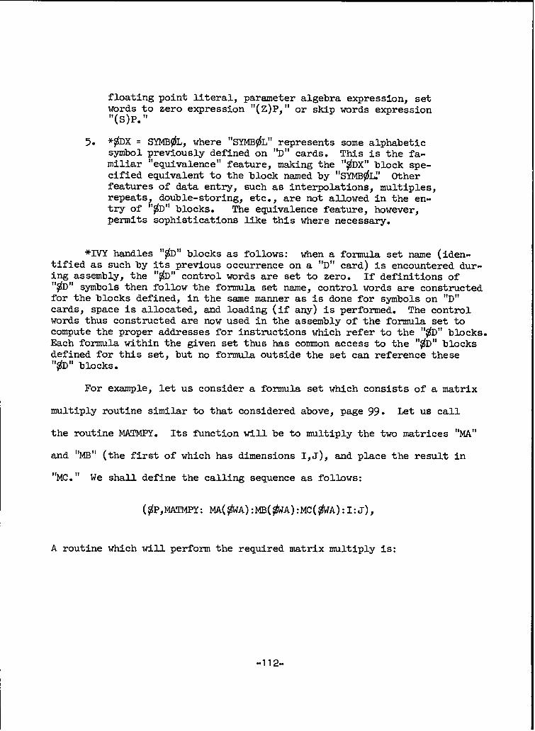
floating point literal, parameter algebra expression, set~~cI~:IO zero expression “(Z)P,” or skip words expression
.
59 *@x . s~#L, where “SYMB@L” represents some alphabeticsymbol previously defined on “D” cards. This is the fa-miliar “equivalence”feature, making the “$DX” block spe-cified equivalent to the block named by “SYMB@~’ Otherfeatures of data entry, such as interpolations, multiples,repeats, double-storing, etc., are not allowed in the en-try of “@D” blocks. The equivalence feature, however,permits sophistications like this where necessary.
+G~ handles “@” blocks as follows: when a formula set name (iden-tified as such by its previous occurrence on a “D” card) is encountered dur-ing assembly, the “#p” control words are set to zero. If definitions of“~D” symbols then follow the fomla set name, control words are const~ctedfor the blocks defined, in the same manner as is done for symbols on “D”cards, space is allocated, and loading (if any) is performed. The controlwords thus constructed are now used in the assembly of the formula set tocompute the proper addresses for instructions which refer to the “$D’]blocks.Each formula within the given set thus has common access to the “@D” blocksdefined for this set, but no formula outside the set can reference these“$D” blocks.
For example, let us consider a formula set which consists of a matrix
multiply routine similar to that considered above, page 99. Let us call
the routine MATMPY. Its function will be to multiply the two matrices “MA”
and “MB” (the first of
“MC.“ We shall define
which has dimensions I,J), and place the result in
the calling sequence as follows:
(@P,MATMPY:MA(@WA):MB($WA):MC(#WA):I:J),
A routine which will perform the required matrix multiply is:
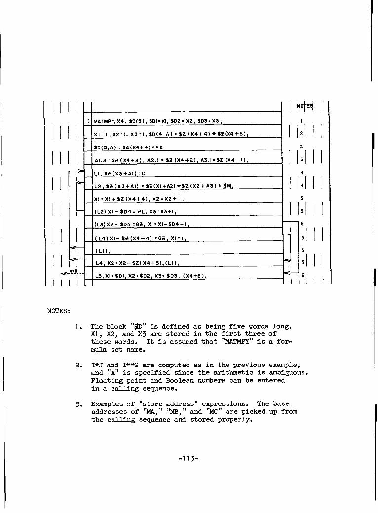
I
I
I
I
II
I I :
I *
I
I I :
I + :4exit------
Ill
iATMPY. X4, $D(5) , $DI=XI, $D2 = X2, $D3= X3 ,
(1=1, X2=l, X3=l, $D(4, A)=$Z(X4+4) *~(X4+5),
twllOE
I
2 II)D(5, A)= $Z(X4+4)**2
112111&l.3=$Z (X4+3), A2. I = $Z (X4+2), A3. I=SZ (X4+1), 11411.I, SZ(X3+AI)=0 4
.2, SFk(X3+Al) =$ Z(XI+A2) *SZ(X2+A3)+$M, 111114
(I= XI+$Z (X4+4), X2=X2+1 , 5
:L2)XI- SD4=ZL, X3= X3+I, 111115
L3)X3-SD5 =GZ, XI= XI-$ D4+I,I
[L4)XI- SZ(X4+4)=GZ, XI’1,
(Ll),
L4, X2= X2-$3 (X4+5 ),(LI),-
5
5 II
5
5 IIL3, XI= SDI, X2=$D2, X3=$D3, (X4+6),
NUTES:
1. The block “#D” is defined as being five words long.Xl, X2, and X3 are stored in the first three ofthese words. It is assumed that “MATM.PY”is a for-mula set name.
2. I*J and I**2 are computed as in the previous example,and “A” is specified since the arithmetic is ambiguous.Floating point and Boolean numbers can be enteredin a calling sequence.
3. Examples of “store address” expressions. The baseaddresses of “MA,” “MB,” and “MC” are pieked up fromthe calling sequence and stored properly.
-113-

4. Matrix “MC” is evaluated.
5. Index registers are altered and conditional branches areperformed. “A” must be specified in all cases wheredynamic modification is desired.
6. Xl, X2, and X3 are restored and exit from the subroutine,to (X4+6), is performed.
Some final notes on the organization of instructions. The block
diagram below should serve as an illustration of how a typical.IVY code
should be organized:
FORMULA SET FORMULA SET FORMULA SETI
a m . . .2
~N
I 1 I I. . .
I !.,.
1FORMULA FORMULA FORMULAS FORMULAS
I L
II
,..1 1
.,.I
L-entries L-entriesL-entries for each for each
formula formula
“Horizontal”branches are allowed between formula sets, formulas in the
same set, and L-entries in the same formula. “Vertical” branches are al-
lowed between a formula set and its formulas, and between formulas and
their L-entr2es. “Diagonal” one-way branches are allowed between
-114-

formulas and formula sets, and L-entries and formula sets or formulas in
the same set. This diagram is a summary of all that has been said pre-
viously on the hierarchical organization of an IVY program.
*Before assembly, fo~ula sets are written on a tape under control
of an “A” card. Each formula set may be written separately, or a numberof formula sets may be written together, as desired”. The entire codemay be assembled at one time, or the various portions may be assembledwhen they are needed. Even a code which contains too many instructionsto fit a given machine may still be assembled and executed a package ata time. Practical examples on the usage of these features are includedin Appendix 1.
The eXt!CUte instruction. The execute instruction is the only entry
allowed on “I” cards which has not yet been discussed. This instruction
is an alternative way to cause IVY to transfer control to an assembled
code without using the “X” card. The execute instruction may appear as
the very last statement in a formula set, and when encountered by the
assembly program, it causes IVY to give control to the formula set or
to a formula in the set just completed. The format is as follows:
, $E.sYM13@L,
where “SYM’BqL”represents the name of any previously converted formula
set, or of a formula in the formula set which has just been assembled.
*S2!EE2Z” The purpose of this chapter has been to introduce theprogrammer to the various IVY branching conventions and to the organi-zation of an IVY program, and in connection with this, such topics ascalling sequences, transfer tables, the manipulation of calling sequencewords, the “#D” symbols for subroutine data, and the execute instruction,Our discussion of the IVY algebraic language is now complete except forthe coding examples in Chapter 8. Table IV summarizes the types of IVYbranches and entries discussed in this chapter and Chapter 4.
-115-

1.
8..
b.
c.
d.
e.
f.
g.
TABLE IV
IVY BRANCHING CONVENTIONS
Types of entries:
ENTRY MEANING
,Xn(A,B), Index loop entry
L9 n) Iacal or L-entry
,Ln.Xn, Iocal or L-entrysubroutine
,#oRM, Formula nsme
,FORM.Xn, Formula subroutine
,FS, Formula set name
,FS.Xn, Formula set subroutine
2. Types of branches:
BRANCH
a. ,(Xn),
b. ,(Ln),
c. ,(Ln,M)
Algebra = C,
d. ,(#P,Ln),
e. ,(F@M),
f. &@lM&M),= c,
TYPE
End of index
Unconditional
loop
L-branch
Conditional L-branch
Pathfinder L-branch
Unconditional branchto formula
Conditional branch toformula
PAGE
92
97
101
102
102
104
104
PAGE
92
97
98
101
103
103
TYPE OFBRANCH NEEDED
a-a.
2-b, 2-c
2-d
2e,2-f
2-g.
2-h, 2-i.
2-j
TO ENTRYOF TYPE
1-a
1-b
1-b
1-c
1-d
1-d
-I 16-
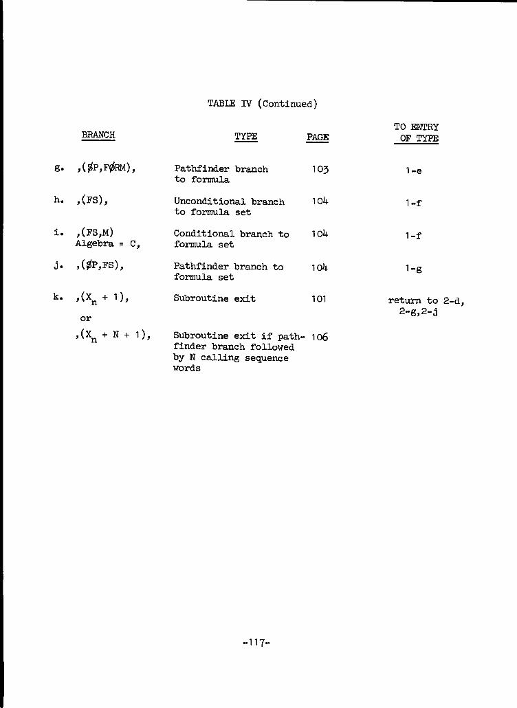
TABLE IV (Continued)
BRANCH
go ,(@,@RM),
h. ,(FS),
i. ,(FS,M)Algebra = C,
j. ,(?p,FS),
k. )(xn+ 1),
,~~n+N+ l),
TYPE
Pathfinder branchto formula
Unconditional branchto formula set
Conditional branch toformula set
Pathfinder branch toformula set
Subroutine exit
Subroutine exit if path-finder branch followedby N calling sequencewords
PAGE
103
104
104
104
101
106
TO ENTRYOF TYPE
1-e
1-f
1-f
1 -g
return to 2-d,2-g,2-j
-117-
tered
cases
CHAPTlm6
IVY SUBROUTINES
Any of the IVY “~” subroutines described in this chapter may be en-
by means of a pathfinder branch from the coder’s program. In some
the routines require a variable length calling sequence; when this
is so, it is to be understood that the calling sequence can occur either
in the code, as follows:
or on a “K” card,
quence block must
,(@P,@@UT: Calling sequence),
in which case the symbol representing the calling se-
appear in the instruction
,(~P,$R@T: SYMB@L (@WP))
calling sequence, as follows:
The two
are the
calling
techniques are equivalent provided that the two calling sequences
same. Thus, when in the description of a particular “@” routine,
sequence entries are described, it is understood that these en-
tries can appear either between colons after the pathfinder branch on the
instruction card, or between colons on a “K” card which is addressed by
a single calling sequence word entry after the pathfinder branch.
-118-

A. The loading program. The loading program “@D” has no calling
sequence and is entered by a simple pathfinder branch:
,(j4P,j41Jl),
“j?!ID”is the program which reads in cards from the on-line reader or the
off-line input tape, recognizing and treating all the various types of
IVY cards described in Chapter 2. If an end-of-file condition occurs in
the reader or on tape, IVY halts after printing an appropriate comment.
The use of the loading program is twofold:
1. To read in new data, on “E” cards, to read in and/or assemblenew code, to read in an “$” card and halt temporarily, etc.In this case control is returned to the expression immediatelyfollowing the pathfinder branch to “@ID” in the programmerscode when an “X” card with columns 2-72 blank is encountered,or to some formula set if an “X” card containing the name ofthis formula set is encountered. Control may also be returnedif a “~E” entry is encountered in a formula set being con-verted, as described in Chapter 5, page 115.
2. To exit from a program when its execution has been completed.The last executable instruction in any IVY code shouldbe apathfinder branch to “@IiD,”in order to read in any programstacked behind the current one, or to halt if no such programexists.
B. The assembly program. The assembly program “@P” can be entered
internally to avoid reading an “A” card through “j!!LD.”However, under
programmer control “#AP” will read only, and wild not write on tape. The
calling sequence for “@iP” is:
(@P,@P: Calling sequence),
where the calling sequence may occur in the parentheses or on a “K” card,
provided that in the latter case only the name of the “K” card and the
-119-

j&DN,F
means “read”; “N” is a hexadecimal e~ressionnumber; and “F” is a parameter algebra expres-file number on tape “N.” If N = O, the systems
modifier “@P” occur in the parentheses following the pathfinder branch
to yiw.” The cal~ng sequence to “@lP” may consist of any number of en-
tries, each consisting of one calling sequence word, as follows:
where: “@”for the tapesion for thetape (equivalent to N = A) is used.
Any number of files on the tape maybe read and converted using “@P”;
however, IVY will give up control to any formula set which ends with an
execute statement, as mentioned at the end of the previous chapter.
Table V shows the correspondencebetween the tape number “N” and
channel and tape numbers on the IBM 7090. These correspondences hold
for both “@lP” and “@P.” Also noted are the tapes which are reserved
for the various types of off-line output. These tape numbers may not be
used by “#Al?”or “~TP” (see next section) unless precautions are taken
to protect the output of previous jobs which may be on these tapes.
CORRESPONDENCE
TAPENO.
TABLE V
BETWEEN IVY TAPE NUMBERS AND 7090 TAPE NUMBERS
7090 RESERVED FOR USE (IF ANY)
o A2 Assembly, if no other specified1 Al IVY system (high density)2 A5 None3 B3 None4 A4 None5 BI None6 B2 None
-120-

TABLE V (Continued)
IVY TAPENO. 7090 RESERVED FOR USE (IF ANY)
7 A6 None8 B6 BCD Input, for reading decks off-line
9 A3 BCD Output (print & punch, high density)A A2 Assembly, if no other specifiedB B4 Nonec B5 4020 Output (plot & print, low density)
On the IBM 7030, tape numbers 1-F can be specified. However, no
list of corresponding absolute channel and tape numbers can be given
since these are assigned by IVY on the basis of available tapes and the
requirements of other programs. In general, the programmer or operator
will be notified of these assignments via the console typewriter in ad-
vance of the time they are used by the program, so that tapes may be pro-
perly mounted and the dials set in plenty of time.
c. Tape manipulation program. “#TP” is a program allowing com-
plete flexibility in manipulating binary (i.e., odd parity) tapes. Its
features include reading, writing, spacing forwards or backwards, posi-
tioning, setting density, rewinding, unloading, writing end-of-file, and
testing the current tape, all under control of various calling sequence
words. The calling sequence is designed
ing sequence word, as a rule, represents
to a particular tape unit.
*For the benefit of those who aretion, a short summary is included here.
in such a manner that each call-
one simple mnemonic instruction
not familiarThe shortest
tion-written on a tape is a record, consisting of one
-121-
with IBM tape opera-block of iIlfOIYIl&&
or more words of

data, and separated from other records by a gap in the tape called theend-of-record ~. Records, in turn, may be gathered together into.——files; files are separated from one another by a record consisting ofa special character followed by a long gap on the tape, called the end-of-file gap or simply the end-of-file. In addition, IVY marks the end..—of the tape with a special record called the end-of-tape record, con-——sisting of one word containing special information and an end-of-file.
Each record read or written by “@P” must be preceded by an iden-
tification word, called the “ID.” Each record in a file must have an ID
different from
tate searching
particular ID,
the other records in the same file, in order to facili-
procedures. When “@P” is searching for a record with a
it searches only the file in which the tape is positioned
when this record is requested. In no case wilJ “@P” ever read beyond
the end-of-tape record, or write beyond the end-of-tape reflective strip.
The calling sequence to “@P” may consist of any number of entries,
each of which may be any one of the following:
10
2.
39
40
5.
6.
7.
@DX, where “X” is a tape number in hexadecimal, 1 < X < C onthe 7090, 1 ~ X ~ F on the 7030. This causes tape ‘X” ~o beset to high density (556bits per inch).
@DXO Tape “X” is set to low density (200 bits per inch).
$RWX. Tape “X” is rewound to the load point. (Identical toperforming manua13ythe operations of pressing the “reset,”“load rewind,” and “start” buttons on the tape unit.)
@LX. Tape “X” is rewound to the load point, the upper headassembly is raised, and the tape is removed from the vacuumcolumns. (Identical to performing manually the operations ofpressing the “reset,” “load rewind,” and “unload” buttons onthe tape unit.)
@FX. Write an end-of-file mark on tape “X~’
$?I’X. Write the end-of-tape record on tape “X,”space the tape to
#BBX,P, where “P”
and back-
expression.
the beginning of this record;
represents a parameter algebra
-122-

This instruction causes tape “X” to backspace through “P”blocks or records, where an end-of-file is counted as arecord. Error indication is given if “P” is large enoughto cause the tape to attempt to backspace through theload point. If P = O this instruction is ignor~d.
8. j?h?X,P. Tape “X” is backspaced over ‘%” files, where thecount “P” includes the current file. The tape is then po-sitioned to read the first record of the file located.Error indication is given if “P” is large enough to causethe tape to attempt to backspace through the load point.IfP= O,this instruction is ignored. If P = 1, the tapeis set to read the first record of the current file.
90 $m3X,l?. Tape “X” is spaced forward over “P” blocks or re-cords. Error indication is given if “P” is large enoughto cause the tape to attempt to space forward through anend-of-file, or if the tape is positioned at the end-of-tape record. If P = C, this instruction is ignored.
10. @FX,P. Tape “X” is spaced forward over “P” files, wherethe count “P” includes the file in which the tape is cur-rently positioned. An attempt to space beyond the end-of-tape record will cause an error indication. If P = 0,this instruction is ignored.
11. @DX,AD(@A)+P, where “AD” is any programmer symbol and “P”is a parameter algebra expression. This entry may occuronly at the end of a calling sequence. The ID of the re-cord at which tape “X” is positioned is compared to thecontents of the location specified by “AI)(@WA)+P,”and ifthe two are equal, @CSl is set to 1. If they are notequal, #CSl is set to 00 The tape remains positioned toread this record.
NOTE: The next two entries each consist of a pair of callingsequence words.
12. @DX,AD(#WA)+P: AE(@WP). “@TP” attempts to find the recordin the current file on tape “X” with ID equal to the con-tents of “AD(@WA)+P,” and if successful, reads the recordinto block “AE.” The current file is scanned twice in anattempt to find the record with the specified ID, so tosave time the programmer should attempt to position thetape at the proper record before @ving the “read” command.If the proper record cannot be found, error indication is@ven and “@P” relinquishes control to IVY, which selectsthe card reader or input tape in an attempt to find the
-123-

next job. “@P” does not return control to the programmer’scalling sequence, since the lost data may have been essen-tial to the program. The block “AE’*must have a non-zerocount and base address, and the count of the record read fromtape may not exceed the count of “AE.” Otherwise, error in-dication is given and IVY takes control. (Using option 11plus the proper spacing instructions the programmer can easilylocate the proper record before reading it.)
13. m, AD($JA)+R AE(@Jp)o A record is written on tape “X,”starting at the point where the tape is positioned, and con-taining the ID specified by “AD($WA)+P” followed by the con-tents of block “AE.” If tinephysical end-of-tape is sensedat any point in the writing of this record, the tape is back-spaced to the start of the record, an end-of-tape record iswritten, and the machine halts after printing a comment tothis effect. When a new tape has been mounted, and “start”(7090)or “console signal” (7030)has been pressed, “@P”will write the record on the new tape. The programmer shouldnote that when a new record is written on a tape containingother information, any of the old information beyond the newrecord will become unreadable. Thus, the new record shouldbe written after any information that is still needed.
14. $*. This calling sequence word causes parallel operationto take place during all the tape operations specified insubsequent calling sequence words until “$S@” is encountered(see below). By parallel operation it is meant that the tapeinput-output will proceed in parallel with computation. Thisentry should be used only in those cases where subsequentcomputations do not depend on the results of the operatione.g., when subsequent computations do not address a blockwhich is being read in or written, etc. Care should be exer-cised in the use of this entry, since it makes detection ofR’l?Iand end-of-tape somewhat more difficult.
15. pkg. This calling sequence word specifies serial operation,i.e., each input-output instruction is completed before thenext is initiated, and all operations are completed before“@P” returns control to the pxxxgsmerts code. If neither“#S@” or “@P@” is specified in the calling sequence, serialoperation is always performed.
*Detection and treatment of errors by “@P. “ Two types of errorsare detected by “$TP”: Errors arising from the tape unit itself (re-dundacy errors), and progrming errors. These are treated as follows:
-124-

1. Redundancy on writinq: A backspace is performed and an attemptis made to rewrite the record. If no error is detected on thesecond writing, “j!TP”proceeds without error indication. If asecond redundancy error is detected, error indication is given,a gap is erased on tape, and a third attempt is made to writethe record. If this atlxmpt is still unsuccessful, the machinestops after printing a comment that the tape is defective andshould be replaced. After the tape has been replaced, press“start~’or ‘~consolesignal~’and the program wi~ proceed.
Redundancy on reading: At most ten attempts are made to readthe faulty record. If all are unsuccessful, an error indica-tion is given and control is surrendered to IVY, which selectsthe card reader or input tape in an attempt to find the nextjob.
2. Programming errors include such things as attempting to spacethe tape too far forwards or backwards, asking to read a re-cord which is not in the current file, incorrect calling se-quence words, etc. In general, spacing errors will cause anerror indication, but “@TP” wi~ proceed to the next callingsequence word. Errors affecting actual reading and writingoperations will cause error indication, and “j!TP”will surren-der control to IVYj since it is assumed that the tape input oroutput operation is vital to the code, and that the code can-not run without it. Some errors, e.g., end-of-tape detection,cause a halt; when the condition has been corrected, pressing“start” or “console signal” will cause “#TP” to proceed. “@TP”indications are included in the list of IVY error indications.
Some examples of “@TP” calling sequences: Included alsois the action “@TP” takes under various conditions.
EXAMPIE N(YSE
(7P, @p: @@),.o. 1
(@P,#TP: @ID3: @R3, GE(@W#)+l: FXNTZ($WP): 2@B2,3: @D2, TH(#WA)+2)
&(#P, P: #P6: @w5: @R5,FN(@A)+l: AD(m): 35, FN(@A)+2: AE(j!fwl?): jmR5,FN(@WA)+3:
AF(@wP):@F5)
(#P,&~%,3: j4?BB,2:@DB, RSN(@A)+2: 4
-12?j-

NOTES:
1.
2.
3.
4.
D.
This calling sequence entry simply causes the machine to waituntil all input-output channels containing tape units havecompleted their current operation. An entry of this type canbe used before operations affecting a block being read or writ-ten in the parallel mode are performed, so that a block stillengaged in input-output transmission will not be altered be-fore the transmission is completed.
In this entry, block “FXNTZ” is written in high density ontape 3, after which tape 2 is backspaced two records and theID of the new record is checked. It is assumed that the den-sity of tape 2 has already been set. Note that the densityof a tape unit can be set internally using calling sequencewords, or externally by pressing a button on the tape unit.In any event, once a tape is set to a certain density, thissetting should not be changed. A given tape unit should alwaysbe read, written, backspaced, etc., in the same density.
The blocks “AD,” “AE,” and “AF” are written on tape 5, then anend-of-file is written. This is all done in the parallel mode,so that the operations may not be complete when l’#TP”returnscontrol. An entry of the type discussed in note 1 should beused before any attempt is made to alter the blocks “AD,” “AE,”and “AI?”.
Tape “B” is spaced forwards 3 files plus 2 records, and block“AXX” is then read. It is always a time-saving procedure toposition a tape properly before a record is read.
The switch test program. “f(sW,”has no calling sequence and
is entered by a simple pathfinder branch
(@P,@W),
The purpose of “#SW” is to test the six sense switches and read the keys
on the 7090 console, and to read the settings of the various buttons>
keys, and switches on the 7030 console. The infoxznationgleaned from
the reading of these console devices is set up in the’’’@CS”block in
-I26-

a format wnicn can be easily tested internally. The first six binary
switches on the 7030 console are treated the ssme as the sense switches
on the 7090 console to provide analogous input. “@CS” is set up as
follows on the two machines:
TABLE VI
“#CS” BL(X2KSETTINGS BY “#SW”
“SCS” WORD
@csl
@cs2
#cs3
@cs4
$CS5
$CS6
ffcs7
@cs8
$CS9
$Cslo
@csl1
@csl2
CONTENTS,7090
sense switch 1: 0 ifoff, 1 if on
sense switch 2
sense switch 3
sense switch 4
sense switch 5
sense switch 6
switches 1-3 inbinary
switches 4-6 inbinary
switches 1-6 inbinary
console keys S,1-35
zero
zero
CONTENTS, 7030
binary switch O
binary switch 1
binary switch 2
binary switch 3
binary switch 4
binary switch 5
switches O-2
switches 3-5
switches O-5
binary keys,O-63
numerical switches
first half word:binary switches.
second half word:digital potentio-meters.
-127-
TYPE OF WORD
fixed
fixed
fixed
fixed
fixed
fixed
fixed
fixed
fixed
Boolean
Boolean
Boolean

Thus we note that $CS1-#CS9 are analogous on both machines if we inter-
pret the first six binary switches on the 7030 as equivalent to the
7090 switches. Similarly, the last 36 binary keys on the 7030 are equi-
valent to the ~ console keys on the 7090. The same sequence of instruc-
tions can be used on either machine to handle these ~ settings. If the
other settings on the 7030 are used, one can retain compatibility by cod-
ing an alternative routine under the control of “@L5,” the machine num-
ber indicator. Or a program can be coded to test the 7030 settings with-
out worrying about incompatibilitywith the 7090, if desired. Such a
code, of course, will not function properly on the 7090 if compatibility
is required.
E. The test trigger routine, “@?T,” is used to test the status of
various internal machine indicators (ac overflow, divide check, etc.,
on the 7090, and various xnaskableindicators on the 7030). After the
test all,indicators are turned off. Certain words of “@CS” are set ac-
cording to the status of the indicators, and if desired, a diagnostic
comment is printed on-line. Also, optionally, the programmer can cause
''#~''togiveup control to~ifany of theindicators are on. IVY
contains various internal programs to handle cases of floating point
overflow or underflow, so in general the trigger settings will reflect
only the results of fixed point operations. The trigger settings, and
the resulting settings of ‘t#CS,”are as follows:
-I28-

“#es”WORD 7090 TRIGGER
@CSl AC overflow:O if off
@CS2 MQ overflow:o if off
TABLE VII
“@S” SEI!TINGSBY “$l?T”
#CS3 Divide check: 10 if off
#CSk Negative square1 if negative,O if not
if on,
if on,
j!fCS~Zero always
if on,
root:
7030 TRIGGERTYPE OFWORD
LC,PF,L9S:1 if any fixedis on
PSH: 1 if on, O fixedif off
ZD: 1 if on, O fixedif off
IR: 1 if on, O fixedif off
indicator word: Booleancontents on entryto “jkrc”
Note that on the 7030 the contents of the entire
placed in $CS5 so that individual indicator bits
indicator word
may be tested.
dicator register is always set to zero on exit from “$IT’.”
The calling sequence to “#’I’T”is as follows:
where “#N” means “no
headed by the symbol
were on”; “#R” mesas
are
The in-
print,” “4P” means “print a diagnostic comment
IATIIand containing a list of the indicators which
“return
means “return control to IVY
Note that “@TT” always has a
control to the problem program,” and “II”
if any of the tested triggers were on.”
fixed-length calling sequence two words long.

Only the format of these calling seqyence words is variable. This calling
sequence, being fixed length, cannot appear on a “K” card.
F. The octal dump program.’’j@D”is used to obtain a dump in octal
of any or all of the data blocks or longhand formula sets used in a pro-
gram. A decimal dump of data, of course, canbe obtained using the print
program “@R” described in the next section. The octal dm appears off-
line on tape 9 unless console key 35 (7090) or binay key 63 (7030)is
down, in which case the dump will be printed on-line. The calling se-
quence to “@@D” may consist of one word (if a dump of ~ data regions
and longhand formula sets is desired) or of any number of words if a
dump of only certain blocks is desired. The one-word entry for dumping
all blocks is:
(@P,$#D:@DA)j.oo
where “@DA” is mnemonic for “dump all.” If only certain blocks are to
be dumped, the format of each calJing sequence word is
....SYMB#L(@P)....
where “SYMB#L” is the name of any data block or longhand formula set.
The dump consists of the following information:
1. The symbol for the block whose dump appears below;
2. A nwnber of lines consisting of the contents of the block,in octal, each line being constructed as follows:
a. A five-digit octal number giving the location ofthe first word on the line on the 7090, a six-di.gitnumber on the 7030;
b. A string of octal numbers:
-130-

(1) eight numbers of twelve digits each are printed onthe 7090;
(2) eight numbers each consisting of eight octal digitsplus two hexadecimal digits in the standard format(i.e., four full words) are printed on the 703).
G. The print program. “@R” is used to print numbers in decimal
in a wide variety of formats. This printing can be done, in a limited
amount, on-line; or off-line on tape 9 for later printing on a peripheral
device; or off-line on tape C for producing a listing on microfilm via
the SC-4020 microfilm device. The format statement controls not only
the format of individual numbers within each block printed, but also the
arrangement of vectors and blocks on a page, the printing of column and
row headings, remarks, etc. The “$?R” calling sequence has a large num-
ber of calling sequence words which will be explained in turn.
10 E2@2E” The simplest calling sequence word entries control
the spacing of the page. Normally single spacing takes place between
lines and double spacing between blocks. If other spacing is desired be-
tween blocks,one or more of the following calling sequence word entries
are used:
Csw
$!IP
$2P
#DP
@T
$%T
pm
@M
-131-
OPERATION
Restore page (on-line)
Half-page skip (on-line)
Double-space printer (on-line)
Restore page (tape 9)
Half-page skip (tape 9)
Double-space page (tape 9)
“Restore page” (advance film -tape C)
I

Csw OPERATION
@M “Half-page skip” (microfilm - tape C)
@M “Double space” (microfilm — tape C)
2. l?rintin~of remarks. Remarks may be
benefit of’a format statement, by use of one of
sequence word entries:
printed, without the
the following calling
@P,R.EM(#wP) print remark on-line;
~T,RFM(@WP) write remark on tape 9;
@M,REM(@WP) write remark on tape C for microfilm;
where “REM” represents a symbol for any remark. Remarks can also be
printed, if desired, under the control of a format statement as de-
scribed below.
3. Format statements. Format statements are remarks constructed
in a particular manner to control the printing of arrays of numbers and
“comment” remarks, as well.as giving various other information about
the format of the printout. The calling sequence entry for a fo~t
statement is as follows:
@F,F@MAT(~Wp)
where “F@MAT” is the name of the desired “format” remark statement.
The format named then holds for all the following information until it
is exhausted, a term which will be explained below.
The first field, and only the first field, of a remark state-
ment must contain one or more control characters followed by a comma;
-lp-

the general appearance of this part of a format statement is as follows:
RIF@MAT =C C C, ~ ~...cNo.o.
where “F@RMAT” is the name of the
characters. Each “C.” may be any
statement and the “Ci” are control
one of the following:
P
T
M
c
R
L
F
fl
oor blank
J.
on-line.
off-line (tape 9).
on microfilm (tape C).
column indices on vectors or arrays.
row indices on vectors or arrays.
vectors and arrays in line format.
fixed point numbers as integers re-gardless of format statement.
print fixed point tags ofnumbers in octal.
ignored.
double-stored
The functions of the chs,racters’’C,”“R,” “L,” “F,” and “$”
will be discussed somewhat later in this section. Of the characters
1111“P, T,” and “M,” only one may occur to specify the mode of printing
desired. If more than one occurs, the last one in sequence will take
precedence. At least one of these characters must occur; if none
occurs, “T” will be assumed. The characters “T” and “M” can be cver-
ruled temporarily by console key 35 (7090) or binary key 63 (7030).
If this is down,the next block encountered will be printed on-line re-
gardless of the format statement. If key 35 is up, “T” or “M” will
again take control. We thus note that this particular key is always
-133-

reserved to specify on-line printing; in general its use should be re-
stricted to emergencies to save machine time.
To print a remark under control of a format statement, the fol-
lowing two calling sequence words must
#F,F@RMAT(@P):
be used:
REMARK(@WP)
The remark will be printed on-line, off-line, or on the microfilm tape
according to the setting of the print key and to which of the characters
11If“P, T,” or “M” occurs in the format statement. For example, if “F@RMAT”
and “REMARK” are defined as follows:
R IWRMAT= PJWFR llWARK = THIS IS A#@I@ LINE lWARK.@#~
the above two calling sequence word entries will cause
THIS IS A
Tw@ LINE REMARK.
to be printed on-line. (“@R” automatically detects the “$#’tand causes
the printer to space at that point).
4. Printing numbers and arrays of numbers.
a. The “C,” “R,” amd “L” controls. As remarked above,
“C” and “R” occurring among the control characters of a format statement
cause column and row indices, respectively, to be printed with arrays of
numbers. The first column index, if any, will always be replaced by the

name of the
indices and
as follows:
block which is about to be printed; the rest of the column
the row indices ascend in sequence. These indices appear
rowJ
column + NAME 2 3 4 ... N
1
2
3
●
.
.
M
The column indices are always properly centered over the appropriate
column.
If “L” is not given, the so-called normal
occurs: namely, one-dimensional arrays or vectors
form of printing
are printed in columns,
and multi-dimensional arrays are printed in matrices such that the first
index varies along columns. The following diagram illustrates the nor-
mal form of a vector and a two-dimensional array:
VECTOR
‘1
‘2
‘3●
●
A:
B1,1
B2,1
B3,1.●9
‘J,l
‘IWO-DIMENSIONALARRAY
‘1,2
‘2,2
‘3,2
‘j,2
‘1,3 ““0 ‘hk
‘2,3 “*” ‘2’k
‘3,3... B3,k
●
●
●
B.J,3 ● “” ‘j,k
-135-
N-dimensional arrays (where N ~ 3) are printed as two-dimensional
matrices. In each matrix the last N-2 dimensions are constant, and the
first index varies along columns as above. The matrices are printed in
such an order that the Yirst
pidly from matrix to matrix,
Nt& dimension least rapidly.
matrices of an array. Thus,
(I, J, K, Lj...,p) and~, ~,
of the last N-2 dimensions varies most ra-
the second dimension less rapidly, .... the
Double spacing always occurs between the
for example, if array “C” has dimensions
represents one of its two-dimensional●☛☛✌❐
matrices, these matrices are printed in the following order:
M1,1,...,1
double space
M2,1’”””’1
double space..●
%,1,...,1
double space
‘1,2,***,1
double space
‘2,2...,1
double space●
●
●
%,l,. O.,P
double space

%+1,1,...,p
double space
●
~-l, L~...,P
double space
%, L,...,P
If the rows of any two-dimensional mtrix are so long as to exceed the
size of the page (119 columns), the matrix wilILthen be printed as fol-
lows:
‘1,1 ‘1,2 ‘1,3 ““” ‘I,i
‘2,1 ‘2,2 ‘2,3 ““” ‘2,i
‘J,l ‘j,2 B.J,3 ““” ‘j,i
double space
‘I,i+l ““” ‘1 ,k
B2,i+l ““” ‘2,k
9
●
●
‘J,i+l ““e ‘j,k
-137-
Since the overflowing portion of the matrix is printed separately, it
can be read easily as an extension of the first portion. Its row in-
dices (if any) are reset to start at 1 and its column indices (if any)
continue from the highest previous value. Thus, if desired, the later
portion of the listfng canbe cut out and attached to the right of the
earlier portion to give a complete picture of the array.
If an “L” is given in the format statement, the so-called line
form of printing occurs; that is, vectors are pfinted_ the ~ne?
and multi-dimensional arrays are printed so that the first index varies
in rows, as follows:
VECTORS
ARRAYS
Al ‘2
‘1,1 ‘2,1
‘1,2 ‘2,2
‘h3 ‘2,3
●
●
●
‘M ‘2,j
‘3 ““”
‘3,1 “*”
‘3,2 ““”
B,3,3 ““”
BS,j ● **
‘k,2
‘k,3
‘k,j
The comments given above about the order of printing of the matrices of
an N-dimensional array and the convention in case the rows of a matrix
overflow the page also apply here.
b. Format control of numbers. The control characters mentioned
above govern only the outward appearance of a listing: the spacing
-13&

between blocks, the appearance of row and column indices, and the order
in which the elements of a vector or array appear across the page. The
remainder of the format statement specifies the exact appearance of each
individual nmber in the listing. After the control characters have
appeared, any number of fields consisting of five decimal numbers sepa-
rated by periods may occur, each specifying the format for one or more
blocks of data. This appears as follows:
RIF@MAT = C1C2...CN, N.S.I.F.E., etc.
t? 1!“N, S,” “I,” “F,” and “E” are decimal numbers having the following
meanings:
N: The number of blocks of data for which this portion of formatis to be used.
s: The number of blank spaces which precede each number printedunder control of this format statement.
I: The number of integer digits (to the left of the decimalpoint) to be printed in the numbers under control of thisportion of the format.
F: The number of fractional digits (to the right of the deci-mal point) to be printed.
E: The number of exponent digits to be printed.
For example, if “F1” is a format as follows:
RIF1 = P, lsl.l.7.2, j$@
and if “B” is a vector of data, the two calling sequence words
$F, F1($WP): B(#WP)
-1>-

will cause the elements of the vector “B” to be printed on-line in a
column as follows:
-X.~+-~
where “x” represents a decimal digit, “ “ represents a blank space, “-”
represents a minus if the sign is negative or blank if positive.
A right-to-left dropout feature operates in the “N.S.I.F.E.”
fields. That is, if “.E” is omitted, the number willbe properly ad-
justed and printed without an exponent; if “.F.E” is omitted, the num-
ber wild.be printed as an integer; and if “.I.F.E’*is omitted, “S”
spaces will be inserted in the listing “N” times- Any combination of
the numbers It!1“S, I,” “F,” or “E” may be zero to work up variations on
this theme.
In general, the “N.S.I.F.E” field holds for all numbers in the
block printed under its control regardless of whether they are fixed or
floating point. However, if “F” appears among the control characters
discussed in the previous section, all fixed point numbers in the block
will be printed as integers, regardless of whether “.F” and “.E’;are
zero or not. The number of digits printed wild equal I+F+E+2, subject
to zero print control (i.e., lead zeroes are suppressed).
The general calling sequence entry then for printing M vectors
under the control of a single format statement is:
@F,F@W(@WP): VECT$R1(@P): VECT@R2(@p) :...:VECT@~($WP)
The format statement must be sufficient to print all M vectors; i.e.,
-140-

the sum of the N/s in all the “N.S.I.F.E” fields in which at least one of
I, F, and E is non-zero must be at least M. For example, the following
format will serve to print 7 vectors (or less):
RIF2=132R, 30107.7.2, 3.2, 2.1.1.5, 2.2.2.6.1, j$$if
To print a string of parameters starting with a given parameter
under control of some format statement, the following calling sequence
entry is used:
@F, F@MAT(@P): @N, PARAM(@WA)+P
where N < 99 is the number of parameters desired and.“P” represents
parameter algebra the result of which must be at least 1. Then the N
consecutive parameters starting with the one in location PARAM(@WA)+P
are printed in the same manner as a vector.
If the programmer wishes to print the parameters in several
blocks using this single entry, the name “PARAM” must specify the last
of these blocks loaded on “D” cards. The paraeter blocks are then
printed in reverse order of their loading, from last to first; the num-
bers in each block, however, are printed in sequence from first to last.
For example, consider the following format statements and
calling sequence to “#pR”:
RIFI = CRT, 3.2.1.5.2, 2.0.3.2, @##
RIF2 = CRPL, 1.1.2.3.1,f$i~
and
-141-
Il(~p, j@R:$F,Fl(@P):MxT(j@):Ap x(@WP):F~Z(@P):
lTNpRL(@P):vHN( $tP):#F,F2(@P): @P5,P@@WA) +1),...
The vectors “MXT,“ “APX,” and “FNTZ” will be printed in parallel columns
in the format
+Xx,-x.xxxxx-—
the two vectors “TNPRL” and “V13N” will be printed in columns parallel
to these in the format
-xxx.Xxj
and five parameters starting with “PC” will
quent line in the format
ficult
to the
-Xx.)mdx.
be printed across a subse-
printing multi-dimensional arrays presents a somewhat more itLf-
problem since the first one or two dimensions must be made known
print progrsm in order to break the block up into its correct two-
dimensional sub-matrices.
assuming a previous format
where “MATRIX”
bra expression
is the symbol
for the first
To print a two-dimensional array, or matrix,
statement, the following is necessary:
more dimensions, the
where “ARRAY” is the
@2, MATRIX(@lP):P
for the block and “P” is a parameter alge-
dimension. To print an array of three or
fo~owing entry is used:
#A, ARRAY($WP): P1:P2
symbol for the block and “Pl” and “P “ are2
-142-

parameter algebra expressions for the first two dimensions. If these
entires are not used for multi-dimensionalblocks, the blocks wilJ be
printed as vectors.
Arrays or vectors (but not parameter blocks) may have been de-
fined as double-stored numbers. If this is so, and one wishes to print
both the “Q” and “T” portion of these numbers, an extra calling sequence
word giving the tag length must be placed immediately after the one nam-
ing the block, as follows:
vector: VECT~R(#WP):$D,P
matrix: @2,MATRIX(~WP):#D,P1:P2
multi-dimensionalarray: ~A,ARRAY(@WP):@D,P1:P2:P3
where “@D” is mnemonic for “double-store,”and the parameter algebra
following it is the tag length in bits. The other parameter algebra
expressions are for the dimensions as described above. When double-
stored numbers are printed in this fashion, the tag, in decimal (or
octal if “@” was one of the control characters in the format statement
described on page 133), preceded by the letter “T,” occupies the low order
digits of the fraction. Thus, for example, if a double-stored block
contains a five-bit tag and is printed according to the format
“N.lO1.7.2,” each number of the block will appear as follows:
_ ‘X.~D&XX
where “D” represents an octal or decimal tag digit. The coder should
bear this in mind and adjust the size of “.F” accordingly.
-143-

Under control of one of two other calling sequence words, one can
print only the “Q” or only the “T” portion of a double-stored number, if
desired. The calling sequence entries to do this are:
print “T” only:
vector: VECT#R(@P):@,P
matrix @2,MATRH(#w) :@T,P1:P2
multi-dimensionalarray: #A,ARRAY(#WP):@,P1 :P2:P3
(Regardless of the format statement, the tag is always printed as a deci-
mal cm octal integer preceded by the letter “T.”)
print “Q” only:
vector: VECT$R(@WP):$Q,P
matrix j!$2,MATRIX(@P):$Q,pl:p2
multi-dimensionalarray: $A,MATRIX(#WP):#Q,P1:P2:P5
5. Printing immediate remarks. We have already discussed how to
print ordinary remarks. Lnmediate remarks, however, differ from ordinary
remarks in that they occur in the format statement itself, and may pre-
cede any “N.S.I.F.E” field enclosed in parentheses, thus:
,(REMARK)N.S.I.F.E,
The characters in an immediate remark may be any legal hollerith charac-
ters, except that parentheses occurring in the immediate remark must be
-14/t-

closed, i.e., must occur in the order
(...)*
Immetiate remarks should be reasombly brief (in no case, over 119 charac-
ters long) and are used usually for short headings, etc., and permit a
considerable sophisticationin the printout. A pair of examples will
serve to illustrate
and
possible uses:
RIF1=P,(PARAM.=) 1.0.1.7.2, ###
Il(@P,@@F,Fl(@WP):#Pl,AD(@WA)+l ),...
will cause parameter “AM” to be printed as follows:
PARAM•.-x*~&x
The folJ_owingformat:
RIFF=CRT,l.54, (~) 1.54,1.1.1.5.2, $$$
and the calling sequence
Il(#P,@:#F,FF(#WP):#2,AA(@WP) :GE+3),...
will.cause the heading
TEMPERATURE
to appear centered in the page above the printout of matrix “AA.”
*6. Error detection. “j%” detects a variety of errors andprints out a nmber of diagnostics on-line. Control is always re-turned to the problem program, however, since the validity of the outputprint has no effect on the workings of the program. Some of the moreserious errors are:
a. Attempting to print blocks of numbers with no formatstatement;
-145-

b. Attempting to print blocks with an inadequate format
statement, i.e., one which does not have enough non-zero “.I.F.E” fields to cover every block specified;
c. Attempting to print an undefined block, i.e., one forwhich the symbol is not in the symbol table, or whichhas no address defined;
d. Attempting to print a block of code.
Other less serious errors, for which no indication is given, are:
a. Attempting to print both the “Q” and “T” portions ofa double-stored number, when “.F” is not large enough toinclude the entire tag and the letter “T.” In this case,printing of the tag is suppressed.
b. Iost significance, e.g., in a case where “.E” is zero ormissing, an integer part is too large for the “.1” spe-cified. In this case the integer is printed modulo 101.Or specifying too few digits for the e orient,in which
3case the exponent is printed modulo 1 .
H. The Punch Progrsm, ~PH, is quite similar in usage and con-
ventions to the print program. The calling sequence and format state-
ments are simply a subset of those for the print program. “@H” pro-
duces “R” cards and “E” cards which may be used as input to a future
IVY program. The following differences exist between “@PH” and “#pR”:
10 No microfilm option is allowed in “~PH.” If the “M” con-trol character appears in the calling sequence or in aformat statement, it is replaced with “T.” (Note thatcards written off-line for later punching are also placedon tape 9 with a distinguishing character detected by theIBM 1401 in the output process.)
2. If any of the spacing options (e.g.,’’#~P,”“@2P,’’etc.)occur in the calling sequence, a blank card is produced.Blank cards are ignored by “j#LD.”
3. The control characters “C,” “R” and “L” of the formatstatement are inoperative. Numbers of a block are simplypunched in sequence on “E” cards separated by commasafter the symbol for the block and an equal sign.
-146-

4.
5.
6.
79
8.
Whether or not the “F’’controlcharacter is present in aformat statement, fixed point numbers are punched as in-tegers so that the “E” cards are punched properly forinput usage.
Remarks are punched on “R” cards (and continuation cards,if necessary) complete with name, equal sign, and allnecessary “##” and “#$#” characters.
Parameters are not punched using the “@PN” convention,but must be punched as vectors.
“@H” ignores immediate remarks in its controlling formatstatements.
Double stored nunbers are punched in the proper input for-mat, i.e.,
AD(Q.P) = N1,N2,0*0,AD(T.P) =M1,M2,...
and so on. The “@” flag of the format statement is stilloperative and will cause the tags to be punched in octal,prefixed of course by the “(B)” entry described inChapter 3.
Bearing these differences in mind, the programmer can easily punch
data and remarks using essentially the same techniques used for printing.
In fact, the same format statements can be used for both punching and
printing without error indication from “#PH.”
I. The microfilm plot program. “#Ml?”is used to produce output
on tape C which, when used as input to the SC-4O2O peripheral microfilm
device, will cause graphs to be produced on microfilm. We have already
seen, in the section describing “#P’R,”how ordinary output listings can
be produced by this device. Plotting is a somewhat more complicated
business; it is not, however, the purpose of this writeup to describe
the characteristics of the 4020 in detail. Instead, the curious reader
-147.

is invited to read either the 4020 manual itself or any of a variety of
writeups on the 4020 which are available.
“@@” permits a wide variety of operations: advance film, select
grid, label grid, write a label horizontally or vertically, plot points
with an option of comecting points with a vector, and generate an arbi-
trary set of axes. This is all done under control of various calling se-
quence words as described below.
1. To advance film, the following calling sequence word mustbe used:
$AFN,P
where “N” is either O or 1: 0 if no hard copy is desired,1 if hard copy is desired. This calling sequence wordcauses the microfilm to be advanced one frame; if N = 1,a series of vertical lines are drawn signifying that hardcopy is desired; the film is then advanced “P” more frameswhere “P” is a parameter algebra expression. For example,the entry
$AFO
will simply cause the film to be advanced one frame. Thefilm must be advanced whenever a graph is complete.
2. The calling sequence words specifying a “select grid” causea grid of lines to be drawn horizontally and verticallyfor the graph coming up. The normal film frame has 1023plotting positions in each direction, and the grid is drawnin the upper right corner of the frame, 900X900, to allowroom at the left and below for labeling. A number oftypes of grids are available under calling sequence con-trol. The following three calling sequence words are usedto select a grid:
f%G: PI:P2
where “Pl” and “P$“ are parameter algebra expressions the
value of which sp cify the horizontal option and verticaloption respectively, as follows:
-148-

3.
VALUE OF PI
56
i’910111213141516
12
5101520255012
56
GRID OFTION
interval (border only)intervals (linear)intervals (linear)intervals (linear)intervals (linear)intervals (linear)intervals (linear)intervals (linear)intervals (linear)intervals (linear)cycle logarithmiccycle logarithmiccycle logarithmiccycle logarithmiccycle logarithmiccycle logarithmic
For example, the callLng sequence
j%G:4:2
words
will cause the following grid to be drawn:
---11IIIIII1I EEY!L ‘k’-------___--
BORDER (900X900)
FILMFRAME(I023XI023)
Any combination of options maybe used, e.g., six cyclelogarithmic (PI = 16) versus 50 linear intervals (P2= 10),etc. On logarithmic grids the main division lines are drawnheavier for easy readability.
Any grid produced by the preceding option canbe kbeledbyusing the “label grid” command immediately foXLowin~ the’’selectgrid” command. Two calling sequence words are necessary, asfollows:
$LG:XYBDS(j#WA)+P
-149-

‘4.
where XXBDS($WA)+P contains the minimum X coordinate, thenext location contains the maximum X coordinate, and thenext two locations contain, respectively, the minimum andmaximum Y coordinates. The kbel.ing of a logarithmicscale follows the usual conventions with a “+” mark placedat each point labeled. Linear labeling consists of “+”marks placed along the left and lower border at points de-fined by the option and a 3 digit signed integer at each“+” mark with a 2 digit signed power of 10 added at theorigin. For example, if we wish to label the grid of theprevious section, and ~in = 3.15621-02, wax = 5.1231,
‘rein= 0} ‘mu = 3, then the grid as labeled wo~d lookas follows:
Because of space limitations, the linear grid of ~ intervalsis labeled only at 25 points.
The fourth option allows the writing of remarks either hori-zontally or vertically to describe the graph and the infor-mationquence
contained in it. The format of ~he-three calling se-words necessary to do this is as follows:
@RN, I@@P): R(&lA)+P1: C(#WA)+P2
where N = O means “write horizontally,” 1 means “write verti-cally;” “REM” is the symbol for the remark to be written; andthe next two quantities addressed are floating point numbersspecifying the row and column at which printing is to begin.A film frame is considered to be divided into 64 rows and128 columns; however, both R and C maybe multiples of 1/4 to
-150-

allow mre exact positioning, superscripts, or subscripts.When writing vertically, the first character is positionedat row R and column C and succeeding characters are eachspaced down one row. No more characters will be printedafter row 64 is reached. When writing horizontally, thefirst character is positioned as before and succeedingcharacters are each spaced one column to the right. Aftercolumn 128 is reached, the next character (if any) will bePO itioned one row down and at column 1. Note that thed ph area defined previously is above row 57 and to theright of column 15.
5. To plot a series of points on a grid, the following fivecalling sequence words are necessary:
#mN,M:@@P):Yc(#wP):xY BDs($wA)+p:TFMP($wP)
where N = O means “do not connect successive points witha line,” N = 1 means ‘~mect successive points;” “XC”is the block containing the ordinates (or the logarithmsof the ordinates, if a log grid is used); “YC” is theblock containing the abscissas (or the logarithms of theabscissas, if a log grid is used); the four words start-ing at the address “XYBDS($WA)+P”contain the minimum andmaximum ordinate, and the minimum and maximum abscissas,in that order; and “TEMP!’is a block the same length as“XC” and “YC” which “j$MP”can use the temporary storage.“M” is the decimal equivalent of the character to beplotted which can be determined from the following table:
TABLE VIII
DECIMAL EQUIVALENTS OF PL(YTTINGCHARACTERS
DEC.
o1
2
?667
CHAR.
;BcDEFG
DEC.
1617181920212223
CHAR. DEC.—— CHAR ●
Tvvwx
DEC.
g50
;:535455
-151-

TABLE VIII (Continued)
DEC.
8910
11
12131415
CHAR.
HIK
DEC. CHAR.
24 Q25 R26 .
2829 *30 Y31 *
d
DEC.
40
?2
43
:;4647
CHAR.
Yzo
>
(Jzc1
DEC.
5657x
59
:6263
If one desires to superimpose two characters, this can be doneby setting M = 64 x (Ist char.) + (2nd char.). The points areplotted with the character or characters specified, and succes-sive points are connected by a vector, if desired. The maximumvector length allowed is 1/16 of the size of the film frame.
6. To generate a pair of axes througha given point, the followingthree calling sequence words are used:
$GA, XYBDS(@A)+P: x21H@(@wA)+P:yZE@( @A)+p
where “XYBDS” is as described above, and “XZJZR@”and “YZER#”represent, respectively, the ordinhte and abscissa of the pointthrough which axes are to be drawn. The axes cover the 9~x900grid area only. As with “~~, “ “@MP” detects certain errors,none of which are serious enough to cause it to return controlto IVY, and prints appropriate diagnostic comments. Remedialaction taken in the event of some errors is described in thetable of error numbers. Some information on “@P” diagnosticsis included in Chapter 7} page 159.
J. The disk program. “#DK” is used to write blocks of data on the
disk unit of the 7030, and on the disk units of 7090 machines which have
-152-

them attached, and to read them back as needed. Although some 7090!s do
not possess a disk unit, “#DK” is nevertheless a valid subroutine on all
7090’s, using a tape to simulate the disk. Up to 32 blocks of data,
remarks, code, or calling sequences may be written on the disk.
10 To write a block on the disk, the following two calling sequencewords are used:
@N, D(@A)+P: DATA(@WP)
where “N” (only on 7090’s not having a disk unit) specifiesthe tape unit being used to simulate the disk. Only onetape unit may be used - i.e., “N” must always be the samenumber in a given program. On the 7030, and on 7090~s hav-ing a disk, “N” is ignored. “ID(SWA)+P” addresses an “ID”word in the same manner as in the “@’I’P”calling sequence.This “ID” is entered into a 32-word table and is as-signed an arc number on the disk (on some 7090’s, a recordnumber on the tape specified). The block “DATA” is thenwritten in this arc (or record). If 32 blocks havealready been written, an error indication is given unlessthe “ID” specified is the same as one of the previous twenty.
2. To read a block from the disk, one enters
@DN,ID($wA)+p: DJYCA(@P)
The “ID” is sought in the table mentioned above, and its loca-tion on the disk (or tape) discovered, and the record is readinto the block specified by “DATA.” If the “ID” cannot befound in the table, “@DK” gives an error indication and con-trol returns to IVY. (The absence of the “ID” from the tableindicates that a record with this “ID” was never written.)
K. The instructions to operator routine. “$@P” functions similarly
to the “~” card in that it prints a remark on-line, sounds a gong if pos-
sible, and halts or waits until the “start” (7090) or “console signal”
(7030) is pressed, signifying that the instructions have been carried out.
The callhg sequence to “#@P” is as follows:
-133-

(~P,$l#P:REMARK(#WP)),...
where “REMARK” is the name of the remark to be printed as a comment to
the operator.
L. The character manipulation program. “~CM” is used to change
remarks or format statements or to construct new ones under programmer
control. “@CM” may not be used to alter calling sequences on “K” cards
(see Chapter 8, pages 182-184). A number of calling sequence words cause
the various necessary functions to be carried out.
1. To set an entire block to contain the same character, e.g.,blank, zero, etc., the following calling sequence wordis used:
@IN, REMARK(@)
where “N” is the two-digit decimal equivalent of the char-acter desired (see Table VIII), and “REMARK” is the blockto be set.
2. To move from one to fifteen characters from one remark blockto another, the following five words are used:
@N:AD(~WA)+P1 :REMl(#WP):AE(j#WA)+P2:REM2(#WP)
where “N” is a hexadecimal digit, 1 < N < F, specifyingthe number of characters to be moved; lo~ation “AD(#WA)-t-P1”contains a fixed point number specifying the characternumber in remark block %EMl” where the “N” characters tobe moved begin; and “AE(~WA)+P “ contains a fixed point num-ber specifying the character n~mber in remark block “REM2”where the “N” characters moved will begin.
3. To compare from one to fifteen characters in one remarkblock to the same number of characters in another remarkblock, the following five words are necessary:
j3CN:AD(@A)+P1:REMl($wP):AE(SWA)+P2:RF@ $WP)

where again 1 < N < F specifies the number of charactersto be compared; “J@SWA)+P “ contains a fixed point num-ber specifying where the “*” characters to be comparedbegin in “REMI;” and “AE(SWP)+~2” contains a fixed pointnumber specifying where the “N characters in “REM2” be-gin. The specified “N” characters in “REMI” are com-pared to the “N” characters in “REM2;” if equal, “jl!csl“is set to 1; if not equal, “#CSl“ is set to zero. Toclarify the usage of “#CM,” a number of examples are in-cluded below.
EXAMPLES:
1. To alter a format statement:
the illustration below, then the calling
the “P” to a “T” and the “7” to a
ing it to print numbers with less
Ill
Ill
“3” in
If “RI”
sequence
and “F1” are as shown in
illustrated will change
the format statement, thus alter-
significant digits off-line:
R FI =CRP, I.I.I.7.2, .S$$
R RI=T3P7SSS 11111
I PARI=3, PAR2=3, PAR3=2,PAR4=II, 11111[$P, $CM: $Ml: PAR($WA)+I :RI($WP): PAR($WA)+2:
1111 FI(SWP): SMI:PAR(SWA)+3: RI(SWP): PAR(SWA)+4: 11111FI($WP) ),...
2. Defining a block and setting it to blanks: If remark block
“R2” is defined as shown below, space is allotted for it but is not
cleared in any way. To ensure that the block contains only legal charac-
ters in this case, all blanks), tinefollowing is used:
1111 [1111
R R2(759)=SS$
1111 .. 11111I (SP,SCM:SSOO, R2($WP)),...
1111 11111
-155-

3* Determination of a character’s position in a table. In the
following example, we wish to see whether a character of “REMARK” lies in
“TABLE”(i.e., whether it is alphanumeric) and if so, its position, so
that we can determine whether x not it is alphabetic:
1111
Ili
R TABLE=O123456789ABCDEFGHIJKLMNQ)PQRSTUVWXY*$$$. 11111
I X1(1,36), PARI=XI,
(SP, $CM:$Cl: pAR(SWA)+i: TABLE($WP):N($WA)+ I: 1111REMARK($WP)),(LI) $CS1-l=O, (Xl),...(not mtabla).
4. . . , LI, (L2)XI-IO=GZ,... (numeric) 1111
I 1. L2 . . ..(al~habdic) P
The calling sequence is entered once for each value of Xl, from I to 36.
Each time PA.R1,the character position in “TABIE,” is set to the value of
xl. It is assumed that NI contains the character position in “REMARK.”
If at some given exit, “#CSl” contains 1, the character is indeed in
“TABLE,” and the contents of Xl are tested to see
is numeric (Xl ~ 10) or alphabetic (Xl > 10). If
pleted without j?!C!Slbeing set to 1, the character
hence not alphanumeric.
whether the character
the index loop is com-
is not in “TABLE” and
M“ WE?.%?!” In this chapter we have dealt with the calling se-quences to all internal IVY subroutines which are available to the pro-grmer. With these subroutines one can do a wide variety of input-outputoperations, indicator and switch testing, and internal manipulation. Ourstudy of the IVY “#’’symbolsis now complete. In Chapter 9 one can find atable of all the IVY “#” symbols (page 1~7), as well as quick referencetables for calling sequences to the various subroutines described in thischapter (pages 197-202).

CHAFTER 7
IVY ERROR INDICA!J!IONS
Each time any of the routines in IVY detects an error, an error
diagnostic is printed. Each routine prints particular information, de-
scribed below; all these printouts have in common an octal number in
columns 73-78. This number, called the error number, can be looked up in
a table of error numbers published separately from this manual, which is
available to manual holders and at the console of each machine on which
IVY is run. This table, arranged in numerical order, gives a complete
description of the error which caused the diagnostic printout. The table
is not included here both because of its length and because from time to
time additions to, corrections of, and deletions from the table will take
place. The details of the rest of the error printout for each routine
are described in this chapter in a brief manner so that the other informa-
tion in a diagnostic line can be easily interpreted.
A. “#ID” prints as follows:
1. Columns 1-72: contents of thewas detected, if possible. Ifeither the card is the ssme asvious error occurred, or else the card contents ar& notavailable to “&D.” In the latter case the type of
card on which the errorthese columns are blank,the one on which a pre-
-157-

2.
3.
4.
error indicated, and the other information printed on the line,are usually sufficient to localize the error.
Columns 73-78, the error number described above.
Columns 79-84, an alphanumeric symbol to help locate the erroron the card printed in columns 1-72. In some cases, this isthe symbol for the formula set or formula in which the erroroccurred. In others this is the last data symbol encounteredon the card before the error was detected.
Columns 85-120, other information, where possible, to help lo-calize the error. For instance, if “L” c-&ds are-being l~aded,columns 85-9o contain the mnemonic code for the operation whichcaused the error indication. In all cases, the explanation ofthe octal error nwnber describes the information which appears.
When data or remarks are being loaded, any error in the definition
of a block or in its loading causes the contnl word to be flagged. When
code is
roneous
fers to
case of
being loaded or assembled, errors caused by referring to such er-
data are caught, and the guilty instructions are replaced by trans-
return control to IVYe The same procedure is foldowed in the
errors peculiar to the code itself. When calling sequence blocks
are being loaded, an
causes the erroneous
when detected by the
error of some sort in a calling sequence word entry
word to be replaced by a word of all ones, which,
subroutine using the calling sequence, causes an
error indication, and in some cases, causes
(e.g., in’’$TP,“ “@P,” etc.).
B. The form of the error diagnostic
control to be given to IVY
for “#AP” is similar to that
for “@D,” except that in many cases the
be printed in columns 1-72. This program
by printing additional information in the
nostic.
card image is not available to
makes up for these difficulties
remaining columns of the diag-

c. “~TP” and “@DK” print diagnostics as follows:
1. Columns I-72 contain, when possible, the ID of the recordbeing written in the form of an octal number prefixed by“ID=,“ and the tape number, i.e., the IVY number as wellas the channel and unit number on the machine being used.
2. Columns 73-78, as usual, contain the octal error number.
3. Columns 79-84 contain the alphanumeric portion of the“#W” part of last calling sequence word encounteredbefore the error was detected.
D. “##D” prints only an octal error number and the symbol of
the last block dumped before the error was detected.
E. “@R” and “$PH” print the octal error number in columns 73-
78, and usually a symbol in columns 79-84. This symbol may be the name
of an erroneous format statement or the last block encountered in the
calling sequence. In some cases it represents the alphanumeric part of
an illegal “@XX” calling sequence command. Which of these it repre-
sents is always explained in the error number description.
F. “@P” and “~CM” also print merely the octal error number and
a symbol which may represent the alphanumeric part of a “j?!XXX”calling
sequence entry or the name of a block. The error description table ex-
plains how this symbol should be interpreted.
Other than the detailed description of the interpretation of
error numbers, little else can be said about error diagnostics. The
above information, plus what has been said about the error detection
procedures of the various subroutines described in Chapter 6, should
suffice to enlighten the programmer on erectly what error he has com-
mitted when this Information is combined with the error number tables.
-159-
1

In general it has been found that a great variety of rather specific
errors can be spotlighted by this method. If,instead, a line containing
a comment describing the error were printed, each
considerable space in core and hence errors noted
general. Although the IVY number system presents
until he learns the more common error numbers and
nevertheless makes the location of errors (often rather difficult in some
other coding systems) a fairly trivial matter. The further advantage of
IVY, that a code containing errors may be executed until an erroneous in-
struction is encountered, greatly simplifies the
and, indeed, is an ideal system for the class of
is an extremely large subset of the class of all
checking is in general a simple process which does not take a large
fraction of time away from the IVY program so that coders with debugged
decks may also run with advantage in the IVY system.
It should be noted that IVY by no means is able to detect all
possible errors because of space and time limitations. More subtle er-
rors, and particularly, coding errors involving e.g.j index 100PS which
have large enough limits to destroy parts of the code and other errors
in method, can be detected and corrected only by a human being. Thus,
the complete absence of error diagnostics is no guarantee that a code is
debugged. Only the successful running of a code to completion with the
corresponding production of correct results is a guarantee of this; and,
indeed, such a run guarantees only that the part of the code executed is
1 debugged.
-160-
comment would take up
would be fewer and more
more work for the coder,
their meanings, it
process of debugging
fal~ble coders which
coders. And yet, error

A further note of caution is now appropriate: although IVY may
not detect a certain error, in many cases the undetected error will cause
an error indication to be generated on some subsequent instruction which
appears to be correct. Detectable errors may also produce this phenomenon.
In a case like this it is advisable to examine the place at which the
generated error printout occurred and work backwards from this point,
both sequentially and in s, non-sequential fashion to the data blocks
and other locations referred to by the instruction on which the diag-
nostic occurs. In this manner the true source of generated error
diagnostics can usually be found.
-161-

CHAPTER 8
CODING EXAMPLES
Coding efficientl~. Coding in an efficient manner is largely an
acquired characteristic and cannot really be taught except by experience.
Neverthelessj a few tips can usually be given on virtually any system
which will accelerate this learning process. Hence the first section of
this chapter is dedicated to coding efficiency. An efficient code is
defined as a code which, when translated to machine language, optimizes
a number of quantities: the number of machine instructions which should.
be minimized; the execution time of the code which should again be a
minimum; the ability of a code to produce accurate results which should
be as great as possible; and the conciseness of the code which should
be as great as possible, both to facilitate understanding of it by per-
sons other than the original coder and to simplify debugging. Thus we
see that constructing an efficient code presents a rather complex mini-
max problem the solution of which is by no means trivial. Nevertheless,
it can be approached rather closely by the experienced coder; the follow-
ing considerations should aid considerably in producing an efficient
code.
-162-

1. Minimizing the number of machine instructions. To do this, a
programer must for the moment forget that he is human and try to think
as a machine. A few simple rules will illustrate this:
a. Although IVY allows
ber of index registers, if more
contains (three on’the 7090 and
for the use of an almost unlimited num-
are specified than a particular machine
fifteen on the 7030), a corresponding
increase in the length of the code is required to simulate the extra in-
dex registers. If, however, one does need more index registers than
are provided physically, it is more efficient to allow for this number
on the “S” card and let “IVYhandle the problem than to specify, e.g.,
three, and do all the necessary storing and restoring in the algebraic
language.
b. If an algebraic expression occurs
larger statements, it is advisable to compute
as a part of two or more
this expression first in
terms of some symbol and use the symbol, rather than the expression, in
the larger statements of which it is a part. For example, the following
is an exsmple of an inefficient
IIA1.2=c(@w)+cx(I)+cxx(M),
Coded efficiently, this example
code:
A2.2=c(#W)+cx(I)+cxx(M)-cx(K)+cx(J),
appears as follows:
IITl=C(@W)+CX(I)+CXX(M),A1.2=T1,A2.2=T1-CX(K)+CX(J),
where “T1” is some suitably chosen temporary location.
c. In the case where a quotient contains a complicated expression
-163-

in the denominator, a person using a hand calculator will usually com-
pute the denominator first, write it down, compute the numerator, then
while the result is still on the dials, divide by the denominator. This
is more efficient than computing the numerator first since in the latter
case one must write down two numbers. Electronic computers work in the
same way. Therefore ~ provides the reciprocal divide operation “//,”
which should be used whenever a relatively complicated expression appears
in the denominator. For instance, some inefficient expressions are
IIG=C+B/(lME+F), H=B+C/(D+E)+F,
efficient expressions for the same things are:
IIG=D*E+F//C+B, H=D+E//(B+C)+F
d. To generalize a bit on the above, two expressions can often be
written with different arrangements of terms and parentheses. In general.
the one with fewer parentheses is always more efficient than the other.
Most often, each set of parentheses in an IVY expression causes a “store”
instruction to be generated. Hence, the fewer parentheses an expression
contains, the shorter the machine language code. For example:
inefficient: -C2+((C2+$++2-(h.@Cl*C3))‘$R)/(2.~Cl)
efficient: 2.&Cl//C2*2-(4.@Cl*C3)*#R-C2
e. Another point to consider under this heading is the relation
between storage used for code and storage used for data. Generally, if
one is decreased the other increases, but not necessarily in direct
-164-

I
proportion. For example, in using the “#J”
bly of one of two alternative formulas (page
convention to skip the assem-
104), giving up one location
for a parameter to control this can save
tive formula would occupy if assembled.
often save a considerable number of data
many locations that the alterna-
Andj on the other hand, one can
locations by using double-stored
data. The code will be lengthened, of course, by the use of instructions
which refer only to the “Q” or to the “T” portions of these numbers, thus
producing what one might call a less efficient code; but the increase in
the length of the code will usually not be as great as the decrease in the
length of the data, and if the amount of storage used rather than the
speed of the code is the paramount consideration, then the use of double-
stored data Is definitely advisable.
2. Minimizing the running time of a code. This is a very elusive
technique to develop, and there are two rather contradictory methods for
doing it. One is to reduce the length of the program using the techniques
described in 1 above. The other is to increase the length of the code by
avoiding index loops and subroutines as much as possible. It is usually
best to compromise on
routines increase the
shorter and by making
the latter method, since adding index loops and sub-
efficiency of the code in other ways by making it
it easier to read. No really hard and fast rules can
be given here - the programer himself must consider his own peculiar re-
quirements of length, speed, simplicity, etc., to reach a decision. Only a
very short and simple code can be truly optimized one hundred percent with
respect to speed.
-I65-

3. Producing accurate results. Results can be affected not only by
cumulative errors resulting from roundoff and truncation, but also by er-
rors resulting from the inherent accuracy of the method used. The latter
can be obtained from any good text on numerical analysis. About roundoff
and truncation errors, however, little is known, but a few simple rules
can be stated which help to minimize errors from this source.
a. When adding together a table of floating point numbers, the
smaller numbers should be added in first. The cumulative effect of these
numbers may change the result of the calculation, but might pass unnoticed
if the larger numbers are first combined to produce a number compared to
which each of the smaller numbers taken alone is not significant.
b. Along the same lines, when any assortment of numbers is be-
ing combined arithmetically, it is best to combine numbers of approximately
the same order of magnitude before working up to higher order results.
This point is made nmre clear by a consideration of the evaluation of a
polynomial, e.g., of fourth degree:
inefficient: c5*(YM+4)+(c4*(Y+R+3))+(c3*(Y**Y2)+(c2*Y)+C1
efficient: c5*y+c4*y+cyyg3*y+cpyc 1
In this case, the number of parentheses also indicates the relative inef-
fiency of the first example. However, in the following example (in which
a number is raised to the 5/2 power) there are no parentheses to give a
clue. The efficient way of writing the operation, however, contains
fewer operations:
-166-

inefficient: AX.$E*5 or AX**5.$R
efficient: AX.@R*AX*AX
The following example can be given to illustrate an efficient way of com-
puting the difference of the squares of two numbers:
inefficient: y**2-(z**2)
efficient: y-z*(y+z)
The latter will give greater accuracy because it follows the rule of mul-
tiplying the two numbers of roughly the same order of magnitude, whereas
in the first expression the two numbers may differ considerably more in
order of magnitude. Thus, to compute, for instance, the expression
# 2- 13x5/2, we use the following sequence:
IITl=AX.$R.#R*AX,T2=BX.~R.#NBX, RESULT=T1-T2*(T1+T2),
Although a great variety of examples can be paraded forth to illustrate
this type of efficiency, it is hoped that the above will be sufficient.
k. Conciseness of the code. An extremely concise code is usually
not efficient from the standpoint of speed but a concise code has other
advantages such as readability, aesthetic beauty, and — especially im-
portant for some coders — compactness. Furthermore, a concise code is
often easier to debug than one which sprawls out like some sort of enor-
mous octopus. The following rules should be observed to a greater or
lesser degree depending on the conciseness desired:
a. Wherever possible, loops should be used to evaluate ex-
pressions where repetitious operations occur. Although 100PS are slower
-I67-

in execution than linear
machine language code.
nomial of degree N:
sequences, they produce a beautifully
For instance, consider the evaluation
compact
of a poly-
inefficient: IIRESULT=C(N+l)*Y+C(N)*Y+...+C(3)*YC+(2)*YW(l),...
efficient: I]RESULT=C(N+l),X1(N,l),RESULT=~*Y+2(Xl ),(x1),...
b. The same sequence of instructions, even if operating on
different quantities, need never appear twice. Instead, the calculation
being performed can be coded as a subroutine, entered from any point in
the code where this calculation is desired. By subroutinizing a code so
that each part of it has a separate function to perform, debugging is
greatly simplified, too, since abnormalities in the results can be
quickly traced to the guilty subroutine. The formula set-formula-local
entry structure of IVY makes it singularly trivial, and almost compulsory,
to code in this manner.
The use of index multiples. (For review, the reader is referred
to Chapter 3, page m, where index multiples are fir$t discussed=)
Suppose, for example, that an array “G” and its index multiples “GX” and
“GXX” are defined as follows:
DIG(AT, BT, CT),GX(BT)=(M)AT,GXX(CT)=(M)AT*BT,...
Suppose, now, that we wish to compute a quantity “D” involving the ele-
ment of “G” having indices (3, 2, 6). Then either of the fo~o~ng se-
quences of instructions can be used:
I]X1=3+GX(2)+GXX(6),DIG+...
-16a-

or
IIA1.I=G(#wP+Mx(2)+Gxx(6), D=G(AI)+.● .
In either case, the
(l*~)+(5*BT) which
page 54.
address given for the element of “G” iS G($WA)+3+
corresponds to the general formula in Chapter 3,
If, now, we wish to address
array “G,“ we can do so in any of
a general element (i, j, k) of the
the following ways. (Let us assume
that i is inXl, j is inX2, andk is in X3):
1. IIX4=X1+GX(X2)+GXX(X3),DIG+...
2. IIA1.l=G(#W)+Xl+GX(X2)+GXX(X3),DIG+...
3* I]A1.l=G(#W)+GX(X2)+GXX(X3),D=G(XI+A1)+...
and so on. As can be seen, there are a great variety of ways in which a
general element of an array can be addressed. Each is best for its own
particular purpose. The decision of which of the above to use, or whether
to use another method, is up to the programmer. For exmple, we recall
that arrays such as “G” are stored column-wise, i.e., the first index
varies most rapidly. Method 3 can be used when we wish to operate on the
elements of a particular column or columns of an array in order, indexed
by Xl. For instance, the example in Chapter 4, page 78, illustrates a
method of operating on the two-dimensional matrices which make up the
three-dimensionalblock “C.”
Index loops. We encountered our first example of an index loop in
Chapter 4, page 92. There the index ran between two values, one of which
-169-

was 1 and the other of which was a parameter algebra expression, thus:
xn(l,P),..o or xn(P,l),...
● ●
(Xn;,... (Xn);...
If one desires to set up an index loop between parameter limits one of
which is not 1, and/or increment the
form for doing this as we learned in
index by values other than kl, the
Chapter ~, page 99, is as follows:
Xn=N1,Lm,o..
.
.
.
Xn=Xn+N2, (Lm)Xn-N3<,...
n, N2 is the increment (positive orwhere N, is the initial value of X
negative), and N3is the final value of Xn. “C” represents some appro-
priate condition for the branch. We note that the Ni must be parameters
since the dynamic modifier “A” is not present. An example of this type
of index loop is given in the next section of this chapter, page 172.
To construct an index loop in which any of the Ni as shown above
are
the
‘2’
computed or dynamic quantities, the modifier “.A’*must occur after
index register symbol left of the equal sign. For example, if Nl,
and N are all computed quantities, the following is used:3
Xn.A=N1,Lm,...
●
✎
✎
Xn.A=Xn+N2, (Lm,A)xn-N5=C,...
-170-

Thus,
fier,
with the use, where necessary, of the “L~“ entry and the “.A” modi-
complete flexibility can be attained in writing index loops.
Double Stored numbers. The entry of double-stored numbers on “E”
cards, and some motivations for their use, e.g., to use the tags to spe-
cify boundary and interior points, etc., have been discussed in Chapter 3,
pages fi-59. If it is a simple case of distinguishing between boundary
and interior points, only a one-bit tag is needed.
boundaries have different conditions on them, more
Again, the choice of how many tag bits to use in a
If, however, the
tag bits are needed.
double stored block
is the programmers. Of course, the fewer tag bits used, the greater
the accuracy of the high-order or “Q” portion of the number. One should
recall that the length of the tag can be minimized by considering that
only four tag bits, for instance, are needed to
tions, and not fifteen bits. Where a number of
are specified by the tag bits, one can load the
specify fifteen condi-
different alternatives
contents of the tag into
an index register and go to a transfer table which carries control to
the various alternative routines, as shown in the following example
(where the tag length is 3, but the tags take on only the five values
o, 1,=.=, 4):
ll====tC LOADACURRENT aTAr3Al NTO*X1. AG ‘T ‘TT.
t- (SP, RC)
111~ ($ P,RD)
[$ P,RE)
II 11- LI. X3, X3= X3+ XI, (X3+I]*
1111
IHII
1111
1111
-171-

The next example illustrates a parabolic rule integration (a spe-
cial case of Simpson’s rule for equal intervals of the independent var-
iable). Here it is assumed that the block “F@” contains N+l values of
the function f(x) to be integrated in order of increasing x. N is an
even integer and the interval in x between values of the function f(x)
is 2h where h is contained in the location represented by the symbol “H.”
We further assume that the block “F@” is double-stored with a tag length
of two bits. f(x) and f(~) have tags of 2, f(x2i) have tags of zero,
and f(x2i+1) have tags of 1. The integration, the result of which is
placed in “TI,” proceeds as
this type of integration is
I=
illustrated. Recall that the formuh for
; (f,+4f2+2f~+● ..+4fN+fN+1)●
1111Li e HII c PARAB@LIC h INTEGRATION.
Ill 2 I Tl=o, xl= l,x2=F0($wc), I I3 LI, X3=F(?J(XI,T.2),(L2)X3=0,
II4 (L3)X3-1 =0, IL>5 Tl=F@(Xl,Q.2)+$M, L4,Xl=Xl +1,
2 w LII 6 X2 =X2-I,(LI )X2=NZ,(L5),
7 L2, TI=2.0* F(ZJ(XI,Q.2)+$ M,(L4),<“ ~
II 8 ‘1 L3, TI=4.0* FO (XI, Q.2)+$M, (L4),e
L5, TI= $M *H/3.0,... ~
I 191 I Ill
H
IIII
II
IIII
-172-

Note the use of “L1” to simulate
in the previous section, is best
an index loop. Tnis technique, described
used when an index register runs between
computed values or values for which there exist no symbols. If, of course,
we have a parameter M which gives the length of the “F@” block, we can
replace the last expression in line 2 with “X2(M,1),” and the first two
expressions in line 6 with ’lX2),”.
A complete IVY code. The reader is now referred to the complete
code illustrated on page 4 which is our next subject for discussion. This
program, although short and simple, illustrates principles which are fol-
lowed in any IVY code, regardless of length or complexity, as well as dem-
onstrating some further coding techniques.
First of all, the gross organization of an IVY code is illustrated
in the example. This organization is as follows:
1.
2.
39
4.
5*
“*” card to identify output. In this case off-line outputis not produced, but the contents of the “*” card will beprinted on-line to identify the printout. This is alsouseful for logging purposes.
“S” card to initialize program. Note that no formulasoccur in either formula set and that there are no storeaddresses. Four index registers and three local entriesare used, and two numbered symbols “R” are specified.
“D” cards. In this example we both define and load thetwo vectors “A@” and “B@,” name the two formula sets“FIOW” and “SUBR,” and set aside one word for temporary,called “T.”
“R” cards, which load two remarks: a format statement anda comment. The error comment is not really necessary inthis case since the vectors obviously have equal counts.It is entered for illustrative purposes.
If any “K” cards were entered, they would occur next insequence.
-173-

6. “A” card to write the first formula set on tape 2, file 1.
7* “I” cards entering the first formula set, called “FI@W.”
8. An “A” card to write the second formula set on tape 2, file 2.
9. “I” cards entering the second formula set, called “SUER.”
10. “A” card to read in and assemble the first formuk Set.Note that an “X” card is not necessary since “F@W” endswith an execute statement.
11. If more data were to be loaded, “E” cards and “X” cards wouldoccur after the last “A” card.
Let us now consider the code in more detail.
mula set is preceded by an “A” card to place it on
this short, both formula sets can be placed in the
by using only one “A” card in front of “FI,#W,”and
statement on line 13 down to the end of “SUBR,” on
We note that each for-
tape 2. In a code
same file, if desired,
moving the execute
line 220 However, the
procedure shown here is equally valid, and is especially useful for lon-
ger codes.
In all IVY codes, long as well as short, there should be a flow code
as in this one; hence the choice of the name “F@W.” The flow code is a
formula set, the function of which is to control the loading of data and
the conversion of other formula sets, as well as the access to and from
the other formula sets of the program which should be semi-independenten-
tities. Thus we note, as in the simple example, that the flow code con-
sists mainly of branches and calling sequences to subroutines, supplied
either by the coder or by IVY. Ionger progams will of course have lon-
ger and more detailed flow codes constructed from a number of formulas,
which test various parameters and branch to various formula sets depending
-174-

on the values of these parameters. Thus the flow code acts as a sort of
traffic policeman, directing the flow of control along the paths desired
in a particular run.
In the case of a code of such length that the entire program will
not fit into memory at one time, the flow code can also assume the role
of monitor, directing the allocation of memory space, altering control
words, and reading new formula sets into the space formerly occupied by
others whose purpose is completed. Coding examples involving this partic-
ular technique occur in Appendix 1,since they are of little interest to
most coders.
In the flow code of our example, the assembly program “@P” is
first entered to convert the subroutine “SUBR” into machine language.
Control is then returned to “F@W” which executes a pathfinder branch
to “SUBR.” Note that at the time “F@W” is converted, this pathfinder
branch has not yet been assigned an address since “SUBR” is not yet
converted. When “FL@W” goes to “@P,” however, this address is com-
puted and inserted. Thus it is perfectly legal for a code to contain
branches to unconvertedroutines as long as the routines are converted
before branch references to them are executed as is true in this case.
The calling sequence to “SUBR” contains the control words of two
vectors “A@” and “BP” of which the dot product, i.e., the sum of the
products of corresponding elements is desired, and the address of a
location “T1” where the result is to be stored. The error return con-
tains, as required, a pathfinder branch to a location which prints out
-175-

an error comment. If control returns to the normal return, the result
is printed on-line. In either case, at the end of the program,control
is returned to IVY by the pathfinder branch
,(@P,@D),
which, we recall.,must always be the last executed instruction in any
IVY code. The loading program selects the reader or off-line tape in an
attempt to find the next IVY code, and if none exists, a halt occurs.
The subroutine first causes the pathfinder contents to be placed
in X4, then sets up a temporary block “~D” four words long. Index regis-
ters are stored in the first three, and the dot product is accumulated
in “~D4,” from where it is later transferred to “TI.” The information
in the calling sequence is examined and if found in error, the contents
of X4 are decreased by one so that the exit is modified to cause con-
trol to return to the error return. Otherwise, the computation is com-
pleted and control returns normally.
140rediscussion of IVY calling sequences. In Chapter 6 we con-
sidered in detail the calling sequences to IVY internal subroutines.
However, this section is designed primarily to consider subroutines
which the programmer has coded and the techniques of constructing and
handling these programmer calling sequences. This discussion supple-
ments in more detail what has been said in Chapter 5, pages 105-110, On
calling sequences.
Usually the “$#A” portion of a calling sequence word contains an
address or count, and this address or count is best used in an index
-176-
1

register for address modification or for counting purposes. One may ob-
serve both of these in the illustrative example discussed in the
previous section. Either of the entries
:SYMB~L(@W): or :SYMB@L($!!WA):
causes the control word address to be placed in the “@WA” portion of the
calling sequence word;
dress is one less than
of the illustration,we
it should be recalled that the control word ad-
the base address of the block. Thus, in line 18
see the two expressions “@Z(X2+l)” and “#Z(X>l)”
occurring. We also see on line 10, the entry “T(#WA)+l” in the calling
sequence which gives the true address of “TI,” and hence this is re-
ferred to in line 20 as ’~Z(Xl)”. To load the “~WA” portion of a calling
sequence word
der contents,
into an index register “Xm” if “Xn” contains the pathfin-
either of the following entires may be used:
Xm = #Z(Xn+N), or Xm = ~Z(X +N, ~WA).n
In other words, the index register is normally loaded from the “@WA” por-
tion if nothing else is specified. However, the latter entry is recom-
mended to avoid confusion.
A parameter, literal,
pression may also be entered
word by one of the entires
or the result of a parameter algebra ex-
in the “@WA” portion of a calling sequence
:SYMB@L: or
where “N” represents a fixed point literal
-177-
:N: or :P:
and “P” represents a parameter

algebra expression. This number may be used in arithmetic or loaded into
15 18an index register if it is less than 2 on the 7090, 2 on the 7030.
If loaded into an index register, again the “@A” modifier is recommended
though not necessary. If used in arithmetic, and if a ‘t@ZUC”entry
occurs in the same calling sequence word, the “~WA” modifier must be
used to mask out the “@XX” portion of
A quantity can be placed in the
quence word by either of the entries
:SYMB@L(@) :
the word.
“#WC” portion of a calling se-
er :@XXX:
where “XXX” represents one, two, or three alphanumeric characters. In
the first entry, the control word count of “SYMB~L” appears in the “SWC”
portion of the calling
into an index register
entry
sequence word, and in general this will be loaded
for counting or testing purposes by means of the
Xm = #Z(Xn+N, @C),
as we see in line 16 of the illustration. The “$WC” modifier must be
present. If, however, a “&XX” entry occurs, it can be loaded into an
index register on the 7090 only if there are one or two characters since
three characters occupy 18 bits. In most cases two characters are per-
fectly sufficient for the coder’s purposes so this can be done with
impunity. The XIS can then be tested for control purposes by using con-
ditional branches dependent on dynamic index arithmetic expressions.
For example, if the entry in calling sequence word 5 consists of only
-178-

.
one character, we might test whether
ing:
The decimal
page 186.
its
the
xl = j!fz(x4+5,
representation of “X” is
this character is “S” by the follow-
@wC), (LI)X1-50 = O,...
obtained from Table 9.1, Chapter 9,
If the “@XX” entry contains three characters,
value using fixed point arithmetic. For example,
fourth entry in a calling sequence for “ABC,” the
it is best to test
if we wish to test
following should
be used:
(L1)#z(x4+4,@WC)-17*64*64-18*64-19 = O
or simply (and more efficiently)
(L1-)#Z(X4+4,$WC)-70803 = O,
where again the decimal representations of “A,” “B,” and “C” are ob-
tained
quence
trated
from Table 9.1.
Constructing a variable length calling sequence. A calling se-
which always contains a fixed number of words such as that illus-
presents no particular problems. The subroutine is simply coded
to take this length into account, and always returns
or exits immediately following the calling sequence.
programmer wishes to code a subroutine the length of
quence varies from one entry to another, a number of
these are discussed in this section.
control to an exit
However, if the
whose calling se-
problems arise, and
1. How to tell when the end of the calling sequence has been
-179-

reached:
a. The
quences on “K”
easiest metfiodof doing this is
cards, and to set up pathfinder
to place
branches
the calling se-
to the subroutine
in this fashion:
(#P, SUBRTN: KNAME(@W)),...
where “KNAME” is the symbol of the calling sequence block which co~itains
the particular calling sequence desired for this block. Then the sub-
routine, in outline, will look as follows:
1111 11111
I SUBRTN:XI, X2= $iE(Xl+l,SWC), X3=SZ(XI+I,$WA),
1111 Ll,... 11111X2= X2-I, X3=X3+I,(LI)X2 =NZ,,.. (exit)
1111 11111
The count and address of the “K” block are loaded into separate index
registers, and the current calling sequence word can be addressed by
“7X(X>l )” with “@WA” and “#WC” modifiers, if needed. At the end of
the routine the count is decreased by 1, the address is increased by 1,
and control is returned
not zero; otherwise, an
calling sequence on “K”
length calling sequence
to the start of the subroutine if the count is
exit is performed.
cards allows us to
by using the count
b. If one does not wish to use “K”
can be included in the code, thus:
Thus, we see that putting
detect the end of a variable
of the block.
blocks, the calling sequences
-180-

(#p,mRTN:cwl :cw2:...:cwN), o..
where each “CSW~“ is some calling sequence word entry. The problem of
detecting the end of the calling sequence then becomes more acute. How-
ever, the problem can be solved in one of the following ways:
(1). The first calling sequence word can contain a param-eter which tells the number of remaining callingsequence words.
(2). The last calling sequence word can differ from all othercalling sequence words in an easily detectable manner,e.g., by containing a special “@XX” different from allothers. A zero word is easily detectable, and can beentered by using
:~,o:
as the last word in the calling sequence.
2. How to move forward through a calling sequence: If an index
register is loaded with the location of the first calling sequence word,
either from the pathfinder or from the control word of a “K” block, one
can advance forward through the calling sequence either by advancing the
index register by one each time a new calling sequence word is desired,
or by using the contents of the index register to compute a stored address
which is incremented by 1 each time a new word is desired, e.g., by the
following technique:
Ll,A1.n = Xm+l,
●
●
9
Xm = Xm+l,(Ll),...
-18I-

where Xm contains initially the location of the first calling sequence
word, minus one, and “n” is the number of times the stored address “Al”
is used.
Constructing a calling sequence block. The final topic in this
chapter will be a consideration of the construction of calling sequence
blocks. It should be recalled from Chapter 3, page 64, that calling se-
quence blocks entered on “K” cards canbe assigned without being loaded
with information; or such blocks may be only @rtially Ioaded with in-
formation. The programmer can then construct these blocks as he wishes,
using only IVY algebraic instructions. Suppose the name of such a block
is “KNAME,“ and we wish to construct a calling sequence word in the Nth
position of this block. Thenwe can do this in any one of a variety of
ways, for example:
KNAME(N,M) = expression,
Xi = N,KNAME(Xi,M) = expression,
‘i =KNAME(@WA),@Z(Xi+N,M) = expression,
and so on. “M” is one of the mxiifiers “#WA” or “#WC,” or maybe
omitted in some cases. The following examples will serve to illuminate
the reader on the techniques involved:
10 To insert a “?~” entry: Suppose we wish to enter the
expression “#ABC” in calling sequence word N. This can be done as
lows:
KNAME(N,#WC) = 17*64%4 + (I&@)+lg,
-182-
fol-

or more simply,
where the decimal
tained from Table
quired here.
KNAME(N,@C) =
representations
9.1, page 1860
70803,
of the characters A, B, and C are ob-
Note that the “#WC” modifier is ~-
2. To insert the control word of a
KNAME(N) = SYMB@L(#W),
where no modifier is required on the left.
symbol:
Similarly, one may enter a
control word modified by a psnmeter algebra expression as follows:
KMME(N) = SYMBOL+ P,
3. To insert the control word address or control word count ofa
symbol in the “~WA” portion:
=( N,#WA) = SYMBOL(@A) ,
or
lWIME(N,$WA) = SYMB@L(*C),
These expressions may also be modified by parameter algebra if desired.
4. To modi~ either the “@A” or “#WC” portion of an already
existing calling sequence word by some expression:
KNAME(N,#WA) = #M+P
or
KNAME(N+~WC) = @+P
and so on. In general, by the use of such expressions, one can produce
-183-

considerably more calling sequence words than by actually entering the
word on the “K” card.
of course,permissible
quences to any of the
duce atypical calling
Such unconventional cal~ng sequence words are,
as long as they do not occur in the calling se-
~ “#” routines. Examples of entries which pro-
sequence
KNAME(N,@C)
KNAME(N,$WA)
KNAME(N)
and so on.
It should be emphasized
by using “@CM,” the character
words are as follows:
SYMB@L (#WA),
SYl@L,(@WA)+SYMB@L2( #WC)j
3.1415926535*RA.DIus
that calling sequences
manipulation routine.
blocks are entirely different in form and in
Thus only the techniques discussed above can
blocks.
Conclusion. These few coding
get the IVY programmer off to a good
be developed with experience, and in
contents
cannot be modified
Calling sequence
from remark blocks.
be used to modify these
examples should prove sufficient to
start. Many other techniques can
general it is easier to do this
with IVY than with most other programming systems. IVY combines the ad-
vantage of being an ideal system both for the beginning coder and for
the virtuoso: for the former because it is a simple system in which it
is almost impossible not to code properly; for the latter because of the
abundance of sophisticated techniques which are available.
-184-

CHAFTER 9
SUMMARY AND TABLES
This chapter is intended to be a thumbnail sketch of the IVY man-
ual. In it are gathered taoles and summaries of the information covered
in the first eight chapters for quick reference purposes. Nothing occurs
here that has not occurred previously, but virtually any topic in the
manual can be found in this chapter quickly and easily; page references
to complete, more detailed discussion are always given.
-185-


1.
2.
30
4.
mum 9.2
IVY SYMBOLS
Special symbols: A (stored addresses),
L (local references within formulas), X (index registers).
See Chapter 2, pages 28-29.
Program defined symbols: One to six
except A, X, and L. Must be defined
a. Formula name
b. Single character used for
c. Nsme of remark
See Chapter 1, page 17and Chapter 3,
alphabetic characters
on “D” cards unless:
renaming index register
pages47-49.
Numbered symbols: a symbol of type 2 followed by numeric
digits. Defined on “S” cards and used only for names of re-
mark and calling sequence blocks. See Chapter 1, page la
Chapter 2, page 29, and Chapter 3, pages 61-67.
Internal IVY symbols: begin with “$” and consist of O, 1,
or 2 alphanumeric characters. These symbols are as follows:
SYMBOL MEANING AND USE PAGE REFERENCE
$ Sign; address modifier and opera-tion (e.g. “+ ~,” etc.)
@ Control word; address modifier$WA$Wc
Control word address; adtiess modifierControl word count; address modifier
* Control word position; address modifier---- ---- ---- ---- ---- ---- ----
@x Convert arithmetic; operationConvert exponent; operation
#u Set result; operation* Set result; operation
69,81
69,8769,8769,8769,87
-187-
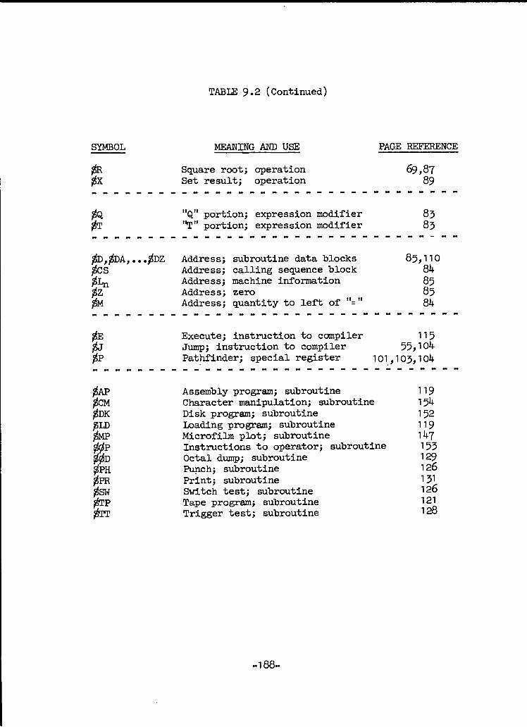
TABLE 9.2 (Continued)
SYMBOL
@R~x---- ----
j$QST----- ---
@D,~DA,...$Dz$cS
----- ---
----- ---
MEANING AND USE
Square root; operationSet result; operation----- -“--- ----- --
“Q” portion; expression modifier“T” portion; expression modifier---- ---- ---- ---- -
Address; subroutine data blocksAddress; calling sequence blockAddress; machine informationAddress; zeroAddress; quantity to left of “=”---- ---- ---- ---- -
Execute; instruction to compilerJump; instruction to compiler
PAGE REFERENCE
69,8789
-.--- ---
8383
---- -----
85,11084858584
----- ---
11555,104
Pathfinder; special register 101,103,104---- ---- ---- ---- ---
Assembly program; subroutineCharacter manipulation; subroutineDisk progrsm; subroutineLoading program; subroutineMicrofilm plot; subroutineInstructions to operator; subroutineOctal dump; subroutineE@ch; subroutinePrint; subroutineSwitch test; subroutineTape program; subroutineTrigger test; subroutine
---- --
11915415211914715312g126131126121128
-188-

TABLE 9.3
CARD FORMATS
1
*
B
s
P
D
R
K
$
T
A
I
L
F
x
E
PAGEFormat REFERENCE
* * *Min(3) nsme,ph.(19) no.(k) code(3) group(3) cat(2) 2~ 22-23---MOOO tapes(2)
J@B,I@D,REEL, etc. 23-26
(N~),A(N2),x(N3),L(NJ),s~oL, (Nt3),... 26
s 30
SYMB@@MB@,SYMB@(N1,N2, ....Nn).SYMB#L(N1,....Nn)=Q1,...,Q 43-57m
NAME(P) = Hj!kIERITH’’CHARACTERS”$ji@ 61-64
NAME(P) = (CSW1:CSW2:....CSWn) 64-67
INSTRUCTIONS 33
TSCW1:TCSJ2:....TCS%/n 33-35
jfRDH@RN,F
35-37
Algebraic code, etc. 68-117
Longhand code, etc. Appendices 2,3
AD:~B,L:#A,M X-39
NAME @F F@MUIA SET OR BLANK 39-40
sYMBdL = Q1jQ2)...jQ#YMB@L(Q.P) = Q1,~,...Qi, S~~L(T.P)
I =Q1,e..,Qi 57”59
See also Table I, page 42, and Table II, pages 60-61.
-189-

TABLE 9.4
AIGEBRAIC OPERATIONS
FIOATING POINT FIXED POINT
+
*
**
/
//
+$-$*$.$R
.#CA
.@J
.@J
+
*
-x+i-
/
//
+$-$
.$3
.$CA
.j?fcx
INDEX REGISTER
+
.jfx
Boolean
+
+(-
See also: Floating point, page 69
Fixed point, page 86
Index register, page 89
Boolean, page 93
RUIE: All operations are considered from left to right, i.e., eachoperation takes in all expressions so far computed on theleft to the right of a left parenthesis or equal sign, which-ever occurs latest.
-190-

TABLE 9.5
SYMBOLS, EXCllLSIVEOF MODIFIERS, ALLOWED IN AIGEBRA
A.
TYPE OF SYMBOL
SYMB@LSYMB@LnNAME
Symbols allowed on either side of equal sign
MEANING
Name of data block or first elementnth element of data blockName of “K” block--numbered or notCalling sequence blockSubroutine data blocksnth element of subroutine data blocksNLA (next loading address)NBA (next block address)Zero addressIndex register n
B. Symbols allowed only on right side of equal sign
$Ll$L2
FAC (first address for code)FAD (first address for data)
#L5 Machine number$L6 No. of BCD characters per word
@ @antity on left of equal sign
NOTES: (Types of symbol modifiers allowed - see Table 9.6):
1.
2.
3.
4.
NOTE
11233
;456
7
;76
Either side of equal sign: type A; or type E (except “@P”)left of equal sign: type A and type Bright of equal sign: ‘l@rp’tor type A and one of types C,D, or F.
Ssme types of modifiers as in note 1 with the addition thattype A can occur with “#WA” and “@C” on left or right ofequal sign.
Same types of modifiers as in note 1 except type E is not allowed.
Either side of equal sign: type Aleft of equal sign: type A and type Bright of equal sign: type A ~ type F.
-191-

TABLE 9.5 (Continued)
NUI!ES:
5. Modifiers required.
Either side of equal sign: type A or type A plus “$WA” or “#WC.”left of equal sign: type A and type Bright of equal sign: type A~d one of types C, D or F I
6. No modifiers allowed.
7. Type A or type A and one of types C, D or F.
-192-
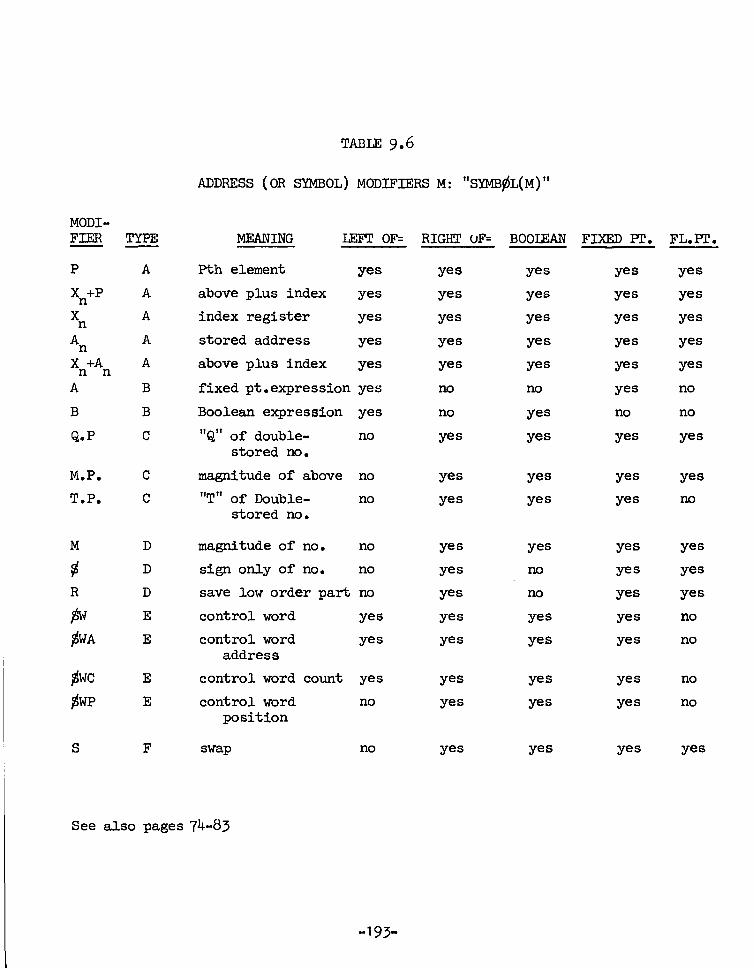
MODI-FIER
P
xn+P
Xn
An
Xn+An
A
B
Q.P
M.P.
T.P.
M
1
R
$
@A
$Wc
j4wP
s
A
A
A
A
A
B
B
c
c
c
D
D
D
E
E
E
E
F
TABLE 9.6
ADDRESS (OR SYMBOL) MODIFIERS M: “SYMS@L(M)“
MEANING LEFT OF= RIGHT uF= BOOLEAN FIXED PI’.
Pth element yes
above plus index yes
index register yes
stored address yes
above plus index yes
fixed pt.expression yes
Boolean expression yes
“Q” of double- nostored no.
magnitude of above no
“T” of Double- nostored no.
magnitude of no. no
sign only of no. no
save low order
control word
control wordaddress
part no
yes
yes
control word count yes
control word noposition
swap no
yes
yes
yes
yes
yes
no
no
yes
yes
yes
yes
yes
yes
yes
yes
yes
yes
yes
yes
yes
yes
yes
yes
no
yes
yes
yes
yes
yes
no
no
yes
yes
yes
yes
yes
yes
yes
yes
yes
yes
yes
no
yes
yes
yes
yes
yes
yes
yes
yes
yes
yes
yes
FL.PI’.
yes
yes
yes
yes
yes
no
no
yes
yes
no
yes
yes
yes
no
no
no
no
yes
See also pages 74-83
-193-

TABLE 9.7
wumssIoNMoDrFmw (RIGHT OF EQUAL SIGN ONLY)
MODIFIXR
.#QoP
MEANING
Put result in “Q” part
Put result in “T” part; may follow only
fixed point expressions
see also pages 83-84.
.194-

TABLE 9.8
REFERENCE POINT ENTRIES AND BRANCHES
A. Reference Point Entries
ENTRY
Xn(l,P)
Xn(P,1)
Ln
LnoXn
F@
FS
FS.Xn
B. Types of Branches
(Xn)
(Ln)
(F@M)
(FS)
(Ln)Algebra=C
(F@M)Algebra=C(= )Algebra=C }
($P,Ln)
(@P,F@RM)(@P,FS) }
(Xm + N)
MEANING
Forwsrd index loop entry
Backward index loop entry
Iocal L-entry for references within formula
?kcal subroutine. Contents of “#P” go to Xn.
Formula entry for references within formulaset. “F@M” not on “D” card.
Formula subroutine C(#P) +Xn
Formula set entry for references from entirecode. “FS” on “D” card
Formula set subroutine.C(SP) +Xn
Loop on index X to nearest previous loopentry for ?ndex Xn
Unconditional branches to L-entry in sameformula, formula in same set, andformula set, respectively.
Conditional branches to L-entry in same for-mula, formula in same set, and formukset, respectively
Pathfinder branches to local subroutine insame formula, formula subroutine insame set, and formula set subroutine,respectively
Return to instruction after calling sequenceof subroutine
-195-

CALLING
TABLE 9.9
SEQUENCE CONVENTIONS
(Each entry represents a legal calling sequence word entered betweencolons on “K” card or after pathfinder branch)
ENTRY MEANING
jhxx 1,2, or 3 alphanumeric characters in “$WC” portion. Usedfor control purposes.
P par~eter algebra expression. Result is computed and ,.placed in “@WA’’_portionor more, if greater than 2’>
AD(#W)+P “AD” any programmer-defined symbol. CW(AD) modified byis placed in entire word.
AD(#WA)+P Control word address modifiedby P is placed in “#WA”portion.
AD(#wc)i-P Control word count modified by P is placed in “#WA”portion.
AD($WP) Control word position
AD(P) Contents of AD(#WA)+P
In addition, the following compound
is placed in “@WA” portion.
are placed in “$WA” portion.
entries are allowed:
9
P
@CX,P (P< 2’8)@CC$AD(#WA)+Pjkxx,AD(@lc)+P@xx,AD($wP)@XCf,AD(P) (C(AD(@A)+P) fixed pt. ~ 218)
-196-

TABLE 9.10
SUMMARY OF CALLING SEQUENCES TO IVY SUBROUTINES
A. $AP
Calling seq. word
@DN,F
Calling seq. word(s)
j?hl)x$IJ)x$Ewx@uLx$EFX$3!rx$BBx,p$BFx,P@Bx,P#FFx,P@DX,AD(#WA)+P
@DX,AD(j!!WA)+P:AE($WP)
MEANING
Read in and convert code in file F, tape N
Set tape “X” to high densitySet tape “X” to low densityRewind tape “X” to load pointRewind tape “X,” then unloadWrite end-of-file on tape “X”Write end-of-tape record on tape “X”Backspace tape “X” through P recordsBackspace tape “X” through P filesForward space tape “X” through P recordsForward space tape “X” through P filesMay be last calling sequence word onl .# If
ID of current record on tape “X = con-tents of location specified, @CSl = 1.If not, j!CSl= O.
Reads into block “AE” the record with ID =c(AD(~WA)+P), from tape “X”
Sets “@!P” to run in parallel modeSets “$TP” to run in serial mode
For further reference see Table VChapter 6, pages 119-126.
, page 120(tape numbers), and
LJ!!z2Calling sequence words
#P, AD(@P) :$R Print a diagnostic comment if any indicatorsare on, and return control to problemprogram
-197-

TABLE 9.10 (Continued)
- (continued)
Calling sequence words
#N:$R~P.AD($WP):@I
@N:@
m
Calling sequence word
$DASYMB@L(SWP)
!&_@@li
Calling sequence word(s)
$1P$2P@DPj#lT#2T$IYrji$lM@Mj4DMpP,REM(~wP)@, REM(@wP)@,r@@P)@F,FORMAT(@wp)
R.mAR.K(@P)
VECTOR(@P)
j4PN,PARAM(@A)+p
j#2,MATRIX(@P):P
MEANING
No print; return to problem programPrint comment and return to IVY if
any indicators onNo print; return to IVY if any indi-
cators on
DumpDump
all data and longhand codedata block or longhand formulaset named
SPR MEANING
Restore page (on-line)Half-page skip (on Mne)Double space (on line)Restore page (off-line)Half-page skip (off-line)Double space (off-line)Restore page (microfilm)Half-page skip (microfilm)Double space (microfilm)Print remark on-linePrint remark off-linePrint remark on microfilmFormat statement (see
note below)Print remark as specified
by previous formatPrint vector specified by
previous formatPrint N parameters as spe-
cified by previous format
SPH MEANING
Insert blank cardInsert blank cardInsert blank cardInsert blank cardInsert blank cardInsert blank cardInsert blank cardInsert blank cardInsert blank cardPunch rem. on-linePunch rem. off-linePunch rem. off-line
Ssme
Punch same
Punch same, ormatrix or array
Ignored
Print matrix (with 1st dimen- Punch same (@2,Psion P) as specified by are superfluous)previous format
-198-

TABIE 9.10 (Continued)
EC @pH,~pR (continued)
Calling sequence word(s)
#A,ARRAY(SWP):Pl:P2
VECT@R(@P) :#D,P
vECT@R(@P) :$Q,,P
VECT@R(@P) :@T,P
j52,MATRIX(@P):#D,P1:P2
$2,MATRIx($wP): j4Q,p,:P2
ji42,MATRIX(@P):@T,P1:P2
#A,ARRAY(@WP):$D,P1:
‘2:‘3
#A,ARRAY($WP):IQ,PI:
‘2:‘3#A,ARRAY($WP):$T,P1:
‘2:‘3
SPR MEANING
Print array(lst 2 dimensionsP1,P2) as specified byprevious format)
Print both Q and T portions
Print Q portion only of DSvector, tag length P
Print T portion only of DS
vector, tag lengbh PPrint both Q and T portions
of DS matrix, tag length
‘1‘1st dimension P2
Print Q portion only of DSmatrix
Print T portion onlyof DS matrix
Print both Q and T portionsof DS array,tag length PI,
1st 2 ‘imensions ‘2)P3
Print Q portionDS array
Print T portionDS array
only of
only of
SPH MEANING
Punch same ($A,PI,P2 are super-
fluous)
Punch same, or ma-trix or array
Punch same, or ma-trix or array
Punch same, or ma-
trix or arrayPunch same (j!!2,P
sare superfluo s
Punch same (@2,P2are superfluous)
Punch same (@2,P2are superfluous)
Punch same (@,P2,P5are superfluous)
Punch same (@ P Pare superfl;052)3
Punch same (#A,P2,P3are superfluous)
Note on format statements: the general appearance of a format statement is asfollows:
——
RIF@MAT = C1C2...Cn,(W_1)~OS101~0~ ‘El ,...,(REMm)NmNSmSImIFmFEm,j$~$~$
whereeach “Ci’trepresents one of the following conditions:
-199-
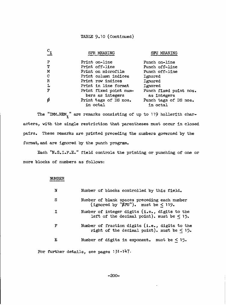
TABLE 9.10 (Continued)
Ci SPR MEANING—
P PrintT PrintM Printc PrintR PrintL PrintF Print
on-lineoff-lineon microfilmcolumn indicesrow indicesin line formatfixed point num-
bers as integers
$ Print tags of DS nos.in octal
The “IMM.REM4” are remarks consisting of up
SPU MEANING
Punch on-linePunch off-lkePunch off-lineIgnoredIgnoredIgnoredPunch fixed point nos.as integers
Punch tags of DS nos.in octal
to 119 holderith char-.A
acters, with the single restriction that parentheses must occur in closed
pairs. These remarks are printed preceding the numbers governed by the
format,and are ignored by the punch program.
Each “N.S.I.F.E.” field controls the printing or punching of one or
more blocks of numbers as follows:
N Number of blocks controlled by this field.
s Number of blank spaces preceding each number(ignored by “#lW”). must be~ 119.
I Number of integer digits (i.e., digits to theleft of the decimal point). must be ~ 15.
F Number ofright
E Number of
fraction digits (i.e., digits to theof the decimal point). must be ~ 15.
digits in exponent. must be ~ 15.
For further details, see pages 131-147.

TABLE 9.10 (Continued)
E4fECalling sequence word(s)
@U?N,P
j?%G:PI:P2
j@:~D@@A)+P
@RN,REM(#WP) :R(#WA)+P1:C($WA)+P2
#pFN,M:xc(@p) :Yc(#wP):XYBDS($WA)+P:TEMP (@WP)
@A,xYBD@$wA)+p: xzER@(j#wA)+P:YZER@(@A)+P
See also pages 147-152.
%?!!?!$
Calling sequence words
j4WRN,n($WA)+P:DATA(@P)
&DN,ID(#wA)+p: DATA(#wP)
MEANING
Advance film; if N = 1, set for ha,rdcopy;advance “P” more frames.
Select grid, horizontal option “Pl,”vertical option “P,..”
Valid only aft& abovezentry. Label grid,assuming X
min’xmax’ymin’‘maxstored
in that order starting at “XYBDS($WA)+P.”Write remark “REM” horizontally (N=O) or
vertically (N=l) starting at row andcolumn position specified.
Plot XC versus YC, using char. M, and connectwith line if N=l. XYBDS as above;“TEMP” = block same length as XC,YC!for erasable.
Generate a pair of axes through XZE@,YZER@;XYBDS as above.
Write “DATA” block on disk with ID asspecified. N = tape number onmachines with no disk, O otherwise.
Read block with ID specified into “DATA.”N as above .
=“ has one calling sequence word, of the form
REMARK(#WP)
The remark specified is printed on-line. See page 153.
-201-

TABLE 9.10 (Continued)
242!Calling sequence word(s)
#sN,WK(@)
#MN:AD($WA)+P1:REMl(@P):AE(SWA)+P2:m2(#WP)
#CN:AD(@A)+pl :=1 (@p):AE(SWA)+P2:-(@p)
See pages 154-156.
MEANING
Set remark specified to the characterrepresented by decimal number “N”(seeTable 9.1).
Move N characters from REMl to REM2,positions as specified.
Compare N characters of REMl and REM2positions as specified; if equal#CSl=1, otherwise @CSl=0.

APPENDIX 1
MANIPULNI’INGTHE SYMBOL TABLE
The main function of this Appendix is to give a detailed descrip-
tion of how the symbol table can be altered and used in computations in-
volving only the TVY algebraic instruction set without recourse to longhand
instructions. More sophisticated computations can be performed using long-
hand instructions, but in general these will not be necessary. Presumably
symbol table manipulations will seldom if ever be used by most programmers;
they are useful only when codes are very long and complicated and extreme
methods of conserving core storage are necessary.
Handling a program which is too large to fit in the machine.
It often happens that the whole of an unusually long program, or one with
a large amount of data, will not fit into core at one time. A code of
this size, however, is quite easy to handle in the IVY system. First, the
code must be organized in a specific fashion: there must be a flow code,
in this case usually called a “master code,” which is in core at all
times, and which controls access to and conversion of the remainder of
the code, only a fraction of which is in core at one time. In this case
-203-

we assume that control passes through each of several portions of the
code only once. As an example of this, we shall consider a program con-
sisting of a master code and six formula sets “FSA,” “FIB,’’,...j’’FSF~”
to be executed in this
time. The master code
order of which only three can occupy core at one
for handling such a case can be diagramed as
follows:
mENTER
& EXECUTE FSA,I CONVERT wi.
READ IN AND CONVERTFSD, FSE,FSF INTO
+, >@
If we assume that the six formula sets occupy files 2-7 on tape 2,
code for doing this looks approximately as follows:
the
Line No.I
II2
II
3
11114
11115
1111
I MASTER,($P, SAP: $RD2,2: $RD2,3:$RD2,4),
c C@DEAEXECUTES ‘FSA,AFSB,hFSC
I
2
3
I
II SL3=FSA(SWA)+I, (SP, $AP: $RD2,5: SRD2,6:”$RD2,7),
11111CODE AtiMITTEDA EXECUTES ‘FSD,AFSE,AFSF 4
11111I (SP, $LD),
I 151I I
-204-

NOSES:
1. The master code, appropriately named “MASTER,” enters “@Pto read in and convert “FSA,” “FSB,” and “FSC.”
2. “FSA,“ “FSB,” and “FSC” are executed, the flow of controlbeing by means of conditional “L” branches and pathfinderbranches peculiar to the program.
3. Next, “@L3,” which contains the next loading address (NLA)for code, is reset to the value it had before “FSA” wasloaded, and the three formula sets “FSD,” “FSE,” and “FSF”are read in and converted, covering the previous three for-mula sets.
4. The second section of the code is executed.
5. At the end of the program, a pathfinder branch to “@Jl” isexecuted.
In addition to the master code, of course, there may be other
formula sets which are always in core, such as subroutines referred to
by both sections of the code. Also, this simple example can easily be
extended to the case where the code must be divided into more than two
sections. It is necessary merely to repeat a similar sequence of in-
structions to that on line 3 as many times as needed.
How to “ping-pong” a code. By “ping-ponging”a code it is meant
that several sections of the code must be repeatedly read in and out of
core since each must be executed more than once, unlike the previous
example. Thus the various sections of the code bounce in and out of
core like a ping-pong ball. To do this, after each section of the code
is converted and executed, it must be written on tape using “@P;” then
it need only be read in from tape for each succeeding execution. This
method saves considerable compi~ng time since on successive executions
-205-

the code need not be re-compiled. If we consider again a case in which
a code contains six formula sets} of which OfiY three Cm fit into core)
and assume each section is to be executed N times, the following diagram
illustrates how the master code should look.
T==ENTER
0-DTApE FLAG E=READ IN FSD,FSE,FsFFROM TAPE($TP)
EXECUTE FSD,FSE,FSF ElTAPE FLAG=O? ‘0
I+TAPE FLAG
WRITE FSD, FSE,
I FSA,FSB,FSC($AP) WRITE FSA,FSB,FSC
I’&
X1+1-XION TAPE ($TP)
IEXECUTE FSA,FSB,FSC
We note that a “tape flag” is necessary, so that the master code can de-
tect whether or not the two sections of the code have been written on
tape.
-206-

IVY DATE73174173176177[7t317918C
PAGE NAME PROBLEM I I I I I I I
I
I
I
I
I
I
I
I
I
I
I
I
I
II
I
II
I
I
I
I
I
I
I
I
I
I
I
I
I
I
I
I
I
I
I
I
I
I
I
I
I
I
I
I
I
I
I
II
I I I i I 1 I12 72 CODE1
II MASTER,TF=O, Xl(l, N), (Ll)TF=Nj!,I
($P, $AP: SR02,2:$RD2,3:$ RD2,4), (L2),,
LI ,($P, STP: SRW3: $RD3, T($WA)+ 1: FSA ($WP):1
ISRD3, T(swA)+2: FsB(swP): $RD3. T(swA)+3:Fsc($wP) ), ~1.- —
1LZ ,.. .I II
c OMITTED ACODE A EXECUTE5 A FsA,A FSB,A FSC I1:
I (L3)TF=NZ, ($P, $Tp: $Rw3:SWR3, T($WA)+I: FSA(SWPJ
$WR3, T($WA)+2: FSB ($WP): $WR3, T($WA) +3 : FSC($WP)),
sL3 = FsA($wA)+I, ($p, $Ap:$RD2,5:SR02,6: $RD2,7),
I
I
I(L4), L3, (sp, $TP: SR03, T(sWA)+4: FsO(SwP):
I $RD3, T(swA)+5: FSE (SWP): $RD3, T($WA)+6: FSF(SWP)), IllL4, ... <J
c OMITTED ACGiOE A EXECUTES ‘FSO,AFSE, AFSF, IL
I (L5)TF=NZ, TF=I ,(sP, sTP, swR3. T(swA)+4:
FSD(SWP): $WR3, T(SwA)+5: FSE($WP): SwR3.T($WA)+6:
FSF(SWP)),J ●xit
L5,(xI) , (SP, SLD),.-— —s
I
I
I
I
I
I
I
I
I
I
I
I
I
I
I
I
I
I
I
I
I
III
I
I
I
Figuro Al
I
I
I
I
I
I—
I
I
I
I
II—
I
I
I
I
I
I
I
I
I
I
I
I
I
I
I
I
I
I
I
I—
-207-

The code for doing this is illustrated in Figure Al. Again it is
assumed that tape 2 contains the six formula sets in unconverted form in
files 2-7, and that tape 3 is a blank to be used in the “ping-ponging”
operation. “T” is a block containing the ID words required by the tape
program. By observing the arrows on the outside of the coding sheet,
one can follow the path of flow as it corresponds to the above diagrsm.
The methods illustrated in this appendix thus far can be general-
ized, extended, or combined to h&dle virtually any lengthy code that can
be devised. Similar methods can also be used to write blocks of con-
verted code on the disk unit of machines which contain such a device.
The speed of a disk unit is always greater than the speed of tapes, so
this procedure is recommended when possible. The programmer should note
that formula sets are the only units of code which can be written on
tape or disk since only formula set names are contained in the symbol
table. Neither individual formulas nor groups of formula sets under
the control of only two calling sequence words can be written: the for-
mer, because formula names are not contained in the symbol table; and
the latter, because two calling sequence word entries are necessary for
each formula set read or written. Whereas one can write several for-
mula sets onto the assembly tape under cotitrolof an “A” card, this is
not possible using “#TP” or *’@DK.”
other manipulations of the symbol table are also possible using
various techniques involving the “#WC” and “@A” modifiers, in addition
to the special locations “#Ll,“ “@L&?,”“$L3,’’and “@+” (see Chapter4,

page 85). In general, however, manipulations which change the contents
of the symbol table are to be avoided if at all possible since they
might cause unpredictable difficulties in IVY. Therefore no examples
of this type of programming are given.
-20g-
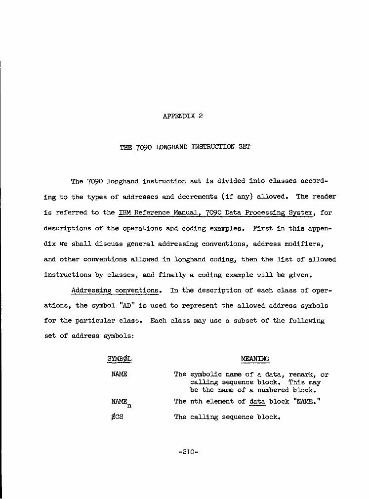
APPENDIX 2
THE 7090 lXINGHANDINSTRUCTION SEX’
The 7090 longhand instruction set is divided into classes accord-
ing to the types of addresses and decrements (if any) allowed. The reader
is referred to the IBM Reference Manual, 7090 Data Processing System, for
descriptions of the operations and coding examples. First in this appen-
dix we shall discuss general addressing conventions, address modifiers,
and other conventions allowed in longhand coding, then the list of allowed
instructions by classes, and finally a coding example will be given.
Addressing conventions. In the description of each class of oper-
ations, the symbol “AD” is used to represent the allowed address symbols
for the particular class. Each class may use a subset of the following
set of address symbols:
W!!2@L! MEANING
The symbolic name of a data, remark, orcalling sequence block. This maybe the name of a numbered block.
NAMEn The nth element of data block “NAME.”
$Cs The calling sequence block.
-210-

An
#Ln
#z
Ln
F
FS
&SR
*
x
N
In each class of
theses following
bol is allowed a
MEANING
The nth element of the calling sequenceblock.
Any of the subroutine data blocks.
The nth element of any of the subrou-tine data blocks.
Address of instruction with “An”modifier.
One of the elements of the “@L” block.
Zero or nulJ address.
Name of an “L” entry.
Formula name.
Formula set name.
Neme of an IVY subroutine.
location of current instruction.
Fixed or floating point literal(Decimal only).
Absolute address equal to the num-ber N.
operations, address modifiers(which occur within paren-
the address symbol) are represented by “Mi,” and each sym-
subset of the following set of modifiers:
‘i MEANING—
M. No modifier
Ml P (parameter algebra)
-211-

~MEANING
‘2Xn + P (parameter algebra plus index
register)
‘3Xn (index register)
‘4An (stored address)
‘5Xn + A (index register plus stored
ad&ess )
M6 @lP (control word position)
%’@C/@A (control word count or address)
Longhand instructions are separated from one another by colons.
The translation to machine language is strictly one-to-one, i.e., each
entry between colons corresponds to one machine word, except’for certain
entries which represent instructions to the compilerjwhich will be noted
as they occur. The elements of an instruction are separated from one
another by commas and sets of closed parentheses. The general format of
a longhand instruction is:
Conventions are
General
:@p(I/Xn),AD(Mi),ECR/CT:
explained in the discussion of each class.
form of a longhand code. Longhand instructions are en-
tered on “L” cards, which maybe intermixed with discretion in any desired
manner with “I” cards, to supplement the algebraic code in as great or
small a manner as desired. However, in this appendix we shall consider
longhand formula sets, i.e., complete routines or subroutines coded in
-212-

longhand. The programmer interested only in inserting a card or two of
longhand code into his program should have no difficulty once the larger
concepts have been studied. See restriction 2, page 217.
Ion@and codes are divided into formula sets, formulas, and
local entries just as are algebraic codes. The same rules for referent.
ing discussed in Chapter 5 also apply to longhand codes. However, the.
methods of forming entry points and branches of course differ between
the two systems. Formula set names, formula names, and L-entries pre-
cede the operation at the entry point in parentheses, thus:
(FS) @P, AD(Mi)
(F) @P, A.D(Mi)
(Ln) @P,AD(Mi)
In branches to these entries, the name of the entry occurs in the address
of the instruction outside parentheses, modified if necessary, e.g.,
TRA,FS(Mi)
TRA,F (Mi)
TRA,Ln(Mi)
and so on for other types of transfer instructions.
Subroutine conventions. Internal IVY subroutines or subroutines
coded in the algebraic language must be entered by the instruction
TSX(~P), NAME
where “#P” is the pathfinder register and “NAME” is the name of the
-213-

subroutine. On the 7090 the pathfinder register “#P” is synonymous with
index register 3, X3. Thus the following entry is equivalent to the
above:
TSX(X3), NAME
If a subroutine written in longhand is enteredby a pathfinder
branch from a portion of the code in algebraic language, or by means of
one of the above instructions, one can use the first instruction of the
subroutine to store the pathfinder contents in the address or decrement
of a specified location “AD” as follows:
(NAME) SXA(@P),AD or (NAME) SXD(@P),AD
which, of course,t are equivalent to the entries
(NAME) SXA(X3),AD or (NAME) SXD(X3),AD
Calling sequences. Calling sequences may be constructed after a
“TSX” to any subroutine by using the pseudo-operation “CSW” and by fol-
lowing it with a standard IVY calling sequence word entry, separating
the calling sequence words from each other by colons. For example:
LITSX(@P),NAME:CSW,@BC,GE($WP):CSW,#CT2,CRA(#WC):CSW,3+7wE: ...
The IVY subroutines with variable length calling sequences (namely @P,
@P,j#@D,@R, ~PH,@P,#DK, and #CM) require an “HTR” with null address
field following the last calling sequence word. This is to signal the
subroutine tlnatthe calling sequence has ended. The compiler automati-
cally inserts this zero word in calling sequences to these routines
-214-

written in the algebraic code, but this is not done automatically in the
longhand system because, as mentioned previously, longhand code is trans-
lated in a one-to-one fashion. Thus, for instance, to print a vector,
the following statements should be used:
LITSX(#P),j?k%:CSW,$F,F@MAT(j$WP) :CSW,VECT@R(@P) :HTR:...
Definition of “#D” blocks. To define “~D” blocks at the beginning
of a formula set coded in longhand, one must enter these definitions be-
tween a single set of colons immediately following the first instruction
of the formula set, for example:
L (FS)SXD(j4P),AD:#D(4),@C(3) = 2.156,3.172,5.171,
$DH(5,9,10),$DM(50) = 5.1’j2,(S)47,5.213,5.215:...
The format for defining “j!D”blocks is otherwise the ssme as the format
for defining them on 1’1”cards, discussed in Chapter 5, pages 110-112.
Since “#D” definitions represent instructions to the compiler, a word
of code is not, in this case, assembled to correspond to the definitions
between the pair of colons.
Renaming. One may rename an index register with an alphabetic sym-
bol in the same manner as on “I” cards, by entering between colons as
follows:
:*SYMB#L = Xn:
Again, since this entry represents an instruction to the compiler, no in-
formation is assembled.
Storing addresses; The “An” symbols may be used in the address
-21‘j-

fields of “store address” instructions, and the address being stored will
be placed ininstructions having addresses modified by this same “An” sym-
bol. In longhand coding, instead of the entry “Anom” specifying m
store address instructions, one must instead mite dom consecutively
all m instructions. The number of store address instructions entered
must equal the number of instructions in which the address is stored.
For example:
L CLA,FRN($W):ADD,FRNX(X1):mA,AI:mA,Al :STA,Al:.e.
...LDQ.FRN(X2+A1):FMP,FTUJ(X3+A1):....ST$.~N(X2+AI ):...
Here three “STA” instructions with address “Al” are present, and three
instructions with addresses modified by “Al” are also present. Note
that instructions in which addresses are stored must occur sequentially
after the “STA” instructions referring to them. The “STA” instructions
must occur sequentially together, as in the above example.
In longhand coding, one can also store ad~esses in instructions
at or near localy formulay or fo~la set entriesj or ne~ the “~A” it-
self, by using the name of the entry or “*” with appropriate modifiers.
“An” is not needed in such a case. For example:
L (Ll)c~,~N(xl ):m,~N(x2):ST@,~(X3) :...
...cLA.FRN(#W):ADD,~@xl ):WA,Ll:wA,Ll(l ):WA,L1(2): ..0
This technique can thus be used to store addresses in a
tion,
items
backward direc-
if desired.
Storing decrements, prefixes, tags, and left half of MQ. If these
are stored in code, then “An” symbols, which are reserved for “STA”
-216-
,

alone, cannot be used. Instead the addresses of ‘rSTD,” “STP,” “SIT,”
and “SLQ” instructions must contain the name of a local, formula, or
formula set entry, or the “*,” with appropriate modifiers, in the same
manner as “STA” instructions which do not use “An” symbols.
Further restrictions on longhand coding. The following check list
summarizes the remaining restrictions on longhand coding:
1. To repeat what was said previously, only three index registers,Xl, X2, and X3,are allowed in 7090 longhand coding.
2. The programmer should note that X3 is used by the algebraiccode not only to simulate the pathfinder, but also to simulateindex registers X4, X5, etc. If the longhand code consistsonly of a few cards inserted in the middle of an algebraiccode, the programmer must save the contents of X3 or of thelast index register above X3 to which he has referred, to en-sure that its previous contents, if needed after the longhandsegment, are not destroyed. This can be done in two ways:
a. In the algebraic code:
II....)Tl =Xn,
L1....(Ionghand code)...
IIXn=Tl,...
where “X “ is the last index register above X3 referredto in th~ algebraic code and “T1” is some suitab~chosen temporary location; or
b. In the longhand code:
1]....(Algebraic code)
LlSXA(X3),Tl:...(Ionghmd code)...
LI.....LXA(X3).T1....
II....(Algebraic code)
The previous contents of X3, simulatingregister, are preserved by the longhand
-217-
some higher indexcode.

3*
4.
class 10
In general, short longhand code inserts in algebraic code shouldbe used with great discretion. Because of the sm~tion ofextra index registers by X3, one must, as remarked above, takegreat care not to destroy the contents of this index register.Branching between such “pockets” of longh~d code ~d the alge-braic co~e should also be avoided. The unwary coder should ingeneral follow these rules:
a. Short longhand inserts in a predominantly algebraic codeshould not use X3 and should not be entered or left bybranches to algebraic code, without the use of great care.
b. Preferably, the smallest unit of longhand code in an alge-braic code should be at least a formula.
Only one index register can be specified in an instruction, i.e.,the “oring” feature of the 7090 is not permitted. This is be-cause of the possibility of wiring the 7090, at some future date,to contain seven index registers in which case this featurewould no longer be present.
h IVY 7090 longhand instruction, together tith its addressjmodifiers, etc., must be complete on one card- For all practi-cal purposes, the end of the card is treated as a colon. Thus,the last instruction on a card need not be followed by a colon.
Arithmetic operations
General format: ~p(I)j~(Mi)
The “I” is entered if indirect addressing is desired.
AD(Mi) = * Nwn(MoM1M#5),@s(MoM1M2M3) $N@MoM,M&4M5M6) ~
@Sn(MoM1M#3),#D( MoM1M#3),#Dn(MoM1 M#5), #Ln(Mo),
$z(MoM1M#y4M5), Ln(MoM1M2My5), F(MoM1M2Mj45),
FS(M0”lM#fl#6)~*(M0MlM&3)> ‘~N(M3)e
*This notation means that any one of the modifiers shown is permitted.
-218-

MNEMONIC
ACLADDADMANAANsCALCAsCIACISDVHDVP
FADFAMFDHFDP
FSBFSM11SIAs
ICHALC.HBLOIIJIQ
NZTpm@T$&&
@IPmRCHARCHBRISSBMSCHA
OPERATIONS IN
MEANING
CIASS1
“x”IF LITERAL JuDwED
Add and carry logicallyAdd (fixed)Add magnitude (fixed)“And” to accumulator (Boolean)“And” to storage (Boolean)Clear and add logicallyCompare accumulator to storageClear and addClear and subtractDivide or halt (fixed)Divide and proceed (fixed)Exclusive “or” to accumulator
(Boolean)Floating addFloating add magnitudeFloating divide or haltFloating divide and proceedFloating multiplyFloating subtractFloating subtract magnitudeInvert indicators from storageIngical compare accumulator and
storageIoad channel ALoad channel BIoad indicatorshad MQMultiply and round (fixed)Multiply (fixed)Minus zero (prefix only)Storage not-zero testOff test for indicatorsOn test for indicators“Or” to accumulator (Boolean)“Or” to storage (Boolean)“Or” storage to indicatorsPlus zero (prefix only)Reset and load channel AReset and load channel BReset indicators from storageSubtract magnitude (fixed)Store channel A
xxxx
xxxxxxx
xxxxxxxxx
xxxxx
xxx
xx
xxx
-219.

MNEMONIC
SCHASCHBSIQSINSTDS21S’ELS@Sl?P
STZSUBUAMUFA
U-I’SUSM
StoreStoreStoreStoreStoreStoreStoreStoreStoreStoreStoreStoreStore
MEANING “x”IF LITERAL ALIQWED
channel Achannel Bleft half of MQlogical worddecrementindicatorslocation counter
prefixMqlocation and traptagzero
Subtract (fixed) xUnnormalized add magnitude xUnnormalized floating add xUmormalized floating multiply xUnnormalized floating subtract xUnnormalized subtract magnitude xZero storage test
EXAMPLES:
MEANING
~,+e(4) Store tag in fourth instruction followingm.dcsl Test contents of “SCSI” for zeroCIA;:3.25613+2 Mad indicated literal into accumulatorLDQ,4(X3) Load C(4 - C[X3])into MQ
Class 2. Shift and sense operations
General format: 4p,AD(Mi)
where AD(Mi) = $Z(MoM1M##4~)JN(MoM3)
-220-

MNEMONIC
ARsIGLIGR
IllsMSEPSERQLSPRSl?rSPU
EXAMPLE
AIS,20
OPERATIONS IN CIASS 2
MEANING
Accumulator left shiftAccumulator right shiftIOng logical left shif%Iong logical right shiftIong left shiftIong right shiftMinus sensePlus senseRotate MQ leftSense printer, channel ASense printer test, channel ASense punch, channel A
EXAMPLES:
MEANING
Shift accumulator left 20AIS;(2O) Same as above. Note alternative form
I IGL;jO(X2)IGL,(X2+50)IGL,#Z(X2+30)PSE,96MSE,1OO
Logical left ~, modified byC(X2)Same as aboveSame as aboveTurn off all sense lightsTest sense light 4
Class 3. Load and Store Index Operations
General format: @PAD
where: “xn” represents the operand index reigster
AD(Mi) = NAME(MoM1M4M6),NAMEn(M&1M4),@(MoM1 ),
Fc@&, )@(M#l )#Dn(MoM1 )&(Mo) ,
@(MoM1M4) ,Ln(MoM1M4),F(Mo~M4) ,FS(MoM1MhM6);[MOMJ .
-221-

MNEMONIC
OPERATIONSIN CLASS3
MEANING
MC
PACPAX
PDx
SXASXD
EXAMPLE
Load complement of address in indexIoad complement of decrement in indexIoad index from addressIoad index from decrementPlace complement of address in indexPlace address in indexPlace complement of decrement in indexPlace decrement in indexPlace index in addressPlace index in decrementStore index in addressStore index in decrement
ExAMPms:
MEANING
LxD(xl), NAME(@P) Count of control word to XlIAC(X2),NAME($WP) Complement of control word address
to x2PXD Clear accumulatorPAX(X3) Address of accumulator to X3
Class 4. Tape Manipulation Operations
General format: ~p, @Mi)
where: AD(Mi) = N(MOM3),@(M2M#4M5) .
OPERATIONS IN CIASS 4
MNEMONIC
BSFABSFBBSRABSRBREWA/BRTBA/B
MEANING
Backspace file, channel ABackspace file, channel BBackspace record, channel ABackspace record, channel BRewind, channel A or BRead tape binary, channel A or B
-222-

MNEMONIC MEANING
RTDA/BRUNA/BSDHA/BSDLA/BWEFA/BWTBA/BWTDA/B
EXAMPIE
SIILB,3WEFAj#Z(An)
Read tape decimal, channel A or BRewind and unload, channel A or BSet density high, chsnnel A or BSet density low, channel A or BWrite end-of-file, channel A or BWrite tape binary, channel A or BWrite tape decimal, channel A or B
EXAMPLES:
MEANING
Set tape B3 for low densityWrite end-of-file on tape, address
stored
Class5. Special Sense Operations
General format: @P,$z(x )n
OPERATIONS
MNEMONIC
CHScmC@MDCTEFTM,ESTM
LBT
RCT
SSMSSP
IN CLASS5
MEANING
Change signClear magnitudeComplement magnitudeDitide check testEnter floating trap modeEnter select trap modeEnter trapping modeFloating roundlbw-order bit testLeave floating trap modeLeave trapping modeP-bit testRestore channel trapsRoundSet sign minusSet sign plus
Warning note: Care should be used in entering any of the trapping
modes, since IVY occupies lower core; and attempts to set up trappingroutines there may destroy parts of IVY.
-223-

class6. Convert Operations
General format: @p,J@ Mi),N
where AD(Mi) = NAME(MOM1M#~4~ YNMn(MOMlM#f14M5),
#z(M,M&4M5) @/@sn@#,M2MJ ,
$D/~Dn(MOMIM&) .
N.f&!2: These operations arerepresents a special
MNEMONIC
CAQCRQ
not indexable. Xn can be only O or Xl, andoperation. See 7090 manual.
OPERATIONS IN CLASS 6
Convert byConvert byConvert by
MEANING
addition from MQreplacement from MQreplacement from AC
This class consists of the single operation ENB, Enable from Y.
The format is
ENB(I),AD(Mi)
where “(I)” is entered if indirect addressing is desired. The allowed“AD(M )“ are the same as for class 1 e~cept that modifiers M6 and ~
&are n t allowed, and the form “N(MOM5) is not allowed.
chsS 8. Transfer and execute operations
General format: @(I), f@Mi)
where “(I)” is entered if indirect addressing is desired;
AD(Mi) = @040M1&j44M5),Ln@oM1M&f4M5),
v@MoM1M&4M5) )*(MoJf1M#y4M5)●
-224-

MNEMONIC
HTRTCHTCNA/BTC@l/BTEFA/BTIFTIj!JTLQ
F@TNZT@TPLT@TQP
TRCA/B
TZEXEc
EXAMPLE
TNZ,*(3)
TCfiA,*
TPL,(X3+3)
OPERATIONS IN CLASS 8
MEANING
Halt and transferTransfer inTransfer onTransfer onTransfer onTransfer ifTransfer ifTransfer onTransfer onTransfer onTransfer onTransfer onTransfer onTransfer onTransfer onTransferTransfer on
channelchannel A/B not in operationchannel A/B in operationend-of-file, channel A/Bindicators offindicators onMQ lessminusno overflownon-zerooverflowplusMQ overflowMQ @lS
redundancy check, channel A/BTrap transferTransfer on zeroExecute
ExAM,PLES:
MEANING
If accumulator is not zero, transfer tothird instruction following
If channel A in operation, transfer tothis location
Return to third word of calling sequenceif accumulator is plus
Transfer to fifth instruction following“JJ?”entry
-225-

Class9. Indicator operations
General format: @P,AD(Mi)
where AD(Mi) = @Z(MON$M4),N. (18 bit address)
OPERATIONS IN CLASS 9
MNEMONIC MEANING
IILIIR
RILRIRRNTSTLSIR
Invert indicators, left halfInvert indicators, right halfLeft half indicators, off testL@% half indicators, on testRight half indicators, off testReset indicators, left halfReset indicators, right halfRight half indicators, on testSet indicators, left halfSet indicators, right half
EXAMPLES:
Assume GE = B(777777),TH = B(110623)
EXAMPIE MEANING
RNT,(GE) Skip next instruction if all rightindicators are on
SIL,(TH) Set left indicators to 110623SIR,125713 9Set right indicators to 12571 10
or 3654218
Class 10. Class 10 consists of the single operation “STA”. This in-
struction has the same format as those in class 1, except that the
address “A (M )“ is also allowed.nO
Class 11. Index testing and incrementing transfers
General format: OP(Xn)j@Mi),D
n“ is the index register operand;where “X
-226-

AD(Mi) = Ln(MoM1M4)jF/@MoM1M4),*(MoM1Mk) .On “TSX,” also &SR
D= immediate decrement = NAME(M&1M7), NAMEn(M&l)j
JZ(MOM1),NO Decrement notalloved on’’TSX”.
OPERATIONS IN CIASS 11
MNEMONIC MEANING
TIX Transfer on indexTNX Transfer on no indexTXH Transfer on index highTXI Transfer with index incrementedTXL Transfer on index lowTSX Transfer and set
EXAMPLES:
EXAMPIE MEANING
index
TSX($P),j?!IJl Pathfinder branch to “$LD”TXI(X1),*(l),l Increment Xl by 1 and go to next
instructionTXL(X2),L1, If index X2 is less than or equalNAME(#WC) to the count of “NAME,” go
to “L1” entry
class 12. Variable length operations
General format: @p,@Mi),N
where AD(Mi) =
MNEMONIC
VDHVDPVIM
N~n(M&$M#3 )Jm (MoM1M#J4M5)~
#CS/#CSn(IVIJflM#f3),@/@n(MoM1M#3),
m&1qy4M5) AN(M3)
OPERATIONS IN CIASS 12
MEANING
Variable lengthVariable lengthVariable length
-227-
divide or haltdivide and proceedmultiply

class 13. Miscellaneous operations using no address
General format: @P,AD(Mi)
AD(Mi) are the same forms as allowed in class 1, but sinceaddresses are not used in these instructions, noerror checking is performed.
OPERATIONS IN CLASS 13
MNEMONIC MEANING
Halt and proceedInvert indicators from accumulator
N@P No operation@I “Or” accumulator and indicatorsPAI Place accumulator in indicatorsPIA Place indicators in accumulatorRIA Reset indicators from accumulator
class 14. Input-output channel commands
General format: @p(I),AD(Mi),CT
A@i) = same as class 1, except X = null or X2(for transmit or no transilit)
CT = same as decrement of class 11
OPERATIONS IN CLASS 14
MNEMONIC MEANING
IjikD Input-output under count control and disconnectI@P Input-output under count control and proceedI@RP Input-output of a record and proceedI#CT Input-output under count control and transferI@RT Input-output of a record and transferI#SP Input-output until signal and proceedI@T Input-output until signal and transfer
Coding example:
Llm,3:RcHA,Ll :TC@A,*:..o:(Ll)I@CT,NAME,NAME(~WC)
-228-
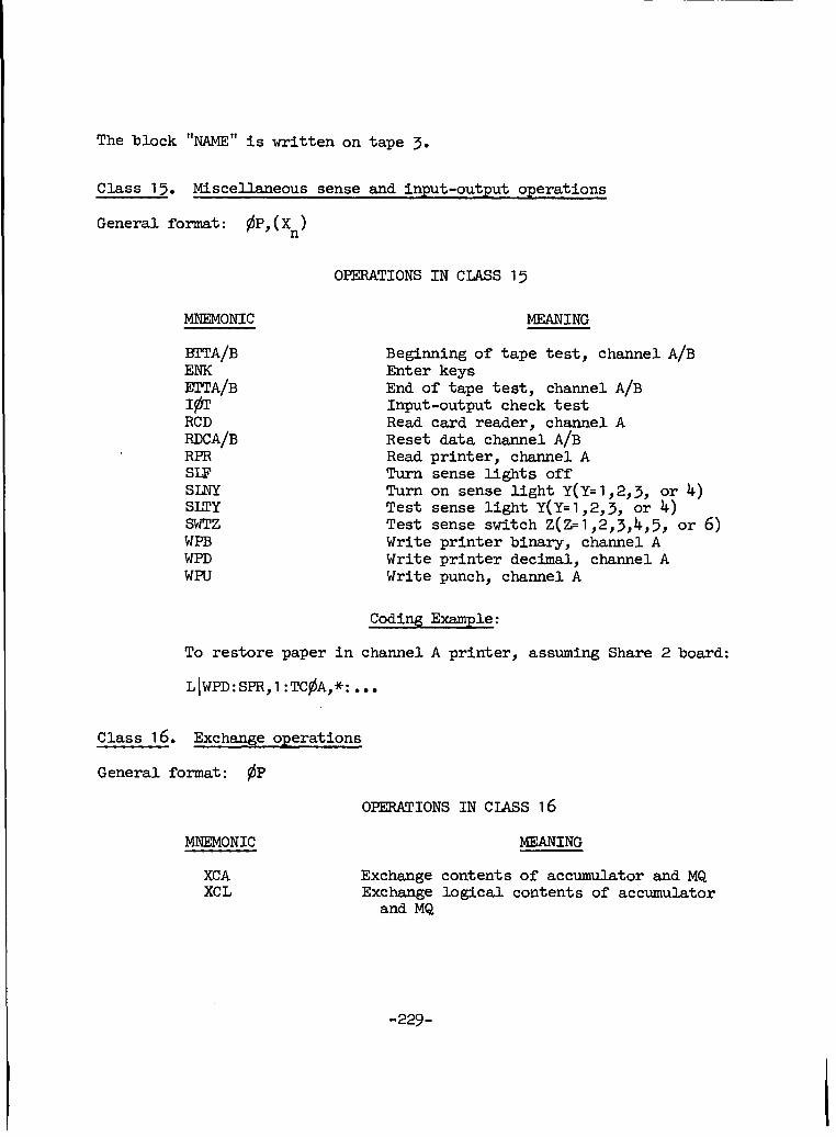
The block “NAME” is written on tape 3.
Class 150 Miscellaneous sense and input-output operations
General format: @p,(Xn)
OPERATIONS IN CLASS 15
MNEMONIC
BTTA/BENKEJ?TA/BI@RCDRDCA/BRPRSLFSLNYSLTYSwTzWPBWPDWPU
MEANING
Beginning of tape test, channel A/BEnter keysEnd of tape test, channel A/BInput-output check testRead card reader, channel AReset data channelA/BRead printer, channel ATurn sense lights offTurn on sense light Y(Y=I,2,3, or 4)Test sense light Y(Y=I,2,3, or 4)Test sense switch Z(Z=l,2,3,4,5, or 6)Write printer binary, channel AWrite printer decimal, channel AWrite punch, channel A
Coding Example:
To restore paper in channel A printer, assuming Share 2 board:
LIWPD:SPR,l:TC@A,*:...
class16. Exchange operations
General format: j$P
OPERATIONS IN CLASS 16
MNEMONIC MEANING
XCA Exchange contents of accumulator and MQXCL Exchange logical contents of accumulator
and MQ
-229-
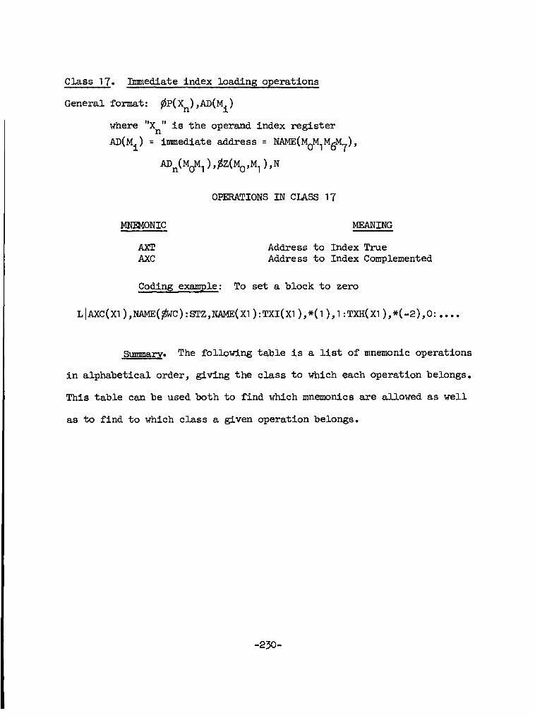
Class17. Immediate index loading operations
General format: Pp(Xn),@Mi)
where “xn” is the operand index register
AD(Mi) = immediate address = NAME(MOM1M6M7),
~n(M#&f$dMoJ$ )>N
OPERATIONS IN CIASS 17
MNIMONIC MEANING
Address to Index TrueAxc Address to Index Complemented
Coding example: To set a block to zero
LIAxc(xl),NAh@@C):wZ,w(Xl ):TxI(x1),*(l),l:T@xl),*(-2),o: ....
s~~. The following table is a list of mnemonic operations
in alphabetical order, giving the class to which each operation belongs.
This table canbe used both to find which mnemonics are allowed as well
as to find to which class a given operation belongs.
-230-

mlnNoloJcncd
mq..lnbln.lnln
Inu-l.
...-(n-
.r’oa)?o-.
-.u
-231-
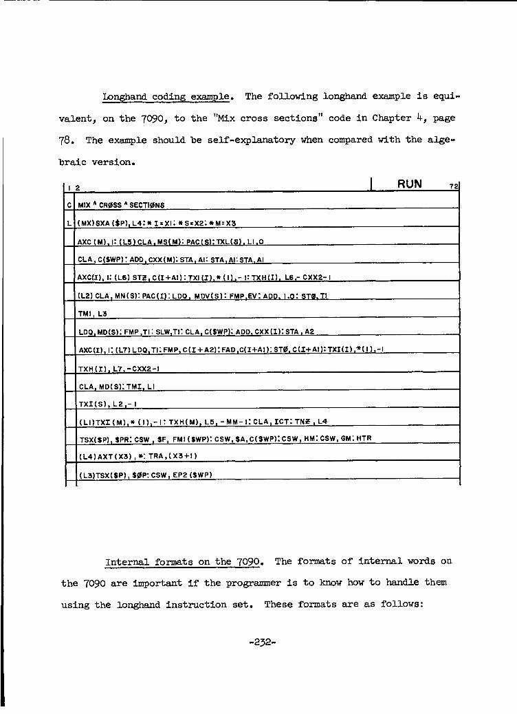
valent,
Ianghand coding example.
on the 7090, to the “Mix
The following longhand
cross sections” code in
example
Chapter
is equi-
4, page
78. The example shouldbe self-explanatorywhen compared with the alge-
braic version.
I RUN 77Ic , .-
C MIX hCRGfSSASECTIONS
L (MX)SxA($P),L4:* I=xI: *stx2:*M=x3
AXC(M),I: (L5)CLA,MS(M): PAC(S) :~L(S). Ll.O
CLA,C(SWP): ADO, CXX(M):STA,AI: STA,AI:STA,AI
AXC(I), I: (L6)STZ,C(I+AI): TXI (1),*(1),-I:TXH(I),L6,-CXX2-I
(L2)CLA, MN(S):PAC(I):LDQ, MDV(S):FMP.EV: ADD. l.O:STO.Tl
TMI, L3
LDQ, MD(S): FMP,TI: SLW,TI: CLA, C($WP): ADD, CXX(I): STA , A2
AXC(I), 1: (L7)LDQ, Tl:FMP, C(I+A2): FAD, C(I+Al): ST@, C(I+Al): TXI(I).*(l ),-l
TXH(I), L7, -CXX2-I
CLA, MD(S) :TMI, LI
TXI(S), L2,-I
(LI)TXI (M), *( I), -1: TxH(M), L5, -MM-l: CLA, IcT:TN=, L4
TSX(SP), SPR: CSW , SF, FM I(SWP): CSW, $A, C(SWP):CSW, HM: CSW, GM: HTR
(L4)AXT(X3), *: TRA1(X3+I)
(L3)TSX($P), SOP:CSW,EP2 ($WP)I
Internal formats on the 7090. The formats of internal wcnxison
the 7090 are important if the programmer is to know how to handle them
using the longhand instruction set. These formats are as follows:
-232-

1. Floating point words:
[S1 E I F I T I01 89 35
where S = the sign bit; E = exponent + 200B;F = normalized fraction; T = tag, if any.
2a. Fixed point words:
Is 100000000] N I01 89 35
where S = the sign bit; the next eight bits are alwayszero; and N is the fixed point number of 27 bits orless, right adjusted so that the low order bit occupiesposition 35.
b. Fixed point double-stored words, tag length P:
p[ooooooool Q I T I01 89 35- P 35
where S = the sign of “Q”; Q = the “Q” portion of 27-Pbits or less, ri@t adjusted so that the low order bitoccupies position 35-P; and T = the “T” portion, of Pbits or less, right adjusted so that the low order bitoccupies position 35.
3. Calling sequence words:
I $xXx I $WA Io 1718 35
where “$XXX” is the BCD representation of the characters“xxx”, right adjusted so that the last character loadedoccupies bit positions 12-17; and “#WA” represents thequantity, if any, in the “@WA” portion, right adjustedso that the low order bit is in position 35.
4. Control words, in symbol table and calling sequences:
Slool $Wc I F I $WA I0123 1718 X)21 35
-233-

where “S” is the sign bit, minus if “$WA” gives thethe address of a table of control words (e.g. fornumbered symbols) or of a particular control word(renamed blocks); lt@c’~i. the count of the block;
“F” is the control word flag, having values asfollows:
F MEANING
o data block1 longhand code block2 algebraic code block
remark block? index register symbol
5 not used6 calling sequence block
7 not yet defined as to content
“@A” is the address of a control word or of a table Ofcontrol words, or the base address of the named blockminus one.
-234-

APPENDIX 3
THE 7030 IONGHAND INSTRUCTION SET
Like the 7090 instruction set, the 7030 set is divided into
classes according to the types of addresses allowed. As a general rule
these classes follow the divisions of 7030 operations according to type,
as well. The reader is referred to the IBM Reference Manual, 7030 Data
Processing System, for descriptions of the operations and coding examples.
The organization of this appendix will follow that of Appendix 2 as
closely as possible.
Addressing conventions. In the description of each class of
operations, the symbols “AD,” “AE,” etc., are used to represent the al-
lowed address symbols for the particular class. Each class may use a sub-
set of the following set of
SYMBOL
NAME
NAMEn
$Cs
address symbols:
MEANING
The symbolic name of a data, remark, orcalling sequence block. This mayalso be the name of a numbered block
The nth element of data block “NAME”
The calling sequence block.
-235-

SYMBOL
jlcsn The
@D Any
#Dn The
nth elementblock
MEANING
of the calling sequence
of the subroutine data blocks
nth element of anydata blocks
An Store address syulbol
@Ln One of the elements of
of the subroutine
the “#L” block
$Z Zero or null address
Ln Name of an “L” entry
F Formula nzune
FS Formula set name
$s3 Name of an IVY subroutine
* Location of current instruction
x Fixed or floating point literal(decimal only)
N Absolute address equal to the number N
P Absolute address equal to the valueof parameter algebra P
Xn Address of nth index register
#P Address of the pathfinder register
#sn Address of system symbol n
system symbols. On the 7030, the special registers such as the
accumulator, factor register, etc., are addressable, and the’’j%nt’symbols
provide the ability to address these registers in any instruction.
-236-

Table A3.1 lists the system symbols, their meaning, and the absolute ad-
dress which will be assembled when these symbols are specified. The
address is given in tne form “word address.bit address”. In instruc-
tions which have less than a 24-bit address field, some of these ad-
dresses must be truncated to the nearest half or full word address to
fit the instruction concerned.
TABLE A3.I
SYSTEM SYMBOLS USED IN 7030 LONGHAND
SYMBOL
$s0#sl7s2$s3$k4$s5$s6$s7$s8$s9@slo$s11$s12$kil3$s14@sl5$S16$%’17$%18$s19
MEANING
location of zerointerval timertime clockinterrupt addressupper boundarylower boundaryboundary control bitmaintenance bitschannel addressother CPUleft zeros counterall ones counterleft accumulatorright accumulatorsign byte registerindicator registermask registerremainder registerfactor registertransit register
AmmEss
0.01.01.282.0
;:;23.574.05.126.07.177.448.09.010.011.012.013.014.015.0
In addition, the index registers can be directly addressed by using
the symbols “Xn” (XO,X1,...,X15) outside parentheses.
Address modifiers. In each class of operations, address modifiers
-237-

(which occur within parentheses following the address symbol) are repre-
sented by “Mi”, and each symbol is allowed a subset of the following set
of modifiers:
Mi MEANING—
‘ono modifier
‘1P (parameter algebra)
‘2Xn + P (parameter algebra
plus index register)
‘3Xn (index register)
‘4An (stored address)
‘5Xn + An (index register
plus stored address)
M6 @@ (control word position
%’ @WC/@A (controlword countor ad~ess)
If parameter algebra appears as a modifier (M1,M2), the result of the
parameter algebra modifies an address field appropriate to the instruc-
tion, e.g., 18 bits in floating point, 19 bits in branches} and 24 bits
in VFL. In the description of operations by classes, each description
contains notes on how parameter algebra modifiers are handled in the
particular class.
Operation modifiers. Certain classes of operations may be fol-
lowed by modifiers, which directly modify the operation itself. Opera-
tion modifiers “@i” follow the operation mnemonic enclosed in
-238-

modifiers are as follows:
MEANING
no modifier
N/U (normalized or unnormalized)
M (minus modifier)
MA (minus absolute modifier)
A (absolute modifier)
MD,F,B (MD = mode = B,BU,D, or DU; F and B =parameter algebra)
I (immediate modifier)
V*I/VtIC/VtICR (progressive indexingmodifiers)
bbbb (four bit binary connective)
IND(indicator mnemonic — see Class 9 forlist).
I/B/BI (immediate, backwards, and back-wards immediate modifiers)
Xn/P(index register or parsmeter algebra‘-count for transmits]
Ion@and instructions are separated from one another by colons.
The translation to machine language is strictly one-to-one, i.e., each
entry between colons corresponds to exactly one machine
(which may be a full or half word). The elements of an
separated from one another by commas and sets of closed
The general format of a longhand instruction is:
-239-
instruction
instruction are
parentheses.

I
:@P(@ )...(@@D(Mj),AE(Ml):i
Conventions are explained in the discussion of each class.
General form of a longhand code. Ion@and instructions are entered
on “L” cards, which may be intermixed with discretion in any desired man-
ner with “I” cards in order to supplement the algebraic code in as great
or small.a manner as desired. However, in this appendix we shall consider
longhand formula sets, i.e., complete routines or subroutines
longhand. The programmer interested only in inserting a card
longhand code into his program should have no difficulty once
concepts have been studied.
Ionghand codes are divided into formula sets, formulas,
coded in
or two of
the larger
and local
entries just as are algebraic codes. The same rules for referencing dis-
cussed in Chapter 5 also apply to longhand codes. However, the methods
of forming entry points and branches of course differ between the two
systems. Formula set names,
operation at the entry point
formula names, and L-entries precede the
in parentheses, thus:
(FS)@P,AD(Mi)
(F)@K~(Mi)
(Ln)@P,AD(Mi)
In branches to these entries, the name of the entry occus in the ad~ess
of the instruction outside parentheses, mcdified if necessary, e.g.>
B,FS(Mi)
B,F(Mi)
-240-

and so on for ot~ types of branch instructions.
Subroutine conventions. Internal IVY subroutines or subroutines
coded in the algebraic language must be entered by the two instructions
LVI($P),*:B,NAME
where “~P” is the pathfinder register and “NAME” is the name of the sub-
routine. On the 7030, the pathfinder register “@P” is synonymous with
index register X15. Thus the following entry is equivalent to the above:
If a subroutine
branch from a portion
LVI(X15),*:B,NAME
written in longhand is entered by a pathfinder
of the code in algebraic language, or by means of
one of the above instructions, one can use the first instruction of the
subroutine to store the pathfinder contents in some specified location,
if desired, thus:
(NAME)SV(@P),AD(Mi) or (NAME)SV(x15),AD(Mi)
Calling sequences. Calling sequences may be constructed after a
pathfinder branch to any subroutine by the use of the pseudo-operation
“CSW,“ as in 7090 longhand; for example:
LILVI(@P),*:B,NAME:CSW,@BC,GE(@P) :CSWj$CT2,CRA(@WC):CSW,l+TH:...
The IVY subroutines with variable length calling sequences (namely @Pj
#TP,POD,@l%,@PH,@MP,#DK, and $CM) require a “CSW” with no fields follow-
ing it after the last calling sequence word containing some sort of
entry. The compiler automatically inserts this zero word in calling
-24I-

sequences to these routines written in the al-gebraic code, but this is
not done automatically in the longhand system because, as mentioned pre-
viously, longhand code is translated in a one-to-one fashion. Thus, for
instance, to print a vector, the following statements should be used:
LILVI(~P),~:B,@R:CSW,~F,F@MAT(@P) :CSW,VECT@R(~WP):CSW:...
Calling sequence words and pathfinder branches take up full words
on the 7030 when translated. Thus, as a general rule, one should enter
pathfinder branches in any alternative exits from a subroutine; this
must be done when the subroutine is coded in the algebraic language.
Longhand subroutines, of course, can be coded to take half word exits
into account, if desired.
Definition of “$D” blocks. Definitions of “@D” blocks in longhand
code must be entered between a single pair of colons immediately follow-
ing the first instruction of the formula set; for example:
L (FS)SV(SP,AD(Mi):@D(~),@C(3) = 2.156,3.172,5.171,
$DH(5,9,1O),ZDM(5O) = 5.152,(S)47,5.213,5.215:...
The format for defining “~D” blocks is otherwise the
for defining them on “I” cards, discussed in Chapter
Since “~D” definitions represent instructions to the
sane as the format
5, pages112-114.
compiler, a 7030
instruction is not, in this case, assembled to correspond
tion between colons.
Renaming. One may rensme an index register with an
to the informa-
alphabetic sym-
bol in the same manner as on “I” cards, by entering between colons as
-242-

follows:
:*S~@L = Xn:
Again, since this entry represents an instruction to the compiler, no in-
formation is assembled.
Storing addresses.
fields of “store value in
The “An” symbols may be used in the address
address” instructions, and the address being
stored will be placed in instructions having addresses modified by this
same “An” symbol. In longhand coding, instead of using “An.m” to specify
the number m of “store value in address” instructions, one must instead
write down all “m” instructions needed. For example:
L Lv(xo),FRN(@w):V+(XO),FRNX(XI):SVA(XO),A1:SVA(XO),AI:SVA(XO),AI
...LET(N).F@x2+A1 ):*+(N),FTtN(x2+Al):....ST(N).FRN(2+A1A1):...
However, it should be noted immediately that the above technique is not
recommended. The “SVA” instruction is very slow, and when several are
used in sequence as above, even slower. Instead, some temporary location
and a free index register should be used to simulate the “SVA”. This iS
what IVY actually does in the translation of such a code written in
Algebraic language. Thus the above is better written as follows:
L L(U),FRN(SW):+(U),IRNX(X1):ST(U),D1:...
..JlJ(X14),D1(l):LVS(X14),X2,X14:Ll?r(N),#Z(X14):*+(N),@Z(X13):.0.:
sT(N),s~(x14):...
where “D1” is some suitably chosen temporary location. Note that unnorma-
lized floating point is always used in address computation; all so-called
“fixed point” numbers are always stored and operated’upon as unnormalized
-243-

floating point, with an exponent of zero and the low order bit in bit
position 49. Also note that the effective address of instructions with
a stored address is computed by placing the sum of the computed address
and of the modifying index register into a spare index register, and
placing an address of zero (~Z) in the instructions with “stored” ad-
dresses. This technique should always be used; if possible, “SVA”
should never appear in a code.
Further restrictions on longhand coding.
1. Only fifteen index registers (XI,X2,...,XI5) are allowed asmodifiers in 7030 longhand coding. In addition, however,index zero, XO, is allowed as an oprand in indexing opera-tions or in the address field of other operations.
2. The programmer should note that X15 is used not only tosimulate the pathfinder register, but also to simuhte X13,x14, X15, X16, etc., in the algebraic code. (Xl3 and Xl4are used to simulate the store address in algebraic code,and for other temporary purposes). Thus, if a longhandcode consists only of a few cards inserted in the middleof the algebraic code, the programmer must save the con-tents of X15, or the contents of the last index registerabove X12 to which he has referred, to ensure that itsprevious contents, if needed after the longhand segment,are not destroyed. This can be done in two ways:
a. In the algebraic code:
II...)Tl = Xn
L!... (Longhand Code)...
IIXn=Tl,...
where “X “ is the last index register aboveX12 refe?red to by the algebraic made~ and “T1” issome suitably chosen temporary lo@atton; or
b. In the longhand code:
-244-
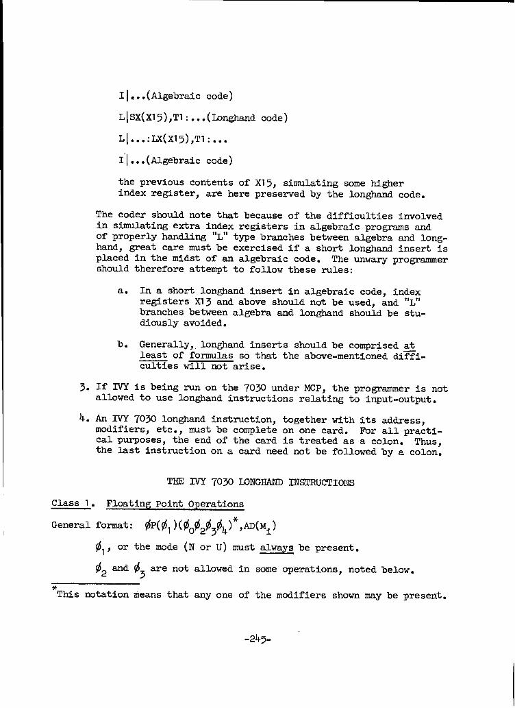
3.
4.
Ii...(Algebraic code)
LlSX(X15)jTl:.o.(tinghandcode)
LI....IX(Xl~).Tl:...
1“1...(Algebraic code)
the previous contents of X15,simulatingsomehigherindex register, are here preserved by the longhand code.
The coder should note that because of the difficulties involvedin simulating extra index registers in algebraic programs andof properly handling “L” type branches between algebra and long-hand, great care must be exercised if a short longhand insert isplaced in the midst of an algebraic code. The unwary programmershould
a.
b.
therefore attempt to follow these rules: - - –
In a short longhand insert in algebraic code, indexregisters X13 and above should not be used, and “L”branches between algebra and longhand should be stu-diously avoided.
Generally,.longhand inserts should be comprised atleast of formulas so that the above-mentioned di~i-culties will not arise.
is being run on the 7030 under MCP, the progrsnmer is notIf IVYallowed to use longhand instructions relating to input-output.
An IVY 7030 longhand instruction, together with its address,modifiers, etc., must be complete on one card. For all practi-cal purposes, the end of the card is treated as a colon. Thus,the last instruction on a card need not be followed by a colon.
THE IVY 7030 LONGHAND INSTRUCTIONS
Class 1. Floating Point Operations
General format: @p(@l)(@Op~@3@~)*,~(”i)
@l, orthemode (Nor U)mustalways represent.
$2and 943are not allowed in some operations, noted below.
*This notation means that any one of the modifiers shown may be present.
-245-

@l@ l@Dl?Dn(M~~1~f2M3M6),7Ln(~40),zz(Mo~41M2My4M5),M ) F(MOM1M2M3),FS(M& M2~4$f6)>LJM&41i2 ~ ,
X,N(M3)Jn(MoM1M2M5))* (MOM1My~4M5)j
$SJM0141M2M5).
Parameter algebra in parentheses modifies full word address(18 bits).
In E k I, SHFL, and SHFR, i.e., the floating point immediate
operations, the forms of address allowed are
p(MOM3)~N(~M3)J> and $Z(MOM1M~y4M5)0
The addresses of these instructions are computed and insertedas 11 bits plus sign. In these cases, “P” in parentheses mo-difies the 11 bit field.
OPERATIONS IN CLASS 1
MNEMONIC MEANING ,,x!t-J-y$2,@5 -
+ Add+MG Add to magnitude
Subtract-MG Subtract from magnitude* Multiply*+ Multiply and add
Multiply and subtract
7- DivideD+ Add doubleD+MG Add double to magnitudeD- Subtract doubleD-MG Subtract double from magnitudeDL Ioad double xDLWF Ioad double with flag x
*This notation means that any one of the modifiers shown maybepresent.
-246-

MNEMONIC
$E+E-I-IE-E-IF+F-KKMGKRKMGRL
M+M+MGM-M-MGR/SHFSHFL
:y
SRDST
MEANING
EXAMPLE
+(N),5.96j2-06
~(N),6(x3)E+(N),cNu(xI)E-I(U),16E-I(u),pz(16)E-I(U),(16)
Multiply double xDivide double xAdd to exponentAdd immediate to exponentSubtract from exponentSubtract immediate from exponentAdd to fractionSubtract from fractionCompare xCompare magnitude xCompare for range xCompare magnitude for range XIaad xLoad factor register xLoad with flag xAdd to memoryAdd magnitude to memorySubtract from memorySubtract magnitude from memoryReciprocal divide xShift fraction xShift fraction leftShift fraction rightStore low order xStore root xStore rounded xStore x
EXAMPLES:
MEANING
Add indicated literal to contents ofaccumulator
Load factor register with C(6+vF[x3])Add EXP(CNT3+C[X1]) to exponent of accumulatorSubtract 16 from exponent of accumulatorSame as above. Note alternative formSame as above. Note alternative form
-247-

class 2. Variable Field Length (vFL) Instructions
o~, the mode, field len@h, and bfiesize, must always represent
In to-memory operations,noted below, the 96 or ~e~ate modifieris not allowed
Some operations noted below do not permit the 02 modifier
AD(Mi), the memory reference, has two interpretations) dependingon whether or not the @6(immediate) or @ (Pro~essiveindexing) modifier is specified. 7
1. Direct: AD(M.) = s~e as class 1. The P modifier in paren-
theses mod.ifi~sbit addresses (24 bits).
Immediate: AD(Mi) = Nl@MoM11”&yM6~ )*,2.
In all cases where $$1is specified, the result of P in paren-
theses and of N outs de parentheses is shifted properly anda sign byte is constructed, according to the mode, fieldlength, and byte size specified. Norma~y when @6 Or @ isspecified the “~Z” and “N” entries shouldbe used to ob~ainimmediate operands. The other entries supply addresses forthose unusual cases where addresses are to be operands.
AE(MJJ, the offset field, = P(MOJ43)only.
OPERATIONS IN CLASS 2
MNEMONIC MEANING f46-~ 02 AIMWED
+ Add x+MG Add to magnitude x
Subtract x
*This notation means that the modifiers which appear must be separatedby commas as indicated.
-21&
I

MNEMONIC
-MG**+
7-CVDCVKKEKF
KRL
13Rcv
L!rRsIMFM+M+lM+MGM-M-1M-MG
ST
EXAMPLE
MEANING #6 ALLOWED
Subtract from magnitudeMultiplyMultiply and addMultiply and subtractDivideConvertConvert doubleCompareCompare if equalCompare fieldCompare field if equalCompare field for rangeCompare for rangeLoadLoad convertedLoad factor registerLoad transmit register
convertedImad transit and setIoad with flagAdd to memoryAdd one to memoryAdd magnitude to memorySubtract from memorySubtract one from memory
xxxxx
xxxxxxxxx
xxx
Subtract magnitude from-memoryStore roundedStore
EXAMPLES:
+(J?U)6,1)(I),27,16(X1) Add 27 to contents16 i-C(N).
L(B,17,2)(v+Ic),8(x2),FsT Load the number in
$2 ALLOVED
x
xxxxxxxxxxxx
xxx
xx
MEANING
of accumulator, offset
location VF(X2). add8 to VF(X2),subtract 1 from CF~X2).Offset = C(FST)
ST(BU,64),STR3 Store right accumulator in STR3
M-(B,16,1),@12(16),2 Subtract a field from the right accumu-lator, offset 2, from field of samelength starting at bit 16 in leftaccumulator.
-249-

Class 3. Connective Operations
General format: @p(#5)(@8)(@o@6@7),~(~~i),~(Mj)
This class is similar to class 2 (just considered) except for thefollowing:
1. The mode specified in 95 must be BU.
2. The connective modifier @Q must always be present. The minusmodifier ~ is never allowed.
2
3. No sign byte is ever constructed
OPERATIONS IN
MNEMONIC MEANING
c ConnectCM Connect to memoryCT Connect for test
for immediate addresses.
CLASS3
936~~
x
x
-EXAMPLES:
EXAMPLE MEANING
[
CM(BU,l,l) 1111),@15(63) Turn on noisy mode indicatorc(Bu,64,8)0111),ARF1,20 “Or” (inclusive) contents of ARl?l
and accumulator, offset 20C(BU,24,1)(OOOO),0 Clear accumulatorCT(BU,FN+3,8)(O011),PLN(64+x3) Test indicated memory field
for zero
class 4. Direct Index Arithmetic.
General format: oP(xn),AD(14i)
where Xn is the operand index register
~(Mi) = same as class 1. P in parentheses may, in theseoperations, modify full word (18bit) or half word (19bit)addresses, as indicated below.
-250-

MNEMONIC MEANING
KC Compare countKV Compare valueIc Load countIll Ioad refill
LV Iaad valueLWX Ioad value
effectiveLX bad index
Rename index
OPERATIONS IN CLASS 4
P MODIFIES MNEMONIC
19 bits Sc19 bits SR19 bits Sv19 bits SVA
19 bits Sx19 bits v+
18 bits V+c
18 bits V-I-CR
MEANING P MODIFIES
Store count 19 bitsStorerefill 19 bitsStorevalue 19 bitsStorevaluein 19 bitsaddressStoreindex 18 bitsAdd to value 19 bits
Add to value, 19 bitscount
Add to value, 19 bitscount,andrefill
Q2ssL2” This class is composed“Load value with sum”.
LVS(Xn)JijXj~ •O~)Xm
of the single operation “LVS,” orThe format of this operation is:
where Xn is the operand index register and the others arethe index registers the sum of whose value fields areplaced in the value field of Xn.
Class 6. ImmediateIndexArithmetic
Generalformat: @PAD
whereXn is the operandindexregister
AD(Mi)= NWMoM1~M&) }xn/$sn(MoM,)>#cs/@(MoM1Jqs
FS(M&$jM6~)>@(M$$M4)}*(MoM1M4)>N
The resultof “P” in parenthesesand “N”maybe placedin an 18-bitor 19-bitfieldin the instruction,asnotedbelow. NormalJythe “@Z”and “N” entriesareused;the otherentrieslistedabove supplyaddressfields,in the rare caseswhen theseare wantedasoperands.
-251-

OPERATIONS IN CLASS 6
MNEMONIC MEANING
C+I Add immediate to countc-I Subtract immediate from countKCI Compare count immediateKVI Compare value immediate
LENGTH OF P OR N
18 bits18 bits18 bits19 bits
C~are valuenegativeimmediate 19 bitsLCI Ioad countimmediate 18 bitsIRI bad refiKlimmediate 18 bitsLVI Ioadvalue immediate 19 bitsLW bad valuenegativeimmediate 19 bitsV+I Add to valueimmediate 19 bitsV+IC Add to valueimmediate,count 19 bitsV+ICR Add to value immediate,count,refill 19 bitsV-I Subtractfromvalue immediate 19 bitsV-IC Subtractfromvalue immediate,count 19 bitsV-ICR Subtractfromvalue immediate,count, 19 bits
refilJ.
=“ Pseudo-operationsto aid in indexi~
Theseoperationsare used to constructindexwords,value
fields,etc.,which canbe loadedinto indexregistersusing someof the
indexinginstructionsdiscussedabove. Each has a distinctformat,and
these shouldbe studiedcarefuKly.
PSEUDO-O-ION
VF,AD(Mi)
CF,AD(Mi)
MEANING ADDRESSES ALLOWED
value field Same as Class 6. A signed,2&-bitaddressis assembledat the nexthalf-wordlocation. “P”and “N”are 24-bitquantities.
countfield Same as Class6. An unsigned,18-bitaddressis assembledat the nexthalf-wordlocation. “P”and “N”are 18-bit.quantities.
-252-

PSEUDO-OPERATION
RF,AD(Mi)
MEANING ADDRESSES ALLOWED
refill field Xn/$Sn(MoM,).*(ltoM,),
Ln(MoM1) F/FS(MoM1),$’CS/$CS,(MoM,)
~D/$Dn(MoM1),NAME/NAMEn(MoM1).
An unsigned, 18-bit address isass.]medas the neat half-wordlocation. “P” is an 18 bitquantity.
XW AD(Mi).AE(Mi), index word First field: same as “VF.”
AJ@J,pSecond field: same as “CF.”Third field: same as “RF.”Fourth field: parameter algebra
for flag bits, < 7.A 64-biti~dex
at the next
EXAMPLESOF INDEXARITHMETIC,ETC.
wor~ is assembledfull-word location.
EXAMPLE
V+I(X1),8
C+I(X2),8
v+(x3),L1:....(L1)vF8-8
XW,PRF(@A),PRF(#WC),*
Value field of Xl8 half-words
Count field of X2
Value field of X3
Indexword:value
MEANING
is incremented by
is incremented by 8
is decreased by 8 bits
fieldcontainsaddressof PRF, count field contains count, re-fill field contains address of currentinstruction
class 8. Unconditional Branching, Execute, and Refill
General format:
AD(Mi) =
@P.AD(Mi)
?Z(M1M344J5)>Ln/F/Fs/*(Mo~,M2~f14M5) t
$kR(in branches only, if preceded by “LVI(~P),*”)
“P” in parentheses modifies half word addresses(19 bits) except as noted.
-233-

MNEMONIC MEANING
BBDBEBEWBRCN$P
EXEXICN#PRRCZ
EXAMPLE
B,*(5)BR,(5)
BranchBranchBranchBranchBranch
disabledenabledenabled and waitrelative
Conditional no operation (inserted onlyif location counter is not set atfull word)
ExecuteExecute indirect and countNo operationRefill (P modifies 18 bits)Refill on count zero (P reedifies18 bits)
EXAMPLES:
MEANING
Branch to fifth half word followingBranch to fifth half word following
Class 9. Indicator Branching
General format: @p(@9), @Mi)
@9isone of theindicator mnemonics listed below, or itsdecimal numerical equivalent.
-254-

MNEMONIC
ADAEAHALBTRCBJCPUSCsDFDS
EEEKEKJE#PEPGKEXEIFIJIKIRLCIsMKM@P
;
PGO-K6PSH
TABLE A3.2
INDICATORMNEMONICSAND DECIMALEQUIVALENTS
RGZRLZRNRURZTFTSUFUK
DECIMAL
%626039851320
z11
2129182121
252226
5;63152341-4727
5856593457354
3610
MEANING
Address invalidAccumulator equalAccumulator highAccumulator lowBinary transitChannel busy rejectCPUsignalChannel signalData fetchData storeDecimal transitEnd exceptionExchange control checkExchange check rejectEnd of operationExchange program checkExecute exceptionInstruction fetchInstruction rejectInstruction checkImaginary rootLost carryIOst significanceMachine checkTo-memory operationNoisy modeOperation code invalidPartial fieldI&ogram indicators o-6Preparationshiftgreaterthan 48
Resultgreatertnan zeroResultlessthan zeroResultnegativeRemainderunderflowResultzeroT flagTime signalU flagUnit check
-255-
—

TABLEA3.2 (continued)
MNEMONIC
UNRJUSAVFXczXEXFXHXLXPFPXPHXPL
@
XVGZXULZXvzZDZM
DECIMAL
717374853m545228303129325149502433
MEANING
Unit not ready rejectUnended sequence of addressesv flagIndex count zeroIndex equalExponent flagIndex highIndex lowExponent flag positiveExponent highExponent lowExponent overflowExponent underflowIndex value greater than zeroIndex value less than zeroIndex value zeroZero divisorZero multiply
For Class 9, AD(Mi) = same as Class 8, exceptonly Xl can
participate in modification.
MNEMONIC
BIBIZBZIBZIZ
OPERATIONS IN CLASS 9
MEANING
Branch on indicatorBranch on indicator and set to zeroBranch on zero indicatorBranch on zero indicator and set to zero
EXAMPLE:
BI(NM),L3 (or BI(63),L3): Go to L3 if “NM” indicator is on
-256-

Class 10. Bit Branching
General format: @P,AD(Mi),AE(M~)
AD(Mi) = same as Class 2 (direct)
AE(M4) = same as Class 9d
MNEMONIC
BBBB1BBNBBZBZBBZBIBZBNBZBZ
BB1,$!s15(63),*(2):to
Class 11. Index Branchinq
OPERATIONS IN CLASS 10
Branch onBranch onBranch on
Branch on
Branch onBranch onBranch onBranch on
turnnext
EXAMPLE:
General format: @P(Xn), AD(Mi)
where Xn is the operand
on noisy modeinstruction
MEANING
bitbit and set to onebit and negatebit and set to zerozero bitzero bit and set to onezero bit and negatezero bit and set to zero
index register;
indicator ahd go
AD(Mi) = same as Class 9
OPERATIONS IN CIASS 11
MNEMONIC MEANING
CB Count and branchCB+ Count, branch,CB- Countj branch,CBH Count, branch,
Count, branch,cm+ Count, branch,
wordcBR- Countj branch,
word
and increment value by full wordand decrease value by full wordand increment value by half wordand refillrefill.and increment value by full
refill, and decrease value by full
-257-

I
MNEMONIC MEANING
CBRH Count, branch, refill, and increment value by half wordCBZ Count-and br&chCBZ+ Count snd branchCBZ- Count and branchCBZH Count and branchCBZR Count, branchCBZR+ Count, branch
full wordCBZR- Countj branch
full wordCBZRH Count, branch
half word
LIIX(X1),L1:Z,(XI):CB+(X1),
onon
on
on
.on zeroon zero and increment value by full wordon zero and decrease value by fulJ.wordon zero and increment value by half wordzero, and refilJzero, refill.,and increment value by
zero, refill, and decrease value by
zero, refill, and increment value by
EXAMPLE:
*(-1):...:(Ll)xw,BxT(@A),BxT(@4c):...
Set block “BXT” to zero
Class 12. Data Transmission Operations
General format: @p(@ll)(@o? )>~(Mi),AE(M3)
@l, = Xn in direct operations, _P < 15 in immediate operations
I@Mi)#E(MJ) = same as C1.aSs 1
OPERATIONS IN CIASS 12
!!W!@& MEANING
T TransmitSWAP Swap
EXAMPIE:
T(15)(I),XI,NAME:Save all 15 indexregistersin block “NAME”
Class 13. Two MiscellaneousOperations
General format: @, AD(Mi)
@Mi) = sae as Class 1. P modifies 18 or 19 bits as notedbelow
-258-

OPERATIONS IN CLASS 13
MNEMONIC
SIC
I
MEANING
Store instructioncounterif ...(mayprecedehalfword branchandindicatorbranchonly) (P modifies19 bits)
z Store zero (P modifies 18 bits)
The following table summarizes all 7030 longhand instructions
for quick reference purposes.
-259-

MNEMONIC CLASS
* 1,2+JG 1,2* 1,2* 1,2** 1,2/ 1,2B 8BB(l,N,Z) 10BD 8BE 8BEW 8BI(Z) 9BR 8BZB(l,N,Z) 10BZI(Z) 9c 3cWJ 6CB(+,-,H) 11CBR(+,-,H) 11CBZ(+,-,H) 11
CBZR(+,-,H)llCF 7CMCN@P :CT 3Cv 2D* 1D~G 1
TAB~ A2.3
7030LONGHANDMNEMONICSAND CL4SSES
MNEMONIC
D*
D/
DLDIMFE*(I)
EXEXICF*
KKC(I)KEKF
KMGKMGRKRKY(I)KVNIL
J.C(I)
Illv
Ill(I)13Rcv
CLASS
1
1
22111
:1
i;:222211
$:)
1,2
4(6)
21,24(6)2
MNEMONIC CLASS
2z) 2(6)LVNILYE 4LVS 5
1,2LX 4M* 1,2M*MG 1,2M~~
N@P :R 8R/RCZ :RF
:se 4SHF(L,R) 1SIC 13sL# 1
SR 4
1,2
SRT 1ST 1,2Sv 4SVA 4
MNEMONIC
SWAPSx
Tv+~~~v-l-cV*ICV-I-CRlJfICRV-FXwz
CLASS
i24
12464
t677
13
-260-
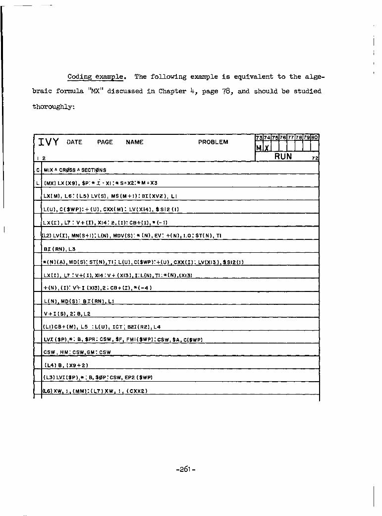
Coding example. The following
braic formula “MX” discussed in Chapter
thoroughly:
example
4, page
is equivalentto the alge-
78, and shouldbe studied
Ivy DATE PAGE NAME PROBLEM73j74j75176177178179180
Mtd 111112 RUN 72,1
CIMIXACRGiSSA SECTIQJNS I
L (MX)LX(X9), $P:*X=XI:* S=X2:*M=X3
LX(M), L6:(L5)LV(S), MS(M +I):BI(XVZ), LI
L(U), C($WP): +(U), CXX(M): LV(X14), $S12(I)
LX(I), L7:V+(I), X14: Z,(I) :CB+(I), *(-1)
(12) LV(I). MN(S+I): L(N) .MDV(S): *(N)> EV: +(N), 1.0: ST(N). TI
BI(RN), L3
*( N)(A), MD(S): ST(N), TI: L(U), C($WP):+(U), CXX(I): LV(X13), $S12(I]
LX(I), L7 :V+( I),X14:V+ (X13), I: L(N), TI:*(N), (X13)
+(N),(I): V% I (X13),2:CB+(I), *(-4)
L(N), MD(S): BI(RN), LI
V+ I(S), 2: B,L2
(LI)CB+(M), L5 :L(U), ICT; BiH(RZ), L4
LVI($P),*: B, $PR: CSW, $F, FM I($WP): CSW, $A, C($WP)
CSW, HM:CSW, GM: CSW
(L4)B, (x9+2)
(L3) LVI($P),* : B, $OP: CSW, EP2 ($WP)
(L6)xw, 1,( MM): (L7)xw, I, (CXX2)
-261-

I
Internalformatson the 7030. The formatsof internalwordson
the 7030 are important if the programmer is to know how to handle themII using the longhand instruction set. These formats are as follows:
1.
2a.
z%.
Floating point words:
I E 5 F I Y TUV s
o 10 1112 59 63
where E = exponent; ES = exponent sign; F = normalizedfraction; T = tag, if any; TW = flag bits; S = fraction sign.
Fixed point words:
o— O1o1 N ]0—OITUVIS
o 1o11 12 32 49 59 63
where N = fixed point number of 37 bits or less, rightadjusted so that the low order bit occupies position 9;TUV = flag bits; S = sign. Note that fixed point num-bers are in reality floating point words, umormalized,with exponent = O. The number is a&justed so that itcan be loaded into a value field by addressing the se-cond half word.
Fixed point double-stored numbers, tag length
o—q 01 Q 1001 T ITUVI S
o 101112 49 59 63
P:
P<lo
o —Olol Q I T ITUVI S P> 10
0 1o11 12 49-(P-10) 59 63
Where Q = the “Q” portion, of 37 or 37-(P-10) bits orless. ri~t ad,justedso that the low order bit appearsin bit 45 or 4~-(P-10); T = the “T” portion, riti~ ad-justed so that the low order bit
= flag bits; S = the sign of~c~upiesposition59;Q.
-262-

3. Calling sequence words:
jo —Olol $xXx Iool $WA 10—010001s1o 1o11 12 29 32 49 60 63
where “#XXX” i.sthe BCD representation of the character“m, “ right adjusted so that the last character loadedoccupies bit positions 24-29; and “$WA” represents thequantity in the “#WA” portion, right adjusted so thatthe lcniorder bit occupies position 49.
4. Control words
o— O1o1 $Wc Iool $WA 10—01 F ISo toll 12 29 32 49
-263-
‘lhequantities“@C,” “@WA,”“F,”and “S”are governed
by the sameconventions as in the 7090 control word,discussed at the end of Appendix 2.

M 18AII IIAt,t?A
N&T&
c~d, 35-37entry, in loadingdata, 51modifierin algebra,78-79in fixed point, meaning,87
INDEx
Special symbolsare found as follows:“*” is found in the A’s asterisk);
[“@” Is found in the D‘s dollar).
BCD charactersTable III, 66Table 9.1, 186
Binary cards, relocatable,loading of, 58-39Binary key 63, to controlon-lineprinting
in Index algebra,meaning,90,170 50,150,133Accuracy of results,166-167 Binary tapeAddress modifiers,j’k-83
al-lowedwith symbols,191-192in 7050l.on@nd, 235-236in -pgo longhand,211-212table of, 193
Advance film, 148Algebra
machine and CMsplay, compexativeexamples,eulnnary of, 1goff.see also type of algebra desired
An see stire *ess
Arraysdefinitionof, 48-49loading,on “D” cards, 49-53printingof
form of printout,135ff.calling sequencewords for, 1~Off.
Assembly card, 35-37AssemblyprOgX’81D,119-120
CSIMng sequence, 197coding examples,204-207
Assignmentof spacefor ce.lMng sequences,64for data, 48-49for remarks,63
“*” card, 22-23“*” convention,algebra,55,91“*” convention,longhand,211,236Axe8, generate,microfilm,152
“B” cards,23-26“B” entry, loadingdata, 50“B” modifier,in algebra,78-79,96Backspacetape, 12.2-123
see tapeBoolean
aJ.gebra,93-96I.iterale,in loading data, 51modifier,inal.gebra,78-79operations,190
Branchfng7off. conventions,table of, 116-117
to end of calling sequence,105-106ff.fO-, 102-103formula set, 103-104local, 97-102table of types, Table 9.8, 195in 7030longhand,240ff.in 7090 longhand,213ff.
“C” cards, 30-31CeJ.llng sequenceblock (“@J”)
set by “@w,” 127set by “@P,” 123set by “@l?,” 129
CalJlng sequenceblocks (definedon “K” cards)altering,coding examples,180,182-lEWdefinitionof non-numberedsymbolsfor, 47tiding of, 64-67numbered symbolsused for, 18,33
Celllng sequencewordsaddressing,108ff.altering,examples,180,182-ltU+conventions,Table 9.9? 196foxmat for, 65-67in 7030I.oiwtuuld,=’klff.7030 intarnalfo=t, 263in 7090 longhand,2147090 Intemd. format,233
-264-

Calllng sequencesaddressingentries in, 108ff.altering,toting examples,176-184in code, 105on “K” cards, 64-67returns b, 105-106ff.
Card punches,Table 9.1, 186Card types, ‘22-42
tables of, 42,189Charactermanipulationprogram, 1~-l 56
c- sequence,202Characters
card characters,punches, etc., Table 9.1,186Eollerith,and octal.equivalents,Table III, 66plotting,and decimal equivalents,Table VIII,151set used by IVY, 17
Classes of operations7030 longhand,2607090 longhand,231
Code, complete,4, 173-176Coding examples,78, 99, 113, 155,156,162-184
70Y3 longhand,2617090 longhand,232
coding forms, 21example,4,232,261
Colonused to separatecalling sequencewords, 64,105used to separatelonghandinstructions,212,239
Columnbinary cards, relocatable,loadingof, ~-~Column indices,in printing, 133,135Comment cards, 30-31Compare remark characters,1m-l 55ff.Complete code, 4,173-176Concisenessof code, 167-168Conditions
for conditionalbranching,98for Jump features,56
Console key 35, to controlon-llneprinting,30,130,133
Continuationof algebraicstatements,86of entrieson “D” and “#E’’cards,47of types of cards, table, 42not permittedin longhand,218,245
Continuedfractions,coding example,72Control characters,in format, 133Controlpunches, 21-22
see also, individualcontrolpunches(“A,” “B,” etc.)
Controlworddescriptionof, 18in error detection,19-207030 format, 2637090 fonsat, 233-29
Control word sndifiersin addressingca.1.llngsequences,I@-l@in algebra,82-83in calling sequences,65-67
CSW pseudo-operation,21k,2klff.
“D” CLWdS, 31definitionof parameterson, 4>44,46definitionof symbolson, 43-49format of, 43-57loadingof data on, 49-53ausmb9ryof entries on, 60-61
Datadefinition,on “D” cards, 43-47double-stored,entry on “E” cards, 59-59
e@*ent bbcks, 55loading,on “D” cards, 49-53,62loading,on “E” cards, 57-59,60printing of, l~ff.plXIChiIlg of, 146-147reading or writing on tape,33-35suppressed,49use of jump feature,55-56
Decimal equivalentsof 7050 indicatorEUle1710UiCS,255-256
Decimal equivalentsof characters,Table 9.1,186
Definitioncards, 31definitionof parameterson, 43-44,46definitionof symbolson, 43-49format of, 43-57loading of data on, 49-53
Differenceof squares,example, 167Dimensions
see arrqwDirect algebra
fixed point, 87 ff.index register,90,100,170
Disk program, 152-153calling sequence,201used to “ping-pong”code, 209
“~” symbols,17-18$CS, 84-85, 123,127,129@D, 8>,110-114,215@E, 115$&,85-86,191,204ff.@, 84,96$P, lolff.$z,85,108-109,211not allowed in calMng sequences,105subroutines,118-156table of, Table 9.2, 187ff.
Double-storeddatacoding examples,171-173entry of, on “E” cards, 58-59modifiers for addressing,79-80, 83-84printing of, 143-144punching of, 1477030 internalformat,2627090 internalformat, 233
Dump program, octal, 130-131Dynamic algebra
fixed point, 88index register,90,100,170
-265-

“E” C81Xh3, k
format for, 57-59sums.v of entries,Table II, 61
“E” entry in data loadlng,53,,61Efficientcoding, 162-168End-of-file
on card reader, 119on tape, 122
Enter data card8, Wformat for, 57-59summaryof entries,Table II, 61
Entries, reference point, Table 9.8, 195Equal sign, megning of, 68
symbolsallowed left or right of, 191Equivalentblocks
definitionof, 55{61restrictionson, ‘E”cards, 57-%
Errorscontrolword in detectionof, 19-20detectionof, 14-16indicationsof, 157-161
by “$DK,” 153by “@R,” 145by “@P,” 124
Examplessee coding examples
Execute card, 39-40Execute instruction,115Exponent digits, in printing, 139Expressionmdlfiers, 83-84
“F”cards, S-39FAC, 85-86, 191FAD, 85-86, 191Fixed point algebra,86-89
modifier,78-79operations,190
Fixed point Iiteralsin definitionof arrays, 48in loadingof data, X,51
Fixed point numbersprinted as integers,133punched ae integers,14770Y3 internalformat, 26270g0 internalformat,233
Floatingpofnt algebra,69-86allowed operands,73exunples,70ff.operations,190
Floatingpoint Iiteralsin algebra,73in loadingdata, 51in 7050 longhand,236,246-247in 7090 I.onghand,211,219-220
Floatingpoint numbers7030 internalformat,2627090 Internalformat,233
Formt statements,for printing 132ff.manipulationofcharactersln, 154-1!%sumnaryof conventions,lgg-200
Formts, card, Table 9.3,189
Formulabranchi~ between, 102-103de.?initi~nof, ~“entries,Table 9.8, 195jump feature,104-105may not be written on tape or disk, 208names. defined on “I” or “L” CardS~
31,-40-41names. not definedwhen “A” card encon-ter;d, 35
number of, 27organization,diagram, 114in 703%310nghana,240 ff.in 7090 longhand,213 ff.
Fonmila setbranchingbetween, 103-104definitionof, 27entries,Table 9.3, 195jump feature, 104-105names, assignedto relatable bl.ocks~x~es, defined on “D” cards, 31,,40-41,47organizationof, diagram, 114writing of, on ape or ~sk~ 2@in 70Xl IDnRhand.240 ff.in ~OjO I.On∧ 213ff.
Forward mace tape. 123IYaction‘&gLts,-ii printing, 1x
Generateaxes, microfilm,152Graphs, on microfilm,147-152Grid
label, microfilm,149-150select,microfilm,148-149
Hard copy, microfilm,148High densitytape, 122HollerlthCharacters,and octal equivalents
Table III, 66!Cable9.1, 186
Horizontaloption,microfilm,148-149Ml’R,used to end 7090 ca.Ulng sequences,214
“I” cards, 37“I” entry, in data loading,52-53ID, on disk, 153ID, on tape, 122
checkingof, 123Identificationcard, 22-23Emnediatealgebra
fixed point, 87ff.Index register,90
Immediateremarks, 14.4-145Index loops, 92-93, 99-1CO, 169-171,195Index mult%ples
coding examples,168-1@loading of, 53usage of, 54
Index registeralgebra,89-91operations,190
Index registersalways t-e on positivevalues, 76,was addressmodifiersin algebra,75-78
-266-

Index registers(continued)definitionof number of, 28-29in efficientcoding, 163renamingof, 91-92usage of, in 7030 longhand,241-242,245usage of, in 7090 longhand,217-218used to address cal.llngsequencewords, 108ffused to return to calling sequences,105-106ff,195
In&Lcatormnemonics,Table A3.2, 255-256Instructioncards, 37Instructions
Reading orwritlng on tape, 35-3?table of, algebraic,190See also operations
Instructionsb operatarcalling seauence. 201
Integerdigits, in”priitiig,laInternalformatsof words
(7050),262-263(7090),232-2~
Interpolants,loadingof, in data, 52-53IfiDiard, 24-25
J@ CSXd, 24Jump feature
Ln data _l_oading,55-56,61in efficientcoding, 165in formulasand formula sets, 104-105restrictions,on “E” cards, 57-58
“K” blocksSee calling sequenceblocks
“K” CSXdS, 32-33format for, 64-67
Key 35(63),to controlon-lineprinting,3,1~,133
“L” cards, 37-38“L” entries
See local.entriesLabel grid, microfilm,149-150Large programs,how to code, 203-209Iil.neformat, inprlnting, 133,138Llterals
in algebra,73in definitionof arrays, @in loadingof data, 50-51in.parameteralgebra,45in 7030 longhand,2$,245-2tiin 7090 Icmgband,211,219-220
L See local.entriesI&ding
of data on “D” cards, 49-53of parameters,43-44,46
Loadingprogramentry to from code, 119return from, using “X” card, 39-40,41,119
Iocal entriesconditionalbranchingto, 97-98definitionof number of, 28
Local entries (continued)examplesof, 98-99pathfinderbranchingto, 101-102restrictionson, 100-101unconditionalbranchingto, 97in 7030 longhand,240ff.in 7090 longhand,213ff.
Logical algebraSee Boolean algebra
Imghand =dS, 37-39for 70~, 235-263for 7090, 210-234
Longhand COdi~ (7050), 235-263example,261restrictionson, 244-245
Iongbandcoding (7090),210-234example,232restrictionson, 217-218
Imghand operations(7030)general format, 240table of, 260
Ion@and operations(7090)general format, 212table of, 231
mopsindex, 92-93,99-100,169-171,195with use of local entries,99-1(X
Law density tape, 122
‘IS’entry In data loading,53Machine number, 85-86, 191Manipu&ationof characters,154-156Manipulationof the symbol table 203-209Matrices (two-dimensionalarrays~
definitionof, 48-49loading,on “D” cards, 49-53multiplicationof, example,99,113printing ofcalling sequence for, 140form of printout, 135ff.
MCPcontrol ca.ras, 23-2670M longhandI/~ not allowedwith, 245
‘~” modifiers,211-212,238Microfilm
calling sequence,201plotting on, 147-152printing on, “M” control, 133
Mnemonics7050 indicator,255-2567030 longhand,26Q7090 hgbend, 231
Mod.ifiers,address, 74-83allcwed with ~boh=, 191-192expression,83-84tables of, 193,194in 7030 longhand,237-239in 7090 Ion@and, 211-212
Move charactersamong remarks, 1%ff.Multiples,entry of, in data, 53
See also index multiples
-267-

N.S.I.F.E. field in format statement,139Names
See symbolsNBA, 85-86,191NJ+ 85-86,191,205ff.Numbered symbols,18
definitionof, ~used in “K” and “R” blocks, 32,33
Numbersformat controlof, 1%ff.printing of, 1*ff.
“@” cards, 33Octal
equivalentsof chexactem, Table 9.1,186llterals,in loading data, 53printingof tags in, 133
Octal.dump prOgMID, 1~-l 31ca~ng sequence,198
Off-lineprinting,control “T,” 133“$~” modifiers,2*-239On-lineprinting
key 35 (63) used to control,~, 1Y, 133Operands
in algebra,table of,in Boolean,96in fixed point, 87in floatingpoint, 73In index algebra,89
Operationmodifiers (7030)Oneratlons
87ff.
2%-239-— —–-—
algebraic,table*of,Table 9.4,190Boolean,93fIxed point, 86-87floatingpoint, 69index register,89longhand,7050 format, 240longhand,7090 format, 212
Operator,Instructionsto“q” cards, 33“##P” routine, 153-1~
Organizationof code, diagram, 11k
“P” card, ~Page spacing (pfintprogram), 131-1~Parabolicintegration,example, 172pa.m~el operationon ts e, 124Parameteralgebra,44-4?
as addressmodifier,75-78“@D” not allowed in, 111as part of double-storemodifier,~-80in definingremarks,62Ln exponents,73in index loops, 92in loading data, 50
Parametersdefinitionand loading of, 43-44,46printingof, 141-142
Parenthesesconventionsfor use, in algebra,70-72,190dlagrsmof use, in algebra, 71efficientcodingwith, 1@+
Parentheses(continued)encloseaddressmodifiers,74,211,258enclosebranches in algebra,74ff.enclose callhg sequences,64,105enclose dimensions,“D” cards, 48enclose double-store specifications,
“E” CtiS, ~enclose entry points, in longhand,213,2@enclose specialentries, “D” cards, 51-53in index loops, 92must be closed in iuxnediateremarks, 145not allowed in parameteralgebra, 4.4on “S” cards, 27ff
Pathfinderbranching, 101ff.in 7030 &n@and, 241ff.fn 7090 I.onshand,213ff.
Pathfinderregister, 101In 7050 longhand,241ff.in 7090 longhand,213ff.
“Ping-pon@g” a code, 2Q5-2Q9Plotting characters
Table VIII, 151Table 9.1, 186
Plotting,on miczmfilm,147-1PPoints,p.lotttngof, on microfilm,151-152Polynomialevaluation,examples,72,166,168Print card, ~Print prugrem, 131-146Pqlnt suppresscard, 30printing
double-storednumberst
143-144error cements, 124,1 5,153,157-161immediateremarks, 144-145listingof code, ~matrices and arrays, 142-143parameters,141-142ramsrks, 132, 1*
Problem card, 24Punch p~grUll, 146-147
calling sequence,198-199Punches,Table 9.1, 186
“Q” portion of double-storeddataloading of, 58-3modifier for handking,~-80,83-84printing of, 143-144
Quadraticforux&s,example,72Quantity
See “Q” portion
“R” cards, 31-32format for, 61-64
“R” entry In data loading,52Read disk, 153,208Read tape, 123-124
examples,with long codes, 20>2@Reciprocaldivide
definition,69in efficientcoding, 163-164uses of, 72
Reel card, 25-26Referencemint entries,Table 9.8, 195
-266-

Relocatablebinary cards, loading of, 38-39Remark cards, 31-32
format for, 61-64,1~2ff.Remarks
definitionand Ioaciingof, 61-64manipulationof charactersin, 1*156titi+ine, 62m,anbereasymbolsused fort 18,32printingof, 132,134used as format statements,132ff.,199-200Writing of, on microfilm,1~-l 51
Remarks, inwdiate, 1U-l 45Renamingof an index register,91-92
in 7050 longhand,242-243in 7090 longhand,215
Repeating,in data loading, 52Reservationof space
for calling sequences,64for data, 48-4$1for remarks,63
Returns to c~ng sequences,105-106ff.Rewind tape, 122Row indices,in printing, 133,135
“s” card, 26-30“S” entry, in data loading,52Select grid, microfilm,148-149Serial operation,on tape, 124Sign modifiersin algebra,81Simpson~s rule, example, 172skipping,in data h3ding, 52Spacing
Page (Print),131-132precedingprinted number, 1~tape, 122-123
special “$” symbols,Table 9.2,187ff.squares,differencesof, example, 1679fA, usage of, 215-216Start card, 26-30Store address
symbol,definitionof number of, 28use of, in algebra,75-78use of, in 709 Ian@and, 243-2&use of, in 7090 tin~~a, 215-216
Subroutineconventionsin 70m longhand,241ff.in 7090 longhand,213ff.See also Pathfinderbranching;
CalMng sequencewordsSubroutinedata blocks (“#D”),usage of, 110-
in 7030 longhand,242in 7090 longhend,215
Suppresseddata blocks, 49SVA, usage of, 243Swap modifier,83Switch test prom, 126-128
“#CS” set by, Table VI, 127Symbol table, 18
manipulationof, 203-wSymbols
allowed In algebra,191A, X, and L, 28-@
.
Symbols (continued)definedby programmer,17,46-48for equivalentblocks, 55for parameters,43-44nunbered, 18,19order of definitionof, 19single character,19special “S,” 17-18 84-86system (7050) 236-237table of, Table 9.2, 187ff.in 7030 longhand.235-236in 7090 longhand,210-211
System symbols (7030),236Table A3.1, 237
“T” card, 33-35“T” portion of data
modifler for, 79-8o, 83-89printing of, 43-144
in octal,133restrictedto unsigned fixed point
integer,~Tables
See item for which table is desiredTag
See “T” portionTape
assembly,read by @P, 119-120assembly,written by @P, 13,35-37used in large codes, 203-205used to simulatedisk, 152-153
Tape, binarymanipulationof, “T” card, 33-35manipulationof, “STP,” 121-12bused for “ping-ponging”code, 2u>-2uj
Tape control card, 33-35Tape manipulationprogram, 121-126
example of caL1.ingsequence, “K” card, 67Tape numbers,Table V, 120-121Test trigger routine, 128-1~
ca~ng sequence,1Y7-198“@S” set by, Table VII, 1~
Transfer tables, 107-10!3,171
Units of an expression,86Unload tape, 122
Variable length calling sequences,179-182Vectors
114 definitionof, 48-49loading,on “D” cards, 49-53plotting of, on microfilm,1>1printing of
calling sequenceentry for, 139-140form of printout 135ff.
Vertical option,microfilm,14tJ-14y
“W” entry, loading data, 51Write
code on tape, 205-.2ogend-of-fileon tape, 122end-of-taperecord, 122
-269-

Write (continued)record on disk, 153record on tape, 124
“X” card, 39-W
Xn See index registers
“Z” entry in loadlng data, 51-52Zeroes
entered in data, 51-52in address (#Z), 85, 106-109,211,2%
-270-