SEM Design Consideration in Advanced Submarine Fire ...
15
SEM Design Consideration in Advanced Submarine Fire. Control Systems ~_. -----=-~ -------=------ ~--~ .. o BUILDING BLOCK 0 by John W. Gustafson Man ag er, Prod uct Engi n.eeri ng The Singer Company, Librascope Division A Paper Presented at U.S. Naval Electronics Systems Command 1978 Standard Electronics Modules Program Government~lndustry Conference 17-18 October 1978 Arlihglon, Virginia
-
Upload
khangminh22 -
Category
Documents
-
view
1 -
download
0
Transcript of SEM Design Consideration in Advanced Submarine Fire ...

SEM Design Consideration in Advanced
Submarine Fire. Control Systems
~_. -----=-~ -------=------ ~--~ ..
o BUILDING BLOCK 0
by John W. Gustafson
Man ag er, Prod uct Engi n.eeri ng
The Singer Company, Librascope Division
A Paper Presented at
U.S. Naval Electronics Systems Command
1978 Standard Electronics Modules Program
Government~lndustry Conference17-18 October 1978
Arlihglon, Virginia

.'
Figure 1
Standard Electronic Modules (SEM's) are the basic building blocksfor the fire control system of the Oberon Submarine.

SEM Design .. Con-sideration in Advanced, ..
Submarine Fire Control Systems
by John W. Gustafson
Manager, Product Engineering
The Singer, Company, Librascope Division
I am here to report on a highly successful application ofthe SEM concept: An advanced fire control systemdesigned and built by Singer's' Librascope Division forthe Royal Australian Navy's submarine fleet. This system, four of which have already been successfully testedand delivered to the RAN, has received the Australian
designation SFCS Mark 1 Mod O.
The purpose of the SFCS Mk 1 Mod 0 is to integratesubmarine sensors and weapons in the most efficientand automated manner possible, in order to improvesubmarine operational effectiveness. The SFCS is thecommand focal point for sensor/fire control integration, threat assessment and weapon firing and control.
Figure 2 shows the functions and features of the SFCS.
Development of the systems was initiated in the springof 1974 by the RAN after careful review of theirOBERON modernization objectives. The Australian
government issued an international tender for a contract definition study, to which companies fromNorway, Holland and England, as well as theUnited States, responded. Librascope was selectedin September 1974, and prepared a comprehensivesystem performance specification. Concurrently, theRAN was procuring the BOG MicroPUFFS sonar, andsoliciting proposals for an improved BOS sonar and anew torpedo. Finally, in September 1975, Librascopewas awarded a $14 mi Ilion contract to develop anddeliver eight Mk 1Mod 0 systems and associatedsupport items.
The decision to implement the design with StandardElectronic Modules was a decisive factor in the award
of the contract to Librascope. Librascope had a background of successful applications of SEM's in theU.S. Navy systems going back to 1968, and hadrecently completed delivery of the Mark 116 FireControl System based on SEM's to NOSC in SanDiego. The RAN foresaw the same advantages ofmodularity, repairability and logistics supportabilitythat have made SEM's attractive to the U.S.N.
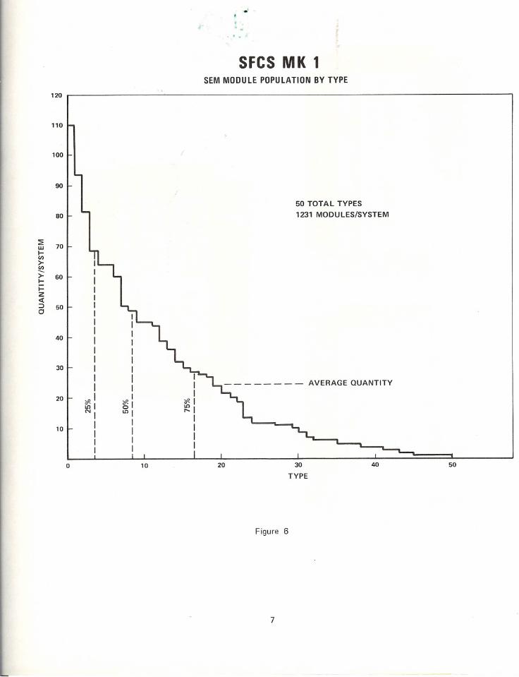
Each SFCS as now configured contains 1231 SEMmodules of 50 types, or a population of 24.6 modules
of each type on the average. Later slides will show thedistribution of this population.
Two new families of size 1A SEM's were developedfor the program. The first is a microcomputer setconsisting of five module types: DRH - the M6800microprocessor, DRN - a peripheral interface adapter,DRM - a 512 byte erasable read only memory,EYA - a 512 byte random access memory, andDRJ - microprocessor clock. These are all size lAmodules. In fact, all SEM's used within the SFCS aresize 1, and over 96 percent are size 1A.
We also developed a family of seven size 1A low powerSchottky logic modules. At the request of NAC, thesewere given the same pin-outs as the existing standardfamily of high speed Schottky modules, and are interchangeable with them for many applications althoughthey have different key codes.
SYSTEM FUNCTIONS AND FEATURES
The SFCS Mk 1 Mod 0 performs five functionscritically important to submarine attack operations:
1. Multiple Sensor Coordination: There are directtransmission lines from all sensor stations to theSFCS. While these data are received automatically,provision is made for operator overrides and manual entries. A ti me history of data from thesesensors is maintained, both in a digital tape recorderand on a large format paper chart recorder. TheSFCS is used to designate bearings for search andto direct another sonar for a contact/target alreadydetected. Note that periscope, ESM/ECM andradar contacts can also be recorded and used.
2. Assessment of Multiple Threats: Threat assessmentstarts when a contact is so nominated and the SFCS
begins the computations to estimate the contactstate vector (location, course and speed). Thisanalysis and the automated TMA process dependson the kind of sensor data available: bearings only,bearings and estimated ranges, or active (sonar,radar), visual or intercept data. Three modes ofoperator interactive TMA are provided, in addition

SFCS MK 1 F.UNCTIONS AND FEATURES. ~
<
• SENSOR INTEGRATION
• GYROCOMPASS
• SPEED LOG
• DATE/TIME CLOCK
• PERISCOPES
• THREAT ASSESSMENT
• MULTIPLE MODES
• AUTO + INTERACTIVE TMA
• SOLUTION OUALITY
• WEAPONS
• MK 8 - 4 (SALVO)
• MK 23 - 3 (W/G)
• MK 48 - 3 (W/G)
• AIR FLIGHT MISSILE
• ACOUSTIC ENVIRONMENT ASSESSMENT
• MULTIPLE TARGET ATTACK CAPABILITY
Figure 2
to an automatic Kalman filter TMA estimator program. Results of the analyses for all threats aresummarized in both tabular and graphical formsfor evaluation. The quality of TMA solution isindicated.
3. Weapon Assignment and Control: The weapon ordergeneration (WOG) process starts when a threat ischosen as a target. A weapon is selected based onthe type of target, tactical situation and commanddecision criteria. An attacking approach may beselected based upon the quality of the TMA solution. All prelaunch weapon orders can be computed automatically - or with operator/Commandoverrides as desired - for both salvo fire and wire
guided torpedoes. The SFCS computes the propersolution for the weapon control mode selected andgives the operator a clear choice of the necessityfor postlaunch guidance and control of the wireguided torpedoes. Capacity for handling an airflight submarine-launched missile is also incorporated in the SFCS.
2
• ESM/ECM SYSTEMS
• RADAR
• SONARS: 2007 (SEARCHER)AN/BOG (RANGER)AN/BOS (ATTACKER)
• WEAPON CONTROL MODES
• CORRECTED INTERCEPT
• BEARING RIDER
• PURSUIT
• SWEEP INTERCEPT
4. Acoustic Environment Assessment: Using bathythermograph or similar sensor data, the soundvelocity profiles and ray traces are computed anddisplayed to the SFCS operator. With th is information, the acoustic environment may be evaluated inorder to (a) decide on own ship search depth, and(b) make optimum settings for acoustic homingtorpedoes.
5. Multiple Target A ttack Capability: The SFCSMk 1 Mod 0 is a "T RACK 4, FIR E 2" system."TRACK 4" means that it can simultaneously com
pute complete TMA solutions for four differenttargets. "FIRE 2" means that two different targetscan be attacked simultaneously - for example: oneWIG torpedo and one salvo of up to five Mk 8torpedoes.
SFCS OPERATION OVERVIEW
Figure 3 shows the eight different hardware elementsof the system, and the primary data flow between them.

SUBMARINE FIRE CONTROL SYSTEM MK 1 MOD 0.'
TARGET AND
OWN SHIP SENSORS
iij!mmi!!immmnmiiiiiiiiiili!IO
SINGERL1BRASCOPE DIVISION
IJ:mm::l!!!!!l!!!:;:ljl!!jlr,·,mmmjllljjL/!•••••••••••••••• 1••• 1.111 ••••••••••••••• 1 11II./SONAR ASSIGNMENT
UNITS (3)COMMANO OISPLAY CONSOLE
WEAPON OATA
CONVERTER
FORWARD TORPEDO ROOM
TORPEOO
TUBES (6)
AN/UYK-20
COMPUTER m!m
CONTROL ROOM
FIRE CONTROL
CONSOLE
MASS MEMORY
SUBSYSTEM
Figure 3
Data from 15 separate channels enters the SFCS via asensor data converter (SDC) located in the CommandDisplay Console. The SDC has nine passive sonartracking channels, as well as capacity for active sonardata, periscope data, intercept receiver data, and ownship course and speed inputs. Analog-to-digital conversions are performed as required, and all availabledata is formatted for transmission to the central
computer.
The sensor data is stored in the computer memory foranalysis. It is also formatted for plotting and outputto the Record/Reproduce unit. The Command Displayis a large 20-by 24-inch paper plotter which producesa permanent time-versus-bearing record of all desiredsensor bearings. Additionally, other pertinent information may be annotated. These data are plotted at oneof three selectable rates, as appropriate to the tacticalsituation. The Command Display Console controlsallow the operator to direct sonar search and trackactions - by designating contact bearings via Sonar
Assignment Units installed at each sonar console.Additionally, the operator may designate track 1.0.numbers for the nine sonar data channels. Designating a track number initiates the storing of all datafrom the selected channel in the computer memoryfor the most recent 30-minute time period. Finally,he may nominate any four of the nine tracking channels as threats - which initiates threat motion analysis.
The movement and processing of data within the SFCSis controlled by a central AN/UYK-20 computer andits associated programs, augmented by a Mass MemorySubsystem. This militarized memory isa CL-107MAfixed head disc, which contains 409,600 16-bit mem
ory locations and has an average access time of 18.4milliseconds. Communication between the computerand other elements of the SFCS is via microprocessorscontained within each element. There are six micro
computers within each SFCS: one in the Weapon DataConverter, one in each of the two Fire Control Consoles, and three in the Command Display Console.
3

These latter three perform the functions of sensordata conversion, control of a cartridge tape unit usedfor program storage and data recording, and controlof the large paper plotter. , .'
Architecturally, the microcomputers ad~s smartperipheral controllers connected to the.AN/UYK-20via NTDS fast interfaces. They are smart because theUYK-20 External Function Commands which they caninterpret and execute are much more complex andsophisticated than those normally associated withperipheral devices. In addition, the microcomputerprograms contain self-test diagnostic programs whichcontinuously check the status of the associated subsystems and report back to the UYK-20. The built-intest and diagnostic capabilities made possible by theuse of microprocessors have enabled us to demonstratea mean time to repair of 14 minutes.
Tactical and off-line computer programs are stored andsafeguarded on a sealed magnetic tape in the Record/Reproduce unit. Normally, at the start of each seapatrol, the programs are moved from the tape to thedisc under computer control. From then on, theprograms are loaded from the disc to the computermemory for execution. The tactical program supportsall normal fire control functioning. It also providesfor both hardware fault monitoring and the recordingof sensor input and fire control output data for postmission analysis.
The combination of a general purpose computer, massmemory and microprocessors distributed within theSFCS results in a digital control system which provides:computational redundancy, flexibility and reliability,and emergency operating modes, should somethinghappen to the computer.
The dual F ire Control Consoles are hardware identical.
Each contains a CRT, alphanumeric "toteboard" displays, and associated controls. Primary interactivecontrols are: a light pen, special function keyboards,four shaft angle encoders, a joystick and various pushbuttons. The nom ination of a contact as a threatinitiates action at each of the consoles. Threat assess
ment is normally performed by a tactical analyst atthe right hand console using CRT displays. Thesedisplays are a combination of numerical and graphicaldata, and include a time bearing plot, a threat motionanalysis display, and a tactical plan display. A summaryof the data on all four threats also appears in numericalform on a tactical tote at the top of the console.
Two of the four threats may be chosen as targets bythe tactical analyst and passed to the weapon controller at the left console. In his operations, the weaponcontroller uses the dedicated function buttons and
interactive CRT displays, which include a sound velocityprofile display, a ray trace display, and a weapon control display. Weapon options include straight runningtorpedoes, which may be fired in salvos, and twodifferent types of wireguided torpedoes. Two different
4
targets may be attacked simultaneously. Communication both ways between the Fire Control Console andthe forward torpedo compartment is via dedicatedfunction buttons on the F ire Control Console and on
the Tube Order and Alarm Device in the torpedo compartment. Orders to torpedoes are initiated at the console .and are output to the six torpedo tubes via theWeapon Data Converter. The orders include prelaunchsettings, the fire order, and postlaunch wireguide control. Postlaunch wireguide maneuver commands areautomatically generated and sent to the weapons, butthey may be overridden manually with the joystick.
The SFCS Mk 1 has a computationally redundantEMERGENCY mode for torpedo firing. Should thecentral computer malfunction, microprocessorswithin each Fire Control Console will automaticallymake appropriate presets to the weapon, including display indications for firing and postlaunch control.Additionally, the more critical preset parameters canbe modified by the weapon controller. During anemergency, each console retains the display existingat the instant of computer malfunction, therebyallowing the operator to review the existing tacticalsituation before changing any presets.
Figure 4 shows three of the new module types designedfor the SFCS program. In the upper left is the NFElow power Schottky Schmidt trigger module whichcontains 12 independent circuits. The upper right isthe DRM ultraviolet erasable read-only memory con
taining 512 bytes of memory. The lower module is theDRN microprocessor interface module, a 40-pin DIPwith each pin simply brought out to the module connector allowing all interconnects to made by backpanel wire-wrap.
Figure 5 shows three modules implemented usingthick film hybrid techniques. These are the CMCplasma panel display driver and the NTDS interfacedrivers and receivers.
The number of modules of each of the 50 types isshown in Figure 6. The most populous module, whichis the DRM read only memory, has 110 per system.Note that four types contribute 25% of the total andnine types 50%.
Figure 7 illustrates several facts. The graph shows thenumber of modules in each of the major units. It alsoshows the fraction that is low power Schottky (LPS),
the fraction that is standard types, and the fraction thatis size 1A. The table includes statistics on the number
of modules we built in-house (844 per system) versusthe number purchased outside (407).
Figure 8 shows a typical SEM drawer. Note in particular the size 1Rand 1W SEM power supplies in the lowertwo rows.
Figure 9 shows the back plane wiring in a typicaldrawer. It was designed by an automated system(Librascope Design Automation System) and wire
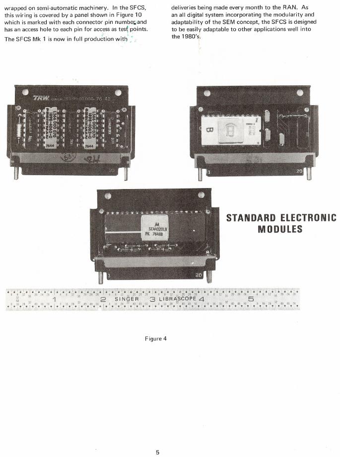
wrapped on semi-automatic machinery. In the SFCS,this wiring is covered by a panel shown in Figure 10which is marked with each connector pin numbe~land
has an access hole to each pin for acc~ss as tes~ points.The SFCS Mk 1 is now in full production wi):h :
Figure4
5
deliveries being made every month to the RAN. Asan all digital system incorporating the modularity andadaptability of the SEM concept, the SFCS is designedto be easily adaptable to other applications well intothe 1980's.
STANDARD ELECTRONIC
MODULES

6
SFCS MK 1SEM MODULE POPULATION BY TYPE
- - - - - - - - AVERAGE QUANTITY
50 TOTAL TYPES
1231 MODULES/SYSTEM
120
1101009080~
70w l-ll)>-lI)-->- 60l- I-Z<l:::::>
500 III40 l- II
II30 l-II
II20 I-
o I Iffil
~IN.Lnl
I10 I-~I
IIL....L..0
10
20 30
TYPE
Figure 6
7
40 50

STANDARD ElECTRONICS MODULES
QUANTITY BY UNIT AND TYPE
400
TYPESQUANTITY I (Per System)Standards
14109
300 -lI II L P Schottky8225
Microcomputer
7344
Power Supplies
320Built In-House
28844I(68.4%)Purchased
22407I(31.6%)I
Ir///////1>-
l-I- 2002<C::::>0 I____ J I
1..----1A
LPS100 I r-----
_____ " LPS I-~p~------STD
ISTD
O~II
STD
Fee
eDewoeITOAD
UNIT
Figure 7
8

9
co
~::l.~u...

Figure 9
10

.,i .
..'
11
a(l)•...:J.~LL

.'
SENSOR ICONTACTDATA MOTION WEAPONMANAGEMENT ANAL YSISI CONTROL
EMERGENCYMODE
OPERATION
WIRE
GUIDANCE
FULL
AIR I LOGISTICSCOOLED SUPPORT
THREAT
ASSESSMENT
CPU
FIRMWARE
CONTROL
MMU
SONARDATA
CONVERSION
FCC
NAVY
STANDARD
MINICOMPUTER
NTDS
DISPLA Y I FASTREFRESH INTERFACES
Figure 11
This pyramid depicts the building block process used to interpret the Standard ElectronicModules (SEM's) concept into the design of an operational submarine fire control system.A base of 1231 SEM's is grouped into progressively more succinct functions and then intosuccessively more unitized packaging. The modules consist of only 50 types and providethe modularity, repairability, and logistics supportability necessary in the navies of todayand tomorrow.
12

/Librascopela division of The 5 I N G E R Company