
integrated contingency plan montana-wyoming pipeline ...
575
Confidentiality Notice: This document is for the sole use of the intended recipient(s) and contains information that is considered to be proprietary to Phillips 66. Any unauthorized review, use, disclosure or distribution is strictly prohibited. INTEGRATED CONTINGENCY PLAN MONTANA-WYOMING PIPELINE RESPONSE ZONE PHMSA Sequence Number 128 Owner/Operator: Phillips 66 600 N. Dairy Ashford, TA-2136 Houston, Texas 77079 24-Hour Number: (800) 231-2551 or (877) 267-2290 Volume 1 of 1 Prepared by: The Response Group, Inc. 13939 Telge Road; Cypress, Texas 77429 PHMSA, 000003322
-
Upload
khangminh22 -
Category
Documents
-
view
0 -
download
0
Transcript of integrated contingency plan montana-wyoming pipeline ...

Confidentiality Notice: This document is for the sole use of the intended recipient(s) and contains information that is considered to be proprietary to Phillips 66. Any unauthorized review, use, disclosure or distribution is strictly prohibited.
INTEGRATED CONTINGENCY PLAN
MONTANA-WYOMING PIPELINE RESPONSE ZONE
PHMSA Sequence Number 128
Owner/Operator: Phillips 66
600 N. Dairy Ashford, TA-2136 Houston, Texas 77079
24-Hour Number: (800) 231-2551 or (877) 267-2290
Volume 1 of 1
Prepared by: The Response Group, Inc. 13939 Telge Road; Cypress, Texas 77429
PHMSA, 000003322


Piping LeakEmergency Response Guide First Responder
DOT EMERGENCY
RESPONSE GUIDEBOOK
QUICK REFERENCE PAGES
COMMAND MANAGEMENT
� Assume the role of Incident Commander� Make an announcement to all on the scene that you have assumed Command� Establish a Unified Command Post up wind, up hill and up stream of the incident in the cold zone� Establish a Unified Staging Area up wind, up hill and up stream of the incident in the cold zone� Begin assigning ICS positions as necessary� Meet, greet & brief responding Agencies as they arrive at the Unified Command Post� Ensure Safety Officer begins and completes a Site Safety PlanIDENTIFICATION AND ASSESSMENT
� Continue to evaluate the hot zone and adjust accordingly� Continue to monitor evacuation activities� Ensure safe Recon to determine extent of impact on water, air, soil, plant life & wildlifeACTION PLANNING
� Complete an ICS Form 201 and Incident Action Plan
DECONTAMINATION / CLEANUP
� Decon activities take place under the ICS Ops Section� Decon capabilities in place before entering Hot Zone� Ensure proper PPE for Decon Team� Clean up strategies should be part of the Unified IAP� Decon runoff needs to be contained and properly disposed ofDISPOSAL
� Ensure early notification of HES� Consult Waste Management Section of this PlanDOCUMENTATION
� Ensure early completion of ICS Form 201 & SSHP� Ensure proper retention of all incident related documents� Ensure timely incident critique & record lessons learned
SAFETY FIRST
Product Guide #
FOSC
SOSC
LOCAL AGENCY IC (s)
RPIC
MEDIACONTROL
AREA
SCENESTAGING
AREA
UNIFIEDCOMMAND
POSTDECON
Wind
Scene Perimeter
Hot Zone
Warm Zone
Cold Zone
LIAISONAREA
INITIALRECONNAISSANCE
SAFETY
� Work with Safety to establish Hot & Warm Zone� Hot & Warm Zone activities� Containment� Recovery / Cleanup� Disposal� Fire Attack / Search & Rescue� Decon� Air Ops� Dispersants
� Gather / display / disseminate incident information� Field Observer(s)� Mapping� Resources� Documentation� Environmental issues� Decon� Technical Specialists
� Order resources� Facilities� Security� Food & lodging� Communications� Medical� Janitorial & Sanitation� Staging
� Cost issues� Equip. & personnel time recorder� Procurement� Compensation & Claims
* Typical Guide/No
Scale Suggested
� Initial Site Characterization� Early calculations� Initial map� Initial photos� Early Hot Zone determination
� Site Safety & Health Plan� Work with Recon & Operations to establish Hot, Warm & Cold Zones
� Assist Agency Representatives and Stakeholder Groups
UNIFIED COMMANDPOST
FIRST RESPONDER GUIDE
UNIFIED COMMAND ICS ORGANIZATION
TYPICAL EMERGENCY SCENE
CONTROL ZONE DIAGRAM
PRODUCTRELEASE AREA
1 2
3 4
DEPUTY IC
INFORMATION OFFICER
LIAISON
� Media
LOGISTICS FINANCEPLANNINGOPERATIONS
Gasoline, Diesel & Crude OilOil < 200°FP LPG Natural Gas
128171 119 115
SAFETY
� Your safety first and then the safety of others� Stay out of the hazard area� If performing Recon approach up wind, up hill, up stream� Determine the immediate hot zone� Do not attempt to contain spilled gasoline on waterISOLATE AND DENY ENTRY
� Evacuate the immediate area� Deny entry to the immediate area� Ask others to help deny entry into the area� If on the scene, ask agency resources to help deny entry into immediate areaNOTIFICATIONS
� Contact your Supervisor� Contact Control Center� Dial 911 if ambulance, police or fire dept. assistance is needed� Contact local OSRO (Notifications Section of this Plan)� Follow Notifications Procedures (Notifications Section of this Plan)
PROTECTIVE EQUIPMENT
� Ensure proper levels of PPE� Ensure PPE is in line with Job Site Safety PlanCONTAINMENT & CONTROL
� Containment & control strategies should be developed within the Unified IAP process/follow ACP� Operations Section Chief oversees containment & control tactical deployment� OSRO's work under the Operations Section and should not freelancePROTECTIVE ACTIONS
� Ensure safe Recon to assess impact on water intakes, adjoining properties, public recreation sites & sensitive sites� Protective action tactical deployment should be part of the Unified IAP
INITIAL ICS/NOTIFICATION FORMS
THAT MAY BE UTILIZED
FACILITY MITIGATION/PROTECTION ACTIONS
� Incident Report Form & Notifications� ICS Form 201 (Incident Breifing, 1-5)� ICS Form 214 (Unit Log)� Site Safety and Health Plan (SSHP)� ICS Form 232 (Resources at Risk Summary)
� Shut-off flow� Isolate leaking section of piping� Notify Terminal Superintendent or designee� Place a container under the leak and attempt to temporarily plug the hole� Initiate spill containment (if outside containment area)� Evacuate contents of line with suctin pump or flush with water to remove remaining oil� Block and purge affected equipment � Initiate recovery/clean-up actions
PHMSA, 000003409

Piping RuptureEmergency Response Guide First Responder
DOT EMERGENCY
RESPONSE GUIDEBOOK
QUICK REFERENCE PAGES
COMMAND MANAGEMENT
� Assume the role of Incident Commander� Make an announcement to all on the scene that you have assumed Command� Establish a Unified Command Post up wind, up hill and up stream of the incident in the cold zone� Establish a Unified Staging Area up wind, up hill and up stream of the incident in the cold zone� Begin assigning ICS positions as necessary� Meet, greet & brief responding Agencies as they arrive at the Unified Command Post� Ensure Safety Officer begins and completes a Site Safety PlanIDENTIFICATION AND ASSESSMENT
� Continue to evaluate the hot zone and adjust accordingly� Continue to monitor evacuation activities� Ensure safe Recon to determine extent of impact on water, air, soil, plant life & wildlifeACTION PLANNING
� Complete an ICS Form 201 and Incident Action Plan
DECONTAMINATION / CLEANUP
� Decon activities take place under the ICS Ops Section� Decon capabilities in place before entering Hot Zone� Ensure proper PPE for Decon Team� Clean up strategies should be part of the Unified IAP� Decon runoff needs to be contained and properly disposed ofDISPOSAL
� Ensure early notification of HES� Consult Waste Management Section of this PlanDOCUMENTATION
� Ensure early completion of ICS Form 201 & SSHP� Ensure proper retention of all incident related documents� Ensure timely incident critique & record lessons learned
SAFETY FIRST
Product Guide #
FOSC
SOSC
LOCAL AGENCY IC (s)
RPIC
MEDIACONTROL
AREA
SCENESTAGING
AREA
UNIFIEDCOMMAND
POSTDECON
Wind
Scene Perimeter
Hot Zone
Warm Zone
Cold Zone
LIAISONAREA
INITIALRECONNAISSANCE
SAFETY
� Work with Safety to establish Hot & Warm Zone� Hot & Warm Zone activities� Containment� Recovery / Cleanup� Disposal� Fire Attack / Search & Rescue� Decon� Air Ops� Dispersants
� Gather / display / disseminate incident information� Field Observer(s)� Mapping� Resources� Documentation� Environmental issues� Decon� Technical Specialists
� Order resources� Facilities� Security� Food & lodging� Communications� Medical� Janitorial & Sanitation� Staging
� Cost issues� Equip. & personnel time recorder� Procurement� Compensation & Claims
* Typical Guide/No
Scale Suggested
� Initial Site Characterization� Early calculations� Initial map� Initial photos� Early Hot Zone determination
� Site Safety & Health Plan� Work with Recon & Operations to establish Hot, Warm & Cold Zones
� Assist Agency Representatives and Stakeholder Groups
UNIFIED COMMANDPOST
FIRST RESPONDER GUIDE
UNIFIED COMMAND ICS ORGANIZATION
TYPICAL EMERGENCY SCENE
CONTROL ZONE DIAGRAM
PRODUCTRELEASE AREA
1 2
3 4
DEPUTY IC
INFORMATION OFFICER
LIAISON
� Media
LOGISTICS FINANCEPLANNINGOPERATIONS
Gasoline, Diesel & Crude OilOil < 200°FP LPG Natural Gas
128171 119 115
SAFETY
� Your safety first and then the safety of others� Stay out of the hazard area� If performing Recon approach up wind, up hill, up stream� Determine the immediate hot zone� Do not attempt to contain spilled gasoline on waterISOLATE AND DENY ENTRY
� Evacuate the immediate area� Deny entry to the immediate area� Ask others to help deny entry into the area� If on the scene, ask agency resources to help deny entry into immediate areaNOTIFICATIONS
� Contact your Supervisor� Contact Control Center� Dial 911 if ambulance, police or fire dept. assistance is needed� Contact local OSRO (Notifications Section of this Plan)� Follow Notifications Procedures (Notifications Section of this Plan)
PROTECTIVE EQUIPMENT
� Ensure proper levels of PPE� Ensure PPE is in line with Job Site Safety PlanCONTAINMENT & CONTROL
� Containment & control strategies should be developed within the Unified IAP process/follow ACP� Operations Section Chief oversees containment & control tactical deployment� OSRO's work under the Operations Section and should not freelancePROTECTIVE ACTIONS
� Ensure safe Recon to assess impact on water intakes, adjoining properties, public recreation sites & sensitive sites� Protective action tactical deployment should be part of the Unified IAP INITIAL ICS/NOTIFICATION FORMS
THAT MAY BE UTILIZED
FACILITY MITIGATION/PROTECTION ACTIONS
� Shut-off flow� Isolate leaking section of piping� Notify Supervisor or designee� Place a container under the leak and attempt to temporarily plug the hole� Initiate spill containment (if outside containment area)� Evacuate contents of line with suctin pump or flush with water to remove remaining oil� Block and purge affected equipment � Initiate recovery/clean-up actions
� Incident Report Form & Notifications � ICS Form 201 (Incident Breifing, 1-5)� ICS Form 214 (Unit Log)� Site Safety and Health Plan (SSHP)� ICS Form 232 (Resources at Risk Summary)
PHMSA, 000003410

Core Plan Section II: Core Plan Elements
Integrated Contingency
Plan
HSE025/DIS II-42 Revision: May 2012
Sec. II-5.9 Failure of Manifold, Mechanical Loading Arm, Other Transfer Equipment or Hoses
Equipment Failure Checklist
Procedures Date/Time
Immediately stop work activities. / / :
Shut off transfer pumps. Close header and tank valves. / / :
Notify Terminal Operations Manager and the Vessel PIC. (Marine Terminal) / /
:
Drain remaining contents of dike to vessel tanks. / / :
Secure the area. / / :
Initiate oil spill cleanup response actions. / /
:
PHMSA, 000003411

Failure of Transfer EquipEmergency Response Guide First Responder
GasolineDieselCrude OilOil < 200°FP
128128128171
DOT EMERGENCY
RESPONSE GUIDEBOOK
QUICK REFERENCE PAGES
SAFETY
� Your safety first and then the safety of others� Stay out of the hazard area� If performing Recon approach up wind, up hill, up stream� Determine the immediate hot zone� Do not attempt to contain spilled gasoline on waterISOLATE AND DENY ENTRY
� Evacuate the immediate area� Deny entry to the immediate area� Ask others to help deny entry into the area� If on the scene, ask agency resources to help deny entry into immediate areaNOTIFICATIONS
� Contact your Supervisor� Contact Control Center� Dial 911 if ambulance, police or fire dept. assistance is needed� Contact local OSRO (Notifications Section of this Plan)� Follow Notifications Procedures (Notifications Section of this Plan)
COMMAND MANAGEMENT
� Assume the role of Incident Commander� Make an announcement to all on the scene that you have assumed Command� Establish a Unified Command Post up wind, up hill and up stream of the incident in the cold zone� Establish a Unified Staging Area up wind, up hill and up stream of the incident in the cold zone� Begin assigning ICS positions as necessary� Meet, greet & brief responding Agencies as they arrive at the Unified Command Post� Ensure Safety Officer begins and completes a Site Safety PlanIDENTIFICATION AND ASSESSMENT
� Continue to evaluate the hot zone and adjust accordingly� Continue to monitor evacuation activities� Ensure safe Recon to determine extent of impact on water, air, soil, plant life & wildlifeACTION PLANNING
� Complete an ICS Form 201 and Incident Action Plan
PROTECTIVE EQUIPMENT
� Ensure proper levels of PPE� Ensure PPE is in line with Job Site Safety PlanCONTAINMENT & CONTROL
� Containment & control strategies should be developed within the Unified IAP process/follow ACP� Operations Section Chief oversees containment & control tactical deployment� OSRO's work under the Operations Section and should not freelancePROTECTIVE ACTIONS
� Ensure safe Recon to assess impact on water intakes, adjoining properties, public recreation sites & sensitive sites� Protective action tactical deployment should be part of the Unified IAP
DECONTAMINATION / CLEANUP
� Decon activities take place under the ICS Ops Section� Decon capabilities in place before entering Hot Zone� Ensure proper PPE for Decon Team� Clean up strategies should be part of the Unified IAP� Decon runoff needs to be contained and properly disposed ofDISPOSAL
� Ensure early notification of HES� Consult Waste Management Section of this PlanDOCUMENTATION
� Ensure early completion of ICS Form 201 & SSHP� Ensure proper retention of all incident related documents� Ensure timely incident critique & record lessons learned
SAFETY FIRST
Product Guide #
INITIAL ICS/NOTIFICATION FORMS
THAT MAY BE UTILIZED
FACILITY MITIGATION/PROTECTION ACTIONS
� Shut off tranfer pumps. Close header & tank valves� Notify Terminal Operators/Manager/Vessel� Drain remaining contents of like to vessel tanks� Secure area� Initiate response actions
� Notification Fax � ICS Form 201 (Incident Breifing)� ICS Form 214 (Unit Log)� Site Safety and Health Plan� ICS Form 232 (Resources at Risk Summary)
FOSC
SOSC
LOCAL AGENCY IC (s)
RPIC
MEDIACONTROL
AREA
SCENESTAGING
AREA
UNIFIEDCOMMAND
POSTDECON
Wind
Scene Perimeter
Hot Zone
Warm Zone
Cold Zone
LIAISONAREA
INITIALRECONNAISSANCE
SAFETY
� Work with Safety to establish Hot & Warm Zone� Hot & Warm Zone activities� Containment� Recovery / Cleanup� Disposal� Fire Attack / Search & Rescue� Decon� Air Ops� Dispersants
� Gather / display / disseminate incident information� Field Observer(s)� Mapping� Resources� Documentation� Environmental issues� Decon� Technical Specialists
� Order resources� Facilities� Security� Food & lodging� Communications� Medical� Janitorial & Sanitation� Staging
� Cost issues� Equip. & personnel time recorder� Procurement� Compensation & Claims
* Typical Guide/No
Scale Suggested
� Initial Site Characterization� Early calculations� Initial map� Initial photos� Early Hot Zone determination
� Site Safety & Health Plan� Work with Recon & Operations to establish Hot, Warm & Cold Zones
� Assist Agency Representatives and Stakeholder Groups
UNIFIED COMMANDPOST
FIRST RESPONDER GUIDE
UNIFIED COMMAND ICS ORGANIZATION
TYPICAL EMERGENCY SCENE
CONTROL ZONE DIAGRAM
PRODUCTRELEASE AREA
1 2
3 4
DEPUTY IC
INFORMATION OFFICER
LIAISON
� Media
LOGISTICS FINANCEPLANNINGOPERATIONS
PHMSA, 000003412

Equipment FailureEmergency Response Guide First Responder
DOT EMERGENCY
RESPONSE GUIDEBOOK
QUICK REFERENCE PAGES
COMMAND MANAGEMENT
� Assume the role of Incident Commander� Make an announcement to all on the scene that you have assumed Command� Establish a Unified Command Post up wind, up hill and up stream of the incident in the cold zone� Establish a Unified Staging Area up wind, up hill and up stream of the incident in the cold zone� Begin assigning ICS positions as necessary� Meet, greet & brief responding Agencies as they arrive at the Unified Command Post� Ensure Safety Officer begins and completes a Site Safety PlanIDENTIFICATION AND ASSESSMENT
� Continue to evaluate the hot zone and adjust accordingly� Continue to monitor evacuation activities� Ensure safe Recon to determine extent of impact on water, air, soil, plant life & wildlifeACTION PLANNING
� Complete an ICS Form 201 and Incident Action Plan
DECONTAMINATION / CLEANUP
� Decon activities take place under the ICS Ops Section� Decon capabilities in place before entering Hot Zone� Ensure proper PPE for Decon Team� Clean up strategies should be part of the Unified IAP� Decon runoff needs to be contained and properly disposed ofDISPOSAL
� Ensure early notification of HES� Consult Waste Management Section of this PlanDOCUMENTATION
� Ensure early completion of ICS Form 201 & SSHP� Ensure proper retention of all incident related documents� Ensure timely incident critique & record lessons learned
SAFETY FIRST
Product Guide #
FOSC
SOSC
LOCAL AGENCY IC (s)
RPIC
MEDIACONTROL
AREA
SCENESTAGING
AREA
UNIFIEDCOMMAND
POSTDECON
Wind
Scene Perimeter
Hot Zone
Warm Zone
Cold Zone
LIAISONAREA
INITIALRECONNAISSANCE
SAFETY
� Work with Safety to establish Hot & Warm Zone� Hot & Warm Zone activities� Containment� Recovery / Cleanup� Disposal� Fire Attack / Search & Rescue� Decon� Air Ops� Dispersants
� Gather / display / disseminate incident information� Field Observer(s)� Mapping� Resources� Documentation� Environmental issues� Decon� Technical Specialists
� Order resources� Facilities� Security� Food & lodging� Communications� Medical� Janitorial & Sanitation� Staging
� Cost issues� Equip. & personnel time recorder� Procurement� Compensation & Claims
* Typical Guide/No
Scale Suggested
� Initial Site Characterization� Early calculations� Initial map� Initial photos� Early Hot Zone determination
� Site Safety & Health Plan� Work with Recon & Operations to establish Hot, Warm & Cold Zones
� Assist Agency Representatives and Stakeholder Groups
UNIFIED COMMANDPOST
FIRST RESPONDER GUIDE
UNIFIED COMMAND ICS ORGANIZATION
TYPICAL EMERGENCY SCENE
CONTROL ZONE DIAGRAM
PRODUCTRELEASE AREA
1 2
3 4
DEPUTY IC
INFORMATION OFFICER
LIAISON
� Media
LOGISTICS FINANCEPLANNINGOPERATIONS
GasolineDieselCrude OilOil < 200°FP
128128128171
SAFETY
� Your safety first and then the safety of others� Stay out of the hazard area� If performing Recon approach up wind, up hill, up stream� Determine the immediate hot zone� Do not attempt to contain spilled gasoline on waterISOLATE AND DENY ENTRY
� Evacuate the immediate area� Deny entry to the immediate area� Ask others to help deny entry into the area� If on the scene, ask agency resources to help deny entry into immediate areaNOTIFICATIONS
� Contact your Supervisor� Contact Control Center� Dial 911 if ambulance, police or fire dept. assistance is needed� Contact local OSRO (Notifications Section of this Plan)� Follow Notifications Procedures (Notifications Section of this Plan)
PROTECTIVE EQUIPMENT
� Ensure proper levels of PPE� Ensure PPE is in line with Job Site Safety PlanCONTAINMENT & CONTROL
� Containment & control strategies should be developed within the Unified IAP process/follow ACP� Operations Section Chief oversees containment & control tactical deployment� OSRO's work under the Operations Section and should not freelancePROTECTIVE ACTIONS
� Ensure safe Recon to assess impact on water intakes, adjoining properties, public recreation sites & sensitive sites� Protective action tactical deployment should be part of the Unified IAP
INITIAL ICS/NOTIFICATION FORMS
THAT MAY BE UTILIZED
FACILITY MITIGATION/PROTECTION ACTIONS
� Shut-off flow� Notify Terminal Superintendent or designee� Tighten leaky valve or fitting, if safe� Transfer tank contents to avaliable tankage
� Notification Fax � ICS Form 201 (Incident Breifing)� ICS Form 214 (Unit Log)� Site Safety and Health Plan� ICS Form 232 (Resources at Risk Summary)
PHMSA, 000003413

Core Plan Section II: Core Plan Elements
Integrated Contingency
Plan
HSE025/DIS II-45 Revision: May 2012
Sec. II-5.10 Tank Overfill
Tank Overfill Response Checklist
Procedures Date/Time
Immediately stop work activities. / / :
Shut off flow to tank. / / :
If safe, ensure dike drains are closed (if applicable). / / :
Initiate oil spill response actions. / / :
Secure the area. / / :
Notify terminal supervisor. / / :
Begin transfer of contents to other tankage. / / :
Sec. II-5.11 Tank Failure
Tank Failure Response Checklist
Procedures Date/Time
Immediately stop work activities. / / :
Shut off flow to tank. / / :
If safe, ensure dike drains are closed (if applicable). / / :
Initiate oil spill response actions. / / :
Secure the area. / / :
Notify terminal supervisor. / / :
Begin transfer of contents to other tankage. / / :
PHMSA, 000003414

Tank OverfillEmergency Response Guide First Responder
DOT EMERGENCY
RESPONSE GUIDEBOOK
QUICK REFERENCE PAGES
SAFETY
� Your safety first and then the safety of others� Stay out of the hazard area� If performing Recon approach up wind, up hill, up stream� Determine the immediate hot zone� Do not attempt to contain spilled gasoline on waterISOLATE AND DENY ENTRY
� Evacuate the immediate area� Deny entry to the immediate area� Ask others to help deny entry into the area� If on the scene, ask agency resources to help deny entry into immediate areaNOTIFICATIONS
� Contact your Supervisor� Contact Control Center� Dial 911 if ambulance, police or fire dept. assistance is needed� Contact local OSRO (Notifications Section of this Plan)� Follow Notifications Procedures (Notifications Section of this Plan)
COMMAND MANAGEMENT
� Assume the role of Incident Commander� Make an announcement to all on the scene that you have assumed Command� Establish a Unified Command Post up wind, up hill and up stream of the incident in the cold zone� Establish a Unified Staging Area up wind, up hill and up stream of the incident in the cold zone� Begin assigning ICS positions as necessary� Meet, greet & brief responding Agencies as they arrive at the Unified Command Post� Ensure Safety Officer begins and completes a Site Safety PlanIDENTIFICATION AND ASSESSMENT
� Continue to evaluate the hot zone and adjust accordingly� Continue to monitor evacuation activities� Ensure safe Recon to determine extent of impact on water, air, soil, plant life & wildlifeACTION PLANNING
� Complete an ICS Form 201 and Incident Action Plan
PROTECTIVE EQUIPMENT
� Ensure proper levels of PPE� Ensure PPE is in line with Job Site Safety PlanCONTAINMENT & CONTROL
� Containment & control strategies should be developed within the Unified IAP process/follow ACP� Operations Section Chief oversees containment & control tactical deployment� OSRO's work under the Operations Section and should not freelancePROTECTIVE ACTIONS
� Ensure safe Recon to assess impact on water intakes, adjoining properties, public recreation sites & sensitive sites� Protective action tactical deployment should be part of the Unified IAP
DECONTAMINATION / CLEANUP
� Decon activities take place under the ICS Ops Section� Decon capabilities in place before entering Hot Zone� Ensure proper PPE for Decon Team� Clean up strategies should be part of the Unified IAP� Decon runoff needs to be contained and properly disposed ofDISPOSAL
� Ensure early notification of HES� Consult Waste Management Section of this PlanDOCUMENTATION
� Ensure early completion of ICS Form 201 & SSHP� Ensure proper retention of all incident related documents� Ensure timely incident critique & record lessons learned
SAFETY FIRST
Product Guide #
FOSC
SOSC
LOCAL AGENCY IC (s)
RPIC
MEDIACONTROL
AREA
SCENESTAGING
AREA
UNIFIEDCOMMAND
POSTDECON
Wind
Scene Perimeter
Hot Zone
Warm Zone
Cold Zone
LIAISONAREA
INITIALRECONNAISSANCE
SAFETY
� Work with Safety to establish Hot & Warm Zone� Hot & Warm Zone activities� Containment� Recovery / Cleanup� Disposal� Fire Attack / Search & Rescue� Decon� Air Ops� Dispersants
� Gather / display / disseminate incident information� Field Observer(s)� Mapping� Resources� Documentation� Environmental issues� Decon� Technical Specialists
� Order resources� Facilities� Security� Food & lodging� Communications� Medical� Janitorial & Sanitation� Staging
� Cost issues� Equip. & personnel time recorder� Procurement� Compensation & Claims
* Typical Guide/No
Scale Suggested
� Initial Site Characterization� Early calculations� Initial map� Initial photos� Early Hot Zone determination
� Site Safety & Health Plan� Work with Recon & Operations to establish Hot, Warm & Cold Zones
� Assist Agency Representatives and Stakeholder Groups
UNIFIED COMMANDPOST
FIRST RESPONDER GUIDE
UNIFIED COMMAND ICS ORGANIZATION
TYPICAL EMERGENCY SCENE
CONTROL ZONE DIAGRAM
PRODUCTRELEASE AREA
1 2
3 4
DEPUTY IC
INFORMATION OFFICER
LIAISON
� Media
LOGISTICS FINANCEPLANNINGOPERATIONS
Gasoline, Diesel & Crude OilOil < 200°FP LPG Natural Gas
128171 119 115
INITIAL ICS/NOTIFICATION FORMS
THAT MAY BE UTILIZED
FACILITY MITIGATION/PROTECTION ACTIONS
� Shut off flow to tank� If safe, ensure dike drains are closed� Begin transfer of contents to other tankage� Notify Terminal Superintentent� Secure area� Initiate response actions
� Incident Report Form & Notifications� ICS Form 201 (Incident Breifing, 1-5)� ICS Form 214 (Unit Log)� Site Safety and Health Plan (SSHP)� ICS Form 232 (Resources at Risk Summary)
PHMSA, 000003415

Tank FailureEmergency Response Guide First Responder
DOT EMERGENCY
RESPONSE GUIDEBOOK
QUICK REFERENCE PAGES
COMMAND MANAGEMENT
� Assume the role of Incident Commander� Make an announcement to all on the scene that you have assumed Command� Establish a Unified Command Post up wind, up hill and up stream of the incident in the cold zone� Establish a Unified Staging Area up wind, up hill and up stream of the incident in the cold zone� Begin assigning ICS positions as necessary� Meet, greet & brief responding Agencies as they arrive at the Unified Command Post� Ensure Safety Officer begins and completes a Site Safety PlanIDENTIFICATION AND ASSESSMENT
� Continue to evaluate the hot zone and adjust accordingly� Continue to monitor evacuation activities� Ensure safe Recon to determine extent of impact on water, air, soil, plant life & wildlifeACTION PLANNING
� Complete an ICS Form 201 and Incident Action Plan
DECONTAMINATION / CLEANUP
� Decon activities take place under the ICS Ops Section� Decon capabilities in place before entering Hot Zone� Ensure proper PPE for Decon Team� Clean up strategies should be part of the Unified IAP� Decon runoff needs to be contained and properly disposed ofDISPOSAL
� Ensure early notification of HES� Consult Waste Management Section of this PlanDOCUMENTATION
� Ensure early completion of ICS Form 201 & SSHP� Ensure proper retention of all incident related documents� Ensure timely incident critique & record lessons learned
SAFETY FIRST
Product Guide #
FOSC
SOSC
LOCAL AGENCY IC (s)
RPIC
MEDIACONTROL
AREA
SCENESTAGING
AREA
UNIFIEDCOMMAND
POSTDECON
Wind
Scene Perimeter
Hot Zone
Warm Zone
Cold Zone
LIAISONAREA
INITIALRECONNAISSANCE
SAFETY
� Work with Safety to establish Hot & Warm Zone� Hot & Warm Zone activities� Containment� Recovery / Cleanup� Disposal� Fire Attack / Search & Rescue� Decon� Air Ops� Dispersants
� Gather / display / disseminate incident information� Field Observer(s)� Mapping� Resources� Documentation� Environmental issues� Decon� Technical Specialists
� Order resources� Facilities� Security� Food & lodging� Communications� Medical� Janitorial & Sanitation� Staging
� Cost issues� Equip. & personnel time recorder� Procurement� Compensation & Claims
* Typical Guide/No
Scale Suggested
� Initial Site Characterization� Early calculations� Initial map� Initial photos� Early Hot Zone determination
� Site Safety & Health Plan� Work with Recon & Operations to establish Hot, Warm & Cold Zones
� Assist Agency Representatives and Stakeholder Groups
UNIFIED COMMANDPOST
FIRST RESPONDER GUIDE
UNIFIED COMMAND ICS ORGANIZATION
TYPICAL EMERGENCY SCENE
CONTROL ZONE DIAGRAM
PRODUCTRELEASE AREA
1 2
3 4
DEPUTY IC
INFORMATION OFFICER
LIAISON
� Media
LOGISTICS FINANCEPLANNINGOPERATIONS
SAFETY
� Your safety first and then the safety of others� Stay out of the hazard area� If performing Recon approach up wind, up hill, up stream� Determine the immediate hot zone� Do not attempt to contain spilled gasoline on waterISOLATE AND DENY ENTRY
� Evacuate the immediate area� Deny entry to the immediate area� Ask others to help deny entry into the area� If on the scene, ask agency resources to help deny entry into immediate areaNOTIFICATIONS
� Contact your Supervisor� Contact Control Center� Dial 911 if ambulance, police or fire dept. assistance is needed� Contact local OSRO (Notifications Section of this Plan)� Follow Notifications Procedures (Notifications Section of this Plan)
PROTECTIVE EQUIPMENT
� Ensure proper levels of PPE� Ensure PPE is in line with Job Site Safety PlanCONTAINMENT & CONTROL
� Containment & control strategies should be developed within the Unified IAP process/follow ACP� Operations Section Chief oversees containment & control tactical deployment� OSRO's work under the Operations Section and should not freelancePROTECTIVE ACTIONS
� Ensure safe Recon to assess impact on water intakes, adjoining properties, public recreation sites & sensitive sites� Protective action tactical deployment should be part of the Unified IAP
Gasoline, Diesel & Crude OilOil < 200°FP LPG Natural Gas
128171 119 115
INITIAL ICS/NOTIFICATION FORMS
THAT MAY BE UTILIZED
FACILITY MITIGATION/PROTECTION ACTIONS
� If safe, ensure dike drains are closed� Notify Terminal Superintendent or designee� Secure area� Initiate response actions
� Incident Report Form & Notifications� ICS Form 201 (Incident Breifing, 1-5)� ICS Form 214 (Unit Log)� Site Safety and Health Plan (SSHP)� ICS Form 232 (Resources at Risk Summary)
PHMSA, 000003416

Core Plan Section II: Core Plan Elements
Integrated Contingency
Plan
HSE025/DIS II-48 Revision: May 2012
Sec. II-5.12 Natural and Other Gas Leaks
Natural and Other Gas Leaks
Procedures Date/Time
Immediately stop work activities. / / :
Shut down and isolate flow. / / :
Evacuate the area. / / :
Eliminate sources of ignition. / / :
All equipment used when handling product must be grounded. / / :
Water spray may reduce vapors or divert vapor cloud. / / :
If exposed, make sure exposed clothing is removed and decon occurs. / /
:
PHMSA, 000003417

Core Plan Section II: Core Plan Elements
Integrated Contingency
Plan
HSE025/DIS II-49 Revision: May 2012
Sec. II-5.13 Natural and Other Gas Leak In or Near a Building
Natural and Other Gas Leaks In or Near a Building
Procedures Date/Time
Immediately stop work activities. / / :
Protect public first, then facilities. / / :
Safely evacuate building if gas is detected inside building. / / :
Always look and listen for any signs of escaped gas. / / :
All open flames are to be extinguished. / / :
Determine leak severity. / / :
Do not enter building with audible leaking gas. / / :
Test the environment to determine safe entry. / / :
Evacuate people from adjacent buildings. / / :
Shut off electrical power to building. / / :
Eliminate all other potential sources of ignition. / / :
Isolate the building from gas sources of ignition. / / :
Close necessary inlet and outlet block valves and open blowdown valves. / /
: After gas sources are shut off, utilize portable combustible gas indicator/detector to determine safe environment. / /
:
PHMSA, 000003418

Natural and Other Gas LeaksEmergency Response Guide First Responder
GasolineDieselLPGNatural GasCrude Oil
128128119 115 128
SAFETY
� Your safety first and then the safety of others� Stay out of the hazard area� If performing Recon approach up wind, up hill, up stream� Determine the immediate hot zoneISOLATE AND DENY ENTRY
� Evacuate the immediate area� Deny entry to the immediate area� Ask others to help deny entry into the area� If on the scene, ask agency resources to help evaluate and deny entry into immediate areaNOTIFICATIONS
� Contact your Supervisor� Contact Control Center� Dial 911 if ambulance, police or fire department assistance is needed� Contact local OSRO (Notifications Section of this Plan)� Follow Notifications Procedures (Notifications Section of this Plan)
COMMAND MANAGEMENT
� Assume the role of Incident Commander� Make an announcement to all on the scene that you have assumed Command� Establish a Unified Command Post up wind, up hill and up stream of the incident in the cold zone� Establish a Unified Staging Area up wind, up hill and up stream of the incident in the cold zone� Begin assigning ICS positions as necessary� Meet, greet & brief responding Agencies as they arrive at the Unified Command Post� Ensure Safety Officer begins and completes a Site Safety PlanIDENTIFICATION AND ASSESSMENT
� Continue to evaluate the hot zone and adjust accordingly� Continue to monitor evacuation activities� Ensure safe Recon to determine extent of impact on water, air, soil, plant life & wildlifeACTION PLANNING
� Create an Initial Action Plan (ICS Form 201)
PROTECTIVE EQUIPMENT
� Ensure proper levels of PPE� Ensure PPE is in line with Site Safety Health PlanCONTAINMENT & CONTROL
� Containment & control strategies should be developed within the Unified IAP process/follow ACP� Operations Section Chief oversees containment & control tactical deployment� OSROs work under the Operations Section and should not freelancePROTECTIVE ACTIONS
� Ensure safe Recon to assess impact on water intakes, adjoining properties, public recreation sites & sensitive sites� Protective action tactical deployment should be part of the Unified IAP
DECONTAMINATION / CLEANUP
� Decon activities take place under the ICS Ops Section� Decon capabilities in place before entering Hot Zone� Ensure proper PPE for Decon TeamDISPOSAL
� Minimal disposal issuesDOCUMENTATION
� Ensure early completion of ICS Form 201 & SSHP� Ensure proper retention of all incident-related documents� Ensure timely incident critique & record lessons learned
SAFETY FIRST
Product Guide #
INITIAL ICS/NOTIFICATION FORMS
THAT MAY BE UTILIZED
FACILITY MITIGATION/PROTECTION ACTIONS
� Shut down and isolate flow� Evacuate the area� Eliminate sources of ignition� All equipment used when handling product must be grounded� Water spray may reduce vapors or divert vapor cloud � If exposed, make sure exposed clothing is removed and decon occurs
� Notification Fax � ICS Form 201 (Incident Briefing)� ICS Form 202� Site Safety Plan� ICS Form 215
FOSC
SOSC
LOCAL AGENCY IC (s)
RPIC
MEDIACONTROL
AREA
SCENESTAGING
AREA
UNIFIEDCOMMAND
POSTDECON
Wind
Scene Perimeter
Hot Zone
Warm Zone
Cold Zone
LIAISONAREA
INITIALRECONNAISSANCE
SAFETY
� Work with Safety to establish Hot & Warm Zone� Hot & Warm Zone activities� Containment� Recovery / Cleanup� Disposal� Fire Attack / Search & Rescue� Decon� Air Ops� Dispersants� Staging
� Gather / display / disseminate incident information� Field Observer(s)� Mapping� Resources� Documentation� Environmental issues� Decon� Technical Specialists
� Order resources� Facilities� Security� Food & lodging� Communications� Medical� Janitorial & Sanitation
� Cost issues� Equip. & personnel time recorder� Procurement� Compensation & Claims
* Typical Guide/No
Scale Suggested
� Initial Site Characterization� Early calculations� Initial map� Initial photos� Early Hot Zone determination
� Site Safety & Health Plan� Work with Recon & Operations to establish Hot, Warm & Cold Zones
� Assist Agency Representatives and Stakeholder Groups
UNIFIED COMMANDPOST
FIRST RESPONDER GUIDE
UNIFIED COMMAND ICS ORGANIZATION
TYPICAL EMERGENCY SCENE
CONTROL ZONE DIAGRAM
PRODUCTRELEASE AREA
1 2
3 4
DEPUTY IC
INFORMATION OFFICER
LIAISON
� Media
LOGISTICS FINANCEPLANNINGOPERATIONS
DOT EMERGENCY RESPONSE
GUIDEBOOK QUICK REFERENCE PAGES
PHMSA, 000003419

Natural and Other Gas Leak Inor Near a BuildingEmergency Response Guide First Responder
GasolineDieselLPGNatural GasCrude Oil
128128119 115 128
SAFETY
� Your safety first and then the safety of others� Stay out of the hazard area� If performing Recon approach up wind, up hill, up stream� Determine the immediate hot zoneISOLATE AND DENY ENTRY
� Evacuate the immediate area� Deny entry to the immediate area� Ask others to help deny entry into the area� If on the scene, ask agency resources to help evaluate and deny entry into immediate areaNOTIFICATIONS
� Contact your Supervisor� Contact Control Center� Dial 911 if ambulance, police or fire department assistance is needed� Contact local OSRO (Notifications Section of this Plan)� Follow Notifications Procedures (Notifications Section of this Plan)
COMMAND MANAGEMENT
� Assume the role of Incident Commander� Make an announcement to all on the scene that you have assumed Command� Establish a Unified Command Post up wind, up hill and up stream of the incident in the cold zone� Establish a Unified Staging Area up wind, up hill and up stream of the incident in the cold zone� Begin assigning ICS positions as necessary� Meet, greet & brief responding Agencies as they arrive at the Unified Command Post� Ensure Safety Officer begins and completes a Site Safety PlanIDENTIFICATION AND ASSESSMENT
� Continue to evaluate the hot zone and adjust accordingly� Continue to monitor evacuation activities� Ensure safe Recon to determine extent of potential impact on the areaACTION PLANNING
� Create an Initial Action Plan (ICS Form 201)
PROTECTIVE EQUIPMENT
� Ensure proper levels of PPE� Ensure PPE is in line with Site Safety Health PlanCONTAINMENT & CONTROL
� Containment & control strategies should be developed within the Unified IAP process/follow ACP� Operations Section Chief oversees containment & control tactical deploymentPROTECTIVE ACTIONS
� Ensure safe Recon to assess impact on area� Protective action tactical deployment should be part of the Unified IAP
DECONTAMINATION / CLEANUP
� Decon activities take place under the ICS Ops Section� Decon capabilities in place before entering Hot Zone� Ensure proper PPE for Decon TeamDISPOSAL
� Minimal disposal issuesDOCUMENTATION
� Ensure early completion of ICS Form 201 & SSHP� Ensure proper retention of all incident-related documents� Ensure timely incident critique & record lessons learned
GENERAL PROCEDURES
Product Guide #
INITIAL ICS/NOTIFICATION FORMS
THAT MAY BE UTILIZED
GENERAL PROCEDURES (CONTINUED)
� Shut off electrical power to building� Eliminate all other potential sources of ignition� Isolate the building from gas sources if possible� Close necessary inlet and outlet block valves and open blowdown valves� After gas sources are shut off, utilize portable combustible gas indicator/detector to determine safe environment
� Notification Fax � ICS Form 201 (Incident Briefing)� ICS Form 202� Site Safety Plan� ICS Form 215
FOSC
SOSC
LOCAL AGENCY IC (s)
RPIC
MEDIACONTROL
AREA
SCENESTAGING
AREA
UNIFIEDCOMMAND
POSTDECON
Wind
Scene Perimeter
Hot Zone
Warm Zone
Cold Zone
LIAISONAREA
INITIALRECONNAISSANCE
SAFETY
� Work with Safety to establish Hot & Warm Zone� Hot & Warm Zone activities� Containment� Recovery / Cleanup� Disposal� Fire Attack / Search & Rescue� Decon� Air Ops� Dispersants� Staging
� Gather / display / disseminate incident information� Field Observer(s)� Mapping� Resources� Documentation� Environmental issues� Decon� Technical Specialists
� Order resources� Facilities� Security� Food & lodging� Communications� Medical� Janitorial & Sanitation
� Cost issues� Equip. & personnel time recorder� Procurement� Compensation & Claims
* Typical Guide/No
Scale Suggested
� Initial Site Characterization� Early calculations� Initial map� Initial photos� Early Hot Zone determination
� Site Safety & Health Plan� Work with Recon & Operations to establish Hot, Warm & Cold Zones
� Assist Agency Representatives and Stakeholder Groups
UNIFIED COMMANDPOST
FIRST RESPONDER GUIDE
UNIFIED COMMAND ICS ORGANIZATION
TYPICAL EMERGENCY SCENE
CONTROL ZONE DIAGRAM
PRODUCTRELEASE AREA
1 2
3 4
DEPUTY IC
INFORMATION OFFICER
LIAISON
� Media
LOGISTICS FINANCEPLANNINGOPERATIONS
DOT EMERGENCY RESPONSE
GUIDEBOOK QUICK REFERENCE PAGES
� Protect public first, then facilities� Safely evacuate building if gas is detected inside building� Always look and listen for any signs of escaped gas� Do not open a building door if escaped gas is detected� All open flames are to be extinguished� Determine leak severity� Do not enter building with audible leaking gas� Test the environment to determine safe entry� Evacuate people from adjacent buildings
PHMSA, 000003420

Core Plan Section II: Core Plan Elements
Integrated Contingency
Plan
HSE025/DIS II-52 Revision: May 2012
Sec. II-5.14 Fire / Explosion It is the Company’s intention to comply with all applicable fire regulations. The objective of the emergency planning and response program is to produce a favorable outcome at the incident with minimal risk to the public, employees and contractors, and emergency responders. Life safety shall be the highest priority for all personnel.
Fire / Explosion / Blowout Checklist
Procedures Date/Time
Person in Charge – Call 911 and activate fire alarm. / / :
Eliminate all ignition sources. / / :
Begin Emergency Shut Down if necessary. / / :
If person(s) down, refer to Medical Emergency Checklist / / :
When fire is noticed at any facility, secure the source if safe to do so. / / :
Account for all personnel in the unit or area where the fire occurred. / / :
Evacuate all non-essential personnel, if necessary. / / :
Establish communications. Contact PIC. / / :
Search for and rescue missing or injured personnel as required. / / :
Use the buddy system. / / :
Ensure the Facility Operators control the process. / / :
Conduct air monitoring to ensure safety of personnel and appropriate PPE is required to respond. (For additional information, see the Site Safety and Health Plan and/or the Safety Coordinator.)
/ / :
Conduct initial fire fighting by IC/UC personnel (trained in the use of firefighting equipment and PPE), which may include use of monitors, deluge systems, and portable fire extinguishers.
/ / :
Evacuate nearby residents if required. / / :
PHMSA, 000003421

Fire or ExplosionEmergency Response Guide First Responder
DOT EMERGENCY
RESPONSE GUIDEBOOK
QUICK REFERENCE PAGES
COMMAND MANAGEMENT
� Assume the role of Incident Commander� Make an announcement to all on the scene that you have assumed Command� Establish a Unified Command Post up wind, up hill and up stream of the incident in the cold zone� Establish a Unified Staging Area up wind, up hill and up stream of the incident in the cold zone� Begin assigning ICS positions as necessary� Meet, greet & brief responding Agencies as they arrive at the Unified Command Post� Ensure Safety Officer begins and completes a Site Safety PlanIDENTIFICATION AND ASSESSMENT
� Continue to evaluate the hot zone and adjust accordingly� Continue to monitor evacuation activities� Ensure safe Recon to determine extent of impact on water, air, soil, plant life & wildlifeACTION PLANNING
� Complete an ICS Form 201 and Incident Action Plan
PROTECTIVE EQUIPMENT
� Ensure proper levels of PPE� Ensure PPE is in line with Job Site Safety PlanCONTAINMENT & CONTROL
� Containment & control strategies should be developed within the Unified IAP process/follow ACP� Operations Section Chief oversees strategiesPROTECTIVE ACTIONS
� Ensure safe Recon to assess impact on area� Protective action tactical deployment should be part of the Unified IAP
DECONTAMINATION / CLEANUP
� Decon activities take place under the ICS Ops Section� Decon capabilities in place before entering Hot Zone� Ensure proper PPE for Decon Team� Clean up strategies should be part of the Unified IAP� Decon runoff needs to be contained and properly disposed ofDISPOSAL
� Ensure early notification of HES� Consult Waste Management Section of this PlanDOCUMENTATION
� Ensure early completion of ICS Form 201 & SSHP� Ensure proper retention of all incident related documents� Ensure timely incident critique & record lessons learned
SAFETY FIRST
Product Guide #
FOSC
SOSC
LOCAL AGENCY IC (s)
RPIC
MEDIACONTROL
AREA
SCENESTAGING
AREA
UNIFIEDCOMMAND
POSTDECON
Wind
Scene Perimeter
Hot Zone
Warm Zone
Cold Zone
LIAISONAREA
INITIALRECONNAISSANCE
SAFETY
� Work with Safety to establish Hot & Warm Zone� Hot & Warm Zone activities� Containment� Recovery / Cleanup� Disposal� Fire Attack / Search & Rescue� Decon� Air Ops� Dispersants
� Gather / display / disseminate incident information� Field Observer(s)� Mapping� Resources� Documentation� Environmental issues� Decon� Technical Specialists
� Order resources� Facilities� Security� Food & lodging� Communications� Medical� Janitorial & Sanitation� Staging
� Cost issues� Equip. & personnel time recorder� Procurement� Compensation & Claims
* Typical Guide/No
Scale Suggested
� Initial Site Characterization� Early calculations� Initial map� Initial photos� Early Hot Zone determination
� Site Safety & Health Plan� Work with Recon & Operations to establish Hot, Warm & Cold Zones
� Assist Agency Representatives and Stakeholder Groups
UNIFIED COMMANDPOST
FIRST RESPONDER GUIDE
UNIFIED COMMAND ICS ORGANIZATION
TYPICAL EMERGENCY SCENE
CONTROL ZONE DIAGRAM
PRODUCTRELEASE AREA
1 2
3 4
DEPUTY IC
INFORMATION OFFICER
LIAISON
� Media
LOGISTICS FINANCEPLANNINGOPERATIONS
Gasoline, Diesel & Crude OilOil < 200°FP LPG Natural Gas
128171 119 115
SAFETY
� Your safety first and then the safety of others� Stay out of the hazard area� If performing Recon approach up wind, up hill, up stream� Determine the immediate hot zone� Do not attempt to contain spilled gasoline on waterISOLATE AND DENY ENTRY
� Evacuate the immediate area� Deny entry to the immediate area� Ask others to help deny entry into the area� If on the scene, ask agency resources to help deny entry into immediate areaNOTIFICATIONS
� Contact your Supervisor� Contact Control Center� Dial 911 if ambulance, police or fire dept. assistance is needed� Contact local OSRO (Notifications Section of this Plan)� Follow Notifications Procedures (Notifications Section of this Plan)
INITIAL ICS/NOTIFICATION FORMS
THAT MAY BE UTILIZED
FACILITY MITIGATION/PROTECTION ACTIONS
� Alert personnel� Notify Supervisor or designee� Activate alarm as required� Notify local fire department� Evacuate non-essential individuals� Identify cause/source/materials involved� Contain fire/spill/material released� Consider potential for escalation� Protect exposures
� Incident Report Form & Notifications� ICS Form 201 (Incident Briefing, 1 5)
� ICS Form 214 (Unit Log)� Site Safety and Health Plan� ICS Form 232 (Resources at Risk Summary)
PHMSA, 000003422

Core Plan Section II: Core Plan Elements
Integrated Contingency
Plan
HSE025/DIS II-54 Revision: May 2012
Sec. II-5.14.1 Fire Prevention Accumulated debris, oil waste, trash, and other potential fuels can be present in all operations and will add to the fire danger. Strict control and isolation of these fuel sources should be exercised to avoid their accumulation in inhabited areas. Gasoline storage and transfer should follow applicable codes. A fire extinguisher should also be made readily available. Smoking is not allowed near flammable materials. Welding and burning require a hot work permit where hydrocarbon mixtures may exist, i.e., vessels, tanks, pipelines, etc., which may contain explosive mixtures or atmospheres. All fires should be completely extinguished before fire-fighting personnel leave the work site.
PHMSA, 000003423

Core Plan Section II: Core Plan Elements
Integrated Contingency
Plan
HSE025/DIS II-55 Revision: May 2012
Sec. II-5.15 Pipeline Station or Manifold Fire
Pipeline Station or Manifold Fire
Procedures Date/Time Bear in mind it is better to take plenty of time in an emergency than to rush in and sustain personal injury. / /
:
Personnel should immediately evacuate hazardous area. / / :
Extinguish fire at once, if possible, with the equipment at hand. a) If product cannot be shut off, it is better to let a controlled fire
burn than to extinguish it as the fuel may spread and flashback occur.
/ / :
If telephone is not in hazardous area, notify Supervisor and Control Center and proceed to shut down as outlined in Section II. / /
: IF TELEPHONE IS IN HAZARDOUS AREA, do not attempt to use it.
a) Trip emergency shutdown control. b) Close fuel supply valve if the emergency shutdown control
fails. c) Get information to Supervisor and fire department as quickly
as possible by any available means.
/ / :
Reduce fuel supply by: a) Closing valves where possible. b) Close tank valves immediately. c) Close mainline fire gates valves on Supervisor's orders if not
in the fire area. If in the fire area, the nearest upstream and downstream valves are to be closed.
/ / :
Notify Terminal Supervisor, Operations Supervisor, and TPTN Duty Officer. Notify all off-site personnel of Facility Emergency Incident. / /
:
If foam is needed, contact necessary resources for assistance. / / :
Post guards at gates or roadways. Call for any help deemed necessary: ambulance, sheriff (to barricade roads, etc.). / /
: Isolate the fire as much as possible and control spreading to other properties by wetting with water. / /
: After the fire has been extinguished or controlled, permit only authorized personnel to go near the location. / /
: Public Relations: Contact EPR&S Group to request media support as needed. / /
:
PHMSA, 000003424

Core Plan Section II: Core Plan Elements
Integrated Contingency
Plan
HSE025/DIS II-56 Revision: May 2012
Sec. II-5.16 Truck Loading Rack Fire
Truck Loading Rack Fire
Procedures Date/Time Be calm – Think first and act with care. Equipment can be replaced – lives cannot. / /
: Stop all loading on rack. Trip emergency shutdown switch – close valves on loading riser. / /
: Attempt to put out or control fire with dry chemical extinguisher. Prompt action can extinguish a small fire. / /
:
Notify Fire Department / / :
If immediate action does not extinguish the fire, then: Clear rack of all truck not on fire and shut off fuel supply by closing all valves on loading lines. / /
:
Advise Supervisor and/or other employees on duty of the fire. / / :
If anyone is injured or burned, remove from area. / / :
Summon help as needed: ambulance, sheriff, etc. / / :
In some cases it may be better to isolate the fire and permit it to exhaust the fuel, rather than to extinguish and risk an explosion. / /
: Water should be applied to lines, equipment and tanks in the fire and surrounding area. / /
: Good judgment is essential as to position of personnel because of potential hazard of heat-induced failure of piping and tanks. / /
:
Turn off switches on electrical service in fire area. / / :
Close gates, post guards to keep spectators away, use sheriff or police to assist. / /
: Public Relations: Contact EPR&S Group to request media support as needed.. / /
:
PHMSA, 000003425

Core Plan Section II: Core Plan Elements
Integrated Contingency
Plan
HSE025/DIS II-57 Revision: May 2012
Sec. II-5.17 Tank Fire Pre-Plan / Flowchart
NOTE: REFER TO COMPANY EMERGENCY RESPONSE WEB SITE FOR A LINK TO THE TANK FIRE PRE-PLANS. DIAGRAMS AND OTHER REFERENCE MATERIALS CAN BE FOUND IN THE COMPANY OPERATIONS FIELD HANDBOOK.
Discover tank fire
Assess severity (i.e. seal only, full surface, piping/pump involved, etc.)
Notify Terminal Manager & Control Center Summon additional help Stop receipt into tank if active Estimate product level in tank Protect exposures if possible
Control Center activate Corporate Notifications
Is the tank, product, bus. int. valve > the cost of extinguishing
the fire?
Yes
Tank equipped with fixed system?
Access to Fire Dept. or Mutual aid?
Is Contract Extinguishment
Feasible?
No
Yes
Yes
Yes
No
No
Can product be pumped out to other tank(s) or
pipeline(s)?
No Yes
Protect exposures
Allow to burn out
Pump out, Burn out or both
Seal fires – activate if sufficient quantity in
system. If not, or there is full involvement, verify
and/or secure resources, then coordinate extinguishment.
Note: Successful mitigation may require elements of all 3 options.
PHMSA, 000003426

Core Plan Section II: Core Plan Elements
Integrated Contingency
Plan
HSE025/DIS II-58 Revision: May 2012
Sec. II-5.18 Spill Response Strategy Guide
Spill Incident
Is Fire, Explosion, Health Hazard
Present?
Assess Safety Hazards
Is Fire Present Beyond Incipient
Stage?
Call 9-1-1 and Evacuate Area
Notify Area Management, Primary Response Team,
and Duty Officer
Call 9-1-1 / Fire Department
Yes Yes No No
Response to Most Gasoline Spills Not
Recommended w/out Fire Department
Assistance
Activate Area Response Team / Establish Command Post and
Communications Center / Implement ICS/UCS
Notify Response Contractors, Company Management & Gov’t Agency Personnel /
Implement Duty Officer Notifications
Potential for 3rd Party Claims / NRDA/SCAT?
Issue Safety Message and PPE Requirements
to Personnel (ICS 201-5))
Implement Secondary
Response Actions
Implement NRDA Response Actions
Periodically Reassess Potential
Yes
Prepare Incident Action Plan (IAP)
Conduct Detailed Hazard and Spill
Assessment
Implement Response Operations
(Go to Next Page)
Prepared Site Safety / Waste Management
Plans
Implement Source Control Techniques
No
Identify and Prioritize Sensitive Area Impacts
PHMSA, 000003427

Core Plan Section II: Core Plan Elements
Integrated Contingency
Plan
HSE025/DIS II-59 Revision: May 2012
Sec. II-5.18 Spill Response Strategy Guide (Cont’d)
Note: Pipeline Emergency Response operations dictate that the Company and Agency Incident Commanders will establish the location of the Incident Command Post and Communication Center. Factors that will be taken into account when deciding on the Incident Command Post will include but not be limited to: location of the pipeline release, personal and public safety, geography, preference of local, state and federal response personnel, weather, size of CP needed and workability.
Implement Response Operations
(From Previous Page)
Determine Available Response and Logistical
Resources
Implement Appropriate Containment and Recovery Actions
Are Sensitive Areas
Threatened?
Determine Waste Storage Needs & Establish Interim
Storage Facilities Are Wildlife Oiled or Threatened?
Yes Yes No
No
Develop ICS 232 (Resources at Risk) Identify &
Prioritize
Determine Cleanup Requirement and Implement
Appropriate Actions
Implement Wildlife Protection
Actions
Implement Appropriate
Protection Actions
Characterize Wasters and Arrange for Proper Disposal
Initiate Demobilization Activities When Appropriate
Conduct Post-Spill Review and Prepare Final Report
PHMSA, 000003428

Core Plan Section II: Core Plan Elements
Integrated Contingency
Plan
HSE025/DIS II-60 Revision: May 2012
Sec. II-5.19 Oil Spill / Release
Oil Release Checklist
Procedures Date/Time
Consider safety of personnel. / / :
Shut off ignition sources. / / :
Stop the flow of spilled product. / / :
Coordinate rescue and medical response actions. / / :
Identify release and assess possible hazards to human health and the environment. / /
:
Report all spills to Supervisor and Management. / / :
PHMSA, 000003429

Core Plan Section II: Core Plan Elements
Integrated Contingency
Plan
HSE025/DIS II-61 Revision: May 2012
Sec. II-5.20 Oil Spill Surveillance
Spill Surveillance Guidelines
• Spill surveillance should begin as soon as possible to aid response personnel with assessing spill size, movement and potential impact locations.
• Cloud shadows, sediment, floating organic matter, submerged sand banks or wind-induced patterns on the water may resemble an oil slick if viewed from a distance.
• Use surface vessels to confirm the presence of any suspected oil slicks, if safe to do so. If possible, direct the vessels from the aircraft and photograph the vessels from the air to show their position and size relative to the slick.
• It is difficult to adequately observe oil on the water from a boat, dock or shoreline.
• Spill surveillance is best accomplished using helicopters or small planes. Helicopters are preferred due to their superior visibility and maneuverability characteristics.
• If fixed-wing planes are used, high wing types provide better visibility than low-wing types.
• Document all observations in writing and with photographs and/or videotapes.
• Describe the approximate oil slick dimensions based on available reference points (i.e. vessel, shoreline features, facilities). Use aircraft or vessel (if safe to do so) to traverse the length and width of the slick while timing each pass. Calculate the approximate size and area of the slick by multiplying speed and time.
• Record aerial observations on detailed maps.
• In the event of reduced visibility, such as dense fog or cloud cover, boats may be used for patrols and documenting the location and movements of the spill. Boats will only be used if safe conditions are present, including on-scene weather and product characteristics.
• Surveillance is also required during spill response operations in order to gauge effectiveness of response operations, to assist in locating skimmers and to continually assess size, movement and impact of spill.
PHMSA, 000003430

Core Plan Section II: Core Plan Elements
Integrated Contingency
Plan
HSE025/DIS II-62 Revision: May 2012
Aerial Spill Surveillance Data Sheet
Incident Name: Date / Time:
Environmental Conditions
Wind Speed (kts): Wind Direction:
Current Speed (kts): Current Direction:
Air Temperature (°F) Water Temperature (°F)
Comments
Clear Partly Cloudy Cloudy
Spill Location
Leading Edge Latitude Deg Min Sec
Longitude Deg Min Sec
Trailing Edge Latitude Deg Min Sec
Longitude Deg Min Sec
Spill Description
Length
Barely Discernable
Silvery Sheen
Faint Colors
Bright Bands of
Color Dull Brown Dark
Brown
Width
General Description
PHMSA, 000003431

Core Plan Section II: Core Plan Elements
Integrated Contingency
Plan
HSE025/DIS II-63 Revision: May 2012
Sec. II-5.20 Oil Spill Surveillance (Cont’d)
Spill Volume Estimating
Early in a spill response, estimation of spill volume is required in order to: • Report to agencies • Determine liquid recovery requirements • Assess manpower and equipment requirements • Determine disposal and interim storage requirements
In the event that actual spill volumes are not available, it may be necessary to estimate this volume.
Spill Volume Estimation Methods
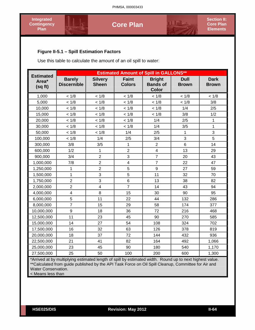
• Water: Visual observation and calibration with the A.P.I. Task Force on Oil Spill Cleanup, Committee for Air and Water Conservation's Spill Size Estimation Matrix. This matrix is included as Figure II-5.1 for spills to water. Other methods which can be used to determine size and volume of a spill include, but are not limited to:
• Other methods which can be used to determine size and volume of a spill include, but are not limited to:
• Vessel/line capacity formulas • Infra-red thermal imaging
• Land: • Use the Transportation Spill to Land Estimation Tool • SCADA (Control Center calculation) • Tank Data Program
PHMSA, 000003432
Core Plan Section II: Core Plan Elements
Integrated Contingency
Plan
HSE025/DIS II-64 Revision: May 2012
Figure II-5.1 – Spill Estimation Factors Use this table to calculate the amount of an oil spill to water:
Estimated Area* (sq ft)
Estimated Amount of Spill in GALLONS** Barely
Discernible Silvery Sheen
Faint Colors
Bright Bands of
Color
Dull Brown
Dark Brown
1,000 < 1/8 < 1/8 < 1/8 < 1/8 < 1/8 < 1/8 5,000 < 1/8 < 1/8 < 1/8 < 1/8 < 1/8 3/8 10,000 < 1/8 < 1/8 < 1/8 < 1/8 1/4 2/5 15,000 < 1/8 < 1/8 < 1/8 < 1/8 3/8 1/2 20,000 < 1/8 < 1/8 < 1/8 1/4 2/5 1 30,000 < 1/8 < 1/8 < 1/8 1/4 3/5 1 50,000 < 1/8 < 1/8 1/4 2/5 1 3 100,000 < 1/8 1/4 2/5 3/4 3 5 300,000 3/8 3/5 1 2 6 14 600,000 1/2 1 2 4 13 29 900,000 3/4 2 3 7 20 43
1,000,000 7/8 2 4 7 22 47 1,250,000 1 2 5 9 27 59 1,500,000 1 3 5 11 32 70 1,750,000 2 3 6 13 38 82 2,000,000 2 4 7 14 43 94 4,000,000 4 8 15 30 90 95 6,000,000 5 11 22 44 132 286 8,000,000 7 15 29 58 174 377 10,000,000 9 18 36 72 216 468 12,500,000 11 23 45 90 270 585 15,000,000 14 27 54 108 324 702 17,500,000 16 32 63 126 378 819 20,000,000 18 37 72 144 432 936 22,500,000 21 41 82 164 492 1,066 25,000,000 23 45 90 180 540 1,170 27,500,000 25 50 100 200 600 1,300
*Arrived at by multiplying estimated length of spill by estimated width. Round up to next highest value. **Calculated from guide published by the API Task Force on Oil Spill Cleanup, Committee for Air and Water Conservation. < Means less than
PHMSA, 000003433
Core Plan Section II: Core Plan Elements
Integrated Contingency
Plan
HSE025/DIS II-65 Revision: May 2012
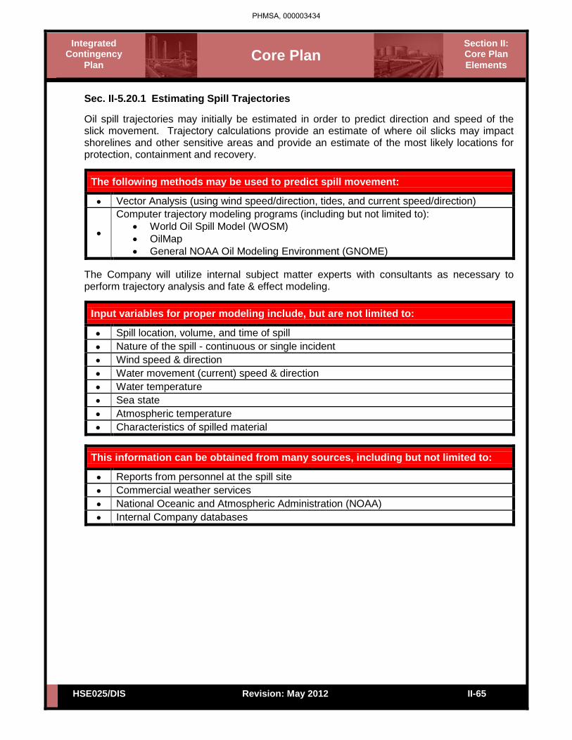
Sec. II-5.20.1 Estimating Spill Trajectories
Oil spill trajectories may initially be estimated in order to predict direction and speed of the slick movement. Trajectory calculations provide an estimate of where oil slicks may impact shorelines and other sensitive areas and provide an estimate of the most likely locations for protection, containment and recovery.
The following methods may be used to predict spill movement:
• Vector Analysis (using wind speed/direction, tides, and current speed/direction)
•
Computer trajectory modeling programs (including but not limited to): • World Oil Spill Model (WOSM) • OilMap • General NOAA Oil Modeling Environment (GNOME)
The Company will utilize internal subject matter experts with consultants as necessary to perform trajectory analysis and fate & effect modeling.
Input variables for proper modeling include, but are not limited to:
• Spill location, volume, and time of spill • Nature of the spill - continuous or single incident • Wind speed & direction • Water movement (current) speed & direction • Water temperature • Sea state • Atmospheric temperature • Characteristics of spilled material
This information can be obtained from many sources, including but not limited to:
• Reports from personnel at the spill site • Commercial weather services • National Oceanic and Atmospheric Administration (NOAA) • Internal Company databases
PHMSA, 000003434

Core Plan Section II: Core Plan Elements
Integrated Contingency
Plan
HSE025/DIS II-66 Revision: May 2012
Sec. II-5.20.2 Sampling and Testing
In defining an acceptable response to a spill incident, it is necessary to know certain physical and chemical characteristics of the spill material. If positive identification of the spilled material can be made without testing, product data may be obtained from a material safety data sheet (MSDS), product specification information, and/or records of product physical and chemical properties. Occasionally a spill may occur in which the spilled material is not readily identifiable. Typically, laboratory analytical data for spill event samples will not be instantaneously available during an emergency. Therefore, it is necessary and desirable to field-categorize oils as the product reacts and changes in the environment. Although varying widely in physical and chemical properties, oil products have common basic features that permit their grouping for predictive evaluation of environmental effects and determination of control actions. In addition, as petroleum products react and change (e.g., weather) when exposed in the environment, the laboratory data may not be representative of "real-time" conditions; rather the data may instead reflect the chemical characteristics of the spilled material(s) at the time of sample collection. The Oil Spill Trajectory Request Form is located in Section III of this plan.
PHMSA, 000003435

Core Plan Section II: Core Plan Elements
Integrated Contingency
Plan
HSE025/DIS II-67 Revision: May 2012
Sec. II-5.21 Spills to Groundwater Sec. II-5.21.1 General Spills to bare ground will initially spread laterally on the surface and then begin migrating downward through the soil and, depending on a variety of factors and circumstances, could reach groundwater. During vertical migration the spill will spread laterally to some degree and a portion of the oil will be absorbed by the soil particles or become trapped in small pores eventually immobilizing the spill.
In general, oil will continue migrating downward until:
• Residual Saturation is reached (all of the oil is absorbed by the soil) • Impenetrable Layer (silt, clay, sandstone, rock) is encountered • Groundwater is reached
If a spill does reach groundwater, the oil will form a mound on the surface of the groundwater (water table) and begin to spread horizontally but preferentially in the direction of groundwater flow. For higher groundwater velocities, a narrow plume elongated in the direction of groundwater flow will form whereas for lower velocities the plume broadens and assumes a more circular pattern. The thickness of the plume or layer of oil on the water table will decrease with distance from the source. As with vertical migration, a portion of the oil will adhere to soil particles and become trapped in small or water filled pores eventually becoming immobilized. For instantaneous or quasi-instantaneous spills, 40-70% of lateral spreading will generally occur in the first 24 hrs whereas 60-90% occurs in the first week. Sec. II-5.21.2 Response Actions In the event of a spill to bare ground, there are a number of actions that should be taken to assess the spill and, if groundwater is impacted, initiate recovery and limit the extent of impact. A decision guide is provided at the end of this section that outlines the general response actions that should be taken. Additional information on these response actions is also provided below.
PHMSA, 000003436

Core Plan Section II: Core Plan Elements
Integrated Contingency
Plan
HSE025/DIS II-68 Revision: May 2012
Sec. II-5.21.3 Initial Assessment As for any spill, the initial response actions for spills to bare ground should include the assessment of health and safety hazards. See the Site Safety and Health Plan as well as the following parameters.
Initial Assessment Parameters
• Spill Size and Product Accumulation (pooled oil) Depth • Product Type (viscosity) • Soil Type/Permeability/Moisture Content • Depth to Groundwater • Estimated Response Time to Initiation of Recovery Actions
Sec. II-5.21.4 Ground Impact Potential Once the assessment is completed, the potential for the spill to impact underlying groundwater should be determined and generally requires some knowledge of the local hydrogeology including soil type/permeability and depth to groundwater, and groundwater flow direction. The common factors, along with selected examples, that contribute to a spill having a higher or lower potential to impact groundwater are:
Higher Potential
• Shallow Groundwater (generally <20 ft) • Low Viscosity Oil (gasoline) • Dry Soil with Low Oil Retention Capacity • Highly Permeable Soils (sand, gravel, coarse grained mixed sediment) • Large Volume • Pooled Oil (creates hydraulic head that enhances penetration) • Response Time (several hours before pooled oil recovery begins)
Lower Potential
• Deep Groundwater (generally >20 ft) • Medium to High Viscosity Oil (industrial fuel oils, crude, lubricants, etc.) • Wet or Moist Soils with High Oil Retention Capacity • Low Permeability Soils (silts, clays, fine grained mixed sediment) • Small Volume • No Pooled Oil on Surface • Response Time (expeditious recovery of pooled oil or saturated soils)
PHMSA, 000003437

Core Plan Section II: Core Plan Elements
Integrated Contingency
Plan
HSE025/DIS II-69 Revision: May 2012
Sec. II-5.21.4 Ground Impact Potential (Cont’d) For small spills that do not pool on the ground surface, vertical penetration into the soil is often limited to 4 to 8 inches with the exception of coarse gravels which could allow considerably deeper penetration. Depth of penetration can be estimated if you know the square footage of surface impact, soil type, depth to groundwater and spill volume. Using the above information and the table shown below, a calculation of how much oil can be adsorbed/retained by the soil between the surface and the water table. If the retention capacity is significantly greater than the spill volume, the potential for the spill to reach groundwater would be low and vice versa.
Retention Capacity
Soil Type Oil Retention Capacity (gal / yd3) Stones, coarse gravel 1
Gravel, coarse san 1.6 Coarse sand, medium sand 3
Medium sand, fine sand 5 Fine sand, silt 8
Sec. II-5.21.5 Supplemental Assessment If the potential exists for a spill to reach groundwater, additional assessment activities should be conducted to confirm groundwater has been impacted and, if so, assess the extent of impacts. In most cases, experienced remediation contractors already under contract to the Company will be utilized to conduct subsequent assessment activities.
These activities commonly include:
• Backhoes or Excavators – excavate pits/trenches to determine penetration depth/groundwater impacts (limited to depths of 10–20 ft)
• Hand or Power Augers – install borings to collect soil/water samples and can be used to install temporary wells (often limited to 15-30 ft)
• Direct Push Drilling Rigs – install borings to collect soil/water samples and can be used to install temporary wells (often limited to 50-100 ft)
• Hollow Stem Auger (HAS) or rotary drill rigs - install borings to collect soil samples and wells for groundwater samples (limited to 100-500 ft)
The type of method used often depends on equipment availability, depth to groundwater and access to the spill area. For areas with shallow groundwater and good access, backhoes or excavators are often the most expedient means of determining penetration depth and groundwater impacts. If access is limited, such as in many tank farms, hand or power augers can be used to install borings and collect samples. Direct push (Geoprobe) rigs can get into many areas but are generally truck mounted and will need road access. For areas with good access and where groundwater is deeper, hollow stem augers or rotary drill rigs are often the best equipment for subsequent assessment.
PHMSA, 000003438

Core Plan Section II: Core Plan Elements
Integrated Contingency
Plan
HSE025/DIS II-70 Revision: May 2012
Sec. II-5.21.5 Supplemental Assessment (Cont’d) Borings or pits should be installed, if safe to do so, in the main spill area where penetration is typically greatest. If groundwater impacts are confirmed or expected, additional borings or wells should be installed by stepping out laterally from the spill area and primarily in the down gradient direction until the groundwater impact area is delineated. It is important to note that if intrusive activities (excavation, drilling, hand augers, etc.) are necessary, additional air monitoring of the excavation and breathing zone around the activities should be conducted to ensure additional hazards are not created by the activities. In addition, if excavation activities are conducted and it is necessary for workers to enter the excavation, confined space permitting and/or shoring regulations may apply. Sec. II-5.21.6 Recover/Remediation In the event a spill does reach groundwater or the threat of reaching groundwater remains, recovery or remediation activities will need to be conducted to mitigate the impacts. The impacts could be limited to low concentrations of hydrocarbons that have dissolved into the groundwater or, for larger spills, involve a layer of oil/product floating (separate, or non-aqueous, phase hydrocarbons) on the groundwater surface (water table) accompanied by elevated concentrations of dissolved (aqueous phase) hydrocarbons in the groundwater.
Some of the more common groundwater remediation techniques include:
• Pump and Treat • Excavation • Bioremediation • Air Sparging • Soil Vapor Extraction • In Situ Oxidation
Selection of the most appropriate remediation technique will depend on a number of factors including product type, soil type, depth to groundwater, access, extent of impacts, current groundwater use, etc. The Company will utilize experienced remediation contractors to select and implement the most appropriate remediation technique(s). The local or regional remediation contractor(s) under contract to the Company are provided in the Contacts Section of this plan, along with their contact information.
PHMSA, 000003439

Core Plan Section II: Core Plan Elements
Integrated Contingency
Plan
HSE025/DIS II-71 Revision: May 2012
• Spill Size/Accumulation • Product Type/Viscosity • Soil Type/Permeability/
Moisture • Depth to Groundwater • Estimated Response Time
Conduct Initial Assessment
• Large Volume/Low Viscosity
• Dry Permeable Soils • Shallow Groundwater • Pooled Oil • Extended Response Time
Is it safe to respond?
Conduct Terrestrial Spill
Cleanup
Conduct Groundwater Remediation
• Pump & Treat • Excavation • Bioremediation • Air Sparging • Soil Vapor Extraction • In Situ Oxidation
Is Groundwater Impacted or likely
to be?
Potential for Groundwater
Impact?
Continue Monitoring Spill
Area
Conduct Supplemental Assessment
• Backhoe/Excavator • Hand Power Augers • Direct Push Drilling • Hollow Steam
Auger/Rotary Drill Rigs
No Yes
Yes No
Yes
No
Spill Occurs
Figure II-5.2 – Groundwater Spill Response Strategy Guide
PHMSA, 000003440

Core Plan Section II: Core Plan Elements
Integrated Contingency
Plan
HSE025/DIS II-72 Revision: May 2012
Sec. II-5.22 Natural Disasters This checklist identifies actions to be taken when the Pipeline and/or its facilities are threatened by thunderstorms, producing lightning or high winds.
Thunderstorms / Lightning / High Winds Checklist Procedures Date/Time
Establish communications with the Field office for weather updates. / / [00:00]
Upon notification by weather monitoring of impending severe weather conditions, notify the initial Incident Commander or the appropriate office of the situation.
/ / [00:00]
Personnel will be instructed to shut down all nonessential activities and take shelter where available until the storm has passed. / /
[00:00] Immediately bring personnel off vessels, tanks, pipe racks, and other elevated work areas. Suspend product loading operations and close all tank openings.
/ / [00:00]
Take shelter until the storm has passed. / / [00:00]
Tornado Safety Checklist
If a tornado warning has been issued. Use the following checklist Procedures Date/Time
Establish communications with the Field office for weather updates. / / [00:00]
Sound the alarm. / / [00:00]
Have location personnel report to the designated area. / / [00:00]
Avoid all windows and proceed to an interior room on the lowest floor or tornado shelter, if available.
• Interior stairwells will be one of the best shelters, if available. / /
[00:00]
Seek shelter under a sturdy/heavy piece of furniture. / / [00:00]
Use your arms to protect the back of your head and neck. / / [00:00]
Once the all clear has sounded:
Account for all Personnel / / [00:00]
Begin search and rescue if any personnel is missing / / [00:00]
PHMSA, 000003441

Core Plan Section II: Core Plan Elements
Integrated Contingency
Plan
HSE025/DIS II-73 Revision: May 2012
Earthquake
Procedures Date/Time
Assess situation and exercise caution. / / [00:00]
Emergency Shut Down, if necessary. Notify Control Center as needed. / /
[00:00] If damage has occurred, close the nearest block valves on either side of the damaged location. / /
[00:00] Conduct visual inspection of the line(s) using one or more of the following methods.
Aircraft Vehicle Walking
/ / [00:00]
Evacuate the line for closer inspection and/or pressure test prior to resuming operations, if necessary. / /
[00:00]
Inspect system integrity / / [00:00]
Check off-site areas for damage. / / [00:00]
River Flood, Severe Storm, Freeze Protection Preparedness Checklist Procedures Date/Time
Refer to applicable Flood, Hurricane, and Freeze Protection Preparedness Plan / /
[00:00]
PHMSA, 000003442

Core Plan Section II: Core Plan Elements
Integrated Contingency
Plan
HSE025/DIS II-74 Revision: May 2012
PHMSA, 000003443
(b) (7)(F)

Core Plan Section II: Core Plan Elements
Integrated Contingency
Plan
HSE025/DIS II-75 Revision: May 2012
PHMSA, 000003444
(b) (7)(F)

Core Plan Section II: Core Plan Elements
Integrated Contingency
Plan
HSE025/DIS II-76 Revision: May 2012
PHMSA, 000003445
(b) (7)(F)

Core Plan Section II: Core Plan Elements
Integrated Contingency
Plan
HSE025/DIS II-77 Revision: May 2012
Sec. II-6 Detection Procedures Sec. II-6.1 Release Detection The Company has a number of safety systems and practices in place to prevent the occurrence and mitigate the subsequent impact of accidental releases. The systems are designed to alert operators with alarms and provide automatic shut-in functions in the event of a release. Pipeline operators are trained to respond to the various system alarms in order to identify and control releases immediately.
The routine responsibilities that ensure releases will be detected and mitigated as soon as possible by IC/UC personnel may include, but are not limited to the following: • Regularly scheduled visual and aerial monitoring.
• Routine walk-through and monitoring of process equipment to ensure proper operation of all equipment at each facility.
• Immediate response to alarms and signals that may indicate a possible release. • Identification and control of the source as soon as safely possible. • Notify the Person in Charge.
All pipelines operated by the Company are equipped with high and low pressure sensors. In the event of a change in pipeline pressure beyond a specified set point, the pressure sensors will trigger an alarm to the facility operator and/or shut down the pipeline and process equipment.
The Company operators will perform the following procedures when they are alerted to a potential pipeline emergency:
Procedures Date/Time Ensure that the pipeline pressure sensing equipment is not malfunctioning. / /
[00:00] The supervisor will request a field inspection of the pipeline in question to identify the source of the suspected leak. / /
[00:00] In the event an oil leak is discovered along the pipeline, this Plan will be activated. / /
[00:00] In the event a leak is not found, an investigation into the cause of the pressure change will continue until determined. / /
[00:00]
PHMSA, 000003446

Core Plan Section II: Core Plan Elements
Integrated Contingency
Plan
HSE025/DIS II-78 Revision: May 2012
Sec. II-6.2 Discharge Detection Systems
The Company will provide a detailed description of the procedures and equipment used to detect discharges. A section on discharge detection by personnel and a discussion of automated discharge, if applicable, will be included for both regular operations and after hours operations. In addition, the Company will discuss the reliability of any automated system, how it will be checked and how frequently the system will be inspected. Sec. II-6.3 Discharge Detection by Personnel
Sec. II-6.3.1 Routine Inspections Terminal operators perform routinely scheduled terminal inspections. Terminal equipment and current movements are checked for evidence of leaks or spills in addition to various other observations such as security, equipment operation, etc. Sec. II-6.3.2 Safe Fill When pipeline receipts or transfers are made, the volumes used in the calculations for space available use a safe fill height as the maximum operating level. Sec. II-6.3.3 Receipt Monitoring Terminal employees coordinate all receipts with pipeline representatives. This involves determination of the volume of each product grade prior to receipt. The receipt progress, incoming volumes and high level alarm signals are monitored at all times when product is being transferred into the terminal from the pipeline by the Control Center. Sec. II-6.3.4 Tank Gauging Each tank scheduled to receive a receipt is gauged prior to receipt to confirm that space is available for the receipt. Sec. II-6.3.5 High Level Alarms All tanks are equipped with high level alarms. High level alarms are indicated by an audible signal that can be heard anywhere on the complex as well as visual indication in the Control Room. A signal is also sent to the Control Center and requires immediate contact with the facility operator. Alarms are tested periodically in accordance with company preventive maintenance procedures. Sec. II-6.3.6 Volume Reconciliation Tanks are gauged at month end as part of our physical inventory reconciliation program. Sec. II-6.3.7 Pipe Testing Belowground piping is periodically tested.
PHMSA, 000003447

Core Plan Section II: Core Plan Elements
Integrated Contingency
Plan
HSE025/DIS II-79 Revision: May 2012
Sec. II-6.3.8 Observations and Documentation The condition of tanks and equipment are observed when employees responsible for the operation and maintenance of the terminal are on shift. Documentation of these conditions will be logged periodically at the discretion of the local supervisor. The following are elements of the oil inventory control system: Sec. II-6.3.9 Physical Inventory This currently serves as the basis for comparing an inventory-reporting period with the previous reporting period. Current practice uses end of month physical inventory [calculated in net barrels per petroleum measurement tables (ASTM D1250 80, 5B, and 6B)] as an opening inventory for the next month's reporting period. Sec. II-6.3.10 Facility Throughput Facility throughput is product leaving a tank primarily through a truck loading rack with meters. Meters on truck loading racks are to be calibrated according to a set interval. They are also reconciled in conjunction with physical inventory taking as well as on a standalone basis. Quantity loaded shall be determined on a net basis using temperature from temperature probes mounted at or near the loading rack and gross gallon quantities from meter pulses. These throughput quantities shall be deducted from inventory. Sec. II-6.3.11 Product Variation A physical inventory can be taken to compare with the book inventory quantity, if necessary. The difference between the book and physical quantity is a product variation. Variations may be positive or negative. Statistical Process Control (SPC) is the basis for determining whether this variation should trigger an investigative effort to determine whether product is unknowingly being discharged. Sec. II-6.3.12 Statistical Process Control (SPC) Control limits (both upper and lower) are set for each product variation based upon historical information at each facility. Product variations between the control limits are considered to be OK and do not require an investigation or documentation. These variations inside of limits are considered to be a "random" occurrence that is an inherent part of the control process. Product variations outside the control limits are to be investigated using techniques outlined in Transportation's Terminal Operation and Procedures Manual with documentation required at both the terminal and Accounting. The control limits will be periodically checked to determine if they are still valid or whether process changes or improvements have invalidated them. If a release is detected, personnel are directed to notify the proper authorities (see the Notifications Section).
PHMSA, 000003448

Core Plan Section II: Core Plan Elements
Integrated Contingency
Plan
HSE025/DIS II-80 Revision: May 2012
Sec. II-6.4 Automated Discharge Detection
The terminal is equipped with high level alarms, which sound an alarm locally at the terminal. Control Center also receives an alarm if this "high level" is reached. When the Company receives these alarms, immediate contact with the facility operator on duty is established. The high level alarm is set below the tank overfill height to ensure enough time to shut down the line before overfilling occurs.
Sec. II-6.5 Source Control
Company operators have been trained to respond to abnormal pipeline/facility operations. Source control will be maintained with the following systems and procedures:
•
• In the event the incident does not allow automatic control, the operator has the flexibility to control a release by manually activating shutdown devices or closing valves, etc. provided that the personnel are not exposed to the released substances.
• In the event the source cannot be controlled by the pipeline operator or remotely with a safety system, the Company will activate this Plan and assemble a team to respond to the situation.
•
PHMSA, 000003449
(b) (7)(F)
(b) (7)(F)
(b) (7)(F)

Core Plan Section II: Core Plan Elements
Integrated Contingency
Plan
HSE025/DIS II-81 Revision: May 2012
Sec. II-6.6 Good Engineering Practices. The Company’s approach to preventing discharges is to assure that all facilities are properly designed, constructed, maintained and operated. Some examples of good engineering practices may include but are not limited to the following:
Engineering Practices
• Components in the pipeline system are designed and constructed in accordance with written specifications.
• Components are inspected to ensure that quality is maintained during material procurement and construction.
• Trained personnel are used during the construction of the facilities. • Various testing methods are used during construction of the facilities.
• External and internal corrosion control methods are used to maintain the facilities in the best possible condition.
• A preventive maintenance program reduces the potential for component malfunction or failure
• Company personnel are properly trained to operate and maintain the pipeline system
• Company has an extensive safety and drug testing program for its employees and requires the same for its contractors.
• Company systems are designed and operated with safety factors in place. For example, the maximum operating pressure of a system is always less than the design pressure of the system and the test pressure of the system.
• Pressures are monitored and controlled so that the maximum operating pressures are not exceeded.
• When appropriate, internal inspection tools are used or lines are subjected to additional hydrostatic testing to determine and assure their integrity.
• All wastes are stored in accordance with applicable regulatory requirements (DOT containers that are non-leaking, closed, in good condition, properly marked/labeled, inspected to ensure integrity, etc.)
PHMSA, 000003450

Core Plan Section II: Core Plan Elements
Integrated Contingency
Plan
HSE025/DIS II-82 Revision: May 2012
Sec. II-6.7 Third-Party Damage Prevention If the systems are properly designed, constructed, operated and maintained, then the most probably source of discharge is due to third-party damage. In order to minimize the risk of damage caused by a third-party a number of steps may be taken, including, but not limited to the following:
Prevention of Third-Party Damage
• The facilities are designed to reduce the chance of third-party damage. For example, most of the facilities are buried or located within fenced and locked areas.
• Areas especially sensitive to third-party damage are road, railroad, and water crossings. Pipelines in these areas usually have additional wall thickness, or burial depth, or are cased to reduce the chance of damage.
• Company facilities are normally located on well- maintained and clearly marked rights-of-way.
• Company facilities are normally monitored by aerial or other patrol at least once per week to check for encroachment and construction activities.
• Company participates in one-call pipeline locating and notification systems where available.
• Company conducts education programs to reduce the possibility of third-party damage.
Sec. II-6.8 Corrosion Mitigation
For external corrosion prevention, the Company generally prevents corrosion of buried pipelines by using approved long-life pipeline coatings supplemented with cathodic protection. Aboveground facilities are generally inspected annually and provided protective coating systems to prevent corrosive deterioration. These primarily include buildings, aboveground pipelines and tanks. In order to prevent internal corrosion of the pipelines, the Company uses chemical injection, pigging and corrosion inhibitors, and inspects pipelines located in high population density areas and environmentally sensitive areas with in-line inspection pigs, where appropriate. A large number of pipelines are hydrostatically tested. Sec. II-6.9 Spill Mitigation
Source control and mitigation involve anything from shutdown of operations to patching a leak, containing a spill, dispersing a vapor cloud, protecting a sensitive area, recovering the spilled material, or other such activities that are involved in an emergency response. Because of the infinite number of circumstances under which an incident could occur and the variety of equipment that could be involved, it is impractical to describe procedures that should be followed in all foreseeable emergency situations.
PHMSA, 000003451

Core Plan Section II: Core Plan Elements
Integrated Contingency
Plan
HSE025/DIS II-83 Revision: May 2012
Sec. II-6.10 Tank Overfill and Fire Prevention Each tank is provided with a connection for a semi-fixed fire protection system. Individual foam laterals that run from connections outside the dike areas serve each tank. The foam laterals are controlled by manual valves. Connections to the tanks depend on roof construction. Foam fire fighting capabilities are provided by the Refinery and/or the Linden Fire Department. Each bulk storage tank is equipped with a liquid level gauging device and an independent high-level alarm system with audible and visual alerts. During product movements the operator and field personnel maintain radio communication. All tanks are also manually gauged to check the accuracy of the automatic liquid level gauging system.
Delivery personnel monitor tank levels during the filling period for small mobile/portable tanks to provide overfill protection.
Sec. II-6.10.1 Storage Tank Overfill Lines All overflow or vent lines on bulk storage tanks, as well as the building heating oil and gasoline additive tanks, are directed into the tank's secondary containment areas. Overflow lines on the jet fuel and diesel fuel additive tanks are directed into the truck rack secondary containment.
Sec. II-6.11 Visual Tank Inspection The visual tank inspection checklist presented below has been included as guidance for inspections and monitoring. Also included in the visual tank inspection will be an inspection of the tank foundation and associated piping. All tankage, pumping equipment, piping and related terminal equipment are inspected every working day for leakage, malfunctions of seals, etc. Storage tanks are inspected monthly and annually and findings are recorded. Example forms are included in this plan. These records shall be maintained for a minimum of five years.
Check tanks for leaks, specifically looking for: • Drip marks • Discoloration of tanks • Puddles containing stored materials • Corrosion • Cracks • Localized dead vegetation
PHMSA, 000003452

Core Plan Section II: Core Plan Elements
Integrated Contingency
Plan
HSE025/DIS II-84 Revision: May 2012
Check foundation for: • Cracks • Discoloration • Puddles containing stored materials • Settling • Gaps between tank and foundation • Damage cause by vegetation roots
Check piping for: • Droplets of stored material • Discoloration • Corrosion • Bowing of pipe between supports • Evidence of stored material seepage on valves and seals • Localized dead vegetation
Terminal operators visually inspect all tanks each working day for leaks. Daily tank gauges are reviewed for evidence of product loss that would indicate a leak in the tank. Any visible oil leaks from tank seams, gaskets, rivets and/or bolts are corrected immediately.
Sec. II-6.12 Secondary Containment Inspection The secondary containment areas shown on the site plans will be inspected on an annual basis. The inspections will include checking for the following:
Dike or berm system: • Level of precipitation in dike/available capacity • Operation status of drainage valves • Debris • Erosion • Location/status of pipes, inlets, drainage beneath tanks, etc.
Secondary containment: • Cracks • Discoloration • Presence of stored materials (standing liquid) • Corrosion • Valve conditions
PHMSA, 000003453

Core Plan Section II: Core Plan Elements
Integrated Contingency
Plan
HSE025/DIS II-85 Revision: May 2012
Retention and drainage ponds: • Erosion • Available capacity • Presence of stored material • Debris • Stressed vegetation
Sec. II-6.13 Pipeline Inspections All pipelines within the Company Pipeline System are monitored on a regular and routine basis.
. These control centers are operated on a 24-
hour basis. Should a leak occur, the operators monitoring the lines can have the line shut down within minutes. The operators can then dispatch field personnel to physically inspect the line in the area of the suspected leak.
These lines are observed regularly by facility/pipeline maintenance personnel. In
addition to these inspections, aircraft that fly the pipeline on a scheduled weekly basis inspect the lines. Sec. II-6.14 Buried Piping Nearly all piping has been moved above grade. Most of the remaining buried, underground lines run under roadways. Some piping appears as "buried", but is really only penetrating an elevated roadway or containment berm for a short distance, approximately 20 feet. Even though such penetrations require sealing to not compromise the containment, any leakage from short, elevated lengths would appear where the pipe penetrates the berm/roadway, rather than migrate vertically downward through compacted clay berms/roadways. This leakage would readily be detected by personnel during routine visual inspections. There are no existing state-of-the-art leak detection devices available for retrofitting to existing buried piping. When a leak is detected from a buried pipe, the Company will excavate, examine, and evaluate the pipe for the cause of the failure. Localized pipe failures will be repaired or replaced. For extensive pipe failures requiring substantial reconstruction, the Company will upgrade to the standard specified under the DPCC regulations. For the purposes of this plan, substantial reconstruction is defined as more than 50 percent of the replacement value of an existing pipe section from valve to valve. Facility practices generally prohibit the installation of buried pipes, other than water and sewer lines. The need for new buried product piping is evaluated on a case-by-case basis. If such a need is identified, the Company will install new buried piping to the standard specified under the DPCC regulations. Should new elevated roadway/containment berm penetrations be required for a project, they will be constructed according to current practices.
PHMSA, 000003454
(b) (7)(F)
(b) (7)(F)

Core Plan Section II: Core Plan Elements
Integrated Contingency
Plan
HSE025/DIS II-86 Revision: May 2012
Sec. II-6.14.1 Exposed Buried Piping If a section of buried pipe is exposed for any reason, it is carefully examined for deterioration, and, if found to be deteriorated, shall be repaired or replaced. Buried piping requiring substantial reconstruction or replacement shall be rerouted above grade, if possible, or upgraded to new buried piping standards. Sec. II-6.14.2 Out-of-Service Pipes If not in service for extended periods of time, terminal pipe connections are blind flanged, plugged or capped and appropriately marked. This practice applies to- all piping in the terminal where an open-ended line could exist, whether or not protected by valving. Sec. II-6.14.3 Pipe Supports In accordance with good engineering practice and petroleum industry standards, pipe supports are designed to minimize abrasion and corrosion and allow for expansion and contraction of the pipeline. Sec. II-6.14.4 Elevated Pipes Elevated pipelines to the loading racks are sufficiently high and the supports adequately protected to prevent tank trucks from accidentally hitting them. Speed limit signs posted at the entrance of each loading rack bay limit any impact damage to aboveground pipelines. Sec. II-6.15 Dike Drainage
Drainage of precipitation accumulation from dike areas is performed only after inspection of the accumulation to ensure compliance with applicable water quality standards. Any water possessing a film, sheen or discoloration on the surface is not discharged until such sheen has been physically removed with the use of absorbent pads.
Drain valves are sealed and locked at all times except when there is an operator on-site who: • Inspects the water for a film, sheen, or discoloration; • Removes any film, sheen, or discoloration; • Monitors the discharge; and, • Records the discharge event in the SPCC plan.
Sec. II-6.16 High Level Alarms
High level alarms on storage tanks are inspected routinely to simulate actual operating conditions to ensure that overfill during tank filling operations are adequately detected. Results of high-level alarm inspections are recorded in the SPCC plan once every six months.
PHMSA, 000003455

Core Plan Section II: Core Plan Elements
Integrated Contingency
Plan
HSE025/DIS II-87 Revision: May 2012
Sec. II-6.17 Rack Drain Rack drains are inspected to ensure that any petroleum release from the loading facilities can be conveyed through clean, open drains into proper on-site containment. Results of the rack drain inspections are recorded in the SPCC plan every six (6) months. Sec. II-6.18 Cathodic Protection System Cathodic protection systems are inspected to ensure proper function. Results are updated in once every six (6) months. Sec. II-6.19 Delivery Lines and Manifold The facility tests the delivery lines and manifold on an annual basis with a two (2) hour recorded pressure test.
Sec. II-7 Emergency Response Equipment, Testing & Deployment Sec. II-7.1 Response Equipment for Small Discharges
Response equipment for small discharges (< 50 barrels) will primarily come from contracted OSRO’s as well as any Company equipment stored locally. Much of this equipment is utilized for day-to-day booming of vessels, as well as for immediate rapid response to all leaks/discharges by terminal personnel and contractors. The equipment can be operated by terminal personnel and/or contractor personnel listed in this Plan. The Management Response Team may authorize additional contractor-supplied equipment and personnel, as needed. This Plan discusses onsite tank storage capacity for recovered oil/water mixtures. *All OSRO specific information will be detailed in the applicable ICP Geographical Annex. Sec. II-7.2 Response Equipment for Medium Discharges
Response equipment for medium (1,200 barrels) discharges again will come from Contacted OSRO’s as well as from Company equipment stored locally. Other contractors may be called upon as well depending on the specific needs. These too are listed in the applicable ICP Geographical Annex.
Sec. II-7.3 Response Equipment for Worst-Case Discharges
Response equipment for a worst-case discharge at any Company operational facility/pipeline is located in the applicable ICP Geographical Annex. The Company has guaranteed through contract or other approved means the ability to ensure appropriate response capabilities to any area worst case discharge. In addition, the Company has also ensured the ability to sustain prolonged operations as well.
PHMSA, 000003456

Core Plan Section II: Core Plan Elements
Integrated Contingency
Plan
HSE025/DIS II-88 Revision: May 2012
Sec. II-8 Waste Management Plan Sec. II-8.1 Introduction
The following wastes may be generated and could be determined to be "hazardous":
• Paint Chips • Avgas Filters • Petroleum contaminated materials that are not considered “of-spec product”
Most of the wastes are "hazardous" due to the benzene concentrations in the wastes (>0.5 mg/l) or ignitability. The avgas filters are frequently determined to be "hazardous" due to the lead concentrations (>5.0 mg/l) in the filters. The paint chips are typically hazardous for lead, chromium or both (>5.0 mg/l). The following materials are more frequently generated and are not considered a solid waste or a “hazardous waste”.
These materials are exempt from the definition of a solid waste because they are classified as an “off-spec product” destined for product reclamation. • Tank bottom water • Loading rack runoff • Tank bottom sludge • Oil/water separate sludge
It is the purpose of the Terminal’s hazardous waste contingency plan to minimize hazards to human health and the environment in the event of an emergency. This plan is designed to address emergencies that may occur during operations at this facility involving hazardous wastes.
Sec. II-8.2 Applicability The plan must be carried out immediately whenever there is a fire, explosion or release of hazardous waste that could threaten human health or the environment.
Sec. II-8.3 Amendments to Plan
The contingency plan must be reviewed and immediately amended whenever:
• Applicable regulations are revised • Plan fails in an emergency
• Facility changes in design, construction, operation, maintenance, or any way increasing the potential for fires, explosions, or releases of hazardous waste, or changes the response necessary in an emergency
• List of emergency coordinators changes • List of emergency equipment changes
PHMSA, 000003457

Core Plan Section II: Core Plan Elements
Integrated Contingency
Plan
HSE025/DIS II-89 Revision: May 2012
Sec. II-8.4 Identification of Emergency Coordinator The names, addresses and phone numbers (office and home) of all persons qualified to act as emergency coordinator are located ICP Geographical Annex 2 of this plan. Sec. II-8.5 Emergency Procedures Whenever there is an imminent or actual emergency situation the emergency coordinator or alternate must immediately activate the facility alarm systems or communications system. The actions that must be taken in the event of a release of hazardous waste to the air, soil or surface water at the facility are located in this Core Plan. Sec. II-8.6 Evacuation Plan Due to the characteristics of the hazardous wastes generated, evacuation of a facility should not be necessary. In the event evacuation is necessary, the facility evacuation plan should be followed. A description of the signal(s) to be used and evacuation routes is provided. The facility drainage plan can be located at the end of this section. Sec. II-8.7 Notification Requirements The only emergency that may occur with regard to the management of hazardous waste at the facility is a sudden or non-sudden release of hazardous waste. The reportable quantity (RQ) for spills of D018 waste is 10 pounds (1.2 gallons). Any spill equal to or greater than the RQ must be reported to the National Response Center. Reporting procedures should follow the guidelines provided in this Core Plan. Sec. II-8.8 Arrangements with Agencies and Contractors As required by 40 CFR 264.53, all Terminals will have provided the police departments, fire departments, hospitals and State and Local Emergency Response Teams that may be called upon to provide emergency services. In addition, the Company will make every effort to invite local agencies to participate, as appropriate, in any exercise or drill. .
PHMSA, 000003458

Core Plan Section II: Core Plan Elements
Integrated Contingency
Plan
HSE025/DIS II-90 Revision: May 2012
Sec. II-8.9 Emergency Equipment
Emergency Equipment
•
A list of all spill response equipment available in the event of a release is listed in the appropriate ICP Geographical Annex of this Core Plan. A list of spill response contractors to be used by the facility in the event of a release that could surpass the response capabilities of the facility is also located in appropriate ICP Geographical Annex of this Core Plan.
• A list of emergency fire equipment at the facility is located in the Emergency Procedures Plan.
• A description of the facility's communication equipment and plan is provided in this Core Plan.
• A description of the facility's alarm systems is provided in this Core Plan. Federal, state and local rules designed to ensure safe and secure handling of waste materials govern the waste disposal activities of the Company. To ensure proper disposal of recovered oils plus associated debris, the Company’s Waste Management and Recycling Guide should be consulted/followed. The Company’s Environmental Group will advise/support IC/UC on all waste management needs during an emergency response to ensure compliance with all applicable regulations and internal waste management policies and guidelines. The Company must describe how and where the facility intends to recover, reuse, decontaminate or dispose of materials after a discharge has taken place. The appropriate permits required to transport or dispose of recovered materials according to local, State and Federal requirements must be addressed.
Material that must be accounted for in the disposal plan, as appropriate, include
• Recovered product • Contaminated equipment and materials, including drums, tank parts, valves, shovels • Personnel protective equipment • Decontamination solutions • Adsorbents • Spent Chemicals
These plans must be prepared in accordance with Federal (e.g., the Resource Conservation and Recovery Act [RCRA], State and local regulations, where applicable.
PHMSA, 000003459

Core Plan Section II: Core Plan Elements
Integrated Contingency
Plan
HSE025/DIS II-91 Revision: May 2012
Initial oil handling and disposal needs may be overlooked in the emergency phase of a response, which could result in delays and interruptions of cleanup operations. Initially, waste management concerns should address:
Initial Waste Management Concerns:
• Skimmer Capacity • Periodic removal of contained oil • Adequate supply of temporary storage capacity and materials
The following action items should be conducted during a spill response:
• Development of a site-specific Safety and Health Plan addressing the proper PPE and waste handling procedures
• Development of a Disposal Plan
• Continuous tracking of oil disposition in order to better estimate amount of waste that could be generated over the short and long-term
• Organization of waste collection, segregation, storage, transportation and proper disposal
• Minimization of risk of any additional pollution • Regulatory review of applicable laws to ensure compliance • Documentation of all waste handling and disposal activities • Disposal of all waste in a safe and approved manner
Good hazardous waste management includes:
• Reusing materials when possible • Recycling or reclaiming waste • Treating waste to reduce hazards or reducing amount of waste generated
The management of the wastes generated in clean-up and recovery activities must be conducted with the overall objective of ensuring:
Overall Objectives
• Worker Safety • Waste Minimization • Cost-Effectiveness • Minimization of Environmental Impacts • Proper Disposal • Minimization of present and future environmental liability
PHMSA, 000003460

Core Plan Section II: Core Plan Elements
Integrated Contingency
Plan
HSE025/DIS II-92 Revision: May 2012
Solid wastes such as sorbents, PPE, debris and equipment will typically be transported from the collection site to a designated site for:
Designated Site Activities
• Storage • Waste segregation • Cost-Effectiveness • Packaging • Transportation
Once this process is complete, the waste will be shipped off-site to an approved facility for required disposal. A general flowchart for waste management guidelines is shown in Figure II-8.1. An overall checklist for containment and disposal is located in Figure II-8.2. Sec. II-8.10 Storage During an oil spill the volume of oil that can be recovered depends on the storage capacity available. Typical short-term storage methods are summarized in Figure II-8.3. If storage containers such as bags or drums are used, the container should be clearly marked and/or color-coded to indicate the type of material or waste contained and/or the ultimate disposal option.
PHMSA, 000003461

Core Plan Section II: Core Plan Elements
Integrated Contingency
Plan
HSE025/DIS II-93 Revision: May 2012
Figure II-8.1 – Waste Management Flowchart
Waste Generation
Solid Waste
Liquid Waste
Non-Oiled Solids
Oiled Solids
Segregate Land Fill
Oil Oily Liquids
Non-Oily Liquids
Treatment Facility
Incineration Incineration Land Farm
Land Fill Land Farm
Disposal
Recycle
PHMSA, 000003462

Core Plan Section II: Core Plan Elements
Integrated Contingency
Plan
HSE025/DIS II-94 Revision: May 2012
Figure II-8.2 – General Waste Containment and Disposal Checklist
Consideration Yes / No / NA
Is the material being recovered as waste or reusable product? Has all recovered waste been containerized and secured so there is no potential for further leakage while the material is being stored?
Has each of the discrete waste streams been identified? Has a representative sample of each waste stream been collected? Has the sample been sent to an approved laboratory for the appropriate analysis (i.e. hazardous waste determination)?
Have the appropriate waste classification and waste code numbers for the individual waste streams been received?
Has a temporary EPA identification number and generator number(s) been received, if they are not already registered with EPA?
Have the services of registered hazardous waste transporter been contracted, if waste is hazardous?
If the waste is nonhazardous, is the transporter registered? Is the waste being taken to an approved disposal site? Is the waste hazardous or Class I nonhazardous? If the waste is hazardous or Class I nonhazardous, is a manifest being used? Is the manifest properly completed? Are all Federal, State and Local laws/regulations being followed? Are all necessary permits being obtained? Has a Disposal Plan been submitted for approval/review? Have PPE and waste-handling procedures been included in the Site Safety and Health Plan to protect the health and safety of waste handling personnel?
PHMSA, 000003463

Core Plan Section II: Core Plan Elements
Integrated Contingency
Plan
HSE025/DIS II-95 Revision: May 2012
Figure II-8.3 – Temporary Storage Methods
PRODUCT
Containment OIL OIL/WATER OIL/SOIL OIL/DEBRIS
(Small) OIL/DEBRIS
(Medium) OIL/DEBRIS
(Large) Capacity
Drums X X .2-.5 yd3
Bags X X X 1-2 yd3
Boxes X X X 1-5 yd3
Open Top Rolloff X X X X X X 8-40 yd3
Roll Top Rolloff X X X X X 15-25 yd3
Vacuum Box X X 15-25 yd3
Frac Tank X X 500-20,000 gal
Poly Tank X X 200-4,000 gal
Vacuum Truck X X X 2,000-5,000 gal
Tank Trailer X X 2,000-4,000 gal
Barge X X 3,000+ gal
Berm, 4 ft
X X X X X X 1yd3
Bladders X X 25-1,500 gal
Approved waste management facilities can be located on the Company website: http://hse.conocophillips.net/EN/environmental/waste/program/Pages/index.aspx
Sec. II-9 Disposal Plan
Oil will be recovered and water will be disposed of as normal produced water through permitted UIC injection wells or third-party disposal wells. Solid waste recovered during clean-up activities will be stored in secure areas (lined, bermed temporary storage areas, lined pits, or tanks) until permits can be secured for proper disposal.
Disposal Options for contaminated soil, depending upon analysis, include but are not limited to the following: • Surface remediation • Enhanced surface remediation • Third party recycling (adsorbents) • Third party disposal
PHMSA, 000003464

Core Plan Section II: Core Plan Elements
Integrated Contingency
Plan
HSE025/DIS II-96 Revision: May 2012
These disposal options will be dependent upon laboratory analysis per current federal, state and local regulation. The Company Waste Management and Recycling Guide should be consulted for the appropriate analytical requirements for each waste stream. Necessary federal, state and local permits will be obtained by Company Environmental personnel. Oil contaminated absorbent materials will be stored in covered secured containers and ultimately shipped for recycling. Spilled material will be skimmed to recover product and minimize contamination of vegetation and soil. Low pressure flushing will also be used to enhance recovery of liquid product. Absorbent materials may be used to recover spilled material that vacuum trucks are unable to pick up. Absorbent materials (and booms) are then recycled and returned for potential future use. Other oil contaminated booms, boats, and boots, will be cleansed by qualified contractors or wiped down on site with rags. The rags will be disposed of properly. The Company has contracted with USCG Certified OSROs for each ICP Geographical Annex. Contact information and response capability for each OSRO can be found in that particular ICP geographically Annex. The OSRO(s) contracted to respond in each ICP Geographical Annex is capable of being on site and ensuring planned temporary storage and waste disposal activities are accomplished within the appropriate tier times. They will provide sufficient temporary storage to ensure enough capacity is available to respond to a worst-case discharge.
PHMSA, 000003465

Core Plan Section II: Core Plan Elements
Integrated Contingency
Plan
HSE025/DIS II-97 Revision: May 2012
Figure II-9.1 Disposal Plan Form
Disposal Plan Page 1 of 3 Date: Location:
Source of Release:
Amount of Release:
Incident Name:
State On-Scene Coordinator:
Federal On-Scene Coordinator:
Time Required for Temporary Storage:
Proposed Storage Method:
Identified Storage Location / Staging Area:
Disposal Priorities Sample Date: Sample ID:
Analysis Required (Type):
Laboratory Performing Analysis:
Disposal Options Available Likely Possible Unlikely
Landfill In-situ Bio-Remediation
In-situ Burn
Pit Burning
Hydrocyclone Off Site Incineration
Reclaim
Recycle Resources Required for Disposal Option(s)
PHMSA, 000003466

Core Plan Section II: Core Plan Elements
Integrated Contingency
Plan
HSE025/DIS II-98 Revision: May 2012
Figure II-9.1 Disposal Plan Form (Cont’d)
Disposal Plan Page 2 of 3 General Information Generator Name:
US EPA ID#:
Waste Properties:
Waste Name::
US EPA Waste Code:
State Waste Code:
EPA Hazardous Waste:
Waste Storage and Transportation:
Proposed Storage Method:
Proposed Transportation Method:
Permits Required for Storage:
Permits Required for Transportation:
Estimated Storage Capacity:
Number and Type of Storage Required:
Local Storage Available for Temporary Storage of Recovered Oil:
PPE Required for Waste Handling:
Waste Coordinator Date:
PHMSA, 000003467

Core Plan Section II: Core Plan Elements
Integrated Contingency
Plan
HSE025/DIS II-99 Revision: May 2012
Figure II-9.1 Disposal Plan Form (Cont’d)
Disposal Plan Page 3 of 3 Sample Information Incident Name:
Sample Number: Date Sent:
Source of Sample:
Date Sample Data Received:
Waste Hazardous? (Circle One) YES NO
Permits/Variances Requested:
Approval Received on Waste Profile:
Date Disposal Can Begin:
Disposal Facilities:
Profile Number:
Storage Contractors:
Waste Transporters:
PPE Designated and In Accordance With Site Safety Plan:
Additional Information:
Waste Coordinator Date:
PHMSA, 000003468

Core Plan Section II: Core Plan Elements
Integrated Contingency
Plan
HSE025/DIS II-100 Revision: May 2012
Sec. II-10 Containment and Recovery Sec. II-10.1 General Containment and recovery refers to the techniques or methods that can be employed to contain and recover petroleum spills on water or the containment of petroleum spills flowing overland. Recovery of terrestrial spills is often very similar, or uses the same techniques as shoreline cleanup.
The following considerations should be taken into account when planning or implementing containment and recovery operations:
• Containment is most effective when conducted near the source of the spill where the oil has not spread over a large area and the contained oil is of sufficient thickness to allow effective recovery and/or cleanup.
• Feasibility is generally dependent on the size of the spill, available logistical resources, implementation time, and environmental conditions or the nature of the terrain in the spill area.
• Aquatic (water) containment is primarily conducted through the use of oil spill containment booms.
• Skimmers are usually the most efficient means of recovery of aquatic spills, although pumps, vacuum systems, and sorbents can also be effective, particularly in smaller waterways.
• Terrestrial (land) containment typically involves berms or other physical barriers.
• Recovery of free petroleum from the ground surface is best achieved by using pumps, vacuum sources, and/or sorbents.
Sec. II-10.2 Technique Selection - Terrestrial Containment and Recovery
The primary factors influencing terrestrial containment and recovery are: • Size - Most containment techniques provide limited storage capacity.
• Slope - Berms and barriers are generally less effective on steeper slopes and accessibility may be limited.
• Surface texture - Rough surfaces with natural ridges and depressions enhance containment and should be taken advantage of whenever possible.
• Substrate permeability - Highly permeable sediments will allow rapid penetration of oil into the substrate, thus complicating containment and recovery.
• Existing drainage courses - Oil is more easily contained and recovered if it is flowing within, or can be diverted to, existing natural or manmade drainage structures.
• Stormwater runoff - Runoff generally requires the containment of larger quantities of liquids and complicates oil recovery.
PHMSA, 000003469

Core Plan Section II: Core Plan Elements
Integrated Contingency
Plan
HSE025/DIS II-101 Revision: May 2012
Sec. II-10.3 Technique Selection - Aquatic Containment and Recovery
Selection of an appropriate aquatic containment, protection and recovery technique depends on a number of factors including:
• Current speed - Surface currents greater than 1 knot can cause boom failure or entrainment of oil beneath the boom when the boom is deployed perpendicular to the current. If deployed at an angle, boom can generally be effective up to 2-3 knots.
• Water depth - Depths greater than 50 feet can complicate boom anchor placement, whereas depths less than 2 feet can preclude effective boom use.
• Channel width - Widths of more than 200 to 300 feet will generally preclude using booms to completely contain oil floating in the waterway, particularly if strong currents are present.
• Slick thickness - Recovery effectiveness with pumps/vacuum systems and skimmers decreases as slick thicknesses decline, becoming relatively ineffective for very thin slicks or sheens.
• Shoreline access - Obstacles (rocks, debris, man- made structures, etc.) in the water or steep or densely vegetated shorelines could restrict access and present safety and operational problems.
• Anchor points - Soft bottom substrates can complicate boom anchor placement.
• Safety - High currents and winds, large obstacles, and other dangerous conditions could present safety hazards and preclude certain techniques.
The OSRO(s) contracted to respond in each ICP Geographical Annex is capable of being on site and ensuring spill containment activities are accomplished within the appropriate tier times. They will provide sufficient containment equipment to ensure enough capacity is available to respond to a worst-case discharge.
PHMSA, 000003470

Section II: Core Plan Elements
Core Plan Integrated
Contingency Plan
II-102
HSE025/DIS
Revision: May 2012
Sec. II-10.4 Protection Technique Selection
Technique Description Primary Logistical Requirements Use Limitations1 Potential Environmental
Effects Spills on Land A. Containment /
Diversion Berms Construct earthen berms ahead of advancing surface spill to contain spill or divert it to a containment area.
Equipment* 1 backhoe, bulldozer, front-end loader, or set of hand tools Personnel 4-8 Workers
• Steep Slopes • Porous substrate
• Disturbance to surface soils and vegetation
• Increased oil penetration
B. Storm Drain Blocking
Block drain opening with sediments, plastic sheet, boards, etc. and secure prevent oil from entering drain.
Equipment* Misc. hand tools, 1 board, plastic sheet, mat, etc. Personnel 1-2 Workers
• May be advantageous for oil to enter drain
• Heavy precipitation
• Increased oil penetration
• Oil can spread to other areas
C. Blocking Dams Construct dam in drainage course/stream bed to block and contain flowing oil. Cover with plastic sheeting. If water is flowing, install inclined pipes during dam construction to pass water underneath.
Equipment* 1 backhoe, bulldozer, front-end loader, or set of hand tools, 1 plastic sheeting roll Personnel 4-6 Workers
• Upstream storage capacity
• Flowing water
• Increased oil penetration
D. Culvert Blocking Block culvert opening with plywood, sediments, sandbags, etc. to prevent oil from entering culvert
Equipment* Misc. hand tools, misc. plywood, sandbags, etc Personnel 3-4 Workers
• Upstream storage capacity
• Flowing water
• Increased oil penetration
E. Interception Trench Excavate ahead of advancing surface/ near-surface spill to contain oil. Cover bottom and downgradient side with plastic.
Equipment* 1 backhoe or set of hand, tools, misc. plastic sheeting Personnel 3-6 Workers
• Slope • Depth to near-
surface flow
• Increased oil penetration
• Disturbance to surface soils and vegetation
PHMSA, 000003471

Section II: Core Plan Elements
Core Plan Integrated
Contingency Plan
II-103
HSE025/DIS
Revision: May 2012
Sec. II-10.4 Protection Technique Selection (Cont’d)
Technique Description Primary Logistical Requirements Use Limitations1 Potential Environmental
Effects Spills on Water F. Diversion Booming Boom is deployed from the
shoreline at an angle towards the approaching slick and anchored or held in place with a work boat. Oil is diverted towards the shoreline for recovery.
Equipment* 1 boat, 3 anchor systems (min), 100 feet boom (min) Personnel 3 workers plus boat crew
• Currents >2-3 kts • Waves > 1-2 ft • Water depth >50
feet (anchoring) • Sensitive
shorelines
• Minor substrate disturbance at anchor points
• Heavy oiling at shoreline anchor point
G. Narrow Channel Containment Booming
Boom is deployed across entire river channel at an angle to contain floating oil passing through channel.
Equipment* 1 boat, vehicle, or winch; 1-2 booms (1.2 x channel width each); 2-10 anchor systems Personnel 2-3 Workers
• Currents >2-3 kts • Water depth >50
feet (anchoring) • Sensitive
shorelines
• Minor substrate disturbance at anchor points
• Heavy shoreline oiling at downstream anchor point
H. Sorbent Barriers A barrier is constructed by installing two parallel lines of stakes across a channel, fastening wire mesh to the stakes, and filling the space between with sorbents.
Equipment* (per 100 ft of barrier): misc. hand tools, 1 boat, 20 fence posts, 200 ft wire mesh, 200 ft2 sorbents, misc. fasteners, support lines, additional stakes, etc. Personnel 2-3 Workers
• Water depths >5-10 feet
• Currents >0.5 kts • Soft substrate
• Minor substrate disturbance at post and shoreline anchor points
• High substrate disturbance if boat is not used
I. Exclusion Booming Boom is deployed across or around sensitive areas and anchored in place. Approaching oil is excluded from area.
Equipment* (per 500 ft of boom): 1 boat, 6 anchor systems, 750 ft boom (min) Personnel 3 workers plus boat crew
• Currents >1-2 kts • Waves >1-2 feet • Water depth >50
feet (anchoring)
• Minor substrate disturbance at anchor points
PHMSA, 000003472

Section II: Core Plan Elements
Core Plan Integrated
Contingency Plan
II-104
HSE025/DIS
Revision: May 2012
Sec. II-10.4 Protection Technique Selection (Cont’d)
Technique Description Primary Logistical Requirements Use Limitations1 Potential Environmental
Effects Spills on Water (Cont’d) J. Deflection
Booming Boom is deployed from the shoreline away from the approaching slick and anchored or held in place with a work boat. Oil is deflected away from shoreline.
Equipment* 1 boat, 5 anchor systems, boom (200 feet) Personnel 3 workers plus boat crew
• Currents >2-3 kts • Waves >1-2 feet • Water depth >50
feet (anchoring) • Onshore winds
• Minor substrate disturbance at anchor points
• Oil is not contained and may contact other shorelines
K. Inlet Dams A dam is constructed across the inlet or channel using local shoreline sediments to prevent oil from entering inlet. Dam can be covered with plastic to minimize erosion.
Equipment* 1 backhoe, bulldozer, front-end loader, or set of hand tools, 1 plastic sheeting roll Personnel 2-6 workers
• Water outflow • Inlet depth >5 feet • Excessive inlet
width
• Sediment/vegetation disturbance at borrow areas
• Inlet substrate disturbance
• Increases suspended sediments
• Water in inlet can become stagnant
L. Debris / Ice Exclusion
Install fence barrier upstream of containment site to exclude debris/ice
Equipment* (per 100 ft of barrier): misc. hand tools, 1 boat, 10 fence posts, 100 feet cyclone fence, misc fasteners, support lines, etc. Personnel 2-3 workers
• Water depth >5-10 feet
• Currents >3-4 kts • Soft substrate
• Minor substrate disturbance at post an anchor points
1 In addition to implementation and accessibility. * Need to establish a safe perimeter and follow safety precautions as appropriate before work begins.
PHMSA, 000003473

Core Plan Section II: Core Plan Elements
Integrated Contingency
Plan
HSE025/DIS II-105 Revision: May 2012
Sec. II-10.5 Shoreline and Terrestrial Cleanup Sec. II-10.5.1 General In the event that terrestrial sediments do become oiled or that petroleum contacts and becomes stranded on a shoreline, cleanup operations should be undertaken to minimize the environmental effects of the petroleum. In most instances, cleanup efforts are not subject to the same time constraints as containment, recovery, and protection operations. As a result, better planning and greater attention to detail is possible. The exception is where there is a high probability of stranded oil becoming remobilized and migrating to previously unaffected areas. In this case, cleanup operations should be implemented immediately.
The following items should be considered in detail: • Documentation of the location, degree, and/or extent of oil conditions • Evaluation of all environmental, cultural, economic, and political factors • Cleanup technique selection
• Mitigation of physical and environmental damage associated with cleanup technique implementation
• Cost-effectiveness
The shoreline or terrestrial oil conditions can range from those which require immediate and thorough cleanup to lightly oiled areas where no action may be the most environmentally sound option. The amount and type of oil, shoreline sensitivity, substrate or shoreline type, intrusive nature of the candidate techniques, and shoreline exposure are all factors that influence technique selection and whether or not cleanup will be required.
Sec. II-10.5.2 Cleanup Technique Selection - Shoreline
The selection of an appropriate shoreline cleanup technique is primarily dependent on the following factors:
• Substrate type - Finer-grained sediments typically require different techniques than coarse- grained sediments.
•
Oil conditions - Heavier oil conditions and larger areas may require more intrusive or mechanical methods, whereas lighter conditions may not require any form of cleanup. For example – removing lighter oils in a marsh area or wetland may cause more harm to the environment than allowing for natural attenuation and biodegrading.
• Shoreline slope - Heavy equipment may not be usable on steeper shorelines.
• Shoreline sensitivity - Intrusive techniques may create a greater impact than the oil itself.
• Oil penetration depth - Significant penetration can reduce the effectiveness of several techniques.
PHMSA, 000003474

Core Plan Section II: Core Plan Elements
Integrated Contingency
Plan
HSE025/DIS II-106 Revision: May 2012
Sec. II-10.5.3 Cleanup Technique Selection - Terrestrial
The selection of an appropriate terrestrial cleanup technique is primarily dependent on the following factors:
• Size - Larger areas will generally require the use of mechanical methods, whereas manual techniques can be used for smaller areas.
• Slope - The use of heavy equipment is often restricted to gradually sloped areas, and manual techniques may be considered unsafe if used on steep terrain.
• Sediment type - Softer sediments may reduce trafficability for heavy equipment and the presence of coarser sediments and bedrock could also restrict the use of certain types of heavy equipment.
• Oil penetration depth - Significant penetration may require the use of heavy equipment or special subsurface remediation techniques.
• Impacted groundwater - Special subsurface remediation techniques would likely be required.
Detailed containment and recovery guidelines, including diagrams and descriptions are described in the Company’s Operations Field Response Manual.
The OSRO(s) contracted to respond in each ICP Geographical Annex are capable of being on site and ensuring spill recovery activities are accomplished within the appropriate tiered response times. They will provide sufficient recovery equipment to ensure enough capacity is available to respond to a worst-case discharge.
Sec. II-10.6 Non-Mechanical Response Options
Non-mechanical response options that could be used in responding to a spill include: • Chemical treatment / dispersants • Bioremediation • In-situ Burning
Although the physical control and recovery of spilled oil is advocated and generally preferable, such actions are not always possible or practical because of factors including safety hazards, remote spill sites, or weather. When non-mechanical methods can result in reduced human hazard or environmental damage, consideration of their use is appropriate but will require regulatory approval.
PHMSA, 000003475

Core Plan Section II: Core Plan Elements
Integrated Contingency
Plan
HSE025/DIS II-107 Revision: May 2012
Sec. II-10.7 Dispersants – Criteria for Use
Consideration of dispersant use during a spill must account for all aspects of the situation including: • Nature of the oil • Resources at risk • Adequacy of cleanup techniques • Natural dispersion • Time • Logistics • Economics • Chemical dispensability of the oil • Nature of the oil/dispersant mixture
Special considerations such as threatened or endangered species, critical habitats, historical or cultural sites, and other structures must also be considered in the decision process. Sec. II-10-7.1 Approval Process All pre-approved dispersants are found in the NCP product schedule. This list is updated on a monthly or bimonthly basis. When considering dispersant use, only a product on this list may be used except during an emergency situation such as an immediate threat to human life. The Federal On-Scene Coordinator (FOSC) may authorize the use of dispersants when concurrence has been received by the RRT. In the case where dispersants are necessary due to an immediate threat, the FOSC may authorize their use and inform the RRT of the action by the most rapid mean of communication available. Sec. II-10.8 In-situ Burning When mechanical recovery of spilled oil is not feasible, in-situ burning should be considered as a potentially viable option. Since burning presents a potential safety and air pollution hazard to the surrounding area, approval from appropriate regulatory agencies is required. In-situ burning alters the composition of the spilled oil by eliminating anywhere from 90 to 99 percent of the original volume of oil provided it is controlled within a fire resistant boom or other containment system. A portion of the original oil is released into the atmosphere as soot and gaseous emissions. Solid or semi-solid residues typically remain following a burn but are relatively easy to retrieve. They can be further reduced in volume through repeated burns, and ultimately are collected and removed from the marine environment.
PHMSA, 000003476

Core Plan Section II: Core Plan Elements
Integrated Contingency
Plan
HSE025/DIS II-108 Revision: May 2012
Sec. II-10.8.1 Evaluation In-situ burning generates a thick black smoke that contains primarily particulates, soot, and various gases (carbon dioxide, carbon monoxides, water vapor, nitrous oxides and PAHs). The components of the smoke are similar to those of car exhaust. Of these smoke constituents, small particulates less than 10 microns in diameter, known as PM-10, (which can be inhaled deeply into the lungs) are considered to pose the greatest risk to humans and nearby wildlife. Each affected area is considered on a case-by-case basis. Decisions to burn or not to burn oil in areas considered case-by-case are made on the basis of the potential for humans to be exposed to the smoke plume, and pollutants associated with it. PM-10 exposure is generally limited to 150 micrograms per cubic meter. Smoke plume modeling is done to predict which areas might be adversely affected. In addition, in-situ burning responses require downwind air monitoring for PM-10. Aerial surveys are also conducted prior to initiating a burn to minimize the chance that concentrations of marine mammals, turtles and birds are in the operational area and affected by the response. SMART (Special Monitoring for Applied Response Technologies) protocols are used. They recommend that sampling is conducted for particulates at sensitive downwind sites prior to the burn (to gather background data) and after the burn has been initiated. Data on particulate levels are recorded and the Scientific Support Team forwards the data and recommendations to the Unified Command. The potential for implementing a successful burn of spilled oil depends upon the knowledge and experience of those responsible for the assessment of the spill situation. Review of the spill conditions, together with the above spill checklist, will ensure that the safety issues, the benefits, and the environmental impacts will have been examined carefully. While steps may be taken to move critical equipment into position for a possible burn, there will be no attempt to ignite spilled oil without prior authorization from both Federal and/or State On-Scene Coordinators.
Before a spill on water is ignited, several factors must be considered: • Oil type, amount and condition • Environmental conditions • Availability of personnel and equipment • Timing • Human safety • Danger of fire spreading • Presence of explosive vapors • Damage to nearby habitats that may prolong natural recovery
PHMSA, 000003477

Core Plan Section II: Core Plan Elements
Integrated Contingency
Plan
HSE025/DIS II-109 Revision: May 2012
Sec. II-10.8.2 Approval Process and Monitoring
When a request for an in-situ burn is made:
• The burn must be outside the corporate city limits, except as deemed necessary by the local fire department.
• Wind direction should move the smoke away from the city and/or populated Areas • Burning must be at least 300 feet from any adjacent properties.
• Burning should commence between the hours of 9:00 am and 5:00 pm of the same day.
• Wind speed should be between 6 and 23 mph during the burn period. • Burn should not be conducted during persistent atmospheric thermal inversions.
In general, SMART is conducted when there is a concern that the general public may be exposed to smoke from the burning oil. It follows that monitoring should be conducted when the predicted trajectory of the smoke plume indicates that the smoke may reach population centers, and the concentrations of smoke particulates at ground level may exceed safe levels. Monitoring is not required, however, when impacts are not anticipated. Execution of in situ burning has a narrow window of opportunity. It is imperative that the monitoring teams are alerted of possible in situ burning and SMART operations as soon as burning is being considered, even if implementation is not certain. This increases the likelihood of timely and orderly The monitoring teams are deployed at designated areas of concern to determine ambient concentrations of particulates before the burn starts. During the burn, sampling continues and readings are recorded both in the data logger of the instrument and manually in the recorder data log. After the burn has ended and the smoke plume has dissipated, the teams remain in place for sometime (15-30 minutes) and again sample for and record ambient particulate concentrations. During the course of the sampling, it is expected that the instantaneous readings will vary widely. However, the calculated time-weighted average readings are less variable, since they represent the average of the readings collected over the sampling duration, and hence are a better indicator of particulate concentration trend. When the time-weighted average readings approach or exceed the Level of Concern (LOC), the team leader conveys this information to the In-Situ Burn Monitoring Group Supervisor (ISB-MGS) who passes it on to the Technical Specialist in the Planning Section (Scientific Support Coordinator, where applicable), which reviews and interprets the data and passes them, with appropriate recommendations, to the Unified Command.
PHMSA, 000003478

Core Plan Section II: Core Plan Elements
Integrated Contingency
Plan
HSE025/DIS II-110 Revision: May 2012
SMART activities are directed by the Operations Section Chief in the ICS/UCS. It is recommended that a "group" be formed in the Operations Section that directs the monitoring effort. The head of this group is the Monitoring Group Supervisor. Under each group there are monitoring teams. At a minimum, each monitoring team consists of two trained members: a monitor and assistant monitor. An additional team member could be used to assist with sampling and recording. The monitor serves as the team leader. The teams report to the Monitoring Group Supervisor who directs and coordinates team operations, under the control of the Operations Section Chief. Communication of monitoring results should flow from the field (Monitoring Group Supervisor) to those persons in the ICS/UCS who can interpret the results and use the data. Typically, this falls under the responsibility of a Technical Specialist on in-situ burning in the Planning Section of the command structure. The observation and monitoring data will flow from the Monitoring Teams to the Monitoring Group Supervisor. The Group Supervisor forwards the data to the Technical Specialist. The Technical Specialist or his/her representative reviews the data and, most importantly, formulates recommendations based on the data. The Technical Specialist communicates these recommendations to the ICS/UCS. Quality assurance and control should be applied to the data at all levels. The Technical Specialist is the custodian of the data during the operation, but ultimately the data belongs to the ICS/UCS incident files. This will ensure that the data is properly archived, presentable, and accessible for the benefit of future monitoring operations. Sec. II-10.9 Bioremediation Sec. II-10.9.1 General Bioremediation is the process of applying nutrients (fertilizer containing nitrogen and phosphorus) or genetically engineered bacteria to oiled terrestrial or shoreline areas to accelerate the natural biodegradation process. During this process, micro-organisms (bacteria) oxidize hydrocarbons, ultimately converting them to carbon dioxide and water. Biodegradation occurs primarily at the oil/water or oil/air interface and is limited by oxygen, moisture, and nutrient availability. It is also sensitive to temperature; the lower the ambient temperature, the lower the rate. If nutrients are used, they must be supplied in such a way that they will not be washed away by tides or any water runoff. Sec. II-10.9.2 Evaluation The decision to use bioremediation treatment should be based on the type of spill, the character of the area impacted, and the local political jurisdiction. In some cases, other forms of cleanup may be required in conjunction with nutrient addition to achieve the desired enhancement rate. Extensive efforts to achieve more acceptance of this technology are underway. As in the case of other oil spill response chemicals, approval must be obtained from the FOSC and SOSC before the nutrients are applied and the products must be listed on government product schedules where required. An expert should be consulted.
PHMSA, 000003479

Core Plan Section II: Core Plan Elements
Integrated Contingency
Plan
HSE025/DIS II-111 Revision: May 2012
The use of biological additives is regulated under Subpart J of the NCP (40 CFR 300.900). Under the NCP, options for the authorization of biological agents are outlined, including a provision for conditional preapproval for use under certain conditions and in certain locations. Consult with the FOSC to determine whether an applicable preauthorization has been approved. The current application and approval procedure includes state approval and does not preempt the States from having their own testing criteria. The Incident Commander will be responsible for providing the FOSC and SOSC with incident specific information needed to approve the conduct of bioremediation operations.
Sec. II-11 Water Quality and Sediment Quality Analysis
If the situations requires, following a release of oil to a waterway, Company will attempt to gather background data to determine the current conditions of the impacted waterway and sediments. An attempt will be made to collect samples ahead of the plume to determine current background conditions. Water quality data and sediment quality data will also be collected from within the impacted area to determine the changes in conditions. Following cleanup efforts, additional sampling will be conducted to demonstrate the effectiveness of the cleanup operations. The sampling protocol will be determined by the volume and type of material spilled. In general, near surface water samples will be obtained along with sediment samples. In some cases, depending on spill-specific conditions, stratified sampling may be required. The following EPA analytical methods may be utilized to determine if oil from the Company release exists on the bottom sediments or within the water column. This is not intended to be an exhaustive list, but may be used as a guideline when deciding which methods to use.
Sec. II-11.1 EPA Analytical Methods**
Product Constituent Possible EPA Methods
GASOLINE Benzene 8020, 8240
Toluene 8020, 8240
Ethylbenzene 8020,8240
Xylenes 8020, 8240
DIESEL Polynuclear Aromatic Hydrocarbons 8100, 8270, 8310
BTEX 8020, 8240
OILS Total Petroleum Hydrocarbons 418.1, Modified 8015
** Contact your Environmental Representative for assistance in selecting the proper analytical methods.
PHMSA, 000003480

Core Plan Section II: Core Plan Elements
Integrated Contingency
Plan
HSE025/DIS II-112 Revision: May 2012
Sec. II-12 Drainage Plan In addition to automated alarms and routine inspections to tanks and dikes, procedures are in place to further ensure the safety of personnel, equipment and protection of the environment. These procedures are intended to be followed at all times to maintain the safety of the facility and to mitigate or prevent the damage potential of a large-scale discharge.
The following elements will be addressed under general facility, storage tanks, the truck rack area, tank water draining, or facility piping and valves as appropriate: • Available containment volume • Route of drainage • Drainage through construction materials • Type/quantity of valves and separators • Sump pump capacities • Weir/boom containment capacity and location • Other cleanup material
• General Facility: The available containment volume of this facility is location in ICP Geographical Annex 1 of this plan.
Sec. II-12.1 Storage Tanks
Each storage tank has a diked area. However, adjacent tanks share common dike walls and accumulated liquids can be drained from one diked area to another through valve regulated drain lines. Accumulated water is removed from diked areas through locked drain valves as necessary. Water accumulation within diked areas is visually inspected for petroleum products and any accumulation of oil is removed with sorbent materials before the water is removed. Drain valves are locked closed when not in use. Drainage from undiked areas is controlled as follows: The two dock loading/unloading areas are equipped with spill pans for catching spilled oil. These pans are covered when there is no barge loading in order to minimize the amount of rainwater that collects in the pans. The pans are piped into a quick drain system, consisting of large containment pits that would channel any spilled product into a 10,000-gallon storage tank. After a rain event, the water in the containment pit is visually inspected prior to being pumped out. Inspections and drainage events are recorded in the terminal SPCC logbook that is retained for a period of three years.
PHMSA, 000003481

Core Plan Section II: Core Plan Elements
Integrated Contingency
Plan
HSE025/DIS II-113 Revision: May 2012
Sec. II-12.2 Truck Rack Area There is an aboveground sump for the truck loading rack area. The sump will handle a small amount of storm run-off and has the petroleum containment capacity of a tank truck compartment. The loading rack is covered in order to reduce the amount of rainfall entering the system. Accumulated oil and water is hauled to a company approved treatment facility. All other non-contact storm water leaves the facility via sheet flow. Sec. II-12.3 Tank Water Drains
Discharge from tank water drains are prevented by:
• Procedures require terminal personnel to be present at all times during the water draining operation.
• All water from the tank is drained into a water collection tank for disposal under guidelines established by applicable pollution control laws, rules and regulations.
Sec. II-13 Detection/Mitigation Procedures Sec. II-13.1 Discharge Detection The Company has a number of safety systems and practices in place to prevent the occurrence and mitigate the subsequent impact of accidental discharges. The systems are designed to alert operators with alarms and
. Pipeline operators are trained to respond to the various system alarms in order to identify and control releases immediately.
SAFETY SYSTEM LIST
• Prevention practices and procedures • Pipeline and breakout tank inspection and testing procedures • Discharge detection equipment and procedures • Recognition of emergency conditions and prediction of the consequences • Leak response actions • Public education
The detection of a discharge from the Company pipeline system may occur in a number of ways, including:
• Discharge detection by Company personnel, pipeline patrols, or the general public
• Various other procedures and practices
PHMSA, 000003482
(b) (7)(F)
(b) (7)(F)

Core Plan Section II: Core Plan Elements
Integrated Contingency
Plan
HSE025/DIS II-114 Revision: May 2012
Sec. II-13.2 Discharge Detection by Personnel
The routine responsibilities that ensure releases will be detected and mitigated as soon as possible by IC/UC personnel may include, but are not limited to the following: • Regularly scheduled visual and aerial monitoring.
• Routine walk-through and monitoring of process equipment to ensure proper operation of all equipment at each facility.
• Immediate response to alarms and signals that may indicate a possible release. • Identification and control of the source as soon as safely possible. • Notify the Initial Incident Commander.
The Company operators will perform the following procedures when they are alerted to a potential pipeline emergency:
Procedures Date/Time Ensure that the pipeline pressure sensing equipment is not malfunctioning. / /
[00:00] The supervisor will request a field inspection of the pipeline ROW in question to identify the source of the suspected leak. / /
[00:00] In the event an oil leak is discovered along the pipeline, this Plan will be activated. / /
[00:00] In the event a leak is not found, an investigation into the cause of the pressure change will continue until determined. / /
[00:00] Right-of-way (ROW) marker signs are installed and maintained at road crossings and other noticeable points and provide an emergency 24-hour telephone number to be used by any person wishing to report a pipeline leak.
PHMSA, 000003483
(b) (7)(F)

Core Plan Section II: Core Plan Elements
Integrated Contingency
Plan
HSE025/DIS II-115 Revision: May 2012
Sec. II-13.4.1 Leak Detection and System Shutdown The Company’s leak detection and response guidelines cover those facilities, controls, and actions required to detect a leak or spillage from the pipeline and to minimize the extent of such leak or spillage and its effect on public safety, the environment, and property.
Levels of Leak Detection
The Company currently uses the following three types of leak detection systems: • Level I – Volume Balance • Level II – Flow Rate and Pressure Deviation • Level III – Pressure and Equipment Status Change
In determining the proper level to assign to a given pipeline system, a system analysis is required. In making such an analysis, consideration should be given to:
• Material characteristics • System physical condition • System size, throughput, and operating conditions • Existing controls • Evaluation of leak/hazard/response scenarios • Public safety • Environmental pollution exposure • Potential property losses • Cost/benefit
PHMSA, 000003484
(b) (7)(F)

Core Plan Section II: Core Plan Elements
Integrated Contingency
Plan
Sec. II-13.5 Leak Detection Systems, Devices, Equipment, or Procedures Sec. II-13.5.1 Leak Detection and System Shutdown The primary consideration in selecting the leak detection system is public safety. Environmental pollution and property losses are important considerations, but since restoration and compensation means are available, these effects should be considered secondary to public safety.
Level I – Volume Balance
General Technique
PHMSA, 000003485
(b) (7)(F)

Core Plan Section II: Core Plan Elements
Integrated Contingency
Plan
HSE025/DIS II-117 Revision: May 2012
Sec. II-13.6 Leak Detection Systems, Devices, Equipment, or Procedures Sec. II-13.6.1 Leak Detection and System Shutdown
Level II – Flow Rate and Pressure Deviation
PHMSA, 000003486
(b) (7)(F)

Core Plan Section II: Core Plan Elements
Integrated Contingency
Plan
HSE025/DIS II-118 Revision: May 2012
Sec. II-13.7 Leak Detection Systems, Devices, Equipment, or Procedures Sec. II-13.7.1 Leak Detection and System Shutdown
PHMSA, 000003487
(b) (7)(F)

Core Plan Section II: Core Plan Elements
Integrated Contingency
Plan
HSE025/DIS II-119 Revision: May 2012
General Pipeline Leak Response Actions
Travel to Suspected Site of Leak
• A means of locating the leak site is necessary for minimum travel time. The general location of the leak may be known from reports.
• If precise directions are not available for finding the site, air surveillance and assistance from a helicopter or other aircraft may be necessary. Areas should maintain a list of companies with aircraft for charter.
Find Leak • If oil continues to escape from the line, the leak may be detected visually.
• If underwater, the leak can be found by having a diver survey the line. The line may have to be pressured up to force gas or oil out of the leak to aid in locating the leak.
Determine Extent of Damage
•
In determining the extent of damage, three basic conditions of the line must be determined:
• Degree of damage to the line • Length of damaged line • Misalignment angle if an underwater pipeline
Report to Area Supervisor
•
Once the extent of damage has been determined, the following information should be reported:
• Location of leak • Size of the Line • Type of coating • Length of damaged section
• Misalignment angle • Water depth (if appropriate) • Local terrain conditions
Begin Repair Preliminaries • Perform whatever repair preliminaries are possible if it safe to do so.
PHMSA, 000003488

Core Plan Section II: Core Plan Elements
Integrated Contingency
Plan
HSE025/DIS II-120 Revision: May 2012
Sec. II-13.8 Source Control This section provides guidelines for controlling a release near the source and mitigating the associated consequences. Source control and mitigation involve anything from shutdown of operations to patching a leak, containing a spill, dispersing a vapor cloud, protecting a sensitive area, recovering the spilled material, or other such activities that are involved in an emergency response. Because of the infinite number of circumstances under which an incident could occur and the variety of equipment that could be involved, it is impractical to describe procedures that should be followed in all foreseeable emergency situations.
In the event of a spill involving a pipeline leak or rupture, the initial mitigation actions will likely consist of:
• Shutting down the pipeline
• Relieving the pressure on the affected line section
• Isolating the line section by closing the appropriate valves
• Evacuating the remaining contents of the affected line section
• Exposing the leak or rupture and installing a temporary patch
If the incident were to involve a breakout tank leak or overfill, the initial mitigation actions may include:
• Terminating transfer operating to the tank, if in progress
• Ensuring associated secondary containment system drain valves are closed
• Transferring the tank contents into available tankage or back into the pipeline
• Patching the leak if feasible and safe
• Water flooding the containment area, if applicable, to minimize soil penetration
Source control measures are implemented as close as possible to the source of a spill to minimize the extent of the affected area and generally involve:
• Construction of barriers, trenches, or earthen berms for containment
• Construction of berms or trenches for diverting spill to containment area
• Deployment of containment booms in waterways down current of the source
• Deployment of recovery equipment (pumps, vacuum trucks, skimmers)
PHMSA, 000003489

Core Plan Section II: Core Plan Elements
Integrated Contingency
Plan
HSE025/DIS II-121 Revision: May 2012
Sec. II-13.9 Good Engineering Practices. The Company’s approach to preventing discharges is to assure that all facilities are properly designed, constructed, maintained and operated in accordance with applicable codes, regulations and good engineering practices. Some examples of good engineering practices may include but are not limited to the following:
Engineering Practices
• Components in the pipeline system are designed and constructed in accordance with written specifications.
• Components are inspected to ensure that quality is maintained during material procurement and construction.
• Trained personnel are used during the construction of the facilities. • Various testing methods are used during construction of the facilities.
• External and internal corrosion control methods are used to maintain the facilities in the best possible condition.
• A preventive maintenance program reduces the potential for component malfunction or failure
• Company personnel are properly trained to operate and maintain the pipeline system
• Company has an extensive safety and drug testing program for its employees and requires the same for its contractors.
• Company systems are designed and operated with safety factors in place. For example, the maximum operating pressure of a system is always less than the design pressure of the system and the test pressure of the system.
• Pressures are monitored and controlled so that the maximum operating pressures are not exceeded.
• When appropriate, internal inspection tools are used or lines are subjected to additional hydrostatic testing to determine and assure their integrity.
• All wastes are stored in accordance with applicable regulatory requirements (DOT containers that are non-leaking, closed, in good condition, properly marked/labeled, inspected to ensure integrity, etc.)
PHMSA, 000003490

Core Plan Section II: Core Plan Elements
Integrated Contingency
Plan
HSE025/DIS II-122 Revision: May 2012
Sec. II-13.9 Third-Party Damage Prevention If the systems are properly designed, constructed, operated and maintained, then the most probable source of discharge is due to third-party damage. In order to minimize the risk of damage caused by a third-party a number of steps may be taken, including, but not limited to the following:
Prevention of Third-Party Damage
• The facilities are designed to reduce the chance of third-party damage. For example, most of the facilities are buried or located within fenced and locked areas.
• Areas especially sensitive to third-party damage are road, railroad, and water crossings. Pipelines in these areas usually have additional wall thickness, or burial depth, or are cased to reduce the chance of damage.
• Company facilities are normally located on well- maintained and clearly marked rights-of-way.
• Company facilities are normally monitored by aerial or other patrol at least once per week to check for encroachment and construction activities.
• Company participates in one-call pipeline locating and notification systems where available.
• Company conducts education programs to reduce the possibility of third-party damage.
Sec. II-13.10 Corrosion Mitigation
For external corrosion prevention, the Company generally prevents corrosion of buried pipelines by using approved long-life pipeline coatings supplemented with cathodic protection. Aboveground facilities are generally inspected annually and provided protective coating systems to prevent corrosive deterioration. These primarily include buildings, aboveground pipelines and tanks. In order to prevent internal corrosion of the pipelines, the Company uses chemical injection, pigging and corrosion inhibitors, and inspects pipelines located in high population density areas and environmentally sensitive areas with in-line inspection pigs, where appropriate. A large number of pipelines are hydrostatically tested. For further details regarding the Corrosion Prevention program, refer to the Company Pipeline Integrity Management Program. Sec. II-13.11 Spill Mitigation
Source control and mitigation involve anything from shutdown of operations to patching a leak, containing a spill, dispersing a vapor cloud, protecting a sensitive area, recovering the spilled material, or other such activities that are involved in an emergency response. Because of the infinite number of circumstances under which an incident could occur and the variety of equipment that could be involved, it is impractical to describe procedures that should be followed in all foreseeable emergency situations.
PHMSA, 000003491

Core Plan Section II: Core Plan Elements
Integrated Contingency
Plan
HSE025/DIS II-123 Revision: May 2012
Sec. II-13.12 Breakout Tanks The visual tank inspection checklist presented below has been included as guidance for inspections and monitoring. Also included in the visual tank inspection will be an inspection of the tank foundation and associated piping. All tankage, pumping equipment, piping and related terminal equipment are inspected every working day for leakage, malfunctions of seals, etc. Storage tanks are inspected monthly and annually and findings are recorded. Example forms are included in this plan. These records shall be maintained for a minimum of five years.
Check tanks for leaks, specifically looking for: • Drip marks • Discoloration of tanks • Puddles containing stored materials • Corrosion • Cracks • Localized dead vegetation
Check foundation for:
• Cracks • Discoloration • Puddles containing stored materials • Settling • Gaps between tank and foundation • Damage cause by vegetation roots
Check piping for:
• Droplets of stored material • Discoloration • Corrosion • Bowing of pipe between supports • Evidence of stored material seepage on valves and seals • Localized dead vegetation
PHMSA, 000003492

Core Plan Section II: Core Plan Elements
Integrated Contingency
Plan
HSE025/DIS II-124 Revision: May 2012
Tank roof drains and firewall drains are normally kept closed. The Company’s major tanks have tank gauges which transmit oil heights to the Operations Control Center, where tank levels are monitored continuously. The tank gauges have alarms set for each tank for high tank level, low tank level, and emergency low tank level. Each tank also has an independent device which gives an alarm for emergency high tank level. Sec. II-13-14 Response Procedures A person evaluating a situation must assess the circumstances surrounding an event, to determine if an emergency situation exists, and respond accordingly. Company personnel are trained in hazards or emergency recognition procedures as described below. An emergency in pipeline and facility operations often originates with the unexpected release or spill of commodities. Uncontained commodities and high vapor concentrations present substantial hazards for fires or explosions until they dissipate to safe levels. In these situations, sources of ignition must be controlled to eliminate fire and explosion hazards. The Company has strict rules for controlling sources of ignition within tank farm property to avoid such explosions or fires. Potential sources of ignition become more difficult to control on public property. Early detection and quick response are the best actions to reduce the hazards. The purpose of this section is to identify the response checklist/procedures to follow based on the type of incident that could occur along the Pipeline System. The checklists below are developed to allow the field personnel the ability to make sound decisions during the initial response of an incident. The checklists are not meant to substitute for emergency response knowledge, training, or sound judgment calls and do not account for all circumstances. In the event of any type of incident, it is imperative that the safety of all personnel be considered first, and then the protection of property second.
PHMSA, 000003493

Core Plan Section II: Core Plan Elements
Integrated Contingency
Plan
HSE025/DIS II-125 Revision: May 2012
PHMSA, 000003494
(b) (7)(F)

Core Plan Section II: Core Plan Elements
Integrated Contingency
Plan
HSE025/DIS II-126 Revision: May 2012
PHMSA, 000003495
(b) (7)(F)

Core Plan Section II: Core Plan Elements
Integrated Contingency
Plan
HSE025/DIS II-127 Revision: May 2012
PHMSA, 000003496
(b) (7)(F)

Core Plan Section II: Core Plan Elements
Integrated Contingency
Plan
HSE025/DIS II-128 Revision: May 2012
PHMSA, 000003497
(b) (7)(F)
( ) ( )( )
(b) (7)(F)

Core Plan Section II: Core Plan Elements
Integrated Contingency
Plan
HSE025/DIS II-129 Revision: May 2012
Sec. II-16 Site Safety and Health Plan
Sec. II-16.1 Introduction This document describes the health and safety guidelines developed for the Response Operations to protect personnel, visitors, and the public from physical harm and exposure to hazardous materials or wastes. The procedures and guidelines contained herein are based upon the best available information at the time of the plan's preparation. Specific requirements will be reviewed and revised when new information is received and/or conditions change. The Site Safety & Health (SS&H) Plan is designed to comply with applicable Federal, State OSHA regulations for Response Operations covered in 29 CFR 1910.120 and Company H&S Policies. Specifically, this program provides procedures and information for program administration, safety and health considerations, personal protective equipment, medical surveillance, training, site control, industrial hygiene monitoring programs, personal hygiene, sanitation, housekeeping, and the decontamination of both personal protective equipment and equipment utilized during the response. The ICS Forms for the Site Safety and Health Plan (ICS 201-5 and ICS 208) are located in the Forms Section of this plan. Sec. II-16.2 Scope All spill response and remedial activities will be conducted in accordance with this SS&H Plan. This plan will cover all personnel, including Company employees, contractors, subcontractors, government employees, and visitors. The SS&H Plan will be modified as necessary and where applicable will address multiple work environments. A copy of this program will be posted at all command, operations, and field centers for the duration of the clean-up activity. It is the responsibility of each manger, supervisor, and crew foremen to be familiar with this plan and to assist in its implementation.
PHMSA, 000003498
(b) (7)(F)
(b) (7)(F)

Core Plan Section II: Core Plan Elements
Integrated Contingency
Plan
HSE025/DIS II-130 Revision: May 2012
Sec. II-16.3 Program Administration The Safety and Health Officer will administer the SS&H Plan. The Safety and Health Officer will be available to answer questions regarding effective implementation of the Program Plan. The Safety and Health Officer is supported by other staff personnel advisors in Safety, Industrial Hygiene, Occupational Medicine, Environmental, Operations and Legal. It is the responsibility of the Safety and Health Officer to monitor the effectiveness of the SS&H Plan and to contact the appropriate support staff for guidance if changes to the plan are necessary. All employees who may be directly involved in any clean-up activities are required to have completed HAZWOPER Training and to have been briefed on the contents of this SS&H Plan. All employers and employees will be responsible for adhering to all Federal, State and Local regulations that may not be specifically outlined in this program.
The Safety and Health Officer will enforce compliance with the SS&H Plan and all other requirements. Any deviations from the stipulated requirements, which are noted by the Safety and Health Officer or any other Company personnel, will be communicated to the responsible contractor. The contractor will take immediate actions to correct the deviations and prepare a written corrective action report to be submitted to the Safety and Health Officer.
Sec. II-16.4 Daily Safety Briefings
Site safety meetings/briefings are the first step in maintaining site safety. Daily meetings will be held at the start of each shift to ensure that all personnel understand site conditions and operating procedures, to ensure that personal protective equipment is being used correctly, to address worker health and safety concerns and to communicate any changes or revisions to the Site Safety and Health Plan.
Briefing Attendance Forms shall be used to document that individuals working the Response Operation recognize the hazards present and the policies and procedures required to minimize exposure or adverse effects of these hazards.
Sec. II-16.5 Visitor Policy
All visitors must provide all required training documentation prior to arrival on-site, if possible. The On-Scene Coordinator and Public Affairs Advisor, or their designee, must approve the site visit and shall coordinate visitor tours with the Spill Containment/Clean-up Organization. The SS&H shall designate a safe route through the site and away from the on-going operations, and provide for visitor escorts. The Team Leader/Foreman at the task site must be notified when the visitor approaches. The Team Leader-Foreman shall acknowledge visitor arrival onsite and communicate approval of the visit and acceptable duration for the visitor onsite.
Visitors are expected to dress appropriately for a field visit and when required, shall wear personal protective equipment (PPE) consistent with that used by workers at the Response Site.
• All visitors shall be approved prior to arrival at the Incident Site
• All visitors to be escorted.
PHMSA, 000003499

Core Plan
Section II: Core Plan Elements
Integrated Contingency
Plan
HSE025/DIS II-131Revision: May 2012
Sec. II-16.6 Response
During the initial response phase the ICS 201-5 form is used to ensure hazards are identified, evaluated and managed; and would typically be used for a Tier 1 response. The ICS 201-5 form can be supported by attachments such as the released product MSDS and other topics at the Safety Officers discretion. In a Tier 1 response the safety officer transitions to the ICS 208 form at their discretion The Tier 2 response would typically use the MSDS, ICS 208 form and Medical Plan form. The ICS 201-5 form would be in place until the Tier 2 Safety team can transition from the Tier 1 team. The ICS 208 form can also be supported with attachments of MSDS and Medical Plan, at the Safety Officers discretion. MSDSs are available at the facility or may be accessed via the netMSDS intranet website at http://w3apps.phillips66.com/netmsds/ or the webMSDS internet website at: http://corpapps.phillips66.net/webmsds/MSDSViewer.aspx. When a response has transitioned to the "project phase" the project is usually turned over to a remediation project group. At that time a SSHP will be developed based on company safety and health procedures.
PHMSA, 000003500

Core Plan Section II: Core Plan Elements
Integrated Contingency
Plan
HSE025/DIS II-132 Revision: May 2012
Sec. II-16.7 Site Safety and Health Plan Evaluation Checklist
SITE SAFETY & HEALTH PLAN EVALUATION CHECKLIST Name of Program Reviewed: Program Drafted By (Name/Organization): Program Reviewed By: Date of Review: Review Includes (check those appropriate): Comprehensive Work Plan (post-emergency)
Safety & Health Program (for planning not site-specific) Site-Specific Site Safety & Health Plan (post-emergency) Emergency Response Plans (emergency phase & routine sites)
Comprehensive Work plan [1910.120(b)(3)] Work tasks, and objectives defined Methods of accomplishing tasks & objectives defined
Personnel requirements for work plan accomplishments Training requirements identified (see 1910.120(e)) Informational programs implemented (see 1910.120(i))
Medical surveillance programs (see 1910.120(f))
Safety and Health Program [1910.120(b)] General: A written safety and health program [1910.120(b)(1)] Organizational structure [1910.120(b)(1)(ii)(A)] Safety and health training program
Medical surveillance program Employer SOP on safety and health
Organization Structure [1910.120(b)(2)]: Chain of command identified
Responsibilities of supervisors and employees Identifies supervisor Identifies site safety and health officer(s)
Other personnel functions and responsibilities Lines of authority / responsibility / communications
Site-Specific Safety & Health Plan [1910.120(b)(4)] For spill response operations (as opposed to those that start from a remedial action) these plans will vary in detail as the response progresses. During the initial emergency phase, responders rely on generic emergency response plans - contingency plans - while a site-specific plan is being developed. As the response progresses into post-emergency phase recovery operations, a basic site-specific plan is used and may become quite detailed for prolonged or large cleanups. Finally, a spill response may become a fully controlled site cleanup (e.g., remedial cleanups) where a fully developed site-specific plan is developed, including detailed emergency response plans for on-site emergencies.
PHMSA, 000003501

Core Plan Section II: Core Plan Elements
Integrated Contingency
Plan
HSE025/DIS II-133 Revision: May 2012
SITE SAFETY & HEALTH PLAN EVALUATION CHECKLIST (CONT’D) Site-Specific Safety & Health Plan [1910.120(b)(4)] (Cont’d) General – Identify and/or specify: Risks for each task in work plan Employee training assignments Protective equipment for each task/objective Medical surveillance requirements
Frequency and types of air monitoring Frequency and types of personnel monitoring
Sampling techniques Air monitoring instruments to be used
Maintenance and calibration for instrumentation Site control measures
Site map Work zones Use of “buddy system” Alerting means for emergencies Safe working practices Nearest medical assistance Decontamination procedures Emergency response plan Confined space entry procedures Spill containment program Pre-entry briefings [1910.120(b)(4)(iii) Provisions for continual evaluation of plan Site Characterization and Analysis:
Spill sites shall be evaluated to identify specific site hazards and determine appropriate safety and health controls.
Preliminary Evaluation – Performed by a qualified person, prior to site entry, to identify and/or specify: Protection methods and site controls All inhalation/skin hazards Location and approximate size of site Description of response activity
Duration of response activity Site topography and accessibility (include air and ground accessibility)
Safety and health hazards anticipated Pathways for hazardous substance dispersion
Status of emergency response units (rescue, fire, hazmat) Risk Identification [1910.120(c)(7):
Employees on site are informed of identified risks
All information concerning chemical, physical and toxicological properties of each substance available to the employer are made available to the responders
Detailed Evaluation [1910.120(c)(2)]:
Immediately after preliminary evaluation, a detailed evaluation is conducted to determine safety controls and protection needed.
Monitoring [1910.120(h)]: Monitoring performed during initial entry Monitoring performed periodically Personnel monitoring performed Illumination Requirements [1910.120(m)]
Areas accessible to employees are lighted to levels not less than the intensities outlined in Table H-120.1
Sanitation Requirements [1910.120(n)]: Potable(n)(1) / Non-potable water(n)(2) Toilet facilities (n)(3) Washing facilities (n)(6) Shower and change rooms (n)(7)
PHMSA, 000003502

Core Plan Section II: Core Plan Elements
Integrated Contingency
Plan
HSE025/DIS II-134 Revision: May 2012
SITE SAFETY & HEALTH PLAN EVALUATION CHECKLIST (CONT’D)
Emergency Response Plans [1910.120(l) and (q)] for emergency response operations (e.g., contingency plans used prior to site safety plan development), routine sites (e.g., emergency plans for remedial sites) Purpose is to prepare for anticipated emergencies: Plan is written and available for inspection Elements [1910.120(l)(2)(i-ix) to be specified Pre-emergency planning Personnel roles, lines of communication PPE and emergency equipment Emergency recognition and prevention Safe distances and places of refuge Site security and control Evacuation routes and procedures Emergency medical treatment and first aid Emergency decon procedures Emergency alerting and response procedures Critique of response and follow-up Additional Elements [1910.120(l)(3)(i)(A-B)]: Site topography, layout and prevailing weather conditions Procedures for reporting incidents to: local, state, and federal government agencies Employee alarm system is installed to notify persons of an emergency situation Additional Requirements [1910.120(l)(3)(ii-viii)] Emergency Response Plan shall be: A separate section of Site Safety and Health Plan Compatible with federal, state and local plans Rehearsed as part of on-site training Current
PHMSA, 000003503

Core Plan Section II: Core Plan Elements
Integrated Contingency
Plan
HSE025/DIS II-135 Revision: May 2012
Sec. II-16.8 Site Exposure Monitoring Plan
Site Name: Date / Time:
A. Monitoring Plan
Air monitoring at the spill site and surrounding areas will be done to ensure site worker and community safety.
Air monitoring will be done during work shift site characterization and on each work shift during cleanup activities until results indicate no further monitoring is required.
All monitoring done at the cleanup site will be documented and the data maintained by qualified personnel on site.
Monitoring will be done in accordance with OSHA 29 CFR 1920.120. Monitoring will be done: During initial site entry and characterization; If a new potential inhalation hazard is introduced into the work area; During cleanup activities, on each work shift; If a new task is begun that may involve potential inhalation exposure.
Noise monitoring, radiation monitoring, etc. will be conducted as needed.
B. Initial Site Monitoring
Monitoring will be done during initial site entry. The monitoring will include checking for: Oxygen (O2) deficiency using a direct reading oxygen meter; Flammable atmospheres (%LEL) using a combustible gas indicator; Benzene, hydrogen sulfide, hydrocarbons, and combustion by-products (SO2, CO), as needed,
using direct-reading instruments, colorimetric indicator tubes, and/or other valid methods.
Instruments will be calibrated prior to and following use.
All monitoring will be documented. (See attached form for example)
C. Post-Emergency Monitoring (On-Going)
Monitoring for benzene, hydrogen sulfide, hydrocarbons and combustion by-products will be done during each work shift on an on-going basis, as needed. Repeat initial site monitoring if any significant changes occur (i.e., temperature increases, more material released, wind direction changes, etc.)
Checks for oxygen deficiency and flammable atmospheres will be made if confined spaces are encountered, or as required.
Exposure monitoring shall be done as necessary. Personnel samples will be collected under the direction of the industrial hygiene personnel. Samples will be analyzed by a laboratory accredited by the American Industrial Hygiene Association.
Results of site monitoring will be made available to site workers’ supervision for informing all affected employees. Results will be available to the Command Center for review by regulatory agencies.
PHMSA, 000003504

II-136
HSE025/DIS
Revision: May 2012
Section II: Core Plan Elements
Core Plan Integrated
Contingency Plan
Sec. II-16.9 Industrial Hygiene HAZMAT Information – Field Data Form
Date: Time Wind Dir. Wind Speed Temp. Event Description: Location Description Time PID / FID H2S SO2 CO LEL O2 Benzene Other Comments 1. 2. 3. 4. 5. 6. 7. 8. 9. 10. 11. 12.
PHMSA, 000003505

Core Plan Section II: Core Plan Elements
Integrated Contingency
Plan
HSE025/DIS II-137 Revision: May 2012
Sec. II-17 Personal Protective Equipment All work shall be conducted in accordance with procedures established during pre-entry briefings and the attached Work Plan. Personal Protective Equipment shall be selected and used to protect personnel from hazards that are likely to be encountered as identified during the initial site characterization and subsequent monitoring. The Safety and Health Officer will determine the PPE requirements for each task associated with the incident based on the work to be conducted, associated hazards, and the following criteria: 1. PPE Use and Limitations
Several factors must be considered when selecting and using PPE:
The protective clothing, gloves and boots must be resistant to permeation or penetration by oil and other chemicals that may be encountered on the site.
Protective clothing and gloves should be durable for heavy work.
Protective clothing and glove materials must maintain protection and flexibility in hot or cold weather conditions.
Protective clothing must be large enough to fit over other clothing without ripping and tearing.
For respirator use, procedures must be in place for the proper selection, use, care, and fit testing of the respirators. Additionally, wearer must be advised as to respirator cartridge expected life and of monitoring for contaminant breakthrough, etc.
Protective footwear must have non-slip soles. Additionally, conditions may require the use of steel toe and/or steel shank footwear.
2. Work Duration
The work duration is expected to last for the full shift and will involve moderate to heavy physical exertion during cleanup activities.
3. PPE Maintenance and Storage
PPE will be maintained and stored by an assigned work crew. Protective clothing and gloves will be evaluated during and at the end of each shift and will be replaced as necessary. Boots and other PPE may be decontaminated for re-use.
4. PPE Decontamination and Disposal
PPE may be decontaminated in designated areas by assigned crews using soap or other suitable cleanser and rinse water. The cleaning solution used will be disposed of in properly labeled containers according to applicable regulations. Contaminated protective gloves and any other PPE to be disposed of will be placed in properly labeled bags and disposed of according to applicable regulations.
PHMSA, 000003506

Core Plan Section II: Core Plan Elements
Integrated Contingency
Plan
HSE025/DIS II-138 Revision: May 2012
5. PPE Training and Proper Fitting All site cleanup workers, supervisors and others entering the contaminated zone will be given training in proper use of PPE. The training will include:
How to use PPE
When and where to use the PPE
How to inspect PPE to determine if it is working properly
Care will be taken to ensure employees are provided properly fitted PPE.
6. PPE Donning and Doffing Procedures
Prior to starting work, all site cleanup workers and others required to wear PPE will be instructed on proper procedures for donning and doffing PPE. Doffing of contaminated clothing, gloves and boots must be done in a manner to prevent skin exposure to the oil or chemicals.
Personal Protective Equipment (PPE)
Respiratory:
Wear a positive pressure air supplied respirator in situations where there may be potential for airborne exposure above exposure limits. If exposure concentration is unknown or if conditions immediately dangerous to life or health (IDLH) exist, use a NIOSH approved self-contained breathing apparatus (SCBA) or equivalent operated in a pressure demand or other positive pressure mode. A respiratory protection program that meets OSHA's 29 CFR 1910.134 and ANSI Z88.2 requirements must be followed whenever workplace conditions warrant a respirator's use.
Skin: The use of thermally resistant gloves is recommended.
Eye/Face: Approved eye protection to safeguard against potential eye contact, irritation or injury is recommended. Depending on conditions of use, a face shield may be necessary.
Other Protective Equipment:
A source of clean water should be available in the work area for flushing eyes and skin. Impervious clothing should be worn as needed. Suggestions for the use of specific protective materials are based on readily available published data. Users should check with specific manufacturers to confirm the performance of their products.
PHMSA, 000003507

Core Plan Section II: Core Plan Elements
Integrated Contingency
Plan
HSE025/DIS II-139 Revision: May 2012
Sec. II-18 Decontamination
Decontamination is the systematic removal of residual chemicals from personnel and equipment after exposure to toxic, flammable and/or hazardous products.
The benefits of Decontamination include: • Enhancing the safety of responders and other personnel. • Decreasing the hazard of environmental contamination.
• Restricting contamination to the immediate area and minimizes the potential for injury to others.
• Each step in the process reduces the amount of residual product on the clothing until safe and acceptable levels area achieved.
Non-Emergency / Routine vs. Emergency Decontamination • Routine decontamination is designed to reduce the amount of residual product on
the clothing until safe and acceptable levels are achieved.
•
Emergency decontamination is designed to remove the patient from the hazardous area, remove contaminated clothing and flush the product off the patient. This will be accomplished taking into account any medical considerations. Water should be used to perform the emergency decontamination of the patient. There is less regard for runoff retention, and the emphasis is to expedite emergency medical treatment.
Decontamination Methods There are many methods for decontamination. The proper method will be determined by the situation and materials involved. Dilution The application of water to reduce the concentration of product to a point
that it no longer presents a hazard. Absorption Mechanically pulled in or soaked up by the sorbent. Chemical Degradation
Altering the chemical composition of the material to the point that it is less hazardous or easier to remove. For example, emulsifying a gasoline spill.
Disposal Easiest form of “decontamination”. Note: Contaminated products require proper disposal – incineration, burial, etc.
Factors Influencing Methodology • Product(s) involved • Hazards associated with the product(s) • Degree or extent of contamination • Physical and chemical properties of the product(s)
PHMSA, 000003508

Core Plan Section II: Core Plan Elements
Integrated Contingency
Plan
HSE025/DIS II-140 Revision: May 2012
Sec. II-19 Response Termination and Follow-up Procedures Termination activities are divided into three phases: debriefing the incident, post-incident analysis, and critiquing the incident. The extent to which these phases are undertaken depends on the nature and magnitude of the spill or release. Even a small product release could elicit very detailed termination activities. For example, a release of H2S resulting with subsequent employee, or public, negative impact. Additionally, some spills or releases trigger outside agency reporting. These events would trigger the formal termination procedures outlined in this section. Sec. II-19.1 Debriefing the Incident Debriefings should begin as soon as the “emergency” phase of the operation is completed. Ideally, this should be before first responders leave the scene, and it should include the hazmat response team, sector officers, and other key players such as public information officers and agency representatives who the Incident Commander determines would benefit from being involved.
Debrief Checklist
Procedures Use safety meeting attendance forms and or memoranda to document the debriefing. Inform responders exactly what hazardous materials they were (possibly) exposed to and the signs and symptoms.
Identify equipment damage and unsafe conditions requiring immediate attention or isolation for further evaluation
Assign information-gathering responsibilities for a Post-Incident Analysis and critique. Summarize the activities performed by each sector, including topics for follow-up. Reinforce the positive aspects of the response. Debrief Performed By:
Date/Time
PHMSA, 000003509

Core Plan Section II: Core Plan Elements
Integrated Contingency
Plan
HSE025/DIS II-141 Revision: May 2012
Sec. II-19.2 Post-Incident Analysis: (PIA)
Response Termination
Termination activities are divided into three phases: debriefing the incident, post-incident analysis, and critiquing the incident. The extent to which these phases are undertaken depends on the nature and magnitude of the spill or release. Even a small product release could elicit very detailed termination activities. For example, a release of H2S with subsequent employee or public negative impact. Additionally, some spills or releases trigger outside agency reporting. These events would trigger the formal termination procedures outlined in this section.
General Information
Debriefing the Incident:
Debriefings should begin as soon as the “emergency” phase of the operation is completed. Ideally, this should be before first responders leave the scene, and it should include the hazmat response team, sector officers, and other key players such as public information officers and agency representatives who the IC determines would benefit from being involved.
Inform responders exactly what hazardous materials they were (possibly) exposed to and the signs and symptoms.
Identify equipment damage and unsafe conditions requiring immediate attention or isolation for further evaluation.
Assign information-gathering responsibilities for a Post-Incident Analysis (PIA) and critique.
Summarize the activities performed by each sector, including topics for follow-up.
Safety meeting attendance forms and or memoranda may be utilized to document the debriefing.
PHMSA, 000003510

Core Plan Section II: Core Plan Elements
Integrated Contingency
Plan
HSE025/DIS II-142 Revision: May 2012
Post-Incident Analysis:
PIA is the detailed, step-by-step review of the incident to establish a clear picture of the events that took place during the incident. It is conducted to establish a clear picture of the emergency response for further study.
The PIA is not the same as investigations conducted to establish the probable cause of the accident for administrative, civil, or criminal proceedings. Those are usually conducted utilizing root cause or hazard and operability methodologies. One person or (or office) should be designated to collect information about the response during the debriefing. Additional data may be obtained from Command post logs, incident reports and eyewitness interpretations.
Once all available data has been assembled and a rough draft report developed, the entire package should be reviewed by key responders to verify the available facts are arranged properly and actually occurred. The PIA should focus on four key topics: Command and Control, Tactical Operations, Resources and Support Services.
Command and Control – Was command established and sectors organized? Did information flow from operations personnel through Sector Officers to the Incident Commander? Were response objectives communicated to the personnel expected to carry them out?
Tactical Operations – Were the tactical options ordered by the IC and implemented by emergency response personnel effective? What worked? What did not?
Resources – Were the resources adequate for the job? Are improvements needed to apparatus and/or equipment? Were personnel trained to do the job effectively?
Support Services – Were the support services received from other organizations adequate? What is required to bring support to the desired level?
Critiquing the Incident: A commitment to critique an all hazardous material response will improve IMT performance by improving efficiency and pinpointing weaknesses. Use the tool as a valuable learning experience (everyone came to the incident with good intentions) A good critique promotes:
Trust in the response system as being self-correcting. Willingness to cooperate through teamwork. Continuing training of skills and techniques. Pre-planning for significant incidents. Sharing information between response agencies.
PHMSA, 000003511

Core Plan Section II: Core Plan Elements
Integrated Contingency
Plan
HSE025/DIS II-143 Revision: May 2012
Critique Format:
A critique leader is assigned. This can be anyone who is comfortable and effective working in front of a group. The critique leader should:
Control the critique. Introduce the players and procedures. Keep it moving and end on schedule.
Ensure that specific questions receive detailed answers. Ensure that all participants follow the critique rules. Ensure that each operational group presents their observations. Keep notes of important points. Sum up the lessons learned. Follow up. Following the critique, forward the written comments to management. They
should highlight suggestions for improving response capabilities and alternative solutions.
When larger incidents are involved or injuries have occurred, formal reports shall be circulated so that everyone in the response system can understand the “lessons learned.”
PHMSA, 000003512

Core Plan
Section III: Training / Exercise Program
Integrated Contingency
Plan
HSE025/DIS Revision: May 2012
Section III – Table of Contents
III-1 Overall Training
III-2 Response Training
III-3 Incident Command System (ICS)/HAZWOPER Training Program
III-4 Response Exercise Program
PHMSA, 000003513

Core Plan
Section III: Training / Exercise Program
Integrated Contingency
Plan
HSE025/DIS III-1 Revision: May 2012
Sec III-1 Overall Training
Experienced, well-trained people are essential for successful implementation of this Emergency Response Plan. Exercises are performed to check the effectiveness of the training and to test the Plan. An ongoing training and exercise program will be carried out at the facility. In addition to maintaining maximum familiarity with all aspects of the Plan, the training and exercise program is intended to provide members of the spill response team with the basic knowledge, skills and practical experience necessary to perform safe and effective spill response operations in accordance with the plan. In order to have a successful exercise program, it is important for responders to be aware of and knowledgeable of the policies set forth in the Area Contingency Plan (ACP) and the use and location of Geographic Response Plans (GRPs) as applicable. Training on the contents of the ACP and use of the GRPs is conducted with annual ICS/UCS training, as applicable. OSHA’s Hazardous Waste Operations and Emergency Response (HAZWOPER) rule (29 CFR 1910.120) became law on March 6, 1990. It sets minimum training and/or competency requirements for people associated with an oil spill emergency. HAZWOPER requirements are described in the following section. Additional training and exercise requirements are discussed in the balance of this section. The training coordinator will devise a training plan and schedule in response to governmental regulations and the specific requirements of the Company, and implement the training plan in cooperation with local oil spill response co-ops and selected contractors. Representatives of governmental agencies and other interested parties may be invited to observe or participate in these activities as determined appropriate.
Sec. III-2 Response Training
As required in the DOT regulation 49 CFR Appendix A to part 194 the company has developed a program for facility response training. Please refer to the appropriate training documentation, which is maintained and available in this section of the Core Plan. Sec. III-2.1 Description of Response Training
The following summarizes the response training elements for all Facilities:
• Incident Command System (ICS) Training Program
• Classroom Training
• HAZWOPER Response Qualifications
PHMSA, 000003514

Core Plan
Section III: Training / Exercise Program
Integrated Contingency
Plan
HSE025/DIS III-2 Revision: May 2012
Sec. III-3 Incident Command System (ICS)/HAZWOPER Training Program
Background The Incident Command System (ICS) was first developed as a result of wild fires in southern California in the 1970s. In 1980, the ICS (originally developed by an entity called Firescope) made the transition into a national program called the National Incident Management System (NIMS). At that time, ICS became the backbone of a wider-based system for all Federal agencies with wildland fire management responsibility. The NIMS ICS has also now been adopted by the U.S. Coast Guard for response to all oil and hazardous substance spills and has been integrated into the National Response System and therefore the National Contingency Plan of the U.S. The U.S. Federal Emergency Management Agency (FEMA) is adopting the ICS, as well as industry entities such as the National Fire Protection Association (NFPA). In summary, the company ICS/UCS organizations and the associated training program was developed directly from NIMS. Training Requirements It is important to have well trained Spill Management Team. New Employees will complete ICS 100 and ICS 200 Level Training. Persons filling key roles in the ICS/UCS Organization (i.e. Command Staff Officers and General Staff Section Chiefs) will also complete ICS 300 Level Training and comply with one of the following: Command and General Staff Additional Requirements
• Observe position a minimum of one WCD exercise
• Serve as Deputy (position) a minimum of one WCD exercise
• Serve previously in (position) in a WCD exercise or actual response ICS 100, ICS 200, and ICS 300 Level Training can be achieved through various mediums including: 1. For ICS 100 and ICS 200 Level Training courses are available on-line through the FEMA
Independent Study Courses through the Emergency Management Institute. A certificate will be provided upon completing each course. http://www.training.fema.gov/IS/crslist.asp:
• IS-100 Introduction to Incident Command System, I-100 • IS-200.a ICS for Single Resources and Initial Action Incidents
2. The Company also offers ICS 100, ICS 200, and ICS 300 internally online through
Computer Based Training (CBT), via the Company Learning Management System. A certificate will be provided upon completing each course.
PHMSA, 000003515

Core Plan
Section III: Training / Exercise Program
Integrated Contingency
Plan
HSE025/DIS III-3 Revision: May 2012
Training Requirements (Cont’d) 3. Instructor Lead Courses- ICS 100, ICS 200, and ICS 300 are also available though a class
room setting. Contact the Company’s Emergency Management Coordinator to scheduling the course internally. In addition the course being offered through the company, both the Emergency Management Institute and the National Fire Academy sponsor NIMS compliant ICS-300 Level Training. Please contact your local or State's Emergency Management Agency or State Fire Academy for details about when and where these courses will be available.
Personnel Response Training Logs The Company will conduct Emergency Response Plan training annually for their personnel to meet the requirement for "personnel response training logs". The actual retention of this activity's documentation is maintained in the Company Learning Management System. Please consult the training coordinator for further information on these records.
Sec. III-3.1 Classroom Training
The Company conducts training at this facility. The topics applicable to response training may consist of, but are not limited to, the following:
• Facility Response Plan/OPA (annual) • SPCC/HWCP Training (annual) • PPE Use, Care and Maintenance • Biannual Boom Deployment Exercises (If owned and maintained at the facility) • Tabletop Drills per this ERP • Fire Extinguishing School • First Aid/CPR
PHMSA, 000003516

Core Plan
Section III: Training / Exercise Program
Integrated Contingency
Plan
HSE025/DIS III-4 Revision: May 2012
Sec. III-3.2 HAZWOPER Response Qualifications
Certain designated Company employees are required to obtain qualifications to meet different levels of initial training (each require 8 hours of annual refresher training) in accordance with OSHA 1910.120 or HAZWOPER. The five (5) levels of HAZWOPER qualification applicable to Company employees are:
• First Responder - Awareness (Level 1) (Sufficient hours of training to demonstrate competencies)
• First Responder - Operations (Level 2) (8 hours initial)
• Hazardous Material Technician (Level 3) (24 hours initial)
• Hazardous Material Specialist (Level 4) (24 hours initial)
• "On-Scene" Commander or Incident Commander (Level 5) (24 hours initial)
Sec. III-3-3 HAZWOPER Levels
First Responder Awareness Level First responders at the Awareness Level are individuals who are likely to witness or discover a hazardous substance release and who have been trained to initiate an emergency response sequence by notifying the proper authorities of the release. They would take no further action beyond notifying the authorities of the release. First responders at the Awareness Level shall have sufficient training or have had sufficient experience to objectively demonstrate competency in the following areas:
• An understanding of what hazardous substances are, and the risks associated with them in an incident.
• An understanding of the potential outcomes associated with an emergency created when hazardous substances are present.
• The ability to recognize the presence of hazardous substances in an emergency. • The ability to identify the hazardous substances, if possible.
• An understanding of the role of the first responder awareness individual in the employer's emergency response plan including site security and control and the U.S. Department of Transportation's Emergency Response Guidebook.
• The ability to realize the need for additional resources, and to make appropriate notifications to the communication center.
PHMSA, 000003517

Core Plan
Section III: Training / Exercise Program
Integrated Contingency
Plan
HSE025/DIS III-5 Revision: May 2012
Sec. III-3.3 HAZWOPER Levels (Cont’d)
First Responder Operations Level First responders at the Operations Level are individuals who respond to releases or potential releases of hazardous substances as part of the initial response to the site for the purpose of protecting nearby persons, property, or the environment from the effects of the release. They are trained to respond in a defensive fashion without actually trying to stop the release.
Their function is to contain the release from a safe distance, keep it from spreading and prevent exposures. First responders at the Operational Level shall have received at least eight hours of training or have had sufficient experience to objectively demonstrate competency in the following areas in addition to those listed for the awareness level and the employer shall so certify: • Knowledge of the basic hazard and risk assessment techniques.
• Know how to select and use proper personal protective equipment provided to the first responder operational level.
• An understanding of basic hazardous materials terms.
• Know how to perform basic control, containment and/or confinement operations within the capabilities of the resources and PPE available with their unit.
• Know how to implement basic decontamination procedures.
• An understanding of the relevant standard operating procedures and termination procedures.
Hazardous Materials Technician Hazardous Materials Technicians are individuals who respond to releases or potential releases for the purpose of stopping the release. They assume a more aggressive role than a first responder at the operations level in that they will approach the point of release in order to plug, patch or otherwise stop the release of a hazardous substance. Hazardous Materials Technicians shall have received at least 24 hours of training equal to the first responder operations level and in addition have competency in the following areas and the employer shall so certify: • Know how to implement the employer's emergency response plan.
• Know the classification, identification and verification of known and unknown materials by using field survey instruments and equipment.
• Be able to function within an assigned role in the Incident Command System.
• Know how to select and use proper specialized chemical personal protective equipment provided to the hazardous materials technician.
• Understand hazard and risk assessment techniques.
• Be able to perform advance control, containment and/or confinement operations within the capabilities of the resources and personal protective equipment available with the unit.
• Understand and implement decontamination procedures. • Understand termination procedures. • Understand basic chemical and toxicological terminology and behavior.
PHMSA, 000003518

Core Plan
Section III: Training / Exercise Program
Integrated Contingency
Plan
HSE025/DIS III-6 Revision: May 2012
Sec. III-3.3 HAZWOPER Levels (Cont’d)
Hazardous Materials Specialist Hazardous Materials Specialists are individuals who respond with and provide support to hazardous materials technicians. Their duties parallel those of the hazardous materials technician, however, those duties require a more directed or specific knowledge of the various substances they may be called upon to contain. The Hazardous Materials Specialist would also act as the site liaison with Federal, state, local and other government authorities in regards to site activities. Hazardous Materials Specialists shall have received at least 24 hours of training equal to the technician level and in addition have competency in the following areas and the employer shall so certify: • Know how to implement the local emergency response plan.
• Understand classification, identification and verification of known and unknown materials by using advanced survey instruments and equipment.
• Know of the state emergency response plan.
• Be able to select and use proper specialized chemical personal protective equipment provided to the hazardous materials specialist.
• Understand in-depth hazard and risk techniques.
• Be able to perform specialized control, containment, and/or confinement operations within the capabilities of the resources and personal protective equipment available.
• Be able to determine and implement decontamination procedures. • Have the ability to develop a site safety and control plan. • Understand chemical, radiological and toxicological terminology and behavior.
On Scene Incident Commander Incident Commanders, who will assume control of the incident scene beyond the First Responder Awareness Level, shall receive at least 24 hours of training equal to the First Responder Operations Level and in addition have competency in the following areas and the employer shall so certify: • Know and be able to implement the employer’s Incident Command System. • Know how to implement the employer's emergency response plan.
• Know and understand the hazards and risks associated with employees working in chemical protective clothing.
• Know how to implement the local emergency response plan.
• Know of the state emergency response plan and of the Federal Regional Response Team.
• Know and understand the importance of decontamination procedures.
PHMSA, 000003519

Core Plan
Section III: Training / Exercise Program
Integrated Contingency
Plan
HSE025/DIS III-7 Revision: May 2012
Sec. III-3.4 Refresher Training Those employees who are trained in accordance with the above descriptions shall receive annual refresher training of sufficient content and duration to maintain their competencies, or shall demonstrate competency in those areas at least yearly. Sec. III-3.5 HAZWOPER Training Certification and Documentation The Company will certify that its spill management response team members assigned to all HAZWOPER levels have received the required training or equivalent and are competent. The Company will train and maintain its spill management team members to HAZWOPER per 29 CFR 1910.120(q) as a minimum. Upon receiving the initial HAZWOPER training, response team members will be issued a certificate indicating that they have completed the required amount of HAZWOPER training and can function as a response team member. A copy of the certificate is included in this Section. Documentation of specific training received by each employee is maintained within the Learning Management System. Refresher training must satisfy the OSHA requirement to maintain competency and at least 4 hours1 of refresher training must be completed. In order to maintain competency, the annual refresher may consist of any of the classes or combinations of classes listed in the Company approved HAZWOPER Courses Table outlined in this section. 1Facilities located in the state of Washington require a minimum of 8-hours of refresher training annually. The Learning Management System may be queried to determine the amount of HAZWOPER training that an employee has received, as well as, to verify that the annual refresher training requirement has been met. The designated Facility Supervisor will determine the specific refresher training provided for each employee. By completing one of these options, the company considers the individual certified per 29 CFR 1910.120(q)(8)(ii). Sec. III-3.6 Response Contractors All contractors responding to a spill/release that involves the Company will be required by their contracts to satisfy the HAZWOPER training requirements of 29 CFR 1910.120 for their position. Sec. III-3.7 Other Response Personnel Sec. III-3.7.1 Skilled Temporary Support Personnel Company and other response support personnel whose skills are needed temporarily to perform immediate emergency support work (such as truck drivers and crane operators) are not required to meet the training requirements discussed above. However, these personnel must be briefed on the potential hazards and the duties to be performed at the site before participating in response operations. They must also receive instruction in the use of any safety and personal protective equipment needed and be provided with all other appropriate safety and health precautions.
PHMSA, 000003520

Core Plan
Section III: Training / Exercise Program
Integrated Contingency
Plan
HSE025/DIS III-8 Revision: May 2012
Sec. III-3.7.2 Specialist Employees Specialist employees are experts who would provide technical advice or guidance during response to a spill incident. Examples of such specialists might include chemists, biologists, industrial hygienists, physicians, or others with skills useful during a spill response operation. Such persons must receive appropriate training or demonstrate competency in their specialty annually. There are no specific requirements on training content or hours of training for these persons except that it entails whatever is necessary to maintain competency in their specific area of expertise. Training and demonstration of competency for skilled support personnel and specialists should be documented. Sec. III-3.7.3 Casual Laborers Casual laborers will generally not be hired, but may be employed by the Company’s response contractors or other response organizations. Contractors will be responsible for providing the appropriate HAZWOPER training to these laborers prior to their involvement in response operations. Sec. III-3.7.4 Volunteers Normally, the Company will not hire and/or train volunteers for work on an oil spill response incident. Consequently, the company will refer volunteers to appropriate state and/or local agencies or organizations that are set up to handle volunteers. In addition, the Company will refer volunteers to appropriate wildlife rescue agencies or contractors, such as the International Bird Rescue Research Center, which may be contracted by the Company to work on the spill cleanup. In the event that the Unified Command approved “volunteers” the Incident Action Plan will include them as resources with scope of work, training and PPE as required. Sec. III-3.8 Waste Handling Training Field operations personnel receive extensive regulatory-required training in HAZWOPER, HAZCOM, emergency response, fire fighting, and other areas as described in this section. Employees at sites which generate hazardous waste receive additional orientation and training specific to hazardous waste regulatory requirements, and hazardous waste emergency response. Site emergency coordinators (qualified individuals) also receive additional training on incident command systems. Sec. III-3.9 Training Records Training records will be maintained as long as personnel have duties under the Response Plan. Training documentation may be verified in the Company Learning Management System.
PHMSA, 000003521

Core Plan
Section III: Training / Exercise Program
Integrated Contingency
Plan
HSE025/DIS III-9 Revision: May 2012
Sec. III-3.10 Company Approved HAZWOPER Courses
The following courses may be used for annual HAZWOPER Refresher Certification. A minimum of four (4) hours credit must be accrued annually to maintain HAZWOPER Refresher Certification. (The state of Washington requires a minimum of 8-hours refresher training annually).
Title Area Credit Hours Frequency References
Incident Command System (ICS) ER 3.0 Initial/Annual ERP
OPA ’90 Plan Review ER 1.0 Initial/Annual
ERP: EPA, DOT and USCG (PowerPoint or classroom)
OPA ’90 Exercise - Table Top Exercise ER 4.0 Annual ERP OPA ’90 Exercise - Equipment Deployment ER 3.0 Annual/
Semi-Annual ERP
Security Training - Facility Personnel ER 1.0 Initial & Changes FSP (PowerPoint or classroom)
Security Training - Marine Facility Security Officer (FSO) ER 4.0 Initial & Changes
FSO Training Program (PowerPoint or classroom)
Security - Facility Exercise ER 2.0 Annual FSP Security - Marine Facility Quarterly Drill ER 1.0 Initial & Quarterly FSP Combined Spill Response and Security Exercise ER 4.0 Annual ERP & FSP
Spill Prevention Control and Countermeasure Plans (SPCC) ENV 1.0 Initial & Changes ERP & SPCC
Spill Prevention Meeting ER 1.0 As needed ERP & FSP Asbestos Communication of Hazard to Employees HS 1.0 As needed OSHA 1910.1001
Benzene HS 1.0 Initial OSHA 1910.1028 Field Survey Instruments & Equipment HS 1.0 Annual OSHA 1910.120
Fire Protection Equipment - Classroom HS 1.0 Annual OSHA 1910.155, 157, 158, 160, 164
Fire Protection Equipment – Hands-on HS 1.0 Every 2 years OSHA 1910.155, 157, 158, 160, 164
Hazard Communication HS 2.0 Initial/As needed OSHA 1910.1200 HAZWOPER – First Responder Awareness Level ER 2.0 Initial/Annual OSHA 1910.120
HAZWOPER – First Responder Operations Level ER 2.0 Initial/Annual OSHA 1910.120
HAZWOPER – General Training ER 2.0 Initial/Annual OSHA 1910.120 HAZWOPER – Hazardous Materials Technician ER 24.0 Initial/Annual OSHA 1910.120
HAZWOPER – On-Scene Incident Commander ER 24.0 Initial/Annual OSHA 1910.120
Hot Work Permits HS 0.5 Initial/3-Years OSHA 1910.120
PHMSA, 000003522

Core Plan
Section III: Training / Exercise Program
Integrated Contingency
Plan
HSE025/DIS III-10 Revision: May 2012
Sec. III-3.10 Company Approved HAZWOPER Courses (Cont’d)
Title Area Credit Hours Frequency References
Hydrogen Sulfide – H2S HS 1.0 Initial/3-Years OSHA 1910.1028 Lead Awareness HS 1.0 Initial/Changes OSHA 1910.1025 Lockout/Tagout HS 1.0 Initial/3-Years OSHA 1910.147
Medical Services and First Aid - CPR HS 6 Hours Per Certification
OSHA 1910.151; Requires a Certified Instructor Course to be taught (determined locally)
NPDES Permitting and Hydrostatic Testing ENV 1.0 As needed Environmental
Training Guideline Occupational Exposure to Blood borne Pathogens HS 1.0 Initial OSHA 1910.1030
Occupational Noise Exposure HS 12.0 Initial/ Annual (For Program Participants)
OSHA 1910.95
Permit-Required Confined Space Entry – General Awareness HS 2.0 Initial/Periodically OSHA 1910.146
Personal Protective Equipment HS 1.0 Initial/As Needed OSHA 1910.132, 133,135; OSHA 1926.500-503
RCRA-Personnel Training for Generators of Hazardous Waste Who accumulate waste on-site Storage
ENV 4.0 Initial/Annual 40 CFR 264.16 and 262.34
Respiratory Protection HS 2.0 Initial/Annual OSHA 1910.134 Safe Transportation of Hazardous Materials – Air DOT 2.0 Initial/2 Years IATA
Safe Transportation of Hazardous Materials – General Awareness DOT 2.0 Initial/2 Years 49 CFR 172.704
Safe Transportation of Hazardous Materials – Highway DOT 2.0 Initial/3 years 49 CFR 172.704
Safe Transportation of Hazardous Materials – Rail DOT 2.0 Initial/3 years 49 CFR 172.704
Safe Transportation of Hazardous Materials – Water DOT 2.0 Initial/3 years 49 CFR 172.704
Safety Related Work Practice - Electrical Hazards - Unqualified HS 1.0 3-Years OSHA 1910.331-
.335 Security – General Awareness (Global) SEC 1.0 Annual Specifications for Accident Prevention Signs and Tags HS 1.0 As needed OSHA 1910.145
Trenching and Excavation - Awareness HS 1.0 Initial & Reg. Changes OSHA 1926.651
Refer to the Learning Management System for additional course information and documentation.
PHMSA, 000003523

Core Plan
Section III: Training / Exercise Program
Integrated Contingency
Plan
HSE025/DIS III-11 Revision: May 2012
Sec. III-4 Response Exercise Program
Experienced, well-trained people are essential for successful implementation of this Emergency Response Plan. Exercises are performed to check the effectiveness of the training and to test the Plan. An ongoing training and exercise program will be carried out at the facility. In addition to maintaining maximum familiarity with all aspects of the Plan, the training and exercise program is intended to provide members of the spill response team with the basic knowledge, skills and practical experience necessary to perform safe and effective spill response operations in accordance with the plan. The Company exercise program is designed to be consistent with the exercise requirements as outlined in the National Preparedness for Response Exercise Program (PREP) Guidelines developed by the U.S. Coast Guard in conjunction with the Pipeline Hazardous Materials Safety Administration (PHMSA) and the U.S. Environmental Protection Agency (EPA). Participation in this program ensures that the Company meets all federal exercise requirements mandated by OPA ’90. The primary elements of the Company exercise program are notification exercises, tabletop exercises, facility-owned equipment deployment exercises, contractor exercises, unannounced exercises by government agencies and area-wide exercises conducted by industry and government agencies. The exercise year for all Company facilities will be from January 1 to December 31. The Facility Manager is responsible for implementing the exercise program. All exercises and actual release event responses will be critiqued. If appropriate, the information derived from the post-exercise or post-event evaluation will be incorporated into the Emergency Response Plan. The IC will cause the facility plan to be updated as necessary and updates will be forwarded to Company Emergency Response & Security Group. Sec. III-4.1 Exercise Format and Procedures Exercises serve to evaluate the thoroughness and effectiveness of the emergency response component of the Emergency Response Plan by testing under simulated conditions. Exercises will be conducted in consistence with the PREP Guideline to maintain maximum effectiveness of the plan. The following is a list of suggested organizations that should be invited to table top and equipment deployment exercises:
• Federal Agencies having jurisdictional responsibility during a spill or emergency (i.e. USCG, EPA, DOT).
• State agencies having jurisdictional responsibility during a spill or emergency.
• Local agencies having jurisdictional reasonability during a spill or emergency (i.e. Local Fire Department, LEPC, Law Enforcement, Health Department).
• Other interested entities that may play a critical role during a spill or fire (i.e. Local Utilities).
PHMSA, 000003524

Core Plan
Section III: Training / Exercise Program
Integrated Contingency
Plan
HSE025/DIS III-12 Revision: May 2012
Sec. III-4.2 Coordination with Local Emergency Services During an event meetings should be conducted with all local emergency services departments. If possible, a single source of contacts with these departments should be appointed. Lines of communication to this source must be determined to allow quick contact. If the situation is expected to be of longer duration, off-duty police or security personnel may be required to assist. These people will be very useful in traffic control including ingress and egress from the site, and preventing unauthorized personnel from entering the area. To ensure coordination between Fire, Police, and other appropriate Public Officials is possible during an emergency, the Area Supervisors are responsible for establishing liaisons with public officials to learn their responsibilities and resources for responding to an emergency. Field Operations are encouraged to involve local officials in drills/training programs, where appropriate.
Company personnel will coordinate with local emergency service officials as necessary to:
• Provide the officials with current information on all Company facilities within their jurisdiction
• Exchange information about responsibilities and resources (both for Company and the officials) available for responding to hazardous liquid pipeline emergencies, and to discuss (preplan) possible responses to be made during potential emergency situations
• Ensure that the names, addresses, and telephone numbers for the officials are current
Sec. III-4.3 Company Terminal Requirements
The program is on a 3-year cycle with different scenario requirements for the exercises throughout the cycle. Each year a terminal will be required to conduct the following exercises:
• Four Notification Exercises which can be exercised in conjunction with a Tabletop and/or Equipment Deployment or separately.
• One Tabletop Exercise (TTX) 1 which can be exercised alone or in conjunction with an Equipment Deployment.
• Two Facility Equipment Deployments (EDX)1 (if there is facility-owned spill response equipment on site). If the facility relies upon the pipeline area response equipment, that equipment should follow the pipeline response plan and equipment exercise program.
• An Agency unannounced exercise, if initiated by jurisdictional agency. • An area exercise, if required by jurisdictional agency.
• Document that primary OSRO contractors listed in the OPA '90 plan have conducted training consistent with the PREP guidelines.
• Self-certification and documentation. (Credit may be taken for responses to actual events, as long as it is properly documented.
1Annually, one exercise, either TTX or EDX must be unannounced.
PHMSA, 000003525

Core Plan
Section III: Training / Exercise Program
Integrated Contingency
Plan
HSE025/DIS III-13 Revision: May 2012
Sec. III.4.4 Company Pipeline Requirements The program is also on a 3-year cycle with different scenario requirements for the exercises throughout the cycle. Each year a pipeline response area will be required to conduct the following exercises:
• Four Notification Exercises which can be exercised in conjunction with a Tabletop and/or Equipment Deployment or separately.
• One Tabletop Exercise (TTX) 1 which can be exercised alone or in conjunction with an Equipment Deployment.
• One Pipeline Equipment Deployment (EDX)1 (if the pipeline area has pipeline-owned spill response equipment.
• An Agency unannounced exercise, if initiated by Jurisdictional agency.
• Document that primary OSRO contractors listed in the OPA '90 plan have conducted training consistent with the PREP guidelines.
• Self-certification and documentation. (Credit may be taken for responses to actual events, as long as it is properly documented.
PHMSA, 000003526

Core Plan
Section III: Training / Exercise Program
Integrated Contingency
Plan
HSE025/DIS III-14 Revision: May 2012
Sec. III-4.5 Guiding Principles
Internal Exercises Internal exercises are those that are conducted wholly within the Company. The internal exercises test the various components of the response plan to ensure the plan adequately meets the OPA '90 requirements for spill response. The internal exercises include:
• Incident Commander (IC) Notification Exercises (Terminals)* • Internal Notification Exercises (Maintenance Groups)* • Spill Management Team Tabletop Exercises • Equipment Deployment Exercises (Facility-Owned Equipment) • Equipment Deployment Exercises (Response Contractors) • Government Initiated Unannounced Exercises
All of the internal exercises, with the exception of the government initiated unannounced exercises, will be self-evaluated and self-certified. *The Qualified Individual is the Incident Commander for the Company. Refer to the job positions identified in the QI Delegation of Authority Letter located in the Introduction section of this plan that may serve as Incident Commander. Other delegated personnel in a supervisory position (i.e. a pump station supervisor, may act as the Incident Commander should a spill occur at his pump station). For the purposes of exercises, generally, the Terminal Supervisor or the Area Supervisor should be the contact person. External Exercises The external exercises go outside the Company to test the interaction of the Company with the response community. The external exercises will test the Company's entire plan and the coordination with members of the response community necessary to conduct an effective response to a pollution incident. The external exercise includes: Area Exercises An area exercise is conducted by EPA, the Coast Guard, DOT and industry working in cooperation to exercise the area contingency plan. This is a large-scale exercise that is planned and evaluated by all parties involved.
PHMSA, 000003527

Core Plan
Section III: Training / Exercise Program
Integrated Contingency
Plan
HSE025/DIS III-15 Revision: May 2012
Sec. III-4.6 Triennial Cycle of Exercising the Entire Response Plan
Every three years all components of the entire response plan must be exercised. The purpose of this requirement is to ensure that all components of the plan function adequately for response to an oil or hazardous substance spill. By complying with the PREP Guidelines as set forth in this section, the Company meets this requirement.
Sec. III-4.7 Credit for Conducting an Exercise When lesser-included exercises occur as part of larger exercises or a real event, the Company facility will receive credit for that lesser included exercise or real event when properly documented. For example, if a terminal responds to an actual spill, the activities involved in the spill response (i.e., the IC notification, the equipment deployment, etc.) will satisfy the requirements of these two exercises, provided the actual response activities meet the objectives of the exercises and are properly documented. Credit for an Area Exercise will be given to the Company facility or facilities for an actual response to a spill in the Area if the plan was utilized for response to the spill and the objectives of the Area Exercise were met, properly documented and certified. The caveat to this statement is that if a The Company facility plan was scheduled for an Area Exercise and an actual spill occurred in the Area for which the facility's plan was not used (i.e., another company's plan was used or an agency plan was used), then the Company facility would not receive credit for the spill response. Sec. III-4.8 Proper Documentation Proper documentation includes documentation, which lists the exercise conducted, the objectives met and the results of the exercise evaluation. This documentation must be in writing and signed by an individual having responsibility for the asset conducting the exercise. All spill response exercise documentation records should be maintained on file at the facility for a minimum of five years.* This Section describes the proper exercise ICS/UCS documentation forms that should be used to document the corresponding exercises. All ICS forms in this section may be utilized to document exercises as well as assisting with actual response. Forms are found in the following locations:
Section IV of this plan contains Company Forms. ERAP contains Initial Response Forms Company Website contains all Company and ICS Forms
*Note: Electronic documentation may be located on the Company Emergency Response website.
PHMSA, 000003528
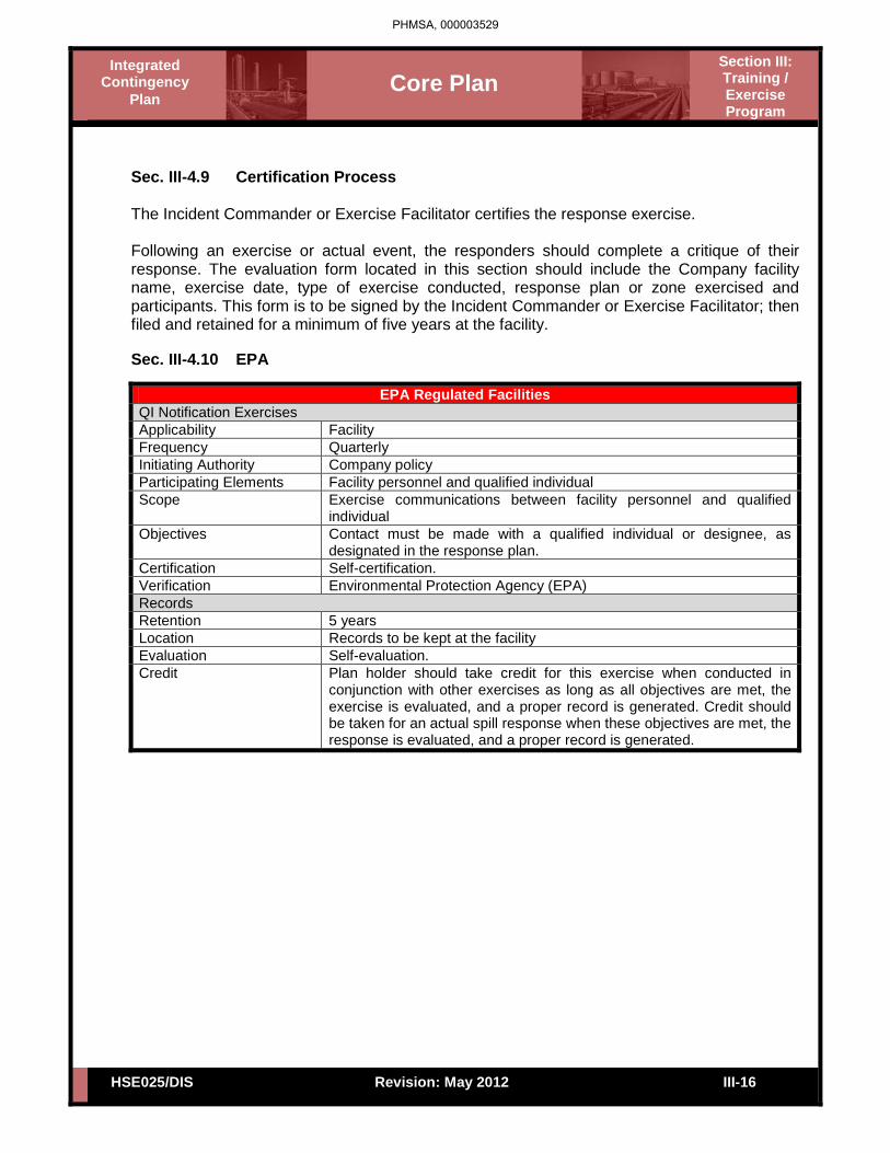
Core Plan
Section III: Training / Exercise Program
Integrated Contingency
Plan
HSE025/DIS III-16 Revision: May 2012
Sec. III-4.9 Certification Process The Incident Commander or Exercise Facilitator certifies the response exercise. Following an exercise or actual event, the responders should complete a critique of their response. The evaluation form located in this section should include the Company facility name, exercise date, type of exercise conducted, response plan or zone exercised and participants. This form is to be signed by the Incident Commander or Exercise Facilitator; then filed and retained for a minimum of five years at the facility.
Sec. III-4.10 EPA
EPA Regulated Facilities QI Notification Exercises Applicability Facility Frequency Quarterly Initiating Authority Company policy Participating Elements Facility personnel and qualified individual Scope Exercise communications between facility personnel and qualified
individual Objectives Contact must be made with a qualified individual or designee, as
designated in the response plan. Certification Self-certification. Verification Environmental Protection Agency (EPA) Records Retention 5 years Location Records to be kept at the facility Evaluation Self-evaluation. Credit Plan holder should take credit for this exercise when conducted in
conjunction with other exercises as long as all objectives are met, the exercise is evaluated, and a proper record is generated. Credit should be taken for an actual spill response when these objectives are met, the response is evaluated, and a proper record is generated.
PHMSA, 000003529

Core Plan
Section III: Training / Exercise Program
Integrated Contingency
Plan
HSE025/DIS III-17 Revision: May 2012
Sec. III-4.10 EPA (Cont’d)
EPA Regulated Facilities
Spill Management Team Tabletop Exercises Applicability Facility spill management team Frequency Annually Initiating Authority Company policy Participating Elements Spill management team as established in the response plan. Scope Exercise the spill management team’s organization, communication,
and decision-making in managing a spill response. Objectives Exercise the spill management team in a review of”
• Knowledge of the response plan; • Proper notifications • Communications system • Ability access an OSRO; • Coordination of internal organization personnel with
responsibility for spill response; • An annual review of the transition from a local team to a
regional, national and international team, as appropriate • Ability to effectively coordinate spill response activity with the
National Response System (NRS) infrastructure. (If personnel from the NRS are not participating in the exercise, the spill management team should demonstrate knowledge of response coordination with the NRS.)
• Ability to access information in Area Contingency Plan for location of sensitive areas, resources available within the area, unique conditions of area, etc.
At least one spill management team tabletop exercise in a triennial cycle would involve simulation of a worst-case discharge scenario.
Certification Self-certification. Verification Environmental Protection Agency (EPA) Records Retention 5 years Location At each facility Evaluation Self-evaluation. Credit Plan holder should take credit for this exercise when conducted in
conjunction with other exercises as long as all objectives are met, the exercise is evaluated, and a proper record is generated. Credit should be taken for an actual spill response when these objectives are met, the response is evaluated, and a proper record is generated.
PHMSA, 000003530

Core Plan
Section III: Training / Exercise Program
Integrated Contingency
Plan
HSE025/DIS III-18 Revision: May 2012
Sec. III-4.10 EPA (Cont’d)
EPA Regulated Facilities Equipment Deployment Exercises Applicability Facilities with facility owned and operated response equipment. Frequency Semi-annually Initiating Authority Company policy Participating Elements Facility Personnel Scope Deploy and operate facility owned and operated response equipment
identified in the response plan. The equipment to be deployed would be either (1) the minimum amount of equipment for deployment as described in "Guiding Principles", or (2) the equipment necessary to respond to a small discharge at the facility, whichever is less. All of the facility personnel involved in equipment deployment operations must be included in a comprehensive training program. All of the facility equipment must be included in a comprehensive maintenance program. Credit should be taken for deployment conducted during training. The maintenance program must ensure that the equipment is periodically inspected and maintained in good operating condition in accordance with the manufacturers’ recommendations and best commercial practices. All inspection and maintenance must be documented by the owner.
Objectives Demonstrate ability of facility personnel to deploy and operate equipment. Ensure equipment is in proper working order.
Certification Self-certification. Verification Environmental Protection Agency (EPA) Records Retention 5 years Location At each facility Evaluation Self-evaluation. Credit Plan holder should take credit for this exercise when conducted in
conjunction with other exercises as long as all objectives are met, the exercise is evaluated, and a proper record is generated. Credit should be taken for an actual spill response when these objectives are met, the response is evaluated, and a proper record is generated.
Note: If a facility with facility owned and operated equipment also identified OSRO equipment in its response plan, the OSRO equipment must also be deployed and operated in accordance with the equipment deployment requirements for OSRO owned equipment.
PHMSA, 000003531

Core Plan
Section III: Training / Exercise Program
Integrated Contingency
Plan
HSE025/DIS III-19 Revision: May 2012
Sec. III-4.10 EPA (Cont’d)
EPA Regulated Facilities Equipment Deployment Exercises Applicability Facilities with OSRO response equipment cited in their response plan. Frequency Annually Initiating Authority Company policy Participating Elements Facility owner or operator and OSRO. Scope Deploy and operate response equipment identified in the response
plan. The equipment to be deployed would be the minimum amount of equipment for deployment as described in "Guiding Principles." All of the OSRO personnel involved in equipment deployment operations must be included in a comprehensive training program. All of the OSRO equipment must be included in a comprehensive maintenance program. Credit should be taken for equipment deployment conducted during training. The maintenance program must ensure that the equipment is periodically inspected and maintained in good operating condition in accordance with the manufacturer's recommendations and best commercial practices. The facility owner or operator must ensure that inspection and maintenance by the OSRO is documented. The OSRO must provide inspection and maintenance information to the owner or operator. Plan holders must ensure that when a regional OSRO is identified in the response plan, the OSRO conducts annual equipment deployment exercises in each operating environment for each CG or EPA Contingency Planning Area, or EPA sub-area (where identified).
Objectives Demonstrate the ability of the personnel to deploy and operate response equipment. Ensure the response equipment is in proper working order.
Certification The facility owner or operator should ensure that the OSRO identified in the response plan provides adequate documentation that the requirements for this exercise have been met.
Verification Environmental Protection Agency (EPA) Records Retention 5 years, kept at the facility. Evaluation Self-evaluation. Credit Plan holder should take credit for this exercise when conducted in
conjunction with other exercises as long as all objectives are met, the exercise is evaluated, and a proper record is generated. Credit should be taken for an actual spill response when these objectives are met, the response is evaluated, and a proper record is generated.
Note: If a facility with facility owned and operated equipment also identified OSRO equipment in its response plan, the OSRO equipment must also be deployed and operated in accordance with the equipment deployment requirements for OSRO owned equipment.
PHMSA, 000003532

Core Plan
Section III: Training / Exercise Program
Integrated Contingency
Plan
HSE025/DIS III-20 Revision: May 2012
Sec. III-4.10 EPA (Cont’d)
EPA Regulated Facilities
Government-Initiated Unannounced Exercises Applicability EPA-regulated facility response plan holders within the region. Frequency Triennially, if successfully completed. A facility deemed by the CG/EPA
not to have successfully completed the exercise may be required to participate in another government initiated unannounced exercise at the discretion of the exercising agency. (Plan holders who have successfully completed a PREP government-initiated unannounced exercise will not be required to participate in another one for at least 36 months from the date of the exercise).
Initiating Authority EPA Particip. Elements EPA-regulated facility response plan holders. Scope Unannounced exercises are limited to a maximum of 10% of response
plan holders per EPA region per year. Exercises are limited to approximately 4 hours in duration. Exercises should involve response to a small discharge scenario (assume 2,100 gallons outside secondary containment and discharged into or on navigable waters and adjoining shorelines.) Exercise would involve deployment of response equipment identified in the facility response plan to respond to spill scenario. PHMSA and MMS will cover unannounced exercises for pipelines and offshore facilities not a part of a complex in their exercise programs.
Objectives Conduct proper notifications to respond to unannounced scenario of a small discharge. Demonstrate that the response is:
• Timely as defined in Section 1 of these Guidelines; • Conducted with adequate amount of equipment for scenario;
and • Properly conducted.
Certification EPA Verification EPA Records Retention 5 years, kept at the facility. Evaluation Evaluation to be conducted by initiating agency. Credit Credit may be granted by the initiating authority for an actual spill
response when the PREP objectives are met, the response is evaluated by the initiating authority and a proper record is generated. Plan holders participating in this exercise may take credit for notification and equipment deployment exercises, if criteria for those exercises are met, the response is evaluated by the plan holder and a proper record is generated.
PHMSA, 000003533

Core Plan
Section III: Training / Exercise Program
Integrated Contingency
Plan
HSE025/DIS III-21 Revision: May 2012
Sec. III-4.11 Coast Guard
Coast Guard Marine Transportation-Related (MTR) Facilities
QI Notification Exercises Applicability Facility Frequency Quarterly Initiating Authority Company policy. Participating Elements Facility personnel, qualified individual Scope Exercise communication between facility personnel and qualified
individual. Objectives Contact must be made with a qualified individual or designee, as
designated in the response plan. Certification Self-certification. Verification U.S. Coast Guard Records Retention 3 years Location Records to be kept at the facility. Credit Plan holder should take credit for this exercise when conducted
in conjunction with other exercises as long as all objectives are met, the exercise is evaluated, and a proper record is generated. Credit should be taken for an actual spill response when these objectives are met, the response is evaluated, and a proper record is generated. For plan holders handling both oil and hazardous substances, a single QI notification will satisfy exercise requirements for both plans, if both plans rely on the same QI. If the plan holder uses two different QIs, the plan holder is required to exercise both separately.
PHMSA, 000003534

Core Plan
Section III: Training / Exercise Program
Integrated Contingency
Plan
HSE025/DIS III-22 Revision: May 2012
Sec. III-4.11 Coast Guard (Cont’d)
Coast Guard Marine Transportation-Related (MTR) Facilities
Emergency Procedures Exercises (Optional) Applicability Facility Frequency Quarterly Initiating Authority Facility owner or operator. Particp. Elements Facility personnel Scope Exercise the emergency procedures for the facility to mitigate or
prevent any discharge or a substantial threat of such discharge or oil/HAZSUB resulting from facility operational activities associated with oil transfers.
Objectives Conduct an exercise of the facility’s emergency procedures to ensure personnel knowledge of actions to be taken to mitigate a spill. This exercise may be a walk-through of the emergency procedures. Exercise should involve one or more of the sections of the emergency procedures for spill mitigation. For example, the exercise should involved a simulation of a response to an oil spill. The facility should ensure that spill mitigation procedures for all contingencies at the facility are addressed at some time.
Certification Self-certification. Verification U.S. Coast Guard Records Retention 3 years Location Records to be kept at the facility. Evaluation Self-evaluation Credit Plan holder should take credit for this exercise when conducted
in conjunction with other exercises as long as all objectives are met, the exercise is evaluated, and a proper record is generated. Credit should be taken for an actual spill response when these objectives are met, the response is evaluated, and a proper record is generated. This section describes an option exercise to provide facilities with an exercise that may be conducted unannounced to fulfill the internal unannounced exercise requirement. At facilities covered by both oil and hazardous substance plans, separate oil and hazardous substance exercises are not required. However, the shipboard personnel should alternate oil and hazardous substance scenarios each quarter.
PHMSA, 000003535

Core Plan
Section III: Training / Exercise Program
Integrated Contingency
Plan
HSE025/DIS III-23 Revision: May 2012
Sec. III-4.11 Coast Guard (Cont’d)
Coast Guard Marine Transportation-Related (MTR) Facilities Spill Management Team Tabletop Exercise Applicability Facility spill management team Frequency Annually Initiating Authority Company policy Participating Elements Spill management team as established in the response plan. Scope Exercise the spill management team’s organization, communication,
and decision-making in managing a spill response. Objectives Exercise the spill management team in a review of:
• Knowledge of the response plan; • Proper notifications; • Communications system; • Ability to access an OSRO/HSRO; • Coordination of internal organization personnel with
responsibility for spill response; • An annual review of the transition from a local team to a
regional, national, and international team, as appropriate; • Ability to effectively coordinate spill response activity with the
National Response System (NRS) infrastructure. (If personnel from the NRS are not participating in the exercise, the spill management team should demonstrate knowledge of response coordination with the NRS);
• Ability to access information in the Area Contingency Plan for location of sensitive areas, resources available within the area, unique conditions of area, etc.
• At least one spill management team tabletop exercise in a triennial cycle would involve simulation of a worst-case discharge scenario.
Certification Self-certification. Verification U.S. Coast Guard Records Retention 3 years Location Records to be kept at the facility. Evaluation Self-evaluation Credit Plan holder should take credit for this exercise when conducted in
conjunction with other exercises as long as all objectives are met, the exercise is evaluated, and a proper record is generated. Credit should be taken for an actual spill response when these objectives are met, the response is evaluated, and a proper record is generated. Plan holders are responsible for ensuring that SMTs are familiar with Area Committees/Regional Response Teams (*RRTs) and Area Contingency Plans in every area in which the plan holder operates. While it is not practicable to require an SMT to exercise in every area/region in which they offer cover each year, each SMT is expected to review ACPs annually and the make-up of Area Committees/RRTs in all areas in which they offer coverage. Self-certification for exercise credit should include SMT certification that the SMT has completed annual review and is familiar with the ACPs and Area Committees in all areas in which the plan holder operates.
PHMSA, 000003536

Core Plan
Section III: Training / Exercise Program
Integrated Contingency
Plan
HSE025/DIS III-24 Revision: May 2012
Sec. III-4.11 Coast Guard (Cont’d)
Coast Guard Marine Transportation-Related (MTR) Facilities
Equipment Deployment Exercises Applicability Facilities with facility owned and operated response equipment. Frequency Semiannually Initiating Authority Company policy Particp. Elements Facility personnel Scope Deploy and operate facility owned and operated response equipment
identified in the response plan. The equipment to be deployed would be either (1) the minimum amount of equipment for deployment as described in “Guiding Principles”, or (2) the equipment necessary to response to an average most probably discharge at the facility, whichever is less. All of the facility’s personnel involved in equipment deployment operations must be included in a comprehensive training program. All of the facility’s equipment must be included in a comprehensive maintenance program. Credit should be taken for deployment conducted during training. The maintenance program must ensure that the equipment is periodically inspected and maintained in good operating condition in accordance with the manufacturer’s recommendations and best commercial practices. All inspection and maintenance must be documented by the owner.
Objectives Demonstrate ability of facility personnel to deploy and operate equipment. Ensure equipment is in proper working order. Deployment should also include testing ACP containment, protection and diversion strategies.
Certification Self-certification. Verification U.S. Coast Guard Records Retention 3 years Location Records to be kept at the facility. Evaluation Self-evaluation Credit Plan holder should take credit for this exercise when conducted in
conjunction with other exercises as long as all objectives are met, the exercise is evaluated, and a proper record is generated. Credit should be taken for an actual spill response when these objectives are met, the response is evaluated, and a proper record is generated. Note: If a facility with facility owned and operated equipment also identifies OSRO equipment in its response plan, the OSRO equipment must also be deployed and operated in accordance with the equipment deployment requirements for OSRO owned equipment.
PHMSA, 000003537

Core Plan
Section III: Training / Exercise Program
Integrated Contingency
Plan
HSE025/DIS III-25 Revision: May 2012
Sec. III-4.11 Coast Guard (Cont’d)
Coast Guard Marine Transportation-Related (MTR) Facilities
Equipment Deployment Exercises Applicability Facilities with OSRO/HSRO response equipment cited in their response
plan. Frequency Annually Initiating Authority Company policy Participating Elements Facility owner or operator and OSRO/HSRO. Scope Deploy and operate response equipment identified in the response
plan. The equipment to be deployed would be the minimum amount of equipment as described in “Guiding Principles.” All of the OSRO/HSRO personnel involved in equipment deployment operations must be included in a comprehensive training program. All of the OSRO/HSRO equipment must be included in a comprehensive maintenance program. Credit should be taken for equipment deployment conducted during training. The maintenance program must ensure that the equipment is periodically inspected and maintained in good operating condition in accordance with the manufacturer’s recommendations and best commercial practices. The facility owner or operator must ensure that inspection and maintenance by the OSRO/HSRO is documented. The OSRO/HSRO must provide inspection and maintenance information to the owner or operator. Plan holders must ensure that when a regional OSRO/HSRO is identified in the response plan, the OSRO/HSRO conducts annual equipment deployment exercises in each operating environment for each CG Contingency Planning Area.
Objectives Demonstrate ability of personnel to deploy and operate equipment. Ensure the response equipment is in proper working order. Whenever feasible, equipment deployment should also include ACP containment, protection and diversion strategies.
Certification The facility owner or operator should ensure that the OSRO/HSRO identified in the response plan provides adequate documentation that the requirements for this exercise have been met.
Verification U.S. Coast Guard Records Retention 3 years Location Records to be kept at the facility. Evaluation Self-evaluation Credit Plan holder should take credit for this exercise when conducted in
conjunction with other exercises as long as all objectives are met, the exercise is evaluated, and a proper record is generated. Credit should be taken for an actual spill response when these objectives are met, the response is evaluated, and a proper record is generated.
PHMSA, 000003538
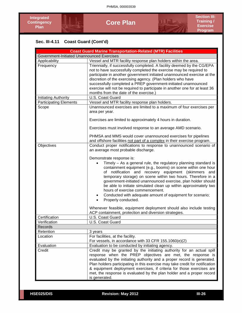
Core Plan
Section III: Training / Exercise Program
Integrated Contingency
Plan
HSE025/DIS III-26 Revision: May 2012
Sec. III-4.11 Coast Guard (Cont’d)
Coast Guard Marine Transportation-Related (MTR) Facilities Government-Initiated Unannounced Exercises Applicability Vessel and MTR facility response plan holders within the area. Frequency Triennially, if successfully completed. A facility deemed by the CG/EPA
not to have successfully completed the exercise may be required to participate in another government initiated unannounced exercise at the discretion of the exercising agency. (Plan holders who have successfully completed a PREP government-initiated unannounced exercise will not be required to participate in another one for at least 36 months from the date of the exercise.)
Initiating Authority U.S. Coast Guard Participating Elements Vessel and MTR facility response plan holders. Scope Unannounced exercises are limited to a maximum of four exercises per
area per year. Exercises are limited to approximately 4 hours in duration. Exercises must involved response to an average AMD scenario. PHMSA and MMS would cover unannounced exercises for pipelines and offshore facilities not part of a complex in their exercise program.
Objectives Conduct proper notifications to response to unannounced scenario of an average most probable discharge. Demonstrate response is:
• Timely – As a general rule, the regulatory planning standard is containment equipment (e.g., booms) on scene within one hour of notification and recovery equipment (skimmers and temporary storage) on scene within two hours. Therefore in a government-initiated unannounced exercise, plan holder should be able to initiate simulated clean up within approximately two hours of exercise commencement.
• Conducted with adequate amount of equipment for scenario; • Properly conducted.
Whenever feasible, equipment deployment should also include testing ACP containment, protection and diversion strategies.
Certification U.S. Coast Guard Verification U.S. Coast Guard Records Retention 3 years Location For facilities, at the facility.
For vessels, in accordance with 33 CFR 155.1060(e)(2) Evaluation Evaluation to be conducted by initiating agency. Credit Credit may be granted by the initiating authority for an actual spill
response when the PREP objectives are met, the response is evaluated by the initiating authority and a proper record is generated. Plan holders participating in this exercise may take credit for notification & equipment deployment exercises, if criteria for those exercises are met, the response is evaluated by the plan holder and a proper record is generated.
PHMSA, 000003539

Core Plan
Section III: Training / Exercise Program
Integrated Contingency
Plan
HSE025/DIS III-27 Revision: May 2012
Sec. III-4.12 DOT (PHMSA)
Onshore Transportation Related Pipelines
Owner or Operator Internal Notification Exercises Applicability Pipeline owner or operator Frequency As indicated by the response plan and, at a minimum, consistent
with the triennial cycle (quarterly) Party Initiating Exercise As indicated in the response plan Participants Facility response personnel and the facility’s qualified individual Scope Exercise notification process between key facility personnel and
the qualified individual to demonstrate the accessibility of the qualified individual
Objectives Contact by telephone, radio, message-pager, or facsimile and confirmation established as indicated in response plan
Format As indicated in response plan Certification Self-certification as indicated in response plan. Each plan should
have a written description of the company’s certification process. Verification Verification conducted by Pipeline and Hazardous Materials
Safety Administration (PHMSA) during regular inspections* or PHMSA tabletop exercises. *Verification will not be done by inspections in the near term.
Records Retention 3 years Location Owner or operator shall retain records as indicated in response
plan. PHMSA to retain verification records.
Credit Plan holder should take credit for this exercise when conducted in conjunction with other exercises as long as all objectives are met, the exercise is evaluated, and a proper record is generated. Credit should be taken for an actual spill response when these objectives are met, the response is evaluated, and a proper record is generated.
PHMSA, 000003540

Core Plan
Section III: Training / Exercise Program
Integrated Contingency
Plan
HSE025/DIS III-28 Revision: May 2012
Sec. III-4.12 DOT (PHMSA)[Cont’d]
Onshore Transportation Related Pipelines
Internal Tabletop Exercises Applicability Pipeline owner or operator Frequency As indicated by the response plan and, at a minimum, consistent
with the triennial cycle (quarterly) Party Initiating Exercise As indicated in the response plan Participants Designated spill emergency response team members. Scope Demonstration of the response team’s ability to organize,
communicate, and make strategic decisions regarding population and environmental protection during a spill event.
Objectives Designated emergency response team members should demonstrate:
• Knowledge of facility response plan; • Ability to organize team members to effectively interface
with a unified command; • Communication capability; and • Coordinate for response capability as outlined in
response plan. Format Internal tabletop exercise as outlined in response plan. Certification Self-certification as indicated in response plan or as defined in
the “Guiding Principles” section of this document, whichever is more stringent. Each plan should have a written description of the company’s certification process.
Verification Verification conducted by PHMSA during regular inspections* or PHMSA tabletop exercises. *Verification will not be done by inspections in the near term.
Records Retention 3 years Location Owner or operator shall retain records as indicated in response
plan. PHMSA to retain verification records.
Credit Plan holders should take credit for this exercise when conducted in conjunction with other exercises as long as all objectives are met, the exercise is evaluated, and a proper record is generated. Credit should be taken for an actual spill response when these objectives are met, the response is evaluated, and a proper record is generated.
PHMSA, 000003541

Core Plan
Section III: Training / Exercise Program
Integrated Contingency
Plan
HSE025/DIS III-29 Revision: May 2012
Sec. III-4.12 DOT (PHMSA)[Cont’d]
Onshore Transportation Related Pipelines
Owner/Operator Equipment Deployment Exercises Applicability Pipeline owner or operator Frequency As indicated by the response plan and, at a minimum, consistent
with the triennial cycle (quarterly). *The number of equipment deployment exercises should be such that equipment and personnel assigned to each response zone are exercised at least once per year. If the same personnel and equipment respond to multiple zones, they need only exercise once per year. If different personnel and equipment respond to various response zones, each must participate in an annual equipment deployment exercise.
Party Initiating Exercise As indicated in the response plan Participants Designated spill emergency response team members. Scope Demonstrate ability to deploy spill response equipment*
identified in the FRP. *May consist entirely of operator owned equipment, or a combination of OSRO and operator equipment.
Objectives Designated emergency response personnel should demonstrate: • Ability to organize, and; • Ability to deploy and operate representative types of key
response equipment as described in response plan. Format Announced deployment exercise indicated in response plan. Certification Self-certification as indicated in response plan. Each plan should
have a written description of the company’s certification process. Verification Verification conducted by PHMSA during regular inspections* or
PHMSA tabletop exercises. *Verification will not be done by inspections in the near term.
Records Retention 3 years Location Owner or operator shall retain records as indicated in response
plan. PHMSA to retain verification records.
Credit Plan holders should take credit for this exercise when conducted in conjunction with other exercises as long as all objectives are met, the exercise is evaluated, and a proper record is generated. Credit should be taken for an actual spill response when these objectives are met, the response is evaluated, and a proper record is generated.
PHMSA, 000003542

Core Plan
Section III: Training / Exercise Program
Integrated Contingency
Plan
HSE025/DIS III-30 Revision: May 2012
Sec. III-4.12 DOT (PHMSA)[Cont’d]
Onshore Transportation Related Pipelines
Unannounced Exercises Applicability Pipeline owner or operator Frequency Maximum of 20 unannounced PHMSA exercises conducted
annually for the pipeline industry as a whole. A single owner or operator will not be required to participate in a PHMSA- initiated unannounced exercise, if they have already participated in one within the previous 36 months.
Party Initiating Exercise PHMSA Participants Designated spill emergency response team members.
Operations staff. On-Scene Coordinator (optional). State and local government (optional).
Scope Demonstrate ability to respond to a worst-case discharge spill event.
Objectives Designated emergency response team members should demonstrate adequate knowledge of their facility response plan and the ability to organize, communicate, coordinate, and respond in accordance with that plan.
Format Unannounced tabletop exercise to discuss strategic issues. Certification Certification can be effectuated by PHMSA personnel conducting
the exercise. PHMSA will provide written certification of the exercise date, participants, and response zone exercised.
Verification Verification can be made by PHMSA personnel conducting the exercise.
Records Retention 3 years Location Owner or operator shall retain records as indicated in response
plan. PHMSA to retain verification records.
Credit Plan holders should take credit for this exercise when conducted in conjunction with other exercises as long as all objectives are met, the exercise is evaluated, and a proper record is generated. Credit should be taken for an actual spill response when these objectives are met, the response is evaluated, and a proper record is generated.
PHMSA, 000003543

Core Plan
Section IV: Forms
Integrated Contingency
Plan
HSE025/DIS Revision: May 2012
Section IV – Table of Contents
IV-1 Company Forms
IV-2 Industry Forms
PHMSA, 000003544

Core Plan
Section IV: Forms
Integrated Contingency
Plan
HSE025/DIS IV-1 Revision: May 2012
Sec. IV-1 Company Forms
Spill Response Equipment Inspection If the facility lists response equipment in this plan, then the equipment shall be inspected on an annual basis. Equipment found to be defective would be repaired or replaced. Documentation of equipment inspection/maintenance records is available at the facility. An example of the response equipment inspection log has been included below:
FACILITY-OWNED EQUIPMENT INSPECTION LOG
Equipment Location: Response Time
Inspected By: Print Sign
Inspection Date: Recovery Capacity (EDRC):
Ex: 7,645 bpd x 20% daily recovery rate = 1,529 bpd EDRC (based on a 20% efficiency)
Equipment Type Description - Model, Style, Size, Capacity, Shelf Life Qty Operational
Status Last Deployment Date
EXAMPLE: Boom 50' Acme 6x6 booms 100' Good 7/01/11
Retention: 5 years Inspection Frequency: DOT/PHMSA: Annual
PHMSA, 000003545

Tank No: Location:
Service:Corrective action is required for any adverse condition noted (visible leaks or any notation on columns 4-9)NOTE: Access onto a floating roof is not required by this form
(1) (2) (3) (4) (5) (6) (7) (8) (9)
EmployeeInitials Date
Visible Leaks (Yes/No)
ShellDistortion
Pressure/Vaccum Relief
Valves
Corrosion(Handrails,
Sketchplates,Attachments,Stairs, etc.)
TankFoundationTank Pipe Supports
Tank Dikes
CoatingInsulationCondition
Nozzles,Tank Valves,
Roof Drains & Tank Piping
Comments: Address all unsatisfactiory conditions above and corrective actions (SAP WO Number)Date
NOTE: Any deficiencies noted during the inspection shall be reported to immediate company supervision and the TIG.ANY LEAKS DISCOVERED DURING INSPECTION NEED TO BE REPORTED IMMEDIATELY.Official Document Location: Livelink 34509973Form: ADM090 MAX 12YCompleted Form Retention: HSE405 3Y (required by EPA 40CFR 112.7(e) (SPCC Plan)
HSE480 5Y (required by facility emergency response plan 40 CFR 112.1.8.1(f) or if facility operates under a Title V Air Permit)
Ref: 49CFR195.432 or 40 CFR112.1.8.1(f)(FRP), 112.7(e)(SPCC) and API-653
GPL-199
Rev 4 2011-05-13
Aboveground Atmospheric Storage TankMonthly Routine In-Service Inspection
Also Use this Form for Annual Inspection of Small Storage Tanks Sized 10,000 gallons or less
Comments
Break-Out Storage
PHMSA, 000003546

1. TERMINAL/FACILITY: TANK TYPE: External Internal Cone Roof
2. TANK #: Spheroid Sphere Other
3. INSPECTOR: DATE:4. SERVICE: 5. CAPACITY:(CHECK APPROPRIATE ANSWER OR MARK THROUGH THE QUESTION IF IT DOES NOT APPLY.)TANK APPURTENANCES (ATMOSPHERIC STORAGE) YES NO FILL IN ITEMS 29 THRU 31 FOR LIFTER ROOF TANKS ONLY6. Are the relief valve vent screens clean? A "Lifter Roof" is a fixed roof that moves and collects vapors. YES NO7. Do the combination pressure/vacuum pallets move 29. Is the relief valve opening mechanism in sa isfactory condition?
freely to an open or closed position? 30. Are the fixed roof stops in satisfactory condition?8. Are the liquid thermal relief valves on tank piping 31. Is roof travel apparen ly free at all positions?
properly mounted to prevent piping overpressure? 32. For liquid seal, is the Launder apparently leak free?9. Is a flame arrestor on the tank (see Std. 26.01-18)? 33. Is liquid seal (i e., diesel fuel) retaining specific gravity over time?
A. Do state regulations or local ordinance require it? 34 Additional comments:B. Can it be removed by applying a design hazard review
or a Management of Change (MOC)?10. Is tank gauge in satisfactory condition?11. Is water drain valve in satisfactory condi ion? SHELL YES NO12. Is roof drain apparently in sa isfactory condition? 35. Is the shell free of leaks?
(i.e., no staining at the base exit of he roof drain piping) 36. Any flat or visible dents on tank shell?37. Full appearance of girth welds/rivet joints on the
FILL IN ITEMS 14 THRU 27 FOR FIXED OR EXTERNAL FLOATING ROOFS vertical/horizontal weld/rivet seams?YES NO 38. Is external "sketchplate or chime" experiencing
13. Is the external roof resting on the surface of the stored liquid? corrosion?14. Is gauge hatch in satisfactory condition? 39. Is the wind girder satisfactorily guarded from corrosion 15. Is roof paint in satisfactory condition? or water accumulation?16. Is check valve mounted in roof sump, is it free of debris, 40. Is the general condition of paint satisfactory?
and does the internal "clapper" operate freely? 41. Additional comments:17. Is roof leak-free? Any patches or epoxy-type repairs noted?18. Are pontoon compartments free of hydrocarbon liquids?19. Does floating roof deck area drain accumulated water well?20. Is roof travel apparently free at all shell height posi ions? TANK BOTTOM/FOUNDATION AREA YES NO21. Are roof drain sump(s) clear of debris? 42. Is the edge tank bottom perimeter free of visible leaks?22. Does roof have large quantities of accumulated dirt on deck area? 43. Is tank berm properly sloped to divert storm water?23. Is primary/secondary seal in satisfactory condition? 44. Are there any physical deformities caused by severe edge
If not, how much is bad (in linear footage)? ft settlement?24. Is seal fabric compa ible for intended product service? 45. Does he tank have a concrete ringwall?25. Are "grounding" shunts installed and spaced accordingly? If YES, please answer the following subparts:26. Are "pinholes" spotted on floating decks area? Accumulated liquid? A. Are any sections of ringwall missing?27. Additional comments: B. Are cracks wider han 1/8" in diameter visible
around the tank perimeter?C. Is there evidence of water migra ion into ringwall cracks?
46. If tank is on earthen foundation, are here any locations wheretank is unsupported from soil?
47. If tank has leak detec ion system, checked & no leaks found?*FILL IN ITEM 28 FOR INTERNAL FLOATING ROOFS 48. Additional comments:28. Through manholes or roof hatches on the fixed roof, visually inspect the
internal floa ing roof and primary seal or the secondary seal (if one is in service) for he following:(A) Is the internal floating roof not res ing on he surface of the YES NO * Be sure to seal tank double containment area after checking leak detec ion ports
liquid inside the storage tank? YES NO(B) Is there any liquid accumulated on top of the roof? FIRE PROTECTION - If Applicable to Storage Tank(C ) Is the seal detached? 49. Are foam line(s) and connections braced satisfactorily?(D) Are there holes or tears in the seal fabric? 50. Do foam chambers appear clean and unobstructed?(E) Are there any defects in the floating roof? 51. Does tank dike area drain sa isfactorily?(F) IFR to shell bonding issues (cables or shunts, etc)? 52. Is the foam bladder vessel filled to 95% capacity?*If the answer to any of the above questions is yes, note corrective actions and 53. Are adequate portable fire extinguishers located at thedate taken. base of the tank stairway or inside the tank farm?
54. Have he internal glass membrane plates remained unbroken in he side-mounted enclosed-shell foam chambers?
55. Is dike capacity maintained to original design capacity?NOTE: Documentation is required to ensure that repairs are made within 45 days of 56. Are adequate "No Smoking" and "Hot Work Permit" signs identifying a defect. If a defect is found that cannot be repaired in 45 days, no ify the posted at tank dike entranceway?area environmental coordinator. 57. Additional comments:
Distribution: Orig - Facility Ref. Copy - Region Office ( R ) Regional Equipment Inspector
Retain inspection report for 2-year period if required by DOT 49CFR 195.404; or EPA 40 CFR 60.115b (NSPS) Retain inspection report for 3-year period if required by EPA 40CFR 112.7(e) (SPCC Plan)Retain inspection report for 5 years if required by facility emergency response plan 40 CFR 112.1.8.1(f) or if facility operates under a Title V Air Permit
Doc. No.: GPL-205Rev.: 2Transportation - Pipelines and Terminals
PI Form - GPL-205 - Annual Tank Inspection Report
Official Blank Form Location: LivelinkCompleted Form Retention:ADM090 / Max/12y
Effective Date: 2009-10-01Page 1 of 1
PHMSA, 000003547

TRANSPORTATION – PIPELINES & TERMINALS EPR&S PREP - COMPANY TRAINING ROSTER/LOG
TRAINING DATE(S): START TIME: (YYYY-MM-DD) END TIME: LOCATION: COMPANY CONTACT: PHONE:
Blank Form Retention: ADM090/MAX 12Y Blank Form Location: Livelink; TPTN-H/S-LibPolProc-Frm/Temp-EPR/PREP-TrainLog Effective Date: MAR-2012 Completed Form Retention: HSE975/5Y Completed From Location: Livelink; Facility files PREP-TrainLog Page 1 of 3
Roster/Log Instructions: Check all training that was successfully completed by participants in attendance. The Course description is associated with the Learning Management System (LMS) Course Express Number.
TRAINING COURSE TITLE/ LEARNING MANAGEMENT SYSTEM COURSE EXPRESS NUMBER: Incident Command System / TPTER000012 Security – Site Personnel / TPTER000030 OPA ′90 Plan Review / TPTER000023 Security - Annual Exercise / TPTER000025 Unannounced Tabletop Exercise / TPTER000021 (1/Y) Security - Marine FSO / TPTER000031 Tabletop Exercise / TPTER000015 Security - Marine Quarterly Drill / PTER000026 Unannounced Equipment Deployment Exercise / TPTER000019 Spill Prevention Briefing and SPCC Review / TPTHSE000323 Equipment Deployment Exercise / TPTER000013 Other: Unannounced Agency Drill / TPTER000018 Spill Response Participation in an Actual OPA 90 Event / TPTER000022
All classes listed above may be applied towards HAZWOPER Refresher Training. Hazwoper, 4-hr Refresher / TPTERHAZWOPER4 HAZWOPER QI-IC / TPTHSE000212 Hazwoper, 8-hr Refresher (WA ONLY) / TPTERHAZWOPER8 HAZWOPER Supervisor Certification / TPTER000024 Certification-24 Hour HAZWOPER Technician Level / TPTER000003 Other:
Company Contact: Send a copy of the completed Training Roster to an EPR&S Coordinator via Company Global Scan or Fax: 918-662-6807. Retain the original copy in the facility files. ► For EPR&S and LMS use only: Review/Submit to LMS Training Administrator Initials: Date:
LMS Entry Completed Initials: Date:
LIST OF ATTENDEES TRAINED / COMPLETED SUCCESSFULLY (* = Did not complete )
LAST NAME, FIRST NAME (PRINT) EMPLOYEE ID NO. OR COMPANY NAME
JOB TITLE & LOCATION SIGNATURE
1. 2. 3. 4. 5. 6. 7. 8. 9. 10. 11. 12. 13. 14.
LAST NAME, FIRST NAME (PRINT) EMPLOYEE ID NO. OR COMPANY NAME
JOB TITLE & LOCATION SIGNATURE
PHMSA, 000003548

TRANSPORTATION – PIPELINES & TERMINALS EPR&S PREP - COMPANY TRAINING ROSTER/LOG
TRAINING DATE(S): START TIME: (YYYY-MM-DD) END TIME: LOCATION: COMPANY CONTACT: PHONE:
Blank Form Retention: ADM090/MAX 12Y Blank Form Location: Livelink; TPTN-H/S-LibPolProc-Frm/Temp-EPR/PREP-TrainLog Effective Date: MAR-2012 Completed Form Retention: HSE975/5Y Completed From Location: Livelink; Facility files PREP-TrainLog Page 2 of 3
15. 16. 17. 18. 19. 20. 21. 22. 23. 24. 25. 26. 27. 28. 29. 30. 31. 32. 33. 34. 35. 36. 37. 38. 39. 40. 41. 42. 43. 44.
PHMSA, 000003549

TRANSPORTATION – HEALTH & SAFETY EPR&S PREP - DRILL DOCUMENTATION
Official Blank Form Retention: ADM090/ MAX 12Y Blank Form Location: Livelink; TPTN-H/S-LibPolProc-Frm/Temp-EPR/PREP-QIN Effective Date: MAR-2012 Completed Form Retention: HSE975/5Y Completed Form Location: Livelink; Facility files PREP-QIN Form Page 1 of 1
QUALIFIED INDIVIDUAL - NOTIFICATION EXERCISE
Facility Name: Date:
Exercise Actual Response Quarter: 1st 2nd 3rd 4th Conducted After Normal Working Hours Yes No Yes No Yes No Yes No
(One of the quarterly QI Notification Exercises must be conducted after normal working hours.)
Exercise Initiated by Terminal Pipeline Person Initiating Contact:
(Name/Position) Person Notified:
(Name/Position) Is this person identified in your response plan as qualified individual; or designee? Yes No
Time Initiated: Number(s) Called
Initiation Communication used: Telephone Radio Pager Other:
Call Complete: Yes No Message Left:
Time in which QI or designee responded: Number Called:
Response Communication used: Telephone Radio Pager Other:
Other Notification: (Name/Position)
Type of Communication used: Telephone Radio Pager Other:
Time Called: Number(s) Called
Notification Complete: Yes No Message Left:
Response Time: Response Number Called:
Emergency Scenario:
Changes to be implemented:
Time Table for Implementation: Corrective Follow-up assignment
Facility Supervisor Signature: Date:
PHMSA, 000003550

TRANSPORTATION – HEALTH & SAFETY EPR&S PREP - DRILL DOCUMENTATION
Blank Form Retention: ADM090/ MAX 12Y Blank Form Location: Livelink; TPTN-H/S-LibPolProc-Frm/Temp-EPR/PREP-TTX Effective Date: MAR-2012 Completed Form Retention: HSE975/5Y Completed Form Location: Livelink; Facility files PREP-TTX Page 1 of 1
SPILL MANAGEMENT TEAM (SMT) - TABLE TOP EXERCISE
Plan Name: Date:
Announced Exercise Unannounced Exercise Actual Response
Location:
Start time: AM PM Stop time: AM PM
Response Plan Scenario Used: Small Spill / Average Most Probable Discharge Medium Spill / Maximum Most Probable Discharge “Worst-Case” Discharge (WCD)
Product: Amount: bbls
1. Did the Spill Management Team (SMT) utilize the ERP during the exercise? Yes No
2. Were internal and external notifications completed per the ERP? Yes No
3. Were communication systems adequate? Yes No
4. Were the Company Oil Spill Removal Organizations (OSRO) notified? Yes No
5. Was there good coordination with On-Scene Coordinator, State and applicable agencies? Yes No
6. Were sensitive site and resource information in the ERP accessed as needed? Yes No
7. Select which of the 15 PREP core components were employed during this particular exercise: Notifications Disposal of recovered material & contaminated debris Staff mobilization Communications Operate within Response Management System Transportation Discharge control Personnel support Assessment of discharge Equipment maintenance & support Containment of discharge Procurement Recovery of spilled material Documentation Protection of sensitive areas
8. Evaluation: Refer to the attached Exercise Critique for this information.
9. Changes to be Implemented and person responsible for follow-up of corrective action:
10. Time Table for Implementation:
11. Self Certifying Signature:
Print Name / Position:
PHMSA, 000003551

TRANSPORTATION – HEALTH & SAFETY EPR&S PREP - DRILL DOCUMENTATION
Blank Form Retention: ADM090/ MAX 12Y Blank Form Location: Livelink; TPTN-H/S-LibPolProc-Frm/Temp-EPR/PREP-EDX Effective Date: Mar2012 Completed Form Retention: HSE975/5Y Completed Form Location: Livelink; Facility files PREP-EDX Page 1 of 2
EQUIPMENT DEPLOYMENT EXERCISE (PREP-EDX)
PLAN NAME: DATE: EXERCISE TYPE: Announced Unannounced or Actual Response DEPLOYMENT LOCATION: TIME STARTED: AM PM TIME OSRO CALLED: AM PM N/A
TIME ON-SCENE: AM PM TIME BOOM DEPLOYED: AM PM N/A
TIME OSRO/RECOVERY EQUIPMENT ARRIVES ON-SCENE FOR DEPLOYMENT: AM PM N/A
TIME COMPLETED EXERCISE: AM PM
EQUIPMENT DEPLOYED: Company-Owned Co-op Equipment OSRO/Contractor owned Both Company & Co-op Equipment Both Company, OSRO/Contractor Company, OSRO/Contractor & Co-op Name of participating OSRO, Co-op and/or Contractor:
DESCRIBE THE GOALS OF THE EQUIPMENT DEPLOYMENT AND LIST ANY AREA CONTINGENCY PLAN (ACP) STRATEGIES TESTED. (Refer to the ICS 201-1 form for sketch of equipment deployment location(s) and booming strategies.)
EXERCISE EVALUATION: 1. DEPLOYMENT OF FACILITY-OWNED EQUIPMENT:
a. List type & amount of all equipment deployed (e.g., boom & skimmers) and number of support personnel employed. Refer to the attached ICS Forms: 211-E (for a list of equipment deployed), 211-P (for personnel employed) or the 201-4
(Resource Summary).
b. All facility/pipeline personnel that are responsible for response operations are involved in a comprehensive training program? Yes No
If so, describe:
c. All pollution response equipment involved in a comprehensive maintenance program? Yes No If so, describe the program:
d. Date of last equipment inspection:
e. Was the amount of equipment deployed at least the amount necessary to respond to the pipeline’s/ facility’s average most probable spill? Yes No
If not, describe why:
f. Was the equipment deployed by personnel responsible for its deployment in the event of an actual spill? Yes No If not, describe why:
g. Was the equipment deployed in its intended operating environment? Yes No If not, explain why:
h. Was all deployed equipment operational? Yes No If not, explain why:
PHMSA, 000003552

TRANSPORTATION – HEALTH & SAFETY EPR&S PREP - DRILL DOCUMENTATION
Blank Form Retention: ADM090/ MAX 12Y Blank Form Location: Livelink; TPTN-H/S-LibPolProc-Frm/Temp-EPR/PREP-EDX Effective Date: Mar2012 Completed Form Retention: HSE975/5Y Completed Form Location: Livelink; Facility files PREP-EDX Page 1 of 2
2. DEPLOYMENT OF OSRO AND/OR COOP-OWNED EQUIPMENT: a. List type & amount of all equipment deployed (e.g., boom & skimmers) and number of support personnel employed.
Refer to the attached ICS Forms: 211-E (for a list of equipment deployed), 211-P (for personnel employed) or 201-4 (Resource Summary).
b. All response organization personnel that are responsible response operations involved in a comprehensive training program? Yes No
If so, describe the program: c. All pollution response equipment involved in a comprehensive maintenance program? Yes No
If so, describe the program: d. Date of last equipment inspection: e. Was a representative sample (at least 1,000 ft. of each boom type and one of each skimmer type) deployed? Yes No
If not, describe why:
f. Was the equipment deployed by personnel responsible for its deployment in the event of an actual spill? Yes No
If not, describe why:
g. Was the equipment deployed in its intended operating environment? Yes No If not, describe why:
h. Was all deployed equipment operational? Yes No If not, explain why:
3. Select which of the 15 core components of the response plan were employed during this exercise: Notifications Disposal of recovered material & contaminated debris Staff mobilization Communications Operate within Response Management System Transportation Discharge control Personnel support Assessment of discharge Equipment maintenance & support Containment of discharge Procurement Recovery of spilled material Documentation Protection of sensitive areas
4. EDX CRITIQUE (Description of lessons learned, procedures and schedule for implementation, and person(s) responsible for follow-up of corrective actions.
a. What went well?
b. Areas for improvement?
c. Corrective actions d. Implementation schedule
e. Person responsible for follow up of corrective actions
5. SELF-CERTIFYING SIGNATURE: DATE: Print Name/Position:
PHMSA, 000003553

Core Plan
Section IV: Forms
Integrated Contingency
Plan
HSE025/DIS IV-10 Revision: May 2012
Sec. IV-2 Industry Forms
NATIONAL PREPAREDNESS FOR RESPONSE EXERCISE PROGRAM (PREP)
15 PREP COMPONENTS EVALUATION WORKSHEET
Incident/Drill Name: Prepared by: at: Period: to Company Name:
ORGANIZATION DESIGN 1) Notifications
Components ICS/UCS Position
Responsible Completed
(Y/N) Date/Time Completed Comments
1a. Test the notifications procedures identified in the Area Contingency Plan and the associated Responsible Party Response Plan.
2) Staff mobilization
Components ICS/UCS Position
Responsible Completed
(Y/N) Date/Time Completed Comments
2a. Demonstrate the ability to assemble the spill response organization identified in the Area Contingency Plan and associated Responsible Party Response Plan.
3) Ability to operate within the response management system described in the plan
Components ICS/UCS Position
Responsible Completed
(Y/N) Date/Time Completed Comments
3.1 Unified Command: Demonstrate the ability of the spill response organization to work within a unified command.
3.1.1 Federal Representation: Demonstrate the ability to consolidate the concerns and interests of the other members of the unified command into a unified strategic plan with tactical operations.
3.1.2 State Representation: Demonstrate the ability to function within the unified command structure.
3.1.3 Local Representation: Demonstrate the ability to within the unified command structure.
Page 1 of 8
PHMSA, 000003554

Core Plan
Section IV: Forms
Integrated Contingency
Plan
HSE025/DIS IV-11 Revision: May 2012
NATIONAL PREPAREDNESS FOR RESPONSE EXERCISE
PROGRAM (PREP) 15 PREP COMPONENTS EVALUATION WORKSHEET
(Cont’d) 3) Ability to operate within the response management system described in the plan (Cont’d)
Components ICS/UCS Position
Responsible Completed
(Y/N) Date/Time Completed Comments
3.1.4 Responsible Party Representation: Demonstrated to function within the unified command structure organization to control and stop the discharge at the source.
3.2. Response Management System: Demonstrate the ability of the response organization to operate within the framework of the response management system identified in their respective plans.
3.2.1 Operations: Demonstrate the ability to coordinate or direct operations related to the implementation of action plans contained in the respective response and contingency plans developed by the unified command.
3.2.2 Planning: Demonstrate the ability to consolidate the various concerns of the members of the unified command into joint planning recommendations and specific long-range strategic plans. Demonstrate the ability to develop short-range tactical plans for the operations division.
3.2.3 Logistics: Demonstrate the ability to provide the necessary support of both the short-term and long-term action plans.
3.2.4 Finance: Demonstrate the ability to document the daily expenditures of the organization and provide cost estimates for continuing operations.
3.2.5 Public Affairs: Demonstrate the ability to form a joint information center and provide the necessary interface between the unified command and the media.
3.2.6 Safety Affairs: Demonstrate the ability to monitor all field operations and ensure compliance with safety standards.
3.2.7 Legal Affairs: Demonstrate the ability to provide the unified command with suitable legal advice and assistance.
Page 2 of 8
PHMSA, 000003555

Core Plan
Section IV: Forms
Integrated Contingency
Plan
HSE025/DIS IV-12 Revision: May 2012
NATIONAL PREPAREDNESS FOR RESPONSE EXERCISE
PROGRAM (PREP) 15 PREP COMPONENTS EVALUATION WORKSHEET
(Cont’d) 4) Discharge control
Components ICS/UCS Position
Responsible Completed
(Y/N) Date/Time Completed Comments
4. Demonstrate the ability of the spill response organization to control and stop the discharge at the source.
4.1 Salvage: Demonstrate the ability to assemble and deploy salvage resources identified in the response plan.
4.2 Firefighting: Demonstrate the ability to assemble and deploy the firefighting resources identified in the response plan.
4.3 Lightering: Demonstrate the ability to assemble and deploy the lightering resources identified in the response plan.
4.4 Other salvage equipment and devices: (electrical and manual controls and barriers to control the source) Demonstrate the ability to assemble and deploy the other salvage devices identified in the response plan.
5) Assessment of discharge
Components ICS/UCS Position
Responsible Completed
(Y/N) Date/Time Completed Comments
5. Demonstrate the ability of the spill response organization to provide an initial assessment of the discharge and provide continuing assessments of the effectiveness of the tactical operations plan for use.
6) Containment of discharge
Components ICS/UCS Position
Responsible Completed
(Y/N) Date/Time Completed Comments
6. Demonstrate the ability of the spill response organization to contain the discharge at the source or In various locations for recovery operations.
Page 3 of 8
PHMSA, 000003556

Core Plan
Section IV: Forms
Integrated Contingency
Plan
HSE025/DIS IV-13 Revision: May 2012
NATIONAL PREPAREDNESS FOR RESPONSE EXERCISE
PROGRAM (PREP) 15 PREP COMPONENTS EVALUATION WORKSHEET
(Cont’d) 7) Recovery of spilled material
Components ICS/UCS Position
Responsible Completed
(Y/N) Date/Time Completed Comments
7. Demonstrate the ability of the spill response organization to recover, mitigate, and remove the discharged product. Includes mitigation and removal activities, e.g. dispersant use, ISB use, and bioremediation use.
7.1 On-Water Recovery: Demonstrate the ability to assemble and deploy the on-water response resources identified In the response plans.
7.2 Shore-Based Recovery: Demonstrate the ability to assemble and deploy the shoreside response resources identified in the response plans.
8) Protection of sensitive areas
Components ICS/UCS Position
Responsible Completed
(Y/N) Date/Time Completed Comments
8. Demonstrate the ability of the spill response organization to protect the environmentally and economically sensitive areas identified in the Area Contingency Plan and the respective industry response plan.
8.1 Protective Booming: Demonstrate the ability to assemble and deploy sufficient resources to implement the protection strategies contained in the Area Contingency Plan and the respective industry response plan.
8.2 Water Intake Protection: Demonstrate the ability to quickly identify water intakes and implement the proper protection procedures from the Area Contingency Plan or develop a plan for use.
8.3 Wildlife Recovery and Rehabilitation: Demonstrate the ability to quickly identify these resources at risk and implement the proper protection procedures from the Area Contingency Plan to develop a plan for use.
Page 4 of 8
PHMSA, 000003557

Core Plan
Section IV: Forms
Integrated Contingency
Plan
HSE025/DIS IV-14 Revision: May 2012
NATIONAL PREPAREDNESS FOR RESPONSE EXERCISE
PROGRAM (PREP) 15 PREP COMPONENTS EVALUATION WORKSHEET
(Cont’d) 8) Protection of sensitive areas (Cont’d)
Components ICS/UCS Position
Responsible Completed
(Y/N) Date/Time Completed Comments
8.4 Population Protection (Protect Public Health and Safety): Demonstrate the ability to quickly identify health hazards associated with the discharged product and the population at risk from these hazards, and to implement the proper protection procedures from the Area Contingency Plan or develop a plan for use.
9) Disposal of recovered material and contaminated debris
Components ICS/UCS Position
Responsible Completed
(Y/N) Date/Time Completed Comments
9. Demonstrate the ability of the spill response organization to dispose of the recovered material and contaminated debris.
10) Communications
Components ICS/UCS Position
Responsible Completed
(Y/N) Date/Time Completed Comments
10. Demonstrate the ability to establish an effective communications system for the spill response organization.
10.1 Internal Communications: Demonstrate the ability to establish an intra-organization communications system. This encompasses communications at the command post and between the command post and deployed resources.
10.2 External Communications: Demonstrate the ability to establish communications both within the response organization and other entities (e.g., RRT, claimants, media, regional or HQ agency offices, non-governmental organizations, etc.).
Page 5 of 8
PHMSA, 000003558

Core Plan
Section IV: Forms
Integrated Contingency
Plan
HSE025/DIS IV-15 Revision: May 2012
NATIONAL PREPAREDNESS FOR RESPONSE EXERCISE
PROGRAM (PREP) 15 PREP COMPONENTS EVALUATION WORKSHEET
(Cont’d) 11) Transportation
Components ICS/UCS Position
Responsible Completed
(Y/N) Date/Time Completed Comments
11. Demonstrate the ability to provide effective multi-mode transportation both for execution of the discharge and support functions.
11.1 Land Transportation: Demonstrate the ability to provide effective land transportation for all elements of the response.
11.2 Waterborne Transportation: Demonstrate the ability to provide effective waterborne transportation for all elements of the response.
11.3 Airborne Transportation: Demonstrate the ability to provide the necessary support of all personnel associated with the response.
12) Personnel support Components ICS Position
Responsible Completed
(Y/N) Date/Time Completed Comments
12. Demonstrate the ability to provide the necessary support of all personnel associated with the response.
12.1 Management: Demonstrate the ability to provide administrative management of all personnel involved in the response. This requirement includes the ability to move personnel into or out of the response organization with established procedures.
12.2 Berthing: Demonstrate the ability to provide overnight accommodations on a continuing basis for a sustained response.
12.3 Messing: Demonstrate the ability to provide suitable feeding arrangements for personnel involved with the management of the response.
12.4 Operational and Administrative Spaces: Demonstrate the ability to provide suitable operational and administrative spaces for personnel involved with the management of the response.
Page 6 of 8
PHMSA, 000003559

Core Plan
Section IV: Forms
Integrated Contingency
Plan
HSE025/DIS IV-16 Revision: May 2012
NATIONAL PREPAREDNESS FOR RESPONSE EXERCISE
PROGRAM (PREP) 15 PREP COMPONENTS EVALUATION WORKSHEET
(Cont’d) 12) Personnel support (Cont’d)
Components ICS Position Responsible
Completed (Y/N)
Date/Time Completed Comments
12.5 Emergency Procedures: Demonstrate the ability to provide emergency services for personnel involved in the incident.
13) Equipment maintenance and support Components ICS Position
Responsible Completed
(Y/N) Date/Time Completed Comments
13. Demonstrate the ability to maintain and support all equipment associated with the response.
13.1 Response Equipment: Demonstrate the ability to provide effective maintenance and support for all response equipment. Provide effective waterborne transportation for all elements of the response.
13.2 Response Equipment: Demonstrate the ability to provide effective maintenance and support for all equipment that supports the response. This requirement includes communications equipment, transportation equipment, administrative equipment, etc.
14) Procurement Components ICS Position
Responsible Completed
(Y/N) Date/Time Completed Comments
14. Demonstrate the ability to establish an effective procurement system.
14.1 Personnel: Demonstrate the ability to procure sufficient personnel to mount and sustain an organized response. This requirement includes insuring that all personnel have qualifications and training required for their position within the response organization.
14.2 Response Equipment: Demonstrate the ability to procure sufficient response equipment to mount and sustain an organized response.
14.3 Support Equipment: Demonstrate the ability to procure sufficient support equipment to support and sustain an organized response.
Page 7 of 8
PHMSA, 000003560

Core Plan
Section IV: Forms
Integrated Contingency
Plan
HSE025/DIS IV-17 Revision: May 2012
NATIONAL PREPAREDNESS FOR RESPONSE EXERCISE
PROGRAM (PREP) 15 PREP COMPONENTS EVALUATION WORKSHEET
(Cont’d) 15) Documentation
Components ICS Position Responsible
Completed (Y/N)
Date/Time Completed Comments
15. Demonstrate the ability of the spill response organization to document all operational and support aspects of the response and provide detailed records of decisions and actions taken.
Page 8 of 8
PHMSA, 000003561

Revision: May 2012 HSE025/DIS
Integrated Contingency
Plan
Montana-Wyoming Pipeline Response Zone
Annex
Annex
Annex – Table of Contents
1 Facility and Locality Information
2 Notification Procedures
3 Environmental Sensitive Area Information
4 Regulatory Cross Reference
5 Administration
PHMSA, 000003562

Montana - Wyoming Pipeline Response Zone
Annex
Annex 1: Facility & Locality
Information
Integrated Contingency
Plan
Revision: May 2012 HSE025/DIS
Annex 1 – Table of Contents
1.0 Owner/Operator Information
1.1 Purpose of Plan
1.2 Scope of Plan
1.3 Objectives
1.4 Management Certification
1.5 Qualified Individual Delegation of Authority
1.6 Response Zone – Area 1, 2 & 3 Significant & Substantial Harm Certification and WCD Amounts
1.6.1 Hazard Identification and Discharge Analysis
1.6.2 Significant and Substantial Harm Certification – Area 1, 2 & 3
1.6.3 Determination of Significant and Substantial Harm
1.6.4 Worst Case Discharge
1.6.5 Identification of Response Area
1.7 Response Zone - Area 1
1.7.1 Area Information Summary
1.7.2 Pipeline Information - Area 1
1.7.3 Spill Response Equipment
1.7.4 YPL Area 1 Response Corridor Index
PHMSA, 000003563

Montana - Wyoming Pipeline Response Zone
Annex
Annex 1: Facility & Locality
Information
Integrated Contingency
Plan
Revision: May 2012 HSE025/DIS
Annex 1 – Table of Contents
1.8 Response Zone - Area 2
1.8.1 Area Information Summary
1.8.2 Pipeline Information
1.8.3 Spill Response Equipment
1.8.4 YPL Area 2 Response Corridor Index
1.9 Response Zone - Area 3
1.9.1 Area Information Summary
1.9.2 Pipeline Information
1.9.3 Spill Response Equipment
1.9.4 YPL Area 3 Response Corridor Index
1.10 Response Zone – Glacier Crude North/South
1.10.1 Area Information Summary Glacier Crude South
1.10.2 Area Information Summary Glacier Crude North
1.10.3 Pipeline Information
1.10.4 Spill Response Equipment
1.10.5 Glacier North Area Response Corridor Index
1.10.6 Glacier South Area Response Corridor Index
1.10.7 Area Facility Information – Glacier Crude South
1.10.8 Significant and Substantial Harm Certification
1.10.9 Determination of Significant and Substantial Harm
PHMSA, 000003564

Montana - Wyoming Pipeline Response Zone
Annex
Annex 1: Facility & Locality
Information
Integrated Contingency
Plan
Revision: May 2012 HSE025/DIS
Annex 1 – Table of Contents 1.10.10 Hazard Identification and Discharge Analysis
1.10.11 Worst Case Discharge
1.10.12 Identification of Response Areas
1.10.13 Glacier Pipeline Identification of Breakout Tankage and Breakout Tankage Worst Case Discharge
1.10.14 Crude Oil Characteristics
1.11 Response Zone – Pioneer Pipeline Areas 1 and 2
1.11.1 Area Information Summary – Pipeline Area 1
1.11.2 Area Information Summary – Pipeline Area 2
1.11.3 Pipeline Information
1.11.4 Spill Response Equipment
1.11.5 Pioneer Pipeline Area 1 Response Corridor Index
1.11.6 Pioneer Pipeline Area 2 Response Corridor Index
1.11.7 Significant and Substantial Harm Certification
1.11.8 Worst Case Discharge
1.11.9 Identification of Response Areas
1.12 Response Zone Seminoe Pipeline Area
1.12.1 Area Information Summary
1.12.2 Pipeline Information
1.12.3 Spill Response Equipment
PHMSA, 000003565

Montana - Wyoming Pipeline Response Zone
Annex
Annex 1: Facility & Locality
Information
Integrated Contingency
Plan
Revision: May 2012 HSE025/DIS
Annex 1 – Table of Contents 1.12.4 Seminoe Pipeline Area 1 & 2 Response Corridor Index
1.12.5 Seminoe Pipeline Area 3 Response Corridor Index
1.12.6 Significant and Substantial Harm Certification
1.12.7 Worst Case Discharge
1.12.8 Identification of Response Areas
ANNEX 1 - A
PHMSA, 000003566

Montana - Wyoming Pipeline Response Zone
Annex
Annex 1: Facility & Locality
Information
Integrated Contingency
Plan
A1-1 Revision: May 2012 HSE025/DIS
1.0 Owner & Operator Information
OWNER /OPERATOR ADDRESS
Phillips 66 Company 600 North Dairy Ashford, TA-2136 Houston, TX 77079
PIPELINE MAINENANCE FACILITY ADDRESS
See each specific Response Zone area in this Annex
1.1 Purpose of Plan
This Annex is designed to show the Company’s compliance with the regulations set forth by the Department of Transportation in 49 CFR 194/195. This Annex is also designed to provide field personnel with the information necessary to respond to incidents in a safe and efficient manner. For purposes of this plan, incidents are defined as events that happen within the Montana - Wyoming Zone’s pipeline system, that create unacceptable impacts on people, property, or the environment and require emergency response operations. Emergency response operations involve actions taken at, or in close proximity to, the site of an incident that are designed to mitigate the situation and get initial control over the incident, ensure safety of all concerned, develop plans of action, and facilitate communications
1.2 Scope of Plan
This plan applies to emergency response operations carried out by field personnel and the Emergency Response Team. This plan applies to any type or size of incident that may occur within the Montana - Wyoming Response Zone. The plan contains prioritized procedures for personnel to follow in the event of a release or other emergency situation within the pipeline response zone.
PHMSA, 000003567

Montana - Wyoming Pipeline Response Zone
Annex
Annex 1: Facility & Locality
Information
Integrated Contingency
Plan
A1-2 Revision: May 2012 HSE025/DIS
1.3 Objectives
The objectives of this plan are to: Comply with 49 CFR 194 and 195 regulations Comply with the Occupational Safety and Health Act requirements for an
employee emergency plan and fire prevention plan as described in 29 CFR 1910.38 and the emergency planning and response requirements according to 29 CFCR 1910.119(n) and 29 CFR 1910.120
Follow the format described in Appendix A of 49 CFR part 194 Define the roles and responsibilities for Company personnel. Detail Emergency Response Team notification and activation procedures. Provide Company personnel with rapid access to the tools needed to carry out
emergency response operations.
PHMSA, 000003568

Montana - Wyoming Pipeline Response Zone
Annex
Annex 1: Facility & Locality
Information
Integrated Contingency
Plan
A1-3 Revision: May 2012 HSE025/DIS
1.4 Management Certification
MANAGEMENT CERTIFICATION
This plan is approved for implementation as herein described. Manpower, equipment and materials will be provided as required in accordance with this Plan. The Company is dedicated to protection of the environment and commits to implement the necessary measures, as specified in the Plan, as necessary in a spill response emergency. In addition to any OSRO and non-company resources listed in this Plan, the necessary personnel and equipment resources, owned or operated by the facility owner or operator, are available to respond to a discharge within appropriate response times. This plan has been prepared in accordance to and is consistent to the National Contingency Plan and the applicable Area Contingency Plan(s) for the facilities covered by this plan.
CERTIFICATION SIGNATURE:
Rob Yarbrough Director, Emergency Preparedness, Response & Security PRINTED NAME TITLE
May 2012
DATE
PHMSA, 000003569

Montana - Wyoming Pipeline Response Zone
Annex
Annex 1: Facility & Locality
Information
Integrated Contingency
Plan
A1-4 Revision: May 2012 HSE025/DIS
1.5 Qualified Individual Delegation of Authority
PHMSA, 000003570

Montana - Wyoming Pipeline Response Zone
Annex
Annex 1: Facility & Locality
Information
Integrated Contingency
Plan
A1-5 Revision: May 2012 HSE025/DIS
It is the Qualified Individual’s responsibility to first make the appropriate notifications, then to initiate response operations. This individual has absolute authority to obligate any funds necessary to carry out all required and/or directed response activities. This individual will also act as liaison with city, county, state and federal agencies and serve as the On-Scene Incident Commander. The Response Zone QI and Alternate are identified in Annex 2.
The following checklist (the checklist is not all inclusive) serves as a guide to the On-Scene Incident Commander/Qualified Individual.
The minimum duties required of the QI / PIC include: Notify all response personnel, as needed
Identify the character, exact source, amount, and extent of the release, as well as the other items needed for notification
Notify and provide necessary information to appropriate Federal, State, and local authorities with the designated response roles, including the National Response Center, State Emergency Response Commission, and Local Emergency Planning Commission
Assess the possible hazards to human health and the environment due as a result of the release. This assessment must consider both the direct and indirect effects of the release (i.e., the effects of any hazardous surface waters runoffs from water or chemical agents used to control fire and heat-induced explosion)
Assess and implement prompt removal actions to contain and then remove the substance released
Coordinate rescue and response action as previously arranged with all response personnel
Use authority to immediately access company funding to initiate response, mitigation and clean-up activities
Direct clean-up activities until properly relieved of this responsibility
PHMSA, 000003571

Montana - Wyoming Pipeline Response Zone
Annex
Annex 1: Facility & Locality
Information
Integrated Contingency
Plan
A1-6 Revision: May 2012 HSE025/DIS
1.6 Response Zone – Area 1, 2 & 3 Significant & Substantial Harm
Certification and WCD Amounts Sec. 1.6.1 Hazard Identification and Discharge Analysis
This section examines the Pipeline/Facility owner/operators ability to predict where releases could occur. Hazard evaluation is a widely used industry practice that allows owners and operators to develop an understanding of potential hazards and the response action necessary to address these hazards. Hazard identification and evaluation will assist pipeline/facility personnel in planning for releases, thereby reducing the severity of impact resulting from a release. The evaluation may also assist in the identification of release sources resulting in corrective action prior to a release. Specific safety and health considerations are identified for responding to a release as a result of the hazard evaluation. Oil Characteristics
MSDS information for the system is available on the Company website.
Methods of Discharge Detection
Method 1
The pipeline systems are continuously monitored and controlled by the Company Control Center. This group has the ability to remotely monitor all aspects of the operations at the origination as well as the destination and of the system. Examples of the control and operations capabilities are:
1. Remote Start and Stop - Remote meter counts at both ends 2. Remote Pressure at Both Ends - Remote control valves at both ends 3. Alarm Status at Both Ends - Line control alarms 4. Remote Tank Gauges - Suction and discharge pressure control 5. Normal or Adverse Weather conditions - Maximum shutdown time is approximately
15 minutes
Method 2
Using public education, the Company has established relationships with community, public and emergency response agencies that enable quick notification in the event of a spill.
Method 3
The Company, as required by DOT Part 195, has established line patrols that meet or exceed the required patrols in Part 195. Fixed wing aircraft, helicopters and patrols on the ground perform these patrols.
PHMSA, 000003572

Montana - Wyoming Pipeline Response Zone
Annex
Annex 1: Facility & Locality
Information
Integrated Contingency
Plan
A1-7 Revision: May 2012 HSE025/DIS
Sec. 1.6.2 Significant and Substantial Harm Certification – Area 1, 2 & 3
Applicability of Significant and Substantial Harm – DOT / PHMSA All Relevant Pipelines as Listed below in this Section
Pipeline Name: YPL Area 1 Is the pipeline greater than 6 and 5/8 inches (168 mm) in outside nominal diameter, and greater than 10 miles (16 kilometers) in length, YES_______X___________ NO____________________ Has the line section experienced a release greater than 1,000 barrels within the past five (5) years, YES___________________ NO_________X___________ Has any line section experienced two or more reportable releases, as defined in 49 CFR 195.5, within the past five (5) years, or YES___________________ NO_________X___________ Does any line section contain any electric resistance welded pipe, manufactured prior to 1970 and operates at a maximum operating pressure established under 40 CFR 195.406 that corresponds to a stress level greater than 50 percent of the specified minimum yield strength of the pipe, or YES X NO Is any line located within a 5-mile (8 km) radius of potentially affected public drinking water intakes and could reasonably be expected to reach public drinking water intakes, or YES_______X___________ NO____________________ Is any link located within a 1-mile (1.6 km) radius of potentially affected environmentally sensitive areas and could reasonably be expected to reach these areas? YES_______X___________ NO___________________ Based on the DOT/PHMSA criteria above, ALL of the Company Pipelines are considered to be a system of Significant and Substantial Harm. The Company certifies to the Pipeline and Hazardous Materials Safety Administration of the Department of Transportation that we have obtained, by contract or other approved means, the necessary private personnel and equipment to respond, to the maximum extent practicable, to a worst case discharge.
I certify under penalty of law that I have personally examined and am familiar with the information submitted in this document, and that based on my inquiry of those individuals responsible for obtaining information, I believe that the submitted information is true, accurate and complete.
Robert Yarbrough Name Date
May 2012
PHMSA, 000003573

Montana - Wyoming Pipeline Response Zone
Annex
Annex 1: Facility & Locality
Information
Integrated Contingency
Plan
A1-8 Revision: May 2012 HSE025/DIS
Sec. 1.6.3 Determination of Significant and Substantial Harm
The YPL System meets the definition for “Significant and Substantial Harm” because it meets at least one of the criteria listed in 49 CFR §194.103(c). Therefore, a response plan per 49 CFR Part 194 must be submitted for the YPL System.
Vulnerability Analysis
Vulnerabilities along this pipeline are identified in Site Sensitive Maps contained in Annex 3. Also, immediate response areas have been identified in this Annex. Discharge Analysis
The equipment and manpower to respond to a spill are available from several sources and are listed with the equipment and contractors in this Plan. In addition, equipment and manpower requirements for each response site are listed in this Plan.
Sec. 1.6.4 Worst Case Discharge
The worst-case discharge volume calculations are based on the guidance as provided by 40 CFR Part 194. A worst-case discharge is defined as the largest foreseeable discharge in adverse weather conditions that a pipeline could discharge in a response area. The worst-case discharge is based on the comparison of several factors.
Second, the worst-case discharge could be a foreseeable discharge for a line section based on the maximum historic discharge.
Third, if the line section within the response area contains break out tanks, the worst-case discharge may be the quantity of the largest tanks or tank battery within a single containment dike, adjusting for the capacity of the containment system.
PHMSA, 000003574
( ) ( )( )
(b) (7)(F)

Montana - Wyoming Pipeline Response Zone
Annex
Annex 1: Facility & Locality
Information
Integrated Contingency
Plan
A1-9 Revision: May 2012 HSE025/DIS
The Company reviewed the historic spill data for each line and noted the volume of the breakout tankage along the lines and has concluded that the first example (which considers line flow and response time) is the most applicable in the Company's case. The calculations for this response area, as per 40 CFR 194 guidelines, have been included in this section.
Worst Case Discharge Volume
The calculated data for the WCD volume of identified response areas along Yellowstone Pipeline follows in this Section. These response areas meet the requirements for “Substantial” harm to the environment as designed per 49 CFR 194 in the event of a WCD spill at these locations. In an effort to simplify the analysis of these multiple areas, they are grouped together into three sectors. Additionally, WCD Zone 1 is divided into three sub zones.
PHMSA, 000003575
(b) (7)(F)

Montana - Wyoming Pipeline Response Zone
Annex
Annex 1: Facility & Locality
Information
Integrated Contingency
Plan
A1-10 Revision: May 2012 HSE025/DIS
Within each of these sub zones, "immediate" response worksites were identified and are listed on the WCD calculation table in this Section. Immediate response worksites and required equipment are identified in this Plan.
It was concluded that if an adequate amount of oil spill response (OSR) equipment could begin to be deployed (within the 6-hr response time) on the largest volume spill, then that level of adequacy could be extrapolated to the other (lesser volume) discharge "areas" within that respective sub zone.
• WCD Zone #1: YPL (10") Billings to Missoula; Thompson Falls to Spokane Area #1.1: YPL - Billings to Helena - Missouri River (MP# 179-183) Area #1.2: YPL - Helena to Missoula - Clarks Fork River (MP# 183-323) Area #1.3: YPL -Thompson Falls to Spokane - Coeur d’Alene River (MP# 417-475)
• WCD Zone #2: YPL (8"/6") Spokane to Moses Lake - Spokane (MP# 531-537) • WCD Zone #3: YPL (6") Helena to Great Falls - Smith River (MP# 60)
Response Area 4 is described in WCD Zone 2, which is not covered by this Annex. Please refer to the Eastern Washington Response Zone Annex for this segment of the YPL.
PHMSA, 000003576
(b) (7)(F)

Montana - Wyoming Pipeline Response Zone
Annex
Annex 1: Facility & Locality
Information
Integrated Contingency
Plan
A1-11 Revision: May 2012 HSE025/DIS
. of product located in Response Area 3. Based on this scenario, clusters of OSR-equipment and personnel located within 210 miles of both the Billings and Helena OSR-equipment bases could be mobilized. See this Plan for an inventory of equipment. The Company IMAT can also be activated for support in a response.
Approximately 4,480 feet of boom is available from these area OSR-equipment bases. In addition, beyond what is available from these bases, heavy equipment, vac trucks, etc. are available from local and regional contractors. Local contractors are predominantly within the 210-mile circle of response. As the need of a spill event would dictate, regional contractors would subsequently be mobilized from distances outside of the 210-mile limit. OSR-equipment availability lists for both local and regional response contractors are contained in this Plan. Adequate storage for recovered product is present from onsite tankage at the area terminal facilities.
Based on this scenario, clusters of OSR-equipment and personnel located
within 210 miles of this point could respond from the Missoula, MT and Spokane, WA OSR-equipment bases. Approximately 1800 feet of boom is available from these company OSR-equipment bases. Additional company booming is available from the Bozeman, Laurel and Billings areas. In addition, beyond what is available from these bases, heavy equipment, vac trucks, etc. are available from local and regional contractors. Adequate storage for recovered product is present from onsite tankage at the area terminal facilities.
at the Smith River crossing along Mile Post 60 located in Response Area 2. Based on this scenario, clusters of OSR-equipment and personnel located within 210 miles of this point North of Helena could be mobilized.
Additionally, the areas shown below have been designated as "immediate" response areas as required per 49 CFR 195. It is not felt that "substantial" harm to the environment would result from a WCD spill at these locations because of their location, terrain or probable runoff results from a spill.
PHMSA, 000003577
(b) (7)(F)
(b) (7)(F)
(b) (7)(F)

C A N A D AC A N A D A
Aurora
GreatFalls
Pierre
Bismarck
Denver
CheyenneLakeCitySacramento
Carson
San Jose
SanFrancisco
Oakland
Portland
Salem
Seattle
Olympia
BoiseCity
BILLINGS DIVISION MAPPIPELINES & TERMINALS
ACIER 12
NE
ON
8"
SEM
INOE
IR6
Refinery
Crude Terminal
Products Terminals
CPPL PipelinesCrude
Products
Assets not in Billings Division
Ivanhoe
Roundup
Thompson Falls
"
PHMSA, 000003578
(b) (7)(F)
(b) (7)(F)
(b) (7)(F)
(b) (7)(F)
(b) (7)(F)
(b) (7)(F)

Montana - Wyoming Pipeline Response Zone
Annex
Annex 1: Facility & Locality
Information
Integrated Contingency
Plan
A1-13 Revision: May 2012 HSE025/DIS
1.7 Response Zone – Area 1
Sec. 1.7.1 Area Information Summary
Area Information
Maintenance Group Name
Yellowstone Pipeline Area 1
Response Area Location
Southern Montana
Line Section Billings to Manhattan Counties Yellowstone, Stillwater, Sweetgrass, Park and Gallatin Mile Posts 0 - 148 Telephone (day/night)
406-255-5641 / 406-667-2320
Address 338 Hwy 87 East, Billings, MT 59101 Owner Phillips 66 Owner Location (street)
600 North Dairy Ashford, 2136 Tarkington Building
Emergency Telephone
800-231-2551 or 877-267-2290
City Houston State Texas Zip 77079 County Harris Telephone 281-293-3891
Refer to the Notifications Annex – Phone List for QI/IC and Alternate QI/IC information
PHMSA, 000003579

Montana - Wyoming Pipeline Response Zone
Annex
Annex 1: Facility & Locality
Information
Integrated Contingency
Plan
A1-14 Revision: May 2012 HSE025/DIS
Sec. 1.7.2 Pipeline Information – Area 1
Pipeline Description
The geography of the land along the pipeline can be described as a high mountain plain containing mountainous regions that have significant elevation changes and consists of numerous small drainage areas, creeks and rivers.
While some of the land is used for agricultural purposes, most of the pipeline runs through sparsely populated and undeveloped land, with the exception of portions of Coeur D’Alene, which is a well-developed urban area.
A spill originating from this Pipeline is likely to be discovered quickly and response conducted immediately upon discovery. However, this Plan is designed for a worst case scenario, which is a catastrophic tank or pipeline failure under extreme weather during flood conditions.
The vulnerability analysis along with the response zone area hazard evaluation and Worst Case Discharge Information can be found above. The Site Sensitive Maps are located in Annex 3.
YPL Area 1 contains response information for the geographic area from Billings, MT to Manhattan, MT (YPL 10”) and Alkali Creek to Laurel (Powder River 4”). Description of Operations
Yellowstone Pipe Line Company operates a refined petroleum products pipeline system that extends a total of 644 miles from Billings, Montana to Spokane, Washington. The 10" mainline extends 328 miles from Billings to Missoula, Montana and 119 miles from Thompson Falls, Montana to Spokane, Washington. The portion (88 miles) of the mainline from Missoula to Thompson Falls, Montana is currently purged and out-of-service. Additional lines in the system include the YPL 6” line from Helena to Great Falls, Montana and the YPL 8"/6" line from Spokane to Moses Lake, Washington. Phillips 66, Exxon Pipe Line Company and Union Oil Company jointly own the Yellowstone Pipe Line system. The system is constructed of pre-1970, 10-inch ERW pipe. The following grades of petroleum products are shipped on the Yellowstone Pipe Line:
• No-Lead Premium Gasoline (N91-N92) • No-Lead Regular Gasoline (N85.5 - N87) • Commercial Jet Fuel (JFA) • No. 1 Fuel Oil (Y) • No. 2 Fuel Oil (D43)
PHMSA, 000003580

Montana - Wyoming Pipeline Response Zone
Annex
Annex 1: Facility & Locality
Information
Integrated Contingency
Plan
A1-15 Revision: May 2012 HSE025/DIS
YPL Area 1 encompasses the following lines:
1. YPL 10” Mainline from Billings to Manhattan
2. YPL 12”/8” “Exxon” Suction line from Exxon Refinery to Billings Auto Auction
3. YPL 12” Suction line from ConocoPhillips Refinery to YPL Station
4. YPL 8” Yale line from Yale tank farm to YPL Station
5. ConocoPhillips 4” 16 mile product line from Alkali Creek to Laurel
6. Seminoe 8” Suction from Exxon to Seminoe Station
7. Seminoe 10’ Suction from ConoocPhillips Refinery to Seminoe Station
8. Seminoe Mainline originating at Billings Seminoe Station to MP 8
Sec. 1.7.3 Spill Response Equipment
Please refer to Annex 2 for the Company’s spill response equipment
PHMSA, 000003581

PHMSA, 000003582
(b) (7)(F)
(b) (7)(F)
(b) (7)(F)
(b) (7)(F)

PHMSA, 000003583
(b) (7)(F)

Klein
Pryor
Lavina
Musselshell
87
212
12
87
310
12
10
191
212
94
90
90
47
120 295 37
244
463
308
19
72
78
313
311
SheridanBig HornPark
Treasure
Roseb d
Big Horn
Musselshell
Stillwater
SweetGrass
WheatlandGoldenValley
JudithBasin
Carbon
Ivanhoe - Roundup 6" (Idle)
Glacier 8"
Glacier 12"
YPL 10"/8"/6
Glacier - Roundu
MONTANAWYOMING
p
Ivanhoe
Byron 8"
Billings Area Pipeline Systems
Filename: Billings Systems Map.pdf
PHMSA, 000003584
(b) (7)(F)
( ) ( )( )
(b) (7)(F)
(b) (7)(F)
(b) (7)(F)
(b) (7)(F)

90
90
90
87
87
Gla
cier
12"
Seminoe 8"
Glacier - Roundup 10"
Glacier 10"
Exxon-YPL 12" Suction
Byron 8"Idle
Billings Area Pipeline SystemsYellowstone County, Montana
Suction
Billings
Lockwood
PHMSA, 000003585
(b) (7)(F)
(b) (7)(F)

(b) (7)(F)

PHMSA, 000003587

Montana - Wyoming Pipeline Response Zone
Annex
Annex 1: Facility & Locality
Information
Integrated Contingency
Plan
A1-22 Revision: May 2012 HSE025/DIS
Sec. 1.7.4 YPL Area 1 Response Corridor Index
(Refer to map on previous page.)
Pipeline Mile Marker Response Corridor Map Reference # MP 0 Yellowstone River A 1 MP 0 Coulson Ditch 2
MP 0 to 6 City of Billings 3 MP 0 Yegan Ditch 4
MP 14.5 Alkali Creek 5 MP 21 Canyon Creek 6 MP 28 Big Lake 7
MP 34.2 Greenwood Creek 8 MP 35 Toll Creek 9
MP 39.5 Struck Creek 10 MP 46 East White Beaver Creek 11 MP 49 Sheep Creek 12 MP 57 West White Beaver Creek 13
MP 62.5 Sweet Grass Creek 14 MP 81 Cow Creek 15 MP 83 Oxbow Creek 16
MP 85.5 Duck Creek 17 MP 87 No Name Ditch 18 MP 101 Shields River 19
MP 103.5 Ferry Creek 20 MP 105 Dry Creek 21 MP 106 Yellowstone River B 22
MP 108.3 Fleshman Creek 23 MP 119.5 Billman Creek 24 MP 122 Rocky Creek 25 MP 130 East Gallatin River 26
MP 130.5 Bozeman Creek 27 MP 131.5 Drainage Ditch 28
MP 130 - 138 MP 130 - 138 29 MP 139.5 Thompson River 30 MP 0-16 Powder River Line 31
PHMSA, 000003588

Montana - Wyoming Pipeline Response Zone
Annex
Annex 1: Facility & Locality
Information
Integrated Contingency
Plan
A1-23 Revision: May 2012 HSE025/DIS
Response Areas
Location MP Location MP YPL 6 Inch White Beaver Cr. 46.0 Prickly Pear Creek 2.5 Sheep Creek 49.0 Hwy. Crossing 5.0 Hwy./White Beaver Creek 53.0 Bridge Creek 19.0 Hwy. Crossing 54.0 Beaver Creek 20.0-25.0 Crest Creek 60.0 Middle Creek 31.0 Sweetgrass Cr. 63.0 East Fork Creek 35.0 Bailey Clark Ditch 70.0 Encampment Creek 37.0 Hwy. Crossing 72.0 Hwy. Crossing 42.0 Hwy. Crossing 74.0 Spanish Coulee 50.0 Hwy. Crossing 77.0 Hwy. Crossing 70.0 Little Timber Cr. 78.5 Sand Coulee 73.0 West Fork Creek 79.0 Great Falls, Montana 77.0-79.0 Shed Creek 80.0 Great Falls Terminal 79.0 Cow Creek 81.0 YPL 10 Inch Duck Creek 86.0 Alkali Creek 6.0 Hwy. Crossing 88.0 Alkali Creek 7-7.5 S. Dog Creek 88.5 Alkali Creek 9.5 Springdale St. 90.0 Hwy./RR Cro. 10.5 Hwy. Crossing 101.5 Alkali Creek 14.0 Hwy. Crossing 103.5 Two Pine School 18.0 Hwy. Crossing 105.0 Peterson School 31.0 Hwy. Crossing 108.0 Greenwood Cr. 34.5 Flynn Creek 116.0 Toll Creek 35.5 Quinn Creek 120.0 Struck Creek 39.5 Hwy. Crossing 122.0 Columbus Sta. 40.0
PHMSA, 000003589

Montana - Wyoming Pipeline Response Zone
Annex
Annex 1: Facility & Locality
Information
Integrated Contingency
Plan
A1-24 Revision: May 2012 HSE025/DIS
Response Areas Cont’d.
Location MP Location MP Bozeman, MT 130.0-132.0 Tigh Creek 283.0 Hwy. Crossing 133.0 Antelope Creek 287.0 Bozeman Ter. 133.0 Wood Creek 289.0 Hwy. Crossing 134.0 RR Crossing 293.0 Thompson Creek 139.5 Tyler Creek 294.0 Ferris Ditch 141.0 Hwy./RR Cro. 297.0 Hwy. Crossing 142.0 Ryan Creek 299.0 Manhattan Sta. 150.0 Cramer Creek 301.0 Nixon Gulch 152.0 Iris, MT 304.0 Hwy. Crossing 172.0 Hwy. Crossing 305.0 Toston Canal 174.0 Starvation Creek 307.0 Crow Creek 175.0 RR Crossing 307.5 Hwy. Crossing 184.0 Clinton, MT 309.0 Hwy. Crossing 196.0 RR Crossing 310.0 Beaver Creek 197.0 Hwy./RR Cro. 312.0 Hwy. Crossing 198.0 RR Crossing 313.0 RR Crossing 211.0 Deer Creek 320.0 Hwy. Crossing 212.0 Missoula, MT 325.0-326.0 RR Crossing 216.0 Missoula Ter. 329.0 Helena Ter. 218.0 Hwy. Crossing 329.5* Helena, MT 218.0-222.0 Hwy. Crossing 333.0* Porcupine Creek 232.0 LaValle Creek 334.0* McDonald Creek 236.0 E. Fork Creek 339.0* Hwy./RR Cro. 238.0 Hwy./RR Cro. 341.0* Elliston, MT 239.0 Hwy. Crossing 342.0* Hwy./RR Cro. 244.5 Schley Creek 343.0* Dog Creek 248.0 Finley Creek 346.0* Hwy./RR Cro. 251.0 Finley Creek 347.0* McDonald Creek 254.0 Hwy. Crossing 352.0* Creek 255.0 Valley Creek 352.5* Warm Springs Creek 262.0 Creek 353.0* RR Crossing 264.0 Jocko Canal 362.0* Drummond Sta. 277.0 Revias Creek 364.0* Flint Creek 279.0 Gunderson Cr. 365.0*
* Out of Service segment
PHMSA, 000003590

Montana - Wyoming Pipeline Response Zone
Annex
Annex 1: Facility & Locality
Information
Integrated Contingency
Plan
A1-25 Revision: May 2012 HSE025/DIS
Response Areas Cont’d.
Location MP Location MP Magpie Creek 368.0* Hwy. Crossing 502.0 Magpie Creek 369.0* Coeur d'Alene, Idaho 503.0-507.0 Vanderburg Cr. 371.0* Post Hill, Washington 512.0-513.0 Camas Creek 374.0* RR Crossing 514.0 Clear Creek 374.5* Spokane, Washington 520.0-537.0 Camas Creek 382.0* Moses Lake 6"/8" Rainbow Lake 387.0-388.0* Creek/Hwy. Crossing 540.0 Hwy./RR Cro. 401.0* RR/Hwy. Crossing 543.0 Hwy./RR Cro. 412.0* Geiger Junction 547.0 RR Crossing 416.0* Hwy. Crossing 547.0 Creek 419.0 Hwy. Crossing 548.0 Thompson Falls Creek 419.0 Fairchild Terminal 556.0 Prospect Creek 421.0 Hwy. Crossing 557.0 Prospect Creek 424.0 Hwy. Crossing 558.0 Prospect Creek 425.0 RR Crossing 560.0 Daisy Creek 427.0 Hwy. Crossing 561.0 Twenty-Four Gulch 434.0 Hwy. Crossing 566.0 Paragon Gulch 440.0 Hwy. Crossing 570.0 Murray Creek 447.0 Creek/Hwy. Crossing 579.0 Prichard Creek 448.0 Hwy. Crossing 580.0 Prichard Creek 453.0 Hwy. Crossing 588.0 Prichard, Idaho 454.0 Hwy. Crossing 589.0 Cataldo, Idaho 478.0 RR Crossing 590.0 Cataldo Sta. 479.0 Hwy. Crossing 592.0 Bentley Creek 482.0 RR Crossing 612.0 Ruteman Creek 483.0 Creek/Hwy. Crossing 613.0 Service Creek 484.0 Hwy. Crossing 616.0 Curran Creek 484.5 Hwy. Crossing 622.0 Hwy. Crossing 484.5 Hwy. Crossing 627.0 Hwy. Crossing 486.0 Siphon Canal 633.0 Reserve Creek 488.0 RR Crossing 642.0 Hwy. Crossing 489.0 Crab Creek 643.0 Cedar Creek 490.0 Moses Lake Terminal 644.0 Wolf Lodge Cr. 494.0 Powder River 4 Inch Blue Creek 496.0 To Be Determined Fernan Creek 500.0
* Out of Service segment
PHMSA, 000003591

PHMSA, 000003592
(b) (7)(F)
(b) (7)(F)

PHMSA, 000003593

Montana - Wyoming Pipeline Response Zone
Annex
Annex 1: Facility & Locality
Information
Integrated Contingency
Plan
A1-28 Revision: May 2012 HSE025/DIS
1.8 Response Zone – Area 2
Sec. 1.8.1 Area Information Summary
Area Information
Maintenance Group Name
Yellowstone Pipeline Area 2
Response Area Location
Helena, MT
Line Section Main Line and Great Falls Line Counties Gallatin, Broadwater, Jefferson, Lewis & Clark, Powell, Granite Mile Posts Main Line – MP 147 to MP 277
Great Falls Line – MP 0 to MP 80.5 Telephone (day/night)
406-442-5010 X20 / 406-431-0138
Address 3180 Hwy 12 East, Helena, MT 59601 Owner Owner Location (street)
600 North Dairy Ashford, 2136 Tarkington Building
Emergency Telephone
800-231-2551 or 877-267-2290
City Houston State Texas Zip 77079 County Harris Telephone 281-293-3891
PHMSA, 000003594

Montana - Wyoming Pipeline Response Zone
Annex
Annex 1: Facility & Locality
Information
Integrated Contingency
Plan
A1-29 Revision: May 2012 HSE025/DIS
Sec. 1.8.2 Pipeline Information – Area 2
Pipeline Description The geography of the land along the pipeline can be described as a high mountain plain containing mountainous regions that have significant elevation changes and consists of numerous small drainage areas, creeks and rivers.
While some of the land is used for agricultural purposes, most of the pipeline runs through sparsely populated and undeveloped land, with the exception of portions of Coeur D’Alene, which is a well-developed urban area.
A spill originating from this Pipeline is likely to be discovered quickly and response conducted immediately upon discovery. However, this Plan is designed for a worst case scenario, which is a catastrophic tank or pipeline failure under extreme weather during flood conditions.
The vulnerability analysis along with the response zone area hazard evaluation and Worst Case Discharge Information can be found above. The Site Sensitive Maps are located in Annex 3.
YPL Area 2 contains response information for the geographic area from Manhattan, MT to Drummond, MT including Helena, MT to Great Falls, MT.
Description of Operations
Yellowstone Pipe Line Company operates a refined petroleum products pipeline system that extends a total of 644 miles from Billings, Montana to Spokane, Washington. (YPL Area 1, 2 and 3 response area information are located in this Appendix.) The 10" mainline extends 328 miles from Billings to Missoula, Montana and 119 miles from Thompson Falls, Montana to Spokane, Washington. The portion (88 miles) of the mainline from Missoula to Thompson Falls, Montana is currently purged and out-of-service. Additional lines in the system include the YPL 6” line from Helena to Great Falls, Montana and the YPL 8"/6" line from Spokane to Moses Lake, Washington. ConocoPhillips, Exxon Pipe Line Company and Union Oil Company jointly own the Yellowstone Pipe Line system. The system is constructed of pre-1970, 10-inch ERW pipe.
The following grades of petroleum products are shipped on the Yellowstone Pipe Line:
• No-Lead Premium Gasoline (N91-N92) • No-Lead Regular Gasoline (N85.5 - N87) • Commercial Jet Fuel (JFA) • No. 1 Fuel Oil (Y) • No. 2 Fuel Oil (D43)
YPL Area 2 encompasses the following lines:
1. YPL 10” Mainline from Manhattan to MP 277
2. Great Falls line from MP 0 to MP 80.5
PHMSA, 000003595

Montana - Wyoming Pipeline Response Zone
Annex
Annex 1: Facility & Locality
Information
Integrated Contingency
Plan
A1-30 Revision: May 2012 HSE025/DIS
Sec. 1.8.3 Spill Response Equipment
Please refer to Annex 2 for the Company’s spill response equipment
PHMSA, 000003596

(b) (7)(F)

Montana - Wyoming Pipeline Response Zone
Annex
Annex 1: Facility & Locality
Information
Integrated Contingency
Plan
A1-32 Revision: May 2012 HSE025/DIS
Sec. 1.8.4 YPL Area – 2 Response Corridor Index
(Refer to map on previous page.)
Pipeline Mile Marker Response Corridor Map Reference #
MP 148.5 East Gallatin River 1 MP 160 Missouri River A 2 MP 171 Lombard Canal 3 MP 197 Beaver Creek A 4 MP 198 Staubach Creek 5
MP 200.5 Drainage Ditch # 1 6 MP 201 Antelope Creek 7
MP 202.5 Drainage Ditch # 2 8 MP 203 Spokane Creek 9 MP 211 Prickly Pear Creek 10 MP 215 Wash 11 MP 218 Helena Valley Canal 12
MP 218 to 221 MP 218 - 221 13
MP 231 Ten Mile Creek 14 MP 237 MacDonald Creek 15 MP 238 Dog Creek 16 MP 239 Little Blackfoot Creek 17 MP 260 Clark Fork River 18 MP 11 Missouri River B 19 MP 25 Beaver Creek B 20
MP 33.5 Hound Creek 21 MP 37 Encampment Creek 22 MP 38 Allen Creek 23 MP 37 Drainage Ditch # 3 24 MP 40 Spring Creek 25 MP 41 Unnamed Creek 26 MP 50 Spanish Creek 27 MP 60 Smith River B 28 MP 77 Great Falls 29 MP 80 Missouri River C 30
PHMSA, 000003598

Montana - Wyoming Pipeline Response Zone
Annex
Annex 1: Facility & Locality
Information
Integrated Contingency
Plan
A1-33 Revision: May 2012 HSE025/DIS
Response Areas
Location MP Location MP YPL 6 Inch White Beaver Cr. 46.0 Prickly Pear Creek 2.5 Sheep Creek 49.0 Hwy. Crossing 5.0 Hwy./White Beaver Creek 53.0 Bridge Creek 19.0 Hwy. Crossing 54.0 Beaver Creek 20.0-25.0 Crest Creek 60.0 Middle Creek 31.0 Sweetgrass Cr. 63.0 East Fork Creek 35.0 Bailey Clark Ditch 70.0 Encampment Creek 37.0 Hwy. Crossing 72.0 Hwy. Crossing 42.0 Hwy. Crossing 74.0 Spanish Coulee 50.0 Hwy. Crossing 77.0 Hwy. Crossing 70.0 Little Timber Cr. 78.5 Sand Coulee 73.0 West Fork Creek 79.0 Great Falls, Montana 77.0-79.0 Shed Creek 80.0 Great Falls Terminal 79.0 Cow Creek 81.0 YPL 10 Inch Duck Creek 86.0 Alkali Creek 6.0 Hwy. Crossing 88.0 Alkali Creek 7-7.5 S. Dog Creek 88.5 Alkali Creek 9.5 Springdale St. 90.0 Hwy./RR Cro. 10.5 Hwy. Crossing 101.5 Alkali Creek 14.0 Hwy. Crossing 103.5 Two Pine School 18.0 Hwy. Crossing 105.0 Peterson School 31.0 Hwy. Crossing 108.0 Greenwood Cr. 34.5 Flynn Creek 116.0 Toll Creek 35.5 Quinn Creek 120.0 Struck Creek 39.5 Hwy. Crossing 122.0 Columbus Sta. 40.0
PHMSA, 000003599

Montana - Wyoming Pipeline Response Zone
Annex
Annex 1: Facility & Locality
Information
Integrated Contingency
Plan
A1-34 Revision: May 2012 HSE025/DIS
Response Areas Contd.
Location MP Location MP Bozeman, MT 130.0-132.0 Tigh Creek 283.0 Hwy. Crossing 133.0 Antelope Creek 287.0 Bozeman Ter. 133.0 Wood Creek 289.0 Hwy. Crossing 134.0 RR Crossing 293.0 Thompson Creek 139.5 Tyler Creek 294.0 Ferris Ditch 141.0 Hwy./RR Cro. 297.0 Hwy. Crossing 142.0 Ryan Creek 299.0 Manhattan Sta. 150.0 Cramer Creek 301.0 Nixon Gulch 152.0 Iris, MT 304.0 Hwy. Crossing 172.0 Hwy. Crossing 305.0 Toston Canal 174.0 Starvation Creek 307.0 Crow Creek 175.0 RR Crossing 307.5 Hwy. Crossing 184.0 Clinton, MT 309.0 Hwy. Crossing 196.0 RR Crossing 310.0 Beaver Creek 197.0 Hwy./RR Cro. 312.0 Hwy. Crossing 198.0 RR Crossing 313.0 RR Crossing 211.0 Deer Creek 320.0 Hwy. Crossing 212.0 Missoula, MT 325.0-326.0 RR Crossing 216.0 Missoula Ter. 329.0 Helena Ter. 218.0 Hwy. Crossing 329.5* Helena, MT 218.0-222.0 Hwy. Crossing 333.0* Porcupine Creek 232.0 LaValle Creek 334.0* McDonald Creek 236.0 E. Fork Creek 339.0* Hwy./RR Cro. 238.0 Hwy./RR Cro. 341.0* Elliston, MT 239.0 Hwy. Crossing 342.0* Hwy./RR Cro. 244.5 Schley Creek 343.0* Dog Creek 248.0 Finley Creek 346.0* Hwy./RR Cro. 251.0 Finley Creek 347.0* McDonald Creek 254.0 Hwy. Crossing 352.0* Creek 255.0 Valley Creek 352.5* Warm Springs Creek 262.0 Creek 353.0* RR Crossing 264.0 Jocko Canal 362.0* Drummond Sta. 277.0 Revias Creek 364.0* Flint Creek 279.0 Gunderson Cr. 365.0*
PHMSA, 000003600

Montana - Wyoming Pipeline Response Zone
Annex
Annex 1: Facility & Locality
Information
Integrated Contingency
Plan
A1-35 Revision: May 2012 HSE025/DIS
Response Areas Contd.
Location MP Location MP Magpie Creek 368.0* Hwy. Crossing 502.0 Magpie Creek 369.0* Coeur d'Alene, Idaho 503.0-507.0 Vanderburg Cr. 371.0* Post Hill, Washington 512.0-513.0 Camas Creek 374.0* RR Crossing 514.0 Clear Creek 374.5* Spokane, Washington 520.0-537.0 Camas Creek 382.0* Moses Lake 6"/8" Rainbow Lake 387.0-388.0* Creek/Hwy. Crossing 540.0 Hwy./RR Cro. 401.0* RR/Hwy. Crossing 543.0 Hwy./RR Cro. 412.0* Geiger Junction 547.0 RR Crossing 416.0* Hwy. Crossing 547.0 Creek 419.0 Hwy. Crossing 548.0 Thompson Falls Creek 419.0 Fairchild Terminal 556.0 Prospect Creek 421.0 Hwy. Crossing 557.0 Prospect Creek 424.0 Hwy. Crossing 558.0 Prospect Creek 425.0 RR Crossing 560.0 Daisy Creek 427.0 Hwy. Crossing 561.0 Twenty-Four Gulch 434.0 Hwy. Crossing 566.0 Paragon Gulch 440.0 Hwy. Crossing 570.0 Murray Creek 447.0 Creek/Hwy. Crossing 579.0 Prichard Creek 448.0 Hwy. Crossing 580.0 Prichard Creek 453.0 Hwy. Crossing 588.0 Prichard, Idaho 454.0 Hwy. Crossing 589.0 Cataldo, Idaho 478.0 RR Crossing 590.0 Cataldo Sta. 479.0 Hwy. Crossing 592.0 Bentley Creek 482.0 RR Crossing 612.0 Ruteman Creek 483.0 Creek/Hwy. Crossing 613.0 Service Creek 484.0 Hwy. Crossing 616.0 Curran Creek 484.5 Hwy. Crossing 622.0 Hwy. Crossing 484.5 Hwy. Crossing 627.0 Hwy. Crossing 486.0 Siphon Canal 633.0 Reserve Creek 488.0 RR Crossing 642.0 Hwy. Crossing 489.0 Crab Creek 643.0 Cedar Creek 490.0 Moses Lake Terminal 644.0 Wolf Lodge Cr. 494.0 Powder River 4 Inch Blue Creek 496.0 To Be Determined Fernan Creek 500.0
PHMSA, 000003601

Montana - Wyoming Pipeline Response Zone
Annex
Annex 1: Facility & Locality
Information
Integrated Contingency
Plan
A1-36 Revision: May 2012 HSE025/DIS
1.9 Response Zone – Area 3
Sec. 1.9.1 Area Information Summary
Area Information
Maintenance Group Name
Yellowstone Pipeline Area 3
Response Area Location
Drummond, Missoula, Thompson Falls
Line Section Drummond, MT – MT/ID Border Counties Granite, Missoula, Sanders Mile Posts 277 - 438 Telephone (day/night)
406-549-3519 X13 / 406-544-0007
Address 3330 Raser Dr., Missoula, MT 59808 Owner Owner Location (street)
600 North Dairy Ashford, 2136 Tarkington Building
Emergency Telephone
800-231-2551 or 877-267-2290
City Houston State Texas Zip 77079 County Harris Telephone 281-293-3891
PHMSA, 000003602

Montana - Wyoming Pipeline Response Zone
Annex
Annex 1: Facility & Locality
Information
Integrated Contingency
Plan
A1-37 Revision: May 2012 HSE025/DIS
Sec. 1.9.2 Pipeline Information – Area 3
Pipeline Description The geography of the land along the pipeline can be described as a high mountain plain containing mountainous regions that have significant elevation changes and consists of numerous small drainage areas, creeks and rivers.
While some of the land is used for agricultural purposes, most of the pipeline runs through sparsely populated and undeveloped land, with the exception of portions of Coeur D’Alene, which is a well-developed urban area.
A spill originating from this Pipeline is likely to be discovered quickly and response conducted immediately upon discovery. However, this Plan is designed for a worst case scenario, which is a catastrophic tank or pipeline failure under extreme weather during flood conditions. The vulnerability analysis along with the response zone area hazard evaluation and Worst Case Discharge Information can be found above. The Site Sensitive Maps are located in Annex 3.
YPL Area 3 contains response information for the geographic area from Missoula, MT to Clark Fork, ID. Description of Operations
Yellowstone Pipe Line Company operates a refined petroleum products pipeline system that extends a total of 644 miles from Billings, Montana to Spokane, Washington. (YPL Area 1, 2 and 3 response area information are located above in this Annex.) The 10" mainline extends 328 miles from Billings to Missoula, Montana and 119 miles from Thompson Falls, Montana to Spokane, Washington. The portion (88 miles) of the mainline from Missoula to Thompson Falls, Montana is currently purged and out-of-service. Additional lines in the system include the YPL 6” line from Helena to Great Falls, Montana and the YPL 8"/6" line from Spokane to Moses Lake, Washington. ConocoPhillips, Exxon Pipe Line Company and Union Oil Company jointly own the Yellowstone Pipe Line system. The system is constructed of pre-1970, 10-inch ERW pipe.
The following grades of petroleum products are shipped on the Yellowstone Pipe Line:
• No-Lead Premium Gasoline (N91-N92) • No-Lead Regular Gasoline (N85.5 - N87) • Commercial Jet Fuel (JFA) • No. 1 Fuel Oil (Y) • No. 2 Fuel Oil (D43)
Sec. 1.9.3 Spill Response Equipment
Please refer to Annex 2 for the Company’s spill response equipment
PHMSA, 000003603

PHMSA, 000003604
(b) (7)(F)
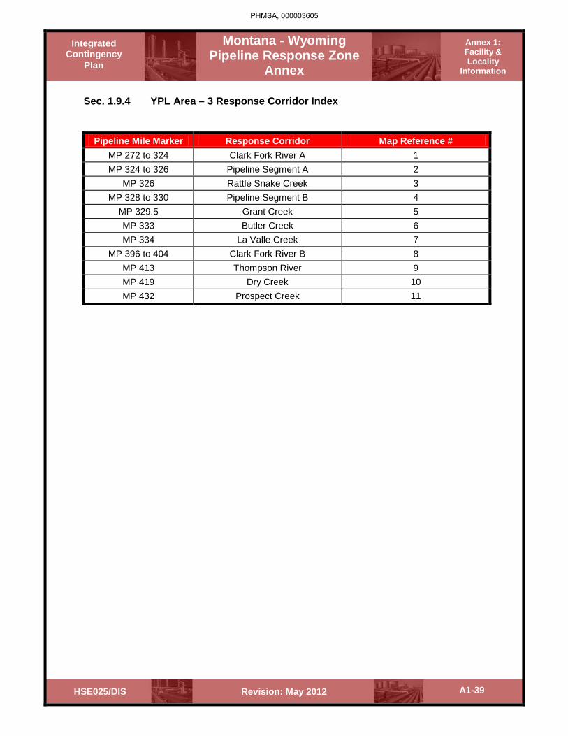
Montana - Wyoming Pipeline Response Zone
Annex
Annex 1: Facility & Locality
Information
Integrated Contingency
Plan
A1-39 Revision: May 2012 HSE025/DIS
Sec. 1.9.4 YPL Area – 3 Response Corridor Index
Pipeline Mile Marker Response Corridor Map Reference # MP 272 to 324 Clark Fork River A 1 MP 324 to 326 Pipeline Segment A 2
MP 326 Rattle Snake Creek 3 MP 328 to 330 Pipeline Segment B 4
MP 329.5 Grant Creek 5 MP 333 Butler Creek 6 MP 334 La Valle Creek 7
MP 396 to 404 Clark Fork River B 8 MP 413 Thompson River 9 MP 419 Dry Creek 10 MP 432 Prospect Creek 11
PHMSA, 000003605

Montana - Wyoming Pipeline Response Zone
Annex
Annex 1: Facility & Locality
Information
Integrated Contingency
Plan
A1-40 Revision: May 2012 HSE025/DIS
Response Areas
Location MP Location MP
YPL 6 Inch White Beaver Cr. 46.0 Prickly Pear Creek 2.5 Sheep Creek 49.0 Hwy. Crossing 5.0 Hwy./White Beaver Creek 53.0 Bridge Creek 19.0 Hwy. Crossing 54.0 Beaver Creek 20.0-25.0 Crest Creek 60.0 Middle Creek 31.0 Sweetgrass Cr. 63.0 East Fork Creek 35.0 Bailey Clark Ditch 70.0 Encampment Creek 37.0 Hwy. Crossing 72.0 Hwy. Crossing 42.0 Hwy. Crossing 74.0 Spanish Coulee 50.0 Hwy. Crossing 77.0 Hwy. Crossing 70.0 Little Timber Cr. 78.5 Sand Coulee 73.0 West Fork Creek 79.0 Great Falls, Montana 77.0-79.0 Shed Creek 80.0 Great Falls Terminal 79.0 Cow Creek 81.0 YPL 10 Inch Duck Creek 86.0 Alkali Creek 6.0 Hwy. Crossing 88.0 Alkali Creek 7-7.5 S. Dog Creek 88.5 Alkali Creek 9.5 Springdale St. 90.0 Hwy./RR Cro. 10.5 Hwy. Crossing 101.5 Alkali Creek 14.0 Hwy. Crossing 103.5 Two Pine School 18.0 Hwy. Crossing 105.0 Peterson School 31.0 Hwy. Crossing 108.0 Greenwood Cr. 34.5 Flynn Creek 116.0 Toll Creek 35.5 Quinn Creek 120.0 Struck Creek 39.5 Hwy. Crossing 122.0 Columbus Sta. 40.0
PHMSA, 000003606

Montana - Wyoming Pipeline Response Zone
Annex
Annex 1: Facility & Locality
Information
Integrated Contingency
Plan
A1-41 Revision: May 2012 HSE025/DIS
Response Areas Contd.
Location MP Location MP
Bozeman, MT 130.0-132.0 Tigh Creek 283.0 Hwy. Crossing 133.0 Antelope Creek 287.0 Bozeman Ter. 133.0 Wood Creek 289.0 Hwy. Crossing 134.0 RR Crossing 293.0 Thompson Creek 139.5 Tyler Creek 294.0 Ferris Ditch 141.0 Hwy./RR Cro. 297.0 Hwy. Crossing 142.0 Ryan Creek 299.0 Manhattan Sta. 150.0 Cramer Creek 301.0 Nixon Gulch 152.0 Iris, MT 304.0 Hwy. Crossing 172.0 Hwy. Crossing 305.0 Toston Canal 174.0 Starvation Creek 307.0 Crow Creek 175.0 RR Crossing 307.5 Hwy. Crossing 184.0 Clinton, MT 309.0 Hwy. Crossing 196.0 RR Crossing 310.0 Beaver Creek 197.0 Hwy./RR Cro. 312.0 Hwy. Crossing 198.0 RR Crossing 313.0 RR Crossing 211.0 Deer Creek 320.0 Hwy. Crossing 212.0 Missoula, MT 325.0-326.0 RR Crossing 216.0 Missoula Ter. 329.0 Helena Ter. 218.0 Hwy. Crossing 329.5* Helena, MT 218.0-222.0 Hwy. Crossing 333.0* Porcupine Creek 232.0 LaValle Creek 334.0* McDonald Creek 236.0 E. Fork Creek 339.0* Hwy./RR Cro. 238.0 Hwy./RR Cro. 341.0* Elliston, MT 239.0 Hwy. Crossing 342.0* Hwy./RR Cro. 244.5 Schley Creek 343.0* Dog Creek 248.0 Finley Creek 346.0* Hwy./RR Cro. 251.0 Finley Creek 347.0* McDonald Creek 254.0 Hwy. Crossing 352.0* Creek 255.0 Valley Creek 352.5* Warm Springs Creek 262.0 Creek 353.0* RR Crossing 264.0 Jocko Canal 362.0* Drummond Sta. 277.0 Revias Creek 364.0* Flint Creek 279.0 Gunderson Cr. 365.0*
PHMSA, 000003607

Montana - Wyoming Pipeline Response Zone
Annex
Annex 1: Facility & Locality
Information
Integrated Contingency
Plan
A1-42 Revision: May 2012 HSE025/DIS
Response Areas Contd.
Location MP Location MP
Magpie Creek 368.0* Hwy. Crossing 502.0 Magpie Creek 369.0* Coeur d'Alene, Idaho 503.0-507.0 Vanderburg Cr. 371.0* Post Hill, Washington 512.0-513.0 Camas Creek 374.0* RR Crossing 514.0 Clear Creek 374.5* Spokane, Washington 520.0-537.0 Camas Creek 382.0* Moses Lake 6"/8" Rainbow Lake 387.0-388.0* Creek/Hwy. Crossing 540.0 Hwy./RR Cro. 401.0* RR/Hwy. Crossing 543.0 Hwy./RR Cro. 412.0* Geiger Junction 547.0 RR Crossing 416.0* Hwy. Crossing 547.0 Creek 419.0 Hwy. Crossing 548.0 Thompson Falls Creek 419.0 Fairchild Terminal 556.0 Prospect Creek 421.0 Hwy. Crossing 557.0 Prospect Creek 424.0 Hwy. Crossing 558.0 Prospect Creek 425.0 RR Crossing 560.0 Daisy Creek 427.0 Hwy. Crossing 561.0 Twenty-Four Gulch 434.0 Hwy. Crossing 566.0 Paragon Gulch 440.0 Hwy. Crossing 570.0 Murray Creek 447.0 Creek/Hwy. Crossing 579.0 Prichard Creek 448.0 Hwy. Crossing 580.0 Prichard Creek 453.0 Hwy. Crossing 588.0 Prichard, Idaho 454.0 Hwy. Crossing 589.0 Cataldo, Idaho 478.0 RR Crossing 590.0 Cataldo Sta. 479.0 Hwy. Crossing 592.0 Bentley Creek 482.0 RR Crossing 612.0 Ruteman Creek 483.0 Creek/Hwy. Crossing 613.0 Service Creek 484.0 Hwy. Crossing 616.0 Curran Creek 484.5 Hwy. Crossing 622.0 Hwy. Crossing 484.5 Hwy. Crossing 627.0 Hwy. Crossing 486.0 Siphon Canal 633.0 Reserve Creek 488.0 RR Crossing 642.0 Hwy. Crossing 489.0 Crab Creek 643.0 Cedar Creek 490.0 Moses Lake Terminal 644.0 Wolf Lodge Cr. 494.0 Powder River 4 Inch Blue Creek 496.0 To Be Determined Fernan Creek 500.0
PHMSA, 000003608

Montana - Wyoming Pipeline Response Zone
Annex
Annex 1: Facility & Locality
Information
Integrated Contingency
Plan
A1-43 Revision: May 2012 HSE025/DIS
1.10 Response Zone – Glacier Crude South/North
Sec. 1.10.1 Area Information Summary Glacier Crude South
Area Information
Maintenance Group Name
Glacier Crude Station South
Response Area Location
Southern Montana
Line Section 12” M.L., 10” M.L., 10” Transfer, 8” M.L. Byron to Billings Counties Yellowstone, Mussellshell, Goldenvalley, Stillwater, Park (MT & WY),
Big Horn (WY), Wheatland (MT) Mile Posts 12”= 0 – 76b, 10”= 0 – 134, 10” Xfer = 0 – 4, 8”= segment 0 – 86 and
segment 134 – 186. Telephone (day/night)
406-255-7988 / 406-860-1001
Address 502 Erie Drive; Billings, MT 59101 (Mail:338 Hwy 87 East, Billings, MT 59101)
Owner Phillips 66 Owner Location (street)
600 North Dairy Ashford, 2136 Tarkington Building
Emergency Telephone
800-231-2551 or 877-267-2290
City Houston State Texas Zip 77079 County Harris Telephone 281-293-3891
PHMSA, 000003609

Montana - Wyoming Pipeline Response Zone
Annex
Annex 1: Facility & Locality
Information
Integrated Contingency
Plan
A1-44 Revision: May 2012 HSE025/DIS
Sec. 1.10.2 Area Information Summary Glacier Crude North
Area Information Maintenance Group Name
Glacier Crude North
Response Area Location
Northern Montana
Line Section 12” ML 12/8” ML Counties Glacier, Pondera, Teton, Chouteau, Judith Basin, Wheatland, Fergus Mile Posts 12”/8” 186 – 426 Telephone (day/night)
406-873-4815 / 406-799-2382
Address See Below Owner ConocoPhillips Owner Location (street)
600 North Dairy Ashford, 2136 Tarkington Building
Emergency Telephone
800-231-2551
City Houston State Texas Zip 77079 County Harris Telephone 281-293-3891
Sec. 1.10.3 Pipeline Information
Glacier Crude System Description
The Glacier Pipeline system extends in a southeast direction from the United States/Canadian border near Carway, Alberta to Laurel, Montana. For Customs (custody transfer) purposes, the 12-inch and 8-inch segments of the Glacier system between the United States/Canadian border and Cut Bank Station are called Aurora Pipe Line. On the southern end of the system, an 8-inch and a 6-inch line flows northward from Frannie, Wyoming to Billings, Montana.
PHMSA, 000003610

Montana - Wyoming Pipeline Response Zone
Annex
Annex 1: Facility & Locality
Information
Integrated Contingency
Plan
A1-45 Revision: May 2012 HSE025/DIS
Major Stations
Frannie Crude Station: North Conoco Road, Frannie, WY 82433 Driving Directions: On Highway 310, proceed to Frannie at 4th
Street (milepost 254.8). Turn Right at 0.15 miles.
Billings Glacier System: 502 Erie Drive, Billings, MT 59101 Description: Billings Station is the terminating point of the 12-inch and the 10-
inch lines. Volumes can be delivered directly from the 10-inch and 12-inch to pipeline tankage, and to the ConocoPhillips and Exxon refiners. Transfers can be made from pipeline tankage to ConocoPhillips and Exxon refinery.
Driving Directions: Take exit 450, off of I-90. Turn on 27th
Street at Belknap. Turn right at Erie Drive. Turn left to continue across the railroad spur to the road into the station gate.
Roundup Station: 701 3rd
Description Roundup Station is located about 15 miles west of Roundup, MT and is approximately 73.9 miles (26K bbls) downstream from Utica
om Cut Bank on the nch mainline from
Cut Bank, and is the originating station on the 10-inch line to Billings. Volumes from the 8-inch Cut Bank line can be delivered to tankage or bypassed to the 10-inch Billings line. Glacier has three storage tanks at Roundup. One is used to store SWT/581 from the 8-inch line and the other two are for storage of LIT/585 from the 8-inch line.
Street East, Roundup, MT 59072
Driving Directions: From the intersection of Highway 12 and Highway 87, go west to Roundup. Proceed on Highway 87/12 toward Roundup, east 0.3 miles. At Horsetheif Road (milepost 48.3), turn 10.6 miles.
Cut Bank Station: PO Box 1252, Tank Farm Hill, Cut Bank, MT 59427 Description: Cut Bank Station is the originating pump station on the Glacier
system. Crude oil is received from Plains Pipeline 12-inch line. Receipts are delivered to pipeline tankage or delivered to foreign tankage at Cut Bank. Custody transfer of materials received from Plains Pipeline is based on Meter 1 at Cut Bank.
Driving Directions: On Highway 2, on Humble Road (milepost 256.5), east end of Cut Bank. Turn right going south 0.25 miles.
Buffalo Station: West Dry Creek Road, 0.75 miles south of the intersection of
Buffalo Canyon Road and West Dry Creek Road, Buffalo, MT Description:
Driving Directions: Take left and head west and then north 1.5 miles and site will be on right side.
PHMSA, 000003611
(b) (7)(F)
(b) (7)(F)

Montana - Wyoming Pipeline Response Zone
Annex
Annex 1: Facility & Locality
Information
Integrated Contingency
Plan
A1-46 Revision: May 2012 HSE025/DIS
Pipeline Description
The geography of the land along the Pipeline can be described as a high mountain plain containing mountainous regions that has significant elevation changes and consists of numerous small drainage areas, creeks and rivers. While some use of the land is for agriculture purposes, most of the pipeline runs through sparsely populated and undeveloped land.
A spill originating from this Pipeline is likely to be discovered quickly and response conducted immediately upon discovery. However, this Plan is designed for a worst case scenario, which is a catastrophic tank or pipeline failure under extreme weather conditions during flood conditions.
This Plan contains response procedures and information for the geographic area from:
1. Glacier North from the Canadian Border to Great Falls, MT:
• Saint Mary’s River • Willow Creek • Saint Mary’s Canal • North Fork of Milk Creek • Milk River • Cut Bank Creek • Marias River • Dry Fork of Marias River • Teton River • Missouri River • Belt Creek
2. Glacier South including Judith Gap as well as Lavina, MT to Byron, MT:
• Judith River • Musshelshell River • Painted Robe Creek • Dean Creek • Yellowstone River A (from YPL Area 1) • Yellowstone River • Cottonwood Creek • Five Mile Creek • Clark Fork Yellowstone River • Bluewater Creek • Sage Creek • Shoshone River
Sec. 1.10.4 Spill Response Equipment
Please refer to Annex 2 for the Company’s spill response equipment
PHMSA, 000003612

15
90
15
90
15
15
94
90
90
94
90
15
Glacier Pipeline 12"
Glacier Pipeline 8"
12"
8"6"
8"
8"
8"
Murphy
Cut Bank
Judith Gap
Ivanhoe
Laurel
Frannie
Byron
BILLINGSREFINERY
10"
Roundup
12" Loop
FrannieGathering
Cenex LeasedLine
Cut Bank
Great Falls
Sheridan
Helena
Missoula
CANADAMONTANA
MONTANA
MO
NTA
NA
MONTANA
NO
RTH
DA
KO
TASO
UTH
DA
KO
TA
WYOMING
IDAHO Reference Point
Receipt Point
Inactive Pipelines
Active Pipelines
Billings Area MapBillings Area MapShowing Glacier CrudeShowing Glacier Crude
Pipeline SystemsPipeline SystemsFilename: Glacier Crude.mxd
Created: 09/09/2008
PHMSA, 000003613

Montana - Wyoming Pipeline Response Zone
Annex
Annex 1: Facility & Locality
Information
Integrated Contingency
Plan
A1-48 Revision: May 2012 HSE025/DIS
Description of Operations
Glacier Pipeline: The Company operates a crude oil pipeline that extends from the United States - Canada border near Carway, Alberta to Byron, Wyoming. The system is comprised of four major segments that are as follows:
• 8"/10” mainline from Canada Border to Billings, MT • 12" mainline from Cut Bank to Billings, MT • 8" mainline from Billings, MT to Byron, WY (Idle pipeline; purged) • 10” Transfer line from Billings to Lockwood
The pipeline is constructed of pre-1970, 6, 8, 10 and 12 inch ERW pipe. Various grades of crude oil are handled through pipeline. The grades range from heavy sour to butane.
Glacier Pipeline System DOT Tankage:
• Cut Bank All Tanks #1010, #1020, #1030 and #1040 • Roundup All Tanks #1002, #1003, #1004, • Billings 1007, 1008, 1009, 1143
PHMSA, 000003614

M o n t a n aM o n t a n a
L e w i s a n d C l a r kL e w i s a n d C l a r k
T e t o nT e t o nF l a t h e a dF l a t h e a d
P o n dP o n d
H i l lH i l lL i b e r t yL i b e r t yT o o l eT o o l e
C a s c a d eC a s c a d e
C h o u t e aC h o u t e a u
F e r g uF e r g u
M e a g h e rM e a g h e r
Missouri River
Teto
Saint Mary
Milk River
¦49
¦12
¦89
¦200
¦12¦284
¦17
¦89
¦89
¦233
¦2
¦279
¦12
¦232
¦225
¦287
¦80
¦2
¦89
¦87
¦2
¦2
¦233
¦200
¦89
¦89
¦12
¦191
¦12
¦21
¦15
¦430
¦12
¦89
¦12 Helena
Havre
¬
eline Integrity Mapping GroupP: Glacier North Overviewe: 1/11/2011
PHMSA, 000003615
(b) (7)(F)
(b) (7)(F)
(b) (7)(F)
(b) (7)(F)
(b) (7)(F)

PHMSA, 000003616
(b) (7)(F)
(b) (7)(F)
(b) (7)(F)
(b) (7)(F)
(b) (7)(F)
(b) (7)(F)
(b) (7)(F)
(b) (7)(F)
(b) (7)(F)

Montana - Wyoming Pipeline Response Zone
Annex
Annex 1: Facility & Locality
Information
Integrated Contingency
Plan
A1-51 Revision: May 2012 HSE025/DIS
Sec. 1.10.5 Glacier North Area Response Corridor Index
Pipeline Mile Marker Response Corridor Map Reference # MP 423 Saint Mary’s River 1 MP 420 Willow Creek 2 MP 416 Saint Mary’s Canal 3
MP 411.5 North Fork of Milk River 4 MP 403.5 Milk River 5 MP 379.5 MP 369.5 Cut Bank Creek 6
MP 353 Marias River 7 MP 332 Dry Fork of Marias River 8 MP 303 Teton River 9 MP 269 Missouri River 10 MP 260 Belt Creek 11 12” Loop Landowners 12
PHMSA, 000003617

#
M o n t a n aM o n t a n a
Glacier Crude 8 inch
F e r g u sF e r g u s
ll
M u s sM u s s
W h e a t l a n dW h e a t l a n d
¦19 ¦200
¦238
¦12
160
40
¬
Pipeline Integrity Mapping GroupMAP: Glacier South View 1aDate: 1/17/2011
PHMSA, 000003618
(b) (7)(F)
(b) (7)(F)
(b) (7)(F)
(b) (7)(F)
(b) (7)(F)
(b) (7)(F)
(b) (7)(F)

PHMSA, 000003619
(b) (7)(F)
(b) (7)(F) (b) (7)(F)
(b) (7)(F)
(b) (7)(F)
(b) (7)(F)

Creek
kk
B i g H o r nB i g H o r n
C a r b o nC a r b o n
l l o w s t o n el l o w s t o n e
P r y o rP r y o r
B i l lB i l l
LL
P o w eP o w e
¬
Pipeline Integrity MappiMAP: Glacier South View 1bDate: 1/17/2011
(b) (7)(F)
(b) (7)(F)
(b) (7)(F)
(7)(F)
(b) (7)(F)

PHMSA, 000003621
(b) (7)(F) (b) (7)(F)
(b) (7)(F)
(b) (7)(F)
(b) (7)(F)
(b) (7)(F)

Montana - Wyoming Pipeline Response Zone
Annex
Annex 1: Facility & Locality
Information
Integrated Contingency
Plan
A1-56 Revision: May 2012 HSE025/DIS
Sec. 1.10.6 Glacier South Area Response Corridor Index
Pipeline Mile Marker Response Corridor Map Reference #
MP 207 Judith River 1 MP 47 Musselshell River 2 MP 38 Painted Robe Creek 3 MP 114 Dean Creek 4
MP 15 Yellowstone River A (From YPL Area 1) 5
MP 66 Yellowstone River 6 MP 54 Cottonwood Creek 7 MP 49 Five Mile Creek 8 MP 62 Clarks Fork Yellowstone River 9 MP 38 Bluewater Creek 10 MP 32 Sage Creek 11 MP 0 Shoshone River 12
PHMSA, 000003622

Montana - Wyoming Pipeline Response Zone
Annex
Annex 1: Facility & Locality
Information
Integrated Contingency
Plan
A1-57 Revision: May 2012 HSE025/DIS
Sec. 1.10.7 Area Facility Information - Glacier Crude South
PHMSA, 000003623
(b) (7)(F)
(b) (7)(F)

Montana - Wyoming Pipeline Response Zone
Annex
Annex 1: Facility & Locality
Information
Integrated Contingency
Plan
A1-58 Revision: May 2012 HSE025/DIS
Glacier Pipeline System - DOT Tankage
PHMSA, 000003624
(b) (7)(F)

Montana - Wyoming Pipeline Response Zone
Annex
Annex 1: Facility & Locality
Information
Integrated Contingency
Plan
A1-59 Revision: May 2012 HSE025/DIS
Sec. 1.10.8 Significant and Substantial Harm Certification – Glacier Crude North/South
Applicability of Significant and Substantial Harm – DOT / PHMSA All Relevant Pipelines as Listed below in this Section
Pipeline Name: Glacier Crude Area Is the pipeline greater than 6 and 5/8 inches (168 mm) in outside nominal diameter, and greater than 10 miles (16 kilometers) in length, YES_______X___________ NO____________________ Has the line section experienced a release greater than 1,000 barrels within the past five (5) years, YES___________________ NO_________X___________ Has any line section experienced two or more reportable releases, as defined in 49 CFR 195.5, within the past five (5) years, or YES___________________ NO_________X___________ Does any line section contain any electric resistance welded pipe, manufactured prior to 1970 and operates at a maximum operating pressure established under 40 CFR 195.406 that corresponds to a stress level greater than 50 percent of the specified minimum yield strength of the pipe, or YES_______X_________ NO_________ ___________ Is any line located within a 5-mile (8 km) radius of potentially affected public drinking water intakes and could reasonably be expected to reach public drinking water intakes, or YES_______X___________ NO____________________ Is any link located within a 1-mile (1.6 km) radius of potentially affected environmentally sensitive areas and could reasonably be expected to reach these areas? YES_______X___________ NO___________________ Based on the DOT/PHMSA criteria above, ALL of the Company Pipelines are considered to be a system of Significant and Substantial Harm. The Company certifies to the Pipeline and Hazardous Materials Safety Administration of the Department of Transportation that we have obtained, by contract or other approved means, the necessary private personnel and equipment to respond, to the maximum extent practicable, to a worst case discharge.
I certify under penalty of law that I have personally examined and am familiar with the information submitted in this document, and that based on my inquiry of those individuals responsible for obtaining information, I believe that the submitted information is true, accurate and complete.
Robert Yarbrough
Name Date May 2012
PHMSA, 000003625

Montana - Wyoming Pipeline Response Zone
Annex
Annex 1: Facility & Locality
Information
Integrated Contingency
Plan
A1-60 Revision: May 2012 HSE025/DIS
Sec. 1.10.9 Determination of Significant and Substantial Harm
The Glacier Pipeline System meets the definition for “Significant and Substantial Harm” because it meets at least one of the criteria listed in 49 CFR §194.103(c). Therefore, a response plan per 49 CFR Part 194 must be submitted for the YPL System.
Sec. 1.10.10 Hazard Identification and Discharge Analysis
Sensitive Area and Vulnerability Analysis
Vulnerabilities along this pipeline are identified in Site Sensitive Maps contained in Annex 3. Also, immediate response areas have been identified in this Annex. Vulnerability to Natural Disasters
Natural disasters may also play a role in how to respond to a worst case scenario. Listed in Annex 3 are the types of natural disasters that were reviewed for applicability to this facility and the appropriate response
Discharge Analysis
The equipment and manpower to respond to a spill are available from several sources and are listed with the equipment and contractors in this Plan. In addition, equipment and manpower requirements for each response site are listed in this Plan.
PHMSA, 000003626

Montana - Wyoming Pipeline Response Zone
Annex
Annex 1: Facility & Locality
Information
Integrated Contingency
Plan
A1-61 Revision: May 2012 HSE025/DIS
Sec. 1.10.11 Worst Case Discharge
Worst Case Discharge Volume
This method and formula below will be used to determine the WCD Volume in adverse weather conditions at any response area in the Yellowstone Pipeline System Area:
PHMSA, 000003627
(b) (7)(F)

Montana - Wyoming Pipeline Response Zone
Annex
Annex 1: Facility & Locality
Information
Integrated Contingency
Plan
A1-62 Revision: May 2012 HSE025/DIS
Sec. 1.10.12 Identification of Response Areas
PHMSA, 000003628
(b) (7)(F)
(b) (7)(F)

Montana - Wyoming Pipeline Response Zone
Annex
Annex 1: Facility & Locality
Information
Integrated Contingency
Plan
A1-63 Revision: May 2012 HSE025/DIS
Glacier Pipeline Identification of Response Areas and Worst Case Discharge Calculation
*Glacier 12": Canada Border to Billings
**Glacier 8”/10”: Canada Border to Byron, WY (8" from Cut Bank to Roundup; 10" from Roundup to Billings & 8” from Billings to Byron, also referred to as Frannie Line).
PHMSA, 000003629
(b) (7)(F)

Montana - Wyoming Pipeline Response Zone
Annex
Annex 1: Facility & Locality
Information
Integrated Contingency
Plan
A1-64 Revision: May 2012 HSE025/DIS
PHMSA, 000003630
(b) (7)(F)

Montana - Wyoming Pipeline Response Zone
Annex
Annex 1: Facility & Locality
Information
Integrated Contingency
Plan
A1-65 Revision: May 2012 HSE025/DIS
Sec. 1.10.14 Crude Oil Characteristics
Crude Oil Characteristics
Synonyms - Coal oil; Mineral oil; Petroleum; Petroleum, Crude oil; Rock oil; Seneca oil
United Nations Number 1267
CHRIS Code OIL Formula - CnH2n+2, or CHnH 2n-2 Boiling Point 32-400 EC 90-750 EF Appearance/Odor - Thick, heavy liquid, yellow to dark reddish brown or black color, distinct tarry odor.
Freezing Point -45EC -50 EF
Specific Gravity - 0.85 to 0.95 Vapor Pressure 20EC (68EF) (mmHg) 1 to 3 Chemical Family - Hydrocarbon mixture Reid Vapor Pressure (psia) -0.10 Vapor Pressure 46EC (115EF) (psia) 0.15 Pollution Category – US EPA 1MO I Vapor Density (Air = 1.0) above 1 Applicable Bulk Reg. 46 (CFR Subchapter D Solubility in Water Negligible
Fire & Explosion Hazard Data
Grade - C or D depending on flash point Electrical Group - D General - When heated to composition, it emits toxic fumes. Moderate to severe. Flash Point (EF) - 50 to + 90 Flammable Limits Unavailable Autoignition Temp. (EF) Unavailable Extinguishing Agents CO2, dry chemical, foam, water fog. Special Procedures Tanks exposed to fire should be kept cool with a water spray. Fire fighters should wear respiratory protection.
Health Hazard Data
Health Hazard Ratings Odor Threshold (ppm) PEL/TWA (ppm) TLV/TWA (ppm)
0,1,0 Unavailable Unavailable Unavailable General - Liquid causes skin irritation. Symptoms - Skin contact; skin irritation and burns. Short Exposure Tolerance - Unavailable Exposure Procedures - Wipe spilled liquid from skin, remove contaminated clothing and wash affected areas with soap and water. For eye contact, flush with water for 15 minutes while obtaining medical attention.
Reactivity Data
Stability - Chemically stable. Compatibility - Material: Usual materials of construction are suitable. Cargo: Group 33 of compatibility chart.
Spill or Leak Procedure
Wear rubber gloves, face shield, protective clothing. Have all-purpose canister mask available. Secure ignition sources. If a spill occurs, call the National Response Center, 800-424-8802.
PHMSA, 000003631

Montana - Wyoming Pipeline Response Zone
Annex
Annex 1: Facility & Locality
Information
Integrated Contingency
Plan
A1-66 Revision: May 2012 HSE025/DIS
Worst Case Discharge Locale Map 1
PHMSA, 000003632
(b) (7)(F)
(b) (7)(F)
(b) (7)(F)

Montana - Wyoming Pipeline Response Zone
Annex
Annex 1: Facility & Locality
Information
Integrated Contingency
Plan
A1-67 Revision: May 2012 HSE025/DIS
Worst Case Discharge Map 2
PHMSA, 000003633
(b) (7)(F)
(b) (7)(F)
(b) (7)(F)
(b) (7)(F)

Montana - Wyoming Pipeline Response Zone
Annex
Annex 1: Facility & Locality
Information
Integrated Contingency
Plan
A1-68 Revision: May 2012 HSE025/DIS
1.11 Response Zone – Pioneer Pipeline Areas 1 and 2
Sec. 1.11.1 Area Information Summary – Pipeline Area 1
Area Information
Maintenance Group Name
Pioneer Pipeline Area 1
Response Area Location
Rock Springs Area
Line Section Pioneer 12” & 8” Counties Carbon, Sweetwater, & Uinta Mile Posts 0 through 194 on the 12” & 0 through 186 on the 8” Telephone (day/night)
307-362-7541 x16 / 307-389-3156
Address 90 Foothill Blvd., Rock Springs, WY 82901-5551 Owner Phillips 66 Owner Location (street)
600 North Dairy Ashford, 2136 Tarkington Building
Emergency Telephone
800-231-2551 or 877-267-2290
City Houston State Texas Zip 77079 County Harris Telephone 281-293-3891
Sec. 1.11.2 Area Information Summary – Pipeline Area 2
Area Information
Maintenance Group Name
Pioneer Pipeline Area 2
Response Area Location
North Salt Lake Area
Line Section Pioneer 12’ & 8” Counties Uinta County WY, Rich, Morgan, Weber & Davis Counties UT Mile Posts 194.0 to 262.0 – on the 12” & 247.0 to 291.6 on the 8” Telephone (day/night)
801-299-3617 / 801-631-6042
Address 245 East 1100 North, North Salt Lake, UT 84054 Owner Phillips 66 Owner Location (street)
600 North Dairy Ashford, 2136 Tarkington Building
Emergency Telephone
800-231-2551 or 877-267-2290
City Houston State Texas Zip 77079 County Harris Telephone 281-293-3891
PHMSA, 000003634

Montana - Wyoming Pipeline Response Zone
Annex
Annex 1: Facility & Locality
Information
Integrated Contingency
Plan
A1-69 Revision: May 2012 HSE025/DIS
Sec. 1.11.3 Pipeline Information
Pipeline Description
The geography of the land along the Pipeline can be described as a high mountain plain containing mountainous regions that has significant elevation changes and consists of numerous small drainage areas, creeks and rivers. While some use of the land is for agriculture purposes, most of the pipeline runs through sparsely populated and undeveloped land.
A spill originating from this Pipeline is likely to be discovered quickly and response conducted immediately upon discovery. However, this Plan is designed for a worst case scenario, which is a catastrophic tank or pipeline failure under extreme weather conditions during flood conditions.
This plan includes information on the Pioneer 12” line as well as the 8” line. Pipeline milepost markers listed on overview maps in this section correlate to the 8” line. New pipeline milepost markers for the 12” line will be added in a later plan update.
This Plan contains response procedures for the geographic area from:
Pioneer Area 1, including the following
• Sugar Creek & Patrick Draw • Bitter Creek • City of Rock Springs • City of Green River and Green River • Blacks Fork River • Big Muddy Creek • Bear River and various irrigation canals • City of Evanston
Pioneer Area 2 from North Salt Lake City to the Utah – Wyoming Border:
• Great Salt Lake • Weber River • Farmington Bay • Numerous small drainages and creeks
PHMSA, 000003635

Montana - Wyoming Pipeline Response Zone
Annex
Annex 1: Facility & Locality
Information
Integrated Contingency
Plan
A1-70 Revision: May 2012 HSE025/DIS
Description of Operations
The Company operates a refined petroleum products pipeline that extends 305 miles from Sinclair, Wyoming to North Salt Lake, Utah. PPL System is jointly owned by Sinclair Pipe Line Company and the Company. The pipeline is constructed of 2000, 12 inch ERW pipe and pre-1970, 8-inch ERW pipe.
The following are the grades of petroleum products shipped on the system:
• No-Lead Premium Gasoline (N91) • No-Lead Regular Gasoline (N85) • Military Jet Fuel (JP4) • Commercial Jet Fuel (JFA) • No. 1 Fuel Oil (Y) • No. 2 Fuel Oil (D45/D40)
This plan includes information on the Pioneer 12” line as well as the 8” line. Pipeline milepost markers listed on overview maps in this section correlate to the 8” line. New pipeline milepost markers for the 12” line will be added in a later plan update.
Sec. 1.11.4 Spill Response Equipment
Please refer to Annex 2 for the Company’s spill response equipment
PHMSA, 000003636

PHMSA, 000003637
(b) (7)(F)
(b) (7)(F)
(b) (7)(F)
(b) (7)(F)(b) (7)(F)

Montana - Wyoming Pipeline Response Zone
Annex
Annex 1: Facility & Locality
Information
Integrated Contingency
Plan
A1-72 Revision: May 2012 HSE025/DIS
Sec. 1.11.5 Pioneer Pipeline Area 1 Response Corridor Index
Pipeline Mile Marker Response Corridor Map Reference #
MP 0-10 Sugar Creek 1 MP 74-86 Patrick Draw 2
MP 86-126 Bitter Creek 3 MP 113-115 City of Rock Springs 4 MP 128-132 City of Green River 5 MP 130-128 Green River 6 MP 132-206 Blacks Fork River 7
MP 194 Big Muddy Creek 8 MP 206-211 Bear River 9 MP 211-214 City of Evanston 10
12” Loop Landowners 12
PHMSA, 000003638

PHMSA, 000003639
(b) (7)(F) (b) (7)(F)
(b) (7)(F)
(b) (7)(E)
(b) (7)(F)

Montana - Wyoming Pipeline Response Zone
Annex
Annex 1: Facility & Locality
Information
Integrated Contingency
Plan
A1-74 Revision: May 2012 HSE025/DIS
Sec. 1.11.6 Pioneer Pipeline Area 2 Response Corridor
Pipeline Mile Marker Response Corridor Map Reference #
MP 287.9 Mill Creek 1 MP 286.6 Deuel, Stone and Burton Creeks 2
MP 287 to MP 284 Stock Road Drainage 3 MP 282.5 Farmington Creek 4 MP 281.5 Shepard Creek 5 MP 279.9 Haight Creek 6 MP 277.5 Holmes Creek 7 MP 276.5 North Fork of Holmes Creek 8
No pipeline crossing Farmington Bay 9 MP 276 Snow Creek 10 MP 274 Kays Creek 11
MP 272.5 Davis Weber Canal 12 MP 272 Bambrough Canal 13
MP 271 and MP 268.7 to MP 270.8 Weber River 14
MP 236 to MP 248 Lost Creek 15 No pipeline crossing Great Salt Lake 16
PHMSA, 000003640

Montana - Wyoming Pipeline Response Zone
Annex
Annex 1: Facility & Locality
Information
Integrated Contingency
Plan
A1-75 Revision: May 2012 HSE025/DIS
Sec. 1.11.7 Significant and Substantial Harm Certification – Pioneer Pipeline Area 1 & 2
Applicability of Significant and Substantial Harm – DOT / PHMSA All Relevant Pipelines as Listed below in this Section
Pipeline Name: Pioneer Pipeline Area Is the pipeline greater than 6 and 5/8 inches (168 mm) in outside nominal diameter, and greater than 10 miles (16 kilometers) in length, YES_______X___________ NO____________________ Has the line section experienced a release greater than 1,000 barrels within the past five (5) years, YES___________________ NO_________X___________ Has any line section experienced two or more reportable releases, as defined in 49 CFR 195.5, within the past five (5) years, or YES___________________ NO_________X___________ Does any line section contain any electric resistance welded pipe, manufactured prior to 1970 and operates at a maximum operating pressure established under 40 CFR 195.406 that corresponds to a stress level greater than 50 percent of the specified minimum yield strength of the pipe, or YES_______X_________ NO_________ ___________ Is any line located within a 5-mile (8 km) radius of potentially affected public drinking water intakes and could reasonably be expected to reach public drinking water intakes, or YES_______X___________ NO____________________ Is any link located within a 1-mile (1.6 km) radius of potentially affected environmentally sensitive areas and could reasonably be expected to reach these areas? YES_______X___________ NO___________________ Based on the DOT/PHMSA criteria above, ALL of the Company Pipelines are considered to be a system of Significant and Substantial Harm. The Company certifies to the Pipeline and Hazardous Materials Safety Administration of the Department of Transportation that we have obtained, by contract or other approved means, the necessary private personnel and equipment to respond, to the maximum extent practicable, to a worst case discharge.
I certify under penalty of law that I have personally examined and am familiar with the information submitted in this document, and that based on my inquiry of those individuals responsible for obtaining information, I believe that the submitted information is true, accurate and complete.
Robert Yarbrough
Name Date March 2011
PHMSA, 000003641

PHMSA, 000003642
(b) (7)(F)
(b) (7)(F)
(b) (7)(F)
(b) (7)(F)
(b) (7)(F)

Emergency Evacuation Guide Sinclair Station
GENERAL OR PARTIAL EVACUATION RULES
Be aware of potential hazards Move upwind of emergency and/or at 90 degree angle If route is impassable, radio for assistance Listen for further announcements Proceed to nearest assembly area
ONCE AT ASSEMBLY AREAS
Report to Safety Leader or Station Personnel Account for personnel Assess need for medical assistance Wait until Safety Leader or Station Personnel gives “All Clear” signal or issues other instructions before dispersing.
PHMSA, 000003643
(b) (7)(F)

Montana - Wyoming Pipeline Response Zone
Annex
Annex 1: Facility & Locality
Information
Integrated Contingency
Plan
A1-78 Revision: May 2012 HSE025/DIS
Sensitive Area and Vulnerability Analysis
Vulnerabilities along this pipeline are identified in Site Sensitive Maps contained in Annex 3. Also, immediate response areas have been identified in this Annex. Vulnerability to Natural Disasters
Natural disasters may also play a role in how to respond to a worst case scenario. Listed in Annex 3 are types of natural disasters that were reviewed for applicability to this facility and the appropriate response.
Sec. 1.11.8 Worst Case Discharge
Worst Case Discharge Volume
The method, data and formula described below will be used to determine the WCD Volume in adverse weather conditions at any response area along this system. The calculated data for the WCD volume for identified response areas and breakout tankage along this system follows in this Section. These response areas meet the requirements for “Significant & Substantial” harm criteria as designated per 49 CFR 194 in the event of a worst case discharge at these locations.
PHMSA, 000003644
(b) (7)(F)

Montana - Wyoming Pipeline Response Zone
Annex
Annex 1: Facility & Locality
Information
Integrated Contingency
Plan
A1-79 Revision: May 2012 HSE025/DIS
Response Time and Equipment: It was concluded that if an adequate amount of OSR-equipment could begin to be deployed (within 6-hr response time) on the largest volume spill, then that level of adequacy could be extrapolated to the other (lesser volume) discharge "areas" along the systems.
Approximately 3,050 feet of boom is available from area OSR-equipment bases. Beyond what is available from those bases, additional boom, heavy equipment, vac trucks, and other equipment is listed in this Plan is also available as needed. Adequate storage for recovered product is present from onsite tankage at the area terminal facilities. Recovery capacities are listed on the equipment lists in this Plan.
PHMSA, 000003645
(b) (7)(F)
(b) (7)(F)

Montana - Wyoming Pipeline Response Zone
Annex
Annex 1: Facility & Locality
Information
Integrated Contingency
Plan
A1-80 Revision: May 2012 HSE025/DIS
Additionally, the areas shown below have been designated as “immediate” response areas as required per 49 CFR 195. It is not felt that "substantial" harm to the environment would result from a WCD spill at these locations because of their location, terrain or probable runoff results from a spill.
PHMSA, 000003646
(b) (7)(F)

Montana - Wyoming Pipeline Response Zone
Annex
Annex 1: Facility & Locality
Information
Integrated Contingency
Plan
A1-81 Revision: May 2012 HSE025/DIS
Location MP Sinclair 0.0 UPRR Crossing 257.0 Rawlins 7.0 Highway Crossing 258.0 UPRR Crossing 17.0 Highway Crossing 271.0 I-80 Crossing 23.0 Highway Crossing 272.0 Red Desert, WY 54.0 Highway Crossing 273.0 Tipton Station 62.0 Highway Crossing 275.0 I-80 Crossing 65.0 Kaysville 276-280.0 Highway Crossing 78.5 UPRR Crossing 281.0 I-80 Crossing 83.5 Residential/Commercial 287-290.0 UPRR Crossing 93.0 North Salt Lake Terminal 290.0 I-80 Crossing 94.0 Highway Crossing 98.0 I-80 Crossing 100.5 I-80 Crossing 104.0 Rock Springs, WY 115.0 I-80 Crossing 116.0 Rock Springs Terminal 118.0 I-80 Crossing 118.0 Pilot Butte Station 125.0 UPRR Crossing 125.0 Green River, WY 129.0 Highway Crossing 154.0 Highway Crossing 165.0 Highway Crossing 179.0 Union Station 186.0 I-80 Crossing 192.0 Highway Crossing 193.5 UPRR Crossing 195.0 Highway Crossing 201.0 Evanston, WY 212.0 I-80 and UPRR Crossing 218.0 Trail Creek 228-236.0 Lost Creek 236-246.0 5 Highway Crossing 248.0 UPRR Crossing 255.0 Morgan, UT 256.0 UPRR Crossing 257.0 Highway Crossing 258.0 Highway Crossing 271.0 Highway Crossing 272.0 Highway Crossing 273.0 Highway Crossing 275.0 Kaysville 276-280.0 UPRR Crossing 281.0 Residental/Commercial 287-290.0 North Salt Lake Terminal 290.0
PHMSA, 000003647

Montana - Wyoming Pipeline Response Zone
Annex
Annex 1: Facility & Locality
Information
Integrated Contingency
Plan
A1-82 Revision: May 2012 HSE025/DIS
Pioneer 12 Inch Valve Location Listing Valves are strategically located to minimize impacts to water and other sensitive areas.
Valve Name or P/L
Location Mile Post as of 10/11/00
Linefill from Previous Location
Valve Type(s) Manual MO'd Check
Sinclair Station D/S 0.2 148 Y Rawlins 7.6 5476 Y Elevation Break MP 16 16.0 6216
Riner Road 25.2 6808 Y Elevation Break MP 36 36.0 7992
Wamsutter 46.8 7992 Y Red Desert 54.3 5550 Y Tipton Station U/S 62.0 5698 Y Tipton Station D/S 62.0 0 Y Elevation Break MP78 78.0 11840
Deadman Wash 87.6 7104 Y Elevation Break MP 94 94.0 4736
Elevation Break MP 97 97.0 2220
Elevation Break MP 114 114.0 12580
BLM Horse Corral 116.3 1702 Y North Rock Springs 119.0 1998 Y Y Rock Springs Terminal 123.2 3108
Pilot Butte Station U/S 129.5 4662 Y
Pilot Butte Station D/S 129.6 74 Y
Green River U/S 132.7 2294 Y Green River D/S 133.5 592 Y Y Green River Water Tank Check 134.7 888 Y
Elevation Break 136.0 962 Telephone Canyon 138.7 1998 Y Elevation Break 142.0 2442 Blacks Fork East U/S 148.0 4440 Y
Blacks Fork East D/S 148.9 666 Y Y
Little America 158.0 6734 Y Granger Exit 162.4 3256 Y
PHMSA, 000003648

Montana - Wyoming Pipeline Response Zone
Annex
Annex 1: Facility & Locality
Information
Integrated Contingency
Plan
A1-83 Revision: May 2012 HSE025/DIS
Pioneer 12 Inch Valve Location Listing Contd.
Valve Name or P/L Location
Mile Post as of 10/11/00
Linefill from Previous Location
Valve Type(s) Manual MO'd Check
Blacks Fork West U/S 173.4 8140 Y
Blacks Fork West D/S 174.7 962 Y Y
Austin Reservoir 187.5 9472 Y Y Union Station U/S 194.0 4810 Y Union Station D/S 194.2 148 Y* Elevation Break 207.0 2072 Elevation Break 212.0 3700 Bear River U/S 215.1 2294 Y Bear River D/S 220.1 3700 Y Y Elevation Break 222.0 1406 State Line 231.9 7326 Y Y Elevation Break 245.0 9694 Lost Creek 249.4 3256 Y* Old Shoe (previously BLCAC) 256.2 5032 Y*
Croydon Station 261.8 4144 Y* Totals 193732 9 22 9 900# Valves 7 19 8 *1500# Valves 2 3 1
PHMSA, 000003649

Montana - Wyoming Pipeline Response Zone
Annex
Annex 1: Facility & Locality
Information
Integrated Contingency
Plan
A1-84 Revision: May 2012 HSE025/DIS
PHMSA, 000003650
(b) (7)(F)

Montana - Wyoming Pipeline Response Zone
Annex
Annex 1: Facility & Locality
Information
Integrated Contingency
Plan
A1-85 Revision: May 2012 HSE025/DIS
PHMSA, 000003651
(b) (7)(F)

Montana - Wyoming Pipeline Response Zone
Annex
Annex 1: Facility & Locality
Information
Integrated Contingency
Plan
A1-86 Revision: May 2012 HSE025/DIS
1.12 Response Zone – Seminoe Pipeline
Sec. 1.12.1 Area Information Summary
Area Information
Maintenance Group Name
Seminoe Pipeline
Response Area Location
Billings to Sinclair
Line Section 8” Counties Big Horn, Crow Reservation, Sheridan, Johnson, Natrona, and
Carbon Counties Mile Posts Mile Post 8 - 336 Telephone (day/night)
307-265-8011 / 307-752-7041
Address 5090 Lathrop Rd, Evansville, WY 82636 Owner Phillips 66 Owner Location (street)
600 North Dairy Ashford, 2136 Tarkington Building
Emergency Telephone
800-231-2551 or 877-267-2290
City Houston State Texas Zip 77079 County Harris Telephone 281-293-3891
PHMSA, 000003652

Montana - Wyoming Pipeline Response Zone
Annex
Annex 1: Facility & Locality
Information
Integrated Contingency
Plan
A1-87 Revision: May 2012 HSE025/DIS
Sec. 1.12.2 Pipeline Information
Pipeline Description
The geography of the land along the pipeline can be described as a high mountain plain containing mountainous regions that have significant elevation changes and consists of numerous small drainage areas, creeks and rivers. While some use of the land is for agricultural purposes, most of the pipeline runs through sparsely populated and undeveloped land. A spill originating from this Pipeline is likely to be discovered quickly and response conducted immediately upon discovery. However, this Plan is designed for a worst case scenario, which is a catastrophic tank or pipeline failure under extreme weather conditions during flood conditions.
This Plan contains response procedures and information for the geographic area along:
Area 1 & 2: The pipeline from Kaycee, Wyoming to Billings, Montana (Area 1 covers MP 0-8 and Area 2 covers MP 8-182).
Area 3: The pipeline from Kaycee, WY Milepost 182 to end of the pipeline. This includes the geographic area of the North Platte River Valley and associated drainages between Casper, Wyoming and Glendo Reservoir near Douglas, Wyoming.
Description of Operations
The Seminoe Pipeline System and includes a refined petroleum products pipeline that extends 335 miles from Billings, Montana to Sinclair, Wyoming. Seminoe Pipeline System is wholly owned by the Company. The pipeline is constructed of pre-1970, 8-inch ERW pipe. The following grades of petroleum products are shipped on the SPL System:
• Premium Unleaded (N91) • Regular Unleaded (N85) • Jet Fuel • No. 1 Fuel Oil, and No. 2 Fuel Oil
Sec. 1.12.3 Spill Response Equipment
Please refer to Annex 2 for the Company’s spill response equipment
PHMSA, 000003653

PHMSA, 000003654
(b) (7)(F)
(b) (7)(F)
(b) (7)(F)
(b) (7)(F)
(b) (7)(F)
(b) (7)(F)
(b) (7)(F)
(b) (7)(F)
(b) (7)(F)

Note: Due to limitations of map, river mile markers are approxi thest upstream.
Hysham
Forsyth
Sheridan
Billings
Miles City
Big Horn
Rosebud
Custer
Sheridan
Yellowstone
Carbon
Park
Powder River
Musselshell
Big Horn
Treasure
Campbell
Stillwater
Golden Valley
98.0
94.0
90.086.0
110.0
106.0
102.0
MONTANAWYOMING
Plan Area 1 Overview0 10 205
Miles
N
This may be used to reference affected areas within response corridors downstream
When two corridors intersect, rivermile text notations occur at the nearest marker of the continuing waterway
River Mile Markers occur every 5 milesPipeline Markers occur every 2 milesNumbers on response corridors correspond to tab #sys Other Waterways
Crow Nation BoundaryCities/TownsMile Markers
Interstate 90
Interstate 94
#1 Yellowstone River
#
#1 Yellowstone River
Tongue RiverWolf Creek
Soldier CreekBig Goose Creek
Little Goose Creek
Tongue River
Goo
se
Cre
ek
Big
Horn
Riv
er205
10
15
60
PHMSA, 000003655
(b) (7)(F)
(b) (7)(F)
(b) (7)(F)
(b) (7)(F)

Note: Due to limitations of map, river mile markers are approximate and start at initial point of impact furthest upstream.
CrowNation
Hysham
Forsyth
Miles City
Lodge Grass
Crow Agency
Big Hor
Rosebud
Custer
Sheridan
Yellowstone
Carbon
Park
Musselshell
Big Horn
Treasure
Campbell
Stillwater
Golden Valley
MONTANAWYOMING
AREA 2 OVERVIEW A0 10 205
Miles
N
This may be used to reference affected areas within response corridors downstream
When two corridors intersect, rivermile text notations occur at the nearest marker of the continuing waterway
River Mile Markers occur every 5 milesPipeline Markers occur every 2 milesNumbers on response corridors correspond to tab #s
ys
Other WaterwaysCrow Nation BoundaryCities/TownsMile Markers
#2 Yellowstone River
#2 Yellowstone River
Big
Horn
Rive
r
#4 Woody Creek
#5 Beauvais Creek
20
15
10
15
60
40
PHMSA, 000003656
(b) (7)(F)
(b) ( )( )
(b) (7)(F)
(b) (7)(F)
(b) (7)(F)
(b) (7)(F)

Note: Due to limitations of map, river mile markers are approximate and start at initial point of impact furthest upstream.
an
202
198
Campbell
Joh
Sher
Crook
WestonWashakie
Big Horn
Big H
Natrona
Powder River Carter
Converse
Hot Springs
NiobraraFremont
MONTANAWYOMING
AREA 2 OVERVIEW B0 10 205
Miles
N
This may be used to reference affected areas within response corridors downstream
When two corridors intersect, rivermile text notations occur at the nearest marker of the continuing waterway
River Mile Markers occur every 5 milesPipeline Markers occur every 2 milesNumbers on response corridors correspond to tab #s
Crow Nation BoundaryCities/TownsMile Markers
Powder RiverSeminoe System
Plan Area 3Tab 9
Pow
der R
iver
#
#24
Craz
y W
oman
Cre
ek
#24
lear C
reek
#22 C
lear C
reek
k
210
190
130
30
PHMSA, 000003657(b) (7)(F)
(b) (7)(F)
(b) (7)(
(b) (7)(F)
(b) (7)(F)
(b) (7)(F)
(b) (7)(F)

Montana - Wyoming Pipeline Response Zone
Annex
Annex 1: Facility & Locality
Information
Integrated Contingency
Plan
A1-92 Revision: May 2012 HSE025/DIS
Sec. 1.12.4 Seminoe Pipeline Area 1 & 2 Response Corridor
Pipeline Mile Marker Response Corridor Map Reference #
MP 8 to 22 Pryor Creek 1 MP 1 to 8 Yellowstone River 2
MP 22 to 30 Big Woody Creek 3 MP 30 to 36 Beauvais Creek 5 MP 36 to 48 Bighorn River 6 MP 48 to 58 BIA Canal 7 MP 48 to 58 Soap Creek 8 MP 58 to 61 Rotten Grass Creek 9
MP 62.5 Lodge Grass Creek 10 MP 71 Little Bighorn River 11 MP 75 Pass Creek 12
MP 88.5 Tongue River 13
MP 92.3 Wolf Creek 14
MP 97.5 Soldier Creek 15 MP 101 Big Goose/ Goose Creek 16 MP 107 Little Goose Creek 17
MP 111.6 Sheridan Terminal 17A MP 122 Piney Creek 18 MP 126 Shell Creek 19 MP 132 Rock Creek 20 MP 134 French Creek 21 MP 137 Clear Creek 22 MP 140 Bull Creek 23
MP 148-161 Crazy Woman Creek 24
PHMSA, 000003658

Montana - Wyoming Pipeline Response Zone
Annex
Annex 1: Facility & Locality
Information
Integrated Contingency
Plan
A1-93 Revision: May 2012 HSE025/DIS
Sec. 1.12.5 Seminoe Pipeline Area 3 Response Corridor Index
Pipeline Mile Marker Response Corridor Map Reference #
MP 186-176 Powder River MP 186-176 MP 243.6 North Platte River A MP 243.6 MP 243.8 Casper Station MP 243.8 MP 246 Elkhorn Creek MP 246 MP 248 Sage Creek MP 248
MP 249.4 Thorndale Acres MP 249.4 MP 250 Garden Creek MP 250
MP 252.6 Wolf Creek MP 252.6 MP 254 Squaw Creek MP 254 MP 263 Bates Creek MP 263 MP 269 Bolton Creek MP 269 MP 272 Bear Creek MP 272
MP 284 Canyon Creek MP 284
MP 301 North Platte River B MP 301 MP 328 North Platte River C MP 328
PHMSA, 000003659

Montana - Wyoming Pipeline Response Zone
Annex
Annex 1: Facility & Locality
Information
Integrated Contingency
Plan
A1-94 Revision: May 2012 HSE025/DIS
Casper Station
PHMSA, 000003660
(b) (7)(F)

Montana - Wyoming Pipeline Response Zone
Annex
Annex 1: Facility & Locality
Information
Integrated Contingency
Plan
A1-95 Revision: May 2012 HSE025/DIS
Sec. 1.12.6 Significant and Substantial Harm Certification – Seminoe Pipeline
Applicability of Significant and Substantial Harm – DOT / PHMSA All Relevant Pipelines as Listed below in this Section
Pipeline Name: Seminoe Pipeline Area Is the pipeline greater than 6 and 5/8 inches (168 mm) in outside nominal diameter, and greater than 10 miles (16 kilometers) in length, YES_______X___________ NO____________________ Has the line section experienced a release greater than 1,000 barrels within the past five (5) years, YES___________________ NO_________X___________ Has any line section experienced two or more reportable releases, as defined in 49 CFR 195.5, within the past five (5) years, or YES___________________ NO_________X___________ Does any line section contain any electric resistance welded pipe, manufactured prior to 1970 and operates at a maximum operating pressure established under 40 CFR 195.406 that corresponds to a stress level greater than 50 percent of the specified minimum yield strength of the pipe, or YES_______X_________ NO_________ ___________ Is any line located within a 5-mile (8 km) radius of potentially affected public drinking water intakes and could reasonably be expected to reach public drinking water intakes, or YES_______X___________ NO____________________ Is any link located within a 1-mile (1.6 km) radius of potentially affected environmentally sensitive areas and could reasonably be expected to reach these areas? YES_______X___________ NO___________________ Based on the DOT/PHMSA criteria above, ALL of the Company Pipelines are considered to be a system of Significant and Substantial Harm. The Company certifies to the Pipeline and Hazardous Materials Safety Administration of the Department of Transportation that we have obtained, by contract or other approved means, the necessary private personnel and equipment to respond, to the maximum extent practicable, to a worst case discharge.
I certify under penalty of law that I have personally examined and am familiar with the information submitted in this document, and that based on my inquiry of those individuals responsible for obtaining information, I believe that the submitted information is true, accurate and complete.
Robert Yarbrough
Name Date March 2011
PHMSA, 000003661

5
GENERAL OR PARTIAL EVACUATION: - Be aware of potential hazards. - Move upwind of emergency and/or at 90
degree angle. - Radio for assistance, if route is impassable. - Listen for further announcements. - Proceed to nearest assembly area.
ASSEMBLY AREAS:- Report to Safety Leader or Station Personnel. - Account for personnel. - Assess need for medical assistance. - Wait until the Safety Leader or Station
Personnel announces "All Clear" signal orissues other instructions before dispersing.
SECONDARY REFUGE POINT: - Parking lot at Outback Steak House.
PHMSA, 000003662
(b) (7)(F)
(b) (7)(F)

PHMSA, 000003663
(b) (7)(F)
(b) (7)(F)
(b) (7)(F)
(b) (7)(F)
(b) (7)(F)
(b) (7)(F)
(b) (7)(F)
(b) (7)(F)

Montana - Wyoming Pipeline Response Zone
Annex
Annex 1: Facility & Locality
Information
Integrated Contingency
Plan
A1-98 Revision: May 2012 HSE025/DIS
PHMSA, 000003664
(b) (7)(F)

Montana - Wyoming Pipeline Response Zone
Annex
Annex 1: Facility & Locality
Information
Integrated Contingency
Plan
A1-99 Revision: May 2012 HSE025/DIS
Sec. 1.12.8 Identification of Response Areas: To simplify the analysis of the areas, they are grouped into two sectors:
• Area 1: Billings, MT to Kaycee, WY (Area 1-MP 0-8 and Area 2 MP 8-182) • Area 2: Kaycee, WY (MP 182) to Rawlins, WY.
• Breakout tanks have secondary containment to contain 110% of the largest tank capacity
• Check valves are installed downstream of the response area, preventing the reverse flow of oil
• Immediate response worksites and required response resources have been identified in this Plan.
• Equipment and manpower required to respond to a spill are available from several sources and are listed with the equipment and contractors in this Plan.
Response Time and Equipment: It was concluded that if an adequate amount of OSR-equipment could begin to be deployed (within 6-hr response time) on the largest volume spill, then that level of adequacy could be extrapolated to the other (lesser volume) discharge "areas" along the systems.
Approximately 3,050 feet of boom is available from area OSR-equipment bases. Beyond what is available from those bases, additional boom, heavy equipment, vac trucks, and other equipment is listed in this Plan is also available as needed. Adequate storage for recovered product is present from onsite tankage at the area terminal facilities. Recovery capacities are listed on the equipment lists in this Plan.
PHMSA, 000003665
(b) (7)(F)

Montana - Wyoming Pipeline Response Zone
Annex
Annex 1: Facility & Locality
Information
Integrated Contingency
Plan
A1-100 Revision: May 2012 HSE025/DIS
Seminoe Pipeline Identification of Breakout Tankage and Breakout Tankage Worst Case Discharge
PHMSA, 000003666
(b) (7)(F)
(b) (7)(F)

Montana - Wyoming Pipeline Response Zone
Annex
Annex 1: Facility & Locality
Information
Integrated Contingency
Plan
A1-101 Revision: May 2012 HSE025/DIS
Additionally, the areas shown below have been designated as "immediate" response areas as required per 49 CFR 195. It is not felt that "substantial" harm to the environment would result from a WCD spill at these locations because of their location, terrain or probable runoff results from a spill.
Location MP Location MP Pryor Creek 11.5 Kaycee Station 182 Woody Creek 28.0 I-25 Crossing 194.0 Lodge Grass Station 59.7 Casper Station 244.0 Big Goose Creek 101 Medicine Bow Hwy 262.0 Little Goose Creek 107.2 Bates Creek 262.5 Sheridan Station 111.7 Morgan Creek 306.0 Crazy Woman Creek 156.0 I-25 Crossing 166.0 Seminoe State Park 308.0 Sinclair Station 34.0
Worst Case Discharge Locale, illustrate the location of the WCD point (highest volume) as the Big Horn River crossing (highest volume) of all the identified immediate response areas and the location of oil spill response (OSR) equipment available for this system.
PHMSA, 000003667

Montana - Wyoming Pipeline Response Zone
Annex
Annex 1: Facility & Locality
Information
Integrated Contingency
Plan
A1-102 Revision: May 2012 HSE025/DIS
Description of Factors Affecting Response Efforts
Factors Considerations Affecting Response Site Specific Response
Data
Size of spill Area impacted Resources available (equipment/manpower) Location of spill (e.g. sensitive area vs. no sensitive area)
Response Tactics
Proximity to Downgradient Water
Type of water system (e.g. river, lake, etc.) Presence and type of any water intakes, water wells or wellhead protection areas Pathway to water (how fast can spill reach water and pathway be blocked to intercept)
Response Tactics, Methods of movement and Drainage Diagram
Proximity to Fish, Wildlife, and Sensitive Environments
Near sensitive area (e.g. endangered species nesting area, estuary, wildlife mgmt area) How spill is transported Potential to harm Ability to dissolve or emulsify Is it a slug /continuous discharge? Quantity?
Product hazard analysis
Likelihood that discharge will travel offsite
Conduit to carry spill offsite (culvert, sewer pipe, ditch) Type of containment/secondary containment Type of terrain and soil type Ground Water/ Karst Topography
Description of Area and Vulnerability Analysis
Location of material spilled
Will the vapor tend to gather in low-lying areas? Is the area populated? Are there cultural, environmental, economical sensitivities?
Facility and Drainage Diagram
Type of material discharged (Typically gasoline, diesel, or jet fuel)
Is there an ignition source? Does the product float or sink when in contact with water? Is the product volatile? Water solubility (does it mix in water?) Is material persistent in environment? Flammable/ Explosive? Toxic? Gaseous? Reactive?
Description of Operations or Product Hazard Analysis
Weather or aquatic conditions
Temperature (air, water) Wind (direction and speed) Currents/ Tides - N/A Season (ice, snow, rain present) Weather related health/safety factors (e.g. hypothermia, heat stroke, ignition of product)
Winter months are generally between November and April
Available remediation equipment
Tactics available (Land farm remediation, do nothing, aerate, incinerate, dispose) Availability (Logistics and on-scene time) Location of equipment Type of equipment required
Waste Plan development
Probability of a chain reaction or failures
Pathway Processes affected or potential to affect (direct/indirect) Potential to compound incident (e.g. oil spill progressing to fire or explosion) Potential for further release/event stable
Tactics and Vulnerabilities
Direction of spill pathway
How will it flow over terrain Sensitivities impacted downstream (e.g. public, environmental, water intakes) Natural containment areas
Facility and Drainage Diagram and Tactics
PHMSA, 000003668

Montana - Wyoming Pipeline Response Zone
Annex
Annex 1 A: Facility & Locality
Information
Integrated Contingency
Plan
Revision: May 2012 HSE025/DIS
BILLINGS PRODUCT TERMINAL
(TRUCK RACK)
Annex 1 A– Table of Contents 1.0A Area Information Summary
1.1A Significant and Substantial Harm Certification
1.2A Tank Data
1.3A Spill History
1.4A Emergency Action Plan
1.5A Evacuation
PHMSA, 000003669

Montana - Wyoming Pipeline Response Zone
Annex
Annex 1 A: Facility & Locality
Information
Integrated Contingency
Plan
A1A-1 Revision: May 2012 HSE025/DIS
1.0A Area Information Summary – Billings Product Terminal
Area Information Maintenance Group Name: Yellowstone Pipeline Area 1
Response Area Location: Southern Montana
Address (Physical/Mailing): 2110 1st Avenue S. PO Box 30576 Billings, MT 59101 Billings, MT 59107
County: Yellowstone County, MT
Owner/Operator: Phillips 66 Company
Address: 600 North Dairy Ashford; TA-23136 Houston, Texas 77079
County: Harris
Emergency Telephone: (800) 231-2551 or (877) 267-2290
PHMSA, 000003670
(b) (7)(F)

Montana - Wyoming Pipeline Response Zone
Annex
Annex 1 A: Facility & Locality
Information
Integrated Contingency
Plan
A1A-2 Revision: May 2012 HSE025/DIS
1.1A Significant and Substantial Harm Certification
Applicability of Substantial Harm Criteria
Does the facility transfer oil over-water to or from vessels and does the facility have a total oil storage capacity greater than or equal to 42,000 gallons? No
Does the facility have a total oil storage capacity of greater than or equal to 1 million gallons and does the facility lack secondary containment that is sufficiently large to contain the capacity of the largest aboveground oil storage tank plus sufficient freeboard to allow for precipitation within any aboveground oil storage tank area?
No
Does the facility have a total oil storage capacity of greater than or equal to 1 million gallons and is the facility located at a distance such that a discharge from the facility could cause injury to fish and wildlife and sensitive environments?
No
Does the facility have a total oil storage capacity of greater than or equal to 1 million gallons and is the facility located at a distance such that a discharge from the facility would shut down a public drinking water intake?
No
Does the facility have a total oil storage capacity of greater than or equal to 1 million gallons and has the facility experienced a reportable oil spill in an amount greater than or equal to 10,000 gallons within the last 5 years?
No
I certify under penalty of law that I have personally examined and am familiar with the information submitted in this document, and that based on my inquiry of those individuals responsible for obtaining information, I believe that the submitted information is true, accurate and complete.
Robert Yarbrough Name Date
May 2012
PHMSA, 000003671

PHMSA, 000003672
(b) (7)(F)
(b) (7)(F)
(b) (7)(F)

XXXXXXXXXXXXXXXXXXXXXXXXXXXXXXXXXXXXXXXXXXXXXXXXXXXXXXXXXXXXXXXXXXXXXXXXXXXXXXXXXXXXXXXXXXXXXXXXXXXXXXXXXXXXXXXXXX
DATE
NOT TO BE DISCLOSED, USED OR DUPLICATED
REVISION DESCRIPTIONDRAWING NO.A
1
REFERENCE DRAWING NO.
B
2
REV BY NO.DATECHK BY APPR. BY
CONOCOPHILLIPS PIPELINE COMPANY
3
-CONFIDENTIAL-
EXCEPT AS AUTHORIZED IN WRITING BY
REVISION DESCRIPTION APPR. BYREV BY CHK BY
FOLD
C
D
1 2 3
DSGN.
DATE
4
DR.
CK.
5
PROJECT NO.
DWG. SCALE
PLOT SCALE
CONTRACTOR No.
AP. TITLE:
DWG. No. REV. No.SHEET OF
6
A
B
4 5
FOLD
C
6
D
XXXXXXXXXXXXX
SCALE: 1"=20’ (22x34)
SCALE: 1"=40’ (11x17)
20’ 0’ 20’ 40’
PHMSA, 000003673
(b) (7)(F)

Montana - Wyoming Pipeline Response Zone
Annex
Annex 1 A: Facility & Locality
Information
Integrated Contingency
Plan
A1A-5 Revision: May 2012 HSE025/DIS
Reportable oil spills are those that: (a) violate applicable water quality standards, or (b) cause a film or sheen upon or discoloration of the surface of the water or adjoining shorelines or cause a sludge or emulsion to be deposited beneath the surface of the water or upon adjoining shorelines (40 CFR part 110). This facility has not experienced a reportable oil spill. The data for a reportable oil spill would be recorded accordingly and all reportable oil spill history details would be kept in facility files as required by OPA.
1.4A Emergency Action Plan
This emergency action plan covers designated actions employers and employees must take to ensure employee safety from fire and other emergencies. The following guidelines describe site-specific response procedures for foreseeable emergencies. Unique circumstances at the time of an emergency may necessitate deviation from these procedures. The safety of employees will always be given the highest priority in making response decisions. Refer to the Company Core Plan for additional information pertaining to Emergency Response Procedures.
Alarms
During the event of an emergency, the alarms will be sounded, voice and/or horn. The alarms are to be utilized to assure everyone in the facility has heard it.
Company owned and maintained automated or mechanical alarms or alarm systems will be inspected and documented.
PHMSA, 000003674
(b) (7)(F)

Montana - Wyoming Pipeline Response Zone
Annex
Annex 1 A: Facility & Locality
Information
Integrated Contingency
Plan
A1A-6 Revision: May 2012 HSE025/DIS
PHMSA, 000003675
(b) (7)(F)

Montana - Wyoming Pipeline Response Zone
Annex
Annex 1 A: Facility & Locality
Information
Integrated Contingency
Plan
A1A-7 Revision: May 2012 HSE025/DIS
ed.
t
PHMSA, 000003676
(b) (7)(F)

Montana - Wyoming Pipeline Response Zone
Annex
Annex 1 A: Facility & Locality
Information
Integrated Contingency
Plan
A1A-8 Revision: May 2012 HSE025/DIS
Medical Procedure
If a medical emergency occurs during normal working hours:
a. Immediately contact supervision. b. Administer first aid and CPR, as necessary. c. Immediately call an ambulance, when necessary. d. Keep spectators away from the injured or ill person.
If the patient will be kept in the hospital, and is unable to call his/her spouse or family, the district director or designee or their designate will notify the patient’s spouse or family. After Hours Medical Emergency
a. Immediately call 911 and request to have an ambulance dispatched to the building;
state the location and floor. b. Attend to the injured or ill person to the best of your ability and knowledge. c. Notify supervision, as soon as possible.
PHMSA, 000003677

Revision: May 2012 HSE025/DIS
Integrated Contingency
Plan
Annex 2: Notification Procedures
Montana-Wyoming Pipeline Response Zone
Annex
Annex 2 – Table of Contents
2.0 Notifications Overview
2.1 Incident Reporting
2.2 Emergency Notification Responsibilities
2.3 Notifications
2.4 Contractors
PHMSA, 000003678

A2-1 Revision: May 2012 HSE025/DIS
Integrated Contingency
Plan
Annex 2: Notification Procedures
Montana-Wyoming Pipeline Response Zone
Annex
2.0 Notifications Overview
Immediate actions are required at the onset of an emergency response to limit the extent of a release, minimize the potential hazard to human health and the environment, and implement an effective response. It is also important to act decisively to create a professional working atmosphere among Company and regulatory authority personnel and public officials. This section is intended to provide guidance for determining the appropriate initial response and notification actions that should be carried out in the event of a release or other emergency incident.
This Section II of the Core Plan outlines general guidelines on the procedures and sequence for making the various internal and external notifications following discovery of a pipeline release or other emergency incident.
The internal notification procedures are essentially the same for all emergency incidents although the external notifications will vary depending on the type of incident, type and quantity of material released, and the consequences (injuries, deaths, and property damage).
Company personnel have the authority and obligation to terminate any operation in response to an abnormal, threatening, or hazardous situation
2.1 Incident Reporting
Incident Reporting Guidance can be located on the Company web site. Utilize the following Incident Report Form to log all pertinent information relative to Montana-Wyoming response zone incident response. When filling out this form, try to complete as much (if not all) information as possible.
PHMSA, 000003679

TRANSPORTATION – HEALTH & SAFETY EPR&S PREP - INCIDENT REPORT FORM
Blank Form Retention: ADM090/ MAX 12Y Blank Form Location: Livelink; TPTN-H/S-LibPolProc-Frm/Temp-EPR/PREP-IRF Effective Date: MAR-2012 Completed Form Retention: HSE975/5Y Completed Form Location: Livelink; Facility files PREP-IRF Page 1 of 3
Company, Agency and environmental notifications must be made quickly. Do NOT wait for all incident information before calling the National Response Center at 800-424-8802. Use this form to record as much incident information as possible. Communicate within 30 to 60 minutes of discovery time. Use the Emergency Notifications Log to document all communication, any additional information and distribution.
I. INCIDENT TYPE A. Check all that apply: Release Security Fire Other (Specify)
B. REPORTING PARTY C. SUSPECTED RESPONSIBLE PARTY Name/Title: Name/Title: Company: Company: Address: Address: City, State Zip: City, State Zip: Call Back #: Call Back #:
D. Calling for the Responsible Party? Yes No II. INCIDENT LOCATION INFORMATION Incident Location: Terminal Pump Station Vessel Pipeline Truck Rail Owner Name: Operator Name: Address: 600 N. Dairy Ashford, TA-2136 Address: City, State, Zip: Houston, TX 77079 City, State, Zip: County/Parish: Hwy or River Mile Marker: Section-Township-Range: Latitude Longitude Dist./Dir. to Nearest City: Facility Storage Capacity: (bbls) Container Type ( AST/ UST) Container Capacity (bbls) Site Supervisor/Contact: Call Back #: III. INCIDENT DESCRIPTION & IMPACTS Date/Time Discovered: Discovered by: Material Released: Quantity Released: (bbls/lbs) Duration of the Release: Weather Conditions: Quantity to Surface Water: Temperature: °F Humidity: Off Company Property? Yes No Wind Speed: Direction: Evacuations: Yes No # Evacuated: Name of Surface Water Fire: Yes No # Hospitalized: Distance to Water: (ft/mi) Explosion: Yes No # of Injuries: # of Fatalities Media coverage expected? Yes No If Operator error, has Drug and Alcohol program been initiated? Yes No DOT jurisdiction event? Yes No
If DOT event, list those completing Drug and Alcohol testing? Incident description (Including Source and or Cause of the Incident) Impacted area description Damage description and estimate ($, days down, etc.) Actions taken to correct, control or mitigate (Change in Security Level, FSP and/or ERP Implemented, etc.)
PHMSA, 000003680

TRANSPORTATION – HEALTH & SAFETY EPR&S PREP - INCIDENT REPORT FORM
Agency/Person Contacted Notified By Office Phone Cell Phone Other Phone Date & Time Notified Log # Comments
Blank Form Retention: ADM090/ MAX 12Y Blank Form Location: Livelink; TPTN-H/S-LibPolProc-Frm/Temp-EPR/PREP-IRF Effective Date: Jan 31,2012 Completed Form Retention: HSE975/5Y Completed Form Location: Livelink; Facility files PREP-IRF Page 2 of 3
IV. EMERGENCY NOTIFICATIONS - LOG Follow-Up: Yes No Duty Officer/ 800-231-2551 N/A Fax:
918-662-0179
Follow-Up: Yes No
Follow-Up: Yes No
Follow-Up: Yes No
Follow-Up: Yes No
Follow-Up: Yes No
Follow-Up: Yes No
Follow-Up: Yes No
Follow-Up: Yes No
Follow-Up: Yes No
Follow-Up: Yes No
Follow-Up: Yes No
Follow-Up: Yes No
Follow-Up: Yes No Follow-Up: Yes No
PHMSA, 000003681

TRANSPORTATION – HEALTH & SAFETY EPR&S PREP - INCIDENT REPORT FORM
Agency/Person Contacted Notified By Office Phone Cell Phone Other Phone Date & Time Notified Log # Comments
Blank Form Retention: ADM090/ MAX 12Y Blank Form Location: Livelink; TPTN-H/S-LibPolProc-Frm/Temp-EPR/PREP-IRF Effective Date: Jan 31,2012 Completed Form Retention: HSE975/5Y Completed Form Location: Livelink; Facility files PREP-IRF Page 3 of 3
Follow-Up: Yes No
Follow-Up: Yes No
Follow-Up: Yes No
Follow-Up: Yes No
Follow-Up: Yes No
Follow-Up: Yes No
Follow-Up: Yes No
Follow-Up: Yes No Follow-Up: Yes No
V. ADDITIONAL INFORMATION
** Alternate NRC contact information: Fax: 202-267-2165, TDD: 202-267-4477, or e-mail: [email protected]
VI. PREPARED BY AND DISTRIBUTION Prepared by: Date: IMPACT Entry Complete: Yes No
* Notify the appropriate Company DOT Coordinator to complete the PHMSA FORM F 7000-1, as applicable.
PHMSA, 000003682

A2-5 Revision: May 2012 HSE025/DIS
Integrated Contingency
Plan
Annex 2: Notification Procedures
Montana-Wyoming Pipeline Response Zone
Annex
2.2 Emergency Notification Responsibilities
All Personnel The most important thing is individual personal safety
• Always think before responding. • Never rush into the scene of an incident. • Always assess the situation first and know the hazards. • Never perform any actions that may put your safety at risk
Initial Response Checklist The first employee who responds to the scene of an emergency should take the following actions
• For emergencies reported to or observed. Notify the Montana-Wyoming Response Zone Area Supervisor
•
Upon initial discovery, employees should notify local emergency services as needed. If anyone is seriously injured, or the emergency is beyond the Response Zone’s abilities, dial 911 immediately. Be sure to give your name, phone number, nature of emergency, exact location, and the number of injuries.
• If safe, take prompt action to eliminate any dangers.
• If necessary, evacuate everyone from the danger area to a safe location.
• Contact a spill response contractor if product has been released or discharged.
•
Promptly decide: • Whether or not the emergency situation can be readily brought under
control and if immediate action can be taken. Always use the correct PPE.
• If there is a spill, deploy necessary local equipment and absorbent material and begin mitigation procedures.
• Direct the initial phase of control, containment, and response until a supervisor arrives.
•
Area supervisor (or designee) notifies the following: • Initial company response personnel • Response resources (if not already done so) • Applicable regulatory agencies
PHMSA, 000003683

����������������� �� ��������������������������������
������������������� ���
��!����"��!���#$�%��"��!���&����#$����������������� ����������� ������� ������������������������� ��!����"����� ����������� ������������� #����$%����%�$�&� '�� ��� ������� (�))���*�������� � #������"������+&��������)�)���, �������� ��-�� �%�*���%������! � ��.�������
'��"����(��(�)�(��"#����(���������(��*'�#��+���������������,�����""�!����������!������#.� ���"�
�� �"/�� ����)�0�1���!)0�%2������
3�������45�+3���,�"�� ��0�-����4�#��6)��'�#�� +.��,��������� .��,� ������� ��7�
������/ �����50�1���!)0�%2������
�����8�����-6����0�1���!)0�%2������
&���4��/��*0�%�������������*����� "�,'�#�� +.��,�������.� .��,� ������� ��7�
������/
����(��������������
0� �"��!����������!���������������(9:4������� 9�'�;��'���!7 +� �,������ �� +� �,�����������6��� ������������ 3 �(7���� +� �,��������� +� �,�����������2������� 2�**�2���� + ��,��������� +.��,������.��"����7�:�4������������ 1��*�-5�"��*�� +�� ,�������.� +�� ,���������%���!��0��6)�� %<��45�%���� +.��,��������� +.��,������� �%���!��0�"4� 2��6)�35�=�<� +� �,��������� +� �,�.�����.�%���!��0���!�����!�:�(��>��) ��6��3�1����� +� �,�����.� � +� �,�.���.���%���!��0�8�!)�) ���!�15�4���� +�� ,��������� + ��,���.� .� -���������?@A@� �����)�%��� +.��,�.������. +.��,������� �-���������?@A@� %7����C���D +.��,�����.��� +.��,��.��� ��-���������?@A@� %<��45�%���� +.��,��������� +.��,������� �
�������������������������(���
����,����0� �"��� ���������!������"��!70�&������#������ +.��,��������� +.��,������� � ��7���)�����0�3 �(5���(#����� +.��,�������. +.��,� ����.�� ��7�8��!�0�&<�35���2�7��� +.��,�������.� +.��,� ������� ��7�4��/���0���6*�-5���2�7��� +.��,��������� +.��,� ����.�� ��7�1��/�0�3�)7���15���(#����� +.��,��������� +.��,� �����.. ��7�1�� ����D0������35���(#����� +.��,������� � +.��,� ��� ��. ��7����D0�47�**��5���(#����� +.��,�������.. +.��,������� � ��7�%����)0�2�##���(#����� +.��,��������� +.��,� ������ ��7�1�)70�8����5���2�7��� +.��,��������. +.��,��������� ��7�%����0�E����=5���2�7��� +.��,��������� +.��,�������� ��7�
��������������
PHMSA, 000003684
(b) (6)
(b) (6)
(b) (6)

����������������������������
����,���� "�,�!����!��������������1��������6���50�@�5F������*��4#��!)0��� + ��,��������� ��G�7�)��6�������0�@�5 + ��,��������� ��7�)%49��:�42-9����������) + ��,��.����.� + ��,��������� �7�)��� #�)�2�75�4��6�)0�@�5H�1���!)0%2 +.��,��.�����. +.��,�..���� � ��7���1��&���7����%�������������#����6� +.��,�.������.H���(������ +.��,�����.���H�-��5���( ��7�4���7/�)��=�� �!����-))����� +���,����� ���H���(�%� '� +���,��� ���.�H�4���� ��7���!���*/��*)�3�����������7�����)H�1���!)0�%2 +.��,�������� ��7�"��)��I)�=��<����� #��� +.��,��. ����� ��7�
��������������
PHMSA, 000003685

�����#��!����"��!����� ���
��!����"��!���#$�%��"��!��� �����#&����$�(���"&�������9�)#��)�������� + ��,�.�.� �� +���,����������(-���9�!��� �+������*�, + ��,����� ��� +���,�����..��&�����������)��4��6�0�&���7����9�!���+9�, +.��,���������&�������=���7���4��6����&�-- ///5/���7��5!�6 +���,���������J545����)��E���*��)�������=��7������� ������������J545���#�5����@������ +���,��� ����� + ��,�.�.� ���+&9�,J545��)7�:�=�*����4��6��+1�D� ��0�%2, +.��,�..������ +.��,��.������J4�-�&�������9�)��������)��6���� +.��,�����. �������1���*�������:�E�)����)��6����0�%2 +.��,�������.���#�5����2���)#�������0�%2 +.��,�����.�� ��?��%������������������� +.��,�.������.�"�4����%40�%2 +.��,�...�� ���)�)����:�� ��!����4��6�)�+��4,0�%2 +.��,� .������"!7/���(������"��*K������)���"�����0�%2 +.��,�...��� � ���%�������&�������"����!��(��!�� +.��,�...�����%�������9���8�<�+"��*K������), +.��,��������� + ��,��� �.���%�������4���������%��)7��� +.��,�..�� .��%2�"!7/���(�����0��)�5�.�+1 ��� +.��,� ���.���%2�4�9����4������ ��!����9�)#��)���� ))�� +.��,�...�����4�9����%�������4�������4�"��*K������) +.��,�...���������"������#�5��1���!)0�%2 ��� +.��,���������������#�5����(�1���!)�9��� +.��,���������4���������(�1���!)�9����� +.��,����� .��- '�������---�-*6���*�-� + ��,���������- '�������1!�4<���%4H�1��� +.��,������ ����4��;����/)�����������0�%2 ��� +.��,���������(������#�5��1���!)0�%2 ��� +.��,����� .��47������;����/)�����������0�% ��� +.��,���������"�)#�����1���!)�������)) +.��,�����.���"�)#�����%�*���)�+1���!), +.��,���������"�)#�����4�5�L����I)�+1�� +.��,���������%�*���C�29��%�9�*�����5�0�1 +.��,��. �����%�*���C2L?��14�2L�� +.��,���������%�*���CJ89�&1��2L� +.��,����� ���������(#���� + ��,�.���.����� #����9�������(� #�� +.��,����������� #����9�������4����� +.��,��������� +.��,���������������9�������4������1���!) +.��,������� �9�����*��1����!����&���7����:�4��������+1&4�, + ��,� ����.�� +.��,���������;����/)������)7�"��7��� +.��,�����..�.���! ���1�D� ���4�/���2���� ��� ��� +.��,�� ������(��<��1!�8�<��=������/��%���!� ��� +.��,��������� +.��,��.����.�((8�(�/�����5H���6��� ������%!�5 +.��,�.�������((8�(�/�����5H�E�)�� ��!���) + ,�.����.��2�)������ +.��,������ �.;����/)�����L����������� + ��,���������
�������������
PHMSA, 000003686

����������������� �� ��������������������������������
������������������� ���
��!����"��!���#$�%��"��!���&����#$����������������� ����������� ������� ������������������������� ��!����"����� ����������� ������������� #����$%����%�$�&� '�� ��� ������� (�))���*�������� � #������"������+&��������)�)���, �������� ��-�� �%�*���%������! � ��.�������
'��"����(��(�)�(��"#����(���������(��*'�#��+�����,������""�!����������!������#.� ���"�
�����/�)�����0�%))����0�%1��� �
%2����3���40�-����5�#��6)��'�#�� +.��,�����.��� +.��,��.��� �� ��2�
������/ � �
�.������*�5��&���20�7���������)0�%1���.��
�����)�%���0�-����5�#��6)�� "�,'�#�� +.��,�.������. +.��,������� � ��2�
������/ ���.��
����(��������������
0� �"��!����������!���������������(/95������� /�'�:��'���!2 +� �,������ �� +� �,�����������6��� ������������ ; �(2���� +� �,��������� +� �,�����������1������� 1�**�1���� + ��,��������� +.��,������.��"����2�9�5������������ <��*�-=�"��*�� +�� ,�������.� +�� ,���������%���!��0��6)�� %>��5=�%���� +.��,��������� +.��,������� �%���!��0�"5� 1��6)�;=�?�>� +� �,��������� +� �,�.�����.�%���!��0���!�����!�9�(��@��) ��6��;�<����� +� �,�����.� � +� �,�.���.���%���!��0�A�!)�) ���!�<=�5���� +�� ,��������� + ��,���.� .� -���������BCDC� <�����E��) +.��,�����.��� +.��,��..�����
������������������1������(���
����,����0� �"��� ���������!��������)��0�;� �)�1=�+; ,���(#����� +.��,�.���� �� +.��,�� ����� ��2�(���0�7������#������ +.��,�.���� �� +.��,�� ����� ��2�-�*��)��0��������(#����� +.��,�..��.��� +.��,�.������ ��2����!�)��0�A������������)���5#���)� +.��,�..��.�. +.��,�.������ ��2�(����0�������*���1�2��� +.��,�..��.�.� +.��,�.������. ��2�������0�/��*��A=���5�����1�2��� +.��,�����.�.� +.��,��..����� ��2�/�!��)0���)���?=���(#����� +.��,�����.��� +.��,��..�� �� ��2�5��*�0�<����7=���(#����� +���,����� .�� +���,��.�����. ��2�52��#�0�%>��/=���(#����� +���,����� .� +���,��������� ��2����E���*0�%>��;=���(#����� +.��,�� ������ +.��,���.��..� ��2����!��6�0�/2��*�-=���������5�#��6)�� +.��,�����.��� +.��,�������� ��2�52��*��0�5��6��7=����#������ +.��,�..��.��� +.��,�.������� ��2�?2���>��0������1=���1�2��� +.��,�..��.��� +.��,�������� ��2�
���������������
PHMSA, 000003687
(b) (6)
(b) (6)
(b) (6)

����������������������������
����,���� "�,�!����!��������������<��������6���=0�C�=F������*��5#��!)0��� + ��,��������� ��G�2�)��6�������0�C�= + ��,��������� ��2�)%5/��9�51-/����������)H�5#�>��� + ��,��������� +.��,���.����� �2�)��� #�)�1�2=�5��6�)0�C�=H�"�����0�%1 +.��,��.�����. +.��,�..���� � ��2���2��&���2����%�������������#����6� +.��,�.������.H���(������ +.��,�����.���H�-��=���( ��2�5���2E�)��?�� �!����-))����� +���,����� ���H���(�%� '� +���,��� ���.�H�5���� ��2���!��-<��/�����H�%))����0�%1 +.��,��.������ ��2��*E��*)�;�����������2�����)H�<���!)0�%1 +.��,�������� ��2�"��)��I)�?��>����� #��� +.��,��. ����� ��2�
���������������
PHMSA, 000003688

�����#��!����"��!����� ���
��!����"��!���#$�%��"��!��� �����#&����$�(���"&�������/�)#��)�������� + ��,�.�.� �� +���,����������(-�/�!���� �+5#���A��, +���,������� +���,���.����.�<C���7���������)0�%1 +.��,�.��������<C���%))�����9�5��*��)�������0�%1 +.��,�..������ +.��,��.������&�����������)��5��6�0�� ��!����%! �=������ +.��,���������&�����������)��5��6�0�7������0�%1 +.��,�� ������ +.��,��. �� �&�����������)��5��6�0�"����� +.��,�..������&�����������)��5��6�0�%))������)#��2������� +.��,������ ��&�����������)��5��6�0�%))�����/��!���5����� +.��,���������&�����������)��5��6�0�&���2����/�!���+/�, +.��,���������&�������(��>)�5��6� + ��,�� ��.���&�������?���2���5��6����&�-- EEE=E���2��=!�6 +���,���������J=5=���#�����-!�������0�%1�&�������/�)��������)��6���� +.��,�����. ��J=5=���#�=����C������ +���,��� ����� + ��,�.�.� ���+&/�,J=5=��)2�9�?�*����5��6�0�%1 +.��,�..������ +.��,��.������J=5=�����)��5��6�0�%1 +.��,�..������J5�70��)������ +���,�..��� ��J5�-�&�������/�)��������)��6���� +.��,�����. �������<���*�������9�7�)����)��6����0�%1 +.��,�������.���#�=����1���)#�������0�%1 +.��,�����.�� ��B��%������ A��>�A����+ ��,�.������ +.��,�.������.��B��%������������������� +.��,�.������.�"�5����%50�%1 +.��,�...�� ���)�)����9�� ��!����5��6�)�+��5,0�%1 +.��,� .������"!2E���(������"��*K������)���"�����0�%1 +.��,�...��� � ���%�������&�������"����!��(��!�� +.��,�...�����%�������/���A�>�+"��*K������), +.��,��������� + ��,��� �.���%�������5���������%��)2��� +.��,�..�� .��%1���#�=�"����2���*���6=�5���)�-��B������<����� +.��,�...���.�%1��)2�9�?�*����(��>)0�"����� +.��,�...�����%1�"!2E���(�����0��)��. ��� +.��,� ���.���%1�5�/����5������ ��!����/�)#��)���� ))�� +.��,�...�����%1�5�����"!2E����(5 + ��,��������� + ��,� ��� ��.5�/����%�������5�������5�"��*K������) +.��,�...���������"������#���<���!)0�%1 ��� +.��,���������������#�����(�<���!)�/�� +.��,���������5���������(�<���!)�/�� +.��,����� .��- '�������---�-*6���*�-� + ��,���������- '�������<!�5>���%5 +.��,������ ����5��:����E)�����������0�%1 ��� +.��,���������(������#���<���!)0�%1 ��� +.��,����� .��52������:����E)�����������0�% ��� +.��,���������"�)#�����<���!)�������)) +.��,�����.���"�)#�����%�*���)�+<���!), +.��,���������"�)#�����5�=�L����I) +.��,���������%�*���31LB��<5�1L�� +.��,���������%�*���3JA/�&<��1L� +.��,����� ���-<��/����� +.��,��.������<��>���!����� +.��,���������<�����(�E�� +.��,�.���������������������� +.��,�.���������5����)�*��������0�%1 +.��,�.�.�������5��7���������)�%1 +.��,����� ���
��������������
PHMSA, 000003689

7���������)�(�'��?��>)�+?�����(����, +.��,����� �.�"��)����� �(�E�� +.��,������.��"��)����� 0����������)#��2�� +.��,������.�.���.���"�������)�)����9�� ��!����5��6�) +.��,�...�����"������(�E����� #��� +.��,�.�.�����"������?�������#�= +.��,�..������"�������� +.��,�����.���A�(���<���*E������������%1 +.��,��������.A�(�����)�*���������%1 ��� +.��,�.�.�����A�(���A�E)�9�����>�������0�%1 ��� +.��,�..�� � �A�(���(�E����������0�%1 +.��,� .���� �%))����/6���1���� ����(��� +.��,�..������%�������� +.��,�.����� �(��>)��<!�A�>��?������E��%���!� ��� +.��,��������� +.��,��.����.�/�����*��<����!����&���2��� + ��,� ����.��/��'�E��� +.��,��������� +.��,���������/������ +.��,�.����� �:����E)������)2�"��2��� +.��,�����..�.���! ���-6)�� +.��,� .������<�4� ���5�E���1���� ��� ��� +.��,�� ������������(#���� + ��,�.���.�����(��� #����/�������(� #�� +.��,����������������:����E)�����L����� + ��,���������������/�������5������<���!) +.��,������� �(��>��<!�A�>��?������E��%���!� ��� +.��,��������� +.��,��.����.�((A�(�E����� #���H���6��� ������%!�= +.��,�.�������((A�(�E����� #���H�7�)�� ��!���) + ,�.����.��/�����*��<&5� + ��,� ����.�� +.��,���������1�)������ +.��,������ �.:����E)������)2�"��2��� +.��,�����..�.
���������������
PHMSA, 000003690

����������������� �� ��������������������������������
������������������� ���
��!����"��!���#$�%��"��!���&����#$����������������� ����������� ������� ������������������������� ��!����"����� ����������� ������������� #����$%����%�$�&� '�� ��� ������� (�))���*�������� � #������"������+&��������)�)���, �������� ��-�� �%�*���%������! � ��.�������
'��"����(��(�)�(��"#����(���������(��*'�#��+����,������""�!����������!������#.� ���"�
�����/�)�����0�%))����0�%1��� �
%2����3���40�-����5�#��6)��'�#�� +.��,�����.��� +.��,��.��� �� ��2�
������/ %1��� �
������7�52��#�-6�0�5#�8���0�9-������
�2�)��2��20�������5�#��6)�� "�,'�#�� +���,����� .�� +���,��������. ��2�
������/ -
����(��������������
0� �"��!����������!���������������(/:5������� /�'�;��'���!2 +� �,������ �� +� �,�����������6��� ������������ < �(2���� +� �,��������� +� �,�����������1������� 1�**�1���� + ��,��������� +.��,������.��"����2�:�5������������ =��*�-7�"��*�� +�� ,�������.� +�� ,���������%���!��0��6)�� %8��57�%���� +.��,��������� +.��,������� �%���!��0�"5� 1��6)�<7�9�8� +� �,��������� +� �,�.�����.�%���!��0���!�����!�:�(��>��) ��6��<�=����� +� �,�����.� � +� �,�.���.���%���!��0�?�!)�) ���!�=7�5���� +�� ,��������� + ��,���.� .�
������������������1������(���
����,����0� �"��� ���������!������������0�/��*��?7���5�����1�2��� +.��,�����.�.� +.��,��..����� ��2�<�8)��0�3������1�2��� +.��,�����.��� +.��,��..���.� ��2�/�!��)0���)���97���(#����� +.��,�����.��� +.��,��..�� �� ��2�52����'��!��0�%��8����#������ +.��,�����.��� +.��,��..����� ��2�5@����0�3��������#������ +.��,�����.��� +.��,��..����� ��2�A��)���'��!��0�5��6������#������ +.��,� ������ +.��,��..����� ��2�9��*0���*��57����#������ +.��,� ������ +.��,��..����� ��2�/�'�)��0���)������#������ +.��,� ������ +.��,�������� ��2�52��#0�/7�5�������#������ +.��,� ������ +.��,��..����� ��2�1�����0�<� �)����#������ +.��,�����.��� +.��,��..����� ��2�&�� ��*���0��������#������ +.��,� ������ +.��,������� � ��2����!��6�0�/2��*�-7���������5�#��6)�� +.��,�����.��� +.��,�������� ��2�?�(����0�%���2�@�/7����#������ +.��,�.���.��� +.��,��� ����� ��2�
���������������
PHMSA, 000003691
(b) (6)
(b) (6)
(b) (6)

����������������������������
����,���� "�,�!����!��������������=��������6��� �����0�B�7C���6��0��� + ��,��������� ��D�2�)��6�������0�B�7 + ��,��������� ��2�)%5/��:�51-/����������)E�5#�8��� + ��,��������� +.��,���.����� �2�)��� #�)�1�27�5��6�)0�B�7E�=���!)0%1 +.��,��.�����. +.��,�..���� � ��2���2��&���2����%1����5#�������#70??��+&�%� +.��,��������� +.��,����������+�"5, ��2�5���2@�)��9�� �!����-))����� +���,����� ���E���(�%� '� +���,��� ���.�E�5���� ��2���!��"��)��F)�9��8����� #��� +.��,��. ����� ��2�
���������������
PHMSA, 000003692

�����#��!����"��!����� ���
��!����"��!���#$�%��"��!��� �����#&����$�(���"&�������/�)#��)�������� + ��,�.�.� �� +���,���������-� �����#)������!����)�5��������)��� +���,���.���� +���,���.��.���(-�/�!���� �+5#���?��, +���,������� +���,���.����.�=B���%))�����:�5��*��)�������0�%1 +.��,�..������ +.��,��.������&�����������)��5��6�0�� ��!����%! �7������ +.��,���������&�����������)��5��6�0�B*�2��(��2��*��&�����������)��5��6�0�3��8)� +.��,� �������&�����������)��5��6�0�3������ +.��,���������&�����������)��5��6�0�?��� +.��,� ���� �� +.��,������ �.&�����������)��5��6�0�%))������)#��2������� +.��,������ ��&�����������)��5��6�0�%))�����/��!���5����� +.��,���������&�����������)��5��6�0�&���%���/��!���5����� +.��,���������&�����������)��5��6�0�5�#�����/��!���5����� +.��,� ���.���&�����������)��5��6�0�12� #)�������) +.��,� ���� ��&�������(��8)�5��6� + ��,�� ��.���&�������9���2���5��6����&�-- @@@7@���2��7!�6 +���,���������&�������9���2���5��6�0�%1 +.��,�� ������G757����)��A���*��)�������9��2������� ������������G757���#�����-!�������0�%1�&�������/�)��������)��6���� +.��,�����. ��G757���#�7����B������ +���,��� ����� + ��,�.�.� ���+&/�,G757��)2�:�9�*����5��6�0�%1 +.��,�..������ +.��,��.������G757�����)��5��6�0�%1 +.��,�..������G5�A�+�!2�2��)���, +��.,�� ������ +��.,�� �������������H��%������ ?��8�?����+ ��,�.������ +.��,�.������.B��5�����(���0�/�!���� +�� ,���������B��G���*��� ��*�������I?�(���3����������0�B� + ��,����� ��� +�� ,� .������B*�2����#�����"����2�:�9������0�=�)� + ��,����� ���B*�2����#�����"����2�:�9������0�=�)�I��6��� �������6)�� +�� ,���.���.�B*�2����#�����"����2�:�9������0I=�)��-��H������=����� +�� ,���.�����B*�2����#�7�����)2�:�A� �0�=�)� +�� ,���.�����B*�2����#�7�����)2�:�A� �0��������F-���� +�� ,������.�.B*�2����#�7�����)2�:�A� �0�3�8������)2�"��2��� +�� ,������.��B*�2����H +�� ,���������B*�2���)2�:�A� � +�� ,������.��%�������&�������"����!��(��!�� +.��,�...�����%�������/���?�8�+"��*J������), +.��,��������� + ��,��� �.���%�������5���������%��)2��� +.��,�..�� .��%1�=���*�������:�A�)����)��6���� +.��,�������.�%1���#�����1���)#������� +.��,�����.�� %1���#�7�"����2���*���67�5���)�-��H������=����� +.��,�...���.�%1���H +.��,�...���. %1��(5��)#��2 + ��,� ��� ��.%1��)2�:�9�*����(��8)0�"����� +.��,�...�����%1�5�/����5������ ��!����/�)#��)���� ))�� +.��,�...�����%1�5�����(��� + ��,�������������"������#���%))�������� ��� +.��,���������������#���%))�����������0�/� ��� +.��,��.������������#���12� #)�������)�/��� +.��,� �������- '�������12� #)�������) ��� +.��,� ������ ������#���&�������� +.��,� .����.�(������#���12� #)�������) ��� +.��,� �������(������#���%))���� ��� +.��,���������52������%))����������� ��� +.��,��� �. ��
��������������
PHMSA, 000003693

52������5��*��)������� ��� +.��,� ������ "�)#���������8�����)�K����� +.��,� �������"�)#������� �����%�*����� +.��,��� �.���"�)#�����5�7�(���8)0�%))�� +.��,��.������%�*���3�KB�&=��1K��� +.��,�������.�%�*���3/�%��=5�1K�� +���,� � �����%�*���31%��1K��� +.��,��.�� ���-6)���&�����/�#*)��� 0��������������� +.��,� .��������50�A�������������%1 +.��,� ���� ����50�%�������������%1 +.��,� ���.�� ��50�%))������������%1 +.��,���������0���.� ��50�5��*��)��������%1 +.��,� ���.���������#���������*F-����0�B� +�� ,�������.�"�)#�����3�������%�*������0�B� +�� ,���.��� �"�)#�����52�)2����%�*���������0�B�?�(���%))�����������0�%1 +.��,��� �.�� ?�(���5��*��)��������%1 +.��,� �������?�(���52�)2����������0�B� +�� ,�..������%))�����B��!������)��� +.��,��.���.��%�������(�@�����70�������� ��!���) + ,�.�������%�������(�@�����70�A�)�� ��!���) + ,�.����.��%�������(�@�����70�%����@���� +.��,��� ���. %�������(�@�����70�12� #)�������)��� +.��,� ���.���%1�/���?�8 + ��,��� �.��� +.��,������.��(��8)��=!�?�8��9������@��%���!� ��� +.��,��������� +.��,��.����.�(������#���������*F-����0�B� +�� ,���������(������#���3����!!0�B��5����� +�� ,�� .�����(������#���(��2��)�0�B� +�� ,�� ������52������3�������������0�B� ��� +�� ,�..��� ��9�����H�������)�����%))�����������0�%1 +.��,��� �. ��
���������������
PHMSA, 000003694

������������ � ���������������������������������������
������������������������
�� �� �!�� ���"#�$ �!�� ��������"#����������������� ����������� ������� ������������������������� ��!����"����� ����������� ������������� #����$%����%�$�&� '�� ��� ������� (�))���*�������� � #������"������+&��������)�)���, �������� ��-�� �%�*���%������! � ��.�������
%��!����&��&�'�&��!"����&���������&��(%�"��)�����* �����!!+ ���������+ �������"-�� ��!�
�� �"/�� ����)�0�1���!)0�%2������
3�������45�+3���,�"�� ��0�-����4�#��6)��%�"�� +.��,��������� +.��,� ������� ��7�
������. �*�(�� �����50�1���!)0�%2������
�.������*�4��&���70�8���������)0�%2���.��
�����)�%���0�-����4�#��6)���!�*%�"�� +.��,�.������. +.��,������� � ��7�)
������. 0�%2���.��
����&���������� ���
/���!�+ ���������+ �������+��������(:;4������� :�'�<��'���!7 +� �,������ �� +� �,�����������6��� ������������ 3 �(7���� +� �,��������� +� �,�����������2������� 2�**�2���� + ��,��������� +.��,������.��"����7�;�4������������ 1��*�-5�"��*�� +�� ,�������.� +�� ,���������%���!��0��6)�� %=��45�%���� +.��,��������� +.��,������� �%���!��0�"4� 2��6)�35�>�=� +� �,��������� +� �,�.�����.�%���!��0���!�����!�;�(��?��) ��6��3�1����� +� �,�����.� � +� �,�.���.���%���!��0�@�!)�) ���!�15�4���� +�� ,��������� + ��,���.� .� -��5�ABCB� %7����D���E +.��,�����.��� +.��,��.��� ��
������������� ���0������&���
����* ���/���!�������������+ �������1��*0��%7����15���2�7��� +.��,� ������ +.��,�������.� ��7�%��� ')0�>��� �85�+1��,���4�����2�7��� +.��,� ������ +.��,��.����� ��7�4#����0�>��� ��5�+1��,���2�7��� +.��,�.����.�� +.��,������.�� ��7�"��!70�&������#������ +.��,��������� +.��,������� � ��7�47�� ��0��������2�7��� +.��,��� ����� +.��,��������� ��7���)�����0�3 �(5���(#����� +.��,�������. +.��,� ����.�� ��7�@��!�0�&=�35���2�7��� +.��,�������.� +.��,� ������� ��7�4��/���0���6*�-5���2�7��� +.��,��������� +.��,� ����.�� ��7�1��/�0�3�)7���15���(#����� +.��,��������� +.��,� �����.. ��7�1�� ����E0������35���(#����� +.��,������� � +.��,� ��� ��. ��7����E0�47�**��5���(#����� +.��,�������.. +.��,������� � ��7�%����)0�2�##���(#����� +.��,��������� +.��,� ������ ��7�1�)70�@����5���2�7��� +.��,��������. +.��,��������� ��7�%����0�8����>5���2�7��� +.��,��������� +.��,�������� ��7�3��')��0���'�@5���(#����� +.��,� ���.��� + ,� � ��7�
���������������
PHMSA, 000003695
(b) (6)
(b) (6)
(b) (6)

����������������������������
����* ����!�*+ ���+ ���������������1��������6���50�B�5F������*��4#��!)0��� + ��,��������� ��G�7�)��6�������0�B�5 + ��,��������� ��7�)%4:��;�42-:����������) + ��,��.����.� + ��,��������� �7�)��� #�)�2�75�4��6�)0�B�5H�1���!)0%2 +.��,��.�����. +.��,�..���� � ��7���1��&���7����%�������������#����6� +.��,�.������.H���(������ +.��,�����.���H�-��5���( ��7�4���7/�)��>�� �!����-))����� +���,����� ���H���(�%� '� +���,��� ���.�H�4���� ��7��� ���*/��*)�3�����������7�����)H�1���!)0�%2 +.��,�������� ��7�"��)��I)�>��=����� #��� +.��,��. ����� ��7�
���������������
PHMSA, 000003696

������"�� �� �!�� ����������
�� �� �!�� ���"#�$ �!�� ���������"�����#�&���!&�������:�)#��)�������� + ��,�.�.� �� +���,�������������*����)7�;�>�*������#�5 + ��,��.��� �� +.��,�� ����������*������4#������#5 +.��,��� ���������*���(��������:�)#��)��2�� + ��,��.��� �� + ��,��������.����*���>�����:�)����) +.��,��� ����� +.��,�� �������(-���:�!��� �+������*�, + ��,����� ��� +���,�����..���1B���8���������)0�%2 +.��,�.��������1B���%))�����;�4��*��)�������0�%2 +.��,�..������ +.��,��.������&�����������)��4��6�0�� ��!����%! �5������ +.��,���������&�����������)��4��6�0�&���7����:�!���+:�, +.��,���������&�������(��=)�4��6� + ��,�� ��.���&�������>���7���4��6����&�-- ///5/���7��5!�6 +���,���������J545���#�5����B���������1�E� ��0�%2 +���,��������� + ��,�.�.� ��J545��)7�;�>�*����4��6��+1�E� ��0�%2, +.��,�..������ +.��,��.�����������1���*�������;�8�)����)��6����0�%2 +.��,�������.��)�)����;�� ��!����4��6�)�+��4C����1��=0�%2, +.��,� ����� ."!7/���(������"��*K������)���"�����0�%2 +.��,�...��� � ���%2�1���*�������;�8�)����)��6���� +.��,�������.�%2��)7�;�>�*����(��=)0�"����� +.��,�...�����%2�"!7/���(�����0�����1��= + ��,�.��� ���%2�4�:����4������ ��!����:�)#��)���� ))�� +.��,�...�����%2�4�����"!7/����(4 + ��,��������� + ��,� ��� ��.4�����2���#�� ��� +.��,���������><���A0�>�����A�������6)�� +���,������� �><���2 +���,������.��><��%-C4�:� +���,�����.��� + ��,..������><�����%��)7��� +���,������� ><�8� ��;��)7���#�5�+>8��, +���,�����.��� &�������:�)�����2��)���><�"!7/���(����� +���,���.�.��� + ��,�..������><����;�8�)����)��6������� ))�� +���,���.���.�><�(��=)�;�")������4�� +���,�������������!������#���1���!)�%2 ��� +.��,����� .��������#���8���������)�%2 ��� +.��,����� ������C(������#�������1��=�%2 ��� +.��,� ����� - '�������---�-*6���*�-� + ��,���������- '�������-��*��*�-� + ��,��� ��� �- '�������- �����%�*���:� ��� +.��,�� ������(������#���1���!)�%2 ���(������#���8���������)�%2 ��� +.��,������� �47������1!7�����������%2 +���,��� ����."�)#�����1���!)�������)) +.��,�����.���"�)#�����1���!)�4�5�L���� +.��,���������"�)#�����4���/������� ���� +.��,���������%�*���D--D��%�D���:�*� +.��,���������%�*���D8>&�2L�� +���,���.�����%�*���D:2L +.��,�.����.��- '�������- �����%�*���:�)#��)� ��� +���,����� ���- '�����������1��= +.��,� ����� - '�������8���������)�� ��!����4��6� +.��,�.�������- '�������8���������)�%2 +.��,�.�����������������*)���0�-�'���� +.��,��������������������1��=0�%2 +.��,� ������������������1����0�-�'���� +.��,���������
��������������
PHMSA, 000003697

�������@� �0�%2 +.��,�.����� ��������%�=�:6��0�-�'���� +.��,��.��������#��))�(#����0�@5@5�5 + ,�..�������������L��!���� +.��,��� �����������#���:���*�#�%2"�)#�����8���������)�1����) +.��,�.�������"�)#�����8���������)�4��!�� +.��,���������@�(���1!7�����������>< +���,��� �� ��@�(������!�)��������%2 +.��,��� ��.��@�(���8������������%2 +.��,� ����� .@�(���(7��#)��������%2 +.��,���.�����%2��)70�>�*������*�(��=)�1���!) +.��,�����.��.%2�&�������>���7���4��6� +.��,�.����.�� +���,����� .��(��=��>���!����4�����(��6��� +.��,��.�����.(������#����7�������%2 +.��,������.�.(������#��������1������%2 +.��,������.�.(������#���:���*�#�%2 +.��,���������(�'��>���7���4��6��%2 +.��,�.����� � +.��,���������:�����*��1����!����&���7��� + ��,� ����.��:�����*��J����(�� + ��,� �������:6���1�����1������1���� +.��,�������� 47�������7��������������%2 +.��,�.����� �47������8��*���L�������������%2 +.��,��� �����47������3�*�7�1�)���������%2 +.��,���������47������%�))��)7�����������%2 +.��,������.��47������(��*�����������%2 +.��,��� �.���47������:���*�#��������%2 +.��,������.��47������2������������%2 +.��,�.�.�����4�5�%���I)�:�)��6����� +.��,��� ��� �2�'����1���*�B�*���(����4��6� +.��,������ ��2�'����1���*�B�*��0�D����&���� +.��,�����.��.J����)��1���!)�����(�'��>��=) +.��,����� ���J����)������1��=�%2�>�����>��=) +.��,� �������J����)��8���������)�%2�>�������#�5 +.��,���������J����)��@�=/��*�>�����J)��) +.��,�����.���J����)��&���7/�)���������!��+�����, + ,�.�������J����)��((@����������(�/���#���� + ,�.�������>������������ +.��,��.������>�����B���=��������������� +.��,�.����� ����� ����1��=�����&���� +.��,��� �����
���������������
PHMSA, 000003698

��������������������� ������������������������������
��� �������������������� �
���� ����������� �!���������" ���� ����������������� ����������� ������� ������������������������� ��!����"����� ����������� ������������� #����$%����%�$�&� '�� ��� ������� (�))���*�������� � #������"������+&��������)�)���, �������� ��-�� �%�*���%������! � ��.�������
#�������$���$�%�$����������$����������$� �&#������'������(����������������������������������*��������
�.����)�������&���/0�&���/�1����2�3�0�45� .��.
�����6�����0�-����1�#��7)��#���� + ��,��������� + ��,�������.� ��/�
������+ ��&���/0�2�����0�45� .�.�
�.����)�������&���/0�&���/�1����2�3�0�45� .��.
8����*�29�:���*)����0�%�������������*�������(�#���� + ��,��������� + ��,�� ������ ��/�
������+ �3�0�45� .��.
����$����,���� ������
-������������������������������������(8;1������� 8�'�<��'���!/ +� �,������ �� +� �,�����������7��� ������������ = �(/���� +� �,��������� +� �,�����������5������� 5�**�5���� + ��,��������� +.��,������.��"����/�;�1������������ 6��*�-9�"��*�� +�� ,�������.� +�� ,���������%���!��0��7)�� %3��19�%���� +.��,��������� +.��,������� �%���!��0�"1� 5��7)�=9�>�3� +� �,��������� +� �,�.�����.�%���!��0���!�����!�;�(��?��) ��7��=�6����� +� �,�����.� � +� �,�.���.���%���!��0�2�!)�) ���!�69�1���� +�� ,��������� + ��,���.� .� -���������@ABA� ����������� + ��,��������� + ��,�������� -���������@ABA� %3��19�%���� +.��,��������� +.��,������� �
� ����� ���������� �.�������$� �
����(�����-����������� ����������������(�����0�C�������#������ + ��,�..���.�� + ��,�..���.�� ��/�6��)��0�%/�������#������ + ��,��������� + ��,��������� ��/�%�2��!/��0�=� �����������1�#��7)�� + ��,��������� + ��,������� � ��/�=���)0�5/�����=9���5�/��� + ��,�������� + ��,������.�� ��/�>��*0�=��� �����#������ + ��,��������� + ��,��������� ��/�-�*��)��0�8�'�����9�+8�',���5�/��� +���,�������.� +���,�� ������ ��/�C�����0�%3�����#������ +���,�������.� +���,�� ������ ��/�8/��*)0�:��!����#������ +���,�������.� +���,�� ����.� ��/�>�*��0�%3�����#������ +���,���.����� +���,��������� ��/�:���*)����0����!�%9����#������ + ��,��������� + ��,��������� ��/��������0�1/�����C9���5�/��� + ��,�������� + ��,������� � ��/�6�� E�)�0�6������#������ + ��,��������� + ��,��������� ��/�
���������������
PHMSA, 000003699
(b) (6)
(b) (6)
(b) (6)

��� ������������������� ���� �
����(�������(������������������� ���6��������7��� ������1��7�)0�A�9 + ��,��������� +���,�.������� ��F�/�)��7�������0�A�9 + ��,��������� ��/�)%18��;�15-8����������) + ��,��.����.� + ��,��������� ��/�)��� #�)�5�/9�1��7�)0�A�9G�"�����0�%5 +.��,��.�����. +.��,�..���� � .�/�)��/��&���/����%5����1#�������#9022��+&�%� +.��,��������� +.��,����������+�"1, ��/�1���/H�)��>�� �!����-))����� +���,����� ���G���(�%� '� +���,��� ���.�G�1���� ��/����� �*H��*)�=�����������/�����)G�6���!)0�%5 +.��,�������� ��/�)"��)��I)�>��3����� #��� +.��,��. ����� ��/�)
���������������
PHMSA, 000003700

���������� ���������������� �
���� ����������� �!���������������" ��� �$� ��&�������8�)#��)�������� + ��,�.�.� �� +���,����������(-�8�!���� �+1#���2��, +���,������� +���,���.����.�6A���&9�1����2�3�0�45 + ��,������.��&�����������)��1��7�0�A���� �������8�!���+8., + ��,���������&�������(��3)�1��7� + ��,�� ��.���&�������>���/���1��7����&�-- HHH9H���/��9!�7 +���,���������4919���#�9����A������ +���,��� ����� + ��,�.�.� ���+&8�,4919��)/�;�>�*����1��7��+&9�1����2�3�0�45, + ��,����� �.�4919�����)��1��7��+%����0�45, + ��,�� ����� ,����%5�6���*�������;�:�)����)��7���� +.��,�������.�45�"!/H���(����� ��� + ��,�.�������45�1�����(��� ��� + ��,�����.���4��/���������� ��!����%���!� ��� + ��,��� ��.��4��/���@ + ��,�������.�4��/��7)������>�����@����� + ��,�����.���><���@0�>�����@�������7)�� +���,������� �><��%-B1�8� +���,�����.��� + ��,..������><�:� ��;��)/���#�9�+>:��, +���,�����.��� &�������8�)�����5��)���><�"!/H���(����� +���,���.�.��� + ��,�..������><�"!/H���(����� + ��,�..������><����;�:�)����)��7������� ))�� +���,���.���.�><�(��3)�;�")������1�� +���,�������������������#�����7)��������45 + ��,���������������#����7��)���0�>< +���,�� ������������#���%��!����������45 ��� + ��,� ����.��- '�������&9�1����2�3�0�45 ��� + ��,���������- '��������!*��0�45 ��� + ��,���.��.��(������7��)���0�>< +���,�� �� ���1/��������7)��������45 ��� + ��,�.���.���1/������%��!����������45 ��� + ��,� �����.�"�)#�����6��������%�*��0�4 + ��,������.��"�)#�����2�3�7�H0�45 + ��,���������"�)#�����1H���H�����������0�> +���,���������%�*���C6<4�5J��� + ��,������ ��%�*���C@1>��%�8�*� +���,���������%�*���C5JK�5J�. + ��,�����....������#���4�����������>< +���,�� ������"�)#�������"���7��)����><�8�!���� ��� +���,�� ������"�)#��������'���������0�><�%� ���� ��� +���,���.�����2�(������'���������0�>< +���,��� �����2�(�����7)�������0�45 + ��,�.���.���2�(���%��!���������0�45 + ��,� �����.�2�(���8/�������0�45 + ��,������� �2�(���1H���H�����������0�>< +���,������ ��2�(���4����������0�>< +���,�� ������(������#���8�H��)0�>< ��� +���,���.���..(������#���8�3�1#��!)�>< ��� +���,���������(������#���>�)��6�������0�45 ��� + ��,�����.. �(������#���>��*)����))0�45 ��� + ��,�����..��8�����*��4����(�� + ��,� �������1/���������'����������>< ��� +���,���.��..�1/������1H���H������������>< ��� +���,� �������1/������4����������0�>< +���,�� ������
��������������
PHMSA, 000003701

4����)����7)�������0�45�(�'��>��3) ��� + ��,�.���.���4����)��:�����87��0�><�(�'��>��3) +���,� �������4����)��"���-������6�)��(�'��>�����1�##�� + ��,�������.� + ��,���������4����)��4��/�(�H����� #��� + ��,���������������� �-�*�����B6�/ ��B(����)�� + ��,� ����..�����"�����:�����87��0�>< +���,� ��������������6�������0�45 + ��,��� ������������������7���0�45 + ��,������.������������ �!���0�45 + ��,�.����� ��������C��)7���0�45 + ��,��.�������������2�����0�45 + ��,��.�� ����������&���/�1����2�3�0�45 + ��,��� �� ���������8��0�45 + ��,���.��� ��������1���/�>�'��0�45 + ��,�.��������������>�)��6�������0�45 + ��,�����.. ��������>��*)����))0�45 + ��,�����..�������#�)�����* + ��,� �����..>�'���6�)���/����� + ��,���������>�'���87���>�����%�)��� + ��,�.������. + ��,� ������ >����� + ��,� ����� �
���������������
PHMSA, 000003702

������������������� ��������������������������������
� ������������������� ����
�������� ������!"�#�� ������$����!"����������������� ����������� ������� ������������������������� ��!����"����� ����������� ������������� #����$%����%�$�&� '�� ��� ������� (�))���*�������� � #������"������+&��������)�)���, �������� ��-�� �%�*���%������! � ��.�������
%�� ����&���&�'�&�� �!�����&������ ��&���(%��!���)�����*��� ��� ������������������ ��!�,������ �
�����/��0��#�1*2��3��)3���2�45� ����
1�*����4�����2�-����6�#��3)��%�!�� +���,����� ��� +���,��� ����� ��0�
������- �1��*2���)#��2�45� ���.
�� �"8�� ����)�2�9���!)2�%:������
;�������6<�+;���,�"�� ��2�-����6�#��3)��� �*�%�!�� +.��,��������� +.��,� ������� ��0�
������- �� �����<2�9���!)2�%:������
����&���������������
���� ������������������� ���������(1=6������� 1�'�5��'���!0 +� �,������ �� +� �,�����������3��� ������������ ; �(0���� +� �,��������� +� �,�����������:������� :�**�:���� + ��,��������� +.��,������.��"����0�=�6������������ 9��*�-<�"��*�� +�� ,�������.� +�� ,���������%���!��2��3)�� %>��6<�%���� +.��,��������� +.��,������� �%���!��2�"6� :��3)�;<�4�>� +� �,��������� +� �,�.�����.�%���!��2���!�����!�=�(��?��) ��3��;�9����� +� �,�����.� � +� �,�.���.���%���!��2�/�!)�) ���!�9<�6���� +�� ,��������� + ��,���.� .�
��������������������.�������&���
����*��� ����� ���� ���������������� �9������2�@�����(#����� +���,����� ��� +���,�������. ��0�9��>�!2�����>����#������ +���,���.����� +���,�������.. ��0���3*)��2�1�'����#������ +���,���.����� +���,�������.� ��0�4�*��2�%>�����#������ +���,���.����� +���,��������� ��0�4����)2�@������(#����� +���,����� ��� +���,��������� ��0�(�� ���2���3*���:�0��� +���,���.����� +���,��������. ��0�� )'��!2�1�����:�0��� +���,����� ��� +���,������.�� ��0�
���������������
PHMSA, 000003703
(b) (6)
(b) (6)
(b) (6)

� ����������������������������
����*��� �� �*����������� ���������9��������3��� ������6��3�)2�A�< + ��,��������� +���,�.������� ��B�0�)��3�������2�A�< + ��,��������� ��0�)%61��=�6:-1����������) + ��,��.����.� + ��,��������� ��0�)��� #�)�:�0<�6��3�)2�A�<C�9���!)2%: +.��,��.�����. +.��,�..���� � .�0�)��/��&���0����%:����6#�������#<2//��+&�%� +.��,��������� +.��,����������+�"6, ��0�6���08�)��4�� �!����-))����� +���,����� ���C���(�%� '� +���,��� ���.�C�6���� ��0�������*8��*)�;�����������0�����)C�9���!)2�%: +.��,�������� ��0�)"��)��D)�4��>����� #��� +.��,��. ����� ��0�)
���������������
PHMSA, 000003704

������!�������� ��������� ����
�������� ������!"�#�� ������������!$����"�&��� &�������1�)#��)�������� + ��,�.�.� �� +���,���������9���������A�*���-����)�����8�&��D��1�)����) +.��,��� ������(-�1�!���� �+6#���/��, +���,������� +���,���.����.�9A���"��)���2�:E����� +���,���������&�����������)��6��3�2�A���� �������1�!���+1., + ��,���������&�����������)��6��3�2�&���0����1�!���+1�, +.��,���������&�������(��>)�6��3� + ��,�� ��.���&�������4���0���6��3����&�-- 888<8���0��<!�3 +���,���������F<6<���#�<����A������ +���,��� ����� + ��,�.�.� ���+&1�,F<6<��)0�=�4�*����6��3�2�%: +.��,�..������ +.��,��.�����������%�������9���*�������=�7�)����)��3���� +.��,�������.�%�������6���������%��)0��� +.��,�..�� .��%:���#�<�"����0���*���3<�6���)�-��G������9����� +.��,�...���.�%:���G +.��,�...���. %:�"!08���(����� + ��,���������%:�6�1����6������ ��!����1�)#��)���� ))�� +.��,�...�����45���G2�4�����G�������3)�� +���,������� �45��%-H6�1� +���,�����.��� + ��,..������45�����%��)0��� +���,������� 45�"!08���(����� + ��,�..������45����=�7�)����)��3������� ))�� +���,���.���.�45�(��>)�=�")������6�� +���,������������ �������������;�0�)���������2 +���,��. ���� ������#�����)#��2�45 ��� +���,��. ��� �������#���60��*��2�45 ��� +���,���.��. �- '�������---�-*3���*�-� + ��,���������- '�������-*� )�+60��*��2�45 +���,�� .�����- '�������-��1�)#��)� + ��,���������(������#���9������2�45 ��� +���,�� .�����(������#���60��*��2�45 ��� +���,������.��60������9!�"�����������%: +.��,���������"�)#�����9!�"�����������%:�% +.��,���������"�)#�����������))�+9���!) +.��,�����.���"�)#�����45�%�*����������+� +���,���������%�*���@�&9�-9��:I +���,���������%�*���@:4��-%�1�*� +���,���������%�*���@F1/�:I� +.��,����� ���- '�������-���8�+9���!)2�%:, +.��,���������- '�������9���!)�%: +.��,���������- '�������&��������������45 +���,���������9!�"�����������%:���6 +.��,�������.��%���;�0�)���������2�45 +���,�� .����. +���,�������� � ��!����%! ���&�������������2�45 +���,���������� ��!����6��3�)��5����8)�����������2�%: +.��,���������"�)#��������3��)���������%� �����+��)#��, +���,��� �����"�)#�����;�0�)����������45�"����0��� +���,�� .�����"�)#�����60��*���45�%� ���� +���,���������"�)#�����6�<�I�����+9���!)2�%:, +.��,���������/�(���60��*���������2�%: +.��,��������� ����)�(���>%:���#�<�"����0�=���3<�6���)�4�����G������9����� +.��,�...��.��%:��)02�4�*������*�(��>)�9���!) +.��,�����.��.(������#�����)#��2�45 ��� +���,����� �� (������#����3��)3����45 +���,���.�� ��
��������������
PHMSA, 000003705

1��!����:��!����)��� +���,���������60���������'����������45 ��� +���,���.��..�60������&��������������45 ��� +���,������� �60������60��*����������45 ��� +���,������.��F����)����)#���45�4�����=�6�8���� ��!��� +���,����� ��� +���,����� ���F����)���3��)3����4�����(���� +���,���.���� F����)��/�>����6 �������!����< +���,�� .�����F����)��1��0�)����4�����4��>) +���,���������F����)��60��*���45�(�'��4��>) +���,���.�.���F����)��60��*���45�4�����:���� ����(���� +���,���.�� ��4������������ +.��,��.����������������������9������2�45 +���,�� .��������������#)��2�45 +���,����� .����������3��)3���2�45 +���,���.������������%��)2�45 +���,���.������������1��0�)���2�45 +���,������� ��������60��*��2�45 +���,���.��. �:�'�������8�7�3��� ��� +.��,��� �����4�����A���>����������%��) +���,�������� 4�����A���>���60��*���45 +���,���.����� +���,���.����
���������������
PHMSA, 000003706

A2-29 Revision: May 2012 HSE025/DIS
Integrated Contingency
Plan
Annex 2: Notification Procedures
Montana-Wyoming Pipeline Response Zone
Annex
2.4 Contractors The company has response agreements with various Oil Spill Response Organizations (OSRO) and contractors. These contractors will be activated on an as-needed basis and typically only if the incident requires resources beyond those available from Montana-Wyoming Response Zone. The contract service agreements follow:
PHMSA, 000003707

A2-30 Revision: May 2012 HSE025/DIS
Integrated Contingency
Plan
Annex 2: Notification Procedures
Montana-Wyoming Pipeline Response Zone
Annex 2.4.1 MSRC
PHMSA, 000003708

A2-31 Revision: May 2012 HSE025/DIS
Integrated Contingency
Plan
Annex 2: Notification Procedures
Montana-Wyoming Pipeline Response Zone
Annex
PHMSA, 000003709

A2-32 Revision: May 2012 HSE025/DIS
Integrated Contingency
Plan
Annex 2: Notification Procedures
Montana-Wyoming Pipeline Response Zone
Annex 2.4.2 RMCAT Environmental Services, Inc
PHMSA, 000003710

A2-33 Revision: May 2012 HSE025/DIS
Integrated Contingency
Plan
Annex 2: Notification Procedures
Montana-Wyoming Pipeline Response Zone
Annex
PHMSA, 000003711

A2-34 Revision: May 2012 HSE025/DIS
Integrated Contingency
Plan
Annex 2: Notification Procedures
Montana-Wyoming Pipeline Response Zone
Annex
PHMSA, 000003712

A2-35 Revision: May 2012 HSE025/DIS
Integrated Contingency
Plan
Annex 2: Notification Procedures
Montana-Wyoming Pipeline Response Zone
Annex
PHMSA, 000003713

Integrated Contingency
Plan
Annex 2: Notification Procedures
Montana-Wyoming Pipeline Response Zone
Annex
A2-36 Revision: May 2012 HSE025/DIS
PHMSA, 000003714

Integrated Contingency
Plan
Annex 2: Notification Procedures
Montana-Wyoming Pipeline Response Zone
Annex
A2-37 Revision: May 2012 HSE025/DIS
PHMSA, 000003715

Integrated Contingency
Plan
Annex 2: Notification Procedures
Montana-Wyoming Pipeline Response Zone
Annex
A2-38 Revision: May 2012 HSE025/DIS
PHMSA, 000003716

Integrated Contingency
Plan
Annex 2: Notification Procedures
Montana-Wyoming Pipeline Response Zone
Annex
A2-39 Revision: May 2012 HSE025/DIS
PHMSA, 000003717

Integrated Contingency
Plan
Annex 2: Notification Procedures
Montana-Wyoming Pipeline Response Zone
Annex
A2-40 Revision: May 2012 HSE025/DIS
PHMSA, 000003718

Integrated Contingency
Plan
Annex 2: Notification Procedures
Montana-Wyoming Pipeline Response Zone
Annex
A2-41 Revision: May 2012 HSE025/DIS
PHMSA, 000003719

Integrated Contingency
Plan
Annex 2: Notification Procedures
Montana-Wyoming Pipeline Response Zone
Annex
A2-42 Revision: May 2012 HSE025/DIS
PHMSA, 000003720

Integrated Contingency
Plan
Annex 2: Notification Procedures
Montana-Wyoming Pipeline Response Zone
Annex
A2-43 Revision: May 2012 HSE025/DIS
PHMSA, 000003721

Integrated Contingency
Plan
Annex 2: Notification Procedures
Montana-Wyoming Pipeline Response Zone
Annex
A2-44 Revision: May 2012 HSE025/DIS
PHMSA, 000003722

Integrated Contingency
Plan
Annex 2: Notification Procedures
Montana-Wyoming Pipeline Response Zone
Annex
A2-45 Revision: May 2012 HSE025/DIS
PHMSA, 000003723

Integrated Contingency
Plan
Annex 2: Notification Procedures
Montana-Wyoming Pipeline Response Zone
Annex
A2-46 Revision: May 2012 HSE025/DIS
PHMSA, 000003724

Integrated Contingency
Plan
Annex 2: Notification Procedures
Montana-Wyoming Pipeline Response Zone
Annex
A2-47 Revision: May 2012 HSE025/DIS
PHMSA, 000003725

Integrated Contingency
Plan
Annex 2: Notification Procedures
Montana-Wyoming Pipeline Response Zone
Annex
A2-48 Revision: May 2012 HSE025/DIS
PHMSA, 000003726
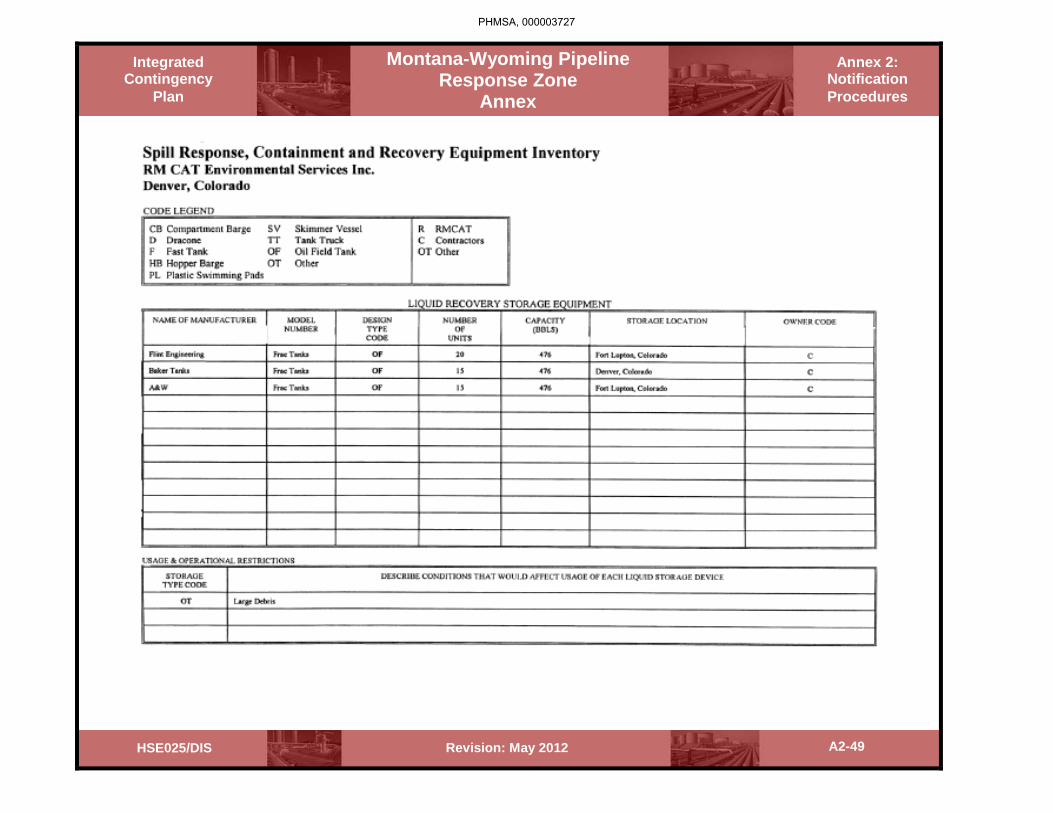
Integrated Contingency
Plan
Annex 2: Notification Procedures
Montana-Wyoming Pipeline Response Zone
Annex
A2-49 Revision: May 2012 HSE025/DIS
PHMSA, 000003727

Integrated Contingency
Plan
Annex 2: Notification Procedures
Montana-Wyoming Pipeline Response Zone
Annex
A2-50 Revision: May 2012 HSE025/DIS
PHMSA, 000003728

A2-51 Revision: May 2012 HSE025/DIS
Integrated Contingency
Plan
Montana-Wyoming Pipeline Response Zone
Annex
Annex 2: Notification Procedures
2.4.3 Olympus Technical Services, Inc.
PHMSA, 000003729

A2-52 Revision: May 2012 HSE025/DIS
Integrated Contingency
Plan
Montana-Wyoming Pipeline Response Zone
Annex
Annex 2: Notification Procedures
PHMSA, 000003730

A2-53 Revision: May 2012 HSE025/DIS
Integrated Contingency
Plan
Montana-Wyoming Pipeline Response Zone
Annex
Annex 2: Notification Procedures
PHMSA, 000003731

A2-54 Revision: May 2012 HSE025/DIS
Integrated Contingency
Plan
Montana-Wyoming Pipeline Response Zone
Annex
Annex 2: Notification Procedures
PHMSA, 000003732

A2-55 Revision: May 2012 HSE025/DIS
Integrated Contingency
Plan
Montana-Wyoming Pipeline Response Zone
Annex
Annex 2: Notification Procedures
PHMSA, 000003733

A2-56 Revision: May 2012 HSE025/DIS
Integrated Contingency
Plan
Montana-Wyoming Pipeline Response Zone
Annex
Annex 2: Notification Procedures
PHMSA, 000003734

A2-57 Revision: May 2012 HSE025/DIS
Integrated Contingency
Plan
Montana-Wyoming Pipeline Response Zone
Annex
Annex 2: Notification Procedures
PHMSA, 000003735

A2-58 Revision: May 2012 HSE025/DIS
Integrated Contingency
Plan
Montana-Wyoming Pipeline Response Zone
Annex
Annex 2: Notification Procedures
PHMSA, 000003736

A2-59 Revision: May 2012 HSE025/DIS
Integrated Contingency
Plan
Montana-Wyoming Pipeline Response Zone
Annex
Annex 2: Notification Procedures
PHMSA, 000003737

A2-60 Revision: May 2012 HSE025/DIS
Integrated Contingency
Plan
Montana-Wyoming Pipeline Response Zone
Annex
Annex 2: Notification Procedures
PHMSA, 000003738

A2-61 Revision: May 2012 HSE025/DIS
Integrated Contingency
Plan
Montana-Wyoming Pipeline Response Zone
Annex
Annex 2: Notification Procedures
PHMSA, 000003739

A2-62 Revision: May 2012 HSE025/DIS
Integrated Contingency
Plan
Montana-Wyoming Pipeline Response Zone
Annex
Annex 2: Notification Procedures
PHMSA, 000003740

A2-63 Revision: May 2012 HSE025/DIS
Integrated Contingency
Plan
Montana-Wyoming Pipeline Response Zone
Annex
Annex 2: Notification Procedures
PHMSA, 000003741
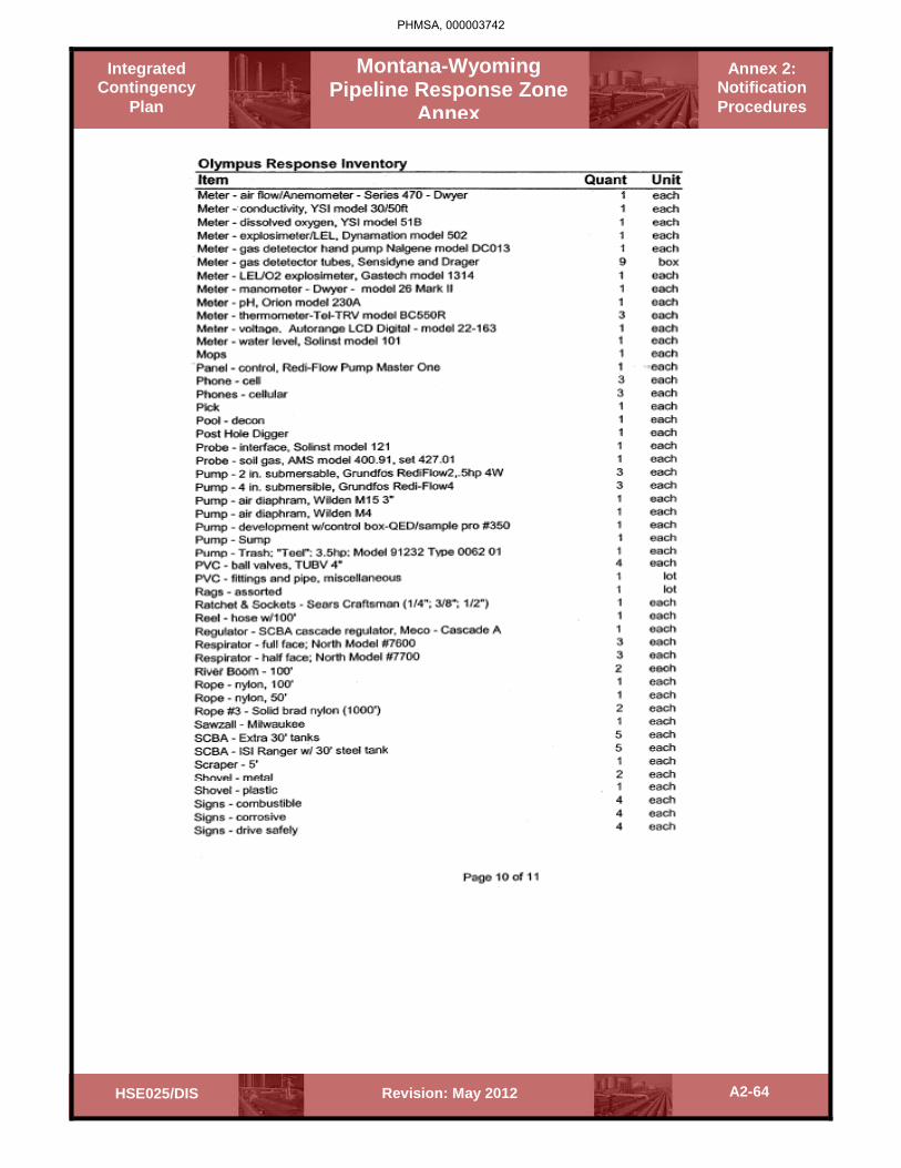
A2-64 Revision: May 2012 HSE025/DIS
Integrated Contingency
Plan
Montana-Wyoming Pipeline Response Zone
Annex
Annex 2: Notification Procedures
PHMSA, 000003742

A2-65 Revision: May 2012 HSE025/DIS
Integrated Contingency
Plan
Montana-Wyoming Pipeline Response Zone
Annex
Annex 2: Notification Procedures
PHMSA, 000003743

A2-66 Revision: May 2012 HSE025/DIS
Integrated Contingency
Plan
Montana-Wyoming Pipeline Response Zone
Annex
Annex 2: Notification Procedures
2.4.4 Enviro Care, Inc.
PHMSA, 000003744

A2-67 Revision: May 2012 HSE025/DIS
Integrated Contingency
Plan
Montana-Wyoming Pipeline Response Zone
Annex
Annex 2: Notification Procedures
PHMSA, 000003745

A2-68 Revision: May 2012 HSE025/DIS
Integrated Contingency
Plan
Montana-Wyoming Pipeline Response Zone
Annex
Annex 2: Notification Procedures
PHMSA, 000003746

A2-69 Revision: May 2012 HSE025/DIS
Integrated Contingency
Plan
Montana-Wyoming Pipeline Response Zone
Annex
Annex 2: Notification Procedures
PHMSA, 000003747

A2-70 Revision: May 2012 HSE025/DIS
Integrated Contingency
Plan
Montana-Wyoming Pipeline Response Zone
Annex
Annex 2: Notification Procedures
PHMSA, 000003748

A2-71 Revision: May 2012 HSE025/DIS
Integrated Contingency
Plan
Montana-Wyoming Pipeline Response Zone
Annex
Annex 2: Notification Procedures
PHMSA, 000003749

A2-72 Revision: May 2012 HSE025/DIS
Integrated Contingency
Plan
Montana-Wyoming Pipeline Response Zone
Annex
Annex 2: Notification Procedures
PHMSA, 000003750

A2-73 Revision: May 2012 HSE025/DIS
Integrated Contingency
Plan
Montana-Wyoming Pipeline Response Zone
Annex
Annex 2: Notification Procedures
PHMSA, 000003751

A2-74 Revision: May 2012 HSE025/DIS
Integrated Contingency
Plan
Montana-Wyoming Pipeline Response Zone
Annex
Annex 2: Notification Procedures
PHMSA, 000003752

Integrated Contingency
Plan
Montana - Wyoming Pipeline Response Zone
Annex
Revision: May 2012 HSE025/DIS
Annex 3: Environmental Sensitive Area
Information
Section 3 – Table of Contents
3.0 Sensitive Area General Response Strategies
3.1 Historical/Archaelogical Sites
3.2 Natural Areas
3.3 National, State and Local Parks
3.4 Protected Waterways
3.5 Recreational Sites
3.6 Water Supply Intakes
3.7 Wetlands
3.8 Wildlife Refuges
3.9 Natural Resource Damage Assesments
PHMSA, 000003753

Integrated Contingency
Plan
Montana - Wyoming Pipeline Response Zone
Annex
Annex 3: Environmental Sensitive Area
Information
A3-1 Revision: May 2012 HSE025/DIS
Sec. 3.0 Sensitive Area General Response Strategies Hazard Identification and Discharge Analysis
This section examines the Pipeline/Facility owner/operator’s ability to predict where releases could occur. Hazard evaluation is a widely used industry practice that allows owners and operators to develop an understanding of potential hazards and the response action necessary to address these hazards. Hazard identification and evaluation will assist pipeline/facility personnel in planning for releases, thereby reducing the severity of impact resulting from a release. The evaluation may also assist in the identification of release sources resulting in corrective action prior to a release. Specific safety and health considerations are identified for responding to a release as a result of the hazard evaluation.
Oil Characteristics
MSDS information for the system is available on the Company website.
Methods of Discharge Detection
Method 1
The pipeline systems are continuously monitored and controlled by the Company Control Center. This group has the ability to remotely monitor all aspects of the operations at the origination as well as the destination and of the system. Examples of the control and operations capabilities are:
1. Remote Start and Stop - Remote meter counts at both ends 2. Remote Pressure at Both Ends - Remote control valves at both ends 3. Alarm Status at Both Ends - Line control alarms 4. Remote Tank Gauges - Suction and discharge pressure control 5. Normal or Adverse Weather conditions - Maximum shutdown time is approximately
15 minutes
Method 2
Using public education, the Company has established relationships with community, public and emergency response agencies that enable quick notification in the event of a spill.
Method 3
The Company, as required by DOT Part 195, has established line patrols that meet or exceed the required patrols in Part 195. Fixed wing aircraft, helicopters and patrols on the ground perform these patrols.
PHMSA, 000003754

Integrated Contingency
Plan
Montana - Wyoming Pipeline Response Zone
Annex
Annex 3: Environmental Sensitive Area
Information
A3-2 Revision: May 2012 HSE025/DIS
Vulnerability Analysis
A description of human health and environmental sensitivities along this pipeline is included in this Plan. Vulnerabilities are also identified in under each worksite. The response areas have been identified as shown in this Section.
Discharge Analysis
The equipment and manpower to respond to a spill are available from several sources and are listed with the equipment and contractors in this Plan. In addition, equipment and manpower requirements for each response site are listed in this Plan.
PHMSA, 000003755

PHMSA, 000003756
(b) (7)(F)
(b) (7)(F)

PHMSA, 000003757

PHMSA, 000003758
(b) (7)(F)
(b) (7)(F)
PHMSA, 000003759
(b) (7)(F)
(b) (7)(F)

PHMSA, 000003760
(b) (7)(F)
(b) (7)(F)

PHMSA, 000003761
(b) (7)(F)
(b) (7)(F)
PHMSA, 000003762
(b) (7)(F)
(b) (7)(F)

PHMSA, 000003763
(b) (7)(F)
(b) (7)(F)

PHMSA, 000003764
(b) (7)(F)
(b) (7)(F)

PHMSA, 000003765
(b) (7)(F)
(b) (7)(F)

PHMSA, 000003766
(b) (7)(F)
(b) (7)(F)

PHMSA, 000003767
(b) (7)(F)
(b) (7)(F)

PHMSA, 000003768
(b) (7)(F)
(b) (7)(F)

PHMSA, 000003769

PHMSA, 000003770
(b) (7)(F)(b) (7)(F) (b) (7)(F)

PHMSA, 000003771
(b) (7)(F) (b) (7)(F)

PHMSA, 000003772
(b) (7)(F) (b) (7)(F)

PHMSA, 000003773
(b) (7)(F)
(b) (7)(F)

PHMSA, 000003774
(b) (7)(F)
(b) (7)(F)

PHMSA, 000003775
(b) (7)(F) (b) (7)(F)

PHMSA, 000003776
(b) (7)(F)
(b) (7)(F)

PHMSA, 000003777
(b) (7)(F)(b) (7)(F)

PHMSA, 000003778
(b) (7)(F)
(b) (7)(F)

PHMSA, 000003779
(b) (7)(F)(b) (7)(F)

PHMSA, 000003780
(b) (7)(F) (b) (7)(F)

PHMSA, 000003781
(b) (7)(F)
(b) (7)(F)

PHMSA, 000003782
(b) (7)(F) (b) (7)(F)

PHMSA, 000003783
(b) (7)(F) (b) (7)(F)

PHMSA, 000003784
(b) (7)(F) (b) (7)(F)

PHMSA, 000003785
(b) (7)(F)
(b) (7)(F)

PHMSA, 000003786
(b) (7)(F)(b) (7)(F)

PHMSA, 000003787
(b) (7)(F) (b) (7)(F)

PHMSA, 000003788
(b) (7)(F) (b) (7)(F)

PHMSA, 000003789
(b) (7)(F)(b) (7)(F)

PHMSA, 000003790
(b) (7)(F) (b) (7)(F)

PHMSA, 000003791
(b) (7)(F)(b) (7)(F)

Montana - Wyoming Pipeline Response Zone
Annex
Annex 3: Environmental Sensitive Area
Information
Integrated Contingency
Plan
A3-39 Revision: May 2012 HSE025/DIS
Type of Disaster Applicable (Yes/No) Area's Risk (H/L) Specific Affects to Response General Affects
to Response
Earthquakes Yes Low Safety, Communications, Transportation Routes, Access
Infrastructure damage (roads, bridges, communications, water/electric) Agency resources available Weather-responder safety Evacuations-responder safety Evacuation access Event prioritization and resources with agencies and United Command System.
Hurricanes No NA NA
Floods Yes Moderate Safety, Communications, Transportation Routes, Access
Forest/Wild Fires Yes High Safety, Explosion, Fire, Reactive Possibilities, Communications, Evacuation/Transportation Routes
Landslides Yes Low Safety, Explosion, Fire, Reactive Possibilities, Base Soil Changes, Flex lines, Landslides Pin Flags used of check soil changes.
Volcanoes No NA Safety, Communications, Access, Transportation Routes
Tornadoes Yes NA Safety, Communications, Access, Transportation Routes
Blizzards Yes High Safety, Communications, Transportation Routes, Access, Temperature
Ground Water/ Karst Topography No NA
Infiltration into soil/ground water, Special recovery methods, Special monitoring/program assessment, Maintenance of public water supply
Unstable Soils Yes Moderate Safety, Explosion, Fire, Reactive Possibilities, Base Soil Changes, Flex lines, Landslides Pin Flags used to check soil changes.
Risk analysis and probability of occurrence of specific natural disasters along this system are based on information received from the Yellowstone County LEPC and other local area resources along other parts of the pipeline.
PHMSA, 000003792

MONTANA/WYOMING EMERGENCY RESPONSE PLAN – RESPONSE ZONE APPENDIX HAZARD EVALUATION/WCD
54 09/04
PHMSA, 000003793
(b) (7)(F)
(b) (7)(F)

MONTANA/WYOMING EMERGENCY RESPONSE PLAN – RESPONSE ZONE APPENDIX HAZARD EVALUATION/WCD
55 09/04
PHMSA, 000003794
(b) (7)(F)
(b) (7)(F)

Montana - Wyoming Pipeline Response Zone
Annex
Annex 3: Environmental Sensitive Area
Information
Integrated Contingency
Plan
A3-42 Revision: May 2012 HSE025/DIS
The following are only example of potential strategies that could be used if an incident impacts a sensitive area. These strategies are not a guarantee of what will occur or the equipment/resource deployment that will be used. Strategic planning will be tailored to meet the need of the actual circumstance.
Sec. 3.1 Historical/Archaeological Sites
Environmental Response Scenario The following scenario provides probable, effective response actions in the event of a spill to a historical / archaeological site. Depending on the site-specific conditions, Company may choose to respond in a manner different from that described below. The manpower, equipment and recovery rates are all dependent upon site-specific conditions and Company will respond in an appropriate manner.
Description of the Affected Area Historical / Archaeological Sites are areas such as battlefields, homes of historically or culturally significantly individuals, and prehistoric dwellings and burial grounds designated by federal, State and local governments for preservation. Historical / Archaeological Sites may be either remote from, or close to, human habitation. Historical / Archaeological Sites are generally identified and marked as such on maps and at public access points. 1. Public Health and Safety Concerns
Immediate evacuation of the public from the affected area, and their subsequent health and safety are a major concern. The danger zone for the public will generally be downwind of the point of discharge and the resulting plume.
2. Project Personnel Safety Concerns
The greatest safety concern for project personnel is fire and explosion. Response team personnel will conduct continuous air monitoring for flammable vapors with a combustible gas meter and will suspend operations when readings exceed 10 percent of the lower explosive limit (LEL). Response team personnel will use non-sparking equipment whenever monitoring indicates explosion/fire potential. Smoking paraphernalia, including lighters, will not be permitted in the work areas under any circumstances. Other safety concerns for project personnel and Company representatives and the regulatory agency’s representatives are inhalation of hydrocarbon vapors (specifically benzene vapors), skin contact with liquid hydrocarbon, heat stress and cold exposure, and contact with, or bites from, poisonous plants, insects, snakes, rodents and large wildlife indigenous to the Natural area.
PHMSA, 000003795

Montana - Wyoming Pipeline Response Zone
Annex
Annex 3: Environmental Sensitive Area
Information
Integrated Contingency
Plan
A3-43 Revision: May 2012 HSE025/DIS
Air monitoring analysis will dictate the level of PPE utilized by workers in the exclusion zone. The support area, including break and eating areas, will be located in a safe area, and upwind of the exclusion zone wherever possible. The response contractor will exercise due care to avoid damage to the historical/archaeological site.
3. Property and Environmental Impact
Property impact of a spill in a historical / archeological site will be a major concern. Major historical / archaeological sites sometimes have considerable commercial value due to tourism. A spill may have adversely affect the commercial value of adjacent public and private property, as well as the historical / archeological site itself.
Environmental impact on a historical / archeological site will vary depending on the size of undeveloped land and water affected by the spill. Petroleum hydrocarbons may have an adverse impact on most forms of plant and animal life, and can destroy the exposed natural portion of a historical/archaeological site.
4. Potential Logistical Problems
Logistic support at historical/archaeological sites will vary from site to site. Historical sites typically have good transportation and utility service. Archeological sites are frequently in remote areas lacking both transportation and utilities. It may be necessary to set up support areas, lay-down areas, etc., outside the site itself, in order to minimize disturbance of the site.
Transportation of personnel, equipment and materials into and out of the area should not require specialized vehicles. Temporary utilities, including potable water, fuel and electricity may be available locally.
Initial Response Strategies 1. The Company Incident Commander will:
• Initiate evacuation of the public from the immediate area of the spill and from the area toward which the plume is moving,
• Initiate appropriate actions to isolate the pipeline or any other source of the spill; i.e., turn off the nearest block valves and shut down the flow of product.
• Order immediate deployment of the response contractor's oil containment boom (minimum 200 ft long), complete with anchors,
• Notify the response contractor's program manager that a spill is in progress and • Notify the appropriate Federal, State and Local regulatory agencies. A Local, State and
Federal agency notification is listed in this FRP.
PHMSA, 000003796

Montana - Wyoming Pipeline Response Zone
Annex
Annex 3: Environmental Sensitive Area
Information
Integrated Contingency
Plan
A3-44 Revision: May 2012 HSE025/DIS
2. The response contractor's program manager will dispatch a response supervisor to the location of the spill by the fastest means practical. The response contractor's supervisor will be equipped with a one-day supply of PPE to include supplied air, and a radio or mobile telephone. The response contractor's supervisor will contact the Company Incident Commander immediately on arrival at the site and jointly assess the magnitude of the problem, noting any special considerations that may affect selection of resources required to complete the response action.
3. The response contractor's program manager will mobilize the Tier 1 response team while the response contractor's supervisor is en route to the site. The Tier 1 response team will be capable of removing 1,500 BBL of product per day, will be enroute within 2 hours of notification, and will arrive on-site within 12 hours of notification. This team should consist of:
• 8 HAZWOPER-trained personnel (including a supervisors and a site safety officer), • 2 pick-up trucks, • 1 one-ton box truck/associated supplies, • 2 vacuum trucks, • 1 van, • 2 work boats, if needed • 2,000 ft of containment boom, • one foam trailer with applicator and foam to cover 90,000 square feet, • a seven (7)-day supply of PPE, • 12 sets of air bottles, • lights, • 2 skimmers, • 1 generator, • 1 air compressor, • PID/LEL, • detector tube specific for benzene (not affected by other hydrocarbons) • 4 radios, and • expendable supplies (absorbent booms & pads, PPE)
The Tier 1 team will immediately report to the response contractor's supervisor for a briefing on the response action, a tailgate health and safety meeting, and a briefing by appropriate authorities concerning care to be taken to avoid damage to the historical/archaeological site. The response contractor's supervisor will direct the team's activities from this point on, including setting up laydown areas and support areas.
4. The response contractor's program manager will begin mobilizing the Tier 2 and Tier 3
response teams once the Tier 1 team is enroute to the site.
The Tier 2 response team will be capable of removing 3,000 BBL per day, will be on-site within 36 hours of notification, and should consist of the Tier 1 response team, plus:
PHMSA, 000003797

Montana - Wyoming Pipeline Response Zone
Annex
Annex 3: Environmental Sensitive Area
Information
Integrated Contingency
Plan
A3-45 Revision: May 2012 HSE025/DIS
• 12 HAZWOPER-trained personnel, • 4 work boats, • 4,000 feet of containment boom, • 2 skimmers, • 2 vans, • 2 pick-up trucks, • 2 vacuum trucks, • 1 skid unit (1,500 gallon capacity), • 8 radios, and • 24 air bottles
The Tier 3 response team will be capable of removing 6,000 BBL per day, will be on-site within 60 hours of notification, and should consist of the Tier 1 and Tier 2 response teams, plus:
• 23 men, • 2 pick-up trucks, • 4 vans, • 1 supply trailer, • 4 work boats, • 6,000 feet of containment boom, • 3 vacuum trucks, • 3 skimmers, • 12 radios, and • 48 air bottles
5. The first task of the Tier 1 response team will be to minimize the spread of the hydrocarbon
on the water and ground surface in order to protect the public, the historical / archeological site features and environmentally sensitive areas downstream of the spill. The team will place a containment boom on water or construct earthen berms of imported clay on land as close as possible to the point of origin of the spill to minimize the area of most severe contamination. The placement of the containment boom/ berm will also be based on personnel safety considerations for the personnel setting up the containment boom / berm. The team will then place one or more secondary booms / berms farther away, in the path(s) of the plumes deemed by the Company Incident Commander and the response supervisor to be the most dangerous to the public or to the environment.
6. Health and Safety Plan
Initial health and safety response actions will be in accordance with the Site Safety Plan Appendix. The response contractor's Site Safety Officer will complete a Site-Specific Health and Safety Plan after the initial hazard assessment is conducted.
PHMSA, 000003798

Montana - Wyoming Pipeline Response Zone
Annex
Annex 3: Environmental Sensitive Area
Information
Integrated Contingency
Plan
A3-46 Revision: May 2012 HSE025/DIS
7. Implementation of Air Monitoring Program
Company's Incident Commander will assign a Site Safety Officer (SSO) who will begin monitoring activities (using a PID, an LEL meter and benzene-specific detection tubes) in the area of the spill immediately on arrival, to assess the danger from fire and explosion in the work area, determine potential exposure to benzene, delineate the exclusion zone, and establish the support zone. Instruments, frequency of readings, records and responses to action levels will conform to the Health and Safety Plan. The SSO will pay particular attention to LEL readings.
As soon as possible after the SSO completes his initial air monitoring for the spill site hazard assessment and delineates the work zones, he/she will begin a perimeter air-monitoring program to confirm that the exclusion zone is properly sized and to document potential offsite migration of vapors that could impact the unprotected public or wildlife.
8. Contingency Planning
The Company Incident Commander, the SSO and the response contractor's supervisor will identify evacuation routes of egress and procedures, safe distances and places of refuge, and emergency alerting procedures to be used in the event of an uncontrollable situation such as fire or explosion.
9. Assessment of Affected Area(s)
The Company Incident Commander and the response contractor's supervisor will jointly review the maps provided in this FRP, inspect the affected area(s) and assess:
• The nature of the spilled liquid - • Source of the spill, • Direction(s) of spill migration, • Apparent or otherwise known subsurface geophysical feature that might impact the
work; i.e., subsurface sand layers, water table elevation, • Overhead and buried utility lines, pipelines, etc., • Nearby population, property or environmental features that might be affected by the
contained spill, or by an uncontained spill.
The Tiers 1, 2, and 3 response team resources in personnel, equipment and material will be assessed to determine if they are adequate to effectively perform the work.
If the Company Incident Commander determines that additional resources are required, the response contractor's supervisor will request additional resources for the Tier 2 and 3 response teams from the response contractor's program manager if deemed necessary by the assessment. Additional equipment may include backhoes, dump trucks, watercraft, generators, light sets, bulldozers and front-end loaders. Equipment operators, laborers, and engineers may be mobilized as necessary. Additional material may include more spill booms, absorbent materials, foam and imported clay for berms.
PHMSA, 000003799

Montana - Wyoming Pipeline Response Zone
Annex
Annex 3: Environmental Sensitive Area
Information
Integrated Contingency
Plan
A3-47 Revision: May 2012 HSE025/DIS
10. Delineation of Exclusion and Support Zones
The Site Safety Officer (SSO) will mark the limits of the exclusion zone with red plastic tape, using existing trees to support the tape where possible. The support zone will be marked with green plastic tape if in the SSO's judgment such marking is necessary to avoid confusion with a contaminated area. If the exclusion zone cannot be physically marked, the SSO will annotate a site map or layout sketch and brief all personnel on the zone layout prior to site entry.
11. Protection of Downstream Sensitive Areas
Company's Incident Commander, the response contractor's supervisor and SSO will inspect the boom / berm system to ensure that it is effectively protecting the public and environmentally sensitive areas downstream of the spill. The response contractor's supervisor will direct placement of additional booms / berms or relocation of existing booms / berms if ongoing measures are judged to be ineffective.
Ongoing Response 1. Recovering Wildlife for Transfer to Treatment Facilities
The response contractor will cooperate with Company and local wildlife assistance agencies to recover birds, fish, small and large animals affected by the spill, for transportation by the appropriate wildlife agencies to treatment facilities.
2. Recovery and Transfer of Free Product
Construction of the free product temporary storage area as close as practical to, but outside of, the historical / archeological site will start after the containment booms / berms are in place and judged effective in limiting the spread of the plume. The storage will consist of frac tanks or rubber bladders. The tanks or bladders will be surrounded by a berm built up from on-site materials or imported clay.
The contractor's response team will recover free product with vacuum trucks, sorbent booms and pads, oil skimmers and vacuum pumps.
3. Install Siphon Dams, Etc.
The contractor's response team may construct a siphon dam to contain the spilled product if contaminated surface water is flowing. A siphon dam is built of earth with steel or plastic pipes embedded through it at a vertical angle such that the lighter, floating product is trapped behind the dam while the water below it is permitted to flow through the pipes.
PHMSA, 000003800

Montana - Wyoming Pipeline Response Zone
Annex
Annex 3: Environmental Sensitive Area
Information
Integrated Contingency
Plan
A3-48 Revision: May 2012 HSE025/DIS
4. Debris Removal
Debris will consist of steel, concrete, timber and vegetation contaminated by the spilled product, plus product-soaked sorbent materials and trash generated by the response team. Debris will be inspected by appropriate agency experts for historically or archaeologically important artifacts or other material prior to its disposal.
Company will remove and dispose of debris or may direct the response contractor to do so. Ultimate disposal may depend on the degree of contamination and is subject to approval by the regulating agencies. Typically, steel and concrete will be transported to a landfill. Timber and vegetation will be either landfilled or incinerated off-site. The regulatory agencies may permit on-site burning of timber and vegetation under some circumstances.
5. Stabilize Damaged or Affected Structures
The response contractor will construct temporary bracing and shoring as necessary to prevent collapse of structures and foundations that might impede or endanger the response work. This may include timber shoring as temporary replacements for sleepers under a damaged pipeline section and historically or archaeologically important buildings or other structures.
Company will stabilize damaged major pipeline bridges and pipeline river crossings, if needed.
6. Initial Response and Draft Work Plan
The response contractor will prepare a draft work plan and submit it to Company. The work plan will include:
• Special measures to avoid damage to historical/archaeological features, materials and
artifacts, • A summary of initial response actions and results, • Subsequent planned activities, • Water and soil removal and treatment and/or disposal, • Air monitoring program, • Sampling and Analysis Plan, • Restoration and repairs, and • A schedule for the work.
7. Debriefing/Dissemination of Information and Data
The Company Incident Commander will interface with the regulatory agencies and news media. The response contractor will not disseminate any information or data without approval of the Company Incident Commander. The response contractor may furnish personnel to assist the Company Incident Commander in debriefing .
PHMSA, 000003801

Montana - Wyoming Pipeline Response Zone
Annex
Annex 3: Environmental Sensitive Area
Information
Integrated Contingency
Plan
A3-49 Revision: May 2012 HSE025/DIS
8. Documentation of Cleanup Efforts and Progress
The response contractor will prepare and maintain records, including photos and/or video, documenting the response. Records and documents will include the supervisor's daily notes, personnel time sheets, equipment usage logs, material delivery tickets, daily air monitoring logs, and soil and water analysis reports.
The response contractor's program manager will submit to the Company Incident Commander a report summarizing the accomplishments of the preceding week, the cost status and the response activity schedule.
9. Public Relations/Agency Liaison
The Company Incident Commander will provide all direct contact with the news media and with regulatory agencies.
Cleanup Strategies Historical/Archaeological Sites 1. Access on or Through Historical/Archaeological Sites
Because of the potential for irrecoverable damage to historical/archaeological sites, vehicle and equipment access will be strictly controlled and coordinated with the appropriate government entities and/or custodians. When equipment is permitted to enter or cross a historical/archaeological site. Access routes will be clearly marked and the response crews will be thoroughly briefed on where and where not, they may place and utilize equipment. On this type of site, the probability is high that the amount of laborers will dramatically increase to compensate for equipment not being permitted on the site or equipment usage being limited.
2. Protection of Historical/Archaeological Sites
Once human health and safety concerns have been addressed, priority will be given to protecting historical/archaeological sites from contamination or to limiting further contamination. Whenever the release is waterborne, booms will typically be deployed as the isolating/protecting mechanism. Because of potential access restrictions, boats used to deploy the boom may have to be landed at some distance from the site and floated to the scene. The first responder should identify potential boat launch sites and communicate this to the response crew prior to their arrival.
If the release is overland, then protection and isolation of historical/archaeological sites becomes more difficult. Typically, overland releases are contained by digging berms and trenches downstream of the spill. However, in the event that the spill occurs on or near historical/archaeological areas, it is possible that digging of berms and trenches will be severely curtailed or prohibited. Therefore, berms will be constructed either from sorbent materials or from imported fill.
PHMSA, 000003802

Montana - Wyoming Pipeline Response Zone
Annex
Annex 3: Environmental Sensitive Area
Information
Integrated Contingency
Plan
A3-50 Revision: May 2012 HSE025/DIS
3. Recovery of Product from Water and Treatment of Contaminated Water
Typically, product is recovered from surface water (i.e., rivers, lakes, and ponds) by a combination of mechanical skimming, vacuum recovery, and the use of sorbent materials. As mentioned above, access of equipment through or near historical/archaeological sites may be restricted or prohibited altogether. It may become necessary for recovery equipment to be launched some distance from the release site. This may have an impact on response time and will be factored accordingly. Temporary storage of recovered product may be accomplished by the use of small barges or other containers.
The treatment of contaminated water will have several challenges under this scenario. It will most likely not be feasible to store contaminated water in traditional storage containers such as tanks, at least in close proximity to the site. This could be overcome by pumping across or around the site to a place where adequate storage can be staged. The Company Incident Commander or the first responder will have to assess the situation quickly and communicate with the response crew in order to ensure that sufficient quantities of the correct equipment are deployed.
Once the contained waters have been stored, treatment options can be explored. Possible treatment options include steam or air stripping, oil/water separation, carbon adsorption, or other methodologies or combinations of methodologies.
4. Cleaning of Affected Structures
Traditional methods of cleaning structures affected by released product include wiping, hot water, low or high-pressure wash-down, and/or the use of surfactants, emulsifiers, or other agents. Because of the potential for irrecoverable damage to historical/archaeological structures, the method of choice for cleaning structures will be wiping with sorbent pads. Alternative methods will be discussed with the appropriate authorities and used only with their concurrence.
5. Solids Handling/Removal
Removal of product-laden soils will be conducted only with the concurrence and at the direction of the cognizant authorities.
Sorbent materials and other solid residue will be placed in trash bags and removed from the site for disposition.
Because of the nature of historical/archaeological sites, contaminated debris will be removed only with the concurrence and at the direction of the cognizant authorities.
PHMSA, 000003803

Montana - Wyoming Pipeline Response Zone
Annex
Annex 3: Environmental Sensitive Area
Information
Integrated Contingency
Plan
A3-51 Revision: May 2012 HSE025/DIS
Site Restoration 1. Sampling and Analysis to Verify Cleanup
Sampling and analysis of the remaining soils and water will be coordinated with local, State and federal agencies to verify that the cleanup meets their requirements.
2. Rebuild/Reconstruct Affected Structures/Areas
Historical / archaeological site restoration activities will be site-specific and may entail major efforts by a combination of Company and multiple regulatory and preservation agencies. As early as possible, Company should determine the feasibility and practicality of restoration in consultation with the appropriate authorities so that detailed, deliberate plans, specifications and costs can be prepared.
3. Final Report
The response contractor will prepare a Final Report for Company, summarizing the actions taken during the response activities, with particular attention to restoration and verification of cleanup.
PHMSA, 000003804

Montana - Wyoming Pipeline Response Zone
Annex
Annex 3: Environmental Sensitive Area
Information
Integrated Contingency
Plan
A3-52 Revision: May 2012 HSE025/DIS
Sec. 3.2 Natural Areas
Environmental Response Scenario The following scenario provides probable, effective response actions in the event of a spill to a natural area. Depending on the site-specific conditions, Company may choose to respond in a manner different from that described below. The manpower, equipment, and recovery rates are all dependent upon site-specific conditions and Company will respond in an appropriate manner.
Description of the Affected Area Natural areas are areas designated by federal, State and local governments to remain in their undeveloped condition. A natural area may include any type of terrain, including sea shore, deserts, streams, lakes, swamps, forests, and mountainous areas. Natural areas are usually remote from human habitation, and are not developed for residential or commercial use. Natural areas are generally identified and marked as such on maps. 1. Public Health and Safety Concerns
Since natural areas are by definition uninhabited and tourism is not encouraged, the immediate evacuation is not expected to require a major effort. The danger zone for the public will generally be downwind of the point of discharge and the resulting plume.
2. Project Personnel Safety Concerns
The greatest safety concern for project personnel is fire and explosion. The response team personnel will conduct continuous air monitoring for flammable vapors with a combustible gas meter and will suspend operations when readings exceed 10 percent of the lower explosive limit (LEL). Response team personnel will use non-sparking equipment whenever monitoring indicates explosion/fire potential. Smoking paraphernalia, including lighters, will not be permitted in the work areas under any circumstances.
Other safety concerns for project personnel and Company representatives and the regulatory agencies' representatives are inhalation of hydrocarbon vapors (specifically benzene vapors), skin contact with liquid hydrocarbons, heat stress and cold exposure, and contact with, or bites from, poisonous plants, insects, snakes, rodents and large wildlife indigenous to the natural area.
Air monitoring analysis will dictate the level of PPE utilized by workers in the exclusion zone. The support area, including break and eating areas, will be located in a safe area, and upwind of the exclusion zone wherever possible.
3. Property and Environmental Impact
Natural areas are not developed and have little commercial value. Environmental impact on a natural area can be immediate and extensive. Petroleum hydrocarbons may have an adverse Environmental impact on a natural area can be immediate and extensive.
PHMSA, 000003805

Montana - Wyoming Pipeline Response Zone
Annex
Annex 3: Environmental Sensitive Area
Information
Integrated Contingency
Plan
A3-53 Revision: May 2012 HSE025/DIS
Petroleum hydrocarbons may have an adverse impact on most forms of plant and animal life, and can destroy the exposed portion of a natural area. Major natural areas provide habitats and food supplies for wildlife and are sources of oxygen for the atmosphere.
4. Potential Logistical Problems
Very little logistic support can be expected in natural areas. There will be few if any roads into and through such areas, and probably no utilities in the area. Support areas, lay-down areas, etc will be established in available clearings, or land will be cleared for the purpose.
Transportation of personnel, equipment and materials into and out of the area may require specialized vehicles such as UTVs, swamp buggies, airboats or barges. The response contractor should possess, or have ready access to, the minimum required equipment.
Temporary utilities, including potable water, fuel and electricity will probably be absent and must be brought in by the response contractor's team.
Initial Response Strategies 1. The Company Incident Commander or designee will:
• Initiate evacuation of the public from the affected areas and from the area toward which the plume is moving,
• Initiate appropriate actions to isolate the pipeline or any other source of the spill; i.e., turn off the nearest block valves and shut down the flow of product,
• Order immediate deployment of the response contractor's oil containment boom (minimum 200 ft long), complete with anchors,
• Notify the response contractor's program manager that a spill is in progress and • Notify the appropriate Federal State, and local regulatory agencies. Local, State and
Federal agency notification is listed in this FRP. 2. The response contractor's program manager will dispatch a response supervisor to the
location of the spill by the fastest means practical. The response supervisor will be equipped with a one-day supply of PPE to include supplied air, and a radio or mobile telephone. The response supervisor will contact the Company Incident Commander immediately on arrival at the site and jointly assess the magnitude of the problem, noting any special considerations that may affect selection of resources required to complete the response action, particularly the contaminated media; i.e., soil, water, or both.
3. The response contractor's program manager will mobilize the Tier 1 response team while
the response supervisor is en route to the site. The Tier 1 response team will be capable of removing 1,500 BBL of product per day, will be enroute within 2 hours of notification, and will arrive on-site within 12 hours of notification. This team should consist of:
PHMSA, 000003806

Montana - Wyoming Pipeline Response Zone
Annex
Annex 3: Environmental Sensitive Area
Information
Integrated Contingency
Plan
A3-54 Revision: May 2012 HSE025/DIS
• 8 HAZWOPER-trained personnel (including a supervisors and a site safety officer), • 2 pick-up trucks, • 1 one-ton box truck/associated supplies, • 2 vacuum trucks, • 1 van, • 2 work boats, • 2,000 ft of containment boom, • one foam trailer with applicator and foam to cover 90,000 square feet, • a seven (7)-day supply of PPE, • 12 sets of air bottles, • lights, • 2 skimmers, • 1 generator, • 1 air compressor, • PID/LEL, • detector tube specific for benzene (not affected by other hydrocarbons) • 4 radios, and • expendable supplies (absorbent booms & pads, PPE)
The Tier 1 team will immediately report to the response contractor's supervisor for a briefing on the response action and a tailgate health and safety meeting. The response contractor's supervisor will direct the team's activities from this point on, including setting up laydown areas and support areas.
4. The response contractor's program manager will begin mobilizing the Tier 2 and Tier 3
response teams once the Tier 1 team is enroute to the site.
The Tier 2 response team will be capable of removing 3,000 BBL per day, will be on-site within 36 hours of notification, and should consist of the Tier 1 response team, plus:
• 12 HAZWOPER-trained personnel, • 4 work boats, • 4,000 feet of containment boom, • 2 skimmers, • 2 vans, • 2 pick-up trucks, • 2 vacuum trucks, • 1 skid unit (1,500 gallon capacity), • 8 radios, and • 24 air bottles
PHMSA, 000003807

Montana - Wyoming Pipeline Response Zone
Annex
Annex 3: Environmental Sensitive Area
Information
Integrated Contingency
Plan
A3-55 Revision: May 2012 HSE025/DIS
The Tier 3 response team will be capable of removing 6,000 BBL per day, will be on-site within 60 hours of notification, and should consist of the Tier 1 and Tier 2 response teams, plus:
• 23 HAZWOPER-trained personnel, • 2 pick-up trucks, • 4 vans, • 1 supply trailer, • 4 work boats, • 6,000 feet of containment boom, • 3 vacuum trucks, • 3 skimmers, • 12 radios, and • 48 air bottles
5. The first task of the Tier 1 response team will be to minimize the spread of the product on
water and ground surface in order to protect the public and environmentally sensitive areas downstream of the spill. The team will place a containment boom on water or construct earthen berms on land as close as possible to the point of origin of the spill to minimize the area of most severe contamination. The placement of the containment boom / berm will also be based on personnel safety considerations for the personnel setting up the containment boom / berm. The team will then place one or more secondary booms / berms farther away, in the path(s) of the plumes deemed by the Company Incident Commander and the response supervisor to be the most dangerous to the public or to the environment.
6. Health and Safety Plan
Initial health and safety response actions will be in accordance with the Site Safety Plan Appendix. The response contractor's Site Safety Officer will complete a Site Specific Health and Safety Plan after the initial hazard assessment is conducted.
7. Implementation of Air Monitoring Program
Company's Incident Commander will assign a Site Safety Officer (SSO) who will begin monitoring activities (using a PID, an LEL meter and benzene-specific detection tubes) in the area of the spill immediately on arrival, to assess the danger from fire and explosion in the work area, determine potential exposure to benzene, delineate the exclusion zone, and establish the support zone. Instruments, frequency of readings, records and responses to action levels will conform to the Health and Safety Plan. The SSO will pay particular attention to LEL readings.
As soon as possible after the SSO completes his initial air monitoring for the spill site hazard assessment and delineates the work zones, he/she will begin a perimeter air-monitoring program to confirm that the exclusion zone is properly sized and to document potential offsite migration of vapors that could impact the unprotected public or wildlife .
PHMSA, 000003808

Montana - Wyoming Pipeline Response Zone
Annex
Annex 3: Environmental Sensitive Area
Information
Integrated Contingency
Plan
A3-56 Revision: May 2012 HSE025/DIS
8. Contingency Planning
The Company Incident Commander, the SSO and the response contractor's supervisor will identify evacuation routes of egress and procedures, safe distances and places of refuge, and emergency alerting procedures to be used in the event of an uncontrollable situation such as fire or explosion.
9. Assessment of Affected Area(s)
The Company Incident Commander and the response contractor's supervisor will jointly review the maps and inspect the affected area(s) and assess:
• The nature of the spilled liquid, • Source of the spill, • Direction(s) of spill migration, • Apparent or otherwise known subsurface geophysical feature that might impact the
work; i.e., subsurface sand layers, water table elevation, • Overhead and buried utility lines, pipelines, etc., • Nearby population, property or environmental features that might be affected by the
contained spill or by an uncontained spill.
The Tiers 1, 2, and 3 response team resources in personnel, equipment and material will be assessed to determine if they are adequate to effectively perform the work. If the Company Incident Commander determines that additional resources are required, the response contractor's supervisor will request additional resources for the Tier 2 and 3 response teams from the response contractor's program manager. Additional equipment may include backhoes, dump trucks, watercraft, generators, light sets, bulldozers and front-end loaders. Equipment operators, laborers, and engineers may be mobilized as necessary. Additional material may include more spill booms, absorbent materials, foam and imported clay for berms.
10. Delineation of Exclusion and Support Zones
The Site Safety Officer (SSO) will mark the limits of the exclusion zone with red plastic tape, using existing trees to support the tape where possible. The support zone will be marked with green plastic tape if in the SSO's judgment such marking is necessary to avoid confusion with a contaminated area. If the exclusion zone cannot be physically marked, the SSO will annotate a site map or layout sketch and brief all personnel on the zone layout prior to site entry.
PHMSA, 000003809

Montana - Wyoming Pipeline Response Zone
Annex
Annex 3: Environmental Sensitive Area
Information
Integrated Contingency
Plan
A3-57 Revision: May 2012 HSE025/DIS
11. Protection of Downstream Sensitive Areas
Company's Incident Commander, the response contractor's supervisor, and SSO will inspect the boom / berm system to ensure that it is effectively protecting the public and environmentally sensitive areas downstream of the spill. The response contractor's supervisor will direct placement of additional booms / berms or relocation of existing booms / berms if ongoing measures are judged to be ineffective.
Ongoing Response 1. Recovering Wildlife for Transfer to Treatment Facilities
The response contractor will cooperate with Company and local wildlife assistance agencies to recover birds, fish, small and large animals affected by the spill, for transportation by the appropriate wildlife agencies to treatment facilities.
2. Recovery and Transfer of Free Product
Construction of the free product temporary storage area will start after the containment booms / berms are in place and judged effective in limiting the spread of the plume. The storage will consist of frac tanks or rubber bladders. The tanks or bladders will be surrounded by a berm built up from on-site materials or imported clay. Construction may require some cleaning of trees and shrubs.
The response team will recover free product with vacuum trucks, sorbent booms and pads, oil skimmers and vacuum pumps.
3. Install Siphon Dams, Etc.
The response team may construct a siphon dam to contain the spilled product if contaminated surface water is flowing. A siphon dam is built of earth with steel or plastic pipes embedded through it at a vertical angle such that the lighter, floating product is trapped behind the dam while the water below it is permitted to flow through the pipes.
4. Debris Removal
Debris will consist of steel, concrete, timber and vegetation contaminated by the spilled product, plus product-soaked sorbent materials and trash generated by the response team. Contaminated trees and shrubs are anticipated to make up the majority of the debris.
Company will remove and dispose of debris or may direct the response contractor to do so. Ultimate disposal may depend on the degree of contamination and is subject to approval by the regulating agencies.
PHMSA, 000003810

Montana - Wyoming Pipeline Response Zone
Annex
Annex 3: Environmental Sensitive Area
Information
Integrated Contingency
Plan
A3-58 Revision: May 2012 HSE025/DIS
Typically, steel and concrete will be transported to a landfill. Timber and vegetation will be either landfilled or incinerated off-site. The regulatory agencies may permit on-site burning of timber and vegetation under some circumstances.
5. Stabilize Damaged or Affected Structures
The response contractor will construct temporary bracing and shoring as necessary to prevent collapse of structures and foundations that might impede or endanger the response work. This may include timber shoring as temporary replacements for sleepers under a damaged pipeline section.
Company will stabilize damaged major pipeline bridges and pipeline river crossings, if needed.
6. Initial Response and Draft Work Plan
The response contractor will prepare a draft work plan and submit it to Company. The work plan will include:
• A summary of initial response actions and results, • Subsequent planned activities, • Water and soil removal and treatment and/or disposal, • Air monitoring program, • Sampling and Analysis Plan, • Restoration and repairs, and • A schedule for the work.
7. Debriefing/Dissemination of Information and Data
The Company Incident Commander will interface with the regulatory agencies and news media. The response contractor will not disseminate any information or data without approval of the Company Incident Commander. The response contractor may furnish personnel to assist the Company Incident Commander in debriefing.
8. Documentation of Cleanup Efforts and Progress
The response contractor will prepare and maintain records, including photos and/or video, documenting the response. Records and documents will include the supervisor's daily notes, personnel time sheets, equipment usage logs, material delivery tickets, daily air monitoring logs, and soil and water analysis reports.
The response contractor's program manager will submit to the Company Incident Commander a report summarizing the accomplishments of the preceding week, the cost status and the response activity schedule.
PHMSA, 000003811

Montana - Wyoming Pipeline Response Zone
Annex
Annex 3: Environmental Sensitive Area
Information
Integrated Contingency
Plan
A3-59 Revision: May 2012 HSE025/DIS
9. Public Relations/Agency Liaison
The Company Incident Commander will provide all direct contact with the news media and with regulatory agencies.
Cleanup Strategies for Natural Areas 1. Access on or Through Natural Areas
Natural areas will probably have few, if any, existing roads. Use of overland or waterborne access will require the approval of the cognizant authorities. The Company Incident Commander will request the cognizant authorities to mark the approved routes and work areas for the use of the response contractor. If overland transportation routes are practical and acceptable to the appropriate authorities, the response contractor may construct temporary roads into the spill area, and construct such staging and laydown areas. The response contractor will minimize the size and number of vehicles used in the response.
Water-borne transportation may be a practical alternative to roads, in some instances. In such cases, the response contractor may use workboats and/or barges to mobilize the response equipment to the site. Equipment sizes may be limited by the capacity of available watercraft and possible restrictions on the use of powered boats. The response contractor may have to construct a temporary landing to tie up the watercraft and offload the equipment.
The terrain in some natural area may be so rugged that land and water transportation is impractical. In such cases, the response contractor may have to use helicopters to lift personnel and equipment to the site. Since heavy equipment is not readily air-transportable, most of the response work may have to be done using labor and hand tools, with a limited amount of lightweight equipment. Helicopter landing zones will be located, and if necessary cleared, at the direction of Company and the appropriate government agencies.
Roads, staging areas, watercraft landings and helicopter landing zones will be restored to their pre-spill conditions as described in SITE RESTORATION below.
2. Protection of Natural Areas
Once human health and safety issues have been addressed, the next priority will be given to limiting the spread of spilled product and further contamination of plant and animal life. This is usually accomplished primarily with containment booms and berms. The Company Incident Commander and the first responder will identify the land areas and/or water bodies threatened by the spill, and select the boom and berm locations. The Company Incident Commander will communicate special or additional equipment and material needs to the contractor's response team.
Where a body of water is affected or threatened by the spill, the response contractor will usually deploy containment booms as close downstream of the spill site as may be safe and practical. If the impacted area includes rough water, such as rapids and falls, the boom may have to be installed at a distance downstream, where the water is calm enough for the boom
PHMSA, 000003812

Montana - Wyoming Pipeline Response Zone
Annex
Annex 3: Environmental Sensitive Area
Information
Integrated Contingency
Plan
A3-60 Revision: May 2012 HSE025/DIS
to be effective. This may increase the volume of contaminated water to be collected and treated. If use of the nearest effective deployment site is denied by the cognizant authorities, or if lack of roads, cliffs, heavy forests etc. make its use impractical, it may be necessary to deploy the boom at another site even further downstream.
Containment of an overland spill is normally done with ditches and berms, but only with the concurrence at the direction of the cognizant authorities. The response contractor may dig ditches and build berms downslope of the spill site to stop the overland flow of the spilled product. In some cases it may be possible to use this ditch/berm system to divert the product to a collection point downslope of the spill. If the soil dug from the ditches is clay, it may be used to build the berms. Sandy or gravelly soils do not make good barrier berm material. If importing clay from offsite is impractical and no clay is available onsite, the response contractor may have to use sorbent materials, i.e., sorbent booms and pads, to construct the berm.
3. Recovery of Product from Water and Treatment of Contaminated Water.
Product is typically recovered from water bodies such as lakes, ponds and rivers by a combination of mechanical skimming, vacuum recovery, and sorbent materials. The point of recovery may be some distance downstream of the spill site, if access to a closer location is denied or is impractical. This may increase the response time, the amount of contaminated water, and the length of shoreline to be cleaned and restored. The size and capacity of skimming equipment, pumps, piping, and tankage may be limited by access restrictions, as described above.
Product spilled onto the ground is usually recovered by excavating the product-laden soils. Other methods such as by soil/vapor extraction, or pumping from recovery wells may be considered as part of the long-term plan. Porous soils, such as sands and gravels may permit the product to soak in to a depth of several feet or more, usually until it is stopped by a layer of clay, solid rock or a water table. Soils contaminated with product will be excavated only with the concurrence of and as directed by, the appropriate government agencies. Clay soils usually retain the product at or near the surface, and require less excavation than sandy/gravelly soils.
The methods of temporary storage of the contaminated water will be site-specific, and will be highly dependent on site access. Barges may be practical where contaminated waters are navigable. Tank trailers or frac tanks may be used if roads are accessible or constructible. Rubber bladder tanks may be used, but require cleared, relatively smooth laydown areas.
The decision to treat contaminated water onsite or transport it offsite for treatment may be made by Company and the cognizant authorities with consideration of factors such as availability of utilities, suitable land area, and a comparison of the difficulties of getting the treatment equipment to the site versus the difficulties of getting the contaminated water to an offsite treatment facility. The urgency of completing the response and restoration of the spill area may also affect this decision. Once the contained waters have been stored, treatment options can be explored. Possible treatment options include steam or air stripping, oil/water separation, carbon adsorption, or other methodologies or combinations of methodologies.
PHMSA, 000003813

Montana - Wyoming Pipeline Response Zone
Annex
Annex 3: Environmental Sensitive Area
Information
Integrated Contingency
Plan
A3-61 Revision: May 2012 HSE025/DIS
4. Cleaning of Affected Structures
Man-made structures can be cleaned by traditional methods that include wiping, hot water, low or high-pressure washdown and use of surfactants, emulsifiers or other agents. The use of surfactants, emulsifiers and other agents may be prohibited in, or adjacent to, rough water due to the difficulty of recovery of the wash water.
Affected natural structures may include large rocks and boulders, which can usually be cleaned by the same methods as man-made structures. Cleaning rocky shorelines along rapids and near waterfalls, and rocky cliffs, may require special safety precautions and special equipment such as safety lines.
Cleaning methods and materials to be used at a spill will be discussed with the appropriate authorities and used only with their concurrence.
Washdown water and other liquids from cleaning activities should be contained by the boom or ditch/berm system, then collected and treated with the contaminated ground and surface waters.
5. Solids Handling and Removal
Removal of product-laden soils will be conducted only with the concurrence and at the direction of the appropriate authorities. The extent of excavation will probably be limited, since excavation will mar the natural state of the affected area.
Sorbent materials and other solid residue will be placed in trash bags and removed from the site for disposition. The response contractor will take particular care to remove all his site-generated wastes from the area, and will conduct a final walking inspection of the entire area with the Company Incident Commander to confirm that this has been done prior to departure.
Contaminated soils and other solids will be removed from the site unless the cognizant authorities direct differently. Solids will probably be removed from the site by truck where roads are available or by barges where navigable waterways are reasonably close. In areas so remote that the only access is by aircraft, removal of solids from the site may be impractical. In this event, the Company Incident Commander and the appropriate authorities will determine if onsite containment or disposal is acceptable, and if it is, the best methods of doing so consistent with protection of the environment and the public health and safety.
Site Restoration 1. Sampling and Analysis to Verify Cleanup
Sampling and analysis of the remaining soils and water will be coordinated with local, State and federal agencies to verify that the cleanup meets their requirements.
PHMSA, 000003814

Montana - Wyoming Pipeline Response Zone
Annex
Annex 3: Environmental Sensitive Area
Information
Integrated Contingency
Plan
A3-62 Revision: May 2012 HSE025/DIS
2. Rebuild/Reconstruct Affected Structures/Areas
Natural area restoration activities will vary considerably from site to site and may entail major efforts by a combination of Company and multiple regulatory and other government agencies. Typical efforts may include seeding and mulching with wild grasses, and the planting of shrubs and seedling trees. New seeding and plantings will be similar to those removed during the response. Temporary access roads, shoreline landings, helicopter landing zones and staging/laydown areas will be regraded and returned to a natural state.
As early as possible, Company should determine the feasibility and practicality of restoration in consultation with the appropriate authorities so that detailed, deliberate plans, specifications, and costs can be prepared.
3. Final Report
The response contractor will prepare a Final Report for Company, summarizing the actions taken during the response activities, with particular attention to restoration and verification of cleanup.
PHMSA, 000003815

Montana - Wyoming Pipeline Response Zone
Annex
Annex 3: Environmental Sensitive Area
Information
Integrated Contingency
Plan
A3-63 Revision: May 2012 HSE025/DIS
Sec. 3.3 National, State and Local Parks Environmental Response Scenario The following scenario provides probable, effective response actions in the event of a spill to a national, State or local park. Depending on the site-specific conditions, Company may choose to respond in a manner different from that described below. The manpower, equipment, and recovery rates are all dependent upon site-specific conditions and Company will respond in an appropriate manner.
Description of the Affected Area National, State and local parks are areas designated by various government agencies for the benefit of the general public. The larger public parks may have a general office with a recreational area and/or a camping ground. Much of a major park may be relatively undeveloped. The smaller public parks could be limited to combination general buildings, rest rooms, recreation areas, playgrounds, swimming pools, camping areas, hiking paths, or undeveloped terrain. A public park maybe located in almost any type of terrain, including shorelines, forests, deserts, and mountainous areas. Parks are usually, but not always, populated by administrative personnel, campers and hikers, with a variety of mammals, reptiles, birds, fish and insects. Public parks are identified and marked as such on maps and sometimes along their boundaries. 1. Public Health and Safety Concerns
Many National, State and local parks are close to centers of human habitation, where a spill is likely to have a major, direct effect on public safety and health. A major priority will be evacuation of the public in the affected area. The danger zone for the public will generally be downwind of the point of discharge and the resulting plume.
2. Project Personnel Safety Concerns
The greatest safety concern for project personnel is fire and explosion. The response contractor's team personnel will conduct continuous air monitoring for flammable vapors with a combustible gas meter and will suspend operations when readings exceed 10 percent of the lower explosive limit (LEL). Response contractor's team personnel will use non-sparking equipment whenever monitoring indicates explosion/fire potential. Smoking paraphernalia, including lighters, will not be permitted in the work areas under any circumstances.
Other safety concerns for project personnel and Company representatives and the regulatory agencies' representatives are inhalation of hydrocarbon vapors (specifically benzene vapors), skin contact with liquid hydrocarbon, and heat stress and cold exposure. Contact with, or bites from, poisonous plants, insects, snakes, rodents and large wildlife will be a concern in some remote parks.
PHMSA, 000003816

Montana - Wyoming Pipeline Response Zone
Annex
Annex 3: Environmental Sensitive Area
Information
Integrated Contingency
Plan
A3-64 Revision: May 2012 HSE025/DIS
Air monitoring analysis will dictate the level of PPE utilized by workers in the exclusion zone. The support area, including break and eating areas, will be located in a safe area, and upwind of the exclusion zone wherever possible.
3. Property and Environmental Impact
Property impact of a spill on a public park will depend on the extent to which it has been improved or developed. Public parks are frequently well developed and have considerable commercial value; a spill may have a serious impact on the commercial value of public property.
Environmental impact on a public park will vary depending on the size of undeveloped land and water affected by the spill. Petroleum hydrocarbons may have an adverse impact on most forms of plant and animal life, and can destroy the exposed natural portion of a public park.
4. Potential Logistical Problems
Availability of roads and utilities are site-specific and may vary from place to place within a single large park. It may be necessary to close existing public and private roads for the duration of the response activities. There may be insufficient solid level ground or a wide enough clearing in which to set up support areas, lay-down areas, etc.
Transportation of personnel, equipment and materials into and out of some parks may require specialized vehicles such as UTVs, swamp buggies, airboats or helicopters. The response contractor should possess, or have ready access to, the minimum required equipment.
Temporary utilities, including potable water, fuel and electricity may be available at some parks and absent at others. If not available, they must be brought in by the contractor's response team.
Initial Response Strategies 1. The Company Incident Commander will:
• Initiate evacuation of the public from the affected areas and from the area toward which the plume is moving,
• Initiate appropriate actions to isolate the pipeline or any other source of the spill; i.e., turn off the nearest block valves and shut down the flow of product,
• Order immediate deployment of the contractor's oil containment boom (minimum 200 ft long), complete with anchors,
• Notify the response contractor's program manager that a spill is in progress and • Notify the appropriate Federal, State, and local regulatory agencies. Local, State and
Federal agency notification is listed in this FRP. 2. The response contractor's program manager will dispatch a response supervisor to the
location of the spill by the fastest means practical. The response supervisor will be equipped with a one-day supply of PPE to include supplied air, and a radio or mobile telephone.
PHMSA, 000003817

Montana - Wyoming Pipeline Response Zone
Annex
Annex 3: Environmental Sensitive Area
Information
Integrated Contingency
Plan
A3-65 Revision: May 2012 HSE025/DIS
The response supervisor will contact the Company Incident Commander immediately on arrival at the site and jointly assess the magnitude of the problem, noting any special considerations that may affect selection of resources required to complete the response action.
3. The response contractor's program manager will mobilize the Tier 1 response contractor's
team while the response supervisor is en route to the site. The Tier 1 response contractor's team will be capable of removing 1,500 BBL of product per day, will be enroute within 2 hours of notification, and will arrive on-site within 12 hours of notification. This team should consist of:
• 8 HAZWOPER-trained personnel (including a supervisors and a site safety officer), • 2 pick-up trucks, • 1 one-ton box truck/associated supplies, • 2 vacuum trucks, • 1 van, • 2 work boats, • 2,000 ft of containment boom, • one foam trailer with applicator and foam to cover 90,000 square feet, • a seven (7)-day supply of PPE, • 12 sets of air bottles, • lights, • 2 skimmers, • 1 generator, • 1 air compressor, • PID/LEL, • detector tube specific for benzene (not affected by other hydrocarbons) • 4 radios, and • expendable supplies (absorbent booms & pads, PPE)
The Tier 1 team will immediately report to the response contractor’s supervisor for a briefing on the response action and a tailgate health and safety meeting. The response contractor's supervisor will direct the team's activities from this point on, including setting up laydown areas and support areas.
4. The response contractor's program manager will begin mobilizing the Tier 2 and Tier 3
response contractor's teams once the Tier 1 team is enroute to the site.
The Tier 2 response contractor's team will be capable of removing 3,000 BBL per day, will be on-site within 36 hours of notification, and should consist of the Tier 1 response contractor's team, plus:
• 12 HAZWOPER-trained personnel, • 4 work boats, • 4,000 feet of containment boom, • 2 skimmers, • 2 vans, • 2 pick-up trucks, • 2 vacuum trucks,
PHMSA, 000003818

Montana - Wyoming Pipeline Response Zone
Annex
Annex 3: Environmental Sensitive Area
Information
Integrated Contingency
Plan
A3-66 Revision: May 2012 HSE025/DIS
• 1 skid unit (1,500 gallon capacity), • 8 radios, and • 24 air bottles The Tier 3 response contractor's team will be capable of removing 6,000 BBL per day, will be on-site within 60 hours of notification, and should consist of the Tier 1 and Tier 2 response contractor's teams, plus:
• 23 HAZWOPER-trained personnel, • 2 pick-up trucks, • 4 vans, • 1 supply trailer, • 4 work boats, • 6,000 feet of containment boom, • 3 vacuum trucks, • 3 skimmers, • 12 radios, and • 48 air bottles
5. The first task of the Tier 1 response contractor's team will be to minimize the spread of the
product on the water and ground surface in order to protect the public and the vegetation and wildlife in the refuge. The team will place a containment boom / berm as close as possible to the point of origin of the spill to minimize the area of most severe contamination. The placement of the containment boom / berm will also be based on personnel safety considerations for the personnel setting up the containment boom / berm. The team will then place one or more secondary booms / berms farther away, in the path(s) of the plumes deemed by the Company Incident Commander and the response supervisor to be the most dangerous to the public or to the environment.
6. Health and Safety Plan
Initial health and safety response actions will be in accordance with the standard operating procedure. The response contractor's Site Safety Officer will complete a Site-Specific Health and Safety Plan after the initial hazard assessment is conducted.
7. Implementation of Air Monitoring Program
Company's Incident Commander will assign a Site Safety Officer (SSO) who will begin monitoring activities (using a PID, an LEL meter and benzene-specific detection tubes) in the area of the spill immediately on arrival, to assess the danger from fire and explosion in the work area, determine potential exposure to benzene, delineate the exclusion zone, and establish the support zone. Instruments, frequency of readings, records and responses to action levels will conform to the Health and Safety Plan. The SSO will pay particular attention to LEL readings.
PHMSA, 000003819

Montana - Wyoming Pipeline Response Zone
Annex
Annex 3: Environmental Sensitive Area
Information
Integrated Contingency
Plan
A3-67 Revision: May 2012 HSE025/DIS
As soon as possible after the SSO completes his initial air monitoring for the spill site hazard assessment and delineates the work zones, he/she will begin a perimeter air-monitoring program to confirm that the exclusion zone is properly sized and to document potential offsite migration of vapors that could impact the unprotected public or wildlife.
8. Contingency Planning
The Company Incident Commander, the SSO and the response contractor's supervisor will identify evacuation routes of egress and procedures, safe distances and places of refuge, and emergency alerting procedures to be used in the event of an uncontrollable situation such as fire or explosion.
9. Assessment of Affected Area(s)
The Company Incident Commander and the response contractor's supervisor will jointly review the maps provided and inspect the affected area(s) and assess:
• The nature of the spilled liquid, • Source of the spill, • Direction(s) of spill migration, • Apparent or otherwise known subsurface geophysical feature that might impact the
work; i.e., subsurface sand layers, water table elevation, • Overhead and buried utility lines, pipelines, etc., • Nearby population, property or environmental features that might be affected by the
contained spill, or by an uncontained spill.
The Tiers 1, 2, and 3 response contractor's team resources in personnel, equipment and material will be assessed to determine if they are adequate to effectively perform the work.
If the Company Incident Commander determines that additional resources are required, the response contractor's supervisor will request additional resources for the Tier 2 and 3 response contractor's teams from the response contractor's program manager. Additional equipment may include backhoes, dump trucks, watercraft, generators, light sets, bulldozers and front-end loaders. Equipment operators, laborers, and engineers may be mobilized as necessary. Additional material may include more spill booms, absorbent materials, foam and imported clay for berms.
10. Delineation of Exclusion and Support Zones
The Site Safety Officer (SSO) will mark the limits of the exclusion zone with red plastic tape, using existing trees to support the tape where possible. The support zone will be marked with green plastic tape if in the SSO's judgment such marking is necessary to avoid confusion with a contaminated area. If the exclusion zone cannot be physically marked, the SSO will annotate a site map or layout sketch and brief all personnel on the zone layout prior to site entry.
PHMSA, 000003820

Montana - Wyoming Pipeline Response Zone
Annex
Annex 3: Environmental Sensitive Area
Information
Integrated Contingency
Plan
A3-68 Revision: May 2012 HSE025/DIS
11. Protection of Downstream Sensitive Areas
Company's Incident Commander, the response contractor's supervisor and SSO will inspect the boom / berm system to ensure that it is effectively protecting the public and environmentally sensitive areas downstream of the spill. The response contractor's supervisor will direct placement of additional booms / berms or relocation of existing booms / berms if ongoing measures are judged to be ineffective.
Ongoing Response 1. Recovering Wildlife for Transfer to Treatment Facilities
The response contractor will cooperate with Company and local wildlife assistance agencies to recover birds, fish, small and large animals affected by the spill, for transportation by the appropriate wildlife agencies to treatment facilities.
2. Recovery and Transfer of Free Product
Construction of the free product temporary storage area will start after the containment booms / berms are in place and judged effective in limiting the spread of the plume. The storage will consist of frac tanks or rubber bladders. The tanks or bladders will be surrounded by a berm built up from on-site materials, or imported clay.
The response contractor's team will recover free product with vacuum trucks, sorbent booms and pads, oil skimmers and vacuum pumps.
3. Install Siphon Dams, Etc.
The response contractor's team may construct a siphon dam to contain the spilled product if contaminated surface water is flowing. A siphon dam is built of earth with steel or plastic pipes embedded through it at a vertical angle such that the lighter, floating product is trapped behind the dam while the water below it is permitted to flow through the pipes.
4. Debris Removal
Debris will consist of steel, concrete, timber and vegetation contaminated by the spilled product, plus product-soaked sorbent materials and trash generated by the response contractor's team.
Company will remove and dispose of debris or may direct the response contractor to do so. Ultimate disposal may depend on the degree of contamination and is subject to approval by the regulating agencies.
Typically, steel and concrete will be transported to a landfill. Timber and vegetation will be either landfilled or incinerated off-site. The regulatory agencies may permit burning of timber and vegetation under some circumstances, but this is unlikely within the boundaries of the public park itself.
PHMSA, 000003821

Montana - Wyoming Pipeline Response Zone
Annex
Annex 3: Environmental Sensitive Area
Information
Integrated Contingency
Plan
A3-69 Revision: May 2012 HSE025/DIS
5. Stabilize Damaged or Affected Structures
The response contractor will construct temporary bracing and shoring as necessary to prevent collapse of structures and foundations that might impede or endanger the response work. This may include timber shoring as temporary replacements for sleepers under a damaged pipeline section.
Company will stabilize damaged major pipeline bridges and pipeline river crossings, if needed.
6. Initial Response and Draft Work Plan
The response contractor will prepare a draft work plan and submit it to Company. The work plan will include:
• A summary of initial response actions and results, • Subsequent planned activities, • Water and soil removal and treatment and/or disposal, • Air monitoring program, • Sampling and Analysis Plan, • Restoration and repairs, and • A schedule for the work.
7. Debriefing/Dissemination of Information and Data
The Company Incident Commander will interface with the regulatory agencies and news media. The response contractor will not disseminate any information or data without approval of the Company Incident Commander. The response contractor may furnish personnel to assist the Company Incident Commander in debriefing.
8. Documentation of Cleanup Efforts and Progress
The response contractor will prepare and maintain records, including photos and/or video, documenting the response. Records and documents will include the supervisor's daily notes, personnel time sheets, equipment usage logs, material delivery tickets, daily air monitoring logs, and soil and water analysis reports.
The response contractor's program manager will submit to the Company Incident Commander a report summarizing the accomplishments of the preceding week, the cost status and the response activity schedule.
9. Public Relations/Agency Liaison
The Company Incident Commander will provide all direct contact with the news media and with regulatory agencies.
PHMSA, 000003822

Montana - Wyoming Pipeline Response Zone
Annex
Annex 3: Environmental Sensitive Area
Information
Integrated Contingency
Plan
A3-70 Revision: May 2012 HSE025/DIS
Cleanup Strategies for National, State and Local Parks 1. Access on or Through National, State and Local Parks
Response activities, particularly movement of vehicles and equipment into and out of the area may temporarily inconvenience or disrupt the public's use of the park facilities. The Company Incident Commander and the response contractor will coordinate response activity traffic control with the authorities responsible for the park.
The response contractor will use existing roads into the spill area wherever possible and where permitted by the cognizant authorities. The response contractor will construct staging and laydown areas, in locations approved by the appropriate authorities responsible for the park, taking into consideration any ongoing use of the park, and nearby habitations if any are present. Where roads do not exist but a practical and approved route is available, the response contractor may construct temporary roads to the spill site, and staging/laydown areas. The response contractor will utilize the minimum size and number of vehicles in the response activities.
Where the cognizant authorities approve and navigable waterways are convenient to the site, the response contractor may use workboats and/or barges to mobilize the response equipment to the site. Equipment sizes may be limited by the capacity of available boats and barges. It may be necessary to construct a temporary landing to tie up the watercraft and offload the equipment.
If the spill occurs in a park area so rugged that land and water transportation is impractical, the response contractor may have to use helicopters to lift personnel and equipment to the site. Since heavy equipment is not readily air-transportable, most of the response work in such areas may have to be done using labor and hand tools, with a limited amount of lightweight powered equipment. Helicopter landing zones may be located, and if necessary cleared, at the direction of Company and the appropriate government agencies.
Roads, staging areas, watercraft landings and helicopter landing zones will be restored to their pre-spill conditions as described in SITE RESTORATION below.
2. Protection of National, State and Local Parks
Once human health and safety have been addressed, priority will be given to protecting the park features from contamination, and limiting further spread of the spilled product. Natural areas, playground equipment, swimming pools, and pavilions used for public gatherings will be given special attention. Containment booms and) berms are usually used to contain and direct the spilled product. The cognizant authority, Company Incident Commander and the first responder will identify the park features, land areas and water bodies threatened by the spill, prioritize the features to be protected, and select the boom and berm locations. The Company Incident Commander will communicate special or additional equipment and material needs to the contractor's response team.
Where a body of water is affected or threatened by the spill, the response contractor will normally deploy containment booms as close downstream of the spill site as may be safe and practical. If the impacted area includes rough water, such as rapids and waterfalls,
PHMSA, 000003823

Montana - Wyoming Pipeline Response Zone
Annex
Annex 3: Environmental Sensitive Area
Information
Integrated Contingency
Plan
A3-71 Revision: May 2012 HSE025/DIS
the boom may have to be installed at a distance downstream, where the water is calm enough for the boom to be effective. This may increase the volume of contaminated water to be collected and treated. If use of the nearest effective deployment site is denied by the cognizant authorities, or if lack of roads, cliffs, heavy forests etc. make its use impractical, it may be necessary to deploy the boom at another site even further downstream.
Containment of an overland spill is usually done with ditches and berms. With the approval at the direction of the cognizant authorities, the response contractor will dig ditches and build berms downslope of the spill site to stop the overland flow of the spilled product. In some cases it may be possible to use this ditch/berm system to divert the product to a collection point downslope of the spill. If the soil dug from the ditches is clay, it may be used to build the berms. Sandy or gravelly soil does not make good barrier berm material. If importing clay from offsite is impractical and no clay is available onsite, the response contractor may have to use sorbent materials, i.e., sorbent booms and pads, to construct the berm.
3. Recovery of Product from Water and Treatment of Contaminated Water
Product is typically recovered from water bodies such as lakes, ponds and rivers by a combination of mechanical skimming, vacuum recovery, and sorbent materials. The preferred point of recovery is normally be as close as practical downstream of the spill site. Access for personnel and equipment will be a major factor in selecting the equipment and where it will be used.
Product spilled onto the ground is usually recovered by excavating the product-laden soils. Other methods such as by soil/vapor extraction, or pumping from recovery wells may be considered as part of the long-term plan. Porous soils, such as sands and gravels may permit the product to soak in to a depth of several feet or more, usually until it is stopped by a layer of clay, solid rock or a water table. It is expected that product-contaminated soils in playgrounds and other areas of frequent and intense human use may be excavated more completely than at spill sites in less-used areas of parks. Clay soils usually retain the product at or near the surface, and require less excavation than sandy/gravelly soils.
If space is available and if the cognizant agency permits, the response contractor may construct the water storage and treatment system in the park, near the site of the spill, at a safe distance from any feature subject to human occupation or usage. If space is not available for practical reasons, or if onsite treatment would be a continuing hazard to the public safety and health, the contained water may have to be transported offsite for treatment or disposal.
Once the contained waters have been stored, treatment options can be explored. Possible treatment options include steam or air stripping, oil/water separation, carbon adsorption, or other methodologies or combinations of methodologies.
PHMSA, 000003824

Montana - Wyoming Pipeline Response Zone
Annex
Annex 3: Environmental Sensitive Area
Information
Integrated Contingency
Plan
A3-72 Revision: May 2012 HSE025/DIS
4. Cleaning of Affected Structures
Man-made structures can be cleaned by traditional methods that include wiping, hot water, low or high-pressure wash down, and use of surfactants, emulsifiers or other agents. Swimming pools and playground equipment will receive special attention during cleaning. Some wooden structures that cannot be adequately cleaned may have to be removed and/or replaced.
Affected natural structures may include large rocks and boulders, which can usually be cleaned by the same methods as man-made structures. Cleaning rocky shorelines along rapids and near waterfalls, and rocky cliffs, may require special safety precautions and special equipment such as safety lines.
Cleaning methods and materials to be used at a spill will be discussed with the appropriate authorities and used only with their concurrence.
Washdown water and other liquids from cleaning activities should be contained by the boom or ditch/berm system, then collected and treated with the contaminated ground and surface waters.
5. Solids Handling and Removal
Product-laden soils will be removed to the satisfaction of, and at the direction of, the appropriate authorities. The extent of excavation may be limited in some park areas, since excavation will mar their natural state. Heavy equipment, such as tracked excavators and dump trucks, will probably be used wherever their use is not prohibited by the cognizant authorities or impractical due to access restrictions.
Sorbent materials and other solid residue will be placed in trash bags and removed from the site for disposition. The response contractor will take particular care to remove all his site-generated wastes from the area, and will conduct a final walking inspection of the entire area with the Company Incident Commander to confirm that this has been done prior to departure.
Contaminated soils and other solids will be removed from the site unless the cognizant authorities concur with or direct other disposition. Solids may be removed by s trucks where roads are available, or by barges where navigable waterways are reasonably close. In areas so remote that the only access is by aircraft, removal of solids from the site may be impractical. In this event, the Company Incident Commander and the appropriate authorities will determine if onsite containment or disposal is acceptable, and if it is, the best methods of doing so consistent with protection of the environment and the public health and safety.
Site Restoration 1. Sampling and Analysis to Verify Cleanup
Sampling and analysis of the remaining soils and water will be coordinated with local, State and federal agencies to verify that the cleanup meets their requirements.
PHMSA, 000003825

Montana - Wyoming Pipeline Response Zone
Annex
Annex 3: Environmental Sensitive Area
Information
Integrated Contingency
Plan
A3-73 Revision: May 2012 HSE025/DIS
2. Rebuild/Reconstruct Affected Structures/Areas
Public Park restoration activities will vary considerably from site to site and may involve park officials. As early as possible, the Company should determine the feasibility and practicality of restoration in consultation with the appropriate authorities so that detailed, deliberate plans, specifications, and costs can be prepared.
3. Final Report
The response contractor will prepare a Final Report for Company, summarizing the actions taken during the response activities, with particular attention to restoration and verification of cleanup.
PHMSA, 000003826

Montana - Wyoming Pipeline Response Zone
Annex
Annex 3: Environmental Sensitive Area
Information
Integrated Contingency
Plan
A3-74 Revision: May 2012 HSE025/DIS
Sec. 3.4 Protected Waterways Environmental Response Scenario The following scenario provides probable, effective response actions in the event of a spill to a protected waterway. Depending on the site-specific conditions, Company may choose to respond in a manner different from that described below. The manpower, equipment, and recovery rates are all dependent upon site-specific conditions and Company will respond in an appropriate manner.
Description of the Affected Area Protected waterways are those designated by the U.S. Department of the Interior as part of the Wild and Scenic Rivers System. By their nature, they are in remote areas and/or areas of rugged terrain. 1. Public Health and Safety Concerns
Most major protected waterways are remote from human habitation, where a spill is unlikely to have a direct effect on the public safety and health except for small numbers of tourists and hikers, white-water rafters and other sportsmen.
2. Project Personnel Safety Concerns
The greatest safety concern for project personnel is fire and explosion. The response contractor's team personnel will conduct continuous air monitoring for flammable vapors with a combustible gas meter and will suspend operations when readings exceed 10 percent of the lower explosive limit (LEL). Response contractor's team personnel will use non-sparking equipment whenever monitoring indicates explosion/fire potential. Smoking paraphernalia, including lighters, will not be permitted in the work areas under any circumstances.
Other safety concerns for project personnel, Company representatives and the regulatory agencies' representatives are inhalation of hydrocarbon vapors (specifically benzene vapors), skin contact with liquid hydrocarbons, heat stress and cold exposure, falling rocks, drowning, and contact with or bites from, poisonous plants, insects, snakes, rodents and large wildlife indigenous to the protected waterways.
Air monitoring analysis will dictate the level of PPE utilized by workers in the exclusion zone. The support area, including break and eating areas, will be located in a safe area and upwind of the exclusion zone wherever possible.
3. Property and Environmental Impact
Property impact of a spill in a protected waterway will depend on its proximity to inhabited or improved property. Major protected waterways are generally undeveloped; the primary commercial value derives from tourism. A spill is expected to have minimal impact on the commercial value of public or private property.
PHMSA, 000003827

Montana - Wyoming Pipeline Response Zone
Annex
Annex 3: Environmental Sensitive Area
Information
Integrated Contingency
Plan
A3-75 Revision: May 2012 HSE025/DIS
Environmental impact on a protected waterway can be severe. Petroleum hydrocarbons may have an adverse impact on most forms of plant and animal life, and can destroy vegetation along the banks of the protected waterway.
4. Potential Logistical Problems
Protected waterways are frequently remote from major transportation networks and utility services. Roads into such areas may be seasonal and intermittent, and should be considered generally unreliable. There may be insufficient cleared space on which to set up support areas and lay-down areas adjacent to the protected waterway, since they are frequently in canyons and gorges or similar rough terrain, or have heavily wooded shorelines. Temporary berms or dams cannot interrupt the flow of the waterway.
Transportation of personnel, equipment and materials into and out of the area may require specialized vehicles such as UTVs, cranes, hoists and repelling gear. The response contractor should possess, or have ready access to, the minimum required equipment.
Temporary utilities, including potable water, fuel and electricity will probably be absent and must be brought in by the response contractor's team.
Initial Response Strategies The deployment of containment booms maybe impractical in reaches of the waterway in which the water flow is fast and turbulent. It may be necessary to deploy the booms and recover the spilled liquids some distance downstream of the spill, where water conditions are favorable. The recovery point may be downstream of the protected waterway itself. 1. The Company Incident Commander will;
• Initiate evacuation of the public from the affected areas and from the area toward which the plume is moving,
• Initiate appropriate actions to isolate the pipeline or any other source of the spill; i.e., turn off the nearest block valves and shut down the flow of product.
• Order immediate deployment of the response contractor's oil containment boom (minimum 200 ft long), complete with anchors,
• Notify the response contractor's program manager that a spill is in progress and • Notify the appropriate Federal, State, and local regulatory agencies. Local, State and
Federal agency notification is listed in this FRP. 2. The response contractor's program manager will dispatch a response supervisor to the
location of the spill by the fastest means practical. The response contractor's supervisor will be equipped with a one-day supply of PPE to include supplied air, and a radio or mobile telephone. The response contractor's supervisor will contact the Company Incident Commander immediately on arrival at the site and jointly assess the magnitude of the problem, noting any special considerations that may affect selection of resources required to complete the response action.
PHMSA, 000003828

Montana - Wyoming Pipeline Response Zone
Annex
Annex 3: Environmental Sensitive Area
Information
Integrated Contingency
Plan
A3-76 Revision: May 2012 HSE025/DIS
3. The response contractor's program manager will mobilize the Tier 1 response contractor's team while the response contractor's supervisor is en route to the site. The Tier 1 response contractor's team will be capable of removing 1,500 BBL of product per day, will be enroute within 2 hours of notification, and will arrive on-site within 12 hours of notification. This team should consist of:
• 8 HAZWOPER-trained personnel (including a supervisors and a site safety officer), • 2 pick-up trucks, • 1 one-ton box truck/associated supplies, • 2 vacuum trucks, • 1 van, • 2 work boats, • 2,000 ft of containment boom, • one foam trailer with applicator and foam to cover 90,000 square feet, • a seven (7)-day supply of PPE, • 12 sets of air bottles, • lights, • 2 skimmers, • 1 generator, • 1 air compressor, • PID/LEL, • detector tube specific for benzene (not affected by other hydrocarbons) • 4 radios, and • expendable supplies (absorbent booms & pads, PPE)
The Tier 1 team will immediately report to the response contractor's supervisor for a briefing on the response action and a tailgate health and safety meeting. The response contractor's supervisor will direct the team's activities from this point on, including setting up laydown areas and support areas.
4. The response contractor's program manager will begin mobilizing the Tier 2 and Tier 3
response contractor's teams once the Tier 1 team is enroute to the site.
The Tier 2 response contractor's team will be capable of removing 3,000 BBL per day, will be on-site within 36 hours of notification, and should consist of the Tier 1 response contractor's team, plus:
• 12 HAZWOPER-trained personnel, • 4 work boats, • 4,000 feet of containment boom, • 2 skimmers, • 2 vans, • 2 pick-up trucks, • 2 vacuum trucks, • 1 skid unit (1,500 gallon capacity), • 8 radios, and • 24 air bottles
PHMSA, 000003829

Montana - Wyoming Pipeline Response Zone
Annex
Annex 3: Environmental Sensitive Area
Information
Integrated Contingency
Plan
A3-77 Revision: May 2012 HSE025/DIS
The Tier 3 response contractor's team will be capable of removing 6,000 BBL per day, will be on-site within 60 hours of notification, and should consist of the Tier 1 and Tier 2 response contractor's teams, plus:
• 23 HAZWOPER-trained personnel, • 2 pick-up trucks, • 4 vans, • 1 supply trailer, • 4 work boats, • 6,000 feet of containment boom, • 3 vacuum trucks, • 3 skimmers, • 12 radios, and • 48 air bottles
5. The first task of the Tier 1 response contractor's team will be to minimize the spread of the
product into the protected waterway. The team will place sorbent pads as close as possible to the point of origin of the spill. The team may then place one or more containment booms downstream of the spill source, if residual liquids continue to spill from the source.
6. Health and Safety Plan
Initial health and safety response actions will be in accordance with the standard operating procedure. The response contractor's Site Safety Officer will complete a Site-Specific Health and Safety Plan after the initial hazard assessment is conducted.
7. Implementation of Air Monitoring Program
Company's Incident Commander will assign a Site Safety Officer (SSO) who will begin monitoring activities (using a PID, an LEL meter and benzene-specific detection tubes) in the area of the spill immediately on arrival, to assess the danger from fire and explosion in the work area, determine potential exposure to benzene, delineate the exclusion zone, and establish the support zone. Instruments, frequency of readings, records and responses to action levels will conform to the Health and Safety Plan. The SSO will pay particular attention to LEL readings.
As soon as possible after the SSO completes his initial air monitoring for the spill site hazard assessment and delineates the work zones, he/she will begin a perimeter air-monitoring program to confirm that the exclusion zone is properly sized and to document potential offsite migration of vapors that could impact the unprotected public.
PHMSA, 000003830

Montana - Wyoming Pipeline Response Zone
Annex
Annex 3: Environmental Sensitive Area
Information
Integrated Contingency
Plan
A3-78 Revision: May 2012 HSE025/DIS
8. Contingency Planning
The Company Incident Commander, the SSO and the response contractor's supervisor will identify evacuation routes of egress and procedures, safe distances and places of refuge, and emergency alerting procedures to be used in the event of an uncontrollable situation such as fire or explosion.
9. Assessment of Affected Area(s)
The Company Incident Commander and the response contractor's supervisor will jointly review the maps provided and inspect the affected area(s) and assess:
• The nature of the spilled liquid, • Source of the spill, • Direction(s) of spill migration, • Dams, rapids or other river features downstream. • Apparent or otherwise known subsurface geophysical feature that might impact the
work; i.e., subsurface sand layers, water table elevation, • Overhead and buried utility lines, pipelines, etc., • Nearby population, property or environmental features that might be affected by the
contained spill, or by an uncontained spill.
The Tiers 1, 2, and 3 response contractor's team resources in personnel, equipment and material will be assessed to determine if they are adequate to effectively perform the work.
If the Company Incident Commander determines that additional resources are required, the response contractor's supervisor will request additional resources for the Tier 2 and 3 response contractor's teams from the response contractor's program manager. Additional equipment may include backhoes, dump trucks, watercraft, generators, light sets, bulldozers and front-end loaders. Equipment operators, laborers, and engineers may be mobilized as necessary. Additional material may include more spill booms, absorbent materials and foam.
10. Delineation of Exclusion and Support Zones
The Site Safety Officer (SSO) will mark the limits of the exclusion zone with red plastic tape, using existing trees or rocks to support the tape where possible. The support zone will be marked with green plastic tape if in the SSO's judgment such marking is necessary to avoid confusion with a contaminated area. If the exclusion zone cannot be physically marked, the SSO will annotate a site map or layout sketch and brief all personnel on the zone layout prior to site entry.
PHMSA, 000003831

Montana - Wyoming Pipeline Response Zone
Annex
Annex 3: Environmental Sensitive Area
Information
Integrated Contingency
Plan
A3-79 Revision: May 2012 HSE025/DIS
11. Protection of Downstream Sensitive Areas
Company's Incident Commander, the response contractor's supervisor and SSO will inspect the boom system to ensure that it is effectively protecting the public and environmentally sensitive areas downstream of the spill. The response contractor's supervisor will direct placement of additional booms or relocation of existing booms if ongoing measures are judged to be ineffective.
Ongoing Response 1. Recovering Wildlife for Transfer to Treatment Facilities
The response contractor will cooperate with Company and local wildlife assistance agencies to recover birds, fish, reptiles and mammals affected by the spill, for transportation by the wildlife agencies to treatment facilities.
2. Recovery and Transfer of Free Product
Construction of the free product temporary storage area will start after the containment booms are in place and judged effective in limiting the spread of the plume. The storage will consist of frac tanks or rubber bladders. The tanks or bladders will be surrounded by a berm built up from on-site materials or imported clay.
The response contractor's team will recover free product with vacuum trucks, sorbent booms and pads, oil skimmers and vacuum pumps.
3. Install Siphon Dams, Etc.
The response contractor's team may construct a siphon dam to contain the spilled product if the contaminated water is shallow (10 feet or less) and flowing gently. A siphon dam is built of earth with steel or plastic pipes embedded through it at a vertical angle such that the lighter, floating product is trapped behind the dam while the water below it is permitted to flow through the pipe. A siphon dam will not be practiced or effective in confined waterways with rapidly moving, turbulent water.
4. Debris Removal
Debris will consist of steel, concrete, timber and vegetation contaminated by the spilled product, plus product-soaked sorbent materials and trash generated by the response contractor's team.
Company will remove and dispose of debris or may direct the response contractor to do so. Ultimate disposal may depend on the degree of contamination and is subject to approval by the regulating agencies.
Typically, steel and concrete will be transported to a landfill. Timber and vegetation will be either landfilled or incinerated off-site. The regulatory agencies may permit on-site burning of timber and vegetation under some circumstances.
PHMSA, 000003832

Montana - Wyoming Pipeline Response Zone
Annex
Annex 3: Environmental Sensitive Area
Information
Integrated Contingency
Plan
A3-80 Revision: May 2012 HSE025/DIS
5. Stabilize Damaged or Affected Structures
The response contractor will construct temporary bracing and shoring as necessary to prevent collapse of structures and foundations that might impede or endanger the response work. This may include timber shoring as temporary replacements for sleepers under a damaged pipeline section.
Company will stabilize damaged major pipeline bridges and pipeline river crossings, if needed.
6. Initial Response and Draft Work Plan
The response contractor will prepare a draft work plan and submit it to Company. The work plan will include:
• A summary of initial response actions and results, • Subsequent planned activities, • Water and soil removal and treatment and/or disposal, • Air monitoring program, • Sampling and Analysis Plan, • Restoration and repairs, and • A schedule for the work.
7. Debriefing/Dissemination of Information and Data
The Company Incident Commander will interface with the regulatory agencies and news media. The response contractor will not disseminate any information or data without approval of the Company Incident Commander. The response contractor may furnish personnel to assist the Company Incident Commander in debriefing.
8. Documentation of Cleanup Efforts and Progress
The response contractor will prepare and maintain records, including photos and/or video, documenting the response. Records and documents will include the supervisor's daily notes, personnel time sheets, equipment usage logs, material delivery tickets, daily air monitoring logs, and soil and water analysis reports.
The response contractor's program manager will submit to the Company Incident Commander a report summarizing the accomplishments of the preceding week, the cost status and the response activity schedule.
9. Public Relations/Agency Liaison
The Company Incident Commander will provide all direct contact with the news media and with regulatory agencies.
PHMSA, 000003833

Montana - Wyoming Pipeline Response Zone
Annex
Annex 3: Environmental Sensitive Area
Information
Integrated Contingency
Plan
A3-81 Revision: May 2012 HSE025/DIS
Cleanup Strategies for Protected Waterways 1. Access to and on a Protected Waterway
Getting personnel, equipment and materials to the response site will be a major problem in this scenario. Nature, as well as the cognizant authorities, may limit the sizes and weights to what can be carried by hand.
Protected waterways are typically not navigable by any watercraft large enough to transport heavy equipment, and the cognizant authorities may restrict or prohibit the use of powered boats in the protected waterway itself. Rapids and waterfalls in some protected waterways may make water-borne transportation both difficult and dangerous. Shoreline access may be restricted in some protected waterways by high cliffs, and may in some cases be heavily wooded with no nearby roads. These conditions would severely limit the use of heavy equipment in the response.
Where roads or railroad lines are available in the vicinity, and the heavy equipment can approach the shoreline, it may be mobilized and used. Routes and work areas will be subject to approval and onsite directions of the cognizant authorities. Construction of temporary road extensions or access road spurs may be necessary. When mobilization or use of heavy equipment is impractical, the response contractor may have to mobilize additional labor and perform the work using hand tools with a limited amount of lightweight powered equipment. In very remote areas it may be necessary for the response crew to approach the spill site on foot. It may be practical to use helicopters to deliver personnel and light equipment and materials to a remote site in rugged terrain.
In some cases, the spill containment may actually be deployed downstream of the protected waterway, due to the impracticality of getting sufficient equipment and personnel into the immediate area of the spill. The Company Incident Commander will coordinate with the owners of the affected property downstream of the protected waterway if this becomes necessary.
2. Protection of Protected Waterways
Once human health and safety concerns have been addressed, priority will be given to preventing contamination of the protected waterway, or to limiting further contamination if it has already occurred. This is usually accomplished primarily with containment booms and berms. The Company Incident Commander and the first responder will select the boom and berm locations. The Company Incident Commander will communicate special or additional equipment and material needs to the contractor's response team.
The Company Incident Commander and the response contractor will attempt to contain the spilled product on land before it reaches the waterway, if it has not already done so. Time will be critical. With the approval of and at the direction of the cognizant authorities, the response contractor may dig ditches and build berms downslope of the spill site to stop the overland flow of the spilled product and prevent it from entering the protected waterway. In some cases it may be possible to use this ditch/berm system to divert the product to a collection point. If the soil dug from the ditches is clay, it may be used to build the berms. Sandy or gravelly soil does not make good barrier berm material. If importing clay from
PHMSA, 000003834

Montana - Wyoming Pipeline Response Zone
Annex
Annex 3: Environmental Sensitive Area
Information
Integrated Contingency
Plan
A3-82 Revision: May 2012 HSE025/DIS
offsite is impractical and no clay is available onsite, the response contractor may have to use sorbent materials, i.e., sorbent booms and pads, to construct the berm.
To contain the spilled product once it has contaminated the protected waterway, the response contractor will probably deploy containment booms as close downstream of the spill site as may be safe and practical. The impacted area may include rough water, such as rapids and falls, in which case the boom may have to be installed at a distance downstream, where the water is calm enough for the boom to be effective. This may increase the volume of contaminated water to be collected and treated. If use of the nearest effective deployment site is denied by the cognizant authorities, or if lack of roads, cliffs, heavy forests etc. make its use impractical, it may be necessary to deploy the boom at another site even further downstream. The location of the containment boom is critical and will require the approval of the cognizant authorities.
3. Recovery of Product from Water and Treatment of Contaminated Water.
Product is typically recovered from the surface water by a combination of mechanical skimming, vacuum recovery, and sorbent materials. The point of recovery may be some distance downstream of the spill site, if access to closer sites is denied or is impractical. This may increase the response time, the amount of contaminated water, and the length of shoreline to be cleaned and restored. The size and capacity of skimming equipment, pumps, piping, and tankage may be limited by access restrictions, as described above.
The methods of temporary storage of the contaminated water will be site-specific, and will be highly dependent on site access and approval by the cognizant authorities. Railroad tank cars, tank trailers or frac tanks may be used if roads/railroads are accessible or constructible. Rubber bladder tanks may be used, but require cleared, relatively smooth laydown areas.
The decision to treat contaminated water onsite or to transport it offsite for treatment will be made by Company and the cognizant authorities with consideration of factors such as availability of utilities, suitable land area, and a comparison of the difficulties of getting the treatment equipment to the site versus the difficulties of getting the contaminated water to an offsite treatment facility. Once the contaminated waters have been stored, treatment options can be explored. Possible treatment options include steam or air stripping, oil/water separation, carbon adsorption, or other methodologies or combinations of methodologies.
4. Cleaning of Affected Structures
Manmade structures can be cleaned by traditional methods that include wiping, hot water, low or high-pressure wash down and use of surfactants, emulsifiers or other agents.
Affected natural structures may include large rocks and boulders, which can usually be cleaned by the same methods as man-made structures. Cleaning rocky shorelines along rapids and near waterfalls will probably be done with sorbent pads since recovery of wash-down water surfactants emulsifiers and other agents may be impractical near rough water. Cleaning activities near rough water may also require special safety precautions and equipment such as safety lines.
PHMSA, 000003835

Montana - Wyoming Pipeline Response Zone
Annex
Annex 3: Environmental Sensitive Area
Information
Integrated Contingency
Plan
A3-83 Revision: May 2012 HSE025/DIS
Cleaning methods and materials to be used at a spill will be discussed with the appropriate authorities and used only with their concurrence and at their direction.
Wash down water and other liquids from cleaning activities onshore should be contained by the ditch/berm system, then collected and treated with the contaminated ground and surface waters.
5. Solids Handling and Removal
Removal of product-laden soils will be conducted only with the concurrence and at the direction of the appropriate authorities. Excavation may be limited to manual labor activities by the exclusion of heavy equipment due to restricted access.
Sorbent materials and other solid residue will be placed in trash bags and removed from the site for disposition. The response contractor will take particular care to remove all his site-generated wastes from the area, and will conduct a final walking inspection of the entire area with the Company Incident Commander to confirm that this has been done prior to departure.
Contaminated soils and other solids will be removed from the site unless the cognizant authorities direct otherwise. Solids may be removed from the site by truck where roads are available or by barges where navigable waterways are reasonably close. In areas so remote that the only access is by aircraft, removal of solids from the site may be impractical. In this event, the Company Incident Commander and the appropriate authorities will determine if onsite containment or disposal is acceptable, and if it is, the best methods of doing so consistent with protection of the environment and the public health and safety.
Site Restoration 1. Sampling and Analysis to Verify Cleanup
Sampling and analysis of the remaining soils and water will be coordinated with local, State and federal agencies to verify that the cleanup meets their requirements.
2. Rebuild/Reconstruct Affected Structures/Areas
Restoration activities will vary considerably from site to site. As early as possible, the Company should determine the feasibility and practicality of restoration in consultation with the appropriate authorities so that detailed, deliberate plans, specifications, and costs can be prepared.
3. Final Report
The response contractor will prepare a Final Report for Company, summarizing the actions taken during the response activities, with particular attention to restoration and verification of cleanup.
PHMSA, 000003836

Montana - Wyoming Pipeline Response Zone
Annex
Annex 3: Environmental Sensitive Area
Information
Integrated Contingency
Plan
A3-84 Revision: May 2012 HSE025/DIS
Sec. 3.5 Recreational Sites Environmental Response Scenario The following scenario provides probable, effective response actions in the event of a spill to a recreational site. Depending on the site-specific conditions, Company may choose to respond in a manner different from that described below. The manpower, equipment, and recovery rates are all dependent upon site-specific conditions and Company will respond in an appropriate manner.
Description of the Affected Area Recreational sites are areas designated by federal, State and local governments for public use. A recreational site may include any type of terrain, including beaches, streams, lakes, forests, and mountainous areas. Recreational sites may be either remote from, or close to, human habitation, and are frequently developed for residential use and commercial enterprises related to recreation activities. Recreational sites are generally identified and marked as such on maps. 1. Public Health and Safety Concerns
Immediate evacuation of the public, and their subsequent health and safety, are a major concern. The danger zone for the public will generally be downwind of the point of discharge and the resulting plume.
2. Project Personnel Safety Concerns
The greatest safety concern for project personnel is fire and explosion. The response contractor's team personnel will conduct continuous air monitoring for flammable vapors with a combustible gas meter and will suspend operations when readings exceed 10 percent of the lower explosive limit (LEL). Response contractor's team personnel will use non-sparking equipment whenever monitoring indicates explosion/fire potential. Smoking paraphernalia, including lighters, will not be permitted in the work areas under any circumstances.
Other safety concerns for project personnel, Company representatives and the regulatory agencies' representatives are inhalation of hydrocarbon vapors (specifically benzene vapors), skin contact with liquid hydrocarbons, heat stress and cold exposure, and contact with, or bites from, poisonous plants, insects, snakes, rodents and large wildlife indigenous to the recreational site.
Air monitoring analysis will dictate the level of PPE utilized by workers in the exclusion zone. The support area, including break and eating areas, will be located in a safe area and upwind of the exclusion zone wherever possible.
PHMSA, 000003837

Montana - Wyoming Pipeline Response Zone
Annex
Annex 3: Environmental Sensitive Area
Information
Integrated Contingency
Plan
A3-85 Revision: May 2012 HSE025/DIS
3. Property and Environmental Impact
Property impact of a spill on a recreational site will depend on the degree of private, commercial and public development in the affected area. Major recreational sites are generally well developed and have considerable commercial value; a spill may be expected to have a major impact on the commercial value of public and private property.
Environmental impact on a recreational site can be immediate and extensive. Petroleum hydrocarbons may have an adverse impact on most forms of plant and animal life, and can destroy the exposed portion of a recreational site. Major recreational sites provide habitats and food supplies for wildlife and are sources of oxygen for the atmosphere.
4. Potential Logistical Problems
Logistic support at recreational sites will vary from site to site, but typically includes access to major transportation networks and utility services. Roads into and through such areas may be considered generally reliable. Sufficient solid level ground or a wide enough clearing in which to set up support areas, lay-down areas, etc should be available.
Transportation of personnel, equipment and materials into and out of some recreation sites may require specialized vehicles such as UTVs, swamp buggies, airboats or helicopters. The response contractor should possess, or have ready access to, the minimum required equipment.
Temporary utilities, including potable water, fuel and electricity may be available at some recreation areas and absent at others. If not available, they must be brought in by the contractor's response team.
Initial Response Strategies 1. The Company Incident Commander will:
• Initiate evacuation of the public from the immediate area of the spill and from the area toward which the plume is moving.
• Initiate appropriate actions to isolate the pipeline or any other source of the spill; i.e., turn off the nearest block valves and shut down the flow of product.
• Order immediate deployment of the response contractor's oil containment boom (minimum 200 ft long), complete with anchors.
• Notify the response contractor's program manager that a spill is in progress and • Notify the appropriate Federal, State, and local regulatory agencies. Local, State and
Federal agency notification is listed in this FRP. 2. The response contractor's program manager will dispatch a response supervisor to the
location of the spill by the fastest means practical. The response contractor's supervisor will be equipped with a one-day supply of PPE to include supplied air, and a radio or mobile telephone. The response contractor's supervisor will contact the Company Incident Commander immediately on arrival at the site and jointly assess the magnitude of the
PHMSA, 000003838

Montana - Wyoming Pipeline Response Zone
Annex
Annex 3: Environmental Sensitive Area
Information
Integrated Contingency
Plan
A3-86 Revision: May 2012 HSE025/DIS
problem, noting any special considerations that may affect selection of resources required to complete the response action.
3. The response contractor's program manager will mobilize the Tier 1 response contractor's
team while the response contractor's supervisor is en route to the site. The Tier 1 response contractor's team will be capable of removing 1,500 BBL of product per day, will be enroute within 2 hours of notification, and will arrive on-site within 12 hours of notification. This team should consist of:
• 8 HAZWOPER-trained personnel (including a supervisors and a site safety officer), • 2 pick-up trucks, • 1 one-ton box truck/associated supplies, • 2 vacuum trucks, • 1 van, • 2 work boats, • 2,000 ft of containment boom, • one foam trailer with applicator and foam to cover 90,000 square feet, • a seven (7)-day supply of PPE, • 12 sets of air bottles, • lights, • 2 skimmers, • 1 generator, • 1 air compressor, • PID/LEL, • detector tube specific for benzene (not affected by other hydrocarbons) • 4 radios, and • expendable supplies (absorbent booms & pads, PPE)
The Tier 1 team will immediately report to the response contractor's supervisor for a briefing on the response action and a tailgate health and safety meeting. The response contractor's supervisor will direct the team's activities from this point on, including setting up laydown areas and support areas.
4. The response contractor's program manager will begin mobilizing the Tier 2 and Tier 3
response contractor's teams once the Tier 1 team is enroute to the site.
The Tier 2 response contractor's team will be capable of removing 3,000 BBL per day, will be on-site within 36 hours of notification, and should consist of the Tier 1 response contractor's team, plus:
• 12 HAZWOPER-trained personnel, • 4 work boats, • 4,000 feet of containment boom, • 2 skimmers, • 2 vans,
PHMSA, 000003839

Montana - Wyoming Pipeline Response Zone
Annex
Annex 3: Environmental Sensitive Area
Information
Integrated Contingency
Plan
A3-87 Revision: May 2012 HSE025/DIS
• 2 pick-up trucks, • 2 vacuum trucks, • 1 skid unit (1,500 gallon capacity), • 8 radios, and • 24 air bottles
The Tier 3 response contractor's team will be capable of removing 6,000 BBL per day, will be on-site within 60 hours of notification, and should consist of the Tier 1 and Tier 2 response contractor's teams, plus:
• 23 HAZWOPER-trained personnel, • 2 pick-up trucks, • 4 vans, • 1 supply trailer, • 4 work boats, • 6,000 feet of containment boom, • 3 vacuum trucks, • 3 skimmers, • 12 radios, and • 48 air bottles
5. The first task of the Tier 1 response contractor's team will be to minimize the spread of the
product on the water and ground surface in order to protect the public and environmentally sensitive areas downstream of the spill. The team will place a containment boom on water or construct earthen berms on land as close as possible to the point of origin of the spill to minimize the area of most severe contamination. The placement of the containment boom / berm will also be based on personnel safety considerations for the personnel setting up the containment boom / berm. The team will then place one or more secondary booms / berms farther away, in the path(s) of the plumes deemed by the Company Incident Commander and the response contractor's supervisor to be the most dangerous to the public or to the environment.
6. Health and Safety Plan
Initial health and safety response actions will be in accordance with the standard operating procedure. The response contractor's Site Safety Officer will complete a Site-Specific Health and Safety Plan after the initial hazard assessment is conducted.
7. Implementation of Air Monitoring Program
Company's Incident Commander will assign a Site Safety Officer (SSO) who will begin monitoring activities (using a PID, an LEL meter and benzene-specific detection tubes) in the area of the spill immediately on arrival, to assess the danger from fire and explosion in the work area, determine potential exposure to benzene, delineate the exclusion zone, and establish the support zone. Instruments, frequency of readings, records and responses to action levels will conform to the Health and Safety Plan. The SSO will pay particular attention to LEL readings.
PHMSA, 000003840

Montana - Wyoming Pipeline Response Zone
Annex
Annex 3: Environmental Sensitive Area
Information
Integrated Contingency
Plan
A3-88 Revision: May 2012 HSE025/DIS
As soon as possible after the SSO completes his initial air monitoring for the spill site hazard assessment and delineates the work zones, he/she will begin a perimeter air-monitoring program to confirm that the exclusion zone is properly sized and to document potential offsite migration of vapors that could impact the unprotected public or wildlife.
8. Contingency Planning
The Company Incident Commander, the SSO and the response contractor's supervisor will identify evacuation routes of egress and procedures, safe distances and places of refuge, and emergency alerting procedures to be used in the event of an uncontrollable situation such as fire or explosion.
9. Assessment of Affected Area(s)
The Company Incident Commander and the response contractor's supervisor will jointly review the maps provided and inspect the affected area(s) and assess:
• The nature of the spilled liquid, • Source of the spill, • Direction(s) of spill migration, • Apparent or otherwise known subsurface geophysical feature that might impact the
work; i.e., subsurface sand layers, water table elevation, • Overhead and buried utility lines, pipelines, etc., • Nearby population, property or environmental features that might be affected by the
contained spill or by an uncontained spill.
The Tiers 1, 2, and 3 response contractor's team resources in personnel, equipment and material will be assessed to determine if they are adequate to effectively perform the work.
If the Company Incident Commander determines that additional resources are required, the response contractor's supervisor will request additional resources for the Tier 2 and 3 response contractor's teams from the response contractor's program manager. Additional equipment may include backhoes, dump trucks, watercraft, generators, light sets, bulldozers and front-end loaders. Equipment operators, laborers, and engineers may be mobilized as necessary. Additional material may include more spill booms, absorbent materials, foam and imported clay for berms.
10. Delineation of Exclusion and Support Zones
The Site Safety Officer (SSO) will mark the limits of the exclusion zone with red plastic tape, using existing trees to support the tape where possible. The support zone will be marked with green plastic tape if in the SSO's judgment such marking is necessary to avoid confusion with a contaminated area. If the exclusion zone cannot be physically marked, the SSO will annotate a site map or layout sketch and brief all personnel on the zone layout prior to site entry.
PHMSA, 000003841

Montana - Wyoming Pipeline Response Zone
Annex
Annex 3: Environmental Sensitive Area
Information
Integrated Contingency
Plan
A3-89 Revision: May 2012 HSE025/DIS
11. Protection of Downstream Sensitive Areas
Company's Incident Commander, the response contractor's supervisor and SSO will inspect the boom / berm system to ensure that it is effectively protecting the public and environmentally sensitive areas downstream of the spill. The response contractor's supervisor will direct placement of additional booms / berms or relocation of existing booms / berms if ongoing measures are judged to be ineffective.
Ongoing Response 1. Recovering Wildlife for Transfer to Treatment Facilities
The response contractor will cooperate with Company and local wildlife assistance agencies to recover birds, fish, small and large animals affected by the spill, for transportation by the appropriate wildlife agencies to treatment facilities.
2. Recovery and Transfer of Free Product
Construction of the free product temporary storage area will start after the containment booms / berms are in place and judged effective in limiting the spread of the plume. The storage will consist of frac tanks or rubber bladders. The tanks or bladders will be surrounded by a berm built up from on-site materials or imported clay.
The response contractor's team will recover free product with vacuum trucks, sorbent booms and pads, oil skimmers and vacuum pumps.
3. Install Siphon Dams, Etc.
The response contractor's team may construct a siphon dam to contain the spilled product if contaminated surface water is flowing. A siphon dam is built of earth with steel or plastic pipes embedded through it at a vertical angle such that the lighter, floating product is trapped behind the dam while the water below it is permitted to flow through the pipe.
4. Debris Removal
Debris will consist of steel, concrete, timber and vegetation contaminated by the spilled product, plus product-soaked sorbent materials and trash generated by the response contractor's team. Contaminated lumber from marine facilities is anticipated to make up the majority of the debris.
Company will remove and dispose of debris or may direct the response contractor to do so. Ultimate disposal may depend on the degree of contamination and is subject to approval by the regulating agencies.
Typically, steel and concrete will be transported to a landfill. Timber and vegetation will be either landfilled or incinerated off-site. The regulatory agencies may permit on-site burning of timber and vegetation under some circumstances.
PHMSA, 000003842

Montana - Wyoming Pipeline Response Zone
Annex
Annex 3: Environmental Sensitive Area
Information
Integrated Contingency
Plan
A3-90 Revision: May 2012 HSE025/DIS
5. Stabilize Damaged or Affected Structures
The response contractor will construct temporary bracing and shoring as necessary to prevent collapse of structures and foundations that might impede or endanger the response work. This may include timber shoring as temporary replacements for sleepers under a damaged pipeline section.
Company will stabilize damaged major pipeline bridges and pipeline river crossings, if needed.
6. Initial Response and Draft Work Plan
The response contractor will prepare a draft work plan and submit it to Company. The work plan will include:
• A summary of initial response actions and results, • Subsequent planned activities, • Water and soil removal and treatment and/or disposal, • Air monitoring program, • Sampling and Analysis Plan, • Restoration and repairs, and • A schedule for the work.
7. Debriefing/Dissemination of Information and Data
The Company Incident Commander will interface with the regulatory agencies and news media. The response contractor will not disseminate any information or data without approval of the Company Incident Commander. The response contractor may furnish personnel to assist the Company Incident Commander in debriefing.
8. Documentation of Cleanup Efforts and Progress
The response contractor will prepare and maintain records, including photos and/or video, documenting the response. Records and documents will include the supervisor's daily notes, personnel time sheets, equipment usage logs, material delivery tickets, daily air monitoring logs, and soil and water analysis reports.
The response contractor's program manager will submit to the Company Incident Commander a report summarizing the accomplishments of the preceding week, the cost status and the response activity schedule.
9. Public Relations/Agency Liaison
The Company Incident Commander will provide all direct contact with the news media and with regulatory agencies.
PHMSA, 000003843

Montana - Wyoming Pipeline Response Zone
Annex
Annex 3: Environmental Sensitive Area
Information
Integrated Contingency
Plan
A3-91 Revision: May 2012 HSE025/DIS
Cleanup Strategies for Recreational Sites 1. Access on and through Recreational Sites
Response activities, particularly movement of vehicles and equipment into and out of the area may temporarily inconvenience or disrupt the public's use of the recreational site facilities. The Company Incident Commander and the response contractor will coordinate access routes and response activity traffic control with the authorities responsible for the recreational site.
The response contractor may use existing roads into the spill area wherever possible and where permitted by the cognizant authorities. The response contractor will construct staging and laydown areas in locations approved by the appropriate authorities responsible for the recreational site, taking into consideration all ongoing public activities, and any nearby habitations. Where roads do not exist but a practical and approved route is available, the response contractor may construct temporary roads to the spill site, and staging/laydown areas. The response contractor will utilize the minimum size and number of vehicles in the response activities.
Where navigable waterways are convenient to the site and the cognizant authorities approve waterborne access, the response contractor may use workboats and/or barges to mobilize the response equipment to the site. Response equipment sizes may be limited by the capacity of available boats and barges. The response contractor may use existing boat landings/docks or construct a temporary landing to tie up the watercraft and offload the equipment.
Roads, staging areas and watercraft landings will be restored to their pre-spill conditions as described in SITE RESTORATION below.
2. Protection of Recreational Sites
One of the major concerns in this scenario is the removal of contamination to levels acceptable for the protection of the public using the park.
Once immediate human health and safety have been addressed, priority will be given to protecting the recreational site features from contamination, and limiting further spread of the spilled product. Playground equipment, swimming pools, and pavilions used for public gatherings will be given special attention. Containment booms and berms may be used to contain and direct the spilled product. The cognizant authority, the Company Incident Commander and the first responder will identify the recreational site features, land areas and water bodies threatened by the spill, prioritize the features to be protected, and select the boom and berm locations. The Company Incident Commander will communicate special or additional equipment and material needs to the contractor's response team.
Where a body of water is affected or threatened by the spill, the response contractor will usually deploy containment booms as the isolating/protecting mechanism. The booms will be deployed downstream of the spill if the water is moving, as in a stream or river. The boom will be deployed to surround the spill if it is on a pond or lake where the water is relatively stagnant.
PHMSA, 000003844

Montana - Wyoming Pipeline Response Zone
Annex
Annex 3: Environmental Sensitive Area
Information
Integrated Contingency
Plan
A3-92 Revision: May 2012 HSE025/DIS
Containment of an overland spill is typically done with ditches and berms. With the concurrence of and at the direction of the cognizant authority, the response contractor may dig ditches and build berms downslope of the spill site to stop the overland flow of the spilled product. In some cases it may be possible to use this ditch/berm system to divert the product to a collection point downslope of the spill. If the soil dug from the ditches is clay, it may be used to build the berms. Sandy or gravelly does not make good barrier berm material. If importing clay from offsite is impractical and no clay is available onsite, the response contractor may have to use sorbent materials, i.e., sorbent booms and pads, to construct the berm.
3. Recovery of Product from Water and Treatment of Contaminated Water
Product is typically recovered from water bodies such as lakes, ponds and rivers by a combination of mechanical skimming, vacuum recovery, and sorbent materials. The point of recovery will be as close as practical downstream of the spill site.
Product spilled onto the ground is usually recovered by excavating the product-laden soils. Excavation of contaminated soils will be performed only with the concurrence of and at the direction of the cognizant authorities. Other methods such as soil/vapor extraction, or pumping from recovery wells may be considered as part of the long-term plan. Porous soils, such as sands and gravels may permit the product to soak in to a depth of several feet or more, usually until it is stopped by a layer of clay, solid rock or a water table. Clay soils usually retain the product at or near the surface, and require less excavation. Collection of product for treatment or disposal will easier in clay soils than in sandy/gravelly soils.
Selection of storage and treatment locations will depend on patterns of public use of the site, proximity of the public using the recreational site, and approvals and/or preferences of the responsible authorities. If space is available and if the cognizant agency permits, the response contractor may construct the water storage and treatment system in or adjacent to the recreational site, near the site of the spill, at a safe distance from any feature subject to human occupation or usage. If space is not available for practical reasons, or if onsite treatment would be a continuing hazard to the public safety and health, the contained water may have to be transported offsite for treatment or disposal.
Once the contaminated waters have been stored, treatment options can be explored. Possible treatment options include steam or air stripping, oil/water separation, carbon adsorption, or other methodologies or combinations of methodologies.
4. Cleaning of Affected Structures
Man-made structures can be cleaned by traditional methods that include wiping, hot water, low or high-pressure washdown, and use of surfactants, emulsifiers or other agents. Swimming pools, playground equipment, pavilions and similar structures will receive special attention during cleaning. Some wooden structures that cannot be adequately cleaned may have to be removed and/or replaced.
Cleaning methods and materials to be used at a spill will be discussed with the appropriate authorities and used only with their concurrence and at their direction.
PHMSA, 000003845

Montana - Wyoming Pipeline Response Zone
Annex
Annex 3: Environmental Sensitive Area
Information
Integrated Contingency
Plan
A3-93 Revision: May 2012 HSE025/DIS
Washdown water and other liquids from cleaning activities should be contained by the boom or ditch/berm system, then collected and treated with the contaminated ground and surface waters.
5. Solids Handling and Removal
Product-laden soils will be removed to the satisfaction of, and at the direction of, the appropriate authorities. It is expected that product-contaminated soils in playgrounds and other areas of frequent and intense human use at recreational sites will be excavated more completely than at spill sites in more remote areas. Heavy equipment, such as tracked excavators and dump trucks, may be used wherever their use is not prohibited by the cognizant authority, or is impractical due to access restrictions.
Sorbent materials and other solid residue will be placed in trash bags and removed from the site for disposition. The response contractor will take particular care to remove all his site-generated wastes from the area, and will conduct a final walking inspection of the entire area with the Company Incident Commander to confirm that this has been done prior to departure.
Contaminated soils and other solids will be removed from the site. Solids will be removed by trucks where roads are available, or by barges where navigable waterways are reasonably close and the volume of contaminated soils justifies their use.
Site Restoration 1. Sampling and Analysis to Verify Cleanup
Sampling and analysis of the remaining soils and water will be coordinated with local, State and federal agencies to verify that the cleanup meets their requirements.
2. Rebuild/Reconstruct Affected Structures/Areas
Recreational site restoration activities will vary considerably from site to site and may entail major efforts by a combination of Company and multiple regulatory and municipal, county or state agencies. As early as possible, the Company should determine the feasibility and practicality of restoration in consultation with the appropriate authorities so that detailed, deliberate plans, specifications, and costs can be prepared.
3. Final Report
The response contractor will prepare a Final Report for Company, summarizing the actions taken during the response activities, with particular attention to restoration and verification of cleanup.
PHMSA, 000003846

Montana - Wyoming Pipeline Response Zone
Annex
Annex 3: Environmental Sensitive Area
Information
Integrated Contingency
Plan
A3-94 Revision: May 2012 HSE025/DIS
Sec. 3.6 Water Supply Intakes Environmental Response Scenario The following scenario provides probable, effective response actions in the event of a spill to a water supply intake. Depending on the site-specific conditions, Company may choose to respond in a manner different from that described below. The manpower, equipment, and recovery rates are all dependent upon site-specific conditions and Company will respond in an appropriate manner.
Description of the Affected Area Water supply intakes generally include lakes, reservoirs, rivers, streams, springs, and similar bodies of water near the inhabited areas that are served by the intake. 1. Public Health and Safety Concerns
The most serious impact on public health and safety is contamination of the drinking water, followed by danger of fire or explosion, and inhalation of toxic vapors. The danger zone for the public will generally be downwind of the point of discharge and the resulting plume.
2. Project Personnel Safety Concerns
The greatest safety concern for project personnel is fire and explosion. The response contractor's team personnel will conduct continuous air monitoring for flammable vapors with a combustible gas meter and will suspend operations when readings exceed 10 percent of the lower explosive limit (LEL). Response contractor's team personnel will use non-sparking equipment whenever monitoring indicates explosion/fire potential. Smoking paraphernalia, including lighters, will not be permitted in the work areas under any circumstances.
Other safety concerns for project personnel, Company representatives and the regulatory agencies' representatives are inhalation of hydrocarbon vapors (specifically benzene vapors), skin contact with liquid hydrocarbons, heat stress and cold exposure. Contact with, or bites from, poisonous plants, insects, snakes, rodents and large wildlife will be a concern in some remote parks.
Air monitoring analysis will dictate the level of PPE utilized by workers in the exclusion zone. The support area, including break and eating areas, will be located in a safe area and upwind of the exclusion zone wherever possible.
3. Property and Environmental Impact
Property impact of a spill on a Water Supply Intake will depend on its proximity to inhabited or improved property and whether the water purification equipment is contaminated by the spill. Major Water Supply Intakes are frequently developed as recreational areas and have considerable commercial value.
PHMSA, 000003847

Montana - Wyoming Pipeline Response Zone
Annex
Annex 3: Environmental Sensitive Area
Information
Integrated Contingency
Plan
A3-95 Revision: May 2012 HSE025/DIS
Environmental impact on vegetation and wildlife in a Water Supply Intake can be severe if not removed immediately, but this will be secondary to the potential affects on the public health and welfare.
4. Other Impacts
The intake may be rendered unfit as a source of public drinking water for a prolonged time. It may become necessary to locate, and activate or enlarge alternate sources of drinking water. These may be artisan wells or surface water sources such as lakes or rivers not ordinarily used for drinking water. Purification facilities may be required to treat the water from such sources, to make it suitable for public use.
5. Potential Logistical Problems
Water Supply Intakes are typically close to the population centers that they serve. Major transportation networks and utility services are usually available in the general vicinity. Roads to such areas are generally reliable, but public and/or private roads may need to be closed for the duration of the cleanup.
Transportation of personnel, equipment and materials within the area may require specialized vehicles such as UTVs, workboats, swamp buggies, airboats or barges. The response contractor should possess, or have ready access to, the minimum required equipment.
Temporary utilities, including potable water, fuel and electricity may be available; if not, the response contractor’s team must bring them in.
Initial Response Strategies 1. The Company Incident Commander will
• Initiate evacuation of the public from the affected areas and from the area toward which the plume is moving,
• Alert appropriate health authorities to warn the public of possibly tainted water supply, and initiate analysis of the water for potability.
• Initiate appropriate actions to isolate the pipeline or any other source of the spill; i.e., turn off the nearest block valves and shut down the flow of product.
• Order immediate deployment of the response contractor's oil containment boom (minimum 200 ft long), complete with anchors,
• Notify the response contractor's program manager that a spill is in progress and • Notify the appropriate Federal, State, and local regulatory agencies. Local, State and
Federal agency notification is listed in this FRP. • Initiate measures to locate or develop temporary alternate water supply if the spill or the
response activities will render the intake unusable. The temporary supply will be provided until the intake is judged by the appropriate health agency to be acceptable.
PHMSA, 000003848

Montana - Wyoming Pipeline Response Zone
Annex
Annex 3: Environmental Sensitive Area
Information
Integrated Contingency
Plan
A3-96 Revision: May 2012 HSE025/DIS
2. The response contractor's program manager will dispatch a response supervisor to the location of the spill by the fastest means practical. The response contractor's supervisor will be equipped with a one-day supply of PPE to include supplied air, and a radio or mobile telephone. The response contractor's supervisor will contact the Company Incident Commander immediately on arrival at the site and jointly assess the magnitude of the problem, noting any special considerations that may affect selection of resources required to complete the response action.
3. The response contractor's program manager will mobilize the Tier 1 response contractor's
team while the response contractor's supervisor is en route to the site. The Tier 1 response contractor's team will be capable of removing 1,500 BBL of product per day, will be enroute within 2 hours of notification, and will arrive on-site within 12 hours of notification. This team should consist of:
• 8 HAZWOPER-trained Personnel (including a supervisors and a site safety officer), • 2 pick-up trucks, • 1 one-ton box truck/associated supplies, • 2 vacuum trucks, • 1 van, • 2 work boats, • 2,000 ft of containment boom, • one foam trailer with applicator and foam to cover 90,000 square feet, • a seven (7)-day supply of PPE, • 12 sets of air bottles, • lights, • 2 skimmers, • 1 generator, • 1 air compressor, • PID/LEL, • detector tube specific for benzene (not affected by other hydrocarbons) • 4 radios, and • expendable supplies (absorbent booms & pads, PPE)
The Tier 1 team will immediately report to the response contractor's supervisor for a briefing on the response action and a tailgate health and safety meeting. The response contractor's supervisor will direct the team's activities from this point on, including setting up laydown areas and support areas. One of the first tasks of the Tier 1 response contractor's team will be to double, and if possible, triple the containment boom system to minimize the possibility of boom failure or product bypassing the boom system and/or entering the intake. It may be necessary for the Tier 1 response contractor's team to work extended hours, using lights after nightfall.
4. The response contractor's program manager will begin mobilizing the Tier 2 and Tier 3
response contractor's teams once the Tier 1 team is enroute to the site.
PHMSA, 000003849

Montana - Wyoming Pipeline Response Zone
Annex
Annex 3: Environmental Sensitive Area
Information
Integrated Contingency
Plan
A3-97 Revision: May 2012 HSE025/DIS
The Tier 2 response contractor's team will be capable of removing 3,000 BBL per day, will be on-site within 36 hours of notification, and should consist of the Tier 1 response contractor's team, plus:
• 12 HAZWOPER-trained Personnel, • 4 work boats, • 4,000 feet of containment boom, • 2 skimmers, • 2 vans, • 2 pick-up trucks, • 2 vacuum trucks, • 1 skid unit (1,500 gallon capacity), • 8 radios, and • 24 air bottles The Tier 1 response contractor's team will work 24 hours per day, in shifts.
The Tier 3 response contractor's team will be capable of removing 6,000 BBL per day, will be on-site within 60 hours of notification, and should consist of the Tier 1 and Tier 2 response contractor's teams, plus:
• 23 HAZWOPER-trained Personnel, • 2 pick-up trucks, • 4 vans, • 1 supply trailer, • 4 work boats, • 6,000 feet of containment boom, • 3 vacuum trucks, • 3 skimmers, • 12 radios, and • 48 air bottles
5. The first task of the Tier 1 response contractor's team will be to minimize the spread of the
product on the water and ground surface in order to protect the public and environmentally sensitive areas. The team will place a containment boom as close as possible to the point of origin of the spill to minimize the area of most severe contamination. The placement of the containment boom will also be based on personnel safety considerations for the personnel setting up the containment boom. The team will then place one or more secondary booms farther away, in the path(s) of the plumes deemed by the Company Incident Commander and the response contractor's supervisor to be the most dangerous to the public or to the environment.
PHMSA, 000003850

Montana - Wyoming Pipeline Response Zone
Annex
Annex 3: Environmental Sensitive Area
Information
Integrated Contingency
Plan
A3-98 Revision: May 2012 HSE025/DIS
6. Health and Safety Plan
Initial health and safety response actions will be in accordance with the standard operating procedure. The response contractor's Site Safety Officer will complete a Site-Specific Health and Safety Plan after the initial hazard assessment is conducted.
7. Implementation of Air Monitoring Program
Company's Incident Commander will assign a Site Safety Officer (SSO) who will begin monitoring activities (using a PID, an LEL meter and benzene-specific detection tubes) in the area of the spill immediately on arrival, to assess the danger from fire and explosion in the work area, determine potential exposure to benzene, delineate the exclusion zone, and establish the support zone. Instruments, frequency of readings, records and responses to action levels will conform to the Health and Safety Plan. The SSO will pay particular attention to LEL readings.
As soon as possible after the SSO completes his initial air monitoring for the spill site hazard assessment and delineates the work zones, he/she will begin a perimeter air-monitoring program to confirm that the exclusion zone is properly sized and to document potential offsite migration of vapors that could impact the unprotected public or wildlife.
8. Contingency Planning
The Company Incident Commander, the SSO and the response contractor's supervisor will identify evacuation routes of egress and procedures, safe distances and places of refuge, and emergency alerting procedures to be used in the event of an uncontrollable situation such as fire or explosion.
9. Assessment of Affected Area(s)
The Company Incident Commander and the response contractor's supervisor will jointly review the maps provided and inspect the affected area(s) and assess:
• The nature of the spilled liquid, • Source of the spill, • Direction(s) of spill migration, • Relative position of the intake, • Apparent or otherwise known subsurface geophysical feature that might impact the
work; i.e., subsurface sand layers, water table elevation, • Overhead and buried utility lines, and pipelines, etc., • Nearby population, property or environmental features that might be affected by the
contained spill, or by an uncontained spill. The Tiers 1, 2, and 3 response contractor's team resources in personnel, equipment and material will be assessed to determine if they are adequate to effectively perform the work.
PHMSA, 000003851

Montana - Wyoming Pipeline Response Zone
Annex
Annex 3: Environmental Sensitive Area
Information
Integrated Contingency
Plan
A3-99 Revision: May 2012 HSE025/DIS
If the Company Incident Commander determines that additional resources are required, the response contractor's supervisor will request additional resources for the Tier 2 and 3 response contractor's teams from the response contractor's program manager. Additional equipment may include backhoes, dump trucks, watercraft, generators, light sets, bulldozers and front-end loaders. Equipment operators, laborers, and engineers may be mobilized as necessary. Additional material may include more spill booms, absorbent materials, foam and imported clay for berms.
10. Delineation of Exclusion and Support Zones
The Site Safety Officer (SSO) will mark the limits of the exclusion zone with red plastic tape, using existing trees to support the tape where possible. The support zone will be marked with green plastic tape if in the SSO's judgment such marking is necessary to avoid confusion with a contaminated area. If the exclusion zone cannot be physically marked, the SSO will annotate a site map or layout sketch and brief all personnel on the zone layout prior to site entry.
11. Protection of Downstream Sensitive Areas
Company's Incident Commander, the response contractor's supervisor and SSO will inspect the boom system to ensure that it is effectively protecting the public and environmentally sensitive areas downstream of the spill. The response contractor's supervisor will direct placement of additional booms or relocation of existing booms if ongoing measures are judged to be ineffective.
Ongoing Response 1. Recovering Wildlife for Transfer to Treatment Facilities
The response contractor will cooperate with Company and local wildlife assistance agencies to recover birds, fish, reptiles and mammals affected by the spill, for transportation by the wildlife agencies to treatment facilities.
2. Recovery and Transfer of Free Product
Construction of the free product temporary storage area will start after the containment booms are in place and judged effective in limiting the spread of the plume. The storage will consist of frac tanks or rubber bladders. The tanks or bladders will be surrounded by a berm built up from on-site materials or imported clay.
The response contractor's team will recover free product with vacuum trucks, sorbent booms and pads, oil skimmers and vacuum pumps.
PHMSA, 000003852

Montana - Wyoming Pipeline Response Zone
Annex
Annex 3: Environmental Sensitive Area
Information
Integrated Contingency
Plan
A3-100 Revision: May 2012 HSE025/DIS
3. Install Siphon Dams, Etc.
The response contractor's team will construct a siphon dam to contain the spilled product if the contaminated water is flowing, and the water is shallow enough for this to be practical; i.e., if the water depth is less than 10 feet. A siphon dam is built of earth with steel or plastic pipes embedded through it at a vertical angle such that the lighter, floating product is trapped behind the dam while the water below it is permitted to flow through the pipes.
4. Debris Removal
Debris will consist of steel, concrete, timber and vegetation contaminated by the spilled product, plus product-soaked sorbent materials and trash generated by the response contractor's team. Timber debris may result from demolition of docks, piers and similar marina structures contaminated too badly for decontamination to be practical
Company will remove and dispose of debris or may direct the response contractor to do so. Ultimate disposal may depend on the degree of contamination and is subject to approval by the regulating agencies.
Typically, steel and concrete will be transported to a landfill. Timber and vegetation will be either landfilled or incinerated off-site. The regulatory agencies may permit on-site burning of timber and vegetation under some circumstances.
5. Stabilize Damaged or Affected Structures
The response contractor will construct temporary bracing and shoring as necessary to prevent collapse of structures and foundations that might impede or endanger the response work. This may include timber shoring as temporary replacements for sleepers under a damaged pipeline section.
Company will stabilize damaged major pipeline bridges and pipeline river crossings, and public and private marine structures, if needed.
6. Initial Response and Draft Work Plan
The response contractor will prepare a draft work plan and submit it to Company. The work plan will include:
• A summary of initial response actions and results, • Subsequent planned activities, • Water and soil removal and treatment and/or disposal, • Air monitoring program, • Sampling and Analysis Plan, • Restoration and repairs, and • A schedule for the work.
PHMSA, 000003853
Montana - Wyoming Pipeline Response Zone
Annex
Annex 3: Environmental Sensitive Area
Information
Integrated Contingency
Plan
A3-101 Revision: May 2012 HSE025/DIS
7. Debriefing/Dissemination of Information and Data
The Company Incident Commander will interface with the regulatory agencies and news media. The response contractor will not disseminate any information or data without approval of the Company Incident Commander. The response contractor may furnish personnel to assist the Company Incident Commander in debriefing.
8. Documentation of Cleanup Efforts and Progress
The response contractor will prepare and maintain records, including photos and/or video, documenting the response. Records and documents will include the supervisor's daily notes, personnel time sheets, equipment usage logs, material delivery tickets, daily air monitoring logs, and soil and water analysis reports.
The response contractor's program manager will submit to the Company Incident Commander a report summarizing the accomplishments of the preceding week, the cost status and the response activity schedule.
9. Public Relations/Agency Liaison
The Company Incident Commander will provide all direct contact with the news media and with regulatory agencies.
Cleanup Strategies for Water Supply Intakes 1. Access to, at and on Water Supply Intakes
Access to the site will probably be by road or navigable waterway, subject to approval and oversight by the cognizant authority. Personnel and equipment may be mobilized by truck or boat/barge. Once the floating equipment reaches the water supply intake, the booms can be deployed and moved by boat. Personnel can be landed on the shoreline as required to anchor containment booms, clean shoreside structures and excavate small volumes of contaminated soil. Tracked or wheeled heavy equipment may be used along the shoreline for major excavation where the shore can be approached from the landward side.
The response contractor will construct temporary roads, staging and laydown areas in locations approved by the appropriate authorities responsible for the intake, taking into consideration the need to avoid interfering with the operation of the intake wherever possible.
Where navigable waterways are convenient to the site and the cognizant authorities approve the use of waterborne equipment, the response contractor may use workboats and/or barges to mobilize the response equipment to the site. Equipment sizes may be limited by the capacity of available boats and barges. The response contractor may use existing boat landings/docks or construct a temporary landing to tie up the watercraft and offload the equipment.
PHMSA, 000003854

Montana - Wyoming Pipeline Response Zone
Annex
Annex 3: Environmental Sensitive Area
Information
Integrated Contingency
Plan
A3-102 Revision: May 2012 HSE025/DIS
Roads, staging areas, and watercraft landings will be restored to their pre-spill conditions as described in SITE RESTORATION below.
2. Protection of Water Supply Intakes
Protection of the water supply intake from contamination by the spilled product is the crucial aspect of this scenario.
Once human health and safety concerns have been addressed, priority will be given to protecting the intake from contamination. Whenever the release is waterborne, booms will be typically deployed as the isolating/protecting mechanism. Boats will probably be used to deploy the booms. The cognizant authority, the Company Incident Commander and the first responder should identify potential boat launch sites and communicate this to the response crew prior to their arrival.
If the release is overland, then priority should be given to preventing the spilled product from reaching the water body. Containment of an overland spill is typically done with ditches and berms. With the approval of and at the direction of the cognizant authorities, the response contractor may dig ditches and build berms downslope of the spill site to stop the overland flow of the spilled product. In some cases it may be possible to use this ditch/berm system to divert the product to a collection point downslope of the spill. If the soil dug from the ditches is clay, it may be used to build the berms. Sandy or gravelly soil does not make good barrier berm material. If importing clay from offsite is impractical and no clay is available onsite, the response contractor may have to use sorbent materials, i.e., sorbent booms and pads, to construct the berm.
3. Recovery of Product from Water and Treatment of Contaminated Water
Typically, product is recovered from surface water like a water supply intake by a combination of mechanical skimming, vacuum recovery, and manual application of sorbent materials. Temporary storage of recovered product may be accomplished by the use of tank trailers, small barges or other containers. All recovery and storage plans, techniques, equipment and materials will be subject to the approval and direction of the cognizant authorities.
Prolonged storage of contaminated water in close proximity to the intake may be inadvisable due to the continued danger of leaks from the tanks and pipefittings. If the cognizant authorities concur, the storage tanks or barges may be moved offsite as soon as practical to reduce this hazard. The Company Incident Commander or the first responder will have to assess the situation quickly and communicate with the response crew in order to ensure that sufficient quantities of the correct storage and transfer equipment are deployed.
Once the contaminated waters have been stored, treatment options can be explored. Although onsite storage and treatment is generally preferred by regulatory agencies, offsite water treatment should be considered as an alternative in order to remove the hazard of recontaminating the water body. Possible treatment options include steam or air stripping, oil/water separation, carbon adsorption, or other methodologies or combinations of methodologies.
PHMSA, 000003855

Montana - Wyoming Pipeline Response Zone
Annex
Annex 3: Environmental Sensitive Area
Information
Integrated Contingency
Plan
A3-103 Revision: May 2012 HSE025/DIS
4. Cleaning of Affected Structures
Traditional methods of cleaning structures affected by released product include wiping, hot water, low or high-pressure washdown, and/or the use of surfactants, emulsifiers or other agents. Because improper or misapplied materials and procedures may do more harm than good, and because of the potential for irrecoverable damage to the intake structure and the water purification process system downstream of it, the method of choice for cleaning an intake structure contaminated with product will require the approval and direction of the cognizant authority. Alternative methods, including the use of detergents or emulsifiers, will be discussed with the appropriate authorities and used only with their concurrence and at their direction.
5. Solids Handling and Removal
Product-laden soils on the shore of the water supply body will be removed to the satisfaction of, and at the direction of, the appropriate authorities. Heavy equipment, such as tracked excavators and dump trucks, will be used wherever their use is not prohibited by the cognizant authority or impractical due to access restrictions.
Sorbent materials and other solid residue will be placed in trash bags and removed from the site for disposition. The response contractor will take particular care to remove all his site-generated wastes from the area, and will conduct a final walking inspection of the entire area with the Company Incident Commander to confirm that this has been done prior to departure.
Contaminated soils and other solids will be removed from the site as approved by and at the direction of the cognizant authority. Trucks may remove solids where roads are available. Barges may be used for removal of large volumes of contaminated solids where navigable waterways connect to the water supply body, provided caution is exercised to avoid recontamination by spillage.
Site Restoration 1. Sampling and Analysis to Verify Cleanup
Sampling and analysis of the remaining soils and water will be coordinated with local, State and federal agencies to verify that the cleanup meets their requirements. This effort may be prolonged in order to ensure that the public is not endangered by residual spill-related contaminants in the drinking water supply.
2. Rebuild/Reconstruct Affected Structures/Areas
Restoration requirements will vary considerably from site to site. As early as possible, the Company should determine the feasibility and practicality of restoration in consultation with the appropriate authorities so that detailed, deliberate plans, specifications, and costs can be prepared.
PHMSA, 000003856

Montana - Wyoming Pipeline Response Zone
Annex
Annex 3: Environmental Sensitive Area
Information
Integrated Contingency
Plan
A3-104 Revision: May 2012 HSE025/DIS
3. Final Report
The response contractor will prepare a Final Report for Company, summarizing the actions taken during the response activities, with particular attention to restoration and verification of cleanup.
PHMSA, 000003857

Montana - Wyoming Pipeline Response Zone
Annex
Annex 3: Environmental Sensitive Area
Information
Integrated Contingency
Plan
A3-105 Revision: May 2012 HSE025/DIS
Sec. 3.7 Wetlands Environmental Response Scenario The following scenario provides probable, effective response actions in the event of a spill to wetlands. Depending on the site-specific conditions, Company may choose to respond in a manner different from that described below. The manpower, equipment, and recovery rates are all dependent upon site-specific conditions and Company will respond in an appropriate manner.
Description of the Affected Area Wetlands are described in 40 CFR 230.3(t) as "...those areas that are inundated or saturated by surface or ground water at a frequency and duration sufficient to support, and that under normal circumstances do support, a prevalence of vegetation typically adapted for life in saturated soil conditions. Wetlands generally include swamps, marshes, bogs and similar areas” Wetlands are frequently, but not always, remote from human habitation, and are generally undeveloped. Wetlands are not always identified and marked as such. 1. Public Health and Safety Concerns
Most major wetlands are remote from human habitation, where a spill is unlikely to have a direct effect on public safety and health. However, some small wetlands may be found in or near metropolitan areas, where public safety and health will be a major and immediate concern, primarily due to danger of fire or explosion, or due to inhalation of toxic vapors. The danger zone for the public will generally be downwind of the point of discharge and the resulting plume.
2. Project Personnel Safety Concerns
The greatest safety concern for project personnel is fire and explosion. The response team personnel will conduct continuous air monitoring for flammable vapors with a combustible gas meter and will suspend operations when readings exceed 10 percent of the lower explosive limit (LEL). Response team personnel will use non-sparking equipment whenever monitoring indicates explosion/fire potential. Smoking paraphernalia, including lighters, will not be permitted in the work areas under any circumstances.
Other safety concerns for project personnel, Company representatives and the regulatory agencies' representatives are inhalation of hydrocarbon vapors (specifically benzene vapors), skin contact with liquid hydrocarbons, heat stress and cold exposure, and contact with, or bites from, poisonous plants, insects, snakes, rodents and large wildlife indigenous to the wetlands.
Air monitoring analysis will dictate the level of PPE utilized by workers in the exclusion zone. The support area, including break and eating areas, will be located in a safe area, and upwind of the exclusion zone wherever possible.
PHMSA, 000003858

Montana - Wyoming Pipeline Response Zone
Annex
Annex 3: Environmental Sensitive Area
Information
Integrated Contingency
Plan
A3-106 Revision: May 2012 HSE025/DIS
3. Property and Environmental Impact
Property impact of a spill on wetlands will depend on its proximity to inhabited or improved property. Major wetlands are generally undeveloped and have little or no commercial value; a spill is expected to have minimal property impact.
Environmental impact on wetlands can be severe. Petroleum hydrocarbons may have an adverse impact on most forms of plant and animal life, and can destroy the exposed portion of wetlands. Wetlands perform a valuable filtering action for the waters that pass through them, removing solids and organic materials. Wetlands also provide a habitat for wildlife and are a source of oxygen for the atmosphere.
4. Potential Logistical Problems
Wetlands are typically remote from major transportation networks and utility services. Roads into and through such areas may be seasonal, intermittent, and should be considered generally unreliable. There may be insufficient solid ground on which to set up support areas, lay-down areas, etc.
Transportation of personnel, equipment and materials into and out of the area may require specialized vehicles such as UTVs, swamp buggies, airboats or barges. The response contractor should possess, or have ready access to, the minimum required equipment.
Temporary utilities, including potable water, fuel and electricity will probably be absent and must be brought in by the response team.
Initial Response Strategies 1. The Company Incident Commander will
• Initiate evacuation of the public from the affected areas and from the area in which the plume is moving,
• Initiate appropriate actions to isolate the pipeline or any other source of the spill; i.e., turn off the nearest block valves and shut down the flow of product.
• Order immediate deployment of the response contractor's oil containment boom (minimum 200 ft long), complete with anchors,
• Notify the response contractor's program manager that a spill is in progress and • Notify the appropriate Federal, State, and local regulatory agencies. A local, State and
Federal agency notification is listed in this FRP. 2. The response contractor's program manager will dispatch a response supervisor to the
location of the spill by the fastest means practical. The response contractor's supervisor will be equipped with a one-day supply of PPE to include supplied air, and a radio or mobile telephone. The response contractor's supervisor will contact the Company Incident Commander immediately on arrival at the site and jointly assess the magnitude of the problem, noting any special considerations that may affect selection of resources required to complete the response action.
PHMSA, 000003859

Montana - Wyoming Pipeline Response Zone
Annex
Annex 3: Environmental Sensitive Area
Information
Integrated Contingency
Plan
A3-107 Revision: May 2012 HSE025/DIS
3. The response contractor's program manager will mobilize the Tier 1 response team while the response contractor's supervisor is en route to the site. The Tier 1 response team will be capable of removing 1,500 BBL of product per day, will be enroute within 2 hours of notification, and will arrive on-site within 12 hours of notification. This team should consist of:
• 8 HAZWOPER-trained personnel (including a supervisors and a site safety officer), • 2 pick-up trucks, • 1 one-ton box truck/associated supplies, • 2 vacuum trucks, • 1 van, • 2 work boats, • 2,000 ft of containment boom, • one foam trailer with applicator and foam to cover 90,000 square feet, • a seven (7)-day supply of PPE, • 12 sets of air bottles, • lights, • 2 skimmers, • 1 generator, • 1 air compressor, • PID/LEL, • detector tube specific for benzene (not affected by other hydrocarbons) • 4 radios, and • expendable supplies (absorbent booms & pads, PPE)
The Tier 1 team will immediately report to the response contractor's supervisor for a briefing on the response action and a tailgate health and safety meeting. The response contractor's supervisor will direct the team's activities from this point on, including setting up laydown areas and support areas.
4. The response contractor's program manager will begin mobilizing the Tier 2 and Tier 3
response teams once the Tier 1 team is enroute to the site.
The Tier 2 response team will be capable of removing 3,000 BBL per day, will be on-site within 36 hours of notification, and should consist of the Tier 1 response team, plus:
• 12 HAZWOPER-trained personnel, • 4 work boats, • 4,000 feet of containment boom, • 2 skimmers, • 2 vans, • 2 pick-up trucks, • 2 vacuum trucks, • 1 skid unit (1,500 gallon capacity), • 8 radios, and • 24 air bottles
PHMSA, 000003860

Montana - Wyoming Pipeline Response Zone
Annex
Annex 3: Environmental Sensitive Area
Information
Integrated Contingency
Plan
A3-108 Revision: May 2012 HSE025/DIS
The Tier 3 response team will be capable of removing 6,000 BBL per day, will be on-site within 60 hours of notification, and should consist of the Tier 1 and Tier 2 response teams, plus:
• 23 HAZWOPER-trained personnel, • 2 pick-up trucks, • 4 vans, • 1 supply trailer, • 4 work boats, • 6,000 feet of containment boom, • 3 vacuum trucks, • 3 skimmers, • 12 radios, and • 48 air bottles
5. The first task of the Tier 1 response team will be to minimize the spread of the product on
the water and ground surface in order to protect the public and environmentally sensitive areas. The team will place a containment boom as close as possible to the point of origin of the spill to minimize the area of most severe contamination. The placement of the containment boom will also be based on personnel safety considerations for the personnel setting up the containment boom. The team will then place one or more secondary booms farther away, in the path(s) of the plumes deemed by the Company Incident Commander and the response contractor's supervisor to be the most dangerous to the public or to the environment.
6. Health and Safety Plan
Initial health and safety response actions will be in accordance with the standard operating procedure. The response contractor's Site Safety Officer will complete a Site-Specific Health and Safety Plan after the initial hazard assessment is conducted.
7. Implementation of Air Monitoring Program
Company's Incident Commander will assign a Site Safety Officer (SSO) who will begin monitoring activities (using a PID, an LEL meter and benzene-specific detection tubes) in the area of the spill immediately on arrival, to assess the danger from fire and explosion in the work area, determine potential exposure to benzene, delineate the exclusion zone, and establish the support zone. Instruments, frequency of readings, records and responses to action levels will conform to the Health and Safety Plan. The SSO will pay particular attention to LEL readings.
As soon as possible after the SSO completes his initial air monitoring for the spill site hazard assessment and delineates the work zones, he/she will begin a perimeter air-monitoring program to confirm that the exclusion zone is properly sized and to document potential offsite migration of vapors that could impact the unprotected public or wildlife.
PHMSA, 000003861

Montana - Wyoming Pipeline Response Zone
Annex
Annex 3: Environmental Sensitive Area
Information
Integrated Contingency
Plan
A3-109 Revision: May 2012 HSE025/DIS
8. Contingency Planning
The Company Incident Commander, the SSO and the response contractor's supervisor will identify evacuation routes of egress and procedures, safe distances and places of refuge, and emergency alerting procedures to be used in the event of an uncontrollable situation such as fire or explosion.
9. Assessment of Affected Area(s)
The Company Incident Commander and the response contractor's supervisor will jointly review the maps provided and inspect the affected area(s) and assess:
• The nature of the spilled liquid, • Source of the spill, • Direction(s) of spill migration, • Apparent or otherwise known subsurface geophysical feature that might impact the
work; i.e., subsurface sand layers, water table elevation, • Overhead and buried utility lines, pipelines, etc., • Nearby population, property or environmental features that might be affected by the
contained spill, or by an uncontained spill. The Tiers 1, 2, and 3 response team resources in personnel, equipment and material will be assessed to determine if they are adequate to effectively perform the work. If the Company Incident Commander determines that additional resources are required, the response contractor's supervisor will request additional resources for the Tier 2 and 3 response teams from the response contractor's program manager. Additional equipment may include backhoes, dump trucks, watercraft, generators, light sets, bulldozers and front-end loaders. Equipment operators, laborers, and engineers may be mobilized as necessary. Additional material may include more spill booms, absorbent materials, foam, and imported clay for berms.
10. Delineation of Exclusion and Support Zones
The Site Safety Officer (SSO) will mark the limits of the exclusion zone with red plastic tape, using existing trees to support the tape where possible. The support zone will be marked with green plastic tape if in the SSO's judgment such marking is necessary to avoid confusion with a contaminated area. If the exclusion zone cannot be physically marked, the SSO will annotate a site map or layout sketch and brief all personnel on the zone layout prior to site entry.
11. Protection of Downstream Sensitive Areas
Company's Incident Commander, the response contractor's supervisor and SSO will inspect the boom system to ensure that it is effectively protecting the public and environmentally sensitive areas downstream of the spill. The response contractor's supervisor will direct placement of additional booms or relocation of existing booms if ongoing measures are judged to be ineffective.
PHMSA, 000003862

Montana - Wyoming Pipeline Response Zone
Annex
Annex 3: Environmental Sensitive Area
Information
Integrated Contingency
Plan
A3-110 Revision: May 2012 HSE025/DIS
Ongoing Response 1. Recovering Wildlife for Transfer to Treatment Facilities
The response contractor will cooperate with Company and local wildlife assistance agencies to recover birds, fish, reptiles and mammals affected by the spill, for transportation by the wildlife agencies to treatment facilities.
2. Recovery and Transfer of Free Product
Construction of the free product temporary storage area will start after the containment booms are in place and judged effective in limiting the spread of the plume. The storage will consist of frac tanks or rubber bladders. The tanks or bladders will be surrounded by a berm built up from on-site materials or imported clay.
The response team will recover free product with vacuum trucks, sorbent booms and pads, oil skimmers and vacuum pumps.
3. Install Siphon Dams, Etc.
The response team will construct a siphon dam to contain the spilled product if the contaminated water is flowing. A siphon dam is built of earth with steel or plastic pipes embedded through it at a vertical angle such that the lighter, floating product is trapped behind the dam while the water below it is permitted to flow through the pipes.
4. Debris Removal
Debris will consist of steel, concrete, timber and vegetation contaminated by the spilled product, plus product-soaked sorbent materials and trash generated by the response team.
Company will remove and dispose of debris or may direct the response contractor to do so. Ultimate disposal may depend on the degree of contamination and is subject to approval by the regulating agencies.
Typically, steel and concrete will be transported to a landfill. Timber and vegetation will be either landfilled or incinerated off-site. The regulatory agencies may permit on-site burning of timber and vegetation under some circumstances.
5. Stabilize Damaged or Affected Structures
The response contractor will construct temporary bracing and shoring as necessary to prevent collapse of structures and foundations that might impede or endanger the response work. This may include timber shoring as temporary replacements for sleepers under a damaged pipeline section.
Company will stabilize damaged major pipeline bridges and pipeline river crossings, if needed.
PHMSA, 000003863

Montana - Wyoming Pipeline Response Zone
Annex
Annex 3: Environmental Sensitive Area
Information
Integrated Contingency
Plan
A3-111 Revision: May 2012 HSE025/DIS
6. Initial Response and Draft Work Plan
The response contractor will prepare a draft work plan and submit it to Company. The work plan will include:
• A summary of initial response actions and results, • Subsequent planned activities, • Water and soil removal and treatment and/or disposal, • Air monitoring program, • Sampling and Analysis Plan, • Restoration and repairs, and • A schedule for the work.
7. Debriefing/Dissemination of Information and Data
The Company Incident Commander will interface with the regulatory agencies and news media. The response contractor will not disseminate any information or data without approval of the Company Incident Commander. The response contractor may furnish personnel to assist the Company Incident Commander in debriefing.
8. Documentation of Cleanup Efforts and Progress
The response contractor will prepare and maintain records, including photos and/or video, documenting the response. Records and documents will include the supervisor's daily notes, personnel time sheets, equipment usage logs, material delivery tickets, daily air monitoring logs, and soil and water analysis reports.
The response contractor's program manager will submit to the Company Incident Commander a weekly report summarizing the accomplishments of the preceding week, the cost status and the response activity schedule.
9. Public Relations/Agency Liaison
The Company Incident Commander will provide all direct contact with the news media and with regulatory agencies.
Cleanup Strategies for Wetlands 1. Access on and Through Wetlands
Access on and through wetlands may probably be severely restricted by the regulatory agencies due to the severe and long-lasting damage that could result. Routes for temporary roads and laydown areas will be coordinated with the appropriate authorities with due consideration for critical and sensitive vegetation and animal habitats. The cognizant authorities will be requested to assist the Company Incident Commander and the response contractor by directing the layout of
PHMSA, 000003864
Montana - Wyoming Pipeline Response Zone
Annex
Annex 3: Environmental Sensitive Area
Information
Integrated Contingency
Plan
A3-112 Revision: May 2012 HSE025/DIS
temporary roads and work areas, and the marking of areas in which personnel and equipment are prohibited. Response personnel will be briefed on the approved and prohibited areas on their arrival and at the daily tailgate safety briefings.
Boats and/or barges may prove practical and less disruptive to the wetlands than vehicles and tracked equipment in some cases. The response contractor may have to construct a temporary landing to tie up the watercraft and offload some personnel, equipment and materials. The response contractor will minimize the size and number of heavy equipment used in the response, to the minimum necessary to do the work.
All access roads, boat landings, etc. will be restored to their pre-spill conditions as described in SITE RESTORATION below.
2. Protection of Wetlands
Once human health and safety issues have been addressed, the next priority will be given to limiting the spread of spilled product and further contamination of plant and animal life. This is usually done with containment booms and berms. The cognizant authorities, the Company Incident Commander and the first responder will identify the areas threatened by the spill, and select the boom and berm locations. The Company Incident Commander will advise the contractor's response team of special or additional equipment and material needs.
Booms typically protect swamps and ponds that are contaminated or threatened by a spill. Booms will be deployed by boat if possible, provided that the cognizant authorities approve their use. Where the water is too shallow for workboats, the response contractor may have to deploy the boom manually, by workers wading in the water or mud.
Ditches and berms typically protect a spill on solid ground. With the concurrence and at the direction of the cognizant authorities, the response contractor may dig ditches and/or build berms around the spill site to stop the overland flow of the spilled product. Tracked excavators and/or bulldozers may be used for this where there is solid enough ground to support heavy equipment and the regulatory agencies permit its use. In some cases it may be possible to use this ditch/berm system as the product collection system or to divert the product to a collection point. If the soil dug from the ditches is clay, it may be used to build the berms. Sandy or gravelly soil does not make good barrier berm material. Clay dug from other onsite areas may be used only with the approval of, and at the direction of, the cognizant authorities. If importing clay from offsite is impractical and no clay is available onsite, the response contractor may have to use sorbent materials, i.e., sorbent booms and pads, to construct the berm.
3. Recovery of Product from Water and Treatment of Contaminated Water.
Product is typically recovered from lakes, ponds and rivers associated with wetlands by a combination of mechanical skimming, vacuum recovery, and sorbent materials. Boats may be used to move personnel, booms and materials where water depth is adequate and if the cognizant authorities concur.
PHMSA, 000003865

Montana - Wyoming Pipeline Response Zone
Annex
Annex 3: Environmental Sensitive Area
Information
Integrated Contingency
Plan
A3-113 Revision: May 2012 HSE025/DIS
Product spilled onto the ground of a wetland does not normally soak very far into the soil, due to the saturated nature of the soil. The spilled product will probably collect as pools in low spots of the ground surface. Vacuum pumps and sorbent pads may be used to remove the majority of the product. Excavation of remaining contaminated soils will be done only with the concurrence and at the direction of the appropriate authorities. Other methods such as by soil/vapor extraction, or pumping from recovery wells may be considered as part of a long-term plan. Free product will probably be pumped to temporary storage, and used sorbent materials will be collected and handled as solid wastes.
The methods of temporary storage of the contaminated water will be site-specific, and will depend on suitable onsite ground space, distance to a suitable offsite storage area, and agency approvals. Barges may be practical storage containers where navigable waters are conveniently close and the cognizant authority approves their use. Tank trailers or frac tanks may be used if roads are closer than barge access to the wetlands spill site. In any case, the regulatory agencies may require that product and contaminated water be transported offsite as quickly as possible.
Once the contained waters have been stored, treatment options can be explored. Possible treatment options include steam or air stripping, oil/water separation, carbon adsorption, or other methodologies or combinations of methodologies. It is expected that the water treatment facility will be installed outside the wetlands.
4. Cleaning of Affected Structures
Wetlands typically do not include many man-made structures. However such man-made structures as are contaminated by the spilled product can be cleaned by traditional methods that include wiping, hot water, low or high-pressure wash down, and use of surfactants, emulsifiers or other agents. The use of surfactants, emulsifiers and other agents may be prohibited by the regulatory or other cognizant authorities in some areas. Cleaning methods and materials to be used at a spill will be discussed with the appropriate authorities and used only with their concurrence and at their direction.
Wash down water and other liquids from cleaning activities should be contained by the boom or ditch/berm system, then collected and treated with the contaminated ground and surface waters.
5. Solids Handling and Removal
Removal of product-laden soils will be conducted only with the concurrence and at the direction of the appropriate authorities. Heavy equipment such as excavators will be used where the cognizant authorities permit it. Otherwise contaminated soils will be excavated manually using shovels and other hand tools.
Sorbent materials and other solid residue will be placed in trash bags and removed from the site for disposition. The response contractor will take particular care to remove all his site-generated wastes from the area, and will conduct a final walking inspection of the entire area with the Company Incident Commander to confirm that this has been done prior to departure. .
PHMSA, 000003866

Montana - Wyoming Pipeline Response Zone
Annex
Annex 3: Environmental Sensitive Area
Information
Integrated Contingency
Plan
A3-114 Revision: May 2012 HSE025/DIS
Contaminated soils and other solids will be removed from the site unless the regulatory authorities dictate that they remain onsite. Transportation plans, including routes, vehicle types and loading methods may require the approval of the cognizant authorities. Trucks may be used where roads are available. Barges may be more practical where navigable waterways are reasonably close. Where vehicle and barge use is impractical or prohibited by regulatory agencies, solids from the site may have to be removed manually.
Site Restoration 1. Sampling and Analysis to Verify Cleanup
Sampling and analysis of the remaining soils and water will be coordinated with local, State and federal agencies to verify that the cleanup meets their requirements.
2. Rebuild/Reconstruct Affected Structures/Areas
Wetlands restoration activities will vary considerably from site to site. As early as possible, the Company should determine the feasibility and practicality of restoration in consultation with the appropriate authorities so that detailed, deliberate plans, specifications, and costs can be prepared.
3. Final Report
The response contractor will prepare a Final Report for Company, summarizing the actions taken during the response activities, with particular attention to restoration and verification of cleanup.
.
PHMSA, 000003867

Montana - Wyoming Pipeline Response Zone
Annex
Annex 3: Environmental Sensitive Area
Information
Integrated Contingency
Plan
A3-115 Revision: May 2012 HSE025/DIS
Sec. 3.8 Wildlife Refuges Environmental Response Scenario The following scenario provides probable, effective response actions in the event of a spill to a wildlife refuge. Depending on the site-specific conditions, Company may choose to respond in a manner different from that described below. The manpower, equipment, and recovery rates are all dependent upon site-specific conditions and Company will respond in an appropriate manner.
Description of the Affected Area Wildlife refuges are areas designated by the federal government to remain in a natural or underdeveloped condition for the benefit of wild animals, particularly game species and those that are endangered. The vegetation and water supply generally support a wide variety of insects, fish, reptiles, mammals and birds, some of which may be endangered or otherwise protected by law. A wildlife refuge may include any type of terrain, including shorelines, swamps, forests, deserts, and mountainous areas. Wildlife refuges are frequently, but not always, remote from human habitation, and are generally undeveloped. Wildlife refuges are usually identified and marked as such on maps and along their boundaries. 1. Public Health and Safety Concerns
Most major wildlife refuges are remote from human habitation, where a spill may affect the health and safety of a relatively small number of forest rangers, fish and game agents and visitors. The danger zone for the public will generally be downwind of the point of discharge and the resulting plume.
2. Project Personnel Safety Concerns
The greatest safety concern for project personnel is fire and explosion. The response contractor's team personnel will conduct continuous air monitoring for flammable vapors with a combustible gas meter and will suspend operations when readings exceed 10 percent of the lower explosive limit (LEL). Response contractor's team personnel will use non-sparking equipment whenever monitoring indicates explosion/fire potential. Smoking paraphernalia, including lighters, will not be permitted in the work areas under any circumstances.
Other safety concerns for project personnel, Company representatives and the regulatory agencies' representatives are inhalation of hydrocarbon vapors (specifically benzene vapors), skin contact with liquid hydrocarbons, heat stress and cold exposure, and contact with, or bites from, poisonous plants, insects, snakes, rodents and large wildlife indigenous to the wildlife refuge.
Air monitoring analysis will dictate the level of PPE utilized by workers in the exclusion zone. The support area, including break and eating areas, will be located in a safe area, and upwind of the exclusion zone wherever possible.
PHMSA, 000003868

Montana - Wyoming Pipeline Response Zone
Annex
Annex 3: Environmental Sensitive Area
Information
Integrated Contingency
Plan
A3-116 Revision: May 2012 HSE025/DIS
3. Property and Environmental Impact
Property impact of a spill on a wildlife refuge will depend on its proximity to inhabited or improved property. Major wildlife refuges are generally undeveloped but may have potential commercial value; a spill may have serious impact on the commercial value of public or private property.
Environmental impact of a spill on a wildlife refuge can be immediate and extensive. Petroleum hydrocarbons may have an adverse impact on most forms of plant and animal life, and can destroy the exposed portion of a wildlife refuge. Wildlife refuges provide crucial habitats and food supplies for wildlife and are sources of oxygen for the atmosphere.
The more tender vegetation, such as grasses, may be destroyed by direct contact with the spilled product. Hardier vegetation such as shrubs and trees contaminated by the spilled product may be removed as part of the response activities. The loss of habitat and food supply is expected to have a serious impact on wildlife in the refuge.
Wildlife may be threatened by direct contact with the spilled product, eating product-contaminated vegetation, and hunger if large areas are cleared of contaminated vegetation during the response activities. The times of greatest danger to wildlife will be during migrations, when large numbers of birds depend on the refuges for food and safety. Even temporary loss of part of a major refuge could have a serious impact on some species. Loss of part of a key breeding ground for an endangered species could contribute to its extinction.
4. Potential Logistical Problems
Wildlife refuges differ from site to site, but typically they are remote from major transportation networks and utility services. Roads into and through such areas may be seasonal, intermittent, and should be considered generally unreliable. There may be insufficient solid level ground or a wide enough clearing in which to set up support areas, lay-down areas, etc.
Transportation of personnel, equipment and materials into and out of the area may require specialized vehicles such as UTVs, swamp buggies, airboats or helicopters. The response contractor should possess, or have ready access to, the minimum required equipment.
Temporary utilities, including potable water, fuel and electricity will probably be absent and must be brought in by the response contractor's team.
PHMSA, 000003869

Montana - Wyoming Pipeline Response Zone
Annex
Annex 3: Environmental Sensitive Area
Information
Integrated Contingency
Plan
A3-117 Revision: May 2012 HSE025/DIS
Initial Response Strategies 1. The Company Incident Commander will:
• Initiate evacuation of the public from the affected areas and from the area toward which the plume is moving,
• Initiate appropriate actions to isolate the pipeline or any other source of the spill; i.e., turn off the nearest block valves and shut down the flow of product.
• Order immediate deployment of the response contractor's oil containment boom (minimum 200 ft long), complete with anchors,
• Notify the response contractor's program manager that a spill is in progress and • Notify the appropriate Federal, State, and local regulatory agencies. Local, State and
Federal agency notification is listed in this FRP. 2. The response contractor's program manager will dispatch a response supervisor to the
location of the spill by the fastest means practical. The response contractor's supervisor will be equipped with a one-day supply of PPE to include supplied air, and a radio or mobile telephone. The response contractor's supervisor will contact the Company Incident Commander immediately on arrival at the site and jointly assess the magnitude of the problem, noting any special considerations that may affect selection of resources required to complete the response action.
3. The response contractor's program manager will mobilize the Tier 1 response contractor's
team while the response contractor's supervisor is en route to the site. The Tier 1 response contractor's team will be capable of removing 1,500 BBL of product per day, will be enroute within 2 hours of notification, and will arrive on-site within 12 hours of notification. This team should consist of:
• 8 HAZWOPER-trained personnel (including a supervisors and a site safety officer), • 2 pick-up trucks, • 1 one-ton box truck/associated supplies, • 2 vacuum trucks, • 1 van, • 2 work boats, • 2,000 ft of containment boom, • one foam trailer with applicator and foam to cover 90,000 square feet, • a seven (7)-day supply of PPE, • 12 sets of air bottles, • lights, • 2 skimmers, • 1 generator, • 1 air compressor, • PID/LEL, • detector tube specific for benzene (not affected by other hydrocarbons) • 4 radios, and • expendable supplies (absorbent booms & pads, PPE)
PHMSA, 000003870

Montana - Wyoming Pipeline Response Zone
Annex
Annex 3: Environmental Sensitive Area
Information
Integrated Contingency
Plan
A3-118 Revision: May 2012 HSE025/DIS
The Tier 1 response contractor's team will immediately report to the response contractor's supervisor for a briefing on the response action and a tailgate health and safety meeting. The response contractor's supervisor will direct the team's activities from this point on, including setting up laydown areas and support areas.
4. The response contractor's program manager will begin mobilizing the Tier 2 and Tier 3
response contractor's teams once the Tier 1 team is enroute to the site.
The Tier 2 response contractor's team will be capable of removing 3,000 BBL per day, will be on-site within 36 hours of notification, and should consist of the Tier 1 response contractor's team, plus:
• 12 HAZWOPER-trained personnel, • 4 work boats, • 4,000 feet of containment boom, • 2 skimmers, • 2 vans, • 2 pick-up trucks, • 2 vacuum trucks, • 1 skid unit (1,500 gallon capacity), • 8 radios, and • 24 air bottles
The Tier 3 response contractor's team will be capable of removing 6,000 BBL per day, will be on-site within 60 hours of notification, and should consist of the Tier 1 and Tier 2 response contractor's teams, plus:
• 23 HAZWOPER-trained personnel, • 2 pick-up trucks, • 4 vans, • 1 supply trailer, • 4 work boats, • 6,000 feet of containment boom, • 3 vacuum trucks, • 3 skimmers, • 12 radios, and • 48 air bottles
5. The first task of the Tier 1 response contractor's team will be to minimize the spread of the
product on the water and ground surface in order to protect the public and the vegetation and wildlife in the refuge. The team will place a containment boom as close as possible to the point of origin of the spill to minimize the area of most severe contamination. The placement of the containment boom will also be based on personnel safety considerations for the personnel setting up the containment boom. The team will then place one or more secondary booms farther away, in the path(s) of the plumes deemed by the Company Incident Commander and the response contractor's supervisor to be the most dangerous to the public or to the environment.
PHMSA, 000003871

Montana - Wyoming Pipeline Response Zone
Annex
Annex 3: Environmental Sensitive Area
Information
Integrated Contingency
Plan
A3-119 Revision: May 2012 HSE025/DIS
6. Health and Safety Plan
Initial health and safety response actions will be in accordance with the standard operating procedure. The response contractor's Site Safety Officer will complete a Site-Specific Health and Safety Plan after the initial hazard assessment is conducted.
7. Implementation of Air Monitoring Program
Company's Incident Commander will assign a Site Safety Officer (SSO) who will begin monitoring activities (using a PID, an LEL meter and benzene-specific detection tubes) in the area of the spill immediately on arrival, to assess the danger from fire and explosion in the work area, determine potential exposure to benzene, delineate the exclusion zone, and establish the support zone. Instruments, frequency of readings, records and responses to action levels will conform to the Health and Safety Plan. The SSO will pay particular attention to LEL readings.
As soon as possible after the SSO completes his initial air monitoring for the spill site hazard assessment and delineates the work zones, he/she will begin a perimeter air-monitoring program to confirm that the exclusion zone is properly sized and to document potential offsite migration of vapors that could impact the unprotected public or wildlife.
8. Contingency Planning
The Company Incident Commander, the SSO and the response contractor's supervisor will identify evacuation routes of egress and procedures, safe distances and places of refuge, and emergency alerting procedures to be used in the event of an uncontrollable situation such as fire or explosion.
9. Assessment of Affected Area(s)
The Company Incident Commander and the response contractor's supervisor will jointly review the maps provided and inspect the affected area(s) and assess:
• The nature of the spilled liquid, • Source of the spill, • Direction(s) of spill migration, • Apparent or otherwise known subsurface geophysical feature that might impact the
work; i.e., subsurface sand layers, water table elevation, • Overhead and buried utility lines, pipelines, etc., • Nearby population, property or environmental features that might be affected by the
contained spill, or by an uncontained spill. • Closest concentration of wildlife and breeding areas
The Tiers 1, 2, and 3 response team resources in personnel, equipment and material will be assessed to determine if they are adequate to effectively perform the work.
PHMSA, 000003872

Montana - Wyoming Pipeline Response Zone
Annex
Annex 3: Environmental Sensitive Area
Information
Integrated Contingency
Plan
A3-120 Revision: May 2012 HSE025/DIS
If the Company Incident Commander determines that additional resources are required, the response contractor's supervisor will request additional resources for the Tier 2 and 3 response teams from the response contractor's program manager. Additional equipment may include backhoes, dump trucks, watercraft, generators, light sets, bulldozers and front-end loaders. Equipment operators, laborers, and engineers may be mobilized as necessary. Additional material may include more spill booms, absorbent materials, foam and imported clay for berms.
10. Delineation of Exclusion and Support Zones
The Site Safety Officer (SSO) will mark the limits of the exclusion zone with red plastic tape, using existing trees to support the tape where possible. The support zone will be marked with green plastic tape if in the SSO's judgment such marking is necessary to avoid confusion with a contaminated area. If the exclusion zone cannot be physically marked, the SSO will annotate a site map or layout sketch and brief all personnel on the zone layout prior to site entry.
11. Protection of Downstream Sensitive Areas
Company's Incident Commander, the response contractor's supervisor and SSO will inspect the boom system to ensure that it is effectively protecting the public and environmentally sensitive areas downstream of the spill. The response contractor's supervisor will direct placement of additional booms or relocation of existing booms if ongoing measures are judged to be ineffective.
Ongoing Response 1. Recovering Wildlife for Transfer to Treatment Facilities
The response contractor will cooperate with Company and local wildlife assistance agencies to recover birds, fish, small and large animals affected by the spill, for transportation by the appropriate wildlife agencies to treatment facilities. The response contractor will take extreme care to minimize the disruption or displacement of wildlife, with particular attention to the breeding areas of protected species.
2. Recovery and Transfer of Free Product
Construction of the free product temporary storage area will start after the containment booms are in place and judged effective in limiting the spread of the plume. The storage will consist of frac tanks or rubber bladders. The tanks or bladders will be surrounded by a berm built up from on-site materials or imported clay.
The response contractor's team will recover free product with vacuum trucks, sorbent booms and pads, oil skimmers and vacuum pumps.
PHMSA, 000003873

Montana - Wyoming Pipeline Response Zone
Annex
Annex 3: Environmental Sensitive Area
Information
Integrated Contingency
Plan
A3-121 Revision: May 2012 HSE025/DIS
3. Install Siphon Dams, Etc.
The response contractor's team may construct a siphon dam to contain the spilled product if the contaminated water is flowing. A siphon dam is built of earth with steel or plastic pipes embedded through it at a vertical angle such that the lighter, floating product is trapped behind the dam while the water below it is permitted to flow through the pipes.
4. Debris Removal
Debris will consist of steel, concrete, timber and vegetation contaminated by the spilled product, plus product-soaked sorbent materials and trash generated by the response contractor's team. Contaminated vegetation is anticipated to make up the majority of the debris.
Company will remove and dispose of debris or may direct the response contractor to do so. Ultimate disposal may depend on the degree of contamination and is subject to approval by the regulating agencies.
Typically, steel and concrete will be transported to a landfill. Timber and vegetation will be either landfilled or incinerated off-site. The regulatory agencies may permit on-site burning of timber and vegetation under some circumstances, but this is unlikely within the boundaries of the wildlife refuge itself.
5. Stabilize Damaged or Affected Structures
The response contractor will construct temporary bracing and shoring as necessary to prevent collapse of structures and foundations that might impede or endanger the response work. This may include timber shoring as temporary replacements for sleepers under a damaged pipeline section.
Company will stabilize damaged major pipeline bridges and pipeline river crossings, if needed.
6. Initial Response and Draft Work Plan
The response contractor will prepare a draft work plan and submit it to Company. The work plan will include:
• A summary of initial response actions and results, • Subsequent planned activities, • Water and soil removal and treatment and/or disposal, • Air monitoring program, • Sampling and Analysis Plan, • Restoration and repairs, and • A schedule for the work.
PHMSA, 000003874

Montana - Wyoming Pipeline Response Zone
Annex
Annex 3: Environmental Sensitive Area
Information
Integrated Contingency
Plan
A3-122 Revision: May 2012 HSE025/DIS
7. Debriefing/Dissemination of Information and Data
The Company Incident Commander will interface with the regulatory agencies and news media. The response contractor will not disseminate any information or data without approval of the Company Incident Commander. The response contractor may furnish personnel to assist the Company Incident Commander in debriefing.
8. Documentation of Cleanup Efforts and Progress
The response contractor will prepare and maintain records, including photos and/or video, documenting the response. Records and documents will include the supervisor's daily notes, personnel time sheets, equipment usage logs, material delivery tickets, daily air monitoring logs, and soil and water analysis reports.
The response contractor's program manager will submit to the Company Incident Commander a report summarizing the accomplishments of the preceding week, the cost status and the response activity schedule.
9. Public Relations/Agency Liaison
The Company Incident Commander will provide all direct contact with the news media and with regulatory agencies.
Cleanup Strategies for Wildlife Refuges 1. Access on and Through Wildlife Refuges
Access on and through wildlife refuges may be severely restricted by the regulatory agencies during the mating /nesting seasons of some animal species. The regulatory agencies are expected to judge whether the response activities may cause more harm than good, or they may elect to postpone some or all of the response activities to a later time. Routes for temporary roads and laydown areas should be established by the appropriate authorities with due consideration to critical and sensitive vegetation and animal habitats. Boats and/or barges may prove practical and less disruptive to the wildlife than vehicles and tracked equipment in some cases. The response contractor may have to construct a temporary landing to tie up the watercraft and offload personnel, equipment and materials. The response contractor will minimize the size and number of heavy equipment used in the response. In all cases the cognizant authorities will participate in and approve all plans, routes, equipment, materials, and methods.
All work areas, to include access roads, laydown areas, boat landings, etc. will be restored to their pre-spill conditions as described in SITE RESTORATION below.
PHMSA, 000003875

Montana - Wyoming Pipeline Response Zone
Annex
Annex 3: Environmental Sensitive Area
Information
Integrated Contingency
Plan
A3-123 Revision: May 2012 HSE025/DIS
2. Protection of Wildlife Refuges
Once human health and safety issues have been addressed, the next priority will be given to limiting the spread of spilled product and further contamination of plant and animal life. This is typically done with containment booms and earthen berms. The cognizant authorities, Company Incident Commander and the first responder will have to quickly identify the areas threatened by the spill, and select the boom and berm locations. The Company Incident Commander will communicate special or additional equipment and material needs to the contractor's response team.
Where a body of water is affected or threatened by the spill, the response contractor will normally deploy containment booms as close downstream of, or around, the spill site as may be safe and practical. If the impacted area includes rough water, such as rapids and falls, the boom may have to be installed at a distance downstream, where the water is calm enough for the boom to be effective. This may increase the volume of contaminated water to be collected and treated. If use of the nearest effective deployment site is denied by the cognizant authorities, or if lack of roads, cliffs, heavy forests etc. make its use impractical, it may be necessary to deploy the boom at another site even further downstream.
Containment of an overland spill is typically done with ditches and berms. With the approval of, and at the direction of, the cognizant authorities, the response contractor may dig ditches and/or build berms downslope of, or around, the spill site to stop the overland flow of the spilled product. In some cases it may be possible to use this ditch/berm system to divert the product to a collection point. If the soil dug from the ditches is clay, it may be used to build the berms. The cognizant authority may prefer that clay for berms be obtained at an alternative clay source, offsite. Sandy and gravelly soils are not good barrier berm materials. If importing clay from offsite is impractical and no clay is available onsite, the response contractor may have to use sorbent materials, i.e., sorbent booms and pads, to construct the berm.
The Company Incident Commander and the response contractor will cooperate with the cognizant authorities to assist in the recovery of animals affected by the spilled product. The refuge staff, park rangers and/or wildlife rescue specialists will probably handle the animals, with some transportation provided by Company and the response contractor.
3. Recovery of Product from Water and Treatment of Contaminated Water.
Product is typically recovered from water bodies such as lakes, ponds and rivers by a combination of mechanical skimming, vacuum recovery, and sorbent materials. The point of recovery may be some distance downstream of the spill site, if access to closer sites is denied or is impractical. This may increase the response time, the amount of contaminated water, and the length of shoreline to be cleaned and restored. The size and capacity of skimming equipment, pumps, piping, and tankage may be limited by access restrictions, as described above.
PHMSA, 000003876

Montana - Wyoming Pipeline Response Zone
Annex
Annex 3: Environmental Sensitive Area
Information
Integrated Contingency
Plan
A3-124 Revision: May 2012 HSE025/DIS
Excavation of soil to recover product spilled onto the ground may be strictly controlled by the cognizant authorities, or even prohibited altogether. Other methods such as by soil/vapor extraction, or pumping from recovery wells may be considered as part of the long-term plan for some refuges, but these may be judged to be too intrusive for others.
The methods of temporary storage of the contaminated water will be dependent on site access and approval by the cognizant authorities. Barges may be practical where navigable waters are nearby. Tank trailers or frac tanks may be used if roads are accessible or constructible. Rubber bladder tanks may be used, but require cleared, relatively smooth laydown areas. It may be necessary to pump the contaminated water/product a considerable distance to a storage area outside the refuge itself. The response contractor should be sensitive to noise control and to leaks from fittings and pumps in the transfer system.
Once the contained waters have been stored, treatment options can be explored. Possible treatment options include steam or air stripping, oil/water separation, carbon adsorption, or other methodologies or combinations of methodologies. It is expected that the water treatment facility may be installed outside the refuge. Planning for the treatment technology and the location of the equipment will require approval of the cognizant authority.
4. Cleaning of Affected Structures
Wildlife refuges typically do not include many man-made structures. However, there may be visitor centers, viewing platforms and water-control equipment at some refuges. These structures contaminated by the spilled product may be cleaned by traditional methods that include wiping, hot water, low or high-pressure washdown, and use of surfactants, emulsifiers or other agents. The use of surfactants, emulsifiers and other chemical agents may be prohibited by the regulatory or other cognizant authorities in some areas of the wildlife refuge. Cleaning methods and materials to be used at a spill will be discussed with the appropriate authorities and used only with their concurrence and at their direction. Some wooden structures that cannot be adequately cleaned may have to be removed and/or replaced.
Washdown water and other liquids from cleaning activities should be contained by the boom or ditch/berm system, then collected and treated with the contaminated ground and surface waters.
5. Solids Handling and Removal
Removal of product-laden soils will be conducted only with the concurrence of, and at the direction of, the appropriate authorities. Where the noise and exhaust fumes from heavy equipment such as tracked excavators may disturb mating or nesting animals such equipment will be used only if the cognizant authorities permit it. Otherwise contaminated soils may have to be excavated manually using shovels and other hand tools.
Sorbent materials and other solid residue will be placed in trash bags and removed from the site for disposition. The response contractor will take particular care to remove all his site-generated wastes from the area, and will conduct a final walking inspection of the entire area with the Company Incident Commander to confirm that this has been done prior to departure.
PHMSA, 000003877

Montana - Wyoming Pipeline Response Zone
Annex
Annex 3: Environmental Sensitive Area
Information
Integrated Contingency
Plan
A3-125 Revision: May 2012 HSE025/DIS
Excavated contaminated soils and other solids will be removed from the site unless the regulatory authorities dictate that they remain onsite. Trucks may be used where roads are available. Barges may be more practical where navigable waterways are reasonably close. Where vehicle and barge use is impractical or prohibited by regulatory agencies, solids from the site may have to be removed manually.
Site Restoration 1. Sampling and Analysis to Verify Cleanup
Sampling and analysis of the remaining soils and water will be coordinated with local, State and federal agencies to verify that the cleanup meets their requirements.
2. Rebuild/Reconstruct Affected Structures/Areas
Wildlife refuge restoration activities will vary considerably from site to site and may entail major efforts by a combination of Company and multiple regulatory and wildlife agencies. As early as possible, the Company should determine the feasibility and practicality of restoration in consultation with the appropriate authorities so that detailed, deliberate plans, specifications, and costs can be prepared.
3. Final Report
The response contractor will prepare a Final Report for Company, summarizing the actions taken during the response activities, with particular attention to restoration and verification of cleanup.
PHMSA, 000003878

Montana - Wyoming Pipeline Response Zone
Annex
Annex 3: Environmental Sensitive Area
Information
Integrated Contingency
Plan
A3-126 Revision: May 2012 HSE025/DIS
Sec. 3.9 Natural Resource Damage Assessments Under the provision of CERCLA, the Oil Pollution Act of 1990 (OPA '90), and numerous state statutes, cost recovery can be obtained from industry for natural resource damage caused by the release of oil or hazardous substances to the environment. Natural resources are defined as land, air, biota, groundwater and surface water. A federal or state government entity, an Indian tribe or another nation acting as a public trustee of a natural resource may file claims for damages to natural resources. A Natural Resource Damage Assessment (NRDA) is used to determine the damages owed to a public Trustee for residual natural resource injuries. This assessment is often conducted by the public Trustee, the potential responsible party or both. During the NRDA study, the injured natural resources are identified, the extent of the injury is quantified and the extent of the economic damage resulting from the loss of services provided by the resources is determined. In addition, the assessment also determines the cost of restoration or replacement of the injured natural resource. A NRDA study is not conducted in all cases. HSE will work closely with the Trustees on a case-by-case basis to determine if a NRDA study is required. Company may choose to conduct a parallel study if the trustee determines that a NRDA will be conducted. The Environmental Coordinator should be contacted immediately if a Trustee contacts any member of the Company response team. HSE will provide assistance in conducting NRDA studies. If a spill occurs that could potentially result in a NRDA, steps should be taken to assist the Trustees and to help protect Company interests throughout the assessment process. The following sampling procedures describe the steps that might be taken if the spill enters a stream. Sampling events would be modified appropriately if the spill only impacts land. To fully characterize the impact of the spill, several sampling events may be required. The initial round of samples should be collected as soon as possible following the spill event. Follow up sampling events will be scheduled to document the site restoration. 1. Formulate a sampling plan. Observe the site conditions and determine the best locations to
collect samples. Contact a local lab and obtain the proper sampling containers, sampling equipment and documentation. The sample collection may be delegated to the lab or to response contractor personnel.
2. Contact the State Environmental Representative and inform them that samples are to be
collected and offer to split the samples. If the State representative is not immediately available, do not wait, go ahead and collect the samples and inform them later. Time is a critical factor.
3. In any spill event, data collection and documentation are key factors to minimizing adverse
financial and public perception impact to Company. The increased use of NRDA and lawsuits by local, county and state agencies following a spill, regardless of the efficiency of the response, requires an increased awareness and documentation of our response actions. Any sample collection event and all types of documentation may be utilized in a legal setting, therefore utilizing proper data collection techniques and detailed documentation are important.
.
PHMSA, 000003879

Montana - Wyoming Pipeline Response Zone
Annex
Annex 3: Environmental Sensitive Area
Information
Integrated Contingency
Plan
A3-127 Revision: May 2012 HSE025/DIS
a. Photo Documentation: Photograph and/or Video Tape the event as thoroughly as possible. A photo record of the event should be maintained. All major events and response efforts should be photographed to establish a record of the events as they occur.
b. Written Documentation: A written log should be maintained that outlines the following
information: 1) Major response events (i.e. time of the spill, time of the response, when valves were shut in, estimated volume of product. etc.) most of this information is documented on the Release Report Form in this FRP; 2) instructions or guidance provided to Company by State or Trustee representatives; 3) amount of product recovered; 4) amount of hazardous waste or special wastes generated as a result of the spill; 5) a sample collection location map that outlines the date, time, and type of samples collected, and; 6) date of project completion.
4. Sample Parameters/Collection: In the event of a product spill, review the State cleanup
criteria for the individual state and sample accordingly, your Environmental Coordinator can assist in determining the proper sampling methodology and clean-up standards. If this information is not readily available instruct the lab to analyze for the following parameters: BTEX, (EPA Test Method 8020), and PAH (EPA Test Method 8270). BTEX analysis requires three 40 ml vials for liquid and one 4 oz glass jar for solids. PAH analysis requires a l liter glass jar for liquids, and one 8 oz. glass jar for solids. Properly labeling and chain of custody must be employed when collecting samples. All sample containers should be laboratory quality, glass containers. Use clean stainless steel or Teflon sample spoons and use proper decontamination techniques between samples. All samples should be placed in an ice chest, cooled and transported to the lab as soon as possible. You may choose to delegate the sampling duties to the lab or to the response contractor. Consult your Environmental Coordinator if you have questions concerning proper sample containers or equipment.
Sample Location #1: Background Samples
1 Sediment Sample -- BTEX, PAH 1 Water Sample -- BTEX, PAH
As soon as possible following the spill event, collect a background sample. This sample should be upstream of the spill event in an area that has not been impacted by the spill.
Sample #2: Spilled Product Sample
Collect a sample of the product that has been spilled. This sample is not to be analyzed but should be stored on ice for the next few weeks. The material may be useful in the future in the event that fingerprint analysis is required. Collect approximately 2 quarts of the material if possible.
Sample Location #3: Midpoint Sample
1 Water Sample -- BTEX, PAH 1 Sediment Sample -- BTEX, PAH
PHMSA, 000003880

Montana - Wyoming Pipeline Response Zone
Annex
Annex 3: Environmental Sensitive Area
Information
Integrated Contingency
Plan
A3-128 Revision: May 2012 HSE025/DIS
Collect a sample of the water and sediment in the area that has been impacted by the release event. This sample will help determine the impact of the spill on the environment.
Sample Location #4: Downstream Sample
1 Water Sample -- BTEX, PAH 1 Sediment Sample -- BTEX, PAH
Collect a sample downstream of the area that has been impacted. This should be downstream of the last containment dike or boom. If the release has not been contained attempt to get ahead of the plume to collect the samples.
5. Air Samples Surveys should be conducted near the release site. Initially, a simple benzene
draeger tube may be used. Your Environmental Coordinator will assist in establishing a sampling program if more sophisticated air sampling is required. Follow the same basic approach that is applied to the water sampling. Collect at least one air sample from an upwind location and two samples from a downwind location. Always take precautions collecting the samples and do not put yourself at risk when collecting the samples.
Sampling Procedures 1. Always wear latex or rubber gloves when taking samples. This protects the sample from
your hands and your hands from the sample. 2. It is best to use a clean, clear glass jar for sampling. Four- or six-ounce jars are sufficient.
Dip or lower the jar (using string if necessary) into the oil or oily water at about a 30° angle. This may allow more oil and less water to flow over the lip of the jar. Do not fill the jar more than 2/3 full.
3. If sampling a small amount of light oil, such as a sheen, the oil can be collected more easily
using a Teflon strip or sorbent pad that is transferred to a sample jar. Do not use anything containing organic fibers such as rag, cotton, cheesecloth, etc.; these may contaminate the sample, thus, giving improper analysis results.
4. Decanting the water may be necessary to get enough oil for analysis. To decant, fasten the
lid on securely and turn the jar over allowing the water to settle towards the lid. Then unscrew the lid just enough to allow the excess water to slowly escape.
5. Fasten the lid after lining it with aluminum foil or Teflon to obtain a good seal. 6. Affix the documentation label to the jar after wiping it clean and dry for the label to adhere.
The label should identify the following information:
• Date and time of sampling • Source/location of sample (be specific) • Name of person who took the sample • Sample designation using a sequential numbering or lettering system
PHMSA, 000003881

Montana - Wyoming Pipeline Response Zone
Annex
Annex 3: Environmental Sensitive Area
Information
Integrated Contingency
Plan
A3-129 Revision: May 2012 HSE025/DIS
a. Samples should be delivered to a laboratory immediately for analysis. If samples cannot be delivered immediately, they should be temporarily stored in a refrigerator or a cool dark place since exposure to heat and light could affect the analysis. Samples should be transported in waterproof containers or wrapped in enough sorbent material to soak up the entire contents of the jar in case of leakage or breakage.
PHMSA, 000003882

Revision: May 2012HSE025/DIS
Montana-Wyoming Pipeline
Response Zone Annex
Annex 4: Regulatory
Cross Reference
Integrated Contingency
Plan
Annex 4 – Table of Contents
4.0 DOT 49 CFR 194
PHMSA, 000003883

A4-1 Revision: May 2012HSE025/DIS
Montana-Wyoming Pipeline
Response Zone Annex
Annex 4: Regulatory
Cross Reference
Integrated Contingency
Plan
Sec. 4.0 DOT 49 CFR 194 DOT/PHMSA 49 CFR PART 194 CROSS REFERENCE
§ 194.105 Brief Description Location (a) Each operator shall determine the worst case discharge for
each of its response zones and provide the methodology, including calculations, used to arrive at the volume.
Annex 1
(b) The worst case discharge is the largest volume, in barrels, of the following:
--
(b)(1) The pipeline's maximum release time in hours, plus the maximum shutdown response time in hours (based on historic discharge data or in the absence of such historic data, the operator's best estimate), multiplied by the maximum flow rate expressed in barrels per hour (based on the maximum daily capacity of the pipeline), plus the largest line drainage volume after shutdown of the line section(s) in the response zone expressed in barrels; or
Annex 1
(b)(2) The largest foreseeable discharge for the line section(s) within a response zone, expressed in barrels, based on the maximum historic discharge, if one exists, adjusted for any subsequent corrective or preventive action taken; or
Annex 1
(b)(3) If the response zone contains one or more breakout tanks, the capacity of the single largest tank or battery of tanks within a single secondary containment system, adjusted for the capacity or size of the secondary containment system, expressed in barrels.
Annex 1
(b)(4) Operators may claim prevention credits for breakout tank secondary containment and other specific spill prevention measures as follows:
Annex 1
§ 194.107 Brief Description (a) Each response plan must plan for resources for responding, to
the maximum extent practicable, to a worst case discharge, and to a substantial threat of such a discharge.
Annex 1
(b) An operator must certify in the response plan that it reviewed the NCP and each applicable ACP and that its response plan is consistent with the NCP and each applicable ACP as follows:
Sec. I
(b)(1) As a minimum to be consistent with the NCP as a facility response plan must: -
(b)(1)(i) Demonstrate an operator's clear understanding of the function of the Federal response structure, including procedures to notify the National Response Center reflecting the relationship between the operator's response organization's role and the Federal On Scene Coordinator's role in pollution response;
Sec. II
(b)(1)(ii) Establish provisions to ensure the protection of safety at the response site; and Sec. II
(b)(1)(iii) Identify the procedures to obtain any required Federal and State permissions for using alternative response strategies such as in-situ burning and dispersants as provided for in the applicable ACPs; and
Sec. II
PHMSA, 000003884

A4-2 Revision: May 2012HSE025/DIS
Montana-Wyoming Pipeline
Response Zone Annex
Annex 4: Regulatory
Cross Reference
Integrated Contingency
Plan
Sec. 4.0 DOT 49 CFR 194
DOT/PHMSA 49 CFR PART 194 CROSS REFERENCE
§ 194.105 Brief Description Location
(b)(2) At a minimum, to be consistent with the applicable ACP the plan must:
(b)(2)(i) Address the removal of a worst case discharge and the mitigation or prevention of a substantial threat of a worst case discharge;
Sec. II
(b)(2)(ii) Identify environmentally and economically sensitive areas; Annex 3(b)(2)(iii) Describe the responsibilities of the operator and of Federal,
State and local agencies in removing a discharge and in mitigating or preventing a substantial threat of a discharge; and
Sec. II
(b)(2)(iv) Establish the procedures for obtaining an expedited decision on use of dispersants or other chemicals. Sec. II
§ 194.107 Brief Description (c) Each response plan must include: --(c)(1) A core plan consisting of -- --(c)(1)(i) An information summary as required in § 194.113, Annex 1(c)(1)(ii) Immediate notification procedures, Sec. II, Annex 2(c)(1)(iii) Spill detection and mitigation procedures, Sec. II(c)(1)(iv) The name, address, and telephone number of the oil spill
response organization, if appropriate, Annex 2
(c)(1)(v) Response activities and response resources, Sec. II, Annex 2 (c)(1)(vi) Names and telephone numbers of Federal, state, and local
agencies which the operator expects to have pollution control responsibilities or support,
Annex 2
(c)(1)(vii) Training procedures, Sec. III (c)(1)(viii) Equipment testing, Sec. III(c)(1)(ix) Drill program – an operator will satisfy the requirement for a
drill program by following the National Preparedness for Response Exercise Program (PREP) guidelines. An operator choosing not to follow PREP guidelines must have a drill program that is equivalent to PREP. The operator must describe the drill program in the response plan and OPS will determine if the program is equivalent to PREP.
Sec. III
(c)(1)(x) Plan review and update procedures; Sec. II (c)(2) An appendix for each response zone that includes the
information required in paragraph (c)(1)(i)-(ix) of this section and the worst case discharge calculations that are specific to that response zone. An operator submitting a response plan for a single response zone does not need to have a core plan and a response zone appendix. The operator of a single response zone onshore pipeline shall have a single summary in the plan that contains the required information in § 194.113.7; and.
Annex 1
PHMSA, 000003885

A4-3 Revision: May 2012HSE025/DIS
Montana-Wyoming Pipeline
Response Zone Annex
Annex 4: Regulatory
Cross Reference
Integrated Contingency
Plan
Sec. 4.0 DOT 49 CFR 194
DOT/PHMSA 49 CFR PART 194 CROSS REFERENCE
§ 194.105 Brief Description Location (c)(3) A description of the operator’s response management system
including the functional areas of finance, logistics, operations, planning, and command. The plan must demonstrate that the operator’s response management system uses common terminology and has a manageable span of control, a clearly defined chain of command, and sufficient trained personnel to fill each position.
Sec. I & II
§ 194.111 Brief Description Location(a) Each operator shall maintain relevant portions of its response
plan at the operator’s headquarters and at other locations from which response activities may be conducted, for example, in field offices, supervisor’s vehicles, or spill response trailers.
Sec. I
§ 194.113 Brief Description Location(a) The information summary for the core plan, required by §
194.107, must include: --
(a)(1) The name and address of the operator. Sec. I, Annex 1 (a)(2) For each response zone which contains one or more line
sections that meet the criteria for determining significant and substantial harm as described in § 194.103, a listing and description of the response zones, including county(s) and state(s).
Annex 1
(b) The information summary for the response zone appendix, required in § 194.107, must include: --
(b)(1) The information summary for the core plan. Sec. I (b)(2) The names or titles and 24-hour telephone numbers of the
qualified individual(s) and at least one alternate qualified individual(s);
Annex 2
(b)(3) The description of the response zone, including county(s) and state(s), for those zones in which a worst case discharge could cause substantial harm to the environment.
Annex 1
(b)(4) A list of line sections for each pipeline contained in the response zone, identified by milepost or survey station number, or other operator designation.
Annex 1
§ 194.115 Brief Description Location
(b)(5) The basis for the operator's determination of significant and substantial harm. Sec. I
(b)(6) The type of oil and volume of the worst case discharge. Annex 1
PHMSA, 000003886

A4-4 Revision: May 2012HSE025/DIS
Montana-Wyoming Pipeline
Response Zone Annex
Annex 4: Regulatory
Cross Reference
Integrated Contingency
Plan
Sec. 4.0 DOT 49 CFR 194
DOT/PHMSA 49 CFR PART 194 CROSS REFERENCE
§ 194.115 Brief Description Location (a) Each operator shall identify and ensure, by contract or other
approved means, the resources necessary to remove, to the maximum extent practicable, a worst case discharge and to mitigate or prevent a substantial threat of a worst case discharge.
Annex 1 & 2
(b) An operator shall identify in the response plan the response resources which are available to respond within the time specified, after discovery of a worst case discharge, or to mitigate the substantial threat of such a discharge.
Sec. II, Annex 2
§ 194.117 Brief Description Location (a) Each operator shall conduct training to ensure that: -- (a)(1) All personnel know -- -- (a)(1)(I) Their responsibilities under the response plan Sec. II, Annex 2 (a)(1)(ii) The name and address of, and the procedure for contacting,
the operator on a 24-hour basis Annex 2
(a)(1)(iii) The name of, and procedures for contacting, the qualified individual on a 24-hour basis Annex 2
(a)(2) Reporting personnel know -- --
(a)(2)(I) The content of the information summary of the response plan. Sec II, Annex 2
(a)(2)(ii) The toll-free telephone number of the National Response Center
Sec II, Annex 2
(a)(2)(iii) The notification process Sec II, Annex 2 (a)(3) Personnel engaged in response activities know -- -- (a)(3)(I) The characteristics and hazards of the oil discharged Annex 1 (a)(3)(ii) The conditions that are likely to worsen emergencies,
including the consequences of facility malfunctions or failures, and the appropriate corrective actions.
Sec. II, Annex 1
(a)(3)(iii) The steps necessary to control any accidental discharge of oil and to minimize the potential for fire, explosion, toxicity, or environmental damage
Sec. II, Annex 1
(a)(3)(iv) The proper firefighting procedures and use of equipment, fire suits, and breathing apparatus Sec. II, Annex 1
(b) Each operator shall maintain a training record for each individual that has been trained as required by this section. These records must be maintained in the following manner as long as the individual is assigned duties under the response plan
Sec. III
PHMSA, 000003887

A4-5 Revision: May 2012HSE025/DIS
Montana-Wyoming Pipeline
Response Zone Annex
Annex 4: Regulatory
Cross Reference
Integrated Contingency
Plan
Sec. 4.0 DOT 49 CFR 194
DOT/PHMSA 49 CFR PART 194 CROSS REFERENCE
§ 194.117 Brief Description Location (b)(1) Records for operator personnel must be maintained at the
operator's headquarters Sec. III
(b)(2) Records for personnel engaged in response, other than operator personnel, shall be maintained as determined by the operator.
Sec. III
(c) Nothing in this section relieves an operator from the responsibility to ensure that all response personnel are trained to meet the OSHA standards for emergency response operations in 29 CFR 1910.120 ...
Sec. III
PHMSA, 000003888

A4-6 Revision: May 2012HSE025/DIS
Montana-Wyoming Pipeline
Response Zone Annex
Annex 4: Regulatory
Cross Reference
Integrated Contingency
Plan
Sec. 4.0 DOT 49 CFR 194
DOT/PHMSA 49 CFR PART 195.402 & .403 CROSS REFERENCE
49 CFR 195.402 Brief Description Location
(c)
Maintenance and Normal Operations: The manual required by paragraph (a) of this section must include procedures for the following to provide safety during maintenance and normal operations:
--
(c)(4)
Determining which pipeline facilities are located in areas that would required an immediate response by the operator to prevent hazards to the public if the facilities failed or malfunctioned.
Annex 1
(c)(5) Analyzing pipeline accidents to determine their causes. Annex 1
(c)(6) Minimizing the potential for hazards identified under paragraph (c)(4) of this section and the possibility of recurrence of accidents analyzed under paragraph (c)(5) of this section.
Annex 1
(c)(9)
In the case of facilities not equipped to fail safe that are identified under paragraph 195.402 (c)(4) or that control receipt an delivery of the hazardous liquid or carbon dioxide, detecting abnormal operating conditions by monitoring pressure, temperature, flow or other appropriate operational data and transmitting this data to an attended location.
Sec. II
(c)(12) Establish and Maintain Liaison with Public Officials Sec. II (e) Emergencies Sec. II-
(e)(1) Receive, Identify, and Classify Notices of Events Sec. II (e)(2) Procedures for Prompt and Effective Response Sec. II (e)(3) Availability of Response Personnel and Resources Sec. II, Annex 1 & 2(e)(4) Emergency Shutdown and Pressure Reduction Procedures Sec. II (e)(5) Control and Minimization of Released Hazardous Liquid Sec. II(e)(6) Evacuation, Traffic, and Security Control Sec. II(e)(7) Notification of Emergency Officials Sec. II, Annex 2 (e)(8) Assessment of HVL Clouds N/A (e)(9) Post Incident Critique Annex 1
PHMSA, 000003889
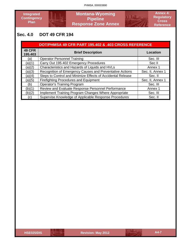
A4-7 Revision: May 2012HSE025/DIS
Montana-Wyoming Pipeline
Response Zone Annex
Annex 4: Regulatory
Cross Reference
Integrated Contingency
Plan
Sec. 4.0 DOT 49 CFR 194
DOT/PHMSA 49 CFR PART 195.402 & .403 CROSS REFERENCE
49 CFR 195.403 Brief Description Location
(a) Operator Personnel Training Sec. III (a)(1) Carry Out 195.402 Emergency Procedures Sec II (a)(2) Characteristics and Hazards of Liquids and HVLs Annex 1 (a)(3) Recognition of Emergency Causes and Preventative Actions Sec. II, Annex 1 (a)(4) Steps to Control and Minimize Effects of Accidental Release Sec. II (a)(5) Firefighting Procedures and Equipment Sec. II, Annex 1
(b) Operator’s Training Program Sec. III (b)(1) Review and Evaluate Response Personnel Performance Annex 1 (b)(2) Implement Training Program Changes Where Appropriate Sec. III
(c) Supervise Knowledge of Applicable Response Procedures Sec. II
PHMSA, 000003890

Montana-Wyoming Pipeline Response Zone
Annex
Annex 5: Administration
Integrated Contingency
Plan
Revision: May 2012 HSE025/DIS
Annex 5 – Table of Contents
5.0 Distribution List
5.1 Record of Revisions
PHMSA, 000003891

Montana-Wyoming Pipeline Response Zone
Annex
Annex 5: Administration
Integrated Contingency
Plan
A5-1 Revision: May 2012 HSE025/DIS
Sec. 5.0 Distribution List
Recipient Address Plan Type Held
Hard Copy CD DOT / PHMSA Melanie Barber
US DOT Office of Pipeline Safety 1200 New Jersey Avenue NE East Building E22-210 Washington, DC 20590
0 2
U.S. Fish and Wildlife Service
Mark Wilson, Field Supervisor 585 Shepard Way Helena, MT 59601
1 1
U.S. Forest Service
Darryl Sansouci Missoula Ranger District Fort Missoula, Building 24-A Missoula, MT 59801
1 1
Lolo National Forest, Plains/Thompson Falls Ranger District
Randy Hojem 408 Clayton, or P.O. Box 429 Plains, MT 59859
1 1
Blackfeet Tribe – Environmental Department
Gerald Wagner, Environmental Director 457 Hospital Road (PO Box 2029) Browning, MT 59417
0 1
Blackfeet Nation – Bureau of Indian Affairs
Stephen Pollock, Superintendent 531 SE Boundary St. PO Box 2029 Browning, MT 59417
1 1
Crow Nation – BIA, Frank Rollusson Director of Natural Resources
Weaver Drive, Bldg #2 (PO Box69) Crow Agency, MT 59022 1 1
LEPC, Yellowstone County, MT
Jim Kraft, Director 217 N. 27th; County Courthouse, Room 312 Billings, MT 59101
0 1
Yellowstone Pipeline Area 2 & 3 Supervisor (Spokane)
c/o Bruce Sandy 6317 East Sharp Avenue Spokane, WA 99212 1 1
PHMSA, 000003892

Montana-Wyoming Pipeline Response Zone
Annex
Annex 5: Administration
Integrated Contingency
Plan
A5-2 Revision: May 2012 HSE025/DIS
Distribution List Cont.
Recipient Address Plan Type Held
Hard Copy CD Yellowstone Pipeline Area 1 Supervisor (Billings)
Jeff Harmon 338 Hwy 87 East Billings, MT 59101
1 1
Pioneer Pipeline Area Supervisor (NSL)
Dale Baxter 245 East 1100 North North Salt Lake City, UT 84054
1 1
LEPC – Glacier County
Charley Farmer, DES 1210 E. Main; Courthouse Annex Cut Bank, MT 59427
0 1
Denver Area Supervisor
Karl Rheinboldt 3960 East 56 h Avenue Commerce City, CO 80022
1 1
Seminoe Pipeline Area Supervisor (Casper)
Rodney Warren 5090 Lathrop Road Evansville, WY 82636
1 1
Seminoe Pipeline Area Supervisor (Rock Springs)
c/o Rob Anderson 90 Foothill Blvd. Rock Springs, WY 82901
1 1
Seminoe Pipeline Area Supervisor (Sheridan)
c/o David Plymell 3404 Hwy 87 Sheridan, WY 82801
1 1
Pioneer Pipeline Area Supervisor (Sinclair)
c/o Mike Winder 404 North 6th Avenue Sinclair, WY 82334
1 1
Glacier Crude Pipeline Area Supervisor (Cut Bank)
c/o Mike Boyd Tank Farm Hill, 38Humble Rd. (P.O. Box 1251) Cut Bank, MT 59427
1 1
Yellowstone Pipeline Area 1 Supervisor (Roundup)
c/o Neil Hough 701 3rd St. East Roundup, MT 50972
1 1
Yellowstone Pipeline Area 1 Supervisor (Billings)
c/o Joshua B. Brown 338 Hwy 87 East Billings, MT 59101
1 1
Billings Product Terminal Supervisor (Truck Rack)
c/o Dick R. Johnston 338 Hwy 87 East Billings, MT 59101
1 1
Yellowstone Pipeline Area 2 & 3 Supervisor (Helena)
c/ Earl Anderson 3180 Hwy 12 East Helena, MT 59601
1 1
PHMSA, 000003893

Montana-Wyoming Pipeline Response Zone
Annex
Annex 5: Administration
Integrated Contingency
Plan
A5-3 Revision: May 2012 HSE025/DIS
Distribution List Cont.
Recipient Address Plan Type Held
Hard Copy CD Yellowstone Pipeline Area 2 & 3 Supervisor (Bozeman)
c/o Mike Crawford 318 West Griffin Drive Bozeman, MT 59715
1 1
Glacier Crude PL & YPL 2 & 3 Area Supervisors (Great Falls)
c/o James (Jim) T. Olson and Dallas Mayo 1401 52nd Street North Great Falls, MT 59405
2 2
Yellowstone Pipeline Areas 2 & 3 Supervisor (Missoula)
Mike Kuntz 3330 Raser Drive Missoula, MT 59802
1 1
Terminal Supervisor – Thompson Falls
Theodore J. Hagemo 5315 Hwy 200 East Thompson Falls, MT 59873
1 1
Director, Emergency Preparedness, Response & Security (EPR&S)
Rob Yarbrough c/o EPR&S Coordinator 600 North Dairy Ashford TR-2002 Houston, TX 77079
1 1
Billings Refinery, Emergency Response Coordinator
George H. Jurovich 401 S. 23rd Street Billings, MT 59101
1 1
Missoula Terminal Supervisor
Richard Colgrove 3300 Raser Drive Missoula, MT 59808
1 1
Emergency Management District, Sweetwater County
Attn: Judy Valentine 731 C Street, Bldg A – Ste #131 Rock Springs, WY 82901
1 (ERAP only) 1
LEPC/Montana Disaster & Emergency Services; District 1 Representative
Attn: Martha-Jo Smith 25 Silcox Lane Thompson Falls, MT 59873 0 1
Idaho Office of Energy Resources
Attn: Jennifer Pope 304 N. 8th Street, Suite 250 (PO Box 83720) Boise, ID 83720-0199 208-332-1677
0 1
PHMSA, 000003894

Montana-Wyoming Pipeline Response Zone
Annex
Annex 5: Administration
Integrated Contingency
Plan
A5-4 Revision: May 2012 HSE025/DIS
5.1 Record of Revisions
REVISION DATE
Sections REASON FOR REVISION REMOVED INSERTED
May 2012 Entire Plan Entire Plan New plan implemented
PHMSA, 000003895

Montana-Wyoming Pipeline Response Zone
Annex
Annex 5: Administration
Integrated Contingency
Plan
A5-5 Revision: May 2012 HSE025/DIS
Update Notice
Montana & Wyoming Response Zone
Integrated Contingency Plan (ICP) To all holders of the ICP Date: May 2012 Revision: Initial Version Attached are the revised pages of the ICP that has been assigned to you. Please update your copy with these revisions:
Section/Annex Remove Pages Replacement Pages Entire Plan Entire Old Plan New Plan Montana & Wyoming ERP CD
Destroy all previously dated Montana & Wyoming CDs.
New Montana & Wyoming ERP Dated 5/12
Update Notice Replace the Revision Log at the beginning of the “Administration” Section and Insert this Update Notice at the end of the “Record of Revisions” Section.
PHMSA, 000003896