Overview of Magnetless Brushless Machines - HKU Scholars ...
25
1 Abstract—Because of the definite merits of high efficiency and high power density, the permanent-magnet (PM) brushless machines have been dominating the high-performance industrial applications. However, the problems of high PM material cost, fluctuating supply of rare-earth materials and ineffective PM flux control have hindered the widespread applications of the PM brushless machines. In recent years, many attentions have been shifted to the magnetless candidates, while the focuses are mainly placed on the classical candidates. In this paper, an overview of magnetless brushless machines, including both the classical and advanced types, is presented, with emphasis on their machine topologies, features and performances. In addition, the upcoming trend of these machines is reviewed and discussed. Index Terms—Brushless, doubly-salient, electric vehicle, flux-reversal, flux-switching, flywheel, magnetless, mass transit transportation, overview, reluctance, robotic, ship propulsion, wind power generation. I. INTRODUCTION Due to a large variety of industrial applications, including the electric vehicles, wind power generations, ship propulsion systems, and robotic applications, the development of electric machines has become a hot research topic in last century. The electric machines can be generally categorized as two major groups, namely the brushed machines, and the brushless machines. As compared with the brushed ones, the brushless machines can enjoy the absolute advantage of maintenance-free operation, so that these type of machines have become the major trend since the last few decades [1], [2]. By the classification of machine materials, the brushless machines can be further divided into two subgroups, namely the permanent-magnet (PM) brushless machines, and the magnetless brushless machines. Upon the installation of high-energy-density PM materials, the PM brushless machines can provide superior performances and hence they have become very attractive for high-performance applications [3]. However, due to the fluctuating supply of rare- earth materials, there is a drastic increase of PM material costs [4]. To improve the product competitiveness and market penetration, the magnetless brushless machines are becoming more attractive, especially for the automotive electric drives [5]. Nevertheless, the research interests are mainly focused on the classical candidates, while the discussions on the advanced Overview of Magnetless Brushless Machines Christopher H. T. Lee, K. T. Chau, Chunhua Liu, and C. C. Chan Department of Electrical and Electronic Engineering, The University of Hong Kong, Hong Kong, China
-
Upload
khangminh22 -
Category
Documents
-
view
2 -
download
0
Transcript of Overview of Magnetless Brushless Machines - HKU Scholars ...

1
Abstract—Because of the definite merits of high efficiency and high power density, the permanent-magnet (PM)
brushless machines have been dominating the high-performance industrial applications. However, the problems of high
PM material cost, fluctuating supply of rare-earth materials and ineffective PM flux control have hindered the
widespread applications of the PM brushless machines. In recent years, many attentions have been shifted to the
magnetless candidates, while the focuses are mainly placed on the classical candidates. In this paper, an overview of
magnetless brushless machines, including both the classical and advanced types, is presented, with emphasis on their
machine topologies, features and performances. In addition, the upcoming trend of these machines is reviewed and
discussed.
Index Terms—Brushless, doubly-salient, electric vehicle, flux-reversal, flux-switching, flywheel, magnetless, mass
transit transportation, overview, reluctance, robotic, ship propulsion, wind power generation.
I. INTRODUCTION
Due to a large variety of industrial applications, including the electric vehicles, wind power generations, ship propulsion
systems, and robotic applications, the development of electric machines has become a hot research topic in last century. The
electric machines can be generally categorized as two major groups, namely the brushed machines, and the brushless machines.
As compared with the brushed ones, the brushless machines can enjoy the absolute advantage of maintenance-free operation, so
that these type of machines have become the major trend since the last few decades [1], [2]. By the classification of machine
materials, the brushless machines can be further divided into two subgroups, namely the permanent-magnet (PM) brushless
machines, and the magnetless brushless machines.
Upon the installation of high-energy-density PM materials, the PM brushless machines can provide superior performances and
hence they have become very attractive for high-performance applications [3]. However, due to the fluctuating supply of rare-
earth materials, there is a drastic increase of PM material costs [4]. To improve the product competitiveness and market
penetration, the magnetless brushless machines are becoming more attractive, especially for the automotive electric drives [5].
Nevertheless, the research interests are mainly focused on the classical candidates, while the discussions on the advanced
Overview of Magnetless Brushless Machines
Christopher H. T. Lee, K. T. Chau, Chunhua Liu, and C. C. Chan
Department of Electrical and Electronic Engineering, The University of Hong Kong, Hong Kong, China
2
machine types are still inadequate. In particular, a comprehensive overview and discussion on the magnetless brushless machine
family, especially on the advanced candidates, is still absent in literature.
The purpose of this paper is to provide an overview of the magnetless brushless machines, including both the classical and
advanced candidates. Current technologies of various magnetless brushless machines, including the machine structures,
characteristics, operation principles, control algorithms, and upcoming trends, will be critically reviewed and discussed.
II. CLASSICAL TOPOLOGIES
In general, there are four major types of fundamental magnetless brushless machines available, namely the squirrel-cage
induction machine (IM) [6], the synchronous reluctance machine (SynRM) [7], the vernier reluctance machine (VRM) [8] and
the switched reluctance machine (SRM) [9]. Even though all these candidates are categorized as the magnetless brushless
machines, each of them exhibits the unique features and distinctive characteristics.
A. Induction Machine
The IM has been regarded as one of the most developed electric machines [10]. Literally speaking, the IM is operated based
on the principle of electromagnetic induction, which can be achieved by the rotating magnetic field. The induction brushless
machine with the squirrel-cage structure [11] is a magnetless brushless machine. The basic performances of the IM can be
accurately estimated by the equation modeling [12]. The IM has been employed in many variable-speed situations, such as wind
power generation, while the doubly-fed IM has been widely accepted as one of the best options for these applications [13]. To
further improve the torque density, the dual-electrical-port control scheme has been recently implemented to the cascaded
doubly-fed IM [14].
Even though the three-phase topology is the most common design, the IM with higher number of phases have also drawn some
attentions for various applications [15]. In particular, the nine-phase IM with the dual-inverter-fed topology has been proposed
[16]. Apart from the design of machine structure, the control algorithm is another attractive technology that has drawn
considerable attentions [17]. In particular, a huge variety of sensorless control schemes have been employed in the industrial
applications [18]. However, the sensorless vector control cannot estimate the rotor frequency in the ultra-low speed region. To
cater this situation, a mechanical simulator that estimates the disturbance torque by the error of the torque current has been
developed [19].
B. Synchronous Reluctance Machine
As one of the earliest types of electric machines, the SynRM has been developed as a cylindrical rotor with multiple slits in
early 1900s [7]. The SynRM is operated based on the principle of minimum reluctance, which can be achieved by the rotating
3
magnetic field. The major torque component of the SynRM comes from the reluctance torque, which is directly proportional to
the saliency ratio. To improve the saliency ratio as well as the output torque performance, a segmental rotor structure [20] and an
axially laminated rotor structure [21] have been developed. The rotor design is crucial for the SynRM, while the multi-objective
genetic algorithm with the Pareto front solutions has been employed for rotor optimization [22].
Apart from the average torque value, the torque ripple issue is another important criterion to determine the machine
performance. To minimize the torque pulsation, the asymmetrical rotor barrier arrangement [23] and the torque harmonic
compensation approach [24] have been proposed. With the advantages of high reliability and low maintenance, the doubly-fed
SynRM has shed great potential for variable-speed applications [25].
C. Vernier Reluctance Machine
Same as the SynRM, the VRM is also operated based on the principle of minimum reluctance. Yet, the VRM distinguishes
itself by the salient rotor pole structure [26]. In the meantime, the VRM is operated based on the rotating field scheme [27],
whose operation is similar as the SynRM one.
Based on the rotating field operation with the salient pole structure, the relatively smoother torque can be produced even in the
low-speed situation. To utilizing these characteristics, the VRM is purposely designed with the machine structure of relatively
higher number of poles, and hence the high-torque low-speed operation can be achieved [28]. The VRM has been extended to
form the double-stator VRM (DS-VRM) [29] and the double-rotor VRM (DR-VRM) [30]. Yet, same as other reluctance
machines, the VRM also suffers from the problem of relatively lower power factor. To improve the power factor, the VRM with
the doubly-slotted stator structure has been developed [31]. As the extension from the doubly-slotted structure, the VRM with the
fractional slot concentrated winding arrangement has been developed [32].
D. Switched Reluctance Machine
Same as the VRM, the SRM consists of the salient pole structure and this type of machine is also operated based on the
principle of minimum reluctance. Yet, unlike the SynRM and VRM that are operated by the rotating field, the SRM is instead
operated by the phase current pulse scheme. The simplest SRM consists of the one-phase 2/2-pole (two-stator-pole/two-rotor-
pole) topology [33], while it is not practical for industrial applications. The SRM has been further developed as the three-phase
6/4-pole structure [34], the three-phase 12/8-pole structure [35], the three-phase 24/16-pole structure [36] and the four-phase
8/6-pole structure [33]. It has been reported that the torque density can be improved based on the machine dimension
optimization, the selection of pole-pair combinations and the choice of materials [37]. Recently, the new topology with higher
ratio of rotor to stator pole has also been explored [38]. With the new rotor to stator pole arrangement, more winding slot area as
well as larger torque density can be achieved.

4
To improve the performance of the SRM, the reduction of torque ripple and acoustic noise have become a hot research topic
in the past few decades. The torque pulsations as well as the acoustic noise are generally produced at the point of phase
commutation [39]. Hence, these problems can be relieved by the optimization of machine dimension [40] and the optimized
control of the commutation angle [41]. In particular, the SRM with the cylindrical rotor design has been proposed to reduce the
windage loss and acoustic noise, such that it can enjoy better efficiency at high operating speed [42]. In addition, to optimize the
current waveforms, the implementation of phase shift to the second and third harmonics has been introduced [43].
In order to produce the torque properly, the phase current pulse of the SRM conventionally has to synchronize with its rotor
position. However, the position sensors not only increase the construction cost and system complexity, but also decrease the
reliability of the system [44]. Upon the analysis of the variation of the flux-linkages among the phases, the sensorless control
algorithm can be accomplished [45]. Recently, the utilization of the mutual inductance between the two excited phases has been
realized for position sensorless control [46].
TABLE I COMPARISONS OF THE CLASSICAL MAGNETLESS MACHINES
IM SynRM VRM SRM
Operating principle Induction Reluctance Reluctance Reluctance
Rotor structure Squirrel-cage Axially laminated Salient pole Salient pole
Control scheme Rotating field Rotating field Rotating field Switching pulse
Efficiency High Medium Medium Low
Torque range Low Medium High Low
Speed range High Medium Low High
E. Comparison and Summary
The qualitative comparisons between the four classical magnetless brushless machines are given in Table I, while the
quantitative comparisons can be found on the other literatures [37, 47 and 48]. The comparisons are based on the key features,
including the operating principle, rotor structure, control scheme, efficiency, torque range, and speed range.
III. RECENT TOPOLOGIES
Apart from the aforementioned accomplishments, new developments of other magnetless topologies have received well
attentions recently.
5
A. Derived Machines from PM topologies
With reference to the design philosophies from the profound PM machines (PMMs), the advanced magnetless machines can
then be produced. Not surprisingly, the derived magnetless machine can share the similar characteristics as well as advantages
from its ancestors.
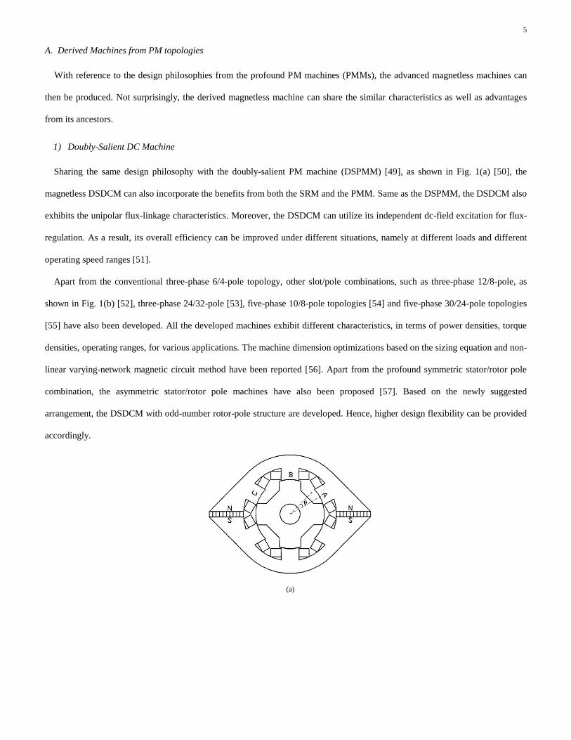
1) Doubly-Salient DC Machine
Sharing the same design philosophy with the doubly-salient PM machine (DSPMM) [49], as shown in Fig. 1(a) [50], the
magnetless DSDCM can also incorporate the benefits from both the SRM and the PMM. Same as the DSPMM, the DSDCM also
exhibits the unipolar flux-linkage characteristics. Moreover, the DSDCM can utilize its independent dc-field excitation for flux-
regulation. As a result, its overall efficiency can be improved under different situations, namely at different loads and different
operating speed ranges [51].
Apart from the conventional three-phase 6/4-pole topology, other slot/pole combinations, such as three-phase 12/8-pole, as
shown in Fig. 1(b) [52], three-phase 24/32-pole [53], five-phase 10/8-pole topologies [54] and five-phase 30/24-pole topologies
[55] have also been developed. All the developed machines exhibit different characteristics, in terms of power densities, torque
densities, operating ranges, for various applications. The machine dimension optimizations based on the sizing equation and non-
linear varying-network magnetic circuit method have been reported [56]. Apart from the profound symmetric stator/rotor pole
combination, the asymmetric stator/rotor pole machines have also been proposed [57]. Based on the newly suggested
arrangement, the DSDCM with odd-number rotor-pole structure are developed. Hence, higher design flexibility can be provided
accordingly.
(a)

6
(b)
Fig. 1 Doubly-salient machines. (a) Three-phase 6/4-pole DSPMM [50]. (b) Three-phase 12/8-pole DSDCM [52].
2) Flux-Reversal DC Machine
Exhibiting the bipolar flux-linkage patterns, the flux-reversal PMM (FRPMM) can potentially provide higher power density
than the unipolar candidate does, i.e., the DSPMM. Unlike the DSPMM that inserts the PM pieces within the stator yoke, the
FRPMM instead mounts the PM pieces with alternating polarities on its stator tooth [58], as shown in Fig. 2(a). Undoubtedly, the
magnetless version of the FRPMM can be established, while some special arrangement on the stator pole should be
implemented.
To imitate the FRPMM structure, the stator poles of the magnetless FRDCM are purposely modulated as a three-tooth per
stator pole topology [59], as shown in Fig. 2(b). With the modulated stator pole, the dc-field winding can be wound in a way to
imitate the PM pieces with the alternating polarities. Based on the magnetless structure, the FRDCM enjoys the definite cost-
benefit as compared with the PM counterparts. However, high saturation effect occurs within the modulated tooth easily, such
that further improvement of the power density may be hindered.
(a)

7
(b)
Fig. 2 Flux-reversal machines. (a) The outer-stator inner-rotor FRPMM [58]. (b) The outer-rotor inner-stator FRDCM [59].
3) Flux-Switching DC Machine
Same as the flux-switching PMM (FSPMM), as shown in Fig. 3(a), that has drawn most of the attentions among its
competitive group [60], its derived magnetless candidate, namely the FSDCM has also become very popular recently. Inheriting
the characteristics from its ancestor, the FSDCM exhibits the bipolar flux-linkage patterns. As a result, higher power density can
be potentially produced [61].
To achieve the bipolar flux-linkage patterns, there are generally two fundamental dc-field winding arrangements available,
namely the toroidal-field winding arrangement [62] and the wound-field winding arrangement [63], as shown in Fig. 3(b) and
Fig. 3(c), respectively. Unlike the FRDCM that modulates the fluxes within the stator tooth, the FSDCM instead regulates the
fluxes within the stator yoke. Consequently, better core utilization and lower saturation effect can be potentially resulted. Even
though the toroidal-field winding machine can potentially produce higher torque density, it suffers from more severe saturation
problem within its stator iron yoke. On the other hand, the magnetic field of the would-field winding machine is radially excited
and not concentrated, so that the saturation problem can be relieved. To achieve the maximum output torque, the relationship
between the armature and the field currents has also been carried out [64].
With the attempt to further utilize the inner space of the FSDCM, the DR-FSDCM has been proposed [65], as shown in Fig.
3(d). Based on the toroidal-field winding arrangement, the armature and dc-field windings can provide the symmetrical fluxes
towards the two rotors. Hence, very simple and robust structure is resulted.

8
(a)
(b)
(c)

9
(d)
Fig. 3 Flux-switching machines. (a) Three-phase FSPMM [60]. (b) FSDCM with toroidal-field winding arrangement [62]. (c) FSDCM with wound-field
winding arrangement [63]. (d) DR-FSDCM with toroidal-field winding arrangement [65].
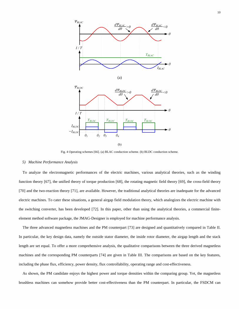
4) Operating Principles
With respect to the back electromotive force (EMF) waveforms, the advanced magnetless machines can be further classified
into two major groups, namely the sinusoidal-like machine and the trapezoidal-like machine [66]. In order to operate these
machines properly, two conduction schemes are available, namely the brushless ac (BLAC) scheme and the brushless dc (BLDC)
scheme. In particular, the BLAC scheme is more suitable for the sinusoidal-like machine while the BLDC scheme is for the
trapezoidal-like machine.
In the BLAC scheme, the sinusoidal armature current IBLAC is employed in accordance to the status of the flux-linkage ΨBLAC,
such that the positive electromagnetic torque TBLAC is produced. This BLAC operating scheme is shown in Fig. 4(a). Since the
injected armature current in the BLAC scheme is perfectly aligned with the back EMF waveform, the minimized torque pulsation
performance can be achieved.
In the BLDC scheme, when the flux-linkage ΨBLDC is increasing, a positive rectangular current IBLDC is employed. As a result,
the positive electromagnetic torque TBLDC is produced. Meanwhile, when the flux-linkage is decreasing, a negative rectangular
current is instead employed to produce also the positive electromagnetic torque. This BLAC operating scheme is shown in Fig.
4(b). With respect to the interaction between the back EMF and the armature current pattern, the trapezoidal-like machine with
the BLDC scheme can potentially produce higher output power and torque levels.
10
(a)
(b)
Fig. 4 Operating schemes [66]. (a) BLAC conduction scheme. (b) BLDC conduction scheme.
5) Machine Performance Analysis
To analyze the electromagnetic performances of the electric machines, various analytical theories, such as the winding
function theory [67], the unified theory of torque production [68], the rotating magnetic field theory [69], the cross-field theory
[70] and the two-reaction theory [71], are available. However, the traditional analytical theories are inadequate for the advanced
electric machines. To cater these situations, a general airgap field modulation theory, which analogizes the electric machine with
the switching converter, has been developed [72]. In this paper, other than using the analytical theories, a commercial finite-
element method software package, the JMAG-Designer is employed for machine performance analysis.
The three advanced magnetless machines and the PM counterpart [73] are designed and quantitatively compared in Table II.
In particular, the key design data, namely the outside stator diameter, the inside rotor diameter, the airgap length and the stack
length are set equal. To offer a more comprehensive analysis, the qualitative comparisons between the three derived magnetless
machines and the corresponding PM counterparts [74] are given in Table III. The comparisons are based on the key features,
including the phase flux, efficiency, power density, flux controllability, operating range and cost-effectiveness.
As shown, the PM candidate enjoys the highest power and torque densities within the comparing group. Yet, the magnetless
brushless machines can somehow provide better cost-effectiveness than the PM counterpart. In particular, the FSDCM can
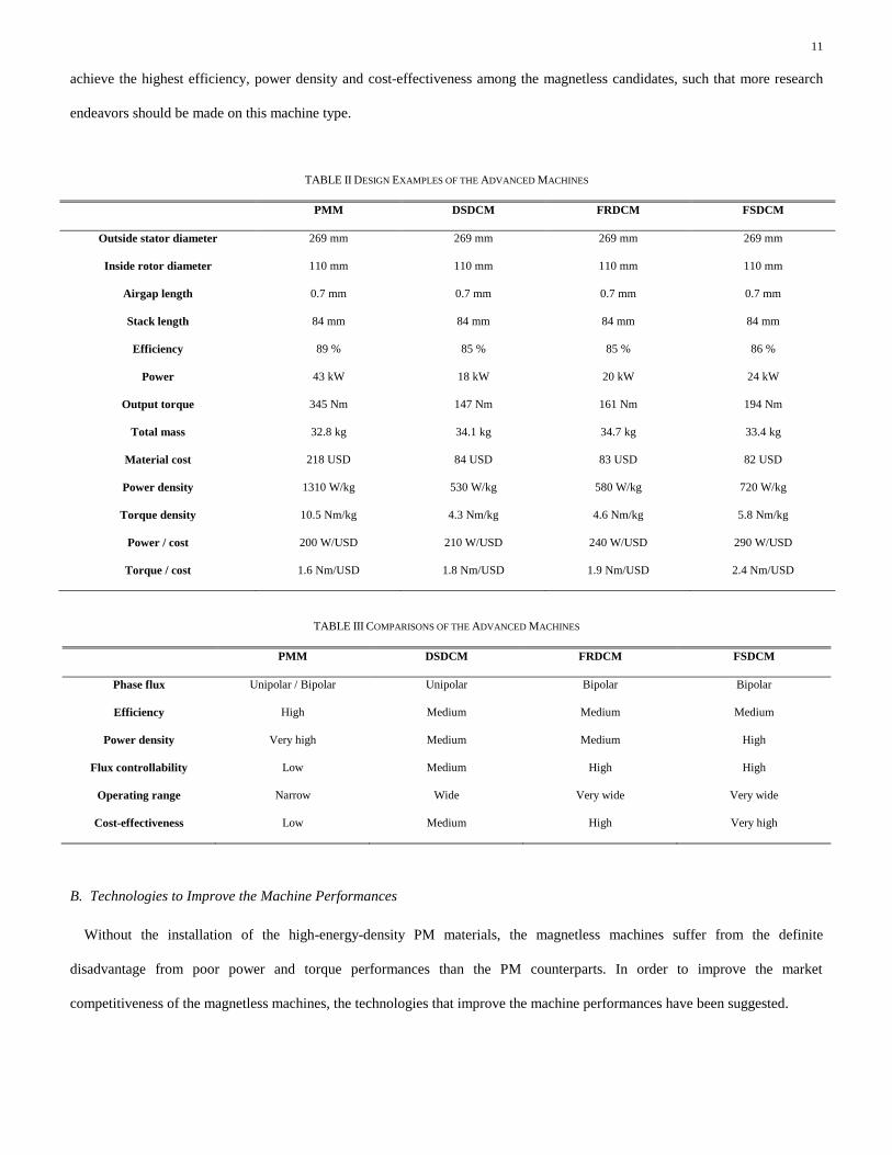
11
achieve the highest efficiency, power density and cost-effectiveness among the magnetless candidates, such that more research
endeavors should be made on this machine type.
TABLE II DESIGN EXAMPLES OF THE ADVANCED MACHINES
PMM DSDCM FRDCM FSDCM
Outside stator diameter 269 mm 269 mm 269 mm 269 mm
Inside rotor diameter 110 mm 110 mm 110 mm 110 mm
Airgap length 0.7 mm 0.7 mm 0.7 mm 0.7 mm
Stack length 84 mm 84 mm 84 mm 84 mm
Efficiency 89 % 85 % 85 % 86 %
Power 43 kW 18 kW 20 kW 24 kW
Output torque 345 Nm 147 Nm 161 Nm 194 Nm
Total mass 32.8 kg 34.1 kg 34.7 kg 33.4 kg
Material cost 218 USD 84 USD 83 USD 82 USD
Power density 1310 W/kg 530 W/kg 580 W/kg 720 W/kg
Torque density 10.5 Nm/kg 4.3 Nm/kg 4.6 Nm/kg 5.8 Nm/kg
Power / cost 200 W/USD 210 W/USD 240 W/USD 290 W/USD
Torque / cost 1.6 Nm/USD 1.8 Nm/USD 1.9 Nm/USD 2.4 Nm/USD
TABLE III COMPARISONS OF THE ADVANCED MACHINES
PMM DSDCM FRDCM FSDCM
Phase flux Unipolar / Bipolar Unipolar Bipolar Bipolar
Efficiency High Medium Medium Medium
Power density Very high Medium Medium High
Flux controllability Low Medium High High
Operating range Narrow Wide Very wide Very wide
Cost-effectiveness Low Medium High Very high
B. Technologies to Improve the Machine Performances
Without the installation of the high-energy-density PM materials, the magnetless machines suffer from the definite
disadvantage from poor power and torque performances than the PM counterparts. In order to improve the market
competitiveness of the magnetless machines, the technologies that improve the machine performances have been suggested.

12
1) Multi-Tooth Structure
To improve the torque density, the multi-tooth (MT) structure, which employs the multiple tooth per stator pole arrangement,
has been proposed [75]. Upon the MT topology, the magnetic flux within the stator yoke can be regulated in a way to transfer the
energy to the rotor simultaneously. Consequently, the torque density can be potentially improved. In particular, the MT machine
is favorable for the high-torque low-speed operation [76]. In order word, when larger number of tooth per stator pole is
employed, higher torque density with lower operating range can then be achieved. However, the maximum number of the
multiple tooth is limited by the physical constrain and the saturation within the tooth. Detailed analysis and comparisons between
the MT structure and the conventional structure can be found in [77].
2) Double-Stator Structure
To improve the power density, the inner space of the single-stator machine has been utilized to serve as an additional stator.
As a result, the double-stator (DS) machines, which consist of two separated stators, is formed. Unlike the typical DS machine,
which accommodates both armature and dc-field windings in the same winding slots, the partitioned-stator machine instead
allocates the two winding sets into two stators separately [78], as shown in Fig. 5(a). Consequently, the partitioned-stator
machine can relieve the saturation problem that happens in the conventional DS machines. Hence, better efficiency can be
potentially achieved.
Because the inner- and outer-rotor tooth of the DS machine are typically aligned with each other, the torque ripples of the two
torque components are unfavorably superimposed. To improve the torque ripple problem, the mechanical-offset (MO) structure,
whose inner- and outer-rotor tooth are purposely mismatched with a conjugated angle to each other, as shown in Fig. 5(b), is
proposed [79]. As a result, the torque ripples from the inner-segment and outer-segment can be perfectly integrated, as shown in
Fig. 5(c). Consequently, a smoother resultant torque can be produced. However, same as other DS machines, the MO structure
suffers from the complex manufacturing processes.
(a)

13
(b)
(c)
Fig. 5 Double-stator machines. (a) Partitioned-stator machine [78]. (b) MO machine [79]. (c) Operating waveforms for MO machine [79].
3) Axial-Field Structure
Despite the traditional radial-field (RF) structure, the magnetless machines can be extended to form the axial-field (AF) family
[80]. Upon the employment of the radial area for the torque production, the AF machines can produce higher power and torque
densities as compared with its RF counterparts do [81]. Since the AF machines are derived from the RF topologies, theoretically
every RF machine should be able to form its corresponding AF derivation. As one of the most mature machine type, the AF-IM
has been developed [82]. According to the theoretical and experimental results, the AF-IM can provide better performances,
including higher efficiency and higher starting torque, than the RF counterparts do.
Same as the IM, another traditional magnetless machine, the SRM has been further extended to form the AF-SRM. The
developed AF-SRM consists of the sandwiched-stator double-sided-rotor structure with the toroidal winding arrangement [83],
as shown in Fig. 6(a). In particular, the AF-SRM with higher number of rotor pole is more preferable for the high-torque low-
speed applications, such as the electric vehicle or electric ship propulsion.
With the definite advantage of relatively higher torque density, the AF-DSDCM with the sandwiched-stator double-sided-rotor
structure has been proposed [84]. With the modular stator construction, the derived AF-DSDCM can reduce its stator yoke to
improve the torque density and to minimize the material costs.

14
To reduce the iron losses within the yoke, the double-face printed circuit technology for the multilayer winding arrangement,
has been implemented into the AF machine [85], as shown in Fig. 6(b). The torque of the double-face-printed machine is
produced by the interaction between the homopolar flux and the rotating axial flux created by the dc-field and three-phase
armature winding, respectively. The double-face-printed machine employs the solid steel discs as the rotor part, and therefore
high robustness can be achieved for the flywheel application.
Even though the AF topology enjoys some superior advantages, as compared with the well-developed RF counterpart, this
type of machine suffers from the immature technology and manufacturing complexity.
(a)
(b)
Fig. 6 Axial-field machines. (a) Sandwiched-stator double-sided-rotor AF-SRM [83]. (b) Double-face-printed AF machine [85].
15
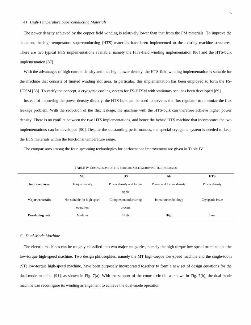
4) High-Temperature Superconducting Materials
The power density achieved by the copper field winding is relatively lower than that from the PM materials. To improve the
situation, the high-temperature superconducting (HTS) materials have been implemented to the existing machine structures.
There are two typical HTS implementations available, namely the HTS-field winding implementation [86] and the HTS-bulk
implementation [87].
With the advantages of high current density and thus high power density, the HTS-field winding implementation is suitable for
the machine that consists of limited winding slot area. In particular, this implementation has been employed to form the FS-
HTSM [88]. To verify the concept, a cryogenic cooling system for FS-HTSM with stationary seal has been developed [89].
Instead of improving the power density directly, the HTS-bulk can be used to serve as the flux regulator to minimize the flux
leakage problem. With the reduction of the flux leakage, the machine with the HTS-bulk can therefore achieve higher power
density. There is no conflict between the two HTS implementations, and hence the hybrid HTS machine that incorporates the two
implementations can be developed [90]. Despite the outstanding performances, the special cryogenic system is needed to keep
the HTS materials within the functional temperature range.
The comparisons among the four upcoming technologies for performance improvement are given in Table IV.
TABLE IV COMPARISONS OF THE PERFORMANCE IMPROVING TECHNOLOGIES
MT DS AF HTS
Improved area Torque density Power density and torque
ripple
Power and torque density Power density
Major constrain Not suitable for high speed
operation
Complex manufacturing
process
Immature technology Cryogenic issue
Developing rate Medium High High Low
C. Dual-Mode Machine
The electric machines can be roughly classified into two major categories, namely the high-torque low-speed machine and the
low-torque high-speed machine. Two design philosophies, namely the MT high-torque low-speed machine and the single-tooth
(ST) low-torque high-speed machine, have been purposely incorporated together to form a new set of design equations for the
dual-mode machine [91], as shown in Fig. 7(a). With the support of the control circuit, as shown in Fig. 7(b), the dual-mode
machine can reconfigure its winding arrangement to achieve the dual-mode operation.
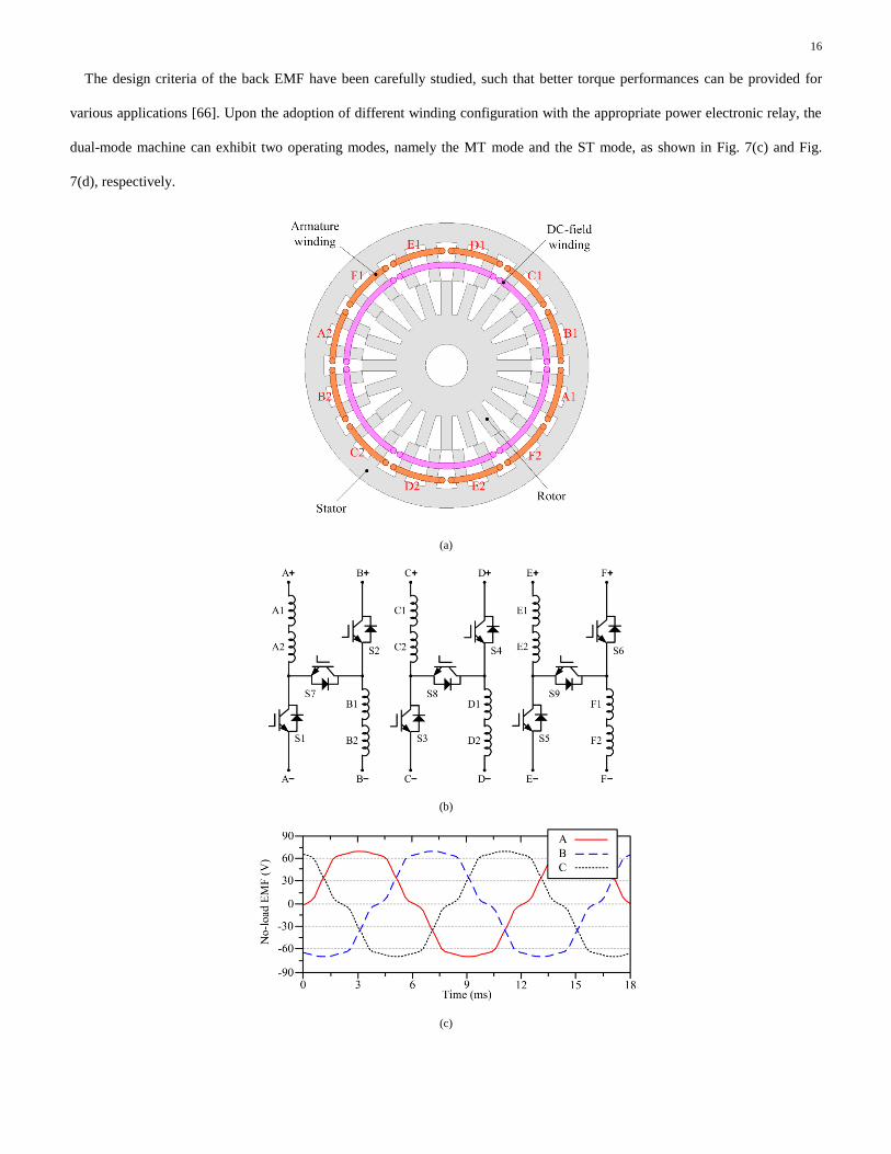
16
The design criteria of the back EMF have been carefully studied, such that better torque performances can be provided for
various applications [66]. Upon the adoption of different winding configuration with the appropriate power electronic relay, the
dual-mode machine can exhibit two operating modes, namely the MT mode and the ST mode, as shown in Fig. 7(c) and Fig.
7(d), respectively.
(a)
(b)
(c)

17
(d)
Fig. 7 Dual-mode machines. (a) Machine structure [91]. (b) Control circuit [91]. (c) Back EMF waveforms at MT mode with low operating speed [66]. (d)
Back EMF waveforms at ST mode with high operating speed [66].
D. Linear Topology
Due to the widespread of applications, the rotatory machines have attracted most of the attentions in the past few decades. Yet,
upon the enhancing development on the mass transit technology, there are increasing needs on the research of the linear
machines. The basic structure of the linear machine can be regarded as the extension from the rotatory counterparts [92], as
shown in Fig. 8(a).
Same as the AF machine, the linear machines can be derived from its corresponding rotatory ancestors. As one of the most
mature candidates, the rotatory SRM has been developed as the linear SRM (L-SRM) [93]. The design considerations of the
mover, as the analogue of the rotor in the rotatory machine, are well studied. To improve the force density, the dual-side mover
L-SRM with the segmental stator topology has been developed [94], as shown in Fig. 8(b). In addition to the L-SRM, there are
also researches on the L-IM [95], L-FSDCM [96] and L-FRDCM [97]. Since the PM installations for the long-stator is very
expensive, the magnetless linear machine has been regarded as the very promising structure for the railway transportation system.
(a)

18
(b)
Fig. 8 Linear machines. (a) Analogue between rotatory and linear machines [92]. (b) Dual-side L-SRM with the segmental stator topology [94].
Fig. 9 Improved DTC scheme with the SVPWM [98].
E. Advanced Control Algorithm
As one of the most conventional control scheme, the direct torque control (DTC) has been widely employed for the BLAC
operating machines, while the traditional approach suffers from low estimation accuracy and system complexity. To improve the
situation, the integration among the fifth-order filter, the high-pass filter and the logical calculation has been proposed [98].
Upon the adoption of the developed algorithm, better estimation capability and improved system quality can be achieved.
In the meantime, the relationship between the independent dc-field excitation of the DSDCM and the system quality has been
analyzed. Consequently, the space vector pulse width modulation (SVPWM) has been implemented with the existing DTC
scheme. By utilizing the linear co-relation between the electromagnetic torque and the sine value of torque angle, the improved
control scheme is formed [99], as shown in Fig. 9. As a result, the torque loop can be eliminated while the output torque can be

19
regulated linearly by the voltage loop. Based on the improved DTC scheme, smaller torque pulsation and lower current total
harmonic distortion (THD) are resulted.
IV. CONCLUSION
The backgrounds, modern developments and upcoming technologies of the magnetless brushless machines have been
reviewed, with the clear descriptions on the operating principles, machine structures and control algorithms. The characteristics
of the magnetless machines are discussed, with the highlights of the corresponding unique features. Upon the definite advantages
of cost-effectiveness and flux regulation capability, the advanced magnetless machines have shown the great potential in some
industry applications, such as electric vehicles, wind power generations, ship propulsion systems, and mass transit applications.
The future work of this machine type should be the new machine designs with improved power density, reduced torque pulsation,
greater operating flexibility and advanced control strategy.
V. ACKNOWLEDGMENT
This work was supported by a grant (Project No. 17200614) from Hong Kong Research Grants Council, Hong Kong Special
Administrative Region, China.
VI. REFERENCES
[1] Chau, K.T., Chan, C.C., Liu, C.” “Overview of permanent-magnet brushless drives for electric and hybrid electric vehicles,”
IEEE Trans. Ind. Electron., 2008, 55, (6), pp. 2246–2257.
[2] Emadi, A., Lee, Y.J., Rajashekara, K.: “Power electronics and motor drives in electric, hybrid electric, and plug-in hybrid
electric vehicles,” IEEE Trans. Ind. Electron., 2008, 55, (6), pp. 2237–2245.
[3] Chau, K.T.: Electric Vehicle Machines and Drives – Design, Analysis and Application. Wiley-IEEE Press, 2015.
[4] Dorrell, D., Parsa, L., Boldea, I.: “Automotive electric motors, generators, and actuator drive systems with reduced or no
permanent magnets and innovative design concepts,” IEEE Trans. Ind. Electron., 2014, 61, (10), pp. 5693–5695.
[5] Boldea, I., Tutelea, L.N., Parsa, L., Dorrell, D.: “Automotive electric propulsion systems with reduced or no permanent
magnets: An overview,” IEEE Trans. Ind. Electron., 2014, 61, (10), pp. 5696–5711.
[6] Tesla N.: “A new system of alternate current motors and transformers,” AIEE Trans., 1888, 5, (V), pp. 308–324.
[7] Kostko, J.K.: “Polyphase reaction synchronous motors,” AIEE Trans., 1923, 42, (11), pp. 1162–1168.
[8] Lee, C.H.: “Vernier motor and its design,” IEEE Trans. Power App. Syst., 1963, 82, (66), pp. 343–349.
[9] Nasar, S.A.: “D.C.-switched reluctance motor,” Proc. IEEE, 1969, 116, (6), pp. 1048–1049.
[10] Alger, P.L., Arnold, R.E.: “The history of induction motors in America,” Proc. IEEE, 1976, 64, (9), pp. 1380–1383.

20
[11] Fynn, V.A.: “Single-phase squirrel-cage motor with large starting torque and phase compensation,” AIEE Trans., 1915, 34,
(10), pp. 2215–2240.
[12] Slemon, G.R.: “Modeling of induction machines for electric drives,” IEEE Trans. Ind. Appl., 1989, 25, (6), pp. 1126–1131.
[13] Barrado-Rodrigo, J.A., Talpone, J.I., Martinez-Salamero, L.: “Variable-speed wind energy conversion system based on a
dual stator-winding induction generator,” IET Renew. Power Gener., 2017, 11, (1), pp. 73–80.
[14] Han, P., Cheng, M., Chen, Z.: “Dual-electrical-port control of cascaded doubly-fed induction machine for EV/HEV
applications,” IEEE Trans. Ind. Appl., 2017, 53, (2), pp. 1390–1398.
[15] Klingshirn, E.A.: “High phase order induction motors – Part I – Description and theoretical considerations,” IEEE Trans.
Power App. Syst., 1983, PAS-102, (1), pp. 47–53.
[16] Umesh, B.S., Sivakumar, K.” “Dual-inverter-fed pole-phase modulated nine-phase induction motor drive with improved
performance,” IEEE Trans. Ind. Electron., 2016, 63, (9), pp. 5376–5383.
[17] Holtz, J. “Sensorless control of induction motor drives,” Proc. IEEE, 2002, 90, (8), pp. 1359–1394.
[18] Holtz, J.: “Sensorless control of induction machines – with or without signal injection?,” IEEE Trans. Ind. Electron., 2006,
53, (1), pp. 7–30.
[19] Kobayashi, N., Pandu, F., Kondo, K., Yamazaki, O.: “Induction motor speed-sensorless vector control using mechanical
simulation and disturbance torque compensation,” IEEE Trans. Ind. Appl., 2016, 52, (3), pp. 2323–2331.
[20] Lawrenson, P.J., Gupta, S.K.: “Developments in performance and theory of segmental-rotor reluctance motors,” Proc. IEE,
114, (5), pp. 645–653.
[21] Cruickshank, A.J.O., Anderson, A.F., Menzies, R.W.: “Theory and performance of reluctance motors with axially laminated
anisotropic rotors,” Proc. IEE, 1971, 118, (7), pp.887–894.
[22] Mohammadi, M.H., Rahman, T., Silva, R., Li, M., Lowther, D.A.: “A computationally efficient algorithm for rotor design
optimization of synchronous reluctance machines,” IEEE Trans. Magn., 2016, 52, (3), p. 8200804.
[23] Sanada, M., Hiramoto, K., Morimoto, S., Takeda, Y.: “Torque ripple improvement for synchronous reluctance motor using
an asymmetric flux barrier arrangement,” IEEE Trans. Ind. Appl., 2004, 40, (4), pp. 1076–1082.
[24] Bianchi, N., Bolognani, S., Bon, D., Pre, M.D.: “Torque harmonic compensation in a synchronous reluctance motor,” IEEE
Trans. Energy Convers., 2008, 23, (2), pp. 466–473.
[25] Hsieh, M.F., Chang, Y.H., Dorrell, D.G.: “Design and analysis of brushless doubly fed reluctance machine for renewable
energy applications,” IEEE Trans. Magn., 2016, 52, (7), p. 8204705.
[26] Qishan, G., Andresen, E., Chun, G.: “Airgap permeance of vernier-type, doubly-slotted magnetic structures,” IET Electr.
Power Appl., 1988, 135, (1), pp. 17–21.

21
[27] Mukherji, K.C., Tustin, A.: “Vernier reluctance motor,” Proc. IEE, 1974, 121, (9), pp. 965–974.
[28] Shi, C., Qiu, J., Lin, R.: “A novel self-commutating low-speed reluctance motor for direct-drive applications,” IEEE Trans.
Ind. Appl., 2007, 43, (1), pp. 57–65.
[29] Lin, T., Qiu, J., Shi, C.: “Novel dual-excitation self-commutating low speed reluctance motor,” The International
Conference of Electrical Machines and Systems, 2009, pp. 1–5.
[30] Lin, T., Qiu, J., Shi, C.: “Dual-rotor self-commutating low speed reluctance motors,” The International Conference of
Electrical Machines and Systems, 2010, pp. 1733–1738.
[31] Taibi, S., Tounzi, A., Piriou, F.: “Study of a stator current excited vernier reluctance machine,” IEEE Trans. Energy
Convers., 2006, 21, (4), pp. 823–831.
[32] Jia, S., Qu, R., Li, J., Li, D., Lu, H.: “Comparison of stator dc current excited Vernier reluctance machines with different
field winding configurations,” IEEE Trans. Magn., 2017, 53, (6), p. 8103504.
[33] Miller, T.J.E.: “Optimal design of switched reluctance motors,” IEEE Trans. Ind. Electron., 2002, 49, (1), pp. 15–27.
[34] Krishnan, R., Arumugam, R., Lindsay, J.F.: “Design procedure for switched-reluctance motors,” IEEE Trans. Ind. Appl.,
1998, 24, (3), pp. 456–461.
[35] Radun, A.V., Ferreira, C.A, Richter, E.: “Two-channel switched reluctance stator/generator results,” IEEE Trans. Ind. Appl.,
1998, 34, (5), pp. 1026–1034.
[36] Torrey, D.A.: “Switched reluctance generators and their control,” IEEE Trans. Ind. Electron., 2002, 49, (1), pp. 3–14.
[37] Chiba, A., Takano, Y., Takeno, M., Imakawa, T., Hoshi, N., Takemoto, M., Ogasawara, S. “Torque density and efficiency
improvements of a switched reluctance motor without rare-earth material for hybrid vehicles,” IEEE Trans. Ind. Appl.,
2011, 47, (3), pp. 1240–1246.
[38] Desai, P.C., Krishnamurthy, M., Schofield, N., Emadi, A.: “Novel switched reluctance machine configuration with higher
number of rotor poles than stator poles: Concept to implementation,” IEEE Trans. Ind. Electron., 2010, 57, (2), pp. 649–
659.
[39] Castano, S.M., Bilgin, B., Lin, J., Emadi, A.: “Radial forces and vibration analysis in an external-rotor switched reluctance
machine,” IET Electr. Power Appl., 2017, 11, (2), pp. 252–259.
[40] Radun, A.V.: “Design considerations for the switched reluctance motor,” IEEE Trans. Ind. Appl., 1995, 31, (5), pp. 1079–
1087.
[41] Husain, I.: “Minimization of torque ripple in SRM drives,” IEEE Trans. Ind. Electron., 2002, 49, (1), pp. 28–39.
[42] Kiyota, K., Kakishima, T., Chiba, A., Rahman, M.A.: “Cylindrical rotor design for acoustic noise and windage loss
reduction in switched reluctance motor for HEV applications,” IEEE Trans. Ind. Appl., 2016, 52, (1), pp. 154–162.
22
[43] Bayless, J., Kurihara, N., Sugimoto, H., Chiba, A.: “Acoustic noise reduction of switched reluctance motor with reduced
RMS current and enhanced efficiency,” IEEE Trans. Energy Conver., 2016, 31, (2), pp. 627–636.
[44] Ehsani, M., Fahimi, B.: “Elimination of position sensors in switched reluctance motor drives: State of the art and future
trends,” IEEE Trans. Ind. Electron., 2002, 49, (1), pp. 40–47.
[45] Husain, I., Ensani, M.: “Rotor position sensing in switched reluctance motor drives by measuring mutually induced voltage,”
IEEE Trans. Ind. Appl., 1994, 30, (3), pp. 665–672.
[46] Kuai, S.Y., Zhao, S., Heng, F.P., Cui, X.: “Position sensorless technology of switched reluctance motor drives including
mutual inductance,” IET Electr. Power Appl., 2017, 11, (6), pp. 1085–1094.
[47] Yang, Z., Shang, F., Brown, I.P., Krishnamurthy, M.: “Comparative study of interior permanent magnet, induction, and
switched reluctance motor drives for EV and HEV applications,” IEEE Trans. Transport. Electrific., 2015, 1, (3), pp. 245–
254.
[48] Lang, K., Muetze, A., Bauer, R., Pircher, S.: “Comparison of induction and synchronous reluctance machine based actuators
for elevated temperature environment,” IEEE Trans. Energy Conver., 2016, 31, (3), pp. 1012–1022.
[49] Liao, Y., Liang, F., Lipo, T.A.: “A novel permanent magnet motor with doubly salient structure,” IEEE Trans. Ind. Appl.,
1995, 31, (56), pp. 1069–1078.
[50] Cheng, M., Chau, K.T., Chan, C.C., Zhou, E., Huang, X.: “Nonlinear varying-network magnetic circuit analysis for doubly
salient permanent-magnet motors,” IEEE Trans. Magn., 2000, 36, (1), pp. 339–348.
[51] Chau, K.T., Cheng, M., Chan, C.C.: “Nonlinear magnetic circuit analysis for a novel stator doubly fed doubly salient
machine,” IEEE Trans. Magn., 2002, 38, (5), pp. 2382–2384.
[52] Fan, Y., Chau, K.T.: “Design, modeling, and analysis of a brushless doubly fed doubly salient machine for electric
vehicles,” IEEE Trans. Ind. Appl., 2008, 44, (3), pp. 727–734.
[53] Zhang, Z., Yan, Y., Tao, Y.: “A new topology of low speed doubly salient brushless DC generator for wind power
generation,” IEEE Trans. Magn., 2012, 48, (3), pp. 1227–1233.
[54] Zhu, D., Qiu, X., Zhou, N., Yan, Y.: “A novel five phase fault tolerant doubly salient electromagnetic generator for direct
driven wind turbine,” The International Conference of Electrical Machines and Systems, 2008, pp. 2418–2422.
[55] Liwei, S., Bo, Z.: “Analysis of a new five-phase fault-tolerant doubly salient brushless dc generator,” IET Electr. Power
Appl., 2016, 10, (7), pp. 633–640.
[56] Zhang, Z., Yu, L., Wang, Y., Wang, Y., Yan, Y..: “Overview and design methodology of doubly salient brushless dc
generator with stator-field winding,” IET Electr. Power Appl., 2017, 11, (2), pp. 197–211.

23
[57] Liu, X., Zhu, Z.Q.: “Stator/rotor pole combinations and winding configurations of variable flux reluctance machines,” IEEE
Trans. Ind. Appl., 2014, 50, (6), pp. 3675–3684.
[58] Deodhar, R.P., Andersson, S., Boldea, I., Miller, T.J.E.: “The flux-reversal machine: A new brushless doubly-salient
permanent-magnet machine,” in Conf. Rec. IEEE IAS Annu. Meeting, 1996, pp. 786–793.
[59] Lee, C.H.T., Chau, K.T., Liu, C.: “Design and analysis of a cost-effective magnetless multiphase flux-reversal DC-field
machine for wind power generation,” IEEE Trans. Energy Convers., 2015, 30, (4), pp. 1565–1573.
[60] Zhu, Z.Q., Chen, J.T.: “Advanced flux-switching permanent magnet brushless machines,” IEEE Trans. Magn., 2010, 46, (6),
pp. 1447–1453.
[61] Pollock, C., Pollock, H., Barron, R., Coles, J.R., Moule, D., Court, A., Sutton, R.: “Flux-switching motors for automotive
applications,” IEEE Trans. Ind. Appl., 2006, 42, (5), pp. 1177–1184.
[62] Tang, Y., Paulides, J.J.H., Motoasca, T.E., Lomonova, E.A: “Flux-switching machine with DC excitation,” IEEE Trans.
Magn., 2012, 48, (11), pp. 3583–3586.
[63] Zulu, A., Mecrow, B.C., Armstrong, A.: “A wound-field three-phase flux-switching synchronous motor with all excitation
sources on the stator,” IEEE Trans. Ind. Appl., 2010, 46, (6), pp. 2363–2371.
[64] Yang, S.M., Zhang, J.H., Jiang, J.Y.: “Modeling torque characteristics and maximum torque control of a three-phase, dc-
excited flux-switching machine,” IEEE Trans. Magn., 2016, 52, (7), p. 8104204.
[65] Yu C., Niu, S.: “Development of a magnetless flux switching machine for rooftop wind power generation,” IEEE Trans.
Energy Convers., 2015, 30, (4), pp. 1703–1711.
[66] Lee, C.H.T., Chau, K.T., Liu, C.: “Design and analysis of an electronic-geared magnetless machine for electric vehicles,”
IEEE Trans. Ind. Electron., 2016, 63, (11), pp. 6705–6714.
[67] Lipo, T.A.: “Winding distribution in an ideal machine,” in Analysis of Synchronous Machine, 2nd ed. Boca Raton, FL, USA:
CRC Press, 2012, pp. 1–76.
[68] Staton, D.A., Soong, W.L., Deodhar, R.P., Miller, T.J.E.: “Unified theory of torque production in ac, dc, and reluctance
motors,” in Conf. Rec. IEEE IAS Annu. Meeting, 1, 1994, pp. 149–156.
[69] Hansen, K.L.: “The rotating magnetic field theory of ac motors,” J.AIEE., 1925, 44, (2), pp. 170–178.
[70] West, H.R.: “The cross-field theory of alternating-current machines,” Trans. AIEE., 1926, XLV, pp. 466–474.
[71] Doherty, R.E., Nickle, C.A.: “Synchronous machines I–An extension of Blondel’s two-reaction theory,” Trans. AIEE., 1926,
XLV, pp. 912–947.
[72] Cheng, M., Han, P., Hua, W.: “General airgap field modulation theory for electrical machines,” IEEE Trans. Ind. Electron.,
2017, 64, (8), pp. 6063–6074.

24
[73] Cao, R., Mi, C., Cheng, M.: “Quantitative comparison of flux-switching permanent-magnet motors with interior permanent
magnet motor for EV, HEV, and PHEV applications,” IEEE Trans. Magn., 2012, 48, (8), pp. 2374–2384.
[74] Cheng, M., Hua, W., Zhang, J., Zhao, W.: “Overview of stator-permanent magnet brushless machines,” IEEE Trans. Ind.
Electron., 2011, 58, (11), pp. 5087–5101.
[75] Faiz, J., Raddadi, J., Finch, J.W.: “Spice-based dynamic analysis of a switched reluctance motor with multiple teeth per
stator pole,” IEEE Trans. Magn., 2002, 38, (4), pp. 1780–1788.
[76] Lee, C.H.T., Chau, K.T., Liu, C., Wu, D., Gao, S.: “Quantitative comparison and analysis of magnetless machines with
reluctance topologies,” IEEE Trans. Magn., 2013, 49, (7), pp. 3969–3972.
[77] Shi, J.T., Zhu, Z.Q.: “Analysis of novel multi-tooth variable flux reluctance machines with different stator and rotor pole
combinations,” IEEE Trans. Magn., 2015, 51, (5), p. 8104611.
[78] Zhu, Z.Q., Wu, Z.Z., Liu, X.: “A partitioned stator variable flux reluctance machine,” IEEE Trans. Energy Convers., 2016,
31, (1), pp. 78–92.
[79] Lee, C.H.T., Chau, K.T., Liu, C., Ching, T.W, Li, F.: “Mechanical offset for torque ripple reduction for magnetless double-
stator doubly salient machine,” IEEE Trans. Magn., 2014, 50, (11), p. 8103304.
[80] Oh, S.C., Emadi, A.: “Test and simulation of axial flux-motor characteristics for hybrid electric vehicles,” IEEE Trans. Veh.
Technol., 2004, 53, (3), pp. 912–919.
[81] Profumo, F., Zhang, Z., Tenconi, A: “Axial flux machines drives: A new viable solution for electric cars,” IEEE Trans. Ind.
Electron., 1997, 44, (1), pp. 39–45.
[82] Nasiri-Gheidari, Z., Lesani, H.: “Investigation of characteristics of a single-phase axial flux induction motor using three-
dimensional finite element method and d-q model,” IET Electr. Power Appl., 2013, 7, (1), pp. 47–57.
[83] Madhavan, R., Fernandes, B.G.: “Performance improvement in the axial flux-segmented rotor-switched reluctance motor,”
IEEE Trans. Energy Convers., 2014, 29, (3), pp. 641–651.
[84] Lee, C.H.T., Chau, K.T., Liu, C., Ching, T.W., Li, F.: “A high-torque magnetless axial-flux doubly salient machine for in-
wheel direct drive applications,” IEEE Trans. Magn., 2014, 50, (11), p. 8202405.
[85] Bernard, N., Ahmed, H.B., Multon, B.: “Design and modeling of a slotless homopolar axial-field synchronous machine for a
flywheel accumulator,” IEEE Trans. Ind. Appl., 2004, 40, (3), pp. 755–762.
[86] Joshi, C.H., Prum, C.B., Schiferl, R.F., Driscoll, D.I.: “Demonstration of two synchronous motors using high temperature
superconducting field coils,” IEEE Trans. Appl. Supercond., 1995, 5, (23), pp. 968–971.
[87] Werfel, F.N., Flogel-Delor, U., Wippich, D., Rothfeld, R.: “A large scale approach of bulk HTS to the electric utility area,”
IEEE Trans. Appl. Supercond., 1999, 9, (2), pp. 2018–2021.

25
[88] Wang, Y., Sun, J., Zou, Z., Wang, Z., Chau, K.T.: “Design and analysis of a HTS flux-switching machine for wind energy
conversion,” IEEE Trans. Appl. Supercond., 2013, 23, (3), p. 5000904.
[89] Wang, Y., Wang, C., Feng, Q., Li, X., Ching, T.W.: “Design and experiment of an HTS flux-switching machine with
stationary seal,” IEEE Trans. Appl. Supercond., 2017, 27, (4), p. 5201405.
[90] Rao, H., Xu, W.: “Modular stator high temperature superconducting flux-switching machines,” IEEE Trans. Appl.
Supercond., 2014, 24, (5), p. 0601405.
[91] Lee, C.H.T., Chau, K.T., Liu, C.: “Design and analysis of a dual-mode flux-switching doubly salient DC-field magnetless
machine for wind power harvesting,” IET Renew. Power Gener., 2015, 9, (8), pp. 908–915.
[92] Boldea, I., Nasar, S.A.: “Linear electric actuators and generators,” IEEE Trans. Energy Convers., 1999, 14, (3), pp. 712–
717.
[93] Lee, B.S., Bae, H.K., Vijayraghavan, P., Krishnan, R.: “Design of a linear switched reluctance machine,” IEEE Trans. Ind.
Appl., 2000, 36, (6), pp. 1571–1580.
[94] Wang. D., Wang, X., Du, X.F.: “Design and comparison of a high force density dual-side linear switched reluctance motor
for long rail propulsion application with low cost,” IEEE Trans. Magn., 2017, 53, (6), p. 7207204.
[95] Lv, G., Zhou, T., Zeng, D., Liu, Z.: “Influence of parameters of cap-lamination secondaries on performances in single-sided
linear induction motors,” IET Electr. Power Appl., 2017, 11, (3), pp. 393–398.
[96] Li, W., Chau, K.T., Liu, C., Qiu, C.: “Design and analysis of a flux-controllable linear variable reluctance machine,” IEEE
Trans. Appl. Supercond., 2014, 24, (3), p. 5200604.
[97] Xu, L., Zhao, W., Ji, J., Zhou, H., Jiang, T.: “Design and analysis of a new linear wound-field flux reversal machine based
on magnetic gear effect,” IEEE Trans. Magn., 2015, 51, (11), p. 8205004.
[98] Wang, Y., Deng, Z.: “An integration algorithm for stator flux estimation of a direct-torque-controlled electrical excitation
flux-switched generator,” IEEE Trans. Energy Convers., 2012, 27, (2), pp. 411–420.
[99] Wang, Y., Deng, Z.Q.: “Analysis of electromagnetic performance and control schemes of electrical excitation flux-switching
machine for DC power systems,” IEEE Trans. Energy Convers., 2012, 27, (4), pp. 844–855.