IRJET-Modeling and Control of DC Chopper Fed Brushless DC Motor
Upload
khangminh22Category
view
0download
0
M A R M A R A U N I V E R S I T Y
I N S T I T U T E F O R G R A D U A T E S T U D I E S
I N P U R E A N D A P P L I E D S C I E N C E S
B R U S H L E S S D I R E C T C U R R E N T M O T O R
C O N T R O L M E T H O D S A N D A P P L I C A T I O N S
ALBAN EXAUCE MOUANDZA MBOUNGOU
MASTER THESIS
Depar tment of Mechatronics Engineer ing
Thesis Supervisor
Prof . Dr . Mustafa Caner AKÜNER
ISTANBUL, 201 9
M A R M A R A U N I V E R S I T Y
I N S T I T U T E F O R G R A D U A T E S T U D I E S
I N P U R E A N D A P P L I E D S C I E N C E S
B R U S H L E S S D I R E C T C U R R E N T M O T O R
C O N T R O L M E T H O D S A N D A P P L I C A T I O N S
ALBAN EXAUCE MOUANDZA MBOUNGOU
o523516921
MASTER THESIS
Depar tment of Mechatronics Engineer ing
Thesis Supervisor
Prof . Dr . Mustafa Caner AKÜNER
ISTANBUL, 201 9


i
ÖNSÖZ
Elektrikli motorların kontrolü günümüzde endüstriyel işlem zincirinin en önemli
alanlarından biridir. Pratik olarak, elektromekanik güç dönüşümünün tüm yönlerinde,
elektrik motorlarının varlığı çok önemlidir.
Çalışmam, farklı tipte motorların sunumuna ve vektör genişlik modülasyonu tekniğinin
uygulanmasına odaklanıyor. Bu teknik, simulink üzerinde uygulama ile programlamaya
dayanmaktadır.
Bu araştırma, gerçek zamanlı kontrol sistemleri hesaplama hakkında daha fazla şey
öğrenmeme izin veriyor. Bütün bunlar için aileme, özellikle de bu hatıranın yazılmasında
beni destekleyen babam Albert ve annem Marcelline, arkadaşım Striciana'ya
minnettarım.
Bu konuda çalışmama ve farklı teknikleri daha iyi anlamama yardımcı olan danışmanım
Pr. Dr. Mustafa Caner Aküner'e teşekkür ederim.
Eylül 2019 Alban Exauce Mouandza Mboungou
ii
TABLE OF CONTENTS
ÖNSÖZ ....................................................................................................................................... I
TABLE OF CONTENTS ........................................................................................................... II
LIST OF FIGURES................................................................................................................... V
LIST OF TABLES ................................................................................................................ VIII
ÖZET ........................................................................................................................................ IX
ABSTRACT .............................................................................................................................. X
YENİLİK BEYANI ................................................................................................................. XI
GENERAL INTRODUCTION .................................................................................................. 1
CHAPTER 1: PRESENTATION OF ELECTRIC MOTORS ................................................... 3
1.1 Voltage and Current Systems ...................................................................................... 3
1.2 The Alternatives Magnitudes ........................................................................................... 4
1.2.1 The alternative tension .............................................................................................. 4
1.2.2 The Alternating Current ............................................................................................ 5
1.3 The Continuous Quantities ............................................................................................... 5
1.3.1 The Continuous tension............................................................................................. 6
1.3.2 The continuous current .............................................................................................. 7
1.4 Classification of Electric Motors ..................................................................................... 7
1.5 The DC Motors ................................................................................................................ 8
1.5.1 Shunt excitation machines, separate and permanent magnet .................................... 8
1.5.2 The Compound excitation machine .......................................................................... 9
1.5.3 The universal machine ............................................................................................ 10
1.6 Alternate Current Motors ............................................................................................... 10
1.6.1 Induction machines ................................................................................................. 10
1.6.2 Synchronous machines ............................................................................................ 11
1.6.3 The universal motor ................................................................................................ 13
iii
1.6.4 Variable reluctance machines ................................................................................. 13
1.6.5 Linear machines ...................................................................................................... 15
1.6.6 Hysteresis machines ................................................................................................ 16
1.6.7 Piezoelectric Motors ................................................................................................ 17
1.6.8 Stepper motors ........................................................................................................ 18
1.6.9 Brushless Motors ..................................................................................................... 19
1.7 Conclusion...................................................................................................................... 21
CHAPTER 2: PRESENTATION OF BRUSHLESS MOTORS ............................................. 22
2.1 Introduction .................................................................................................................... 22
2.2 Definition of a Brushless Motor ..................................................................................... 23
2.2.1 Presentation of permanent magnet synchronous motors. ........................................ 23
2.2.2 Structure of permanent magnet synchronous motors. ............................................. 24
2.2.3 Principle of operation of permanent magnet synchronous motors .......................... 25
2.3 Presentation of Direct Current Brushless Motors .......................................................... 27
2.3.1 Introduction ............................................................................................................. 27
2.3.2 Constitution of BLDC motors ................................................................................. 28
2.4 Comparison between the BLDC Motor and the DC Motor ........................................... 31
2.5 Domain of use of BLDC Motors .................................................................................... 32
2.6 Inverter Systems Switches of BLDC Motors. ................................................................ 34
2.6.1 The diodes. .............................................................................................................. 34
2.6.2 Mosfet ..................................................................................................................... 36
2.6.3 Insulated gate bipolar transistor. ............................................................................. 37
2.7 Conclusion...................................................................................................................... 38
CHAPTER 3: BRUSHLESS MOTOR CONTROL ................................................................ 39
3.1 Introduction .................................................................................................................... 39
3.2 Selectivity of Control of Rotating Machines. ................................................................ 40
iv
3.3 Control Methods Using Sensor Technology .................................................................. 41
3.3.1 Hall effect sensors ................................................................................................... 41
3.3.2 Theory of PID control ............................................................................................. 43
3.3.3 Evolution of PID control ......................................................................................... 44
3.3.4. Smart controllers .................................................................................................... 46
3.3.5 Determination of the performance of fuzzy controllers .......................................... 50
3.4 Sensorless Control Methods ........................................................................................... 52
3.4.1 Terminal Voltage Sensing ....................................................................................... 53
3.4.2 Third harmonic integration method ........................................................................ 54
3.4.3 Terminal Current Sensing ....................................................................................... 56
3.4.4 Back-EMF Integration ............................................................................................ 57
3.4.5 Using the MLI policy .............................................................................................. 57
3.4.6 Extended Kalman Filter (EKF) ............................................................................... 61
3.4.7 Sliding -Mode Variable Structure Control .............................................................. 63
3.5 Conclusion...................................................................................................................... 66
CHAPTER 4: APPLICATION OF SENSORLESS SPEED CONTROL OF BLDC MOTOR
USING THE SPACE VECTOR PULSE WIDTH MODULATION (SVPWM) CONTROL
TECHNIQUE APPLIED TO THE VOLTAGE INVERTER .................................................. 67
4.1 Modeling of the Motor ................................................................................................... 69
4.2 Inverter modeling and control ........................................................................................ 72
4.3 Space vector width modulation calculation ................................................................... 83
4.4 Simulation Results ......................................................................................................... 89
RECOMMENDATIONS………………………………..………………………….……….101
REFERENCES………………………………………………………………………………104
ANNEXES…………………………………………………..………………………………108
CURRICULUM VITAE…………………………………………………………………….111
11
v
LIST OF FIGURES
Figure 1.1 Representation of alternative magnitudes. ............................................................... 4
Figure 1.2 Representation of continuous electrical quantities. ................................................. 6
Figure 1.3 Electric Dynamo ...................................................................................................... 6
Figure 1.4 Representation of shunt excitation machines, series and separate. .......................... 9
Figure 1.5 Compound excitation machine ................................................................................ 9
Figure 1.6 The Universal Machine .......................................................................................... 10
Figure 1.7 Representation of the induction machine ............................................................... 11
Figure 1.8 The Synchronous Machine .................................................................................... 12
Figure 1.9 Variable Reluctance Machine ................................................................................ 14
Figure 1.10 Linear Motor ........................................................................................................ 15
Figure 1.11 Hardware Requirement of the Hysteresis Motor ................................................. 16
Figure 1.12 View of the hysteresis motor and stator hysteresis. ............................................. 16
Figure 1.13 Representation of a Piezomotor ........................................................................... 17
Figure 1.14 Stepper motor ....................................................................................................... 19
Figure 1.15 Brushless Motors (right) and DC Motors (left) ................................................... 20
Figure 2.1 From left to right, representation of a DC motor and a BLDC motor. .................. 22
Figure 2.2 Permanent Magnet Synchronous Motor Diagram ................................................. 24
Figure 2.3 Representation of a motor with axial flow (left) and radial flow (right) ............... 25
Figure 2.4 Closed loop speed control of PMSM block diagram ............................................. 26
Figure 2.5 BLDC Motor Configuration .................................................................................. 28
Figure 2.6 Rotor and permanent magnets representation in front of the stator ....................... 31
Figure 2.7 Diode and characteristics with PN junction ........................................................... 35
Figure 2.8 Schematic of (a) N-channel MOSFET and (b) characteristics. ............................. 36
Figure 2.9 IGBT symbol ......................................................................................................... 38
Figure 3.1 DC motor drive block diagram .............................................................................. 40

vi
Figure 3.2 PID Controller block diagram ................................................................................ 43
Figure 3.3 Diagram of the digital PID motor control system .................................................. 45
Figure 3.4 Typical diagram of a fuzzy-control system............................................................ 48
Figure 3.5 Block diagram of a model reference adaptive control ........................................... 49
Figure 3.6 Fuzzy controller coupled with a genetic optimization algorithm .......................... 50
Figure 3.7 Typical Diagram of a Sensorless Control System ................................................. 52
Figure 3.8 Phase current switching and Detection Zero Crossing Points of the EMF Back ... 54
Figure 3.9 Four-step converter for driving a three-phase BLDC motor.................................. 60
Figure 3.10 Speed and Position Control Using the Kalman Filters Method ........................... 62
Figure 3.11 Variable structure control based on an extended state observer. ......................... 65
Figure 4.1 Drive system block diagram .................................................................................. 68
Figure 4.2 Two-level voltage inverter ..................................................................................... 73
Figure 4.3 Modulation of the intersective pulse width ............................................................ 76
Figure 4.4 Outline Diagram of the Intersecting MLI .............................................................. 76
Figure 4.5 System working with MLI and normally ............................................................... 77
Figure 4.6 Simplified diagram of a BLDC motor control system ........................................... 78
Figure 4.7 Sequence of operation ............................................................................................ 79
Figure 4.8 Configuration of the different circuits during each conduction period .................. 80
Figure 4.9 Topology of the circuit ........................................................................................... 81
Figure 4.10 Phase voltage during intervalls ............................................................................ 83
Figure 4.11 Eight states for the voltage inverter ..................................................................... 85
Figure 4.12 Representation of the different sectors ................................................................ 85
Figure 4.13 Switching pattern of voltage space vectors .......................................................... 86
Figure 4.14 Calculation of 𝑉𝑟𝑒𝑓 in sector 1 ........................................................................... 87
Figure 4.15 Simulink representation of the all system ............................................................ 95
Figure 4.16 Trapezoidale Back EMF ...................................................................................... 96

vii
9Figure 4.17 Statot Current representation ............................................................................. 96
Figure 4.18 Speed representation ............................................................................................ 97
Figure 4.19 Electromagnetic torque and speed representation ................................................ 98

viii
LIST OF TABLES
Table 1. Classification of Electrical Machinery ........................................................................ 8
ix
ÖZET
FIRÇASIZ DOĞRU AKIM MOTORLARINDA KONTROL YÖNTEMLERI
VE UYGULAMASI
Motor kontrolü, endüstriyel sistem mühendisliği alanındaki en ilginç çalışma konularından
biridir. Günümüzde, endüstriyel bilişim, mekanik ve elektronik alanındaki enerjinin
kullanımıyla ilgili zorluklarla birleştiğimiz gelişmelerle birlikte, yeni motor türlerinin
geliştirilmesine ihtiyaç duyulmaktadır. Çok fazla enerji tüketmeden ve bakım maliyetini
düşürmeden en iyi şekilde çalışabilme. Bu, fırçasız motorların nasıl geliştirildiğinden dolayı,
arıza ve bakım riskini önemli ölçüde azaltan yoksundurlar. Daha sonra, bu tip motor oldukça
yüksek motor torku geliştirir ve bu da asenkron motor için iyi bir alternatiftir. Bobin içindeki
elektrik akımını değiştirmek için fırçalar ve mekanik anahtarlarla donatılmamış, bu eyleme izin
vermek için yeni elektronik sistemler geliştirilmiştir. Bu sistemler sadece anahtarlamaya izin
vermekle kalmaz, aynı zamanda motorun kendisini de kontrol eder. Bizim görevimiz, bu
motorların farklı kontrol tiplerini sunmak ve hassas bir fırçasız motor durumu için bir hız
kontrol sistemi gerçekleştirmektir. Fırçasız motorlar sensörler kullanılarak kontrol edilebilir.
Kontrolü sensörsüz kullanacağız çünkü bu durumun olmaması, sensörlerin ve sensörlerin
beslendiği elektrik kablolarının neden olacağı sorunların riskini azalttığı için daha avantajlıdır.
Aynı zamanda motorun büyüklüğü üzerinde avantaj sağlayan etkileri olan motorun büyüklüğü
azalır.
x
ABSTRACT
BRUSHLESS DIRECT CURRENT MOTOR CONTROL METHODS AND
APPLICATIONS
Electrical Motor control is one of the most interesting subjects of study in the field of industrial
systems motorering. Today, with the developments we are witnessing in the field of industrial
computing, mechanics and electronics combined with the challenges associated with the use of
energy, it becomes necessary to develop new types of motors that are able to operate optimally
without consuming a lot of energy and reducing the cost of maintenance. This is how the
brushless motors have been developed because they are devoid of which reduces the risk of
breakdowns and maintenance in a considerable way. Then, this type of motor develops quite
high motor torque, which makes it a good replacement for the asynchronous motor. Not
equipped with brushes and mechanical switches to switch the electrical current inside the coils,
new electronic systems have been developed to allow this action. These systems not only allow
switching but also control the motor itself. Our job is to present the different types of control of
these motors and to realize a speed control system for a precise case of brushless motors.
Brushless motors can be controlled using sensors or not. We will use the control without sensors
because it is more advantageous insofar as the absence reduces the risks of problems due to the
sensors and the electric cables supplying the sensors. Also the size of the motor decreases which
has advantageous effects on the size of the motor.

xi
YENİLİK BEYANI
Bu tez çalışmasının kendi çalışmam olduğunu, tezin planlanmasından yazımına kadar bütün
aşamalarda etik dışı davranışımın olmadığını, bu tezdeki bütün bilgileri akademik ve etik
kurallar içinde elde ettiğimi, bu tez çalışmasıyla elde edilmeyen bütün bilgi ve yorumlara
kaynak gösterdiğimi ve bu kaynakları da kaynaklar listesine aldığımı, yine bu tezin çalışılması
ve yazımı sırasında patent ve telif haklarını ihlal edici bir davranışımın olmadığı beyan ederim.
04/09/2019
Alban Exauce Mouandza Mboungou
1
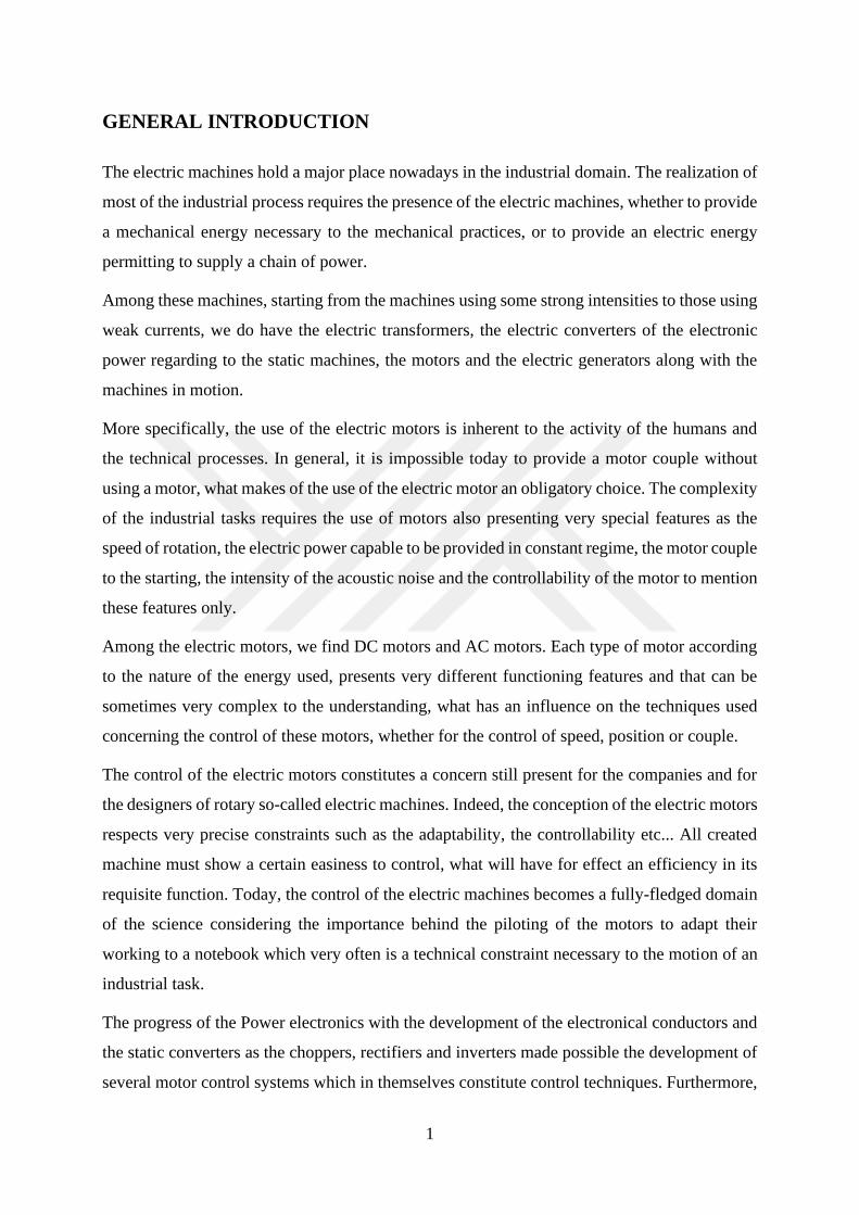
GENERAL INTRODUCTION
The electric machines hold a major place nowadays in the industrial domain. The realization of
most of the industrial process requires the presence of the electric machines, whether to provide
a mechanical energy necessary to the mechanical practices, or to provide an electric energy
permitting to supply a chain of power.
Among these machines, starting from the machines using some strong intensities to those using
weak currents, we do have the electric transformers, the electric converters of the electronic
power regarding to the static machines, the motors and the electric generators along with the
machines in motion.
More specifically, the use of the electric motors is inherent to the activity of the humans and
the technical processes. In general, it is impossible today to provide a motor couple without
using a motor, what makes of the use of the electric motor an obligatory choice. The complexity
of the industrial tasks requires the use of motors also presenting very special features as the
speed of rotation, the electric power capable to be provided in constant regime, the motor couple
to the starting, the intensity of the acoustic noise and the controllability of the motor to mention
these features only.
Among the electric motors, we find DC motors and AC motors. Each type of motor according
to the nature of the energy used, presents very different functioning features and that can be
sometimes very complex to the understanding, what has an influence on the techniques used
concerning the control of these motors, whether for the control of speed, position or couple.
The control of the electric motors constitutes a concern still present for the companies and for
the designers of rotary so-called electric machines. Indeed, the conception of the electric motors
respects very precise constraints such as the adaptability, the controllability etc... All created
machine must show a certain easiness to control, what will have for effect an efficiency in its
requisite function. Today, the control of the electric machines becomes a fully-fledged domain
of the science considering the importance behind the piloting of the motors to adapt their
working to a notebook which very often is a technical constraint necessary to the motion of an
industrial task.
The progress of the Power electronics with the development of the electronical conductors and
the static converters as the choppers, rectifiers and inverters made possible the development of
several motor control systems which in themselves constitute control techniques. Furthermore,
2
these techniques still present some limits in the realization of their requisite functions [1].
Beside the progress of the electronics in general, it is fundamental not to forget the contribution
of the software of simulations such as MATLAB/Simulink that permits in an environment
without risk to conduct tests of simulations of any type of electromechanical system. With the
contribution of the simulation software, the recent works developed in the domain of the control
of the electric motors do not only limit themselves. To present the techniques of control that
already exist, but they rather go deepening the theoretical and practical knowledge as well that
we have on the working of the electric machines and they search for the means to develop new
types of more efficient control while leaning on new concepts or on the limits and ways of
research of works developed by our predecessors.
This thesis is a work about the control of motors with direct current without brushes and more
specifically on a very particular technique of the control of these motors that is called control
without sensors. Two techniques allow to control the motors to alternating current without
brushes: the technique of control with sensors which uses some sensors as the sensors of
position and speed, Hall effects sensors, the sensors to variable reluctance [1] and the technique
of control without sensors that are based on other technologies to allow the control of the motor.
This thesis aims to present all these techniques of control and to make a deepening on the
technique of control without sensors while achieving a simulation.
Having been at first motors of secondary importance, today, considering the progress achieved
notably in electronics with the design of transistors, electronic cards, microprocessors, the
microcontrollers of various categories and the progress in theory of control. These motors
represent a big way toward applications till now unexpected as in the conception of the drones
[2] in the military domain, in the car, aviation and a lot of other applications. All it is due to the
features of these motors that are for example the high speed, an absent acoustic noise, a high
efficiency, a fast-dynamic response couple features satisfying.
Thus, to get an efficient functioning of the motor, it is necessary to understand it in depth to
know how better to control it, what requires passing necessarily by the stages of simulation that
permit to collect convenient data and to compare them to the theoretical data.
3
CHAPTER 1: PRESENTATION OF ELECTRIC MOTORS
An motor, in general, is a device capable of transforming any form of energy into mechanical
energy that will be used to produce a mechanical torque and which will most often aim to
generate a circular or linear motion. Thus, an electric motor is a machine whose role is to
convert electrical energy into mechanical energy. The electrical energy in this kind of system
constitutes the primary energy or power supply of the motor. Mechanical energy in turn
constitutes secondary energy or output energy, which allows any system to perform its required
function.
In summary, an electric motor is therefore a converter of electrical energy into mechanical
movement. The energy used by electric motors can be presented under two very well-known
aspects: the alternative nature that generates a system of voltage and alternating current and the
continuous nature that generates a system of continuous voltage and current. There are several
types of electric motors and each of them uses one or the other of these two kinds of electrical
energy for their power supply. Motors using alternating current are called AC motors and those
using continuous one is the family of DC motors.
1.1 Voltage and Current Systems
There are two major forms of electrical energy: Alternative energy and continuous energy. The
electrical energy is featured by two electrical quantities which are the voltage and the electric
current.
By definition, the electrical voltage characterizes the potential difference between any two
points and it is the necessary pressure that must be applied to the electric charge carriers to set
them in motion. This movement which can be characterized by a flow of electrons through a
conductor portion is the electric current.
The voltage is characterized by the symbol U or V and the current is characterized by the symbol
I. Depending on whether one is in AC or DC mode, the representation of voltages and currents
can become a little more specific taking into account the characteristics of the different current
regimes.

4
1.2 The Alternatives Magnitudes
Among the alternative electrical magnitudes, we find the AC voltage and the AC current which
are, with the frequency, the two most important magnitudes allowing to characterize an
alternating electric network.
Figure 1.1 Representation of alternative magnitudes.
1.2.1 The alternative tension
AC voltage is the voltage naturally produced by electrical voltage generation systems that are
usually power station. To generate an alternating voltage, the presence of an alternator is
necessary. The AC voltage is an instantaneous voltage, that is to say that its value varies over
time as Figure 1.1 shows a representation of the AC voltage.
a.The Alternator
The role of an alternator is to transform mechanical energy into electrical energy. As a whole,
an alternator is made up of an armature circuit and an excitation winding. The armature circuit
is constituted of three coils distributed on the stator spaced from each other by 120º. The
excitation winding is in turn a winding wound on the rotor and traversed by the DC excitation
current. It allows the creation of magnetic poles called rotors and the introduction of a given
flux in the magnetic circuit. In an alternator, the armature is on the stator and the inductor is on
the rotor. An alternator operates on the principle of the induced voltage, the excitation circuit
on the rotor is supplied by a DC voltage and therefore produces a fixed magnetic field. When
the rotor is driven by an external device, the constant magnetic field from the excitation circuit
is seen as a magnetic field when it periodically scans the coils spaced 120º apart on the stator.
5
These coils being traversed by a variable magnetic field induce sinusoidal electromotive forces
as shown in Figure 1.1, therefore variable in time and space, which in turn produce an
alternating voltage across the electric machine. This is how alternative energy is produced in a
conventional way.
1.2.2 The Alternating Current
After the alternator has produced AC voltages, and these voltages are present at these terminals,
the connection of a load that is of resistive, capacitive or inductive type will cause the alternator
to charge a current of some intensity in the load. Let us remember that the loads do not consume
voltages but rather alternating currents under a certain voltage. The current absorbed by the
load will be characterized by its intensity that is to say its value and by its frequency which
represents the number of round-trip performed by the latter between the load and the system of
production of the alternating voltage. The shape of the electric current is almost often similar
to that of the voltage. In resistive circuits, this is strictly the case because the voltage is
proportional to the current by the resistance factor.
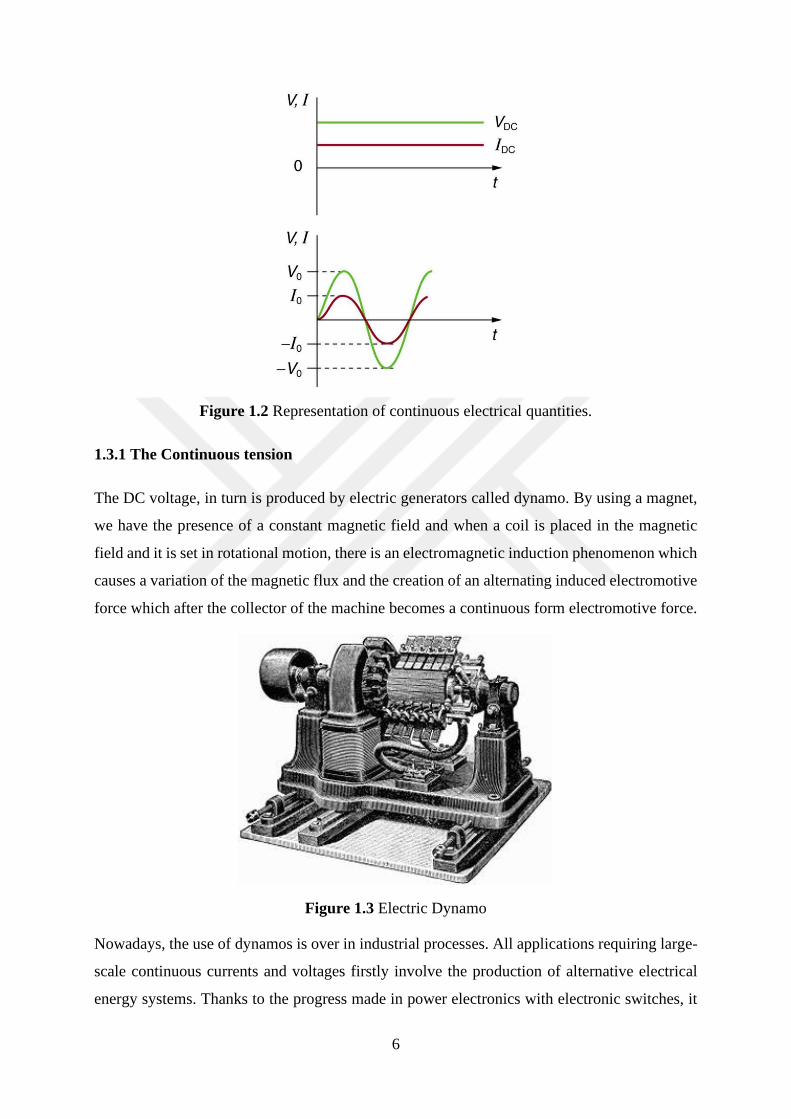
1.3 The Continuous Quantities
The Continuous quantities include DC voltage and DC current. Different quantities
representing alternative systems, voltage and direct current have no frequency. The peculiarity
of these quantities is that they have no instantaneous value as for the voltage and the alternating
current. Their numerical values and waveforms do not vary over time whether for a resistive,
capacitive or inductive circuit. Furthermore, the circuits supplied under this regime do not
provide much information transiently because the continuity of the electric current nullify the
derivatives of these circuits. The Figure 1.2 shows a representation of the continuous quantities
in a graph with a comparison to the alternative quantities. It is easy to make the difference and
to notice the difference of the waveforms of the different electrical quantities.
6
Figure 1.2 Representation of continuous electrical quantities.
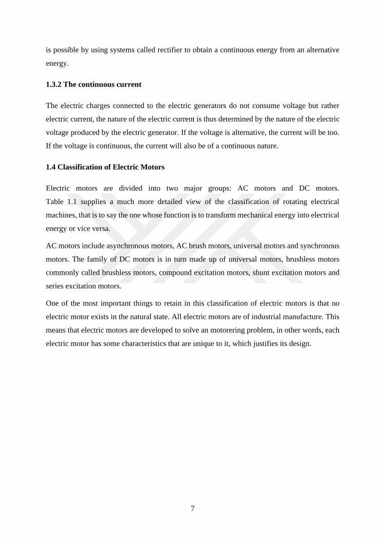
1.3.1 The Continuous tension
The DC voltage, in turn is produced by electric generators called dynamo. By using a magnet,
we have the presence of a constant magnetic field and when a coil is placed in the magnetic
field and it is set in rotational motion, there is an electromagnetic induction phenomenon which
causes a variation of the magnetic flux and the creation of an alternating induced electromotive
force which after the collector of the machine becomes a continuous form electromotive force.
Figure 1.3 Electric Dynamo
Nowadays, the use of dynamos is over in industrial processes. All applications requiring large-
scale continuous currents and voltages firstly involve the production of alternative electrical
energy systems. Thanks to the progress made in power electronics with electronic switches, it
7
is possible by using systems called rectifier to obtain a continuous energy from an alternative
energy.
1.3.2 The continuous current
The electric charges connected to the electric generators do not consume voltage but rather
electric current, the nature of the electric current is thus determined by the nature of the electric
voltage produced by the electric generator. If the voltage is alternative, the current will be too.
If the voltage is continuous, the current will also be of a continuous nature.
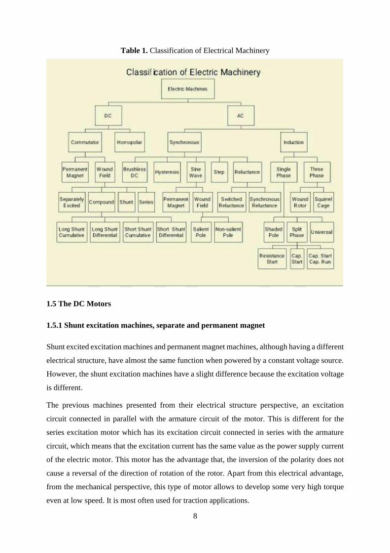
1.4 Classification of Electric Motors
Electric motors are divided into two major groups: AC motors and DC motors.
Table 1.1 supplies a much more detailed view of the classification of rotating electrical
machines, that is to say the one whose function is to transform mechanical energy into electrical
energy or vice versa.
AC motors include asynchronous motors, AC brush motors, universal motors and synchronous
motors. The family of DC motors is in turn made up of universal motors, brushless motors
commonly called brushless motors, compound excitation motors, shunt excitation motors and
series excitation motors.
One of the most important things to retain in this classification of electric motors is that no
electric motor exists in the natural state. All electric motors are of industrial manufacture. This
means that electric motors are developed to solve an motorering problem, in other words, each
electric motor has some characteristics that are unique to it, which justifies its design.
8
Table 1. Classification of Electrical Machinery
1.5 The DC Motors
1.5.1 Shunt excitation machines, separate and permanent magnet
Shunt excited excitation machines and permanent magnet machines, although having a different
electrical structure, have almost the same function when powered by a constant voltage source.
However, the shunt excitation machines have a slight difference because the excitation voltage
is different.
The previous machines presented from their electrical structure perspective, an excitation
circuit connected in parallel with the armature circuit of the motor. This is different for the
series excitation motor which has its excitation circuit connected in series with the armature
circuit, which means that the excitation current has the same value as the power supply current
of the electric motor. This motor has the advantage that, the inversion of the polarity does not
cause a reversal of the direction of rotation of the rotor. Apart from this electrical advantage,
from the mechanical perspective, this type of motor allows to develop some very high torque
even at low speed. It is most often used for traction applications.

9
The inconvenient with the series motor is that it must never start empty or it will run, it must
be loaded enough to be turned on.
Figure 1.4 Representation of shunt excitation machines, series and separate.
1.5.2 The Compound excitation machine
The compound excitation machine is a machine which combines the characteristics of a shunt
excitation machine and a series excitation machine.
Figure 1.5 Compound excitation machine

10
The shunt characteristic is considered when the machine is not running under load and the series
characteristic is completed when the motor is running under load. This kind of connection
allows us to obtain an undercurrent machine with series excitation but having the possibility to
operate without load thanks to the shunt connection which allows to fulfil additional function
compared to a pure machine with serial excitation or a pure machine shunt excitation.
1.5.3 The universal machine
The universal machine is a DC machine by its design but has the advantage of operating either
by being supplied with direct current or by being supplied by alternating current. The basic
equations of the DC machine are still applicable even in the case of AC voltage operation as
the nature of the voltage source. The universal motor behaves much like the serial motor which
can also be powered by an AC voltage.
Figure 1.6 The Universal Machine
These types of series motors, which are used as a universal motor, have their applications in
household appliances and machine tools, which require, at a frequency of 50 Hz, electrical
powers not exceeding 1 KW, rotational speeds not reaching 700 rpm and can be with the
variation of the supply voltage.
1.6 Alternate Current Motors
1.6.1 Induction machines
Induction machines are electrical machines that operate on the principle of electromagnetic
induction invented by Faraday. This law states that as soon as there is a magnetic field in a coil
or turn, this magnetic field induces an electromotive force called induced electromotive force.
If the circuit is closed, there will be a current in this circuit. The asynchronous motor, usually
an induction motor, is a motor in which the expected current in the rotor to produce the torque

11
is produced by the electromagnetic force induced on the rotor by the magnetic field generated
by the stator coil.
Figure 1.7 Representation of the induction machine
Unlike DC motors, the asynchronous motor does not have a switching system because there is
no electromechanical connection between the stator and the rotor. The result of such a system
is that the problems of motor wear or crash due to the deterioration of the brushes is eliminated.
Among the advantages, it can be noted that:
• The asynchronous motor can be robust and have very high power levels.
• It also requires little maintenance.
Regarding its disadvantages,
• There is a strong dependence between the load and the speed developed by the motor.
• A peak of current at ignition.
Synchronous machines are also another set of AC machine used in industry in very specific
applications. Contrary to asynchronous machines, synchronous machines have an operating
principle like asynchronous machines.
1.6.2 Synchronous machines
Synchronous machines are most often seen as alternators because they are widely used in the
production of electrical energy. Alternators are electrical machines that convert mechanical
energy into electrical energy. The property of these machines is that the rotor frequency is the
same as the frequency of the rotating field, so that in motor operation, the speed of rotation is
always equal to the synchronous speed. Thus, synchronous machine served for a long time to
privileged applications while the asynchronous machine was the industrial machine. Later, with
the developments of power electronics, we have a new perspective.
12
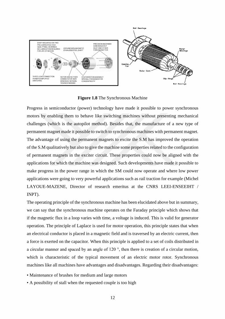
Figure 1.8 The Synchronous Machine
Progress in semiconductor (power) technology have made it possible to power synchronous
motors by enabling them to behave like switching machines without presenting mechanical
challenges (which is the autopilot method). Besides that, the manufacture of a new type of
permanent magnet made it possible to switch to synchronous machines with permanent magnet.
The advantage of using the permanent magnets to excite the S.M has improved the operation
of the S.M qualitatively but also to give the machine some properties related to the configuration
of permanent magnets in the exciter circuit. These properties could now be aligned with the
applications for which the machine was designed. Such developments have made it possible to
make progress in the power range in which the SM could now operate and where low power
applications were going to very powerful applications such as rail traction for example (Michel
LAYOUE-MAZENE, Director of research emeritus at the CNRS LEEI-ENSEEIHT /
INPT).
The operating principle of the synchronous machine has been elucidated above but in summary,
we can say that the synchronous machine operates on the Faraday principle which shows that
if the magnetic flux in a loop varies with time, a voltage is induced. This is valid for generator
operation. The principle of Laplace is used for motor operation, this principle states that when
an electrical conductor is placed in a magnetic field and is traversed by an electric current, then
a force is exerted on the capacitor. When this principle is applied to a set of coils distributed in
a circular manner and spaced by an angle of 120 °, then there is creation of a circular motion,
which is characteristic of the typical movement of an electric motor rotor. Synchronous
machines like all machines have advantages and disadvantages. Regarding their disadvantages:
• Maintenance of brushes for medium and large motors
• A possibility of stall when the requested couple is too high

13
• Need an additional device to allow start up on the network.
And as advantages:
• To create the same expectations as an asynchronous motor thanks to semiconductor
technology and the development of higher performance permanent with efficiency.
• To have a fixed speed whatever the load.
The high cost of synchronous machines means that they are not generally used as motors. They
are more used as alternators to produce electrical energy, in applications requiring a stable speed
depending on the load, and as special motors like brushless, stepper motors.
1.6.3 The universal motor
The universal motor as its name suggests is a type of electric motor that can operate by receiving
an alternative power supply as well as receiving a continuous power supply. The use of an
additional device to make these two types of power supply possible is not necessary. This
characteristic of the universal motor is due to its electrical design at the level of its armature
and its inductor. The design of the universal motor is based on that of the series excitation
motor. The goal in this electric motor being developed a motor torque, the direction of rotation
of a universal motor does not change even when (the polarity) of the current changes, which is
a great advantage in an AC voltage operation. In DC mode, it is necessary to reverse the polarity
of the armature or inductor which requires an additional device. Just like the series motor, the
universal motor is racing empty. The frequency of the current has no effect on the speed of
rotation. This rotational speed decreases as the load increases. A phi cosine and a bad
performance. A good start couple.
1.6.4 Variable reluctance machines
These machines also called Vernier machines are electromagnetic devices whose operating
principle is based on the minimization of reluctance. The reluctance is the equivalent of the
electrical resistance, the reluctance characterizes the ability of the magnetic circuit to oppose
the passage of the magnetic flux in the circuit. This principle, also called the electromagnet, is
the oldest method of converting electrical energy into mechanical energy.
14
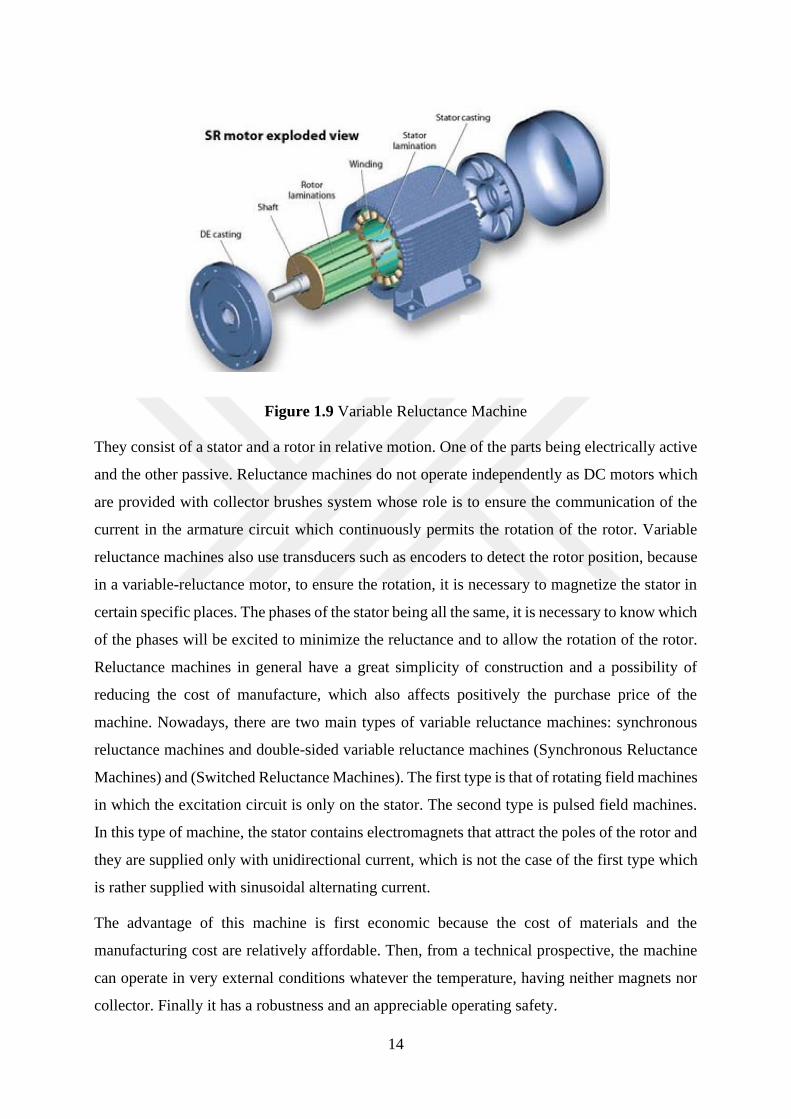
Figure 1.9 Variable Reluctance Machine
They consist of a stator and a rotor in relative motion. One of the parts being electrically active
and the other passive. Reluctance machines do not operate independently as DC motors which
are provided with collector brushes system whose role is to ensure the communication of the
current in the armature circuit which continuously permits the rotation of the rotor. Variable
reluctance machines also use transducers such as encoders to detect the rotor position, because
in a variable-reluctance motor, to ensure the rotation, it is necessary to magnetize the stator in
certain specific places. The phases of the stator being all the same, it is necessary to know which
of the phases will be excited to minimize the reluctance and to allow the rotation of the rotor.
Reluctance machines in general have a great simplicity of construction and a possibility of
reducing the cost of manufacture, which also affects positively the purchase price of the
machine. Nowadays, there are two main types of variable reluctance machines: synchronous
reluctance machines and double-sided variable reluctance machines (Synchronous Reluctance
Machines) and (Switched Reluctance Machines). The first type is that of rotating field machines
in which the excitation circuit is only on the stator. The second type is pulsed field machines.
In this type of machine, the stator contains electromagnets that attract the poles of the rotor and
they are supplied only with unidirectional current, which is not the case of the first type which
is rather supplied with sinusoidal alternating current.
The advantage of this machine is first economic because the cost of materials and the
manufacturing cost are relatively affordable. Then, from a technical prospective, the machine
can operate in very external conditions whatever the temperature, having neither magnets nor
collector. Finally it has a robustness and an appreciable operating safety.

15
With the progress made in improving the operation of these machines, whether those with
rotating field or pulsed field, the possible applications of these machines are first the household
appliances, the washing machines are a convincing example, in traction of electric vehicles, and
further applications in space and aeronautics.
1.6.5 Linear machines
To meet industrial applications, instead of using rotary motors, one rather use linear motors.
From the point of view of differences, there are no great differences between a linear motor and
a rotary motor except for their geometric configuration in space and in their operation. A linear
motor is an electric motor that has been unrolled and that now produces a linear force along the
length by installing an electromagnetic field displacement. It consists of a movable part, the
slider, comprising the magnets and a fixed part, the stator comprising the coil, the position
sensors, the thermal protectors.
Figure 1.10 Linear Motor
The operating principle of a linear motor is not different from that of a rotary motor. In this
principle of operation, we always find the same elements but with a different layout, this is the
case of coils and magnets. It aims to produce a force because the movement is linear and not
rotational. The linear displacement is under the effect of the electromagnetic force under no
other assistance.
The advantage of this type of motor is found in a simplification of hardware. The use of a rotary
motor coupled with other ancillary systems to produce linear motion is no longer necessary.
The disadvantage of linear machines is a very poor dissipation of heat produced by Joule effect.
Linear motors have a long life, synchronized movements, and a high dynamic. Its cost of use is
reduced, easy integration, a wide range force / speed.
16
Linear tubular motors are an excellent solution for replacing pneumatic cylinders. They are also
used in demanding industrial applications.
1.6.6 Hysteresis machines
As its name suggests, the hysteresis motor is an electromechanical energy converter that uses
the hysteresis phenomenon to generate torque at the rotor. This type of motor is not new but
has never known a large expansion. Not to mention that the magnetic hysteresis depends on the
material used, the cause of non-expansion of hysteresis motors is related to this. The efficient
operating characteristics of a hysteresis motor largely depend on the materials used.[5]
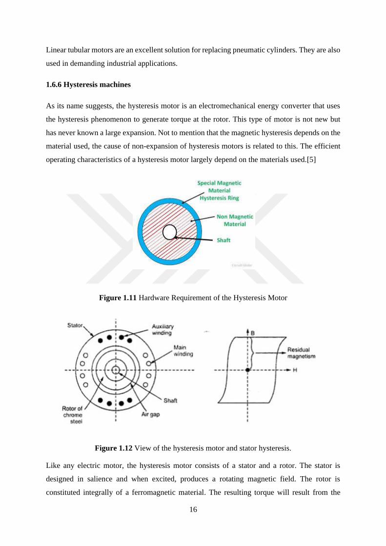
Figure 1.11 Hardware Requirement of the Hysteresis Motor
Figure 1.12 View of the hysteresis motor and stator hysteresis.
Like any electric motor, the hysteresis motor consists of a stator and a rotor. The stator is
designed in salience and when excited, produces a rotating magnetic field. The rotor is
constituted integrally of a ferromagnetic material. The resulting torque will result from the
17
interaction between the flux induced in the rotor and the magneto motive force.
The hysteresis motors have a smooth and quiet operation, and this due to the smooth surface of
the rotor, a constant torque, a moderate current at startup. The characteristic of the hysteresis
motor is that the rotor is very solid and consists of a material having a high degree of magnetic
hysteresis. The rotor is most often cylindrical. The most commonly wound stator receives
alternating currents necessary to produce the couple.
The disadvantage of the hysteresis motor is low efficiency, low developed power, oscillation
phenomena. There are two main types of hysteresis motors: cylindrical hysteresis motors that
have a cylindrical rotor, and either composed of a hysteretic material or a mixture with a core
formed of a non-hysteresis material.
Disk-shaped hysteresis motors. The space between the rotor and the stator is between the flat
side of the disk and the stator.[6]
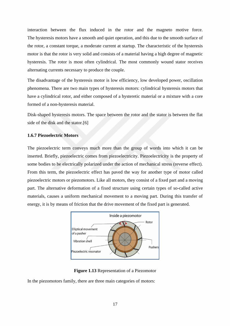
1.6.7 Piezoelectric Motors
The piezoelectric term conveys much more than the group of words into which it can be
inserted. Briefly, piezoelectric comes from piezoelectricity. Piezoelectricity is the property of
some bodies to be electrically polarized under the action of mechanical stress (reverse effect).
From this term, the piezoelectric effect has paved the way for another type of motor called
piezoelectric motors or piezomotors. Like all motors, they consist of a fixed part and a moving
part. The alternative deformation of a fixed structure using certain types of so-called active
materials, causes a uniform mechanical movement to a moving part. During this transfer of
energy, it is by means of friction that the drive movement of the fixed part is generated.
Figure 1.13 Representation of a Piezomotor
In the piezomotors family, there are three main categories of motors:
18
• Inchworn motors that use a principle close to the movement of an earthworm with a
succession of elongations / contractions interspersed with phases of hooking forward or
backward.
• Ultrasonic motors, which use piezoelectric materials to generate elliptical contact between
the rotor and the stator.
• Inertial motors that rely on alternations between slow and fast movements.
[Christian Belly, Inertial piezoelectric motors: designs, achievements, test-tests, December 08,
2011, France]
The advantages of piezomotors are numerous:
• Potentially high power density compared to a motor DC.
• Low noise level
• Simple manufacturing
• No electromagnetic disturbances
•High torque
Disadvantages:
• Need for high frequency power source
• High cost
• Complex power supply
Applications
Watches, micro robotics, automobile, Mems
1.6.8 Stepper motors
The steppers like any electric motor, electromechanical converters. Stepper motors are also part
of a class of electric motors that are called special motors in relation to their configuration or
their way of absorbing electric current from the power source. Stepper motors convert electrical
energy, in the form of an electrical pulse signal, into mechanical movement.[7]

19
Figure 1.14 Stepper motor
In its mechanical constitution, the stepper motor has a constitution close to the synchronous
machine. Its stator carries the windings, its rotor is provided with permanent magnets in the
case of so-called polarized or active structures. In the case of reluctance or passive structures,
the rotor consists of toothed ferromagnetic part. Both stator and rotor have salient poles.
Conventional power supplies are either AC or DC. These are power supplies whose flow of
electricity is constant like a stream of water flowing in a river. The stepper motor does not
receive power from such sources because it is powered by electrical impulses. To do this,
between the motor and the power source, elements are added to meet this requirement. There
is thus: a unit which generates the control pulses of the electronic switching contactors, a power
electronics system for switching, responsible for supplying the energy to the windings of the
motor at precise moments.
The principle of operation of the stepper motors is based on the switching of the windings of
the stator, the stator on which the phases are mounted. The electronic pulse is translated by a
sequencer. The sequencer in turn controls the electronic switches which according to their
opening times will distribute the polarities in the stator windings. Each switching generating
just one step, a continuous switching is necessary to generate several steps to create a rotational
movement equivalent to a complete revolution of the rotor. All configurations of the voltages
across the windings correspond to a displacement of the stable position of the rotor.
1.6.9 Brushless Motors
Brushless motors as under the abbreviation of BLDC Motors Brushless Direct Current Motors
that can be translated into French DC motors without brushes, come to solve the problems
related to energy consumption. For example, in the automotive industry where permanent
20
magnet and high-performance motors are required as necessary characteristics to allow optimal
operation of hybrid vehicles.
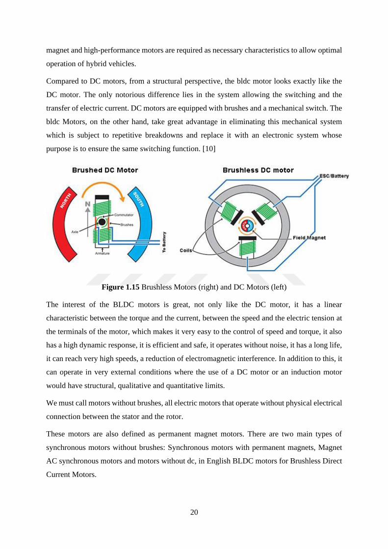
Compared to DC motors, from a structural perspective, the bldc motor looks exactly like the
DC motor. The only notorious difference lies in the system allowing the switching and the
transfer of electric current. DC motors are equipped with brushes and a mechanical switch. The
bldc Motors, on the other hand, take great advantage in eliminating this mechanical system
which is subject to repetitive breakdowns and replace it with an electronic system whose
purpose is to ensure the same switching function. [10]
Figure 1.15 Brushless Motors (right) and DC Motors (left)
The interest of the BLDC motors is great, not only like the DC motor, it has a linear
characteristic between the torque and the current, between the speed and the electric tension at
the terminals of the motor, which makes it very easy to the control of speed and torque, it also
has a high dynamic response, it is efficient and safe, it operates without noise, it has a long life,
it can reach very high speeds, a reduction of electromagnetic interference. In addition to this, it
can operate in very external conditions where the use of a DC motor or an induction motor
would have structural, qualitative and quantitative limits.
We must call motors without brushes, all electric motors that operate without physical electrical
connection between the stator and the rotor.
These motors are also defined as permanent magnet motors. There are two main types of
synchronous motors without brushes: Synchronous motors with permanent magnets, Magnet
AC synchronous motors and motors without dc, in English BLDC motors for Brushless Direct
Current Motors.

21
1.7 Conclusion
At the end of this first part, we can tell that we design by electric motors all motor which is able
to convert any electrical energy into mechanical energy. For how study, the motor converts the
electrical energy into a torque. The motion is circular and when the motor rotate its produces
any torque in order to make another system moving. In this kind of work. There are many sort
of electrical motors and each of them work with distinct characteristics.

22
CHAPTER 2: PRESENTATION OF BRUSHLESS MOTORS
2.1 Introduction
Brushless motors, as their name suggests in opposition to brush motors or ballast motors are a
type of electric motors without brushes or coals. DC motors in general are provided with a
system called brush-collector whose purpose is to provide electrical switching in the armature
circuit to allow rotation of the motor. The consequence and the disadvantage of this type of
electric motors are the rapid wear of the brushes, which requires periodic maintenance
necessary for the proper functioning of the machine.
A BLDC motor is a set of permanent magnets rotating in front of a set of electrical conductors
of continuous current during a rotation angle most often set at 60 degrees. Figure 2.1 is a
representation of an motor of a DC motor and a BLDC motor. The structural difference of the
two machines is easily visible. The absence of brushes on the BLDC motor requires the use of
a system to remedy it.[10]
Figure 2.1 From left to right, representation of a DC motor and a BLDC motor.
The current inside the electrical conductor must change polarity whenever the magnetic poles
pass. The role of switching ensures that the polarity change is made in such a way that the
torque remains unidirectional. Therefore, in a certain sense the change of polarity is called
switching.
Conceptually, a BLDC motor is not so different from a conventional DC motor. The significant
difference lies in the switching system used on both machines.
23
2.2 Definition of a Brushless Motor
A brushless motor is an electric motor that has no brush, no commutator and a lack of the
mechanical switching system as in conventional DC motors. From this name, we could list a
range of electric motors with this characteristic such as shared reluctance motors for example.
The particularity of the brushless motor is that in addition to bringing together these different
characteristics, the machine is a synchronous type machine [2]. This is to say that the speed of
the machine is the same as the speed of the rotating field. The speed is therefore related to the
frequency of the network and the number of poles of the machine as is the case of synchronous
machines.
N=𝑓×60
𝑃
f is the frequency of the network P the number of pole pair of the machine
N the speed of the machine which is also the speed of synchronism
We can define a motor by its name, but this is not completely true for brushless motors even if
they are types of motor without brushes. Under this name of brushless motor, there is a whole
range of electric motor with principles of operation very different from each other. We can still
agree that the function of the brush-collector system exists in another form in these types of
motor and that on this point, the operating principle of this system remains almost unchanged
scientifically.
Depending on the mode of operation, whether under a system of continuous voltages or a
system of alternating voltages, the brushless motors have very specific names. When operating
under a set of electric square waveform currents, they are called Brushless Direct Current
Motors (BLDC) and when they operate under a system of AC voltages, they are Permanent
Magnet Synchronous Motors (PMSM). They are all three-phase motors but the characteristics
of the signals that supply them are very different.[1]
2.2.1 Presentation of permanent magnet synchronous motors.
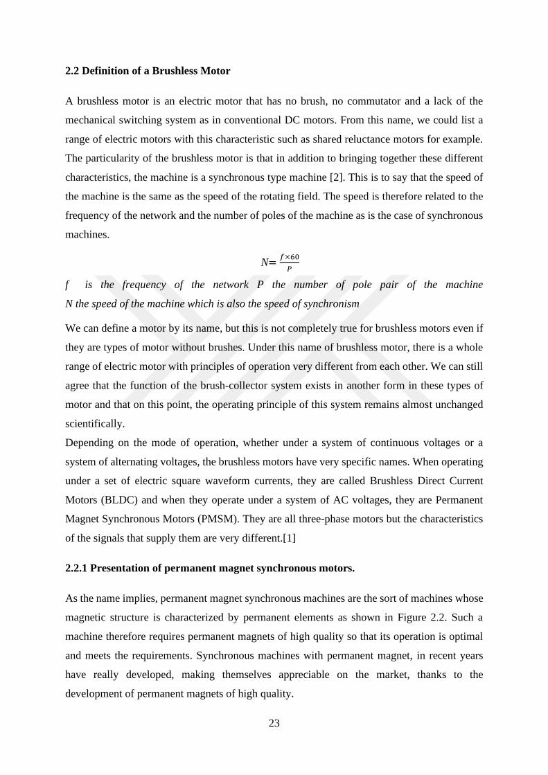
As the name implies, permanent magnet synchronous machines are the sort of machines whose
magnetic structure is characterized by permanent elements as shown in Figure 2.2. Such a
machine therefore requires permanent magnets of high quality so that its operation is optimal
and meets the requirements. Synchronous machines with permanent magnet, in recent years
have really developed, making themselves appreciable on the market, thanks to the
development of permanent magnets of high quality.
24
Figure 2.2 Permanent Magnet Synchronous Motor Diagram
Synchronous machines with permanent magnets can be very different from the point of view
of the disposition of the permanent magnets inside. Therefore, although having the same name,
the difference is seen in the benefits provided by the various provisions and applications that
result. In synchronous machines with permanent magnets the arrangement of the magnets is
made so that the flow distribution inside the machine is sinusoidal.
2.2.2 Structure of permanent magnet synchronous motors.
The structures most used in the design of synchronous machines are the radial structures, which
are ideal for surface mounting of the rotor. In this case, the air gap is uniform.
As mentioned above, advances in the design of sufficiently powerful permanent magnets have
made it possible to create electrical machines in which the excitation fields are produced by
permanent magnets and electromagnetic poles as shown in Figure 2.2. requiring electric
currents for their windings.
All this progress with advanced power transistor control has resulted in the replacement of
mechanical switches with electronic switches and the creation of electronically commutated
permanent magnet machines and intelligent control systems.[13]
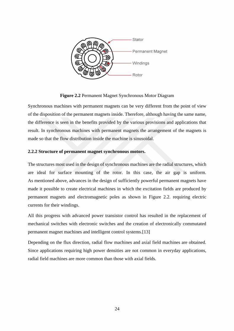
Depending on the flux direction, radial flow machines and axial field machines are obtained.
Since applications requiring high power densities are not common in everyday applications,
radial field machines are more common than those with axial fields.
25
Figure 2.3 Representation of a motor with axial flow (left) and radial flow (right)
Without going into details, it is necessary to remember that one of the most important elements
in synchronous machines with permanent magnets is the permanent magnet. The provision of
permanent magnets in the machine without changing the basic operation of the machine still
has an influence on the geometric structure of the latter and generates several types of
synchronous machines with permanent magnets. Among these types of machines, the following
may be mentioned in order of frequency of use:
•Those whose magnets are mounted on the surface of the outer periphery of the rotor
laminations.
•Those whose magnets are positioned in the grooves of the outer periphery of the rotor
laminations.
•Those whose magnets are placed in the middle of the rotor laminations and oriented in
the radial directions and along the circumference of the rotor.
•There is another type of permanent magnet synchronous motors whose role is to operate
at constant speed and whose purpose is to improve efficiency and power factor, this type of
motor has a cage structure of squirrel used to attenuate the oscillations of the rotor and to
provide the couple.
2.2.3 Principle of operation of permanent magnet synchronous motors
The power supply system for permanent magnet synchronous motors is a three-phase voltage
system. The permanent magnet synchronous motor contains three sets of coils that are
connected to the three phases of the power supply system. It is important to remind that the
voltage / current source is an alternative source.
26
The stator currents produce a magnetic flux rotating in the same way as the flux production in
a three-phase induction machine. [8] From this point of view, we can say that a synchronous
motor with permanent magnets is equivalent to an induction motor, with the difference that the
magnetic field in the gap is produced by a permanent magnet, one of the advantages of this
configuration is the fact that the magnetic field in the rotor does not change over time, being
produced by a permanent magnet so it is constant. Quantities such as flux, current and voltage
are represented by spatial vectors.[9]. One of the most important aspects in synchronous
permanent magnet motor technology is the electromotive force. The electromotive force in this
type of motor is directly proportional to the magnetic flux and velocity, which means that the
waveform of the electromotive force is the same as the flux density. Since the power currents
are sinusoidal, they are also sinusoidal in shape. On the other side, this electromotive force is
very important for controlling the machine. Synchronous machines with permanent magnets
are generally controlled by the technique called vector control or flow-oriented vector control.
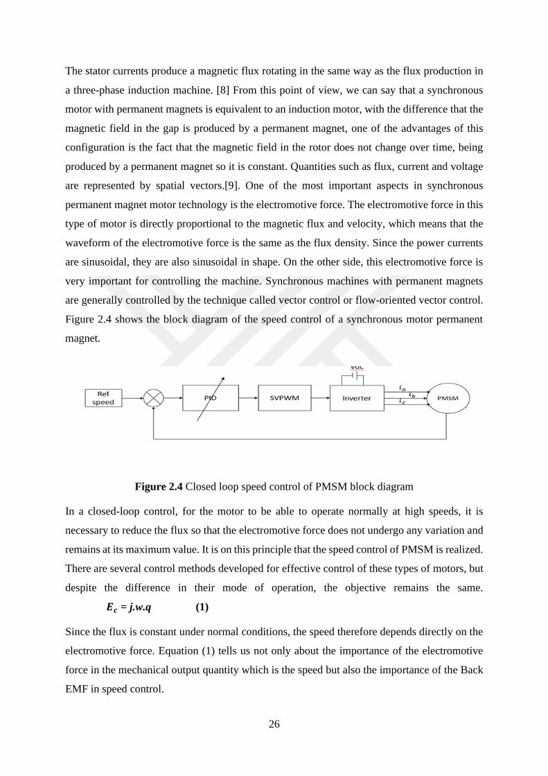
Figure 2.4 shows the block diagram of the speed control of a synchronous motor permanent
magnet.
Figure 2.4 Closed loop speed control of PMSM block diagram
In a closed-loop control, for the motor to be able to operate normally at high speeds, it is
necessary to reduce the flux so that the electromotive force does not undergo any variation and
remains at its maximum value. It is on this principle that the speed control of PMSM is realized.
There are several control methods developed for effective control of these types of motors, but
despite the difference in their mode of operation, the objective remains the same.
𝑬𝒄 = j.w.q (1)
Since the flux is constant under normal conditions, the speed therefore depends directly on the
electromotive force. Equation (1) tells us not only about the importance of the electromotive
force in the mechanical output quantity which is the speed but also the importance of the Back
EMF in speed control.
27
Permanent magnet synchronous machines being electronically switched; the position of the
rotor must always be known by a good electronic commutation. To estimate this position,
methods are used, and among them, one of the most famous is based on the estimation of the
value of the force against electromotive, which is induced in the stator coils.
2.3 Presentation of Direct Current Brushless Motors
2.3.1 Introduction
In the first part, we have highlighted the synchronous machines with permanent magnets, which
are also part of this family of electric motors without brush and whose switching of electric
current is provided by devices of the power electronics. These machines are powered by three-
phase sinusoidal electric currents, which is also the form of their induced electromotive forces.
Having a fairly simple control compared to other electronic machines such as induction motors
for example, and with the advantage of being able to operate in the most extreme conditions in
terms of space or temperature conditions, the synchronous machines with Electronically
switched permanent magnets are so present on the commercial market of rotating electrical
machinery.
Like the Switcher Reluctance Machines, the synchronous machines with permanent magnets,
to be adequately controlled, need to be provided with electronic sensors informing at all times
of the mechanical position of the rotor of the machine [15]. This information allows to know
which phase of the machine must be excited to ensure a successful electronic switching.
The most often used sensors, are Hall effect sensors mounted so that they face a fixed magnet
portion on the rotor and spaced from each other by an angle of 120 degrees. The advantage of
using Hall effect sensors is that they are not expensive. The disadvantage is that in a situation
in which a position check is made, the malfunction of a single sensor would lead to errors in
electronic switching on the one hand and material damage on the other hand. It is from such
considerations that another type of permanent magnet machine operating without brushes and
mechanical collector has been developed. These machines have an induced electromotive force
with a trapezoidal shape and are called Permanent Magnet Brushless Direct Current Machines
(PMBDCM) or Brushless Direct Current Machines (BLDC), which is the abbreviation we will
use.[13]
Thus, the advantages of BLDC machines are that, their control is not as complicated as
synchronous machines with permanent magnets. Also, the sensors to Hall effect is not necessary
28
to ensure electronic switching, which represents an advantage in terms of motor design as well
as costs. [10]
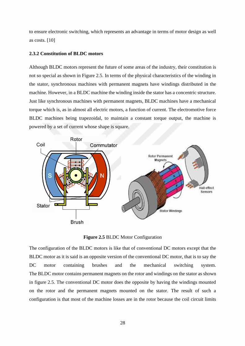
2.3.2 Constitution of BLDC motors
Although BLDC motors represent the future of some areas of the industry, their constitution is
not so special as shown in Figure 2.5. In terms of the physical characteristics of the winding in
the stator, synchronous machines with permanent magnets have windings distributed in the
machine. However, in a BLDC machine the winding inside the stator has a concentric structure.
Just like synchronous machines with permanent magnets, BLDC machines have a mechanical
torque which is, as in almost all electric motors, a function of current. The electromotive force
BLDC machines being trapezoidal, to maintain a constant torque output, the machine is
powered by a set of current whose shape is square.
Figure 2.5 BLDC Motor Configuration
The configuration of the BLDC motors is like that of conventional DC motors except that the
BLDC motor as it is said is an opposite version of the conventional DC motor, that is to say the
DC motor containing brushes and the mechanical switching system.
The BLDC motor contains permanent magnets on the rotor and windings on the stator as shown
in figure 2.5. The conventional DC motor does the opposite by having the windings mounted
on the rotor and the permanent magnets mounted on the stator. The result of such a
configuration is that most of the machine losses are in the rotor because the coil circuit limits
29
the heat transfer to the stator through the air gap, which also influences the density of the current
through the winding.
The advantage of the BLDC motor is to have an inverted structure of the conventional DC
motor, which positively allows the dissipation of the bulk of the losses in the stator.
The BLDC motors are synchronous machines, that the rotor speed is perfectly equal to the
synchronous speed 𝑛 of the rotating magnetic field of the stator. Not like asynchronous motors
in which there is a parameter called slip g, which translates the gap between the synchronous
speed and the actual speed of the stator n and which ultimately affects the speed that the
motor can reach, n= (1-g), the BLDC motors operate directly at the same speed as the rotating
stator field, which has a real advantage over the speed range in which the motor can operate.
BLDC motors are trapezoidally excited, they are excited by trapezoidal or rectangular shaped
signal sequences.
2.3.2.1 Brushless motor operating system
Brushless DC motors are mainly composed of three essential parts: the mechanical part that is
to say the motor itself, an inverter system and a system whose role is to determine the position
of the rotor, that is to say the motor shaft. [1]
2.3.2.2 The BLDC Motors
From the constitution of the BLDC motor perspective, as briefly explained above, a BLDC
motor looks like a DC motor in reverse. That is to say that the elements that form the rotor
finally constitute the stator of the machine and vice versa. The BLDC motor is defined by the
position of the permanent magnets on the rotor. The ways in which permanent magnets are
mounted on the surface or inside the rotor define the characteristics of the operation of the motor
as well as the different areas of application.
The most known rotor configurations are: The rotor magnet surface whose magnets are
mounted radially or with a circumferential configuration.
The spike-type magnet rotor also has magnets mounted in a circumference configuration, with
the only difference that this configuration provides an asynchronous start torque. The interior
magnet rotor has a radial configuration of permanent magnets.[1]
The construction of BLDC motors is like the induction motor and the DC motor. As far as the
operating principle is concerned, it is much closer to the conventional DC motor. Any electric
30
motor has the function of transforming electrical energy into mechanical energy to produce a
motor torque capable of causing any set in a mechanical movement whether rotation or linear.
To do so, it is provided with two parts that are the stator which is the static part and the rotor,
the moving part of the motor.
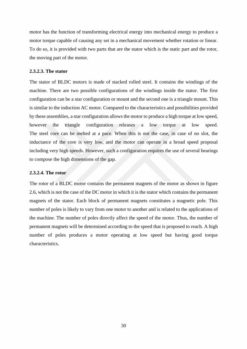
2.3.2.3. The stator
The stator of BLDC motors is made of stacked rolled steel. It contains the windings of the
machine. There are two possible configurations of the windings inside the stator. The first
configuration can be a star configuration or mount and the second one is a triangle mount. This
is similar to the induction AC motor. Compared to the characteristics and possibilities provided
by these assemblies, a star configuration allows the motor to produce a high torque at low speed,
however the triangle configuration releases a low torque at low speed.
The steel core can be melted at a pace. When this is not the case, in case of no slot, the
inductance of the core is very low, and the motor can operate in a broad speed proposal
including very high speeds. However, such a configuration requires the use of several bearings
to compose the high dimensions of the gap.
2.3.2.4. The rotor
The rotor of a BLDC motor contains the permanent magnets of the motor as shown in figure
2.6, which is not the case of the DC motor in which it is the stator which contains the permanent
magnets of the stator. Each block of permanent magnets constitutes a magnetic pole. This
number of poles is likely to vary from one motor to another and is related to the applications of
the machine. The number of poles directly affect the speed of the motor. Thus, the number of
permanent magnets will be determined according to the speed that is proposed to reach. A high
number of poles produces a motor operating at low speed but having good torque
characteristics.

31
Figure 2.6 Rotor and permanent magnets representation in front of the stator
A reduced number allows the motor to operate at high speed at the cost of a couple that must
be monitored regularly.
2.3.2.5 Inverter systems
Inverter systems would never have been possible without the progress of power electronics.
Power electronics is seen as a branch of electronics in which the reflections focus on the
development of electronic switches or systems containing increasingly powerful electronic
switches capable of carrying currents of high intensities of up to one kilo or the mega amp.
The use of such switches makes it possible to control the flow of current through an electric
circuit and consequently supply receivers with a certain predetermined method. All electrical
charges do not consume electricity in the same way [16]. Power generated by power plants
supplies conventional electrical receivers with a constant and predetermined frequency. The
use of electronic switches, by adjusting their switching frequency, allows certain special
receivers such as BLDC motors to be powered at a frequency different from the frequency of
the electrical networks. The operation of these switches also makes it possible to create a
waveform of the signals used to power the machine.
2.4 Comparison between the BLDC Motor and the DC Motor
In a DC motor, there is a brush-collector system which provides switching, that is to say the
change of polarity of the electric current. The collector is a rotating collector placed on the rotor,
and the polarity of the flux is intimately related to the change of polarity of the electric current.
When the electrical conductor passes through the flux, it automatically changes polarity when

32
the polarity of the flux changes. The role of the collector is to synchronize the two polarities so
that they change at the same time.
The change of polarity is necessary for the operation of the motor, so it remains essential
regardless of the motor configuration. Since the flaw of the conventional DC motor is in
mechanical switching, in a BLDC motor, the mechanical switching system is replaced by
another switching system, which has the consequence of increasing the motor performance and
reducing the risks of breakdowns.[1]
This switching system is a set of transistors, electronic switches of the power electronics
ensuring the polarity change of the electric current depending on the position of the rotor.
Between the electronic switches and the rotor is a system responsible for determining the
position of the rotor and controlling the opening or closing of the transistors to produce the
switching. In this type of switching, each frequency cycle f, the current changes polarity twice
in one phase.
The particularities are that the electromotive force has a trapezoidal shape, the direct current
remains constant during a switching interval, with a constant torque. In order to keep the torque
constant, which is the role of switching, the current switches to another phase at the end of each
switching period. This operation takes place during a conduction with square signals, which is
the form of the signals of the BLDC motors. Permanent magnet synchronous motors have had
conduction in which the waveform is sinusoidal as discussed earlier in the presentational section
of the PMSMs.
The BLDC motor shows some interesting operating characteristics relating to its synchronism.
Switching in the stator coils is closely related to the instantaneous position of the rotor, which
means that the motor cannot lose synchronism easily even when the machine operates beyond
the stall torque, hence the name of the machine auto-synchronous.
2.5 Domain of use of BLDC Motors
Due to their characteristics and known developments in the field of power electronics, BLDC
motors have seen their popularity increase throughout time. The technologies invented with the
use of inverters have allowed to power efficiently an motor which originally is a kind of
continuous current machine.[13]
The possibility of BLDC motors to operate in constraining places and the known advances in
the design of increasingly efficient electronic sensors have created a motor that would be called
33
electronics and whose advantages compete with DC motors and with induction machines. All
this has caused the demand for this type of machine to increase. For example, in the Chinese
market the sales volume of 10Kw BLDC machines increased from 78 million in 2004 to 133
million in 2008 and this in 4 years only in China [13].
BLDC motors have a long service life, a high efficiency, a good torque-speed characteristic and
make little noise.
•BLDC motors also find their application in the automotive industry with their power
density which is very high, better than other types of known motors; good speed performance,
good heat dissipation, which is very important for the automotive industry. In a context where
an emphasis is placed on system design that can efficiently use energy, BLDC motors position
themselves as considerable alternatives. [28]
•In aerospace, BLDCs have been used in the design of mini drones for example, the size
of drones requires the use of small motors with good performance in terms of power density
and low noise.
In addition, there are other examples such as hydraulic transmission devices that are being
replaced by systems driven by electric motors. In this area too, there will be a strong presence
of BLDC motors due to the advantage of their small size.
•As with the variable reluctance motors that are used in household appliances, BLDC
motors also have a similar operation to reluctance machines. Variable, and find great
satisfaction to be used in home appliances. Their benefits are in the low noise, good energy
management and high reliability.
• BLDC motors are also used in office electronics such as hard disks, magnetic heads,
CD / DVD players....
For a long time, DC motors were used for general and specific applications, not necessarily
because they had exceptional characteristics but rather because there were no substitutes for
this type of motor. The growing demands in industry and the disadvantages caused by the
structure of this type of motor have led scientists to design electric motors without brush-
collector system to reduce the risk of breakdowns and allow by their design the operation of
this type of motor in very restrictive conditions. It is from these considerations that the brushless
motors were created.

34
2.6 Inverter Systems Switches of BLDC Motors.
Electronic switches are semiconductors that control voltage, current, power, and frequency
efficiently with the use of control systems such as microprocessors, integrated circuits, and
integrator circuits large-scale.
The electronic switches used in the control of BLDC motors are diodes, MOSFET transistors
and IGBT transistors.
2.6.1 The diodes.
A diode is known as an electronic device for driving the electric current under certain
conditions. Firstly, it is a unidirectional switch, it lets the current flow in one direction. In
addition to this, it contains two terminals including an anode and a cathode. When the potential
of the anode is higher than that of the cathode, it lets the current flow. There is a voltage at
which the diode starts to drive. This voltage is defined as the threshold voltage and it depends
on the nature of the semiconductor used to design the diode. A diode contains a junction called
PN, FIG. 2.8, a zone in which the doping varies abruptly from a P-doping to an N-doping. A
depletion zone is created when the two junctions are implemented in contact. This zone arises
because the electrons and the holes migrate on both sides and release a weak zone in charge
carriers. The more the voltage applied on either side of the Pet N junctions reaches the voltage
increases, the more the depletion zone becomes short and its resistance decreases which allows
the passage of the electric current. The most used semiconductor is silicon and its threshold
voltage is 0.7V. If the potential of the anode is greater than or equal to 0.7V, the diode conducts
and is said to be in the state; passing. When the voltage is below 0.7V the diode automatically
stops driving and is said to be the off state and the current through the diode will cancel. At the
terminals of a diode, when it leads the voltage is 0V.
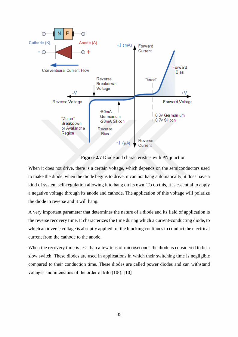
35
Figure 2.7 Diode and characteristics with PN junction
When it does not drive, there is a certain voltage, which depends on the semiconductors used
to make the diode, when the diode begins to drive, it can not hang automatically, it does have a
kind of system self-regulation allowing it to hang on its own. To do this, it is essential to apply
a negative voltage through its anode and cathode. The application of this voltage will polarize
the diode in reverse and it will hang.
A very important parameter that determines the nature of a diode and its field of application is
the reverse recovery time. It characterizes the time during which a current-conducting diode, to
which an inverse voltage is abruptly applied for the blocking continues to conduct the electrical
current from the cathode to the anode.
When the recovery time is less than a few tens of microseconds the diode is considered to be a
slow switch. These diodes are used in applications in which their switching time is negligible
compared to their conduction time. These diodes are called power diodes and can withstand
voltages and intensities of the order of kilo (10³). [10]
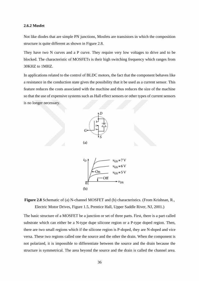
36
2.6.2 Mosfet
Not like diodes that are simple PN junctions, Mosfets are transistors in which the composition
structure is quite different as shown in Figure 2.8.
They have two N curves and a P curve. They require very low voltages to drive and to be
blocked. The characteristic of MOSFETs is their high switching frequency which ranges from
30KHZ to 1MHZ.
In applications related to the control of BLDC motors, the fact that the component behaves like
a resistance in the conduction state gives the possibility that it be used as a current sensor. This
feature reduces the costs associated with the machine and thus reduces the size of the machine
so that the use of expensive systems such as Hall effect sensors or other types of current sensors
is no longer necessary.
Figure 2.8 Schematic of (a) N-channel MOSFET and (b) characteristics. (From Krishnan, R.,
Electric Motor Drives, Figure 1.5, Prentice Hall, Upper Saddle River, NJ, 2001.)
The basic structure of a MOSFET be a junction or set of three parts. First, there is a part called
substrate which can either be a N-type dupe silicone region or a P-type doped region. Then,
there are two small regions which if the silicone region is P-doped, they are N-doped and vice
versa. These two regions called one the source and the other the drain. When the component is
not polarized, it is impossible to differentiate between the source and the drain because the
structure is symmetrical. The area beyond the source and the drain is called the channel area.
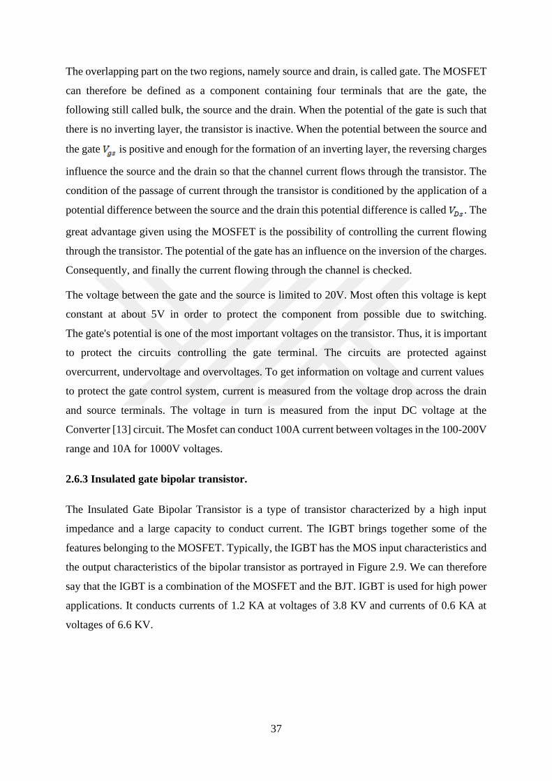
37
The overlapping part on the two regions, namely source and drain, is called gate. The MOSFET
can therefore be defined as a component containing four terminals that are the gate, the
following still called bulk, the source and the drain. When the potential of the gate is such that
there is no inverting layer, the transistor is inactive. When the potential between the source and
the gate is positive and enough for the formation of an inverting layer, the reversing charges
influence the source and the drain so that the channel current flows through the transistor. The
condition of the passage of current through the transistor is conditioned by the application of a
potential difference between the source and the drain this potential difference is called . The
great advantage given using the MOSFET is the possibility of controlling the current flowing
through the transistor. The potential of the gate has an influence on the inversion of the charges.
Consequently, and finally the current flowing through the channel is checked.
The voltage between the gate and the source is limited to 20V. Most often this voltage is kept
constant at about 5V in order to protect the component from possible due to switching.
The gate's potential is one of the most important voltages on the transistor. Thus, it is important
to protect the circuits controlling the gate terminal. The circuits are protected against
overcurrent, undervoltage and overvoltages. To get information on voltage and current values
to protect the gate control system, current is measured from the voltage drop across the drain
and source terminals. The voltage in turn is measured from the input DC voltage at the
Converter [13] circuit. The Mosfet can conduct 100A current between voltages in the 100-200V
range and 10A for 1000V voltages.
2.6.3 Insulated gate bipolar transistor.
The Insulated Gate Bipolar Transistor is a type of transistor characterized by a high input
impedance and a large capacity to conduct current. The IGBT brings together some of the
features belonging to the MOSFET. Typically, the IGBT has the MOS input characteristics and
the output characteristics of the bipolar transistor as portrayed in Figure 2.9. We can therefore
say that the IGBT is a combination of the MOSFET and the BJT. IGBT is used for high power
applications. It conducts currents of 1.2 KA at voltages of 3.8 KV and currents of 0.6 KA at
voltages of 6.6 KV.
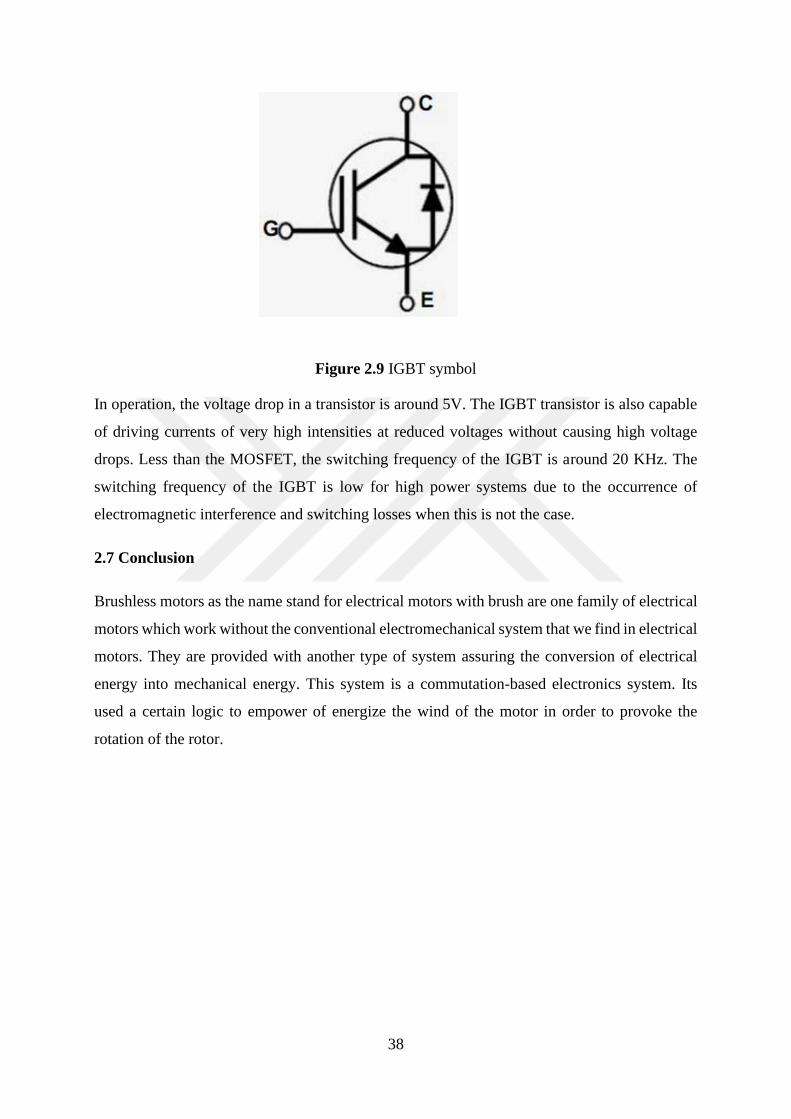
38
Figure 2.9 IGBT symbol
In operation, the voltage drop in a transistor is around 5V. The IGBT transistor is also capable
of driving currents of very high intensities at reduced voltages without causing high voltage
drops. Less than the MOSFET, the switching frequency of the IGBT is around 20 KHz. The
switching frequency of the IGBT is low for high power systems due to the occurrence of
electromagnetic interference and switching losses when this is not the case.
2.7 Conclusion
Brushless motors as the name stand for electrical motors with brush are one family of electrical
motors which work without the conventional electromechanical system that we find in electrical
motors. They are provided with another type of system assuring the conversion of electrical
energy into mechanical energy. This system is a commutation-based electronics system. Its
used a certain logic to empower of energize the wind of the motor in order to provoke the
rotation of the rotor.

39
CHAPTER 3: BRUSHLESS MOTOR CONTROL
3.1 Introduction
Electric motors are machines, they are part of human achievements that can not technically
have autonomy without the intervention of humans. Any machine is first designed for a need,
then to perform a required function that solves the problem. Nowadays, there is a variety of
electrical machines and they all meet specific specifications.
To adapt a machine to the needs of the user, the machine must first be designed to meet the
scientific and technical requirements of the user. These requirements may include speed, motor
torque, internal and external characteristics of the machine depending on certain parameters,
the current consumed by the machine and the voltage system under which the machine should
operate. The fact that machines do not have natural brains means that important notions of
automatic are considered. One of the particularly interesting information is the controllability
of the machine. Beyond the technical characteristics of the machine, it must be controlled by
control devices that can be of various kinds.
Currently, in industry, it is impossible to find completely autonomous machines or that fits
perfectly in industrial systems. To succeed in making work an electric machine and more
precisely an motor in industrial processing sets, it is important to be able to control the machine.
The elements that may be necessary for the control are the output and input indicators. That is
to say, the machine must be able to react in adequacy with the state of the system in which it is
installed. To force the machine to react so we use control techniques. [2]
Servo chains are interesting examples to better explain the concepts of control of electrical
machines. To do this, let us take an example of a speed control of a DC motor as shown in
Figure 3.1. Rotation speed is one of the most important output parameters to control on an
industrial motor. A motor developing a very low speed may not be able to lift a load as a motor
developing too high a speed can easily get off if the load is too heavy. Otherwise, it may just
be necessary for the speed to be constant. In order to obtain the desired characteristics of the
speed, it is necessary to have a margin of action on the parameters responsible for the variation
of the speed of the motor. In a DC motor, the electromotive force is proportional to the actual
speed developed by the motor. [3]
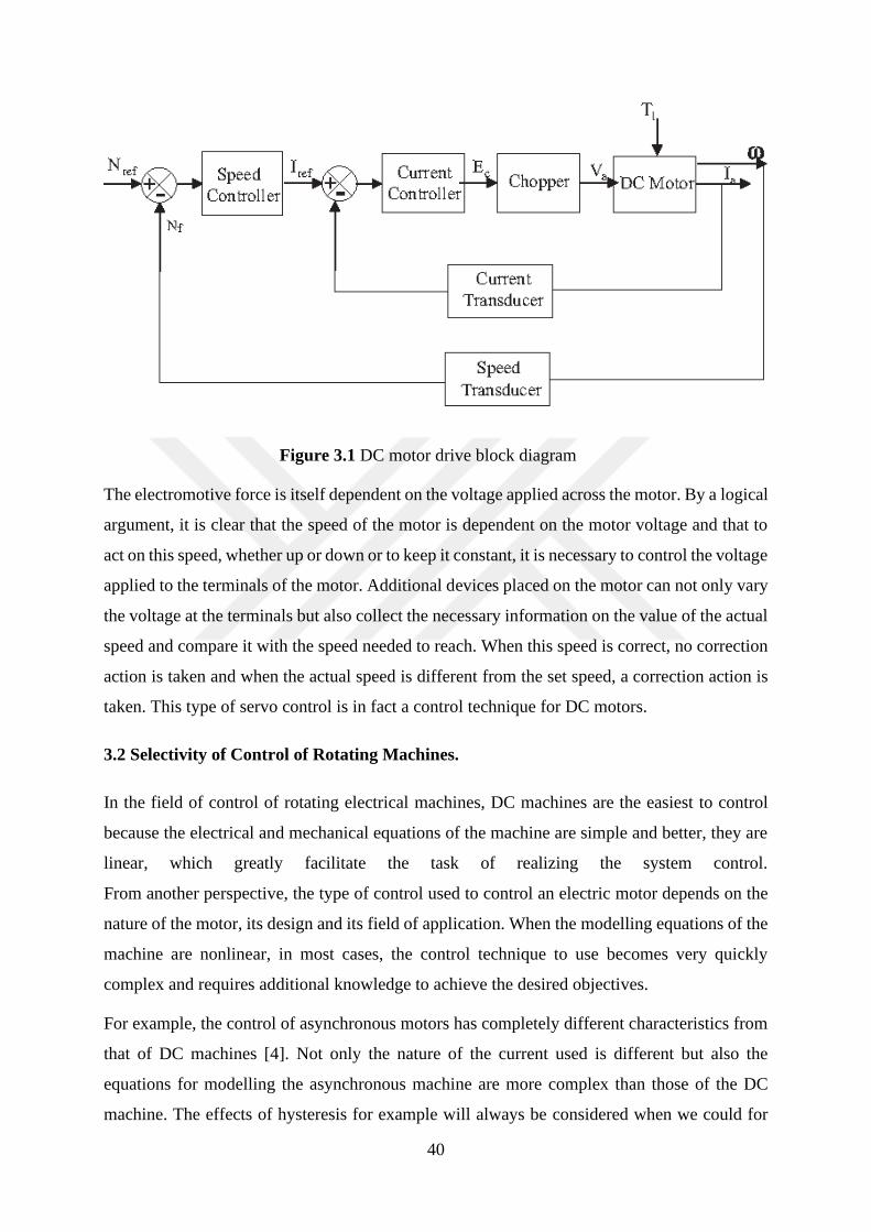
40
Figure 3.1 DC motor drive block diagram
The electromotive force is itself dependent on the voltage applied across the motor. By a logical
argument, it is clear that the speed of the motor is dependent on the motor voltage and that to
act on this speed, whether up or down or to keep it constant, it is necessary to control the voltage
applied to the terminals of the motor. Additional devices placed on the motor can not only vary
the voltage at the terminals but also collect the necessary information on the value of the actual
speed and compare it with the speed needed to reach. When this speed is correct, no correction
action is taken and when the actual speed is different from the set speed, a correction action is
taken. This type of servo control is in fact a control technique for DC motors.
3.2 Selectivity of Control of Rotating Machines.
In the field of control of rotating electrical machines, DC machines are the easiest to control
because the electrical and mechanical equations of the machine are simple and better, they are
linear, which greatly facilitate the task of realizing the system control.
From another perspective, the type of control used to control an electric motor depends on the
nature of the motor, its design and its field of application. When the modelling equations of the
machine are nonlinear, in most cases, the control technique to use becomes very quickly
complex and requires additional knowledge to achieve the desired objectives.
For example, the control of asynchronous motors has completely different characteristics from
that of DC machines [4]. Not only the nature of the current used is different but also the
equations for modelling the asynchronous machine are more complex than those of the DC
machine. The effects of hysteresis for example will always be considered when we could for

41
some needs neglect them in a DC machine. The vector control of the asynchronous machine or
the flow-oriented control makes it possible to transform the typical equations of the
asynchronous machine into an equation system qualitatively similar to the equations of the DC
machine. This gives us an idea of the price of the actions required to be able to simplify the
understanding of the inner workings of an asynchronous machine in order to better control it.
As a reminder, the vector control was proposed in 1971 by the scholars Blashchke and Hass.
This is a method that controls the speed variation of three-phase motors. It allows to transform
the three-phase stator currents of AC electric motors into two orthogonal components which
can be considered as vectors that allow one and the other to adjust the magnetic flux of the
motor and to adjust the motor torque. [4]
The magnetic flux and the torque which, before the transformation, were completely connected
are then separated after transformation, which qualitatively transforms the operation of the AC
three-phase machine by making it like that of the DC machine. Indeed, the Park transformation
allows to define a benchmark to understand and model, after study, the AC machine. The model
thus obtained is like that of the DC machine. The various methods of controlling permanent
magnet machines without brushes and electronically switched are logical but do not provide the
same results with respect to the quality of the control. Moreover, the nature of the machine can
quickly make the control very complicated.
There are two main methods for controlling permanent magnet brushless motors. A method
called sensor control uses a series of sensors to obtain information needed to control the motor.
The other method, which is sensorless control, uses another series of electronics to control the
motor without using mechanical sensors.
The control using sensors is much more used for synchronous machines with permanent
magnets. However, sensorless control is in turn much more used for so-called BLDC machines.
In the following lines, we will briefly present the control technique using the sensors and we
will deepen into the technique that does not use sensors and more specifically in the field of
BLDC machines.
3.3 Control Methods Using Sensor Technology
3.3.1 Hall effect sensors
The most common technique using sensors to control BLDC motors is the one using Hall effect
sensors.
42
The Hall effect sensors, of the scientist Edwin Hall, are sensors that operate on the principle of
Hall effect theory established in 1879. This theory shows that when an electrical conductor is
placed in an electric field, the magnetic field tends to exert a transverse force on the mobile
electric charge carriers of the conductor, causing them to propagate on one side of the electrical
conductor. The result of this magnetic effect is that on one side of the electrical conductor, an
accumulation of electric charges in motion is obtained while on the reverse side of the
conductor, there is rather an accumulation of immobile electric charges. The Hall effect says
that at this moment, there appears a voltage between the two sides of the driver. The
particularity and the advantage of this voltage is that it can be measured. With regard to sensor
control of BLDC motors, much like variable reluctance machines, their rotation requires
information on the position of the rotor in order to be carried out properly. The information of
the position of the rotor informs which winding is to be excited. In their case, the position of
the rotor is determined by Hall effect sensors integrated in the stator. [11]
3.3.1.1 Operation of Hall Effect Sensors
The motor being a three-phase machine, to determine the position of the rotor, three Hall effect
sensors are placed on the stationary part of the machine, in the stator. When the rotor is rotating
and its magnetic poles pass near the sensors, the latter react by giving signals to signify the
passage of the magnetic poles and their natures. The information collected by the different
sensors translate the position of the rotor and the exact sequence of switching is determined, at
which time the corresponding winding of the stator is excited by an electric current.
The position of the Hall effect sensors on the stator is so important because a bad position of
the latter would lead to an error in the determination of the position of the rotor. The electronic
controller controlling the opening and closing phases of semiconductors works closely with
Hall effect sensors. In its principle of operation and according to the configuration of the motor,
the commutation must allow only the conduction of two phases of the motor during 60 electrical
degrees of rotation of the rotor. The Hall effect sensors are therefore mounted in a range of 60
degrees electrical relative to each other. [12]. The most interesting controls for electric motors
are the speed, position and torque controls. In the speed control for example, as seen above, it
is possible to control the motor by the control technique using sensors (Hall effect for example).
Beyond this method, there are still other methods that also allow to obtain satisfactory results.
Among these methods, a particularly interesting one is the PID control.
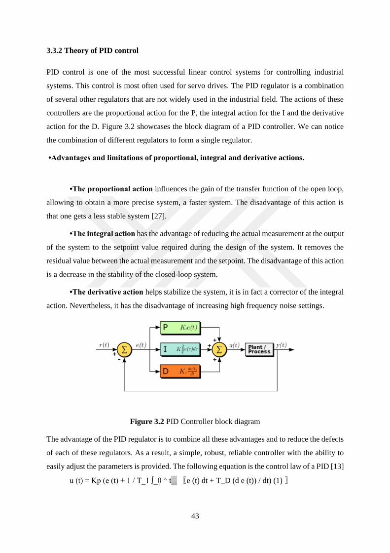
43
3.3.2 Theory of PID control
PID control is one of the most successful linear control systems for controlling industrial
systems. This control is most often used for servo drives. The PID regulator is a combination
of several other regulators that are not widely used in the industrial field. The actions of these
controllers are the proportional action for the P, the integral action for the I and the derivative
action for the D. Figure 3.2 showcases the block diagram of a PID controller. We can notice
the combination of different regulators to form a single regulator.
•Advantages and limitations of proportional, integral and derivative actions.
•The proportional action influences the gain of the transfer function of the open loop,
allowing to obtain a more precise system, a faster system. The disadvantage of this action is
that one gets a less stable system [27].
•The integral action has the advantage of reducing the actual measurement at the output
of the system to the setpoint value required during the design of the system. It removes the
residual value between the actual measurement and the setpoint. The disadvantage of this action
is a decrease in the stability of the closed-loop system.
•The derivative action helps stabilize the system, it is in fact a corrector of the integral
action. Nevertheless, it has the disadvantage of increasing high frequency noise settings.
Figure 3.2 PID Controller block diagram
The advantage of the PID regulator is to combine all these advantages and to reduce the defects
of each of these regulators. As a result, a simple, robust, reliable controller with the ability to
easily adjust the parameters is provided. The following equation is the control law of a PID [13]
u (t) = Kp (e (t) + 1 / T_1 ∫_0 ^ t▒ 〖e (t) dt + T_D (d e (t)) / dt) (1) 〗
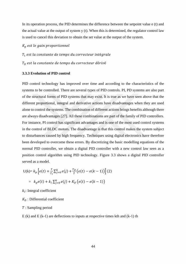
44
In its operation process, the PID determines the difference between the setpoint value e (t) and
the actual value at the output of system y (t). When this is determined, the regulator control law
is used to cancel this deviation to obtain the set value at the output of the system.
𝐾𝑝 𝑒𝑠𝑡 𝑙𝑒 𝑔𝑎𝑖𝑛 𝑝𝑟𝑜𝑝𝑜𝑟𝑡𝑖𝑜𝑛𝑛𝑒𝑙
𝑇1 𝑒𝑠𝑡 𝑙𝑎 𝑐𝑜𝑛𝑠𝑡𝑎𝑛𝑡𝑒 𝑑𝑒 𝑡𝑒𝑚𝑝𝑠 𝑑𝑢 𝑐𝑜𝑟𝑟𝑒𝑐𝑡𝑒𝑢𝑟 𝑖𝑛𝑡é𝑔𝑟𝑎𝑙𝑒
𝑇𝐷 𝑒𝑠𝑡 𝑙𝑎 𝑐𝑜𝑛𝑠𝑡𝑎𝑛𝑡𝑒 𝑑𝑒 𝑡𝑒𝑚𝑝𝑠 𝑑𝑢 𝑐𝑜𝑟𝑟𝑒𝑐𝑡𝑒𝑢𝑟 𝑑é𝑟𝑖𝑣é
3.3.3 Evolution of PID control
PID control technology has improved over time and according to the characteristics of the
systems to be controlled. There are several types of PID controls. PI, PD systems are also part
of the structural forms of PID systems that may exist. It is true as we have seen above that the
different proportional, integral and derivative actions have disadvantages when they are used
alone to control the systems. The combination of different actions brings benefits although there
are always disadvantages [27]. All these combinations are part of the family of PID controllers.
For instance, PI control has significant advantages and is one of the most used control systems
in the control of BLDC motors. The disadvantage is that this control makes the system subject
to disturbances caused by high frequency. Techniques using digital electronics have therefore
been developed to overcome these errors. By discretizing the basic modelling equations of the
normal PID controller, we obtain a digital PID controller with a new control law seen as a
position control algorithm using PID technology. Figure 3.3 shows a digital PID controller
served as a model.
U(k)= 𝑘𝑝 [𝑒(𝑡) +𝑇
𝑇𝐼∑ 𝑒(𝑗) +𝑘𝑗=0
𝑇𝐷
𝑇(𝑒(𝑡) − 𝑒(𝑘 − 1))] (2)
= 𝑘𝑝𝑒(𝑡) + 𝑘𝐼 ∑ 𝑒(𝑗) + 𝐾𝐷𝑘𝑗=0 (𝑒(𝑡) − 𝑒(𝑘 − 1))
𝑘𝐼: Integral coefficient
𝐾𝐷 : Differential coefficient
𝑇 : Sampling period
E (k) and E (k-1) are deflections to inputs at respective times kth and (k-1) th
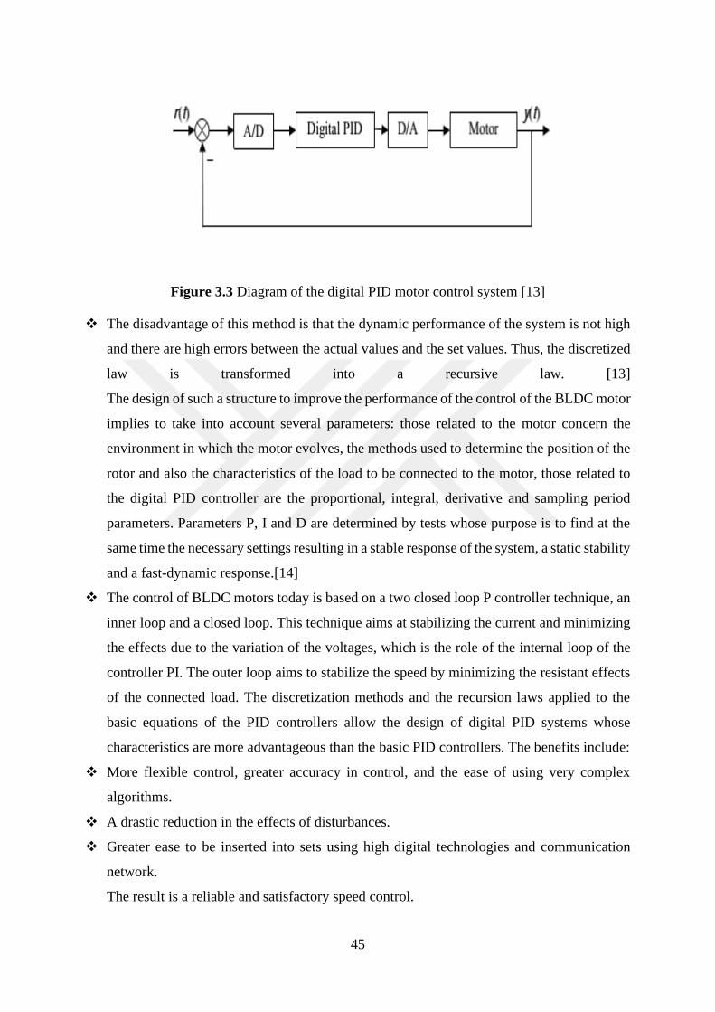
45
Figure 3.3 Diagram of the digital PID motor control system [13]
❖ The disadvantage of this method is that the dynamic performance of the system is not high
and there are high errors between the actual values and the set values. Thus, the discretized
law is transformed into a recursive law. [13]
The design of such a structure to improve the performance of the control of the BLDC motor
implies to take into account several parameters: those related to the motor concern the
environment in which the motor evolves, the methods used to determine the position of the
rotor and also the characteristics of the load to be connected to the motor, those related to
the digital PID controller are the proportional, integral, derivative and sampling period
parameters. Parameters P, I and D are determined by tests whose purpose is to find at the
same time the necessary settings resulting in a stable response of the system, a static stability
and a fast-dynamic response.[14]
❖ The control of BLDC motors today is based on a two closed loop P controller technique, an
inner loop and a closed loop. This technique aims at stabilizing the current and minimizing
the effects due to the variation of the voltages, which is the role of the internal loop of the
controller PI. The outer loop aims to stabilize the speed by minimizing the resistant effects
of the connected load. The discretization methods and the recursion laws applied to the
basic equations of the PID controllers allow the design of digital PID systems whose
characteristics are more advantageous than the basic PID controllers. The benefits include:
❖ More flexible control, greater accuracy in control, and the ease of using very complex
algorithms.
❖ A drastic reduction in the effects of disturbances.
❖ Greater ease to be inserted into sets using high digital technologies and communication
network.
The result is a reliable and satisfactory speed control.
46
However, the development of several other kinds of PID not only warns that it is necessary to
look for the PID required for the control application but also that each PID still has advantages
and disadvantages that future PID seeks to correct [14].
3.3.4. Smart controllers
As we have seen above, the search for optimal control of BLDC motors has led to the creation
of several control techniques which up to now have their share of advantages and their set of
disadvantages as well.
To continue to improve control of BLDC motors, methods using intelligent controllers, which
were originally part of the control methods used in biology and immune system studies, are
beginning to gain prominence in the domain of control of BLDC motors. [14] In essence,
intelligent controllers use methods derived from the theory of automatic control and theories of
artificial intelligence among which we can find genetic algorithms, fuzzy logic, networks of
artificial neurons. These control methods are not based on mathematical methods exclusively
but on logical approaches that sometimes consider subjective concepts such as uncertainty
concepts, environmental constraints that can be very complex to evaluate mathematically or to
model. The fuzzy logic for example takes into account all these considerations, which constitute
the limitations of the control systems usually used. The systems usually used rely too much on
the mathematical modelling, which constitutes the point of reference of the control initiated.
For instance, the control method with Hall effect sensor very strongly depends on the
mathematical model. [14] Although it may be a logic capable of solving the problems
encountered in the conventional control of BLDC electric motors. The control systems using
the fuzzy logic present a great difficulty in being able to adapt to the new information while the
control systems based on neural networks have the ability to adapt to new rules and thus prove
to be solutions for solving problems related to mathematical models of the system (problems of
uncertainty and disruption). Genetic algorithms have demonstrated an ability to improve the
capabilities of control systems improving the results obtained during the controls.
Just as the P, I, D structures that have disadvantages but become very powerful when in
combination, for example, PI, PD, PID, intelligent controllers have remarkable capabilities
when operating in combination. For example, a combination of fuzzy control and artificial
neural net produces a fuzzy neural network controller with the ability to reason better and learn,
while in a separate way, a fuzzy controller learns less well and reasons better when a controller-
neural network does the opposite. The combination of the two logics of control would logically
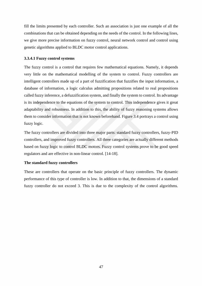
47
fill the limits presented by each controller. Such an association is just one example of all the
combinations that can be obtained depending on the needs of the control. In the following lines,
we give more precise information on fuzzy control, neural network control and control using
genetic algorithms applied to BLDC motor control applications.
3.3.4.1 Fuzzy control systems
The fuzzy control is a control that requires few mathematical equations. Namely, it depends
very little on the mathematical modelling of the system to control. Fuzzy controllers are
intelligent controllers made up of a part of fuzzification that fuzzifies the input information, a
database of information, a logic calculus admitting propositions related to real propositions
called fuzzy inference, a defuzzification system, and finally the system to control. Its advantage
is its independence to the equations of the system to control. This independence gives it great
adaptability and robustness. In addition to this, the ability of fuzzy reasoning systems allows
them to consider information that is not known beforehand. Figure 3.4 portrays a control using
fuzzy logic.
The fuzzy controllers are divided into three major parts: standard fuzzy controllers, fuzzy-PID
controllers, and improved fuzzy controllers. All three categories are actually different methods
based on fuzzy logic to control BLDC motors. Fuzzy control systems prove to be good speed
regulators and are effective in non-linear control. [14-18].
The standard fuzzy controllers
These are controllers that operate on the basic principle of fuzzy controllers. The dynamic
performance of this type of controller is low. In addition to that, the dimensions of a standard
fuzzy controller do not exceed 3. This is due to the complexity of the control algorithms.
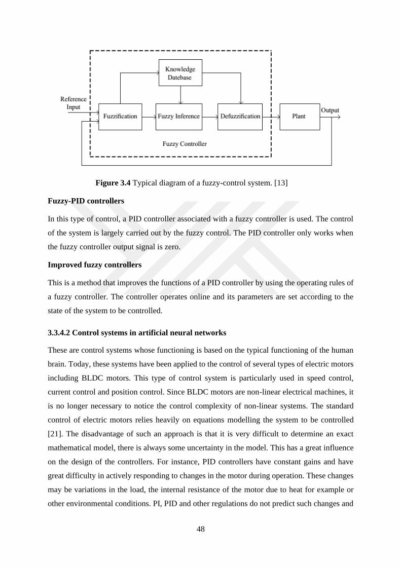
48
Figure 3.4 Typical diagram of a fuzzy-control system. [13]
Fuzzy-PID controllers
In this type of control, a PID controller associated with a fuzzy controller is used. The control
of the system is largely carried out by the fuzzy control. The PID controller only works when
the fuzzy controller output signal is zero.
Improved fuzzy controllers
This is a method that improves the functions of a PID controller by using the operating rules of
a fuzzy controller. The controller operates online and its parameters are set according to the
state of the system to be controlled.
3.3.4.2 Control systems in artificial neural networks
These are control systems whose functioning is based on the typical functioning of the human
brain. Today, these systems have been applied to the control of several types of electric motors
including BLDC motors. This type of control system is particularly used in speed control,
current control and position control. Since BLDC motors are non-linear electrical machines, it
is no longer necessary to notice the control complexity of non-linear systems. The standard
control of electric motors relies heavily on equations modelling the system to be controlled
[21]. The disadvantage of such an approach is that it is very difficult to determine an exact
mathematical model, there is always some uncertainty in the model. This has a great influence
on the design of the controllers. For instance, PID controllers have constant gains and have
great difficulty in actively responding to changes in the motor during operation. These changes
may be variations in the load, the internal resistance of the motor due to heat for example or
other environmental conditions. PI, PID and other regulations do not predict such changes and
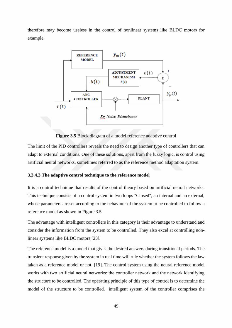
49
therefore may become useless in the control of nonlinear systems like BLDC motors for
example.
Figure 3.5 Block diagram of a model reference adaptive control
The limit of the PID controllers reveals the need to design another type of controllers that can
adapt to external conditions. One of these solutions, apart from the fuzzy logic, is control using
artificial neural networks, sometimes referred to as the reference method adaptation system.
3.3.4.3 The adaptive control technique to the reference model
It is a control technique that results of the control theory based on artificial neural networks.
This technique consists of a control system in two loops "Closed", an internal and an external,
whose parameters are set according to the behaviour of the system to be controlled to follow a
reference model as shown in Figure 3.5.
The advantage with intelligent controllers in this category is their advantage to understand and
consider the information from the system to be controlled. They also excel at controlling non-
linear systems like BLDC motors [23].
The reference model is a model that gives the desired answers during transitional periods. The
transient response given by the system in real time will rule whether the system follows the law
taken as a reference model or not. [19]. The control system using the neural reference model
works with two artificial neural networks: the controller network and the network identifying
the structure to be controlled. The operating principle of this type of control is to determine the
model of the structure to be controlled. intelligent system of the controller comprises the
50
structure to be controlled so that the output signal of the latter follows the output signal of the
reference model.
3.3.4.4 Optimized control system using genetic algorithms
Genetic algorithms used in BLDC motor control applications provide much more control.
Generally, they are used in speed control applications requiring high accuracy. The genetic
algorithms consider the different operating states of the system to be controlled and improve
the control rules of the BLDC motor. [20-24]
Figure 3.6 Fuzzy controller coupled with a genetic optimization algorithm
Being used to improve control systems as shown in Figure 3.6, they are used to improve control
systems using fuzzy logic. In response to the non-linear nature of BLDC motors, fuzzy
controllers coupled with genetic algorithms improve the performance of the controller thus
created. The performances that this association of control logics bring are among others the
stability and the quality of the control which are quite satisfactory.
3.3.5 Determination of the performance of fuzzy controllers
The fuzzy controller's performance is determined by the controller's ability to reason in real
situation and this ability depends on the fuzzy controller programming, how it is designed to
reason, to respond to emerging situations in the environment.
Two important parameters determine the performance of a fuzzy controller: these are the scale
and quantization factors. [13]
In general, the scale factor and the quantization factor are fixed and therefore can not vary in
real time. This feature limits the performance of the controller and makes it less able to adapt
to changes in the characteristics of the system to be controlled. To solve this problem, we insert
51
in the fuzzy controller's control rules some analytic expressions to obtain coefficients that can
be set or correct when the BLDC motor is running.
To enable this task, factors corresponding to the various errors returned by the scale factor and
the quantization factor are used. The quantization error factor 𝐾𝑒1and quantization change error
factor 𝐾𝑒𝑐 make it possible to adapt the fuzzy controller to the change of the system. Finally,
the scale factor 𝐾𝑢 transforms the values from the fuzzy control so that they are converted for
use on the system to be controlled [24].
All these three parameters 𝐾𝑒1, 𝐾𝑒𝑐 and 𝐾𝑢 have an influence on the response of the system,
which is closely related to the values of these different parameters, which is why their choice
is judicious and to consequences on the system.
The choice of the parameter values is done considering the fact that :
First, 𝐾𝑒1 has an influence on the speed of response of the system. The larger 𝐾𝑒1is, the faster
the system reacts. The smaller 𝐾𝑒1is, the slower the system convergence rate will be. However,
too much 𝐾𝑒1would cause large overruns.
• Similarly, 𝐾𝑒𝑐 influences the response of the system. More 𝐾𝑒𝑐is large more the
response of the system is slow. The smaller 𝐾𝑒𝑐 is, the greater is the risk of oscillations.
• Finally, 𝐾𝑢 is the most influential factor on the system's response. 𝐾𝑢, is the proportional
gain of the controller. A great value of 𝐾𝑢would also have a great influence on the speed
of the system to respond. A large value of 𝐾𝑢 makes the system faster. A low value
generates strong oscillations of the system.
The adjustment of these parameters can only be done in a precise way in theory. In practice,
two parameters are determined and the third is determined according to the responses of the
system. We therefore carry out tests to determine its value which appears only as an equilibrium
value[24].
After determining the parameters, we obtain a system with a satisfactory response, satisfactory
static and dynamic performance of the fuzzy controller. The only problem is that the parameters
𝐾𝑒1 , 𝐾𝑒𝑐and 𝐾𝑢 are never satisfying in the long run taking into account the fact that they are
static. Thus, it is necessary to adjust them online using a method that takes into account the
static error of the dynamic system.
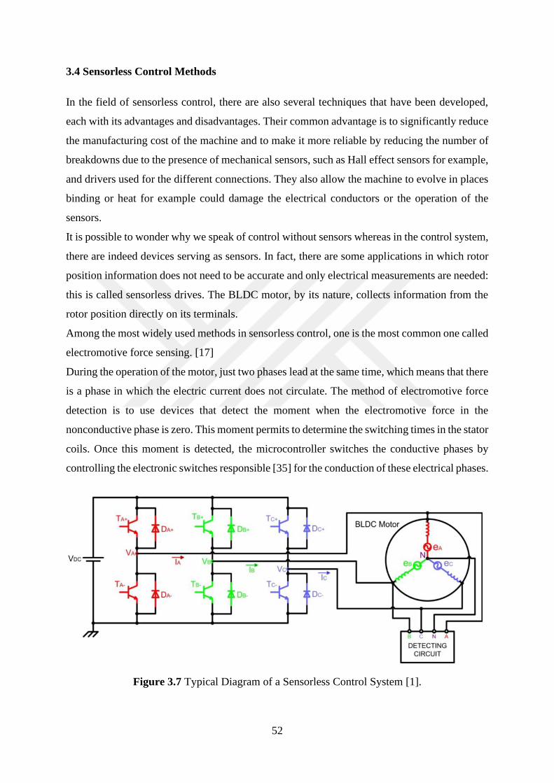
52
3.4 Sensorless Control Methods
In the field of sensorless control, there are also several techniques that have been developed,
each with its advantages and disadvantages. Their common advantage is to significantly reduce
the manufacturing cost of the machine and to make it more reliable by reducing the number of
breakdowns due to the presence of mechanical sensors, such as Hall effect sensors for example,
and drivers used for the different connections. They also allow the machine to evolve in places
binding or heat for example could damage the electrical conductors or the operation of the
sensors.
It is possible to wonder why we speak of control without sensors whereas in the control system,
there are indeed devices serving as sensors. In fact, there are some applications in which rotor
position information does not need to be accurate and only electrical measurements are needed:
this is called sensorless drives. The BLDC motor, by its nature, collects information from the
rotor position directly on its terminals.
Among the most widely used methods in sensorless control, one is the most common one called
electromotive force sensing. [17]
During the operation of the motor, just two phases lead at the same time, which means that there
is a phase in which the electric current does not circulate. The method of electromotive force
detection is to use devices that detect the moment when the electromotive force in the
nonconductive phase is zero. This moment permits to determine the switching times in the stator
coils. Once this moment is detected, the microcontroller switches the conductive phases by
controlling the electronic switches responsible [35] for the conduction of these electrical phases.
Figure 3.7 Typical Diagram of a Sensorless Control System [1].
53
In sum, two phases always conduct to the same moment and the non-driving phase is used to
detect the electromotive force. This is cyclically ensured so that the motor is always powered.
Figure 3.7 shows the typical diagram of BLDC motor training by the control method without.
It can be discerned that the complete system consists of an inverter acting as a switching system,
the brushless motor itself, and a system for detecting the position of the rotor.
There are two methods for detecting electromotive force in a BLDC motor. A method called
direct electromotive force detection method and another method called indirect method of
electromotive force detection. In the following lines we will talk about these methods.
The direct method of electromotive force detection is to detect the moment when the
electromotive force of the non-conducting phase vanishes. This method is also called zero
detection, electromotive force against. It is classified in two parts which are:
• Zero-crossing detection (ZCD) also known as Terminal Voltage Sensing
• The PWM control strategy.
3.4.1 Terminal Voltage Sensing
This technique as mentioned above is to detect the moment during which the electromotive
force against the inactive phase is cancelled. The detection of this instant by an appropriate
system triggers a timer whose end of the count generates the following switching sequence.
Two phases are used to obtain the information concerning the electromotive force against. As
a result, the microcontroller accurately determines the instant of phase switching within the
stator. Not to mention that the role of switching is to produce a constant and maximum torque,
in the case of BLDC motors, it is necessary that the electromotive force and the conductive
phases of the electric current are aligned, and also the inverter system must switch all the
electrical 60 degrees as soon as the zero of the electromotive force is detected.
Figure 3.8 shows the different phases of the motor when it is in operation, it can be seen that
the moments when the electromotive force goes through zero and the switching times do not
occur at the same time. Typically, they take place after a certain time corresponding to 30
electrical degrees.

54
Figure 3.8 Phase current switching and Detection Zero Crossing Points of the EMF Back [1]
The commutations generated by the inverter system produce harmonics. The amplitudes of the
different harmonics being different. It is necessary to eliminate the highest harmonics because
they have negative consequences on the operation of the machine. For this purpose, low pass
filters are placed on each phase of the stator to eliminate the highest harmonics. The
consequence of the use of these filters has a negative impact on the speed range of the machine
which finally can not operate at high speed [1].
Studies show that the electromotive force reaches its zero when the voltage of the phase that
does not conduct the electric current is equal to half of the DC voltage applied to the motor.
[20] Concerning the strategy to obtain the zero of the electromotive force, the low pass filters
can be replaced by a pulse width modulation system (PWM). One of the first benefits of this
integration is the elimination of the negative effect that low pass filters have on the motor.
By using a PWM strategy, it is no longer necessary to create a virtual neutral point to extract
the electromotive force [1].
3.4.2 Third harmonic integration method
In this method of detecting the instant of switching, it is assumed that the motor contains
electrical phases connected in a star. Then, the third harmonic of the electromotive force is used
to determine the different switching times. The technique is based on the fact that if the
55
distribution of the flux in the gap is trapezoidal; then the sum of the voltages of the different
phases equilibrium and the harmonics such as the fifth and the seventh harmonic are also
cancelled, which is not the case of the third harmonic which keeps a constant phase. The
advantage of using the third harmonic is that there is a reduction of filtering, the delays caused
by the filters have no problem and the machine operates at high speeds. This means that the
speed range in which the machine can operate is relatively large.
The third harmonic method makes it possible to easily estimate the position of the rotor flux,
which favors switching and allows more efficient and appropriate current control.
Also, in comparison with the electromotive force zero detection method, in which it is very
difficult to determine the zero crossing of the low speed electromotive force, the third harmonic
can be detected at low speed. [29]
In addition, the components of the harmonics of the air gap of the machine depending on the
rotor magnets and the stator winding, in the case where the phases of the inductance are
constant, whatever the position of the rotor, it is possible to measure the third harmonic of the
electromotive force. Referring to FIG. 3.7, the sum 𝑉𝑆𝑈𝑀 of the voltages of the different phases
containing only the third harmonic and its multiples, the voltage which contains the third
harmonic is filtered and integrated in order to estimate the leakage flux of the rotor. The leak
flow estimate provides the necessary information to ensure switching when needed.
𝑉𝑆𝑈𝑀 = 𝑉𝐴𝑁 + 𝑉𝐵𝑁 + 𝑉𝐶𝑁 ≈ (𝑒𝐴 + 𝑒𝐵 + 𝑒𝐶) ≈ 3𝐸3 sin(3𝑤𝑒 . 𝑡)
⋌𝑟3= ∫𝑉𝑆𝑈𝑀𝑑𝑡
These two expressions give us, for 𝑉𝑆𝑈𝑀, the expression in which we obtain the measurement
of the third harmonic and the moments of commutation. Studies show that the third harmonic
component of rotor flux ⋌𝑟3vanishes at 60 degrees electrical and that this corresponds exactly
to the moment at which the switching must be carried out in the stator.
In order to detect the component of the third harmonic in the case of an operation of BLDC
motors without sensors, the third harmonic component is extracted by exploiting the voltage
between S and the midpoint H of the DC bus. [30] Of course, an open-loop start procedure is
necessarily used and the stator resistors are connected in a triangle to allow the third harmonic
component to be detected.
Improvements have been made on this technique. For example, an air compressor needs to start
with a fairly small torque. When starting in reduced torque, the switching has a delay time
during high speed operation. For this purpose, a Phase Locked Loop (PLL) is used in which
56
freewheel diodes conduct just after switching and an inverter system is responsible for reversing
the voltage measured across the stator. The integration of the third harmonic of the
electromotive force instead of the voltage across the stator therefore allows to reduce the
switching delays and thus improve the performance of the motor.
The advantage of this technique is that even at low speed, it is possible to detect the signal of
the third harmonic and trigger switching, which is not possible when using the force zero
detection method against electromotive. Indeed, the electromotive force against being
proportional to the speed, a low speed generates risks of the false zero of the force against the
electromotive, which makes the detection very delicate at low speed.
Applications using this method are in the domain in which high speed operation is required.
The ease of implementation of the PLL system, the robustness of the system and low sensitivity
to the production of electrical noise are great advantages. The technique can also be used in
systems that require these benefits as an operation requirement.
The method of indirect electromotive force detection comes to correct the problems
encountered when using the direct electromotive force detection method. In the following lines,
these methods are explained in detail.
3.4.3 Terminal Current Sensing
This technique uses power transistors and freewheel diodes mounted in antiparallel. The
conduction state of the freewheel diodes informs about the passage of electric current in a phase.
This current comes from the electromotive force produced in the motor winding. Thus, when
the current conducting phase is active, the conduction signal of the phase is collected at the
level of the power transistors. In this technique, the line current of the motor must be in phase
with the signal of the electromotive force, in this way the produced torque is maximum [1]. It
is necessary that the switching action be performed every 60 electrical degrees. Although,
requiring a start-up circuit to indicate when switching is required for start-up, the advantage
with this technique is that the rotor position can be easily detected in any speed range, whatever
at high speed, the conduction condition of the diode on the negative side is that 𝑒𝑐<0.
The disadvantage is that the technique does not work on a machine whose stator winding
inductions do not vary with the position of the rotor. This condition is achieved with the SMPM
Motors but impossible with the IPM Motors.
One of the disadvantages is that it is impossible to detect the position of the rotor when the
motor is stopped. The current of the open phase comes from the electromotive forces, which

57
requires an adequate starting procedure. [19] This method is only used for low speed
applications. And the disadvantages are in the fact that additional devices are needed to detect
the circulating currents in the freewheeling diodes. As a result, the method is therefore little
used in practical applications.
3.4.4 Back-EMF Integration
This method uses the information of the electromotive force of the unexcited phase to determine
the switching times. The electromotive force is integrated when the electromotive force of the
unexcited phase crosses zero. The phase current is switched when the integrated value of the
electromotive force reaches a predefined value [1]. This value corresponds to a switching point.
The advantage of this method is that it supplies the system with the characteristic of being less
sensitive to interference from switching and adaptability to changes of speed except for low
speed applications that are problematic for this type of techniques.
3.4.5 Using the MLI Method
Pulse width modulation, abbreviated MLI, is one of the most widely used techniques for
controlling the output AC output currents of electronic power converters. The pulse width
modulation enables to vary at high frequency the duty cycle of the converter switches to obtain
desired currents or voltages at low frequency [1]. The most important in the power converters
being the characteristics of the output quantities that is to say the current and the electric tension,
the use of the MLI had much more appreciation than the semiconductors because of the fact
that converter circuits using semiconductor-based switching types only work at all.
Characteristics such as switching frequency, harmonic output, losses, and response time should
be considered in the development of modulation strategies. The MLI provides a fundamental
frequency voltage and eliminates the highest harmonics in a considerable way.
In methods for controlling BLDC motors, there are several techniques that use MLI strategy to
achieve high performance. These methods include the conventional 120-degree method, virtual
neutral point elimination, techniques for low speeds and high speeds, and low power
applications.
3.4.5.1 The conventional MLI 120 degree technique
This is a technique in which the inverter system is controlled with the help of a method using
pulse width modulation. The system switches all 120 degrees and the advantage results in a loss
58
reduction on the inverter side. The disadvantage is the production of many harmonics of high
amplitudes [1].
3.4.5.2 The virtual neutral elimination technique
This method is based on the techniques already studied. Indeed, as we mentioned above, the
aim is to determine the instant of phase switching in the motor. The motor contains three phases
and cyclically, one of the phases is inactive when the other two conduct the electric current
needed to always have the desired torque.
To detect the electromotive force in order to achieve good switching, a virtual neutral called
point is used, to determine the potential difference between the floating phase and the virtual
neutral to detect when this voltage cancels. This potential difference corresponds to the
electromotive force of the inactive phase [1].
Virtual neutral elimination is achieved using filters. The zero crossing of the electromotive force
is detected by measuring the voltage across the idle phase compared to the ground using the
proper PWM strategy. By applying it to the switches in the upper part of the converter, the
strategy is to detect the electromotive force just at the moment when the MLI is not working,
that is to say inactive. It is at this moment (period) that the relationship between the voltage of
the non-conductive phase and the electromotive force is such that:
𝑉𝑐 =3
2𝑒𝑐
This method allows to get a large margin of speed and can also be used in high and low voltage
systems. It finds its application in fuel pumps for vehicles, compressors and vacuum machines.
3.4.5.3 The technique for low speed or low voltage applications
It also presents its challenges when the voltage is low, there are losses in the electronic switches,
which has negative repercussions on the motor performance. As we know, mechanical
characteristics such as speed have a direct link with the voltage across the motor. The lower the
speed is, the lower the tension is. At low speed, it is almost impossible to detect the magnitude
of the electromotive force [22].
To be able to detect the instant of switching, one uses either a PWM strategy or one eliminates
the voltage losses related to the conduction of the diodes.
The use of PWM strategy reduces heat-related power losses in the diodes. In this technique, for
low voltage applications, the voltage of the phase not conducting the electric current is
59
determined when the switches that are placed above are in idle state and the current flows
through the wheel diode D. Studies [28] show that the voltage across this phase is such that:
𝑉𝑐 =3
2𝑒𝑐 −
𝑉𝐷
2
At high speed the voltage 𝑉𝐷 does not affect 𝑉𝑐 and therefore the zero crossing is easily detected.
However, at low speed the term 𝑉𝐷 affects 𝑉𝑐 because the electromotive force against 𝑒𝑐 being
related to the speed is very low.
3.4.5.4 The technique for high speed or high voltage applications
It uses a microcontroller whose role is to allow switching within the three phases. The three-
phase operating circuit feeds the microcontroller, but their current is limited using three resistors
placed on each phase. The RC time constants of the resistances controlling the passage of
current in the microcontroller being long, they cause false switching. In high voltage
applications, to achieve successful switching, it is necessary to accurately detect the zero
crossing. The discharge time of the RC circuits is reduced by using resistors of very low values
connected in parallel with the resistors limiting the phase currents. Throughout the operation of
the system, the duty cycle used in the MLI strategy is very high. A diode is placed on the branch
circuit of the additional resistor to block the currents from the discharge of the RC circuits. This
technique allows, for example, motors using 300V / 30000rpm voltages to reach high speeds to
operate efficiently[1].
3.4.5.5 The technique for low power applications
This technique also uses a PWM technique for motor control. In its applications, the technique
is particularly used for the purpose of reducing power consumption and heat losses. In practice,
FPGA integrated circuits are used. The voltages of the stator phases are sampled and introduced
into the FGPA controller which in turn calculates the switching times. The MLI reference duty
cycle is acquired and communicated by an internal resistor and an 8-bit Analogue / Digital
converter [1].
3.4.5.6 The technique of controlling hysteresis currents
It uses a MLI strategy in which the usual converter using its switches is reduced to a converter
using just four switches and an auxiliary capacitor. The problem in this technique is an
asymmetric voltage problem [21].

60
The consequence on the PWM strategy is that switching is done every 60 degrees. The
hysteretic current control technique provides robust torque and speed response compared to
voltage control using the MLI strategy. In this configuration the equation 𝐼𝑐 = −(𝐼𝐴 + 𝐼𝐵) is
still valid.
Figure 3.9 Four-step converter for driving a three-phase BLDC motor
It is interesting to note that this technique, although reduced to the control of two current-
conducting phases, allows the system to behave as a system in which control is provided over
the three phases and having the ability to behave as a system in which driving phases with a
cycle of 120 degrees.
Machine control is actually an approach deduced from the estimates or modelizations that one
realizes after having studied the system or the machine to control to be more precise. The
different approaches that we put in place aims to lead to a law of control. The power of the
control law is directly related to the power of the approach technique used. For instance, an
approach based on mathematical modelling will produce an efficient control law depending on
whether the equations used to understand the system are accurate or not. The concept of model
uncertainty gives us an idea of how the relationship between modelling and approach and the
control law are closely related.
Control of BLDC motors is much more effective when control systems are equipped with a
feedback control system. Speed control or position control applications require the use of such
devices to make control effective, that is, to achieve the goals proposed from the start. The
machine modelling approaches bring out the concept of a system state vector that can be used
to represent and describe the dynamic behaviour of a system as a function of the evolution of
its state variables. In general, it is difficult to know these variables by measurements, which
requires the use of a state observer whose role is to provide a system state vector estimate:
61
This estimate is most often asymptotic and exponential. [these-boulaid.] The control techniques
that we will see in the following lines present the control methods that use the notion of system
state vector.
3.4.6 Extended Kalman Filter (EKF)
As explained in the previous sections, the control techniques used for non-linear systems differ
from those used for linear systems. The use of conventional PID controllers shows big limits
when it comes to controlling non-linear systems. This is because the behaviour of nonlinear
systems is not predictable, and the state of the system can change rapidly when the variables
used to model the system vary or the characteristics of the system vary. For instance, a PID
regulator will not be able to control a motor whose resistance varies suddenly.
The complexity of linear systems including their modelling requires the use of other control
methods and the implementation of other types of controllers whose control laws are adaptive
,namely, they take into account the state of the system to control and its possible variation in
time, which is the nature of the systems called observing. They give an approximation of the
state vector of the system to be controlled. EKF algorithms permits to estimate the state vector
of nonlinear systems, which is the case of BLDC motors which are nonlinear systems. The EKF
algorithm is an optimal recessive algorithm that takes all measurements into its processing and
ultimately provides an estimate of important variables [1].
The EKF algorithm requires to know the dynamics of the system, the state of the important
variables when the system is in the initial state, the description of the errors of the system from
a statistical point of view. The method using the EKF algorithm is used to estimate the position
of the rotor as well as to estimate the speed of the latter. We are not supposed to ignore that the
rotor position remains the most important information for determining the switching times in
the stator coils of the BLDC motor. This algorithm comes into application to determine the
motor state variables after the stator line voltages and currents have been determined. It is
necessary that the electrical quantities are not filtered during the treatment.
One of the disadvantages of this method is that the algorithm requires a lot of calculations,
which requires a well-fitting formulation to get the best of the algorithm.
The advantage is that the position and the speed of the motor are precisely determined whether
it is during the steady state or during the dynamic regime. The EKF method easily manages the
limits related to the imperfections and non-linearity of the model used and is part of the methods
of used in wide applications regarding the sensorless control. The development of high-tech
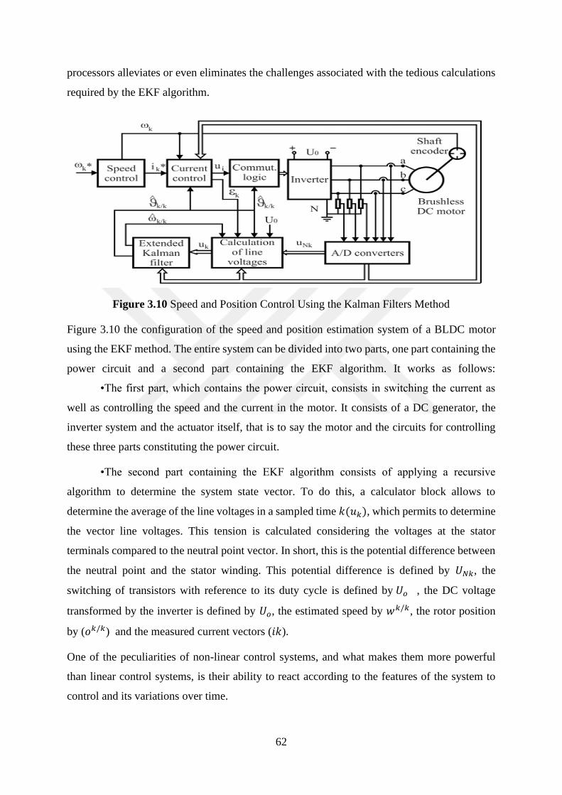
62
processors alleviates or even eliminates the challenges associated with the tedious calculations
required by the EKF algorithm.
Figure 3.10 Speed and Position Control Using the Kalman Filters Method
Figure 3.10 the configuration of the speed and position estimation system of a BLDC motor
using the EKF method. The entire system can be divided into two parts, one part containing the
power circuit and a second part containing the EKF algorithm. It works as follows:
•The first part, which contains the power circuit, consists in switching the current as
well as controlling the speed and the current in the motor. It consists of a DC generator, the
inverter system and the actuator itself, that is to say the motor and the circuits for controlling
these three parts constituting the power circuit.
•The second part containing the EKF algorithm consists of applying a recursive
algorithm to determine the system state vector. To do this, a calculator block allows to
determine the average of the line voltages in a sampled time 𝑘(𝑢𝑘), which permits to determine
the vector line voltages. This tension is calculated considering the voltages at the stator
terminals compared to the neutral point vector. In short, this is the potential difference between
the neutral point and the stator winding. This potential difference is defined by 𝑈𝑁𝑘, the
switching of transistors with reference to its duty cycle is defined by 𝑈𝑜 , the DC voltage
transformed by the inverter is defined by 𝑈𝑜, the estimated speed by 𝑤𝑘/𝑘, the rotor position
by (𝑜𝑘/𝑘) and the measured current vectors (𝑖𝑘).
One of the peculiarities of non-linear control systems, and what makes them more powerful
than linear control systems, is their ability to react according to the features of the system to
control and its variations over time.
63
Advances have been made in the field of control using the EKF method. The use of the stator
resistors, the rotor flux and the angular velocity of the rotor simultaneously with a system
adapted to the reference model (MRAS) have been realized but the disadvantage of the solution
is that it is sensitive to variations rotor and stator resistors. Another method called Bi-input EKF
uses the EKF algorithm and the information based on the stator and rotor resistors estimation
model. The advantage results in an improved control of the speed, a very precise estimation of
the rotor flux, the load torque as well as the angular velocity of the rotor and a non-sensitivity
to the variations of the resistors of the stator and the rotor.
3.4.7 Sliding -Mode Variable Structure Control
In recent years, the control industry has developed very advanced control systems. As the
structures of the controller systems become more complex, the usual control systems such as
PID controllers, for example, lose their place. Therefore, we are witnessing the creation of
mixed control systems, most often PID controllers coordination with other types of controllers,
all this to improve the performance of controllers and to make the control of the control systems
not only possible but also effective [25].
The emergence of non-linear systems from a technical point of view has led to the development
of control systems for nonlinear systems. Above we have some control systems such as
intelligent controllers that appear as a solution to the control of nonlinear systems like BLDC
motors.
Fuzzy controllers, neural network controllers and genetic controllers are some of these types of
controls that help in controlling BLDC motors.
Beyond these control methods, we have seen the systems observe with Kalman filters. In the
same register, there is another control system called variable structure control with sliding
mode. It is one of the largest research topics in the field of control motorering. Simulations and
experiments have revealed that the variable structure control strategy is more robust than the
PID strategy against external disturbances and disruption models [25].
Systems of variable structure act on the system to be controlled by considering the evolution of
its state vector. Studies [26] on systems of variable structure, when controlling systems, have
shown that the dynamics of the system is not only determined by the feedback controllers used
but also by the switching strategy adopted. Starting from the equations of state modelling a
system that one seeks to control, and by taking a control law to control the system with different
64
switching strategies, one realizes that the different switching strategies have different influences
on the systems to control.
The system can be stable under the application of a switching strategy and not be on the other,
even if the control laws adopted remain the same.
Variable structure control is a nonlinear technique for controlling nonlinear systems. This
technique offers advantages that cannot be obtained with the use of conventional linear
controllers [25]. Slip control is a technique of variable structure control by which a system is
forced to behave according to a certain control law. Slip control uses feedback controllers acting
on the system to be controlled based on a predetermined area in which the system must evolve.
The system to be controlled is represented by a set of points, the feedback controllers influence
the representative points of the system so that these points are approaching the predetermined
surface. When this is done, the evolution of the system is limited to this surface. This surface is
a state space called a sliding surface. The purpose of the slip control is to keep the representative
points of the system in the sliding surface or at the boundaries of the sliding surface [34].
The advantages of such a control is that the uncertainties of the mathematical model and the
external perturbations do not affect the dynamics of the controlled system, the closed-loop
response becomes totally indifferent to the uncertainties related to the system. The fast
switching offered by the control to Sliding variable structure provides opportunities for better
control over current ripples caused by load variation and switching in windings. [26,27]
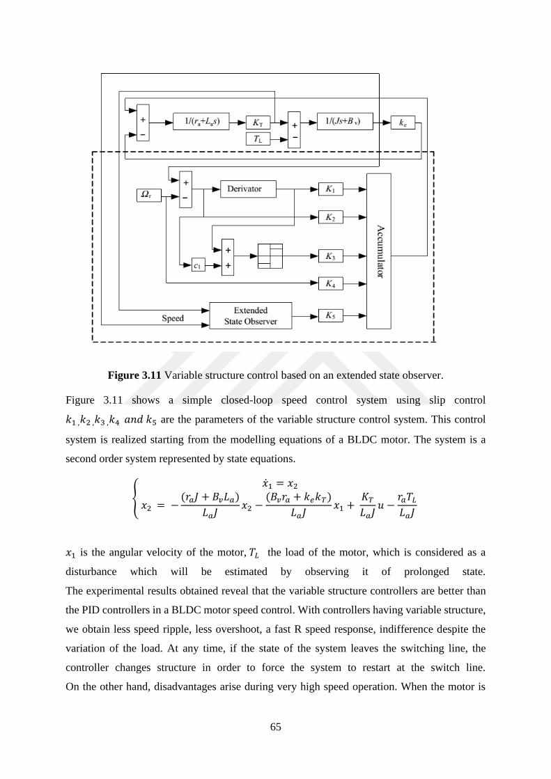
65
Figure 3.11 Variable structure control based on an extended state observer.
Figure 3.11 shows a simple closed-loop speed control system using slip control
𝑘1 ,𝑘2 ,𝑘3 ,𝑘4 𝑎𝑛𝑑 𝑘5 are the parameters of the variable structure control system. This control
system is realized starting from the modelling equations of a BLDC motor. The system is a
second order system represented by state equations.
{
�̇�1 = 𝑥2
𝑥2 = −(𝑟𝑎𝐽 + 𝐵𝑣𝐿𝑎)
𝐿𝑎𝐽𝑥2 −
(𝐵𝑣𝑟𝑎 + 𝑘𝑒𝑘𝑇)
𝐿𝑎𝐽𝑥1 +
𝐾𝑇𝐿𝑎𝐽
𝑢 −𝑟𝑎𝑇𝐿𝐿𝑎𝐽
𝑥1 is the angular velocity of the motor, 𝑇𝐿 the load of the motor, which is considered as a
disturbance which will be estimated by observing it of prolonged state.
The experimental results obtained reveal that the variable structure controllers are better than
the PID controllers in a BLDC motor speed control. With controllers having variable structure,
we obtain less speed ripple, less overshoot, a fast R speed response, indifference despite the
variation of the load. At any time, if the state of the system leaves the switching line, the
controller changes structure in order to force the system to restart at the switch line.
On the other hand, disadvantages arise during very high speed operation. When the motor is
66
operating at high speed, the representative points of the system tend to really exceed the
switching line during a certain period. The exceedances are converted into disruption producing
undesirable instabilities when the system converges to the original phase plane. By switching
the controller structure to a conventional controller structure, this problem is settled.
3.5 Conclusion
Since the brushless direct current motors began to attract the attention of people because of their
great abilities to produce good torque and less loses during their operation due to the absence
of brush in their constitution , many control technics have started to be developed in other make
the operation of those electrical motors following certain conditions of torque, speed during
various characteristics of operation. This chapter presents those methods and gives another
point of view regarding the Sensorless control of BLDC motors.

67
CHAPTER 4: APPLICATION OF SENSORLESS SPEED CONTROL OF
BLDC MOTOR USING THE SPACE VECTOR PULSE WIDTH
MODULATION (SVPWM) CONTROL TECHNIQUE APPLIED TO THE
VOLTAGE INVERTER
Motor control is one of the most dynamic branches of dynamic systems motorering. The
diversity of electric motors also leads to an increased development of electric motor control
methods.
After making a general development of BLDC motors and giving the different methods that are
used nowadays to control these motors, in this part we will work on a different way of
controlling which is the sensorless control of BLDC motors.
The advantage of practicing a sensorless control is notorious because it increases the reliability
of the machine and its ability has evolved in tight places as has been emphasized in previous
chapters.
Today, there are very powerful methods for sensorless control of BLDC motors. As such we
can mention the sliding mode control which today is increasingly used and studied to allow an
efficient control of BLDC motors. The nature of the behavior of BLDC motors which is a
nonlinear behavior forced the ingeneer to develop control systems capable of being robust
enough to be less dependent on mathematical model equations and thus to compensate for
variations of the mathematical model and behaviors non-predictable model related to nonlinear
nature.
Beyond the techniques developed and how powerful they are, there are always limits related to
the design of the control system because any control system is based on a logic that is never
true. Nowadays, we know that when a BLDC motor works, just two phases are powered, the
flow of electric current is ensured only by two phases between two commutations and so on. In
a BLDC motor a phase and this cyclically is always floating, non-conductive this electric
current.
The BLDC motor has the reverse of conventional DC motor has no collector or brushes. Thus,
the switching of the electric current in the stator coils is provided by an electronic system whose
operating principle is highly dependent on the rotor position. The position of the rotor is
essential for determining the switching sequence and which phases must be energized to enable
the conduction of the electric current.
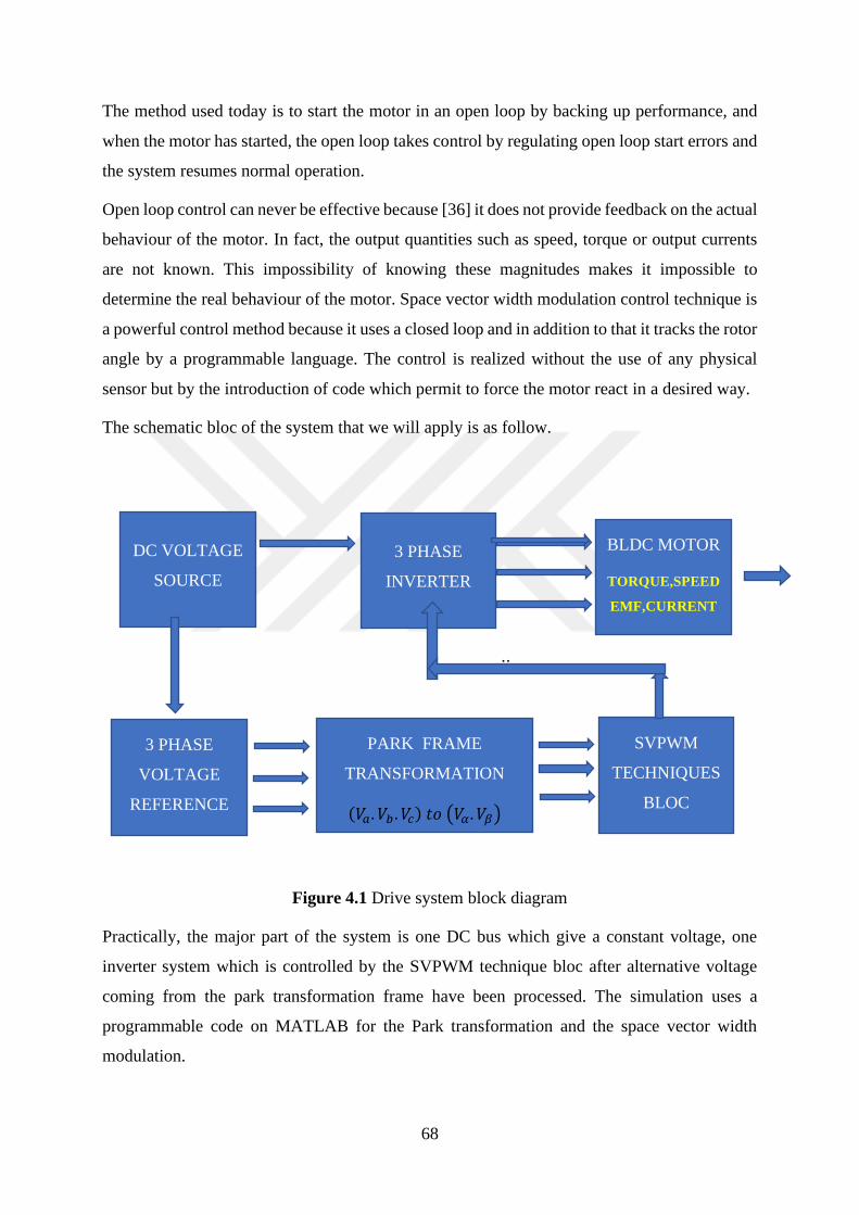
68
The method used today is to start the motor in an open loop by backing up performance, and
when the motor has started, the open loop takes control by regulating open loop start errors and
the system resumes normal operation.
Open loop control can never be effective because [36] it does not provide feedback on the actual
behaviour of the motor. In fact, the output quantities such as speed, torque or output currents
are not known. This impossibility of knowing these magnitudes makes it impossible to
determine the real behaviour of the motor. Space vector width modulation control technique is
a powerful control method because it uses a closed loop and in addition to that it tracks the rotor
angle by a programmable language. The control is realized without the use of any physical
sensor but by the introduction of code which permit to force the motor react in a desired way.
The schematic bloc of the system that we will apply is as follow.
;;
Figure 4.1 Drive system block diagram
Practically, the major part of the system is one DC bus which give a constant voltage, one
inverter system which is controlled by the SVPWM technique bloc after alternative voltage
coming from the park transformation frame have been processed. The simulation uses a
programmable code on MATLAB for the Park transformation and the space vector width
modulation.
DC VOLTAGE
SOURCE
SVPWM
TECHNIQUES
BLOC
3 PHASE
VOLTAGE
REFERENCE
PARK FRAME
TRANSFORMATION
(𝑉𝑎. 𝑉𝑏 . 𝑉𝑐) 𝑡𝑜 (𝑉𝛼. 𝑉𝛽)
BLDC MOTOR
TORQUE,SPEED
EMF,CURRENT
3 PHASE
INVERTER
69
In the lines that follow, we will proceed to the modeling of the different parts of the control
system
4.1 Modeling of the Motor
We will therefore perform electrical modeling, which refers to the electrical equations of the
machine which are actually a generalization of Ohm's law and mechanical modeling, which
refers to Newton's second law.
BLDC motor operating by delivering current to its stator in reference to the rotor through
inverter. The flux generated by the stator, the current magnet with which the permanent magnet
rotor flows which develops torque. The rotor rotates in a specific direction to align with the
stator flow at synchronous speed. The stator is effectively switched to an unidirectional rotation.
▪ Hypothesis
We will retain the following hypotheses:
• The machine is three-phase and balanced
• The windings of the motor are connected in star
• The magnetic material is not saturated
• The permeability of iron is supposed to be infinite
• The detent torque of the machine is considered as zero.
We also consider that the permeability of magnets is close to that of air, that it is equal to 1.
The machine contains smooth poles. The inductor is of low value and does not vary. The air
gap being wide, it is considered that the fluxes induced in the stator are small compared to the
fluxes induced by the magnets of the rotor [33]. The armature reaction is negligible. It is
considered that the values of the resistances do not vary. They are therefore considered to be
constant. The operating point of the machine has no influence on the flow distribution. The
modelling of the BLDC motor is like the DC motor.
BLDCM modelling consists of two parts:
An electrical part and a mechanical part.
Electrical modelling is based on the ohm law. By applying a mesh law in the electrical circuit
representative of an electrical phase, it is possible to determine the electric model of the
machine.
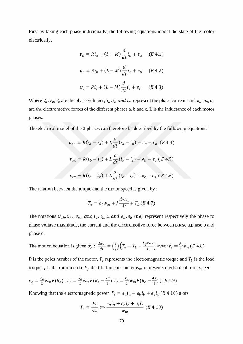
70
First by taking each phase individually, the following equations model the state of the motor
electrically.
𝑣𝑎 = 𝑅𝑖𝑎 + (𝐿 −𝑀)𝑑
𝑑𝑡𝑖𝑎 + 𝑒𝑎 (𝐸 4.1)
𝑣𝑏 = 𝑅𝑖𝑏 + (𝐿 −𝑀)𝑑
𝑑𝑡𝑖𝑏 + 𝑒𝑏 (𝐸 4.2)
𝑣𝑐 = 𝑅𝑖𝑐 + (𝐿 −𝑀)𝑑
𝑑𝑡𝑖𝑐 + 𝑒𝑐 (𝐸 4.3)
Where 𝑉𝑎, 𝑉𝑏, 𝑉𝑐 are the phase voltages, 𝑖𝑎, 𝑖𝑏 𝑎𝑛𝑑 𝑖𝑐 represent the phase currents and 𝑒𝑎, 𝑒𝑏 , 𝑒𝑐
are the electromotive forces of the different phases a, b and c. L is the inductance of each motor
phases.
The electrical model of the 3 phases can therefore be described by the following equations:
𝑣𝑎𝑏 = 𝑅(𝑖𝑎 − 𝑖𝑏) + 𝐿𝑑
𝑑𝑡(𝑖𝑎 − 𝑖𝑏) + 𝑒𝑎 − 𝑒𝑏 (𝐸 4.4)
𝑣𝑏𝑐 = 𝑅(𝑖𝑏 − 𝑖𝑐) + 𝐿𝑑
𝑑𝑡(𝑖𝑏 − 𝑖𝑐) + 𝑒𝑏 − 𝑒𝑐 ( 𝐸 4.5)
𝑣𝑐𝑎 = 𝑅(𝑖𝑐 − 𝑖𝑎) + 𝐿𝑑
𝑑𝑡(𝑖𝑐 − 𝑖𝑎) + 𝑒𝑐 − 𝑒𝑎 ( 𝐸 4.6)
The relation between the torque and the motor speed is given by :
𝑇𝑒 = 𝑘𝑓𝑤𝑚 + 𝐽𝑑𝑤𝑚𝑑𝑡
+ 𝑇𝐿 (𝐸 4.7)
The notations 𝑣𝑎𝑏 , 𝑣𝑏𝑐, 𝑣𝑐𝑎 𝑎𝑛𝑑 𝑖𝑎, 𝑖𝑏 , 𝑖𝑐 𝑎𝑛𝑑 𝑒𝑎, 𝑒𝑏 𝑒𝑡 𝑒𝑐 represent respectively the phase to
phase voltage magnitude, the current and the electromotive force between phase a,phase b and
phase c.
The motion equation is given by : 𝑑𝑤𝑚
𝑑𝑡= (
1
𝐽) (𝑇𝑒 − 𝑇𝐿 −
𝑘𝑓2𝑤𝑒
𝑃) avec 𝑤𝑒 =
𝑃
2𝑤𝑚 (𝐸 4.8)
P is the poles number of the motor, 𝑇𝑒 represents the electromagnetic torque and 𝑇𝐿 is the load
torque. 𝐽 is the rotor inertia, 𝑘𝑓 the friction constant et 𝑤𝑚 represents mechanical rotor speed.
𝑒𝑎 =𝑘𝑒
2𝑤𝑚𝐹(𝜃𝑒) ; 𝑒𝑏 =
𝑘𝑒
2𝑤𝑚𝐹(𝜃𝑒 −
2𝜋
3) 𝑒𝑐 =
𝑘𝑒
2𝑤𝑚𝐹(𝜃𝑒 −
4𝜋
3) ; (𝐸 4.9)
Knowing that the electromagnetic power 𝑃𝑡 = 𝑒𝑎𝑖𝑎 + 𝑒𝑏𝑖𝑏 + 𝑒𝑐𝑖𝑐 (𝐸 4.10) alors
𝑇𝑒 =𝑃𝑒𝑤𝑚
⟺𝑒𝑎𝑖𝑎 + 𝑒𝑏𝑖𝑏 + 𝑒𝑐𝑖𝑐
𝑤𝑚 (𝐸 4.10)
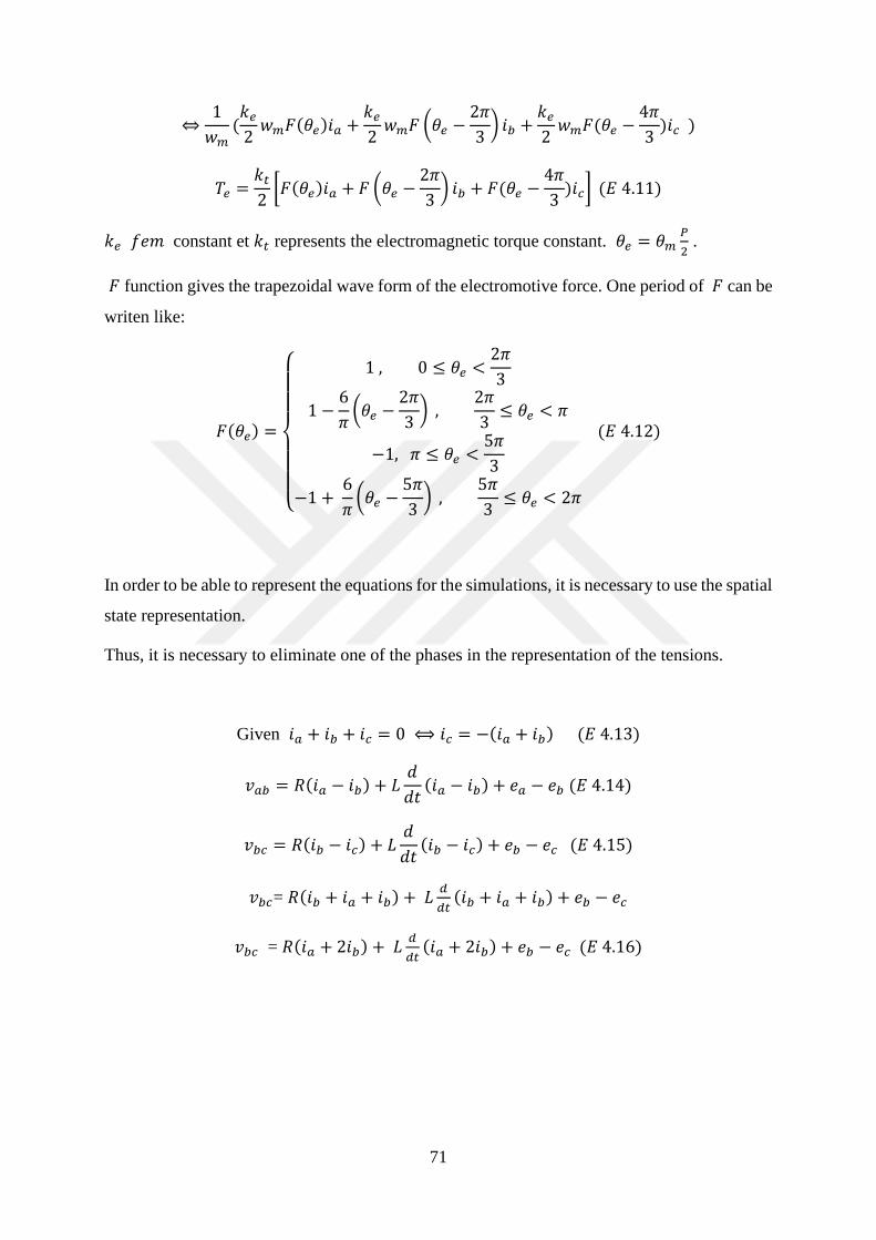
71
⇔1
𝑤𝑚(𝑘𝑒2𝑤𝑚𝐹(𝜃𝑒)𝑖𝑎 +
𝑘𝑒2𝑤𝑚𝐹 (𝜃𝑒 −
2𝜋
3) 𝑖𝑏 +
𝑘𝑒2𝑤𝑚𝐹(𝜃𝑒 −
4𝜋
3)𝑖𝑐 )
𝑇𝑒 =𝑘𝑡2[𝐹(𝜃𝑒)𝑖𝑎 + 𝐹 (𝜃𝑒 −
2𝜋
3) 𝑖𝑏 + 𝐹(𝜃𝑒 −
4𝜋
3)𝑖𝑐] (𝐸 4.11)
𝑘𝑒 𝑓𝑒𝑚 constant et 𝑘𝑡 represents the electromagnetic torque constant. 𝜃𝑒 = 𝜃𝑚𝑃
2 .
𝐹 function gives the trapezoidal wave form of the electromotive force. One period of 𝐹 can be
writen like:
𝐹(𝜃𝑒) =
{
1 , 0 ≤ 𝜃𝑒 <
2𝜋
3
1 −6
𝜋(𝜃𝑒 −
2𝜋
3) ,
2𝜋
3≤ 𝜃𝑒 < 𝜋
−1, 𝜋 ≤ 𝜃𝑒 <5𝜋
3
−1 + 6
𝜋(𝜃𝑒 −
5𝜋
3) ,
5𝜋
3≤ 𝜃𝑒 < 2𝜋
(𝐸 4.12)
In order to be able to represent the equations for the simulations, it is necessary to use the spatial
state representation.
Thus, it is necessary to eliminate one of the phases in the representation of the tensions.
Given 𝑖𝑎 + 𝑖𝑏 + 𝑖𝑐 = 0 ⟺ 𝑖𝑐 = −(𝑖𝑎 + 𝑖𝑏) (𝐸 4.13)
𝑣𝑎𝑏 = 𝑅(𝑖𝑎 − 𝑖𝑏) + 𝐿𝑑
𝑑𝑡(𝑖𝑎 − 𝑖𝑏) + 𝑒𝑎 − 𝑒𝑏 (𝐸 4.14)
𝑣𝑏𝑐 = 𝑅(𝑖𝑏 − 𝑖𝑐) + 𝐿𝑑
𝑑𝑡(𝑖𝑏 − 𝑖𝑐) + 𝑒𝑏 − 𝑒𝑐 (𝐸 4.15)
𝑣𝑏𝑐= 𝑅(𝑖𝑏 + 𝑖𝑎 + 𝑖𝑏) + 𝐿𝑑
𝑑𝑡(𝑖𝑏 + 𝑖𝑎 + 𝑖𝑏) + 𝑒𝑏 − 𝑒𝑐
𝑣𝑏𝑐 = 𝑅(𝑖𝑎 + 2𝑖𝑏) + 𝐿𝑑
𝑑𝑡(𝑖𝑎 + 2𝑖𝑏) + 𝑒𝑏 − 𝑒𝑐 (𝐸 4.16)

72
Then we have :
(𝑖𝑎𝑖𝑏𝑤𝑚𝜃𝑚
)= (
−𝑅
2
000
0
−𝑅
2
00
00
−𝑘
𝑓
1
0000
)(
𝑖𝑎𝑖𝑏𝑤𝑚𝜃𝑚
) +
(
2
3𝐿
−1
3𝐿
00
001
3
0)
(
𝑣𝑎𝑏 − 𝑒𝑎𝑏𝑣𝑏𝑐 − 𝑒𝑏𝑐𝑇𝑒 − 𝑇𝐿
)
(𝑖𝑎𝑖𝑏𝑤𝑚𝜃𝑚
)=
(
10−100
01−100
00010
00001)
(𝑖𝑎𝑖𝑏𝑤𝑚𝜃𝑚
) (𝐸 4.17)
4.2 Inverter modelling and control
Inverters have become very important today in the power supply of industrial machines. An
inverter is defined as a converter of power electronics whose purpose is to convert a continuous
energy into an alternative energy.
The advantage of using inverters lies in the fact that with an inverter it is possible to supply an
AC circuit at any frequency with sinusoidal characteristics which may be completely different
from the voltages and currents provided by the networks. from power plants.
The inverters are composed of electrical switches which can be IGBT, MOS or GTO transistors
provided with a diode in parallel according to the power to be transmitted.
Motor control today can not be done without the help of inverters. The fact is that there is a
multitude of rotating machines and they are not all powered by currents whose waveform is the
same. The design of asynchronous motors used for the usual applications does not require the
use of inverters because it is made so that the waveform of the feed currents of the machines is
compatible with the waveform of the currents generated by the inverters. power plants and these
motors run at constant speed. Particular motors such as BLDCs do not use sinusoidal three-
phase voltages like asynchronous motors, and since it is impossible to have usual voltage
sources generating voltages of these waveforms, it is therefore necessary to use voltage
inverters. In addition, variable speed drive applications require the use of inverters. The figure
shows an example of an inverter supplying an motor.
The particularity of these inverters is that they do not operate autonomously, It requires a control
law to meet the requirements of BLDC motors. There are several methods to control the
inverters. One of these methods and the most effective is the PWM command. The MLI makes
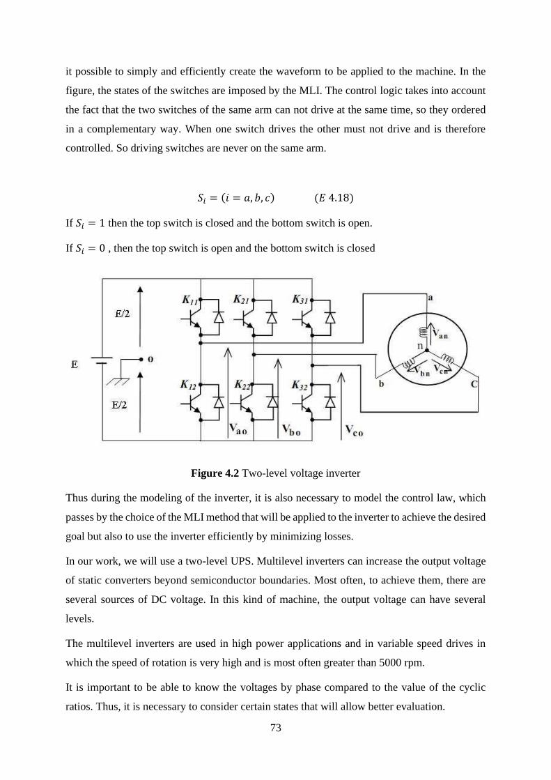
73
it possible to simply and efficiently create the waveform to be applied to the machine. In the
figure, the states of the switches are imposed by the MLI. The control logic takes into account
the fact that the two switches of the same arm can not drive at the same time, so they ordered
in a complementary way. When one switch drives the other must not drive and is therefore
controlled. So driving switches are never on the same arm.
𝑆𝑖 = (𝑖 = 𝑎, 𝑏, 𝑐) (𝐸 4.18)
If 𝑆𝑖 = 1 then the top switch is closed and the bottom switch is open.
If 𝑆𝑖 = 0 , then the top switch is open and the bottom switch is closed
Figure 4.2 Two-level voltage inverter
Thus during the modeling of the inverter, it is also necessary to model the control law, which
passes by the choice of the MLI method that will be applied to the inverter to achieve the desired
goal but also to use the inverter efficiently by minimizing losses.
In our work, we will use a two-level UPS. Multilevel inverters can increase the output voltage
of static converters beyond semiconductor boundaries. Most often, to achieve them, there are
several sources of DC voltage. In this kind of machine, the output voltage can have several
levels.
The multilevel inverters are used in high power applications and in variable speed drives in
which the speed of rotation is very high and is most often greater than 5000 rpm.
It is important to be able to know the voltages by phase compared to the value of the cyclic
ratios. Thus, it is necessary to consider certain states that will allow better evaluation.

74
- First, it is assumed that the motor is star-coupled and that the currents flowing in its windings
are equal in standards
- The switches are perfect, so there is no voltage drop or loss of power
- The sum of the stator currents is zero and the neutral of the motor is not connected to the
midpoint of the inverter.
- To avoid complicating the system, all output voltages have the same reference point
- The DC voltage source supplying the inverter is ideal.
Under these conditions, the phase voltages can be expressed as a function of the control logic
𝑆𝑖 .
𝑈𝑖𝑛 = 𝑆𝑖𝑈𝑐 −𝑈𝑐
2 (E 4.19)
Moreover, starting from the point O of the source, one can express phase to phase voltages
𝑉𝑎𝑏 , 𝑉𝑏𝑐, 𝑉𝑐𝑎 .
{𝑉𝑎𝑏 = 𝑉𝑎𝑜 + 𝑉𝑜𝑏 = 𝑉𝑎𝑜 − 𝑉𝑏𝑜𝑉𝑏𝑐 = 𝑉𝑏𝑜 + 𝑉𝑜𝑐 = 𝑉𝑏𝑜 − 𝑉𝑐𝑜𝑉𝑐𝑎 = 𝑉𝑐𝑜 + 𝑉𝑜𝑎 = 𝑉𝑐𝑜 − 𝑉𝑎𝑜
(E 4.20)
Applying Chasles's relation to input voltages 𝑉𝑎𝑜, 𝑉𝑏𝑜 𝑒𝑡 𝑉𝑐𝑜 , on a :
{𝑉𝑎𝑜 = 𝑉𝑎𝑛 + 𝑉𝑛𝑜𝑉𝑏𝑜 = 𝑉𝑏𝑛 + 𝑉𝑛𝑜𝑉𝑐𝑜 = 𝑉𝑐𝑛 + 𝑉𝑛𝑜
(E 4.21)
As mentioned above, the system is voltage balanced, so from the neutral point of the motor, we
have the following relationship:
𝑉𝑎𝑛 + 𝑉𝑏𝑛 + 𝑉𝑐𝑛 = 0 (E 4.22)
Adding the volages, we have: 𝑉𝑎𝑜 + 𝑉𝑏𝑜 + 𝑉𝑐𝑜 = 3𝑉𝑛𝑜 and consequently,
𝑉𝑛𝑜 =1
3(𝑉𝑎𝑜 + 𝑉𝑏𝑜 + 𝑉𝑐𝑜) (E 4.23)
By replacing (5) in (3), we get:
{
𝑉𝑎𝑛 =
2
3𝑉𝑎𝑜 −
1
3𝑉𝑏𝑜 −
1
3𝑉𝑐𝑜
𝑉𝑏𝑛 = −1
3𝑉𝑎𝑜 +
2
3𝑉𝑏𝑜 −
1
3𝑉𝑐𝑜
𝑉𝑐𝑛 = −1
3𝑉𝑎𝑜 −
1
3𝑉𝑏𝑜 +
2
3𝑉𝑐𝑜
( 𝐸 4.24)

75
By using the expression (1), we can write that:
[𝑉𝑎𝑛𝑉𝑏𝑛𝑉𝑐𝑛
] =𝑈𝑐
3[2 −1 −1−1 2 −1−1 −1 2
] [
𝑆𝑎𝑆𝑏𝑆𝑐
] (E 4.25)
Taking 𝑖 = {𝑎, 𝑏, 𝑐} , 𝑉𝑖𝑛 represents the output voltages et 𝑉𝑖𝑜 the input voltages.
We can say that [𝑉𝑖𝑛] = [𝑇][𝑉𝑖𝑜] with :
[𝑇] =1
3[2 −1 −1−1 2 −1−1 −1 2
] (𝐸 4.26)
The control of the inverter will be ensured by a modulation structure of the pulse width which
is abbreviated by PWM. Pulse width modulation is now one of the most powerful and widely
used methods in motor control. It makes it possible to vary the speed of the motors with a high
efficiency. [32]
There are several types of MLI, and each type of MLI has its well-defined characteristics. The
choice of a technique depends on the type of machine to be controlled, the power range, the
semiconductors used for the inverter and the simplicity of implementation of the algorithm. It
is ultimately cost and performance criteria that will determine this choice. The performance
criteria make it possible to evaluate and compare the qualities of the different MLI techniques.
The modulation of the intersective pulse width or triangle sine operates according to the
following principle: First, one has a sinusoidal reference or another form having a frequency
𝑓𝑠, this reference is called the modulator. Second, we have a triangular signal called the
frequency carrier 𝑓𝑝. This signal is characterized by a high frequency.

76
Figure 4.3 Modulation of the intersective pulse width
By using the points of intersection of the two references, the switching times of the switches of
the inverter are determined. Generally, the carrier is triangular. The output signal of the MLI is
1 if the modulator is larger than the carrier and it is 0 otherwise. Thus we can also notice that
the output signal changes state at each intersection of the modulator and the carrier.
Figure 4.4 Outline Diagram of the Intersecting MLI
The downside of this command is that it limits the performance of the motor because the
maximum value of the voltage can only reach half the dc voltage applied to the inverter. This
technique is used in applications in which high power transfer is not high.
The diagrams in the following figure show how the PWM command works and how a PWM
structure appears much more efficient and effective than a control structure using voltage drives
for control. Indeed, control using MLI is a pulse control. The lengths of the periods are directly
proportional to the speed of the motor.
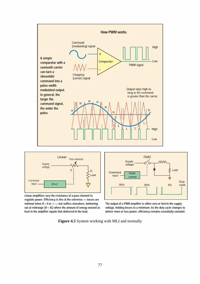
77
Figure 4.5 System working with MLI and normally
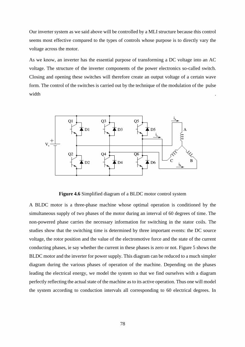
78
Our inverter system as we said above will be controlled by a MLI structure because this control
seems most effective compared to the types of controls whose purpose is to directly vary the
voltage across the motor.
As we know, an inverter has the essential purpose of transforming a DC voltage into an AC
voltage. The structure of the inverter components of the power electronics so-called switch.
Closing and opening these switches will therefore create an output voltage of a certain wave
form. The control of the switches is carried out by the technique of the modulation of the pulse
width .
Figure 4.6 Simplified diagram of a BLDC motor control system
A BLDC motor is a three-phase machine whose optimal operation is conditioned by the
simultaneous supply of two phases of the motor during an interval of 60 degrees of time. The
non-powered phase carries the necessary information for switching in the stator coils. The
studies show that the switching time is determined by three important events: the DC source
voltage, the rotor position and the value of the electromotive force and the state of the current
conducting phases, ie say whether the current in these phases is zero or not. Figure 5 shows the
BLDC motor and the inverter for power supply. This diagram can be reduced to a much simpler
diagram during the various phases of operation of the machine. Depending on the phases
leading the electrical energy, we model the system so that we find ourselves with a diagram
perfectly reflecting the actual state of the machine as to its active operation. Thus one will model
the system according to conduction intervals all corresponding to 60 electrical degrees. In
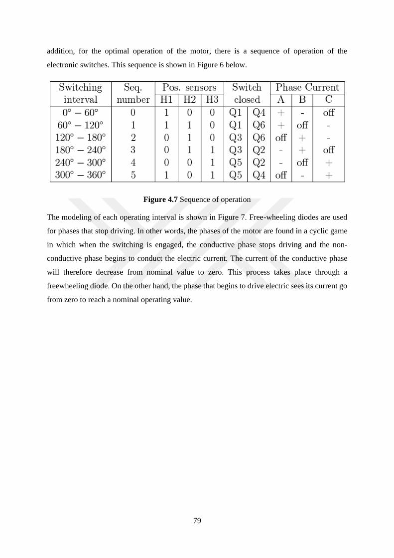
79
addition, for the optimal operation of the motor, there is a sequence of operation of the
electronic switches. This sequence is shown in Figure 6 below.
Figure 4.7 Sequence of operation
The modeling of each operating interval is shown in Figure 7. Free-wheeling diodes are used
for phases that stop driving. In other words, the phases of the motor are found in a cyclic game
in which when the switching is engaged, the conductive phase stops driving and the non-
conductive phase begins to conduct the electric current. The current of the conductive phase
will therefore decrease from nominal value to zero. This process takes place through a
freewheeling diode. On the other hand, the phase that begins to drive electric sees its current go
from zero to reach a nominal operating value.
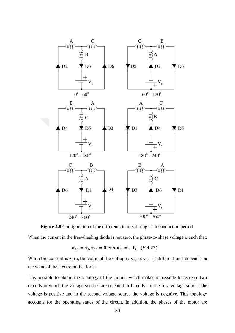
80
Figure 4.8 Configuration of the different circuits during each conduction period
When the current in the freewheeling diode is not zero, the phase-to-phase voltage is such that:
𝑣𝑎𝑏 = 𝑣𝑠 , 𝑣𝑏𝑐 = 0 𝑎𝑛𝑑 𝑣𝑐𝑎 = −𝑉𝑠 (𝐸 4.27)
When the current is zero, the value of the voltages vbc et vca is different and depends on
the value of the electromotive force.
It is possible to obtain the topology of the circuit, which makes it possible to recreate two
circuits in which the voltage sources are oriented differently. In the first voltage source, the
voltage is positive and in the second voltage source the voltage is negative. This topology
accounts for the operating states of the circuit. In addition, the phases of the motor are
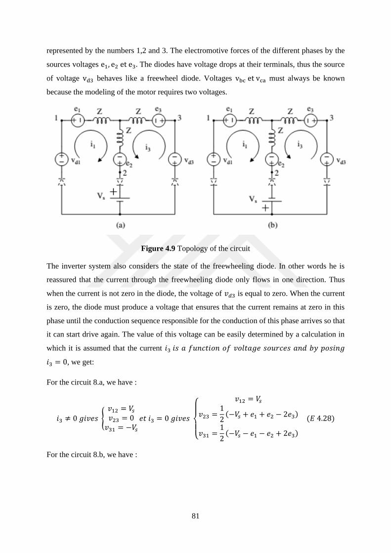
81
represented by the numbers 1,2 and 3. The electromotive forces of the different phases by the
sources voltages e1, e2 et e3. The diodes have voltage drops at their terminals, thus the source
of voltage vd3 behaves like a freewheel diode. Voltages vbc et vca must always be known
because the modeling of the motor requires two voltages.
Figure 4.9 Topology of the circuit
The inverter system also considers the state of the freewheeling diode. In other words he is
reassured that the current through the freewheeling diode only flows in one direction. Thus
when the current is not zero in the diode, the voltage of 𝑣𝑑3 is equal to zero. When the current
is zero, the diode must produce a voltage that ensures that the current remains at zero in this
phase until the conduction sequence responsible for the conduction of this phase arrives so that
it can start drive again. The value of this voltage can be easily determined by a calculation in
which it is assumed that the current 𝑖3 𝑖𝑠 𝑎 𝑓𝑢𝑛𝑐𝑡𝑖𝑜𝑛 𝑜𝑓 𝑣𝑜𝑙𝑡𝑎𝑔𝑒 𝑠𝑜𝑢𝑟𝑐𝑒𝑠 𝑎𝑛𝑑 𝑏𝑦 𝑝𝑜𝑠𝑖𝑛𝑔
𝑖3 = 0, we get:
For the circuit 8.a, we have :
𝑖3 ≠ 0 𝑔𝑖𝑣𝑒𝑠 {
𝑣12 = 𝑉𝑠𝑣23 = 0𝑣31 = −𝑉𝑠
𝑒𝑡 𝑖3 = 0 𝑔𝑖𝑣𝑒𝑠
{
𝑣12 = 𝑉𝑠
𝑣23 =1
2(−𝑉𝑠 + 𝑒1 + 𝑒2 − 2𝑒3)
𝑣31 =1
2(−𝑉𝑠 − 𝑒1 − 𝑒2 + 2𝑒3)
(𝐸 4.28)
For the circuit 8.b, we have :
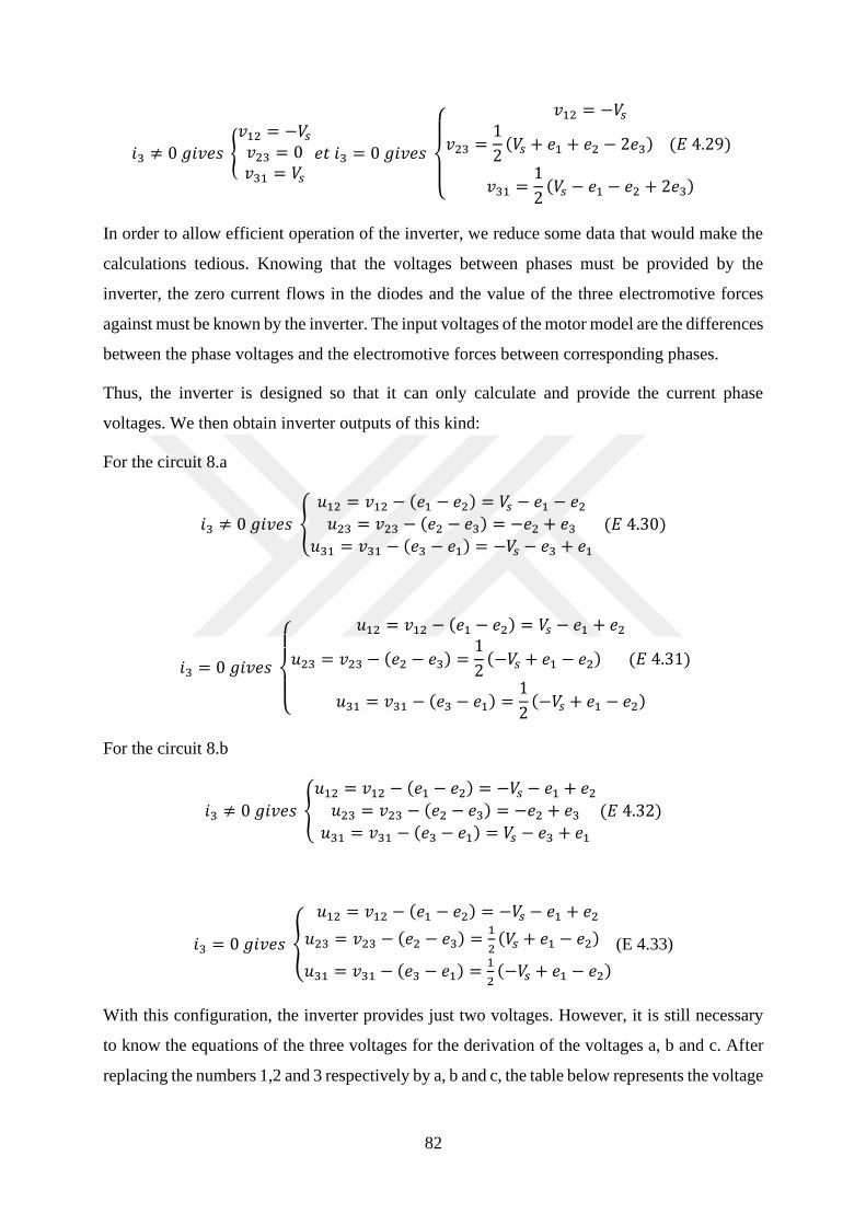
82
𝑖3 ≠ 0 𝑔𝑖𝑣𝑒𝑠 {
𝑣12 = −𝑉𝑠𝑣23 = 0𝑣31 = 𝑉𝑠
𝑒𝑡 𝑖3 = 0 𝑔𝑖𝑣𝑒𝑠
{
𝑣12 = −𝑉𝑠
𝑣23 =1
2(𝑉𝑠 + 𝑒1 + 𝑒2 − 2𝑒3) (𝐸 4.29)
𝑣31 =1
2(𝑉𝑠 − 𝑒1 − 𝑒2 + 2𝑒3)
In order to allow efficient operation of the inverter, we reduce some data that would make the
calculations tedious. Knowing that the voltages between phases must be provided by the
inverter, the zero current flows in the diodes and the value of the three electromotive forces
against must be known by the inverter. The input voltages of the motor model are the differences
between the phase voltages and the electromotive forces between corresponding phases.
Thus, the inverter is designed so that it can only calculate and provide the current phase
voltages. We then obtain inverter outputs of this kind:
For the circuit 8.a
𝑖3 ≠ 0 𝑔𝑖𝑣𝑒𝑠 {
𝑢12 = 𝑣12 − (𝑒1 − 𝑒2) = 𝑉𝑠 − 𝑒1 − 𝑒2𝑢23 = 𝑣23 − (𝑒2 − 𝑒3) = −𝑒2 + 𝑒3
𝑢31 = 𝑣31 − (𝑒3 − 𝑒1) = −𝑉𝑠 − 𝑒3 + 𝑒1
(𝐸 4.30)
𝑖3 = 0 𝑔𝑖𝑣𝑒𝑠
{
𝑢12 = 𝑣12 − (𝑒1 − 𝑒2) = 𝑉𝑠 − 𝑒1 + 𝑒2
𝑢23 = 𝑣23 − (𝑒2 − 𝑒3) =1
2(−𝑉𝑠 + 𝑒1 − 𝑒2) (𝐸 4.31)
𝑢31 = 𝑣31 − (𝑒3 − 𝑒1) =1
2(−𝑉𝑠 + 𝑒1 − 𝑒2)
For the circuit 8.b
𝑖3 ≠ 0 𝑔𝑖𝑣𝑒𝑠 {
𝑢12 = 𝑣12 − (𝑒1 − 𝑒2) = −𝑉𝑠 − 𝑒1 + 𝑒2𝑢23 = 𝑣23 − (𝑒2 − 𝑒3) = −𝑒2 + 𝑒3𝑢31 = 𝑣31 − (𝑒3 − 𝑒1) = 𝑉𝑠 − 𝑒3 + 𝑒1
(𝐸 4.32)
𝑖3 = 0 𝑔𝑖𝑣𝑒𝑠 {
𝑢12 = 𝑣12 − (𝑒1 − 𝑒2) = −𝑉𝑠 − 𝑒1 + 𝑒2
𝑢23 = 𝑣23 − (𝑒2 − 𝑒3) =1
2(𝑉𝑠 + 𝑒1 − 𝑒2)
𝑢31 = 𝑣31 − (𝑒3 − 𝑒1) =1
2(−𝑉𝑠 + 𝑒1 − 𝑒2)
(E 4.33)
With this configuration, the inverter provides just two voltages. However, it is still necessary
to know the equations of the three voltages for the derivation of the voltages a, b and c. After
replacing the numbers 1,2 and 3 respectively by a, b and c, the table below represents the voltage
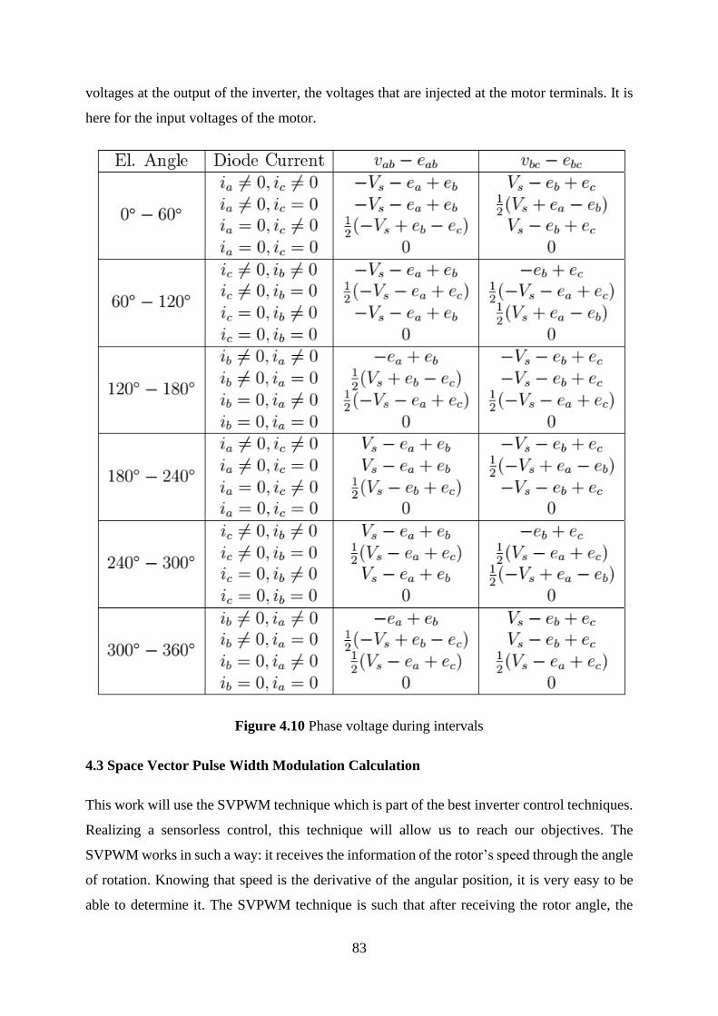
83
voltages at the output of the inverter, the voltages that are injected at the motor terminals. It is
here for the input voltages of the motor.
Figure 4.10 Phase voltage during intervals
4.3 Space Vector Pulse Width Modulation Calculation
This work will use the SVPWM technique which is part of the best inverter control techniques.
Realizing a sensorless control, this technique will allow us to reach our objectives. The
SVPWM works in such a way: it receives the information of the rotor’s speed through the angle
of rotation. Knowing that speed is the derivative of the angular position, it is very easy to be
able to determine it. The SVPWM technique is such that after receiving the rotor angle, the

84
system generates two voltages 𝑉𝛼 𝑎𝑛𝑑 𝑉𝛽. These two voltages are then used to determine the
value of the reference voltage vector 𝑉𝑟𝑒𝑓 and the angle α between the voltage vectors. The
implementation of the SVPWM technique requires three major steps that are:
• Calculation of 𝑉𝛼, 𝑉𝛽 𝑎𝑛𝑑 𝛼
• Calculation of 𝑇0, 𝑇1 𝑎𝑛𝑑 𝑇2
• Determination of all the commutation time of all the switcher devices from 𝑆1 𝑡𝑜 𝑆7
❖ Calculation of 𝑽𝜶, 𝑽𝜷 𝒂𝒏𝒅 𝜶
The reference voltage called 𝑉𝑟𝑒𝑓 is given by the following formula. That reference voltage is
important because it gives the ability to operate SVPWM technique by determining
𝑉𝛼, 𝑉𝛽 𝑎𝑛𝑑 𝛼 .
|𝑉𝑟𝑒𝑓| = √𝑉𝛼2 + 𝑉𝛽2 (𝐸 4.34)
𝛼 = tan−1𝑉𝛽
𝑉𝛼 (𝐸 4.35)
Starting from the relation established above to determine the matrix relation between the simple
voltages and the switches, one deduces the relation between the composed voltages and the
switches, thus
[𝑉𝑎𝑏𝑉𝑏𝑐𝑉𝑐𝑎
] = 𝑈𝑐 [1 −1 00 1 −1−1 0 1
] [
𝑆𝑎𝑆𝑏𝑆𝑐
] (𝐸 4.36)
The inverter system contains three arms each supporting two switches that are seen as variables.
Each of these variables can be seen as a non-zero vector. Six vectors corresponding to the
different states of the switches are thus determined, and two vectors which represent the zero
state in order to be able to operate the system without problems. In the previous paragraphs, we
have explained the operation of each of these switches. By analyzing the different states of these
switches, the spatial vectors, which are eight in number, are determined.
(𝑉0, 𝑉1, 𝑉2, 𝑉3, 𝑉4, 𝑉5, 𝑉6, 𝑉7) as we can see in the following pictures.
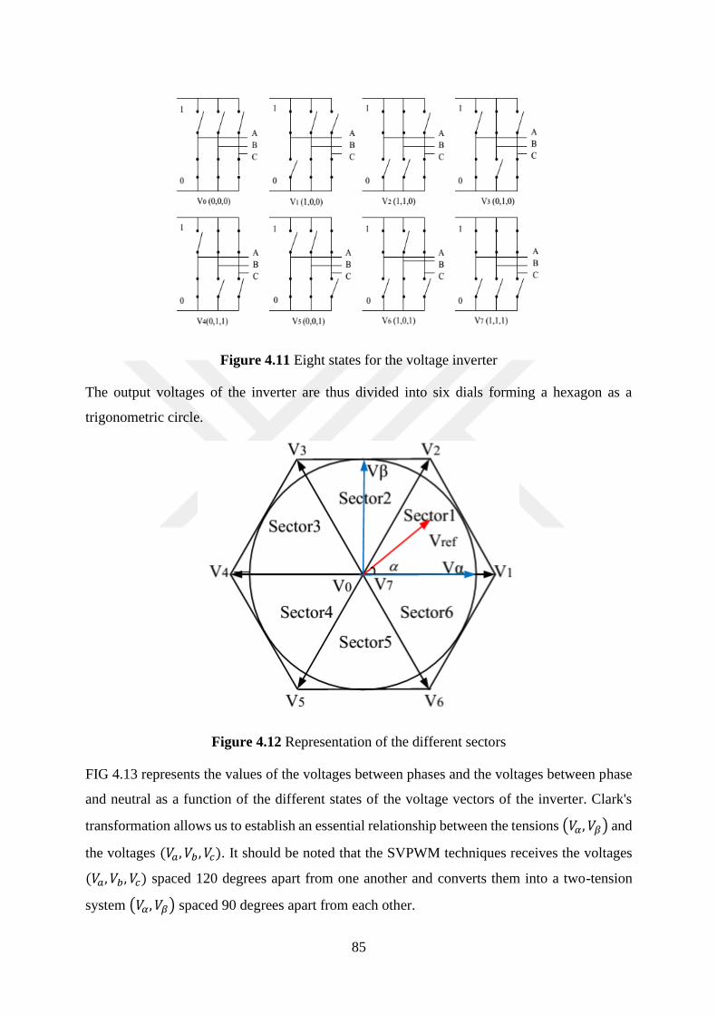
85
Figure 4.11 Eight states for the voltage inverter
The output voltages of the inverter are thus divided into six dials forming a hexagon as a
trigonometric circle.
Figure 4.12 Representation of the different sectors
FIG 4.13 represents the values of the voltages between phases and the voltages between phase
and neutral as a function of the different states of the voltage vectors of the inverter. Clark's
transformation allows us to establish an essential relationship between the tensions (𝑉𝛼, 𝑉𝛽) and
the voltages (𝑉𝑎, 𝑉𝑏 , 𝑉𝑐). It should be noted that the SVPWM techniques receives the voltages
(𝑉𝑎, 𝑉𝑏, 𝑉𝑐) spaced 120 degrees apart from one another and converts them into a two-tension
system (𝑉𝛼, 𝑉𝛽) spaced 90 degrees apart from each other.
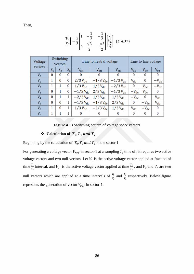
86
Then,
[𝑉𝛼𝑉𝛽] =
2
3[ 1 −
1
2−1
2
0√3
2−√3
2 ]
[𝑉𝑎𝑉𝑏𝑉𝑐
] (𝐸 4.37)
Figure 4.13 Switching pattern of voltage space vectors
❖ Calculation of 𝑻𝟎, 𝑻𝟏 𝒂𝒏𝒅 𝑻𝟐
Beginning by the calculation of 𝑇0, 𝑇1 𝑎𝑛𝑑 𝑇2 in the sector 1
For generating a voltage vector 𝑉𝑟𝑒𝑓 in sector-1 at a sampling 𝑇𝑠 time of , it requires two active
voltage vectors and two null vectors. Let 𝑉1 is the active voltage vector applied at fraction of
time 𝑇1
𝑇𝑠 interval, and 𝑉2 is the active voltage vector applied at time
𝑇2
𝑇𝑠 , and 𝑉0 and 𝑉7 are two
null vectors which are applied at a time intervals of 𝑇0
𝑇𝑠 and
𝑇7
𝑇𝑠 respectively. Below figure
represents the generation of vector 𝑉𝑟𝑒𝑓 in sector-1.
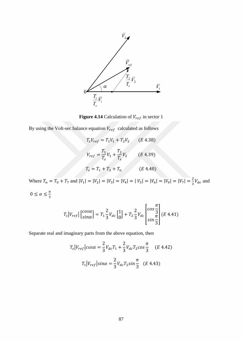
87
Figure 4.14 Calculation of 𝑉𝑟𝑒𝑓 in sector 1
By using the Volt-sec balance equation 𝑉𝑟𝑒𝑓 calculated as follows
𝑇𝑠𝑉𝑟𝑒𝑓 = 𝑇1𝑉1 + 𝑇2𝑉2 (𝐸 4.38)
𝑉𝑟𝑒𝑓 =𝑇1𝑇𝑠𝑉1 +
𝑇2𝑇𝑠𝑉2 (𝐸 4.39)
𝑇𝑠 = 𝑇1 + 𝑇2 + 𝑇𝑛 (𝐸 4.40)
Where 𝑇𝑛 = 𝑇0 + 𝑇7 and |𝑉1| = |𝑉2| = |𝑉3| = |𝑉4| = | 𝑉5| = |𝑉6| = |𝑉0| = |𝑉7| =2
3𝑉𝑑𝑐 and
0 ≤ 𝛼 ≤𝜋
3
𝑇𝑠|𝑉𝑟𝑒𝑓| [𝑐𝑜𝑠𝛼𝑠𝑖𝑛𝛼
] = 𝑇12
3𝑉𝑑𝑐 [
10] + 𝑇2
2
3𝑉𝑑𝑐 [
𝑐𝑜𝑠𝜋
3
𝑠𝑖𝑛𝜋
3
] (𝐸 4.41)
Separate real and imaginary parts from the above equation, then
𝑇𝑠|𝑉𝑟𝑒𝑓|𝑐𝑜𝑠𝛼 =2
3𝑉𝑑𝑐𝑇1 +
2
3𝑉𝑑𝑐𝑇2𝑐𝑜𝑠
𝜋
3 (𝐸 4.42)
𝑇𝑠|𝑉𝑟𝑒𝑓|𝑠𝑖𝑛𝛼 =2
3𝑉𝑑𝑐𝑇2𝑠𝑖𝑛
𝜋
3 (𝐸 4.43)

88
𝑇1 and 𝑇2 are calculated as follows:
𝑇1 =|𝑉𝑟𝑒𝑓|𝑇𝑠𝑠𝑖𝑛 (
𝜋3 − 𝛼)
23𝑉𝑑𝑐𝑠𝑖𝑛
𝜋3
(𝐸 4.44)
𝑇2 =|𝑉𝑟𝑒𝑓|𝑇𝑠𝑠𝑖𝑛(𝛼)
23𝑉𝑑𝑐𝑠𝑖𝑛
𝜋3
(𝐸 4.45)
𝑇0 = 𝑇𝑠 − 𝑇1 + 𝑇2 (𝐸 4.46)
❖ Determination of all the commutation time of all the switcher devices from
𝑺𝟏 𝒕𝒐 𝑺𝟕
The calculation of these magnitudes in any other sector gives with 𝑛 = {1,2,3,4,5,6,7},
𝑇𝑠|𝑉𝑟𝑒𝑓| [𝑐𝑜𝑠𝛼𝑠𝑖𝑛𝛼
] = 𝑇12
3𝑉𝑑𝑐 [
cos (𝑛 − 1)𝜋
3
sin (𝑛 − 1)𝜋
3
] + 𝑇22
3𝑉𝑑𝑐 [
𝑐𝑜𝑠𝑛𝜋
3
𝑠𝑖𝑛𝑛𝜋
3
] (𝐸 4.47)
Separate real and imaginary parts from the above equation, then:
𝑇𝑆|𝑉𝑟𝑒𝑓|𝑐𝑜𝑠𝛼 =2
3𝑉𝑑𝑐𝑇1 cos(𝑛 − 1)
𝜋
3+2
3𝑉𝑑𝑐𝑇2𝑐𝑜𝑠𝑛
𝜋
3 (𝐸 4.48)
𝑇𝑆|𝑉𝑟𝑒𝑓|𝑠𝑖𝑛𝛼 =2
3𝑉𝑑𝑐𝑇1 sin(𝑛 − 1)
𝜋
3+2
3𝑉𝑑𝑐𝑇2𝑠𝑖𝑛𝑛
𝜋
3 (𝐸 4.49)
Then,
𝑇1 =√3𝑇𝑠|𝑉𝑟𝑒𝑓|sin (𝑛
𝜋3 − 𝛼)
𝑉𝑑𝑐 (𝐸 4.50)
𝑇2 =√3𝑇𝑠|𝑉𝑟𝑒𝑓|sin (𝛼 −
(𝑛 − 1)𝜋2
)
𝑉𝑑𝑐 (𝐸 4.51)
And 𝑇0 = 𝑇𝑠 − 𝑇1 + 𝑇2
SVPWM and SPWM, the SVPWM method is self-instantaneous of the time at the value of the
revolutions, is reduced, the total of the harmonics is also reduced and finally, this method allows
a better use of the DC voltage bus.
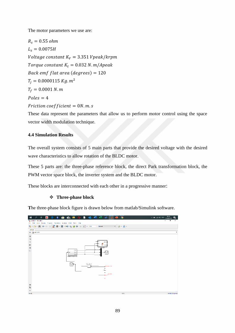
89
The motor parameters we use are:
𝑅𝑠 = 0.55 𝑜ℎ𝑚
𝐿𝑠 = 0.0075𝐻
𝑉𝑜𝑙𝑡𝑎𝑔𝑒 𝑐𝑜𝑛𝑠𝑡𝑎𝑛𝑡 𝐾𝑉 = 3.351 𝑉𝑝𝑒𝑎𝑘/𝑘𝑟𝑝𝑚
𝑇𝑜𝑟𝑞𝑢𝑒 𝑐𝑜𝑛𝑠𝑡𝑎𝑛𝑡 𝐾𝑡 = 0.032 𝑁.𝑚/𝐴𝑝𝑒𝑎𝑘
𝐵𝑎𝑐𝑘 𝑒𝑚𝑓 𝑓𝑙𝑎𝑡 𝑎𝑟𝑒𝑎 (𝑑𝑒𝑔𝑟𝑒𝑒𝑠) = 120
𝑇𝑗 = 0.0000115 𝐾𝑔.𝑚2
𝑇𝑓 = 0.0001 𝑁.𝑚
𝑃𝑜𝑙𝑒𝑠 = 4
𝐹𝑟𝑖𝑐𝑡𝑖𝑜𝑛 𝑐𝑜𝑒𝑓𝑓𝑖𝑐𝑖𝑒𝑛𝑡 = 0𝑁.𝑚. 𝑠
These data represent the parameters that allow us to perform motor control using the space
vector width modulation technique.
4.4 Simulation Results
The overall system consists of 5 main parts that provide the desired voltage with the desired
wave characteristics to allow rotation of the BLDC motor.
These 5 parts are: the three-phase reference block, the direct Park transformation block, the
PWM vector space block, the inverter system and the BLDC motor.
These blocks are interconnected with each other in a progressive manner:
❖ Three-phase block
The three-phase block figure is drawn below from matlab/Simulink software.
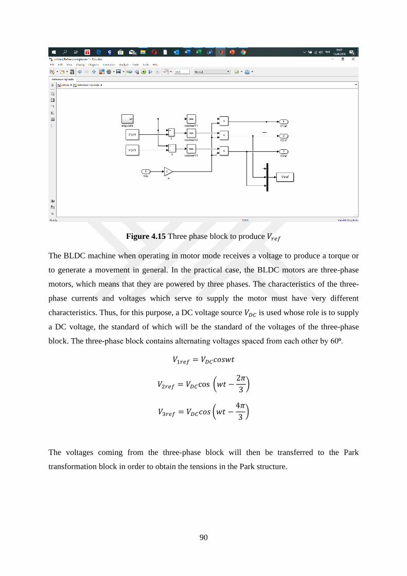
90
Figure 4.15 Three phase block to produce 𝑉𝑟𝑒𝑓
The BLDC machine when operating in motor mode receives a voltage to produce a torque or
to generate a movement in general. In the practical case, the BLDC motors are three-phase
motors, which means that they are powered by three phases. The characteristics of the three-
phase currents and voltages which serve to supply the motor must have very different
characteristics. Thus, for this purpose, a DC voltage source 𝑉𝐷𝐶 is used whose role is to supply
a DC voltage, the standard of which will be the standard of the voltages of the three-phase
block. The three-phase block contains alternating voltages spaced from each other by 60⁰.
𝑉1𝑟𝑒𝑓 = 𝑉𝐷𝐶𝑐𝑜𝑠𝑤𝑡
𝑉2𝑟𝑒𝑓 = 𝑉𝐷𝐶cos (𝑤𝑡 −2𝜋
3)
𝑉3𝑟𝑒𝑓 = 𝑉𝐷𝐶𝑐𝑜𝑠 (𝑤𝑡 −4𝜋
3)
The voltages coming from the three-phase block will then be transferred to the Park
transformation block in order to obtain the tensions in the Park structure.
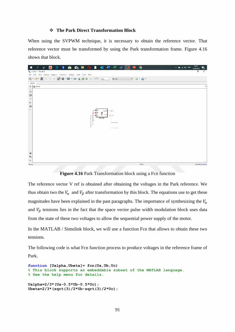
91
❖ The Park Direct Transformation Block
When using the SVPWM technique, it is necessary to obtain the reference vector. That
reference vector must be transformed by using the Park transformation frame. Figure 4.16
shows that block.
Figure 4.16 Park Transformation block using a Fcn function
The reference vector V ref is obtained after obtaining the voltages in the Park reference. We
thus obtain two the 𝑉𝛼 and 𝑉𝛽 after transformation by this block. The equations use to get these
magnitudes have been explained in the past paragraphs. The importance of synthesizing the 𝑉𝛼
and 𝑉𝛽 tensions lies in the fact that the space vector pulse width modulation block uses data
from the state of these two voltages to allow the sequential power supply of the motor.
In the MATLAB / Simulink block, we will use a function Fcn that allows to obtain these two
tensions.
The following code is what Fcn function process to produce voltages in the reference frame of
Park.
function [Ualpha,Ubeta]= fcn(Ua,Ub,Uc) % This block supports an embeddable subset of the MATLAB language. % See the help menu for details.
Ualpha=2/3*(Ua-0.5*Ub-0.5*Uc); Ubeta=2/3*(sqrt(3)/2*Ub-sqrt(3)/2*Uc);
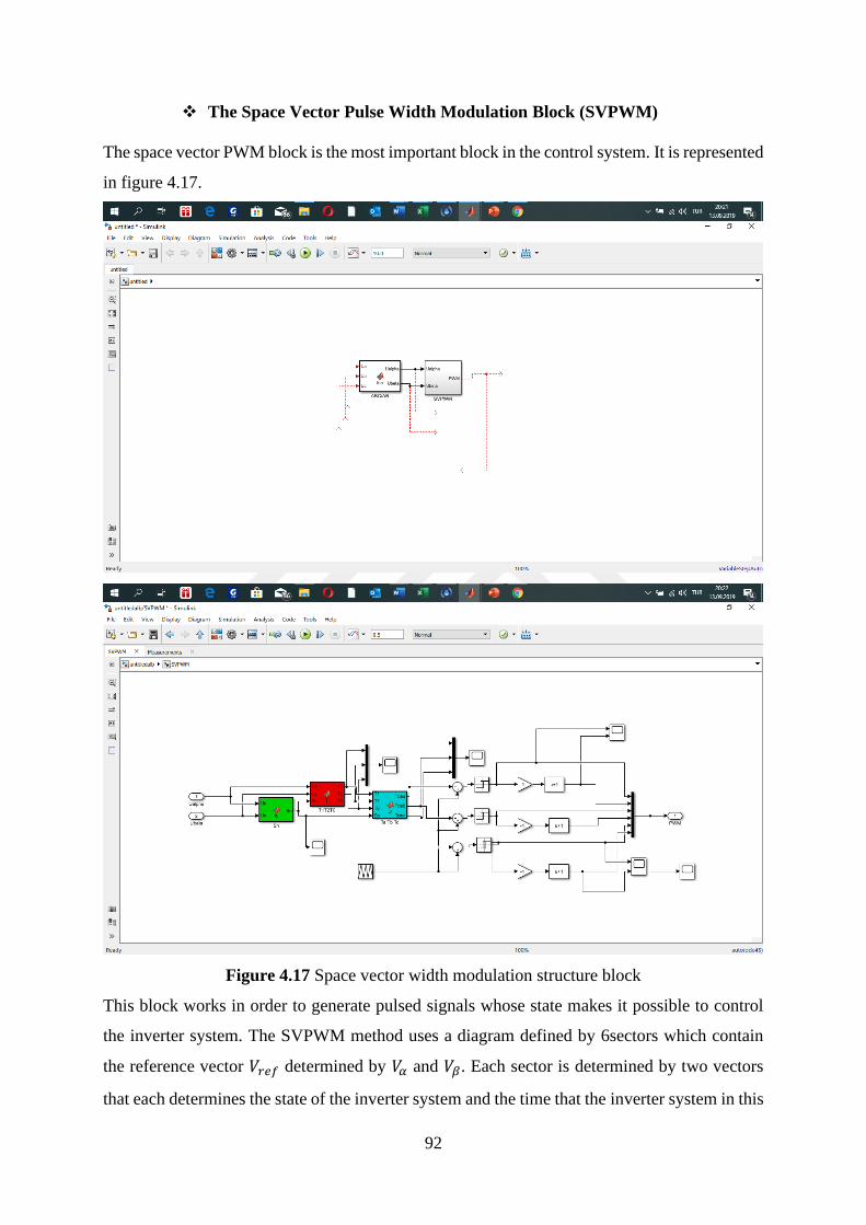
92
❖ The Space Vector Pulse Width Modulation Block (SVPWM)
The space vector PWM block is the most important block in the control system. It is represented
in figure 4.17.
Figure 4.17 Space vector width modulation structure block
This block works in order to generate pulsed signals whose state makes it possible to control
the inverter system. The SVPWM method uses a diagram defined by 6sectors which contain
the reference vector 𝑉𝑟𝑒𝑓 determined by 𝑉𝛼 and 𝑉𝛽. Each sector is determined by two vectors
that each determines the state of the inverter system and the time that the inverter system in this

93
state. The SVPWM block therefore uses three functions that ultimately influence the gate of the
inverter system.
❖ The inverter system
The role of the inverter system is to convert the voltage of the DC source into a cyclic three-
phase voltage system of variable waveform.
Figure 4.18 Inverter system
Figure 4.18 shows the inverter system contains a system of six IGBT transistors. Each transistor
contains a part called gate which allows the triggering of each transistor when it is excited by
the modulation signal of the pulse width. The opening and the closing of each excited devices

94
are going to produce different levels of voltage and energize two of three phases or wind of the
stator motor.
The following part presents the simulation results of the Sensorless speed control of a BLDC
motor by using the space vector width modulation techniques. We present the plot of the
mechanical speed, the back electromotive force, the electromagnetic torque and stator current.
The load torque is a constant which has a value of 0.13 Nm. The motor has been simulated
before, so we choose a motor with simulated characteristics.
𝑅𝑠 = 0.55 𝑜ℎ𝑚
𝐿𝑠 = 0.0075𝐻
𝑉𝑜𝑙𝑡𝑎𝑔𝑒 𝑐𝑜𝑛𝑠𝑡𝑎𝑛𝑡 𝐾𝑉 = 3.351 𝑉𝑝𝑒𝑎𝑘/𝑘𝑟𝑝𝑚
𝑇𝑜𝑟𝑞𝑢𝑒 𝑐𝑜𝑛𝑠𝑡𝑎𝑛𝑡 𝐾𝑡 = 0.032 𝑁.𝑚/𝐴𝑝𝑒𝑎𝑘
𝐵𝑎𝑐𝑘 𝑒𝑚𝑓 𝑓𝑙𝑎𝑡 𝑎𝑟𝑒𝑎 (𝑑𝑒𝑔𝑟𝑒𝑒𝑠) = 120
𝑇𝑗 = 0.0000115 𝐾𝑔.𝑚2
𝑇𝑓 = 0.0001 𝑁.𝑚
𝑃𝑜𝑙𝑒𝑠 = 4
𝐹𝑟𝑖𝑐𝑡𝑖𝑜𝑛 𝑐𝑜𝑒𝑓𝑓𝑖𝑐𝑖𝑒𝑛𝑡 = 0𝑁.𝑚. 𝑠
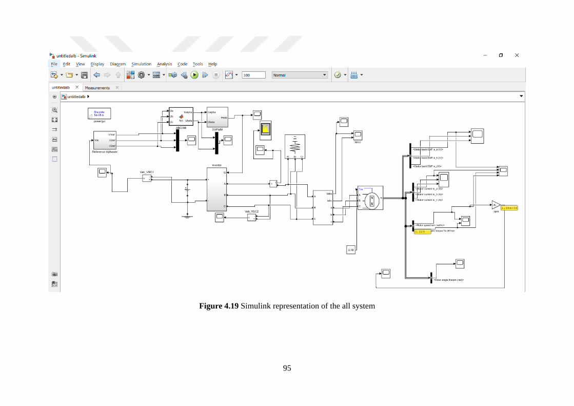
95
Figure 4.19 Simulink representation of the all system
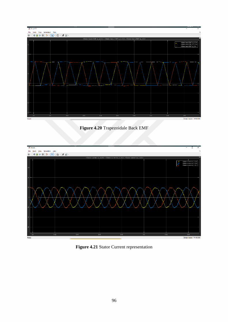
96
Figure 4.20 Trapezoidale Back EMF
Figure 4.21 Stator Current representation
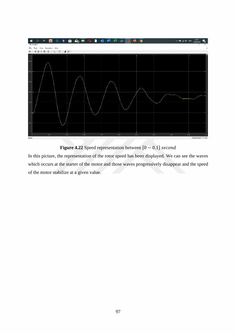
97
Figure 4.22 Speed representation between [0 − 0.1] 𝑠𝑒𝑐𝑜𝑛𝑑
In this picture, the representation of the rotor speed has been displayed. We can see the waves
which occurs at the starter of the motor and those waves progressively disappear and the speed
of the motor stabilize at a given value.
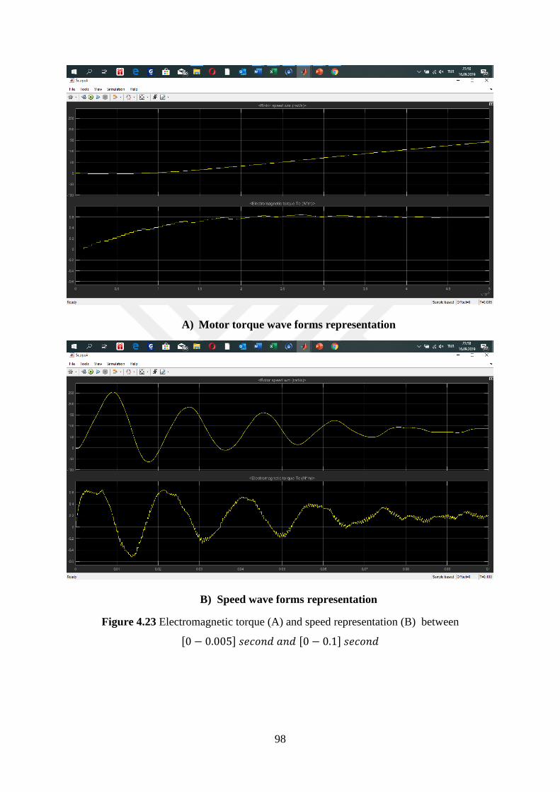
98
A) Motor torque wave forms representation
B) Speed wave forms representation
Figure 4.23 Electromagnetic torque (A) and speed representation (B) between
[0 − 0.005] 𝑠𝑒𝑐𝑜𝑛𝑑 𝑎𝑛𝑑 [0 − 0.1] 𝑠𝑒𝑐𝑜𝑛𝑑
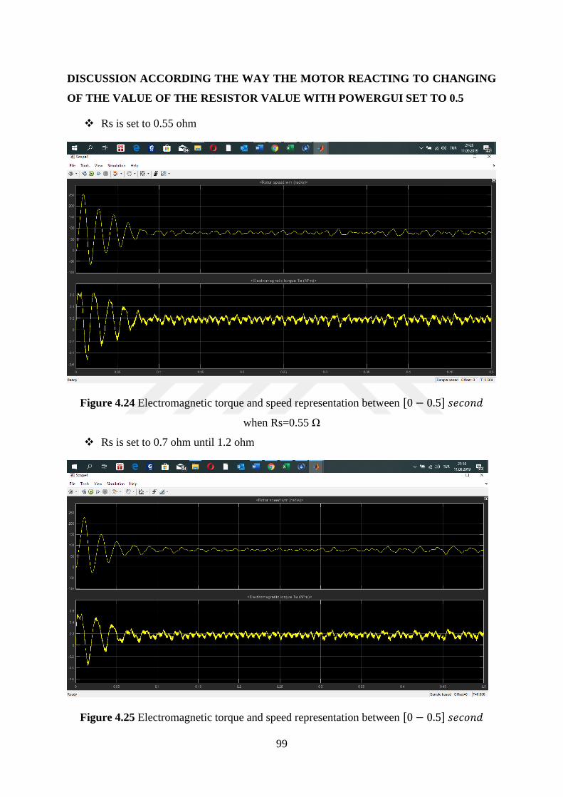
99
DISCUSSION ACCORDING THE WAY THE MOTOR REACTING TO CHANGING
OF THE VALUE OF THE RESISTOR VALUE WITH POWERGUI SET TO 0.5
❖ Rs is set to 0.55 ohm
Figure 4.24 Electromagnetic torque and speed representation between [0 − 0.5] 𝑠𝑒𝑐𝑜𝑛𝑑
when Rs=0.55 Ω
❖ Rs is set to 0.7 ohm until 1.2 ohm
Figure 4.25 Electromagnetic torque and speed representation between [0 − 0.5] 𝑠𝑒𝑐𝑜𝑛𝑑
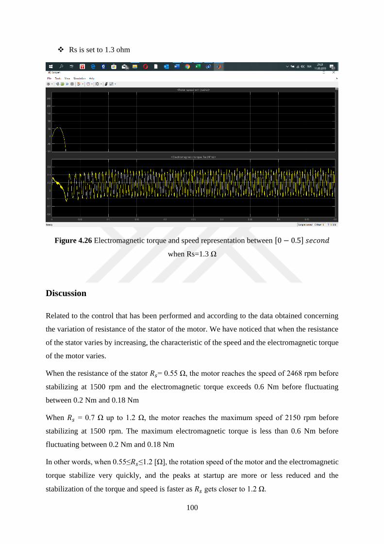
100
❖ Rs is set to 1.3 ohm
Figure 4.26 Electromagnetic torque and speed representation between [0 − 0.5] 𝑠𝑒𝑐𝑜𝑛𝑑
when Rs=1.3 Ω
Discussion
Related to the control that has been performed and according to the data obtained concerning
the variation of resistance of the stator of the motor. We have noticed that when the resistance
of the stator varies by increasing, the characteristic of the speed and the electromagnetic torque
of the motor varies.
When the resistance of the stator 𝑅𝑠= 0.55 Ω, the motor reaches the speed of 2468 rpm before
stabilizing at 1500 rpm and the electromagnetic torque exceeds 0.6 Nm before fluctuating
between 0.2 Nm and 0.18 Nm
When 𝑅𝑠 = 0.7 Ω up to 1.2 Ω, the motor reaches the maximum speed of 2150 rpm before
stabilizing at 1500 rpm. The maximum electromagnetic torque is less than 0.6 Nm before
fluctuating between 0.2 Nm and 0.18 Nm
In other words, when 0.55≤𝑅𝑠≤1.2 [Ω], the rotation speed of the motor and the electromagnetic
torque stabilize very quickly, and the peaks at startup are more or less reduced and the
stabilization of the torque and speed is faster as 𝑅𝑠 gets closer to 1.2 Ω.
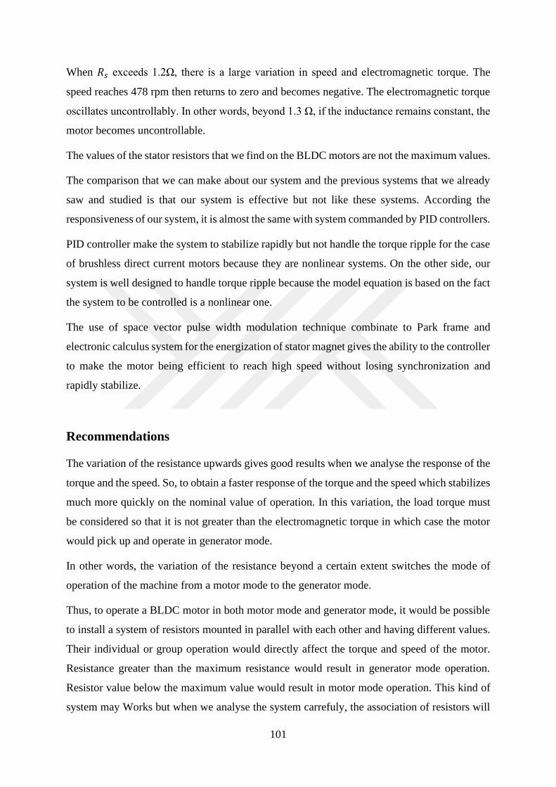
101
When 𝑅𝑠 exceeds 1.2Ω, there is a large variation in speed and electromagnetic torque. The
speed reaches 478 rpm then returns to zero and becomes negative. The electromagnetic torque
oscillates uncontrollably. In other words, beyond 1.3 Ω, if the inductance remains constant, the
motor becomes uncontrollable.
The values of the stator resistors that we find on the BLDC motors are not the maximum values.
The comparison that we can make about our system and the previous systems that we already
saw and studied is that our system is effective but not like these systems. According the
responsiveness of our system, it is almost the same with system commanded by PID controllers.
PID controller make the system to stabilize rapidly but not handle the torque ripple for the case
of brushless direct current motors because they are nonlinear systems. On the other side, our
system is well designed to handle torque ripple because the model equation is based on the fact
the system to be controlled is a nonlinear one.
The use of space vector pulse width modulation technique combinate to Park frame and
electronic calculus system for the energization of stator magnet gives the ability to the controller
to make the motor being efficient to reach high speed without losing synchronization and
rapidly stabilize.
Recommendations
The variation of the resistance upwards gives good results when we analyse the response of the
torque and the speed. So, to obtain a faster response of the torque and the speed which stabilizes
much more quickly on the nominal value of operation. In this variation, the load torque must
be considered so that it is not greater than the electromagnetic torque in which case the motor
would pick up and operate in generator mode.
In other words, the variation of the resistance beyond a certain extent switches the mode of
operation of the machine from a motor mode to the generator mode.
Thus, to operate a BLDC motor in both motor mode and generator mode, it would be possible
to install a system of resistors mounted in parallel with each other and having different values.
Their individual or group operation would directly affect the torque and speed of the motor.
Resistance greater than the maximum resistance would result in generator mode operation.
Resistor value below the maximum value would result in motor mode operation. This kind of
system may Works but when we analyse the system carrefuly, the association of resistors will
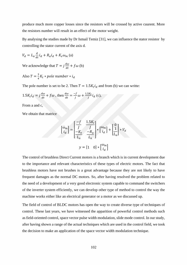
102
produce much more copper losses since the resistors will be crossed by active cuurent. More
the resistors number will result in an effect of the motor weight.
By analysing the studies made by Dr Ismail Temiz [31], we can influence the stator resistor by
controlling the stator current of the axis d.
𝑉𝑑 = 𝐿𝑎𝑑
𝑑𝑡𝑖𝑑 + 𝑅𝑎𝑖𝑑 + 𝐾𝑒𝜔𝑚 (a)
We acknowledge that 𝑇 = 𝑗𝑑𝜔
𝑑𝑡+ 𝑓𝜔 (b)
Also 𝑇 =3
4𝐾𝑡 ∗ 𝑝𝑜𝑙𝑒 𝑛𝑢𝑚𝑏𝑒𝑟 ∗ 𝑖𝑑
The pole number is set to be 2. Then 𝑇 = 1.5𝐾𝑡𝑖𝑑 and from (b) we can writte:
1.5𝐾𝑡𝑖𝑑 = 𝑗𝑑𝜔
𝑑𝑡+ 𝑓𝜔 , then
𝑑𝜔
𝑑𝑡=
−𝑓
𝐽𝜔 +
1.5𝐾𝑡
𝐽𝑖𝑑 (c),
From a and c,
We obtain that matrice
[�̇�𝑚𝑖𝑑] =
[ −𝑓
𝐽
1.5𝐾𝑡𝐽
−𝐾𝑒𝐿𝑎
−𝑅𝑎𝐿𝑎 ]
∗ [𝜔𝑚𝑖𝑑] + [
01
𝐿𝑎
] ∗ 𝑉𝑑
𝑦 = [1 0] ∗ [𝜔𝑚𝑖𝑑]
The control of brushless Direct Current motors is a branch which is in current development due
to the importance and relevant characteristics of these types of electric motors. The fact that
brushless motors have not brushes is a great advantage because they are not likely to have
frequent damages as the normal DC motors. So, after having resolved the problem related to
the need of a development of a very good electronic system capable to command the switchers
of the inverter system efficiently, we can develop other type of method to control the way the
machine works either like an electrical generator or a motor as we discussed up.
The field of control of BLDC motors has open the way to create diverse type of techniques of
control. These last years, we have witnessed the apparition of powerful control methods such
as field-oriented control, space vector pulse width modulation, slide mode control. In our study,
after having shown a range of the actual techniques which are used in the control field, we took
the decision to make an application of the space vector width modulation technique.

103
It shown us that the advantages using that technique compared to other technique. Even though
the equation that we use are quite a little bit complicated, the implementation of the techniques
is not so difficult, and it gives good result.
104
REFERENCES
[1] José C.G-R., Ernesto V-S., Jaime G-G. (2010) Position and Speed Control of Brushless DC
Motors Using Sensorless Techniques and Applications Trends.2010 (Sensors 2010), July, 10,
6901-6947.
[2] Farah, S. (2013) Brushless Motors Identification and Command for small drone. Toulouse,
France.
[3] M. Godoy, S., Felix, A.F. (2017) Modeling Power Electronics and Interfacing Energy
Conversion Systems. ISBN 9781119058472(epub) Hoboken, NJ, USA,
[4] J. Holtz (2006). Sensorless Control of Induction Machines: With or Without Signal
Injection, IEEE Trans. Ind: Electrton.,53:7-30
[5 Georges Nagy (1960) The Hysteresis Motor Gill University, Montréal, Canada
[6] J.J. Nitao, E.T. Scharleman, and B.A. Kirkendall (2009) "Equivalent Circuit Modelling of
Hysteresis Motors", Lawrence Livermore, National Laboratory, 21 July 2009, USA
[7] Haute Ecole Spécialisée de Suisse Occidentale, IAI, Systèmes électromécaniques Les
Moteurs pas à pas", Suisse
[8] Sophie Sekalala, (2006) "Performance Of A Three-Phase Permanent Magnet Motor
Operating As A Synchronous Motor and a Brushless DC Motor" August 2006, City University,
New-York
[9] Freescale Semiconductor, Inc.,"3-phase PM Synchronous Motor Torque Vector Control
Using 56F805", Designer Reference Manual, DRM018/D Rev.0,03/2003
8[10] Ramu Krishnan, (2010) "Permanent Magnet Synchronous and Brushless DC Motor
Drives”, Virgina Tech, Blacksburg, Virginia, USA
[11] Brushless DC Motor Control using the LPC2141 Application Note; AN10661, NXP
Semiconductors: Eindhoven, the Netherlands, October 2007.
[12] 3-Phase BLDC Motor Control with Hall Sensors using 56000/E Digital Signal Controllers
Application Note; AN1916, Freescale Semiconductor: TX, USA, 2005.
[13] Chang-Liang (2012) "Permanent Magnet Brushless DC Motor Drives and Controls" 2012,
Xia Tianjin University, P.R. China.
105
[14] Leonid Reznik. (1997) "Fuzzy Controlers”, Victorya University of Technology,
Melbourne, Australia.
[15] Xia, C. L., Liu, D., Wang, Y. F., et al. (2007) Control of brushless DC motors using fuzzy
set base dimmune feedback PID controller. Transactions of China Electrotechnical Society,
22(9), 68–73 (in Chinese).
[16] Chen, W., Xia, C. L., (2006) Sensorless control of brushless DC motor based on fuzzy
logic. IEEE Proceedings of the World Congress on Intelligent Control and Automation, China,
6298–6302.124 Permanent Magnet Brushless DC Motor Drives and Controls
[17] Xia, C. L., Xiu, J. (2006) Sensorless control of switched reluctance motor based on ANFIS.
Lecture Notes in Computer Science, 234:645–653.
[18] Rubaai, A., Ricketts, D., Kankam, M. D. (2001) Experimental verification of a hybrid
fuzzy control strategy for a high-performance brushless DC drive system. IEEE Transactions
on Industry Applications, 37(2), 503–512.
[19] Kaushal Kishor, Sheela Tiwari,"Speed Control of a Brushless DC Motor Using Neural
Network Based MRAC"NIT, International Journal of Industrial Electronics and Electrical
Motorering, ISSN: 2393-2835, India, 2017.
[20] Lin, C. L., Jan, H. Y., Shieh, N.C. (2003) GA-Based multi-objective PID control for a
linear brushless DC motor. IEEE Transactions on Mechatronics, 8(1), 56–65.
[21] Xia, C. L., Liu, D., Wang, Y. F. (2007) Artificial neural network control of brushless DC
motor based on immune feedback adaptive learning. Journal of Tianjin University, 40(10),
1235–1240 (in Chinese).
[22] Xia, C. L., Fang, H. W., Chen, W., et al. (2006) Ant colony algorithm based fuzzy control
for a brushless DC motor. IEEE Proceedings of the World Congress on Intelligent Control and
Automation China,6498–6502.
[23] Wang, Y. F., Xia, C. L., Zhang, M. H., et al. (2007) Adaptive speed control for brushless
DC motors based ongenetic algorithm and RBF neural network. IEEE International Conference
on Control and Automation China, 1219–1222.
[24] Liu, D., Xia, C. L., (2007) Control of brushless DC motor using fuzzy set based immune
feedback PID controlle. IEEE International Symposium on Industrial Electronics, Spain, 1045–
1049.
106
[25] Maoqing Zhang, Zhongcheng Yu, Hongcai Huan and Yanrong Zhou, March (2007),” The
Sliding Mode Variable Structure Control Based on Composite Reaching Law of Active
Magnetic Bearing” ICIC International 2008 ISSN 1881-803X pp. 59-63
[26] Xia, C. L., Liu, J. H., Yu, W., et al. (2005) Variable structure control of BLDCM based on
extended state observer. IEEE International Conference on Mechatronics and Automation,
Canada, 568–571.
[27] Lim, K. W., Low, T. S., Rahman, M. F. et al. (1991) A discrete time variable structure
controller for a brushless DC motor drive. IEEE Transactions on Industrial Electronics, 38(2),
102–107.
[28] José C.G-R.; Ernesto V-S.; Jaime G-G. (2010) Position and Speed Control of Brushless
DC Motors Using Sensorless Techniques and Applications Trends. (Sensors 2010), July
2010,10,6901-6947.
[29] Johnson, J.P., Ehsani, M., Guzelgunler, Y. (1999) Review of Sensorless Methods for
Brushless DC. In Proceedings of the 1999 IEEE Industry Applications Conference (Thirty-
Fourth IAS Annual Meeting), Phoenix, AZ, USA, October 1999; Volume 1. pp. 143-150
[30] Moreira, J.C. (1996) Indirect Sensing for Rotor Flux Position of Permanent Magnet AC
Motors Operating Over a Wide Speed Range. IEEE Trans. Ind. Appl. 1996, 32, 1394-1401.
[31] Ismail T., Selçuk A.(2000) Investigating The Brushless DC Motors By State Space
Approach.M.Ü. Fen Bilimleri Dergisi, Sayı:16,2000 pp. 237-252
[32] Antonio F.,Anthony Mallet (2019) “Adaptive Closed-Loop Speed Control of BLDC
Motors with Applications to Multi-Rotor Aerial Vehicles”,LAA-CNRS, Toulouse
University,CNRS,Toulouse,France.
[33] P.suganthi,S.nagapavithra (2017) “Modeling and Simulation of Closed Loop Speed
Control for BLDC Motor” Mahendra Engineering College, Mahendhirapuri, Mallasamudram,
Namakkal DT- 637503
[34] Subrat S.,Brajesh K.,Nirbhar N., (2017) “Controller Design for Closed Loop Speed
Control of BLDC Motor” Birla Institute of Technology, Mesra,
[35] Alejandra D.L.G.,Lizeth T.Luis A., ( 2018) “Speed Sensorless Robust Control for a
Brushless DC motor” Metropolitan Autonomous University

107
[36] Poonam M.Y.,Gadgune S.,(2019) “Position and Speed Control of Brushless DC Motors
using Sensorless Techniques: A Review”, International Journal of Engineering Research &
Technology (IJERT), ISSN: 2278-0181, Vol. 8 Issue 01, January-2019
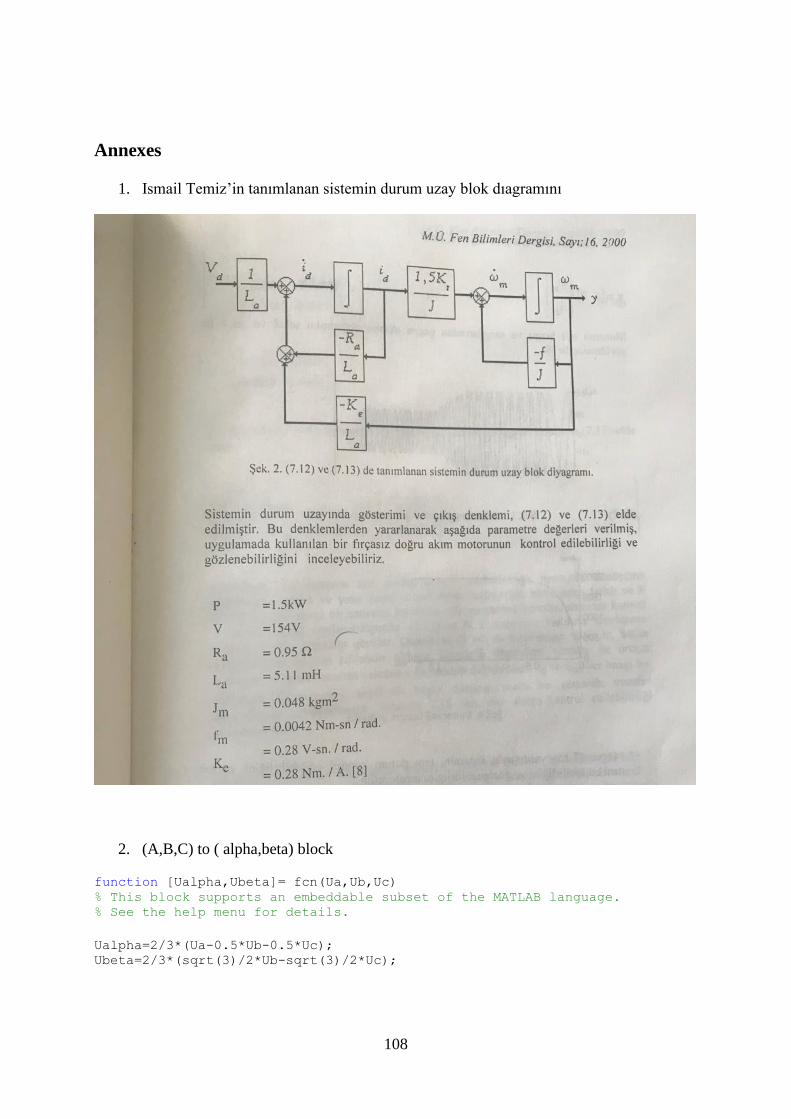
108
Annexes
1. Ismail Temiz’in tanımlanan sistemin durum uzay blok dıagramını
2. (A,B,C) to ( alpha,beta) block
function [Ualpha,Ubeta]= fcn(Ua,Ub,Uc) % This block supports an embeddable subset of the MATLAB language. % See the help menu for details.
Ualpha=2/3*(Ua-0.5*Ub-0.5*Uc); Ubeta=2/3*(sqrt(3)/2*Ub-sqrt(3)/2*Uc);

109
3. Sn function
function Sn = S(Ux,Uy) theta=atan2(Uy,Ux)*180/pi; if theta>=0&&theta<60 Sn=1; elseif theta>=60&&theta<120 Sn=2; elseif theta>=120&&theta<180 Sn=3; elseif theta>=-180&&theta<-120 Sn=4; elseif theta>=-120&&theta<-60 Sn=5; else Sn=6; end
4. T function
function [T1,T2,T0]=T(Ux,Uy,Sn) Ts=1/2000; Udc=24;
X=sqrt(3)*Ts/Udc*Uy; Y=sqrt(3)*Ts/2/Udc*(sqrt(3)*Ux+Uy); Z=sqrt(3)*Ts/2/Udc*(-sqrt(3)*Ux+Uy);
if Sn==1 T1=-Z;T2=X; elseif Sn==2; T1=Z;T2=Y; elseif Sn==3; T1=X;T2=-Y; elseif Sn==4; T1=-X;T2=Z; elseif Sn==5; T1=-Y;T2=-Z; else T1=Y;T2=-X; end
if T1+T2>Ts a=T1;b=T2; T1=a*Ts/(a+b); T2=b*Ts/(a+b); end
T0=Ts-T1-T2;
5. D function
function [Tcma,Tcmb,Tcmc]=D(T1,T2,T0,Sn) Ts=1/2000; Udc=24; ton1=0.5*T0; ton2=ton1+T1/2; ton3=ton2+T2/2;

110
if Sn==1 Tcma=ton1;Tcmb=ton2;Tcmc=ton3; elseif Sn==2; Tcma=ton2;Tcmb=ton1;Tcmc=ton3; elseif Sn==3; Tcma=ton3;Tcmb=ton1;Tcmc=ton2; elseif Sn==4; Tcma=ton3;Tcmb=ton2;Tcmc=ton1; elseif Sn==5; Tcma=ton2;Tcmb=ton3;Tcmc=ton1; else Tcma=ton1;Tcmb=ton3;Tcmc=ton2; end
111
Curriculum Vitae
Alban Exauce Mouandza Mboungou
Zafer Mahallesi Adile Naşıt Bulvarı
Esenyurt/ Istanbul-Turkey
Mobile: 00905343825106
Email address: [email protected]
Nationality: Congolese
Day and place of birth: 26/09/1992 in Pointe-Noire – Republic of Congo
Single
Work experience:
May 2015: SOGEF, Dakar, Senegal
Position: Technician Electromechanical
Function: Maintenance of Groups Producing Cold ,refrigerant gas and liquid.
July 2013: Dakar Dem Dik, Dakar, Senegal
Positon: Tehnician Electrotechnical
Function: Maintenance of electrical systems for electronic buses
Education:
2017-2018: Master’s Degree in Mechatronics Motorering University of Marmara, Istanbul,
Turkey
2014-2015:Bachelor’s Degree in Electrotechnics Speciality: Electromechanics, Refrigeration
& Air-conditioning Dakar Higher Institute of Industrial Technology, Senegal
2013-2014: Advanced Vocational Training Certificate in Electrotechnics College of
Entrepreneurship & Technical Development, Dakar (CETD, Le G15)
2011-2012: Preparatory Classes in General Science of Motorering École Polytechnique of
Masuku University of Sciences and Techniques of Masuku, Gabon
2010-2011: Science-based Baccalauréat in Mathematics-Physics Lycée de l’Excellence de
Franceville, Gabon.

112
Personal skills and others:
Languages:
French: Native language
English: Fluent
Turkish: Fluent
Computing:
Internet Browsers (google chrome, internet explorer, mozilla firefox)
Monitor: Keeping information update, put all necessary information
Other programs: Proteus, FEMM, EPLAN (Microsoft office (word, Access, Excel, power
point)
Personal interest: Reading, Social Networks, Learning other culture, Geography of French
speaking countries.

113

114
Copyright © 2022 FDOKUMEN