
Sensorless direct vector control of induction motor with a unified sliding mode observer
11
Control Engineering Practice 16 (2008) 67–77 Sensorless direct vector control of an induction motor $ M. Menaa a, , O. Touhami b , R. Ibtiouen b , M. Fadel c a Laboratoire de Robotique Paralle´lisme et Electro-e´nerge´tique, De´partement d’Electrotechnique, Universite´des Sciences et de la Technologie Houari Boumediene BP 32 EL Allia, Alger 16111, Algeria b De´partement de Ge´nie Electrique, Ecole Nationale polytechnique, 10 AV Pasteur, El-Harrach, Alger, Algeria c Laboratoire d’Electrotechnique et d’Electronique Industrielle ENSEEIHT, Toulouse, 2 Rue Camichel BP 7122-31071 Cedex7, France Received 21 May 2006; accepted 2 April 2007 Available online 16 May 2007 Abstract In high-performance variable speed AC drive systems it is often important to accurately determine machine parameters and rotor speed values. An extended complex Kalman filter (ECKF) is used to estimate rotor resistance and mutual inductance without the use of a speed sensor. Such estimates are important in air gap flux orientation control. The ECKF is chosen over the more common extended Kalman filter based on the real-valued model as it is not as computationally intensive. The model of an induction machine obtained by the spiral vector theory and the ECKF are used to develop a new adaptive direct air gap flux orientation control with two sensors: one for the stator voltage and one for the stator current without Park transformation. The simulation tests show the effectiveness of the proposed adaptive direct air gap flux orientation control method. r 2007 Elsevier Ltd. All rights reserved. Keywords: Induction machine; Extended Kalman filter; Extended complex Kalman filter; Spiral vector theory; Parameter estimation; Sensorless control and sonsorless direct air gap flux orientation control 1. Introduction Vector control allows high-performance control of torque, speed, or position to be achieved from an induction machine. Induction machines have been the most widely used machines in fixed-speed applications for reasons of cost, size, weight, reliability, ruggedness, simplicity, effi- ciency, and ease of manufacture. In variable-speed, high- performance drives, the DC machine and permanent magnet synchronous machine have prevailed as the induction machine requires more complex methods of control and more expensive, higher-rated inverters. The disadvantages of the induction machine becoming less emphasized as the computing power of the microprocessors and digital signal processors is increased, with reducing costs and size, together with improvements in inverter technology (Holtz, 2002; Vas, 1990; Wade, Dunnigon, & Williams, 1997). The method of vector control can provide at least the same performance from an inverter-driven induction machine as is obtainable from a separately excited DC machine. Vector control provides decoupled control of the flux magnitude and the torque producing current. The fast torque response obtained using vector control is achieved by estimating, measuring, or calculating the magnitude and position of the flux in the machine. The measurement of the flux can be made by the search coils or Hall effect devices, inserted into the air gap of the machine. Alternatively, the air gap flux can be determined analyti- cally by stator field integration. However, due to the stator resistance voltage drop, the result may be biased. This could affect the performance of the drive at low speed (Holtz, 2002; Ouhrouche, 2000). To overcome this draw- back, the flux must be estimated using observer. The estimation of the flux using a state observer involves the rotor resistance and mutual inductance, which are known ARTICLE IN PRESS www.elsevier.com/locate/conengprac 0967-0661/$ - see front matter r 2007 Elsevier Ltd. All rights reserved. doi:10.1016/j.conengprac.2007.04.002 $ This paper was not presented at any IFAC meeting. Corresponding author. Tel.: +213 50130729; fax: +213 21522528. E-mail addresses: [email protected], [email protected] (M. Menaa), [email protected] (O. Touhami), ribtiouen@yahoo. com (R. Ibtiouen), [email protected] (M. Fadel).
-
Upload
independent -
Category
Documents
-
view
6 -
download
0
Transcript of Sensorless direct vector control of induction motor with a unified sliding mode observer

ARTICLE IN PRESS
0967-0661/$ - se
doi:10.1016/j.co
$This paper�CorrespondE-mail addr
(M. Menaa), t
com (R. Ibtiou
Control Engineering Practice 16 (2008) 67–77
www.elsevier.com/locate/conengprac
Sensorless direct vector control of an induction motor$
M. Menaaa,�, O. Touhamib, R. Ibtiouenb, M. Fadelc
aLaboratoire de Robotique Parallelisme et Electro-energetique, Departement d’Electrotechnique,
Universite des Sciences et de la Technologie Houari Boumediene BP 32 EL Allia, Alger 16111, AlgeriabDepartement de Genie Electrique, Ecole Nationale polytechnique, 10 AV Pasteur, El-Harrach, Alger, Algeria
cLaboratoire d’Electrotechnique et d’Electronique Industrielle ENSEEIHT, Toulouse, 2 Rue Camichel BP 7122-31071 Cedex7, France
Received 21 May 2006; accepted 2 April 2007
Available online 16 May 2007
Abstract
In high-performance variable speed AC drive systems it is often important to accurately determine machine parameters and rotor
speed values.
An extended complex Kalman filter (ECKF) is used to estimate rotor resistance and mutual inductance without the use of a speed
sensor. Such estimates are important in air gap flux orientation control. The ECKF is chosen over the more common extended Kalman
filter based on the real-valued model as it is not as computationally intensive. The model of an induction machine obtained by the spiral
vector theory and the ECKF are used to develop a new adaptive direct air gap flux orientation control with two sensors: one for the
stator voltage and one for the stator current without Park transformation. The simulation tests show the effectiveness of the proposed
adaptive direct air gap flux orientation control method.
r 2007 Elsevier Ltd. All rights reserved.
Keywords: Induction machine; Extended Kalman filter; Extended complex Kalman filter; Spiral vector theory; Parameter estimation; Sensorless control
and sonsorless direct air gap flux orientation control
1. Introduction
Vector control allows high-performance control oftorque, speed, or position to be achieved from an inductionmachine. Induction machines have been the most widelyused machines in fixed-speed applications for reasons ofcost, size, weight, reliability, ruggedness, simplicity, effi-ciency, and ease of manufacture. In variable-speed, high-performance drives, the DC machine and permanentmagnet synchronous machine have prevailed as theinduction machine requires more complex methods ofcontrol and more expensive, higher-rated inverters. Thedisadvantages of the induction machine becoming lessemphasized as the computing power of the microprocessorsand digital signal processors is increased, with reducing
e front matter r 2007 Elsevier Ltd. All rights reserved.
nengprac.2007.04.002
was not presented at any IFAC meeting.
ing author. Tel.: +213 50130729; fax: +213 21522528.
esses: [email protected], [email protected]
[email protected] (O. Touhami), ribtiouen@yahoo.
en), [email protected] (M. Fadel).
costs and size, together with improvements in invertertechnology (Holtz, 2002; Vas, 1990; Wade, Dunnigon, &Williams, 1997).The method of vector control can provide at least the
same performance from an inverter-driven inductionmachine as is obtainable from a separately excited DCmachine. Vector control provides decoupled control of theflux magnitude and the torque producing current.The fast torque response obtained using vector control is
achieved by estimating, measuring, or calculating themagnitude and position of the flux in the machine. Themeasurement of the flux can be made by the search coils orHall effect devices, inserted into the air gap of the machine.Alternatively, the air gap flux can be determined analyti-cally by stator field integration. However, due to the statorresistance voltage drop, the result may be biased. Thiscould affect the performance of the drive at low speed(Holtz, 2002; Ouhrouche, 2000). To overcome this draw-back, the flux must be estimated using observer. Theestimation of the flux using a state observer involves therotor resistance and mutual inductance, which are known
ARTICLE IN PRESS
Nomenclature
va stator voltage, Via, ir stator, rotor current, Alga, lgr stator, rotor leakage flux, Wbm transformation ratioR1, R2 stator, rotor resistance, O‘1, ‘2 stator, rotor leakage inductance, HLa, Lr stator, rotor main inductance, HMs, Mr mutual inductance between stator windings and
mutual inductance between rotor windings, HMrs mutual inductance between stator and rotor, HR02 rotor resistance in stator reference frame, O
‘02 rotor leakage inductance in stator referenceframe, H
om, osl, Om electrical, slip, rotor speed, rad/sF0 air gap flux, Wbe1, e2 stator, rotor dynamic e.m.f.P pole pair numberTem electromagnetic torque, NmT sampling time, sW, V state, measured noisesm, sv variance of state noise, measured noisey measured currentI unit matrix* conjugate
Re
t=0
A
Im
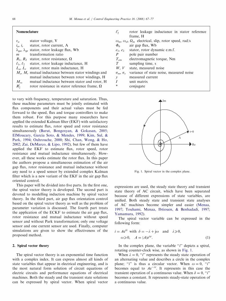
Fig. 1. Spiral vector in the complex plane.
M. Menaa et al. / Control Engineering Practice 16 (2008) 67–7768
to vary with frequency, temperature and saturation. Thus,these machine parameters must be jointly estimated withflux components and their actual values must be fedforward to the speed, flux and torque controllers to makethem robust. For this purpose many researchers haveapplied the extended Kalman filter (EKF) with satisfactoryresults to estimate flux, rotor speed and rotor resistancesimultaneously (Barut, Bongosyan, & Gokasan, 2005;ElMoucary, Garcia Soto, & Mendes, 1999; Kim, Sul, &Park, 1994; Ouhrouche, 2000; Shi, Chan, Wong, & Ho,2002; Zai, DeMarco, & Lipo, 1992), but few of them haveapplied the EKF to estimate flux, rotor speed, rotorresistance and mutual inductance simultaneously. How-ever, all these works estimate the rotor flux. In this paperthe authors propose a simultaneous estimation of the airgap flux, rotor resistance and mutual inductance withoutany need to a speed sensor by extended complex Kalmanfilter which is a new variant of the EKF in the air gap fluxoriented control.
This paper will be divided into five parts. In the first one,the spiral vector theory is developed. The second part isdevoted to modelling induction machine by spiral vectortheory. In the third part, air gap flux orientation controlbased on the spiral vector theory as well as the problem ofparameter variation is discussed. The fourth part treatsthe application of the ECKF to estimate the air gap flux,rotor resistance and mutual inductance without speedsensor and without Park transformation; only one voltagesensor and one current sensor are used. Finally, computersimulations are given to show the effectiveness of theproposed method.
2. Spiral vector theory
The spiral vector theory is an exponential time functionwith a complex index. It can express almost all kinds ofstate variables that appear in electrical engineering, and isthe most natural form solution of circuit equations ofelectric circuits and performance equations of electricalmachines. Both the steady and the transient state solutionscan be expressed by spiral vector. When spiral vector
expressions are used, the steady state theory and transientstate theory of AC circuit, which have been separatedbecause of different expressions of state variables, areunified. Both steady state and transient state analysesof AC machines become simpler and easier (Menaa,1997; Touhami, Menaa, Ibtiouen, & Benhadadi, 1997;Yamamura, 1992).The spiral vector variable can be expressed in the
following form:
i ¼ Aedt with d ¼ �lþ jo and lX0,
oX0; A ¼ jAjejj. ð1Þ
In the complex plane, the variable ‘‘i’’ depicts a spiral,rotating counter-clock wise, as shown in Fig. 1.When l ¼ 0, ‘‘i’’ represents the steady state operation of
an alternating value and describes a circle in the complexplane; ‘‘i’’ is thus a circular vector. When o ¼ 0, ‘‘i’’becomes equal to Ae�lt. It represents in this case thetransient operation of a continuous value. When d ¼ 0, ‘‘i’’becomes a constant. It represents steady-state operation ofa continuous value.

ARTICLE IN PRESSM. Menaa et al. / Control Engineering Practice 16 (2008) 67–77 69
3. Induction machine model by spiral vector theory
Generally, the spiral vector theory is used to describe themodel by transfer function (De Aguiar & Cad, 2000; Muni,Pillai, & Saxena, 1996; Yamamura, 1992). In this paper, theauthors use this theory to develop a state space model.
The first step, in the estimation process is the definition of asuitable machine model. When the spiral vector theory is usedfor modelling the induction machine, it can be represented bya nonlinear third-order differential equation. This modeltakes into account both electrical and mechanical transients.Only the variables and the parameters of one stator phaseand one rotor phase are considered.
By separating the slow mechanical modes from the fastelectrical ones, linear time varying electrical modes can bededuced.
It is assumed that the stator and motor windings areelectrically and geometrically symmetrical, the air gap isuniform, the field distribution is uniform and that theeffects of field saturation, eddy currents and hysteresis arenegligible. In that case the induction motor may berepresented by the model of the three-phase stator androtor windings shown in Fig. 2 (instead of the D–Q model),and the following model per phase can be derived:
va ¼ R1ia þ ‘1dia
dtþ
dlga
dt,
0 ¼ R2ir þ ‘2dir
dtþ
dlgr
dt. ð2Þ
The equations describing the stator and the rotor fluxesequations are as follows:
lga ¼ Laia þMsib cos2p3
� �þMsic cos �
2p3
� �
þMrsir cos yð Þ þMrsis cos yþ2p3
� �
þMrsit cos y�2p3
� �, ð3Þ
Fig. 2. Three phase stator and rotor windings distribution of an induction
machine.
lgr ¼ Lrir þMris cos2p3
� �þMrit cos �
2p3
� �
þMrsia cos yð Þ þMrsib cos yþ2p3
� �
þMrsic cos y�2p3
� �. ð4Þ
The stator and rotor currents of symmetrical spiralvector are:
ia ¼ A1edt; ib ¼ A1e
dt�jð2p=3Þð Þ; ic ¼ A1edtþjð2p=3Þð Þ, (5)
ir ¼ A2ed0t; is ¼ A2e
d0t�jð2p=3Þð Þ; it ¼ A2ed0tþjð2p=3Þð Þ. (6)
Inserting (5) and (6) into the expressions for stator androtor flux (3) and (4), the following expressions areobtained:
lga ¼ La þMs
2
� �ia þ
3
2Mrsire
jy, (7)
lgr ¼ Lr þMr
2
� �ir þ
3
2Mrsiae
�jy. (8)
Introducing (7) and (8) in (2) gives:
va ¼ R1ia þ ‘1d
dtia þ La þ
1
2Ms
� �d
dtia
þ3
2Mrs
d
dtire
jy� �,
0 ¼ R2ir þ ‘2d
dtir þ Lr þ
1
2Mr
� �d
dtir
þ3
2Mrs
d
dtiae�jy� �
, ð9Þ
with y ¼ omt.The obtained model (9) by spiral vector theory can
represent the induction machine in any reference frame.This model contains only variables and parameters of onestator phase ‘‘a’’ and one rotor phase ‘‘r’’, which aresegregated from the other phases. In opposition to Parkmodel where the voltage and the current of two phaseshave to be known, the spiral vector model only needs thevoltage and the current of one phase to achieve a vectorcontrol (Menaa, Touhami, & Ibtiouen, 2001, 2003; Menaa,Touhami, Ibtiouen, & Iung, 1998).
4. Air gap flux orientation control based on the spiral vector
model
The air gap flux orientation control based on the spiralvector model consists of choosing a model in the referenceframe attached to the rotating field, the air gap flux vectorF0 is aligned with the real axis in order to achieve, as in aseparately excited DC machine, decoupling control be-tween the flux and the produced torque (Menaa, 1997;Menaa et al., 1998).The torque is then controlled by the imaginary
part of the stator current of the phase ‘‘a’’. At the

ARTICLE IN PRESSM. Menaa et al. / Control Engineering Practice 16 (2008) 67–7770
same time, the flux is controlled by the real part of thestator current of the phase ‘‘a’’, called the flux pro-ducing current (Menaa, 1997; Menaa et al., 1998). Toobtain the model in the reference frame fixed in therevolving field, set:
va ¼ v1ejys ,
ia ¼ i1ejys , ð10Þ
ir ¼ i2ejysl , (11)
with ysl ¼ ys � y.Replacing (10) and (11) in (9), the obtained model
referred to the revolving field is as follows:
v1 ¼ R1i1 þ ‘1 þ3
2M
� �d
dtþ jos
� �i1 þ
3
2
d
dtþ jos
� �i2p,
0 ¼ R02i2p þ ‘02 þ3
2M
� �d
dtþ josl
� �i2p
þ3
2M
d
dtþ josl
� �i1, ð12Þ
with M ¼Mrs/m.Then, the T type transient state equivalent circuit of the
induction machine in the revolving field is deduced, andrepresented in Fig. 3.
e1 ¼ �jos ‘1 þ3
2M
� �i1 þ
3
2Mi2p
� �, (13)
e2 ¼ �josl ‘02 þ3
2M
� �i2p þ
3
2Mi1
� �. (14)
The electromagnetic torque is given by:
Tem ¼94
PM Im i1i�2p
� . (15)
Inserting the expression of the air gap flux F0 ¼32
Mði1 þ
i2pÞ in (12) and (15) gives:
v1 ¼ R1i1 þ ‘1d
dtþ jos
� �i1 þ
d
dtþ jos
� �F0,
0 ¼ R02i2p þ ‘02
d
dtþ josl
� �i2p þ
d
dtþ josl
� �F0, ð16Þ
Tem ¼32
P Im i1F�0� �
. (17)
Fig. 3. T-type transient state equivalen
As air gap flux orientation requires that ReðF0Þ ¼ F0
and ImðF0Þ ¼ 0, (16) and (17) become:
v1 ¼ R1i1 þ ‘1d
dtþ jos
� �i1 þ
d
dtþ jos
� �ReðF0Þ,
0 ¼ R02i2p þ ‘02
d
dtþ josl
� �i2p þ
d
dtþ josl
� �ReðF0Þ, ð18Þ
Tem ¼32
PRe F0ð ÞImði1Þ. (19)
Considering the air gap flux and the rotor speed asreference, the air gap flux orientation equations obtain thefollowing form:
Imði1Þ ¼2
3
1
P
Temref
F0ref
,
‘02R02
d
dtReði1Þ þReði1Þ ¼
sR02
d
dtF0ref
þ1
ð3=2ÞMF0refþ‘02R02
osl Imði1Þ,
osl ¼‘02ðd=dtÞ Imði1Þ þ R02 Imði1Þ
sF0ref� ‘02 Reði1Þ
, ð20Þ
os ¼ osl þ om,
Reðv1Þ ¼ ‘1d
dtReði1Þ þ
d
dtF0refþ R1 Reði1Þ � ‘1os Imði1Þ,
Imðv1Þ ¼ ‘1d
dtImði1Þ þ R1 Imði1Þ � os ‘1 Reði1Þ þ F0ref
� �,
ð21Þ
with s ¼ ð‘02=32
MÞ þ 1.The bloc diagram of direct vector control is represented
in Fig. 4.The calculation of the slip speed ‘‘osl‘‘and flux controller
parameters depend on the rotor resistance and mutualinductance that significantly can vary with temperature,frequency and saturation. Any error in the slip speedcalculation entails error in the air gap flux positionresulting in coupling between the flux and torque produ-cing currents due to axis misalignment. This results in atorque response with possible overshoot or undershootand a steady-state error. There is, therefore, a require-ment to track the changes in the rotor resistance and
t circuit of the induction machine.

ARTICLE IN PRESS
Fig. 4. Speed sensorless direct air gap flux orientation control of an induction machine.
M. Menaa et al. / Control Engineering Practice 16 (2008) 67–77 71
mutual inductance with a parameter identifier. In mostapplications, speed sensors are necessary and essential inspeed control loop. However, sensors have several dis-advantages in terms of drive cost, reliability, and noiseimmunity (Holtz, 2002).
Several papers deal with the speed and parametersestimation. The most used in the last decade is the EKF,but generally these papers treat the speed, rotor flux androtor resistance estimation. In this paper the authorspresent for the first time the simultaneous estimation of theair gap flux, rotor resistance and mutual inductancewithout speed sensor in the direct air gap flux control.
The ECKF is a variation of nonlinear Kalman filter inthe complex form. It has been shown by (Nishiyama, 1997)that the ECKF is more attractive than the real one ‘‘EKF’’from the point of view of modelling and stabilityconsideration. The ECKF is more used in the powersystem estimation (Dash, Pradhan, & Panda, 1999; Flores,Gu, & Bollen, 2003) but not in electrical machineestimation. To the best of knowledge, this paper is thefirst one that treats the parameter estimation of inductionmachine with ECKF.
The Kalman filter algorithm and its extension are aspecial kind of observer that provides optimal filtering ofthe noises in measurement and inside the system if thecovariances of these noises are known. The system and
measurement noise disturbances are white and haveGaussian probability distribution. When the Kalman filteris used the state space model of an induction machine in thestator reference frame is required; to obtain the model instator reference, setting i1 ¼ ia, i2 ¼ ire
jy and v1 ¼ va in (9),the following induction machine model in the statorreference frame is obtained:
v1 ¼ R1i1 þ ‘1 þ L1ð Þd
dti1 þ
3
2M
d
dti2,
0 ¼ R2i2 þ ‘2 þ L2ð Þd
dt� jom
� �i2
þ3
2M
d
dt� jom
� �i1. ð22Þ
After all treatment and simplification, the following statespace model of an induction machine in the stator referenceframe, which is function of the air gap flux, is obtained.
_X eðtÞ ¼ AeX eðtÞ þ BeUðtÞ,
Y eðtÞ ¼ CeX eðtÞ, ð23Þ
where
X e tð Þ ¼i1
F0
" #; Y e tð Þ ¼ i1 and U tð Þ ¼ v1.

ARTICLE IN PRESSM. Menaa et al. / Control Engineering Practice 16 (2008) 67–7772
The coefficients of the matrices Ae, Be and Ce are given inAppendix A.
As the parameter estimation of an induction machine isto be implemented on a computer, so a time-discrete modelis the most appropriate. The discrete time varying model isdeduced from the continuous model by applying the Eulerformula (first order). It is given by:
X eðk þ 1Þ ¼ AeDX eðkÞ þ BeDUðkÞ,
Y eðkÞ ¼ CeDX eðk þ 1Þ. ð24Þ
The coefficients of the matrices AeD, BeD and CeD aregiven in Appendix A.
In practice, the induction machine cannot be representedperfectly by the previous deterministic model. To take intoaccount the system uncertainties and disturbances, thefollowing stochastic model is introduced:
X eðk þ 1Þ ¼ AeDX eðkÞ þ BeDUðkÞ þW ðkÞ,
Y eðkÞ ¼ CeDX eðk þ 1Þ þ V ðkÞ. ð25Þ
The state noise W and measured noise V can be anycombination of harmonics and complex Gaussian whitenoise with zero-mean and variances s2w and s2v , respectively.Real and imaginary parts of W(k) are mutually indepen-dent and have the same variance, i.e. s2w ¼ s2wr þ s2wi ands2wr ¼ s2wi. The real and imaginary parts of V(k) are alsomutually independent and have the same variance, i.e. s2v ¼s2vr þ s2vi and s2vr ¼ s2vi.
The ECKF allows simultaneous estimation of complexstates and parameters. These parameters are considered asextra states in an augmented state vector. This augmentedmodel is nonlinear because of multiplication betweenstates. Thus it must be linearized along the state trajectoryto give a linear perturbation model. The standard complexKalman filter is then applied on this linearized model. Theextended complex Kalman filter only requires machinesquantities that can be easily measured (stator voltage andstator current). In this new approach only the voltage andcurrent of one phase of stator are required, but in the DQ
model the voltage and current of two phases of stator arenecessary (Baghli, Al-Rouh, & Rezzoug, 2006; Duval,
Fig. 5. Adjustment parameter in speed control of an induction
Clerc, & Le Gorrec, 2006; Loron and Laliberte, 1993). Adynamic model of three phases induction machine, byspiral vector theory, has two complex state variablesnamely the stator current (i1) and air gap flux (F0) (inopposition to the Park model where four state variablesexist). An extended induction machine model results if therotor resistance, mutual inductance and rotor speed areincluded as additional state variables. The extended modelcan be expressed as follows:
xðk þ 1Þ ¼ f ðxðkÞ;UðkÞ; kÞ þW ðkÞ,
ZðkÞ ¼ HðkÞxðkÞ þ V ðkÞ, ð26Þ
with
f xðkÞ;UðkÞ; kð Þ ¼AeDX eðkÞ þ BedUðkÞ
YðkÞ
" #
YðkÞ ¼ R0232
M Om
h it
. ð27Þ
Then, linearizing the above system around the states andapplying an ECKF, the obtained nonlinear recursive filterbased on the ECKF for estimating a complex state andparameters of an induction machine is given by:Prediction of state
xpðk þ 1Þ ¼ f xðkÞ;UðkÞ; kð Þ. (27a)
Estimation of error covariance matrix
Ppðk þ 1Þ ¼ AðkÞPðkÞA�tðkÞ þQ. (27b)
Kalman filter gain
K ¼ Ppðk þ 1ÞH�tðkÞ HðkÞPp k þ 1ð ÞH�tðkÞ þ R ��1
. (27c)
State estimation
xðk þ 1Þ ¼ xpðk þ 1Þ þ K yðkÞ �HðkÞxðkÞ½ �. (27d)
Update of the error covariance matrix
Pðk þ 1Þ ¼ Ppðk þ 1Þ � KHðkÞPpðk þ 1Þ. (27e)
The matrices A(k) and H(k) are given in Appendix A.
machine using the direct air gap flux orientation control.

ARTICLE IN PRESS
Table 1
Rated values and parameters of the induction machine
Rated power 2 kW
Rated speed 1425 rpm
Rated frequency 50Hz
Rated voltage 220/380V
Rated current 4/7A
Pole pair number 2
Rotor inertia 0.0164 kgm2
Stator resistance, R1 4.1049ORotor resistance, R02 5.253OMutual inductance, (3/2)M 0.2145H
Stator leakage inductance, ‘1 0.0132H
Rotor leakage inductance in stator reference frame, ‘02 0.0132H
M. Menaa et al. / Control Engineering Practice 16 (2008) 67–77 73
5. Simulation results
The simulation tests were carried out using the direct airgap flux orientation control scheme of Fig. 5 without anyspeed measurement. The control is realized when thevoltage and current of one phase of stator are trackedwithout any geometric transformation, whereas in the caseof the vector control based on the DQ model, it is necessaryto track two voltages (vas and vbs) and two currents (ias andibs) when applying Park transformation (Barut, Bongos-yan, & Gokasan, 2002; Castaldi, Geri, Montanari, & Tilli,2005; Loron and Laliberte, 1993; Mueller, 1999; Poyhonen,Arkiko, Jover, & Hyotyniemi, 2005; Vas, 1990; Yazid,Menaa, Touhami, & Ibtiouen, 2005).
To test the performance of the proposed control, thesimulations were performed on a 50Hz, 2 kW inductionmachine with the rated parameters listed in Table 1. The
initial values are x0 ¼ 0þ 0j 0þ 0j R0s32
M 0h it
and
the sampling time T ¼ 0.1ms.The performance of the ECKF estimation is very
sensitively influenced by the values of the system para-meters and covariance matrix elements. In this study, toavoid computational complexity, the covariance matrix ofthe state noise Q, the covariance of the measured noise R
and the error covariance matrix P are chosen in diagonalform, also satisfying the condition of positive definiteness.According to the Kalman filter theory, Q and R have to beobtained by considering the stochastic properties of thecorresponding noises (Nishiyama, 1997; Vas, 1998); how-ever, since these are usually not known, in most cases, thecovariance matrix elements are used as weighting factors ortuning parameters. In this study tuning the initial values ofP, Q and R is done by trial and error to achieve a rapidinitial convergence. The values of P, Q and R are:
P0 ¼ diag 103 103 1022 3:51017 314104 �
,
Q ¼ diag 108 108 5108 51013 1:571020 �
,
R ¼ 51020.
Figs. 6 and 7 show different scenarios used to test theperformances of the estimation and control algorithm
under load torque, noise and rotor resistance increase by50% and mutual inductance decrease by 20% to their ratedvalues.Fig. 6(a–d) show in the first part (0 spto2.5 s) the
simulation test between zero speed and 125 rad/s under aload torque of 10Nm from standstill to 1.5 s. It can beobserved that the rotor speed and air gap flux are notaffected by the load torque change and the rotor speederror and air gap flux error are small. In the second part(2.5 spto5.3 s), the simulation test in the field weakeningrange is shown and for the time range (3.75 sptp4.75 s) aload torque of 5Nm is applied to the shaft, the rotor speedand air gap flux are not disturbed a lot by the torquechange and their errors are low. In the third part the speedreference goes down to 125 rad/s with no load torque andthe estimated rotor speed and air gap flux track theirreferences with a weak error. In the last part the rotorspeed is inversed (�125 rad/s) and at 8 s a negative loadtorque (�10Nm) is applied, remarking that the speed errorand flux error are not important. The rotor speedestimation error (Omachine�Om) is not more than 0.5% inthe steady state, which is the same value for the speedcontroller input (Omref�Om). For the air gap flux estima-tion error ðF0machine � F0Þ the maximum value is 0.5% inthe steady state and for the air gap flux controller inputðF0ref � F0Þ it is almost equal to zero in the steady state.Fig. 6e and f show the variation of the estimated rotor
resistance and estimated mutual inductance. Let us notethat the estimated rotor resistance converges quickly to itsreference and the estimated mutual inductance decreasesfrom initial value to its true value with no significant error.The estimated mutual inductance is scarcely affected by thespeed inversion. The rotor resistance error is not over0.95% in steady state and the mutual inductance error isless than 8% in steady state.Fig. 7(a–d) show in the first part the machine start-up
without load torque, the rotor speed and air gap flux tracktheir references with weak error. In the second part(0.6 spto3.4 s), the simulation test in low speed is shownand between (1.7 spto2.75 s) a load torque of 5Nm isapplied to the shaft, remarking that the estimated rotorspeed and air gap flux are not affected by torque change.The rotor speed error and the air gap flux error are weak. Inthe last part, the simulation test at zero speed is shown. Theestimated rotor speed and air gap flux track their referenceswith a very small error. The rotor speed estimation error(Omachine�Om) is not more than 1.8% in the steady state.The maximum value of the speed controller input(Omref�Om) is 1.5%. For the air gap flux estimation error(F0machine�F0) the maximum value is 0.8% in the steadystate and for the air gap flux controller input (F0ref�F0) it isalmost equal to zero in the steady state.Fig. 7e and f depict the variation of the estimated rotor
resistance and mutual inductance, which converge to theirtrue values with small error. The rotor resistance error isless than 0.65% in steady state and the mutual inductanceerror is not more than 0.6% in steady state.

ARTICLE IN PRESS
0 8 10
time (s)
-200
-100
0
100
200
300
-150
-50
50
150
250
Roto
r sp
eed
(ra
d/s
)
0 6 10
-4
-2
0
2
-5
-3
-1
1
3
Sp
eed
est
imati
on
err
or
(rad
/s)
10 8 4
time (s)
0
40
80
120
160
-20
20
60
100
140
Sp
eed
con
troll
er i
np
ut
(rad
/s)
0 6 10
time (s)
0
0.2
0.4
0.6
0.8
1
0.1
0.3
0.5
0.7
0.9
Air
gap
flu
x (
Wb
)
0 10
-0.008
-0.004
0
0.004
-0.006
-0.002
0.002
0.006A
irgap
flu
x e
stim
ati
on
err
or
(Wb
)
10 8
time (s)
0
0.4
0.8
0.2
0.6
1
Air
gap
flu
x c
on
troll
er i
np
ut
(Wb
)
0 4 10
0
4
8
12
10
2
6
Roto
r re
sist
an
ce (
Oh
m)
10 8 6 0
time (s)
-4
0
4
8
-2
2
6
Roto
r re
sist
an
ce e
rror
(Oh
m)
0 2 10
0.17
0.18
0.19
0.2
0.21
0.22
0.165
0.175
0.185
0.195
0.205
0.215
Mu
tual
ind
uct
an
ce (
Hen
ry)
10 8
time (s)
-0.04
-0.02
0
0.02M
utu
al
ind
uct
an
ce e
rror
(Hen
ry)
2 4 6 2 4 8
2 06
2 4 8 2 4 6 8
6 4 2 0
4
6
6 8
4 2 0
2 6 8
4 2
Fig. 6. Simulation tests results, (a) speed variation, (b) error of speed variation, (c) air gap flux variation, (d) error of air gap flux variation, (e) rotor
resistance variation and rotor resistance error, (f) mutual inductance variation and mutual inductance error.
M. Menaa et al. / Control Engineering Practice 16 (2008) 67–7774
These results show that the ECKF and the direct air gapflux orientation control achieve a low speed error and alsogive stable air gap flux response which is almost unaffectedby the load torque change and give a good estimation ofmachine parameters. The obtained results show that the
expected performance is attained. In summary, let us notethat:
�
The spiral vector theory permits to reduce the modelorder, which reduces the order of the covariance
ARTICLE IN PRESS
0 2 5
time (s)
-20
20
60
100
140
0
40
80
120
Roto
r sp
eed
(ra
d/s
)
0 2 4 5
0
2
4
Sp
eed
est
imati
on
err
or
(rad
/s)
5 3 1 0
time (s)
0
40
80
120
-20
20
60
100
140
Sp
eed
con
troll
er i
np
ut
(rad
/s)
0 3
time (s)
0
0.4
0.8
1.2
0.2
0.6
1
Air
gap
flu
x (
Wb
)
0 4
-0.008
-0.004
0
0.004
0.008
-0.006
-0.002
0.002
0.006A
irgap
flu
x e
stim
ati
on
err
or
(Wb
)
5 1
time (s)
0
0.4
0.8
0.2
0.6
1
Air
gap
flu
x c
on
troll
er in
pu
t (W
b)
0 5
5
6
7
8
5.5
6.5
7.5
Roto
r re
sist
an
ce (
Oh
m)
5
time (s)
0
1
2
0.5
1.5
2.5
Roto
r re
sist
an
ce e
rror
(Oh
m)
0
0.17
0.18
0.19
0.2
0.21
0.175
0.185
0.195
0.205
0.215
Mu
tual
ind
uct
an
ce (
Hen
ry)
5
time (s)
-0.04
-0.03
-0.02
-0.01
0
-0.045
-0.035
-0.025
-0.015
-0.005
0.005
Mu
tual
ind
uct
an
ce e
rror
(Hen
ry)
1 3 4 1 3
4 2
1 2 4 5 1 2 3 5
4 3 2 0
1 2 3 4
4 3 2 1 0
1 2 3 4 5
4 3 2 1 0
Fig. 7. Simulation tests results, (a) speed variation, (b) error of speed variation, (c) air gap flux variation, (d) error of air gap flux variation, (e) rotor
resistance variation and rotor resistance error, (f) mutual inductance variation and mutual inductance error.
M. Menaa et al. / Control Engineering Practice 16 (2008) 67–77 75
matrices. In this case, the error covariance matrix P andthe covariance matrix of state noise Q have (5� 5)elements each instead of (7� 7) elements in theconventional theory (Barut et al., 2005; Vas, 1998;
Yazid et al., 2005). The covariance of the measurednoise R is a scalar instead of (2� 2) elements in theconventional theory (Barut et al., 2005; Vas, 1998; Yazidet al., 2005).

ARTICLE IN PRESSM. Menaa et al. / Control Engineering Practice 16 (2008) 67–7776
�
In this new method R is not a matrix, so, the inversionmatrix in the ECKF algorithm (27c) is avoided in theopposite of the EKF based on the conventional model.This will reduce the computational time. � The spiral vector model permits to reduce the sensornumbers, leading to decreasing noise effect.
6. Conclusion
This paper has presented a novel model for inductionmachine associated to a new nonlinear filter ‘‘ECKF’’ forspeed sensorless direct air gap flux orientation control withparameter estimation.
The major contribution of this study is the reduction of thenumber of sensors from four or six in DQ model to twosensors using this new technique. The simultaneous estimationof the rotor resistance and mutual inductance as well as the airgap flux components and the rotor speed are accomplished.
The performances of the ECKF algorithm and direct airgap flux orientation control are tested for differentscenarios obtained by applying step and linear variationto the rotor speed reference with load torque, rotorresistance and mutual inductance variation.
The performances observed of the system are satisfac-tory under step type variation and reversal of the loadtorque and step/linear changes and reversal in the rotorspeed. The system has also demonstrated the expectedrobustness to step variations forced on the rotor resistanceand mutual inductance.
These observations and the obtained results motivate furtherexperimental implementation of the developed method.
Acknowledgment
This paper enters in the setting of a cooperation agreementinternational CMEP-Tassili under the 05MDU662 code.
Appendix A
The coefficients of systems (23) are as follows:
Ae ¼Ae11 Ae12
Ae21 Ae22
" #; Be ¼
1=‘T
‘02=‘Ts
" #and
Ce ¼ 1 0 �
,
Ae11 ¼� R1sþ R02 � j‘02om
� �‘1sþ ‘02
,
Ae12 ¼ðR02=
32
MÞ � jsom
‘1sþ ‘02,
Ae21 ¼R02s�‘02RT
s‘T
þ j‘02s�1þ
‘02‘Ts
� �om,
Ae22 ¼ðR02=
32
MÞ � jsom
s�1þ
‘02‘Ts
� �,
‘T ¼ ‘1 þ‘02s
and RT ¼ R1 þR02s
.
The coefficients of systems (24) are as follows:
AeD ¼ eðAe�TÞ � I þ AeT ; CeD ¼ Ce,
BeD ¼ A�1e AeD � Ið ÞBe � BeT ; tk ¼ kT .
The matrices of A(k) and H(k) are given by
AðkÞ ¼qf
qx¼
AeDðkÞq AeDX eðkÞþBeDUðkÞð Þ
qY
0 I
" #,
HðkÞ ¼ CeDqqY CeDX eðkÞð Þ
h i.
References
Baghli, L., Al-Rouh, I., & Rezzoug, A. (2006). Signal analysis and
identification for induction motor sensorless control. Control Engi-
neering Practice, 14(11), 1313–1324.
Barut, M., Bongosyan, O. S., & Gokasan, M. (2002). EKF based
estimation for direct vector control of induction motors. In: Proceed-
ings of IEEE-IECON’02 Annual Meeting (Vol. 2), pp. 1710–1715.
Barut, M., Bongosyan, O. S., & Gokasan, M. (2005). Speed sensorless
direct torque control of IMs with rotor resistance estimation. Elsevier
Journal, Energy Conversion and Management, 46, 335–349.
Castaldi, P., Geri, W., Montanari, M., & Tilli, A. (2005). A new adaptive
approach for on-line parameter and state estimation of induction
motors. Control Engineering Practice, 13(1), 81–94.
Dash, P. K., Pradhan, A. K., & Panda, G. (1999). Frequency estimation of
distorted power system signals using extended Kalman filter. IEEE
Transaction on Power Delivery, 14(3), 761–766.
De Aguiar, M. L., & Cad, M. M. (2000). The concept of complex transfer
function applied to the modelling of induction motors. In: Proceedings
of IEEE, pp. 387–391.
Duval, C., Clerc, G., & Le Gorrec, Y. (2006). Induction machine control
using robust eigenstructure assignment. Control Engineering Practice,
14(1), 29–43.
ElMoucary, Ch., Garcia Soto, G., & Mendes, E. (1999). Robust rotor flux,
rotor resistance and speed estimation of an induction machine using
the extended Kalman filter. In: Proceedings of the IEEE, ISIE, Bled,
Slovenia, pp. 742–746.
Flores, R. A., Gu, I. Y. H., & Bollen, M. H. J. (2003). Positive and
negative sequence estimation for unbalanced voltage dips. In:
Proceedings of IEEE, pp. 2498–2502.
Holtz, J. (2002). Sensorless control of induction motor drives (survey
paper). Proceedings of IEEE, 90(8), 1359–1394.
Kim, Y-R., Sul, S-K., & Park, M-H. (1994). Speed sensorless vector
control of induction motor using extended Kalman filter. IEEE
Transactions on Industry Applications, 30(5), 1225–1233.
Loron, L., & Laliberte, G. (1993). Application of the extended Kalman
filter to parameters estimation of induction motors. In: Proceedings,
EPE, pp. 85–90.
Menaa, M. (1997). Modelling and analysis of electrical machines by spiral
vector theory. Master thesis, Houari Boumediene University of
Sciences and Technologie (in French).
Menaa, M., Touhami, O., & Ibtiouen, R. (2001). Identification of
induction motor by tacking account of spiral vector theory. Proceed-
ings of IEEE-SDEMPED, Grado, Italy, pp. 283–287.
Menaa, M., Touhami, O., & Ibtiouen, R. (2003). Estimation of rotor
resistance of an induction motor using extended Kalman filter and
spiral vector theory. In: Proceedings of IEEE CCA, Istanbul, Turkey,
pp. 1262–1266.

ARTICLE IN PRESSM. Menaa et al. / Control Engineering Practice 16 (2008) 67–77 77
Menaa, M., Touhami, O., Ibtiouen, R., & Iung, R. (1998). Vector control
induction motor by spiral vector theory. In: Proceedings IEEE CCA,
Trieste, Italy, pp. 1265–1270.
Mueller, K. (1999). Efficient TR estimation in field coordinates for
induction motor. Proceedings IEEE ISIE, Bled, Slovenia, pp. 735–741.
Muni, B. P., Pillai, S. K., & Saxena, S. N. (1996). A PC based internal
power factor angle controlled interior permanent magnet synchronous
motor drive. In: Proceedings of IEEE-PECS, pp. 931–937.
Nishiyama, K. (1997). A nonlinear filter for estimating a sinusoidal signal
and its parameters in white noise: on the case of a single sinusoid.
IEEE Transaction on Signal Processing, 45(4), 970–981.
Ouhrouche, M. A. (2000). EKF-based estimation of rotor flux, speed and
rotor resistance in cage induction motor sensorless drive. In:
Proceedings of IASTED International Conference Modelling and
Simulation, Pettsburg, Pennsylvania, USA, pp. 308–092.
Poyhonen, S., Arkiko, A., Jover, P., & Hyotyniemi, H. (2005). Coupling
pairwise support vector machines for fault classification. Control
Engineering Practice, 13(6), 759–769.
Shi, K. L., Chan, T. F., Wong, Y. K., & Ho, S. L. (2002). Speed estimation
of an induction motor drive using an optimization extended Kalman
filter. IEEE Transaction on Industrial Electronics, 49(1), 124–132.
Touhami, O., Menaa, M., Ibtiouen, R., & Benhadadi, M. (1997).
Spiral vector theory applied to salient pole synchronous machine.
In: Proceedings of IFAC’1997 system structure and control,
pp. 544–549.
Vas, P. (1990). Vector control of AC machines. London, UK: Oxford
University Press.
Vas, P. (1998). Sensroless vector and direct torque control. New York:
Oxford University Press.
Wade, S., Dunnigon, M. W., & Williams, B. W. (1997). A new method of
rotor resistance estimation for vector-controlled induction machines.
IEEE Transactions on Industrial Electronics, 4(2), 247–257.
Yamamura, S. (1992). Spiral vector theory of AC circuits and machines.
Oxford: Clarendon Edition.
Yazid, K., Menaa, M., Touhami, & O., Ibtiouen, R. (2005). Application
of EKF to parameters estimation and neural network of an induction
motor. In: Sixth international symposium on advanced electromechani-
cal motion systems, electromotion, pp. 79–83.
Zai, L. Ch., DeMarco, Ch. L., & Lipo, Th. A. (1992). An extended
Kalman filter approach to rotor time constant measurement in PWM
induction motor drives. IEEE Transactions on Industry Applications,
28(1), 96–104.