Delta Sensorless Vector Control Compact ... - Delta Electronics
Upload
khangminh22Category
view
4download
0
p-ISSN : 2335-1357 e-ISSN : 2437-1122
Mediterranean Journal of Modeling andSimulation
Med. J. Model. Simul. 10 (2018) 001-016
M J
M S
A Sliding Mode Observer Based Sensorless VectorControl of DFIG Based Wind Turbine
Noureddine Boumalha a �, Djillali Kouchih b , Mohamed Seghir Boucherita
a Process Control Laboratory, 10 Avenue H. Badi BP 182, Automatic control department, ENP Alger,Algeria
b Electronic Department, University Saad Dahlab, Blida, Algeria
ARTICLE INFO
Article history :Received April 2018Accepted August 2018
Keywords :Wind Energy ;DFIG ;Vector Control ;Sensorless ;Sliding Mode Observer.
ABSTRACT
The modeling of a sliding mode observer which is used for the sensorlessvector control of double fed induction generator (DFIG). The observerdetects stator �ux components in the phase stationary reference frame. Theestimated rotor speed which is used in speed feedback loop is calculatedby an adaptive observer based. The observer is adapted using a simplealgorithm. Stability analysis based on Lyapunov theory is performed inorder to guarantee the closed loop stability. Simulation tests under loaddisturbance are provided to evaluate the consistency and performance ofthe proposed control technique in the low and high speeds.
c 2014-2018 LESI. All rights reserved.
1. Introduction
Wind generation is one type of renewable energy resource that has been the focusof renewable energy pro�le in states with strong wind resources [17, 22].Practically, thedoubly fed induction generators (DFIG). Sensorless vector control systems for DoublyFed Induction Generators (DFIG) baeed wind turbine. Have been previously publishedby several researchers. Most of the earlier work is based on open loop methods, wherethe estimated and measured rotor currents are compared in order to derive the rotorposition. The estimation of the rotor �ux and speed is based on an adaptive observer.The controlled quantities are calculated using stability analysis based on Lyapunov theory.For controlled of DFIG, the parametric variation modi�es the performances of the controlsystem when we use a control law with �xed parameters [3, 25]. However, the performanceswill be degraded to high speed of wind turbine. To o¤er control robustness, the VariableStructure Control possesses this robustness. This problem can be remedied by replacingthe switching function by a smooth continuous function [6]. The sensorless control method
�Email : [email protected]
1

N. Boumalha et al./ Med. J. Model. Simul. 10 (2018) 001-016
is implemented by Matlab/simulink and several steady results are given and con�rm thevalidity of the approach.
Fig. 1 �Con�guration of a DFIG wind turbine system
2. System Modelling
2.1. Model in a-b-c coordinate reference frameThe DFIG can be modelled as following where the voltage equations of stator and rotor
can be expressed using matrix notation by [10, 18] :
[Vs] = [Rs] [Is] +d [ s]
dt(1)
[Vr] = [Rr] [Ir] +d [ r]
dt(2)
Where : the vector of voltages, currents and �ux of stator and rotor windings arerespectely.
[Vs] = [Vsa Vsb Vsc]t; [Vr] = [Vra Vrb Vrc]
t
[Is] = [Isa Isb Isc]t; [Ir] = [Ira Irb Irc]
t
[ s] = [ sa sb sc]t; [ r] = [ ra rb rc]
t
The stator and rotor resistances matrices are given by
2

N. Boumalha et al./ Med. J. Model. Simul. 10 (2018) 001-016
[Rs] =
24 Rs 0 00 Rs 00 0 Rs
35 ; [Rr] =
24 Rr 0 00 Rr 00 0 Rr
35Where : Rs and Rr resistance of stator and rotor windings. The instantaneous stator
and rotor �ux per phase are given by :
[ s] = [Lss] [Is] + [Msr] [Ir] (3)
[ r] = [Lrr] [Ir] + [Mrs] [Is] (4)
Where :
[Lss] =
24 Laa Lab LacLba Lbb LbcLca Lcb Lcc
35 ; [Lrr] =
24 LAA LAB LACLBA LBB LBCLCA LCB LCC
35 (5)
The mutual inductances matrix can be written :
[Msr] =Ms
24 cos (�r) cos��r +
2�3
�cos��r � 2�
3
�cos��r � 2�
3
�cos (�r) cos
��r +
2�3
�cos��r +
2�3
�cos��r � 2�
3
�cos (�r)
35 (6)
Where :Msr : stator/rotor mutual inductancesLr ,Ls : rotor and stator winding inductances.Replace the relations (3) and (4) respectively in equations (1) and (2) ; we obtain the
following two expressions : [1, 2, 9]�Vs = [Rs] [Is] + [Lss]
ddt[Is] +
ddt[Msr] [Ir]
Vr = [Rr] [Is] + [Lrr]ddt[Ir] +
ddt[Msr]
t [Is](7)
The electromagnetic torque is given by the following general expression [11, 12] :
Cem = p [Is]d [Msr] [Ir]
dt
2.2. Modeling of DFIG with rotor short-circuit fault modelingThe modelling of DFIG rotor inter-turn short-circuit fault is similar to the previous
case following the same steps.The new form of rotor voltages equations are rewritten as follows : [ 11, 12]
[Vr] = [Rr] [Ir] +d [ r]
dt(8)
Where :
3

N. Boumalha et al./ Med. J. Model. Simul. 10 (2018) 001-016
[Vr] = [Vra Vrb Vrc Vrd]t ; [Ir] = [Ira Irb Irc Ird ]
t
[ r] = [ ra rb rc rd]t
The rotor resistance matrix can be rewritten as follows : [7, 19]
[Rr] =
2664(1� )Rr 0 0 :Rr
0 Rr 0 00 0 Rr 00 0 0 :Rr
3775 (9)
We will have the new inductance rotorique matrix following :
[Lrr] = Lfrs diag [(1� ) 1 1 ] +Mr
26664(1� )2 � (1� )
2� (1� )
2 (1� )
� (1� )2
1 �12
� 2
� (1� )2
�12
1 � 2
(1� ) � 2
� 2
2
37775 (10)
And the matrix of mutual inductances is : [4, 20]
[Msr] =Ms
2664(1� ) cos (�r) (1� ) cos
��r � 2�
3
�(1� ) cos
��r +
2�3
�cos��r +
2�3
�cos (�r) cos
��r � 2�
3
�cos��r � 2�
3
�cos��r +
2�3
�cos (�r)
cos (�r) cos��r � 2�
3
� cos
��r +
2�3
�3775 (11)
3. Vector Control of DFIG
In order to establish a vector control of DFIG, we recall here its modelling in the Parkframe. The equations of the stator voltages and rotor of the DFIG are de�ned by : (1)and (2)8>><>>:
Vds = Rs:ids +ddt[ ds]� !s qs
Vqs = Rs:iqs +ddt
� qs�+ !s ds
Vdr = Rr:idr +ddt[ dr]� !r qr
Vqr = Rr:iqr +ddt
� qr�+ !r dr
(12)
The equations of stator and rotor �ux are given as follows : [21, 23]8>><>>: ds = Ls:ids +Msr:idr qs = Ls:iqs +Msr:iqr dr = Lr:idr +Mrs:ids qr = Lr:iqr +Mrs:iqs
(13)
The electromagnetic torque can be expressed by : [16, 15]
Cem = pMsr
Lr
� dsIqr � qsIdr
�(14)
4
N. Boumalha et al./ Med. J. Model. Simul. 10 (2018) 001-016
We obtain Tthe rotor voltages as a function of rotor currents as follows :8<: Vdr =hRr +
�Lr � M2
sr
Ls
�SiIdr � g!s
�Lr � M2
sr
Ls
�Iqr
Vqr =hRr +
�Lr � M2
sr
Ls
�SiIqr + g!s
�Lr � M2
sr
Ls
�Idr + g!s
MsrVs!sLs
(15)
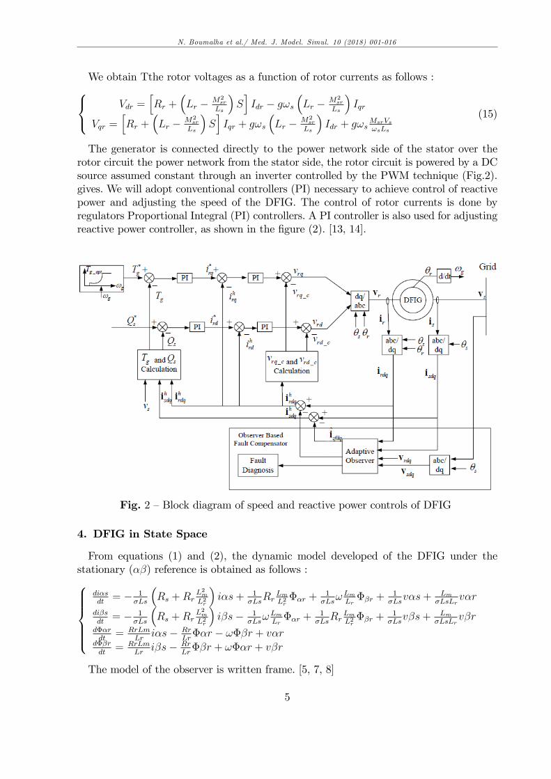
The generator is connected directly to the power network side of the stator over therotor circuit the power network from the stator side, the rotor circuit is powered by a DCsource assumed constant through an inverter controlled by the PWM technique (Fig.2).gives. We will adopt conventional controllers (PI) necessary to achieve control of reactivepower and adjusting the speed of the DFIG. The control of rotor currents is done byregulators Proportional Integral (PI) controllers. A PI controller is also used for adjustingreactive power controller, as shown in the �gure (2). [13, 14].
Fig. 2 �Block diagram of speed and reactive power controls of DFIG
4. DFIG in State Space
From equations (1) and (2), the dynamic model developed of the DFIG under thestationary (��) reference is obtained as follows :8>>>><>>>>:
di�sdt= � 1
�Ls
�Rs +Rr
L2mL2r
�i�s+ 1
�LsRr
LmL2r��r +
1�Ls
!LmLr��r +
1�Ls
v�s+ Lm�LsLr
v�r
di�sdt= � 1
�Ls
�Rs +Rr
L2mL2r
�i�s� 1
�Ls!LmLr��r +
1�Ls
RrLmL2r��r +
1�Ls
v�s+ Lm�LsLr
v�rd��rdt
= RrLmLr
i�s� RrLr��r � !��r + v�r
d��rdt
= RrLmLr
i�s� RrLr��r + !��r + v�r
The model of the observer is written frame. [5, 7, 8]
5

N. Boumalha et al./ Med. J. Model. Simul. 10 (2018) 001-016
(dXdt= AX +BU +G
�Y � Y
�Y = CX
(16)
With
X = [i�s i�s ��r ��r]t;Y =
�i�si�s
�u = [u�s u�s u�r u�r]
t
A =
�A11 A12A21 A22
�
B =
�B11 B12B21 B22
�
I =
�1 00 1
�
J =
�0 �11 0
�With
A11 =
24 � �1� �s
� L2m�s�Ls Lr
�0
0��1� �s
� L2m�s�Ls Lr
� 35A12 =
�Lm
�r�Ls LrwLm�Ls Lr
wLm�Ls Lr
Lm�r�Ls Lr
�
A21 =
�Lm�r
0
0 Lm�r
�
A22 =
� �1�r
�ww �1
�r
�
B11 =
�1
� Ls0
0 1� Ls
�
B12 =
� �Lm�Ls Lr
0
0 �Lm�Ls Lr
�
6

N. Boumalha et al./ Med. J. Model. Simul. 10 (2018) 001-016
B21 =
�0 00 0
�
B22 =
�1 11 1
�
� r =LrRr
We de�ne
�! = ! � ! (17)
The symbol ^ denotes estimated values and G is the observer gain matrix. We willdetermine the di¤erential system describing the evolution of the error
e = X � X (18)
The state matrix of the observer can be written as
A = A+ �A (19)
With
�A =
0BB@0 0 0 +Lm
b�!
0 0 �Lmb�! 0
0 0 0 ��!0 0 +�! 0
1CCA (20)
Then, we can write
dX
dt= AX +BU +G
�Y � Y
�de
dt= (A�GC) e� �AX
We de�ne the Lyapunov function
V = eT e+(�!)2
�(21)
� is a positive scalar.This function should contain terms of the di¤erence and to obtain mechanism adapta-
tion. The stability of the observer is guaranteed for the condition
dV
dt< 0
7

N. Boumalha et al./ Med. J. Model. Simul. 10 (2018) 001-016
We obtain the adaptation mechanism in the form
! =
tZ0
�
�Lmb
���s ei�s � ��r ei�s
��dtt (22)
The matrix of gain G is selected such as the eigenvalues of the matrix A-GC .The estimated electromagnetic torque is expressed
Ce =3
2pLmLr
���r {�s � ��r {�s
�(23)
5. Sliding Mode Observer
5.1. Principle of a sliding-mode observerWe consider nonlinear system of the form : [19, 26]�_x(t) = f(x(t); u(t))y(t) = Cx(t)
(24)
where
x 2 Rn; u 2 Rm
y 2 Rp
We assume that the system is observable, for the system (28), we de�ne the observerby sliding mode by : [24]
�x = f(x(t); u(t)) + �Is (25)
Or x 2 Rn; � 2 Rn�p is the matrix of the observation gains to be speci�ed and is thevector of discontinuous sign :
Is = Sign (S) = [sign (s1) ; sign (s2) :::::sign (sp) ; ]T (26)
Where is the classic sign function and is the next slip surface
S = NCx = [s1; s2::::::sp] (27)
�x = x� x (28)
Or N 2 RPxP is a matrix to be speci�edThus, the dynamics of the observation error becomes :
�x = f(x; u)� f(x; u) + �Is (29)
8

N. Boumalha et al./ Med. J. Model. Simul. 10 (2018) 001-016
5.2. Sliding mode observer applied to the DFIGThe sliding mode observer proposed for the estimation of the DFIG �ows :8>>>>>>>><>>>>>>>>:
�x1 = ax1 +
RrLmaLr
x3 +Lmbx4px5 +
1�Ls
��r + �T1 Is
�x2 = ax2 � Lm
bx3px5 +
RrLmaLr
x4 +1�Ls
��s + �T2 Is
�x3 =
RrLmLr
x1 � RrLrx3 � x4px5 + �ar + �
T3 Is
�x4 =
RrLmLr
x2 � RrLrx4 � x3px5 + ��r + �
T4 Is
�x5 = d (x3x2 � x4x1)� Tr
J� fv
Jx5 = q1 (x5 � x5) + �
T5 Is
(30)
a =1
�Ls
�Rs +Rr
L2mL2r
�b = �LsLr
� = 1� L2mLsLr
With
x =�{�s {�s ��r ��r wr
�y =
�{�s {�s wr
�Is =
�sign (S1) sign (S2)
�T�S1 = x1 � x1S2 = x2 � x2
S1 and S2 represent the sliding surfaces.The gains : q1, �T1 , �
T2 , �
T3 , �
T4 , �
T5 are calculated to ensure the asymptotic convergence
of the error estimate. They are given by :��T1�T2
�= D�1
��1 00 �2
�and D = 1
(�2+(kpx5)2)
�� �kpx5
kpx5 �
���31 �32�41 �42
�=
���c �px5px5 �c
��q3 00 q4
����1 00 �2
���51�1
�52�2
�= d
�x2 �x1
� (31)
Sach as :��1 > je3jmax�2 > je4jmax
9
N. Boumalha et al./ Med. J. Model. Simul. 10 (2018) 001-016
8<:q1 > 0q3 > 0q4 > 0
The residual signal is calculated as follows, r = [y � y] and we de�ne as the detectionthreshold (lower limit).
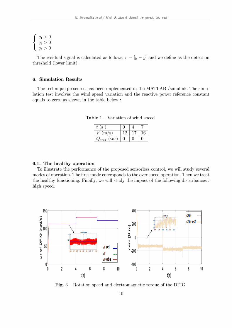
6. Simulation Results
The technique presented has been implemented in the MATLAB /simulink. The simu-lation test involves the wind speed variation and the reactive power reference constantequals to zero, as shown in the table below :
Table 1 �Variation of wind speed
t (s ) 0 4 7V (m/s) 12 17 16Qsref (var) 0 0 0
6.1. The healthy operationTo illustrate the performance of the proposed sensorless control, we will study several
modes of operation. The �rst mode corresponds to the over speed operation. Then we treatthe healthy functioning. Finally, we will study the impact of the following disturbances :high speed.
Fig. 3 �Rotation speed and electromagnetic torque of the DFIG
10
N. Boumalha et al./ Med. J. Model. Simul. 10 (2018) 001-016
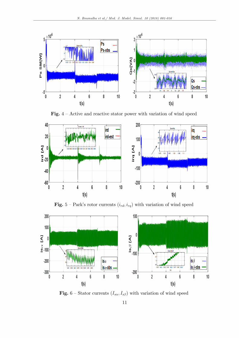
Fig. 4 �Active and reactive stator power with variation of wind speed
Fig. 5 �Park�s rotor currents (ird; irq) with variation of wind speed
Fig. 6 �Stator currents (Is�; Is�) with variation of wind speed
11
N. Boumalha et al./ Med. J. Model. Simul. 10 (2018) 001-016
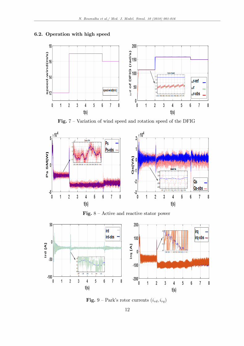
6.2. Operation with high speed
Fig. 7 �Variation of wind speed and rotation speed of the DFIG
Fig. 8 �Active and reactive stator power
Fig. 9 �Park�s rotor currents (ird; irq)
12
N. Boumalha et al./ Med. J. Model. Simul. 10 (2018) 001-016
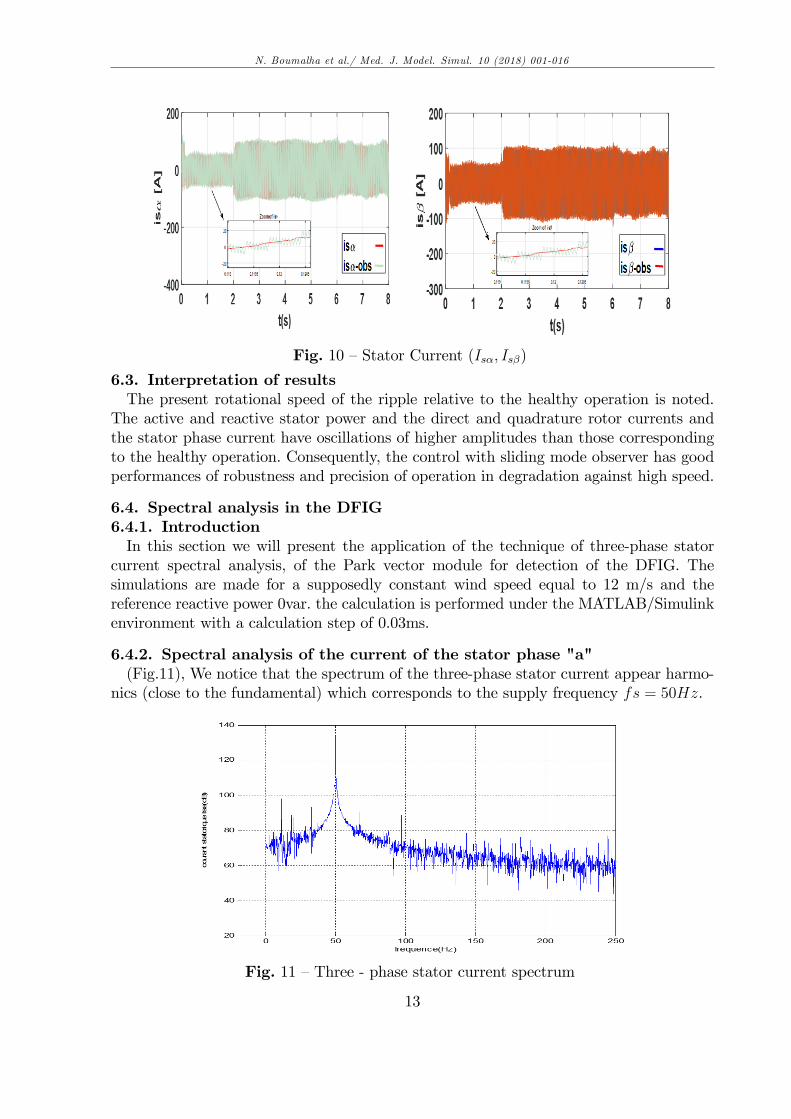
Fig. 10 �Stator Current (Is�; Is�)
6.3. Interpretation of resultsThe present rotational speed of the ripple relative to the healthy operation is noted.
The active and reactive stator power and the direct and quadrature rotor currents andthe stator phase current have oscillations of higher amplitudes than those correspondingto the healthy operation. Consequently, the control with sliding mode observer has goodperformances of robustness and precision of operation in degradation against high speed.
6.4. Spectral analysis in the DFIG6.4.1. IntroductionIn this section we will present the application of the technique of three-phase stator
current spectral analysis, of the Park vector module for detection of the DFIG. Thesimulations are made for a supposedly constant wind speed equal to 12 m/s and thereference reactive power 0var. the calculation is performed under the MATLAB/Simulinkenvironment with a calculation step of 0.03ms.
6.4.2. Spectral analysis of the current of the stator phase "a"(Fig.11), We notice that the spectrum of the three-phase stator current appear harmo-
nics (close to the fundamental) which corresponds to the supply frequency fs = 50Hz.
Fig. 11 �Three - phase stator current spectrum
13
N. Boumalha et al./ Med. J. Model. Simul. 10 (2018) 001-016
7. Conclusion
A new approach to doubly-fed induction generator (DFIG) based wind turbine modelinghas been presented. It can be readily applied for the analysis of healthy of the DFIG. Theglobal control scheme introduces high performances of robustness ; stability and precision,particularly, under uncertainty caused by load variation. Furthermore, this observationmethod presents a simple algorithm that has the advantage to be easily implantable in acalculator. The sliding mode observer uses an adaptation mechanism for the rotor �ux andspeed estimation. This approach relies on the improvement of an estimation of the rotor�ux components and rotor speed. The estimation of the rotor �ux has well made morerobust and more stable the DFIG based Vector Control. Through simulation strategy hasbeen validated steady-state conditions by Matlab/simulink.
Acknowledgments
The authors deeply appreciate the support obtained from ENP (Automatic controldepartment, ENP Alger, Algeria) and USDB (Electronic Department, University SaadDahlab, Blida, Algeria) which has permitted the participation and presentation of thiswork .
REFERENCES
[1] Adam MIRECKI : Etude comparative de chaines de conversion d.energie dediees aune éolienne de petite puissance. These doctorat de l.Institut National Polytechniquede Toulouse, Avril 5, ( 2005).
[2] A. Ur Rehman, Yu Chen : Simulation using MATLAB/Simulink on Rotor WindingInter-turn Short Circuit Fault in DFIG. Xi�an Jiaotong University Xi�an, Shaanxi,China, (2016).
[3] B. Chitti Babu, K.B. Mohanty : Doubly-Fed Induction Generator for Variable SpeedWind Energy Conversion Systems- Modeling & Simulation. International Journal ofComputer and Electrical Engineering, Vol. 2, No. 1, February, (2010).
[4] C. Wei, Z. Zhang : Stator Current-Based Sliding Mode Observer for Sensorless VectorContorl of Doubly-Fed Induction Geneartors. IEEE Trans. on Application 3, (2015) ,978-1-4673-7151.
[5] D. Casadei, A. Yazidi : Diagnostic Technique based on Rotor Modulating SignalsSignature Analysis for Doubly Fed Induction Machines in Wind Generator Systems.IEEE Industry Applications Conference, (2006). 41st IAS Annual Meeting ConferenceRecord , (2006), pp. 1525 �1532.
[6] D. Kouchih, R. Hachelaf, N. Boumalha, M. Tadjine, and M.S. Boucherit : Vector faulttolerant control of induction motor drives subject to stator interturn faults. The 16thPower Electronics and Motion Control Conference and Exposition, Antalya, Turkey,September 21-24, (2014).
[7] D. Kouchih ; M. Tadjine ; and M.S. Boucherit : Analysis of controlled induction motordrives with stator faults, International Symposium on Environment Friendly energiesand Applications, Northumbria university, Newcastle upon Tyne, United Kingdom,(2012).
14
N. Boumalha et al./ Med. J. Model. Simul. 10 (2018) 001-016
[8] D. Kouchih ; M. Tadjine ; and M.S. Boucherit : Analysis of controlled induction motordrives with stator faults, International Symposium on Environment Friendly energiesand Applications, Northumbria university, Newcastle upon Tyne, United Kingdom,(2012).
[9] D. Casadei, A. Yazidi : Diagnostic Technique based on Rotor Modulating SignalsSignature Analysis for Doubly Fed Induction Machines in Wind Generator Systems.IEEE Industry Applications Conference, (2006). 41st IAS Annual Meeting ConferenceRecord , (2006), pp. 1525 �1532.
[10]F. Poitiers : Etude et Commande de Génératrices Asynchrones pour l�Utilisation del�Energie Eolienne.Thèse de doctorat, Nantes, (2003).
[11]F. Poitiers, T. Bouaouiche, M. Machmoum : Advanced control of a doubly-fed induc-tion generator for wind energy conversion. Electric Power Systems Research Volume79, (2009). pp. 1085-1096.
[12]H. Camblong : Minimisation de l�Impact des Perturbations d�Origine Eolienne dansla Generation d.Electricite par des Aerogenerateurs a Vitesse Variable. These de Doc-torat en Automatique, Ecole Nationale Superieure d.Arts et Metiers, Centre de Bor-deaux, France, (2003).
[13] J. Zafar, J. Gyselinck : CUSUM based Fault Detection of Stator Winding ShortCircuits in Doubly Fed Induction Generator based Wind Energy Conversion Systems.Department of Electrical Engineering Université Libre de Bruxelles (ULB) CP165/52,50 Av. F.D. Roosevelt, 1050 Brussels, Belgium, (2010).
[14]Jawwad ZAFAR : Winding Short-Circuit Fault Modelling and Detection in Doubly-Fed Induction Generator basedWind Turbine Systems. Phd Thesis, Université libre deBruxeles, Faculty of Applied Sciences Department of Electrical Engineering, October13, (2011).
[15]Jesper S. Thomsen and Carsten S. Kalles�e, Stator fault modeling of induction motors,IEEE Int. Symposium on Power Electronics, Eletrical Drives, Automation andMotion,pp.1275-1280, (2006).
[16]L. Holdsworth, X.G. Wu, J.B. Ekanayake, N. Jenkins : Comparison of �xed speed anddoubly-fed induction wind turbines during power system disturbance. Proc. Gener.Transm. Distrib., 150(3), (2003). pp. 343-352.
[17]M.E.H. Benbouzid : Bibliography on induction motors fault detection and diagnosis.IEEE Trans. on Energy Conversion, 14 (4) , (1999). pp. 1065�1074.
[18]M. E. H. Benbouzid : Review of induction motors signature analysis as a medium forfaults detection. IEEE Trans. on Industrial Electronics, 47 (5) , (2000). pp. 984�993.
[19]N. Benouzza, A. Benyettou, A. Bendiabdellah, B. Kraloua ,D. Toumi : Rotor CageFaults Diagnosis in 3 Phase Induction Motors, by Park�s Vector Approach. JordanianInternational Electrical Electronics Engineering Conference, (2001).
[20]R. M.Tallam, T. G. Habetler, R.G. Harley : Transient model for induction machineswith stator winding turn faults.IEEE Trans. on Application, 38(3) , (2002). pp. 632-637.
[21]S. Ebrahimkhani : Robust fractional order sliding mode control of doubly-fed inductiongenerator -based wind turbines . ISA Transactions , (2016).
[22]S. Shao, E. Abdi, F. Barati, R. McMahon : Stator-Flux-Oriented Vector Controlfor Brushless Doubly Fed Induction Generator. IEEE Transactions. On Industrial
15
N. Boumalha et al./ Med. J. Model. Simul. 10 (2018) 001-016
Electronics, Vol. 56, No. 10, (2009).[23]T. Ghennam, E.M. Berkouk, B.François : Modeling and control of a doubly fed in-
duction generator (DFIG) based wind conversion system. International Conference onPower Engineering, Energy and Electrical Drives, (2009). POWERENG
[24]X. Zheng, R. Song : Full-order terminal sliding mode stator �ux observer for DFIG.IEEE Trans. on Application, (2016) , 978-1-4673-8644-9.
[25]X. Cheng, V. Cocquempot and C. Christophe, A model of asynchronous machine forstator fault detection and isolation, IEEE Trans. Ind. Eletron., vol. 50, no. 3, pp.578-584, (2003).
[26]Y. Gritli, A. Stefani, F. Filippetti and A. Chatti, Stator fault analysis based on wavelettechnique for wind turbines equipped with DFIG, In Proceeding of IEEE InternationalConference on Clean Electrical Power, Capri, Italy, (2009), pp. 485-491.
Appendix 1 - Wind Turbine Parameters
Rated power : Ps = 7500WMoment of the inertia : J = 0:31125kg:m2
Wind turbine radius : R = 3mGear box ratio : G = 5:4Air density : � = 1:25kg=m3
Appendix 2 - DFIG Parameters
Rated power : 7500WMutual inductance : Lm = 0:0078HStator leakage inductance : Ls = 0:0083HRotor leakage inductance : Lr = 0:0081HStator resistance : Rs = 0:455Rotor resistance : Rr = 0:62Number of pole pairs : P = 2Moment of the inertia : J = 0:31125kg:m2
Viscous friction : fv = 0:00673kg:m2:s�1
16
Copyright © 2022 FDOKUMEN