Fault Detection for DFIG Based on Sliding Mode Observer of ...
13
1 Bull. Pol. Acad. Sci. Tech. Sci. 69(3) 2021, e137389 BULLETIN OF THE POLISH ACADEMY OF SCIENCES TECHNICAL SCIENCES, Vol. 69(3), 2021, Article number: e137389 DOI: 10.24425/bpasts.2021.137389 CONTROL AND INFORMATICS © 2021 The Author(s). This is an open access article under the CC BY license (http://creativecommons.org/licenses/by/4.0/). Abstract. For fault detection of doubly-fed induction generator (DFIG), in this paper, a method of sliding mode observer (SMO) based on a new reaching law (NRL) is proposed. The SMO based on the NRL (NRL- SMO) theoretically eliminates system chatter caused by the reaching law and can be switched in time with system interference in terms of robustness and smoothness. In addition, the sliding mode control law is used as the index of fault detection. Firstly, this paper gives the NRL with the theoretically analyzes. Secondly, according to the mathematical model of DFIG, NRL-SMO is designed, and its analysis of stability and robustness are carried out. Then this paper describes how to choose the optimal parameters of the NRL-SMO. Finally, three common wind turbine system faults are given, which are DFIG inter-turn stator fault, grid voltage drop fault, and rotor current sensor fault. The simulation models of the DFIG under different faults is established. The simulation results prove that the superiority of the method of NRL-SMO in state tracking and the feasibility of fault detection. Key words: fault detection; doubly-fed induction generator; sliding mode observer; new reaching law. Fault detection for DFIG based on sliding mode observer of new reaching law RuiQi LI 1, 3 , WenXin YU 1, 3 * , JunNian WANG 2, 3 , Yang LU 1, 3 , Dan JIANG 1, 3 , GuoLiang ZHONG 1, 3 , and ZuanBo ZHOU 1, 3 1 School of Information and Electrical Engineering, Hunan University of Science and Technology, Hunan Pro., Xiangtan,411201, China 2 School of Physics and Electronics, Hunan University of Science and Technology, Hunan Pro., Xiangtan,411201, China 3 Key Laboratory of Knowledge Processing Networked Manufacturing, Hunan University of Science and Technology, Hunan Pro., Xiangtan,411201, China * e-mail: [email protected] Manuscript submitted 2020-09-13, revised 2021-03-02, initially accepted for publication 2021-04-12, published in June 2021 limited to detection during startup and cannot be applied during machine operation. In [5], a new fault diagnostic index is pro- posed based on normalized energy evaluation of the given sig- nal using the discrete wavelet transform. Analysis of the sim- ulation results confirms that the proposed fault diagnostic in- dex can accurately discriminate between inter-turn short-circuit fault even with minor shorted turns, winding resistive asym- metrical fault, or unbalanced voltages except for the cases with minor asymmetry and healthy conditions of the stator winding. Reference [6] presents a new online diagnostic approach for the detection of stator and rotor inter-turn short circuit faults in DFIG for wind power applications. It can be used effectively for different generator operating conditions, except that rotor faults cannot be detected in the vicinity of the synchronous speed. In [7], the doubly-fed induction generator (DFIG) stator fault in the slot location is studied because of the special topological structure and the real factors of the generator model. It deter- mines the pulsating magnetomotive force (MMF) expressions mapped to the shorted position in two forms. Based on 2D dis- cretization and piecewise interpolation, a modified fault is de- veloped. In the operation of DFIG connected to the grid, if there is a fault on the grid side, it is easy to be off the grid, which di- rectly affects the safe and reliable operation of the primary grid. For the grid-side faults, reference [8] presents a new control ap- proach for enhancing the fault ride-through capability of wind farms connected to the grid through a voltage-source-converter- based high-voltage dc transmission line. A controlled voltage drop in the wind farm collector grid is initiated upon a fault in the high-voltage grid to achieve fast power reduction. Ref- 1. Introduction Wind power generators have long been working in inaccessible environments such as deserts, Gobi, and the sea. They are of- ten accompanied by severe weather such as blizzards, typhoons, sandstorms, and thunderstorms. When the wind power genera- tion system fails, it is difficult for humans to go to the fault site for timely detection and maintenance. The traditional fault de- tection technology is challenging to detect the early faults of the system accurately, forcing the wind turbine to be in a state of fault. When the wind turbine is in trouble for a long time, it will shut down the wind turbine and even damage the elec- trical equipment. Therefore, seeking an online fault detection technology that is sensitive to early faults has important prac- tical significance. At present, there are many kinds of fault detection technologies for wind turbines. In this paper, fault detection and diagnosis technologies based on state estima- tion are studied mainly for electrical system faults and sensor faults [1]. The winding faults of the rotor and the stator are the lead- ing electrical faults of the generator [2, 3]. Reference [4] intro- duces a method of detecting stator winding faults based on the measurement signal of a built-in sensor based on a frequency converter, which can be easily detected, even the single-phase short-circuit fault of the stator winding.However, this method is
-
Upload
khangminh22 -
Category
Documents
-
view
1 -
download
0
Transcript of Fault Detection for DFIG Based on Sliding Mode Observer of ...

1Bull. Pol. Acad. Sci. Tech. Sci. 69(3) 2021, e137389
BULLETIN OF THE POLISH ACADEMY OF SCIENCES TECHNICAL SCIENCES, Vol. 69(3), 2021, Article number: e137389DOI: 10.24425/bpasts.2021.137389
CONTROL AND INFORMATICS
© 2021 The Author(s). This is an open access article under the CC BY license (http://creativecommons.org/licenses/by/4.0/).
Abstract. For fault detection of doubly-fed induction generator (DFIG), in this paper, a method of sliding mode observer (SMO) based on a new reaching law (NRL) is proposed. The SMO based on the NRL (NRL- SMO) theoretically eliminates system chatter caused by the reaching law and can be switched in time with system interference in terms of robustness and smoothness. In addition, the sliding mode control law is used as the index of fault detection. Firstly, this paper gives the NRL with the theoretically analyzes. Secondly, according to the mathematical model of DFIG, NRL-SMO is designed, and its analysis of stability and robustness are carried out. Then this paper describes how to choose the optimal parameters of the NRL-SMO. Finally, three common wind turbine system faults are given, which are DFIG inter-turn stator fault, grid voltage drop fault, and rotor current sensor fault. The simulation models of the DFIG under different faults is established. The simulation results prove that the superiority of the method of NRL-SMO in state tracking and the feasibility of fault detection.
Key words: fault detection; doubly-fed induction generator; sliding mode observer; new reaching law.
Fault detection for DFIG based on sliding mode observer of new reaching law
RuiQi LI1, 3, WenXin YU1, 3*, JunNian WANG2, 3, Yang LU1, 3, Dan JIANG1, 3, GuoLiang ZHONG1, 3, and ZuanBo ZHOU1, 3
1 School of Information and Electrical Engineering, Hunan University of Science and Technology, Hunan Pro., Xiangtan,411201, China2 School of Physics and Electronics, Hunan University of Science and Technology, Hunan Pro., Xiangtan,411201, China
3 Key Laboratory of Knowledge Processing Networked Manufacturing, Hunan University of Science and Technology, Hunan Pro., Xiangtan,411201, China
*e-mail: [email protected]
Manuscript submitted 2020-09-13, revised 2021-03-02, initially accepted for publication 2021-04-12, published in June 2021
BULLETIN OF THE POLISH ACADEMY OF SCIENCESTECHNICAL SCIENCES, Vol. 69(3), 2021, Article number: e137389DOI: 10.24425/bpasts.2021.137389
Fault detection for DFIG based on sliding mode observerof new reaching law
RuiQi LI1,3, WenXin YU1,3∗, JunNian WANG2,3, Yang LU1,3, Dan JIANG1,3,GuoLiang ZHONG1,3, and ZuanBo ZHOU1,3
1School of Information and Electrical Engineering, Hunan University of Science and Technology, Hunan Pro., Xiangtan, 411201, China2School of Physics and Electronics, Hunan University of Science and Technology, Hunan Pro., Xiangtan, 411201, China
3Key Laboratory of Knowledge Processing Networked Manufacturing, Hunan University of Science and Technology,Hunan Pro., Xiangtan, 411201, China
Abstract. For fault detection of doubly-fed induction generator (DFIG), in this paper, a method of sliding mode observer (SMO) based on a newreaching law (NRL) is proposed. The SMO based on the NRL (NRL–SMO) theoretically eliminates system chatter caused by the reaching lawand can be switched in time with system interference in terms of robustness and smoothness. In addition, the sliding mode control law is used asthe index of fault detection. Firstly, this paper gives the NRL with the theoretically analyzes. Secondly, according to the mathematical model ofDFIG, NRL–SMO is designed, and its analysis of stability and robustness are carried out. Then this paper describes how to choose the optimalparameters of the NRL–SMO. Finally, three common wind turbine system faults are given, which are DFIG inter-turn stator fault, grid voltagedrop fault, and rotor current sensor fault. The simulation models of the DFIG under different faults is established. The simulation results provethat the superiority of the method of NRL–SMO in state tracking and the feasibility of fault detection.
Key words: fault detection, doubly-fed induction generator, sliding mode observer, new reaching law.
1. Introduction
Wind power generators have long been working in inaccessibleenvironments such as deserts, Gobi, and the sea. They are of-ten accompanied by severe weather such as blizzards, typhoons,sandstorms, and thunderstorms. When the wind power genera-tion system fails, it is difficult for humans to go to the fault sitefor timely detection and maintenance. The traditional fault de-tection technology is challenging to detect the early faults ofthe system accurately, forcing the wind turbine to be in a stateof fault. When the wind turbine is in trouble for a long time,it will shut down the wind turbine and even damage the elec-trical equipment. Therefore, seeking an online fault detectiontechnology that is sensitive to early faults has important prac-tical significance. At present, there are many kinds of faultdetection technologies for wind turbines. In this paper, faultdetection and diagnosis technologies based on state estima-tion are studied mainly for electrical system faults and sensorfaults [1].
The winding faults of the rotor and the stator are the lead-ing electrical faults of the generator [2, 3]. Reference [4] intro-duces a method of detecting stator winding faults based on themeasurement signal of a built-in sensor based on a frequencyconverter, which can be easily detected, even the single-phaseshort-circuit fault of the stator winding.However, this method is
∗e-mail: [email protected]
Manuscript submitted 20XX-XX-XX, initially accepted for publication20XX-XX-XX, published in June 2021.
limited to detection during startup and cannot be applied duringmachine operation. In [5], a new fault diagnostic index is pro-posed based on normalized energy evaluation of the given sig-nal using the discrete wavelet transform. Analysis of the sim-ulation results confirms that the proposed fault diagnostic in-dex can accurately discriminate between inter-turn short-circuitfault even with minor shorted turns, winding resistive asym-metrical fault, or unbalanced voltages except for the cases withminor asymmetry and healthy conditions of the stator winding.Reference [6] presents a new online diagnostic approach forthe detection of stator and rotor inter-turn short circuit faults inDFIG for wind power applications. It can be used effectively fordifferent generator operating conditions, except that rotor faultscannot be detected in the vicinity of the synchronous speed.In [7], the doubly-fed induction generator (DFIG) stator faultin the slot location is studied because of the special topologicalstructure and the real factors of the generator model. It deter-mines the pulsating magnetomotive force (MMF) expressionsmapped to the shorted position in two forms. Based on 2D dis-cretization and piecewise interpolation, a modified fault is de-veloped.
In the operation of DFIG connected to the grid, if there isa fault on the grid side, it is easy to be off the grid, which di-rectly affects the safe and reliable operation of the primary grid.For the grid-side faults, reference [8] presents a new control ap-proach for enhancing the fault ride-through capability of windfarms connected to the grid through a voltage-source-converter-based high-voltage dc transmission line. A controlled voltagedrop in the wind farm collector grid is initiated upon a faultin the high-voltage grid to achieve fast power reduction. Ref-
Bull. Pol. Acad. Sci. Tech. Sci. 69(3) 2021, e137389 1

2
R.Q. Li, W.X. Yu, J.N. Wang, Y. Lu, D. Jiang, G.L. Zhong, and Z.B. Zhou
Bull. Pol. Acad. Sci. Tech. Sci. 69(3) 2021, e137389
R. Li, W. Yu, J. Wang, Y. Lu, D. Jiang, G. Zhong, and Z. Zhou
erence [9] proposes a new stability solution based on PLL fre-quency for the instability of the grid-side converter of the windturbine. Because DFIG-based wind turbine has the character-istic of transient fault with low voltage ride through (LVRT)capability, in [10], a new three-phase fault direction identifica-tion method for the outgoing transmission line of the wind farmis presented. Reference [11] proposes a decoupled fault ride-through strategy for a doubly fed induction generator (DFIG) toenhance network stability during grid disturbances. It can im-prove both the active and reactive power capability during faultride-through operation.
For most electrical fault monitoring, it is still carried outbased on the measurement of the current. The current sensoris composed of multiple components, which also has the pos-sibility of damage. Once the current sensor fails, it will di-rectly cause the wrong judgment of the motor control system,resulting in control failure and more significant loss [12, 13].In [14], for a class of nonlinear Itô stochastic systems, a newobserver method based on sliding mode control is proposed toaccurately estimate system state, sensor faults, and disturbancesat the same time. Reference [15] suggests a current and posi-tion sensor fault detection and isolation algorithm with parityequation for driving motor of In-wheel independent drive elec-tric vehicle. This fault detection and diagnosis method with theparity equation can be extended to other systems as well. Ref-erence [16] presents a switching fault-tolerant control (SFTC)strategy for a DFIG-based wind turbine subject to rotor and sta-tor current sensor faults. The proposed SFTC strategy is able toprovide superb transient and steady-state performance, strongrobustness to parameter uncertainties, and high fault-tolerancecapability under rotor and stator current sensor faults. In [17],also a new fault-tolerant control (FTC) strategy for a DFIG-based wind turbine with sensor fault is proposed. The DFIGsystem is decomposed into stator, rotor, grid current models,and the sensor fault observer is presented to provide accurateestimations of sensor fault components in the presence of modeluncertainties.
Recent years, artificial intelligence (AI) has also been re-searched for fault detection and diagnosis in wind turbines.Reference [18] presents an LSTM-based diagnosis method formultiple open-circuit switch faults of back-to-back converter inDFIG-based wind turbine system. Simulation studies demon-strate the effectiveness of the proposed method in classifyingmultiple open-circuit faults. In [19], a convolutional neural net-work (CNN) model is presented to learn features from fre-quency data directly and detect faults of gearboxes. In [20],a novel approach based on DNN model is proposed to thefault detection in a direct drive wind turbine. Reference [21]presents a probabilistic neural network to detect and classifyshort-circuit and open-circuit faults in real time.
Sliding mode control is a kind of robustness controlmethod with chattering. In order to improve the sliding modecontroller’s performance, the constant velocity reaching law(CVRL) was proposed in [22]. This CVRL reduces the chatter-ing of the system, but the response speed of the system also de-creases. Reference [22] also designed an exponential reachinglaw (ERL). Compared with the CVRL, it eliminates the inter-
dependence between response speed and chattering. However,the robustness of the system cannot be guaranteed while thechattering is reduced. In [23], a new exponential reaching law(NERL) is proposed that allows chattering reduction on controlinput for a Multi-Input / Multi-Output (MIMO) modular robotarm while keeping high tracking performance of the controllerin the steady-state regime. However, when the system is closeto the sliding mode surface, the system still makes a particu-lar control gain to do back and forth movement, which meansthe system will maintain constant amplitude oscillation nearthe origin. Reference [24] also proposed a NERL. The NERLbased sliding mode control proves to be capable of reducingthe system chattering phenomenon as well as accelerating theapproaching process. However, its anti-interference ability isfeeble.
In this paper, to solve the lack of the above reaching law,a new reaching law (NRL) is proposed. The NRL achieves theunification of rapidity, smoothness, and robustness. And then,the NRL is employed to the observation of the DFIG rotorcurrent. The sliding mode observer (SMO) based on the NRL(NRL- SMO) has an excellent tracking effect and is more sen-sitive to DFIG electrical faults. Under three different electricalfaults of wind turbines, the NRL–SMO can accurately detectand locate the fault.
The arrangement of this paper is as follows. Section 2 of thispaper theoretically analyzes the proposed NRL and proves therelated theorem. In Section 3, NRL–SMO is designed, and itsstability and robustness are analyzed. Section 4 gives the op-timal parameter selection scheme of NRL–SMO. In Section 5,NRL–SMO is applied on a DFIG simulink model, and real-timeresults are compared to conventional SMO. In Section 6, theconclusion of the entire paper will be provided.
2. Proposal and analysis of NRL
The NRL presented in this paper is as follows:
s =−ks− εe−β (t−λ (t))
δ0 +(1−δ0)e−α‖s‖ sign(s), (1)
λ (t) =
0
(|e| ≤ fξ
)
t(|e|> fξ
) , e is the error between the estimated
sliding mode value and the target value, fξ is the critical valueof the steady-state error that the system can tolerate, k, α , β ,ε are positive parameter and k > β , α 1, 0 < δ0 < 1, ‖s‖represents the norm of s.
At the initial stage of the system, when the starting point isfar from the sliding mode surface, e−β (t−λ (t)) → 1, e−α‖s‖ → 0,s →−ks− ε
δ0sign(s). It guarantees that the state of the sliding
mode system can approach the sliding mode at a higher speedat initial time. When the starting point is close to the slidingmode surface, e−β (t−λ (t)) → 1, e−α‖s‖ → 1, s→−εsign(s). Thestate of the sliding mode system will slide up and down on thesurface of the sliding mode. If ε is small, then the chatteringdue to the reaching law is weak.
2 Bull. Pol. Acad. Sci. Tech. Sci. 69(3) 2021, e137389
Fault detection for DFIG based on sliding mode observer of new reaching law
In the stabilization phase of the system with no interference,|e| ≤ fξ , λ (t) → 0. As time goes to infinity, e−β (t−λ (t)) → 0,s → 0. This shows that the system chatter will also decay tozero in the form of an exponent.
In the stabilization phase of the system with interference,|e| > fξ , λ (t) → t, e−β (t−λ (t)) → 1, e−α‖s‖ → 0, the NRL
switches to the form of the initial phase, s →−ks− εδ0
sign(s).
All of the above are optimal representations of NRL at dif-ferent stages of the system. The properties of NRL are furtherexplained in theorem 1 below.
Theorem 1.1. The motion state will reach the sliding mode surface s(t) =
0 within a limited time t ′r.
t ′r <1
k−βln(
1+k−β
ε‖s(0)‖
). (2)
2. After the motion state reaching the sliding mode surface,the chattering decays exponentially to zero.
Proof.1. Do not consider the system parameter uncertainty and ex-
ternal interference, the time function λ (t) = 0. In this case, theform of the NRL (1) will be:
s =−ks− εe−β t
δ0 +(1−δ0)e−α‖s‖ sign(s) . (3)
Assume:N(s) =
εδ0 +(1−δ0)e−α‖s‖ .
When δ0 → 1, then N(s) = ε . Equation (3) is transformedinto:
s =−ks− εe−β t . (4)
Solve (4):
s(t) = s(0)e−kt − εt∫
0
e−k(t−τ)e−βτ signs(τ)dτ . (5)
Set the time that the sliding mode system reaches the slidingmode surface as te, when δ0 → 1, then s(te) = 0, substitute itinto (5):
0 = s(0)e−kte − εe−kte signs(0)te∫
0
e(k−β )τ dτ ,
0 = e−kte
[s(0)− ε
k−β
(e(k−β )te −1
)signs(0)
], (6)
s(0) =ε
k−β
(e(k−β )te −1
)signs(0) .
IntroducesT sign s = ‖s‖1 ≥ ‖s‖2, (7)
where ‖s‖1 is the first norm of s, ‖s‖2 is the second norm of s.
Multiply signT s(0) on both sides of (6), from the (7), wehave:
‖s(0)‖ ≥ εk−β
(e(k−β )te −1
),
te ≤1
k−βln(
1+k−β
ε‖s(0)‖
).
When 0 < δ0 < 1
0 < δ0 +(1−δ0)e−α‖s‖ < 1,
N(s)> ε ,
we have the arrival time t ′r:
t ′r <1
k−βln(
1+k−βN(s)
‖s(0)‖)< te ,
t ′r <1
k−βln(
1+k−β
ε‖s(0)‖
).
2. Take s → 0 on both sides of (3):
dsdt
∣∣∣∣s→0
=−ks∣∣s→0 −
εe−β t
δ0 +(1−δ0)e−α‖s‖ sign(s)∣∣s→0.
Then:dsdt
→−εe−β t sign(s).
With t → ∞:dsdt
→ 0.
Thus, the chatter will decay to zero exponentially.
3. Rotor current NRL–SMO for DFIG
Aiming at the fault detection of DFIG, the proposed NRL is ap-plied to design a SMO that can adapt to sudden faults. Throughthe NRL–SMO, various states of the rotor current of the DFIGstably tracked and the change curve analysis of the slidingmode control law is performed to achieve the purpose of faultdetection.
3.1. The design of rotor current NRL–SMO for DFIG. Inthis paper, a three-phase asynchronous motor with a wound ro-tor is used as a DFIG. Figure 1 shows the control structure dia-gram of the sliding mode observer-based on stator voltage ori-entation for DFIG.
The correlation between the stator current and the rotor cur-rent can be obtained after decoupling the stator current and therotor current through the vector control method of stator flux
Bull. Pol. Acad. Sci. Tech. Sci. 69(3) 2021, e137389 3

3
Fault detection for DFIG based on sliding mode observer of new reaching law
Bull. Pol. Acad. Sci. Tech. Sci. 69(3) 2021, e137389
Fault detection for DFIG based on sliding mode observer of new reaching law
In the stabilization phase of the system with no interference,|e| ≤ fξ , λ (t) → 0. As time goes to infinity, e−β (t−λ (t)) → 0,s → 0. This shows that the system chatter will also decay tozero in the form of an exponent.
In the stabilization phase of the system with interference,|e| > fξ , λ (t) → t, e−β (t−λ (t)) → 1, e−α‖s‖ → 0, the NRL
switches to the form of the initial phase, s →−ks− εδ0
sign(s).
All of the above are optimal representations of NRL at dif-ferent stages of the system. The properties of NRL are furtherexplained in theorem 1 below.
Theorem 1.1. The motion state will reach the sliding mode surface s(t) =
0 within a limited time t ′r.
t ′r <1
k−βln(
1+k−β
ε‖s(0)‖
). (2)
2. After the motion state reaching the sliding mode surface,the chattering decays exponentially to zero.
Proof.1. Do not consider the system parameter uncertainty and ex-
ternal interference, the time function λ (t) = 0. In this case, theform of the NRL (1) will be:
s =−ks− εe−β t
δ0 +(1−δ0)e−α‖s‖ sign(s) . (3)
Assume:N(s) =
εδ0 +(1−δ0)e−α‖s‖ .
When δ0 → 1, then N(s) = ε . Equation (3) is transformedinto:
s =−ks− εe−β t . (4)
Solve (4):
s(t) = s(0)e−kt − εt∫
0
e−k(t−τ)e−βτ signs(τ)dτ . (5)
Set the time that the sliding mode system reaches the slidingmode surface as te, when δ0 → 1, then s(te) = 0, substitute itinto (5):
0 = s(0)e−kte − εe−kte signs(0)te∫
0
e(k−β )τ dτ ,
0 = e−kte
[s(0)− ε
k−β
(e(k−β )te −1
)signs(0)
], (6)
s(0) =ε
k−β
(e(k−β )te −1
)signs(0) .
IntroducesT sign s = ‖s‖1 ≥ ‖s‖2, (7)
where ‖s‖1 is the first norm of s, ‖s‖2 is the second norm of s.
Multiply signT s(0) on both sides of (6), from the (7), wehave:
‖s(0)‖ ≥ εk−β
(e(k−β )te −1
),
te ≤1
k−βln(
1+k−β
ε‖s(0)‖
).
When 0 < δ0 < 1
0 < δ0 +(1−δ0)e−α‖s‖ < 1,
N(s)> ε ,
we have the arrival time t ′r:
t ′r <1
k−βln(
1+k−βN(s)
‖s(0)‖)< te ,
t ′r <1
k−βln(
1+k−β
ε‖s(0)‖
).
2. Take s → 0 on both sides of (3):
dsdt
∣∣∣∣s→0
=−ks∣∣s→0 −
εe−β t
δ0 +(1−δ0)e−α‖s‖ sign(s)∣∣s→0.
Then:dsdt
→−εe−β t sign(s).
With t → ∞:dsdt
→ 0.
Thus, the chatter will decay to zero exponentially.
3. Rotor current NRL–SMO for DFIG
Aiming at the fault detection of DFIG, the proposed NRL is ap-plied to design a SMO that can adapt to sudden faults. Throughthe NRL–SMO, various states of the rotor current of the DFIGstably tracked and the change curve analysis of the slidingmode control law is performed to achieve the purpose of faultdetection.
3.1. The design of rotor current NRL–SMO for DFIG. Inthis paper, a three-phase asynchronous motor with a wound ro-tor is used as a DFIG. Figure 1 shows the control structure dia-gram of the sliding mode observer-based on stator voltage ori-entation for DFIG.
The correlation between the stator current and the rotor cur-rent can be obtained after decoupling the stator current and therotor current through the vector control method of stator flux
Bull. Pol. Acad. Sci. Tech. Sci. 69(3) 2021, e137389 3

4
R.Q. Li, W.X. Yu, J.N. Wang, Y. Lu, D. Jiang, G.L. Zhong, and Z.B. Zhou
Bull. Pol. Acad. Sci. Tech. Sci. 69(3) 2021, e137389
R. Li, W. Yu, J. Wang, Y. Lu, D. Jiang, G. Zhong, and Z. Zhou
Fig. 1. DFIG control structure diagram of sliding mode observer for stator voltage orientation
orientation. At this time, we obtain the rotor side mathematicalmodel of doubly-fed induction motor [25]:
[idr
iqr
]= A0
[idr
iqr
]+A1
−Lmiqr
Ls
ϕs −Lmidr
Ls
+Bu ,
y =Cir ,
(8)
where
A0 =1σ·
−Rr
Lrω f −
ωsL2m
LsLr
ωsL2m
LsLr−ω f
−Rr
Lr
,
A1 =
RsLm
σLsLr
ω f −ωs
σLrLm
ωs −ω f
σLrLm
RsLm
σLsLr
,
B =
− Lm
σLsLr0
1σLr
0
0 − Lm
σLsLr0
1σLr
,
C =
[1 00 1
],
idr, iqr are the current vectors of the rotor of the d, q; Rs, Rrare rotor and stator resistance; Ls, Lr are the self-inductance of
the stator and rotor; Lm is the mutual inductance between thestator and the rotor; ωs, ω f are the stator speed and slip speed
σ = 1− L2m
LsLr.
Simplify (8) into (9):
ir = Air +Bu+ f ,
y =Cir ,(9)
where
A =
− RsL2
m
σL2s Lr
− Rr
σLrω f
−ω f − RsL2m
σL2s Lr
− Rr
σLr
,
B =
− Lm
σLsLr0
1σLr
0
0 − Lm
σLsLr0
1σLr
,
f =
ω f −ωs
σLrLsLmψs
RsLmψs
σL2s Lr
.
According to sliding mode variable structure control andstate observer theory, the structure of the SMO is constructedas follows: ˜ir = Air +Bu+ f + v,
y =Ci ,(10)
4 Bull. Pol. Acad. Sci. Tech. Sci. 69(3) 2021, e137389
Fault detection for DFIG based on sliding mode observer of new reaching law
where ir =[
idr iqr
]Tis the estimated value of the rotor
current and v is the control law of the sliding mode observer,
v =[
v1 v2
]T.
The design sliding surface is:
s = e : ce = 0, (11)
e =
[e1
e2
]=
[idr − idr
iqr − iqr
],
c is the sliding mode surface parameter, c > 0.From (9), (10) and (11), we can get:
s = cA(ir − ir
)− cv . (12)
Combined with the NRL proposed in (1), the sliding modecontrol law can be obtained:
v =
[v1
v2
]= Ae− 1
cs
= A
[e1
e2
]
− 1c
(−ks− εe−β (t−λ (t))
δ0 +(1−δ0)e−α‖s‖ sign(s)
). (13)
Substitute (13) into (10) to get the complete mathematicalmodel of the rotor current NRL–SMO:
˜ir = Air +Bu+ f +A[ir − ir
]
−1c
(−ks− εe−β (t−λ (t))
δ0 +(1−δ0)e−α‖s‖ sign(s)
),
y =Ci .
(14)
3.2. Stability analysis of NRL–SMO. In order to illustratethat the system of the rotor current NRL–SMO (14) is asymp-totically stable, the following will prove it by Lyapunov stabil-ity theory, and get Theorem 2.
Theorem 2. For the system of rotor current NRL–SMO (14),the system gradually stabilizes under the action of the slidingmode control law (13).
Proof. Define the Lyapunov function:
V =12
sT · s. (15)
Substitute (9), (10), (11), (12) into the derivative of the Lya-punov function:
V = sT s+ sT s
=[
s1 s2
][ s1
s2
]+[
s1 s2
][ s1
s2
]
= 2(s1s1 + s2s2)
= 2[
c(− RsL2
m
σL2s Lr
− Rr
σLr
)(idr − idr
)s1 + cω f
(iqr − iqr
)s1
− c(− RsL2
m
σL2s Lr
− Rr
σLr
)(idr − idr
)s1 − cω f
(iqr − iqr
)s1
− ks21 −
εe−β (t−λ (t))
δ0 +(1−δ0)e−α‖s‖ sign(s1)s1 + c(−ω f )
×(idr − idr
)s2 + c
(− RsL2
m
σL2s Lr
− Rr
σLr
)×(iqr − iqr
)s2
− c(−ω f )(idr − idr
)s2 − c
(− RsL2
m
σL2s Lr
− Rr
σLr
)(iqr − iqr
)
× s2 −ks22 −
εe−β (t−λ (t))
δ0 +(1−δ0)e−α‖s‖ sign(s2)s2
]
= 2
[−ks2
1 −εe−β (t−λ (t))
δ0 +(1−δ0)e−α‖s‖ |s1|
− ks22 −
εe−β (t−λ (t))
δ0 +(1−δ0)e−α‖s‖ |s2|
].
Since k, α , β , δ0 are positive parameters, then V ≤ 0 knownby Lyapunov’s stability theorem, the rotor current NRL–SMOis asymptotically stable.
3.3. Robust analysis of the rotor current NRL–SMO. Tomake the rotor current NRL–SMO can track the rotor current indifferent states stably, it is necessary to analyze the robustnessof the rotor current NRL–SMO.
Theorem 3. For the system of rotor current with uncertainty in-terference, as shown in (16), when d(t)<
εcδ0
, under the action
of sliding mode control law, NRL–SMO system is still stable,that is, NRL–SMO system will still gradually converge to thesliding mode surface s(t) = 0.
Proof. Consider the following DFIG rotor-side control systemwith uncertain interference:
ir = Air +Bu+ f +d(t),
y =Cir(16)
d(t) represents the uncertain interference or unknown part ofthe system, assuming that the following matching conditionsare met:
rank(d(t)) = rank(ir(t)), ‖d(t)‖ ≤ dM, (17)
where dM is a positive number.
Bull. Pol. Acad. Sci. Tech. Sci. 69(3) 2021, e137389 5

5
Fault detection for DFIG based on sliding mode observer of new reaching law
Bull. Pol. Acad. Sci. Tech. Sci. 69(3) 2021, e137389
Fault detection for DFIG based on sliding mode observer of new reaching law
where ir =[
idr iqr
]Tis the estimated value of the rotor
current and v is the control law of the sliding mode observer,
v =[
v1 v2
]T.
The design sliding surface is:
s = e : ce = 0, (11)
e =
[e1
e2
]=
[idr − idr
iqr − iqr
],
c is the sliding mode surface parameter, c > 0.From (9), (10) and (11), we can get:
s = cA(ir − ir
)− cv . (12)
Combined with the NRL proposed in (1), the sliding modecontrol law can be obtained:
v =
[v1
v2
]= Ae− 1
cs
= A
[e1
e2
]
− 1c
(−ks− εe−β (t−λ (t))
δ0 +(1−δ0)e−α‖s‖ sign(s)
). (13)
Substitute (13) into (10) to get the complete mathematicalmodel of the rotor current NRL–SMO:
˜ir = Air +Bu+ f +A[ir − ir
]
−1c
(−ks− εe−β (t−λ (t))
δ0 +(1−δ0)e−α‖s‖ sign(s)
),
y =Ci .
(14)
3.2. Stability analysis of NRL–SMO. In order to illustratethat the system of the rotor current NRL–SMO (14) is asymp-totically stable, the following will prove it by Lyapunov stabil-ity theory, and get Theorem 2.
Theorem 2. For the system of rotor current NRL–SMO (14),the system gradually stabilizes under the action of the slidingmode control law (13).
Proof. Define the Lyapunov function:
V =12
sT · s. (15)
Substitute (9), (10), (11), (12) into the derivative of the Lya-punov function:
V = sT s+ sT s
=[
s1 s2
][ s1
s2
]+[
s1 s2
][ s1
s2
]
= 2(s1s1 + s2s2)
= 2[
c(− RsL2
m
σL2s Lr
− Rr
σLr
)(idr − idr
)s1 + cω f
(iqr − iqr
)s1
− c(− RsL2
m
σL2s Lr
− Rr
σLr
)(idr − idr
)s1 − cω f
(iqr − iqr
)s1
− ks21 −
εe−β (t−λ (t))
δ0 +(1−δ0)e−α‖s‖ sign(s1)s1 + c(−ω f )
×(idr − idr
)s2 + c
(− RsL2
m
σL2s Lr
− Rr
σLr
)×(iqr − iqr
)s2
− c(−ω f )(idr − idr
)s2 − c
(− RsL2
m
σL2s Lr
− Rr
σLr
)(iqr − iqr
)
× s2 −ks22 −
εe−β (t−λ (t))
δ0 +(1−δ0)e−α‖s‖ sign(s2)s2
]
= 2
[−ks2
1 −εe−β (t−λ (t))
δ0 +(1−δ0)e−α‖s‖ |s1|
− ks22 −
εe−β (t−λ (t))
δ0 +(1−δ0)e−α‖s‖ |s2|
].
Since k, α , β , δ0 are positive parameters, then V ≤ 0 knownby Lyapunov’s stability theorem, the rotor current NRL–SMOis asymptotically stable.
3.3. Robust analysis of the rotor current NRL–SMO. Tomake the rotor current NRL–SMO can track the rotor current indifferent states stably, it is necessary to analyze the robustnessof the rotor current NRL–SMO.
Theorem 3. For the system of rotor current with uncertainty in-terference, as shown in (16), when d(t)<
εcδ0
, under the action
of sliding mode control law, NRL–SMO system is still stable,that is, NRL–SMO system will still gradually converge to thesliding mode surface s(t) = 0.
Proof. Consider the following DFIG rotor-side control systemwith uncertain interference:
ir = Air +Bu+ f +d(t),
y =Cir(16)
d(t) represents the uncertain interference or unknown part ofthe system, assuming that the following matching conditionsare met:
rank(d(t)) = rank(ir(t)), ‖d(t)‖ ≤ dM, (17)
where dM is a positive number.
Bull. Pol. Acad. Sci. Tech. Sci. 69(3) 2021, e137389 5

6
R.Q. Li, W.X. Yu, J.N. Wang, Y. Lu, D. Jiang, G.L. Zhong, and Z.B. Zhou
Bull. Pol. Acad. Sci. Tech. Sci. 69(3) 2021, e137389
R. Li, W. Yu, J. Wang, Y. Lu, D. Jiang, G. Zhong, and Z. Zhou
The rotor current NRL–SMO is as in (14), then it is obtainedby subtracting (14) from (16):
s = ce
= cA(ir − ir
)+ cd(t)− cA
(ir − ir
)
+ c1c
(−ks− εe−β (t−λ (t))
δ0 +(1−δ0)e−α‖s‖ sign(s)
), (18)
s = cd(t)− ks− εe−β (t−λ (t))
δ0 +(1−δ0)e−α‖s‖ sign(s). (19)
According to the Lyapunov function, the arrival condition forsliding mode is sT s < 0, then multiply sT on both sides of (19):
sT s = sT
(Gd(t)− ks− εe
−β (t−λ (t))
δ0 +(1−δ0)e−β‖s‖ sign(s)
),
sT s ≤ c‖s‖dM − k(s2
1 + s22)− εe
−β (t−λ (t))
δ0 +(1−δ0)e−β‖s‖ × (|s1|+ |s2|) .
Whenεe
−β (t−λ (t))
δ0 +(1−δ0)e−β‖s‖ > cdM,
sT s < 0. Because of the uncertainty interference in the system,the time function λ (t)→ t:
εe−β (t−λ (t))
δ0 +(1−δ0)e−β‖s‖ → εδ0
.
And when:dM <
εcδ0
,
sT s < 0. The system stability condition is satisfied, that is,NRL–SMO system will still gradually converge to the slidingmode surface s(t) = 0.
4. Parameters selection of Rotor currentNRL–SMO and decision method of the timefunction
4.1. Parameters selection of Rotor current NRL–SMO
4.1.1. Parameter k, β . From Theorem 1, the time for the sys-tem state to reach the sliding surface meets the following con-ditions:
t ′r <1
k−βln(
1+k−β
ε‖s(0)‖
).
Assume: z = k−β
t ′r < y(z) =1z
ln(
1+‖s(0)‖
ε
).
Derivative of function y with respect to z:
y′(z) =
1ε
‖s(0)‖z+1
− ln(
1+‖s(0)‖
εz)
z2 ,
y′(z) =
(‖s(0)‖
εz)
1+‖s(0)‖
εz− ln
(1+
‖s(0)‖ε
z)
z2 .
Because of k > β , we know:
1ε
‖s(0)z‖+1
< 1.
When
z >ε(e−1)‖s(0)‖
, ln(
1+‖s(0)‖
εz)> 1,
y′(z)< 0.
The function y(z) decreases monotonously, so in order to im-prove the system response speed, we can increase the value ofz = k−β .
4.1.2. Parameter α . The parameter α is in the exponentialswitching function (1−δ0)e−α‖s‖. When the state of the slidingmode system is far away from the sliding mode surface, in orderto get a fast response speed, the exponential switching functionshould satisfy e−a‖s‖ → 0, parameter a should satisfy a 1.
4.1.3. Parameter ε , δ0. From Section 2, we know that whenthe system state is far from the sliding surface, s → −ks −εδ0
sign(s), so the value ofεδ0
should be large to ensure the re-
sponse speed of the system; When the system state is close tothe sliding surface, s →−εsign(s), ε cannot be too large, oth-erwise it will produce higher chattering. In order to satisfy thecondition that
εδ0
is a large number and δ0 is a small number at
the same time, parameter δ0 should satisfy δ0 ≤ 1.
4.1.4. Parameter c. From Section 3.3, we know that when theboundary of uncertain interference satisfies dM <
εδ0
, the slid-
ing mode system is stable. Therefore, parameter affects the ro-bustness of the sliding mode observer system. We can improvethe robustness of the system by reducing the value of parame-ter c.
4.1.5. Summary. From the above analysis, we can find thatthe system response time and stability not only depend on theinfluence of various parameters, but also depend on the initialvalue ‖s(0)‖ of the system and the boundary value dM of uncer-tain interference. Therefore, we cannot determine the specific
6 Bull. Pol. Acad. Sci. Tech. Sci. 69(3) 2021, e137389
Fault detection for DFIG based on sliding mode observer of new reaching law
parameters of NRL–SMO but can only give a rough selectionrange of each parameter.
4.2. Decision method of the time function. From the anal-ysis of the robustness of the sliding mode observer system inSection 3.3, we know that the time function λ (t) is mainly toimprove the robustness of the system during the fault phase. Forthe time function to work, the residual e and the critical valuesof steady-state errors fξ must be introduced, The size of fξ isdetermined by the steady-state error that meets the requirementsof the system fξ > 0.
When the difference |e| between the actually detected rotorcurrent and the sliding mode estimate is greater than fξ , λ (t)→t. The purpose of eliminating the time t in the time exponentialterm in the sliding mode observer and increasing the robustnessof the sliding mode system are achieved. When |e|< fζ , λ (t)→0, the time function λ (t) does not work.
5. Fault design and simulation analysis
This section uses MATLAB / SIMULINK to build a vector-controlled DFIG model. On this basis, a rotor current NRL–SMO is built. Then three common wind turbine system faultsare given: DFIG inter-turn stator fault, grid voltage drop fault,and rotor current sensor fault. The feasibility of the proposedsliding mode observer is verified by observing the estimationerror of the rotor current output of the sliding mode system atdifferent fault stages. By following the output estimation errorof the rotor current SMO based on different reaching law, it isverified that NRL–SMO is superior to the SMO based on ERLin tracking the rotor current state. Finally, analyzing the changecurve of the sliding mode control law to achieve the purpose offault detection. Table 1 are the parameters of the wind turbineto be simulated in this paper.
Table 1Main parameters of the DFIG system
Item Value Item Value
Grid voltage (V) 220 Nominal power (VA) 3730
Grid frequency (Hz) 50 Voltage (line-line) (V) 460
DC Bus Voltage 600 Pole pairs 4
Wind speed m/s < 12 Rs(Ω) 1.115
Blade radius ofwind turbine (m)
2 Rr(Ω) 1.083
Gear boxtransmission ratio
1:3 Lσs, Lσr (mH) 5.974
Lm (H) 0.2037
Using the selection rules of the NRL parameters described inSection 4 and the decision method of time function, combinedwith the parameters of the DFIG system shown in Table 1, theparameters of the SMO based on NRL are c = 0.1, k = 100,ε = 10, β = 0.05, δ0 = 0.001, α = 15, fξ = 0.1. The parametersof the SMO based on ERL are k = 100, ε = 100.
5.1. Unfaulty conditions. The system simulation duration is3 s. When the DFIG system is running in a healthy state, thewind speed set at 0–1 s is 6 m/s, the wind speed at 1–2 s is8 m/s, and the wind speed returns to 6 m/s after 2 s. Figure 2 isthe given wind speed curve.
Fig. 2. Wind speed curve
Figure 3 is the tracking curve of the actual measured valueof the rotor current d-axis and the estimated value of the slidingmode observer. Figure 4 is the error curve of the real measuredvalue of the rotor current d-axis and the estimated value of thesliding mode. Figures 3 and 4 show that the NRL–SMO canaccurately track the state of the d-axis of the rotor current dur-ing the initial stage of the system or the stage of variable windspeed. The sliding mode observer based on the ERL can hardlytrack the rotor current state of the system at the above step, andthe error can be up to 80 A.
Fig. 3. Rotor current d-axis measurement and estimated value trackingcurve
It can be found from Fig. 4 that when the system is in a stablestate, both SMO can track the rotor current state of the system.The error of the NRL–SMO is steady at about 0.003 A, andalmost, chattering does not occur, but SMO based on the ERLwill produce a sliding mode modal region of −0.01∼0.01 A.
Bull. Pol. Acad. Sci. Tech. Sci. 69(3) 2021, e137389 7

7
Fault detection for DFIG based on sliding mode observer of new reaching law
Bull. Pol. Acad. Sci. Tech. Sci. 69(3) 2021, e137389
Fault detection for DFIG based on sliding mode observer of new reaching law
parameters of NRL–SMO but can only give a rough selectionrange of each parameter.
4.2. Decision method of the time function. From the anal-ysis of the robustness of the sliding mode observer system inSection 3.3, we know that the time function λ (t) is mainly toimprove the robustness of the system during the fault phase. Forthe time function to work, the residual e and the critical valuesof steady-state errors fξ must be introduced, The size of fξ isdetermined by the steady-state error that meets the requirementsof the system fξ > 0.
When the difference |e| between the actually detected rotorcurrent and the sliding mode estimate is greater than fξ , λ (t)→t. The purpose of eliminating the time t in the time exponentialterm in the sliding mode observer and increasing the robustnessof the sliding mode system are achieved. When |e|< fζ , λ (t)→0, the time function λ (t) does not work.
5. Fault design and simulation analysis
This section uses MATLAB / SIMULINK to build a vector-controlled DFIG model. On this basis, a rotor current NRL–SMO is built. Then three common wind turbine system faultsare given: DFIG inter-turn stator fault, grid voltage drop fault,and rotor current sensor fault. The feasibility of the proposedsliding mode observer is verified by observing the estimationerror of the rotor current output of the sliding mode system atdifferent fault stages. By following the output estimation errorof the rotor current SMO based on different reaching law, it isverified that NRL–SMO is superior to the SMO based on ERLin tracking the rotor current state. Finally, analyzing the changecurve of the sliding mode control law to achieve the purpose offault detection. Table 1 are the parameters of the wind turbineto be simulated in this paper.
Table 1Main parameters of the DFIG system
Item Value Item Value
Grid voltage (V) 220 Nominal power (VA) 3730
Grid frequency (Hz) 50 Voltage (line-line) (V) 460
DC Bus Voltage 600 Pole pairs 4
Wind speed m/s < 12 Rs(Ω) 1.115
Blade radius ofwind turbine (m)
2 Rr(Ω) 1.083
Gear boxtransmission ratio
1:3 Lσs, Lσr (mH) 5.974
Lm (H) 0.2037
Using the selection rules of the NRL parameters described inSection 4 and the decision method of time function, combinedwith the parameters of the DFIG system shown in Table 1, theparameters of the SMO based on NRL are c = 0.1, k = 100,ε = 10, β = 0.05, δ0 = 0.001, α = 15, fξ = 0.1. The parametersof the SMO based on ERL are k = 100, ε = 100.
5.1. Unfaulty conditions. The system simulation duration is3 s. When the DFIG system is running in a healthy state, thewind speed set at 0–1 s is 6 m/s, the wind speed at 1–2 s is8 m/s, and the wind speed returns to 6 m/s after 2 s. Figure 2 isthe given wind speed curve.
Fig. 2. Wind speed curve
Figure 3 is the tracking curve of the actual measured valueof the rotor current d-axis and the estimated value of the slidingmode observer. Figure 4 is the error curve of the real measuredvalue of the rotor current d-axis and the estimated value of thesliding mode. Figures 3 and 4 show that the NRL–SMO canaccurately track the state of the d-axis of the rotor current dur-ing the initial stage of the system or the stage of variable windspeed. The sliding mode observer based on the ERL can hardlytrack the rotor current state of the system at the above step, andthe error can be up to 80 A.
Fig. 3. Rotor current d-axis measurement and estimated value trackingcurve
It can be found from Fig. 4 that when the system is in a stablestate, both SMO can track the rotor current state of the system.The error of the NRL–SMO is steady at about 0.003 A, andalmost, chattering does not occur, but SMO based on the ERLwill produce a sliding mode modal region of −0.01∼0.01 A.
Bull. Pol. Acad. Sci. Tech. Sci. 69(3) 2021, e137389 7

8
R.Q. Li, W.X. Yu, J.N. Wang, Y. Lu, D. Jiang, G.L. Zhong, and Z.B. Zhou
Bull. Pol. Acad. Sci. Tech. Sci. 69(3) 2021, e137389
R. Li, W. Yu, J. Wang, Y. Lu, D. Jiang, G. Zhong, and Z. Zhou
Fig. 4. Error curve of rotor current d-axis measured value and esti-mated value
Figures 5 and 6 are the tracking curve and error curve of theactual measured value and sliding mode estimated value of thesystem rotor current q-axis, respectively, and the same conclu-sion as the d-axis can be obtained from the figure. Figures 7and 8 are the variable curves of the sliding mode control lawbased on the NRL and the ERL, respectively. It can be seenfrom the figure that the maximum value of the new sliding modecontrol law can reach 20000 at the initial stage of the system.The value of the traditional sliding mode control law does notexceed 10000, which shows that the new SMO responds moresensitively to the initial error and responds faster. When the sys-tem is stable, the amplitude of the new sliding mode control lawdoes not exceed 103. In contrast, the traditional sliding modecontrol law can reach 1000. It is indicating that the observa-tion error and the system chatter generated by the new slidingmode control law in the stable stage are small. When the sys-tem is in the variable wind speed stage of 1 and 2 s, the valuesof the two sliding mode control laws have reached about 1300,which shows that the two sliding mode control laws can recog-nize the system’s change wind speedwell. Moreover, the changefrequency of the two sliding mode control laws in the variable
Fig. 5. Rotor current q-axis measured value and estimated value track-ingcurve
wind speed stage is far lower than the steady-state of the sys-tem, which can be used as a performance index for judging thecondition of the wind speed of the system.
Fig. 6. Error curve of measured and estimated values of rotor currentq-axis
Fig. 7. Variation curve of sliding mode control law based on the NRL-current q-axis
Fig. 8. Variation curve of sliding mode control law based on the ERL
8 Bull. Pol. Acad. Sci. Tech. Sci. 69(3) 2021, e137389
Fault detection for DFIG based on sliding mode observer of new reaching law
5.2. Inter-turn stator fault. During the operation of theDFIG, the turns of the motor winding often fail due to variousovervoltage damages or wire quality problems. The followingmodel is designed to simulate this fault. ∆Rs is the change valueof the short-circuit fault resistance of the stator inter-turn fault.The expression of resistance fault change set in this paper isas (20):
∆Rs =
0 0 ≤ t ≤ 0.5
−0.1115 0.5 < t < 1.0
0 t ≥ 1.0
. (20)
Figure 9 is the tracking curve of the actual measured valueof the rotor current d-axis and the estimated value of the slidingmode observer; Fig. 10 is the error curve of the actual mea-sured value of the rotor current d-axis and the estimated valueof the sliding mode. It can be seen from Fig. 9 that when thesystem fails in 0.5 s, the rotor current fluctuates very little. Itcan be seen from Fig. 10, After the failure, the observation er-ror of SMO–NRL rose from about 0.003 A to about –0.5 A,and the observation error of SMO–ERL rose to about 1.1 A,indicating that the fault caused damage to the observer systemand made the residual error not zero. Both observers can detectthe occurrence of the fault.
Fig. 9. Rotor current d-axis measurement and estimated value trackingcurve
Fig. 10. Error curve of rotor current d-axis measured value and esti-mated value
Figures 11 and 12 are the tracking curve and error curve ofthe actual measured value and sliding mode estimated valueof the system rotor current q-axis, respectively, and the sameconclusion as the d-axis can be obtained from the figure. Fig-ures 13 and 14 are the change curves of the sliding mode controllaw based on the NRL and the ERL when the Inter-turn statorfault occurs. In the fault phase (0.5–1.0 s) the value of the new
Fig. 11. Rotor current q-axis measured value and estimated value
Fig. 12. Error curve of measured and estimated values of rotor currentq-axis
Fig. 13. Variation curve of sliding mode control law based on the NRL
Bull. Pol. Acad. Sci. Tech. Sci. 69(3) 2021, e137389 9

9
Fault detection for DFIG based on sliding mode observer of new reaching law
Bull. Pol. Acad. Sci. Tech. Sci. 69(3) 2021, e137389
Fault detection for DFIG based on sliding mode observer of new reaching law
5.2. Inter-turn stator fault. During the operation of theDFIG, the turns of the motor winding often fail due to variousovervoltage damages or wire quality problems. The followingmodel is designed to simulate this fault. ∆Rs is the change valueof the short-circuit fault resistance of the stator inter-turn fault.The expression of resistance fault change set in this paper isas (20):
∆Rs =
0 0 ≤ t ≤ 0.5
−0.1115 0.5 < t < 1.0
0 t ≥ 1.0
. (20)
Figure 9 is the tracking curve of the actual measured valueof the rotor current d-axis and the estimated value of the slidingmode observer; Fig. 10 is the error curve of the actual mea-sured value of the rotor current d-axis and the estimated valueof the sliding mode. It can be seen from Fig. 9 that when thesystem fails in 0.5 s, the rotor current fluctuates very little. Itcan be seen from Fig. 10, After the failure, the observation er-ror of SMO–NRL rose from about 0.003 A to about –0.5 A,and the observation error of SMO–ERL rose to about 1.1 A,indicating that the fault caused damage to the observer systemand made the residual error not zero. Both observers can detectthe occurrence of the fault.
Fig. 9. Rotor current d-axis measurement and estimated value trackingcurve
Fig. 10. Error curve of rotor current d-axis measured value and esti-mated value
Figures 11 and 12 are the tracking curve and error curve ofthe actual measured value and sliding mode estimated valueof the system rotor current q-axis, respectively, and the sameconclusion as the d-axis can be obtained from the figure. Fig-ures 13 and 14 are the change curves of the sliding mode controllaw based on the NRL and the ERL when the Inter-turn statorfault occurs. In the fault phase (0.5–1.0 s) the value of the new
Fig. 11. Rotor current q-axis measured value and estimated value
Fig. 12. Error curve of measured and estimated values of rotor currentq-axis
Fig. 13. Variation curve of sliding mode control law based on the NRL
Bull. Pol. Acad. Sci. Tech. Sci. 69(3) 2021, e137389 9

10
R.Q. Li, W.X. Yu, J.N. Wang, Y. Lu, D. Jiang, G.L. Zhong, and Z.B. Zhou
Bull. Pol. Acad. Sci. Tech. Sci. 69(3) 2021, e137389
R. Li, W. Yu, J. Wang, Y. Lu, D. Jiang, G. Zhong, and Z. Zhou
sliding mode control law will rise from 100 to 200, while thevalue of the traditional sliding mode control law will be main-tained at 1000. This indicates that NRL–SMO is more sensitiveto failures, while ERL–SMO cannot identify inter-turn statorfault through changes in the control law.
Fig. 14. Variation curve of sliding mode control law based on the ERL
5.3. Grid voltage drop fault. Voltage drop fault is a kind offault that is more harmful to the wind turbine system in prac-tice. The following article simulates this kind of fault on thesimulation software through its physical meaning. It observesthe tracking status of the sliding mode observer when the windturbine system suffers from the grid fall fault.
In this paper, the voltage amplitude value at the input endof the power grid is set to 311 V, the frequency is 50 Hz, andthe phase difference of the three-phase voltage is 120 degrees.The wind turbine system is set to drop the three-phase voltageon the grid side during 0.5 s to 1 s. After 1s, the grid voltagereturns to the standard value. Because the symmetrical three-phase voltage drops, the corresponding voltage amplitude willalso drop. In the static space coordinate system, the space vectorexpression can be expressed by (21):
ug =Ug(1−h)e jωgt . (21)
In Eq. (21), Ug is the grid voltage amplitude, wg is the gridvoltage electrical angular velocity, and h is the percentage indi-cating the degree of fault.
Figure 15 is the tracking curve of the actual measured valueof the rotor current d-axis and the estimated value of the slidingmode observer; Fig. 16 is the error curve of the actual measuredvalue of the rotor current d-axis and the estimated value of thesliding mode. The figure shows that during the fault phase andthe system recovery phase, the rotor current will fluctuate vio-lently, and the error between the estimated value and the actualvalue of the two sliding mode observers will increase. The er-ror of SMO based on ERL can be up to 56.53 A. However, theerror based on the NRL–SMO in this paper does not exceed3.253 A. It can be seen from the enlarged view of the errorcurve of Fig. 16 in 2–2.5 s. At this stage, the performance of
the new sliding mode observer is not as good as that of the tra-ditional sliding mode. However, when the system is completelystable at 2.8 s, the error is stable at 0.003, and the sliding modeis much smaller than the traditional sliding mode observer. Theabove shows that NRL–SMO has a stronger anti-interferenceability and less chattering.
Fig. 15. Rotor current d-axis measurement and estimated value track-ing curve
Fig. 16. Error curve of rotor current d-axis measured value and esti-mated value
Figures 17 and 18 are the tracking curve and error curve ofthe actual measured value and sliding mode estimated valueof the system rotor current q-axis, respectively, and the sameconclusion as the d-axis can be obtained from the figure. Fig-ures 19 and 20 are the change curves of the sliding mode con-trol law based on the NRL and the ERL when the grid volt-age drop fault occurs. It can be seen from the figure that in thefault phase (0.5–1 s), the new sliding mode control law will in-crease sharply but will soon return to a relatively low mode, andthe traditional sliding mode control law is not sensitive enough.During the system recovery phase, the sliding mode control lawfluctuates greatly. The maximum value of the new sliding modecontrol law reaches 16520, the maximum value of the tradi-tional sliding mode control law reaches 7854, and the two con-tinue for a long time. After 1.5 s, the mode of the new controllaw is still in. It is continuously shrinking, and the traditionalcontrol law is almost unchanged. The above also shows that the
10 Bull. Pol. Acad. Sci. Tech. Sci. 69(3) 2021, e137389
Fault detection for DFIG based on sliding mode observer of new reaching law
new observer has a more sensitive response, stronger robust-ness, higher requirements for system error and chatter, and canpass the frequency, amplitude, and Time to judge whether thevoltage drop fault occurs in the DFIG system.
Fig. 17. Rotor current q-axis measured value and estimated valuetracking curve
Fig. 18. Error curve of rotor current q-axis measured value and esti-mated value
Fig. 19. Variation curve of sliding mode control law based on the NRL
Fig. 20. Variation curve of sliding mode control law based on the ERL
5.4. Rotor current sensor fault. Rotor current sensor faultis also a common failure in actual production. It occurs at theoutput of the system, and it is easy to control and solve, so it isessential to discuss. The value of fault value A is shown in (22):
∆Rs =
0 0 ≤ t ≤ 0.5
4esin(πt) 0.5 ≤ t < 1.0
0 t ≥ 1.0
. (22)
Figure 21 is estimated value of the sliding mode observer;Fig. 22 is the error curve of the actual measured value of the ro-tor current d-axis and the estimated value of the sliding mode.It can be seen from the figure that when the sensor fails, theSMO based on the ERL can’t follow the actual measurementvalue of the rotor current d-axis during the fault phase, and themaximum error can reach 10.35 A. The error between the esti-mated value of the NRL–SMO and the actual measured value ofthe sensor remains near 0.1 A, which indicates that the NRL–SMO can perceptively detect the failure of the system sensor.Figures 23 and 24 are the tracking curve and error curve of theactual measured value and sliding mode estimated value of thesystem rotor current q-axis, respectively, and the same conclu-sion as the d-axis can be obtained from the figure.
Fig. 21. Rotor current d-axis measurement and estimated value track-ing curve
Bull. Pol. Acad. Sci. Tech. Sci. 69(3) 2021, e137389 11

11
Fault detection for DFIG based on sliding mode observer of new reaching law
Bull. Pol. Acad. Sci. Tech. Sci. 69(3) 2021, e137389
Fault detection for DFIG based on sliding mode observer of new reaching law
new observer has a more sensitive response, stronger robust-ness, higher requirements for system error and chatter, and canpass the frequency, amplitude, and Time to judge whether thevoltage drop fault occurs in the DFIG system.
Fig. 17. Rotor current q-axis measured value and estimated valuetracking curve
Fig. 18. Error curve of rotor current q-axis measured value and esti-mated value
Fig. 19. Variation curve of sliding mode control law based on the NRL
Fig. 20. Variation curve of sliding mode control law based on the ERL
5.4. Rotor current sensor fault. Rotor current sensor faultis also a common failure in actual production. It occurs at theoutput of the system, and it is easy to control and solve, so it isessential to discuss. The value of fault value A is shown in (22):
∆Rs =
0 0 ≤ t ≤ 0.5
4esin(πt) 0.5 ≤ t < 1.0
0 t ≥ 1.0
. (22)
Figure 21 is estimated value of the sliding mode observer;Fig. 22 is the error curve of the actual measured value of the ro-tor current d-axis and the estimated value of the sliding mode.It can be seen from the figure that when the sensor fails, theSMO based on the ERL can’t follow the actual measurementvalue of the rotor current d-axis during the fault phase, and themaximum error can reach 10.35 A. The error between the esti-mated value of the NRL–SMO and the actual measured value ofthe sensor remains near 0.1 A, which indicates that the NRL–SMO can perceptively detect the failure of the system sensor.Figures 23 and 24 are the tracking curve and error curve of theactual measured value and sliding mode estimated value of thesystem rotor current q-axis, respectively, and the same conclu-sion as the d-axis can be obtained from the figure.
Fig. 21. Rotor current d-axis measurement and estimated value track-ing curve
Bull. Pol. Acad. Sci. Tech. Sci. 69(3) 2021, e137389 11

12
R.Q. Li, W.X. Yu, J.N. Wang, Y. Lu, D. Jiang, G.L. Zhong, and Z.B. Zhou
Bull. Pol. Acad. Sci. Tech. Sci. 69(3) 2021, e137389
Fig. 25. Variation curve of sliding mode control law based on the NRL
Fig. 22. Error curve of rotor current d-axis measured value and esti-mated value
Fig. 23. Rotor current q-axis measured value and estimated valuetrack-ing curve
Fig. 24. Error curve of measured and estimated values of rotor current q-axis
Fig. 26. Variation curve of sliding mode control law based on the ERL
Figures 25 and 26 are the change curves of the sliding mode control law based on the NRL and the ERL when the figure that after the sensor fails, the amplitude of the sliding mode control law based on the ERL changes from 1000 to about 2000 in the variable wind speed stage. The gain of the sliding mode control based on the NRL increases from 100 to 97980, and then quickly dropped to 1425. When the fault disappeared, and the system was completely stable, it dropped to 107. Com-pared with the sliding mode control law based on the NRL, the change of the sliding mode control law based on the ERL is not apparent, indicating that it is insensitive to the identification of system errors caused by sensor fault. When the rotor current sensor fails, the sliding mode control law based on the NRL has high amplitude, long duration, and fast change frequency. It verifies the idea that fault detection and diagnosis can be carried out through the sliding mode control law based on the NRL.
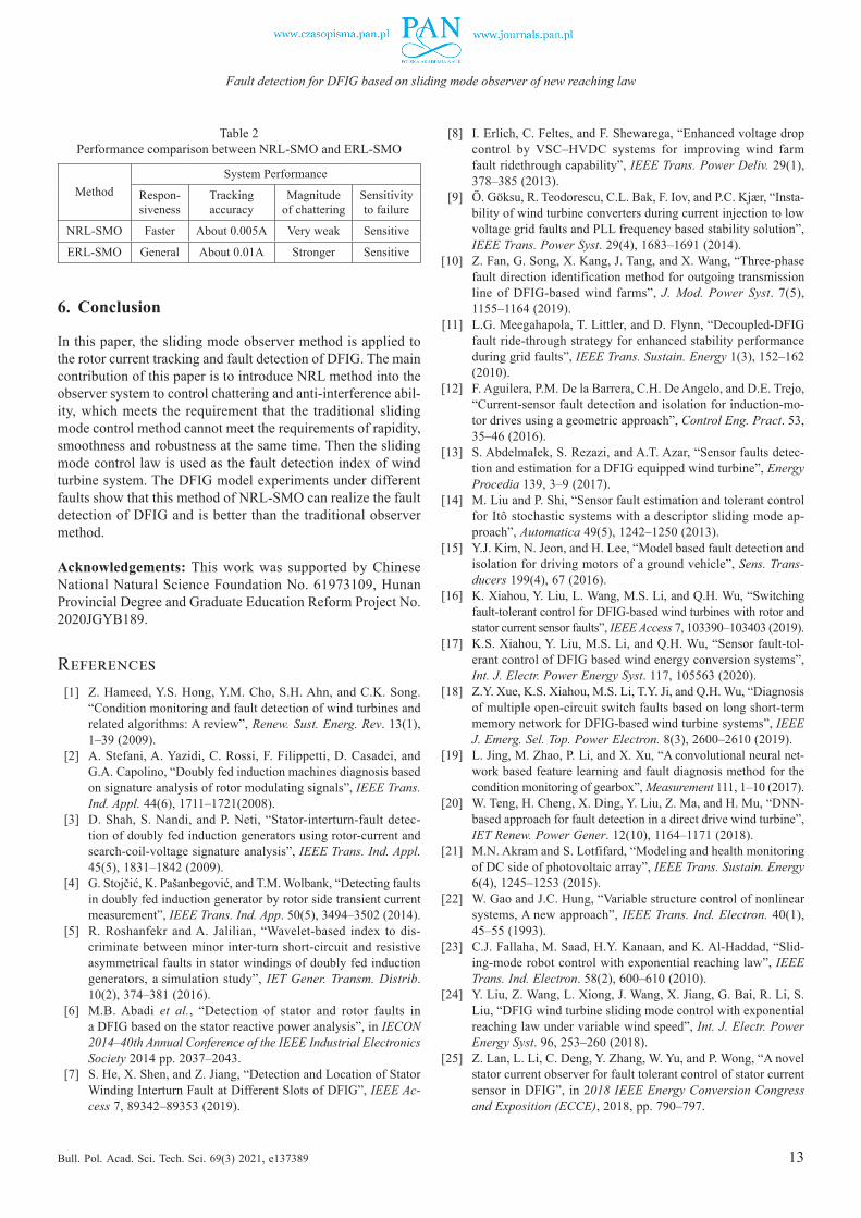
Through the above experiments we can derive the perfor-mance differences between the two observer methods as shown in Table 2. This shows the effectiveness of the NRL-SMO proposed in this paper to track the system state and the fault detection.
13
Fault detection for DFIG based on sliding mode observer of new reaching law
Bull. Pol. Acad. Sci. Tech. Sci. 69(3) 2021, e137389
6. Conclusion
In this paper, the sliding mode observer method is applied to the rotor current tracking and fault detection of DFIG. The main contribution of this paper is to introduce NRL method into the observer system to control chattering and anti-interference abil-ity, which meets the requirement that the traditional sliding mode control method cannot meet the requirements of rapidity, smoothness and robustness at the same time. Then the sliding mode control law is used as the fault detection index of wind turbine system. The DFIG model experiments under different faults show that this method of NRL-SMO can realize the fault detection of DFIG and is better than the traditional observer method.
Acknowledgements: This work was supported by Chinese National Natural Science Foundation No. 61973109, Hunan Provincial Degree and Graduate Education Reform Project No. 2020JGYB189.
References [1] Z. Hameed, Y.S. Hong, Y.M. Cho, S.H. Ahn, and C.K. Song.
“Condition monitoring and fault detection of wind turbines and related algorithms: A review”, Renew. Sust. Energ. Rev. 13(1), 1‒39 (2009).
[2] A. Stefani, A. Yazidi, C. Rossi, F. Filippetti, D. Casadei, and G.A. Capolino, “Doubly fed induction machines diagnosis based on signature analysis of rotor modulating signals”, IEEE Trans. Ind. Appl. 44(6), 1711‒1721(2008).
[3] D. Shah, S. Nandi, and P. Neti, “Stator-interturn-fault detec-tion of doubly fed induction generators using rotor-current and search-coil-voltage signature analysis”, IEEE Trans. Ind. Appl. 45(5), 1831‒1842 (2009).
[4] G. Stojčić, K. Pašanbegović, and T.M. Wolbank, “Detecting faults in doubly fed induction generator by rotor side transient current measurement”, IEEE Trans. Ind. App. 50(5), 3494‒3502 (2014).
[5] R. Roshanfekr and A. Jalilian, “Wavelet-based index to dis-criminate between minor inter-turn short-circuit and resistive asymmetrical faults in stator windings of doubly fed induction generators, a simulation study”, IET Gener. Transm. Distrib. 10(2), 374‒381 (2016).
[6] M.B. Abadi et al., “Detection of stator and rotor faults in a DFIG based on the stator reactive power analysis”, in IECON 2014‒40th Annual Conference of the IEEE Industrial Electronics Society 2014 pp. 2037‒2043.
[7] S. He, X. Shen, and Z. Jiang, “Detection and Location of Stator Winding Interturn Fault at Different Slots of DFIG”, IEEE Ac-cess 7, 89342‒89353 (2019).
[8] I. Erlich, C. Feltes, and F. Shewarega, “Enhanced voltage drop control by VSC–HVDC systems for improving wind farm fault ridethrough capability”, IEEE Trans. Power Deliv. 29(1), 378‒385 (2013).
[9] Ö. Göksu, R. Teodorescu, C.L. Bak, F. Iov, and P.C. Kjær, “Insta-bility of wind turbine converters during current injection to low voltage grid faults and PLL frequency based stability solution”, IEEE Trans. Power Syst. 29(4), 1683‒1691 (2014).
[10] Z. Fan, G. Song, X. Kang, J. Tang, and X. Wang, “Three-phase fault direction identification method for outgoing transmission line of DFIG-based wind farms”, J. Mod. Power Syst. 7(5), 1155‒1164 (2019).
[11] L.G. Meegahapola, T. Littler, and D. Flynn, “Decoupled-DFIG fault ride-through strategy for enhanced stability performance during grid faults”, IEEE Trans. Sustain. Energy 1(3), 152‒162 (2010).
[12] F. Aguilera, P.M. De la Barrera, C.H. De Angelo, and D.E. Trejo, “Current-sensor fault detection and isolation for induction-mo-tor drives using a geometric approach”, Control Eng. Pract. 53, 35‒46 (2016).
[13] S. Abdelmalek, S. Rezazi, and A.T. Azar, “Sensor faults detec-tion and estimation for a DFIG equipped wind turbine”, Energy Procedia 139, 3‒9 (2017).
[14] M. Liu and P. Shi, “Sensor fault estimation and tolerant control for Itô stochastic systems with a descriptor sliding mode ap-proach”, Automatica 49(5), 1242‒1250 (2013).
[15] Y.J. Kim, N. Jeon, and H. Lee, “Model based fault detection and isolation for driving motors of a ground vehicle”, Sens. Trans-ducers 199(4), 67 (2016).
[16] K. Xiahou, Y. Liu, L. Wang, M.S. Li, and Q.H. Wu, “Switching fault-tolerant control for DFIG-based wind turbines with rotor and stator current sensor faults”, IEEE Access 7, 103390‒103403 (2019).
[17] K.S. Xiahou, Y. Liu, M.S. Li, and Q.H. Wu, “Sensor fault-tol-erant control of DFIG based wind energy conversion systems”, Int. J. Electr. Power Energy Syst. 117, 105563 (2020).
[18] Z.Y. Xue, K.S. Xiahou, M.S. Li, T.Y. Ji, and Q.H. Wu, “Diagnosis of multiple open-circuit switch faults based on long short-term memory network for DFIG-based wind turbine systems”, IEEE J. Emerg. Sel. Top. Power Electron. 8(3), 2600‒2610 (2019).
[19] L. Jing, M. Zhao, P. Li, and X. Xu, “A convolutional neural net-work based feature learning and fault diagnosis method for the condition monitoring of gearbox”, Measurement 111, 1‒10 (2017).
[20] W. Teng, H. Cheng, X. Ding, Y. Liu, Z. Ma, and H. Mu, “DNN-based approach for fault detection in a direct drive wind turbine”, IET Renew. Power Gener. 12(10), 1164‒1171 (2018).
[21] M.N. Akram and S. Lotfifard, “Modeling and health monitoring of DC side of photovoltaic array”, IEEE Trans. Sustain. Energy 6(4), 1245‒1253 (2015).
[22] W. Gao and J.C. Hung, “Variable structure control of nonlinear systems, A new approach”, IEEE Trans. Ind. Electron. 40(1), 45‒55 (1993).
[23] C.J. Fallaha, M. Saad, H.Y. Kanaan, and K. Al-Haddad, “Slid-ing-mode robot control with exponential reaching law”, IEEE Trans. Ind. Electron. 58(2), 600‒610 (2010).
[24] Y. Liu, Z. Wang, L. Xiong, J. Wang, X. Jiang, G. Bai, R. Li, S. Liu, “DFIG wind turbine sliding mode control with exponential reaching law under variable wind speed”, Int. J. Electr. Power Energy Syst. 96, 253‒260 (2018).
[25] Z. Lan, L. Li, C. Deng, Y. Zhang, W. Yu, and P. Wong, “A novel stator current observer for fault tolerant control of stator current sensor in DFIG”, in 2018 IEEE Energy Conversion Congress and Exposition (ECCE), 2018, pp. 790‒797.
Table 2 Performance comparison between NRL-SMO and ERL-SMO
MethodSystem Performance
Respon-siveness
Tracking accuracy
Magnitude of chattering
Sensitivity to failure
NRL-SMO Faster About 0.005A Very weak Sensitive
ERL-SMO General About 0.01A Stronger Sensitive