LVRT Strategy -based Multi-controller Switching for DFIG Shi ...
8
LVRT Strategy -based Multi-controller Switching for DFIG Shi-Hong GAO 1,2,a , Cheng-Xiong MAO 1,b,* , Dan WANG 1,c 1 State Key Laboratory of Advanced Electromagnetic Engineering and Technology, Huazhong University of Science and Technology, Wuhan, China 2 School of Information Engineering,Hubei University for Nationalities, Enshi, China a [email protected], b [email protected], c [email protected] *Corresponding author Keywords: Doubly-fed induction generation (DFIG), Low voltage ride-through (LVRT), PI controller, Four-level hysteresis current controller (FLHCC), Rotor-side converter (RSC). Abstract. The RSC is generally controlled by using PI controller, but its narrow bandwidth and slow transient response speed limit the LVRT capability of DFIG. So, a LVRT strategy-based multi-controller switching is proposed in this paper. According to different rotor current setting value, the corresponding control strategy of RSC is implemented. That is, the PI controller is used during normal PCC voltage. However, during PCC voltage sag, the control strategy is switched to FLHCC when the rotor current reaches the first setting value, and a set of resistors is connected into the rotor circuit when the rotor current reaches the second setting value. In addition, the FLHCC implementation, the control strategy switching and the series resistance determination are also introduced in detail. Finally, the feasibility of the proposed LVRT strategy is verified by the dynamic simulation. 1 Introduction With the continuous progress of wind power generation technology, the variable speed constant frequency (VSCF) wind power generation has become the mainstream, in which the DFIGs are most used in wind power generation system, because of its unique mode of integration into the grid. But it is highly sensitive to the grid disturbance, e.g., grid fault [1]. It will result in the voltage dip of the point of common coupling (PCC), and the result is to cause the rotor overcurrent of DFIG. If the rotor overcurrent is not controlled by taking certain measures, the RSC is extremely easy to be damaged because of over-heat effect caused by the rotor overcurrent [2]. It makes the DFIG disconnect with grid, and this will have a serious impact on the safety and stability of the grid operation. Therefore, how to improve the LVRT capability of DFIG is a subject worthy of further study. Through referring a large number of literatures on this issue, the main research findings in recent years are as follows: (1) Adding some hardware facilities, such as the rotor crowbar circuit [3], the dc-link energy absorption or storage circuit [4], and the voltage compensator or impedance network of stator side or the series resistor of rotor side [5-7]. The above methods can greatly improve the LVRT capability of DFIG, but increase the cost of DFIG system and the complexity of control system to some extent; (2) Improving on conventional control strategies, such as the improved PI control strategy and the transient stator flux weakening method [8-9], which means do not increase the hardware cost of DFIG system. But the transient control performance becomes worse during the PCC voltage dip, and as a result that greatly limits the LVRT capability of DFIG. Compared with the conventional PI controller, the hysteresis current controller (HCC) has an excellent transient performance, such as the fast transient response speed and strong control robustness. It is often used in an active power filter of power system to reduce or even eliminate the grid harmonic components that are mainly caused by switching operation and nonlinear loads. Combining excellent steady control performance of PI controller and quick transient response speed of HCC, an improved control strategy in this paper is proposed to improve the LVRT capability of DFIG. The main idea is that the RSC control uses the PI controller during normal PCC voltage, and during the PCC voltage dip, according to the different setting limits of rotor current, a set of resistors is connected into the rotor circuit to limit the initial rotor overcurrent and the This is an open access article under the CC BY-NC license (http://creativecommons.org/licenses/by-nc/4.0/). Copyright © 2017, the Authors. Published by Atlantis Press. 150 Advances in Engineering Research (AER), volume 131 3rd Annual International Conference on Electronics, Electrical Engineering and Information Science (EEEIS 2017)
-
Upload
khangminh22 -
Category
Documents
-
view
2 -
download
0
Transcript of LVRT Strategy -based Multi-controller Switching for DFIG Shi ...
LVRT Strategy -based Multi-controller Switching for DFIG
Shi-Hong GAO1,2,a, Cheng-Xiong MAO1,b,*, Dan WANG1,c
1State Key Laboratory of Advanced Electromagnetic Engineering and Technology, Huazhong University of Science and Technology, Wuhan, China
2School of Information Engineering,Hubei University for Nationalities, Enshi, China
[email protected], [email protected], [email protected]
*Corresponding author
Keywords: Doubly-fed induction generation (DFIG), Low voltage ride-through (LVRT), PI controller, Four-level hysteresis current controller (FLHCC), Rotor-side converter (RSC).
Abstract. The RSC is generally controlled by using PI controller, but its narrow bandwidth and
slow transient response speed limit the LVRT capability of DFIG. So, a LVRT strategy-based
multi-controller switching is proposed in this paper. According to different rotor current setting
value, the corresponding control strategy of RSC is implemented. That is, the PI controller is used
during normal PCC voltage. However, during PCC voltage sag, the control strategy is switched to
FLHCC when the rotor current reaches the first setting value, and a set of resistors is connected into
the rotor circuit when the rotor current reaches the second setting value. In addition, the FLHCC
implementation, the control strategy switching and the series resistance determination are also
introduced in detail. Finally, the feasibility of the proposed LVRT strategy is verified by the
dynamic simulation.
1 Introduction
With the continuous progress of wind power generation technology, the variable speed constant
frequency (VSCF) wind power generation has become the mainstream, in which the DFIGs are
most used in wind power generation system, because of its unique mode of integration into the grid.
But it is highly sensitive to the grid disturbance, e.g., grid fault [1]. It will result in the voltage dip
of the point of common coupling (PCC), and the result is to cause the rotor overcurrent of DFIG. If
the rotor overcurrent is not controlled by taking certain measures, the RSC is extremely easy to be
damaged because of over-heat effect caused by the rotor overcurrent [2]. It makes the DFIG
disconnect with grid, and this will have a serious impact on the safety and stability of the grid
operation. Therefore, how to improve the LVRT capability of DFIG is a subject worthy of further
study. Through referring a large number of literatures on this issue, the main research findings in
recent years are as follows: (1) Adding some hardware facilities, such as the rotor crowbar circuit
[3], the dc-link energy absorption or storage circuit [4], and the voltage compensator or impedance
network of stator side or the series resistor of rotor side [5-7]. The above methods can greatly
improve the LVRT capability of DFIG, but increase the cost of DFIG system and the complexity of
control system to some extent; (2) Improving on conventional control strategies, such as the
improved PI control strategy and the transient stator flux weakening method [8-9], which means do
not increase the hardware cost of DFIG system. But the transient control performance becomes
worse during the PCC voltage dip, and as a result that greatly limits the LVRT capability of DFIG. Compared with the conventional PI controller, the hysteresis current controller (HCC) has an
excellent transient performance, such as the fast transient response speed and strong control
robustness. It is often used in an active power filter of power system to reduce or even eliminate the
grid harmonic components that are mainly caused by switching operation and nonlinear loads. Combining excellent steady control performance of PI controller and quick transient response
speed of HCC, an improved control strategy in this paper is proposed to improve the LVRT
capability of DFIG. The main idea is that the RSC control uses the PI controller during normal PCC
voltage, and during the PCC voltage dip, according to the different setting limits of rotor current, a
set of resistors is connected into the rotor circuit to limit the initial rotor overcurrent and the
This is an open access article under the CC BY-NC license (http://creativecommons.org/licenses/by-nc/4.0/).
Copyright © 2017, the Authors. Published by Atlantis Press. 150
Advances in Engineering Research (AER), volume 1313rd Annual International Conference on Electronics, Electrical Engineering and Information Science (EEEIS 2017)
FLHCC is used to rapidly track the rotor command current. After the PCC voltage restores to
normal, the PI controller is again used to control the RSC. Therefore, this hybrid control strategy
considers the steady performance of DFIG and its transient performance as well.
2 Transient Characteristics of Rotor Voltage and Current during PCC Voltage Dip
For easy to write the dynamic voltage and flux linkage equations of DFIG, the reference directions
of voltage, current and flux linkage adopt the motor convention in this paper. Thus, the dynamic
equations of voltage and flux linkage vector in an arbitrary reference coordinate can be written out
[1,4,9], in which the rotor-side parameters have been converted to the stator side. These equations
are given as follows:
s s s s s r r r r r r
s s s m r r m s r r
; ( )
;
R p j R p j
L L L L
v i ψ ψ v i ψ ψ
ψ i i ψ i i (1)
where 𝒗, 𝒊, 𝝍 are voltage, current and flux linkage vectors, respectively;𝑅, 𝐿 are resistance and
self-inductance, respectively; 𝑠, 𝑟,𝑚 subscripts denote parameters of the stator, rotor windings and
excitation, respectively; 𝜔 is angular speed of reference frame; 𝑝 denotes the differential operator,
which has 𝑝 = 𝑑/𝑑𝑡. Selecting stator flux linkage and rotor current as state variables, and eliminating the stator current
and rotor flux linkage from Eq.(1), the relationship between rotor voltage and state variables can be
derived as follows:
r s r s r r r r r0 r r r r[ ( )] { [ ( )]} { [ ( )]}k p j ω ω R σL p j ω ω R σL p j ω ω v ψ i v i (2)
where 𝒗r0 denotes rotor open-circuit voltage generated by the stator dynamic flux linkage,
which has 𝒗r0 = 𝑘s[𝑝 + 𝑗(𝜔 − 𝜔r)];𝑘s is defined as the coupling effect coefficient of DFIG stator
winding, which has 𝑘s = 𝐿m/𝐿s; 𝜎 is called as the leakage coefficient of DFIG rotor windings,
which has 𝜎 = 1 − 𝐿m2 /(𝐿s𝐿r).
2.1 Symmetrical Dip Case of PCC Voltage
If three-phase short circuit fault occurs in the grid, it will lead to symmetrical PCC voltage dip.
Assuming that the voltage amplitude drops from 𝑉s to (1 − 𝑘)𝑉s, according to the conservation
principle of flux linkage, and neglecting the DFIG stator winding resistance, the stator flux linkage
vector in the stator reference coordinate can be derived from Eq.(1), it can be expressed as
s1 /
s sf sn s 1 s 1(1 )t τjω t
k V e jω kV e jω
ψ ψ ψ (3)
where 𝝍sf, 𝝍sn are steady and transient components of the stator flux linkage vector,
respectively; 𝑘 denotes the voltage dip degree coefficient; 𝜏s is the stator winding time constant,
which has 𝜏s = 𝐿s/𝑅s; 𝜔1 is the synchronous angular speed of the grid.
In terms of Eqs.(2) and (3), the rotor voltage vector 𝒗r in the rotor reference coordinate can be
obtained as follows:
s1 1 /(1 )
r s s r s r r r[ (1 ) ( 1 ) ] ( )t τjsω t j s ω t
k V s k e k jω τ e e R σL p
v i (4)
where 𝑠 is slip ratio of DFIG, which has 𝑠 = 1 − 𝜔r/𝜔1.
Considering that the DFIG stator winding resistance sR is very small, the influence of 1/𝜏s on
the rotor voltage 𝒗r can be neglected. Therefore, the Eq.(4) can be simplified as
s1 1 /(1 )
r s s r r r[ (1 ) (1 ) ] ( )t τjsω t j s ω t
k V s k e s ke e R σL p
v i (5)
Before the PCC voltage drops, the rotor excitation voltage of DFIG is supplied by the RSC, it can
be expressed as
151
Advances in Engineering Research (AER), volume 131
1
r r
js tV e
v (6)
where 𝑉r is the amplitude of the rotor exciting voltage.
In order to simplify the theoretical analysis, the excitation voltage 𝒗r remains constant before
and after the PCC voltage dip. The rotor current vector can be obtained from Eqs.(5) and (6), it can
be described as
s1 1 /(1 )
r r s s s s r r{[ (1 )] (1 ) } ( )t τjsω t j s ω t
V k V s k e k V s ke e R σL p
i (7)
According to the Laplace and its inverse transform, an rotor current vector expression can be
derived from Eq.(7). It consists of three current components: the transient component 𝒊rdc decaying
by the time constant 𝜏r that has𝜏r = 𝜎𝐿r/𝑅r, the periodic component 𝒊rn with the frequency (1 −𝑠)𝜔1 and decaying by the time constant 𝜏s, and the steady component with the frequency 𝑠𝜔1.
2.2 Asymmetrical Dip Case of PCC Voltage
If asymmetrical short circuit fault occurs in the grid, e.g., single-phase grounding or two-phase short
circuit, it will cause the asymmetrical PCC voltage dip. According to the symmetrical component
theory, the PCC voltage can be decomposed into positive, negative and zero sequence components
[10], it can be expressed as
1 1
s s1 s2 s0
j t j tV e V e V
v (8)
where �̇�s1, �̇�s2, �̇�s0 are the positive, negative and zero sequence voltage phasors.
In the above voltage components, only the positive and negative sequence voltage components
establish the air gap flux linkage of DFIG. The sum of them constitutes the steady component of air
gap flux linkage, but the zero sequence voltage component creates no air gap flux linkage. In terms
of the conservation principle of flux linkage and ignoring 1/𝜏s, the rotor open circuit voltage 𝒗r0
generated by the stator flux linkage 𝝍s similarly can be derived, it can be expressed as
s1 1 1 /(2 ) (1 )
r0 r1 r2 rn s1 s2 1 n0[ (2 ) (1 ) ]t τjsω t j s ω t j s ω t
sk sV e s V e j s ωψ e e
v v v v (9)
where 𝒗r1, 𝒗r2 are the positive and negative sequence steady component of rotor open-circuit
voltage; 𝒗rn is the transient component of rotor open-circuit voltage; 𝜓n0 is the initial value of the
stator flux linkage transient component.
Typical asymmetrical grid faults have single-phase grounding fault and two-phase short circuit
fault. They will lead to asymmetrical PCC voltage dip. The positive, negative and zero sequence
voltage components are shown in Tab.1.
Tab.1 Voltage sequence component
fault types 𝑉s1 𝑉s2 𝑉s0
phase a voltage dip (1 − 𝑘/3)𝑉s −𝑘𝑉s/3 −𝑘𝑉s/3
phases b and c voltage dip (1 − 𝑘/2)𝑉s 𝑘𝑉s/2 𝑘𝑉s/2
Combining Eqs.(2), (6) and (9), the rotor current vector expression similarly can be derived, and
it consists of four current components: the transient component 𝒊rdc decaying by the time constant
𝜏r, the positive sequence steady component 𝒊rf1 with the frequency 𝑠𝜔1, the negative sequence
steady component 𝒊rf2 with the frequency (2 − 𝑠)𝜔1, and the periodic component 𝒊rn with the
frequency (1 − 𝑠)𝜔1 and decaying by the time constant 𝜏s.
2.3 Rotor Current Dynamic Waveforms
In the previous chapter, the rotor current dynamic characteristics during the PCC voltage dip are
analyzed in detail. In the following, to verify the correctness of the above theoretical analysis, the
dynamic simulations of rotor current are carried out for different voltage dip types. The main DFIG
parameters used in the dynamic simulation are shown in the Tab.A1 of the appendix. In this paper,
152
Advances in Engineering Research (AER), volume 131
the case of the PCC voltage dip degree coefficient 𝑘 = 1 is only studied. The RSC is still
connected with the DFIG rotor circuit during the PCC voltage dip, and the control strategy of RSC
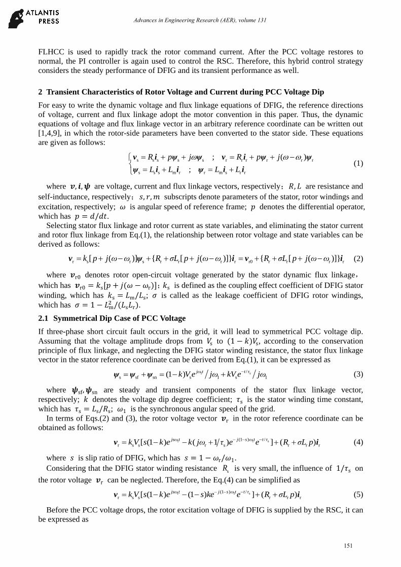
adopts the stator flux vector orientation. For different PCC voltage dip types, the phase a rotor
current dynamic waveforms are shown in Fig.1. ra
[p.u
.]i
[s]t
ra[p
.u.]
i ra[p
.u.]
i
5.8 6 6.2 6.4 6.6-3
-1.5
0
1.5
3
5.8 6 6.2 6.4 6.6-3
-1.5
0
1.5
3
5.8 6 6.2 6.4 6.6-4
-2
0
2
4
6
[s]t [s]t
phase a voltage dip phase b and c voltage dip symmetrical voltage dip
Fig.1 Phase a rotor current dynamic waveforms
It can be seen from Fig.1 that, during the symmetrical voltage dip, the rotor circuit flows through
very large overcurrent that exists at the moment of voltage sag and recovery. But during the
asymmetrical voltage dip, a larger rotor oscillation current lasts throughout the voltage sag.
3 Proposed FLHCC
3.1 Principle of HCC
Detailed HCC principle analysis is introduced in [11] and [12]. In the stationary 𝛼 − 𝛽 reference
coordinate, eight discrete space voltage vectors of RSC output can be expressed as [13]
( 1) /3
r dc
r
2 / 3 1,2, 6
0 0,7
j k πV e k
k
v
v (10)
If the rotor resistance is neglected, the error equation of rotor current in the rotor reference
coordinate can be derived from Eq. (2), it can be described as
𝜎𝐿r𝑝Δ𝒊r = 𝒗r∗ − 𝒗r (11)
where Δ𝒊r is the current error that hasΔ𝒊r = 𝒊r∗ − 𝒊r, in which 𝒊r
∗ is the rotor command current;
𝒗r∗ is the rotor command voltage, which has 𝒗r
∗ = 𝒗r0 + 𝜎𝐿r𝑝𝒊r∗.
In terms of Eq.(11), the rotor command voltage 𝒗r∗ must be accurately determined to satisfy the
rotor current errorΔ𝒊r = 0. So, it requires that the rotor open-circuit voltage 𝒗r0 and the rotor
command current derivative 𝑝𝒊r∗ are accurately measured, but this is difficult to achieve in actual
engineering.
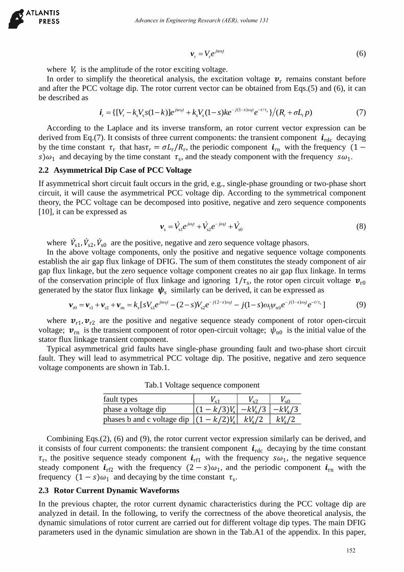
3.2 Proposed FLHCC
The structure of FLHCC in the stationary 𝛼 − 𝛽 reference coordinate is shown in Fig.2, in
which the bandwidth of two HCCs is 𝛿 + Δ𝛿.
0v7v
0
1
2
0
1
2
3
α 0d β 0d
α 1d α 2d α 3d
β 1d
β 2d αd
1v
2v3v
4v
5v 6v
δ+ δ / 2 δ / 4
δ / 4
rαi
δ+ δ / 2
δ / 2
rβi
βd
δ>> δ
Fig.2 Structure of FLHCC
The FLHCC proposed in this paper canceled the outer loop of the double HCC introduced in [11],
in which the outer loop is used to detect the command voltage section. Furthermore, the FLHCC
solved the judgment of the RSC output voltage uncertainty presented in [12]. The spatial position of
the command voltage vector of FLHCC is automatically determined and updated by two HCCs.
According to the status values 𝑑α𝑑β of two HCCs, the optimum voltage vector of RSC output is
153
Advances in Engineering Research (AER), volume 131
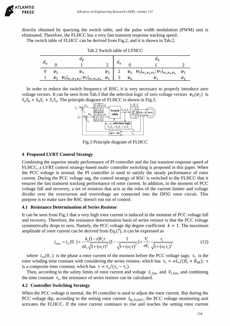
directly obtained by querying the switch table, and the pulse width modulation (PWM) unit is
eliminated. Therefore, the FLHCC has a very fast transient response tracking speed.
The switch table of FLHCC can be derived from Fig.2, and it is shown in Tab.2.
Tab.2 Switch table of LFHCC
𝑑α 𝑑β
𝑑α 𝑑β
0 1 2 0 1 2
0 𝒗5 𝒗4 𝒗3 2 𝒗6 𝒗0|𝒗1,𝒗3,𝒗5; 𝒗7|𝒗2,𝒗4,𝒗6 𝒗2
1 𝒗5 𝒗0|𝒗1,𝒗3,𝒗5; 𝒗7|𝒗2,𝒗4,𝒗6 𝒗3 3 𝒗6 𝒗1 𝒗2
In order to reduce the switch frequency of RSC, it is very necessary to properly introduce zero
voltage vectors. It can be seen from Tab.3 that the selection logic of zero voltage vectors 𝒗0(𝒗7) is
𝑆a𝑆b + 𝑆b𝑆c + 𝑆c𝑆a. The principle diagram of FLHCC is shown in Fig.3.
Switch
table
012
αd
βdrβi
rαi
0123
*
rαi
*
rβi
a b cS S S
rbi
rci
rβi
rαi
+DFIG
selection logic0 7/v v
a b b c c aS S S S S S
αβ abc
Fig.3 Principle diagram of FLHCC
4 Proposed LVRT Control Strategy
Combining the superior steady performance of PI controller and the fast transient response speed of
FLHCC, a LVRT control strategy-based multi- controller switching is proposed in this paper. When
the PCC voltage is normal, the PI controller is used to satisfy the steady performance of rotor
current. During the PCC voltage sag, the control strategy of RSC is switched to the FLHCC that it
ensures the fast transient tracking performance of rotor current. In addition, in the moment of PCC
voltage fall and recovery, a set of resistors that acts as the roles of the current limiter and voltage
divider over the overcurrent and overvoltage are connected into the DFIG rotor circuit. This
purpose is to make sure the RSC doesn't run out of control.
4.1 Resistance Determination of Series Resistor
It can be seen from Fig.1 that a very high rotor current is induced in the moment of PCC voltage fall
and recovery. Therefore, the resistance determination basis of series resistor is that the PCC voltage
symmetrically drops to zero. Namely, the PCC voltage dip degree coefficient 𝑘 = 1. The maximum
amplitude of rotor current can be derived from Eq.(7), it can be expressed as
s s r rrmax ra
2 2 2rr r r r r
(1 ) 1(0 ) [1 ]
1 ( ) 1 ( ) 1 ( )
k s V τ V τi i
σLσL ω τ ω τ ω τ
(12)
where 𝑖ra(0−) is the phase a rotor current of the moment before the PCC voltage sags; 𝜏r is the
rotor winding time constant with considering the series resistor, which has 𝜏r = 𝜎𝐿r/(𝑅r + 𝑅SR); τ
is a composite time constant, which has τ = 𝜏r/(𝜏s − 𝜏r). Then, according to the safety limits of rotor current and voltage 𝐼r_lim and 𝑉r_lim, and combining
the time constant 𝜏r, the resistance of series resistor can be calculated.
4.2 Controller Switching Strategy
When the PCC voltage is normal, the PI controller is used to adjust the rotor current. But during the
PCC voltage dip, according to the setting rotor current 𝐼th_FLHCC, the PCC voltage monitoring unit
activates the FLHCC. If the rotor current continues to rise and reaches the setting rotor current
154
Advances in Engineering Research (AER), volume 131
𝐼th_SR, a set of resistors is connected into the rotor circuit, and is removed until the rotor current is
less than the setting value 𝐼th_SR. After simulation analysis, the current limit 𝐼th_FLHCC is 1.25p.u. to
not trigger the FLHCC under moderate voltage dip. The other one 𝐼th_SRis 1.5p.u. to not frequently
activate the series resistor under deep voltage dip. The controller switching strategy proposed in this
paper is shown in Fig.4.
Maximum value
calculation
th_FLHCCI
rabci
th_SRI≥
≥
FLHCC activation
FLHCC inactivation
and PI activation
SR activation
SR inactivation
Fig.4 Controller switching strategy
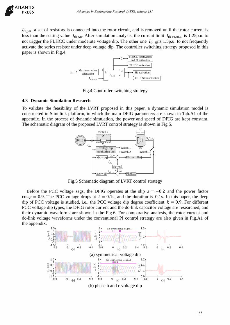
4.3 Dynamic Simulation Research
To validate the feasibility of the LVRT proposed in this paper, a dynamic simulation model is
constructed in Simulink platform, in which the main DFIG parameters are shown in Tab.A1 of the
appendix. In the process of dynamic simulation, the power and speed of DFIG are kept constant.
The schematic diagram of the proposed LVRT control strategy is shown in Fig 5.
voltage dip
monitoring unit
abc→dq
dq→αβ
abc→αβ
PI controller
FLHCC
DFIG
switch 2
RSCswitch 1
a b cS S S
C
rdqi
*
rdqi
SRRrabci
*
rαβirαβi
switch 1
switch 2
Fig.5 Schematic diagram of LVRT control strategy
Before the PCC voltage sags, the DFIG operates at the slip 𝑠 = −0.2 and the power factor
cos𝜑 = 0.9. The PCC voltage drops at 𝑡 = 0.1s, and the duration is 0.1s. In this paper, the deep
dip of PCC voltage is studied, i.e., the PCC voltage dip degree coefficient 𝑘 = 0.9. For different
PCC voltage dip types, the DFIG rotor current and the dc-link capacitor voltage are researched, and
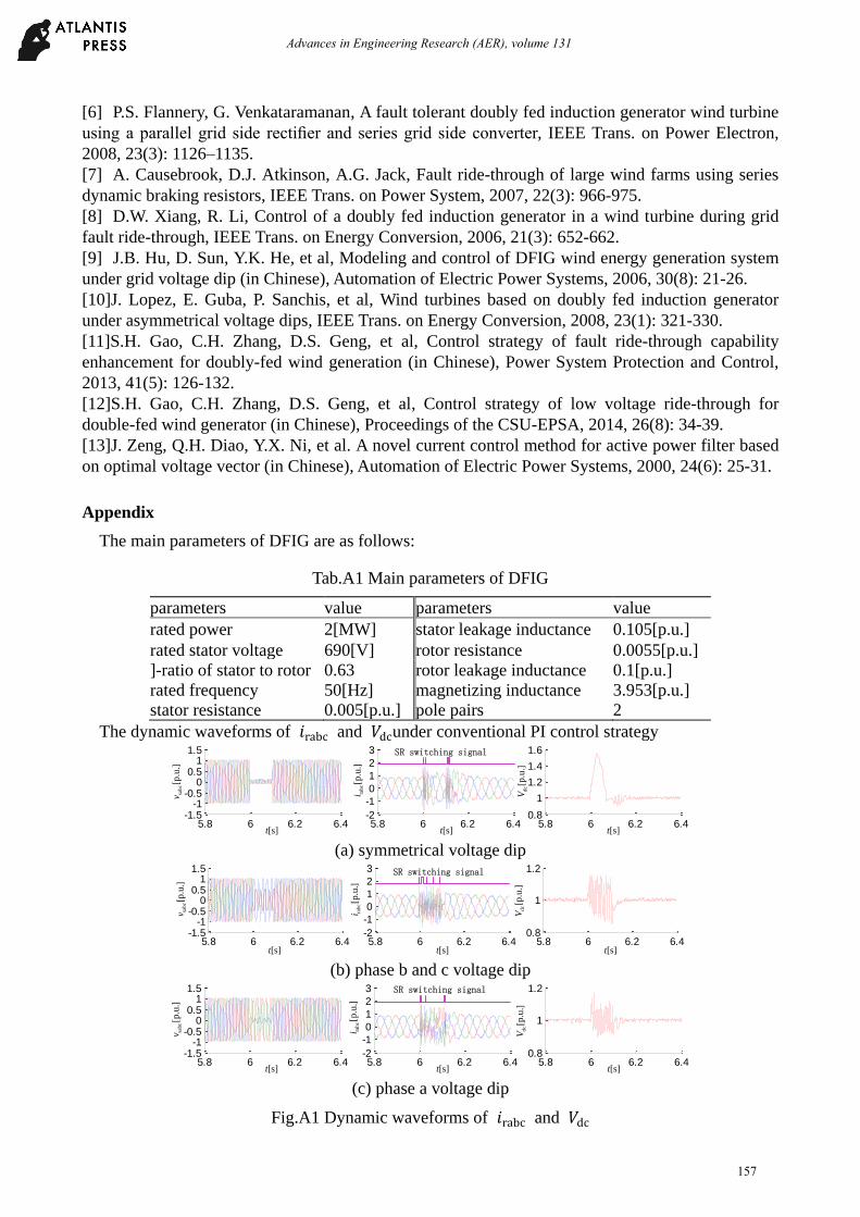
their dynamic waveforms are shown in the Fig.6. For comparative analysis, the rotor current and
dc-link voltage waveforms under the conventional PI control strategy are also given in Fig.A1 of
the appendix.
sabc[p
.u.]
v rab
c[p
.u.]
i
dc[p
.u.]
V
[s]t [s]t [s]t5.8 6 6.2 6.4
-1.5-1
-0.50
0.51
1.5
5.8 6 6.2 6.4-2
-1
0
1
2
3
5.8 6 6.2 6.40.7
1
1.3SR switching signal
(a) symmetrical voltage dip
5.8 6 6.2 6.4-1.5
-1-0.5
00.5
11.5
5.8 6 6.2 6.4-2
-1
0
1
2
3
5.8 6 6.2 6.40.9
1
1.1
1.2SR switching signal
sab
c[p
.u.]
v
rabc[p
.u.]
i dc[p
.u.]
V
[s]t [s]t [s]t (b) phase b and c voltage dip
155
Advances in Engineering Research (AER), volume 131
5.8 6 6.2 6.4-1.5
-1-0.5
00.5
11.5
5.8 6 6.2 6.4-2
-1
0
1
2
3
5.8 6 6.2 6.40.8
1
1.2SR switching signal
sabc[p
.u.]
v rab
c[p
.u.]
i
dc[p
.u.]
V
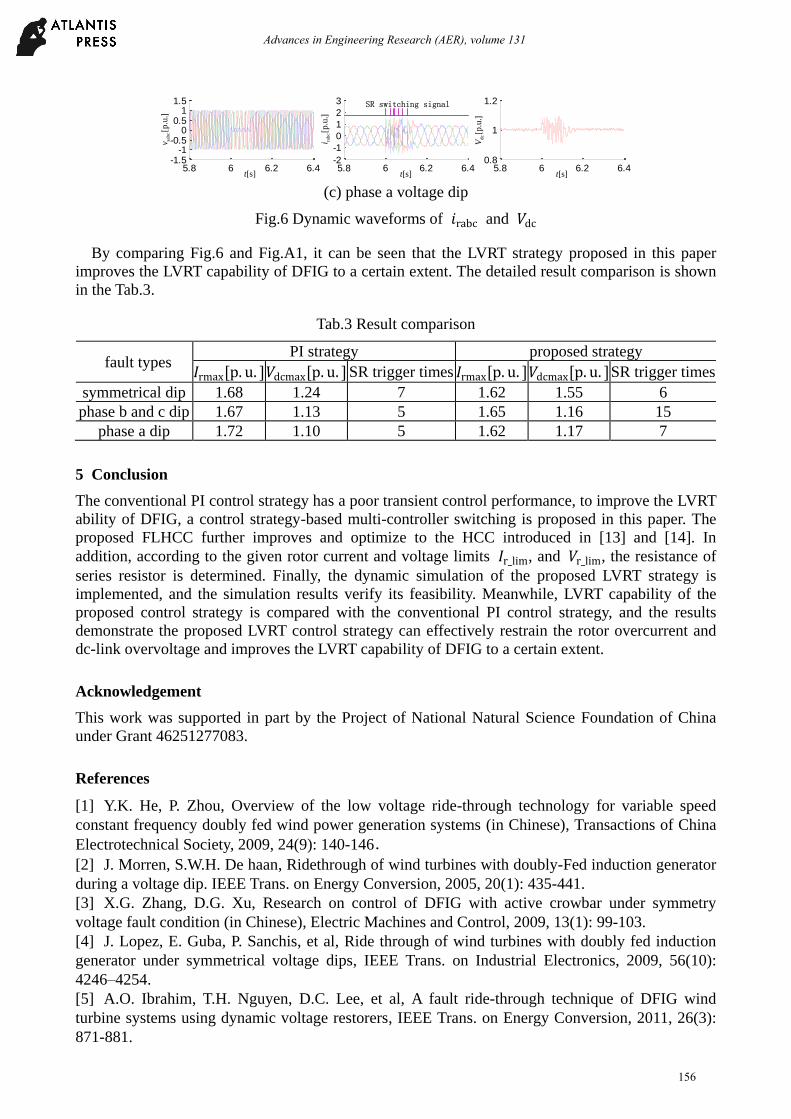
[s]t[s]t [s]t (c) phase a voltage dip
Fig.6 Dynamic waveforms of 𝑖rabc and 𝑉dc
By comparing Fig.6 and Fig.A1, it can be seen that the LVRT strategy proposed in this paper
improves the LVRT capability of DFIG to a certain extent. The detailed result comparison is shown
in the Tab.3.
Tab.3 Result comparison
fault types PI strategy proposed strategy
𝐼rmax[p. u. ] 𝑉dcmax[p. u. ] SR trigger times 𝐼rmax[p. u. ] 𝑉dcmax[p. u. ] SR trigger times symmetrical dip 1.68 1.24 7 1.62 1.55 6
phase b and c dip 1.67 1.13 5 1.65 1.16 15
phase a dip 1.72 1.10 5 1.62 1.17 7
5 Conclusion
The conventional PI control strategy has a poor transient control performance, to improve the LVRT
ability of DFIG, a control strategy-based multi-controller switching is proposed in this paper. The
proposed FLHCC further improves and optimize to the HCC introduced in [13] and [14]. In
addition, according to the given rotor current and voltage limits 𝐼r_lim, and 𝑉r_lim, the resistance of
series resistor is determined. Finally, the dynamic simulation of the proposed LVRT strategy is
implemented, and the simulation results verify its feasibility. Meanwhile, LVRT capability of the
proposed control strategy is compared with the conventional PI control strategy, and the results
demonstrate the proposed LVRT control strategy can effectively restrain the rotor overcurrent and
dc-link overvoltage and improves the LVRT capability of DFIG to a certain extent.
Acknowledgement
This work was supported in part by the Project of National Natural Science Foundation of China
under Grant 46251277083.
References
[1] Y.K. He, P. Zhou, Overview of the low voltage ride-through technology for variable speed
constant frequency doubly fed wind power generation systems (in Chinese), Transactions of China
Electrotechnical Society, 2009, 24(9): 140-146.
[2] J. Morren, S.W.H. De haan, Ridethrough of wind turbines with doubly-Fed induction generator
during a voltage dip. IEEE Trans. on Energy Conversion, 2005, 20(1): 435-441.
[3] X.G. Zhang, D.G. Xu, Research on control of DFIG with active crowbar under symmetry
voltage fault condition (in Chinese), Electric Machines and Control, 2009, 13(1): 99-103.
[4] J. Lopez, E. Guba, P. Sanchis, et al, Ride through of wind turbines with doubly fed induction
generator under symmetrical voltage dips, IEEE Trans. on Industrial Electronics, 2009, 56(10):
4246–4254.
[5] A.O. Ibrahim, T.H. Nguyen, D.C. Lee, et al, A fault ride-through technique of DFIG wind
turbine systems using dynamic voltage restorers, IEEE Trans. on Energy Conversion, 2011, 26(3):
871-881.
156
Advances in Engineering Research (AER), volume 131
[6] P.S. Flannery, G. Venkataramanan, A fault tolerant doubly fed induction generator wind turbine
using a parallel grid side rectifier and series grid side converter, IEEE Trans. on Power Electron,
2008, 23(3): 1126–1135.
[7] A. Causebrook, D.J. Atkinson, A.G. Jack, Fault ride-through of large wind farms using series
dynamic braking resistors, IEEE Trans. on Power System, 2007, 22(3): 966-975.
[8] D.W. Xiang, R. Li, Control of a doubly fed induction generator in a wind turbine during grid
fault ride-through, IEEE Trans. on Energy Conversion, 2006, 21(3): 652-662.
[9] J.B. Hu, D. Sun, Y.K. He, et al, Modeling and control of DFIG wind energy generation system
under grid voltage dip (in Chinese), Automation of Electric Power Systems, 2006, 30(8): 21-26.
[10]J. Lopez, E. Guba, P. Sanchis, et al, Wind turbines based on doubly fed induction generator
under asymmetrical voltage dips, IEEE Trans. on Energy Conversion, 2008, 23(1): 321-330.
[11]S.H. Gao, C.H. Zhang, D.S. Geng, et al, Control strategy of fault ride-through capability
enhancement for doubly-fed wind generation (in Chinese), Power System Protection and Control,
2013, 41(5): 126-132.
[12]S.H. Gao, C.H. Zhang, D.S. Geng, et al, Control strategy of low voltage ride-through for
double-fed wind generator (in Chinese), Proceedings of the CSU-EPSA, 2014, 26(8): 34-39.
[13]J. Zeng, Q.H. Diao, Y.X. Ni, et al. A novel current control method for active power filter based
on optimal voltage vector (in Chinese), Automation of Electric Power Systems, 2000, 24(6): 25-31.
Appendix
The main parameters of DFIG are as follows:
Tab.A1 Main parameters of DFIG
parameters value parameters value
rated power 2[MW] stator leakage inductance 0.105[p.u.]
rated stator voltage 690[V] rotor resistance 0.0055[p.u.]
]-ratio of stator to rotor 0.63 rotor leakage inductance 0.1[p.u.]
rated frequency 50[Hz] magnetizing inductance 3.953[p.u.]
stator resistance 0.005[p.u.] pole pairs 2
The dynamic waveforms of 𝑖rabc and 𝑉dcunder conventional PI control strategy
5.8 6 6.2 6.4-1.5
-1-0.5
00.5
11.5
5.8 6 6.2 6.4-2
-1
0
1
2
3
5.8 6 6.2 6.40.8
1
1.2
1.4
1.6
sab
c[p
.u.]
v
rabc[p
.u.]
i
dc[p
.u.]
V
[s]t [s]t [s]t
SR switching signal
(a) symmetrical voltage dip
sabc[p
.u.]
v rabc[p
.u.]
i
dc[p
.u.]
V
[s]t [s]t[s]t5.8 6 6.2 6.4
-1.5-1
-0.50
0.51
1.5
5.8 6 6.2 6.4-2
-1
0
1
2
3
5.8 6 6.2 6.40.8
1
1.2SR switching signal
(b) phase b and c voltage dip
5.8 6 6.2 6.4-1.5
-1-0.5
00.5
11.5
5.8 6 6.2 6.4-2
-1
0
1
2
3
5.8 6 6.2 6.40.8
1
1.2SR switching signal
[s]t
sab
c[p
.u.]
v
rabc[p
.u.]
i dc[p
.u.]
V
[s]t [s]t (c) phase a voltage dip
Fig.A1 Dynamic waveforms of 𝑖rabc and 𝑉dc
157
Advances in Engineering Research (AER), volume 131