An Effective Reference Generation Scheme for DFIG With Unbalanced Grid Voltage
9
An Effective Reference Generation Scheme for DFIG With Unbalanced Grid Voltage M. A. Asha Rani, C. Nagamani, Member, IEEE, G. Saravana Ilango, Member, IEEE, and A. Karthikeyan, Member, IEEE Abstract—This paper presents a reference current generation scheme for improved dynamic performance of a doubly fed induc- tion generator (DFIG) subjected to unbalanced grid voltage. The power and torque oscillations induced due to the unbalance in grid voltage are minimized using additional compensatory terms in the reference currents. The focus is on estimating the reference currents and control implementation without the need for dual vector control. Real and reactive power control is implemented in the positive reference frame using stator flux-oriented vector control. The rotor-side converter (RSC) is controlled to enable effective reduction of oscillations in torque and active and reactive power. The dc-link voltage oscillation is minimized and the grid-side power factor is maintained unity using the grid-side converter (GSC). Unlike the previously reported techniques, the proposed scheme enables effective reduction of oscillations in torque, active, and reactive power, and the dc-link voltage, all in a single target. The performance of DFIG is investigated in consideration with the Indian Electricity Grid Code (IEGC). Numerical simulations are carried out in power system computer aided design/electromagnetic transients including direct current (PSCAD/EMTDC) for the labo- ratory 3-hp DFIG test setup. The results establish that the perfor- mance of DFIG is notably enhanced with the proposed scheme. Index Terms—Decoupled control, doubly fed induction generator (DFIG), Indian Electricity Grid Code (IEGC), stator flux-oriented control, unbalance. NOMENCLATURE , Instantaneous value of voltage and current. Instantaneous value of flux. , Stator reference frame. , Rotor reference frame. DC-link voltage. Instantaneous value of stator magnetizing current. , DC-side current for grid-side converter (GSC) and rotor-side converter (RSC), respectively. , , and Resistance, inductance, and capacitance. , Real and reactive power. , Angular velocity of stator flux and rotor. Angle between stator voltage vector and -axis. Angle between stator and rotor axis. Angle between stator flux axis and -axis. First subscripts , Stator and rotor. , , and fe Mutual, grid, and front-end converter. Second subscripts , Synchronous reference frame. ub Unbalance. , Positive and negative sequence components. Superscripts Reference. Quantity in positive reference frame. I. INTRODUCTION V ARIABLE speed wind turbines based on doubly fed induction generator (DFIG) connected to the grid are commonly used in wind farms. With disturbances such as sag, swell, or unbalance in the grid voltage, the generator encounters fluctuations in electromagnetic torque which leads to mechanical stresses and subsequently to wear and tear of the rotating parts. In addition, considerable oscillations occur in the active and reac- tive power as well as in the dc-link voltage. The dc-link voltage oscillation is the most severe problem affecting a DFIG under unsymmetrical voltage sag which reduces the life of the dc-link capacitor. In India, wind farms connected to grid at 66 kV or above are governed by the Indian Electricity Grid Code (IEGC) as per the Electricity Act, 2003. The grid code stipulates the limits of acceptable performance of the wind farms in terms of power control, fault, or low-voltage ride through, total harmonic dis- tortion (THD) in voltage and current, etc., under disturbed grid conditions such as sag, swell, unbalance, etc. The “low-voltage ride through” implies that the wind turbine has to remain connected to the grid for a specified period of time even when the grid voltage dips. As per IEGC [20] and [21], wind farms connected at or above 66 kV should remain connected to the grid during system fault as specified in Fig. 1 and can be disconnected from the grid only if the operating point falls below the specified value. represents the minimum voltage required for normal operation of wind turbine which is about 80% of nominal system voltage and represents 15% of nominal system voltage. Wind farms shall be able to withstand a voltage unbalance of 3% for grid voltages below 220 kV. The maximum permissible THD is 3% in voltage and it is 5% for the grid current for variable speed wind turbines. During grid voltage unbalance, 1949-3029 © 2014 IEEE. Personal use is permitted, but republication/redistribution requires IEEE permission. See http://www.ieee.org/publications_standards/publications/rights/index.html for more information. Manuscript received February 17, 2014; revised April 16, 2014; accepted May 05, 2014. Date of publication June 02, 2014; date of current version June 17, 2014. M. A. Asha Rani, C. Nagamani, and G. Saravana Ilango are with the Department of Electrical and Electronics Engineering, National Institute of Technology, Tiruchirappalli 620 015, Tamil Nadu, India (e-mail: [email protected]; [email protected]; [email protected]). A. Karthikeyan is with the Department of Electrical and Electronics Engineering, National Institute of Technology, Surathkal 575 025, Karnataka, India (e-mail: [email protected]). Color versions of one or more of the figures in this paper are available online at http://ieeexplore.ieee.org. Digital Object Identifier 10.1109/TSTE.2014.2322672 1010 IEEE TRANSACTIONS ON SUSTAINABLE ENERGY, VOL. 5, NO. 3, JULY 2014
Transcript of An Effective Reference Generation Scheme for DFIG With Unbalanced Grid Voltage
An Effective Reference Generation Scheme for DFIGWith Unbalanced Grid Voltage
M.A.Asha Rani, C. Nagamani,Member, IEEE,G. Saravana Ilango,Member, IEEE, andA. Karthikeyan,Member, IEEE
Abstract—This paper presents a reference current generationscheme for improved dynamic performance of a doubly fed induc-tion generator (DFIG) subjected to unbalanced grid voltage. Thepower and torque oscillations induced due to the unbalance in gridvoltage are minimized using additional compensatory terms in thereference currents. The focus is on estimating the reference currentsand control implementation without the need for dual vectorcontrol. Real and reactive power control is implemented in thepositive � reference frame using stator flux-oriented vectorcontrol. The rotor-side converter (RSC) is controlled to enableeffective reduction of oscillations in torque and active and reactivepower. The dc-link voltage oscillation isminimized and the grid-sidepower factor is maintained unity using the grid-side converter(GSC). Unlike the previously reported techniques, the proposedscheme enables effective reduction of oscillations in torque, active,and reactive power, and the dc-link voltage, all in a single target.The performance of DFIG is investigated in consideration with theIndian Electricity Grid Code (IEGC). Numerical simulations arecarried out in power system computer aided design/electromagnetictransients including direct current (PSCAD/EMTDC) for the labo-ratory 3-hp DFIG test setup. The results establish that the perfor-mance of DFIG is notably enhanced with the proposed scheme.
IndexTerms—Decoupled control, doubly fed induction generator(DFIG), Indian Electricity Grid Code (IEGC), stator flux-orientedcontrol, unbalance.
NOMENCLATURE
, Instantaneous value of voltage and current.Instantaneous value of flux.
, Stator reference frame., Rotor reference frame.
DC-link voltage.Instantaneous value of stator magnetizingcurrent.
, DC-side current for grid-side converter (GSC)and rotor-side converter (RSC), respectively.
, , and Resistance, inductance, and capacitance., Real and reactive power., Angular velocity of stator flux and rotor.
Angle between stator voltage vector and-axis.
Angle between stator and rotor axis.Angle between stator flux axis and -axis.
First subscripts, Stator and rotor., , and fe Mutual, grid, and front-end converter.
Second subscripts, Synchronous reference frame.
ub Unbalance., Positive and negative sequence components.
SuperscriptsReference.Quantity in positive reference frame.
I. INTRODUCTION
V ARIABLE speed wind turbines based on doubly fedinduction generator (DFIG) connected to the grid are
commonly used in wind farms. With disturbances such as sag,swell, or unbalance in the grid voltage, the generator encountersfluctuations in electromagnetic torquewhich leads tomechanicalstresses and subsequently towear and tear of the rotating parts. Inaddition, considerable oscillations occur in the active and reac-tive power as well as in the dc-link voltage. The dc-link voltageoscillation is the most severe problem affecting a DFIG underunsymmetrical voltage sag which reduces the life of the dc-linkcapacitor.
In India, wind farms connected to grid at 66 kV or above aregoverned by the Indian Electricity Grid Code (IEGC) as per theElectricity Act, 2003. The grid code stipulates the limits ofacceptable performance of the wind farms in terms of powercontrol, fault, or low-voltage ride through, total harmonic dis-tortion (THD) in voltage and current, etc., under disturbed gridconditions such as sag, swell, unbalance, etc.
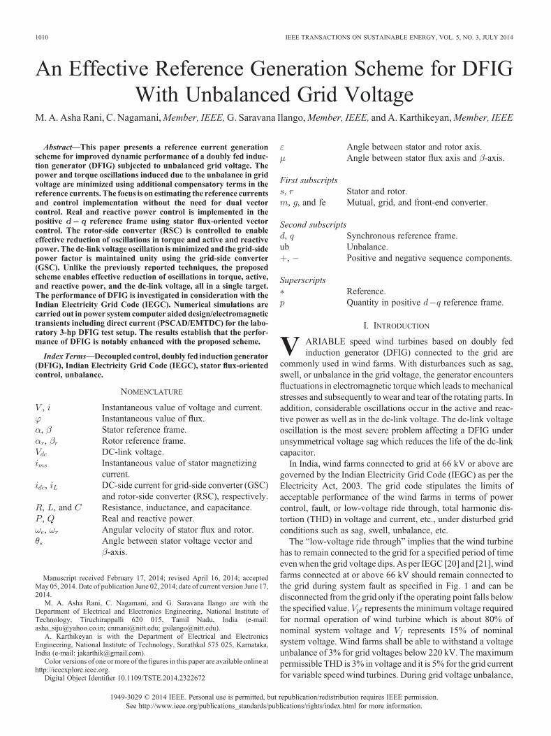
The “low-voltage ride through” implies that the wind turbinehas to remain connected to the grid for a specified period of timeevenwhen the grid voltage dips. As per IEGC [20] and [21], windfarms connected at or above 66 kV should remain connected tothe grid during system fault as specified in Fig. 1 and can bedisconnected from the grid only if the operating point falls belowthe specified value. represents the minimum voltage requiredfor normal operation of wind turbine which is about 80% ofnominal system voltage and represents 15% of nominalsystem voltage. Wind farms shall be able to withstand a voltageunbalance of 3% for grid voltages below 220 kV. The maximumpermissible THD is 3% in voltage and it is 5% for the grid currentfor variable speed wind turbines. During grid voltage unbalance,
1949-3029 © 2014 IEEE. Personal use is permitted, but republication/redistribution requires IEEE permission.See http://www.ieee.org/publications_standards/publications/rights/index.html for more information.
Manuscript received February 17, 2014; revised April 16, 2014; acceptedMay 05, 2014. Date of publication June 02, 2014; date of current version June 17,2014.
M. A. Asha Rani, C. Nagamani, and G. Saravana Ilango are with theDepartment of Electrical and Electronics Engineering, National Institute ofTechnology, Tiruchirappalli 620 015, Tamil Nadu, India (e-mail:[email protected]; [email protected]; [email protected]).
A. Karthikeyan is with the Department of Electrical and ElectronicsEngineering, National Institute of Technology, Surathkal 575 025, Karnataka,India (e-mail: [email protected]).
Color versions of one ormore of the figures in this paper are available online athttp://ieeexplore.ieee.org.
Digital Object Identifier 10.1109/TSTE.2014.2322672
1010 IEEE TRANSACTIONS ON SUSTAINABLE ENERGY, VOL. 5, NO. 3, JULY 2014
oscillations in the electromagnetic torque, active and reactivepower, dc-link voltage, and also the THD in grid current need tobe curtailed. Hence, the controller design has to incorporate thefeatures of minimizing oscillations in addition to the powercontrol under disturbed grid conditions.
In [1]–[5], rotor-side and grid-side control schemes are im-plemented based on double vector control. In these controlschemes, grid-side converter (GSC) and rotor-side converter(RSC) current references are generated based on different indi-vidual control targets such as minimizing the double frequencyoscillations of sinusoidal or cosinusoidal terms of stator active orreactive power, total active or reactive power, torque, negativesequence windings currents, grid currents, etc.
In [6]–[12], control schemes are implemented in the positivesequence reference frame. In [6], a coordinated control of theGSC and RSC under grid unbalance using proportional integraland resonant (PIR) compensator is proposed to eliminate torquepulsations and to reduce stator active power oscillations. In [7],the grid voltage unbalance is compensated by injecting negativesequence currents into the ac system using GSC or RSC or byboth so as to reduce dc-link voltage oscillations and torque ripple.Using this technique, the oscillations in active power and torqueare reduced. However, oscillations in dc-link voltage are high. In[8]–[10], a rotor current control strategy using a main and anauxiliary controller in the and reference frame,respectively, is proposed. The system is designed to operate fordifferent targets. The oscillations in power and torque areconsiderably reduced. In [11], an improved direct power control(DPC) strategy using two resonant controllers and a PI controlleris proposed for maintaining constant stator power, to eliminatetorque pulsations and to maintain sinusoidal stator current.
In [13]–[16], control schemes are implemented based onsequence decomposition. In [17], DPC of DFIG subjected togrid voltage unbalance using hysteresis band control with spacevector pulse width modulation (SVPWM) is proposed. Severalcontrol strategies with and without sequence calculation arediscussed which enables reduction of oscillations in activepower, torque, and dc-link voltage. However, this scheme in-volves classic DPC which operates at nonconstant switchingfrequency. A control technique for decoupled control of activeand reactive power of DFIG directly connected to the grid isspecified in [18]. In [19], a simple stator flux-oriented vectorcontrol scheme is proposed without using dual vector control
which enables simultaneous reduction of oscillations in activepower, torque, and dc-link voltage. However, this scheme isdeveloped without considering the -axis voltage variationsunder grid unbalance.
In this paper, a novel scheme is proposed for reference currentgeneration for DFIG control during grid voltage unbalance. Thepower control is implemented in the positive frame usingstator flux-oriented vector control. This method incorporates anadditional term in the reference current which helps to compen-sate the effects of unbalance. This method is simple as there is noneed for dual vector control which introduces time delays due tosequential decomposition and affects the dynamic performanceof the system. Also, the number of current control loops and PIcontrollers needed is less. The rotor-side controller is used fordecoupled control of active and reactive power and for reducingoscillations in torque and power. The GSC is used for currentexchange at unity power factor (UPF) with the grid and tomaintain a constant dc-link voltage. Simulations are carried outfor the laboratory 3-hp DFIG test setup in PSCAD/EMTDCsoftware. The effectiveness of the reference generation scheme isvalidated for the grid voltage dip of 2%–80% in view of IEGC.
II. DFIG MODEL AND CONTROL UNDER UNBALANCED GRID
VOLTAGE
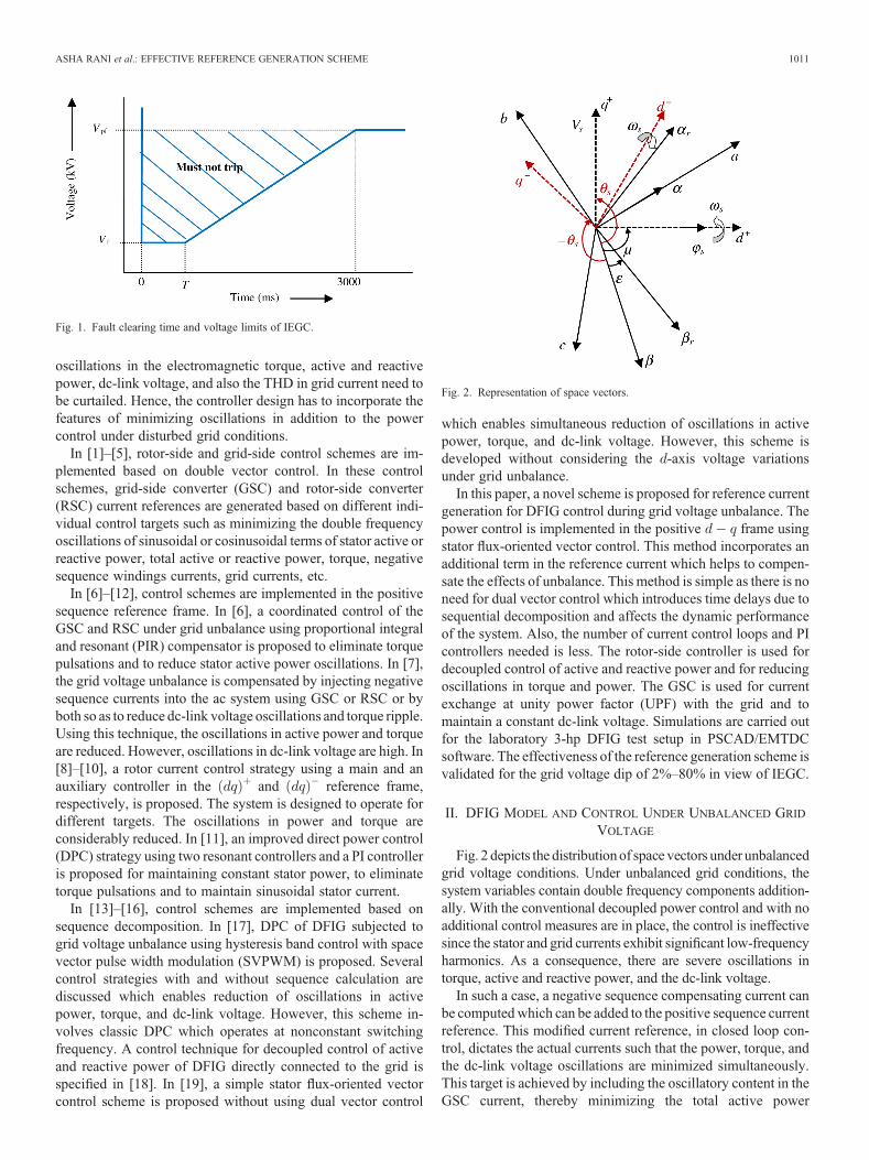
Fig. 2 depicts the distributionof space vectors under unbalancedgrid voltage conditions. Under unbalanced grid conditions, thesystem variables contain double frequency components addition-ally. With the conventional decoupled power control and with noadditional control measures are in place, the control is ineffectivesince the stator and grid currents exhibit significant low-frequencyharmonics. As a consequence, there are severe oscillations intorque, active and reactive power, and the dc-link voltage.
In such a case, a negative sequence compensating current canbe computedwhich can be added to the positive sequence currentreference. This modified current reference, in closed loop con-trol, dictates the actual currents such that the power, torque, andthe dc-link voltage oscillations are minimized simultaneously.This target is achieved by including the oscillatory content in theGSC current, thereby minimizing the total active power
Fig. 1. Fault clearing time and voltage limits of IEGC.
Fig. 2. Representation of space vectors.
ASHA RANI et al.: EFFECTIVE REFERENCE GENERATION SCHEME 1011
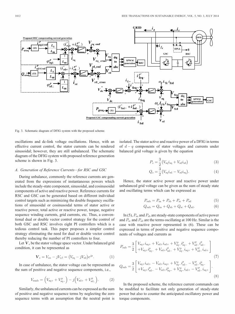
oscillations and dc-link voltage oscillations. Hence, with aneffective current control, the stator currents can be renderedsinusoidal; however, they are still unbalanced. The schematicdiagram of the DFIG system with proposed reference generationscheme is shown in Fig. 3.
A. Generation of Reference Currents—for RSC and GSC
During unbalance, commonly the reference currents are gen-erated from the expressions of instantaneous powers whichinclude the steady-state component, sinusoidal, and cosinusoidalcomponents of active and reactive power. Reference currents forRSC and GSC can be generated based on different individualcontrol targets such as minimizing the double frequency oscilla-tions of sinusoidal or cosinusoidal terms of stator active orreactive power, total active or reactive power, torque, negativesequence winding currents, grid currents, etc. Thus, a conven-tional dual or double vector control strategy for the control ofboth GSC and RSC involves eight PI controllers which is atedious control task. This paper proposes a simpler controlstrategy eliminating the need for dual or double vector controlthereby reducing the number of PI controllers to four.
Let be the stator voltage space vector. Under balanced gridcondition, it can be represented as
In case of unbalance, the stator voltage can be represented asthe sum of positive and negative sequence components, i.e.,
Similarly, the unbalanced currents can be expressed as the sumof positive and negative sequence terms by neglecting the zerosequence terms with an assumption that the neutral point is
isolated. The stator active and reactive power of a DFIG in termsof components of stator voltages and currents underbalanced grid voltage is given by the equation
Hence, the stator active power and reactive power underunbalanced grid voltage can be given as the sum of steady stateand oscillating terms which can be expressed as
In (5), and are steady-state components of active powerand and are the terms oscillating at 100 Hz. Similar is thecase with reactive power represented in (6). These can beexpressed in terms of positive and negative sequence compo-nents of voltages and currents as
In the proposed scheme, the reference current commands canbe modified to facilitate not only generation of steady-statepower but also to counter the anticipated oscillatory power andtorque components.
Fig. 3. Schematic diagram of DFIG system with the proposed scheme.
1012 IEEE TRANSACTIONS ON SUSTAINABLE ENERGY, VOL. 5, NO. 3, JULY 2014
The electromagnetic torque in terms of componentsof stator and rotor currents is given by
where is the number of pole pairs.
B. Control of RSC
Since stator flux-oriented frame of reference is considered, the-axis stator voltage is zero under balanced grid condition.
However, under unbalanced grid condition, -axis stator voltageis not zero due to the double frequency component. The com-ponents of magnetizing current in the axes also havedouble frequency oscillations. As a result, is no longer zero.Thus
As explained in Section II, the current references are modifiednot just to damp the double frequency oscillations of sinusoidalor cosinusoidal terms of active or reactive power as individualtargets of RSC as in [1]–[3], [5], [7], and [8]. Instead, compen-sating reference currents are generated for -axis and -axiscontrol in order to eliminate the effect of double frequencyoscillations (both sinusoidal and cosinusoidal terms simulta-neously) in stator active and reactive power, respectively, in asingle target. As a consequence, the electromagnetic torqueoscillations can be minimized. This target can be achieved bycontrolling the oscillating terms of active and reactive power tozero. Hence, the positive and negative sequence stator referencecurrents in the positive frame can be obtained from therequired values of stator active and reactive power by equatingoscillating terms to zero as
Hence, the stator reference currents referred to the positiveframe can be obtained from (12) as
where
Using the stator reference current equations (13)–(16), corre-sponding stator fluxes referred to the positive frame can beobtained from the stator voltages in the respective frames byneglecting the stator resistance voltage drop. Hence, the statorvoltage equation in the reference frame in terms of statorflux can be written as
From (18), the positive and negative sequence statorfluxes that referred to the positive frame can beobtained as
Hence, the rotor reference currents can be obtained from statoraxes fluxes and stator reference currents as
The axes reference currents for RSC are obtained byadding the compensating (negative sequence) term to the neces-sary currents (positive sequence) needed to produce: 1) thedesired steady-state active and reactive powers and 2) to reducethe oscillations in active and reactive power. Hence
The rotor axes voltages can be expressed as
The cross-coupling terms in (24) and (25) are compensatedusing feed-forward compensation to obtain the desired axesvoltages for rotor-side control. These are the necessary voltagesto be fed to the rotor which in turn produce the rotor currents forreducing the oscillations in torque and power.
C. Control of GSC
The compensating current references can be generated in asimilar way as mentioned for RSC. Hence, GSC can be con-trolled tominimize thefluctuations in the dc-link voltage and also
ASHA RANI et al.: EFFECTIVE REFERENCE GENERATION SCHEME 1013
for current exchange at UPF with the grid. As the dc-link voltagefluctuations are reduced, the double frequency oscillationsin total active power can be reduced. Similarly, the doublefrequency oscillations in total reactive power can be reducedas a consequence of the control objective to maintain powerfactor.
The GSC active and reactive power in terms of compo-nents under steady-state can be represented using (26) and (27)and active and reactive powers of GSC under unbalanced gridvoltage can be represented as in (28) and (29), as follows:
In (28), and are steady-state components of grid-sideactive power and and are the oscillating terms. Similar isthe case with reactive power represented in (29). Hence, thereference currents for minimizing the double frequency oscilla-tions in dc-link voltage and total reactive power at grid terminalscan be obtained by controlling the oscillating terms of active andreactive power to zero. Thus, the positive and negative sequenceGSC reference currents in the positive frame can beobtained from the required values of grid-side active and reactivepower by equating oscillating terms to zero as
Hence, the positive and negative sequence reference currentsfor GSC referred to the positive axes can be obtained from(30) as
where
Finally, the axes reference currents forGSC are obtainedby adding the compensating (negative sequence) term to thedesired currents (positive sequence) needed to maintain the dc-link voltage constant and to maintain power factor as
Here, the GSC -axis positive sequence reference current isdictated by the dc-link voltage and . The axes voltagesfor GSC can be expressed as
It is required to compensate for the cross-coupling termsin (35) and (36) to obtain the axes control voltages forGSC.
III. SIMULATION RESULTS
Simulations are carried out for the laboratory 3-hp DFIG testsetup in PSCAD/EMTDC software.
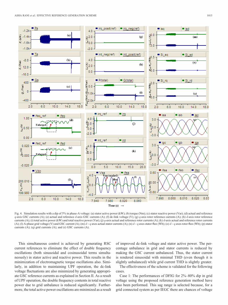
The parameters of the machine are given in the Appendix(Table III). The performance of DFIG subjected to 5% dip inphase—A grid voltage is shown in Fig. 4. For the purpose ofinvestigation, , , , and are set as 1.5 kW, 0kVar, 0 kVar, and 200V, respectively. The sequence of events inthe simulation with grid unbalance is given in the Table I. TheGSC and RSC voltage and current controller are designed for adamping ratio and for a steady-state error of 0.01%.Thesettling time for rotor-side and grid-side current controllers andgrid-side dc-link voltage controller are chosen as 0.02, 0.01, and0.012, respectively for determining . The parameters of the PIcontrollers are given in the Appendix (Table IV).
From the simulation results, it is notable that at whenunbalance is introduced into the system all the system variablesin frame such as stator voltages, stator fluxes, and dc-linkvoltage starts oscillating at double frequency. In addition, thestator, rotor, and GSC currents exhibit lower-order harmonicsthough they are still unbalanced. As a consequence, theaxes magnetizing currents, stator active and reactive power, andtotal active and reactive power exhibit double frequency oscilla-tions. If no additional control measures are in place, it leads tosustained oscillations in all the above-mentioned variables asseen in Fig. 4.
From the instant until , the speed of themachine is maintained constant at 1450 rpm and at ,the speed of the machine is varied from 1450 to 1550 rpmlinearly. In this variable speed operation, the controller tracksalso the reference stator active and reactive powers as in Fig. 4.
For 5% voltage unbalance by activating the proposed control-ler, the oscillations in active power, electromagnetic torque, anddc-link voltage are reduced to 23%, 15.4%, and 66% of theirrespective original values. It is also notable that the statorcurrents and grid currents are sinusoidal with low THD of1.14% and 0.47%, respectively, though they are unbalanced.The percentage oscillations in active power, electromagnetictorque, and dc-link voltage of the DFIG system using theproposed method are compared with the simulation resultsobtained in [3], [6]–[9] and are listed in Table II.
1014 IEEE TRANSACTIONS ON SUSTAINABLE ENERGY, VOL. 5, NO. 3, JULY 2014
This simultaneous control is achieved by generating RSCcurrent references to eliminate the effect of double frequencyoscillations (both sinusoidal and cosinusoidal terms simulta-neously) in stator active and reactive power. This results in theminimization of electromagnetic torque oscillations also. Simi-larly, in addition to maintaining UPF operation, the dc-linkvoltage fluctuations are also minimized by generating appropri-ate GSC reference currents as explained in Section II. As a resultof UPF operation, the double frequency contents in total reactivepower due to grid unbalance is reduced significantly. Further-more, the total active power oscillations areminimized as a result
of improved dc-link voltage and stator active power. The per-centage unbalance in grid and stator currents is reduced bymaking the GSC current unbalanced. Thus, the stator currentis rendered sinusoidal with minimal THD (even though it isslightly unbalanced) while grid current THD is slightly greater.
The effectiveness of the scheme is validated for the followingcases.
Case 1: The performances of DFIG for 2%–80% dip in gridvoltage using the proposed reference generation method havealso been performed. This sag range is selected because, for agrid connected system as per IEGC there are chances of voltage
Fig. 4. Simulation results with a dip of 5% in phase-A voltage: (a) stator active power (kW); (b) torque (Nm); (c) stator reactive power (Var); (d) actual and reference-axis GSC currents (A); (e) actual and reference -axis GSC currents (A); (f) dc-link voltage (V); (g) -axis rotor reference currents (A); (h) -axis rotor referencecurrents (A); (i) total active power (kW) and total reactive power (Var); (j) -axis actual and reference rotor currents (A); (k) -axis actual and reference rotor currents(A); (l) A-phase grid voltage (V) and GSC current (A); (m) axes actual stator currents (A); (n) axes stator flux (Wb); (o) axes rotor flux (Wb); (p) statorcurrents (A); (q) grid currents (A); and (r) GSC currents (A).
ASHA RANI et al.: EFFECTIVE REFERENCE GENERATION SCHEME 1015

dip from 10% to 85% and which can even last for 3 s. From theinvestigation, it is observed that under larger unsymmetricalvoltage dips up to 70%, the controller exhibits similar perfor-mance beyond which stator current is exceeding the machine-rated current.
Case 2: Dynamic studies were also carried out for linearvariation in rotor speed ranging from 1450 to 1550 rpm asshown in Fig. 5 and also under high-speed variations (1400–1700 rpm) with 10% dip in phase-A voltage to analyze thetransient performance of the scheme. Under high speed varia-tions, it is observed that the maximum percentage oscillations inactive power and torque are around 4.4% and 3%, respectively,with a settling time of 0.15 s andwith amaximumpeak overshootof 14%.
Case 3: The performance of DFIG subjected to unsymmetricaldip [double line (DL)] in phases A and B is also investigated.
Case 4: Simulations are carried out for different referencepowers also with unsymmetrical dips. In cases 3 and 4, smoothcontrol is achieved along with significant reduction in electro-magnetic torque, stator active and reactive power, total active andreactive power, and dc-link voltage oscillations.
Case 5: The performance of the scheme with parametervariation is also investigated with an increase of 10% in1) , , and and 2) , , , and with grid voltagedips up to 70%. It is observed that the percentage oscillations inactive power, torque, and dc-link voltage are increased to amaximum of about 1.2%, 2%, and 6.7%, respectively, from theiroriginal values (Table II) for case 1) and 1.6%, 2.3%, and 12%,respectively, for case 2). Due to space limitation, all the simula-tion results are not included in this paper.
IV. CONCLUSION
This study has presented an improved scheme of referencecurrent generation based on stator flux-oriented vector controlimplemented in the positive reference frame for improvedperformance of a DFIG subjected to unbalanced grid voltage inconsideration with the IEGC.
TABLE IICOMPARISON OF DFIG PERFORMANCE WITH DIFFERENT CONTROL SCHEMES UNDER
GRID VOLTAGE UNBALANCE
Fig. 5. Simulation results with speed variation under 10% dip in phase-A gridvoltage with proposed control: (a) rotor speed (rpm); (b) rotor currents (A);(c) stator active power (kW) and reactive power (kVar); and (d) torque (Nm).
TABLE ISEQUENCE OF EVENTS
1016 IEEE TRANSACTIONS ON SUSTAINABLE ENERGY, VOL. 5, NO. 3, JULY 2014
The proposed reference generation scheme enhances theoverall performance of the system with the following merits.
Simultaneous control of all variables such as electromagnetictorque, stator as well as total active and reactive power, and dc-link voltage is possiblewithout the need for double vector controlwith reduced number of PI controllers. Oscillations in activepower, reactive power, torque, and dc-link voltage are notablyreduced compared to other schemes. THD is less than 5% in thestator and grid currents for grid voltage dip up to 65%. Noadditional reactive power compensators are needed. Effectivecontrol even under voltage dips in single or double lines.
APPENDIX
REFERENCES
[1] H. Wang, W. Zhang, J. Hu, and Y. He, “Improved dual-PI rotor currentcontrol scheme for a wind-driven DFIG during asymmetrical grid voltagedips,” in Proc. IEEE Int. Electr. Mach. Drives Conf. (IEMDC), 2009,pp. 171–176.
[2] Y. Zhou, P. Bauer, J. A. Ferreira, and J. Pierik, “Operation of grid-connectedDFIG under unbalanced grid voltage condition,” IEEE Trans. EnergyConvers., vol. 24, no. 1, pp. 240–245, Mar. 2009.
[3] E. Javan and A. Darabi, “A new control strategy of DFIG- based windturbines under unbalanced grid voltage conditions,” in Proc. IEEE2nd Power Electron. Drive Syst. Technol. Conf. (PEDSTC’11), 2011,pp. 175–180.
[4] D. Ya and L. Hui, “Dual-PI rotor current control of doubly-fed inductionwind generators under unbalance grid voltage,” inProc. Asia-Pacific PowerEnergy Eng. Conf. (APPEEC), 2011, pp. 1–5.
[5] A. G. Abo-Khalil, D.-C. Lee, and J.-I. Jang, “Control of back-to-back PWMconverters for DFIG wind turbine systems under unbalanced grid voltage,”in Proc. Int. Symp. Ind. Electron. (ISIE), 2007, pp. 2637–2642.
[6] J. Hu, Y. He, L. Xu, and B. W. Williams, “Improved control of DFIGsystems during network unbalance using PI-R current regulators,” IEEETrans. Ind. Electron., vol. 56, no. 2, pp. 439–450, Feb. 2009.
[7] Y. Wang, L. Xu, and B. W. Williams, “Compensation of network voltageunbalance using doubly fed induction generator-based wind farms,” IETRenew. Power Gener., vol. 3, no. 1, pp. 12–22, 2009.
[8] L. Xu, “Enhanced control and operation of DFIG-based wind farmsduring network unbalance,” IEEE Trans. Energy Convers., vol. 23, no. 4,pp. 1073–1081, Dec. 2008.
[9] L. Xu, “Coordinated control of DFIG’s rotor and grid side converters duringnetwork unbalance,” IEEETrans. PowerElectron., vol. 23, no. 3, pp. 1041–1049, May 2008.
[10] J. Hu, Y. He, and L. Xu, “Improved rotor current control of wind turbinedriven doubly-fed induction generators during network voltage unbalance,”Electr. Power Syst. Res., vol. 80, no. 7, pp. 847–856, 2010.
[11] H. Nian, Y. Song, P. Zhou, and Y. He, “Improved direct power controlof a wind turbine driven doubly fed induction generator during transientgrid voltage unbalance,” IEEE Trans. Energy Convers., vol. 26, no. 3,pp. 976–985, Sep. 2011.
[12] J. Hu and Y. He, “DFIG wind generation systems operating with limitedconverter rating considered under unbalanced network conditions- analysisand control design,” Renew. Energy, vol. 36, no. 2, pp. 829–847, 2010.
[13] Y. Liao, H. Li, J. Yao, and K. Zhuang, “Operation and control of a grid-connected DFIG-based wind turbine with series grid-side converter duringnetwork unbalance,” Electr. Power Syst. Res., vol. 81, no. 1, pp. 228–236,2011.
[14] Y. Quan, H. Nian, J. Hu, and J. Li, “Improved control of the grid-connectedconverter under the harmonically distorted grid voltage conditions,” inProc. Int. Conf. Electr. Mach. Syst. (ICEMS), 2010, pp. 204–209.
[15] J.-I. Jang, Y.-S. Kim, and D.-C. Lee, “Active and reactive power control ofDFIG for wind energy conversion under unbalanced grid voltage,” in Proc.CES/IEEE 5th Int. Power Electron. Motion Control Conf. (IPEMC), 2006,pp. 1–5.
[16] J. Hu, W. Zhang, H. Wang, and Y. He, “Improved MRAS observer andsensorless control of DFIG during network voltage unbalance,” in Proc.IEEE Int. Electr. Mach. Drives Conf. (IEMDC), 2009, pp. 1486–1491.
[17] G.Abad,M.A.Rodriguez,G. Iwanski, and J. Poza, “Direct power control ofdoubly fed induction generator based wind turbines under unbalanced gridvoltage,” IEEE Trans. Power Electron., vol. 25, no. 2, pp. 1073–1081, Feb.2010.
[18] R. Datta and V. T. Ranganathan, “Decoupled control of active and reactivepower for a grid-connected doubly-fed wound rotor induction machinewithout position sensors,” in Proc. 34th IAS Annu. Meet. Conf. Record Ind.Appl. Conf., 1999 pp. 2623–2630.
[19] M. A. Asha Rani, A. Karthikeyan, and C. Nagamani, “Decoupled control ofdoubly-fed-induction generator under unbalanced grid voltage with modi-fied reference generation,” inProc. IEEE Int. Conf. Power, Energy Control,2013, pp. 420–425.
[20] Central Electricity Regulatory Commission, Ministry of Power, CentralGovernment of India, Indian Electricity Grid Code. New Delhi, India:Central Electricity Regulatory Commission, Apr. 2010.
[21] Central Electricity Regulatory Commission, Ministry of Power, CentralGovernment of India, Central Electricity Authority (Grid Standards)Regulations, 2010. The Gazette of India, Jun. 26, 2010.
M. A. Asha Rani received the B.Tech. degree fromCollege of Engineering Perumon (CUSAT), Kerala,India, in 2004, and the Masters degree from RajivGandhi Institute of Technology, Kottayam, India, in2007.
Since 2004, she has been with the Departmentof Electrical and Electronics Engineering, CaarmelEngineering College, Pathanamthitta, India. Currently,she is a Full-Time Research Scholar (under QIP) withthe National Institute of Technology, Tiruchirappalli,India.Her research interests includeRenewable Energy
Systems and Power quality.
C. Nagamani (M’10) received the B.Tech. degreefrom S.V.U.C.E., Tiruapati, M.Tech. degree from IIT,Kanpur, and the Ph.D. degree from the University ofTechnology, Sydney, NSW, Australia, respectively.
From 1985 to 1991, she was with the CentralPower Research Institute, Bangalore, India. Subse-quently, she joined the EEE Department, NationalInstitute of Technology (then known as RegionalEngineering College), Tiruchirappalli, India, as alecturer. Currently, she is a Professor with the samedepartment. Her research interests include power elec-
tronics and drives, renewable energy systems, and FACTS controllers.
TABLE IIIMACHINE PARAMETERS
TABLE IVPI CONTROLLER PARAMETERS FOR GSC AND RSC
ASHA RANI et al.: EFFECTIVE REFERENCE GENERATION SCHEME 1017

G. Saravana Ilango (M’13) graduated from MadrasUniversity, Chennai, India, in 2000. He received theMasters degree from Bharathidasan University,Trichy, India, in 2001, and the Ph.D. degree fromNational Institute of Technology, Tiruchirappalli,India.
From 2001 to 2004, hewas a Lecturer withNoorulIslam College of Engineering, Kumaracoil, India.Currently, he is working as an Assistant Professorwith the National Institute of Technology since 2006.His research interests include power electronics and
drives, renewable energy systems, and FACTS controllers.
A. Karthikeyan (S’10–M’11) received the B.E.degree from Bharathidasan University and the M.S.(by research) and Ph.D. degrees fromNational Instituteof Technology, Tiruchirappalli, India, respectively.
He was an adhoc faculty member with the Depart-ment of Electrical and Electronics Engineering,National Institute of Technology, Tiruchirappalli,India. Currently, he is an Assistant Professor with theDepartment of Electrical and Electronics Engineering,National Institute of Technology, Surathkal, India. Hisresearch interests include power electronics applica-
tions in renewable energy and power quality.
1018 IEEE TRANSACTIONS ON SUSTAINABLE ENERGY, VOL. 5, NO. 3, JULY 2014