
Virtual-Flux-Based Voltage-Sensor-Less Power Control for Unbalanced Grid Conditions
17
IEEE TRANSACTIONS ON POWER ELECTRONICS, VOL. 27, NO. 9, SEPTEMBER 2012 4071 Virtual-Flux-Based Voltage-Sensor-Less Power Control for Unbalanced Grid Conditions Jon Are Suul, Member, IEEE, Alvaro Luna, Member, IEEE, Pedro Rodr´ ıguez, Senior Member, IEEE, and Tore Undeland, Fellow, IEEE Abstract—This paper presents a virtual flux-based method for voltage-sensor-less power control of voltage source converters un- der unbalanced grid voltage conditions. The voltage-sensor-less grid synchronization is achieved by a method for virtual flux es- timation with inherent sequence separation in the stationary ref- erence frame. The estimated positive and negative sequence (PNS) virtual flux components are used as basis for calculating cur- rent references corresponding to the following objectives for con- trol of active and reactive powers under unbalanced conditions: 1) balanced positive sequence currents, 2) elimination of double- frequency active power oscillations, and 3) elimination of double- frequency reactive power oscillations. For simple implementation and flexible operation, the derived current references are synthe- sized into one generalized equation where the control objectives can be selected by real coefficients. Since the converter has a lim- ited current capability, a simple, generalized, method for current limitation is also presented with the purpose of maintaining the in- tended power flow characteristics during unbalanced grid faults. The proposed strategies for virtual flux-based voltage-sensor-less operation have been investigated by simulations and laboratory experiments, verifying the expected performance of active and re- active power control with different objectives. Index Terms—Control of active and reactive powers, three-phase voltage source converters, unbalanced grid voltage, virtual flux, voltage-sensor-less control. I. INTRODUCTION O VER the past decades, there has been a continuous growth in the use of three-phase voltage source converters (VSCs) for grid-connected power conversion systems [1], [2]. The es- tablished applications of VSCs cover a wide power range and include, among others, variable speed wind turbines and other Manuscript received September 26, 2011; revised December 28, 2011; accepted February 26, 2012. Date of current version May 15, 2012. This work was supported in part by the Project ENE2011-29041-C02-01 funded by the Spanish Ministry of Science and Innovation. Recommended for publication by Associate Editor V. Staudt. J. A. Suul was with the Department of Electric Power Engineering, Nor- wegian University of Science and Technology, 7491 Trondheim, Norway. He is now with SINTEF Energy Research, 7465 Trondheim, Norway (e-mail: [email protected]). A. Luna is with the Department of Electrical Engineering, Technical Univer- sity of Catalonia, 08034 Barcelona, Spain (e-mail: [email protected]). P. Rodr´ ıguez is with the Department of Electrical Engineering, Technical University of Catalonia, 08034 Barcelona, Spain, and also with the Electri- cal Engineering Division, Abengoa Research, E-41014 Seville, Spain (e-mail: [email protected]). T. Undeland is with the Department of Electric Power Engineering, Norwe- gian University of Science and Technology, 7491 Trondheim, Norway (e-mail: [email protected]). Color versions of one or more of the figures in this paper are available online at http://ieeexplore.ieee.org. Digital Object Identifier 10.1109/TPEL.2012.2190301 distributed generation systems, regenerative loads, energy stor- age systems, high-voltage dc-transmission, and various types of compensation devices. In an increasing number of these appli- cations, the VSCs are required to be capable of operating during grid voltage disturbances [3]–[5]. The performance of control systems designed for balanced three-phase conditions will, how- ever, degenerate if the grid voltage becomes unbalanced [6]. One of the main challenges for unbalanced operation of three- phase VSCs is to achieve both fast and accurate grid synchro- nization. The simple and well-known synchronous reference frame (SRF) phase-locked loop (PLL) can, however, not achieve satisfactory operation during unbalanced conditions without sig- nificantly reducing the bandwidth, as demonstrated by the re- sults presented in [7]. As reviewed in [8], several solutions to overcome this problem have been suggested, for instance, by adding digital filters in the traditional SRF PLL structure, or by applying various techniques for separating PNS components in synchronous or stationary reference frames. The performance of the inner control loops, i.e., the current control loop in a traditional cascaded control structure, must also be ensured un- der unbalanced conditions. This is usually achieved by either implementing separate current controllers in the PNS SRFs or by applying current controllers designed for operating in the stationary reference frame [9]–[11]. With satisfactory performance of the current controllers, the operational characteristics of a converter under unbalanced con- ditions will mainly be influenced by the objectives and tech- niques used for calculating the current references. In early pub- lications related to control of VSCs during unbalanced con- ditions, the focus was mainly on avoiding second harmonic oscillations in the active power flow of the converter, and by that reducing or eliminating oscillations in the dc-link volt- age [9], [10], [12], [13]. In other cases, the priority has been to assure balanced sinusoidal currents from the converter, in- dependently of the grid voltage unbalance. With the increased use of VSCs in renewable energy systems and the emergence of grid codes requiring capability for delivering reactive power to the grid during voltage disturbances, other control objectives have become relevant [3], [14]. Several recent publications have, therefore, presented generalized discussions on how to derive current references corresponding to different objectives for con- trol of active and reactive powers during unbalanced conditions, as well as comparative studies investigating converter operation with various control objectives [5], [14]–[20]. The available studies of generalized and flexible power con- trol strategies for VSCs during unbalanced conditions are based on utilizing measured voltages to fulfill the specified control 0885-8993/$31.00 © 2012 IEEE
-
Upload
independent -
Category
Documents
-
view
3 -
download
0
Transcript of Virtual-Flux-Based Voltage-Sensor-Less Power Control for Unbalanced Grid Conditions

IEEE TRANSACTIONS ON POWER ELECTRONICS, VOL. 27, NO. 9, SEPTEMBER 2012 4071
Virtual-Flux-Based Voltage-Sensor-Less PowerControl for Unbalanced Grid Conditions
Jon Are Suul, Member, IEEE, Alvaro Luna, Member, IEEE, Pedro Rodrıguez, Senior Member, IEEE,and Tore Undeland, Fellow, IEEE
Abstract—This paper presents a virtual flux-based method forvoltage-sensor-less power control of voltage source converters un-der unbalanced grid voltage conditions. The voltage-sensor-lessgrid synchronization is achieved by a method for virtual flux es-timation with inherent sequence separation in the stationary ref-erence frame. The estimated positive and negative sequence (PNS)virtual flux components are used as basis for calculating cur-rent references corresponding to the following objectives for con-trol of active and reactive powers under unbalanced conditions:1) balanced positive sequence currents, 2) elimination of double-frequency active power oscillations, and 3) elimination of double-frequency reactive power oscillations. For simple implementationand flexible operation, the derived current references are synthe-sized into one generalized equation where the control objectivescan be selected by real coefficients. Since the converter has a lim-ited current capability, a simple, generalized, method for currentlimitation is also presented with the purpose of maintaining the in-tended power flow characteristics during unbalanced grid faults.The proposed strategies for virtual flux-based voltage-sensor-lessoperation have been investigated by simulations and laboratoryexperiments, verifying the expected performance of active and re-active power control with different objectives.
Index Terms—Control of active and reactive powers, three-phasevoltage source converters, unbalanced grid voltage, virtual flux,voltage-sensor-less control.
I. INTRODUCTION
OVER the past decades, there has been a continuous growthin the use of three-phase voltage source converters (VSCs)
for grid-connected power conversion systems [1], [2]. The es-tablished applications of VSCs cover a wide power range andinclude, among others, variable speed wind turbines and other
Manuscript received September 26, 2011; revised December 28, 2011;accepted February 26, 2012. Date of current version May 15, 2012. This workwas supported in part by the Project ENE2011-29041-C02-01 funded by theSpanish Ministry of Science and Innovation. Recommended for publication byAssociate Editor V. Staudt.
J. A. Suul was with the Department of Electric Power Engineering, Nor-wegian University of Science and Technology, 7491 Trondheim, Norway. Heis now with SINTEF Energy Research, 7465 Trondheim, Norway (e-mail:[email protected]).
A. Luna is with the Department of Electrical Engineering, Technical Univer-sity of Catalonia, 08034 Barcelona, Spain (e-mail: [email protected]).
P. Rodrıguez is with the Department of Electrical Engineering, TechnicalUniversity of Catalonia, 08034 Barcelona, Spain, and also with the Electri-cal Engineering Division, Abengoa Research, E-41014 Seville, Spain (e-mail:[email protected]).
T. Undeland is with the Department of Electric Power Engineering, Norwe-gian University of Science and Technology, 7491 Trondheim, Norway (e-mail:[email protected]).
Color versions of one or more of the figures in this paper are available onlineat http://ieeexplore.ieee.org.
Digital Object Identifier 10.1109/TPEL.2012.2190301
distributed generation systems, regenerative loads, energy stor-age systems, high-voltage dc-transmission, and various types ofcompensation devices. In an increasing number of these appli-cations, the VSCs are required to be capable of operating duringgrid voltage disturbances [3]–[5]. The performance of controlsystems designed for balanced three-phase conditions will, how-ever, degenerate if the grid voltage becomes unbalanced [6].
One of the main challenges for unbalanced operation of three-phase VSCs is to achieve both fast and accurate grid synchro-nization. The simple and well-known synchronous referenceframe (SRF) phase-locked loop (PLL) can, however, not achievesatisfactory operation during unbalanced conditions without sig-nificantly reducing the bandwidth, as demonstrated by the re-sults presented in [7]. As reviewed in [8], several solutions toovercome this problem have been suggested, for instance, byadding digital filters in the traditional SRF PLL structure, or byapplying various techniques for separating PNS components insynchronous or stationary reference frames. The performanceof the inner control loops, i.e., the current control loop in atraditional cascaded control structure, must also be ensured un-der unbalanced conditions. This is usually achieved by eitherimplementing separate current controllers in the PNS SRFs orby applying current controllers designed for operating in thestationary reference frame [9]–[11].
With satisfactory performance of the current controllers, theoperational characteristics of a converter under unbalanced con-ditions will mainly be influenced by the objectives and tech-niques used for calculating the current references. In early pub-lications related to control of VSCs during unbalanced con-ditions, the focus was mainly on avoiding second harmonicoscillations in the active power flow of the converter, and bythat reducing or eliminating oscillations in the dc-link volt-age [9], [10], [12], [13]. In other cases, the priority has beento assure balanced sinusoidal currents from the converter, in-dependently of the grid voltage unbalance. With the increaseduse of VSCs in renewable energy systems and the emergenceof grid codes requiring capability for delivering reactive powerto the grid during voltage disturbances, other control objectiveshave become relevant [3], [14]. Several recent publications have,therefore, presented generalized discussions on how to derivecurrent references corresponding to different objectives for con-trol of active and reactive powers during unbalanced conditions,as well as comparative studies investigating converter operationwith various control objectives [5], [14]–[20].
The available studies of generalized and flexible power con-trol strategies for VSCs during unbalanced conditions are basedon utilizing measured voltages to fulfill the specified control
0885-8993/$31.00 © 2012 IEEE

4072 IEEE TRANSACTIONS ON POWER ELECTRONICS, VOL. 27, NO. 9, SEPTEMBER 2012
objectives, and similar studies have not been conducted forVSCs operating in voltage-sensor-less mode. This paper will,therefore, present a voltage-sensor-less approach and will derivethe equations needed for flexible control of active and reactivepowers under unbalanced conditions based on the concept ofvirtual flux (VF). The analysis will be based on the VF esti-mation method proposed in [21] and will result in VF-basedactive and reactive power control strategies, analogous to thevoltage-based strategies presented in [15]–[19].
II. VOLTAGE-SENSOR-LESS GRID SYNCHRONIZATION
UNDER UNBALANCED GRID VOLTAGE CONDITIONS
In parallel to the development of control strategies for op-eration under unbalanced voltage conditions, there has beenincreasing focus on voltage-sensor-less control of VSCs, moti-vated by cost reduction, increased modularity in hardware andsoftware and, in some cases, by increased reliability [22]–[30].Among the methods for voltage-sensor-less operation, the con-cept of “flux-based” or “VF-based” control, applied and dis-cussed in various ways in [26]–[29], has become well knowndue to its simplicity and easy interpretation in analogy to theflux of electrical machines.
A. Review of Voltage-Sensor-Less Grid Synchronizationand VF-Based Control Under Unbalanced Conditions
Considering the relatively large number of publications dis-cussing voltage-sensor-less operation of VSCs, it is remarkablethat few studies have until now explicitly considered voltage-sensor-less grid synchronization and control under unbalancedgrid voltage conditions. The majority of the available publica-tions related to unbalanced operation are based on mathematicalobservers, as discussed in [31]–[33], without considering the in-herent simplicity of the VF concept.
The first study of VF-based voltage-sensor-less control duringunbalanced conditions was based on direct power control (DPC)with space vector modulation in combination with a slow PLLfor tracking the positive sequence of the estimated VF [34].Later, a double decoupled synchronous reference frame PLLhas been used to track the PNS components of the estimatedVF [35], [36]. A method based on notch filters and low-passfilters in the positive sequence SRF, to cancel the influence fromnegative sequence voltage components on the estimation of thepositive sequence VF, has also been recently presented [37].
The first study of VF-based voltage-sensor-less control thatconsidered explicit estimation of both PNS VF components inthe stationary reference frame was presented in [38]. A sim-pler method for PNS VF estimation, with improved transientresponse and explicitly frequency-adaptive operation, was laterpresented and analyzed in [21]. However, these studies did notpresent any generalized analysis of how to derive current ref-erences corresponding to specific objectives for voltage-sensor-less control of active and reactive powers under unbalancedconditions.
B. Basic Principles of VF Estimation for Voltage-Sensor-LessGrid Synchronization
The concept of “VF” is based on the voltage integral in (1)and can be applied to processing of voltage measurements,[39]–[41], or as an estimation method for voltage-sensor-lesscontrol of VSCs [27], [28], [38], [42]
Ψ =∫
V dt + Ψ0 . (1)
Considering the simple system in Fig. 1, the voltage Vf at thegrid side of the filter inductor is given by (2), expressed in thestationary αβ reference frame
Vf,αβ = Vc,αβ − R1 · Ic,αβ − L1 ·dIc,αβ
dt. (2)
Estimating the converter output voltage from the modulationindex mref , used as reference signal for the pulse width modu-lation (PWM) algorithm, multiplied by the dc-link voltage VDC ,and applying the voltage integral from (1) to (2), the estimatedVFs at the filter terminals can be expressed by (3) [28], [38].Using base values as defined by (4), the per unit expression forthe grid side VF is given by (5)
Ψf ,αβ =∫ (
mref ,αβ · 12VDC − R1 · Ic,αβ
)dt
− L1 · Ic,αβ (3)
Vb = Vphase , Vb,DC = 2 · Vb, Ψb =Vb
ωb(4)
ψf,αβ = ωb
∫(mref ,αβ · vDC − r1 · ic,αβ ) dt
− l1 · ic,αβ . (5)
VF estimation based on ideal integration according to (5)will be sensitive to drift and saturation of the estimated val-ues. The integral part of the VF estimation is, therefore, usu-ally implemented by digital filters designed to emulate inte-gration by having phase and amplitude characteristics resultingin 90◦ phase shift and unity gain for fundamental frequencysignals [28], [38], [42]. Such filter-based methods can, how-ever, be sensitive to grid frequency variations. In this paper, amethod for explicitly frequency-adaptive, filter-based, VF esti-mation designed to achieve inherent sequence separation underunbalanced conditions, as proposed and analyzed in [21], willbe applied.
C. VF Estimation With Inherent Sequence Separation
The applied method for VF estimation is based on utilizationof a second-order generalized integrator (SOGI) configured asa quadrature signal generator (QSG) according to [43], as ageneric, frequency-adaptive, building block.
1) Basic Properties of SOGI-QSG for VF Estimation: Thestructure of the SOGI-QSG is shown to the lower left of Fig. 2,where it can be seen how the fundamental angular frequency ω′
of the grid is used as an explicit input to keep the structure fre-quency adaptive. The figure also indicates how the SOGI-QSG

SUUL et al.: VIRTUAL-FLUX-BASED VOLTAGE-SENSOR-LESS POWER CONTROL FOR UNBALANCED GRID CONDITIONS 4073
Fig. 1. Basic system under consideration.
Fig. 2. Structure of frequency-adaptive DSOGI-based Virtual Flux (DSOGI-VF) estimation with inherent Sequence Separation, designed on basis of theSOGI-QSGs from [43] and the FLL from [45].
has two output signals, where the signal v′, usually referred toas the direct output signal, is a bandpass-filtered version of theinput signal v, according to the transfer function given in (6).The second output signal from the SOGI-QSG, qv′, is usuallylabeled as the quadrature output signal since it is given by theintegral of v′ according to the transfer function in (7) and willtherefore be a 90◦ phase-shifted version of v′ for fundamentalfrequency sinusoidal signals. These properties were utilized forstationary frame sequence separation of voltage measurementswhen the SOGI-QSG was proposed in [43] but are also corre-sponding to the phase and amplitude characteristics required forVF estimation as discussed in [21]
v′ (s)v (s)
=kε · ω′ · s
s2 + kε · ω′ · s + ω′2 (6)
qv′ (s)v (s)
=ω′
s· v′ (s)
v (s)=
kε · ω′2
s2 + kε · ω′ · s + ω′2 . (7)
Considering (7) and the structure of the SOGI-QSG, it can beunderstood that the quadrature output signal qv′ corresponds tothe VF integral of the bandpass-filtered signal v′, scaled by theper unit grid angular frequency, as indicated in (8). Accordingto [21], this signal can be defined as the “frequency-scaled VF,”labeled χ as given by (8), and will be a convenient basis forVF-based grid synchronization and control
qv′ = ω′ · 1s· v′ = ω′
pu · ωb ·1s· v′
︸ ︷︷ ︸ψ ′
= ω′pu · ψ′ = χ. (8)
By applying the definition from (8), estimation of thefrequency-scaled VF at the filter terminals in Fig. 1 can beexpressed in the Laplace domain by
χf,αβ (s) =kε · ω′2
s2 + kε · ω′ · s + ω′2
· [mref ,αβ (s) · vDC − r1 · ic (s)]
− ω′pu · l1 · ic,αβ (s) . (9)

4074 IEEE TRANSACTIONS ON POWER ELECTRONICS, VOL. 27, NO. 9, SEPTEMBER 2012
2) Structure for VF Estimation With Inherent Sequence Sepa-ration: By utilizing both of the output signals from two SOGI-QSGs, it is possible to achieve VF estimation with inherentsequence separation in the stationary αβ reference, as demon-strated in [21]. The output signals from the α-axis and β-axisSOGI-QSGs are then used as basis for positive and negativesequence calculation (PNSC) according to the theory of sym-metrical components in the time domain [21], [43], [44]. Theresulting structure is shown in Fig. 2, and the expressions forthe PNS VF components based on the outputs of the two SOGI-QSGs are given by[
χ+α
χ+β
]=
12
[χα + v′
β
χβ − v′α
],
[χ−
α
χ−β
]=
12
[χα − v′
β
χβ + v′α
]. (10)
This method is labeled as DSOGI-VF estimation, since it isbased on two parallel SOGI-QSGs, and the main advantagecompared to other available methods for VF estimation underunbalanced conditions is that delays originating from cascadedVF estimation and sequence separation are avoided [21]. Asshown by the block diagram in Fig. 2, sequence separation of thecurrent measurements is necessary for estimating the individualPNS VF components at the point of common coupling in Fig. 1,and this requires two additional SOGI-QSGs in the structure.The sequence separation of the currents is, however, operated inparallel to the estimation of the PNS VF components, based onthe same configuration of SOGI-QSGs and will, therefore, notslow down the dynamic response of the VF estimation [21].
In Fig. 2, a frequency-locked loop (FLL), with the structureand tuning proposed by Rodriguez [45], is used to track thegrid frequency. The frequency estimation of this FLL is basedon the error signals of the SOGI-QSGs. Gain normalizationbased on the amplitude of the estimated positive sequence VFand the estimated angular frequency is included in the structureto obtain a transient response that is independent of the gridvoltage conditions. However, any other method for frequencytracking could be used, like for instance, a traditional SRF-PLLoperating on the estimated positive sequence VF component.
3) Transient Response and Steady-State Accuracy of theDSOGI-VF Estimation: From the block diagram in Fig. 2, it canbe found that the dynamic response of the VF estimation will bedominated by the second-order transfer function of the SOGI-QSG. According to traditional approximations for second-ordersystems, a gain constant kε =
√2, corresponding to a critically
damped response of (6) and (7), should result in a rise time of ap-proximately a quarter of a fundamental frequency period (5 msfor a 50-Hz system) and a settling time of abut 1 period (20 ms ina 50-Hz system). Simulations and experiments presented in [21]have verified the validity of this tuning and the correspondingtransient response. It should be noted that this transient responseachieved by DSOGI-VF estimation for voltage-sensor-less gridsynchronization is the same as for grid synchronization by se-quence separation of voltage measurements according to [43],and similar to the response of other well-known methods forsequence separation like the delayed signal cancellation [46].
From the structure in Fig. 2, it can also be seen that thesteady-state accuracy of the DSOGI-VF estimation will dependon the accuracy of the available parameters for the inductance l1
and the equivalent resistance r1 of the filter inductor. Inaccuratevalues of these parameters will cause deviations in the phaseand amplitude of the estimated PNS VF signals but will notintroduce any stability problems to the DSOGI-VF estimationmethod itself. The consequence of inaccurate VF estimationwill, therefore, mainly be to introduce steady-state deviationsin the active and/or reactive power flow control at the point ofsynchronization to the grid. This is, in principle, the same effectas for VF-based grid synchronization under balanced conditions,as analyzed in [42].
4) Initialization and Start-Up of DSOGI-VF Estimation:Initialization and start-up of the converter, the control system,and the estimation method needed for grid synchronization isa general problem in case of voltage-sensor-less operation ofVSCs. A common approach is to estimate the phase angle andfrequency of the grid voltage by presampling techniques andthen predict values that can be used to initialize the grid syn-chronization method and the control loops at the time whenswitching of the converter is enabled [24], [38]. The same ap-proach can be used to initialize the values of the integrators ofthe SOGI-QSGs used for VF estimation in Fig. 2.
Detailed investigations of start-up procedures are, however,considered outside the scope of these investigations, and a sim-ple approach is, therefore, applied by considering a control sys-tem with inner loop current controllers in the stationary refer-ence frame. If the current controllers are fast enough to preventovercurrents at the time of enabling the converter switching,and if the converter dc-link is precharged to a voltage above thepeak value of the line voltages, the converter can then be startedwith zero as current reference, without requiring any informa-tion from the grid synchronization method. With the converterin operation with zero current, the DSOGI-VF estimation willconverge quickly so that the rest of the control system can beenabled.
III. VF-BASED CURRENT REFERENCE CALCULATION FOR
ACTIVE AND REACTIVE POWER CONTROL UNDER
UNBALANCED GRID VOLTAGE CONDITIONS
The following sections will present the foundation for powercalculations based on PNS VF components and a systematicderivation of current references corresponding to different ob-jectives of active and reactive power control.
A. Active and Reactive Powers Expressed by VF
The starting point for the following derivations will be theformulation of instantaneous active and reactive powers, wellknown from the work of Akagi et al. [47]. Only three-phasethree-wire systems will be considered, and vector notation basedon the representation introduced in [48] and [49], accordingto the conventions applied in [15]–[19], will be used for thederivations. The active and reactive power components are thenexpressed by (11) and (12), respectively, where “•” denotes theinner-product while “×” represents the cross-product of twovectors. The vector operation “⊥” indicates lagging of 90◦ with

SUUL et al.: VIRTUAL-FLUX-BASED VOLTAGE-SENSOR-LESS POWER CONTROL FOR UNBALANCED GRID CONDITIONS 4075
respect to the original vector
p = vα · iα + vβ · iβ = v · i (11)
q = vβ · iα − vα · iβ = − |v × i| = v⊥ · i. (12)
Starting from the definition of VF from (1), the voltage vectorneeded for the power equations of (11) and (12) can be foundby differentiation according to (13). As supported by the resultsand discussions presented in [27] and [35], sufficient accuracy ofpower calculations is usually achieved by neglecting the deriva-tive of the VF vector amplitude, as given by the approximationshown in (13). Utilizing the definition of the frequency-scaledVF according to (8), and introducing the results from (13) into(11) and (12), the active and reactive powers can be expressedby (14) and (15)
v =d
dtψ =
d
dt
(|ψ| · ejωt
)=
d |ψ|dt
+ jω · ψ
=
⎡⎢⎢⎢⎣
d |ψ|dt
∣∣∣∣α
− ω · ψβ
d |ψ|dt
∣∣∣∣β
+ ω · ψα
⎤⎥⎥⎥⎦ ≈
[−ω · ψβ
ω · ψα
]=
[−χβ
χα
]= −χ⊥
(13)
p ≈ χα · iβ − χβ · iα = −χ⊥ · i (14)
q ≈ χα · iα + χβ · iβ = χ · i. (15)
Considering sinusoidal but unbalanced three-phase voltagesand currents at the fundamental frequency, the active and re-active powers can be expressed by the PNS components ofthe voltages and currents as given by (16) and (17), respec-tively [15], [16]. The two last terms in these equations are oscil-lating power components at twice the fundamental frequency,as indicated by the annotation in the equations, originating fromthe interaction between PNS currents and voltages
p = v · i =(v+ + v−)
·(i+ + i−
)= v+ · i+︸ ︷︷ ︸
P +
+v− · i−︸ ︷︷ ︸P −︸ ︷︷ ︸
P
+v+ · i−︸ ︷︷ ︸p+ −
+v− · i+︸ ︷︷ ︸p−+︸ ︷︷ ︸
p2 ω
(16)
q = − |v × i| = v⊥ · i =(v+⊥ + v−
⊥)·(i+ + i−
)= v+
⊥ · i+︸ ︷︷ ︸Q+
+v−⊥ · i−︸ ︷︷ ︸Q−︸ ︷︷ ︸
Q
+v+⊥ · i−︸ ︷︷ ︸q+ −
+v−⊥ · i+︸ ︷︷ ︸q−+︸ ︷︷ ︸
q2 ω
. (17)
For expressing these power equations by the estimated PNS VFcomponents, it has to be considered that the VF is lagging thevoltage by 90◦ in the direction of rotation, while the vector op-eration “⊥” will be applied in the fixed, stationary, αβ referenceframe. A vector diagram illustrating the relationships betweenthe PNS voltage vectors, the corresponding VF vectors, andtheir orthogonal components is given in Fig. 3, and the relation-ship between the voltage vectors and the PNS VF components isgiven by (18). The resulting expressions for calculating the ac-tive and reactive powers, when neglecting the derivative terms,
Fig. 3. Conventions and orientations used for power calculations based onvoltage and VF.
are then given by (19) and (20)
v = v+ + v− ≈ −χ+⊥ + χ−
⊥
v⊥ = v+⊥ + v−
⊥ ≈ χ+ + χ− (18)
p = v · i ≈(−χ+
⊥ + χ−⊥)·(i+ + i−
)= −χ+
⊥ · i+︸ ︷︷ ︸P +
+χ−⊥ · i−︸ ︷︷ ︸P −︸ ︷︷ ︸
P
−χ+⊥ · i−︸ ︷︷ ︸
p+ −
+χ−⊥ · i+︸ ︷︷ ︸p−+︸ ︷︷ ︸
p2 ω
(19)
q = v⊥ · i =(χ+ − χ−)
·(i+ + i−
)= χ+ · i+︸ ︷︷ ︸
Q+
−χ− · i−︸ ︷︷ ︸Q−︸ ︷︷ ︸
Q
+χ+ · i−︸ ︷︷ ︸q+ −
−χ− · i+︸ ︷︷ ︸q−+︸ ︷︷ ︸
q2 ω
. (20)
The active and reactive powers of (19) and (20) can be cal-culated from the PNS VF and current components, available di-rectly from the DSOGI-VF estimation in Fig. 2. Moreover, it wasverified in [21] that the DSOGI-VF estimation has the same tran-sient response and frequency characteristics as DSOGI-basedsequence separation of measured voltages. Active and reactivepower calculations according to (21) and (22), as well as controlstrategies derived by starting from these equations, will there-fore yield similar dynamic response as voltage-based calcula-tions and derivations according to the discussions in [15]–[19],as long as the VF and current components are estimated by theDSOGI-VF structure from Fig. 2.
B. Active and Reactive Power Control ObjectivesUnder Unbalanced Conditions
For derivation of current references corresponding to differentpower control objectives, the active and reactive powers from(19) and (20) should be expressed on basis of the active andreactive current components. Considering that reactive currentcomponents will cause zero average active power flow, whileactive current components will produce zero average reactivepower, the resulting active and reactive power equations are

4076 IEEE TRANSACTIONS ON POWER ELECTRONICS, VOL. 27, NO. 9, SEPTEMBER 2012
given by (21) and (22), respectively
p = v · i ≈(−χ+
⊥ + χ−⊥)·(i+p + i−p + i+q + i−q
)= −χ+
⊥ · i+p︸ ︷︷ ︸P +
+χ−⊥ · i−p︸ ︷︷ ︸P −︸ ︷︷ ︸
P
−χ+⊥ · i−p︸ ︷︷ ︸
p+ −p
+χ−⊥ · i+p︸ ︷︷ ︸p−+
p︸ ︷︷ ︸p2 ω , p
−χ+⊥ · i−q︸ ︷︷ ︸
p+ −q
+χ−⊥ · i+q︸ ︷︷ ︸p−+
q︸ ︷︷ ︸p2 ω , q︸ ︷︷ ︸
p2 ω
(21)
q = v⊥ · i =(χ+ − χ−)
·(i+p + i−p + i+q + i−q
)= χ+ · i+q︸ ︷︷ ︸
Q+
−χ− · i−q︸ ︷︷ ︸Q−︸ ︷︷ ︸
Q
+χ+ · i−q︸ ︷︷ ︸q+ −
q
−χ− · i+q︸ ︷︷ ︸q−+
q︸ ︷︷ ︸q2 ω , q
+χ+ · i−p︸ ︷︷ ︸q+ −
p
−χ− · i+p︸ ︷︷ ︸q−+
p︸ ︷︷ ︸q2 ω , p︸ ︷︷ ︸
q2 ω
.
(22)
Thus, the active and reactive powers can be expressed byone constant term corresponding to the average active/reactivepower flow and two oscillating terms at twice the grid frequency,as well known from voltage-based power calculations [14].The annotations in the equations also indicate how the activecurrent components corresponding to a specific average activepower flow during unbalanced conditions can result in a double-frequency oscillating term p2ω,p in the active power flow aswell as a double-frequency oscillating term q2ω,p in the reactivepower flow. Similarly, the reactive current components corre-sponding to a specific average reactive power flow during un-balanced conditions can result in a double-frequency oscillatingterm q2ω,q in the reactive power as well as a double-frequencyoscillating term p2ω,q in the active power flow.
From (21), it can also be understood that controlling averageactive power P with balanced, positive sequence, three-phasecurrents will require that the negative sequence active currentcomponents are controlled to zero. By properly controlling thePNS active current components so that the term p+−
p will cancelthe term p−+
p , it can also be possible to eliminate the activepower oscillations q2ω,p caused by the average active powerflow P during unbalanced conditions. Another option can be tocontrol the negative sequence active current components withthe purpose of eliminating the reactive power oscillations q2ω,p
caused by the flow of average active power. However, whenrequiring sinusoidal currents, the double-frequency oscillationsin both the active and reactive powers caused by the averagepower flow P cannot be eliminated simultaneously, as discussedin [14]–[17], and [20]. The same line of considerations can alsobe followed for the control of the reactive current componentscorresponding to a specific flow of average reactive power Q.Thus, the following three objectives for control of active orreactive power flow under unbalanced conditions can be defined:O1) operation with balanced positive sequence currents;O2) elimination of double-frequency active power oscillations;O3) elimination of double-frequency reactive power oscilla-
tions.
These three objectives can be applied separately when de-riving current references for controlling the active and reactivepower flow, although it can be seen from (21) and (22) that theactive and reactive power flows under unbalanced conditionsare not inherently decoupled.
From (21) and (22), it can also be seen that in total six distinc-tive components of active and reactive powers are defined, whilethere are only four controllable current components, given bythe PNS components of the active and reactive currents. Thus,only four of the different active and reactive power terms can becontrolled at the same time. Assuming that the average activeand reactive powers should always be controlled, there will beonly two degrees of freedom, which can be used to select theobjectives for control of the active and reactive power flow. Incase of nonzero references for both average active and averagereactive powers, any of the three different control objectives de-fined previously can, therefore, only be achieved as long as thesame objective is applied for both the active and reactive powercontrols.
C. Current Reference Calculation for Active Power Control
Current references for control of average active power ac-cording to the three defined control objectives will be derivedseparately and labeled with subscripts O1–O3 according to thenumbering above.
1) Active Power Control With Balanced Positive SequenceCurrents: The active current reference i∗p,O1 resulting in av-erage active power flow equal to the reference value P∗, whilecontrolling balanced three-phase currents, can be found from(21) by requiring the negative sequence active current compo-nent to be zero. The resulting current reference expressed by thepositive sequence VF is given by
i∗p,O1 =P ∗
|χ+ |2(−χ+
⊥). (23)
This equation for current reference calculation can be consideredas the VF-based equivalent to the voltage-based strategy foractive power control labeled balanced positive sequence control(BPSC) in [15] and [16].
2) Active Power Control With Elimination of Correspond-ing Double-Frequency Active Power Oscillations: The double-frequency active power oscillations caused by a specified flowof average active power can be eliminated by imposing a refer-ence value of zero for the oscillating power component, p∗2ω,p
as given by (24). The negative sequence current reference com-ponents can then be expressed by (25). Substituting (25) intothe expression for the average active power flow P in (21), thepositive sequence active current reference can be expressed bythe reference value P∗ as given by (26)
p∗2ω,p = −χ+⊥ · i∗−p + χ−
⊥ · i∗+p = 0 (24)
i∗−p =χ+
⊥ · χ−⊥
|χ+ |2i∗+p (25)
i∗+p =P ∗
|χ+ |2 − |χ−|2·(−χ+
⊥). (26)

SUUL et al.: VIRTUAL-FLUX-BASED VOLTAGE-SENSOR-LESS POWER CONTROL FOR UNBALANCED GRID CONDITIONS 4077
The total active current reference i∗p,O2 for elimination of thedouble-frequency active power oscillations caused by the aver-age active power reference P∗ can be found by introducing (26)into (25) and calculating the sum of the PNS current referencesas given by
i∗p,O2 = i∗+p + i∗−p
=P ∗
|χ+ |2 − |χ−|2(−χ+
⊥ − χ−⊥),
∣∣χ+∣∣ � ∣∣χ−∣∣ . (27)
Since the negative sequence active current reference is calcu-lated to compensate for the active power oscillations generatedby the positive sequence active current component, (27) can beconsidered as the VF-based equivalent to the voltage-based ac-tive power control strategy labeled PNSC in [15] and [16]. Itshould also be noted that this equation will only be valid as longas the positive sequence VF component is significantly largerthan the negative sequence component. This is as expected,since equal amplitudes of PNS VF components will correspondto “single-phase” operating conditions, where nonzero activepower flow cannot be achieved without double-frequency activepower oscillations.
3) Active Power Control With Elimination of CorrespondingDouble-Frequency Reactive Power Oscillations: The double-frequency reactive power oscillations caused by a specified flowof average active power can be eliminated by imposing a refer-ence value of zero for the oscillating reactive power componentq∗2ω,p as given by (28). The negative sequence current referencecan then be expressed by the positive sequence current referenceas given by (29)
q∗2ω,p = χ+ · i∗−p − χ− · i∗+p = 0 (28)
i∗−p =χ+ · χ−
|χ+ |2i+ . (29)
By substituting the expression from (29) into the expressionfor the average active power flow P in (21), and by using thevector property of (30), the positive sequence current referencerequired for the average active power flow to be equal to thereference value P∗ can be derived to be given by (31)
χ− · χ+⊥ = −χ−
⊥ · χ+ (30)
i∗+p =P ∗
|χ+ |2 + |χ−|2· −χ+
⊥ . (31)
The total current reference required for following the activepower reference P∗ while fulfilling the objective of eliminatingdouble-frequency reactive power oscillations is given by
i∗p,O3 = i∗+p + i∗−p =P ∗
|χ+ |2 + |χ−|2(−χ+
⊥ + χ−⊥︸ ︷︷ ︸
≈v
). (32)
It can be noticed that the active current reference vector in thiscase will follow a steady-state vector trajectory with amplitudeproportional to the trajectory of the grid voltage. If the reactivecurrent component is zero, this characteristic will correspondto zero instantaneous reactive power flow. By controlling theaverage active power flow while eliminating the reactive power
oscillations, this control strategy can be considered as the VF-based equivalent to the voltage-based active power control strat-egy labeled as average-active-reactive control (AARC) in [15]and [16].
D. Current Reference Calculation for Reactive Power Control
The same approach as presented for the active power controlcan be followed for the derivation of reactive current referenceequations, by applying the same three control objectives.
1) Reactive Power Control With Balanced Positive SequenceCurrents: By imposing the condition that the negative sequencereactive current component should be zero, the reactive currentreference resulting in average reactive power flow equal to thereference Q∗ can be found from the expression of the aver-age reactive power flow in (22). The resulting reactive currentreference i∗q ,O1 is given by (33) and can be considered as theVF-based equivalent to the voltage-based reactive power controlstrategy labeled BPSC in [15] and [17]
i∗q ,O1 =Q∗
|χ+ |2(χ+)
. (33)
2) Reactive Power Control With Elimination of Correspond-ing Double-Frequency Active Power Oscillations: Reactivepower control with the objective of eliminating the correspond-ing double-frequency active power oscillations p∗2ω,q requiresthat the condition specified by (34) is fulfilled. By following thesame line of derivation as described for the case of active powercontrol, the resulting expression for reactive current referencecalculation can be derived to be given by (35)
p∗2ω,q = −χ+⊥ · i∗−q + χ−
⊥ · i∗+q = 0 (34)
i∗q ,O2 = i∗+q + i∗−q =Q∗
|χ+ |2 + |χ−|2(χ+ + (−χ−)︸ ︷︷ ︸
≈v⊥
). (35)
In this case, the average reactive power is controlled while thecurrent reference is calculated to follow a vector trajectory thatis proportional to the trajectory of the orthogonal voltage v⊥. Ifthe active power reference is zero, this condition will correspondto zero active power flow. This control strategy can, therefore,be considered as the VF-based equivalent to the voltage-basedreactive power control strategy labeled as AARC in [15] and[17].
3) Reactive Power Control With Elimination of Correspond-ing Double-Frequency Reactive Power Oscillations: Reactivepower control with the objective of eliminating the correspond-ing double-frequency reactive power oscillations q∗2ω,q requiresthe condition specified by (36) to be fulfilled. By following thesame steps as described for case of active power control, thereactive current reference can be derived to be given by (37)
q∗2ω,q = χ+ · i∗−q − χ− · i∗+q = 0 (36)
i∗q ,O3 = i∗+q + i∗−q
=Q∗
|χ+ |2 − |χ−|2 (χ+ − (−χ−)), |χ+ | � |χ−|. (37)

4078 IEEE TRANSACTIONS ON POWER ELECTRONICS, VOL. 27, NO. 9, SEPTEMBER 2012
As the negative sequence reactive current in this case is usedto compensate for the reactive power oscillation caused by thepositive sequence component, this strategy can be considered asa VF-based equivalent to the voltage-based reactive power con-trol strategy labeled PNSC in [15] and [17]. As for active powercontrol with elimination of double-frequency active power oscil-lations, this equation can only be applied as long as the positivesequence VF component is significantly larger than the negativesequence component.
E. Generalized Expressions for Current Reference Calculation
Considering the expressions for the active current referencegiven in (23), (27), and (32), and the expressions for the reactivecurrent reference given in (33), (35), and (37), it can be foundthat it is possible to develop generalized expressions that in-clude the three presented objectives and any gradual transitionbetween them. By introducing a gain constant that is limitedin the range between −1 and 1 for weighting the contributionfrom the negative sequence VF component on the final currentreference, the corresponding expressions for the active and reac-tive current references are given in (38) and (39), respectively.These expressions can be established intuitively from the de-scribed control strategies, but can also be derived in a similarway as described for voltage-based control of active and reactivepower flow in [18] and [19]
i∗p = i∗+p + i∗−p =P ∗
|χ+ |2 + kp |χ−|2·(−χ+
⊥ + kpχ−⊥),
− 1 ≤ kp ≤ 1,∣∣χ+
∣∣ � ∣∣χ−∣∣ for kp = −1 (38)
i∗q = i∗+q + i∗−q =Q∗
|χ+ |2 + kq |χ−|2·(χ+ − kq · χ−)
,
− 1 ≤ kq ≤ 1,∣∣χ+
∣∣ � ∣∣χ−∣∣ for kq = −1. (39)
From these expressions, it is clearly seen that selecting a gainconstant kp equal to −1 will result in (27), corresponding to ac-tive power control under objective O2 with elimination of corre-sponding double-frequency active power oscillations. Selectingkp equal to 0 corresponds to O1 with the current reference equa-tion simplifying to (23) for achieving positive sequence balancedthree-phase currents, while selecting kp equal to 1 correspondsto O3 and will result in (32). Similarly, reactive current referencecalculation with the gain constant kq equal to −1 corresponds toO3 and will result in (37), kq equal to 0 corresponds to O1 andwill simplify the current reference calculation to (33), while kq
equal to 1 corresponds to O2 and will result in (35).The total current reference with nonzero reference values for
both average active and reactive powers is given by
i∗ = i∗p + i∗q =P ∗
|χ+ |2 + kp |χ−|2·(−χ+
⊥ + kpχ−⊥)
+Q∗
|χ+ |2 + kq |χ−|2·(χ+ − kq · χ−)
, −1 ≤ kp ≤ 1,
− 1 ≤ kq ≤ 1,∣∣χ+
∣∣ � ∣∣χ−∣∣ for kp , kq = −1. (40)
The objectives of the current reference calculation can be se-lected independently for the active and reactive components byspecifying the gain factors kp , and kq to 0, −1, or 1, or any valuebetween −1 and 1. From the previous discussions, it should,however, be clear that simultaneous control of both averageactive and average reactive powers with balanced three-phasecurrents will only be achieved if both kp and kq are 0. Simi-larly, elimination of double-frequency active power oscillationswill only be possible if kp = −1 while kq = 1, and elimina-tion of double-frequency reactive power oscillations can onlybe achieved if kp = 1 while kq = −1.
F. Generalized Expressions for Active and ReactivePower Flow Characteristics
Assuming that the currents of the converter are equal to thereference values, it is possible to analyze the active and reac-tive power flow characteristics resulting from different powercontrol objectives in a generalized way. This can be achievedby introducing the generalized current reference equations from(38) and (39) back into the active and reactive power equationsfrom (21) and (22). The expressions for the total active andreactive powers derived by following this approach are givenby (41) and (42), respectively, where φ+− is the phase anglebetween the PNS VF components
p = P ∗ + p2ω,p + p2ω,q︸ ︷︷ ︸p2 ω
= P ∗ +P ∗ · (1 + kp) · |χ−| · |χ+ |
|χ+ |2 + kp · |χ−|2· cos
(2ω · t + φ+−)
+Q∗ · (1 − kq ) |χ−| · |χ+ |
|χ+ |2 + kq · |χ−|2· sin
(2ω · t + φ+−)
(41)
q = Q∗ + q2ω,q + q2ω,p︸ ︷︷ ︸q2 ω
= Q∗ +Q∗ · (1 + kq ) · |χ−| · |χ+ |
|χ+ |2 + kq · |χ−|2· cos
(2ω · t + φ+−)
− P ∗ · (1 − kp) · |χ−| · |χ+ ||χ+ |2 + kp · |χ−|2
· sin(2ω · t + φ+−)
. (42)
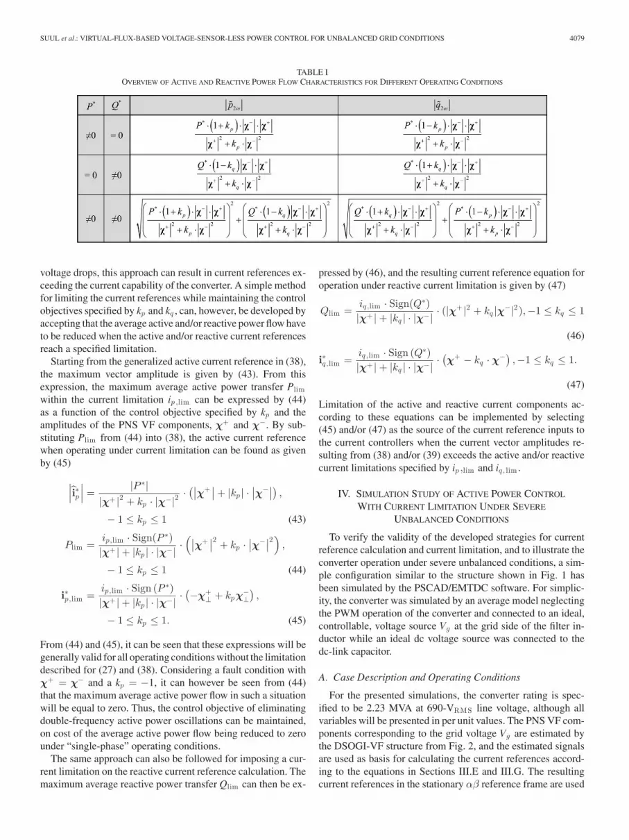
The implications of these equations are summarized in Table I,where the first two rows show the expressions for the amplitudeof double-frequency active and reactive power oscillations wheneither Q∗ or P∗ is zero. In case of nonzero values of both P∗ andQ∗, the oscillating active and reactive power components aregiven by the square sums shown in the last row of the table.
G. Current Reference Calculation for OperationUnder Current Limitation
Converter operation with current reference calculation ac-cording to the generalized equations presented in Section III-Ewill result in average active and/or reactive power flow accordingto the reference values and power flow characteristics accordingto the control objectives specified by kp and kq . In case of severe
SUUL et al.: VIRTUAL-FLUX-BASED VOLTAGE-SENSOR-LESS POWER CONTROL FOR UNBALANCED GRID CONDITIONS 4079
TABLE IOVERVIEW OF ACTIVE AND REACTIVE POWER FLOW CHARACTERISTICS FOR DIFFERENT OPERATING CONDITIONS
voltage drops, this approach can result in current references ex-ceeding the current capability of the converter. A simple methodfor limiting the current references while maintaining the controlobjectives specified by kp and kq , can, however, be developed byaccepting that the average active and/or reactive power flow haveto be reduced when the active and/or reactive current referencesreach a specified limitation.
Starting from the generalized active current reference in (38),the maximum vector amplitude is given by (43). From thisexpression, the maximum average active power transfer Plimwithin the current limitation ip ,lim can be expressed by (44)as a function of the control objective specified by kp and theamplitudes of the PNS VF components, χ+ and χ−. By sub-stituting Plim from (44) into (38), the active current referencewhen operating under current limitation can be found as givenby (45)
∣∣∣i∗p∣∣∣ =
|P ∗||χ+ |2 + kp · |χ−|2
·(∣∣χ+
∣∣ + |kp | ·∣∣χ−∣∣) ,
− 1 ≤ kp ≤ 1 (43)
Plim =ip,lim · Sign(P ∗)|χ+ | + |kp | · |χ−| ·
(∣∣χ+∣∣2 + kp ·
∣∣χ−∣∣2) ,
− 1 ≤ kp ≤ 1 (44)
i∗p,lim =ip,lim · Sign (P ∗)|χ+ | + |kp | · |χ−| ·
(−χ+
⊥ + kpχ−⊥),
− 1 ≤ kp ≤ 1. (45)
From (44) and (45), it can be seen that these expressions will begenerally valid for all operating conditions without the limitationdescribed for (27) and (38). Considering a fault condition withχ+ = χ− and a kp = −1, it can however be seen from (44)that the maximum average active power flow in such a situationwill be equal to zero. Thus, the control objective of eliminatingdouble-frequency active power oscillations can be maintained,on cost of the average active power flow being reduced to zerounder “single-phase” operating conditions.
The same approach can also be followed for imposing a cur-rent limitation on the reactive current reference calculation. Themaximum average reactive power transfer Qlim can then be ex-
pressed by (46), and the resulting current reference equation foroperation under reactive current limitation is given by (47)
Qlim =iq ,lim · Sign(Q∗)|χ+ | + |kq | · |χ−| · (|χ
+ |2 + kq |χ−|2),−1 ≤ kq ≤ 1
(46)
i∗q ,lim =iq ,lim · Sign (Q∗)|χ+ | + |kq | · |χ−| ·
(χ+ − kq · χ−)
,−1 ≤ kq ≤ 1.
(47)
Limitation of the active and reactive current components ac-cording to these equations can be implemented by selecting(45) and/or (47) as the source of the current reference inputs tothe current controllers when the current vector amplitudes re-sulting from (38) and/or (39) exceeds the active and/or reactivecurrent limitations specified by ip ,lim and iq , lim .
IV. SIMULATION STUDY OF ACTIVE POWER CONTROL
WITH CURRENT LIMITATION UNDER SEVERE
UNBALANCED CONDITIONS
To verify the validity of the developed strategies for currentreference calculation and current limitation, and to illustrate theconverter operation under severe unbalanced conditions, a sim-ple configuration similar to the structure shown in Fig. 1 hasbeen simulated by the PSCAD/EMTDC software. For simplic-ity, the converter was simulated by an average model neglectingthe PWM operation of the converter and connected to an ideal,controllable, voltage source Vg at the grid side of the filter in-ductor while an ideal dc voltage source was connected to thedc-link capacitor.
A. Case Description and Operating Conditions
For the presented simulations, the converter rating is spec-ified to be 2.23 MVA at 690-VRMS line voltage, although allvariables will be presented in per unit values. The PNS VF com-ponents corresponding to the grid voltage Vg are estimated bythe DSOGI-VF structure from Fig. 2, and the estimated signalsare used as basis for calculating the current references accord-ing to the equations in Sections III.E and III.G. The resultingcurrent references in the stationary αβ reference frame are used

4080 IEEE TRANSACTIONS ON POWER ELECTRONICS, VOL. 27, NO. 9, SEPTEMBER 2012
Fig. 4. Simulation results illustrating active power control with different control objectives during single-phase faults as well as the influence of current limitation.
as input signals to a set of proportional-resonant (PR) currentcontrollers.
As a starting point for the simulations, the converter is oper-ated under balanced grid voltage conditions with 0.5 p.u. as theactive power reference P∗, and with a limitation of the activecurrent component given by ip ,lim = 1.0 p.u. The average reac-tive power reference Q∗ is in this case set to zero. The converteroperation corresponding to different power control objectives isthen investigated in case of a single-phase grid fault with zeroremaining voltage in phase b.
B. Simulation Results
The main results from the simulations are presented in Fig. 4.The three-phase grid voltages are shown in Fig. 4(a), and it canbe seen that the voltages are balanced with 1.0 p.u. amplitudeuntil a fault resulting in zero remaining voltage in phase b occursat t = 0. The estimated PNS VF components χ+ and χ− areshown in Fig. 4(b) and (c), respectively. When the fault occurs,the amplitude χ+ is reduced from 1.0 to 0.5 p.u., while χ− is in-creased from 0 to 0.5 p.u., with the expected dynamic response.

SUUL et al.: VIRTUAL-FLUX-BASED VOLTAGE-SENSOR-LESS POWER CONTROL FOR UNBALANCED GRID CONDITIONS 4081
Fig. 5. Overview of laboratory setup.
To illustrate the full range of possible control objectives andoperating conditions, the value of kp is changed during the simu-lation, as shown in Fig. 4(d). At the beginning of the simulation,kp is equal to 1, corresponding to objective O3 of eliminatingdouble-frequency reactive power oscillations caused by the av-erage active power flow. The resulting currents are plotted inFig. 4(e), where it can be seen that zero current is injected in thefaulted phase as long as kp = 1.
The active and reactive powers calculated by (11) and (12)are shown in Fig. 4(f). From these curves, it can be seen thata double-frequency active power oscillation with amplitude of0.5 p.u. occurs when the single-phase fault occurs. The reactivepower flow is, however, kept at zero, after a small transient,as long as kp = 1. The average active and reactive powers,corresponding to P and Q in (19) and (20), calculated from thePNS VF and current components, are also plotted in Fig. 4(g),and it can be seen how the average active power flow remainsat 0.5 p.u. after a small transient.
From the time t = 0.04 s, the control parameter kp is rampeddown toward zero. From Fig. 4(e), it can be seen how this re-sults in increasing current in phase b, until three-phase balancedcurrents occur when kp reaches zero. As the current in phase b isincreasing, double-frequency reactive power oscillations startsto occur, as shown by Fig. 4(f), but the average value of the reac-tive power flow is still kept at zero. For operation with balancedthree-phase currents, both the active and reactive power flowhas double-frequency oscillations with amplitude equal to P∗,corresponding to the expressions given in the first row of Table I.
When the control parameter kp is reduced from 0 toward −1,the vector amplitude of the active current reference resultingfrom (38) exceeds the specified limit of 1.0 p.u. Thus, currentreference calculation with current limitation according to (45)is activated. From Fig. 4(e), it can be seen how the maximumcurrent is limited to 1.0 p.u., while Fig. 4(e) and (f) shows howthe average active power flow is reduced as kp is approach-ing −1. For operation with kp = −1, the control objective ofeliminating double-frequency active power oscillations is thenachieved by reducing the average active power flow to zero. Theconverter is, however, providing maximum short-circuit currentin the faulted phase. The reactive power flow resulting from thecurrent injection in the faulted phase still maintains the averagevalue of 0 but has a double-frequency oscillating componentwith amplitude of 0.5 p.u. The amplitudes of the oscillationscan also be verified by substituting the expression for the max-
TABLE IIDETAILS OF LABORATORY SETUP
imum power flow under current limitation from (44) into theexpression given in the first row of Table I.
V. EXPERIMENTAL VERIFICATION OF VF-BASED POWER
CONTROL UNDER UNBALANCED CONDITIONS
As the idealized simulation results presented in the previoussection indicate validity of the developed strategies for VF-basedcurrent reference calculation under unbalanced grid conditions,the same approach has been tested in a small-scale laboratorysetup. The experimental results are presented in the followingsections to verify the feasibility of VF-based voltage-sensor-less grid synchronization and power control under unbalancedconditions.
A. Description of the Laboratory Setup
The laboratory setup used for the presented experiments isoutlined in Fig. 5. Power to the converter dc-link was supplied bya diode rectifier with an adjustable transformer, and an LC filterwas used on the ac side as the interface between the converterand a grid emulator with the ability to generate balanced andunbalanced voltage sags. The main parameters of the system arelisted in Table II.
The structure and the main parts of the control system are out-lined in Fig. 6. All the necessary functionality was implementedin Simulink/MATLAB and operated on the dSPACE DS1103platform used to control the converter. Measured values and

4082 IEEE TRANSACTIONS ON POWER ELECTRONICS, VOL. 27, NO. 9, SEPTEMBER 2012
Fig. 6. Overview of control system implemented in laboratory setup.
internal signals of the control system were logged through thedSPACE interface for postprocessing and plotting by MATLAB.
The experiments were carried out in a laboratory environmentwith a significant background distortion in the grid voltage. Asthe simple PR current controllers used in these experimentsachieve a high gain only at the grid frequency, they are sensitiveto grid voltage distortions. The PR controllers are in this casealso operated with relatively low proportional and resonant gainsto avoid causing oscillations in the LC filter, since active damp-ing of filter oscillations have not been considered. Feed-forwardterms based on measured voltages for relieving the current con-trollers have neither been applied, since the converter is operatedin voltage-sensor-less mode. Additionally, the converter is oper-ated with relatively low margin between the dc-link voltage andthe grid voltage. Therefore, the current waveforms in the pre-sented results will show significant levels of both low-frequencydistortions, as well as higher frequency disturbances caused bythe background distortion in the grid voltage.
Since these experiments are intended as a general proof-of-concept, no further effort has, however, been made in this caseto improve the current control of the converter during distortedvoltage conditions. Thus, the resulting distortions in the volt-ages and currents are influencing the active and reactive powercomponents calculated from voltages and current measurementsand will also challenge the performance of the applied methodfor VF estimation and current reference calculation. Successfulgrid synchronization with accurate estimation of fundamentalfrequency PNS VF components, and corresponding calcula-tion of sinusoidal current references, can therefore be inter-preted as a verification of robust performance of the proposedapproach for voltage-sensor-less control under unbalancedconditions.
B. Experimental Results With Different Strategiesfor Current Reference Calculation
In the following sections, results illustrating the performanceof VF-based voltage sensor-less power control for unbalancedconditions are presented and discussed for five selected caseswith different active and reactive power references and con-
trol objectives. All results were logged when the same voltagesag, corresponding to a single-phase voltage drop of about 50%under no-load conditions, was imposed by the voltage sag gen-erator. The active and reactive current limitations where set tohigh values so that the current reference calculation was baseddirectly on (40) as indicated in Fig. 6.
1) Active Power Control With Balanced Three-Phase Cur-rents (kp = 0): Results from operation with an active powerreference P∗ of 1.0 p.u. while kp is set to zero are shownin Fig. 7. As can be seen from Fig. 7(a) and (b), the three-phase currents remain balanced when the unbalanced drop inthe grid voltage occurs. The current amplitude is, however, in-creased to maintain the average active power injected to thegrid. Fig. 7(c) and (d) shows that the estimated PNS VF compo-nents have a fast, but well damped, response to the unbalancedvoltage drop, as expected from the discussion in Section II.C.3.It can also be noticed that the influence of the harmonic dis-tortion of the currents and voltages are significantly attenuatedin the VF signals, since the sequence separation and VF esti-mation have a filtering effect for frequency components abovethe fundamental grid frequency, as discussed in [21]. The cur-rent references shown in Fig. 7(e) are, therefore, sinusoidalsignals, indicating that the distortions observed in the mea-sured currents are caused by the current controllers and notby the VF-based grid synchronization and reference currentcalculation.
Fig. 7(f) shows the active and reactive powers calculated frommeasurements by using (11) and (12), and Fig. 7(g) shows thepowers calculated from the PNS VF and current componentsaccording to (19) and (20). Inspecting these plots, it can be ver-ified that the average power is maintained when the unbalancedvoltage dip occurs, while second harmonic oscillations appearin both active and reactive powers as expected.
From the plotted power signals, it can be noticed that thereis an influence from the distortions in the grid voltages and cur-rents both before and during the voltage dip. These distortionsalso influence the active and reactive powers so that the secondharmonic oscillations during the unbalanced conditions are notperfectly sinusoidal. As expected, the distortions have a largerinfluence on the active and reactive powers plotted in Fig. 7(f)

SUUL et al.: VIRTUAL-FLUX-BASED VOLTAGE-SENSOR-LESS POWER CONTROL FOR UNBALANCED GRID CONDITIONS 4083
Fig. 7. Results from experiment with P∗ = 1.0 p.u., Q∗ = 0 and active currentreference calculation for achieving balanced three-phase currents (kp = 0).
than on the curves in Fig. 7(g), but the powers calculated fromthe measurements and from the estimated PNS VF componentsare corresponding reasonably well.
Since the results in Fig. 7 has illustrated the performanceof the VF estimation and current reference calculations, onlymeasured voltages and currents together with active and reactivepowers calculated from (19) and (20) will be shown in thefollowing sections to illustrate how the different specified powercontrol objectives are achieved.
2) Active Power Control With Elimination of Double-Frequency Active Power Oscillations (kp = −1): Fig. 8 showsthe results with an active power reference P∗ of 1.0 p.u. when kp
is set to −1 with the purpose of eliminating double-frequencyactive power oscillations. From the plots of the voltages andcurrents, it can be seen that the converter is injecting the largestcurrent in the phase with the lowest voltage. Comparing to Fig. 7,it can also be seen that the voltages at the filter capacitors dur-ing the unbalanced conditions are influenced by the unbalancedcurrent injection due to the significant grid impedance of the
Fig. 8. Results from experiment with P∗ = 1.0 p.u., Q∗ = 0 p.u. and currentreference calculation for eliminating double-frequency active power oscillations(kp = −1).
Fig. 9. Results from experiment with P∗ = 1.0 p.u., Q∗ = 1.0 p.u. andcurrent reference calculation for eliminating double-frequency reactive poweroscillations (kp = 1).
voltage sag generator. Observing the resulting active and reac-tive powers during the unbalanced conditions, it can be noticedthat the objective of eliminating double-frequency active poweroscillations is achieved, while the reactive power oscillationsare almost doubled in amplitude compared to Fig. 7.
3) Active Power Control With Elimination of Double-Frequency Reactive Power Oscillations (kp = 1): For the re-sults in Fig. 9, the active power reference P∗ is still specifiedto 1.0 p.u., but kp is set to 1 when calculating the current ref-erences, with the intention of eliminating double-frequency os-cillations in the reactive power flow. Thus, the lowest currentis injected in the phase with the lowest voltage, correspondingto an “impedance-like” distribution of the currents between thethree phases.

4084 IEEE TRANSACTIONS ON POWER ELECTRONICS, VOL. 27, NO. 9, SEPTEMBER 2012
Fig. 10. Results from experiment with P∗ = 1.0 p.u., Q∗ = 1.0 p.u. and activeand reactive current reference calculation for elimination of double-frequencyactive power oscillations (kp = −1, kq = 1).
Studying the plot of the reactive power flow, it can be seenthat the second harmonic oscillations during the unbalancedconditions are almost completely eliminated. In this case, thereis a significant influence from the distortion in the voltages andcurrents, but the active and reactive powers calculated fromthe sequence separated currents and the estimated VF are stillcorresponding well to the specified control objective.
4) Active and Reactive Power Control With Elimination ofDouble-Frequency Active Power Oscillations (kp = −1, kq =1): Fig. 10 shows results from a case when the active and reac-tive power references are specified as P∗ = 1.0 p.u. and Q∗ =1.0 for injection of equal amounts of active and reactive powersinto the grid, while the current references are calculated to elim-inate double-frequency active power oscillations. Studying themeasured voltages and currents, it can be seen that this resultsin maximum current injection in the phase with the lowest volt-age, and since the reactive power reference has a nonzero value,the currents are phase-shifted with respect to the voltages. Theplots of the active and reactive powers show that the objective ofeliminating second harmonic oscillations in the active power iswell achieved, although the distortions in the currents and volt-ages are causing some disturbances. However, these distortionsare not undermining the fundamental frequency behavior andthe overall control objectives under investigation.
5) Active and Reactive Power Control With Elimination ofDouble-Frequency Reactive Power Oscillations (kp = −1, kq =−1): A last example of control objectives during unbalancedconditions is shown in Fig. 11. In this case, the active andreactive power references are still specified as P∗ = 1.0 p.u.and Q∗ = 1.0, while the current references are calculated toeliminate second harmonic oscillations in the reactive powerflow. Thus, the results show how the lowest current is injectedinto the phase with the lowest voltage, while the currents arephase-shifted with respect to the voltages due to the nonzeroreactive power reference. The lower plot shows how the second
Fig. 11. Results from experiments with P∗ = 1.0 p.u., Q∗ = 1.0 p.u., and activeand reactive current reference calculation for elimination of double-frequencyreactive power oscillations (kp = 1, kq = −1).
harmonic oscillations are eliminated from the reactive powerand instead appear in the active power. Although the significantdistortions in the voltages and currents occurring in this case arereflected to some extent in the active and reactive power flow,the overall control objectives are still achieved.
C. Summary of Experimental Results
Some of the information that can be extracted from the pre-sented experimental results is summarized in Table III. Fromthis table, it can also be noticed that the amplitudes of the activeand reactive power oscillations calculated from the expressionsin Table I are corresponding reasonably well with the active andreactive powers plotted in the presented figures.
The estimated PNS VF amplitudes listed in Table III alsoindicate how the inductance of the grid emulator is influencingthe voltage or the VF at the grid side of the filter inductor dif-ferently depending on the active and reactive power referencesand control objectives. As expected, reactive power injection tothe grid is increasing the positive sequence VF component bothbefore and during the voltage sag, as can be seen from Cases 4and 5. In Case 4, it can, however, be noticed that the negativesequence reactive currents resulting from the objective of elim-inating double-frequency active power oscillations is reducingthe amplitude of the negative sequence VF component. Thus,the double-frequency reactive power oscillations are actuallyreduced in amplitude compared to Case 2. For Case 5, the influ-ence of the negative sequence reactive currents is the opposite,causing an increase in the amplitude of the negative sequenceVF component and, therefore, also an increase in the amplitudeof the double-frequency active power oscillations.
D. Further Implications of the Presented Results
Although the presented results have shown only a few se-lected cases, the VF-based current references from Section III-E, as well as (41) and (42), are valid for any combinations of

SUUL et al.: VIRTUAL-FLUX-BASED VOLTAGE-SENSOR-LESS POWER CONTROL FOR UNBALANCED GRID CONDITIONS 4085
TABLE IIISUMMARY OF EXPERIMENTAL RESULTS
active and reactive power references and control objectives. Byintroducing the active and reactive current limitation strategiesdefined by (45) and (47), the power control objectives spec-ified by kp and kq can also be maintained under generalizedunbalanced conditions, including single-phase faults.
By the results from simulations and experiments, it has alsobeen verified that the transient response of the presented ap-proach for grid synchronization and current reference calcula-tion is fast and well damped when utilized for active and reactivepower control under unbalanced conditions. This is mainly dueto the DSOGI-VF estimation that achieves VF estimation andsequence separation with a response time in the range of 5 ms,which is similar to the performance of conventional sequenceseparation methods based on voltage measurements. Thus, thepresented approach for voltage-sensor-less operation under un-balanced conditions does not imply additional delays as usuallyassociated with sensor-less control strategies.
The derived expressions for VF-based current reference cal-culation can be easily adapted for and investigated together withother types of current controllers than the simple PR-controllersapplied for the presented simulations and experiments. Thus,the poor performance of the current controllers observed in theexperimental results is not a limitation with respect to the ap-plicability of the developed approach for VF-based active andreactive power control.
It can also be noted that the active and reactive power flowcharacteristics described by (41) and (42) can be used as astarting point for specifying active and reactive power referencesin control structures based on the concept of DPC discussedin [28] and [34]. Thus, the same range of flexible power controlobjectives under unbalanced conditions as discussed for controlstructures with inner loop current controllers could be achievedwith the DPC concept.
VF estimation by using the DSOGI-VF structure from [21] asa basis for implementing power control strategies derived from(21) and (22) can, therefore, be considered a general approachthat can be combined with different types of control strategiesand applied for voltage-sensor-less operation of VSCs in a widerange of applications.
VI. CONCLUSION
This paper has proposed a general approach for VF-basedvoltage-sensor-less control of VSCs under unbalanced gridvoltage conditions. A method for VF estimation with inher-ent sequence separation in the stationary reference frame isused to estimate PNS VF components at the point of con-nection to the grid. On this basis, expressions for currentreference calculation corresponding to three different objec-tives of active and reactive power control have been derivedand analyzed. The derived current reference equations havebeen synthesized into generalized equations where the ob-jectives of achieving balanced three-phase currents, elimina-tion of double-frequency active power oscillations, or elim-ination of double-frequency reactive power oscillations canbe selected separately for the active and reactive current ref-erence components by specifying the value of two scalarcoefficients.
Under severe grid fault conditions, current references calcu-lated directly from active and/or reactive power references canexceed the current capability of the converter. A simple strategyfor limiting the active and/or reactive current references withinthe converter’s current capability, while at the same time main-taining the specified power control objectives, has, therefore,been developed. By applying this strategy for current limita-tion, the presented approach for VF-based voltage-sensor-lesscontrol will be valid for operation under generalized unbal-anced conditions, including single-phase fault conditions, forany combinations of active and reactive power references andcontrol objectives.
To verify the derived expressions for current reference calcu-lation, VF-based voltage-sensor-less operation of a VSC underunbalanced conditions has been investigated by simulations andlaboratory experiments. The presented results indicate generalvalidity of the proposed approach for derivation of VF-basedpower control strategies, which can potentially be adapted todifferent control system configurations and utilized for voltage-sensor-less operation under unbalanced conditions in a widerange of applications.

4086 IEEE TRANSACTIONS ON POWER ELECTRONICS, VOL. 27, NO. 9, SEPTEMBER 2012
ACKNOWLEDGMENT
The authors would like to thank Prof. M. Molinas of theNorwegian University of Science and Technology (NTNU) forinitiating and facilitating the cooperation between NTNU andthe Technical University of Catalonia (UPC). The authors wouldalso like to thank the Ph.D. students and researchers of the Re-search Center on Renewable Electrical Energy Systems at UPCfor providing equipment and facilitating the experimental veri-fication of the presented concept during a one-month researchstay of J. A. Suul in Terrassa, Spain, in November 2010.
REFERENCES
[1] S. Chakraborty, B. Kramer, and B. Kroposki, “A review of power elec-tronics interfaces for distributed energy systems toward achieving low-cost modular design,” Renewable Sustainable Energy Rev., vol. 13, no. 9,pp. 2323–2335, Dec. 2009.
[2] J. R. Rodrıguez, J. W. Dixon, J. R. Espinoza, J. Pontt, and P. Lezana,“PWM regenerative rectifiers: State of the art,” IEEE Trans. Ind. Electron.,vol. 52, no. 1, pp. 5–22, Feb. 2005.
[3] F. Blaabjerg, R. Teodorescu, M. Liserre, and A. V. Timbus, “Overviewof control and grid synchronization for distributed power generation sys-tems,” IEEE Trans. Ind. Electron., vol. 53, no. 5, pp. 1398–1409, Oct.2006.
[4] L. Xu, B. R. Andersen, and P. Cartwright, “VSC transmission operatingunder unbalanced AC conditions: Analysis and control design,” IEEETrans. Power Del., vol. 20, no. 1, pp. 427–434, Jan. 2005.
[5] Y. Suh, Y. Go, and D. Rho, “A comparative study on control algorithms foractive front-end rectifier of large motor drives under unbalanced input,”IEEE Trans. Ind. Appl., vol. 47, no. 3, pp. 1419–1431, May/Jun. 2011.
[6] A. Sannino, M. H. J. Bollen, and J. Svensson, “Voltage tolerance testing ofthree-phase voltage source converters,” IEEE Trans. Power Del., vol. 20,no. 2, pp. 1633–1639, Apr. 2005.
[7] V. Kaura and V. Blasko, “Operation of a phase locked loop system underdistorted utility conditions,” IEEE Trans. Ind. Appl., vol. 33, no. 1, pp. 58–63, Jan./Feb. 1997.
[8] M. Boyra and J.-L. Thomas, “A review on synchronization methods forgrid-connected three-phase VSC under unbalanced and distorted condi-tions,” in Proc. 14th Eur. Conf. Power Electron. Appl., Birmingham, U.K,Aug. 30–Sep. 1, 2011, pp. 1–10.
[9] H.-S. Song and K. Nam, “Dual current control scheme for PWM converterunder unbalanced input voltage conditions,” IEEE Trans. Ind. Electron.,vol. 46, no. 5, pp. 953–959, Oct. 1999.
[10] Y. Suh and T. A. Lipo, “Control scheme in hybrid synchronous stationaryframe for PWM AC/DC converter under generalized unbalanced operatingconditions,” IEEE Trans. Ind. Appl., vol. 42, no. 3, pp. 825–835, May/Jun.2006.
[11] A. Timbus, M. Liserre, R. Teodorescu, P. Rodriguez, and F. Blaabjerg,“Evaluation of current controllers for distributed power generation sys-tems,” IEEE Trans. Power Electron., vol. 24, no. 3, pp. 654–664, Mar.2009.
[12] P. N. Enjeti, P. D. Ziogas, and M. Ehsani, “Unbalanced PWM converteranalysis and corrective measures,” in Proc. Conf. Record 1989 IEEE Ind.Appl. Soc. Annu. Meet., San Diego, CA, Oct. 1–5, 1989, vol. 1, pp. 861–870.
[13] P. Rioual, H. Pouliquen, and J.-P. Louis, “Regulation of a PWM rectifierin the unbalanced network state using a generalized model,” IEEE Trans.Power Electron., vol. 11, no. 3, pp. 495–502, May 1996.
[14] R. Teodorescu, M. Liserre, and P. Rodrıguez, Grid Converters for Photo-voltaic and Wind Power Systems. New York: Wiley, 2011.
[15] P. Rodrıguez, A. V. Timbus, R. Teodorescu, M. Liserre, and F. Blaabjerg,“Independent PQ control for distributed power generation systems undergrid faults,” in Proc. 32nd Annu. Conf. IEEE Ind. Electron. Soc., Paris,France, Nov. 6–10, 2006, pp. 5185–5190.
[16] P. Rodriguez, A. V. Timbus, R. Teodorescu, M. Liserre, and F. Blaabjerg,“Flexible active power control of distributed power generation systemsduring grid faults,” IEEE Trans. Ind. Electron., vol. 54, no. 5, pp. 2583–2592, Oct. 2007.
[17] P. Rodrıguez, A. Timbus, R. Teodorescu, M. Liserre, and F. Blaabjerg,“Reactive power control for improving wind turbine system behaviorunder grid faults,” IEEE Trans. Power Electron., vol. 24, no. 7, pp. 1798–1801, Jul. 2009.
[18] F. Wang, J. L. Duarte, and M. A. M. Hendrix, “Design and analysis ofactive power control strategies for distributed generation inverters underunbalanced grid faults,” in IET Generation, Transmiss. Distrib., Aug.2010, vol. 4, no. 8, pp. 905–916.
[19] F. Wang, J. L. Duarte, and M. A. M. Hendrix, “Pliant active and reactivepower control for grid-interactive converters under unbalanced voltagedips,” IEEE Trans. Power Electron., vol. 26, no. 5, pp. 1511–1521, May2011.
[20] A. J. Roscoe, S. J. Finney, and G. M. Burt, “Tradeoffs between AC powerquality and DC bus ripple for 3-phase 3-wire inverter-connected deviceswithin microgrids,” IEEE Trans. Power Electron., vol. 26, no. 3, pp. 674–688, Mar. 2011.
[21] J. A. Suul, A. Luna, P. Rodriguez, and T. Undeland, “Voltage sensor-lesssynchronization to unbalanced grids by frequency-adaptive virtual fluxestimation,” IEEE Trans. Ind. Electron., vol. 59, no. 7, pp. 2910–2923,Jul. 2012.
[22] Y. Ito, Y. Kanno, and S. Kawauchi, “Source voltage sensor-less digitalcontrol using observer for PWM converter,” in Proc. 25th Annu. PowerElectron. Spec. Conf., Taipei, Taiwan, Jun. 20–25, 1994, vol. 1, pp. 160–165.
[23] T. Noguchi, H. Tomiki, and I. Takahashi, “Direct power control of PWMconverter without power-source voltage sensors,” IEEE Trans. Ind. Appl.,vol. 34, no. 3, pp. 473–479, May/Jun. 1998.
[24] P. Barrass and M. Cade, “PWM rectifier using indirect voltage sensing,”IEE Proc—Electric Power Appl., vol. 146, no. 5, pp. 539–544, Sep. 1999.
[25] I. Agirman and V. Blasko, “A novel control method of a VSC without ACline voltage sensor,” IEEE Trans. Ind. Appl., vol. 39, no. 2, pp. 519–524,Mar./Apr. 2003.
[26] V. Manninen, “Application of direct torque control modulation technologyto a line converter,” in Proc. 6th Eur. Conf. Power Electron. Appl., Seville,Spain, Sep. 19–21, 1995, vol. 1, pp. 292–296.
[27] M. Malinowski, M. P. Kazmierkowski, S. Hansen, F. Blaabjerg, and G.D. Marques, “Virtual-flux-based direct power control of three-phase PWMrectifiers,” IEEE Trans. Ind. Appl., vol. 37, no. 4, pp. 1019–1027, Jul./Aug.2001.
[28] M. Malinowski, “Sensorless control strategies for three-phase PWM recti-fiers,” Ph.D. dissertation, Warsaw Univ. Technol., Warsaw, Poland, 2001.
[29] V. Staudt, “Dynamic grid-flux-based control for grid connected voltage-source converters,” in Proc. 10th Conf.-Seminar, Int. School NonsinusoidalCurrents Compensation, Lagow, Poland, Jun. 15–18, 2010, pp. 59–68.
[30] K. H. Ahmed, A. M. Massoud, S. J. Finney, and B. W. Williams, “Sensor-less current control of three-phase inverter-based distributed generation,”IEEE Trans. Power Del., vol. 24, no. 2, pp. 919–929, Apr. 2009.
[31] I.-W. Joo, H.-S. Song, and K. Nam, “Source-voltage sensorless schemefor PWM rectifier under voltage unbalance condition,” in Proc. 4th Int.Conf. Power Electron. Drive Syst., Denpasar, Indonesia, Oct. 22–25, 2001,vol. 1, pp. 33–38.
[32] K. Lee, T. M. Jahns, T. A. Lipo, and V. Blasko, “New observer-based sourcevoltage unbalance control methods in PWM voltage-source converters,”in Proc. 39th IEEE Power Electron. Spec. Conf., Rhodes, Greece, Jun.15–19, 2008, pp. 1509–1514.
[33] Y. A.-R. I. Mohamed, M. A. -Rahman, and R. Seethapathy, “Robust line-voltage sensorless control and synchronization of LCL-filtered distributedgeneration inverters for high power quality grid connection,” IEEE Trans.Power Electron., vol. 27, no. 1, pp. 87–98, Jan. 2012.
[34] M. Malinowski, G. Marques, M. Cichowlas, and M. P. Kazmierkowski,“New direct power control of three-phase PWM boost rectifiers underdistorted and imbalanced line voltage conditions,” in Proc. IEEE Int.Symp. Ind. Electron., Rio de Janeiro, Brazil, Jun. 9–11, 2003, vol. 1,pp. 438–443.
[35] M. Cichowlas, M. Malinowski, M. P. Kazmierkowski, D. L. Sobczuk,P. Rodrıguez, and J. Pou, “Active filtering function of three-phase PWMboost rectifier under different line voltage conditions,” IEEE Trans. Ind.Electron., vol. 52, no. 2, pp. 410–419, Apr. 2005.
[36] E. Abiri, A. Rahmati, and A. Abrishamifar, “A sensorless and simplecontroller for VSC based HVDC system,” J. Zhejiang Univ.: Sci. A,vol. 10, no. 12, pp. 1824–1834, Dec. 2009.
[37] M. Jasinski, P. Okon, and M. P. Kazmierkowski, “Control of grid-interfacing AC-DC-AC converter for variable speed energy generationunder unbalanced and distorted voltage conditions,” in Proc. Int. Conf.Exhib. Ecological Vehicles Renewable Energies, Mar. 26–29, 2009, pp. 1–7.
[38] A. Kulka, “Sensorless digital control of grid connected three phase con-verters for renewable sources,” Ph.D. dissertation, Norwegian Univ. Sci.Technol., Trondheim, Norway, 2009.

SUUL et al.: VIRTUAL-FLUX-BASED VOLTAGE-SENSOR-LESS POWER CONTROL FOR UNBALANCED GRID CONDITIONS 4087
[39] M. Weinhold, “A new control for optimal operation of a three-phasevoltage dc link PWM converter,” in Official Proc. 19th Int. Intell. MotionConf., Nurnberg, Germany, Jun. 25–27, 1991, pp. 371–383.
[40] M. C. Chandorkar, D. M. Divan, and R. Adapa, “Control of parallelconnected inverters in standalone ac supply systems,” IEEE Trans. Ind.Appl., vol. 29, no. 1, pp. 136–143, Jan./Feb. 1993.
[41] J. L. Duarte, A. van Zwam, C. Wijnands, and A. Vandenput, “Referenceframes fit for controlling PWM rectifiers,” IEEE Trans. Ind. Electron.,vol. 46, no. 3, pp. 628–630, Jun. 1999.
[42] R. Pollanen, “Converter-flux-based current control of voltage source PWMrectifiers: Analysis and implementation,” Ph.D. dissertation, LappeenrantaUniv. Technol., Lappeenranta, Finland, Dec. 2003.
[43] P. Rodriguez, R. Teodorescu, I. Candela, A. V. Timbus, M. Liserre, andF. Blaabjerg, “New positive-sequence voltage detector for grid synchro-nization of power converters under faulty grid conditions,” in Proc. 37thAnnu. IEEE Power Electron. Spec. Conf., Jun. 18–22, 2006, pp. 1–7.
[44] W. V. Lyon, Transient Analysis of Alternating-Current Machinery. Cam-bridge, MA: MIT Press, 1954.
[45] P. Rodriguez, A. Luna, I. Etxeberria, R. Teodorescu, and F. Blaabjerg, “Astationary reference frame grid synchronization system for three-phasegrid-connected power converters under adverse grid conditions,” IEEETrans. Power Electron., vol. 27, no. 1, pp. 99–112, Jan. 2012.
[46] J. Svensson, M. Bongiorno, and A. Sannino, “Practical implementation ofdelayed signal cancellation method for phase-sequence separation,” IEEETrans. Power Del., vol. 22, no. 1, pp. 18–26, Jan. 2007.
[47] H. Akagi, E. Watanabe, and M. Aredes, Instantaneous Power Theory andApplications to Power Conditioning. New York: Wiley, 2007.
[48] F. Z. Peng and J.-S. Lai, “Generalized instantaneous reactive power theoryfor three-phase power system,” IEEE Trans. Instrum. Meas., vol. 45, no. 1,pp. 293–297, Feb. 1996.
[49] M. Depenbrock, V. Staudt, and H. Wrede, “A theoretical investigationof original and modified instantaneous power theory applied to four-wiresystems,” IEEE Trans. Ind. Appl., vol. 39, no. 4, pp. 1160–1167, Jul./Aug.2003.
Jon Are Suul (M’11) received the M.Sc. and thePh.D. degrees from the Department of Electric PowerEngineering at the Norwegian University of Scienceand Technology, Trondheim, Norway, in 2006 and2012, respectively.
In 2006, he was employed by SINTEF Energy,Trondheim, where he was engaged in the simulationof power electronic systems. In 2007, he was granteda leave of absence and returned to NTNU for study-ing towards the Ph.D. degree. Since 2012, he hasresumed his position in SINTEF Energy. In 2008, he
was a guest Ph.D. student for two months with the Energy Technology ResearchInstitute of the National Institute of Advanced Industrial Science and Technol-ogy, Tsukuba, Japan. He was also a visiting Ph.D. student for two months withthe Research Center on Renewable Electrical Energy Systems, within the De-partment of Electrical Engineering, Technical University of Catalonia (UPC),Terrassa, Spain, during 2010. His research interests are mainly related to con-trol of power electronic converters in power systems and for renewable-energyapplications.
Alvaro Luna (S’07–M’10) received the B.Sc., M.Sc.,and Ph.D. degrees in electrical engineering from theTechnical University of Catalonia (UPC), Barcelona,Spain, in 2001, 2005, and 2009, respectively.
He joined the faculty of UPC, in 2005, where he iscurrently an Assistant Professor. His research inter-ests include wind turbine control, photovoltaic sys-tems, integration of distributed generation, and powerconditioning.
Dr. Luna is a member of the IEEE Power Electron-ics Society, the IEEE Industrial Electronics Society,
and the IEEE Industry Applications Society.
Pedro Rodrıguez (S’99–M’04–SM’10) received theM.Sc. and Ph.D. degrees in electrical engineeringfrom the Technical University of Catalonia (UPC),Barcelona, Spain, in 1994 and 2004, respectively.
He was a Postdoctoral Researcher at the Cen-ter for Power Electronics Systems, Virginia Tech,Blacksburg, in 2005, and in the Department of EnergyTechnology, Aalborg University (AAU) in 2006. Hejoined the faculty of UPC as an Assistant Professor in1990, where he became the Director of the ResearchCenter on Renewable Electrical Energy Systems in
the Department of Electrical Engineering. He was also a Visiting Professor atthe AAU from 2007 to 2011, acting as a cosupervisor of the Vestas PowerProgram. He still lectures Ph.D. courses at the AAU every year. Since 2011,he has been the Head of Electrical Engineering Division, Abengoa Research,Seville, Spain, although he is still with the UPC as a Part-Time Professor. Hehas coauthored one book and more than 100 papers in technical journals andconference proceedings. He is the holder of seven licensed patents. His researchinterests include integration of distributed generation systems, smart grids, anddesign and control of power converters.
Dr. Rodrıguez is a member of the administrative committee of the IEEEIndustrial Electronics Society (IES), the general chair of IEEE-IES Gold andStudent Activities, the Vice-Chair of the Sustainability and Renewable EnergyCommittee of the IEEE Industry Application Society, and a member of theIEEE-IES Technical Committee on Renewable Energy Systems. He is an Asso-ciate Editor of the IEEE TRANSACTION ON POWER ELECTRONICS.
Tore Undeland (M’86–SM’92–F’00) was born inBergen, Norway, in 1945. He received the M.Sc. andPh.D. degrees from the Norwegian University of Sci-ence and Technology (NTNU), Trondheim, Norway,in 1970 and 1977, respectively.
Since 1970, he has been with NTNU, where he hasbeen a Full Professor since 1984. He has also servedas an Adjunct Professor with Chalmers University ofTechnology, Gothenburg, Sweden, since 2000, and asa Scientific Advisor to SINTEF Energy, Trondheim.His research interests include power electronics and
wind energy systems. He is a coauthor of the well-known textbook Power Elec-tronics: Converters, Applications, and Design (New York: Wiley, 1989, 1995,and 2003).
Dr. Undeland has served as the President of the European Power Electronicsand Drives Association and is a member of the Norwegian Academy of Tech-nological Sciences.