
Decoupled-DFIG fault ride-through strategy for enhanced stability performance during grid faults
12
University of Wollongong Research Online Faculty of Informatics - Papers Faculty of Informatics 2010 Decoupled-DFIG fault ride-through strategy for enhanced stability performance during grid faults Lasantha G. Meegahapola University of Wollongong, [email protected] Damian Flynn University College Dublin, damian.fl[email protected] Tim Liler e Queen's University of Belfast, [email protected] Research Online is the open access institutional repository for the University of Wollongong. For further information contact the UOW Library: [email protected] Publication Details L. G. Meegahapola, D. Flynn & T. Liler, "Decoupled-DFIG fault ride-through strategy for enhanced stability performance during grid faults," IEEE Transactions of Sustainable Energy, vol. 1, (3) pp. 152-162, 2010.
Transcript of Decoupled-DFIG fault ride-through strategy for enhanced stability performance during grid faults
University of WollongongResearch Online
Faculty of Informatics - Papers Faculty of Informatics
2010
Decoupled-DFIG fault ride-through strategy forenhanced stability performance during grid faultsLasantha G. MeegahapolaUniversity of Wollongong, [email protected]
Damian FlynnUniversity College Dublin, [email protected]
Tim LittlerThe Queen's University of Belfast, [email protected]
Research Online is the open access institutional repository for theUniversity of Wollongong. For further information contact the UOWLibrary: [email protected]
Publication DetailsL. G. Meegahapola, D. Flynn & T. Littler, "Decoupled-DFIG fault ride-through strategy for enhanced stability performance during gridfaults," IEEE Transactions of Sustainable Energy, vol. 1, (3) pp. 152-162, 2010.

Decoupled-DFIG fault ride-through strategy for enhanced stabilityperformance during grid faults
AbstractThis paper proposes a decoupled fault ride-through strategy for a doubly fed induction generator (DFIG) toenhance network stability during grid disturbances. The decoupled operation proposes that a DFIG operatesas an induction generator (IG) with the converter unit acting as a reactive power source during a faultcondition. The transition power characteristics of the DFIG have been analyzed to derive the capability of theproposed strategy under various system conditions. The optimal crowbar resistance is obtained to exploit themaximum power capability from the DFIG during decoupled operation. The methods have been establishedto ensure proper coordination between the IG mode and reactive power compensation from the grid-sideconverter during decoupled operation. The viability and benefits of the proposed strategy are demonstratedusing different testnetwork structures and different wind penetration levels. Control performance has beenbenchmarked against existing grid code standards and commercial wind generator systems, based on theoptimal network support required (i.e., voltage or frequency) by the system operator from a wind farminstalled at a particular location.
Keywordsenhanced, stability, ride, performance, fault, during, strategy, dfig, faults, grid, decoupled
DisciplinesPhysical Sciences and Mathematics
Publication DetailsL. G. Meegahapola, D. Flynn & T. Littler, "Decoupled-DFIG fault ride-through strategy for enhanced stabilityperformance during grid faults," IEEE Transactions of Sustainable Energy, vol. 1, (3) pp. 152-162, 2010.
This journal article is available at Research Online: http://ro.uow.edu.au/infopapers/850
1
Abstract−This paper proposes a decoupled fault ride-through (FRT) strategy for a doubly-fed induction generator (DFIG) to enhance network stability during grid disturbances. The decoupled operation proposes that a DFIG operates as an induction generator (IG) with the converter unit acting as a reactive power source during a fault condition. The transition power characteristics of the DFIG have been analyzed to derive the capability of the proposed strategy under various system conditions. The optimal crowbar resistance is obtained to exploit the maximum power capability from the DFIG during decoupled operation. The methods have been established to ensure proper coordination between the IG mode and reactive power compensation from the grid-side converter (GSC) during decoupled operation. The viability and benefits of the proposed strategy are demonstrated using different test network structures and different wind penetration levels. Control performance has been benchmarked against existing grid code standards and commercial wind generator systems, based on the optimal network support required (i.e. voltage or frequency) by the system operator from a wind farm installed at a particular location. Index Terms−DFIG, decoupled operation, coordinated control, crowbar protection, inertial response, reactive power compensation, transition dynamics, voltage stability.
I. INTRODUCTION T present the wind energy industry is experiencing strong growth with an average annual expansion of 25%, such
that at the end of 2009 the worldwide installed wind energy capacity was 158.5 GW [1]. This rapid development in wind energy integration has replaced a significant proportion of conventional synchronous generation capacity, with power systems slowly drifting from large-scale synchronous generation to localized and distributed generation. It is likely that power electronics based variable-speed wind generation technologies (i.e. doubly-fed induction generator (DFIG), direct-drive synchronous generator (DDSG)) will dominate the wind generation industry, while replacing conventional generation capacity. Power electronics based wind generators are robust in normal operation due to their superior controllability over active and reactive power and they require less reactive power during system disturbances [2]-[3]. However, they are insensitive to system frequency variations (zero inertial
This publication has emanated from research conducted with the financial support of Science Foundation Ireland under Grant Number 06/CP/E002. Lasantha Meegahapola and Tim Littler are with the Electric Power and Energy Systems Research Group, Ashby Building, The Queen’s University of Belfast, Stranmillis Road, Belfast, BT9 5AH, Northern Ireland, UK. Damian Flynn is with Electricity Research Centre, University College Dublin, Belfield, Dublin 4, Ireland. (e-mail addresses: [email protected], [email protected] and [email protected])
response), since their mechanical dynamics are decoupled from the electrical dynamics through power electronics converter systems. In addition, voltage support capabilities during network disturbances have been identified as an important issue for local networks, since most wind farms are installed at distributed locations. Island systems and network areas with high wind penetration (especially with power electronics based wind generation) may possess insufficient inertia to support network frequency. Utilities are, therefore, recommended to specifically design grid code standards demanding inertial response capabilities from wind farms for areas with high wind penetration [4]. Artificial inertial response and frequency support strategies are proposed in the literature [5]-[13] for power electronics based wind farms. These studies have proposed individual wind turbine [8-10] and centralized control strategies [12-13] to support system frequency during generator outages. However, their capability during grid faults is uncertain due to the converter ride-through capability during severe disturbances, as inertial response capabilities are mostly assessed as a result of generator outage events in a network. Power utilities have compiled low-voltage ride-through (LVRT) grid code standards for wind farms, demanding additional services for network reliability and security enhancement. LVRT grid code standards specify a minimum voltage profile that a wind farm should be able to ride-through [14]-[16]. Consequently, wind farms are required to stay connected beyond the defined voltage profile stipulated in published grid codes. Although DFIGs are fully grid-code compliant, there exists the potential for a significant reduction in power output due to low network voltage during grid disturbances. Therefore, an inertial response and frequency support capability of the DFIGs during fault ride-through (FRT) operation becomes increasingly important when a fault occurs in close proximity to significant wind resources, especially in island systems, since the resulting active power reduction (due to generator disconnection and LVRT with non-optimum crowbar resistance) of wind generators may surpass the available reserve capability of the system [17-18]. Consequently, system security may be threatened due to a fall in system frequency below the load shedding threshold. In the published literature, various FRT strategies are presented to ensure the continuous operation of DFIG wind turbines during transient disturbances. In most of these studies a crowbar circuit [19]-[20] is suggested to protect the converter system from a rotor current transient/DC link transient. Conventional crowbar protection may cause a detrimental impact on system stability during FRT operation, therefore active crowbar methods [21]-[22] and chopper circuits [23]-[24] have been proposed to improve the FRT of the DFIG. Although DC chopper circuits can minimize the impact from a DC-link transient, crowbar firing due to rotor current transients is inevitable during severe voltage dips [24],
Lasantha Meegahapola, Student Member, IEEE, Tim Littler, Member, IEEE and Damian Flynn, Member, IEEE
Decoupled-DFIG Fault Ride-Through Strategy for Enhanced Stability Performance during Grid Faults
A

2since it is caused by an electromagnetic phenomenon in the generator. An expensive solution would be to increase the converter rating [25] of the DFIG. In references [26]-[27] the authors have enhanced the FRT operation by reconfiguring the grid-side converter (GSC) as a reactive power source to support the local voltage. In addition, strategies have been proposed based on additional converter components and grid devices [28]-[29] to improve the FRT capability of the DFIG. However, any such strategies should be financially viable for distributed generation. A decoupled-DFIG strategy presented in this paper provides a timely contribution to stability enhancement of a power system during high wind penetration in terms of improved active power (while operating as an induction generator (IG)) and reactive power (GSC as a static-synchronous compensator (STATCOM)) during FRT operation while harnessing the natural inertia of the IG to support the system frequency following FRT operation. Initial studies [30]-[31] have illustrated the viability of using a decoupled operation strategy during network disturbances, but limited attention has been placed on operating constraints and limiting factors of decoupled operation. This paper characterizes the decoupled operation, and illustrates the stability improvement using test network structures at different wind penetration levels. The DIgSILENT power factory was used as the simulation tool, in which DFIGs are modeled using DIgSILENT’s dynamic simulation language (DSL) [32].
II. DECOUPLED OPERATION STRATEGY
A. Decoupled Operation The DFIG is comprised of a wound rotor induction generator (WRIG) with a rotor coupled back to back converter system. The rotor-side converter (RSC) is connected to the GSC using a DC link. During grid disturbances, due to the magnetic coupling between the stator and the rotor a high rotor current transient is excited. Hence, to avoid damage to the converter, the RSC is short circuited using a resistor bank, which is commonly known as the crowbar protection. The crowbar effectively decouples the back to back converter unit from the WRIG, and enables the DFIG to operate as an IG. Transition from a DFIG to an IG provides a mechanism to exploit the inertial response capabilities as an induction generator.
Fig. 1. Schematic diagram of decoupled operation strategy.
Normally, the crowbar resistance is fixed. However, within this study it is investigated whether an optimum crowbar resistance can improve the active power performance during
the fault period, while exploiting the inertial response capabilities during the post-fault period. This is achieved by a dynamic crowbar, while coordinating the reactive power support from the GSC (STATCOM mode) to balance the reactive power demand of the IG. In practice, the dynamic crowbar can be implemented using an IGBT pulse resistor control of the rectifier circuit (see Fig. 1) or a resistor bank with discrete steps. Determination of the optimal crowbar resistance is exemplified in Section III.
B. Transition Power Characteristics of a DFIG
The rated active power of a DFIG is based on the aggregate of the stator power output and rotor power output at rated speed. The rated speed of a DFIG is typically 1.2 times the synchronous speed. Therefore, a DFIG is designed to accept the maximum mechanical power input at rated speed. Equation (1) represents the total power output of a DFIG [2].
stot PsP )1( −= (1)
where Ptot, Ps, and s denote the total active power of the DFIG, the active power output of the stator and the DFIG slip, respectively. If losses are neglected, the maximum active power output of a DFIG is equal to the maximum mechanical power input ( max
mechP ), and if the rated speed of the machine is 1.2 pu, the maximum stator power output ( max
sP ) can be derived as follows.
2.1
maxmax mech
sPP = (2)
Therefore, according to (2) a 5 MW DFIG has a maximum stator active power output of 4.17 MW at rated speed. At sub-synchronous speed a DFIG maintains the rated stator power output at the expense of GSC active power absorption. Although the stator power output of a DFIG is limited (at rated speed) by the relation given by (2), the WRIG MVA rating is based on the maximum mechanical power input at rated speed, machine efficiency (η) and the rated power factor (PFrated) according to equation (3).
).(
max
rated
mech
PFPS
η= (3)
Therefore, according to (3), a 5 MW DFIG operating at 0.86 power factor and 99% efficiency has a WRIG MVA rating of 5.9 MVA. The efficiency and power factor are based on induction generator parameters. Theoretically the stator can generate 5.9 MW active power output (with zero reactive power) in IG mode. However, this capability is limited due to the reactive power absorption of the machine during IG mode. The reactive power consumption depends on the IG parameters and operating conditions prevailing during the fault condition (i.e. speed and voltage drop). During normal operation a DFIG follows the power-speed characteristics shown by the solid line of Fig. 2. However, during decoupled operation, a DFIG follows a different power characteristic (see Fig. 2) dependent on the severity of the voltage drop at the DFIG terminals and the crowbar resistance. During the transition (from DFIG to IG) the machine loses rotor current control of the RSC which detrimentally affects power generation below synchronous speed.
3
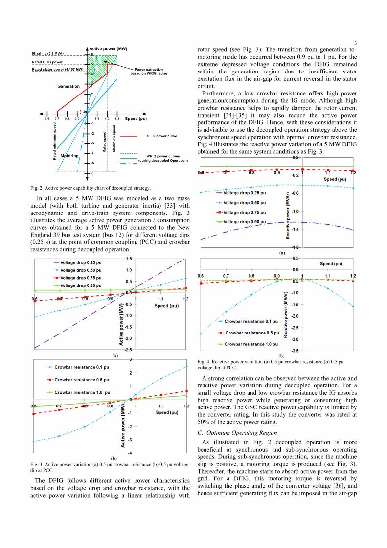
Fig. 2. Active power capability chart of decoupled strategy.
In all cases a 5 MW DFIG was modeled as a two mass model (with both turbine and generator inertia) [33] with aerodynamic and drive-train system components. Fig. 3 illustrates the average active power generation / consumption curves obtained for a 5 MW DFIG connected to the New England 39 bus test system (bus 12) for different voltage dips (0.25 s) at the point of common coupling (PCC) and crowbar resistances during decoupled operation.
(a)
(b) Fig. 3. Active power variation (a) 0.5 pu crowbar resistance (b) 0.5 pu voltage dip at PCC.
The DFIG follows different active power characteristics based on the voltage drop and crowbar resistance, with the active power variation following a linear relationship with
rotor speed (see Fig. 3). The transition from generation to motoring mode has occurred between 0.9 pu to 1 pu. For the extreme depressed voltage conditions the DFIG remained within the generation region due to insufficient stator excitation flux in the air-gap for current reversal in the stator circuit. Furthermore, a low crowbar resistance offers high power generation/consumption during the IG mode. Although high crowbar resistance helps to rapidly dampen the rotor current transient [34]-[35] it may also reduce the active power performance of the DFIG. Hence, with these considerations it is advisable to use the decoupled operation strategy above the synchronous speed operation with optimal crowbar resistance. Fig. 4 illustrates the reactive power variation of a 5 MW DFIG obtained for the same system conditions as Fig. 3.
(a)
(b)
Fig. 4. Reactive power variation (a) 0.5 pu crowbar resistance (b) 0.5 pu voltage dip at PCC.
A strong correlation can be observed between the active and reactive power variation during decoupled operation. For a small voltage drop and low crowbar resistance the IG absorbs high reactive power while generating or consuming high active power. The GSC reactive power capability is limited by the converter rating. In this study the converter was rated at 50% of the active power rating.
C. Optimum Operating Region As illustrated in Fig. 2 decoupled operation is more
beneficial at synchronous and sub-synchronous operating speeds. During sub-synchronous operation, since the machine slip is positive, a motoring torque is produced (see Fig. 3). Thereafter, the machine starts to absorb active power from the grid. For a DFIG, this motoring torque is reversed by switching the phase angle of the converter voltage [36], and hence sufficient generating flux can be imposed in the air-gap

4to reverse the direction of the stator current. Therefore, ride-though is permissible with maximum crowbar resistance for wind farms which are operating below synchronous speed while minimizing the active and reactive power consumption by the IG, and delivering reactive power through the GSC. The decoupled strategy is more feasible for PCC voltages above 0.1 pu during a fault condition. However, it can be extended to obtain an inertial response due to the rapid improvement of the PCC voltage following fault clearance.
III. MODELING ASPECTS OF DECOUPLED STRATEGY
A. Optimal Crowbar Resistance The main function of the dynamic crowbar is to provide optimal active power performance and inertial response while adhering to DFIG protection requirements. The optimal crowbar resistance is constrained by the machine rating (MVA rating), rotor current transient and DC-link transient following crowbar deactivation. Based on the steady-state IG model [37], the active and reactive power of the IG can be expressed as follows:
)/(3
)/(3222
222
imrlimgg
imrlrlgg
ZZZVQ
ZZZVP
+=
+= (4)
where Pg, Qg, Vg, Zrl, and Zim represent the active power generation, reactive power generation, terminal voltage, real component of the equivalent impedance of the IG and the imaginary component of the equivalent impedance of the IG respectively. By assuming that the crowbar resistance (Rcr) is much higher than the rotor and stator resistance, (crowbar resistance is in series with the rotor resistance), and the magnetizing reactance (Xm) is higher than the rotor reactance (Xr), the real and imaginary components of the equivalent impedance can be approximated as follows:
))//(()/(
))//(()/(222
222
mcrmcrsim
mcrmcrrl
XsRXsRXZ
XsRXsRZ
++=
+= (5)
where s is the machine slip. The active power generation and reactive power absorption should not exceed the generator rating (S) during decoupled operation.
22 )()( gg QPS += (6)
From (4) and (5), equation (6) can be simplified as:
))//(())/((3
)/(1322222
222
mcrmcrg
imrlg
XsRXsRVS
ZZVS
+=
+=
By further simplifications, the crowbar resistance can be approximated as:
22 3/;)1(/ gmmcr VSXKKXsR =−= (7)
In order to avoid zero values for Rcr at, or near, synchronous speed (1 pu) the minimum slip is assumed to be 0.01. Further, it is essential to ensure that there is adequate rotor current damping during decoupled operation in order to alleviate the post-clearance rotor current transient. Fig. 5 illustrates the effect of insufficient rotor current damping, and the resulting post-fault rotor current transients due to insufficient crowbar resistance. In both instances the crowbar protection was
activated, since the rotor current transient has exceeded the allowable maximum limit for the rotor current (4.7 kA). The crowbar resistance was deliberately chosen to achieve maximum active power performance. As a result, insufficient damping is obtained when the voltage drop is 0.5 pu, while a large post-fault rotor current transient is seen when the voltage drop is 0.75 pu.
Fig. 5. Rotor current (a) Insufficient damping (0.5 pu voltage drop) (b) High post-fault rotor current transient (0.75 pu voltage drop).
This illustrates the fact that when selecting the optimum crowbar resistance for enhanced active power capability it is essential to consider the converter safety factors. In this situation, considering the rotor current dependent factors (i.e. pre-fault rotor speed, the severity of the voltage drop and the DFIG parameters) [38]-[39], a minimum crowbar resistance of 0.02 pu is required to adequately dampen the rotor current transient. Therefore, the calculated crowbar resistance was further improved during high voltage dips (0.75 pu). In addition, the crowbar resistance was lowered to obtain an improved inertial response (by relaxing the IG rating in equation (7)) capability during low voltage dips (0.25 pu). The optimal crowbar resistance variation for a 5 MW DFIG after being subjected to the above constraints is shown in Fig. 6.
Fig. 6. Optimal crowbar resistance.
In practice, such a scheme can be implemented using a lookup table with discrete steps, which can determine the optimal resistance required for a particular operating speed and expected voltage drop at each wind farm during a fault condition. The expected voltage drop can be determined based on the network strength at the installed location of the wind farm, noting that for a feasible transmission system fault the resulting voltage drop is likely to encompass wind intensive areas in the system.
B. GSC Modeling as a STATCOM The grid-side converter (GSC) is reconfigured as a reactive power source (as a STATCOM) during decoupled operation to support the reactive power demand of the induction generator
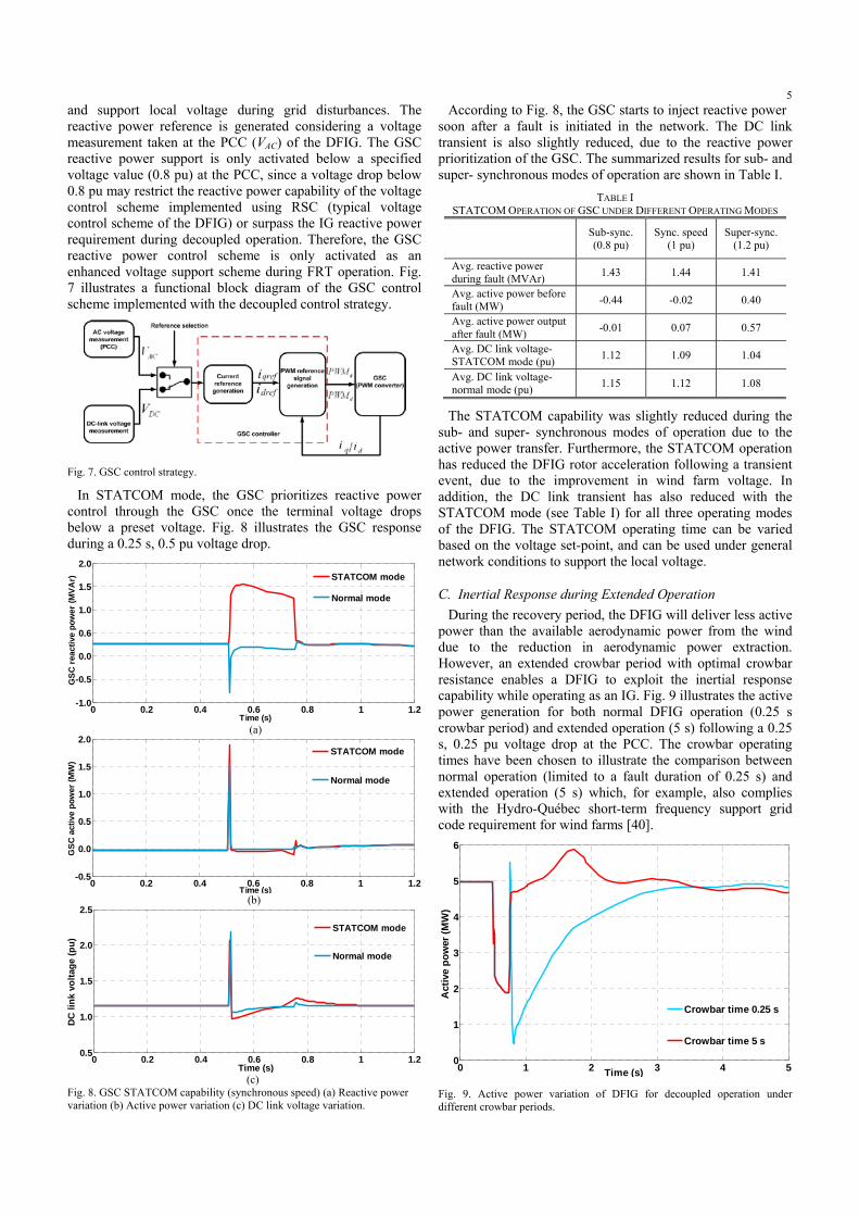
5and support local voltage during grid disturbances. The reactive power reference is generated considering a voltage measurement taken at the PCC (VAC) of the DFIG. The GSC reactive power support is only activated below a specified voltage value (0.8 pu) at the PCC, since a voltage drop below 0.8 pu may restrict the reactive power capability of the voltage control scheme implemented using RSC (typical voltage control scheme of the DFIG) or surpass the IG reactive power requirement during decoupled operation. Therefore, the GSC reactive power control scheme is only activated as an enhanced voltage support scheme during FRT operation. Fig. 7 illustrates a functional block diagram of the GSC control scheme implemented with the decoupled control strategy.
Fig. 7. GSC control strategy.
In STATCOM mode, the GSC prioritizes reactive power control through the GSC once the terminal voltage drops below a preset voltage. Fig. 8 illustrates the GSC response during a 0.25 s, 0.5 pu voltage drop.
0 0.2 0.4 0.6 0.8 1 1.2-1.0
-0.5
0.0
0.6
1.0
1.5
2.0
Time (s)
GSC
reac
tive
pow
er (M
VAr)
STATCOM mode
Normal mode
(a)
0 0.2 0.4 0.6 0.8 1 1.2-0.5
0.0
0.5
1.0
1.5
2.0
Time (s)
GSC
act
ive
pow
er (M
W)
STATCOM mode
Normal mode
(b)
0 0.2 0.4 0.6 0.8 1 1.20.5
1.0
1.5
2.0
2.5
Time (s)
DC
link
vol
tage
(pu)
STATCOM mode
Normal mode
(c)
Fig. 8. GSC STATCOM capability (synchronous speed) (a) Reactive power variation (b) Active power variation (c) DC link voltage variation.
According to Fig. 8, the GSC starts to inject reactive power soon after a fault is initiated in the network. The DC link transient is also slightly reduced, due to the reactive power prioritization of the GSC. The summarized results for sub- and super- synchronous modes of operation are shown in Table I.
TABLE I STATCOM OPERATION OF GSC UNDER DIFFERENT OPERATING MODES Sub-sync.
(0.8 pu) Sync. speed
(1 pu) Super-sync.
(1.2 pu)
Avg. reactive power during fault (MVAr) 1.43 1.44 1.41
Avg. active power before fault (MW) -0.44 -0.02 0.40
Avg. active power output after fault (MW) -0.01 0.07 0.57
Avg. DC link voltage-STATCOM mode (pu) 1.12 1.09 1.04
Avg. DC link voltage-normal mode (pu) 1.15 1.12 1.08
The STATCOM capability was slightly reduced during the sub- and super- synchronous modes of operation due to the active power transfer. Furthermore, the STATCOM operation has reduced the DFIG rotor acceleration following a transient event, due to the improvement in wind farm voltage. In addition, the DC link transient has also reduced with the STATCOM mode (see Table I) for all three operating modes of the DFIG. The STATCOM operating time can be varied based on the voltage set-point, and can be used under general network conditions to support the local voltage.
C. Inertial Response during Extended Operation During the recovery period, the DFIG will deliver less active
power than the available aerodynamic power from the wind due to the reduction in aerodynamic power extraction. However, an extended crowbar period with optimal crowbar resistance enables a DFIG to exploit the inertial response capability while operating as an IG. Fig. 9 illustrates the active power generation for both normal DFIG operation (0.25 s crowbar period) and extended operation (5 s) following a 0.25 s, 0.25 pu voltage drop at the PCC. The crowbar operating times have been chosen to illustrate the comparison between normal operation (limited to a fault duration of 0.25 s) and extended operation (5 s) which, for example, also complies with the Hydro-Québec short-term frequency support grid code requirement for wind farms [40].
0 1 2 3 4 50
1
2
3
4
5
6
Time (s)
Act
ive
pow
er (M
W)
Crowbar time 0.25 s
Crowbar time 5 s
Fig. 9. Active power variation of DFIG for decoupled operation under different crowbar periods.
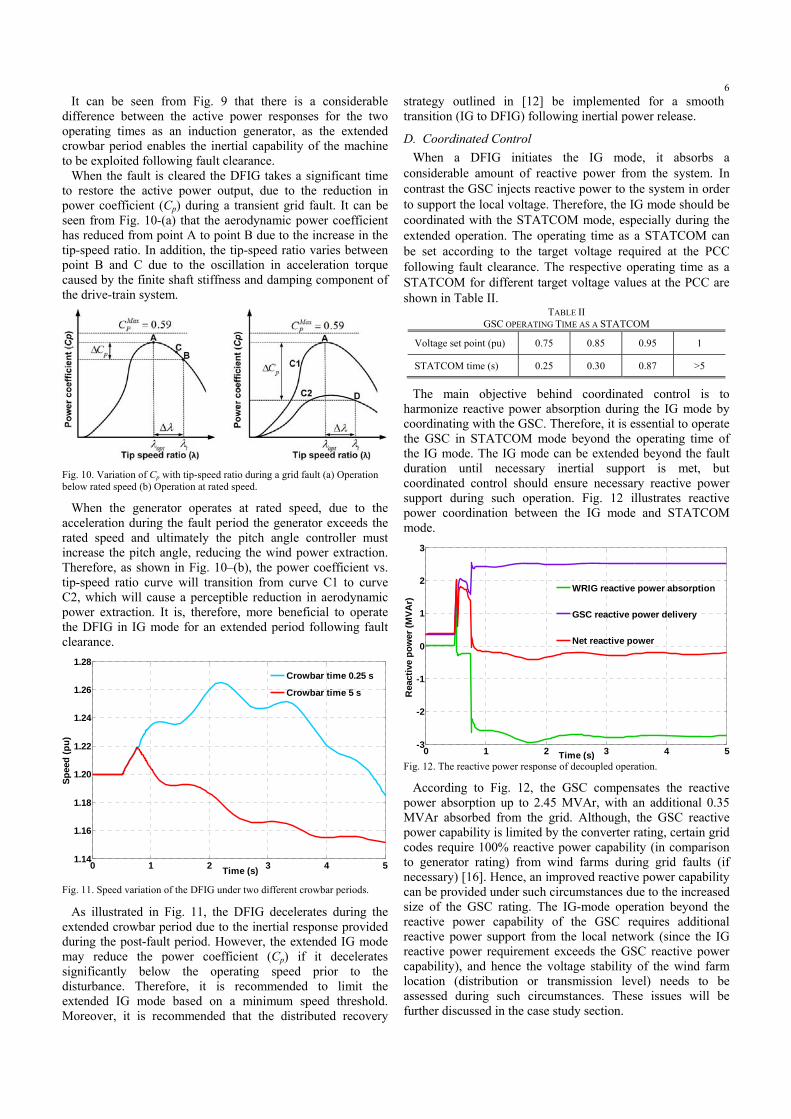
6It can be seen from Fig. 9 that there is a considerable
difference between the active power responses for the two operating times as an induction generator, as the extended crowbar period enables the inertial capability of the machine to be exploited following fault clearance.
When the fault is cleared the DFIG takes a significant time to restore the active power output, due to the reduction in power coefficient (Cp) during a transient grid fault. It can be seen from Fig. 10-(a) that the aerodynamic power coefficient has reduced from point A to point B due to the increase in the tip-speed ratio. In addition, the tip-speed ratio varies between point B and C due to the oscillation in acceleration torque caused by the finite shaft stiffness and damping component of the drive-train system.
Fig. 10. Variation of Cp with tip-speed ratio during a grid fault (a) Operation below rated speed (b) Operation at rated speed.
When the generator operates at rated speed, due to the acceleration during the fault period the generator exceeds the rated speed and ultimately the pitch angle controller must increase the pitch angle, reducing the wind power extraction. Therefore, as shown in Fig. 10–(b), the power coefficient vs. tip-speed ratio curve will transition from curve C1 to curve C2, which will cause a perceptible reduction in aerodynamic power extraction. It is, therefore, more beneficial to operate the DFIG in IG mode for an extended period following fault clearance.
0 1 2 3 4 51.14
1.16
1.18
1.20
1.22
1.24
1.26
1.28
Time (s)
Spee
d (p
u)
Crowbar time 0.25 s
Crowbar time 5 s
Fig. 11. Speed variation of the DFIG under two different crowbar periods.
As illustrated in Fig. 11, the DFIG decelerates during the extended crowbar period due to the inertial response provided during the post-fault period. However, the extended IG mode may reduce the power coefficient (Cp) if it decelerates significantly below the operating speed prior to the disturbance. Therefore, it is recommended to limit the extended IG mode based on a minimum speed threshold. Moreover, it is recommended that the distributed recovery
strategy outlined in [12] be implemented for a smooth transition (IG to DFIG) following inertial power release.
D. Coordinated Control When a DFIG initiates the IG mode, it absorbs a
considerable amount of reactive power from the system. In contrast the GSC injects reactive power to the system in order to support the local voltage. Therefore, the IG mode should be coordinated with the STATCOM mode, especially during the extended operation. The operating time as a STATCOM can be set according to the target voltage required at the PCC following fault clearance. The respective operating time as a STATCOM for different target voltage values at the PCC are shown in Table II.
TABLE II GSC OPERATING TIME AS A STATCOM
Voltage set point (pu) 0.75 0.85 0.95 1
STATCOM time (s) 0.25 0.30 0.87 >5
The main objective behind coordinated control is to harmonize reactive power absorption during the IG mode by coordinating with the GSC. Therefore, it is essential to operate the GSC in STATCOM mode beyond the operating time of the IG mode. The IG mode can be extended beyond the fault duration until necessary inertial support is met, but coordinated control should ensure necessary reactive power support during such operation. Fig. 12 illustrates reactive power coordination between the IG mode and STATCOM mode.
0 1 2 3 4 5-3
-2
-1
0
1
2
3
Time (s)
Rea
ctiv
e po
wer
(MVA
r)
WRIG reactive power absorption
GSC reactive power delivery
Net reactive power
Fig. 12. The reactive power response of decoupled operation.
According to Fig. 12, the GSC compensates the reactive power absorption up to 2.45 MVAr, with an additional 0.35 MVAr absorbed from the grid. Although, the GSC reactive power capability is limited by the converter rating, certain grid codes require 100% reactive power capability (in comparison to generator rating) from wind farms during grid faults (if necessary) [16]. Hence, an improved reactive power capability can be provided under such circumstances due to the increased size of the GSC rating. The IG-mode operation beyond the reactive power capability of the GSC requires additional reactive power support from the local network (since the IG reactive power requirement exceeds the GSC reactive power capability), and hence the voltage stability of the wind farm location (distribution or transmission level) needs to be assessed during such circumstances. These issues will be further discussed in the case study section.
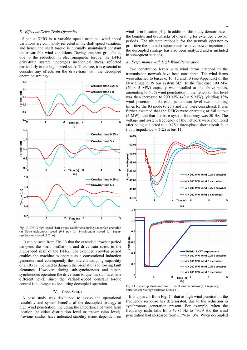
7E. Effect on Drive-Train Dynamics
Since a DFIG is a variable speed machine, wind speed variations are commonly reflected in the shaft speed variation, and hence the shaft torque is normally maintained constant under variable wind conditions. During transient grid faults, due to the reduction in electromagnetic torque, the DFIG drive-train system undergoes mechanical stress, reflected particularly in the high-speed shaft. Therefore, it is essential to consider any effects on the drive-train with the decoupled operation strategy.
0 1 2 3 4 5-0.2
0.2
0.6
1.0
1.4
1.8
Time (s)
Torq
ue (p
u)
Crowbar time 0.25 s
Crowbar time 5 s
(a)
0 1 2 3 4 50.2
0.6
1.0
1.4
1.8
Time (s)
Torq
ue (p
u)
Crowbar time 0.25 s
Crowbar time 5 s
(b)
0 1 2 3 4 50.2
0.6
1.0
1.4
1.8
Time (s)
Torq
ue (p
u)
Crowbar time 0.25 s
Crowbar time 5 s
(c)
Fig. 13. DFIG high-speed shaft torque oscillations during decoupled operation (a) Sub-synchronous speed (0.8 pu) (b) Synchronous speed (c) Super-synchronous speed (1.2 pu).
It can be seen from Fig. 13 that the extended crowbar period dampens the shaft oscillations and drive-train stress in the high-speed shaft of the DFIG. The extended crowbar period enables the machine to operate as a conventional induction generator, and consequently the inherent damping capability of an IG can be used to dampen the oscillations following fault clearance. However, during sub-synchronous and super-synchronous operation the drive-train torque has stabilized at a different level, since the variable-speed constant torque control is no longer active during decoupled operation.
IV. CASE STUDY A case study was developed to assess the operational
feasibility and system benefits of the decoupled strategy at high wind penetration, including the importance of wind farm location (at either distribution level or transmission level). Previous studies have indicated stability issues dependent on
wind farm location [41]. In addition, this study demonstrates the benefits and drawbacks of operating for extended crowbar periods. The ultimate rationale for the network operator to prioritize the inertial response and reactive power injection of the decoupled strategy has also been analyzed and is included in subsequent sections.
A. Performance with High Wind Penetration
Two penetration levels with wind farms attached to the transmission network have been considered. The wind farms were attached to buses 6, 10, 12 and 13 (see Appendix) of the New England 39 bus system [42]. In the first case 100 MW (20 × 5 MW) capacity was installed at the above nodes, amounting to 6.5% wind penetration in the network. This level was then increased to 200 MW (40 × 5 MW), yielding 13% wind penetration. At each penetration level two operating times for the IG mode (0.25 s and 5 s) were considered. It was further assumed that the DFIGs were operating at full output (5 MW), and that the base system frequency was 50 Hz. The voltage and system frequency of the network were monitored after being subjected to a 0.25 s three-phase short circuit fault (fault impedance: 0.2 Ω) at bus 11.
0 1 2 3 4 549.78
49.82
49.86
49.90
49.94
49.98
50.02
50.06
Time (s)
Rot
or a
ngle
(deg
rees
)
4 X 100 MW wind 0.25 s crowbar
4 X 100 MW wind 5 s crowbar
4 X 200 MW wind 0.25 s crowbar
4 X 200 MW wind 5 s crowbar
(a)
0 1 2 3 4 50
0.2
0.4
0.6
0.8
1.0
1.2
Time (s)
Volta
ge (p
u)
4 X 100 MW wind 0.25 s crowbar
4 X 100 MW wind 5 s crowbar
4 X 200 MW wind 0.25 s crowbar
4 X 200 MW wind 5 s crowbar
EirGrid LVRT requirement
(b)
Fig. 14. System performance for different wind scenarios (a) Frequency variation (b) Voltage variation at bus 11.
It is apparent from Fig. 14 that at high wind penetration the frequency response has deteriorated, due to the reduction in synchronous generation present. For example, when the frequency nadir falls from 49.85 Hz to 49.79 Hz, the wind penetration had increased from 6.5% to 13%. When decoupled
8operation was extended beyond the fault duration (5 s) a significant improvement in frequency stability was apparent.
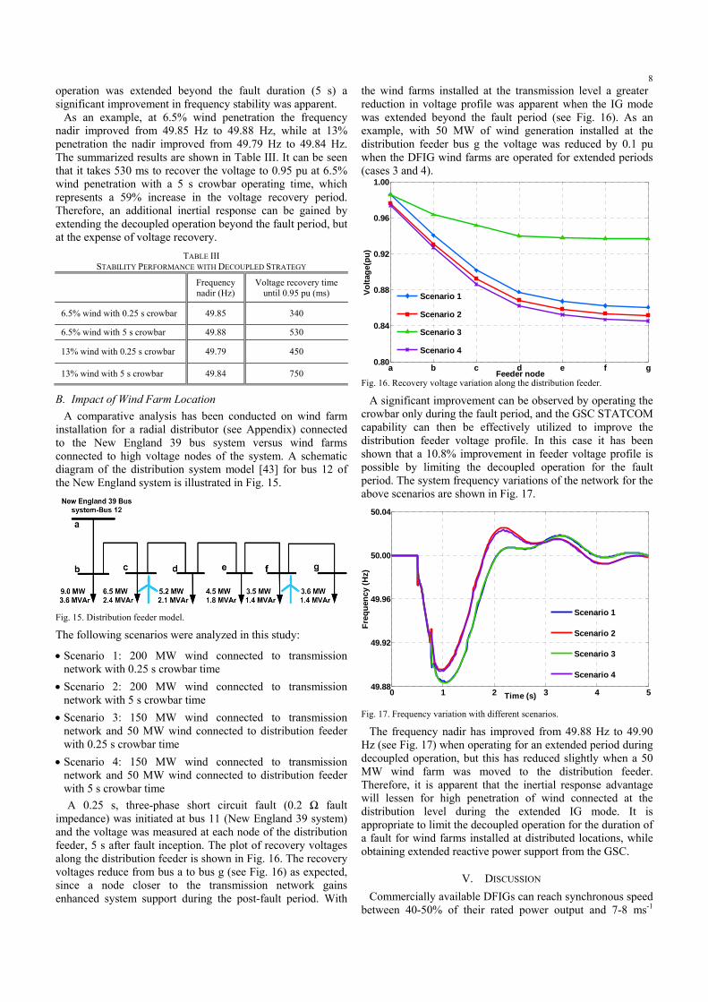
As an example, at 6.5% wind penetration the frequency nadir improved from 49.85 Hz to 49.88 Hz, while at 13% penetration the nadir improved from 49.79 Hz to 49.84 Hz. The summarized results are shown in Table III. It can be seen that it takes 530 ms to recover the voltage to 0.95 pu at 6.5% wind penetration with a 5 s crowbar operating time, which represents a 59% increase in the voltage recovery period. Therefore, an additional inertial response can be gained by extending the decoupled operation beyond the fault period, but at the expense of voltage recovery.
TABLE III STABILITY PERFORMANCE WITH DECOUPLED STRATEGY
Frequency nadir (Hz)
Voltage recovery time until 0.95 pu (ms)
6.5% wind with 0.25 s crowbar 49.85 340
6.5% wind with 5 s crowbar 49.88 530
13% wind with 0.25 s crowbar 49.79 450
13% wind with 5 s crowbar 49.84 750
B. Impact of Wind Farm Location A comparative analysis has been conducted on wind farm
installation for a radial distributor (see Appendix) connected to the New England 39 bus system versus wind farms connected to high voltage nodes of the system. A schematic diagram of the distribution system model [43] for bus 12 of the New England system is illustrated in Fig. 15.
Fig. 15. Distribution feeder model. The following scenarios were analyzed in this study:
• Scenario 1: 200 MW wind connected to transmission network with 0.25 s crowbar time
• Scenario 2: 200 MW wind connected to transmission network with 5 s crowbar time
• Scenario 3: 150 MW wind connected to transmission network and 50 MW wind connected to distribution feeder with 0.25 s crowbar time
• Scenario 4: 150 MW wind connected to transmission network and 50 MW wind connected to distribution feeder with 5 s crowbar time A 0.25 s, three-phase short circuit fault (0.2 Ω fault
impedance) was initiated at bus 11 (New England 39 system) and the voltage was measured at each node of the distribution feeder, 5 s after fault inception. The plot of recovery voltages along the distribution feeder is shown in Fig. 16. The recovery voltages reduce from bus a to bus g (see Fig. 16) as expected, since a node closer to the transmission network gains enhanced system support during the post-fault period. With
the wind farms installed at the transmission level a greater reduction in voltage profile was apparent when the IG mode was extended beyond the fault period (see Fig. 16). As an example, with 50 MW of wind generation installed at the distribution feeder bus g the voltage was reduced by 0.1 pu when the DFIG wind farms are operated for extended periods (cases 3 and 4).
a b c d e f g0.80
0.84
0.88
0.92
0.96
1.00
Feeder nodeVo
ltage
(pu)
Scenario 1
Scenario 2
Scenario 3
Scenario 4
Fig. 16. Recovery voltage variation along the distribution feeder.
A significant improvement can be observed by operating the crowbar only during the fault period, and the GSC STATCOM capability can then be effectively utilized to improve the distribution feeder voltage profile. In this case it has been shown that a 10.8% improvement in feeder voltage profile is possible by limiting the decoupled operation for the fault period. The system frequency variations of the network for the above scenarios are shown in Fig. 17.
0 1 2 3 4 549.88
49.92
49.96
50.00
50.04
Time (s)
Freq
uenc
y (H
z)
Scenario 1
Scenario 2
Scenario 3
Scenario 4
Fig. 17. Frequency variation with different scenarios.
The frequency nadir has improved from 49.88 Hz to 49.90 Hz (see Fig. 17) when operating for an extended period during decoupled operation, but this has reduced slightly when a 50 MW wind farm was moved to the distribution feeder. Therefore, it is apparent that the inertial response advantage will lessen for high penetration of wind connected at the distribution level during the extended IG mode. It is appropriate to limit the decoupled operation for the duration of a fault for wind farms installed at distributed locations, while obtaining extended reactive power support from the GSC.
V. DISCUSSION Commercially available DFIGs can reach synchronous speed
between 40-50% of their rated power output and 7-8 ms-1
9wind speed [1-2]. Hence, an individual DFIG is more likely to be operating beyond synchronous speed (optimum operating region) when the aggregated wind power output is high. Beneficially, the proposed DFIG decoupled strategy is seen (Section IV.A) to be most effective at high wind penetration levels, which are the very conditions when the impact of a network fault would be most severe. Therefore, if DFIG performance causes operational concerns (under fault conditions) such that wind curtailment may be required [17], then as an alternative, wind farm requirements should evolve over time, following current practice [18].
The emulated inertial response capability provided by certain wind farm manufacturers has not been illustrated following transient faults in close proximity to the wind farms [44]. In terms of low voltage dips (>0.25 pu) which do not render converter ride-though problems, it is essential to incorporate emulated inertial response strategies to support the system frequency during the event. As an example, the ΔPKE discharge strategy [12] can be implemented under such circumstances, though inertial power release is limited by the DFIG rated power output (5 MW). The proposed decoupled strategy can also be implemented to provide inertial support under such circumstances, since the available inertial power release is much higher than for the emulated strategies, as the overall inertial power release is constrained to the WRIG rating (5.9 MVA).
According to the EirGrid (transmission system operator, Republic of Ireland) grid code, when the voltage, measured at the HV terminals of the grid-connected transformer, falls below 0.15 pu (see Fig. 14-(b)) wind farms are allowed to disconnect from the grid [15]. Simulation studies show (similar to Fig. 3) that the decoupled strategy is feasible for faults which result in the retained voltage reducing to 0.1 pu (for 0.25 s), which is below the stipulated voltage profile from the EirGrid grid code standard, and could enable the FRT capability of the system to be improved. In terms of extended operation, the proposed strategy has rendered a voltage profile above the stipulated EirGrid LVRT grid code standard [15], even under the worst case scenario (see Fig. 14). Hence, the wind farms should stay connected while providing extended inertial support for the system. Wind-hydro dominant systems can also benefit from the proposed strategy since frequency support problems are much more prominent in such systems, as outlined in [11]. As an example, wind farms in the Hydro-Québec system already requires to provide frequency support during large disturbances (>0.5 Hz) for short duration (<10 s) [40], while this strategy has illustrated frequency support capability for 5 s following a network fault.
VI. CONCLUSIONS A novel decoupled-DFIG FRT strategy has been presented
which can improve both the active and reactive power capability during FRT operation and provides a natural inertial response, constrained to the IG rating and other protection requirements, during grid disturbances. The optimum regions and capability chart have been defined considering the transition power characteristics. The optimal crowbar resistance was obtained by considering the machine rating and the protection requirements of the DFIG. The optimal crowbar resistance delivers enhanced active power support during fault operation and inertial support during extended operation. It has been shown that by proper coordination between the IG
and STATCOM modes that a DFIG can deliver enhanced active power and voltage support during grid faults. Moreover, it has been shown that the turbine drive-train stress can also be reduced by extended decoupled operation.
The results obtained from the exemplars indicate that the proposed decoupled strategy is effective during high wind penetration, while complying with existing grid code standards. Furthermore, it has also been shown that the optimum network support required is dependent upon the wind farm location. A system operator has, therefore, the ultimate choice in prioritizing the network support required from a wind farm installed at a particular location.
ACKNOWLEDGEMENT This publication has emanated from research conducted with
the financial support of Science Foundation Ireland under Grant Number 06/CP/E002.
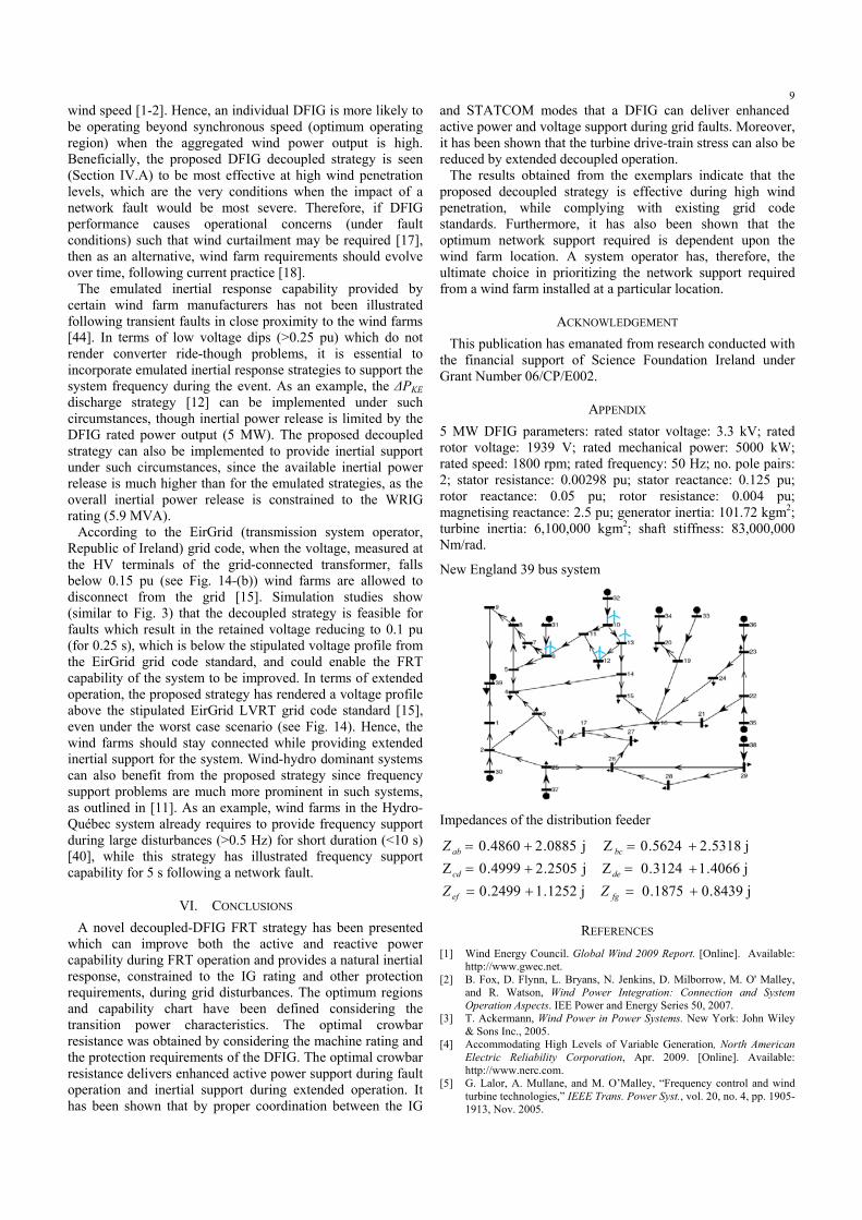
APPENDIX 5 MW DFIG parameters: rated stator voltage: 3.3 kV; rated rotor voltage: 1939 V; rated mechanical power: 5000 kW; rated speed: 1800 rpm; rated frequency: 50 Hz; no. pole pairs: 2; stator resistance: 0.00298 pu; stator reactance: 0.125 pu; rotor reactance: 0.05 pu; rotor resistance: 0.004 pu; magnetising reactance: 2.5 pu; generator inertia: 101.72 kgm2; turbine inertia: 6,100,000 kgm2; shaft stiffness: 83,000,000 Nm/rad.
New England 39 bus system
Impedances of the distribution feeder
j8439.01875.0j1252.12499.0j4066.13124.0Zj2505.24999.0Zj5318.25624.0 Zj0885.24860.0
+=+=+=+=+=+=
fgef
decd
bcab
ZZ
Z
REFERENCES [1] Wind Energy Council. Global Wind 2009 Report. [Online]. Available:
http://www.gwec.net. [2] B. Fox, D. Flynn, L. Bryans, N. Jenkins, D. Milborrow, M. O' Malley,
and R. Watson, Wind Power Integration: Connection and System Operation Aspects. IEE Power and Energy Series 50, 2007.
[3] T. Ackermann, Wind Power in Power Systems. New York: John Wiley & Sons Inc., 2005.
[4] Accommodating High Levels of Variable Generation, North American Electric Reliability Corporation, Apr. 2009. [Online]. Available: http://www.nerc.com.
[5] G. Lalor, A. Mullane, and M. O’Malley, “Frequency control and wind turbine technologies,” IEEE Trans. Power Syst., vol. 20, no. 4, pp. 1905-1913, Nov. 2005.

10[6] G. Ramtharan, J.B. Ekanayake, and N. Jenkins, “Frequency support
from doubly fed induction generator wind turbines,” IET RPG, vol. 1, no. 1, pp. 3-9, Mar. 2007.
[7] L. Holdsworth, J.B. Ekanayake, and N. Jenkins, “Power system frequency response from fixed speed and doubly fed induction generator-based wind turbines,” Wind Energy, vol. 7, no. 1, pp. 21-35, 2004.
[8] J. Morren, J. Pierik, and S.W.H. de Haan, “Inertial response of variable speed wind turbines,” Electric Power Systems Research, vol. 76, no. 11, pp. 980-987, Jul.2006.
[9] M. Kayikci, and J.V. Milanovic, “Dynamic contribution of DFIG-based wind plants to system frequency disturbances,” IEEE Trans. Power Syst., vol. 24, no. 2, pp. 859-867, May 2009.
[10] R.G. de Almeida, J.A.P. Lopes, “Participation of doubly fed induction wind generators in system frequency regulation,” IEEE Trans. Power Syst., vol. 22, no. 3, pp. 944-950, Aug. 2007.
[11] N.R. Ullah, T. Thiringer, and D. Karlsson, “Temporary primary frequency control support by variable speed wind turbines— potential and applications,” IEEE Trans. Power Syst., vol. 23 , no. 2 , pp. 601-612, May 2008.
[12] P.K. Keung, P. Li, H. Banakar, and T.O. Boon, “Kinetic energy of wind-turbine generators for system frequency support," IEEE Trans. Power Syst., vol. 24, no. 1, pp. 279-287, Feb. 2009.
[13] J.M. Mauricio, A. Marano, A. Gomez-Exposito, and J.L. Martinez Ramos, “Frequency regulation contribution through variable-speed wind energy conversion systems,” IEEE Trans. Power Syst., vol. 24, no. 1, pp. 173-180, Feb. 2009.
[14] National Grid Electricity Transmission PLC. The grid code, issue 4, Jun. 2009. [Online]. Available: http://www.nationalgrid.com.
[15] EirGrid, Grid code, version 3.1, May 2008. [Online]. Available: http://www.eirgrid.com.
[16] E.ON Netz GmbH. Grid Code - High and extra high voltage, Bayreuth, Germany, Apr. 2006. [Online]. Available: http://www.eon-netz.com.
[17] All Island TSO Facilitation of Renewables Studies—Work Package 3 Final Report. Jun. 2010. [Online]. Available: http://www.eirgrid.com/renewables/facilitationofrenewables.
[18] R. Piwko, N. Miller, R.T. Girard, J. MacDowell, K. Clark, and A. Murdoch, “Clarifying confusion with transient stability requirements,” IEEE Power and Energy Magazine, vol. 8, no. 2, pp. 18-26, Mar./Apr. 2010.
[19] J. Morren, and S.W.H. de Haan, “Ride-through of wind turbines with doubly-fed induction generator during a voltage dip,” IEEE Trans. Energy conv., vol. 20, no. 2, pp. 435-441, Jun. 2005.
[20] A.D. Hansen, and G. Michalke, “Fault ride-through capability of DFIG wind turbines,” Renewable Energy, vol. 32, no. 9, pp. 1594-1610, Jul. 2007.
[21] Z. Peng, and H. Yikang, “Control strategy of an active crowbar for DFIG based wind turbine under grid voltage dips,” International Conference on Electrical Machines and Systems, pp. 259-264, Oct. 2007.
[22] L. Peng, B. Francois, and Y. Li, “Improved crowbar control strategy of DFIG based wind turbines for grid fault ride-through,” APEC 2009, pp. 1932-1938, Washington, USA, Feb. 2009.
[23] I. Erlich, H. Wrede, and C. Feltes “Dynamic behavior of DFIG-based wind turbines during grid faults," Power Conversion Conference – Nagoya 2007, pp. 1195-1200, Nagoya, Japan, Apr. 2007.
[24] J. Yang, J.E. Fletcher, and J. O'Reilly, “A series dynamic resistor based converter protection scheme for doubly-fed induction generator during various fault conditions,” IEEE PES GM 2009, Calgary, Canada, Jul. 2009.
[25] J. Lopez, P. Sanchis, X. Roboam, and L. Marroyo, “Dynamic behavior of the doubly-fed induction generator during three-phase voltage dips,” IEEE Trans. Energy Conv., vol. 22, no. 3, pp. 709-717, Sep. 2007.
[26] A.H. Kasem, E.F. El-Saadany, and H.H. El-Tamaly, “An improved fault-ride through strategy for doubly fed induction generator based wind turbines,” IET RPG, vol. 2, no. 4, pp. 201-214, 2008.
[27] H.N.D. Le, and S. Islam, “Substantial control strategies of DFIG wind power system during grid transient faults,” IEEE/PES T&D, Chicago, USA, 2008.
[28] C. Zhan, and C.D. Barker, “Fault ride-through capability investigation of a doubly-fed induction generator with an additional series-connected
voltage source converter,” ACDC 2006, pp. 79-84. London, UK, Mar. 2006.
[29] A.O. Ibrahim, T.H. Nguyen, D. Lee, and S. Kim, “Ride-through strategy for DFIG wind turbine systems using dynamic voltage restorers,” ECCE 2009, pp. 1611-1618, San Jose, USA, Sep. 2009.
[30] L.G. Meegahapola, D. Flynn, J. Kennedy, and T. Littler, “Active use of DFIG based wind farms for transient stability improvement during grid disturbances,” IEEE PES GM 2009, Calgary, Canada, Jul. 2009.
[31] L.G. Meegahapola, D. Flynn, and T. Littler, “Optimization of active power performance of a DFIG during transient grid fault,” ICIIS 2009, Peradeniya, Sri Lanka, Dec. 2009.
[32] DIgSILENT GmbH, Power factory manual, version 13.2, Germany, 2007.
[33] V. Akhmatov, “Analysis of dynamic behaviour of electric power systems with large amount of wind power,” Ph.D. dissertation, Elect. Power Eng., Orsted-DTU, Tech. Univ. Denmark, Lyngby, 2003.
[34] O. Anaya Lara, Z. Liu, G. Quinonez-Varela, and J.R. McDonald, “Optimal DFIG crowbar resistor design under different controllers during grid faults,” DRPT 2008, Nanjing, China, 2008.
[35] R. Lohde, S. Jensen, A. Knop, and F.W. Fuchs, “Analysis of three phase grid failure and doubly fed induction generator ride-through using crowbars,” ESPEA 2007, Aalborg, Denmark, Sep. 2007.
[36] M. Aktarujjaman, M.E. Haque, K.M. Muttaqi, M. Negnevitsky, and G. Ledwich, “Control dynamics of a doubly-fed induction generator under sub- and super-synchronous modes of operation,” IEEE PES GM 2008, Pittsburgh, USA, Jul. 2008.
[37] P. Kundur, Power System Stability and Control. New York: McGraw-Hill, 1993.
[38] S. Chondrogiannis, and M. Barnes, “Specification of rotor side voltage source inverter of a doubly-fed induction generator for achieving ride-through capability,” IET RPG, vol. 2, no. 3, pp. 139-150, 2008.
[39] A. Han, Z. Zhang, X. Yin, and Y. Wang, “Study of the factors affected the rotor over current of DFIG during the three-phase voltage dip,” DRPT 2008, Nanjing, China, Apr. 2008.
[40] Technical Requirements for the Connection of Generation Facilities to the Hydro-Québec Transmission System: Supplementary Requirements for Wind Generation, Hydro-Québec, Tech. Rep., May 2003, revised 2005.
[41] L. Meegahapola, D. Flynn, and T. Littler, “Transient stability analysis of a power system with high wind penetration,” UPEC 2008, Padova, Italy, Sep. 2008.
[42] M.A. Pai, Computer Techniques in Power System Analysis. McGraw Hill Publishing Co., 1979.
[43] W. Freitas, C.M. Jose, A. Morelato, L.C. da Silva, V.F. da Costa, and F.A. Lemons, “Comparative analysis between synchronous and induction machines for distributed generation applications,” IEEE Trans. Power Systems, vol. 21, no. 1, pp. 301-311, Feb. 2006.
[44] S. Hartge, “Integration wind energy into the grid (GE Energy),” Integrating wind power in Romania, Bucharest, Romania, Jun. 2009. [Online]. Available: http://www.wind-energy-the-facts.org.
BIOGRAPHIES Lasantha Meegahapola (S’06) was born in Colombo, Sri Lanka in 1982. He received a 1st class BSc. Eng. Honors degree from University of Moratuwa, Sri Lanka in 2006. He is currently pursuing a PhD in the area of transient stability at The Queen’s University of Belfast, UK. His research interest includes renewable energy generation, power system stability, and intelligent approaches in power systems.
Tim Littler is a lecturer in Power Systems, Software Engineering and Mathematics at The Queen’s University of Belfast. His research interests include power system monitoring, protection systems, instrumentation, signal algorithms and analysis, DSP, mathematics and software engineering. He is a member of the IEEE and PES. Damian Flynn (M’96) is a senior lecturer in Power Engineering at University College Dublin. His research interests involve an investigation of the effects of embedded generation sources, especially renewables, on the operation of power systems. He is also interested in advanced modeling and control techniques applied to power plant. He is a member of the IEEE.