Polynomial iterative algorithms for coloring and analyzing random graphs
Upload
independentCategory
view
1download
0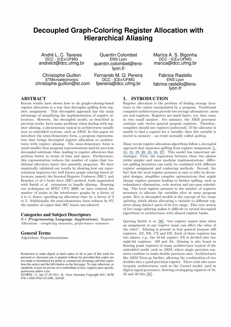
Decoupled Graph-Coloring Register Allocation withHierarchical Aliasing
André L. C. TavaresDCC - ICEx/UFMG
Quentin ColombetENS Lyon
Mariza A. S. BigonhaDCC - ICEx/UFMG
Christophe GuillonSTMicroelectronics
Fernando M. Q. PereiraDCC - ICEx/UFMG
Fabrice RastelloENS Lyon
ABSTRACTRecent results have shown how to do graph-coloring-basedregister allocation in a way that decouples spilling from reg-ister assignment. This decoupled approach has the mainadvantage of simplifying the implementation of register al-locators. However, the decoupled model, as described inprevious works, faces many problems when dealing with reg-ister aliasing, a phenomenon typical in architectures usuallyseen in embedded systems, such as ARM. In this paper weintroduce the semi-elementary form, a program representa-tion that brings decoupled register allocation to architec-tures with register aliasing. The semi-elementary form ismuch smaller than program representations used by previousdecoupled solutions; thus, leading to register allocators thatperform better in terms of time and space. Furthermore,this representation reduces the number of copies that tra-ditional allocators insert into assembly programs. We haveempirically validated our results by showing how our repre-sentation improves two well known graph coloring based al-locators, namely the Iterated Register Coalescer (IRC), andBouchez et al.’s brute force (BF) method, both augmentedwith Smith et al. extensions to handle aliasing. Runningour techniques on SPEC CPU 2000, we have reduced thenumber of nodes in the interference graphs by a factor of4 to 5; hence, speeding-up allocation time by a factor of 3to 5. Additionally the semi-elementary form reduces by 8%the number of copies that IRC leaves uncoalesced.
Categories and Subject DescriptorsH.4 [Programming Language Applications]: RegisterAllocation—complexity measures, performance measures
General TermsAlgorithms, Experimentations
Permission to make digital or hard copies of all or part of this work forpersonal or classroom use is granted without fee provided that copies arenot made or distributed for profit or commercial advantage and that copiesbear this notice and the full citation on the first page. To copy otherwise, orrepublish, to post on servers or to redistribute to lists, requires prior specificpermission and/or a fee.SCOPES ’11, Jun 27-28 2011, St. Goar, Germany Copyright 2011 ACM978-1-4503-0763-5/11/06...$10.00.
1. INTRODUCTIONRegister allocation is the problem of finding storage loca-tions to the values manipulated by a program. Traditionalcomputer architectures provide two storage alternatives: mem-ory and registers. Registers are much faster, yet, they comein very small number. For instance, the ARM processorcontains only twelve general purpose registers. Therefore,compilers should use registers judiciously. If the allocator isunable to find a register for a variable, then this variable isstored in memory – an event normally called spilling.
Many recent register allocation algorithms follow a decoupledapproach that separates spilling from register assignment [1,12, 13, 19, 20, 23, 24, 27]. This model has important ad-vantages. First, the separation between these two phasesyields simpler and more modular implementations: differ-ent spilling heuristics can easily be combined with differentregister assignment and coalescing methods. Second, thefact that the local register pressure is easy to infer in decou-pled designs, simplifies compiler optimizations that mightchange register pressure leading to further spilling, such asredundancy elimination, code motion and pre-pass schedul-ing. The local register pressure is the number of registersnecessary to allocate the variables alive at some programpoint. Key to decoupled models is the concept of live rangesplitting, which allows allocating a variable to different reg-isters along distinct parts of its live range. This very notionof live range splitting makes it difficult to extend decoupledalgorithms to architectures with aliased register banks.
Quoting Smith et al. [26], “two register names alias whenan assignment to one register name can affect the value ofthe other”. Aliasing is present in four general purpose x86registers: AX, BX, CX and DX. Each of these registers hastwo aliases, e.g., the 16-bit register AX is divided into twoeight-bit registers: AH and AL. Aliasing is also found infloating point registers of many architectures typical of theembedded world, such as ARM, where single precision reg-isters combine to make double precision ones. Architectureslike ARM Neon go further, allowing the combination of twodoubles into a quad-precision register. There exist also moreirregular architectures, such as the Carmel model, used indigital signal processors, showing overlapping registers of 16,32 and 40 bits [25].
In order to apply decoupled register allocation onto archi-tectures with aliasing, it is necessary to perform live rangesplitting. Previous solution would split live ranges betweeneach pair of consecutive instructions [20], creating a pro-gram representation called Elementary Form. However, thislevel of live range splitting makes traditional register allo-cators, like those based on PBQP [25], ILP [15] or graphcoloring [8], impractical, because the number of programvariables increases too much.
In this paper we solve this problem introducing a programrepresentation that we call Semi-Elementary Form. Pro-grams in this format provide the essential property requiredby a decoupled register allocator: if the local register pres-sure is lower than the number of available registers at everyprogram point, then spill-free register allocation is possi-ble for the whole program without requiring any additionallive-range splitting. Because the semi-elementary form doesmuch less live range splitting than the original elementaryform, it fosters decoupled allocators that are faster, require asmaller memory footprint and, as a side effect, yield betterregister coalescing when submitted to traditional coalesc-ing heuristics. We also introduce a way to merge the liveranges of variables – the local merging test – which reduceseven more the size of the program’s interference graphs, andspeeds-up allocation time considerably. Finally, we provideas a bonus an improved spilling test, that might produce lessspilling than the simplification heuristics traditionally usedin graph-coloring based register allocation.
The semi-elementary form speeds up register allocation; how-ever, it is not a new register allocation algorithm. Hence,it is not meant to increase the performance of the assem-bly code produced in any substantial way. Although it hasthe side effect of reducing the number of copies in the finalassembly code, this reduction is too small to provide perfor-mance gains. Nevertheless, it considerably simplifies registerallocation, and we believe that this is the best way to handleregister aliasing in decoupled allocators. To substantiate thisclaim, we have adapted two different graph coloring-basedregister allocators to run in a decoupled fashion: George andAppel’s Iterated Register Coalescer [11] and Bouchez et al.’sBrute Force Coalescer [6]. We show, via experiments, thatbuilding semi-elementary form programs is fast. Further-more, allocators working on semi-elementary form programsconsume much less memory than elementary-form based ap-proaches, and are much faster. In our experiments we com-pile the SPEC CPU 2000 benchmarks to miniIR assembly,using 8, 16 and 32 aliased registers.
The rest of this paper is organized as follows: Section 2explains in more details decoupled register allocation. Sec-tion 3 introduces our contributions, and Section 4 providesexperimental data supporting our techniques. Finally, Sec-tion 5 concludes this paper.
2. REGISTER ALLOCATION VIA GRAPHCOLORING
Register allocation is a problem with many different solu-tions; however, the most popular approach seen in the liter-ature is based on graph coloring. This model was first intro-duced by Gregory Chaitin in the early eighties [8]. In orderto do register allocation we color the interference graph of
a = •p1 B,f = •
c = •p3 d = Bp4 E = c
• = a,d,E
E = Bp6 d = a,f
L1
L2L3
L4
a
B
c d
E
a0 = • st a0p1 B,f = •
c = •p3 d = Bp4 E = c
ld a1• = a1,d,E
E = Bp6 d = a0,f
L1
L2L3
L4
B
c d
E
a0
a1
(a) (b)
(c) (d)
f
f
p7 p8
p5p2
p2
p7p8
p5
Figure 1: Traditional graph-coloring-based registerallocation. (a) Example program. (b) Program’s in-terference graph; square nodes plus upper case let-ters denote double precision values. (c) Programafter spilling variable a. (d) New interference graph.
the source program. The interference graph contains a ver-tex for each variable in the source program, and two verticesare adjacent if, and only if, their corresponding variables arealive at the same program point. Here, a program point isthe region between two consecutive instructions. A variablev is alive at a program point p if the control flow graph ofthe program contains a path from p to an instruction thatuses v, which does not cross a place where v is redefined.Figure 1(a) shows an example program, and Figure 1(b)outlines its interference graph. In this example, we assumethat lower-case names denote 32-bit floating-point variables,while upper-case names denote 64-bit doubles. If we assumean architecture with two 64-bit registers, each having two32-bit aliases, then the graph in Figure 1(b) is not colorable.That is, no register assignment keeps all the variables simul-taneously alive in registers. The register allocator normallysolves this problem via spilling. In Figure 1(c) we have sentvariable a to memory; thus, creating two new variables, a0,at the definition point of a, and a1 at its use point. The newinterference graph, given in Figure 1(d) is now colorable.
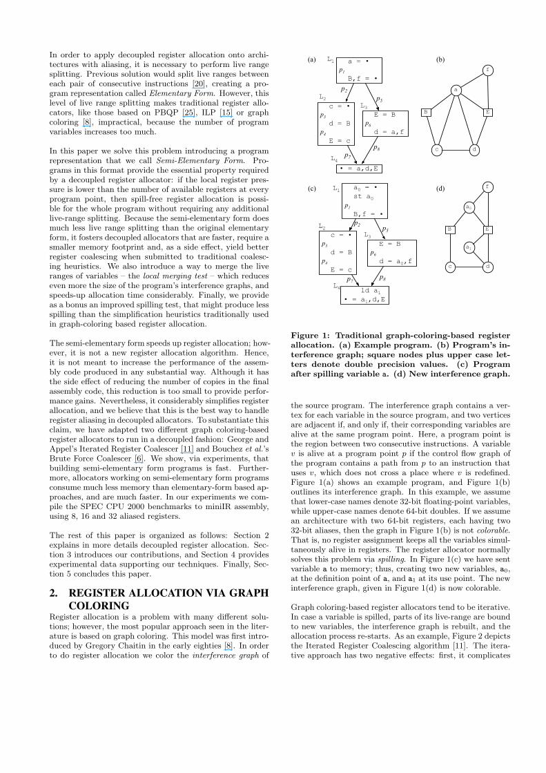
Graph coloring-based register allocators tend to be iterative.In case a variable is spilled, parts of its live-range are boundto new variables, the interference graph is rebuilt, and theallocation process re-starts. As an example, Figure 2 depictsthe Iterated Register Coalescing algorithm [11]. The itera-tive approach has two negative effects: first, it complicates
build
simplify
coalesce freeze potentialspill select
actualspill
rebuild graph if there were actual spills
Figure 2: Iterated register coalescing, as taken fromAppel and Palsberg [2].
the design of the algorithm, as Figure 2 clearly illustrates.Second, it decreases the speed of the algorithms, which mustre-construct, or at least update, the interference graph, andre-do allocation steps that are, in many cases, redundant.
2.1 Decoupled Register AllocationA decoupled register allocator separates the spilling and theregister assignment phases. Hence, once we are done withthe spilling phase, the existence of a register assignment thatkeeps all the live variables in registers is guaranteed. In orderto provide this guarantee, a decoupled algorithm relies onthe following property:
Property 1. The maximum local register pressure at anyprogram point equals the global register pressure.
Property 1 is not present in every program; however, someintermediate representations, such as SSA-form [9] provideit in the absence of aliasing. Due to this property, spilling- the lowering of register pressure - can be done directly onthe code, without the need of a data structure that gives aglobal program view, such as an interference graph. Evenmore, provided that all the registers have the same size,the local register pressure at a given point is the number ofvariables alive at that point; hence, the spill test is reducedto counting the number of variables simultaneously alive. Adecoupled algorithm in general follows these four steps:
1. lower the register pressure at each program point, us-ing any heuristics for variable spilling, i.e [1], until thevariables alive at each point can be colored;
2. use live range splitting to guarantee Property 1. Ingeneral copies with a parallel semantic are used to splitlive-ranges [3, 13]. For an example, see Figure 3(a);
3. assign variables to registers [3, 12]. The register allo-cator must be able to find a way to assign registers tovariables without causing further spills;
4. get rid of φ-functions and parallel copies [4, 21].
Notice that, during the spilling phase it is not necessary todo live range splitting. Instead, for each instruction, we tryto color the interference graph formed by the variables alivein, out and through that instruction, spilling variables untilthis coloring becomes possible.
The advantages of decoupled register allocation: Thefirst advantage is simplicity. Register allocators tend to be
very complicated. As an example, about 20% of the linesof code of LLVM’s [16] machine independent code generatorare exclusively related to register allocation. Thus, from anengineering point of view, it is interesting to design registerallocators that are modular. The decoupled approach fillsthe role very well, because it separates spilling from regis-ter assignment; hence, different heuristics and implementa-tions can be easily combined and independently maintained.From an algorithmic point of view, decoupling simplifies andmakes more effective both spilling and coalescing, becausethese steps have impact on the register pressure, and natu-rally benefit from an easier way to infer this quantity.
The second advantage is a better integration with other com-piler optimizations, due to Property 1. Many compiler op-timizations, such as pre-pass scheduling, if-conversion, codemotion, loop-unroll and jam and partial redundancy elimi-nation, may change the program’s register pressure. Thus,these optimizations have a simpler and faster implementa-tion if its possible to determine changes in register pres-sure accurately via local tests. Traditionally, the calculationof the register pressure at a certain program point needsa global view of the program; however, live range splittingallows it to be computed locally.
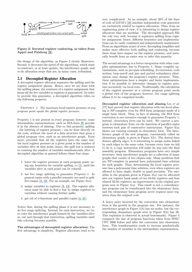
Decoupled register allocation and aliasing Lee et al.[17] have proved that register allocation with two-level alias-ing is NP-complete even for SSA form programs made of asingle basic block. Thus, in face of aliasing, the SSA formconversion is not extensive enough to guarantee Property 1;instead, elementary form can be used. We convert a pro-gram to elementary form via the insertion of parallel copiesbetween each pair of consecutive instructions. Figure 3(a)shows our running example in elementary form. The inter-ference graph of the new program, conveniently called anelementary graph, is given in Figure 3(b). The dotted linesdenote affinity edges: it is interesting to assign nodes linkedby such edges to the same color, because every time we failto do it, a copy instruction will make its way into the finalassembly program. Elementary programs have very simplestructure: their interference graphs are a collection of manygraphs that consist of two cliques only. Many problems thatare NP-complete in general have polynomial time solutionfor such graphs. Thus, determining the local register pres-sure has a polynomial time solution, even when registers areallowed to have single, double or quad precision. The vari-ables in the program given in Figure 3(a) can be allocatedinto our register bank made of two 64-bit registers and fouraliased 32-bit registers; an improvement on the original pro-gram seen in Figure 1(a). This result is not a coincidence:any program can be transformed into the elementary form,and the elementary form program never requires more reg-isters than the original code.
A heavy price incurred by the conversion into elementaryform is the growth in the program size. For instance, theinterference graph in Figure 1(b) has six nodes, but the cor-responding elementary graph seen in Figure 3(b) has 26.This explosion is observed in actual benchmarks. Figure 4compares the size of program functions taken from SPECCPU 2000 before and after the conversion into elementaryform. This transformation tends to increase quadraticallythe number of variables in the intermediate representation.
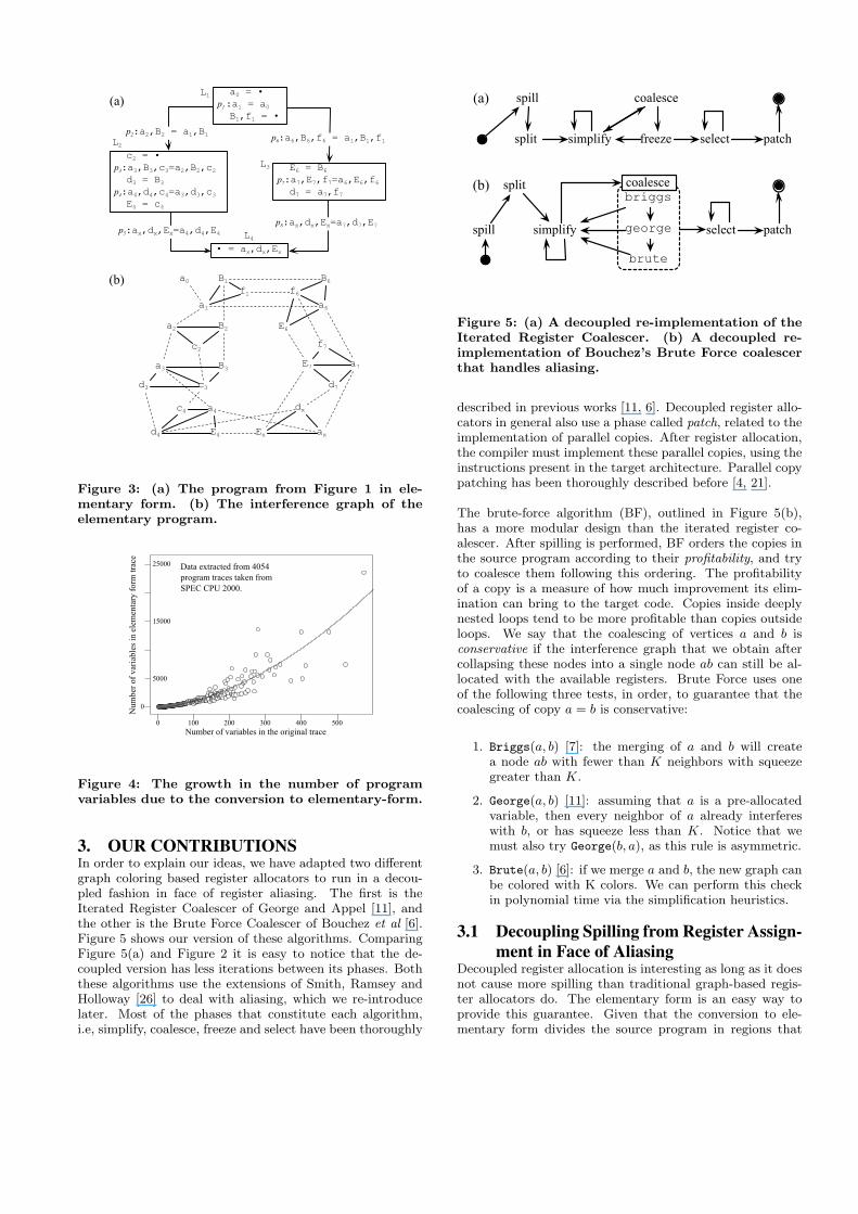
a0 = •p1 :a1 = a0
B1,f1 = •
c2 = •p3:a3,B3,c3=a2,B2,c2
d3 = B3
p4:a4,d4,c4=a3,d3,c3
E4 = c4
• = ax,dx,Ex
E6 = B6
p7:a7,E7,f7=a6,E6,f6
d7 = a7,f7
L1
L2
L3
L4
(a)
p2:a2,B2 = a1,B1 p6:a6,B6,f6 = a1,B1,f1
p8:ax,dx,Ex=a7,d7,E7p5:ax,dx,Ex=a4,d4,E4
a0
a1
B1
a2 B2
c2
a3 B3
c3d3
a4c4
d4 E4
a6
B6
E6
a7E7
d7
axEx
dx
(b)f1 f6
f7
Figure 3: (a) The program from Figure 1 in ele-mentary form. (b) The interference graph of theelementary program.
0
5000
15000
25000
0 100 200 300 400 500Number of variables in the original trace
Num
ber o
f var
iabl
es in
ele
men
tary
form
trac
e
Data extracted from 4054program traces taken fromSPEC CPU 2000.
Figure 4: The growth in the number of programvariables due to the conversion to elementary-form.
3. OUR CONTRIBUTIONSIn order to explain our ideas, we have adapted two differentgraph coloring based register allocators to run in a decou-pled fashion in face of register aliasing. The first is theIterated Register Coalescer of George and Appel [11], andthe other is the Brute Force Coalescer of Bouchez et al [6].Figure 5 shows our version of these algorithms. ComparingFigure 5(a) and Figure 2 it is easy to notice that the de-coupled version has less iterations between its phases. Boththese algorithms use the extensions of Smith, Ramsey andHolloway [26] to deal with aliasing, which we re-introducelater. Most of the phases that constitute each algorithm,i.e, simplify, coalesce, freeze and select have been thoroughly
split simplify
coalesce
freeze select patch
spill
split
simplify patchspill
briggs
george
brute
select
(a)
(b) coalesce
Figure 5: (a) A decoupled re-implementation of theIterated Register Coalescer. (b) A decoupled re-implementation of Bouchez’s Brute Force coalescerthat handles aliasing.
described in previous works [11, 6]. Decoupled register allo-cators in general also use a phase called patch, related to theimplementation of parallel copies. After register allocation,the compiler must implement these parallel copies, using theinstructions present in the target architecture. Parallel copypatching has been thoroughly described before [4, 21].
The brute-force algorithm (BF), outlined in Figure 5(b),has a more modular design than the iterated register co-alescer. After spilling is performed, BF orders the copies inthe source program according to their profitability, and tryto coalesce them following this ordering. The profitabilityof a copy is a measure of how much improvement its elim-ination can bring to the target code. Copies inside deeplynested loops tend to be more profitable than copies outsideloops. We say that the coalescing of vertices a and b isconservative if the interference graph that we obtain aftercollapsing these nodes into a single node ab can still be al-located with the available registers. Brute Force uses oneof the following three tests, in order, to guarantee that thecoalescing of copy a = b is conservative:
1. Briggs(a, b) [7]: the merging of a and b will createa node ab with fewer than K neighbors with squeezegreater than K.
2. George(a, b) [11]: assuming that a is a pre-allocatedvariable, then every neighbor of a already interfereswith b, or has squeeze less than K. Notice that wemust also try George(b, a), as this rule is asymmetric.
3. Brute(a, b) [6]: if we merge a and b, the new graph canbe colored with K colors. We can perform this checkin polynomial time via the simplification heuristics.
3.1 Decoupling Spilling from Register Assign-ment in Face of Aliasing
Decoupled register allocation is interesting as long as it doesnot cause more spilling than traditional graph-based regis-ter allocators do. The elementary form is an easy way toprovide this guarantee. Given that the conversion to ele-mentary form divides the source program in regions that
are very small and simple, the problem of determining thelocal register pressure for each region has polynomial timesolution, at least for architectures with quad, double and sin-gle registers, such as x86, ARM, PowerPC and SPARC. Thepolynomial time solution still holds in face of pre-allocation,a phenomenon caused by architectural constraints that forcevariables to be assigned to particular registers [20].
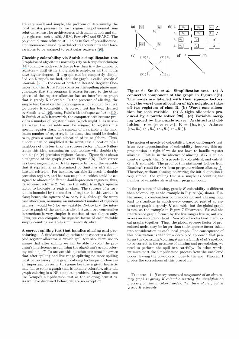
Checking colorability via Smith’s simplification testGraph-based algorithms normally rely on Kempe’s technique[14] to remove nodes with degree less than K – the number ofregisters – until either the graph is empty, or all the nodeshave higher degree. If a graph can be completely simpli-fied via Kempe’s method, then the graph is called greedy Kcolorable [5]. In the case of both the Iterated Register Coa-lescer, and the Brute Force coalescer, the spilling phase mustguarantee that the program it passes forward to the otherphases of the register allocator has an interference graphthat is greedy K colorable. In the presence of aliasing, thesimple test based on the node degree is not enough to checkfor greedy K colorability. A correct test has been devisedby Smith et al. [26], using Fabri’s idea of squeeze factor [10].In Smith et al.’s framework, the computer architecture pro-vides a number of register classes, which might alias in sev-eral ways. Each variable must be assigned to registers in aspecific register class. The squeeze of a variable is the max-imum number of registers, in its class, that could be deniedto it, given a worst case allocation of its neighbors. Thus,a node v can be simplified if the worst case allocation of allneighbors of v is less than v’s squeeze factor. Figure 6 illus-trates this idea, assuming an architecture with double (R)and single (r) precision register classes. Figure 6(a) showsa subgraph of the graph given in Figure 3(b). Each vertexhas been augmented with the squeeze factor of the variablethat it represents, as determined by Smith et al.’s simpli-fication criterion. For instance, variable B6 needs a doubleprecision register, and has two neighbors, which could be as-signed to aliases of different double-precision registers; thus,its squeeze factor is 2. We use the suffix R in B6’s squeezefactor to indicate its register class. The squeeze of a vari-able is bounded by the number of registers in this variable’sclass; hence, the squeeze of a6 or f6 is 4, although the worstcase allocation, assuming an unbounded number of registersin class r would be 5 for any variable. Notice that the inter-ference graph of the variables alive between two consecutiveinstructions is very simple: it consists of two cliques only.Thus, we can compute the squeeze factor of each variablesimply counting variables simultaneously alive.
A correct spilling test that handles aliasing and pre-coloring: A fundamental question that concerns a decou-pled register allocator is “which spill test should we use toensure that after spilling we will be able to color the pro-gram’s interference graph using the algorithm’s graph color-ing technique?” To answer this question one must be awarethat after spilling and live range splitting no more spillingmust be necessary. The graph coloring technique of choice isan important player in this game because a given heuristicmay fail to color a graph that is actually colorable, after all,graph coloring is a NP-complete problem. Many allocatorsuse Kempe’s simplification test as the coloring heuristics.As we have discussed before, we are no exception.
a6
B6
E6
f6 a6
B6
E6
f6
f6
a6E6B6
E6B6
a6 f6
(b)
(c)
(a)
a6 f6
✓✓✓✓
a6
E6/B6f6(d)
2R
2R
4r
4r
(r1)a6
(R1)B6
(R1)E6
(r0)f6
Figure 6: Smith et al. Simplification test. (a) Aconnected component of the graph in Figure 3(b).The nodes are labelled with their squeeze factors,e.g., the worst case allocation of E6’s neighbors takesoff two registers of class R. (b) Worst case alloca-tion for each variable. (c) A tight allocation pro-duced by a puzzle solver [20]. (d) Variable merg-ing guided by the puzzle solver. Architectural def-inition: r = {r0, r1, r2, r3}, R = {R0, R1}. Aliases:{(r0, R0), (r1, R0), (r2, R1), (r3, R1)}.
The notion of greedy K colorability, based on Kempe’s test,is an over-approximation of colorability; however, this ap-proximation is tight if we do not have to handle registeraliasing. That is, in the absence of aliasing, if G is an ele-mentary graph, then G is greedy K colorable if, and only if,G is K colorable. The proof of this statement follows fromBouchez’s result for SSA-form programs without aliasing [5].Therefore, without aliasing, answering the initial question isvery simple: the spilling test is a simple as counting thenumber of variables alive at each program point.
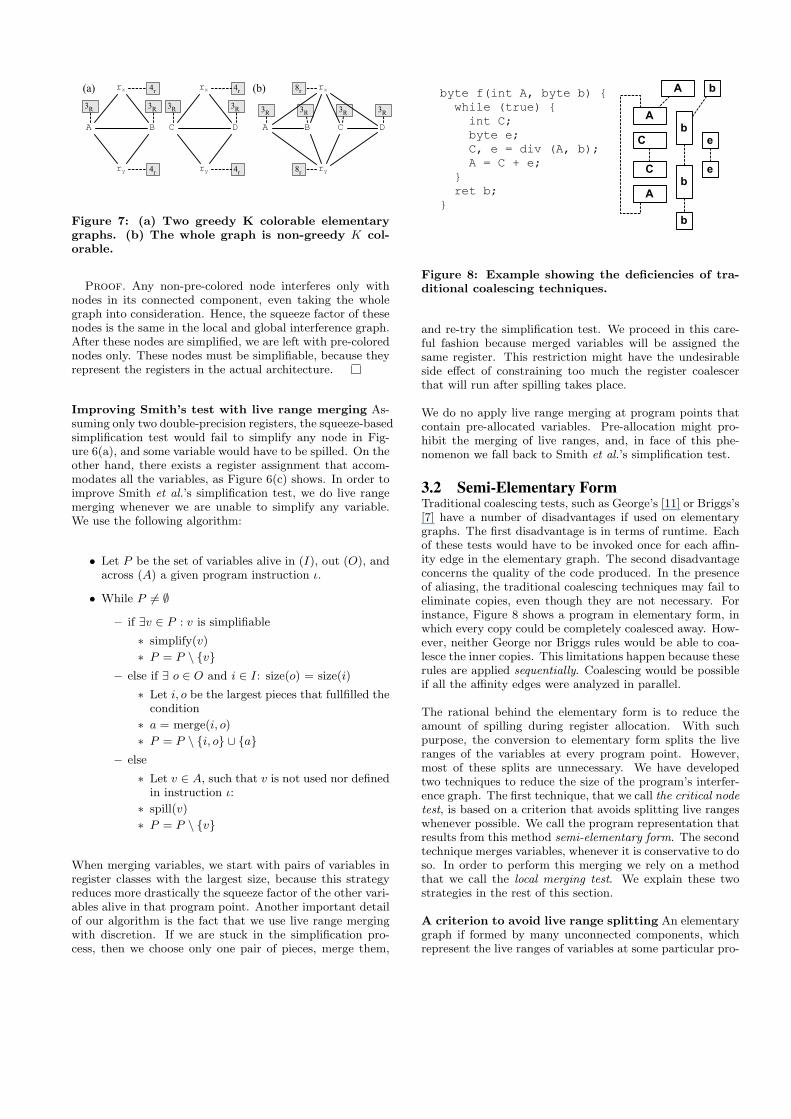
In the presence of aliasing, greedy K colorability is differentthan colorability, as the example in Figure 6(a) shows. Fur-thermore, a combination of pre-coloring and aliasing maylead to situations in which every connected part of an ele-mentary graph is greedy K colorable, but the global graphis not, as the example in Figure 7 illustrates. We call theinterference graph formed by the live ranges live in, out andacross an instruction local. Pre-colored nodes bind many lo-cal graphs together. Thus, the global squeeze factor of pre-colored nodes may be larger than their squeeze factor takeninto consideration at each local graph. The consequence ofthis observation is that for a decoupled approach that per-forms the coalescing/coloring steps via Smith et al.’s methodto be correct in the presence of aliasing and pre-coloring, weneed to perform the spill test carefully. In other words,we must start the simplification process from the uncolorednodes, leaving the pre-colored nodes to the end. Theorem 1proves the correctness of this procedure.
Theorem 1. If every connected component of an elemen-tary graph is greedy K colorable starting the simplificationprocess from the uncolored nodes, then then whole graph isgreedy K colorable.
4r
4r
3R 3R
8r
3R 3R 3R 3R
8r
B
rx
ry
A
(b)(a)
B
rx
ry
A DC
4r
4r
3R 3R
D
rx
ry
C
Figure 7: (a) Two greedy K colorable elementarygraphs. (b) The whole graph is non-greedy K col-orable.
Proof. Any non-pre-colored node interferes only withnodes in its connected component, even taking the wholegraph into consideration. Hence, the squeeze factor of thesenodes is the same in the local and global interference graph.After these nodes are simplified, we are left with pre-colorednodes only. These nodes must be simplifiable, because theyrepresent the registers in the actual architecture.
Improving Smith’s test with live range merging As-suming only two double-precision registers, the squeeze-basedsimplification test would fail to simplify any node in Fig-ure 6(a), and some variable would have to be spilled. On theother hand, there exists a register assignment that accom-modates all the variables, as Figure 6(c) shows. In order toimprove Smith et al.’s simplification test, we do live rangemerging whenever we are unable to simplify any variable.We use the following algorithm:
• Let P be the set of variables alive in (I), out (O), andacross (A) a given program instruction ι.
• While P 6= ∅
– if ∃v ∈ P : v is simplifiable
∗ simplify(v)
∗ P = P \ {v}– else if ∃ o ∈ O and i ∈ I: size(o) = size(i)
∗ Let i, o be the largest pieces that fullfilled thecondition
∗ a = merge(i, o)
∗ P = P \ {i, o} ∪ {a}– else
∗ Let v ∈ A, such that v is not used nor definedin instruction ι:
∗ spill(v)
∗ P = P \ {v}
When merging variables, we start with pairs of variables inregister classes with the largest size, because this strategyreduces more drastically the squeeze factor of the other vari-ables alive in that program point. Another important detailof our algorithm is the fact that we use live range mergingwith discretion. If we are stuck in the simplification pro-cess, then we choose only one pair of pieces, merge them,
A b
Ab
C e
Cb
A
e
b
byte f(int A, byte b) { while (true) { int C; byte e; C, e = div (A, b); A = C + e; } ret b;}
Figure 8: Example showing the deficiencies of tra-ditional coalescing techniques.
and re-try the simplification test. We proceed in this care-ful fashion because merged variables will be assigned thesame register. This restriction might have the undesirableside effect of constraining too much the register coalescerthat will run after spilling takes place.
We do no apply live range merging at program points thatcontain pre-allocated variables. Pre-allocation might pro-hibit the merging of live ranges, and, in face of this phe-nomenon we fall back to Smith et al.’s simplification test.
3.2 Semi-Elementary FormTraditional coalescing tests, such as George’s [11] or Briggs’s[7] have a number of disadvantages if used on elementarygraphs. The first disadvantage is in terms of runtime. Eachof these tests would have to be invoked once for each affin-ity edge in the elementary graph. The second disadvantageconcerns the quality of the code produced. In the presenceof aliasing, the traditional coalescing techniques may fail toeliminate copies, even though they are not necessary. Forinstance, Figure 8 shows a program in elementary form, inwhich every copy could be completely coalesced away. How-ever, neither George nor Briggs rules would be able to coa-lesce the inner copies. This limitations happen because theserules are applied sequentially. Coalescing would be possibleif all the affinity edges were analyzed in parallel.
The rational behind the elementary form is to reduce theamount of spilling during register allocation. With suchpurpose, the conversion to elementary form splits the liveranges of the variables at every program point. However,most of these splits are unnecessary. We have developedtwo techniques to reduce the size of the program’s interfer-ence graph. The first technique, that we call the critical nodetest, is based on a criterion that avoids splitting live rangeswhenever possible. We call the program representation thatresults from this method semi-elementary form. The secondtechnique merges variables, whenever it is conservative to doso. In order to perform this merging we rely on a methodthat we call the local merging test. We explain these twostrategies in the rest of this section.
A criterion to avoid live range splitting An elementarygraph if formed by many unconnected components, whichrepresent the live ranges of variables at some particular pro-
gram point. Therefore, we expect a lot of redundancies be-tween graphs formed from consecutive instructions. Giventwo instructions, the guider and the follower, all the verticesthat correspond to variables live-in at the follower are con-nected through affinity edges to the vertices in the guider.The only vertices in the follower’s graph which have no affini-ties for vertices in the guider’s are those nodes that representvariables defined in the follower instruction. We call themcritical nodes. Normally an instruction defines at most onevariable; hence, we expect to find at most one critical node inthe follower, and this test can be performed quickly. Thereexist, of course, architectures which contains instructionsthat write into more than one register. For instance, in x86we have mul, div, lodsb, etc. In this case, we must performthe critical node test once for each variable defined in theinstruction. In light of these observations, our criterion toavoid live range splitting is as follows:
The critical node test: if every critical vertexin the follower’s graph has a squeeze factor lessthan K, then it is not necessary to insert a par-allel copy between guider and follower to achieveProperty 1.
Theorem 2. Let Gg and Gf be the interference graph atthe guider and the follower, as previously defined. If Gg isgreedy K colorable, then the graph that results from mergingGg and Gf via the critical node test is greedy K colorable.
Proof. The proof is straightforward: if the merging isdone, the resulting graph is formed by all the nodes fromGg plus the critical nodes in the follower. Because of ourcriterion we know that every critical node can be simplified.Once they are simplified, we fall back into Gg, which, byhypothesis, is greedy K colorable.
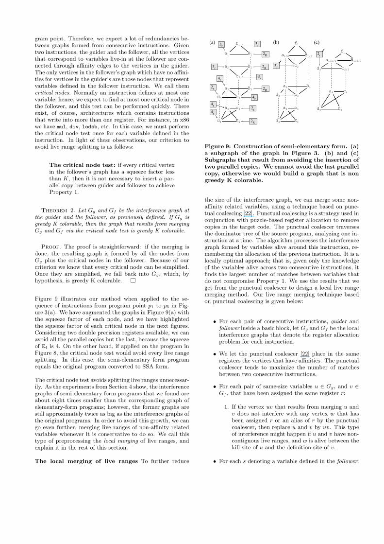
Figure 9 illustrates our method when applied to the se-quence of instructions from program point p1 to p5 in Fig-ure 3(a). We have augmented the graphs in Figure 9(a) withthe squeeze factor of each node, and we have highlightedthe squeeze factor of each critical node in the next figures.Considering two double precision registers available, we canavoid all the parallel copies but the last, because the squeezeof E4 is 4. On the other hand, if applied on the program inFigure 8, the critical node test would avoid every live rangesplitting. In this case, the semi-elementary form programequals the original program converted to SSA form.
The critical node test avoids splitting live ranges unnecessar-ily. As the experiments from Section 4 show, the interferencegraphs of semi-elementary form programs that we found areabout eight times smaller than the corresponding graph ofelementary-form programs; however, the former graphs arestill approximately twice as big as the interference graphs ofthe original programs. In order to avoid this growth, we cango even further, merging live ranges of non-affinity relatedvariables whenever it is conservative to do so. We call thistype of preprocessing the local merging of live ranges, andexplain it in the rest of this section.
The local merging of live ranges To further reduce
a1/2 B1/2
c2
f1
a1 B1
a2 B2
c2
f1
a3 B3
c3d3
a4 c4
d4 E4
a3 B3
c3d3
a4 c4
d4 E4
f1
a1/2/3 B1/2/3
c2/3d3
a4 c4
d4 E4
3r
2R
3r
3r 2R
3r4r
2r 2R
4r
2r4r4r
2R
3r
2r
(a) (b) (c)✓
✓
Figure 9: Construction of semi-elementary form. (a)a subgraph of the graph in Figure 3. (b) and (c)Subgraphs that result from avoiding the insertion oftwo parallel copies. We cannot avoid the last parallelcopy, otherwise we would build a graph that is nongreedy K colorable.
the size of the interference graph, we can merge some non-affinity related variables, using a technique based on punc-tual coalescing [22]. Punctual coalescing is a strategy used inconjunction with puzzle-based register allocation to removecopies in the target code. The punctual coalescer traversesthe dominator tree of the source program, analyzing one in-struction at a time. The algorithm processes the interferencegraph formed by variables alive around this instruction, re-membering the allocation of the previous instruction. It is alocally optimal approach; that is, given only the knowledgeof the variables alive across two consecutive instructions, itfinds the largest number of matches between variables thatdo not compromise Property 1. We use the results that weget from the punctual coalescer to design a local live rangemerging method. Our live range merging technique basedon punctual coalescing is given below:
• For each pair of consecutive instructions, guider andfollower inside a basic block, let Gg and Gf be the localinterference graphs that denote the register allocationproblem for each instruction.
• We let the punctual coalescer [22] place in the sameregisters the vertices that have affinities. The punctualcoalescer tends to maximize the number of matchesbetween two consecutive instructions.
• For each pair of same-size variables u ∈ Gg, and v ∈Gf , that have been assigned the same register r:
1. If the vertex uv that results from merging u andv does not interfere with any vertex w that hasbeen assigned r or an alias of r by the punctualcoalescer, then replace u and v by uv. This typeof interference might happen if u and v have non-contiguous live ranges, and w is alive between thekill site of u and the definition site of v.
• For each s denoting a variable defined in the follower:
a0d0
f0C0
g1e1
f1C1b1
a0C0
C1
f0d0
f1g1 e1b1
C0 = d0
b1,e1,g1 = f1,C1
Live in: a0, d0
Live out: b1, e1, g1
(a) (b)
(c) (d)
p1: C1,f1 = C0,f0
a0 C0/1
d0e1
f0f1g1
b1
Figure 10: A constructed example showing punctualmerging. (a) The elementary-form program. (b)The interference graph. (c) The solution of punctualcoalescing. (d) The solution of punctual merging.
1. If s has a squeeze factor greater than the numberof registers in the register class of s, then undoevery merging of the previous step.
We only merge live ranges inside the same basic block, be-cause, by merging non-affinity related variables, we mayeliminate coalescing opportunities. As we show in Section 4,punctual merging decreases the capacity of both, the Iter-ated Register Coalescer and the Brute Force coalescer toeliminate copies in the final assembly code. Figure 10 illus-trates punctual merging. We have used a different examplethis time, because our running example from Figure 3 isnot complex enough to exercise the interesting aspects ofpunctual merging. Notice that the critical node test, whenapplied on Figure 10(b) would only merge the variables C’sand f’s. However, assuming a solution of punctual coalesc-ing that places variables f0, f1 and g1 into the same column,we can also merge these pieces. The same happen with –non-contiguous – variables d0 and e1. On the other hand,we cannot merge variables a0 and b1, because C0 and C1
have been allocated to aliased of the registers assigned to a0
and b1. If we merged a0 and b1, then the resulting variablewould interfere with both C0 and C1.
4. EXPERIMENTSTesting environment: The algorithms were implementedin Python, producing code to a prototype architecture calledMiniIR 1, which is based on the YAML 2 serialization for-mat. YAML is used by STMicroelectronics Inc to quicklyprototype hardware. MiniIR provides a minimalist textualmachine level intermediate representation to be used for ex-perimental tools. We report numbers for the x86 architec-ture, which we described in miniIR (Figures 13, 14 and 15),
1http://www.assembla.com/wiki/show/bE6Ve4RQir36HFeJe5cbLr2http://www.yaml.org/
0
1
2
3
4
5
6
7
8
9
10
Input Elementary Semi‐Elementary Local‐Merging
8registers 16registers 32registers
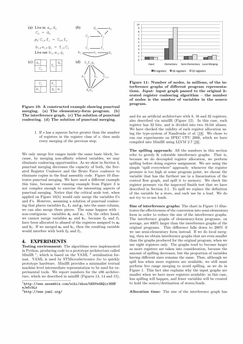
Figure 11: Number of nodes, in millions, of the in-terference graphs of different program representa-tions. Input: input graph passed to the original it-erated register coalescing algorithm – the numberof nodes is the number of variables in the sourceprogram.
and for an artificial architecture with 8, 16 and 32 registers,also described via miniIR (Figure 12). In this case, eachregister has 32 bits, and is divided into two 16-bit aliases.We have checked the validity of each register allocation us-ing the type-system of Nandivada et al. [18]. We chose torun our experiments on SPEC CPU 2000, which we havecompiled into MiniIR using LLVM 2.7 [16].
The spilling approach: All the numbers in this sectionrefer to greedy K colorable interference graphs. That is,because we do decoupled register allocation, we performspilling before doing register assignment. We are using thesimple “spill everywhere” approach: whenever the registerpressure is too high at some program point, we choose thevariable that has the furthest use in a linearization of thecontrol flow graph, and spill it to memory. We check theregister pressure via the improved Smith test that we havedescribed in Section 3.1. To spill we replace the definitionof the variable by a store, and each use by a load. We donot try to re-use loads.
Size of interference graphs: The chart in Figure 11 illus-trates the effectiveness of the conversion into semi-elementaryform in order to reduce the size of the interference graphs.The interference graphs of elementary-form programs, onaverage, are 800% larger than the interference graphs of theoriginal programs. This difference falls down to 200% ifwe use semi-elementary form instead. If we do local merg-ing, then we obtain interference graphs that are even smallerthan the graphs produced for the original program, when weuse eight registers only. The graphs tend to become largeras more registers are taken into consideration, because theamount of spilling decreases, but the proportion of variableshaving different sizes remains the same. Thus, although wespill less when more registers are available, we still mustperform live range merging to avoid spilling, as we do inFigure 1. This fact also explains why the input graphs aresmaller when we have more registers available: in this case,less spilling will happen, and fewer variables will be createdto hold the source/destination of stores/loads.
Allocation time: The size of the interference graph has

0
10
20
30
40
50
60
8registers 16registers 32registers
Elementary Semi‐Elementary Local‐Merging
Figure 12: Allocation time, in hundreds of seconds,for different kinds of interference graphs.
a direct impact on the allocation time, as Figure 12 shows.Considering eight registers only, allocation in semi-elementa-ry form is 3.1 times faster than in elementary form. Thisdifferent increases to 3.3 times if we perform local live rangemerging. With 32 registers the difference is even larger.Semi-elementary form speeds-up register allocation by a fac-tor of 4.7x, and local merging moves this factor to 5.5x.
To put these results in perspective, let’s consider the largestfunction that we found in our benchmark, assuming eightregisters. This function, in SSA-form, has 10,163 variables.The interference graph of the elementary program contains99,364 nodes. On this graph, IRC takes 4,544 seconds. Thisis 49.40x slower than the punctual coalescer [22], which doesnot build an interference graph. The semi-elementary formprogram has an interference graph with 19,024 nodes. Inthis case, IRC is 5,30 times slower than the punctual coa-lescer. After local live range merging we have a graph with13,764 nodes, in which IRC is 1.82x slower than punctualcoalescing. Thus, IRC is 27.2x faster on a graph after locallive range merging than on an elementary graph.
Measuring the effectiveness of live range mergingon the register coalescers The semi-elementary form im-proves the effectiveness of copy coalescing, as we show inFigures 13, 14 and 15. Figure 13 shows only the result ofIRC using Smith et al.’s [26] extensions, implemented ac-cording to Figure 5(a). The algorithm executing over el-ementary graphs left 3418 copies on the SPEC CPU 2000programs. On semi-elementary form this number falls downto 3221 copies. If we perform local live range merging onthe source programs, then IRC leaves 4133 copies on theassembly code. In these experiments we count only copiesinserted into the program to do live range splitting; that is,we do not count the copy instructions that were part of thesource program, even though many of them were coalescedtoo. In this way, we focus on the ability of the allocatorsto handle aliasing. The local live range merging decreasesthe coalescing power of IRC, when compared to the resultsthat we obtain by using semi-elementary form. We spec-ulate that this fact happens because the punctual mergingconstraints too much the interference graph, creating nodeswith larger squeeze factors.
Figure 14 shows the effectiveness of the brute force coa-lescer implemented using the modifications from Section 3,
0
400
800
1200
1600
2000
gcc
bzip2
gap
cra0
mcf
vpr
gzip
vortex
parser
twolf
Elementary Semi‐Elementary LocalMerging
Figure 13: Number of copy instructions left by theiterated register coalescer (IRC) when running ondifferent program representations.
0
300
600
900
1200
1500
gcc
bzip2
gap
cra1
mcf
vpr
gzip
vortex
parser
twolf
Elementary Semi‐Elementary LocalMerging
Figure 14: Number of copy instructions left by thebrute force coalescer (BF) when running on differentprogram representations.
following Figure 5(b). Running the algorithm directly onelementary-form or semi-elementary form programs leaves2803 copies on the final assembly code produced by the al-gorithm. Local live range merging degrades the ability ofthe coalescer to eliminate copies. In this case, BF leaves3503 copies on the assembly programs.
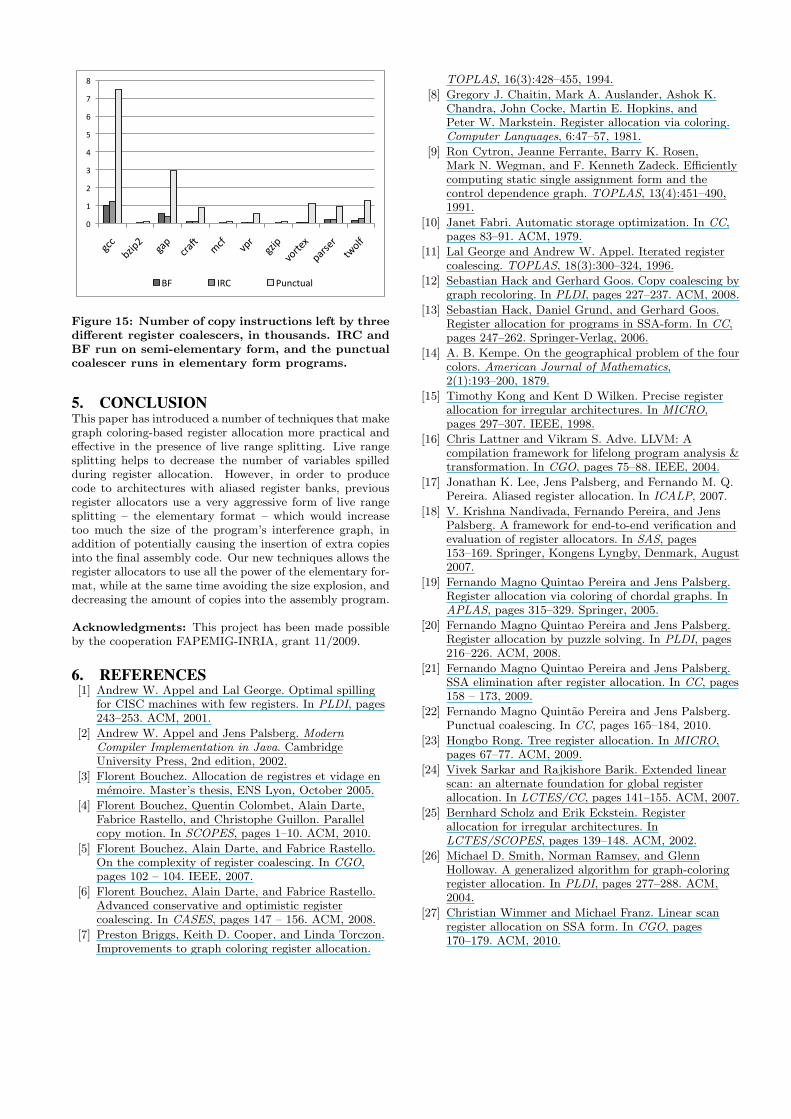
Figure 15 compares the three algorithms: brute force (BF),iterated register coalescing (IRC) and punctual coalescing[22] in terms of the number of copies that each algorithmeliminates via coalescing. We have chosen the best configu-ration for each algorithm: IRC and BF run after simple liverange merging, while punctual coalescing can only run onelementary-form programs. Confirming previous results [6,22], the brute force coalescer is the most effective algorithm,followed by IRC. Confirming previous results [20], the punc-tual coalescer increases the final assembly programs by 6.8%on average. This relatively bad result of the punctual coa-lescer is due to the fact that it is a local approach, whichdoes not attempt to eliminate copies between basic blocks.
0
1
2
3
4
5
6
7
8
gcc
bzip2
gap
cra3
mcf
vpr
gzip
vortex
parser
twolf
BF IRC Punctual
Figure 15: Number of copy instructions left by threedifferent register coalescers, in thousands. IRC andBF run on semi-elementary form, and the punctualcoalescer runs in elementary form programs.
5. CONCLUSIONThis paper has introduced a number of techniques that makegraph coloring-based register allocation more practical andeffective in the presence of live range splitting. Live rangesplitting helps to decrease the number of variables spilledduring register allocation. However, in order to producecode to architectures with aliased register banks, previousregister allocators use a very aggressive form of live rangesplitting – the elementary format – which would increasetoo much the size of the program’s interference graph, inaddition of potentially causing the insertion of extra copiesinto the final assembly code. Our new techniques allows theregister allocators to use all the power of the elementary for-mat, while at the same time avoiding the size explosion, anddecreasing the amount of copies into the assembly program.
Acknowledgments: This project has been made possibleby the cooperation FAPEMIG-INRIA, grant 11/2009.
6. REFERENCES[1] Andrew W. Appel and Lal George. Optimal spilling
for CISC machines with few registers. In PLDI, pages243–253. ACM, 2001.
[2] Andrew W. Appel and Jens Palsberg. ModernCompiler Implementation in Java. CambridgeUniversity Press, 2nd edition, 2002.
[3] Florent Bouchez. Allocation de registres et vidage enmemoire. Master’s thesis, ENS Lyon, October 2005.
[4] Florent Bouchez, Quentin Colombet, Alain Darte,Fabrice Rastello, and Christophe Guillon. Parallelcopy motion. In SCOPES, pages 1–10. ACM, 2010.
[5] Florent Bouchez, Alain Darte, and Fabrice Rastello.On the complexity of register coalescing. In CGO,pages 102 – 104. IEEE, 2007.
[6] Florent Bouchez, Alain Darte, and Fabrice Rastello.Advanced conservative and optimistic registercoalescing. In CASES, pages 147 – 156. ACM, 2008.
[7] Preston Briggs, Keith D. Cooper, and Linda Torczon.Improvements to graph coloring register allocation.
TOPLAS, 16(3):428–455, 1994.
[8] Gregory J. Chaitin, Mark A. Auslander, Ashok K.Chandra, John Cocke, Martin E. Hopkins, andPeter W. Markstein. Register allocation via coloring.Computer Languages, 6:47–57, 1981.
[9] Ron Cytron, Jeanne Ferrante, Barry K. Rosen,Mark N. Wegman, and F. Kenneth Zadeck. Efficientlycomputing static single assignment form and thecontrol dependence graph. TOPLAS, 13(4):451–490,1991.
[10] Janet Fabri. Automatic storage optimization. In CC,pages 83–91. ACM, 1979.
[11] Lal George and Andrew W. Appel. Iterated registercoalescing. TOPLAS, 18(3):300–324, 1996.
[12] Sebastian Hack and Gerhard Goos. Copy coalescing bygraph recoloring. In PLDI, pages 227–237. ACM, 2008.
[13] Sebastian Hack, Daniel Grund, and Gerhard Goos.Register allocation for programs in SSA-form. In CC,pages 247–262. Springer-Verlag, 2006.
[14] A. B. Kempe. On the geographical problem of the fourcolors. American Journal of Mathematics,2(1):193–200, 1879.
[15] Timothy Kong and Kent D Wilken. Precise registerallocation for irregular architectures. In MICRO,pages 297–307. IEEE, 1998.
[16] Chris Lattner and Vikram S. Adve. LLVM: Acompilation framework for lifelong program analysis &transformation. In CGO, pages 75–88. IEEE, 2004.
[17] Jonathan K. Lee, Jens Palsberg, and Fernando M. Q.Pereira. Aliased register allocation. In ICALP, 2007.
[18] V. Krishna Nandivada, Fernando Pereira, and JensPalsberg. A framework for end-to-end verification andevaluation of register allocators. In SAS, pages153–169. Springer, Kongens Lyngby, Denmark, August2007.
[19] Fernando Magno Quintao Pereira and Jens Palsberg.Register allocation via coloring of chordal graphs. InAPLAS, pages 315–329. Springer, 2005.
[20] Fernando Magno Quintao Pereira and Jens Palsberg.Register allocation by puzzle solving. In PLDI, pages216–226. ACM, 2008.
[21] Fernando Magno Quintao Pereira and Jens Palsberg.SSA elimination after register allocation. In CC, pages158 – 173, 2009.
[22] Fernando Magno Quintao Pereira and Jens Palsberg.Punctual coalescing. In CC, pages 165–184, 2010.
[23] Hongbo Rong. Tree register allocation. In MICRO,pages 67–77. ACM, 2009.
[24] Vivek Sarkar and Rajkishore Barik. Extended linearscan: an alternate foundation for global registerallocation. In LCTES/CC, pages 141–155. ACM, 2007.
[25] Bernhard Scholz and Erik Eckstein. Registerallocation for irregular architectures. InLCTES/SCOPES, pages 139–148. ACM, 2002.
[26] Michael D. Smith, Norman Ramsey, and GlennHolloway. A generalized algorithm for graph-coloringregister allocation. In PLDI, pages 277–288. ACM,2004.
[27] Christian Wimmer and Michael Franz. Linear scanregister allocation on SSA form. In CGO, pages170–179. ACM, 2010.
Copyright © 2022 FDOKUMEN