Study of Stability Analysis of a Grid-Connected Doubly Fed ...
Upload
khangminh22Category
view
0download
0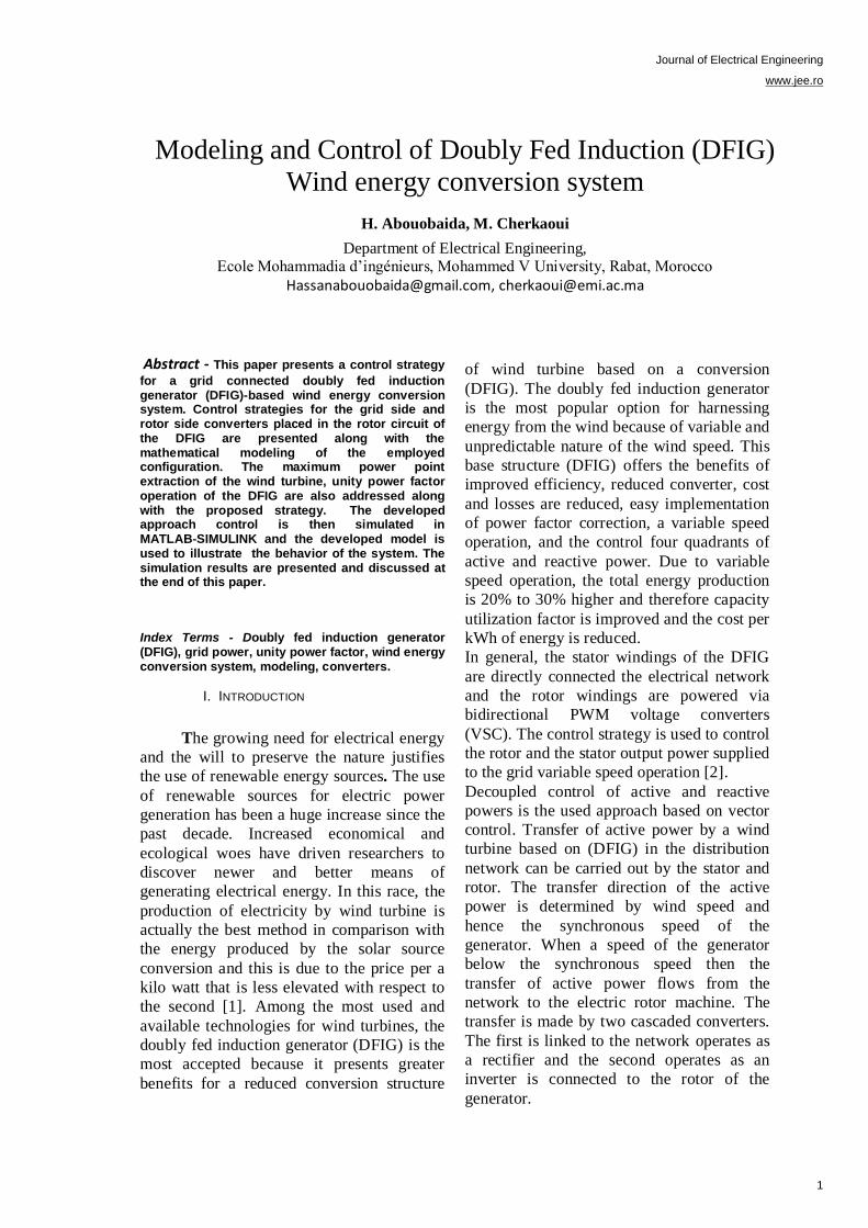
Journal of Electrical Engineering
www.jee.ro
Abstract - This paper presents a control strategy
for a grid connected doubly fed induction generator (DFIG)-based wind energy conversion system. Control strategies for the grid side and rotor side converters placed in the rotor circuit of the DFIG are presented along with the mathematical modeling of the employed configuration. The maximum power point extraction of the wind turbine, unity power factor operation of the DFIG are also addressed along with the proposed strategy. The developed approach control is then simulated in MATLAB-SIMULINK and the developed model is used to illustrate the behavior of the system. The simulation results are presented and discussed at the end of this paper.
Index Terms - Doubly fed induction generator (DFIG), grid power, unity power factor, wind energy conversion system, modeling, converters.
I. INTRODUCTION
The growing need for electrical energy
and the will to preserve the nature justifies
the use of renewable energy sources. The use
of renewable sources for electric power
generation has been a huge increase since the
past decade. Increased economical and
ecological woes have driven researchers to
discover newer and better means of
generating electrical energy. In this race, the
production of electricity by wind turbine is
actually the best method in comparison with
the energy produced by the solar source
conversion and this is due to the price per a
kilo watt that is less elevated with respect to
the second [1]. Among the most used and
available technologies for wind turbines, the
doubly fed induction generator (DFIG) is the
most accepted because it presents greater
benefits for a reduced conversion structure
and efficient energy capture due to variable
speed operation.
of wind turbine based on a conversion
(DFIG). The doubly fed induction generator
is the most popular option for harnessing
energy from the wind because of variable and
unpredictable nature of the wind speed. This
base structure (DFIG) offers the benefits of
improved efficiency, reduced converter, cost
and losses are reduced, easy implementation
of power factor correction, a variable speed
operation, and the control four quadrants of
active and reactive power. Due to variable
speed operation, the total energy production
is 20% to 30% higher and therefore capacity
utilization factor is improved and the cost per
kWh of energy is reduced.
In general, the stator windings of the DFIG
are directly connected the electrical network
and the rotor windings are powered via
bidirectional PWM voltage converters
(VSC). The control strategy is used to control
the rotor and the stator output power supplied
to the grid variable speed operation [2].
Decoupled control of active and reactive
powers is the used approach based on vector
control. Transfer of active power by a wind
turbine based on (DFIG) in the distribution
network can be carried out by the stator and
rotor. The transfer direction of the active
power is determined by wind speed and
hence the synchronous speed of the
generator. When a speed of the generator
below the synchronous speed then the
transfer of active power flows from the
network to the electric rotor machine. The
transfer is made by two cascaded converters.
The first is linked to the network operates as
a rectifier and the second operates as an
inverter is connected to the rotor of the
generator.
Modeling and Control of Doubly Fed Induction (DFIG)
Wind energy conversion system
H. Abouobaida, M. Cherkaoui
Department of Electrical Engineering, Ecole Mohammadia d’ingénieurs, Mohammed V University, Rabat, Morocco
[email protected], [email protected]
1
Journal of Electrical Engineering
www.jee.ro
The Wind energy conversion system
configuration used in this work (DFIG with
converters cascade and a capacity energy
storage system in the dc link) is shown in
Fig. 1.
This paper is structured as follows. Section II
presents the modeling of the DFIG system.
The detailed control strategy is discussed in
Section III. Section IV presents and discusses
simulation and results followed by
conclusions in Section V.
II. Wind energy conversion system modeling
The wind turbine modeling is inspired
from [3]. In the following, the wind turbine
components models are briefly described.
a) The Turbine Model
The aerodynamic power P captured by the
wind turbine is given by :
(1)
Where the tip speed ratio λ is given by :
(2)
and v is the wind, ρ is the air density, R is the
rotor radius, and Cp is the power coefficient.
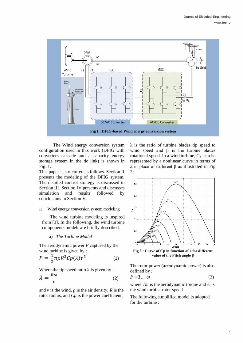
λ is the ratio of turbine blades tip speed to
wind speed and β is the turbine blades
rotational speed. In a wind turbine, Cp can be
represented by a nonlinear curve in terms of
λ in place of different β as illustrated in Fig
2:
Fig 2 : Curve of Cp in function of λ for different
value of the Pitch angle β
The rotor power (aerodynamic power) is also
defined by :
P =Tm . ω (3)
where Tm is the aerodynamic torque and ω is
the wind turbine rotor speed.
The following simplified model is adopted
for the turbine :
Fig 1 : DFIG-based Wind energy conversion system
2
Journal of Electrical Engineering
www.jee.ro
(4)
where Tem is the generator electromagnetic
torque, J is the turbine total inertia, and K is
the turbine total external damping.
The active and reactive stator and rotor
powers are expressed by:
(5)
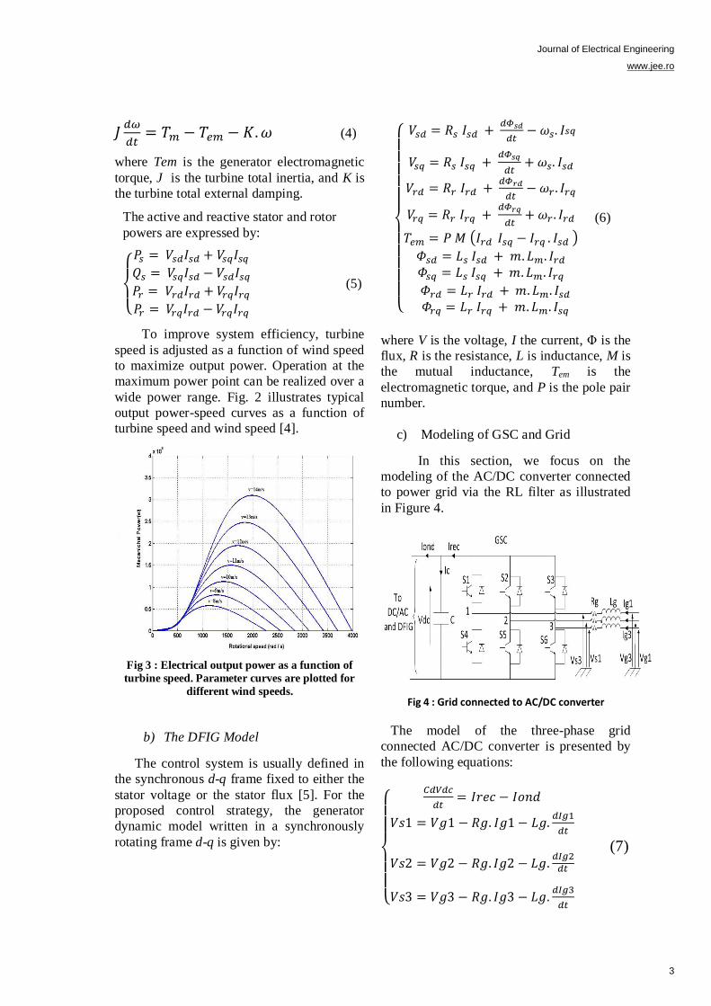
To improve system efficiency, turbine
speed is adjusted as a function of wind speed
to maximize output power. Operation at the
maximum power point can be realized over a
wide power range. Fig. 2 illustrates typical
output power-speed curves as a function of
turbine speed and wind speed [4].
Fig 3 : Electrical output power as a function of
turbine speed. Parameter curves are plotted for
different wind speeds.
b) The DFIG Model
The control system is usually defined in
the synchronous d-q frame fixed to either the
stator voltage or the stator flux [5]. For the
proposed control strategy, the generator
dynamic model written in a synchronously
rotating frame d-q is given by:
(6)
where V is the voltage, I the current, Φ is the
flux, R is the resistance, L is inductance, M is
the mutual inductance, Tem is the
electromagnetic torque, and P is the pole pair
number.
c) Modeling of GSC and Grid
In this section, we focus on the
modeling of the AC/DC converter connected
to power grid via the RL filter as illustrated
in Figure 4.
Fig 4 : Grid connected to AC/DC converter
The model of the three-phase grid
connected AC/DC converter is presented by
the following equations:
(7)
3
Journal of Electrical Engineering
www.jee.ro
With
Vgi : voltages of the electrical network,
Igi : currents of electrical network,
Irec, Iond : output current of the AC/DC
converter and input current of the DC/AC
converter respectively,
Vdc, Ic : voltage and current of the DC link
capacitor respectively
Vsi : input voltages of the AC/DC converter
Si : IGBT transistor
III. Control Strategy
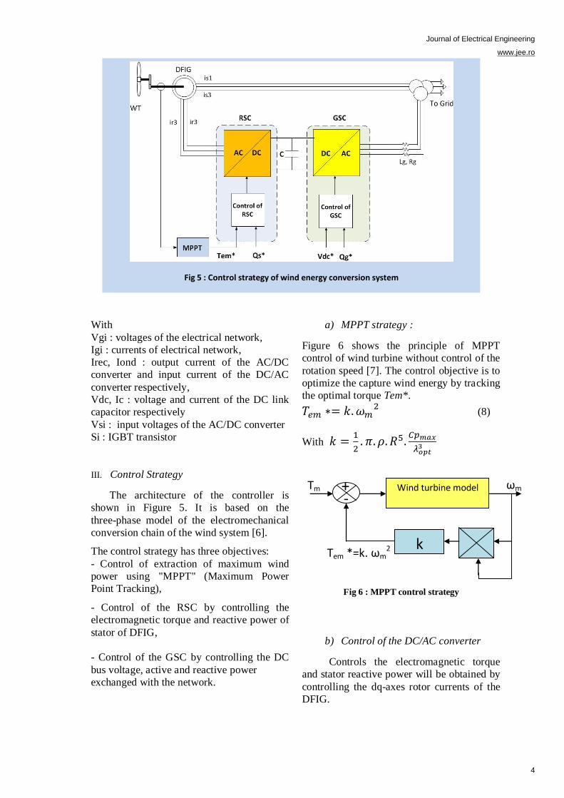
The architecture of the controller is
shown in Figure 5. It is based on the
three-phase model of the electromechanical
conversion chain of the wind system [6].
The control strategy has three objectives:
- Control of extraction of maximum wind
power using "MPPT" (Maximum Power
Point Tracking),
- Control of the RSC by controlling the
electromagnetic torque and reactive power of
stator of DFIG,
- Control of the GSC by controlling the DC
bus voltage, active and reactive power
exchanged with the network.
a) MPPT strategy :
Figure 6 shows the principle of MPPT
control of wind turbine without control of the
rotation speed [7]. The control objective is to
optimize the capture wind energy by tracking
the optimal torque Tem*.
(8)
With
Fig 6 : MPPT control strategy
b) Control of the DC/AC converter
Controls the electromagnetic torque
and stator reactive power will be obtained by
controlling the dq-axes rotor currents of the
DFIG.
Fig 5 : Control strategy of wind energy conversion system
Tm Wind turbine model
k
ωm
Tem *=k. ωm2
Tm
+ -
4
Journal of Electrical Engineering
www.jee.ro
The stator field rotates in steady state at
the synchronous speed. This field is
symbolized by the stator flux vector which
gives a visual idea of the phase and flux
amplitude. By choosing the two-phase dq
related to rotating stator field, and placing the
stator flux vector on the d-axis, we can write
[8]:
(9)
Considering the choice of reference related
to dq rotating stator field and neglecting the
resistance of the stator windings, a
simplification of the equations of DFIG in
the dq reference can be obtained from
equation (6):
(10)
From the equations (6) of the stator and
rotor flux in dq axes, the stator currents can
be obtained from the following expressions:
(11)
These expressions are then substituted into
the equations (6) of the rotor flux which
then become:
(12)
With :
is the dispersion
coefficient of the DFIG.
By replacing the expressions of direct and
quadrature components of rotor flux (12) in
equations (10), we obtain:
(13)
Where:
(14)
The electromagnetic torque Tem can be
expressed from the flux and the stator
currents by:
(15)
It can also be expressed in terms of the
rotor currents and stator flux:
(16)
From equation (9), the electromagnetic
torque becomes:
(17)
The active and reactive stator powers are
expressed by:
(18)
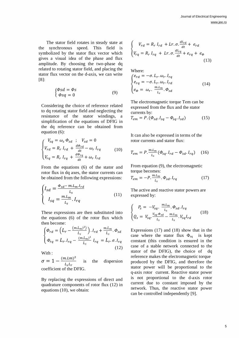
Expressions (17) and (18) show that in the
case where the stator flux Φsq is kept
constant (this condition is ensured in the
case of a stable network connected to the
stator of the DFIG), the choice of dq
reference makes the electromagnetic torque
produced by the DFIG, and therefore the
stator power will be proportional to the
q-axis rotor current. Reactive stator power
is not proportional to the d-axis rotor
current due to constant imposed by the
network. Thus, the reactive stator power
can be controlled independently [9].
5
Journal of Electrical Engineering
www.jee.ro
The DFIG model in dq reference
related to stator rotating field shows that we
can establish a rotor currents control given
that
the influence of couplings can be controlled
of each current independently. The
reference values for these regulators will be
the q-axis rotor current and the d-axis rotor
current.
To establish control loops of the rotor
currents, we assume that the RSC (rotor
side converter) is ideal (which corresponds
to neglecting the dead time imposed by the
drivers of the power switches) and using the
state averaging method, the DC/AC
converter (RSC) may be represented by a
gain G whose expression is:
(19)
with:
Vp: the amplitude of the triangular carrier of
the generation of the PWM.
Vdc : voltage of the DC link capacitor.
Furthermore, we assume that the rotor
voltages are equal to their references Vrk*
(k Є 1, 2, 3), which means that the
amplitude Vp of the carrier must be secured
to Vdc / 2, implying a gain G = 1.
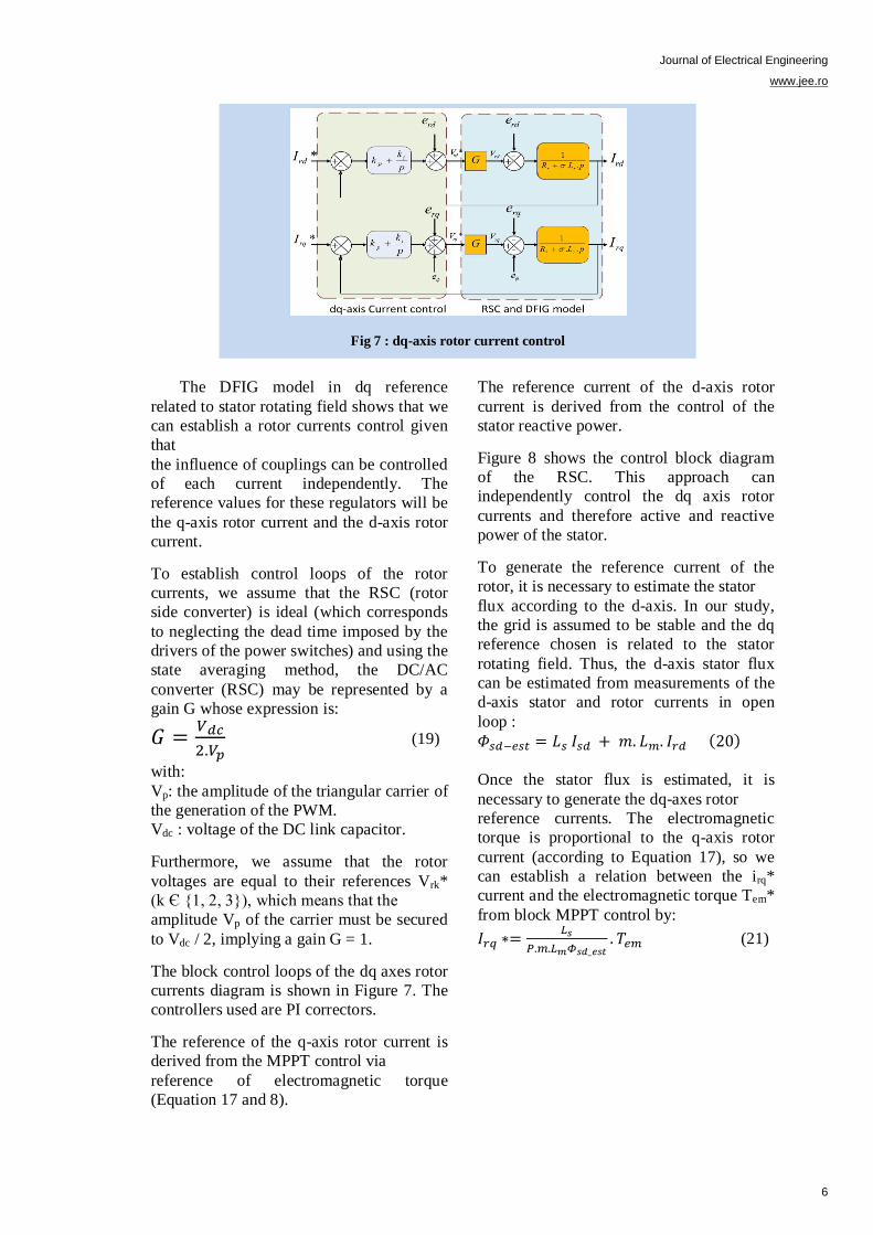
The block control loops of the dq axes rotor
currents diagram is shown in Figure 7. The
controllers used are PI correctors.
The reference of the q-axis rotor current is
derived from the MPPT control via
reference of electromagnetic torque
(Equation 17 and 8).
The reference current of the d-axis rotor
current is derived from the control of the
stator reactive power.
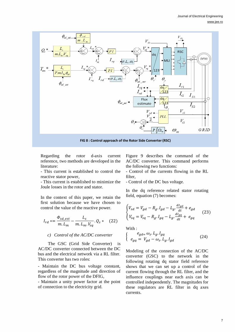
Figure 8 shows the control block diagram
of the RSC. This approach can
independently control the dq axis rotor
currents and therefore active and reactive
power of the stator.
To generate the reference current of the
rotor, it is necessary to estimate the stator
flux according to the d-axis. In our study,
the grid is assumed to be stable and the dq
reference chosen is related to the stator
rotating field. Thus, the d-axis stator flux
can be estimated from measurements of the
d-axis stator and rotor currents in open
loop :
Once the stator flux is estimated, it is
necessary to generate the dq-axes rotor
reference currents. The electromagnetic
torque is proportional to the q-axis rotor
current (according to Equation 17), so we
can establish a relation between the irq*
current and the electromagnetic torque Tem*
from block MPPT control by:
(21)
Fig 7 : dq-axis rotor current control
6
Journal of Electrical Engineering
www.jee.ro
Regarding the rotor d-axis current
reference, two methods are developed in the
literature:
- This current is established to control the
reactive stator power,
- This current is established to minimize the
Joule losses in the rotor and stator.
In the context of this paper, we retain the
first solution because we have chosen to
control the value of the reactive power.
c) Control of the AC/DC converter
The GSC (Grid Side Converter) is
AC/DC converter connected between the DC
bus and the electrical network via a RL filter.
This converter has two roles:
- Maintain the DC bus voltage constant,
regardless of the magnitude and direction of
flow of the rotor power of the DFIG,
- Maintain a unity power factor at the point
of connection to the electricity grid.
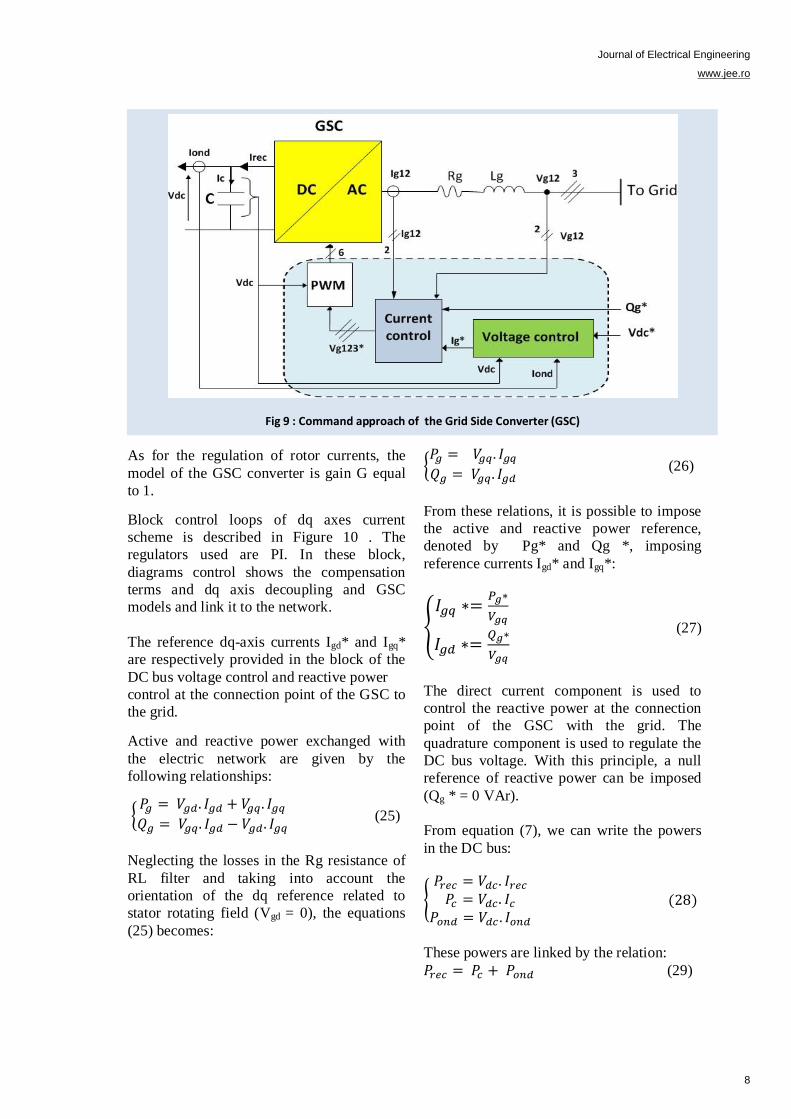
Figure 9 describes the command of the
AC/DC converter. This command performs
the following two functions:
- Control of the currents flowing in the RL
filter,
- Control of the DC bus voltage.
In the dq reference related stator rotating
field, equation (7) becomes:
With :
(24)
Modeling of the connection of the AC/DC
converter (GSC) to the network in the
following rotating dq stator field reference
shows that we can set up a control of the
current flowing through the RL filter, and the
influence couplings near each axis can be
controlled independently. The magnitudes for
these regulators are RL filter in dq axes
currents.
FIG 8 : Control approach of the Rotor Side Converter (RSC)
7
Journal of Electrical Engineering
www.jee.ro
As for the regulation of rotor currents, the
model of the GSC converter is gain G equal
to 1.
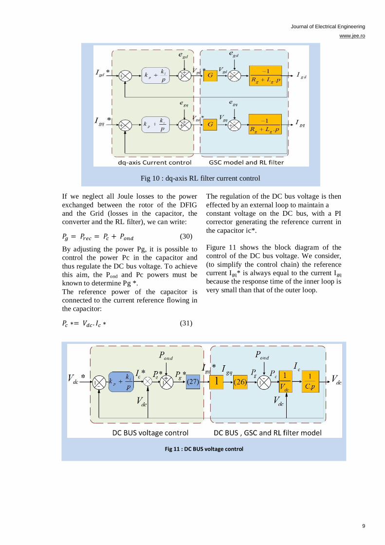
Block control loops of dq axes current
scheme is described in Figure 10 . The
regulators used are PI. In these block,
diagrams control shows the compensation
terms and dq axis decoupling and GSC
models and link it to the network.
The reference dq-axis currents Igd* and Igq*
are respectively provided in the block of the
DC bus voltage control and reactive power
control at the connection point of the GSC to
the grid.
Active and reactive power exchanged with
the electric network are given by the
following relationships:
(25)
Neglecting the losses in the Rg resistance of
RL filter and taking into account the
orientation of the dq reference related to
stator rotating field (Vgd = 0), the equations
(25) becomes:
(26)
From these relations, it is possible to impose
the active and reactive power reference,
denoted by Pg* and Qg *, imposing
reference currents Igd* and Igq*:
(27)
The direct current component is used to
control the reactive power at the connection
point of the GSC with the grid. The
quadrature component is used to regulate the
DC bus voltage. With this principle, a null
reference of reactive power can be imposed
(Qg * = 0 VAr).
From equation (7), we can write the powers
in the DC bus:
These powers are linked by the relation:
(29)
Fig 9 : Command approach of the Grid Side Converter (GSC)
8
Journal of Electrical Engineering
www.jee.ro
If we neglect all Joule losses to the power
exchanged between the rotor of the DFIG
and the Grid (losses in the capacitor, the
converter and the RL filter), we can write:
(30)
By adjusting the power Pg, it is possible to
control the power Pc in the capacitor and
thus regulate the DC bus voltage. To achieve
this aim, the Pond and Pc powers must be
known to determine Pg *.
The reference power of the capacitor is
connected to the current reference flowing in
the capacitor:
(31)
The regulation of the DC bus voltage is then
effected by an external loop to maintain a
constant voltage on the DC bus, with a PI
corrector generating the reference current in
the capacitor ic*.
Figure 11 shows the block diagram of the
control of the DC bus voltage. We consider,
(to simplify the control chain) the reference
current Igq* is always equal to the current Igq
because the response time of the inner loop is
very small than that of the outer loop.
Fig 11 : DC BUS voltage control
Fig 10 : dq-axis RL filter current control
9
Journal of Electrical Engineering
www.jee.ro
In Figure 11 Pond corresponds to the rotor
power: It is a considered as a regulation
disturbance and will be compensated in the
control chain.
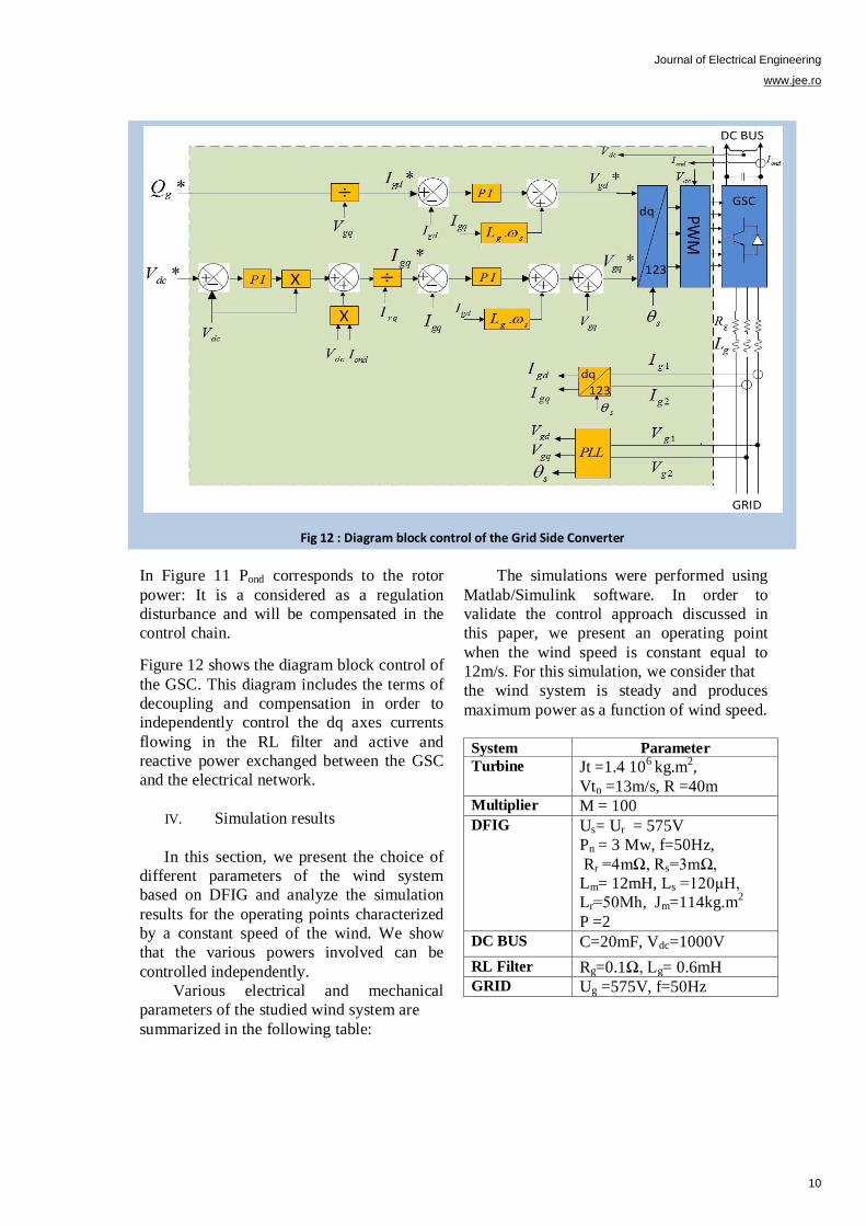
Figure 12 shows the diagram block control of
the GSC. This diagram includes the terms of
decoupling and compensation in order to
independently control the dq axes currents
flowing in the RL filter and active and
reactive power exchanged between the GSC
and the electrical network.
IV. Simulation results
In this section, we present the choice of
different parameters of the wind system
based on DFIG and analyze the simulation
results for the operating points characterized
by a constant speed of the wind. We show
that the various powers involved can be
controlled independently.
Various electrical and mechanical
parameters of the studied wind system are
summarized in the following table:
The simulations were performed using
Matlab/Simulink software. In order to
validate the control approach discussed in
this paper, we present an operating point
when the wind speed is constant equal to
12m/s. For this simulation, we consider that
the wind system is steady and produces
maximum power as a function of wind speed.
System Parameter
Turbine
Jt =1.4 10
6 kg.m
2,
Vtn =13m/s, R =40m Multiplier M = 100
DFIG
Us= Ur = 575V
Pn = 3 Mw, f=50Hz,
Rr =4mΩ, Rs=3mΩ,
Lm= 12mH, Ls =120μH,
Lr=50Μh, Jm=114kg.m2
P =2
DC BUS C=20mF, Vdc=1000V
RL Filter Rg=0.1Ω, Lg= 0.6mH GRID Ug =575V, f=50Hz
Fig 12 : Diagram block control of the Grid Side Converter
10
Journal of Electrical Engineering
www.jee.ro
The reference of the DC bus voltage denoted
Vdc* is set at 1000V. The reference value of
reactive power (Qg*) exchanged with the
network through the converter GSC is set to
(0VAr), which guarantees a power factor
close to unity. The reactive power of stator
Qs is regulated to reference value
(Qs* = 0Var) in the control of RSC. The
switching frequency of the power switches of
the GSC and RSC is set to 10 kHz.
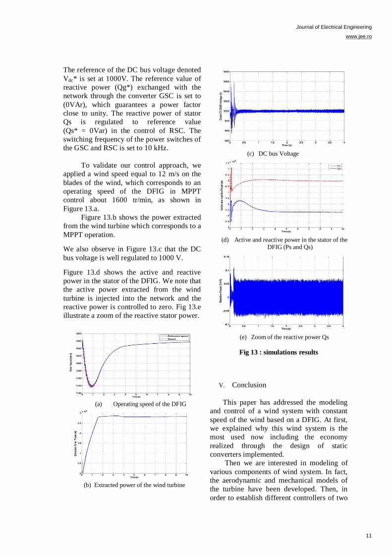
To validate our control approach, we
applied a wind speed equal to 12 m/s on the
blades of the wind, which corresponds to an
operating speed of the DFIG in MPPT
control about 1600 tr/min, as shown in
Figure 13.a.
Figure 13.b shows the power extracted
from the wind turbine which corresponds to a
MPPT operation.
We also observe in Figure 13.c that the DC
bus voltage is well regulated to 1000 V.
Figure 13.d shows the active and reactive
power in the stator of the DFIG. We note that
the active power extracted from the wind
turbine is injected into the network and the
reactive power is controlled to zero. Fig 13.e
illustrate a zoom of the reactive stator power.
(a) Operating speed of the DFIG
(b) Extracted power of the wind turbine
(c) DC bus Voltage
(d) Active and reactive power in the stator of the
DFIG (Ps and Qs)
(e) Zoom of the reactive power Qs
Fig 13 : simulations results
V. Conclusion
This paper has addressed the modeling
and control of a wind system with constant
speed of the wind based on a DFIG. At first,
we explained why this wind system is the
most used now including the economy
realized through the design of static
converters implemented.
Then we are interested in modeling of
various components of wind system. In fact,
the aerodynamic and mechanical models of
the turbine have been developed. Then, in
order to establish different controllers of two
11
Journal of Electrical Engineering
www.jee.ro
converters, we have developed models of
DFIG and Liaison of the GSC to the network
via the RL filter.
In the rest of this paper, we considered
that the wind was in its optimum range of
operation and it worked steady regardless of
the wind speed applied to the blades. We
have focused our study on the control in this
area of operation allowing the wind to extract
the maximum power available. We used an
indirect method of MPPT control without
adjustment of the rotational speed. The
various controls of GSC and RSC were
detailed to provide independent control of
active and reactive power while ensuring
optimal operation of the turbine.
To validate the modeling and control of
the global wind system, we have performed a
simulation for an operating point at constant
wind speed. The results showed that the
active and reactive power of the wind system
based on the DFIG could be controlled
independently while ensuring optimal active
power supplied to the grid.
Bibliographies :
[1] Vijay Chand Ganti, Bhim Singh, Shiv Kumar
Aggarwal, and Tara Chandra Kandpal, DFIG-Based
Wind Power Conversion With Grid Power Leveling
for Reduced Gusts, IEEE TRANSACTIONS ON
SUSTAINABLE ENERGY, VOL. 3, NO. 1,
JANUARY 2012
[2] BY S . Muller, M. Deicke, Rikw. De Doncker,
doubly fed induction generator systems, IEEE
Industry Applications Magazine May | June 2002
[3] J. B. Ekanayake, L. Holdsworth, X. G. Wu, and
N. Jenkins, “Dynamic modeling of doubly fed
induction generator wind turbines,” IEEE Trans.
Power Syst., vol. 18, no. 2, pp. 803–809, May 2003.
[4] Jun Yao, Hui Li, Yong Liao, and Zhe Chen, An
Improved Control Strategy of Limiting the DC-Link
Voltage Fluctuation for a Doubly Fed Induction Wind
Generator, IEEE TRANSACTIONS ON POWER
ELECTRONICS, VOL. 23, NO. 3, MAY 2008
[5] Yufei Tang, Ping Ju, HaiboHe, Chuan Qin, and
Feng Wu, Optimized Control of DFIG-Based Wind
Generation Using Sensitivity Analysis and Particle
Swarm Optimization, IEEE TRANSACTIONS ON
SMART GRID, VOL. 4, NO. 1, MARCH 2013
[6] Mohamed Benbouzid, Brice Beltran, Yassine
Amirat, Gang Yao, Jingang Han and Hervé Mangel,
High-Order Sliding Mode Control for DFIG-Based
Wind Turbine Fault Ride-Through, IEEE IECON
2013, Vienne, Austria 2013
[7] Yateendra Mishra, S. Mishra, Fangxing Li, Zhao Yang Dong, and Ramesh C. Bansal, Small-Signal
Stability Analysis of a DFIG-Based Wind Power
System Under Different Modes of Operation, IEEE
TRANSACTIONS ON ENERGY CONVERSION,
VOL. 24, NO. 4, DECEMBER 2009
[8] M. Itsaso Martinez, Ana Susperregui, Gerardo
Tapia Haritza Camblong, Sliding-Mode Control for a
DFIG-based Wind Turbine under Unbalanced
Voltage, 18th IFAC World Congress Milano (Italy)
August 28 - September 2, 2011
[9] A. Petersson, L. Harnefors, and T. Thiringer,
“Evaluation of current control methods for wind
turbines using doubly-fed induction machines,” IEEE
Trans. Power Electron., vol. 20, no. 1, pp. 227–235,
Jan. 2005.
12
Copyright © 2022 FDOKUMEN