- and they loved the ride! - The Automotive Technician
32
• The Volkswagen Golf which insisted on locking the driver out? • There’s nothing worse than blocked passages, even on a BMW E36 •Part One of Checking the Pulse - a detailed feature on testing the charging system of vehicles Sign up now for: 12 months subscription to TaT which includes six magazines mailed to your postal address Access to illustrated solutions on line Problem solving service Subscription price $115 ...but this issue only, last of the opening special price $99 APPLY ON PAGE 23 Wire & Gas delegates jump on the train - and they loved the ride! August 2008 Issue No 4
-
Upload
khangminh22 -
Category
Documents
-
view
3 -
download
0
Transcript of - and they loved the ride! - The Automotive Technician
• The Volkswagen Golf which insisted on locking the driver out?• There’s nothing worse than blocked passages, even on a BMW E36 •Part One of Checking the Pulse - a detailed feature on testing the charging system of vehicles
Sign up now for: 12 months subscription to TaT
which includes six magazines mailed to your postal address
Access to illustratedsolutions on line
Problem solving serviceSubscription price $115
...but this issue only, last of the opening special price $99
APPLY ON PAGE 23
Wire & Gas delegatesjump on the train- and they loved the ride!
August 2008 Issue No 4

297x210 TAT Fuel Filter Advert.pdf 15/7/08 2:22:04 PM
PublisherThe Automotive Technician Pty LtdABN 27 121 589 802PO Box 101GYMEA NSW 2227
1 Cleg StreetARTARMON NSW 2064Ph 1300 828 000Fax 1300 828 [email protected]
Editor in chiefKen [email protected] 5591 6274Fax 07 5591 81720438 569 517
Technical editorJeff [email protected] 828 000
Technical researchDeyan [email protected] 9476 6277
Technical advisersJack Stepanian
Nick [email protected]
Wayne Broadywww.broadyauto.com.au
Editorial contributorsHayley WindsorAshley Teitzel
International correspondentsJulian Hentze - USA Andrew Kavanagh - Europe
Copy proofingBron Robinson
Advertising inquiriesVicky [email protected] 284 246
Design TemplatesAllan GreenCEO [email protected]
Graphic Design Russell Jones Graphic [email protected]
PrintingBones Print Solutions128 Cope StreetWATERLOO NSW [email protected]
Affiliated associationsVASA [email protected]
TaT Assist TaT SpaceTaT Train TaT’s a Fact
Tips for Tat
are all registered trade names of The Automotive Technician Pty Ltd.The Automotive Technician Pty Ltd publishes technical advice and actual case studies for the purpose of educating technicians.
These advices are given in good faith, and are based on actual workshop repairs. No guarantee is given, nor any liability accepted in respect to any published advice.
The Automotive Technician Pty Ltd is not responsible for the accuracy of any information contained in material submitted by third parties and published in this magazine and accepts no liability in relation to such materials or their content.
Newsworthy articles or comments are welcomed, and should be submitted to the Editor in chief.
All material appearing in The Automotive Technician is copyright. Reproduction in whole or in part is illegal without prior written consent from the Editor in chief.
All advertisers agree to indemnify the publisher for all damages or liabilities arising from their published or unpublished material.
CONTENTSDon’t get spooked by vehicle technology 4 - 5 - 6
RRA Levy Changes 6
Hybrids - the aftermarket of the future 7 - 8 - 9
TaT on the web 10
Global Goss 11
Street Cred - with Hayley 12
The Sheriff - on shonky work 14
TaT’s a Fact 15 - 16
Check the Pulse 17 - 18 -19 - 20
You said it 20
Murphy’s Law - ABS 21
LED light problems 22 - 23
Top tools 24
Hy there - Hybrids 26
Mystery of the Drifting Ground 27
Who needs petrol - LPG story 28 - 29
The last word - Mark Mitchell 30
The team
The Automotive Technician 3
Being a non-technical person, or rather someone who knows nothing about motorcars, I find it fascinating editing the technical material in this magazine. For all I know, most of the articles could be about space science or brain surgery.
What’s obvious, even to me, is that we are in a very advanced technical age.
Having said that, it seems a little odd to me that we still find a large number of technicians who have almost ignored the oldest and most widely used technology of them all, the humble computer.
These same people will happily read this highly technical magazine - and understand it - and they will readily buy a sophisticated scan tool or oscilloscope because they just can’t do without it.
Yet, the tool that is capable of giving them access to the
biggest network of technical data and problem solving, is still regarded as that thing the kids use at home for playing games or meeting their mates on Facebook.
If there’s a computer in the workshop where they work, it’s really only used by the casual who comes in a couple of days a week to punch in the financials for the accountant.
Considering the power of the computer to link to anywhere in the world, it is a mystery to me why such a low budget item should be so ignored.
Why isn’t there a computer on every workshop bench, permanently plugged into the internet, with perhaps TaT as their default home page.
Imagine the scene. A customer brings in a car with a weird, if not time consuming fault. Maybe the TaT team has the solution. Or you need more
information on what a fault code means - GOOGLE IT. Whoops, don’t have a computer handy.
“Great, I’ll go home tonight, kick the kids off the computer and see if I can find the information.” The customer will be most impressed, I think not.
Technicians, it’s time to think about the time-zone you are currently in, and make sure you have the tools to cope with the information age.
The computer is now old hat. It’s the cheapest major tool you could have in your workshop, but absolutely invaluable for looking up urgent information, solving problems by either finding them on the TaT website, or sending an urgent
“help” to our tech team.
In the meantime, for those who are used to going on the internet to look for information, TaT is planning a new links service to direct technicians to website resources dealing with all manner of vehicle technology.
We will check links for their authenticity and accuracy before we provide them.
So if you have stumbled across any interesting websites which might prove useful to your fellow technicians, please send them in to us, and we will assess them and make them available to all.
See you on line. KN
Do you know what this is? If not, go to Page 7
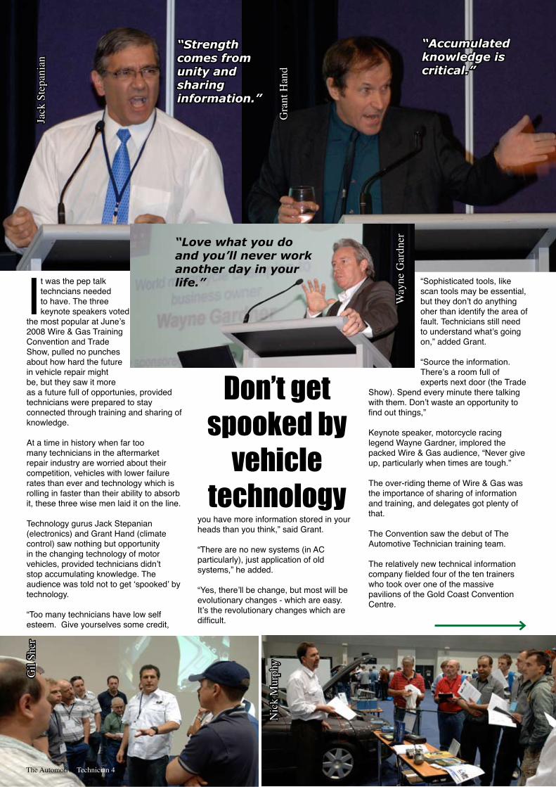
It was the pep talk techncians needed to have. The three keynote speakers voted
the most popular at June’s 2008 Wire & Gas Training Convention and Trade Show, pulled no punches about how hard the future in vehicle repair might be, but they saw it more as a future full of opportunies, provided technicians were prepared to stay connected through training and sharing of knowledge.
At a time in history when far too many technicians in the aftermarket repair industry are worried about their competition, vehicles with lower failure rates than ever and technology which is rolling in faster than their ability to absorb it, these three wise men laid it on the line.
Technology gurus Jack Stepanian (electronics) and Grant Hand (climate control) saw nothing but opportunity in the changing technology of motor vehicles, provided technicians didn’t stop accumulating knowledge. The audience was told not to get ‘spooked’ by technology.
“Too many technicians have low self esteem. Give yourselves some credit,
you have more information stored in your heads than you think,” said Grant.
“There are no new systems (in AC particularly), just application of old systems,” he added.
“Yes, there’ll be change, but most will be evolutionary changes - which are easy. It’s the revolutionary changes which are difficult.
“Sophisticated tools, like scan tools may be essential, but they don’t do anything oher than identify the area of fault. Technicians still need to understand what’s going on,” added Grant.
“Source the information. There’s a room full of experts next door (the Trade
Show). Spend every minute there talking with them. Don’t waste an opportunity to find out things,”
Keynote speaker, motorcycle racing legend Wayne Gardner, implored the packed Wire & Gas audience, “Never give up, particularly when times are tough.”
The over-riding theme of Wire & Gas was the importance of sharing of information and training, and delegates got plenty of that.
The Convention saw the debut of The Automotive Technician training team.
The relatively new technical information company fielded four of the ten trainers who took over one of the massive pavilions of the Gold Coast Convention Centre.
“Love what you do and you’ll never work another day in your life.”
“Strength comes from unity and sharing information.”
“Accumulated knowledge is critical.”
Jack
Ste
pani
an
Gra
nt H
and
Way
ne G
ardn
erDon’t get
spooked by vehicle
technology
The Automotive Technician 4
Nic
k M
urph
y
Gil
Sher
According to Jack Stepanian, technicians needed just a few vital things, apart from knowledge, to continue in their job.
“You need circuit diagrams to identify why a code came up, a digital multimeter, an oscilloscope and a scan tool - use them all. Don’t forget to keep the customer informed.
“As for the test light? Chuck it in the bin,” Jack added.
The Wire & Gas Training Convention helped establish TaT’s credibility as a training resource centre.
Including the AC licence assessment training, the convention fielded eleven of Australia’s top trainers.
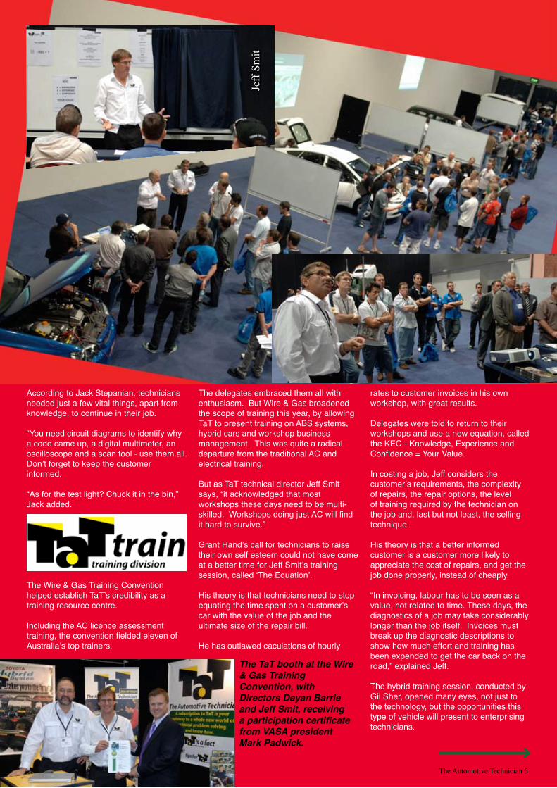
The delegates embraced them all with enthusiasm. But Wire & Gas broadened the scope of training this year, by allowing TaT to present training on ABS systems, hybrid cars and workshop business management. This was quite a radical departure from the traditional AC and electrical training.
But as TaT technical director Jeff Smit says, “it acknowledged that most workshops these days need to be multi-skilled. Workshops doing just AC will find it hard to survive.”
Grant Hand’s call for technicians to raise their own self esteem could not have come at a better time for Jeff Smit’s training session, called ‘The Equation’.
His theory is that technicians need to stop equating the time spent on a customer’s car with the value of the job and the ultimate size of the repair bill.
He has outlawed caculations of hourly
rates to customer invoices in his own workshop, with great results.
Delegates were told to return to their workshops and use a new equation, called the KEC - Knowledge, Experience and Confidence = Your Value.
In costing a job, Jeff considers the customer’s requirements, the complexity of repairs, the repair options, the level of training required by the technician on the job and, last but not least, the selling technique.
His theory is that a better informed customer is a customer more likely to appreciate the cost of repairs, and get the job done properly, instead of cheaply.
“In invoicing, labour has to be seen as a value, not related to time. These days, the diagnostics of a job may take considerably longer than the job itself. Invoices must break up the diagnostic descriptions to show how much effort and training has been expended to get the car back on the road,” explained Jeff.
The hybrid training session, conducted by Gil Sher, opened many eyes, not just to the technology, but the opportunities this type of vehicle will present to enterprising technicians.
The TaT booth at the Wire & Gas Training Convention, with Directors Deyan Barrie and Jeff Smit, receiving a participation certificate from VASA president Mark Padwick.
Jeff
Smit
The Automotive Technician 5
The Automotive Technician 6
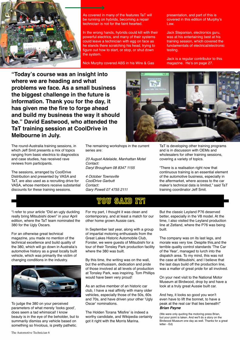
As covered in many of the features TaT will be running on hybrids, becoming a repair technician is not for the faint hearted.
In the wrong hands, hybrids could kill with their powerful electrics, and many of their systems could leave a technician with egg on face as he stands there scratching his head, trying to figure out how to start, or stop, or shut down the system.
Nick Murphy covered ABS in his Wire & Gas
presentation, and part of this is covered in this edition of Murphy’s Law.
Jack Stepanian, electronics guru, was at his entertaining best at his training session, which covered the fundamentals of electrical/electronic testing.
Jack is a regular contributor to this magazine. He’s on page 27.
The round-Australia training sessions, in which Jeff Smit presents a mix of topics ranging from basic electrics to diagnostics and case studies, has received rave reviews from participants.
The sessions, arranged by CoolDrive Distribution and presented by VASA and TaT, are also used as a recruiting drive for VASA, whose members receive substantial discounts for these training sessions.
The remaining workshops in the current series are:
23 August Adelaide, Manhattan MotelContact: Daryl Brougham 08 8347 1155
4 October TownsvilleCoolDrive GarbuttContact: Gary Powell 07 4755 2111
TaT is developing other training programs and is in discussion with OEMs and wholesalers for other training sessions, covering a variety of topics.
“There is a realisation right now that continuous training is an essential element of the automotive business, especially in the aftermarket, where access to the car maker’s technical data is limited,” said TaT training coordinator Jeff Smit.
“Today’s course was an insight into where we are heading and what problems we face. As a small business the biggest challenge in the future is information. Thank you for the day, it has given me the fire to forge ahead and build my business the way it should be.” David Eastwood, who attended the TaT training session at CoolDrive in Melbourne in July.
“I refer to your article “Did an ugly duckling really bring Mitsubishi down” in your April edition, where the TaT team nominated the 380 for the Ugly Oscars.
For an otherwise great technical magazine, you made no mention of the technical excellence and build quality of the 380, which will go down in Australia’s automotive history as a great locally built vehicle, which was primarily the victim of changing conditions in the industry.
To judge the 380 on your perceived parameters of what merely ‘looks good’, does seem a tad whimsical! I know beauty is in the eye of the beholder, but to summarily dismiss any vehicle based on something so frivolous, is pretty pathetic.
For my part, I thought it was clean and contemporary, and at least a match for our other home grown Aussie cars. In September last year, along with a group of impartial motoring enthusiasts from the Great Lakes Historic Automobile Club, Forster, we were guests of Mitsubishi for a tour of their Tonsley Park production facility where the 380 was built.
By this time, the writing was on the wall, but the enthusiasm, dedication and pride of those involved at all levels of production at Tonsley Park, was inspiring. Tom Phillips would have been very proud!
As an active member of an historic car club, I have a real affinity with many older vehicles, especially those of the 50s, 60s and 70s, and have driven your other ‘Ugly Oscar’ nominations.
The Holden Torana ‘Misfire’ is indeed a worthy candidate, and Wikipedia certainly got it right with the Morris Marina.
But the classic Leyland P76 deserved better, especially in the V8 model. At the time, I also visited the Leyland production line at Zetland, where the P76 was being built.
The company was on its last legs, and morale was very low. Despite this,and the terrible quality control standards ‘The Car of the Year’, managed to lurch into the dispatch area. To my mind, this was not the case at Mitsubishi, and I believe that the last days build off the production line, was a matter of great pride for all involved.
On your next visit to the National Motor Museum at Birdwood, drop by and have a look at a truly great Aussie built car.
And hey, it looks so good you won’t even have to lift the bonnet, to have a peak at the real car that lies beneath!” Brian Payne (We were only quoting the motoring press Brian, but your point is taken. And we’ll do a story on the Birdwood Museum one day as well. Thanks for a great letter - Ed)
You said it!
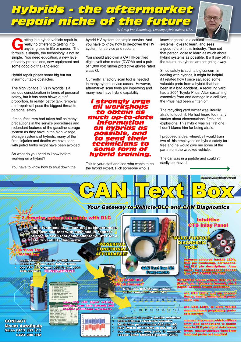
CAN Text BoxYour Gateway to Vehicle DLC and CAN Diagnostics
CAN Test Box KitComponents
1
9
2 3 4 5 6 7 8
10 11 12 13 14 15 16
2.5 metre extension cable with DLC
cable functions as a scan tool cable extension• diagnose and test with ease and in comfort• be free of scan tool cable/adaptor clutter for a • safe driveability diagnostic
CTB ‘Pass Thru’
technology
easily connect generic or OEM scanner• monitor systems scan data streams• see CTB LED’s signal activity and scan • data streams SIMULTANEOUSLY!
CTB cable DLC‘Quick Connect’
CTB cable DLC fits any vehicle• with a compliant OBD-II DLC
IntutitiveCTB Inlay Panel
features coloured backlit LED’s, DLC pin numbering, correspond-ing DLC pin descriptions, 4mm jacks for oscilloscope connec-tion, CTB POWER ‘ON’ LED
INSTANTLY check vehicle DLC pin 16 (Batt+), pin 4 (Chassis Ground), pin 5 (Signal Ground) circuit conditions
use CTB LED’s and pin descrip-tive to identify vehicle CAN proto-col in use
use CTB LED’s to view vehicle manufacturers proprietary proto-cols activity
connect any scope which utilises 8mm lead connections to gather vehicle DLC pin signal data wave-forms - quality shielded 4mm/8mm lead and probe set supplied
‘MULTI-PURPOSE DIAGNOSTIC
TOOL’
constructed of quality durable materials• state-of-the-art electronic circuitry• Diode fuse protection for DLC pins 4/5• Poly Switch fuse safety on DLC pin 16• use appropriate inlay ports to manually • access ‘blink’ SRS/ABS/Systems DTC’s
‘POWERFUL! FUNCTIONAL!AFFORDABLE!’
view CTB LED signal activity, monitor scan data streams and capture oscillscope waveforms
CONTACTMount AutoEquipSales 0413 033 611 0423 200 992
http://www.autoequipment.com.au
Hybrids - the aftermarket repair niche of the future
By Craig Van Batenburg, Leading hybrid trainer, USA
Getting into hybrid vehicle repair is really no different to getting into anything else in life or career. The
formula is simple, the technology is not so simple. You need education, a new level of safety precautions, new equipment and some good old trial-and-error.
Hybrid repair poses some big but not insurmountable obstacles.
The high voltage (HV) in hybrids is a serious consideration in terms of personal safety, but it has been blown out of proportion. In reality, petrol tank removal and repair still pose the biggest threat to personal safety.
If manufacturers had taken half as many precautions in the service procedures and redundant features of the gasoline storage system as they have in the high voltage storage systems of hybrids, many of the fires, injuries and deaths we have seen with petrol tanks might have been avoided.
So what do you need to know before working on a hybrid?
You have to know how to shut down the
hybrid HV system for simple service. And you have to know how to de-power the HV system for service and repairs.
You should also own a CAT III-certified digital volt ohm meter (DVOM) and a pair of 1,000 volt rubber protective gloves rated class O.
Currently, a factory scan tool is needed in many hybrid service cases. However, aftermarket scan tools are improving and many now have hybrid capability.
I strongly urge all workshops to obtain as
much up-to-date information
on hybrids as possible, and to send their technicians to some form of
hybrid training.
Talk to your staff and see who wants to be the hybrid expert. Pick someone who is
knowledgeable in electrical systems, loves to learn, and sees a good future in this industry. Then set that person loose to learn as much about hybrid systems as possible. It will pay off in the future, as hybrids are not going away.
Since safety is such a big concern in dealing with hybrids, it might be helpful if I related how I once salvaged some valuable parts from a hybrid that had been in a bad accident. A recycling yard had a 2004 Toyota Prius. After sustaining extensive front-end damage in a collision, the Prius had been written off.
The recycling yard owner was literally afraid to touch it. He had heard too many stories about electrocutions, fires and explosions. This hybrid was his first one.I don’t blame him for being afraid.
I proposed a deal whereby I would train two of his employees on hybrid safety for free and he would give me some of the parts from the wrecked vehicle.
The car was in a puddle and couldn’t easily be moved.
The Automotive Technician 8
Coming soon...
Timing Belts 2009
What’s the Autodata Difference?
Clear and concise illustrations
Replacement Interval Guides
Repair Times
Special Tools & Precautions
Step by step removal & installation
instructions written by technicians
for technicians
Covering vehicles up to 2009
Now includes Serpentine Belts!
Autodata Australia Pty Ltd . 5/25 Veronica Street . Capalaba . QLD 4157
Tel: 07 3245 3282 . Fax: 07 3245 3422 . Email: [email protected]
Web: www.autodata.com.au
Revised & updated!
Price: $148.50 Inc GST
In the details box can we change it to just have :-
www.autodata.com.au
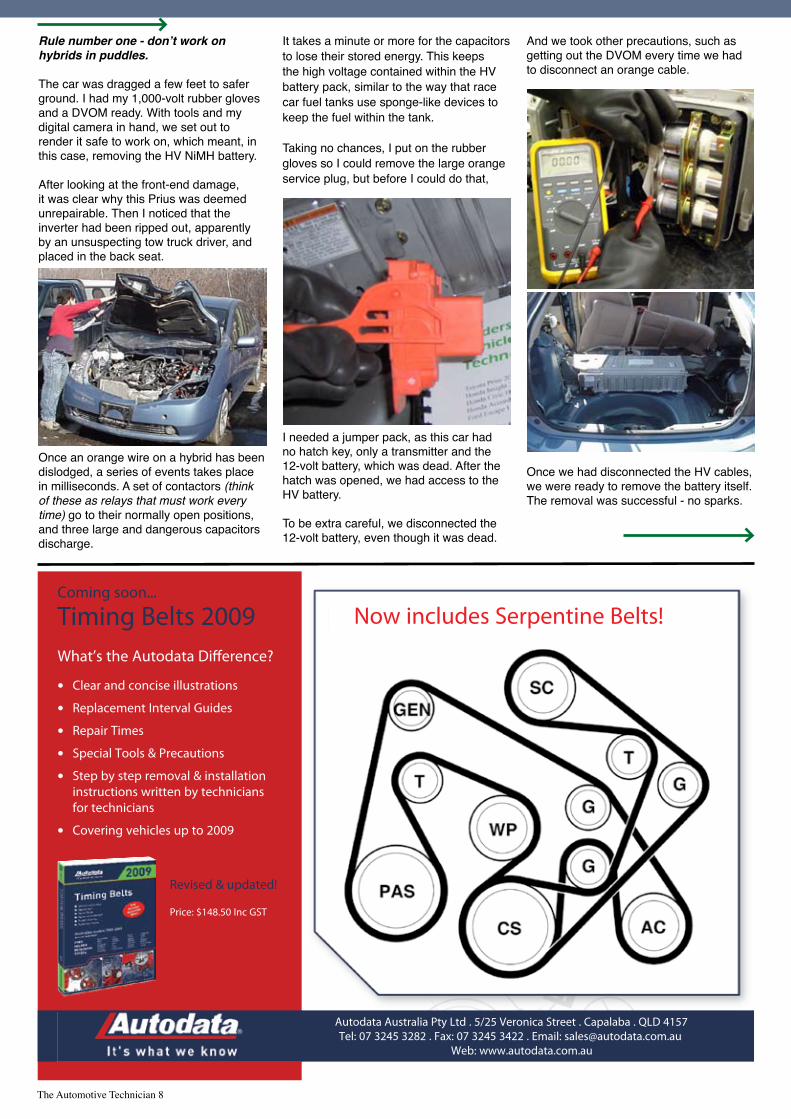
Rule number one - don’t work on hybrids in puddles.
The car was dragged a few feet to safer ground. I had my 1,000-volt rubber gloves and a DVOM ready. With tools and my digital camera in hand, we set out to render it safe to work on, which meant, in this case, removing the HV NiMH battery.
After looking at the front-end damage, it was clear why this Prius was deemed unrepairable. Then I noticed that the inverter had been ripped out, apparently by an unsuspecting tow truck driver, and placed in the back seat.
Once an orange wire on a hybrid has been dislodged, a series of events takes place in milliseconds. A set of contactors (think of these as relays that must work every time) go to their normally open positions, and three large and dangerous capacitors discharge.
It takes a minute or more for the capacitors to lose their stored energy. This keeps the high voltage contained within the HV battery pack, similar to the way that race car fuel tanks use sponge-like devices to keep the fuel within the tank.
Taking no chances, I put on the rubber gloves so I could remove the large orange service plug, but before I could do that,
I needed a jumper pack, as this car had no hatch key, only a transmitter and the 12-volt battery, which was dead. After the hatch was opened, we had access to the HV battery.
To be extra careful, we disconnected the 12-volt battery, even though it was dead.
And we took other precautions, such as getting out the DVOM every time we had to disconnect an orange cable.
Once we had disconnected the HV cables, we were ready to remove the battery itself. The removal was successful - no sparks.
The Automotive Technician 9
we’ve got it covered
Distributors of Automotive Air Conditioning, Electrical and Cooling System Components
cooldrive.com.au
We'vegotitcoveredAAEN.indd 1 22/7/08 1:41:26 PM
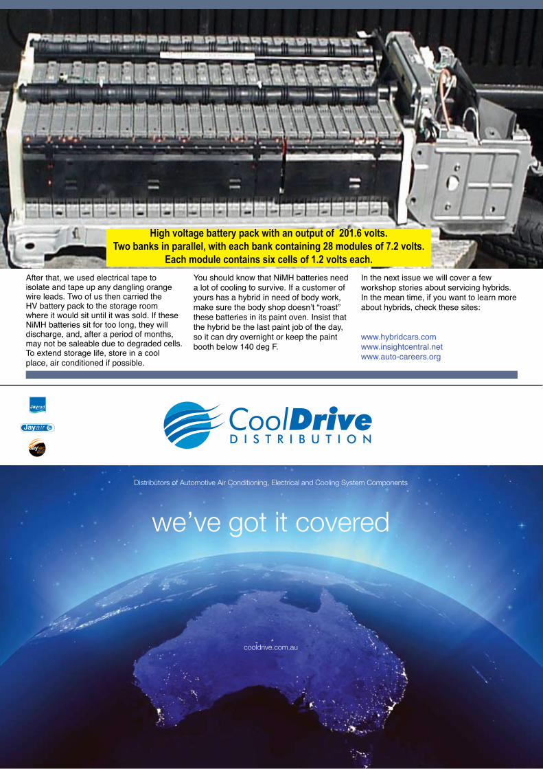
After that, we used electrical tape to isolate and tape up any dangling orange wire leads. Two of us then carried the HV battery pack to the storage room where it would sit until it was sold. If these NiMH batteries sit for too long, they will discharge, and, after a period of months, may not be saleable due to degraded cells. To extend storage life, store in a cool place, air conditioned if possible.
You should know that NiMH batteries need a lot of cooling to survive. If a customer of yours has a hybrid in need of body work, make sure the body shop doesn’t “roast” these batteries in its paint oven. Insist that the hybrid be the last paint job of the day, so it can dry overnight or keep the paint booth below 140 deg F.
In the next issue we will cover a few workshop stories about servicing hybrids. In the mean time, if you want to learn more about hybrids, check these sites:
www.hybridcars.comwww.insightcentral.netwww.auto-careers.org
High voltage battery pack with an output of 201.6 volts.Two banks in parallel, with each bank containing 28 modules of 7.2 volts.
Each module contains six cells of 1.2 volts each.

The Automotive Technician 10
TaT on the WEBThe technical information in this magazine is just the tip of the iceberg. The full value of a Subscription is found on the TaT website. This is where you interact with your fellow technicians, and where the solutions just don’t stop coming.
...this is the
front page of
the website
... want help with a problem? Easy. Just fill in the Assist form and press the submit button.
Select a vehicle make to find all the problems we’ve solved on that model
... looking for a technical story, but
can’t remember
what issue? Here’s
the online index.
...hundreds of solutions - just click on the problem code, and...
...bingo!...want to sell some surplus stuff, share an idea, discuss a problem with your fellow techs ... chat away.

You know, I have tried to understand Nascar and have spent quite a few weekends in front of the idiot box to understand its nuances.
Like all motor sport, it has its ups and downs, its heroes and hard core followers. But just recently, I really got into it.
You see, this little known Tasmanian finally got to drive in the series. Tipped as an Australian who is a ‘street circuit specialist’ he was getting a run in the ‘Little Debbie’ Ford Fusion.
Now my new mates have been teaching me about Nascar. Crafty manoeuvres like drafting, high and low passes, team dynamics and stuff like that, but when I arrived in my Pirtek Shirt, my Russell Ingall signed baseball cap (when he drove for the right colour) and my last six pack of VB, they were curious. They wanted to know about this little known Australian who was racing.
Marcus Ambros (Australian V8 Supercar veteran) got to second place before being punted off the course when he got hit from behind, and finished in the pits. Disappointing result, although this was when my new mates got to hear about a conspiracy involving another great Australian, Phar Lap.
But I digress. Technology is fantastic and what better way to demonstrate that than with the music revolution created by the Apple Corporation. They made accessing music and downloading music so easy that it is now common place. But how will this influence what happens in your workshop?
You would not believe what I am about to tell you. What if you purchased an ECU or control module that had not been programmed yet, but you needed the info. It was after hours and the local dealership was closed?
What if there was an error in the programming code in the ECU that needed to be rectified. What if there was a website
that allowed you access to ECU repairs that could be downloaded and plugged into the ECU and recode it using the right scan tool.
What if the manufacturer found a more efficient way to make the ECU work and all you had to download was the update? Well, it’s here, and it’s called ‘flash’ programming.
It works just like an iPod. You go to the designated manufacturer’s website and enter the vehicle’s VIN number. It identifies the vehicle and either gives you a list of the required updates or you can select the program you want, pay for it (or subscribe to a service) and download it and update the ECU.
A statistic going around here is that some 45% of new vehicle repairs are flash reprogramming. Here’s also something to ponder though. If you have a hard time charging customers for diagnostic time, what about this - a high end 2008 BMW has 168 different modules and would take six hours of downloading flashes if needed to replace or repair. Now how would you charge for that?
Aussie sporting abroad - Andrew in a sentimentalmood
As I pen these words bitter sweet emotion is running through my veins.
Never have I imagined that I would follow the Tour De France so
passionately. Watching an Aussie boy get so close to winning the world’s most prestigious and famous bike race has been a rollercoaster for two weeks.
Unfortunately my back pocket is a little lighter after making many brave wagers with friends and colleagues, all based on brave patriotic intentions. Congratulations to Cadel Evans (pic above) coming second, for the second year in a row. What a fantastic effort and something of which he and Australia should be very proud. Did you know the Belgians have adopted Robbie McEwen, the Aussie cyclist who appears on TV speaking the local language (Flemish), and they love him, with bars and cafes dedicated to his name!
How is it Australia, a nation of 20 million, get themselves etched into the minds of sports lovers all over the world?
This year has seen a record number of Australians compete in the PGA, the English Premier League. This month we saw Aussie boy Andrew Bogut penning a $72 million contract for five years in the NBA and Casey Stoner running a strong second overall in the MotoGP.
With the Olympics, many pundits are tipping a top five finish for little ole Australia. Quite amazing when you think about how young we are as nation, how small we are (in population) and how large we are in character.
Living abroad brings with it a great deal of emotions, mostly homesickness and with it also comes a great deal of pride in saying you’re from one of the luckiest countries in the world, with some of the most beautiful places, people and wildlife in the world.
Missing the industry that has evolved so much since my departure in 2005 has not been easy to cope with. I left behind many friends, colleagues and associates. Many of them have gone on to greater things within the industry and for that I’m proud. Proud to be part of the automotive industry in Australia and also proud to be an Aussie!
If any of you care to keep in touch feel free to drop me a message:[email protected]
the global goss
Andrew Kavanagh, our man in Antwerp, Belgium
The Automotive Technician 11
Julian Hentze, our man in Georgia, USA, now thinks he’s a racing car driver. We would have preferred a pic of Jules at speed. Maybe the camera was faulty.
Now that a large number of subscribers have joined our ranks, it was inevitable that we would be asked for a wiring diagram, or some data which could help a technician solve a problem.
SORRY – but we don’t sell data.
TaT’s mission is to research and find practical solutions for vehicle problems, to impart knowledge about repairs, systems, tools and technology and run training programs.
Why don’t we sell wiring diagrams?
It’s not our business. Those technicians or workshops who subscribe to the providers of data, know what it costs.
Some companies we know pay well over $1,000 a year for access to data, including wiring diagrams. According to them, it’s worth every cent, and this access is as necessary to running the business as having a telephone on the desk.
TaT technical experts say that buying data and wiring diagrams is really no different to buying parts.
Legitimate data is not cheap, so technicians need to think more about charging out data access on invoices, just as charges are made for parts purchased on the customer’s behalf.
TaT could not afford to provide data for its very low subscription, currently $99 a year.
street cred with Hayley Windsor in London
The Automotive Technician 12
YES!, we have no bananas – or data or wiring diagrams
My flatmate left for a trip to Ibiza with his luggage in a
Sainsbury’s supermarket bag.
This is not just because Ibiza is one of the least classy places to holiday, but because Easyjet is now charging passengers an additional fee for all checked-in baggage.
Flight companies around the world are hiking up ticket prices, increasing baggage fees and fuel surcharges and even, as claimed in The Metro last week, flying an average of 3mph slower to reduce fuel consumption.
The Ibiza example doesn’t nearly reflect the pressures faced by an international public concerned about the implications of carbon emission trading schemes and uncertain about future oil supplies.
If the Emissions Trading Scheme wasn’t enough to get your head around, behold the Carbon Trust. It’s based on the presumption that it is unacceptable for businesses
to claim they cannot afford to be green in a severe economic climate. The Carbon Trust, a government funded body that advises firms on carbon emission reduction, is currently launching the world’s first accreditation scheme for organisations that actively reduce their carbon emissions, rather than relying on offsets.
Confused? Me too. And then there’s the all-consuming question ‘what does this do to the price of petrol?’
Truckies from London to Australia are striking in protest. Everyone is worried about rising household costs.
And if fuel prices keep going up – in London, 56 cents above the record set last week – and tension escalates over relationships with key producing countries, where does that leave the car-dependent cities of the world.
The case for reducing carbon emissions is valid, if not vital, and I think most reasonable people agree, but no-one
seems clear about the correct course of action and the impact of any solution on our standard of living.
I don’t have the answer, just amusing, Cambridge-inspired images of new-age (or is that stone-age) taxi drivers punting down the River Thames and rowing down the Gold Coast canals with suit-clad clients who are ‘offsetting’ their living costs.
And if we all can’t dance our doubts away on islands like
Ibiza, we have to deal with it.
I don’t see cars being moth-balled any time soon.
So to the technicians reading this, my considered advice is, don’t stop training, keep up your skills because if you are not rattling around with pistons and gear boxes, you are likely to be pulling on your high voltage gloves and keeping electric and hybrid cars on the road. You’ll need training to keep up with that technology, make no mistake.
journal.mtansw.com.autraining.mtansw.com.au
mtansw.com.au
find out more..
across New South Wales
and currently has over 6,000 Members
for businesses in the motor industry
The MTA is an employer’s association
The Automotive Technician 13
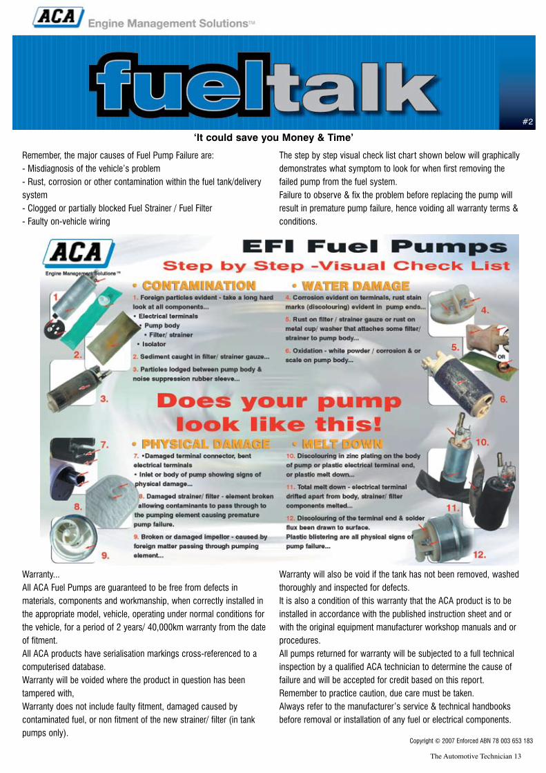
Remember, the major causes of Fuel Pump Failure are:- Misdiagnosis of the vehicle’s problem- Rust, corrosion or other contamination within the fuel tank/deliverysystem- Clogged or partially blocked Fuel Strainer / Fuel Filter - Faulty on-vehicle wiring
The step by step visual check list chart shown below will graphicallydemonstrates what symptom to look for when first removing thefailed pump from the fuel system.Failure to observe & fix the problem before replacing the pump willresult in premature pump failure, hence voiding all warranty terms &conditions.
Warranty...All ACA Fuel Pumps are guaranteed to be free from defects inmaterials, components and workmanship, when correctly installed inthe appropriate model, vehicle, operating under normal conditions forthe vehicle, for a period of 2 years/ 40,000km warranty from the dateof fitment.All ACA products have serialisation markings cross-referenced to acomputerised database.Warranty will be voided where the product in question has beentampered with, Warranty does not include faulty fitment, damaged caused bycontaminated fuel, or non fitment of the new strainer/ filter (in tankpumps only).
Warranty will also be void if the tank has not been removed, washedthoroughly and inspected for defects.It is also a condition of this warranty that the ACA product is to beinstalled in accordance with the published instruction sheet and orwith the original equipment manufacturer workshop manuals and orprocedures.All pumps returned for warranty will be subjected to a full technicalinspection by a qualified ACA technician to determine the cause offailure and will be accepted for credit based on this report.Remember to practice caution, due care must be taken.Always refer to the manufacturer’s service & technical handbooksbefore removal or installation of any fuel or electrical components.
‘It could save you Money & Time’
#2
Copyright © 2007 Enforced ABN 78 003 653 183
The Automotive Technician 14
A.D.R.APPROVED
A.D.R.APPROVED
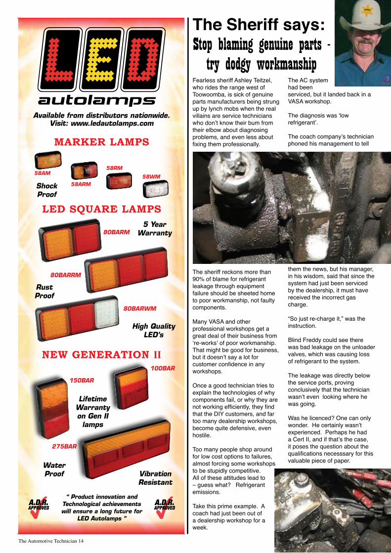
Fearless sheriff Ashley Teitzel, who rides the range west of Toowoomba, is sick of genuine parts manufacturers being strung up by lynch mobs when the real villains are service technicians who don’t know their bum from their elbow about diagnosing problems, and even less about fixing them professionally.
The sheriff reckons more than 90% of blame for refrigerant leakage through equipment failure should be sheeted home to poor workmanship, not faulty components.
Many VASA and other professional workshops get a great deal of their business from ‘re-works’ of poor workmanship. That might be good for business, but it doesn’t say a lot for customer confidence in any workshops.
Once a good technician tries to explain the technologies of why components fail, or why they are not working efficiently, they find that the DIY customers, and far too many dealership workshops, become quite defensive, even hostile.
Too many people shop around for low cost options to failures, almost forcing some workshops to be stupidly competitive. All of these attitudes lead to – guess what? Refrigerant emissions. Take this prime example. A coach had just been out of a dealership workshop for a week.
The AC system had been serviced, but it landed back in a VASA workshop.
The diagnosis was ‘low refrigerant’.
The coach company’s technician phoned his management to tell
them the news, but his manager, in his wisdom, said that since the system had just been serviced by the dealership, it must have received the incorrect gas charge.
“So just re-charge it,” was the instruction.
Blind Freddy could see there was bad leakage on the unloader valves, which was causing loss of refrigerant to the system.
The leakage was directly below the service ports, proving conclusively that the technician wasn’t even looking where he was going.
Was he licenced? One can only wonder. He certainly wasn’t experienced. Perhaps he had a Cert II, and if that’s the case, it poses the question about the qualifications necesssary for this valuable piece of paper.
The Sheriff says:Stop blaming genuine parts -
try dodgy workmanship
Customer complaint
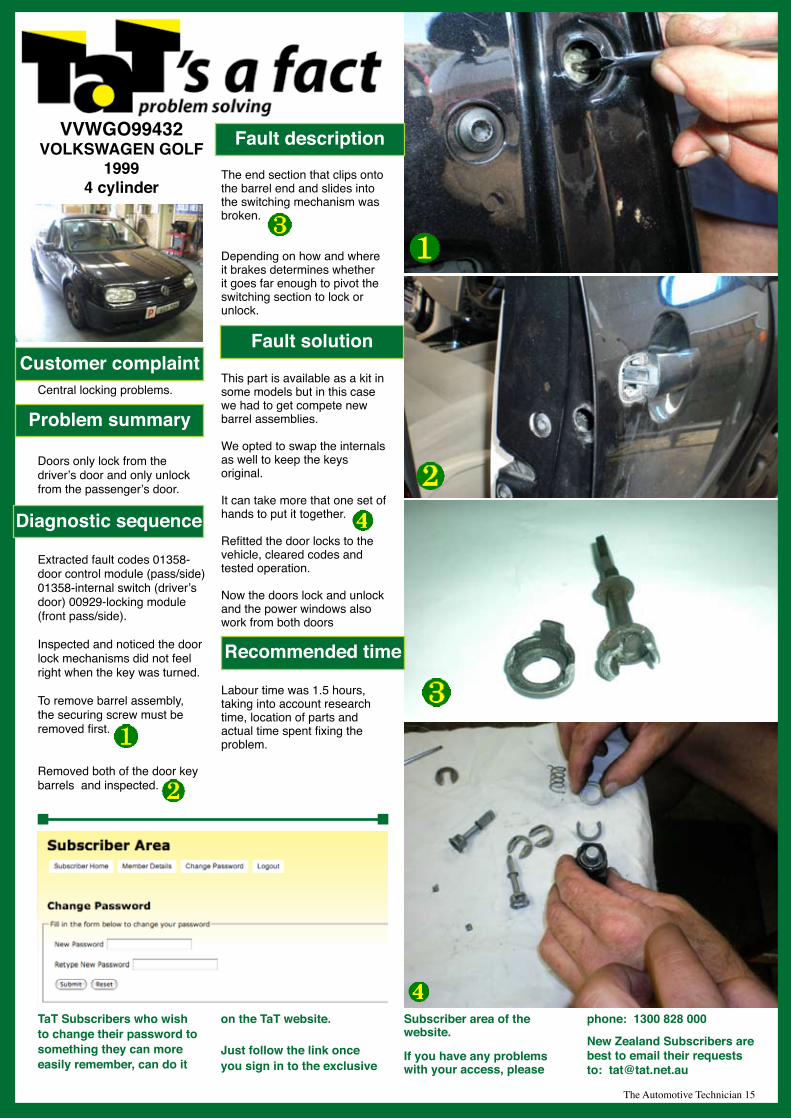
VVWGO99432VOLKSWAGEN GOLF
19994 cylinder
Central locking problems.
Doors only lock from the driver’s door and only unlock from the passenger’s door.
Extracted fault codes 01358-door control module (pass/side) 01358-internal switch (driver’s door) 00929-locking module (front pass/side).
Inspected and noticed the door lock mechanisms did not feel right when the key was turned.
To remove barrel assembly, the securing screw must be removed first.
Removed both of the door key barrels and inspected.
The end section that clips onto the barrel end and slides into the switching mechanism was broken.
Depending on how and where it brakes determines whether it goes far enough to pivot the switching section to lock or unlock.
This part is available as a kit in some models but in this case we had to get compete new barrel assemblies.
We opted to swap the internals as well to keep the keys original.
It can take more that one set of hands to put it together.
Refitted the door locks to the vehicle, cleared codes and tested operation.
Now the doors lock and unlock and the power windows also work from both doors
Labour time was 1.5 hours, taking into account research time, location of parts and actual time spent fixing the problem.
Problem summary
Diagnostic sequence
Fault description
Fault solution
Recommended time
The Automotive Technician 15
TaT Subscribers who wish to change their password to something they can more easily remember, can do it
on the TaT website.
Just follow the link once you sign in to the exclusive
Subscriber area of the website.
If you have any problems with your access, please
phone: 1300 828 000
New Zealand Subscribers are best to email their requests to: [email protected]
Customer complaint
BMW3696421BMW E36
19964 Cylinders
No interior heat.
No interior heat - dual zone system.
Only a small amount of warm air from left side.
Checked all fuses and battery connections.
Hooked up scan tool and checked for any fault codes. No fault codes present.
Tested the operation of the dual electric heater taps. Signal is getting to the two motors but no coolant flow evident through the taps.
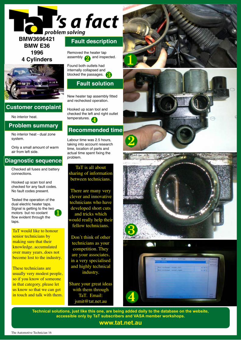
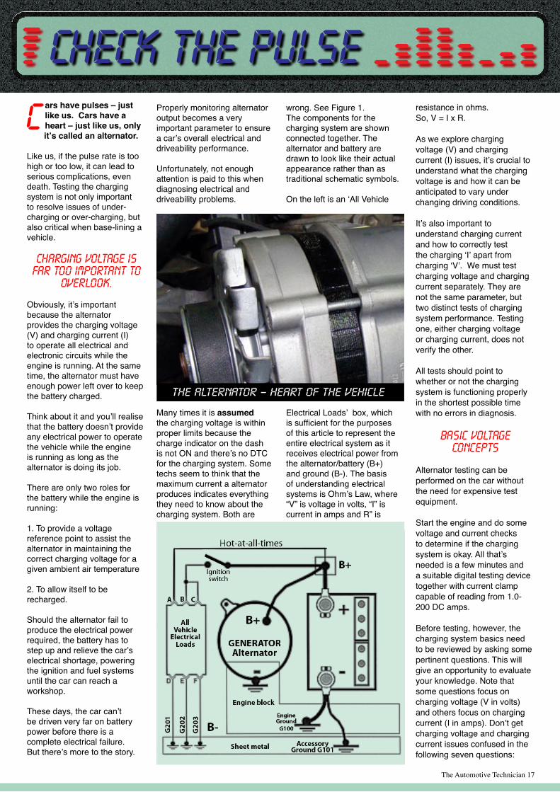
Removed the heater tap assembly and inspected.
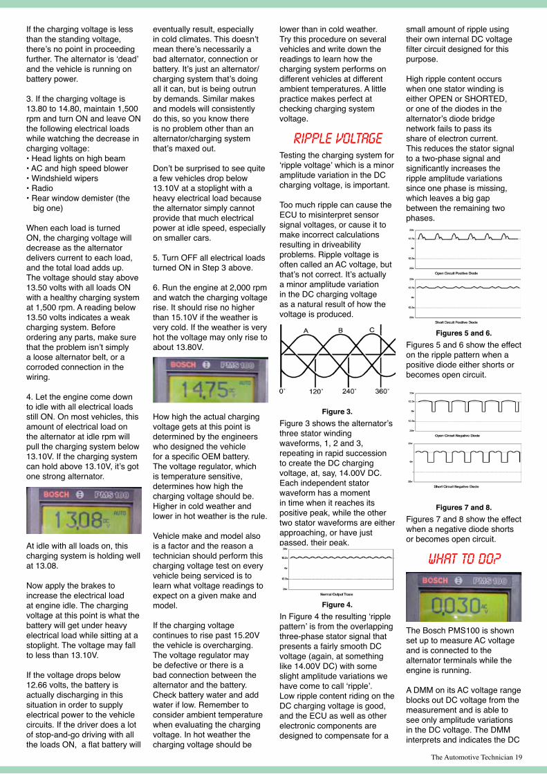
Found both outlets had internally collapsed and blocked the passages.
New heater tap assembly fitted and rechecked operation.
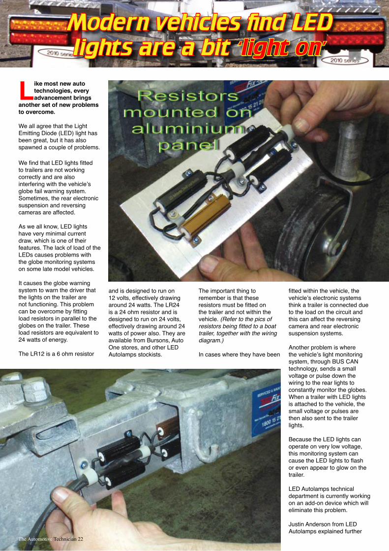
Hooked up scan tool and checked the left and right outlet temperatures.
Labour time was 2.5 hours, taking into account research time, location of parts and actual time spent fixing the problem.
Problem summary
Diagnostic sequence
Fault solution
Recommended time
Fault description
Technical solutions, just like this one, are being added daily to the database on the website, accessible only by TaT subscribers and VASA member workshops.
www.tat.net.au The Automotive Technician 16
TaT is all about sharing of information between technicians.
There are many very clever and innovative technicians who have developed short cuts
and tricks which would really help their
fellow technicians.
Don’t think of other technicians as your competition. They are your associates, in a very specialised and highly technical
industry.
Share your great ideas with them through
TaT. Email: [email protected]
TaT would like to honour senior technicians by making sure that their knowledge, accumulated over many years, does not become lost to the industry.
These technicians are usually very modest people, so if you know of someone in that category, please let us know so that we can get in touch and talk with them.
The Automotive Technician 17
ars have pulses – just like us. Cars have a heart – just like us, only it’s called an alternator.
Like us, if the pulse rate is too high or too low, it can lead to serious complications, even death. Testing the charging system is not only important to resolve issues of under-charging or over-charging, but also critical when base-lining a vehicle.
Charging voltage is far too important to
overlook.
Obviously, it’s important because the alternator provides the charging voltage (V) and charging current (I) to operate all electrical and electronic circuits while the engine is running. At the same time, the alternator must have enough power left over to keep the battery charged. Think about it and you’ll realise that the battery doesn’t provide any electrical power to operate the vehicle while the engine is running as long as the alternator is doing its job.
There are only two roles for the battery while the engine is running:
1. To provide a voltage reference point to assist the alternator in maintaining the correct charging voltage for a given ambient air temperature
2. To allow itself to be recharged.
Should the alternator fail to produce the electrical power required, the battery has to step up and relieve the car’s electrical shortage, powering the ignition and fuel systems until the car can reach a workshop.
These days, the car can’t be driven very far on battery power before there is a complete electrical failure. But there’s more to the story.
Properly monitoring alternator output becomes a very important parameter to ensure a car’s overall electrical and driveability performance.
Unfortunately, not enough attention is paid to this when diagnosing electrical and driveability problems.
Many times it is assumed the charging voltage is within proper limits because the charge indicator on the dash is not ON and there’s no DTC for the charging system. Some techs seem to think that the maximum current a alternator produces indicates everything they need to know about the charging system. Both are
resistance in ohms. So, V = I x R.
As we explore charging voltage (V) and charging current (I) issues, it’s crucial to understand what the charging voltage is and how it can be anticipated to vary under changing driving conditions.
It’s also important to understand charging current and how to correctly test the charging ‘I’ apart from charging ‘V’. We must test charging voltage and charging current separately. They are not the same parameter, but two distinct tests of charging system performance. Testing one, either charging voltage or charging current, does not verify the other.
All tests should point to whether or not the charging system is functioning properly in the shortest possible time with no errors in diagnosis.
Basic voltage concepts
Alternator testing can be performed on the car without the need for expensive test equipment.
Start the engine and do some voltage and current checks to determine if the charging system is okay. All that’s needed is a few minutes and a suitable digital testing device together with current clamp capable of reading from 1.0-200 DC amps.
Before testing, however, the charging system basics need to be reviewed by asking some pertinent questions. This will give an opportunity to evaluate your knowledge. Note that some questions focus on charging voltage (V in volts) and others focus on charging current (I in amps). Don’t get charging voltage and charging current issues confused in the following seven questions:
wrong. See Figure 1. The components for the charging system are shown connected together. The alternator and battery are drawn to look like their actual appearance rather than as traditional schematic symbols.
On the left is an ‘All Vehicle
Electrical Loads’ box, which is sufficient for the purposes of this article to represent the entire electrical system as it receives electrical power from the alternator/battery (B+) and ground (B-). The basis of understanding electrical systems is Ohm’s Law, where “V” is voltage in volts, “I” is current in amps and R” is
Check the Pulse

Question 1: Which of the following two options is the better way to test a vehicle’s charging system?
(1) Test charging voltage (V)(2) Test charging current (I)
Question 2: What effect does high ambient temperature have on alternator output voltage (V)?
Question 3: What effect does low ambient temperature have on alternator output voltage (V)?
Question 4: What effect does high electrical load have on alternator output voltage (V)?
Question 5: What effect does high electrical load have on alternator output current (I)?
Question 6: What effect does low electrical load have on alternator output voltage (V)?
Question 7: What effect does low electrical load have on alternator output current (I)?
Got you thinking? Good.
Answers that Make Practical
Sense
Answer 1: Testing the charging voltage (V) is the best way to verify the condition of the alternator and the charging system. It’s important to differentiate between voltage and current tests when discussing alternators and testing charging systems. Voltage follows current, not the other way around. To have alternator current, there must be alternator voltage. Without voltage there is no current. Current can’t flow if there is no voltage to push/pull electrons through the circuit. Charging current can’t be found in a dead (0.0V) alternator. That’s why the focus must first be on the charging voltage when testing the system.
Yeah, we know. You’ve been seeing this graphic representation of Ohm’s Law ever since high school.
That doesn’t make it any less helpful in understanding the essential electrical relationships.
Test the alternator by monitoring the output voltage under all operating conditions of the vehicle’s electrical system. If the electrical loads are drawing their normal load current and the alternator output voltage is within the proper range the alternator is doing its job. You have verified that the correct charging voltage is present and all vehicle electrical loads are receiving the proper current by their correct operation. The actual total current the alternator is producing is not the issue. The real issue is the charging voltage. If the electrical loads work and the charging voltage is within acceptable limits, the current has to be there if the loads are operating properly.
It’s Ohm’s Law, and George Simon Ohm knew what he was talking about when he came up with V = I x R.
Answer 2: High ambient temperatures lower alternator output voltage (V) because the battery charges easily when warm. If the charging voltage did not decrease, the battery would be severely damaged from overcharging and overheating. The only reason the charging voltage changes with temperature is to meet the battery’s charging needs, which decrease as ambient temperature rises.
Answer 3: The opposite applies at low ambient temperatures. Batteries don’t charge very well when cold, so the charging voltage rises in cold weather to compensate.
Answer 4: High electrical load lowers alternator output voltage. It’s just like placing a load on a battery and watching battery voltage decrease. If the electrical load is very heavy, charging voltage may be lower than normal, which indicates weak output that will result in an undercharged battery.
Answer 5: High electrical load increases alternator output current and alternator heat increases.
Answer 6: Low electrical load decreases alternator current, which allows alternator output voltage to rise to the set point determined by the voltage regulator.
Answer 7: Low electrical load on a alternator lowers alternator output current and alternator heat decreases.
Testing ‘V’See Figure 2. The general idea is to measure the charging voltage at the battery terminals as shown.
The battery terminals provide more convenient connection points than trying to attach test leads to the alternator. Once the DMM is connected, load the charging system by turning ON selected electrical loads, then see how low the charging voltage drops with each load. If the alternator’s strong, it’ll maintain sufficient output voltage under the vehicle’s full electrical load. Next, take the load off the alternator by turning all electricals OFF and let the output voltage find its normal high charging voltage limit to make sure the voltage regulator is doing its job.
The following steps will help you evaluate good or bad charging system voltage: 1. Connect DMM test leads to the battery terminals. Battery standing voltage is the first reading obtained. It should be very close to 12.66V. It may be slightly higher in the range of 12.80 to 13.00 volts if the engine has been running in the last few hours because of normal positive surface charge.
If a little lower, say 12.45V, the battery is less than fully charged, but proceed anyway.
This high reading, 12.91, with the engine off, is the effect of a recent, and temporary, surface charge.
2. Start the engine and run it at 1,500 rpm. Note the charging voltage as read at the battery terminals. This is the initial value of charging
voltage. It should be in the range of 13.80 to 14.80 volts depending on ambient temperature. It will be near the upper limit of 14.80V in colder weather and near the lower limit 13.80V in hotter weather. The actual charging voltage value will be somewhere in between this upper and lower limit in moderate ambient air temperature. If you checked five cars of identical make and model at the same time you might find the charging voltage to be different by a few tenths of a volt. The important thing is it should be within the one-volt range mentioned.
A new alternator had just been intalled in this car, and got this nice 14.36V, high reading at idle.
If the charging voltage isn’t between 13.80 to 14.80, it’s likely that a problem is present, so continue testing for the complete picture.
The Automotive Technician 18
The Automotive Technician 19
If the charging voltage is less than the standing voltage, there’s no point in proceeding further. The alternator is ‘dead’ and the vehicle is running on battery power.
3. If the charging voltage is 13.80 to 14.80, maintain 1,500 rpm and turn ON and leave ON the following electrical loads while watching the decrease in charging voltage:• Head lights on high beam• AC and high speed blower• Windshield wipers• Radio• Rear window demister (the big one)
When each load is turned ON, the charging voltage will decrease as the alternator delivers current to each load, and the total load adds up. The voltage should stay above 13.50 volts with all loads ON with a healthy charging system at 1,500 rpm. A reading below 13.50 volts indicates a weak charging system. Before ordering any parts, make sure that the problem isn’t simply a loose alternator belt, or a corroded connection in the wiring.
4. Let the engine come down to idle with all electrical loads still ON. On most vehicles, this amount of electrical load on the alternator at idle rpm will pull the charging system below 13.10V. If the charging system can hold above 13.10V, it’s got one strong alternator.
At idle with all loads on, this charging system is holding well at 13.08.
Now apply the brakes to increase the electrical load at engine idle. The charging voltage at this point is what the battery will get under heavy electrical load while sitting at a stoplight. The voltage may fall to less than 13.10V.
If the voltage drops below 12.66 volts, the battery is actually discharging in this situation in order to supply electrical power to the vehicle circuits. If the driver does a lot of stop-and-go driving with all the loads ON, a flat battery will
eventually result, especially in cold climates. This doesn’t mean there’s necessarily a bad alternator, connection or battery. It’s just an alternator/charging system that’s doing all it can, but is being outrun by demands. Similar makes and models will consistently do this, so you know there is no problem other than an alternator/charging system that’s maxed out. Don’t be surprised to see quite a few vehicles drop below 13.10V at a stoplight with a heavy electrical load because the alternator simply cannot provide that much electrical power at idle speed, especially on smaller cars.
5. Turn OFF all electrical loads turned ON in Step 3 above.
6. Run the engine at 2,000 rpm and watch the charging voltage rise. It should rise no higher than 15.10V if the weather is very cold. If the weather is very hot the voltage may only rise to about 13.80V.
How high the actual charging voltage gets at this point is determined by the engineers who designed the vehicle for a specific OEM battery. The voltage regulator, which is temperature sensitive, determines how high the charging voltage should be. Higher in cold weather and lower in hot weather is the rule.
Vehicle make and model also is a factor and the reason a technician should perform this charging voltage test on every vehicle being serviced is to learn what voltage readings to expect on a given make and model.
If the charging voltage continues to rise past 15.20V the vehicle is overcharging. The voltage regulator may be defective or there is a bad connection between the alternator and the battery. Check battery water and add water if low. Remember to consider ambient temperature when evaluating the charging voltage. In hot weather the charging voltage should be
lower than in cold weather.Try this procedure on several vehicles and write down the readings to learn how the charging system performs on different vehicles at different ambient temperatures. A little practice makes perfect at checking charging system voltage.
Ripple VoltageTesting the charging system for ‘ripple voltage’ which is a minor amplitude variation in the DC charging voltage, is important.
Too much ripple can cause the ECU to misinterpret sensor signal voltages, or cause it to make incorrect calculations resulting in driveability problems. Ripple voltage is often called an AC voltage, but that’s not correct. It’s actually a minor amplitude variation in the DC charging voltage as a natural result of how the voltage is produced.
Figure 3.Figure 3 shows the alternator’s three stator winding waveforms, 1, 2 and 3, repeating in rapid succession to create the DC charging voltage, at, say, 14.00V DC. Each independent stator waveform has a moment in time when it reaches its positive peak, while the other two stator waveforms are either approaching, or have just passed, their peak.
Figure 4.In Figure 4 the resulting ‘ripple pattern’ is from the overlapping three-phase stator signal that presents a fairly smooth DC voltage (again, at something like 14.00V DC) with some slight amplitude variations we have come to call ‘ripple’. Low ripple content riding on the DC charging voltage is good, and the ECU as well as other electronic components are designed to compensate for a
small amount of ripple using their own internal DC voltage filter circuit designed for this purpose.
High ripple content occurs when one stator winding is either OPEN or SHORTED, or one of the diodes in the alternator’s diode bridge network fails to pass its share of electron current. This reduces the stator signal to a two-phase signal and significantly increases the ripple amplitude variations since one phase is missing, which leaves a big gap between the remaining two phases.
Figures 5 and 6.Figures 5 and 6 show the effect on the ripple pattern when a positive diode either shorts or becomes open circuit.
Figures 7 and 8.Figures 7 and 8 show the effect when a negative diode shorts or becomes open circuit.
What to Do?
The Bosch PMS100 is shown set up to measure AC voltage and is connected to the alternator terminals while the engine is running.
A DMM on its AC voltage range blocks out DC voltage from the measurement and is able to see only amplitude variations in the DC voltage. The DMM interprets and indicates the DC

The Automotive Technician 20
voltage variations as AC Volts since that’s the DMM function selected. The PMS100 reads 0.030, which is a normal low reading. The lower the ripple, the better.
Since AC Volts is selected on the Bosch PMS100, ‘ripple’ has become known as ‘AC riding on the DC charging voltage’ instead of DC voltage variations, which is what it truly is. Industry standards tell us that ripple content should not
exceed 0.30 ‘AC Volts’ for a sufficiently clean and pure DC charging voltage.
More than 0.30 AC Volts may confuse a ECU’s brain (CPU) and cause pesky and intermittent driveability problems. A driveability problem due to excessive AC ripple is only solved by replacing the defective alternator. There may be DTCs, or not. It depends on the amount of ripple present and how a make or model ECU responds to ripple.
It’s a learning game — experience helps.
Don’t forget to check alternator ripple before you start changing parts when attempting to repair a driveability problem.
Part two of ‘Testing the charging system’ will be published in the next issue of TaT when we will go into testing the current of the charging system.
This article is a modified version of an article written by Vince Fischelli for the Master Technician magazine in America.
TaT sincerely thanks Vince Fischelli for allowing us to
use his content for this article. Vince is a technical trainer specialising in electrical and electronics troubleshooting. After a great deal of training in the military, his auto service experience began at an auto electrical shop. He then started his own repair business where he specialised in the hard cases others couldn’t solve. He was also the technical manager of GM’s ECM remanufacturing facility in Dallas, Texas USA. Vince has written numerous books and electrical/electronics training programs.
Check out his web site at:www.veejer.com
Check the PulseThanks to Gary Poot, Home Tune Hills District, Sydney for these tips on belt tightening and carbon build up.
This is the best automotive technical magazine I have come across. I have already met most of your team over the years including Jack and Nick and also Wayne when he was still apprenticed to his father Roley Broady. Very impressive team!
Just some comments to a couple of articles in the June 2008 issue.
BELT TENSIONI use a Gates tool for checking the tension of “Micro-V” belts when replacing them. The tool is called KRIKIT and the part number is Gates 91132 for Micro-V belts and Gates 91107 for V belts.
The narrow three-rib Micro-V alternator belts have a habit of slipping if not absolutely correctly tensioned. Once they have slipped and overheated, the belt has been permanently damaged and needs to be replaced to overcome slippage.
CARBON BUILD-UPFor a long time I have used SUBARU SA459 Upper
Engine Cleaner and the help of an old toothbrush to clean throttle bodies and induction manifolds, withexcellent results.
For cost reasons only I have switched to DELCO 88900161Combustion Chamber Cleaner with the same results.
Share your time saving tips with your fellow technicians.
email to : [email protected]
You said it!
Diagnosticproblems?
We have your solutions. Distributors for Launch, AutoBoss, BulletPro, ADD, Boyce Publications, Electrajet interactive, Electrajet Data, simply call
Terry on 0418 649894 or Garry on 0417 023887. PROBLEM SOLVED.

Murphy’s Law Braking down the wheels
Happy diagnosingNick Murphy
The Automotive Technician 21
ABS was designed in 1929 for the aircraft industry. It was used to reduce
wheel skid and consequently reduce landing distance and give better stability.
A typical ABS is composed of a central electronic unit, four speed sensors (one for each wheel), and two or more hydraulic valves on the brake circuit.
The electronic unit constantly monitors the rotation speed of each wheel. When it senses that any number of wheels are rotating considerably slower than the others (a condition that will bring it to lock up) it moves the valves to decrease the pressure on the braking circuit, effectively reducing the braking force on that wheel.
The wheel then turns faster and when it turns too fast, the force is reapplied. This process is repeated continuously, and this causes the characteristic pulsing feel through the brake pedal. An anti-lock system can apply and release braking pressure up to 20 times a second.
Diagnostic procedures It is important to scan the system and check for any trouble codes. If the system is too early for On Board Diagnostics (OBD), you will have to manually check through the circuit.
Testing wheel speed sensors (WSS) using a oscilloscope:
Locate the WSS connections• Select oscilloscope on 1v scale •
at 5ms per divisionJack the car up so wheels are •
free or road test and observe wave signals on the scope
If you are using 4-channel scope • the wheel speed signal will vary if you are cornering.
ABS wheel speed sensors come in different forms, the most common using an
AC type signal generated by an inductive type sensor.
More uncommon are the inductive sensor with a square waveform. These sensors use live magnets built into the moving hub or the wheel bearings. On the Alfa Romeo the bearing has the live magnets inserted in the wheel bearing seal, with the sensor pickup in the hub.
Euro cars are using a different array of WSS. Caution must be taken when working around the front suspension on 2003 and above SAAB, as the WSS tends to be affected by dirt getting between the wheel hub and the sensor.
Other common causes of triggering WSS codes are loose wheel bearings. The sensor is located in the hub and the impulse ring is on the moving part of the flange. If the wheel bearing has excessive play, the impulse ring will move away from the sensor, reducing the intensity of the signal. The effect of loose/worn wheel bearings can result in setting an ABS code or it could activate the ABS under false pretences.
Apart from WSS faults, the solenoid valves in the hydraulic control unit or the solenoid relay can develop faults.
ABS systems have two relays, one for the hydraulic solenoids and the other for the pump.
Some systems can do a self-test,
meaning if the ignition is turned on, the relays will switch on briefly and supply power to the pump and solenoids. If the control unit detects a fault through lower than normal current draw, it will log a code.
The relays in most modern systems will be integrated into the control unit. In the event of a fault code, the control unit will require repair or replacement.
When an ABS unit is activated, the hydraulic control unit looks at the offending wheel.
To maintain control, the ABS must reduce wheel skid by removing the pressure from the affected wheel. By closing the inlet valve (each wheel has two solenoid valves), the pressure is cut off from the calliper on the skidding wheel.
At the same time, the outlet valve will remain open, allowing the pump to pull pressure away from the brake calliper.
This process can repeat up to 20 times per second causing the brake pedal to pulse. Once the wheel maintains close to the same speed as the other wheels the inlet valve opens, allowing pressure to flow to that calliper. At the same time the outlet valve will start to close while still controlling pressure.
The 4-way system will have two inlet fluid ports and four outlet ports (one per wheel).
When the pressure is pulled away from the offending wheel, it is pumped back into the rest of the system.
Like most new auto technologies, every advancement brings
another set of new problems to overcome.
We all agree that the Light Emitting Diode (LED) light has been great, but it has also spawned a couple of problems.
We find that LED lights fitted to trailers are not working correctly and are also interfering with the vehicle’s globe fail warning system. Sometimes, the rear electronic suspension and reversing cameras are affected.
As we all know, LED lights have very minimal current draw, which is one of their features. The lack of load of the LEDs causes problems with the globe monitoring systems on some late model vehicles.
It causes the globe warning system to warn the driver that the lights on the trailer are not functioning. This problem can be overcome by fitting load resistors in parallel to the globes on the trailer. These load resistors are equivalent to 24 watts of energy.
The LR12 is a 6 ohm resistor
and is designed to run on 12 volts, effectively drawing around 24 watts. The LR24 is a 24 ohm resistor and is designed to run on 24 volts, effectively drawing around 24 watts of power also. They are available from Bursons, Auto One stores, and other LED Autolamps stockists.
The important thing to remember is that these resistors must be fitted on the trailer and not within the vehicle. (Refer to the pics of resistors being fitted to a boat trailer, together with the wiring diagram.)
In cases where they have been
Modern vehicles find LEDlights are a bit ‘light on’
fitted within the vehicle, the vehicle’s electronic systems think a trailer is connected due to the load on the circuit and this can affect the reversing camera and rear electronic suspension systems.
Another problem is where the vehicle’s light monitoring system, through BUS CAN technology, sends a small voltage or pulse down the wiring to the rear lights to constantly monitor the globes. When a trailer with LED lights is attached to the vehicle, the small voltage or pulses are then also sent to the trailer lights.
Because the LED lights can operate on very low voltage, this monitoring system can cause the LED lights to flash or even appear to glow on the trailer.
LED Autolamps technical department is currently working on an add-on device which will eliminate this problem.
Justin Anderson from LED Autolamps explained further
The Automotive Technician 22

The Automotive Technician 23
Right LED
RST
RSTLE
R = Right
S = StopT = TailL = LeftE = Earth
Note: Do not mount the resistors on to plastic surfaces or anything that can’t handle 170°C
Load Resistor Bank
LR12
LR12
LR12
LR12
RS
T
L
Left LED
E
T
S
L
Earth
...to trailer plug
(Boat trailer lamps) LED Autolamps Part No. 207Thanks to LED Autolamps for their assistance and photos.
“The problem we face is that each manufacturer has a different system and therefore different pulses or voltages are used in different model vehicles”.
The company is developing devices for the current Land Rover and Range Rover.
As history has proved many
times, each time new technology is introduced,
problems develop that need to be rectified.
LED lights are certainly the way of the future, especially with hybrid and electric vehicles because of their very low current draw. Technicians just need to overcome some of the small challenges that the new technology presents along the way.
If you have encountered similar problems, please let us know so we can share your experiences. email: [email protected]
YES..I would like to take up your offer of the last chance $99 subscription
(before it reverts to normal price of $115) Title: Mr Ms Mrs Miss (circle) First name_____________________Surname__________________________________
Postal address__________________________________________________________________________________
Suburb ______________________________________State__________Postcode_________________
Work phone number____________________________________Mobile _________________________________
email address _______________________________________________________
Method of paymentCHEQUE: Payable to The Automotive Technician
CAPRICORN ACCOUNT No.: _______________Signature___________________ Account name:________________________________
CREDIT CARD: q Mastercard q Visa Name on Card:____________________________________________
Card Number
Expiry Date:______/______ Amount: $99 Signature: __________________________ Date: _________
PLEASE FAX OR COPY AND SEND WITH WITH YOUR REMITTANCE TO: The Automotive Technician PO Box 101 GYMEA NSW 2227 or FAX TO 1300 828 100From New Zealand, please fax your form to +61 9438 3213
Want more information?In Australia, call 1300 828 000In New Zealand, call +61 2 9966 8600
$99 covers one year and six issues of this magazine
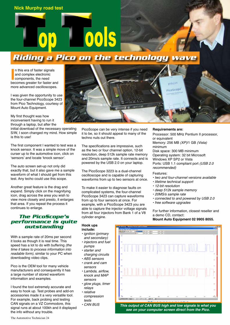
In this era of faster signals and complex electronic components, the need
becomes greater for faster and more advanced oscilloscopes.
I was given the opportunity to use the four-channel PicoScope 3423 from Pico Technology, courtesy of Mount Auto Equipment.
My first thought was how inconvenient having to run it through a laptop, but after the initial download of the necessary operating S/W, I soon changed my mind. How simple is this to use!
The first component I wanted to test was a knock sensor. It was a simple move of the curser up to the automotive icon, click on ‘sensors’ and locate ‘knock sensor’.
The auto screen set-up not only did exactly that, but it also gave me a sample waveform of what I should get from this test. Any techo could use this scope.
Another great feature is the drag and expand. Simply click on the magnifying icon, drag across the area you wish to view more closely and presto, it enlarges that area. If you repeat the process it continues to enlarge.
The PicoScope’s performance is quite
outstanding
With a sample rate of 20ms per second it looks as though it is real time. This speed has a lot to do with buffering (the time it takes to process information into readable form), similar to your PC when downloading video clips.
Pico is the OEM tool for many vehicle manufacturers and consequently it has a large number of stored waveform information and examples.
I found the tool extremely accurate and easy to hook up. Test probes and add-on accessories made it a very versatile tool. For example, back probing and testing CAN signals on a VZ Commodore, this signal runs at about 100kh and it displayed the info without any trouble.
PicoScope can be very intense if you need it to be, so it should appeal to many of the techno nuts out there.
The specifications are impressive, such as the two or four channel option, 12-bit resolution, deep 512k sample rate memory and 20ms/s sample rate. It connects and is powered by the USB 2.0 on your laptop.
The PicoScope 3223 is a dual-channel oscilloscope and is capable of capturing waveforms from up to two sensors at once.
To make it easier to diagnose faults on complicated systems, the four-channel PicoScope 3423 can capture waveforms from up to four sensors at once. For example, with a PicoScope 3423 you are able to capture the injector voltage signals from all four injectors from Bank 1 of a V8 cylinder engine.
Hook ups include: • ignition (primary
and secondary) • injectors and fuel
pumps • starter and
charging circuits • ABS sensors• crank and cam
sensors • Lambda, airflow,
knock and MAP sensors
• glow plugs, timer relays
• relative compression tests
• CAN BUS
Requirements are:Processor: 500 MHz Pentium II processor, or equivalent Memory: 256 MB (XP)/1 GB (Vista) minimum Disk space: 300 MB minimum Operating system: 32 bit Microsoft Windows XP SP2 or Vista Ports: USB 1.1 compliant port (USB 2.0 recommended)Features:• two and four-channel versions available• lifetime technical support • 12-bit resolution• deep 512k sample memory• 20MS/s sample rate• connected to and powered by USB 2.0• free software upgrades
For further information, closest reseller and a demo CD, contact:Mount Auto Equipment 02 9905 8055.
The Automotive Technician 24
opNick Murphy road test
oolsRiding a Pico on the technology wave
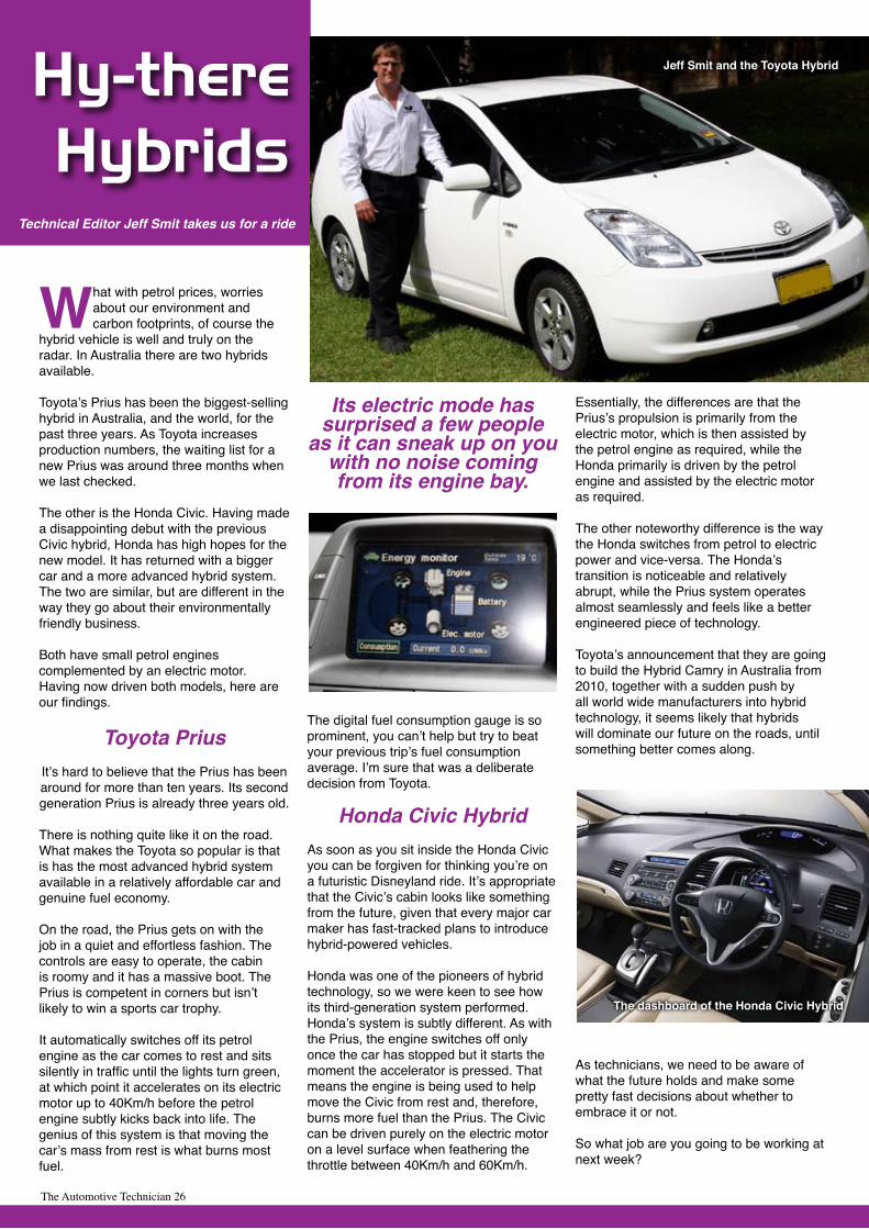
This output of CAN BUS high and low signals is what yousee on your computer screen direct from the Pico.
The Automotive Technician 25
The Automotive Technician 26
What with petrol prices, worries about our environment and carbon footprints, of course the
hybrid vehicle is well and truly on the radar. In Australia there are two hybrids available.
Toyota’s Prius has been the biggest-selling hybrid in Australia, and the world, for the past three years. As Toyota increases production numbers, the waiting list for a new Prius was around three months when we last checked.
The other is the Honda Civic. Having made a disappointing debut with the previous Civic hybrid, Honda has high hopes for the new model. It has returned with a bigger car and a more advanced hybrid system.The two are similar, but are different in the way they go about their environmentally friendly business.
Both have small petrol engines complemented by an electric motor. Having now driven both models, here are our findings.
Toyota PriusIt’s hard to believe that the Prius has been around for more than ten years. Its second generation Prius is already three years old.
There is nothing quite like it on the road.What makes the Toyota so popular is that is has the most advanced hybrid system available in a relatively affordable car and genuine fuel economy.
On the road, the Prius gets on with the job in a quiet and effortless fashion. The controls are easy to operate, the cabin is roomy and it has a massive boot. The Prius is competent in corners but isn’t likely to win a sports car trophy.
It automatically switches off its petrol engine as the car comes to rest and sits silently in traffic until the lights turn green, at which point it accelerates on its electric motor up to 40Km/h before the petrol engine subtly kicks back into life. The genius of this system is that moving the car’s mass from rest is what burns most fuel.
Its electric mode has surprised a few people
as it can sneak up on you with no noise coming from its engine bay.
The digital fuel consumption gauge is so prominent, you can’t help but try to beat your previous trip’s fuel consumption average. I’m sure that was a deliberate decision from Toyota.
Honda Civic HybridAs soon as you sit inside the Honda Civic you can be forgiven for thinking you’re on a futuristic Disneyland ride. It’s appropriate that the Civic’s cabin looks like something from the future, given that every major car maker has fast-tracked plans to introduce hybrid-powered vehicles.
Honda was one of the pioneers of hybrid technology, so we were keen to see how its third-generation system performed.Honda’s system is subtly different. As with the Prius, the engine switches off only once the car has stopped but it starts the moment the accelerator is pressed. That means the engine is being used to help move the Civic from rest and, therefore, burns more fuel than the Prius. The Civic can be driven purely on the electric motor on a level surface when feathering the throttle between 40Km/h and 60Km/h.
Essentially, the differences are that the Prius’s propulsion is primarily from the electric motor, which is then assisted by the petrol engine as required, while the Honda primarily is driven by the petrol engine and assisted by the electric motor as required.
The other noteworthy difference is the way the Honda switches from petrol to electric power and vice-versa. The Honda’s transition is noticeable and relatively abrupt, while the Prius system operates almost seamlessly and feels like a better engineered piece of technology.
Toyota’s announcement that they are going to build the Hybrid Camry in Australia from 2010, together with a sudden push by all world wide manufacturers into hybrid technology, it seems likely that hybrids will dominate our future on the roads, until something better comes along.
As technicians, we need to be aware of what the future holds and make some pretty fast decisions about whether to embrace it or not.
So what job are you going to be working at next week?
Hy-thereHybrids
Technical Editor Jeff Smit takes us for a ride
The dashboard of the Honda Civic Hybrid
Jeff Smit and the Toyota Hybrid
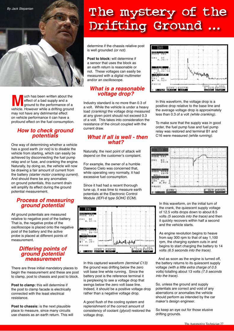
The Automotive Technician 27
Much has been written about the effect of a bad supply and a ground to the performance of a
vehicle. However while a drifting ground may not have any detrimental effect on vehicle performance it can have a profound effect on the fuel consumption.
How to check ground potentials
One way of determining whether a vehicle has a good earth (or not) is to disable the vehicle from starting, which can easily be achieved by disconnecting the fuel pump relay and or fuse, and cranking the engine. Naturally, by doing so, the vehicle will now be drawing a fair amount of current from the battery (starter motor cranking current). And should there be any anomalies on ground potentials, this current drain will amplify its effect during the ground potential measurement.
Process of measuring ground potential
All ground potentials are measured relative to negative post of the battery. That is, the negative probe of the oscilloscope is placed onto the negative post of the battery and the active probe is placed at different points of measurement.
Differing points of ground potential
measurementThere are three initial mandatory places to begin the measurement and these are post to clamp, post to chassis and post to block.
Post to clamp: this will determine if the post to clamp facade is electrically connected with the least electrical resistance.
Post to chassis: is the next plausible place to measure, since many circuits use chassis as an earth return. This will
determine if the chassis relative post is well grounded (or not).
Post to block: will determine if a sensor that uses the block as an earth return is reasonable or not. These voltages can easily be measured with a digital multimeter and/or an oscilloscope.
What is a reasonable voltage drop?
Industry standard is no more than 0.3 of a volt. While the vehicle is under a heavy load (cranking) the voltage drop measured at any given point should not exceed 0.3 of a volt. This takes into consideration the resistance of the circuit coupled with the current draw.
What if all is well - then what?
Naturally, the next point of attack will depend on the customer’s complaint. For example, the owner of a humble Daewoo Cielo was concerned that, while operating very normally, it had excessive fuel consumption.
Since it had had a recent thorough tune up, it was time to measure earth potentials at the Electronic Control Module (IEFI-6 type SOHC ECM).
In this captured waveform (terminal C13) the ground was drifting below the zero volt base line while running. Since the battery post is the reference terminal it is perplexing to see a voltage drop that swings below the zero volt base line. Indeed, it should be a positive voltage drop rather than a negative voltage drop.
A good flush of the cooling system and replenishment of the correct amount of consistency of coolant (glycol) restored the voltage drop.
In this waveform, the voltage drop is a positive drop relative to the base line and the average voltage drop is approximately less than 0.3 of a volt (while cranking).
To make sure that the supply was in good order, the fuel pump fuse and fuel pump relay was restored and terminal B1 and C16 were measured (while running).
In this waveform, on the initial turn of the crank, the quiescent supply voltage of 12.5 volts drops down to about 8.5 volts (5 seconds into the trace) and then it quickly recovers within half a second and the vehicle starts.
As engine revolution begins to heave from say 300 rpm to that of say 1,100 rpm, the charging system cuts in and begins to start charging the battery to 14 volts (6.5 seconds into the trace).
And as soon as the engine is turned off, the battery returns to its quiescent supply voltage (with a little extra charge of 0.5 volts) totalling about 13 volts (7.5 seconds into the trace).
So, unless the ground and supply potentials are correct and void of any aberrations or anomalies the vehicle should perform as intended by the car maker’s design engineer.
So keep an eye out for those elusive drifting grounds.
The mystery of theDrifting Ground ...
By Jack Stepanian
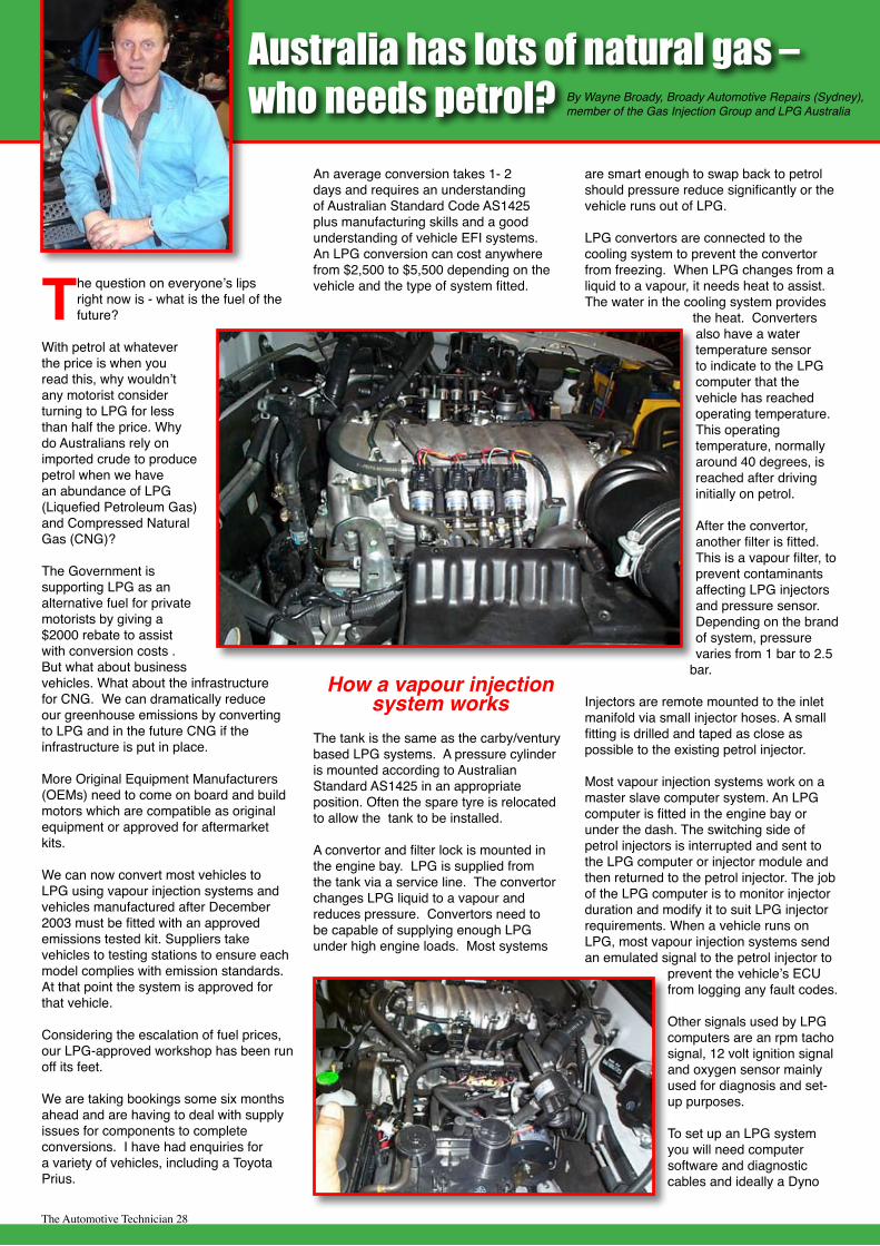
The Automotive Technician 28
The question on everyone’s lips right now is - what is the fuel of the future?
With petrol at whatever the price is when you read this, why wouldn’t any motorist consider turning to LPG for less than half the price. Why do Australians rely on imported crude to produce petrol when we have an abundance of LPG (Liquefied Petroleum Gas) and Compressed Natural Gas (CNG)?
The Government is supporting LPG as an alternative fuel for private motorists by giving a $2000 rebate to assist with conversion costs . But what about business vehicles. What about the infrastructure for CNG. We can dramatically reduce our greenhouse emissions by converting to LPG and in the future CNG if the infrastructure is put in place.
More Original Equipment Manufacturers (OEMs) need to come on board and build motors which are compatible as original equipment or approved for aftermarket kits.
We can now convert most vehicles to LPG using vapour injection systems and vehicles manufactured after December 2003 must be fitted with an approved emissions tested kit. Suppliers take vehicles to testing stations to ensure each model complies with emission standards. At that point the system is approved for that vehicle.
Considering the escalation of fuel prices, our LPG-approved workshop has been run off its feet. We are taking bookings some six months ahead and are having to deal with supply issues for components to complete conversions. I have had enquiries for a variety of vehicles, including a Toyota Prius.
An average conversion takes 1- 2 days and requires an understanding of Australian Standard Code AS1425 plus manufacturing skills and a good understanding of vehicle EFI systems. An LPG conversion can cost anywhere from $2,500 to $5,500 depending on the vehicle and the type of system fitted.
How a vapour injection system works
The tank is the same as the carby/ventury based LPG systems. A pressure cylinder is mounted according to Australian Standard AS1425 in an appropriate position. Often the spare tyre is relocated to allow the tank to be installed.
A convertor and filter lock is mounted in the engine bay. LPG is supplied from the tank via a service line. The convertor changes LPG liquid to a vapour and reduces pressure. Convertors need to be capable of supplying enough LPG under high engine loads. Most systems
are smart enough to swap back to petrol should pressure reduce significantly or the vehicle runs out of LPG.
LPG convertors are connected to the cooling system to prevent the convertor from freezing. When LPG changes from a liquid to a vapour, it needs heat to assist. The water in the cooling system provides
the heat. Converters also have a water temperature sensor to indicate to the LPG computer that the vehicle has reached operating temperature. This operating temperature, normally around 40 degrees, is reached after driving initially on petrol.
After the convertor, another filter is fitted. This is a vapour filter, to prevent contaminants affecting LPG injectors and pressure sensor. Depending on the brand of system, pressure varies from 1 bar to 2.5
bar.
Injectors are remote mounted to the inlet manifold via small injector hoses. A small fitting is drilled and taped as close as possible to the existing petrol injector.
Most vapour injection systems work on a master slave computer system. An LPG computer is fitted in the engine bay or under the dash. The switching side of petrol injectors is interrupted and sent to the LPG computer or injector module and then returned to the petrol injector. The job of the LPG computer is to monitor injector duration and modify it to suit LPG injector requirements. When a vehicle runs on LPG, most vapour injection systems send an emulated signal to the petrol injector to
prevent the vehicle’s ECU from logging any fault codes.
Other signals used by LPG computers are an rpm tacho signal, 12 volt ignition signal and oxygen sensor mainly used for diagnosis and set-up purposes. To set up an LPG system you will need computer software and diagnostic cables and ideally a Dyno
Australia has lots of natural gas – who needs petrol? By Wayne Broady, Broady Automotive Repairs (Sydney),
member of the Gas Injection Group and LPG Australia
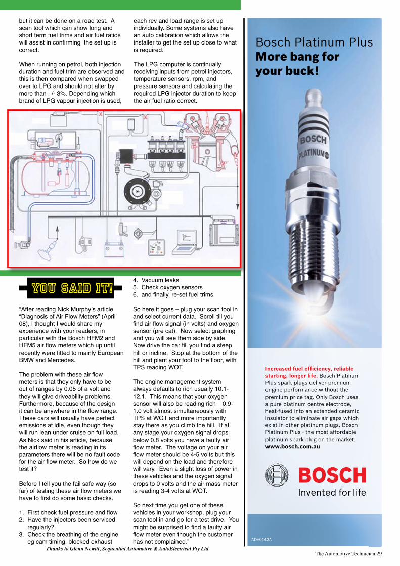
The Automotive Technician 29
but it can be done on a road test. A scan tool which can show long and short term fuel trims and air fuel ratios will assist in confirming the set up is correct.
When running on petrol, both injection duration and fuel trim are observed and this is then compared when swapped over to LPG and should not alter by more than +/- 3%. Depending which brand of LPG vapour injection is used,
each rev and load range is set up individually. Some systems also have an auto calibration which allows the installer to get the set up close to what is required.
The LPG computer is continually receiving inputs from petrol injectors, temperature sensors, rpm, and pressure sensors and calculating the required LPG injector duration to keep the air fuel ratio correct.
“After reading Nick Murphy’s article “Diagnosis of Air Flow Meters” (April 08), I thought I would share my experience with your readers, in particular with the Bosch HFM2 and HFM5 air flow meters which up until recently were fitted to mainly European BMW and Mercedes.
The problem with these air flow meters is that they only have to be out of ranges by 0.05 of a volt and they will give driveability problems. Furthermore, because of the design it can be anywhere in the flow range. These cars will usually have perfect emissions at idle, even though they will run lean under cruise on full load. As Nick said in his article, because the airflow meter is reading in its parameters there will be no fault code for the air flow meter. So how do we test it?
Before I tell you the fail safe way (so far) of testing these air flow meters we have to first do some basic checks.
1. First check fuel pressure and flow2. Have the injectors been serviced regularly?3. Check the breathing of the engine eg cam timing, blocked exhaust
4. Vacuum leaks5. Check oxygen sensors6. and finally, re-set fuel trims
So here it goes – plug your scan tool in and select current data. Scroll till you find air flow signal (in volts) and oxygen sensor (pre cat). Now select graphing and you will see them side by side. Now drive the car till you find a steep hill or incline. Stop at the bottom of the hill and plant your foot to the floor, with TPS reading WOT.
The engine management system always defaults to rich usually 10.1-12.1. This means that your oxygen sensor will also be reading rich – 0.9-1.0 volt almost simultaneously with TPS at WOT and more importantly stay there as you climb the hill. If at any stage your oxygen signal drops below 0.8 volts you have a faulty air flow meter. The voltage on your air flow meter should be 4-5 volts but this will depend on the load and therefore will vary. Even a slight loss of power in these vehicles and the oxygen signal drops to 0 volts and the air mass meter is reading 3-4 volts at WOT.
So next time you get one of these vehicles in your workshop, plug your scan tool in and go for a test drive. You might be surprised to find a faulty air flow meter even though the customer has not complained.”
You said it!
Thanks to Glenn Newitt, Sequential Automotive & AutoElectrical Pty Ltd

The Automotive Technician 30
The June Wire & Gas Convention hosted by VASA on the Gold Coast, was a perfect opportunity to explore the issues which might impact on technicians in the motor industry over the next few years.
Apart from the headlong march of technology itself, there were other things dominating many conversations. Not the least of these was the Australian Government’s announcements on the emissions trading agenda, now known as the Carbon Pollution Reduction Scheme.
Details are hazy at present, but at the convention, delegates were warned that every technician running a workshop would feel the effects of this scheme one way or another, and those handling refrigerant, especially R134a, could face dramatic increases in the price of this commodity.
TaT sought the sage advice of technology importer and guru of the automotive climate control sector, Mark Mitchell, Vice-President of VASA, and industry representative on Refrigerant Reclaim Australia and Refrigerants Australia. He was a foundation board member of the Australian Refrigeration Council, and has represented the Australian Government at a world summit on environmental management of refrigerants.
“I certainly agree with the tone of the keynote speakers at the convention, that the future is full of opportunities for the smart technician.
There will be lots of new challenges both at the technical and business level, but mixed up in this will be a fair share of frustrations.
A great deal of my personal frustration comes from problems which could have been avoided.
For example, I became frustrated by comments from technicians during the VASA AGM, that they were seeing hydrocarbon refrigerants in farm vehicles, and even one direct from a dealership.
This is disheartening, when you consider that there are sufficient rules and regulations
in place in all states to cope with this. In those states where HCs in mobile situations are not totally banned, any workshop using them must first obtain the written approval of the manufacturer of the vehicle.
I get frustrated when organisations and governments go to so much trouble to avoid these situations, but it becomes obvious that people seem to enjoy acting illegally.
It’s early days on the Carbon Pollution Reduction Scheme, but all those technicians handling refrigerant need to know that organisations like VASA are in the thick of the debate, expressing the views of the working technician.
We are not anti-environment, but we have to be interested and concerned if, on current information, the price of HFC refrigerant could rise by $39 a kilo.
From my early involvement in this carbon tax issue, I have to say that at present, all I see is a government full of good intentions, but I honestly don’t believe they’ve thought it through.
In the government’s white paper on this question, they talk about equipment which comes into Australia already charged with refrigerant, which has the potential to rope equipment importers into the Carbon Pollution Reduction Scheme. But the paper makes no distinction between stationary and mobile equipment, and they are poles apart. That’s frustrating.
But for the average technician and small workshop out there in surburbia and in country towns and cities, think on this: the public are hurting on fuel prices, forcing them to make decisions about travel and shopping that they’ve never
had to make before, except perhaps during the war years.
People are starting to shop locally. You know what that means to the technician in his suburban workshop?
There’s already less incentive for a car owner to drive across town to their dealership for a service or a repair.
If I were running a retail workshop right now, I would begin a campaign to make sure that every household within a couple of kilometres of my workshop knew the services I provided, and how easy it is to find me.
Motorists might stick to their dealership while under warranty, but when that expires, just watch them look for a smart local service centre.
Take it from me that when the full impact of the carbon tax bites, everyone will feel the
impact, one way or another.
It will infiltrate down through the community. It has been forecast that the carbon tax will be the biggest single monetary event since the invention of money itself.
So my advice to the technicians of Australia is to make yourself aware of the carbon tax issue and prepare yourself for it.
Join an association, it doesn’t really matter which one, but find one which will keep you informed. VASA is certainly one of those because it represents the AC and auto electrical industries across Australia and New Zealand, and is well connected through its affiliations with organisational and government thinking.
If you are in AC you also need to be kept informed of the new refrigerants which will impact on you in the next few years.
So grab the opportunies, keep on accumulating knowledge, and, as far as the carbon tax is concerned, just watch this space.”
“The carbon tax will be the biggest single monetary event since the invention of money itself”
SX
E-P
rob
ewww.sxeprobe.com
call 02 9905 8055for your nearest Distributor
SXE-ProbeVFP1000
The SXE-Probe is a superior Logic Probe that combines the features of a digital multi-meter and oscilloscope but simplifying the display for technicians that want to find the pulse but don’t need to see the trace signal
View at the push of a button
Voltage• Frequency• Duty Cycle•
Sensor and Circuit Check
Starter Motor
Battery Load
Alternator
Fuel Pump
Stepper Motor
Fuel Injector
CAN - Multiplex
MAP Sensor
Crank Angle Sensor
Camshaft Position Sensor
Throttle Position Sensor
.... and so much MORE!
Makes Trouble ShootingEASY!FAST!
ACCURATE!
Safe for Automotive Computers
Safe for Automotive Sensors
Analyse any type of signal!
Perform continuity tests!
Trace circuit wires!