TECHNICIAN - World Radio History
84
FEBRUARY 1966 VOL. 83 NO. 2 RON KIPP JACK HOBBS QUINTO BOCCHI DOUGLAS HEDIN RICHARD CLAYTON DONALD GRANT JUDITH BERINI MAGGIE KANE GEORGE LIPPISCH RUTH GELINEAU Publisher Managing Editor Technical Editor Industrial Editor Field Editor Assistant Editor Editorial Production Advertising Production Artist Circulation Fulfillment AN OJIBWAY PUBLICATION OJIBWAY PRESS, Inc. Ojibway Building, Duluth, Minn. 55802 AREA CODE 218 727-8511 PUBLICATIONS DIVISION, OJIBWAY PRESS, INC. ROBERT EDGELL President ANGUS STONE Marketing Manager BEN MARSH Editorial Director HARRY RAMALEY Production Director JIM GHERNA Art Director JOE WOLKING Circulation Director Sales Offices: NEW YORK: Ron Kipp, 25 W. 45 St. New York, N.Y. 10036 AREA CODE 212 581.4200 CHICAGO: Jack Daniels, 221 N. LaSalle St., Chicago, Ill. 60601 AREA CODE 312 CE 6.1600 Copyright 1966 by Ojibway Press, Inc., Duluth, Minn. 55802. Reproduction and reprinting pro- hibited except by written authorization of the publication. Subscription price: $5 for 1 year, $8 for 2 years, $10 for 3 years. Pan American and Foreign, $9 for 1 year, $14 for 2 years, and $18 for 3 years. If you have a change of address or a ques- tion about your subscription, write: ELEC- TRONIC TECHNICIAN, Circulation Department, Ojibway Building, Duluth, Minnesota 55802. BE SURE TO SEND ALONG THE ADDRESS LABEL FROM YOUR MOST RECENT ISSUE. POSTMASTER: Second class postage paid at Waseca, Minnesota and at additional mailing offices. Send notification form 3579 to ELECTRONIC TECHNICIAN, Ojibway Building, Duluth, Minnesota 55802. 1 ELECTRONIC TECHNICIAN WORLD'S LARGEST ELECTRONIC TRADE CIRCULATION Cover The professional 'image' of service -dealers and technicians begins with an in -home service call at the doors of 52 -million homes in the nation that now have TV sets. FEATURES In -Home Servicing 39 How to shorten your work week and boost returns through increased productivity Dial 'B' For Broke 42 Use manufacturers diagrams and instructions to make dial -stringing pay Doing More With Your VTVM 45 A variety of jobs you can get done easily Servicing Solid -State TV Circuits 48 Begin learning how to troubleshoot today's circuits successfully Solving UHF Reception Problems 50 How to reduce ca// -backs on ultra high frequency antenna installations Volume Limiting In Communications 53 Conclusion of an article for two-way technicians Blanking and Gating in Color Sets 56 Don't let pulse -actuated circuits 'throw' you Life Insurance for the Shop Owner 80 Falling Off a Log-arithm 84 DEPARTMENTS Letters to the Editor 22 New Products 64 Editor's Memo 26 New Literature 85 Sync on Business 28 News of the Industry 86 Technical Digest 32 Advertisers Index 94 Colorfax 58 Reader Service Card 95 TEKFAX ________ 16 PAGES OF THE LATEST SCHEMATICS MAGNAVOX: TV Chassis T910 Series RCA VICTOR: Color TV Chassis CTC19 SILVERTONE: TV Chassis 564.10000 564.10001 564.10003 564.10002 564.10004 564.10005 SYLVANIA: Color TV Chassis D03.2 TRUETONE: TV Model 2DC1605 ZENITH: TV Chassis 14N31 FEBRUARY 1966 21
-
Upload
khangminh22 -
Category
Documents
-
view
0 -
download
0
Transcript of TECHNICIAN - World Radio History
FEBRUARY 1966
VOL. 83 NO. 2
RON KIPP
JACK HOBBS
QUINTO BOCCHI
DOUGLAS HEDIN
RICHARD CLAYTON
DONALD GRANT
JUDITH BERINI
MAGGIE KANE
GEORGE LIPPISCH
RUTH GELINEAU
Publisher
Managing Editor
Technical Editor
Industrial Editor
Field Editor
Assistant Editor
Editorial Production
Advertising Production
Artist
Circulation Fulfillment
AN OJIBWAYPUBLICATION
OJIBWAY PRESS, Inc.Ojibway Building, Duluth, Minn. 55802
AREA CODE 218 727-8511
PUBLICATIONS DIVISION,OJIBWAY PRESS, INC.ROBERT EDGELL PresidentANGUS STONE Marketing ManagerBEN MARSH Editorial DirectorHARRY RAMALEY Production DirectorJIM GHERNA Art DirectorJOE WOLKING Circulation Director
Sales Offices:
NEW YORK: Ron Kipp, 25 W. 45 St.New York, N.Y. 10036AREA CODE 212 581.4200
CHICAGO: Jack Daniels, 221 N. LaSalleSt., Chicago, Ill. 60601AREA CODE 312 CE 6.1600
Copyright 1966 by Ojibway Press, Inc., Duluth,Minn. 55802. Reproduction and reprinting pro-hibited except by written authorization of thepublication. Subscription price: $5 for 1 year,$8 for 2 years, $10 for 3 years. Pan Americanand Foreign, $9 for 1 year, $14 for 2 years,and $18 for 3 years.If you have a change of address or a ques-tion about your subscription, write: ELEC-TRONIC TECHNICIAN, Circulation Department,Ojibway Building, Duluth, Minnesota 55802.BE SURE TO SEND ALONG THE ADDRESSLABEL FROM YOUR MOST RECENT ISSUE.POSTMASTER: Second class postage paid atWaseca, Minnesota and at additional mailingoffices. Send notification form 3579 toELECTRONIC TECHNICIAN, Ojibway Building,Duluth, Minnesota 55802.
1 ELECTRONICTECHNICIAN
WORLD'S LARGEST ELECTRONIC TRADE CIRCULATION
Cover
The professional 'image' of service -dealers and technicians begins with an in -home service callat the doors of 52 -million homes in the nation that now have TV sets.
FEATURESIn -Home Servicing 39
How to shorten your work week and boost returns through increased productivity
Dial 'B' For Broke 42Use manufacturers diagrams and instructions to make dial -stringing pay
Doing More With Your VTVM 45A variety of jobs you can get done easily
Servicing Solid -State TV Circuits 48Begin learning how to troubleshoot today's circuits successfully
Solving UHF Reception Problems 50How to reduce ca// -backs on ultra high frequency antenna installations
Volume Limiting In Communications 53Conclusion of an article for two-way technicians
Blanking and Gating in Color Sets 56Don't let pulse -actuated circuits 'throw' you
Life Insurance for the Shop Owner 80
Falling Off a Log-arithm 84
DEPARTMENTSLetters to the Editor 22 New Products 64
Editor's Memo 26 New Literature 85
Sync on Business 28 News of the Industry 86
Technical Digest 32 Advertisers Index 94
Colorfax 58 Reader Service Card 95
TEKFAX ________ 16 PAGES OF THE LATEST SCHEMATICS
MAGNAVOX: TV Chassis T910 SeriesRCA VICTOR: Color TV Chassis CTC19
SILVERTONE: TV Chassis 564.10000
564.10001 564.10003
564.10002 564.10004
564.10005
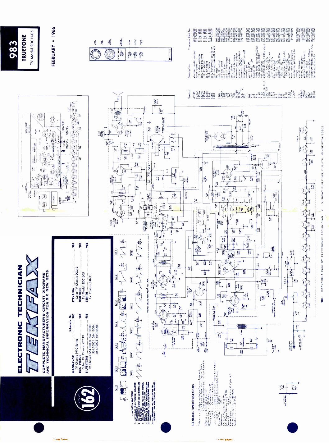
SYLVANIA: Color TV Chassis D03.2
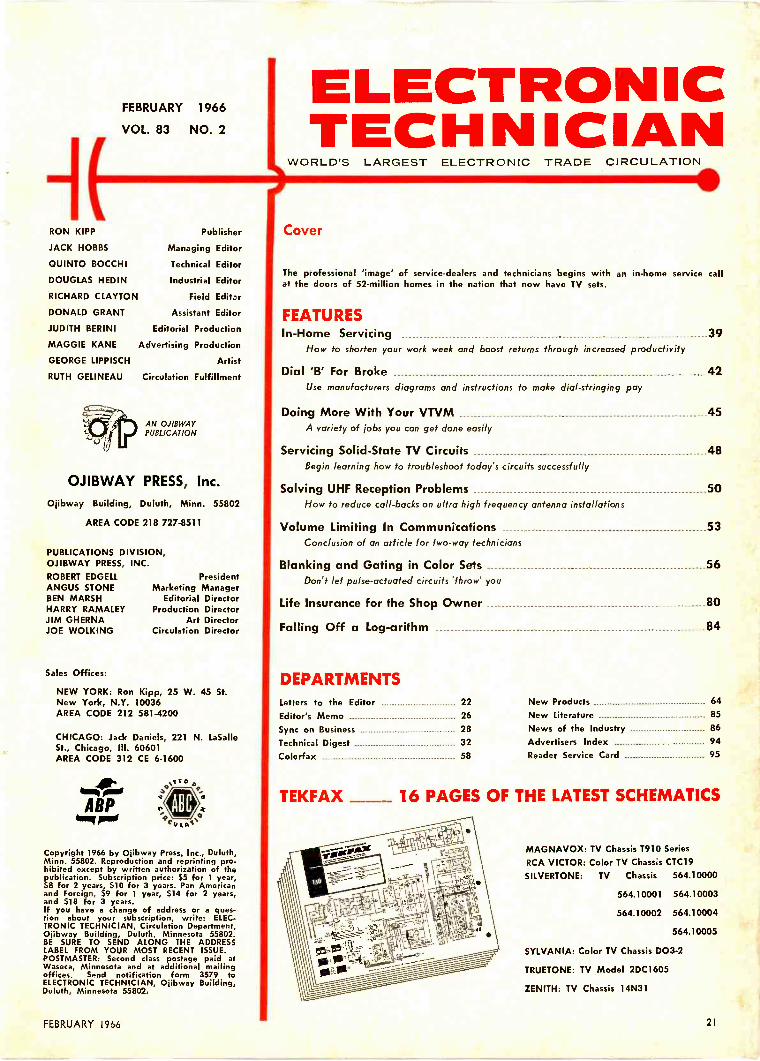
TRUETONE: TV Model 2DC1605
ZENITH: TV Chassis 14N31
FEBRUARY 1966 21
GR
OU
P
lw-1
)
!9!ii
:r7
5v30
5.
- V
OLT
AG
ES
A W
AV
EF
OR
MS
-
I - U
NE
VO
LAG
E 1
15A
.C.1
1PR
OU
GH
ISO
UIT
ION
TR
AN
SF
OR
ME
R.
2- A
LL V
OLT
AG
ES
SH
OW
N O
N S
CH
EM
AT
IC A
RE
D.C
. RE
AD
ING
S,
3- V
OLT
AG
E R
EA
DIN
GS
TA
KE
N W
ITH
NO
RM
AL
SIG
NA
L IN
PU
T U
SIN
G A
V.T
.V.1
4,4-
CO
NT
RO
LS S
ET
FO
R N
OR
MA
L O
PE
RA
TIO
N,
5- W
AV
EF
OR
MS
TA
KE
N W
ITH
NO
RM
AL
SIG
NA
LIN
PU
T.
6- A
LL W
AV
EF
OR
M V
OLT
AG
ES
SH
OW
N O
NS
CH
EM
AT
IC A
RE
PE
AK
TO
PE
AK
RE
AD
ING
S.
GE
NE
RA
L S
PE
CIF
ICA
TIO
NS
ELE
CT
RO
NIC
TE
CH
NIC
IAN
211:
:=E
FC
OM
PLE
TE
MA
NU
FA
CT
UR
ER
S' C
IRC
UIT
DIA
GR
AM
SA
ND
TE
CH
NIC
AL
INF
OR
MA
TIO
N F
OR
SIX
NE
W S
ET
S
Sch
emat
ic N
o.M
AG
NA
VO
X98
5S
YLV
AN
IA98
7T
V C
hass
is T
910
Ser
ies
Col
or T
V C
hass
is D
03-2
RC
A V
ICT
OR
984
TR
UE
TO
NE
983
Col
or T
V C
hass
is C
TC
19T
V M
odel
2D
C16
05S
ILV
ER
TO
NE
988
ZE
NIT
H98
6T
V C
hass
is 1
4N31
TV
Cha
ssis
564
.100
00 5
64.1
0003
564.
1000
1 56
4.10
004
564.
1000
2 56
4.10
005
750
301.
vjV
2ka
$0',
4k3,
3%
CIW-9
tor
Tub
es ..
..I5
tube
s, in
clud
ing
Pic
ture
Tub
e an
d1
HV
Rec
tifie
r T
ube,
plu
s 1
Cry
stal
Dio
de1
Dua
l Sel
eniu
m D
iode
and
1S
oloc
on R
ectif
ier
Ant
enna
...E
xter
nal o
r B
uilt-
inA
nten
na In
put
300
ohm
sT
unin
g V
.H.F
..C
honn
els
2 th
ru 1
3U
.H.F
Cha
nnel
s 14
thru
83
Tun
er V
.H.F
... S
tand
ard
Kol
lsm
an "
Fra
me
Grid
Arb
or"
U.H
.FS
tond
ard
Kol
lsm
an S
olid
Sta
teP
ictu
re T
ube
23C
JP4
Def
lect
ion
110°
I.F. S
ound
Car
rier
41.2
5 M
CI.F
. Pic
ture
Car
rier,
-45.
75 M
CS
ound
I. F
4 . 5
MC
Pow
er S
uppl
y11
0-12
0 V
olts
60
Cyc
le A
.C.
Pow
er C
onsu
mpt
ion.
.15
0 W
atts
Spe
aker
4" P
.M.
cok1
RO
L01
0 @
RA
CK
ET
C-1
71of
of
I 4 v
iv
R-1
6747
0K
Po
4711
INC
.Tim
TO
P to
o
to.
rom
p
10
NN
.T
ut.
043
Wit
Ivr-
.11
L
jw-e
l
PR
INT
ED
WA
RD
AS
SE
MB
LY*
PIA
-40
6
tot I
.F.
AM
PLI
FIE
Rv1
-44E
117
207
Pum
p,T
A 4
.4
84.1
1,0
1.05
4TP
-4R
d
non
SOV
L-20
4
n'°
Nor
1 .
4000
fOa
;14.
I--
.
2401
FA
MP
LIF
IER
4EvT
:7c"
0-20
4 long
RIO
4.4
IT
0.71
4.1
no.
To
.005 woo
f 4.
volf
rut.
Ak$
A1(
0 L
APC
LA
T00
AR
A S
SON
A,
foam
ok<
M..K
000
auto
art
/fp
. /
arz,
1,
carr
fe.
Vie
(Dor
TO
N 9
.04,
S10
9. T
imir
1.4
45 P
c so
up°
T.,
1
:4. 1
" "
r707
sop:
P:2
;
1
I PO
MO
. 901
.0
cwifp
fA
lt
0091
9:9
=T
Mflufa
s flp
sum
,011
170L
11).
RA
IRT
CO
S
,E0
^^^^
^A
A A
A A
qt"
Pd"
,41
799
0141
1.07
1004
91W
V P
.G
. SO
SL-
""^1<;
SO
UN
DF
AM
PLI
FIE
RvT
-7A
MIL
S
90.1
109
14.9
1151
4C S
OU
ND
TA
. Off
VID
EO
AM
PLI
FIE
RV
6T-".
1050
6
KE
YE
D A
G C
VT
-78
681.
8
11-1
4O
110
11
0591
.711
07 w
ring
Tom
,
, Num
SOT.
Vfo
frM
I10
0115
1309
nK
0v
0 0
O -
9408
xto
0.1"
1- O
nF
..16
0011
-14
let
302
L-20
3
C -
r
TO
P W
.1.1
1111
19
.01.
910
TR
Y
ND
DE
SO
UT
EC
TO
RV
T -
04
016
a"
70
Au0
40_0
0.1
cc.V
C IS
/.0
0
it.L
4-20
04
t5/
5901
1
L _
L _9
1__/
Can
L -0
7A
tee
J.1
4?
3
Vv.
9,2
114K
/
ce4
0471
4
C-6
7
Ur
c
VE
RT
ICA
L
FOIOB 0.00
430
00
I-10
3W
OK
-Ki
tole
HO
RIZ
ON
TA
LO
SC
VT
-1s
111F
07
MO
DE
......;4
:-. 9:
220.
2200
DIN
01
To
CO
NT
901.
x
0.02
6
c -us
MIA
KN
LIn
L0.
70Li
mo
rtirt
NO
LO
C-0
0
WO
O
Av
c404
WO
O
0-
70
.44, 33
0KI
0.
/4II.
24co
pTiu
.P
OG
Oco
^^^
^^^
17L
_
TP
-2
1
C-4
/111
1
TP
-3 I -
*WO
W01
uor
3
AU
DIO
OU
TP
UT
VT
-9
1050
1
94'0
-1?
L,. Ile
Boa
-ter
0-10
9
L-20
2
NY
#0-
104
Noo
11-1
20
1.0:
50
WY
cia
-Si
0- J
ut.3
1111
7F01
0-A
SA
MT
.30.
7c
-es
KKM ^
-0- ot
.901
.0
4000
. HO
LD
0424
HO
RiZ
ON
TA
LO
UT
PU
TvT
-021
573
7..1
-4; 80
;141 40.
6.
130V
`
HIG
H V
OLT
AG
ER
EC
TIF
IER
VT
-I5
103
ouI
eul
.00
0503
.033
171
0200
c.oi
t4
e 41
0.
1
-o-
4100
0
` M
oor
NO
to
SR
-27
tic -
21A
C-2
0.II
zoov
2000
0-40
woo ivy
I
lion ,;1
1M
oon
141
Tit
171E
321
615
13F
C0
IOC
W5
L
IFS
?10
5015
44
0710
506
c`.
` 0-16
110
00W
OO
ISE
tla40
16V
173
1000
I
1r j
PT
O..
134J
91
TU
NE
R
'550
730503'
19.
000
oao
Sym
bol
AT
-83
FC
23A
L126
AL1
27A
L128
AL1
33A
1164
L202
L203
L204
L206
AL2
07L2
08L2
63L2
67L3
02T
R-7
8BT
R-9
4R
26, 7
0R
27
R69
R70
R7I
R11
1R
123
R16
3C
20A
, B, C
, DC
54, 1
59C
106
C17
1C
172
R11
R13
R58
R74
R11
0R
164
CC
206
C09
9
F19 MP
367
PW
361
SC
6S
R27
SR
20T
S17
3
983
TR
UE
TO
NE
TV
Mod
el 2
DC
1605
FEB
RU
AR
Y 1
966
CR
P
11.7
44:5
5
-a
NI0
0570
.
coil,
vid
eo p
eaki
ngco
il, v
ideo
pea
king
coil,
RF
cho
keco
il, R
F c
hoke
chok
e he
ater
coil,
hor
izon
tal o
scill
ator
coil,
sou
nd ta
ke -
off 8
4.5
Mc
trap
coil,
IF o
utpu
tco
il sn
d qu
adco
il IF
inpu
tco
il IF
inte
rsta
gede
flect
ion
yoke
coil,
cho
keco
il sn
d in
ters
tage
xfor
mer
ver
t out
put
xfor
mer
, hor
iz o
utpu
tco
ntra
st,
1000
11br
ight
ness
with
on
-off
switc
h 5M
vert
lin
0.5M
vert
hol
d, I.
5Mhe
ight
5M
horiz
freq
adj
ust 5
0,00
0:1
horiz
hol
d, 7
5,00
011
vol 5
00,0
000
250-
200-
40-1
0µf 2
00v
elec
t03
4.01
8800
.01µ
f 1.4
kv 2
0%82
6-10
3826
330p
f 500
v 57
mic
a04
5-00
7200
.01,
0 1.
4kv
10%
837-
1038
2625
0 25
v el
ect
1251
2 4w
10%
3600
0 5w
10%
WW
1300
lw 5
%th
erm
isto
r, 9
.612
col
d12
000
1/2w
5%
4.54
lOw
10%
WW
sync
take
-of
f cou
plat
eco
nnec
tor,
pic
ture
tube
anod
e08
4-00
9900
circ
uit b
reak
er09
9-00
1900
cove
r, F
IV s
ocke
t10
4-03
6700
prin
ted
circ
uit b
oard
132-
0036
01di
ode
1N29
500
3-00
0600
silic
on r
ectif
ier,
500
ma
004-
0027
00se
leni
um d
iode
, hor
iz A
FC
003
-002
000
term
inal
str
ip y
oke
154-
0173
00
VO
LU
ME
CO
NT
RA
ST
WW
7JA
t/'
Des
crip
tion
Tru
eton
e P
art N
o.
xfor
mer
, aud
io o
utpu
t03
1-00
8300
filte
r ch
oke
032-
0023
011
1-01
260
11
1-01
270
111
-012
801
11-0
1330
111
-016
400
09-0
2020
0
09-0
2030
009
-020
400
09-0
2060
109
-020
700
09-0
2080
002
7-02
6300
111-
0267
0010
9-03
0200
033-
0078
0203
3-00
9400
055-
0397
00
055-
0483
0005
5-03
5000
055-
0398
0005
5-03
5100
055-
0417
0005
5-03
2000
055-
0396
00
034-
0179
0005
7-05
9500
053-
3625
1005
1-13
1150
057-
0565
0005
1-12
2550
053-
3625
1013
4-02
0600
983
CO
PY
RIG
HT
196
6 B
Y E
LEC
TR
ON
IC T
EC
HN
ICIA
NO
JIB
WA
Y B
UIL
DIN
G, D
ULU
TH
, MIN
NE
SO
TA
558
02

984C
TC
19 CH
AS
SIS
VO
LTA
GE
WA
VE
FO
RM
S
RC
A V
ICT
OR
Color T
V C
hassisC
TC
1 9
FE
BR
UA
RY
1966
A
AT
TA
CH
TIM
. PM10401
314/061.
ELE
CT
RO
NIC
1-77=T
EC
HN
ICIA
Ntica
CO
MP
LET
E M
AN
UF
AC
TU
RE
R 5, C
IRC
UIT
DIA
GR
AM
SA
ND
TE
CH
NIC
AL IN
FO
RM
AT
ION
FO
RSIX
NE
W SE
TS
CT
C19 C
HA
SSIS LA
YO
UT
I26. AT
-a
TU
BE
AN
D T
RA
NS
IST
OR
CO
MP
LEM
EN
T
V201 R
CA
6JC.6
Sot. IF A
mplifier
V202 R
CA
6/47.6Sound D
emodulator
V203 R
CA
6)06.
In Pu.nore I.F Am
plifierV
204 RC
A 6)C
62nd Picture I.F A
mplifier
=L
I I RC
Atcv.,A
,G,A
Otm
Am
plifier
I RC
A 6G
/ISA.
JA
G1 Sync Separator
Horizontal O
scillator Control
V.11:,,%
1 I RC
A 6G
P7
,,;::: I RC
A 6G
HSA
iSD
e goad laror
Z,;=
Nu.
6G118A
V [tattoo
RC
AR
GH
RR
Bunt'l
"*r
Am
plifier''l
7,1:4R
CA
6GH
ISA
V705 R
CA
12HG
7V
706 RC
A 6A
Q5A
;1142.4R
CA
6GH
IA
V101 R
CA
3A3
V102 R
CA
6131(413V
103 RC
A 2A
V2
V. R
CA
61363V
105 RC
A 61.6
V104 R
CA
19EY
P22
EPV
42 43°''6JC
6v201
SO
UN
D IF
011.202
2nd Dow
olor low Pant
1.11101,001 .le4v .4
,441.11.6114111.,aa.11.1160419
OV
ICI6A
2A
OC
Grad
Wortsontal foto 30: V
P
T201
SO
UN
D T
AK
EO
FF
TR
AN
S-6V-1
is!
!Itc2oil5
L
L2121.6.10
L2133.90
V200.
Vottoo1 ow
l2Otor
V203
no.0110
6JD6
BLU
EI
BA
ND
-
As7.1
4Law V
iCv2003
1ST
PIX
IF.041
WIE
FIN
AD
4
101047.25
AD
J
.1204Hr.
0.50
Ot
0.216
gI B
lanker3.58 m
e Onillator
Sod Video A
mplifier
Audio O
utputI
Chrom
a Bandpass A
mplifier
1 G -Y
Am
plifier.H
igh Voltage R
ectifierShunt R
egulatorFocus R
ectifierm
Horizontal O
Dautppeut r
Color Picture T
ube
1010.1211A/120811 V
HF/U
NE
Eynon
v1R
CA
61354V
HF R
I Am
phfier n UH
F I.F Am
plifier
'4, I RC
A O
RE
SI V
HF H
aanU
HF I -F A
mplther
311 V
HF O
scillatorR
CA
Q51
51037 (Fairchild)
CT
C19 C
hassis Layout
R162
1111004411
TO
scr1151 44.101146
C2 7
L201261C
R224<
10062206
514270 V
-06217
IF2.2
. 101860A
OC
5810
.0331000
00. TS.)
0.21212 M
K
C220
.01
.068
0222330K
021410 K
0215.te=
021522/26
0259
5011
2,9sac..
=C
219=
1000
°ind O
nti:to.°Lt Point
°1.1 0.4.47:Z
nftn4 54,01V
era! 500 2.3V 1.0
V.M
.1 Row
4V P.
--
®A
Cr C
20:41 v 1 s1,00,1 500 63, 20
0V
ortical Row
ISOV
PO
1202S
OU
ND
if TR
AN
S.
CR
2011N
60
60202S
OU
ND
DE
MO
O
0V
.
R205
3300
1LS V
.0212I01
O500 Se","-nle. 2100
O 0030.001 500. 70V
12I
O10221
cork*200001 R
ow ISV
PO
PW7004C
1st Volt. IN
TIM
IIIM Spool
Ilow.oniol eon. 2.5V
VP
Ohow
5:21ar toe' PloloV
owool R
ow 70V
P.
V/O
S.2..11.011.1
gna210020,1 R
an 200V 20
a1102 U
LA
P< R
eferenceend concow
onco potatoPlaw
oolol Row
235V PP
R136 3 M
oo Once control/
Vodoo
awn.
Mom
enta, R.I.
I SOV
0.0.ols,700.
nadronvi Raw
I5V PO
0 TIO
,L.to.:1.62.2
trmwzoncl P..oirol
0 1,100..:11/116321saw
w ,trowntl. polon
Vortiottl R
ow I2V
lionconool Row
I2V
C)
8136-3 Moo ctrino corncob
VW
. I"T" sW
oollV
ortical Row
150V O
PP
.grid
...tat Row
65V V
P
OV
30.S
.A
CC
Cluoine
1.1aontol Row
1170V P -P
Ronticstou3
761
I'16or outputM
orlconeol Roto 25V
P -P
OPW
700.rooloc2C
;00PW
.200yM
oricontol Rent 100V
P.nor,sontol R
ow O
OV
noon..N
orwental N
os 100V P
NO
TE
: Voltage W
aveforms taken w
ith a wideband oscilloscope using a low
capacitance probe. Color B
an fromthe W
R64A
Color B
ar / Dot / C
rosshatch Generator used for the chrom
e, circuit voltage waveform
s.
1203S
OU
ND
DU
TR
AN
S.
g10
0.68K
INT
./.
880
l560icito7
07R
- 2Ti
56Z 0E
E I
82060211 $8209-C
209270
..01470K
-.047
1-205... 2ND
PIA
IF P
LAT
E T
RA
NS
.C
228V
20441.:2514Z
745
120615T
PIX
IF P
LAT
E T
RA
NS
.r
0-1
135Vo
0 BV
4rC222
A3,0
L
V206 A
47 IF
2V3
.001
31
0225
CR
202
4,236E.3
=C
2274.5 P
AC
C221
680
4r$4L213
0.227
J??
C237
.001
SPEA
KE
R
rP
W700-
7103 A ILI O
N E
C. / T
.
AU
6VD
A71°0Q
6!PUT
*CD
R C
20m.
R130
Iip43005w4405V
275
0.1201 M
EG
1 VO
LUM
E
4340VC
236150
4
C234 =330
TP
202
R231106
000L206
1.138h
Ilsoo
R283
330
82346.85E
09
235
TO
1306
MI0
1406V11409
y2
V205 15
1ST
VID
EO
1
W103
lc
DL
IOI
DE
LA
Y
= LIN
E
ti
L7I2150.10
2 V.
1
2ND
VID
EO
ZL2500.
1,7
lcuusrm
ov6
140,
V705
g 7.5 V
12HG
7R
760270
Rela
Mg E
7.7'.16,74.922
224,,,,, C
AM
$0.757_
2W1.700
30040741
061 1C742
.01
2741661301,u5i,c,00
_-005 ......003
...._
050(21./
OFF
-.-...+
140 V3, R
I26 1001
CO
NT
RA
ST
MIM
V703.4
C7400.1
8754680
OX
2P
P
V20E
1 B
40.238150R
OS
S1200212
=C
230
02366600.
V26G
F7
OS
C11
'BS
YE
RT
C265
02022200
8
pw.
040V
205 AV
z6erH8A
221C41, -C
10011.0 MA
P
02720.28782K
-IC-D
OT
r'y IC273
680112680
2EM
RT
P201
72237-*1000
,3400 3 -
,6066
R239
L210L
eath
832115K5W
w8q
5122151..6
V208A
FF
C22.
VE
RT
OU
TP
UT
10091/260F
7
i,23,1
.corM
O 9
V20
ak2
I
__-115221:4,600,2v
4405
2Sc12400111
500146022
53400B
RIG
ION
ES
5
ii260H8A
-C
716
210C
717
.F4';116
18
8727
KIL
LE
R
11173715O
n_
V
L.
3
C719120
C715
.047
47022
V7038
V266418A
BU
RST
AM
P61+4050
1"IRI;,
6729279
4-8-40720.01
-=
I.001o 1.700
47p5
.R738
T702
(2.7B
UR
ST T
RA
NS
ME
G
C7/3
Y7013
I
I 1320Mf
X380
0724E
=fic724
0
3.58 MC
.
!AD
J
R739
10ME
G
r721.01
2,-C
756A _C
7560-.056
.O33
L7075.6PatZ
g.10
IO-3
PP
Y6,o't) O
T
RI
JI
TO
'7_ 11176n-R
I05114050
CO
LO
R K
ILL
ER
+2700
A
Clp
322
I,H
0293
I
O 2139
1.00
NN
0124,
13.358101006vE
RT
02,87
3600
54r.0262=
.I5
C13203
A a6
Oa !
026047
10001
6301
calasN
-
0.
0266N
ICK
6R/77
HO
RIZ
05C
1000
.01
L206110501 W
AV
E
SR
RV
202620
O 261
I W-.N
or
IR= 56K
R2713
3366275
2,5:34.E.:1-.12°641:-
2
--.'014?° --
'
C"21"11
300 NM
=C
262M
OC
266
,II
1011:101
II
OU
A O
LL
5200.0
r61 11044:
2105.7.0
rwIt
774,-*
TT
0882_
OK
R286
C276
2.2M0.1
8155OW
V470 4
i-dr17--'i730K150
1261/1U
lla?4 B
OO
ST
R1V
ER
583.484E
13
EIG
HT
0013.0H
IE
FG
K
820=
0.°2660274
it6o w 626
On
3f1
054610.140_356
107220
00002. HO
LD
C2153-IW
O;
060007C
226
V204
6JC 6
V203
6JD6
P207V
206V
206V
202V
2016F
07604413A
60148A61176
;JCS
t11 634.01160
66013051!
.406
' '0IDO
R 59I KZ
w
V105
6KM
61301312. O
UT
PU
T
0 V.
TO
1105-1
511347
155 V.
2700T
O nos -1
T 02
NI V
OLT
viol33A
HI V
OLT
RE
CT
V103
2P4V
2F
OC
US
RE
CT
.3659
9302
6131(48S
HU
NT
RE
O
TO
nob
61120105
1 KAI
1 KV
ME
.g
0110ISM
W12 M
O
IWIIlO
CA
nol A
MA
MT
C1160 M
IR3
0105SO
OK
21.1161.1 V
OL
TA
DJU
ST
0 VB
5006
3107T
OP
E130T
631.1P
i
0.0/61171
620
:L107
TO
PSB
OT
TO
MP
OI P
RA
SE
n3330
UN0
984C
OP
Y R
IGH
T 1966 B
Y E
LEC
TR
ON
IC T
EC
HN
ICIA
NO
JIBW
AY
BU
ILDIN
G. D
ULU
TH
, MIN
NE
SO
TA
55802M
ore Data on O
pposite Page

ELE
CT
RIC
AL
SP
EC
IFIC
AT
ION
S
Tel
evis
ion
Inst
rum
ent
AN
TE
NN
A IN
PU
T IM
PE
DA
NC
E.1
00 o
hms
5101
1/A
11
CO
NV
ER
GE
NC
EM
egue
ticF
OC
US
.E
lect
rosu
siii
AU
DIO
PO
WE
R O
UT
PU
T R
AT
ING
vo01
0
INT
ER
ME
DIA
TE
FR
EQ
UE
NC
IES
Pic
ture
I -F
Gor
ier
Fte
quee
cy.
4.75
rm
.S
ound
I.F
Car
rier
Fre
e...7
.41
.2S
se.
Col
or S
ub -
Car
tier
Eng
ines
.42
.17
mc.
(N
olui
cal)
PIC
TU
RE
SIZ
E...
..App
roe.
ISO
ses
in. (
mile
.) m
in 1
9EV
P22
Pic
ture
Tub
e
PO
WE
R IN
PU
T12
0 so
lo A
C, 6
0 cy
cle
PO
WE
R R
AT
ING
305
wat
ts 1
0011
SW
EE
P D
EF
LEC
TIO
NM
esm
eric
TE
LEV
ISIO
N R
E F
RE
QU
EN
CY
RA
NG
EA
ll 12
VH
F te
levi
sion
1350
201.
----
----
----
----
----
----
5400
.10
63 o
x.,
174
nv. t
o 21
6 in
c.A
ll 70
UH
F c
hann
els
470
ay. t
o IW
O In
c
B C
NO
TE
S:
K10
00A
LL R
ES
IST
AN
CE
VA
LUE
S A
RE
IN O
HM
S.
ALL
RE
SIS
TO
RS
AR
E 1
/2 W
AT
T E
XC
EP
T A
S N
OT
ED
.I I
ND
ICA
TE
S 5
%T
OLE
RA
NC
E O
N R
ES
IST
OR
S
ALL
CA
PA
CIT
AN
CE
VA
LUE
S 1
.0 A
ND
AB
OV
E A
RE
INpf
,T
HO
SE
BE
LOW
I.0
AR
E IN
se,
UN
LES
S O
TH
ER
WIS
EINDICATED.
DIR
EC
TIO
N O
F A
RR
OW
S A
T C
ON
TR
OLS
IND
ICA
TE
SC
LOC
KW
ISE
RO
TA
TIO
N.
VO
LTA
GE
S A
RE
ME
AS
UR
ED
TO
CH
AS
SIS
GR
OU
ND
WIT
H A
"V
OLT
OH
MY
ST
" N
O S
IGN
AL)
AN
D S
HO
ULD
HO
LD W
ITH
IN ±
20%
AT
RA
TE
D S
UP
PLY
VO
LTA
GE
.
300
OH
M T
RA
NS
MIS
SIO
N L
INE
Com
bina
tion
UH
F/V
HF
Ant
enna
Mat
chin
g
L710
0112
014/
1T
AR
E -
OF
F
V70
7A17
01
y2 6
GH
8AC
HR
OM
A B
AN
OR
MS
CH
RO
MA
BA
ND
RA
SS
TR
AN
S.
6 72
70
1376
2
C72
7.0
1 RN
aso
5.0
7013
R76
415
00
TO
02
+m
os
R70
11,,,
MO
E 3
V70
18Y
a6G
H8A
'V D
E M
OO
=v7
048
81/
2661
18.
1703
... 3
.E8M
C T
RA
NS
3.5
OS
C.
4.21
0r
0710
1L7
046
L704
612
687M
(0^
0734
.01
rlW13
47K w
.01
742
C73
3,50
0
3.8u
h
187
114
7,-"
410
0 1W
.
4707
. 070
11 R
713
0729
.00)
4
.H00
1
006
"0(
30
X 3
F G
Tr
_
4-1,
10114 4
1-1
CT03-
33T
V70
44
Vz6
GH
8AB
LAN
KE
R
225
5709
V70
1 A
1/26
0H8A
R -
V A
MP
.
0.1
4.52
5
,zg
ass_
rCIW
ss..
si70
2 B
%60
H8A
*I'D
EM
OD
AB
U
R14
5...5
00C
OLO
R
CX
633 se
78333
C75
0.0
47
0749
.047
0711
1--4
V70
78O
K2
G -
Y A
0714
.22
400V
AX
IL_
TO
1,1
140
50
702
C71
3
8710 20
0
RS
A50
0.0
1
OC
OS
4
+27
0 V
120K L'
8724
770
1972
6
Tz°
1005
8A01
5
7700
-047
3-t
vv's
-
TO
5753
VlO
t5101
661518
ISO
RB
A
V70
7V
/05
0709
V70
360
1113
A12
1.7
6011
64 6
6118
4
154
0I
Sym
bol
Des
crip
tion
R93
fixed
film
1600
0 ±
10%
3w
R12
0co
ntro
l, on
-of
f -vo
lum
eT
MA
96C
R12
0co
ntro
l, on
-of
f vol
ume
TM
A96
CR
140
cont
rol,
brig
htne
ss,
TM
A96
CR
140
cont
rol b
right
ness
,T
MA
96H
R14
3co
ntro
l tin
t TM
A96
CR
143
cont
rol,
tint T
MA
96H
R14
5co
ntro
l col
or T
MA
96C
R14
5co
ntro
l col
or T
MA
96H
5101
switc
h on
-of
f (pa
rt o
f20
)C
105
.0R
110
+80
-20
% 1
000v
C10
713
0pf 2
0% 6
000v
N22
00C
108
.010
+80
-20
% 1
000v
C10
9pa
per
myl
ar 0
.002
20±
20%
, 100
0vC
110
22pf
20%
100
0v N
750
C11
133
0pf 1
0% 2
500v
N15
00C
113
68pf
10%
400
0v N
1500
C11
418
0pf 1
0% 1
000v
N15
00C
117
330p
f 10%
250
0v N
2200
C11
83
sect
ion
elec
tA
800
450v
B30
0 45
0vC
200
450v
C11
93
sect
ion
elec
tA
800
450v
B20
350
vC
250
25v
C12
010
00pf
20%
100
0vC
121
1000
pf 2
0% 1
000v
C12
210
00pf
20%
100
0vC
123
part
of C
PR
1O1
C12
44
sect
ion
elec
tA
800
450v
B50
0 45
0vC
200
250v
D50
0 50
vC
128
pape
r m
ylar
0.0
047µ
f10
% 1
600v
C12
927
pf 5
% 5
00v
NP
OC
130
680p
f 20%
100
0v
0127
iR51
9M R
I70
181
711
NE
0
5104
SE
RV
ICE
SIV
IT21
7011
05YI
GR
N
RIO
160
V.
1800
13Lu
465
__71
1;*7
1000
3.4
6010
1
11
rj1
0142
100K
12 3
MO
V.
13
8500
6111
111L
U
45
19
War
/
0120
w T
/11
D10
0052
0e 1
04
RI
LS80
0511
70M
IN K
IK43
057
RC
A V
icto
rP
art N
o.
1139
60
1165
64
1169
75
1165
65
v,o
19E
YP
22P
ICT
UR
ET
UB
E
7000
.
_.,
ler
0125
1.51
450
RE
D !C
RIE
R
3
R14
1E
0c
-j22
1.5
Map
BLU
E S
CA
RE
. r
(1,4
80
BLU
OR
YE
L/O
RN
YE
L/ R
ED
0
OR
M81
6
404:
_- 11ERiI
1
W91
7/11
LU
O10
102
270
6.7
3111
01(2
SL
. .rr
0.11
06
U30
3.. B
UJ
H O
RD
SH
AP
E
0130
1
LEF
T 5
101
HO
RIZ
LIN
ES
1804
III 1
1013
121,
11 L
INE
mv
Boo
7_3
_R
ED
/woT
FM
:
W11
7/19
.20
RE
D
1108
1,
R80
310
0
R50
412
0LE
FT
VE
RT
RE
D/ D
RN
LIN
ES
mt.
8020
7
WN
T/,'
1221
,ZI C
R19
X
t
C.8
083
0.1
17.8
05_1
20
4077.
.15
LEF
T 1
4001
1.R
EC
sOR
N L
INE
S
1W
0802
C80
3L8
01A
C.0
02.0
132
.II
RT
. VE
RT
LIN
ES
RE
D/O
RN
1718
02R
I BO
RG
INE
SR
FD
/OR
ES
0109
cs.
R80
6IS
OB
OT
TO
M B
LU11
0012
LIN
ES
ULU
AV
IST
SO
081
SO
O
500,
MLR
12
LIN
ES
8815
120
TO
P R
ED
/OR
NM
OR
I. LI
NE
S
CA
SE
1
0511
).
TO
P R
ED
/66N
550
rV
ER
T
LIN
ES
r
--.1
0;1
8
IL
FAS '1
,1° GR
AY
02
R 1
4...3
0D
DT
RE
0/O
RE
S H
IRE
LIN
ES
5-64
6,-*
R81
5-50
TO
P S
UJ
NO
RM
LIN
ES
eetu
ee-J
BR
A,
NT
.140
V
.270
V
10 1
3152
(TE
RM
5002001 R
151
580
1330
0
II .406
4420
0
0166 7W
CI2
4 C
1200
C12
48S
OR
T
CIM
AT
8094
1,
ase
fC12
4A80
0.
CO
IL
PIO
130
6e0
T--
-ik
yC
si/o
FPL
Rra
o3 O
N20
0
R14
705
0410
0K 1
04
GR
P
INT
ER
LOC
K IZD
V 6
0.0
PO
WE
R S
UP
PLY
CP
RI A
_
TIO
5P
OW
ER
TR
AN
S
6.350
1.0A
6.35
V19
. 0 A
7
1169
7211
6567
1169
7411
6566
1169
73
1136
3910
9229
1136
39
1052
3311
6504
1128
4710
9844
1165
0411
6503
1158
69
1057
7810
5778
1057
78
1128
27
1003
5211
3165
C20
382
0pf 5
% 5
00v
N22
00C
214
1000
pf 2
0% 1
000v
C21
791
pf 5
% 5
00v
NP
OC
222
330p
f 20%
500
v N
1500
C22
768
0pf 1
0% 5
00v
N22
00C
228
1.5p
f±
.25p
f 500
v N
3300
C23
03.
5pf ±
.25p
f 500
v N
PO
C23
110
00pf
+10
0 -0
% 5
00v
C23
2lO
pf ±
.5pf
500
v N
PO
C23
3lO
pf 5
% 5
00v
NP
OC
234
330p
f +10
0 -0
% 5
00v
C23
615
0pf 5
% 5
00v
NP
OC
238
39pf
10%
500
v N
750
C23
956
pf 1
0% 5
00v
N75
0C
242
1000
pf +
100
-0%
500
vC
250
47pf
101
500
v N
PO
C25
168
pf 1
0% 5
00v
NP
OC
255
390p
f 51
1500
v N
1500
C70
333
pf 2
0% 5
00v
N15
0C
709
47pf
10%
500
v N
750
C71
727
0pf 5
% 5
00v
N75
0C
719
120p
f 20%
500
v N
750
C73
022
pf 1
0% 5
00v
NP
OC
735
12pf
5%
500
v N
PO
C74
3pa
per
myl
ar .2
2µf 2
0%20
00v
C75
0.0
47µf
+10
0 -2
0% 1
00v
C75
6pa
per
myl
ar
(056
0mat
che6
00d
pv a
ir)).
A.
B.0
33µf
600
vC
B10
1ci
rcui
t 1.7
5 am
pC
PR
I01
circ
uit p
rinte
d co
mpo
nent
(incl
udes
C12
3, R
129)
CP
RI0
2ci
rcui
t prin
ted
com
pone
nt(in
clud
es C
126,
R14
6)C
R10
1di
ode,
pow
er r
ectif
ier
CR
201
diod
e, r
ectif
ier
1N60
CR
202
diod
e, r
ectif
ier
1N60
CR
203
rect
ifier
, sel
eniu
m d
iode
CR
204
diod
e, s
ilico
n re
ctifi
er1N
3195
CR
205
diod
e, s
ilico
n re
ctifi
er1N
3195
CR
206
diod
e, s
ilico
n re
ctifi
er1N
3195
CR
207
diod
e, s
ilico
n re
ctifi
er1N
3195
CR
801
rect
ifier
, sel
eniu
mA
rect
ifier
, sel
eniu
mB
rect
ifier
, sel
eniu
mC
rect
ifier
, sel
eniu
mD
rect
ifier
, sel
eniu
mD
L101
line
A d
elay
F10
1fu
se h
eate
rJ1
02co
nnec
tor,
AD
GJ1
03co
nnec
tor,
8 p
inco
nver
genc
eJ1
06co
nnec
tor,
8 p
in y
oke
L106
reac
tor,
RF
cho
ke11
09re
acto
r, fi
lter
chok
eL2
05xf
orm
er, 4
.5M
c tr
ap12
06co
il, R
F c
hoke
1.8
µhL2
07co
il, p
eaki
ng 3
6µh
L208
coil,
hor
iz s
ine
wav
eA
coil,
hor
iz s
ine
wav
eB
coil,
hor
iz s
ine
wav
eL2
10co
il, R
F c
hoke
1.8
µhL2
11co
il, R
F c
hoke
12µ
hL2
13re
acto
r, R
F c
hoke
3.9
µhL2
14co
il, p
eaki
ng 1
20µh
(in
clR
239)
L214
coil,
pea
king
60µ
h (in
clR
239)
L708
coil,
hor
iz e
ffici
ency
1709
coil,
pea
king
47µ
hL7
10xf
orm
er, c
hrom
a ta
ke o
ffL7
12co
il, p
eaki
ng 1
50A
h (in
clR
7581
1801
coil,
rig
ht r
ed/g
reen
vert
line
sL8
02co
il, r
ight
hor
iz r
ed/g
reen
lines
L803
coil,
blu
e ho
riz s
hape
L804
coil,
hor
iz c
onve
rgen
ce,
CT
C 1
9AP
W20
0ci
rcui
t, pr
inte
d vi
deo
circ
uit (
less
tube
s)P
W70
0ci
rcui
t, pr
inte
d ch
rom
aci
rcui
t (le
ss tu
bes)
PW
800
circ
uit,
prin
ted
conv
erge
nce
boar
dR
105
cont
rol,
hi -
volta
ge a
djR
106
I.5M
lw (
mat
ched
pai
r)R
107
1.5M
lw (
mat
ched
pai
r)A
1.5M
lw (
mat
ched
pai
r)B
100,
0000
±20
% lw
R11
1fix
ed fi
lm 6
6M 2
0% 6
000v
R11
4fix
ed fi
lm 1
1,00
0M 5
% 2
wR
117
cont
rol,
colo
r ki
ller
R11
9co
ntro
l, A
GC
R12
0co
ntro
l, vo
lum
e (o
n T
MA
)R
121
fixed
film
15,
0001
2 10
% 5
wR
122
fixed
film
15,
0000
10%
5w
R12
4co
ntro
l, ve
rtic
al h
eigh
tR
125
cont
rol,
red
scre
enR
126
cont
rol,
cont
rast
R13
0fix
ed fi
lm 4
3000
10%
5w
R13
3fix
ed fi
lm 6
8000
10%
4w
R13
4fix
ed fi
lm 6
8005
2 10
% 3
wR
135
fixed
film
39,
0000
10%
4w
R13
6co
ntro
l, bl
ue d
rive
R13
7co
ntro
l, gr
een
driv
eR
139
cont
rol,
gree
n sc
reen
R14
1co
ntro
l, bl
ue s
cree
nR
149
cont
rol,
horiz
hol
dR
150
WW
680
0 10
% 1
5wR
151
WW
560
10%
7w
R15
2fix
edfil
m68
000
10%
4w
I
1017
2510
2237
1034
11
1072
3210
7745
7725
210
9231
1092
3210
9806
1092
6010
2882
1022
0910
3534
1173
34
1165
77
1139
50
1154
36
1154
3611
3391
1125
2411
2524
1094
74
1139
98
1139
98
1139
98
1139
9811
4013
1165
0510
2792
1019
98
3125
102
787
1664
316
648
1654
309
248
0181
916
506
1092
4810
0441
1165
07
1165
08
1168
9411
4152
1140
0011
6539
1164
99
1145
97
1145
9811
4595
1165
80
1165
62
1165
63
1165
6111
2842
1092
3551
2410
RC
A V
ICT
OR
Col
or T
V C
hass
is C
TC
19
R15
6W
W 3
9000
10%
7wR
162
cont
rol,
top
and
botto
mpi
n am
plifi
erR
216
cont
rol,
soun
d re
ject
ion
R22
147
0 5%
I/2w
R22
715
00 5
% I/
2wR
232
4300
0 5%
1/2
wR
274
200,
0000
5%
I/2w
R27
682
,000
0 5%
I/2w
R27
9fix
ed fi
lm 3
3,00
00 1
0% 2
wR
283
33,0
000
5% I/
2w50
2333
R70
812
0,00
00 5
% 1
/2w
5024
12R
709
6200
0 5%
1/2
w50
2262
R71
062
0052
5%
1/2
w50
2262
R71
1fix
ed fi
lm 3
9,00
00 1
0% 2
wR
719
fixed
film
68,
0000
10%
2w
R72
6fix
ed fi
lm 6
8,00
00 1
0% 2
wR
729
27,0
000
5% 1
/2w
R74
410
00 5
% lw
R75
3fix
ed 3
3,00
00 1
0% 3
wR
801
cont
rol,
left
blue
hor
izlin
esR
804
cont
rol,
left
vert
red
/gre
enlin
esR
805
cont
rol,
left
horiz
red
/gr
een
lines
R80
8co
ntro
l, bo
ttom
blu
e ho
rizlin
esR
811
cont
rol,
top
red/
gree
nve
rt li
nes
R81
2co
ntro
l, bo
ttom
red
/gre
enho
riz li
nes
R81
3co
ntro
l, to
p re
d/gr
een
horiz
line
sR
814
cont
rol,
botto
m r
ed/g
reen
vert
line
s10
6321
R81
5co
ntro
l, to
p bl
ue h
oriz
lines
1050
59R
TIO
1th
emis
tor,
par
t of y
oke
RT
201
surg
e re
sist
or10
7191
RV
101
varis
tor
1147
07R
V10
2va
risto
r11
2876
RV
201
varis
tor
1128
76R
V20
2va
risto
r11
4862
RV
203
varis
tor
67m
a at
20v
1165
34S
104
switc
h, n
orm
al s
ervi
ce46
760
S10
5sw
itch,
kin
esco
pe b
ias
1133
98S
G10
1sp
ark
gap
10,0
00pf
100
0v1
I 7 1
3 9
SG
701
spar
k ga
p .7
5pf 1
000v
1166
36S
G70
2sp
ark
gap
.75p
f 100
0v11
6636
SG
703
spar
k ga
p .7
5pf 1
000v
1166
36T
101
coil,
focu
s co
ntro
l11
3999
1102
xfor
mer
, hi v
olta
ge11
6554
T10
3xf
orm
er, p
rim 1
5,00
01)
sec
412
1139
97T
104
xfor
mer
, ver
t out
put
1165
37T
105
xfor
mer
, pow
er11
6553
1106
coil,
vid
eo p
eaki
ng11
6538
T10
7xf
orm
er, t
op a
nd b
otto
mpi
n cu
shio
n11
5874
T20
1xf
orm
er, s
ound
IF10
9261
1202
xfor
mer
, inp
ut d
emod
ulat
or(in
clud
es C
205)
1128
70T
203
xfor
mer
, inp
ut d
emod
ulat
or(in
clud
es C
208,
R20
8)10
6383
T20
4xf
orm
er, 1
st p
ix IF
inou
t(in
clud
es C
206)
1165
6012
05xf
orm
er, i
nput
2nd
pix
1165
4512
06xf
orm
er, o
utpu
t 2nd
pix
IF41
.25M
c tr
ap (
incl
udes
C21
3)T
701
xfor
mer
, ban
d pa
ssT
702
xfor
mer
, bur
st p
hase
T70
3xf
orm
er, e
lect
ron
coup
led
osci
llato
r (in
clud
es C
730)
Y70
1cr
ysta
l 3.5
8Mc
knob
, VH
F c
hann
else
lect
or, G
G-5
30M
, W, Y
GG
-532
Lkn
ob, V
HF
cha
nnel
sele
ctor
, FG
-525
E, W
knob
, UH
F c
hann
el s
elec
tor
and
fine
tuni
ng, G
G-5
30M
,W
, Y, G
G-5
32L
knob
, UH
F c
hann
el s
elec
tor
and
f,ne
tuni
ng, F
G-5
25E
,14
651
W knob
, vol
ume
and
brig
ht12
841
GG
-530
M, W
, Y, G
G-5
32L
1655
6kn
ob, v
olum
e an
d br
ight
,F
G-5
25E
, W16
515
knob
, col
or F
G-5
25E
, W16
515
knob
, col
or G
G-5
30M
, W, Y
1284
3G
G-5
32L
1399
4kn
ob, t
int F
G-5
25E
, W16
557
knob
, tin
t GG
-530
M, W
,12
852
Y, G
G-5
32L
0754
1kn
ob, h
oriz
ver
tical
con
tras
t05
662
FG
-525
E, W
0575
3kn
ob, h
oriz
ver
t con
tras
t13
993
GG
-530
M, W
, Y, G
G-5
32L
1399
3sp
eake
r, 3
" X
5"
PM
1399
43.
20 F
G-5
25E
, W13
994
spea
ker,
4"
PM
3.2
014
018
GG
-530
M, W
, Y, 0
0-53
2116
644
RT
101
ther
mis
tor,
tem
p16
645
com
pens
atin
g 50
(pa
rt o
fyo
ke)
0754
1yo
ke, d
efle
ctio
n
1023
14
1165
5811
6457
5020
4750
2115
5022
4350
2420
5023
82
5023
2751
2110
1165
16
1165
55
1063
20
1063
20
1094
72
1166
35
1146
23
1063
20
1165
4411
6540
1165
41
1165
4210
5330
1148
73
1158
39
1148
98
1158
42
1148
75
1158
4111
4360
1148
9211
4362
1148
93
1140
32
1148
74
1127
13
1173
38
1147
4211
6324
Mor
e D
ata
onO
ppos
ite P
age
984
CO
PY
RIG
HT
196
6 B
Y E
LEC
TR
ON
IC T
EC
HN
ICIA
NO
JIB
WA
Y B
UIL
DIN
G, D
ULU
TH
, MIN
NE
SO
TA
558
02

985.S
PE
CIF
ICA
TIO
NS
MA
GN
AV
OX
Tv C
hassis T910
FE
BR
UA
RY
1966
UH
F 30011.ML
NP
UT
ELscrutoN
Ic7_/77=t7
AC
TE
CH
NIC
IAN
CO
MP
LET
E M
AN
UF
AC
TU
RE
R S
' CIR
CU
IT D
IAG
RA
MS
AN
D T
EC
HN
ICA
L INF
OR
MA
TIO
N F
OR
SIX
NE
W S
ET
S
UH
F T
UN
ER
SC
HE
MA
TIC
051
I. F O
UT
PU
T
RE
CE
PT
AC
LE
31405
SC
ICS
WA
T211 G
UM
BO
'
LIZ
VH
F T
UN
ER
SC
HE
MA
TIC
CIO
* 1 US
W
riltrILI
eo leg IS {T
RW
-ow iL--
L 13Ll
LeLE
CR
OA
K 1-0
I. I
V61- j
Ma
NP
uT
L
13
30CZ
1114,
" ST
1702
Nor
27s ,.,
Ti
CA
I
-t
cs
L-
17
VI
3000
4.1
I.91 AS
.5 -4.5I
-6111cal
47s, LCrN,
LSG
RA
IL1-15
2.7
ca
75
00
'as2102
4.72 CiteaC
15I.
Si
LS
1.10'001.,C
016,0
641CA
IT
P
ill
LI
IS
94
1000
026,
Pow
er Source R
atingIF
System
Frequency
60 cyclesV
ideo IFV
oltage117 w
iltsS
ound IFW
attage130 w
attsIntercarrier S
ound IF
Tuning R
ange
Antenna Input Im
pedance
Channels 2-83
Balanced 300 ohm
s
Audio S
ystemO
utput Impedance
Row
er Output
45.75114C41. 2554C
4.514C
3.2 ohme
I wan
TU
SI C
OM
PLIM
INT
Ref.
Function
'qzR
ef.F
unctionT
yeV
101V
HF
Miner O
scillatorV
102V
HF
RF
Am
plifierV
Iset V
ideo IF A
mplifier
Vi
End V
ideo IF A
mplifier
V3
3rd Video IF
Am
plifierV
4V
ideo Am
p. & S
ync Separator
V5
AG
C A
mp. &
Sync S
plitterV
6S
ound IF A
mp.
CR
00
..)1c..4
O1
I( c.=J
6X137
VT
Sound D
etector& A
udio Output
13V10
3HQ
5V
SV
ertical Oscillator ft O
utpotIS
KY
S413E
6119
Horizontal O
scillator13F
(E7
4BZ
6V
201H
orizontal Output
1861354606
V202
Dam
per17A
Y3
IOG
NII
V203
R.V
. Rectifier
103016G
119V
204P
icture .Tube
19FT
P4 19F
LP4
4AU
6
CH
AS
SIS
LAY
OU
T
101
1.15
[00]
O
0
051 Mal 10-T295 w
eA
.M., .,,,,
_..1W
1"w
il WI
IFS
_i\N
-1-115V F
.--1.
-f-rm
._-f_1.
A___,A
....,11.7l 1.1.10.
___!.j...11110
WIS
P.
_1..__,.
..suiL.,......
,-c----t.
...._._7-"E
---)7.°11.1,1_
OW
,157901,
_i____1r
-1.1-c_i..0,
001rK
M.
10190,110,
WM
15790,P
M 7 O
f PO
OM
al 0 OF
IOW
.P
IN I O
f IOW
.P
IN I fat M
ISP
IN 0 O
f WM
PIN
I CI M
.P
IN 9 O
F W
OT
IN0018A
L ON
WI W
OO
KR
IM. 5 O
f PC
-110.11.1.4 O
f PC
-2P
IN 0 O
F ..
PO
I a OF
WM
PIN
Of 001
swM
KIK
,P
INC
IF M
CA
0790,P
IN 2W
OM
OW
.IN
K901.11
NV
TO
M540041
54007.
IRV
NA
M)40004M
OO
T.
cu
0100.T
14 41340070
NO
W,
L_
01124K
t
PC
SOW
senaewes K
P.M
Kr 0.8 0144
NT
CO
OK
E. 100.T
IC M
O 00 K
T;W
Y M
N.. LO
W.,
vms T
.IR115.0
0.--440111V
_K
OK
Kr T
M.
in 10.0
WO
W
v4V
T.4.14
ON
/0
v0010M
aM
M.
se191.04
OW
)M
UM
PO
/Y
OY
e
r
VSuG
MO
O
CV
2.00I
LI
OI
_
270
-,74-1,rr
1.700810C
TO
RLl KO
404c.aw
0W0
.0010'ion
RwIKUA15V
.
R40 .V
r-T
WO
-a T
. -OS
L.
RW
MR
i050.94.5T
W41011v
.18
U1_2
TIN
4C
3110
Cc
io
I.0
lT412
4811118T
VO
IOIF
SN
P
111
sitE1.31
11311110140
.114.11.1
7.1
KA
I
415
01ryow
sm.
LT
N
.104M
ON
K0
AIM
LS
rjr
011..
47
cutiT
A
-5
"Vora
;al!shld
1045.90
L
.1.;
7110-04
LK
L011 110C.0R
901..0-01
1.1014
Lw
15V1D
1110
IIC
t8047600
trr
.00 OW
C15
JO.
NO
V
10.04
TIN
O-O
t WILT
-\ca0.41
Ta
PCI
x571 VW
4700
W.%
jrA
-Er
NIT)00
ullt CO
100-01T
OO
K30
IGO8004
010
1110.0.01.
11990410
:A)... L
...1i \1101.Ioa
r
nace
i
_ _ _ J
CiO
t1201
77007 55.777'
1.201
NW
ON
19.0 1).1
C1044
MO
OD
tO0v
NO
low
C1
0;40N
OV
011
of70:
C40
alvow
."IM
N
49Wa
P00
PC
Z
4,1000
IOW
aI
no
1
"...I4
moo
Irt
VE
RT
owC
.04741011100I 0 IL
TO
V*8.4
C50
1061 01
VG
C44
CO
NIC
Kt
11410O
500II.
PO
OC
O
of
Lov,
"iaT
101M
S1911IO
N5.
603. .1.1
P R
O
KR
OR
M
0101.0CT
IO
0010)
no.-NO
NM
I1001.01001
rr
011E 00 T
OO
N O
LT
Sym
bol Description
Magnavox P
art No.
1147.25M
c trap360842-1
L2IF
input coil360848.1
131st IF
coil361170-1
L42nd IF
coil360849-2
1.53rd IF
coil361161-1
L690M
c tweet coil
360852-4L7
90-160Mc tw
eet coil361157-1
1.8278µh peaking coil
360853-1L9
400µ1-1 peaking coil360853-7
1104.5M
c trap360851-1
L1112O
µh peaking coil?60853-8
L124.5M
c sound take -off coil360845-1
1134.5M
c sound IF coil
360846-3L14
4.5Mc quad coil
360847.2L201
line radiation choke361075-1
L202reactance choke
320325-11.203
horiz osc coil361171-10
L204R
F choke
360783-2L205
RF
choke360783-2
1202audio out xform
er320309-3
1203vent out xform
er320328-1
T204
horiz out xformer
361172.1C
220pf 5%
(NP
O)
250546.2005C
4trim
mer
250371-2c 15
3.3pf ±.25pf
250546-3397C
164.7pf ±
.25pf250546-4798
6188.2pf ±
.25pf250546-8295
C19
4.7pf ±.25pf
250546-4798C
2447pf 10%
NP
OC
28elect 2µf 50v
270082-701C
333pf 10%
N330
250528-3099C
343pf 10%
N1500
250529-30WC
3818P
f 5%250527-1805
C39
.022µf GM
VC
49silver m
ica, 1000pf 1000v250542-1020
C51
polystyrene, 470pf 5%250525-4712
C54
polystyrene, 620pf 5%250525-6212
C204
elect 2000 200v, 200/400150v
C204
elect 200µf 200v, 200/40/270021-120
5µf, 150v270021-121
C206
ceramic 82pf 10%
5000v250475-30
C207
paper, .0270 10% 1000v
(special)250290-13
R17
4300, 3w230150-333
R26
3.6M 5%
R46
thermistor
230130-2R
4982K
5%R
50680K
51%R
5822K
5°.R
5918K
5/.R
6056000 5%
R61
82K 5%
R63
27K 5%
R66
10000 3w230150-318
R201
4.7 fusible240080-19
R211
30K 5%
R47
3.5M vert lin 2M
height2.5M
focus220218-1
R101
1M. off-on-vol (T
910-02&
03)220135-21
R101
1M off-on-vol (T
910-01)220219-1
R204
375 contrast (T910-01 &
03)220208-29
R204
50K contrast (T
910-02)220208-30
R205
200K brightness
220208-27R
2061M
vert hold220208-31
R207
400K LD
R range adjust
220208-26LD
R1
LDR
230168-1V
DR
IV
DR
230167-2
4111S
R201
silicon rectifier530082-2
DI
video det diode (1N60)
530065-1D
2dual selenium
diode530045-4
PC
1printed pac
250526-1P
C2
printed pac250541-1
VH
F tuner (910-01)
340082-1V
HF
tuner (910-02 & 03)
340078-1U
HF
tuner (910.01)340084.1
UH
F tuner (910-02 &
03)340079-1
985C
OP
YR
IGH
T 1966 B
Y E
LEC
TR
ON
IC T
EC
HN
ICIA
NO
JIBW
AY
BU
ILDIN
G, D
ULU
TH
, MIN
NE
SO
TA
55802

986
'031
1Ple
SU
RE
R =
AM
P
NU
Mea
, 111
11. M
Mila
rELI
AL_
1840
51E
c1LE
MO
.11.
1:94
Itfrt
-g41
2B
ASO
SIE
S3
UH
F T
HE
R
1
WW
I
ol17
IWO
1111
1001
011
. 0 1
1110
0111
15
You
sa
.1.-
1 V
OW
km
em
s T
rim
RIL
L K
R. N
KR
Ildf
ON
LY O
N n
otty
PI C
O..)
SLO
NJO
V M
e,57
1010
INV
.,. M
OO
S
SO
UN
D C
IRC
UIT
CO
MP
OS
ITE
010
E0
Sym
bol
Des
crip
tion
C7
.001
0 di
sc 1
0% 1
000v
C15
A40
ele
ct 3
50v
C15
B20
0 el
ect 2
5v22
-274
4C
15C
10,u
f ele
ct 4
00v
C21
470p
f dis
c 20
% 1
000v
22-6
C27
.001
0 di
sc 1
0" 1
000v
22-1
7C
29.0
010
disc
10%
100
0v22
-374
8C
3010
0pf m
ica
10%
500
v22
-910
6C
35.0
0680
dis
c 10
% 1
000v
22-5
021
C44
.015
,0 m
olde
d 10
% 1
000v
22-3
040
C52
470p
f dis
c 20
% 1
000v
22-6
C61
.001
p.f d
isc
10%
100
0v22
-17
RI
12K
A B
onl
y 1/
2w63
-284
5R
247
K A
B o
nly
1/2w
63-2
872
R3
3.3K
A B
onl
y 1/
2w63
-538
4R
62.
7M A
B o
nly
1/2w
63-5
240
R7
6.8K
7w
63-5
338
R8
30K
con
tras
t con
trol
63-4
997
R9
250K
brig
htne
ss c
ontr
ol63
-538
0R
105.
2K r
esis
tor
7w63
-475
4R
1275
012
buzz
con
trol
63-5
318
R14
1M v
olum
e co
ntro
l (A
Csw
itch)
63-6
349
R16
VD
R63
-531
4R
171M
AG
C c
ontr
ol63
-483
3R
191.
8M 1
0% A
B o
nly
63-4
905
R20
5M v
ert s
ize
cont
rol
63-5
030
R21
750K
ver
t hol
d co
ntro
l63
-537
9R
222.
5K v
ert l
in c
ontr
ol63
-530
9R
2361
2 lO
w63
-445
0R
2412
0K IR
C o
nly
1/2w
63-5
314
R26
3K w
idth
con
trol
63-5
031
R28
2.71
1 W
W 1
/2w
63-3
631
R30
ther
mal
res
isto
r su
pplie
dw
ith y
oke
in y
oke
R3I
1M v
olum
e lim
it co
ntro
l63
-483
3L1
A, L
IB1s
t IF
& tr
ap c
oil w
indi
ngas
syS
-576
21L4
chok
e co
il20
-200
415
det s
hunt
pea
king
coi
l20
-201
4L6
soun
d ta
ke -
off w
indi
ngas
syS
-547
85L7
vide
o se
ries
peak
ing
coil
20-2
512
L8vi
deo
shun
t pea
king
coi
l20
-201
7LI
Oqu
ad c
oil w
indi
ng a
ssy
S-4
5229
111
filte
r ch
oke
95-1
805
112
horiz
osc
coi
l win
ding
ass
yS
-568
76T
5so
und
take
-of
fco
ilas
syS
-651
3116
inte
rcar
rier
coil
assy
S -
71I4
5T
7qu
ad c
oil a
ssy
S-4
5831
T8
soun
d ou
tput
xfo
rmer
95-2
185
T9
vert
out
put x
form
er95
-218
6T
10yo
ke95
-229
0T
I 1
Hor
iz s
wee
p xf
orm
erS
-712
86X
1di
ode
crys
tal
103-
23X
2du
al s
elen
ium
dio
de10
3-20
PL1
NE
2H n
eon
bulb
100-
251
Al
inte
grat
or87
-7A
2in
tegr
ator
87-8
A3
R/C
net
wor
k10
5-79
SE
1si
licon
rect
ifier
212-
27S
E2
silic
on r
ectif
ier
212-
27S
PG
Isp
ark
gap
52 9
57S
P 1
spea
ker
Si
part
of R
14S
2ci
rcui
t bre
aker
85-7
63S
2ra
ster
bla
nkin
g sw
itch
85-8
22
TU
BE
P05
4011
65 G
INE
Zen
ith P
art N
o.22
-17
VE
RT
ICA
L C
IRC
UT
T
To,
rot
e If
lo I.
MO
NIC
AI.
NA
MU
R
.C te
ttsm
s on
ma-
-...
tr.
1/2.
. ..A
O M
fg m
IAC
SO
TO
0,01
.11/
0
f4, c
oil/
tryt
N,L
y .1
OW
ON
(C
O T
TT
TT
CO
MO
-
',Mil
1.19
0.11
-'
* H
y,. i
f As
11.;L
:C;1
110,
0, /00
II M
OO
N.,
0. M
O C 1
/0e)
---
NA
M
le O
lf T
OO
NC
RIZ
OR
TA
L C
IRC
UIT
INT
ER
ME
DIA
TE
FR
OM
EN
CY
TO
IF O
UT
PU
TO
N T
UN
ER
-I 1
70I
"
V3 48
Z6
IS
TI.F
.14
0*
29v
CI
TO
TU
NE
R
IL..
IN47
.251
1C
L_I
83
Rio
CS
544
010%
2606
4100
P
AG
CT
O T
UN
ER
W.
iC.%
s,50
tr.
NE
/m
msf
esM
12
401I
f!
tc.
415
T05
0 P
P O
N50
1,11
0 T
IRE
OF
F C
OIL
TS
TO
NE
AT
ER
ON
TU
NE
R
113
4112
61S
T I.
F.
4624
1010
LF
.
vS 4426
SR
O I.
F.
V6
'IOU
SN
IKO
Atil
tS
PA
R L
NL
47 040
SC
UR
O N
CR
PO
W?
(vs arse
ItYG
NC
. CA
P
1151
NT
Ca
1137
57.V
ER
T. O
SC
.
;VE
RT
..C
4IT
PS
T
VI1
RI(
11(2
10
PIO
66.4
OK
*12.
DS
C. D
SC
..6
CO
NT
RO
L
vu 17.1
116
W.
OU
TN
OP
UT
015
.22
1111
3D
AM
PE
R
00C
24
COD
401
2.2
VE
GP
560
510%
do)
1141
.111
11.0
. CO
L
1,0.
41. C
OL
V' W
O s
ms
eL II
NS
IL,6
06,6
Mm
,
1411
4.40
001C
lOT
EO
YB
PR
Bsr
MO
scum
PIY
M
sx,p
uat g
um. G
ovY
N
10,L
OO
N"N
A/
0110
1171
0iin
g
-N
O.O
01.1
. LO
CO
!,
.0. V
INO
.1M
111.
ICO
XI.
. MO
TC
OT
O%
MO
E
LT C
OM
. 110
4VO
1101
1
02,0
0040
0110
L .0
CM
/Mt
""=
"".
" ""
i"'"
66-A
.
01A
mm
illO
ST
ION
c
V4 48
262
ND
I.F
.
4]0
W 27 0109
.
CS
001
±-
_270TtiDt
2 A
.001
kE
i110
9.g, .1
011
=
2130
0
V68
V7A
1/2
IOG
N8
1/2
13J1
0S
OU
ND
LIM
ITE
RS
OU
ND
DIS
CR
.=
WA
'L-
±10
4:40
11.
1150
1T
6
LA I
RU fDI
s,R
23as
)20
0
5.14
COO
C3I
470r
,R
IO 750
*-1
1r11
43
334
t10% 2.
200s
,
RID
C45
8C
45C
CO
I15
0M
O-
I
3500
3506
GO
O01
inIN
SU
LAT
ED
CH
AS
SIS
OkA
CM
[T
V5
4876
3RD
I.F
EL
EC
TR
ON
IC21
1VA
L7M
la A
irT
EC
H N
IC
IA
N
CO
MP
LET
E M
AN
UF
AC
TU
RE
R S
' CIR
CU
IT D
IAG
RA
MS
AN
D T
EC
HN
ICA
L IN
FO
RM
AT
ION
FO
RSI
XN
EW
SE
TS
V6A
1/2
IOG
N8
4V
IDE
O A
MP
.
vs/1
136
,
SIS
0111
081
IfA
.?
470P
110
R4
:10%
1
280
V ..
---1
,27 °L
.
V 7
8
1/2
13J1
0S
OU
ND
OU
TP
UT
C31
VO
LUM
E L
WIT
1131
.11E
611
0.'
RU
RI4
I ME
G
- 073
+70
56±
10%
2110
VO
LUM
E ,
RE
D
3.9
ME
G
I-It
-%
5Crp
c,20
4009
1-1,
1rn
1:28
00
SP
I
TS
1-10
0k
ILI
1.6
/PP
7,1,
- T
O s
ows)
S17
Ifso
ILU
I04
401
6/0
3Y47
4/W
.2 S
i
MO
V
a
161 , 5
2.11
110.
1±
40%
151
R5
0w
i5-
1011
2135
°IS
!t.I,
-2..
RI6
2600
C16 22
01.
711E
6
CP
O.0
(1
INo%
,00
2606
1 r4
.
g2I
PF
toO
%
LI "4
"t
221:
0111
18T
N7 7H
3.38
MIT
ER
SIP
6810
woo
117:
?--
2606
NO
(:)
123
(45
iF
ZE
NIT
H
TV
Cha
ssis
1 4N
3 1
FE
BR
UA
RY
196
6
6
'89
2504
Vs
4HS
8A
.G.C
.a
SY
NC
. CLI
P.
200v
IC39
111.
015
00 .0
035
tI%!"
7".
z10
os
!Wit
4,04
2,!.
c .0
626
r..
440%
FIT
ACC ZC
u
VIO
A1/
2 6G
H8
OR
5108
HO
RIZ
. CO
NT
C19
4.1
PP
2800
VIO
B
AZ r
1201
,39
.V
IVA
1101
..
1/2
6GH
8 O
R50
882
N12
511
06.
HO
RIZ
. OS
C. a
027r
SiD
ISC
H.
rev
210%
1P
100
PF
Mr
RIO
%
121(
04
'.0
C51
1.0
033
-M
IL
1004
280
V
0401
220N
jV
II17
JM6
HO
RIZ
. OU
TP
UT
4.I -55 10
0181
0%
1C
26
0R ,'
01
,SO
Y VA
RIE
SiT
HS
ET
TIN
GO
F 1
1111
11C
ON
TR
OL
C6I
.051
%.-
6411
026
060
**-1
*HI .0
33ta
n3114
5401
SR
OS
C.
V9A
1C
40
1/2
I5F
M7
OR
Tfr
in.
1/2
I3F
M7
VE
RT
.
II 42
C44 .0
15C
BR
IGN
TM
ES
S
TO
N.V
. 175
R.V
.7:0
7)..6
3V
1419
EZ
P4
PIX
*MO
ND
FR
AM
E
1110
0
0101
1
2800
53R
AS
TE
RG
LAM
OR
S S
uiT
Cro
RI9
40v.
YEG
DO
M 9
C4I
PN
RO
NS
SS
S!I
WO
.39
0A
R21
120
f500
_5 M
EG
IFV
ER
TS
IZE
43 110%
%C
O
V98
1/2
I5F
M7
OR
1/2
13F
M7
VE
RT
. OU
TP
UT
e.
'
Ws%
I
1240
1
III
I
±40
nor
022
2.50
VE
RY
.
RU
To
/93/
2
4026
2.1.
.
R29
V12 I K
3H
.V R
EC
T.
/134
214
TE
L
O It
! DO
140
(TO
RT
L 4
1c O
TIT
/131
7
!SLE
EV
E
19E
4'
V13
1
228W
3D
AM
PE
Rvs
/4
063 ,_ los
464.
40
CR
/64
NO
ME
EM
IL.
CO
ILS
*so'
62
2101
4B
M
72°,
-11
EQ
UIV
ALE
NT
CIR
CU
ITA
-1 a
nd A
-2 I
NT
EG
RA
TO
RS
87-7
R Is
68K
87-8
R Is
82K
U5
C64
II/0
4103
0to
0%
BO
OS
T
.154
4
2806
PR
OG
RA
NP
RE
EL
ON
TU
NE
R
Top
GIN
104
154
Ism
s
R(0
C45
1110
0I
"'28
00
1540
1
NE
D
?OW
1003
1
VE
RT
I0(
51. ,
CO
AL
FO
CU
SA
DJ. \1
900S
T
NO
TE
S
LL V
OLT
AG
ES
RE
SU
RE
O P
ITO
N C
HA
SS
IS T
O P
OIN
TS
IND
ICA
TE
D.
ALL
VO
LTA
GE
S A
RE
O C
UN
LES
S O
TH
ER
WIS
E S
PE
CIF
IED
ALL
O C
VO
LTA
GE
S T
O S
E M
EA
SU
RE
D W
ITH
vA
CU
UN
TU
BE
HA
VIN
G II
116
00 IN
PU
T R
ES
IST
AN
CE
.A
LL V
OLT
AG
E if
iEA
SU
RE
NE
NT
S T
O B
E R
AD
E W
ITH
NO
SIG
NA
LP
RE
SE
NT
NO
RM
AL
SE
TT
ING
OF
CO
NT
RO
LS A
ND
CH
AN
NE
L S
ELE
C-
TO
R S
ET
TO
CH
AN
NE
L 1
UN
LES
SIS
E S
PE
CIF
IED
.A
LL C
AP
AC
ITO
R V
ALU
ES
IN N
ICR
OF
AR
AD
S M
ES
SIS
ESPECIFIED.
FO
R C
AP
AC
ITO
R C
AP
AC
ITs
TO
LER
AN
CE
S S
EE
LE
GE
ND
.
ALL
RE
SIS
TO
RS
RE
110
% T
OLE
RA
NC
E. C
AR
RO
N, I
'1 W
AT
TH
ILE
S%
OT
HE
R1S
E S
PE
CIF
IED
RE
SIS
TN
CE
EA
SU
RE
NE
NT
S S
HO
WN
WIT
H C
OIL
DIS
CO
NN
EC
TE
D01
011
CIR
CU
IT
CO
IL R
ES
IST
AN
CE
S S
OT
GIV
EN
AR
E u
NC
IER
ON
E O
HS
p IN
DIC
AT
E s
S 2
0% T
OLE
RA
NC
E.
AP
RO
NS
ON
ror
ernn
F I
ER
S IN
DIC
AT
E C
LOC
AV
1SE
RO
TA
TIO
N.
CH
AS
SIS
-1-
IND
ICA
TE
S V
OLT
AG
E S
OU
RC
E.
PIC
TU
RE
TM
IND
mul
Dt V
OLT
AG
E T
O G
E m
ES
UR
ED
IIIT
NE
LEC
TR
OS
TT
IC O
IL o
vOLT
ET
ER
WIT
H B
RIG
HT
NE
SS
AN
DC
ON
TR
AS
T C
Om
TR
ULS
FU
LL C
uuN
TE
R C
LOC
AiS
EC
A -
CA
PA
CIT
OR
VA
LUE
SE
LEC
TE
D P
ON
SIN
ISU
S T
OR
ERINGING.
0441
111$
NIT
. A R
AN
GE
OF
Al P
P 1
0 71
IF 1
1 R
. V .A
1001
WH
EN
HE
CE
S11
11T
, RE
PLA
CE
WIT
H E
NA
CT
VA
LUE
PO
UN
D IN
TO
NE
CIR
CLE
D L
ET
TE
RS
IND
ICT
E A
lt(3
-111
.A
ND
TE
ST
PO
INT
S W
HE
RE
PP
L1C
AB
LE
C D
ET
EC
TO
R O
UT
PU
T5
1RD
IFG
RID
VID
EO
OU
TP
UT
HS
OU
ND
UN
ITE
SE
IF
AG
CI
SO
UN
D O
UT
PU
Tf
GR
OU
ND
ED
PO
N I
FLI
G01
1414
1r
SO
UN
D D
ISC
GR
ID
986
CO
PY
RIG
HT
196
6 B
Y E
LEC
TR
ON
IC T
EC
HN
ICIA
NO
JIB
WA
Y B
UIL
DIN
G. D
ULU
TH
, MIN
NE
SO
TA
558
02
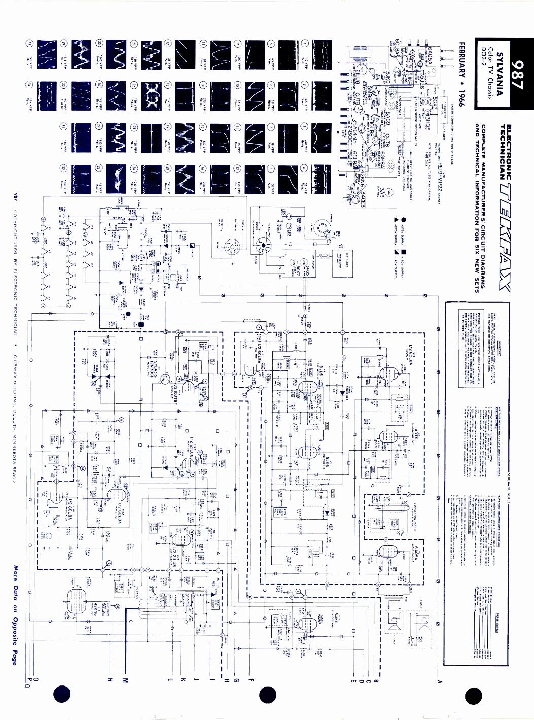
987S
CH
EM
AT
IC N
OT
ES
SYL
VA
NIA
Color T
V C
hassisD
03-2
FE
BR
UA
RY
1966
6AQ
5AA
UD
IO O
UT
PU
T
6CL8A
SO
IF/
AG
C A
MP
00
ELE
CT
RO
NIC
J-7 q1=LT
AII
TE
CH
NIC
IAN
CO
MP
LET
E M
AN
UF
AC
TU
RE
R S
' CIR
CU
IT D
IAG
RA
MS
AN
D T
EC
HN
ICA
L INF
OR
MA
TIO
N F
OR
SIX
NE
W S
ET
S
CH
AS
SIS
CO
NN
EC
TE
D T
O O
NE
SID
E O
F A
C LIN
E
TR
AN
SIS
TO
RU
HF
OS
C.
UH
F T
UN
ER
RIP
UT
5GX
5JL6 r1S
TV
IDE
O IF
5JK6
2ND
VID
EO
IF
IF P
/7147
5JK6
- 1ST
VID
EO
AM
P
C3H
Q5
OS
C/
RF
AM
PM
IXE
RV
HF
TU
NE
R
020
PIC
TU
RE
TU
BE
RE
I9FM
P22 C
AB
INE
TMOUNTED.
NOTE. REPLACE ALL TUBES WITH ORIGINAL
TY
PE
ON
LY
TU
NE
R M
OU
NT
ING
PO
SIT
ION
VA
RIE
S
-11.- HE
AV
Y LIN
E F
OLLO
WS
SE
RIE
SF
ILAM
EN
T S
EQ
UE
NC
E
.,Ne IN
DIC
AT
ES
TU
BE
IND
EX
CO
N.V
giii1;171 E17A
,0"71 YO
KE
SO
CK
ET
UN
ER
SO
LVE
2ND
VID
EO
AM
P/
012B
UR
ST
GA
TE
AM
P
2ILU8
IOJT
8V
ER
T O
SC
/OU
TP
UT
SY
NC
SE
P/
VID
EO
OU
TP
UT
L
8AC
9IO
JT8
CO
RO
NA
AM
P/
R -Y
DE
MO
D1
18A111111
PH
AS
E O
ET
C(111
KILLE
R A
MP
L.7R
EA
CT
AN
CE
/iri4-4' O
M a
C°
OS
C
ILB
8y
13.-Y A
MP
B -Y
DE
MO
D
( VIA
)
303M
. V. R
EC
T.
"7"'7.rc 42KN
6...V
I3H
07112 /
d-SY
L43156C
L8AO
UT
PU
Tts.a,
0._21,4306---27.5 22g'so,
,
II
I
O1.2 V
PP
Vert.
065 V
PP
Vert.
O 1000 V
PP
Vert
NO
ISE
GA
TE
5.5 VP
P
CD
440 VP
P25 V
PP
Vert.
HO
U,
Vert.
68 VP
PH
eria.38 V
PP
Vert.
32 VP
P0
25 VP
PH
on a.H
ero,
28 VP
Pe
270 VP
PM
oog.F
lout
1726 V
PP
Vert.
'12 VP
PV
ert
VP
PH
erta.
O100 V
PP
Vert.
150 VP
PH
Yr' r.
200 VP
PM
ona.
120 VP
P0
50 VP
PH
orikH
ong.
O '110 V
PP
0.30 V
PP
0 .12C V
PP
Hod:.
Moo..
Ilona
C)
145 VP
P0
415 VP
PM
aria.H
orn.
11IIII1
111
IIIill
III
0 *4;',,".7P
045 V
PP
Hom
e.
11190 V
PP
3.58 MC
125 VP
PV
ert.
150 VP
PH
our.
16 VP
P
28
240 VP
Pteen t.
8V
PPH
or.
'230 VP
PH
oM..
4CE
3
MP
ER
.275V S
UP
PLY
I, t1600
SU
PP
LY
A .270V
SU
PP
LY- 140V
SU
PP
LY
1500
]_`c.1M
Nv
TO
O
51
11202w
-20,Y
INK
30B1502N
EO
N
P T
UN
ER
.AN
S1S
TO
RO
M O
SC
VM
TU
NE
R3805R
P A
N.
5GX
7°se,
ER
56500
FIL
R503
0(1
C11300,,,,
Ls. IelT IM
B
OU
TE
R"1 II
lOC
K
1_510
A.
AO
C
IMP
OR
TA
NT
RE
. name IN
ST
RU
CT
OR
S C
AR
EF
ULLY
AN
D O
B-
SE
RV
E T
HE
CO
ND
ITIO
NS
NO
TE
D W
HE
N T
AK
ING
VO
LT-
AG
E R
EA
DIN
OR
OB
SE
RV
ING
AV
EF
OR
MS
.
PIC
TU
RE
Tula N
IGH
VO
LTA
GE
AN
OD
E M
AY
NA
VE
AP
oTE
NI5A
L OF
22.000 VO
LT.
OB
SE
RV
E A
LL HU
M V
OLT
AG
E P
RE
CA
UT
ION
S W
HIN
CE
SE
RV
ICIN
G T
IE C
HA
SS
IS. D
O N
OT
OP
ER
A. T
HE
RE
e1V
ER
WIT
H T
HE
HIG
H V
OLT
AG
E C
OV
EN
01110010.U
SE
FE
TY
GO
GG
LES
AN
D G
LOV
ES
IFIN
H.D
LINO
SA
TH
E P
ICT
UR
E T
UB
E.
VO
LTA
GE
ME
AS
UR
EIN
T C
ON
DIT
ION
S .LE
SS
°TIE
R-
CE
. SP
EC
IFIE
D.
1. Voltage teaaured
toc
umg V
INIL
potter soare 120 volt Tel letw
1 Voltage rum
en.. In bockats taken volh no tam. chsnnet
electo tto
Noe clm
esnoL ant... disconnected,antese tersteala shorted =
Em
ber sad moral to ch-
4. Voltage rodings not In breeket tab., w
ith strongnal M
ina, tuner set to siren. loc.! ...non.
5 Contm
t end Brighlne control sort
for normal picture.
6.vhovrn are erege reed., V
OP
losR
ey Itaobserved due
to nonnsl production toleranc.
WA
VE
FO
RM
ME
AS
UR
EM
EN
T C
ON
DIT
ION
S
I.grevstlorw
e taken uMg
troag 1swel (m
et rumen.,
2. All control. set
lor norm
al ...Mg plcture.
3. Wevelerw
messured w
ith respectto
16111M
ET
EO
RIC
335 secUloecork (O
ther Op oecilloscopoe
wsy Irer
wevform
abase. or .00.667.74. re. terw
e VE
RT
e or HO
R12 refer to *cops trogaeoce
S. V
PP
relw to
poor..
6. Waveform
s waite
with on (a) w
ere taken usMg color
bar gmerator M
gasl 'mem
GE
NE
RA
L SC
HE
MA
TIC
NO
TE
S
I. 2.67orwe lettere on ed.. a1 prInt4d circuit Inclicte
oints. correpondlng with tho Itovnt an pinta board
rt.
idesole pdneed board
3.A
ll cpec1tors P
F unle otherw
ise specified.e. A
rrowcontrol. Intlicte M
rectlaa of eloclmt rum
.lion.
PA
RT
S C
OD
ING
100-1902.299
Vert.
awl 3
S100190
Hts
d1.1V3ou
400.00L..V
.S
upplyed
11.1300.31h1
Ow
Seen
600.600C
awgen
3I
700799
Sow
ed 3e IIV
ideS
wett
P6504
8200270
504
OG
CO
ILS
C504
050811711 200R
504W
OO
CO
LD
0.502
TO
P
RE
DNO
RT
ON
C502cN
ro502_$400v
w_
)1'5 C
3" 9A 5001/0
700v
}. pis TU
E1
C509
1006 "C505
400v
Noy
1100V
NI
SC
504.377
1/2 6CL8A
SO
UN
D Ir
PHY
01041
Il_
J.
iT .0067C
102
W10/10--C
iEN
S560
02
R100
10
IC
OW
2200
IL
200
(1,)t
MF
SC
100
L 104(S
OU
ND
E2556.8
L1023401.
TL
IDS
.o.
v2
4DT
6W
AW
A.. O
ET
8103
CU
i
if
I
C114
MPB
I/00/10116
141334:ri
470
R106
G86
0022 MD
CHUB
2200
1/dC:,7,8A
"wN
".?T
P
*---4
Nests
czn
R214
2206
ITP
11212
630001
MD T
IS
R504
63301
_C3000110
IG01M.
1500
sc, 2502W0
C5106
5000003500
160
CO
DS
20IWO
350v
0515
014V
I!V
I2V
IT
-44---2 43N
S010
VII
VII
V?
VII
ON
15
45
54
121
45
ET
TEC
515
Oag2
5V
IV
2V
S
1502
45
34
3
C514
I 001MFO
C404
001M
ED
o.
!TX
I SY
L43I 5(2N
306)LI N
OIS
E G
AY
E
106
aroO
N E
AR
LY-
RE
CZ
ER
SL
52 IIt
7....4151/
R224
I
11111,)65K
115
14
I(C
2 52200
0220
7608
R104
05026
YI
PD
VO
LvO
L
CO
NN
EC
TIO
NS
PA
RT
OP
SE
500 PL500
R113
1 318EG
TO
NE
I C127
1 0022I Ipso
rY
3
I6A
05A
`2 ON
LYI
reel
AU
DIO
OU
TP
UT
/1556
Rus
221
1550,76 I "
on
0
LIFO
IMFD
-2 ON
LY
+D
r
O
SE
100
ON
LY
8221470n
0012 WO
U
VS
5JK6
21.0 VID
EO
IF
0222002271,0
IS0000
C224vl '--
R2211
G B
8230
C2028
MO
D
1=I
x200--
'56Z%
L210
1NOEo
C228
C230155:
5.65.6
82527son
60.1
0
C232
100
025468.2"6
11236
.566
L212
um
5JK6
1ST
VID
EO
AM
P
N.1.5260 5
DV
)- -
T I
CS
I2I
350v
11-2.38220n
11121011 IV
PR
V'V
IR
249156
-0
1501/0475y)
V711
V2 10J78
SY
NC
SE
P
?N
g=
r2T'00°2
eiK
0000
.. A10
0400229
L
R508
1209
ra.R316
2
VI21
1/2 2ILU8
PO
OP
VE
RT
OS
C
'3T°I
Die
OR
IF
O
5C300
8092
R28
C312
0022 -N
E0
250
40V
C 310
0033M
FO
LC202
R243 47n
j_Cg,5
15.I
9 -
C316
Rl21
R322
6
_1_
ooYosem
mo.--.
azs
0315
0056100K
v
C314
GO
OV
IC317006M
FD
83302 214E
6
rat.-1-
2"2,7'
r2;g1H
EIG
HT
RE
D
0242 .1118011T
ux25
0248
LOIS
100011
BLU
E
1200
SSOV
311
ID
Cro,2351,
ISIir r-\
R30
451/67
latsrov
_
(11)
5 ze
1/2 2ILU8
.556V
ER
T O
UT
PU
T
(7.).
I
CM
G501600
50v
3300
0/YE
LT
EL
R345 IO
NA
CD
R1120
TO
4
OR
N/R
EO
OR
G
tLitT
TO
30/W
HIT
TO
?
TO
TO
S
06
WN
W ,m
im,
Rbe
0214:10,
f`21f2..
TP
I SM
OG
50011P
1 MO
LD
R24
1000
R422
I1006
-70
R426
10011
V136
1/2 6CL8A
.0Ra O
SC
VI311
V2 6C
L8AM
OR
I( RE
GU
LAT
OR
-1(c425.m
mSe
.3-W-
R439
ION
04240047W
D
./2 S
W300
NO
RM
SE
RV
.
R320
7504V
HO
LD
00
0PQ
957C
OP
YR
IGH
T 1966 B
Y E
LEC
TR
ON
IC T
EC
HN
ICIA
NO
J1BW
AY
BU
ILDIN
G. D
ULU
TH
. MIN
NE
SO
TA
55802M
ore Data on O
pposite Page

PIC
TU
RE
TU
BE
RE
MO
VA
L
A B C 0 E H K
QP
1. R
emov
e C
hass
is, Y
oke
and
Deg
auss
ing
Coi
l as
outli
ned
unde
r th
eir
rem
oval
pro
cedu
re.
2. L
ayca
bine
tfa
cedo
wn
ona
soft
mat
eria
l so
as n
ot to
scra
tch
or m
ar th
e fa
ce o
f th
e pi
ctur
e tu
be o
r fi
nish
on
cab-
inet
.3.
Loo
sen
the
mou
ntin
g st
rap
tight
enin
g bo
lt un
til te
nsio
n is
relie
ved
on s
trap
.
4. R
emov
e pi
ctur
e tu
be g
roun
ding
spr
ing.
5. R
emov
e sc
rew
s se
curi
ng p
ictu
re tu
be m
ount
ing
brac
kets
toca
bine
t and
rem
ove
brac
kets
and
str
ap.
6. U
SIN
G G
OG
GL
ES
AN
D G
LO
VE
S, r
each
und
er f
ace
of tu
bean
d lif
t tub
e fr
om c
abin
et.
NO
TE
: Whe
n re
plac
ing
tube
exe
rcis
e ca
utio
n no
t to
dam
age
pins
whe
n re
conn
ectin
g pi
ctur
e tu
be s
ocke
t.
NO
TE
: TO
RE
PLA
CE
CH
ASS
IS, T
UN
ER
CL
UST
ER
, YO
KE
, PIC
TU
RE
TU
BE
AN
D D
EG
AU
SSIN
G C
OIL
RE
VE
RSE
TH
E P
RO
-C
ED
UR
E G
IVE
N I
N T
HE
IR R
EM
OV
AL
PR
OC
ED
UR
E M
AK
ING
CE
RT
AIN
TH
AT
AL
L G
RO
UN
D C
AB
LE
S A
RE
RE
PLA
CE
D I
NT
HE
IR O
RIG
INA
L P
OSI
TIO
N.
#250
620K
1/2
5MB
82N
O V
IDE
O A
RP
71,7
2W
R2.
1056
1226
8500
«B
RIG
117
AN
.
C24
401
VIE
D
0212
1006
717S
Y(1
2011
I
1165
V2
1,11
51,1
C25
6
Thf
111,
RY
46 26
0258
8270
01.2
0002
601.
5602
.71.
216
= 5
11.
LIN
E56
UN
R22
54K
V9r
NU
NN51
6
C24
21
RF
D
7'82
74
600
BA
ND
PA
SS
.1/
2 8A
C9
CIIR
0146
AM
R
7'"
0600T
*WV
(*W
Y/
(lifr
lo 1
_ _
0607
:eon
11608
470
L600
CN
RC
NT
AK
EO
FF
8600
1801
1S
Y
-00-
1 A
511
CO
LOR
I 300
ss
1/2
5MB
8B
UR
ST
611
1 61
49
Jc.
.I
",C
610
.011
6FD R
el 1
2.20
#6I2
ION V1.a
.
0511
FD
SC
601
1.46
2
0011
.
150K
4.21
01,
212
0111
.1
0271
16.
60
R28
6M
EG
BR
IGH
TR
AN
GE
R29
I.0
0C
ON
-T
RA
ST
5295
J.
47K
361
'Te4
e./7
5vN
OSY
/f\
2000
zoo
Y
,V
74
arty
"",4
1/21
0.JT
8'
VID
EO
OU
T
glY
1
0268 V
I.C
629
_I_
9 F
ISO
W#6
46I/2
10JT
882
X
R -
T D
EM
OD
1166
0
F40
IC10
7 (g
rig-6
610)
350
1 -/
EV
:40
175(
71,
R64
G 2
12(i,
,BW
..e°
E
R.I
0658
3506
511
R66
622
6.2
C65
0-D
INE
D
C01
4:0
.15
t Kv
1006
6
C6
6000
E0
16V
R67
047
0051
67/
50Y 1/
2VIIA
10LB
EI
1150
1
C69
-I-
5 6
Itsc604
11.1
007
TT
VT
° #6
75C
LAM
P .1
ME
G
7'75
662
0086
.001
11F
D
20
RE
I9F
MP
22
8614
1606
220.
2W51
4UN
1.60
662
0
f NO
Vvi
i.I/2
10LB
811
-T D
EM
OD
0670
011F
D
Von
F*
N/ 06
36 4
,
V10
6
reoo
1/21
0JT
8g
g.rv
,K
ILLE
R N
AP
KIL
LER
DE
T*2
51I
/ft .4
11c.
,,,11
e2.
C62
535
16E
G0.
..01
-.20
^3!O
R62
6
SY
'
'RF
DS
AM
.C
622
516
ee'.
) "I
,.....
.4,
I/2v8
AC
92
. iP
RA
SE
DE
T
R62
11
$_,,
ME
G
fl i2
t
,,,g,
,
.4 .-
#606
33K
1161
047
0
{ 6.
96,
1115
10O
D
1_ c
.o.
0114
70R
CN
2.2X
---
C13
16D
INE
D
R64
05X 41
1.E
R
1010
C67
4o.
Mee
T5*
I
530
c640
R65
0
C62
4.1
00.
CO
IY:2
1-c
..5'
641
aee-
o
T33
0IM
MO
- C
625
120
*656
4r.:;
4844
RE
AC
T.
1165
4-C
644
6600
0161
F0
XT
600
5.58
160
0652
220
8662
47K
:114
ez
2
C65
8
5665
200 .
1/2
6SH
8A04
5010
4 C
ISC
567
C4M
FD
R57
535
0cc
,.FD
rD
EF
LEC
TIO
N Y
OK
E
1.1.
300
R34
670
n
'91?
CO
LD
0341
347
00
3
1404
1406
00
RN
O 7
%
251U
N
#40
SI
5040
6F
OC
US
C
0432
.1-.
6.
5450
2ME
GF
OC
US
v16
3A3
IIR
EC
T
516
401
NO
V14
03
8451
I
c,.-
4KV
34C
E3
.047
DA
.K.
ME
D
8651
1206
8690
GR
EE
NS
CK
EN
1611
EG
.
011
BO
OS
TE
D B
OO
ST
8692
SLU
ES
LUE
SC
RE
EN
1.5
ME
G.
1114
94
___J
D/
046
RE
D/
PL7
00#4
5a 7
12E
6
66 1
42/2
_71
5OO
ST
E0
5005
7S
C40
4
r70
2B
UD
SC
700
R70
4
11:6
00
5470
2
C70
0.0
5131
1FD
I
roZ
139
. NO
111U
RIZ
R70
000
0
1700
RT
R/G
VE
RT
oezrrD
7700
R-8
11/
MO
R1Z
1702
R71
1/6
1411
2 R70
6
tE"0
115
00
0704
i212
F0
R7.
6011 R
/GM
OW
R71
630
0B
OT
/611
0012
'no
6011
DO
T B
LU11
0012
neon
011
NO
RIZ
4/6
SC
7046
1171
8122
6011
SO
T 1
1/6
VE
RT
GIN
EN
7/11
11N
1700
1710
1706
1712
020/
9111
7T
EL/
RE
D
LuE
zwo
T.1
5111
19)
1072
3911
2111
10%
.2t
IW
1704
61U
1101
112
CE
NT
ER
01.5
2
0721
127
00IW
SC
7040
8750
200
TO
NI.
VE
RT
;DT rd
,J
1101
12
V
1111
47/6
1.11
1111
)
1114
KW
WO
TI
TE
1l11
1U1
J
Sym
bol
C10
0C
104
C10
8C
110
C12
8
CC
2203
40
C21
0C
228
1
C23
6
CC
3321
02 A
C32
1BC
400
CC
C44
3400
821
C50
0
CC
C55
5000
642
C50
8C
510 A B
C51
2 AB C
C60
0C
604
C60
8C
627
C62
9
CC
6664
02
C65
9
C66
4C
668
CC
RR
R22
2765
5407
6068
2
RR
2276
08
R27
2R
274
R29
3
RP
2495
45
R34
511
350
R45
6R
502
R50
4R
508
R51
0R
600
R61
4
PR
6632
04
R62
6R
628
1
4
PR
8R66
6676
0458
R66
6
R67
2
18R
L661
1000
8720
4
L104
L106
L108
1200
L202
L204
1206
1208
1122
1150
11L2
2211
1628
1220
1113
2202
2042
L302
1144
0004
L403
1406
L407
1500
L502
1155
0064
1115
5500
1087
Des
crip
tion
4.7p
f NP
O 5
00v
22pf
NP
O 5
00v
5.6p
f NP
O 5
00v
5.6p
f NP
O 5
00v
.004
7gf 1
kv.0
01gf
2kv
22pf
NP
O 5
00v
5.6p
f NP
O 5
00v
5.6p
f NP
O 5
00v
2000
25v
ele
ct.0
022g
f 2kv
2 se
ctio
n el
ect
100
350v
500
50v
.01g
f 140
0v82
pf N
PO
500
v10
0pf N
PO
500
v22
pf N
PO
500
v.0
1gf 1
.4kv
500g
f 200
v el
ect
.001
0 1.
4kv
.001
0 1.
4kv
3gf 1
50v
elec
t.0
010
1.4k
v2
sect
ion
elec
t30
00 3
50v
200
350v
3 se
ctio
n el
ect
250g
f 350
v30
350
v20
00 2
5v7p
f NP
O 5
00v
100p
f N75
0 50
0v22
0pf N
750
500v
18pf
NP
O 5
00v
5.6p
f NP
O 5
00v
lOpf
NP
O 5
00v
.01g
f 1kv
.010
1kv
18pf
NP
O 5
00v
.010
lkv
.01g
f 1.4
kv4g
f 12v
ele
ct1M
2%
500
v1M
2%
500
v4.
7K 3
w 5
00v
3.9K
5%
500
v1.
5K 5
% 5
00v
10K
2w
500
v1.
8K 5
% 5
00v
4.7K
3w
500
v5.
6K 5
w 5
00v
VD
R 1
.0m
a @
12v
3.80
ther
mis
tor
4.70
5%
1w
500
v66
M 5
00v
3.90
25w
500
v12
00 c
old
ther
mis
tor
VD
R 6
7ma
@ 2
0v1.
2K 2
0w 5
00v
1800
5%
500
v10
M 5
00v
3.3M
5%
500
v3.
3M 5
% 5
00v
1M 2
% 5
00v
1M 2
% 5
00v
22K
2w
500
v33
0K 5
% 5
00v
8.2K
5%
500
v22
K 2
w 5
00v
470K
5%
500
v47
012
5% 5
00v
1.8K
5%
500
v27
00 5
% lw
500
vco
i ,qu
adco
i ,fil
ter
coi ,
twee
t 36g
hco
i ,pe
akin
g 12
01co
i, qu
adco
i ,IF
link
coi
IFtr
apco
iIF
inpu
tco
ipe
akin
g 12
ghco
itw
eet 3
6gh
coi
filte
rco
ipe
akin
g 39
0gh
"see
mis
t ele
ct p
arts
"co
ipe
akin
g 10
001
coi
peak
ing
5601
coi
peak
ing
68gh
coi
peak
ing
1200
1co
ipe
akin
g 39
001
coi
vert
def
lect
ion
coi
vert
def
lect
ion
coi
horiz
freq
uenc
yco
iR
F c
hoke
coi
horiz
def
lect
ion
coi
horiz
def
lect
ion
coi
RF
cho
keco
iB
plu
s ch
oke
coi
filam
ent c
hoke
coi
filam
ent c
hoke
coi
dega
ussi
ngco
ide
gaus
sing
coi
line
chok
eco
ilin
e ch
oke
SYL
VA
NIA
Col
or T
V C
hass
is D
03-2
Syl
vani
aP
art N
o.
43-8
4222
-18
41-1
5820
-20
45-1
5907
-3
41-1
7318
-1
169-
0138
169-
0138
41-1
7315
-143
-930
10-2
43-9
3010
-241
-963
55-1
243
-930
10-2
41-1
7316
-1
41-1
7317
-1
43-1
5012
-29
43-1
5012
-29
43-1
5012
-29
169-
0138
41-1
7245
-135
-162
58-4
435
-162
58-4
418
7-00
17
187-
0017
35-9
2495
-49
38-1
5257
-7pa
rt o
f yok
e
35-9
7961
-336
928
98 3
338
-170
71-1
38-1
7072
-136
-928
98-3
5
35-1
6258
-44
35-1
6258
-44
35-9
2495
-87
35-9
2495
-87
57-1
1602
-150
-113
78-1
50-1
6103
-13
50-8
5953
-13
57-1
1602
-150
-176
80-3
57-1
1637
-157
-178
42-1
50-8
5953
-13
50-1
6103
-13
50-1
1378
-150
-153
18-1
5pa
rt o
f LC
202
50-1
5318
-850
-153
18-5
50-1
5318
-650
-153
18.9
50-1
5318
.15
part
of y
oke
part
of y
oke
50-1
7326
-111
8-00
10pa
rt o
f yok
epa
rt o
f yok
e11
8-00
1056
-175
68-1
50-8
5963
-250
-859
63-2
50-1
7113
-450
-171
13-4
50-1
7838
-150
-178
38-1
1600
coil,
chr
oma
take
off
L601
coil,
reac
tanc
eL6
02co
il,fil
ter
6200
1L6
03co
il, p
eaki
ng 3
6gh
L604
coil,
pea
king
36g
h16
06co
il, p
eaki
ng 6
20gh
1607
coil,
pea
king
36g
hL6
08co
il, p
eaki
ng 3
6gh
L609
coil,
pea
king
lOgh
L610
coil,
pea
king
lOgh
1700
vcoe
irlt,
conv
erge
nce
rt. R
/G
L702
coil
lcon
verg
ence
rt.
R/G
horiz
L704
coil,
con
verg
ence
blu
eho
riz c
ente
rL7
06co
il, c
onve
rgen
ce g
reen
L708
coil,
con
verg
ence
gre
enL7
10co
il, c
onve
rgen
ce r
edL7
12co
il, c
onve
rgen
ce r
edL7
14co
il, c
onve
rgen
ce b
lue
L716
coil,
con
verg
ence
blu
eT
100
xfor
mer
, sou
nd in
ters
tage
1101
xfor
mer
, aud
io o
utpu
t12
00xf
orm
er, I
F in
ters
tage
T20
2xf
orm
er,
IFou
tput
1204
xfor
mer
, 4.5
Mc
trap
1300
xfor
mer
, ver
t out
put
1400
xfor
mer
, hor
iz o
utpu
tT
500
xfor
mer
, pix
tube
fil
1600
xfor
mer
, ban
dpas
sT
602
xfor
mer
, bur
stph
ase
1604
xfor
mer
, 3.5
8Mc
outp
ut17
00xf
orm
er, c
onve
rgen
ce R
.bl
ue h
oriz
CB
500
circ
uit b
reak
erD
L200
dela
y lin
e14
00la
mp,
Neo
n15
001
lam
p, N
eon
NE
2H15
02I
lam
p, n
eon
NE
2HLC
202
coil/
capa
cito
rco
mbi
natio
nL2
155.
601
C23
539
0S
C10
0 1
diod
e, s
ound
det
SC
200
Jdi
ode,
vid
eo d
etS
C30
0di
ode,
ver
t syn
c in
ject
ion
SC
400
1di
ode,
AF
CS
C40
2 f
diod
e, A
FC
SC
404
diod
e, b
oost
ed b
oost
SC
406
diod
e, fo
cus
rest
SC
500
diod
e, 1
40v
rect
ifier
SC
502
diod
e, B
plu
s re
ctifi
erS
C50
4di
ode,
B p
lus
rect
ifier
SC
600
diod
e, k
iller
det
SC
601
diod
e, k
iller
cla
mp
SC
602
diod
e, d
emod
ulat
or g
rid
SC
604
cdlia
omde
p, d
emod
ulat
or g
rid
SC
700
dclia
omde
p,si
licon
SC
d70
2id
edi
ode,
osi
licon
silic
onS
C70
44
sect
ion
SW
300
switc
h,no
rmal
/ser
vice
SW
500
switc
h, o
n/of
fS
W50
2sw
itch,
dia
llig
htX
T60
0cr
ysta
l, 3.
58M
cR
113
1.5M
tone
2ch
R11
41M
vol
R21
422
0K A
GC
R23
275
00 s
nd tr
ap a
djR
282
500K
brig
htne
ssR
286
1M b
right
ness
ran
geR
291
5000
con
tras
tR
297
6K b
lue
driv
eR
299
6K g
reen
driv
eR
314
5M v
er li
nR
320
750K
ver
t hol
dR
334
220K
ver
t hei
ght
R34
410
0 ve
rt c
ent
R41
450
0K h
oriz
hol
dR
424
100K
hig
h vo
lt ad
jR
448
100
horiz
cen
tR
450
2M fo
cus
R61
65K
col
orR
631
1.2K
tint
R64
015
Kki
ller
R69
01.
5M g
reen
scr
een
R69
21.
5M b
lue
scre
enR
694
1.5M
red
scr
een
R70
615
00 L
R/G
ver
tR
708
6012
L R
/G h
oriz
R71
415
00 to
p R
/G h
oriz
R71
630
0 bo
ttom
R/G
hor
izR
720
600
botto
m b
lue
horiz
R72
260
12 b
otto
m R
/G v
ert
R72
610
00 L
blu
e ho
rizR
730
1200
top
R/G
ver
tR
732
300
top
blue
hor
iz01
tran
sist
or,
nois
e ga
tem
agne
t, bl
ue la
tera
lpu
rity
sock
et, t
ube
V16
yoke
, con
verg
ence
yoke
, def
lect
ion
50-1
6184
-450
-161
85-3
50-1
7593
-150
-161
03-1
350
-161
03-1
350
-175
93-1
50-1
6103
-13
50-1
6103
-13
50-8
5953
-14
50-8
5953
-14
50-1
6248
-5
50-1
6248
-6
50-1
7850
-1co
ny. y
oke
cony
. yok
eco
ny. y
oke
cony
. yok
eco
nv. y
oke
cony
. yok
e57
-116
06-1
56-9
7301
-11
57-1
7339
-150
-175
17-1
50-1
6238
-556
-175
59-2
50-1
7314
-155
-173
25-1
50-1
7542
-150
-161
91-2
50-1
7597
-1
50-1
6248
-829
-173
12-1
32-1
6108
-330
-177
94-2
30-9
7684
-230
-976
84-2
50-1
7246
-1
1N29
5IN
295
1N40
921N
4092
1N40
9213
-161
05-3
13-1
6106
-113
-171
74-1
13-1
7557
-113
-175
57-1
13-1
7596
-206
462
13-1
7596
-3
13-1
7596
-313
-101
02-1
13-1
0102
-113
-175
69-1
33-1
6011
-5pa
rt o
f R11
433
-177
09-1
26-1
6162
-137
-152
29-5
37-1
1959
-937
-116
32-7
37-1
7321
-137
-170
73-1
437
-173
49-2
37-1
7073
-12
37-1
1632
-8pa
rt o
f R29
7pa
rt o
f R21
437
-170
73-1
1pa
rt o
f R21
437
-160
21-1
737
-170
73-1
037
-173
49-1
37-1
7539
-137
-173
20-1
37-1
7073
-16
37-1
7073
-13
part
of R
297
37-1
1632
-9pa
rt o
f R69
0pa
rt o
f R69
037
-160
21-7
37-1
6021
-237
-160
21-7
37-1
6021
-637
-160
21-2
37-1
6021
.237
-160
21-2
137
-160
21-5
37-1
6021
-643
15
22-1
5948
-172
-179
24-1
51-1
7083
-251
-175
70-1
Mor
e D
ata
on O
ppos
ite P
age
9$7
CO
PY
RIG
HT
196
6B
Y E
LEC
TR
ON
IC T
EC
HN
ICIA
NO
JIB
WA
Y B
UIL
DIN
G, D
ULU
TH
, MIN
NE
SO
TA
558
02

988S
ILVE
RT
ON
ET
V C
hassis564.10000564.10001564.10002564.10003564.10004564.10005
FE
BR
UA
RY
1966S
ymbol
C106, C
504,C
505, C139
C125, C
137,C
323, C401,
C403, C
407,C
605, C611
C135, C
317,C
319, C320,
C322, C
136C
202, C205
C209, C
321C
211C
312C
324C
408, C623,
C627
C506, C
507C
508C
509C
612, C701,
C702, C
703C
6I3C
513C
629, C630,
C631, C
632R
627
Description
elect 300 25wv
elect lgf 25wv
elect 1500 12wv
elect 20 20wv
elect 200gf lOw
velect 25gf 100w
velect 100 6w
velect 100gf 3w
v
elect 500 25wv
elect 300gf 3wv
elect 3000 lOw
yelect 5000 12w
v
elect 20000 20wv
elect 20 80wv
elect 50 300wv
elect 20gf 50wv
0.50 lw ±
5%
ELE
CT
RO
NIC
2i-ifT=
44ca XT
EC
HN
ICIA
N
CO
MP
LET
E M
AN
UF
AC
TU
RE
R S
' CIR
CU
IT D
IAG
RA
MS
AN
D T
EC
HN
ICA
L INF
OR
MA
TIO
N F
OR
SIX
NE
W S
ET
S
Silvertone P
art No.
T -C
7075
R801
50012 contrastR
802, R806
50K A
GC
& video bias
R803
500K brightness
R804
10K volum
eR
80550K
AG
C bias
R807, R
81350K
sub vert hold & sub
horiz holdR
8085K
vert holdR
80950 vert height
R810
5K vert bias
R811
1K vert
linR
8123K
horiz holdR
81420012 pow
er supply voltcontrolIF
xformer, 2nd &
3rdvideoIF
xformer, 4th A
videoIF
xformer, 4th B
video
PIF
-2P
IF-3
PIF
-4AP
IF-413
L105, L106L107L1081109S
IF-1, S
IF-2
L110L111S
IF-3
L112, L113L114L115.L116L117, L118T
IO1
TIO
2T
IO3
T104
T105
T106
T107
TR
101, TR
I02,T
R103
TR
104
TR
IOS
TR
106, TR
107T
RIO
ST
R109, T
RI10,
TR
III, TR
119,T
R120
TR
II2, TR
116T
RI13
TR
114, TR
118
TR
115T
R117, T
R121
TR
122T
R123
Dl
D2, D
3,D
4, D5,
D6, D
7, D8,
D11, D
12,D
13
DI4, D
15,D
17, D18,
D2I, D
20,D
19
D16
V2, V
3, V4
T -C
7068
T -C
7053T
-C7070
T -C
7036T
-C7077
T -C
7023T
-C7033
T -C
7076T
-C7092
T -C
7093T
-C7038
T -C
8153T
-C7071
T -C
7011
T -C
7087T
-HR
WO
.5-JBT
-G1610
T -G
0035T
-G1603
T -G
1604T
-G0023
T -G
0027T
-G 1616
T -G
2021T
-G0029
T -G
0030T
-G1605
T -G
1615
T -S
8004T
-S8005A
T-S
8005B
coil,filter
T -L156
video det blockT
-S1015
trap, 4.5Mc
T-S
48VIF
xformer 1st &
2ndsound
T -S
302coil, peaking
T-12506
coil, peakingT
-12504sound det xform
erT
-S303
deflection yokeT
-D40
coil, horiz stabilizerT
-A17
coil, width control
T -A
87coil, deflection com
pensateT
-17017choke, horiz filter
T-17012
xformer, sound input
T -V
119xforom
er, vert oscT
-W53
xformer, vert output
T -W
28coil horiz osc
T -A
27xform
er horiz driveT
-A26
xformer flyback
T -F
73xform
er, power
T-P
34A1st, 2nd &
3rd PIF
2SA
4201-05038
2SA
223 or 2SA
227 videoam
pT
-Q5022
2SC
65 video outputT
-050322S
A219 1st &
2nd SIF
1-050212513186 sound am
pT
-Q5026
2SB
22 sound output,dynam
iccapacitor,
horizosc. horiz buffer
T -Q
50252S
B187 vert osc A
GC
amp
T -Q
50272S
A225 A
GC
keyerT
-Q5023
2SA
2011st sync separator,
phase inverterT
-Q5020
2SC
60 2nd sync separatorT
=Q
50312S
B216 vert out, horiz
driveT
-050282S
13375 horiz outputT
-Q5030
258217 elect filterT
-0503615188 video det (includedin L108)
T -E
103115188
sound det, sound IFlim
it-er,
noiselim
iter vert.osc
pulseclipper, A
FC
phasedet &
horiz osc pulseclipper
T -E
1031
SD
-1A reverse current
stopperT
-E1029
seleniumrectifier, pow
ersupply
T -E
1042D
G -13 dam
perT
-E1045
5642 HV
rectifier (3 used)T
-03034
AN
TE
NN
AM
AT
CH
ING
BO
X.
25sofX2
VH
F A
NT
EN
NA
Cat
1000m
old.
To.
;
000m
old
25.1d X2
L14V
HF
1 !Msc.10
mad
RE
AM
MR
EM
M
VW
LIWS
W2.
5600S
W
Ci
120I S
onisf dstoldLs:
RF
L
L
TR
t 25442F
AM
P.
AG
C
CIO
10111111f
Cl
10.n. d
4CoLf
R.
UH
F A
NT
EN
NA
041r \T
o
Rs
6806S
W \
IF8/
C.
1000inenld
L
L2
33m
r)m
mteD
,R
MB
EA
I KM
IX
TC
3
L _UH
F T
UN
ER
511/3
IliC
3R
O-1
3341000.1 a 1800 :
XS
/ .II
ITC
,,-,
1 -5
TR
.5E
1044O
SC
.VC
3
C.
3oisof
TC
2
wI
TR
toe 254219T
RH
:y.22542 19 D3 D
4 IS I 88
1ST
SIF
AM
P.
2ND
SIF
AM
P.
SO
UN
D D
ET
.!V
OLU
ME
]
R.
8200
C30,
0 005.sld
R.
5600
4.3V1
5Ornmfd
8301C
an5600
Onof d
C334
0 CO
5mN
R..
6200S
W
SIF
.2
15188
0 005
I'fd3.8V
R5360-0,0
C3.0 0 005old
SIF
. 33.6V
453011
.D
31500
Cm
.
-
SiI
1.4VIVAI
1 C3.
C 311j,
31
304310
II.
Tile
1°'"fdIc-I...
300.1307
_2.f dlI
D.
c,..,T
.,,,,
TR
.*C
3ta-...
R31
, c...11m
fd.v..
0.00S ",W
w. 2200
30Goof d I I K
t'"
,C
7021.1d
1ii
^v.
mId
Rm
.10K
Rs'
8200
ritC3is
8,40mfd.
TR
105 2SB
186S
OU
ND
AM
P.
TR
03 TR
I l0 25822X2 T
R 111 2S
B22
SO
UN
D O
UT
PU
TD
YN
AM
IC C
AP
AC
ITO
R
Co.. 100of d
113. 150056
SD
T 06
its22IR
so2
102:11
R3111
C317
2.7 -150.1d
hw
C314
R3111 N
W T
R.
1I50.1K
Roo R
"56 2714 4/411
16.1V
j444. T
R, 0
Rao IK
SW
-C
32015000
16214
333
Ron
1500Ran
l
1001(R
ooS
4220S
W
C.c 200. d
%W
eiI 2V
IR
U,
10 hVI
Cos
.1500d
TR
tot 254420T
R 022S
A420
I ST
PIF
AM
P.
2ND
PIF
AM
PT
R 103254420 D
15188T
R 104.254223
3RD
PIF
AM
P. V
IDE
O D
ET
.(254227)
VID
EO
AM
P.
561404
VO
WN
OR
.E
XC
mi
Rim
I K
TR
225442017L_
MIX
.T
R3 254263
OS
C.
Sold
ofd
1004P
IF -I
L3A
o LaR
FvC
i MIX
.
VH
F T
UN
ER
PO
WE
R T
RA
NS
.
1107
on
10.5A
SW,.
541.
C.mle
1000
xfm
g`8
Rs
660N
y,
Cn1000
ong d
J-3T
strald
R12
5600.S
Ir
3 143
9km
Cns1000 i
Zofa
4L4811.
Fins 2
f
D.
d
3470S
188 -'
Tuning
Rig, IR
V C
34F-4f
61a4
704T
5LC104 I
151(733Vd
.504°M 2°
Lim.051,..
c,71M
"o.0.5.
IiRin
;IKR
.a2R
VIK
560001 C
. laT
3nnf d1 A
Rios
PIF
.2I
68000 005inf d
titR
oos50K
TR
it 22S
B 1871T
R 13 2S
A225
AG
C A
MP
. AG
C K
EY
ER
Rsos 5/5/A
GC
RIZ
Ili122 R
IZ3
SR
M
AR
C4-
0.005of d
L107
0 005old
o.71:17
K
-1rs7,-,,-.1.,EC
ies6800
T W
vsittP
IF.4A
0 005of
R i
2200C
132
0 005
Ri,.
201
SD
T250
<-3
L%m
old
C
13'S
11
OK
- !sad,.137
0.0050Rd
PO
WE
R S
UP
PLY
VO
LTA
GE
OM
T
07012000of 4
AC
1201
LsO
SC
5Orsof d
620
TR
i 232582 I 7
6VI
411
4704
Rim
4700
6800S
old1 O
rrild
R,
-It 0.1 old
ELE
CT
RO
NIC
FILT
ER
C101
2000.4R.
10SW
Rs
200
IQ S
A
R703
1500S
W570310N
w
Lus
Coo
2000ot d
0siv.
12V1.2A
II .3V
1
Ds 15168
TR
I 142542011S
T S
YN
C. S
EP
.
6800
17.2
][
is,..3300
R. C
. L_IEJ
470i m
fc,,
0005mfd
bLeRoo
1500KS
WR
as10K
12VT
Rtie 254201
Ott 01215188
PH
AS
E IN
VE
RT
ER
AF
C2.9V
p.pR
037
0.5 1W
Roe
Co.. S
CI0h6
0005fdR"
0
1456Km
dIrT
-1115 V
p
TR
-t -tg 25822
HO
RIZ
. OS
C.
TR
i2S
C60
2ND
SY
NC
. SE
P.
3300SW
w.
.0,1000A
mid
331331<S
W
Com
.2000tId
,tC
owIofd
BV
R4,,
62001(04
NwI
R414
680148R
413"
3300WIlf
113
Rog
3300S
W
C.
Rem
0.0Iofdi2c6m
o
Csm
RO
M
1200 S.1
I) isP4
aO
lmfd
®C
am1
''''
T0.1)510 4
MP
R307
I -...
1
H.C
.I sop --IT
S,-
15ii?o7i
,..4! L'11.--.
0 Cos
®R
omIK
SW
Re:
7404
J73K
Rom
156 0 pa,R
.H
OW
HO
LDold 43300
BO
NI
Rao o
4700 5R
m330014W
NO
TE
S:I.
All
resistance values in ohms K
=1.000 M
=1.000.000.
2.T
ypes ofresistors.
Carbon film
*: Wire w
ound resistorA
llresistance not designated as above are carbon com
position resistors.3.
All
resistance 1/4 watt unless otherw
ise noted.4.
Types of
capacitors.0:
Paper
:E
lectrolyticsM
ylar:
Metalixed paper
:Lacquer
:P
olyethylene:
Polystyrene
Rem
16,0_0.0544dC
.., .V
IIIIIdC
313
1_0.02sifdR
an
330014
Csz
50
old
506S
DT
R71000
470014
ISLIB
ISOR
IZ.H
OL
DI
1
337).;i°4 t
Ti..
2 2,
oRem
II(
T.P
.4Com
50mm
f d 7151(
50mm
R104
5600y4 w
Nb
TR
i2S
B I 87.C
W\
500
VE
RT
. OS
C.
TR
1172513216I
Nf7vP
1-PP
\V
ER
T. O
UT
PU
T
TR
i o5 25C65
VID
EO
OU
TP
UT
12V
DIS
PE
AK
ER
3" X4 "
40 oho
EA
RP
HO
NE
JAC
K
R331
470S
W
V ,
230DB
4P
ICT
UR
E T
UB
E
I 2V
2olif
Con t47K
R2o2
T.P
-VL .
1232
50:'*v4V,
EV)
2000,kt
02r,-,4
"f'1207.--T
hjt2e0
VIR
t):120K
2. C2,
SW
10K
25207
VID
EO
BIA
S
C304
30of d -R
sos33K
74
.50K
Coo
30o.
ISU
6 VE
RT
. hscLq
5K
NE
RH
Ot C
k. Cses
300old
22544
8.07
Rso
50106
300 mf d
Roo
22034
TR
202SB
22T
R121 256216
HO
R. B
UF
FE
R H
OR
I Z. D
RIV
E
R. 111.91
1500 S
W8. ez§
Rea
1500S
WII3V
1
R13
560A
D.
30315188
IC4g R
WO
R571
50 of
112.5VI
014
CO
I50IA
IE
`XV
cos
C1113I
20144..8
C1104
0.05of d
C430 330 S
W25V
7Vp.E
.11,A,
lti2D
iS
O 1 A
All
capacitors not designated as above are ceramic Lapacit or s.
5.V
oltage reading taken with "V
TV
M" from
point indicated tochassis ground, T
uner on unused channel. contrast at maxim
um.
AG
C at m
aximum
clockwise. other control
at normal. line voltage
I 20 volts.6.
All
weve form
s measured w
ith strong signalinput. contrast set
to give normal
picture and AG
C line operating norm
ally.7.
Voltage reading m
ay vary ±20%
.
,4Cios
C"
2020
d
IVE
RT
.1.161
TR
122 2SB
375H
OR
IZ. O
UT
PU
T
Cosm
lig" 15D"
ofp
0.2is,
13-1A
Dis
I
OG
.13Roe
00 I
TV
L1
V2
V 3
Cso
500 mold C
oe500I d
Hs
Sw
at*0401 1114
Oil
MO
IR
loom Liao.
Tonw
eilealot
S4V
0401.1/1M
S N
S
AO
C La 3*
velkao...41
Cs.
0.05old
ST,11.
01414
0 02)4
I2V
0.05rnfd
SD
4 A
66V
01
Do net us
Ws hole
10400
d
Resw
33CIK
UO
KA
mW
M. 30
03.13
SW
.
14 V
RIP
S150011
7'SW
eAc
SWV. V
3 V4
54342X3
RV
RE
CT
988C
OP
YR
IGH
T 1 966 B
Y E
LEC
TR
ON
IC T
EC
HN
ICIA
NO
JIBW
AY
BU
ILDIN
G, D
ULU
TH
, MIN
NE
SO
TA
55802

ConTTUNER REPAIR
Vg}) [A6
Sarkes Tarzian, Inc., largest manufacturer ofTV and FM tuners, offers unexcelled tuneroverhaul and factory -supervised repair service.Completely -equipped and conveniently -located Service Centers offer fast, dependableand factory -supervised repair service on allmakes and models. Centers are staffed by well -trained technicians, assisted by engineeringpersonnel.
Tarzian-made tuners received one day willbe repaired and shipped out the next. Moretime may be required on other makes. Everychannel-not just the channels existing in anygiven area-is checked and re -aligned per orig-
TUNER SERVICE CORPORATION
(Factory -supervised tuner service authorizedby Sarkes Tarzian, Inc.)
547-49 Tonnele Avenue, Jersey City, N.J.Tel : 201-792-3730
inal specifications. Exclusive cleaning methodmakes the tuner look-as well as operate-like new.
Cost, including ALL labor and parts (excepttubes) is only $9.50 and $15 for UV combina-tions. No additional charge. No hidden costs.Too, you get a full, 12 -month warranty againstdefective workmanship and parts failure dueto normal usage.
Always send TV make, chassis and Modelnumber with faulty tuner. Check with yourlocal distributor for Sarkes Tarzian replace-ment tuners, parts or repair service. Or, use theaddress nearest you for fast, factory -supervisedrepair service.
SARKES TARZIAN
TUNER SERVICE DIVISION537 S. Walnut Street, Bloomington, Indiana
Tel: 812-332-6055WEST -10654 Magnolia Blvd., N. Hollywood, Calif.
Tel : 213-769-2720
MANUFACTURERS OF TUNERS, SEMICONDUCTORS, AIR TRIMMERS, FM RADIOS, AM -FM RADIOS, AUDIO TAPE and BROADCAST EQUIPMENT
FEBRUARY 1966 19

IIP 1C1
116J Iris Fe
HERETO STAYMore and more UHF television stations and UHF translatorstations are going on the air every day across the country. And thenumber is increasing rapidly. UHF is accepted ... is here to stay.
Every new UHF station represents a whole new untapped profitarea for electronics distributors and independent television repairmen. Most of the existing television sets now in use were manu-factured prior to 1965, and are not equipped with UHF reception.Every TV set owner in your trading area is practically a sure salefor a UHF television converter... either a built-in or "on -the -
top" unit.
NOW, WHICH MAKE ARE YOUGOING TO SELL TO INSURE
HIGH PROFITS?It's always smart business to stick with a winner. Wherever UHFhas gone on the air-Los Angeles, Chicago, Detroit, Boston,Philadelphia, - Standard Kolisman UHF Converters have con-sistently been Number 1 in distributor preference, dealer prefer-ence and consumer preference. And in the small translator commu-nities, SK's superior performance at the top of the band makesit especially preferred.
Standard Kolisman quality and dependability means a Final Sale-No Returns. Reliable, service -free tuning elements. Built-insafeguards against spurious radiation. Guaranteed by the world'slargest manufacturer of television tuners.
NitStandard KolismanINDUSTRIES INC.2085 NORTH HAWTHORNE AVE., MELROSE PARK, ILLINOIS
... for more details circle 50 on postcard
Nit means Final Sale, No Returns - Service -free Tuning Element, No Spurious
Radiation - Guaranteed 1 Yr. by the World's Largest Manufacturer of T. V. Tuners
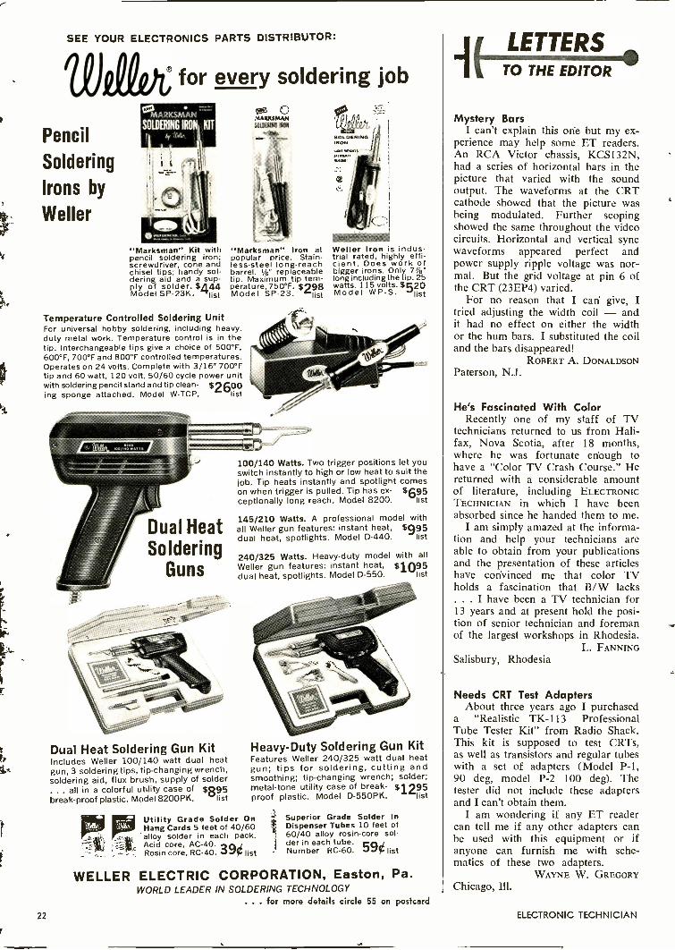
SEE YOUR ELECTRONICS PARTS DISTRIBUTOR:
Pencil
Soldering
Irons by
Weller
0 for every soldering job
SOLDERING IRO KIT
"Marksman" Kit withpencil soldering iron;screwdriver, cone andchisel tips; handy sol-dering aid and a sup-ply
del SP -of solder.23K. 5A44
Mo list
C'MARKSMANMang ON
"Marksman" Iron atlopular
price. Stain-ess -steel long -reachbarrel. 1/8" replaceabletip. Maximum tip tem-perature, 750°F. $998Model SP -23. `list
Temperature Controlled Soldering UnitFor universal hobby soldering, including heavy_duty metal work. Temperature control is in thetip. Interchangeable tips give a choice of 500°F,600°F, 700°F and 800°F controlled temperatures.Operates on 24 volts. Complete with 3/16" 700°Ftip and 60 watt, 120 volt, 50/60 cycle power unitwith soldering pencil stand and tip clean- $2600ing sponge attached. Model W-TCP. list
Dual HeatSoldering
Guns
Dual Heat Soldering Gun KitIncludes Weller 100/140 watt dual heatgun, 3 soldering tips, tip -changing wrench,soldering aid, flux brush, supply of solder
. all in a colorful utility case of silosbreak -proof plastic. Model 8200PK. list
Weller Iron is indus-trial rated, highly effi-cient. Does work ofbigger irons. Only 7/s'long including the tip. 25watts. 115 volts. $520Model WP -S. list
100/140 Watts. Two trigger positions let youswitch instantly to high or low heat to suit thejob. Tip heats instantly and spotlight comeson when trigger is pulled. Tip has ex- $amceptionally long reach. Model 8200. list
145/210 Watts. A professional model withall Weller gun features: instant heat, $995dual heat, spotlights. Model D-440. list
240/325 Watts. Heavy-duty model with allWeller gun features: instant heat, $1095dual heat, spotlights. Model D-550. list
Heavy -Duty Soldering Gun KitFeatures Weller 240/325 watt dual heatgun; tips for soldering, cutting andsmoothing; tip -changing wrench; solder;metal -tone utility case of break- $1295proof plastic. Model D-550PK. list
Utility Grade Solder OnHang Cards 5 feet of 40/60alloy solder in each pack.Acid core, AC -40.Rosin core, RC -40.39¢ list
Superior Grade Solder InDispenser Tubes 10 feet of60/40 alloy rosin -core sol-der in each tube. "A"Number RC -60. list
WELLER ELECTRIC CORPORATION, Easton, Pa.WORLD LEADER IN SOLDERING TECHNOLOGY Chicago, Ill.
. . . for more details circle 55 on postcard
22 ELECTRONIC TECHNICIAN
ji LETTERSit TO THE EDITOR
Mystery BarsI can't explain this one but my ex-
perience may help some ET readers.An RCA Victor chassis, KCS132N,had a series of horizontal bars in thepicture that varied with the soundoutput. The waveforms at the CRTcathode showed that the picture wasbeing modulated. Further scopingshowed the same throughout the videocircuits. Horizontal and vertical syncwaveforms appeared perfect andpower supply ripple voltage was nor-mal. But the grid voltage at pin 6 ofthe CRT (23EP4) varied.
For no reason that I can give, Itried adjusting the width coil - andit had no effect on either the widthor the hum bars. I substituted the coiland the bars disappeared!
ROBERT A. DONALDSONPaterson, N.J.
He's Fascinated With ColorRecently one of my staff of TV
technicians -returned to us from Hali-fax, Nova Scotia, after 18 months,where he was fortunate enough tohave a "Color TV Crash Course." Hereturned with a considerable amountof literature, including ELECTRONICTECHNICIAN in which I have beenabsorbed since he handed them to me.
I am simply amazed at the informa-tion and help your technicians areable to obtain from your publicationsand the presentation of these articleshave convinced me that color TVholds a fascination that B/W lacks. . . I have been a TV technician for13 years and at present hold the posi-tion of senior technician and foremanof the largest workshops in Rhodesia.
L. FANNINGSalisbury, Rhodesia
Needs CRT Test AdaptersAbout three years ago I purchased
a "Realistic TK-113 ProfessionalTube Tester Kit" from Radio Shack.This kit is supposed to test CRTs,as well as transistors and regular tubeswith a set of adapters (Model P-1,90 deg, model P-2 100 deg). Thetester did not include these adaptersand I can't obtain them.
I am wondering if any ET readercan tell me if any other adapters canbe used with this equipment or ifanyone can furnish me with sche-matics of these two adapters.
WAYNE W. GREGORY
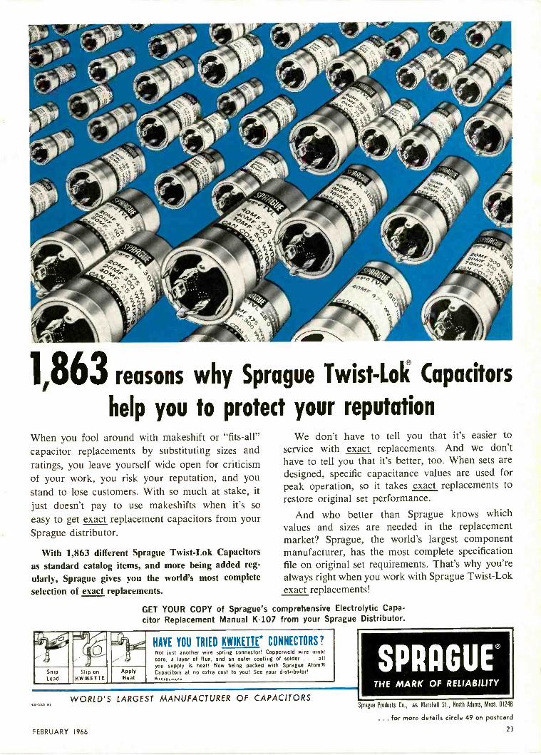
1,863 reasons why Sprague Twist-Lok Capacitors
help you to protect your reputationWhen you fool around with makeshift or "fits -all"capacitor replacements by substituting sizes andratings, you leave yourself wide open for criticismof your work, you risk your reputation, and youstand to lose customers. With so much at stake, itjust doesn't pay to use makeshifts when it's so
easy to get exact replacement capacitors from yourSprague distributor.
With 1,863 different Sprague Twist-Lok Capacitorsas standard catalog items, and more being added reg-ularly, Sprague gives you the world's most completeselection of exact replacements.
GET YOUR COPY of Sprague's
We don't have to tell you that it's easier toservice with exact replacements. And we don'thave to tell you that it's better, too. When sets aredesigned, specific capacitance values are used forpeak operation, so it takes exact replacements torestore original set performance.
And who better than Sprague knows whichvalues and sizes are needed in the replacementmarket? Sprague, the world's largest componentmanufacturer, has the most complete specificationfile on original set requirements. That's why you'realways right when you work with Sprague Twist-Lokexact replacements!
comprehensive Electrolytic Capa-citor Replacement Manual K-107 from your Sprague Distributor.
' %a
,--- c, 7.
L.."4-1,-. ---,..-
1,.." :.-
HAVE YOU TRIED KWIKETTE* CONNECTORS?Not just another wire spring connector! Copperweld wire innercore, a layer of flux, and an outer coating of solder . . . allyou supply is heat! Now being packed with Sprague Atom*
SnipLead
Slip onKWIKETTE
ApplyHeat
Capacitors at no extra cost to you! See your distributor!*TRAOLMARK
WORLD'S LARGEST MANUFACTURER OF CAPACITORS
SPRAGUETHE MARK OF RELIABILITY
es -s10 lir
FEBRUARY 1966
Sprague Products Co., 65 Marshall St., North Adams, Mass. 01248
. . . for more details circle 49 on postcard
23
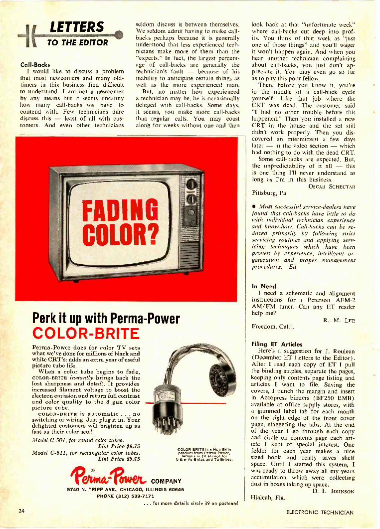
LETTERSTO THE EDITOR
Call -BacksI would like to discuss a problem
that most newcomers and many old-timers in this business find difficultto understand. I am not a newcomerby any means but it seems uncannyhow many call-backs we have tocontend with. Few technicians darediscuss this - least of all with cus-tomers. And even other technicians
seldom discuss it between themselves.We seldom admit having to make call-backs perhaps because it is generallyunderstood that less experienced tech-nicians make more of them than the"experts." In fact, the largest percent-age of call-backs are generally thetechnician's fault - because of hisinability to anticipate certain things aswell as the more experienced man.
But, no matter how experienceda technician may be, he is occasionallydeluged with call-backs. Some days,it seems, you make more call-backsthan regular calls. You may coastalorig for weeks without one and then
Perk it up with Perma-PowerCOLOR-BRITEPerma-Power does for color TV setswhat we've done for millions of black andwhite CRT's: adds an extra year of usefulpicture tube life.
When a color tube begins to fade,COLOR-BRITE instantly brings back thelost sharpness and detail. It providesincreased filament voltage to boost theelectron emission and return full contrastand color quality to the 3 .gun colorpicture tube.
COLOR-BRITE is automatic .. . noswitching or wiring. Just plug it in. Yourdelighted customers will brighten up asfast as their color sets!Model C-501, for round color tubes.
List Price $9.75Model C-511, for rectangular color tubes.
List Price $9.75
feAttie Owelt,
COLOR-BRITE is a HueBriteproduct from Perma-Power,
famous in TV service forb & w Vu-Brites and Tu-Brites.
COMPANY5740 N. TRIPP AVE., CHICAGO, ILLINOIS 60646
PHONE (312) 539-7171for more details circle 39 on postcard
look back at that "unfortunate week"where call-backs cut deep into prof-its. You think of that week as "justone of those things" and you'll wagerit won't happen again. And when youhear another technician complainingabout call-backs, you just don't ap-preciate it. You may even go so faras to pity this poor fellow.
Then, before you know it, you'rein the middle of a call-back cycleyourself! Like that job where theCRT was dead. The customer said"I had no other trouble before thishappened." Then you installed a newCRT in the house and the set stilldidn't work properly. Then you dis-covered an intermittent a few dayslater - in the video section - whichhad nothing to do with the dead CRT.
Some call-backs are expected. But,the unpredictability of it all - thisis one thing I'll never understand aslong as I'm in this business.
OSCAR SCHECTARPittsburg, Pa.
Most successful service -dealers havefound that call-backs have little to dowith individual technician experienceand know-how. Call-backs can be re-duced primarily by following strictservicing routines and applying serv-icing techniques which have beenproven by experience, intelligent or-ganization and proper managementprocedures.-Ed
In NeedI need a schematic and alignment
instructions for a Peterson AFM-2AM/FM tuner. Can any ET readerhelp me?
R. M. LEEFreedom, Calif.
Filing ET ArticlesHere's a suggestion for J. Roulean
(December ET Letters to the Editor).After I read each copy of ET I pullthe binding staples, separate the pages,keeping only contents page listing andarticles I want to file. Saving thecovers, I punch the margin and insertin Accopress binders (BF250 EMB)available at office supply stores, witha gummed label tab for each monthon the right edge of the front coverpage, staggering the tabs. At the endof the year I go through each copyand circle on contents page each art-icle I kept of special interest. Onefolder for each year makes a nicesized book and really saves shelfspace. Until I started this system, Iwas ready to throw away all my yearsaccumulation which were collectingdust in boxes taking up space.
D. L. JOHNSONHialeah, Fla.
24 ELECTRONIC TECHNICIAN
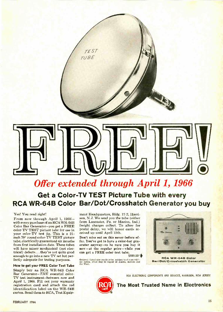
Drd
Oiler extended through April 1, 1966Get a Color -TV TEST Picture Tube with every
RCA WR-64B Color Bar/Dot/Crosshatch Generator you buyYes! You read right!From now through April 1, 1966 -with every purchase of an RCA WR-64BColor Bar Generator-you get a FREEcolor -TV TEST picture tube for use inyour color -TV test jig. This is a 21 -inch 70° round color -TV TEST picturetube, electrically guaranteed six monthsfrom first installation date. These tubeswill have minor mechanical (not elec-trical) defects ... they're not quite goodenough to go into a new TV set but per-fectly adequate for testing purposes.
How to get your FREE Color Test TubeSimply buy an RCA WR-64B ColorBar Generator- THE essential color -TV test instrument-between now andApril 1, 1966. Fill out your warrantyregistration card and attach the redidentification label on the WR-64Bcarton. Send them to RCA, Test Equip-
ment Headquarters, Bldg. 17-2, Harri-son, N.J. We send you the tube (eitherfrom Lancaster, Pa. or Marion, Ind.)freight charges collect. To allow forpostal delay, we will honor cards re-ceived up until April 15th.Don't miss out on this never -before of-fer. You've got to have a color -bar gen-erator anyway-so be sure you buy itnow-at the regular price-while youcan get a FREE color test tube.
$189.504Optional distributor resale price, subject to change with-out notice. Price may be higher in Alaska, Hawaii andthe West.
I
RCA WR-64B ColorBar/Dot/Crosshatch Generator
RCA ELECTRONIC COMPONENTS AND DEVICES, HARRISON, NEW JERSEY
The Most Trusted Name in Electronics
FEBRUARY 1966 25

hundreds ofantennas
BUT
ONLY ONETHAT'S
EXACTLY
RIGHT
for UHF'RecePtl,°11,at its VE'v
BEST.
PAT.PENDING
RevolutionaryMODEL UPW
UHF PASSIVE WAVE ANTENNAConstant impedence transition is pro-vided from a Wave Guide ElementSystem to a balanced transmissionline in a proportional additive manner.This system in which there are noelectrical connections,PROVIDES HIGH GAIN ACROSS THE
ENTIRE UHF BANDand eliminates noise caused by looseelements at high frequencies. Highoverall gain across the entire UHFband makes this antenna more desir-able than any frequency consciousyogi types being marketed today.Excellent color reception assured.More gain than a Parabolic. Topquality construction.
Write for literature and lowretail prices. All
inquiries given prompt attention.
S & A ELECTRONICS INC.Manufacturers of the TARGET ANTENNA
West Florence Street Toledo, Ohio 43605Phone 419-693-0528
EDITOR'SMEMO
This Shrinking World
While astronomers tell us that theuniverse literally expands in a con-tinuously accelerating manner - asindicated by the "red -shift" theory-and while new telescopes above theearth's atmosphere have extended ourvision farther into the universe,things on earth are getting smaller.Even distances on earth-in point oftime-continue to shrink.
Some years ago we observed -under a powerful magnifying glass-an electric motor which ran anddeveloped a certain amount of "gnat -power." It was one sixty-fourth ofan inch in diameter. The motor wasmade under a microscope.
Not long after this, we observed-again under magnification-a numberof wires which had been insertedthrough a hole drilled through a hu-man hair. At that time the wire wassaid to be the smallest ever made.
And then we were shown a num-
ber of electronic components stackedon top of the head of an ordinarystraight pin! But some other thingshave become smaller since.
All these things, of course, arerelatively large compared with somemicroelectronic components manufac-tured today. We only mention them toshow how things are shrinking in elec-tronics.
Now comes the mock-up of a colorTV set with a six-inch screen which,the manufacturer says will be aboutthe size of an ordinary portable radioof just a few years ago. The "teeney-vision" set is expected to be on themarket within a year.
These shrinking innovations havecome about because of space-age ne-cessity. Where it will end, no oneknows.
Coming events always cast theirshadows before them, to paraphrasean old cliche which has avoided theerosions of historical change. Thus,we call attention to a few shadowsthat hint of things to come.
But we've been doubting for sometime if this "shadowy" coming -eventsbarometer can survive indefinitely.Maybe you've wondered, too.
Just how small can things get andstill cast a shadow?
fat, ugly machine that canmake you a lot* of money.
Just so you'll be sure . . it's an oven. Not for pies. Nor cakes. Not even for pizzas.
It's for television picture tubes, and performs chores like tube evacuation, cathodebombarding, induction heating, and more. Most important, it is part of the exclusiveWindsor System of picture tube rebuilding-your key to a business you can run (rightalong with what you're doing right now), and make extra money with in amounts youmight not have thought possible (`like $4,000, $5,000, $10,000 a year and more!).
Sound good? Then send for the full story. Write direct, or circle our number right away.Who knows, that happy guy in the picture could be you.
WINDSOR ELECTRONICS, INC.999 North Main StreetGlen Ellyn, Illinois 60137
.. for more details circle 43 on postcard
26
. . . for more details circle 56 on postcard
ELECTRONIC TECHNICIAN

New design for color... and all other!
QUICK -CHECKSMORE COLORTV TUBESWITHGm* ACCURACY
illakes test under actualT set -operating conditions
NEWB&Kmodel 707
DYNAMIC MUTUAL CONDUCTANCETUBE TESTER with obsolescence protection
Tests:New and old TV andRadio Tubes. TestsNuvistors, Novars,10 -pin tubes, 12 -pinCompactrons, EuropeanHi-Fi tubes, VoltageRegulators, and MostIndustrial types.
You're always ahead with B&K. The new "707" gives you the famous B&Kprofessional tube -testing speed and efficiency-plus the ability to test morecolor TV tubes with Gm* accuracy.
Provides multiple -socket section to quick -check most of the TV and radiotube types the true dynamic mutual conductance way*-plus simplified switchsection to check other tube types in Dyna-Jet emission circuit. Also includesprovision for future new sockets.
You can quickly check all the tubes in the set, detect hard -to -locate weaktubes that need replacement ... sell more tubes, save call-backs, and makemore profit. Makes test under set -operating conditions. Checks each section ofmulti -section tubes separately. Checks for all shorts, grid emission, leakage, andgas. Makes quick "life" test. Exclusive adjustable grid emission test providessensitivity to over 100 megohms. Quickly pays for itself. Net, $18995
See your B&K Distributor or Write for Catalog AP22-R
NEW TUBE INFORMATION SERVICEKeep your tube tester up-to-date.Subscribe now to tube informationservice, available every 3 months.
B & K MANUFACTURING CO.DIVISION OF DYNASCAN CORPORATION
1801 W. BELLE PLAINE AVE. CHICAGO, ILL. 60613
Export; Empire Exporters, 123 Grand St., New York 13, U.S.A.
... for more details circle I5 on postcard
27
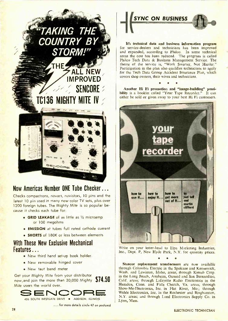
"TAKING THECOUNTRY BY
STORM!"
ALL NEW,IMPROVED
SENCORE
TC136 MIGHTY MITE IV
Now Americas Number ONE Tube Checker ...Checks compactrons, novars, nuvistors, 10 pins and thelatest 10 pin used in many new color TV sets, plus over1200 foreign tubes. The Mighty Mite is so popular be-cause it checks each tube for:
GRID LEAKAGE of as little as 1/2 microampor 100 megohms
EMISSION at tubes full rated cathode current
SHORTS of 180K or less between elements
With These New Exclusive MechanicalFeatures ...
New third hand set-up book holder. New removable hinged cover New taut band meter
Get your Mighty Mite from your distributornow,and join the more than 30,000 MightyMite users the world over.
I\J C3 1=1
$14.50
426 SOUTH WESTGATE DRIVE ADDISON, ILLINOIS
SYNC ON BUSINESS
It's technical data and business information programfor service -dealers and technicians has been improvedand expanded, according to Philco. In some technicalareas the cost has been reduced. The program is calledPhilco Tech Data & Business Management Service. Thetheme of the service is, "Work Smarter, Not Harder."Participation in the plan also qualifies technicians to applyfor the Tech Data Group Accident Insurance Plan, whichcovers shop owners, their wives and technicians.
Another Hi Fi promotion and "image -building" possi-bility is a booklet called "Your Tape Recorder." It caneither be sold or given away to your best Hi Fi customers.
yourtape
recorder
how to by
get more joel taNout of it... and
martinclifford
Write on your letter -head to Elpa Marketing Industries,Inc., Dept. P, New Hyde Park, N.Y. for quantity prices.
Stancor replacement transformers are now availablethrough Columbia Electric in the Spokane and Kennewick,Wash, and Lewiston, Idaho, areas; through Kiesub Corp.in the Long Beach, Anaheim, Oxnard and San Bernardino,Calif. areas; through Lafayette Radio Electronics in theHamden, Conn. and Falls Church, Va. areas; throughShow -Me -Electronics, Inc. in Flat River, Mo.; throughWehle Electronics, Inc. in the Rochester and Binghamton,N.Y. areas; and through Land Electronics Supply Co. inLynn, Mass.
... for more details circle 47 on postcard28 ELECTRONIC TECHNICIAN
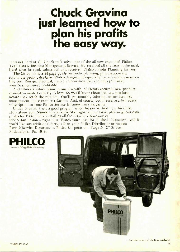
Chuck Gravinajust learned how to
plan his profitsthe easy way.
It wasn't hard at all. Chuck took advantage of the all -new expanded PhilcoTech -Data & Business Management Service. He received all the facts in the mail,liked what he read, subscribed and received Philco's Profit Planning kit free.
The kit contains a 24 -page guide on profit planning, plus an accurate,easy -to -use profit calculator. Philco designed it especially for service -businessmenlike you. You get practical, usable information that can help you makeyour business more profitable.
And Chuck's subscription means a wealth of factory -accurate new productmanuals - mailed directly to him. So you'll know about the new productsbefore they reach the retailers. You'll get monthly information on businessmanagement and customer relations. And, of course, you'll receive a full year'ssubscription to your Philco Service Businessman's magazine.
Chuck Gravina knew a good program when he saw it. And he subscribed.How about you? Shouldn't you subscribe right now and start planning your ownprofits for 1966? Philco is mailing all the details to thousands ofservice -businessmen right now. Watch your mail for all the information. And ifyou'd like any additional facts, talk to your Philco Distributor or contactParts & Service Department, Philco Corporation, Tioga Esc "C" Streets,Philadelphia, Pa. 19134.
PH I LCOA SUBSIDIARY Of 1...4;YZAVerWennAan:y,
FEBRUARY 1966
... for more details circle 40 on postcard
29
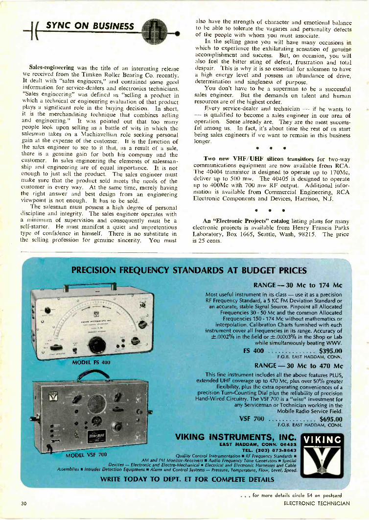
SYNC ON BUSINESS
Sales -engineering was the title of an interesting releasewe received from the Timken Roller Bearing Co. recently.It dealt with "sales engineers," and contained some goodinformation for service -dealers and electronics technicians."Sales engineering" was defined as "selling a product inwhich a technical or engineering evaluation of that productplays a significant role in the buying decision. In short,it is the merchandising technique that combines sellingand engineering." It was pointed out that too manypeople look upon selling as a battle of wits in which thesalesman takes on a Machiavellian role seeking personalgain at the expense of the customer. It is the function ofthe sales engineer to see to it that, as a result of a sale,there is a genuine gain for both his company and thecustomer. In sales engineering the elements of salesman-ship and engineering are of equal importance. It is notenough to just sell the product. The sales engineer mustmake sure that the product sold meets the needs of thecustomer in every way. At the same time, merely havingthe right answer and best design from an engineeringviewpoint is not enough. It has to be sold.
The salesman must possess a high degree of personaldiscipline and integrity. The sales engineer operates witha minimum of supervision and consequently must be aself-starter. He must manifest a quiet and unpretentioustype of confidence in himself. There is no substitute inthe selling profession for genuine sincerity. You must
also have the strength of character and emotional balanceto be able to tolerate the vagaries and personality defectsof the people with whom you must associate.
In the selling game you will have many occasions inwhich to experience the exhilarating sensation of genuineaccomplishment and success. But, on occasion, you willalso feel the bitter sting of defeat, frustration and totaldespair. This is why it is so essential for salesmen to havea high energy level and possess an abundance of drive,determination and singleness of purpose.
You don't have to be a superman to be a successfulsales engineer. But the demands on talent and humanresources are of the highest order.
Every service -dealer and technician - if he wants to- is qualified to become a sales engineer in our area ofoperation. Some already are. They are the most success-ful among us. In fact, it's about time the rest of us startbeing sales engineers if we want to remain in this businesslonger.
Two new VHF/UHF silicon transistors for two-waycommunications equipment are now available from RCA.The 40404 transistor is designed to operate up to 170Mc,deliver up to 500 mw. The 40405 is designed to operateup to 400Mc with 700 mw RF output. Additional infor-mation is available from Commercial Engineering, RCAElectronic Components and Devices, Harrison, N.J.
An "Electronic Projects" catalog listing plans for manyelectronic projects is available from Henry Francis ParksLaboratory, Box 1665, Seattle, Wash, 98215. The priceis 25 cents.
PRECISION FREQUENCY STANDARDS AT BUDGET PRICES
MODEL FS 400
enumill%
RANGE - 30 Mc to 174 McMost useful instrument in its class - use it as a precisionRF Frequency Standard, a 5 KC FM Deviation Standard or
an accurate, stable Signal Source. Pinpoint all AllocatedFrequencies 30 - 50 Mc and the common AllocatedFrequencies 150 -174 Mc without mathematics or
interpolation. Calibration Charts furnished with eachinstrument cover all frequencies in its range. Accuracy of
±.0002°/o in the field or 1:.00003% in the Shop or Labwhile simultaneously beating WWV.
FS 400 $395.00F.O.B. EAST HADDAM, CONN.
RANGE - 30 Mc to 470 McThis fine instrument includes all the above features PLUS,
extended UHF coverage up to 470 Mc, plus over 50% greaterflexibility, plus the extra operating conveniences of a
precision Turn -Counting Dial plus the reliability of precisionHand -Wired Circuitry. The VSF 700 is a "wise" investment for
any Serviceman or Technician working in theMobile Radio Service Field.
VSF 700 $695.00F.O.B. EAST HADDAM, CONN.
VIKING INSTRUMENTS, INC.EAST HADDAM, CONN. 06423
TEL. (203) 873-8643MODEL VSF 700 Quality Control Instrumentation RF Frequency Standards
AM and FM Monitor -Receivers Audio Frequency Tone Generators SpecialDevices - Electronic and Electro-Mechanical Electrical and Electronic Harnesses and Cable
Assemblies Intruder Detection Equipment Alarm and Control Systems - Pressure, Temperature, Flow, Level, Speed.
WRITE TODAY TO DEPT. ET FOR COMPLETE DETAILS
30
. for more details circle 54 on postcard
ELECTRONIC TECHNICIAN
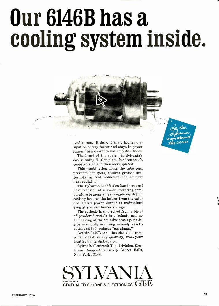
Our 6146B has acooling system inside.
And because it does, it has a higher dis-sipation safety factor and stays in powerlonger than conventional amplifier tubes.
The heart of the system is Sylvania'scool -running Hi -Con plate. It's iron that'scopper -plated and then nickel -plated.
This combination keeps the tube cool,prevents hot spots, assures greater uni-formity in heat reduction and efficientheat radiation.
The Sylvania 6146B also has increasedheat transfer at a lower operating tem-perature because a heavy oxide insulatingcoating isolates the heater from the cath-ode. Rated power output is maintainedeven at reduced heater voltage.
The cathode is cold -rolled from a blendof powdered metals to eliminate peelingand flaking of the emissive coating. Emis-sive materials are progressively reacti-vated and this reduces "gm slump."
Get the 6146B and other electronic com-ponents fast, in any quantity, from yourlocal Sylvania distributor.
Sylvania Electronic Tube Division, Elec-tronic Components Group, Seneca Falls,New York 13148.
SYLVAN IASUBSIDIARY OF
GENERALTELEPHONE & ELECTRONICS GTEFEBRUARY 1966 31
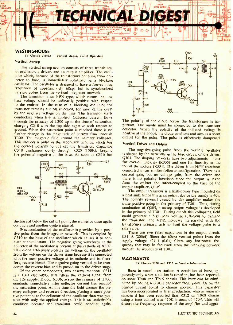
V78IOUS
59P/48813R200
' 7
9V PPH
(0.1 MT NAV Arlin15411 HOR12 9.100 m3
A-01 JOLY. REMOTE 11011111/1104 $ 1 M.. 11001,t
:701'
100
WESTINGHOUSETV Chassis V-2483 - Vertical Stages, Circuit Operation
Vertical Sweep
The vertical sweep section consists of three transistors;an oscillator, a driver, and an output amplifier. The oscil-lator which, because of the transformer coupling from col-lector to base, is immediately identified as a blockingoscillator. The oscillator is designed to have a free -runningfrequency of approximately 60cps but is synchronizedby sync pulses from the vertical integrator network.
The transistor is an NPN type, which means that thebase voltage should be ordinarily positive with respectto the emitter. In the case of a blocking oscillator thetransistor remains cut off (blocked) for most of the cycleby the negative voltage on the base. The transistor startsconducting when B -I- is applied. Collector current flowsthrough the primary of T300 up to the time of saturation,charging C310 with the top side negative with respect toground. When the saturation point is reached there is nofurther change in the magnitude of current flow throughT300. The magnetic field around the primary collapses.This induces a pulse in the secondary winding which hasthe correct polarity to cut off the transistor. CapacitorC310 discharges slowly through R325 (150K), keepingthe potential negative at the base. As soon as C310 has
QV.
TO
VERTICAL
4VDRIVER
II
FROM
VERTICAL
INTEGRATOR
0303
OSCILLATOR
discharged below the cut off point, the transistor once againconducts and another cycle is started.
Synchronization of the oscillator is provided by a posi-tive pulse from the integrator network. This is coupled byC310 to the base of the oscillator which causes it to con-duct at that instant. The negative going waveform at thecollector of the oscillator is present at the cathode of X307.This diode effectively isolates the voltage on the oscillatorfrom the voltage on the driver stage because it is connectedwith the most positive voltage at its cathode and is, there-fore, reverse biased. The negative -going vertical pulse over-comes the reverse bias and is passed on to the driver stage.
Of the other components, two deserve mention. C311is a 10µ,f electrolytic that filters the vertical signal fromthe 12v supply. Diode, X306, across the primary of T300,conducts immediately after collector current has reachedthe saturation point. At this time the field around the pri-mary collapses and reverses direction, placing a more posi-tive potential at the collector of the oscillator than was pos-sible with only the applied voltage. This is an undesirablecondition because the transistor could conduct again.
5505 1501(
FROM
OSC
0 0
R335
LIN.
---.C312
C315
R336
187V Ps
"
R334
HEIGHT 0332
8331
60V
R340
R338
Oil1ZAF3
DAMPER t
SIT
T301
C313
rAID
TO
YOK
C316
7
6 I
5
5510 I.
Irva e+++
The polarity of the diode across the transformer is im-portant. The anode must be connected to the transistorcollector. When the polarity of the induced voltage ispositive at the anode, the diode conducts and acts as a shortcircuit for the pulse. The pulse is effectively dampened.
Vertical Driver and Output
The negative -going pulse from the vertical oscillatoris shaped by the networks in the base circuit of the driver,Q304. The shaping networks have two adjustments - onefor over-all linearity (R335) and one for linearity at thetop of the picture (R331). The driver is an NPN transistorconnected in an emitter -follower configuration. There is acurrent gain, but no voltage gain, from the driver andthere is no polarity inverison since the output is takenfrom the emitter and direct -coupled to the base of theoutput amplifier, Q305.
The output transistor is a high -power type mounted ona heat sink. Since this is an output device the supply is 60v.The polarity reversal caused by this amplifier makes thepulse positive -going in the primary of T301. Thus, duringconduction of Q305, a sweep output voltage is developedin the primary of T301. During cutoff this collapsing fieldcould generate a high peak voltage sufficient to damagethe transistor. The VDR, however, in parallel with thetransformer primary, acts to limit the voltage pulse to asafe value.
There are two filter capacitors in the output circuit.C314A (200µf) filters the 60cps vertical pulses from thesupply voltage. C313 (0.01) filters any horizontal fre-quency that may be fed back from the blanking networkthrough the secondary of T301.
MAGNAVOXTV Chassis T908 and T915 - Service Information
Buzz in sound-on station. A condition of buzz, ap-parently only when a station is tuned -in, has been reportedon some T908 and T915 chassis. This buzz can be elimi-nated by adding a 0.01µf capacitor from point 3A on theprinted circuit board to chassis ground. This capacitorhas been incorporated in later production. Also in some in-stances it has been reported that R312 on T908 chassisusing a tone control was 470K instead of 4702. This willdistort the frequency response of the amplifier and aggra-
32 ELECTRONIC TECHNICIAN

First UHF/VHF/FM 2-83 antennathat really works in fringe areas
Jr
NewWinegardChroma-TelCT -100
NEW ! Model CT -100 $52.50
Wingard's sensational new CT -100 Chroma-Tel has 29elements in all. And they're all working to provide thefinest all -band reception (UHF -VHF -FM) even in difficultfringe areas.
In addition to those 29 elements, the CT -100 incor-porates a unique matching network that guaranteesmaximum signal transfer to the downlead-and on allchannels 2-83 plus FM. Gives sharpest color and black& white reception.
And like all Chroma-Tels, it has Winegard's exclusiveChroma-Lens Director System (intermixes both VHF andUHF directors on the same linear plane without sacrificing
performance) ... and our Impedance Correlators (specialphasing wires that automatically increase the impedanceof Chroma-Tel's elements to 300 ohms).
That's Winegard's new CT -100 Chroma-Tel. Biggerand better. But not too big. The full -line of WinegardChroma-Tels still offers half the bulk; half the windloading; half the truck space; and half the weight of allother all -band antennas-and at much lower prices. Nowonder Winegard Chroma-Tels (now 4 models) are thehottest performing, hottest selling all -band antennas onthe market! Better call your Winegard distributor orwrite for Chroma-Tel Fact Finder 242.
Model CT -40 $17.50
Model CT -90 $37.50
Model CT -80 $27.50
FREE!
Every Winegard Chroma-Tel, including the new CT -100,comes complete with free CS -283 UHF -VHF Signal Splitter.Hangs behind set and separates UHF and VHF signals com-ing from antenna to the two pairs of set terminals.
Winegard ANTENNA SYSTEMS Winegard Co. 3000 Kirkwood Burlington, Iowa 52602. . for more details circle 57 on postcard
Experiencefor Sale
Sure seems we started something!Yes; over ten years ago, when we startedoverhauling tuners (all makes and models),we set a price of $9.95 for this service.
Apparently there are those who would liketo imitate our achievement-and for 450less.
Maybe the special skills, special equipmentand downright old fashioned experiencewe built up during these past years areworth that little extra.-You be the judge.Remember; 45¢ buys you more than aquarter of a million man/hours of expe-rience, plus true devotion to our business. . . our only business . . . overhaulingyour television tuners the best way weknow how. And in over ten years wesure know how!
Castle - The Pioneer of TV tuner overhaulingNot the cheapest - just the best.
For complete tun-er overhaul we stillcharge only $9.95.This includes alllabor and parts;except tubes andtransistors, whichare charged extraat low net prices.
r-Simply send us the defective tuner complete; include tubes:1shield cover and any damaged parts with model numberand complaint. Your tuner will be expertly overhauled andreturned promptly, performance restored, aligned to originalstandards and warranted for 90 days.UV combination tuner must be single chassis type; dismantletandem UHF and VHF tuners and send in the defective unitonly.Exact Replacements are available for tuners unfit for over-haul. As low as $12.95 exchange. (Replacements are new orrebuilt.)
CASTLETV TUNER SERVICE, INC.MAIN PLANT:
EAST:
CANADA:
5713 N. Western Ave., Chicago 45, Illinois41-92 Vernon Blvd., Long Island City 1, N. Y.
Castle TV Services, Ltd.... Nation-wide service.For service in Canada write to Chicago or usereader service card in this magazine.*Major parts are charged extra in Canada.
TECHNICAL DIGEST
vate the buzz condition so check the value of this resistorwhen making the change. Hum In Audio. If excessive humis noticed on T908 or T915 chassis, the following circuitchange is suggested: Remove R308, 33K resistor, in theaudio driver circuit, and replace it with a series combina-tion of a 5.6K and 27K resistor. Be sure that the 27Kresistor connects to the audio driver base and the 5.6Kresistor to the 12v+ source (point VC). Then connect a54., 20v electrolytic capacitor between the junction of thetwo resistors and chassis ground.
RCA VICTORRecord Changer RP217, -218, -219 Series - Service Information
The record changer mechanism is properly lubricatedat the factory so lubrication should not be necessary for along period of time. When lubrication does become neces-sary it should be remembered that excessive lubricationcan be detrimental to the operation of the changer. Acouple of drops of oil or a small dab of grease is normallyall that is required. A light machine oil is used to lubricatethe drive motor bearings, idler wheel bearings, and otherfast rotating parts. A cloth impregnated with this oil isused to wipe the stabilizer arm shaft (20A), pickup arm liftrod (47) and pickup arm pivot shaft (54) after any oxida-tion has been removed by polishing them and the inside oftheir housings with crocus cloth. All other bearings andsliding surfaces such as the cycling gear, other slow rotat-ing parts, lever pivot studs, cycling -gear -stud slot in thecycling slide (17), control lever stud (40), automatic neutrallink detent lever (40), record push off lever, and pointsupon which the cycling slide rides, are lubricated with amedium weight clinging type non -solidifying grease. Thecup of the turntable bearing is filled with grease and in-stalled with the cup facing up. (A metal washer is installedon each side of this bearing.) A small dab of a heavysilicon grease should be applied to the pickup verticalpivot shaft at the point where the pickup rides. Note: Thetrip pawl (18), trip level (56) and clutch lever (57) shouldnot be lubricated.
Cleaning
Oil or grease on any surface in the turntable drive sys-tem can cause slippage which in turn can produce wowor stalling. It is, therefore, very important that the spindleor shaft, of the motor, the idler wheel rubber tire, and theinside surface of the turntable rim be periodically cleanedto remove any accumulation of oil or grease. The surfaceof the landing lever (44) where it is contacted by the pick-up arm pivot lever (54A) should be cleaned to avoid acondition of erratic landing. One of the causes for theseconditions can be excessive lubrication, particularly of thedrive motor upper bearing.
Recommended cleaning agents for the rubber partsof the mechanism are: isopropyl alcohol, or naphtha.
AdjustmentsOnly three adjustments are necessary for setting the
proper operation of the RP217, -218 & -219 record chang-ers provided that no parts have been misshapen.One adjustment is necessary to regulate the correct landingof the stylus on the record and two adjustments to regulatethe horizontal and vertical movement of the pickup arm.
for more details circle 18 on postcard
34 ... for more details circle 19 on postcard
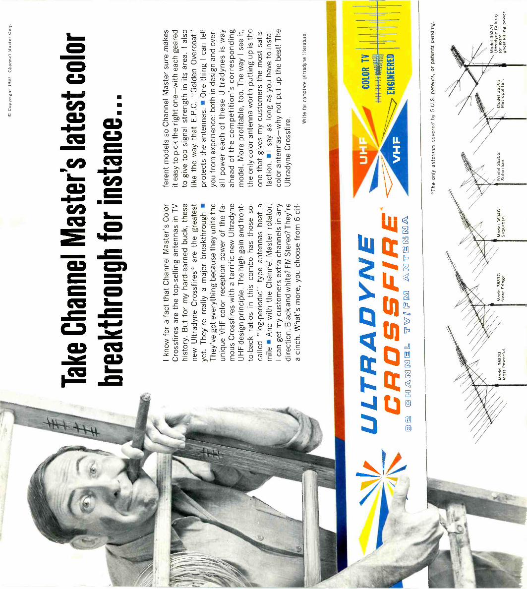
7"
© C
opyr
ight
196
5 C
hann
el M
aste
r C
orp.
Tak
e C
hann
el M
aste
r's la
test
col
or
brea
kthr
ough
for
inst
ance
...
I kno
w fo
r a
fact
that
Cha
nnel
Mas
ter's
Col
orC
ross
fires
are
the
top
-sel
ling
ante
nnas
in T
Vhi
stor
y. B
ut fo
r m
y ha
rd-e
arne
d bu
ck, t
hese
new
Ultr
adyn
e C
ross
fires
* ar
e th
e gr
eate
stye
t. T
hey'
re r
eally
a m
ajor
bre
akth
roug
h T
hey'
ve g
ot e
very
thin
g be
caus
e th
ey u
nite
the
uniq
ue V
HF
col
or r
ecep
tion
pow
er o
f the
fa-
mou
s C
ross
fires
with
a te
rrifi
c ne
w U
ltrad
yne
UH
F d
esig
n pr
inci
ple.
The
hig
h ga
in a
nd fr
ont -
to -
back
rat
ios
in th
is c
ombo
has
thos
e so
-ca
lled
"log
-per
iodi
c" ty
pe a
nten
nas
beat
am
ile A
nd w
ith th
e C
hann
el M
aste
r ro
tato
r,I c
an g
et m
y cu
stom
ers
extr
a ch
anne
ls in
any
dire
ctio
n. B
lack
and
whi
te?
FM
Ste
reo?
The
y're
a ci
nch.
Wha
t's m
ore,
you
cho
ose
from
6 d
if-
UC
LTR
RO
AS
DSII
CR
OS
SF
IRE
.E
D@
gC
=O
LER
gl, U
'Wf P
G1
Li\M
5TE
RIG
UL\
Mod
el 3
632G
Mos
t Pow
erfu
l.M
odel
363
3GM
odel
363
4GN
ear
Frin
ge.
Sub
urba
n.
fere
nt m
odel
s so
Cha
nnel
Mas
ter
sure
mak
esit
easy
to p
ick
the
right
one
-with
eac
h ge
ared
to g
ive
top
sign
al s
tren
gth
in it
s ar
ea.
Ial
solik
e th
e w
ay th
at E
.P.C
. "G
olde
n O
verc
oat"
prot
ects
the
ante
nnas
. O
ne th
ing
I can
tell
you
from
exp
erie
nce:
bot
h in
des
ign
and
over
-al
l pow
er e
ach
of th
ese
Ultr
adyn
es is
way
ahea
d of
the
com
petit
ion'
s co
rres
pond
ing
mod
el. M
ore
prof
itabl
e, to
o. T
he w
ay I
see
it,th
e on
ly c
olor
ant
enna
wor
th p
uttin
g up
is th
eon
e th
at g
ives
my
cust
omer
s th
e m
ost s
atis
-fa
ctio
n. I
say
as lo
ng a
s yo
u ha
ve to
inst
all
colo
r an
tenn
as-w
hy n
ot p
ut u
p th
e be
st! T
heU
ltrad
yne
Cro
ssfir
e. Writ
e fo
r co
mpl
ete
Ultr
adyn
e lit
erat
ure.
CO
LOR
TV
1111
1111
1"1
"2
Age
liE
NG
INE
ER
ED
*The
onl
y an
tenn
as c
over
ed b
y 5
U.S
. pat
ents
, or
pate
nts
pend
ing.
Mod
el 3
635G
Mod
el 3
636G
Sub
urba
n.M
etro
polit
an.
Mod
el 3
637G
Ultr
adyn
e C
olor
ayfo
r ex
tra
ghos
t kill
ing
pow
er.

CO
R?
I know it's hit
the roof.
And brother,
I'mcleaning
up.
With A
merica's
best-sellingantennas
CH
AN
NE
LM
AST
ER
And don't forget the V
HF
/FM
branches of Am
erica's most
successful CO
OR
family.
Color C
rossfires
Color C
rossfireM
odel 3611GF
ringe VH
F.
Crossfire C
oloray
Crossfire C
olorayM
odel 3618GF
or metropolis and suburbs.
Each perfectly engineered for color and
designed for maxim
um pow
er in its areaM
ore Crossfires* have been sold than any
other antenna in TV
history. A 7 -m
odel seriesof the w
orld's most pow
erful antennas ...now
better than ever for color, black -and -w
hite and FM
stereo; from suburb to fringe
to super -fringe. Com
bines our revolutionaryprinciple of P
roportional Energy A
bsorptionw
ith our exclusive Tri-B
and Director S
ystemto deliver the high clean broadband gainneeded for color reception. C
overed by 3separate patents.
Crossfire C
oloray* ... ghost -killer extraor-dinary! F
or weak -pocket m
etropolitan andsuburban areas. C
ombines high gain char-
acteristics of Crossfire w
ith a unique Pow
erE
qualizer circuit that provides up to 30 to1 front -to -back ratios. E
xclusive -75 and 300ohm
impedance insures ideal color recep-
tion for MA
TV
and co -axial home installa-
tions. Second m
odel (3110G) available for
strong -signal areas. Both m
odels protectedby rem
arkable money -back guarantee.
All m
odels protected by exclusive E.P
.C."G
olden Overcoat"
Write for the full facts on the C
rossfires and the Colorays.
CH
AN
N Z
MA
ST II
ELLE
NV
ILLE, N
EW
YO
RK

TECHNICAL DIGEST
Land Adjustment
The landing point of the stylus is controlled by aneccentric stud (44A) in the landing lever (44). Whenthis stud is adjusted for proper landing on one size record(7 in. preferably) the points for the other two sizes areautomatically set by fixed steps on the landing lever.
The landing adjustment stud (44A) is accessible fromthe top of the motor board through an access hole adjacentto and forward of the pickup arm pivot bearing and is also
HEIGHTADJUSTMENT
SCREW
SPRING
PICKUP ARM LIFT PIN
Ass' ro AleCAP
PICKUP ARM LIFT PIN
HEIGHT 0ADJUSTMENT
SCREW
PICKUP ARM
LANDING LEVER 0
PICKUP ARM 0LEVER
,/10X".LANDING
ADJUSTMENTSTUD
CYCLING SLIDE 0
accessible from the under side of the motor board. It is
adjusted as follows: 1-Disconnect the power to thechanger. 2-Place a record on the turntable (7 in. prefer-able). 3-Turn function knob to SEL and rotate turntableby hand until the pickup arm is at the end of its inwardtravel and just starts to lower. 4-Turn the landing ad-justment stud (44A) to position the stylus so that it willland midway between the outer edge of the record andthe grooves. 5-Check landing on other two sizes and"touch-up" adjustment as necessary.
Height Adjustments
Two height adjustments are necessary on this type ofchanger. One is to provide a "clutch" clearance whichcontrols the horizontal movement of the pickup arm, andthe second adjusts the vertical lift of the pickup arm toclear a stack of records. They are adjusted as follows:1-Rotate the turntable until the mechanism is completely"Out of Cycle." 2-Adjust the height adjustment screw(67) to obtain a clearance between the pickup arm lever(54) and landing lever (44) of 0.07 in. to 0.085 in. (aboutthe thickness of a penny). 3-Trip mechanism and rotateturntable, until pickup arm has completed its inwardtravel and is just ready to descend. 4-Adjust height ad-justment screw (11) so that the stylus is 1 3/16 in. abovethe surface of the turntable mat.
FEBRUARY 1966
PINPOINT COLOR TVTROUBLE IN SECONDS...
WITH THE NEW IMPROVED
SENCORE CA122(A)
COLOR CIRCUIT ANALYZER
It's a standard ten color bar generator; produces verticallines, horizontal lines, crosshatch, and adjustable dots,
PLUS a complete TV analyzer for color and B&W-atless money than color generators only. Here is what the
CA122(A) will do for you by tried and proven signalinjection into these stages.
UNIVERSAL TUNER SUBSTI-TUTE for Color (or B&W).
A must to check tuner re-striction of RF color signal.
EACH IF STAGE to quicklyisolate a stage with lowgain.
VIDEO AMPS from detectorto the CRT tube, up to
30 VPP.
BANDPASS AND CHROMAAMPS signal injection forcolor trouble isolation.
CHECKOUT COLOR DEMOD-ULATORS for troubles orphase adjustments.
4.5 MC IF for signal in-
jection up to the audiodiscriminator.
AUDIO AMPS; 900 cyclesfor injection right up to thespeaker.
See your distributor today.
SYNC CIRCUITS; verticaland horizontal pulses toquickly isolate sync faults.
PLUSThe CA122(A) is not only a colorgenerator and analyzer, but providescolor gun interruptors for purity ad-justments and a shading bar patternfor color tem-perature controlsettings. Youget all this foronly. $1815039G12 Rectan-
$ 495gular color tubeadaptor.
He has the CA122(A) in stock now.
EJ CD 1=1426 SOUTH WESTGATE DRIVE ADDISON, ILLINOIS
... for more details circle 46 on postcard
37

EXACT REPLACEMENT
direct from factory to you
PART NO. 8152.75
CIRCUIT BREAKEREXACT REPLACEMENT
FOR COMPLETE LISTING SEEBACK OF CARD
PATENT NO.
3038047TRIP RATING
2.75A
LITTELFUSEDES Pl AINES ILLINOIS
Complete range of highquality circuit breakersto cover every replace-ment need, packagedfor your convenienceindividually on a displaycard or 5 per box.
Also, available in10 cardassortment (9 separateratings) or 10 breakersper unit box (9 separateratings).
packagedfor yourparticular needs
LITTELFUS EDES PLAINES, ILLINOIS
,14

FEBRUARY 1966
IN -HOME
.11114
Did you ever wish you could work an "old fashioned" eight hour day and gohome at 5 p.m. instead of working until nine - trying to finish your benchwork? Ever wish the day contained thirty hours instead of twenty-four?
You can go home at a reasonable time - cut your working hours substantiallyand make more money than you ever made before - if you'll use your head anddevelop your in -home service techniques to a higher level. Many hours can beshaved off your work week if you can eliminate time lost carrying sets back andforth - from customer to shop, from shop to customer.
Add up the time spent, for example, dismantling sets, carting chassis backto the shop, setting them up on the bench, stripping them down again, carting themback to the customer and then setting them up again. Divide your weekly incomeunder this system by the number of hours you work. You don't have to bereminded that it comes out to "pea -picker" wages.
Two ViewsSome service -dealers say it isn't practical to repair most major breakdowns
in the home. They say you can't replace parts and then wait around the housewhile the set "cooks" properly for hours. They say you just can't give a set theproper attention in the home - working on the living -room floor or on a kitchentable - without proper shop test instruments and tools. And furthermore, theysay, when solid-state equipment is widely used, there'll be fewer sets serviced in thehome.
Well, maybe. But until that time comes, we disagree - with certain reserva-tions. We agree, of course, that the "tube -snatcher" type technician can't do it.We agree that the shop that pays a benchman who has nothing to do won't find it
4E- ... for more details circle 34 on postcard 39
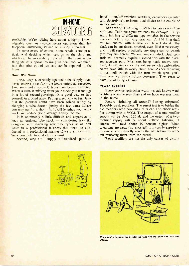
INHOME
VIBitprofitable. We're talking here about a highly knowl-edgeable one- or two -technician operation that hastelephone answering service or a shop attendant.
In some cases, of course, home -repair is not prac-tical. And deciding which sets go to the shop andwhich can be successfully repaired in the home is onething you're supposed to use your head for. We main-tain that nine out of ten sets can be repaired in thehome.
How It's DoneFirst, keep a carefully updated tube supply. And
never remove a set from the home unless all suspected(and some not suspected) tubes have been substituted.When a tube is missing from your stock you'll indulgein a lot of second-guessing; it's a good way to findyourself in a blind alley. Pulling a set only to find laterthat the problem could have been solved simply bychanging a tube doesn't justify the few extra dollarsyou may get for a shop job. It will lengthen your workweek and reduce your average hourly income.
It is admittedly a little difficult and expensive tokeep an updated tube stock - considering how thedesigners keep throwing new tube types at us. Butwe're in a professional business that must be con-ducted in a professional manner if we are to survive.So a complete tube stock is a must.
Second, keep a full supply of "standard" parts on
hand - on/off switches, rectifiers, capacitors (regularand electrolytic), resistors, dual -diodes and a couple ofindoor antennas.
But a word of warning: don't try to carry everythingwith you. Take push-pull switches for example. Carry-ing a full line of different type switches in the servicecar or truck is not very practical. A 1M long -shaftvolume control with a turn switch will do it. Theshaft can be cut down, notched, even filed if necessary,and it will replace practically any single control switchyou may run across. We said single control. Dual con-trols will normally require a second trip with the directreplacement part. Most sets being made today, how-ever, do use singles for the volume switch combinationso we have little to worry about here. As for replacinga push-pull switch with the turn switch type, you'llhear very few protests from customers. They seem totrust the older types more.
Power SuppliesEvery service technician worth his salt knows weak
rectifiers when he sees them and we hope replaces themin the home.
Picture shrinking all around? Losing crispness?Probably weak rectifiers. The surest test is to bridge theold rectifiers with new ones. You can also check recti-fier output with a VOM. The output of a one -rectifiersupply will be about 125vdc and the output of a two -rectifier supply will be about 250vdc. Silicons, ofcourse, will read about 10 percent higher. Whenseleniums are weak (not shorted) it is usually expedientto wire silicons directly across the old seleniums with-out removing them from the chassis.
Weak rectifiers are not the only causes of picture
When you're heading for a shop job take out the VOM and just lookaround.
40 ELECTRONIC TECHNICIAN

shrinking, however. In voltage doubler power supplies,when the solid-state rectifiers check out good, weshould look for the large -capacity electrolytic that leadsinto the junction of the two rectifiers. Bridge it with aknown -good one and watch the picture spread. Carrytwo 1401.4S, 300v electrolytics for this purpose. Whenthis capacitor "opens" or loses all of its capacity welose all B + - consequently picture and sound too.
When new rectifiers and a new doubler electrolyticfail to bring B + up to normal, we might next want totry a new input filter capacitor. This will be the onewired directly to the 5U4 heater (in tube sets) or tothe output of the two solid-state rectifiers. When thiscapacitor goes bad you'll get a reduced picture plustraces of ac hum bars in the raster. But, in many cases- and this is important - you'll get only the reducedpicture with no noticeable traces of hum.
Whenever you get strange symptoms on sets - wemean abnormal symptoms like irregularly coloredrasters, whistling or screeching from the speaker, flut-tering pictures or any symptom not normally associatedwith bad tubes - go after the filter capacitors. Youcan use a small hand mirror to see behind an uprightchassis and then clip a substitute filter across the dif-ferent filter terminals. By moving around from oneterminal to the next you can find out which capacitoris open. Then solder the substitute in place - you cando this very often without having to remove the chassis.Carry three 404 types rated at 450v. Of course, if thefilter is leaking, that's another matter.
But what about vertical sweep problems? Here toofilters will solve many of these problems. A 404 in thevertical output as decoupling or a 1004 at 50v inthe output tube cathode frequently goes bad.
Most customers will gladly pay for any special attention you givethem.
Other ProblemsNow these problems are relatively simple. How
about video, sound and sync troubles? Still not so dif-ficult when we use the proper techniques. Once we haveeliminated suspicious tubes and other major compo-nents and we see that we are heading for a shop job,that is the time to look to the VOM. Check voltages,check resistors, look for overheating or burned -up com-ponents - in short, just look around.
Of course, you won't find it easy to work withouta schematic unless you know your basic circuits. Hereis another place you use your head. You should knowhow basic circuitry operates - and you should know itwell enough to draw the basic circuit with a pencil.This is the difference between "tyro" and pro.
If you know basic circuits you can pinpoint thetrouble area quickly. But if you don't know your cir-cuits, how they work, how they're wired and know theapproximate values of the components in each circuit,you'll probably be checking the sync circuit when youshould be checking the AGC line - wasting time.
Once you decide the troubled circuit, you can thencheck voltages or resistances. Some technicians preferto check resistances. Without a schematic they don'tknow the exact voltages to expect. But the resistorsare color -coded. And with the ohmmeter you can dis-cover shorted coupling and by-pass capacitors and off -value resistors. Carry a wide assortment of capacitorsranging from 180pf (for horizontal oscillator circuits)up to 0.54 (frequently used as AGC filters). OtherAGC circuits, requiring heavier filtering, use 24 whichis also a stock item. This same capacitor often takes thebuzz from sound discriminator circuits.
Customer RelationsNow, assuming you're technically qualified and
equipped to do home servicing, let's go over some addi-tional points you'll have to keep in mind.
1. Don't begin work on a set until you put a drop -cloth on the floor and arrange your tools and test in-struments in an orderly manner.
2. If the set is rather old and certain parts appearmarginal in value and tolerance, recommend shop re-pair for the set - after you notify the customer thatthe particular break -down can be repaired in the home.
3. Make sure you ask the customer about otherfaults (perhaps intermittents) that existed before theset broke down. Remember: you can't wait around tosee what else may be wrong.
4. If you suspect multiple problems that can't beproperly taken care of in the home - recommend shopwork. One or more call-backs can weaken your cus-tomer relations image and make your work and adviceappear considerably less than "professional" in thecustomer's opinion.
If you are technically qualified and if you use yourhead you can build a profitable business with in -homeservicing. When the average set owner sees to whatlengths you're willing to go to repair his set in thehome you'll be able to collect more for your time thanyou would on shop jobs.
FEBRUARY 1966 41

Use manufacturers'diagrams and instructions
to make TV -radiodial stringing pay
"The only thing wrong with thisradio is a broken dial cord so I'lljust wait until you fix it," is a com-mon remark heard by techniciansevery day. And the customer usu-ally adds quickly, "It won't costmuch will it?"
Broken dial cords sound easyenough to repair, but they do takemuch more than a minute to re-place and in some cases quite a bitof time. Small table -model radiodial cords can be replaced easierthan a complicated TV dial cord.
Some points to remember in-clude:
1. Always cut the replacementcord from four to six in. longer thanthe broken cord. Unless otherwisespecified by the manufacturer, usea medium dial cord not a heavycord.
2. The tied knot should have atouch of service glue applied to it.This will prevent it from cominguntied.
3. Apply a small drop of lightoil to the pulley bearings.
4. Clean dial bracket, glass andwipe old grease off the dial assem-bly. Apply a little petrolatum tothe pointer base so it will slide eas-ily.
5. Provide yourself with originalmanufacturers diagrams and dialstringing instructions. These instruc-tions tell what direction to wind thecord, whether tuning capacitors arefully closed or open, number ofcord turns to be made around thetuning shaft, pulleys, etc.
TV and Auto Radio DialsAs we know, new TV sets now
have both UHF and VHF tuners.Some manufacturers use a combina-tion of two dial cords or a dialcord and gear assembly. The dialcord can easily be replaced butbroken plastic or fiber gears mustbe obtained from manufacturers'distributors or from the factory.
Auto radios may use a simpledial arrangement. If it is a pushbutton type the dial may be slip-ping at a pressure metal plate.
Check tension of slippage on sliding- and push-button car radios.
42 ELECTRONIC TECHNICIAN
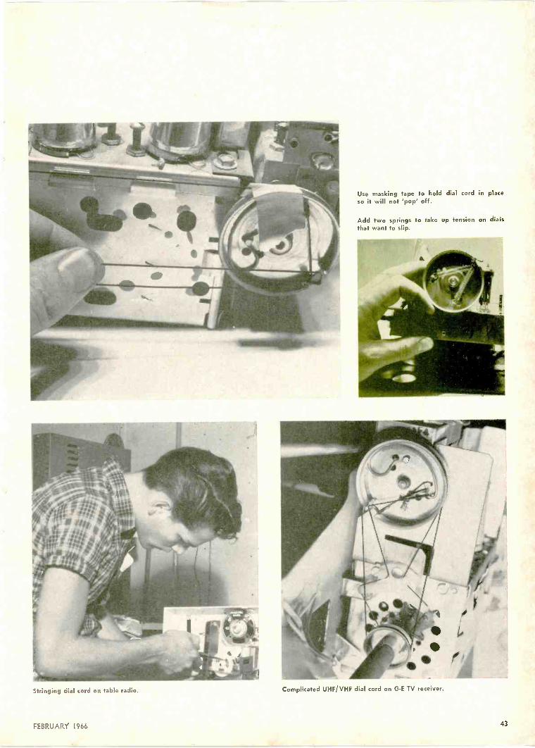
Stringing dial cord on table radio.
Use masking tape to hold dial cord in placeso it will not 'pop' off.
Add two springs to take up tension on dialsthat want to slip.
Complicated UHF/VHF dial cord on G -E TV receiver.
FEBRUARY 1966 43

AM/FM radio dial-two dials in one.
Stripped plastic gear on RCA UHF tuningassembly.
Pressure on the rubber drive be-tween the two metal pieces can betightened by spreading them witha screw driver. The outside metaldisc can be loosened through set-screws, snugged up and then set.But be careful: if the assembly istoo tight the buttons will be hard topush. Sometimes the rubber discscome loose from the metal pieces.Use rubber cement to hold them inplace. Let the rubber discs drythoroughly before reassembling theunit.
In very difficult push buttondrive assemblies a coating of liquidrosin may be necessary. A drop ofoil on the push -rods and bearingswill also help. If a dial light as-
sembly is clipped to the dial pointerassembly, drop light oil on thesemounting parts. A drop is all thatis necessary. Also clean the dial as-sembly and the dial glass becauseauto radios become very dirty.
In some long dial cord drive as-semblies a couple of springs maybe necessary to tighten the dial cordproperly. If the dial pointer is hardto see, spray red paint over it.
Several dial cord stringing toolsare on the market and help to speedup dial cord repair. And you canuse tape to hold the dial cord inplace until it is completely wound.Finally, make sure the dial light isworking before the radio or TVchassis is replaced in the cabinet.
Replacing dial cord and plastic gear dr;ve on Sylvania UHF/VHF tuner.
44 ELECTRONIC TECHNICIAN

One group of techniciansholds that the VTVM (properlyETVM) should be used only onthose jobs that it can performquickly, accurately and efficiently.That is, when it is used as a wide -range ohmmeter, a small -signal acvoltmeter and low-level dc volt-meter. The other group holds thatit will do almost anything well.
The first group says it can getmore jobs done better and faster.And the second group counters thatit can get just as many good jobsdone and as quickly.
We will be concerned here pri-marily with some of the test jobsyou can perform with a good gen-eral-purpose VTVM. Some majorjobs for which the VTVM wasspecifically designed were outlinedin "You and Your VTVM," ELEC-TRONIC TECHNICIAN, April 1965.
The general-purpose VTVM hasa dc input resistance of not lessthan 10M. It will read ac/RMS,P -P, dc voltage and resistance. Ithas a reasonably flat frequency
response from 30cps to 3Mc. Aspecial probe will extend its fre-quency response to about 250Mc.Its normal maximum dc range isabout 1500v but it can be used upto 30,000v with a high voltageprobe. And its input resistance forac is around 1M-shunted byabout 60pf capacitance.
Current MeasurementIt may be necessary under cer-
tain circumstances to measure cur-rent with a VTVM. Perhaps theonly VOM in the shop is out oforder or away for repairs. Althoughmost general-purpose V TV M swere not designed for measuringcurrent directly, a fairly reliablemethod of calculating current ispossible with a VTVM.
To measure cathode current,which is usually the same as the
TL.
1,101MI,
VTVM PROBES
plate current in a triode or the sumof plate and screen current in apentode, measure the dc voltageacross the cathode bias resistor(Fig. 1). Then determine current bydividing the indicated voltage bythe resistance in ohms. To convertamp to milliamp, simply multiplyby 1000.
At the same time, by switchingto the proper ac voltage scale onthe meter, the effectiveness of acathode bypass capacitor can bequickly determined. If ac is presentwhen a signal is passing throughthe tube, the ac is not being ade-quately bypassed unless the circuitwas designed to be degenerative-with negative feedback being ap-plied at this point.
The current being drawn by abeam power horizontal output tubecan be approximated by measuringthe voltage drop across its cathodebias resistor and then using ohmsE/R formula as previously men-tioned. If the drop across a 1000cathode resistor measures 10v, the
117 VAC
IVTVM
Fig. 1-Measure dc voltage across the cathode bias resistor and useohm's E/R formula to determine approximate current. Fig. 2-Method of measuring current in an ac circuit.
FEBRUARY 1966 45
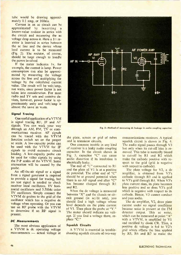
tube would be drawing approxi-mately 0.1 amp, or 100ma.
Current in an ac circuit can beapproximated by inserting aknown -value resistor in series withthe circuit and measuring the acvoltage drop across it. Here a 1St re-sistor is inserted in series betweenthe ac line and the device whoseload current is to be measured(Fig. 2). The resistor, of course,should be large enough to handlethe power involved.
If the meter indicates iv, forexample, the current is lamp. Powerconsumption can also be approxi-mated by measuring the voltageacross the line and multiplying thevoltage by the calculated currentvalue. The result will be volt/amp,not watts, since power factor is nottaken into consideration. For mostradio and TV sets and resistive de-vices, however, power factor is ap-proximately unity and volt/amp isalmost the same as watts.
Signal TracingOne useful application of a VTVM
is signal tracing RF, IF and AFsignals. You can work your waythrough an AM, FM, TV or com-munications receiver. AF signalscan be traced with the VTVMfunction switch set on the properac scale. A low -capacity probe canbe used with the VTVM for IFsignals to avoid excessive circuitloading. A low -capacity probe canbe used for video signals by usingthe P -P scales of the VTVM. Someattenuation will be caused by theprobe.
An off -the -air signal or a signalfrom a signal generator is requiredto provide a signal for tracing, butno test signal is needed to checkreceiver local oscillators, TV hori-zontal oscillators and 3.58Mc colorTV oscillators. Simply connect theVTVM dc probes to the grid of theoscillator which has a negative dcvoltage when operating. Or you canuse an RF probe with the VTVMto determine if an RF signal ispresent.
DC MeasurementsThe most obvious application of
a VTVM is dc operating voltagemeasurements - actual voltage at
Fig. 3-Method of measuring dc leakage in audio coupling capacitor.
the plate, screen or grid of tubesand in transistor circuits.
One common trouble in any kindof receiver is a leaky audio couplingcapacitor. In the circuit shown inFig. 3, capacitor "C" can causeaudio distortion if its insulation iselectrically leaky.
The end of "C" connected to R1and the plate of VI is at a positivedc potential. The other end of "C"should be at ground potential whenthere is no AF signal and after "C"has become charged through R1and R2.
When the dc voltage is measuredbetween "X" and the chassis or cir-cuit ground (in ac/dc sets), youshould find a high voltage whoselevel depends on the plate currentof V I. Then place the probe at "Y."The meter should indicate no volt-age. If you find a voltage there, re-place "C."
Squelch CircuitsA VTVM is essential in trouble-
shooting squelch circuits of two-way
communications receivers. A typicalsquelch circuit is shown in Fig. 4.The audio signal passes through V3but only when its cut-off bias is re-moved. This tube is normally biasedto cut-off by R1 and R2 whichmake the cathode positive with re-spect to the grid (grid is negativewith respect to cathode).
The plate voltage for V2, a dcamplifier, is obtained from V3'scathode through R3 and is appliedto V3's grid through R4. When V3'splate current rises, its plate becomesless positive and so does V3's gridwhich is negative with respect to itscathode. Hence, V3 cannot conductand pass audio.
The dc amplifier, V2, draw platecurrent under no signal conditionsbecause noise is present at the FMdetector output. This ac noise,which can be measured at point "A"with a VTVM, is amplified by V1and rectified by diode CR. Thus, apositive dc voltage is fed to V2'sgrid which offsets the bias appliedby R5, R6 and R7 to make the
46 ELECTRONIC TECHNICIAN
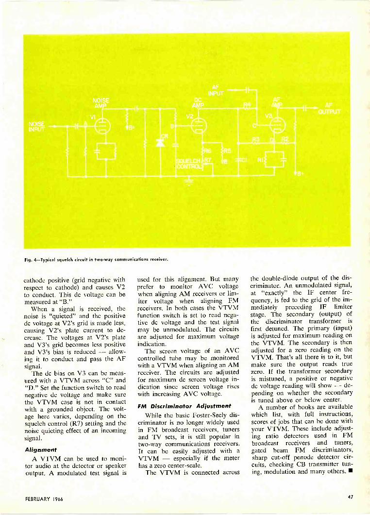
Fig. 4-Typical squelch circuit in two-way communications receiver.
cathode positive (grid negative withrespect to cathode) and causes V2to conduct. This dc voltage can bemeasured at "B."
When a signal is received, thenoise is "quieted" and the positivedc voltage at V2's grid is made less,causing V2's plate current to de-crease. The voltages at V2's plateand V3's grid becomes less positiveand V3's bias is reduced - allow-ing it to conduct and pass the AFsignal.
The dc bias on V3 can be meas-ured with a VTVM across "C" and"D." Set the function switch to readnegative dc voltage and make surethe VTVM case is not in contactwith a grounded object. The volt-age here varies, depending on thesquelch control (R7) setting and thenoise quieting effect of an incomingsignal.
AlignmentA VTVM can be used to moni-
tor audio at the detector or speakeroutput. A modulated test signal is
used for this alignment. But manyprefer to monitor AVC voltagewhen aligning AM receivers or lim-iter voltage when aligning FMreceivers. In both cases the VTVMfunction switch is set to read nega-tive dc voltage and the test signalmay be unmodulated. The circuitsare adjusted for maximum voltageindication.
The screen voltage of an AVCcontrolled tube may be monitoredwith a VTVM when aligning an AMreceiver. The circuits are adjustedfor maximum dc screen voltage in-dication since screen voltage riseswith increasing AVC voltage.
FM Discriminator AdjustmentWhile the basic Foster -Seely dis-
criminator is no longer widely usedin FM broadcast receivers, tunersand TV sets, it is still popular intwo-way communications receivers.It can be easily adjusted with aVTVM - especially if the meterhas a zero center -scale.
The VTVM is connected across
the double -diode output of the dis-criminator. An unmodulated signal,at "exactly" the IF center fre-quency, is fed to the grid of the im-mediately preceding IF limiterstage. The secondary (output) ofthe discriminator transformer isfirst detuned. The primary (input)is adjusted for maximum reading onthe VTVM. The secondary is thenadjusted for a zero reading on theVTVM. That's all there is to it, butmake sure the output reads truezero. If the transformer secondaryis mistuned, a positive or negativedc voltage reading will show - de-pending on whether the secondaryis tuned above or below center.
A number of books are availablewhich list, with full instructions,scores of jobs that can be done withyour VTVM. These include adjust-ing ratio detectors used in FMbroadcast receivers and tuners,gated beam FM discriminators,sharp cut-off penode detector cir-cuits, checking CB transmitter tun-ing, modulation and many others.
FEBRUARY 1966 47
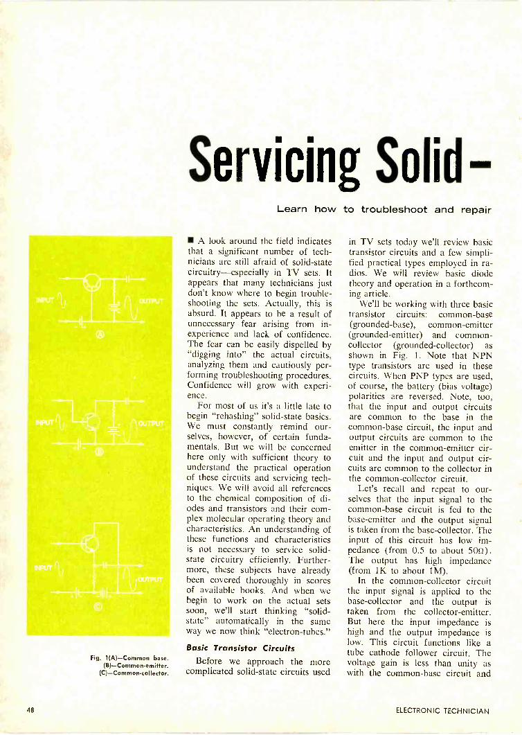
Fig. 1(A) --Common base.(B)-Common-emitter.
(C)-Commoncollector.
Servicing SolidLearn how to troubleshoot and repair
A look around the field indicatesthat a significant number of tech-nicians are still afraid of solid-statecircuitry-especially in TV sets. Itappears that many technicians justdon't know where to begin trouble-shooting the sets. Actually, this isabsurd. It appears to be a result ofunnecessary fear arising from in-experience and lack of confidence.The fear can be easily dispelled by"digging into" the actual circuits,analyzing them and cautiously per-forming troubleshooting procedures.Confidence will grow with experi-ence.
For most of us it's a little late tobegin "rehashing" solid-state basics.We must constantly remind our-selves, however, of certain funda-mentals. But we will be concernedhere only with sufficient theory tounderstand the practical operationof these circuits and servicing tech-niques. We will avoid all referencesto the chemical composition of di-odes and transistors and their com-plex molecular operating theory andcharacteristics. An understanding ofthese functions and characteristicsis not necessary to service solid-state circuitry efficiently. Further-more, these subjects have alreadybeen covered thoroughly in scoresof available books. And when webegin to work on the actual setssoon, we'll start thinking "solid-state" automatically in the sameway we now think "electron -tubes."
Basic Transistor CircuitsBefore we approach the more
complicated solid-state circuits used
in TV sets today we'll review basictransistor circuits and a few simpli-fied practical types employed in ra-dios. We will review basic diodetheory and operation in a forthcom-ing article.
We'll be working with three basictransistor circuits: common -base(grounded -base), common -emitter(grounded -emitter) and common -collector (grounded -collector) asshown in Fig. 1. Note that NPNtype transistors are used in thesecircuits. When PNP types are used,of course, the battery (bias voltage)polarities are reversed. Note, too,that the input and output circuitsare common to the base in thecommon -base circuit, the input andoutput circuits are common to theemitter in the common -emitter cir-cuit and the input and output cir-cuits are common to the collector inthe common -collector circuit.
Let's recall and repeat to our-selves that the input signal to thecommon -base circuit is fed to thebase -emitter and the output signalis taken from the base -collector. Theinput of this circuit has low im-pedance (from 0.5 to about 5012).The output has high impedance(from 1K to about 1M).
In the common -collector circuitthe input signal is applied to thebase -collector and the output istaken from the collector -emitter.But here the input impedance ishigh and the output impedance islow. This circuit functions like atube cathode follower circuit. Thevoltage gain is less than unity aswith the common -base circuit and
48 ELECTRONIC TECHNICIAN

State TV Circuitstoday's circuits successfully
the power gain is generally less thanthat in either a common -base or acommon -emitter circuit.
In the common -emitter circuitthe input signal is applied to thebase -emitter and taken from thecollector -emitter. The input im-pedance ranges from 20 to about50000 and output impedancesrange from about 50 to 50,0000.Power gain may reach 40db or pos-sibly more. The circuit producesboth current and voltage gain.
We also recall that a signal isshifted 180 deg, from input to out-put, in the common -emitter circuit.Signals in the other two circuits re-main in phase from input to outputlike it does in a tube cathode fol-lower circuit. The common -emittercircuit is widely used as a high -gainamplifier.
Transistor BiasingAlthough we will not detail bias-
ing methods at this point, it will benecessary to touch on certain basicrequirements before we proceedwith practical transistorized cir-cuitry. In fact and in practice, manytrouble symptoms can be traced tooff -bias conditions in transistor cir-cuits caused by out -of -tolerance re-sistors or electrolytic capacitor fail-ures. Transistors, like electrontubes, must be properly biased sothey will function as required invarious applications. Electron tubesrequire a positive plate voltage andnegative grid voltage (in most ap-plications).
On the other hand, transistorsfunction with similar voltage po-
larities (either negative or positive)on both the base and collector ele-ments. In general (for most appli-cations) this means establishing aforward bias across the emitter/basejunction to obtain high conductionand a reverse bias across the collec-tor/base junction to obtain low con-duction. This holds true for bothNPN and PNP type transistors.This point should be thoroughlyunderstood, however: When a tubehas little or no bias, it draws heavyplate current. When a transistor hasno bias, it is cut off-little or nocurrent flows through it.
Note, too, that the emitter biaspolarity is positive in PNP transis-tors and negative in NPN types; thecollector is negative in the PNPtransistor and positive in the NPNtransistor; the base is negative inthe PNP transistor and positive inthe NPN type. Two basic biasingarrangements for common -emitterNPN transistor circuits are shownin Fig. 2. Polarity of the voltagesupply is reversed for PNP transis-tor circuits.
In many practical cases, biasnetworks may include diodes orthermistors to compensate for varia-tions caused by ambient tempera-tures, current or voltage variations.These components must be watchedcarefully in practical servicing.
We will also find practical tran-sistorized circuits that employ bothpositive (regenerative) and negative(degenerative) feedback.
Forthcoming articles will dealextensively with coupling methodsfor transistor stages, single and
double -diode circuit functions,phase splitting circuits, "forward"AGC circuits where an increase incollector current causes a decreasein stage gain and circuit trouble-shooting and repair techniques ofother specialized arrangements thatyou must know to successfully diag-nose and troubleshoot solid-stateTV circuits.
Soon most B/W TV sets will betransistorized and with solid-statecolor coming, every technician mustprepare himself for this opportunityto increase his profits.
Fig. 2(A)-Bias network in common -emittercircuit uses emitter stabilizing resistor.(B)-Common-emitter circuit using split -voltage -divider bias network.
FEBRUARY 1966 49
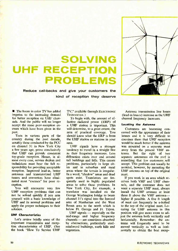
SOLVINGRECEPTIONPROBLEMS
Reduce call-backs and give your customers thekind of reception they deserve
The boom in color TV has addedimpetus to the increasing demandfor better reception on UHF chan-nels. And the public will no longeraccept the same poor -reception ex-cuses which have been given in thepast.
Tests in various parts of thecountry during the past decade,notably those conducted by the FCCon channel 31 in New York Citya few years ago, prove conclusivelythat UHF can provide consistenttop -grade reception. Hence, in al-most every case, service dealers andtechnicians must bear the full re-sponsibility for providing acceptablereception. Improved lead-in, betterantennas and transistorized UHFtuners and converters have elimi-nated most "excuses" for poor re-ception.
You will encounter very fewUHF reception problems that cannot be solved quickly if you armyourself with a basic knowledge ofUHF and its normal problems andapply the proper techniques to theirsolution.
UHF CharacteristicsLet's review briefly some of the
important transmission and recep-tion characteristics of UHF. (Seethe book "How To Service UHF
TV," available through ELECTRONICTECHNICIAN.)
To begin with, the amount of ef-fective radiated power (ERP) ofa UHF station is important. Thiswill determine, to a great extent, thearea of practical coverage. Youshould know what the ERP is fromthe UHF station or stations in yourarea.
UHF signals have a strongertendency to travel in a straight lineas their frequency increases. Lessdiffraction exists over and aroundtall buildings and hills. This causesproblems, particularly in large cit-ies and in suburban and ruralareas where the terrain is irregular.In a word, "shadow" areas and deadspots exist. Translators are fre-quently used in highly populatedareas to solve these problems. InNew York City, for example, atranslator was installed on theGeorge Washington bridge to beamchannel 31's signal into the Inwoodarea of Manhattan and the WestBronx area to the north which isbelow Ft. George and Ft. Tryon.
UHF signals - especially on themid -range and higher frequencychannels - are sometimes absorbedby obstructions, particularly steel -reinforced buildings, earth hills andvegetation.
Antenna transmission line losses(lead-in losses) increase as the UHFchannel frequency increases.
Locating the AntennaCustomers are becoming con-
cerned with the appearance of theirhomes and it is very difficult toconvince them that UHF receptionwould be much better if the antennawas mounted on a separate mastaway from the present VHF an-tenna. But the sight of twoseparate antennnas on the roof issomething that few customers , willaccept. This problem can usually beavoided, however, by mounting theUHF antenna on top of the originalmast.
If you work in an area which re-ceives both VHF and UHF chan-nels, and the customer does notwant a separate UHF mast, alwaysinstall the UHF antenna at leastthree ft above the VHF antenna-higher if possible. A five ft lengthof mast can frequently be u -boltedto the top of the original mast. Lo-cating the UHF antenna in thisposition will give more room to ad-just the antenna both vertically andhorizontally. Remember: the an-tenna will frequently need to bemoved vertically as well as hori-zontally to obtain the best recep-
50 ELECTRONIC TECHNICIAN
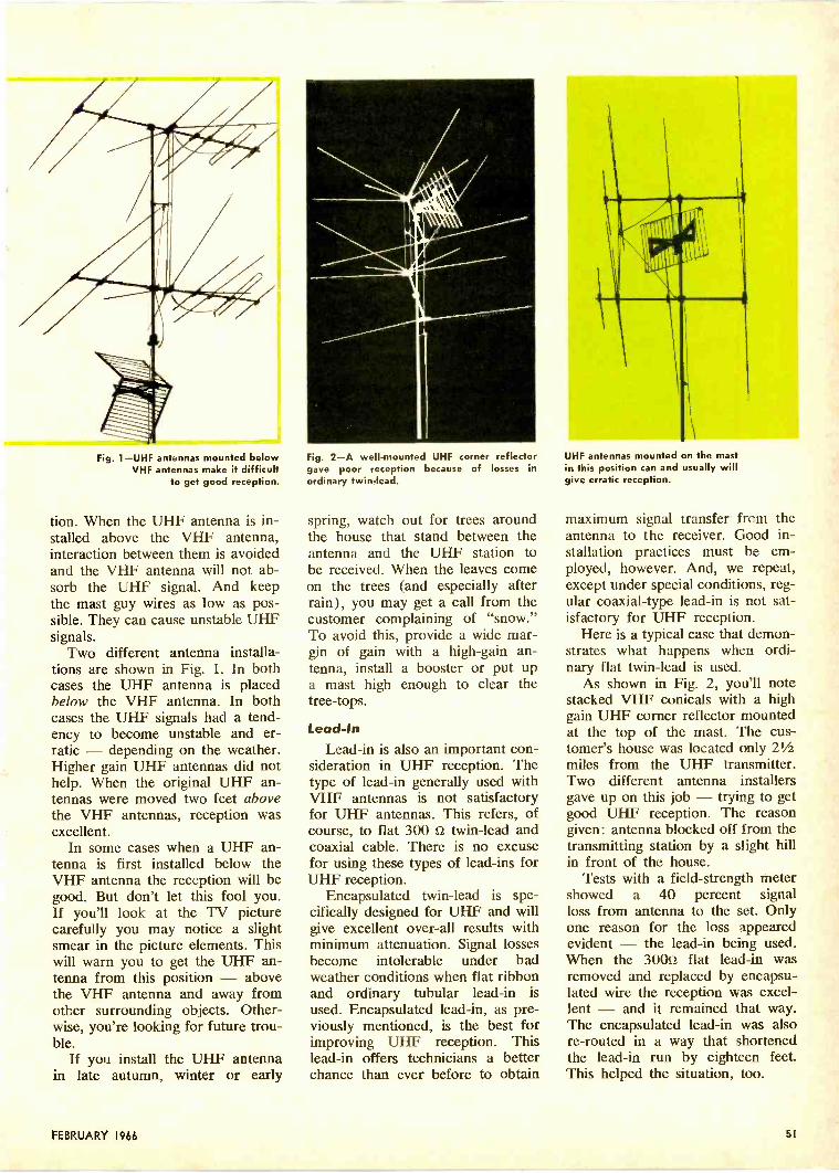
Fig. 1-UHF antennas mounted belowVHF antennas make it difficult
to get good reception.
tion. When the UHF antenna is in-stalled above the VHF antenna,interaction between them is avoidedand the VHF antenna will not ab-sorb the UHF signal. And keepthe mast guy wires as low as pos-sible. They can cause unstable UHFsignals.
Two different antenna installa-tions are shown in Fig. 1. In bothcases the UHF antenna is placedbelow the VHF antenna. In bothcases the UHF signals had a tend-ency to become unstable and er-ratic - depending on the weather.Higher gain UHF antennas did nothelp. When the original UHF an-tennas were moved two feet abovethe VHF antennas, reception wasexcellent.
In some cases when a UHF an-tenna is first installed below theVHF antenna the reception will begood. But don't let this fool you.If you'll look at the TV picturecarefully you may notice a slightsmear in the picture elements. Thiswill warn you to get the UHF an-tenna from this position - abovethe VHF antenna and away fromother surrounding objects. Other-wise, you're looking for future trou-ble.
If you install the UHF antennain late autumn, winter or early
Fig. 2-A well -mounted UHF corner reflectorgave poor reception because of losses inordinary twin -lead.
spring, watch out for trees aroundthe house that stand between theantenna and the UHF station tobe received. When the leaves comeon the trees (and especially afterrain), you may get a call from thecustomer complaining of "snow."To avoid this, provide a wide mar-gin of gain with a high -gain an-tenna, install a booster or put upa mast high enough to clear thetree -tops.
Lead -In
Lead-in is also an important con-sideration in UHF reception. Thetype of lead-in generally used withVHF antennas is not satisfactoryfor UHF antennas. This refers, ofcourse, to flat 300 ti twin -lead andcoaxial cable. There is no excusefor using these types of lead-ins forUHF reception.
Encapsulated twin -lead is spe-cifically designed for UHF and willgive excellent over-all results withminimum attenuation. Signal lossesbecome intolerable under badweather conditions when flat ribbonand ordinary tubular lead-in isused. Encapsulated lead-in, as pre-viously mentioned, is the best forimproving UHF reception. Thislead-in offers technicians a betterchance than ever before to obtain
UHF antennas mounted on the mastin this position can and usually willgive erratic reception.
maximum signal transfer from theantenna to the receiver. Good in-stallation practices must be em-ployed, however. And, we repeat,except under special conditions, reg-ular coaxial -type lead-in is not sat-isfactory for UHF reception.
Here is a typical case that demon-strates what happens when ordi-nary flat twin -lead is used.
As shown in Fig. 2, you'll notestacked VHF conicals with a highgain UHF corner reflector mountedat the top of the mast. The cus-tomer's house was located only 21/2miles from the UHF transmitter.Two different antenna installersgave up on this job - trying to getgood UHF reception. The reasongiven: antenna blocked off from thetransmitting station by a slight hillin front of the house.
Tests with a field -strength metershowed a 40 percent signalloss from antenna to the set. Onlyone reason for the loss appearedevident - the lead-in being used.When the 30052 flat lead-in wasremoved and replaced by encapsu-lated wire the reception was excel-lent - and it remained that way.The encapsulated lead-in was alsore-routed in a way that shortenedthe lead-in run by eighteen feet.This helped the situation, too.
FEBRUARY 1966 51
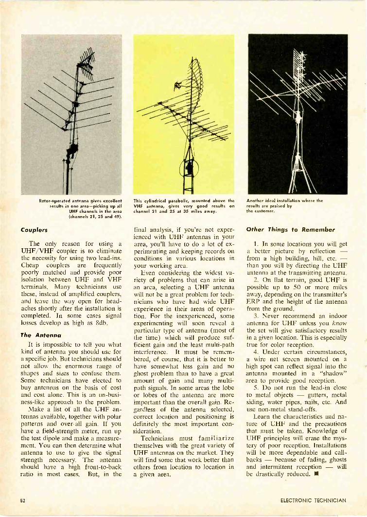
Rotor -operated antenna gives excellentresults in one area-picking up all
UHF channels in the area(channels 21, 25 and 49).
Couplers
The only reason for using aUHF/VHF coupler is to eliminatethe necessity for using two lead-ins.Cheap couplers are frequentlypoorly matched and provide poorisolation between UHF and VHFterminals. Many technicians usethese, instead of amplified couplers,and leave the way open for head-aches shortly after the installation iscompleted. In some cases signallosses develop as high as 8db.
The AntennaIt is impossible to tell you what
kind of antenna you should use fora specific job. But technicians shouldnot allow the enormous range ofshapes and sizes to confuse them.Some technicians have elected tobuy antennas on the basis of costand cost alone. This is an un-busi-ness-like approach to the problem.
Make a list of all the UHF an-tennas available, together with polarpatterns and over-all gain. If youhave a field -strength meter, run upthe test dipole and make a measure-ment. You can then determine whatantenna to use to give the signalstrength necessary. The antennashould have a high front -to -backratio in most cases. But, in the
This cylindrical parabolic, mounted above theVHF antenna, gives very good results onchannel 21 and 25 at 35 miles away.
final analysis, if you're not exper-ienced with UHF antennas in yourarea, you'll have to do a lot of ex-perimenting and keeping records onconditions in various locations inyour working area.
Even considering the widest va-riety of problems that can arise inan area, selecting a UHF antennawill not be a great problem for tech-nicians who have had wide UHFexperience in their areas of opera-tion. For the inexperienced, someexperimenting will soon reveal aparticular type of antenna (most ofthe time) which will produce suf-ficient gain and the least multi -pathinterference. It must be remem-bered, of course, that it is better tohave somewhat less gain and noghost problem than to have a greatamount of gain and many multi -path signals. In some areas the lobeor lobes of the antenna are moreimportant than the overall gain. Re-gardless of the antenna selected,correct location and positioning isdefinitely the most important con-sideration.
Technicians must familiarizethemselves with the great variety ofUHF antennas on the market. Theywill find some that work better thanothers from location to location ina given area.
Another ideal installation where theresults are praised bythe customer.
Other Things to Remember
1. In some locations you will geta better picture by reflection -from a high building, hill, etc. -than you will by directing the UHFantenna at the transmitting antenna.
2. On flat terrain, good UHF ispossible up to 50 or more milesaway, depending on the transmitter'sERP and the height of the antennafrom the ground.
3. Never recommend an indoorantenna for UHF unless you knowthe set will give satisfactory resultsin a given location. This is especiallytrue for color reception.
4. Under certain circumstances,a wire net screen mounted on ahigh spot can reflect signal into theantenna mounted in a "shadow"area to provide good reception.
5. Do not run the lead-in closeto metal objects - gutters, metalsiding, water pipes, nails, etc. Anduse non-metal stand-offs.
Learn the characteristics and na-ture of UHF and the precautionsthat must be taken. Knowledge ofUHF principles will erase the mys-tery of poor reception. Installationswill be more dependable and call-backs - because of fading, ghostsand intermittent reception - willbe drastically reduced.
52 ELECTRONIC TECHNICIAN

A previous article (January1966 ELECTRONIC TECHNICIAN)explored the functions of AutomaticDeviation Limiting (ADL) and Au-tomatic Load Control (ALC) cir-cuits used in various two-way trans-mitters. Additional volume limitingcircuits will be covered here.
AgampA highly sophisticated speech -
level controller, called "AGAMP"(Automatic Gain Adjusting Ampli-fier), is a syllable -controlled, vari-able -gain, speech amplifier with aninput range of 40db, an output vari-ation of only 4db, and a bandpassof 250-3000cps (Fig. 1). Developedspecifically for telephone -systemuse, it is also employed ahead ofRF transmitters. Its gain -adjustingaction works two ways: Loud speechcauses the gain to drop; weak speechcauses it to increase. The result isa nearly -constant speech output.And gain -control occurs only onspeech - not on noise. Further-more, at high input levels, gain -reducing action is fast; at low levels,it's slow. With noise, of course,the circuit is in a no action state.
As shown in Fig. 1, the speech -input signal passes through the in-put attenuator which matches ex-ternal levels to AGAMP's range.The signal is then amplified by thepreamp, which compensates for theloss of the following variolosser -a variable -resistance diode bridgewhich is the heart of the equipment.After this, the output amplifier pro-vides additional gain and the level -controlled signal appears at the out-put terminals.
The variolosser is simply an 8 -diode dual bridge which forms apad between the preamp and theoutput amplifier. Since the imped-ance of a diode varies with the cur-rent flowing through it, it followsthat a dc control current fed to thevariolosser will vary its impedance.Varying the impedance of this padvaries the signal level supplied to theoutput amplifier.
A portion of the preamp's out-put appears across the thresholdlevel control. This control sets thepoint at which gain -increasing ac-tion occurs. (Most speech is abovethreshold and most noise, below;hence speech is amplified more than
Syllabic -controlled speech amplifier providesnearly -constant output
Lenkurt Electric's AGAMP.
FEBRUARY 1966 53
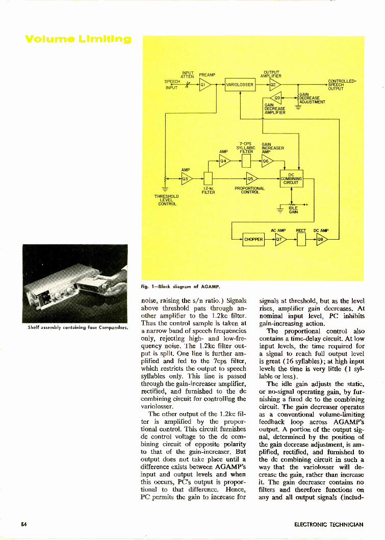
Shelf assembly containing four Compandors.
INPUT PREAMPATTENSPEECH
INPUT01
AMP
--y.>THRESHOLD
LEVELCONTROL
VARIOLOSSER
OUTPUTAMPLIFIER
Q2
Q9
GAINDECREASEAMPLIFIER
CONTROLLED- SPEECH
OUTPUT
"'GAINDECREASEADJUSTMENT
7 -CPS GAINSYLLABIC INCREASER
AMP FILTER AMP
04
2-1(cFILTER
Q5
06
PROPORTIONALCONTROL
DCCOMBINING
CIRCUIT
IDLEGAIN
CHOPPER
AC AMP RECT DC AMP
Fig. 1-Block diagram of AGAMP.
noise, raising the s/n ratio.) Signalsabove threshold pass through an-other amplifier to the 1.2kc filter.Thus the control sample is taken ata narrow band of speech frequenciesonly, rejecting high- and low -fre-quency noise. The 1.2kc filter out-put is split. One line is further am-plified and fed to the 7cps filter,which restricts the output to speechsyllables only. This line is passedthrough the gain -increaser amplifier,rectified, and furnished to the dccombining circuit for controlling thevariolosser.
The other output of the 1.2kc fil-ter is amplified by the propor-tional control. This circuit furnishesdc control voltage to the dc com-bining circuit of opposite polarityto that of the gain -increaser. Butoutput does not take place until adifference exists between AGAMP'sinput and output levels and whenthis occurs, PC's output is propor-tional to that difference. Hence,PC permits the gain to increase for
signals at threshold, but as the levelrises, amplifier gain decreases. Atnominal input level, PC inhibitsgain -increasing action.
The proportional control alsocontains a time -delay circuit. At lowinput levels, the time required fora signal to reach full output levelis great (16 syllables) ; at high inputlevels the time is very little (1 syl-lable or less).
The idle gain adjusts the static,or no -signal operating gain, by fur-nishing a fixed dc to the combiningcircuit. The gain decreaser operatesas a conventional volume -limitingfeedback loop across AGAMP'soutput. A portion of the output sig-nal, determined by the position ofthe gain decrease adjustment, is am-plified, rectified, and furnished tothe dc combining circuit in such away that the variolosser will de-crease the gain, rather than increaseit. The gain decreaser contains nofilters and therefore functions onany and all output signals (includ-
64 ELECTRONIC TECHNICIAN
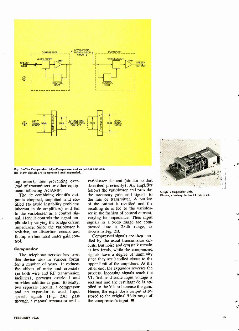
rCOMPRESSOR
VARIOLOSSER
H
INPUT
CONTROLRECT
L J
INPUT
O RANGE5 db
RANGE
INTERVENINGTRANSMISSION
CIRCUITS
INTERVENINGb TRANSMISSION
CIRCUITS
r
28db
EXPANDOR
VARIOLOSSER
Ar4P I SPEECH
OUTPUT
CONTROLRECT
J
56OUTPUdb SIGNAL
RANGE
Fig. 2-The Compandor. (A)-Compressor and expandor sections.(B)-How signals are compressed and expanded.
ing noise), thus preventing over-load of transmitters or other equip-ment following AGAMP.
The dc combining circuit's out-put is chopped, amplified, and rec-tified (to avoid instability problemsinherent in dc amplifiers) and fedto the variolosser as a control sig-nal. Here it controls the signal am-plitude by varying the bridge circuitimpedance. Since the variolosser isresistive, no distortion occurs andthump is eliminated under gain con-trol.
CompandorThe telephone service has used
this device also in various formsfor a number of years. It reducesthe effects of noise and crosstalk(in both wire and RF transmissionfacilities), prevents overload andprovides additional gain. Basically,two separate circuits, a compressorand an expandor is used. Inputspeech signals (Fig. 2A) passthrough a manual attenuator and a
variolosser element (similar to thatdescribed previously). An amplifierfollows the variolosser and providesthe necessary gain and signals tothe line or transmitter. A portionof the output is rectified and theresulting dc is fed to the variolos-ser in the fashion of control current,varying its impedance. Thus inputsignals in a 56db range are com-pressed into a 28db range, asshown in Fig. 2B.
Compressed signals are then han-dled by the usual transmission cir-cuits. But noise and crosstalk remainat low levels, while the compressedsignals have a degree of immunitysince they are handled closer to theupper limit of the amplifiers. At theother end, the expandor reverses theprocess. Incoming signals reach theVL first, and some input voltage isrectified and the resultant dc is ap-plied to the VL to increase the gain.Hence, the expandor's output is re-stored to the original 56db range ofthe compressor's input.
Single Compandor unit.Photos, courtesy Lenkurt Electric Co.
FEBRUARY 1966 55

I/2 6JT8AGC AMP!
HORIZPULSE
IN
Fig. 1-Simplified typical AGC circuit.
COMPOSITEVIDEO IN
Fig. 2-Cancellation pulse amplitude is deter-mined by a divider network just ahead ofthe sync takeoff point.
2
Fig. 3-Simplified typical blanker circuit.
Fig. 4-The blanker has a cathode load re-sistor common with the bandpass amplifier.
Fig. 5-Simplified burst gate clipper.
Blanking and Gating in Color Sets Blanking and gating are probablytwo of the least understood func-tions in color TV sets. Actually,neither adds anything to the pictureor sound. If the systems workthere's no reason to even think aboutthem. When the set requires service,it rarely involves blanking or gat-ing. So, we have a fairly reliablecircuit that technicians are rarelyconcerned with and hence, knowlittle about.
Why talk about it then? Well, ifyou've ever "tangled" with a setthat did have blanking or gatingtrouble, then you know how manyhours can be wasted trying to solvea problem which seems to have norelation to anything! Although theprinciples of monochrome TVblanking and gating are very simi-lar to those employed in color sets,it is more involved in color sets.Hence, what you know aboutmonochrome blanking and gatingcan be applied to color - and viceversa.
At the BeginningThe blanking and gating signals
we are concerned with are genera-ted in the receiver's horizontal sec-
tion. Generally, the pulses aresampled from the flyback. Theyoccur during retrace time and serveno less than seven different func-tions. Perhaps the general lack ofunderstanding of these retrace -timepulses arises because many tech-nicians do not know why they areneeded. Two separate pulses areusually employed.
The pulses are used to gate vari-ous circuits both "on" and "off"and even to create continuous bi-ases for some stages. Consequently,both positive and negative pulsesare needed. In some instances atube may be gated "on" by apply-ing a positive pulse to the grid orit may be gated "off" by applyingthe same pulse to the cathode.
AGC KeyingKeyed AGC is not uncommon on
monochrome sets and is now gen-erally considered best for automaticgain control. A typical circuit isshown in Fig. 1. Its operation issimple: A positive pulse is sampledfrom the flyback and applied to theplate of a triode which receives noother supply voltage. Hence, thetube conducts only during retrace
time (when a positive sync pulse ison the control grid). Thus, we havea negative rectified voltage at theplate which is filtered and appliedto the IF, tuner, etc. The pulseamplitude is directly proportionalto the sync -pulse amplitude.
Keyed AGC systems have highgain, good noise immunity and arenot affected by video changes. Be-cause a triode is used in this circuit,the keying pulse can be "felt" atthe grid of the triode and reflectsback to the sync amplifier. Sincethis could upset sync action, a can-celling pulse is applied to the com-posite signal just ahead of the synctakeoff point. This cancellationpulse is the same as that applied tothe AGC amplifier. The cancellationpulse amplitude is determined by adivider network at the input point.This is shown in Fig. 2.
The BlankerThe blanker serves several func-
tions. Three outputs from a typicalblanker circuit are shown in Fig. 3.The same positive pulse used forAGC keying is applied to theblanker grid. Since this is a highamplitude pulse, the blanker tube
56 ELECTRONIC TECHNICIAN
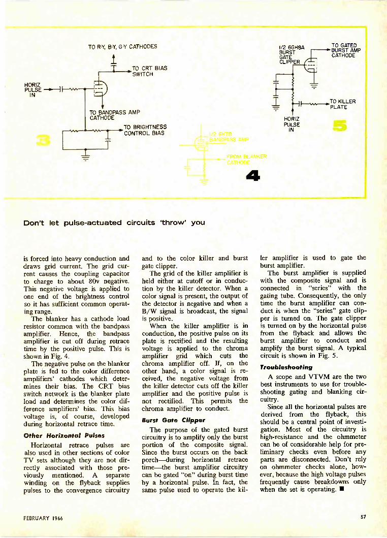
HORIZPULSE --4,'-41
IN
TO R -Y, B -Y, G -Y CATHODES
IT TO CRT BIAS
I - SWITCH
TO BANDPASS AMPCATHODE
I=
IT
...TO BRIGHTNESSCONTROL BIAS
Don't let pulse -actuated circuits 'throw' you
is forced into heavy conduction anddraws grid current. The grid cur-rent causes the coupling capacitorto charge to about 80v negative.This negative voltage is applied toone end of the brightness controlso it has sufficient common operat-ing range.
The blanker has a cathode loadresistor common with the bandpassamplifier. Hence, the bandpassamplifier is cut off during retracetime by the positive pulse. This isshown in Fig. 4.
The negative pulse on the blankerplate is fed to the color differenceamplifiers' cathodes which deter-mines their bias. The CRT biasswitch network is the blanker plateload and determines the color dif-ference amplifiers' bias. This biasvoltage is, of course, developedduring horizontal retrace time.
Other Horizontal PulsesHorizontal retrace pulses are
also used in other sections of colorTV sets although they are not dir-rectly associated with those pre-viously mentioned. A separatewinding on the flyback suppliespulses to the convergence circuitry
4
and to the color killer and burstgate clipper.
The grid of the killer amplifier isheld either at cutoff or in conduc-tion by the killer detector. When acolor signal is present, the output ofthe detector is negative and when aB/W signal is broadcast, the signalis positive.
When the killer amplifier is inconduction, the positive pulse on itsplate is rectified and the resultingvoltage is applied to the chromaamplifier grid which cuts thechroma amplifier off. If, on theother hand, a color signal is re-ceived, the negative voltage fromthe killer detector cuts off the killeramplifier and the positive pulse isnot rectified. This permits thechroma amplifier to conduct.
Burst Gate ClipperThe purpose of the gated burst
circuitry is to amplify only the burstportion of the composite signal.Since the burst occurs on the backporch-during horizontal retracetime-the burst amplifier circuitrycan be gated "on" during burst timeby a horizontal pulse. In fact, thesame pulse used to operate the kil-
1/2 6GH8ABURSTGATECLIPPER
HORIZPULSE
IN
TO GATEDBURST AMPCATHODE
H.w___..TO KILLERPLATE
ler amplifier is used to gate theburst amplifier.
The burst amplifier is suppliedwith the composite signal and isconnected in "series" with thegating tube. Consequently, the onlytime the burst amplifier can con-duct is when the "series" gate clip-per is turned on. The gate clipperis turned on by the horizontal pulsefrom the flyback and allows theburst amplifier to conduct andamplify the burst signal. A typicalcircuit is shown in Fig. 5.
TroubleshootingA scope and VTVM are the two
best instruments to use for trouble-shooting gating and blanking cir-cuitry.
Since all the horizontal pulses arederived from the flyback, thisshould be a central point of investi-gation. Most of the circuitry ishigh -resistance and the ohmmetercan be of considerable help for pre-liminary checks even before anyparts are disconnected. Don't relyon ohmmeter checks alone, how-ever, because the high voltage pulsesfrequently cause breakdowns onlywhen the set is operating.
FEBRUARY 1966 57
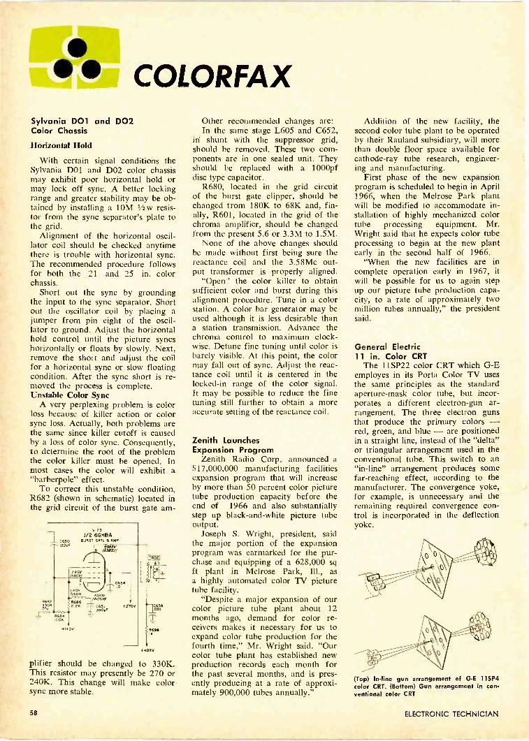
COLORFAXSylvania DOI and DO2Color Chassis
Horizontal Hold
With certain signal conditions theSylvania DOl and D02 color chassismay exhibit poor horizontal hold ormay lock off sync. A better lockingrange and greater stability may be ob-tained by installing a 10M 1/2w resis-tor from the sync separator's plate tothe grid.
Alignment of the horizontal oscil-lator coil should be checked anytimethere is trouble with horizontal sync.The recommended procedure followsfor both the 21 and 25 in. colorchassis.
Short out the sync by groundingthe input to the sync separator. Shortout the oscillator coil by placing ajumper from pin eight of the oscil-lator to ground. Adjust the horizontalhold control until the picture syncshorizontally or floats by slowly. Next,remove the short and adjust the coilfor a horizontal sync or slow floatingcondition. After the sync short is re-moved the process is complete.Unstable Color Sync
A very perplexing problem is colorloss because of killer action or colorsync loss. Actually, both problems arethe same since killer cutoff is causedby a loss of color sync. Consequently,to determine the root of the problemthe color killer must be opened. Inmost cases the color will exhibit a"barberpole" effect.
To correct this unstable condition,R682 (shown in schematic) located inthe grid circuit of the burst gate am -
1 C650
+140V
1/2 6GFiBABURST GATT B AMP
+120(f12041
3:0;IF
Al
C658001
RcN
+4058
plifier should be changed to 330K.This resistor may presently be 270 or240K. This change will make colorsync more stable.
Other recommended changes are:In the same stage L605 and C652,
in shunt with the suppressor grid,should be removed. These two com-ponents are in one sealed unit. Theyshould be replaced with a 1000pfdisc type capacitor.
R680, located in the grid circuitof the burst gate clipper, should bechanged from 180K to 68K and, fin-ally, R601, located in the grid of thechroma amplifier, should be changedfrom the present 5.6 or 3.3M to 1.5M.
None of the above changes shouldbe made without first being sure thereactance coil and the 3.58Mc out-put transformer is properly aligned.
"Open" the color killer to obtainsufficient color and burst during thisalignment procedure. Tune in a colorstation. A color bar generator may beused although it is less desirable thana station transmission. Advance thechroma control to maximum clock-wise. Detune fine tuning until color isbarely visible. At this point, the colormay fall out of sync. Adjust the reac-tance coil until it is centered in thelocked -in range of the color signal.It may be possible to reduce the finetuning still further to obtain a moreaccurate setting of the reactance coil.
Zenith LaunchesExpansion Program
Zenith Radio Corp. announced a$17,000,000 manufacturing facilitiesexpansion program that will increaseby more than 50 percent color picturetube production capacity before theend of 1966 and also substantiallystep up black -and -white picture tubeoutput.
Joseph S. Wright, president, saidthe major portion of the expansionprogram was earmarked for the pur-chase and equipping of a 628,000 sqft plant in Melrose Park, Ill., asa highly automated color TV picturetube facility.
"Despite a major expansion of ourcolor picture tube plant about 12months ago, demand for color re-ceivers makes it necessary for us toexpand color tube production for thefourth time," Mr. Wright said. "Ourcolor tube plant has established newproduction records each month forthe past several months, and is pres-ently producing at a rate of approxi-mately 900,000 tubes annually."
Addition of the new facility, thesecond color tube plant to be operatedby their Rauland subsidiary, will morethan double floor space available forcathode-ray tube research, engineer-ing and manufacturing.
First phase of the new expansionprogram is scheduled to begin in April1966, when the Melrose Park plantwill be modified to accommodate in-stallation of highly mechanized colortube processing equipment. Mr.Wright said that he expects color tubeprocessing to begin at the new plantearly in the second half of 1966.
"When the new facilities are incomplete operation early in 1967, itwill be possible for us to again stepup our picture tube production capa-city, to a rate of approximately twomillion tubes annually," the presidentsaid.
General Electric11 in. Color CRT
The 11SP22 color CRT which G -Eemployes in its Porta Color TV usesthe same principles as the standardaperture -mask color tube, but incor-porates a different electron -gun ar-rangement. The three electron gunsthat produce the primary colors -red, green, and blue - are positionedin a straight line, instead of the "delta"or triangular arrangement used in theconventional tube. This switch to an"in -line" arrangement produces somefar-reaching effect, according to themanufacturer. The convergence yoke,for example, is unnecessary and theremaining required convergence con-trol is incorporated in the deflectionyoke.
(Top) In -line gun arrangement of G -E 11SP4color CRT. (Bottom) Gun arrangement in conventional color CRT
58 ELECTRONIC TECHNICIAN
Why are RCA SolidCopper Circuits made withcomputer precision ?
To give them
Space Age dependability.
RCA SOLID
COPPER CIRCThey won't come loose.Won't short circuit.
Won't go haywire.That's why they're
the circuits ofthe Space Age.
The Most Trusted Name in Electronics
FEBRUARY 1966 59
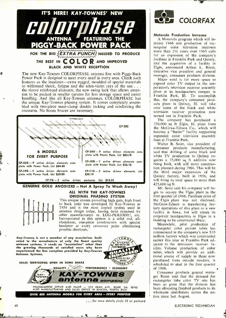
IT'S HERE! KAY-TOWNES' NEW
Cili1117 fillSffANTENNA FEATURING THE
PIGGY -BACK POWER PACKFOR THE BIG EXTRA PUNCH NEEDED TO PRODUCE
THE BEST IN C 0 L 0 R AND IMPROVEDBLACK AND WHITE RECEPTION
The new Kay -Townes COLORPHASE antenna line with Piggy -BackPower Pack is designed to meet every need in every area. Check suchfeatures as the insulator-extra rugged, moulded of special materialsto withstand shock, fatigue and the ultra -violet rays of the sun . . .
the sleeve reinforced elements, the new swing lock that allows anten-nas to be packed in smaller cartons for less storage space and easierhandling. And like all Kay -Townes antennas, COLORPHASE hasthe unique Kay -Townes phasing system. It comes completely assem-bled with two-piece mast -clamp double locking and reinforcing thecrossarm. No boom braces are necessary.
POWER PACK
N N NO N N
NNNNN N N \ \- - _ _\\\\
6 MODELSFOR EVERY PURPOSE
CP-23G -9 active driven elements com-plete with Power Pack. List $44.80
CP-19G -9 active driven elements com-plete with Power Pack. List $35.05
CP-28G
CP-28G -9 active driven elements com-plete with Power Pack. List $53.75
CP-15G -7 active driven elements com-plete with Power Pack. List $26.10
CP-11G- 5 active driven elements. List$20.19
CP-7G -3 active driven elements. List $13.02
GENUINE GOLD ANODIZED - Not A Spray To Wash Away!ALL WITH THE KAY-TOWNESORIGINAL PHASING SYSTEM
This unique system providing high gain, high frontto back ratio was developed by Kay -Townes in1954 and is the most copied system used inantenna design today, having been renamed byother manufacturers as LOG -PERIODIC, etc.Incorporated in this system is a solid rod, all -aluminum, one-piece construction with specialinsulator at every crossover point eliminatingpossible shortouts.
Kay -Townes is not a member of any association. Dedi-cated to the manufacture of only the finest qualityantenna systems, it needs no "association" other thanthe growing thousands of satisfied users who haveexperienced the fine reception provided by Kay -TownesAntenna Systems.
SALES TERRITORIES OPEN IN SOME AREAS
AFFILIATEDONLY WITH FINE
PERFORMANC
_ QUALITY PERFORMANCE ECONOMY
KAY-TOWNESeartfrerina companyHEADQUARTERS OFFICE AND PLANT -- 1511 DEAN AVE., ROME, GAALSO MANUFACTURING AND SALES OFFICE IN RINCON, PUERTO RICO
30162
OVER 800 ANTENNA MODELS FOR EVERY AREA - EVERY PURPOSE
iss COLORFAX
Motorola Production IncreaseA Motorola program which will in-
crease 1966 unit production of rec-tangular color television receiversmore than 21/2 times over 1965 callsfor an expansion of the company'sfacilities in Franklin Park and Quincy,and the acquistion of a facility inElgin, announced Arthur L. Reese,executive vice president and generalmanager, consumer products division.
Major need is for more space toexpand color TV output in the cor-poration's television receiver assemblyplant at its headquarters campus inFranklin Park, Ill. To accomplishthis, the company's consumer prod-ucts plant in Quincy, Ill. will takeover some of the black and whitetelevision receiver production nowturned out in Franklin Park.
The company has purchased a250,000 sq ft Elgin, Ill. plant fromthe McGraw -Edison Co., which willbecome a "feeder" facility supportingexpanded color television assemblylines at Franklin Park.
Walter B. Scott, vice president ofconsumer products manufacturing,said that shifting of some black andwhite TV production to Quincy re-quires a 75,000 sq ft addition nowbeing built, with still more construc-tion planned during 1966. This will bethe third major expansion of theQuincy factory, built in 1956, andwill bring its total space to more than425,000 sq ft.
Mr. Scott said his company will be-gin to occupy the Elgin plant in thefirst quarter of 1966. Purchase price ofthe Elgin plant was not disclosed.McGraw -Edison is transferring fac-tory operations of this plant to a newfacility in Iowa, but will retain itscorporate headquarters in Elgin in abuilding to be constructed there.
Meanwhile, pilot production ofrectangular color picture tubes hascommenced in the company's new $10million factory which was constructedearlier this year at Franklin Park ad-jacent to the television receiver fa-cility. Volume production of colortubes, which will provide an addi-tional source of supply to those nowpurchased from outside vendors, isscheduled to start in the first quarterof 1966.
Consumer products general mana-ger Reese said that the demand forrectangular tube color TV sets hasbeen so great that the division hasbeen allocating finished products to itswholesale distributors across the na-tion since last August.
... for more details circle 32 on postcard60 ELECTRONIC TECHNICIAN
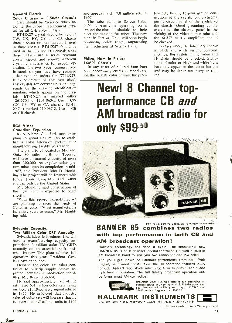
General ElectricColor Chassis - 3.58Mc Crystals
Care should be exercised when se-lecting the proper replacement crys-tal for all G -E color chassis.
ET41X27 crystal should be used inCW, CX, FY, CY and CA chassissince a shunt resonant circuit is usedin these chassis. ET41X47 should beused in the CB and HB chassis sincethese chassis use a series resonantcrystal circuit and require differentcrystal characteristics for proper op-eration. The two types became mixedin stock so you may have receivedeither type on orders for ET41X27.It is recommended that you checkany crystals for correct units and seg-regate by the drawing identificationnumbers which appear on the crys-tals. ET41X27 is marked either126J370-1 or 1107 863-1. Use in CWCX, CY, FY or CA chassis. ET41-X47 is marked 210,067-2. Use in CBor HB chassis.
RCA VictorCanadian Expansion
RCA Victor Co., Ltd. announcesplans to spend $25 million to estab-lish a color television picture tubemanufacturing facility in Canada.
The plant, to be located in Midland,Ont., 80 miles north of Toronto,will have an annual capacity of morethan 300,000 rectangular color pic-ture tubes upon its completion in mid -1967, said President John D. Hould-ing. The project will be financed withfunds from Canadian and othersources outside the United States.
Mr. Houlding said construction ofthe new plant is expected to beginshortly.
"With this record expenditure, weare planning to meet the needs ofCanadian color TV set manufacturersfor many years to come," Mr. Hould-ing said.
Sylvania Capacity,Two Million Color CRT Annually
Sylvania Electric Products, Inc. willhave a manufacturing capacity ap-proaching 2 million color TV CRTsannually on an extended shift basiswhen its new Ohio plant achieves fulloperation this year, President GeneK. Beare announces.
Demand for color TV tubes con-tinues to outstrip supply despite re-peated increases in production sched-ules, Mr. Beare reported.
He said approximately half of theestimated 5.4 million color sets in useon Dec. 31, 1965, were manufacturedin 1965. He predicted that industrysales of color sets will increase sharplyto more than 4.5 million units in 1966
and approximately 7.8 million sets in1967.
The tube plant in Seneca Falls,N.Y., currently is operating on a"round-the-clock" schedule to helpmeet the demand for tubes. The newplant in Ottawa, Ohio, will soon beginproducing color tubes, augmentingthe production at Seneca Falls.
Philco, Hum In Picture16M91 Chassis
In any cases of colored hum barson monchrome pictures in models us-ing the 16M91 color chassis, the prob-
lem may be due to poor ground con-nections of the eyelets to the chromaperma circuit panel or the eyelets tothe chassis. Good grounding of theeyelets on the chroma panel in thevicinity of the video output tube andthe 6GU7 matrix amplifiers shouldbe checked.
In cases where the hum bars appearin black and white on monochromepictures, the eyelets in the video andIF chain should be checked. Symp-toms of color or black and white humbars may appear at the top or bottomand may be either stationary or roll-ing.
New! 8 Channel top-
performance CB andAM broadcast radio foronly $99."
BANNER 85FCC rules, part 95, applicable to Banner 85 operation.
combines two radioswith top performance in both CB andAM broadcast operation!
Hallmark technology has done it again! The sensational newBANNER 85 is an 8 channel, crystal -controlled CB with a built-inAM broadcast band to give you two radios for one low price!And, you'll get unexcelled Hallmark performance from both. Withrugged, hand -wired construction, the CB operation features 0.3Avfor 6db S+N/N ratio; 45db selectivity; 4 watts power output andhigh level modulation. The full fidelity broadcast operation out-performs most AM car radios.
HALLMARK 3000-FCC type accepted 30W transceiver forbusiness service in 25-50 me band. 22W (min) power out-put. Transistorized mobile power supply. 115VAC and12VDC models. Suggested list $269.50
HALLMARK INSTRUMENTSP. 0. BOX 10941 2620 FREEWOOD DALLAS, TEX. 75220 (214) FL 7.0184
... for more details circle 24 on postcard
63FEBRUARY 1966
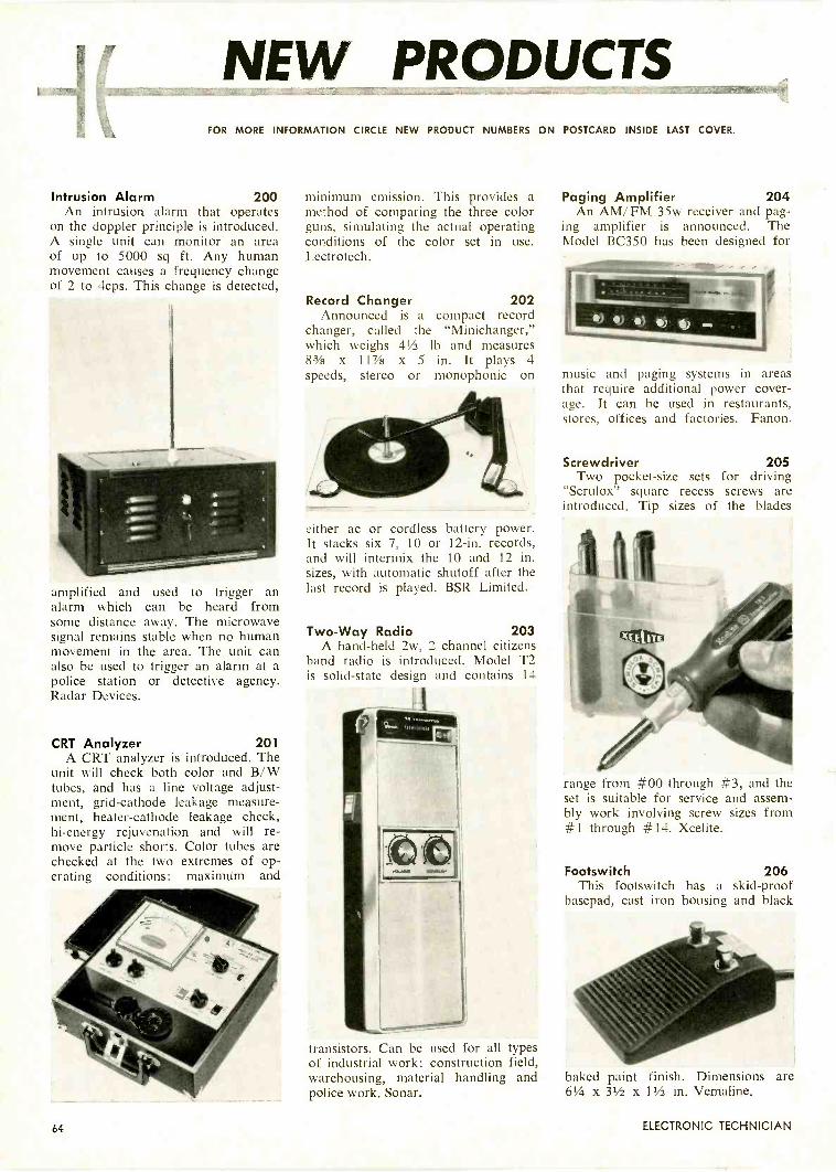
t.
NEW PRODUCTSFOR MORE INFORMATION CIRCLE NEW PRODUCT NUMBERS ON POSTCARD INSIDE LAST COVER.
Intrusion Alarm 200An intrusion alarm that operates
on the doppler principle is introduced.A single unit can monitor an areaof up to 5000 sq ft. Any humanmovement causes a frequency changeof 2 to 4cps. This change is detected,
amplified and used to trigger analarm which can be heard fromsome distance away. The microwavesignal remains stable when no humanmovement in the area. The unit canalso be used to trigger an alarm at apolice station or detective agency.Radar Devices.
CRT Analyzer 201A CRT analyzer is introduced. The
unit will check both color and B/Wtubes, and has a line voltage adjust-ment, grid -cathode leakage measure-ment, heater -cathode leakage check,hi -energy rejuvenation and will re-move particle shorts. Color tubes arechecked at the two extremes of op-erating conditions: maximum and
minimum emission. This provides amethod of comparing the three colorguns, simulating the actual operatingconditions of the color set in use.Lectrotech.
Record Changer 202Announced is a compact record
changer, called the "Minichanger,"which weighs 41/2 lb and measures83/8 x 117/8 x 5 in. It plays 4speeds, stereo or monophonic on
either ac or cordless battery power.It stacks six 7, 10 or 12 -in. records,and will intermix the 10 and 12 in.sizes, with automatic shutoff after thelast record is played. BSR Limited.
Two -Way Radio 203A hand-held 2w, 2 channel citizens
band radio is introduced. Model T2is solid-state design and contains 14
transistors. Can be used for all typesof industrial work: construction field,warehousing, material handling andpolice work. Sonar.
Paging Amplifier 204An AM/FM 35w receiver and pag-
ing amplifier is announced. TheModel BC350 has been designed for
music and paging systems in areasthat require additional power cover-age. It can be used in restaurants,stores, offices and factories. Fanon.
Screwdriver 205Two pocket-size sets for driving
"Scrulox" square recess screws areintroduced. Tip sizes of the blades
range from #00 through #3, and theset is suitable for service and assem-bly work involving screw sizes from#1 through #14. Xcelite.
Footswitch 206This footswitch has a skid -proof
basepad, cast iron housing and black
baked paint finish. Dimensions are61/4 x 31/2 x 11/2 in. Vemaline.
64 ELECTRONIC TECHNICIAN
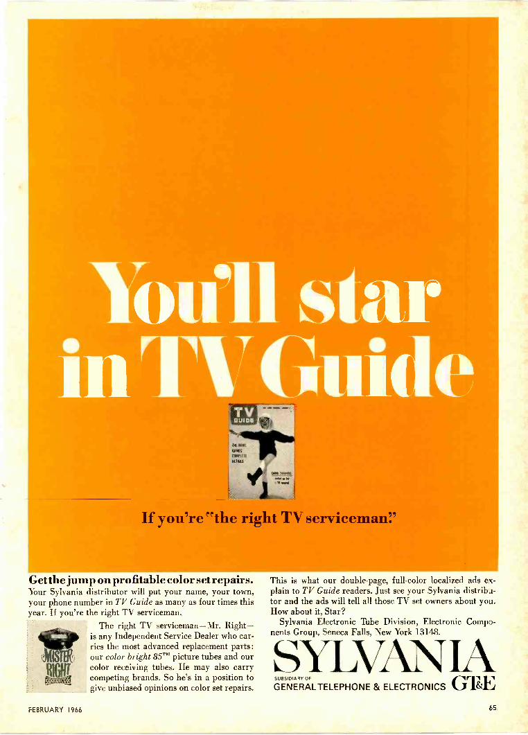
You'll starin e
If you're "the right TV service . I,,
Get the jump on profitable color set repairs.Your Sylvania distributor will put your name, your town,your phone number in TV Guide as many as four times thisyear. If you're the right TV serviceman.
The right TV serviceman-Mr. Right-is any Independent Service Dealer who car-ries the most advanced replacement parts:our color bright 85TM picture tubes and ourcolor receiving tubes. He may also carrycompeting brands. So he's in a position togive unbiased opinions on color set repairs.
This is what our double -page, full -color localized ads ex-plain to TV Guide readers. Just see your Sylvania distribu-tor and the ads will tell all those TV set owners about you.How about it, Star?
Sylvania Electronic Tube Division, Electronic Compo-nents Group, Seneca Falls, New York 13148.
VAN IASUBSIDIARY OF
GENERALTELEPHONE & ELECTRONICS GTEFEBRUARY 1966 65
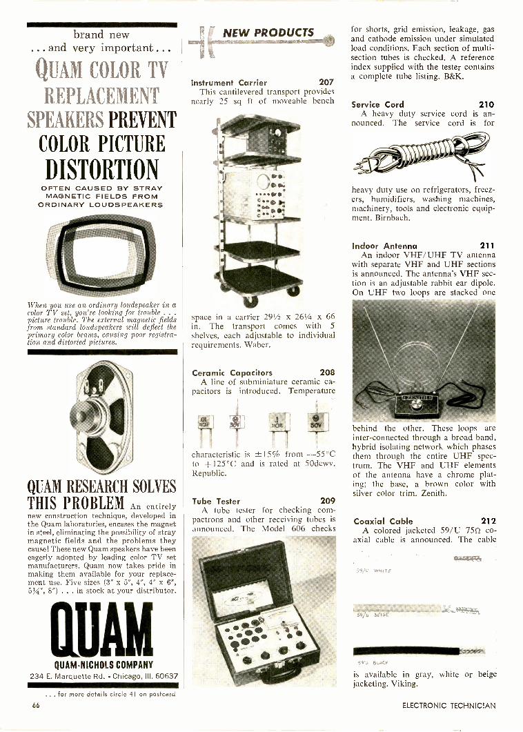
brand new... and very important ...
QUAM COLOR TV
REPLACEMENT
SPEAKERS PREVENT
COLOR PICTURE
DISTORTIONOFTEN CAUSED BY STRAYMAGNETIC FIELDS FROM
ORDINARY LOUDSPEAKERS
When you use an ordinary loudspeaker in acolor TV set, you're looking for trouble . . .
picture trouble. The external magnetic fieldsfrom standard loudspeakers will deflect theprimary color beams, causing poor registra-tion and distorted pictures.
QUAM RESEARCH SOLVES
THIS PROBLEM An entirelynew construction technique, developed inthe Quam laboratories, encases the magnetin steel, eliminating the possibility of straymagnetic fields and the problems theycause! These new Quam speakers have beeneagerly adopted by leading color TV setmanufacturers. Quam now takes pride inmaking them available for your replace-ment use. Five sizes (3" x 5", 4", 4" x 6",5W, 8") . . . in stock at your distributor.
QUAMQUAM-NICHOLS COMPANY
234 E. Marquette Rd. Chicago, III. 60637
... for more details circle 41 on postcard
66
NEW PRODUCTS
Instrument Carrier 207This cantilevered transport provides
nearly 25 sq ft of moveable bench
space in a carrier 291/2 x 261/4 x 66in. The transport comes with 5
shelves, each adjustable to individualrequirements. Waber.
Ceramic Capacitors 208A line of subminiature ceramic ca-
pacitors is introduced. Temperature
characteristic is -±15% from -55°Cto +125°C and is rated at 50dcwv.Republic.
Tube Tester 209A tube tester for checking corn-
pactrons and other receiving tubes isannounced. The Model 606 checks
for shorts, grid emission, leakage, gasand cathode emission under simulatedload conditions. Each section of multi -section tubes is checked. A referenceindex supplied with the tester containsa complete tube listing. B&K.
Service Cord 210A heavy duty service cord is an-
nounced. The service cord is for
heavy duty use on refrigerators, freez-ers, humidifiers, washing machines,machinery, tools and electronic equip-ment. Birnbach.
Indoor Antenna 211An indoor VHF/UHF TV antenna
with separate VHF and UHF sectionsis announced. The antenna's VHF sec-tion is an adjustable rabbit ear dipole.On UHF two loops are stacked one
behind the other. These loops areinter -connected through a broad band,hybrid isolating network which phasesthem through the entire UHF spec-trum. The VHF and UHF elementsof the antenna have a chrome plat-ing; the base, a brown color withsilver color trim. Zenith.
Coaxial Cable 212A colored jacketed 59/U 759. co-
axial cable is announced. The cable
SLACK
is available in gray, white or beigejacketing. Viking.
ELECTRONIC TECHNICIAN

Finco ModelUVF-10For MetropolitanAreasList $18.50
Finco ModelUVF-16For Local andSuburban AreasList $30.50
Finco ModelUVF-18For Suburban andNear Fringe AreasList $42.50
Finco Model
UVF-24For Near Fringeand DeepFringe AreasList $59.95
A major breakthroughin Antenna design!
FIAIGC7ALL BANDUHFVHFFM"COLOR VE-LOG"
Featuring Finco's Exclusive Gold Corodizing
Finco's new All -Band Color ye -Log Antenna does the workof three - gives startlingly clear black and white picturesand beautiful color on both UHF and VHF television chan-nels. Its superlative design also assures the finest in
stereophonic and monophonic FM sound reproduction.Comparison tests have proved the superiority of the All -Band UVF Series - superiority backed by Finco's guaran-tee of supremacy and unquestioned warranty.
Prices and specifications subject to change without notice.
UVF ColorVe-Log Antennas...Engineered forthe future! Revolutionary new UHF Section Heavy Aluminum reinforced insulator
insert cup and heavy duty rivet Back-up bracket and square boom Finco's exclusive triple thick
sleeved elements Lock-tite no -tilt saddle bracket Finco's exclusive double contact
to drive line Continuous one-piece drive line and
exclusive air insulated polystyrenecross -over spacer
THE FINNEY COMPANY 34 W. Interstate Street Bedford, OhioWrite for beautiful color brochure Number 20-322, Dept. 110
FEBRUARY 1966
... for more details circle 21 on postcard
67
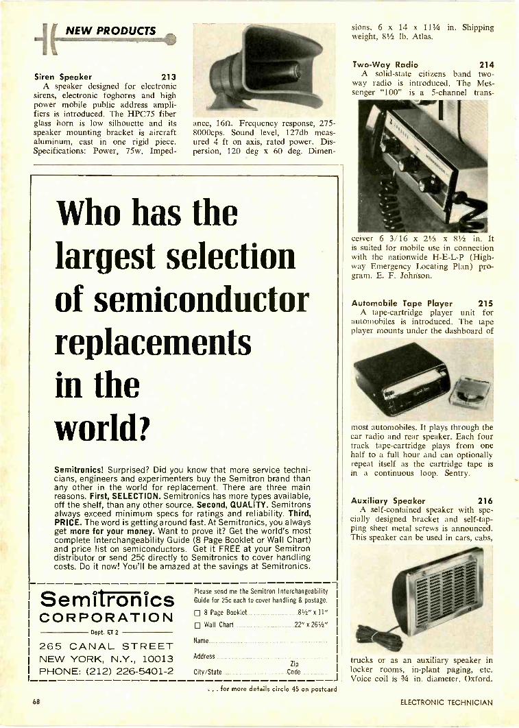
NEW PRODUCTS
Siren Speaker 213A speaker designed for electronic
sirens, electronic foghorns and highpower mobile public address ampli-fiers is introduced. The HPC75 fiberglass horn is low silhouette and itsspeaker mounting bracket is aircraftaluminum, cast in one rigid piece.Specifications: Power, 75w. Imped-
ance, 1651. Frequency response, 275-8000cps. Sound level, 127db meas-ured 4 ft on axis, rated power. Dis-persion, 120 deg x 60 deg. Dimen-
Who has thelargest selectionof semiconductorreplacementsin theworld?Semitronics! Surprised? Did you know that more service techni-cians, engineers and experimenters buy the Semitron brand thanany other in the world for replacement. There are three mainreasons. First, SELECTION. Semitronics has more types available,off the shelf, than any other source. Second, QUALITY. Semitronsalways exceed minimum specs for ratings and reliability. Third,PRICE. The word is getting around fast. At Semitronics, you alwaysget more for your money. Want to prove it? Get the world's mostcomplete Interchangeability Guide (8 Page Booklet or Wall Chart)and price list on semiconductors. Get it FREE at your Semitrondistributor or send 25G directly to Semitronics to cover handlingcosts. Do it now! You'll be amazed at the savings at Semitronics.
SemitropicsCORPORATION
Dept. ET 2
Please send me the Semitron InterchangeabilityGuide for 25c each to cover handling & postage.
8 Page Booklet 81/2" x 11"
Wall Chart 22" x 261/2"
Name
AddressZip
City/State CodeJ
265 CANAL STREETNEW YORK, N.Y., 10013PHONE: (212) 226-5401-2
sions, 6 x 14 x 111/4 in. Shippingweight, 81/2 lb. Atlas.
Two -Way Radio 214A solid-state citizens band two-
way radio is introduced. The Mes-senger "100" is a 5 -channel trans-
ceiver 6 3/16 x 21/2 x 81/2 in. Itis suited for mobile use in connectionwith the nationwide H -E -L -P (High-way Emergency Locating Plan) pro-gram. E. F. Johnson.
Automobile Tape Player 215A tape -cartridge player unit for
automobiles is introduced. The tapeplayer mounts under the dashboard of
most automobiles. It plays through thecar radio and rear speaker. Each fourtrack tape -cartridge plays from onehalf to a full hour and can optionallyrepeat itself as the cartridge tape isin a continuous loop. Sentry.
Auxiliary Speaker 216A self-contained speaker with spe-
cially designed bracket and self -tap-ping sheet metal screws is announced.This speaker can be used in cars, cabs,
or as an auxiliary speaker inlocker rooms, in -plant paging, etc.Voice coil is 3/4 in. diameter. Oxford.
trucks
... for more details circle 45 on postcard
68 ELECTRONIC TECHNICIAN

The package that rides like people!
It's there in hours andcosts you less when you ship byGreyhound Package Express
Every Greyhound bus is a package car-rier as well as a people carrier. Whenyou specify Greyhound PackageExpress your shipments leave and arriveon fast, frequent passenger schedules.Shipments going hundreds of miles usu-ally arrive the next morning... fre-
quently, the very same day. Nobody haslower rates, and you can ship anytime-at your convenience -24 hours a day, 7days a week, weekends and holidays,too. When fast service and low cost areimportant to you, look into GreyhoundPackage Express. Save time! Save
It's there in hours and costs you lessFor Example Buses Daily Running Time 20 lbs. 30 lbs. 40 lbs.BOSTON-
NEW YORK21 4 hrs. 35 mins. $2.00 $2.35 $2.60
LOS ANGELES-SAN FRANCISCO
25 9 hrs. 15 mins. 2.10 2.45 2.80
PITTSBURGH-CLEVELAND
11 1 hr. 50 mins. 1.80 2.05 2.40
INDIANAPOLIS-CHICAGO
10 4 hrs. 0 mins. 1.90 2.20 2.55
*Other low rates up to 100 lbs. Lot shipments, too.
money! Save trouble! Ship C.O.D., Col-lect, Prepaid ... or open a GreyhoundPackage Express Charge Account.For information on service, rates androutes, call Greyhound, or write:Greyhound Package Express, Dept. 53-B
140 S. Dearborn St., Chicago, Ill. 60603.
One of a series of messages depicting another growing service of The Greyhound Corporation.
... for more details circle 23 on postcard
FEBRUARY 1966 69
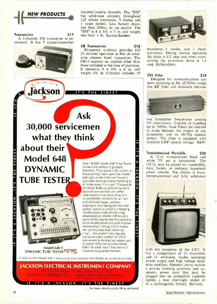
NEW PRODUCTS
Transceiver 217A 5 -channel, CB transceiver is an-
nounced. It has 5 crystal -controlled
O\ o°
Jackson
transmit/receive channels. The "S5S"has solid-state circuitry throughout(25 silicon transistors, 5 diodes and1 zener diode). Low battery drain,less than 200ma dc on receive. The"S5S" is 8 x 31/2 x 7 in. and weighsless than 4 lb. Squires -Sanders.
CB Transceiver 218Frequency synthesis provides full
23 channel operation in this all solid-state citizens band transceiver. TheCB14 requires no crystals other thanthose included at the time of purchase.It measures 9 x 35/s x 8 in. andweighs 43/4 lb. Circuitry includes 19
...IT'S THE FINEST
Ask30,000 servicemen
what they thinkabout theirModel 648DYNAMIC
TUBE TESTE
Model 648-1DYNAMIC TUBE TESTER $17995t
Over 30,000 Model 648 Tube Testerowners are Jackson's greatestboosters. They speak with authority,because they have used the Model648 right in the field and found itprovides more accurate checking ofall tube types. It's a fact! Thousandsof Model 648s are providing moreyears of service than any othertube testers in its price class as itis completely versatile for all newand old tube types. Jacksonengineers have designed the tubesocket layout to simplify changing,thereby practically eliminatingobsolescence. Model 648 ownersparticularly appreciate the exclusivecolor keyed panel and push-buttonsequence switching which makesset-up time less than warm-uptime... the angled view zig-zagexclusive color -coded roll chartconveniently located on upper partof panel. Why not put the Model648-1 to work now? You too willbecome its greatest booster.
Check all the Model 648-1 features at your Jackson distributor, or write for catalog
JACKSON ELECTRICAL INSTRUMENT COMPANYII P T -10
xport: Morhan ExportingBroadway, New York 13
IF IT'S A JACKSON...IT'S THE FINEST
transistors, 8 diodes, and 2 Zenerregulators. During receive operationthe drain is 0.2 amp and when trans-mitting the maximum drain is 1.1amp. Hallicrafters.
TVI Filter 219Designed for communications sys-
tems operating in the 25-50Mc range,this RF filter will eliminate extrane-
ous transmitter frequencies causingTV interference. Capable of handlingup to 1000w, these filters are insertedin series between the output of anytransmitter and its 50-7552 antennasystem. The filter is equipped withstandard UHF coaxial fittings. B&W.
Transistorized Portable 220A 12 -in. transistorized black and
white TV set is introduced. TheGT12, may be played on automobile,boat, battery or ordinary householdpower sources. The chassis is trans-former -powered and fully solid-state
with the exception of the CRT. Ithas a complement of 24 transistorsand 14 solid-state diodes includingpower supply and high voltage solid-state rectifiers. Optional extras includea private listening earphone and ac-cessory power cord that may beplugged into an automobile cigarettelighter, a boat chart -light socket orto a rechargeable battery. Sylvania.
... for more details circle 28 on postcard70 ELECTRONIC TECHNICIAN

There goes another $203 out of your pocket.(that G -E two-way radio could have saved)
Three bucks an hour you're paying him. Andhe just lost a two -hundred dollar customerfor you.
You could've reached him. General Elec-tric two-way radio instantly reaches thosepeople you can't reach by phone. It givesyou complete control of your business.
So you run a snappy service. Quick de-liveries. Speedy pick-ups. Fast emergencycalls. Instant re-routing. On -the -spotchanges, cancellations and sales informa-tion.
With service like this, you keep custom-ers. And make new ones. You also get moreuse out of your fleet. Waste fewer man-
hours. Save on gas mileage. Save on tele-phone charges. Save time and more time.And that's money.
When a two-way radio is counted on forso much, it has to be good. That's why com-panies going for two-way systems, go forGeneral Electric.
G -E started the two-way radio business.It's the world's largest electron cs manufac-turer. The world's largest manufacturer ofelectrical equipment. So who else couldknow more about it?
For big, busy companies or small, busycompanies looking to get big, there's a com-plete line of appropriate General Electric
high performance FM two-way radio equip-ment. Look into it.
Call your G -E communications consultantlisted in the Yellow Pages under "RadioCommunication." Or write for completedescriptive information. General ElectricCompany, Communication Products Dept.,Section 11526 , Lynchburg, Virgina.
... for more details circle 22 on postcard
First in Two -Way Radio
GENERAL ELECTRIC

4( NEW PRODUCTS
Fluorescent Lights 221A line of fluorescent shop lights
are introduced. A prismatic mirror
lens gives a greater concentration oflight intensity. The fluorescent tube ishoused in rubberized polyethylene andthe lamp is encased in a shock -resist-ant, plastic tube. Huston.
Jungle Radio 222A commercial version of the "Jun-
gle Radio" being used in Vietnam isannounced. The unit could provideradio communications for forest rang-ers over long distances, forest firefighters, explorers, prospectors, biggame hunters and others who travelfor distances over difficult terrain andwhere light weight and small size of
ilLow cost-all so/id-stateleW! CITIZENS RADIO TRANSCEIVER
MESSENGER"100"the new Johnson Messenger "IOU" puts you on the rightroad to greater profits with a top-quality transceiver forthe popular -priced market! This compact, 5 -channel unitdelivers performance and proven reliability no other CBtransceiver in its price range can match!
Advanced circuitry! Receiver is both sensitive and selec-tive-unique Johnson speech compression circuit preventsoxermodulation and delivers a crisp, clean, penetratingsignal with no adjacent channel "splatter"... boosts aver-age transmitted power for greater readability at extendedranges. Circuit design provides maximum power output-high performance noise limiting gives user "whisper quiet"operation!
Circuitry Features of the "100" include: Narrow bandwidth receiver for excellent selectivity!
High receiver sensitivity for maximum range!
Unique speech compression circuit which prevents overmodulation and helps deliver a clean, crisp signal without adja-cent channel "splatter"! Three types of usage from oneunit-Mobile, Base or Portable.
CALL OR WRITE TODAYfor complete information!
E. F. JOHNSON COMPANY2718 10th Ave. S.W. Waseca, Minn. 56903 1
95NET(Mobile Unit)
items to be carried are important con-siderations. Delco.
Intercom System 223A radio/intercom system for the
home is introduced. The Model 8408radio/intercom is a solid state AM/
FM unit and includes one master con-trol unit, one door station, and threeremote control units. Intercom andradio use separate volume controls.Fasco.
Paging Projector 224A 3w paging projector is an-
nounced. The PA30 is a re-entranthorn for public address or paging ap-plication. The rectangular horn pro-
vides a 90 deg by 120 deg dispersionangle. A swivel bracket allows thehorn to be rotated to either thehorizontal or vertical axis. Electro-Voice.
For more information on these
NEW PRODUCTS
See pages 95 and 96
READERS SERVICE
... for more details circle 31 on postcard72 ELECTRONIC TECHNICIAN
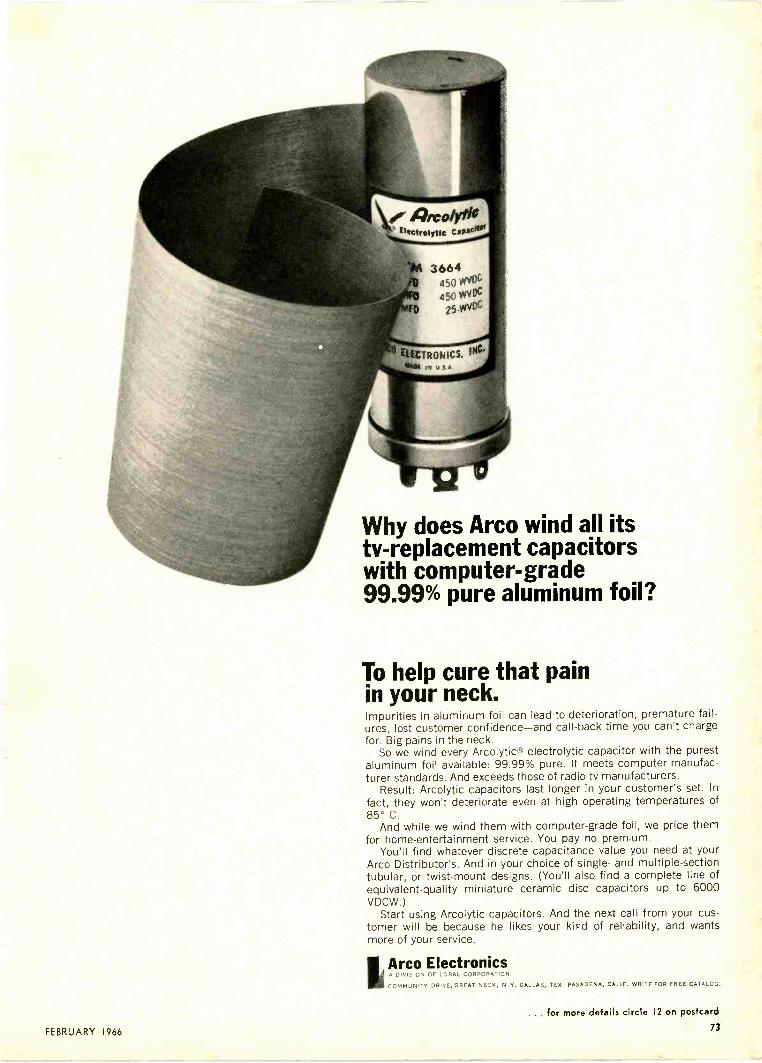
Why does Arco wind all itstv-replacement capacitorswith computer -grade99.99% pure aluminum foil?
To help cure that painin your neck.Impurities in aluminum foil can lead to deterioration, premature fail-ures, lost customer confidence-and call-back time you can't chargefor. Big pains in the neck.
So we wind every Arcolytic electrolytic capacitor with the purestaluminum foil available: 99.99% pure. It meets computer manufac-turer standards. And exceeds those of radio-tv manufacturers.
Result: Arcolytic capacitors last longer in your customer's set. Infact, they won't deteriorate even at high operating temperatures of85° C.
And while we wind them with computer -grade foil, we price themfor home -entertainment service. You pay no premium.
You'll find whatever discrete capacitance value you need at yourArco Distributor's. And in your choice of single- and multiple -sectiontubular, or twist -mount designs. (You'll also find a complete line ofequivalent -quality miniature ceramic disc capacitors up to 6000VDCW.)
Start using Arcolytic capacitors. And the next call from your cus-tomer will be because he likes your kind of reliability, and wantsmore of your service.
IArco ElectronicsA DIVISION OF LORAL CORPORATION
COMMUNITY DRIVE,GREAT NECK, N.Y. DALLAS, TEX. PASADENA, CALIF. WRITE FOR FREE CATALOG.
FEBRUARY 1966
for more details circle 12 on postcard
73

NEW0 INID_USTRIES, INC
AKTRON
REAR
SEAT
SPEAKER
MTCOMPLETE NOTHING ELSE TO BUYALUMINUM VOICE COIL SPEAKER
SOLDERLESS HOOK-UPFADER CONTROL GIVES COMPLETE
SPEAKER BALANCEMULTI-IMPEDENCE SPEAKER
LOUVERED, CHROME PLATED GRILLCOMPLETE INSTALLATION BROCHURE
EYE CATCHINGPROTECTIVE DISPLAY PACKAGING
STANDSBY ITSELF
HANGSFROM PEGBOARD
REAR SEAT SPEAKER 111
NEW PRODUCTS
itSpeaker System 225
A speaker system of moderate sizeis announced. The speaker compon-
ents include a 14 -in. long -throwwoofer and a horn -loaded high fre-quency assembly with a 14 -elementacoustic lens. Lansing.
Connectors 226A pigtail connector and tap con-
nector are introduced. They are apre -insulated, self -stripping connector.
The pigtail connector is designed forconnecting two or three wires. Thetap connector is designed for makingbridge splices on a "run" wire with-out interrupting or breaking the cir-cuit. 3M.
Frequency Deviation 227A meter for measuring frequency
deviation is announced. The ModelPI -112 frequency deviation meter is
designed for monitoring deviations ofpower line frequencies, turbine flowsensors, tachometers, rotating machin-ery, repetition rate pickup and otherfrequency generating devices. Stand-ard meter sizes are 31/2 to 41/2 in.wide. Anadex.
Power Supply 228A regulated power supply providing
variable regulated dc plate and biasvoltages, plus ac heater voltages is an-nounced. It has separate meters forvoltage and current. The Model 780provides regulation from 0 to 400v
at high current, up to 150mc. Itgives up to 6amp at 6.3vac for op-eration of vacuum tube heaters. Pre-cise.
Solid -StatePower Supply 229
Announced is dc power supply ad-justable from 0-25vdc at 0-200maand 0.2% line or load regulation. Ithas floating output terminals with sep-
5 ttSV14.5110 MOW'S 5540.51455.1,
NIParate chassis ground terminal, 2% ac-curacy D'Arsonval meter for monitor-ing voltage and current. It is 61/4 x5 x 6 in. and weighs 31/2 lb. ElectroProducts.
For more information on these
NEW PRODUCTS
See pages 95 and 96
READERS SERVICE
... for more details circle 37 on postcard74 ELECTRONIC TECHNICIAN
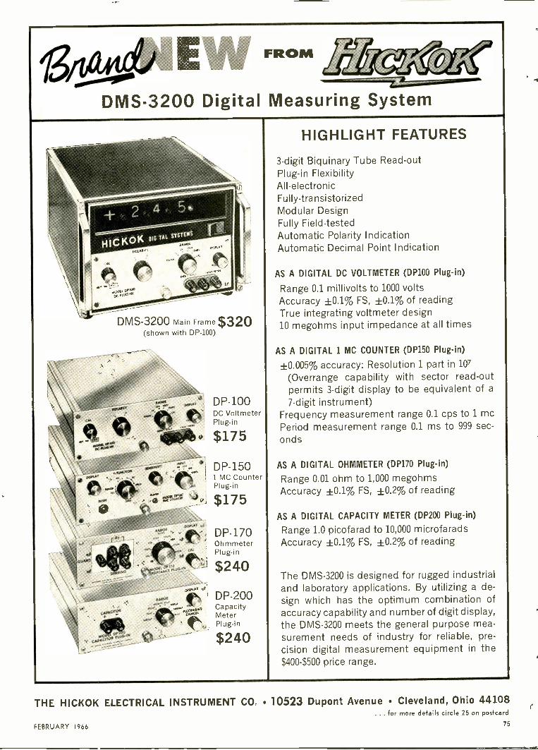
FROM
DMS-3200 Digital Measuring System
DMS-3200 Main Frame $320(shown with DP -100)
DP -100DC VoltmeterPlug-in
DP -1501 MC CounterPlug-in
$175
DP -170OhmmeterPlug-in
$240
gfr..\. DP -200
"ftr MeCapacityter
4eb, Plug-in
$240
HIGHLIGHT FEATURES
3 -digit Biquinary Tube Read-outPlug-in FlexibilityAll -electronicFully -transistorizedModular DesignFully Field-testedAutomatic Polarity IndicationAutomatic Decimal Point Indication
AS A DIGITAL DC VOLTMETER (DP100 Plug-in)
Range 0.1 millivolts to 1000 voltsAccuracy ±0.1% FS, ±0.1% of readingTrue integrating voltmeter design10 megohms input impedance at all times
AS A DIGITAL 1 MC COUNTER (DP150 Plug-in)
±0.005% accuracy: Resolution 1 part in 107(Overrange capability with sector read-outpermits 3 -digit display to be equivalent of a7 -digit instrument)
Frequency measurement range 0.1 cps to 1 mePeriod measurement range 0.1 ms to 999 sec-onds
AS A DIGITAL OHMMETER (DP170 Plug-in)
Range 0.01 ohm to 1,000 megohmsAccuracy ±0.1% FS, ±0.2% of reading
AS A DIGITAL CAPACITY METER (DP200 Plug-in)
Range 1.0 picofarad to 10,000 microfaradsAccuracy ±0.1% FS, ±0.2% of reading
The DMS-3200 is designed for rugged industrialand laboratory applications. By utilizing a de-sign which has the optimum combination ofaccuracy capability and number of digit display,the DMS-3200 meets the general purpose mea-surement needs of industry for reliable, pre-cision digital measurement equipment in the$400-$500 price range.
FEBRUARY 1966
THE HICKOK ELECTRICAL INSTRUMENT CO, 10523 Dupont Avenue Cleveland, Ohio 44108... for more details circle 25 on postcard
75
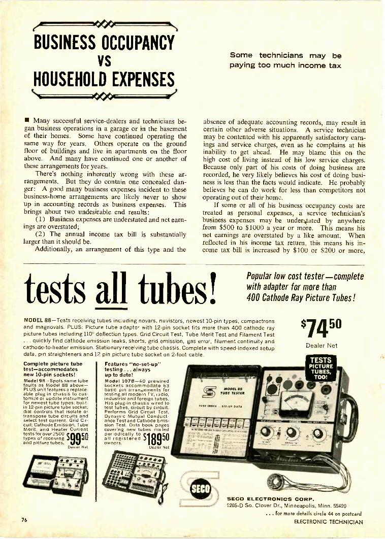
BUSINESS OCCUPANCYvs
HOUSEHOLD EXPENSES
Many successful service -dealers and technicians be-gan business operations in a garage or in the basementof their homes. Some have continued operating thesame way for years. Others operate on the groundfloor of buildings and live in apartments on the floorabove. And many have continued one or another ofthese arrangements for years.
There's nothing inherently wrong with these ar-rangements. But they do contain one concealed dan-ger: A good many business expenses incident to thesebusiness -home arrangements are likely never to showup in accounting records as business expenses. Thisbrings about two undesirable end results :
(1) Business expenses are understated and net earn-ings are overstated;
(2) The annual income tax bill is substantiallylarger than it should be.
Additionally, an arrangement of this type and the
Some technicians may bepaying too much income tax
absence of adequate accounting records, may result incertain other adverse situations. A service technicianmay be contented with his apparently satisfactory earn-ings and service charges, even as he complains at hisinability to get ahead. He may blame this on thehigh cost of living instead of his low service charges.Because only part of his costs of doing business arerecorded, he very likely believes his cost of doing busi-ness is less than the facts would indicate. He probablybelieves he can do work for less than competitors notoperating out of their home.
If some or all of his business occupancy costs aretreated as personal expenses, a service technician'sbusiness expenses may be understated by anywherefrom $500 to $1000 a year or more. This means hisnet earnings are overstated by a like amount. Whenreflected in his income tax return, this means his in-come tax bill is increased by $100 or $200 or more,
tests all tubes!Popular low cost tester-completewith adapter for more than400 Cathode Ray Picture Tubes!
MODEL 88-Tests receiving tubes including novars, nuvistors, newest 10 -pin types, compactronsand magnovals. PLUS: Picture tube adaptor with 12 -pin socket fits more than 400 cathode raypicture tubes including 110° deflection types. Grid Circuit Test, Tube Merit Test and Filament Test... quickly find cathode emission leaks, shorts, grid emission, gas error, filament continuity andcathode -to -heater emission. Stationary receiving tube chassis. Complete with speed -indexed setupdata, pin straighteners and 12 -pin picture tube socket on 2 -foot cable.
Complete picture tubetest-accommodatesnew 10 -pin sockets!Model 98-Spots same tubefaults as Model 88 above-PLUS unit features a replace-able plug-in chassis to cus-tomize or update instrumentfor newest tube types; built-in 12 -pin picture tube socket;dial controls that isolate ortranspose tube circuits andselect test current. Grid Cir-cuit; Cathode Emission; TubeMerit; and Heater Currenttests for over 2500types of receivingand picture tubes.
Dealer Net
76
Features "no -set-up"testing . .. alwaysup to date!Model 1078-40 prewiredsockets accommodate 63basic pin arrangements fortesting all modern TV, radio,industrial and foreign tubes.Has plug-in chassis wired totest tubes, circuit by circuit.Performs Grid Circuit Test,Dynamic Mutual Conduct-ance Test and Cathode Emis-sion Test. Data book pagescovering new tubes mailed
all registered .powners.
periodically to
Dealer Net
'74"Dealer Net
SECO ELECTRONICS CORP.1205-D So. Clover Dr., Minneapolis, Minn. 55420
... for more details circle 44 on postcard
ELECTRONIC TECHNICIAN

You've got nobusiness advertisingin the Yellow Pages.
(Unless you wantmore business.
Find it here first-fast.Action -People do.
FEBRUARY 196677

even if he's in the 20 percent tax bracket. This isa heavy penalty for negligence or self deception.
Dividing Expenses
All expenses that are partly personal or householdand partly business should be divided on the basis ofthe facts surrounding each individual case. Thebusiness part, without fail, should be chargedto the business. Rationalizing any other course shouldbe discouraged. It may be reasoned by a servicetechnician that the same home would be occupiedanyway, whether a business were conducted out of itor not. Maybe so! But, if the business actually occu-pies any substantial part of the premises (one roomas an office, for example), then the service technicianand his family has less living space for their personaluse. The business should foot the bill.
Determining what part of total occupancy expensesthe business should defray isn't easy. Floor spaceoccupied by the business is probably the best formulato use. If, for example, one -sixth of floor space isoccupied by the business it should pay for one -sixth ofthe occupancy costs.
Divisible costs may include water, gas, electricityor heating costs. If the property is rented, part ofthe rent is a business charge. If the tenant must main-tain the premises at his own expense, a pro rata shareof costs is also a deductible business expense.
If a service technician owns his premises, a prorata share of the following expenses are deductible asa business cost: Property tax, interest on mortgage,
STANCORTV REPLACEMENT
GUIDERti-LHLr.
PART TO PART C
FOR TRANS,I C,ON COMOOto
if any, fire insurance and repairs. In addition, de-preciation can be charged on that part of the propertyused for business purposes.
Some of the expenses of occupancy can be de-ducted as personal items in an income tax return;others cannot. Those that cannot be taken as per-sonal deductions should certainly be deducted to theextent possible as business deductions. Those that canbe taken as personal deductions, such as mortgageinterest and property tax should still be pro ratedbetween business and personal deductions. It will fre-quently result in a lower income tax.
If most or all of the garage is used for businesspurposes, this fact should be taken into account inarriving at business occupancy cost. Yard usage isalso a factor to consider, although the value of yardspace so occupied is not comparable to householdspace.
For business reasons, a service technician may rentor buy premises in a business area or on a mainthoroughfare. If occupancy cost is higher because ofthis fact, a larger share of the cost may be charged tothe business, not being based entirely on the footageoccupied by the business.
If a business phone is installed in a home, theInternal Revenue Service will probably insist thatsome part of the bill be considered personal. On thebasis of useage, however, a larger part of the billmay be charged to the business. Toll charges that canbe identified as business should be charged in theirentirety to the business.
SERVICEHERE IS YOUR NEW 1966STANCOR PART -TO -PART
CROSS REFERENCE
GUIDE
COMPLETE FROM
A to I
N
MONOCHROME AND COLOR are included in the1966 Stancor Cross Reference Guide. Over 12,000Manufacturers' Part Numbers Cross Referenced toStancor Standard Replacement Transformersand Sweep Components.
* With 151 other brands in between.
ASK YOUR DISTRIBUTOR FOR YOUR COPY!
SOLD NATIONALLY THROUGH ELECTRONIC DISTRIBUTORS BYELECTRONIC MARKETING DIVISION3501 W. Addison Street Chicago, Illinois 60618
78 ELECTRONIC TECHNICIAN

successful service shopbeats rising costs with B&K
television analyst
"As every serviceman knows, major TV repairs representan increasingly large part of the service business and theaverage time per repair has increased"...
says Willard Horne of Home Radio and Television in Evanston, Illinois.
After more than 25 successful years in the servicebusiness, twenty of them in the same location,Mr. Horne can be considered an authority onhow to keep a business profitable. Mr. Hornesays, "In order to be successful, our 3 -man shophas to be competitive on the large jobs as wellas the small ones. With the increase in bench timethat we were experiencing and the limitations onwhat we could charge, there was a reduction ofprofit that had to be stopped. Then we boughta B&K Model 1076 Television Analyst."
"Now our customers get the same extra -valueservice on the big repairs and the small ones,"said Mr. Horne. "We use the Television Analystfor troubleshooting a wide variety of complaints,*particularly for those that require touch-up align-
ment, location of IF overloads and color con-vergence. We are more competitive now that weuse the B&K Television Analyst because wespend far less time on the jobs that used to bedogs, with benefits both to the shop and ourcustomers."* B&K Model 1076 Television Analyst checks
every stage in a black and white or color TVreceiver. Nine VHF RF channels, 20 to 45 MCIF, audio, video, sync, bias voltage and AGCkeying pulse are available. The model 1076 pro-vides its own standard test pattern, white dot,white line crosshatch, and color bar pattern slidetransparencies. It includes a blank slide whichcan be used for closed -circuit -TV display floorpromotion. Its net price is $329.95.
Find out how you will increase your TV service profits with a B&KModel 1076. See your distributor or write for Catalog AP 22.
B & K MANUFACTURING CO.DIVISION OF DYNASCAN CORPORATION1801 W. BELLE PLAINE AVE. CHICAGO, ILL. 60613
Export: Empire Exporters, 123 Grand St., New York 13, U.S A.
FEBRUARY 1966
... for more details circle 16 on postcard
79

Life
Insurance
For theShop Owner
Business/Industrial Radio is
Get Your Full Share ofthe 2 -Way Communications Market with
101110011111/0111111/91/HIPHere's a red-hot opportunity to sell more 2 -way radio! Now you can offerJohnson business/industrial "202" or "303" radio for practically any appli-cation ... and for extended range, simply add a mobile P/A 85 full poweramplifier to your customer's vehicles! With a P/A 85 added to his base station,you can further punch up his signal for even greater range.
With the base and mobile P/A 85 full power amplifiers added to the Johnson2 -way "Messenger" line you can dependably equip two of anything from amotorcycle to a semi -truck for practically the same dollar investment requiredfor one transceiver of another manufacture. Increase your share of the hotBusiness/Industrial 2 -way market with the new P/A 85! Call or write forthe facts today.
Shouldn't you be selling Johnson?
E. F. JOHNSON COMPANY2719 10th Ave. S.W. Waseca, Minn. 56903
Few are
properly prepared
when death comes
The value of life insurance is un-questionably recognized by most in-dividuals but TV -radio shop ownersare not ordinary individuals: They'rebusinessmen. This status gives themgreater personal freedom, a chancefor greater income, but in addition,a greater burden, too.
The shop owner has sacrificed asteady income to become a business-man. Perhaps he has lost pensionand other employee benefits andexposed his personal holdings tothe claims of business creditors.
Individuals, no matter for whomthey work (even themselves), havecertain basic needs which must bemet in case of death - and mostrecognize this by buying life in-surance. The self-employed busi-nessman, however, must go beyondthese simple needs to properly pro-vide for his family in case of hisuntimely death.
Insurance NeedsFew business concerns, for ex-
ample, operate without credit. Ade-quate life insurance should be pro-vided to pay off outstanding debtsbecause death does not cancel debts.In contrast, your widow will belucky to collect half of what is owedto you. Additionally, if you are asole proprietor and no one is avail-able to continue the business, your
80
... for more details circle 30 on postcard
ELECTRONIC TECHNICIAN

Life Insurance . ONLY CHEMTRONICSwidow will probably sell the busi-ness assets - but only for a fractionof their actual value. Shrinkage ofyour estate could leave your widowvirtually penniless, even though youmay now believe she has been ade-quately provided for.
If you happen to be one whohas really made it, you might alsoconsider the bite that federal estatetaxes will take from your accumu-lated wealth (see Table I).
Most people think in terms ofcarrying enough insurance to coverfinal expenses. But these expensesare seldom itemized fully. Some ofthese include hospital, burial, cur-rent bills, unpaid loans, unpaidproperty taxes, unpaid income taxes,estate and inheritance taxes, attor-ney and executor or administratorsfees. And there's more.
After your death, a basic incomeshould be provided to supplementSocial Security payments if childrenunder 18 are left behind or to pro-vide for the basic requirements ofyour widow if no children exist (seeTable II).
Your family will have to adjustto a lower income level when youare gone and it is beneficial to havesome income allowance for a read-justment period of a year or two.Also, if at all possible, an emergencyfund should be set up so your familycan better meet future crisis. Andinsurance should be available topay off existing mortgages. Mosthomes are mortgaged and if youhave your own building, it is prob-ably mortgaged, too. These pay-ments could be an oppressive burdenon your widow.
Some men delude themselves bythinking their wives can go back towork. After being out of the labormarket for even a few years, how-ever, even the most skilled womenhave difficulty finding suitableemployment.
ERRATUMManufacturer of the New Prod-
uct, number 226, listed under"Changer" on page 82 of the Oc-tober issue, should have read "BSR"instead of DuFine.
TOPQUALITYSHOULD
PROVEN AEROSOLCHEMICALS
BE USED IN ANY TV SETOVER 1,000,000 CANS SOLD
41:04.'lletONICS14
CHENITRONKS
NON INTIAMMOIIGNER ClEANEE
TUN
LOBECONTAINS
'1/4'.3.11torboOtt
-tiCNED10R 411.
N. 810
TUN-O-LUBETRIPLE ACTION TUNER CLEANERCLEANS LUBRICATES PROTECTSWILL NOT DETUNE TV TUNERS WILLNOT HARM PLASTIC PARTS SAFENON-FLAMMABLE3 OZ. SPRAY CAN 984
8 OZ. SPRAY CAN 1.98
TROL-AIDCONTROL & CONTACT CLEANERNON-FLAMMABLE PROVIDESLONGER -LASTING PROTECTIONAGAINST NOISE AND OXIDATION SAFE FOR PLASTIC PARTS3 OZ. SPRAY CAN 98c8 OZ. SPRAY CAN 1.98
MANUFACTURERS OFNO -ARC FROST -AID
MASK-N-GLAS KLEER SPRAYWrite for Illustrated Catalog
1260 RALPH AVE.BROOKLYN, NEW YORK 11236
... for more details circle 20 on postcard
SERIES AP -30PATENTS PENDING
Now anAtlas Sound
speaker thatcan do more
than any one speakercould do before
and all you need is ascrewdriver to mount,connect and adjust it
New Series AP -30 install easier,faster and better with built-in trans-formers, screw -to -line terminals andwatts/impedance switch. Very highefficiency in thrifty with amplifierpower for !ow level reinforcement.The speakers are 30 watts rugged forpenetration over distance and noise.
From solderless installation toquality performance on the job, fourweather -sealed AP -30 models coveryour requirements for most single andmultiple installations.
From $23.70 net.For the complete Professional Series
AP -30 story, ask for catalog Er -H12
ATLAS SOUND, Division ofpilas so1111 American Trading and Production Corporation4.-.........=,, 1419-51 39th Street, Brooklyn, New York 1121811.11, Canada: Atlas Radio Corporation, Toronto
THIRTY YEARS OF LEADERSHIP IN COMMERCIAL SOUND(i)4.T2Z.
FEBRUARY 1966
... for more details circle 14 on postcard
81
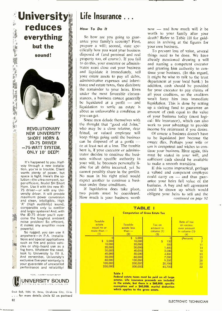
University Life Insurance . . .
reduceseverything
but thesound!
REVOLUTIONARYNEW UNIVERSITYSHORT HORN &
ID -75 DRIVER-75 -WATT SYSTEM,
ONLY 10- DEEP!
It's happened to you. Half-way through a new installa-tion, you're in trouble. Clientwants plenty of power, butspace is tight. Here's the so-lution-the ultra -compact, su-per -efficient, Model SH ShortHorn. Use it with the new ID -75 driver-or with any Uni-versity driver. It will providemaximum power conversionand clean, intelligible, High'A' (high audibility) sound,comparable only to costlierand larger systems! And, withthe ID -75 driver you'll over-come the toughest ambientnoise problem! So efficient,it makes any amplifier morepowerful.
So rugged, you can use itanywhere-in P.A. installa-tions and special applicationssuch as fire and police vehi-cles or ship -board use as afog horn. Whatever the need,look to University to fill it.And remember, University'sexclusive five-year warranty isyour guarantee of unexcelledperformance and reliability!
LISTEN-UNIVERSITY SOUNDS BETTER
re)UNIVERSITY SOUNDDIVISION OF ary lINO AlrfC. INC.
How To Do It
So how are you going to guar-antee your family's security? First,prepare a will; second, state spe-cifically how you want your businessdisposed of (and personal and realproperty too, of course). If you failto do this, your executor or adminis-trator must close out your businessand liquidate it immediately, sellyour estate assets to pay all debts,administrative expenses and inheri-tance and estate taxes, then distributethe remainder to your heirs. Evenunder the most favorable circum-stances, a business cannot generallybe liquidated at a profit - andliquidation to settle an estate isabout as unfavorable a condition asyou can get.
Some men delude themselves withthe thought that "good old John,"who may be a close relative, dearfriend, or valued employee willkeep things going until the businesscan be disposed of at a profit -or at least not at a loss. The troublehere is, if your executor or adminis-trator decides to continue the busi-ness without specific authority inyour will, he becomes personally li-able for all debts incurred, yet hecannot possibly share in the profits.No man in his right mind wouldexpect another to continue a busi-ness under these conditions.
If liquidation does take place,two points must be considered.How much is your business worth
now - and how much will it beworth to your family after yourdeath? Refer to Table III for guid-ance in arriving at the figures foryour own business.
To prevent loss of value, severalthings need to be done. We havealready mentioned drawing a willand naming a competent executorand granting him authority to con-tinue your business. (In this regard,it might be wise to talk to the trustdepartment at your local bank.) Inaddition, cash should be providedfor your executor to pay claims ofall your creditors, so the creditorswon't force him into immediateliquidation. This is done by settingup a sinking fund to guarantee anamount of cash equal to the valueof your business today (most logi-cal: life insurance), which can alsowork to your advantage to provideincome for retirement if you desire.
Of course a business doesn't haveto be liquidated just because theowner dies. Perhaps your wife orson is competent and wishes to con-tinue your business. Here again, thismust be stated in your will, andsufficient cash should be availableto make a smooth transition.
If this seems impractical, perhapsa valued and competent employeecould carry on - and thus guar-antee your heirs full value of thebusiness. A buy and sell agreementcould be drawn up which wouldobligate your heirs to sell and the
continued on page 92
TABLE IComputation of Gross Estate Tax
Taxableestate
equal to ormore than -
(1)
Taxableestate less
than -(2)
Tax onamount incolumn (1)
(3)
Rate of taxon excess
over amountin column (1)
(4)
0 $ 5,000 0 (Percent) 3
$ 5,000 10,000 $ 150 710,000 20,000 500 1120,000 30,000 1,600 1430,000 40,000 3,000 1840,000 50,000 4,800 2250,000 60,000 7,000 2560,000 100,000 9,500 28
100,000 250,000 20,700 3C250,000 500,000 65,700 32
Table I
Federal estate axes must be paid on all largeestates. Life insurance proceeds are includedin the estate, but there is a $60,000. specificexemption and a $60,000. marital deductionwhich applies to the gross estate.
Desk 868, 9500 W. Reno, Oklahoma City, Okla.. . . for more details circle 52 on postcard82 ELECTRONIC TECHNICIAN

This newZenith antennadoesn't believe
in ghosts
6
ZenithWavemagnetindoor
TV antennaDesigned for clear, sharp,
all -channel (2 to 83) receptionin color or B&W, the Zenith
Wavemagnet antenna meets thequality standards set for Zenith"original parts"... your assurance
of the world's finest performance.
The VHF and UHF elements areheavy chrome -plated. Separate
lead-in cables for UHF and VHFcorrespond to the input arrangementof every new all -channel TV receiver.
This new design features a specialnetwork providing substantial step-up
of basic dipole impedance, resultingin a lower voltage standing wave ratio
(VSWR) than the ordinary VHF indoorantennas. This reduces snow effect,reflections and ghosts.
Optimum UHF performance is achievedwith two full-size UHF loops, arranged one
/behind the other, that are carefullyphased through a coupling network through
the entire UHF spectrum from 470 to 890megacycles. The increased sensitivity develops
an exceptionally high front -to -back ratio equalto that in many outdoor antennas. This is
remarkably effective in reducing ghostsand man-made interference.
Order the new Wavemagnet antenna(Part Number 973-56) and other genuine Zenithreplacement parts and accessories from your
Zenith distributor.
AEIV/TAIThe quality goes inbefore the name goes cull)
Specifications subject tochange without notice
FEBRUARY 1966
... for more details circle 58 on postcard
83

cr)C)UU)OOU)
UJC)
O
OcoCA
U
t
O
0
U)
0..O
lisme4
Cl)O
VI
(0).'C)
0U)C)C.)
C.)
E"
4.)
0
0C)
C)
C)
%fat
0zon
0i.
U)C)
. .
o>
cn
O
Otd
C)
on
gO 'aE -0U) 0
4..L Cn
-0
Uwe
° LTS
t:Ir
0
CyaE-4O z
a -
O'car ari
r -I
2 0 UE ro
as
F-a)a
o E0 0
,;
0V)
0 U) 0cA C) .1.
CO)
L.&4 71 6-
t 0.1.. 0 0
0 C..)121)
01' 0O V
O 0. 0)-) 0
C)
0"a"O 0
O 0C.)
C.)
.-Cd
cn 7:1 aes a0.)
1-1 0 00 0
4a) N
C/)
(11
C)
0-0
FALLING OFFA LOG-ARITHMRemember a few basic facts and you'll find it easy
Of all the tools of mathematicalaid which TV -radio, Hi-Fi, audioand two-way radio communicationstechnicians have available, loga-rithms are probably the least under-stood. Actually, an understanding oflogarithms is as easy as falling offa log once you learn how.
All you need to know are a fewbasic but important facts to under-stand logarithms and decibels. Witha few moments of study you canremember the logs of numbers vir-tually from plus to minus infinity.
Chart I lists the logs of five num-bers from 1 to 10. Let's discuss afew of the points concerning thesenumbers. First, we take the num-bers easy to remember. The log of1 is zero and at the other end ofthe list we have the log of 10 whichis 1. These numbers can easily beremembered. Next we pick 3 num-bers which have a lasting relationto each other. These numbers are2, 4 and 8. They have the relation2", or 21, 22 and 23. As you wouldexpect, their logs are also relatedby .3n, or .3 x 1, .3 x 2 and .3 x 3,or .3, .6 and .9
Remembering the logs of 1 and10 and 2, 4 and 8, we now have 5
CHART INumberLog. (1
1 2 4 8 10
Place)(3place)
0
0
.3
.301
.6
.602
.9
.903
1
1.000
of the 10 important points (or logs)committed to memory.
Next, let's take the two remainingnumbers which are related in thesame manner as 2, 4 and 8. Thesenumbers are 3 and 9 and are relatedby 31 and 32. Their logs are relatedby .477 x 1 and .477 x 2, or .477and .954, as shown in Chart II. Wecommit these last two logs to mem-ory and then leave 7 of the 10 re-lated in a manner which is forevereasy to recall. The logs for 5, 6 and7 have no relation to the others andmust be separately remembered. Thelogs of numbers from 1 to 10 areshown in Chart III.
Three -place accuracy from mem-ory is obtained by remembering thatthe logs of 2, 4 and 8 are .301, .602and .903 which really says 3 once,3 twice, 3 trice. The 3 -place logs for3 and 9 were shown previously tobe .477 x 1 and .477 x 2, or .477and .954. Of course, the logs for 1and 10 are 0 and 1, respectively,with repeating zeros to infinity.
Now let's consider logs and deci-bels. By definition, db = 10 logPi/P2 to the base 10. If Pi is largerthan P2, we have plus db; if P1 issmaller than P2 we have negative
CHART II
Number 3 9
Logio(1 place) .5 .95(3 place .477 .954
CHART Ill
Number 1 2 3 4 5 6 7 8 9 10Log. (1 place) 0 .3 .5 .6 .7 .8 .85 .9 .95 1
(3 place) 0 .301 .477 .602 .699 .802 .845 .903 .954 1.000
84
... for more details circle 36 on postcard
ELECTRONIC TECHNICIAN
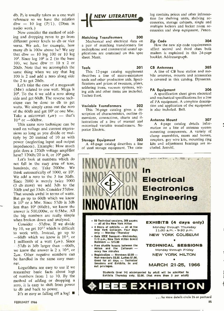
db. P2 is usually taken as a one wattreference so we have the relationdbw = 10 log (P/1). (Dbm inaudio work.)
Now consider the method of add-ing and dropping zeros to go fromdifferent power levels to db or viceversa. We ask, for example, howmany db is 100w above lw? We saythat dbw = 10 log 100 or 10 log102. Since log 102 is 2 (to the base10), we have dbw = 10 x 2 or20db. Note that we accomplish thesame thing when we say that log100 is 2 and add a zero along sidethe 2 to get 20db.
Let's take the case of a megawatt(Mw) related to one watt. Mega is106. To the 6 we add a zero alongside and get 60db. The reverse tech-nique can be done to db to getwatts. We simply cross out the zeroof the 60db and get 106 or one Mw.Take a microwatt (p,W) - that's10-6 or -60dbw.
This same zero technique can beused on voltage and current expres-sions so long as you divide or mul-tiply by 20 instead of 10 as withpower (neglecting input and outputimpedances). Example: How muchgain does a 120db voltage amplifierhave? 120db/20 is 6, or 106 gain.
Let's look at numbers which donot fall in the easy area of tens,hundreds, etc. Take 2000w. Wethink automatically of 1000, or 103.We add a zero to the 3 for 30db.Since 2000 is merely twice 1000(3 db more) we add 3db to the30db and get 33db. Consider 57dbw.That sounds awful in terms of watts.But go up to 60db which we knowis 106 or a Mw. Since 57db is 3dbless than 106 (60db), we know theanswer is 500,000w, or 0.5Mw. Allthe big numbers are really simplewhen broken down and analyzed.
Consider -57dbw. If we divideby 10, we get 105.7 which is difficultto work with. Instead, go up to-60db which we know is 10-6, or1 millionth of a watt (p.W). Since-57db is 3db larger than -60db,we know the answer is 2 x 10⁻⁶, or2p,w. Other negative numbers canbe handled in the same easy man-ner.
Logarithms are easy to use if weremember basic facts about logsof numbers from 1 to 10. By themethod of adding or dropping azero, it is easy to shift from powerto db and back to power.
It's as easy as falling off a log!
NEW LITERATURE
Matching Transformers 300Mechanical and electrical data on
a pair of matching transformers foraudiophone and commercial sound ap-plications are contained on this specsheet. Merit.
Tools 301This 12 -page catalog supplement
describes a line of micro -miniaturetools and other production aids. Speci-fications and prices of tweezers, pliers,soldering irons, vacuum systems, wir-ing aids and other items are included.Techni-Tool.
Variable Transformers 302This 76 -page catalog gives a de-
scription of characteristics, outline di-mensions, connections, charts and il-lustrations of a line of manual andmotorized variable transformers. Su-perior Electric.
Storage Equipment 303A 48 -page catalog describes a line
of steel storage equipment. The cata-
log contains prices and other informa-tion for shelving units, shelving ac-cessories, storage cabinets, single andmultiple lockers and locker room ac-cessories and shop equipment. Penco.
Zip Code 304How the new zip code requirements
affect second and third class bulkmailers is explained in this 24 -pagebooklet. Addressograph.
CB Antennas 305A line of CB base station and mo-
bile antennas, mounts and accessoriesis covered in this catalog. Dynascan.
PA Equipment 306A specification sheet gives electrical
and mechanical specifications for a lineof PA equipment. A complete descrip-tion and application of the equipmentis also included. Bell.
Antenna Mount 307A 4 -page catalog details infor-
mation on a line of antenna systemmounting components. A variety ofclamp assemblies, masts and booms,couplers, guy wire kits, mounting ringkits and adjustment bearings are in-cluded. Jerrold.
INNOVATION InINN al0t4 Electrical
INNOVATION
ElectronicsEngineering
80 Technical sessions, 300 papers- all at the New York Hilton
4 floors of exhibits - all at theNew York Coliseum. Four daysonly - Monday - Thursday
Gala IEEE Banquet-Wednesday,7:15 p.m., New York Hilton GrandBallroom - $15.00Free shuttle busses between theHilton and the Coliseum -every few minutesRegistration - Members $2.00 -Non-members $5.00. Ladies $1.00.Good for all days - TechnicalSessions and Exhibits. In andout privileges.
EXHIBITS (4 days only)Monday through Thursday
11:30 a.m. - 9:30 p.m.NEW YORK COLISEUM
TECHNICAL SESSIONSMonday through Friday
NEW YORK HILTON
MARCH 21-25, 1966Students (over 14) accompanied by adult will be admitted toExhibits Thursday only. $2.00. (Not more than 3 per adult)
<>0 IEEE EXHIBITIONFEBRUARY 1966
... for more details circle 26 on postcard
85

"My shop's been loaded...since I got my FCC License."
"And I could kick myself for not getting it sooner. I'm pulling in allkinds of mobile, marine and CB business that I couldn't touch before;have even had some calls to work on closed-circuit television. I've hiredtwo new men to help out and even with them, I'm two weeks behind."And so it goes. Once you have that FCC Ticket, you open the door toall kinds of new business. And that's not all. The knowledge you needto pass the FCC exam gives you a fundamental understanding of allelectronics. You'll find you can do more work in less time ... work onalmost any kind of electronics gear.What's the best way to get a Commercial FCC License ... and still keepup with your work? Thousands of men will tell you "Cleveland Instituteof Electronics". CIE has been preparing men for FCC License examssince 1934. What's more, they back their Home Study Licensing Pro-grams with this remarkable money -back offer:
A CIE FCC License course will quickly prepare you for a Com-mercial FCC License. If you fail to pass the FCC examination...on the very first try...after completing your course, CIE willrefund all your tuition. You get an FCC License... or yourmoney back!
Send coupon today for CIE's FREE informative booklet "HOW TOGET A COMMERCIAL FCC LICENSE". Cleveland Institute of Elec-tronics, Dept. ET -21, 1776 E. 17th St., Cleveland, Ohio 44114.
NEWin
1966
Only CIE offers new, up-to-the-minutelessons in all of these subjects: Logical
Troubleshooting
Laser Theory andApplication
Microminiaturization
Single SidebandTechniques
Pulse Theory andApplication
Boolean Algebra
SEND COUPON TODAY FOR FREE BOOKLET
Cleveland Instituteof Electronics1776 E. 17th St., Dept. ET -21Cleveland, Ohio 44114Please send FREE Booklet "HOW TO GET ACOMMERCIAL FCC LICENSE," without obligation.
HOW TO GET ACOMMERCIALFCC LICENSE
Your occupation
Name Age(please print)
Address
City State ZipA leader in Electronics Training...since 1934
J
NEWS OF THE INDUSTRY
Free MoviesAt Atlanta Airport
Air travelers at the Atlanta (Ga.) Municipal Airportwill soon find that all the free movies aren't in the air-planes. A free -admission movie theatre for waiting passen-gers will open in the Atlanta airport early in February,according to Modern Talking Picture Service, Inc., NewYork.
William Oard, MTPS vice president, said the SkyportCinema will feature movies on recreation, sports, businessinformation, travel and other short subjects especiallyselected to entertain and appeal to the predominant num-ber of businessmen air travelers.
The 50 -seat cinema in Atlanta will join a growing groupof cinemas being operated by Modern Talking PictureService, Inc., in Cincinnati and Minneapolis -St. Paul. TheAtlanta airport is the fourth largest in the nation with 11million visitors annually. Additional theatres are plannedfor other metropolitan airports.
Random House, RCA MergeDavid Sarnoff, chairman of the board of the Radio
Corp. of America, and Bennett Cerf, chairman of the boardof Random House, Inc., announce an agreement in prin-ciple for the acquisition of Random House by RCA.The agreement is subject to approval by the boards ofdirectors of the two companies and by the shareholdersof Random House. If the agreement is approved, the pub-lishing company will become a wholly owned subsidiaryof RCA. It is contemplated that Random House will con-tinue to function as a separate entity with complete edi-torial autonomy in the hands of its own board of directorsand no changes in its present personnel and management.
The transaction would involve an exchange of stockin the ratio of .62 share of RCA common stock for eachone of the 1,274,176 shares of Random House commonstock presently outstanding. Mr. Cerf will be proposed forelection as a member of the RCA board of directors fol-lowing the acquisition.
N.Y. Metro AreaUHF Penetration
At least 28 percent of the TV homes in the New YorkMetropolitan area are equipped to watch television onUHF channels 14 to 83, as well as VHF channels 2 to 13.There is also every likelihood that the UHF penetration iseven higher, perhaps running to 35 or 40 percent.
These are the findings reported in a new analysis ofUHF figures prepared by WNJU-TV, the New Yorkarea's first and only commercial UHF station, operatingon Channel 47.
Among the 350,000 homes in the area's Spanish-speak-ing community, which comprises WNJU-TV's prime au-dience, the study shows a similar 28 percent minimumpenetration as of the end of 1965, for a total of 98,000homes. This compares with the million -and -a -half UHFhomes out of the total 5.5 million TV homes in the NewYork market.
Based on projected TV set sales for 1966, the WNJU-TV study counts another 1,200,000 all -channel units beingadded to New York area homes this year, with about 85,-
86 ELECTRONIC TECHNICIAN
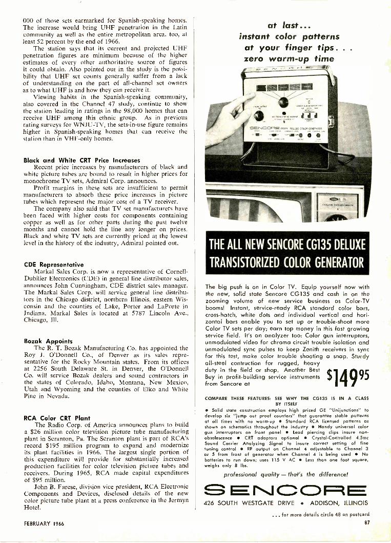
000 of those sets earmarked for Spanish-speaking homes.The increase would bring UHF penetration in the Latincommunity as well as the entire metropolitan area, too, atleast 52 percent by the end of 1966.
The station says that its current and projected UHFpenetration figures are minimum because of the higherestimates of every other authoritative source of figuresit could obtain. Also pointed out in the study is the possi-bility that UHF set counts generally suffer from a lackof understanding on the part of all -channel set ownersas to what UHF is and how they can receive it.
Viewing habits in the Spanish-speaking community,also covered in the Channel 47 study, continue to showthe station leading in ratings in the 98,000 homes that canreceive UHF among this ethnic group. As in previousrating surveys for WNJU-TV, the sets -in -use figure remainshigher in Spanish-speaking homes that can receive thestation than in VHF -only homes.
Black and White CRT Price IncreasesRecent price increases by manufacturers of black and
white picture tubes are bound to result in higher prices formonochrome TV sets, Admiral Corp. announces.
Profit margins in these sets are insufficient to permitmanufacturers to absorb these price increases in picturetubes which represent the major cost of a TV receiver.
The company also said that TV set manufacturers havebeen faced with higher costs for components containingcopper as well as for other parts during the past twelvemonths and cannot hold the line any longer on prices.Black and white TV sets are currently priced at the lowestlevel in the history of the industry, Admiral pointed out.
CDE RepresentativeMarkal Sales Corp. is now a representative of Cornell-
Dubilier Electronics (CDE) in general line distributor sales,announces John Cunningham, CDE district sales manager.The Markal Sales Corp. will service general line distribu-tors in the Chicago district, northern Illinois, eastern Wis-consin and the counties of Lake, Porter and LaPorte inIndiana. Markal Sales is located at 5787 Lincoln Ave.,Chicago, Ill.
Bozak AppointsThe R. T. Bozak Manufacturing Co. has appointed the
Roy J. O'Donnell Co., of Denver as its sales repre-sentative for the Rocky Mountain states. From its officesat 2256 South Delaware St. in Denver, the O'DonnellCo. will service Bozak dealers and sound contractors inthe states of Colorado, Idaho, Montana, New Mexico,Utah and Wyoming and the counties of Elko and WhitePine in Nevada.
RCA Color CRT PlantThe Radio Corp. of America announces plans to build
a $26 million color television picture tube manufacturingplant in Scranton, Pa. The Scranton plant is part of RCA'srecord $195 million program to expand and modernizeits plant facilities in 1966. The largest single portion ofthis expenditure will provide for substantially increasedproduction facilities for color television picture tubes andreceivers. During 1965, RCA made capital expendituresof $95 million.
John B. Farese, division vice president, RCA ElectronicComponents and Devices, disclosed details of the newcolor picture tube plant at a press conference in the JermynHotel.
FEBRUARY 1966
at last...instant color patternsat your finger tips. .
zero warm-up time
THE ALL NEW SENCORE CG135 DELUXE
TRANSISTORIZED COLOR GENERATOR
The big push is on in Color TV. Equip yourself now withthe new, solid state Sencore CG135 and cash in on thezooming volume of new service business as Color -TVbooms! Instant, service -ready RCA standard color bars,cross -hatch, white dots and individual vertical and hori-zontal bars enable you to set up or trouble -shoot moreColor TV sets per day; earn top money in this fast growingservice field. It's an analyzer too: Color gun interruptors,unmodulated video for chroma circuit trouble isolation andunmodulated sync pulses to keep Zenith receivers in syncfor this test, make color trouble shooting a snap. Sturdyall -steel contruction for rugged, heavyduty in the field or shop. Another BestBuy in profit -building service instrumentsfrom Sencore at $1499'COMPARE THESE FEATURES: SEE WHY THE CG135 IS IN A CLASS
BY ITSELFSolid state construction employs high priced GE "Unijunctions" to
develop six "jump out proof counters" that guarantee stable patternsat all times with no warm-up Standard RCA licensed patterns asshown on schematics throughout the industry Handy universal colorgun interruptors on front panel Lead piercing clips insure non -
obsolescence CRT adaptors optional Crystal -Controlled 4.5mcSound Carrier Analyzing Signal to insure correct setting of finetuning control RF output on Channel 4 adjustable to Channel 3or 5 from front of generator when Channel 4 is being used Nobatteries to run down; uses 115 V AC Less than one foot square,weighs only 8 lbs.
professional quality - that's the difference!
CD 1=1426 SOUTH WESTGATE DRIVE ADDISON, ILLINOIS
... for more details circle 43 on postcard
87
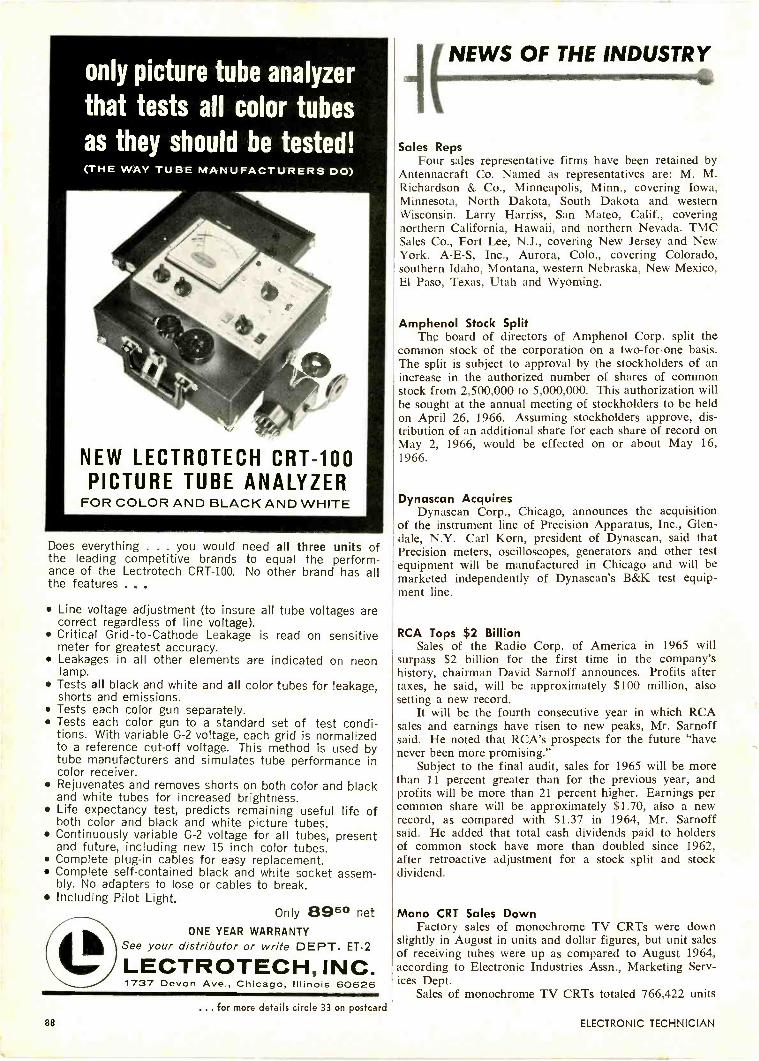
only picture tube analyzer
that tests all color tubesas they should be tested!
NEW LECTROTECH CRT -100PICTURE TUBE ANALYZER
Does everything . . . you would need all three units ofthe leading competitive brands to equal the perform-ance of the Lectrotech CRT -100. No other brand has allthe features . . .
Line voltage adjustment (to insure all tube voltages arecorrect regardless of line voltage).
Critical Grid -to -Cathode Leakage is read on sensitivemeter for greatest accuracy.
Leakages in all other elements are indicated on neonlamp.
Tests all black and white and all color tubes for leakage,shorts and emissions.
Tests each color gun separately. Tests each color gun to a standard set of test condi-
tions. With variable G-2 voltage, each grid is normalizedto a reference cut-off voltage. This method is used bytube manufacturers and simulates tube performance incolor receiver.
Rejuvenates and removes shorts on both color and blackand white tubes for increased brightness.
Life expectancy test, predicts remaining useful life ofboth color and black and white picture tubes.
Continuously variable G-2 voltage for all tubes, presentand future, including new 15 inch color tubes.
Complete plug-in cables for easy replacement. Complete self-contained black and white socket assem-
bly. No adapters to lose or cables to break. Including Pilot Light.
Only 895° netONE YEAR WARRANTY
See your distributor or write DEPT. ET -2
LECTROTECH, INC.1737 Devon Ave., Chicago, Illinois 60626
NEWS OF THE INDUSTRY, Inimio
Sales RepsFour sales representative firms have been retained by
Antennacraft Co. Named as representatives are: M. M.Richardson & Co., Minneapolis, Minn., covering Iowa,Minnesota, North Dakota, South Dakota and westernWisconsin. Larry Harriss, San Mateo, Calif., coveringnorthern California, Hawaii, and northern Nevada. TMCSales Co., Fort Lee, N.J., covering New Jersey and NewYork. A -E -S, Inc., Aurora, Colo., covering Colorado,southern Idaho, Montana, western Nebraska, New Mexico,El Paso, Texas, Utah and Wyoming.
Amphenol Stock SplitThe board of directors of Amphenol Corp. split the
common stock of the corporation on a two -for -one basis.The split is subject to approval by the stockholders of anincrease in the authorized number of shares of commonstock from 2,500,000 to 5,000,000. This authorization willbe sought at the annual meeting of stockholders to be heldon April 26, 1966. Assuming stockholders approve, dis-tribution of an additional share for each share of record onMay 2, 1966, would be effected on or about May 16,1966.
Dynascan AcquiresDynascan Corp., Chicago, announces the acquisitionthe instrument line of Precision Apparatus, Inc., Glen-
dale, N.Y. Carl Korn, president of Dynascan, said thatPrecision meters, oscilloscopes, generators and other testequipment will be manufactured in Chicago and will bemarketed independently of Dynascan's B&K test equip-ment line.
RCA Tops $2 BillionSales of the Radio Corp. of America in 1965 will
surpass $2 billion for the first time in the company'shistory, chairman David Sarnoff announces. Profits aftertaxes, he said, will be approximately $100 million, alsosetting a new record.
It will be the fourth consecutive year in which RCAsales and earnings have risen to new peaks, Mr. Sarnoffsaid. He noted that RCA's prospects for the future "havenever been more promising."
Subject to the final audit, sales for 1965 will be morethan 11 percent greater than for the previous year, andprofits will be more than 21 percent higher. Earnings percommon share will be approximately $1.70, also a newrecord, as compared with $1.37 in 1964, Mr. Sarnoffsaid. He added that total cash dividends paid to holdersof common stock have more than doubled since 1962,after retroactive adjustment for a stock split and stockdividend.
Mono CRT Sales DownFactory sales of monochrome TV CRTs were down
slightly in August in units and dollar figures, but unit salesof receiving tubes were up as compared to August 1964,according to Electronic Industries Assn., Marketing Serv-ices Dept.
Sales of monochrome TV CRTs totaled 766,422 units... for more details circle 33 on postcard
88 ELECTRONIC TECHNICIAN

valued at $12,728,359, representing declines of 2.0% and5.8% respectively from the 781,992 units valued at $13,-514,078 sold in August 1964. The August totals werehigher than those for the previous month of July 1965,when sales totaled 573,077 units valued at $9,398,233,representing increases of 33.7% and 35.4%, respectively.
Mono TV CRT sales for the first 8 months of 1965totaled 5,673,946 units valued at $94,650,078, down4.7% and 10.3% respectively from the 5,955,233 unitsvalued at $105,495,505 sold during the January/Augustperiod of 1964.
Rise in Color TV SalesDistributor sales of color TV receivers to dealers
during the first 6 months of 1965 totaled 839,000 units,up 83.3% from sales during this period last year, whilemonochrome TV receiver sales at this level were offslightly (-1.6%) at 3,387,000 for the comparable period,the Electronic Industries Assn. Marketing Services Dept.announces.
According to data compiled by the department, distribu-tors suffered sales declines of monochrome TV receiversin 6 out of 9 geographical regions of the country. Ofthe three regions (New England, East North Centraland South Atlantic) which registered increases, the EastNorth Central area showed a sharp, contrasting rise ofnearly 9% in distributor sales (from 678,000 sets duringthe first half of 1964 to 739,000 sets the first half of 1965.)
Distributors enjoyed sales increases of color TV re-ceivers in all 9 geographical regions of the U.S. duringthe first half of this year. West Central, East South Cen-tral and South Atlantic regions set the pace with increasesof 111%, 109% and 100%, respectively. The East NorthCentral, Middle Atlantic and Pacific regions, which his-torically have been the largest markets for TV receivers,showed significant gains.
Transistor RadiosA survey conducted by Sony Corp. at Shea and Yankee
Stadiums, New York, shows that 7 out of 10 followersof the Jets and Giants have tiny transistor radios withthem, tuned to the games they are watching. Some fansuse battery operated television sets, the survey showed.
As one person pointed out, the chance to learn moreabout intricate plays and referee signs is made easier withthe descriptions by radio announcers.
Sony said that a similar survey, conducted four yearsago at Yankee Stadium during the baseball season showedthat 4 out of 10 fans were resorting to transistor radiosfor "inside" information.
Philco AppointsThe appointment of Richard Hershey as sales training
supervisor in Philco Corp.'s Consumer Electronics Div.is announced by Armin E. Allen, vice president and gen-eral manager of the division.
Mr. Hershey succeeds Frank Adler, resigned. He re-ports to Richard D. Levin, sales promotion manager ofthe division.
Admiral RecordA record fourth quarter with volume 30 percent higher
than last year will push consolidated sales of AdmiralCorp. to a new high of $300 million for 1965, Ross D.Siragusa, chairman of the board, announces.
Mr. Siragusa that orders placed in December indicatedthe company's 1966 - first quarter volume will be at thesame record level as the fourth quarter.
ways toincreaseyour
incomeRCA Institutes, Inc. offers these four compre-hensive home study courses especially de-signed to help build your income immediately!
COLOR TV Add Color TV Servic-ing to your skills with this up-to-the-minute home training courseand take advantage of the growingprofit potential in this area! Trainunder the direction of RCA ... ex-perts in Color TV.
IT3/ciao
AUTOMATION ELECTRONICSTrains you for the many applica-tions of automation electronics inindustry and government includingPhotoelectronics, Digital ComputerTechniques, Synchros and Servo-mechanisms, Automatic ControlSystems, and many more!
TRANSISTORS You get the nec-essary background for semiconduc-tor technology including character-istics of tunnel diodes, rectifiersand other solid state devices.Tran-sistor trainer also available.
MOBILE COMMUNICATIONSTrains you to service and main-tain 2 -way radio communicationson land, sea, and air! Gives youthe technical foundation for spacecommunications!
Take advantage of RCA's Liberal Tuition Plan. You only pay forlessons you order; and have no long-term obligations. Licensed byNew York State Education Department. Approved for Veterans.
RCA INSTITUTES, INC.A Service of Radio Corporation of America350 West Fourth Street, New York, N.Y. 10014
The Most Trusted Name in Electronics
199 mi SEND THIS COUPON NOW FOR COMPLETE FREE INFORMATION In
RCA INSTITUTES, INC. Home Study School, Dept. ET -26350 West Fourth Street, N. Y., N. Y. 10014Without obligation, rush me free information on the following RCA Home Train-ing Course: COLOR TV TRANSISTORS MOBILE COMMUNICATIONS
AUTOMATION ELECTRONICS_
Name Age
Address
City State Zip
CANADIANS-Take advantage of these same RCA courses at no additional cost.No postage. No customs. No delay. Send coupon to: RCA Victor Company, Ltd.,5581 Royalmount Ave., Montreal 9, Quebec.
IM NM li li li IRM ME MI MI Ell
FEBRUARY 1966 89
c::F=4-ZD quick -acting
"Quick -Acting" fuses for protection ofsensitive instruments or delicate appara-tus;-or normal acting fuses for protec-tion where circuit is not subject tocurrent transients or surges.
INSIST ON
BUSSMANN MFG. DIVISION, m -G Edison Co., ST. LOUIS, MO. 63107
ITT/ABC MergerHarold S. Geneen, chairman and president of Inter-
national Telephone and Telegraph Corp., and Leonard H.Goldenson, president of American Broadcasting Co., is-sued the following joint statement:
"The board of directors of our two companies haveapproved a merger of American Broadcasting Cos., andInternational Telephone and Telegraph Corp. on the fol-lowing basis:
"ITT will issue 0.5719 of a share of common stockand 0.5719 of a share of a new convertible preferencestock ($10 stated value) for each share of ABC commonstock. The convertible preference stock will be convertibleon a share -for -share basis into ITT's common stock, butnot less than $2.40 per share. This new convertiblepreference stock cannot be called for ten years. In theeleventh year, the initial redemption price is $150 pershare and will decrease thereafter at the rate of $5 eachyear to a minimum of $100.
"The transaction will involve the issuance by ITT, atthe closing, of approximately 2,675,957 shares of itscommon stock and approximately 2,675,957 shares of thenew convertible preference stock.
"The approvals by each company are subject to theexecution of a mutually agreeable contract containingcomplete terms and conditions relating to the merger,which contract will be submitted to the boards of directorsof each company for approval.
"The consummation of the arrangement is also subjectto the approval of the shareholders of each company andto the approval of the Federal Communications Commis-sion and other appropriate government agencies and theobtaining of a favorable tax ruling.
BUSS : The Complete Line of Fuses and ....NEWS OF THE INDUSTRY
Jerrold EarningsThe Jerrold Corp. continued its record sales and earn-
ings pattern during the third quarter of the fiscal yearending Feb. 28, 1966. Milton J. Shapp, president andchairman of the board of the Philadelphia electronics firmannounces that, on an unaudited basis, net income for thethird quarter was $1,207,596, equal to 56 cents per share,approaching net income for the first half of the year of$1,294,949. Consolidated sales for the third quarter were$9,084,070. Consolidated sales and net earnings for thenine months ended November 30, 1965, rose to $24,525,-496 and $2,502,545 respectively.
Earnings per share of common stocks for the 9 monthsequalled $1.17 per common share. No provision was re-quired for Federal Income Taxes caused by a tax losscarryover of approximately $3,000,000 from previousperiods.
E -V DividendThe Electro-Voice, Inc., board of directors declares a
second semi-annual dividend of 71/2 cents per share. Thisbrings the total dividends declared this year to 15 centsas compared to 10 cents per share for the previous year.The $0.075 dividend will be paid on Jan. 24, 1966 to E -Vshareholders of record date Jan. 10, 1966.
FUSETRONdual -element Fuses
slow blowing
"Slow blowing" fuses prevent needless out-ages by not opening on harmless overloads-yet provide safe, protection against short-circuits or dangerous overloads.
INSIST ON
BUSSMANN MFG. DIVISION, McGrawEdison Co., ST. LOUIS, MO. 63107. . . for more details circle I7 on postcard
90 ELECTRONIC TECHNICIAN

BITSSSUB -MINIATUREFUSEHOLDER COMBINATION
FUSE ONLY.270 x .250INCHES
GMW FUSEand HWAFUSEHOLDER
For space -tight applications. Fuse has window forinspection of element. Fuse may be used with orwithout holder.
Fuse held tight in holder by beryllium copper con-tacts assuring low resistance.
Holder can be used with or without knob. Knobmakes holder water -proof from front of panel.
Military type fuse FMO1 meets all requirements ofMIL -F-23419. Military type holder FHN42W meetsall military requirements of MIL -F -19207A.
Write for BUSS Bulletin SFB
INSIST ON
BUSSMANN MFG. DIVISION, McGraw Edison Co., ST. LOUIS, MO. 63107
CATV SystemA CATV system serving greater Harrisburg, Pa.
opened recently. This is announced by Robert H. Beis-swenger, executive vice president of the Jerrold Corp. ofPhiladelphia.
More than 12,000 subscribers have already signed forthe new TV/FM reception service, which will initiallyprovide 11 TV channels including stations from Wash-ington, Baltimore, Philadelphia, York, Hershey, the localUHF and VHF stations, plus a locally -originated timeand weather channel. In addition, subscribers will re-ceive six FM radio stations.
Distributor Training ProgramA training program on constant -voltage transformers
for its distributors is inaugurated by Sola Electric, ElkGrove Village, Ill.
The training program, which consists primarily of aslide film presentation entitled "The Why and How ofConstant -Voltage Transformers," will be presented by Solasalesmen to distributor sales personnel.
Sylvania's Sales AgentKimball Electronics, Salt Lake City, Utah, is appointed
as authorized sales agent of closed circuit TV systems forthe Commercial Electronics Div. Sylvania Electric Prod-ucts, Inc.
Kimball Electronics will assist in the marketing ofeducational and commercial closed circuit TV systemsin the Salt Lake City area. In addition, the companywill install and service the equipment.
Fuseholders of Unquestioned High QualitySales of Imported Radios, TVs
Imported radios and television receivers sold underU.S. brand names increased markedly during the first halfof 1965, the Electronic Industries Assn., Marketing Serv-ices Dept. reports.
Sales of imported radios bearing U.S. brands accountedfor 10.8% (at 703,000 units) of total radio imports duringthe 1965 first half compared to 7.5% (at 1,017,000 units)during 1964. Sales of imported TV receivers comprised63% (at 257,000 units) of total TV receiver imports dur-ing the first 6 months of 1965 compared to 54% (at383,000 units) during 1964.
During 1960, total radio imports comprised only 42%of total U.S. home radio sales. Since that year, the quan-tity of imported radios has surpassed that of U.S.produced radios.
During 1961, imported radios amounted to 12.2 mil-lion units, or 52% of total U.S. sales. During the follow-ing 2 years imported radios maintained a level of 13.6million units and accounted for 58% of annual U.S. radiosales. Radio imports during the first 6 months of thisyear amounted to 6.5 million units, comprising 54.5%of total U.S. sales.
"IRC" Now OfficialAt a special meeting stockholders overwhelmingly
approved a change of corporate name to "IRC, Inc." from"International Resistance Co."
The firm's board of directors had recommended thechange because the forty -year old corporation has beenknown as "IRC" almost from its founding. In fact, theinitials have been used as part of the company trademarkfor decades.
BUSS SHIELDED FUSEHOLDERS
PREVENTRADIOFREQUENCYINTERFERENCE
For use where fuse and fuseholder could pick up radio frequen-cy radiation which interferes with circuit containing fuseholder-or other nearby circuits.
Fuseholder accomplishes both shielding and grounding.
Available to take two sizes of fuses -1/4 x 11/4" and 1/4 x 1" fuses.
Meet all requirements of both MIL -I -6181D and MIL -F -19207A.
Write for BUSS Bulletin SFH-12
INSIST ON
BUSSMANN MFG. DIVISION, McGraw Edison Co., ST. LOUIS, MO. 63107
. . . for more details circle 17 on postcard
9iFEBRUARY 1966

INJECTORALLTHE NEEDLE DOES THE JOE!
No. 899
N E !WAX MWE LUBRICANT M.
INJECTORAL
TUNERCLEAN ER
CLEANS AND 10021NOME FROM VOW.CONTROLS AND ItT.
CAN'T SPILLCAN'T EVAPOPP
TioLlt0"
. .10
_TIGER of a CLEANER!InjectoraIlTuner Clomer-No.899INN...is the best cleaner on the market today. It
cleans better, and bider than all other cleaners
and ...leaves a wax-fiee coating thatprotects arid lubricates contacts. Equipped with
the Injectorall 6 inch steel needle it reacheshardtn get at places in tuners. Ask tor...
INJECTORALL TUNER CLEANER in the bhster-pack
NO. 899WN
6 oz... $1.95 net
Great Neck, N. Y. 11024
INJECTORALL
ELECTRONICS
CORPORATION
... for more details circle 27 on postcard
Fill in coupon for a FREE One Year Sub-scription to OLSON ELECTRONICS' Fantas-tic Value Packed Catalog - Unheard ofLOW, LOW PRICES on Brand NameSpeakers, Changers, Tubes, Tools, StereoAmps, Tuners, CB, Hi-Fi's, and thousandsof other Electronic Values. Credit planavailable.
If you have a friend interested in electronicssend his name and address for a FREE sub-scription also.
468 S. Forge Street Akron, Ohio 44308
TABLE IIRetired worker & Retired worker Widow Widow & Widow & 2
wife, both 65 age 65, wifeage 62
age 62 1 child or morechildren
$190.00 $175.00 $105.00 $190.00 $254.00
Life Insurance . continued front page 82
Table IISocial security benefits shown for a workeror self-employed person who has earned anaverage of $400.00 per month or more. Awidow receives benefits only after age 62or if there are children under age 18.
TABL_E IIIGOING
ASSETSAccounts ReceivableGoods on HandFixtures & EquipmentReal EstateCashOthers
Total
LIABILITIESAccounts PayableNotes OutstandingOthers
Total
BOOK VALUETotal AssetsLess Total LiabilitiesBook ValueNOTES:
CONCERN VALUES
$$
GOING CONCERN VALUESAverage Annual Earnings
including "Salary" (1)Less Interest Earnings
on Book Value (2)True Annual EarningsLess Annual Cost to Hire
"Replacement" (3)Annual Good Will ValueEstimated Years Good Will
may last (4)Total Worth of Good WillPlus Book ValueTotal Going Concern Value
X
$
(1) Should include your salary plus any profit taken from the business.(2) This is the interest you would earn on your money if it weren't invested in
your business. 4% is a conservative figure.(3) This is the minumum annual income you could expect if you were an em-
ployee instead of the owner.(4) Good will can be expected to last a maximum of 5 years, though 3 years is
closer to an average.LIQUIDATING VALUES
ASSETS LIABILITIESAccounts Receivable (5) Accounts PayableGoods on Hand (6) Notes OutstandingFixtures & Equip. (7) OthersReal Estate TotalCashOthers
NOTES:(5)
(6)
(7)
TotalTOTAL LIQUIDATING VALUE
Total AssetsLess Total LiabilitiesTotal Liquidating Value
TOTAL LOSS AT DEATHTotal Going Concern Value $
Total Liquidating ValueTotal Loss at Death
People will not pay bills after .he owners death or after a business haschanged hands. A 5C% collection figures is about average.Normal shrinkage is 50% between value at death and time of sale.Fixtures and equipment isn't new - it's all used, and will command onlythe used price.
... for more details circle 38 on postcard
92 ELECTRONIC TECHNICIAN

Life Insurance ...employee to buy your business fora stipulated price. How is he to payfor it? By buying insurance on yourlife. The actual financial arrange-ments should be discussed with acompetent life insurance agent, butit can be done without either ofyou suffering any hardship. Besidesproviding a guaranteed market foryour business at a specified price,it also buys a great deal of em-ployee loyalty. For example, if yourman at the service bench is agree-able to this arrangement, he'll workharder and do a better job for younow because he knows that the busi-ness might be his someday, andyou'll know that he won't be leav-ing you to work for a competitor.
Such an arrangement is all themore valuable because it relievesyour widow of business worries, theadministration of the estateis expedited and good will is pro-moted by the continuation of thebusiness. A valuable present bene-fit is that your credit and financialstanding is enhanced because busi-ness life insurance relieves yourcreditors of any danger of loss asa result of your death.
Although most service and salesshops seem to be owned by soleproprietors, there are a few partner-ships. In this case the same thingshold true - a will, a binding buyand sell agreement, a specified priceand adequate life insurance to fundthe purchase by the survivor is theonly legally and financially soundway to continue the business. With-out this provision, the partnership,and thus the business, dies with anyof the partners.
The survivor loses his livelihood,and actually must cooperate in everyway possible to help liquidate thebusiness so his partner's widow willbe able to claim her share of thebusiness assets. Of course, it is pos-sible to continue in business witha partner's widow - but this isalmost never a satisfactory arrange-ment for either party.
Although we have not coveredall the pitfalls one may run into,the few that have been pointed outcan be avoided simply. Others canalso be taken care of with the as-sistance of your attorney and anagent experienced in the field ofbusiness life insurance.
Otto Werksent in
thisCoupon
UNIVERSITY SOUND
Desk B 68PI, P.O. Box 1056Oklahoma City, Oklahoma 73101
Please send me the COMMERCIAL SOUND PRODUCTS
Catalog '66 right away.
NAME
ADDRESS
CITY STATE ZIP
Look what he got!The total facts about the total lively sound of people -
to -people. About new Reflex Trumpets . .. Drivers
. . . Paging/Talk-Back Speakers . . . Sound Col-
umns . . . and every type of speaker for com-mercial sound and public address applications.The best systems for auditorium or playingfield . . . plant or patio . . . fixed or mobile.
Send for this new and up-to-date commer-cial sound reference book right away.
You'll be an expert too, just likea smart Dane named Otto.
UUNIVERSITY SOUNDA DIVISION OF LTV LING ALTEC. INC9500 W. Reno, Oklahoma City, Okla.
. . . for more details circle 51 on postcard
J. W. Miller 4th Video IF replacement formore than 20 Color TV manufacturers
Model 6037 Fourth Video IFTransformer is a high quality re-
placement for most Color TV sets.
Cross Reference Guide No. 6037
listing manufacturers, models and
part numbers has been prepared
for quick, easy comparison. In-
cluded are a schematic diagram
and installation instructions.
Write today or mail reader service
card for your copy.
tUeetikt!
6 0 3 7Color Video
Detector
J. W. MILLER COMPANY\. 5917 South Main Street Los Angeles, California 90003
See your local distributor for the full line of RF and IF coils, chokes, filters and transformers.
FEBRUARY 1966
... for more details circle 35 on postcard
93

QUIETROLE
Harmless to metal... non-conductive, non -inflamma-ble and non -corrosive. Zeroeffect on capacity andresistance.
EFFICIENT!
SAFE!
FAST!
AUTOMATIC
STAPLE GUNSFor Fastening Any
/Inside or OutsideWire Up to 1/2" in Diameter
nUPTO, 7No. T-18
UP TO
No. T-75
Telephone wire Intercom wire
Bell wire Thermostat wire Radiant heating wire
Radio & TV wiresTapered striking edgegets into close corners!
Available in:Brown, Ivory, Beige,Monel, Bronze, Natural
I JUNIUS STREET BROOKLYN 12. N. V.
... for more details circle 13 on postcard
there'sEXTRAPROFIT inNOISECTOMIES*
AETROLIOU
IS HARMLESSTO PLASTICS
utRi.cLEArinV
ond whs. Valaaftbaav hood.of
*a simple quick opera-tion performed by Doc-tors of Electronics
with the aid of Quietroleto cure scratchy, noisytuners and controls of TVand radio. Fast set re-covery with no ill side -effects assured. Savestime ... makes money forservicemen.
TVAmp
tualincANTclIANER
MRCS V WV,,ara.aaa easta,,
At Your Distributor ... Ask for Quietrole by Name.
manufactured by
QUIETROLE co.Spartanburg, South Carolina
... for more details circle 42 on postcard
ADVERTISERS INDEX
American Telephone & Telegraph Co. 77
Amperex Electronic Corp. 3rd Cover
Arco Electronics 73
Arrow Fastener Co. 94
Atlas Sound 81
B & K Mfg. Co. 27, 79
Bussmann Mfg. Div. 90.91
Castle TV Tuner Service, Inc. 34
Channel Master Corp. 35-36
Chemtronics, Inc. 81
Cleveland Institute of Electronics 86
Electronic Marketing Div. 78
Finney Co. 67
General Electric Co., Communication
Products Dept. 71
Greyhound Corp. 69
Hallmark Instruments 63
Hickok Electrical Instrument Co. 75
I.E.E.E. 85
Injectorall Electronics Corp. 92
Jackson Electrical Instrument Co. 70
Jerrold Electronics Corp. 2nd Cover
Johnson Co., E. F. 72, 80
Kay -Townes Antenna Co. 60
Lectrotech, Inc. 88
Littelfuse, Inc. 38
Miller Co., J. W. 93
Mosley Electronics, Inc. 84
Oaktron Industries, Inc. 74
Olson Electronics, Inc. 92
Perma-Power Co. 24
Philco Corp. 29
Quam-Nichols Co. 66
Quietrole Co. 94
Radio Corp. of America
RCA Electronics &
Components 4th Cover, 25
RCA Institutes
RCA Sales Corp.
89
59
S & A Electronics, Inc. 26
Sarkes Tarzian Tuner Service Div. 19
Seco Electronics 76
Semitronics Corp. 68
Sencore, Inc. 28, 37, 87
Sprague Products Co. 23
Standard Kollsman Industries, Inc. 20
Sylvania Electric Products, Inc. 31, 65
University Sound 82, 93
Viking Instruments, Inc. 30
Weller Electric Corp. 22
Windsor Electronics, Inc. 26
Winegard Co. 33
Zenith Sales Corp. 83
Note On the Doorstep
4 Villeame
"Dear Sam: Sorry, forgot about thehairdresser, door is unlocked, go onin. The TV is in the bedroom. Wemoved it there because Ed had itapart and company came in. Theknobs are in the kitchen, top drawer.The kids were watching a Western-Indians, shooting, dust and then camean awful smoke which smelled thewhole house up.
"There was a big bang-then every-thing rolled round and round. Nearlyscared us out of our wits. For a min-ute we thought it blew up. This mighthelp you find the trouble.
"Ed tried to fix it, but he got 'bit'by a tube or something and droppedit like a hot potato. It's probably inthe doghouse now, because Roverthought Ed was playing and ran outthe door with the tube. Oh yes, thehack from the set is behind the daven-port with some wires Ed yankedout when the tube hit him. He sureyelled. Hope you don't get bit too. Ifyou can't find everything, call Ed. Ithink he took some other things outtoo. He is anxious to see the big gametomorrow morning. Please lock thedoor when you leave. Thank you. Mrs.Herkemer."P.S. "If the tube isn't in the doghouse,and you can't find Rover, look underthe beds-he always carries thingsunder them."
MOVING?Be sure to let usknow your new ad-dress at least 6 weeksin advance. Andplease enclose a com-plete address labelfrom one of your re-cent issues.
ELECTRONIC
TECHNICIANOjibway Bldg.
Duluth, Minn. 55802727-8511
94 ELECTRONIC TECHNICIAN

PICK ANY NUMBERFROM 1G3GT TO 19AU4
AND YOU'RE A WINNER!
1G3GT/163GT 4HA5 6BZ6 60W8 8CW5
1X2B 5HG8 6CB66 61-65 9A8
3E6 5U8 6CG7 6H08 10CW5
3C86 6AL5 6DT6 6S4A 12AT7
3065 6AU4016. 6EH7 6SN7GTB 12AU7A
3HA5 6AU6A 6EJ7 6U8A 12AX4GTE
4BL8 6AV6 6GB5 6U9 12AX7A
4EH7 6AX4G16 6GJ7 6X9 150W5
4EJ7 6 666 6065 6Y9 16A8
40K5 66L8 6066 8605 19AU4
...AND ON AND ON. FOR THE COMPLETE LIST, WRITE
AMPEREX ELECTRONIC CORPORATION, HICKSVILLE, 1,1, NEW YORK 118D2.
. . . for more de+ai s circle I I on pos+=ard
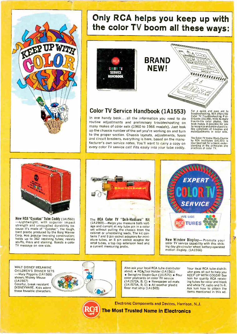
New RCA"Cycolac"Tube Caddy (1A1560)-Lightweight, with superior impactstrength and unequalled durability be-cause it's made of "Cycolac", the tough,hard plastic produced by the Borg WarnerCorp. Has popular two -wing construction;holds up to 362 receiving tubes; resistsscuffs, mars and staining. Boasts a colorTV message on one side.
Only RCA helps you keep up withthe color TV boom all these ways:
(SI
SERVICE
HANDBOOK
Color TV Service Handbook (1A1553)In one handy book ...all the information you need to doroutine adjustments and preliminary troubleshooting onmany makes of color sets (1960 to 1966 models). Just lookup the chassis number of the set you're working on and turnto the proper section. Chassis layouts, adjustments, fusesand circuit breakers, everything is here, based on the manu-facturer's own service notes. You'll want to carry a copy onevery color TV service call! Fits easily into your tube caddy.
For a quick and easy aid totroubleshooting, RCA offers theColor TV Troubleshooting Pict -0 -Guide (1A1389). With its manytrue-to-life color photos, thisbook makes it possible for youto recognize and understand vis-ible symptoms of troubles andmaladjustments in color sets.
The Color TV Home Study Courseby RCA Institutes (1A1325) isyour best bet for a basic under-standing of the principles andpractices of color TV.
The RCA Color TV "Quik-Mediure" Kit(1A1569)-Helps you measure both volt-age and current at any tube pin in a colorset without pulling the chassis from thecabinet or unsoldering leads. The kit con-tains 7 and 9 pin socket adaptors for mini-ature tubes, an 8 pin socket adaptor foroctal tubes, a top cap extension lead anda current measuring probe.
New Window Display-Promote yourcolor TV service capability with this strik-ing day-glo circular wheel battery -operatedmotion display. (1A1566)
WALT DISNEY MELAMINECHILDREN'S DINNER SETS-Mary Poppins (1A1568)shown; Mickey Mouse(1A1567)Colorful, break resistantDISNEYWARE. Kids adorethese loveable characters.
Also ask your local RCA tube distributorabout: RCA.Tool Holder (1A1561) Swingline Staple Gun (1A1570) Fourcolor postcards on color TV service(1A1572A, B, C) Newspaper ad mats(1A1573A, B, C) All weather plasticfloor mat strip (1A1565)
Your local RCA tube distrib-utor goes all out to help youKEEP UP WITH COLOR! Seehim for quality RCA receiv-ing tubes for color and blackand white TV, radio and hi-fi.Ask him how to obtain theitems mentioned in this ad.
Electronic Components and Devices, Harrison, N.J.
The Most Trusted Name in Electronics