Electronics - World Radio History
186
-
Upload
khangminh22 -
Category
Documents
-
view
1 -
download
0
Transcript of Electronics - World Radio History

October 11, 1971 $1.00 A McGraw-Hill Publication
A realistic CAD model for zener diodes 67 New source of millimeter wave power: lmpatt diodes 78 Finding the errors in data bit streams 82
Electronics® Minicomputers
move up with mixed memories

MOS technology presents another American ideal to satisfy your revolutionary ideas...
THE MCS 2050 RAM IS HERE! THE MCS 2050, a 256 BIT STATIC RANDOM
ACCESS READ/WRITE MEMORY can do a
lot for you, your customers, your nation . . .
fast, without a big power grab!
Consider the tenets to which its dedicated: Low
Power Operation — Typically 200 Milliwatts,
Static Circuitry — No External Clocks Required,
Access Time—Typically 600 n sec, Standby Power
Mode — Power Dissipation — 20 milliwatts, 200 n
sec Input Address Skew, TTL/DTL Input and Output
Compatibility, Complete Decoding Internal to Memory,
Wire Or Capability, Supply Voltages —9V, —7V, +5V.
THE MCS 2050, 256 BIT STATIC R.A.M. . . . FROM MOS TECHNOLOGY . . . IN VALLEY FORGE . . . WHERE IDEALS
HAVE ALWAYS BEEN TRANSPLANTED INTO ACTION.
We've Turned A Technology
Into A Company M.= MOS TECHNOLOGY, INC. VALLEY FORGE INDUSTRIAL PARK, VALLEY FORGE, PENNA. 19481'215-66G-7950
A Proud Affiliate of Allen-Bradley Co.
EASTERN REGIONAL OFFICE—REGIONAL SALES DIRECTOR—Mr. William Whitehead, MOS TECHNOLOGY, INCORPORATED, 88 Sunnyside Blvd., Suite 307, Plainview, New York 11803 • Phone: (516) 822-4240 • ALABAMA, FLORIDA, GEORGIA, N. CAROLINA, S. CAROLINA, TENNESSEE, MISSISSIPPI—Currie Aerospace Associates, P.O. Box. 1424, Huntsville, Alabama 35807 • Phone: (205) 536-5650 • 2907 McCoy Road, P.O. Box 13229, Orlando, Florida 32809 • Phone: (305) 855-0843 • P.O. Box 5588, Greensboro, North Carolina 27403 • Phone: (919) 273-3040 • NEW ENGLAND STATES—Victor Associates, 179 Union Ave., Framingham, Massachusetts 01701 • Phone: (617) 879-5710 • NORTHERN NEW JERSEY, NEW YORK (WESTCHESTER COUNTY, LONG ISLAND)—Falk Baker Associates, 383 Franklin Avenue, Nutley, New Jersey 07110 • Phone: (201) 661-2430 • E. PENNSYLVANIA, SOUTHERN NEW JERSEY—Rivco, P.O. Box 338, King of Prussia, Pennsylvania 19406 • Phone: (215) 265-5211 • DELA-WARE, MARYLAND, WASHINGTON, D.C., VIRGINIA, W. VIRGINIA—Bernard White & Company, Inc., 7 Church Lane, Baltimore, Maryland 21208 • Phone: (301) 484-5400.
CENTRAL REGIONAL OFFICE—REGIONAL SALES DIRECTOR—Mr, Alan Mattal, MOS TECHNOLOGY, INCORPORATED, 10400 W. Higgins Rd., Suite 631, Rosemont, Illinois 60018 • Phone: (312) 298-2035 • ILLINOIS, INDIANA, WISCONSIN—Coombs Associates, Inc., 1001 E. Touhy, Des Plaines, Illinois 60018 • Phone: (312) 298-4830 • OHIO, KENTUCKY, W. PENNSYLVANIA—McShane, Inc., P.O. Box 523, 123 W. Washington, Medina, Ohio 44256 • Phone: (216) 725-4568 • MICHIGAN—R. C. Merchant & Co., 18411 W. McNichols Road, Detroit, Michigan 48219 • Phone: (313) 535-6000 • MINNESOTA, N. DAKOTA, S. DAKOTA—Mel Foster Company, Inc., 7389 Bush Lake Road, Edina, Minnesota 55435 • Phone: (612) 941-7600 • MISSOURI, KANSAS, NEBRASKA, IOWA—Harlan J. Weisler & Assoc. Inc., 2050 Woodson Road, St. Louis, Missouri 63114 • Phone: (314) 428-3934 • TEXAS, OKLAHOMA, ARKANSAS, LOUISIANA—Norvell Associates, 10210 Monroe Drive, Dallas, Texas 75220 • Phone: (214) 357-6415.
WESTERN REGIONAL OFFICE—REGIONAL SALES DIRECTOR—Mr. Jack Turk, M9S TECHNOLOGY, INCORPORATED, 2172 Dupont Drive, Patio Bldg., Suite 221, Newport Beach, California 92660 • Phone: (714) 833-1600 • ARIZONA, NEW MEXICO—Toward Engineering Assoc., P.O. Box 15268, Arcadia Station, Phoenix, Arizona 85018 • Phone: (602) 955-3193 • CALIFORNIA, NEVADA—Bertrand & Zoolalian, Inc., 7340 Florence Avenue, Suite 205, Downey, California 90241 • Phone: (213) 927-4406 • Hunter Associates, 1208 Fox Plaza, San Francisco, California 94102 • Phone: (415) 626-8576 • COLORADO, UTAH, WYOMING—R. G. Enterprises, 1107 South Pearl Stree:, Denver, Colorado 80210 • Phone: (303) 744-2464 • WASHINGTON, OREGON, IDAHO, MONTANA—J. A. Tudor & Assoc. Inc., 2605 Western Avenue, Seattle, Washington 98121 • Phone: (206) 682-7444. INTERNATIONAL SALES REPRESENTATIVES—ARGENTINA—T. R. C. Electronica, S.A.C.I.el., Cangallo 4450, Buenos Aires, Argentina • Phone: 88-4044/5/6, M-. M. Lissin • ENGLAND, WALES, SCOTLAND, IRELAND—Impectron Limited, lmpectron House, 21-31 King Street, London W3 9LH, England • Phone: 01-992-5388 • FRANCE —Bureau de Liaison, 113 Rue de L'Universite, Paris Vile, Franre • Phone: 551.9920 • GERMANY, NETHERLANDS—International Micro Electronics, Inc., Arabellahaus 1838, Arabellastr. 5, 8000 Munich Al, Germany • Phone: 92-321 • INDIA—Electronic Enterprises, 46 Karani Building, New Charni Road, Bombay 4, India • Phone: 375375 • ISRAEL—Eastronics, Ltd., 75 Haifa Road, P.O. Box 21029, Tel-Aviv, Israel • Phone: 38352 • ITALY—Special -Ind. Corporation, Piazza Spotorno, 20159 Milano, Italy • Phone: 632-435 • JAPAN, HONG KONG, KOREA, TAIWAN—Takachiho Koheki Company Ltd., 1-7, Chome Kohjimachi, Chiyoda-Ku, Tokyo 102, Japan • Phone: 263-3211 • SWEDEN, DENMARK, FINLAND, NORWAY—Thrue F. Forsberg, Forshagatan 58, P.O. Box 79, Farsta 1, Sweden • Phone: 647040 • SWITZERLAND—Ernst M. Egli, Ingenieur—Bureau Ag, Witikonerstrasse 295, Zurich (CH 8053), Switzerland • Phone: 53.38.11.
Circle 900 on reaoer service card

The big buy in big-screen lab scopes
IL
«Ir
SCAlt FOCUS ' AteNN
' N. /IN d
NS FWD Ord%
You don't have to give up perfor-
mance capabilities to save money on a big-screen scope; HP's 182A gives
you both.
For $2200, you can get a main-frame, a 50-MHz dual-channel am-plifier, and a delayed-sweep time
base. This combination gives you the biggest display area of any high-
frequency scope (8-div x 10-div, 1.3 cm/div), 5 mV/div sensitivity, and 10 ns/div sweep time.
And that's only the beginning. The
182A system isn't limited to 50 MHz
in the plug-ins it can accept. Thanks
to HP's pioneering advances in CRT technology, the 182A will take the
entire family of 180 System plug-ins
For $2550 you can get a 100 MHz
system (mainframe, dual-channel vertical amplifier, and non-delayed
sweep; delayed sweep $450 extra). Also available at $2550 is HP's new
1 GHz sampling system (mainframe and plug-in) that's as easy to use as
a real-time scope! And the 182A is
the only large-screen lab scope that has these capabilities.
So, if you're in the market for a
high-frequency scope—get the 182A in the 50-MHz configuration, and pro-
tect yourself against having to buy a whole new system for 100-MHz capa-
bilities in the future. It's like getting free "bandwidth insurance" with your mainframe!
+.1•111111111,.. ,111M1111111111.1.1..
ink ••••77— — 71
W 7 • 4r--
ez) --ur
e)
For further information on the 182A, contact your local HP field engineer,
or write Hewlett-Packard, Palo Alto,
California 94304. In Europe: 1217 Meyrin-Geneva, Switzerland.
Scopes are changing.
Are you?
081/16
HEWLETT ie PACKARD
Electronics/October 11, 1971 Circle 1 on reader service card 1

Save $15 on our new communications kit
and get something special in your system.
The kit contains 12 Schottky diodes, 4 pin diodes, and one low-noise tran-sistor. As well as application notes and data sheets.
If you bought these components separately, it would cost you more than $34. But right now you can buy the whole kit and kaboodle for $19.40. We're sure that once you've tried them, you'll come back for more.
This is the kind of performance that will bring you back. The HP 2800 Schottky diode is ideally suited for high level detector applications with a breakdown voltage of 70 volts. The HP 2835 Schottky diode with a breakdown voltage of 5 volts and a forward voltage drop of .33 volts at one mA makes an ideal VHF/UHF mixer.
The HP 3080 pin diode as an AGC element guarantees low cross-
modulation and intermodulation down to frequencies of 5 MHz. The HP 35824A transistor makes an ideal low noise RF amplifier with a noise figure of 3 dB at 1 GHz.
So if you're looking for ways to improve the performance of your RF amplifiers, mixers, detectors or AGC's, tear out the coupon and a check and send them both in.
You may also want one of our very popular Schottky diode kits. For $8.40, you get eight each of three different Schottky barrier diodes. Try them and see what a difference they make in your circuits.
Clip this coupon and mail with check, money order or P.O. to: Hewlett-Packard Associates, 620 Page Mill Road, Palo Alto, California 94304. Your local HP sales office can also handle the order.
$34.00 value for $19.40! (offer expires on January 31, 1972)
D Send me one of your communications kits. (HP 5082-0051) Here's $8.40 for a diode kit. (HP 5082-0050) (California residents add 5% sales tax)
Name
Company
City/State/Zip
Frequencies D less than 10 MHz 010 to 250 MHz 0 250 to 500 MHz
500 to 1000 MHz D greater than 1000 MHz
HEWLETT ilk PACKARD
COMPONENTS 01109
2 Circle 2 on reader service card Electronics/October 11, 1971

Electronics The International Magazine of Electronics Technology October 11, 1971
lE Electronics International (follows page 24)
THE NETHERLANDS: Read-only memory cut out for the job, 9E WEST GERMANY: Fingering the display, 10E; V\Af computerizes bugs, 10E FRANCE: Home-grown CAS system enters world competition, 11E JAPAN: Coding scheme opens way for semiconductor laser link, 12E GREAT BRITAIN: Car's image displaces radar in speed checking gear, 12E NEW PRODUCTS INTERNATIONAL, 21E
29 Electronics Review
SOLID STATE: Current-switching scheme promises fast LSI logic, 29 MEMORIES: Sangamo division buys Sylvania's Soniscan, 29 LASERS: High-gain, flash-pumped laser gives coded pulse, 30 COMMERCIAL ELECTRONICS: Rotating-ring watch display may leapfrog others, 30 INDEX OF ACTIVITY: 31 COMPUTERS: Illiac 4 takes another step away from campus, 32; Univac aims 1616 at military, FAA, 32; Heat will limit specs, 34 COMPANIES: Solitron to head down C/MOS path, 34 EMPLOYMENT: Self-help groups see some daylight, 36 GOVERNMENT: Electronics figure heavily in negative trade balance, 36 PACKAGING: Brushes, tags bid for place in connector sun, 38 MILITARY ELECTRONICS: Displays, computers to teach dogfighting, 38 ADVANCED TECHNOLOGY: Diode key to first precise measure of speed of light, 40 FOR THE RECORD: 40
61 Technical articles
COMPUTERS: Evolution breeds a minicomputer that can take on its big brothers, 62 (cover) COMPUTER-AIDED DESIGN: A convenient way to model the handy zener diode, 68 CIRCUIT DESIGN: Designer's casebook, 73 SOLID STATE: Impatt diodes and millimeter-wave applications grow up together, 78 COMMUNICATIONS: Digital data links deserve a bit error rate detector, 82 PACKAGING & PRODUCTION: Solving interconnection problems in big multilayer pc boards, 88
93 Probing the News
COMPANIES: TI sees computers in its future, 93 SOLID STATE: Linear IC market in ferment, 97 INTERNATIONAL: Electronics to impact European automobiles, 99 AEROSPACE: Joint space talk outlook: clear skies, 103
107 New Products
IN THE SPOTLIGHT: Linear 'LSI' shrinks scope for field work, 107 INSTRUMENTS: Light meter is highly stable, 109; Digital wattmeter reads to 20 kW at 20 kHz, 109 DATA HANDLING: Controller is multipurpose, 113; Portable cassette recorder designed for remote input, 113 PACKAGING AND PRODUCTION: Board tester isolates faults, 117; Logic aids in wire identification, 117 SEMICONDUCTORS: TI adds three Schottky TTLS, 123 MATERIALS: 126
Departments
Publisher's letter, 4 Readers comment, 6 40 years ago, 10 People, 14 Meetings, 21 Electronics Newsletter, 25 Washington Newsletter, 51 New Books, 126 New Literature, 128 Personal Business, PB1 International Newsletter, 3E
Title R registered U.S. Patent Office; Copyright 1971 Mcgraw-Hill Inc. All rights reserved, including the right to reproduce the contents of this publication in whole or part. Volume No. 44, Number 21
Electronics/October 11, 1971 3

Looking for Bit Errors?
Actual Eye Pattern
Here they are! Day Address Hour/Min Bit Errors
Kingsley Roby of our engineer-ing staff uses the DCS Model 4660 Link-BERC (Link-Bit Error Rate Calculator) to check out ou- own 10 mega-bit PCM equipment. Why not 01 let him help you check your T-1, T-2, standard IRIG or spe-cial digital transmission links?
With selectable bit-blanking, clock-phasing, bit error rate intervals and stan-dard internal calibration . . . analyzing your link will be a lot easier and less time-consuming than complicated computer
or pulse generator / scope lash-ups Also remember your printer (Cr one we will supply) can be con-nected :o Link-BERC to provide a hard copy record of system bit error rates.
Call us or circle he reader service number for a 'ree appli-
cation brochure and a demon-stration at your facility.
Model 4660 Link-BERC
00 01 02 03 04 05
0102 0105 0 107 0109
000 110 000 190 190 000
DATA-CONTROL SYSTEMS, INC.
Commerce Drive, Danbury Connecticut 05810
203 743-9241
Readers comment
Jeweled movements
To the Editor: The Washington Newsletter of Aug. 16 erroneously reported that Hamilton Watch Co. is "the last fully integrated watch-maker in the U.S. able to turn out precision timing devices vital to this country's industrial base." In fact, Bulova is the only movement pro-ducer left among the 60 American companies that had produced jew-eled movements domestically dur-ing the past century. Elgin ceased domestic manufacture of jeweled movements in 1967 and Hamilton ended domestic movement manu-facturing in 1969-70. The Defense Department acquisi-
tion of Hamilton's facilities suggests there is a renewed appreciation of the unique defense capabilities of the quality watch industry. But Bulova—not Hamilton—is the sole domestic producer of precision jew-eled movements.
William Gowen Bulova Watch Co.
New York City • Mr. Gowen is correct in noting that Bulova is the only domestic inte-grated watchmaker still producing precision jeweled movements for watches. However, both Bulova and Hamilton make such movements for applications other than watches.
EEs in Britain
To the Editor: Those taking part in your ballot on a union for EEs [Aug. 2, p. 50; Sept. 21, p. 72] will be glad to know that we are in the process of solving the same problem in En-gland. We have formed, with the full approval of the engineering in-stitutions, our own union, the United Kingdom Association of Professional Engineers. Confined to degreed engineers, it will be equiva-lent to the British Medical Associ-ation. It has the powers of inter-vention between employer and employee and is technically a trade union; but through its special con-tacts and lobbying powers it achieves its ends without disruption. We are pressing for a common
code of professional conduct prop-erly drawn up and enforced. We have also published a guide to sala-
6 Circle 6 on reader service card Electronics/October 11, 1971

Coup de RAM. When the 1101 random access memory was introduced, we knew it was a winner. So, we second sourced it.
Likewise with the 11011, 1101A and 1101A1.
Now we've designed our very own 256 word x 1 bit RAM, the MM1101A2.
Basically, our new MM1101A2 gives you twice the speed of the 1101A1 (namely, 500nS Max.) with no increase in power. (A design feat we're frankly quite proud of.) Otherwise, our new MM1101A2 has all the other features you've grown to know in the 1101 series.
Including the use of silicon gate technology.
So, whether you need a good second source for the 1101, 11011, 1101A and 1101A1, or a good first source for our fast new MM1101A2, just drop us a line. Or give us a call. Or TWX us. Or cable if necessary. But don't just sit there.
National Semiconductor Corporation, 2900 Semi-conductor Drive, Santa Clara, California 95051. Phone (408) 732-5000. TWX: (910) 339-9240. Cable: NATSEMICON.
National
Electronics/October 11, 1971 Circle 7 on reader service card 7

lunrilata III Nalarpo FirilaroN uNrefiligiu N
ruatar ]inla How Hermes did away with vast rhombic or log-periodic antenna farms. Shoed away by a shrewd array: Take 1 meter diameter loops, 4 meters apart, and get an omni directional broad-band receiving array. Covers 2 - 32 MHz. Optimum beam characteristics for both long and short range communications. Rosette configurittion of linear arrays gives a number of overlapping high gain beams - all available simultaneously. * Using less than one hundredth of traditional real estate. Aperiodic Loop Systems are shrewd enough for restricted space, quick set up, roof mountable, or just below ground level. And portable version now available. From polar icecap to sweltering tropics. Installed in more than 52 locations for more than ten gov-ernments and more than 32 of their agencies. Give up the antenna farm. ASK US
Hermes Electronics Limited Suite 315 2020 F Street N. W. WASHINGTON D.C., 20006 Telephone 202 296-2978 TWX 710-822-1106
Readers comment
ries and conditions of service. We intervene when an employer deals with an individual unfairly. (We are acting tough with an employer who has dismissed 38 of his professional engineers for refusing to join a blue-collar union with which he signed an agreement.) No union can en-force guaranteed job security, but when there have to be redun-dancies, we advise the employer on how to handle the problem and see that our members get the best pos-sible terms and their full rights un-der the law. We then redeploy them with the aid of our appointments service; we offer career advice when required; we shall one day be able to offer career planning as a pack-age service. We are lobbying for portable pensions, mid-career train-ing, and a promotion ladder on the technical side. Ukape emphasizes differentials,
independence, loyalty to the firm, freedom of choice, and advance-ment by talent and not by age. Our member retains his professional in-tegrity and outlook, remaining com-pletely separate from the blue-collar union system, and yet strong enough to withstand its less desir-able manifestations. He can get on with his engineering job, and leave the sordid details to Ukape, which sees that he gets a fair, not extor-tionate, reward. There is con-sequently no prejudice in manage-ment against Ukape. For Ukape, there are no "two sides to industry"; just one profession of engineering.
R. L. Clarke United Kingdom Association
of Professional Engineers London, England
Who's who
To the Editor: The article on Hall-effect ics [Aug. 2, p. 46] attributes the discovery of the effect to E.F. Hall of Ohio State University. In fact, credit should go to E.H. Hall, fellow of Johns Hopkins University (E.H. Hall, "On a New Action of the Magnet on Electric Currents," American Journal of Mathematics, 2, 287, 1879).
Jerome H. Perlstein Johns Hopkins University
Baltimore, Md.
8 Circle 8 on reader service card Electronics/October 11, 1971

GE WILL BEND FOR YOU!
Now you can have performance, sta-bility and a choice of six different lead configurations with GE's POWER-GLAS C122 silicone encapsulated SCRs. General Electric makes your mounting proceduies simpler by factory forming the C122 round leads to match six standard configurations. The C122 also features a tab mounting hole that oermits torque limit free mounting, thus eliminating possible pellet damage as-sociated with center-mounting-hole pack-ages. The 8 ampere C122 is available in 50 to 500 volt types. These features, plus the stability achieved by POWER-GLAS
GENERAL
passivation, make the C122 the best value in plastic packaged SCRs. Standard 200V versions in 1000 lot quantities cost 85e each.
GE offers the industry's broadest line of SCRs, Triacs and Triggers designed for all applications. Contact your local autho-rized GE distributor for complete informa-tion on GE's POWER-GLAS SCR and Triac products.
GE'S POWER-GLAS MEANS IM-PROVED PERFORMANCE AND RELIA-BILITY FOR YOU.
j ELECTRIC
BASIC TYPES TO-66 EQUIVALENT PRINTED CIRCUIT BOARD TyPES 0 I , . .. , o 1;1
U( 0
Ill [iri J
Electronics/October 11, 1971 Circle 9 or reader service card 9

Over the years, helping companies get started in Georgia, we've learned a few things about finding workers.
And we've put what we've learned into a computerized manpower matchmaker that's second to none.
You tell us your workforce requirements. We'll tell you which Georgia communities can fill them.
The information is accurate and updated quarterly for over 400 Georgia communities.
Give us a call at 404-656-3599. Or send us the,. coupon. And we'll start talking to the matchmaker.
Georgia Department of Industry & Trade Industry Division. Dept. EL-7. P.O. Box 38097 Atlanta, Georgia 30334.
Please tell me more about your manpower matchmaker. And how Georgia will train my workforce at no cost to me.
Name Title
Company
Addre,,
Co,
Georgia, the unspoiled.
n Georgia' the odds of finding the workforce you need are 400 to 1.
In your favor.
40 years ago From the pages of Electronics. October 1931
Out of each depression, economists tell us, some new invention or in-dustry has always arisen to lead the world into new business activity.
If such is to be the way out of the present depression, then certainly on the horizon of 1931 there is no more promising prospect to perform such service, than the electronic tube with all its manifold appli-cations.
But always over the brightest pic-ture of electronic possibilities, hangs the spectre of patent infringement.
If the owners of electronic patents could see the advantage of cross-li-censing and exchanging patent privileges under a voluntary pooling plan that would stimulate both manufacture and profits, how far would the development of this art be pushed ahead?
In schoolrooms during the winter months, natural illumination goes through wide changes, imposing burdens on little eyes. But with a photocell electric lights will be auto-matically switched on each time the natural light falls below a predeter-mined value. Since there are 400,000 schoolrooms having electric lights, the market for photocell con-trol looks bright.
A device which amplifies an electric current ten quadrillion times was exhibited by E. S. Darlington of the vacuum-tube department of the General Electric Company at the radio and electric show of the Elec-tric League of Washington, D.C., in September. The device is a low-grid-current tube, which in conjunc-tion with a thyratron tube is capable of utilizing 0.00000000000000001 (10") ampere to control 0.1 am-pere—or 100 milliamperes—directly. To demonstrate the remarkable
sensitivity of the combination, Mr. Darlington utilized the relatively small current generated by rubbing an amber rod with a piece of paper, to turn on and off a 10-watt incan-descent lamp, with the amber rod at distances varying from 5 to 15 feet. A current of 10" ampere thus directly controlled the 0.1 ampere used by the lamp.
10 Circle 10 on reader service card Electronics/October 11, 1971

WE JUST SHIPPED OUR 100,000,000th SNAP ACTION SWIT
ti
Sad but true. We were too busy working on our second hundred million snap action switches to bother much celebrating our first hundred million. And busy is the key word. Today, for instance, we'll ship about 70,000 snap action switches. And another 70,000 tomorrow. It goes on at this pace every work-ing day. That's 17 million dependable Cherry switches a year to actuate 17 million de-pendable products. All because product designers like Cherry's long-life coil-spring
AND NOBODY NOTICED
MOO
mechanism. And because production people find high-overtravel Cherry switches easier —and faster—to install. See for yourself why Cherry snap-action switches are so popular. Send for the com-plete Cherry switch catalog.
CHERRY CHERRY ELECTRICAL PRODUCTS CORP.
3608 Old Deerfield Road—Highland Park, Illinois 60035
Makers of patented Leverwheel/Thumbwheel Switches, Matrix Selector Switches, Snap-Action Switches and Keyboards.
Electronics/October 11, 1971 Circle 1 1 on reader service card 11

he GR Systems Family
stems capability from General Radio

Resistance Trimming is only the beginning... complete functional trimming is now a reality
Resistance trimming at speeds to 10,000 triims per hour and accuracies to ±0.1% is only the beginning witi Micronetic's new Model 80 Laser Trim System. NOW you can select the specific functional trimming capabil-ities you need to trim your fully as-sembled hybrid circuits.
Functional trimming is fast and economical Trimming assembled hybrid cir-
cuits to a functional specification can compensate for active device variations through the adjustment of only a few resistors. Throughput in-creases. yield improves, and the need for a separate final test opera-tion is eliminated. In addition, be-cause the Model 80 can functionally trim to compensate for wide fluctu-ations in active device parameters, specifications on these active de-vices can be relaxed for substantial added cost savings.
General Radio instrumentation makes it possible Micronetic Systems has joined
forces with General Radio Company to provide a complete functional
trimming system. The Model 80 measurement system is bui t by Gen-eral Radio in modular plug-in form. The basic module is the Resistance Measurement Unit, standa.d on the Model 80. Separate plug-in modules to measure ac and dc voltage and current, frequency, and capacitance are available as options to provide complete functional trimrr ng cape-
Micronetic Systems, Inc. A GR ASSOCIATE
Functional software included MicronetiCs exclusive Resistor
Trimming Language (RTL) scftware package allows complete flexibility by controlling all parameters of the laser :rim system with simp e English language statemenits. Instructions to control ail the GR plug-in: modules are included in the RTL software supplied with every Model 80.
Lowest capital investment The standard system, complete
with the basic resistance measure-ment module and RTL software, costs only $59,000., net FCB Water-town, Mass. Modular expansion ca-pability means you pay only for the capability you need.
General Radio service The complete Model 80 System
carries a full one-year warranty. Service, if required, is performed by General Rad o's worldwide service organization.
Write or call Micronetic Systems or ycur local GR sales engireer for information on how you can save money w th the Model 80. Resistance trimming is only the beginning . .
60 ARSENAL STREET, WATERTOWN, MASSAOHUSETTS 02172 • 617 926-2570
General Radio l' NEW YORK (N.Y.) 212 964-2722 (N J.) 231 791-8590 • BOSTON 617 646-CE-50 CHICAGO 312 992-0800 • WASHING-ON, D.C. 301 881-5333 • LOS ANGELES 714 540-9830 TORONTO 416 252-3395 • ZURICH (0455 24 20, GRASOWSTADLER 617 369-37t7 • TIME/DATA 415 327-9322
Circle 13 on reader service card

STATIONKEEPING
TOTAL ELECTRONIC SYSTEMS CAPABILITY. SPECIALISTS IN TIME RADAR AND DATA SYSTEMS OFFERING RAPID GROWTH.
rentirIlE1R.1R.A. RESEARCH CORPORATION
an equal opportunity employer
P.O. BOX 222, BUFFALO, N.Y. 14225
People
1 knew the silicon-on-sapphire technology was ready, but the
company wasn't making any effort to shift into the manufacturing," says Joseph R. Burns, describing the situation during the last of the 11 years he spent at RCA's David Sar-noff Research Laboratories in Princeton, N.J. Burns' reaction was typical—he quit to set up his own company. But his timing, he's the first to admit, was terrible. It was September 1970, the stock market was down, and "electronics" was a dirty word among Wall Street in-vestors. But Burns, holder of a Ph.D. in electrical engineering and a lead-ing contributor to RCA's sos exper-tise, when he was in charge of semi-conductor device applications there, [Electronics, July 20, 1970, p. 82], figured he needed $1 million to get his company started. He got it and now as president of Inselek, the 34-year-old, 6'5" Burns, a forward on Princeton's basketball team for three years, is ready to make some big noises in his old college town. Inselek, billing itself as "the silicon-on-sapphire components company", is the electronics industries' first commercial supplier of sos wafers— offered to semiconductor houses like Fairchild Semiconductor and Texas Instruments—and it will soon intro-duce both memory and linear sos devices for circuit designers.
Burns predicts great things for the fledgling technology. The inherently great isolation afforded by the sap-phire insulator will lead to very high-speed mos products having very high packing densities and dis sipating low powers, he points out. And they will be extremely competi-tive with bipolar devices. By way of example he cites two
devices he helped develop while at RCA; a 50-bit dynamic shift register operating at a spectacularly high 90 megahertz (for the Avionics Labora-tory at Wright-Patterson AFB, Ohio) and a 256-bit, fully-decoded random access memory with 35-na-nosecond access time (for NASA).
Inselek will introduce in the next few weeks a 64-bit static RAM, com-patible with transistor-transitor logic and with less than 40-nano-second access time. And early next
Burns: Beginning to scratch the surface.
year, the company will have a 256-bit unit with less than 75-nano-second access time. Both units will dissipate about 0.1 milliwatt per bit compared with the 2 to 5 mw/bit dissipated in the same speed range by bipolar units, Burns asserts. He is also planning large-capacity RAMs-1,024- and 2,048-bit devices for mid-1972.
In the linear area, Inselek's first offering will be a quad-transistor configuration on a chip—four mos devices to serve as building blocks for linear ICs.
Overall, Burns' feeling is that In-selek is "just barely scratching the surface of the technology, without really pushing the devices' true ca-pabilities." He predicts at least a factor of four improvement in both speed and packing density in the next 18 to 24 months.
T he communications and electron-ics industries don't seem to be
having any problems with President Nixon's new economic policies [Electronics, Aug. 30, p. 21]—or at least that's the view the Federal Communications Commission (FCC) gets, concedes Executive Director John M. Torbet. "Of course we don't try to make economic policy here," explains Torbet, recently charged by FCC Chairman Dean Burch to field questions on the Pres-ident's new economic stabilization plan, "but we have to interpret it for the industry in the industry's terms." To date, all the questions
Circle 14 on reader service card Electronics/October 11, 1971

Cut costs... increase production... improve quality...just 90 minutes after your new Fluke ATE* comes through the door.
Terminal/10, Fluke's new series of auto-matic test, control and data acquisition equipment comes to you after a three year development program and more than a year of on-line testing.
Here's the ATE you can put right to work verifying and calibrating lab or production multimeters or ac and dc sources. Check out analog and combina-tion analog-digital subassemblies. Col-lect, manipulate, reduce, store and report high accuracy data. Calibrate oscillo-scopes, high frequency signal generators, meters and counters. Do it with ease and assurance because each of these ATE systems has been specifically designed with the user in mind by one of the world's outstanding precision electronic instrument firms. The Fluke Terminal/ 10 uses a non-
dedicated computer so you won't have to alter it in any way or take it away
*Automatic Test Equipment
from other tasks. In many instances you can plug right into the computer you already have. Up to 16 Terminal/ 10 systems can be served by a single com-puter. We use BASIC, a popular language
compatible with a wide range of system requirements and standard industry-wide time-sharing packages. Other languages are also available.
Instruments and proc-esses can be added to the system at any time without changes in CPU core size require-ments.
All systems come with self-check routines to give you a last way to verify
V1110118.••MI. t•
performance and establish system pre-cal, post-cal and so on. Systems are manually programmable from the Fluke interface processor and CRT terminal. The CRT display interfaces with the
operator to give him rapid instruction or provide a means of program develop-ment. For proportional systems control, an auxiliary keyboard is provided.
The E1A compatible interface gives you a broad range of CPU configura-tions using an initial computer utility meeting both cost and need parameters. At the same time, you can economically expand the system to meet new require-ments. The new Fluke Terminal/ 10 is on the
air now and a touring demo unit will be in your area soon. To arrange a demon-stration or get complete information call your local Fluke sales engineer or con-tact us directly.
Fluke, Box 7428, Seattle, Washington 98133. Phone: (206) 774-2211. TWX: 910-449-2850/ In Europe, address Fluke Nederland (N.V.), P.O. Box 5053, Tilburg, Holland. Phone: (04250) 70130. Telex: 884-52237/ In the U.K.,
address Fluke International Corp., Garnett Close, Watford, WD2, 4TT. Phone: Watford, 33066. Telex: 934583.
IFL 1 ..1
Electronics/October 11, 1971 Circle 15 on reader service card 15

When you need something else to make it work...
ask us. Say, as an engineer, you design a new product. Then you discover you need something else to make it work. What could be more frustrating? Especially if you don't know where to find that something else. Stop biting your nails. We'll help you find it. It's probably in the Northern Plains* Industrial Catalog. This complete, indexed, cross-referenced, multi-everything compilation service contains valuable information on something else. It tells who makes them, and where they are made. Clip the coupon and mail it. The service is free.
Now you know. Aren't you glad you asked?
•lowa, Kansas, Minnesota, Nebraska, South Dakota, Upper Michigan and Wisconsin.
INDUSTRIAL CATALOG
Area Development Dept.
NORTHERN NATURAL GAS COMPANY
2223 Dodge Street • Omaha, Nebraska 68102
Dear Sir:
Ni Northern Natural Gas Company
Can you put me on the track of a possible source of _
NAME
COMPANY
ADDRESS
CITY
E
E Drawing enclosed
TITLE
STATE ZIP
People
Torbet: We We don't make economic policy.
he's forwarded to the Cost of Living Council have been concerned with the complex formula used to calcu-late television advertising rates—de-pendent upon changes in audience, season, and time of day or day of week.
Torbet took the administrative helm of the FCC earlier this year af-ter wearing the uniforms of the four services—most recently as deputy chief of staff of the U.S. Air Force Academy, Colorado Springs. The lean, gray Torbet, with degrees from Michigan State University and the Air Force Institute of Technology, is responsible for the day-to-day oper-ation of the FCC. Activities on a re-cent day ranged from requesting a budget increase from the White House to ordering removal of Gay Lib's lavender graffiti from the stone front of the Federal Commu-nications Commission's Washington headquarters.
Torbet also has had to solve the FCC's own problems resulting from Nixon's new economic policies. "For example, a personnel realignment we didn't foresee," he admits. "Al-though we haven't heard the details on the 5% Federal job cutback from the White House, when we do, we're ready to accomplish it through existing vacancies and attrition.
"In addition, we have kept the President's views on economic stabi-lization in mind in writing the fiscal '73 budget request," he continues. Torbet last week asked the Office of Management and Budget for only a modest increase over last year's $31 million. "We're anxious to move into new programs," he says., "but with the new economic policies, we will not achieve all of those we want."
1 6 Circle 16 on reader service card Electronics/October 11, 1971

in Ion Implantation there is only one manufacturer with proven performance: Accelerators, Inc.
, F . mu i _. ,..
.
ee .... .
•• • •
• • • - ••
" ear
. .
•
1 •
MI
' . lie' . •
1M .
• •• .. •• ..i.H:
• • u •
I'
40 Implanters already in the Field processing thousands of wafers per week after week after week . . . There are lots of people talking about Implanters these days, but not too many delivering them. Maybe that's because it's a little more difficult to build and deliver working systems than it is to talk about them. Or, perhaps success in this business takes a greater commitment than most are willing, or able, to make.
After all, Implanters are Accelerators and it takes a lot of time and effort to put together an Accelerator com-pany. We've done it. That's our name, and that's our business—our only business. And today, 5 years after starting the Implanter business, it's still our performance vs. the good intentions of others.
If the industry's rapid swing towards Ion Implantation has got you thinking about a facility of your own, why not give us a call? We'll recommend a system, from our wide line of research and/or production Implanters, that best suits your needs.
Accelerators, Inc. offers a complete line of fully auto- We can usually deliver in 60 days, and while you're matic, programmable production Implanters, with waiting, we'll get you started by Implanting your wafers unequaled throughput capability, at our own facility.
Accelerators, Inc.
The full-time Ion Implantation Company
For information on our Implanters and/or Implantation Service, write or call Accelerators, Inc./212 Industrial Blvd. /Austin, Texas/78745/512-444-3639
Electronics/October 11, 1971 Circle 17 on reader service card 17

CERAMIC. GLASS. AIR. PLASTIC
VARIAOLE TRIMMER CAPACITORS ,
RED CAP' CERAMIC CAPACITORS 1 pF to 10 uF 21 Temperature Characteristics 50 to 200 Volts
MONOBLOC FIXED CERAMIC CAPACITORS
Full Range, including Chips and Glass Sealed Capacitors
TUBULAR and DISC
CERAlVIICONS"
Feed Thru and Stand Offs
QUARTZ CRYSTALS, CRYSTAL OSCILLATORS, CRYSTAL FILTERS, OVENS Complete Line of Frequency
Control Components
Designing with Quality ERIE Electronic Components makes life just a little simpler... Try to beat this winning
combination. A full line of electronic
components produced to quality
and performance standards that are
right on target with your design and
equipment needs.
ERIE has long been known as
the quality name in electronic
components. And today we're the
IN place to go for top-of-the-line
components. ERIE plays a vital role
in military, industrial, commercial,
home entertainment and
communications systems. You
name it . . ERIE's there. Why don't
you join the swing to ERIE?
Write TODAY for literature
describing any component family
illustrated. And if you would like to
see your ERIE man, just jot a note.
We'll do the rest. Who knows, ERIE
components may even make your
'life just a little simpler.
ERIE TECHNOLOGICAL PRODUCTS, INC. Erie, Pennsylvania 16512
Circle 19 on reader service card

. MOD POT is the most versatile %" square potentiometer available today. A whole family of cermet or
MOD POT versatility is unmatched. Hundreds of standard modules give you millions of options.
Actual Size
hot-molded composition resistive moaules, switch options and vernier drives with single or concentric shafts. These pre-engineered, pre-tested modules form single, dual, triple or quadruple section controls. Millions of possible combinations to solve your unique control prob-
lems. Cermet elements are rated at 2 watts (70°C) with resistances from 100 ohms to 5 megs. Composition elements ratea at 1 watt (70°C) with resistances from 50 ohms to 10 megohms, five standard tapers. And if you need something truly special we're equipped to handle that too.
ALLEN-BRADLEY General offices and factory: Milwaukee, W1 53204 USA
Export Department: 1293 Broad Street, Bloomfield, N. J. 07003 USA, Cable address ABCONTROL
United Kingdom: Bletchley, Bucks.
Circle 20 on reader service card
LxE71-30 e Allen-Bradley 1971
CONTACT YOUR ALLEN-BRADLEY REPRESENTATIVE AUSTRIA Ing. Hans Deutsch Electrowarme-Geratebau Braunhirschengasse 41 A1153 Vienna 15 AUSTRALIA Anodeon Sales Division 443 Concord Road Rhodes, N.S.W. 2138 ARGENTINA T.R.C. Electronica, S.A.C.I.el. Calle Corrientes 1145 Buenos Aires BELGIUM EMAC S.P.R.L. 134-142 Rue Bara Brussels 7 BRAZIL Staub S/A, Electronica, Comercio e Industria Rua Missionarios, 126 Sao Paulo FINLAND INTO o/y 11 Meritullinkatu Helsinki 10 FRANCE Bureau de Liaison 113 Rue de l'Universite Paris (7e) GERMANY Alfred Neye Enatechnik 14 Schillerstrasse 2085 Ouickborn-Hamburg Telex 02-13590 HONG KONG Gibb, Livingston & Company Ltd. P & 0 Building Hong Kong INDIA Electronic Enterprises 46, Karani Building New Charni Road Bombay 4 ISRAEL Eastronics 75 Haifa Road Tel-Aviv ITALY Special-Ind Corporation Piazza Spotorno. 3 20159 Milano JAPAN Ace Company Ltd. Kato Building 2-2 Nihonbashi-Tori Chuo-Ku, Tokyo MEXICO Gimbel Mexicana S.A. Avenida Sonora #170 Mexico 11, D.F.
NETHERLANDS Technische Handelmaatschappij De Buizerd N.V. 193 Bezuidenhoutseweg The Hague, 2078 NEW ZEALAND Professional Electronics Ltd. P.O. Box 3335 Auckland NORWAY Morgenstierne & Co. A.S. Konghellegt, 3 Oslo 5 PERU Elecsa S.A. Av. Wilson 905 Lima
PHILIPPINES Guevara & Sons 470-B San Luis-St. Ermita Manila SOUTH AFRICA Fairmont Electronics (Pty.) Ltd. Suite 133, Valley Centre Jan Smuts Avenue Johannesburg SPAIN Anglo-Espanola de Electricidad S.A. Av. Jose Antonio 525 Barcelona 11 SWEDEN Thu re F. Forsberg Forshagagatan 58 S-123 48 Farsta 1 SWITZERLAND Ernst M. Egli Ingenieur-Bureau A.G.' 8053 Zurich
EXE71-4
Allen-Bradley 1971
Meetings
Switching & Automata Theory: IEEE, Michigan State University, East Lansing, Mich., Oct. 13-15.
Holm Seminar on Electric Contact Phenomena: IEEE, Illinois Institute of Technology, Drake Hotel, Chi-cago, Oct. 13-15.
1971 Region 8 Convention-Eurocon: IEEE, Le Palais de Beaulieu, Lau-sanne, Switzerland, Oct. 13-15.
Fall Electronics Conference: IEEE, Pick Congress Hotel, Chicago, Oct. 18-20.
Annual Electronic Connector Sym-posium: IEEE, Cherry Hill Inn, Cherry Hill, N.J., Oct. 20-21.
Electronic & Aerospace Systems Convention: IEEE, Sheraton Park Hotel, Washington, Oct. 25-27.
1971 Joint Conference on Major Systems: IEEE, Disneyland Hotel, Anaheim, Calif., Oct. 25-29.
Int'l Electron Devices Meeting: IEEE, Hilton Hotel, Washington D.C., Oct. 11-13.
Northeast Electronics Research & Engineering Meeting (NEREm): IEEE, Sheraton Boston Hotel, War Mem. Aud., Boston, Nov. 3-5.
Nuclear Science Symposium: IEEE, Sheraton Palace Hotel, San Fran-cisco, Calif., Nov. 3-5.
CALL FOR PAPERS
International Conference on Com-puter Communication (iccc 72): IEEE, Washington D.C., Oct. 24-26, 1972. Deadline for submission of papers is March 6, 1972 to Dr. Stan-ley Winkler, gen. prog. chairman, IBM Corp., 18100 Frederick Pike, Gaithersburg, Md. 20760
International Conference on Mag-netics: IEE, Kyoto, Japan, April 10-13, 1972. Deadline for digests is No-vember 20, 1971 to Professor Eiichi Goto, c/o INTERMAG 72 Secretariat. KDD Research & Development Lab-oratory, 1-23 Nakameguro 2-chome. Meguro-ku, Tokyo, Japan.
magnetic power ís greatmliut must be controlled... Assure the accuracy of your measuremants with proper magnetic shielding.
Smart design engineers save time and money by having essential components at their fingertips whea tuilding prototypes and lab models. Your magnetic shield problems can be handled simply and economically with Netic and Co-Netic foil. Can be cut with scissors as you need it. Easily formed ta desired shapes.
Order this handy supply now. Complete the coupon below and mat today.
Laboratory supply Illustrated, in convenient roll for lab use.
Then when you are ready for production, order your fabricated and formed magnetic shield parts from the source of over 80% of the original current design of magnetic shielding.
MAGNETIC SHIELD DIVISION PERFECTION MICA COMPANY
(horse office)
740 Thomas Drive•Bensenville, Illinois 60106 (312) 766-7800
(west coast office)
1325 East Esther Street• Long Beach, Calif. 90813 Long Beach 591-5638-39•Los Angeles 775-8079
SEND FOF BROCHURE AND PRtlCES ON SPECIAL LABORATCRY KIT.
NAME
COMPANY
ADDRESS
CITY
STATE ZIP
Electronics/October 11, 1971 Circle 21 on reader service card 21

OCA helped it get there.
Circle
A decade and a half ago the miniature computer was unknown. Integrated circuits that could handle multiple computer func-tions on a single silicon chip did not exist. And one of the main reasons why miniaturization was impossible was the inability to make pre-cise reductions of circuit artwork . . . the microimages that were the first photomasks.
Then GC:A's David W. Mann Company introduced the first commercially available Photorepeater®. It combined special optics with precision step-and-repeat motions into a microimag,ing system which fast became the industry standard. As IC technology improved, GCA photomasking systems pro-vided the reliable, precise means necessary to meet manufacturing demands for more cir-cuit functions on smaller chips.
The rest is design and packaging history.
Through the Mann product line. GCA provides total photomasking systems which
• A GCA
24 on reader service card CORPORATION
handle smaller and smaller circuit geometries and enable computer people to build more computer power into less space.
If you could use a fast-turnaround, high yield photomask production capability backed by the most experience in the industry, turn to GCA. We've made the progress. We have the systems. And the information. Write GCA Corporation, Burlington Road, Bedford, Mass. 01730.
The Mann 1795 Photorepeater

Electroni•c 11,1971
ss International
VW harnesses computer to diagnose bugs: page 10E
Minicomputer-controlled tester measures characteristics of stereo amplifier: page 21E

When does double-Ilea beat dual-trace?
When you get superior medium bandwidth performance at a competitive price.
If you need a medium bandwidth 'scope that measures two signals simultaneously, reflect on the me-rits of real double-beam against dual-trace.
It could be in your interest. Real double-beam waveforms aren't chopped or alternately switched. So they're brighter with less discontinui-ties. You get more information con-tent.
Two guns are a great help in trigger-ing. Time-shared beam switching may give misleading results (such as un-true phase displacement between the two waveforms).
*All prices subject to local taxes and duties
Of course, double beam has its limi-tations. Like frequency range. Above 15 MHz we couldn't make our CRT's as good as they are at a low cost. That's why we offer two models for medium bandwidth work.
Our 10 MHz PM 3230. Internal trigger-ing from either amplifier and fully protected FET inputs. Plus built-in TV frame sync separator.
r ?toe Is -to 1401r. 20 el 15 Or. 10
13N't 32:3°
5 e13.0510n:\I
lie<
s'es"
And our 15 MHz PM 3231. Delay lines in each channel show those faster leading edges. Minimal DC drift and FET inputs as well.
If you're thinking dual-trace when price and application really suggests real double-beam, consider this pair. Contact your local Philips organisa-tion or write:
Test and Measuring Instruments Dept., N.V. Philips' Gloeilampenfabrieken, Eindhoven, The Netherlands.
TEST AND MEASURING INSTRUMENTS
PHILIPS

International Newsletter October 11, 1971
U.S. computer firms
turn out for Soviet
EDP show ...
... as IBM moves
closer to deal
with U.S.S.R.
European firms
seek to fill void
left by RCA
British firm builds
350-MHz counter
Foreseeing a breakthrough in electronics trade with the Soviet bloc, more than 100 Western manufacturers of computers and related hard-ware have turned up at "Systemotechnika 71," a data processing and office equipment show now being held in Leningrad. Glahe International, a German trade-fair organizer instrumental in lining up the firms, regards the big turnout of U.S. companies-14 altogether—as the first major step toward an East-West rapprochement in the electronics sector. Among the 14 American firms are IBM, Western Electric, NCR, ITT, Bell & Howell, Rank-Xerox, and Memorex. Glahe International says that the lineup of Western hardware was
selected to meet Soviet needs in computer and peripheral device appli-cations, in air and road traffic control, in hospitals, schools, universities, statistical offices, and at various administrative centers. One requirement that the Soviets insisted upon was that Western peripherals be able to work in conjunction with Russian-made computers.
The Leningrad show is another step in IBM's march on the Soviet Union's market for computers and related equipment. IBM is using an impres-sively large stand at the show and is displaying a 360/50—hitherto not sold in the U.S.S.R. Moreover, IBM recently disclosed that it had engaged the services of Satra Consulting Corp., a New York-based firm specializ-ing in East-West trade, to handle some of its needs in developing eventual Soviet business. These two moves represent a further significant coming-together for
IBM and Soviet computer planners. A year ago, a top-ranking delegation of IBM officials visited MoscoW, but chairman Thomas Watson refused to comment on the prospects of dealing with the Soviet Union, pending the outcome of consultations with Administration officials. At that time, he only hinted at what he termed a "potential relationship."
RCA Corp.'s abrupt scuttling of its computer manufacturing operations is intensifying negotiations toward cooperation among European elec-tronics companies interested in building their own computers. Siemens AG, which was a partner with RCA in computer manufacturing [Elec-tronics, International Newsletter, Sept. 27] is said to be moving toward alliance with the Netherlands' Philips to form a combine that could take second place in the European computer market behind IBM. The RCA move also is said to have given new impetus to talks among
those two firms and France's CH and Britain's ICL, leading to a possible tie-in for computers. The companies are reported to be seeking some form of collaboration without government intervention to take up the slack left by RCA. ICL may be a big gainer in any such move; the com-pany was said to have been working on a deal with Siemens about three months ago, but the German firm, at that time still linked with RCA, was reluctant to flash the green light.
A new high in frequency rating for a direct-gated frequency counter is claimed by Britain's Racal Instruments Ltd. The instrument gives 1-hertz resolution on a one-second sample to 300 megahertz under adverse con-
Electronics I October 11, 1971

International Newsletter
ditions and 350 MHz in normal use. Available higher-frequency counters divide down the input frequency before gating a sample, so that last-figure resolution is lost, says the company. Racal uses MECL-3 ECL gates on multilayered thick film substrates to keep interconnections short and precise, plus a thick film preamplifier with 10-millivolt sensitivity and a programable attenuator to adjust the input level. U.K. price will be $1,860. Higher-frequency counters are in development.
Sony develops
consumer Earom
... as GEC works
on silicon gate
associative memory
Nixdorf takes
award for Spanish
terminal network
Addenda
A nonvolatile semiconductor memory that can be erased with impulses of reverse polarity from the writing pulses has been developed by engi-neers at the Sony Corp. The memory uses a single metal-alumina-oxide FET of the n-channel enhancement type to obtain read-access times in the tens of nanoseconds. However, write and erase times are too slow to allow use in read-write applications, so the new unit will be used as an electrically alterable read-only memory. Single-chip devices built thus far have had up to 256-bit capacities; larger configurations with decoding capabilities are planned. The Earom was developed in Sony's semiconductor production plant
rather than in the laboratory, and so company engineers feel they can move it into products as early as next year. Applications may include programing radios or TVs to turn on a specified station at a predetermined time or programing jukeboxes.
In a joint effort, GEC Semiconductors Ltd. and GEC-Marconi Electronics Ltd. are developing a 128-bit silicon gate associative store for production next year. Experimental MOS content-addressable chips show that search time will not be longer than 10 nanoseconds and write time within 15 ns. The chips measure about 120 miP in a dual in-line package. Normal arrangement will be 16 words of eight bits and the price objective for 1,000-and-up quantities is less than $30. GEC men envision a substantial market in parallel data processing and in high-speed correlation func-tions, particularly in radar where the existing trace can be held in the store and the incoming trace compared with it very quickly.
Winning out over heavy competition, West Germany's Nixdorf Computer AG has landed a $1.5 million contract to set up a nationwide computer terminal network in Spain. The system will consist of 120 terminals and eventually tie together all revenue-collecting offices around the country. The terminals initially will be used in off-line operation but later will be put on-line to work in conjunction with a central computer—an IBM 370/135, located in Madrid. The terminals are Nixdorf 820/05 models.
Interdata Inc. is buying an assembly plant in Britain for its new model 70 and 80 minicomputers, and plans to be fully operational by next summer. The New Jersey firm plans for eventual full manufacturing in Britain.. . The Swedish Ministry of Industry has named a commission to study the steps necessary to improve the native computer industry's competitive position, and to promote better use of EDP by industry . . . Australian sources report that nation's computer companies are being flooded with job applications from the U.S. following the demise of RCA's computer division.
Electronics I October 11, 1971

Decade ANI-FNII Signal Generator
MS 100 NI
MDflIIflDL 1611X1111- AM-flit-SIGNALWRATOI -10iillz...100 MItz
a product of Schomandl KG itHommoL Fully transistorized; high spectral purity; suitable for remote control 300 Hz to 100 MHz with crystal accuracy; smallest increments 1 Hz AM and FM with crystal-controlled centre frequency; sweep operation and frequency-shift keying
The programmable AM-FM Signal Gen-erator MS 100 M produces an output fre-quency between 300 Hz and 100 MHz in least increments of 1 Hz with crystal accu-racy and extreme spectral purity (suppres-sion of spurious frequencies 80 dB, unwanted frequency deviation 0.3 Hz).
This signal can be frequency-modulated (max. deviation 100 kHz) and amplitude-modulated (max. depth 95%) above 10 kHz w.th 1 kHz (internal) or 20 Hz to 20 kHz (external). The built-in interpolation oscil-lator permits sweep operation with sweep widths between + 5 Hz and + 5 MHz.
Frequency-shift keying (50 bauds) with shifts ranging from small to very large is also possible. The electronically stabilized output EMF (+ 0.1 dB) of 1 VMS can be reduced to 0.3 V (-130 dB) with the built-in calibrated attenuator. The frequency drift of the 10-MHz crystal housed in an oven is as low as 2x10⁻⁸/month.
—80
dB
—90
100
—110
—120
—130
—140
%\
i ,
Signal-to-noise
rati
o (r
efer
red to
1 Hz ban
dwid
th)
—..--
I
!
\*.....«'"«.." .....
Off-tune from carrier ---.-
10Hz 100 Hz 1 kHz 10 kHz 100 kHz
Programming is made in the 1-out-of-10 or BCD code (TTL compatible) with the auxiliary unit DE 410. The switching time is <5 msec.
Please write for data sheet MS 100 M.
Frequency Synthesizer ND 100M 300 Hz to 100 MHz
The specifications of this precision signal generator correspond to those of the MS 100 M. It does not, however, incorpo-rate an AM-FM modulator and a calibrated attenuator.
ROHDE & SCHWARZ 8000 München 80 MühldorfstraRe 15 West Germany Tel. (08 11) 41 29-1 Telex 5 23 703
Distributors in: Addis Abeba, Athenai, Auckland, Bangkok, Bern, Bogotà, Bombay, Brno, Bromma, Brussels, Budapest, Buenos Aires, Caracas, Djakarta, Dublin, Guayaquil, Hel-sinki, Istanbul, Karachi, Kobenhavn, Lima, Lisboa, Madrid, Melbourne, Mexico, Milano, Montevideo, Nairobi, Nicosia, Osaka, Oslo, Ottawa, Paris, Passaic (N. J.), Pretoria, Reykja-vik, Rijswijk, Rio deJaneiro,Santiago de Chile,Seoul,South Ockendon,Teheran,Tema,Wien
Electronics I October 11, 1971 Circle 154 on reader service card 5 E

In Data Loggers, Schlumberger
is first in Europe. First in innovation.
First in expertise.
First in flexibility.
Take Sch umberger's outstanding Compact
Series, for a start. The first true 'off-the-shelf' data logging system in Europe and the world!
Its 1,000,000 configurations offer everything from a low-cost single channel system to a
complex 1,000 channel alarm monitoring system,, recording at up to 1,000 readings per minute!
Small wonder more than 1,500 Compacts
have already been sold throughout the world.
And Schlumberger's new Digital Computer Interface (DCI) gives the Compacts even greater flexibility. The DCI is bi-directional and can be
used with a variety of digital computers which can be programmed ir high level language like
FORTRAN, to provide on-line data 'eduction and direct data logger control.
Then there's Schlumperger's DTU (Data Transfer Unit). A b'eak-through in technology, making it Europe's most popular low cost data logging system.
A fully flexible modular unit, the DTU will
convert any digita instrument into a low cost logger.
It can handle data from two diigital sources and recordl on two output devices at up to 6,000 readings per second, Furtner, it monitors up to 100 channels with 1pV accuracy.
But standard systems apart, Schlumberger designs and manufactures tailor-made loggers to
customers' exact specifications.
Beat that for a total data logger service!
So whatever you measure, get the best
results fast. Choose the logger that fleets your needs most exactly and gives you best value for money.
Choose Sphlumber ,er-' rove' first in Europe.
D 100 channel Compact: thermocouple cold junction compensation, resistance thermometer power supplly, off-limit dete.:,•tion, linearization, etc. Up to 1,000 channels capacity.
Oi Computer-based system: a standard Compact interfaced to a PD P-8 compute'.
0 Special marix logger: custom-built for monitoring components in a 20 x 50 matrix.
1pV logger: can record up to 100 points with 1pV accuracy.
0 20-channel, 2-tier Compact: with digital clock, off-limit detector, and drive for typewriter.
0 20-channef, 3-tier Compact: with additional facilhes for linearization, resistance thermometer and a second output device.
O DTU (Data Transfer Unit): with LM 1604 DVM 20-channel capacity and digital clock. Drives two output devices.
DTU (Data Transfer Unit): converts any digital instrument into a da-.a logger at low cost.
0 Typical plug-in modules: More than 20 available.
a Output recorder: low cost strip-printer. (D Output recorder: Facit 4070 paper tape punch.
Austria and Eastern Europe: A-1120 Wien XII, Meirenger Hauptstrasse 46
Australia: 112, High Street, Kew, Victoria 3101
Finland: Wallininkula 5., Helsinki 53 France: 57, rue de Paris, 92-Bagneux
Italy: Via Pompeo Neri, 13, 20146 Milano Sweden: Vesslevagen 2-4, Lidingo
Switzerland: 8040 Zürich, Badenerstrasse 333 U.K.: Solartron, Farnbcrough, Hampshire
W. Germany: 8000 München 15, Bayerstrasse 13
Schlumberger European Marketing, 57, rue de Paris, 92-Bagneux, France
Circle 155 on reader service card


Only a bloody fool won't recognise a good thing when
he sees it.
0.003 Wo accuracy Fast response Digital voltage readout Ease of operation
Portable Five minute warm up
For Automatic Testing applications B.C.D. Programme/Output option 01
enables all the functions of the PVS 106 to be externally programmed with
standard TTL input levels. All lines feature storage and complete isolation from both output and chassis.
At the same time print out of all information is available, again
at standard TTL levels.
PVS 106
ATE systems made in Britain for the rest of the world.
and the Avionic PVS 106 is in a class of its ovà'
PVS 106 A precision (0.003 Gio ) D.C. voltage calibrator with fast (0.1 second) manual keyboard operation offering full digital
programmability.
The Model PVS 106 is a digitally designed, keyboard op-eMted all solid state stable D.C. voltage calibrator.
This instrument covers 0 to 1000V D.C. in four ranges, 1, 10, 100 and 1000 volts, each with seven digit readout. Voltage output and polarity
change are obtained by manual selection on front panel keyboard. The PVS 106 will meet the most exacting requirements from a D.C. calibrator. Reliability is assured by the digital design and use
of conDuter grade components together with stringent quality control.
A major feature of the PVS 106 is the elimination of all analogue signals from the switches, the switches only carrying non-critical digital signals. This avoids
the usual troublesome problems in most D.C. calibrators of switch noise and contact resistance.
Avionic& Digital Equipment Ltd
AVIONIC & DIGITAL EQUIPMENT LIMITED, Avionic House, Main Street, East Calder, Midlothian, Scotland.
Telephone: Mid Calder 153
SELLING AGENTS REL Equipment & Components Limited,
Croft House, Bancroft, Hit'chin, Herts ST5 1BU. Telephone: Hitchin 50551 Telex: 82431

Electronics international Suàntf 'cant developments in technology and business
Read-only memory cut out for the job Diagonal slots in plane
dividing word and sense lines
couple lines when signal
polarization is correct
A read-only memory, claimed to be 10 times larger per module and four times faster than existing units, has been developed at Philips' Gloei-lampenfabrieken's sprawling labo-ratories in Eindhoven, Holland. The unit uses a new matrix in which in-formation is stored in linear induc-tive coupling elements between the word and the sense lines. The construction sandwiches a
ground plane between a set of hori-zontal word lines and a set of verti-cal sense lines. To obtain the cou-pling, slits are etched in the ground plane at each crossing of word and sense lines. The slits are oriented in either of two 45° diagonal positions. The structure is completed with two shielding ground planes on either side of the sandwich.
High-frequency components of the magnetic field of the word lines penetrate the ground plane through the slits. The direction of the field that penetrates the ground plane de-pends on the orientation of the slits. The result is not a yes/no system, as are most capacitance or inductive stores, but a coupling that is either positive or negative.
In working out the concept over the past five years, Philips research-ers were influenced by what they felt were two disadvantages of exist-ing capacitance systems: "If you take a capacitive coupling element," says R.M.G. Wijnhoven, research scientist at the Philips lab, "you can
have the situation where only one capacitance is loading the other word line." This loading variation results in variations in driving wave form, and, to give adequate toler-ances on timing, elongates cycle time. The same situation occurs on the sense line where one or many, or even no, capacitances are coupled to it. This influences propagation char-acteristics, again resulting in vari-ations in timing.
Considerable research went into determining the best slit shape. To avoid parasitic capacitance cou-plings, the slit must be as narrow as possible near the crossing of the sense and word lines, yet there must be space for the magnetic field to penetrate the ground plane. Capaci-tance coupling is minimized in the Philips system by giving the word and sense lines a pitch of 1 millime-ter. Also, inductive couplings are optimized by use of dumbbell shaped slits (see diagram). The biggest trouble, however,
stemmed from noise due to the eddy current in the ground plane. Con-nections of the word lines to the ground plane at edges of the matrix were tricky because the ground plane current spread out to regions of neighboring slits. The solution was to allow for a 1.5 centimeter unused edge. The complete memory stack, con-
sisting of 2,048 words, is made up of four submodules of 512 words each. These submodules are built up of two sense line sets, each 100 lines wide, on a flexible Mylar sheet, which is then glued to a 0.6-mm glass-epoxy board, with the ends of the sheet used to interconnect the sense lines via a pressure contact.
Instead of an integral informa-tion-carrying ground plane, Philips opts for a plane made up of small pieces covering 64 words and 100 bits. These are mounted in a ground plane frame made of gold-plated copper on Mylar and containing windows in which fit the smaller in-
-E-Circle 156 on reader service card

Electronics international
formation planes. The gold-plated edges of the small planes overlap the window edges and pressure con-tact makes an integral ground plane system. On top of the ground plane, perpendicular to the sense lines, are placed 512 word lines, etched on four 0.6-mm boards. The sense lines, information plane, and word line boards are positioned simply by using registration holes and pins. The pitch of 1 mm for word and
sense lines is a practical minimum, fixed both by the limits of etching very long lines and the fact that the output signal becomes extremely small when the stack is reduced. "With this pitch," says Wijnhoven, "if you feed in 200 milliamperes with a rise time of 10 nanoseconds you get an output signal equal to, or larger than, 1.2 millivolts." Max-imum propagation delay on the sense line is 16 nanoseconds and the attenuation is 4 decibels. Word line delay is 2 nanoseconds.
In the electronics around the memory, Philips licked the small signal detection without major diffi-culties by using a preamplifier which boosts the signal up to about 20 millivolts. A post selection circuit using MOS/FET transistors con-denses the internal 200-bit word to an external 100-bit word. Then comes a polarity detector with an in-put sensitivity of 10 millivolts. De-tection chain delay is 11 ns.
West Germany
Crossed light beams bridge
operator/display interface
Take an array of light beams, cross-ing at right angles, mount it about half an inch in front of a display— CRT tube, microfilm screen, even a TV set—and you've got a novel method of selecting and marking the information displayed for com-puter processing.
That's the approach taken by Sie-mens AG in a system that allows an operator to merely jab a finger or a pencil, which interrupts two of the crossed beams, at a spot on the screen to select a displayed item.
Siemens called the system a light-gate, field-selection matrix. The new technique, devised by
Peter Salminger of the company's Munich-based data technology lab-oratories, offers several advantages to terminal designers. Since infor-mation selection can be done directly with the finger and without any space-consuming aids in front of the terminal, the equipment lay-out is considerably simplified. It's further simplified because the se-lection process is not incorporated into the display but is performed ex-ternal to the screen. What's more, since the beams can be in the in-frared range, the displayed informa-tion is not obscured, as it might be in selection schemes using an over-lay of touch-sensitive wires.
Matrix. In the prototype setup, the light beams that form the selec-tion matrix are produced by a series of light transmitters arranged along two adjacent edges of a frame. On the opposite two edges are semicon-ductor light-detector elements, one for each transmitter. The light comes from a single gallium-arse-nide source, the emission of which is distributed to individual trans-mitters through glass fiber light pipes. Lenses produce the required beam collimation. The beam pattern is made up of
five vertical and six horizontal beams, giving a matrix with 30 pos-sible selection fields. Of these, five are used as control fields and 25 as information fields. Thus, with a typ-ical screen display capacity of 14 80-character rows, each information field can accommodate an informa-tion item, or discriptor, with up to 45 characters. The five control fields are used to initiate specific hard-ware functions such as transmission, reset, or display-erase, and thus cor-respond to special-function keys of keyboard-type control devices.
VW harnesses a computer
to diagnose bugs
Despite the inroads electronic mea-suring instruments have made into automobile service shops, the me-
chanic's job of pin-pointing faults can still be an exasperating one. Now, Volkswagenwerk AG, Ger-many's biggest automobile maker, has introduced an electronic fault-location setup. Built around a small computer, the system links up with the test circuitry being installed on all new vw models and carries out up to 88 different checks—many of them fully automatically—in about half an hour. At the same time, the system prints out the test results to tell the repairman which parts are defective or are expected to go bad shortly. For the car owner that printout also serves as a record of his car's performance. To get maximum effectiveness
from the system, vw is incorporat-ing the test circuitry in all models in serial production. The internal cir-cuitry, which comes at no extra costs to vw car buyers, will also be in-stalled in the Audi models made at the company's Audi-Union division. On line. The first such computer-
run diagnostic stands, will show up shortly at the company's service shops in Germany. By May all 2,500 vw shops there will be equipped. Later, the setup will be installed at vw shops elsewhere in Europe and overseas. The diagnostic stand costs around
$3,000, complete with computer, the printer, a reader, and a small key-board unit. To speed up hardware delivery for the systems, two firms have been chosen as the prime elec-tronics suppliers—Siemens AG and Hartmann and Braun, a Frankfurt company. Hartmann and Braun is building the systems—about 1,500 of them—that will go abroad. The systems will be installed at
vw shops on a lease basis; shop con-cessionaries must pay a rental fee of about $86 a month. The 88-point test will cost car owners between $3.60 and $4.20 depending on vw model. The first five diagnoses after a new car purchase will be free, however. To perform the tests the mechanic
fits the plug at the end of the diag-nosis cable into a multi-pole socket on the car. Next he replaces the oil dipstick with a temperature sensor, because oil temperature is one pa-
Electronics/October 11, 1971

Check out. Volkswagen's new models have
computer connection tap
rameter to which some of the sub-sequent measurements are related. He then inserts into the system's reader a plastic punch card contain-ing the test program. A number pasted next to the test socket tells the mechanic which card to use for the particular vw model being checked. The punch card contains all the data for the diagnosis pro-gram plus the nominal values of test parameters with which the actual ones obtained during the tests are compared. The test program begins with a
few visual inspections, which in-clude checking the play of the steer-ing wheel, the clutch, the hand-brake, and other mechanisms. During these checks the mechanic uses the portable keyboard unit pushing "plus" or "minus" buttons depending on whether results are good or bad. Next come the test items that the
computer checks out automatically: brake lights, turn signals, rear win-dow heaters, battery, and other elec-trical systems. In the battery check, for example, the state of charge is determined as well as the voltage drop it produces across various elec-trical devices. Compression is deter-mined indirectly by measuring the amplitude of the starter current which is required to turn over the engine. In these and similar tests, the computer compares the nominal
values with those fed in by the test circuitry. Some of the checks do demand a
bit of work on the part of the me-chanic, however. For instance, in toe-in, toe-out, and camber mea-surements of wheel suspension and alignment, the mechanic removes the front wheel hub caps and mounts a small mirror in their place. About two feet off to the side is a projector and an array of photocells. When the steering wheel is moved back and forth, a small cross of light formed by the projector is focused on the photocell array. The currents produced by the cells are added and the corresponding voltages are changed into degree and minute readings, which indicate whether or not limit values are exceeded.
France
Home-grown CAS system
enters world competition
French engineers have developed an aircraft collision avoidance sys-tem (cAs) that threatens to collide head-on in the international elec-tronics market with American sys-tems now being developed. The French have taken pains to make their version compatible with the systems in the United States so that they will be in position to capture a good share of the business—once airlines decide to equip all commer-cial craft with anticollision gear.
Jean Besson, chief of the design team working on the system, says it can achieve distance accuracy of 3 meters and speed accuracy of 20 knots/second, a performance he claims surpasses that of U.S.-devel-oped versions. The French have fol-lowed the standards set down by the U.S. Air Transportation Associ-ation, which has been encouraging development of CAS prototypes. McDonnell Douglas, Bendix and Sierra Research all have come up with proposed systems. The French prototype, now in its
final development stages, is being handled by ONERA, the National Office of Aerospace Study and Re-
search, located just south of Paris in the suburb of Chatillon.
Final tests are planned for this autumn, Besson says, when the sys-tem will be tried out over the sea and mountainous terrain to check for echo problems and to increase the range of the system to 50 miles. Tests over flat terrain this spring were successful. "We have no rea-son to expect any obstacles," says Besson, who hopes to turn the test findings over to French industry for commercialization. ONERA believes that with the
growing number of aircraft in the skies—and the imminent arrival of supersonic transport—CAS will soon be standard equipment for commer-cial and business aircraft. It already has assurances from the Concorde builders that the ONERA system will be a recommended Concorde acces-sory.
Compatibility. ONERA's system would work only between planes equipped with the same or compa-tible gear. It would operate with a 50-watt transmitter on a frequency of 1.6 GHz. Besson says that when two aircraft enter the 50-mile range, they would pick up each other's sig-nals. The distortion from the as-signed frequency would permit equipment aboard to calculate the rate of approach by measuring the amount of Doppler effect, or change in frequency due to the movement of the transmitters toward the re-ceivers. The distortion would be only 0.0001%, if the two craft were approaching at a rate of 300 meters per second, about 600 miles an hour, Besson adds; hence the need for precision equipment to analyze the signal. Due to the high frequency of the
signal, however, Besson's team had to add a frequency divider to reduce it to 50 MHz, a measurable range. The distortion is then reamplified and measured to provide the exact tau factor—or rate of approach. Meanwhile, the precise distance be-tween the crafts is being measured by timing the exact moment of re-ception.
Transmissions from all equipped aircraft would be synchronized by precision oscillator clocks. ONERA
Elechonics /October 11, 1971

Electronics international
tentatively plans to use a rubidium atomic clock developed by Thom-son-CSF. The clock controls the emission of
the radio signal every three seconds. Each three-second burst is divided into slots of 1,500 microseconds, al-lowing for each aircraft to read mes-sages from many aircraft at once. Every emission contains the trans-mitting craft's altitude. These data are compared in a
minicomputer with the altitude of the receiving craft. The computer sounds the alarm if it calculates a collision course and the pilot is ad-vised by a flashing light to climb or dive immediately.
Japan
Coding opens way for
semiconductor laser link
Based on a small solid state laser, a communications system developed by Nippon Electric provides per-formance rivaling that of systems with large gas lasers—at a lower price. The system can transmit six telephone voice channels, or 300-kilobit-per-second data, up to 3 ki-lometers and in Tokyo's climate achieve error-free operation more than 99% of the time. If the distance is reduced to 1 kilometer, 99.9% op-eration is achieved.
Price of the equipment, about $10,000 per unit, includes coder and decoder, laser transmitter and ava-lanche photodiode receiver, and re-ceiving and transmitting antennas. The receiving antenna is an inex-pensive-to-make fresnel lens, and the transmitting antenna is a cam-era telephoto lens specially coated for use at near infrared. The semiconductor laser can de-
liver reasonably large pulses, but its duty factor is low. Thus a highly ef-ficient modulation scheme is needed. The laser is operated at a peak
power output of 0.5 watts and a duty factor of 0.1% with a pulse length of 20 nanoseconds and repe-tition rate of 20 microseconds. With on-off modulation the data trans-
mission rate is only 50 kilobits per second. This data rate can be in-creased by the use of pulse-position modulation. Each 20-microsecond interval is divided into a number of equal length time slots, and the slot in which the pulse appears can be made to vary with the input infor-mation. A 20-nanosecond pulse length gives up to 1,000 slots. Nippon Electric goes one better,
though. It uses differential pulse-po-sition modulation, which eliminates the need for synchronizing or other noninformation pulses.
In this approach, each 20-micro-second interval is divided into, say, eight equal-length time slots repeat-ing endlessly. As opposed to stan-dard pulse-position modulation, where the signal for succeeding time frames may appear in, say, positions five, three, and four, in differential pulse position modulation the first pulse appears in slot five, but the following number, three, will appear three empty positions later, or slot one of the second frame.
If no special precautions are taken, the following four would ap-pear in time slot six of the same frame. This cannot be allowed be-cause two pulses in the same frame exceeds the laser's allowable repeti-tion rate. What's more, the average signal pulse rate would exceed the sampling rate, an impossible situ-ation. Nippon Electric engineers solved that by shifting the pulse by the length of one frame, or eight time slots, an innovation that makes the approach practical. The actual system built by Nip-
pon Electric can transmit six tele-phone channels or 300 kilobits per second and so requires 26 power or 64 time slots. It expects to use an even shorter pulse and build a sys-tem with 4,096 time slots.
Great Britain
Car's image displaces radar
in speed checking gear
Speed trap radars used by the police in Britain date back about a decade and need a heavy-duty battery to
power a klystron. One candidate for the next equipment generation is the Gunn-diode powered radar, which is very much lighter. But the Home Office, which supplies speed trap equipment to the police, may abandon radar altogether and use the optical image of the vehicle. The principle is to look at the
passing car through a fixed vertical grating and use a photodiode to reg-ister the frequency with which a bright spot in the image moves in and out from behind the grating bars. The fluctuations in diode out-put will be directly proportional to vehicle speed, and so provide an easy basis of measurement. Home Office men say the main
advantage of the proposed equip-ment is that it can be very light; the solid state electronics are low volt-age and use little power because the system uses no transmitted beam. It will also be used across the road at right angles, which will get rid of the doppler radar squint angle that sometimes produces ambiguous re-sults and legal arguments.
Peaks. Though an unambiguous waveform from the photodiode might seem to depend on non-uniform distribution of bright spots on the vehicle, engineers at Marconi Radar Systems Ltd., which is devel-oping the system for the Home Of-fice, say that in practice this is not a problem. If it did become a prob-lem—that is if reflectivity is just too uniform—it could be dealt with by tracing the peaks of individual bright spots, they say. For night op-eration, it would probably be used along with a weak light pointed across the road.
Marconi's prototype equipment obtains a grating effect by using 16 narrow, vertical mirrors side by side and slightly separated. The mirrors focus the vehicle's image on a single photodiode. IC logic is used for es-tablishing the validity of the signal, frequency counting, and driving a three-figure readout, which may be solid state or liquid crystal. The aim is a system that will give an accurate reading from 20 to 150 miles per hour and fit in a box that can easily be carried around, resited and put into service by one man.
Electronics/October 11, 1971
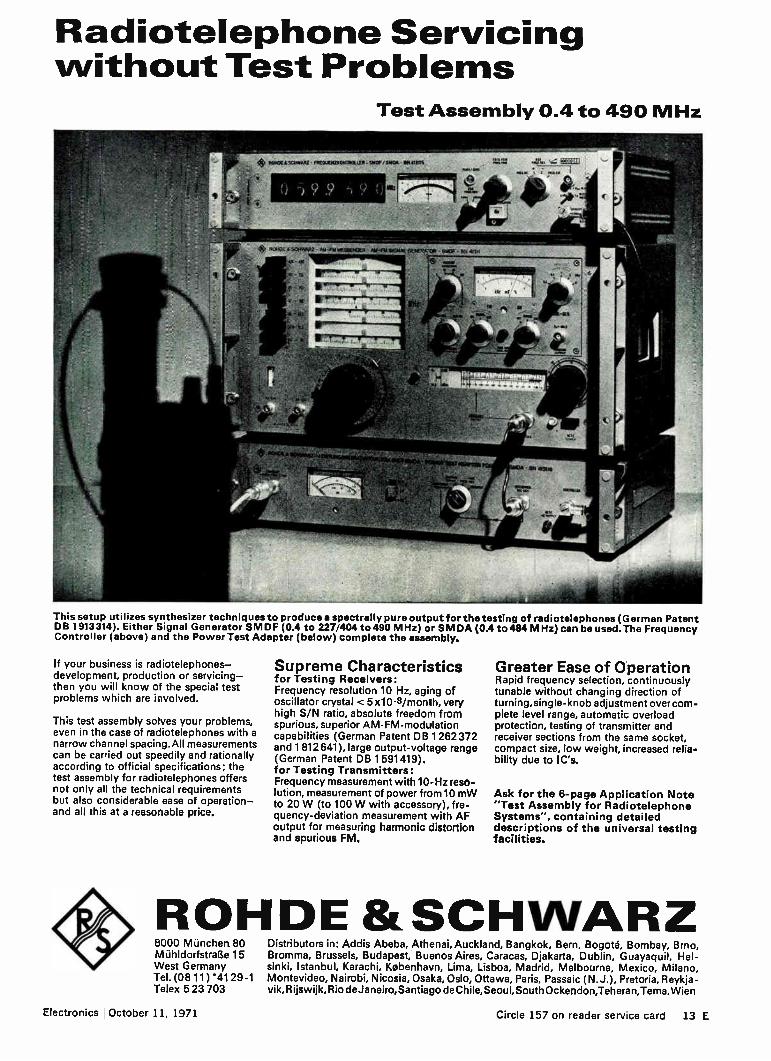
Radiotelephone Servicing without Test Problems
Test Assembly 0.4 to 490 MHz
This setup utilizes synthesizer techniques to produce a spectrally pure output for the testing of radiotelephones (German Patent DB 1913 314). Either Signal Generator SMDF (0.4 to 227/404 to 490 MHz) or SM DA (0.4 to 484 MHz) can be used. The Frequency Controller (above) and the Power Test Adapter (below) complete the assembly.
If your business is radiotelephones— development, production or servicing— then you will know of the special test problems which are involved.
This test assembly solves your problems, even in the case of radiotelephones with a narrow channel spacing.All measurements can be carried out speedily and rationally according to official specifications; the test assembly for radiotelephones offers not only all the technical requirements but also considerable ease of operation— and all this at a reasonable price.
Supreme Characteristics for Testing Receivers: Frequency resolution 10 Hz, aging of oscillator crystal < 5 x10 -8/month, very high S/N ratio, absolute freedom from spurious, superior AM-FM-modulation capabilities (German Patent DB 1 262 372 and 1 812 641), large output-voltage range (German Patent DB 1591419). for Testing Transmitters: Frequency measurement with 10-Hz reso-lution, measurement of power from 10 mW to 20 W (to 100 W with accessory), fre-quency-deviation measurement with AF output for measuring harmonic distortion and spurious FM.
Greater Ease of Operation Rapid frequency selection, continuously tunable without changing direction of turning, single-knob adjustment over com-plete level range, automatic overload protection, testing of transmitter and receiver sections from the same socket, compact size, low weight, increased relia-bility due to IC's.
Ask for the 6-page Application Note "Test Assembly for Radiotelephone Systems", containing detailed descriptions of the universal testing facilities.
ROHDE &SCHINARZ 8000 M ünchen 80 Mühldorfstralle 15 West Germany Tel. (0811) 41 29-1 Telex 5 23 703
Distributors in: Addis Abeba, Athenai, Auckland, Bangkok, Bern, Bogotà, Bombay, Brno, Bromma, Brussels, Budapest, Buenos Aires, Caracas, Djakarta, Dublin, Guayaquil, Hel-sinki, Istanbul, Karachi, Kobenhavn, Lima, Lisboa, Madrid, Melbourne, Mexico, Milano, Montevideo, Nairobi, Nicosia, Osaka, Oslo, Ottawa, Paris, Passaic (N. J.), Pretoria, Reykja-vik, Rijswijk, Rio deJaneiro,Santiago de Chile, Seoul,South Ockendon,Teheran,Tema,Wien
Electronics October 11, 1971 Circle 157 on reader service card 13 E

5
now you can study a microsecond event in a multi-hour recording
If you've ever tried to trace a transient, you'll welcome this unique recording technique.
It starts with the basic ANA-LOG 7, a seven channel analog magnetic tape recorder. To this you add the unique Microviewer rotary scanning head shown in the photo above.
The combination works like this. You feed the output of the ANA-LOG 7 to an oscilloscope and then playback until the transient you've recorded shows up, momentarily, on the screen.
The tape is then stopped and the Microviewer started. As the Micro-viewer reproducing head rotates, the transient signal will now appear as a 'stop action' image on the oscilloscope.
All seven tracks on the tape, up to a maximum of four at a time, can be seen in this manner.
You get easier location, easier display, without the problems of winding and rewinding the tape.
The ANA-LOG7 with the cover
removed to show the endless loop cartridge. This has a cycling
time of 2.5 s to 10 mins depending on the tape speed. ANA-LOG 7 can also be used for
battery operation with a standard built-in converter.

Not only more convenient, also much more economical
The alternative method of tracing a transient is to record the whole test using UV equipment. Although UV recorders are cheaper to buy than magnetic tape, they are more expensive to run, costing around
0.27 per meter. If you were recording 10 kHz data,
which is not high for transient analysis, the UV recorder would eat up paper at the rate of S 16 per minute. After 300 minutes the purchase price difference between the two types of recorder would be closed.
And after that magnetic tape recording would not only be more accurate, more flexible and more convenient, but also cheaper.
Magnetic tape — greater recording flexibility We think it's logical to record
electrical transducer signals on an electronic instrument.
Results can be played back and measured on an oscilloscope or spectrum analyser or even stored into a computer after digitizing.
Signals can be easily modified. Differentiated or integrated for example. A permanent visual record can be
obtained by replaying the tape at
the slowest speed, 15/16 in/s, and re-recording on a conventional chart recorder.
By recording at low speed and playing back at high speed, the effective frequency difference of two signals can be multiplied, simplifying their separation for analysis.
Only with magnetic tape is such recording flexibility possible.
This unique delay loop accessory allows a variable delay of up to 15 seconds between two signals. In this way, time separated events can be simultaneously displayed on anDscilloscope or recorder.
Magnetic tape — endless recording applications
The endless loop tape cartridge accessory enables long term recording without tape rewinding.
The cartridge consists of a metal
box, closed with a transparent lid and used in the same way as a normal tape cartridge. It works for all seven channels and at all tape speeds.
The length of loop is obtainable from 2 to 15 meters, giving loop periods of about 2.5 seconds to 10 minutes.
Applications of the endless loop cartridge are numerous. Repeated replays for further study. History recording. And as a delay line having longer delay times and wider bandwidths than most electronic systems.
Why ANA-LOG 7? Having seen the advantages of
magnetic tape recording you should now make a competitive survey. We're confident you'll find the ANA-LOG 7 unbeatable. We'd like to send a detailed brochure to prove it. This is our address: N.V. Philips' Gloeilampenfabrieken, Electro-acoustics Division, Eindhoven, The Netherlands.
PHILIPS INSTRUMENTATION RECORDING EQUIPMENT
PHILIPS Circle 158 on reader service card

G ELECTRO
OERZ
THERMOSCRI PT Bimetal Temperature Recorder with clockwork
WITHOUT CONNECTING LEADS — IN DIRECT CONTACT WITH AMBIENT MEDIUM — THERMOSCRIPT RECORDS TEMPERATURE VARIATIONS
• during shipment and storage of perishable goods g> in heating, air conditioning and drying installations
e in application below ground and in open air
THERMOSCRIPT after 32 days use
THERMOSCRIPT offers:
e Bimetal movement — Accuracy ±1 0 C Metal case constitutes temperature sensor
e Three measuring ranges at choice Type 83 80 10 0 . .. +65° C Type 83 80 12 —20... + 45° C Type 83 80 14 —40... +25° C
e Minimum and Maximum Indices
e Chart drive with clockwork Running time 32 days — Accuracy better than 1% of recording time
e Any position of use — no maintenance g> Small size — 165x92x46 mm e Low weight — approx. 1 kg (2.2 lb)
Ask for list C-7.11
GOERZ ELECTRO Ges.m.b. H., A-1101 Wien - Postfach 204 - Telex: 13161

UNFORGETTABLE MEMORIES
CAPACITIES: 3,5 million bits to 180 million bits
ACCESS TIME: 4 milliseconds or 10 milliseconds
SA 7000 - For high speed mass memory systems
DISESTOR 510 — The first mass memory system that combines fast head-per-track
versatility of interchangeable discs.
SA 8000 - Eight mass memory systerns.
SA 7000 10 megabits
to 180 megabits
average access time 10 milliseconds
DISESTOR 510
10 megabits average access time
10 milliseconds
access with the
SA 8000 3,5 magabits
to 35 megabits
average access time 4 milliseconds
FOR ASSISTANCE in defining your system memory requirements, or to tailor an interface
to your unique needs, we suggest that you "borrow"
a General Instrument memory engineer.
GENERAL
INSTRUMENT
GENERAL INSTRUMENT EUROPE SYSTEMATICS DIVISION
P.zza Amendola, 9 20149 MILANO
tel. 469.77.51-2-3-4-5 telex 31454 - cable GINEUR
GENERAL INSTRUMENT (U.K.) Ltd. - Stonefield Way - RUISLIP Middlesex - HA4 OJT. - telephone: 01-845.12.88 - telex: 22.623
GENERAL INSTRUMENT DEUTSCHLAND GmbH - Neumarkter Strasse, 61 - (8) MUNCHEN 80 - telephone: 45.22.39 - telex: 524.523
GENERAL INSTRUMENT FRANCE - 11/13 Rue Gandon - 75 PARIS 13e - telephone: 588.74.31 - telex: 26.766
Agents: Austria, Belgium, Denmark, Holland, Israel, Norway, Sweden, Switzerland
-4-- Circle 159 on reader service card Circle 160 on reader service card 17 E

WHY DO KEITHLEY ELECTROMETERS WIN ALL THE KUDOS? Simple—they outperform all others.
We offer more sensitivity, stability and versatility, in more models and accessories, to make sure you get the most for your money.
Take our solid-state 610C. For an economical $610, it measures 200 uV to 100 V with 10 14 ohms input resistance, currents as small as 6 x 10-15 ampere, resistance to 10 14 ohms and charge from 10 -13 to 10 -5 coulomb. Our battery operated 602 goes for $670, operates at 1500 volts off ground and provides per-formance similar to the 610C. Both models are available from stock.
For your digital needs, the systems-compatible 615 gives unparalleled accuracy and conven-ience, including optional BCD output. Other Keithley Electrometers and Picoammeters of-fer you many choices of performance and price. We've been innovating electrometer values like these for over 20 years. They've created an industry-wide reputation for kudos-winning performance. Win some kudos your-self. Call your Keithley Sales Engineer for technical literature and demonstrations. Or contact us direct. Keithley Instruments, Inc., 28775 Aurora Road, Cleveland, Ohio 44139. Telephone: 216/248-0400. In Europe: 14, Ave. Villardin, 1009 Pully, Suisse. Prices slightly higher outside the U.S.A.
KHIM H "V"
Users call electrometers "KEITHLEYS" ... the nicest KUDOS yet
18 E Circle 161 on reader service card Electronics October 11, 1971
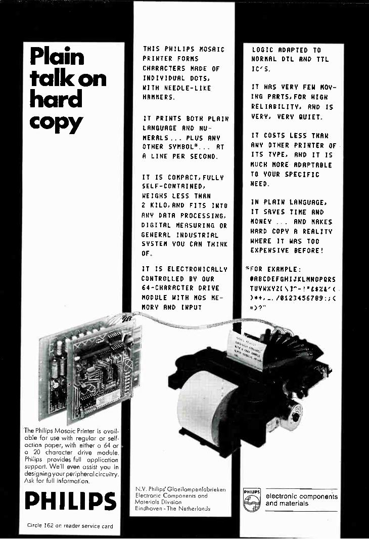
Plain talk on hard copy
e7" -1
The Philips Mosaic Printer is avail-able for use with regular or self-action paper, with either a 64 or a 20 character drive module. Philips provides full application support. We'll even assist you in designing your peripheral circuitry. Ask for full information.
PHILIPS
THIS PHILIPS MOSAIC
PRINTER FORKS
CHARACTERS MADE OF
INDIVIDUAL DOTS,
WITH NEEDLE-LIKE
HAMMERS
IT PRINTS BOTH PLAIN
LANGUAGE AND NU-
MERALS... PLUS RNY
OTHER SYMBOL* AT
R LINE PER SECOND
IT IS COMPACT, FULLY
SELF-CONTAINED,
WEIGHS LESS THAN
2 KILO,AND FITS INTO
ANY DATA PROCESSING,
DIGITAL MEASURING OR
GENERAL INDUSTRIAL
SYSTEM YOU CAN THINK
OF
IT IS ELECTRONICALLY
CONTROLLED BY OUR
64-CHRRRCTER DRIVE
MODULE WITH NOS ME-
MORY AND INPUT
N.V. Philips' Gloeilampenfabrieken Electronic Components and Materials Division Eindhoven - The Netherlands
LOGIC ADAPTED TO
NORMAL DTL AND TTL
IC , S.
IT HAS VERY FEW MOV-
ING PARTS, FOR HIGH
RELIABILITY, AND IS
VERY, VERY QUIET,
IT COSTS LESS THAN
ANY OTHER PRINTER OF
ITS TYPE, AND IT IS
MUCH MORE ADAPTABLE
TO YOUR SPECIFIC
NEED.
IN PLAIN LANGUAGE,
IT SAVES TIME AND
MONEY . . AND MAKES
HARD COPY R REALITY
WHERE IT WAS TOO
EXPENSIVE BEFORE!
%FOR EXAMPLE:
#ABCDEFGHIJKLMNOPQRS
TUVWXYZI\l"-!"£$%e(
)*+,..../8123456789:::
=>?"
PHILIPS
e•-•::. •
electronic components and materials
Circle 162 on reader service card

,
111:71411:11‘
automation: in the key positions
the answer is PIGNONE SUD
A success proven in hundreds of installations throughout the world where Pignone Sud equipments are playing the leading role both in regulation and control of industrial process. Control systems devised for the solution of all your problems today and tomorrow.
• Process controll computers • Electronic remote control systems • Electronic and pneumatic instrumentation for
measurement and control • Control and safety-relief valves • Valves for nuclear plants
Head offices and factory: Bari, Italy Sales management:
C.so P.ta Romano, 68 • 20122 Milan. Italy Telex 31246 (ENI for Pignone Sud)
PIGNON[ SUD
20 E Circle 163 on reader service card Electronics October 11, 1971

New products international
Minicomputer runs checkout of stereo amplifiers Japanese test system
for development, production
stages exercises unit over
wide frequency, power range
Faced with an average annual wage increase of 18%, Japanese manu-facturers of consumer electronics are increasing their use of mini-computer-controlled test systems. Meguro Denpa Sokki hopes to take advantage of this trend with its new automatic test system for stereo amplifiers. The system, designated the MS-
8002, produces the complete char-acteristics of a stereo audio ampli-fier during development, and it can also 'be used for production testing. It takes a skilled technician a half day or longer to measure manually the characteristics of an amplifier over a wide range of frequency and power output for many com-binations of control settings. With the automatic tester, the number of measurement points is greatly increased, the time for measure-ments is reduced to less than half, and a skilled technician is not needed. Also, accuracy is improved, the company says. Automatic type-out from digital systems eliminates differences among technicians as well as errors inherent in analog test equipment. The automatic system uses an
unskilled operator as a link to close the loop between the system and the amplifier being tested. The op-erator sets the amplifier controls to the appropriate positions for the start of the test, electrically con-nects the system to the amplifier,
Electronics October 11, 1971
and then pushes the start button. The test continues until it is neces-sary to reset the controls of the amplifier, at which point the com-puter stops the test and gives in-structions to the operator on a dis-play board. The operator resets the amplifier controls, pushes a restart button, and the test continues. Measurements of noise are also
made, with the amplifier input terminals short circuited and open circuited. Furthermore, a check of maximum music power is made, with the amplifier operating from an external programable regulated power supply. The external supply is needed because the voltage of the amplifier's own power supply drops as steady state output power used for testing increases. Frequency range over which dis-
tortion can be measured is 10 hertz to 99.9 kilohertz. Distortion meas-urement range is 0.1% to 30%. The programable attenuator used in the system has a range of 0.1 to 99.9 decibels, exceeding the re-quirements of most audio testing procedures.
Price of the system, including the
computer and a teletypewriter, is $50,746. The computer represents almost one-half of the price. Next year, Meguro will offer a high-fre-quency option that will enable users to test automatically a com-plete high-fidelity tuner-amplifier system from the antenna input terminal to the speaker output terminal. This option will more than double the price. Programable components. Many
components of the system are standard test instruments made by Meguro, including the programable audio frequency oscillator, pro-gramable distortion meter, pro-gramable attenuator, programable power supply, and monitor oscillo-scope. Other units are special items made by Meguro. The two most important are the interface between the computer and the system, in-cluding the display showing in-structions for the operator, and the adapter with leads for making con-nections to the stereo amplifier that is under test. Two important components of
the system are purchased from other companies. The analog-to-
Point by point. Tester checks amplifier at various control settings.

New products international
digital converter is a standard Yoko-gawa-Hewlett-Packard digital volt-meter with a range of dc to 10 megahertz alternating current. This unit has a digital display which
Connector model mcN3 has a thin in-sulator and a guide that prevents insertion with the contacts arranged in the wrong order. There are 35 con-tacts with a pitch of 4 mm. Hirose Electric Co. Ltd., 5-5-23 Osaki, Shina-gawa-ku, Tokyo, Japan [443]
is normally ignored by the opera-tor, because all results are printed by the teletypewriter, and the unit is used only as an a-d converter. The other purchased component
Multitester Ta-700 offers range of ap-plications for aligning television re-ceivers, audio equipment, communica-tion apparatus. It also functions as transistor tester. Sanwa Electric In-strument Co. Ltd., Dempa Bldg., 2-4-4 Sotokanda, Chiyoda-ku, Tokyo [444]
is the Hitachi Ltd. Hitac-10 mini-computer, which is normally sup-plied in this system with a memory of 8,000 words of 16 bits each. The teleprinter is supplied by Hitachi
•
•
'
X-Y tracker type C426 has a sampling rate of 15.75 kHz, automatic and man-ual modes of operation, and output voltage in the X-Y coordinates with origin on the center of picture. Mama-matsu TV Co Ltd., 1126 Mamamatsu, Shizuoka, Japan [445]
EMT know how to help radar
CRC 21

but manufactured by Teletype in the U.S. Complete software for the system will be supplied to users, together with sufficient information to select the subroutines and to
Two-pen recorder model vP-654s offers 1 mv full scale sensitivity, no external induced noise, a pressure inking sys-tem, and two input amplifiers. Matsu-shita Communication Industrial Co. Ltd., 880 Tsunashima-cho, Kohoku-ku, Yokohama, Japan [446]
change their sequence. Options include a programable
intermodulation distortion meter, a digital-to-analog converter and an X-Y recorder. An additional 4,000-
Potentiometer J80s has a life of more than ten million cycles, and low rota-tional torque of less than 7 g-cm. Ac-curacy is ± 0.1% independent linear-ity. Copal Electronics Co. Ltd., 26, Shiba-Nishikubo, Sakuragawa-cho, Minato-ku, Tokyo [447]
word memory unit and additional software are needed to operate the X-Y recorder.
Meguro Denpa Sokki K.K. 2-1-5 Chuo-cho, Meguro-Ku, Tokyo, Japan [441]
Miniature rectangular connectors are designed for rack-and-panel and cable-chassis applications. The units feature equally spaced, high density contacts. Daiichi Denshi Kogyo K.K., 2-10-12 Yoyogi, Shibuya-ku, Tokyo, Japan [448]
designers help themselves. Help yourself to EEV duplexer know-how.
It comes in all shapes and sizes, at most frequencies and powers. And you can rely on every EEV cell for extra-long life and high quality. Many are available from stock — for others we'11 give firm delivery dates.
EEV have a lively record of success in advanced duplexer and component design . . . witness our L, S, C and X band balanced duplexers and our L, S, C and X band protector cells. EEV 's range of primerless devices is one of the best, giving full-time protection without keep-alive.
EEV know how to help you with your systems, too. We have computer-aided design groups, ad-vanced manufacturing capability, and one of Europe's most up-to-date test facilities. Send us your specifi-cation and we'11 advise you. Or perhaps you just need data sheets at this stage. Either way, please4 write or telephone and we'11 be glad to help.
EEV know how. @ELECTRIC VALVE CO LTD, Chelmsford, Essex, England CM1 2QU. Tel : 0245 61777. Telex: 99103. Grams: Enelectico Chelmsford
Circle 164 on reader service card

DAC's
(11
new 12-BIT
ADC
'99
8-Bit Binary 2-Digit BCD 10-Bit Binary 3-Digit BCD 12-Bit Binary
. . . $19
. . . $19
. . . $29
. . . $39
. . . $49
ADC's 8-Bit Binary . . . $49 10-Bit Binary . . . $69 12-Bit Binary . . $99
(Single Quantity Prices)
FEATURES: Ready to use (need only de power) DAC settling time ... from 2 ps ADC conversion times ... from 15 ADC. quanitizing error ...±1/2 LSB Absolute accuracy ... >±.1/2 LSB Linearity ... from 0.01% Tempco ... 20 ppMr C Operating temp ... 0°C to 70°C Analog ranges ...
±.10V, ±5V, OV to 10V DTL/TTL compatible ADC - parallel & NRZ serial output All models pin-for-pin compatible
CALL TODAY! FRANCE — 722-70-40
WEST GERMANY — lcking (08178) 35285 JAPAN — 03-503-3711
Wellex , NC.
A SUBSIDIARY OF REDCOR CORP. 1000 Chalon', Road • Conco,d, Caldohna 94520
New products international
Motor model mR13Eo01-01 is a minia-ture unit with an electronic governor for use in minicassette recorders. Vol-tage is from 4.5 to 9 v, speed is 3,000 rpm, and maximum torque is 3 g-cm. Hosiden Shoji Co. Ltd., 1-4-33 Kit-akyuhoji, Yao, Osaka, Japan [449]
High frequency oscillator type GET-
42SP is mainly for measuring trans-mission line filters, wide band ampli-fiers, and other test signal sources. Range is 1 to 1,000 Num. Ando Elec-tric Co. Ltd., 4-19-7 Kamata, 0th-ku, Tokyo, Japan [450]
loffluitiammilmmiffliam
Transmission characteristic measur-ing instrument called Selemo provides synchronous testing over a frequency range of 20 hertz to 2 megahertz. An-ritsu Electric Co. Ltd., 4-12-20 Mina-miazabu, Minato-ku, Tokyo, Japan [451]
Head-per-track magnetic disc stor-age unit called Minidisc has a capacity of up to 6.4 megabits. Applications are in the low capacity range, and average access time is 8.4 ms. Scientific Data Systems Israel Ltd., P.O. Box 5101 Haifa, Israel [452]
Linear operational amplifier in lc mode is packaged in a To-99 DIP. Fea-tures include internal frequency com-pensation, short circuit protection, and offset voltage null capability. Ancom Ltd., Devonshire St., Cheltanham 01.50 3yr, England [453]
55,7 vIDIO lO,C11. C.1
o ,e
ir
Color test signal generator model PM 5522 is intended for factory align-ment of the crominance section of PAL TV receivers. Unit checks delay line, demodulator and matrix areas. Phil-ips SpA, Milano, Piazza Quattro No-vembre 3, Italy [454]
24 E Circle 165 on reader service card Electronics October 11, 1971

13.0tEiC
you've got 'em on your doorstep!
Stolec's extensive range of thumbwheel switches are in world
demand - and world supply. Sub-miniature, miniature, standard,
intermediate, to meet all requirements - or if your need is for
suppressors or logic probes - they're all as good as off-the-shelf
and on the way from any of our stockists listed below.
the thumbwheel switch people
!le HASTINGS • SUSSEX • ENGLAND • TELEPHONE HASTINGS 29692 • TELEX 95169
AUSTRALIA McMurdo (Australia) Pty Ltd, Victoria AUSTRIA Dipl-Ing Norbert Burisch, Vienna BELGIUM BTB, Brussels DENMARK Scansupply, Copenhagen FRANCE Usine Jeanrenaud, Dole GERMANY Megatron KG, Munich HOLLAND De Buizerd NV, 's Gravenhage HONG KONG Micro Electronics Ltd, Kowloon
ITALY Jeanrenatid Italia SPA, Rome JAPAN Okaya Electric Industries Co Ltd, Tokyo NEW ZEALAND David J Reid (NZ) Ltd, Auckland S AFRICA Eagle Electric Co (Pty) Ltd, Cape Town SWEDEN Gylling Teledata AB, Stockholm SWITZERLAND Arnherd AG Ing, Zcich USA Inter-Market Inc, Illinois ISRAEL RDT Electronics Engineering Ltd, Tel-Aviv
Electronics October 11, 1971 Circle 166 on reader service card 25 E

Ours are perfect teammates for you leading system builder DATA AMPLIFIER model 613 Designed for use on computers, data processing systems,
etc., this direct-coupled dc amplifier with differential input circuit satisfies highest level of performance. Tests prove consistent characteristics of ---
Input impedance: lomn 0 Gain accuracy: -±0.1% D Gain: x5000, 2000, 1000, 500, 200, 100 & 50 (Att. of 1/100 provided) D Measurable voltage range:
101.4V-20V D Frequency response: DC-20kHz -±10% at 10V p-p output 0 Common-mode rejection:110d13/50Hz
D Drift: 3 µ VrC, 10µV/day 0 Linearity: ±0.01% Output: -±10V, ±-100mA
It weighs 3kg and measures 192(H) x 51(W) x 350(L) mm.
• • GAIN
Ile•
100
•
01.(
s..••• v•IMOIA
me me
BANDWIDTH
1•• .
Lei
And there is a choice of gain selection types, manual and remote.
We are also read\r for some modification to best meet your requirements.
MINIATURE STRIP CHART RECORDER model 8C San-et engineering makes possible miniatur-ization of strip chart recorder just down to 11(W) x 6.5(H) x 24(0) cm a. rid 1.5kg... without reducing versatility and reliability.
It provides over 30 days continuous recording with dots on pressure sensitive
paper. Switches and controls are placed on the front panel thus allowing to be com-patible with most OEM systems; while there are five exclusive amplifier modules
for using it as an independent unit to record electrical, physical and chemical variables. Reasonable price is something extra.
For further information write to
A quarter-century experienced manufacturer of test & measuring instruments
AAA SAN-El SAN-EI INSTRUMENT CO LTD. 223-2, Nishi-okubo 2-chome, Shiniuku-ku, Tokyo 160, Japan
Cable: SANE I INSTRUMENT TOKYO Telex: 232-2426 (SANE I TOK) JAPAN
New products international
General purpose relay type 134 offers a resistance of less than 150 milliohms for 0.5 amperes, 3 y de. Life is more than 10 million operations, and dielec-tric strength is 1,500 V ac. Fujitsu Ltd., 2-6-1 Marunouehi, Chiyoda-ku, Tokyo, Japan [455]
Multipurpose meter measures voltage in ac and de modes (up to 400 and 30 respectively), phase sequence, ohms (from 0 to 5,0009), and verifies the continuity of electric circuits. Con-struction D'Appareillage, 8, Rue Jean Dollfus, Paris 18e, France [456]
Display unit model EV 8010 is for proc-ess monitoring, bridge balancing, X-Y displays, production control, and com-puter programing applications. Fre-quency response is from de to 1 MHz. Electronic Visuals Ltd., P.O. Box 16, Staines, England [457]
26 E Circle 167 on reader service card Electronics October 11, 1971

ic tester Sm-0005B checks ics with up to 16 pins in go/no-go mode. Input, output characteristics can be meas-ured with a meter, and maximum testing time is 850 ms. Kokuyo Elec-tric Co. Ltd., 1-36-15 Okayama Meguro-ku, Tokyo, Japan [4581
Computer peripheral called the Mini Burster is designed to separate printed-out documents, bursting con-tinuous stationary up to three parts a set, without removing the sprocket holes. Data-set Ltd., Ia. House, Put-ney, S.W. 15, England [459]
Dual four-input multiplexer type T 164 offers speed of 25 ns though delay, and is DTL and TTL compatible. It is available in three types of DIPS, plas-tic and ceramic, over varying tempera-ture ranges. SGS Group, Via C Olivetti, 1, 20041-Agrate Br., Milan, Italy [460]
This rotor belongs to the escap®26P DC micromotor
This ultra-light, bell-shaped rotor, consisting entirely of an unsupported coil of copper wire, offers a highly advanced solution for the problem of low-inertia micromotors.
Thanks to it, the Escap 26P micromotor develops 5 to 10 times more power than a conventional motor of the same dimensions. A voltage of 150 mV is enough to start it, and its efficiency amounts to 80%.
The Escap 26P micromotor (ra 26 mm) is particularly suitable for use in servo-systems. It is used in magnetoscopes, computer terminals and many other forms of apparatus in which high-per-formance micromotors are required.
We manufacture a wide range of motors including a number of special models, reducers and regulators. Let us know your specific requirements, so that we can suggest the most suitable solutions.
Reply coupon
Please send me information concerning your micromotors
Application contemplated:
Name (Company):
Address:
To be returned to:
Portescap Reno SA 165, rue Numa-Droz CH-2300 La Chaux-de-Fonds, Switzerland
Electronics October 11, 1971 Circle 168 on reader service card 27 E

New products international
THE INVISIBLE WIRE is produced by the
ULP-OM Plant turning out
25 km per hour of glass-insulated wire with the conducting core of various metals & alloys,
1.0 micron to 100.0 microns in diameter,
which is:
• suited for operation in aggressive fluids, vacuum, in a wide range of temperatures (— 200 C to + 550 "C)
• capable of conducting electric current of tremendous density — hundred and thousands of amperes per sq.mm
• extremely strong & flexible
There is nothing like the ULP-6M PLANT
to produce conductors for super-microminiaturized electric circuits and components: resistors, transformers, chokes, etc.
Exporter: V/0 TECHMASHEXPORT, 35, Mosfilmovskaya, Moscow V-330, USSR, Telex: 256
rt.e) TECHMASHEXPORT
De amplifier type 6L61 is designed for industrial applications, and fen-tures a floated input circuit and wide common-mode voltage range of de ±-1.5 kv. San-Ei Instrument Co. Ltd., 2-223-2 Nishiokubo, Shinjuku-ku, Tokyo 160, Japan [461]
Dual-beam synchroscope model DS-5016 features two identical differen-tial amplifiers with senstivity of 50 i.iv/cm. De offset operation is provided, and range is de 1 MHz, 3 dB. Iwatsu Electric Co. Ltd., 1-7-41 Kugayama, Suginami-ku, Tokyo, Japan [462]
Probe is for debugging logic systems in place of oscilloscope equipment. Indication of a high logic level is given by a lighted lamp at the end of the tool. Birch-Stolec Ltd., Pons-wood Industrial Estate, Windmill Rd., Hastings, Sussex, England [463]
28 E Circle 169 on reader service card Electronics October 11, 1971

Computer Manufacturers throughout the World choose OEM Products from MDS. Why?
The products are dependable and give a high performance.
The produas are price worthy and economical. The products are available on a large scale for all peripheral areas.
MDS Chain Printers
MDS Paper Tape Equipment
MDS — The Specialist in the Computer Periphery solves EDP Problems.
Great Britain: MDS-Data Processing Ltd OEM Marketing 50 Vauxhall Bridge Road London SW I Phone: 01-8 28 12 88 Telex: 0051-26 20 30
Germany: MDS-Deutschland GmbH OEM Marketing 190, WeinsbergstraEle D 5000 Koln 30 Phone: 52 30 71, Telex: 8 88 1969 Cable Address: Datarec KOIn
MDS Magnetic Tape
Handlers
MDS Lister Printers
France and Belgium: MDS-France S. A. OEM Marketing 90, Avenue des Champs Elysees 75-Paris 8è Phone: 2 25-5710, Telex: 29 516
MDS Drum Printers
• MDS Card Handling Equipment
OEM Marketing
The Netherlands and all other European countries: MDS-Nederland N. V. OEM Marketing 199, Van Leijenberghlaan, Postbus 7263 Amsterdam-Buitenveldert, Phone: 44 13 33, Telex: 14 392 Cable Address: Mohawk Amsterdam
USA and Canada: Mohawk Data Sciences Corp OEM Marketing Palisade Street, Herkimer, New York 13350 Phone: 315/86 76 000 Telex: 0023 09 39458
Electronics October 11, 1971 Circle 170 on reader service card 29 E

Rati's contactless components...
tailored to your special requirements. Contactless keyboards use modern solid state components to provide
bounce-free, long life operation. RAFI contactless keyboards provide the
reliability and high speed operation required for electronic data proces-sing, information transmission and
control systems. Custom or standard keyboard modules per ECMA or
DIN 2127 layout are available to fit
RAFI Raimund Finsterhiilz1
Elektrotechnische Spezialfabrik
798 Ravensburg/Württ. P. 0. Box 2060
Telefon 0751 / 89 - 1
Telex: 0732866
your specific requirements. The mo-dular construction permits use of as many as 25 illuminated and non-illu-minated keys in each row in either vertical or horizontal direction. Enco-ded keyboards are also available in mono-, dual- or trifunctions. Encoded keys are provided with two-key roll-over. When you need reliable, long life, bounce-free keys or key-boards, we're the people to see.
125 From Rafi's top line
Ask for detailed information on: D signal lamps D actuators D keyboards
contactless components
New products international
Contactless meter relay RL series is composed of a light emitting diode and photo transistor. Built-in surge pro-tecting circuit shields semiconductors from damage. Kuwano Electrical In-struments Co. Ltd., 890 Mizonokuchi, Kawasaki, Japan [464]
Pin header/plug A23-2054 is compa-tible with most 24-lead 0.6-in, pitch dual in-line sockets and provides a plug-in housing for discrete compo-nents. Device may be used as a free plug. Jermyn Industries, Vestry Es-tate, Sevenoaks, Kent, England [465]
Miniature capacitors are for radio and TV applications. Designated series 244, they are packaged in aluminum, and operate over the temperature range of —40 to +85°C. General Instrument .Europe SpA, 20149 Milano, P.zza Amendola 9, Italy [466]
30 E Circle 171 on reader service card Electronics ' October 11, 1971
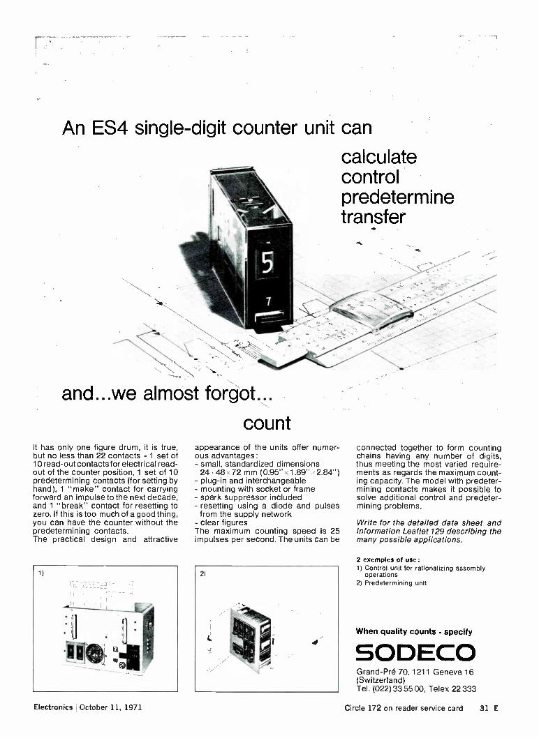
An ES4 single-digit counter unit can
calculate control predetermine transfer
and...we almost forgot..
count It has only one figure drum, it is true, but no less than 22 contacts - 1 set of 10 read-out contacts for electrical read-out of the counter position, 1 set of 10 predetermining contacts (for setting by hand), 1 "make" contact for carrying forward an impulse to the next decade, and 1 "break" contact for resetting to zero. If this is too much of a good thing, you can have the counter without the predetermining contacts. The practical design and attractive
1)
.1 I
appearance of the units offer numer-ous advantages: - small, standardized dimensions 24 • 48 ‘. 72 mm (0.95" x 1.89" .•• 2.84") - plug-in and interchangeable - mounting with socket or frame - spark suppressor included - resetting using a diode and pulses from the supply network - clear figures The maximum counting speed is 25 impulses per second. The units can be
2)
connected together to form counting chains having any number of digits, thus meeting the most varied require-ments as regards the maximum count-ing capacity. The model with predeter-mining contacts makes it possible to solve additional control and predeter-mining problems.
Write for the detailed data sheet and Information Leaflet 129 describing the many possible applications.
2 exemples of use: 1) Control unit for rationalizing assembly
operations 2) Predetermining unit
When quality counts - specify
SODECO Grand-Pre 70, 1211 Geneva 16 (Switzerland) Tel. (022) 33 55 00, Telex 22 333
Electronics October 11, 1971 Circle 172 on reader service card 31 E

a lot of pot; cheap it's not There's nothing quite like it: the ESI DEKAPOT". You build it into your system or instrument because you want honest-to-Kelvin-Varley wirewound precision with long term stability: 20 ppm linearity to be precise. Three or two decades and a 100-position potentiometer on a single panel dial. Wide value range. Off shelf delivery. $105-$180 and your customer will never regret it.
(Want a custom assembly? Ask.)
ELECTRO SCIENTIFIC INDUSTRIES
13900 N.W. Science Park Drive Portland, Ore. 97229 Phone: 503/646-4141
Circle 173 on reader service card
Wherever you are in the world of electronics, the best place to reach your
local market is in the international edition of Electronics magazine.
New products international
Interference measurement transducer RFT is for rf applications. When con-nected to a 50 ohm line, resonances are eliminated, and frequency is from 0.1 mHz to 100 MHz. Control Tech-nology Ltd., Meeching Rd., Newhaven, Sussex, England [467]
General purpose counters type 5241A offer direct reading over 0 to 75 mHz frequency range, and measure to 18 GHZ with plug-ins that go directly into the front panel. Yolcogawa-Hewlett-Packard Ltd., Ohashi Bldg., 1-59 Yo-yogi, Shibuya-ku, Tokyo 151, [468]
Digital multi-purpose real time cor-relator model NJZ-260 offers a resolu-tion of 256 points, signal delay time of 1 is to 20 s, and range of 0.00004 HZ to 500 kHz. Japan Radio Co., 25 Sakuragawa-cho, Shiba Nishikubo, Mitanot-lcu, Tokyo, Japan [469]
32 E Electronics October 11, 1971

AOIP multifonction digital voltmeters
always find them...
The VNIM voltmeter, with its interchangeable plug-in
units, is very sensitive. Whatever the measures are : D.C. A.G. Volt or resistance, its 1 !..e.V, 1 p.12 are ex-
ceptional. It is accurate : 5.10-4 of the reading value for the basic unit. This new AOIP instrument may be supplied with 23 ranges in 4 plug-in units. Its compact-ness is very interesting : height : 4 units - 1/2 19" rack.
Its characteristics are remarkable : 12 000 measuring points, floatting input, memorized display, variable sample rate, option : B.C.D. output, and so on ... advan-ced technology.
mesures
Order for :
• information on the digital voltmeter VNIM
• leaflet on our "NEW PRODUCTS"
Firm
Name
Function
Street Phone
Town . Dpt
'Tour de Lyon" 177 à 185, rue de Bercy, 75-PARIS 12. BP. 301 Paris 13. - Tel.. 345-22-37
Represented in 34 countries
Electronics ' October 11, 1971 Circle 174 on reader service card 33 E

Nortronics' comprehensive line of 7 and 9 channel, 1131111-compatibl heads for ½' tape are specified b leading manufacturers all ove the world.
Maybe that's because of extra' features such as our terminal con-nector which provides rapid head plugability. But we also think it's due to Nortronics' unique ability to design the right head and deliver it in prototype or production quanti-ties anywhere in this world.
Write for detailed technical infor-mation on Nortronics heads for digital applications today!
world's leader in magnetic heads
Brussels 1050, Belgium Phone: 73-54-17 Telex: 25107
European Operations Of
Nortronics Company, Inc., Minneapolis, Minn. USA.
New products international
Series 703-3895 (wire wrapping) and series 703-3787 (soldering) 18-pin sockets are available with gold- or tin-plated contacts. They are dual in-line packaged. Cambion Electronic Prod-ucts Ltd., Castleton, Nr. Sheffield 830 2wft, England [470]
Frequency meter-tachometer models MT-F4 and PAT-F6 employ transistor-transistor logic and have binary coded decimal information encoded in 1, 2, 4, and 8 bits. Europeenne D'Etude Electronique Pour la Phisque, 9, Rue Mont-Louis, Paris 11e France [471]
Monolithic voltage stabilizer SFC 2376 Pc in a mini DIP has input voltage of 9 to 30 volts. Power limiter protects element against overload. Sescosem Halbeiter cmbii & Co. icc, D-8000 Munich 25, Fallstrasse 42, Germany [472]
Photocell lamp type cdse has a 60 dB output ratio, and temperature charac-teristics vary inversely with those of LEDs. Applications include volume con-trol, circuit protection. Moririca Electronics Ltd., 205, Totsuka-cho, Totsuka-ku, Yokohama, Japan [473]
Electrolytic capacitors W.200 series are wire ended type, and applications include most coupling, decoupling, or power supply smoothing requirements. Capacitance is from 2.2 pf to 0.01 F. 001. Ltd., Hanworth Lane, Chertsey, Surrey, England [474]
011111111 VOLT-01111 IIETER
«
Digital voltage and ohmmeter model MV-51 has an accuracy of 0.1%, and dual slope and input floating systems. Input impedance is 1,000 megohms or more. Asahi Keiki Co. Ltd., 1-15-13 Shimomaruko, Ohta-ku, Tokyo, Japan [475]
Circle 175 on Reader Service Card
34 E Electronics October 11, 1971

UP! Electronics International ad pages
Wherever you are in the world of electronics, the best place to reach your
local market is in the international edition of Electronics magazine.
109
222
252
442
509
1966 67 68 69 1970
Electronics Our Readers Are Changing
The World.
New
DIODES from AEI Semiconductors
Controlled Avalanche Diodes * 0 Kilowatt reverse power dissipation * 3 Specified Minimum Avalanche Voltage — 1000V: 1200V; 1400V: * Maximum Avalanche Voltage —1800V. * 3 Current Grades —2.5A; 6.0A; 11.5Amp.
Reverse Polarity types available. * Surge Current —100A; 130A; 150A; * Approved to BS93000667 and C668 for assessed quality and reliability.
High Temperature Diodes Device Series No: liK'03A 111.03A Surge Current — 10mS at 175 C 260A 200A Repetative Peak Reverse Voltage Range 120-1400V 120-1400V Mean Forward Current at 150 C 13A 9.5A Polarity Stud either Anode or Cathode
Low Cost 70-100 amp Diodes Device Series No M70 M100 Surge Current 1000A 1300A Mean Forward Current at 90 C 75A 100A Reverse Voltage VRsm range 50 800V 50-800V Polarity Stud either Anode or Cathode 25 up price from 75p 100p
Low cost Diode Bridges Device Series No . PM /Ail PM6A0 Configuration Full Wave Diode Pair
Bridge Surge Current at 150°C 150A 150A Current Output 16A at 75'C 10A per diode
at 60 C Voltage VFIRm 150V-1300V 150V-1300V Package Electrically isolated heatsink
— AMP type 250 FASTON terminals 100 up price from 130p 75p
Act now — contact AEI Semiconductors for further information; their close association with every aspect of industry enables them to talk your language.
AEI SEMICONDUCTOR are in control AEI Semiconductors Ltd., Lincoln, England. Telex 56163
6E610063
Electronics October 11, 1971 Circle 176 on reader service card 35 E

POWER
Need power? How much.., and what for? Just let us know, because the power people in Europe are Philips! Thyristors, for example. We've got a wide programme ranging from 1 A up to 160 A average current and voltages up to 1600 V. Where thyristors with special dynamic characteristics are required, in motor control for example, we offer devices with dV/dt up to 300 V/ps and di/dt of at least 100 A/ps. And their avalanche characteristics allow them to absorb large reverse transients without damage. But that's just the beginning.
PHILIPS
•
Other power products by Philips are...
Power zeners for voltage regulation or transient suppression. with ratings from 1.5 to 300 W
Triacs all the way up to 50A/1200 V.
Li Rectifier diodes from a few milliamps up to 400A/2000 V.. plus a complete selection of fast-recovery 1200-300 ns1 diodes.
O High-voltage rectifier stacks, including units rated to 150 kV, and controlled-avalanche units stacked in series for RF heating.
D Welding stacks, including the new "Ignistor" which replaces the ignitron in automatic resistance welding.
The Philips power range is probably much bigger than you think. We have a data file describing it all. It's yours. Just ask for it.
N.V. Philips' Gloeilampenfabrieken Electronic Components and Materials Division, Eindhoven - The Netherlands.
PHILIPS electronic components and materials
36 E Circle 177 on reader service card Electronics October 11, 1971

Electronics Newsletter October 11, 1971
Mexico staring hard
at U.S.-owned
'garage operations'
First balloon goes
up on Nixon R&D
plan for 1972
Pad relocation
goes into multiplier
Growth of U.S.-owned electronics operations in Mexico has accelerated faster than most people—and the Federal Government—realized. The total is now an astonishing 180, sources at the Department of Commerce estimate. This hasn't gone unnoticed by the Mexican government. There are now indications, based on industrial intelligence from Washington, that Mexico is planning to cash in on this growth by requiring owners to capitalize their operations to increase tax revenues. The extent of such operations was realized only recently by Commerce
when operations owned by "U.S. individuals" not previously tabulated were added to those held by U.S. corporations. The planned move by the Mexican government is not expected to make Mexico less attractive as an offshore assembly area to the U.S. semiconductor industry and some systems houses. It would take something drastic to slow this trend, sources say, something that isn't expected to happen. The Mexican government, they say, has taken no action against a large number of garage operations" packed with "wall-to-wall workers and, in some cases, no toilets," but is waiting for the industry to flourish—obtaining large orders and making delivery commitments—before it cracks down.
The Nixon administration's 1972 plan to dramatically raise America's declining investment in industrial R&D [Electronics, Sept. 27, p. 33] will emphasize a more liberal tax structure for rapid depreciation and writeoffs of new R&D equipment and facilities, rather than direct Federal investment. This is the conclusion drawn by some electronics industries leaders after hearing former Treasury official Murray L. Weidenbaum address the Electronics Industries Association's Fall Conference. Though economist Weidenbaum has returned to the faculty of Washington Uni-versity, St. Louis, his recent role as Treasury's assistant secretary for economic policy made him privy to the Nixon "game plans," and some listeners sensed a trial balloon in Weidenbaum's comments. Weidenbaum, who first gained prominence in the mid-60s as a critic
of the defense industry's profit structure, reflects Nixon Administration concern that "since 1964, this nation has been investing an ever smaller share of its national resources in R&D," and believes it can best be turned around by private sector financing encouraged by a high and rising level of economic activity; tax advantages such as those employed by Australia, Britain, Canada, Norway, Spain, and other West European countries; a broad approach to civilian markets with steady funding not limited to single economic sectors or mechanism such as existing institutes or universities; and more research on the R&D process itself.
Possibly the most sophisticated bipolar logic device available anywhere is being offered by the Microelectronic Products division of Hughes Aircraft. It's an eight-bit multiplier fabricated on a full 1.5-in.-diameter wafer using three layers of metal interconnects and a technique called pad relocation—a technique that Hughes officials believe is an improve-ment over Texas Instruments' discretionary wiring [Electronics, Oct. 13, 1969, p. 44]. The TTL multiplier is the first of a family to come from Hughes, and
consists of 52 full adders plus 96 additional gates for the equivalent of
Electronics !October 11, 1971 as

Electronics Newsletter
616 gates. Developers say it can form 8 million products a second, multi-plying two eight-bit numbers plus sign to get a 16-bit result plus sign each time it forms a product.
It's aimed initially at military computer applications, such as airborne computers, for fast-Fourier transforms or digital filtering, but Hughes hopes to expand on the concept to provide other devices for the com-mercial computer market.
Under-$100
calculator
set for January
Coast Guard search
for Loran resumes
TI to sell
TV tuning diodes
Electronic Arrays
sells calculator firm
The first under-$100 electronic calculator is on the way—and it's all-U.S. made. Ragen Precision Industries of North Arlington, N.J., will ship in early January the shirt-pocket-sized device. Designed with two C/MOS logic chips and an eight-digit liquid crystal display, it's a four-function device with floating decimal point. Ragen builds both electronics and display. Ragen has an order from Alexander's, a New York Department store
chain, for 20,000 calculators with an option for 20,000 more. Measuring 2% inches by seven-eighths of an inch by 31/, inches, it
will operate for more than a year on a 9-volt dry cell battery. The chips drive the liquid crystal displays directly.
The Coast Guard is trying once again to acquire a solid state Loran C transmitter. Originally christened Transloc, for transportable Loran C, and contracted to Sylvania, the program ran into technical and funding problems and was dropped. The new contract is with Megapulse Inc. of Waltham, Mass., and is for about $940,000 all told. The old Sylvania contract was about $6 million. The cost differential is largely due to a proprietary approach taken by Megapulse to generation of ultrahigh-power pulses, and to a relaxation of the Coast Guard's pressure for a transportable system. Due to be delivered before October 1972, the megapulse transmitter
would be a preproduction prototype capable of delivering more than 200 kilowatts effective radiated power—and, when paralleled with others like it, come up with the megawatt or more the Coast Guard requires.
Texas Instruments shortly will enter the market for tuning diodes for VHF and UHF television, a market it says can approach 1.5 billion units by 1980. TI products are electrically similar to parts Siemens has been making in Germany for a few years, but TI uses a standard small-signal glass diode package rather than the plastic used by Siemens and Motorola, the only other domestic producer.
This means TI can use its automated diode production line, which is becoming available as ICs take over computer diode applications.
International Calculating Machines, the calculator manufacturing sub-sidiary established late last year by Electronic Arrays, has been sold to Lago-Cale Inc. An outright sale was one of three options Electronic Arrays president Mois Gerson suggested recently [Electronics, Sept. 13, p. 38]. Lago-Cale is headed by Max Lagomarsino, son of the founder of Totalia Calculator Co. of Italy, who has sold calculators as a distributor in this country for years. Lago-Cale will sublease the ICM facility, use ICM designs, and retain the top management.
26 Electronics lOctober 11, 1971

Distributor Stocking Locations Arizona: Hamilton, Phoenix 1602) 269-1391 California: Hamilton, Mountain View (415) 961-7000 Hamilton, Culver City (213) 870-7171 Hamilton, San Diego (714) 279-2421 Hamilton, Culver City (213) 836-7200 Compar, Burlingame (415) 347-5411 Colorado: Intermark Electronics, Denver (3031 936-8284 Florida: Hamilton, Hollywood (3051 925-5401 Illinois: Hamilton, Schiller Park (Chicago) 13121 678-6310 Kansas: Hamilton, Prairie Village (Kansas City) 1913) 362-3250 Massachusetts: Electrical Supply, Cambridge 1617) 491-3300 Michigan: Hamilton, Detroit (313) 538-1003 Minnesota: Hamilton, Minneapolis (6121 920-5866 Maryland: Hamilton, Hanover (Baltimore) (3011 796-5000 Missouri: Hamilton, Hazelwood (St. Louis) (3141 731-1144 New Jersey: Hamilton, Cherry Hill (6091 662-9337 Hamilton, Cedar Grove (2011 239-0800 New Yoh: Semiconductor Concepts, Inc., Hauppauge (516) 273-1234 Hamilton, Syracuse 1315) 437-2642 Texas: Hamilton, Dallas (214) 638-2850 Hamilton, Houston 1713) 526-4661 Washington: Hamilton, Seal:): (206) 624-5930 Canada: Prelco Electronics, Montreal (514) 389-8051 £lectro Sonic Ind. Sales, Toronto (4161 924-9301 Hamilton, Montreal (514) 381-9127 Hamilton, Toronto (416) 789-1338
Representatives Arizona: Erskine Associates, Scottsdale (602) 263-7654 California: Cornpar, Burlingame (415) 347-5411 ilertrand-Zoolalien, Downey (2131 927-4406 Colotado: R. G. Enterprises, Denver (3031 744-2464 Florida: Hanson Associates, Melbourne (3051 727-7474 Illinois: Compar, Des Plaines (312) 775-0170 Massachusetts: Contact Sales, Inc., Lexington (617) 861-1550 Michigan: Compar, Garden City (313) 425-1235 Minnesota: Cornstrand, Inc., Minneapolis 1612) 560-5300 Missouri: Compar, St. Louis 1314) 562-3399 New Jersey: P.A.L. Components, Fort Lee 12011 461-6111 Thomas Associates, Haddonfield (6091 854-3011 New Mexico: Electronic Marketing, Albuquerque 15051 265-7837 New Yoe: P.A.L. Components, Greenvale (5161 484-4900 Compar, Albany (518) 489-7408 Compar, Cicero (3151 471-3356 Compar, Fairport (7161 271-2230 Compar, Endwell.(607) 723-8743 Ohio: Compar, Fairview Park 1216) 333-4120 Compar, Dayton (5131 890-9260 Texas: Carter Associates, Garland (214) 276-7151 Washington: Compar, Kirkland (2021 822-4191 Canada: Cantronics, Montreal (514) 733-0749 Cantronics, Ontario (4161 636-8311
International Representatives & Distributors Japan: Electro Marketing Corp., Tokyo 359-4521 Germany: Omni Ray GmbH, Munich (08111 513-2059 Omni Ray GmbH, Breyell (02153) 3261 Holland: Klaasing Electronics, Amsterdam 928444 or 928445 Sweden: Stenhardt Komponentbolag, Bromrna 08/37-29-45 Switzerland: Dimos AG, Zurich (051) 626140 Australia: Aurierna Pty. Ltd., Sydney (021 296-144
BIG TIME BRIGHT LIGHTS LED displays and Litronix have hit the big time. Our displays are in volume production. They are low cost and they are totally reliable. But don't just take our word for
it—try them. Compare the long run advantages in design, reliability, availability and cost. Take a look at a few of the LED stars now playing in full production at Litronix.
4 Outshines MAN-1 at lower cost. Introducing the Data Lit 10A, MAN-1 economy model. Has an amazing brightness of 500 foot Lamberts at 10 mA with 0.27 inch character. High quality, high volume new star with low price tag. $6.75.•
New 4 digit array. Small, bright display with .125 inch character heights and packaged for assembly economy. The Data Lit 34 is designed for low power and high brightness needs. It has four times the light emitting area
as the MAN-3A. You can end stack it for 8, 16, etc, etc, digit displays. $3.80 per digit.
4 Power Saver, Money Saver too. The Data Lit 8 display, with .24 inch character height, consumes half the power of the MAN-1 type display, and half the voltage drop. It's just as bright. Mounts on 0.3 inch centers. Priced at $6.25.
World Famous "Skinny DIP." Perfect display for small calculator and portable instruments. Has .120 inch characters and comes in a very thin,
DIP package, Data Lit 30, priced at $3.80.
4 Largest LED Display in the Known World. The Data Lit 6 is a 0.6 inch display with black substrate for fantastic distance viewing. Available in vertical mount that plugs into a standard .156 PC connector. Price: $14.00.
Other Wonderful LED products. We also have a full chorus of second source and proprietary LED displays, discrete visible and infrared emitters,
opto isolators and many other good things. Write for a copy of our product guide and a personally autographed photo of Carlos, producer of
the show. LED's will save you money in the long run.
O All prices in 1,000 piece quantities
The bright guys
litronix Litronix, Inc. • 19000 Homestead Road • Cupertino, California 95014 • (408) 257-7910 • TWX: 910-338-0022
Electronics/October 11, 1971 Circle 27 on reader service card 27

Your key to MOS performance - today!
full TTL compatibility without the • need for interface 1) MK 19(17 P components or 4x80-bit Shift Register
high voltage, high power clocks. Our clock is single phase, low capacitance and TTL compatible.
Our revolutionary production process, ion implantation, has quietly come of age. Today it's the most uncomplicated method for achieving such sophisti-cated benefits as low threshold voltages for TTL compatibility and depletion mode devices for state-of-the-art performance. Want proof? Then take a look at some examples of the advantages offered by MOSTEK's ion-implanted product line:
(1) Threshold Adjustment. Take our MK 1007 P 4x80-bit dynamic shift register, for instance. Ion implantation makes possible a low threshold device for zecuee 7
'
(2) Depletion Mode Devices. With ion implantation we have replaced en-hancement type load resistors found in all MOS/LSI to date with constant current, depletion devices. Results? See for yourself:
Low power over a wide supply range for memories such as our MK 4007 P RAM 's illustrated by the constant current cram n versus supply voltage shown in Figure 1. Power remains low with the depletion loads compared with the enhancement loads of the com-petitive 256-bit circuit.
2) MK 4007 P 256x1-bit RAM
FIGURE 1
Single SV supply operation. MOSTEK's MK 5002 P 4-digit counter/display circuit for instrumentation purposes can operate from a single +5V logic supply, drawing less than 25 mW, or from any supply from 4.5 to 20V! Ion implantation is the only processing tool capable of delivering this performance
from otherwise conventional, cost-effective P-channel LSI.
see- " •
" 3) MK 5002 P Counter/Display Circuit
Find out how easy it is to use the products and processes of the leader in MOS—MOSTEK. Call our home office at (214) 242-1494 and ask for marketing or applications assistance. Or contact your nearest MOSTEK sales office listed below, or your local Sprague office or distributor.
Ask for our new catalog!
OSTEK CORPORRT1011
An affiliate of Sprague Electric Company 1400 Upfield Drive Carrollton, Texas 75006
Sales Offices: 12870 Panama Street, Los Angeles. Calif. 90066, (213) 391-2746 515 S. West Street, Jackson, Michigan 49203, (517) 787-0508 60 Turner Street, Waltham, Mass. 02154, (617) 899-9107
Circle 28 on reader service card

Electronics review Significant developments er technolugy arid business
Current switch scheme promises fast LSI logic By cutting propagation
delay and power hunger,
HP configuration can yield
larger, faster logic chips
Logic designers working with Ls! circuits have a problem: their rule-book hampers both circuit size and performance because the logic con-figurations they are working with weren't intended for LSI circuits. DTL, TTL, and ECL configurations originally were designed as gate functions and not for highly inte-grated functions. The power/delay product of these circuit configura-tions is about 80 picojoules; a TTL gate typically has an 8-nanosecond propagation delay and requires about 10 milliwatts, and an ECL gate has a 0.9-nanosecond propagation delay and draws approximately 90 milliwatts. In terms of LSI, this means circuit size is limited by al-lowable propagation delay and package power limitations. Other roads. There are other logic
configurations, however, and an en-gineer at the Solid State Laboratory of Hewlett Packard Labs, Palo Alto, Calif. is working with one that cuts this power/delay product by a fac-tor of four. According to John E. Price, a member of the technical staff at Hewlett Packard labs, a power-delay product of only 5 pi can be obtained with a form of cur-rent switching logic. Price is working with two versions of such a gate: one employs positive feedback and the other a reference signal—the base of the transistor that's tied to the vo, output is connected to a 200-millivolt reference source instead of
being connected simply to vo,. Price says that with the current
switch configuration, "I've built gates that have a propagation delay of about 0.4 nanosecond and dissi-pate 10 mw, and gates that have de-lays of 2 nanoseconds and dissipate 2.5 mw. The basic figure of merit re-mains around 5 pi." HP's interest in the high-speed circuit could be for new calculator circuits, high-speed counters, or high-frequency oscillo-scopes, but Price won't comment on this. Price's work will be described at the International Electron De-vices meeting in Washington.
Both circuits' configurations have been built with both conventional phosphorous-doped and arsenic-doped emitter structures [Electron-ics, Sept. 13, p. 36]. The arsenic emitter devices offer a propagation delay of from 0.4 to 0.6 nanosecond with power dissipation from 6 to 10 mw while the conventional phos-phorous emitter structures have de-lays of from 0.4 to 2 nanoseconds with dissipation amounting to from 2.5 to 18 mw.
Price says that besides being fast, the current-switching configurations are easy to work with. A fanout of 5, for example, is easy to obtain, and noise margin is over 100 millivolts with an output swing of from 0 to 200 mv, which Price says "is quite good." Supply voltage is 2.5 to 3 v and there are no speed-limiting re-sistors in the signal path. As an example of how an LSI or
Ms! circuit could be improved with the current-switch configuration, Price points to the TTL type 7483 Ms! four-bit full adder. This circuit requires 500 mw and has a propaga-tion delay of from 32 to 48 nano-seconds. A similar function imple-
mented with current switching logic requires only 150 mw and a propa-gation delay that adds up to only 6 nanoseconds.
Memories
Sangamo division buys
Soniscan from Sylvania
Soniscan, the magnetoacoustic bulk memory that promised multimega-bit storage at 0.1 to 0.2 cents a bit [Electronics, July 6, 1970, p. 49], has been sold by GTE Sylvania to a divi-sion of the Sangamo Electric Co. The purchaser was Microsonics Inc. of Weymouth, Mass; the deal was consumated Sept. 27. The dealings were quite complex;
Logical. The difference between reference-
voltage circuit (top) and positive-feedback
circuit is shown in color. Reference-voltage is faster, hotter. costlier
Electronics/October 11, 1971 29
Electronics review
negotiations went on for almost six months. A possible factor in the length of the negotiations were Syl-vania's simultaneous investigations of "several joint venture and tech-nology exchange offers," according to a company spokesman.
Financial details have not been disclosed, although both firms ap-pear to have established solid patent positions for themselves. And Syl-vania, through its royalties, can hope to share in what many observ-ers feel will be a lucrative piece of the mass memory market. But the question remains: why did Sylvania share when it could have had it all?
Stability woes. Although Sylvania claimed greater success with ferro-acoustic techniques than other firms that had tried similar memory tech-nologies, Sylvania was believed to have had problems with the long-term stability of Soniscan-stored data and with addressing—its engi-neering teams simply did not have the training and experience to solve them. This may have been a key reason for Sylvania's sale to Micro-sonics.
Microsonics, according to its gen-eral manager, T.J. Geoghegan, has the required skills. "Our business for years has been delay lines for storage, display refreshment, and other applications. And we have the experience with bulk and surface-wave propagation, transducers, and production techniques which we feel can solve Soniscan's problems." Navy waits. Geoghegan says that
the firm plans to seek out commer-cial markets. But the military may be on the preferred customer list. The Naval Air Systems Command still is interested in Soniscan for its Advanced Airborne Digital Com-puter System—and though neither the Navy nor Microsonics will com-ment, the Navy's own comparative tests during 1970 pegged Soniscan— with its low power needs, high pack-ing density (5,000 bits per cubic inch), 75-nanosecond read-write time, and its low price—as the best among available and future bulk memory technologies. The Navy has been waiting like a cat for the mouse ever since, and so even though Goeghegan won't say any-
thing about the Navy's potential as a customer, it's safe to say that the Navy brass in the Pentagon has his phone number.
Lasers
High-gain, flash-pumped
laser gives coded pulse
If lasers are to become realistic com-munications tools, it will be neces-sary to obtain efficiently a coded-pulse output from a high-power, flash-pumped laser. Two experi-menters at Texas Instruments' Cen-tral Research Lab think they've found the key with an acousto-optic modulation technique that permits not only switching of high-power flash lasers, which isn't new, but variable output pulses. The approach taken by Warner
C. Scott and M. DeWit was to use an acousto-optic beam deflector—a quartz resonator whose transmissive or reflective properties can be con trolled by exciting it with radio fre-quencies—arranged so that the un-deflected portion of the laser beam provides an output pulse, while the deflected portion re-enters the laser's feedback loop. The deflection of the acousto-optic device depends on the power applied to it, hence the threshold population inversion can be electronically controlled by varying the rf power; an additional feature is that very low rf power is required, typically only a watt, com-pared to the higher levels necessary with conventional Q-switching.
Using the quartz resonator as a switch is not a new approach, but it's done in a different way: a Bell Labs technique uses the switch to vary the loss of a continuously pumped laser resonator from high (no lasing) to low, with consequent lasing and output. But it is impos-sible to obtain variable pulses in this manner from a flash-pumped laser, since the energy output is a function of the population inversion within the laser at the time of the flash; this means that threshold inversion is generally predetermined by mirror transmissions. Thus, variable pulses
could be obtained only with a de-flecting mirror, unsuitable for high frequencies and not amenable to wide control.
In experiments, Scott and DeWit switched a krypton-pumped neo-dymium-YAG laser, providing both single and multiple pulses, using a 100-megahertz acousto-optic deflec-tor. Single 70-millijoule output pulses, 30 nanoseconds wide (31/2 to 4 megawatts peak) have been ob-tained, with even higher power ob-tained with double pulses. Accord-ing to Scott, energy and times were completely stable and the pulses could be varied in energy from zero to the maximum available.
Scott will not comment on pos-sible applications at TI, but Ti's equipment group is very active in military laser-controlled bombs and surveillance systems using infrared detectors. Possible applications could lie in this area, or in commu-nications.
Commercial electronics
Rotating-ring watch display
may leapfrog LEDs, crystals
Low-cost complementary mos digi-tal countdown circuits have made electronic wristwatches a reality, but since most of these timepieces use gear-driven hands to display the time, they still have numerous mov-ing parts. Light-emitting diodes also have been used to display the time, and liquid crystals hold promise, too. But to display digits constantly, both require more power than the 1.5-volt batteries in these watches can provide. And liquid crystals have limited lifetimes, and are tem-perature-sensitive. A Southern California inventor
has come up with a new kind of dis-play system for electronic watches that might offer an attractive al-ternative to gear-driven hands, LEDs, and liquid crystals. What's more, the rotating-ring display sys-tem, as it's called, is compatible with the 1.2-to-1.5-v batteries now used in electronic watches, and can have all the drive circuitry on one cimos
30 Electronics/October 11, 1971

INDEX
175
150
125
75
50 UI Industria 'commercial electronics ciatri Consumer electronicsom Defense electronics ma Total industry
JFMAMJJ ASONDJFMAMJ J A SONO J,FMAMJ J ASOND 1969 1970 1971
Segment of Industry Aug. '71 July 71* Aug. '70
Consumer electronics 113.4 101.8 86.2 Defense electronics 112.4 112.7 126.0 Industrial-commercial electronics 116.3 116.1 127.8 Total Industry 116.1 111.6 /18.2
Electronics Index of Activity Oct. 11, 1971
While the index of total industry output for August climbed 4.5 points from July's figure, it was still 1.8% below the August 1970 total. Consumer was the largest contributor to the late summer rise as it chalked up an 11.4% increase. Experts are crediting President Nixon's new eco-nomic program for the generally im-proved air of consumer confidence.
Industrial-commercial also made a slight contribution with a 0.2-point in-crease. The only August loser was de-fense, down 0.3% from the previous month and 10% from its year-ago level.
Indexes chart pace of production volume for total in-dustry and each segment. The base period, equal to 100, is the average of 1965 monthly output for each of the three parts of the industry. Index numbers are ex-pressed as a percentage of the base period. Data is seasonally adjusted. • Revised.
chip, says the inventor of the display system, Hans Dill.
Dill is manager of the solid state device research department at Hughes Aircraft Co., Newport Beach, Calif., but his application for the patent on the rotating-ring dis-play system has been assigned to him by the company, and all his work on the concept and a feasibil-ity model has been done at home outside company time. Dill also is an authority on ion-implanted mos devices, and several Hughes patents, including one covering the silicon gate process, bear his name.
In his system, the rotating rings, which ultimately may be made of metal-impregnated plastic (all-metal rings are used in the working model), form the rotor of a pulse-driven step motor that's moved ei-ther forward or reverse by a three-phase stator drive. The rings rotate in grooves once a pulse is applied, but are held at rest by permanent magnets. No power is consumed while they're not moving. Three or more such rings could be
arranged concentrically on the face of a watch with appropriate indica-tors for the second, minute, hour, and date. The indicator might be a simple dark printer on one part of the ring, the rest of which is painted the same color as the watch face to provide contrast. The concept also is applicable to instrumentation in which a large variety of information must be observed or monitored quickly via a multichannel analog display. The ring or rotor contains equally
spaced magnetic and nonmagnetic areas. The stator poles of the mag-netic drivers are grouped into three phases, each covering about a third of the ring's circumference. In one phase, the ring poles (magnetic areas) and stator poles are aligned with each other; the other two phases have a one-third overlap of the magnetic poles—clockwise for one phase and counter-clockwise for the other. Thus, the stator poles of the three phases are displaced by two-thirds of a division along the circumference.
Ring movement, which corre-sponds to hand movement in con-ventional watches, is triggered by a pulse from the cimos drive circuit. This compensates the magnetic field of the fully aligned phase and one of the phases that are one-third aligned. Then the magnetic field from the permanent magnet in the remaining nonaligned phase re-duces magnetic reluctance by align-ing the magnetic areas of the ring with the stator poles. This moves the ring by two-thirds of a division. Di-rection of ring movement is gov-erned by which of the partly over-lapping phases is compensated. The single-ring prototype steps in
less than 50 milliseconds with pulses that deliver about 100 ampere-turns. Magnetic flux should acceler-ate the ring with about 20 g's, result-ing in stepping speeds of 5 milli-seconds. Dill calculates the power consumption of the entire system at 5 to 6 microwatts; this could extend the life of a 1.2-v battery to two or three years instead of the usual year. The rings may be driven separately
Electronics/October 11 1971 31

Electronics review
Time turns. Rotating-ring display system for electronic watch can use single C/MOS chip.
or be electronically coupled, but they're always completely sealed and are the only moving parts in the watch.
Dill's next step is to build a bet-ter-looking model than his original. Then he hopes to license the rotat-ing ring display system to a major watch manufacturer.
Computers
Illiac 4 to go operational
by spring of '72
Spring of '72 is the magic date now for the giant Illiac 4 computer. That's when the unique system is scheduled to be turned on oper-ationally. An object of intense inter-est by the data processing commu-nity because of its 64 processors, each with its own memory, the huge parallel system is also becoming as-sociated less and less with the Uni-versity of Illinois—its designer.
First major break in the univer-
sity's involvement was the decision to locate the system at NASA's Ames Research Center in California. The building to house Illiac 4 is under construction now, and officials say it will be ready in time for the spring date. The move to the Government facility was made primarily to safe-guard the machine from possible student rioters. Hardware is being built and put together at the Paoli, Pa., plant of Burroughs, the builder, where debugging is currently under way. Not all the processors are working in the system yet—there are some input/output problems—but Illiac 4 will be ready for its spring timetable, officials maintain. The university still has contract
responsibility for hardware, but transfer of diagnostics and main-tenance from the school is the latest step in the gradual phaseout of the school's involvement. NASA has awarded a contract to Automation Technology Inc., Champaign, Ill., to continue development of off-line diagnostics, create a maintenance team to monitor the system on-line,
and formulate and build a tester for the printed circuit cards. Under the new contract, some of
the people who were working on the project at the school have trans-ferred to ATI; and four Burroughs engineers will form the nucleus of the maintenance team. All even-tually will be transferred to Ames. Even the existence of ATI is, in a sense, part of this phasing out; its president, Arthur B. Carroll, was second in command of the Iliac project for several years.
Univac aims 1 61 6
at military, FAA markets
With an order for its new 1616 com-puter in hand, Univac has formally unveiled the breadbox-sized proces-sor. The announcement comes as no surprise [Electronics, July 5, p. 18]. The sale of the first machine to rrr Gilfillan for evaluation in its Navy AN /sPs-48 long-range air-search ra-dar confirmed reports of Univac's market plans for the system. The three-dimensional sPs-48 shipboard system for attack carriers, cruisers, and frigates will feed into the Naval Tactical Data System and provide information for carrier aircraft in-terceptor control, and ship missile launching. Though Univac says the 1616 model to be delivered in De-cember for the sPs-48 will have 32,768 words of memory, it declined to disclose price or application in the ITT system. However, the company said typi-
cal applications cover "air traffic control; converting radar data and flight facts into visual displays; preprocessors for the front end of centralized shipboard systems; so-nar and beacon signal processing, transferring data in real time; and shipboard control systems such as radar, electronic countermeasures and navigation." Beyond military sales, Univac clearly is shooting for Federal Aviation Administration business, specifically the expansion anticipated for the Automated Ra-dar Terminal System on which it's already prime contractor. And the Sperry Rand computer
32 Electronics/October 11, 1971

THE GROWING
7904 Oscilloscope
TEKTRONIX®
7000 Series Oscilloscope Systems
From 500 MHz at 10 m1/ or: 1 GHz @ <4 V/cm direct access plug-in
For those who have requirements in between 500 MHz and 50 MHz there's the 150-MHz 7704 (R7704 rackmount), 90-MHz 7504 (7514 storage), all with 4 plug-in compartments; 90-MHz 7503 with 3 plug-in compartments.
Exclusive to the 7000 Series is:
CRT READOUT— Deflection factors and sweep speeds, the DMM and counter outputs, invert and un-calibrated symbols, etc., are automati-cally displayed on the CRT—where you look for information. CRT Readout can be ordered initially or as a conversion kit that is easily installed. In each case the cost is only $400. And it is available in all scopes except the 7403N.
MULTIPLE-PLUG-IN MAINFRAMES Three or four-plug-in mainframes allow up to twenty combinations of vertical and horizontal operating modes. You can now use plug-ins with widely different features . . . simultaneously. If you wish, start with only one horizontal and one
7403N Oscilloscope (R7403N 5 1/4-inch rackmount)
vertical plug-in and add more as your measurement requirements change.
PLUG-IN VERSATILITY Plug-ins are available to make virtually any measurement desired. Examples are: • single trace • dual trace • combina-tions for multiple trace • 10 yV/div dif-ferential • 1 mA/div current amplifier • differential comparator • Sampling to 14 GHz • 45-ps risetime TDR • 1.8 GHz spectrum analyzer • curve tracer • single time bases • dual time bases with cali-brated mixed sweep • 500-ps dual time base with triggering to 600 MHz • 525-MHz direct counter • digital multimeter.
RUGGEDIZED MILITARY VERSION
The AN/USM-281C consisting of main-frame, vertical plug-ins, dual time base and accessory cover is the militarized version of the 7403N Oscilloscope System.
dual-trace, 61/2-inch CRT and delaying sweep for only $2200
7000-Series Scopes, complete with plug-ins, start as low as $1670. Call your nearby TEKTRONIX Field Engineer today for a demonstration of the scopes that make more measurements easier and quicker or write: Tektronix, Inc., P.O. Box 500, Beaverton, Oregon 97005.
U.S. Sales Prices FOB Beaverton, Oregon
Tektronix lease and rental programs are available in the U.S.
Electronics/October 11, 1971 Circle 33 on reader service card 33

Electronics review
ney, N.Y., is successful, they may become familiar terms in the con-nector business. Bendix has been re-searching two new types of con-tacts—the brush contact, a bundle of small wires that makes contact with another bundle by simply inter-leaving the wire ends, and the laun-dry tag, a contact intended for edge connections to printed circuit boards by gripping plated-through holes with a pair of jaws that closes through the hole when the board is inserted. The brush contacts, now being
sold in prototype quantities, are en-visioned in several applications, in-cluding almost any situation now using a pin-and-socket arrange-ment, according to Donald E. Mi-chel, Bendix chief engineer for mi-croelectronics. Michel says that the contact insertion force for a brush is about 11/4 ounces, much less than the typical 6-ounce insertion force for pin-and-socket contacts. When put-ting together matching halves of a 100-contact connector, Michel says, "you might need a sledge-hammer if you used pin and sockets" but it could be managed easily by hand with the brushes.
Michel also points out that since brush contacts are hermaphroditic, it might be possible to build connec-tors that interconnect fiat-pack hy-brid circuits by stacking them up and do away with printed circuit board interconnections entirely. The laundry tag contacts are a
little further away from regular use—Michel estimates samples will be available by early 1972—but he does feel that they can compete as a low-cost connection medium with any of the present pc board connec-tor contacts, such as the tuning fork and the pin and socket. The laundry-tag grippers are
shaped as chamfered jaws on the ends of a tuning fork. When the pc board is inserted, the insertion force can be transmitted to the jaws to cause them to close and lock through the plated-through hole, putting pressure on the inside hole surface to make electrical contact. Several mechanisms have been used to provide the closure force—rollers in the connector that ride up a ramp
Fit. Bendix connector's brush contacts
to a detent position to close the jaws, a set of polypropylene hinges where insertion force is used to move one hinge member relative to the other and close the jaws, and a simple cam mechanism that might serve several connectors that could be actuated with a screwdriver. The push contact is made by cut-
ting chamfered ends on phosphor bronze wires each about 6 mils in diameter and then crimping the 14 wires in a holder. The contacts, when engaged with another bundle of brushes, are designed for a total engagement of 0.125 inch, resulting in 5 milliohms contact resistance. A lower engagement gives inconsistent contact resistance; a greater figure tends to accentuate wire bending as the two bundles are engaged. Test results show that up to 500 matings produced little change in contact re-sistance.
Military electronics
Displays, computers
to teach dogfighting
Close-range aerial combat is one of the most difficult skills a fighter pilot must master. But the most effective way to learn it is to get involved in the real thing—roughly analogous to learning to swim by being thrown in a river. The U.S. Navy hopes to do the
next best thing to boost the dog-fighting skills of student pilots with an electronic system being devel-oped by Cubic Corp., San Diego, Calif. Called the Air Combat Ma-neuvering Range, it will enable pi-lots to practice dogfights in the air while a ground instructor monitors
the action in real time on a com-puter-driven video display and gives instructions by radio. Two important benefits of the sys-
tem are that it will get the instructor out of the air and on the ground where he can better observe the ac-tion, and help teach pilots to iden-tify the "missile envelope," the ef-fective area in which he should fire to hit the target. This will be accom-plished by transmitting an audio tone automatically when a pilot is in the right position. The system will consist of four
major elements: a computation and control subsystem by System Devel-opment Corp.; a tracking instru-ment subsystem—a high-speed, phase-locked-loop ranging system operating at L band; display and debriefing subsystem by Adage Corp.; and an airborne instrumen-tation subsystem by Lear Siegler. The latter is an instrument pod 9 feet long and 5 inches in diameter that will be carried in place of the usual Sidewinder missile. The pod will house a distance-measuring-equipment transponder, attitude-heading reference unit, angle-of-at-tack sensor, weapons-bus monitor (for weapons status information), and a data encoder. The computation and control sub-
system will consist of three Xerox Data Systems Sigma 5 computers. One of these will compute aircraft positions and one will simulate the firing of missiles when a pilot pushes a button, displaying the imaginary trajectories on the dis-play. The third computer will be the system's overall controller. At the Yuma, Ariz., training
range, the tracking instrumentation subsystem will consist of a manned master station and six unmanned remote transponder sites. On com-mand from the computer, the mas-ter may instruct a particular remote unit to interrogate a given aircraft by its identification code. The air-craft pod's response will be picked up by all six stations and relayed to the master station, which will com-pute the slant ranges of all six, using a Kalman filter program, and trans-mit the data to the central com-puter.
38 Electronics/October 11, 1971

THE GROWING I1111111111111.11111111h.
•
7904 Oscilloscope
TEKTRONIX®
7000 Series Oscilloscope Systems
or: 1 GHz g<4 V/cm direct access plug-in
For those who have requirements in between 500 MHz and 50 MHz there's the 150-MHz 7704 (R7704 rackmount), 90-MHz 7504 (7514 storage), all with 4 plug-in compartments; 90-MHz 7503 with 3 plug-in compartments.
Exclusive to the 7000 Series is:
CRT READOUT— Deflection factors and sweep speeds, the DMM and counter outputs, invert and un-calibrated symbols, etc., are automati-cally displayed on the CRT—where you look for information. CRT Readout can be ordered initially or as a conversion kit that is easily installed. In each case the cost is only $400. And it is available in all scopes except the 7403N.
MULTIPLE-PLUG-IN MAINFRAMES Three or four-plug-in mainframes allow up to twenty combinations of vertical and horizontal operating modes. You can now use plug-ins with widely different features . . . simultaneously. If you wish, start with only one horizontal and one
..
ROOM TO
GROW
SELECT FROM 2 2
• i a
'V 2 '
• .2. 22
. ' PLUG-INS
—. '3
7403N Oscilloscope
vertical plug-in and add more as your measurement requirements change.
PLUG-IN VERSATILITY Plug-ins are available to make virtually any measurement desired. Examples are: • single trace • dual trace • combina-tions for multiple trace • 10 iiV/div dif-ferential • 1 mA/div current amplifier • differential comparator • Sampling to 14 GHz • 45-ps risetime TDR • 1.8 GHz spectrum analyzer • curve tracer • single time bases • dual time bases with cali-brated mixed sweep • 500-ps dual time base with triggering to 600 MHz • 525-MHz direct counter • digital multimeter.
RUGGEDIZED MILITARY VERSION
The AN/USM-281C consisting of main-frame, vertical plug-ins, dual time base and accessory cover is the militarized version of the 7403N Oscilloscope System.
to 50 MHz at 5 mV
dual-trace, 61/2 -inch CRT and delaying sweep for only $2200
7000-Series Scopes, complete with plug-ins, start as low as $1670. Call your nearby TEKTRONIX Field Engineer today for a demonstration of the scopes that make more measurements easier and quicker or write: Tektronix, Inc., P.O. Box 500, Beaverton, Oregon 97005.
U.S. Sales Prices FOB Beaverton, Oregon
Tektronix lease and rental programs are available in the U.S.
(R7403N 5 1/4-inch rackmount)
Electronics/October 11, 1971 Circle 33 on reader service card 33

Electronics review
division declares "it is not a minicomputer" in terms of perform-ance, though its size and price sug-gest it. The 1616 base price is $16,000 for a 16-bit machine with 4,096 words of core memory that can be expanded to 65,536 words. Cycle time is 650 nanoseconds for the 2-foot-square box that stands 14.25 inches tall. The company says that "against
computers in the same price range, the 1616 requires less memory for handling data, less instructions to solve a given problem, and has faster execution time." Univac says also that the indus-
trial version of its 1616 with com-mercial-grade memory has about 6,000 hours mean time between fail-ure for the total system.
Heat will limit specs,
says IBM researcher
Between them, semiconductor and computer makers create the impres-sion that computers continually will become faster, more powerful, and smaller, whether in single large mainframes or in nets of mini-computers. But IBM research scien-tist Robert W. Keyes figures that the time may be near when IC computer performance specifications and cost reductions are going to be limited simply by heat.
"If you look at the indicators like throughput, speed, declining cost, and so on, they all project toward infinity. Circuits per computer ap-pear to rise asymptotically, speed is rising about linearly as the years pass. But from the rise of the alloy diffused transistor to the lc, speed-power products have remained within a fairly well-defined ball-park," he says. And after a mathematical investi-
gation of the facts of life within a computer, Keyes predicts that the clamps will come not because of gate propagation delay or device size limits, as some have predicted, or because packing density will level off ("Indeed, using variations of electron-beam lithography, it should be able to make ics with active ele-
ments measured in molecules), but just because chips will overheat. And so long as computers are tied
to semiconductor technology as we know it, there doesn't seem to be any way out of the bind. Speed—a factor of packing den-
sity, device size, and power—is ex-pected by Keyes to level off at 10 times today's available speeds. Since the industry now is using circuits with gate propagation delays in the nanosecond region, things should top out at about a few tenths of a nanosecond.
"But high packing densities com-bined with small device areas (junc-tions) are going to make the heat transfer problem ever tougher," he says. "Even using liquid cooling, it is hard to dissipate much more than 10 watts per square centimeter to-day. A hundred watts per square centimeter, not an unreasonable fig-ure for some large-scale integrated devices in the minds of designers, if not on their drawing boards, is go-ing to be just about impossible."
This will limit propagation time and thus limit speed because LSI de-vices will have to be designed less densely than electron-beam li-thography or other techniques might allow. And while they have not made a
vigorous study like Keyes, the eco-nomics of the situation is becoming apparent to computer makers. A spokesman for one quality mini-computer producer notes that "for the next 10 years at least, it's soft-ware where the breakthroughs will come." Some of Keyes' colleagues
disagree. One of them, Gerald A. Maley of IBM, would add new func-tions to existing chip designs and put more thought into architecture to improve machine performance.
Companies
Solitron to head
down C AMOS path
A new marketing strategy is begin-ning to emerge at the San Diego plant of Solitron Devices Inc. now
that Walter Greenwood, the ex-Hughes Aircraft Co. executive, has had time to assess and influence it in his new job as executive vice presi-dent [Electronics, June 7, p. 14]. Per-haps surprisingly for a company that showed a loss in its 1970 net, the strategy includes ambitious plans to go up against the formi-dable competition already in the rapidly growing market of comple-mentary Mos. From Japan. Solitron also has a
foot in the calculator camp, with a contract from Matsushita Commu-nications in Japan for 15,000 sets of five chips each. A sizable follow-on order is being negotiated with Mat-sushita, says Peter Gopal, manager of mos custom systems. The calcu-lator chips are p-channel mos de-vices.
Both the ctmos and calculator ca-pabilities were acquired from out-side Solitron. The ctmos expertise came with the hiring of three former employees of Hughes Aircraft's Mi-croelectronics division. Carroll Per-kins was most recently mos market-ing manager at the Hughes division; he's now Solitron's mos product manager, with responsibility for both cimos and p-channel devices, excluding calculator devices. The ctmos effort will emulate the
RCA cD4000A series. Solitron's cm4000 series, like RCA'S, will con-sist of 41 basic devices, but whether or not all 41 are produced will de-pend on demand. The company cur-rently has four products available in sample quantities of a few hundred and is generating artwork on new types at a rate of two a week. "We have generated artwork on
about 15 types and will start ship-ping about five types during Octo-ber," says Perkins. He has his sights aimed high. "By year end we should have 25, and by the end of the first quarter of 1972 we should have caught up with RCA," he says.
Solitron is following the RCA lead because the RCA series has been well promoted and well established as standard devices. However, Solitron regards the 4000 series mainly as a springboard for developing custom-made devices.
Perkins calculates the 1971 mar-
34 Electronics/October 11, 1971

Bell &Howell &Heads-YouWin
"Wow! We've done it! A super headed recorder/reproducer like nothing nobody's ever seen!"
This from one of our brighter back room boys as he charged into our office.
"Take a look guys. 2MHz performance at 60 ips. Realize what that means? Perfect recording with half the tape. And at about $200 a reel, that's a cash register full of saved bucks."
"Not bad."
"And it's so good we've given the record head a whompin' 5,000 hour warranty."
"Well, I think we got something to work with. Anything else?"
"Yeah, those are both industry firsts from Bell & Howell."
"And'?"
"Well, it has the usual 14 channels. 15/16 to 240 ips and stuff like that, in the conventional format."
"Ummm, who uses the thing?"
"R&D types mostly. It's about as sophisticated as you can get. They use it for aircraft tests. Cars. To pull down whole libraries of data from field recorders. That sort of thing."
"Sounds like a heckuva machine."
"System."
"Okay, system. So what do you call the super headed system?"
"The VR3700B."
"Wow. That really tells it like it is. Okay, we'll do an ad. But first I'll flip you for coffee. Call it."
"Heads."
"You win."
"Hey, not a bad headline for the..."
"Are you kidding? Beat it. Sheez, can you imagine."
Read about it. Bell & Howell, CEC/Instruments Division, 360 Sierra Madre Villa, Pasadena, California 91109.
CEC/IfISTRUMEnT5 Division
ri BELL Ei HOWELL
t) Copyright 1970 Bell & Howell
Circle 35 on reader service card

Electronics review
ket for c/mos at slightly more than $5 million, increasing to $15 million in 1972, $80 million in 1974, and $170 million by 1975. While coun-ter-type circuits now account for more than 80% of sales, he expects that random access memories will be the biggest single factor within about three years.
Employment
Self-help groups
see some daylight
Are engineers becoming employable again? Maybe so. Certainly some of their self-help group efforts appear to be bearing fruit after nearly a year [Electronics, Jan. 18, p. 34]. The depressed Boston area
spawned many such groups, and now one of them has decided to close—despite the recent RCA com-puter division shutdown—because 80% of its participants have been hired. Called the Sudbury Experi-ment, the group was small, too small for projecting national trends. But now other groups are reporting a gradual improvement in hiring. And in every case, the jobs are in engi-neering.
Interestingly, the key men in some of these efforts are quickest to land jobs themselves. Once the most vocal, the Economic Action Group Inc., Needham, Mass., continues to function, though more quietly—its founder, Gerald Wallick, has moved after finding a new job in New Hampshire. Paul Jackman, head of the Topsfield Group, now wears two hats as head of the group and con-sultant to the Massachusetts Science and Technology Foundation. The largest effort in Massachu-
setts has been the state-sponsored Route 128 Center for Professionals, a clearing house for jobless tech-nologists and potential employers. In August the center held a special seminar for about 20 jobless engi-neers. At the same time, the center kept records on 50 other engineers.
Like the IEEE-AIAA sponsored "Tiger Breeding" sessions [Electron-ics, Jan. 18, p. 35], the seminar was
aimed at improving the job-landing skills of the participants, and it seems to be successful. During a 30-day period beginning
halfway through the seminar, the participants had about four inter-views each, versus about 2.5 per man in the control group. "Appar-ently engineers need nudging," says a spokesman. Compared to the con-trol group, the trained 20 are sched-uling more interviews, going to more job placement agencies, carry-ing in more resumes personally, and generally being more aggressive than their counterparts. And the payoff is in jobs; of the
20 seminar-trained engineers three soon found work compared to one of the 50-man nonseminar group.
Government
Electronics figures heavily
in negative trade balance
Disclosure of August's trade fig-ures—the numbers that triggered President Nixon's 10% import sur-charge—show that electronics im-ports, though still on the plus side, made a significant contribution to that month's negative balance of $259.7 million. When added to ear-lier figures, the August total showed that U.S. imports overall exceeded exports in the first eight months of 1971 by $936.1 million—a sharp contrast from the $2.23 billion sur-plus in the same 1970 period. A precise breakout of figures on
electronic products and components exports and imports in August will not be available for several weeks, but increases occurred in all elec-tronics categories—manufactured goods and electrical machinery, ap-paratus and appliances. Commerce also came up with an-
other set of supporting figures: for the first time the U.S. imported more than half of Japan's electron-ics exports in 1970. American pur-chases of $1.2 billion in Japanese electronics last year were up 14% from 1969. Consumer products ac-counted for 84.7% of the total, and showed an 11% increase. Since con-
sumer products have long been Ja-pan's bread-and-butter business in the U.S. market, the Commerce fig-ures are less startling than the agency's disclosure that the U.S. more than doubled its imports of Japanese computers in 1970. Their value: $78 million vs $36.5 million the year before. Component shipments to the
U.S., at $67.9 million, represented 5.6% of total electronics imports, al-though this figure slipped $6.6 mil-lion from the 1969 peak. All other equipment areas showed gains, however, rising to $116 million, or 0.7% of the total. Included in this last category are telephone and tele-graph equipment—particularly switchboards and exchanges—where sales to the U.S. totaled $15.7 mil-lion, more than triple the 1969 level for such sales. One intriguing aspect of the U.S.
data is the notation that Japan— which has mounted a sharp export drive in all world markets for every kind of telecommunications equip-ment—also is expected to import more of this hardware in 1971 as its own domestic requirements in-crease. For example, its imports of communications and electronics this year are expected to rise 20% to 30% from the 1970 total of $590 million. Leading this increase will be com-puters, integrated circuits, and test and measuring instruments.
Nevertheless, Japan's Communi-cations Industry Association expects its members' exports throughout the world this year will jump. another 19%. The biggest boost, 30%, is ex-pected in wire telephone and tele-graph equipment, with respective increases of 17%, 16%, and 15% for microwave hardware, carrier equip-ment, and broadcast systems.
Packaging
Brushes, tags bid for
place in connector sun
"Brush" and "laundry tag" may conjure visions of a dry-cleaning es-tablishment, but if the Bendix Elec-trical components division in Sid-
36 Electronics/October 11, 1971

"ESP rectifiers. They're new from Unitrode.
"Typical recovery time is 15 nano-seconds in any circuit. And that's the fastest available in a power rectifier.
Forward voltage drop is as low as .8V at 20A. That's efficiency. And, as
you can see, they're in extremely compact packages having continuous ratings of 2.5A to 20A in 50V, 75V,
100V and 125V types. And with many thousands of hours of life tests behind
them, you can be sure of a state-of-the-art product with demonstrated reliability. Unitrode
has the statistical test data to prove it.
'With ESP rectifiers, you can design high current, high frequency power supplies to 500 KHz with
very low diode losses and at very low cost. They're available off-the-shelf in three series. UES 101-4 for 2.5A, UES 201-4 for 6A,
and LJES 301-4 for 20A applications. Now you know what ESP stands for:'
"You mean Efficiency, Speed and Power."
"That's very perceptive of you:'
For fast action, call Sales Engineering collect at (617) 926-0404, Unitrode Corporation,
Dept.11C, 580 Pleasant Street, Watertown, Mass. 02127.
Circle 37 on reader service card

Electronics review
ney, N.Y., is successful, they may become familiar terms in the con-nector business. Bendix has been re-searching two new types of con-tacts—the brush contact, a bundle of small wires that makes contact with another bundle by simply inter-leaving the wire ends, and the laun-dry tag, a contact intended for edge connections to printed circuit boards by gripping plated-through holes with a pair of jaws that closes through the hole when the board is inserted. The brush contacts, now being
sold in prototype quantities, are en-visioned in several applications, in-cluding almost any situation now using a pin-and-socket arrange-ment, according to Donald E. Mi-chel, Bendix chief engineer for mi-croelectronics. Michel says that the contact insertion force for a brush is about 11/4 ounces, much less than the typical 6-ounce insertion force for pin-and-socket contacts. When put-ting together matching halves of a 100-contact connector, Michel says, "you might need a sledge-hammer if you used pin and sockets" but it could be managed easily by hand with the brushes.
Michel also points out that since brush contacts are hermaphroditic, it might be possible to build connec-tors that interconnect flat-pack hy-brid circuits by stacking them up and do away with printed circuit board interconnections entirely. The laundry tag contacts are a
little further away from regular use—Michel estimates samples will be available by early 1972—but he does feel that they can compete as a low-cost connection medium with any of the present pc board connec-tor contacts, such as the tuning fork and the pin and socket. The laundry-tag grippers are
shaped as chamfered jaws on the ends of a tuning fork. When the pc board is inserted, the insertion force can be transmitted to the jaws to cause them to close and lock through the plated-through hole, putting pressure on the inside hole surface to make electrical contact. Several mechanisms have been used to provide the closure force—rollers in the connector that ride up a ramp
Flt. Bendix connector's brush contacts
to a detent position to close the jaws, a set of polypropylene hinges where insertion force is used to move one hinge member relative to the other and close the jaws, and a simple cam mechanism that might serve several connectors that could be actuated with a screwdriver. The push contact is made by cut-
ting chamfered ends on phosphor bronze wires each about 6 mils in diameter and then crimping the 14 wires in a holder. The contacts, when engaged with another bundle of brushes, are designed for a total engagement of 0.125 inch, resulting in 5 milliohms contact resistance. A lower engagement gives inconsistent contact resistance; a greater figure tends to accentuate wire bending as the two bundles are engaged. Test results show that up to 500 matings produced little change in contact re-sistance.
Military electronics
Displays, computers
to teach dogfighting
Close-range aerial combat is one of the most difficult skills a fighter pilot must master. But the most effective way to learn it is to get involved in the real thing—roughly analogous to learning to swim by being thrown in a river. The U.S. Navy hopes to do the
next best thing to boost the dog-fighting skills of student pilots with an electronic system being devel-oped by Cubic Corp., San Diego, Calif. Called the Air Combat Ma-neuvering Range, it will enable pi-lots to practice dogfights in the air while a ground instructor monitors
the action in real time on a com-puter-driven video display and gives instructions by radio. Two important benefits of the sys-
tem are that it will get the instructor out of the air and on the ground where he can better observe the ac-tion, and help teach pilots to iden-tify the "missile envelope," the ef-fective area in which he should fire to hit the target. This will be accom-plished by transmitting an audio tone automatically when a pilot is in the right position. The system will consist of four
major elements: a computation and control subsystem by System Devel-opment Corp.; a tracking instru-ment subsystem—a high-speed, phase-locked-loop ranging system operating at L band; display and debriefing subsystem by Adage Corp.; and an airborne instrumen-tation subsystem by Lear Siegler. The latter is an instrument pod 9 feet long and 5 inches in diameter that will be carried in place of the usual Sidewinder missile. The pod will house a distance-measuring-equipment transponder, attitude-heading reference unit, angle-of-at-tack sensor, weapons-bus monitor (for weapons status information), and a data encoder. The computation and control sub-
system will consist of three Xerox Data Systems Sigma 5 computers. One of these will compute aircraft positions and one will simulate the firing of missiles when a pilot pushes a button, displaying the imaginary trajectories on the dis-play. The third computer will be the system's overall controller. At the Yuma, Ariz., training
range, the tracking instrumentation subsystem will consist of a manned master station and six unmanned remote transponder sites. On com-mand from the computer, the mas-ter may instruct a particular remote unit to interrogate a given aircraft by its identification code. The air-craft pod's response will be picked up by all six stations and relayed to the master station, which will com-pute the slant ranges of all six, using a Kalman filter program, and trans-mit the data to the central com-puter.
38 Electronics/October 11, 1971

Are nervous resistors giving your products the jitters?
Stabilize with Metal Glaze' Stability. The magic word in electronic components. And in resistors, the word for stability is Metal Glaze. And the word is out, because millions are already in field use.
Metal Glaze, noted for its mechanical and electrical ruggedness, is also an extremely stable resistive system. Oper-ated at rated power, and in many cases at twice rated power, Metal Glaze resis-tors go coolly along, resisting change for thousands of hours. They are truly precision resistors, and we have reams
of test printouts to prove our case. The glass-hard Metal Glaze film s
permanently fused to a solid ceramic core. The lead wire terminations are soldered to the core in a patented proc-ess. This makes the resistive element and the terminations one continuous component ready for molding in an environmentally protective envelope.
Competitively priced in power ratings from 1/8 watt to 2 watts, Metal Glaze resistors are available to 1% tolerance, and 100 ppm temperature coefficient.
TRW Metal Glaze resistors are avail-able in quantity from your local TRW industrial distributor. Or contact TRW Electronic Components, IRC Boone Division, Boone, North Carolina 28607. Phone (704) 264-8861.
IRC RESISTORS
Electronics/October 11, 1971 Circle 39 on reacer service card 39

Electronics review
Under contract to the Naval Air Systems Command, Cubic is sched-uled to have the first unit operating at the range at Yuma by November 1972. Two more ranges are planned, including one at Cherry Point, N.C. Total value of the contract, includ-ing four tracking stations for aircraft and missile testing, is expected to be about $47 million.
Advanced technology
Diode key to first precise
measure of speed of light
MIT experimenters led by Ali Javan, father of the gas laser, may have come up with the most precise method yet of measuring the speed of light. They have developed a diode that's small enough to mea-sure infrared wavelengths. The de-velopment is a result of work going on in the Physics department's laser group since 1968 on direct measure-ment of the frequency of light waves.
Their method involves focusing laser beams on a diode and measur-ing a resultant harmonic beat on an oscilloscope. But this necessitated the diode development because or-dinary silicon diodes have tungsten leads that are 1 mil or more in diameter, too large to resonate be-yond the submillimeter range. But a diode that works with light waves must have an "antenna" smaller than one wavelength of light—or smaller than any antenna built be-fore. The structure of the MIT diode is
conventional, and the only differ-ences lie in size and composition. The tungsten wire is about 2.5 mi-crons in diameter and 1/8 inch long, and is electrochemically etched to a point about 1,000 angstroms in diameter. This wire is mounted at the end of • a coaxial cable and makes a mechanical contact with a nickel post. David R. Sokoloff, a member of the group, says "We sus-pect that an oxide layer forms on the metal post so it's really a metal-oxide-metal diode. Electron tunnel-ing causes rectification, and some
NiO
TUNGSTEN
1/8 2.5p
4-0.1p
Ni
Small beat. Diode developed at MIT to mea cure speed of light precisely.
theoretical studies have been done on the response, but no one really knows what is going on."
Focusing the light beams from two-near-infrared gas lasers on a diode's whiskers sets up electrical oscillations at their infrared fre-quencies. Simultaneously, a micro-wave beam from a klystron is di-rected at the diode, which also responds electrically at that fre-quency. The frequencies of the laser and microwave beams set up a har-monic beat note at a low frequency. The tungsten transmits the optical frequency alternating currents to a thin film of oxide on the diode post, where electron tunneling mixes the currents and converts them to a cur-rent that carries the beat to a scope for measurement. The frequencies of the two laser beams are then compared through harmonic analy-sis and measurement of the beat note.
In an experiment using four la-sers, the laser frequencies were mixed in the diode and tuned to a time signal sent from the National Bureau of Standards, making it pos-sible to compare the various laser frequencies in several steps. With this method, a carbon monoxide la-ser frequency was found to be preci-sely 58,024,341 million cycles per second. With silicon diodes the highest frequency measured was about a twentieth as high.
Sokoloff says the group is now ex-perimenting with a method of vac-uum-coating thin filaments on plas-tic to make still smaller whiskers capable of measuring frequencies into the visual range. "Up until two years ago people thought this couldn't be done," observes Soko-
loff, adding that now "we can make measurements that have never been made before." For instance, the speed of light is
the product of its frequency times wavelength. Wavelength is normally measured by interferometer or grat-ing, and frequency is calculated us-ing the experimentally known value of the speed of light. But with the ability to directly measure fre-quency in the infrared and optical ranges, it will be possible to deter-mine the true speed of light more accurately. It is also possible that the standards of length and time will be made interdependent through a defined value of the speed of light. One possible use for time and distance measurement by lasers is laser ranging of the moon.
For the record
Sale. United Aircraft Corp.'s Ham-ilton Standard Medical Electronics division, Windsor Locks, Conn., re-portedly has been sold to General Medical Corp., Richmond, Va., at an undisclosed price. A spokesman for General Medical says the sale is not final, and the company will not discuss details until it is. Hamilton Standard has been in the medical electronics business for five years, spinning-off uA-developed space technology for use in artificial kid-ney machines, and blood circulation and respiratory apparatus.
Goldmark's goal. Having turned down $750,000 a year at CBS to sit back and think, Peter C. Goldmark, retiring head of CBS Laboratories, Stamford, Conn., has instead set up a new company to solve communi-cations industry problems. The firm, to be located in Stamford, will be a systems engineering venture to bring state-of-the-art CATV and video cassette technology to bare communication needs of urban cen-ters. His long-range objective is to piece together the many forms of communications, including satellite, for the cities of the future.
Fast miniprinter. A serial printer up to 10 times faster than available competitors has been unveiled by
40 Electronics/October 11, 1971

This new IEC 10 MHz Function Generator has a couple of things going for it! ( like sweep &phase lock)
SINE MO
MULTIPLIER SWEEPS
ONT TRIG GATE
INTERSTATE
s,,t, Irlry nf A T 0 Inc
Dept. 7000, Box 3117 Anaheim, Calif. 92803 (714) 772-2811, TWX 714-776-0280 Telex Nos. 655443, 655419
SWEEP CONT TRIG SHIFT BURST
SUM YN
LIECMU!
SWEEP RESET CAL
PWM SYNC OUT
ATTENUAI tfflareglatilll
TRIG SLOPE MA,
"or 50 0 Ol
And that's not all. Sweep and phase-lock are just two of the numerous
features that distinguish this new IEC 0.0005 Hz to 10 MHz all-purpose
test instrument. For example, trigger/gate, and calibrated output atten-uation. The F55. The Great One. Top of the Series 50 line that includes four other brand new function generators. What do they have in common besides superb performance? 10 MHz capability, fixed and variable offset, variable width pulses as well as fixed width pulses and ramps, simpler man/machine interface and much, much easier maintainability. That's what. Plus the special features of each model, such as the sweep and phase-lock blend of the F55.
Depending on requirements, there's a particular Series 50 model that's exactly right for your needs. And priced accordingly, from $595 up. Like a look? Call, TWX, write or wire our John Norburg at Interstate today. Ask for a demonstration. Get a new IEC Function Generator going.
For you.
F5I
Electronics/October 11, 1971
• 7
F52 F53 F54 F55
Circle 41 on reader service card 41

Three new GE SSL's to put more energy
in your work A A
SSL-54 SSL-55B SSL-55C
We've just come up with three lens-end infrared solid state lamps with more useful energy than before. SSL-54 has more power in the narrow
20° cone than its sister lamps, SSL-4 and SSL-34. And you still get the same fast rise time. SSL-55I3 and SSL-55C, in a 20° cone,
generate almost twice the mW per dollar than any other GE SSL. So you can use less expensive detectors than before. Or place them farther away than before.
Typical ratings for the SSL-54, SSL-55B and the SSL-55C are 1.0mW, 4.8mW and 6.0mW, respectively. They're just right for "mark sense"
applications, detection systems, and computer-related uses like BOT and EOT sensing. 1000 lamp prices: SSL-54 — $1.21,
SSL-55B—$2.26, SSL-55C—$2.52 ea. Complete technical information on
the new SSL's — previously called light emitting diodes — is free. Just write.
and seven other ways to make your job a little easier.
NEW NEON GLOW LAMP #3AG-F. New circuit component lamp with tinned leads, and a special silicone Oh-Film® coating that increases leakage re-sistance to 1,000 megohms minimum. Use with MOSFET, matrix or time delays.
NEW RED NUMERIC DISPLAYS SSL-140 SSL-190. Red, easy-to-read seven segment solid state readouts with character heights of .140" and .190". Wide segments for each viewing.
All products shown actual size.
If, Trademark of General Electric Company.
NEW WEDGE BASE INCANDESCENT LAMPS (low-cost, all-glass construction)
74
557 558
#74. New smaller size wedge base lamp for auto-motive and aircraft indi-cator and electronic appli-cations, where space is at a premium. T-1 3/4 bulb size, 14V, 0.1A, .75cp. #657. First wedge base flasher lamp. For attention-getting warning lights on instrument panel. The
657
ratings: 14V, .42A, 2.5cp. #558. Lens end wedge base lamp beams light for fiber optics illumination, instru-ment panels, and warning lights. 14V, .27A. #857. New 28-volt wedge base lamp for indicator applications. It completes GE's line of 6.3-, 14- and 28-volt ratings.
For General Electric's 2-part SSL manual on theory, characteristics and applications — 106 pages in all — send $1.00 for each set to: General Electric Company, Miniature Lamp Department, #382, Nela Park, Cleveland, Ohio 44112.
CIRCLE NO. 230 SSL, 231 RED NUMERIC, 232 WEDGE BASE: 233 NEON GLOW
GENERAL ELECTRIC
Electronics review
Printer Technology Inc., Woburn, Mass. Priced at $1,700 in coEm lots, the Printec-100 is aimed squarely at the minicomputer market, now us-ing output devices like IBM'S Selec-tric (at 10 to 15 characters a second and about $3,000), Teletypes, and more costly line printers. The new device's claims to fame are full char-acters, not dot matrices, a 1,200-baud phone line communications capability (said to cut communi-cations costs), and its pricing.
Manpower. Electronics and aero-space engineers show the highest unemployment rates-5.3% each—in a new National Science Foundation survey of engineering society mem-bers. EES with computer and mathe-matics specializations also suffered unemployment rates higher than the 3% average for all engineers, while electrical and communications engi-neers were better off, with rates of 2.2% and 2.9%, respectively. The survey, conducted by the En-
gineers Joint Council this summer and published in late September by the NSF, showed the highest unem-ployment figures for young EEs [Electronics, Sept. 27, p. 27]-5.5% for those under 24—followed by the 60- to 64-year age group with 4.2% and the 55- to 59-year-old group at 4.1%. Those engineers without an academic degree were the hardest hit with 4.4% unemployed, followed by those with master's 3.2%; bach-elor's, 2.8%; and doctorates, 1.9%.
Defense-aerospace unemploy-ment was the highest, with engi-neers previously working in posi-tions directly related to aerospace reporting a rate of 6.3%; defense, 4.8%; and transportation, 3.3%. The lowest rate, 1.3%, was reported by engineers previously employed in public works.
Boost. By adding an optical cavity or waveguide region beside the p-n light-generating junction within a GaAs semiconductor laser, RCA Laboratories in Princeton, N.J., says it has doubled the output efficiency at peak powers. Varying cavity size affects output power, with units pro-ducing anywhere from 1 watt peak to 20 watts.
42 Electronics/October 11, 1971

SIGNY4 1) by Bourns; the quality leader.
against solvents and processes normally used in circuit-board cleaning.
II LIV1J41U off-the-shelf from your local
Bourns distributor, or factory direct . . .
A-ESTJCILI-A-WATIT *
Get waLi for the same price you formerly paid for a comparable //2 watt wirewound potentiometer. SPECIFY Bourns new Model 3345 ... the latest addition to Bourns growing family of LOW-COST TRIMPOT' POTENTIOMETERS
MORE POWER PLUS. .
- SMALL SIZE: .450" diameter x .23".
LOW T.C.• 70 PPM/°C over temperature range of —55 to +125°C.
STANDARD RESISTANCE RANGE:. .10 to 50K ohms
BOTH TOP and SIDE ADJUST Configurations.
For complete details on the Model 3345, contact your local Bourns Distributor, Representative, Sales Office. or Bourns Trimpot Products Sales Department.
pOIJRNS *5000-9999 piece price
BOURNS, INC., TRIMPOT PRODUCTS DIVISION • 1200 COLUMBIA AVE., RIVERSIDE, CALIF. 92E07
Electronics/October 11, 1971 Circle 43 on reader service card 43

Will The Designer Who Ordered Plastic Silicon Power In More Than One Package Size, Power Rating and Lead Form,
Small 10 to 40 W
100 mA to 5 A
30 to 350 V
Medium Large 30 to 90 W 65 to 100 W 100 mA to 10 A 5 A to 15 A
30 to 350 V 40 to 80 V
Isolated Non-Isolated Mounting Screw Mounting Screw
CASE 77
Please Drop It Right Into
Isolated Mounting Screw
*TRADEMARK MOTOROLA INC.
CASE 199
It's Ready! Thermopad* plastic power — now available in just about any size, power rating and lead configuration you require . . . for immediate drop-in into any metal-device socket you might have: TO-66, TO-5 or PCB, for flat or flag-mounting, with or without heat sinks ... in high voltage, complementary EpiBase* and Darlington technology!
And you've got over 120 types to do it with: 33 registered and 90 house-numbered units that ensure your getting exactly what you need . . . eliminating over or under-design . . . without costing more than you want to pay!
You have your choice of 40 "small" case 77 types offering the most compact design possibilities . . . available in either E-C-B or B-C-E pin styles ... readily replacing TO-66 units and furnished in 10 different lead forms.
Use the newest, "medium-sized," case 199 to directly replace TO-66s and other plastic types with unformed leads where
CASE 90
direct, metal-to-metal mounting screw attachment is desired. Like the case 77 and case 90, the 199 provides the most intimate heatsink-to-header contact seal in the indus-try and offers superior hermetic case integ-rity in high humidity environments. Power dissipation is also greater because of its 60% bigger heatsink area.
"Large" in every way, the case 90's mini-mum, .032" thermal path length provides essentially the same OJc as a copper TO-3 in spite of the fact it has only one-fourth the heatsink surface area! You also get Darling-ton/ complementary capability and up-to-100 W performance!
Get the whole story on Motorola plastic silicon power — write Box 20912, Phoenix, AZ 85036 and receive data sheets plus a copy of the new LEADFORMS brochure . . . it details dimensions, styles and applications of Motorola's unique capability to fit plastic power devices to any of your sockets. It's right now!
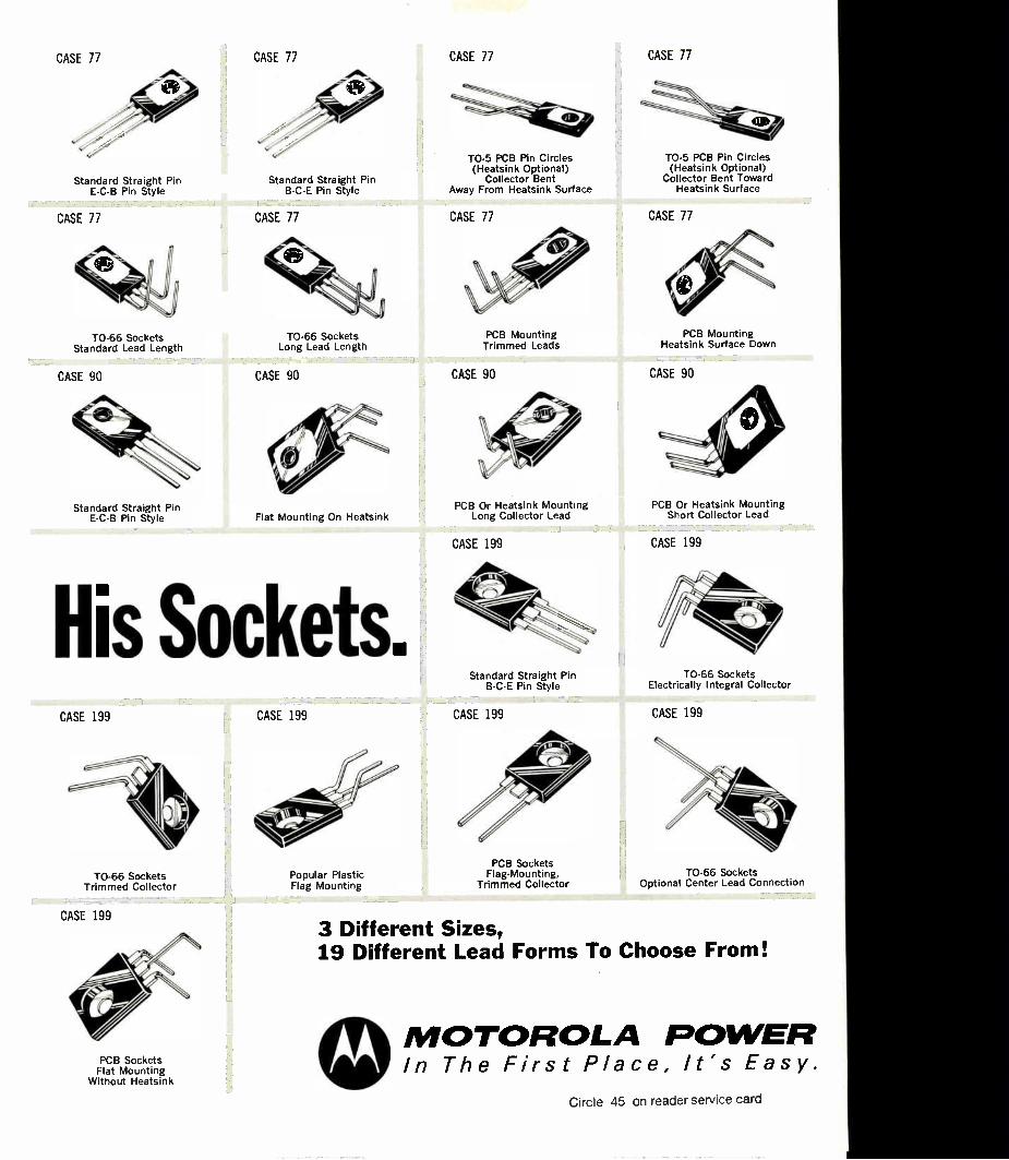
CASE 77 CASE 77 CASE 77 CASE 77
Standard Straight Pin E-C-B Pin Style
CASE 77
TO-66 Sockets Standard Lead Length
CASE 90
Standard Straight Pin E-C-B Pin Style
Standard Straight Pin B-C-E Pin Style
CASE 77
TO-66 Sockets Long Lead Length
CASE 90
Flat Mounting On Heatsink
His Sockets. CASE 199
TO-66 Sockets Trimmed Collector
CASE 199
PCB Sockets Flat Mounting
Without Heatsink
CASE 199
Popular Plastic Flag Mounting
TO-5 PCB Pin Circles (Heatsink Optional)
Collector Bent Away From Heatsink Surface
CASE 77
PCB Mounting Trimmed Leads
CASE 90
PCB Or Heatsink Mounting Long Collector Lead
CASE 199
Standard Straight Pin B-C-E Pin Style
CASE 199
PCB Sockets Flag-Mounting,
Trimmed Collector
TO-5 PCB Pin Circles (Heatsink Optional)
Collector Bent Toward Heatsink Surface
CASE 77
PCB Mounting Heatsink Surface Down
CASE 90
PCB Or Heatsink Mounting Short Collector Lead
CASE 199
TO-66 Sockets Electrically Integral Collector
CASE 199
TO-66 Sockets Optional Center Lead Connection
3 Different Sizes, 19 Different Lead Forms To Choose From!
0 MOTOROLA POWER In The First Place, It's Easy.
Circle 45 on reader service card

2. Proven reliability.
1. Millisecond/bit programing.
This ROM doesn't need
off-the-shelf delivery. Volume production, 4. 111
Less than a penny
3.
per bit in volume. asks. Why wait around
and pay more tor
one that doesP
46 Electronics/October 11, 1971

The masked ROM has had it.
The future of the masked mem-ory is being cut short by a 2nd-generation ROM of a different color: Intersil's 256-bit (32 x 8) 50-ns programable IM5600.
It's a fully decoded T2L mem-ory, housed in a 16-pin ceramic or plastic DIP or flatpack.
It comes in full military or com-mercial ranges, with a choice of open-collector or tri -state outputs.
The difference is that every IM5600 is delivered with logic "zeros" in all 256 locations. When you need a particular ROM, you yourself can program—permanently and very simply—the logic "ones" wherever your truth table dictates.
And by every standard, the completed ROM measures up to and beats what's previously been available.
BIPOLAR INTERSIL MASKED ROM IM5600 ROM
Price Down to 1c per bit
Mask charge $500 typical
Inventory costs High Availability In quantity Delivery 5 to 12 weeks Reliability Excellent
Below 10 per bit Zero Minimum In quantity Immediate
Excellent
The price is right.
In any quantity, the IM5600 costs less than the masked ROM. That's less than a penny a bit in volume.
But you save other ways, too. For instance, you can cut your in-ventory and service costs because you only have to stock one kind of memory, instead of a different masked ROM for every variation of your truth table.
Get a programer
tree. But here's the biggest bargain. •
Get a free programer box with your first order of IM5600s totaling 1,000 pieces or more.
This suitcase-mounted unit automatically tests each ROM, pro-grams it and then verifies the ac-curacy of the completed memory. All at a rate of better than two ROMs per minute.
Reliability is a quarter-billion
nn hours. And do they last? You bet. A
constantly monitored study has logged well over 1,000,000 device hours of high temperature operating and storage life testing without a single failure. Send for full details covered in IM5600 Reliability Report.
Intersii
By the carload, quick as a wink. The IM5600 is in volume pro-
duction right now. Ask for what you need and get it when you need it.
It can be computer-programed at a millisecond a bit, or one girl can program a thousand memories a day using an Intersil Portable Programer Box. Order them pre-programed from your Intersil distrib-utor and you still get off-the-shelf delivery. Or buy quantities of blank ROMs, mount them on your own PC cards and stock them. When you need it, program a complete card at a time, plug it in and go! And Intersil guarantees 100% program-ing yield. From Intersil, the oneto re-member when it comes to memories. 10900 North Tantau Ave., Cupertino, CA 95014.
Get 'em here. Intersil stocking distributors. Schweber Electronics; Century Electronics; Semiconductor Spe-cialists; DeMambro Electronics; R. V. Weatherford Co. Intersil area sales offices. Los Angeles (213) 370-5766; Metro-politan New York (201) 567-5585; Minneapolis (612) 925-1844; San Francisco Bay Area (408)257-5450; Singapore, Telex RS 21607. Overseas representatives. Clichy, France: Tranchant Electronique. Amsterdam, Holland: Klaasing Electronics. Tokyo, Japan: Internix. Zurich, Switzerland: Laser & Elec-tronic Equipment. London, U.K.: Tranchant Electronique. Munich, West Germany: Spezial Electronics. U.S. sales reps in all major cities.
Electronics/October 11, 1971 Circle 47 on reader service card 47

When the Apollo 15 astronauts wenr for a drive in their Lunar Roving Vehicle, they could depend on a reliable navigation system to get them "home" to the lunar Module again.
Distance and heading back to the Lunar Module were displayed continuously on the LRV console, derived from the output of a unique Signal Processing Unit designed and built by Boeing.
This compact digital/analog computer had to meet some of the toughest specs ever for electronic hardware. Such as gravity forces of 121/2 Gs during launch. Temperatures from minus 250 to plus 250 degrees. And
hard vacuum. What's more, the SPU, along
with the rest of the navigation system and the complete LRV, was designed, built, tested and delivered to NASA by Boeing in the shortest time ever for Apollo-qualified hardware. It's a typical example of Boeing's total capability for on-time delivery of highly reliable special-purpose computers.
Other Boeing computers now in development include a controller for the USAF Airborne Warning and Control System, a central computer for Mariner/ Venus/Mercury '73, and a low-cost attitude computer for
spacecraft. Early development work is under way on advanced configurations for an ultra-reliable Grand Tour computer. When you need a special-
purpose computer, come to Boeing. We can do the exact ¡ob you need. At very competitive prices.
Write to Mr. Herbert S. Broad-well, Boeing Electronic Products, P.O. Box 3999, Seattle, Wash-ington 98124. Or call him at 206-773-6116.
EZEW77717A/"C" erArtMe./C7:5"
48 Circle 48 on reader service card Electronics/October 11, 1971

Introducing the little counter that can.
It can become four different systems. It can go anywhere you do. It can protect you against obsolescence. It can make buying and maintaining a counter less expensive than ever before.
Meet the Hewlett-Packard 5300, the snap-together counter that's not much bigger than the palm of your hand. It has six digit accuracy, solid state display and autoranging. It'll make period, frequency, time interval and ratio measurements, operate on its optional snap-on battery pack and drive a printer. Rugged dust-proof aluminum case resists almost any bumps it might get in the field. Prices start at only $520 for one of the most amazing counters you've ever owned.
Start with the basic mainframe ($395). Then snap on any of the following modules (more on the way) to make just the counter you need, and avoid obsolescence, too:
10 MHz frequency module. Model 5301A, $125.
50 MHz all-purpose module in-cludes period, time interval. Model 5302A, $250.
500 MHz module with both 502 and 1 mn inputs. Model 5303A, $750.
100 ns time interval module with: unique "time holdoff" feature, dc coupling, slope and trigger level con-trols, and period and frequency measure-ments to 10 MHz. All the functions you'd pay $1200 for in a universal counter. Model 5304A, $300.
Rechargeable battery pack module works with any of the other modules for cord-free operation. Model 5310A, $175.
The 5300 is one system you have to use to appreciate. If you've ever needed to accurately measure frequency or time interval, you owe it to yourself to call your nearby HP field engineer for further information. Or write Hewlett-Packard, Palo Alto, California 94304; Europe: 1217 Meyrin-Geneva, Switzerland.
Counters that promise a lot and deliver it all. 02109
HEWLETT ei PACKARD
ELECTRONIC COUNTERS
Circle 49 on reader service card

LINEARS FROM RAYTHEON
SEMICONDUCTOR. OP AMPS
702 Wideband Amplifier
709 General Purpose
725 Precision
741 General Purpose
747 Dual 741
748 Uncompensated 741
4709 Dual 709
101 General Purpose
107 Compensated 101
108 Precision'
4558 Dual 741 (Available in mini-DIP)
4531 High Slew Rate
4131 Precision
4132 Micropower
INTERFACE ELEMENTS
710 High Speed Comparator 711 Dual High Speed Comparator 9622 Dual-Line Receiver 7520 Series Core Memory Sense
Amplifiers
4431 Dual -Line Receiver
1414 Dual 710 with strobes 1488 Quad Line Driver/ EIA
Compatible* 1489 Quad Line Receiver / EIA
Compatible*
VOLTAGE REGULATORS
723 Precision Positive / Negative
109 1 5V Voltage Regulator*
RAYTHEON LINEARS ARE AVAILABLE IN ALL POPULAR PACKAGES:
Plastics — 8-pin mini DIP; 14 and 16-pin DIPs
T Pak — TO-3; 8 and 10-pin TO-5
Ceramic — 14 and 16-pin DIPs; 10 and 14-pin flat packs
When you need a linear IC of any kind,
give us a call. We've got what you want.
We're stronger than ever in both proprie-
tary and off-the-shelf linear circuits.
And that's not our only strength.
Raytheon Semiconductor has changed
Our new technical team is deeply
involved in development programs to
provide new design tools. New digital
analog interfacing that allows active
switching and amplifying. Greater inte-
gration of external parts in voltage regu-
lators. Super Beta process for precision
op amps.
If you haven't been keeping up with us
lately you've got a surprise coming. Write
for more LIC information and see.
Raytheon Semiconductor, 350 Ellis
Street, Mountain View, California 94040.
(415) 968-9211.
RIP THIS PAGE OUT AND TACK IT ON YOUR WALL.
YOU CAN USE IT.
'Available fourth quarter 1971.
Circle 50 on reader service card
RAYTHEON

Washington Newsletter October 11, 1971
EDP buys
for Army
top DOD list ...
... With DSA taking
11, the Navy 37
and USAF 31
NAE urges NIH to
build engineering
effort ...
... as group defines
biomedical specialty
Beyond the World Wide Military Command and Control System's (WVVMCCS) 13 computers, scheduled for contract on Oct. 15, military , sources predict awards for the purchase, lease, or expansion of 140 more systems during the next six months. Biggest single piece of hardware in the Army's 74 computer actions is the Persincom 70X, a large personnel management system usirig 126 remote terminals- in the Washington area to replace three CDC 3800s, one Burroughs B3500 and six IBM machines. The Army also plans two computer moves for automated telecommunica-tions centers at Bayonne, N.J., and Oakland, with options for more. With most of the acquisitions by all the services falling in the category
of standard business computers, IBM stands tallest in the competition. Nevertheless, Univac and Burroughs are competing strongly for many of the big machine orders, with Honeywell, although not a military favorite, also pushing.
•
Though the Navy plans 37 computer acquisitions and the Air Force another 18 in addition to VVVVMCCS, the second biggest dollar buy con-templated probably will be the Defense Supply Agency's award for 11 processors to be used in its Samms program for supply and material management. Big Navy programs include: 11 small shipboard com-puters to be acquired by NavShips, six large-scale machined for Naval Ocean Surveillance Centers, and one large-scale system to replace two CDC 3800s at the Naval Research Laboratory. Potentially big is the sale of a single machine for the first phase of the Automatic Data Distribu-tion System that will interface with the Naval Tactical Data System. Other Navy EDP efforts in the next six months cover one general-pur-pose machine for the Underwater Systems Center, six small ones for hospitals, and seven numerical control systems for rework centers.
The Air Force is still after six large systems for regional use in its delayed Advanced Logistics System effort, another to replace an IBM 7040 at the Human Resources Laboratory and 10 small systems for as many of its hospitals.
The National Academy of Engineering has asked the National Insti-tutes of Health to expand and clarify its role in biomedical engineering. To help do this, NAE wants ,NIH to create an overview body of indus-trial, medical, engineering, and social experts. In a report to be published late this month, the academy also recommends that NIH expand its in-house engineering competence, support goal-oriented research, help establish university programs for design and product-oriented bio-medical engineers, and support engineering internships at the institutes.
Dr. Herbert H. Rosenberg, director of NIH's resources analysis office, says he expects the hierarchy at the Department of Health, Education, and Welfare to respond favorably, but cautiously, to the report, which reflects an Arthur D. Little survey of 50 biomedical engineering firms.
Biomedical engineers should be applying their skills to health service rather than to basic research, researchers at George Washington Uni-versity medical school have decided in a study funded by the Engi-
Electronics I October 11, 1971 51

Washington Newsletter
neering Foundation. That school's James C. Aller estimates that there may be about 3,000 biomedical engineers currently employed in what is now called a "clinical" engineering capacity, but the health care industry could use up to 50,000 profitably—decreasing the cost of health care by reducing equipment costs. "The research and manufacturing segments of the biomedical instru-
mentation industry are reaching maturity, so the thrust of biomedical engineering curricula should be redirected towards keeping equipment in service," Aller says. "Engineers should be more concerned with the selection and upkeep than with the design of new instrumentation."
LEAA leans to Future LEAA research in speaker recognition may be limited to com-puter techniques, implies a Law Enforcement Assistance Adminis-
computers for tration study to be published later this year. "This method of speaker voice recognition recognition may prove to be the most promising," concludes the report,
written for LEAA by the Michigan state police. The potential for legal acceptance of speaker verification by panels of listeners, and by ob-servers examining voice prints, the report explains, is diminished by the fact that those methods are not completely objective. LEAA, which has put $500,000 into speaker verification so far, has
subcontracted Stanford Research Institute for specification of criteria, and perhaps hardware, for computer recognition techniques. About $25,-000 of the SRI award is going to Texas Instrument to maintain a liaison with a manufacturer.
Jobs in aerospace Though Federal officials contend "the worst is behind us" when they speak of the economic slump and its related job losses, there is fresh
engineering seen evidence that aerospace and its related electronics will be among the stabilizing by June last industries to stabilize. Overall jobs are expected to continue to
decline through June 1972, says the Aerospace Industries Association, to a level of approximately 894,000. Of these jobs, 147,000 will be engi-neers and scientists—a drop of 37.5% from the 1967 peak of 235,000. A breakout of engineering jobs by product groups shows there were
83,000 engineering and scientific jobs in the aircraft industry in March, for example, but this slipped to 77,000 by June and will drop to 75,000 in December, before levelling off at 69,000 next June. Comparable openings in missile and space work were 51,000 in March and 49,000 in June, will decline another 1,000 by December and stabilize at 47,000 by June. Other aerospace engineering jobs—ground electronics, for ex-ample—stood at 32,000 last March, dropped to 31,000 by June and are expected to slip another 1,000 by year end before bottoming out at about 30,000 by the middle of next year.
Addenda The Navy committed itself at the Sept. 30 deadline to buy 48 more F-14 fighters from Grumman Aerospace for $806 million when Senate floor opposition to eliminate the buy crumbled, as anticipated [Elec-tronics, Aug. 16, p. 48]. . . . But the Navy apparently lost on its ex-tremely-low-frequency Sanguine system for shore-to-submarine com-munications [Electronics, July 5, p. 35] with 44-42 Senate passage of an amendment to cut its $5.57 million appropriation by $2 million. The Navy may recoup, however, on a vote to reconsider if the 13 senators absent can be rounded up.
52 Electronics I October 11, 1971
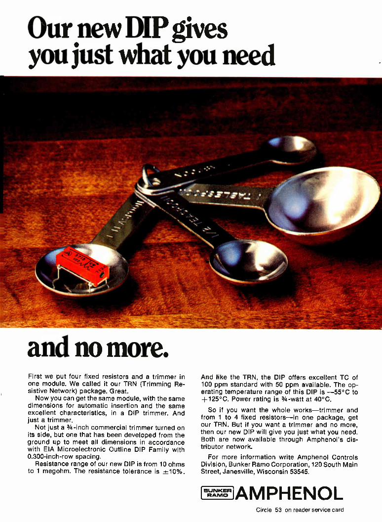
Our new DIP gives you just what you need
and no more. First we put four fixed resistors and a trimmer in one module. We called it our TRN (Trimming Re-sistive Network) package. Great. Now you can get the same module, with the same
dimensions for automatic insertion and the same excellent characteristics, in a DIP trimmer. And just a trimmer.
Not just a 3/4 -inch commercial trimmer turned on its side, but one that has been developed from the ground up to meet all dimensions in accordance with EIA Microelectronic Outline DIP Family with 0.300-inch-row spacing.
Resistance range of our new DIP is from 10 ohms to 1 megohm. The resistance tolerance is +10%.
And like the TRN, the DIP offers excellent TC of 100 ppm standard with 50 ppm available. The op-erating temperature range of this DIP is —55°C to +125°C. Power rating is 3/4 -watt at 40°C.
So if you want the whole works—trimmer and from 1 to 4 fixed resistors—in one package, get our TRN. But if you want a trimmer and no more, then our new DIP will give you just what you need. Both are now available through Amphenol's dis-tributor network.
For more information write Amphenol Controls Division, Bunker Ramo Corporation, 120 South Main Street, Janesville, Wisconsin 53545.
BUNKER RAMO AMPHENOL
Circle 53 on reader service card

ASK FOR NEW EARNINGS REPORTS
IBM ABC . XEROX
..•%111111MfflMIIMIL 1111
THIS WEEK ONLY PORTFOLIO ANALYSIS
$ 3 95
10 BUY/SELL. DECISIONS
•«...4.........4..., Jum At» .
ii `ear.' ta
IQ - BEST BUYS ,..,.-. ,..Tryt.;.. TEXACO 35%;A--AT ST 112 14 f fl CA 3E1% 43A,
NO STAMPS WITH STOCK PURCHASE
TODAYS' FEATURES AMPEX 18 3,4 BUDD CO. 13 % GEN. FOS. 82 1/2 LOEWE TH. 18 7/8
IND. 27741 `6

By1979, you'll shop for stocks in your supermarket.
The stock exchange is going electronic. Millions of dollars are now being invested in computers, terminals and
electronic components to break today's paper bottleneck. Already, Wall Street is the biggest single market for read-out devices.
By the end of this decade, the securities industry may well be one of the biggest single markets for all electronics.
You'll buy and sell stocks through terminals located not only in brokerage houses, but in hotels, restaurants, private offices and even supermarkets. So, if the price of sirloin is up, you may still save the day with a great buy on IBM common. Just slip your identification card into the terminal and buy or sell any stock you want. Each transaction will be verified instantly, with your account statement printed out on the spot.
But helping you increase your portfolio is only one way electronics will make life easier in the future.
The fact is, products of electronics technology will be doing more for us tomorrow than electricity does for us today. In business, transportation, communications, health care; even housework.
Who are the master minds masterminding these changes? Our readers. Among them design, quality, and production engineers in components,
computers and computer peripheral equipment. Every two weeks, Electronics presents them with a complete up-to-the-
minute picture of the state of the technology. Plus all the fast-changing developments in their particular fields of interest. Industry-wide and world-wide.
If you want to be a part of the future, speak to the men who are working on it today.
Electronics, a McGraw-Hill market-directed publication.
Our readers are changing the world.
Bectrores
Electronics/October 11, 1971 55

Do you face a make or buy decision on power supplies?
USE LAMBDA POWER HYBRID VOLTAGE REGULATORS-AND
BUILD YOUR OWN. ($16 in quantities of 1000)
ACTUAL SIZE
FROM MELVILLE, N.Y. 1-DAY DELIVERY
ACTUAL SIZE
FROM N. HOLLYWOOD,CAL. 1-DAY DELIVERY
ACTUAL SIZE
FROM CHICAGO,ILL. 1-DAY DELIVERY
FROM MONTREAL,QUE. 1-DAY DELIVERY
The world's first Power Hybrid Voltage Regulator, the biggest ad-vance in power supply design since the silicon power transistor, is now available for 1-day shipment from four Lambda distributing points.
22 models provide up to 28 VDC, up to 5 A output, 85
watts dissipation, 0.2% line or load regulation... Cap $16 in quantities of 1000.
If you build your own power supplies, the Power Hybrid Voltage WHETHER Regulator will save you money at every step from design through YOU MAKE production. And now Lambda will save you time as well. Call or write for Brochure L-10. OR BUY...
MELVILLE, NEW YORK 11746 515 Brood Hollow Road Tel. 516-694-4200 ARLINGTON HEIGHTS, (CHICAGO) ILL. 60005 2420 East Oakton St., Unit Q Tel. 312-593-2550
NORTH HOLLYWOOD, CALIF. 91605 13425 Wyandotte Street Tel. 213-877-0041 MONTREAL, QUEBEC 100C Hymus Blvd., Pointe-Claire, Quebec-730 Tel. 514-697-6520
LAMBDA ELECTRONICS CORP.
A ,,Y7«.) Company
')(3 Circle 56 on reader service card Electronics/October 11. 1971

What's smaller than a breadbox, has two channels and built-in preamps,
and writes well under pressure? Answer: the Brush 220.
The Brush 220. A rugged, two-channel recorder that's little to the tune of 25 pounds, accurate to 991/2% linearity. Just plug it in. And then let Brush per-
formance take over. It starts with our pressurized ink system.
A system that forces ink into the paper, instead of just laying it on. So you get traces that are clear, clean, and crisp. And a disposable ink cartridge holds a year's supply of ink.
Built-in preamps give you a measurement range
of 1 millivolt per chart civision to 500 volts full scale. And a choice of 20 signal conditioners give you an even wider range. Four chart speeds are push-button con-trolled. And two event markers are standard. The Brush 220. It just nay solve your
recording riddles. To see the Brush 220 in action, call your Brush Sales Engineer. Or write for more information to Gould Inc., Instrument Systems Division, 3631 Perkins
Avenue, Cleveland, Ohio 44114 or Rue Van Boeckel 38 Brussels 1140, Belgium.
BRUSH INSTRUMENTS
Electronics/October 11, 1971 Circle 57 on reader service card 57

The next generation is here now
The SABRE IV is more than a laboratory recorder/reproducer. It's a complete magnetic tape system that is setting NEW STANDARDS in the accurate recording and recovery of data ... whether low or high frequency, analog or digital.
A SABRE IV in your laboratory means data reduc-tion performance unmatched by other recorder/ reproducers. The SABRE IV allows you to reduce data up to 2.0 MHz in the direct mode and 500 KHz in the FM mode with unequalled reproduction quality. With eight transport speeds the SABRE ¡V allows time base expansion and contraction ratios up to 128:1. The Total Bandwidth Convertibility of the SABRE IV provides more capability than pre-viously found in two or more recorder/reproducers.
If you would like to know more about the most ad-vanced magnetic tape systems available today... including the best portable system available today ... write or call:
SANDAMO ELECTRIC COMPANY The Innovators in Tape Instrumentation Data Systems P.O. Box 3347 Springfield, Illinois 62708 (217) 544-6411/Telex: 406-421 05714
58 Circle 58 on reader service card Electronics/October 11, 1971

ILENJD FLAME-RETARDANT TRACK-RESISTANT X-RAY SHIELDING
PHENOLIC, MELAMINE-PHENOLIC AND ALKYD MOLDING COMPOUNDS Thermosets rorrnulateu to provide an extra factor of product safety. With greater range in choice of properties.
Improved arc-resistance, excellent resistance to tracking under the influence of conductive contaminants, X-radiation shielding, and humidity-resistant characteristics are among the qualities offered by Plenco in this series of compounds. All are recognized under the Component Recognition Program of Underwriters' Laboratories, and were developed to help answer current concern for increased safety in electronic and electrical products. Where design and reliability requirements are being upgraded, Plenco gives the designer a wide range of properties and cost. Permits him to optimize the best approach to his problem.
1111111r;
FOR COMPLETE
INFORMATION
on these or any Plenco molding compound, write for brochure, data sheets or property charts. Wide-ranging selectivity and experienced assistance is of course offered you whatever your molding problem or process. Just part of our regula- service, and yours whenever you wish it.
Fe ENJCC) THERMOSET PLASTICS
See us at the Show— Booth 1132
PLASTICS ENGINEERING COMPANY 1607 Geele Ave., Sheboygan, Wis. 53081 Through Plenco research . . a wide range of ready-made or custom-formulated phenolic, melamine, epoxy and alkyd thermoset molding compounds, and industrial resins.
Electronics/October 11. 1971 Circle 59 on reader service card 59
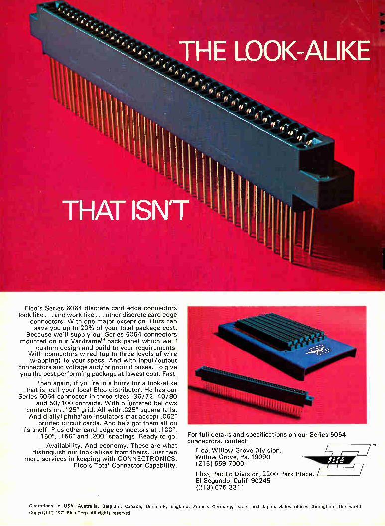
Elco's Series 6064 discrete card edge connectors look like ... and work like ... other discrete card eage
connectors. With one major exception. Ours can save you up to 20% of your total package cost.
Because we'll supply our Series 6064 connectors mounted on our VariframeTM back panel which we'll
custom design and build to your requirements. With connectors wired (up to three levels of wire wrapping) to your specs. And with input/output
connectors and voltage and/or ground buses. To give you the best performing package at lowest cost. Fast.
Then again, if you're in a hurry for a look-alike that is, call your local Elco distributor. He has our
Series 6064 connector in three sizes: 36/72, 40/80 and 50/100 contacts. With bifurcated bellows
contacts on .125" grid. All with .025" square tails. And diallyl phthalate insulators that accept .062"
printed circuit cards. And he's got them all on his shelf. Plus other card edge connectors at .100",
.150", .156" and .200" spacings. Ready to go.
Availability. And economy. These are what distinguish our look-alikes from theirs. Just two
more services in keeping with CONNECTRONICS, Elco's Total Connector Capability.
6064 For full details and specifications on our Series connectors, contact:
Elco, Willow Grove Division, Willow Grove, Pa. 19090 (215) 659-7000
Elco, Pacific Division, 2200 Park Place, El Segundo, Calif. 90245 (213) 675-3311
Operations in USA, Australia, Belgium, Canada, Denmark, England, France. Germany, Israel and Japan. Sales offices throughout the world.
copyright© 1971 Elco Corp. All rights reserved.
Technical articles
Minicomputer evolves with maxi capabilities: p. 61 (cover)
What is a minicomputer? If your answer is a small computer that performs simple functions economically where speed and capability aren't important, you're not with it, says a trio of authors from Digital Equipment Corp. The latest addition to the PDP-11 family, with its Schottky trumsi logic, semiconductor mixed memories, and floating-point units, has evolved into the general-purpose sector formerly the ex-clusive domain of much larger machines; yet it maintains the cost-effectiveness that originally made minicomputers feasible.
The cover: The front panel of the new PDP-11 /45 gives a hint of its impressive ca-pabilities. The address control board, with its Schottky TTL/MSI circuits and its bipo-lar read-only memories for microprograming functions, tells even more.
Computer modeling works for zener diodes: p. 67
Despite the widespread use of the zener diode in a host of circuit designs, only a few computer models are available for it, and these don't adequately deal with its thermal effects. The latest of the models, however, not only can handle the thermal considerations, says author Emanuel Schnall, but uses easy-to-evaluate circuit ele-ments and can adapt to linear and nonlinear analysis programs.
Millimeter-wave applications and Impatt diodes—the perfect match: p. 78
The proliferation of millimeter-wave communications, alarm, landing, and radar braking systems is greatly increasing the attractiveness of silicon lmpatt diodes as a solid state source, notes author N.B. Kramer. The diodes give high power with high efficiency, are compact, and offer impressive flexibility in a number of impor-tant applications.
Bit error rate detector—handy tool for digital data links: p. 82
Digital data transmission system designers have a problem. As their systems pro-liferate, there's an increasing need for bit error correction, but the usual approach is through software—frequently expensive and complicated. The solution, says au-thor Kingsley P. Roby, is to implement bit error rate detection in hardware: the technique is simple and inexpensive, and uses the same principles as in analog networks.
Taking on interconnection problems in big multilayer pc boards: p. 88
In very large, very dense systems, designers can't afford to ignore the considera-tions involved in making thousands of reliable interconnections, says author P.O. Benham. One such challenge was a 3-foot-diameter, nine-layer pc board for a phased-array antenna system that needed 23,000 plated-through holes. It was conquered with a numerically controlled drilling operating and a plastic-encased preform solder system.
And in the next issue. . .
How electronics companies are automating to survive hard times. . shortcuts for Chebyshev and Butterworth filter analysis . . . how gallium phosphide and gal-lium-arsenide-phosphide stack up . . . timing for semiconductor memories.
-E-Circle 60 on reader service card 61

Evolution breeds a minicomputer that can take on its big brothers Fast Schottky TTL/MSI, semiconductor memories, multiple unified buses,
microprograming, and floating-point units bring minicomputer
up to large-machine capabilities without sacrificing cost-effectiveness
by Richard J. Clayton, Bruce A. Delagi, and Rony Elia-Shaoul, Digital Equipment Corp., Maynard, Mass.
D By incorporating the newest technological develop-ments and building on changing user requirements, the minicomputer is evolving along lines that are putting less emphasis on the "mini" and more on the "com-puter." Now, instead of remaining the limited-perform-ance, stripped-down version of the bigger machines that met a need for economical computing power where speed and capacity weren't essential, the minicomputer is fast reaching the capabilities of the larger computers. At the same time, the cost-effective design philosophy that established the minicomputer concept is being re-tained. The latest step in this evolution is the PDP-11/45, the
newest addition to the PDP-11 family. The 11/45 is a 16-bit, general-purpose computer that refines mini-computer organization and technology to solve prob-lems normally associated with larger computers. Mul-tiple unified buses, mixed memory systems (bipolar, mos, and core), an exceptionally powerful instruction set, microprograming, hardware floating-point units, memory segmentation, Schottky logic gates, and mul-tilayer boards are some of the techniques that are help-ing the PDP-11 family to redefine the boundaries of minicomputers. To understand minicomputer evolution consider the
basic structure of the first minicomputer, as shown in Fig. 1 (a). In such early machines, separate buses to and from the central processor were provided for in-put/output and for memory. In most cases, the in-put/output bus operated synchronously (clocked), could handle only those peripherals within a narrow range of response times, and was relatively slow. The memory bus was fast and generally asynchronous. With this configuration the limit on memory usually
was no more than eight modules of 4 kilowords each. Also, bus length was held to about 10 feet and termi-nations had to be tuned rather carefully. Speed ranges were quite restricted, and mixed memory add-on capa-bility was not available. Minicomputer design made a significant advance
when the concept of unified busing was introduced in the PDP-11 architecture [Electronics, Dec. 21, 1970, p. 47]. The Unibus is essentially a fast asynchronous sys-tem for data transfer between computer system ele-ments. Its features are overlap of bus transfer, selection of the next system element to be granted use of the bus (bus arbitration), fast asynchronous operation, and im-
proved drive capability over previous minicomputer memory buses—twice as many loads can be driven over five times the distance. Overlap of bus transfers and bus arbitration increases
bus channel capacity. Multichannel direct memory ac-cess and all interelement communications are obtained in this way with the involvement of no additional cost or time penalty.
Because the Unibus operates asynchronously, a user can mix memories of different speeds, and bus buffers (bidirectional repeaters) can be added to expand load capability and line lengths as required. System commu-nication on the Unibus, as used in the 11/20, the first general-purpose member of the PDP-11 line, is illus-trated in Fig. 1. Even though the Unibus was successful in increasing
system generality, the advent of high-speed semicon-ductor memories, with access times surpassing the max-imum speed of the bus, required a new approach to memory organization.
Basically, the new approach, shown in Fig. 1 (c), is to separate the memory system into two parts: one for the slower core, bulk memory devices, and conventional pe-ripherals; and the other for the higher-speed semicon-ductor memory units. To accomplish this, a very fast, short, dedicated bus is added to the system. This bus connects a dual-port semiconductor memory system to the central processor. The second semiconductor memory control port is a standard Unibus interface (Unibus 2 in the figure). The dual-port architecture brings to a minicomputer
a degree of flexibility and system performance improve-ment previously only seen in much larger systems. Be-cause communications between the central processor and solid state memory need involve only one of the two semiconductor memory controls, the second control is free to handle external Unibus data requests up to the full Unibus rate of 40 million bits per second.
In more advanced configurations, Unibus 2 need not be directly connected to Unibus 1, but may be used as a second bus operating simultaneously and indepen-dently of Unibus 1. Thus, Unibus 2 can be a very high-speed swapping channel while keeping Unibus 1 to handle interrupts and other external requests. One of the more interesting applications, shown in
Fig. 1 (d), of this second Unibus is in cross-connecting two processors so that both operate in an environment
62 Electronics/October 11, 1971

MEMORY BUS
(a)
BULK AND CORE MEMORIES
UNIBUS 1
FAST DEDICATED BUS
I/0 BUS
CPU
UNIBUS 2
SEMI CONDUCTOR MEMORY
(c)
SEMI-CONDUCTOR MEMORY
BULK AND CORE MEMORIES
Do DE PERIPHERALS
UNIBUS MEMORY +Ii0
SEMI CONDUCTOR MEMORY
(b)
CORE MEMORY
PERI-PHERALS
UNIBUS
UNIBUS
CORE MEMORY
(dl
PERI-PHERALS
SEMI CONDUCTOR MEMORY
1. Comes the evolution. Early minicomputers (a) had separate I/O and memory buses, usually less than 10 feet long. Unified bidirectional
bus concept (b) could handle more loads on lengths up to 50 ft. New approach in the 11 /45 (c), required for fast IC memories, uses several buses: a Unibus for slower-speed memories; another for faster ones; and a dedicated unit to handle transactions between CPU and fast
semiconductor storage. Dual-processor 11/45 system (d) allows both to share data with virtually no conflict or data time penalty.
that offers virtually no conflict or data time penalty in accessing a common data base. The high-speed semiconductor memory system as
shown in Fig. 2 comprises matrix and control modules. The matrix module contains the actual memory ele-ments. The two semiconductor memories currently available for the PDP-11/45 are mos units with 4,096 words of 16 bits and bipolar stores with 1,024 words of 16 bits. A control module provides timing, central pro-cessor interface, and Unibus interface circuitry for up to four matrix modules. mos and bipolar matrix modules require different control modules. The 11/45 contains physical provisions for up to two
controllers, each associated with four matrix modules. Thus, a maximum of 32k words of mos, or 8k of bipo-lar, or 16k of mos combined with 4k of bipolar, is pos-sible. This organization is suited to accommodate any future higher-density semiconductor memory elements. The mos memory used right now is the 1103-1, a
1,024-bit chip first delivered by Intel. This choice was based on cost and performance of production-proven devices. The mos memory system level access time is 350 nanoseconds, and unlike core memory systems of-fering comparable access times, is much less dependent on addressing patterns. While the mos memories offer a substantial speed im-
provement, the PDP- 11/45 was designed for still faster operation and also offers a lower-density, higher-power, and higher-cost bipolar memory system for high-speed applications. On a system basis, access time here is 295 ns, again largely independent of addressing pattern. The primary memory component is a 256 bit, TTL-corn-
patible bipolar chip available from Intersil and Texas Instruments.
Because semiconductor memories are inherently volatile, several methods are available to the user to handle temporary power outages. Of these, the most common is to keep basic process-state information in core memory, which usually is available on all large sys-tems, while dedicating semiconductor memory to pro-gram storage. Since programs are generally not self-modifying, they can be kept on disk or tape storage and then replaced automatically when power is restored. Also, a range of power-retention options is available to keep the system up until backup primary power can be restored. Without semiconductor storage the 11/45 is about
twice as fast and costs, depending on memory and in-struction execution mixes, about 1.5 times as much as the 11/20; with semiconductor storage, the system can be as much as seven times faster, but only twice as ex-pensive.
All of the PDP-11/45 memory systems offer optional byte parity. This increases the word length of the matrix to 18 bits and provides additional reliability. The PDP- 11 family instruction set also represents an
evolutionary step in minicomputer architecture. The worth of an instruction set is evaluated on the basis of three criteria: how easily coding to solve problems may be accomplished by the user; once coded, how fast the program runs; and how much storage is required to contain this code and the data on which it operates.
In the PDP-11 family, focus is on the data types, the data structures, the operations, and the interrupt sys-
Electronics/October 11, 1971 63

UNI BUS 17/
UNIBUS CONTROL AND PRIORITY
ARBITRATION UNIT
DEDICATED, HIGH-SPEED BUS
PROCESSOR STATUS WORD
MEMORY CONTROLLER
SM
SM
CPU MICROPROCESSOR
MEMORY MANAGEMENT
UNIT
S SM
MEMORY CONTROLLER
SM
SM —01 SM
SM = SEMICONDUCTOR MEMORY
ARITHMETIC AND LOGICAL PROCESSOR INCLUDING DATA PATHS)
FLOATING POINT
PROCESSOR
1 GENERAL REGISTERS
FPU MICROPROCESSOR -
8 K CORE
8K CORE
OTHER PERIPHERALS
(UNIBUS 1 AND 2 ARE NORMALLY CONNECTED)
AUNIBUS
EACH MEMORY MATRIX IS 4,096 WORDS X 16 BITS MOS
OR 1,024 WORDS X 16 BITS BIPOLAR
2. New approaches. The CPU's memory management unit accesses the fast semiconductor stores through the dedicated bus, and provides
address mapping and memory protection. Optional floating-point processor operates asynchronously to implement floating-point arithmetic.
tems that form the basis of the solutions of problems. The entire range of data types (bit, byte, word, multiple word, signed and unsigned integer, and floating-point variables) can be effectively handled by the PDP- 11 fam-ily instruction set. Byte data, for example, is commonly used in both operating systems and customer environ-ments. Because a programer working with the 11 family has many byte instructions available, he can handle words or bytes as the program demands without loss of coding, storage efficiency, or speed of operation. In ad-dition, he can conveniently deal with signed and un-signed data. For example, it's frequently necessary to add, subtract, or compare signed operands, (data) or unsigned operands, (address), and detect overflows. Most machines can handle only one, not both. In earlier machines, for instance, unsigned arithmetic compari-sons were done with hardware; the signed arithmetic comparisons were handled by software, which took sev-eral instructions to accomplish. This not only prolonged computer time, but greatly increased the probability of programer error. In the 11/45, a complete set of condi-tional branches and condition codes provide the hard-ware to handle both signed and unsigned operands.
In virtually all applications, data elements are orga-nized into structures. A key feature of the 11 family is its ability to directly support a wide variety of data structures by any of 12 distinct addressing modes. This support lets the programer choose one that's optimal to his specific problem. Even as recently as 1968, minicomputers had very
primitive interrupt structures, and no way of controlling priorities. Thus, when a request for access to the bus was received from a teleprinter, disks, or tapes, the sys-tem had little flexibility to determine which request was
more important and what time slot to allot to it. Fur-ther, all the devices on the line had to be polled to de-termine which had made the request. Moreover, there was no software interrupt system to book requests that could be serviced at a later time when processor priority level dropped. When the PDP- 11/20 was introduced, four priority
levels for interrupts were provided. And in the 11/45, the number of priority levels has been increased to eight, four for hardware or software interrupts and four for software interrupts only. Also, polling was elimi-nated—the interrupting unit provides a unique interrupt vector that identifies the requesting device. Another feature of the 11/45 is a second set of gen-
eral registers. With it, the processor status word can be used to specify which set of registers is assigned to a particular device interrupt-service routine. Thus some of the general registers can be dedicated to servicing very fast devices only, reducing interrupt service times by as much as 50%. The classic approach to CPU design is to implement
major state registers, instruction decoders, and other functions using networks of combinational logic in dis-crete elements. Although usable in a system with the ex-tensive range of features of the 11/45, these networks are expensive, physically big, and difficult to debug. However, in the microprocessor design approach for
the 11/45, bipolar read-only memories are used to in-terpret instructions and operate the control points both within the computer's data path and the external envi-ronment. Because microprocessor implementations directly realize instruction flows, the design goes much faster. Debugging of the initial breadboard proceeds rapidly because it's easy to change the control memory's
64 Electronics/October 11, 1971

Why Schottky TTL won High-speed logic was essential in achieving the 295-na-nosecond operating speed of the PDP-11/45. The choice fell between the well-established emitter-coupler logic and a newer family recently introduced by Texas Instruments— Schottky Tim.
Small component size is a key design element in fast systems because of the need for short signal paths. Avail-ability of a wide range of Net= circuits (both Schottky and standard) was a key point in the choice of Schottky TEL over ECL. In many cases non-Schottky msl gates oper-ate faster than a logically equivalent collection of individ-ual Schottky gates, so both types of rri. can be used wher-ever either type is most cost-effective.
Schottky rm utilizes the same thresholds, logic levels, and power supplies as conventional rri., so that a single power supply, regulated to a tolerance of + 10%, can be used. No level shifters or logic circuits are required to in-terface with rrt, DTL, and low-threshold mos circuitry, thereby reducing system costs and eliminating associated system propagation delays. A system can be graded ac-cording to speed requirements by carefully mixing stan-dard rm, mos, high-speed rri, and Schottky rrt circuits to provide optimum cost/performance benefits to the equipment users.
Ti's series 54S/74S Schottky TTL has impressive specs: power dissipation of 20 milliwatts per gate and a typical propagation delay of 3 ns, similar to the speeds of ECL. This performance is achieved by using Schottky-barrier diode clamps across the collector and base on all normally saturating transistors.
In Schottky TTL, the Schottky-barrier diode is employed as a Baker clamp across the base-collector junction of an npn transistor (Fig. a). Since the diode has a lower for-ward-voltage drop than the base-collector junction, base drive current is diverted through the diode when the tran-sistor is turned on, preventing the transistor from reaching saturation due to elimination of excess charge storage in the base region. As a result, turn-off times are dramatically reduced. For example, the basic 54S/74S gate circuit, (Fig b), achieves 3-ns propagation delay while maintaining rise and fall times in the 2-3-ns range to minimize system noise considerations.
All input transistors in the basic Schottky Tri gate schematic are clamped by Schottky diodes instead of pn diodes as in conventional rm. The lower forward voltage drop of the Schottky units gives greater protection against both negative voltage transients and positive line reflec-tions possible in high-speed digital systems. And since the reverse input characteristic of a Schottky TTI, gate more closely approximates an ideal termination, resistive termi-nals usually are not required for lines of impedances be-tween 50 and 150 ohms.
In addition to the Schottky diode clamps, 54S/74S em-ploys other basic design changes to reduce internal circuit propagation delays. Transistor geometries are approxi-mately one-half the area of conventional Tn., transistors, resulting in reduced delays due to minimize parasitic ca-pacitive effects. Although Schottky diodes and advanced design geometries are used in Schottky rrt, basic process-ing steps are very similar to those employed in conven-tional rm. Over 2 million device hours have been logged under high-temperature accelerated stress tests to Mil-Std-883 conditions. Failure rates that have been verified at TI have proven to be as good as those logged in for standard rim devices.
COLLECTOR CONTACT
ISOLATION
-),
EMITTER CONTACT
1 BASE CONTACT
SiO2 ISOLATION
P TYPE SUBSTRATE
SCHOTTKY DIODE GUARD RING (a)
Use of Schottky barrier clamps and elimination of gold-doped slice processing in 54S/74S circuits results in stabil-ity of ac delays and dc thresholds over operating tempera-ture ranges. Stability of dc thresholds (and thus, noise margins) is important where devices of varying complex-ities drive each other—when driving an Ms! function with a simple gate, for example. Other circuit design techniques minimize switching
overlap of the totem-pole output transistor, thus reducing current spikes—about 20% of those in 54H/74H high-speed rm. Thus, fewer decoupling capacitors need be used with Schottky TTL. And the lower dynamic power dissipation permits increased complexity and use of smaller power supplies— Schottky TTL circuits of up to 80-gate complex-ity are now possible. The sN74S181 arithmetic logic unit used in the PDP 11/45 computer is a 75-gate chip that can perform 16 arithmetic or logic functions. Even when used with a standard rrt carry/look-ahead package, the sN74S181 provides a 16-bit addition time of 25 ns against 40 ns when using an equivalent conventional rm circuit.
In general, mst-level Schottky rm greatly decreases sys-tem interconnections (and thus, wiring delays) and reduces on-chip delays. The sN74S153 dual four-input multiplexer achieves a propagation delay of 5.8 ns through two logic levels, or 2.9 ns per level. THE sN74S153 was also used in the PDP 11/45 and was instrumental in achieving the pro-cessor speed goals. However, with basic Schottky TTL gates, delays of 4 to 5 ns per logic levels are typical; on-chip Ms! delays usually remain between 2.5 and 3.0 ns per logic level.
74S00 GATE
7 j 1
(b)
J
Electronics/October 11. 1971 65

contents. But most importantly, the size and cost of con-trol logic are significantly reduced.
Both the central processor and the floating-point pro-cessor contain microprocessors with bipolar Roms. These microprocessors, shown in Fig. 3, handle state se-quencing and data-path and bus-control supervision. These microprocessors comprise the microprogram ad-dress register, control memory, control memory output buffer, and microprogram address control unit. The microprogram address register is made of D-type
flip-flops holding the next address of the control memory to be read (similar to major-state shift registers of conventional machines). The control memory is a 256 x 64 masked Rom ar-
ray. Its output is fed to the control memory output buf-fer, a 48-bit D-type flip-flop register, and also to the mi-croprogram address control. The control memory output buffer drives multiplexer selectors and provides enabling levels for timing pulses throughout the ma-chine. The control memory output also supplies its own next address and selects the external signals and inter-nal sense points which modify that address. The optional floating-point instructions represent an-
other area where microprograming techniques and fast, high-density Roms now permit the user to achieve sub-stantial system improvements at low cost.
Floating-point capability in a computer system re-lieves the user of keeping track of the decimal point which is cumbersome in applications where the dyna-mic range of the variables is large. It also allows the programer to use higher-level languages, such as For-tran and Basic, providing faster problem-solving. Using these types of languages, at least sevenfold increase in programer efficiency can be achieved over assembly language techniques. The floating multiply time is 8 mi-croseconds for 32-bit numbers and 15p.s for 64-bit num-bers. As a result, more than 20 times as many calcu-lations can be performed with the 11/45 floating-point processor than with programed operations.
o. CONTROL MEMORY
ADDRESS REGISTER
CLOCK SIGNALS
TIMING GENERATOR
w
TO OTHER CPU
ELEMENTS
CONTROL MEMORY
CONTROL MEMORY DATA
BUFFER
ENABLE LEVELS
TO CPU CONTROL POINTS
W w
MICRO-PROGRAM ADDRESS CONTROL
4-
NSE ELEMENTS
3. Microprocessor control. Microprocessor controller supervises state sequencing and data-path bus control. Its analogous to in-
struction decode and major-state control of conventional machines.
Multilayer boards, too. Because of the high speed achieved in the PDP 11/45's central processor, both crosstalk and the propagation characteristics of the signals become an important con-sideration. With Schottky Tit, typical rise times of from 1.5 to 3 nanoseconds made the use of multilayer boards for all high-speed elements the logical choice. Although multilayer technology isn't new, the PDP
11/45 represents one of its first high-volume, low-cost computer applications.
However, an extra bonus resulted. Not only did this technique improve the electrical environment, but it re-sulted in a 20% increase in packaging density. This in-creased density, in turn, shortened interconnection dis-tances, thus reducing system noise and lowering drive requirements of the individual circuits. These boards are 8.5 inches by 15 inches, and have
four layers and 216 edge contacts along one side. One of the two inner layers is used for a ground plane; the other serves to carry power lines. All the logic signals are kept on the two outer layers. The components are placed on one of the outer layers; the other layer is wave-soldered. A standard grid pattern, which can house a max-
imum of 144 ics or equivalent components, is used on most boards. This allows the two inner layers to be identical for all of the multilayer boards used in the computer. That way manufacturing costs and produc-tion lead time are reduced considerably.
GOLD CONTACTS
WAVE-SOLDER SIDE
COMPONENT BOARD (UP TO 150 IC's)
SIGNAL ETCH
e GROUND
POWER
SIGNAL ETCH
GLASS EPDXY
The computing power of the 11/45 system is well suited to time-sharing applications. The key to a time-sharing system is management of system resources—per-haps the most important of which is memory. The 11/45 segmentation unit provides a mechanism by which a system supervisory program can control alloca-tion of active storage to each user. This is realized by segmenting each user's program and assigning such seg-ments to specific elements of the storage system. In this way, for example, frequently executed portions of a program can be assigned to the high-speed bipolar memory, while large data arrays are located in a much slower memory (such as core). These procedures imple-ment a software cache system. What's ahead for the 11/45 architecture? One devel-
opment will be extension of the semiconductor memory system as soon as more cost-effective, higher density, faster components are available. While continued higher performance systems will be implemented, the major direction of future evolution will be toward mul-tiple-processor configurations.
66 Electronics/October 11, 1971

A convenient way to model the handy zener diode Unlike earlier computer models, this set copes adequately with the
zener diode's thermal effects, uses easy-to-evaluate circuit elements,
and is well suited to available linear and nonlinear analysis programs
by Emanuel Schnell, Design Automation Inc., Lexington, Mass.
E The zener diode is an important and frequently used circuit component, but only a few computer models of it are available for computer-aided design. None of them fully account for thermal effects, and they are often dif-ficult to adapt for circuit analysis programs. Moreover, a special computer program is frequently needed to de-termine model parameter values. A new set of linear and nonlinear zener models solves
these problems. Besides providing for all thermal ef-fects, they can be adapted to all popular linear and non-linear analysis programs. Their parameters also may be found directly from a data sheet, by graphical analysis, or by measurement. A linear zener model can be regarded as a simplified
RATED POWER
(WATTS)
0.4
0.5
5
10
50
NOMINAL BREAKDOWN
VZT (VOLTS)
3.3 4.7 5.6 8.2
39 75
3.3 5.1
27 75
4.7 5.6 6.8
10 47 110
10 20 51 75
10 47 110
5.1 30 50 110
DIODE TYPE
1N746 1N 750 1N 752 1N 959 1N975 1N982
1N5226 1N5231 1N 5254 1N 5267
1N 3825 1N 3827 1N 3829 1N 3020 1N3036 1N 3045
1N4958 1N 4965 1N4975 1N4979
1N2974 1N 2995 1N3007
1N 4552 1N 3324 1N3331 1N3342
TEST POWER PT
(WATTS)
0.07 0.09 0.11 0.12 0.12 0.13
0.07 0.10 0.12 0.13
0.25 0.25 0.25 0.25 0.26 0.25
1.25 1.30 1.28 1.50
2.5 2.6 2.5
12.5 12.6 12.5 12.1
portion of a nonlinear model. Any single linear repre-sentation cannot be used for all zener operating regions and then, of course, it is necessary to modify it to ac-count for the nonlinear aspects of diode performance.
In any case, it's easier to start by developing linear models, since this will establish certain circuit elements that can also be used later in a nonlinear model. Zener impedance, for instance, is common to both types of models, as are thermal compensation components, a constant back-voltage, and transition and package ca-pacitances. Once these elements are described by pa-rameters that can be evaluated directly, then the prob-lems of fitting the model to existing computer programs can be tackled.
BULK RESISTANCE
(OHMS)
0.5 0.2 0.3 1
10 25
0.5 0.2 0.2 0.5
0.2 0.4 0.4 0.2 1
20
0.02 0.1 0.2 0.7
0.1 1.5 3
0.03 0.6 0.6 1.5
DYNAMIC RESISTANCE
RdT (OHMS)
18 9 2 3
25 160
20 7
30 160
5.5 1.6 0.8 2.1
54 200
1.2 4
16 30
0.35 6.5
25
0.005 0.7 2.0 5.5
EXPONENT
N, N,„
1.08 1.36 0.62 0.93 1.00 0.93
0.91 1.21 0.74 0.71
1.20 1.31 1.37 1.05 0.94 1.33
0.86 0.79 0.77 0.71
0.81 0.86 0.88
1.19 0.72 0.77 0.88
1.37 0.99 1.04
0.93 1.04 0.92 0.96
1.10 1.26 1.61 1.00 0.95 0.99
0.80 0.84 0.96
1.39 0.78 0.77 0.65
REGULATION COEFFICIENT
RdTIZT (VOLTS)
0.36 0.18 0.04 0.05 0.08 0.27
0.40 0.14 0.14 0.27
0.29 0.07 0.03 0.05 0.30 0.46
0.15 0.26 0.40 0.60
0.08 0.36 0.58
0.01 0.29 0.50 0.61
* Z,K not specified; Nia cannot be evaluated.
1. Zener data. Tabulation of typical parameter values for small-signal zener model lists 27 representative diodes. The data can be used to
approximate circuit parameters for both linear and nonlinear zener models. Diodes are arranged by power rating and then by voltage rating.
Electronics/October 11, 1971 67
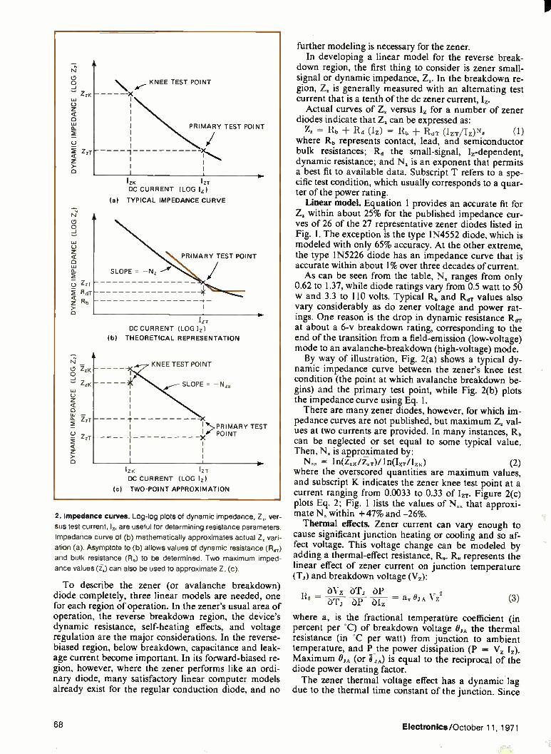
2. Impedance curves. Log-log plots of dynamic impedance, Z., ver-
sus test current, lz, are useful for determining resistance parameters.
Impedance curve of (b) mathematically approximates actual Z. vari-
ation (a). Asymptote to (b) allows values of dynamic resistance (Rer)
and bulk resistance (R.) to be determined. Two maximum imped-
ance values (ii) can also be used to approximate Z. (c).
To describe the zener (or avalanche breakdown) diode completely, three linear models are needed, one for each region of operation. In the zener's usual area of operation, the reverse breakdown region, the device's dynamic resistance, self-heating effects, and voltage regulation are the major considerations. In the reverse-biased region, below breakdown, capacitance and leak-age current become important. In its forward-biased re-gion, however, where the zener performs like an ordi-nary diode, many satisfactory linear computer models already exist for the regular conduction diode, and no
further modeling is necessary for the zener. In developing a linear model for the reverse break-
down region, the first thing to consider is zener small-signal or dynamic impedance, Z,. In the breakdown re-gion, Z, is generally measured with an alternating test current that is a tenth of the dc zener current, L.
Actual curves of Z. versus Iz for a number of zener diodes indicate that Z, can be expressed as:
Z, = Rb Rd (IZ) = Rb RdT (IZT/IZ)Ns (1) where Rb represents contact, lead, and semiconductor bulk resistances; Rd the small-signal, Iz-dependent, dynamic resistance; and N, is an exponent that permits a best fit to available data. Subscript T refers to a spe-cific test condition, which usually corresponds to a quar-ter of the power rating.
Linear model. Equation 1 provides an accurate fit for Z. within about 25% for the published impedance cur-ves of 26 of the 27 representative zener diodes listed in Fig. 1. The exception is the type 1N4552 diode, which is modeled with only 65% accuracy. At the other extreme, the type 1N5226 diode has an impedance curve that is accurate within about 1% over three decades of current. As can be seen from the table, N, ranges from only
0.62 to 1.37, while diode ratings vary from 0.5 watt to 50 w and 3.3 to 110 volts. Typical Rb and R, values also vary considerably as do zener voltage and power rat-ings. One reason is the drop in dynamic resistance RdT at about a 6-v breakdown rating, corresponding to the end of the transition from a field-emission (low-voltage) mode to an avalanche-breakdown (high-voltage) mode. By way of illustration, Fig. 2(a) shows a typical dy-
namic impedance curve between the zener's knee test condition (the point at which avalanche breakdown be-gins) and the primary test point, while Fig. 2(b) plots the impedance curve using Eq. 1. There are many zener diodes, however, for which im-
pedance curves are not published, but maximum Z, val-ues at two currents are provided. In many instances, R. can be neglected or set equal to some typical value. Then, N, is approximated by:
N,. = ln(z.K/I,T)/1n(I,/IzK) (2) where the overscored quantities are maximum values, and subscript K indicates the zener knee test point at a current ranging from 0.0033 to 0.33 of IzT. Figure 2(c) plots Eq. 2; Fig. 1 lists the values of Nza that approxi-mate N, within +47% and -26%. Thermal effects. Zener current can vary enough to
cause significant junction heating or cooling and so af-fect voltage. This voltage change can be modeled by adding a thermal-effect resistance, R.. R. represents the linear effect of zener current on junction temperature (Ti) and breakdown voltage (Vz):
ÔVz ÓT.1 Ro = bP biz — &TA Vz2 (3) bT.1
where a, is the fractional temperature coefficient (in percent per °C) of breakdown voltage OJA the thermal resistance (in °C per watt) from junction to ambient temperature, and P the power dissipation (P = Vz Ii). Maximum OjA (or is equal to the reciprocal of the diode power derating factor. The zener thermal voltage effect has a dynamic lag
due to the thermal time constant of the junction. Since
68 Electronics /October 11, 1971

only one mode of cooling is usually significant, a simpli-fied single-node thermal model can be used. And the dynamic lag is realized by shunting R. with a thermal-effect capacitance, C.;
Ce = TJA/ Re = Cj A/ avVz2 (4) where C JA is the thermal capacitance (in watt-seconds per °C), and TJA the thermal time constant (r„ = OJAC.,A)•
When the zener is cooled primarily by convection, the single-node approximation lumps the thermal capaci-tance of the case and the diode chip together. This pro-duces thermal time constants of about 0.5 second to 50 seconds for axial-lead-mounted diodes, varying with lead length and case design. Alternatively, if cooling is mainly by conduction, the junction-to-case thermal re-sistance predominates, and the thermal capacitance of only the diode chip applies. Thermal time constants are only about 0.05 to 0.5 second for diodes that are bolted and heat-sunk.
Finishing the model. Now that the essential circuit elements for the reverse-breakdown zener are defined, a linear model can be synthesized for this most frequently used mode of zener operation. Combining all elements (bulk resistance, dynamic resistance, and thermal-effect resistance and capacitance) with a battery that repre-sents breakdown back-voltage results in the linear model of Fig. 3(a) for zener reverse-breakdown oper-ation. The fact that it's valid only when current flows in the direction indicated implies that the nominal break-down voltage, Vz, is greater than the breakdown back voltage, Vb: Vb = VzT IZT(Rb Rp RdT) (5)
Voltage Vb is determined by a specific test voltage and current.
In contrast to its performance in the reverse-break-down mode, the zener behaves similar to an ordinary diode when reverse-biased. For this reason, the ele-ments used for its reverse-biased linear model are the same as those for an ordinary diode. However, thé pa-rameters defining these elements can be so selected as to simplify the job of relating the description to the real device. The linear model of Fig. 3(b) synthesizes zener leak-
age and capacitive currents in the reverse-bias region, below breakdown. Resistor R. represents the junction ohmic leakage resistance at a given temperature, Co the capacitance of the diode package, and C, the voltage-dependent transition capacitance.
Transition or depletion-layer capacitance C, varies with junction voltage, v: C(v) = Co/ (1 — V/VC) Ne 1)/(Vc v)Ne (6)
where Ve is the diffusion potential (typically 0.7 V for silicon, 0.3 v for germanium), and N. represents a grad-ing constant, which ranges from 0.33 for a graded junc-tion to 0.5 for an abrupt junction. Constant Co repre-sents the capacitance at y = 0, while constant D is the capacitance at y = V,. - 1. Eq. 6 applies for reverse junction voltages smaller than VzK, at which C, rapidly drops towards zero.
There are several methods for evaluating parameter values. Even low-accuracy techniques are helpful since they aid in determining expected-value ranges when de-ciding if and how laboratory testing should be used.
CATHODE
CATHODE
Co
Rt, R,1 I,)
Zz
R 11
(a) REVERSE BREAKDOWN MODEL
r I- — cp c, (v)
II I
Rb
(b) REVERSE-BIASED MODEL
ANODE
ANODE
3. Linear models. Circuit (a) synthesizes the zener in reverse break
down. It consists of lz-dependent dynamic resistance Ra, bulk resist
ance R., breakdown back-voltage V,„ and thermal-effect compo-
nents R. and C.. Reverse-biased model (b) includes leakage
resistance R, package capacitance C., and voltage-dependent tran-
sition capacitance C,. Ordinary unit models forward-biased zener.
The typical or approximate values, indicated for most model parameters, may be accurate only within 20%, but yield an overall model whose accuracy can be within 5%.
In estimating resistance Rb, either the values in Fig. 1 or a multi-point data curve can be used. A log-log plot of zener impedance versus I, like the one shown in Fig. 2(b), yields an asymptote that will fix a value for Rb.
This same curve also yields exponent N., though it can also be approximated from the two-point data of Fig. 2(c) or by using Eq. 2. A simple and often accept-able method is to set N. equal to unity. Then, once Z., Iz, Rb, and N. are known, Rd can be found from Eq. 1.
Thermal-effect resistance Ro is computed with Eq. 3, after a, and T., have been determined from test or de-sign data. Alternatively, thermal resistance T, can be assigned some typical value like 0.7 divided by the power derating factor. Or again, a, and 01A can be esti-mated from data for diodes with a similar package type, zener voltage, and zener current.
Next, leakage resistance ft, can be obtained in two ways— from the average slope of a curve for y versus re-verse current (I,), or by dividing a reverse-bias test volt-age by the appropriate leakage current. Back-voltage Vo can then be computed directly from Eq. 5.
Transition capacitance C, is measured at various test voltages. Next, exponent N. can be found from a log-log plot of C, versus v, or assumed to be 0.33 for dif-fused-junction diodes (0.5 for alloy-junction diodes). Diffusion potential V,. can be solved graphically as the intersection of horizontal and diagonal asymptotes on a log-log plot of C, versus -y, or it may be assumed to be 0.7 v (for silicon at 25°C). Once C, is known at some voltage, the value of D can
be computed with Eq. 6. Otherwise, approximations de-rived from handbook data can be used 5,200/VzT99 pi-cofarads for 1/4 -w diodes, 24,000/VZT" pF for 3/4 to 10-w diodes, and 58,000/V," pF for 50-w diodes.
Electronics/October 11, 1971 69

What's been done for the zener?
Since its introduction in the late 1950s, just five com-puter models have been developed for the zener diode through 1970. The first and still most widely used linear model is a battery and a series resistance. Accuracy was improved somewhat by Chandler' in
1960. He added a second series resistance to represent the zener self-heating effect. Chandler's addition was extended by Mollinge in 1963. A third independent investigation by Rigg" in 1962
led to another refinement of the linear zener model. Rigg introduced a junction transition capacitance shunted by a junction resistance to represent zener im-pedance below the diode's knee region. There are only two nonlinear zener models, and both
are difficult to program. Daniel's model (in 1967) in-cludes nonlinear current sources that realize dynamic, bulk, and leakage resistances, and transition and diffu-sion capacitances, but does not satisfactorily represent zener self-heating effects. Todd's' model (in 1970) em-ploys a temperature-dependent, constant-current source for leakage.
REFERENCES: 1. J.A. Chandler, The Characteristics and Applications of Zener (Voltage Refer-ence) Diodes," Electronic Engineering. Vol. 32, February. 1960. 2. T. Mollinga, "Effect of Temperature and Current on Zener Breakdown," Electro. Technology, Vol. 72, October, 1963. 3. B. Rigg, "The Characteristics and Applications of Zener Diodes," Electronic En-gineering, Vol. 34, November, 1962. 4. M.E. Daniel, "Development of Mathematical Models of Semiconductor Devices for Computer-Aided Circuit Analysis," IEEE Proc., Vol. 55, Nov., 1967. 5. C.D. Todd, "Zener and Avalanche Diodes," Wiley, N.Y. 1970.
The value of package capacitance Cr, can be obtained from a bottom asymptote to the log-log plot of C, versus -v. It can also be measured by using an internally open-circuited packaged zener. Thermal-effect capacitance C„ is computed from Eq. 4, after the thermal time constant TJA has been obtained from test data. (It is also possible to use a typical value estimated from a similar package for T A.)
Analysis problems. Now that linear models for synthesizing the zener in either its reverse-breakdown or reverse-bias region have been described and the ways to evaluate their parameters discussed, it's possible to con-sider how to use the models in current computer pro-grams. Unfortunately, there are potential problems in any adaptation of a model to a computer program, but fortunately, they are not insoluble.
In general, most linear circuit analysis programs, such as ECAP (electronic circuit analysis program) and equivalent time-shared software packages, allow the models of Fig. 3 to be represented by fixed-value resist-ive and capacitive elements. Naturally, the loss in accu-racy that results from using fixed values for Rd(I,) and C,(v) depends on the magnitude and importance of the variations omitted. That loss can be minimized by ECAP'S transient analysis capability if Rd and C, are ex-pressed as piecewise-linear variables. A few numerical considerations should be observed
for computer analysis. Thermal-effect resistance R. can have negative values at zener voltages below about 6 v, where temperature coefficient a, can become negative. This leads to convergence problems in dc analysis if cir-cuit resistance external to the zener is unusually low—
for instance, if it is comparable to dynamic resistance R,,. The problem can be avoided by redfacing the mag-nitude of R„ to obtain a positive net series resistance for Rd + R„ + RI, in the model of Fig. 3(a). The extremely short time constant of the path
through R. and the two capacitors in Fig. 3(b) could make the time taken by transient analysis excessive. Very short integration time steps and, therefore, long computation times are needed to prevent a numerical error buildup. The difficulty is usually circumvented by placing package capacitance Ç in parallel with transi-tion capacitance C„ since C, is normally higher in value. The two can then act as a single capacitor.
Using linear models for a zener diode, however, will not yield the most accurate results possible because such models are an approximation of the diode's non-linear performance. But linear models do provide a basis for developing a computer-adaptable nonlinear model— and a major problem with existing zener mod-els is the difficulty in adapting them for computer use. A linear small-signal model is unable to deal with
fractional current variations that are large enough to cause significant changes in zener diode voltage, Rd(Iz), or C,(v). It also cannot handle transitions from one zener operating region to another. These functions re-quire some kind of nonlinearity. An appropriate form for the nonlinearity can be derived from a consideration of the voltage regulation of the linear zener diode model of Fig. 3(a). From linear to nonlinear. Zener voltage regulation is
found by integrating dynamic impedance Z. in Eq. 1 with respect to current. When Nz 1, the calculation yields:
Vz — VzT = (Rb Ro) (Iz — IzT)
RdT 'ST R I% ) 1 es (7) 1 — N. IZT
If N. = 1, then: V, - VzT = (Rb + Re) (17. - + rIzT 1 ri(Iz/IzT) (8) Equation 7 could cause computational difficulties if
N. is close to unity, because it approaches an indetermi-nate numerical form. Moreover, the equation is difficult to rewrite into the explicit voltage-dependent current form needed for compatibility with presently available nonlinear circuit analysis programs. It is convenient, therefore, to let Nz be unity and use Eq. 8, which is de-terminate for all positive values of I,, and which results in an explicit voltage-dependent current source.
Both Eq. 7 and Eq. 8 have a voltage regulation coefficient, RdTizT, associated with the nonlinear loga-rithmic current term. In Eq. 8, this coefficient gives the effective nonlinear regulation for a current change of 2.718:1. Figure 1 includes typical regulation coefficient values, which range from 0.01 y (for a 5.1-v breakdown rating) to 0.61 v (for a 110-v breakdown rating).
Nonlinear model. A basic nonlinear zener diode model that covers all three regions of operation is shown in Fig. 4. The circuit employs an Ebers-Moll model for the forward diode, which consists of 11,, 110,
C,(v,), and i,(v,). The model also has an expo-nential current source, iz(v2), which represents zener voltage regulation.
70 Electronics/October 11, 1971

The dependent Ebers-Moll diode current source, i,(v,), can be expressed as: il(v1) = Is, [exp (qv, /MkT) - 1] (9)
where l,, is saturation current, M a junction emission constant, k Boltzmann's constant, T junction tempera-ture (in K), and q the charge on an electron. M usually ranges between 1 (ideal) and 2, while kT/q is always 25.7 millivolts at 25'C. Diffusion capacitance Cd is:
Cd(il) = q[i, (v,) + Is ,]/2/7FMkT (10) where F is the intrinsic diode cutoff frequency.
Back-voltage VB is defined to obtain zero terminal current at zero terminal voltage, allowing the model to be used for both high and low operating currents. If v, = 0 at the zener test condition (Vi, IT) and i,(v,) ap-proaches -I,, then VB can be given by:
= ViT - Rhin. - R. IB (11) where:
IB = IiT - I,, - (ViT - IzTRb)/11, (12) The value for VB lies between breakdown back-voltage V,, and zener test voltage VZT. The logarithmic component of zener voltage in Eq. 8
is represented by current source i2(v2): i2(v2) = I.2[exp (v2/RdTI,) - e.] (13)
where 1,2 is: Is2 = IB/(1 - e„) (14)
and where e,, is defined as: e. = exp(-VB/Rd-rIzT) (15)
to obtain zero diode terminal current at zero terminal voltage when v2 = -VB (for accurately modeling zener leakage current or a low operating current).
Since regulation coefficient RdTIzT ranges from 0.01 to 0.61 AT for the diodes listed in Fig. 1, the exponent in Eq. 15 varies from -8.3 to -510. This indicates that typical es, values are below 0.0003, making e, significant only at currents lower than those in the zener test current re-gion.
Except for Rd(lz), all the elements in both linear mod-els of Fig. 3 are explicitly called for in the nonlinear model of Fig. 4. Dynamic resistance Rd, however, is implicitly modeled through current source i2(v2). Differ-entiating Eq. 13 with respect to v2 and inverting the re-sult yields:
dv,/di2 = RdTIzT(i2 + This expression represents 11, for Ns = 1, in accordance with Eq. 1.
Nonlinear analysis. Parameter values for the non-linear model are obtained in the same fashion as for the linear models. The methods already discussed for find-ing Rb, R., and C„, and for solving the equations for R., C. and C, are identical. Values of saturation current Is,, cutoff frequency F and junction emission constant M are determined by measuring diode leakage current, storage time and forward voltage, respectively.
Regulation coefficient RdTIzT can be estimated from data like that of Fig. I. The remaining parameters of diffusion capacitance Cd(i,), back-voltage VB, and cur-rent source i2(v2) are computed using Eqs. 10 through 15, once all necessary variables are known. Again, certain computer numerical analysis precau-
tions must be observed. Those previously mentioned for R. and C. also apply to the nonlinear model. Forward voltages approaching diffusion potential V,.
can lead to numerically excessive values for transition
- --11-c„ C,110
(y,
Rb CATHODE —;--,VV\,- -•
V2
ANODE
4. Nonlinear model. Adding C., R., C., back-voltage \in, and volt-
age-dependent current source i. to Ebers-Moll diode model ac-
counts for zener self-heating effects and nonlinear voltage regu-
lation. The circuit is accurate for all operating currents.
capacitance C, in Eq. 6. This may require a restriction that limits the magnitude of C, or a convenient larger value of V,: the first modification is preferable. If NET-1 (network analysis program) is used, the magnitude of C, is automatically limited. But floating voltage source VB requires a series element, which should be a small re-sistor approximately equal to 0.001 R.. The nonlinear model of Fig. 4 makes it possible to
save programing time since the dependent exponential currents, i,(v,) of Eq. 9 and i2(v2) of Eq. 13, have the same general mathematical form: i = I[exp(a) - b]
where I = Ist, a = qv, /Mkt, and b = 1 when i = i,(v,), and where I = Is2, a = v2/RerIzT, and b = e, when i = iz(v2)-On the other hand, the model may be difficult to rep-
resent with some circuit analysis programs. NET-1 and Circus (circuit simulator), for example, must include both exponentially dependent current sources as part of the diode model. Since the sources are connected to ele-ments that cannot be eliminated from the network, an internal computation loop is formed with very short time constants. This, in turn, results in excessive com-putation time for transient analysis because extremely small integration time steps are required.
Sceptre (system for circuit evaluation and prediction of transient radiation effects), however, provides ideal diode current sources that implement Eq. 9 and that can be used without an Rb element. Then C, and C„ shunt iz(v2), thus avoiding computational delay errors in Sceptre's state-variable transient analysis, without intro-ducing a short time constant. Dc analysis usually presents no problems; modeling
compromises are generally necessary only for efficient transient analysis. In many applications, the forward-biased portion of the nonlinear zener model can be eliminated to ease the short-time constant problem for transient analysis with NET- 1 and Circus. The vari-ables Cd(v,) and i,(v,) are simply omitted from the model.
Electronics/October 11, 1971 71

A better way to maintain oscillator specifications.
A lot of oscillators can't meet their own specs once in operation. That's why we came up with a better way. A die cast zinc enclosure to keep specs what they should be. No other oscillator offers our kind of enclosure. Or our kind of performance: Models in 1MHz, 3MHz, and 5MHz
ranges. And when you write for our spec sheets, what you read is what you get. Write to Motorola Component Products Dept., 4545 W. Augusta Blvd., Chicago,111. 60651. ci) MOTOROLA
72 Circle 72 on reader service card Electronics/October 11, 1971

LDesigner's casebook One-of-eight decoders test and correct parity by Michael J. Gordon, Jr. Psynexus Systems, Wilmetter,
Only four one-of-eight decoder packages are all it takes to build an eight-bit parity checker that also can be used for parity correction. Either odd or even parity testing can be done. The basic circuit can be adapted to suit almost any
logic family; complete data is given for rn. and mos packages. When wired as indicated, the decoders pro-duce a logic 0 output for correct parity, a logic 1 output for incorrect parity.
Suppose the input word is 10111001, and it is to be checked for even parity. Since there is an odd number of Is, a parity error should be indicated. The three least-significant bits become the I„, I, and I, inputs. The next three bits, going from right to left, are inputs I, I, and I. The last two bits become I„ and I,.
Because decoder D, receives only a single 1, its out-put is I. The input to D, contains three Is, causing an-other parity error. Decoder D, also produces a 1, since its input contains just one I. Three Is, therefore, are ap-plied to D„ resulting in a 1 output, indicating a parity error.
If the input word has correct, even parity, the output will be a 0. Let the word be 10010110. Now D, produces a 0, D, a I, and D, a I. Since the input to D, contains an even number of Is, the output is 0, indicating correct parity. Using the output as the parity bit corrects any parity
error. If the circuit is wired for even parity, there will al-ways be an even number of Is. When wired for odd par-ity, the circuit will always supply an odd number of Is.
For example, if the seven-bit word 1101101 is checked for even parity, the circuit's 1 output can be-come the eighth bit to correct the parity error. Of course, whenever word parity is correct, the circuit pro-duces a 0, which does not change parity. The outputs of the decoders shown in the diagram are
wire-oRed together. If the decoder package used does not have this feature, an OR gate must be added to its output.
Testing, testing. Eight-bit parity checker generates a logic 0 for correct parity, a logic 1 for incorrect parity. Decoders D„ D. and D, accept
input data word and supply three-bit input for output decoder D. Circuit can test for either odd or even parity, depending on how it is wired.
An OR gate must be added to output of each decoder if the type of logic employed cannot be wire-ORed.
17
D
DCB A
• • •
G
D)
DC B
é • •
D,
D C B A
• • •
D4
DC B
PARITY BIT
1 OUTPUT
PACKAGE PIN NUMBERS DECODER LOGIC PARITY
A B C D E F G
ODD 13 2 4 11 15 6 1 MOTOROLA rVIC4038 P TTL
EVEN 3 5 12 14 15 6 1
ODD 2 5 12 13 15 9 7 MOTOROLA MC 1150 L MOS
EVEN 4 3 11 14 15 9 7
Electronics/October 11, 1971 73

With feedback, isolation amp gives better-than-unity gain by Roland J. Turner RCA Corp., Missile and Surface Radar division, Moorestown, N.J.
An isolation amplifier with degenerative feedback pro-vides gain over a large bandwidth, yet keeps output im-pedance low. An amplifier set up this way can be an ex-cellent driver for long, low-impedance transmission lines or other highly capacitive loads. The circuit can even be used as a gate when its dual MOSFET is driven to cutoff. (Conventional isolation amplifiers, like emit-ter-followers, are usually unity-gain circuits.)
Moreover, gain and output impedance in the im-proved amplifier are insensitive to variations in the MOSFET's transconductance (gm) and the bipolar transis-tor's beta (/3). Normally, gm drops by a factor of three as temperature rises from room conditions to 60°C, while )3 increases with rising temperature. In this amplifier, the changes in gm and 13 can offset each other. Gain is 17 decibels from several kilohertz to 20
megahertz; output impedance is less than 10 ohms. Fur-thermore, isolation greater than 50 dB can be achieved at frequencies as high as 6 MHz. The circuit's input can be operated either matched or unmatched. As can be seen from the diagram, MOSFET Q, has two
control gates. When the bias (V.,) of the second control
gate (G2) is decreased from 4 to -3 y dc, the forward gain through gate G, can drop by 50 dB, without ad-versely affecting its input characteristics. As V„.,s be-comes negative, Q, is driven into pinchoff, reducing its drain current. Transconductance through the signal gate then drops from 15 millimhos to 50 micromhos. The voltage transfer function for the amplifier is:
e. _ &OR' 1)R2l 1 -I- g(i3 1)R2
which indicates that amplifier gain is directly propor-tional to gm. If gm(fl + 1)R, is greater than 1, e./ei re-duces to:
e. 1 ei — 1 ± 1/g.2()3 -F 1)R2 R2
and circuit output impedance becomes:
1 Z. —
(i3 + 1) + 1/R2 13+1
which equals R,P) for frequencies to 10 mHz. As Q, approaches pinchoff, its drain current drops,
thereby driving Q, towards cutoff. Since Z. increases as /3 decreases, amplifier gain is effectively reduced by mis-match. In the limit, as both gm and )3 approach 0: e0/e, approaches 1 + R, /112, and Z. approaches R, + R 2. The input transmission-line transformer is similar to
a Z-match type 50-200E. If the secondary of the trans-former is terminated with 200 ohms, a low input VSWR can also be realized. Total parts cost is less than $5.
R,
Line driver. Isolation amplifier makes ideal line driver. It supplies more than unity gain while holding output impedance under 10 ohms
through frequencies as high as 20 megahertz. Degenerative feedback through Q, makes circuit performance insensitive to device parameter
changes. Bias of Q,'s control gate G2 effects gating action without harming input characteristics of signal control gate G,.
74 Electronics/October 11, 1971
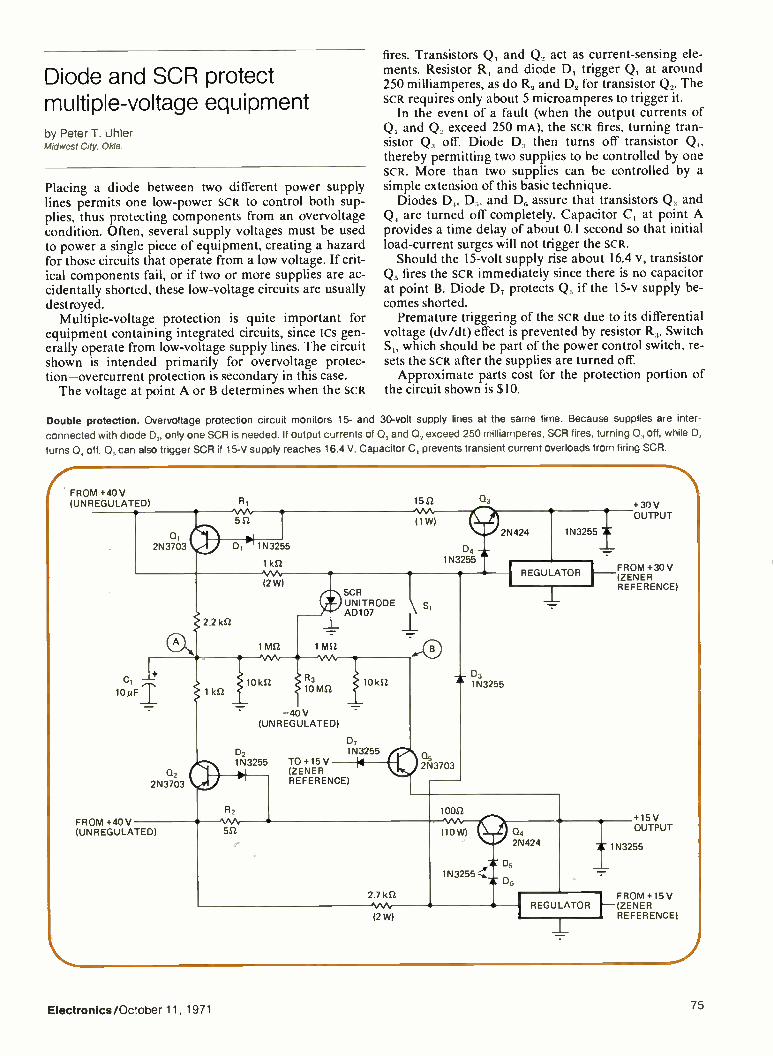
Diode and SCR protect multiple-voltage equipment by Peter T. Uhler Midwest City, Okla.
Placing a diode between two different power supply lines permits one low-power SCR to control both sup-plies, thus protecting components from an overvoltage condition. Often, several supply voltages must be used to power a single piece of equipment, creating a hazard for those circuits that operate from a low voltage. If crit-ical components fail, or if two or more supplies are ac-cidentally shorted, these low-voltage circuits are usually destroyed.
Multiple-voltage protection is quite important for equipment containing integrated circuits, since Ics gen-erally operate from low-voltage supply lines. The circuit shown is intended primarily for overvoltage protec-tion—overcurrent protection is secondary in this case. The voltage at point A or B determines when the SCR
fires. Transistors Q, and Q, act as current-sensing ele-ments. Resistor R, and diode D, trigger Q, at around 250 milliamperes, as do R, and D, for transistor Q,. The SCR requires only about 5 microamperes to trigger it.
In the event of a fault (when the output currents of Q, and Q exceed 250 mA), the SCR fires, turning tran-sistor Q„ off. Diode D, then turns off transistor Q„ thereby permitting two supplies to be controlled by one SCR. More than two supplies can be controlled by a simple extension of this basic technique.
Diodes D„ D, and D6 assure that transistors Q, and Q. are turned off completely. Capacitor C, at point A provides a time delay of about 0.1 second so that initial load-current surges will not trigger the SCR.
Should the 15-volt supply rise about 16.4 v, transistor Q. fires the SCR immediately since there is no capacitor at point B. Diode D, protects Q. if the 15-v supply be-comes shorted.
Premature triggering of the SCR due to its differential voltage (dv Mt) effect is prevented by resistor R3. Switch S„ which should be part of the power control switch, re-sets the SCR after the supplies are turned off. Approximate parts cost for the protection portion of
the circuit shown is $10.
Double protection. Overvoltage protection circuit monitors 15- and 30-volt supply lines at the same time. Because supplies are inter-
connected with diode D„, only one SCR is needed. If output currents of 0, and 0, exceed 250 milliamperes, SCR fires, turning 0„ off, while D,
turns Co, off. 0 can also trigger SCR if 15-V supply reaches 16.4 V. Capacitor C, prevents transient current overloads from firing SCR.
Electronics/OCtober 11, 1971 75

Dual op amp comparator controls ramp reference by Ronnie Jack McKinley Duncan, Oklahoma
A control comparator can be used to establish the end points of a sawtooth generator's ramp output. That way, the sawtooth's end points don't drift with temperature, providing a stable output. The ramp, which travels from absolute zero potential to 5 volts, can be varied over a frequency range of 0.33 hertz to 1 kilohertz.
Constant-current source Q, linearly charges capacitor C„ whose voltage is buffered by unity-gain follower A,. Comparator A, is formed by two operational amplifiers operating at open-loop gain; a flip-flop is realized from NOR gates G, and G2. Diodes D, and D, prevent gate
inputs from becoming more negative than -0.5 v, while the 4.7- and 3.3-kilohm voltage dividers stop the gate inputs from exceeding 5 V. The comparator sets up two threshold reference
points—one at absolute zero potential, the other at 5 V. When the voltage across C, reaches 5 v, A, switches, causing the flip-flop to produce a negative pulse. This turns Q, off and Q3 on so that C, discharges.
Since Q3's emitter is biased at -2 v, the discharging capacitor tries to reach VsAT -2 V. However, when the voltage across C, becomes zero, the comparator switches, returning the flip-flop to its original state.
Transistor Q, now conducts, Q3 goes off, C, begins charging again from a stable zero point, and the cycle repeats. Because of the comparator reference, the base-line of the ramp cannot be shifted by any temperature variance in the VssT of Q3.
Designer's casebook is a regular feature in Electronics. We invite readers to submit original and unpublished circuit ideas and solutions to design problems. Explain briefly but thor-
oughly the circuits operating principle and purpose. We'll pay $50 for each item published.
Supplying temperature-stable output. Dual comparator in this sawtooth generator sets lower and upper end points of ramp. Constant cur-
rent from 0, charges C, until the capacitor's voltage becomes 5 V. Comparator A, then switches, toggling flip-flop formed by G, and Gz. Qz
turns off, 03 turns on, and C, discharges until its voltage is zero. Then Az switches again, triggering the flip-flop, which turns Qz on and Qz off.
2.2 kel
6.8 kS2
2N2923
+12V
2N3905
2N697
1N758
FREQUENCY ADJUSTMENT 1 MS2
2.2 kO 1N751
FAIRCHILD µA 741
0.22 µF
OUTPUT
4.7 ket
A2
MOTOROLA MC 1437 L
1N914
5V
0 V — 471AZ—
'.SN /102N
76 Electronics/October 11, 1971

PHILIPS data systems
Our OEM mini computers
speak 118 languages
243 dialects...
plus FORTRAN.
Philips - Sales and Service worldwide
Philips offers a range of mini-computers, backed by the largest sales and service network of any electronics company in the world. OEM's will benefit from large volume Philips production, that gives prices as low as $ 1,800 for the P850, to quantity purchasers.
The P850, our smallest mini, has a 16-bit word, 3.2 microsecond cycle time 512 word memory (expandable). Punched tape I/O, teleprinter, card reader, display unit and magnetic cassette tape units are all available. Transfer rates are up to 50,000 words per second. Special options include interrupts, power failure/automatic re-start and a real time clock. Software includes a mathematical library, relocatable loader and
restricted assembler — impressive for such a small machine.
If you'd like to know more about getting a little Philips into your system, get in touch with OEM Marketing in:
Europe: N.V. Philips-Electrologica PO Box 553, Apeldoorn, Netherlands
North America: North American Philips Corp. Dept. 007 100 East 42nd Street, New York NY 10017
Far East: Philips Industrial Development and Consultant Co. Ltd. Kokusai Building, (7th floor) 1-1 Marunouchi 3-chome, Chiyoda-Ku, Tokyo 100, Japan
PHILIPS
Electronics/October 11, 1971 Circle 77 on reader service card 77

lmpatt diodes and millimeter-wave applications grow up together As millimeter-wave communications, alarm, and landing systems proliferate,
silicon Impatt diodes, with their impressive flexibility, power
output, and efficiency, become more attractive as solid state sources
by N.B. Kramer, Hughes Research Laboratories, Torrance, Calif.
El The applications for systems using millimeter-wave frequencies are growing, and so is the attractiveness of silicon Impatt diodes as solid state sources. Recent de-velopment work has done much to enhance the advan-tages of the diodes. Among those advantages: Impatts give the highest millimeter-wave cw power of any solid state device—as high as 150 milliwatts at 100 gigahertz. Moreover, Impatts are many times more efficient than LSA diodes and are at least as efficient as the best Gunn devices. And Impatts are vastly smaller, lighter, and simpler than the old varactor harmonic generators.
Flexibility is another important plus for Impatts. They can be operated efficiently as stable amplifiers and already are providing serious competition to traveling wave tubes at the higher millimeter-wave frequencies. Small, simple, wideband Impatt sweep generators are becoming standard throughout the millimeter trans-mission band. Parametric amplifier pumps using stabi-lized Impatt oscillators are being designed into a num-ber of new systems and appear to provide paramp noise figures as good as conventional pump sources. Millime-ter-wave communications systems, such as Bell Labora-tories' trial transmission unit, will use silicon Impatts for transmitters and local oscillators. And other potential uses include small doppler radar for intrusion alarms, aircraft landing systems, and collision avoidance net-
1. Old ways. Showing the way to today's Impatts were these old
mesa diode structures. Used primarily for computer switching, these devices relied on close bond between surface adjacent to junction
and copper heat sink to provide a good heat transfer.
works. Many new applications will be explored as expe-rience with Impatt devices increases. A silicon Impatt's electrical performance is impres-
sive. At millimeter wave frequencies, Impatt diodes op-erate at less than 30 volts bias with bias currents in the 100-300-milliampere range. Conventional single-drift structures regularly give power output levels in the 100-milliwatt range at efficiencies of a few percent. And recently developed configurations, such as the double-drift diode, promise significant increases: power output approaching the 1-watt level with 10% efficiency will be possible under operating conditions. One problem with Impatts has been the high noise
encountered in avalanche devices. But in many appli-cations, such as power amplifiers, noise is not impor-tant; in others, such as paramp pumps, problems due to noise can be eliminated by using a stabilizing cavity. In fact, extensive investigations have shown that Impatt sources make attractive pumps for low-noise, wideband paramps for application in radar and communications systems.
State-of-the-art Impatts. The first practical Impatts were silicon pn junction diodes for computer switching and these form the basis of the present cw Impatt struc-tures. Operating in X band, the early devices were planar or mesa diodes with junction areas of about 10-4
GOLD STRAP
n+ SILICON n PUCK ro
0.002"
COPPER HEAT SINK
2. New ways. Modern Impatt design eliminates excess high resist-
ivity material by forming epi-layer; Punch-through occurs only at
avalanche. Less material also reduces rf series resistance and low-
ers the overall thermal resistance to the back contact.
78 Electronics/October 11 1971

METALIZED QUARTZ STANDOFF
SILVER BUMP
GOLD RIBBON —
3. Lab pack. This typical stand-off package exhibits low loss be-
cause stand-off volume can be made small. It can also be tailored for
low parasitics but the drawback is that it cannot be sealed com-
pletely immediately around the actual diode area.
cm2, compared to the 10-5 cm2 areas attainable now for mm wave devices.
In addition to a geometry change, the new devices have been greatly refined to minimize thermal resist-ance, resulting in higher power capability. Careful at-tention also has been given to precise control of the doping profile to minimize rf series resistance. Then scaling of the basic diode design to operate at higher-frequency ranges is easily accomplished and perform-ance agrees with simple lower-frequency models. The great improvement in Impatt performance levels
over the last five years has been closely related to reduc-tion in diode volume. Early cw diodes were upside-down-diffused mesa structures that relied on the inti-mate bond between the surface adjacent to the pn junction and a copper heat sink for good heat transfer (Fig. 1). A modern diode is represented in Fig. 2. Excess high-
resistivity material is eliminated by tailoring the epi-taxial layer so that the depletion layer just punches through to the substrate at avalanche breakdown. Most of the excess substrate material also has been removed to reduce rf series resistance and lower the thermal re-sistance to the back contact. New silicon processing techniques, as well as careful
application of some old techniques, work together to yield the high performance of Impatt devices; epitaxial layers grown at low temperatures (below 1,000°C) have given the best results. Non-abrupt doping gradient at the my interface, caused by outdiffusion during con-ventional high-temperature epitaxial growth, resulted in lower efficiency. More recently, ion implantation has been utilized
successfully for junction formation. The high tempera-tures associated with conventional diffusion processes are not required in the ion implantation process; there-fore, abrupt doping transitions at the p'n and nn + junc-tions can be maintained. Also, the extremely shallow junctions that can be made with ion implantation result in minimum thermal impedance. Complementing ion-implantation methods, a low-
temperature diffusion process has been developed that
GOLD RIBBON
SOLDER PREFORM
METALIZED QUARTZ RING
4. Tough contender. More suitable for industrial applications, this
hermetically sealed package is good at the lower millimeter-wave
frequencies; however, it has higher rf loss and less flexible parasitic
adjustment than does the stand-off package.
provides equally good junctions. Wafer thinning and special bonding techniques also have contributed sig-nificantly to improved performance at millimeter wavelengths.
Ion implantation and low-temperature diffusion will play an increasingly important role in silicon Impatt diode fabrication. In addition to the usefulness of im-plantation in forming highly controllable shallow p • re-gions, it is an indispensable tool in forming the new 13+ pnn (double-drift) Impatt structure for millimeter-wave operation. The double-drift diode is more efficient because it utilizes both carrier species (electrons and holes) created in the avalanche process. Moreover, the diode's active region is thicker and junction area can be increased while maintaining sufficiently high diode im-pedance levels. The combination of increased efficiency and larger
active volumes result in significantly improved power output capability (it's theoretically quadrupled). Ion im-plantation is used to build this new type of diode struc-ture by employing the range-energy relationship to tailor the diode's p region.
Packaging of diodes for millimeter-wave applications has always been a problem. Reduction of package para-sitics is a must because of the high frequencies and low diode impedance levels. Furthermore, millimeter wave-guide dimensions are very small, putting size and toler-ance constraints on diode packages. Rf loss increases with increasing frequency, so only low-loss materials can be used in package design. The additional require-ment of minimum thermal impedance for power de-vices like Impatts makes package design critically im-portant for efficient rf performance. A package that is convenient for laboratory experi-
ments is shown in Fig. 3. A small metalized quartz standoff is mounted near the diode and a ribbon bond is made from the standoff to the back of the diode. The standoff's small volume gives this type of package its low loss. And parasitics can be easily tailored—ribbon inductance and shunt capacitance can be varied by changing standoff dimensions and position.
However, this lab package is completely open, pre-
Electronics /OctOber 11, 1971 79

Impatt power Avalanche diodes operating in the Impatt (impact ava-lanche transit time) mode develop their considerable power output when carriers at a pn junction build up due to avalanche and then move across the structure's drift re-gion. A simple three-layer (single drift) p+nn+ device is shown in Fig. a. To function as an amplifier or oscillator, the device must deliver power to its output circuit—it must have a negative-resistance characteristic. In the Impatt mode, negative resistance develops as the result of a phase delay of drifting carriers. This is due to both avalanche generation and transit time delay.
In avalanche, internal secondary emission occurs at a pn junction that has been reverse-biased into breakdown. At high fields (several hundred kilovolts per centimeter), car-riers will acquire enough energy to knock valence elect-rons into the conduction band, producing hole-electron pairs. These new carriers cause further generation, until a critical field is reached and avalanche occurs. Under steady state conditions the maximum field across
DIFFUSION DRIFT STRUCTURE
SINGLE-DRIFT STRUCTURE
(a)
SUBSTRATE
the junction will be limited to the avalanche or critical field. But under transient conditions, if the field is moved rapidly from below critical level to above it, and then be-low it again, the current will still be increasing when the field has passed its maximum; in effect, a phase delay will be introduced. This is the delay caused by avalanche buildup. The current-voltage phase shift can be as great as 90 under small-signal conditions. This, combined with transit time delay (between 90° and 270°) allows the diode to exhibit the required negative resistance over a micro-wave frequency band. However, a double-drift-space (2d) Impatt diode gets its
greater power from the additional drift region implanted onto the simpler structure. It has four layers (Fig. b) in-stead of the usual three, and this double-drift region, to-gether with the resulting bigger diodes, is responsible for the power increase over the single-drift structures, thus, in a double-drift diode, (a p+pnn• structure for example), in addition to the drifting electrons on a p'nn• diode, holes drift across the added p region in phase with the electrons, resulting in greater power outputs. —Laurence Altman
ION-IMPLANT COMPLEMENTARY DRIFT STRUCTURE
Pc
DIFFUSION DRIFT STRUCTURE
n
SUBSTRATE
>14 - - 0.2p 0.514 I 0.514
DOUBLE-DRIFT STRUCTURE
1514
TUNING PINS (SPRING LOADED)
CONNECTOR
LOCKING NUT
BELLOWS
BIAS PIN WITH TEFLON SLEEVE
RADIAL CHOKE
SLIDING SHORT (MICROMETER-DRIVEN)
IMPATT DIODE
5. In tune. Typical millimeter-waveguide cavity structure has consid-erable mass for heat sinking but mass can be reduced if external sinking is available. Mechanical tuning in the structure is accom-plished through a sliding-short technique.
cluding hermetic sealing immediately around the diode. In addition, the small standoff makes the package deli-cate; its use is justified only in systems where rf power output and efficiency are of paramount importance. A rugged, hermetrically sealable package is shown in
Fig. 4. This type can be very useful at the lower mil-limeter-wave frequencies even though rf loss is higher
6. Run for the money. lmpatt packages such as this one are becom-ing strong competitors to klystron oscillators. This unit, cheaper than comparable klystrons, gives continuous tuning over a 30 to 40 gi-gahertz range with a minimum output of 50 milliwatts.
than in the lab version and tailoring of the parasitics less flexible. The package also can be made with a ce-ramic body for added strength. Due to the high power densities (2 x 10³ w/cm2) re-
quired for efficient Impatt operation at millimeter wavelengths (corresponding to junction temperatures of approximately 200'), some attention must be given to
80 Electronics/October 11, 1971

CURRENT REGULATED
SUPPLY
IMPATT CAVITY
AMPLIFIER
LEVELING LOOP
1STABILIZINGH CAVITY ISOLATOR
IMPATT PARAMP PUMP
DETECTOR
OUTPUT
7. Widely used. Paramp pumps made with Impatts are being
adapted for radar systems. These pumps are smaller, lighter, and
less complex than varactor chains they replace.
diode life. Certainly, silicon Impatts will not be attrac-tive as millimeter-wave power sources if the junction temperature must be limited to values equivalent to conventional transistor and diode ratings. Though ex-tensive life data is not available, experience in limited life testing and in operational systems has revealed no fundamental failure mechanisms that would inherently limit longevity at these power densities and junction temperatures. Care must be taken in diode design and fabrication to avoid metalization or mechanical weak-nesses that might be aggravated by high-temperature operation. For optimum efficiency, cavity design must be closely
related to diode design. Waveguide circuitry is used al-most exclusively at millimeter wavelengths and wave-guide cavities for Impatt diodes generally have proven highly versatile and flexible. This has resulted in simi-larity of physical size and configuration among millime-ter-wave Impatt diode mounts. A schematic of a typical cavity with bias connector
and tuning elements is shown in Fig. 5. At high fre-quencies and power outputs the cavity mass must be large to assure adequate heat sinking. Where external heat sinking, such as a cold plate, is available, cavity volumes can be reduced significantly.
Applications. With the appropriate cavity design, me-chanically tunable cw oscillators using Impatt diodes will be replacing klystrons at millimeter-wave fre-quencies. An oscillator capable of continuous tuning over a 10-GHz band (30 to 40 GHz) with 50 mw min-imum output is shown in Fig. 6. This unit is cheaper than a klystron of comparable performance, requires a simpler power supply, and is easier to tune. The oscilla-tor also has an electronic tuning sensitivity of 2 mHz/mA, making it useful for phase-lock jobs. A millimeter-wave Impatt oscillator used with a
stabilizing cavity and an appropriate leveling circuit makes an efficient solid state pump source for low-noise parametric amplifiers. A block diagram of such a paramp pump, being designed into several wideband radar and communications systems, is shown in Fig. 7. A complete Impatt pump is much smaller, lighter, and less complex than a varactor multiplier chain providing equivalent paramp performance.
Stable circulator-coupled reflection amplifiers em-
8. And back at the lab. Millimeter-wave sweep generator has lmpatt
oscillators for laboratory testing. Bias-current tuned, the head is
fixed by flexible cable to the power supply.
ploying Impatts have been successfully demonstrated at millimeter-wave frequencies. At V band, small-signal gain-bandwidth products of 15 GHz have been mea-sured with power outputs exceeding 100 mw obtainable at 8-dB power gain. Comparable performance has also been observed in the 30-40-GHz range. This type of am-plifier will be useful for low-level transmitters and for TwT preamplifiers.
Injection-locked oscillators for power amplification of wideband fm and phase-modulated millimeter-wave signals also have been demonstrated. Impatt oscillators have a good locking figure of merit (product of frac-tional locking bandwidth and voltage gain) and can be used to efficiently amplify angle-modulated signals. The advantage here is that unwanted amplitude modulation is stripped from the signal due to the limiting character-istic of the locked oscillator. A new millimeter-wave sweep generator for labora-
tory instrumentation has been developed using a bias-current tuned Impatt oscillator; a photograph of the complete unit is shown in Fig. 8. The rf head is con-nected by flexible cable to the power supply, permitting the sweeper to be conveniently connected at any loca-tion in a test system. The Impatt sweeper is more com-pact and less complex than a comparable backward-wave oscillator sweeper. Sweep bandwidths up to 15 GHz can be obtained with power output of greater than 1 mw over the band. The power output variations with frequency are smooth when suitable isolation or pad-ding is used. The wideband bias-current tuning capabil-ity of this oscillator should make it attractive for other electronic tuning applications. Doppler radar is another type of millimeter-wave sys-
tem that should find wide use with the availability of simple solid state sources. Demonstration units have been built in the 50-GHz range that employ a single-drift Impatt diode for the transmitter/local oscillator in a homodyne configuration. This type of radar can be small, inexpensive, and portable. Range over 100 yards can be easily obtained in an inexpensive unit. With a good-quality mixer and a high-power Impatt, range could be extended to 1,000 yards or more. Foreseeable applications include such products as intrusion alarms, and such automotive tasks as braking radars and speed-ometers. II]
Electronics/October 11. 1971 81

Digital data links deserve a bit error rate detector Hardware is replacing software for the job of picking up errors
in digital data transmission; the equipment is based on the same
mathematical principles as are used in monitoring analog networks
by Kingsley P. Roby, Data-Control Systems Inc, Danbury, Conn.
D Since the early days of digital data transmission and processing, there have been software programs for bit error correction. But as the use of data links spreads, the need arises for simple, inexpensive hard-ware to monitor digital equipment. Recently the surge in digital transmission has made the need more urgent. The tool that has been developed for this job is the
bit error rate detector. The technique is basically the same as that used for the evaluation of analog data net-works, where the input characteristics of frequency ver-sus phase/amplitude are compared with those of the output, except that for digital networks an equivalent digital mathematical model is used. With digital systems, however, distortion of the signal
is not necessarily cumulative. If signal distortion ex-ceeds the system design threshold, the information is to-tally lost; if it is less than the threshold, the information can be totally recovered. A bit error rate detector simply compares a pattern that has passed through a digital de-vice with an identical pattern generated by a reference code generator, as the block diagram in Fig. 1(a) shows The comparison is made on a bit-for-bit basis. If the two states disagree, an error is counted, and displayed as a function of time or as bit errors per n bits transmitted. The detector is as versatile as it is easy to use. It can
check performance in any digital line—telephone lines, magnetic tape recorders, data modems, or pulse code modulated telemetry links. About a dozen different ver-sions of the device are being manufactured, and some can be used to test at rates up to 400 megahertz.
In almost all cases, the equipment to be tested must be taken out of operation. The detector generates a known digital pattern, and inputs it to the digital de-vice. Because an independent code is generated at the receiver, the delay through the system does not have to be compensated for. But it is necessary to synchronize the reference code generator to the incoming data. When a link does not transmit its own clock, or where
the received data includes much jitter or noise, a bit synchronizer is needed. This accepts the data, and re-creates a clean data stream and an accompanying clock by using the data transitions (ones and zeros) to syn-chronize a phase-locked, voltage-controlled oscillator with the incoming data. The oscillator then functions as the clock. In the absence of transitions, the vco will "coast," or mark time, and still be synchronous at the end of the coasting period.
To check the bit synchronizer itself, jitter is simulated by modulating a vcc that acts as a bit rate oscillator and controls jitter amplitude and frequency. Noise is summed with the code generator output, and the com-posite signal (jitter plus noise) is applied to the bit syn-chronizer input, as in Fig. 1(b). The synchronizer's per-formance is verified by comparing its bit error rate with curves of bit error rate versus signal/noise ratio. There are three basic types of digital communication
links that can be tested: simplex links, where data flows in one direction only; duplex links, where there is simul-taneous two-way flow; and half-duplex links, where data flows in one direction some of the time and in the opposite direction the rest of the time. The basic config-urations are shown in Fig. 2. Simplex testing requires two bit error rate detectors, one at the data source to act as the transmitter and one at the data sink to act as the receiver. Duplex testing also usually requires two error rate detectors, the pattern generator output of one unit being sent to the error rate detector of the other unit.
SOURCE PATTERN GENERATOR
BIT RATE OSCILLATOR
JITTER OSCILLATOR
F_,.. BIT RATE VCD
DIGITAL LINK
la
COMPARATOR
REFERENCE PATTERN GENERATOR
PATTERN GENERATOR
NOISE GENERATOR
(b)
BIT SYNCH-RONIZER
ERROR COUNTER
— CLOCK STREAM
DATA STREAM
--11>
BIT ERROR RATE DETECTOR
1. What BERDS are and do. Bit error rate detectors are used to test
digital links by comparing a known pattern transmitted from a data
source with an identical pattern simultaneously generated at the
data output (a). By adding a noise generator and a jitter oscillator, a
BERD also may test the ability of the bit synchronizer to recreate
clean data stream and the accompanying clock (b).
82 Electronics/October 11, 1971

The arrangement for testing a half-duplex loop is similar to duplex, except that the link call only be used in one direction at a time. In this case, each error rate detector is used as a pattern generator when testing in one direction, and as an error rate counter when testing in the other direction. In doing this, the pattern gener-ator is independent of the error rate detector, since data may be sent at different rates in either direction.
It is possible to measure error rate on a duplex or bidirectional simplex communication link with one de-tector, but only when the data link can be looped back to the source. In this case, if errors are incurred ran-domly throughout the link, the actual bit error rate is half that recorded. When no clock is available, it may be necessary to include a bit synchronizer at the receiv-ing end to simulate the clock function. If there is no jit-ter or frequency variation, the clock used in the pattern generator to the bit error rate counter can be bypassed. This method is useful particularly with hardline links which can be looped back to the source. The type and length of digital pattern determines the
extent that the bit error rate measurement includes a sufficient variety of pattern combinations. A simple pat-tern—a series of marks, a series of spaces, or alternating marks and spaces—suffices for a primitive test setup. This type of pattern is easy to generate and to synchro-nize, but provides only limited information about sys-tem performance, and is effective only for low-speed data systems. Another type of pattern generator, in-tended for systems with a fixed word length, is a fixed-length, switchable, repeating word generated by a pre-settable shift register, as shown in Fig. 3(a). This is use-ful where a data sink, such as a teletypewriter, can inter-pret patterns. The switched shift registers may be replaced by a pro-
gramed sequence which would step through each combination of n bits. When an 8-bit pattern is used and placed within proper framing, the pattern generator provides signaling to the teletypewriter, which then types out a particular sequence of symbols, such as "The quick brown fox, etc." Bit error rate is then deter-mined by the number of incorrect symbols. The most frequently used pattern generator is the
pseudo-random noise, or shift register, generator, shown in Fig. 3(b). It combines the output of some of the shift register stages to produce a repeating pattern of a par-ticular length. One of the primary advantages of this ar-rangement is that the output is a long, random sequence which contains all the combinations of 1 s and Os charac-teristic of normal data transmission. A fairly continuous spectrum from dc to the bit rate is
obtained by using a maximum pattern length, which is usually 2n-1 bits long. The maximum number of 1 s in a row is n and the maximum number of Os is n-1. (Ob-serving the code n bits at a time, that is, bit 1 through n, then 2 through n+1, will reveal all possible combina-tions of logical 1 s and Os in n bits.) The longer and more complex the pattern, the greater the spectral density, or number of pattern combinations, that can be analyzed. There are several standard interfaces used to adapt
bit error rate detectors to various digital systems. Usu-ally, the test equipment interface is determined by some common logic family, such as rrt, where 0 to 0.8 volt
indicates one state, and 2 to 5.5 V indicates the other. But bipolar and neutral transmission are still used in some teleprinter systems. The neutral mode uses a pulse current for a 1 and the absence of current for a O. The bipolar mode is similar, except that the polarity of the current is used to distinguish Is from Os. The EIA standard interface is designated Rs-232. The
transmission is basically a polar signal +5 to 15 y in amplitude where a 1 is negative and 0 positive. An in-terface similar to Rs-232 used by the military is Mil Std 188. The logic levels are polar +6 V with the positive voltage indicating a 1.
In addition to interfacing voltage level, code formats must also be considered. The seven Inter-Range Instru-mentation Group (tRIG) codes are the standard of the aerospace industry (Fig. 4). The RZ (return-to-zero) code is used when a dc response is not required. Where the absolute polarity of the logic does not have to be maintained, the mark and space codes have the advan-tage. This is because a logical 1 (in the case of a mark code) is indicated by the change of state and not the ab-solute level as in the case of NRz-L (non-return-to-zero level) code. A biphase code requires a higher frequency response
for a given data rate, but due to its high transition den-sity provides improved performance in the absence of excessive jitter. For this reason, it is often used with tape recorders. Delay modulation, or Dm, was developed to
PATTERN GENERATOR
SOURCE MODEM
(a)
SINK MODEM
ERROR RATE DETECIUR
PATTERN GENERATOR
ERROR RATE DETECTOR
PATTERN
GENERATOR
ERROR RATE DETECTOR
PATTERN GENERATOR
BIT ERROR RATE DETECTOR
MODEM
(c)
- CLOCK STREAM
- DATA STREAM
2. Digital link trio. In simplex transmission, data flows in one direc-
tion (a); in duplex and half-duplex, two BERDS are needed because
data flows in both directions (b); however, one BERD may be used
(c) if the transmission line can be looped back to the source.
Electronics/October 11, 1971 83

BIT RATE OSCILLATOR DIVIDER
BIT BIT B T BIT 2 3 4
BIT N
— CLOCK STREAM
— DATA STREAM
DATA OUTPUT
1 0 0 0 1 0 0 1 1 0 1 0 1 1 1
le----PATTERN CYCLE-P.1
BIT RATE OSCILL ATOR
(7)
FAH FFBH FFcH FF,
4-BIT SHIFT REGISTER
3. Generating patterns. Test patterns for a BERD can be pre-set into a shift register (a) so that it repeats each n bits. The output of the bit
rate oscillator provides the clock for the shift register. To generate a variety of more complicated patterns, the feedback points can be
changed and more flip-flops may be added to the shift register (b).
provide maximum transition density with minimum fre-quency requirement. DM has a transition in the middle of the bit period for a 1 and a transition at the begin-ning of a bit period for a 0, except that when a 0 follows a 1 there is no transition. DM can provide packing den-sities of up to 20 kilobits per inch on magnetic tape.
Several highly specialized codes have also been de-veloped. One is the two-tone coding used over tele-phone lines for long-distance calls: the flurry of beeping heard after dialing is a series of tone pairs representing numbers which transfer billing information into the telephone company office. A different technique is used by the telephone com-
pany to transmit 1.5-MHz synchronous data over pairs of wires. It's done in the T-1 PCM transmission system with a bipolar format in which there's a pulse for each 1, and no pulse for a 0. Each successive pulse is of oppo-site polarity. Every 6,000 feet, a repeater detects, re-synchronizes, and reamplifies the data to its nominal value. This system is transformer-coupled and bal-anced, and has a high common-mode rejection ratio that allows it to perform well in a multiconductor cable with other noise-producing signals. The average signal current approaches zero because each pulse equals the previous pulse in amplitude and is opposite to it in po-larity. This means that the system requires no dc re-sponse. With a repeatered line, signals can be trans-mitted over at least 25 miles without degradation.
After the interface requirements have been met, the digital information may be considered in terms of the logic family in the bit error rate detectors. To measure the bit errors in the incoming data stream, a synchro-nous clock is needed to feed the data into the sink por-tion of the bit error rate detector. It is also necessary to synchronize the reference pattern with the incoming pattern. The synchronous clock can be provided in a number
of ways. Usually, the input data is transferred into a flip-flop register bit by bit. If the data is entered in NRz-L form, then an optimum clock transition occurs in the middle of the bit period. However, because the data exists at a 1 or a 0 level for the entire bit period, the in-put clock and data may be at any phase relationship so long as they are synchronous, that is, with one clock
pulse occurring within the period of each data bit. To make bit-for-bit comparisons, the input data must
be synchronized with the reference pattern generator. There are several ways of doing this, depending on the type of pattern generator used, length of code, and number of bits. The most obvious method is to observe the incoming data, recognize a particular part of the pattern, and simultaneously preset the reference gener-ator to that state. A faster method is to preset the refer-ence pattern generator to the state of the incoming data. To synchronize input data with the reference pattern
at high bit rates, the clock to the reference generator can be deleted once each pattern cycle as long as the pattern comparator exhibits a high error rate. Eventually, the two patterns will fall into synchronization, and no more clock pulses will be deleted. The problem here is time. It takes an n-bit code approximately m2n/2 bits to acquire sync, where m is the number of bits used to determine an out-of-sync condition. When using a shift register generator, the method of synchronization is simple and efficient, as Fig. 5(b) shows. The state of a pattern gen-erated by a maximum-length n-bit shift register counter is determined by n bits of the code. To acquire sync, at least n bits of incoming data will be gated into the refer-ence shift register. After the register is filled, the feed-back loop is reconnected, and incoming data is applied to the comparator. All bits used for synchronization must be error-free. If not, the shift register will be faked into a different part of the pattern. For this reason, if the error rate is very high, several attempts at synchro-nization may be required.
Because of errors and jitter, the reference code gener-ator may jump out of synchronization with the input data. If this happens, it is convenient to have a circuit to detect the out-of-sync patterns and automatically re-synchronize them. Loss of sync is evidenced by a 50% error rate. Consequently, the obvious way to uncover out-of-sync conditions is to detect error rates of 50% over a given interval. However, the random errors can approximate loss of
sync, and, as the error rate increases, there is a greater probability of mistakenly attributing an error burst to loss of sync. By observing the error rate over fairly long periods,
84 Electronics/October 11, 1971

1 0 1 1 0 0 0 1 1 0 1 Bit status 'Ili 1111111i
NRZ-L
NRZ-M
NRZ-S
RZ
Blo-L
Bic, S
Bic' M
NON-RETURN TO ZERO-LEVEL 1 is one level, 0 the other level.
NON-RETURN TO ZERO-MARK
1 is a change in level, 0 no change in level.
DM
T-I
NON-RETURN TO ZERO-SPACE
1 is no change in level, 0 a change in level.
RETURN TO ZERO 1 is a half-bit wide pulse, 0 a no pulse condition.
BI PHASE-LEVEL
1 is 10, and 0 is 01
BI -PHASE SPACE
Transition is at beginning of every bit period. 1 is no second transition, and 0 is a second transition half a bit period later.
BI -PHASE MARK Transition is at beginning of every bit period. 1 is a second transition half a bit period later, and 0 is no second transition.
DELAY MODULATION
1 is a transition in the middle of the bit period, 0 a transition at the start of the bit period except there's no transition after a 1.
COMMON CARRIER PCM CODE
1 is a pulse, 0 is no pulse, with each succeeding pulse of opposite polarity.
4. Codes. The top seven codes are aerospace standard. DM is for high-density tape recording; T-1 for telephone PCM systems.
the chances of such misinterpretation are reduced, ex-cept that if the patterns are in fact out of sync, a large number of errors are incurred while the decision is being made, and this results in a distorted bit error reading. The problem boils down to a tradeoff between accuracy in determining out-of-sync conditions and the number of bits required to do this job. A practical solu-tion is to have a monitor of resynchronization pulses, so that the operator can interpret bit error rate measure-ments according to the incidence of resync pulses. When bursts of errors cause a false resynchronization
pulse and the error rate is high, the attempt to re-synchronize usually fails. The net result is that the au-tomatic resync circuits, instead of keeping the reference pattern in sync, are knocking it out of sync, and causing an abnormally high error-rate reading. One solution to this problem is a switch that disables the automatic re-sync whenever error rate reaches a certain threshold. But if this is done, a manual resync switch must be in-cluded in the design, to allow the operator to resynchro-nize whenever the 50% error rate indicates an out-of-synchronization condition. To see how all these elements combine to form a
practical bit error tester, take the example of the DCS Model 4660 Bit Error Rate Counter. This unit was de-veloped for aerospace and wideband synchronous data communications. It uses a 2,047-bit pseudo-random noise code at data rates up to 10 Mb/s. A sync pulse is provided for both the source pattern and the reference pattern, and is used to synchronize an oscilloscope with the source pattern. To modify the source and reference
pattern, a control is included that provides a period of no transitions in the code called "blanking." This blank-ing control forces the pattern output to the zero state for the first 32, 64, 128, or 256 bits after the sync pulse in each pattern cycle. Basically, this provides an extremely low-frequency component in the pattern to test the "coasting" ability of bit synchronizers. Because the con-trol is separate for source pattern and reference pattern, it can also be used to introduce errors at a known rate; that is, by selecting "0" blanking in the source pattern and "32" blanking in the reference pattern, the source
DATA IN —II>
CLOCK IN
D
FF
CK
DATA DATA IN --*.> OUT
CLOCK I
DATA OUT
-- CLOCK — DATA
INPUT DATA
lb)
FEEDBACK
IREAD BIT t ERROR RATE
o 4 ACQUIRE SYNC
SHIFT REGISTER GENERATOR
COMPARATOR ERROR e COUNT
5. Synchronizing methods. If the clock code format is in NRZ-L form, the optimum transition occurs in the middle of the bit period
(a). To synchronize input data with the reference pattern, the shift
register generator must be filled with return data (b).
Electronics/October 11, 1971 85

II II I imm 6. Typical BERD scope displays. Returned data is summed with noise (a). The same data is synced to the data transitions showing the
"eye" pattern (b). With source synced to reference pattern, defined traces are characteristic errors, faint ones are random errors (c).
pattern will have, for instance, 23 logical Is that the ref-erence pattern isn't expecting. This provides a cali-brated error rate of 23/2047, or 115/104 on the three di-git display. To test a two-way data loop, the bit error rate counter
is connected to the data source and sink. A source code clock synchronizes the returning data. (If the counter were used to test a radio transponder link or one with severe data degradation or frequency shift, a bit syn-chronizer at the data sink would have been necessary.)
After the switches have been adjusted for the proper code format and data inversion, the bit error rate counter acquires sync either automatically or manually, and bit error rate is shown as a digital display. If it indi-cates an excessively high error rate or an out-of-sync condition, the return data is examined to determine that it really exists and isn't a random result, and that it meets the minimum operating criteria for the 4660 in-put limiter or for the bit synchronize input, if used. The first step in characterizing system performance is
to observe the input data on an oscilloscope synchro-nized to the data transistions and study the "eye" pat-tern. Some of these are shown in Fig. 6. By super-imposing many data transitions, the full range of effects of jitter and noise can be seen at a glance. The measure of data ambiguity is related to the amount the "eye" of Fig. 6(b) is closed. This indicates the difficulty encoun-tered by the input limiter in making the logical 1/0 de-cision. If the scope external sync is connected to the source pattern sync on the link counter, the pattern can
BIT RATE OSCILLATOR Ir
REFERENCE PATTERN GENERATOR
— CLOCK — DATA
SOURCE PATTERN GENERATOR
REFERENCE PATTERN SYNC
DATA IN
COMPARATOR
SOURCE TPATTERN SYNC
>>
DATA LINK
RETURN DATA
7—«
LIMITER
Y ERROR I PULSE
ERROR RATE COUNTER
7. Testing the tester. Test points in the Model 4660 bit error rate
calculator permit testing not only the quality of the transmission link
but the accuracy of the test device itself.
be seen bit for bit. With a delay sweep scope it is pos-sible to examine the entire 2,047-bit pattern. The next step is to examine the errors. These appear
as pulses each time a disagreement occurs between the two patterns. By observing error pulses and data simul-taneously on a dual beam oscilloscope, with source pat-tern sync connected to the scope external sync, it is pos-sible to determine the errors characteristic of the transmission system. Random errors are caused by noise and appear on the scope display as scattered pulses. Characteristic errors are those that occur con-sistently at a particular part of the pattern. Both ran-dom and characteristic errors are shown in the scope trace in Fig. 6(c). Errors that occur after a period of no transitions indicate poor low-frequency response, while those that occur only during a peak transition-101010— indicate poor high-frequency response. Another method of ferreting out the cause of errors is
to synchronize the scope to the error output; this means the first bit on the scope is always the erroneous one. If the errors are predominantly 1 s they may indicate in-duced spikes, if predominantly Os they indicate signal dropouts. The scope trace may be used to synchronize the errors with other equipment, as well. For example, if errors were being introduced by a nearby printer, the print command pulse could be synchronized on the scope trace by the error pulse from the link counter. Another characteristic which can be measured using
this configuration is transmission delay. This is done by making ource pattern sync serve as the oscilloscope ex-ternal sync and observing the reference pattern sync on the oscilloscope display. A calibrated sweep shows the delay as the interval between the start of the sweep (source sync) and the occurrence of the pulse (reference sync). For accurate measurement, it's necessary to sub-tract from this the delay occurring in the bit error rate counter by connecting the pattern output directly to the bit synchronizer input. If the total delay is greater than 2,047 bits, it is also necessary to estimate overall delay and add an integral number of 2,047-bit delays to the fi-nal figure.
In bit error rate testing, it is important to remember that this is basically a digital distortion measurement. Just as the phase error in a distortion meter is nulled out to take a reading, errors introduced by the test equip-ment must be removed. To make these measurements, test points on the bit error rate detector itself are usually provided. Test points for the model 4660 are shown in Fig. 7. Ideally, the test fixture should simulate exactly the equipment receiving the data. Since the information is digital, this is usually not a question of impedance and levels but rather of timing and inversion.
86 Electronics/October 11, 1971

Can you imagine what the signal source of the future will be like?
Will it have excellent frequency accuracy and stability? Better amplitude characteristics? Systems capability with inexpensive interfacing and
software you can handle yourself? And how about a reasonable price tag?
Well, the new Hewlett Packard 3320A and 3320B Frequency Synthesizers give you all this—plus a lot more!
Both instruments give you frequency accuracy and stability measured in a few parts per million per year. That's a thousand times better than any RC oscillator.
They both give you the signal purity of a good RC oscillator—a new feature for a frequency synthesizer.
The 3320B offers you amplitude accuracy, resolution
and frequency response measured in a few hundredths dB over a 100-dB attenuation range. So it is both a fre-quency standard and a very precise level generator.
The 3320A and 3320B have optional remote control and the 3320B can even be controlled directly from most tape readers or card readers (like the new HP 3260A Marked Card Programmer).
And to top it off, the 33à) has the widest frequency
range of any test oscillator, programmable oscillator or
low cost frequency synthesizer on today's market, 0.01 Hz to 13 MHz.
How about the price tag?
The 3320A, priced at $1900, and the 3320B at $2400 give you two great buys in signal sources— both today and in the future.
We call the 3320 "the new price/performance bench-mark for precision signal sources." Electronics magazine
called it a "pacesetter." You'll call it "a steal." For further information on the 3320A/B, contact your
local HP field engineer. Or write Hewlett-Packard, Palo
Alto, California 94304. In Europe: 1217 Meyrin-Geneva, Switzerland.
HEWLETT â PACKARD
--p SIGNAL SOURCES
UM 07(01DICV ref.«.
a.. at $1900, It's a Steal!
o
091/18
Electronics/October 11, 1971 Circle 87 on reader service card 87

Solving interconnection problems in big multilayer pc boards The task was formidable: interconnecting 23,000 plated-through holes
in a 3-ft, nine-layer phased-array antenna board; the solution:
numerically controlled drilling and a plastic-encased preform solder system
by Philip 0. Benham, Raytheon Co., Bedford. Mass
As systems grow larger and more complex, formerly routine considerations such as interconnections for printed circuit boards are becoming increasingly impor-tant and potentially troublesome for designers. A very large multilayer board presents soldering, drilling, and interconnection problems that become a critical part of the overall design. These problems came to a head in a multilayer board designed for use in a phased-array an-tenna system, and their solution provides a model for other high-density pc board applications. The antenna, developed under an Air Force contract,
required a nine-layer pc board about 3 feet in diameter with about 23,000 plated-through holes, each of which required a soldered contact for a receptacle that holds a phase shifter. The antenna, a space-fed reflective array of ferrite
phase shifters, is illuminated with rf energy by a single four-square horn (a cluster of four horns that defines the four quadrants). The reflector is an array of 3,850
1. Down the tubes. Array of high-permeability Hipernom tubes fits
over phase-shifter array in space-fed system.
high-permeability Hipernom metal tubes welded to-gether (Fig. 1); each tube is fitted around a ferrite phase shifter (Fig. 2). Each phase shifter plugs into a six-pin connector mounted on the 34-inch-diameter multilayer circuit board, which carries the logic and control cur-rents (Fig. 3).
Before deciding on a single, large multilayer board, a set of smaller boards was considered. But the problems of interconnecting the smaller boards with wires having controlled capacitance and inductance were too formi-dable; hence the single-board approach. However, the single-board method presented four challenges: gener-ating accurate artwork; finding a laminating press large enough to handle the 34-in, board; assuring good lami-nating over the entire board; and accurately drilling the 23,000 holes. A board fabricator was found whose presses were
large enough and whose laminating techniques were adequate to assure quality work, but the artwork and
2. Inside look. Mockup shows how Hipernom tubes enclose ferrite phase shifters with their coils and drive networks.
Electronics/October 11, 1971 88

3. 13Ig board. This nine-layer printed circuit board holds 3,850 re-
ceptacles for the plug-in phase shifters.
drilling were more difficult. To attain the needed accu-racy in the artwork, it was necessary to apply a tech-nique commonly used in integrated circuit mask-mak-ing. And accurate drilling of the holes in the boards required the use of a numerically controlled drilling machine. With such a large board, it's not practical to generate
oversize artwork and then reduce it with a camera, as is common practice with smaller boards: accurate 1-to-1 artwork must be produced. But since the pattern is com-posed mainly of six-dot groupings corresponding to the receptacle terminals, a master six-dot pattern was pro-duced at 10-to-1 scale (a larger scale, say 100 to 1, would not have been justified for the accuracy needed). Then it was reduced and reproduced with a step-and-re-peat process to form the artwork master for the com-plete board. When the antenna is finally assembled, each of the
Hipernom tubes must line up accurately with its own ferrite phase shifter. To assure alignment, the tubular array was made first and measurements were taken directly off the array and transformed into coordinate information for a numerically controlled drilling ma-chine. Each multilayer board is thus drilled to match one particular array of Hipemom tubes, and a separate drill tape is made for each board. Once the board is made and drilled, the receptacle
contacts must be attached. Hand soldering is in-sufficiently reliable as well as time-consuming and costly. Flow-soldering methods also are not practical because of the great size of the board—large copper areas would cause uneven heat distribution, leading to warpage. The choice fell to a system based on prepackaged,
measured amounts of solder in irradiated heat-shrink-able plastic. The plastic recovers from its initial shape to
4. Dimple-strip. Sections of Dimole-strip show solder performs—
solid for flush pins and with holes for through-pins.
a flat sheet when heated above a predetermined tem-perature. It's a specially compounded polymer com-posed of long, chain-like molecules. To achieve its heat-shrinkable properties, the polymer is bombarded with ionizing radiation from a high-energy electron beam to form cross links between the molecules. This molecular change creates a new material that no longer melts and flows at the low temperature it would have prior to cross linking. The new melting point is higher than the tem-peratures needed to melt the preform's solder. The cross-linked polymer can be expanded, molded,
or shaped when heated above its melting point before irradiation. If the irradiated material with its cross-linked molecules is cooled while being held in a particu-lar shape, it will retain that shape until it's heated above the original pre-irradiation melting point again. The material then returns to the shape it held prior to cross-linking. Thus, it has an "elastic memory," and it is this action that forces the molten solder into the plated-through holes. A commercial version of the soldering preform, called
Dimple-strip (made by Raychem Corp., Menlo Park, Calif.), was redesigned to make the size and spacing of the solder preforms fit this job. Most connector pins are essentially flush with one side of the board, as shown in Fig. 5(a), and thus require only a solid solder preform. However, some pins also pass through the board and extend outward to connect to flat cable. To handle these pins, a solder ring and a plastic dimple with a perfora-tion was developed so that the pin could pass through but still make an effective seal to the plastic, thus pre-venting solder from escaping. To form the Dimple-strip, cavities or dimples are
shaped while the material is heated above its original melting point, then solder forms are inserted in the dim-ples. The solder used is 50-50 indium/tin with a melting
Electronics/October 11, 1971 89

(a) HEAT
4 HEAT
CONNECTOR PIN
CONNECTOR PIN
MULTILAYER PC BOARD
MULTIPLE PREFORMED STRIP
SOLDER SPHERE
PLATED - THROUGH HOLE
MULTILAYER PC BOARD
MULTIPLE PREFORMED STRIP
SOLDER RING
MOLTEN SOLDER
MOLTEN SOLDER
5. Shrink and press. Three stages (a) of heating for flush-pin connections show original solder sphere in its dimple, molten solder moving
up plated-through hole as dimple shrinks, and final state, with solder fillet on both top and bottom. Similar action occurs for the through-pin
connection, except that a solder ring and a punctured dimple are used. Normal elasticity of the material creates a seal around pin.
6. Seal It. The Dimple-strip is sealed to the multilayer printed circui
board to prevent solder leakage, with pc board hold-down plate
base plate bolted together.
point of 117°C or 242T, chosen so that the board will not be exposed to high temperatures during formation of the solder contacts. The key to successful soldering with the Dimple-strips
is to get a good seal between the plastic and the board around the base of each dimple; otherwise, solder will escape during heating. A good seal can be assured by using a hold-down plate that clamps the board and plastic together (Fig. 6).
Before soldering, all pins, which have been plated with tin, are cleaned and coated, and the board is coated with liquid flux, such as the type 611 made by Alpha Metals or Kester type 1544. This assures good solder coverage of the holes. The hold-down plate then is loaded with the flush-pin Dimple-strips, omitting areas where through-pins occur. The through-pin Dimple-strips then are placed in position on the hold-down plate. The board, with flush pins inserted, is placed over the Dimple-strips on the hold-down plate. After it's registered to the circuit board with special pins, the through-pins are inserted. The connector backup plate then is placed over the
connectors and the whole assembly is bolted together. The assembly next goes to a preheated base plate, with a preheated top plate clamped in place. Preheating is needed to bring the mass of metal in the clamping plates to near the soldering temperature before the as-sembly goes in the oven; without preheating, the solder might melt in the oven before the copper of the plated through holes is at the proper temperature, resulting in poor solder joints. The assembly stays in the 300° oven for 5 minutes un-
der a vacuum of 25 inches of mercury. Thus, more than 23,000 connections are made in just a few minutes with-out temperature variations that might cause warpage in wave-soldering.
After removal from the oven, the board is inspected, and a small soldering iron is used to reflow solder around unsound joints. Yields generally have ranged near 97%, with the remaining 3% easily touched up. D
90 Electronics/October 11, 1971
Your water-expensive
Conditioned water cheap
How good siould good water be in order to operate efficiently in the electronics business?
We know what it means to you when a semicon-ductor is spotted with impurities. We understand why you must have a reliable
source of water that meets your exact megohm specifications. Meeting these needs—con-stantly, dependably, automatically, economi— cally, is our business. Our product and service equipment lines are
complete and efficient. For example, a Culligan Aqua-Cleer reverse osmosis system, followed by our deionizer service units, combine to provide
extremely high quality water at exceptionally low cost. And there are no acid or alkali caused waste treatment problems.
In addition to conditioning process and pro-duction water, Culligan capability includes equipment for softening, filtration, boiler water, cooling towers, and waste water treatment.
Call your local Culligan Man today for a consulta-tion. He will evaluate your water needs as to flow, quality, application, and treatment equipment re-quirements.
THE WORLD-WIDE WATER CONDITIONING PEOPLE VWHO SERVE YOU BETTER LOCALLY Franchised Dealers in the U.S. and 85 countries. Culligan International Headquarters, Northbrook, Illinois 60062. Franchises available.
Electronics/October 11, 1971 Circle 91 on reader service card 91
Probing the news
the business that led to TI'S entry into computer development and manufacture. As early as 1958, Geophysical Services Inc., TI'S sub-sidiary, developed the TIAC 827 for handling the immense quantities of seismic data involved in locating oil deposits. Several machines were purchased by major oil companies. And in 1967, GSI introduced the 870A, which is still being built and sold for seismic work. But the big machine for seismology will be TI'S ASC.
TI once considered bidding on an-other giant computer—the Univer-sity of Illinois' Illiac 4—but didn't because it looked like a money-loser, according to insiders. Bur-roughs Corp, got the contract. Now, with TI trying to get into the big computer market, James Marley, marketing manager at Burroughs, says TI won't be a serious competitor for some time because even with its technical capability, the Texas firm
doesn't have Burroughs' experience in software and maintenance.
Meanwhile, TI'S competition in maxi and minicomputers is main-taining a wait-and-see attitude. "We don't know enough about Us Ad-vanced Scientific Computer to know whether or not we should be wor-ried," says James Thornton, vice president of Control Data Corp., Minneapolis, Minn. Thornton doesn't expect to learn much about the ASC until either TI gets a con-tract and has to reveal its designs or the company changes its traditional tight-lipped policy. At the Foxboro Co., Foxboro,
Mass., Bruce H. Baldridge, manager of corporate marketing and product planning, recalls discussions with TI about a year and a half ago regard-ing a possible OEM agreement for a TI process-control computer: "At that time," says Baldridge, "they had no software, no marketing group to sell to end users, no sys-tems engineering, no systems analy-sis. We looked upon them as a pos-sible computer supplier." But TI has
Ti's super computer
The Advanced Scientific Computer may sound impressive, but it's still a mys-tery to most experts in the computer community. TI began work on what was to be a more powerful computer than anything else available in 1966. Today, the company says that one ASC is in final stages of hardware and software checkout in Austin, Texas, and another is being built for TI's computer center near Amsterdam, the Netherlands. Possible ASC applications, in addition to processing of seismic data and design automation at TI, include weather fore-casting, atomic energy research, air traffic control, and antiballistic missile analysis. The Asc's main memory is built with hybrid mos circuits made by TI in its
Houston facility. It will be the first really large computer to be built with an mos memory, or for that matter with any semiconductor memory—the largest to date has been IBM's System 370 model 145, which uses bipolar circuits. No official information is available on size or speed of the Asc's main memory; but it probably uses Ti's 2,048-bit mos arrays, which cycle in 150 nano-seconds, and contains an estimated 2.5 million bits. The ASC also contains an associative memory made of Ti's high-speed emitter-coupled logic. This array probably is used with the main memory as a speed-enhancing buffer.
Backing up the associative array and the main memory are four-multiple-head disk units with a total capacity of 3.2 billion bits—each equal in capacity to the largest commercially available disks—mm's 3330 and similar competi-tive gear. These, however, use removable disk packs, whereas TI'S disks are fixed, and have faster access time through their multiple heads. The ASC is a pipeline machine (the output of one of a large number of pro-
cessors is the input of another). As a one-pipe machine, the ASC isn't as pow-erful as the Star-100, according to an outside expert; but in four-pipe form it is said to be equal or better than CDC'S big machine. An important difference between the two computers is memory organiza-
tion. In the Star-100 one memory access brings out eight 64-bit words in 1.25 microseconds and once the first word is out, the following words come faster. Random access to any word in the ASC high-speed semiconductor arrays is something like 150 nanoseconds. The pricetag for an ASC; about $10 million.
now established application engi-neering and software groups, and has beefed up its marketing.
If TI starts selling process control systems to customers who will do the systems application, analysis, and other work, says Baldridge, "we wouldn't likely shrug them off." But if TI decides to stay in the semicon-ductor process control area, Baldridge says, "we may not bump into them at all. Process control is a big field." While Ti's ASC grew out of the re-
quirements of its geophysical oper-ations, the TI minicomputers were motivated by factory automation and, to some degree, military activ-ity. One of Ti's early minis was the 856/7, developed to replace an SDS 910 that, in turn, replaced paper tape in programing the TI contin-uous automatic test (CAT) system for transistors. These 5-microsecond, 24-bit computers were patterned af-ter the 910, and a smaller, more practical version, the 853, was used for the CAT and other test systems. A recent venture was a joint de-
velopment by TI and Applied Ki-netics Inc., a subsidiary of Alloy Metal Products, Inc., of Davenport, Iowa, of an advanced process-con-trol computer system for melting applications in the metals industry. The AK! series 70 system includes a TI 980 minicomputer; the system is installed by AKI and serviced by TI.
Peripherals. In peripheral equip-ment, TI'S Silent terminal uses a thermal printhead and is made in portable versions, and as replace-ments for the IBM 1050 and 2741 terminals and teleprinters. The com-pany's line of tape transports in-cludes plug-in replacements for the IBM 360 series 2400 Cri has a $1.8 million contract from the General Services Administration) for rela-tively low-cost OEM transports and transports and controllers for the IBM System 370. TI'S focus is rugged-ness, mechanical simplicity, and electronic sophistication. McCord says TI needs a broad
line in peripherals, and is working to develop more equipment. More-over, though TI hasn't announced any definite intentions, it's hinting strongly that some of the work on the big scientific computer could lead to sales of the high-speed disk recorder for the ASC. LI
94 Electronics/October 11, 1971

Right for the times!
Here's why these new counters—offered in four frequency ranges of 50, 200, 512 MHz and 3 GHz —are right for today's requirements:
New 6150 series expandable universal counter-timers. S-D developed this line to handle almost every counter/timer requirement — bench and sys-tems. Four basic models cover frequency ranges of 50, 200, 512 MHz, and fully automatic 3 GHz. Buy for current requirements and up-grade frequency range at any time. These in-struments were designed from scratch for programmability: single line or binary, total control including attenuators, and analog or digital trigger level control.
5 6 3 498 COUNTER, EMIR MUDII 61.'1
_,10.4
talAULA.Ule 1.11kAtt lOon,
6150 options and features: Choice of 100 nsec or 10 nsec TIM resolution—choice of five oscil-lators—four types of BCD output—up to 9-digit readout — versatile remote programming — 3 1/2 " height in full rack width —10mV rms reso-lution to 0.1 Hz.
Expandability. The expandable counter con-cept satisfies many needs, present and future. Why? Because it's so simple and economical to upgrade the frequency range of your count-er and add options. BCD output, additional readout digits, and a 200 MHz frequency range (in place of 50) are added by inserting new plug-in PC cards right inside your lab in min-utes. Go to 512 MHz or 3 GHz, higher stability oscillators, 10 nsec TIM resolution (on 6150 universal series), and remote programming— all are offered as expandable option kits in-stalled by your local S-D service center.
'e". '°°«"' ""11i'i•OeIÓN refIXA1.Cr 1.•• 1,411
10 11
13Y13TRON
50 200 512 3 MHz MHz MHz GHz
Universal Model: 6150 6151 6152 6153
Counters Price: $1195 $1495 $2150 $2995
eum-.1.10.e
•A, A/0
DONNER
1 0 Agee MAX .1.11T
Concord Instruments Division, 888 Galindo Street, Concord, CA 94520. Phone: (415) 682-6161
Circle 95 on reader service card

HIE El-Meneu BETTER QUALITY AND RELIABILITY THROUGH CONTROL
Sios.. 21/2 x Actual Size
Capacitor Problems That Require A Lot Of Self-Control...Chemically Speaking Problem 1: How to make sure the silver paste composition used for electrodes provides the best results for each electrical parameter in a given capacitor design?
Problem 2: How to improve the recognized moisture reliability of our dipped mica capaci-tors without adversely affecting life reliability?
Problem 3: How to upgrade the reliability of molded mica capacitors to equal that of dipped mica capacitors so designers can take advantage of body uniformity and axial lead design?
Solution: Chemical self-control! To do this we operate our own chemical manufacturing plant where we formulate silver pastes, phenolic dipping compounds, and epoxy molding compounds — all under strict controls.
Result: Dipped mica capacitors and molded mica capacitors of equally high reliability that operate up to 150°C. Send for technical literature and always insist on El-Menco brand ca-pacitors ... your assurance of better quality and reliability through control.
THE ELECTRO MOTIVE MFG. CO., INC. WILLIMANTIC, CONNECTICUT 06226
Dipped Mica • Molded Mica • Silvered Mica Films • Mica Trimmers & Padders Mylar-Paper Dipped • Paper Dipped • Mylar Dipped • Tubular Paper
West Coast Manufacturers contact: COLLINS & HYDE CO., 900 N. San Antonio Rd., Los Altos, California 94022 5380 Whittier Blvd., Los Angeles, California 90022
ALSO SOLD NATIONALLY THROUGH ELECTRONIC PARTS DISTRIBUTORS
96 Circle 96 on reader service card Electronics/October 11, 1971

Probing the news
Solid state
Linear IC market in ferment Reshuffle caused by recession and saturation of op amp sector pushes
designers into consumer, computer interface, other special-purpose ICs
by Lawrence Curran, Los Angeles bureau manager
There's a shakeup going on in linear integrated circuits. The day of the dominance of the general-pur-pose operational amplifier is fading and semiconductor companies in the linear business are concentrating on the more-specialized devices. The shakeup has been triggered
by a number of factors that have combined to slow the brisk new product introduction pace of the years from 1967 through mid-1970. They include an apparent near-saturation of the op amp market, a recession that redistributed linear designers and process engineers, and a recognition that the growth markets are now in consumer and computer-interface circuits. The action has already started.
There's a big surge in demand for consumer circuits—mainly devices that go into sockets in television and stereo sets—and the market for com-puter-interface ics is blossoming. Not that linear suppliers are
abandoning op amps. The LM 118 introduced in August by National Semiconductor Corp. has most people, including at least one com-petitor, convinced it's the newest in-dustry standard. More than one firm will become alternate sources for the unit, including Motorola's Semiconductor Products division. National calls the LM 118 an easy-to-use device with a very high slew rate—the minimum rate is 50 volts per microsecond with zero offset— and the unit is internally compen-sated. High-slew-rate op amps have typically required external compo-nents for compensation. Few, if any, other truly new op
amps are being introduced in the in-dustry, as suppliers think the op amp market is saturated. So linear
lc houses are going through a tran-sition period as the emphasis shifts to consumer circuits and a variety of interface devices for the industrial market, such as line drivers and re-ceivers, sense amplifiers, digital-to-analog and analog-to-digital con-verters, and comparator circuits for level sensing. There's also some ef-fort to develop new voltage regu-lators and custom circuits for the automotive market.
But the transition hasn't been smooth so far, and it doesn't look like it will settle down for awhile. Most linear suppliers were caught with big inventories in mid-1970 when the recession began to hit hard. This led to price cutting, which is still going on, even though business is picking up at most firms. Just how hard this price cutting has hit makers is reflected by first-half linear sales. Units were up to 26.5 million compared with 24 million in the first half of 1970, but dollar sales dropped from $44.6 million in 1970 to $40.3 million this year. This dropped the average selling price for a linear lc from $1.86 to $1.52. The price cutting is evidence of
the linear market's "immaturity," says Steve Thompson, linear IC marketing manager at Motorola, who says the pricing trends have be-come "almost irrational" at some companies. If it continues he says, it will lead to the cutthroat pricing that hit bipolar ITL circuits. But he doesn't think the downward trend can continue for too long: "enough people are aware of the situation so that economic conditions may not force the same degree of price cut-ting that happened when inven-tories were high." Thompson looks for 1971 linear lc sales to be in the
area of $86 million, up $6 million over last year. For 1972, he sees sales hitting $98 million.
Slowing new products. Playing a big role in the linear business shakeup are key personnel shifts among the companies. As the reces-sion set in, many companies were forced to let some of their linear de-signers go. Other key linear people left voluntarily to accept better job offers. As a result, new linear prod-ucts have been slow in coming on the market. For example, late last year Fairchild Semiconductor offi-cials were hoping to introduce some 40 new linears in 1971. It now looks like only about a third of these cir-cuits will reach the market by year end. The reason is personnel cut-backs and "some premature an-nouncements," says Anthony Liv-ingston, Fairchild's product marketing manager for linear Ics. No more super op amps? Nearly
all linear lc makers feel the evolu-tion of the general-purpose op amp has reached the end of the string. "No more super op amps are com-ing," says Fairchild's Livingston, "although you'll see specials like the 776 programable op amp." The in-dustry has been through four gener-ations of op amps now, "and it's dif-ficult to design the fifth-generation device, though the Lb.4 118 looks like it could be it," says Thompson.
Agreeing with Thompson on the op amp's future is Robert Dobkin, National's director of advanced cir-cuit development. Linears grew ini-tially because of the popularity of the Fairchild uA709, but he says that they may have reached a prac-tical limit with the LM 118 in terms of ease of use and wide application. "I don't see much in the way of in-
Electronics/October 11, 1971 97

Probing the news
novation in op amps," he observes, "but I do see new device types—cir-cuits that people don't normally think of as being linears. National is working on a new type of voltage regulator and a high-speed com-parator circuit and expects to intro-duce 40 linears in 1972. While Sprague Electric Co. isn't
talking about op amps as a growth business either, it is moving strongly into linear ics. The company is beefing up its consumer-oriented linear lc design and development efforts with the emphasis on TV and automotive circuits. It expects to double the number of designers for these circuits to about 20 by the end of the year. "We're so enthused
about projections in these fields that we are more or less downplaying digital circuit development to con-centrate more fully on the linears," a Sprague official notes. Texas Instruments, which hasn't
been recognized as a strong factor in the linear market, is coming on strong now, particularly in con-sumer parts and computer-interface circuits. And even though Lawrence J. Housey, product manager for linear circuits in Dallas, says the in-dustry can still expect evolutionary improvements in op amps he con-cedes that "the tradeoffs are getting harder to make."
Signetics Corp. is about the only major semiconductor manufacturer hinting at big new things in the op amp arena. Alan Gregory, director of linear products, says that while
Problem-solving at Motorola
Rumors have been flying in the semiconductor industry that the linear ic op-eration at Motorola's Semiconductor Products Division is crumbling—that few new product ideas are being generated outside of the consumer product area, that Motorola lost control of its process, and that circuit designers ha been given production line responsibilities to solve some of the proble And this is the company that many objective observers have ranked as nu ber one in linear ic sales for the past two years or more.
Steve Thompson, Motorola's linear ic marketing manager, doesn't de , there have been problems, but insists they're all under control and the di
sion is moving again at full capacity in linears. The process difficulties we mainly attributable to Motorola's use of silicon with a 1-0-0 orientatio -
rather than the more prevalent 1-1-1 type. This reportedly leads to linear d vices with limited density, and which require channel stops on metal runs prevent the creation of transistors where they shouldn't be. Thompson says Motorola has been "completely off" 1-0-0 silicon for about two years. "We got everything changed over by the end of 1969 and we saw no ill effects aft the first part of 1970." Op amp specialists at Burr-Brown Research Corp., Tucson, Ariz., designe
the MC-1539 op amp marketed by Motorola. which was being supplied in large volumes to Burr-Brown about two years ago. When the processing problems occurred at Motorola. Burr-Brown turned to Sprague to supply the device. Motorola's Thompson says that his firm cleaned up the design and processing problems affecting the MC-1539 a year ago and has been changing over to a modified design for the last six months. "These changes put us in a delivery bind," he says. "There's no technical problem now, it's simply a ca-pacity problem," but he concedes Motorola still isn't supplying the MC-1539 to Burr-Brown. Thompson suggests that the recession was the principal culprit in slowing
the pace of new product introduction. "Business conditions did affect us. We had cutbacks and some people were redistributed to production jobs. We didn't reduce our R&D. but we combined production engineering and R&D t shorten product introduction cycle times. Our R&D people now know the da to-day production problems and they don't specify themselves into a corner He cites recent Motorola activity in sense amps. line drivers and receive
comparator circuits for level sensing, and digital-to-analog and analog-digital converters as evidence that there's no dearth of product developme One major Motorola competitor isn't taking any comfort from past Motorola problems, saying that while the company may have been momentarily stopped. "they'll come back strong, especially in consumer circuits." IN
the company initially "chased the market" with its versions of Fair-child and National op amps, "We will not have any new op amps that employ present technology for the time being. To make a significant improvement in op amps will re-quire a technological break-through—and we're working on it."
Signetics appears to have a leg up on its linear competitors with its phase-locked loop devices. These give the company an edge in linear circuits for the communications and computer peripheral market be-cause they're being designed into modems, printers, and receivers. National Semiconductor has al-ready become a second source for the phase-locked loop units, with Fairchild and Advanced Micro De-vices to follow soon.
Consumer: the action. The poten-tially lucrative high-volume con-sumer circuit business is the market that has the linear houses really turning on. Motorola's Thompson says the consumer portion of the market grew by 120% in dollar sales from 1970 to 1971 and the same kind of growth is predicted for 1972 over 1971. Reducing it to dollars, National's Dobkin pegs the con-sumer linear market, excluding au-tomotive parts, at $10 million this year, doubling to $20 million in 1972. National has established a new
group to concentrate on consumer circuits, from which products should be flowing within the next few months, Dobkin says. Fairchild's Livingston says his company has de-veloped or is developing a color pro-cessing IC for television sets, a cir-cuit that contains the complete audio section of a television set in-cluding the 5-watt output amplifier, and a general-purpose monolithic circuit that can control all the tim-ing functions in an appliance such as a washer or dryer. And Motorola is moving into volume production with a phase-locked loop stereo de-multiplexer that's scheduled for for-mal introduction in November. Most of the major linear suppliers
are casting a wary eye toward Dal-las as TI readies its consumer prod-uct push. Motorola's Thompson characterizes TI as being "very ag-gressive on price, and they're sec-ond-sourcing everyone in the indus-
98 Electronics/October 11, 1971

try in the consumer area." 'Fes
Housey is reluctant to talk about TI'S specific plans because so much of its work is custom and is being done for a limited number of cus-tomers. He will say, though, that the firm has 40 to 50 consumer linears in development. Computer market: good. Linear IC
houses are also watching growth curves in computer-interface circui-try, which are not expected to be as steep as those in the consumer prod-uct arena, but offer great potential, nevertheless. National's Dobkin says the 1971 industry figure for sense amps, line drivers, and receiv-ers will be about $20 million, grow-ing to about $30 million next year.
Housey feels his firm is espe-cially strong in line drivers and re-ceivers, memory drivers, and sense amplifiers. TI is heavily involved in custom work, also, including what Housey calls "linear Lsi" for mul-tiple memory interfaces.
Fairchild recently introduced a precision comparator circuit and a high-speed comparator as the van-guard of a new series of interface circuits. Motorola has developed an ac-coupled sense amp for plated wire memories, which is described as a comparator type of amplifier that will probably bow later in Oc-tober. Motorola also has a six-bit monolithic digital-to-analog conver-ter circuit ready for the market; it will sell for about $5 in large quan-tities. This compares with $10-30 for the nearest monolithic six-bit unit and $70-80 for an eight-bit monolithic d-a converter on the market. Motorola also has coming an mos clock driver aimed at doing a job done only by hybrid circuits today— driving the heavy capacitive loads of mos devices and handling swings in voltage from —30 to +5 volts. What it all boils down to is that
high-volume, general-purpose linear IC makers are bumping into the lim-its of optimization and innovation. The tradeoffs are forcing them to the specialized and custom devices. How it changes the job of the circuit maker is best summed up by Signet-ics' Gregory: "Rather than telling a customer what we have and what he should use, we will go to bed with him and build what he wants, based on the technology we have."
Probing the news
International
Electronics to impact European automobiles Fuel injection, electronic ignition, antiskid braking will
proliferate as pollution, safety issues catch on
To many car buffs, U. S. automo-biles are not even in the same league as European models. Yet vis-itors to the Paris Auto Show this month will not find much difference between new European offerings and 1972 U. S. cars in the way of electronic accessories. Like U. S. car makers [Electronics, May 10, p. 105], European manufacturers are slowly adding nonentertainment electron-ics to their products, with the big ex-pansion expected in three or four years. And despite their current lead in
developing car electronics, Europe may eventually lag the U. S., since the legislative outlook in Europe is not nearly as clear as in the U. S. Voluntary adoption of electronics will rest heavily on substantial price cuts, asserts a spokesman for British Leyland Motors, makers of Austin and Morris cars. He feels electroni-cally controlled alternators and fans are good bets, but believes antiskid brakes and electronic fuel injection and ignition won't be able to com-pete with conventional approaches without tough laws to back them up.
In Paris, Daimler-Benz will unveil its new 35-sLc sedan with the elec-tronically controlled fuel injector developed several years ago by Robert Bosch, GmbH. Mercedes models will include electronic wind-shield and headlight wiper-washer combinations. The only electronic gear on a French car will be the Citroen Ds-21's Bosch fuel injector and electronic tachometer, neither new this year. The Aston Martin and Jaguar V-12, however, will have the new Joseph Lucas electronic ig-nition. Also not being shown are the
antiskid systems developed by Daimler-Teldix, Bosch, Bendix, and Peugeot. The legislative situation is most
advanced in West Germany, mak-ing that country the leader in au-tomotive electronic systems. By 1975, 80% to 90% of all cars in West Germany are expected to have elec-tronic fuel injection and in the next four years the car electronics market will quadruple from its present $10 million in total sales to $40 million, according to Eckhard Zeiffer, mar-keting manager at Texas Instru-ments' Freising, Bavaria, facility. At TI'S Freising plant, circuits are
being developed for electronic di-rection indicators, speedometers, tachometers, fuel injection, antiskid units, and voltage regulators. TI is cooperating with nearly all major car equipment suppliers in Europe, including Bosch, Smiths Ltd., and Lucas in Britain, and with Italian firms. Siemens AG, Munich, and several other German firms are working on custom-tailored ICs. In-termetall GmbH, a subsidiary of the ITT Group, has already hit the mar-ket with an integrated circuit, the SAK 110, designed for tachometers; the circuit has a maximum fre-quency of 10 kilohertz and comes in an eight-pin mini-DIP package.
Innovative. However, Bosch is far and away the most active automo-tive electronics supplier in Europe. Bosch, which recently opened a $10 million R&D facility near Stuttgart, makes an electronically controlled fuel injection system that's used on a dozen European cars, including the Volkswagen 411 and the Mer-cedes-Benz 280 SE. And now the
Electronics/October 11, 1971 99
.%\
AMERICAN rMADE
Tolerance
SCHAUER 1-Watt
ZENERS } Immediate Shipment
Low Prices ANY voltage from 2.0 to 18.0
Quantity Price each 1-99 $1.07 100-499 500-999 1000-4999 5000 tip
«MP
Gold plated
leads
Write for complete rating data and other tolerance prices.
.97
.91
.86 82
All welded and brazed assembly
No fragile nail heads
Buy the kit-.. Save
a lot
woof
IreebeeereNi Man !!!!!!..p.•
Kit contains a 51-piece assortment of SCHAUER 1% tolerance 1-watt zeners covering the voltage range of 2.7 to 16.0. Three diodes of each voltage packaged in reusable poly bags. Stored in a handy file box. Contact your distributor or order direct.
A $54.57 value for
ONLY Semiconductor Division
SCHAUER Manufacturing Corp.
4514 Alpine Ave. Cincinnati, Ohio 45242 Telephone: 513/791-3030
Probing the news
system is being redesigned to make all the circuitry integrated. Bosch has developed a four-wheel antiskid device, an electronically controlled transmission that shifts gears in 0.3 second, and an electronic control unit to evaluate inputs from the brakes, accelerator, steering wheel, and engine.
Bosch's four-wheel antiskid sys-tems are being tested by several au-tomobile companies. The big ob-stacle to mass application of such systems, Bosch maintains, is price: the system that will go into the Mer-cedes 350 SL as optional equipment next year will run about $400, easily within range of buyers of expensive Mercedes models but too high for the low-priced market. Bosch feels that the price must be halved before large demand can be expected.
Bosch is working on the electron-ically controlled transmission in conjunction with Zahnradfabrik Friedrichshafen (zF). The heart of the system is a solid state control that functions without any inter-ruption of tractive power during the gearshift operation. One version now being tested and developed specifically for trucks shifts gears up to 10 times faster than an experi-enced truck driver can. Electronic transmission units should hit the market in about two years initially as optional equipment on trucks and then for passenger cars.
Future. Collision avoidance is an-other Bosch activity, but an eco-nomically viable system is still far off. Last year, the company made an extensive evaluation of systems pro-posed so far and ruled out radar-based or laser-based approaches as impractical. The company feels that an inductive loop-based system is technically better, although very ex-pensive. The company also is mak-ing electronic windshield wiper con-trol units; a windshield washer-wiper combination; wiper control systems for front and rear lights, and a headlight illumination regu-lator that helps prevent drivers in oncoming cars from being blinded.
Reports from France say that all four of the country's car makers— Peugeot, Citroen, Renault, and Simca—have felt no competitive
pressure from the U.S. car sales overseas to go electronic, although Peugeot is working on its own fuel injection system and Citroen's high-priced Ds-21 model will include the Bosch fuel injector.
In England, while Lucas has elec-tronics systems for fuel injection, ig-nition, antiskid brakes, systems monitoring, and engine speed con-trol, buyers are few. Steve Rayner, chief engineer of the company's electronic design group, says he wouldn't be surprised if the biggest orders for car electronics come from Continental Europe rather than Britain. Jaguar and Aston-Martin use the Lucas electronically switched breakerless ignition, but neither will talk about future plans. The two auto manufacturers in
Sweden, Volvo and Saab, both use the Bosch electronic fuel injection on certain models; 30% of Saab cars are equipped with it. The only other electronic system in Saab's auto is the transistorized timing units in the car's gasoline-fired heater. The heater is made by Ebers Pacher of West Germany, which also builds the timer. Electronically controlled windshield wipers and turning sig-nals look attractive, says Bertil Ylhage, head of Saab auto electrical systems, but the costs for such de-vices are still too high. The outlook for automotive elec-
tronics is less than certain in Italy, too. A planner from the Fiat elec-tronics division in Milan says, it is safety that the Italian will pay for and it is probably in that area that electronics will gain entry into the car market."
Tests. Toward that end, Fiat is testing an antiskid device for its model 130 luxury sedan. The com-pany says the device meets U.S. standards that will go into effect in 1973. Fiat is also experimenting with a fuel injection system devel-oped by its subsidiary, Magnetti Marelli in Milan.
Marelli's biggest seller is elec-tronic ignition used on prestige sports and racing cars. Marelli is also working on an electronic wind-shield washer, which will provide 12 to 40 strokes per minute and is slated to hit the market next year. D Contributing to this article were Electronics staffers John Gosch in Frankfurt and Michael Payne in London, and McGraw-Hill World Newsmen Michael Johnson in Paris, Andrew Heath in Milan, and Robert Skole h Stockholm.
100 Circle 100 on reader service card Electronics/October 11, 1971

Sorensen's new SRL power supply has a great thing going for it.
Built-in overvoltage protection that can be quickly set and instantly checked even under full load. SRL is a new low voltage, regulated DC power supply for systems and laboratory applications. We designed it by asking power supply users what they liked and didn't like, the features they wanted or needed. Features like exclusive front panel moni-toring and adjustment of overvoltage setpoint with-out removing the load. SRL comes in 14 models: 4 voltage ranges to 60
VDC, 4 power levels to 2000 watts. It offers higher power density, low ripple and noise, fast response time over full load range, operation to 71°C, IC reliability. Check out SRL. Or any of the hundreds of other
Sorensen power supplies with output voltages from 3 to 150,000 VDC, output currents from 1.5mA to 1000 A. They are all listed, with prices, in the Sorensen catalog. Write for your free copy to Raytheon Company, Sorensen Power Supplies, 676 Island Pond Road. Manchester. New Hampshire 03103. Tel: 603-668-1600.
Model
Output Power
Voltage
(VDC)
Current (ADC)
7 I `C
16.7
33.5 67
55°C 60°C
SRL 10-25
50 100
0-10 25 50 100
22 44 88
SRL 20-12
25 50
0-20 12
25
50
10.5
22
44
8
16.7
33.5
SRL 40- 6
12
25
50
0-40 6
12
25 50
5.3
10.5
22 44
4
8
16.7 33.5
SRL 60- 4
8
17 35
0-60 4
8 17
35
3.5
7 14.9
31
2.68
5.36 11.4 23.4
SRIPRIPts
Circle 101 on reader service card

the barrier buster
the first DAC for only w in singles
SPECIFICATIONS: ELECTRICAL Digital Inputs Resolution 8 binary bits Coding straight binary, eight parallel
lines Data inputs DTL or TTL compatible,
positive logic Loading: one standard TTL load li. max. = 1.6 ma O Vin = 0.4V
Update rate 5MHZ
ANALOG OUTPUT Type of output current Output current + 2.6 ma Output voltage compliance 1.2v max. Output settling time 1 usec to -± 0.4% of FS Resolution . .... 10 [La Linearity ± 1/2 LSB Temperature coefficient ± 100 ppm 'c of FS Input power -I-- 15 vdc (iï 10 ma Operating temperature range . O'c to + 70°c Storage temperature range — 55°c to +85°c Size 2-W o 1"L o 0.41-1 plug-in
module Weight 2 oz.
FEATURES: Fast settling time ... 1 iisec. Small size ... 0.8 cubic inches DTL/TTL compatible Ultra linear ... LSB Low power consumption ... 15 milliwatts Complete ... simply apply DC power
ORDERING INFORMATION: DAC-9-8B PRICE: $9.95 each
Clip out and mail to VARADYNE SYSTEMS • 1020 Turnpike Street, Canton, Massachusetts 02021
Something old / something new / nothing borrowed Send today for your Free New 1911 Fall/Winter Catalog giving the complete details and specifications on 100 models, 30 of which are brand new. D/A's from $9.95. A/D's from $69.00
name
company
street
city state zip
irl&Et Ala It N .E
[NA
A DIVISION OF VARADYNE INC.
1020 Turnpike Street Canton, Massachusetts 02021
or phone (617) 828-6395

Probing the news
Aerospace
Joint space talk outlook: clear skies Spotlight at second round in Moscow will be on guidance and communications
group; though hardware is a long way off, both sides praise progress
by Ray Connolly, Washington bureau manager
Achieving compatibility among elec-tronic systems, even on the smallest scale, is one of the most trying tasks engineers face. And they could be forgiven for thinking that anything on such a grand scale as compatible systems for U.S. and Russian manned space flight would be all but impossible.
Yet the prospects for attaining this goal are good as engineering teams of the National Aeronautics and Space Administration and the Soviet Academy of Sciences make ready for a November meeting in Moscow. This will be their second in a series designed to make the civil-ian space hardware of the two su-perpowers compatible. How long the 15-man American
team, headed by Glynn Lunney of NASA's Manned Spacecraft Center, will meet with the Soviets is not yet certain, but U.S. sources believe the stay will far outlast the initial two-day session in Houston last June since NASA wants its negotiators to complete agreement on a number of technical specifications.
Details. While the June meeting produced agreements on more than 60 points in principle, technical de-tails remain to be worked out on spacecraft docking and related com-munications, stabilization, and close-in navigation systems. As the minutes of that meeting note, "A great amount of work will be neces-sary, jointly and in each country."
Before the two nations reach the point of undertaking a joint effort from scratch, they will begin by docking spacecraft in orbit, most likely an Apollo vehicle with a Sal-yut-class craft, both proven systems. The second phase will be docking of a Russian Salyut spaceship with
America's Skylab scheduled for 1973 launch [Electronics, Sept. 13, p. 40]. Most significant for the long-term
plans of the U.S. electronics com-munity are the efforts of the second of three working groups, the one re-sponsible for compatibility of radio guidance, optics, and other guid-ance and communications systems. During the June sessions, NASA'S
Donald C. Cheatham, chairman of the five-man U.S. team on Working Group 2, found Viktor Legostayev and his 10-man Russian team to be "most cooperative." Continuation of that relationship is seen as essential in achieving mutually acceptable operational standards in the 37 areas covered by that group. There are 15 standards for communi-cations alone to be decided on. Rendezvous and docking meth-
ods are being explored by Working Group 1. This group also must es-tablish requirements for automatic linking of electrical power and com-munications systems after docking. Working Group 2 has agreed that the docking procedure itself will be best achieved manually using on-board systems only. "For the present," said the group, "ren-dezvous guidance systems would not depend upon the accuracies of ground tracking systems." Both sides agreed to look further at laser and radio systems with passive re-flectors for rendezvous. Papers pro-posing values for these and other still-undefined parameters are being exchanged by both countries as a basis for discussions in November, according to NASA. Agreement has been reached on
some of the more obvious commu-nications requirements. For ex-
Space meeting? U.S.S.R's Soyuz (above)
or Salyut may linkup with NASA vehicle.
ample, Soviet and American space-craft in Earth orbit will have simplex communications links at distances to at least 150 kilometers, voice communications, and omnidi-rectional antennas. A Russian proposal to use telegraphy to extend communications range and simplify possible language barriers still is
-4-Circle 102 on reader service card 103

1\119441rtt‘ept
-$14.4t 4 lettel
14,Z# le t141•41..,
...41,4141414, 1S,000 .4,14;4 1.%etevelot,lete! The vehicle? Nikkei Electronics — the Japanese version of Electronics Magazine published in Japanese for consumption in Japan only.
Jet4%1VtevItele Nikkei Electronics will be published hi-weekly by NIKKEI/McGRAW-HILL INC. — a joint venture of NI-HON KEIZAI SHINBUN and McGRAW-HILL INC. Nikkei Elec-tronics will be published entirely in the Japanese language including advertisements. For your conven-ience in placing advertising in Nikkei Electronics, the sales staff of Electronics Magazine has been designated as your liaison.
EI;lel,;Át The editorial staff of Nikkei Elec-tronics consists of ten full-time editors plus contributions from Electronics editors, the McGraw-Hill World News staff and the news services of NIHON KEIZAI SHIM-BUN—the world's largest publisher of financial newspapers.
Every two weeks, these editors will produce a news and technology Japanese language magazine for electronics engineers in Japan.
C4(441.4, • Nikkei Electronics will begin pub-
lication with a paid Japan circu-lation of 15,000 in April and with a guaranteed paid Japan circula-tion of 20,000 within the first year of publication.
• Nikkei Electronics circulation is restricted to: engineers and man-agement in companies manufac-turing electronics products; users of electronics products; and managers of governmental and independent R&D; educational and electronics studies associa-tions.
• The subscriber universe for Nikkei Electronics is 120,000 elec-tronics engineers plus 18,000 new engineers graduating annually.
• Nikkei Electronics is the only Japanese Electronics magazine going ABC. All others are not audited.
44%
°‘Izeze,;,Ettetn,e,e4 If you sell, or want to sell your products in Japan, you can talk to 20,000 buying influences in their native tongue for just $400 a page.
• If you are already advertising in any of the unaudited lesser media in Japan, here is your opportunity to consolidate your schedule in the one strong medium, make a dominant impression and save advertising dollars.
If you are interested in advertising in Nikkei Electronics contact your local Electronics salesman or any of the Electronics sales offices in the U.S. and Western Europe.
I1/4P Ettetie-e.,Z,e4
A Nikkei /McGraw-Hill Publication.
Probing the news
being considered by the U.S. But both sides agree on the frequencies for spacecraft communication.
Russian cosmonauts will use the uhf band between 120 and 140 megahertz, while the U.S. has ten-tatively agreed to 250-300 wiz. The type of modulation to be used by U.S. spacemen also is pending. Both countries will carry transceivers us-ing hardware provided by each for its specific frequency. Both nations also decided that communication "would be useful" between space-craft, astronauts outside the ve-hicles, and ground stations, al-though gffiund stations on each side will use only their own frequency. The U.S. said NASA is considering
technical parameters for the trans-ceivers proposed by the Soviets. Once technical requirements are drawn up at the November session, both countries will participate in de-sign, development, manufacture, and testing of the new transceivers. More specs. Though both coun-
tries agree that a coherent trans-ponder using an omnidirectional antenna (4-pi steradian) will be required on board passive space-craft, at least five transponder speci-fications still must be worked out in Moscow. The list, which may be ex-panded later, includes receiver and transmitter frequencies, receiver sen-sitivity, transmitter power output, transponder phase delay, and band-widths. In addition, planning of maneuvers leading to rendezvous will demand accurate data ex-changes between Russian and U.S. ground stations on spacecraft state vectors. The Americans and Russians
have agreed that their first consider-ations should not depend on ground tracking for rendezvous guidance. They also concurred that more long-range discussions will be needed to define space mission models, their probable ranges, and approximate accuracies applicable in each case. Though an equivalent set of
nonelectronic hardware problems also faces the negotiators (space docking, vehicle atmosphere, and astronaut transfer systems are a few) engineers at NASA see none that cannot successfully be resolved. D
104 Electronics/October 11, 1971

When you come o us for connectors, you could have your whole job wrapped up.
In the old days, we made con-nectors only to your specifications. We still do. But now we've gone a lot further. We added off-the-shelf connectors. And now
we'll mount either type to your specifications. And we'll have them wrapped to your specifications.
In short, we'll give you a connector or a complete wired backpanel assembly. Or anything else in between. You save time, money and aggravation, because you don't
have to set up an in-house operation. And we can probably do it at lower cost because we make our
own plastic bodies, form our own contacts, and assemble our own connectors. We even draw our own wire for wrapping.
It used to be you could only come to us for connectors. Now you can throw the whole wrap at us. To find out what we really can do, call Russ Sanders at 814-723-2000
or write him at GTE Sylvania, Precision Materials Group, Parts Division, Warren, Pennsylvania 16365.
Ν3 SYLVANIA Circle 105 on reader service card

„sol It plots. And it prints. And it's reasonable.
And it's only one machine. If you wanted someone
to design a COM System that could plot, who would you call?
CalComp. We're the people who
taught your computer to draw. And while working with our early plotters, we could see the need for (1) getting large quantities of information reduced onto something smaller; and (2) producing it a lot faster.
Thus, Computer Output Microfilm.
A COM System that could turn programmed information into bar charts, line graphs, or even a complete set of engineering drawings.
And because our
CalComp 1670 COM System could print as well as plot, you could add written information to charts, or transfer lengthy written records onto easy-to-store film.
In fact, the equivalent of 100 pounds of information would now fit on 60 4 x 6 inch microfiche. Or on 16 mm., 35 mm., or 105 mm. film.
Finally, we included still another feature.
Simplicity. Once our system is
programmed, it needs virtually no adjustment. It turns out plotted and printed information that's consistent and accurate.
And CalComp COM
0000000
Systems are reasonable. In fact, we offer the best price/ performance in the industry.
And we support them with 52 sales and service offices around the world.
See for yourself. Write to California Computer Products, Inc., Dept. EM-10-71 2411 West La Palma Avenue, Anaheim, California 92801. Or call (714) 821-2011.
106 Circle 106 on reader service card Electronics/October 11, 1971

New products
Linear ̀ L.S1' shrinks scope for field work By Stephen Wm. Fields, San Francisco bureau manager
Three iCs hold most of
circuitry in battery-powered
instrument; new gain cell
controls sensitivity variation
A new low—in size, that is—has been reached with the introduction of the model 211 portable oscilloscope from Tektronix. The 211 is a single-channel, laboratory-quality, 500-ki-lohertz, battery-operated scope that measures 3-by-5-by-9 inches and weighs about 2.5 pounds. The 211 is aimed at field main-
tenance applications where small size and low power drain are impor-tant. Vertical calibration is variable from 1 millivolt per division to 50 volts per division. Horizontal sweep rates are variable from 5 micro-seconds per division to 200 millise-conds per division, and a contin-uously variable sweep magnifier provides uncalibrated sweep rates to about 1 tts per division. CRT viewing area is 3 by 5 centimeters. One of the keys to the 211's small
size is large scale integration. Most of the 211's circuitry is contained in three monolithic integrated circuits, all proprietary to Tektronix. Ac-cording to David Allen, the designer of the 211, "two of the Ics contain 70% of the active circuitry—sort of like linear Ls)." One Ic contains the sweep circuit, the trigger circuit, and the horizontal amplifier, and is made up of both npn and pnp tran-sistors. This device, says Allen, is manufactured with a compatible FET/bipolar process that is proprie-tary to Tektronix. Another lc contains both the ver-
tical and horizontal output ampli-
fiers. It provides the 4-milliamp ver-tical drive current and the 1-mA horizontal drive current required by the CRT. The third Ic is a quad op amp in which two act as current sources and the other two are the vertical amplifier.
According to Allen, the biggest problem in designing the 1cs was in "squeezing in all of the components. When you are putting 104 transis-tors on a 65-by-65-mil chip, you run into signal path problems and parts placement problems. For example, during one of the early designs, we had the trigger interfering with the sweep circuit." As a result of this, about 90% of the silicon surface is used—there are even devices placed between the bonding pads. Power supply design was also an
obstacle in reducing the scope's size. Allen says that the sensitivity of an oscilloscope is a function of the CRT
intensity. In standard-size scopes, the power supplies are regulated twice—once at the input and once at the high-voltage output. But to save space in the 211, only input regu-lation (2 to 5%) is employed. To control the intensity/sensitivity vari-ations, the 211 uses a gain cell in a feedback loop. This gain cell is a Tektronix development that's based on a circuit whose gain is dependent on the input current. In the 211, as the intensity control is turned up, the voltage goes down and the sensi-tivity goes up. "To correct this," says Allen, "we feed back high voltage through the gain cell." This ap-proach is employed in both the hori-zontal and vertical circuits. The 211 will be available by the
end of this year at a price of about $500. Tektronix Inc, Box 500, Beaverton, Ore.
97005 [338]
On the spot. Portable scope weighing 2.5 pounds is designed for field maintenance jobs.
Electronics/October 11, 1971 107

Are quartz oscillators good enough for your communication system? Let's face it. Your system's performance is directly related to the quality of its frequency source. And that's why so many people are switching to atomic 1 frequency standards. We say this although we make some
of the best quartz oscillators on the market. But then we make the best alternative. The HP 5065A Rubidium Frequency
Standard is 100 times more stable than quartz. For example, the long-term stability is 1 x10 -11 per month, and the short-term stability is 5 x 10-12 for one second averaging—the best guaranteed rubidium stability available. This means better accuracy over longer
intervals between cali-bration and better signal to noise ratios. Then there's our
3-year Rubidium Frequency Vapor Reference warranty. This covers the operation of the entire module, not just the gas cell part which only goes wrong once in a blue moon anyway.
So if you're working in color TV, navigation or communication systems, we can solve many of your worries. The 5065A, which costs $7500, has proved itself in the field for the past three years.
Should your applications require even greater long-term stability, ask about
our Cesium Beam Frequency Standard. Its long-term drift is virtually unmeasurable.
In fact, we're the only company that can supply you with all three types of frequency source—quartz, rubidium and cesium. And your local HP field engineer is the one source for all your frequency needs. So give him a call. Or write us for complete information at Hewlett-Packard, Palo Alto, California 94304; Europe: 1217 Meyrin-Geneva, Switzerland.
0 2118
HEWLETT â PACKARD
FREQUENCY STAN DARDS
Circle 108 on reader service card

New products
Instruments
Light meter is highly stable
Compact, low-cost unit
uses photometric filter and
Schottky-barrier diode
As the field of optoelectronics ex-pands, the need for instruments to accurately measure light increases— especially for instruments that are highly stable, compact and portable.
A Santa Monica, Calif., company, United Detector Technology, says it has such an instrument in its model 40A Opto-Meter. The unit solves the chief problems of those who have had to use bulky, difficult-to-calibrate instruments in this fledg-ling field, says Paul Wendland, pres-ident.
His company has specialized in silicon photodiode detectors since starting in business five years ago, and such a detector is a key part of the model 40A. The unit can be hand-held and operates on power supplied by two internal 12-v mer-cury batteries.
Bulkier instrumentation using photomultiplier tubes can't be built for less than $3,000, Wendland says, and would have to be calibrated daily against a National Bureau of Standards lamp. The model 40A is guaranteed not
to drift more than 1% in six months in responsivity after its initial cali-bration against such a lamp stan-dard by the manufacturer. The Opto-Meter sensor head in-
corporates a computer-selected photometric filter and a Schottky-barrier p-i-n photodiode combined with an operational amplifier. The photometric filter consists of four pieces of colored glass cemented to-gether after being computer-se-lected to give the desired spectral re-sponse in the filter. The Schottky-barrier diode's response is nearly flat. Wendland says that at 4,500 angstroms, this means a response that's 80% of the peak response vs. about 1% for a photomultiplier tube. The model 40A measures both ra-
diometric and photometric power and energy. The light power range is from 0.001 microwatt to 10 milli-watts in six ranges in the radio-metric mode, and 0.001 foot candle to 10,000 ft. in the photometric mode. On the most sensitive scales, the Opto-Meter can resolve 10 -9 watt and 10-3 ft. The instruments light energy range is from 0.001 micro-joule to 1 millijoule in five ranges in the radiometric mode, and 0.001 ft-candle-second to 1,000 ft-c-s in the photometric mode. The $495 price includes the sensor
head and both the radiometric and photometric filters. Delivery is from stock. United Detector Technology, 1732 21st St.,
Santa Monica, Calif., 90404 [351]
Digital wattmeter reads
to 20 kW at 20 kHz
Simplicity is the strong suit of the Model 235 wattmeter, made by Clarke-Hess Communications Re-search Corp. For one thing, it's simple to read—it has a digital dis-play using cold-cathode tubes. But more important, it's easy to use. The unit has a wide frequency
and power range. The 235 measures power from 2 watts to 20 kilowatts over a span of 20 hertz to 20 kilohertz. Such ranges usually re-quire external circuitry before tak-
I
ing a reading. But with the 235, volt-age and current leads from the load are attached to the instrument, a range is selected with a front-panel switch, and that's it. "There aren't 62 shunts or 62 dropping resistors to put in," points out company presi-dent Kenneth Clarke. The selectable ranges are de-
lineated according to maximum voltage and current. The A setting permits a maximum rms input of 632 volts and 31.6 amperes. For B, it's 200 v and 10 A; for C, it's 63.2 v and 3.16 A; and for D, it's 20 v and 1 A. For all settings, the accuracy is ± 1% of the full-scale reading for currents between 1 and 30 A. The 235 computes power with a
solid state multiplier. At the instru-ment's input is a 30-A shunt in series with a variable-gain amplifier. It's this amplifier that's adjusted to se-lect ranges.
"We're still digging up appli-cations," says Clarke of his instru-ment. Among those already found are measuring the output of chop-pers and silicon controlled rectifiers.
Size of the 235 is 81/2 by 10 by 11 inches, and weight is 13 pounds. It sells for $2,500. Clarke-Hess Communications Research
Corp., 43 W. 16th St., New York, N.Y. 10011
[352]
System quickly pinpoints
communication-line faults
Diagnostic system called Detect per-forms end-to-end testing of data networks. The system consists of a
Electronics/October 11, 1971 109

New products
central station and individual units at remote locations in the network. Applications are in commercial end-user organizations and common car-riers. It can be incorporated into any existing single-or multi-line network on a plug-in basis. The unit may be either desk- or wall-mounted. Data Products Corp., Telecommunications
Div., 17 Amelia Pl., Stamford, Conn. 06904
[353]
Capacitance meter/converter
provides 41/2-digit readout
A capacitance meter/converter, series 2450, measures high-Q ca-pacitors with 0.2% of full scale accu-racy. Single-capacitor or three-ter-minal differential measurements can be made in ranges of from 0 to
uffl1111111111111111\., MI
I.
19 7
J
1.9999 pF, to 0 to 1,999.9 pF. Drive signal is a 10 kilocycle square wave, and analog output is 1.9999 volts full scale. Price is $1,875. Spearhead Inc., 1401A Cedar Post Lane,
Houston, Texas 77055 [354]
Digital voltmeter offers
resolution of 100
DigiTec model 266 digital voltmeter features 41/2 digits, and an accuracy of 0.02% of reading. Indicators are LED displays, and front panel con-trols include self-check zero and cal-ibration to assure maximum accu-racy. Other features are guarded input, isolated BCD and system functions, 100 ti,v resolution, and voltage measurement to 1,000 v dc. Price is $525. Delivery time is up to eight weeks after receipt of order. United Systems Corp., 918 Woodley Rd.,
Dayton, Ohio 45403 [355]
Oscilloscope has 5 mV/cm
sensitivity at 60 MHz
Model 1062 scope offers 60 MHz bandwidth at 50 mv/cm. A trigger-ing system provides flat full-band-
width sensitivity. Variable hold-off allows synchronous triggering on digital word lengths. Price for rack-mounted version R1062 is $2,045, and for 1063/R1063 without de-layed sweep it is $1,845. Dumont Oscilloscope Laboratories Inc., 40
Fairfield Pl., West Caldwell, N.J. 07006 [356]
Time interval meter gives
resolution of 1 ms or 1 /is
Time interval meter, model 355, has five-digit display, separate input channels and input signal condi-tioning. Resolution is 1 ms and 1 its, switch selectable, and readout ranges from 1 le through 99.999 s. An internal crystal-controlled os-cillator determines accuracy. Price is $450 and an optional computer printer interface is available for $100. Eldorado Electrodata Corp., 601 Chalomar
Rd., Concord, Calif. 94520 [357]
Portable photometer
aimed at process control
Model 3100 photometer calibrates illumination and brightness for in-spection of photocells and photo-transistors, can also function as a
process control instrument and as an edge sensor. Unit is available with four probes having a sensitivity to 0.0002 foot-candle. Price of the photometer is $295. Vactec Inc., 2423 Northline Ind. Blvd., Mary-
land Heights, Mo. 63043 [358]
7-channel monitor scope
fits in 31/2 -inch-high rack
Designed around linear and digital integrated circuits, monitor oscillo-scope system includes seven inde-pendent oscilloscopes using a 1-in. by 3-in. CRT, packaged in a 31/2 -in.-high rack mount configuration. Fea-tures include no vertical drift from 0 to 55°C, bandwidth from dc to 10 MHz, and sensitivity from 50 mV/in. to 10 v/in. Automatic triggering is on a 5-mv signal. Primary appli-cations include calibration, real time data monitoring, and data playback for wideband analog tape recorders in pcm, fm, direct, and pdm record modes. Price is $2,795. California Instruments Co., 5150 Convoy St.,
San Diego, Calif. 92111 [359]
Non-reset counters designed
for low-cost metering jobs
Series 8Z9 counters go up to 99,999 and then repeat. Applications are in metering or timing of business ma-chines, photo equipment, and pack-aging and production machinery. Unit runs at 500 counts per minute and has an operating life of five mil-lion counts at 10 unit counts per rev-olution. Price of the model 8Z9 is $4.50. Stock Drive Products, Div. of Designatronics Inc., 55 S. Denton Ave., New Hyde Park,
N.Y. 11040 [360]
110 Electronics/October 11 1971

Up to 200 hits/minute...
Up to 6 stacks of p.c. boards at a time...
Up to 20" x 24" board size...
Up to 12 different drill sizes/setup.
...The QUADRAMATIC MARK II is up to it!
Excellon
TOOLING UP for p.c. board drilling need not rely on your skill with a crystal ball. It's true that there is no predicting just what your circuit designers will need next year... even next week .. but you can anticipate a need for fast drilling of clean holes by the thousands or millions. • That's where the QUADRAMATIC MARK Il comes in. It's a numerically controlled, granite framed, very accurate, very fast p.c. drilling machine that can simultaneously drill 0.0135" to 0.250" holes in tour stacks of 20" X 12.45" circuit boards...or three stacks 20" X 16.60" ...or two stacks 20" X 24". And with the optional Excellon automatic drill changer, the
EXCELLON INDUSTRIES
23915 GARNI ER / TORRANCE, CALIFORNIA 90505
Phone: (213) 325-8000
Telex: 674562— Cable: EXCELLON Torrance
MARK Il can drill up to twelve different hole sizes per spindle with the same setup; or it can exchange dull drills for sharp ones automatically; or both! • With four boards/ stack, and four stacks, a $5/hour operator can deliver up to 330 holes for one penny of labor cost! That includes multiple hole sizes. And that means versatility plus economy... which is what the QUADRAMATIC
MARK Il is all about. • Get the rest of the facts from this brochure from Excellon, the recognized leader in p.c. drilling.
Where variety is the problem, versatility is the answer.
egie" ,,••••...„,. 414
ENGLAND • Excellon International • Arkwright 18, Astmoor Industrial Estate, Floncorn • Cheshire, England • Phone: Runcorn 66545 • Telex. 627496 U FRANCE/BELGIUM • Electro-Outil • 31, Rue du Gouvarneur-General-Eboue • Issy-Les-Moulineaux (Seine) • Pans, France • Phone: 736-16-50 • Telex: 25045 III SCANDINAVIA • Edvard Schneidler AB • Malmskillnadsgatan 54 • Stockholm 3, Sweden • Phone: 23 24 20 •Telex 17434 • THE NETHERLANDS • Excellon Europa N.V. • Vljthuizerdijk 158, Vijfhuizen • Netherlands • Phone: 02508-456 • Telex: 41478 NI GERMANY/AUSTRIA • Excellon Europa GmbH • 6368 Bad Vilbel b. Frankfurt • Alte Strasse 37 • Deutschland • Phone: 06193-85794 • Telex: 416101 • ITALY • Franco &Puccio • Via Mauro Macchi, 70-20124 Milano. Italy • Phone: 2042245 II SPAIN • Antonio Casas, S.A. • Caril.tera Sta. CruY de Calafel Km 10 Apartado de Correos (P.O. Box) No. 16 • San Baudilio de Llobregat • Baroelona. Spain • Phone: 2910262 II ISRAEL • Talviton Electronics Ltd. • P.O. Box 3282 • Tel Aviv, Israel • Phone: 444572 • Cable Address: TALVITKO • AUSTRALASIA • Tungsten Carbide Tooling Pty Ltd. • 3 Expo Court • Mount Waverley, Victoria 3149, Australia • Phone: 544-9700 • FAR EAST • Nippon S.T. Johnson Sales Co. Ltd. • No. 3-5, Uchikanda-3 Chome Chiyoda-Ku • Tokyo, Japan • Phone: Tokyo (2521 1251-35 • Telex: 02223367 • Yuan Kong Enterprises Ltd. • P.O. Box 22687 • Taipei. Taiwan • Phone: 338833 te The China Engineers, Ltd. • Alexandra House Rm. 250 • Hong Kong • Phone: 230181 • Telex: HX-3297
Electronics/October 11, 1971 Circle 111 on -eader service card 111

How can Philios guarantee the oerformance of its F oower transistors for mooile transmitters?
Yes ...t le worc
No more wondering "50 watt is 50 what?"
With Philips RF power transistors for mobile transmitters, you know precisely what you're ordering. You get precisely what you order. If used as specified, it will not fail.., or your money back! How is this possible? Not as diffi-
cult as it seems. It starts, of course, with a product
of superior reliability. But the real se-cret is in the specifying. We provide you with a set of SOAR
(Safe Operating ARea) curves setting forth, in detail, at exactly what com-bination of VSWR, temperature and supply voltage variations the transis-tor will operate correctly. When we say "25 watt", we mean, for example, "25 watt performance, with a 700C heat sink, withstanding a VSWR of 50, 20% overvoltage and an increase of 20% drive power". Rather than forcing you to build in your own safety margin... with the probability you will over-specify and over-spend to be on the safe side... we determine all the derating parameters for you. The specification is part of the prod-uct... and we stand behind it.
The full range of Philips RF power
Pout (Watt)
is guarantee.
transistors for mobile transmitting equipment... civil, military, aerospace or maritime.., is shown in the accom-panying table.Write for full specifica-tions.
electronic components and materials
SSB 30 MHz 28 V
N.V. Philips' Gloeilampenfabrieken Electronic Components and Materials Division Eindhoven, The Netherlands.
Distribu-ed and sold in the U.S. by: Amperex Electronic Corporation Semiconductor and Microcircuits division Providence Pike, SLATE RSVILLE R.I. 02876
In Canada: Philips Electron Devices a division of Philips Electronics Industries Ltd. 116, Vanderhoof Avenue TORONTO 17 - Ontario
VHF UHF 175 MHz FM 470 MHz FM
13.5 V 28 V 13.5 V 28 V
0.5 1.0 1.5 2.0
2N4427 2N3866
2N4427
BLX65
2.5 2N3553 BLX66
3.0 4.0 6.0 7.0 8.0 BLX13 12.0 13.0 15.0 BLY88A KY92A
2N3924 BLX67 BLX92
BFS22A BFS23A 2N3375
2N3926 BLX68 BLX93
BLY87A BLY91A 2N3927
2N3632
20.0 25.0 BLY89A BLY93A
40.0 50.0 BLX14 100.0 BLX15
BLY90 BLY94
BLX69 BLX94
— BLX95
PHILIPS 112 Circle 112 on reader service card Electronics/October 11, 1971

New products
Data handling
Controller is multi-purpose
Asynchronous serial model
handles CRTs, printers,
cassettes for Varian 620
One of the problems a mini-computer manufacturer faces is that of designing custom interfaces for the myriad peripheral devices of-fered with the machines. It can cost $5,000 to $10,000 to develop such a
custom controller, and it's usually expensive to produce because it has to be a wire-wrapped rather than a printed, flow-soldered board.
Engineers at Varian Data Ma-chines have attacked this problem with a universal asynchronous serial controller that interfaces any Varian 620 minicomputer to any peripheral device using an asynchronous serial interface. Thus the range covered is from cathode ray tubes through se-rially connected printers to tape cas-settes and teletypewriter terminals. James Orris, director of product
management, says that 40% of his firm's business is in peripheral de-vices—and it's growing, so Varian wants to cut out that custom inter-face development cost and be able to mass-produce the controllers. The trend among peripheral equipment makers to furnish serial interfaces with their equipment has enabled Varian to come up with the model E-2184, a versatile serial controller that will be available on one flow-soldered circuit board to plug into any Varian 620 computer. There are three versions of the
unit, ranging in data rate from 40 to 10,000 bits per second, and with five, six, seven, or eight bits with parity. Cable lengths from 20 feet to one mile are offered. A buffered CRT would require the 10,000 b/s rate, as would interfacing with an-other computer, Orris says; a pe-ripheral device such as a card punch would require the 40 b/ rate.
But Orris adds that printers are probably the biggest market for the serial controller. Varian usually in-cludes two printers or two CRT units in its standard price list for the 620 computer line. The model E-2184 will allow the firm to offer a wider range with far less interface devel-opment cost. The controller board has rear edge connectors and re-quires only one input/output slot in the central processor mainframe or I/0 expansion chassis.
All versions are serial, direct-con-nect, character-buffered units ca-pable of half or full duplex oper-ation. Existing teletypewriter command set is utilized. Operation can be either under program control or in an interrupt mode using a pri-ority interrupt module option. An-other option permits automatic block transfers in conjunction with a buffer interface controller. A typical model E-2184 will sell
for approximately $600. Delivery time for the controller is 30 days af-ter receipt of order. Varian Data Machines, 2722 Michelson Dr.,
Irvine, Calif. 92664 [361]
Portable cassette recorder
designed for remote input
In many business and record-keep-ing operations, data is entered dur-ing the day via inexpensive, slow-speed teleprinter, and at night the remote terminals are polled auto-matically at high speed by a central computer.
This is the type of application that International Computer Prod-ucts Inc. has in mind for its Termi-Cette 3300, a portable unit that is truly incremental in record and playback. It permits corrections and editing, even deletion of characters,
at any location on the tape. The recorder uses a bit-mark se-
quencing technique that permits the recorder to sense the beginning and end of each character, and position the tape accurately for recording or corrections. It operates at 10, 15 or 30 characters per second for com-patibility with data terminals, and can record at the 10 c/s of a conven-tional teleprinter, then transmit at higher speed over the telephone lines, or to a higher-speed printer or a terminal with cathode ray tube display. It can be used with wired or acoustically coupled terminals, and simply plugs into the terminal through the standard EIA Rs-232-C interface. A current loop is available as an option. The standard TermiCette is con-
trolled from the front panel switches, but a remote-control op-tion permits control either from the keyboard of the terminal, or over a line from the central computer. Each 300-foot cassette can hold
approximately 50,000 characters, and the error rate is less than one per million. Fast-forward operates at 400 characters per second, and fast-reverse at 100 c/s.
A feature of the TermiCette is easy manual search for data. Press-ing the standby button (or hitting the proper key in remote operation) puts a six-second space in the tape, and this can be located in fast-for-ward or reverse by watching an in-dicator that lights when data is being recorded or transmitted over the system. The 3300 is packaged in a carry-
ing case with protective cover. It is 163/4 inches deep, 101/2 inches wide and 6%8 inches high, and weighs 18 pounds. It requires 75 watts at 115 volts. Price is $1,650 in unit quan-tity, with discounts available for vo-
Electronics/October 11, 1971 113

Our Reconstituted Mica Capacitors Are Tested Harder
You get higher capacitor reliability for less
Because Custom Electronics, Inc. is the reconstituted mica capaci-tor maker who precisely grades the dielectric material before it reaches production, other manu-facturers' final mistakes are never started at Custom. The result is fewer production rejects, and lower job quotes for Custom Elec-tronics' customers. Add this grad-ing system to Custom Electronics' rather fanatical Quality Control ef-forts throughout the production process, and it becomes clear why our client list reads like the who's who of high voltage electronics.
If your high voltage capacitor needs are RELIABILITY and IM-MEDIATE SERVICE write or call Custom Electronics, Inc., Browne St., Oneonta, N.Y. 13820. Phone 607-432-3880. TWX 510-241-8292
N The QC Fanatics (C->JSTOIVI CUSTOM ELECTRONICS, Inc.
New products
lume users. Delivery time is 30 days after receipt of order. International Computer Products, Inc., P.O.
Box 34484, Dallas, Texas 75234 [362]
Tape perforator handles
120 characters per second
Model P-1200 tape perforator oper-ates at 120 characters per second, using punch pins that extend mech-anism life by reducing the force nec-essary to perforate heavy-duty tape materials. Other features include
synchronous operation, five-through eight-level operation, and a capstan drive that requires no adjustment. Price is $1,500, with quantity dis-counts available. Tally Corp, 8301 S 180th St, Kent, Wash
98031 [363]
Desktop display terminals
offer 1200- or 2400-baud rate
Interactive display terminals, series 45, have detachable keyboards with 64 characters, 32 control codes, 17 functioning keys, and 12 editing keys. Models 80 and 84 are fully buffered, with 12-in, screens and switch-selectable data rates of 1,200 baud asynchronous or 2,400 baud
-
synchronous. The model 80 displays 1,000 characters' in 25 lines of 40 characters and the 84 displays 960 characters in a 12-by-80 format. Price of the desktop-size units is $3,430 to $4,650 depending on quantity. Leases are available. Photophysics Inc., 1601 Stierlin Rd., Moun-
tain View, Calif. 94040 [364]
80-column-card reader
processes 500 per minute
The capability of plugging into the IBM System/3 computer is offered by the model 8063 card reader de-signed for 80-column-card reading at 500 per minute. Life expectancy is more than 10 years or 20,000 hours, read error rate is less than one in 300 x 10" data bits, and each column of data is individually syn-chronized with a strobe signal. Price
is less than $5,000, and leasing for a 36-month period costs about $200 per month. Bridge Data Products Inc., 738 S. 42nd St.,
Philadelphia, Pa. 19104 [365]
Graphics display terminal
aimed at business uses
A business-oriented graphics dis-play terminal, the model 4010, is compatible with more than 20 time-sharing systems, more than 20 min-icomputers, and with IBM 360/370 systems. A software package, Plot-10, is provided. The CRT terminal offers alphanumeric input to the computer by a teletypewriter, and graphic input by a dual thumbwheel arrangement on the keyboard. Price is $3,950 or $3,400 for 20 or more. Leasing costs $200 a month, includ-
114 Circle 114 on reader service card Electronics/October 11, 1971

ing complete maintenance. Tektronix Inc., P.O. Box 500, Beaverton,
Ore. 97005 [366]
Data coupler provides link
to switched networks
Data coupler, model EDc1001A, connects customer-provided au-tomatic data equipment to the switched telecommunications net-work for data and voice communi-cations. The unit has a voltage inter-face for use with terminal equipment that cannot tolerate con-tact bounce and electromagnetic radiation. The EDc1001A provides automatic linear control of signal levels above a specified threshold. Elgin Electronics Inc., Walnut St., Waterford,
Pa. 16441 [367]
Remote batch terminals
feed into any computer
Designed to communicate with any computer, the series 120 remote batch terminals are multiprogra-mable. Models 123 and 124 use a 4,096-word core memory, a 300-card-per minute reader, and a 135-or 600-line-per-minute printer. The model 125 offers a standard 4k memory, two magnetic tape cas-settes, an IBM 735 Selectric type-writer, and either a synchronous or asynchronous controller. The 125 can also act as a stand-alone com-puter when it is not being used on-line. Eldorado Electrodata Corp, 601 Chalomar
Rd, Concord, Calif 94520 [368]
INTERFERENCE CONTRI1ST
THE INDISPENSABLE TOOL FOR THE
MICROELECTRONICS/SEMICONDUCTOR
INDUSTRY
• Permits qualitative analysis of wafer failures.
• Effective in detecting structural changes during manufacture.
• Topographic defects stand out and are quickly recognized.
With the Vickers M41 Photoplan from Bausch & Lomb you get all the manifold advantages of Differential Interference Contrast (Nomarski-type) plus welcome ease of attachment and in-use convenience. Modu-lar design makes changing from another illumination mode to incident Nomarski simple and fast. Comfortable viewing results from a design giving high priority to user welfare. Only two adjustments are required to spread the interference con-
trast fringe . . . let you choose the color and light-dark contrast you so urgently need.
With the built-in, vibration-free camera system for automatic photo-micrography M41 constitutes the ultimate equipment for your visual/ photographic work.
There's a lot more to the Photoplan story and it's all in our catalog 31-2340. Write for it now.
Distributed in U.S.A. by
BAUSCH & LOMB SCIENTIFIC INSTRUMENT DIVISION
99746 Bausch Street, Rochester, N.Y. 14602
Circle 115 on reader service card

THE HALF-BUCK BARRIER.
Beckman'i
INSTRUMENTS, INC
HELIPOT DIVISION FULLERTON, CAL IFORNiA
HELPING SCIENCE AND INDUSTRY IMPROVE THE QUALITY OF LIFE.
Here they are: the best buys. Our new Series 72 single-turn 3/8" cermet trimmers at an eye-opening 49¢ each in the 1,000 quantity. They're equally well-priced in other quantities, too. One alone costs just 700.
But there's also that dependable Helipot quality and performance, plus things you don't get elsewhere. Like our resistance and slider stability ... change is less than 0.5% in the first 1,000 operation hours, progressively less thereafter. Imhressive, when the life expectancy exceeds five years' continuous du:y under full-rated power. And the Series 72 sealing — compatible with wave so dering, low-viscosity potting, and board washing even with chlorinated solvents. Add the wide range of values, ±100 ppm/°C
tempco, and off-the-shelf availability from 17 nationwide stocking points and what have you got? The best reasons in the world for requesting complete specs and data on this breakthrough line of Helipot cermet trimmers. Do it now — it won't cost you a cent.

New products
Packaging and production
Board tester isolates faults
Computerized unit runs
variety of checks on digital,
analog and hybrid modules
At first glance, test systems for LSI circuits and those for circuit boards and assemblies are similar. But there's an important difference: you throw away a bad IC, but generally fix a defective module. And the
problem of isolating a specific bad part on a board can be even more difficult than finding out whether the complex logic board is bad. The equipment group of Texas
Instruments, which markets transis-tors and IC testers developed for TI'S components group, has now begun selling an assembly tester developed for its own use. The ATs-960 (it uses a TI 960 com-
puter) performs functional, ac and dc parametric and special tests on analog, digital or hybrid modules. Results can be in go/no-go form or actual measurements, and the sys-tem can also be used for adjust-ments to bring the module into specification. For the latter, a CRT display can tell the operator "turn potentiometer R15 clockwise 15 turns, then counterclockwise until the pass light appears." The Ars-960 can be used with up
to four independent test stations; each station can be running tests on different modules. The maximum number of pins per station is 256. Any commercially available or
special programable test instrument
can be used. The system can even be bought without any test instru-ments, for users who already have their own or wish to make volt-meters, counters, function gener-ators and pulse measurement sys-tems. TI supplies special forcing/measuring power supplies rated at up to 100 volts or 1 ampere, a digital functional test unit, and analog and digital fault isolation units. Up to 16 low-frequency, eight high-frequency, and 32 sampling probes can be used. For fault isolation on analog
boards, clip-on probes are employed with special diagnostic routines. For digital assemblies, two techniques are available: the conventional ap-proach using computer-generated diagnostic routines is most appro-priate for high-volume boards where the considerable cost of pro-gram generation can be amortized. An alternate technique developed by TI utilizes a universal program with a multi-pin lc probe. The ATs-960 test system is priced
at $50,000 to $150,000. Texas Instruments Equipment Group, Box
1444, Houston, Texas 77001 [391]
Computer logic helps solve
wire identification problems
Identifying a wire in a jungle of ca-bles has always been a hair-pulling experience. Now the W.H. Brady Co., Milwaukee, Wis., promises to make the job easier with a system called the Pathfinder. The machine locates and identifies wires by using computer logic; coded pulses sent through the cables are picked up by a display and instantly translated into a digital number.
Capabilities include locating ran-dom wires, specific wires among any number, and shorts or selected ter-minals on all types of connector as-semblies. The Pathfinder eliminates the use of multicolored wire, as well as assembly errors, and it reduces inspection time. In addition, the unit will detect crossed wires, incor-rect wires, high and low resistance shorts, and open circuits. The Pathfinder is capable of cod-
ing up to 999 wires and will identify pulses up to two miles away from the encoder unit, using a common-ground principle. The unit will also trace and identify telephone circuits, and complex missile and aircraft cabling.
Users can design their own sys-tems by selecting the necessary com-ponents to accomplish specific re-quirements in wire identification. Two basic versions of the Path-
finder are available. The model 99 is for assemblies, harnesses, or wiring systems requiring as many as 99 leads; and the model 999, a high-ca-pacity unit, offers a minimum of 199 pulse signals, with capabilities up to 999. W.H. Brady Co., 727 W. Glendale Ave., Mil-
waukee, Wis. 53201 [392]
Ultrasonic bonder can shift
to thermocompression type
Model Nu-822 wire bonder is for hybrid circuit, semiconductor and lc production. It can be converted from cold ultrasonic ball bonding to thermocompression bonding by the operator. Work height range is 1/2
4-Circle 116 on reader service card 117

FROM MEXICO WIRE WOUND RESISTOR New products
SILICON INSULATED SMALL SIZE, HIGH STABILITY, LOW T.C.R. LOW PRICE.
PRICE 100 Pz. US S 6„cro 13,00 10,00 I2,00 20,00
1 W at 5% 0,2 W at 0,2% 100e. Max, 3,1 e. Min.
TOL 5% 2% 1% 0,5% 0,2%
PRICE 100 Pz. US S 10,00 12,ce 15,00 18,00 22,00
2 W ot 5% I W at 0,2% 250. Moo, 0,1 1% Min,
Pr ice F.O.B. Me>ico City 5 Free samples for anybody who writes on Co, letter, Coll or write L. Michel Kun Pris,
SPECIAL I.C.R. AVAILARLE, We also maker All types of wire wound, ceramics and fiber gloss f rom }W to I 000 W Metal oxide resistors from W to I OW, Down to 1%.
Thick film circuitry, pasm,. and active. Lood resistor assembly up to 20 Mego wotts, Edge wound, punched grid etc, etc,
t—rt\--1 LE EX
LEMEX, S.A.- Sol Estaban No, 23,- MEXICO 16, D.F.
MEXICO CITY TEL, 561-30-00
Circle 118 on reader service card
THIS SPACE CONTRIBUTED BY THE PUBLISHER
IISTEN rfo youR Bo' )1r.
If something's going wrong, it'll tell you. 1. Change in bowel or bladder habits. 2. A sore that does not heal. 3. Unusual bleeding or discharge. 4. Thickening or lump
in breast or elsewhere. 5. Indigestion or difficulty
in swallowing. 6. Obvious change in wart or mole. 7. Nagging cough or hoarseness.
If you have a warning signal, see your doctor. If it's a false alarm, he'll tell you. If it isn't, you can give him time to help. Don't be afraid. It's what you don't know that can hurt you.
American Cancer Society
in., and a manual control permits multilevel bonding without search height adjustment. Mech-El Industries Inc., 73 Pine St., Woburn,
Mass. 01801 [395]
DIP cartridge has its own
heat sink and rfi shielding
lc packaging system, designated Dipstik, eliminates soldering, pc boards, card files, extractors, ex-tenders, and related hardware. In-stead, a cartridge and receptacle will hold up to five dual in-line ICs, pro-viding its own heat sink and emi/rfi shielding. Receptacle provides stan-dard 0.025-in. wirewrap pins for in-terconnecting logic wiring, while the cartridge with feed-through termi-nals provides test or tie points. Price is about $1 per position. SAE Advanced Packaging, 2165 S. Grand
Ave., Santa Ana, Calif. 92705 [393]
Pc terminal strengthens
DIP-to-board connections
Printed circuit terminals, model 1938-8, are available in chain form or precut strips to fit specific lc re-quirements. The DIP connector has a grid contact arrangement, and holds typical on-center spacing of 0.100 inch between terminals of DIPs. Molex Inc., 5224 Katnne Ave., Downers
Grove, Ill. 60515 [398]
Matrix board simplifies
data, control programing
Matrix programing board is de-signed for computer, machine tool control, data handling, and process-ing applications. Program preselec-tion is executed by connecting the X-Y coordinates by means of a shorting pin or diode plug. The board measures 20 by 30 by 4.5 mm, and has 4.5-mm spacing between centerlines of holes. A special tool is not required for this 4.5-mm config-uration. Price is $66 in quantities of 50. Delivery is from stock.
Interswitch, 770 Airport Blvd., Burlingame,
Calif. 94010 [399]
Desoldering tool uses
jet of high-velocity air
Desoldering tools, models GSS and ESS, are self-cleaning and are de-signed for one-hand operation. The work is done by a jet of high-veloc-ity air, controlled by a finger valve, moving past a hollow heated tip. Air jet creates a suction which entrains solder particles and catches them in a receptacle. Price is $21.95. Hunter Associates, 792 Partridge Dr., Som-
erville, N.J. [394]
Wide-cavity MOS packages
accommodate larger chips
mos packages with 28- and 40,-lead composite housings are available with 0.240-sq.-in. cavities, 0.040 in. deep with a 0.050-in.-wide gold-plated seal ring. The housings are
designed with the leads brazed to the bottom of the package, allowing the cavity to be expanded without extensive modification. Price is from
118 Electronics/October 11, 1971
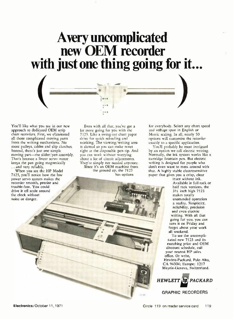
Avery uncomplicated new OEM recorder
with just one thing going for it...
You'll like what you see in our new approach to dedicated OEM strip chart recorders. First, we eliminated all those complicated moving parts from the writing mechanisms. No more pulleys, cables and slip clutches. Instead, there's just one simple moving part—the slider/pen assembly. That's because a linear servo motor keeps the pen going magnetically ... and very reliably. When you see the HP Model
7123, you'll notice how the low power servo system makes the recorder smooth, precise and trouble-free. You could drive it off scale around the clock without noise or danger.
Even with all that, you've got a lot more going for you with the 7123. Like a swing-out chart paper drive for quick reloading and reinking. The viewing/writing area is slanted so you can make notes right at the disposable pen tip. And you can work without worrying about a lot of circuit adjustments. They're simply not needed anymore.
Since it's an OEM machine from the ground up, the 7123
has options
for everybody. Select any chart speed and voltage span in English or Metric scaling. In all, nearly 50 options will customize the recorder exactly to a specific application.
You'll probably be most intrigued by an option we call electric writing. Normally, the ink system works like a cartridge fountain pen. But electric writing is designed for people who don't even want to mess around with that. A highly stable electrosensitive paper that gives you a crisp, clear
trace without ink. Available in full rack or half rack versions, the 31/2 inch high 7123 makes totally unattended operation a reality. Simplicity, reliability, precision and even electric writing. With all that going for you, you can turn it on Friday and forget about your work all weekend. To see the uncompli-
cated new 7123 and its matching price and OEM discount schedule, call your nearest HP sales office. Or write, Hewlett-Packard, Palo Alto, CA 94304; Europe: 1217 Meyrin-Geneva, Switzerland.
HEWLETT â PACKARD
GRAPHIC RECORDERS 1110:
Electronics/October 11, 1971 Circle 119 on reader service card 119

Talk to Gudebrod about your tying operation
this month.. And about Lacing Tapes, harness rooms and systems. About
temperature and vibration . . . speed and rejects! About Nylon, Dacron, Teflon, Nomex, Glass tapes and cords—treated and untreated . . . that meet or exceed military and industrial specifications, about cost comparisons with other methods . . . and all backed up with one hundred years of manufacturing knowledge.
Dacron, Teflon, Nomex—Du Pont Registered Trade Marks
Talk to Gudebrod this month!
Write to this address for prompt return of our
Product Data Catalog.
etectronic3 .2)ivi3ion Dept. 8310
Mudebrod Bros. Silk Co., Inc. 12 South 12th Street, Philadelphia, Pa. 19107
Circle 120 on reader service card
New lalkquallty Instrumentation at famous HEATHKIT do-lt-yoursell savings! (A) New Heathkit solid-state digital multimeter. A true lab-grade digital multimeter at about half the cost of comparable DMMs! 5 overlapping DC voltage ranges, 100 uy to 1000 V; AC ranges, 100 uV to 500 V; 10 ranges measure 100 nanoamperes to 2 am-peres on AC or DC; 6 resistance ranges, 0.1 ohm to 20 megohms. Automatic polarity indicators. Automatic decimal point, over-range light. Precision DC calibrator furnished plus transfer method for AC calibration. Solid-state with cold cathode readout tubes & "mem-ory" circuit for stable, non-blinking operation. Assembles in about 10 hours. Kit IM-102, 9 lbs. ...229.95* New Heathkit 175 MHz scaler & counter combo...for less than $300! (B) The Heathkit IB-101 counts from 1 Hz to over 15 MHz. Hz/kHz ranges & over-range indicator let you make an 8-digit measurement down to the last Hz. 5- (C) digit cold-cathode readout; extremely low input triggering...less than 30 mV at 100 MHz; all solid-state with 26 ICs, 8 tran-sistors. (C) Heathkit IB-102 scaler ex-tends capability well into the VHF range at a price far below a 175 MHz counter. Compatible with virtually any counter. 10:1 & 100:1 scaling ratios give resolution down to 10 Hz...1:1 ratio provides straight-through counting. Solid-state, fully regulated supplies. Carrying handle/tilt stand. Kit IB-101, 7 lbs. 199.95* Kit IB-102, 7 lbs. 99.95* (D) New Heathkit DC-15 MHz dual trace solid-state oscilloscope... $399.95* Features rock-solid triggered sweep; full bandwidth in both automatic & normal modes; complete dual trace capability — Ch. 1, Ch. 2, chop, alternate; X-Y mode with 5% or less phase shift; 24 nsec rise time; 9-position 1, 2, 5 sequence vertical attenuator; 8 x 10 cm rectan-gular flat-face CRT with mu-metal shield. Kit 10-105, 35 lbs.... 399.95*
to:ge l -10
Exciting '72 Catalog Yours FREE
for the Asking
aM3
um_
HEATH COMPANY, Dept. 520-28 Benton Harbor, Michigan 49022
I: Rush my new Heathkit Catalog D Enclosed is $ plus shipping. Please send model(s)
Name
Address
City State Zip Prices & specifications subject to change without notice. *Mail order prices; F.O.B. factory. TE-249
(A)
New products
$1.07 to 97 cents for 28-lead pack-ages, depending on quantity, and from $1.30 to $1.18 for 40-lead packages. They are available within six weeks of receipt of order. 3M Co., St. Paul, Minn. 55101 [396]
Circuit card connector uses
low-withdrawal-force contact
Two-piece metal-to-metal pc card connector features a contact with a withdrawal force of one to six ounces. Contact is designed to pro-vide low insertion and extraction forces, permitting mating of large
numbers of contacts without me-chanical jacks, screws, or cams. Called series 8219, connector is a high-density unit with contacts spaced on 0.050-in. centers. Connec-tor sizes are 18, 30, 36, 42, 54 and 72 contacts. Elco Corp., Willow Grove, Pa. 19090 [400]
DIP handler feeds and sorts
up to 4,000 units per hour
Integrated circuit handler, model lc 2500A, accepts dual in-line packages having from eight to 24 leads. It can handle up to 4,000 devices per hour in general-purpose applications of feeding and sorting DiPs, such as digital and linear integrated circuits, pulse transformers, and resistor net-works. The unit accepts most com-mercially available shipping maga-zines and interfaces with all test systems using TTL or DTL levels. Test leads are brought out in short wire lengths to connector, resulting in low capacitance. Price is $6,500. Computest Corp., 3 Computer Dr, Cherry
Hill, N.J. [397]
120 Circle 141 on reader service card Electronics/October 11, 1971
HOW MANY
MILLIONAIRES ARE THERE IN THE UNITED STATES?
... and how many NEW mil-lionaires join the ranks every year? How did they acquire their wealth? The number and the reasons may astonish you! This amazing story is revealed in a valuable new booklet. "NEW ROADS TO WEALTH AND OPPORTUNITY." Even more exciting are the factual details about a specific business opportunity that is nothing short of a gold mine. Why? Because, as an asso-ciate of the organization providing the oppor-tunity, you help others to succeed. For your free copy of "New Roads to Wealth and Opportunity," phone, wire, or write immediate-ly to:
E.L.E.K. INTERNATIONAL Box 22125.C/sneer, Colorado 80222.(303) 757-5500
CIRCLE 970 ON READER SERVICE CARD
RADAR SYSTEMS GROUND AND AIRBORNE. AUTOMATIC TRACKING ANTENNA SYSTEMS. NIKE AJAX. NIKE HER-CULES. M-33. NISCI-1A. MPS-19. MPS-9. SCR 584, TPE-1D. TPS-28. FAA-ASR-2. AIRBORNE SYSTEMS. APN-84. APN-102. APS-20. APS-27. APS-45. DPN-19. DIGITAL COMPUTERS. IBM 650. IBM 704. e LARGEST INVENTORY OF RADAR AND
MICROWAVE FOUIPMEN7 IN THE WORLD.
RADIO RESEARCH INSTRUMENT CO. 3 QUINCY ST., NORWALK, CONN. 06850 12031 853-2600
CIRCLE 969 ON READER SERVICE CARD
ifiniti DISPENSER AIN OPERATED
for miniature potting and encapsulating
Avallable en 3 sties
6cc • 12cc • 30cc
PHILIP FISHMAN COMPANY CAMERON ST.. WELLESL L Y MASSACRUSETTS 02111
CIRCLE 968 ON READER SERVICE CARD
HARD-TO-FIND PRECISION TOOLS
Lists more than 1700 items—pliers, tweezers, wire strippers, vacuum systems, relay tools, optical equipment, tool kits and cases. Also includes four pages of useful "Tool Tips" to aid in tool selection.
.-TECT•TEIMCST -r001,13 a..d. 4117 N. eette Street, %mix, Arise. VATS
CIRCLE 967 ON READER SERVICE CARD
Radiation Devices Co.
2
3 4 5 8 7 a
e 10 8 6—L17j-a
1.5
1.1 12 13 3.
3
OEM'S — BROADCASTERS
UNIVERSITIES — SERVICE COMPANIES
Rev.,, Our Economical L.. oilnstrument,. Acce.sobas, and Signal Proceseng Components Spanning The Frequency Ran, From D Ç to 2 Gliz To Get Best Value For Your Electrono, Dollar Brochures am1 AppIxebon Nor., Are
Available Upon Tour Ro,,,,,
RADIATION DEVICES CO BOX 8450, BALTIMORE, MD. 2234
CIRCLE 966 ON READER SERVICE CARD
SOLD!
-Please discontinue our ad in 'Search-
light' as we have sold the equipment
through this advertising." Can "Search-
light" Serve You?
INVITATION TO DEMONSTRATE AN AUTOMATIC VEHICLE IDENTIFICATION
SYSTEM FOR BUSES
All present or prospective suppliers of Automatic Vehicle Identification I AVI I systems are
invited to demonstrate the performance of their equipment in a preliminary screening test
any time during 1971. Successful systems will provide transponders to be mounted on
buses, and capable of transmitting at least 9,999 individual codes as the vehicle is moving
at least forty miles per hour, to an interrogator located on or near the particular lane in
which the bus is traveling. Systems which demonstrate this capability in the approximately
two-hour screening test involving temporary mounting of transponders on three buses and
temporary installation of an interrogator and appear promising with respect to final installed
costs and benefits, will be invited to participate in a full scale test.
Lasting at least six months, the full test will involve approximately forty buses each
equipped with at least one transponder from each participating supplier. At least one inter-
rogator from each supplier will be installed. Signals from each bus will be transmitted to a
computer at the Lincoln Tunnel, which will be checking performance of the AVI systems and
interpreting the AVI information to determine the actual travel time of individual buses
through the corridor. Transponders and interrogators are to be supplied and maintained
without cost to the test. Costs for installing transponders and interrogators, transmitting
signals, computer processing, evaluating and reporting the performance of the candidate
AVI systems will be borne by the project.
The United States Department of Transportation has authorized the test to evaluate the
benefits and costs of an Automatic Vehicle Identification (AVI) system for buses using the
1-495 corridor between the New Jersey Turnpike and the Port Authority Bus Terminal. Par-
ticipating agencies include the Tri-State Regional Planning Commission, The Port of New
York Authority, the New Jersey Department of Transportation, the New Jersey Turnpike
Authority, and Transport of New Jersey (the major operator of interstate buses in the New
Jersey-New York area).
If the full test is successful, recommendations will be made to USDOT for equipping most,
if not all, buses using the Port Authority Bus Terminal with an AVI system. Installation of a
system of this magnitude is likely to set the pattern for more widespread introduction of AVI
for such purposes as fleet control by truck and other operators, automatic toll collection,
motor vehicle administration, etc.
Interested suppliers may obtain a copy of "Feasibility Study-Automatic Vehicle Identifica-
tion Systems" from the Clearinghouse for Federal Scientific and Technical Information,
Springfield, Virginia 22151. The Reference No. is PB 185387, and the cost is $3. This study
was performed for the United States Department of Transportation to determine the feasi-
bility of adopting a national standard for an AVI system.
Prospective suppliers desiring further information are invited to contact Mr. Robert S.
Foote; Manager, Tunnels and Bridges Research Division; The Port of New York Authority;
Ill Eighth Avenue, New York, New York 10011; telephonei212) 620-8144.
Remember ...
MAIL MOVES
THE COUNTRY but
ZIP CODE MOVES
THE MAIL
Electronics/October 11, 1971 121

Now—complete coverage of Electronic Measurement—in 1 Vol.
Electronic Measurement and Instrumentation by Bernard M. Oliver and John M. Cage 720 pp. $29.50
This is the most complete, current work on elec-tronic measurement available. It reviews the scien-tific philosophy of measurement, discusses draw-backs and opportunities of network theory, and details the latest information on instruments and instrument systems . . . oscillography . . optimiza-tion of digital techniques for signal analysis . . . en-gineering noise measurement . . . theoretical bases of network applications to measurement . . . and topics of similar engineering importance.
Computer techniques for practicing engineers
Application of Computers to Engineering Analysis by John R. Wolberg 288 pp. $14.50
This new book tells how to make effective use of the computer in engineering analysis and outlines the principles of developing mathematical models from problem statement to debugged model. It provides useful numerical techniques, practical aids, methods for evaluating program quality, alternatives and adap-tations to new systems and case studies of real engineering problems. It offers a systematic approach to the kinds of computer analysis problems engineers repeatedly encounter and explains advanced con-cepts and techniques that can otherwise be picked up only through experience.
A pocket-sized guide to 1500 essential engineering formulas
Engineering Formulas by Kurt Gieck 384 pp. $8.50
slow you can have at your fingertips the engineering lormulas you use most often. This unique, reliable, practical pocket book brings together over 1500 for-mulas and 300 diagrams to simplify engineering cal-culations and is printed on one side of each page to provide room for your notes. It presents tables of measurement, areas, solid bodies, trigonometry, ana-lytical geometry, special functions, differential cal-culus and statistics and provides formulas of kine-matics, dynamics, hydraulics, heat strength, machine parts, electrical engineering, optics, and chemistry.
Now available in book form—ELECTRONICS' most significant articles on computer memory technology
Electronics Computer Memory Technology Edited by Wallace B. Riley 263 pp. $14.50
Written by outstanding authorities, these articles ex-plain how the various forms of computer memories work, how similar ones vary from each other, which systems major businesses and industries are using, and what systems are on the planning boards. Ferrite cores, thin films, MOS and other semi-conductor memories, read-only memories, electromechanical and acoustic memories, electro-optic and opto-elec-tronic forms, sonic films, cryoelectrics, ferroelectrics, memory testing, special memories, using memories to cut costs, and making memories stand up under severe military applications—all these and many more areas are covered.
Also of special interest to ELECTRONICS readers
Organizing for Innovation-A Systems Approach to Technical Management—by J. A. Morton 192 pp. $11.50
A highly successful, internationally known engineer-manager shows how to motivate and integrate creative personnel in technological organizations.
Intrinsic Safety-The Safe Use of Electronics in Hazardous Locations—by R. J. Redding, F.I.E.E. 192 pp. $12.50
The world's foremost authority on intrinsically safe design shows how safety is built into basic design without performance or convenience loss and within budget.
McGraw-Hill Book Co.dept. 23-EL-1011 — I
330 W. 42nd St., New York, N.Y. 10036 I
ISend me the book(s) checked below on 10 days' approval. At the end of that time I will remit price plus tax, postage and handling or return book(s) postpaid. This offer valid only in U.S. and subject to accept- I
l ance by McGraw-Hill.
l [I] Electronic Measurement and El Electronics Computer Memory I Instrumentation (476500) D Application of Computers to Ilj Technology (529159) Organizing for I
Engineering Analysis (713006) Innovation (434204) I II Engineering Formulas (232024) D Intrinsic Safety (942242)
I Name
I I Address
l City State Zip I
L 23-EL-1011 , _1
SOLDERING + DESOLDERING +
RESOLDERING
SOLDER( JABILITY ELEMENTARY TO ELITE
WORLD'S MOST PRACTICAL SOLDER HANDLING TOOLS
SOIDAPI/IZZ". • SOIDAVAC
sort91PUize
Desoldering Tools
4 SOIDAYAC
• LIGHT WEIGHT, PORTABLE • SELF-CLEANING • FAST, VACUUM ACTION
eolimsvp. 111EPSSOLDERING •
One tip applies. removes solder
fflts driL SOLDERING TOOLS
• EXPERT CRAFTSMANSHIP • FAST SOLDERING CYCLES
LONER SOLDERING INSTRUMENT •
EASY KNOB CONTROL
TEMPERATURE SETTING
IN A CLASS BY ITSELF FOR YOU ALONE
ELECTRONICALLY CONTROLLED
Send for our FREE 12 page
BOLDER ABILITY manual
E EDISY Xt>7 ▪ 15954 AMNIA STREET S VAN NUTS, CALIFORNIA 91406 Y. PHONE (213) 989.2324
N® TELEX NO. 65-1469 EDSYNEX VAN
* U S. and Foreign Patents Appited For Ads in EEM, MAS, EBG, AE, IR. and EPAC Catalogs
idleOrest THERMAL GUARD SOLDERING INSTRUMENT HOLDER
idleOrest 7 with
LONER Circle 142 on reader rvice card
la YOU'RE WHISTLING IN THE DARK...
if you think that heart disease and stroke hit only the other fellow's family.
C. ,ntrrhurei h> the
GIVE ... so more will live
HEART FUND
1:)2 Circle 122 on reader service card Electronics/October 11, 1971

New products
Semiconductors
TI adds three Schottky TTLs
High-speed MSI units include
arithmetic logic circuit
with 15-nanosecond add time
An easy way for designers to up-grade the speed of their conven-tional transistor-transistor-logic equipment is to use Schottky-clamped Tit, but not all popular functions are available in sTTL.
Texas Instruments, which produces the only generally available si-n. line, has now expanded its family with high-speed versions of three popular TTL MS! circuits. The three provide speeds previously obtain-able only with emitter-coupled logic, which can not be conveniently added to a TTL system.
First in the trio is the SN54S/74S181 arithmetic logic unit, the Schottky version of the sN54/74181. This Ms! function has proved a great attraction to users, for it can save many packages; Motorola has even taken the num-ber (181) for an ECL part perform-ing the same function even though it isn't a plug-in replacement. The S181 performs 16 binary arithmetic manipulations on two 4-bit words, including add, subtract, decrement, and direct transfer. Typical add/subtract time is only 15 nanoseconds (the conventional part requires 24). The 181 also performs 16 logic functions of two Boolean variables, including NAND, AND,
NOR, OR, and exclusive-OR.
Power dissipation of the 54S/74S181 is about 700 milliwatts, or 10 mw per gate, and it operates from the standard 5-v Tn., supply. The plastic DIP, commercial range 74s181 is priced at $26 in 100-piece quantities, and delivery is 2 to 4 weeks. Military range units and ce-ramic DIP and flat packs are also available. The sN54S/74S153 is a dual 4-to-
1 multiplexer, the Schottky version and plug-in replacement for the 5N54/75 153. It can be used to con-vert serial to parallel data or to ran-domly select data from a number of sources. Typical delay time from the data input is 6 ns, compared to 14 for the standard 153. Power dissipa-tion is typically 225 mw. Price is $6.85 for the plastic version in quan-tities of 100. The third new Schottky part is a
110-MHz dual type D flip-flop, the sN54S/74S74, a plug-in replace-ment for the standard 7474 and high-speed 74H74 flip-flops. Up to now, 'Fri, was limited to about 40 wiz input. Each half of the unit fea-tures a typical propagation delay of 7 ns. This part, unlike ECL versions, is a true dc-coupled flip-flop rather than a tracky ac type. Power dissi-pation is typically 75 mw per flip-flop. The least expensive version, the
sN74S74 in plastic, costs $3.01 in quantities of 100. Texas Instruments Inc., Inquiry Answering
Service, Box 5012, M/S 308, Dallas, Texas
75222 [411]
Unijunction transistors in
plastic are programable
Programable unijunction transis-tors, series Pl3T1-2 are packaged in To-92 cases constructed from an
epoxy compound featuring moisture resistance and stable performance under high humidity. The units are planar passivated. Price is as low as 55 cents in 1,000 quantities. Unitrode Corp., 580 Pleasant St., Watertown,
Mass. 02172 [415]
Optical switch provides
50 ns square-wave rise time
Optical switch, model os-391s-060 or -200, offers Schmitt trigger cir-cuitry in a device using LEDs and phototransistors. This circuitry al-lows the switch to directly drive DTL and Tn.. levels. Typical square-wave rise time is 50 ns. and the trigger
e.
permits clean logic switching and wave shaping with no oscillations in response to slow mechanical action through the optical switch. Price is $12.90 in 100 lots. HEI Inc., Jonathon Industrial Center, Chaska,
Minn 55318 [417]
Read-only memories
are field-alterable
Off-the-shelf read-only memory units can be supplied after customer specifies desired data contents in
punched tape, card, or tabulated listing formats. Bit capacities range from 8 k to over 200 k per system, and a variety of basic word/bit con-figurations are available, many of
Electronics/October 11, 1971 123

New products
them alterable to give additional formats by changing the input code and drive matrix circuitry. Price is 0.8 to 2 cents per bit depending on speed, capacity, and quantity. Datapac Inc., 3180 Redhill Ave., Costa
Mesa, Calif. 92627 [419]
LED display and decoder
included in plug-in package
Light-emitting diode displays called GaAsLites include a digital display-module, solid state indicator lamps, and a display bezel assembly. The display-module combines a seven-segment display, current limiting re-sistors, and a decoder/driver into one plug-in package. Price is $21 to $12 depending on quantity. Monsanto Co., 277 Park Ave., New York,
N.Y. 10017 [413]
Optical coupler offers high
input-output isolation
Optical coupler permits ± 3,000 (or more) volts isolation between input and output sides and higher output-input current ratios. The unit can also serve as a high-speed solid state switch or relay, as an interface de-
vice between systems, or as a line driver-receiver element. It is housed in a DIP compatible with standard 14-pin IC sockets. M7 Inc., 210 Campus Dr., Arlington, Heights,
III. 60004 [416]
Low-cost phototransistor
aimed at card-reading jobs
Model T1,78 phototransistor for card-reading and other applications features a light current of 7 milliam-
peres typically at 20 milliwatts per square centimeter. Dark current is 25 nanoamperes at 30 volts reverse voltage, and continuous power dissi-
pation at 25>C is 50 milliwatts. The unit has an emitter-collector voltage and a collector-emitter voltage of 7 and 50 v respectively. Price is 50 cents in 1,000 piece orders. Texas InstrJments Inc., P.O. Box 5-12, MS/
308, Dallas, Texas 75222 [418]
Buffer ICs drive clocks,
lamps, lines, memories
TTL Quad 2 NAND buffers drive transistor-transistor logic and DTL clock lines, lamps, medium length data lines, TTL gates, and high ca-pacitive loads such as mos memory arrays. Unit output is low only when all inputs are high, and propagation delay time is less than 15 ns. Version N7437A is 78 cents in 100 to 999 quantities, and the s5438F is $5.04 in the same quantities. Signetics Inc., 811 E. Argues Ave., Sunny-
vale, Calif. 94086 [414]
Quad-line receiver design
gives high noise immunity
Quad-line receiver, type HD-1489A, is designed to interface between single-ended transmission lines and
data terminals. Typical hysteresis is 1.15 v, resulting in high noise im-munity, and a response control pin in each of the four circuits permits the filtering of high-frequency noise or the paralleling of several receiv-ers on a single line. Price is $4 in quantities of 100 to 999. HarrisSemiconductor, Melbourne, Fla. [420]
IC sockets accept TO cans
with up to 12 leads
A series of 12 integrated-circuit sockets, type 131-55, fit into To packages with up to four leads on a 0.100-in, pin circle, and up to 12 leads on a 0.200-in, pin circle. The
body material is made of glass-filled nylon to provide continuous oper-ation from -55 to + 125°C. Usage is in a wide variety of production ap-plications, and three different styles are available. Barnes Div., Bunker Ramo Corp., 24 N. Lans-
downe Ave., Lansdowne, Pa. 19050 [487]
C/MOS digital ICs
offered in chip form
Unencapsulated chips, previously available in standard packages, are offered in a line of logic circuits se-lected for a wide variety of appli-cations in hybrid design such as au-tomotive circuits, industrial controls, appliances, clocks, medical electron-ics, computers, and communications equipment. Prices of the cD4000A series, for 100 to 900 lots, range from $1.98 to $8.95 depending on type of circuit. RCA Commercial Engineering, Harrison, N.J.
07029 [486]
124 Electronics/October 11, 1971

NEW! First comprehensive guide to every aspect of TTL devices and their practical applications
DESIGNING WITH TTL INTEGRATED CIRCUITS Prepared by the IC Applications Staff of Texas Instruments Incorporated
Edited by Robert L. Morris and John R. Miller
This thoroughly comprehensive and practical volume— the first to explore the entire family of TTL integrated circuits—is a complete source book on the newest, most versatile, reliable, and economical innovation in systems technology. It covers not only design philosophy, eco-nomics, basic descriptions, and electrical performance of TTL devices; but many practical applications of the circuits in digital systems.
It will save you time and work by providing many com-pleted designs easily converted to your particular needs ... reduce costs by suggesting the most cost-effective integrated circuits to use in your system...help your de-cision making by reviewing all modern logic types and giving you a comparison of the characteristics of sub-series within the TTL series. The first book devoted exclusively to the transistor-
transistor logical family of integrated circuits, this volume will prove invaluable to electronics engineers, computer designers, and systems analysts and to non-engineer managers who want information on the best uses of TTL devices.
384 pages, 390 illustrations, $18.50
• MAIL COUPON TODAY • • • McGraw-Hill Book Company • • 330 West 42nd Street, New York, N. Y. 10036
e • Send me Texas Instruments' DESIGNING WITH TTL INTE- , • GRATED CIRCUITS (637458) for 10 days' examination. At the . • end of that time I will remit $18.50 plus tax, postage, and han- •
• filing charges. If I decide not to keep the book I will return It In •
• the carton provided within 10 days. (Remit in full with coupon,
• • plus tax, and McGraw-Hill pays all delivery costs.) • • • Name • • •
Address e • • City State Zip • e Otter good In U.S. and Canada only. 23-6-7 • • • • • • OOOOO • • • • • • • • • • • • • • • • • • •
DIGITAL VOLTMETERS by the originator...
MX-1 FIVE DIGIT AUTO-RANGING DIGITAL VOLTMETER
LX-2 FOUR DIGIT AUTO-RANGING DIGITAL MULTIMETER
MX-2 FOUR DIGIT HIGH ACCURACY DIGITAL MULTIMETER
X-3A THREE DIGIT DIGITAL MULTIMETER
• •
GSM-64 FIVE DIGIT MIL SPEC DIGITAL VOLTMETER
X-2 MIL FOUR DIGIT FLIGHT LINE DIGITAL MULTIMETER
20 YEARS OF RELIABILITY
1€1 NON-LINEAR SYSTEMS, INC. DEL MAR, CALIFORNIA (714) 755-1134 / TWX 910 443 1132
Electronlcs/Oc:ober 11, 1971 Circle 125 on reader service card 125

ACTIVE FILTERS For E ectronic Signal Processing. Low Pass, High Pass, Band Pass Band Reject, Notch or Spike
I:. e '
goR ;F"tè It
Experiment with our variable portable battery or line operated filters and then ...
select from our fixed filters for P.C. mounting:
• Now available with cermet pots for improved performance
A.P. CIRCUIT CORP. 865 West End Ave., New York, N.Y. 10025
Tel. (212) 222-0876
CrrHe 1.)6 reader service card
NEW
Catalog of pressure sensitive electronic
component drafting aids
ime saving electronic component MA shapes, patterns and conductor line tapes are listed by the thousands in By-Buk's new P-50 catalog. This easy to use, cost-saver index of pressure sensitive printed circuit drafting aids is the source book of ideas for engineers, designers and draftsmen interested in faster, more accurate artwork layouts. Find new ways to reduce the tedium of repetitive artwork with individually die cut artwork patterns in opaque black, transparent red and transparent blue materials.
FREE CATALOG Send today for a free copy of the new P-50 catalog and
FREE SAMPLES a selection of samples.
BY-BUK COMPANY 4326 W. Pico Blvd. Los Angeles, Calif. 90019 (213) 937-3511
New products/Materials New books
Acrylic optical components includ-ing prisms, beam splitters and light pipes can be custom-generated in a variety of sizes. Impact strength is said to be six to 17 times greater than glass, and other features in-clude low cost, high visible light transmittance, and haze held to 2% or less. Applied Products Corp., 451 Caredean Rd., Horsham, Pa. [481]
Solder process called Solderex is for through-hole rack plating of printed circuit boards. The tin/lead method does not emit hazardous or offen-sive fumes, and has high throwing power. It produces bright, readily-flowed 60/40 deposits. Sel-Rex Corp., 75 River Rd., Nutley, N.J. 07110 [482]
Epoxy molding powder, Eccomold 1099, is formulated for transfer-molding applications where low density and/or dielectric constant are required. Typical applications include encapsulation of aerospace components, integrated circuits, coils, capacitors, and semiconduct-ors. Price is from $6 to $8 per pound. Emerson & Cuming Inc., Canton. Mass. 02021 [483]
Epoxy coating powder called Nova-by 6521 is for fast packaging of heat-sensitive electronic compo-nents. Processing temperatures may be as low as 120C, and coating times as fast as one second are pos-sible at higher temperatures. Edge coverage values range from 40% minimum to 65% or higher. Coating thicknesses from 0.010 to 0.035 in. can be obtained with one appli-cation. Rogers Corp., Rogers, Conn. 06263 [484]
Thick-Film Microelectronics Fabri-cation, Design, and Applications Morton L. Topfer, Van Nostrand Reinhold Co., 210 pp., $10.95
No one becomes an expert by read-ing alone; but a book should pro-vide a start in the right direction, some insight into potential trouble areas, and a good list of references to back up statements in the text. Morton Topfer's book fulfills all these criteria. The strongest sections are those
covering technology, equipment, processing, assembly, and pack-aging techniques, which as an ag-gregate make up about half the text. Though each specific topic is neces-sarily brief (it's impossible to com-pletely cover resistor pastes in only two pages) the central points are co-vered.
In the equipment and processing sections, there's a good discussion of screen printing, including a useful table showing production rates. As-sembly techniques are discussed, with special attention to flip-chip and beam-lead connections, while the packaging sector details all the various approaches, including plas-tic encapsulation. About the only point that's open
to criticism is that the sections on applications seem to stray from the main point of the book—they get in-volved in details of circuit operation simply from a circuit standpoint without any real relation to the book's main topic, thick-film tech-nology.
Other sections, on system parti-tioning, reliability, and thick films in hermetic and nonhermetic appli-cations, also contribute to the book's value. Several examples are in-cluded to show how the problems of hybrid design differ from those of discrete circuits. For example, it's pointed out that level shifting usu-ally may be implemented with a ca-pacitor, diode, and resistor clamp, but in the hybrid approach, the large capacitor presents a serious problem. The circuit therefore is re-designed to a resistor-transistor unit, which can be easily handled in hy-brid form. Data on reliability also is included.
126 Circle 143 on reader service card Electronics/October 11, 1971

CONSIDERING Frequency, Time, or Voltage Measurements?
NEED Digital Systems or Time Code Instrumentation?
CALL ELDORADO! .. Eldorado invented the 1 ns Time
Interval Meter
. . . Eldorado invented direct gigahertz frequency measurements
. . . Eldorado pioneered low-cost IC counters
. . Eldorado introduced the first U.S. made electronic calculator at under $200
ELDORADO ELDORADO ELECTRODATA CORPORATION
601 Chalomar Rd. • Concord, Calif. 94520 • (415)686-4200
Circle 127 on reader service card
Meet the Extremists:
MODEL 101
MAGNETOMETER
precision magnetic
MODEL 505 GAUSSMETER • Lowest cost • Self-contained
A completely self-contained instrument for magnetic field measurement.
Measure from
1 Gamma to
50,000 Gauss!
A complete line of
measuring equipment.
r
MODEL 750 GAUSSMETER • Wide range • Versatile Features wide measure-ment range, high ac-curacy and ease of operation.
MODEL 3265 GAUSSMETER • Unexcelled readability • High precision
Features absolute, dif-ferential and incre-mental measurement operations.
Send for Free technical booklet on AFL Magnetics equipment.
RFL Industries, Inc. Instrumentation Division • Boonton, N. J.
We make 100 + different --- kinds of termination , hardware but that's not the end s
\4/
leie r-rwet
We are in termination hardware because our customers asked us. They had some definite ideas about miniature posts, sockets, plugs or test clips. Binding post caps that don't melt at solder-ing temperatures, for example. Most of our termination
products were developed for superior insulation, dielectric strength, con-tact resistance. (Transis-tor sockets with minimum insulation resistance of 500,000 megohms at 100 VDC.) But despite the length
of our line, it's not the
end. We will develop new hardware for new appli-cations with the same commitment to quality in design, materials and workmanship that has fed the growing demand for our rotary and push button switch lines. Like to know more?
Write or phone for our latest general engineer-ing catalog. Grayhill, Inc., 523 Hillgrove Ave., La Grange, Ill. 60525, (312) 354-1040.
Grayhill pioneers in miniaturization
Circle 144 on reader service card Circle 145 on reader service card 127

New Literature SUBJECT: Toroidal Cores —Pata Sheets
USE: RF Coils, Chokes, Filters, Transformers
FREQ: To 200 MC.
SOURCE: Micrometals
MICROMETALS 228 N. SUNSET, CITY OF INDUSTRY, CALIFORNIA 91744
(213) 968-4718
Circle 128 on reader service card
e If pu seal, press, cut, weld, braze, form, inspect... AND ASSEMBLE... we can build a machine to do it faster, better, at lower cost!
No. 4175 Automatic Diode Assembly Machine (Also resistors and capacitors)
We've been designing and manufacturing auto-matic "process and assembly" equipment for the electronics industry for over 40 years. To-day, thousands of Kahle machines are in use throughout the United States and in over 30 countries around the world. They produce re-sistors, capacitors, diodes, lamp components and assemblies, encapsulated glass assemblies, and a wide range of diversified electronic com-ponents and assemblies.
Our unique experience enables us to arrive at design solutions, produce operating equipment more quickly and less expensively. You de-scribe your process and we'll build you a machine. Call 201 — 867-6500 or write for our free Capabilities Brochure. Kahle Engineering, 3322 Hudson Ave., Union City, N. J. 07087.
Relays. International Rectifier Corp., Crydom Div., 1521 Grand Ave., El Segundo Calif. 90245 has published a brochure describing a line of computer-compatible, solid state SPST ac relays. Specifications and a chart are included. Circle 421 on reader service card.
Linear encoders. Sequential Infor-mation Systems Inc., 249 N. Saw Mill River Rd., Elmsford, N.Y. 10523. A two-page product sheet provides features, applications, and outline drawings of modular optical linear encoders. [422]
Thin film etchants. Transene Co., Route 1, Rowley, Mass. 01969. Techniques for generating thin film microcircuits and data sheets on thin film etchants are included in a 15-page bulletin. [423]
Audio signal delay. Gotham Audio Corp., 2 W. 46th St., New York, N.Y. 10036 has available a six-page brochure describing the Delta-Tau model 101 for digital processing of audio signals. [424]
Flat load cells. Strainsert Co., Bryn Mawr, Pa. 19010. Brochures 365-2 and 365-2mP give dimensional data, specifications, and model designa-tions for general-purpose, precision universal, and compression flat load cells. The four-page bulletins de-scribe mechanical properties and in-clude tabulations of deflection and spring rates. [425]
Computer graphics system. Concord Control Inc., 1282 Soldiers Field Rd., Boston, Mass. 02135. Two bro-chures describe a graphic data pro-cessor which is a digitizer, plotter, and edit station; and two high-pre-cision plotter systems, the MK 8 and the Nix 10. [426]
Panel meters. Digilin Inc., 1007 Air-way, Glendale, Calif. 91201. A set of technical notes describes the uses of digital panel meters, with specific applications for the company's line of 21/2 -, 31/2 -, and 4-digit meters. In-cluded is a discussion of noise rejec-tion, active filtering techniques, and display of sensor outputs. [427]
128 Circle 146 on reader service card Electronics/October 11, 1971

precision magnetic measuring equipment.
CONSIDERING Frequency, Time, or Voltage Measurements?
NEED Digital Systems or Time Code Instrumentation?
CALL ELDORADO! . Eldorado invented the 1 ns Time Interval Meter
. Eldorado invented direct gigahertz frequency measurements
. . . Eldorado pioneered low-cost IC counters
. . . Eldorado introduced the first U.S. made electronic calculator at under $200
ELDORADO ELDORADO ELECTRODATA CORPORATION
601 Chalomar Rd. • Concord, Calif. 94520 • (415)686-4200
Circle 127 on reader service card
Meet the Extremists:
MODEL 505 GAUSSMETER
• Lowest cost • Self-contained
A completely self-contained instrument for magnetic field measurement.
Measure from
1 Gamma to
50,000 Gauss!
A complete line of
MODEL 750 GAUSSMETER • Wide range • Versatile
Features wide measure-ment range, high ac-curacy and ease of operation.
e jelle
MODEL 3265 3265 GAUSSMETER
• Unexcelled readability • High precision
Features absolute, dif-ferential and in•re-mental measurement operations.
Send for Free technical booklet on RFL Magnetics equipment.
RFL Industries, Inc. Instrumentation Division • Boonton, N. J.
We make 100 + different kinds of termination /- 4.4 hardware but that's not the end
"1/4
die e,
We are in termination hardware because our customers asked us. They had some definite ideas about miniature posts, sockets, plugs or test clips. Binding post caps that don't melt at solder-ing temperatures, for example. Most of our termination
products were developed for superior insulation, dielectric strength, con-tact resistance. (Transis-tor sockets with minimum insulation resistance of 500,000 megohms at 100 VDC.) But despite the length
of our line, it's not the
end. We will develop new hardware for new appli-cations with the same commitment to quality in design, materials and workmanship that has fed the growing demand for our rotary and push button switch lines. Like to know more?
Write or phone for our latest general engineer-ing catalog. Grayhill, Inc., 523 Hillgrove Ave., La Grange, Ill. 60525, (312) 354-1040.
Grayhill pioneers in miniaturization
Circle 144 on reader service card Circle 145 on reader service card 127

New Literature SUBJECT: Toroidal Cores—Data Sheets
USE: RF Coils, Chokes, Filters, Transformers
FREQ: To 200 MC. SOURCE: Micrometals
MICROMETALS 228 N. SUNSET, CITY OF INDUSTRY, CALIFORNIA 91744
(213) 968-4718
Circle 128 on reader service card
e If qou seal, press, cut, weld, braze, form, inspect... AND ASSEMBLE... we can build a machine to do it faster, better, at lower cost!
No. 4175 Automatic Diode Assembly Machine (Also resistors and capacitors) ----
We've been designing and manufacturing auto-matic "process and assembly" equipment for the electronics industry for over 40 years. To-day, thousands of Kahle machines are in use throughout the United States and in over 30 countries around the world. They produce re-sistors, capacitors, diodes, lamp components and assemblies, encapsulated glass assemblies, and a wide range of diversified electronic com-ponents and assemblies.
Our unique experience enables us to arrive at design solutions, produce operating equipment more quickly and less expensively. You de-scribe your process and we'll build you a machine. Call 201 — 867-6500 or write for our free Capabilities Brochure. Kahle Engineering, 3322 Hudson Ave., Union City, N. J. 07087.
Relays. International Rectifier Corp., Crydom Div., 1521 Grand Ave., El Segundo Calif. 90245 has published a brochure describing a line of computer-compatible, solid state SPST ac relays. Specifications and a chart are included. Circle 421 on reader service card.
Linear encoders. Sequential Infor-mation Systems Inc., 249 N. Saw Mill River Rd., Elmsford, N.Y. 10523. A two-page product sheet provides features, applications, and outline drawings of modular optical linear encoders. [422]
Thin film etchants. Transene Co., Route 1, Rowley, Mass. 01969. Techniques for generating thin film microcircuits and data sheets on thin film etchants are included in a 15-page bulletin. [423]
Audio signal delay. Gotham Audio Corp., 2 W. 46th St., New York, N.Y. 10036 has available a six-page brochure describing the Delta-Tau model 101 for digital processing of audio signals. [424]
Flat load cells. Strainsert Co., Bryn Mawr, Pa. 19010. Brochures 365-2 and 365-2mP give dimensional data, specifications, and model designa-tions for general-purpose, precision universal, and compression flat load cells. The four-page bulletins de-scribe mechanical properties and in-clude tabulations of deflection and spring rates. [425]
Computer graphics system. Concord Control Inc., 1282 Soldiers Field Rd., Boston, Mass. 02135. Two bro-chures describe a graphic data pro-cessor which is a digitizer, plotter, and edit station; and two high-pre-cision plotter systems, the MK 8 and the MK 10. [426]
Panel meters. Digilin Inc., 1007 Air-way, Glendale, Calif. 91201. A set of technical notes describes the uses of digital panel meters, with specific applications for the company's line of 21/2 -, 31/2 -, and 4-digit meters. In-cluded is a discussion of noise rejec-tion, active filtering techniques, and display of sensor outputs. [427]
128 Circle 146 on reader service card Electronics/October 11, 1971

D,ck
Wolters
The custom touch: Suddenly a man's car is his castle
One prosperous New York motorist hardly flinches anymore when buzzers sound and lights flash on the dashboard as he turns the ignition key. The audio-visual display is merely a built-in warning system reminding him to fasten his seat-belt. Federal safety regulations say a new car (all built after Jan. 1) has to have one. But how about the refrig-erator, telephone and television set in the back seat? That was his own idea. Between government edicts on safety
"extras" and his own desire for person-alized motoring, the affluent American car buyer can—and increasingly does— keep a platoon of white-smocked tech-nicians busy installing, adjusting and re-pairing a bevy of intricate hardware that has very little to do with moving the car
OCTOBER 1971
CARS
A fast look at the new 72s
INVESTMENTS
Mutual funds race for profits Taking a flyer with high-yield corporate bonds
FAMILY
Parents' plight; the school and college drop-out
THE GOOD LIFE
Tailgate parties: pass the Klops and the mulled wine
TRAVEL
Washington's new Kennedy Center
HEALTHY, WEALTHY AND WISE
down the road. For anywhere from $300 (for a 9-in. TV set) to $30,000 and up (for the accoutrements of a salon-on-wheels), a veritable arsenal of luxury equipment is being marketed for the mo-torist with a penchant for comfort, con-venience, and individual expression on the road. Any car nowadays can be person-
alized, but usually the investment is war-ranted only on the costlier ones, such as the Continentals, Cadillacs, Thunder-birds, and the like. Only the owner's imagination limits what can be done to them in the way of customization. Whole new interiors are being fashioned for some out of crushed velvet. Others have deep-pile carpeting, or one-way glass. Station wagons are being made out of Cadillacs and Lincolns, which do not or-dinarily come from the factory in that form. The list of possible custom "ex-tras" is just about endless: • A 21/2 cu. ft. bar and refrigerator
PERSONAL BUSINESS like all McGraw-Hill publications, is written for a select audience. It is devoted entirely to your personal interests and activities as an aid to better management of your time and money.
that starts at about $1,000. A complete service of goblets, decanters, ice bucket and walnut cabinet can run to $1,700. • A toaster and coffeemaker set with
a 110-volt A.C. adapter, at least $700. • A rolling executive conference
room installed in a limousine. It starts at $10,000, but a walnut cabinet-desk en-semble can be had for only $1,600. • High-intensity lights for reading. A
small battery-powered unit may cost $100. An installation of several Tensor or quartz lamps can run to $1,000. • Personal television. A 9-in, black-
and-white set may cost only $300, but a large color set can hit $1,700—and also present some tricky antenna problems. • Private communications. Tele-
phones have to be purchased from the local telephone company, but a short-wave radio makes a good substitute, at between $300 to $1,500. A custom paint job can run $1,335
and up; consider, for instance, one in Morono Pearl, which gives something in the way of added value by seeming to change colors as the car travels down the highway. On the less frivolous side, executives and professional men claim that customizing to provide on-the-road conference space or such things as
Copyright 1971 Personal Business Personal Business 1

You can't replace a $30,000 house with $20,000 worth of insurance. If you haven't increased the value of your homeowners insurance recently, you may be seriously under-insured. Inflation has upped the value of the average house by 43% over the past ten years.
See a State Farm agent about insuring your home and your
possessions for what they're worth today with no worry about tomorrow ...because a special inflation coverage feature automatically increases the amount your policy pays, as inflation continues to boost the cost of things. We're the world's largest home insurer. We protect
you from loss by fire, tornado, burglary, vandalism and more.
State Farm Fire and Casualty Company. Home Office: Bloomington, Illinois.
For your home, your life, your health and your car—State Farm is all you need to know about insurance.
State Farm inflation-coverage
Homeowners Insurance

stereo sound on which technical and business reports can be played while driving return at least some of their cost in time saved.
Detroit's car builders will install some luxury items, such as plush carpeting and stereo tape sets (which start at $35), right at the factory. With the new 1972 cars, indeed, they are offering a host of comfort-and-convenience items. Air-conditioning (starting at $400) and "climate control" devices ($500 up) are increasingly common options. Rear win-dow defoggers ($30) take some of the sting out of winter driving, and electric seat adjusters can be had for between $90 and $140.
For driving comfort and safety, the manufacturers gladly come through with disc brakes, which last longer, stop more smoothly, and come as standard equipment on all Imperials, Cadillacs and Lincoln Continentals; they are at least a $75 option on most other cars. Anti-skid brakes are also now available on Thunderbirds, Mark IVs, Cadillacs and Imperials, for $220 and up. Auto-matic devices are also proliferating. For $50, a motorist can have his headlights rigged to dim automatically as other cars approach. With another $40 attachment, his headlights won't flick off as he leaves the car until he has time to get into the house.
Anti-theft devices on the steering col-umn and warning buzzers to alert drivers that they left the key in the ignition are standard equipment (by law last year), but the sporty Chevrolet Corvette is the only '72 car with an anti-theft audio alarm system as a standard item. One, of course, can be put on any car.
Both domestic and foreign auto com-panies—and a host of custom shops--stand ready to add just about anything a motorist's heart desires. First step in get-ting a customized car is to get the car it-self from a local dealer. Some money may be saved by dealing directly with a custom shop for the alterations, but let-ting the dealer make arrangements may save some headaches. It saves some fretting, too, when an owner realizes that his car is not going to be transformed into the chariot of his dreams overnight. Customizers say he should expect to al-low as much as six weeks for a major job.
Most automobile dealers can recom-mend a custom shop, but two prominent Midwest customizers who do work across the country are Custom-Craft, Inc., a division of American Sunroof Corp. (which builds all sun roofs for U. S. cars) and Moloney Standard Coach Builders of Chicago.
The 1972 models: little change in a mark-time year
The big-splurge so traditional to Detroit's announcements of its new cars is oddly subdued this year. The reason is that Detroit has fewer really "new" cars to talk about than it has had in recent memory. Rising costs, a tight market, and unanswered questions about future federal safety standards (which could dictate major design changes next year) have made it so. There are, to be sure, enough cosme-
tic changes in grilles and exterior metal work to distinguish a '72 model from a '71. But the car buyer who feels he must look over everything new that Detroit has to offer will find he has an easy assign-ment this season. The Ford Motor Co. is the only domestic manufacturer offering a totally different '72 body. The all-new Thunderbird and luxurious Lincoln Con-tinental Mark IV have it. So do the Ford Torino intermediate lines and the Mer-cury Montego.
For the economy-minded, the modest appearance changes in most other lines
New Ford Thunderbird
Chevrolet Caprice
Lincoln-Continental Mark IV
offer a special break. Detroit insiders suggest that a thrifty buyer look over his dealer's '71 left-over cars before signing up for a '72—they are not only lower in list price than the new models, but the dealer% also gets a 5% price rebate from the factory on the out-dated models and may be willing to shave the price even further. The new Mark IV is competing this
year with Cadillac's unchanged Eldo-rado for buyers in the sporty $8,000 and up (far up) range. For luxury at a lower price (in the $5,500 to $8,000 category), shoppers should check the new Thun-derbird, which Ford is pitting against the Oldsmobile Toronado and Buick Riviera, both hardly altered from last year. The all-new Torino and Montego are aimed at the buyer in the mid-$3,000-and-up category, whose alternate choices might be the Chevrolet Chevelle, Pontiac Le-Mans, Dodge Coronet and American Motors' Ambassador—all of which have only received a face-lift for '72.
In a season of minimal change, there are still enough variations to invite some looking. Dodge's top-of-the-line Polaro and Monaco ($4,000 and up) are more different from each other than in several years. The Plymouth Fury ($3,000 and up) and Chrysler ($4,000 and up) also have some new styling worth noting. For the high-style-minded, Detroit observers of the new-model year suggest a close inspection of the Chevrolet Caprice. When it is loaded with extras, it takes on a remarkable Cadillac-like look—and it costs about 40% less, or near $5,000.
{, aellibm

The mutual fund derby is off and running again
Small, fast-moving mutual funds are back in action, and once again there is a profit-performance contest to watch. But they aren't the go-go funds of a few sea-sons back. They are saner, more sober, and managed with more caution. Maybe, just maybe—for an investor—they are a place to lay new bets. "But before step-ping in," says a top Wall Street pro, "a man will want to bone up. Among other things, this means studying the pro-spectus for a change."
In 1967 and 1968, a youthful gener-ation of mutual fund managers refined the art of stock-price appreciation and renamed it to suit the speculating public. They called it "performance" and this quickly became a watchword for smart innovation and unique ways of eval-uating securities for a fund portfolio. The method—as Fred Carr, former head of Enterprise Fund once said—was to "conversationally develop the concept of the company" whose stock was being considered. "Fundamentals" such as price-earnings history and company rank and position in the industry often took a back seat to a company's real or imagined "concept"—or its uniqueness.
The result: a host of fund investments in thinly-capitalized stocks, many of them over-the-counter.
For a time, it worked like clockwork, and men such as Carr, Manhattan Fund's Jerry Tsai, Winfield Growth Fund's Dave Meid, and Security Equity Fund's Fred Alger became as familiar to Wall Street board rooms as a big-city commuter is to broken down trains and delayed buses. By discovering unex-plored "situations" and searching the woodwork for obscure upbeat com-panies, these men of the go-go funds were called "gunslingers"—and they lived and breathed high appreciation. They made the conservative "Dow" and the Standard & Poor's average pale by comparison. In 1967, for instance, Win-field Growth doubled its assets, and Carr's speedy portfolio managers at En-terprise managed a 117.5% jump. Then the clock stopped. The gun-
slingers hadn't reckoned on a crashing bear market. So when the Dow went from its December 1968 high of 995 to a woeful May 1970 bottom of 631, the go-go funds fell in line—and fell apart. It was so bad that even the "little guy"—the naive small investor—figured that too many stocks were overpriced. Suddenly, "fundamentals" became vital again, and even the gunslingers were lining up and pledging allegiance to them.
For nearly 18 months or so, it seemed that the "performance" craze was dead.
But like the Phoenix rising from ashes, a new bull market began to bob and weave last November. With it, the go-go fund managers reappeared. True, the cast of characters has changed (Carr, for one, no longer runs Enterprise), and attitudes have been tempered by past di-saster. But if the results in 1971. are an indication, a number of fund managers are once again taking up the basic pat-tern: fast in-and-out trading, and picking long-shots.
In the first half of this year, the Dow went up a modest 6.23%, and the S&P 500, jumped 8.19%. At the same time, some 55 mutual funds turned in impres-sive gains in asset value of 25% or more, according to Arthur Lipper Corp. in a survey of the fund business. Topping the Lipper list: Channing Venture Fund, a tiny $1-million grown fund with gains of nearly 80%. Channing's style has been not unlike that of the small high-perform-ance funds of years back: 40% of its as-sets riding on two companies—National Patent Development (soft contact lenses, a volatile stock), and Banister Continental (Canadian pipeline). Before Channing sold Banister convertible stock, its investment had doubled. Of course, it is probably much easier
to manage $1-million than it is to over-see $100-million or more. Thus, most of the new-breed high-performance funds are small—most have assets somewhere under $20-million. At this size, they can locate enough small fast-moving "situ-ations" to largely fill their portfolios, whereas $100-million funds are forced into more conservative investments at the expense of high performance. In any case, the manager of the small go-go hopeful must strive to discover the so-called hot stocks—and time their acqui-sition precisely. The investor must learn to live with the idea of taking maximum "reasonable" risk to get maximum gain—or else switch to bluer chips. Though they believe in their approach,
the managers of the small, higher-risk funds are—today—aware that the golden gate can always swing shut. For one thing, the ordeal by fire that saw the Dow decline 50% has not been deftly skipped over by the fund men. They know the real score. High-risk situations and vola-tile stocks still have their old appeal: but for the most part, the go-go mentality that characterized the 1967-1968 bull market period has been diluted to the point where "fundamentals"—meaning sound analysis—are given at least rea-sonable attention. Moral: Review the fast appreciation funds—but do so cau-tiously, with a keen eye on both manage-ment and prospectus.
4 Personal Business

Corporate bonds: booming yields for easy sleepers
Yields in the corporate bond market have been so high lately that investors have been nailing down 8% returns by simply buying bonds of the Bell System. Some have gone even higher in profits by picking such companies as ITT and Chrysler. "But it's crucial to buy qual-ity," says a top bond man on Wall Street. "If you're bond-minded, you want one that will let you sleep at night."
But what about yields that are truly high, in the 11% to 15% range, for in-stance? If sleep is no object, an investor can find literally dozens of unusual situ-ations—what might be called Bonds for Iron Stomachs.
Hunting for high yields is like taking a tour of the disaster areas of American business. Aerospace, airlines, conglom-erates, computer leasing—these indus-tries are fraught with problems that range from the nightmarish to the merely hair-raising. Buying their bonds can be so perilous that ordinary brokers hardly know such securities exist. "Nobody in his right mind would touch those things," says one bond trader who sells strictly "investment grade" paper for large institutions.
Yet some investors—or better, some gamblers—buy them; otherwise, their prices would sink to zero. But, cautions Russell Fraser, the vice-president who heads Standard & Poor's corporate bond rating operation: "You've got to be the kind of guy who takes a crack at new issues in stocks—a really speculative kind of animal."
In general terms, the risks are twofold, and they are very real risks indeed. One is that the corporation's business may get so bad that it can no longer meet the interest payments. In that case, the bonds go into default, and the bond-holder loses his yield. The other risk is that the company may simply go bank-rupt, or go into reorganization to avoid bankruptcy, in which case the investor might very well lose all his principal, too. The other side of the coin, though, is
that yields are fat, and if the company's fortunes improve, the bondholder can make substantial capital gains as well— gains that are taxed at only half the rate of interest payments. Capital apprecia-tion might occur, too, if the operation is taken over by another company. Further,
bondholders, as creditors, rank far higher than stockholders when it comes to gathering in the remains of a defunct business. If the company fails, there is often enough left over from auctions to pay bondholders 1 oe or 150, say, on the dollar.
With this in mind, an adventurous soul might, for instance, runmage among the shards of James Ling's old empire. LTV Ling Altec has a sinking-fund deben-ture—a senior security—with a 63/4 % coupon due to mature in 1988. Originally issued with warrants, since detached and exercised, these debentures trade for around $480, far below their $1,000 par value. At that price the coupon equals a current yield of 14.06%. Savvy bond buyers also deal in yields
to maturity, which are calculated ac-cording to a complex formula that takes into account both compound interest and the capital gain to be scored when (or if) the bonds are payed off at par when they mature. In practice, bonds' market prices usually rise in anticipation as the maturity date nears. In the case of Ling Altec's 63/4 s of '88, the yield to ma-turity works out to nearly 15.5%. J&L Industries, which controls Jones
& Laughlin Steel, has a 63/4 senior de-benture due in 1994. Priced around $490, it has a current yield of 13.78% and a yield to maturity of 14.44%. Oko-nite, a cousin in the Ling empire, has a 61/2 senior debenture of 1988, trading around $460, to yield 14.13% currently, 15.62% to maturity. Okonite was recently taken over by Ling's new ve-hicle, Omega-Alpha. The old holding company, Ling-Temco-Vought itself, has a bond outstanding, the 5s of '88, that trades around $445. Its current yield is 11.24%. Yield to maturity is 13.39%. S&P's ratings, which are familiarly
Beehive: NYSE's busy Bond Room
triple-A or double-A on high quality bonds, descend from B down through triple-C and double-C to no rating at all on high-yield securities. Such a rating means pretty much "outright specula-tion," with increasing emphasis on "out-right." LTV and Okonite have B ratings; J&L and Ling Altec, are rated triple-C. The nearer the maturity date, the
higher the yield to maturity. The com-puter leasing company Levin Townsend, for instance, has a 71/2 debenture due in 1979. Recently priced around $600, it boasts a current yield of 12.5%. The yield to maturity, though, is 17.2%.
Leveraging, of course, can make the potential gain even greater. If he can ar-range to buy on 25% margin, an investor need put only $150 to buy a $600 de-benture, making the potential capital gain equal to 267%. He would have to pay 7% or 8% interest, naturally, on the $450 he borrowed from his broker, but that would be more than covered by the 12.5% current yield. If he is optimistic enough, he might even reason that, should worse come to worst, enough might be salvaged in bankruptcy pro-ceedings to pay bondholders 15e on the dollar—and he would recover his $150. Anyone daring enough to plunge into
deep-discount bonds would be wise to check how large the issue is out-standing. If the issue is less than $10-million, the market may be so thin that only a small amount of trading will pro-duce sharp price swings—when the bondholder decides to sell his own bonds, for instance. That is a risk, for ex-ample, in First National Realty & Con-struction 61/2s of '76, of which only $2.6-million are outstanding. Priced around $580, these yield 11.21% currently and 19.54% to maturity. Another Levin Townsend issue, the 9s of '74, have $5-million outstanding. They trade for around $770. The current yield: 11.69%. The yield to maturity: 19%. But the thin-ness of the market needs inspection.

FAMILY
National dilemma: How to cope with college drop-outs
EMOTIONAL OUTBURSTS
WIN LOW MARKS WITH
CAMPUS COUNSELORS
Steve's parents started saving for his education when he was a toddler. All of a sudden, it seemed, Steve was in high school, earning good grades and partici-pating in sports. To everyone's pleasure, he was accepted by his first-choice col-lege, an Eastern "name" school. Then Steve came home for Thanksgiving. He had a knapsack and a girl in tow, and announced that he was dropping out of school. For his parents, the news bore all the sting of the proverbial serpent's tooth. The scene that followed is being re-
played with increasing frequency in homes across the country. The college "drop-out" is not only a major heartache for an increasing number of American families, but he—or she—is also a trou-bling concern for college administrators as well. Of all the freshmen they see en-tering their ivied gates this fall, college officials are acutely aware that only 55% will stay around long enough to earn di-plomas. The real puzzler is that reasons for campus failure these days are far more often of an emotional nature than academic, and thus harder to remedy. A study in 1965 by Edward A. Leven-
son, M.D., of the William Alanson White Institute in New York, draws a portrait of the typical drop-out which highlights the problem. The study indicates that he is generally above average in intelligence and creativity. His mind is bright, but mixed up. Socially he is likely to be a "loner." When these psychological traits collide with the alien environment of the campus, the potential drop-out becomes an actual drop-out.
Lately there has been a growing feel-ing among administrators that perhaps dropping out in many cases is not en-tirely the wrong move. Many of these students, they say, may actually be in the wrong school, with choice of col-leges probably directed more toward prestige than toward curriculum. Once
enrolled, they may find that their "edu-cation" is preparation for graduate school and practically nothing else. They may back down on the idea of "adjust-ing" to college life. Beyond this, there is the student who is suddenly confronted with more independence than he has ever known.
Administrators realize that behind such pressures lies one that is even more difficult to handle—the American success syndrome. Success to many American parents is synonymous with a house in the suburbs and a college edu-cation for the children. They push for these goals, and consider anything short of them as failure. College deans hear constant reports of parents who resort even to bribery (a new car or trip to Eu-rope) to bend their children to working for that all-important diploma.
But Dr. Robert W. Pitcher, co-author of Why College Students Fail, finds that today's teenagers simply are not moti-vated as strongly as their parents. "They are frequently over-protected by people who want them to have everything they didn't have—such children have never really heard 'no.' " Consequently, says Dr. Pitcher, the adolescent's motivation and perseverence are slow to develop. Wise parents, say such experts, will
start emotional preparation for college in the high school years, if not sooner. They will try to discover their child's true ambitions, and provide realistic help in attaining his goals—not their own.
Fathers have a special role to play, these authorities say. Typical "business-men" fathers find it hard to encourage their children to make their own deci-sions. If the father is quite successful in his business or profession, he poses an-other stumbling block; a college-age son may feel he could never compete on his Dad's level, and quits. "Too many boys come to my office
still holding onto their father's coattails," says Eugene S. Wilson, former dean of admissions at Amherst College. "The boy, not Dad, should map out a college admissions program, for example. But a lot of fathers can't let go." Compound paternal pressure with maternal posses-siveness, says Dr. George Hall, head of psychiatric services at New York Univer-sity, and you have a child with a highly developed "separation anxiety." In this state of helpless dependency, he is a prime candidate to flee school. Counselors advise parents to allow
their youngsters to make some real blun-ders before they have to face college. One suggested trial is to let the youth manage his own checking account, and to learn to live with the consequences of his own bloopers. "Let him cover his own bounced checks," Dr. Pitcher strongly advises.
Finally, campus counselors implore parents to soft-pedal their emotions if and when a son or daughter does drop out. Irate fathers, full of blame for the college, are familiar to deans across the country, and mothers who suffer "ner-vous breakdowns" are more common than realized. All of which, the officials point out, does no good for anybody.
Psychiatrists now suggest that for some young people dropping-out may even be beneficial—if the youth is put on his own to seek a job or serve in the mili-tary, and find his own way back to campus. "He'll get back, if he has the basic stuff," says Amherst's Wilson. "Many do, and then college has some real meaning for them."
Besides Dr. Pitcher's Why College Students Fail, other recent works that explore the drop-out problem include Anyone Can Go to College, by Herbert Livesey, Ph.D., director of admissions at NYU (Viking, $6.50), and Einstein's 1971 College Entrance Guide (Grosset & Dun-lap, $3.95).
6 Personal Business

We know that when you get plenty of help in the planning stages, better workmanship and on-time delivery, you're not likely to try other sources. So we put more manpower in the field; operate three stra-tegically located plants and provide the largest dealer network. That way, you can
always count on timely per-sonal help from a Lyon Dealer salesman, a factory representative, or both. You have a lot more going for you when you take full ad-vantage of Lyon leadership. Proven quality. The best selection—more than 1600 stock items. The easiest
ordering system. The best packaging. All of our products are unit packaged and shipped as shown in the cat-alog. And most orders are rolling in 24 to 72 hours. Next time, spare yourself: enjoy the kind of service that made us No. 1. Call your Lyon Dealer.
'We know what it takes to
service LYON METAL PRODUCTS, Inc. 75 Monroe Avenue, Aurora, Illinois 60507
Please send me a copy of catalog No. 100
Name
Firm
Address
City State 7Ip
Look for us in the Yellow Pages under LYON "STEEL SHELVING," "LOCKERS" or "SHOP EQUIPMENT"
LYON METAL PRODUCTS, INC. General Offices: 75 Monroe Ave., Aurora, III. 60507
Plants in Aurora, 'Ill., York, Pa., Los Angeles Dealers and Branches in All Principal Cities
Moo Ono
o N METAL PRODUCTS

AMERICAN MOTORS
INTRODUCES THE
GUARANTEED CAR.
If anything goes wrong with one of our 72's and it's our fault, we'll fix it free. Anything.

AMERICAN MOTORS1972 BUYER PROTECTION PLAN.
For years, car buyers in this country have been saying that instead of shiny new chrome every year, what they really want is a good car they can count on.
That's why American Motors and its dealers put together their 1972 Buyer Protection Plan.
Here's how it works:
A STRONG GUARANTEE IN PLAIN ENGLISH.
ru When you buy a new 1972 car from an American
Motors dealer, American Motors Corporation guarantees to you that, except for tires, it will pay for the repair or re-placement of any part it supplies that is defective in material or workmanship.
This guarantee is good for 12 months from the date the car is first used or 12,000 miles, whichever comes first.
All we require is that the car be properly maintained and cared for under normal use and service in the fifty United States or Canada and that guaranteed repairs or replacements be made by an American Motors dealer.
This guarantee gives you 12-month or 12,000-mile coverage on a lot of things most car warranties don't. It covers air conditioning, battery, radio, wiper blades, front end alignment, light bulbs—literally everything we put on the car except tires.
In other words, if something we did goes wrong with one of our '72's, you won't have to pay for the parts or the labor. We will.
A MORE THOROUGHLY-CHECKED CAR. FROM THE FACTORYAND THE DEALER.
Naturally, we wouldn't be backing our cars like this if we weren't more sure of
them than we've ever been before. For 1972, we've put in more quality control steps, more tests and more people to see that every car leaving our factory is as per-fect as man and machine can make it. At the dealer's, it's checked over again.
Every car (not one of 50, one of 5, every one) is road-tested for starting, handling, braking and overall performance.When the serviceman completes the test, he signs his report and slides it over the sun visor, where you can see it. And, when a man signs his name to something, you can be sure he's done his job. And
- IF.- done it right.
A LOANER CAR WHEN YOU NEED IT. FREE.
Not only do we offer you a strong guar-antee, we've set up a system to back it up without inconveniencing you.
If you have to leave your '72 overnight for guarantee repairs, over 2,000 dealers will loan you one of their cars. A nice, clean, well- equipped car in good condition. Free.
A DIRECT LINE TO DETROIT. TOLL-FREE.
We're making some big prom-ises, and we fully intend to keep them. But, just in case you have a problem, we have a way of han-dling it.When you buy a '72, you get the name and toll-free num-ber of a person in Detroit.
If you call, we promise you you'll get results. And fast.
These aren't just fancy words. We mean it. Nobody in the business does
as much for you after you buy a car, and it takes a lot of time, men and money to do all of these things. But we think it's worth it.
Since we're giving American car-buyers exactly what they say they want, we should sell more cars than we've ever sold before. American Motors

THE GOOD LIFE
A pre-game treat: Drop that tailgate and pass the Klops
GERMAN MEATBALLS AND
MULLED WINE? IS THERE
A TASTIER DEFROSTER?
To paraphrase the poet, October's bright blue weather all too often is the time when the frost is on the bleachers and the spectators are turning blue. Even the excitement of football can be thin cover from the keening wind, unless, of course, proper provision has been made to insulate the inner man from all that hostile cold. One of the more hospitable ways to do it is with a tailgate lunch out-side the stadium just before the game.
This is no time for a dry ham sandwich and a hard-boiled egg. The station wagon tailgate should beckon with something sturdy and rib-sticking, and festive as well—perhaps a lusty hot soup plus charcuterie, or the makings of a Klops party. Klops, for the uninitiated, are German meatballs. To begin with the soup, the occasion
calls for a good thick potage, one that can be made one day, heated up the next, and poured into thermos jugs for the trip to the stadium. One candidate is a split pea soup which the French call St. Germain.
It takes the following ingredients for two quarts (six servings): 1 pkg. (2 cups) split peas, 1 ham bone (or 1/2 lb. ham in 2-in. cubes), 1/2 cup chopped onion, 1 cup chopped celery (with leaves), Y2 cup chopped carrots, 1 bay leaf, 1 clove gar-lic (slivered), 1 tsp. sugar, 1/4 tsp. thyme, 2 tbsps. butter, 2 tbsps. flour, salt and pepper to taste.
Soak the peas overnight in enough water to cover. Save the liquid, and add enough water to it to make 12 cups. Put the bone (or ham) into the peas and wa-ter, and simmer three hours. Add the rest of the ingredients, and simmer an-other hour. Put through a sieve or strainer. Mix the butter and flour into a paste. Mix with a little of the soup, then add it to the pot. Bring to a boil once, then season and pour into a thermos. The consistency should be that of thick cream; if it's too thick, add a little milk, and if too thin, more flour and butter.
At the game, serve in big mugs with a few croutons on top, and offer a platter of charcuterie—sliced ham, Swiss, tongue, cervelat or salami, and some French bread, buttered and cut horizon-tally, for make-it-yourself sandwiches. Bring along the mustard (try Dijon)—or some Major Gray's English chutney.
For drinks, a hot rum toddy (in thermos) is in order for starters. To serve six, dissolve six lumps of sugar in a tum-bler of hot water. Add a good shake of cinnamon, another of allspice, three or four small pieces of lemon rind, and one
Edward Hanke
10 Personal Business

clove per drink. Add 12 oz. of golden rum and enough hot water to make eight generous drinks. Pour piping hot into the thermos. For something to go with the cold cuts, a good ale is hard to beat— Ballantine's India, or the English Bass or Whitbread, are favorites.
With all the hot-food carriers now on the market, carrying a hot dish for tail-gate consumption is no problem. A real cold weather favorite are German meat-balls, or Konigsberger Klops. For six servings, ingredients are two slices bread (soaked in water), 1 lb. ground beef, 1/2 lb. ground veal, 1/2 lb. ground pork, three eggs, 2 tbsps. butter, 1/2 cup minced onion, 3 tbsps. chopped parsley, 1 tbsp. grated lemon rind, 2 tsps. lemon juice, 1-1/2 tsps. Worcestershire, salt and pepper, and 5 cups of stock or canned beef broth (boiling). For the sauce, 2 tbsps. of capers and enough butter and flour roux to thicken will be needed.
Saute the onion in butter. Squeeze the water out of the bread. Mix these and all ingredients and form 1-Y2-in. balls. Drop them into boiling stock or beef bouillon and the butter-flour and capers. Bring to a boil. Keep separate in the thermos. At the game, serve the sauce over the meat balls on paper plates. A hot mulled wine goes well with
Klops. To serve six, heat (but do not boil) one bottle of red wine in a suitable saucepan. A regional Bordeaux such as St. Emilion, or a chianti, Spanish Rioja or California burgundy will do. Add 1 qt. water. Y4 cup sugar, two or three twists of lemon peel, a couple of dashes of An-gostura, a pinch of allspice, 1/2 tsp. cin-namon, and six cloves. When it is piping hot, strain it into thermos bottles.
Tailgate party fans generally have their own preference for cocktails before digging into the food, but an excellent choice before serving the Klops and wine would be a whiskey sour de luxe. The recipe calls for the following per drink: a drop or two of Pernod, two jig-gers of bourbon (2 oz.), the juice of half a lemon (or more, if the fruit is not partic-ularly juicy), and a half teaspoon of sugar. Shake it all together with ice, and shake real hard. Then pour it into a thermos for the trip to the game.
Most hosts figure about one or one and a half drinks per guest when they load up the thermos. But the total volume depends on the nature of the guests—and how frosty a reception Oc-tober has whipped up at the stadium.
Veteran tailgaters add these pointers: Bring plenty of paper napkins, forks and spoons (knives are not really neces-sary). Plastic cups serve better than pa-per. The soup goes best in heavy mugs of china or enamelled tin, even if they must be washed later. Above all, be pre-pared to serve without delay; the game, after all, is the thing—fiddle too long, and you may lose your audience.
Good Old American Inflation Fighters
Fight inflation four different ways with Wang calcu-
lators and computers. A Wang instrument will increase the productivity of anyone who works with numbers.
Since a Wang calculator is a capital investment which
raises productivity, you qualify for the expected 10% Job Development Tax Credit. Since every Wang calcula-
tor is made in the heart of New England, our prices will
not be affected by the tax on imports. And since every
Wang calculator is field expandable, your purchase will
not become obsolete.
Increased employee output, 10% tax advantage, no
import duty and a guarantee against obsolescence — that's fighting inflation. And Wang can fight anywhere, in any department; because we have the widest line of
calculators — from business machines to full computers. To find out how our army can fight inflation for you,
call collect, Mr. Courtney at 617-851-7211.
WANG LABORATORIES, INC. Dept. PB -10
836 NORTH STREET, TEWKSBURY, MASSACHUSETTS 01876
Personal Business 11

If you read the May 31 issue of TIME, you won't want to miss the 1971 issue of Georgia's Industrial Survey.
If you caught the cover story of the May 31 issue of TIME, you read that "the Southern boom has urbanized and industrialized Georgia more quickly and completely than the rest of the Deep South.
"Georgia leads the region's indexes of growth and change:'
Of course, you don't have to take TIME's
word for what's happening in
Georgia. You can send
for your free copy of our 1971 Industrial
Survey and get it straight from the source.
Georgia Department of Industry & Trade, Industry Division, Dept. MH-3, P.O. Box 38097, Atlanta, Georgia 30334.
Georgia, the unspoiled.
This unique book helps you manage your personal affairs with the same skill you bring to your business:
Business Week's
Guide to Personal Business
$9.95.
"Many a man who should know better—whose business or professional income is, say, $25,000 to $50,000 or more—treats his own personal business like a third cousin who turns up in town in search of a loan. He brushes them off," says Editor Joseph L. Wiltsee.
If that describes your situation in any way, here's help. This unique book, dis-tilled from the popular "Personal Business" section of Business Week, offers you a wealth of new ideas on planning and managing your personal finances. Real estate, investments, insurance, school costs, taxes, estate planning—even advice on how to choose and evaluate an advisor! The money you can save— or make—from just one of the ideas in this 320-page guide should more than pay for its modest cost.
Get it now from your favorite book store for $9.95. Or send your order (enclose payment please) to the address below. Note: a special deluxe edition, bound in buckram, gold stamped, slipcased is available at $2.50 more per copy, by mail only.
Business Week Guide Book Service Office 330 Broadway Marion, Ohio 43302
It's the season for apples— and cider, too
Apples have been bred in just about as many varieties as their distant cousin, the multinonymous rose. But does an apple by any other name taste as sweet? Americans, according to a recent sur-vey, couldn't care less. Just three names—Delicious, McIntosh, and Wine-sap—top all others as the favorites.
Delicious is semi-tart and particularly favored as a desert just as it comes from the tree. It has excellent keeping quali-ties, although it does turn mealy when over-ripe. The more globular McIntosh has dense meat that is crisp and tangy; its main drawback is that it bruises eas-ily. Winesaps are particularly fine for pies and for making sweet cider.
Cider is most easily made with a cider press. Anyone without one, however, is free to substitute time and muscle. One process is to run cut-up apples through a meat grinder, then mash them to a fi-ner pulp with a mortar. The pulp is then placed in the center of a length of strong but loosely woven cloth. By twisting from both ends, a willing worker can hope to express about a gallon of juice from ev-ery 30 pounds of apples. A few ripe crabapples added to the mix lends zest. The cider one buys in markets and at
roadside stands usually contains pre-servatives. Occasionally it can be found without these additives, and the tempta-tion is to use it to make hard cider; in-deed, some of it is sold that way, with or without the proper credentials for peddl-ing alcoholic beverages, which it is, run-ning to about 12 to 14 proof. But trying to ferment your own sweet cider can prove to be a disaster unless the proper equipment and strain of yeast are used. One source of information and supplies can be found at Semplex of U.S.A., Box 122276, Minneapolis, Minn.
Just how "hard" pure sweet cider gets depends, in the end, on the degree of aging. For the impatient, there are some quick substitutes. One is con-cocted by shaking together 8 oz. of freshly expressed apple juice, 1 I/2 oz. of vodka, a dash of bitters, the juice of half a lime, and a pinch of cinnamon.
12 Personal Business

111111101•10 Take a Sony on the mad.
Wednesday. And your Girl Friday is minding the home office while you're tending to busi-ness in the hinterlands. What you need is a replacement. Well, we've got one. Hit the road with the new Sony TC-90 AC/DC portable Cassette-Corder®. It features Sony's built-in condenser microphone that picks up your voice with amazing clarity from any direction while leaving your
0.0.0.11°
hands free. Only $99.95 you'll find the TC-90 a snap to use. Cassettes snap in instantly and pop out at the touch of a button. Another good roadmate is Sony's TC-60 portable
Cassette-Corder® for just $49.95. This versatile economizer is built with the same high standards of quality as our high-priced models and can operate with equal ease on internal batteries or house current. Get two for the road—or anywhere else—from
Sony/Superscope. SONY 1,11111.&141
You never heard it so good
(i)197 1 SnnerNCOpe. Inc.. 11130 Vineland Ave.. Sun Valley. Calif. 91352. Send for free catalog.

Pennsylvania Grade motor oils: TRAVEL
important when you powered along with 200.5 "cubes"
(Vital as you drive 426) Big power. Power for sustained high-speed driving. And for all of today's power accessories.
Big power is rough on ordinary motor oils. It causes them to break down.
But don't worry. Pennsylvania Grade motor oils are anything but ordinary. They provide the greatest stability under high compression ... the surest resistance to
build-up of acid, sludge, and varnish. No wonder Pennsylvania
Grade motor oils are the most asked-for brands in America. Our informative booklet
describes the types of motor oils to use under varied ser-vice conditions. For your free copy. write Dept. PB110.
PENNSYLVANIA GRADE CRUDE OIL ASSOCIATION P 0 Box 250. Oil City, Pennsylvania 16301
'Pkid0r4,
Prqxurgance:
Desk set in classic jet crystal with clock - $80.00. Others, $3.95 to $175.00
SHEAFF the proud craftsmen
W. A. SHEAFFER PEN COMPANY, t—e)Cfrmi COMPANY, FORE :MADISON. 104Y Y 32e,27
Kennedy Center: VIPs and tourists jamming the aisles
IN WASHINGTON, THE
ARTY FARE SPANS
AFRO AND BOSTON POPS
When the John F. Kennedy Center for the Performing Arts opened in Washing-ton last month, it had an immediate and paradoxical effect on night life in the capital. It made it harder to get tickets for plays and concerts—but more fun for the man who lands a pair on the aisle. Mu-sic-loving tourists as well as locals and all stripe of VIPs—who formally picked up tickets to most Washington shows at the last minute—are learning to plan in advance. Those from out of town are lin-ing up their seats through their out-of-town ticket brokers, or are putting the bee on contacts in the capital. And advance planning pays. The Cen-
ter, a huge white marble palace at the Potomac waterline, is spacious, gracious, delightful. Its cream-white-red interiors glisten with imported mirrors and crystal, and provide acres of room to promenade, possibly to view the politi-cal luminaries who have been drawn like everybody else to the Center. Or (thanks to a special mandate from the Congress) a lover of the arts can sip cocktails be-tween the acts, and—if installed in one of the poshier boxes—can chat with friends in a private anteroom almost as big as the den back home. Democratic is hardly the term. The Center's entrance is from a land-
scaped flagstone terrace off an exten-sion of New Hampshire Ave., and it is no place to arrive at the last minute. Show-goers have a 300-ft. walk through flag-draped halls to the Center's river side where the foyers of the various audi-toriums flow into the main thorofare. The 19-million cu. ft. structure has four the-aters (including a film house to open next season), a cocktail lounge, and three quite pleasant restaurants. The acoustics?—There's not a "dead"
seat in the house: this holds true for the largest auditorium, the concert hall, seating 2,760. A few of the big-name performers
have been sold out for weeks, and scalpers in and about the town's big ho-
14 Personal Business

tels are charging hold-up prices. But there remains an opportunity to obtain tickets conventiodally for such items as: • The world premier this month of Wil-
derness Journal, a symphony by John Lemontaine, especially commissioned for the Kennedy Center. • A founding-artists series to raise
money for show tickets for the poor; among the pop stars appearing are Dia-hann Carroll (Oct. 8), Pearl Bailey (Oct. 9), Victor Borge (Oct. 29), Tony Bennett (Nov. 13), Duke Ellington (Dec. 26). • Two top American ballet com-
panies—the National, using the opera house the weeks of Oct. 10 and Dec. 5, and Ballet Theater, the Center's own company, opening for two weeks on Dec. 19. • A refurbished version of Leonard
Bernstein's 1956 musical Candide, with a new book and changes in the score—a pre-Broadway run (Oct. 21-Nov. 19). • Concerts by many of the world's
great symphony orchestras, including not only such standards as the Phila-delphia (Oct. 4), Boston (Oct. 25), De-troit (Nov. 5), and Chicago (Nov. 19). • An Afro-Asian festival built around
dance troupes from Senegal, Iran, Cam-bodia, and Morocco, and featuring such theatricalism as the sword dance.
Other star billings include Antal Dorati leading the National symphony and chorus, and various soloists, in a com-plete version of Haydn's Creation (Nov. 2-4); England's new Philharmonic, with Lorin Maazel conducting (Nov. 15); a
new production of Verdi's comic opera Falstaff (Dec. 2-6); Story Theater, Paul Sill's unique combination of mime and fable-telling that clicked last season as a Broadway attraction for children (Dec. 6-Jan. 1); and the Moravian Folk Com-pany of singers, dancers, and musicians from Czechoslovakia (Dec. 12).
With as many as three major attrac-tions in the Center the same night, the managers have tried to unmuddle the traffic crush by staggering curtain times. Still it can be a nerve-racking affair to have to inch a car into or out of the 1,600-space underground garage. Wait-ing for a cab for the after-show trip to your hotel can be a drag, too. So Wash-ingtonians and repeat visitors have found that the best gambit is to arrive early and stay late, dining and drinking at La Grande Scene or at one of the two other restaurants in the Center. The Kennedy Center sits alongside
Rock Creek parkway, with little else but trees and the river close by. One dining spot within wandering distance is the first-rate Watergate Terrace, in the apartment-hotel complex that has be-come so popular with the upper echelon of the Nixon administration. It is a well-lit two-block walk from the Terrace to the Center, and a number of showgoers have been dining there. There is also a Howard Johnson at hand.
Advertisement
MOVING
How to Talk to a Gorilla for Fun and Profit. A lot of people worry when they use a moving company. They think the mov-ing man is a gorilla who drives a truck. So anything he has to say just naturally sounds like jungle gibberish. It's full of strange, legal terms like "tare weight" and "bill of lading." Which somehow
always creep into the final bill. And make it add up to a lot more than they originally expected to pay.
Well, now you can speak to the mov-ing man in his own terms. There are new government regulations that care-fully translate all of the gibberish into easy, everyday language. And help you to save time and money by explaining your rights when you use a moving
company's services. Lyon, one of the big, national moving com-panies, is offering to send you a free copy of these regulations under no obligation.
By reading these new regulations, you'll learn what to do when you think the bill is too high. What the mover's liability is for lost or damaged house-hold goods. How to avoid delays in delivery. Where to file a claim. And how generally to protect yourself and your possessions on moving day.
Every state has its own regulations. And these are often difficult to learn. Because many states don't print them for general distribution to the public. However, your local Lyon Moving and Storage agent will be happy to provide you with the rules that apply within your state.
For a free copy of the regulations governing your move within or out of state, call (800) 243-6000 for your nearest Lyon agent. In Conn. call col-lect 1-800-942-0655. The calls are toll free, and there's no obligation.
You're probably wondering why Lyon, a moving company, would want you to know about these new regula-tions. For a very simple reason. Lyon feels the more you know about the new rules that protect you, the more you'll want to let Lyon guard your goods.
INCHh. MOVING • STORAGE 'III LYON VAN LINES, INC.
Personal Business 15

Healthy, Wealthy and Wise
The teen-ager, the parent —and alcohol
Tax scene: the smartest way to handle "T & E"
z I :111 ji
"It isn't always pot, by any means," says Dr. Selden Bacon, director of the Alcohol Studies Center, Rutgers University. "Parents, some of them, anyway, ought to take a close look at the teen-ager versus alcohol." Why teen-agers drink, how much, when, where—and with what effects—are carefully explored in an excellent study, Teen-age Drinking, by Bacon and Jones (Crowell). It's a book that pulls few punches—and a lot of them are aimed at parents with dated misconceptions. The obvious point is made: By and large, a teen-ager's drinking habits are patterned af-ter what he sees his parents do. Then the advice becomes less obvious. Some ex-amples:
Drugs: Don't relate the drinking experimentation of a teen-ager to the use of drugs. The two habits are quite different, and drinking rarely leads to drugs. Driv-ing: Drinking is not a prime cause of teen-age auto accidents; teen-agers are gen-erally well aware of the drinking-driving problem, often more so than their parents. Sex: Drop the notion, too, that teen-age drinking is a sure sign of an inner malad-justment; and as for sex, the evidence shows that most teen-agers are, again, well aware of the alcohol-sex relationship. Some evidence indicates that modest drink-ing actually may reduce experimentation in sex. Finally, the authors pose the ques-tion: Why are so many parents so ready to believe the worst about teen-agers?
Anybody who fails to keep clear, complete records of travel and entertainment ("T & E") expenses may face double jeopardy: They may miss out on the business ex-pense reduction and pay a penalty besides. Lately the IRS has been undercutting deductions by 100% where records have been poor (and on appeal, the Tax Court has sided with IRS). Now, a hot stick has been poked. In a recent case, the Tax Court backed the IRS and disallowed an MD's professional entertainment costs due to faulty records—then slapped on a heavy penalty. Question of the deduc-tions' legitimacy made no difference. Moral: Keep a detailed T & E tax diary, plus receipts for all outlays of $25 or over. . . . Brighter side: A new Tax Court case shows that travel expenses can be deducted where a taxpayer goes on a trip to in-spect a piece of investment real estate—even in a resort-area.
Estate tax trend: There is no question about taking the proceeds of your private
life insurance out of your taxable estate—by giving all interest in the policy to your wife, with no strings attached. Now you can do the same thing with group life insur-ance (company, association, or the like)—if state law specifically allows it. States have been changing their laws on the point, and at latest count, Iowa and Missouri have brought the total to 39. . . . The hitch? You can't back out later on, and change beneficiaries.
Jet-setters may not zoom down on Florida's brand new Disney World, but you'll find families with kids (and without) jamming the place. This $300-million, 27,000-
acre spread of fun, fable, and Americana a la Disney, 15 mi. south of Orlando, inland—is fabulous. If you plan a visit, take this tip: Book a ho-tel weeks ahead, but don't count on those at the site or in Orlando. Drive to and from the show in a car, from Tampa (try the Causeway Inn,
)te Causeway Inn South, or Manger Motor Inn), from Sarasota (Three e 5,g nit Crowns, Frontenac), or St. Petersburg Beach (Treadway Inn). . . . Now
is the time to book hotel s
If we design it you can count on it being a winner. Take our new Ink Ribbon Printer. We'll customize it to your special require-ments. What do we have to start with? A printer that's front loading, with two spools and 200 inches of true ink rib-bon, and a reliable automatic feeding and reversing mechanism. It has a typewriter ribbon advancing action that assures longer ribbon life, doesn't re-quire pressure sensitive tickets or tape, and gives you up to 30 active digits for use with ticket or tape. The rest is up to you to ask and us
to design. Count on us. Write Product Manager, ITT General
Controls, 801 Allen Ave-nue, Glen-
dale, California
91201.
GENERAL CONTROLS ITT Circle 147 on reader service card
Celco Amplifiers
for CRT DISPLAYS
60 VOLT 6 amps 9 amps
12 amps 35 VOLT 4 amps 8 amps 12 amps 16 amps 20 VOLT 4 amps 8 amps 12 amps
MAHWAH. N. J. 07430
UPLAND, CAL. 91786 CM,
CON:_i I AN 11Ni: I NGINE Ij 7ING LAI3ORATORIES GUMP/1NY
The newest, fastest and easiest way to specify indicator lights,
push button switches and readouts.
Dialco's new 56-page product selector guide helps you select
from over 1,500,000 visual indicators
This book is the result of an all-out effort to provide you with fingertip data on all Dialight components and to make it very easy for you to locate the detailed specs and information you desire. Designers and engineers will find the "Product Selector Guide" invaluable in their work. Send for your copy today. Dialight Corp. 60 Stewart Ave., Brooklyn, N.Y.11237.
DIALIGH A North American Philips Company
Circle 148 on reader service card Circle 135 on reader service card D1

UNBELIEVABLE ADHESIVE
It's a fact: EASTMAN 9101' Adhesive can form remark-ably strong, long-lasting bonds between just about any materials you can think of — and do it with surprising speed, without the need for any mixing, heat, solvents, catalysts or more than contact pressure.
Hard to believe? Find out for yourself what this unique adhesive can do, and how it can help you cut assembly costs. Get your copy of the EASTMAN 910 Adhesive infor-mation kit by writing to Chemicals Division, EASTMAN CHEMICAL PRODUCTS, INC., Kingsport, Tennessee.
Circle 136 on reader service card
SYNCH RON When you need a lot of motor in a little package
The Esterline Angus Minigraph recorder is so small (35/8" x 5%" x 4%") that it can go practically anywhere— by itself or OEM. Some of its de-manding applications include labora-tories and the aerospace industry. So its designed for precision and reliability as well as compactness. That includes specifying a Hansen Synchron motor to drive the chart and to activate the impact plate, which in turn causes a stylus to write a record consisting of dots. Precise. Reliable. Compact. That's Synchron. Maybe it's what you need
HANSEN MANUFACTURING COMPANY, INC. PRINCETON, INDIANA 47670
HANSEN REPRESENTATIVES: Carey & Associates, Houston and Dallas, Texas; R. S. Hopkins Co., Sherman Oaks, Calif.; Melchior Associates, Inc., San Carlos, Calif.; The Fromm Co., River Forest, III., John Orr Associates, Grand Rapids. Mich.; H. C. Johnson Agency, Inc., Rochester, N.Y.; Winslow Electric Co., Essex, Conn., Kiley Electric Co., Villanova, Pa.; Herbert Rude Associates, Inc., Teaneck, N.J.
Export Department: 2200 Shames Drive, Westbury, N.Y. 11590
Advertising Sales Staff Pierre J. Braudé [212] 971-3485 Advertising Sales Manager
Atlanta, Ga. 30309: Charlton H. Calhoun, Ill 1375 Peachtree St.. N.E. [404] 892-2868
Boston, Mass. 02116: James R. Pierce 607 Boyleston St. [617] 262-1160
Chicago, M. 60611: Ralph Nanning Kenneth E. Nicklas. 645 North Michigan Avenue, [312] MO 4-5800
Cleveland, Ohio 44113: William J. Boyle [716) 586-5040
Dallas, Texas 75201: Richard P. Poole 1340 Republic National Bank Building [214] RI 7-9721
Denver, Colo. 80202: Harry B. Doyle, Jr. Tower Bldg.. 1700 Broadway [303] 266-3863
Detroit, Michigan 48226: Ralph Hanning 2600 Penobscot Building [313] 962-1793
Houston, Texas 77002: Richard P. Poole 2270 Humble Bldg. [713] CA 4-8381
Los Angeles, Calif. 90017: Robert J. Rielly Bradley K. Jones, 1125 W 6th St., [213] HU 2-5450
Minneapolis, Minn. 55402: Kenneth E. Nicklas 1104 Northstar Center [612] 332-7425
New York, N.Y. 10036 330 W. 42nd St. Warren H. Gardner [212] 971-3617 Michael J. Stoller [212] 971-3616
Philadelphia, P8.19103: Jeffrey M. Preston 6 Penn Center Plaza, [215] LO 8-6161
Pittsburgh, Pa. 15222: Jeffrey M. Preston 4 Gateway Center, [412] 391-1314
Rochester, N.Y. 14534: William J. Boyle 9 Greylock Ridge, Pittsford, N.Y. (716) 586-5040
St. Louis, Mo. 63105: Kenneth E. Nicklas The Clayton Tower, 7751 Carondelet Ave. [341] PA 5-7285
San Francisco, Calif. 94111: Don Farris Richard R Butera. 425 Battery Street, [415] 362-4600
Paris: Alain Offergeld 17 Rue-Georges Bizet, 75 Paris 16, France Tel: 720-73-01
Geneva: Alain Offergeld 1 rue du Temple, Geneva, Switzerland Tel: 32-35-63
United Kingdom: Keith Mantle Tel Hyde Park 1451, 34 Dover Street, London WI
Milan: Robert Saidel, Roberto Laureni 1 via Baracchini Phone 86-90-656
Brussels: Alain Offergeld 22 Chaussee de Wavre Brussels 1040, Belgium Tel: 13-65-03
Stockholm: Brian Bowes Office 17, Kontor-Center AB, Hagagarten 29, 113 47 Stockholm. Tel: 24 72 00
European Special Project Manager: Oliver Ball Tel: Hyde Park. 1451. London: 34 Dover Street
Frankfurt/Main: Fritz Krusebecker Liebigstrasse 27c Phone 72 01 81
Tokyo: Masaru Wakeshima, McGraw-Hill Publications Overseas Corporation, Kasumigaseki Building 2-5, 3-chome. Kasumigaseki, Chiyoda-Ku, Tokyo, Japan [581] 9811
Osaka: Akihiko Kamesaka, McGraw-Hill Publications Overseas Corporation, Kondo Bldg . 163, Umegae-cho Kita-ku [362] 8771
Australasia: Warren E. Ball, IPO Box 5106, Tokyo, Japan
Business Department Stephen R. Weiss, Manager [212] 971-2044
Thomas M. Egan, Production Manager [212] 971-3140
Carol Gallagher Assistant Production Manager [212] 971-2045
Dorothy Carter, Contracts and Billings [212) 971-2908
Frances Vallone, Reader Service Manager [212] 971-13057
Electronics Buyers' Guide George F. Werner, Associate Publisher [212] 971-3139
Regina Hera, Directory Manager [212] 971-2544
D2 Circle 149 on reader service card Electronics/October 11, 1971

October 11,1971 Electronics advertisers Accelerators, Inc.
Winn-McLane Associates, Inc. S AEI Semiconductors Limited 35E
MCR Advertising Limited Alien-Bradley Company 20-21
Hoffman-York, Inc. American Motors Corp. P B. 8-9
Wells, Rich & Greene, Inc. Amphenol Controls Group,
Bunker Ramo Corporation 53 Marsteller, Inc.
St AOIP 33E A. P. Circuit Corp. 126
Ernest Newman Advertising Agency rt Avionlc & Digital Equipment Ltd. 8E
Hall Advertising Ltd. Bausch & Lomb, Inc. 115
Wolff Assoc., Inc. • Beckman Instruments, Inc., Helipot Div. 116
N. W. Ayer/Jorgensen/MacDonald, Inc. Bell & Howell - Electronics
& Instruments Group 35 Coordinated Communications, Inc.
S Birch Stolec Ltd. 25E Garnet Keeler Public Relations
Boeing Electronic Products 48 N. W. Ayer, F. E. Baker. Inc.
Boums, Inc. 43 Marlborough Assoc., Inc.
Business Week Guide P.B.12 Benson & Stagg. Inc.
By-Buk Company, Sub. of Webtek Corp. 126 J. R. Bloome Company
California Computer Products 106 Dailey & Associates Advertising
CELCO (Constantine Engineering Laboratory Co.) D-1 Stano Advertising
Constantine Engineering Laboratory Co. (CELCO) D-1 Steno Advertising
• Cherry Electrical Products Corp. 11 Kolb/Tookey and Assoc., Inc.
• Colorado Video, Inc. D-4 • Culligan USA 91
Alex T. Franz, Inc. Custom Electronics, Inc. 114
Laux Advertising. Inc. Data Control Systems, Inc. 6
Technical, Industrial & Scientific Marketing, Inc Dialight Corporation D-1
Michel-Cather, Inc. Eastman Chemical Products, Inc.,
Industrial Chemicals D-2 J. Walter Thompson Company
• EDSYN, INC. 122 ADSYN Advertising Agency
Elco Corporation 60 Mort Barish Associates, Inc.
Eldorado Electrodata Corp. 127 Martel Scroggin Advertising, Inc.
• Electro Motive Mfg. Co., Inc. 96 Culver Adv., Inc.
Electronics 54-55 D-4 • Electro Scientific Industries 32E
Hugh Dwight Advertising, Inc. • English Electric Valve Co. Ltd. 22E-23E
C. R. Casson Ltd. • Erie Technological Products Company, Inc. 18-19
Altman Hall Associates Advertising Excelion Industries, Inc. 111
Elgin Davis, Inc. • Fluke Manufacturing Co., John 15
Bonfield Associates GCA Corporation 24
Culver Advertising, Inc. General Dynamics Corp. 22-23
Young and Rubicam, Inc. General Electric Co., Miniature Lamp Div. 42
Batten. Barton. Durstine & Osborn. Inc. General Electric Co., Semiconductor
Products Department 9 Advertising & Sales Promotion Syracuse Operation
• General instrument Europe S. P. A. 17E Studio Hedy
General Radio Co. 12-13 GRAD Associates
Georgia Department of Industry & Trade P.B. 12 Cargill. Wilson & Acree, Inc.
Georgia Department of Industry & Trade 10 Cargill. Wilson & Acree. Inc. Advertising
• Goerz Electro GmbH 18E Werbemittlung
Gould, Inc./Brush Instruments 57 Carr Liggett Adv.. Inc.
• Grayhill, incorporated 127 Carr Liggett Advertising, Inc.
GTE Sylvania, Parts Division 105 Doyle Dane Bernbach, Inc
Gudebrod Bros. Silk Co., Electronics Division 120 Coastline Advertising
Hansen Manufacturing Company D-2 Keller-Crescent Co.
• Heath Company, Sub. of Schiumberger Ltd. 120 Advance Advertising Services
Hermes Electronics Ltd. 8 Public & Industrial Relations Limited
• Hewlett Packard 2 Lennen & Newell, Inc.
• Hewlett Packard, Colorado Springs Division 1 Tallant/ Yates Adv., Inc.
• Hewlett Packard, Loveland 87 Tallant /Yates Advertising
• Hewlett Packard Lennen & Newell, Inc.
• Hewlett Packard, San Diego Div. Phillips Ramsey Advertising
Intersil Jack Herrick Advertising, Inc.
Interstate Electronics Corporation 41 Leland Oliver Company, Inc.
• ITT General Controls D-1 MacManus, John & Adams, Inc.
119 Philip Fishman Port of New York Authority
46-47 Radiation Devices Co. Radio Research Instruments Co
108 8 49 E. L. E. K. International
Kahle Engineering Co. 128 Douglas Turner, Inc.
• Keithiey Instruments, Inc. 16E The Bayless-Kerr Co.
• Lambda Electronics Corporation 56 Michel-Cather, Inc.
Lames S. A. 118 C. Gonzalez K.
Litronix, Inc. 27 Regis McKenna. Inc.
Lyon Metal Products P.B. 7 Reincke. Meyer & Finn, Inc.
. Lyon Van Lines P.B 15 N. W. Ayer/Jorgensen/MacDonald, Inc.
McGraw-Hill Book Company 125 McGraw-Hill Professional &
Reference Book Division 122 • Magnetic Shield Division, Perfection Mica Co. 21
Duane Rice Advertising/Art • MDS-Deutschland GmbH 29E
Publicitas GmbH Micrometals 128
PAP (Printing-Advertising-Promotion) MOS Technology, Inc. 2nd cover
Henry S. Goodsell Advertising, Inc. Mostek Corporation 28
Continental Communications. Incorporated • Motorola Communications and Electronics. Inc. 72
Brand Advertising, Inc. Motorola Semiconductor Products, Inc. 44-45
E. B. Lane & Associates Inc • National Semiconductor Corp. 7
Chat Day, Inc. Advertising Nikkei Electronics 104
• Non-Linear Systems, Inc. 125 Marketing Directions, Inc.
Northern Natural Gas Company 16 Bozel and Jacobs, Inc.
• Nortronlcs Company, Inc. 34E Fischbein Advertising, Inc.
Pa. Grade Crude 011 Assoc. P.B. 14 Meldrum & Fewsmith, Inc.
e Philips ELA 14E-15E Marsteller International S. A.
Philips Electrologica Office Machine Division 77 TAG-Intermarco delaMar
• Philips GAD Eicoma 19E & 36E TAG - Intermarco delaMar
Philips GAD Eicoma 112 TAG - Intermarco delaMar
• Philips N. V. Pit/T & M. Division 2E Marsteller International S. A.
• Pignons SUD 20E Linea SPN
Plastics Engineering Company 59 Kuttner & Kuttner, Inc.
Polaroid Corp. 5 Doyle Dane Bernbach, Inc.
• Portescap 27E
Presse et Publicite Rati • 30E
OSW - Werbeagentur Raytheon Semiconductor 50
Durel Advertising RCA Electronic Components 4th cover
Al Paul Lefton Company RFL industries (instrumentation Div.) 127
Josephson, Cuflari & Company • Rohde & Schwarz 5E8 13E • San-el Instrument Co. Ltd. 26E
OCS, Inc. • Sangamo Electric Company 58
Winius Brandon Company Scanbe Manufacturing Corp. D-3
Warren C. Wilson & Associates Schauer Manufacturing Corp. 100
Nolan, Keelor & Stites W. A. Sheaffer Pen Co., A Textron Company P.B. 14
Sperry Boom, Inc. • Schiumberger 6E-7E
T. B. Browne Ltd. Sierra Research Corporation 14
B. P. Myer Associates, Inc. • Sodeco 31E
D. P. Industrie Sony Superscope P.B. 13
Audio Advertising Assoc. Sorensen Operation Raytheon Company 101
Provandie, Eastwood & Lombardi, Inc. Sperry Information Displays Division 3rd cover
N. A. Winter Advertising Agency State Farm Insurance P.B. 2
Needham, Harper & Steers • Systron Donner Concord Instruments 95
Bonfield Associates • Tektronix, Inc. 33 & 92
Dawson, Inc TRW Electronics, IRC Boone Division 39
The Bowes Company Unitrode Corporation 37
Impact Advertising, Inc Varadyne, Inc., Systems Division 102
John Donlan Advertising • V/0 Techmashexport 28E
V/0 Vneshtorgreklama Wang Laboratories P.B. 11
WLI Associates. Inc. • Zones, Inc. 24E
RPS Printing & Advertising
Classified & Employment Advertising F. J. Eberle, Manager 212-971-2557
EQUIPMENT (Used or Surplus New) For Sale 121
Jensen Tools 121 121 121 121 121
• For more information on complete product fine see adver-tisement in the latest Electronics Buyer's Guide
# Advertisers in Electronics International
SCANBE LOGIC PANELS
MODULAR PANELS
30 to 180 positions in 30 socket zones 14 & 16 pin sockets with and without Vcc and GND pins Solderless Wrap Pins
UNIVERSAL MODEL
Universai Panel accepts any DIP 18 row modules have 50 pins per row Vcc and GND pins provided
CUSTOM TYPE
Custom' designed panels Availab e with any I/O system Unlimited configurations
All Panels use Scanbe's reliable ME-2 sockets. A complete Software/Wrapping service is available to provide the packaging engineer a complete system. COMPLETE CATALOG now available.
LEED MANUFACTURING CORP.
3445 Fletcher Avenue El Monte, California 91731
Phone. 213) 579-2300
Circle 137 on reader service card

How Can You Sort Useful Information from 100 Million Bits Per Second? Today the television camera is an extremely versatile data acquisition tool. It can give you around 100 million bits of information per second —spatial dimensions, brightness, color, time — with a wide range of sensitivities. Not all of what the camera sees is usable, however.
How can you extract the exact, useful data you need from this source? Colorado Video has the Model 321 Video Analyser specifically designed to help you pinpoint the data you want and eliminate the redundant or useless bits.
The 321 can be used on a "stand-alone" basis as a laboratory instrument for such applications as image analysis and camera-to-hard-copy interfacing. Or, the 321 can provide input to your computer for a variety of analysis functions. It can also be controlled by the computer. The 321 now is being used for such diverse operations as automatic instrument calibration via computer, cancer cell analysis and measuring changes in the diameter of human veins.
Find out what the Colorado Video Model 321 Video Analyser can do for you. Write or call for information. Price: $2500.
COLORADO VIDEO, INCORPORATED
•
P.O. Box 928, Boulder, Colorado 80302. Phone (303) 444-3972 Video Data Acquisition • Processing • Display • Transmission
How much free time
do you have available for reading?
Add up the number of magazines that corne across ‘'our desk.
Multiply them by an average reading time — minutes to scan, an hour or m( we to dig in. N lost people can only spend six hours each
week on all sources of occupational information. So how do you fill your professional needs
and still keep your relic-ling within reason? I,eaf through this issue again. Notice how much of its editorial is
designed to keep you aware of trends, show you how new technologies are being applied, and give you information on new products.
If you want to keep yourself up to date and cut down on your reading time, do the same thing with every issue of Electronics.
When 'ou make Electronics your regular habit, you'll find you have only occasional need for other electronics magazines.
More information, in less reading time, is one reason it pays you to have your own subscription to Electronics.
Electronics. It's all you need to read.
04 Ci -ole 138 on reader service card Electronics/October 11, 1971

Sperry explodes the LED myth There has been a lot said in recent months about LED's rep-resenting the most significant advance in display technelogy and how they are destined to dominate the digital display market. We feel it's time to explode the myth and set the. record straight. So, here's a direct, point-by-point, compari-son of Sperry seven segment gas discharge planar displayse vs LED displays.
COST For the price of a single 1/4" LED digit you can buy three 1/2" or three 1/3" Sperry display dig-its*. And, in the future, the Sperry displays should continue to be less expensive than LED displays. Gives you something to think about, doesn't it?
SIZE Let the size speak for itself
41
Sperry 1/3 -
Sperry 1/2-
READABILITY Have you tried to read a 1/2 " or even a U" LED display at 20'? On the other hand, the Sperry 1/3" display is easy to read at that distance and the 1/2" model can be read at up to 40'. See the difference?
LEty
LED 78'
COLOR With LED's, you have the choice of red, red or red. Not so with Sperry. They come in an eye appealing orange — with amber and red available with filters. If you like red, why pay more for a LED?
APPEARANCE Which do you prefer — looKing at individual red dots on LED devices or at continuous unbroken Sperry figures. The chcice is yours.
BRIGHTNESS Sure you can read LED's indoors, but how about in bright light or direct sunlight? LED's fade fast while Sperry displays stay clearly legible with no appreciable loss in brightness. And, Sperry devices won't poop out when it gets hot!
9 o 4 U 4
3 0
Sperry advantages don't stop here either. The small Sperry package is only a shade larger than a LED and nearly as thin. Sperry power dissipation is also significantly lower. And, Sperry reliability is so good that they have proven fail-safe in stringent, high performance aircraft applications including the Boeing 747. There are no wire bonds to go bad, either. Don't just take our word for it. Arrange far a comparison demonstra-tion and see for yourself what the difference will mean to your particular application.
For complete technical information on. Sperry displays, use this publication's reader service card or phone or write: Sperry Information Displays Divisicn P.O Box 3579, Scottsdale, Arizona 85257 Telephone (602) 947-8371
PER« INFORMATION DISPLAYS
It's a whole new ball game in display devices!
_JL lr-S-PE R.«' RAND
t Patents pending
*based on 1,000 d!git quantity, and above. Sperry displays are available in 3 digit, 2 digit, and 11/2 (7 segment character and a 1 with + and —) digit models in both 1/3" and 1/2 " sizes.
Circle 901 on reader service card

The easy way to communicate Just look at the charts. The basic facts they present dramatize RCA's single-source capability in total product for your communications needs.
These devices are performance-proved. You get maximum dependability in communications appli-cations.
For more information, see your RCA Representa-tive or call Microwave Marketing: (201) 485-3900; TWX 710 995-4474. International: RCA, 2-4 rue du Lièvre, 1227 Geneva, Switzerland, or Sunbury-on-Thames, U.K., or P.O. Box 112, Hong Kong.
r1W7L1 CZ*
rél
Choose RCA traveling-wave tubes. S lect from one of the industry's wid lines, supported by a 20-year bac ground in developing and field-testin state-of-the-art systems.
Power RCA Output Frequency Type (W) (GHz) Application
A1378 20 7.9 - 8.4 Government
A1446 20 9.8 - 10.7 Government
A1447 5 7.9 - 8.4 Government
A1390 20 10.7 - 11.7 Common Carrier
A1443 15 10.7 - 11.7 Common Carrier
A1455 20 12.7 - 12.95 Community Antenna Relay System
A1456 20 10.7 - 13.2 Common Carrier, Community Antenna Relay System
A1460 15 13.0 - 14.0 Government
o a as
o
Now you have the transferred-electro amplifier, introduced by RCA to th industry earlier this year. This is th first available octave bandwidth sol state amplifier for C-band and abov
Power RCA Output Frequency Type (mW) (GHz) Application
S384 250 6.0 -8.0 Common Carrier
S385 250 8.0 - 10.0 Government Common Carrier
S386 120 14.0 - 16.0 Community Antenna Relay System
You have accepted the transferred electron oscillator as another of RCA's major contributions to microwave de-sign. Now you have a choice in stand-ard products and subsystems for pulsed and CW applications from L. through Ku-band.
ower "Output .
Type (mW) (GHz) Application
S409 100 6.0 - 8.0 Comman Carrier
S410 30 8.0 - 10.0 Government, Common Carrier
S411 30 10.0 - 12.0 Common Carrier
S412 10 12.0 - 14.0 Business Radio, Community Antenna Relay System