Electronics-1963-01-04.pdf - World Radio History
154
-
Upload
khangminh22 -
Category
Documents
-
view
0 -
download
0
Transcript of Electronics-1963-01-04.pdf - World Radio History
111111111111111111•11111111■11111111MUIMMIIMUIU111111111 111111111111,111U
lift TIMM
ii iR
I.
III ammo 111111111
¡EMI! Fr= Witm"a..
MUM: rnarmw
DO-T No.
DO-144
DO-T29
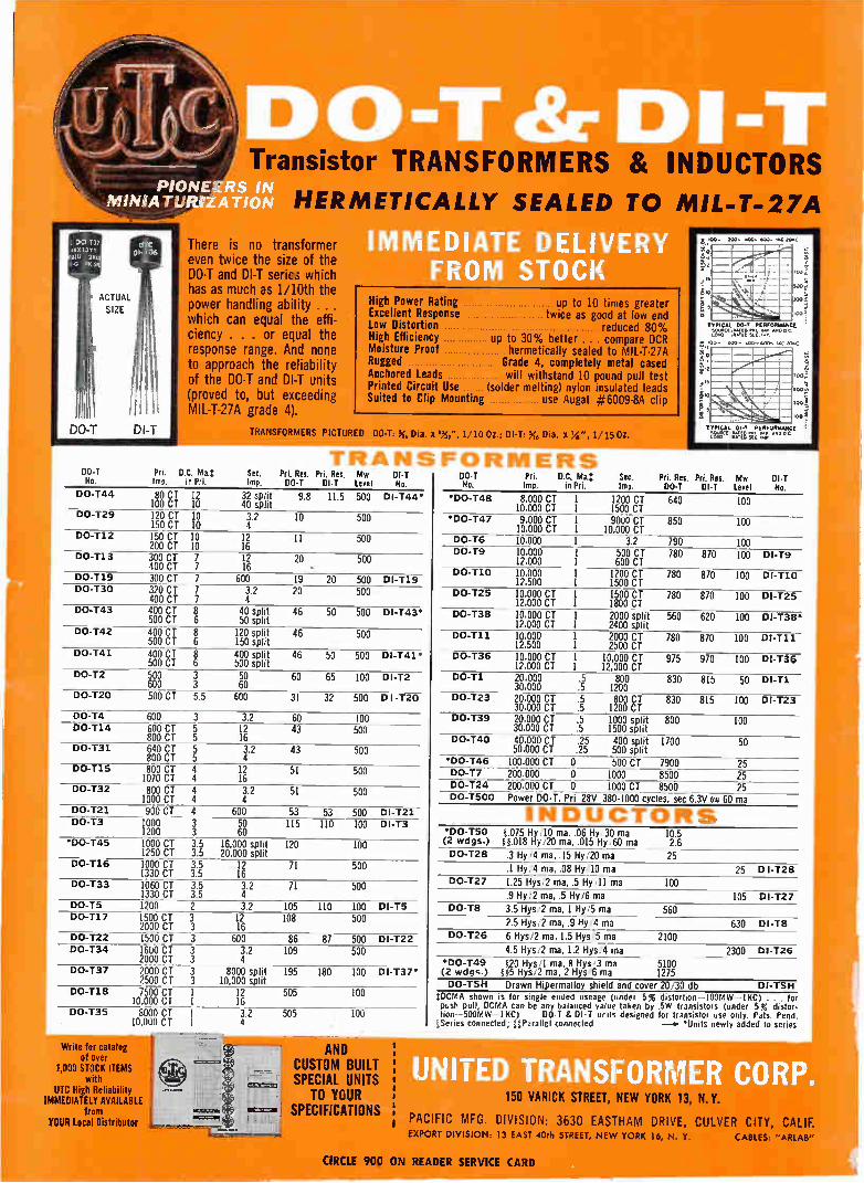
Transistor TRANSFOMS & INCTUCTOITS
HERMETICALLY SEALED TO MIL-T-27A
There is no transformer even twice the size of the DO-T and DI-T seric.i which has as much as 1/10th the power handling ability ... which can equal the effi-ciency . . . or equal the response range. And none to approach the reliability of the DO-T and DI-T units (proved to, but exceeding MIL-T-27A grade 4).
Pri. D.C. MaT: lm. in Pri.
80 CT 12 100 CT 10 120 CT 10 3.2 10 150 CT 10 4 150 CT 10 12 11 200 CT 10 16
IMMEDIATE DELIVER FROM STOCK
High Power Rating Excellent Response Low Distortion High Efficiency Moisture Proof Rugged Anchored Leads Printed Circuit Use Suited to Clip Mounting
up to 10 times greater • twice as good at low end reduced 80%
up to 30% better compare DCR hermetically sealed to MIL-T-27A Grade 4, completely metal cased will withstand 10 pound pull test (solder melting) nylon insulated leads
use Augat #6009-8A clip
TRANSFORMERS PICTURED D0111.6 Dia.1111L10 Oz.; 01-T Dia. x ' 1:15 Oz.
TRANSFORMERS See. PrL Res. Fri. Res. Imp. DO-T DI-T
32 split 9.8 11.5 40 split
Mw Level
500
01-T No.
DI-T44"
500
DO-T12 500
DO-T13 300 CT 7 12 20 400 CT 7 16
DO-T19 300 CT 7 600 19 20 DO-T30 320 CT 7 3.2 20
400 CT 7 4 DO-T43 400 CT 8 40 split 46 50
500 CT 6 50 split DO-T42 400 CT 8 120 split 46
500 CT 6 150 split DO-T41 400 CT 8 400 split 46 50
500 CT 6 500 split DO-T2 500 3 50 60 65
600 3 60 DO-T20 500 CT 5.5 600 31 32
500
500 DI-119 500
500 DI-143.
500
500 01-T41 •
100 DI-T2
500 D I -T20
DO-T4 DO-T14 600 CT 5
800 CT 5 DO-T31
600 3 3.2 60 12 43 16
100 500
640 CT 5 800 CT 5
3.2 43 4 500
DO-T15 800 CT 4 12 51 1070 CT 4 16
DO-T32 800 CT 4 1000 CT 4 4
500
3.2 51 500
DO-T21 900 CT 4 600 53 53 DO-T3 1000 3 50 115 110
1200 3 60
500 DI-T21 100 DI-T3
*D0-145 1000 CT 3.5 16,000 split 120 1250 CT 3.5 20,000 split
DO-T16 1000 CT 3.5 12 71 1330 CT 3.5 16
DO-133 1060 CT 3.5 3.2 71 1330 CT 3.5 4
DO-T5 1200 2 3.2 105 110 DO-T17 1500 CT 3 12 108
2000 CT 3 16
100
500
500
100 DI-T5 500
DO-122 1500 CT 3 600 86 87 DO-134 1600 CT 3 3.2 109
2000 CT 3 4
500 DI-122 500
DO-137 2000 CT 3 8000 split 195 180 2500 CT 3 10,000 split DO-T18 7500 CT 1 12 505
10,000 CT 1 16
100 Dl-T37*
100
DO-135 8000 CT 1 10,000 CT 1
Write for catalog of over
1,000 STOCK ITEMS with
UTC High Reliability IMMEDIATELY AVAILABLE
from
3.2 505 4
100
AND CUSTOM BUILT SPECIAL UNITS
TO YOUR SPECIFICATIONS
00-T Pri. D.C. Ma.- See. Ne.
•D0-T48 8.000 CT Imp. in Pd. Imp.
1 10.000 CT 1 9.000 CT 1 9000 CT 10.000 CT 1 10,000 CT 10.000 1 3.2
1200 CT 1500 CT
'DO-T47
Is
à
TYPICAL let PERFORMANCE SOUIN[ OWED PM. lee .1) C LOAD .11«.0 SIC. Ye
goo, Z00.. 400- 600, toc ion
Pri. Res Pri. Res. Mw DI-T DO-T DIT Level No.
640 100
850 100
DO-T6 DO-T9 10.000 1 500 CT
12,000 1 600 CT DO-T10 10.000 1 1200 CT
12.500 1 1500 CT DO-T25 10.000 CT 1 1500 CT
12,000 CT 1 1800 CT DO-T38 10.000 CT 1 2000 split
12.000 CT 1 2400 split DO-T11
790 100 780 870 100 DI-T9
780 870 100 DI-110
780 870 100 DI-T25
10.000 1 2000 CT 12.500 1 2500 CT 10,000 CT 1 10,000 CT 12.000 CT 1 12,000 CT
560 620 100 DI-T38•
780 870 100 DI-T11
DO-T36 975 970 100 DI-136
DO-T1 20.000 .5 800 30,000 .5 1200
DO-T23 20.000 CT .5 800 CT 830 30.000 CT .5 1200 CT
DO-T39 20.000 CT .5 1000 split 800 30.000 CT .5 1500 split
DO-T40 40.000 CT .25 400 split 1700 50.000 CT .25 500 split
830 815 50 DI-T1
815 100 DI-T23
100
50
'DO-146 25 DO-T7 DO-124 DO-T500
100.000 CT 0 200.000 0 200,000 CT 0 Power DO-T, Pri 28V 380-1000 cycles, sec 6.3V «a 60 ma
500 CT 7900 1000 8500 1000 CT 8500 25
25
INDUCTORS 'DO-T50 1.075 Hy/10 ma, .06 Hr,30 ma (2 wdgs.) 81.018 Hy/20 ma, .015 Hy/60 ma
10.5 2.6 25 DO-T28 .3 Hy/4 ma, .15 Hy/20 ma
.1 Hy/4 ma, .08 Hy/10 ma 25 D I-T28 DO-T27 1.25 Hys/2 ma, .5 Hy/11 ma 100
.9 Hy/2 ma, .5 Hy/6 ma 105 DI-T27 DO-1.8 3.5 Hys/2 ma, 1 Hy/5 ma 560
2.5 Hys/2 ma, .9 Hy/4 ma 630 Di-T8 DO-T26 6 Hys/2 ma, 1.5 Hys,5 ma 2100
4.5 Hys/2 ma, 1.2 Hys/4 ma 2300 DI-T26 'DO-149 (2 wdes.)
,20 Hys/1 ma, 8 Hys/3 ma 5100 115 Hys/2 ma, 2 Hys/6 ma 1275
DO-TSH Drawn Hipermalloy shield and cover 20/30 clb DI-TSH eDCMA shown is for single ended useage (under 5% distortion-100Mw -11re) . for push pull. DCMA can be any balanced value taken by .5W transistors (under 5% distor-lion---500MW-IKC) DO-T & D1-T units designed for transistor use only. Pats. Pend.
tSeries connected; uParallel connected *Units newly added to series
150 VARICK STREET, NEW YORK 13, N. Y.
PACIFIC MFG. DIVISION: 3630 EASTHAM DRIVE, CULVER CITY, CALIF. YOUR Local Distributor EXPORT DIVISION 13 EAST 40th STREET, NEW YORK to, N. Y. CABLES ARLAB"
CIRCLE 900 ON READER SERVICE CARD

January 4, 1')(;
electronics A McGraw-Hill Publication 75 Cents
W. W. MacDONALD, Editor
J. M. CARROLL, Managing Editor
SENIOR EDITORS: Samuel Weber,
George W. Sideris. SENIOR ASSO-
CIATE EDITORS: Michael F. Wolff,
John F. Mason. ASSOCIATE EDITORS:
Michael F. Tomaino, Sylvester P. Carter, William P. O'Brien, Sy Vogel,
Leslie Solomon, George J. Flynn, Lau-
rence D. Shergalis, George V. Novotny, Leon H. Dulberger. ASSISTANT EDI-
TORS: Nilo Lindgren, Stanley Froud, Stephen B. Gray, Roy J. Bruun, Barry
A. Briskman. REGIONAL EDITORS: Harold C. Hood (Pacific Coast, Los
Angeles , Thomas Maguire (New Eng-
land, Boston ), Cletus M. Wiley
(Midwest, Chicago). ART DIRECTOR:
Howard R. Berry. ASSISTANT ART
DIRECTOR: John C. Wright, Jr.
TORIAL ASSISTANTS: Glorio '
Lorraine Rossi, Virgin:
Lynn Emery, A-
Werner, Ali,
NEWS
e e Grà
e
'ree_ 1. 5e" *:-e. o
• e
e•••••
•-•
e
çé.
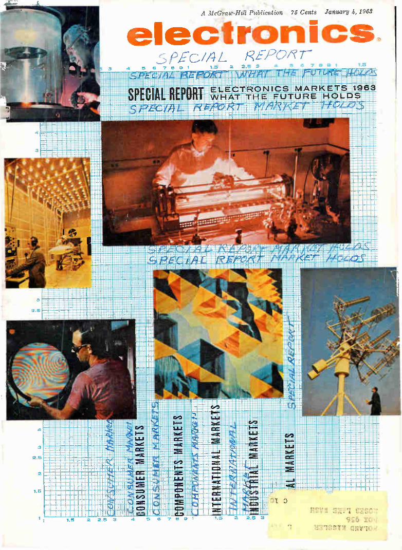
DIRECTIONS IN ELECTRONICS. Symbolic of the many branches of our industry in 1963 are a plasma-focusing electron gun in bell jar at GE, Hawk missile under environmental test at Raytheon, color picture tube degaussing at RCA, etch pits on CdS crystals viewed with microscope at Philips' in the Nether-lands, ground-station antennas for Tiros satellite, by RCA, and a helium-neon gas laser at Avco. For our annual market report see p 43 COVER
DOWN UNDER—Suddenly Mecca for Radio Men. Australia is breaking out in a rash of U. S. facilities—satellite tracking sta-tions, a big Navy vlf station and radio research stations. Major attractions are the country's geographic location and relative freedom from radio interference 20
BLACK BOX BLAST DETECTION—Hope or Hoax? Will unat-tended seismic detection stations be able to police a nuclear test ban? Even if such stations are reliable, can clandestine tests be moved into space? Here is an authoritative summary of the engineering problems that make the black box a political hot potato 26
DRONE HELICOPTER Is Tested by Navy. In two recent tests, g" controls maneuvered the 'copter at distances to six
'nmanned helicopters could be used for reconnaissance ;ver antisubmarine weapons 32
)RT: WHAT THE FUTURE HOLDS—Our pre-electronics industry in 1963 and beyond is con--r all segments of the electronics industry, but
selective basis. Space exploration, military strial automation and consumer demand will sales. Major challenges are international ,ercapacity and increasing selectivity in contracts.
By L. H. Dulberger and B. Anello 43
NT LINES: Micromodules Make it as a complete digital computer for •hs only 90 lb. The computer uses can operate from widely varying
By A. S. Rettig, RCA 77
LASER LIGHT. A semi-signals, converting them to fies the demodulated signal. nctions in a dual role. *, T. Kimura and Y. Uno,
University of Tokyo 82
Contents Continued

electronics January 4, 1963 Volume 36 No. 1
Published weekly, with Electronics Buyers' Guide and Reference Issue as part of the subscription, by
McGraw-Hill Publishing Company, Inc. Founder: James H. McGraw (1860-194S).
Title ® registered U.S. Patent Office;
C) copyright 1963 by McGraw-Hill Publishing Co., Inc. All rights re-served, including the right to repro-duce the contents of this publication, in whole or in part.
Executive, editorial, circulation and advertising offices: McGraw-Hill Build-
ing, 330 West 42nd Street, New York 36, N. Y. Telephone Longacre 4-3000. Teletype TWX N.Y. 212-640-4646. Cable
McGrawhill, N. Y. PRINTED IN AL-BANY, N. Y.; second class postage
paid at Albany, N. Y.
OFFICERS OF THE PUBLICATIONS DIVISION: Shelton Fisher, President; John R. Callaham, Vice President and
Editorial Director; Joseph H. Allen,
Vice President and Director of Adver-tising Sales; A. R. Venezian, Vice President and Circulation Coordinator; Daniel F. Crowley, Vice President and Controller.
OFFICERS OF THE CORPORATION: Donald C. McGraw, President; Hugh J.
Kelly, Harry L. Waddell, Executive Vice Presidents; L. Keith Goodrich, Executive Vice President and Treas-urer; John J. Cooke, Vice President and Secretary.
Subscriptions are solicited only from those actively engaged in the field of the publication. Position and com-
pany connection must be indicated on orders. Subscription rates: United
States and Possessions, $6.00 one year, $9.00 two years, $12.00 three years. Canada: $10.00 one year. All
other countries $20.00 one year. Single Copies, United States and Possessions
and Canada 751. Single copies all other countries $1.50.
THE PUBLISHER, UPON WRITTEN RE-QUEST FROM ANY SUBSCRIBER TO
OUR NEW YORK OFFICE, AGREES TO REFUND THAT PART OF THE SUB-SCRIPTION PRICE APPLYING TO COPIES NOT YET MAILED.
Subscribers: Please address change of address notices, subscription orders or complaints to Fulfillment Manager,
Electronics, at above address. Change of address notices should provide old as well as new address, including postal zone number if any. If pos-sible, attach address label from re-cent issue. Allow one month for change to become effective.
Postmaster: Please send Form 3579
to Fulfillment Manager, Electronics, 330 West 42nd Street, New York 36, New York.
•
ABC a
Audited Paid Circulation
2
CONTENTS continued
MULTITONE OSCILLATORS—Source of Simultaneous Frequen-cies. Simple, two-transistor circuit is designed to oscillate simultaneously at any of five selected frequencies with no mutual mixing. It is the basis of a five-bit parallel data encoder for telemetry. By R. Stapelfeldt, Westinghouse Air Brake 86
FAIL-SAFE SQUELCH CIRCUIT Adapts to Changing Noise Levels. It has a smooth, noiseless transition between on and off
states, is ideal for use in remote unattended receivers, in air-craft or vehicles. Circuit includes an a-m detector, noise ampli-fier, noise detector and modified Schmitt to key the receiver output. By H. G. Michael, Collins 88
AIR TRAFFIC CONTROL—Communication and Weather Net-works Planned. Last of three articles on ATC. Plans are to reduce plane-to-ground radio contacts and make better use of available frequencies. Weather system will include 1,000 observ-ing stations. Processing and presentation are major features of plan. By J. F. Mason 92
DEPARTMENTS
Crosstalk. Market Analysis
Comment. Air Traffic Control
Electronics Newsletter. Megawatt Space Power Source Planned
Washington Outlook. Military Procurement to Level Off Next Year
Meetings Ahead. National Symposium on Radio-Frequency Interference
Research and Development. New Approaches Electronic Self-Repair
Components and Materials. Brigh Picture Tube
Production Techniques. N ment Standardized
Design and Appli ping Motor
Literat
3
4
7
12
3

CROSSTALK
"THERE ARE TWO TIMES in a man's life when he should not speculate," Mark Twain said, "when he can't afford it, and when he can."
Perhaps Twain said this after he lost a fortune by misguided investment of huge sums in a typesetting machine. Twain needed a penetrating market survey and technical counsel before he jumped in with his hard-won money.
In spite of Twain's epigram, the needs of com-merce demand intelligent speculation or profits grind to a halt. Each year that we research the electronics
marketplace, it becomes clearer to us what the role of the long-range planner and marketing expert is to his firm. Many of the decisions made, in effect, by
marketing men today, were once reserved for the company president and the board of di-rectors. With the high level of technical knowl-edge needed for intelligent judgments in elec-tronic marketing, judging has become a full profession. Recommendations by market analysts have
become near fiats on the direction a company should take in research, product development, production effort, sales approach, new invest-ments and diversification.
Business planning today must acknowledge such complications as the growing international character of electronics. Competition is no longer a simple domestic affair—rather it includes what businessmen in European, Eastern and indi-rectly, Soviet-block nations are doing.
Further affecting decisions is the increasing dominance of research and development in the already complex electronics industry. With the aerospace industry, electronics accounts for the greatest share of money spent on research and development in this country. The military in-dulges in nearly as much Research, Develop-ment, Test and Evaluation projects as it does procurement, in electronics.
Thus, marketing men must include a high scientific and engineering competence in their battery of investigative tools. Deep involvement in a given segment of the electronics industry is needed to understand completely the seg-ment's potential and problems. The marketing
INTERNATIONAL FLAVOR of the electronics indus-try is reflected in this view of transmitting towers at the Vatican's high-power broadcasting site, erected by Telefunken, near Rome. The statue is the Archangel Gabriel
analyst may also be called on to help make a decision on his firm's activity in an area about which little is known either to himself or to his company. The tools of marketing men vary, and the
demonstrable results as well. Much is gained by a well ordered study of the other guy's ex-perience, and the collection of blue sky expecta-tions by knowledgeable persons.
Statistical market data help, by supplying a base of past sales for the building projections. Government predictions, and industry associa-tion statistics enter the mix.
Accuracy depends chiefly on tailoring the quest, for answers to a clearly defined range of questions. But in the end, a marketing survey is of
value chiefly because blended and weighted sets of views are produced by persons devoting full-time to the job.
In the ELECTRONICS marketing report this week, we endeavor to add to the knowledge of persons interested in all aspects of the market. Specific recommendations are limited—general trends are accurately indicated. The tone and health of the industry, what the experts are saying, and why they say it, are organized and clari-fied as the opinions of those "in the know." Read our report—and join them.
January 4, 1963 3

kunours versatile
900A SWEEP GENERATOR covers the range of three regular
instruments! The most economical wide-band Sweep Generator in the electronics industry ... covers all your needs from 1/2 mc to 1200 mc, for IF's, radar, video, teleme-tering, communications!
Two ranges-0.5 mc to 400 mc and 275 mc to 1200 mc. Supplies sweep signal with center from 500 kc to 1000 mc and with sweep widths as broad as 400 mc and as narrow as 100 kc. RF output, carefully monitored by matched crystal diodes feeding two-stage, push-pull AGC amplifier, is flat within ±-0.5 db at full sweep width up to 800 mc and -1-.1.5 db from 800 mc to 1200 mc. When using sweep widths as narrow as 20 mc, flat-ness at any center frequency is approxi-mately -±0.15 db. $1260.00
Now... full production assures fast delivery.
11.S 1:Cal 400 me
411111:..11.111, It MUM UUUUUU 1111111111M11121
till1M11111118 OOOOO 11111111M11. alterdltritiliranlifj
MI 111111111111111111111
1111111111111111111111 111111111MIUMIIIII
pri .., III Mil 11111118.1111t11111111111
e AROCOMOMMUUMMOdis UOMMUMMUMMUMW 111WIIIMI Min mom
• HIGH OUTPUT! .25 volt RMS on VHF, .5 volt RMS on UHF!
• WIDE SWEEP WIDTHS ! VHF-100 kc to 400 mc UHF-100 kc to 40% or more of C.F.
• FLAT OUTPUT ! Flat to ± .5 db on widest sweep width!
Write for on-the-spot demonstration.
JERROLD ELECTRONICS CORPORATION
A subsidiary of The Jerrold Corporation Dept. ¿TE-168, Philadelphia 32, Pa.
COMMENT
Air Traffic Contra
Saw the first of what I am sure will be three excellent articles on air traffic control. Naturally, the article was of extreme interest to many people here and they are look-ing forward to the next two.
J. C. FORBES The Mitre Corporation Bedford, Massachusetts
The first article, by Senior As-sociate Editor John Mason, ap-peared on p 37, Dec. 7, and the second on p 46, Dec. 14. The third and last appears in this issue, on p 92.
Those Lab Courses
I most heartily concur with your views in the editorial, Five Years? Or a Better Four? in the Decem-ber 14 issue (p 3), 1962.
I started working for a B.S. in E.E. at the age of 34 last summer, and have been constantly hearing warnings from upperclassmen about how I will be slaughtered by labs in the years ahead. There have been repeated recommendations to switch to physics because it's more mod-ern, there are fewer labs, the point requirements for a degree are lower, and the degree commands as good a price as the E.E. does. All excellent reasons!
And I may make the change after my freshman program is completed. Time is a precious commodity to me now, and when one works dur-ing the day and goes to school at night, there is no room for lost motion. I refuse to waste one minute on the "old discipline" labs that persist today to prolong ar-chaic academic traditions. If labs take up so much time and are so "necessary," why don't they carry more credit? I even suspect many graduate
courses could be included in the undergraduate curriculum, if the latter were modernized by getting rid of a lot of chaff. But then I suppose we mustn't overlook the fact that engineering schools are trying to secure their financial stake in the "education business"
by prolonging their program, a dis-tasteful but plausible explanation. Anyway, industry can count on
one less engineer in 1968. He will be me, as I refuse to become a victim of the system.
ROBERT D. FREED New York, New York
SiC Junctions For Lasers?
For all the recent attention on the light emission p-n junction, I fail to find any mention of silicon-carbide junctions in which the light emission effect in the visible region has been known for years. The ma-terial may be valuable for current-pumped lasers.
G. A. MAY National Research Council Ottawa, Canada
Five years ago, researchers were interested in silicon carbide, but they found its efficiency too low. Gallium arsenide, on the other hand, is highly efficient in the conversion of electricity to light. For more information on diode lasers, see p 24, Nov. 16, and p 14, Nov. 23, 1962.
Equation Errors
Your Nov. 30, 1962, issue con-tains an article entitled Reliability: 1962. On p 63 is a section on Se-quential Testing which contains several errors. The y-intercept numbers in the equations for the accept and reject lines are numeri-cally wrong in that the intercept
in each case should be approxi-mately 590 (slide-rule accuracy).
Further, on p 64, the statement that "The test would have to con-tinue at least 1,800 hours . . ." is not correct, and is not justified or explained in the text.
D. H. WYTHE, JR. Sunnyvale, California
The correct equation for the ac-cept line is y = 138.62x + 588.8, while the equation for the reject line should be y = 138.62x — 588.8.
The statement on p 64 should read 600 hours, which is three times contract MTBF.
4 CIRCLE 4 ON READER SERVICE CARD electronics

Signetics offers three ways to planar integrated circuits:
STANDARD DTL logic
circuits
off-the-shelf We can give you immediate delivery on any of our standard circuits. Our standard line includes: NAND/NOR Gate, Buffer, Multi-Purpose Flip-Flop, Diode Array, and Exclusive-OR Net-work. Each of these circuits provides a maximum noise rejection and the highest speed possible on low power consumption. And each is a product of the most refined degree of planar technology today. Your choice of TO-5 can or flat modular packaging. Write for complete details: 680 West Maude Avenue, Sunnyvale, California.
SIGNETICS INTEGRATED CIRCUITS
variFEBS customized digital or
linear circuits
3 weeks This is the quickest and most eco-nomical way to get integrated circuits made to meet your requirements. Here's how it works. Take any of our standard circuits. (They all have 500 MC transistors, 3 nsec diodes, 60 pf capacitors, and resistors up to 20 K.) And redesign the interconnection patterns. Then we'll integrate your interconnection patterns onto the silicon chip. Your choice of TO-5 can or flat modular packaging. Write for complete details to: 680 West Maude Avenue, Sunnyvale, California.
SIGNETICS INTEGRATED CIRCUITS
preFEBS' custom digital
or linear circuits
8 weeks Here's the newest concept in inte• gated circuits. You design your own linear or digital circuit. Breadboard it with individually packaged transis-tors, resistors, diodes and capacitors from our stock. (These components have their associated parasitic ca-pacitance and will duplicate the performance in the final integrated circuit.)Then return the circuit to us. And we'll integrate it. Your choice of TO-5 can or flat modular packaging. Write for complete details: 680 West Maude Avenue, Sunnyvale, California.
SIGNETICS INTEGRATED CIRCUITS
CIRCLE 5 ON READER SERVICE CARD
re-to-measure precision"
iésrra
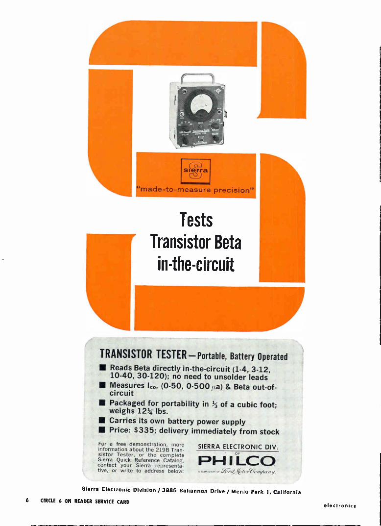
Tests Transistor Beta in-the-circuit
Ii TRANSISTOR TESTER—Portable, Battery Operated • Reads Beta directly in-the-circuit (1-4, 3-12,
10-40, 30-120); no need to unsolder leads • Measures lc., (0-50, 0-500 pa) & Beta out-of-
circuit
MI Packaged for portability in 3 of a cubic foot; weighs 123 lbs.
• Carries its own battery power supply
• Price: $335; delivery immediately from stock
For a free demonstration, more information about the 219B Tran-sistor Tester, or the complete Sierra Quick Reference Catalog, contact your Sierra representa-tive, or write to address below:
SIERRA ELECTRONIC DIV. F
PH I LCO A S1.13S1 Dr ARV Y .(/' /6. 'rfi /fe-;( '//1//t1/11/ ,
Sierra Electronic Division / 3885 Bohannon Drive / Menlo Park 1, California
6 CIRCLE 6 ON READER SERVICE CARD electronics
electronics NEWSLETTER
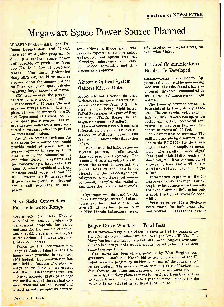
Megawatt Space Power Source Planned WASHINGTON—AEC, the De-
fense Department, and NASA have set up a joint program to
develop a nuclear space power
unit capable of producing from 300 Kw to 1 Mw of electrical
power. The unit, designated
Snap-50/Spur, would be used as
a power source for communications satellites and other space vehicles
requiring large amounts of power. AEC will manage the program,
expected to cost about $250 million over the next 6 to 10 years. The new program brings together bits and pieces of development work by AEC and Department of Defense on nu-clear space power sources. The re-organization indicates a more con-
certed government effort to produce an operational system.
Air Force officials envisage fu-ture needs for a source that would provide sustained power for life support systems to keep up to 20 men in orbit, for communications and other electronics systems and for maneuvering a large vehicle in space. A vehicle capable of all these
missions would require at least 300 Kw. However, Air Force says that it now has no precise requirement for a unit producing so much
power.
Navy Seeks Contractors For Underwater Range
WASHINGTON—Next week, Navy is scheduled to receive preliminary management proposals for prime contracts for the in-air and under-water tracking systems for Project Autec (Atlantic Undersea Test and Evaluation Center). Funds for the underwater test
range at Andros Island in the Ba-hamas were provided in the fiscal 1963 budget. But construction has been held up because of diplomatic snags in reaching an agreement with the British for use of the area.
Navy, however, plans to enlarge
the facility beyond the original con-cept. This was outlined recently at a meeting with prospective contrae-
tors at Newport, Rhode Island. The range is expected to require radar, underwater and optical tracking, telemetry, microwave and com-munications, computing and data
processing equipment.
Airborne Optical System Gathers Missile Data
BOSTON—Airborne system designed to detect and measure characteristic optical radiations from U. S. mis-siles is now being flight-tested. Called Skyscraper, it's part of Proj-ect Press (Pacific Range Electro-magnetic Signature Studies). The instrumentation will measure
infrared, visible and ultraviolet ra-diation at altitudes above 30,000 feet, where atmospheric attenuation
is low. A computer is fed information on
aircraft position, missile launch time and predicted trajectory. The computer directs an optical tracker. When the target is acquired, the tracker locks on and controls the aircraft and the line-of-sight opti-cal system. A multiple spectrometer continually samples the radiation and tapes the data for later analy-
sis. Skyscraper was designed by Air
Force Cambridge Research Labora-tories and built aboard a KC-135 aircraft. It has been turned over to MIT Lincoln Laboratory, scien-
tific director for Project Press, for evaluation flights.
Infrared Communications Headset Is Developed
DALLAS—Texas Instrument's Ap-paratus division will be announcing soon that it has developed a battery-powered infrared communication set using gallium-arsenide light sources. The two-way communication set
is contained in two ordinary head-sets. The set carries voice over an infrared link between two operators facing each other. Successful con-versations have been held over dis-tances in excess of 100 feet. The demonstration unit uses TI's
gallium-arsenide light sources (sim-ilar to the SNX100) for the trans-mitter. Output is amplitude modu-lated. The resultant voice signal "has good high-fidelity quality at short ranges." Receiver consists of a focusing lens, and a TI silicon photo-voltaic detector (type M7003).
Information capacity of the in-frared carrier wave is high. For ex-ample, tv broadcasts were transmit-ted over a similar link, using only a small fraction of available band-width.
Set's optics provide a 30-degree beam width for both transmitter and receiver. TI says that for other
Sugar Grove Won't Be a Total Loss WASHINGTON—Navy has decided to move part of its communica-tions facility from Cheltenham, Md., to Sugar Grove, W. Va. The Navy has been looking for a substitute use for Sugar Grove since it cancelled last year the trouble-ridden project to build a 600-foot
radio telescope there. One reason has been strong pressure by West Virginia con-
gressmen. Another is Navy's bid to temper criticism of the ill-fated telescope project by making some use of the money spent
on the project. The area was made virtually free of background disturbances, including construction of an underground lab.
Initially, the Navy plans to move its receivers from Cheltenham to Sugar Grove. That will take a year or more. Money for the move is being included in the fiscal 1964 budget
January 4, 1963 7
applications, it will be "a simple matter" to come up with "an ex-ceedingly narrow beam, requiring more precise alignment, but allow-ing long-distance transmission." Average output of the gallium
arsenide light source is 0.5 mw at wavelength of 0.897 angstroms. Effi-ciency (light power output over electrical power input) is now about 0.1 percent.
Venus Probing Upsetting Solar System Theories
STANFORD, CALIF. Findings from NASA's two-pronged probing of Venusian secrets may upset long held theories about that planet and the origin of the solar system, at-tendees at the American Geophysi-cal Society meeting were told last week.
JPL's Venus radar bounce ex-periment indicates that Venus's ro-tational direction may be opposite to that of earth and all other planets in the solar system except Uranus, baffling proponents of the theory that the planets originally coalesced from swirling gas masses all turning in the same direction. Rotational direction of Venus was determined by analyzing the spread of the return 2,388-Mc radar signal. Further, it appears that Venus ro-tates only once every 250 earth days.
Mariner's December 14 fly-by has established the mass of Venus at 0.81485 that of earth's—indicated by a two-way doppler measurement. Mariner was slowed 3,000 mph by the gravitational field of Venus.
Initial reduction of data from the probe's 3-axis fluxgate magnetom-eter gives no evidence of a Venu-sian magnetic field, but scientists cautioned that solar winds could confine a weak field to inside Mari-ner's 21,500 mile vantage point. The finding is consistent with theory that planetary fields are par-tially a function of rotational speeds.
Ranger Launch Scrubbed For Reliability Tests
INSTEAD of being launched early this year, as originally scheduled by NASA, Ranger VI will undergo
an autopsy to find out what ailed the first five Rangers. NASA said that Ranger VI will
be "subjected to an exhaustive test program" and design review. Re-sulting reliability improvements are to be incorporated in Rangers VII through IX. None of the first five Rangers
fulfilled their lunar missions. Mariner, which evolved from
Ranger, had a better batting av-erage. Mariner got to Venus after one launch failure.
Reading System Recognizes 20 Different Type Styles
SYLVANIA REPORTS development of a multifont print reader that can handle 20 different type styles. Rate of conversion from print to punched cards or tape is 700 characters a second. Speeds up to 20,000 char-acters a second are feasible, the company says.
Material to be read is scanned by a flying spot. Reflections are converted to signals that are com-pared with coded reference charac-ters. Information provided to the recognition unit is a pattern of 320 elements representing light and dark areas in the character being read. These elements are tested simultaneously for the best match against stored representations of 2,000 characters. The system is insensitive to type
size, automatically compensates for variations in paper and type regis-tration, and scanning is digitally controlled so reading can be pro-grammed.
Flash Detector to Help Guard Eyes from A-Blasts
SPECIAL GOGGLES that will darken an instant after an atomic explo-sion are to be developed by National Cash Register under a $234,000 Air Force contract. The goggles are to protect aircrew members from blinding light. NCR plans to make the goggles of photochromic ma-terials that darken only when ex-posed to ultraviolet light. Ultravio-let light will be provided by a source triggered by an electronic flash detector. The goggles are to darken within 75 microseconds.
In Brief . • •
NASA HAS AWARDED graduate train-ing grants for the academic year 1963-64 to 88 colleges and uni-versities. Grants will go to some 800 predoctoral trainees who have chosen a graduate study research program that is space oriented.
RUSSIA'S 12th satellite in its Cosmos geophysical research series is now circling the earth once every 901 minutes. This is the first shot in the program since October. The project is designed to study radiation belts, their effect on radiowave propagation and the structural elements of spaceships.
GOODYEAR will develop a high-reso-lution radar system for the Air Force's new RF-4C photo-recon-naissance aircraft, a modified version of the Navy's Phantom II. Radomes will be made of re-inforced fiber glass.
GE'S THIN ROUTE tropo radio-tele-type writer communications sys-tem is now being used by the Air Force at overseas installa-tions. GE says the system sub-stantially reduces transmission costs for point-to-point communi-cation.
INSTRUMENTATION and control sys-tems for Project Nerva (p 24, Rec. 28, 1962), will be developed by Edgerton, Germeshausen & Grier under a $5.5 million con-tract with the Space Nuclear Pro-pulsion Office.
VOCALINE will quality test Sono-buoys furnished under BuWeps contracts for the Navy.
IBM WILL DESIGN an advanced data center for the NASA-Marshall Space Flight Center in Hunts-ville, Ala., that will allow scien-tists to keep track of the thou-sands of deadlines associated with manned lunar explorations.
AUSTRIA'S Air Force plans to con-struct three long-range radar stations that will put the whole of Austrian territory under radar surveillance. First is being built at Kolom«an Mountain near Mond-see.
8 electronics

Investigate these Power Amplifiers for your VHF Communications Needs!
CHECK THESE KEY PARAMETERS:
Pd @ 25°C case 1 W
8Vcso 30 V
BVcEo 15 V
'FT 1 Kmc
PG @ 160 Mc 7 db
Cob 8 pF
rb' Cc 60 nsec
Sprague's ECDC technology, proven in the 2N2 100 nanosecond film memory driver, has been extended to amplifier or oscillator transistors covering a wide range of VHF communications applications.
The ECDC process combines the benefits of electro-chemical and diffusion technology to provide today's best combination of electrical character-
istics for maximum circuit efficiency.
For complete engineering data, write for Engineering Bulletins 30,409 and 30,414 to Technical Literature Service, Sprague Electric Company, 35 Marshall
Street, North Adams, Massachusetts.
SPRAGUE COMPONENTS
TRANSISTORS
CAPACITORS
MAGNETIC COMPONENTS
RESISTORS
MICRO-CIRCUITS
INTERFERENCE FILTERS
PULSE TRANSFORMERS
PIEZOELECTRIC CERAMICS
PULSE-FORMING NETWORKS
TOROIDAL INDUCTORS
HIGH TEMPERATURE MAGNET WIRE
CERAMIC-BASE PRINTED NETWORKS
PACKAGED COMPONENT ASSEMBLIES
FUNCTIONAL DIGITAL CIRCUITS
ELECTRIC WAVE FILTERS
SPRAGUE® THE MARK OF RELIABILITY
'Sprague and e are registered trademarks of the Sprague Electric Co. .$T-11711
January 4, 1963 CIRCLE 9 ON READER SERVICE CARD 9
Aidk
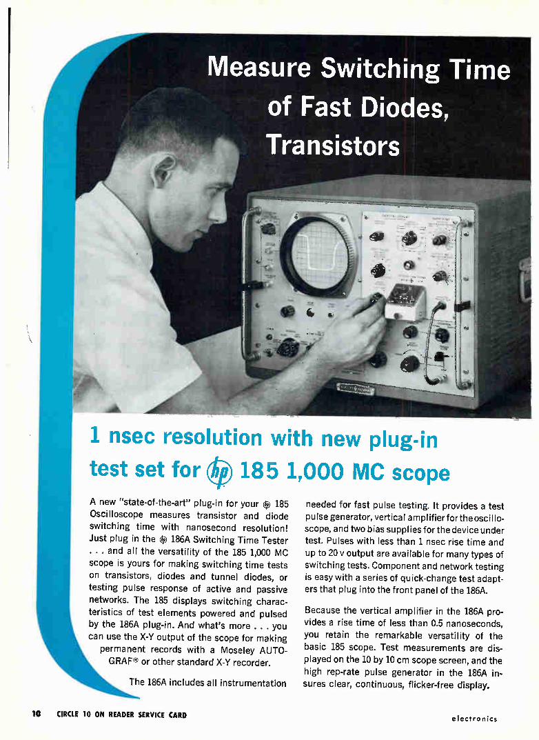
1 nsec resolution with new plug-in
test set for 185 1,000 MC scope A new "state-of-the-art" plug-in for your 185
Oscilloscope measures transistor and diode
switching time with nanosecond resolution! Just plug in the e 186A Switching Time Tester . . . and all the versatility of the 185 1,000 MC
scope is yours for making switching time tests on transistors, diodes and tunnel diodes, or
testing pulse response of active and passive
networks. The 185 displays switching charac-
teristics of test elements powered and pulsed
by the 186A plug-in. And what's more . . . you
can use the X-Y output of the scope for making
permanent records with a Moseley AUTO-
GRAF or other standard X-Y recorder.
The 186A includes all instrumentation
needed for fast pulse testing. It provides a test
pulse generator, vertical ampl ifier for the oscillo-scope, and two bias supplies for the device under
test. Pulses with less than 1 nsec rise time and
up to 20 y output are available for many types of
switching tests. Component and network testing
is easy with a series of quick-change test adapt-
ers that plug into the front panel of the 186A.
Because the vertical amplifier in the 186A pro-
vides a rise time of less than 0.5 nanoseconds,
you retain the remarkable versatility of the
basic 185 scope. Test measurements are dis-played on the 10 by 10 cm scope screen, and the
high rep-rate pulse generator in the 186A in-
sures clear, continuous, flicker-free display.
10 CIRCLE 10 ON READER SERVICE CARD electronics
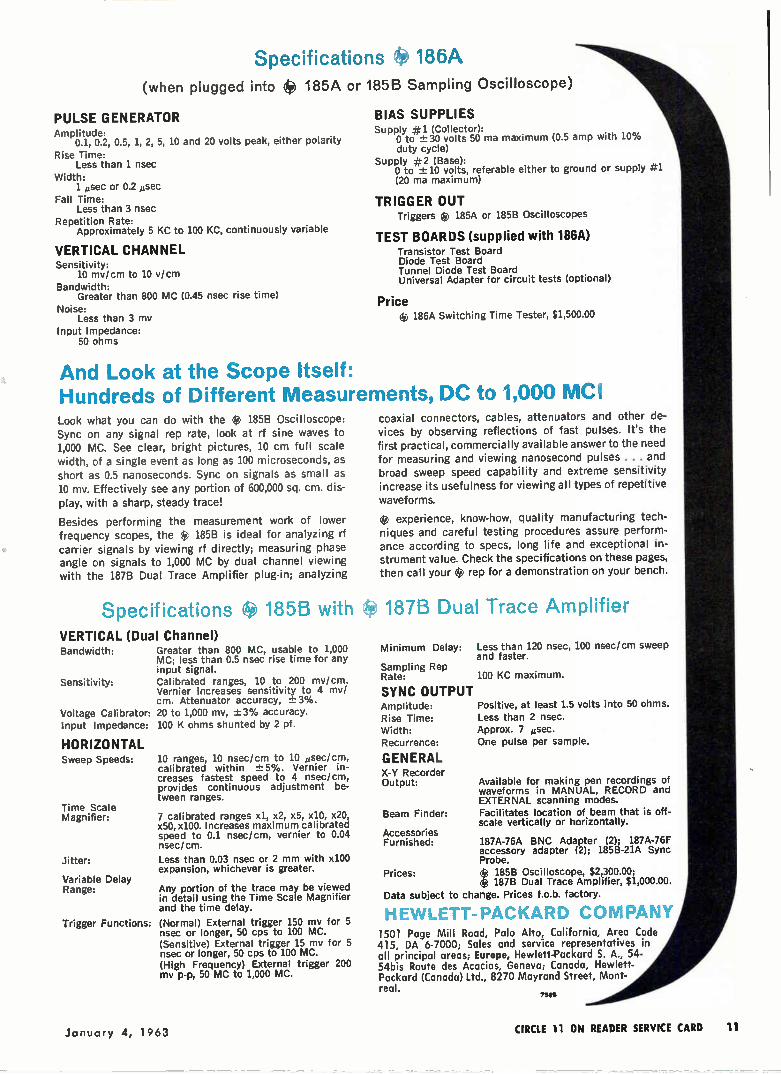
Specifications IS 186A (when plugged into fÈ 185A or 185B Sampling Oscilloscope)
PULSE GENERATOR Amplitude:
0.1, 0.2, 0.5, 1, 2, 5, 10 and 20 volts peak, either polarity
Rise Time: Less than 1 nsec
Width: 1 eisec or 0.2 ,sec
Fall Time: Less than 3 nsec
Repetition Rate: Approximately 5 KC to 100 KC, continuously variable
VERTICAL CHANNEL Sensitivity:
10 mv/cm to 10 v/cm Bandwidth:
Greater than 800 MC (0.45 nsec rise time)
Noise: Less than 3 mv
Input Impedance: 50 ohms
BIAS SUPPLIES Supply #1 (Collector):
0 to ±-. 30 volts 50 ma maximum (0.5 amp with 10% duty cycle)
Supply #2 (Base): 0 to 71.- 10 volts, referable either to ground or supply #1 (20 ma maximum)
TRIGGER OUT Triggers e 185A or 185B Oscilloscopes
TEST BOARDS (supplied with 186A) Transistor Test Board Diode Test Board Tunnel Diode Test Board Universal Adapter for circuit tests (optional)
Price çe.e 186A Switching Time Tester, $1,500.00
And Look at the Scope Itself: Hundreds of Different Measurements, DC to 1,000 MC! Look what you can do with the *' 185B Oscilloscope: Sync on any signal rep rate, look at rf sine waves to 1,000 MC. See clear, bright pictures, 10 cm full scale width, of a single event as long as 100 microseconds, as short as 0.5 nanoseconds. Sync on signals as small as 10 mv. Effectively see any portion of 600,000 sq. cm. dis-play, with a sharp, steady trace!
Besides performing the measurement work of lower frequency scopes, the 1-f 185B is ideal for analyzing rf carrier signals by viewing rf directly; measuring phase angle on signals to 1,000 MC by dual channel viewing with the 187B Dual Trace Amplifier plug-in; analyzing
coaxial connectors, cables, attenuators and other de-vices by observing reflections of fast pulses. It's the
first practical, commercially available answer to the need for measuring and viewing nanosecond pulses . . . and broad sweep speed capability and extreme sensitivity increase its usefulness for viewing all types of repetitive
waveforms.
experience, know-how, quality manufacturing tech-niques and careful testing procedures assure perform-ance according to specs, long life and exceptional in-strument value. Check the specifications on these pages, then call your 1-f) rep for a demonstration on your bench.
Specifications 185B with 187B Dual Trace Amplifier VERTICAL (Dual Channel) Bandwidth: Greater than 800 MC, usable to 1,000
MC; less than 0.5 nsec rise time for any input signal.
Sensitivity: Calibrated ranges, 10 to 200 mv/cm. Vernier increases sensitivity to 4 mv/ cm. Attenuator accuracy, 3%.
Voltage Calibrator: 20 to 1,000 mv, ±3% accuracy. Input Impedance: 100 K ohms shunted by 2 pf.
HORIZONTAL Sweep Speeds:
Time Scale Magnifier:
Jitter:
Variable Delay Range:
10 ranges, 10 nsec/cm to 10 gsec/cm, calibrated within ±5%. Vernier in-creases fastest speed to 4 nsec/cm, provides continuous adjustment be-tween ranges.
7 calibrated ranges xl, x2, x5, x10, x20, x50, x100. Increases maximum calibrated speed to 0.1 nsec/cm, vernier to 0.04 nsec/cm.
Less than 0.03 nsec or 2 mm with x100 expansion, whichever is greater.
Any portion of the trace may be viewed in detail using the Time Scale Magnifier and the time delay.
Trigger Functions: (Normal) External trigger 150 mv for 5 nsec or longer, 50 cps to 100 MC. (Sensitive) External trigger 15 mv for 5 nsec or longer, 50 cps to 100 MC. (High Frequency) External trigger 200 mv p-p, 50 MC to 1,000 MC.
Minimum Delay:
Sampling Rep Rate:
SYNC OUTPUT Amplitude: Rise Time: Width: Recurrence:
GENERAL X-Y Recorder Output:
Beam Finder:
Accessories Furnished:
Prices:
Less than 120 nsec, 100 nsec/cm sweep and faster.
100 KC maximum.
Positive, at least 1.5 volts into 50 ohms. Less than 2 nsec. Approx. 7 usec. One pulse per sample.
Available for making pen recordings of waveforms in MANUAL, RECORD and EXTERNAL scanning modes. Facilitates location of beam that is off-scale vertically or horizontally.
187A-76A BNC Adapter (2); 187A-76F accessory adapter (2); 185B-21A Sync Probe. e 185B Oscilloscope, $2,300.00; Oe 187B Dual Trace Amplifier, $1,000.00.
Data subject to change. Prices f.o.b. factory.
HEWLETT-PACKARD COMPANY 1501 Page Mill Road, Palo Alto, California, Area Code 415, DA 6-7000; Sales and service representatives in all principal areas; Europe, Hewlett-Packard S. A., 54-54bis Route des Acacias, Geneva; Canada, Hewlett-Packard (Canada) Ltd., 8270 Mayrand Street, Mont-real.
75611
January 4, 1963 CIRCLE 11 ON READER SERVICE CARD 11
WASHINGTON OUTLOOK
PROCUREMENT
TO LEVEL OFF
NEXT YEAR
MORE FOR
LIMITED-
WAR GEAR
AND MORE FOR
MILITARY
SATELLITES
NASA WANTS
$6 BILLION
SUCCESSFUL
TEST DOESN'T
SAVE SKYBOLT
MILITARY PROCUREMENT is expected to level off under the Pentagon's fiscal 1964 budget that goes to Congress later this month. New production orders should run about $18 billion and R&D con-
tracting around $7.1 billion, roughly the same as this year. However, electronics orders will probably rise slightly from this year's $4.5 bil-lion for production and $2.1 billion for R&D.
The budget totals some $48.3 billion, up about $2.5 billion from fiscal 1963. But this does not mean more new defense business. The rise reflects major boosts in new orders during the past two years, resulting in more production shipments and completion of R&D projects.
LOOK FOR A MAJOR SHIFT in defense contracting emphasis— reflecting recent policy decisions—in the Pentagon's fiscal 1964 budget. The proportionate share of contracts for conventional, nonnuclear arms and equipment will rise substantially over 1963, while the share for strategic weapons systems will drop sharply. Funds for another 150 Minuteman ICBMs are anticipated, but there will be no new money for bombers, except for minor amounts to continue R&D on the RS-70 airplane.
DEFENSE COMMUNICATIONS AGENCY is expected to get enough money in the new budget to expand work on military communi-
cations satellites. Funds to begin the projects are in the 1963 budget, requests for proposals are about to be issued and contractors will be selected within six months. For a start, a small active repeater will be
orbited at an altitude of at least 5,000 miles. Later, a larger, synchronous satellite will be developed.
NASA'S FISCAL 1964 BUDGET request to Congress is expected to tally close to $6 billion, compared to the $3.7 billion it got for 1963. More than 70 percent of the new budget is reportedly earmarked for manned space flight projects, including Saturn, Apollo and Gemini. Expectations are that many scientific space programs will be stretched out due to a dollar shortage.
SKYBOLT MISSILE PROJECT is dead, despite the successful test firing last week. Technical factors never really were the prime consideration in Skybolt's demise. The missile's low rating in Pentagon "cost-effectiveness" studies was the major reason.
In the test late last month over the Atlantic near Cape Canveral, the missile was air-launched from a B-52 flying at 40,000 feet. The missile reportedly hit its target 900 miles away. Air Force said it was the first time a ballistic missile was launched from an aircraft to fly a full mission under its own power and guidance. The Nassau agreement to sell Britain Polaris in place of Skybolt still
stands, however. Polaris production will be stepped up, though the number to be sold Britain has yet to be decided.
12 electronics

Raytheon storage tubes
help FAA control air traffic more effectively, improve flight safety
Fifty-one Raytheon "bright display" electronic systems fea-turing Raytheon CK1383 two-gun storage tubes are being pro-duced for the air traffic controllers of the Federal Aviation Agency. The CK1383 stores radar blips and presents them on a Raytheon CRT CK1381 display tube (Radar/ PPI television• type presentation). This way, a continuous picture of a plane's flight path is available. The video can be seen in many areas at the same time, making the controllers' tasks faster and easier. Panoramic displays can depict instantaneously the status of all aircraft in a selected area. In addition, the display itself is bright enough to be seen in a normally lighted room.
Raytheon Storage Tubes are available for many other types of scan conversion and for such applications as stop motion, in-tegration for signal-to-noise improvement, information stor-age for data processing systems, slow-down video, time delay,
and phase shift. Whatever your storage tube requirements, Raytheon can
meet them best. Unmatched capabilities and more than a dec-ade of experience are at your command. For complete details on Raytheon storage tubes and display devices, please write: Raytheon, Industrial Components Di-vision, 55 Chapel St.,Newton 58,Mass.
RAYTHEON CIRCLE 13 ON READER SERVICE CARD
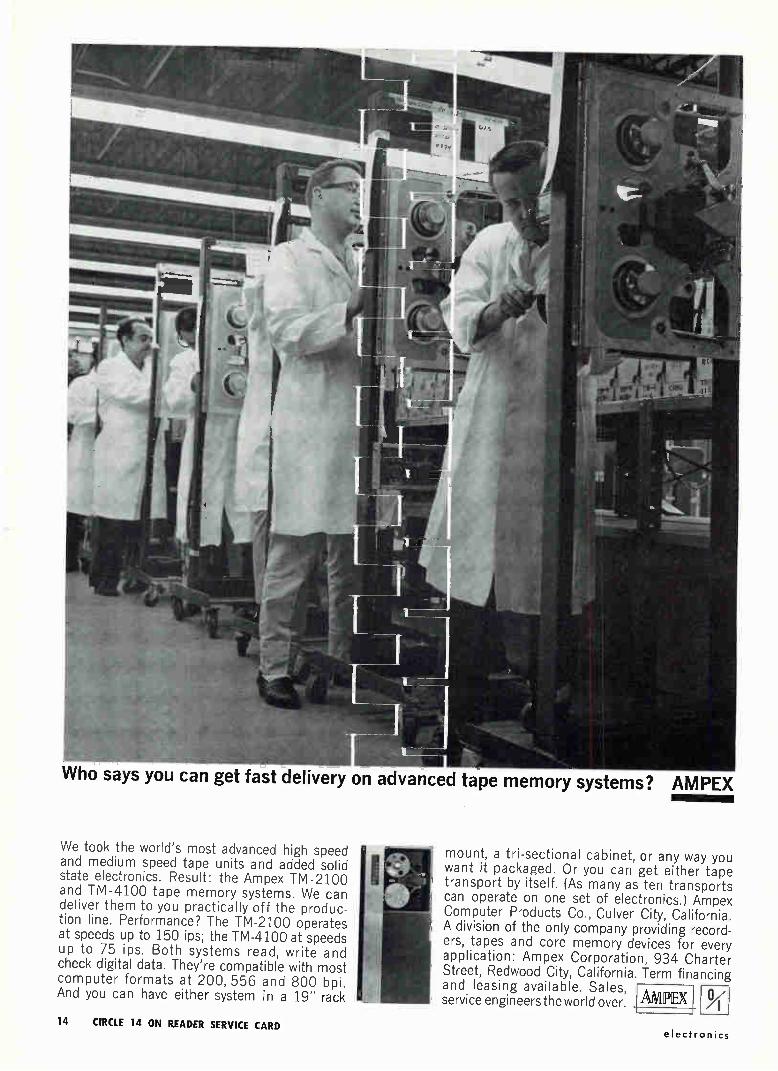
Who says you can get fast delivery on advanced tape memory systems? AMPEX
We took the world's most advanced high speed and medium speed tape units and added solid state electronics. Result: the Ampex TM-2100 and TM-4100 tape memory systems. We can deliver them to you practically off the produc-tion line. Performance? The TM-2100 operates at speeds up to 150 ips; the TM-4100 at speeds up to 75 ips. Both systems read, write and check digital data. They're compatible with most computer formats at 200, 556 and 800 bpi. And you can have either system in a 19" rack
mount, a tri -sectional cabinet, or any way you want it packaged. Or you can get either tape transport by itself. (As many as ten transports can operate on one set of electronics.) Ampex Computer Products Co., Culver City, California. A division of the only company providing record-ers, tapes and core memory devices for every application: Ampex Corporation, 934 Charter Street, Redwood City, California. Term financing and leasing available. Sales, service engineers the world over limPEX
A"
14 CIRCLE 14 ON READER SERVICE CARD electronics
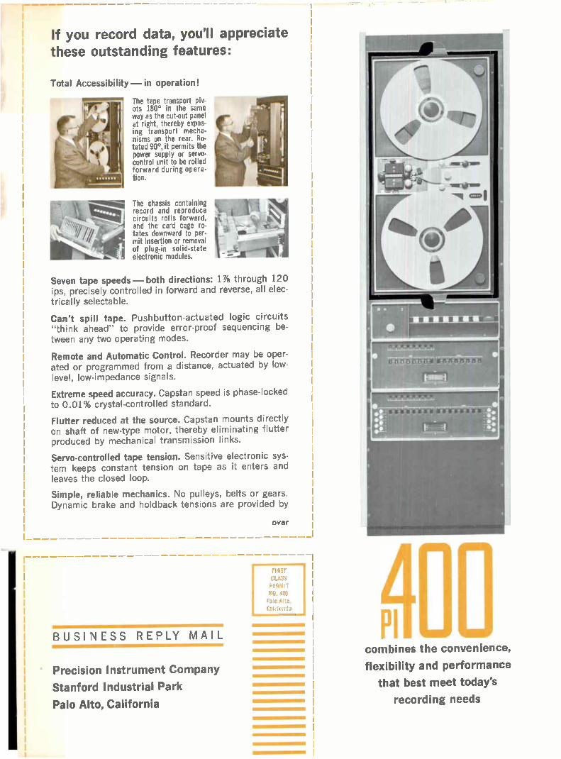
If you record data, you'll appreciate these outstanding features:
Total Accessibility—in operation!
The tape transport piv-ots 180° in the same way as the cut-out panel at right, thereby expos-ing transport mecha-nisms on the rear. Ro-tated 90', it permits the power supply or servo-control unit to be rolled forward during opera-tion.
The chassis containing record and reproduce circuits rolls forward, and the card cage ro-tates downward to per-mit insertion or removal of plug-in solid-state electronic modules.
Seven tape speeds— both directions: 17/s through 120 ips, precisely controlled in forward and reverse, all elec-trically selectable.
Can't spill tape. Pushbutton-actuated logic circuits "think ahead" to provide error-proof sequencing be-tween any two operating modes.
Remote and Automatic Control. Recorder may be oper-ated or programmed from a distance, actuated by low-level, low-impedance signals.
Extreme speed accuracy. Capstan speed is phase-locked to 0.01% crystal-controlled standard.
Flutter reduced at the source. Capstan mounts directly on shaft of new-type motor, thereby eliminating flutter produced by mechanical transmission links.
Servo-controlled tape tension. Sensitive electronic sys-tem keeps constant tension on tape as it enters and leaves the closed loop.
Simple, reliable mechanics. No pulleys, belts or gears. Dynamic brake and holdback tensions are provided by
BUSINESS REPLY MAIL
Precision Instrument Company
Stanford Industrial Park
Palo Alto, California
over
D. 489
Pale Ato,
California
combines the convenience,
flexibility and performance
that best meet today's
recording needs

Selei* o an exciting new
magnetic tape data recorder
from
Close-up of PI-400 tape guiding mechanism. The tape chute reduces trans-verse vibration and positions the edges of the tape accurately to minimize skew. The bilateral symmetry permits the tape to be transported in either direction with equal control.
reel motor torque; mechanical brakes function only on power failure.
Gentlest tape handling. Tape and capstan motion are synchronized in starting and stopping; no rubbing of an idling capstan against stationary tape.
Expanded signal-handling capacity. The PI-400 trans-port lends itself admirably to a wide variety of encoding and decoding techniques. Presently available are record and reproduce electronic systems using standard tech-niques, as well as many quasi-standard modifications. Special requirements will be given prompt attention by our staff of experienced applications engineers. For in-formation on how the PI-400 will meet your recording problem, fill out the postcard below and mail it now.
EJ I would like technical data concerning the performance of the PI-400 in the following application:
To record, to reproduce or both?
Recording or reproducing time per reel
Type of data -
Data bandwidth required-
EI Send me general brochure #71 on the PI-400, including specifications.
D Have your representative phone. My number is
Name
Title
Organization
Address

G16
Once in orbit, OGO (NASA's Orbiting Geophysical Observatory) must orient scientific equipment in three direc-tions. Some of its experimental packages must line up per-pendicular to the sun's rays. Other experiments must turn to face the earth. Another group must seek a line parallel to OGO's own orbital plane. STL engineers and scientists have produced a hermetically sealed drive mechanism to help solve these orientation requirements. Two mechanisms are used in OGO's attitude control system. One rotates solar arrays in continuous orientation with the sun; a second keeps experiment packages fixed in desired position with respect to the orbital plane. The drive mechanism (shown above) is hermetically sealed to permit use of a conventional high-speed servo-motor without the usual problems of gear lubri-cation. It does its work by wabble or twist motion at a rate
of one degree per second with a final gear reduction of about 24,000 to 1. STL's many projects include building OGO spacecraft for NASA's Goddard Space Flight Center, build-ing spacecraft for Air Force-ARPA, and continuing Systems Management for the Air Force's Atlas, Titan and Minute-man programs. These activities create immediate openings in fields such as: Space Physics, Radar Systems, Applied Mathematics, Space Communications, Antennas and Micro-waves, Analog Computers, Computer Design, Digital Com-puters, Guidance and Navigation, Electromechanical De-vices, Engineering Mechanics, Propulsion Systems, Materials Research. For Southern California or Cape Canaveral posi-tions, write Dr. R. C. Potter, One Space Park, Dept. G-1, Redondo Beach, California or P. O. Box 4277, Patrick AFB, Florida. STL is an equal opportunity employer.
SPACE TECHNOLOGY LABORATORIES, INC. a subsidiary of Thompson Ramo Wooldridge Inc.
Los Angeles • Vandenberg AFB • Norton AFB, San Bernardino • Cape Canaveral • Washington, D.C. • Boston . Huntsville • Dayton
VISITING LOS ANOELES JAN. 14-FEB. 1? SEE "ART IN SCIENCE" EXHIBIT AT STL'S SPACE TECHNOLOGY CENTER.
January 4, 1963 15
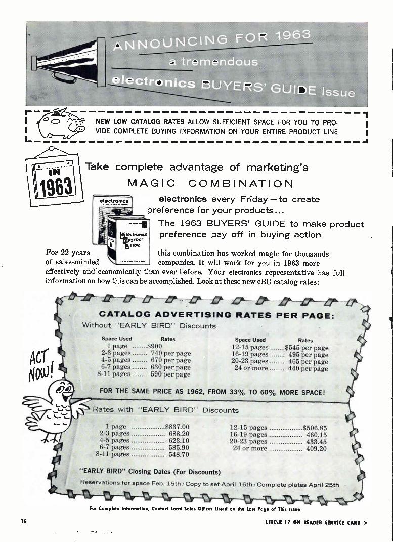
NEW LOW CATALOG RATES ALLOW SUFFICIENT SPACE FOR YOU TO PRO-
VIDE COMPLETE BUYING INFORMATION ON YOUR ENTIRE PRODUCT LINE
Take complete advantage of marketing's
MAGIC COMBINATION
electronics every Friday—to create
preference for your products...
The 1963 BUYERS' GUIDE to make product
preference pay off in buying action
For 22 years this combination has worked magic for thousands of sales-minded companies. It will work for you in 1963 more effectively and economically than ever before. Your electronics representative has full information on how this can be accomplished. Look at these new eBG catalog rates:
qtr Now!
CATALOG ADVERTISING RATES PER PAGE:
Without "EARLY BIRD" Discounts
Space Used Rates Space Used Rates
1 page $900 12-15 pages $545 per page 2-3 pages 740 per page 16-19 pages 495 per page 4-5 pages 670 per page 20-23 pages 465 per page 6-7 pages 630 per page 24 or more 440 per page
8-11 pages 590 per page
FOR THE SAME PRICE AS 1962, FROM 33% TO 60% MORE SPACE!
-s Rates with "EARLY BIRD" Discounts 1 page $837.00 12-15 pages $506.85
2-3 pages 688.20 16-19 pages 460.15 4-5 pages • 623.10 20-23 pages 433.45 6-7 pages 585.90 24 or more 409.20
8-11 pages 548.70
"EARLY BIRD" Closing Dates (For Discounts)
Reservations for space Feb. 15th / Copy to set April 16th / Complete plates April 25th
16
For Complete Information, Contact Local Sales Offices Listed on the Last Page of This Issue
CIRCLE 17 ON READER SERVICE CARD—›-

MITSUBISHI MICROWAVE ANTENNAS
FOR TELECOMMUNICATIONS
Japan today has the second largest microwave network in the world. Mitsubishi Electric, with the longest micro-wave antenna experience in Japan, has supplied 90?i, of the antennas used in the trunk lines of this extensive network. Mitsubishi antenna systems include parabolic, scatter, horn reflector and radar types, as well as a complete line of waveguide components and acces-sories. Frequencies from 900 Mc. to 24 KMc. are covered. The IU-61, shown above and specified at the right, is typical of the outstanding performance of Mitsubishi microwave antennas. Full technical informa-tion on any of these types of antennas is available at your request.
IU-61 6000 Mc. Band Parabolic Antenna
Diameter : Frequency Range :
Feed System : Gain :
Beam Width : First Side Lobe :
Wide Angle Radiation : (over 60 degrees)
Front-to-Back Ratio : VSWR :
Ellipticity Ratio : Discrimination of anti-circularly polarized wave coupling of Both Arms
Guaranteed for Wind Velocity of :
Weight
4 meters 5925-6175 McIs or 6175-6425M c/s Dual circularly polarized wave 45 db 0.98 degrees (half power) —23 db —60 db
65-70 db 1.02 1.1 (power axial ratio)
: —30 db : —35 db
60 meters/second : 800 kilograms
MITSUBISHI ELECTRIC MANUFACTURING COMPANY Head Office : Tokyo Building, Marunouchi, Tokyo Cable Address: MELCO TOKYO
• Air inflated parabolic antenna • Horn reflector antenna
---CIRCLE 18 ON READER SERVICE CARD
• 25>;16 meter scatter antenna
CIRCLE 19 ON READER SERVICE CARD 19
CALE IN TUTE MILES
300
Nurre WEST CAPE U.S. NAVY VLF
APOLLO TRACKING STATION .
GNAVARA (SRI) PEARtE (USAF) MUCHEA (MERCURY)
U.S. NAVY MICROWAVE FLIGHTS(
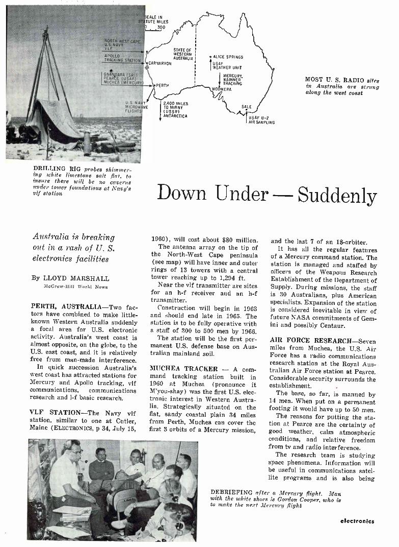
DRILLING RIG probes shimmer-ing white limestone salt flat, to insure there will be no caverns under tower foundations at Navy's vif station
Australia is breaking out in a rash of U. S. electronics facilities
By LLOYD MARSHALL McGraw-Hill World News
PERTH, AUSTRALIA—Two fac-tors have combined to make little-known Western Australia suddenly a focal area for U.S. electronic activity. Australia's west coast is almost opposite, on the globe, to the U.S. east coast, and it is relatively free from man-made interference.
In quick succession Australia's west coast has attracted stations for Mercury and Apollo tracking, vif communications, communications research and l-f basic research.
VLF STATION—The Navy vif station, similar to one at Cutler, Maine (ELECTRONICS, p 34, July 15,
STATE c)F WESTERN AUSTRALIA
CARNARVON
PERTH
l2,400 MILES TO MIRNY (USSR) ANTARCTICA
• ALICE SPRINGS
USAF WEATHER UNIT
MERCURY, MARINER TRACKING
WOCIMERA
SALE
USAF U-2 AIR SAMPLING
MOST U. S. RADIO sites in Australia are strung along the west coast
Down Under Suddenly
1960), will cost about $80 million. The antenna array on the tip of
the North-West Cape peninsula (see map) will have inner and outer rings of 13 towers with a central tower reaching up to 1,294 ft.
Near the vif transmitter are sites for an h-f receiver and an h-f transmitter.
Construction will begin in 1963 and should end late in 1965. The station is to be fully operative with a staff of 300 to 500 men by 1966. The station will be the first per-
manent U.S. defense base on Aus-tralian mainland soil.
MUCHEA TRACKER — A com-mand tracking station built in 1960 at Muchea (pronounce it M'you-shay) was the first U.S. elec-tronic interest in Western Austra-lia. Strategically situated on the flat, sandy coastal plain 34 miles from Perth, Muchea can cover the first 3 orbits of a Mercury mission,
and the last 7 of an 18-orbiter. It has all the regular features
of a Mercury command station. The station is managed and staffed by officers of the Weapons Research Establishment of the Department of Supply. During missions, the staff is 30 Australians, plus American specialists. Expansion of the station is considered inevitable in view of future NASA commitments of Gem-ini and possibly Centaur.
AIR FORCE RESEARCH—Seven miles from Muchea, the U.S. Air Force has a radio communications research station at the Royal Aus-tralian Air Force station at Pearce. Considerable security surrounds the establishment.
The base, so far, is manned by 14 men. When put on a permanent footing it would have up to 50 men.
The reasons for putting the sta-tion at Pearce are the certainty of good weather, calm atmospheric conditions, and relative freedom from tv and radio interference. The research team is studying
space phenomena. Information will be useful in communications satel-lite programs and is also being
DEBRIEFING after a Mercury flight. Man with the white shoes is Gordon Cooper, who is to make the next Mercury flight
electronics
"Nothing is impossible to diligence and skill" Samuel Johnson
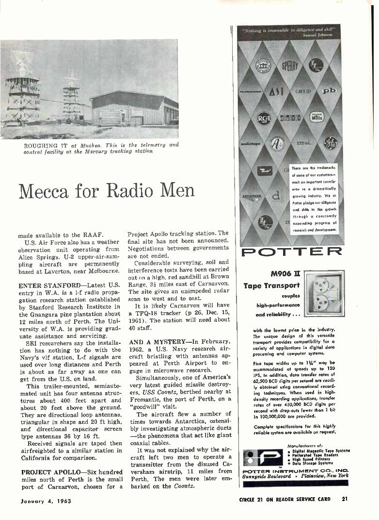
ROUGHING IT at Mifchea. This is the telewetry and control facility at the Mercury tracking station
Mecca for Radio Men
made available to the RAAF. U.S. Air Force also has a weather
observation unit operating from Alice Springs. U-2 upper-air-sam-pling aircraft are permanently based at Laverton, near Melbourne.
ENTER STANFORD—Latest U.S. entry in W.A. is a l-f radio propa-gation research station established by Stanford Research Institute in the Gnangara pine plantation about 12 miles north of Perth. The Uni-versity of W.A. is providing grad-uate assistance and servicing. SRI researchers say the installa-
tion has nothing to do with the Navy's vlf station. L-f signals are used over long distances and Perth is about as far away as one can get from the U.S. on land.
This trailer-mounted, semiauto-mated unit has four antenna struc-tures about 400 feet apart and about 20 feet above the ground. They are directional loop antennas, triangular in shape and 20 ft high, and directional capacitor screen type antennas 36 by 16 ft.
Received signals are taped then airfreighted to a similar station in California for comparison.
PROJECT APOLLO—Six hundred miles north of Perth is the small port of Carnarvon, chosen for a
Project Apollo tracking station. The final site has not been announced. Negotiations between governments
are not ended. Considerable surveying, soil and
interference tests have been carried out on a high, red sandhill at Brown Range, 3i miles east of Carnarvon. The site gives an unimpeded radar scan to west and to east.
It is likely Carnarvon will have a TPQ-18 tracker (p 26, Dec. 15, 1961). The station will need about 40 staff.
AND A MYSTERY—In February, 1962, a U.S. Navy research air-craft bristling with antennas ap-peared at Perth Airport to en-gage in microwave research.
Simultaneously, one of America's very latest guided missile destroy-ers, USS Coontz, berthed nearby at Fremantle, the port of Perth, on a "goodwill" visit. The aircraft flew a number of
times towards Antarctica, ostensi-bly investigating atmospheric ducts —the phenomena that act like giant coaxial cables.
It was not explained why the air-craft left two men to operate a transmitter from the disused Ca-versham airstrip, 11 miles from Perth. The men were later em-barked on the Coontz.
1=3 -r r E R
These are the trademarks
of some of our customers—
each an important contrib-
utor to a dramatically
growing industry. We at
Potter pledge our diligence
and skills to this growth
through a constantly
expanding program of
research and development.
M906 II
Tape Transport
couples
high-performance
and reliability ...
with the lowest price in the industry. The unique design of this versatile transport provides compatibility for a variety of applications in digital data processing and computer systems.
Five tape widths up to 11/4 " may be accommodated at speeds up to 120 IPS. In addition, data transfer rates of 62,500 BCD digits per second are readi-ly obtained using conventional record-ing techniques. When used in high.
density recording applications, transfer rates of over 450,000 BCD digits per second with drop-outs fewer than 1 bit in 100,000,000 are provided.
Complete specifications for this highly reliable system are available on request.
Manufacturers of:
• Digital Magnetic Tape Systems • Perforated Tape Readers • High Speed Printers • Data Storage Systems
POTTER INMTIRLJIVIENIT ca.. INC.
Elunnyside Boulevard • Plainview, New York
January 4, 1963 CIRCLE 21 ON READER SERVICE CARD 21
*
TOPS 'em ALL!
paracignamics
10 wiloriv Microwave Swept Sources
1.0-18.0 Gets
The pinnacle of power levels, at the highest standard of reliability, is now easily within reach via the Paradynamics Series 858B Swept Signal Sources. Flexibility is a key factor here, too, since these highly versatile units incorporate all of the features of the Paradynamics standard milli-watt, 1, 2 and 5 watt instruments. With the 858B Series, Paradynamics 'makes
available for the first time standard production 10-watt instruments capable of operating either as stable CW Signal Generators or as Sweeping Oscillators. Maximum reliability with a minimum of heat, space and weight is assured in these units through the use of permanent magnet focused wave tubes for both the BWO and TWT. Unique features such as remote programming
of RF frequency, power and modulation make the 858B Series a natural selection for use in auto-matic check-out systems, antenna range setups and other similar applications.
11, Power Output Leveling +0.75 db • May Be Pulse Modulated • May Be Remote Programmed
e Panel Height 17 1/i" Weight-95 lb
Catalog available on request
paradynamics INCORPORATED
10 Stepar Place / Huntington Station, L. I., N. Y. / 516 HA 7-7961
New DIFFUSION FURNACE with Kanthal A-1 elements
MODEL K-36 Tube Furnace tube I.D. 21/2
end zones 29 1/2" center zone 11"
Laboratory ovens Burn-off
Pot-type ovens
furnaces --"•' •
Sterilizers
Box
furnaces
Many design features util-ized in the new Despatch K-36 combustion and diffu-sion furnace combine to give it broader applications and new dependability for labor-atory and production work. The Kanthal 3-zone A-1
elements are divided into end and center zone heats. The silicon control rectifier and transformer assembly with proper instrumentation provides accurate * 12° F. heat uniformity current. con-trol. The all ceramic exterior tubes and the efficient new type insulation, alumina-silica fibers in multiple lay-ers, combine to maintain a cool shell even when the fur-nace is operated at capacity heat. The new Despatch K-36
features are well suited to analytical work of semi-con-ductor deposits, for diffu-sion involving vapor growth, for combustion carbon de-termination.
For complete information write for bulletin 206-6F.
Drawer ovens
Walk-in batch ovens
DESPATCH OVEN CO. 619 S.E. 8th St-, Minneapolis 14, Minn.
CIRCLE 200 ON READER SERVICE CARD
r-. I
BEST MINIATURIZED INDICATOR
ÍADICATOR t 4 t i •• ,,,i,, ... .
e ii i 44 41..e., 44 4.4 r • ••••••0 • 4,4,4.. 4140.0 .1.44 • a ••. , 0,4.04 . 4 44. 4 ,
0 1.44, i 0,.4.1s11....ii,si 4 /see 4 C i• 4) 4.4444 4, . .444 44 e 4 .,
444 l s r l 4. 4 .41.4 I 4 , * 0*. , _..) et ..st **lie ,
..1 f . 4, 4+41. 4041 ii 1, ................o. ..e........... - . ..0-él..,..‘ .......i.n.,
V-403
I
R;01
IlbAuji"64,
R-101
R-101 Tuning indicaor and Battery residual capacity indicator
F-10.2 FM tuning indicator
V-103 Audio level indicator
A-104 AM tuning indicator
SB-10S Stereo balancing indicator
B-106 Battery indicator Eb201 Smaller type tuning and
battery indicator
V-203 Smaller type level indicator B-206 Smaller type battery indicator 11-301 Larger type tuning and
battery indicator V-303 Larger type level indicator
SE-305 Larger type stereo balancing indicator
V-403 VU meter
V-403B Audio level indicator
SB-405 Null indication stereo balancing indicator
ACCEPTABLE SPECIAL DIAL UPON YOUR REQUEST
DISTRIBUTOR
ATAKA NEW YORK, INC. ATAKA & CO., LTD 633 THIRD AVENUE OHTEMACHI BLDG.
16TH FLOOR 1-CHOME, OHTEMACHI NEW YORK 17, N.Y., U.S.A. CHIYODA-KU, TOKYO PHONE : OXFORD 7-7480 PHONE: 201-6411
MAKER
TOYO MUSEN CO., LTD. 75, WAKASAYASHI-CHO, SETAGAYA-KU TOKYO
22 CIRCLE 22 ON READER SERVICE CARD CIRCLE 201 ON READER SERVICE CARD
electronics

Coors produces the largest isostatically formed ceramic parts now available to industry. Complete homogeneity of ceramic is assured because of this unique Coors process used in forming large parts. Homogeneity is essential in high-frequency, high-power applications—radomes, envelopes and windows—because hot spots and punctures created by voids and air pockets are virtually eliminated by Coors. Complete uniformity also means reliable, uniform strength properties. In addition to fabricating large precision ceramics, Coors can metalize such king-size ceramic parts as shown here. Write for Data Sheet 3001, "New Ceramic Design Freedom With Coors Forming Methods," or call your nearest Coors Regional Sales Manager: W EST COAST, William S. Smith, Jr., EM 6-8129, Redwood City, Calif.; M IDWEST, John E. Marozeck, 529-2510, Roselle, Ill.; CENTRAL, Donald Dobbins, GL 4-9638, Canton, Ohio; EAST COAST, John J. McManus, MA 7-3996, Manhasset, N. Y.; NEW ENGLAND, W ARREN G. MCDONALD, FR 4-0663, Schenectady, IV. Y.; SOUTHWEST, Kenneth R. Lundy, DA 7-5716, Dallas; SOUTHWEST, William H. Ramsey, UN 4-6369, Houston.
ALUMINA CERAMICS Coors Porcelain Co., Golden, Colo.
CIRCLE 23 ON READER SERVICE CARD
MINIATURE THIN WALL 100% SHIELDED TEFLON COAXIAL CABLE
Inner-space, outer-space, or lack of space — wherever size, weight,and shielding of coax is a criteria, Hitemp's new cables provide design advantages not previously available! Engineering, production, and Q.C. techniques
advanced by Hitemp make it possible to hold shielding to a wall thickness of 1.5 mils, or less. For example, on a RG-196A/U teflon insulated coax cable, Hitemp holds the O.D. to .040" or half the O.D. of conventional wire braid construction (.080"). Subsequently, there's a weight savings of 21%. And this miniaturized cable can be wrapped around a 3/8" mandrel.
Naturally, the 100% shielded construction improves attenuation characteristics, reduces cross-talk to a minimum, stabilizes capacitance, and lowers VSWR. 100% shielding offers you assembly economies, too. It
eliminates many termination problems associated with braided shields, and increases the reliability of the terminations, themselves.
Wherever your circuitry requires lower attenuation, improved VSWR, and so forth — wherever shielding, weight, size, flexibility,and reliability are critical, that's where it will pay you to use Hitemp's new miniature 100% shielded.
SEND FOR A SAMPLE if you'd like to run some checks on it yourself. Or, send us a piece of what you're currently using. We'll evaluate it and advise you of the savings you can make with Hitemp's new miniature coax. Why not take advantage of either offer today!
HITEIVIP WIRES CO. a Division of Simplex Wire & Cable Co.
1200 SHAMES DRIVE, WESTBURY, NEW YORK 1532 S. CALIFORNIA AVE., MONROVIA, CALIF.
24 CIRCLE 24 ON READER SERVICE CARD electronics
04' ..• (re 4,t, eg
, • ., . •,‘,"11/140.
‘‘ \‘
• •%! ,•• t • .*
19 •
, . &• .1/4‘. 4 • .7 17.
• • • **me. «e":09" • .4 • • ..11 • - -
• -; • -••••••-•-••• • 7 ••7••• "r1.›....-7•• 17 • .16.
, • • , ss• ••••
• • • ••• • •••.•• . •• • •• • •
. . %.% • •• • % nme ,01. • •••
% % .1.. • •• • •• •
%.‘ • %••• % %•.% • • •••••
%,. • , • •••• • ••• • •••• % % •
, • S. •,'• ‘,„ ••• • ,•••• • „ . • • %.• •••• • % • „.‘
• • % % % • ." • %•• . - .• . • „„..,• , .•
• . . • .S- •" %. • •> •`••• • • • . • . • •` , - • "„• - •
• - • des , •
5. 5
1.•
• -
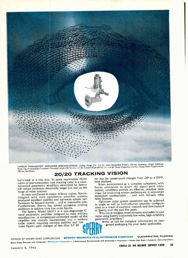
MINK TYPICAL PARAMETRIC AMPLIFIER SPECIFICATIONS: Tuning Range 5.4 - 5.9 Gc: Gain-Bandwidth Product 150 mc minimum; Single Sideband Noise Figure (including Circulator) Uncooled Mode (290°K)2.3 - 2.7 db; Cooled Mode (80'K) 1.3 - 1.6 db; Pump Frequency 17.5 Gc; Pump Power Requirements
100 mw maximum.
20/20 TRACKING VISION 0° +150°F
Let's look at it this way. In space exploration 20/20 vision of instrumentation and tracking radar is a must. Advanced parametric amplifiers developed by Sperry will reduce minimum discernible target size and up the range of radar systems.
In tests conducted in major military radars, Sperry-designed solid state parametric amplifier systems produced excellent stability and optimum system per-formance far beyond normal...and at reasonable cost. Furthermore, Sperry has solved cryogenic cooling problems to achieve ultra low noise figures.
The Sperry Model D61C1 is a non-degenerate C-band parametric amplifier designed to meet military specifications. A temperature-controlled model of this amplifier was recently incorporated into a military radar system requiring extreme stability and low noise figure—gain changes of less than 0.5 db
DIVISION OF SPERRY RAND CORPORATION Materials • Microwave Subsyatisms • Microwave Components and Antennas • Microline • Radar Test Sets • Systems Instrumentation
P s Ell
per day for temperature changes from -2 to were realized. When incorporated as a complete subsystem, with
ferrite circulators to divert the signal path when desired, amplifiers provide an effective, practical tech-nique for improving system performance at economics heretofore unobtainable ... and with fail-safe relia-bility features.
Optimum radar system operations can be achieved in single as well as multi-channel amplifier configura-tions as a result of extensive research and development at Sperry over the past five years.
Why not investigate improvements attainable in your radar using Sperry's extremely low noise, high reliability parametric amplifiers?
Write or call for complete information on inte-grated packaging for your radar applicatión.
CLEARWATER, FLORIDA
Solicl State Devices and
SPERRY MICROWAVE ELECTRONICS COMPANY
January 4, 1963 CIRCLE 25 ON READER SERVICE CARD 25
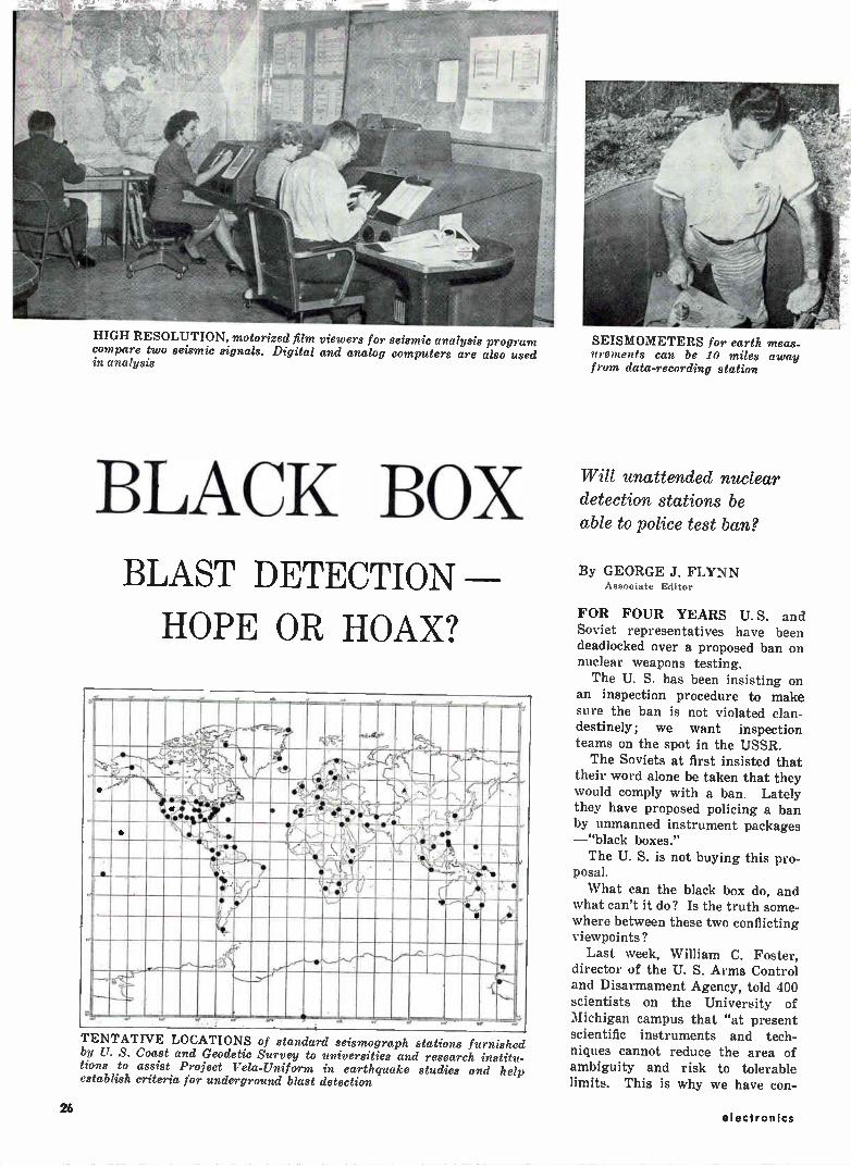
HIGH RESOLUTION, motorized film viewers for seismic analysis program compare two seismic signals. Digital and analog computers are also used in analysis
BLACK BOX BLAST DETECTION
HOPE OR HOAX?
I Mime lierigalt
- r ii11131MWOMIVIL ¡IN imidm . rr,, ino I ` IIMIIIIMIRI
,M1111 11 anumputi PI 1111,5Mgenill. .
I Ill I II II
I
__....4- dimeamilliall1111111
111111111111111 II III
TENTATIVE LOCATIONS of standard seismograph stations furnished by U. S. Coast and Geodetic Survey to universities and research institu-tions to assist Project Vela-Uniform in earthquake studies and help establish criteria for underground blast detection
SEISMOMETERS for earth meas-urements can be 10 miles away from data-recording station
Will unattended nuclear detection stations be able to police test ban?
By GEORGE J. FLYNN Associate Editor
FOR FOUR YEARS U. S. and Soviet representatives have been deadlocked over a proposed ban on nuclear weapons testing.
The U. S. has been insisting on an inspection procedure to make sure the ban is not violated clan-destinely; we want inspection teams on the spot in the USSR. The Soviets at first insisted that
their word alone be taken that they would comply with a ban. Lately they have proposed policing a ban by unmanned instrument packages —"black boxes." The U. S. is not buying this pro-
posal.
What can the black box do, and what can't it do? Is the truth some-where between these two conflicting viewpoints?
Last week, William C. Foster, director of the U. S. Arms Control and Disarmament Agency, told 400 scientists on the University of Michigan campus that "at present scientific instruments and tech-niques cannot reduce the area of ambiguity and risk to tolerable limits. This is why we have con-
26 electronics
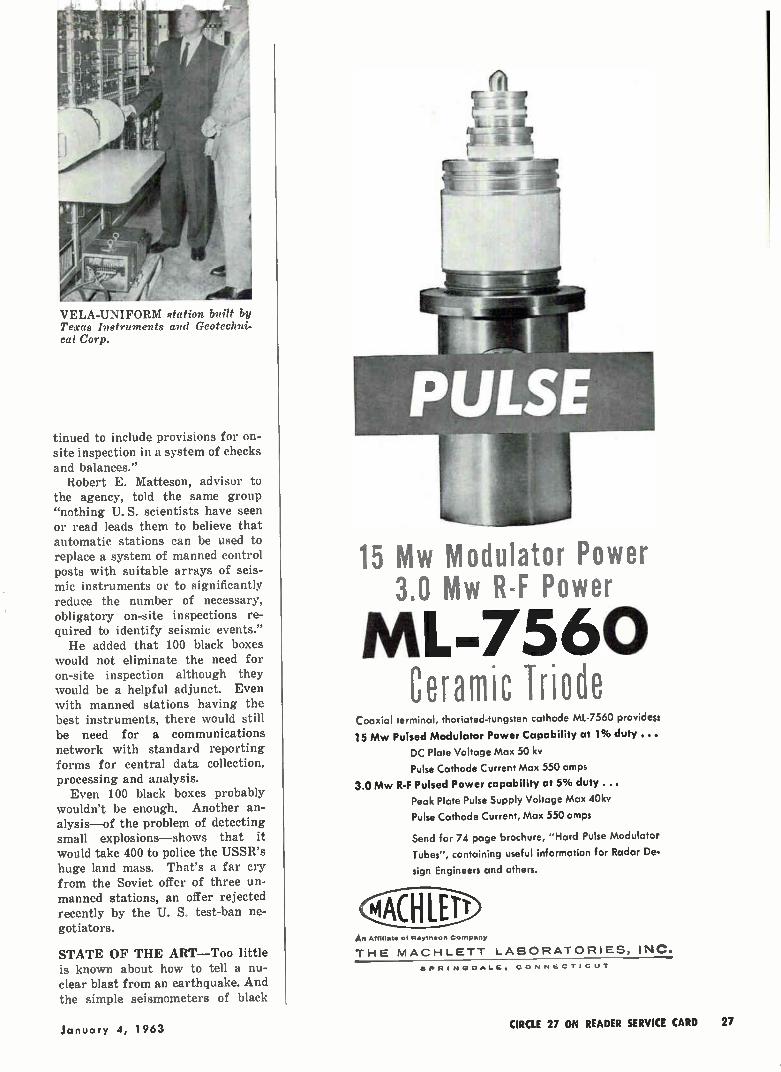
VELA-UNIFORM station built by Texas Instruments and Geotechni-cal Corp.
tinued to include provisions for on-site inspection in a system of checks and balances."
Robert E. Matteson, advisor to the agency, told the same group "nothing U. S. scientists have seen or read leads them to believe that automatic stations can be used to replace a system of manned control posts with suitable arrays of seis-mic instruments or to significantly reduce the number of necessary, obligatory on-site inspections re-quired to identify seismic events." He added that 100 black boxes
would not eliminate the need for on-site inspection although they would be a helpful adjunct. Even with manned stations having the best instruments, there would still be need for a communications network with standard reporting forms for central data collection, processing and analysis. Even 100 black boxes probably
wouldn't be enough. Another an-alysis—of the problem of detecting small explosions—shows that it would take 400 to police the USSR's huge land mass. That's a far cry from the Soviet offer of three un-manned stations, an offer rejected recently by the U. S. test-ban ne-gotiators.
STATE OF THE ART—Too little is known about how to tell a nu-clear blast from an earthquake. And the simple seismometers of black
le
15 Mw Modulator Power 3.0 Mw R-F Power
ML-7560 Ceramic Triode
Coaxial terminal, thoriated-tungsten cathode ML-7560 provides:
15 Mw Pulsed Modulator Power Capability at 1% duty ...
DC Plate Voltage Max 50 kv
Pulse Cathode Current Max 550 amps
3.0 Mw R-F Pulsed Power capability at 5% duty
Peak Plate Pulse Supply Voltage Max 40kv
Pulse Cathode Current, Max 550 amps
Send for 74 page brochure, "Hard Pulse Modulator
Tubes", containing useful information for Radar De.
sign Engineers and others.
P‘C_HIE31 . Aftitiote of Raytheon Company
THE MACHLETT LABORATORIES, INC.
SPRINGDALE. CONNECTICUT
January 4, 1963 CIRCLE 27 ON READER SERVICE CARD 27
LARGE VALUES OF CAPACITANCE IN SMALL PHYSICAL SIZE!
Sprague offers two series of "block-
buster" electrolytic capacitors for use in digital power supplies and allied applica-tions requiring extremely large values of capacitance.
Type 36D Powerlytic® Capacitors pack
the highest capacitance values available
in their case sizes. Intended for operation at temperatures to 65 C, maximum capac-
itance values range from 150,000 luF at 3 volts to 1000 µF at 450 volts.
Where 85 C operation is a factor,
Sprague offers the Type 32D Compulytic®
Series, the ultimate in reliable long-life
electrolytics for digital service. These re-markably trouble-free units have maxi-
mum capacitance values ranging from
130,000 ,uF at 2.5 volts to 630 I.LF at 450 volts.
Both 32D and 36D Capacitors have low
equivalent series resistance and low leak-age currents, as well as excellent shelf
life and high ripple current capability. If you'd like complete technical data
on Type 36D units, write for Engineering
Bulletin 3431. For the full story on the
"blue ribbon" Type 32D Series, write for Engineering Bulletin 3441B to the Tech-
nical Literature Section, Sprague Electric
Company, 35 Marshall Street, North Adams, Massachusetts.
SPRAGUE® THE MARK OF RELIABILITY
48-3C.R1
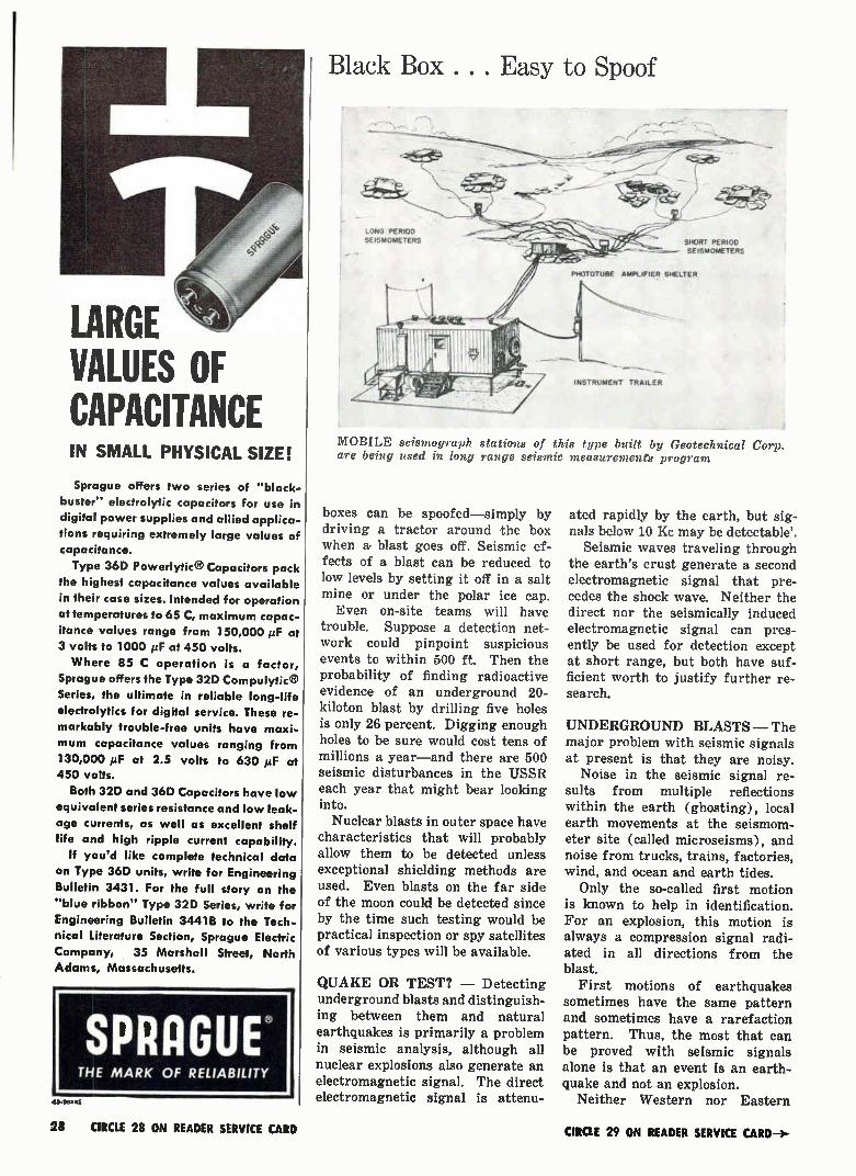
Black Box . . . Easy to Spoof
LONG PERIOD SEISMOMETERS
-
e tece SHORT PERIOD
- SEISMOMETERS
PHOTOTUBE AMPLIFIER SHELTER
INSTRUMENT TRAILER
MOBILE seismograph stations of this type built by Geotechnical Corp. are being used in long range seismic measurements program
boxes can be spoofed—simply by driving a tractor around the box when a blast goes off. Seismic ef-fects of a blast can be reduced to low levels by setting it off in a salt mine or under the polar ice cap. Even on-site teams will have
trouble. Suppose a detection net-work could pinpoint suspicious events to within 500 ft. Then the probability of finding radioactive evidence of an underground 20-kiloton blast by drilling five holes is only 26 percent. Digging enough holes to be sure would cost tens of millions a year—and there are 500 seismic disturbances in the USSR each year that might bear looking into. Nuclear blasts in outer space have
characteristics that will probably allow them to be detected unless exceptional shielding methods are used. Even blasts on the far side of the moon could be detected since by the time such testing would be practical inspection or spy satellites of various types will be available.
QUAKE OR TEST? — Detecting underground blasts and distinguish-ing between them and natural earthquakes is primarily a problem in seismic analysis, although all nuclear explosions also generate an electromagnetic signal. The direct electromagnetic signal is attenu-
ated rapidly by the earth, but sig-nals below 10 Kc may be detectable'.
Seismic waves traveling through the earth's crust generate a second electromagnetic signal that pre-cedes the shock wave. Neither the direct nor the seismically induced electromagnetic signal can pres-ently be used for detection except at short range, but both have suf-ficient worth to justify further re-search.
UNDERGROUND BLASTS — The major problem with seismic signals at present is that they are noisy.
Noise in the seismic signal re-sults from multiple reflections within the earth (ghosting), local earth movements at the seismom-eter site (called microseisms), and noise from trucks, trains, factories, wind, and ocean and earth tides.
Only the so-called first motion is known to help in identification. For an explosion, this motion is always a compression signal radi-ated in all directions from the blast.
First motions of earthquakes sometimes have the same pattern and sometimes have a rarefaction pattern. Thus, the most that can be proved with seismic signals alone is that an event is an earth-quake and not an explosion.
Neither Western nor Eastern
28 CIRCLE 28 ON READER SERVICE CARD CIRCLE 29 ON READER SERVICE CARD-->

We are. If you think that's bold, you should
see our new Skyroad transportation
system. Skyroad is an integrated net-
work of trucks, trains and Flying Tigers'
airfreight combined to give you door-to-
door airfreight service in 1451 cities
and towns. With Skyroad, you can forget your wor-
ries about delays in loading and unloading
shipments. Freight is never held up
because we have a nationwide teletype system that keeps tabs on your shipment
from initial pickup to final delivery.
Skyroad simplifies your shipping too.
You pay only one flat rate. And you
receive only one bill for this combined
service. You'll be amazed at how low Sky-
road rates are. We never play big wheel
with other people's money. See for your-
self. Call for details.

Black Box . . . What About Space Tests? (continued from p 26 and 28)
SEISMOMETER for use in holes or wells as deep as 10,000 ft im-proves signal-to-noise ratio as much as 10:1 over surface types
FILM READER scans data on 16-mm film. Seismologists can quickly locate events of interest but do not always agree on the inter-pretation of weak signals
scientists at the 1958 Geneva Con-ference of Experts were able to show how shallow underground nu-clear explosions could be positively identified', and no method sug-gested since then has been verified. With the seismic equipment
available today, seismologists can reliably identify a first compression motion if the signal-to-noise ratio is 7:1 or better (s/n of 5:1 may be acceptable). But a radial compres-sion pattern cannot be positively determined from only a few scat-tered seismic stations—clean first-motion signals from a network of stations are necessary. The signal-to-noise ratio is thus
a major stumbling block of any unattended inspection system. Since tactical weapons with powers of 5 Kt or less are of interest, signal power is relatively low. Simple de-coupling techniques can reduce it by a factor of ten or more. Hang-ing the bomb in a cage within a cavern can reduce the seismic effect by as much as 300. There is evi-dence that small explosions deep in arctic snow are completely muffled.
BLACK BOXES — Simple and rugged seismometers able to oper-ate unattended for a month or more can reliably detect the first motion of a 5-Kt blast 100 to 200 miles away. A network to cover the Soviet Union would need 400 or more stations. The manned seismic stations first
proposed at the Geneva Conference are more sensitive and complicated instruments than unattended ones can be and have a range of about 1,000 miles. The Soviet Union now has over 100 seismic observatories of the most modern type.
Seismic stations cannot just be placed on the ground and turned on. A quiet area is needed and the equipment must be directly con-nected to bed rock. Spoofing is relatively easy. Driving a tractor around a site could bury blast sig-nals in noise.
SPACE BLASTS — At least five different types of ground-based equipment to detect blasts in space appear feasible at this time'. De-tection methods would be based on
SEISMIC STATION requires at least three seismometers, power supply, recording system and tim-ing signals with 0.1-second absolute accuracy
the visible flash, the electromag-netic signal, and soft or long-wave-length thermal x-rays.
Los Alamos estimates that 10' of the total energy of a 1-megaton blast is given off as visible light over a 30-microsecond period. If the same energy proportion holds for smaller explosions, a 10-kiloton blast would give off 4 x 10' joules as light.
With an optical system having a 0.2-radian field of view, and pho-totube with a sensitivity of 0.04 amp per watt, a peak photocurrent pulse of 0.08 microamp would be obtained from a 10-Kt blast 101 Km away. This can be used to obtain a signal-to-noise ratio of 10 to 1, with a false-alarm probability of 1 in 10' seconds. But if the light pulse is only
0.9 times as much as assumed, the false-alarm probability is 3 x 10' or about 1 per year. An acceptable false-alarm rate has generally been estimated at 1 per century.
RADIO ENERGY — Electromag-netic energy from the nuclear blast is concentrated in the 10 to 100-Mc band and is relatively insensitive to the size of the blast. The signal from a blast 10' Km away is about 3 x 10' watt/in'. Cosmic noise in the same band is approximately 6 x 10 watts/ne, giving a signal to noise ratio of 100:1. But nonstatis-tical variations in cosmic noise could occasionally give a spike 100 times the rms level, thereby giving a false alarm.
30 electronics

The x-ray pulse from a nuclear blast lasts from 0.1 to 1 micro-second; thermal x-rays reaching the ionosphere and upper atmos-phere from a space blast would cause a nearly instantaneous in-crease in ionization in these re-gions. Time for the suddenly in-creased ionization to dissipate is a function of altitude, initial elec-tron density and time of day. It ranges from hundreds to thousands of seconds.
VLF PHASE SHIFT—The sudden increase in electron density causes an effective lowering of the D layer and a consequent phase shift in vlf signals that travel in the duct formed by the layer and the earth. A 10-Kt blast 105 Km away could
cause a phase shift in a 20-Re sig-nal of 480 degrees in 1 microsec-ond. This is a much larger rate of phase change than the 0.5-degree-per-second rate for a solar flare and the 0.03-degree rate for sunset and sunrise. The U. S. Navy is now evaluating vif phase-shift de-tection methods (ELECTRONICS, p
28, Oct. 19, 1962). Two other ways of detecting
space blasts appear feasible. Low-ering of the D layer increases ab-sorption of cosmic noise, and a 10-Kt blast at 105 Km is estimated to change the 15-Mc cosmic signal by about 0.1 db. Although the magni-tude of change is small, the rate of change is much higher than any caused by natural events, so de-tection with a fast-acting riometer should be possible. The other method is based on de-
tecting the air fluorescence that oc-curs when thermal x-rays excite nitrogen molecules. Approximately 0.25 percent of the absorbed energy is emitted as blue light at 3914 A. An air-fluorescence detector has been operated by Los Alamos Lab-oratory for 2i years, and a detec-tion range of 105 Km for a 1-Kt blast is believed possible.
REFERENCES (1) S. D. Abercrombie, Ground Based
Detection of Atomic Weapons, Paper pre-sented at 9th IRE-Professional Group Nuclear Science, 1962.
(2) Carl Romney, Commentary on "The Detection of Underground Explosions" (An article by L. Don Leet, Scientific American, June, 1962), Vesiac Bulletin, U. of Michigan, Ann Arbor, Mich.
(3) Cabell A. Pearse, Ground Based High Altitude Detection Systems, Paper presented at 9th IRE-Professional Group Nuclear Science, 1962.
All illustrations accompanying this arti-cle were furnished by The Geotechnical Corp., Garland, Texas.
TI has what you need in pulse programming!
Versatility — Custom combination of modules for any desired
performance characteristics. Portability —Compact, light-weight, easy to carry. High Rep Rate — Repetition rates
of 100 cycles to 100 megacycles.
Texas Instruments Series 6000 Pulse Generators are the smallest instruments available with the advantages of modular construction plus a wide range of operating features which include variable width and delay, variable rise and fall times, plus and minus out-
puts, pulse mixing, programmed and random word generation.
TI Pulse Generators combine dependable performance with a high degree of versatility and convenience. Circuitry is all solid state with com-pact controls. Write for complete information.
INDUSTRIAL PRODUCTS GROUP
44(r) cd TEXAS INSTRUMENTS INCORPORATED P o BOX 66027 HOUSTON 6 TEXAS
SENSING • RECORDING . TESTING • DIGITIZING INSTRUMENTS
THE INSTRUMENTS OF TEXAS INSTRUMENTS
CIRCLE 31 ON READER SERVICE CARD
electronics
Editorial Opportunity IT DOESN'T HAPPEN OFTEN, but electronics, "bible of the industry"
and a McGraw-Hill publication, has an opening for an Assistant Editor. Ideally, the man we are looking for and to whom a post on our
New York staff could be a long-term challenge, would have an electrical engineering degree or technical equivalent, practical experience in our field and a demonstrated aptitude for editing, writing, reporting. He prob-ably lives somewhere in the metropolitan area and therefore would have no relocation problem.
Write The Editor, electronics, 330 W. 42nd St., New York 36, stating experience, aspirations and past earnings. Mark the envelope "Confiden-tial" and it will be kept that way.
January 4, 1963 31

HOW TO BEND BARS and TUBING
HOW TO BEND...
OFF CENTER EYES
o Insert bar stock be-tween Locking Pin and Radius Pin of desired size.
o Set Forming Roller against material and advance Operating Arm.
Complete operation with one steady move-ment.
HOW TO BEND ...
o Clamp tube. Insert Fol-low Block between ma-terial and Forming Roller.
e Advance Operating Arm until it strikes Angle Stop.
e Remove Follow Block, release clamp and re-move tube.
with
bl — ACRO
BENDER
Complete details on forming rodsr and tubing with standard accessories as well as tips and technical data on angle, channel and other materials will be found in "It's Easy to Bend", a 32 page summary of Di-Acro Benders and bending. A copy is yours free of charge.
Consult the yellow pages of your phone book for the name of your nearest Di-Acro distributor or write:
pronounced die-adr-ro 0 111£ -_
DI-ACRO CORPORATION
431-W 8th Ave., Lake City, Minn.
GROUND CONTROLS bring unmanned helicopter in for landing
Navy Tests Drone 'Copter
Unmanned helicopters could spy on enemy and deliver undersea weapons
DALLAS—Bell Helicopter has suc-cessfully demonstrated the capabil-ity of a remote-control helicopter drone system, in two unmanned flights at the Naval Ordnance Test Station, China Lake, Calif. Bell be-lieves the system could expand the use of helicopters on hazardous mil-itary missions, such as: • Using drones as decoys to probe
and expose enemy firepower. • Providing radar or tv spying
platform above a battlefield. Held stationary at 7,000 to 8,000 feet, such a helicopter could broadcast a continuing picture of enemy troop and equipment positions and move-ments. In Navy use, drones could safely scout shorelines and ship movements. • Flying into contaminated areas
with radiation detectors to measure the effect of nuclear explosions. • Reducing the hazard of deliver-
ing antisubmarine underwater mis-siles and depth charges. The present system can stabilize
on four axes. This unit activates servomechanisms that control pitch, roll, yaw and collective axes by hy-draulic manipulation of a dual con-trol system.
Control signals are telemetered from a 17-by-13-inch ground-con-
trol panel to the autopilot through a pulse-amplitude-modulation data-link system. An encoder mixes multi-channel control commands for single-channel broadcast to the heli-copter by an f-m transmitter. A de-coder in the craft converts the tel-emetered commands into channel signals acceptable to the autopilot. Lag time between command and re-action is measured in microseconds. The recent tests at China Lake
involved an 11-year-old Army OH-13E helicopter. It was flown 72 minutes over a prescribed course. After the first flight, it was re-fueled, checked and reflown on a second 48-minute unmanned flight. Flight altitudes ranged up to 2,000 feet, maximum speed was 70 knots, and maneuvering distance 6 miles.
TRIPOD-MOUNTED ground con-trol panel is checked out
32 CIRCLE 32 ON READER SERVICE CARD CIRCLE 33 ON READER SERVICE CARD-÷-
KNOW OF A SMALL , RUGGED
METAL-CERAMIC TRIODE
WITH HIGH Po THROUGH 1600 MCS ?
SOUNDS LIKE A PICTURE
WORTH HEARING ABOUT
THIS ONE IS WORTI4 LISTENING TO.ITS GENERAL ELECTRICS NEW ZP-1026, a triode amplifier with the highest known power-handling capability of any tube its size through 1600 mc. Its peak power capabilities include 2 KW at 0.02 duty, and 750 watts at 0.03 duty.
This G-E triode was designed for use in applications such as TACAN. IFF, steerable arrays, Doppler radar and altimeters, and is only one of a complete line of metal-ceramic tubes General Electric has for a variety of military applications. Its features include long pulse and high duty capabilities, long life, small size and heat-sink cooling.
HERE ARE SOME CHARACTERISTICS OF OTHER TYPICAL G-E TUBES ...
ZP-1030 METAL-CERAMIC
TETRODE
ZP-1016B METAL CERAMIC
TRIODE
ZP-1029 METAL-CERAMIC
DIODE
TYPICAL APPLICATION
AM and CW Com-munications, SSB, Satellite Communi-cations. Tropo-Scat-ter
Series Regulator
PF
BRIEF 100 W carrier linear DESCRIPTION amplifier @ 225-
400 mc; 300 W CW @ 225-400 mc; 200 W CW @ 900 mc.
ELECTRONICS INCLUDING IGNITRONS, HYDROGEN THYRATRONS, MAGNETRONS, METAL. GENERAL ELECTRIC
PROGRESS IN MICROWAVE TECHNOLOGY CERAMIC TETRODES, TWT's, HIGH POWER DUPLEXERS, HIGH-POWER WAVEGUIDE FILTERS, KLYSTRONS AND THERMI. ONIC CONVERTERS. FOR INFORMATION ON THESE PRODUCTS, WRITE SECT. 265-23, POWER TUBE DEPARTMENT 2.55-23
POWER TUBE DEPT., GENERAL ELECTRIC CO., SCHENECTADY, N. Y. OR TELEPHONE TODAY: SCHENECTADY. N. Y. FRanklin 4-2211 (Ext. 5.3433) • WASHINGTON, D. C EXecutive 3.3600 • DAYTON. OFDOBAidwin 3.7151 e LOS ANGELES. CALIT•
NEW YORK. N. Y Wisconsin 7.4065 • BRadshaw 2.8566 SYRACUSE, N. Y. 652.5102 • CHICAGO, ILL. SPring 7-1600 • CLIFTON, N. .I.GRegory 3-6387 • ORLANDO, FLA.GArden 4.6280
Eb r_- 10 KVdc; --- 10;
Pp 300 W.
Heat-sink cooled; .==-- 0.300 Adc;
PIV = 5500 v.

HOW WE TOOK
TeE SLIP OUT OF
TEFLON* Why Gudebrod's Common Sense
Approach to Lacing Problems
Pays Dividends For Customers!
Motor manufacturers came to us some time ago with a problem. They re-
quired a flat-braided lacing tape that would meet temperature requirements
of —100 °F to 500° F. A teflon lacing tape would meet the temperature re-
quirements but teflon is slippery .... knots were hard to tie ... harnesses
worked loose after installation. Valuable production time would be lost!
Gudebrod's answer to this problem was to coat teflon with a special synthetic
rubber finish that was non-flaking and fungistatic. We then flat-braided it
—we originated the flat braiding process! The result was TEMP-LACE « H, a teflon lacing tape that met the temperature requirements of motor manu-
facturers and assured them that knots would not slip, harnesses would stay
tied and assemblies would remain firm long after installation.
Taking the slip out of teflon is but one of many ways in which Gudebrod's
common sense approach to problems pays dividends for customers. What-
ever your lacing needs—nylon, glass, dacront, fungus proofing, color coding,
special finishes, Gudebrod has the answer because:
1. Gudebrod lacing tape increases production! 2. Gudebrod lacing tape reduces labor costs! 3. Gudebrod lacing tape means minimal maintenance after installation! 4. Gudebrod is quality—our standards for lacing tape are more exacting than
those required for compliance with MIL-T!
Write today for our Technical Products Data Book which explains the many
advantages of Gudebrod lacing tape for both civilian and military use.
Address inquiry and your lacing tape problems to Electronics Division.
*DuPont registered trademark for its TFE•fluorocarbon fiber. tDuPont trade name for its polyester fiber.
UDEBROD BROS. SILK CO., INC. FOUNDED IN 1870
34th STREET, NEW YORK 1, NEW YORK
MEETINGS AHEAD
MILLIMETER AND SUBMILLIMETER CON-FERENCE, IRE-Orlando Section; Cherry Plaza Hotel, Orlando, Flor-ida, Jan. 7-10.
RELIABILITY & QUALITY CONTROL SYM-POSIUM, IRE-PGRQC, AIEE, ASQC, EIA; Sheraton Palace Hotel, San Fran-cisco, Calif., Jan. 21-24.
INSTITUTE OF ELECTRICAL & ELEC-TRONICS ENGINEERS WINTER GENERAL
MEETING & EXPOSITION, IEEE; Statler and New Yorker Hotels, New York City, Jan. 27-Feb. 1.
MILITARY ELECTRONICS WINTER CON-VENTION, IRE-PGMIL ; Ambassador Hotel, Los Angeles, Calif., Jan. 30-Feb. 1.
QUANTUM ELECTRONICS INTERNATIONAL SYMPOSIUM, IRE, SFER, ONR; Unesco Building and Parc de Exposition, Paris, France, Feb. 11-15.
INFORMATION STORAGE AND RETRIEVAL SYMPOSIUM, American University; International Inn, Washington, D. C., Feb. 11-15.
ELECTRICAL & ELECTRONIC EQUIPMENT EXHIBIT, ERA, ERC; Denver Hilton Hotel, Denver, Colo., Feb. 18-19.
SOLID STATE CIRCUITS INTERNATIONAL CONFERENCE, IRE-PGCT, AIEE, Uni-versity of Pennsylvania; Sheraton Hotel and U. of P., Philadelphia, Pa., Feb. 20-22.
PACIFIC COMPUTER CONFERENCE, AIEE; California Institute of Technology, Pasadena, Calif., March 15-16.
BIONICS SYMPOSIUM, United States Air Force; Biltmore Hotel, Dayton, Ohio, Mar. 18-21.
IEEE INTERNATIONAL CONVENTION, In-stitute of Electrical and Electronics Engineers; Coliseum and Waldorf-Astoria Hotel, New York, N. Y., March 25-28.
ENGINEERING ASPECTS OF MAGNETO-HYDRODYNAMICS SYMPOSIUM, IRE-PGNS, AIEE, IAS, University of Cali-fornia; UCLA, Beverly, Calif., April 10-11.
OHIO VALLEY INSTRUMENT-AUTOMA-TION SYMPOSIUM, ISA, et al; Cin-cinnati Gardens, Cincinnati, Ohio, April 16-17.
INTERNATIONAL NON-LINEAR MAGNETICS CONFERENCE, IRE-PGEC, PGIE, AIEE; Shoreham Hotel, Washington, D. C., April 17-19.
ADVANCE REPORT RADIO FREQUENCY INTERFERENCE NATIONAL
SYMPOSIUM, IRE-PGRFI; Bellevue Strat-ford Hotel, Philadelphia, Pa., June 4-5, 196.1. March 1 is the deadline for sub-mitting a 250-word abstract to: Albert R. Kali, Technical Program Chairnian, c/o Ark Electronics Corp., 624 Davisville Road, Willow Grove, Pennsylvania. Sym-posium theme is "new dimensions in ni." Papers in the following rfi areas are specifically invited: instrumentation, sup-pression; system. compatibility analysis; communications; special problems above 10 kmc; measurement problems in the volt range. After selection of papers, authors will be requested to submit a 1,000-5,000 word summary for publica-tion in the PGRFI Symposium Transac-tions.
34 CIRCLE 34 ON READER SERVICE CARD electronics
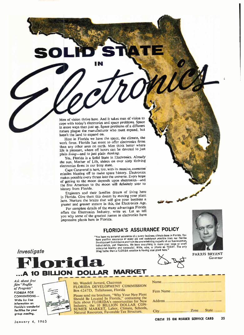
Investigate
Men of vision thrive here. And it takes men of vision to cope with today's electronics and space problems. Space in more ways than just up. Space problems of a different nature plague the manufacturer who must expand, but hasn't the land to expand on.
Here in Florida we have the space, the climate, the work force. Florida has more to offer electronics firms than any other area on earth. Men think better where life is pleasant, where off hours can be devoted to just plain living—and to just plain thinking.
Yes, Florida is a Solid State in Electronics. Already the sun, Mother of Life, shines on over sixty thriving electronics firms in our busy state.
Cape Canaveral is here, too, with its massive, awesome. missiles blasting off to make space history. Electronics makes possible every thrust into the universe. Every hope of getting to the moon depends upon electronics—and the first American to the moon will definitely soar to history from Florida.
Engineers and their families dream of living here in Florida. Give them this dream by moving your plant here. Nurture the brains that will give your business a greater and greater stature in this, the Electronics Age.
For complete details of the many advantages Florida offers the Electronics Industry, write us. Let us tell you why some of the greatest names in electronics have impressive plants here in Florida.
e
or asp. woke'
FLORIDA'S ASSURANCE POLICY "You have my personal assurance of a sunny business climate here in Florida. You have positive assurance of every aid and assistance possible from our Florida Development Commission and from the overwhelming majority of our businessmen, industrialists, and financiers. We have everything to make your large or small enterprise healthy and successful. Write, wire, or phone us TODAY. The only thing better than a FLORIDA vacation is having your plant here."
Flcorl cla ...A 10 BILLION DOLLAR MARKET
Ask about free r film "Profile Mr. Wendell Jarrard, Chairman Name of Progress" FLORIDA DEVELOPMENT COMMISSION FLORIDA FOR Box 4247D, Tallahassee, Florida Firm Name CONVENTIONS— Please send me brochure, "Why Your New Plant Write for free Should Be Located In Florida," containing the information on facts about FLORIDA's opportunities for New Address Florida's wonderful Industry, the 10 BILLION DOLLAR CON-facilities for your SUMER MARKET, Labor, Climate, Schools, group meeting. Natural Resources, Favorable Tax Structure. City Zone State
CIRCLE 35 ON READER SERVICE CARD 35
FARRIS BRYANT Governor
January 4, 1963
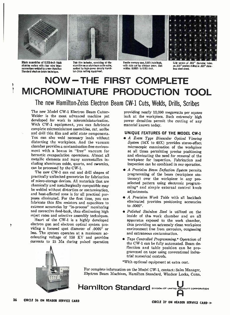
Micro assemblies of 0.030-inch thick alumina wafers with riser wire inter-connections welded by a new Hamilton Standard electron beam technique.
Thin film inductor, consisting of tita-nium film on an aluminum oxide wafer, scribed by high-power density Hamil-ton-Zeiss cutting equipment.
Ferrite memory core, 0.005-inch thick, with slots cut by electron beam. Slot widths: 0.0005- to 0.00I-inch.
a a •
a
a
•
Grid screen of .003" diameter holes on .010" centers drilled in .020' stain-less steel sheet.
NOW THE FIRST COMPLETE MICROMINIATURE PRODUCTION TOOL
The new Hamilton-Zeiss Electron Beam CW-1 Cuts, Welds, Drills, Scribes The new Model CW-1 Electron Beam Cutter-Welder is the most advanced machine yet developed for work in microminiaturization. With CW-1 equipment, you can fabricate complete microminiature assemblies, cut, scribe and drill thin film and solid state components. You can also weld necessary leads without distorting the workpiece. And the vacuum chamber provides a contamination-free environ-ment with a bonus in "free" vacuum for hermetic encapsulation operations. Almost all metallic elements and many nonmetallics in-cluding aluminum oxide, quartz, and coramics, can be processed by the CW-1. The new CW-1 can cut and drill shapes of
practically unlimited geometries for fabrication of micro-storage devices. All materials that are chemically and metallurgically compatible may be welded without distortion or contamination, and heat-affected zone is for all practical pur-poses eliminated. For the first time, you can fabricate thin film resistors and capacitors to extreme accuracies by "in-process" monitoring and corrective feed-back, thus eliminating high reject rates and selective assembly techniques.
Heart of the CW-1 is a highly developed electron gun and electron optical system pro-viding a focused spot diameter of .0005" or less. The system operates at a maximum ac-celerating voltage of 150 KV and provides currents to 15 Ma during pulsed operation
providing nearly 10,000 megawatts per square inch at the workpiece. Such extremely high power densities permit the cutting of any material known today.
UNIQUE FEATURES OF THE MODEL CW-1 • A Zoom Type Binocular Optical Viewing
System (14X to 40X) provides stereo-effect microscopic examination of the workpiece at all times permitting precise positioning and eliminating the need for removal of the workpiece for inspection. Fabrication and inspection can be combined in one operation.
• A Precision Beam Deflection System permits programming of the beam (workpiece sta-tionary) over the workpiece in any pre-selected pattern using electronic program-ming* and simple external control knob adjustments.
• A Precision Work Table with all backlash eliminated provides positioning accuracies to .0002".
• Polished Stainless Steel is utilized on the inside of the work chamber and on all apparatus exposed to the work chamber, thus providing an extremely clean workpiece environment free from corrosion, outgassing and extraneous contamination.
• Tape Controlled Programming.* Operation of the CW-1 can be fully automated. Beam de-flection and table position can be pro-grammed on tape using conventional indus-trial numerical controls.
*With optional equipment at extra cost.
For complete information on the Model CW-1, contact: Sales Manager, Electron Beam Machines, Hamilton Standard, Windsor Locks, Conn.
U Hamilton Standard DIVISION OF UNITED AIRCRAFT CORPORATION
36 CIRCLE 36 ON READER SERVICE CARD CIRCLE 37 ON READER SERVICE CARD >-
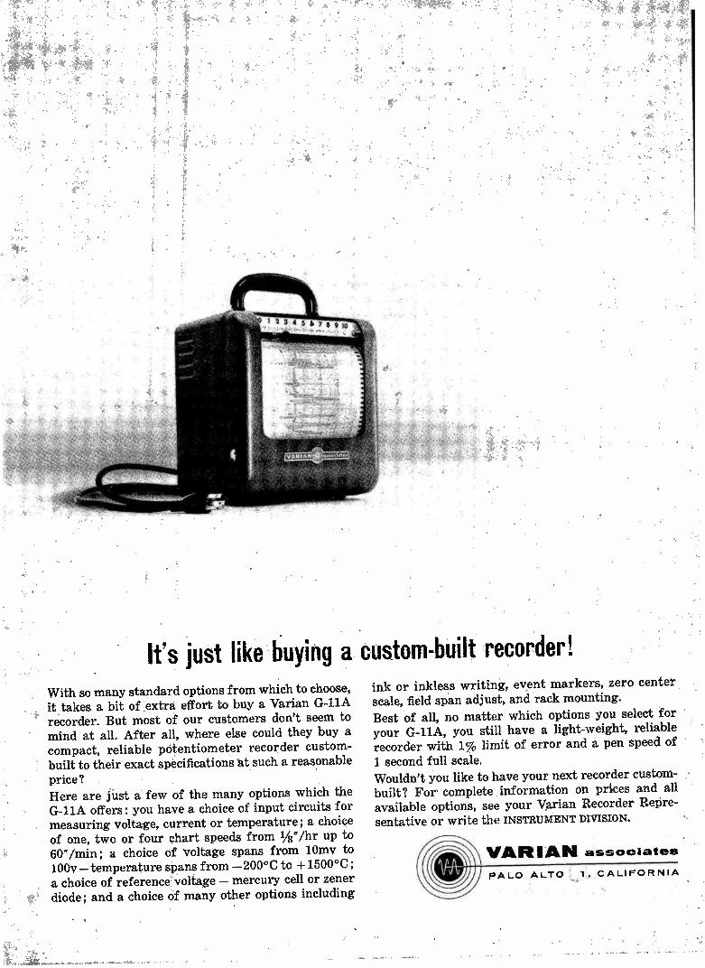
Ifs just like buying a custom-built recorder! With so many standard options from which to choose, it takes a bit of extra effort to buy a Varian G-11A recorder. But most of our customers don't seem to mind at all. After all, where else could they buy a compact, reliable potentiometer recorder custom-built to their exact specifications at such a reasonable price? Here are just a few of the many options which the G-11A offers: you have a choice of input circuits for measuring voltage, current or temperature; a choice of one, two or four chart speeds from 1/8"/hr up to 60"/min; a choice of voltage spans from 10mv to 100v—temperature spans from —200°C to +1500°C ; a choice of reference voltage — mercury cell or zener diode; and a choice of many other options including
ink or inkless writing, event markers, zero center scale, field span adjust, and rack mounting. Best of all, no matter which options you select for your G-11A, you still have a light-weight, reliable recorder with 1% limit of error and a pen speed of
1 second full scale. Wouldn't you like to have your next recorder custom-built ? For complete information on prices and all available options, see your Varian Recorder Repre-sentative or write the INSTRUMENT DIVISION.
VARIAN associates PALO ALTO 1, CALIFORNIA

PUMPS • VALVES • BAFFLES • GAUGES
VACUUM COMPONENTS DIFFUSION PUMPS
*Licensed exclusively from Edwards High Vacuum Limited. U. S. Patent No. 2919061.
Only NRC offers a full line of high-speed diffusion pumps with all these impor-tant advantages: • No super-heating ... min-imizes pump fluid decompo-sition. • Fractionating
jet assembly.. . constantly puri-fies pump fluid... lower pressures can be held longer.
• Patented Cold Cap* ... an NRC exclusive...cuts back-streaming 98%. Available now in 4", 6", 10", 16" and 32" sizes for all your high vacuum testing and production applications, where performance and reliability really count.
CRYO AND MOLECULAR BAFFLES
Now, your high vacuum system can be oper-ated at lowest pressures for extended periods of time with no detectable trace of hydro-carbons reaching the chamber! The reason: NRC's Circular Chevron Cryo Baffle and the all-new NRC Molecular Sorbent Baffle (which utilizes three full trays of zeolite) virtually eliminate back-migration of pump fluid va-pors. Yet, they provide exceptionally high con-ductance for maximum useful pumping speed.
1 ,' ! 7 N RC 1 \,, crepo-an. /
MANUFACTURING PLANTS
SLIDE VALVES
New NRC Slide Valves (HC Series) are very. high and ultra-high vacuum valves at conven-tional prices. Pressures of 10.8 to 104° torr range have been produced ... without baking... in vacuum systems using these valves. 100% clear opening and low height provide highest conductance. Double -pumped stem seal cuts gas bursts 99%. They're available in 4" and 6" sizes, either hand or air operated.
VACUUM GAUGES
Get accurate, reproducible direct-readings to 10-'3 torr with the new NRC Model 752 Red-head Magnetron Gauge! The only really satis-factory gauge commercially available for measurements below 1 x 10 torr. Increased current readings provide 50 times the sensi-tivity of hot-wire ionization gauges. Because there's no hot filament, it's magnitudes less "gassy", can't become contaminated by vapor-izing of gauge elements. And the 752 Gauge is not X-ray limited. NRC's full line of vacuum gauges and controls also includes an improved Bayard-Alpert type gauge, Model 751, for accurate, reliable meas-urement in the 1 x 10⁻³ to 104° torr rangé.
A Subsidiary of National Research Corporation
160 Charlemont St.
Newton 61, Massachusetts
Area Code 617, DEcatur 2-5800
IN NEWTON,
All of the above components are stock items. Write today for prod-uct data sheets. Let us show you how NRC components can improve the performance of your high vac-. uum system.
MASSACHUSETTS AND PALO ALTO, CALIFORNIA
38 CIRCLE 38 ON READER SERVICE CARD electronics
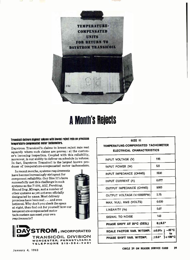
,4Ñ
TEMPERATURE-
COMPENSATED
UNITS
FOR RETURN TO
DAYSTROM TRANSICOIL
A Mouth's Rejects Transicoil delivers highest volume with lowest reject rate on precision
temperature-compensated motor tachometers.
Daystrom Transicoil's claims to lowest reject rate rest squarely where such claims are proven: at the custom-er's incoming inspection. Coupled with this reliability, moreover, is our ability to deliver on schedule in volume. In fact, Daystrom Transicoil is the largest known pro-ducer of temperature-compensated motor tachometers.
In recent months, systems requirements have become increasingly stringent for component reliability. Our Size 11's have successfully met this challenge in such systems as the F-104, A3J, Pershing,
Hound Dog, Mirage, and a number of other systems as yet not even officially designated by name. Most delivery promises have been met. .. and even bettered. Why don't you check the specs at right, then find out for yourself how our
temperature-compensated motor tachometers can meet your own requirements?
1 I.% DAVSTROM , INCORPORATED
TRANSICOIL DIVISION WORCESTER, PENNSYLVANIA
TELEPHONE 215-584-242 1
SIZE 11
TEMPERATURE-COMPENSATED TACHOMETER
ELECTRICAL CHARACTERISTICS
INPUT VOLTAGE (V) 115
INPUT POWER (W) 5.5
INPUT IMPEDANCE (OHMS) 1500
INPUT CURRENT (A) 0.077
OUTPUT IMPEDANCE (OHMS) 5000
OUTPUT VOLTAGE (V/100ORPM) 2.75
MAX. NULL RMS (VOLTS) 0.020
LINEARITY (°/o) 0.07
SIGNAL TO NOISE 140
PHASE SHIFT AT 25°C (DEG.) 0±0.5°
SCALE FACTOR VAR. W/TEMP. -1=0.5% —55°C to
PHASE SHIFT VAR. W/TEMP. ±0.5° +100°C
January 4, 1963 CIRCLE 39 ON READER SERVICE CARD 39
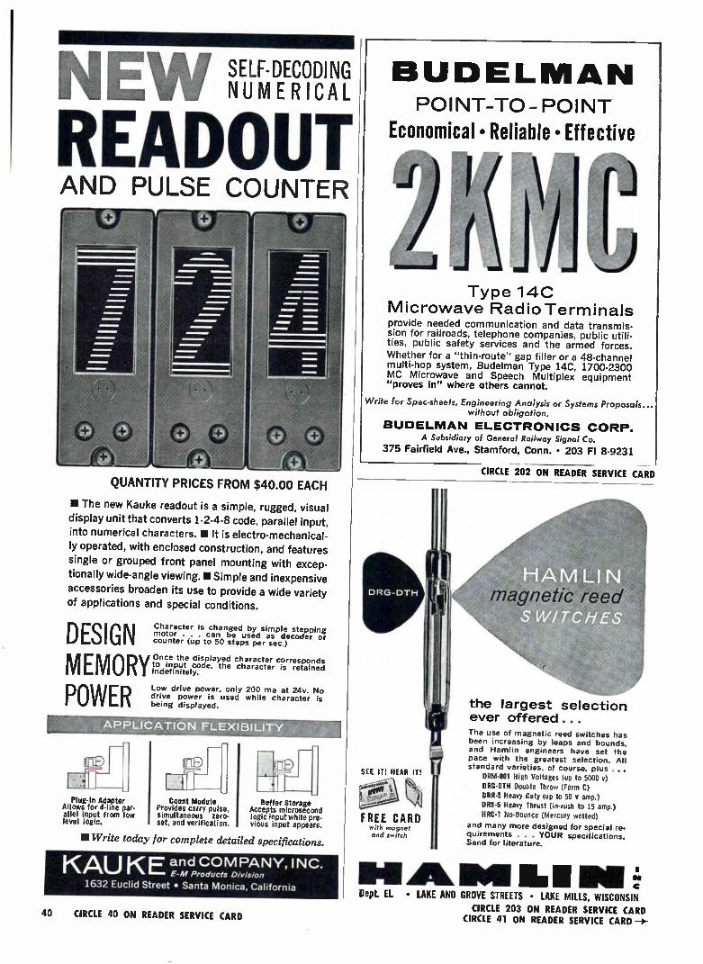
NEW MIVEM READOUT AND PULSE COUNTER
QUANTITY PRICES FROM $40.00 EACH
II The new Kauke readout is a simple, rugged, visual
display unit that converts 1-2-4-8 code, parallel input,
into numerical characters. II It is electro-mechanical-
ly operated, with enclosed construction, and features
single or grouped front panel mounting with excep-
tionally wide-angle viewing. • Simple and inexpensive
accessories broaden its use to provide a wide variety
of applications and special conditions.
DESIGN MEMORY POWER
Character is changed by simple stepping motor . . . can be used as decoder or counter (up to 50 steps per sec.)
Once the displayed character corresponds to input code, the character is retained indefinitely.
Low drive power, only 200 ma at 24v. No drive power is used while character is being displayed.
Plug-In Adapter Allows for 4-line par-allel input from low level logic.
Count Module Provides carry pulse, simultaneous zero-set, and verification.
Buffer Storage Accepts microsecond logic input while pre-vious input appears.
11Write today for complete detailed specifications.
KAU KE and COMPANY, INC. E-M Products Division
1632 Euclid Street • Santa Monica, California
40 CIRCLE 40 ON READER SERVICE CARD
BUDELMAN POINT-TO-POINT
Economical • Reliable • Effective
1 I Type 140
Microwave Radio Terminals provide needed communication and data transmis-sion for railroads, telephone companies, public utili-ties, public safety services and the armed forces. Whether for a "thin-route" gap filler or a 48-channel multi-hop system, Budelman Type 14C, 1700-2300 MC Microwave and Speech Multiplex equipment "proves in" where others cannot.
Write for Spec-sheets, Engineering Analysis or Systems Proposals... without obligation.
BUDELNIAN ELECTRONICS CORP. A Subsidiary of General Railway Signal Co.
375 Fairfield Ave., Stamford, Conn. • 203 FI 8-9231
CIRCLE 202 ON READER SERVICE CARD
the largest selection ever offered ...
SEE IT! HEAR IT!
with rrul3nr,t and svioc!)
magnetic reed
The use of magnetic reed switches has been increasing by leaps and bounds, and Hamlin engineers have set the pace with the greatest selection. All standard varieties, of course, plus ...
DRM-001 High Voltages (up to 5000 e) ORG-DIM Double Throw (Form C) ORR-5 Heavy Duty (up to 50 v amp.) DRS-5 Heavy Thrust (in-rush to 15 amp.)
HRC-1 No-Bounce (Mercury wetted)
and many more designed for special re. quirements . . . YOUR Specifications. Send for literature.
1111411AMAII 11.1I I 1,4
Dept. EL • LAKE AND GROVE STREETS • LAKE MILLS, WISCONSIN
CIRCLE 203 ON READER SERVICE CARD CIRCLE 41 ON READER SERVICE CARD
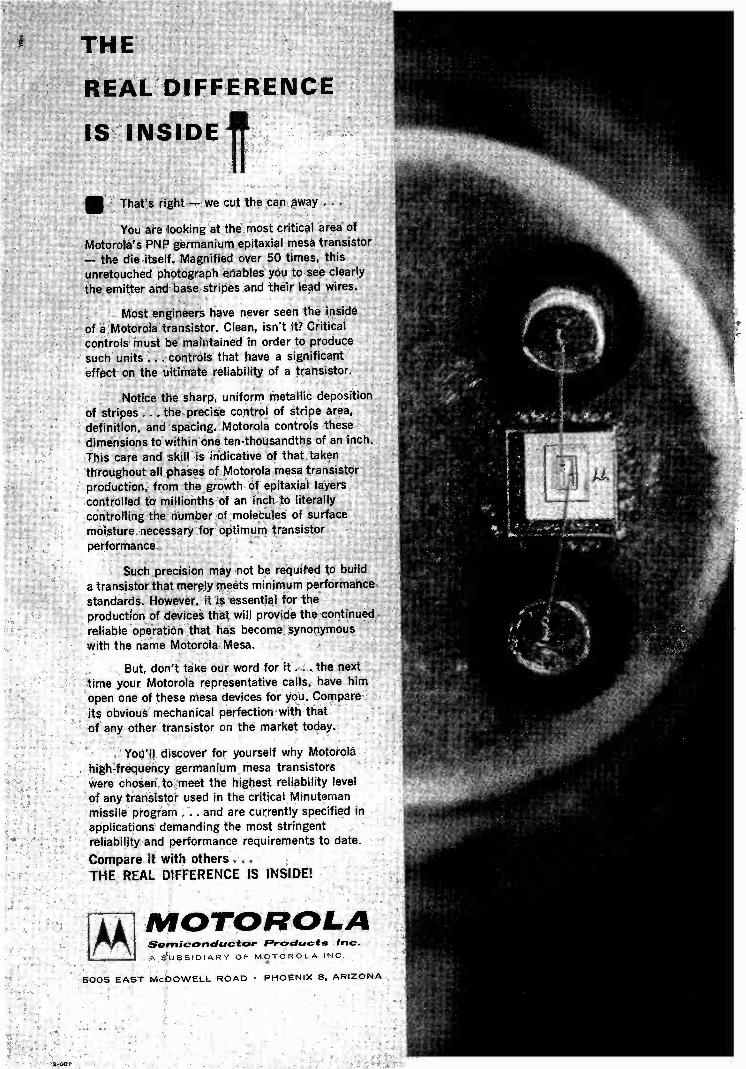
THE
REAL DIFFERENCE
IS INSIDE1
That's right — we cut the can away ..
You are looking at the most critical area of Motorola's PNP germanium epitaxial mesa transistor — the die itself. Magnified over 50 times, this unretouched photograph enables you to see clearly the emitter and base stripes and their lead wires.
Most engineers have never seen the inside of a Motorola transistor. Clean, isn't it? Critical controls must be maintained in order to produce
such units ... controls that have a significant effect on the ultimate reliability of a transistor.
Notice the sharp, uniform metallic deposition
of stripes . . . the precise control of stripe area, definition, and spacing. Motorola controls these dimensions to within one ten-thousandths of an inch. This care and skill is indicative of that taken throughout all phases of Motorola mesa transistor production, from the growth of epitaxial layers controlled to millionths of an inch to literally controlling the number of molecules of surface moisture necessary for optimum transistor
performance.
Such precision may not be required to build a transistor that merely meets minimum performance
standards. However, it is essential for the production of devices that will provide the continued , reliable operation that has become synonymous with the name Motorola Mesa.
But, don't take our word for it ... the next time your Motorola representative calls, have him open one of these mesa devices for you. Compare
its obvious mechanical perfection with that ,of any other transistor on the market today.
You'll discover for yourself why Motorola high-frequency germanium mesa transistors were chosen to meet the highest reliability level of any transistor used in the critical Minuteman missile program ... and are currently specified in applications demanding the most stringent reliability and performance requirements to date.
Compare it with others...
THE REAL DIFFERENCE IS INSIDE!
MOTOROLA Semiconductor F'roducts Inc.
A SUBSIDIARY OF MOTOROLA INC
5005 EAST McDOWELL ROAD • PHOENIX 8, ARIZONA
2-001

GREAT NAMES
GET TOGETHER...
... something good is bound to happen ... like the introduction of Sorensen's QB Series transistorized low-voltage dc power supplies.
This great-name firm wanted to deliver the best. They used the best: Clarostat Series 43 2-watt wire-wound potentiometers.
Clarostat Series 43 pot was a natural selection. Long a favorite of industrial equipment manufacturers, the Series 43 offers a wide variety of mounts, terminals and shaft configurations. Available in resistance tolerances of -± 10% or closer from 1 to 50K ohms, the Series 43 is designed to do its job ... and then some! It is an obvious choice of great-name manufacturers who will not compromise with quality.
Sorensen, a unit of Raytheon Company, wanted — and got — the finest ... Clarostat. If you're a great name (or would like to be one) contact Clarostat ...today.
AA mr-4 CLAROSTAT MFG. CO., INC. DOVER, NEW HAMPSHIRE
42 CIRCLE 42 ON READER SERVICE CARD electronics

ELECTRONICS MARKETS 1963 _nu 1m
By LEON
i—n \L _J L _J
H. DULBERGER Associate Editor • BEN ANELLO Mgr., Market Service Dept
INDUSTRIAL PROPUCTS MOST - 'roe?
ii _e AT OR IOPPoero -14See " No-
i„pr, o • COMP0Aie._ ). ..›
ier ee e ne e 8LE ' e.---‘t oe fire eoe- ' 4,
,e0. ce fet° / /e4 '-ta 42. .ke e-ru. N.-rre'? • -(;)'' e ''.#ebg,_ - ej , j) ,e0 , Álue. ,
v I • , ie , '0 • 1‘. Q *Pr IN --0 er
• / - -k, eN 0 .ç- #P vp •A ill 0
;-----------+— Z---_ (5 iii ‘Z e C 'eN 0 CZ
' 1 2 0 e .. ..., .... - - -14 re t n _Z
0 1\ iz ur qx _tu - -*,r- - L. - o > o; e> , . ... Z \ LI '._z. 'Ft a º,- • 0 0---___ ,0 ,, 4. 0 \ Z e«) ih
• CI, 2 ›,s_
% '?I• I;* ‘, 74Cse ' Vie• .. • 'to, lkill,i ;_., ào‘• ' ',..,, 0 o C.
\e8 .e°, 4` ' 'el.. leo , .1:?,..t._- avàel. s.f 01 \ . - , . t,e, e -
tb 0 ' tO
op i &tabu/ vaN . 1 ' i \ ; o• j 94/00-1;'.
' 1963 electronics, a McGraw-Hill Publication
REPRINTS AVAILABLE
SEE READER SERVICE CARD

IN A NUTSHELL: • Industrial products lead profit parade. Data communications and reduction, industrial controls and
computers show strength • More color-television programming boosts consumer interest in sets • Key points in military
buying: big command and control systems, equipment for limited war • Microminiature techniques sweep into com-
ponents industry • Foreign competition grows, so do opportunities for sales abroad
ELECTRONICS MARKETS 1963
INTRuilUCTION
THE FUTURE HOLDS CONTINUED GROWTH for all segments of the electronics industry, on an increas-ingly selective basis. The combined impetus of space exploration, industrial needs, increasing military pre-paredness and consumer product demand, will produce increasing sales. International markets and competition are growing factors in electronics. Government con-tracts are being awarded with care, and overcapacity is besetting some segments of the industry, notably com-ponents.
INDUSTRIAL ELECTRONICS APPLICATIONS are burgeoning in industrial control, data processing and data communication. Jobs once done mechanically are now done increasingly with electronics. Test, measure-ment and control instruments are being used in new in-dustries. High-volume communications systems are multi-plying. Ultrasonics, cryogenics, lasers and teaching ma-chines are opening new markets. New navigation sys-tems for aircraft and ships are under development.
SPACE RESEARCH is creating markets for ground tracking gear, telemetering systems, guidance and check-out equipment. Research to achieve space goals is cre-ating a host of new components and technologies that find use on earth too.
MILITARY SPENDING is aimed at increasing limited-war capability, creating command and control systems for hardened missile sites and portable operations. More communications facilities are a must, and procurement for missiles, surveillance equipment, tactical aircraft and phased-array radar is increasing. Antimissile and anti-submarine research is continuing, and reliability and electromagnetic compatability of equipment is receiving greater attention.
Air-traffic-control spending is up, and nuclear reactor control and instrumentation devices are selling faster.
CONSUMER ELECTRONICS is receiving a boost with increased demand for color television, and more firms building color tubes and sets. Stereo f-m is growing, as well as high-fidelity sales. All-channel tv—providing vhf and uhf coverage—will improve future b&w receiver sales.
COMPONENTS are phasing into microminiature pro-duction techniques, with military R&D leading the way. Integrated circuits, thin films and molecular electronics are receiving attention. Transistor unit sales are up, and military and industrial uses of vacuum tubes continue level. The military is trending toward greater use of transistors, and planning more microelectronic circuits in future projects. Overcapacity in the component indus-try is causing some concern.
INTERNATIONAL SALES by American electronic firms to all parts of the world is rising; but foreign com-petition is viewed as an increasing problem by many U. S. firms. Imports of consumer electronic products, from Japan and other countries remains high. Exports of U. S. industrial and military equipment will go up, especially, computer and data processing systems.
MORE EFFICIENT MANAGEMENT of electronic firms, particularly those dealing with the military, must evolve in the next seven years. Because of growing com-petition, profit margins are shrinking in government contracts. It will be the job of management to cut costs, to realize a full allowable profit. Observers believe that profits in the future can actually be higher than in the past.
44 electronics

ELECTRONIC TELEPHONE EXCHANGE (inset), developed by Automatic Electric Co., a subsidiary of 6T&E, is compatible with electro-mechanical switching equipment. Magnetic switches in hermetically sealed capsules (above) are used in switching matrix
45 January 4, 1963

ELECTRONICS _MARKETS 1963
-mum. ,m.--mmummin«IIIIIMMIR
PRECISION D•C and AC VOLTAGES are generated by Ballantine Laboratories calibrator (left) shown providing stable reference stand-ard in oscilloscope calibration. Standards instruments and devices represent a maturing market
INDUSTRIAL PRODUCTS
TEST 1NSTRUMENTS--Sales of test instruments for measuring electrical parameters are burgeoning. The market for instruments for industrial and scientific use is also growing rapidly.
The cornerstone for achieving market penetration is designing increased measurement precision, accuracy
and repeatability into new instruments. Contemporary
instrumentation and system requirements, for both in-dustry and the military, demand better measurement per-formance than previously acknowledged. Frequency heads the list of parameters that must be measured more accurately. In industrial and scientific instruments tem-perature and pressure measurements are desired with improved precision and repeatability.
TEST STANDARDS—A new and active market is developing for instruments and components designed to perform calibration checks to maintain the increased accuracies of new measuring instruments. While still only a fraction of the dollar volume ol the test instru-
ment business itself, test standards show promise of being a profitable area for new sales efforts.
These test standards range from accurately measured capacitors and inductors to accurate frequency and volt-age-generating devices.
Standards labs are springing up across the U. S.,
contracting to maintain the accuracy of a plant's entire complement of test equipment. These firms perform periodic checks and recalibration of instruments, based on historical knowledge of when to service each instru-
ment. A standards lab may earn several hundred thou-sand dollars a year from a single account.
Digital readout for instruments is enjoying rising popu-larity. Advantages cited include greater facility of use by semitechnical personnel, nonambiguous display; and in printed readout devices, records of each reading.
Among the digital readout methods, the largest num-ber of instruments employ numerical glow tubes, fol-
lowed by electromechanical devices, and electrolum ines-cent (solid-state) devices. There is rising interest in
46 electronics
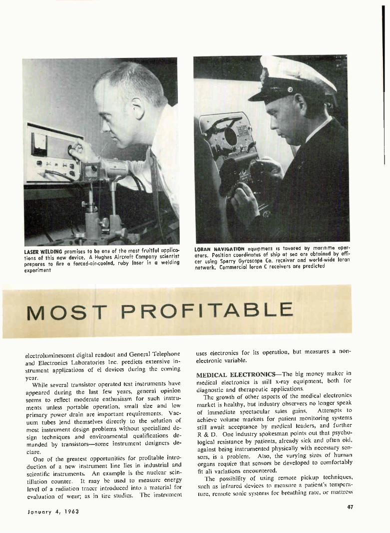
LASER WELDING promises to be one of the most fruitful appiica-tions of this new device. A Hughes Aircraft Company scientist prepares to fire a forced-air-cooled, ruby laser in a welding experiment
LORAN NAVIOATION equipment is tavored by maritime oper-
ators. Position coordinates of ship at sea are obtained by offi-cer using Sperry Gyroscope Co. receiver and world-wide loran network. Commercial loran C receivers are predicted
MOST PROFITABLE
electroluminescent digital readout and General Telephone and Electronics Laboratories Inc. predicts extensive in-strument applications of el devices during the coming
year. While several transistor operated test instruments have
appeared during the last few years, general opinion seems to reflect moderate enthusiasm for such instru-
ments unless portable operation, small size and low primary power drain are important requirements. Vac-uum tubes lend themselves directly to the solution of most instrument design problems without specialized de-sign techniques and environmental qualifications de-manded by transistors—some instrument designers de-
clare. One of the greatest opportunities for profitable intro-
duction of a new instrument line lies in industrial and scientific instruments. An example is the nuclear scin-tillation counter. It may be used to measure energy level of a radiation tracer introduced into a material for
evaluation of wear; as in tire studies. The instrument
uses electronics for its operation, but measures a non-
electronic variable.
MEDICAL ELECTRONICS—The big money maker in medical electronics is still x-ray equipment, both for diagnostic and therapeutic applications. The growth of other aspects of the medical electronics
market is healthy, but industry observers no longer speak
of immediate spectacular sales gains. Attempts to achieve volume markets for patient monitoring systems still await acceptance by medical leaders, and further R & D. One industry spokesman points out that psycho-logical resistance by patients, already sick and often old, against being instrumented physically with necessary sen-sors, is a problem. Also, the varying sizes of human organs require that sensors be developed to comfortably
fit all variations encountered. The possibility of using remote pickup techniques,
such as infrared devices to measure a patient's tempera-ture, remote sonic systems for breathing rate, or mattress
January 4, 1963 47
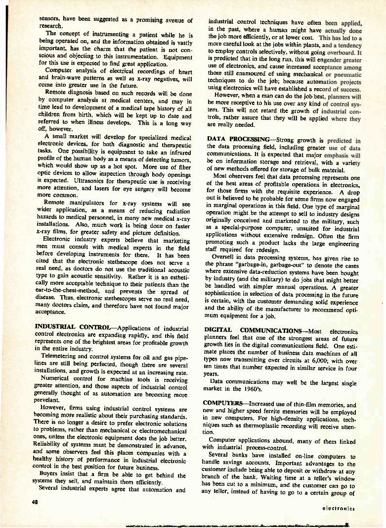
sensors, have been suggested as a promising avenue of research.
The concept of instrumenting a patient while he is being operated on, and the information obtained is vastly important, has the charm that the patient is not con-scious and objecting to this instrumentation. Equipment for this use is expected to find great application.
Computer analysis of electrical recordings of heart and brain-wave patterns as well as x-ray negatives, will come into greater use in the future.
Remote diagnosis based on such records will be done
by computer analysis at medical centers, and may in time lead to development of a medical tape history of all children from birth, which will be kept up to date and referred to when illness develops. This is a long way off, however.
A small market will develop for specialized medical electronic devices, for both diagnostic and therapeutic tasks. One possibility is equipment to take an infrared profile of the human body as a means of detecting tumors, which would show up as a hot spot. More use of fiber optic devices to allow inspection through body openings is expected. Ultrasonics for therapeutic use is receiving more attention, and lasers for eye surgery will become more common.
Remote manipulators for x-ray systems will see wider application, as a means of reducing radiation hazards to medical personnel, in many new medical x-ray installations. Also, much work is being done on faster x-ray films, for greater safety and picture definition.
Electronic industry experts believe that marketing
men must consult with medical experts in the field before developing instruments for them. It has been cited that the electronic stethescope does not serve a
real need, as doctors do not use the traditional acoustic type to gain acoustic sensitivity. Rather it is an estheti-cally more acceptable technique to their patients than the ear-to-the-chest-method, and prevents the spread of disease. Thus, electronic stethescopes serve no real need, many doctors claim, and therefore have not found major acceptance.
INDUSTRIAL CONTROL--Applications of industrial control electronics are expanding rapidly, and this field represents one of the brightest areas for profitable growth in the entire industry.
Telemetering and control systems for oil and gas pipe-lines are still being perfected, though there are several installations, and growth is expected at an increasing rate.
Numerical control for machine tools is receiving greater attention, and those aspects of industrial control generally thought of as automation are becoming more prevelant.
However, firms using industrial control systems are becoming more realistic about their purchasing standards. There is no longer a desire to prefer electronic solutions to problems, rather than mechanical or electromechanical ones, unless the electronic equipment does the job better. Reliability of systems must be demonstrated in advance,
and some observers feel this places companies with a healthy history of performance in industrial electronic control in the best position for future business.
Buyers insist that a firm be able to get behind the systems they sell, and maintain them efficiently.
Several industrial experts agree that automation and
industrial control techniques have often been applied, in the past, where a human might have actually done the job more efficiently, or at lower cost. This has led to a more careful look at the jobs within plants, and a tendency to employ controls selectively, without going overboard. It is predicted that in the long run, this will engender greater use of electronics, and cause increased acceptance among those still enamoured of using mechanical or pneumatic techniques to do the job; because automation projects using electronics will have established a record of success.
However, when a man can do the job best, planners will be more receptive to his use over any kind of control sys-tem. This will not retard the growth of industrial con-trols, rather assure that they will be applied where they are really needed.
DATA PROCESSING—Strong growth is predicted in the data processing field, including greater use of data communications. It is expected that major emphasis will be on information storage and retrieval, with a variety of new methods offered for storage of bulk material.
Most observers feel that data processing represents one of the best areas of profitable operations in electronics, for those firms with the requisite experience. A drop out is believed to be probable for some firms now engaged in marginal operations in this field. One type of marginal operation might be the attempt to sell to industry designs originally conceived and marketed to the military, such as a special-purpose computer, unsuited for industrial
applications without extensive redesign. Often the firm promoting such a product lacks the large engineering staff required for redesign.
Oversell in data processing systems, has given rise to the phrase "garbage-in, garbage-out" to denote the cases where extensive data-reduction systems have been bought by industry (and the military) to do jobs that might better
be handled with simpler manual operations. A greater sophistication in selection of data processing in the future
is certain, with the customer demanding solid experience and the ability of the manufacturer to recommend opti-mum equipment for a job.
DIGITAL COMMUNICATIONS--Most electronics planners feel that one of the strongest areas of future growth lies in the digital communications field. One esti-mate places the number of business data machines of all
types now transmitting over circuits at 6,000; with over ten times that number expected in similar service in four years.
Data communications may well be the largest single market in the 1960's.
COMPUTERS—Increased use of thin-film memories, and new and higher speed ferrite memories will be employed
in new computers. For high-density applications, tech-niques such as thermoplastic recording will receive atten-tion.
Computer applications abound, many of them linked with industrial process-control.
Several banks have installed on-line computers to
handle savings accounts. Important advantages to the customer include being able to deposit or withdraw at any branch of the bank. Waiting time at a teller's window has been cut to a minimum, and the customer can go to any teller, instead of having to go to a certain group of
48 electronics

»Fe- et te,
windows. Advantages to the bank include time saved in balancing cash at the end of the banking day.
COMMUNICATIONS—Both radio and wire communi-cations will continue to grow in volume throughout the world. The desire to achieve practical satellite com-munications will see increased effort by major firms and the government to produce high-volume, 24-hour-a-day,
systems. Right now some 500 circuits are available to carry
voice by cable or high-frequency radio from the U. S. to overseas points.
By 1970, General Telephone and Electronics Corp. estimates, 3,000 circuits will be needed to satisfy the de-mands of voice, data, and image traffic, not including
international television. Data communications will be one of the fastest growing
areas of the electronics industry. It will be a common thing for computers and other business machines to "talk
to each other." Millimeter wavelengths will see development exploit-
ing untouched areas of the radio spectrum and handling specialized applications such as plasma sheath penetra-
tion in space operations. Microwave communications will expand, with foreign
markets opening rapidly for systems operating in this
frequency range. Optical communications techniques will see active
research and systems development, with the great band-width capabilities of this medium attracting planners with high information density requirements. Among others, General Electric is exploring this field, with a closed-loop optical television link possessing a five-mile range.
ULTRASONICS—The applications of ultrasonic tech-niques in industry are expanding rapidly, and assure spe-cialists in this field an excellent market. New research is being carried out in various techniques
from microdeburring of microminiature components to control of solid rocket propellant burning rates. In the electronics industry itself, ultrasonic cleaning is now firmly entrenched, according to R. L. Jeffery, president of National Ultrasonic Corp. He explains that white-room concepts now prevail in the industry, and final cleaning of components, subassemblies and micromodules by
ultrasonics, is prevalent. Jeffery indicates that cold welding using ultrasonics is
of growing importance to avoid damage to sensitive com-ponents, and that ultrasonic plating to achieve a fine deposition of precious metals, and also for printed circuit work, is getting attention. Ultrasonic removal of dust,
dirt and oxides from magnetic tape helps to eliminate much of the costly information "drop out" problem.
Liquid-level sensing; thickness testing; drilling of easily damaged parts; defoaming in liquid flow or filling opera-tions; drying of granulated, porous or fibrous materials; are other areas of research or growing application.
Ultrasonics is finding application in counting of ob-jects, such as automobiles entering or leaving parking lots, where nonambiguous counting is a must. Medical use of ultrasonics is also growing.
OCEANOGRAPHY—The present interest in oceano-graphic research by physical scientists and antisubmarine warfare researchers will produce a fallout of techniques
ELECTRON MICROSCOPE under final assembly at RCA. The instrument is widely used in medical and scientific research. It employs 50 vacuum tubes, allows photographing objects one million times thinner than a human hair.
ULTRASONIC CLEANING equipment installed in white room, shown in use on missile components. These 500-watt gen-erators by National Ultrasonic Corp. drive barium-titanate transducers at Martin-Marrieta Corp. installation

and equipment designs that will spark strong industrial activity undersea.
We are engaged in a general age of ocean explorations, leading to an understanding of this environment; and finally to increased commercial operations in the medium, using electronics. Right now, some $15 million is spent each year in commercial electronic oceanography. The studies now being conducted of ocean currents
and the development of instruments to measure them, will find use in ship salvage operations. There are many wrecks on the ocean bottom, containing still valuable cargo.
Salvage operations will be effected in the future with the help of undersea handling equipment, positioned with sonar and optical sensors, including tv.
Exploitation of undersea mineral and food supplies in the future will lead to a mining and perhaps farming industry carried on beneath the surface. A general knowledge of the character of the ocean, gained with the aid of oceanographic instruments will increase yield, a spokesman for Loral Electronics Corp., states.
Loral expects that their line of undersea one and two man craft, heavily instrumented with electronic sensors, will find application in this field.
Underwater equipment maintenance of offshore oil rigs and dock facilities will foster development of salinity and corrosion measuring instruments. The growing problem of nuclear waste disposal will re-
quire development of oceanographic techniques, using electronic devices, to monitor ocean currents and radio-active leakage.
NAVIGATION SYSTEMS—Commercial application of navigation systems will probably see its largest increase in
airborne systems. Jim McSweeny of Sperry Gyroscope Co. predicts development of inertial navigation systems for use by commercial airlines in time to meet the re-quirements of supersonic airliners now being developed. This may occur by 1968. He points out that inertial navi-gation with its inherent high accuracy will be needed to obtain maximum utilization of airspace. It will give in-
stantaneous readout of position, important at speeds in excess of Mach one.
These systems will use an inertial platform, gyros, ac-celerometers and computers. They will obviate the need to shoot the stars and make radio contact to get a d-f fix. No ground-support equipment is required for an inertial navigation system. About two to three more years of military experience with such systems is required to allow development of a suitably inexpensive equipment for commercial use to begin.
Maritime use of inertial navigation systems is not apt
to come about, Mr. McSweeny believes, as shipping firms do not have the time saving requirement faced in the air. Instead, loran coverage of shipping lanes will increase, and commercial loran C receivers will be developed. These receivers will read out directly in latitude and longitude, but must be inexpensive to find acceptance.
NASA is talking about a commercial navigation satel-lite of lower accuracy than Transit for use by both air-craft and ships. However the price of a receiver for use with such a satellite may prove to be too high for com-mercial use.
An upsurge of radar applications for harbor control
seems certain, to avoid the present high accident rate
ANALOG COMPUTER in use to simulate a complete metal rolling metal in the mill, drives, regulators and control system on large
we‘toevel .4 44 q
'4‘
normally associated with operations in ports. A ship identification system, similar in concept to if, but much simpler will be used as part of increased collision avoid-ance operations in harbor control. Land navigation systems are apt to prove expensive,
and find no civilian market demand, Mr. McSweeny feels. The military has a land navigation requirement for tank and troop carrier operations beyond established roads. Such systems cost $40 to $50 thousand dollars each, which prohibits civilian land vehicle use.
TEACHING MACHINES--A spokesman for Loral Elec-tronics Corp. predicts a steady growth for the teaching-machine industry, but cautions that only a small portion of the actual material and equipment sold is electronic. One estimate of the total market's size by 1967 is $100 million including softgoods, with about $20 million worth of electronics tucked inside that figure. Much of the
development required before teaching machines become prevalent as a technique, is the development of good pro-gramming material, which is a slow job. In the strictest sense, a programmed textbook with a graphite pencil scoring system is a teaching machine. In a more sophis-ticated system, employing programming logic, switching and relay equipment, slide display and perhaps audio devices, the entire aid may cost $1,200, exclusive of the programming softgoods.
The student is taught a bit at a time, and his knowledge reinforced by questions and exercises programmed according to his grasp of the subject.
An outstanding advantage of teaching machines is that they enable a single exceptional instructor to reach many
50 electronics
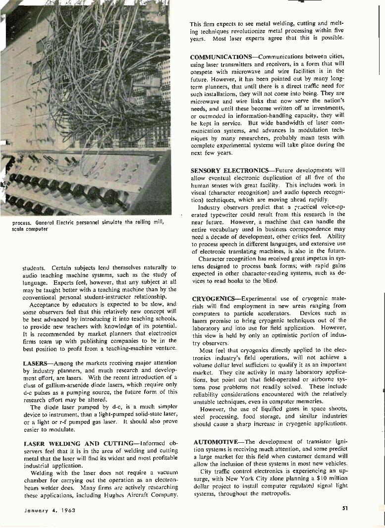
process. General Electric personnel simulate the rolling mill, scale computer
students. Certain subjects lend themselves naturally to audio teaching machine systems, such as the study of language. Experts feel, however, that any subject at all may be taught better with a teaching machine than by the conventional personal student-instructor relationship.
Acceptance by educators is expected to be slow, and some observers feel that this relatively new concept will be best advanced by introducing it into teaching schools, to provide new teachers with knowledge of its potential. It is recommended by market planners that electronics firms team up with publishing companies to be in the best position to profit from a teaching-machine venture.
LASERS—Among the markets receiving major attention by industry planners, and much research and develop-ment effort, are lasers. With the recent introduction of a class of gallium-arsenide diode lasers, which require only d-c pulses as a pumping source, the future form of this research effort may be altered. The diode laser pumped by d-c, is a much simpler
device to instrument, than a light-pumped solid-state laser, or a light or r-f pumped gas laser. It should also prove easier to modulate.
LASER WELDING AND CUTTING—Informed ob-servers feel that it is in the area of welding and cutting metal that the laser will find its widest and most profitable industrial application.
Welding with the laser does not require a vacuum chamber for carrying out the operation as an electron-beam welder does. Many firms are actively researching these applications, including Hughes Aircraft Company.
This firm expects to see metal welding, cutting and melt-ing techniques revolutionize metal processing within five years. Most laser experts agree that this is possible.
COMMUNICATIONS—Communications between cities, using laser transmitters and receivers, in a form that will compete with microwave and wire facilities is in the future. However, it has been pointed out by many long-term planners, that until there is a direct traffic need for such installations, they will not come into being. They are microwave and wire links that now serve the nation's needs, and until these become written off as investments, or outmoded in information-handling capacity, they will be kept in service. But wide bandwidth of laser com-munication systems, and advances in modulation tech-niques by many researchers, probably mean tests with complete experimental systems will take place during the next few years.
SENSORY ELECTRONICS—Future developments will allow eventual electronic duplication of all five of the human senses with great facility. This includes work in visual (character recognition) and audio (speech recogni-tion) techniques, which are moving ahead rapidly.
Industry observers predict that a Is ractical voice-op-erated typewriter could result from this research in the near future. However, a machine that can handle the entire vocabulary used in business correspondence may need a decade of development, other critics feel. Ability to process speech in different languages, and extensive use of electronic translating machines, is also in the future.
Character recognition has received great impetus in sys-tems designed to process bank forms; with rapid gains expected in other character-reading systems, such as de-vices to read books to the blind.
CRYOGENICS—Experimental use of cryogenic mate-rials will find employment in new areas ranging from computers to particle accelerators. Devices such as lasers promise to bring cryogenic techniques out of the laboratory and into use for field application. However, this view is held by only an optimistic portion of indus-try observers.
Most feel that cryogenics directly applied to the elec-tronics industry's field operations, will not achieve a volume dollar level sufficient to qualify it as an important market. They cite activity in many laboratory applica-tions, but point out that field-operated or airborne sys-tems pose problems not readily solved. These include reliability considerations encountered with the relatively unstable techniques, even in computer memories.
However, the use of liquified gases in space shoots, steel processing, food storage, and similar industries should cause a sharp increase in cryogenic applications.
AUTOMOTIVE—The development of transistor igni-tion systems is receiving much attention, and some predict a large market for this field when customer demand will allow the inclusion of these systems in most new vehicles.
City traffic control electronics is experiencing an up-surge, with New York City alone planning a $10 million dollar project to install computer regulated signal light systems, throughout the metropolis.
January 4, 1963 51
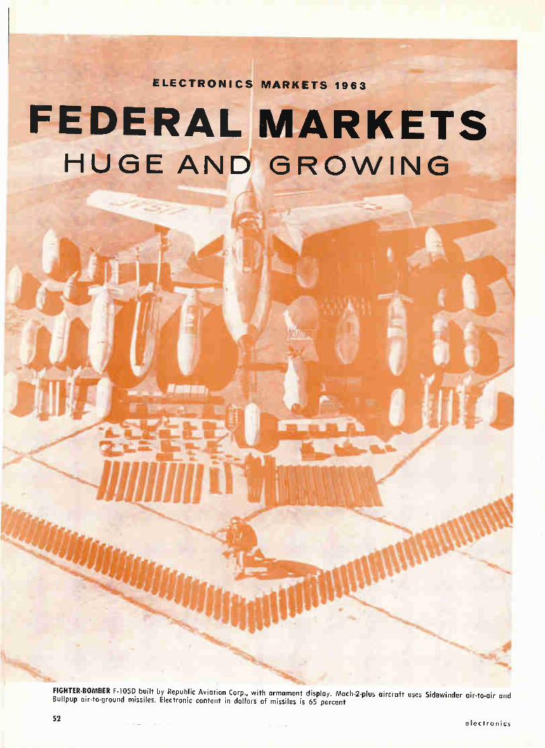
ELECTRONICS MARKETS 1963
FEDERAL MARKETS HUGE AND GROWING
FIGHTER•BOMBER F-105D built by Republic Aviation Corp., with armament display. Mach-2-plus aircraft uses Sidewinder air-to-air and Bullpup air-to-ground missiles. Electronic content in dollars of missiles is 65 percent
52 electronics
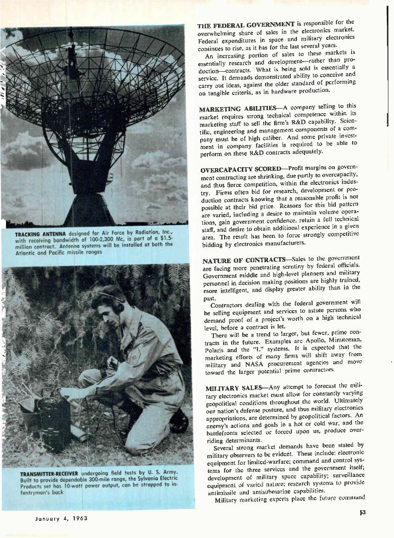
TRACKING ANTENNA designed for Air Force by Radiation, Inc., with receiving bandwidth of 100-2,300 Mc, is part of a $1.5-million contract. Antenna systems will be installed at both the Atlantic and Pacific missile ranges
TRANSMITTER-RECEIVER undergoing field tests by U. S. Army. Built to provide dependable 300-mile range, the Sylvania Electric Products set has 10-watt power output, can be strapped to in-fantryman's buck
THE FEDERAL GOVERNMENT is responsible for the overwhelming share of sales in the electronics market. Federal expenditures in space and military electronics continues to rise, as it has for the last several years. An increasing portion of sales to these markets is
essentially research and development—rather than pro-duction—contracts. What is being sold is essentially a service. It demands demonstrated ability to conceive and carry out ideas, against the older standard of performing on tangible criteria, as in hardware production.
MARKETING ABILITIES—A company selling to this market requires strong technical competence within its marketing staff to sell the firm's R&D capability. Scien-tific, engineering and management components of a com-pany must be of high caliber. And some private invest-ment in company facilities is required to be able to perform on these R&D contracts adequately.
OVERCAPACITY SCORED—Profit margins on govern-ment contracting are shrinking, due partly to overcapacity, and thus fierce competition, within the electronics indus-try. Firms often bid for research, development or pro-duction contracts knowing that a reasonable profit is not possible at their bid price. Reasons for this bid pattern
are varied, including a desire to maintain volume opera-tions, gain government confidence, retain a full technical staff, and desire to obtain additional experience in a given area. The result has been to force strongly competitive
bidding by electronics manufacturers.
NATURE OF CONTRACTS—Sales to the government are facing more penetrating scrutiny by federal officials. Government middle and high-level planners and military personnel in decision making positions are highly trained, more intelligent, and display greater ability than in the
past. Contractors dealing with the federal government will
be selling equipment and services to astute persons who demand proof of a project's worth on a high technical level, before a contract is let.
There will be a trend to larger, but fewer, prime con-tracts in the future. Examples are Apollo, Minuteman, Polaris and the "L" systems. It is expected that the marketing efforts of many firms will shift away from military and NASA procurement agencies and move toward the larger potential prime contractors.
MILITARY SALES—Any attempt to forecast the mili-tary electronics market must allow for constantly varying geopolitical conditions throughout the world. Ultimately our nation's defense posture, and thus military electronics appropriations, are determined by geopolitical factors. An
enemy's actions and goals in a hot or cold war, and the battlefronts selected or forced upon us, produce over-
riding determinants. Several strong market demands have been stated by
military observers to be evident. These include: electronic equipment for limited-warfare; command and control sys-tems for the three services and the government itself; development of military space capability; surveillance
equipment of varied nature; research systems to provide antimissile and antisubmarine capabilities.
Military marketing experts place the future çommand
Junuury 4, 1963

AMBIENT LIGHT SURVEILLANCE system for Army allows tv camera to view tank in the dark. Image intensifier at pick up requires only starlight, moonlight and skyglow
end control market in the front rank for sales through 1970.
MILITARY BUSINESS CLIMATE--Next year's Depart-ment of Defense (fiscal 1963) RDT&E budget is expected to equal that of last year's. For the following fiscal year,
1964, it may go down a slight amount. This is due to the phasing out of large systems now reaching the end of their construction phase; and the beginning research on new projects.
FORM OF CONTRACTS--Much of today's military contracting is in research, development, test, evaluation, and to a lesser extent, operations and maintenance. The nature of modern warfare has shifted procurement quan-tities of electronic systems from thousands or hundreds; to tens, or even one of a kind, in weapons or support systems.
EFFECTS OF CUBAN CRISES—The Cuban situation has focused sudden interest on the needs of military service leaders requesting more limited and general war capability for U. S. fighting forces. Not yet resolved are requests that would boost the budgets of all three serv-ices. The Army wants more close support aircraft and antimissile capability. Navy desires increased attention
on ASW developments; and fast surface craft for support operations. Air Force seeks more missiles and aircraft, greater emphasis on the RS-70, and a beef up of their air reconnaissance ability; proven so important for detecting
offensive weapons build up by the overfly and oblique photos of Cuba.
Estimates run to as high as an extra $4.5 billion on top of the present $48 billion defense budget for fiscal
1963 and 1964, Some feel $2 billion is more likely.
COMMAND AND CONTROL—The front-running mili-tary market through 1970, will be command-and-control systems. They impose severe technical demands on the electronics industry. The most capable scientific, engi-neering and management minds will be enlisted to meet
the challenge. Solutions will employ computers, data re-duction, communications, and display techniques. Command and control for military use includes input
sensors such as surveillance radar, communications nets using tropospheric and ionospheric scatter equipment, and digital-computer data-processing equipment. Also
required are display techniques, including digital and analog readout systems.
Reliable and fast command and control between gov-ernment and national military command centers is needed to allow international and local control of aircraft dis-patch, submarine direction, and missile-launch com-mands. Portable command and control systems are needed for tactical operations in all three services by local commanders.
An important problem is command of the huge retalia-tory missile force this country is building up. Command ability is required to order strikes from hardened and soft sites, as well as roving launchers, such as Polaris
submarines. The command and control systems must be hardened, technically fool proof, spook proof (im-
pervious to sabotage), and fast acting.
The systems must be designed with ability to deter-mine by radar and computers within brief moments which retaliatory missiles would be hit first in an attack
so that these may be fired first. Such systems demand a high order of sophistication in information handling, using extensive electronics.
LIMITED WARFARE--Activity in electronics for hm-
$4 electronics
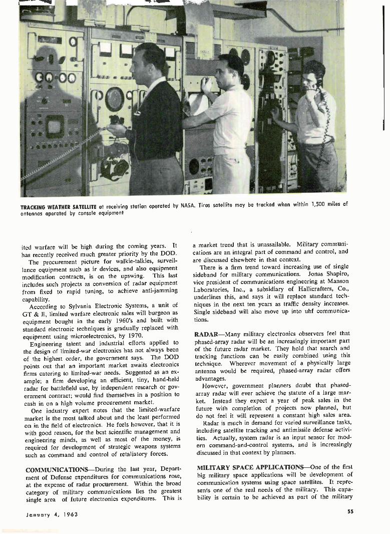
TRACKING WEATHER SATELLITE at receiving station operated by NASA. Tiros satellite may be tracked when within 1,500 miles of
antennas operated by console equipment
ited warfare will be high during the coming years. It
has recently received much greater priority by the DOD. The procurement picture for walkie-talkies, surveil-
lance equipment such as ir devices, and also equipment modification contracts, is on the upswing. This last includes such projects as conversion of radar equipment from fixed to rapid tuning, to achieve anti-jamming
capability. According to Sylvania Electronic Systems, a unit of
GT & E, limited warfare electronic sales will burgeon as equipment bought in the early 1960's and built with standard electronic techniques is gradually replaced with
equipment using microelectronics, by 1970. Engineering talent and industrial efforts applied to
the design of limited-war electronics has not always been of the highest order, the government says. The DOD points out that an important market awaits electronics firms catering to limited-war needs. Suggested as an ex-ample; a firm developing an efficient, tiny, hand-held radar for battlefield use, by independent research or gov-ernment contract; would find themselves in a position to cash in on a high volume procurement market. One industry expert notes that the limited-warfare
market is the most talked about and the least performed on in the field of electronics. He feels however, that it is with good reason, for the best scientific management and engineering minds, as well as most of the money, is required for development of strategic weapons systems such as command and control of retaliatory forces.
COMMUNICATIONS—During the last year, Depart-ment of Defense expenditures for communications rose, at the expense of radar procurement. Within the broad category of military communications lies the greatest single area of future electronics expenditures. This is
a market trend that is unassailable. Military communi-cations are an integral part of command and control, and are discussed elsewhere in that context.
There is a firm trend toward increasing use of single sideband for military communications. Jonas Shapiro, vice president of communications engineering at Manson Laboratories, Inc., a subsidiary of Hallicrafters, Co., underlines this, and says it will replace standard tech-niques in the next ten years as traffic density increases. Single sideband will also move up into uhf communica-tions.
RADAR—Many military electronics observers feel that phased-array radar will be an increasingly important part of the future radar market. They hold that search and tracking functions can be easily combined using this technique. Wherever movement of a physically large antenna would be required, phased-array radar offers advantages.
However, government planners doubt that phased-array radar will ever achieve the statute of a large mar-ket. Instead they expect a year of peak sales in the
future with completion of projects now planned, but do not feel it will represent a constant high sales area.
Radar is much in demand for varied surveillance tasks, including satellite tracking and antimissile defense activi-ties. Actually, system radar is an input sensor for mod-ern command-and-control systems, and is increasingly discussed in that context by planners.
MILITARY SPACE APPLICATIONS—One of the first big military space applications will be development of communication systems using space satellites. It repre-sents one of the real needs of the military. This capa-bility is certain to be achieved as part of the military
January 4, 1 963 55
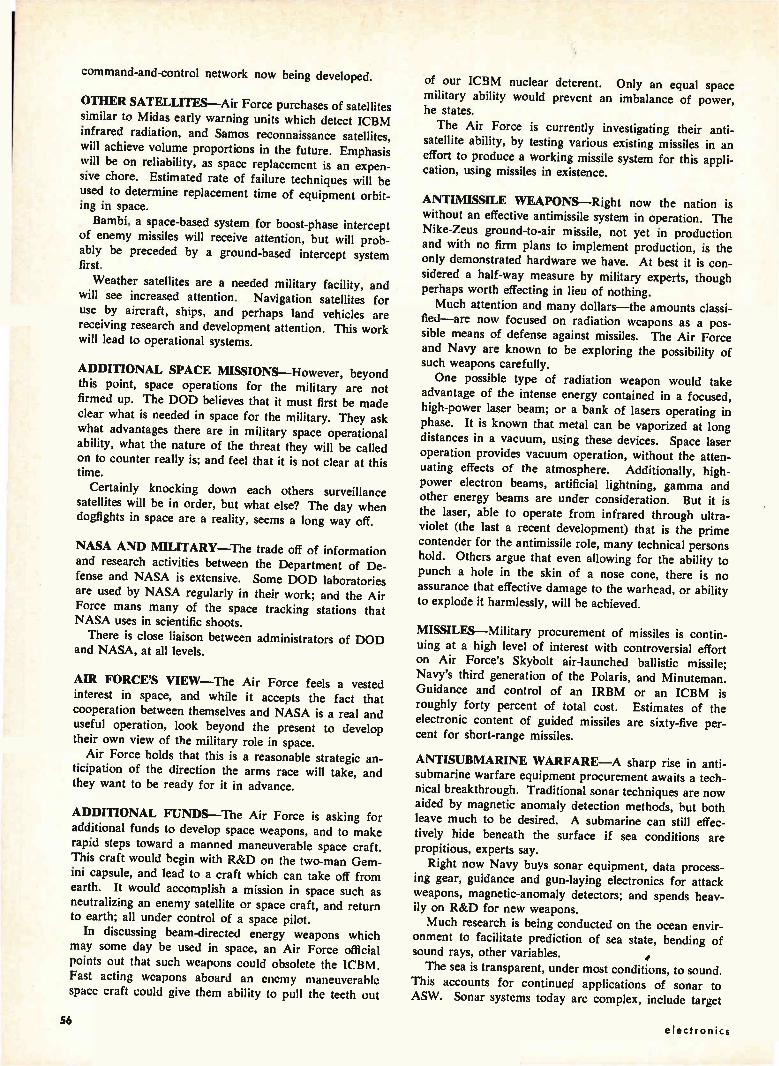
command-and-control network now being developed.
OTHER SATELLITES—Air Force purchases of satellites similar to Midas early warning units which detect ICBM infrared radiation, and Samos reconnaissance satellites, will achieve volume proportions in the future. Emphasis will be on reliability, as space replacement is an expen-sive chore. Estimated rate of failure techniques will be used to determine replacement time of equipment orbit-ing in space.
Bambi, a space-based system for boost-phase intercept of enemy missiles will receive attention, but will prob-ably be preceded by a ground-based intercept system first.
Weather satellites are a needed military facility, and will see increased attention. Navigation satellites for use by aircraft, ships, and perhaps land vehicles are receiving research and development attention. This work will lead to operational systems.
ADDITIONAL SPACE MISSIONS—However, beyond this point, space operations for the military are not firmed up. The DOD believes that it must first be made clear what is needed in space for the military. They ask what advantages there are in military space operational ability, what the nature of the threat they will be called on to counter really is; and feel that it is not clear at this time.
Certainly knocking down each others surveillance satellites will be in order, but what else? The day when dogfights in space are a reality, seems a long way off.
NASA AND MILITARY—The trade off of information and research activities between the Department of De-fense and NASA is extensive. Some DOD laboratories are used by NASA regularly in their work; and the Air Force mans many of the space tracking stations that NASA uses in scientific shoots.
There is close liaison between administrators of DOD and NASA, at all levels.
AIR FORCE'S VIEW—The Air Force feels a vested interest in space, and while it accepts the fact that cooperation between themselves and NASA is a real and useful operation, look beyond the present to develop their own view of the military role in space.
Air Force holds that this is a reasonable strategic an-ticipation of the direction the arms race will take, and they want to be ready for it in advance.
ADDITIONAL FUNDS—The Air Force is asking for additional funds to develop space weapons, and to make
rapid steps toward a manned maneuverable space craft. This craft would begin with R&D on the two-man Gem-ini capsule, and lead to a craft which can take off from earth. It would accomplish a mission in space such as neutralizing an enemy satellite or space craft, and return to earth; all under control of a space pilot.
In discussing beam-directed energy weapons which may some day be used in space, an Air Force official points out that such weapons could obsolete the ICBM. Fast acting weapons aboard an enemy maneuverable space craft could give them ability to pull the teeth out
of our ICBM nuclear deterent. Only an equal space military ability would prevent an imbalance of power, he states.
The Air Force is currently investigating their anti-satellite ability, by testing various existing missiles in an effort to produce a working missile system for this appli-cation, using missiles in existence.
ANTIMISSILE WEAPONS—Right now the nation is without an effective antimissile system in operation. The Nike-Zeus ground-to-air missile, not yet in production and with no firm plans to implement production, is the only demonstrated hardware we have. At best it is con-sidered a half-way measure by military experts, though perhaps worth effecting in lieu of nothing. Much attention and many dollars—the amounts classi-
fied—are now focused on radiation weapons as a pos-sible means of defense against missiles. The Air Force and Navy are known to be exploring the possibility of such weapons carefully. One possible type of radiation weapon would take
advantage of the intense energy contained in a focused, high-power laser beam; or a bank of lasers operating in phase. It is known that metal can be vaporized at long distances in a vacuum, using these devices. Space laser operation provides vacuum operation, without the atten-uating effects of the atmosphere. Additionally, high-power electron beams, artificial lightning, gamma and other energy beams are under consideration. But it is the laser, able to operate from infrared through ultra-violet (the last a recent development) that is the prime contender for the antimissile role, many technical persons hold. Others argue that even allowing for the ability to punch a hole in the skin of a nose cone, there is no assurance that effective damage to the warhead, or ability to explode it harmlessly, will be achieved.
MISSILES—Military procurement of missiles is contin-uing at a high level of interest with controversial effort on Air Force's Skybolt air-launched ballistic missile; Navy's third generation of the Polaris, and Minuteman. Guidance and control of an IRBM or an ICBM is roughly forty percent of total cost. Estimates of the electronic content of guided missiles are sixty-five per-cent for short-range missiles.
ANTISUBMARINE WARFARE—A sharp rise in anti-submarine warfare equipment procurement awaits a tech-nical breakthrough. Traditional sonar techniques are now aided by magnetic anomaly detection methods, but both leave much to be desired. A submarine can still effec-tively hide beneath the surface if sea conditions are propitious, experts say.
Right now Navy buys sonar equipment, data process-ing gear, guidance and gun-laying electronics for attack weapons, magnetic-anomaly detectors; and spends heav-ily on R&D for new weapons.
Much research is being conducted on the ocean envir-onment to facilitate prediction of sea state, bending of sound rays, other variables. The sea is transparent, under most conditions, to sound.
This accounts for continued applications of sonar to ASW. Sonar systems today are complex, include target
56 electronics
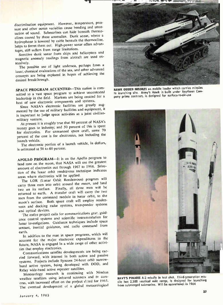
discrimination equipment. However, temperature, pres-sure and other ocean variables cause bending and atten-uation of sound. Submarines can hide beneath thermo-clines caused by these anomalies. Dunk sonar, where a hydrophone is lowered by cable beneath the thermocline, helps to ferret them out. High-power sonar offers advan-tages, still suffers from range limitations.
Sensitive dunk sonar from ships and helicopters and magnetic anomaly readings from aircraft are used ex-
tensively. The possible use of light undersea, perhaps from a
laser; chemical evaluations of the sea, and other advanced concepts are being explored in hopes of achieving the
desired breakthrough.
SPACE PROGRAM ACCENTED—This nation is com-mitted to a vast space program to achieve uncontested leadership in the field. Markets are being created for a
host of new electronic components and systems. Since NASA's electronic facilities are greatly aug-
mented by the use of military facilities and equipment, it is important to judge space activities as a joint civilian-
military venture. At present it is roughly true that 90 percent of NASA's
money goes to industry; and 50 percent of this is spent for electronics. For unmanned space craft, some 70 percent of the cost is for electronics, not including the
launch vehicle. The electronic portion of a launch vehicle, in dollars,
is estimated at 50 to 60 percent.
APOLLO PROGRAM—It is on the Apollo program to land men on the moon, that NASA will use the greatest amount of electronics out through 1967 to 1968. Selec-tion of the lunar orbit rendezvous technique indicates
areas where electronics will be applied. The LOR (Lunar Orbit Rendezvous) program will
carry three men into orbit around the moon, and land two on its surface. Finally, all three men will be returned to earth. A transfer craft will carry the two men from the command module in lunar orbit, to the moon's surface. Both space craft will employ rendez-vous and docking radar systems, transponder systems
and optical devices. The entire project calls for communications gear, guid-
ance control systems and scientific instrumentation for lunar investigations. Guidance techniques include space sextant, inertial guidance, and radio command from
earth. In addition to the man in space programs, which will
account for the major electronic expenditures in the future, NASA is engaged in a wide range of other activi-ties that employ electronics.
Communications satellite developments are being car-ried forward, with interest in both active and passive systems. Projects include Syncom 24-hour orbit narrow-band active system, being developed with DOD, and
Relay wide-band active repeater satellites. Meteorology research is continuing with Nimbus
weather satellites using infrared scanners and tv cam-eras, with increased effort on the project sInted for 1963. The eventual development of a global meteorological
HAWK GUIDED MISSILES on mobile loader which carries missiles to launching site. Army's Hawk is built under Raytheon Com-pany prime contract, is designed for surface-to-air-use
NAVY'S POLARIS A 3 missile in test shot. Third-generation mis-sile has 2,500 nautical mile ronge, is designed for launching from submerged submarine. Will be operational in 1964
57 January 4, 1963
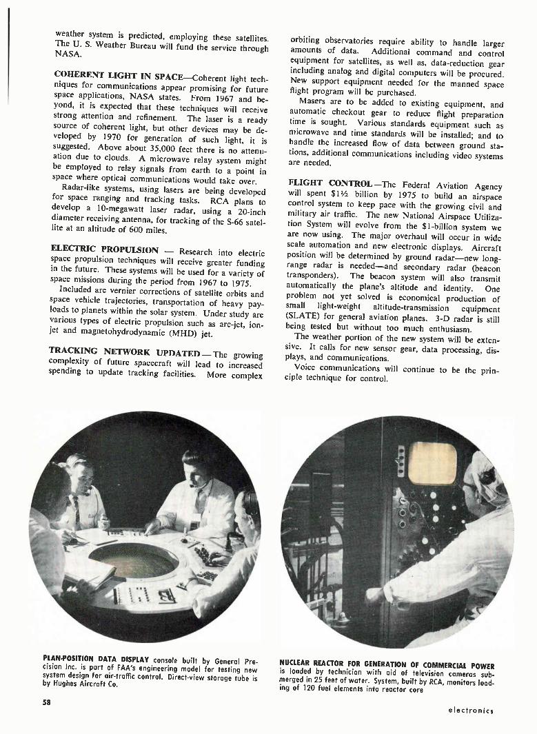
weather system is predicted, employing these satellites. The U. S. Weather Bureau will fund the service through NASA.
COHERENT LIGHT IN SPACE--Coherent light tech-niques for communications appear promising for future space applications, NASA states. From 1967 and be-
yond, it is expected that these techniques will receive strong attention and refinement. The laser is a ready
source of coherent light, but other devices may be de-veloped by 1970 for generation of such light, it is suggested. Above about 35,000 feet there is no attenu-ation due to clouds. A microwave relay system might be employed to relay signals from earth to a point in space where optical communications would take over.
Radar-like systems, using lasers are being developed for space ranging and tracking tasks. RCA plans to develop a 10-megawatt laser radar, using a 20-inch
diameter receiving antenna, for tracking of the S-66 satel-lite at an altitude of 600 miles.
ELECTRIC PROPULSION — Research into electric space propulsion techniques will receive greater funding in the future. These systems will be used for a variety of space missions during the period from 1967 to 1975.
Included are vernier corrections of satellite orbits and space vehicle trajectories, transportation of heavy pay-
loads to planets within the solar system. Under study are
various types of electric propulsion such as arc-jet, ion-jet and magnetohydrodynamic (MHD) jet.
TRACKING NETWORK UPDATED — The growing complexity of future spacecraft will lead to increased spending to update tracking facilities. More complex
PLAN-POSITION DATA DISPLAY console built by General Pre-cision Inc. is part of FAA's engineering model for testing new system design for air-traffic control. Direct-view storage tube is by Hughes Aircraft Co.
orbiting observatories require ability to handle larger amounts of data. Additional command and control equipment for satellites, as well as, data-reduction gear
including analog and digital computers will be procured. New support equipment needed for the manned space flight program will be purchased.
Masers are to be added to existing equipment, and automatic checkout gear to reduce flight preparation time is sought. Various standards equipment such as microwave and time standards will be installed; and to handle the increased flow of data between ground sta-tions, additional communications including video systems are needed.
FLIGHT CONTROL--The Federal Aviation Agency will spent $1 1/2 billion by 1975 to build an airspace control system to keep pace with the growing civil and military air traffic. The new National Airspace Utiliza-tion System will evolve from the $1-billion system we
are now using. The major overhaul will occur in wide scale automation and new electronic displays. Aircraft position will be determined by ground radar—new long-range radar is needed—and secondary radar (beacon transponders). The beacon system will also transmit automatically the plane's altitude and identity. One problem not yet solved is economical production of small light-weight altitude-transmission equipment
(SLATE) for general aviation planes. 3-D radar is still being tested but without too much enthusiasm.
The weather portion of the new system will be exten-sive. It calls for new sensor gear, data processing, dis-plays, and communications.
Voice communications will continue to be the prin-ciple technique for control.
NUCLEAR REACTOR FOR GENERATION OF COMMERCIAL POWER is loaded by technician with aid of television cameras sub-merged in 25 feet of water. System, built by RCA, monitors load-ing of 120 fuel elements into reactor core
58 electronics
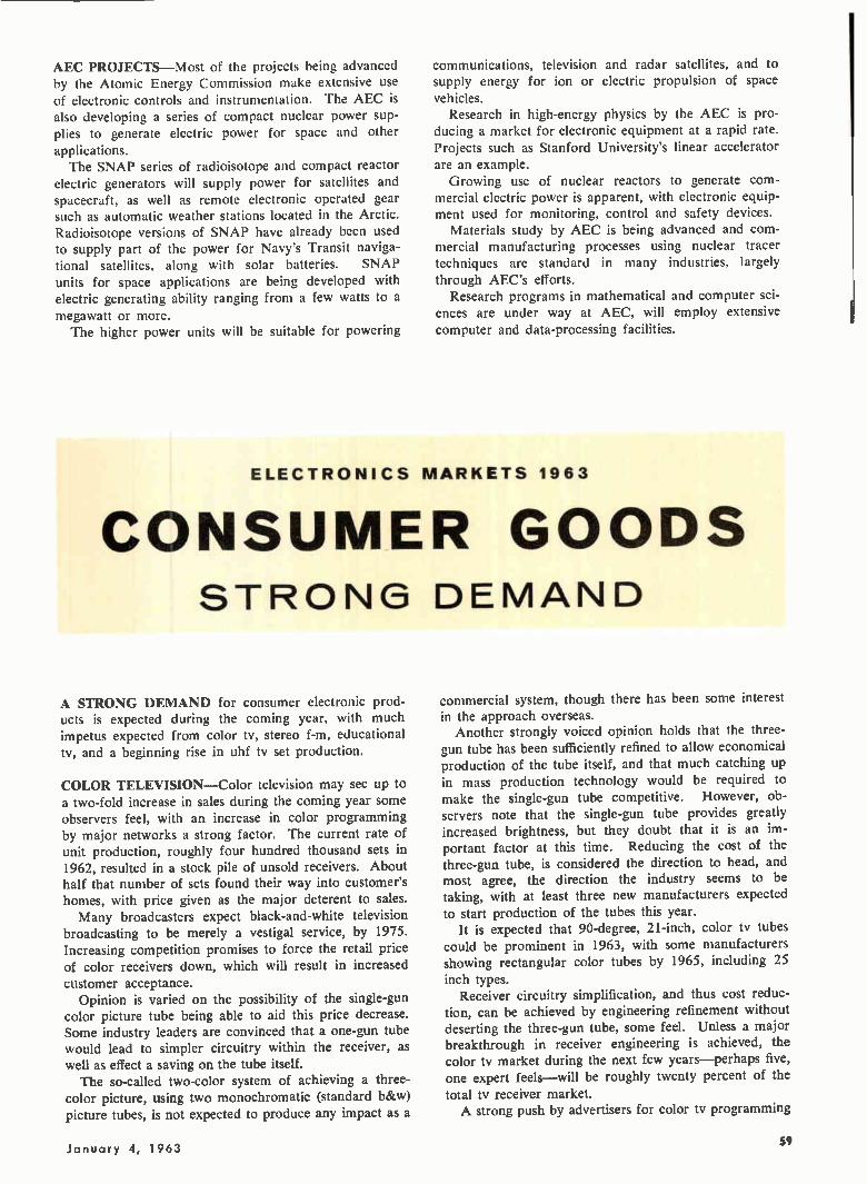
AEC PROJECTS—Most of the projects being advanced by the Atomic Energy Commission make extensive use of electronic controls and instrumentation. The AEC is also developing a series of compact nuclear power sup-plies to generate electric power for space and other
applications. The SNAP series of radioisotope and compact reactor
electric generators will supply power for satellites and spacecraft, as well as remote electronic operated gear such as automatic weather stations located in the Arctic. Radioisotope versions of SNAP have already been used to supply part of the power for Navy's Transit naviga-tional satellites, along with solar batteries. SNAP units for space applications are being developed with electric generating ability ranging from a few watts to a megawatt or more. The higher power units will be suitable for powering
communications, television and radar satellites, and to supply energy for ion or electric propulsion of space vehicles.
Research in high-energy physics by the AEC is pro-ducing a market for electronic equipment at a rapid rate. Projects such as Stanford University's linear accelerator are an example. Growing use of nuclear reactors to generate com-
mercial electric power is apparent, with electronic equip-ment used for monitoring, control and safety devices.
Materials study by AEC is being advanced and com-mercial manufacturing processes using nuclear tracer techniques are standard in many industries, largely through AEC's efforts.
Research programs in mathematical and computer sci-ences are under way at AEC, will employ extensive computer and data-processing facilities.
ELECTRONICS MARKETS 1963
CONSUMER GOODS STRONG DEMAND
A STRONG DEMAND for consumer electronic prod-ucts is expected during the coming year, with much impetus expected from color tv, stereo f-m, educational tv, and a beginning rise in uhf tv set production.
COLOR TELEVISION—Color television may see up to a two-fold increase in sales during the coming year some observers feel, with an increase in color programming by major networks a strong factor. The current rate of unit production, roughly four hundred thousand sets in 1962, resulted in a stock pile of unsold receivers. About half that number of sets found their way into customer's homes, with price given as the major deterent to sales. Many broadcasters expect black-and-white television
broadcasting to be merely a vestigal service, by 1975. Increasing competition promises to force the retail price of color receivers down, which will result in increased customer acceptance.
Opinion is varied on the possibility of the single-gun color picture tube being able to aid this price decrease. Some industry leaders are convinced that a one-gun tube would lead to simpler circuitry within the receiver, as well as effect a saving on the tube itself. The so-called two-color system of achieving a three-
color picture, using two monochromatic (standard b&w) picture tubes, is not expected to produce any impact as a
commercial system, though there has been some interest in the approach overseas.
Another strongly voiced opinion holds that the three-gun tube has been sufficiently refined to allow economical production of the tube itself, and that much catching up in mass production technology would be required to make the single-gun tube competitive. However, ob-servers note that the single-gun tube provides greatly increased brightness, but they doubt that it is an im-portant factor at this time. Reducing the cost of the three-gun tube, is considered the direction to head, and most agree, the direction the industry seems to be taking, with at least three new manufacturers expected
to start production of the tubes this year. It is expected that 90-degree, 21-inch, color tv tubes
could be prominent in 1963, with some manufacturers showing rectangular color tubes by 1965, including 25 inch types.
Receiver circuitry simplification, and thus cost reduc-tion, can be achieved by engineering refinement without deserting the three-gun tube, some feel. Unless a major breakthrough in receiver engineering is achieved, the color tv market during the next few years—perhaps five, one expert feels—will be roughly twenty percent of the total tv receiver market. A strong push by advertisers for color tv programming
January 4, 1963 59
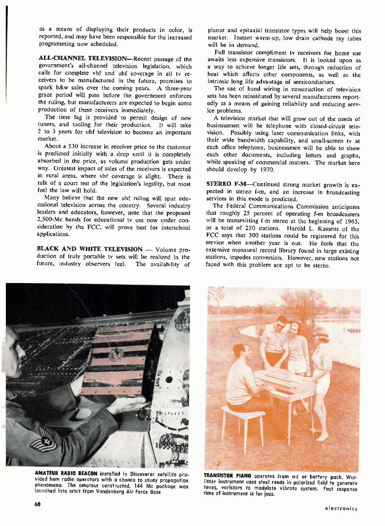
as a means of displaying their products in color, is reported, and may have been responsible for the increased programming now scheduled.
ALL-CHANNEL TELEVISION—Recent passage of the government's all-channel television legislation, which calls for complete vhf and uhf coverage in all tv re-ceivers to be manufactured in the future, promises to spark b&w sales over the coming years. A three-year grace period will pass before the government enforces the ruling, but manufacturers are expected to begin some production of these receivers immediately.
The time lag is provided to permit design of new tuners, and tooling for their production. It will take
2 to 3 years for uhf television to become an important market.
About a $30 increase in receiver price to the customer is predicted initially with a drop until it is completely absorbed in the price, as volume production gets under way. Greatest impact of sales of the receivers is expected in rural areas, where vhf coverage is slight. There is talk of a court test of the legislation's legality, but most feel the law will hold. Many believe that the new uhf ruling will spur edu-
cational television across the country. Several industry leaders and educators, however, note that the proposed 2,500-Mc bands for educational tv use now under con-sideration by the FCC, will prove best for interschool applications.
BLACK AND WHITE TELEVISION — Volume pro-duction of truly portable tv sets will be realized in the future, industry observers feel. The availability of
• --AMATEUR RADIO BEACON installed in Discoverer satellite pro-vided ham radio operators with a chance to study propagation phenomena. The amateur constructed, 144 Mc package was launched into orbit from Vandenberg Air Force Base
planar and epitaxial transistor types will help boost this market. Instant warm-up, low drain cathode ray tubes will be in demand.
Full transistor compliment tv receivers for home use awaits less expensive transistors. It is looked upon as a way to achieve longer life sets, through reduction of heat which affects other components, as well as the intrinsic long life advantage of semiconductors. The use of hand wiring in construction of television
sets has been reinstituted by several manufacturers report-edly as a means of gaining reliability and reducing serv-ice problems.
A television market that will grow out of the needs of businessmen will be telephone with closed-circuit tele-vision. Possibly using laser communication links, with their wide bandwidth capability, and small-screen tv at
each office telephone, businessmen will be able to show each other documents, including letters and graphs, while speaking of commercial matters. The market here should develop by 1970.
STEREO F-M—Continued strong market growth is ex-pected in stereo f-m, and an increase in broadcasting services in this mode is predicted. The Federal Communications Commission anticipates
that roughly 25 percent of operating f-m broadcasters will be transmitting f-m stereo at the beginning of 1963,
or a total of 250 stations. Harold L. Kassens of the
FCC says that 300 stations could be registered for this service when another year is out. He feels that the extensive monaural record library found in large existing
stations, impedes conversion. However, new stations not faced with this problem are apt to be stereo.
TRANSISTOR PIANO operates from a-c or battery pack. Wur-litzer instrument uses steel reeds in polarized field to generate tones, varistors to modulate vibrato system. Fast response time of instrument is for jazz.
60 electronics
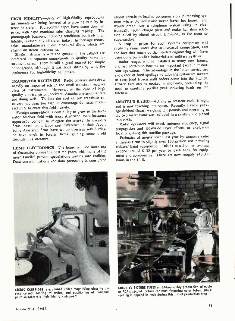
HIGH FIDELITY—Sales of high-fidelity reproducing instruments are being fostered at a growing rate by in-terest in stereo. Prerecorded tapes have come down in price, with tape machine sales climbing rapidly. The phonograph business, including renditions not truly high fidelity, is essentially all stereo today. In teen-age record sales, manufacturers make monaural disks, which are
played on stereo instruments. Single instruments with the speaker in the cabinet are
preferred to separate components in quality home in-strument sales. There is still a good market for simple phonographs, although it has been shrinking with the preference for high-fidelity equipment.
TRANSISTOR RECEIVERS—Radio receiver sales draw heavily on imported sets in the small transistor receiver class of instruments. However, in the case of high quality a-m transistor receivers, American manufacturers are doing well. To date the cost of f-m transistor re-ceivers has been too high to encourage domestic manu-
facturers to enter this field heavily. Foreign competition is continuing to grow in the tran-
sistor receiver field with most American manufacturers apparently content to relegate the market to overseas firms, based on a labor cost difference in their favor. Some American firms have set up overseas subsidiaries, or have stock in foreign firms, gaining some profit through this measure.
HOME ELECTRONICS—The home will see more use of electronics during the next ten years, with many of the more fanciful present speculations turning into realities. Data communications and data processing is considered
STEREO CARTRIDGE is examined under magnifying glass to as-sure correct seating of stylus, and positioning of diamond point in Motorola high fidelity instrument
almost certain to lead to consumer store purchasing sys-tems where the housewife never leaves her home. She would order over a telephone system using an elec-tronically coded charge plate and make her item selec-tion aided by closed circuit television, to the store or
supermarket. A drop in prices for such systems equipment will
probably come about due to increased competition, and the fact that much of the needed engineering will have been done on similar industrial and military systems.
Radar ranges will be installed in many new homes, and are certain to become an important facet in restau-rant operations. The advantage in the latter service are avoidance of food spoilage by allowing restaurant owners to keep food frozen until orders come into the kitchen. Frozen fare can be cooked in moments, precluding the need to carefully predict peak ordering loads on the kitchen.
AMATEUR RADIO—Activity in amateur radio is high, and is now reaching into space. Recently a radio pack-age dubbed Oscar, weighing ten pounds and operating in the two meter band was included in a satellite and placed into orbit.
Radio operators will check antenna efficiency, signal propagation and Heaviside layer effects, at worldwide locations, using this satellite package.
Estimates of money spent last year by amateur radio enthusiasts run to slightly over $38 million not including citizens' band equipment. This is based on an average expenditure of $155 per year by each ham, for equip-ment and components. There are now roughly 240,000
hams in the U. S.
COLOR TV PICTURE TUBES on 24-hour-a-day production schedule at RCA's second factory for manufacturing color tubes. Black coating is applied in neck during this initial production step
January 4, 1963 _ 61
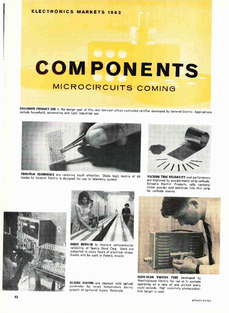
ELECTRONICS MARKETS 1963
COM PON E NTS MICROCIRCUITS COMING
CONSUMER PRODUCT USE is the design goal of this new low-cost silicon controlled rectifier developed by General Electric. Applications include household, automotive and light industrial use
THIN-FILM TECHNIQUES are receiving much attention. Diode logic matrix of 64 VACUUM TUBE RELIABILITY and performance diodes by General Electric is designed for use in telemetry system are improved by powder-metal strip cathode.
Sylvania Electric Products rolls carbonyl nickel powder and additives into thin strip for cathode sleeves
DIODE BURN-IN to improve semiconductor reliability at Sperry Rand Corp. Units are subjected to many hours of e'ectrical stress. Diodes will be used in Polaris missile
SLOW-SCAN VIDICON TUBE developed by Westinghouse Electric for use in tv systems
SILICON WAFERS are checked with optical operating at a rate of one picture every pyrometer for exact temperature during eight seconds. High resistivity photoconduc-growth of epitaxial layers, Motorola tive target is used
62 electronics
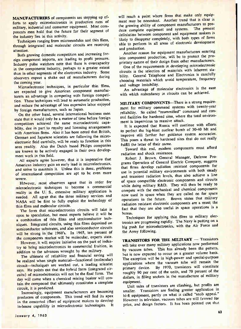
MANUFACTURERS of components are stepping up ef-
forts to apply microelectronics in production runs of military, industrial and consumer equipment. Most com-ponents men hold that the future for their segment of
the industry lies in this activity. Techniques ranging from micromodules and thin films,
through integrated and molecular circuits are receiving
attention. Both growing domestic competition and increasing for-
eign component imports, are leading to profit pressure. Industry pulse watchers note that there is overcapacity
in the components industry, perhaps to a greater extent than in other segments of the electronics industry. Some observers expect a shake out of manufacturers during
the coming year. Microelectronic techniques, in particular thin films,
are expected to give American component manufac-turers an advantage in competing with foreign competi-
tion. These techniques will lead to automatic production, and reduce the advantage of less expensive labor enjoyed
by foreign manufacturers, such as Japan. On the other hand, several international business men
state that it would only be a matter of time before foreign
competitors achieved the same microelectronic capa-bility, due in part to royalty and licensing arrangements with American firms. Also it has been noted that British, German and Japanese scientists are following the micro-
electronic field carefully, will be ready to function in this
area readily. Also the Dutch based Philips companies are known to be actively engaged in their own develop-
ment work in this field. All experts agree however, that it is imperative that
American industry gain an early lead in microelectronics, and strive to maintain it. Unless this is done, problems of international competition are apt to be even more
severe. Hdwever, most observers agree that in order for
microelectronic techniques to become a commercial reality in the U. S., extensive military application is needed. All agree that the three military services and NASA will be first to fully exploit the technology of thin films and molecular circuits. The form that microelectronics circuits will take is
open to speculation, but most experts believe it will be a combination of thin films and semiconductor tech-
niques. Integrated circuits, using thin films deposited on semiconductor substrates, and also semiconductor circuits will be strong in the 1960's. In 1965, ten percent of the components market will be molecular, experts state.
However, it will require initiative on the part of indus-try to bring microelectronics to commercial fruition, in
addition to the advances wrought by the military. The ultimate of reliability and financial saving will
be realized when single material—functional (molecular) circuit—techniques are worked out, a leading scientist says. He points out that the hybrid form (integrated cir-
cuits) of microelectronics will not be the final form. The day will come when a chemical mixing beaker will con-tain the compound that ultimately constitutes a complete
circuit, it is predicted. Increasingly, equipment manufacturers are becoming
producers of components. This trend will find its apex in the concerted effort of equipment makers to develop in-house capability in microelectronic technologies. It
will reach a point where firms that make only equip-ment may be nonextent. Another trend that is clear is the growing ability of component manufacturers to pro-duce complete equipment and systems. The present deliniation between component and equipment makers is likely to disappear completely, with both types of firms able to perform in all areas of electronic development
and production. Another reason for equipment manufacturers entering
into component production, will be to protect the pro-prietary nature of their design from other manufacturers. One of the requirements in developing microelectronic
circuits is the selection of materials with inherent sta-bility. General Telephone and Electronics is carefully
choosing materials which avoid temperature, frequency
and voltage instability. An advantage of molecular electronics is the ease
with which redundancy in circuits can be achieved.
MILITARY COMPONENTS—There is a strong require-ment for military command systems with twenty-year reliability. So called "mummified" command and con-trol facilities for hardened sites, where the total environ-
ment is impervious to massive attack. It is expected that Russia will continue with efforts
to perfect the big-blast nuclear bomb of 30-40 Mt and improve still further her guidance system accuracies. This poses a threat to hardened sites that do not really
fulfill the letter of their name. Toward this end, modern components must afford
radiation and shock resistance. Robert J. Brown, General Manager, Defense Pro-
grams Operation of General Electric Company, suggests that firms develop radiation resistant components for use in potential military environments with both steady and transient radiation levels, thus also achieve a line
of space compatible electronic components and circuits while doing military R&D. They will then be ready to
compete with the mechanical and chemical components now used in space when they are called on for space operations in the future. Brown states that military radiation resistant electronic components are a must; the fact that they are also useful in space operations is a
bonus. Techniques for applying thin films to military elec-
tronics are progressing rapidly. The Navy is putting on a big push for microelectronics, with the Air Force and
the Army following.
TRANSISTORS FOR THE MILITARY — Transistors will take over many military applications now performed by vacuum tubes. This has already been the pattern, but is now expected to occur on a greater volume basis. The exception will be in high-power and special-purpose applications where the vacuum tube will remain the primary device. By 1970, transistors will constitute
roughly 90 per cent of the units, and 70 percent of the
dollars, in filling sockets in the manufacture of military
equipment. Unit sales of transistors are climbing, but profits are
smaller. Transistors are finding greater application in hi-fi equipment, partly on what is called "snob appeal." However in television, vacuum tubes are still favored for price, and design factors. It has been pointed out that
January 4, 1963 63
in the tv sockets where the most trouble occurs, high voltage, damper, horizontal deflection; the semiconductor device is at present no better suited.
NEW APPLICATIONS--A wide range of new applica-tions for semiconductor components are being found. Home appliances now include semiconductors as the con-trol element in timing cycles, where bimetal strips and similar electromechanical devices were used.
General Electric Company has just introduced a series of consumer priced silicon controlled rectifiers for use in automatic clothes dryers, and automobile alternators.
Ignition systems now employ transistors, and some automobile experts expect commercial trucking will
soon standardize on transistor systems. Reduced mainte-nance and easier cold weather starting are obtained.
Miniature portable transistor tv sets, such as Sony's eight pound receiver which can operate from battery pack or an auto battery, through the cigar lighter socket, are receiving attention. It is expected that an increasing
number of American firms will begin marketing similar tv receivers, based on the Japanese firm's success.
The development of a transistor operated piano by the Wurlitzer Co. marks another home-instrument vic-tory for the transistor. The eighty-pound piano is able to operate from a-c and battery pack, has a 64-note key-
board. Steel reeds vibrate in a polarized electric field to produce the tone, with pickup plates, amplifier and loudspeaker.
Bulova's transistor operated wrist watch, employing a
tiny tuning fork to achieve accuracy, provides another example of semiconductors invading a new field.
VACUUM TUBES—Receiving-tube sales are trending down, based on industry unit counts. Military tube sales have held up, over the past three years, and less use of tubes by consumer and industrial electronic man-ufacturers is responsible for the down trend in sales. This is due to the longer life of vacuum tubes today, and the use of multipurpose tubes—several in one envelope.
Also new circuit developments permit doing a job with
DURING the first six months of 1962, United States electronic exports spurted up 32 percent over the previous year, reaching $370 million, the Department of Com-merce reports.
Our government's efforts to foster foreign-trade ex-pansion is aimed at a further increase in exports during the coming year. The electronics industry will share in the
gain, if it occurs. In spite of the slowing economy of western Europe, the coming year is expected to at least equal the present level of electronic exports.
EUROPEAN MARKET—A downturn in the European
fewer tubes. This has come about through development of better tube types. Transistor sales are increasing, and are a factor in the drop off of tube sales.
Total receiving tube sales will drop some ten percent in the next five years.
Tubes have not yet reached their ultimate in reliability, and a factor of two improvement is predicted. Improve-ment in filaments arc being made. Methods of using nickel in fabricating cathodes are leading to lower and more predictable cathode interface levels.
ELECTROLUMINESCENT DEVICES — The greatest use of electroluminescent devices in the electronics in-dustry during the next year will be in digital readout.
Use of nonlinear resistive devices for switching and display will be developed. The equipment will translate digital information to analog information for electro-luminiscent display. It will employ electroluminescent and photoconductive devices.
General Telephone And Electronics hopes to develop a flat black-and-white tv display. They hold that a color picture tube is possible. Within the next three years, specialized crt's for lower definition display will be using electroluminescent cross grid techniques.
It is possible that a flat, wall type picture tube may develop out of work on electroluminescent tubes. The techniques would employ a piezoelectrical material, such as the Yando device, developed at General Telephone and Electronics.
STANDARDIZATION—Industry experts state that our competitive international position would be improved
if standardization were brought to the many varieties of components now being manufactured, quantities would go up, costs down. An example are tv receiver tubes. There are now 100 to 120 types, which might be re-placed by 10 without impairing performance.
Trade associations are not considered effective enough in bringing this standardization about. Fear of govern-ment antitrust laws are weakening some efforts at standardizing.
economy has been noted, but is not thought to affect U. S. export trade to these countries, by present indicators.
Technology advances in the world electronics market are expected to come mainly from the U. S. over the near
term. However, European (and Japanese) firms are ex-pected to develop advanced research and development capabilities in the future, to maintain commercial leader-ship within their specialties. In components, the U. S. will always maintain a lead, due to advanced R&D work in areas funded by DOD.
Europe enjoys a technical lead in the area of lower
microwave band, communications equipment. One huge
64 electronics

MOBILE RADIOS will be supplied to Lon-don motorcycle patrolmen and other United Kingdom police forces by Cossor Communications Co., Ltd. a subsidiary of Raytheon Co.
TELEVISION TRANSMITTER in Austria will radiate German language programs to four and a half million tv screens. Telefunken engineers erected equip-ment, Austrian, Swiss and German en-gineers will operate it
a..111MLIE
FLIGHT INFORMATION SYSTEM employing transistor operated control network is built in Switzerland. Tele -Norm Autophon equipment is shown at New York Inter-national Airport; similar systems are installed in European stock exchanges, indus-trial plants and banks
European firm has developed a kit of transistors suitable for use in home television, which may prove technically superior to U. S. types designed for tv service.
AUTOMATION IN EUROPE—There is strong stimulus for automation applications in Europe, due to shortage of skilled help and climbing labor rates. Steel mills and similar factories are trending toward automation rapidly. U. S. manufacturers of electronic automation equipment, including computers, will find a ready market throughout most of Europe during the next five years. NATO nations, and to a lesser extent SEATO nations,
TRANSISTOR TV CAMERA built by Tokyo Shibaura Electric Co., Ltd. is designed for field or studio use,. Instrument pro-vides 525 line, 30 frame, scanning
COMPUTERS FOR FRENCH AND ENGLISH firms, built by RCA, undergoing final test before overseas shipment. RCA has multimillion dollar agreements to sell data-processing systems to European companies
will provide international military electronics in the future
to aid in the huge job of achieving military preparedness for treaty organization members. This will increase com-petition for U. S. military suppliers. Small guided missile production in France is rising, and the country is export-ing to the U. S. and NATO countries at increasing rates.
The requirements of America's military and space efforts have produced test equipment of advanced and specialized design which finds a ready foreign market. Both Germany and England export sophisticated test
equipment to the U. S., but both countries, plus the rest of the international market place, are part of the growing
January 4, 1963 65
market for U. S. built test equipment. Most European countries do not have volume requirements for spe-cialized test equipment and measuring instruments, thus have not developed extensive manufacturing capacity for such equipment.
Production of radio and television sets are responsible for much of the electronics sales in Germany, with indus-trial electronics, including data reduction and process con-trol becoming increasingly important.
JAPAN—Already assured of a strong consumer elec-tronics product capability, Japan is now seeking to de-
velop industrial, space, and to some extent, military equip-ment capability.
Sales of consumer electronics are approaching satura-tion for the local market, with 60 percent of Japanese families owning tv sets; practically all have radios. A
gcneral downtrend of electronic sales is partly due to a slowing down of the entire Japanese economy, which some feel expanded too fast.
By switching to the production of transistor radios with six or more transistors, and to high-fidelity units, Japan has succeeded in raising her export level to the U. S.
The nation is expected to become a future leader in international color tv production, largely because of a strong demand developing within their own country.
Several industry observers expect electronic toys to become a big market in the future, and when it does they
look to Japan to become the leader in this field. The nation is well on its way to developing an exten-
sive industrial electronic capability, but that growth too,
is slowing down. Industrial sales are a small portion of the electronic industry.
Computer development is receiving strong attention from Japanese industrial firms. Additionally, a Japanese government subsidy of $278 million has been allocated for research to develop large electronic computers. Right
now, Japan is a large importer of U. S. built machines, both analog and digital. Japanese companies are form-ing joint effort groups for rapid computer development. They are aided by large numbers of engineers being trained on government subsidies. In time they will be less dependent on licensing arrangements with the U. S. in building computers, as these engineers create original equipment. Local use, as well as export volume is ex-pected for the Japanese-built computers.
Japanese scientists are interested in microelectronic techniques, attend U. S. professional conferences devoted to this subject regularly, and are engaged in their own R&D. Wage levels are rising in Japan, and automation techniques plus microelectronics will undoubtedly help the country offset these in the future. However, because
Japan does not have a large military electronics effort, microcircuits are not expected to achieve commercial applications soon.
The Japanese are doing advanced research on trans-
lating machines, speech operated typewriters, thermo-electric devices, and communications techniques. They have instituted a space research program, firing sounding rockets with instrument packages into the upper atmos-phere and space. Some of the ground tracking equipment, instrumentation and rockets are being exported. The nation is also cooperating with the U. S. in com-
munications satellite developments, has signed an agree-
ment with NASA to construct a ground station for han-dling satellite signals.
Medical electronic equipment is expected to become a growth area for Japan, with small precision equipment, and perhaps electron microscopes among the products.
Because of little local need for military electronics, Japan has developed few sophisticated systems of this type.
Strict quality control of electronic exports is a feature of the nation's trade operations, and has contributed to their international success.
Japan is striking out for the Latin American market strongly, expects to be a major supplier to countries south of our border. Additionally she seeks to capture India, Burma and Pakistan as markets.
LATIN AMERICA—Future development of the Alli-ance For Progress Program will strengthen the economy of Latin America, and hence the electronics market in these countries.
At present Latin America has a relatively low income per capita level, and thus consumer purchasing power is limited. However, the citizens of these countries exhibit a strong desire for radio and television receivers plus a need for communications equipment of all types. Micro-wave systems to accommodate mountainous terrain are much in demand.
Much of the Latin American electronic equipment now in service is of World War Two vintage, and there is a brisk trade in supplying replacement components to maintain this gear.
The Latin American Free Trade Area which is an af-filiation of countries below the border, is apt to figure strongly in the future of their electronics industry. Major
aims include enlargement of marketing ability of member countries, and encouragement of trade between them. A tariff reduction between LAFTA countries, and a comple-
mentation of manufacturing resources to flesh out the product lines of LAFTA as a whole is contemplated. Some American observers are fearful that this might lock out some electronic equipment now sold to LAFTA mem-bers, because of future tariff levels.
Mexico is achieving some sufficiency in supplying itself with electronics, and relative to the rest of Latin America, is experiencing a healthy growth in electronic manu-facturing capability. Many foreign companies, such as Siemens, are setting up production facilities in Mexico. Both Brazil and Argentina have healthy beginnings on electronic operations.
European and Japanese firms are striving for a greater share of the Latin American electronics market, and
many feel that their sales techniques are in some ways superior to those of Americans in dealing with Latin American customs and mores.
Political unrest in Latin American countries has to some extent put a damper on plans by some American firms to invest or set up facilities below the border.
CANADA—The future of th-.; Canadian electronics mar-ket will depend heavily on the ability of Canadian firms
to produce more original equipment for the export mar-ket. The nation is strong in manufacture of communica-tions and navigation equipment, but must branch into
other sophisticated areas of electronics for healthy growth.
66 electronics

ELECTRONICS MARKET TABLES 1962
". 1963 electronics a McGraw-Hill Publication
I i 1 .1_, ; • , ; f• , , • 1 TOTAL ELECTRON CS INDUSTRY
TOTALS
CONSUMER
INDUSTRIAL
FEDERAL
REPLACEMENT COMPONENTS
1962
17,200
2,584
3,211
9,905
1,500
1963 illions,
9,04
2,56
3,48
1,50
1,50
SOURCES: Electronics Div., SOSA, U.S. Department of Commerce Electronics Industries Association
Prepared by the Market Services Department of electronics magazine
1 966 1970
21,817 22,000
2,548 3,500
4,433 6,500
13,100 10,000
1,700 2,000
1+1 . I
CONSUMER
ELECTRON ICS
PRODUCTS
SUMER ELECTRONICS TOTAL
I Receivers Total Monochrome Color
Table Console
idio Sets Total A M F-M Auto A-M Auto F-M
honographs Total Monaural Stereophonic
ape Recorders Total (Monaural & Stereo)
ecords & Tape
igh Fidelity Total Amplifiers Tuners Loudspeakers Turntables & Cartridges Packaged
mateur Equipment (incl. CB)
rgans, Electronic
1962 1963 1966 (Millions of dollars)
2,584 2,564 2,548
1,029 1,026 938 910 864 750 119 162 188 35 50 75 84 112 113
390 385 395 180 150 125 50 70 100 120 110 100 40 55 70
495 435 435 50 45 45
445 390 390
80 85 100
260 275 275
75 78 85 15 16 19 13 15 17 13 13 13 11 11 11 23 23 25
65 70 80
150 165 180
40 45 60
FEDERAL
ELECTRONICS
EXPENDITURES
1962 1963 1966 (Millions of Dollars)
FEDERAL ELECTRONICS TOTAL 9,905 11,500 13,100
Department of Defense 9,200 Procurement 4,900
Aircraft 1,500 Missiles 1,500 Ships 500 Mobile & Ordnance 200 Electronics & Communications 1,200
Res., Dey., Test & Eval. 3,000 Operations & Maintenance 1,300
National Aeronautics & Space Adm. 500 Procurement 300 RDT&E 200
Federal Aviation Agency Procurement RDT&E
Atomic Energy Commission
State Department Procurement USIA
135 76 59
9,450 5,540 1,800 1,950 500 100
1,300 3,000 1,800
770 570 200
200 135 65
10,500 6,100 1,600 2,300 600 300
1,300 3,200 2,200
1,300 800 200
200 150 50
35 40 50
35 15 20
40 18 22
50 20 30
-1-• • • The figures are listed so that the amount shown after each heading is the total of its subdivisions; all totals read upwards
1
114i-1 I-7:
r I L I
ELECTRONIC COMPONENTS 1962 1963 1966
(Millions of dollars)
Antennas & Hardware 230 235
Capacitors Total Paper & Film Electrolytic, Aluminum Electrolytic, Tantalum Mica (incl. glass & vitreous enamel) Ceramic Variable
310 100 50 70 25 35 30
Complex Components 80 (incl. microminiature)
Connectors Total Coaxial
Standard Miniature
Cylindrical Rack 8‘ Panel Printed Circuit Special Purpose
320 95 50 75 25 35 40
1962 1963 1966 (Millions of dollars)
250 Relays Total Electromagnetic
350 Telephone Type 100 Crystal Can 55 Coaxial (incl. switches) 80 Stepping 25 Thermal 40 Other (Dry Reed & mercury wetted 50 motor driven)
95 200
190 220 250 26 30 40 15 16 20 11 14 20 70 75 75 54 60 65 16 20 30 24 35 40
Delay Lines 18 20 30
Electroluminescence 7 8 12
Electron Tubes Total Receiving Tubes
Miniature Standard Glass Other (metal, ceramic, etc.)
Power & Special Purpose High Vacuum Gas & Vapor Klystrons Magnetrons Traveling Wave Tubes Light Sensing, Emitting Storage Other
TV Picture Tubes
Ferrite Devices
Filters
Loudspeakers
Magnetic Tape Audio Instrument Video
Microwave Components ( Less tubes & antennas)
Power Supplies (subassembly)
Printed Circuits
Quartz Crystals
880 890 930 320 300 280 224 210 200 84 80 70 12 10 10
300 320 350 70 75 85 28 28 30 53 55 60 43 44 48 49 54 60 31 35 36 13 15 17 13 14 14
260 270 300
16 18 22
38 45 70
60 65 75
50 55 65 20 20 20 27 30 35 3 5 10
100 110 150
30 32 40
80 85 100
29 30 35
'Packaged components; two or more components packaged and shipped as a single unit but not a complete circuit function. Also includes modules which have several com-ponents packaged and shipped as a single unit, which comprise a complete circuit function.
200 205 220 100 100 100 32 32 32 18 20 25 7 8 14
12 13 15 7 8 10
24 24 24
Resistors Total 300 Fixed 145
Composition 59 Carbon 29 Metal Film 18 Wirewouna 39
Variable (Potentiometers) 132 Non-wirewound 55 Wirewound 77
Non-precision 13 Precision 64
Varistors & Thermistors 15 Other (attenuators, meter resistors) 8
300 139 55 27 18 39 135 57 78 13 65 18 8
290 125 48 24 15 38 135 57 78 13 65 23 7
Semiconductors Total 580 600 630 Transistors 300 310 320
Silicon 100 105 110 Germanium 200 205 210
Diodes & Rectifiers 180 180 190 Silicon 120 120 130 Germanium 60 60 60
Special Devices 100 110 120 Silicon Controlled 15 20 25 Microwave & Variable Capacitance
diodes 12 13 15 Tunnel diodes 2 2 3 Solar Cells 5 5 5 Infrared Detectors 12 14 15 Selenium, Copper Oxide, & Thermoelectric devices 12 14 15
Photo devices 1 1 1 Reference Voltage diodes 6 6 6 Regulator Voltage diodes 35 35 35
Servos & Synchros Total Resolvers Gyros Servo Motors Synchros Rate Generators Motor Generators
60 5
12 15 22 3 3
65 7
13 16 23 3 3
80 10 14 20 27 5 4
Timing Devices 10 12 16
Transducers Total Accelerometers Pressure Displacement Strain Other
120 15 35 30 20 20
130 17 37 35 21 20
150 20 40 40 25 25
Transformers & Reactors 185 190 195
Wire & Cable Hookup Wire Magnet Wire Resistance Wire Coaxial Cable Other
240 75 65 15 45 40
245 75 65 15 50 40
255 70 70 15 60 40
1
, 1 :
1 9 G 3 19" 1
INDUSTRIAL ELECTRONICS
INDUSTRIAL ELECTRONICS TOTAL
Test & Measuring Total Specti um Analyzers Signal Generators Phasemeters Oscilloscopes Recorders, Graphic Voltage, Current & Power Meters
(Multimeters) Components Testers (tube,
transistor, etc.) Calibrators, Instrument Recorders, Data Tape Bridges & Decades Power Supplies (lab type) Counters, Frequency & Time Engine Analyzers Waveform Measuring Impedance & SWR Radiometers Panel Meters, Indicating Active & Passive Networks Microwave Test Equipment Spectrometers Infrared Detectors Digital Voltmeters Colorimeters Spectrophotometers
Nuclear Instruments & Controls Total Gaging & Process Control Reactor Controls Amplifiers Detecting Heads Portable Survey Instruments Power Supplies Monitoring Instruments Pulse Height Analyzers Dosimeters & Chargers Radiation Sources Counting Rate Meters Particle Accelerators
Industrial Controls Total Numerical Controls Infrared Ovens Ultrasonics Tv Remote Magnetic Tape Controls Photoelectric Controls Servo Remote Controls Computer Control
1962 1963 1966 (Millions of dollars)
3,211 3,485 4,433
490 540 700 10 10 15 36 36 40 3 5 10
60 65 80 30 35 50
15 18 22
17 18 20 26 28 30 30 35 50 10 10 15 50 55 75 50 52 55 27 28 30 20 20 25 5 6 10 5 6 10
21 24 30 6 7 10
17 20 25 20 22 30 25 30 50 2 3 6 2 3 6 3 4 6
110 130 180 8 10 15
40 45 60 4 5 7 6 7 10 8 9 10 8 9 10 6 7 10 4 4 6 6 10 15 4 5 10 3 4 7 13 15 20
190 215 305 27 28 30 20 25 55 20 24 30 10 12 20 15 15 20 8 9 10
70 72 80 20 30 60
Closed Circuit TV Total Industrial Educational Theater Medical
Telemetry Equipment
Teaching Devices
Dictating Devices
Medical Equipment Total Radioactive Tracer Equipment X-Ray Equipment Hearing Aids Electrocardiographs Monitoring Systems Pressure Recorders Ultrasonic Diagnosis Other
Computers & Related Equipment Digital Analog Peripheral Equipment
Converters A to D Converters D to A Converters Card to Tape Readers, Paper Tape Readout Devices Magnetic Tape Equipment Other
Communications Equipment Total Land Mobile Microwave Ipt to pt) Radio Relay Terminal Equipment Marine Commercial Facsimile Airborne Carrier Current Equipment Antennas Intercom & Sound Systems Navigational Aids Vehicular Traffic Control Broadcast Equipment
Transmitters A-M Transmitters F-M Transmitters Tv Consoles & Accessories Tv Cameras, Color Tv Cameras, Monochrome
1962 1963 1966 (Millions of dollars)
41 32 3 1 5
50 35 5 2 8
78 50 15 3 10
60 65 80
5 10 40
90 100 120
125 145 190 5 8 12
50 60 80 50 53 60 2 2 4 3 5 10 3 4 9 2 3 5 10 10 10
Total 1,150 1,205 1,510 950 970 1,200 50 60 90 150 175 220 20 24 30 20 24 30 7 8 12
15 16 15 13 15 20 60 70 90 15 18 23
950 1,025 1,230 120 130 160 70 80 120 20 25 40 40 45 60 10 12 20 16 18 20 80 85 90 12 15 20
140 145 180 170 175 190 200 205 220 17 18 20 55 70 90 3 5 5 3 8 12 10 12 18 10 12 15 12 15 20 17 18 20
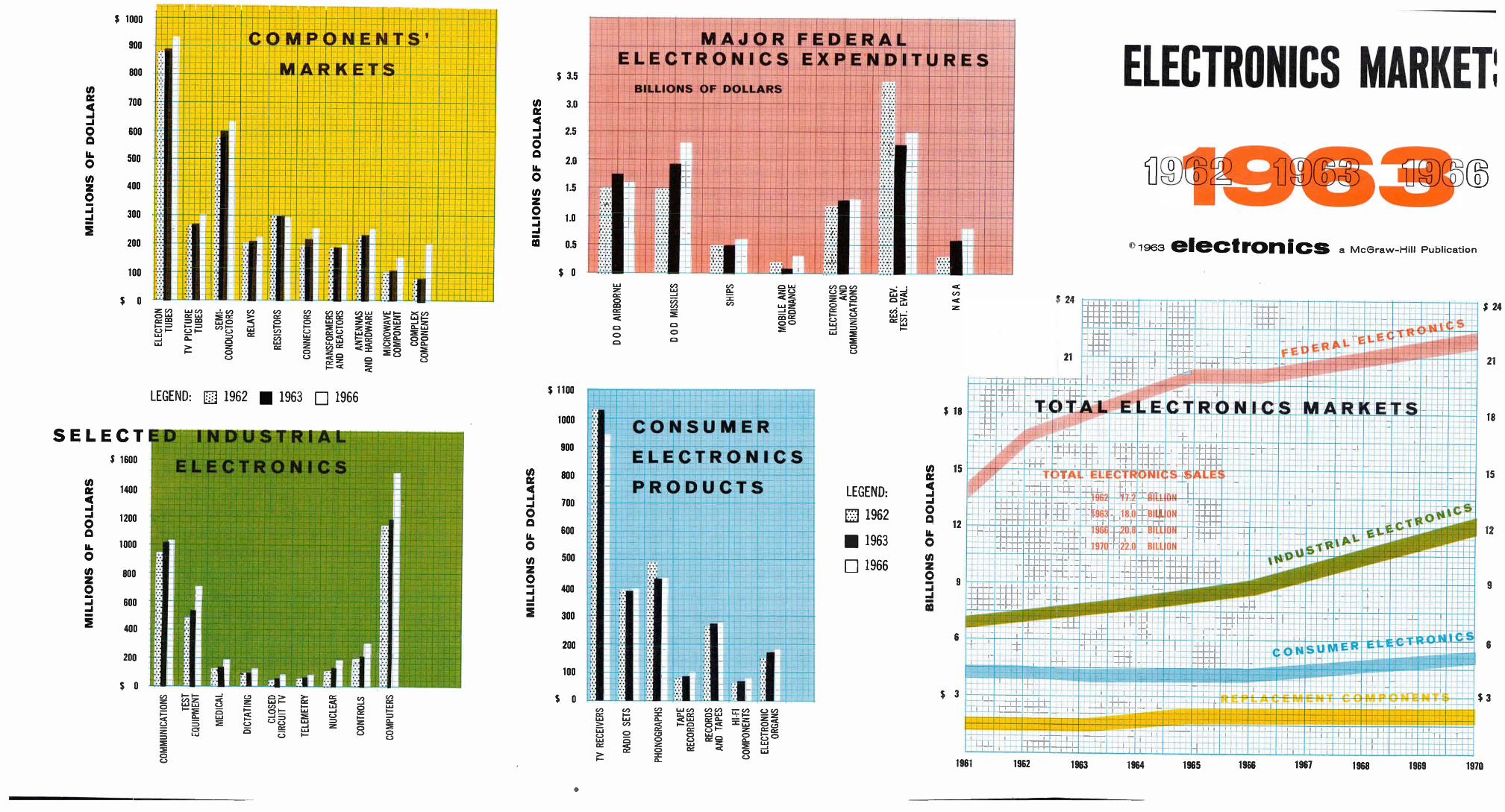
MILLIONS OF DOLLARS
MILLIONS OF DOLLARS
COMM
UNIC
A1IO
NS
TEST
11QU
IPME
NT
MEDICAL
DICT
ATIN
G
CLOS
ED
CIRC
UIT
TV
TELE
METR
Y
NUCL
EAR
CONT
ROLS
COMP
UTER
S
1V RECEIVERS
RADIO
SETS
PHONOGRAPHS
TAPE
RE
CORD
ERS
RECORDS
AND
TAPE
S
HI-FI
COMPON
ENTS
ELECTRONIC
ORGANS
Cf.
CO
02
•mdi
CO
am.
OD
CO
»ma
CO
CO
44
4D.
r—•
(SD
Cr)
r‘..)
MIR
BlagilignaBURRE419881116111111111813
1111111111111111110111fflilim
inua
ll11
1111
1111
1111
1
Cil
MILLIONS OF DOLLARS
• : • : • : • : : • : : • " - • - • " • • : • : : • : • : • : • : • : • : : : • : • • : • : • : : • : • : • : • : • : • : • : • : • : • : • : • : • : • • : • : • : • : • : • :
: : • : : : • : : • •
C)
-4
SOIN02110313
C) o
44
cr)
(0
0")
c.A.)
E]
(.0
r-
rn
c")
rn
BILLIONS OF DOLLARS
CO
47
nu
,
im ii.
a
mum
im -
BM
IMuMMMUMM
Mk
IMMIUMMIMMIM
MMIUMMI
MMAUMMuMMMM MMUMMIUMI
MMII9MMMMUMMMIMMUIMMI I
OD
CO
e,
r n
ELECTRON
TUBE
S
TV P
ICTU
RE
TUBE
S
SEMI
-CONDUCTORS
RELAYS
RESISTORS
CONNECTORS
TRANSFORMERS
AND
REACTORS
ANTENNAS
AND
HARDWARE
MICROWAVE
COMPONENT
COMPLEX
COMPONENTS
1%,
44
N.1
Ce
CO
Cr
::::
::::
:::::::::::_::::::::.
• .1.:.:0.'.
.0:.
e',:'¡
.!_i_!..:::¡''..:
......
...f:.
[.
1
,
I
11 1
L:::::::':
•!:•1!:i
:j: :
j:ikli l'
1
-I 1-1-
t
I
LI 1 I i
HI 1-
': • : • • • : • •
mum IIIIImmum
mu
mum» mumummummummum mum
»mum» ummummummumum
mum
1111111111
mum mum »MUM»
MILMIMM MMUMMIMMUM
UNIMMIM IIMM§IMIMMIMMIMMIMEM
-
•
mmEMMUMMMMEMOMM
111:1
ginar
M111
"1191111:1111::1MMMMU.
ke
n. Billiarennn".
11111
FM
Inalmuumuu.«
mmilMfflumm
•
mummummummumm
P II
1111111111
I a
1111
111 mum. mum m
M
um.-
mm
mummummumm mum,
1 1 mum
nuirar
im
um
mum mule
mmum
m -AMR
ummuummummummummummummum
77mumumum
IIIII
mummummummum
IMMUM
'/MMMUMMM
• MMUIMMMOMM
MMME11:11
mur-mmumm
mil muMmUmmum mu
min BM
MUMMJIMM
rri.
lg.
. MMUMMUMIMM
UMW
111111111111MINMMIIMMU
MIUMMIMMMM
jjj..mmu.mm.. ummi
mum
«BMW
1111
MMUMMO MUMMUMUMM u II
=MU
DOD A
IRBORNE
D 0 D MIS
SILES
SHIPS
MOBI
LE AND
ORDNANCE
ELEC
TRON
ICS
AND
COMM
UNIC
ATIO
NS
RES. DE
V.
TEST
. EVAL
.
NASA
BILLIONS OF DOLLARS
44
C7
44
nl
nl
0
• w
Z 0
CA 2
]
m X
mm
• > r
Cl)
nl
uoll'ep!lcind 1111-1-^AeJc0V\I
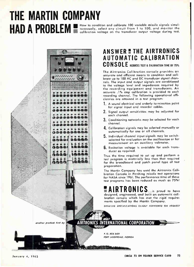
THE MARTIN COMPANY HAD A PROBLEM "
How to condition and calibrate 100 variable missile signals simul-taneously, select any circuit from 1 to 100, and monitor the calibration voltage on the transducer output voltage during test.
to to 1- 110 • IS)
ed.* io
- —
.1 ) ) ) Y_Y ) fr ) ) ) fr )
) • ) ) ) Y X.X.YJLY-X.X,LX.M-'t '
saasaa be • • 41›.0.4beelk
aa b *el» lb Ile a 1110
*a, 4116 edletittlikelb Jib a a a **lea.
• á 11/
di di iiáááááá
()glebe tie de1 el ebb&
áááááli biá
(3; gee glel 010/66411111
diatiáá One Ciabededeb di di di a a eti al beaked!" di di di di IL d'i 460 'Meat& di di
ar fir— babe"
:s
another product first by
ANSWER THE A1RTRONICS AUTOMATIC CALIBRATION CONSOLE REDUCES TEST & CALIBRATION TIME BY 75% The Airtronics Calibration console provides an accurate and efficient means to condition and cali-
brate up to 100 AC and DC transducer signal chan-nels. The input and output signals are conditioned to the voltage level and impedances required by the recording equipment and transducers. An accurate .1% step calibration is provided to each recording channel. The following operational effi-ciencies are attained in a test program:
1. A sound electrical and orderly termination point for signal input and recorder cables.
2. Signal output sensitivities may be adjusted for each channel.
3. Conditioning networks may be selected for each
channel.
4. Calibration signals may be selected manually or automatically for one or all channels.
Individual channel input signals may be switch-selected for evaluation on the oscilloscope or for measurement on an auxiliary voltmeter.
Excitation voltage is available for each trans-ducer as required.
Thus the time required to set up and perform a test program is materially less than that required for the breadboard and patch panel type of test preparation.
The Martin Company has used the Airtronics Cali-bration Console in Pershing missile test operations for NASA since 1961. The performance time of these test programs has been reduced as much as 75%!
5.
6.
"AIRTRONICS ...is proud to have designed, engineered, and built an automatic cali-bration console which has met the rigid require-ments specified by the Martin Company.
DETAILED SPECIFICATIONS GLADU FURNISHED ON REQUEST
P. 0. BOX 8429
FORT LAUDERDALE, FLORIDA
January 4, 1963 CIRCLE 73 ON READER SERVICE CARD 73

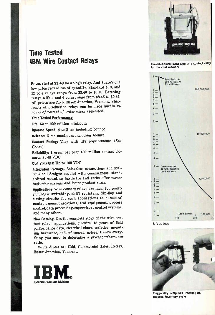
Time Tested IBM Wire Contact Relays
Prices start at $3.40 for a single relay. And there's one
low price regardless of quantity. Standard 4, 6, and
12 pole relays range from $3.40 to $6.15. Latching relays with 4 and 6 poles range from $8.45 to $9.35. All prices are f.o.b. Essex Junction, Vermont. Ship-ments of production relays can be made within 24
hours of receipt of order when requested.
Time Tested Performance
Life: 50 to 200 million minimum
Operate Speed: 4 to 8 ms including bounce
Release: 5 ms maximum including bounce
Contact Rating: Vary with life requirements (See
Chart)
Reliability: 1 error per over 400 million contact clo-
sures at 48 VDC
Coil Voltages: Up to 100 VDC
Integrated Package. Solderless connections and mul-tiple coil designs coupled with compactness, stand-ardized mounting hardware and racks offer manu-facturing savings and lower product costs.
Applications. Wire contact relays are ideal for count-ing, logic switching, shift registers, flip-flop and
timing circuits for such applications as numerical control, communications, test equipment, process
control, data processing, supervisory control systems, and many others.
New Catalog. Get the complete story of the wire con-tact relay—applications, circuits, 15 years of field performance data, electrical characteristics, mount-
ing hardware, and, of course, prices. Here's every-thing you need to determine a price/performance
ratio. Write direct to: IBM, Commercial Sales, Relays,
Essex Junction, Vermont.
IBM® 'General Products Division
The mechanical latch type wire contact relay
for low cost memory
2 —
Specified Life 200 Million At 35 Milliomps
— 9 — 8 — 7 — 6 —
5 —
4 —
3 —
2 —
1 — 9 — 8 — 7 — 6 —
5 — 4 —
3 —
2 — Generated At 30 CPS Resistive Load 48 Volts.
1 — 9 — —
7 —
6 —
—
4 —
3 —
2 —
Load (Amps) 100,000 1 —
1.0 2.0 3
100,000,000
10,000,000
1,000,000
Life vs Load
Pluggability simplifies installation, reduces inventory cycle

THE INSULATION OF ”MYLAR" IS SHOWN IN GREEN
SOLVING INSULATION PROBLEMS WITH "MYLAR"
High dielectric and thermal properties of "Mylar" make busway smaller... at lower cost
The outstanding performance of "Mylar" polyester film in thin gauges allowed the Square D Company to design a more compact busway at lower cost. "Mylar" provided an insulation material that was both strong and durable, with higher dielectric and thermal prop-erties that eliminated the air space needed for cooling between the bars. Unlike many conventional insulat-ing materials, heat can be dissipated directly through the "Mylar" without causing any breakdown of the insulating value.
While the Square D busway operates within Class A temperature limits, the unit was subjected tó a Class B test (130°C.)."Mylar" withstood this test, giving a 25° safety factor—and an expected insulation life of four times Class A insulation. The combination of properties of "Mylar" offers
you added benefits that can lead to product improve-ment. "Mylar" is resistant to solvents, easy to work with as compared with other insulation materials. "Mylar" has excellent volume resistivity even at ele-vated temperatures. It has low moisture permeability. You may be able to reduce your costs through de-
sign modifications and manufacturing economies, using "Mylar" to replace your present insulating ma-terial. Why not investigate its unique combination of properties in your applications? Save time and money now by writing to Du Pont Company, Film Dept., Wilmington 98, Delaware.
only DU PONT makes
MI' L AR® POLYESTER FILM
oU PONT Ott y,S.. Oft
Better Things for Better Living ...through Chetnistry
76 CIRCLE 76 ON READER SERVICE CARD electronics

electronics Jani«tql 1PejJ
MICROPAC weighs in at only 90 pounds, but is a complete digital computer for tactical applications
Computers in the Front Lines:
Micromodules Make it Possible
Development of micromodules has
significantly reduced the size and weight of
electronic equipment. This computer has a
wide range of uses. It takes advantage
of micromodular construction
By A. S. RETTIG, Surface Communications Div., Defense Electronics Products, Radio Corporation of America, Camden, N. J.
THIS GENERAL-PURPOSE mili-tary digital computer will be used in tactical applications where high reliability, small size and weight and low power requirements are primary considerations. The com-puter uses micromodular construc-tion, providing high packaging den-sity, excellent reliability and a predicted failure rate of 0.04-per-cent per 1,000 hours per two-circuit micromodule. The computer, as a whole, has a mean-time-before-fail-
77

INPUT-OUTPUT INSTRUCTION W
-PARITY SPARE
38 37
36
31 30
29
22 21
16
IN
COMMAND
WORD-BLOCK FLIP-FLOP
WORD-BLOCK COUNTER
if-DEVICE SECTION
15 13 12
STORAGE ADDRESS
COMPUTER INSTRUCTION W.
PARITY SPARE-
36
31 30
28 27
16
12
OPERATION CODE
1_
INDEX REGISTER
MINOR ADDRESS
a MAJOR ADDRESS
FORMAT of computer words Fig. .1
ALPHA-NUMERIC W 38 37
36
31 30
25 24
19 18
13 12
7 6
PARITY SIGN OPTIONAL
SIX ALPHA NUMERIC
CHARACTERS
38 37
36
BINARY WORD
PARITY SING Or PLUS I =MINUS
MAGN IODE (right) of computer
conforming to Fieldata-
THE COMPUTER is divided into five major subsections, all of which have micromodular features—Fig. 2
are of over 1,000 hours at a 60-per-cent confidence level. Much of the equipment in the
computer is time-shared to further reduce the required circuits. Devel-oped under the Signal Corps micro-module program, its name MICRO-PAC, which stands for Micromodule Data Processor and Computer, was designed to be compatible with the U. S. Army's Fieldata automatic data-processing equipment.
The high packaging density gained with micromodules (about 150,000 components per cubic foot in the circuit section) permits the effective use of a single-case design of 2.7 cu ft that weighs 90 pounds. It requires 250 watts d-c power and 270 v-a generator power.
SYSTEM ORGANIZATION — The computer accommodates a wide variety of problems and has 21 mechanized instructions as shown in the table. It also has register provisions and is a binary syiichro-
PAPER TAPE PUNCH/PRINTER
PEAL-TME INPUT
LOGIC RACK (top), power supply arid ¡ri (1110171 stack
CONTROL PANEL
INPUT-OUTPUT UNIT
PAPER TAPE READER
REAL-TIME OUTPUT
MAJOR TRANSFER BUS ,MTE)
HIGH-SPEED .ÉMORY
PROGRAM CONTROL UNIT
ADDER INPUT BUS
CENTRAL LPRO CESSOR
ADDER OUPUT BUS
- - - CONTROL
nous computer operating in a com-pletely serial mode at a clock fre-quency of 1.6 Mc, permitting a reasonably short execution time per instruction. The clock pulses drive a timing-
level generator producing a se-quence of gate levels of varying lengths within a 63-clock pulse period. This 63-clock pulse period of about 40 esec is called a minor cycle, and is abbreviated during certain instructions to decrease op-eration time. An instruction is executed in one or more minor cycles plus a minor cycle for in-struction access. The various 38-bit word formats
are provided. Figure 1 shows the format of a binary word, an alphanumeric word, a computer in-struction word or an input-output instruction word. The basic random-access ferrite core memory of 2,048 word capacity is expandable in mul-tiples of 2,048 to a maximum of 8,192 words.
INFORMATION
The computer is divided into five major subsections as shown in Fig. 2. These include: high-speed mem-ory, central processor, program con-trol, input-output and major trans-fer bus.
HIGH-SPEED MEMORY — The high-speed memory unit contains the core-memory and registers for data storage, controls for reading, writing and word selection. The memory operates with coincident-current selection (destructive read-out with regeneration) having a duty cycle of 40 esec between read interrogations. The memory array consists of 20
double planes, each containing two 64 x 32 core matrices; also in-cluded in the stack are a diode board, heater assembly and header board containing plugs for external connection. This section appears in the lower right-hand corner of the photo. The 20 double planes provide two spare bits per word. These
78 electronics

spares can be utilized by connecting the sense winding output to any input circuit and completing a cir-cuit between the digit winding to the digit drive of the corresponding regenerative loop. The memory module bank is a completely self-contained plug-in unit. Four banks may be used with the computer. A 13-bit address generated by the
central processor determines which one of four memory banks and which of 8,192 words will be selected and sent to the two memory output registers. Register 1 is a temporary buffer for parallel data flow to and from the memory; register 2 is both a buffer effecting parallel-to-serial conversion of data and an operand register for several instructions.
CENTRAL PROCESSOR — The central processor performs internal data-processing functions. It has a one-bit adder, various shift regis-ters that, among other functions are used with the adder to form the arithmetic unit, gates to transfer data between registers and adder, and control timing and logic.
All arithmetic operations are done in binary-serial form using a one-bit adder. Subtraction is ac-complished by two's-complement ad-dition. Multiplication is performed by successive addition of partial products, and division is executed by a nonrestoring algorithm. Com-puter operands are fixed-point, signed magnitude. The accumulator, instruction and
program-counter registers are con-tained within this section. The ac-cumulator contains first the operand and then the result of the arithmetic instructions. In divide, the remain-der is stored in the accumulator and the quotient in the Q-register (a register simulated in high-speed memory). In multiply, the high-order result is stored in the ac-cumulator while the low-order re-sult is in the Q-register. The instruction register holds the in-struction during execution in the computer. The program counter stores the address of the next in-struction to be executed in the program sequence. Other registers required for the central processing function are simulated in the mem-ory.
PROGRAM CONTROL UNIT — The program control unit generates
the various controls required by the high-speed memory, central proc-essor and input-output sections. It comprises the decoders, signal gen-erators, and control flip-flops.
INPUT-OUTPUT DEVICES—The input-output section controls data exchange between the central proc-essor and control panel, a paper-tape reader and printer-punch plus a real-time channel. The standard Fieldata intercommunication con-ventions, 8-bit characters, ready-busy line and strobe line, are used for all input-output operations. On-line insertion of information may be accomplished at 300-characters-per-second by a paper-tape reader or by a programmed instruction re-questing operator input at the con-sole. In the latter mode, the computer waits until a specified quantity of information has been inserted and then automatically con-tinues program execution.
Similarly, on-line output of in-formation may also be performed by a paper-tape punch-printer at 30 characters-per-second or through the control panel. In the last case, the computer waits until the opera-tor has requested the display of the instruction-specified number of words and then automatically con-
tinues program execution. The computer can communicate
with other computers with real-time input and output channels on a computer-interrupt basis at a maximum rate of 300 characters-per-second.
The computer may concurrently perform real-time input, real-time output, and data-processing func-
HOW COMPACT CAN A COMPUTER GET?
This computer won't fit in a man's pocket, but it represents an achievement in size and weight reduction.
It is possible because of micromodules that permit a good deal of circuit to occupy a minimum of physical space. Groups of these tiny circuits make possible a design of high packaging density, excellent reliability and low power needs
INSTRUCTIONS AND TIMING
Instruction
Approximate Time µsec
(including IAC)
Arithmetic: I Add 2 Subtract 3 Multiply Fast (18 bits) 4 Multiply 5 Divide
Transfer: 6 Transfer llitconditional 7 l'ransfer and Load ['es. 8 Transfer on Negative 9 Transfer on Zero 10 Transfer on Index
Logical 11 Shift Right 12 Shift Left 13 Store 14 Logical Multiply 15 Load 16 Halt
Sense 17 Sense 18 Sense and Set 19 Sense and Reset
Input-Output 20 Read Alphanumeric 21 Write Alphanumeric
80 80
32'. 1035 1075
40 120 40 40 200
280, max. 280, max. 80 80 120 40
40 40 40
variable variable
tions. When a character has been received from the real-time input unit or when the real-time output unit signifies that it is ready to ac-cept a character, the computer tem-porarily interrupts its data-process-ing function, services the character and then resumes data processing from the point of interruption. One to seven-character storage or re-trieval operations are implemented by computer interrupts until a com-plete data word or a single control character has been stored or re-trieved. A program interrupt will then transfer the completed word to the message storage section of the high-speed memory, or retrieve a complete word from the message-storage section for output.
MAJOR TRANSFER BUS—Most transfers are accomplished by a major transfer bus; some transfers to and from the adder that occur concurrently with transfers of data through the major bus are executed by minor transfer buses.
CIRCUIT DESCRIPTION — Re-quirements of +90 C maximum in-ternal ambient temperature to per-mit reliable circuit performance within the high-density micro-module packaging, made silicon semiconductor components manda-tory. For the bulk of the micro-module logic circuits, the 2N914
January 4, 1963 79

switching transistor was selected for its relatively high-speed switch-ing and good reliability record. The basic circuit is the standard
logic gate of Fig. 3A with the fol-lowing characteristics: fan in-20 maximum; fan out-4; power dis-sipation-75 mw average; pair de-lay-60 nsec nominal, and rise time —30 nsec nominal.
This standard gate is the most frequently used micromodule in the computer. Low-power gates are pro-vided when the speed and power capabilities of these standard gates are not required. Several micro-module configurations of the stand-ard and low-power gates were de-signed. Gates are packaged two to a micromodule. Several gate micro-modules were designed with differ-ent input-diode arrangements so that the module's 12 standard out-puts could accommodate the input-terminal requirements of a number of different logical configurations. Diode-cluster micromodules are pro-vided to handle unusual cases.
Although the gates make up the bulk of micromodules in the com-puter, many other special-purpose circuits are required. Figure 3B shows a shift register capable of shifting at a 1.6-Mc clock rate with an output drive of two standard gates and one steering resistor of another shift register stage. A starting point for the design
of the shift register was the stand-ard gate. Two standard gates were interconnected in a flip-flop arrange-ment and capacitor-resistor-diode gates tied to the bases for the trig-ger input. This was satisfactory except for a worst-case condition at 125 C which had a turn-off time of 0.15 µsec instead of 0.13 µsec. The worst-case test included a maximum load of four standard gates and the steering resistor input of the shift register. The maximum output load was reduced, to two standard gates, and the steering input and base drive loads were also reduced slightly. These modifications that permitted operation under worst-case temperature conditions were satisfactory and therefore conse-quently adopted. The studies were continued to
determine the requirements for even better operation. Inductors added in series with the steering input resistors permitted a sub-
stantial increase in operation speed and a reduction in trigger power. The addition of the two inductors
decouples the collector from the fol-lowing trigger steering network during the time of the trigger pulse. After the trigger pulse, there is over 0.5 izsec for the capacitor to assume its new voltage state.
This circuit would be the most desirable one to use from an elec-trical viewpoint; however, the addi-tion of the two inductors would re-quire more than one micromodule for a shift-register stage and, in the interests of economy of volume, the design without the inductors was chosen.
All logic micromods are compati-ble and use common supply voltages and signal-voltage characteristics. Line receivers and drivers are pro-vided for the transition from com-puter signal voltage to Fieldata operation.
All electronic components are operated well below rating to assure
maximum reliability. Resistors are operated at a maximum of 20-per-cent of rating. Silicon transistors are junction-temperature limited to 100 C in operation, although cir-cuits were designed and tested for 125 C operating temperatures.
POWER SUPPLY — The power supply is operationally typical of digital computers in that it fur-nishes a large number of well-regulated output voltages with low source impedance. However, it dif-fers from most computer supplies in two major respects that com-plicate the design: the requirement for small overall size and poor regu-lation of the primary power source. A block diagram of this supply is shown in Fig. 4. The input voltage source for the
computer may range from a poorly regulated field-type to a well regu-lated commercial power line. The d-c power supply has been designed for the following input power condi-tions: voltage-120 v, 10 percent single phase; frequency-50 to 60 cps, 10 percent; transient voltage range— (5 sec) 31 to 86 cps. The required d-c output of the
supply with two memory packages (4,096 word capacity) is 250 watts, consisting of 13 different voltages. The wide range of input voltage and frequency coupled with the require-
ment of minimum size and weight, made unsatisfactory the conven-tional design approach using a power transformer with individual rectifiers and regulators for each voltage. Instead, a power supply in-corporating the following features was designed: (1) controlled bridge rectifiers operating directly from the a-c line, to achieve rough regula-tion in the order of 15-percent; (2) single-section L-C-filter to reduce ripple to less than 10-percent after 60-cycle line input rectification; (3) Morgan regulator circuit, using a silicon-controlled rectifier and a square-loop core to achieve regula-tion in the order of 2-percent; (4) single-section L-C-filter to reduce ripple to less than 1-percent after high-frequency regulation; (5) silicon-controlled rectifier parallel inverter operating at 1,000 cycles, using a power transformer with separate windings for individual supplies; and (6) individual recti-fiers and regulators for each output voltage, where required.
In the bridge rectifier and filter, silicon-controlled rectifiers are used as the primary type of rectification to provide lossless voltage regula-tion to the Morgan circuit. The regulation required is relatively crude with a large ripple voltage inasmuch as the Morgan circuit can operate with pure or pulsating dc-inputs. Severe voltage and fre-quency variations of the primary power source make the exclusive use of a Morgan circuit or con-trolled bridge awkward. If only a controlled bridge is used, the filter choke required is large and heavy, although the capacitor is reasona-ble. If a Morgan circuit is used exclusively with a conventional full-wave bridge input, the filter capac-itor required on the bridge must have a high voltage rating, which represents height, weight, and vol-ume, since physical size increases with voltage rating. In addition, the nearly 2:1 voltage variations from the bridge would make acceptable regulation difficult. The use of a combination of two circuits allows much smaller chokes and capacitors to achieve the same regulation and transient load response for the in-put to the inverter. The Morgan regulator and filter
circuit provides lossless, tighter regulation for the inverter input.
80 electronics

The circuit generates pulses of ap-proximately constant width to the load, by virtue of the silicon-con-trolled rectifier acting as a switch in series with the load. The repeti-tion rate of these pulses is con-trolled by a voltage-sensing feed-back network that regulates average potential. The repetition rate ranges from 500 to 2,000 cps; thus, the filter choke and capacitor may be much smaller and lighter than those required if the controlled bridge were used to operate the in-verter. The Morgan circuit regula-tion response is inherently faster than the controlled bridge since its repetition rate is so high. This is an advantage for transient load changes, because the controlled bridge response is always at least a half-cycle behind at line fre-quencies. The parallel silicon inverter uses
two silicon-controlled rectifiers in a parallel inverter to convert 50 volts d-c to 1,000 cycles a-c. Two additional silicon rectifiers are used for 400 cycles a-c. The scr require-ments are 5 amperes average cur-rent and about 150 volts peak-in-verse voltage to allow for switching transients. These are reasonable ratings, well within the range of available scr's. The rectifiers are triggered 180-degrees out of phase by a binary counter to insure sym-metry of the applied square wave to the transformer.
Insuring symmetry of the 1,000--cycle square wave minimizes thr 1,000-cycle ripple in the rectified outputs of the individual supplies and reduces the amount of regula-tion required. The power transformer has eight
output windings for the various voltage supplies. Bridge rectifiers are used on the higher-voltage wind-ings to minimize winding space, while full-wave center-tapped wind-ings are used for low voltage to minimize diode drops. Where volt-ages are close in value, or load cur-rents are small, one winding is used for several voltage outputs. The 128-v and 26-v fan-motor
supplies are derived from taps on the primary winding of the 400-cycle auto-transformer. The individual output regulators
are of the series and shunt types. The series regulators are used for high-current supplies, with shunt
+18 'vvs. 5.IIK
IN 14
IN
CLUSTER
+6V +I8V
82pF
CR i
CR 2 I.62K
(A) -
9.09K
+ 6 1.2IK
NOTE: RESISTORS I/8W, ±2% CR I,CR2-1N914
01 — 2N9I4
OUT A
ONO
1.2IK
CL 8 CR5
IN 8 44
2.t;.pF
Ci ----1(
2N9I4
5.62K 5 62K 4 1.2IK
CR6
CR 3
N
I2QpF
78K
8.25K
9V CR2y
STEER A I.78K 120PF
TRIG
8.25K
y CR 1
STEER I.78K
pF
(B)
02 2N9I4
OUT
STANDARD GATE circuit is the most frequently used micromodule in the computer (A); shift register operates at a 1.6-Mc clock rate (B)— Fig. 3
POVAC INPUT SCR
PHASE— CONTROLLED
BRIDGE RECTIFIER
PHASE CONTROL
60-75V DC
SCR VARIABLE
4F REGULATOR 4ORGAN TYPE)
PRF CONTROL
50V + 2%
1,000CPS 50V
SQUARE WAVE OUTPUT RECTIFIERS AND REGULATORS
28V FANS
DC OUTPUT VOLTAGES
LEGEND: SCR: SILICON CONTROLLED RECTIFIER
POWER SUPPLY for the computer uses several modern techniques achieve high regulation from a widely varying power source—Fig. 4
zener-diode regulators for low-cur-rent supplies. These regulators are standard. Little regulation is re-quired to compensate for input changes, because of good regulation preceding the inverter; hence, a minimum of power is wasted in series regulators, and power-supply efficiency and cooling are not prob-lems.
CONTROL PANEL—The control panel provides for manual insertion of information into the computer and for monitoring and selecting
to
the various operational modes. Information may be entered man-
ually by the keyboard on the control panel. Input or output data may be displayed in digital and binary forms by 10 Nixie tubes and 38 neons, respectively.
This work was a joint effort by the Tactical Data Processing activ-ity of the Digital Data Communica-tions Department of RCA Defense Electronic Products. The author thanks A. Coleman, E. Schlain. R. Torrey, W. Miller and H. Sauer for their work.
January 4, 1963 81

PARAMETRIC DIODES. Two kinds of silver-bonded, point-contact diodes (Ge and Si) have been tested. Shown here are Ge diodes, type GSB1B—Fig. 1
THE VERSATILE
How It Detects
TO RECEIVER
PUMPING POWER SOURCE
LASER HEAD
PLUNGER
DOTTED WHITE LINE shows path of laser beam in experimental setup—Fig. 2
AUTHORS Shigebumi Saito (right) and Kaneyuki Kuro-kawa (left) demonstrate the experimental setup used in demodulating and amplifying laser signals
By S. SAITO, K. KUROKAWA, Y. FUJII T. KIMURA and Y. UNO Institute of Industrial Science, University of Tokyo, Tokyo, Japan
SEVERAL methods of demodu-lating laser signals into micro-wave have been tested and it has been found that the semiconductor diode has a high quantum effi-ciency. Further, the diode, which can be used in the infrared re-gion, allows parametric amplifi-cation of the demodulated signal. Experiments show that parametric diodes can demodulate and am-plify the signal from a ruby laser.
PRINCIPLES—For frequency con-version, especially demodulation of laser light, nonlinear devices are necessary. A. T. Forrester' demonstrated the square-law char-acteristics and microwave re-sponse of a photocathode, and B. J. McMurtry and A. E. Siegman' succeeded in detecting and ampli-fying the beat components in laser light. They used the external photoelectric effect, or photoelec-tric emission, in which the elec-trons are carried away from the cathode material by photon en-ergy. There is another photo-electric effect, the so-called inter-nal photoelectric effect (a general term for photoconductivity, photo-voltaic effect, etc.) that uses the same principle — electrons are taken away from the filled band to the conduction band by acquisi-tion of photon energy. To discuss the applicability of
these photoelectric effects to a laser detector, consider quantum efficiency. The signal-to-noise ra-tio of optical superheterodyne re-ception is proportional to the quantum efficiency 17, as
S/N = 771',„/hvB where P,, is input light power, h is Planck's constant, v is light fre-
quency and B is receiver band-
POINT-CONTACT DIODE
and Amplifies Laser Light
Laser signals are demodulated and converted into microwave by a semi-
conductor diode that also parametrically amplifies the demodulated signal
width. The quantum efficiency of the usual photocathode material is poor. To 6,943 A light from the ruby laser, for example, n = 10" to 10' for a Ag Cs photocathode and n = 10 to 10' for an oxide cathode. By contrast, the internal photoelectric effect of the semicon-ductor has a quantum efficiency of nearly 100 percent. Thus it can be an efficient detector. This detector also has the possibility of infrared light detection. The infrared limit of the photoemission is about 1.2 microns in wavelength obtained from a Ag Cs photocathode. For semiconductors, however, the limit it determined by the energy-band gap between the filled band and the conduction band. Many semicon-ductors have a low energy gap; for example, an intermetallic compound semiconductor InSb has an ex-tremely narrow band gap, 0.17 ev, which means that light of 10 mi-crons wavelength is still detectable.
H. Inaba and A. E. Siegmans and L. U. Kibler' first reported the de-tection of the laser light by a pin silicon diode and a germanium diode, respectively. We have de-tected the laser light by a point-contact diode and parametrically amplified the microwave signals.
POINT CONTACT DIODE—Since the excitation of electrons by inci-dent light may take place without any appreciable time delay, the fre-quency response of the detecting device is restricted chiefly by the velocity of holes or electrons, re-combination, and the additional re-sistance or capacitance. Since the semiconductor point-contact diode is conventionally used for micro-wave detection, it has sufficiently fast response.
Because these diodes are made for parametric amplification, both detection and amplification can be obtained by the parametric prin-ciple. This device gives high gain, low noise figure and a wide band-width. It may be an excellent and sensitive laser detector.
LASER—The laser used is a Ray-theon model LH-1. The crystal is 0.05 percent trivalent chromium ion doped ruby, 2.5 inches long and 0.25 inch in diameter. The pumping xenon flash tube is a EG&G type FX-38. The crystal and xenon flash tube are placed at the two foci of an elliptical mirror. This laser is usually pumped to a level of 300 joules in the experiment. Thres-hold is about 150 joules. Output power of the laser light is several watts at the peak. The beat fre-quency fb of two adjacent longi-tudinal modes is generally given by Ib = c/2Ln, where L is the ruby rod length, n is the refractive index of ruby, c is the light velocity in vacuum; (see Fig. 3A). The third harmonic of beat frequency should be 4,026 Mc. 3,960 Mc is obtained experimentally with both photo-diode and photocathode.
LASER COMMUNICATION
If, as seems possible, photo-diodes can be used for down conversion and amplification of laser light, these semicon-ductor devices could play an important role in laser com-munication systems of the future. These experiments show that the photodiode is in-deed a promising device
Two kinds of silver-bonded, point-contact parametric diodes were tested. They are germanium and silicon (Fig. 1), manufactured by Nippon Electric Co. The ger-manium diode is a GSB1B; the silicon diode is a test specimen. These diodes are all glass-sealed, and the junction is visible (Fig. 1). The crystals are about 1 mm square, with n-type doping; the point-con-tact is made by Ag-Ga wire 0.05 mm in diameter. Junction capaci-tance is 0.1 to 0.3 pf.
EXPERIMENTAL SETUP — The experimental equipment for diode-type detection is shown in Fig. 3B. (See also Fig. 2 and photo). The diode is placed in the 4,000 Mc waveguide cavity. Laser light from the ruby is reflected by a partially transparent mirror (96 percent re-flectance) used to adjust the posi-tion of incident spot. Neither colli-mation nor a focusing system is employed. The laser light is pro-jected obliquely to the junction of the diode through a hole drilled on the cavity wall. Behind the mirror, a phototube monitors the laser out-put power. The 8,000-Mc pumping-power waveguide is placed across the 4,000-Mc waveguide. Pumping power is coupled to the 4,000-Mc cavity by a stub in a hole. A dual beam oscilloscope displays any two of these three: receiver output, diode current or monitor phototube output. An equivalent circuit of the
photodiode including the detector is shown in Fig. 3C. When no pumping power is applied, the nega-tive conductance should be excluded. The signal source is a current gen-erator at the junction excited by photon energy. The isolator de-
January 4, 1963 83

DETECTED 3RD BEAT FREQUENCY ,,, 3,960 MC
(A)
ISOLATOR
C
CAVITY AND DIODE TUNING CIRCUIT
NEGATIVE CONDUCTANCE BY PARAMETRIC AMPLIFICATION
SPECTRUM of laser ight (A); and twt photodetector (D)—Fig. 3
BEAT FREQUENCY -.1,320 MC
DETECTED CURRENT SOURCE
MONITOR PHOTOTUBE HALF MIRROR
(96% REFLECTANCE)
LASER LIGHT
OUTPUT
B
AMPLIFIER CAVITY
,--PUMPING WAVEGUIDE
DIODE
LASER HEAD
PLUNGER
FOCUSING FLUX
ELECTRON BEAM
GUN
I
GLASS WINDOW
COLLECTOR
OXIDE CATHODE
I ( INPUT
(D)
diode detector-amplifier system (B);
couples the detector from the re-ceiver and stabilize the parametric amplifier. A similar detection experiment
was done with a phototube twt. The experimental equipment for a phototube twt is almost identical with that for the diode. Instead of
HELIX
equivalent
the junction of the diode as shown in Fig. 3B, a traveling-wave tube with oxide-coated cathode plays a main role. See Fig. 3D. The laser light is projected to the cathode through a transparent glass window and cylindrical collector. The emit-ted photoelectrons form an electron
(A) TIME EC4LE: 100 (B)
C 1,D) TIME 20 ¡LS/I'1.
DETECTED OUTPUT of phototube twt (A) is upper trace; lower trace is beam current (500 ga/div). Detected output of Ge diode (B) is upper trace; lower trace is diode current (100 ua/div). Coincidence between laser output and diode current (C) shows monitor phototube current in upper trace and diode current (100 pal div) in lower trace. Coincidence between diode current (lower trace, 100 ualdiv) and detected output (upper trace) of Ge diode is shown in (D)—Fig. 4
OUTPUT
LASER
HEAD
LASER LIGHT
circuit of detector system (C);
beam that amplifies the detected signal contained in the electron beam in a conventional way. Twt output is fed to the receiver.
RESULTS—The output of the pho-todiode detector not parametrically amplified is shown in Fig. 4B. The spectrum of the detector outputs is shown in Fig. 5A. The half width of the spectrum is about 10 Mc. This photodiode spectrum is almost identical with that of the phototube twt. The output of the phototube twt is shown in Fig 4A. The peak emitted current is about 500 ea and the net amplifier gain at this level of beam current is 0 db. Since the receiver bandwidth is about 10 Mc, the details of the spec-trum cannot be found from these data. The equivalent input power of the detected beat component is about —60 dbm for both types of the detectors. The equivalent in-put power is the input power that could produce the same output as the detected signal of the laser light. Considering the extremely small area of the junction, the diode detectors are much more sensitive than the oxide cathode twt. This is also clear from considerations of the quantum efficiency. The waveform of the ruby laser
output has many irregular spikes. The coincidences of the spikes be-tween the three waveforms of the
84 electronics

monitor phototube output, diode current and detected output are important. The coincidence be-tween the phototube output and the diode current is nearly perfect (Fig. 4C) ; the coincidence between the diode current and the micro-wave output is less perfect (Fig. 4D). Figure 5B shows the changes of the photodiode current and the detected output. The negative bias voltage increases the detector out-put because the increase of junction impedance makes the junction ca-pacitance smaller. Thus the avail-able output power may be increased. With pumping power, the diode
detector system operates as a parametric amplifier. The detected current through the junction is amplified, increasing linearly with the parametric amplifier gain as shown in Fig. SC. The change of diode impedance, probably the in-crease of the d-c capacitance Co in Fig. 3C, is observed during illumi-nation. This could be explained by the increase of capacitance due to decrease of bias voltage induced by photovoltaic emf. This conclusion is supported in that the gain of the parametric amplifier increases during laser illumination if the cavity is detuned by reducing L in Fig. 3C (moving the plunger toward the diode). But gain decreases (Fig. 6A) if the cavity is detuned by increasing L (moving the plunger away from the diode). This change of gain corresponds to the junction voltage. When the diode bias is open-circuited, the photo-voltaic emf. appears with the inci-dence of the light beam and cannot decay. The gain changes suddenly with incidence of light (Fig. 6B). The change of impedance is also observed in direct impedance
RELATIVE OUTPUT
• PHOTOTUBE
X PHOTODIODE
•--....-•
3,850
(A)
RELATIVE OUTPUT
O B
3,900 3,950 4,000
FREQUENCY IN MC
-2 -4 -6 BIAS IN VOLTS
x-GERMANIUM a 600 SIL ICON
400. cc
á 200
L)
SPECTRUM of phototube output and photodiode output (A); bias-voltage characteristics of the de-tector diode (B); parametric amplifier gain of the detected signal (C)—Fig. 5
measurements by the standing-wave detector during illumination. Figure 6C shows an example of
REFERENCES (1) A. T. Forrester, et. al., Phya Rev
95, p 1,691, 1955. (2) B. J. McMurtry and A. E. Siegman,
(A) TIME SCA. (B) TIME SCALE:
Ge
C
O
4,050
60
0 -2 -4 BIAS IN VOLTS
30
40
x-Ge
•- Si
-55 /
b I 115 210 25 PARAMETRIC AMPLIFIER GAIN IN 08
the output of the standing-wave detector. The standing-wave ratio changes with laser light.
Appl Opt, 1, p 51, 1962. (3) H. Inaba and A. E. Siegman, Proc
IRE, 50, p 1,823, 1962. (4) L. U. Kibler, Proc IRE, 50, p 1,835,
1962.
(C) TIME SCALE .‘S/DIV.
CHANGE of parametric amplifier gain for Ge diode (A)—upper trace is for reduced L, middle trace for tuned L, and lower trace for increased L. Gain change when Si diode circuit is open-circuited (B)— upper trace is for large L, middle trace for tuned L, and lower trace for small L. Standing-wave detector output for Ge diode (C) is shown in lower trace and diode current is in upper trace—Fig. 6
January 4, 1963 85

MULITONE OSCILLATORS-New Transferring the amplitude stabilizing elements to individual tank circuits
permits sinusoidal oscillation at several frequencies with no mutual mixing
PICK A FREQUENCY
Here's how to design five os-cillators, all tuned to different frequencies, using only two transistors. The multitone circuit can operate at any of the five frequencies, or in any frequency combination. The circuit forms the basis
of a five-bit parallel data en-coder for telemetry use
THE SIMPLE two-transistor cir-cuit, Fig. 1, represents a large class of multitone oscillator circuits that can be designed for simultaneous oscillations at many independent frequencies. There is negligible in-teraction between the frequency de-termining tank circuits, and output has low harmonic distortion. The circuits use noncritical components
The key to multitone oscillator design is the amplitude stabiliza-tion process in an ordinary oscilla-tor. Fig. 2A depicts the starting transient of a series-tank oscillator. If the switch is closed at t = there will be a buildup of an oscil-
lation at a frequency wo ••••• UN/LC
with oscillation envelope amplitude increasing exponentially propor-tionally to t (IRAI — R)/2L.
In any practical circuit this ex-ponential buildup is eventually lim-ited by nonlinearities in the circuit —usually in the negative-resistance device itself. The amplitude of os-cillation stabilizes at a steady state value where energy added by the negative resistance source equals the energy lost in the tank. This steady-state amplitude of oscilla-tion permits the average negative resistance of the source to equal the equivalent positive resistance R of the series tank circuit. The terminal characteristics of
the negative-resistance source are modified by the steady-state oscil-lation. Not only is there a sinusoidal oscillation at the tank frequency co., but terminal characteristics of the source at frequencies other than coo have been seriously affected by the periodic clipping or saturation of the source, which is necessary to maintain the steady-state amplitude of oscillation. Any attempt to use the negative-resist-ance source simultaneously at a frequency other than wo will conse-quently introduce mixing and am-
1800n,
fn 217V C,
1N625 £IN625 A1N625 IIN625 IN625
S
+6 TO +12 VOLTS
I K
150
27 2NI308
33 82
Cs
\ SW 5
220
0152
2 N652
OUTPUT
ANY COMBINATI01, OF f1 THROUGH f5
DIFFERENT PERMUTATIONS of one through five tones are generated by this circuit, enabling it to operate as a five-bit parallel encoder for industrial telemetry—Fig. 1
plitude-modulation effects.
NONLINEAR TANK—If, instead, the equivalent series resistance of the tank circuit cam be made to ad-just itself upward to equal the nega-tive resistance of the source, steady-state oscillations can be achieved without ever driving the negative resistance source into its nonlinear region (see curves, Fig. 2B and 2C) .
In conventional oscillator opera-tion (Fig. 2B), the envelope ampli-tude increases exponentially until the nonlinear portion of the nega-tive-resistance source curve is
reached and equilibrium R = IR„1 established. This equilibrium lies in the nonlinear region and will be maintained by the periodic clipping or saturation of the transistor, tube or tunnel diode used as the nega-tive-resistance source.
In the tank-stabilized oscillator, Fig. 2C, the envelope amplitude in-creases exponentially, but is limited by the increasing positive series re-sistance of the nonlinear tank cir-cuit; R = IR„I in the steady state, but now the equilibrium of positive and negative resistances occurs in the linear region of the negative-resistance source. The source can be used simultaneously at other fre-quencies without mixing occurring, if the instantaneous sum of all os-cillation voltages never drives the source into its nonlinear region. Nonlinear series tank circuits can
be achieved in many different ways (see Fig. 2D). The basic require-ment is that the effective series re-sistance of the tank circuit at reso-nance must increase with rms cur-
rent amplitude. The V// nonlinear-ity of the added circuit element in each tank causes the equivalent positive series resistance of the tank to increase above the low-level equivalent value R, = coL/Q = 1/QcoC of the simple series L-C tank circuit, Fig. 2A. The parallel non-linear elements cause a nonlinear
86 electronics
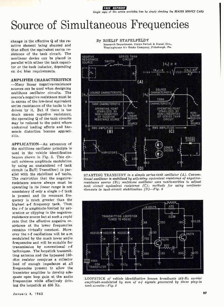
Single copy of this article available free by simply checking the READER SERVICE CARD
Source of Simultaneous Frequencies change in the effective Q of the re-active element being shunted and thus affect the equivalent series re-sistance of the tank circuit. The nonlinear device can be placed in parallel with either the tank capaci-tor or the tank inductor, depending on d-c bias requirements.
AMPLIFIER CHARACTERISTICS —Many linear negative-resistance sources can be used when designing multitone oscillator circuits. The source's negative resistance must be in excess of the low-level equivalent series resistances of the tanks to be driven by it. But if there is too much excess negative resistance, the operating Q of the tank circuits may be reduced to the point where undesired loading effects and har-monic distortion become appreci-able.
APPLICATION—An extension of the multitone oscillator principle is used in the vehicle identification beacon shown in Fig. 3. This cir-cuit achieves amplitude modulation by using an unstabilized r-f tank circuit (a BaTi Transfilter) in par-allel with the stabilized a-f tanks. The restriction that the negative-resistance source always must be operating in its linear range is not mandatory if only a single r-f tank is present and its resonant fre-quency is much greater than the highest a-f frequency tank. Then the r-f is amplitude-limited by sat-uration or clipping in the negative-resistance source but at such a rapid rate that the effective negative re-sistance at the lower frequencies remains virtually constant. More-over the r-f oscillations will be a-m modulated by the much lower audio frequencies and will be suitable for transmission by conventional r-f techniques. The loopstick transmit-ting antenna and the bypassed 160-ohm resistor comprise a collector load of enough impedance at all frequencies present to allow the transistor amplifier to develop ade-quate open loop gain at the audio frequencies while effectively driv-ing the loopstick at 456 Kc.
By ROELIF STAPELFELDT Research Department. Union Switch & Signal Div., Westinghouse Air Brake Company, Pittsburgh, Pa.
NEGATIVE RESISTANCE SOURCE SWITCH
0—t
IR n
SERIES TAI'4 ,, CIRCUIT
(A)
SOURCE CHARACTERISTIC I
1 Rn1 R
IRnI-R (1RnI-R121 t t-j1I/LC -
2L 4L2
SOURCE CHARACTERISTIC
TANK CHARACTERISTIC CHARACTERISTIC
RMS AMPLITUDE 0
(B)
NON-LINEAR
H REGION OF SOURCE
OPERATING POINT STABILIZED BY
NON-LINEARITIES OF NEGATIVE
RESISTANCE SOURCE
OPERATING POINT STABILIZED BY NON-LINEARITIES OF SERIES TANK
CIRCUIT
o RMS AMPLITUDE
(C)
ZENER DIODES
I NON-' LrNEAR f-e•R EG I 0 N
OF SOURCE
BIASED DIODES
STARTING TRANSIENT in a simple series-tank oscillator (A). Conven-tional oscillator is stabilized by adjusting equivalent resistance of negative-resistance source (B); multitone oscillator uses nonlinearities to adjust tank circuit equivalent resistance (C); methods for using nonlinear elements in tank-circuit stabilization (D)—Fig. 2
LOOPSTICK of vehicle identification beacon broadcasts 465-Ifc carrier amplitude-modulated by sum of a-f signals generated by three plug-in tank circuits—Fig. 3
January 4, 1963 87
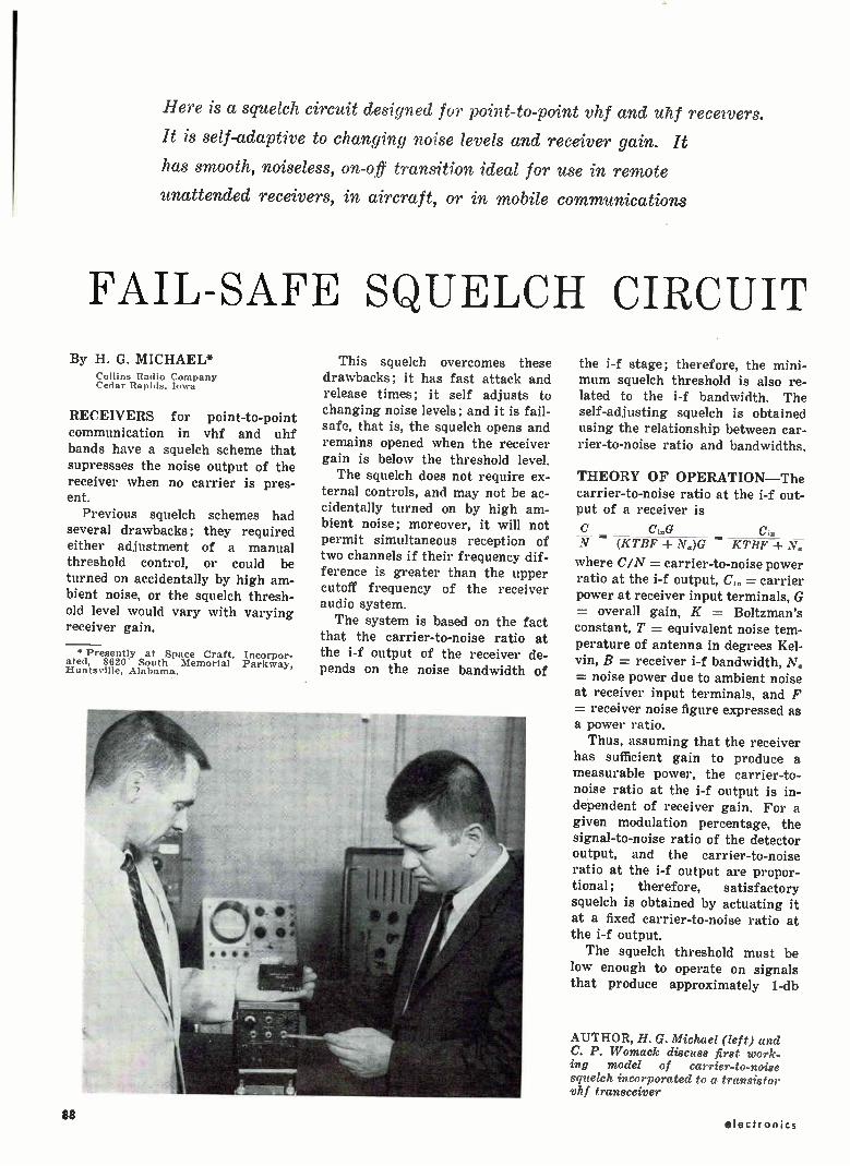
Here is a squelch circuit designed for point-to-point vhf and uhf receivers.
It is self-adaptive to changing noise levels and receiver gain. It
has smooth, noiseless, on-off transition ideal for use in remote
unattended receivers, in aircraft, or in mobile communications
FAIL-SAFE SQUELCH CIRCUIT
By H. G. MICHAEL* Collins Radio Company Cedar Rapids. Iowa
RECEIVERS for point-to-point communication in vhf and uhf bands have a squelch scheme that supressses the noise output of the receiver when no carrier is pres-ent.
Previous squelch schemes had several drawbacks; they required either adjustment of a manual threshold control, or could be turned on accidentally by high am-bient noise, or the squelch thresh-old level would vary with varying receiver gain.
* Presently at Space Craft, Incorpor-ated, 8620 South Memorial Parkway, Huntsville, Alabama.
This squelch overcomes these drawbacks; it has fast attack and release times; it self adjusts to changing noise levels; and it is fail-safe, that is, the squelch opens and remains opened when the receiver gain is below the threshold level. The squelch does not require ex-
ternal controls, and may not be ac-cidentally turned on by high am-bient noise; moreover, it will not permit simultaneous reception of two channels if their frequency dif-ference is greater than the upper cutoff frequency of the receiver audio system. The system is based on the fact
that the carrier-to-noise ratio at the i-f output of the receiver de-pends on the noise bandwidth of
the i-f stage; therefore, the mini-mum squelch threshold is also re-lated to the i-f bandwidth. The self-adjusting squelch is obtained using the relationship between car-rier-to-noise ratio and bandwidths.
THEORY OF OPERATION—The carrier-to-noise ratio at the i-f out-put of a receiver is
C. N = -(KTBF ± NOG KTBF
where C/N = carrier-to-noise power ratio at the i-f output, C,„ = carrier power at receiver input terminals, G = overall gain, K = Boltzman's constant, T = equivalent noise tem-perature of antenna in degrees Kel-vin, B = receiver i-f bandwidth, N. = noise power due to ambient noise at receiver input terminals, and F = receiver noise figure expressed as a power ratio. Thus, assuming that the receiver
has sufficient gain to produce a measurable power, the carrier-to-noise ratio at the i-f output is in-dependent of receiver gain. For a given modulation percentage, the signal-to-noise ratio of the detector output, and the carrier-to-noise ratio at the i-f output are propor-tional; therefore, satisfactory squelch is obtained by actuating it at a fixed carrier-to-noise ratio at the i-f output.
The squelch threshold must be low enough to operate on signals that produce approximately 1-db
AUTHOR, H. G. Michael (left) and C. P. Womack discuss first work-ing model of carrier-to-noise squelch incorporated to a transistor vhf transceiver
88 electronics
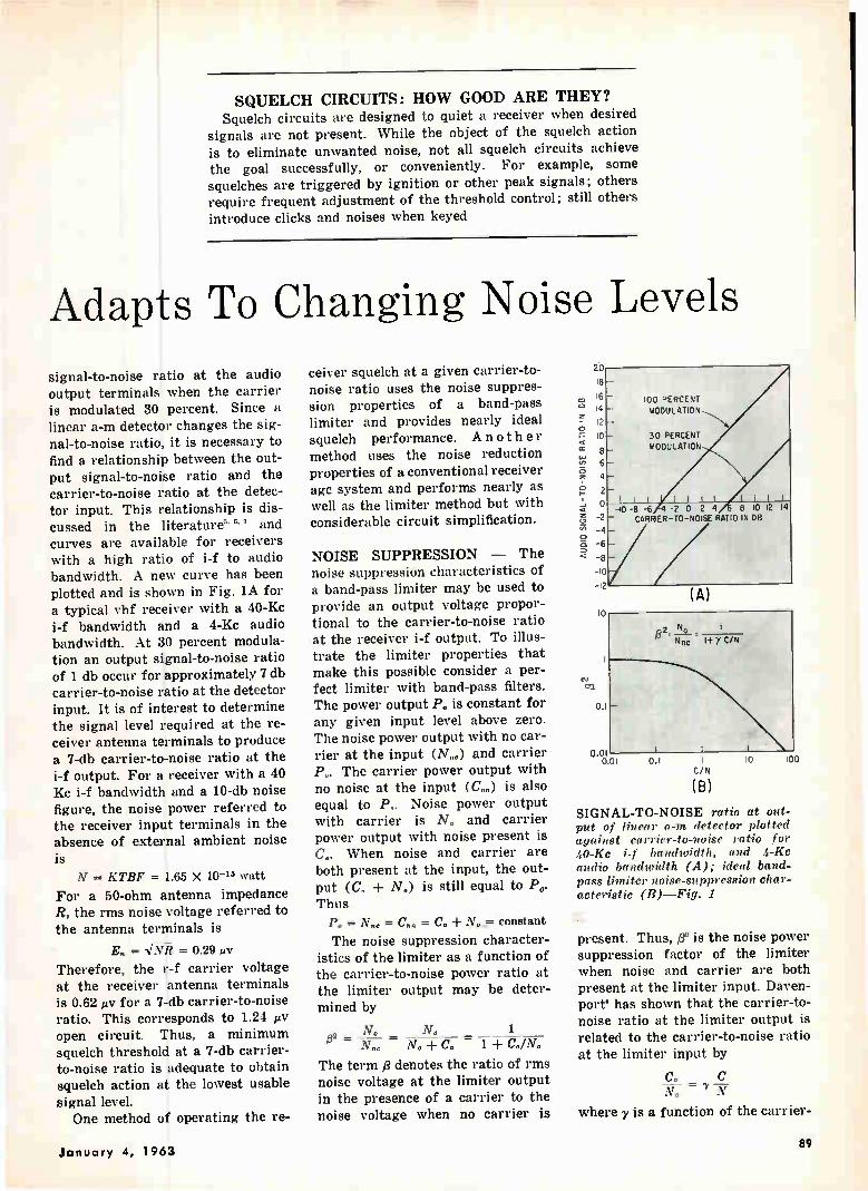
SQUELCH CIRCUITS: HOW GOOD ARE THEY? Squelch circuits are designed to quiet a receiver when desired
signals are not present. While the object of the squelch action is to eliminate unwanted noise, not all squelch circuits achieve the goal successfully, or conveniently. For example, some squelches are triggered by ignition or other peak signals; others require frequent adjustment of the threshold control; still others introduce clicks and noises when keyed
Adapts To Changing Noise Levels
signal-to-noise ratio at the audio output terminals when the carrier is modulated 30 percent. Since a linear a-m detector changes the sig-nal-to-noise ratio, it is necessary to find a relationship between the out-put signal-to-noise ratio and the carrier-to-noise ratio at the detec-tor input. This relationship is dis-cussed in the literature" and curves are available for receivers with a high ratio of i-f to audio bandwidth. A new curve has been plotted and is shown in Fig. lA for a typical vhf receiver with a 40-Kc i-f bandwidth and a 4-Kc audio bandwidth. At 30 percent modula-tion an output signal-to-noise ratio of 1 db occur for approximately 7 db carrier-to-noise ratio at the detector input. It is of interest to determine the signal level required at the re-ceiver antenna terminals to produce a 7-db carrier-to-noise ratio at the i-f output. For a receiver with a 40 Kc i-f bandwidth and a 10-db noise figure, the noise power referred to the receiver input terminals in the absence of external ambient noise is N = KTBF = 1.65 X 10-'5 watt
For a 50-ohm antenna impedance R, the rms noise voltage referred to the antenna terminals is
= NÉ = 0.29 r.tv
Therefore, the r-f carrier voltage at the receiver antenna terminals is 0.62 e for a 7-db carrier-to-noise ratio. This corresponds to 1.24 e open circuit. Thus, a minimum squelch threshold at a 7-db carrier-to-noise ratio is adequate to obtain squelch action at the lowest usable signal level. One method of operating the re-
ceiver squelch at a given carrier-to-noise ratio uses the noise suppres-sion properties of a band-pass limiter and provides nearly ideal squelch performance. A no ther method uses the noise reduction properties of a conventional receiver age system and performs nearly as well as the limiter method but with considerable circuit simplification.
NOISE SUPPRESSION — The noise suppression characteristics of a band-pass limiter may be used to provide an output voltage propor-tional to the carrier-to-noise ratio at the receiver i-f output. To illus-trate the limiter properties that make this possible consider a per-fect limiter with band-pass filters. The power output P. is constant for any given input level above zero. The noise power output with no car-rier at the input (N..) and carrier P„. The carrier power output with no noise at the input (C..) is also equal to Po. Noise power output with carrier is N. and carrier power output with noise present is C.. When noise and carrier are both present at the input, the out-put (C. ± N.) is still equal to Po. Thus p.= N., = C.. = N, constant
The noise suppression character-istics of the limiter as a function of the carrier-to-noise power ratio at the limiter output may be deter-mined by
No N, 1 132 _
N„c C,, — 1 + Co/N.
The term denotes the ratio of rms noise voltage at the limiter output in the presence of a carrier to the noise voltage when no carrier is
AUDIO SIGNAL-TO-NOISE RATIO I
N DB
20
18
16
14
12
10
8 6
4
2
o
-2
-4
-6
-8
-10
.2
10
(A)
100 PERCENT MODULATION
30 PERCENT MODULATION
I II -10 -8 -6 -2 0 2 4 8 10 12 14 — CARRIER-TO-NOISE RATIO IN 08
n2. No _ 1 Nnc 1+ y C/N
0.1 —
0.01 0.01 0.1 1
C/N
(B)
10
SIGNAL-TO-NOISE ratio at out-put of linear a-m detector plotted against carrier-to-noise ratio for 40-Kc i-f bandwidth, and 4-Kc audio bandwidth (A); ideal band-pass limiter noise-suppression char-acteristic (B)—Fig. 1
present. Thus, 03 is the noise power suppression factor of the limiter when noise and carrier are both present at the limiter input. Daven-port' has shown that the carrier-to-noise ratio at the limiter output is related to the carrier-to-noise ratio at the limiter input by
N„ N
where y is a function of the carrier-
January 4, 1963 89
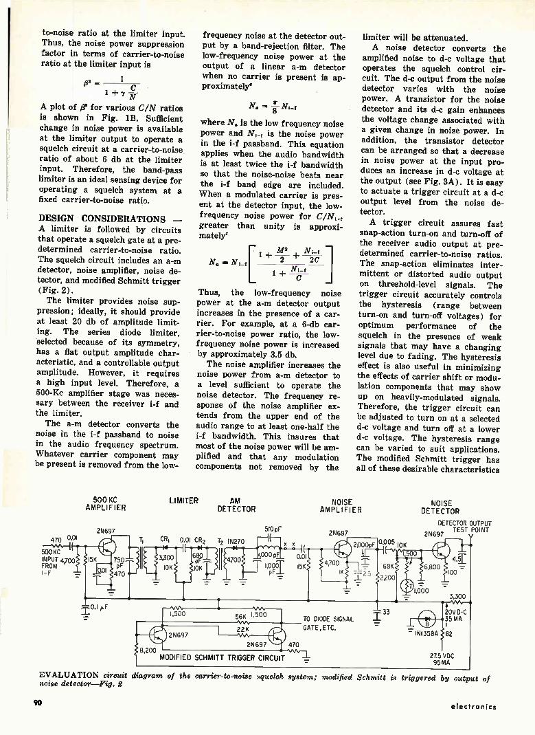
to-noise ratio at the limiter input. Thus, the noise power suppression
factor in terms of carrier-to-noise ratio at the limiter input is
/32 _ 1 + 7 w
A plot of fr for various C/N ratios is shown in Fig. 113. Sufficient change in noise power is available
at the limiter output to operate a squelch circuit at a carrier-to-noise ratio of about 6 db at the limiter input. Therefore, the band-pass
limiter is an ideal sensing device for operating a squelch system at a fixed carrier-to-noise ratio.
DESIGN CONSIDERATIONS — A limiter is followed by circuits
that operate a squelch gate at a pre-determined carrier-to-noise ratio. The squelch circuit includes an a-m detector, noise amplifier, noise de-tector, and modified Schmitt trigger (Fig. 2).
The limiter provides noise sup-pression; ideally, it should provide
at least 20 db of amplitude limit-ing. The series diode limiter, selected because of its symmetry, has a flat output amplitude char-acteristic, and a controllable output amplitude. However, it requires a high input level. Therefore, a 500-Kc amplifier stage was neces-sary between the receiver i-f and the limiter.
The a-m detector converts the noise in the i-f passband to noise in the audio frequency spectrum. Whatever carrier component may be present is removed from the low-
470 one
500 KC INPUT 4,700 FROM 1-F
500 KC AMPLIFIER
2N697
I5K 1750 pF 470
8 200 MODIFIED SCHMITT TRIGGER CIRCUI-
frequency noise at the detector out-put by a band-rejection filter. The
low-frequency noise power at the output of a linear a-m detector when no carrier is present is ap-proximately°
N. = N 8
where N. is the low frequency noise power and N, is the noise power in the i-f passband. This equation applies when the audio bandwidth is at least twice the i-f bandwidth
so that the noise-noise beats near the i-f band edge are included. When a modulated carrier is pres-
ent at the detector input, the low-frequency noise power for C/N,
greater than unity is approxi-mately'
[ N. = Ni-f 1 ± - 2- ± - 2C -
M2 Ni_, ]
1 -}- --C
Thus, the low-frequency noise power at the a-m detector output increases in the presence of a car-rier. For example, at a 6-db car-
rier-to-noise power ratio, the low-frequency noise power is increased by approximately 3.5 db.
The noise amplifier increases the noise power from a-m detector to a level sufficient to operate the
noise detector. The frequency re-sponse of the noise amplifier ex-tends from the upper end of the
audio range to at least one-half the i-f bandwidth. This insures that most of the noise power will be am-plified and that any modulation components not removed by the
LIMITER AM DETECTOR
510 pF
CR 1 0.01 CR2 12 IN270
3,300
§0b
2N697
56K 1:5":3'v°
limiter will be attenuated. A noise detector converts the
amplified noise to d-c voltage that operates the squelch control cir-
cuit. The d-e output from the noise detector varies with the noise power. A transistor for the noise detector and its d-c gain enhances the voltage change associated with
a given change in noise power. In addition, the transistor detector
can be arranged so that a decrease in noise power at the input pro-duces an increase in d-c voltage at the output (see Fig. 3A). It is easy to actuate a trigger circuit at a d-e output level from the noise de-tector.
A trigger circuit assures fast snap-action turn-on and turn-off of the receiver audio output at pre-determined carrier-to-noise ratios.
The snap-action eliminates inter-mittent or distorted audio output
on threshold-level signals. The trigger circuit accurately controls
the hysteresis (range between turn-on and turn-off voltages) for optimum performance of the squelch in the presence of weak signals that may have a changing level due to fading. The hysteresis effect is also useful in minimizing the effects of carrier shift or modu-lation components that may show
up on heavily-modulated signals. Therefore, the trigger circuit can
be adjusted to turn on at a selected d-c voltage and turn off at a lower d-c voltage. The hysteresis range can be varied to suit applications. The modified Schmitt trigger has all of these desirable characteristics
NOISE AMPLIFIER
2N697
2,000pF 0'0 10K 05
1
TO DIODE SIGNAL
22 K GATE , E TC.
2N697 470
NOISE DETECTOR
DETECTOR OUTPUT 2N697 TEST POINT
68K 6,800
2,200
1"
1,000
20V D-C 35 MA
IN1358A
27.5 VDC 95 MA
EVALUATION circuit diagram of the carrier-to-noise nuelch system; modified Schmitt is triggered by output of noise detector—Fig. 2
90 electronics
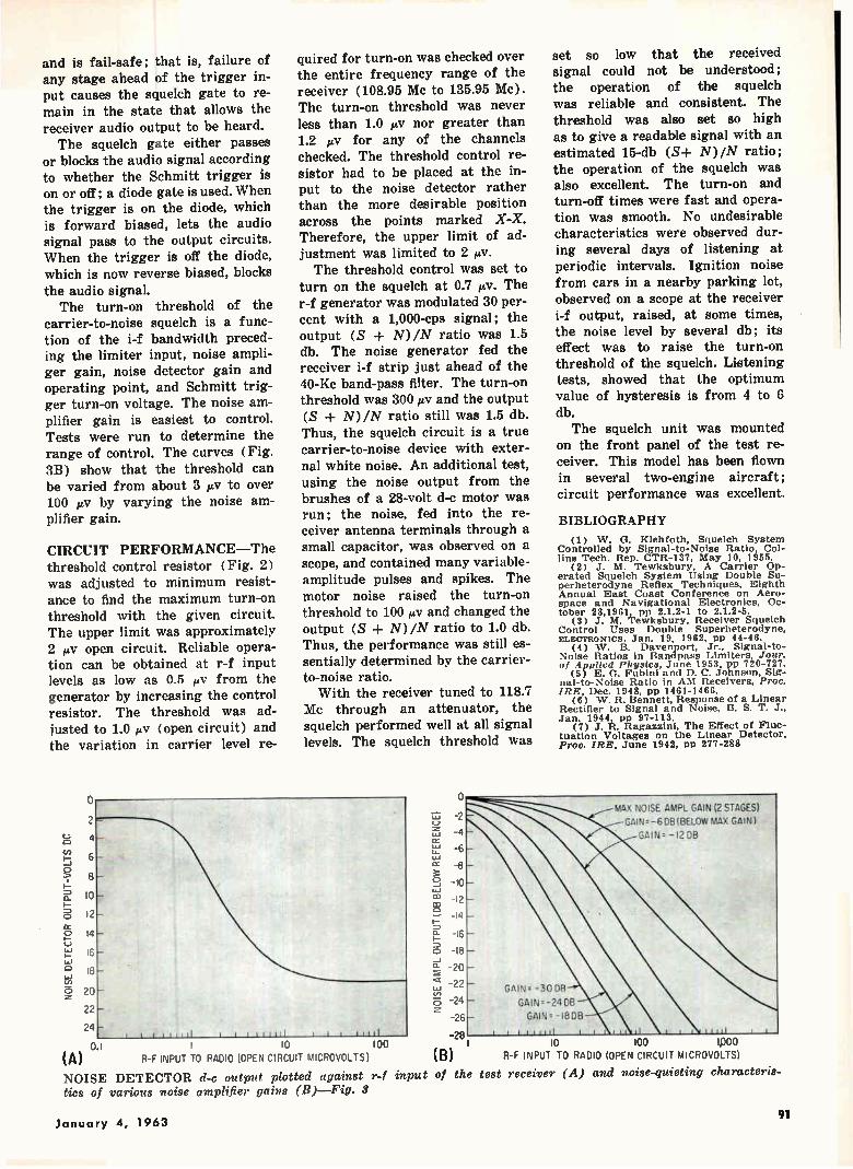
and is fail-safe; that is, failure of any stage ahead of the trigger in-put causes the squelch gate to re-main in the state that allows the receiver audio output to be heard. The squelch gate either passes
or blocks the audio signal according to whether the Schmitt trigger is on or off; a diode gate is used. When the trigger is on the diode, which is forward biased, lets the audio signal pass to the output circuits. When the trigger is off the diode, which is now reverse biased, blocks the audio signal. The turn-on threshold of the
carrier-to-noise squelch is a func-tion of the i-f bandwidth preced-ing the limiter input, noise ampli-ger gain, noise detector gain and operating point, and Schmitt trig-ger turn-on voltage. The noise am-plifier gain is easiest to control. Tests were run to determine the range of control. The curves (Fig. 3B) show that the threshold can be varied from about 3 µV to over 100 e by varying the noise am-plifier gain.
CIRCUIT PERFORMANCE—The threshold control resistor (Fig. 2) was adjusted to minimum resist-ance to find the maximum turn-on threshold with the given circuit. The upper limit was approximately 2 pAT open circuit. Reliable opera-tion can be obtained at r-f input levels as low as 0.5 tiv from the generator by increasing the control resistor. The threshold was ad-justed to 1.0 e (open circuit) and the variation in carrier level re-
NOIS
E DETECTOR OUTPUT-VOLTS DC
2
quired for turn-on was checked over the entire frequency range of the receiver (108.95 Mc to 135.95 Mc). The turn-on threshold was never less than 1.0 e nor greater than 1.2 /iv for any of the channels checked. The threshold control re-sistor had to be placed at the in-put to the noise detector rather than the more desirable position across the points marked X-X. Therefore, the upper limit of ad-justment was limited to 2 e. The threshold control was set to
turn on the squelch at 0.7 e. The r-f generator was modulated 30 per-cent with a 1,000-cps signal; the output (S + N)/N ratio was 1.5 db. The noise generator fed the receiver i-f strip just ahead of the 40-Kc band-pass filter. The turn-on threshold was 300 e and the output (S + N)/N ratio still was 1.5 db. Thus, the squelch circuit is a true carrier-to-noise device with exter-nal white noise. An additional test, using the noise output from the brushes of a 28-volt d-c motor was run; the noise, fed into the re-ceiver antenna terminals through a small capacitor, was observed on a scope, and contained many variable-amplitude pulses and spikes. The motor noise raised the turn-on threshold to 100 e and changed the output (S + N)/N ratio to 1.0 db. Thus, the performance was still es-sentially determined by the carrier-to-noise ratio. With the receiver tuned to 118.7
Mc through an attenuator, the squelch performed well at all signal levels. The squelch threshold was
6-
8 —
10 -
12
14
16
18
20
22
24 1 I 1 1 1 11 11 t 1 1 tul I I.
o 1 10 loo (A) R-F INPUT TO RADIO (OPEN CIRCUIT MICROVOLTS)
NOISE DETECTOR d-c output plotted against r-f input tics of various noise amplifier gains (B)—Fig. 3
0 mop
17.1 -2
-ti-ce
-8
-bau au -12 -14
o_
o F-
-18
-24
-26
28
(B)
of the
-6
set so low that the received signal could not be understood; the operation of the squelch was reliable and consistent. The threshold was also set so high as to give a readable signal with an estimated 15-db (S+ N)/N ratio; the operation of the squelch was also excellent. The turn-on and turn-off times were fast and opera-tion was smooth. No undesirable characteristics were observed dur-ing several days of listening at periodic intervals. Ignition noise from cars in a nearby parking lot, observed on a scope at the receiver i-f output, raised, at some times, the noise level by several db; its effect was to raise the turn-on threshold of the squelch. Listening tests, showed that the optimum value of hysteresis is from 4 to 6 db. The squelch unit was mounted
on the front panel of the test re-ceiver. This model has been flown in several two-engine aircraft; circuit performance was excellent.
BIBLIOGRAPHY (1) W. G. Klehfoth, Squelch System
Controlled by Signal-to-Noise Ratio, Col-lins Tech. Rep. CTR-137, May 10, 1955.
(2) J. M. Tewksbury, A Carrier Op-erated Squelch System Using Double Su-perheterodyne Reflex Techniques, Eighth Annual East Coast Conference on Aero-space and Navigational Electronics. Oc-tober 23,1901, pp 2.1.2-1 to 2.1.2-5.
(3) J. M. Tewksbury, Receiver Squelch Control Uses Double Superheterodyne, ELECTRONICS, Jan. 19, 1962, pp 44-46.
(4) W. B. Davenport, Jr., Signal-to-Noise Ratios in Bandpass Limiters, Jour. of Applied Physics, June 1953, pp 720-727.
(5) E. G. Fubini and D. C. Johnson, Sig-nal-to-Noise Ratio in AM Receivers, Proc. IRE, Dec. 1948, pp 1461-1466.
(0) W. R. Bennett, Response of a Linear Rectifier to Signal and Noise, B. S. T. J., Jan. 1944, pp 97-113.
(7) J. R. Ragazzini, The Effect of Fluc-tuation Voltages on the Linear Detector, Proc. IRE, June 1942, pp 277-288
MAX NOISE AMPL GAIN (2 STAGES)
GAINr-6 08 (BELOW MAX GAIN)
GAIN.-I2 08
GAIN. -3008
GAIN=-24 DE)
GAIN. -I8DB
j ji juil it ti 11 i ut titi
io ioo ipoo R-F INPUT TO RADIO (OPEN CIRCUIT MICROVOLTS)
test receiver (A) and noise-quieting characteris-
January 4, 1963 91

IMPROVED Air Traffic Communication
Communications network will be improved in a number of ways now under study.
Weather network will undergo comprehensive long-range buildup
By JOHN F. MASON, Senior Associate Editor
THE PILOT of a six-hour jet flight from New York to San Francisco talks to air traffic control men on the ground approximately fifty times. On a one-hour flight from New York to Washington, he uses his voice communications gear eleven times. He averages, on the long flight, one voice contact with the ground
every seven minutes; on the short flight, one every five minutes. The result of all this loquacity is that the pilot
and controller are often talking when they need to be doing something else; the available frequencies are loaded; and the entire air traffic control system slows
WSR-57 WEATHER radar at FAA's experimental sta-tion can detect precipitation at ranges up to 200 miles
down. The situation is bad today, and will undoubt-edly get worse, since by 1975, the number of hours flown per year will increase by one third.
Solution to the problem will not be sought by advanced data link—although such equipment will be developed for the future; nor will additional fre-quency allocations be requested. Instead, the need for voice communications will be reduced. The pilot who now makes fifty voice reports on
a transcontinental flight will make approximately 16 in the future. He can dispense with the remaining 34 since his beacon transponder will automatically tell the controller his altitude and identity; ground radar will reveal his position; and his computer-processed flight plan will be transmitted from center to center and presented to controllers on electronic displays (ELECTRONICS, p 37, Dec. 7). Point-to-point data link will also relieve the pilot of much time-consuming conversation with other ground facilities.
In view of the lightened load on voice communi-cation, vhf-uhf will continue to be the basic means of control through 1975. The system will, never-theless, be improved.
VOICE - SYSTEM IMPROVEMENTS — Six tech-niques are being considered for increasing the capa-bility of uhf-vhf radio.
• Minor improvements of the current system—Vhf will be changed from 100-Kc channel selectivity to 50 Kc by 1966. (Uhf will continue to operate with 100 Kc separation.) This will increase the number of available channels from 185 to 253. More channels would become available if it were possible to assign vhf transmitters and receivers on adjacent 50 Kc frequencies at the same ground site. To do this, a new generation of ground receivers and transmit-ters with more exacting specifications than present gear would have to be built, and sharply-tuned antenna coupling devices would have to be developed. Such gear is now being tested at FAA's National Aviation Facilities Experimental Center (NA FEC), near Atlantic City, N. J.
Other minor improvements under study include the possibility of using directional antenna patterns to reduce the number of required frequencies; and the possible benefit of separately operating the vhf/uhf switches of each paired assignment. • Increase sector size and capacity—Larger sectors
would reduce the number of channels needed, by put-ting more planes on the same channel. It is hoped that with computers, displays and data link, one controller can increase his sector capacity from seven to 20 aircraft.
electronics
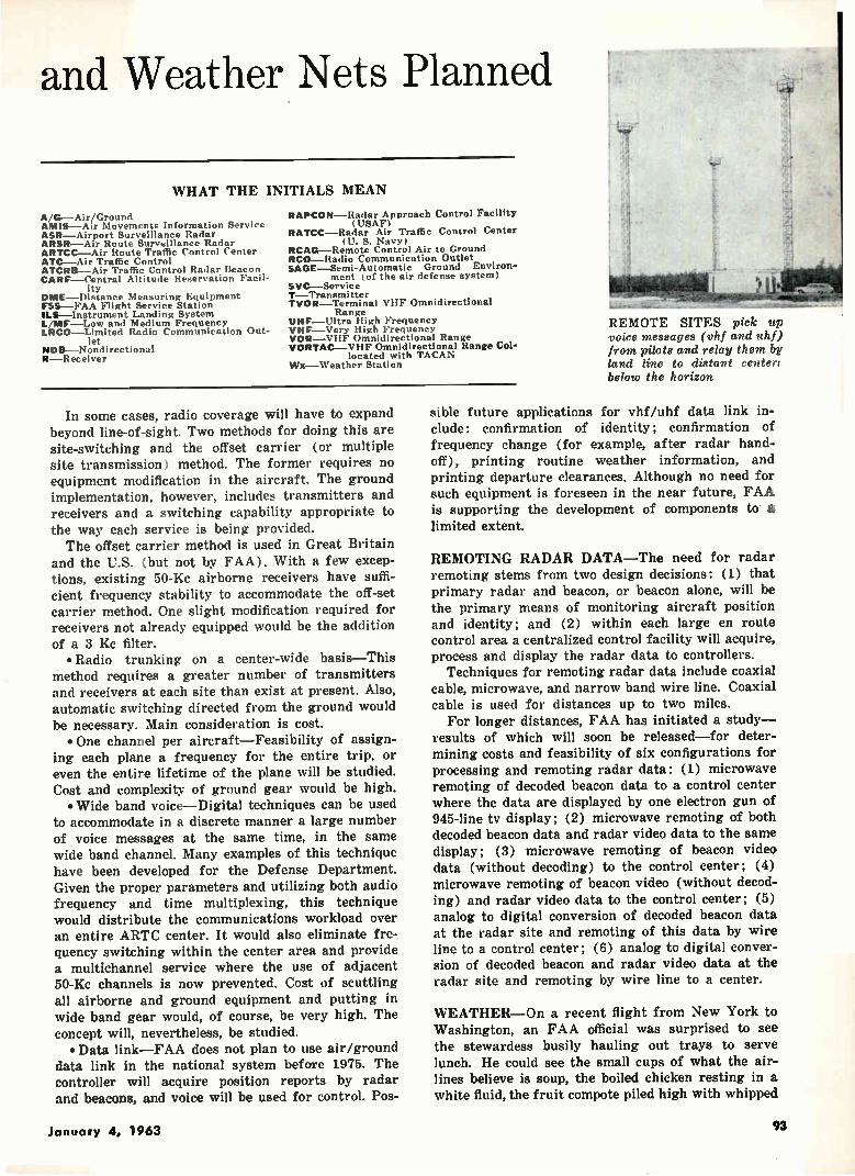
and Weather Nets Planned
WHAT THE INITIALS MEAN
A/G--Air/Ground AMIS—Air Movements Information Service ASR—Airport Surveillance Radar ARSR—Air Route Surveillance Radar ARTCC—Air Route Traffic Control Center ATC—Air Traffic Control ATCRB--Air Traffic Control Radar Beacon CARF—Central Altitude Reservation Facil-
ity DME —Distance Measuring Equipment FSS—FAA Flight Service Station ILS—Instrument Landing System L MF—Low and Medium Frequency LRCO—Limited Radio Communication Out-
let NDB—Nondirectional R--Receiver
RAPCON—Radar Approach Control Facility (USAF)
RATCC—Radar Air Traffic Control Center (G. S. Navy)
RCAG—Remote Control Air to Ground HCO—Radio Communication Outlet SAGE—Semi-Automatic Ground Environ-
ment (of the air defense system) SVC—Service T-- Transmitter TV OR—Terminal VHF Omnidirectional
Range UHF—Ultra High Frequency VHF—Very High Frequency VOR —VilF Omnidirectional Range V ORTAC—VHF Omnidirectional Range Col-
located with TACAN Wx—Weather Station
In some cases, radio coverage will have to expand beyond line-of-sight. Two methods for doing this are site-switching and the offset carrier (or multiple site transmission) method. The former requires no equipment modification in the aircraft. The ground implementation, however, includes transmitters and receivers and a switching capability appropriate to the way each service is being provided. The offset carrier method is used in Great Britain
and the U.S. (but not by FAA). With a few excep-tions, existing 50-Kc airborne receivers have suffi-cient frequency stability to accommodate the off-set carrier method. One slight modification required for receivers not already equipped would be the addition of a 3 Kc filter. • Radio trunking on a center-wide basis—This
method requires a greater number of transmitters and receivers at each site than exist at present. Also, automatic switching directed from the ground would be necessary. Main consideration is cost. • One channel per aircraft—Feasibility of assign-
ing each plane a frequency for the entire trip, or even the entire lifetime of the plane will be studied. Cost and complexity of ground gear would be high. • Wide band voice—Digital techniques can be used
to accommodate in a discrete manner a large number of voice messages at the same time, in the same wide band channel. Many examples of this technique have been developed for the Defense Department. Given the proper parameters and utilizing both audio frequency and time multiplexing, this technique would distribute the communications workload over an entire ARTC center. It would also eliminate fre-quency switching within the center area and provide a multichannel service where the use of adjacent 50-Kc channels is now prevented. Cost of scuttling all airborne and ground equipment and putting in wide band gear would, of course, be very high. The concept will, nevertheless, be studied. • Data link—FAA does not plan to use air/ground
data link in the national system before 1975. The controller will acquire position reports by radar and beacons, and voice will be used for control. Pos-
REMOTE SITES pick up voice messages (vhf and uhf) from pilots and relay them by land line to distant center: below the horizon
sible future applications for vhf/uhf data link in-clude: confirmation of identity; confirmation of frequency change (for example, after radar hand-off), printing routine weather information, and printing departure clearances. Although no need for such equipment is foreseen in the near future, FAA is supporting the development of components to a limited extent.
REMOTING RADAR DATA—The need for radar remoting stems from two design decisions: (1) that primary radar and beacon, or beacon alone, will be the primary means of monitoring aircraft position and identity; and (2) within each large en route control area a centralized control facility will acquire, process and display the radar data to controllers.
Techniques for remoting radar data include coaxial cable, microwave, and narrow band wire line. Coaxial cable is used for distances up to two miles.
For longer distances, FAA has initiated a study— results of which will soon be released—for deter-mining costs and feasibility of six configurations for processing and remoting radar data: (1) microwave remoting of decoded beacon data to a control center where the data are displayed by one electron gun of 945-line tv display; (2) microwave remoting of both decoded beacon data and radar video data to the same display; (3) microwave remoting of beacon video data (without decoding) to the control center; (4) microwave remoting of beacon video (without decod-ing) and radar video data to the control center; (5) analog to digital conversion of decoded beacon data at the radar site and remoting of this data by wire line to a control center; (6) analog to digital conver-sion of decoded beacon and radar video data at the radar site and remoting by wire line to a center.
WEATHER—On a recent flight from New York to Washington, an FAA official was surprised to see the stewardess busily hauling out trays to serve lunch. He could see the small cups of what the air-lines believe is soup, the boiled chicken resting in a white fluid, the fruit compote piled high with whipped
January 4, 1963 93

L/M NOB 88
cream, and the cups for the scalding water later. Although forbidding under the best of conditions,
the menu was particularly formidable because of what was going to take place in fifteen minutes. The stewardess had apparently not been told that the thunderstorm ahead would put every tray and every delicacy on it into a quick state of weightlessness, followed, just as suddenly, by at least two g's. The official knew this because he had visited friends in the airport weather station before boarding the plane. The pilot, he learned later, had not had time between flights to check the weather. To avoid perils of travel such as this one, and
others that are far worse, FAA is developing the Common Aviation Weather System (CAWS). "The objective of the system is to communicate weather data to the airspace user," FAA's W. Eggert, head of research for CAWS, said. "The CAWS is actually an engineering problem. We are not trying to improve the science of meteorology." The system is being coordinated with the Weather
Bureau, the Defense Department, and other govern-ment agencies. When operative, it will service all airspace users, both civil and military, in the United States through the 1975 period. FAA has taken over the Air Force's 433-L Weather Observation and Fore-casting System in the U. S., the Air Force will handle it for its operations overseas. The CAWS will consist of four subsystems: observ-
ing, processing, presenting, and communicating.
OBSERVING—By 1975, there will be 1,000 surface observing stations-600 will be automatic stations at terminals and generate observations on a five-minute cycling time; 200 will be manual stations at ter-minals, and 200 will be automatic remote stations— all 400 providing hourly observations.
There will be 100 upper-air radiosonde/rocketsonde stations at hub terminals; 100 pilot-to-forecaster service stations at hub terminals; and 100 longrange radar stations at hub terminals and gap filling radars as dictated by topography. Implementation of this equipment will begin in 1964 and be finished in 1970.
PROCESSING—The CAWS design includes a single
FAA WANTS to simplify this complex communications network in the new system
MILITARY BASE
OPERATIONS OFFICE
A/G VOICE
RCO AT AIRPORT
36
mir
vol T0ORTOME ,i0RTAC
700
A/G r VOICE: d i Ili
VHF/UHF T R
AREA
•
MILITARY
VHF/UHF T " R
¿CREA B T R
ARSR-4142 ATCR8-I
CENTER B CENTER B
SVC F 4 L
TwR I
COMBINED STATION / TOWER
71
CENTER COMPUTER B AREA B
ATCRB 5
ASH-1,2,5,4
68
AIRLINE FLIGHT DISPATCH OFFICE
national processing center, four regional processing centers, and 100 local centers at hub terminals. Proc-essing subsystem design and implementation is de-pendent upon the availability of adequate forecasting techniques—many of which do not exist today. Im-plementation of the subsystem will begin in 1965, and finish in 1975.
PRESENTING—Displays must be numerous, stand-ard and readily understandable. There are five dis-play situations in the CAWS: pilot groudd briefing, which will use direct display, tv, telephone and radio; airborne pilot briefing—radio; ATC towers, ATC centers and processing centers will all use direct dis-plays and tv.
The design provides for up to 750 ground briefing stations, 100 continuous weather broadcasting sta-tions and 100 pilot-to-forecaster stations. It antici-pates a total of up to 750 tower displays and 20 to 30 center installations.
COMMUNICATING—The CAWS design includes an evolutionary transition from the present multiple civil and military communication circuits to a con-figuration that uses only two primary circuits—both transmitting alphanumeric and graphic messages. One of these circuits is used by aviation meteor-ologists, civil and military, for collecting observations and exchanging intra-processing products. The other circuit transmits only operational products to CAWS users—pilots, dispatchers, and the ATC system. Both circuits use the normal telephone line bandwidth.
Telephone links with automatic telephone briefing equipment will be used for pilot ground briefings. Radio links (L/MF, vhf, uhf) will be used for pilot-to-forecaster, continuous weather broadcast and ad-vanced planning transmissions.
Around-the-base circuits, ATC tower and center displays and local processing centers will use tv, mainly to present local weather radar data.
LAST IN A SERIES OF THREE ARTICLES. First appeared on Dec. 7, second on Dec. 14
FIXED BASE
OPERATOR
AIRLINE FLIGHT
DISPATCH OFFICE
MANUAL AIR
DEFENSE CENTER
LEGEND TELETYPE TELEPHONE OR INTERPHONE
-x-x-A-A-A- COAXIAL LINE •
-•-•-••-•-*-- TEL AUTOGRAPH
TRANSMISSOMETER receiver (f ore-gr ound) measures strength of light from transmissometer transmitter (background) to determine visibility
94 electronics
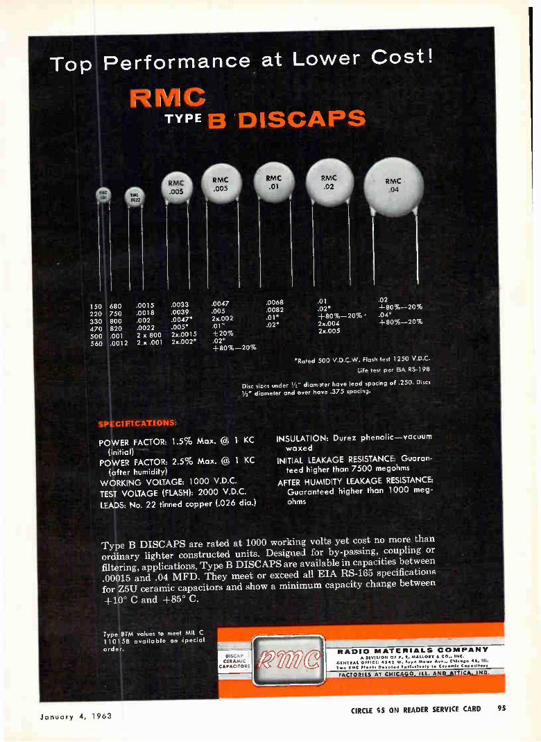
Top Performance at Lower Cost!
RMC TYPE B DISCAPS
ltMC .301
RMC 0022
150 680 .0015 .0033 .0047 220 750 .0018 .0039 .005 330 800 .002 .0047* 2x.002 470 820 .0022 .005* .01 * 500 .001 2 x 800 2x.0015 +20% 560 .0012 2 x .001 2x.002* .02*
-I-80%-20%
.0068
.0082
.01*
.02*
.01
.02* +80%-20% - 2x.004 2x.005
.02 ±80%-20% .04* +80%-20%
*Raed 50) V D.C.W. Flash test 1250 V.D.C.
Life test per EIA R5-198
Disc sizes unier diameer have lead spacing of .250. Discs
1/2" diameter 2nd over have .375 spachg.
SPEC F I CATIONSi
POWER FACTOR: 1.5% Max. @ 1 KC (initial)
POWER FACTOR: 2.5% Max. @ 1 KC (after humidity)
WORKING VOLTAGE: 101) V.D.C. TEST VOLTAGE (FLASH): 2000 V.D.C.
LEADS: No. 22 tinned copper (.026 dia.)
INSULATION: Durez phenolic—vacuum waxed
INITIAL LEAKAGE RESISTANCE: Guaran-teed higher than 7500 megohms
AFTER HUMID'TY LEAKAGE RESISTANCE: Guaranteed higher than 1000 meg-ohms
Type B DISCAPS are rated at 1000 working volts yet cost no more than ordinary lighter constructed units. Designed for by-passing, coupling or filtering, applications, Type B DISCAPS are available in capacities between .00015 and .04 MFD. They meet or exceed all EIA RS-163 specifications for Z5U ceramic capacitors and show a minimum capacity change between
+10° C and +85° C.
Type BTM values to meet MIL C 11015B available on special order. Imo(
DISCAP CERAMIC
CAPACITORS
RADIO MATERIALS COMPANY A DIVISION OF P. R. MALLORY IL CO., INC.
GENERAL OFFICE: 4242 W. Bryn Mawr Ave., Chicago 46, III. Two RMC Plants Exclusively to Ceramic Capacitors
Kill1111M1
January 4, 1963 CIRCLE 95 ON READER SERVICE CARD 95

RESEARCH AND DEVELOPMENT
New Approaches to Electronic Self-Repair
Natural physical phenomena may increase electronic reliability
AS MILITARY and space re-quirements necessitate the con-struction of more and more com-plex systems, the contemporary philosophies of reliability and main-tainability will become inadequate for successful performance of mis-sion objectives. Most severely af-fected will be the systems on which maintenance cannot be performed, such as satellite-borne systems, and strategic military systems where the luxury of even a small downtime cannot be afforded. A paper investigating various
models of self-repair presented at the Aerospace Science and Engi-neering Symposium at Brooks AFB , by Jerome Klion, of the Rome Air • Development Center, Griffiss AFB, included the following:
Practical self-repair consists of sensing f ail ur e, discarding the failed component, and replacing it with a working one. The compara-ble requirements in redundant sys-tems have been met with relays, solenoids, and other complex de-vices. However, dependence on these devices has been the major draw-back to satisfactory redundant con-figurations.
An alternate approach is the use of natural phenomena to effect switching, sensing and interconnec-tion. These may be more reliable and more easily implemented than conventional methods.
One phenomenon that could be used to sense failure is the Peltier effect. Electronic component failure is generally followed or immediately preceded by a change in tempera-ture; by using thermocouples, this temperature change reflected in terms of a voltage outside a preset range can activate replacement. It appears there are more means of reliably implementing replacement and discard than of sensing failure.
M11, -OXIDIZING AGENTS
LEVEL 2
LEVEL I
CONDUCTING MAIL
LOW DENSITY
HIGH DENSITY
• (A)
A-•
Lip
LEVEL I
,E
COMPONENT
MEMBRANE
HEATING ELEMENT
VOLATILE LIQUID
J
(B)
OSMOSIS SELF-REPAIR uses oxidation and osmosis for interconnecting electronic components, (A); diffusion self-repair depends on vaporizing measured amounts of volatile liquid, (B)—Fig. 1
Replacement or discard might be accomplished by an efficient and re-liable phenomenon such as osmosis, gaseous diffusion, tropisms, gravity, induction, or anisotrophy.
OSMOSIS SELF-REPAIR—In os-mosis self-repair, a u to ma tic switching is accomplished by an air pressure differential caused by failure of an on-line electronic component. If the pressure differ-ential fails to occur, a process of osmosis working independently of the pressure differential provides a backup to restore operation.
In Fig. 1A, section AB is a cylin-drical tube with a pressure-sensi-tive semipermeable membrane, valve or one-way diaphragm Mi, N equally spaced paths along the length of the section, each con-nected to a separate electronic com-ponent in section E, a column of mercury or other conducting mate-rial, and N oxidizing agents each connected electrically to a failure-sensing device in each component.
Section CD contains solutions of
high and low densities separated by a semipermeable membrane. Sec-tion BC contains a gaseous medium, a pressure-sensitive semipermeable membrane, valve, or one-way dia-phragm lit, and the current level of osmosis.
Initially the column of conducting material is at level 1, providing a conductive path for the necessary power to operate component 1. No power is being provided to the re-maining components. If an active component fails, the failure sensor for that component activates its re-spective oxidizing agent. The ensu-ing oxidation consumes a prescribed portion of the environmental me-dium in section AB, decreasing the environmental pressure between the column of conducting material and the upper end of section AB. The pressure loss causes conducting ma-terial to rise to level 2 and complete the upper electrical circuit. At the same time, the failed component is disconnected, stopping the oxida-tion process.
If the oxidizing agent fails, os-
96 electronics

D A of pulse amplitudes of pulse risetimes
2 millivolts
peak-to-peak.
A D of time differences
50 picoseconds up to
100 microseconds. 0.4 nanosecond.
TYPE 367 KAIDOtet
••••••
TYPE 3777 ••••••••• SWEEP
TYPE API DIGITAL UNIT
y
TEKTRONIX READOUT OSCILLOSCOPE
with Dual-Trace Sampling With this new Tektronix Readout Oscilloscope you can measure pulse ampli-
tudes and time increments faster and easier. For, after selecting measurement points on the displayed waveform once for all successive similar measurements, you make the tests and read the digital data directly. Indicators light to designate the readout status—whether in the preset-limit range, below it, or above it.
In a typical test application, such as measuring transistor switching times, you can read directly such characteristics as the delay, rise, storage, and fall times; the total turn-on and turn-off times; the width of pulse A and pulse B; and time and amplitude between two selected points on either waveform. You know immediately by the digital presentation and indicator rrets whether or not the
item tested has met specifications.
Also, the Tektronix Readout Oscilloscope—with digital and sampling plug-in units—can be externally programmed for automatic sequential operation.
On a production line, in a laboratory, or for sustained testing programs, the
digital convenience of this Tektronix Readout Oscilloscope can speed up and simplify your measurement applications.
Type 567 Readout Osci'loscope (without plug-ins) $ 700
Plug-In Units include:
Type 6R1 Digital Unit $2500
Type 3S76 Sampling Dual-Trace Unit $1100
Type 3777 Sampling Sweep Unit . . . $ 650
U.S. Sales Prices f.o.b. Beaverton, Oregon
FOR A DEMONSTRATION— PLEASE CALL YOUR TEKTRONIX FIELD ENGINEER
Soon Available-2 new plug-in units to extend digital readout of signal information to low and medium fre-quency applications.
P. 0. BOX 500 • BEAVERTON, OREGON / Mitchell 4-0161 • TWX-503-291-6805 • Cable: TEKTRONIX. Tektronix, Inc./ OVERSEAS DISTRIBUTORS IN 27 COUNTRIES AND HONOLULU, HAWAII. Tektronix Field Offices are located in principal cities throughout the United States. Please consult your Telephone Directory. Tektronix Canada Ltd: Montreal, Quebec • Toronto (Willowdale) Ontario • Tektronix International A. G., Terrassenweg 1A, Zug, Switzerland.
January 4, 1963 CIRCLE 97 ON READER SERVICE CARD 97
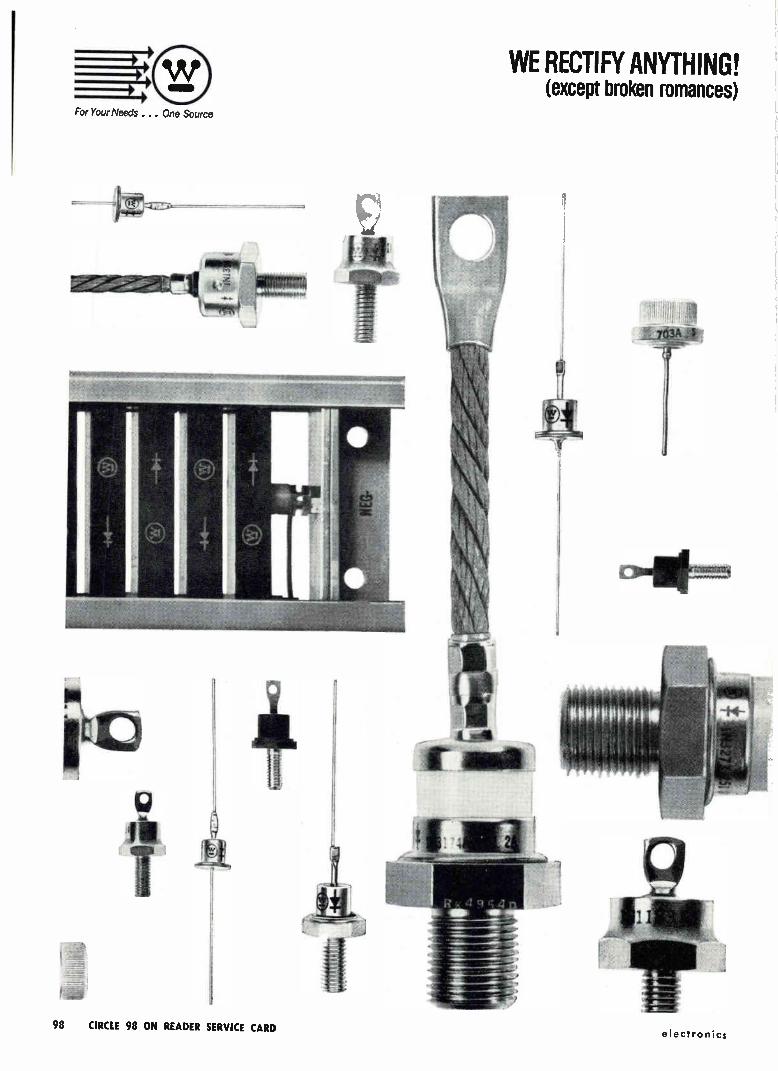
For Your Needs . . . One Source
WE RECTIFY ANYTHING! (except broken romances)
98 CIRCLE 98 ON READER SERVICE CARD electronics
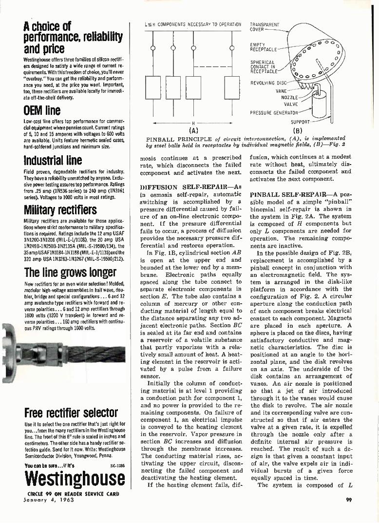
Free rectifier selector
A choice of performance, reliability and price Westinghouse offers three families of silicon rectifi-ers designed to satisfy a wide range of current re-quirements. With this freedom of choice, you'll never "overbuy." You can get the reliability and perform-ance you need, at the price you want. Important, too, these rectifiers are available locally for immedi-ate off-the-shelf delivery.
OEM line Low-cost line offers top performance for commer-cial equipment where pennies count. Current ratings of 5, 10 and 15 amperes with voltages to 600 volts are available. Units feature hermetic sealed cases, hard-soldered junctions and minimum size.
Industrial line Field proven, dependable rectifiers for industry. They have a reliability unmatched by anyone. Exclu-sive power testing assures top performance. Ratings from .25 amp (1N536 series) to 240 amp (IN3161 series). Voltages to 1000 volts in most ratings.
Military rectifiers Military rectifiers are available for those applica-tions where strict conformance to military specifica-tions is required. Ratings include the 12 amp USAF 1N1200-1N1206 (MIL-E-1/1108), the 20 amp USA 1N249B-1N250B-1N2135A (MIL-S-19500/134), the 35 amp USAF IN 1184-IN 1188 (MI L-E-I/1135)and the 120 amp USA 1N3263-I N3267 (MIL-S-19500/212).
The line grows longer New rectifiers for an even wider selection! Molded, modular high-voltage assemblies in half wave, dou-bler, bridge and special configurations ... 6 and 12 amp avalanche type rectifiers with forward and re-verse polarities ... 6 and 12 amp rectifiers through 1000 volts (1200 V transient) in forward and re-verse polarities ... 160 amp rectifiers with continu-ous PRV ratings through 1600 volts.
Use it to select the one rectifier that's just right for you...from the many rectifiers in the Westinghouse line. The front of this 6" rule is scaled in inches and centimeters. The other side has a handy rectifier se-lection guide. Send for it now. Write: Westinghouse Semiconductor Division, Youngwood, Penna.
You can be sure... if it's SC-1086
Westinghouse
H COMPONENTS NECESSARY TO OPERATION
H
(A)
TRANSPARENT COVER
EMPTY RECEPTACLE
SPHERICAL CONTACT IN RECEPTACLE
REVOLVING DISC--
VANE —
NOZZLE
VALVE
PRESSURE GENERATOR
SUPPORT
(B)
PINBALL PRINCIPLE of circuit interconnection, (A), is implemented by steel balls held in receptacles by individual magnetic fields, (B)—Fig. 2
mosis continues at a prescribed rate, which disconnects the failed component and activates the next.
DIFFUSION SELF-REPAIR—As in osmosis self-repair, automatic switching is accomplished by a pressure differential caused by fail-ure of an on-line electronic compo-nent. If the pressure differential fails to occur, a process of diffusion provides the necessary pressure dif-ferential and restores operation.
In Fig. 1B, cylindrical section AB is open at the upper end and bounded at the lower end by a mem-brane. Electronic paths equally spaced along the tube connect to separate electronic components in section E. The tube also contains a column of mercury or other con-ducting material of length equal to the distance separating any two ad-jacent electronic paths. Section BC is sealed at its far end and contains a reservoir of a volatile substance that partly vaporizes with a rela-tively small amount of heat. A heat-ing element in the reservoir is acti-vated by a pulse from a failure sensor.
Initially the column of conduct-ing material is at level 1 providing a conduction path for component 1, and no power is provided to the re-maining components. On failure of component 1, an electrical impulse is conveyed to the heating element in the reservoir. Vapor pressure in section BC increases and diffusion through the membrane increases. The conducting material rises, ac-tivating the upper circuit, discon-necting the failed component and deactivating the heating element.
If the heating element fails, dif-
fusion, which continues at a modest rate without heat, ultimately dis-connects the failed component and
activates the next component.
PINBALL SELF-REPAIR—A pos-sible model of a simple "pinball" binomial self-repair is shown in the system in Fig. 2A. The system is composed of H components but only L components are needed for
operation. The remaining compo-nents are inactive.
In the possible design of Fig. 2B, replacement is accomplished by a pinball concept in conjunction with an electromagnetic field. The sys-tem is arranged in the disk-like platform in accordance with the configuration of Fig. 2. A circular aperture along the conduction path of each component breaks electrical
contact to each component. Magnets are placed in each aperture. A sphere is placed on the discs, having satisfactory conductive and mag-netic characteristics. The disc is positioned at an angle to the hori-zontal plane, and the disk revolves on an axis. The underside of the disk contains an arrangement of vanes. An air nozzle is positioned so that a jet of air introduced through it to the vanes would cause the disk to revolve. The air nozzle and its corresponding valve are con-structed so that if air enters the valve at a given rate, it is expelled through the nozzle only after a definite internal air pressure is reached. The result of such a de-sign is that given a constant input of air, the valve expels air in indi-vidual bursts of a given force equally spaced in time. The system is composed of L
CIRCLE 99 ON READER SERVICE CARD January 4, 1963 99

Brogan Associates, Inc.
how to match a PAV to tough GSE specs
From its all solid state circuitry to its MIL-type hermetically sealed meter and plug-in
amplifiers, every design feature of the Model VM-235 Phase Angle Voltmeter has
been selected for rigorous service in Aerospace Ground Equipment.
Your North Atlantic man can quickly demonstrate how this rugged, miniaturized
version of North Atlantic's famous PAV provides direct, accurate reading of phase
angle, nulls, total, fundamental, quadrature and in-phase voltages—even under the
roughest of military field conditions.
The VM-235's ability to meet tough system specs is demonstrated daily in opera-
tional and support equipment for USAF and Navy aircraft and missile programs. Its
capabilities for complex measurements are shown in the abridged specifications below:
Voltage Range 1 my to 300 v f.s., 12 ranges
Voltage Accuracy ±2% f.s.
Phase Accuracy dial: 1-- 1°; meter: -±3% of F.S. degrees Signal Frequency 400 cps
Input Impedance 1 megohm
Reference Input 26 y or 115 y
Meter scale 3-0-3, 10-0-10 linear
Phase Angle Dial 2 scales, 90° (elec.) apart
Nulling Sensitivity 2 microvolts (phase sensitive)
Harmonic Rejection 55db (with filters)
Dimensions ay,e h. x 81h" w. x 6%" d.
North Atlantic's field engineering representative in your area has full data on the VM-235, as well as modified versions for specific systems requirements.
For his name, call or write today, or request Bulletin VM-235.
NOR.T11 ATLANTIC industries, inc. TERMINAL DRIVE, PLAINVIEW, L. I., NEW YORK • OVerbrook 1-8600
spherical contacts, seated in recep-tacles around the circumference of the disk, and acting as conducting paths that activate L components. An independent magnetic field in each receptacle holds its respective sphere firmly in position. When a component fails, the failure sensor reverses the magnetic field of its receptacle and also supplies air to revolve the disk. On reaching its apex with no applied magnetic field (or at any point if the reversed magnetic field is enough to expel the receptacle), the affected sphere drops out and seeks another recep-tacle with a favorable magnetic field. At this time, the disk stops and system operation is restored.
BIOLOGICAL SELF - REPAIR — The best-known self-repairing de-vice, and in spite of its shortcom-ings the most reliable to date, is the human body. On the system level, a remarkable example of an expand-ing, never-dying system is the hu-man race. The human body has an average
life of 70 years. During this time, the skin appears almost constant and continues to perform its func-tion, yet the mean time to wear-out or replacement of each surface cell is measured in months. Moreover, in the event of a cut, built-in failure sensors immediately begin removal of damaged cells and re-placement with working cells.
It is not outside the realm of pos-sibility to consider an electronic system having similar characteris-tics. The system could be a matrix arrangement of organic semicon-ductor blocks that could function successfully if enough blocks were operative. In the event of a random, wearout or incipient failure of one or more blocks, a built-in sensing system inherent to the makeup of the material would initiate forma-tion of a new block. Wearout or in-cipient failures could be predicted or sensed in advance and an auto-matic replacement rate chemically adjusted and maintained. One straight-forward approach to
self-repair involves a flux and an at-mosphere, where the flux could be contained within a given element not unlike that within hollow-core solder and released by breakage of the element. This approach is analo-
gous to blood glucose and air facili-
100 CIRCLE 100 ON READER SERVICE CARD electronics
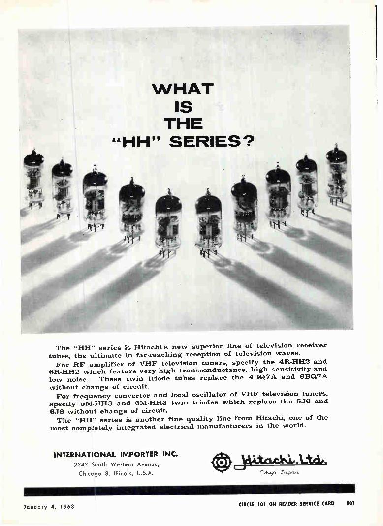
WHAT IS THE
"HH" SERIES?
The "HH" series is Hitachi's new superior line of television receiver tubes, the ultimate in far-reaching reception of television waves.
For RF amplifier of VHF television tuners, specify the 4R-HH2 and 6R-HH2 which feature very high transconductance, high sensitivity and
low noise. These twin triode tubes replace the 4BQ7A and 6BQ7A
without change of circuit.
For frequency convertor and local oscillator of VHF television tuners, specify 5M-HH3 and 6M-HH3 twin triodes which replace the 5J6 and
6J6 without change of circuit. The "HH" series is another fine quality line from Hitachi, one of the
most completely integrated electrical manufacturers in the world.
INTERNATIONAL IMPORTER INC.
2242 South Western Avenue,
Chicago 8, Illinois, U.S.A.
January 4, 1963 CIRCLE 101 ON READER SERVICE CARD 101
-
THE OLDEST MANUFACTURER OF CADMIUM SULPHIDE AND CADMIUM SELENIDE PHOTOCONDUCTIVE CELLS
WE'VE HELPED OUR CUSTOMERS*
Daylight Switches
Automatic Door Controls
Burglar Alarms
Counting - Sorting Devices
Medical Pulse Counters
Oil Burner Flame Detecto ON LOTS OF Conveyor Routing Controls
Analogue - Digital Converters
Furnace Temperature Controllers
Camera Automatic Exposure Controls
TV Receiver Automatic Brightness - Contrast Controls
Reading Machines for Blind
Space Vehicle Sun Sensors for Attitude Control and Telemetry
Metal Working Automatic Line Followers
Boat. Automatic Pilots
Computer Punched Tape - Card Readers
ctors
SHED A LITTLE LIGHT**
uto *asilenmers
c Flippers
14.0. o' s.
Jr. "
ee.e,;,',••••%.
ers
Outs
ontactless Control with ter Moveme
Photoelectric Targets for "Light Guns"
Lamp-Photocells in Logic Circuitry
Watthour Meter Testers
PROBLEMS***
Clairex Photoconductive Cells, in their capacity as reliable, light-controlled variable re-sistors, have assisted thous-ands of systems design engi-neers; (most of the leading electronics manufacturers have depended on Clairex for years as a key source of supply).
** Clairex Photoconductive Cells don't require much!
***Clairex Photoconductive Cells are now operating as essen-tial components in hundreds of applications, both simple and complex, (the list at left
-- e;is just a sample).
You tool4ay -benefit from this wealth of e,cperience. Clairex of-fers the industry's most complete line in a wide variety of glass or metal packages (special units al-so developed). Write today for technical information; become fa-miliar with "The Light Touch In Automation And Control."
CLAIREX CORPORATION 8 West 30th Street, N. Y. 1, N. Y.
tating the repair of tissue. Many flux-atmosphere combinations are possible: liquid solders, dental sil-ver, suspended metals. In most eases air could act as atmosphere, resulting in a hardening of bond between the otherwise fluid metal and the element. A particularly promising ap-
proach to self-repair of components involves crystalline anisotropy. It is known that metallic whiskers form on capacitor plates and pro-duce short circuits. It may be pos-sible to turn this phenomenon to advantage; metallic whiskers are an example of crystalline anisotropy where the material has different properties in different directions. Conceivably, circuit elements could be made as single crystals with anisotropie properties, to facilitate repair of a given break.
High-Frequency Optical Phonon Masing Reported
By SY VOGEL Associate Editor
NEW YORK—A recently observed phenomenon — stimulated emission of phonons with frequencies almost as high as light frequencies—might be used in a new light or acousti-cal generator or amplifier.
C. D. Becker of Precision Instru-ment Co. described this phenome-non at the Ultrasonics Symposium. Becker induced stimulated emission of phonons (defined as packets, or quanta, of elastic energy) with an alpha quartz tube filled with mer-cury vapor (illustration A). The mercury discharge provides ultra-violet (uy) energy that raises (pumps) the energy levels of the quartz molecules; the ultraviolet light spectra that go into the quartz ensuing are thereby affected by the phonon maser action within the quartz. The spectrometer looks at one of
these spectral lines and at the line spectra (Raman lines) whose fre-quencies are slightly above and be-low the frequency of the incident-light line; the differences between the spectral intensities observed at low (B) and high (C) values of ultraviolet pumping energies are due to, and indicate, optical-phonon maser action within the quartz. When enough electrical power is
102 CIRCLE 102 ON READER SERVICE CARD electronics

DROPOUT
PROTECTION
MINCOM SERIES CM-100 RECORDER / REPRODUCER
Data loss from dropouts is practically eliminated in the CM-100, due to this unique system's predetection recording capability. In ordinary post-recording, a dropout more than 6 db down is gen-erally considered a data loss; the CM-100's operational predetection performance retains such signals through superior phase characteristics and extended bandwidth. Mincom's CM-100 Recorder/Reproducer, performing longitudinal recording with fixed heads up to 1.5 mc at 120 ips, also offers 7 or 14 tracks, trouble-free dynamic braking, complete modular plug-in assembly, built-in calibration, instant push-button selection of six speeds. Versatile, reliable, a model of simple main-tenance and operation, the CM-100 is tops in its field. Write today for detailed specifications.
Mincom Division 3 COMPANY January 4, 1963
Los Angeles 25, California • Washington 4, D.C.
CIRCLE 103 ON READER SERVICE CARD 103
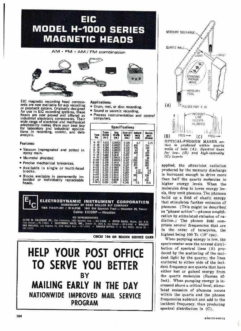
EIC MODEL H-1000 SERIES MAGNETIC HEADS
AM • FM • AM / FM combination
EIC magnetic recording head compon-ents are now available for any recording or playback system. Originally designed for use in EIC recording systems, these heads are now proved and offered as industrial electronic components. Their wide range of electrical and mechanical adaptability makes them your best buy for laboratory and industrial applica-tions in recording, control, and data analysis.
Features:
• Vacuum impregnated and potted in epoxy resin.
• Mu-metal shielded.
• Precise mechanical tolerances.
• Available in single or multi-head blocks.
• Blocks available in permanently im-bedded or individually replaceable heads.
Applications: • Drum, reel, or disc recording. • Sound or seismic recording. • Process instrumentation and control
computers.
Specifications
Type No.
Track Width (In.)
Gap Width (In.)
Over-All width (In.)
Induct- ance (mh)
Resist. ance
(Ohms)
A- 12 A- 40 A- 50 8- 50 C- 50 A- 60 A- 90 A-100 8-100 C-100 A-125 8-125 C-125 A-140 13-140 C-140 A-30-3
0.012 0.040 0.050 0.050 0.050 0.060 0.090 0.100 0.100 0.100 0.125 0.125 0.125 0.140 0.140 0.140 0.030
0.00025 0.00025 0.00025 0.00025 0.0010 0.0010 0.00025 0.00025 0.0010 0.00025 0.0020 0.0050 0.0050 0.0010 0.0010 0.0030 0.001
0.125 0.125 0.125 0.125 0.125 0.207 0.207 0.187 0.187 0.187 0.207 0.207 0.207 0.207 0.207 0.207 0.145
6.7 600 750 65
325 3
100 1200 500 375 29 1.17 0.224
500 7
235 7.0
6.75 215 220 30
220 200 30
265 265 265 34 1.9 0.7
230 10
230 14.5
EIC ELECTRODYNAMIC INSTRUMENT CORPORATION SUBSIDIARY OF REED ROLLER BIT COMPANY TWX 713-571-341 / RI 8-2760 1841 Old Spanish Trail - Houston 25, Texas
Cable: EICORP - Houston
EIC REPRESENTATIVES CLYDE M. SALISBURY CO., San Francisco, 1453 Seventh Ave. - MO 4-0586 • REPCO SALES, Miami, 401 N.W. 71st Street - PL 7-2911 • ELECTRONIC SALES, INC., Denver 22, 2641 S. Ivy Street - SK 6-4148 • WALLACE AND WALLACE, Los Angeles 15, 1206 Maple Ave. - RI 7-0401 • BRANCH OFFICE: P. 0. Box 30201, Dallas 30 - EM 1-0174.
CIRCLE 104 ON READER SERVICE CARD
HELP YOUR POST OFFICE TO SERVE YOU BETTER
BY
MAILING EARLY IN THE DAY NATIONWIDE IMPROVED MAIL SERVICE
PROGRAM
MERCURY DISCHARGE
QUARTZ WALL
/
/ / /
/ /
,/ /
;
; STANDING ', PHONON ',WAVE ,'
_
MERCURY POOL
(A) PULSED HIGH V IN
LINE (2,537A E-1,180TC)
(B) FRED (C) FRED
OPTICAL-PHONON MASER ac-tion is produced within quartz walls of tube (A). Spectral lines for low- (D) and high-intensity (C) inputs
applied, the ultraviolet radiation produced by the mercury discharge
is increased enough to drive more than half the quartz molecules to higher energy levels. When the
molecules drop to lower energy lev-
els, they emit phonons. The phonons build up a field of elastic energy
that stimulates further emission of
phonons. (This might be described as "phaser action"-phonon amplifi-cation by stimulated emission of ra-
diation.) The phonon field com-prises several frequencies that are in the order of teracycles, the
highest being 100 Te ( 10'' cps).
When pumping energy is low, the
spectrometer sees the normal distri-bution of spectral lines (13) pro-duced by the scattering of the inci-
dent light by the quartz; the lines scattered to either side of the inci-dent frequency are quanta that have
either lost or gained energy from the quartz molecules (Raman ef-
fect). When pumping energy is in-
creased above a critical level, stimu-
lated emission of phonons occurs
within the quartz and the phonon frequencies subtract and add to the incident frequency, thus producing spectral distribution in (C).
104 electronics

WHAT IS HAPPENING IN ELECTRONICS IN 1963 ? See for yourself by-..visiting the
th
international exhibition of
electronic components
FROM 8" - 12' FEBRUARY 1963 IN PARIS PORTE OE VERSAILLES
The largest display in the world covering the field of electronics
All components, valves and semiconductors, measuring, testing and electro-acoustic equipments
Under the patronage of the F.N.I.E.
Send now for full information and literature :
FÉDÉRATION NATIONALE DES INDUSTRIES ÉLECTRONIQUES 23, rue de Lubeck - PARIS 160 PASsy 01-16
3rd
PUBLI-SERVICE - PARIS
international congress of quantum electronics
organised by the French section of the I.R.E. and by the S.F.E.R.
FROM 10'h - 15'h FEBRUARY 1963
FROM 10'h - 15' FEBRUARY 1963
Unesco -House Information 7, rue de Madrid PARIS 8'
28 years
ago...
In 1933, the French National Association of Radio-Electrical Industries, which for ten years had been organizing the annual Wireless Show, decided to exhibit separately the receivers appealing to consu-mers and components used only by manufacturersand technicians. Thus was born, in January 1934 the first French components Exhibition. By 1957 its inter-national character had already been well established, and since then the International Exhibition of Electronic Components, is reserved exclusively to manufacturers, and opens its doors every year to firms specialized in the field of Electronics.
Largest specialized display.
To-day, it is considered to be the world largest display in the field of components and electronic accessories. Its success grows year by year. Not only does it display, on a vast scale the world's production of electronic components, but it is also a privileged occasion for specialized constructors and technical elite of all countries to meet and to compare equipment and techniques, and also to build up together the trends of to-morrow's develop-ments.
7 Times more foreign exhibitors in 5 years.
Year by year the international character of the Exhibition is increasing. Whereas in 1957 only about thirty foreign stands could be counted, to-day the Golden Book of foreign exhibitors enlists 250 Firms. As for foreign visitors, the high technical qualification of which was particularly noticeable last year, their number is increasing proportionately. In 1962 they accounted for 12 % of all visitors, coming from 30 different countries.
Products
exhibited
In order to maintain the specific character of the Exhibition which is entirely devoted to the field of electronic components, the participation is reserved exclusively to Firms actually manufacturing the equipment listed underneath. — Variable and adjustable capacitors — fixed capacitors — radiofrequency coils — coils and trans-formers for industrial and audio frequencies — resis-tors — terminal and wiring accessories — switching — safety devices — power supplies — racks and chassis — aerials — electro-acoustical material — tubes — semiconductors — meters — relays — equipment and materialsfor electronic purposes — miscellaneous.
25.000 m2 - 800 exhibitors
January 4, 1963 CIRCLE 107 ON READER SERVICE CARD 107
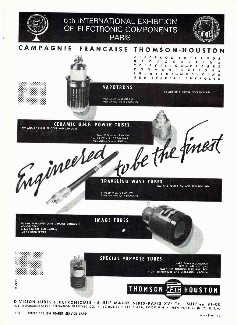
6 th INTERNATIONAL EXHIBITION OF ELECTRONIC COMPONENTS
PARIS
CAMPAGNIE FRANCAISE THOMSON-HOUSTON ELECTRON TUBES FOR
BROADCASTING
TELEV.ISION—RADARS
COMMUNICATIONS
I NDUSTRY—MEDICINE
AND SPECIAL PURPOSES
VAPOTRONS POWER GRID VAPOR COOLED TUBES
From 15 kW up to 30Ce kW From 30 mc/s up to 1000 mc/s
CERAMIC U.H.F. POWER TUBES CW AND RF PULSE TRIODES AND TETRODES
From 20 W up to 25 kW CW
From 15 kW up to 2.5 MW (peak) From 200 mc/s up to 3000 mc/s
efto,
lc"
PICK-UP TUBES IVIDICONS — IMAGE-ORTHICON) MONOSCOPES X- RAYS IMAGE INTENSIFIERS IMAGE CONVERTERS
ja
TRAVELING WAVE TUBES CW AND PULSED EM AND PPM FOCUSED
From 30 W up to 4 kW CW From 100 mc/s up to 6000 mc/s
IMAGE TUBES
SPECIAL PURPOSE TUBES HARD TUBES MODULATOR
SPECIAL APPLICATIONS GAS-TIGHT THROUGH TERMINALS FOR
HIGH TEMPERATURE AND ULTRA-HIGH %/Actium
THOMSON EFTH HOUSTON
DIVISION TUBES ELECTRONIQUES • 6, RUE MARIO NIKIS-PARIS XVe-Tel.: SUFfren 91-00 U.S. REPRESENTATIVE: THOMSON ELECTRIC CO. • 50 ROCKEFELLER PLAZA, ROOM 916 • NEW YORK 20 (N. Y.), U.S. A.
108 CIRCLE 108 ON READER SERVICE CARD electronics
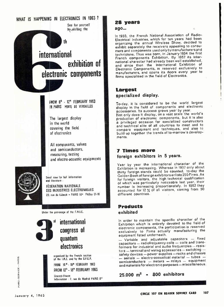
WHAT IS HAPPENING IN ELECTRONICS IN 1963 ?
See for yourself by...visiting the
th
international exhibition of
electronic components
FROM 8' - 12 FEBRUARY 1963 IN PARIS PORTE DE VERSAILLES
The largest display in the world covering the field of electronics
All components, valves and semiconductors, measuring, testing and electro-acoustic equipments
Under the patronage of the F.N.I.E.
Send now for full information and literature :
FÉDÉRATION NATIONALE DES INDUSTRIES ÉLECTRONIQUES 23, rue de Lubeck - PARIS 16e PASsy 01-16
3rd
PUBLI-SERVICE - PARIS
international congress of quantum electronics
organised by the French section of the I.R.E. and by the S.F.E.R.
FROM 10'h - le FEBRUARY 1963
FROM 10' - 15' FEBRUARY 1963 Unesco -House Information : 7, rue de Madrid PARIS 8'
28 years ago...
In 1933, the French National Association of Radio-Electrical Industries, which for ten years had been organizing the annual Wireless Show, decided to exhibit separately the receivers appealing to consu-mers and components used only by manufacturers and technicians. Thus was born, in January 1934 the first French components Exhibition. By 1957 its inter-national character had already been well established, and since then the International Exhibition of Electronic Components, is reserved exclusively to manufacturers, and opens its doors every year to firms specialized in the field of Electronics.
Largest specialized display.
To-day, it is considered to be the world largest display in the field of components and electronic accessories. Its success grows year by year. Not only does it display, on a vast scale the world's production of electronic components, but it is also a privileged occasion for specialized constructors and technical elite of all countries to meet and to compare equipment and techniques, and also to build up together the trends of to-morrow's develop-ments.
7 Times more foreign exhibitors in 5 years.
Year by year the international character of the Exhibition is increasing. Whereas in 1957 only about thirty foreign stands could be counted, to-day the Golden Book of foreign exhibitors enlists 250 Firms. As for foreign visitors, the high technical qualification of which was particularly noticeable last year, their number is increasing proportionately. In 1962 they accounted for 12 % of all visitors, coming from 30 different countries.
Products
exhibited
In order to maintain the specific character of the Exhibition which is entirely devoted to the field of electronic components, the participation is reserved exclusively to Firms actually manufacturing the equipment listed underneath. — Variable and adjustable capacitors — fixed capacitors — radiofrequency coils — coils and trans-formers for industrial and audio frequencies -- resis-tors — terminal and wiring accessories — switching — safety devices — power supplies — racks and chassis — aerials — electro-acoustical material — tubes — semiconductors — meters — relays — equipment and materials for electronic purposes — miscellaneous.
25.000 ni2 - 800 exhibitors
January 4, 1963 CIRCLE 107 ON READER SERVICE CARD 107

6 th INTERNATIONAL EXHIBITION OF ELECTRONIC COMPONENTS
PARIS
CAMPAGNIE FRANCAISE THOMSON-HOUSTON
earee ELECTRON TUBES FOR
BROADCASTING
TELEV.ISION—RADARS
COMMUNICATIONS
IN DUSTRY—MEDICINE
AND SPECIAL PURPOSES
VAPOTRONS POWER GRID VAPOR COOLED TUBES
From 15 kW up to 306 kW From 30 mc/s up to 1000 roc's
CERAMIC U.H.F. POWER TUBES CW AND RF PULSE TRIODES AND TETRODES
From 20 W up to 25 kW CW From 15 kW up to 2.5 MW (peak) From 200 mc/s up to 3000 mc/s
Ate
PICK-UP TUBES (VIDICONS — IMAGE-ORTHICON) MONOSCOPES X-RAYS IMAGE INTENSIFIERS IMAGE CONVERTERS
TRAVELING WAVE TUBES CW AND PULSED EM AND PPM FOCUSED
From 30 W OP to 4 kW CW From 100 mc/s up to 6000 mc/s
IMAGE TUBES
SPECIAL PURPOSE TUBES HARD TUBES MODULATOR
SPECIAL APPLICATIONS GAS-TIGHT THROUGH TERMINALS FOR
HIGH TEMPERATURE AND ULTRA-HIGH Nbec-uunn
THOMSON EFTH HOUSTON
DIVISION TUBES ELECTRONIQUES • 6, RUE MARIO NIKIS-PARIS XVe-Tel.: SUFfren 91-00 U.S. REPRESENTATIVE. THOMSON ELECTRIC CO. • 50 ROCKEFELLER PLAZA, ROOM 916 • NEW YORK 20 (N. Y.), U.S. A.
108 CIRCLE 108 ON READER SERVICE CARD electronics
TUBES AND MICROWAVE
ÇQMPQrgi.N.1..T5 : • : ***** - * * -.....---••••••
THOMSO 6, RUE MARIO
n
>AMPLIFIERS KLYSTRON
>REFLEX KL YSTRONS >TRAVELING WAVE TUBES
>MA GNE TR ON S TR AND AT R TUBES
-VARIAN NIKIS-PARIS XVe • Tel.: SUFfren 9 1-00
HIGH SPEED STATIC VOLTAGE REGULATORS
Input. —Mains supply voltage fluc-
tuation ± 15% —Mains supply frequency 48-
52 cycles —Power factor of regulator at
full load more than 0.86
Output: —Regulation accuracy±-0.2% —Overall harmonic distortion
Less than 3% —Admissible load variation 5
to 100% —Recovery time constant: —For 20% mains variation
0.04 sec. —For 95% load variation
0.03 sec. —Efficiency at full load 96% —Radiation free—Instantane-
ous start up —10 Standard ratings: 0.5-
1-2-5-10-15-20-30-40-60 Kva —Mains supply: 110-117-127
and 220 V
•
SATURABLE REACTORS —Power rating from 0.05 to
300 Kva (oven supply. motor control, etc.)
• MAGNETIC AMPLIFIERS
—For proportional tempera-ture regulation
• STATIC CONSTANT-
CURRENT SUPPLIES
FOR ELECTROMAGNETS
Input: —Single-phase or three-ph.tmt
mains supply :1-, 10';
Output: —Power rating 1 to 100 Kva —Regulation accuracy: Drift
less than 0.005'l in 8 hours
—Set point adjustment to 100%
—Recovery time constant for 10% mains supply fluc-tuations, 3 millisec.
Also: field stabilization with Hall effect and nuclear resonance-devices
•
STABILIZED
POWER SUPPLIES
—For electron-beam furnaces
RUSCH V 01 TR EG
138, RUE GALLIÉNI-PARIS/RUEIL-MALMAISON (S.-&-0.) Tel 967-1 1 -33 et 967-20-54
RAPY
CIRCLE 204 ON READER SERVICE CARD
January 4, 1963 CIRCLE 109 ON READER SERVICE CARD 109

LOUDSPEAKERS
AUDAX FRANCE
Societé Anonyme ou Capaol de 6000.000 NB
45, Avenue Pasteur
MONTREUIL (Seine) FRANCE Telephone ; AVRon 50-90 +
Telegrams : OPARLAUDAX-PARIS
CIRCLE 205 ON READER SERVICE CARD
More than half of all television receivers manufactured in France use VIDEON components: the first French specialists in manufacture of UHF tuners, VHF ro-tary switches, intermediate-frequency coils, deflection coils, high-voltage trans-formers, chokes, etc.
VIDEON 95 rue d'Aguesseau, Paris/Boulogne-sur-Seine, France Tel.: VAL 55-95
Plant in Manville near Rouen (Seine Maritime)
RAPY
Société des Ateliers René Halftermeyer
Société Anonyme au Capital de N.F. 3.000.000. Established in 1923, by
Mr. R. Halftermeyer.
Head Office:
35, avenue Faidherbe.
MONTREUIL-PARIS (Seine) FRANCE
Plants:
- at the Head-Office address
- St Aubin-les-Elbeuf (Seine-Maritime) FRANCE
RADIO AND TELEVISION ELECTRONIC COMPONENTS
• Variable Condensers for Broadcasting • Variable Condensers for professional
use
• High Voltage Transformers and Deflec-tion YokeS
• U H F Tuners
• Printed Circuits, etc...
Ask for complete date.
110 CIRCLE 110 ON READER SERVICE CARD CIRCLE 206 ON READER SERVICE CARD
electronics
In the electronic measurement field. the component quality conditions instrument accuracy and reliability.
AT RIBET-DESJARDINS'S, OVER 5.000 COMPONENTS ARE STRICTLY SELECTED.
THEIR QUALITY IS SUBJECTED TO MANY TESTS.
FACTOR OF R.D. PRODUCTION IMPROVEMENT TECHNOLOGICAL INVESTIGATION IS THE MAIN
R I BET - DESJARDINS Based upon an unceasing study of research requirements and demands, the activity of R. D. Development Department deals altogether with the three basic features of the problems arising from scientific evolution and industry conditions :
- Investigation of French and Foreign markets in order to find the most reliable components.
- Testing of the selected samples according to much higher per-formances than requested in common use, these requirements lead from time to time to creating original components either by cooperation with manufacturers or by R.D. own manufacture.
- Systematic testing of every component in order to keep a
constant quality.
From observation instrument the oscilloscope has come to measurement instru-ment. This underlines enough the importance of the reliability and accuracy of its components, taking into account specific conditions of use (change in tempe-rature, humidity, pecular ageing of each component...) for securing the constancy of performances in the future.
The permanent technological investigation performed by R.D. is the most obvious security of this constancy, more especially as it constitutes at the same time a continuous improvement in the operating reliability of the equipment.
MEASURE & CONTROL DEPARTMENT: 13-17, rue Périer MONTROUGE (Seine) FRANCE Tél. : ALEsia 24-40 Cable Address : PILACELECT - MONTROUGE CANADIAN BRANCH : RIBET -DESJARDINS (Canada) L. t. d.
Room 114,5757 Decelles Avenue - MONTREAL Agencies throughout the world: addresses sent on request.
CIRCLE 207 ON READER SERVICE CARD
ELECTRICAL CONNECTORS
AERONAUTICS NAVY ELECTRONICS RADIO
9 Rue Gallieni BOULOGNE BILLANCOURT FRANCE
SOURIAU ELECTRIC G. m. b. H. Dusseldorf Rathausufer 17
SOURIAU ITALIANA S. p. A. Milan Piazza Velasca 5
SOCIETE ELECTRIQUE BENELUX SOURIAU Bruxelles Rue Royale 163
Arle
ne pu
blic
ité
CIRCLE 111 ON READER SERVICE CARD 111 January 4, 1963

6 th INTERNATIONAL EXHIBITION OF ELECTRONIC COMPONENTS
PARIS
C 15 1-f French electronics group manufactures all components
Safety electronic tubes and special tubes — CSF. DIVISION TUBES ELECTRONIQUES 79, BOULEVARD
HAUSSMANN, PARIS 8e • • • • Quartz - Quartz filter - Crystals controls - Ovens — CSF.
DEPARTEMENT DE PIEZO-ELECTRICITE 6, RUE A. LA LYRE, COURBEVOIE SEINE • • • • Millimetric
microwave components — CSF. DIVISION INTERNATIONALE 79, BOULEVARD HAUSSMANN, PARIS 8e • II •
Special electric alloys - Sintered alloys - Very high capacity resistors - Relays
Synchros - Motors - Transformers — CSF. COMPOSANTS EXPORT 128, RUE DE PARIS, MONTREUIL-
SOUS-BOIS SEINE • • • • Any industrial or electronic ceramics - Thermistors - Metal.
plated ceramics - Thermoelectric modules — CICE. COMPAGNIE INDUSTRIELLE DES CERAMIQUES
ELECTRONIQUES 63, RUE BEAUMARCHAIS, MONTREUIL-SOUS-BOIS SEINE • • • • Ferrite cores for
radio and TV - Ferrinox High grade pot cores for telecommunications - Memory and
switching cores - Memory stacks- Ferrite Microwaves Devices — COFELEC (joint venture with :
BULL - CFTH and UGINE) • Semi-conductors — COSEM (joint venture with : SACM and BELVU) • Ceramic, plastic film, mica, Tantalum capacitors - Delay lines - Functionnal modules — LCC. STEAFIX
• Carbon coated resistors - Metal Layer resistors — EUR1ST A e Windings - Printed
circuits - Magnetic circuits - Transformers-power supply (Manoury) - Transformers
L. T. — OREGA • CSF. COMPOSANTS EXPORT 128, RUE DE PARIS, MONTREUIL-SOUS-BOIS SEINE BUZZ
Connectors - Rotary switches - Microphones - Earphones — SOCAPEX 9, RUE EDOUARD
NIEUPORT,SURESNESSEINE••BZUBIIMMUMIZIIIMIIBBIMMIIIMIIIZZIIIM
ITALIAN AFFILIATED COMPANIES
Ceramic, plastic film, paper and electro-chemical capacitors - Variable capacitors —
CIRCE - DUCATI - MICROFARAD • Semi-conductors — MISTRAL • DUCATI -ELETTROTECHNICA- EXPORT
CASELLA POSTALE 572 BOLOGNE ITALY — Distributor in FRANCE : LCC. STEAFIX • • • • • • • • • • •
CSF - COMPAGNIE GÉNÉRALE DE TÉLÉGRAPHIE SANS FIL 79 BOULEVARD HAUSSMANN /PARIS EP,/ANJ. 84-60
112 CIRCLE 112 ON READER SERVICE CARD electronics

basic instruments A 1211
A 1149
Plug-in and accessories such as TYPE A 1215: Aperiodic divider per.
mitting direct counting
up to >60 Mc TYPE A1212 : Preset time-base TYPE A1170 : Universal codeverter
and some other extra features
present
a complete line of
all solid-state
frequency
time-interval
period COUNTERS
Max Frequency Count capacity Counting time Standard frequency
Standard stability ±. 1 part in,...)
Standard frequencies outputs
Frequency measurements I,
Input characteristics
12 frequency inputs) I,
Period measurements
Time Interval measurements
Pulse duration and radio measurements
A 1149
> 22 MC 99.999.999 0.1-1-10 Sec.
5 MC
A 1213
> 22 MC 999.999
0.1-1-10 Sec. 1 MC
10' a week 10 a week 10' a week
1 cis. 10 cis....10 MC 1 c's .10 Os._ 1 MC
50 mV to 100 Vrms 50 mV to 100 Vrms 2=100 Z --1001«2/50t4+F
200 mV to 100 Vrms 200 mV to 100 Vrms Z-100 Ki2, 30 tr.p.F Z=1001(12130141 F
1 or Elperiods Period input I, IA-1149 and A-1213) or 1, (A-1197 and A-1211
Polarity + ; Sensitivity 5 to 8V; Polarity + + and—polarity Z=10 KS1/100µ0 Sensitivity: 6 to 50V built in pulse shaper
A 1197
> 220 KC 99.999
0.1-1-10 Sec. 100 KC
to• a week
1c/s:10c1s....100 KC
0.2 V to 100 Vrms 2=500Ktl, 30µµ
1V to 10 Vrms = 10 KU
> 220 KC 99.999
0.1-1-10 Sec. 100 KC
10' a week
lc/s: 10 cis...1001(C
d° A-1197
d° A-1197
• • • •
Ror_iuzr .11/17/1/1717/1
according to their very low consumption all this instruments can easily be
DC powered. ask for built-in battery power-pack models. 18 hours duty! and DC to AC converters.
stributed in U.S.A. an a a EST ON - Newark (N.J.)
for complete information on our line of products and address „ our agency in your country please apply to
ROCHAR-ELECTRON1QUE. 51, rue Racine
January 4, 1963 CIRCLE 113 ON READER SERVICE CARD 113

A McGRAW-HILL PUBLICATION, 330 West 42nd St, New York 36, N.Y. ELECTRONICS BUYERS' GUIDE and reference issue 2.f •
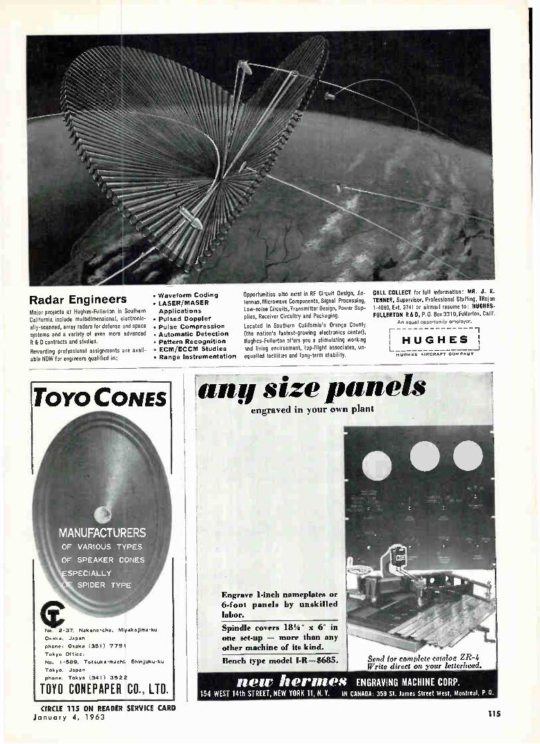
Radar Engineers Major projects at Hughes-Fullerton in Southern California include multidimensional, electronic-ally-scanned, array radars for defense and space systems and a variety of even more advanced R & D contracts and studies.
Rewarding professional assignments are avail-able NOW for engineers qualified in:
• Waveform Coding • LASER/MASER Applications
• Pulsed Doppler • Pulse Compression • Automatic Detection • Pattern Recognition • ECIVI/ECCIYI Studies • Range Instrumentation
Toro CONES
MANUFACTURERS OF VARIOUS TYPES
OF SPEAKER CONES
SPECI ALLY
SPIDER TYPE
No 2-37. Nakano•eho, Miyakejlata-ku
Osaka. Japan
phone, Osaka (351) 7791 Tokyo Office:
No, 1-589, Totsuka•rnachl. Shinjuku-ku
Tokyo, Japan
phone. Tokyo (341) 3522
TOY0 CONEPAPER CO., LTD.
Opportunities also exist in RF Circuit Design, An-tennas, Microwave Components, Signal Processing, Low-noise Circuits, Transmitter Design, Power Sup-plies, Receiver Circuitry and Packaging.
Located in Southern California's Orange County
(the nation's fastest-growing electronics center), Hughes-Fullerton offers you a stimulating working Ind living environment, top-flight associates, un-equalled facilities and long-term stability.
CALL COLLECT for full information: MR. J. E. TENNEY, Supervisor, Professional Staffing, TRoian 1-4080, Ext. 3741 or airmail resume to: HUGHES-FULLERTON R&D, P.O. Box 3310,Fullerlon, Calif.
An equal opportunity employer.
HUGHES: HUGHES AIRCRAFT COIAPAblY
any stze pane/s • engraved in your own plant
Engrave 1-inch nameplates or 6-foot panels by unskilled labor.
Spindle covers 184" x 6" in one set-up — more than any other machine of its kind.
Bench type model 1-R—$685. Send for complete cataloa ZR-4 Write direct on your letterhead.
Men' Iterates ENGRAVING MACHINE CORP. 154 WEST 14th STREET, NEW YORK 11, N. Y. IN CANADA. 359 St. James Street West, Montreal, P.O.
CIRCLE 115 ON READER SERVICE CARD January 4, 1963 115
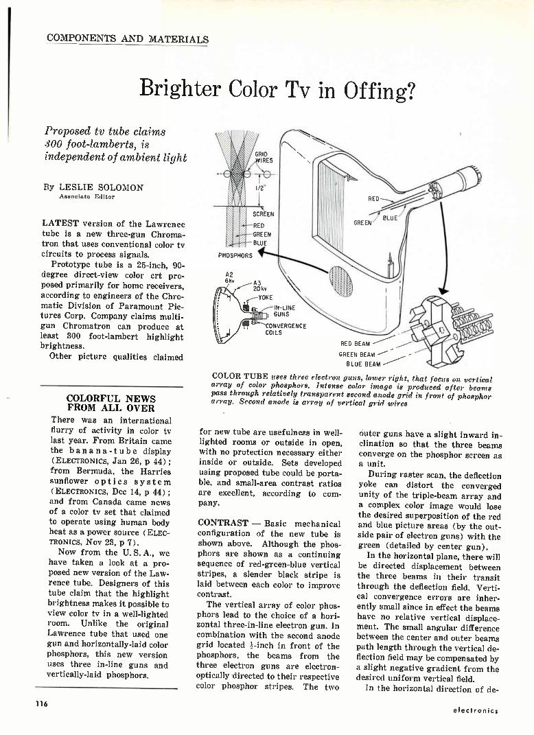
COMPONENTS AND MATERIALS
Brighter Color Tv in Offing?
Proposed tv tube claims 300 foot-lamberts, is independent of ambient light
By LESLIE SOLOMON Associate Editor
LATEST version of the Lawrence tube is a new three-gun Chroma-tron that uses conventional color tv circuits to process signals.
Prototype tube is a 25-inch, 90-degree direct-view color crt pro-posed primarily for home receivers, according to engineers of the Chro-matic Division of Paramount Pic-tures Corp. Company claims multi-gun Chromatron can produce at least 300 foot-lambert highlight brightness.
Other picture qualities claimed
COLORFUL NEWS FROM ALL OVER
There was an international flurry of activity in color tv last year. From Britain came the banana-tube display (ELECTRONICS, Jan 26, p 44) ; from Bermuda, the Harries sunflower optics system (ELECTRONICS, Dec 14, p 44) ; and from Canada came news of a color tv set that claimed to operate using human body heat as a power source (ELEC-TRONICS, Nov 23, p 7). Now from the U. S. A., we
have taken a look at a pro-posed new version of the Law-rence tube. Designers of this tube claim that the highlight brightness makes it possible to view color tv in a well-lighted room. Unlike the original Lawrence tube that used one gun and horizontally-laid color phosphors, this new version uses three in-line guns and vertically-laid phosphors.
GRID WIRES
PHOSPHORS
A2 6kv A3
20kv
Et IN-LINE GUNS
CONVERGENCE COILS
RED BEAM
GREEN BEAM
BLUE BEAM
COLOR TUBE uses three electron guns, lower right, that focus on vertical array of color phosphors. Intense color image is produced after beams pass through relatively transparent second anode grid in front of phosphor array. Second anode is array of vertical grid wires
for new tube are usefulness in well-lighted rooms or outside in open, with no protection necessary either inside or outside. Sets developed using proposed tube could be porta-ble, and small-area contrast ratios are excellent, according to com-pany.
CONTRAST — Basic mechanical configuration of the new tube is shown above. Although the phos-phors are shown as a continuing sequence of red-green-blue vertical stripes, a slender black stripe is laid between each color to improve contrast. The vertical array of color phos-
phors lead to the choice of a hori-zontal three-in-line electron gun. In combination with the second anode grid located -inch in front of the phosphors, the beams from the three electron guns are electron-optically -directed to their respective color phosphor stripes. The two
outer guns have a slight inward in-clination so that the three beams converge on the phosphor screen as a unit.
During raster scan, the deflection yoke can distort the converged unity of the triple-beam array and a complex color image would lose the desired superposition of the red and blue picture areas (by the out-side pair of electron guns) with the green (detailed by center gun).
In the horizontal plane, there will be directed displacement between the three beams in their transit through the deflection field. Verti-cal convergence errors are inher-ently small since in effect the beams have no relative vertical displace-ment. The small angular difference between the center and outer beams path length through the vertical de-flection field may be compensated by a slight negative gradient from the desired uniform vertical field.
In the horizontal direction of de-
116 electronics
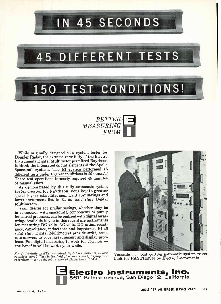
IN 45 SECONDS é
45 DIFFERENT TESTS
E BETTER MEASURING
FROM
While originally designed as a system tester for Doppler Radar, the extreme versatility of the Electro Instruments Digital Multimeter permitted Raytheon to check the integrated circuit elements of the Apollo Spacecraft systems. The EI system performed 45 different tests under 150 test conditions in 45 seconds! These test operations formerly required 45 minutes of manual effort. As demonstrated by this fully automatic system
tester created for Raytheon, your key to greater speed, higher reliability, significant cost savings and lower investment lies in EI all solid state Digital Multimeters. Your desires for similar savings, whether they be
in connection with spacecraft, components or purely industrial processes, can be realized with digital meas-uring. Available to you in this regard are instruments for measuring DC volts, AC volts, DC ratios, resist-ance, capacitance, inductance and impedance. EI all solid state Digital Multimeters provide swift, accu-rate answers to your measurement and display prob-lems. Put digital measuring to work for you now — the benefits will be worth your while.
For full details on. El's individual digital instruments, or our complete capabilities in the field of measurement, display and recording—write direct in care of Department MA-1.
Versatile cost cutting automatic system tester built for RAYTHEON by Electro Instruments.
Electro Instruments, Inc. 8 611 Balboa Avenue, San Diego 12, California
January 4, 1963 CIRCLE 117 ON READER SERVICE CARD 117

Clete() DEFLECTION
HIGH Efficiency
MAXIMUM Resolution
MINIMUM Distortion
LOW Residual
FASTEST Spot Recovery
WIDE RANGE
Inductances
Celco Precision Deflection Yokes are now available for neck diameters from 1/2 " to 5" for all types of military and commercial CRT displays. For technical assistance or Celco's latest catalog, call or write:
&lets' CONSTANTINE ENGINEERING LABORATORIES COMPANY
Mahwah, N. J. Area Code: 201 DAvis 7-1123 Ed Ryder
Miami, Fla. Area Code: 305 PLaza 1-1132 Walt Faust
Upland, Cal. Area Code: 714 YUkon 2-0215 Bob Reese
flection, a comparatively larger positive magnetic gradient (a sad-dle-shaped distribution of flux den-sity) effectively maintains beam convergence along this axis.
STABILITY—Thus by a small change in winding distribution of a conventional deflection yoke, auto-matic dynamic convergence in the rectangular axes of the display is attained. Trapezoidal error, evi-dent in diagonal corners, is cor-rected by a magnetically-driven convergence magnet assembly atop the outer electron guns. Correc-tions are electrically symmetrical and convergence stability is a high order since a major portion of the correcting function is tied directly to the deflection yoke which is the actual disturbance source. The post-deflection focusing sec-
ond-anode grid is an array of closely-spaced parallel taut wires, located ti-inch from the phosphors operating at a potential of 6 Kv. Approximately 20 Kv is applied to the final anode consisting of the Aquedag internal coating and the phosphor coating.
As the screen of the evacuated
bulb must withstand air pressure, it is designed with a convex arc ar-ranged along the horizontal axis of view similar to a theatre stage. Since the electronic nature of this crt dictates that the phosphor screen surface be nearly co-planar with the second-anode grid, this de-termines a virtually flat panel sec-tion along the vertical axis. Thus, the second-anode grid is an arrange-
ment of vertically strung wires ar-rayed in a smoothly-bowed curtain.
Component Makers Urged To Revamp Thinking MORE manufacturers of electronic systems are acquiring the know how to make component for their own systems, according to G. B. Mallory, President of P. R. Mallory and Co. Company has evaluated a study
of a group of the largest users of components in the country. Survey reveals that 21 percent of them al-ready have component or module production capability, and 14 per-cent of firms that use components
Rectifiers Assembled in Nitrogen
NITROGEN replaces air in specially built glassed-in boxes, used to weld pigtailed-mounted silicon rectifiers. Technique prevents oxygen contami-nation, keeps moisture down to one part in million or less, according to General Instrument. Station is part of new rectifier facility that costs quarter million dollars. Company says the facility produces super-reliable devices at cost of conventional units, due to high yield
118 CIRCLE 118 ON READER SERVICE CARD electronics
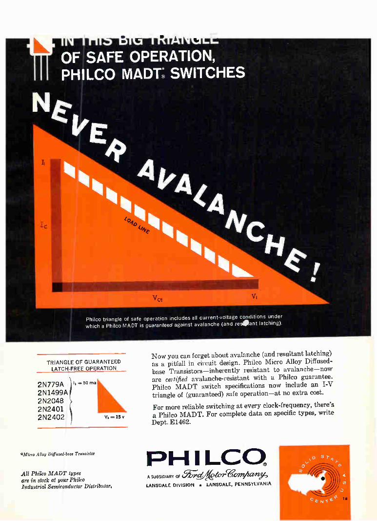
I
Philco triangle of safe operation includes all current-voltage conditions under which a Philco MADT is guaranteed against avalanche (and reseant latching)
TRIANGLE OF GUARANTEED LATCH-FREE OPERATION
2N779A 2N1499A 2N2048 2N2401 2N2402
Ii 50 ma
*Micro Alloy Diffused-base Transistor
All Philco MADT types are in stock at your Philco Industrial Semiconductor Distributor.
Now you can forget about avalanche (and resultant latching) as a pitfall in circuit design. Philco Micro Alloy Diffused-base Transistors—inherently resistant to avalanche—now are certified avalanche-resistant with a Philco guarantee. Philco MADT switch specifications now include an I-V triangle of (guaranteed) safe operation—at no extra cost.
For more reliable switching at every clock-frequency, there's a Philco MADT. For complete data on specific types, write Dept. E1462.
PH I LCQ A SUBSIDIARY OF (.577tr-r-ektorWorniurrey, LANSDALE DIVISION • LANSDALE, PENNSYLVANIA
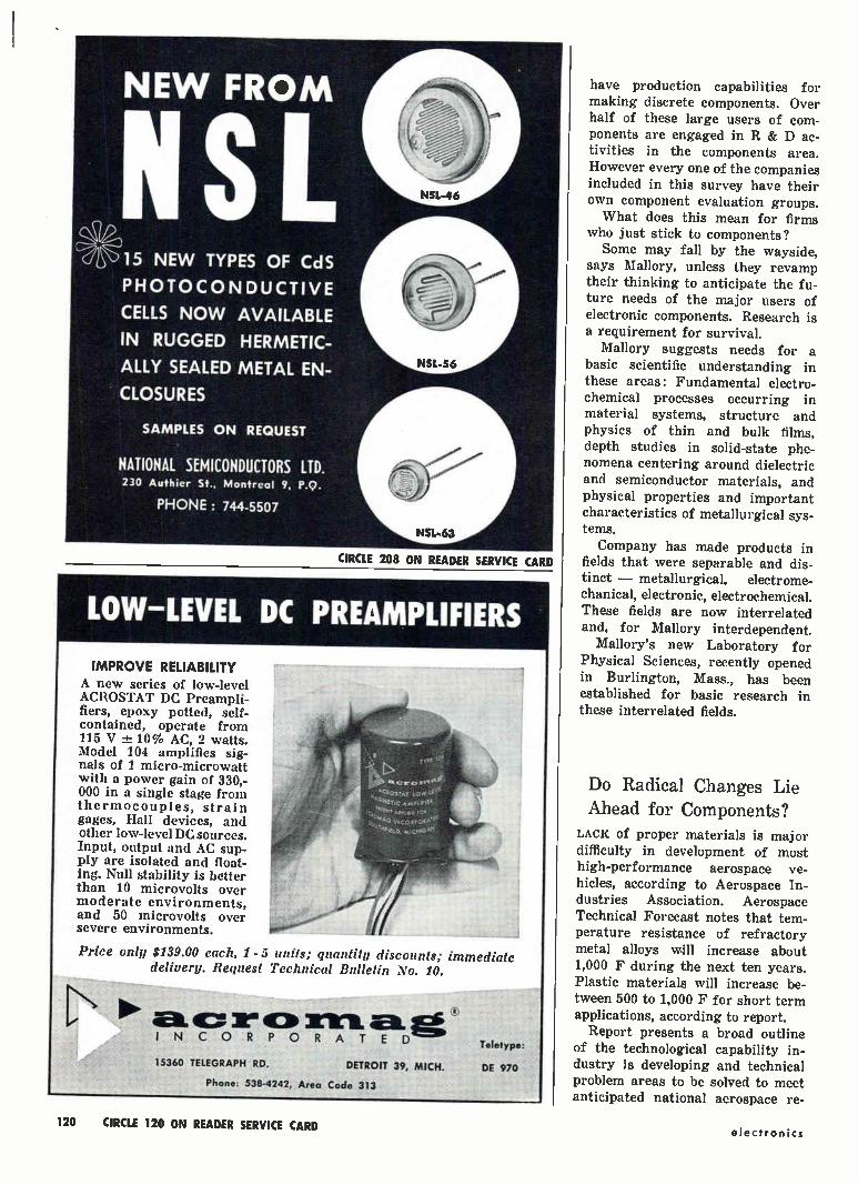
CIRCLE 208 ON READER SERVICE CARD
15 NEW TYPES OF CdS
PHOTOCONDUCTIVE
CELLS NOW AVAILABLE
IN RUGGED HERMETIC-
ALLY SEALED METAL EN-
CLOSURES
LOW-LEVEL DC PREAMPLIFIERS
IMPROVE RELIABILITY A new series of low-level ACROSTAT DC Preampli-fiers, epoxy potted, self-contained, operate from 115 V -± 10% AC, 2 watts. Model 104 amplifies sig-nals of 1 micro-microwatt with a power gain of 330,-000 in a single stage from thermocouples, strain gages, Hall devices, and other low-level DC sources. Input, output and AC sup-ply are isolated and float-ing. Null stability is better than 10 microvolts over moderate environments, and 50 microvolts over severe environments.
NTiC
eCit
Price only $139.00 each, 1 - 5 units; quantity discounts; immediate delivery. Request Technical Bulletin No. 10.
,/ 111C 3ILe CI> e INCORPORATED
15360 TELEGRAPH RD. DETROIT 39, MICH.
Phone. 538-4242, Area Code 313
Teletype:
DE 970
have production capabilities for making discrete components. Over half of these large users of com-ponents are engaged in R & D ac-tivities in the components area. However every one of the companies included in this survey have their own component evaluation groups. What does this mean for firms
who just stick to components? Some may fall by the wayside,
says Mallory, unless they revamp their thinking to anticipate the fu-ture needs of the major users of electronic components. Research is a requirement for survival.
Mallory suggests needs for a
basic scientific understanding in these areas: Fundamental electro-chemical processes occurring in material systems, structure and physics of thin and bulk films, depth studies in solid-state phe-nomena centering around dielectric and semiconductor materials, and physical properties and important characteristics of metallurgical sys-tems.
Company has made products in fields that were separable and dis-tinct — metallurgical, electrome-chanical, electronic, electrochemical. These fields are now interrelated and, for Mallory interdependent.
Mallory's new Laboratory for Physical Sciences, recently opened in Burlington, Mass., has been established for basic research in these interrelated fields.
Do Radical Changes Lie
Ahead for Components?
LACK of proper materials is major difficulty in development of most high-performance aerospace ve-hicles, according to Aerospace In-dustries Association. Aerospace Technical Forecast notes that tem-perature resistance of refractory metal alloys will increase about 1,000 F during the next ten years. Plastic materials will increase be-tween 500 to 1,000 F for short term applications, according to report. Report presents a broad outline
of the technological capability in-dustry is developing and technical problem areas to be solved to meet anticipated national aerospace re-
120 CIRCLE 120 ON READER SERVICE CARD electronics

C H ÁÑL S Ell'41111itirrilVill? le; ( SPECIFY MIDLAND CRYSTAL FILTERS
Id Years ago,- Midland knew of the impending high frequency spectrum "jam-. Today it's here! The steep attenuation slope exhibited by a crystal filter is an important characteristic in design of H.F. com-munications systems for maximum channel separa-tion. Crystal filters are small, reliable, rugged and stable over a wide temperature range. They are more in demand now than ever before. That's why Midland, through purchase, is integrating Itek's Electro-Products Division's production, test equip-ment and filter designs into Midland's already estab-lished 100,000 square foot facility — to further enhance the ability to serve the growing needs of the communications industry. Two typical Midland production filters are the EL-1B and DL-1B. Check the response, inband ripple and ultimate attenuation, with only 3 db insertion loss. Approx. size 2"x1 "x 3/4". Write for Engineering Bulletins NBS-104 and NBS-105 for complete technical information.
xc mow Igt uoo
110' MANUFACTURING COMPANY
3155 Fiberglas Road à--
WORLD'S LARGEST PRODUCER OF QUARTZ CRYSTALS & CRYSTAL FILTERS • Division PACIFIC INDU CIRCLE 209 ON READER SERVICE CARD
-'e"
-ons"'' PUNA
the finest precision coaxial connectors*
*TIVI R (miniaturized TNC)
General 702 BEACON STREET. BOSTON iS.MASSACHUSETTS
Telephone 617 267-5120
Fittings, Inc.
Kansas City 15, Kansas
OlenuoN FOR PRECISION MEASUREMENT OF PUSH AND PULL
(NOUN
since 1835
Completely New Model DPP MAGNETICALLY ACTIVATED CLUTCH ... holds maximum readings VERSATILE . .. hundreds of uses .. . checking tension and compression in lab, factory or field TESTS PUSH AND PULL FROM EITHER END ... does the work of two gauges ACCURATE .. . within 1/2 of 1% RANGE ... models in 1 to 50 pound capacities 2 As a hand-held 'instru-ment, the Chatillon DPP gives complete flexibil-ity. It may be used in any position for check-ing tension or compres-sion in an unlimited variety of applications. With the Chatillon LTC test stand, designed specifically for use with the DPP, it becomes a compact, low capacity laboratory tester. SEND FOR DATA SHEETS. Full details on both the DPP Push Pull gauge and the LTC Test Stand are yours for the asking. Write to John Chatillon & Sons, 85 Cliff Street, New York 38, N. Y.
à
...the force in force measurement Manufacturers of scales, force measuring
instruments and precision springs.
CIRCLE 210 ON READER SERVICE CARD
January 4, 1963 CIRCLE 121 ON READER SERVICE CARD 121
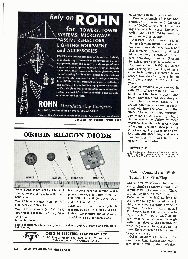
Rely on ROHN for TOWERS, TOWER
SYSTEMS, MICROWAVE PASSIVE REFLECTORS, LIGHTING EQUIPMENT and ACCESSORIES ROHN is the largest company of its kind exclusively
manufacturing communication towers and allied
equipment. They can supply a wide range of both
guyed and self-supporting towers from all heights
up to 800. They have available engineering and
manufacturing facilities for special tower systems
and complete engineering and design services.
Also ROHN makes microwave passive reflectors
and complete tower lighting equipment. So wheth-
er it's a single tower or a complete communications
system, contact ROHN for dependable and reliable
equipment and service.
ROHN Manufacturing Company Box 2000, Peoria, Illinois • Phone 309-637-8416
"Pioneer Manufacturers of towers of all kinds—Representatives world-wide"
CIRCLE 211 ON READER SERVICE CARD
ORIGIN SILICON DIODE
SE-
ph
.ettf
Origin diodes shown, are available in 4
models for PIV of 400, 600, 800 and
1000 volts.
Max. AC input voltages (RMS) of 280,
420, 560 and 700 volts.
Max. reverse current (at Ply, 25 C
ambient) is less than 101,A, only 50A
for SW-1.
Main Products:
150 SE-1.5
1111111111111,11111111111 to
111111111MT
Max. average rectified current (single
phase, half-wave) is 150m A for SM-
150, 500m A for SE-05. 1 A for SW 1,
and 1 5 A for SE-1 5.
Surge current for 1= one cycle) is
respectively 10 A, 16 A, 30 A and 20 A.
Ambient temperature operating range
is —55 to -,13 .0 for each diode.
Semi-conductors, condenser type spot welder, synthetic enamel and miniature ball bearing.
ORIGIN ELECTRIC COMPANY LTD. 1-195 Takadaminami-cho, Toshima ku, Tokyo, Japan
Cable Address "ORIGINELE TOKYO"
quirements in the next decade.' Tensile strength of glass fiber
reinforced plastics will increase from 200,000 psi to 300,000 psi dur-ing the next ten years. Structural weight can be reduced by one-third in rocket motor casing.
Forecast sees more radical changes in components. Use of small parts and molecular electronics and thin films will increase by at least 20 percent and as high as 80 per-cent, according to report. Present densities, largely using printed wir-ing, are about 10,000 equivalent parts per square foot. Use of mole-
cular techniques is expected to in-crease this density to one billion
equivalent parts in the next ten years.
Report predicts improvement in reliability of electronic systems as much as 100 times greater than today. Aerospace industry also pre-dicts that memory capacity of ground-based data processing equip-ment will increase about a million times. "An entirely new methodol-ogy must be developed to obtain the necessary reliability of space missions. It is virtually certain that redundant systems incorporating self-checking, fault-locating and in-dicating, self-organizing and adap-tive features will have to be de-vised," forecast notes.
REFERENCE (1) Aerospace Technical Forecast, Aero-
space Industries Association, 1725 De Sales St., N. W., Washington 6, D. C. ($3.00)
Motor Commutates With Transistor Flip-Flop
KEY to new brushless motor lies in use of simple oscillator circuit that commutates electronically. There are no brushes to wear out, and motor is said to last as long as the bearings. Cycle output is vari-able, and good starting torque is claimed. Ametek motor, named
Komlectro, does not rely on spark-ing contacts for operation. Continu-ous rotation is achieved through switching action of the commutator
which sequences the current in the rotor, thereby causing the d-e motor to operate on a-c.
Other advantages claimed for small fractional horsepower motor, packaged in small cube: reduction
122 CIRCLE 122 ON READER SERVICE CARD electronics
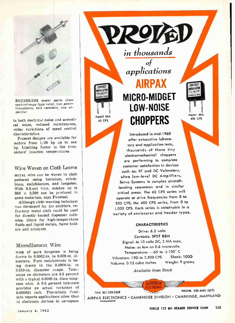
/4/
BRUSHLESS motor parts show squirrel-cage type rotor, two power transistors, two resistors, one ca-pacitor
in both electrical noise and acousti-cal noise, reduced maintenance, wider variations of speed control characteristics.
Present designs are available for motors from 1/20 hp up to one hp. Limiting factor is the tran-sistors' junction temperatures.
Wire Woven on Cloth Looms METAL wire can be woven in cloth patterns using tantalum, colum-bium, molybdenum, and tungsten. With 0.6-mil wire, meshes up to 350 x 2,300 can be produced in some materials, says Fansteel. Although cloth weaving technique
was developed for ion emitters, re-fractory metal cloth could be used for directly heated dispenser cath-odes, filters for high-temperature fluids and liquid metals, flame hold-
ers and catalysts.
Mierofilament Wire WIRE of pure tungsten is being drawn in 0.0002-in. to 0.029-in. di-ameters. Pure molybdenum is be-ing drawn in the 0.0008-in. to 0.019-in, diameter range. Toler-ances on diameters are 0.5 percent with a typical 0.0005-in. diam tung-sten wire. A 0.5 percent tolerance provides an actual variation of 0.000001 inch. Thermionic Prod-ucts reports applications other than in electronic devices in aerospace.
Model 30A
60 CPS
aTR9rel) in thousands
of applications
AIRPAX MICRO-MIDGET LOW-NOISE
CHOPPERS Introduced in mid-1960
after exhaustive labora-tory and application tests,
thousands of these tiny
electromechanical choppers
are performing to complete
customer satisfaction in devices
such as: RF and DC Voltmeters,
ultra low-level DC Amplifiers,
Servo Systems in complex aircraft-
landing sequences and in similar
critical areas. The 60 CPS series will
operate at drive frequencies from 0 to
250 CPS; the 400 CPS series, from 0 to 1,000 CPS. Each series is obtainable in a
variety of enclosures and header types.
,
Model 40A
400 CPS
CHARACTERISTICS
Drive: 6.3 volts
Contacts: SPDT BBM
Signal: to 10 volts DC; 2 MA max.
Noise: as low as 0.6 microvolts
Temperature: —65 to +100° C
Vibration: 15G to 2,500 CPS Shock: 100G
Volume: 0.15 cubic inches Weight: 9 grams
Available from Stock
TWX 301-228-3558 Q o PHONE: 228-4600 (301)
AIRPAX ELECTRONICS • CAMBRIDGE DIVISION • CAMBRIDGE, MARYLAND incorporated
January 4, 1963 CIRCLE 123 ON READER SERVICE CARD 123
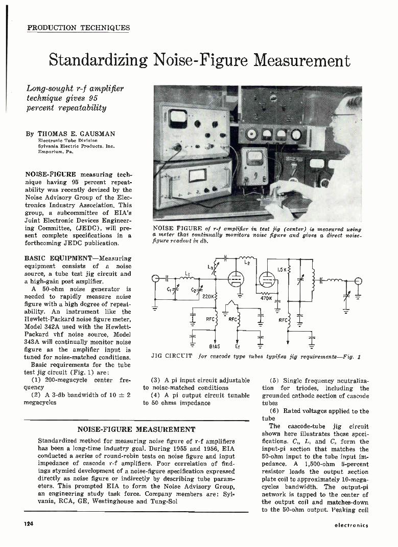
PRODUCTION TECHNIQUES
Standardizing Noise-Figure Measurement
Long-sought r-f amplifier technique gives 95 percent repeatability
By THOMAS E. GAUSMAN Electronic Tube Division Sylvania Electric Products, Inc. Emporium, Pa.
NOISE-FIGURE measuring tech-nique having 95 percent repeat-ability was recently devised by the Noise Advisory Group of the Elec-tronics Industry Association. This group, a subcommittee of EIA's Joint Electronic Devices Engineer-ing Committee, (JEDC), will pre-sent complete specifications in a forthcoming JEDC publication.
BASIC EQUIPMENT—Measuring equipment consists of a noise source, a tube test jig circuit and a high-gain post amplifier. A 50-ohm noise generator is
needed to rapidly measure noise figure with a high degree of repeat-ability. An instrument like the Hewlett-Packard noise figure meter, Model 342A used with the Hewlett-Packard vhf noise source, Model 343A will continually monitor noise figure as the amplifier input is tuned for noise-matched conditions.
Basic requirements for the tube test jig circuit (Fig. 1) are:
(1) 200-megacycle center fre-quency
(2) A 3-db bandwidth of 10 ± 2 megacycles
NOISE FIGURE of r-f amplifier in test jig (center) is measured using a meter that continually monitors noise figure and gives a direct noise-figure readout in db.
JIG CIRCUIT for cascode type tubes typifies jig
(3) A pi input circuit adjustable to noise-matched conditions
(4) A pi output circuit tunable to 50 ohms impedance
NOISE-FIGURE MEASUREMENT
Standardized method for measuring noise figure of r-f amplifiers has been a long-time industry goal. During 1955 and 1956, EIA conducted a series of round-robin tests on noise figure and input impedance of cascode r-f amplifiers. Poor correlation of find-ings stymied development of a noise-figure specification expressed directly as noise figure or indirectly by describing tube param-eters. This prompted EIA to form the Noise Advisory Group, an engineering study task force. Company members are: Syl-vania, RCA, GE, Westinghouse and Tung-Sol
requirements—Fig. .1
(5) Single frequency neutraliza-tion for triodes, including the grounded cathode section of cascode tubes
(6) Rated voltages applied to the tube The cascode-tube jig circuit
shown here illustrates these speci-fications. C„ L, and C„ form the input-pi section that matches the 50-ohm input to the tube input im-pedance. A 1,500-ohm 5-percent resistor loads the output section plate coil to approximately 10-mega-cycles bandwidth. The output-pi network is tapped to the center of the output coil and matches-down to the 50-ohm output. Peaking coil
124 electronics
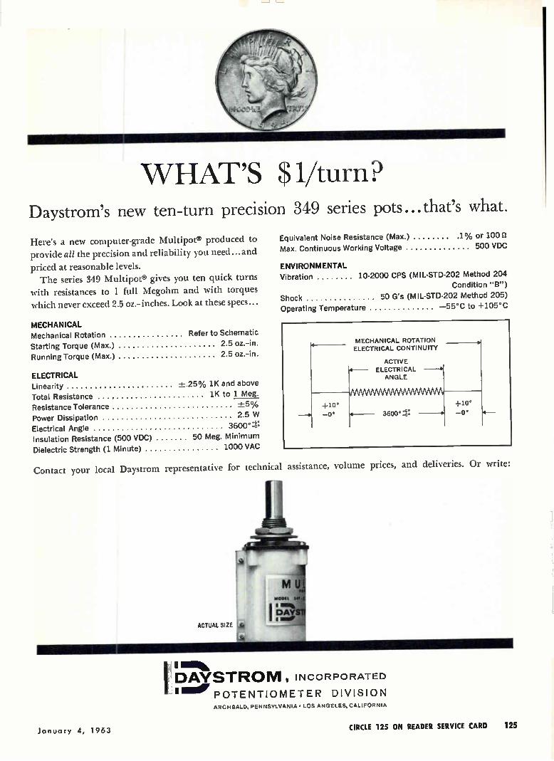
WHAT'S 1/turn Daystrom's new ten-turn precision 349 series pots...that's what.
Here's a new computer-grade Multipots produced to
provide all the precision and reliability you need...and
priced at reasonable levels. The series 349 Multipots gives you ten quick turns
with resistances to 1 full Megohm and with torques
which never exceed 2.5 oz.-inches. Look at these specs...
MECHANICAL Mechanical Rotation Refer to Schematic
Starting Torque (Max.) 2.5 oz.-in.
Running Torque (Max.) 2.5 oz.-in.
ELECTRICAL Linearity +.25% 1K and above
Total Resistance 1K to 1 Meg.
Resistance Tolerance +5%
Power Dissipation 2.5 W
Electrical Angle 3600° Insulation Resistance (500 VDC) 50 Meg. Minimum
Dielectric Strength (1 Minute) 1000 VAC
Contact your local Daystrom representative for technical assistance, volume
Equivalent Noise Resistance (Max.) 1% or 100 2
Max. Continuous Working Voltage 500 VDC
ENVIRONMENTAL Vibration 10-2000 CPS (MIL-STD-202 Method 204
Condition "B")
Shock 50 G's (MIL-STD-202 Method 205)
Operating Temperature —55°C to +105°C
ACTUAL SIZE lie*
prices, and deliveries. Or write:
s mob, DAYSTROIVI , INCORPORATED I Me POTENTIOMETER DIVISION
ARCHBALD, PENNSYLVANIA • LOS ANGELES, CALIFORNIA
January 4, 1963 CIRCLE 125 ON READER SERVICE CARD 125
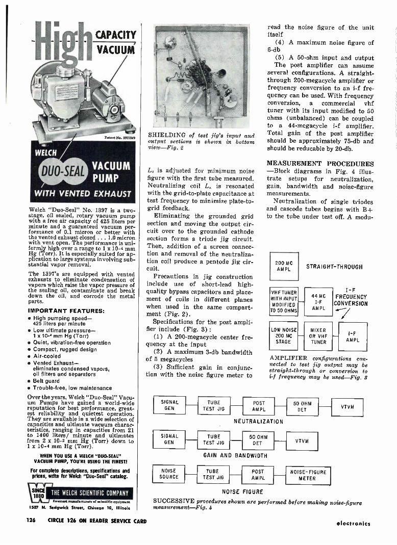
hCAPACITY VACUUM/
Welch "Duo-Seal" No. 1397 is a two-stage, oil sealed, rotary vacuum pump with a free air capacity of 425 liters per minute and a guaranteed vacuum per-formance of 0.1 micron or better with the vented exhaust closed . . . 1.0 micron with vent open. The performance is uni-formly high over a range to 1 x 10⁻⁴ mm Hg (Torr). It is especially suited for ap-plication to large systems involving sub-stantial vapor removal.
The 1397's are equipped with vented exhausts to eliminate condensation of vapors which raise the vapor pressure of the sealing oil, contaminate and break down the oil, and corrode the metal parts.
IMPORTANT FEATURES: • High pumping speed-425 liters per minute
• Low ultimate pressure-1 x 10⁻⁴ mm Hg (Torr)
• Quiet, vibration-free operation • Compact, rugged design • Air-cooled • Vented Exhaust—
eliminates condensed vapors, oil filters and separators
• Belt guard • Trouble-free, low maintenance
Over the years, Welch "Duo-Seal" Vacu-um Pumps have gained a world-wide reputation for best performance, great-est reliability and quietest operation. They are available in a wide selection of capacities and ultimate vacuum charac-teristics, ranging in capacities from 21 to 1400 liters/ minute and ultimates from 2 x 10⁻² mm Hg (Torr) down to 1 x 10⁻⁴ mm Hg (Torr).
WHEN YOU USE A WELCH "DUO-SEAL" VACUUM PUMP, YOU'RE USING THE FINEST!
For complete descriptions, specifications and prices, write for Welch "Duo-Seal" catalog.
WELCH SCIENTIFIC COMPANY foremost manufacturers uf scientific equipment
1507 N. Sedgwick Street, Chicago 10, Illinois
SHIELDING of test jig's input and output sections is shown in bottom view—Fig. 2
L2 is adjusted for minimum noise figure with the first tube measured. Neutralizing coil L. is resonated
with the grid-to-plate capacitance at test frequency to minimize plate-to-grid feedback.
Eliminating the grounded grid section and moving the output cir-cuit over to the grounded cathode section forms a triode jig circuit. Then, addition of a screen connec-tion and removal of the neutraliza-tion coil produce a pentode jig cir-cuit.
Precautions in jig construction include use of short-lead high-quality bypass capacitors and place-ment of coils in different planes when used in the same compart-ment (Fig. 2).
Specifications for the post ampli-fier include (Fig. 3) :
(1) A 200-megacycle center fre-quency at the input
(2) A maximum 3-db bandwidth of 5 megacycles
(3) Sufficient gain in conjunc-tion with the noise figure meter to
SIGNAL GEN
SIGNAL
GEN
NOISE
SOURCE
TUBE
TEST JIG
TUBE
TEST JIG
read the noise figure of the unit itself
(4) A maximum noise figure of 6-db
(5) A 50-ohm input and output The post amplifier can assume
several configurations. A straight-through 200-megacycle amplifier or frequency conversion to an i-f fre-quency can be used. With frequency conversion, a commercial vhf
tuner with its input modified to 50 ohms (unbalanced) can be coupled to a 44-megacycle i-f amplifier. Total gain of the post amplifier should be approximately 75-db and should be reducable by 20-db.
MEASUREMENT PROCEDURES —Block diagrams in Fig. 4 illus-
trate setups for neutralization, gain, bandwidth and noise-figure measurements.
Neutralization of single triodes and cascode tubes begins with B+ to the tube under test off. A modu-
200 MC M PL
VHF TUNER WITH INPUT
MODIFIED TO 50 OHMS
LOW NOISE 2C0 MC
STAGE
STRAIGHT-THROUGH
44 MC I-F AMPL
MIXER OR VHF TUNER
I-F FREQUENCY CONVERSION
I-F
AMPL
AMPLIFIER configurations con-nected to test jig output may be straight-through or conversion to i-f frequency may be used—Fig. 3
POST AM PL
NEUTRALIZATION
50 OHM
OFT
GAIN AND BANDWIDTH
TUBE
TEST JIG POST
AMPL
50 OHM
OFT
VTVM
NOISE- FIGURE
METER
VTVM
NOISE FIGURE
SUCCESSIVE procedures shown are performed before making noise-figure measurement—Fig. 4
126 CIRCLE 126 ON READER SERVICE CARD electronics
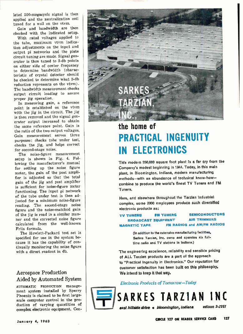
lated 200-megacycle signal is then applied and the neutralization coil tuned for a null on the vtvm.
Gain and bandwidth are then checked with the indicated setup. With rated voltages applied to
the tube, maximum vtvm indica-tion adjustments on the input and output pi networks and the plate circuit tuning are made. Signal gen-erator is then tuned to 3-db points on either side of center frequency to determine bandwidth (charac-teristic of crystal detector should be checked to determine what 3-db reduction represents on the vtvm). The bandwidth measurement checks output circuit loading to assure proper jig operation.
In measuring gain, a reference point is established on the vtvm with the jig in the circuit. The jig is then removed and the signal gen-erator output increased to obtain the same reference point. Gain is the ratio of the two output voltages. Gain measurement serves three purposes: checks tube under test, checks the jig, and helps correct for second-stage noise. The noise-figure measurement
setup is shown in Fig. 4. Fol-lowing the manufacturer's manual for setting up the noise figure meter, the gain of the post ampli-fier is adjusted so that the total gain of the jig and post amplifier is sufficient for noise-figure meter functioning. The input pi network of the tube under test is then ad-justed for a minimum noise-figure reading. The second-stage noise figure and the noise-matched gain of the jig is read in a similar man-ner and the corrected noise figure calculated from the well-known Friis formula. The Hewlett-Packard test set is
specified for use in the system be-cause it has the capability of con-tinually monitoring the noise figure with a direct readout in db.
Aerospace Production Aided by Automated System AUTOMATIC PRODUCTION manage-ment system installed by Sperry Phoenix is claimed to be first large-scale computer control in the pro-duction of varying quantities of complex electronic equipment. Cen-
the home of
PRACTICAL INGENUITY IN ELECTRONICS This modern 250,000 square foot plant is a far cry from the
Company's modest beginning in 1944. Today, in this main
plant, in Bloomington, Indiana, modern manufacturing
methods—with an abundance of technical know-how—
combine to produce the world's finest TV Tuners and FM
Tuners.
Here, and elsewhere throughout the Tarzian industrial
complex, some 2000 employees produce such diversified
electronic products as:
TV TUNERS FM TUNERS SEMICONDUCTORS BROADCAST EQUIPMENT AIR TRIMMERS
MAGNETIC TAPE FM RADIOS and AM/FM RADIOS
(In addition to the extensive manufacturing facilities,
Sarkes Tarzian, Inc. owns and operates six full-time radio and TV stations in Indiana.)
The engineering excellence, reliability and sensible pricing
of ALL Tarzian products are a part of the approach
to "Practical Ingenuity in Electronics." Our reputation for
customer satisfaction has been built on this philosophy.
We intend to keep it that way.
Electronic Products of Tomorrow—Today
SARKES TARZIAN INC east hillside drive • hloomington, indiana edison 2-7251
January 4, 1963 CIRCLE 127 ON READER SERVICE CARD 127
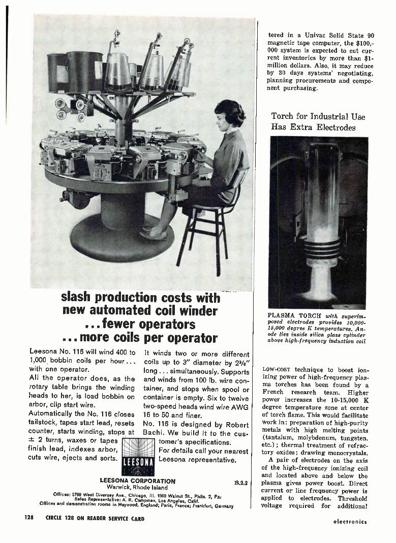
slash production costs with new automated coil winder
... fewer operators . more coils per operator
Leesona No. 116 will wind 400 to 1,000 bobbin coils per hour... with one operator. All the operator does, as the rotary table brings the winding heads to her, is load bobbin on arbor, clip start wire.
Automatically the No. 116 closes tailstock, tapes start lead, resets counter, starts winding, stops at .± 2 turns, waxes or tapes finish lead, indexes arbor, cuts wire, ejects and sorts.
It winds two or more different coils up to 3" diameter by 23/8" long ... simultaneously. Supports and winds from 100 lb. wire con-
tainer, and stops when spool or container is empty. Six to twelve two-speed heads wind wire AWG 16 to 50 and finer.
No. 116 is designed by Robert Bachi. We build it to the cus-
tomer's specifications. For details call your nearest Leesona representative. LEESONA
LEESONA CORPORATION Warwick, Rhode Island
Offices: 5700 West Diversey Ave., Chicago, III. 1500 Walnut St., Phila. 2, Pa; Sales Representative: A. R. Campman, Los Angeles, Calif.
Offices and demonstration rooms in Heywood, England; Paris, France; Frankfurt, Germany
B.2.2
tered in a Univac Solid State 90 magnetic tape computer, the $100,-000 system is expected to cut cur-rent inventories by more than $1-million dollars. Also, it may reduce by 30 days systems' negotiating, planning procurements and compo-nent purchasing.
Torch for Industrial Use Has Extra Electrodes
PLASMA TORCH with superim-posed electrodes provides 10,000-15,000 degree K temperatures. An-ode lies inside silica glass cylinder above high-frequency induction coil
Low-cosT technique to boost ion-izing power of high-frequency plas-ma torches has been found by a French research team. Higher power increases the 10-15,000 K degree temperature zone at center of torch flame. This would facilitate work in: preparation of high-purity metals with high melting points (tantalum, molybdenum, tungsten, etc.) ; thermal treatment of refrac-tory oxides; drawing monocrystals. A pair of electrodes on the axis
of the high-frequency ionizing coil and located above and below the plasma gives power boost. Direct current or line frequency power is applied to electrodes. Threshold voltage required for additional
128 CIRCLE 128 ON READER SERVICE CARD electronics
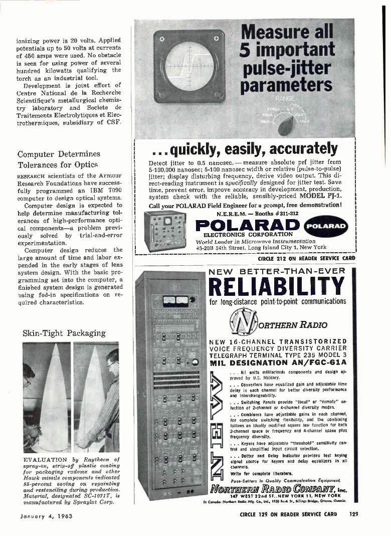
ionizing power is 20 volts. Applied potentials up to 50 volts at currents of 450 amps were used. No obstacle
is seen for using power of several hundred kilowatts qualifying the torch as an industrial tool.
Development is joint effort of Centre National de la Recherche Scientifique's metallurgical chemis-try laboratory and Societe de Traitements Electrolytiques et Elec-trothermiques, subsidiary of CSF.
Computer Determines Tolerances for Optics RESEARCH scientists of the Armour Research Foundations have success-fully programmed an IBM 7090 computer to design optical systems.
Computer design is expected to help determine manufacturing tol-erances of high-performance opti-cal components—a problem previ-ously solved by trial-and-error experimentation. Computer design reduces the
large amount of time and labor ex-pended in the early stages of lens system design. With the basic pro-gramming set into the computer, a finished system design is generated using fed-in specifications on re-quired characteristics.
Skin-Tight Packaging
EVALUATION by Raytheon of spray-on, strip-off plastic coating for packaging radome and other Hawk missile components indicated 95-percent saving on repainting and restenciling during production. Material, designated SC-1071T, is manufactured by Spraylat Corp.
al
Measure all 5 important pulse-jitter parameters
to . quickly, easily, accurately
Detect jitter to 0.5 nanosec. — measure absolute prf jitter from 5-100,000 nanosec; 5-100 nanosec width or relative (pulse-to-pulse) jitter; display disturbing frequency, derive video output. This di-rect-reading instrument is specifically designed for jitter test. Save time, prevent error, improve accuracy in development, production, system check with the reliable, sensibly-priced MODEL PI-1.
Call your POLARAD Field Engineer for a prompt, free demonstration!
N.E.R.E.M. — Booths =.311-312
POLARAD ELECTRONICS CORPORATION
World Leader in Microwave Instrumentation 43-20B 34th Street, Long Island City 1, New York
POLARAD
CIRCLE 212 ON READER SERVICE CARD
NEW BETTER—THAN—EVER
RELIABILITY for long-distance point-to-point communications
ORTHERN RADIO
NEW 16-CHANNEL TRANSISTORIZED VOICE FREQUENCY DIVERSITY CARRIER TELEGRAPH TERMINAL TYPE 235 MODEL 3 MIL DESIGNATION AN/FGC-61A
. . . All units militarized: components and design ap-proved by U.S. Military.
. . . Converters have equalized gain and adjustable time delay in each channel for better diversity performance and interchangeability.
. . . Switching Panels provide "local" or "remote" se-lection of 2-channel or 4-channel diversity modes.
. . . Combiners have adjustable gains in each channel,
for complete switching flexibility, and the combining follows an ideally modified square law function for both 2-channel space or frequency and 4-channel space plus
frequency diversity.
. . . Keyers have adjustable "threshold" sensitivity con-trol and simplified input circuit selection.
. Dotter and Delay Indicator provides test keying
signal source for keyers and delay equalizers in all channels.
Write for complete literature.
Pace-Setters in Quality Communication Equipment.
hionYEZIW PADIO COTOPM1r, inc. 147 WEST 22nd ST..NEW YORK 11, NEW YORK
In Coned°, Northern Rodio Mfg. Co. Md., 1950 Bonk St., BdUngs Bridge, Ottawa, Ontario.
January 4, 1963 CIRCLE 129 ON READER SERVICE CARD 129
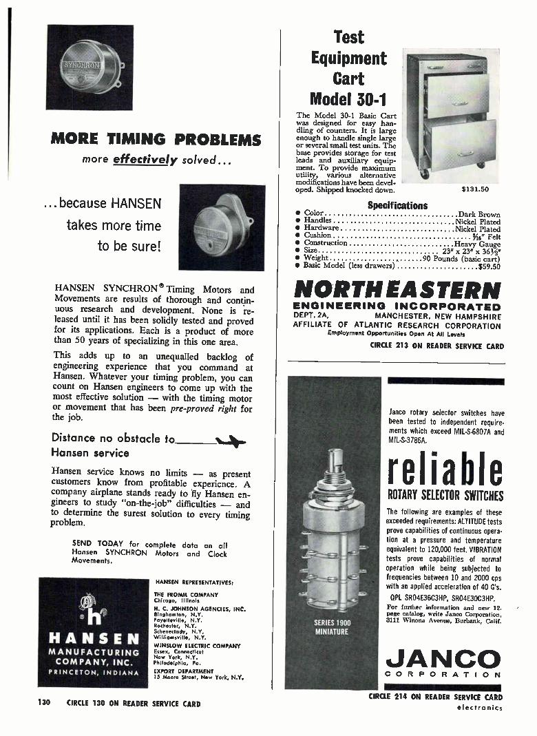
MORE TIMING PROBLEMS more effectively solved...
...because HANSEN
takes more time
to be sure!
HANSEN SYNCHRON ® Timing Motors and Movements are results of thorough and contin-uous research and development. None is re-leased until it has been solidly tested and proved for its applications. Each is a product of more than 50 years of specializing in this one area.
This adds up to an unequalled backlog of engineering experience that you command at Hansen. Whatever your timing problem, you can count on Hansen engineers to come up with the most effective solution — with the timing motor or movement that has been pre-proved right for the job.
Distance no obstacle to Hansen service
Hansen service knows no limits — as present customers know from profitable experience. A company airplane stands ready to fly Hansen en-gineers to study "on-the-job" difficulties — and to determine the surest solution to every timing problem.
SEND TODAY for complete data on all Hansen SYNCHRON Motors and Clock Movements.
HANSEN MANUFACTURING COMPANY, INC.
PRINCETON, INDIANA
HANSEN REPRESENTATIVES:
THE FROMM COMPANY Chicago, Illinois
H. C. JOHNSON AGENCIES, INC. Binghamton, N.Y. Fayetteville, N.Y. Rochester, N.Y. Schenectady, N.Y. Williamsville, N.Y.
WINSLOW ELECTRIC COMPANY Essex, Connecticut New York, N.Y. Philadelphia, Pa.
EXPORT DEPARTMENT 15 Moore Street, New York, N.Y.
Test Equipment
Cart Model 30-1
The Model 30-1 Basic Cart was designed for easy han-dling of counters. It is large enough to handle single large or several small test units. The base provides storage for test leads and auxiliary equip-ment. To provide maximum utility, various alternative modifications have been devel-oped. Shipped knocked down. $131.50
Specifications • Color Dark Brown • Handles Nickel Plated • Hardware • Cushion
Nickel Plated 5/16" Felt
• Construction. Heavy Gauge • Size 23" x 23" x 36 • Weight 90 Pounds (basic cart) • Basic Model (less drawers) $59.50
NORTH EASTERN ENGINEERING INCORPORATED DEPT. 2A, MANCHESTER, NEW HAMPSHIRE AFFILIATE OF ATLANTIC RESEARCH CORPORATION
Employment Opportunities Open At All Levels
CIRCLE 213 ON READER SERVICE CARD
lanco rotary selector switches have been tested to independent require-ments which exceed MIL-S-6807A and MIL-S-3786A.
reliable ROTARY SELECTOR SWITCHES The following are examples of these exceeded requirements: ALTITUDE tests prove capabilities of continuous opera-tion at a pressure and temperature equivalent to 120,000 feet. VIBRATION tests prove capabilities of normal operation while being subjected to frequencies between 10 and 2000 cps with an applied acceleration of 40 G's.
QPL SRO4E36C3HP, SRO4E30C3HP. For further information and new 12.
page catalog, write Janco Corporation, 3111 Winona Avenue, Burbank, Calif.
JANCO CORPORATION
130 CIRCLE 130 ON READER SERVICE CARD electronics CIRCLE 214 ON READER SERVICE CARD
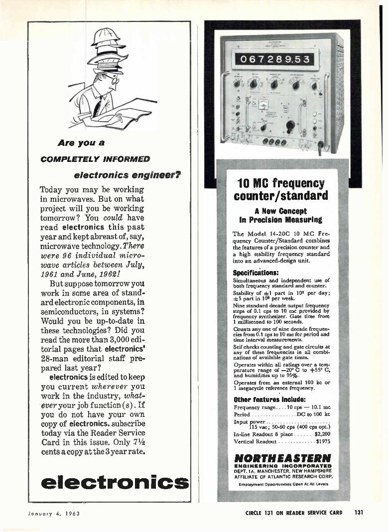
Are you a
COMPLETELY INFORMED
electronics engineer?
Today you may be working in microwaves. But on what project will you be working tomorrow? You could have read electronics this past year and kept abreast of, say, microwave technology. There were 96 individual micro-wave articles between July, 1961 and June, 1962!
But suppose tomorrow you work in some area of stand-ard electronic components, in semiconductors, in systems? Would you be up-to-date in these technologies? Did you read the more than 3,000 edi-torial pages that electronics' 28-man editorial staff pre-pared last year?
electronics is edited to keep you current wherever you work in the industry, what-ever your job function (s) . If you do not have your own copy of electronics, subscribe today via the Reader Service Card in this issue. Only 71/2 cents a copy at the 3 year rate.
electronics
NORTH EASTERN
067289.53
10 MC frequency counter/standard
A New Concept In Precision Measuring
The Model 14-20C 10 MC Fre-
quency Counter/Standard combines the features of a precision counter and a high stability frequency standard into an advanced-design unit.
Specifications: Simultaneous and independent use of both frequency standard and counter.
Stability of ±1 part in 108 per day; ±5 part in 108 per week.
Nine standard decade output frequency steps of 0.1 cps to 10 mc provided by frequency synthesizer. Gate time from 1 millisecond to 100 seconds.
Counts any one of nine decade frequen-cies from 0.1 cps to 10 mc for period and time interval measurements.
Self checks counting and gate circuits at any of these frequencies in all combi-nations of available gate times.
Operates within all ratings over a tem-perature range of —20° C to +55° C, and humidities up to 95%.
Operates from an external 100 kc or 1 megacycle reference frequency.
Other features include: Frequency range. . . .10 cps — 10.1 mc
Period DC to 100 kc
Input power 115 vac; 50-60 cps (400 cps opt.)
In-line Readout 8 place 82,200
Vertical Readout $1975
ENGINEERING INCORPORATED
DEPT. IA, MANCHESTER, NEW HAMPSHIRE AFFILPATE OF ATLANTIC RESEARCH CORP.
Employment Opportunities Open At All Levels
January 4, 1963 CIRCLE 131 ON READER SERVICE CARD 131
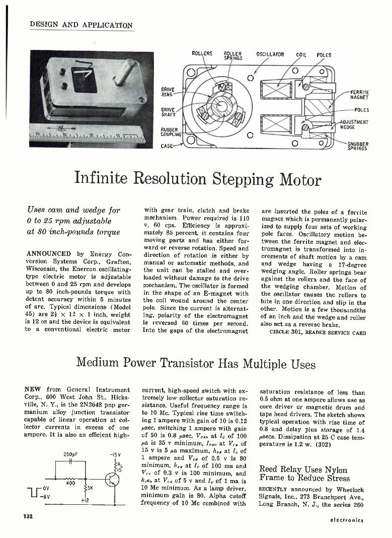
DESIGN AND APPLICATION
\m\e\,\,e,,,,,i,\\\‘\\
DRIVE RING
DRIVE SHAFT
RUBBER COUPLING
CASE
ROLLERS ROLLER SPRINGS
OSCILLATOR COIL POLES
Infinite Resolution Stepping Motor
Uses cam and wedge for 0 to 25 rpm adjustable at 80 inch-pounds torque
ANNOUNCED by Energy Con-version Systems Corp., Grafton, Wisconsin, the Enercon oscillating-type electric motor is adjustable between 0 and 25 rpm and develops up to 80 inch-pounds torque with detent accuracy within 5 minutes of arc. Typical dimensions (Model 45) are 2i x 1 x 1 inch, weight is 12 oz and the device is equivalent to a conventional electric motor
with gear train, clutch and brake mechanism. Power required is 110 AT, 60 cps. Efficiency is approxi-mately 85 percent, it contains four moving parts and has either for-ward or reverse rotation. Speed and direction of rotation is either by manual or automatic methods, and the unit can be stalled and over-loaded without damage to the drive mechanism. The oscillator is formed in the shape of an E-magnet with the coil wound around the center pole. Since the current is alternat-ing, polarity of the electromagnet is reversed 60 times per second. Into the gaps of the electromagnet
FERRITE MAGNET
POLES
ADJUSTMENT WEDGE
SNUBBER SPRINGS
are inserted the poles of a ferrite magnet which is permanently polar-ized to supply four sets of working pole faces. Oscillatory motion be-tween the ferrite magnet and elec-tromagnet is transformed into in-crements of shaft motion by a cam and wedge having a 17-degree wedging angle. Roller springs bear against the rollers and the face of the wedging chamber. Motion of the oscillator causes the rollers to bite in one direction and slip in the other. Motion is a few thousandths of an inch and the wedge and roller also act as a reverse brake.
CIRCLE 301, READER SERVICE CARD
Medium Power Transistor Has Multiple Uses
NEW from General Instrument Corp., 600 West John St., Hicks-ville, N. Y., is the 2N2648 pnp ger-manium alloy junction transistor capable of linear operation at col-lector currents in excess of one ampere. It is also an efficient high-
250pF
0 V
1 -11 8 V
-15 V
current, high-speed switch with ex-tremely low collector saturation re-sistance. Useful frequency range is to 10 Mc. Typical rise time switch-ing 1 ampere with gain of 10 is 0.12 µsec, switching 1 ampere with gain of 50 is 0.8 µsec, V,,,„ at lc of 100 µa is 35 y minimum, /elm at Ver of 15 y is 5 a maximum, hrE at 1, of 1 ampere and Vcs of 0.5 sr is 80 minimum, //pH at lc of 100 ma and V, of 0.3 y is 100 minimum, and
at V, of 5 y and 1c of 1 ma is 10 Mc minimum. As a lamp driver, minimum gain is 80. Alpha cutoff frequency of 10 Mc combined with
saturation resistance of less than 0.5 ohm at one ampere allows use as core driver or magnetic drum and tape head drivers. The sketch shows typical operation with rise time of 0.8 and delay plus storage of 1.4 µsecs. Dissipation at 25 C case tem-perature is 1.2 w. (302)
Reed Relay Uses Nylon Frame to Reduce Stress RECENTLY announced by Wheelock Signals, Inc., 273 Branchport Ave., Long Branch, N. J., the series 260
132 electronics

How IrOffi JF0
Model MCD643 (range: 1-28 pf.) Shown approx. 3X actual size
actual size
CANADIAN PATENT ;604,810 U.S. PATENT .2,922,093
IT IS HERE...a new kind of capacitor that combines the precise tuning capability of a piston trimmer, the long-lived adjustment of an air variable—and the rugged Max-C construction with its triple range. • THE REASON: A new ultra reliable anti-backlash adjustment mechanism with full-thread engagement. II THE PROOF?—Virtually no thread wear after 500 cycles of adjustment. Mil-C-14409A specifi-cations call for 75 cycles. 01 Other Super Max-C capacitor advantages are: 1. MULTI-TURN instead of 180 degree rotation of air variables. 2. FACTORY PRESET TORQUE at any value between 1 and 8 inch ounces can be supplied upon special request. 3. HIGHER SHOCK AND VIBRATION RESISTANCE. 4. KNOB CONTROL possible when panel mounted because of. the fixed position of the adjustment screw throughout the tuning range. 5. EXTENDED CAPACITANCE RANGE of 300 per cent beyond that of conventional precision piston trimmers due to proven Max-C embedded electrode construction. 6. COM-PLETELY SEALED INTERIOR CONSTRUCTION locks out humidity and other atmospheric elements (greatly exceeds salt spray and humidity cycling requirements of Mil-C-14409A). 7. ULTRA-LINEAR. TUNING— absolute repeatability. 8. Q FACTOR IS: 500 guaranteed minimum at 1 MC. 9. INSULATION RESISTANCE is 106 megohms. 10. DC work-
ing voltage is 1000 VDC. 11. LOW temperature coefficient of capacitance. 12. LOW inductance and low loss for higher
frequency use. 13. No derating from —55°C to +125°C. 14. Rugged shock and vibration resistance. 15. Di-
electric strength is 2000 VDC. 16. New JFD plat-ing for excellent RF conductivity and noise-free
tuning protects all metal parts from corro-sion and improves life of adjustment.
Panel mounting and printed circuit types are available: 1-14 pf., 1-28 pf., 1-42 pf., 1-60 pf.,
1-90 pf. FU Write for Bulletin MCD-62 jrn ELECTRONICS
CORPORATION Components Division
15th Avenue at 62nd Street, Brooklyn 19, N. Y. Phone 212 DE 1-1000 • TWX212-833-7001 Cable-JEFDEE N.Y.
HD WESTERN • 909 So. First Ave. • Arcadia, Calif. Phone: HIlIcrest 6-0312
JFD MIDWESTERN • 6330 Hermlone St. • Chicago 46, III. Phone: 775-5424
JFD MIDWESTERN-OHIO • 7415 Montgomery Rd. Cincinnati 36, Ohio • Phone 421-1166
JFD NORTHEASTERN • Ruth Drive, P. 0. Box 228 Marlboro, Mass. • Phone: HUntley 5-7311
JFD CANADA • 51 McCormack Street • Toronto, Ontario, Canada • Phone ROger 2-7571
¡FO ELECTRONICS (ISRAEL) LTD. • Industrial area 8.. Building 23 • Azor, Israel • Cable Addaess: JFD AZUR, ISRAEL
January 4, 1963 CIRCLE 133 ON READER SERVICE CARD 133
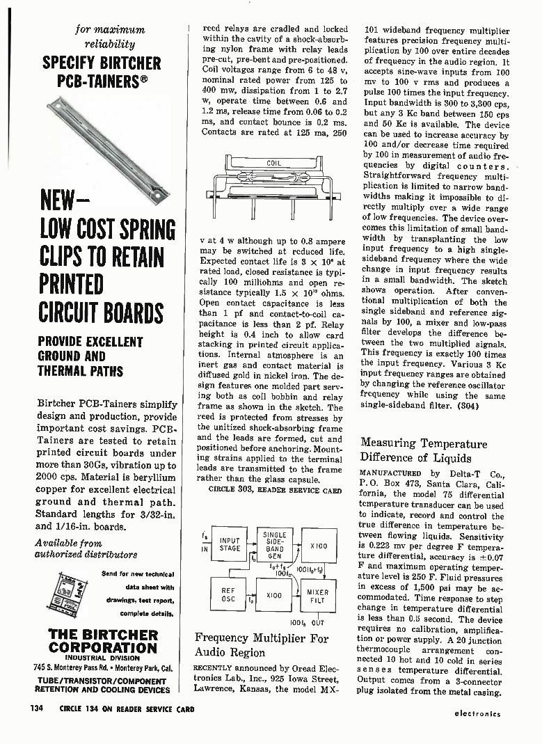
for maximum reliability
SPECIFY BIRTCHER PCB-TAINERS®
NEW-LOW COST SPRING CLIPS TO RETAIN PRINTED CIRCUIT BOARDS PROVIDE EXCELLENT GROUND AND THERMAL PATHS
Birtcher PCB-Tainers simplify design and production, provide important cost savings. PCB-Tainers are tested to retain printed circuit boards under more than 30Gs, vibration up to 2000 cps. Material is beryllium copper for excellent electrical ground and thermal path. Standard lengths for 3/32-in. and 1/16-in. boards.
Available from authorized distributors
Send for new technical
data sheet with
drawings, test report,
complete details.
THE BIRTCHER CORPORATION
INDUSTRIAL DIVISION
745 S. Monterey Pass Rd. • Monterey Park, Cal.
TUBE/TRANSISTOR/COMPONENT RETENTION AND COOLING DEVICES
reed relays are cradled and locked within the cavity of a shock-absorb-ing nylon frame with relay leads pre-cut, pre-bent and pre-positioned. Coil voltages range from 6 to 48 IT, nominal rated power from 125 to 400 mw, dissipation from 1 to 2.7 w, operate time between 0.6 and 1.2 ms, release time from 0.06 to 0.2 ms, and contact bounce is 0.2 ms. Contacts are rated at 125 ma, 250
COIL
y at 4 w although up to 0.8 ampere may be switched at reduced life. Expected contact life is 3 x 10° at rated load, closed resistance is typi-cally 100 milliohms and open re-sistance typically 1.5 x 101° ohms. Open contact capacitance is less
than 1 pf and contact-to-coil ca-pacitance is less than 2 pf. Relay height is 0.4 inch to allow card stacking in printed circuit applica-tions. Internal atmosphere is an inert gas and contact material is diffused gold in nickel iron. The de-sign features one molded part serv-ing both as coil bobbin and relay frame as shown in the sketch. The reed is protected from stresses by the unitized shock-absorbing frame and the leads are formed, cut and positioned before anchoring. Mount-ing strains applied to the terminal leads are transmitted to the frame rather than the glass capsule.
CIRCLE 303, READER SERVICE CARD
fo
IN INPUT STAGE
REF OSC
fo
SINGLE SIDE-BAND ) GEN
X100
f f o 100 (f0+ fol 100fo.
X100 --•• MIXER FI LT
100 fs OUT
Frequency Multiplier For Audio Region RECENTLY announced by Oread Elec-tronics Lab., Inc., 925 Iowa Street, Lawrence, Kansas, the model MX-
101 wideband frequency multiplier features precision frequency multi-plication by 100 over entire decades of frequency in the audio region. It accepts sine-wave inputs from 100 my to 100 y rms and produces a pulse 100 times the input frequency. Input bandwidth is 300 to 3,300 cps, but any 3 Kc band between 150 cps and 50 Kc is available. The device can be used to increase accuracy by 100 and/or decrease time required by 100 in measurement of audio fre-quencies by digital counters. Straightforward frequency multi-plication is limited to narrow band-widths making it impossible to di-rectly multiply over a wide range of low frequencies. The device over-comes this limitation of small band-width by transplanting the low input frequency to a high single-sideband frequency where the wide change in input frequency results in a small bandwidth. The sketch shows operation. After conven-tional multiplication of both the single sideband and reference sig-nals by 100, a mixer and low-pass filter develops the difference be-tween the two multiplied signals. This frequency is exactly 100 times the input frequency. Various 3 Kc input frequency ranges are obtained by changing the reference oscillator frequency while using the same single-sideband filter. (304)
Measuring Temperature Difference of Liquids MANUFACTURED by Delta-T Co., P. O. Box 473, Santa Clara, Cali-fornia, the model 75 differential temperature transducer can be used to indicate, record and control the true difference in temperature be-tween flowing liquids. Sensitivity is 0.223 my per degree F tempera-ture differential, accuracy is 7L0.07 F and maximum operating temper-ature level is 250 F. Fluid pressures in excess of 1,500 psi may be ac-commodated. Time response to step
change in temperature differential is less than 0.5 second. The device requires no calibration, amplifica-tion or power supply. A 20 junction
thermocouple arrangement con-nected 10 hot and 10 cold in series senses temperature differential. Output comes from a 3-connector plug isolated from the metal casing.
134 CIRCLE 134 ON READER SERVICE CARD electronics

THERMOCOUPLES
WATER OUT
WATER IN
The transducer is a very low im-pedance source (80 ohms) and gen-erates a relatively large signal (typical 10 mv) linear in terms of temperature difference with excel-lent common-mode rejection and effective electromagnetic shielding. It is ideal for use in the vicinity of electric-arc heaters where strong electric or magnetic fields, high pressures and stray electric cur-rents are present. (305)
Potentiometer Wire of Precious Metal Alloy SECON METALS CORP., 7 Intervale St., White Plains, N. Y., has developed a potentiometer wire designated Secon Alloy 20-245. This precious metal alloy has a temperature co-efficient of resistance of less than 20 parts per million, and a specific re-sistance of 245 ohms per circular mil foot. It has a tensile strength of 140,000 ppsi. It can be used with light wiper pressures. Excellent life and noise results can be ob-tained even in sizes below 0.001 in. diameter. (306)
Test Jack Designed For Limited Space SEALECTRO CORP., 139 Hoyt St., Mamaroneck, N. Y., announces a Press-Fit test jack for application in chassis where extension below chassis must be held to a minimum and costs dictate the use of an in-expensive test jack. The SKT-0500 features a stamped beryllium
LAPP PORCELAIN WATER COILS
or TOP I, 1 TINOS
• • in all '-'i-r -
1 ;== hese o
+.8-
standard TYPE L FITTING
izes L PP
5 to \ Ilt ¡aye you rime and
TYPE C FITTING
money \ Ilf 14_ so,r5
' TYPE S FITTING
WATER COILS—DIMENSIONS IN INCHES
Cat. No. Single Equiv. Aver. Number Basic or Pipe A D E F H Length of Unit* Twin Size In Feet Turns
22957 T % 2% 5% ,S2 %2 91/2 12 11
10723 T % 4% 12 Mt 'A 18 29 lei
10190 T 1 4% 13% % 1146 221/2 31 10%
27016 S % 2% 514 1/2 5(6 10% 12 11-30°
10719 S 1% 4% 12 1% 1 22 28 10%
10729 S 1% 5 15 1% 11/8 23% 32 91/2-22°
"Basic unit includes ceramic coil, base, spider, cemented clamping fittings and leakage current tap. Specify type of fitting, top and bottom ("L" "C" or "S") and length of lead pipe required-36" is standard. Lead pipe is standard—flexible metal hose can be furnished. Special length coils and fittings
are available—standard units only are shown here.
Lapp Save with our standards. But if you need specials, count on us for them too. Either way, Lapp gives you service and quality you can depend on.
WRITE for Bulletin 301-R. Lapp Insulator Co., Inc., 200 Sumner St., LeRoy, N. Y.
January 4, 1963 CIRCLE 135 ON READER SERVICE CARD 135
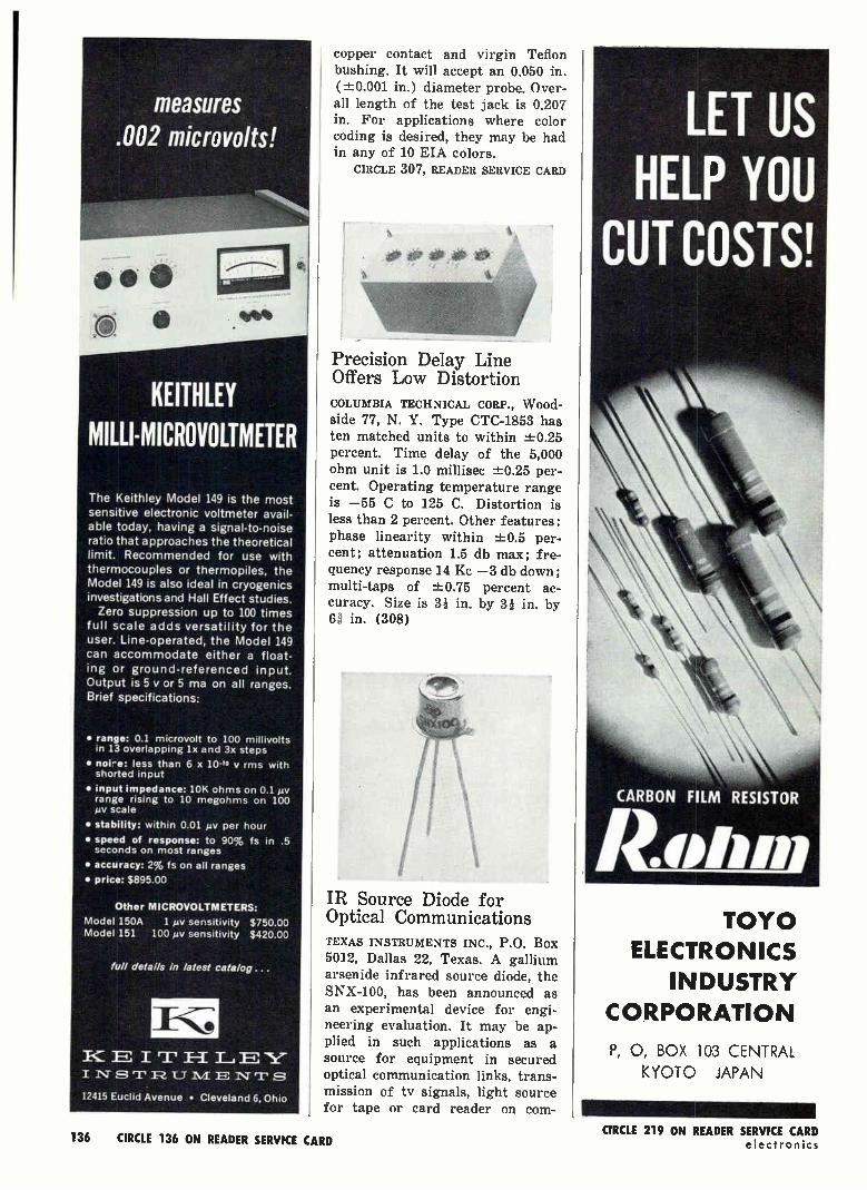
e %eV*
KEITHLEY Mull-MICRO VOLTMETER
The Keithley Model 149 is the most sensitive electronic voltmeter avail-able today, having a signal-to-noise ratio that approaches the theoretical limit. Recommended for use with thermocouples or thermopiles, the Model 149 is also ideal in cryogenics investigations and Hall Effect studies. Zero suppression up to 100 times
full scale adds versatility for the user. Line-operated, the Model 149
can accommodate either a float-ing or ground-referenced input. Output is 5 y or 5 ma on all ranges. Brief specifications:
• range: 0.1 microvolt to 100 millivolts in 13 overlapping lx and 3x steps
• noi-e: less than 6 x 1040 V rms with shorted input
• input impedance: 10K ohms on 0.1 Mv range rising to 10 megohms on 100 ,uv scale
• stability: within 0.01 p.v per hour
• speed of response: to 90% fs in .5 seconds on most ranges
• accuracy: 2% fs on all ranges
• price: $895.00
Other MICROVOLTMETERS:
Model 150A 1 mv sensitivity $750.00 Model 151 100 pv sensitivity $420.00
full details in latest catalog ...
E I m H L., E NT
12415 Euclid Avenue • Cleveland 6, Ohio
copper contact and virgin Teflon bushing. It will accept an 0.050 in. (±0.001 in.) diameter probe. Over-all length of the test jack is 0.207 in. For applications where color coding is desired, they may be had in any of 10 EIA colors.
CIRCLE 307, READER SERVICE CARD
Precision Delay Line Offers Low Distortion COLUMBIA TECHNICAL CORP., Wood-side 77, N. Y. Type CTC-1853 has ten matched units to within ±0.25 percent. Time delay of the 5,000 ohm unit is 1.0 millisec ±0.25 per-cent. Operating temperature range is —55 C to 125 C. Distortion is less than 2 percent. Other features: phase linearity within ±0.5 per-cent; attenuation 1.5 db max; fre-quency response 14 Kc —3 db down; multi-taps of -1=0.75 percent ac-curacy. Size is 31 in. by 31 in. by 6a in. (308)
IR Source Diode for Optical Communications TEXAS INSTRUMENTS INC., P.O. Box 5012, Dallas 22, Texas. A gallium arsenide infrared source diode, the SNX-100, has been announced as an experimental device for engi-neering evaluation. It may be ap-plied in such applications as a source for equipment in secured optical communication links, trans-mission of tv signals, light source for tape or card reader on com-
LET US HELP YOU
CUT COSTS!
CARBON FILM RESISTOR
TOYO ELECTRONICS
INDUSTRY
CORPORATION
P, 0, BOX 103 CENTRAL
KYOTO JAPAN
136 CIRCLE 136 ON READER SERVICE CARD CIRCLE 219 ON READER SERVICE CARD
electronics

puters and source in IR radar equipment It is designed to op-erate as a forward, biased diode to emit light of a relatively narrow spectral width in the near infrared. The output can be easily modulated linearly with the forward bias cur-rent. The device has been success-fully modulated at frequencies from d-e through 900 Mc. (309)
ril!Mil 111 rtpleilTrI 1'; I
Standoff Capacitors Rated at 500 V D-C CAMBRIDGE THERMIONIC CORP., 445 Concord Ave., Cambridge 38, Mass., has added four new series of gen-eral-purpose, ceramic dielectric, fixed, standoff capacitors to its line. Ideal for by-pass, filter and non-critical coupling circuits, they meet the rugged performance character-istics of MIL-C-11015. All are de-signed for operation from —55 C to +85 C and are rated at 500 y d-c. The 3251 series is available with, capacitance values from 47 to 470 gef ; the 3252, from 47 to 1500 it'd; the 3254, from 680 to 1500 1.4; and the 3255, from 1,000 to 4,700 emf. All are available with toler-ances of either ±-10 percent or ±20 percent. (310)
Heater-Cathode Triode Has Low Noise Output RAYTHEON CO., 55 Chapel St., New-ton 58, Mass. The high mu CK8096 subminiature heater-cathode triode is said to be about 20 db lower than conventional triodes in microphonic noise output due to reductions of structural resonances within the audio frequency range. Quiescent noise referred to the grid at 10 cps is —130 dbv per cycle and at
...from the DD Line of Data Transmission
1-UGH SPEED DIGITAL DATA TRANSMISSION OVER A SEA PATH?
YES! WITH SEPATH
Rixon SEPATH equipment provides the solution to a challenging problem: how to transmit high-speed digital data via hf radio. Better, SEPATH does it without obsoleting existing communication terminal equipment. Best, SEPATH equipment is in service and available now!!!
Basically, a high-speed serial binary data stream is fed into the SEPATH transmit termi-nal where it is converted into parallel low-speed data streams suitable for propagation through multipath conditions. These are then transmitted simultaneously over existing radio teletype channels. At the receiving station, this parallel information is regenerated and reassembled into serial form, and then sent to its destination. Encryption? No problem.
For further information, contact our applications engineers ...
1R,IX001\1" crI1oN-Ics, LNG.
2121 INDUSTRIAL PARKWAY MONTGOMERY INDUSTRIAL PARK —SILVER SPRING, MARYLAND
TELEPHONE: 622-2121 TWX: 301 622-2292 CIRCLE 216 ON READER SERVICE CARD
HIGH STABILITY THERMISTORS Temperatures lo 300 C with leads, greater
sensitivity with lower resistance at 25 C,
time constants as low as .4 sec in .050"
dia. discs, and exceptional stability are out-
standing features. 200 Standard items avail-
able Innumerable yanations of assembly,
size, geometry, resistance and temperature
coefficient; resistance tolerances to -± 1%
and ratios to 0.5%. can be produced
to specifications. Reliability is assured by
a rigid quality control system.
WRITE FOR DETAILED ENGINEERING DATA
Thermonetics Li Incorporated
724€ ETON AVE. CANOGA PARK, CALIF.
PUTS THE BEST IN CREATIVE ELECTRONICS
INTO YOUR HANDS
Send for
REE Catalog
28 pages of professional elec-tronic equipment in kit and wired form—for Lab . ..Line . . . Home
EICO, 3300 N. Blvd., LIC. 1. N. Y. p Send free 32-page catalog & dealer's name O Send new 36.page Sul to III Fl for
Mich I enclose 25e for Postage & handing
Name
ACOress CI!), Zone State
3300 N. Blvd., L.I.C. 1, N. Y.
Export Dept., Roburn Agencies
431 Greenwich St., N. Y. 13, N. Y.
January 4, 1963 CIRCLE 217 ON READER SERVICE CARD
CIRCLE 137 ON READER SERVICE CARD 137

Pulse magnetrons, used in commercial all-weather radar systems, are part of
the extensive line of Litton microwave tubes and display devices. For informa-
tion write to San Carlos, California. In Europe, Box 110, Zurich 50, Switzerland.
CIRCLE 218 ON READER SERVICE CARD
Automation Division eElectronic Engineering Company of California
1601 E. Chestnut Avenue • Santa Ana, California Phone: 547-5501, P.O. Box 58 • Representative in Western Europe and Israel: Electronic Engineering S.A., C.P. 142 Fribourg, Switzerland. EE 2-60
CH LITTON INDUSTRIES ELECTRON TUBE DIVISION
HOW TO INCREASE YOUR READING CAPACITY EECO's block, punched-tape reader can digest 80, 96, 120 or 160 bits of information at a step (depending upon the model you select). It's better de-signed for applications like machine tool control and automatic checkout and tests. For instance, it offers a com-plete test per block; identification of data function by position in block; elimination of data storage records and address decoding circuits. Straight-forward programming by blocks. Standard units read 80, 96, 120, 160 bit blocks. In modular or standard 19" rack mounting units. Takes 1", 8-level paper or mylar tape punched on 0.1" centers. Reader head designed for either forward or reverse reading. Most models are bi-directional. Write for data sheets.
1,000 cps is —153 dbv per cycle. Built to withstand impact shock of 450 g, acceleration of 1,000 g, and vibration of 10g over extended periods, the tube has been tested to operate at altitudes of 60,000 ft.
CIRCLE 311, READER SERVICE CARD
Core Memory
Meets MIL 16400 AMPEX CORP., 934 Charter St., Red-wood City, Calif. The RM-3 mili-tary core memory is available in 128, 256, 512, 1024, 2048 or 4096 word sizes, with 4 to 36 bits per word in two-bit increments. It has a memory cycle of 3 µsec and a buffer cycle of 2 ¿sec. It can per-form split-cycle operation in 4 iLscc. A temperature stabilizing enclosure chamber permits operation at tem-peratures from 85 C to below zero deg C. (312)
Casting Compound WEMS, INC., 4807 W. 118th Place, Hawthorne, Calif. WEMS-105, a two-component epoxy based resin system that cures at room tempera-ture, is used to embed or pot welded electronic modules where light weight is important. Kits available in i and 14 pint sizes. (313)
Slip Ring Capsule Contains 136 Circuits SLIP RING CO. OF AMERICA, 3612 W. Jefferson Blvd., Los Angeles 16, Calif. Series 1517 inertial guidance slip ring capsule is designed for missile flight simulator tests. This low noise level assembly performs up to 10,000 hr continuous opera-
tion for accurate checks of compo-nents alignment and calibration of complete inertial guidance naviga-
138 CIRCLE 138 ON READER SERVICE CARD electronics

tional systems. It contains 136 cir-
cuits: 18 five-amp, 8 two-amp and 110 one-amp circuits. Overall di-mensions: 6 in. long by 1.25 in.
diameter. CIRCLE 314, READER SERVICE CARD
High Vacuum Relay Has SPDT Contacts
P.ESITRON LABORATORIES, INC., 3860 Centinela Ave., Los Angeles 66, Calif. Type R-7 high vacuum relay has applications in switching pulse forming networks, antenna change-over system, switching in explosive atmospheres and general switching in high voltage equipment for ground and airborne applications. The high vacuum minimizes con-
tact arcing and maintains the con-tacts free from oxidation which in-sures stable and low contact re-sistance. (315)
A-C Null Detector Tunes From 20 to 200 Kc
BOONTON ELECTRONICS CORP., 738 Speec:well Ave., Morris Plains, N. J., offers model 51-A a-c null de-tector. Intended primarily as an indicator for use with 1-f impedance bridges, there is a provision for dis-criminating against all frequencies but the one to which it is tuned. Tuning range is 20 to 200 Kc. When used as an impedance bridge indi-cator, it can be adjusted to show separately when resistive or reac-tive balancing takes place. External frequency standards can be switched in for checking or accu-rately setting the frequency of the generator which is to power the bridge. (316)
ELECTR0111C5 EllIGINEER5 WITH VISION WILL RECOGNIZE THIS COIL DESIGN ADVANCEMENT AS A NEW INDUSTRY STANDARD FOR COIL FABRICATION AND PACKAGING.
Now Electronics Engineers can expect more from a molded coil. Delevan's new Molded Shielded Fixed Coil reaches out to high inductance values in a miniature size. Electromagnetic shielding, feature of Series 1537-700 parts, is fully effective not only along the body but also at the ends of the coil guaranteeing efficient shielding regardless of your packaging configuration. The length of the molded body permits lead mounting of .400" PC hole spacing.
Series 1537-700 is a high quality product with reliability built into every design feature and manufacturing process. You will find it worthy of the Delevan name.
SPECIFICATIONS:
• Size: 0.157" Diameter; 0.375" Length
• Shielding: Less than 2% coupling
• Inductance: 0.1 uh thru 120,000 oh (74 values)
• Environment: Grade 1, Class D, MIL-C-15305
DekvAn 0 ELECTRONICS CORPORATION
A Subsidiary of American Precision Industries, Inc. 270 QUAKER RD. • El • EAST AURORA, N. Y.
4
I MOLDED "SHIELDED" FIXED COILS
ACTUAL SIZE
Write for further information on 1537-700 Molded "Shielded" Fixed Coils Today.
CIRCLE 141 ON READER SERVICE CARD
Your electronics BUYERS'
GUIDE should be kept in
your office at all times—as
accessible as your tele-
phone book.
January 4, 1963 141
Neu solid state, completely transistorized
airborne VHF/FM telemetry transmitter
There's safety in numbers — especially those transposed from the exceptionally reliable TS-2 telemetry transmitter, designed and produced by Advanced Electronics. Proven Performance has earned it a prime spot in telemetry systems for a major space vehicle ... with many other important applications imminent to meet its advanced technology. This new solid state, com-pletely transistorized unit delivers 2.0 watts minimum into a 50 ohm load ... an exciting achievement for such a compact package. There are other FM and AM telemetry trans-mitters and amplifiers in the line. Their fine record of space age attainments is indicative of Advanced Electronics' unique capabilities. We invite you to consult with our specialized engineering staff to help expedite your telem-etry program.
Write or call for details and literature.
SEE OUR TELEMETRY CATALOG AO:
'ADVANCED • - ELECTRONICS • CORPORATION
2 Commercial St., Hicksville, L, I., N. Y. • OV 1-6400
TELEMETRY TRANSMITTERS & AMPLIFIERS • POWER SUPPLIES • R.F. FILTERS
Literature
of the Week
WIRE WOUND RESISTOR Dale Electron-ics Inc., Columbus, Neb. Bulletin R-72-T describes the type G series precision wire wound power resis-tor. CIRCLE 317, READER SERVICE CARD
MAGNETIC COMPUTER Burroughs Corp., Detroit 32, Mich. An 8-page tech-nical information bulletin contains a well illustrated article on the D210 magnetic computer. (318)
PRECISION VARIABLE ATTENUATOR Wein-schel Engineering, Gaithersburg, Md. Single-sheet bulletin describes model 905 variable attenuator that covers continuously the attenuation range to 10 db from d-c to 1,000 Ge. (319)
MEMORY CORES Electronic Memories, Inc., 9430 Bellanca Ave., Los An-geles 45 Calif., has available a one-page guide to ferrite memory core types. (320)
CLUTCHES/BRAKES Vibrae Corp., Alpha Industrial Park, Route 129, Chelms-ford, Mass. Brochure presents data on small (servo size 11, 15, 16) mag-netic dry particle clutches and brakes for precision instruments and servo systems. (321)
MIXERS Brinkmann Instruments, Inc., 115 Cutter Mill Road, Great Neck, N. Y. Four-page folder covers three-dimensional Turbula mixers designed for unusual mixing and cleaning problems. (322)
SUBMINIATURE CONNECTORS Continen-tal Connector Corp., 34-63 56th St., Woodside 77, N. Y., has avail-able Form SM1062, a 16-page sub-miniature connector catalog. (323)
RESEARCH/ENGINEERING Ryan Indus-tries, Inc., 888 E. 70th St., Cleve-land 2, 0., has available a brochure on applied and basic research/proj-ect engineering services in cryo-genics and related subjects. (324)
STRAIN GAGE ACCELEROMETER Consoli-dated Electrodynamics Corp., 360 Sierra Madre Villa, Pasadena, Calif. Bulletin 4204 describes a tri-axis strain gage accelerometer. (325)
PELLET TYPE THERMISTORS Gulton In-dustries, Inc., 212 Durham Ave., Metuchen, N. J. Bulletin 1104 covers the D series of pellet type thermistors for three-dimensional circuit packages. (326)
DIGITAL MODULES Engineered Electron-ics Co., 1441 E. Chestnut Ave., Santa Ana, Calif. A 48-page cata-log deals with the G-series tran-sistorized digital circuit board modules. (327)
OVERVOLTAGE/UNDERVOLTAGE SENSORS Perkin Electronics Corp., 345 Kan-sas St., El Eegundo, Calif., Tech. nical data sheet describes three over-
142 CIRCLE 142 ON READER SERVICE CARD
Model 1041C $310 WIDER FREQUENCY RANGE
20cps to 1500 Mc.
GREATER SENSITIVITY 300 mV full scale AC/DC
HIGHER ZERO STABILITY Transistor stabilized power
HIGHER ACCURACY 2% full scale
HIGH IMPEDANCE 1.5 pf AC 100 mnpc
MARCONI INSTRUMENTS
DIVISION OF ENGLISH ELECTRIC CORPORATION
Ill CEDAR LANE • ENGLEWOOD, NEW JERSEY
\lain Plant: St. Albans. England
CIRCLE 215 ON READER SERVICE CARD electronics
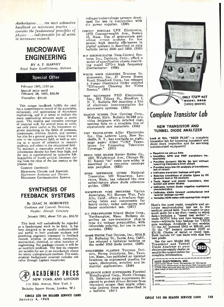
Authoritative . . . the most exhaustive handbook on microwave practice . . . contains the fundamental principles of physics . . . indispensable for all active in microwave research.
MICROWAVE ENGINEERING
BY A. F. HARVEY Royal Radar Establishment, Malvern
Special Offer
February 1963, 1245 pp.
Special price until February 28, 1963, $29.50
Thereafter: $35.00
This unique handbook fulfills the need for a comprehensive record of the principles, techniques, and applications of microwave engineering, and it is timed to include the many outstanding advances made in recent years. The modern and complete coverage of material will, for several years to come, not only prove useful to the microwave en-gineer practicing in the fields of antennas, components, electron devices, and systems, but also be a general guide to those who are new to the microwave field, as well as serv-ing as a source of reference to research students, and others in the educational field. To maintain a reasonable overall size, the information density has been kept high, and the text is supplemented by extensive bib-liographies of world archival literature dat-ing from the close of the last century to the present day.
Contents (sections) : Microwave Circuits and Materials Microwave Antennas and Devices Microwave Communication Systems
SYNTHESIS OF FEEDBACK SYSTEMS
By ISAAC M. HOROWITZ Guidance and Controls Division,
Hughes Aircraft Company
January 1963, about 725 pp., $16.50
This book will undoubtedly be regarded as a fundamental work in its field. It has been designed to be equally understandable and useful to both graduate students and practicing engineers interested in feedback control, whether in electrical, mechanical, aeronautical, chemical, or other branches of engineering. For graduate courses it will be an excellent textbook. The first six chapters are suitable for use in an introductory course for senior undergraduate students. The math. ematical background assumed includes cal-culus through Laplace transforms.
AP ACADEMIC PRESS NEW YORK AND LONDON
Ill Fifth Avenue, New York 3
Berkeley Square House, London, W.1
voltage / undervoltage sensors devel-oped for use in conjunction with d-c power supplies. (328)
CIRCUIT MODULES LFE Electronics, 1079 Commonwealth Ave., Boston 15, Mass. Use of germanium and silicon circuit modules for low power, high density efficiencies in digital systems is described in data bulletin series 2300 and 2350. (329)
H-F DISCRIMINATOR Data-Control Sys-tems, Inc., Danbury, Conn., offers a series of specification sheets describ-ing model GFD-4 high frequency discriminator. (330)
WHITE ROOM CLEANERS Branson In-struments, Inc., 37 Brown House Road, Stamford, Conn., has released a 4-page illustrated folder entitled "Ultrasonic Cleaning for White Rooms." (331)
TEST EQUIPMENT PRD Electronics, Inc., 202 Tillary St., Brooklyn 1, N. Y. Bulletin 900 describes a line of electronic instrumentation for microwave systems. (332)
SILICON RUBBER Dow Corning Corp., Midland, Mich. Bulletin 09-036 pro-vides designers with detailed engi-neering data on a complete line of elastomeric raw materials. (333)
UHF TRANSLATORS Adler Electronics Inc., One Lefevre Lane, New Ro-chelle, N. Y., has available an eight-page paper titled "UHF Trans-lators for Expanding Television Coverage." (334)
RESIN CORE SOLDER Kester Solder Co., 4201 Wrightwood Ave., Chicago 39, Ill. Kester "44" resin core solder is described in a two-color envelope size pamphlet. (335)
DIODE REFERENCE GUIDES National Transistor, 500 Broadway, Law-rence, Mass., has released two new subminiature glass diode reference guides. (336)
MICROWAVE TUBE BROCHURE Varian Associates, 611 Hansen Way, Palo Alto, Calif., offers a brochure feat-uring tubes and components for heavy radar, radar astronomy and linear accelerator use. (337)
D-C PREAMPLIFIER Inland Motor Corp., Northampton, Mass. Bulletin de-scribes an npn-transistor plug-in type d-e voltage preamplifier, with reversible polarity, for use in servo systems. (338)
DIODE TESTER Test Devices, Inc., 3014-B So. Halladay St., Santa Ana, Calif., has released a technical bulletin on the model 1050 diode tester. (339)
ENGINEERED PLASTICS Taunton Divi-sion, Haveg Industries, Inc., Taun-ton, Mass., has published an updated brochure on engineered plastics for space, electronics, aviation and in-dustrial applications. (340)
SELENIUM SURGE SUPPRESSORS Fansteel Metallurgical Corp., North Chicago, Ill. Selenium surge suppressors de-signed to protect silicon devices from transient surges that might other-wise destroy them are described in a bulletin. (341)
omplete Transistor Lab
• ONLY $7450 NET ' MODEL 2500
(battery powered)
NEW TRANSISTOR AND TUNNEL DIODE ANALYZER
Look at this "SECO PLUS"—a complete transistor lab for incoming transistor and diode stock inspection and for servicing transistorized equipment!
• Requires no set-up data • Identifies NPN and PNP transistors im-mediately
• Provides dynamic GO-No Go test without removing transistors from circuit
• Provides accurate DC analysis of transistors out of circuit
• Indicates transistor leakage and gain • Matches transistors of similar types by AC dynamic test or DC analysis
• Tests signal and power transistors, also tunnel and zener diodes
• Indicates tunnel diode negative resistance characteristics
• Indicates diode forward conductance and reverse leakage current
• Includes VOM meter with appropriate ranges
Here's the most rapid, complete and ac-curate semi-conductor test set in the medium priced field. You'd expect to pay much more for a set that—needs no setup data—includes a "speed test socket"— reads BOTH Icbo and Iceo leakage cur-rents—subtracts Iceo leakage for TRUE gain readings. Available in two models: (1) the AC powered 250A at $86.50; and (2) the "B" battery powered 250B at $74.50. Choice of metal or wood case. Both include 24" test leads with slim line test prods.
See the new Model 250 Transistor and Tunnel Diode Analyzer at your electronics supply dealer or send in the coupon below for complete information.
SECO ELECTRONICS, INC. 1243 South Clover Drive. Minneapolis 203. Minnesota Please rush information on the Model 250 Transistor and Tunnel Diode Analyzer plus full fine folder describing com-plete range of Seco test equipment.
NAME
COMPANY
ADDRESS
CITY STATE
dr-SECO
CIRCLE 220 ON READER SERVICE CARD CIRCLE 143 ON READER SERVICE CARD 143 January 4, 1963
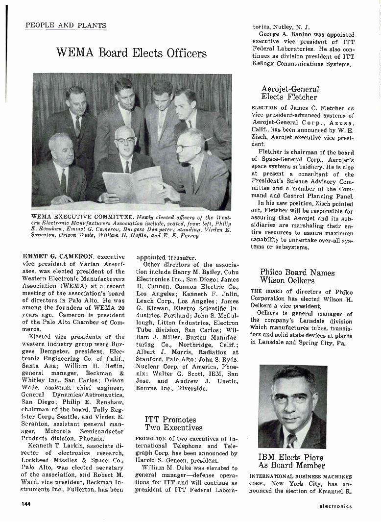
PEOPLE AND PLANTS
WEMA Board Elects Officers
WEMA EXECUTIVE COMMITTEE. Newly elected officers of the West-ern Electronic Manufacturers Association include, seated, from left, Philip E. Renshaw, Emmet G. Cameron, Burgess Dempster; standing, Virden E. Scranton, Orison Wade, William H. Heflin, and E. E. Ferrey
EMMET G. CAMERON, executive vice president of Varian Associ-ates, was elected president of the Western Electronic Manufacturers Association (WEMA) at a recent meeting of the association's board of directors in Palo Alto. He was among the founders of WEMA 20 years ago. Cameron is president of the Palo Alto Chamber of Com-merce.
Elected vice presidents of the western industry group were Bur-gess Dempster, president, Elec-tronic Engineering Co. of Calif., Santa Ana; William H. Heflin, general manager, Beckman & Whitley Inc., San Carlos; Orison Wade, assistant chief engineer, General Dynamics/Astronautics, San Diego; Philip E. Renshaw, chairman of the board, Tally Reg-ister Corp., Seattle, and Virden E. Scranton, assistant general man-ager, Motorola Semiconductor Products division, Phoenix.
Kenneth T. Larkin, associate di-rector of electronics research, Lockheed Missiles & Space Co., Palo Alto, was elected secretary of the association, and Robert M. Ward, vice president, Beckman In-struments Inc., Fullerton, has been
appointed treasurer. Other directors of the associa-
tion include Henry M. Bailey, Cohu Electronics Inc., San Diego ; James H. Cannon, Cannon Electric Co., Los Angeles; Kenneth F. Julin, Leach Corp., Los Angeles; James G. Kirwan, Electro Scientific In-dustries, Portland; John S. McCul-lough, Litton Industries, Electron Tube division, San Carlos; Wil-liam J. Miller, Burton Manufac-turing Co., Northridge, Calif.; Albert J. Morris, Radiation at Stanford, Palo Alto; John S. Rydz, Nuclear Corp. of America, Phoe-nix; Walter G. Scott, IBM, San Jose, and Andrew J. Unetic, Bourns Inc., Riverside.
ITT Promotes Two Executives
PROMOTION of two executives of In-ternational Telephone and Tele-graph Corp. has been announced by Harold S. Geneen, president.
William M. Duke was elevated to general manager—defense opera-tions for ITT and will continue as president of ITT Federal Labora-
tories, Nutley, N. J. George A. Banino was appointed
executive vice president of ITT Federal Laboratories. He also con-tinues as division president of ITT Kellogg Communications Systems.
Aerojet-General Elects Fletcher
ELECTION of James C. Fletcher as
vice president-advanced systems of Aerojet-General Corp., Azusa, Calif., has been announced by W. E. Zisch, Aerojet executive vice presi-dent.
Fletcher is chairman of the board of Space-General Corp., Aerojet's space systems subsidiary. He is also at present a consultant of the President's Science Advisory Com-mittee and a member of the Com-mand and Control Planning Panel.
In his new position, Zisch pointed out, Fletcher will be responsible for assuring that Aerojet and its sub-sidiaries are marshaling their en-tire resources to assure maximum capability to undertake over-all sys-tems or subsystems.
Philco Board Names Wilson Oelkers
THE BOARD of directors of Philco Corporation has elected Wilson H. Oelkers a vice president.
Oelkers is general manager of the company's Lansdale division which manufactures tubes, transis-tors and solid state devices at plants in Lansdale and Spring City, Pa.
IBM Elects Piore As Board Member
INTERNATIONAL BUSINESS MACHINES
CORP., New York City, has an-nounced the election of Emanuel R.
144 electronics
COLLEGE IS BUSINESS' BEST FRIEND Business employs almost half of
the product of colleges—the college
graduate. Business management is
largely composed of college gradu-
ates. Business concerns benefit ex-
tensively from the research colleges
engage in. Business owes college a
great debt.
Higher education is facing during the
next decade greatly enlarged student enrollments, the problems of an ex-plosion of knowledge, and the need to meet ever growing demands for ever better educated men and women.
These problems involve vastly in-creased costs which cannot be met out of present income.
The operating cost of higher educa-tion today is over four and a half billion dollars a year and will at least
double in this decade.
Business and industry, as major bene-ficiaries of American higher educa-tion, must recognize a responsibility to contribute their fair share.
American business corporations pro-duce much of the nation's wealth. They have enormous power for good. We believe they can exercise it in a meaningful way—as many do now— by providing voluntary support for colleges and universities of their
choice.
These conclusions, and the follow-ing statement of conviction, were
outcomes of a recent conference of business leaders sponsored in New York by the Council for Financial
Aid to Education, Inc.
HIGHER EDUCATION
XEEP ARIGHT
A STATEMENT
We believe that, in the light of the present urgency, now is the time for a broader and deeper participation by the business com-munity in the support of higher education. We therefore call upon our colleagues in American business and industry to help spread the base of voluntary support of higher education as a necessary supple-ment to the extensive support which busi-
KENNETH H. KLIPSTEIN, American Cyanamid Co.
JOSEPH A. GRAZIER, American Radiator & Standard Sanitary Corporation
M. NIELSEN, The Babcock & Wilcox Co.
HARMON S. EBERHARD, Caterpillar Tractor Co.
HAROLD H. HELM, Chemical Bank New York Trust Company
F. W. MISCH, Chrysler Corporation
FRANK O. H. WILLIAMS, Connecticut General Life Insurance Company
WESLEY M. DIXON, Container Corporation of America
THOMAS C. FOGARTY, Continental Can Company, Inc.
SAMUEL LENHER, E. I. du Pont de Nemours & Company
MARION B. FOLSOM, Eastman Kodak Company
LEWIS B. CUYLER, First National City Bank
RALPH J. CORDINER, General Electric Company
LEONARD F. GENZ, General Foods Corporation
GEORGE RUSSELL, General Motors Corporation
JOHN C. GRISWOLD, W. R. Grace & Company
OF CONVICTION
ness now provides to education through taxes. We urge responsible management to think through its opportunity and its obligation to adopt meaningful programs of voluntary corporate support to those colleges and universities whose service and quality they wish to encourage and nurture. We on our part will do no less.
JERRY McAFEE, Gulf Oil Corporation
GEORGE S. DIVELY, Harris-Intertype Corporation
FRANK R. MILLIKEN, Kennecott Copper Corporation
JAMES C. DONNELL II, Marathon Oil Company
REINHARD A. HOHAUS, Metropolitan Life Insurance Co.
STUART T. SAUNDERS, Norfolk & Western Railway Co.
STANLEY DE J. OSBORNE, Olin Mathieson Chemical Corp.
WILLIAM CARPENTER, Pittsburgh Plate Glass Co.
CHAMP CARRY, Pullman, Incorporated
JAMES T. GRIFFIN, Sears, Roebuck and Company
H. GERSHINOWITZ, Shell Development Company Shell Oil Company
E. L. STEINIGER, Sinclair Oil Corporation
JOHN E. SWEARINGEN, Standard Oil Company (Indiana)
M. J. RATHBONE. Standard Oil Company (N. J.)
CHARLES E. SPAHR, Standard Oil Company (Ohio)
J. ERIK JONSSON, Texas Instruments, Inc.
HARRY B. MeCLURE, Union Carbide Corporation
J. S. JOHNSON, U. S. Rubber Company
W. HOMER TURNER U. S. Steel Foundation, Inc.
R. D. LILLEY, Western Electric Company, Inc.
ALFRED S. GLOSSBRENNER. Youngetown Sheet & Tube Co. «
'JAMES B. BLACK, Pacific Gas & Electric Co.
'G. KEITH FUNSTON, New York Stock Exchange
'NEIL McELROY, The Procter & Gamble Co.
'DE WITT WALLACE, The Reader's Digest
'IRVING S. OLDS, Former Chairman of the Board
U. S. Steel Corp.
'FRANK W. ABRAMS, Former Chairman of the Board
Standard Oil Co. (N. J.)
'WALTER D. FULLER, The Curtis Publishing Co.
'DEVEREUX C. JOSEPHS, Former Chairman of the Board
Neu, York Life Insurance Co.
'ROBERT E. WILSON, U. S. Atomic Energy Commission
'FRANK H. SPARKS, President Council for Financial Aid lo Education, Inc.
*Director, Couticit for Fincinciat Aid to Education
Published as a public service in cooperation with The Advertising Council and the Council for Financial Aid to Education.
January 4, 1963 145
FREDDY
(Ç. AN YOU HEAR - ME?
by gag:
What you need, Freddy, in order to screen out those unwanted signals, is a
REEVES-HOFFMAN CRYSTAL FILTER (or maybe in your case just the container
would be good enough). Like Freddy, perhaps you have a need for a good filter
system. If so, why not get the facts now about Reeves-Hoffman crystal filters, avail-
able in frequency ranges from audio to 30 mc to meet commercial or military
specifications. Are we coming through loud and clear? Then write for bulletin QCF.
REEVES-FACOFFIVIA‘NI
CARLISLE, PENNSYLVANIA
DIVISION OF DYNAMICS CORPORATION OF AMERICA
PRODUCERS OF PRECISION
FREQUENCY CONTROL DEVICES ... crystals • crystal-controlled frequency sources, standards,
filters • component ovens
CIRCLE 221 ON READER SERVICE CARD
Custom Melting, Complete Redrawing, Strand and Vacuum Annealing Services for fine wire processing to customers' specifications.
WRITE for valuable brochure contain-ing fine wire com-positions, perti-nent properties and applications.
• Semiconductors
• Resistors
• Potentiometers
• Thermocouples
• Electronic Tubes
• Other Electronic Applications
precious, base, exotic
and special metals
— bare or
insulated
Piore as a member of the board of directors. Piore is IBM vice presi-dent, research and engineering. The former chief scientist of the
Office of Naval Research joined IBM in 1956 as director of research. He was elected a vice president in 1960.
Tamar Hires Barnhart As Chief Engineer
SIMON W. BARNHART has been ap-pointed chief engineer of Tamar Electronics, a division of Tamar Electronics Industries, Inc., Gar-dena, Calif.
Prior to joining Tamar, Barn-hart was department manager of the Armament Control division of Autonetics where he supervised 200 engineering personnel in all phases of engineering on airborne radar,
armament control systems, and as-sociated ground support equipment.
Kollmeyer Joins Adler Electronics
JASPER C. KOLLMEYER has joined the Systems Engineering depart-ment, Government Products division of Adler Electronics, Inc., New Rochelle, N. Y., as an executive en-gineer. He was formerly manager of systems design with ITT-Kellogg Co. Adler produces telecommunica-
tions systems and communications equipment.
TRW Microwave Names Price
APPOINTMENT of Oliver R. Price as manager advanced development, TRW Microwave division, Canoga Park, Calif., has been announced.
He will be responsible for TRW's
146 CIRCLE 146 ON READER SERVICE CARD electronics

Hanover Fair
Market Place for World Trade
The Hanover Fair is many things.
It is the world's largest interna-
tional trade fair devoted to busi-
ness only.
Its display of products includes
materials, equipment, and ma-
chinery for a broad range of indus-
trial applications.
It continually serves as a funda-
mental instrument for direct sales
negotiation and marketing analy-
sis at the international level.
Its strict policy of assigning exhib-
its according to product category
and the comprehensive scope of
each product area assure the op-
portunity for profitable business
contacts.
The Hanover Fair 1963 will have
5400 exhibitors from 27 countries
and a total display area of
6,372,000 sq. ft.
April 28-May 7 Hanover, Germany
Forinformation, room reservation forms,
and tickets of admission:
GERMAN AMERICAN
CHAMBER OF COMMERCE
666 Fifth Avenue
New York 19, N.Y.
increased activity in company and contract supported R&D programs in microwave antennas and compo-
nents. Prior to joining the Thompson
Ramo Wooldridge Inc. division, Price was chief engineer at Micro-Radionics and for several years was a member of the R&D Laboratories at Hughes Aircraft where he headed the advanced studies sec-tion.
McCulloh Takes New Position
WILLIAM L. MCCULLOH has joined Frequency Engineering Laborato-ries as senior electronic engineer in the firm's Systems division. His new duties will involve engineering
development of countermeasures equipment.
McCulloh was formerly senior electrical engineer at Lockheed Electronics Co.
Hare Accepts Post At CTS of Canada
WILLIAM F. J. HARE has been named director of research at CTS of Can-ada, Ltd., Ontario, Canada. He will head research on solid state devices and investigate the development of new and diversified products for the firm's Canadian electronics market.
Prior to joining CTS, Hare was a member of the technical staff of
Save time with these tested transistor design circuits Here's a ready source of quick, time-sav-ing answers to your transistor circuit problems ... practical guidance on essen-tial phases of today's semiconductor de-velopments. Because these three volumes bring you the successful work of prac-ticing engineers, every topic has perma-nent reference value and contributes to the Library's usefulness in your work.
You'll have at your fingertips hundreds of prored transis-tor circuits — with all the necessary de-sign informa-tion and com-ponent values required to uti-lize them in your own de-signs — and sa ve valuable man-hours of time and effort.
TRANSISTOR CIRCUITS
Edited by John M. Carroll
Managing Editor
Electronics
3 vols. 932 pp., 1735 illus. and tables, $24.95— payable $8.95 in 10 days, $8.00 monthly
Praise by experts ...
". . . a valuable reference to the circuit de-signer and en-gineer." —Electronics
". . . useful to those who are entering the field of semi-conductor cir-cuit design." —Con trot
"... a conven-ient and com-p rehe nsi v e. source of trans-istor informa-tion." —Radio-Elec-
troleies
LIBRARY These titres. big manuals supply hundreds and hun-dreds of transistor cir-cuits ready to be adapted to your specific needs . give valuable material on transistor characteristics, structures, and tech-niques. Articles. photo-graphs. des ign charts, nomographs, and ready-to-use circuits cover a vast range of applications ... from simple one-trans-istor -push-pull" ampli-fiers . . . to complex com-puter switching circuits with high-power transis-tors. You get data and circuits for home-enter-tainment and broadcast ,.quipment . .. computer and servomechanism cir-cuits ... missile, aircraft. and satellite equipment . . . industrial scientific, and medical devices . . . and many more. Library includes . . . Transistor Circuits and Applical inliR .1fotiera Transistor Circuits Design Manual for Transistor Circuits
dare 83.55. Bo let separately, these books would cost you $28.50. But under this special Library offer, they come to you at a saving—and you pay in small, enarenient in
if you desire.
SEE THIS LIBRARY 10 DAYS FREE Direct From Publisher
McGraw-Hill Book Co., Dept. L-1-4 327 W. 41st St., N. Y. C. 36 Send me the Transistor Circuit Library. In 10 days I will (cheek one) El remit full price of $24.05: or 1:1 only $8.95 in 10 days and $8.00 monthly. Other-wise I will return books postpaid. PRINT Name
Address City Zone. State
Primpanv
Posit Ion For price and terms outside U. S.
L write McGraw-Hill Inn., N. Y. C. 1.1.4
CIRCLE 222 ON READER SERVICE CARD
January 4, 1963 147
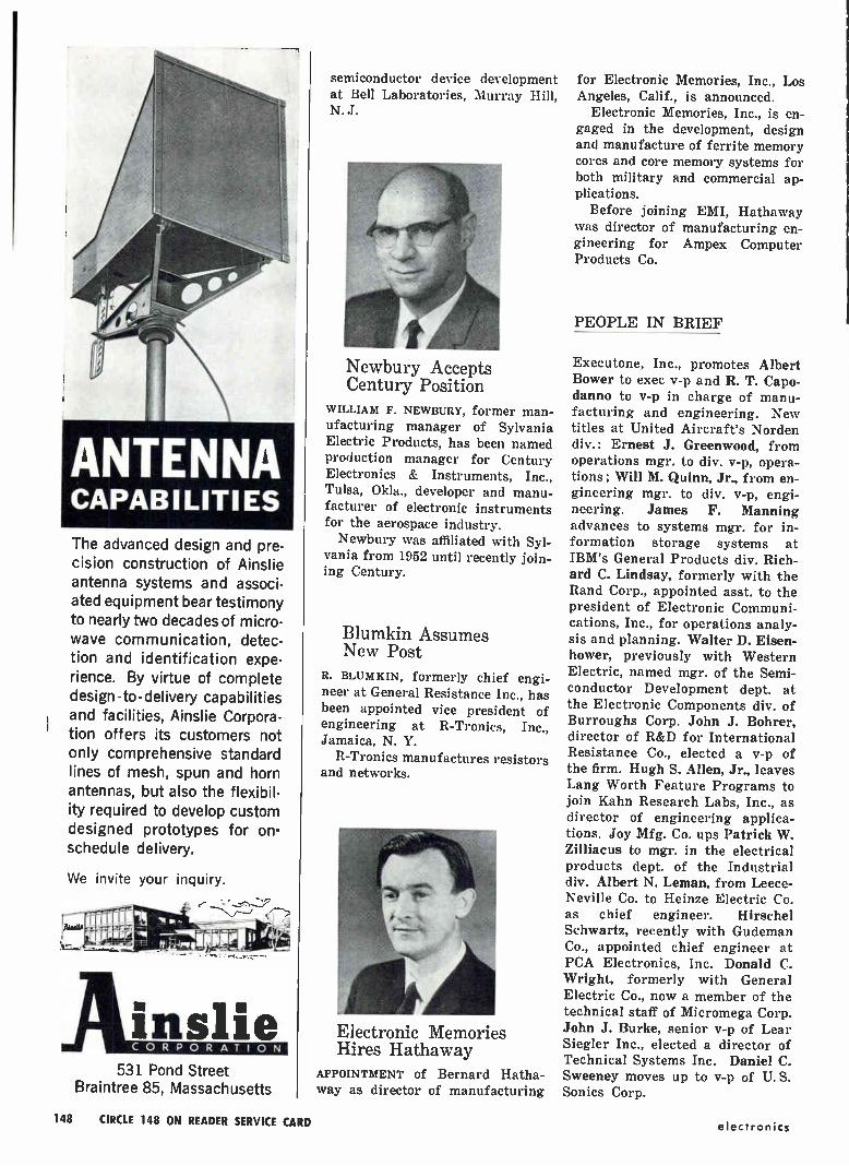
ANTENNA CAPABILITIES
The advanced design and pre-cision construction of Ainslie antenna systems and associ-ated equipment bear testimony to nearly two decades of micro-wave communication, detec-tion and identification expe-rience. By virtue of complete design-to-delivery capabilities and facilities, Ainslie Corpora-tion offers its customers not only comprehensive standard lines of mesh, spun and horn antennas, but also the flexibil-ity required to develop custom designed prototypes for on. schedule delivery.
We invite your inquiry.
531 Pond Street Braintree 85, Massachusetts
semiconductor device development at Bell Laboratories, Murray Hill, N. J.
Newbury Accepts Century Position
WILLIAM F. NEWBURY, former man-ufacturing manager of Sylvania Electric Products, has been named production manager for Century Electronics & Instruments, Inc., Tulsa, Okla., developer and manu-facturer of electronic instruments for the aerospace industry. Newbury was affiliated with Syl-
vania from 1952 until recently join-ing Century.
Blumkin Assumes New Post
R. BLUMKIN, formerly chief engi-neer at General Resistance Inc., has been appointed vice president of engineering at R-Tronics, Inc., Jamaica, N. Y.
R-Tronics manufactures resistors and networks.
Electronic Memories Hires Hathaway
APPOINTMENT of Bernard Hatha-way as director of manufacturing
for Electronic Memories, Inc., Los Angeles, Calif., is announced.
Electronic Memories, Inc., is en-gaged in the development, design and manufacture of ferrite memory cores and core memory systems for both military and commercial ap-plications.
Before joining EMI, Hathaway was director of manufacturing en-gineering for Ampex Computer Products Co.
PEOPLE IN BRIEF
Executone, Inc., promotes Albert Bower to exec v-p and R. T. Capo-danno to v-p in charge of manu-facturing and engineering. New titles at United Aircraft's Norden div.: Ernest J. Greenwood, from operations mgr. to div. v-p, opera-tions; Will M. Quinn, Jr., from en-gineering mgr. to div. v-p, engi-
neering. James F. Manning advances to systems mgr. for in-formation storage systems at IBM's General Products div. Rich-ard C. Lindsay, formerly with the Rand Corp., appointed asst. to the president of Electronic Communi-cations, Inc., for operations analy-sis and planning. Walter D. Eisen-hower, previously with Western Electric, named mgr. of the Semi-conductor Development dept. at the Electronic Components div. of Burroughs Corp. John J. Bohrer, director of R&D for International Resistance Co., elected a v-p of the firm. Hugh S. Allen, Jr., leaves Lang Worth Feature Programs to join Kahn Research Labs, Inc., as director of engineering applica-tions. Joy Mfg. Co. ups Patrick W. Zilliacus to mgr. in the electrical products dept. of the Industrial div. Albert N. Leman, from Leece-Neville Co. to Heinze Electric Co. as chief engineer. Hirschel Schwartz, recently with Gudeman Co., appointed chief engineer at PCA Electronics, Inc. Donald C. Wright, formerly with General Electric Co., now a member of the technical staff of Micromega Corp. John J. Burke, senior v-p of Lear Siegler Inc., elected a director of Technical Systems Inc. Daniel C. Sweeney moves up to v-p of U.S. Sonies Corp.
148 CIRCLE 148 ON READER SERVICE CARD electronics

What's your present job in electronics? What will you be working on tomor-row? Do you know the latest electronic developments outside your particular specialty that may affect your work?
Below is a sampling of topics within the 3,000 plus editorial pages produced per year by electronics' 28-man edito-rial staff. No matter where you work today, or in which job function (s), electronics will keep you fully in-formed as an electronic engineer. Sub-scribe today via the Reader Service Card in this issue. Only 7% cents a copy
at the 3 year rate.
Capacitors Communications Air Traffic Control
Amplifiers
Computers Crystals
Generators
Military Electronics
trge Techniques
Thin Films
Infrared
Microwaves
Radar ,
Transducers
electronics IS EDITED TO KEEP YOU FULLY INFORMED
ON ALL PHASES OF ELECTRONICS
Antennas
Data Processing
Instruments
Biophysics
Detectors
Lasers & Masers
Diodes & Diode Circuits
Magnetics
Modulators Networks Oscillators
Satellites
Transistors
Semiconductors Spice
Electronics
..•••••••••,‘"
Filters
Memories
Plasma & Ion En• ineerin
Switerr&--Switching Circuits
January 4, 1963 149
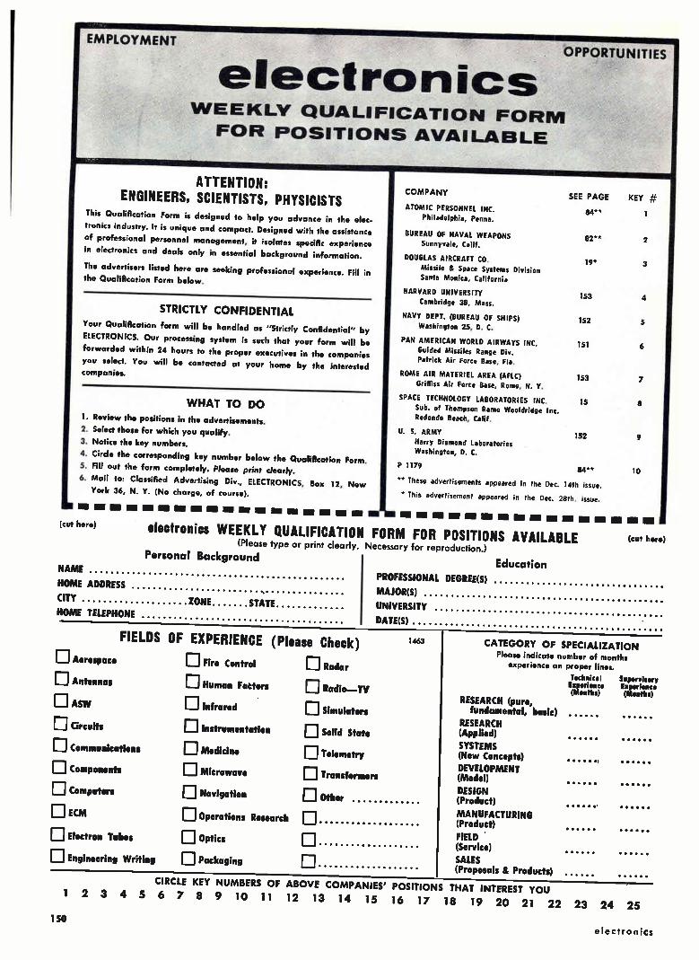
EMPLOYMENT
NAME
HOME ADDRESS
CITY ZONE STATE HOME TELEPHONE
OPPORTUNITIES
electronics WEEKLY QUALIFICATION FORM FOR POSITIONS AVAILABLE
ATTENTION: ENGINEERS, SCIENTISTS, PHYSICISTS
This Qualification Form is designed to help you advance in the elec-
tronics industry. It is unique and compact. Designed with the assistance
of professional personnel management, it isolates specific experience
in electronics and deals only in essential background information.
The advertisers listed here are seeking professional experience. Fill in
the Qualification Form below.
STRICTLY CONFIDENTIAL
Your Qualification form will be handled as "Strictly Confidential" by
ELECTRONICS. Our processing system is such that your form will be
forwarded within 24 hours to the proper executives in the companies
you select. You will be contacted at your home by the interested companies.
WHAT TO DO
1. Review the positions in the advertisements.
2. Select those for which you qualify. 3. Notice the key numbers.
4. Circle the corresponding key number below the Qualification Form.
5. Fill out the form completely. Please print clearly.
6. Mail to: Classified Advertising Div., ELECTRONICS, Box 12, New
York 36, N. Y. (No charge, of course).
COMPANY SEE PAGE
ATOMIC PERSONNEL INC. 84" Philadelphia, Penna.
BUREAU OF NAVAL WEAPONS
Sunnyvale, Calif.
DOUGLAS AIRCRAFT CO.
Missile & Space Systems Division Santa Monica, California
HARVARD UNIVERSITY
Cambridge 38, Mass.
NAVY DEPT. (BUREAU OF SHIPS)
Washington 25, D. C.
PAN AMERiCAN WORLD AIRWAYS INC.
Guided Missiles Range Div. Patrick Air Force Base, Fla,
ROME AIR MATERIEL AREA (AFLC) GrifFiss Air Force Base, Rome, N. Y.
SPACE TECHNOLOGY LABORATORIES INC. 15
Sub. of Thompson Ramo Wooldridge Inc. Redondo Beach, Calif.
U S. ARMY 152
Harry Diamond Laboratories Washington, D. C.
P 1179 84**
** These advertisements appeared in the Dec. 14th issue.
* This advertisement appeared in the Dec. 28th. issue.
KEY
1
82** 2
19* 3
153 4
152 5
151 6
153 7
8
9
10
MI MI MI IM IM MI 1311 'BMW IM MI MR IIM WI ZM
(cut here) electronics WEEKLY QUALIFICATION FORM FOR POSITIONS AVAILABLE (cut herb) (Please type or print clearly. Necessary for reproduction.)
Personal Background Education
PROFESSIONAL DEGREE(S)
MAJOR(S)
UNIVERSITY
DATE(S)
El Aerospace
DAntennas
D ASW D Circuits
D Communications
DComponents
D Computers
EI ECM
Ej Electron Tubes
D Engineering Writing
FIELDS OF EXPERIENCE (Please Check)
D Fire Control D Radar DHuman Factors
El infrared
D Instrumentation
D Medicine
DMicrowave
D Navigation
DOperations Research
D Optics D Packaging
11 Radio—TV
D Simulators
D Solid State II] Telemetry
D Transformers
D Other
1463
RESEARCH (pure, fundamental, basic)
RESEARCH (Applied)
SYSTEMS (New Concepts)
DEVELOPMENT (Model)
DESIGN (Product)
MANUFACTURING (Product)
FIELD (Service)
SALES (Proposals & Products)
CATEGORY OF SPECIALIZATION Please indicate number of months
experience on proper lines.
Technical Supervisory Experience Experience (Months) (Meath)
CIRCLE KEY NUMBERS OF ABOVE COMPANIES' POSITIONS THAT INTEREST YOU
I 2 3 4 5 6 7 8 9 10 11 12 13 14 15 16 17 18 19 20 21 22 23 24 25
150 electronics

ENGINEERS • SCIENTISTS
encyclopedic exposure to the whole world of space vehicle & missile technology is basic to engineering with PAN AM'' at the Atlantic Missile Range. The
reason: engineers and scientists here strive to match the capabilities of each new
launch vehicle with range test systems of equal or greater accuracy. Our engineers and scientists have pushed the past and present instrumentation systems to their operational limits— and have gone on to create a whole new range technology. They have developed design criteria and are providing technical direction for global tracking and telemetry systems, combining the latest techniques from all areas of electronics, optics and infrared. 0 Today, forward looking groups at PAN AM's Guided Mis-siles Range Division are not only planning for this year's and next year's tests but are considering range requirements five through fifteen years ahead— requirements to test manned space vehicles still on the drawing boards or "existing in concept" only.
OPPORTUNITIES NOW EXIST to join PAN AM at the Cape in developing range systems hemispheric, global and celestial in scope—
and share in the exceptional professional development implicit in these assignments.
Systems Engineers-EE's, Physicists & Mathematicians capable of assuming complete project responsibility for new range systems.
Instrumentation Planning Engineers — EE's, Physicists to be responsible for specific global range instrumentation concepts.
Senior Engineers & Scientists— PhD's in Math, Physics, Celestial Mechanics, Astronomy or Electronics.
Experience in one or more of these areas: Pulse radar, CW techniques, telemetry, infrared, data handling, communications, closed circuit TV, frequency analysis, command control, command guidance, underwater sound, timing, shipboard instrumentation.
Why not write us today, describing your interests and qualifications in any All ie
of the areas above. Address Dr. Charles Carroll, Dept.28A-1, Pan American illfflogglie GUIDED MISSILES RANGE DIVISION World Airways, Incorporated, P.O. Box 4336, Patrick Air Force Base, Florida. *Carrying on Range Planning, Engineering and Operation of Atlantic Missile 111.1" 111. PATRICK AIR FORCE BASE, FLORIDA
Range for the USAF since 1953. An equal opportunity employer. 411b
151 January 4, 1963

NOW FORMING A select group of
Electronics Engineers to manage the
Installation,
Maintenance & Reliability
Programs for Naval
shipboard electronics
Get in on the ground floor for these TOP-LEVEL opportunities by contacting
the Director—Industrial Relations
and Manpower, Code 720-A.
The increasing complexity of electronic equipments and systems on board the Navy's surface and sub-surface ships has spot-lighted the importance of installation and maintenance engineering more than ever before. Therefore, the Bureau of Ships is establishing an ELECTRONICS MAINTENANCE CENTER in Norfolk, Virginia, to take over the management of—and the responsibility for—shipboard INSTALLA-TION, RELIABILITY, MAINTENANCE and PRODUCT IMPROVEMENT requirements for
• ECM and RADAR,
• COMMUNICATIONS • SONAR, and
• SUPPORT Systems
As yet, this is not a large organization, but the implications for the future are interesting. These will be pivotal positions which will give a man with a few years
experience—and some management potential—an insight and influence that may be limited only as the individual himself is limited. Since he will be responsible in his own area for relations with design and development people in the Bureau, with industrial contractors, with operating units and support activities, and with counter-parts in other Bureaus—he will have ample opportunity to know, and become known.
In all, there are openings for perhaps 30 engineers, and as many technicians, with these numbers to increase steadily as the Center takes over more of its assigned responsibilities. Starting salaries range up to $12,845 ($13,615 by January 1st, 1964),
and offer the important benefits of Career Civil Service. The Center will be located in Norfolk, Virginia ... where climate and costs are just right for ocean front living.
bureau of ships Department of the Navy, Washington 25, D.C.
a message to R&D-oriented
EE's and Physicists from an old friend in Washington, D.C.
We have several staff open-ings for Electronics Engi-neers and Physicists at our research laboratories in northwest Washington, D. C., just off Connecticut Avenue.
Our 1400 or more scientists, engineers and support per-sonnel perform research in advanced electronic and elec-tro-mechanical fuzing and guidance systems . . . and other electronic ordnance devices such as range find-ers, self-adaptive controls,
and optical and acoustical sensors. We are—or, rather, we were —DOFL, the Diamond Ordnance Fuze Laboratory, a highly-respected govern-ment research organization. Now, however, we have a new name, and new expan-sion plans that are calling for research into nuclear ra-diation and reactors, plasma physics, fluid logic systems, fluid amplification, lasers (of course), stochastic proc-esses, organic and metallo-
Want to learn more? Get in touch with James L. Charney.
HARRY DIAMOND LABORATORIES
organic polymers, binary semiconducting compounds, microelectronics, quantuum mechanics . . . and literally dozens of others.
You'll like the work, the fa-cilities, the location, the benefits of Career Civil Service ... and the freedom of research that may take you well beyond our pri-mary missions. (For those interested in advance de-gree work, our programs are among the best you'll find anywhere.)
formerly DOFL DEPARTMENT OF THE ARMY
Connecticut Avenue at Van Ness, N.W. • Washington 25, D. C.
152
electronics

EMPLOYMENT
OPPORTUNITIES
NATIONAU COVERAGE
The advertisements in this section include all em-ployment opportunities — executive, management, technical, selling, office, skilled, manual. etc.
Look in the forward section of the magazine for additional Employment Opportunities advertising.
- RATES - DISPLAYED: The adverti›ing :ate is $40.17 per
inch for all advertising appearing on other than a ,.ontract basis. Contract rates quoted on request.
An advertising Inch is measured 7/a vertically on a column-3 columns-30 inches to a page.
Subject to Agency Commission.
UNDISPLAYED: $2.70 per line, minimum 3 lines. To figure advance payment count 5 average words as a line.
Box numbers—count as I line.
Diseount of 10°a If full payment is made in ad-lance for 4 consecutive insertions.
Not subject to Agency Commission.
SEAR C BUSINESS OPPOR
An opportunity in the area of High Energy Particle Physics
HARVARD UNIVERSITY
opcnier) for
ELECTRONICS ENGINEERS
to join small groups of scientists and engineers in the development of in-strumentation for the world's largest electron accelerator—a 6-BEV alternat-ing gradient synchrotron. Experience or knowledge of fast pulse transistor circuitry, power supplies and intercon-nections desirable.
Resumes and inquiries concerning ibis opportunity are invited
PERSONNEL DEPARTMENT
ifflRUflR UNIVERSITY
1352 Massachusetts Avenue
Harvard Square, Cambridge 38, Mass.
An equal opportunity employer
LIGHT SECTION Classified Advertising
UNITIES EQUIPMENT - USED or RESALE
DISPLAYED --RATES--- UNDISPLAYED
The advertising is $27.25 per inch for all advertising other than on a contract basis. AN ADVERTISING INCH is measured 7/8" vert. on a column, 3 cols.-30 inches—to a page. EQUIPMENT WANTED or FOR SALE ADVERTISE-MENTS acceptable only in Displayed Style.
$2.70 a line, minimum 3 lines. To figure ad-vance payment count 5 average words as a line.
BOX NUMBERS count as one line additional.
DISCOUNT of 10°/e if full payment is made in advance for four consecutive insertions.
Send NEW ADVERTISEMENTS or Inquiries to Classified Adv. Div. of Electronics, P. 0. Box 12, N. Y. 36, N. Y.
EXCELLENT USED LABORATORY EQUIPMENT H-P =132bA SHF SIG. GEN. I(e•15.5 C.C., LIKE NEW 51685 H-P =628A SHF SIG. GEN. 15-21 G.C.. LIKE NEW. $1490 G.R. =805C STO. SIG. GEN. 50 KC-50 MC. EXCELLENT 5 695 MEAS. CORP 084R SIG. GEN. 300 MC-1000 MC, EXCELLENT 5 695 KAY MEGAMATCH SWEEPER 10 MC-I C.C., 30 MC SWEEP WIDTH S 415
RUTHERFORD B7 PULSE GENERATOR ALMOST NEW 5 430 DUMONT 401 SCOPE. DC-200 KC. 10 MV CM. NEW CRT $ 190 TEKTRONIX PLUGINS 53 51 -13". 53 51 "K", each 5 65
— SELL OR TRADE, MAKE OFFER — ELECTRO DIGITAL VOLTMETER. OUA 100. .001-999.9 VDC. 01°,, AUTO RANGING. ENDEVCO TRIAXIAL ACCELEROMETER =2223 & 2616 3 CHANNEL LAB. AMPLIFIER
FREQ. METERS—PRD 579A. 1.6-2.6 GC: FXR N4I0A. 1-4 GC LINK AVIATION 250400 PHASE COMPARATOR & PWR SUPPLY, SERVO ANALYSIS.
ALL WITH MONEY-BACK GUARANTEE, FOB BERKELEY, ADD. CALIF. TAX IN CALIF.
SPECIALTIES RESEARCH, BOX 2116 S. BERKELEY STA., BERKELEY 5, CALIF.
1 FOR RESEARCH — DEVELOPMENT
& EXPERIMENTAL WORK Clvm• 10.000 different electronic parts: wave-guide, radar components and parts, test sets. pulsers, antennas, pulse mfr., magnetrons. IF and pulse amplifiers, dynamotors, 400 cycle xmfrs, 584 ant, pedestals. etc. PRICES AT A FRACTION OF ORIOINAI. COST!
COMMUNICATIONS EQUIP CO. 343 CANAL ST., N. Y. IS. WO 6-4045
CHAS. ROSEN Fonierly at 131 Liberty St.)
CIRCLE 951 ON READER SERVICE CARD
LOOKING FOR USED/ SURPLUS ELECTRONIC
EQUIPMENT/COMPONENTS? For an up-to-date listing of such equip-
ment see Searchlight Section of Dec. 14th.
CIRCLE 950 ON READER SERVICE CARD
RADIO RESEARCH INSTRUMENT CO. AUTO-TRACK & TELEMETRY ANTENNA PEDESTALS 3 8. 10 CM, SCR. 5134 AUTOTRACK RADARS. AN TP5-113 SEARCH. AN TPSYO HT. FINDERS AN FPN•32GCA. AN , APS-10 NAVIG. & WEATHER. AN AP5•1513 PRECISION. AN API2-358 PRECISION. AN AP5-31A SEARCH. DOZENS MORE. .5-1-2 MEGAWATT HIGH POWER PULSERS.
RADIO RESEARCH INSTRUMENT CO. 550 Flits Ave., New York Judson 6-4691
RADAR SYSTEMS & COMPONENTS/ Ieve CIRCLE 952 ON READER SERVICE CARD
OVER 2,000,000
RELAYS IN STOCK!
U Send for Catalog SS . Send
RELAY CORP. 4? WHITE ST., N.T.I3,N.Y. • WAlker 5-6900
CIRCLE 953 ON READER SERVICE CARD
"IN-SERVICE" ENGINEERS ROME AIR MATERIEL AREA
(A major component of Air Force Logistics Command)
Rome Air Materiel Area has been assigned the mission of provid-ing Ground Communications-Elec-tronic logistic support to the Air Force. A very vital facet for ful-filling this responsibility involves those engineering functions neces-sary to insure the performance integrity of the C-E equipments and systems once they become operational.
TYPICAL RESPONSIBILITIES OF ROAMAs 'IN-SERVICE ENGINEERS" ARE:
Modification or rehabilitation of opera-tional Ground CAE equipments by correc-tion of design deficiencies.
- Development of engineering specifications for support of procurement.
- Providing engineering design criteria to insure maintainability, serviceability and reliability of operational CBE equipment.
- Performing engineering liaison with AF Contractors.
CURRENT AND FUTURE ASSIGNMENTS CREATE AN EVER INCREASING DEMAND
FOR:
Electronic Engineers (all options)
Electrical Engineers
Mechanical Engineers
General Engineers
TO MONITOR AND PERFORM WORK ON VITAL PROJECTS IN THE FOLLOWING AREAS:
Search and Detection Radar
Missile Guidance and Tracking Digital and Analog Computers
Beacon and Identification Equipments ICBM Communications Sub-Systems
Communications Ancillary Equipments Electronics Systems (Warning, Intelligence,
Command, Support)
We have an immediate and urgent need for Graduate engineers, to insure the operational readiness of Ground C-E systems and equip-ments. Current demands at Rome Air Materiel Area for in-service engineering support are heavy. Increased mission responsibilities will entail even heavier demands in the future.
ROAMAs Directorate of Materiel Management provides an im-mediate career opportunity for graduate Electronic, Electrical, General and Mechanical Engi-neers. Ground Communications and operational Electronics Sys-tems and Equipments are subject to continuous change consistent with advances in the state of the art. Keep abreast of the con-tinuous scientific advancements as a contributor to the engineering accomplishments of the Air Force in the highly specialized fields of communications electronics.
For more information about Air Force Civilian career opportunities in "In-Service" Engineering submit your resume to:
Mr. William Pagano
Professional Scientific Recruiter
ROAMA GRIFFISS AIR FORCE BASE
Rome, New York
153
January 4, 1963
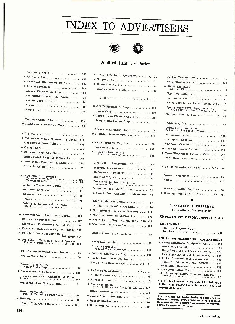
INDEX TO ADVERTISERS
Academic Press 143
• Acromag, Inc. 120
• Advanced Electronics Corp 142
• Ainslie Corporation 148
Airpax Electronics, Inc 123
Airtruntcs International Corp 73
Ampex Corp. 14
Arena 110
Audax 110
Birtcher Corp., The
Audited Paid Circulation
• Hewlett-Packard Company 10, 11
• Hitachi, Ltd. 101
• Hitemp Wires Inc 24
Hughes Aircraft Co 115
I 13 M 74, 75
• J F D Electronics Corp 133
Junco Corp. 130
• Japan Piezo Electric Co., Ltd 155
134 Jerrold Electronics Corp
• Dude'man Electronics Corp 40
•CSF 112
• Celco-Constantine Engineering Labs 118
ChatIlion & Sons. John 121
• Clairex Corp. 102
• Clarostat Mfg. Co., Inc 42
Consolidated Reactive Metals, Inc 146
• Constantine Engineering Labs 118
Coors Porcelain Co 23
• Daystrom Incorporated Potentiometer Div. Transicoll Div.
DeLevan Electronics Corp.
Despatch Oven Co
Di Amo Corp
Drusch
duPont de Nemours & Co.. Inc, E. I.
• Electrodynamic Instrument Corp 104
Electro Instruments Inc 117
Electronic Engineering Co. of Calif. 138
• Electronic Instrument Co.. Inc. (EICO) 137
• Fairchild Semiconductor Corp.
3rd cover, 156
• Federation Nationale des Industries Electroniques 105, 106, 107
Florida Development Commission
Flying Tiger Line
General Electric Co. Power Tube Dept. 33
• General RF Fittings, Inc
German American Chamber of Com-merce
Gudebrod Bros. Silk Co., Inc
Hamilton Standard Div. of United Aircraft Corp
• Hamlin, Inc.
Hansen Mfg. Co., Inc
121
125 39
141
22
32
Kauke & Company, Inc
• Keithley Instruments, Inc
40
136
• Lapp Insulator Co.. Inc 135
Leesona Corp. 128
• Litton Industries Inc. Electron Tube Div 138
Machlett Laboratories, Inc 27
Marconi Instruments 142
McGraw-Hill Book Co. 147
Midland Mfg. Co 121
Minnesota Mining & Mfg. Co. Mincom Div.
Mitsubishi Electric Mfg. Co
Motorola Semiconductor Products Inc 41
109 NRC Equipment Corp 38
National Semiconductors Ltd 120 76
• New Hermes Engraving Machine Corp 115
• North Atlantic Industries, Inc 100
• Northeastern Engineering. Inc....130 131
• Northern Radio Co., Inc 129
Origin Electric Co., Ltd
Paradynamice Inc.
Philco Corporation Sub. of Ford Motor Co
35 • Polarad Electronics Corp
29 • Potter Instrument Co., Inc
Precision Instrument CO 17. 18
• Radio Corp. of America 4th cover
Radio Materials Co 95
147 • Raytheon Company 13
34 • Reeves-Hoffman Div. of Dynamics Corp. of
Ribet-Desjardins
36 • Rixon Electronics, Inc.
40 • Rochar Electronique
130 • Rohn Mfg. Co
America 146
111
137
113
122
122
Sarkes Tarzian Inc 127
Seco Electronics Inc 143
• Sierra Electronic Div. of Philco
Signetics Corp.
Souriau et Cie 111
Space Technology Laboratories, Inc 15
Sperry Microwave Electronics Co., Div. of Sperry Rand Corp 25
Sprague Electric Co 9 23
Tektronix, Inc. 07
Texas Instruments Inc. Industrial Products Groups 31
Thermonetics Inc. 137
Thompson-Houston 108
Thompson-Varian 109
• Toyo Conepaper Co., Ltd 115
• Toyo Electronics Industry Corp 135
Toyo Musen Co., Ltd 22
• United Transformer Corp 2nd cover
Varian Associates 31
Videon 110
103
19 Welch Scientific Co., The 126
• Westinghouse Electric Coro 98, 99
CLASSIFIED ADVERTISING
F. J. Eberle, Business Mgr.
EMPLOYMENT OPPORTUNITIES .151-153
EQUIPMENT
(Used or Surplus New) For Sale
153
INDEX TO CLASSIFIED ADVERTISERS
22 • Communications Equipment Co 163
Harvard University 153
119 Navy Dept. of the (Bureau of Ships) 152
129 Pan American World Airways Inc 151
21 • Radio Research Instruments Co 153
Rome Air Material Area (AFLC) 153
Specialties Research 153
• Universal Relay Corp 153
U. S. Army, Harry Diamond Labora-tories
152
• See advertisement in the July 25, 1962 issue of Electronics Buyers' Guide for complete line of products or services.
This Index and our Reader Service Numbers are pub• lished as a service. Every precaution is taken to make them accurate, but electronics assumes no responsi• bilities tor errors or omissions.
154
electronics
electronics
Audit Bureau of Circulations
Associated Beninese Publicatiorus
Audited Paid Circulation
R. S. QUINT: Assistant Publisher Buyers' Guide and Business Manager
FRED STEWART: Promotion Manager
B. ANELLO: Market Services Manager
JAMES T. HAUPTLI
Advertising Salta Manager
RICHARD J. TOMLINSON: Production Manager
GEORGE E. POMEROY: Classified Manager
HUGH J. QUINN: Circulation Manager
ADVERTISING REPRESENTATIVES
ATLANTA (9): Michael H. Miller, Robert C. Johnson 1375 Peachtree St. N.E., Trinity 5-0523
(WOO code 404)
BOSTON (16): William S. Hodgkinson, Donald R. Furth McGraw-Hill Building, Copley Square, Congress 2-1160 (area code 617)
CHICAGO (11): Harvey W. Wernecke, Robert M. Denmead 645 North Michigan Avenue, Mohawk 4-5800
(area code 312) CLEVELAND (13):
Paul T. Fegley 55 Public Square, Superior 1-7000
(area code 216)
DALLAS (1): Frank Le Beau The Vaughn Bldg., 1712 Commerce St. Riverside 7-9721 (area code 214)
DENVER (2); J. W. Patten Tower Bldg., 1700 Broadway, Alpine 5-2981 (area code 303)
HOUSTON (25): Joseph C. Page, Jr. Prudential Bldg., Holcombe Blvd., Riverside 8-1280 (area code 713)
LOS ANGELES (17): Peter S. Carberry, Ashley P. Hartman, W. C. Gries 1125 W. 6th St., Huntley 2-5450
(area code 213) NEW YORK (36):
Donald H. Miller, Henry M. Shaw, George F. Werner 500 Fifth Avenue, LO-4-3000
(area code 212) PHILADELPHIA (3): Warren H. Gardner, William J. Boyle 6 Penn Center Plaza, LOcust 8-4330
(area code 215)
SAN FRANCISCO (11): R. C. Alcorn 255 California Street, Douglas 2-4600
(area code 415) LONDON W1:
Edwin S. Murphy Jr. 34 Dover St.
FRANKFURT/Main: Matthi e Herfurth 85 Westendstrasse
GENEVA: Michael R. Zeynel 2 Place du Port
"Headquarters for Business Information"
McGraw-Hill Technical and Business Publications
American Machinist Metal-working Manufacturing
Aviation Week and Space Technology
Business Week Chemical Engineering Chemical Week Coal Age Construction Methods and
Equipment Construction Daily Control Engineering Electrical Construction
and Maintenance Electrical Merchandising Electrical Newsletter Electrical West
Electrical Wholesaling Electrical World Electronics Engineering Digest Engineering and Mining Journal E & MJ Metal and Mineral
Markets Engineering News-Record Factory Fleet Owner Industrial Distribution National Petroleum News Nucleonics Nucleonics Week
Week Platt's Oilgram News Platt's Oilgram Price Service Power
Product Engineering Purchasing Week Science Week Textile World
Overseas only: Automobile International
(English, Spanish) Ingenieria Internacional
Construccion (Spanish) International Management
(English, Spanish Portuguese editions)
Metalworking Production (Great Britain)
Available by subscription only — to qualified persons actively engaged in the field of the publi-
cation. For subscription rates and information describing the editorial coverage of any of the
above publications, write to: Subscription Manager, Circulation Department, McGraw-Hill Pub-
lishing Company, 330 West 42nd Street, New York 36, N. Y.
Acoustical Components of Superior Quality
JAPAN PIEZO supplies 80% of
Japan's crystal product require-
ments.
STEREO CARTRIDGE
Crystal — "PIEZO" Y-130 X'TAL STEREO CARTRIDGE
At 20 °C, response: 50 to 10,000 cis with a separation of 16.5 db. 0.6 V output at 50 mm/sec. Tracking force: 6+1 gm. Compliance: 1.5 x 10⁻⁶ cm,idyne. Termination: 1M f-1
+150 pF.
Write for detailed catalog on our complete line of acoustical products including pickups, microphones, record players, phonograph motors and many associated products.
FEZO JAPAN PIEZO ELECTRIC CO., LTD. Kami-renjaku, Mitaka, Tokyo, Japan
January 4, 1963 CIRCLE 155 ON READER SERVICE CARD 155

V,,
E3readboard or custom microc rcuit components.
You design and breadboard it.
156
electronics

(Actual size —4 • )
We integrate it. What you do: Using data sheet information for Fairchild custom design components. you develop a worst-case circuit design. You can then breadboard the components and experiment until circuit performance meets your requirements exactly. The transistors, resis-tors, capacitors and diode arrays are Fairchild production microcircuit components physically separated and mounted in standard packages. Thus, your breadboard working model is a functional replica of the finished
integrated microcircuit.
What we do: Fairchild uses your proven breadboard design with its specifications to develop masks and test
equipment for manufacturing the integrated microcircuit. The circuit elements are diffused into a single chip of silicon using the Planar* process and intraconnected using an evaporated metal over oxide process ,. Delivery is within ninety days from acceptance of your custom design. The finished microcircuit product possesses the same reliability demonstrated in over nine million hours of operating life tests on Fairchild Micrologic units.
Data sheets sent on request.
FAIRCHILD
SEMICONDUCTO R FAIRCHILD SEMICONDUCTOR/54S WHISMAN RD., MOUNTAIN VIEW, CALIF./YORKSHIRE fl 8161/TWX: 41S-VEN.916S/A DIVISION OF FAIRCHILD CAMERA AND INSTRUMENT CORPORATION
*Planar: a patented Fairchild process. t M.0.0.: a patented Fairchild process.
CIRCLE 901 ON READER SERVICE CARD
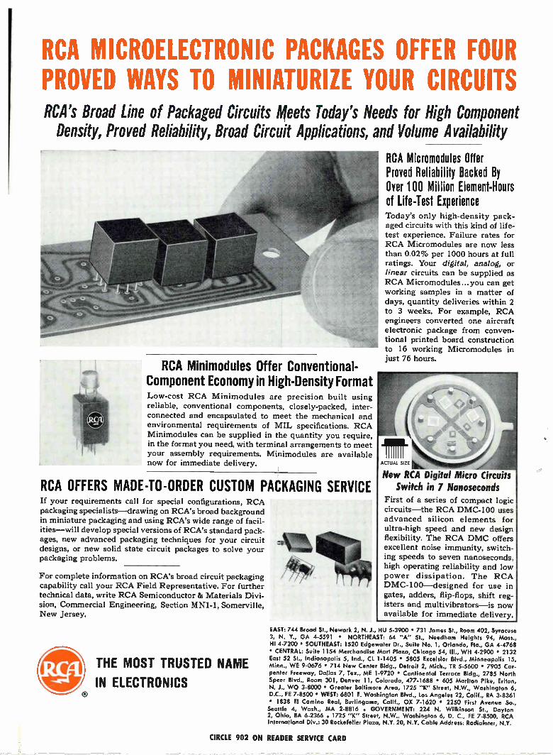
RCA MICROELECTRONIC PACKAGES OFFER FOUR PROVED WAYS TO MINIATURIZE YOUR CIRCUITS RCA's Broad Line of Packaged Circuits Meets Today's Needs for High Component
Density, Proved Reliability, Broad Circuit Applications, and Volume Availability
RCA Minimodules Offer Conventional-Component Economy in High-Density Format Low-cost RCA Minimodules are precision built using reliable, conventional components, closely-packed, inter-connected and encapsulated to meet the mechanical and environmental requirements of MIL specifications. RCA Minimodules can be supplied in the quantity you require, in the format you need, with terminal arrangements to meet your assembly requirements. Minimodules are available now for immediate delivery.
RCA OFFERS MADE-TO-ORDER CUSTOM PACKAGING SERVICE If your requirements call for special configurations, RCA packaging specialists—drawing on RCA's broad background in miniature packaging and using RCA's wide range of facil-ities—will develop special versions of RCA's standard pack-ages, new advanced packaging techniques for your circuit designs, or new solid state circuit packages to solve your packaging problems.
For complete information on RCA's broad circuit packaging capability call your RCA Field Representative. For further technical data, write RCA Semiconductor 86 Materials Divi-sion, Commercial Engineering, Section IVINI-1, Somerville, New Jersey.
ele llio THE MOST TRUSTED NAME
Vie IN ELECTRONICS
RCA Micromodules Offer Proved Reliability Backed By Over 100 Million Element-Hours of Life-Test Experience Today's only high-density pack-aged circuits with this kind of life-test experience. Failure rates for RCA Micromodules are now less than 0.02% per 1000 hours at full ratings. Your digital, analog, or linear circuits can be supplied as RCA Micromodules ...you can get working samples in a matter of days, quantity deliveries within 2 to 3 weeks. For example, RCA engineers converted one aircraft electronic package from conven-tional printed board construction to 16 working Micromodules in just 76 hours.
ACTUAL SIZE
New RCA Digital Micro Circuits Switch in 7 Nanoseconds
First of a series of compact logic circuits—the RCA DMC-100 uses advanced silicon elements for ultra-high speed and new design flexibility. The RCA DMC offers excellent noise immunity, switch-ing speeds to seven nanoseconds, high operating reliability and low power dissipation. The RCA DMC-100—designed for use in gates, adders, flip-flops, shift reg-isters and multivibrators—is now available for immediate delivery.
EAST: 744 Brood St., Newark 2, N. J., HU 5-3900 • 731 James St., Room 402, Syracuse 3, N. Y., GA 4-5591 • NORTHEAST: 64 "A" St., Needham Heights 94, Mass., HI 4-7200 • SOUTHEAST: 1520 Edgewater Dr., Suite No. 1, Orlando, Fla., GA 4-4768 • CENTRAL: Suite 1154 Merchandise Mart Plaza, Chicago 54, III., WH 4-2900 • 2132 East 52 St., Indianapolis 5, Ind., CL 1-1405 • 5805 Excelsior Blvd., Minneapolis 15, Minn., WE 9-0676 • 714 New Center Bldg., Detroit 2, Mich., TR 5-5600 • 7905 Car-penter Freeway, Dallas 7, Tex., ME 1-9720 • Continental Terrace Bldg., 2785 North Speer Blvd., Room 301, Denver 11, Colorado, 477-1688 • 605 Marlton Pike, Erlton, N. J., WO 3-8000 • Greater Baltimore Area, 1725 "K" Street, N.W., Washington 6, D.C., FE 7-8500 • WEST: 6801 E. Washington Blvd., los Angeles 22, Calif., RA 3-8361 • 1838 El Camino Real, Burlingame, Calif., OX 7-1620 • 2250 First Avenue So., Seattle 4, Wash., MA 2-8816 . GOVERNMENT: 224 N. Wilkinson St., Dayton 2, Ohio, BA 6-2366 . 1725 "K" Street, N.W., Washington 6, D. C., FE 7-8500. RCA International Div.: 30 Rockefeller Plaza, N.Y. 20, N.Y. Cable Address: Radiointer, N.Y.
CIRCLE 902 ON READER SERVICE CARD