Hobby-Electronics-1982-08.pdf - World Radio History
68
-
Upload
khangminh22 -
Category
Documents
-
view
5 -
download
0
Transcript of Hobby-Electronics-1982-08.pdf - World Radio History
AUGUST' 82 ISSN 0142-6192 1
70%- . ..ep
Project Electronics For Everyone
PROJeCT: MUSIC-Audio Analyser TEST EQUIPMENT-LED Millivoltmeter 'INTO RADIO-SWR Mete
Introduction\ to Electronics
Beginner's Guide to Construction
Ambit's new style catalogue continues to lead the market with
low prices, new items, info, 3 £1 discount vouchers. In a recent supplier survey, we were one of only two suppliers listed in all
categories! There's a few examples of some super low prices
78XX 1A '37p
BC237/8/9 8p
3SK51 54p
10MHz XTALS
£2
8 Pole 10.7MHz XTAL
filters £14.50
2GHz coax relay
150W £10.95
CMOS 4000 0.11 400,1 0.11 4002 0.12 4007 0.13 4008' 0.50 4008AE 0.80 4009 0.25 4010 0.30 4011AE 0.24 4011 0.11 4013 9.25 4015 0.5e 4016 0.22 4017 0.40 4019 0.38 4020 0.55 4021 0.55 4022 0.55 4023 0.15 4024 0.33 4025 0.15 4026 1.05 4027 0.26 4028 0.50 4029 0.55 4030 0.35 4035 0.67 4040 0.50 4042 0.50 4043 0.50 4043AE 0.93 4044 0.60 4046 0.60 4047 0.68 4049 0.24 4050 0.24 4051 0.55 4052 0.55 4053 0.55 4054 1-30 4055 1.30 4056 ,1.30 4059 575 4060 0.75 4063 1.15 4056 0.371 4067 430 4068 016 40694E 0.14 4070 0.16 4071 0.-16 4072 0.16 4073 016 4075 0.16 4076 0.55 4077 0.18 4078 0.18 4081 0.12 4082 0.18 4093 0.30 4099 0.60 4175 0.80 4502 0.60 4503 0.50 4506 0.70 4507 0.37 4508 1.50 4510 0.55 4511 0.46 4512 0.55
4514 4515 4516, 4518 4520 4521 4522 4527 4528 4529 4531 4532 4534 4536 4538 4539 4543 4549 4553 4554 4555 4556 4557 4558 4559 4560 4561 4562 4566 4568 4569 4572 4580 4581 4582 4583 4584 4585 4702 4703 4704 4705 4706 4720 4723 4724 4725 40014 40085 40098 40106 40160 40161 40162 40163 40174 40175 40192 40193 40194 40195
1.25 1.25 0.60 0.35 0.60 1.30 0.89 0.80 0.65 0.70 0.65 0.80 4.00 2.50 . 0.85 0.80 000 3.50 2.70 . 1.20 0.35 0.40 230 0.80 3.50 2.50 1.00 2.50 1.20 1.45 1.70 0.22 3.25 1.40 0.70 0.80 0.27 0.45 450 448 424 4.24 4.50 4.00 095 0.95 2.24 0.54 0.99 0.54 0.69 1.05 1.05 1.05 1.05 1.05 1.05 1.08 1.08 1.08 1.08
TT L N 740014 0.10 740IN 0.10 740214 0.20 740314 0.11 7404N 0.12 7405N 0.12
740614 0.22 7407N 0.22 •740814 0.15 di7409N 0.15 741014 0.12 741114 0.18 741214 0.19 741314 0.27 7414N 0.51 741614 0.27 741714 0.27 742014 0.13 742114 0.28 7423N 0.22 742514 0.22 742614 0.22 742714 0.22 743014 0 12 7432N 0 23 7437N 0.22 743874 022 744014 0 14 7441N 0.54 744214 0 42 ,7443N 0.62 7444N 0.62 7445N 0.62 744614 0.62 7447N 0.62 744874 0.56 7450 0.14 745114 0.14 7453N 0.14 7454N 0.14 746074 0.14 747014 0.28 747214 0 27 747314 0.28 7474N 0.28 747514 0.35 747674 0.30 748014 0.26 7481nt 0.20 748274 0 75 7485N 0.75 7486N 0.24 748974 1.05 7490N 0.30 749114 0.55 749214 0.35 749314 0.35 7494N 0.70 7495N 0.60 749674 0.45 749714 1.40 74100 1.10 74104 062 74105 0.62 74107 0.26 7410974 0.35 7411074 0.54 7411114 0.68 7411214 1.70 7411614 1 98 7411814 085 74I19N • 1 20 7412014 0.95 74I21N 034 7412274 0.34 7412374 040
All thé""usual" stuff at rock bottom prices + Toko coils, crystal and ceramic filters, micrometals toroids, Fairite ferrites, Alps switches, OKI LSI, Piezo .sounders, RF, IF Modules + Kits etc.
1_1 uà y AMBIT
i INTERNATIONAL'S
fl , 7r- vvaonthaajm: „
Prices shown EXCLUDE VAT. Access/Barclaycard may be used with written or telephone orders, official MA details on application. E & EO. POSTAGE and PACKING
50p per order
7412514 0.40 7415374 0.55 74170N 1.25 74126N 0.40 74154N 0.55 7417374 1.10 74128N 0.65 74155N 0.55 7417474 0.75 7413274 0.50 7415614 0.55 7417514 0 75 7413674 065 7415714 0.55 7417614 0.75 7414114 045 74159N 1.90 74177N 0.75 7414274 1.85 74160N 055 7417814 0.90 7414314 2.50 7416IN 0.55 74179N 1.35 7414414 2.50 74162N 0.55 7418014 0_75 74145N 075 7416314 0.55 7418114 1.22 7414714 1.50 7416414 0.55 74182N 0.70 74148N 1 09 74165N 0.55 74184N 1.20 7415014 0.79 7416614 0.70 7418514 1.20 7415114 0_55 7416714 1.25 74188N 3.(30
NICADS: UK's LOWEST PRICES AMBIT'S NEW CONCISE COMPONENT CATALOGUE IS OUT NOW - I 4 • --------
171 -
,greorriyorY: inre . atflo at
vithre se at
CAPACITY TYPE 1-9 10-49 500 mAh AA 80 74 2200 mAh C 2.35 1.99 1200 mAh D 2.14 2.06 4000 mAh D 3.05 2.85 110 mAh PP3 3.70 3.50)
7419014 7419114 7419214 74193N 7419414 7419574 7419614 7419714 1419814 7419914 74221N 7424614 7424714 7424814 7424914 7425114 74265N 7427314 7427814 7427914 74283N 74284N 7428514 74290N 74293N 7429714 7429814 7436514 7436614 7436714 7436814 7439014 74393N 7449074
0.55 0.55 0.55 0.55 0.55 0.55 0.55 0.55 0.85 1.00 1.00 1 50 1 51 1.89 0 11 1.05 0.66 2 67 2.49 089 1.30 350 350 1.00 1.05 236 1.85 9-85 0.85 0B5 0.85 1 85 1 85 1 85
74LSN 74LSOON 74LSOIN 74LSO2N 74LSO3N 74LSO4N 74LSO5N 74LSOBN 74LSO9N 74LSION 74LSI1N 74LS12N 74LS13N 74LSI4N 74LS15N 74LS2ON 74LS21N 74LS22N 74LS26N 74LS27N 74LS28N 74LS3ON 74LS32N 74LS33N 74LS37N 74LS38N 74LS4ON 74LS42N 74LS47N 74LS48N 74LS49N 74LS51N 74LS54N 74LS55N 74LS73N
0.10 0.10 0.11 0.11 0.14 0.13 0.12 0.12 0.12 0.12 0.12 0.20 0.30 0.12 0.12 0.12 0.12 0.14 0.12 0.15 0.12 0.12 0.15 0.15 0.14 0.13 0.30 0.35 0.45 0.55. 0.13 0.14 0.14 0.21
• .-74LS74N 0,16 74LS75N 0.22 74LS76N 0.20 74LS7BN 0.19 74LS83N 0.40 74LS85N 0.60 74LS86N 0.14 74LS9ON 0.32 74LS91N 0.28 74LS92N 0.31 74LS93N 0.31 74LS95N 0.40 74LS96N 1 20 74LS107N 025 74LS109N 0.20 74LS112N 0.20 74SL113N 0.20 74LS114N 0.19 74LS122N 0.35 74LS123N 0.35 74LSI24N 1.80 2744LL8S1125N 0 N 0..224
26 4
74LS132N 0.42 2744LL5S113633NN 00..2204
74LS138N 0.30 7744LL5S114395NN 10:2030
741_5151N 0.30 74LSI53N 0.27 2744LL5S115545NN 00..3959
74LSI56N 0.37 74LS157N 010 74LS158N 0.30 74LS160N 0.37 74LS161N 037 74LS762N 0.37 74LS163N 0,37 74LS164N 0,40 74LS 1 65N 0.60 74LSI66N 0.80 2744LL5S1168N 08 N 0:70
68 5
74LS170N 0.90 2744LL5S117743NN 00.4800
74LS175N 0.40 74LS181N 1.05 74LSI83N 1 75 74LS1139N 1 28 7744LLsSi19002NN 09..4455 7777744444 LLLLL sss: 1;119999056341 NNNNN 00000, .4533425555
74LS197N 0.60 74LS200N 3.40 74LS202N 3 45 74LS221N 0.50 74LS240N 0.80 7744LLS5224421NN 002800
74LS243N 0.70 74LS244N 060 74LS245N 0.80 74LS247N 1 35
74LS248N 74LS249N 74LS251N 74LS253N 74LS257N 74LS258N 74LS259N 74LS260N 74LS266N 74LS273N 74LS275N 74LS279N 74LS2130N 74LS283N 74LS290N 74LS293N 74LS295N 74LS298N 74LS365N 74LS366N 74LS367N 74LS368N 74LS373N 74LS374N 74LS375N 74LS377N 74LS378N 74LS379N 74LS384N 74LS385N 74LS386N 74LS390N 74LS393N 74LS395N 74LS396N 74LS398N 74LS399N 74LS445N 74LS447N 74LS490N 74LS668N 74LS669N 74LS670N
RAM 2102 2112 2114 2 4027 4116 2 4116 3 4864P 6116P•3 6116P 4 8264
74CXX 74C00 74CO2 74C04 74C08 74C10 74CI4 74C20 74C30 74C32 74C42 74C48 74C73 74C74
1.35 1.35 0.35 0.35 0.40 0.37 0.60 0.50 0.22 0.70 3.20 0.35 2.50 0.42 0.50 0.40 1.50 0.76 0.32 0.34 032 0.35 070 0.70 0.40 0.85 0.65 060 2.50 2.05 029 0.68 0.61 2 10 1 99 2.75 230 1 40 1 95 1 10 1 05 1 05 1 70
1 70 340 1 49 5 78 1 59 1 49
12 50 900
11 25 12 50
0.20 0.20 0.20 0.20 -0.20 0.55 0.20 0.20 0.20 0.80 1.03 0.50 0.50
74C76 74C83 74C85 74C86 74C89 74C90 74C93 74C95 74C107 74C15I 74C154 74C157 74C160 74C161 74C162, 74C 163 74C 164 74C165 74C173 74C174 74C175 74C192 74C193 74C195 74C200 74C221 , 74C901 74C902 74C903 74C904 74C905 74C906 74C907 74C908 74C909 74C910 74C9I4 74C918 74C925 74C926 74C927
0.48 0.98 0.98 0.26 2.68 0.80 0.80 0.94 0.48 1.52 2.26 1.52 1.05 1.05 1.05 1.05 0.80 0.84 0.72 1.05 1.05 1.08 1.08 1.08 452 1 06 0.38 0.38 038 0.38 564 038 0.38 084 1 52 3 62 086 098 432 4 32 4 32
Processors 8080 series 8080AFC/2 t7.30 8212 2.30 8214 3.50 8216 1.95 8224 3.50 8251 021 8255 5.40
Z80 series 183A £3.75 ZBOADRT 750 280APIO 3.50 ZBOAS10 ,1 11.00 Z8OAS10/2 11.00 Z8OAS10/9 9.95 Z8OCTC 4 OD 280ACTC 450 78001 65 00
PROM 2708 200 2716 (3 00 2532 OA 2732 £400
AMBIT international TELEPHONE (STD 02771- 230909 TELEX 995194 AMBIT G POSTCODE CM14 4SG
200 north 5eruire Rood, Brentwood, ESSEX
PROJECTS
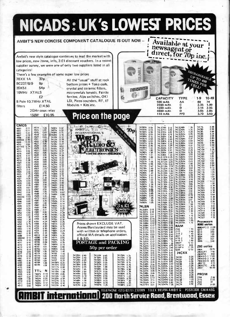
* DIGITAL VOLTMETER 20 Not quite a one-chip-wonder, but closet INTO RADIO SWR METER 48 Cheap and cheerful, but it does the trick. POPULAR COMPUTING HE MICROTRAINER 57 Continuing with the constructional details. PROJECT:MUSIC AUDIO ANALYSER 53 Spectrums analysed here.
FEATURES POPULAR COMPUTING ZX INTERFACES EXPLAINED 10 The ins and outs of the ZX Spectrum and ZX81 . SPOTLIGHT ON THE SPECTRUM 14 Analysing Sinclair's latest. * BEGINNER'S GUIDE TO CONSTRUCTION 28 A practical introduction. GADGETS, GAMES AND KITS METERTECH DVM 37 Digital multimeter reviewed. * FAMOUS NAMES 39 Julius Plucker INTO RADIO RADIO RULES 43 Resonant with meaning.
REGULARS Monitor 6 Points Of View 17 What's On Next 18 Breadboard Exhibition 26 Buylines 34 Clever Dick 35 Backnumbers 40 Bookshelf 46 HE Subscriptions 60 PCB Service 63 PCB Printout 65 Index to Advertisements 65 Classified Advertisements 66
Editor: Ron Keeley Editorial Assistant: Paul Coster BSc Advertisement Manager: Gary Price Managing Editor: Ron Harris BSc Managing Director: T.J. Connell
AUGUST 1982 Vol 4 No 8
I-1 8—I 11,• •L' , 1 i •_1
I-lE DIGITAL MILLIVOLTMETER
o ON
Hobby Electronics is normally published on the second Friday of the month prior to the cover date. Hobby Electronics, 145 Charing Cross Roae, London WC2H OEE, 01-437 1002. Telex No 8811896. Published by Argus Specialist Publications Ltd.
Design and Organisation by MM Design and Print Ltd, 145 Charing Cross Road, London WC2H OEE, 01-437 1002. Distributed by S. M. Distribution Ltd, 16/18 Trinity Gardens, London SW9 8DX.
Printed by GB Ltd, Colchester. Covers printed by Alabaster Passmore. Notice: The contents of this publication including all articles, designs, plans, drawings and programs and all copyright and other intellectual property rights therein belong to Argus Specialist Publications Limited. All rights conferred by the Law of Copyright and other intellectual property rights and by virtue of international copyright conventions are specifically reserved to Argus Specialist Publications Limited and any reproduction requires the prior written consent of the Company.
©Copyright 1982 Argus Specialist Publications Ltd. Member of Audit Bureau of Circulation.
Hobby Electronics, August 1982 3

BleAK "IRRESISTABLE
RESISTOR BARGAINS" Pak No. Qty.' Description Price SXIO 400 Mixed All type '' Resistors El SXII 400 Pre formed 1/4 lh watt Carbon
Resistors LI 9[12 200 1/4 watt Carbon Resistors U SX13 200 1/4 watt Carbon Resistors LI SX14 150 'h watt Resistors 22 ohm
2m2 Mixed El SX15 100 I and 2 watt Resistors 22
ohm 2m2 Mixed El Paks ›012 15 contain a range of Carbon hIm Resistors st assorted values from 22 ohms to 2 2 meo Save pounds on these resistor paks and have a full range to cover your projects Quantities approximate, count by weight
AUDIO PLUGS, SOCKETS AND ACCESSORIES
2, pieces of Audio Plugs, Sockets and Connectors e to include DIN I 8V 240" Inline 36 Pin
Speakers, Phono lack Stereo and Mono etc etc 'Valued at well over £3 normal Order No SX25 Our Price £1 50 per pak Guaranteed to save you money
SI26 3 Prs of 6 pin 240" DIN Plugs and Chassis Sockets
SX27 I a Right Angle Stereo lack Plug 6 3mm plus matching metal chassis mounting socket
SX28 4 Phono plugs and ?dual phono connectors 5020 I o 2 5mm Plug to 3 5mm Socket adaptor • SX30 I y 3 5mm Plug to 2 5mm Socket adaptor SX3I 1 y 3 5mm Plug to Phono Socket adaptor
50p
30p 30P 20p 20p 20p
1 Amp SILICON RECTIFIERS Glass Type similar 104000 SERIES IN4001-1N4004 50 - 500v uncoded -- you select for VLTS ALL perlect devices - NO duds Min 50y 50 toi S1.00 worth double ORDER NO SX76
Silicon General Purpose BPS Traes/oro TO-18 Casei. Lock fir leads coded CV7644 Similar to BC147
BC107 IT139 ALL NEW, VCE 70v IC500mA Nle 75-250 50 on 100 on 500 od 1000 off ; PRICE £2.00 £3.80 £17.50 £30.00g
Silicon General Purpose PNP transistors TO-5 Case Lock lit leads coded C09507 similar 292905A to BFX30 VC 60 IC 600mA Min life 50 ALL NEW
50 od 100 off 500 off 1000 off PRICE £2.50 £4.00 £19.00 £35.00
Order as CV9507
BI-PAK PCB ETCHANT AND DRILL KIT Complete PCB Kit comprises 1 Expo Mini Drill 10.00ORPM 12v DC incl 3 collets Z. 1 x 1mm Twist bit. 1 Sheet PCB Transfers 210mm x 150mm. 1 Etch Resist Pen. 1 'bib pack FERRIC CHLORIDE crystals 3 sheets copper clad board. 2 sheets Fibreglass copper clad board. Full instructions for making your own PCB boards Retail Value over £15.00 OUR 8I-PAK SPECIAL KIT PRICE £9.75 ORDER NO. SX81
"CAPABLE CAPACITOR PAKS"
Pak No. Qte Description Price SXI6 250 Capacitors Mired Types LI SX17 200 Ceramic Capacitors Miniature
Mixed El SX18 100 Mixed Ceramics I pf - 5 PI El SX19 100 Mixed Ceramics680f- 0i5mt LI 5020 100 Assorted Polyester/Polystyrene
Capacitors LI SX2I 60 Mixed C280 type capacitors
metal foil LI SX22 100 Electrolytics, all sorts El SX23 50 Quality Electrolytics
50-1000m1 LI 5024 20 Tantalum Beads, mired El Quantities approximate. count by weight.
SX91 SX42 SX43 SX46
SX47
SUS
5880
BARGAINS 20 a Large 2" RED LED El 20 small 125 Red LED s CI 10 Rectangular Green LED s 2 Cl 30 Assorted hoer Diodes 250m. 2 watt mired voltages all coded New El 4 Black Instrument Knobs-winged with pointer 1/4" Standard screw lit sire 29 xi 20mm SOp 20 Assorted Slider Knobs Black/Chrome etc El 12 Neons and Filament lamps Low voltage and mains - VIIIOUS types and colours - some panel mounting £1
Silicon NPN`L' TypeTransitors 10-92 Plastic centre collector Like BC182L - 183L - 184L •.‘ 1 VCBO 45 VCEO 30 IC200mA life 100-400 [..j
ALL perlect devices - uncoded ORDER AS SX183L 50 off 100 off 500 off 1000 ofl
£1.50 £2.50 £10.00 £17.00
PNP SILICON TRANSISTORS: Similar ZTX500 - Z10214 - E-Line VCE0 40 VCBO 35 lc 300mA Hfe 50-400
Brand New - Uncoded - Pefecl Devices
50 off 100 Oft 500 off 1000 oft
f2.00 £3.50 £15.00 £25.00 Order as ZTXPNP
BI-PAK SOLDER - DESOLDER KIT Kit comprises ORDER NO SX80 1 High Duality 40 watt General Purpose Lightweight Soldering Iron 240v mains Ind 3/16" (4 7mm) bit. 1 Quality Desoldenng pump High Suction with automatic election Knurled, anti-corrosive casing and tenon nozzle. 1.5 metres of De-soldering braid on plastic dispenser. 2 yds It 83m) Resin Cored Solder on Card 1 Heat Shunt tool tweezer Type. Total Retail Value over £12.00 OUR SPECIAL KIT PRICE £0.95
Send your orders to Dept HEP BI PAK PO BOX 6 WARE HEATS
SHOP AT 3 BALDOCK ST
WARE HEATS _
BI-PAK's COMPLETELY NEW CATALOGUE Completely re-designed lull of the type of components you require plus some very interesting ones you will soon be using and of course the largest range of semiconductors for the Amateur and Professional you could hope to find
there are no wasted pages of useless Information so often included in Catalogues published nowadays lust solid facts i e price description and individual tnatures of what we have available But remember Bi -Pak s policy has always been to sell quality components at competitive prices and THAT WE STILL DO.
BENIN S COMPLETELY NEW CATALOGUE is now available to you You will be amazed how much you can save when you shop or Electronic Components with a Br-Pak Catalogue Have one by you all the time-it pays to buy BI PAK
To receive your copy send 75p plus 25p p&p
Use your credit card. Ring us on Ware 3182 NOW and get your order men faster. Gads normally sent 2nd
/. Class Marl. " Remember you must add VAT at 15% to your order
letal. Postage add 75p per Total order
HE PROJECT KITS Make us your No. 1 SUPPLIER OF KITS and COMPONENTS for H.E. Projects. We supply carefully selected sets of parts to enable you to contruct H.E. projects. Kits include ALL the electronics and hardware needed. Printed circuit boards (fully etched, drilled and roller tinned) or Veroboard are, of course, included as specified in the original article, we even include nuts, screws and I.C. sockets. PRICES INCLUDE CASES unless otherwise stated. BATTERIES ARE NOT INCLUDED. COMPONENT SHEET INCLUDED. If you do not have the issue of H.E. which includes the project - you will need to order the instruction reprint at an extra 45p each.
Reprints available separately 45p each + p. Et p. 40p.
T.V.I FILTER Jly 82 £4.98 SUNBURN TIMER - TANOVER Jly 82 £8.99 AUTO WAH June 82 £17.89 inc case or £11.48 less case. AUTO GREENHOUSE SPRINKLER June 82 £14.38 less pump and power supply (12V 2A). TELEPHONE TIMER June 82 £31.24 less power supply (suitable type below). POWER SUPPLY DESIGN 12V 500mA June 82 £9.79. ECHO REVERB UNIT May 82. Less case f31.82. Economy case WB3 £3.76 extra DIGITAL THERMOMETER May 82 ex-cluding case + bezel £15.80 LIGHT SEEKER May 82 £4.99 AUDIO SIGNAL GENERATOR May 82 £19.69 CABLE TRACKER May 82 £9.37 DIGITAL CAPACITANCE METER Apr 62 £19.98 SIGNAL TRACER Apr 82 f3.61 BIKE ALARM Apr 82 £10.98 DIGITAL DICE Mar 82 f6.82 BICYCLE SIREN Mar 82 £10.18 NOISELESS FUZZBOX Feb 82 £9.77 SOUND SWITCH Feb 82 £8.31 , MASTHEAD AAMPLIFIER Feb 82 £13.74 DRUM SYNTHESIZER Dec 81. Eull kit £19.98 GUITAR HEADPHONE AMPLIFIER Dec 81 £3.48 IN CAR CASSETTE POWER SUPPLY Dec 81 £4.46 SCRATCH FILTER Nov 81 Mono £5.44 Stereo £8.40 LED VU METER Nov 81 less case £4.56 SIMPLE STYLUS ORGAN Nov 81 less case £4.74 METRONOME Nov 81 £11.88 TELEPHONE BELL REPEATER Oct 81 £12.78 iVied Linking wire extra 14p metre ,tennesinamulUN LOCK Oct 81 less solenoid £17.43 BABY ALARM Oct 81 £8.14, Fig 8 linking wire 7p metre 'DIANA' METAL LOCATOR Sept 81 £32.25 POWERPACK Sept 81 £9.58
REACTION TESTER GAME Sept 81 £11.98 VARIABLE BENCH POWER SUPPLY Aug 81 f25.35 ULTRASOUND BURGLAR ALARM July 81 £18.67 ELECTRONIC DOOR BUZZER July 81 £5.65 ELECTRONIC METRONOME July 81 £4.67 CONTINUITY CHECKER June 81 £5.34 ENVELOPE GENERATOR June 81 £16.85 AUDIO MIXER June 81 £4.99 PUBLIC ADRESS AMPLIFIER March 81 £1821, Extras - horn speakers £6.83 each, PA MIC £4.40 FUZZBOX March 81 £10.35 WINDSCREEN WIPER CONTROLLER March 81 £7.67 STEAM LOCO WHISTLE March 81 £12.26 PHOTOGRAPHIC TIMER March 81 £3.28 HEARTBEAT MONITOR Feb 81 £23.40 TWO-TONE TRAIN HORN Feb 81 £5.24 less case MEDIUM WAVE RADIO Feb 81 £7.67 BENCH AMP Jan 81 £10.10 NICARD CHARGER Jan 81 £7.67 CH OFFER Jan 81, less case £7.04 BATTERY CHARGE MONITOR Dec 80 £5.40 MEMORY BANK - MINI SYNTH-ESISER Nov Et Dec 80 £28.40 TRANSISTOR TESTER Nov 81 £6.12 inc test leads GUITAR PRE-AMP Nov 80 £5.65 case (diecast) extra £2.29 INTRUDER ALARM Oct 80 £19.61 TOUCH SWITCH Sept 80 £2.57 less case En- contacts GUITAR PHASER Sept 80 £15.22 SOUND OPERATED FLASH TRIGGER July 80 no skt £4.99 FOG HORN June 80 £6.21 SPEED CONTROLLER FOR R/C April 80 £16.41 (less case) DIGITAL FREQUENCY METER april 80 f39.35 DIGI-DICE Jan 80 £10.97 GUITAR TUNER Nov 79 f11.99 CAR ALARM Feb 79 £12.07
CABLE TRACKER AS FEATURED IN MAY 82 H.E.
A SUPERB PROJECT FOR THE HOME HANDYMAN - PICKS UP NAILS, SCREWS, CABLES AND PIPES land other buried metal objects).
QUICKLY SAVES ITS OWN COST
BE SURE - BE SAFE
FULL KIT INCLUDES ALL HARDWARE, ELECTRONICS Et PCB £9.37 + PEtP
MORE PROJECT KITS - SIMILAR STYLE TO H.E. INSTRUCTIONS INCLUDED (SEPARATELY 45p EACH)
PLEASE QUOTE REF. NO. WHEN ORDERING 81 PEST CONTROL 'Ultrasonic cat scarer' £6.98 B2 COMPONENT TESTER £8.38 B3 ENLARGER TIMER - relay output £26.99 84 GUITAR NOTE EXPANDER £16.87 B5 CAMERA OR FLASH GUN TRIGGER Infra red system £11.98 86 SIMPLE INFRA RED REMOTE CONTROL £16.39 B7 0-12V POWER SUPPLY £16.99 B8 SOIL MOISTURE MONITOR £4.23 B9 SOUND TO LIGHT - single channel £7.97 B10 THREE CHANNEL SOUND TO LIGHT £19.98
PLIERS
B11 IN SITU TRANSISTOR TESTER £6.73 812 WEIRD SOUND EFFECTS GENERATOR £5.68 B13 AUDIBLE VISUAL METRO-NOME f5.98 B14 ELECTRONIC DICE £5.71 8152K RAM PACK Less case for ZX81 £13.34 516 MINI EGG TIMER £4.14 1317 AUDIO EFFECTS UNIT FOR WEIRD SOUNDS £12.71 818 LED JEWELLERY - Cross brooch £2.77 Star brooch £9.71 Spiral brooch £7.50
SPECIAL OFFER
CUTTERS
GOOD QUALITY TOOLS. IDEAL FOR CIRCUIT BUILDING PLIERS CI.68 NOW £1.48 CUTTERS £1.69 NOW £1.49
4 Hobby Electronics, August 1982
I.C.s TOOLS CASES TRANSISTORS RESISTORS KITS CAPACITORS HARDWARE MAGENTA ELECTRONICS LTD.
sj•
MEMORY BANK SYNTHESISER Miniature synthesiser featuring vibrato, envelope, tempo, volume + pitch controls. Uses 24 push button switches in a keyboard style layout. Based on a custom designed L.c. The accessible memory stores a 32 beat length sequence of notes + spaces. Can be played 'live'. Fitted with an internal speaker. Jack socket allows the use of an external amplifier if wished.
Memory Bank Synthesizer £28.40 Complete kit inc. case, pcb's etc. Reprint extra 45p. Available separately 45p + 45p p&p.
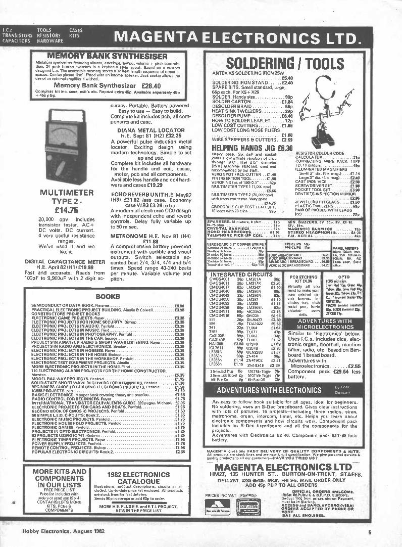
MULTIMETER TYPE 2 - £14.75
20,000 opv. Includes transistor tester. AC + DC volts. DC current. 4 very useful resistance
ranges. We've used it and we
like it.
DIGITAL CAPACITANCE METER H.E. April 82 (H1) £19.98
Fast and accurate. Reads from 100pF to 9,900uF with 2 digit ac-
curacy. Portable. Battery powered. Easy to use - Easy to build.
Complete kit includes pcb, all com-ponents and case.
DIANA METAL LOCATOR H.E. Sept 81 (H2) £32.25
A powerful pulse induction metal locator. Exciting design using modern technology. Simple to set
up and use. Complete kit includes all hardware for the handle and coil, cases, meter, pcb and all components.
Available less handle and coil hard-ware and cases £19.29
ECHO REVERB UNITH.E. May82 (H3) £31.82 less case. Economy
case WB3 £3.76 extra. A modern all electronic CCO design with independent echo and reverb controls. Delay fully variable up to 50 m sec.
METRONOME H.E. Nov 81 (H4) £11.88
A comprehensive battery powered instrument with audible and visual outputs. Switch selectable ac-cented beat 2/4, 3/4, 4/4 and 5/4 times. Speed range 40-240 beats per minute. Variable volume and pitch.
BOOKS SEMICONDUCTOR DATA BOOK. Newnes £5.90 PRACTICAL ELECTRONIC PROJECT BUILDING. Ainalie & Colwell £3.95 CONSTRUCTORS PROJECT BOOKS ELECTRONIC GAME PROJECTS. Rayer £3.35 ELECTRONIC PROJECTS FOR HOME SECURITY. Bishop £3.35 ELECTRONIC PROJECTS IN AUDIO. Penfold £3.35 ELECTRONIC PROJECTS IN MUSIC. Hind £3.35 ELECTRONIC PROJECTS IN PHOTOGRAPHY. Penfold £3.35 ELECTRONIC PROJECTS IN THE CAR. George £3.35 PROJECTS IN AMATEUR RADIO & SHORT WAVE LISTENING. Rayer £3.35 PROJECTS IN RADIO AND ELECTRONICS. Sinclair £3.35 ELECTRONIC PROJECTS IN HOBBIES. Rayer £3.35 ELECTRONIC PROJECTS IN THE HOME. Bishop £3.35 ELECTRONIC PROJECTS IN THE WORKSHOP. Penfold £3.35 ELECTRONIC TEST EQUIPMENT PROJECTS. Ainalie £3.35 MORE E‘ECTRONIC PROJECTS IN THE HOME. Flind £3.35 110 ELECTRONIC ALARM PROJECTS FOR THE HOME CONSTRUCTOR. Marston £5.35 MODEL RAILWAY PROJECTS. Penfold £1.95 SOLID STATE SHORT WAVE RECEIVERS FOR BEGINNERS. Penfold £1.30 BEGINNERS GUIDE TO BUILDING ELECTRONIC PROJECTS. Penfold £1.50 IC555 PROJECTS. parr £1.90 BASIC ELECTRONICS. A super book covering theory and practice £7.95 RADIO CONTROL FOR BEGINNERS. Rayer £1.75 INTERNATIONAL TRANSISTOR EQUIVALENTS GUIDE. 320 pages. Michaels £2.05 ELECTRONIC PROJECTS FOR CARS AND BOATS. Penfold £1.95 SECOND BOOK OF CMOS IC PROJECTS. Penfold £1.50 50 SIMPLE LED. CIRCUITS: Book 2 £1.35 ELECTRONIC MUSIC PROJECTS. Penfold £1.75 ELECTRONIC HOUSEHOLD PROJECTS. Penfold £1.75 ELECTRONIC GAMES. Penfold £1.75 PROJECTS IN OPTO ELECTRONICS. Penfold £1.25 52 PROJECTS USING IC 741. Redmer £1.25 ELECTRONIC TIMER PROJECTS. Rayer £1.95 POWER SUPPLY PROJECTS. Penfold £1.75 REMOTE CONTROL PROJECTS. Bishop £1.95 POPULAR ELECTRONIC CIRCUITS: Book 2 f2.35
MORE KITS AND COMPONENTS IN OUR LISTS
FREE PRICE LIST Price list included with
orders or send sae 19 x 4) CONTAINS LOTS MORE
KITS, PCBs & COMPONENTS
1982 ELECTRONICS CATALOGUE
Illustrations, product descriptions, circuits all in-cluded. Up-to-date price list enclosed. All products are stock lines for fast delivery. Sends flOp in stamps or add 80p to order.
MORE H.E. PLUS E.E. and E.T.I. PROJECT. KITS IN THE PRICE LIST
PRICES INC VAT ,P&P-145p
Pm • • ale sews
SOLDERING I TOOLS ANTEX X5 SOLDERING IRON 25W
£5.48 lit SOLDERING IRON STAND £2.40 \ SPARE BITS. Small standard, large, 65p each. For X5 -i, X25 SOLDER. Handy size 99p I 4 ( SOLDER CARTON £1.84 • DESOLDER BRAID 69p , HEAT SINK TWEEZERS 29p e4r .7
DESOLDER PUMP £6.48 HOW TO SOLDER LEAFLET 12p LOW COST CUTTERS £1.69 r LOW COST LONG NOSE PLIERS £1.68 WIRE STRIPPERS Et CUTTERS £2.69
HELPING HANDS JIG £6.30 Heavy base. Six ball and socket RESISTOR COLOUR CODE joints allow infinite variation of clips CALCULATOR 21p through 3600. Has 234" diameter CONNECTING WIRE PACK TYPE 125 x I magnifier attached, used and ED. 11 colours 49p recommended by our staff. ILLUMINATED MAGNIFIERS VERO SPOT FACE CUTTER .. £1.49 Small 2" dia. 15 x mag.) .... £1.14 PIN INSERTION TOOL £1.98 Large 3" dia. 14 x mag) £2.40 VEROPINS Ipk of 100) 0.1" 52p CAST IRON VICE £2.98 MULTIMETER TYPE 111,000 opv) SCREWDRIVER SET £1.98 £6.66 POCKET TOOL SET £3.98 MULTIMETER TYPE 2120,000 opv) DENTISTS INSPECTION MIRROR with transistor tester. Very good £2.85 £14.75 - JEWELLERS EYEGLASS £1.50 CROCODILE CLIP TEST LEAD SET. PLASTIC TWEEZERS 69p 10 leads with 20 clips ,. 99p , PAIR OF PROBES WITH LEADS
.. (cc) ' 77p . 1 SPEAKERS. Miniature, 8 ohm 87p MIN. BUZZERS. 6V. 50p. SIV., £1 • 10. 64-75 ohm 89p CRYSTAL EARPIECE 65p MAGENTIC EARPIECE 15p MONO HEADPHONES £2 96 STEREO HEADPHONES £4-35 TELEPHONE PICK-UP COIL ....•72p F.M. AERIAL 49p
VEROBOARD 0.1" COPPER STRIPS' 10 strips 24 holes £1.20 per 6 i 24 sums 37 holes 78p 24 strips 50 holes 89P 36 strips 37 holes 89P 36 strips 50 holes 99p Terminal pins 0.1" 52p/100
PP3 CLIPS 10p PPS CLIPS 11p PANEL METERS
EUROBREADBOARD £8.20 S DEC BREADBOARD £3.98 BIMBOARD 1 BREADBOARD £.98 YEROBLOC BREADBOARD f4.20
50uA; 100uA; 1mA, 1A, 25V. 100uA-0- 100uA; 5A, AU £4.98 each. State value.
' INTEGRATED CIRCUITS 11 CMOS4001 20p LM3O1A CMOS4011 20p LM317K CMOS4017 62p LN13342 cmosee 69p LM380N CMOS4049 32p LM386N
30p LM387 CMOS4093 38p LM389 CMOS4098 66p LM3909N CMOS4511 68p MC3340 CMOS4518 60p 0M335 555 26p SN76477 556 79p TDA1022 741 22p TL064 7555 99p TL071 Ca3130E 98p, TL082 CA3140E 52p TL083 HA1388 £3.50 U2376 ICL7611 88p U267B LF351N 58p ULN2283 LF353N 99p ZN414 LF355N £1.14 ZN419CE LF356N £1.15 ZN1034E
36p £3.20 £1.513 egp 92p
£1.10
82p ££21.1151 £8.98
PCB ETCHING OPTO KIT £4.98 LEDS with clips.
Virtually all you ,,3mamm Red2oprePerill i1sitillt need to make your '
cir-_GrIten.274, Yellow 23p, OS own printed f cuit boards. In- Li, segment Metal BP cludes tray, etch
ferric PB22°RP1702 9911ceramic resonator resist pen, fen' ..._ .,,,,,,._.0.istor 22p. chloride even 03142_,....
drills. mum 1111. £2.59 . £5.58 £1.64 47p 74p rim
£1.69 £2.20 £1.57 98p
£2.21 £2.89
ADVENTURES WITH MICROELECTRONICS
Similar to 'Electronics' below. Uses I.C.s. Includes dice, elec-tronic organ, doorbell, reaction timer, radio, etc. Based on Bim-board 1 bread board. Adventures with Microelectronics £2.55 Component pack £29.64 less battery.
3.5mm Jack Plug 15P SPST Min Toggle 59p 35es, Jack Socket 12p DPOT Min Toggle 79p Min Push On 18p . Min Push Oft 22P
ADVENTURES WITH ELECTRONICS by Tom Duncan
An easy to follow book suitable for all ages. Ideal for beginners. No soldering, uses an S-Dec breadboard. Gives clear instructions with lots of pictures. 16 projects-including three radios, siren, metronome, organ, intercom, timer, etc. Helps you learn about electronic components and how circuits work. Component peck includes an S-Dec breadboard and all the components for the projects. Adventures with Electronics £2.40. Component pack £17.98 less battery.
MAGENTA gives you FAST DELIVERY OF QUALITY COMPONENTS & KITS. All products are stock lines and are new & full specification. We give personal service & quality products to all our customers-HAVE YOU TRIED US?
•
MAGENTA ELECTRONICS LTD HM27, 135 HUNTER ST., BURTON-ON-TRENT, STAFFS,
DE14 2ST. 0283 65435. MON-FRI 9-5. MAIL ORDER ONLY ADD 45p P&P TO ALL ORDERS
OFFICIAL ORDERS WELCOME. IRISH REPUBLIC & B.F.P.O. EUROPE: Deduct 10% from prices shown Payment. must be in Sterling. ACCESS and BARCLAYCARD (VISA) ORDERS ACCEPTED BY PHONE OR POST. SAE ALL ENQUIRES.
Hobby Electronics, August 1982 5
MONITOR IN NOVEMBER, the 5th Breadboard Ex-hibition comes to London. The most suc-cessful show of its type, it wiRoffer elec-tronics enthusiasts the opportunity to see for themselves what they have been reading about in their favourite magazine (that's us of course!). This year, a series of lectures and demonstrations will allow the visitor to learn at first hand how some of these circuits and projects work — and how they may be modified to suit personal needs.
There is also the opportunity to see mail order firms display the contents of their catalogues, and the latest on offer from firms that are "household names" to the electronics buff.
This year, too, a number of exciting competitions are being planned, to fire the imagination and interest of the com-petitive visitor . . . so, whatever your in-terest in the hobby of electronics, don't miss BREADBOARD '82!
gem*
TEST
MEASUREMENT '82
*I>• • MI
Laerfflics
0732 865191
One of the greatest problems for the amateur electronics constructor is the availability of accurate, reliable and (most importantly) reasonably priced test equipment. The catalogue from Lawtronics, recently arrived on the Monitor desk, offers quite a few items which meet this requirement.
The range includes dual-trace oscilloscopes from £223, hand-held digital meters from £37 (analogue meters for less than £15), bench meters from £92, plus logic analysers, signal sources and other, more specialised equipment. The full range is described in the catalogue from Lawtronics, 139 High Street, Edenbridge, Kent TN8 5AX; 'phone 0732 865191.
The listed prices do not include either VAT or p&p, and the company offers a 14-day 'Sale or Return' evaluation period.
Let there be LEDs! A complete new 'family' of these devices have been recently introduced by Zaerix Elec-tronics. As the picture (above) shows, they have rectangular, square, domed, - dot and arrow shapes, as well as the standard 3 mm and 5 mm types. Altogether the range comprises 30 lens shapes, three lead frame designs and seven basic colours, diffused or transparent. Typical power handling is 105 mW. For details, contact Zaerix Electronics Limited, Electron House, Cray Avenue, St Mary Cray, Orpington, Kent BR5 3QJ; 'phone 0732 460424.
An interesting development in remote control around the home has been made by TK Electronics. The system allows control of up to 16 appliances plugged into receiver units, which are themselves plugged into the mains. The transmitter is hand-held (more than one may be us-ed) and transmits a coded signal which may be altered to prevent interference with other units.
Possibly the most interesting aspect of the system is that the transmitter may be controlled by external logic, enabling automatic control of appliances from a single, central controller such as a digital timer, or microcomputer, thus providing a convenient interface between the con-trol system and the controlled elements.
The system is supplied as a kit, con-sisting of a transmitter and two receivers and is priced at around £48, including VAT. The transmitter is housed in a black plastic hand-held box while the receivers (additional units are also available seperately) are not supplied with a case, allowing it to be installed inside the con-trolled appliance.
As a new service for customers, TK Electronics have arranged a simple telephone number for orders placed on Access or Barclaycard.The number is: 01 567 8910 - easy enough to remember, isn't it! Finally, TK's new free short-form catalogue is also available in return for a large SAE addressed to TK Electronics, 11 Boston Road, London W7 3SJ. A full sized technical and infor-mation brochure is planned for later this year.
The only item missing in the range of ac-tivities *supported by the Technical Leisure Centre appears to be — elec-tronics! However, they do offer an in-teresting range of tools and materials for model and precision engineers, clock and jewellery makers, and they also offer 'home computer items'. The centre is located at 1, Grangeway, Kilburn, Lon-don NW6 2BW; Tel; 01 328 3128. Fur-ther news of their activities will be in-cluded in their free newspaper, Technical Leisure News, which is available on receipt of a large stamped and self addressed envelope.
Monitor has become quite a conniseur of catalogues, of late. Greenweld's 1982/83 number, just published, pro-mises 'a veritable cornucopia of com-ponents' and at both first and second glances, it certainly seems to contain quite a large range, consisting of just about everything needed for hobby elec-tronics. The catalogue is available by mail for 50p plus 25p postage and in-clud.es a free Bargain list, five 12p dis-count vouchers and a First Class reply-paid envelope. Write for the catalogue to Greenweld, 443 Millbrook Road, Southampton S01 OHX. Don't forget that the listed prices include VAT.
Speaking of test equipment (well?) Stotron Ltd have a new 10 Mhz Logic Probe by Sabtronics. The LP-10 is a high speed probe with the capability of detec-ting pulses down to 50 nS. The input im-pedance is 100k, to avoid loading the circuit under test, and it will detect 'floating' inputs caused by open lines, dirty contacts, etc. Two LEDs indicate '0' and '1' logic levels while a third LED displays logic transitions detected by the pulse stretching circuitry. The probe is powered by the circuit under test via clip leads and pulls approximately 35 mA. For further details, contact Stotron Ltd Haywood Way, lvyhouse Lane, Hastings, Sussex; 'phone 0424 442160.
6 Hobby Electronics, August 1982
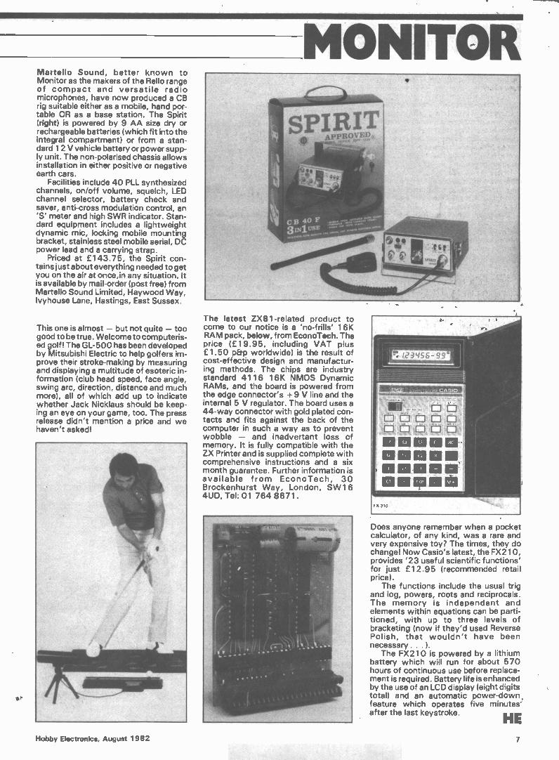
MONITOR Martello Sound, better known to Monitor as the makers of the Rello range of compact and versatile radio microphones, have now produced a CB rig suitable either as a mobile, hand por-table OR as a base station. The Spirit (right) is powered by 9 AA size dry or rechargeable batteries (which fit into the integral compartment) or from a stan-dard 12 V vehicle battery or power supp-ly unit. The non-polarised chassis allows installation in either positive or negative earth cars.
Facilities include 40 PLL synthesized channels, on/off volume, squelch, LED channel selector, battery check and saver, anti-cross modulation control, an 'S' meter and high SWR indicator. Stan-dard equipment includes a lightweight dynamic mic, locking mobile mounting bracket, stainless steel mobile aerial, DC power lead and a carrying strap.
Priced at £143.75, the Spirit con-tains just about everything needed to get you on the air at once,in any situation. It is available by mail-order (post free) from Martello Sound Limited, Haywood Way, Ivyhouse Lane, Hastings, East Sussex.
This one is almost — but not quite — too good to be true. Welcome to computeris-ed golfl The GL-500 has been developed by Mitsubishi Electric to help golfers im-prove their stroke-making by measuring and displaying a multitude of esoteric in-formation (club head speed, face angle, swing arc, direction, distance and much more), all of which add up to indicate whether Jack Nicklaus should be keep-ing an eye on your game, too. The press release didn't mention a price and we haven't asked!
The latest ZX81-related product to come to our notice is a 'no-frills' 16K RAM pack, below, from EconoTech. The price (£19.95, including VAT plus £1.50 p&p worldwide) is the result of cost-effective design and manufactur-ing methods. The chips are industry standard 4116 16K NMOS Dynamic RAMs, and the board is powered from the edge connector's + 9 V line and the internal 5 V regulator. The board uses a 44-way connector with gold plated con-tacts and fits against the back of the computer in such a way as to prevent wobble — and inadvertant loss of memory. It is fully compatible with the ZX Printer and is supplied complete with comprehensive instructions and a six month guarantee. Further information is available from EconoTech, 30 Brockenhurst Way, London, SW16 4UD, Tel: 01 764 8671.
-
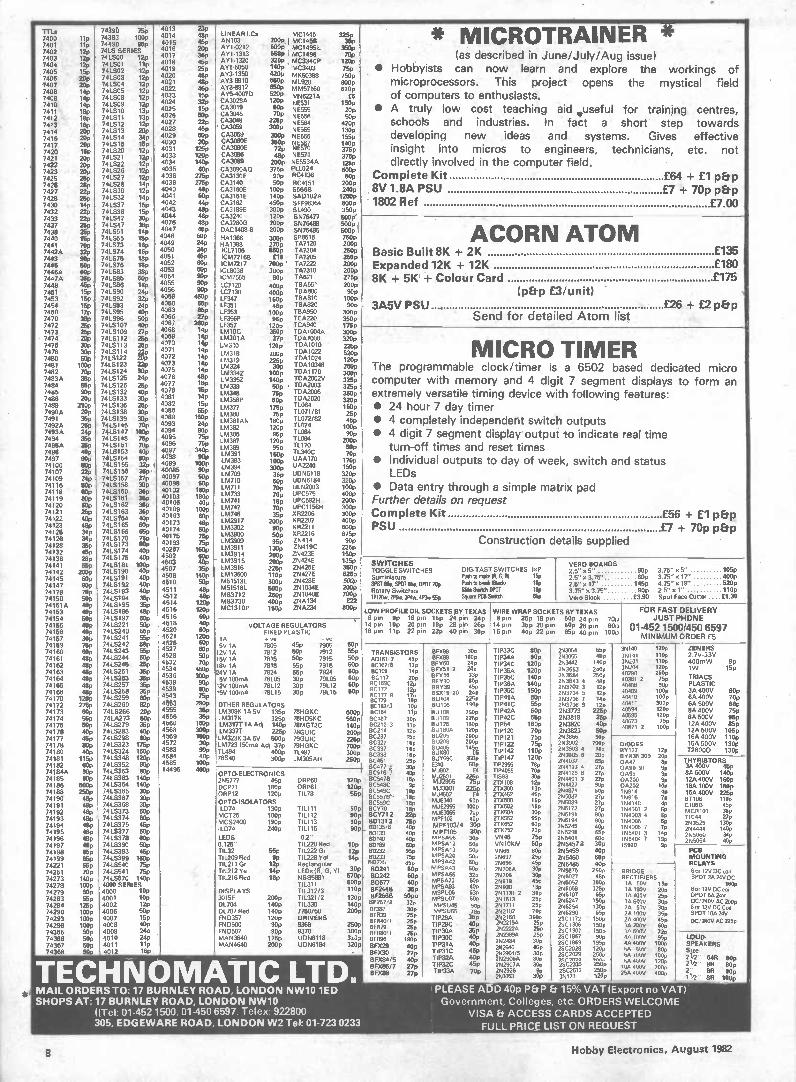
Does anyone remember when a pocket calculator, of any kind, was a rare and very expensive toy? The times, they do change! Now Casio's latest, the FX210, provides '23 useful scientific functions' for just £12.95 (recommended retail price).
The functions include the usual trig and log, powers, roots and reciprocals. The memory is independent and elements within equations can be parti-tioned, with up to three levels of bracketing (now if they'd used Reverse Polish, that wouldn't have been necessary . . . I.
The FX210 is powered by a lithium battery which will run for about 570 hours of continuous use before replace-ment is required. Battery life is enhanced by the use of an LCD display (eight digits total) and an automatic power-down feature which operates five minutes after the last keystroke.
HE Hobby Electronics, August 1982 7
TTIA 7400 7401 7402 7403 7404 , 7406 7406 7407 7408 7409 7410 7411 7412 7413 7414 7416 7417 7420 7421 7422 7423
lip lip 12p 12p 12p 15p 20p 209 149 14p 14p lep 18p 18p 20p 20p 209 15p 20p 20p 20p
74390 iSp 74393 100p 74490 95p 74LS SERIES 741S00 i2 ' 741601 lip 741502 12p 741503 12p 741504 129 741505 12p 741508 12p 741509 12p 741510 13p 741511 13p 741512 12p 741613 20p 741514 34p 741615 15p 741520 129 741521 129 741522 129 741526 12p
4013 4014 4015 4016 4017 4018 4019
4020 4021 4022 4023 4024 e,,, 2, 5 '-'‘. 4027 4028 4029 4030 4031 4033 4034 4035
23p 4gp 4gp '. 2op -38p 45p 25p
48P 4,gp 4gp
15P 32p 15p 500 22, 45p 50p 20p 125p 120p 140p 60p
LINEAR Ms MC1445 03 200P 1 MC1458
AY10212 800P MC14951 AY 1-1313 8659 1 MC1496 AY1.1320 320P , MC3340P AY1-5050 140p MC3403
- AY31350 82OP MK50398 AY3-8910 550P ML920 AY3-8912 850P MM57160 " 64°070 52°,,,,P MN6221A CA3028A CA3019 .L.P NE531
."P NE555 CA3046 2,°_P NE556 CA3048 4409 NE564 • CA3059 3009 5E565 CA3069 300P 56566 CA3060E 35013 5E567 CAE np 5E570 CA3086 4gp 5E571 CA3089 200p NE5534A CA3090A0 375p PLL024
RC4136
32X) 350p 70p 120p 25P' 750p 8130p 620p
f6 150p 20p 50p 420p 130p 155p 141)p 375p 375p
125p
MP
* MICROTRAINER * -
(as described in June/July/Aug issue) • Hobbyists can now learn and explore the workings of
microprocessors. This project opens the mystical field of computers to enthusiasts.
• • A truly low cost teaching aid *useful for training centres, .
schools and industries. In fact a short step towards developing new ideas and systems. Gives effective insight into micros to engineers, technicians, etc. not directly involved in the computer field.
C omplete Kit 7425 7426
25p 28p
74LS27 741528
12p 149
4036 4039
275p 275p
CA3130E 5pp CA3140 50p RC4151
60p 200p
£64 + £1 p&p 8V 1.8A PSU 7427 22p 741530 12p 4040 48p CA3160E 100p $5668 240p £7 + 70p p&p
7428 25p 74LS32 14p 4041 50p CA3161E 140p SAD102A 12509
7430 14p 74LS37 15p 4042 44p CA3162 450p S FF96364 800p 1802 Ref £7.00
7432 22p 74LS38 15p 4043 4044
48p 48p
CA3189E 300p 01490 350p
7433 2743 74LS42 30p CA3240 120p $576477 500p 7437 25p 74LS47 360 42 76
'"'”'_ 48p 45p
CA3280G 200p 0N76490 DAC1408-8 200p
5009 1 7438 7440
25p 15p
741551 74LS55
149 15p 4048 5UP
$N76495 HA1366 300p SP8515
500p 1 750p ACORRI ATOM
7441 70p 74LS73 18p 4049 24P H41388 270p TA7120 200p 7442A 32p 74LS74 16p 4050 24P ICL7106 850p TA7204
26°P Basic Built 8K + 2K £135 7443 90p 741575 18p 4051 459 ICM72168 £18 TA7205 250p 7445 50p 741576 18p 4052 80P ICM7217 , 700p I TA7222
. 26°P Expanded 12K + 12K £180 7446A OOP 741583 38P 4°53 50P IC18038 300p 747310 200p 7447A 36p 741585 50p 4054 909 ICM7555 80p 74621
2759 8K + 5K + Colour Card £175 7448 469 741588 18p 40,,L5 „..,939 1C7120 400p 1134651 200p 7451 15p 741590 24p .,,r„. .41 LC7130 400p TBA800 90p (p&p £3/unit) , 7453 15p 74LS92 32p '1,....„.0,.. 450P 1E347 160p TBA810 100p 7454 7480
159 17p
74LS93 741595
24p 409
r„°..., «,',1,1.,...,
55P 55P
LF351 45p TBA820 LF353 100, TBA950
90° 300p
3A5V PSU . £26 + £2 p&p 7470 36p 741596 50p '.... - 27P LF356P 95p TCA220 350p Send for detailed Atom list 7472 25p 7415107 40p 4067 2609 LF357 120e TCA940 175p 7073 25p 7415109 27p 4°68 14P LM10C 350p TDA1004A 300p • 7474 20p 7415112 25p 4069
4070 149 14P
LM301A Vp . TDA1008 320p 7476 7478 7480 7481 7482 7483A 7484 7485 7486
30p 30p 50p 100p 70p 38p 86p 909 20p
7415113 7415114 7415122 7415123 7416124 7415125 7415128 7415132 7415133
259 22n 20p 229 90p 24p 25p 401, 30p
4071 4072 4073 4075 4076 4077 4078 4081
142 .7 ."9 140
4811 169 11310
L114310 120p TDA1010 LM318 200 „, TDAI022 1M319 225 ;; TDA1024 LM324 30 TDA10348 LM334Z 100p TDA1170 1M3352 140n TDA2002V LM339 6,4 . TDA2003 L,34,5 75; TDA2006 LM358P 60p TDA2020
225p 6.20p 120p
250P 300p 3251, 3251 350P 320p
M IC R 0 TIMER The programmable clock/timer is a 6502 based dedicated micro computer with memory and 4 digit 7 segment displays to form an extremely versatile timing device with following features:
7489 7490A
210p 20p
7415136 7416138
25p 30p
4082 4088
,L49 '''''' LM377 175p 11064
unao 75p 11071/81 150p 25p
• 24 hour 7 day timer 7491 7492A 7493A 7494 7495A
35p 25p 24p 35p 359
7415139 7410145 7415147 7415148 7415151
30P 70p 180p 75p 70p
40°6 4093 4094 4095 4096
w.055Pn ',—.-"'" .". - 90p 75p 75p
LM381AN 180p 11072/82 1M382 120 71074 p 164396 951) 71084 1M397 120p 71094
71170
45P 100p 900
200p 50P
• 4 completely independent switch outputs • 4 digit 7 segment display output to indicate real time
turn-off times 7498 40p 7415153 409 4097 4098
340p 90p
164389 55p 16.1391 .ign,, 71340C 70p
and reset times 7497 90p
80p 7415154 7416155
90p 32p 4099 100p
. 1.. 61393 ,33; UAA170 UA2240
170p • Individual outputs to day of week, switch and status 74100 74107 74109
22p 24p
7415156 7415157
4 36p, 27p
40085 40097 40098
90p 50P 50p
394 3IX/p LL,AM 70 36p UDN6118
9
LM710 sop UDN6184
150p
320p 320p
LEDs 74116 50p 741.5168 30p
40102 180p -..M 733711 709ULN2003 100P • Data entry through a simple matrix pad 74118
74119 74120 74121
80p 80p 80p 25p
7415160 7410161 7415162 7415163
369 36p 36p 36p
40103 40108 40109
180p 409 100p
,IL. 70p UPC575 1M741 lep UPC592H LM747 70p UPC 1156H 1/0748 35p XR2206
400p 2909 300p 300P
Further details on request Complete Kit £56 £1
74122 40p 7415164 7415165
40p 813p
40163
40173
60.,
44 2009 052207 400p + p&p
74123 74125
48p 34p 7416166 58p 40174 80p
.1-51,2!,1,,„12 90p. XR2211
,.= 50p XR2216 600p 675p
PSU £7 + 70p p&p 74128 74128
34p 36p
7415170 7415173
no 60p
40175 40193
759 75p
:•`..13.709 L. 95p ZN414
ZN419C 90p
225p Construction details supplied .
74132 46p 7415174 40p 40267 1609 LM3911 13op LM3914 ZN423E 150p
74136 28p 7415175 409 4502 60o 200p LM3915 ZN424E
1,3LP SWITCHES TOGGLE SWITCHES DIGITAST SWITCHES /x P Suminiature Ruh to make IR, 6,111 Np SPST 809 SPOT fi5p. 01171799 R1sh 16 IIRRI eel 199
VERO BOARDS 2.5" x 5" 90p 3.75" x 5" 105p 2.5" x 3.75" 80p 3.75" x 17" 400p 2.5" 17" 145p 4.75" x 19" 620p
74141 74142 74145
55p 2013p 60p
7415181 7415190 7415191
100p 40p 40p 40p
4503 4501 4508 4510
4isp 35p 1400 Sop
2ppp 1643916 225p ZN426E 1M 13600 110p ZN427E M51513L 300p ZN428E
.",.',„"". "*'""1,,,,,,,„'
74147 74178
90p 70p
7415192 7415193 40p 4511 a p M515161 500p ZN10345
.w.„,,,,' `""P 7°69
Rotary Switches Side Switch DPOT 199 x
3.75" x 3.75" 90p 2.5" x 1" 110p 74150 50p 7415194 36p 4512 400 MB3712 250p ZN1040E 1P13»/,311w,3P4w4P3o/ 559 SO.. PCB We 651, Vero Block £3.90 Spot Face Cutter .... C1.30 7416IA 40p 7415195 36p 4514 120p MB3730 400p ZNA134
MC1310P ZNA234 £22
8°°P LOW PROFILE DIL SOCKETS ElY TEXAS WIRE WRAP SOCKETS BY TEXAS FOR FAST DELIVERY 74153 400 7415196 48p 4516 120p 150p
74154 50p 7415197 80p 4516 60p 8 po 9p 18 pn 16p 24 pin 24p 8 pin 25p 18 p n 50P 24 pin 7011 JUST PHONE VOLTAGE REGULATORS
,, 74155 40p 7415221
7415240 50p 55p
4518 4520
40p 60p
14 pin 10p 20 pn 18p 28 pin 26p 16 119 22 22p 40 30p
14 pin 35p 20 p n 60p 28 p/n 8011 16 01-452 1500/450 6597 74158
74157 409 30p 7415241 55p 4521
4526 120o
FIXED PLASTIC 1, .o. ye - 00
pin pin pin pn 40P 22 P o 65P 40 Pl. 10014 MINIMUM ORDER £5
74159 74160 74161 74162 74163 74164 74165 74166 74170
75p 60p 48p 48p 489 489 48p 48p 120p
74LS242 7415243 7410244 74LS245 7415251 7415253 7415257 7415258 7415259
58p 55p 60p 25p 35p 35p 35p 35p 60p
4527 4528 4532
4534 4536 4_53„11 '1,..,04,.. 40;4
66°°PP 50p ,0„ 4,'"„''' ---"" 300p op,., 47 -,, ''''''' 75p
7805 45P 7905 125VV 1AA 15V 1A 7812 50P 7912
7815 501, 7915 113V lA 7818 55p 7918 24V IA 7824 55p 7924 5V 10OrnA 78105 30p 79105 12V 100mA 78112 30p 79112 15V 100mA 78115 30p 79115
50P 850 ea 60P 60p 60p 60p cop
TRANSISTORS 01)161, 2 45p BC107/ 8 33p BC109 14p BC117 20p BC169C 121, BC172 12p
, 15,Eg 9 ile,
BlIrxX8988 1.0313,p
BF V50 249 BFY51 2 24p tee MP
130V39 45D BSX19 20 24p 130104 225p
TT:Pp3433AC 9080pp
TIP34C 120p Tip,p 120p
TIP35C 140p
,11p..„,P36A ',1,4e 11r.o, ..••P TIP41A 5131,
2A3,0,5554 abbpp
253442 140p
2NNr" 244 250P 1113643 4 48 253702 3 ,2r, 253704 5 12p 253706 7 14p
331,151,4041 1120,31%
35201 110p 35204 120P 40290 260p 40361 2 75p 40408 90p 40409 100p 40410 100p
ZENERS 2.7V-33V 40OmW 9p 1W 15p
TRIACS PLASTIC 3A 400V 60p , 6A 400V 70p
74172 275p 7415260 e2p 4503 290P OTHER REGULATORS 13C182,3 10p 130105 190p TIP41C 55P 253708 9 120 40411 . 300p 6A 500V 88p 74173 70174 74175 74126
60p 55p 50p 00p
7415266 74 LA273 7415279 7415283
20p 60p 35p 40p
4555 4556 4560 4568
35P 361, 150p 300P
LM309K IA 5V 135p 78HGKC LM317K 325o 78H05KC LM317T IA Adj 140p 78M GT2C LM3377 225p 78GUIC
600p 550p 140p 200p
BC184 11P BC187 30¡, 8C212 3 1 1p BC214 12p
•Buipt, 2500 BU109 225p 90126 150p BU180A 120p 130205 200P
TIP42A 60p TIP42C 65p TIP54 160p TIP120 70p
2N3773 225p 253819 25p 253820 eP 2N3823 50p
4400559945 1122009 P ,,,,.„
-4.0"Wii 2 10749
8A 400V 75 BA 500V 95pP
V 855pp 1122A 4000V 10 050
74177 74178
46p 80p
7415298 7415323
90p 175p
4569 4572
180P 30P
LM323K 3A 5V 5009 79GUIC 1M723 150inA Adj 37p 79HGKC
227pe 9C237 15p 01327 16p
PU7PP MP TIP121 75p
11P1Z7 75P
2183866 900
79918pP
16A 400V 110p 16A 500V 130p
74180 74181 74182 74184A
40p 116p 60p 90p
74LS324 7416348 7415352 7415353
1613p 120p 80p 90p
4583 4584 4585 14495
90P 40P 100p
41:4P
71494 400p TL497 78540 300p LM305AH
.....2 soPP 250P
81337 16p BC338 16p BC461 25p BC477 e 30p
7 40p
.1380.,19.U,Y74p069C9° ,1„.;pp'", 31Lpet:6 ""P
TTlipP114427 11.2010pp
TIP2955 789 70P
. 2751990037 4 253905 6 20p 254037 65p 254123 4 27p 254125 6 27p
I3DVIO1D27E9 1211 EIV 036.300 201, 0047 Op 04,90 91 9p 0A95 9,
728000 130p , „,-. ,-, .. ,I-17nISTuRa 3A 400 8A 600V 140p ' OPTO-ELECTRONICS
74185 90p 7415363 140p 255777 45p ORP60 ,BC516
upp 13C5470 16p .12„0---1 .0'04 TT:Ps400355
91029P 254401 3 27p 0A200
74186 74188 74190
5009 250p 48p
7415364 7415365 7415367
140p 30p 30p
OCP71 180p ORP61 ORP12 120p TIL78 12°P 55p
BC548C 9P BC549C le ,, Bc5,78, ._ lii;
14J2955 75P MJ3001 225p MJ4502 £4
ITX108 IT7(300 13p ZTX452 45p ZTX500 15p
2114427 90p 254871 60p 255087 27p
00202 109pP 15914 15916 2112118°75pPPP
74191 74192 74193 74194
48p 4ep 48p 48p
7415368 7415373 7415374 74LS375
30p 60p 60p 46p
OPTO-ISOLATORS ILD74 130p TIL111 MCT26 100p TILI12 MCS2400 190p 111113 11074 240p TIL116
90p 90p sop p
BC559C rep BCY70 18p BCY71 2 229 BD131 2 00135 ,6 47e
-MJF340 60p wuMJE3M 10074 .40.,02 .0p
MPF103/4 30p
ezT0)(4,5022 53.516_,,P
,Tx n
ITX652 60P ZT" 52 lop
755089 27p 22NN65119721 9207pp
255194 90p 255245 40p
154148 41, 115.1000031 2, Op
154005 61, 154006 7 7p
.13,111662A1T:10445:100VVV C1060 45p :4101 36p
27p 253525 130 254444 140pP
74195 48p 7415377 60p _
40p MPF1OS 30p 255298 65p 155401 3 14n 255060 340 74196 48p 74LS378 60p LIDS O.2 0,140 4,j, 1111'5005 30p VN46 75p 255401 60o 155404 7 19p 2195064 40p 74197 409 7415390 50p 0.125" TIL220040 .03p 05,83 ii; N195812 50p VN1OKM 60p 2N5457 8 30P 15920 9p
PCB 74198 65p 74LS393 46p TIL32 55p TIL222 Gr 12p B0232, 95p MPSA 13 50p VN66 80p 255459 40p 24199 74221 74251
86p 55p 70p
7415399 7415540 7415541
160p 75p 75p
111209 Red 9P TIL228 Vol TIL211 Gr 12p Rectangular TIL212 Ye 14p LEDs I R, G, V/
up
30P
507,33 15, BD' 35 89, BD241 cep
MPSA20 50p MPSA42 50p MPSA43 50p MPSA56
26697 259 25698 45p 25706A 301,
2N5460 60p 2N5485 40p 2N5875 26-0P
MOUNTING RELAYS 6 or 12V DC coil BRIDGE .
74273 74278 74279
140p 100p 517p
7415670 140p 4000 SERIES 4000 OP
TIL216 Red 18p NSB588I TIL311
DISPLAYS TIL312/3
570P 600P 110p
60242 60p 13-0677 40p BF244B 35p ...,.. 8F256° 5°1".
32o MPSAL° 50P PAPs..., op MSPUC6 63p
25708 30p 25518 450 25930 18p 251131 2 36 p
29602, 459 256052 300p 225N660p597 362,59p
RECTIFIERS IA 50V 19p 1,p A 14000ovv 22,0pp
SPDT 2A 24V DC 160p
6 or 12V DC coil DPDT 5A 24V
74283 55p 4001 10p 3015F 200p TIL321/2 130p BF257'8 32, MRSUO7 60p 251613 2517 256247 190p IA 600V 30p DC/240V AC 200p
74284 125p 4002 12p DL704 140p TIL330 140p 8F337 30P
MPSU45 90p 251711 25c. 256254 130p 28 50V 30p 6 or 12V DC Coil 74290 100p 4006 50p DL707 Red 140p 7750/60 26e.
' BFR39 25n MPS1.165 780 2192102 709 256290 65p 28 100e 35p SPOT 10A 24V
74293 100p 4007 15p FND357 120p DRIVERS 8FR40/1 259 rp2gA 35p 252160 3500 2SC 1172 150p 2A 400V 45p DC/240V AC 225p
74298 74365
100p 50p
4008 4009
409 2 4o
FND500 90p 9368 F50 507 90p 9370
250P 300P
8p479 25p RFF180/1
TIP26C 4°P TIP 30A 30A 35p 2522190 25p 2522224. 25p
25C 1306 150p 2SCI307 150p
'10 200V 600 30 600V 72p
LOUD-SPEAKERS si,, 1 - 2/2 648 80p
21/.2- OR 80p
711/2 - le le,
74366 74367 74368
\
50p 50p 50o
4010 4011 4012
2.4p . 11p 169
MAN3640 175p UDN6118 MAN4640 200p UDN6184
3439 320p -
BFR96 180p 99x2g 40, 8FX30 27p BFX84/5 40p BFX86/7 27p BFX88 27p
TI93°C 40p ' TIP31A 40p TIP31C 45p TIP32A 417P TIP32C 4511 TIP33A Asp
2NA 25p 2N24134 300 252646 451, 2N2904/ 5 30P 252906A --suo 252907A 30p pL 2926 3,0,,,,
2SC1957 9Up 2SC1969 1959 25C2028 120p 2SC2029 250p ,9,9n7p lnn- 2SC2335 25017 in6,2 re
48 100V 95p 4A 400V 100p 60 50V 80p 68 i0OV 100p 68 400V 120p 10A 400V 200p 25A 4OBV 4009
Ill 1 • Y AIL ORDERS TO: 17 BURNLEY ROAD, LONDON NW10 1ED i PLEASE ADD 40p P&P Ee 15% VAT (Export no VAT)• HOPS AT: 17 BURNLEY ROAD, LONDON NW10 , Government Colleges, etc. ORDERS WELCOME
«Tel: 01-452 1500, 01-450 6597. Telex: 922800 VISA Et ACCESS CARDS ACCEPTED . 305, EDGEWARE ROAD, LONDON W2 Tel: 01-723 0233 FULL PRIC_E LIST ON REQUEST
8 Hobby Electronics, August 1982
The MICR PROFESSOR solves theemystery of micro-processors.
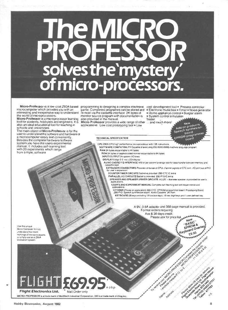
Micro-Professor is a low-cost Z80A based microcomputer which provides you with an interesting and inexpensive way to understand the world of microprocessors. Micro-Professor is a microprocessor learning tool for students, hobbyists and engineers. It is also an ideal educational tool for teaching in schools and universities. The main object of Micro-Professor is for the user to understand the software and hardware of a microcomputer easily and conveniently. Besides the complete hardware/software system you have the users experimental manual. It includes self-learning text with 20 experiments which range from simple, software
programming to designing a complex electronic game. Completed programes can be stored and re-read via the cassette interface. 2K bytes of monitor source program with documentation is also provided in the manual. Micro-Professor provides a wide range of other applications: Low cost prototyping tool • Low
cost development tool • Process controller • Electronic music box • Timer • Noise generator • Home appliance control • Burglar alarm • System control simulation Tester ,. ... and much more!
TECHNICAL SPECIFICATION
CPU 280A CPU Pugh perlormance microprocessor with 158 instructions
SOFTWARE COMPATIBILITY Capable of executing Z80/8080/8085 machine language program
RAM 2K bytes expandable to 4K bytes
ROM 2K bytes of sophisticated monitor expandable to 8K bytes
INPUT/OUTPUT 24 system I/O lines
DISPLAY 6 digit 05" red LED display
AUDIO CASSETTE INTERFACE 165 bit per second average rate for data transter between memory and cassette tape
EXTENSION CONNECTORS Provides all buses of CPU. channel signals of CTC and /0 port bus of PIO for users expansion
COUNTER TIMER CIRCUITS Socket is provided Z80-CTC IC extra
PARALLEL I/0 CIRCUITS Socket is provided Z80-PIO IC extra
SPEAKER AND SPEAKER DRIVER CIRCUITS A 2 25" - diameter speaker is provided for user s applications
USERS AND EXPERIMENT MANUAL Complete self-learning text with experiments and applications
OPTIONS (Pnces on application) Z80-CTC EPROM programmer board Prototypeng Board Z80-P10 Speech synthesiser board Audio Cassette 2K Ram
KEYBOARD 36 keys including 19 function keys. 16 hex-digit keys and 1 user defined key
A 9V, 0.5A adaptor and 350 page manual is provided. Formal orders requiring
Acc & 30 days credit. Please ask for price list.
Use the unique Micro-Computer to truly
understand the inside
workings of microprocessors or simply use as a 280A evaluation system
£69.95 Flight Electronics Ltd. * Mail Order only
MICRO-PROFESSOR is a trade mark of Multitech Industrial Corporation. 280 is a trade mark of Zilog Inc.
+ p&p
Fee,
//
e' cpÓ cc.•
iz•.• 0 e re () b
e
ee •
Hobby Electronics, August 1982 9
• Popular Computing
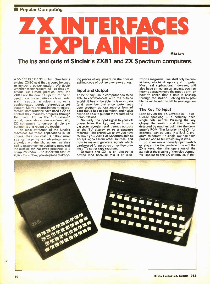
ZX INTERFACES EXPLAINED
The ins and outs of Sinclair's ZX81 and ZX Spectrum computers.
ADVERTISEMENTS for Sinclair's original ZX80 said that is could be used to control a power station. We doubt whether many readers will be that am-bitious! On a more practical level, the ZX81 and the new ZX Spectrum can be used to control activities such as model train layouts, a robot arm, or a sophisticated burglar alarm/deterrent system. Many entrants in recent 'micro-mouse' competitions have used a ZX to control their mouse's progress through the maze. And in the 'professional' world, many laboratories are now using ZX computers to control simple ex-periments and record the results.
The main attraction of the Sinclair machines for these applications is, of course, their low cost. But their small size can also be an advantage on a crowded workbench, as well as their ability to survive the rough and tumble of life outside the hallowed precincts of a computer room — an important feature if, like the author, you are prone to dropp-
ing pieces of equipment on the floor or spilling cups of coffee over everything.
Input and Output To be of any use, a computer has to be able to communicate with the outside world. It has to be able to take in data (and remember that a computer sees your program as just another form of data that it has to deal with), and it also has to be able to put out the results of its computations.
Normally, the input signal to your ZX come from the kyboard or from a cassette recorder, and it sends outputs to the TV display or to a cassette recorder. This article will show you how to make your ZX81 or Spectrum able to accept signals from other sources, and how to make it generate signals which can be used for purposes other than driv-ing a TV set or tape recorder.
Because the ZX is an electronic device (and because this is an elec-
tronics magazine), we shall only be con-sidering electrical inputs and outputs. Most real applications, however, will also have a mechanical aspect, such as how to actually move the robot's arm, or how to sense that a train is passing through the station. Solving these pro-blems will have to be left to your ingenui-ty!
The- Key To Input Each key on the ZX keybord is — elec-trically speaking — a normally open single pole switch. Pressing the key closes the switch and this can be detected by routines built into the com-puter's ROM. The function INKEYS, for example, can be used in a BASIC pro-gram to detect if a single key has been pressed and to tell which key it was.
So, if we wire a normally open switch or relay contact in parallel with one of the ZX's keys, then the operation of the switch or the closing of the relay contact will appear to the ZX exactly as if that
Hobby Electronics, August 1982 10

Popular Computing
a a Y Y2 Y3 Y4 Y5
X1 X2 X3 X4 X5 X6 X7 X8
Y1 Y2 Y3 Y4 1 2 3 4 5 0 W E il T 0 9 8 7 8 A S D F G
0 I U y ht z x - , n/1 L K
5 H
space sq N B
Each keyswItch connects between one X connector point and one Y connector point as shown in the table above.
Figure 1(a). The ZX81 keyboard connections; (b) component-side view of the ZX81 board, showing the keyboard sockets.
Figure 2(a). The Spectrum keyboard connections; (b) the keyboard sockets from the component side of the Spectrum PCB.
Xn Yn
SIMPLE SWITCH
FROM VOLTAGE TO BE SENSED
Figure 3. Inputs to the ZX keyboard matrix.
EDGE CONNECTOR SOCKET TO MATE —1.
WITH ZX
SOCKETS FOR INPUT/OUTPUT INTERFACE BOARDS
X1 X2 X3 X4 X5
X6
X7
X8
1 2 3 4 5 CI W E R T A S D F G 0 9 8 P 0 I U Y
caps shift
Z X C V
enter L K J H
space symbol shift Ki N 8
Each keyswitch connects between one X connector poin and one Y connector point as shown in the table above.
Xn Yn
OPTO-ISOLATOR
/1
FROM VOLTAGE TO BE SENSED (CHOOSE RESISTOR FOR 5mA IN LED)
DOUBLE SIDED PC8 PLUG FOR ZX PRINTER OR OTHER
PERIPHERALS
'MOTHERBOARD'
Figure 5. A mother board with sockets for I/O interfaces, connections for a ZX printer or Rampack, etc.
key had been pressed, and it can be detected by your program.
You can't get at the actual switch contacts themselves on the ZX81 or Spectrum keyboards as they are sealed units, so you will have to connect your added switche(s) to the 5 and 8 way film-cable sockets mounted on the com-puter PCB. One contact of each keyboard switch is connected to one lead in the 5 way cable, the other contact is connected to one lead in the 8 way cable, so that the 40 keys are arranged in a 5 x 8 matrix. The actual connections for each key are shown in Figures 1 and 2, so if you wanted your added switch to appear to the computer as key '2', it would have to be connected between connector points X1 and Y2.
This technique is usefully simple, but there are a few points to watch. Any
leads connected to the keyboard must be relatively short — say less than 30 cm — or they are liable to confuse your ZX by picking up stray noise. Also, INKEYS will refuse to recognise any of them. And, of course, you have to be sure that any contacts you may add are open-circuit whenever you want to use the normal keyboard. A simple joystick can be made using
this technique to add interest to games programs. Four normally open switches should be used, mechanically connected to the joystick so that one switch is clos-ed when you move the stick in a par-ticular direction. The switches could be wired in parallel with the four cursor con-trol keys (numbered 5 to 8), correspon-ding to movements of the stick as Up, Down Left and Right.
Since neither side of the keyboard
EDGE CONNECTOR SOCKET MOUNTED ON INTERFACE PCB
'ZX'
PCB CARRYING INPUT/OUTPUT INTERFACE
DOUBLE SIDED PCB PLUG WIRED TO TAILS OF SOCKET CONTACTS,
Figure 4. An add-on board must allow access to the ZX socket contacts.
switches can be connected to ground (doing so would prevent the ZX from working properly), some form of isolating device is needed if you want the ZX to sense an electrical signal. As il-lustrated in Figure 3, a suitable relay could be used, or perhaps a phototran-sistor/LED opto-isolator. If an opto-isolator is used, the emitter of the photo-transistor should be connected to the 8 way kéyboard connector, and the collec-tor to the 5 way connector.
The Rear Connector If we want our ZX to provide outputs — for controlling motors, lights or whatever — or if we want it to be able to detect more than one input signal at a time, then we have to add an interface circuit to the ZX's rear connector.
This connector consists of two rows of contact pads spaced 0.1" apart along the rear edge of the ZX's printed circuit board. Row A is on the top surface of the PCB and row B is immediately underneath. The ZX81 connector has 23 contact positions on each side, the Spectrum has 28; in both cases a slot has been cut into the PCB in one of the contact positions to locate a polarising key fitted to the mating socket. Suitable sockets are readily available from a number of specialised ZX hardware sup-pliers.
The connector carries the computer's address, data and control signals as well as power lines and was intended for use with add-on devices such as the ZX81's 16K Rampack or the ZX printer; but, as described in the remainder or this article, it also allows you to plug on your own In-put/Output interface board. One point to remember when building any add-on for the ZX is that it doesn't prevent you from adding other extensions. This means, in effect, that it should include a double sid-ed PCB plug which is wired to carry the same signals as the actual ZX connector, and to which other extensions can be fit-ted. One way of achieving this is il-lustrated in Figure 4. Alternatively, you could make up a 'motherboard' as shown in Figure 5. This would have sockets for accepting I/O interface boards and a double sided PCB plug at the end for connecting to the ZX printer or Rampack. Again, suitable PCB plugs are available from some ZX hardware suppliers.
Hobby Electronics, August 1982 11
• Popular Computing
Signal Pin Side A Side B No. (top) (bottom)
1 A15 A14 2 A13 Al2 3 D7 +5V 4 +9V 5 Slot 6 DO OV 7 D1 V 8 02 CK 9 D6 AO 10 D5 Al 11 D3 A2 12 04 A3 13 (NT (ORGE 14 NMI OV 15 HALT VIDEO 16 MREG Y 17 (ORO V 18 RD U 19 WR BUSRQ 20 —5V RESET 21 WAIT Al 22 + 12V A8 23 —12V A5 24 M1 A4 25 RFSH ROMCS 26 A8 BUSACK 27 Al 0 A9 28 Al 1
Figure 6. The Spectrum rear connector signals.
Signal Pin Side A Side 8 No. (top) (bottom)
1 D7 +5V 2 RAMCS +9V 3 Slot 4 DO OV 5 01 OV G D2 O 7 De AO 8 D5 Al 9 03 A2 10 04 A3 11 (NT AIS 12 NMI A14 13 HALT A13 14 10110 Al 1 16 RD Al 0 17 WR A9 18 BUSACK A8 19 WAIT Al 20 BUSRECI AO 21 RESET AS 22 M1 A4 23 REFSH ROMCS
Figure 7. 2X81 connector signals.
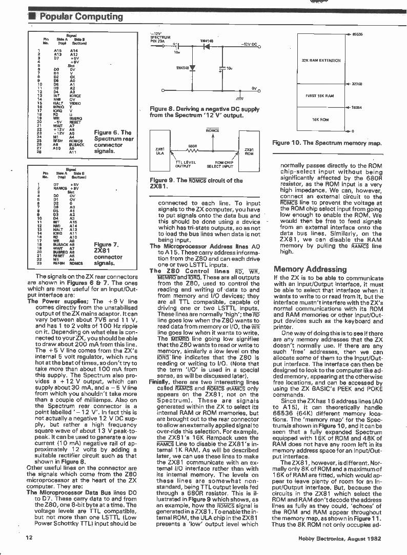
The signals on the ZX rear connectors are shown in Figures 6 Et 7. The ones which are most useful for an Input/Out-put interface are: The Power supplies; The +9 V line
comes directly from the unstabilised output of the ZX mains adaptor. It can vary between about 7V5 and 11 V, and has 1 to 2 volts of 100 Hz ripple on it. Depending on what else is con-nected to your ZX, you should be able to draw about 200 mA from this line. The + 5 V line comes from the ZX's internal 5 volt regulator, which runs hot at the best of times, so don't try to take more than about 100 mA from this supply. The Spectrum also pro-vides a + 12 V output, which can supply about 30 mA, and a — 5 V line from which you shouldn't take more than a couple of milliamps. Also on the Spectrum rear connector is a point labelled ' — 12 V'. In fact this is not actually a negative 12 V DC sup-ply, but rather a high frequency square wave of about 13 V peak-to-peak. It can be used to generate a low current (10 mA) negative rail of ap-proximately 12 volts by adding a suitable rectifier circuit such as that shown in Figure 8.
Other useful lines on the connector are the signals which come from the Z80 microprocessor at the heart of the ZX computer. They are: The Microprocessor Data Bus lines DO
to D7. These carry data to and from the Z80, one 8-bit byte at a time. The voltage levels are TTL compatible, but not more than one LSTTL (Low Power Schottky TTL) input should be
'-12V' SPECTRUM PIN 23A 1N4148
—12V DC
10u
1N4148 10e
OV
Figure 8. Deriving a negative DC supply from the Spectrum '12 V' output.
ROMCS
Figure 9. The ROMCS circuit of the ZX81.
680R
TTL LEVEL ROM CHIP OUTPUT SELECT INPUT
connected to each line. To input signals to the ZX computer, you have to put signals onto the data bus and this should be done using a device which has tri-state outputs, so as not to load the bus lines when data is not being input.
The Microprocessor Address lines AO to A15. These carry address informa-tion from the Z80 and can each drive one or two LSTTL inputs.
The Z80 Control lines MEMRCland IORQ. These are all outputs from the Z80, used to control the reading and writing of data to and from memory and I/O devices; they are all TTL compatible, capable of driving one or two LSTTL inputs. These lines are normally 'high'; there line goes low when the Z80 wants to read data from memory or I/O, the ¡TN line goes low when it wants to write. The MEMRQ line going low signifies that the Z80 wants to read or write to memory, similarly a low level on the IORQ line indicates that the Z80 is reading or writing to I/O. (Note that the term 'I/O' is used in a special sense, as will be discussed later).
Finially, there are two interesting lines called RAMCS and ROMCS (RA7i1 only appears on the ZX81, not on the Spectrum). These are signals generated within the ZX to select its internal RAM or ROM memories, but are brought out to the rear connector to allow an externally applied signal to over-ride this selection. For example, the ZX81's 16K Rampack uses the RAMCS Line to disable the ZX81 's in-ternal 1K RAM. As will be described later, we can use these lines to make the ZX81 communicate with an ex-ternal I/O interface rather than with its internal memory. The levels on these lines are somewhat non-standard, being TTL output levels fed through a 680R resistor. This is il-lustrated in Figure 9 which shows, as an example, how the ROMCS signal is generated in a ZX81. To enable the in-ternal ROM, the ULA chip in the ZX81 presents a low' output level which
32K RAM EXTENSION
FIRST 16K RAM
16K ROM
65535
32768
16384
o
Figure 10. The Spectrum memory map.
normally passes directly to the ROM chip-select input without being significantly affected by the 68OR resistor, as the ROM input is a very high impedance. We can, however, connect an external circuit to the ROMCS line to prevent the voltage at the ROM chip select input from going low enough to enable the ROM. We would then be free to feed signals from an external interface onto the data bus lines. Similarly, on the ZX81, we can disable the RAM memory by pulling the RAMCS line high.
Memory Addressing If the ZX is to be able to communicate with an Input/Output interface, it must be able to select that interface when it wants to write to or read from it, but the interface mustn't interfere with the ZX's normal communications with its ROM and RAM memories or other Input/Out-put devices such as the keyboard and printer.
One way of doing this is to see if there are any memory addresses that the ZX doesn't normally use. If there are any such 'free' addresses, then we can allocate some of them to the Input/Out-put interface. The interface can then be designed to look to the computer like ad-ded memory, appearing at the otherwise free locations, and can be accessed by using the ZX BASIC's PEEK and POKE commands.
Since the ZX has 16 address lines (AO to A15), it can theoretically handle 65536 (64K) different memory loca-tions. The 'memory map' for the Spec-trunis shown in Figure 10, and it can be seen that a fully expanded Spectrum equipped with 16K of ROM and 48K of RAM does not have any room left in its memory address space for an Input/Out-put interface.
The ZX81, however, is different. Nor-mally only 8K of ROM and a maximum of 16K of RAM are fitted, which would ap-pear to leave plenty of room for an In-put/Output interface. But, because the circuits in the ZX81 which select the ROM and RAM don't decode the address lines as fully as they could, 'echoes' of the ROM and RAM appear throughout the memory map, as shown in Figure 11. Thus the 8K ROM not only occupies ad-
12 Hobby Electronics, August 1982

Popular Computing •
ECHOES OF LOWER 32K
16K RAM
ECHO OF ROM
8K ROM
65535
32768
16384
8192
o
Figure 11. The ZX81 memory map.
dresses 0 to 8191, but it also appears to occupy addresses 8192 to 16383. Similarly, multiple echoes of the RAM appear throughout the address space. In fact, one of these RAM echoes, which starts at address 49152, is essential to the circuits in the ZX81 which produce the TV display. There are, however, a lot of unnecessary echoes which could be removed — by holding the RAMCS or nomcs lines high when required — to make room for our interface. In practice, because it interferes least with the use of really large RAM expansions such as the Memopack 64K (reviewed in the June issue of HE), the best address to put an interface is just above the ROM, at ad-dress 8192.
Z80 I/O Addressing As well as 64K of memory, the Z80 pro-cessor can also handle 64K special 'I/O' addresses. From a hardware point of view, these use the same 16 address lines (AO to Al 5) as memory, but are ac-cessed when the Z80 Ord output goes low, whereas a normal memory access is signalled by MFiEQ going to a low level. We could, therefore, design an In-put/Output interface so that it respond-ed to these special 'I/O' addresses, rather than appearing in the normal memory map. From a software point of view, the Z80's I/O addresses are handl-ed by a special class of Z80 machine code instruction. There is no equivalent instruction in ZX81 BASIC, so a special machine code routine would have to be written to handle an Input/Output inter-face mapped into the 'I/O' address space. Spectrum BASIC, however, in-cludes IN and OUT commands which act like PEEK and POKE — but on this 'I/O' space, rather than on memory. This is fortunate because, as we have seen, there is no room in the Spectrum's memory map for an Input/Output inter-face.
Some of the I/O address space is already used by the keyboard and cassette ports, and other parts have been allocated to Sinclair add-ons such as the printer and the eagerly awaited Spectrum disc drive. Instead of allocating specific blocks of the I/O ad-dress space for these functions, the ZX designers have, instead, used the state
of individual address lines to select in-dividual 'I/O' functions. For example, br-inging Al low, while leaving the other address lines high, would select the ZX printer. Overall, lines AO and A8-A1 5 are allocated for ZX peripherals. In all cases a low' level on an address line selects the function. This means that if we want to put our Input/Output inter-face in the 'I/O' map, we must chose an address which as AO-A4 and A8-A15 all
Theory and Practice Many different kinds of interface have been designed for the ZX81, ranging from straightforward I/O boards for con-trolling relays, lights etc, through joystick controllers and full-sized keyboards to -analogue-to-digital con-verters. No doubt similar products for the Spectrum will appear in due course. Now that we know what signals are available at the rear connector of a ZX computer, and how we can use them to communicate with the outside world, we are better able to understand how these work.
There's nothing like hands-on ex-perience, though, so the next practical step is to consider such a circuit or, bet-ter still, to build it! Accordingly, next month's HE will contain a simple, effec-tive I/O Board project, providing eight TTL-level input and output lines and suitable for use with either a ZX81 or a ZX Spectrum.
HE
W INES AGAMI From the past it came, growing daily, striking terror into the hearts of lesser publications, and spreading its influence across the country in its quest to infiltrate every town, every home, every mind.
Not a horror story, but a success story. And if electronics theory strikes terror into you, then you need the help of Elec-tronics — It's Easy. Originally a long-running series in Electronics Today International, Electronics — It's Easy was printed as a set of three books. They sold out. It was reprinted as a single volume. It sold out. Now this phenominally successful publication is available again, in its third reprint. Electronics — It's Easy is a comprehensive and simply-written guide which explains the theory land the practice) of electronics step by step. Every aspect of the subject is covered, starting with the basic principles and working through to the how and why of today's technology. You can obtain your copy of Electronics — It's Easy by mail order using the coupon below. Make cheques or postal orders payable to ASP Ltd; alternatively you may pay by Access or Barclaycard.
E.-Send to: Sales Office (Specials),
513 London Road, Thornton Heath Surrey CR4 6AR
Please send me copies of Electronics — It's Easy. I have enclosed £ (£4.95 each including p&p).
NAME
ADDRESS
Please debit my account My Access/ Barclaycard No. is
Signature
Hobby Electronics, August 1982 13
Ill Popular Computing
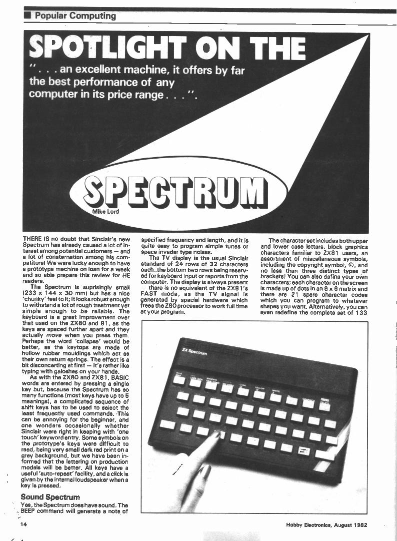
. . . an excellent machine, it offers by far the best performance of any computer in its price range . . . ".
THERE IS no doubt that Sinclair's new Spectrum has already caused a lot of in-terest among potential customers — and a lot of consternation among his corn-petitorsl We were lucky enough to have a prototype machine on loan for a week and so able prepare this review for HE readers. .
The Spectrum is suprisingly small (233 x 144 x 30 mm) but has a nice 'chunky' feel to it; it looks robust enough to withstand a lot of rough treatment yet simple enough to be reliable. The keyboard is a great improvement over that used on the ZX80 and 81, as the keys are spaced further apart and they actually move when you press them. Perhaps the Word 'collapse' would be better, as the keytops are made of hollow rubber mouldings which act as their own return springs. The effect is a bit disconcerting at first — it's rather like typing with galoshes on your hands.
As with the ZX80 and ZX81, BASIC words are entered by pressing a single key but, because the Spectrum has so many functions (most keys have up to 5 meanings), a complicated sequence of shift keys has to be used to select the least frequently used commands. 'This can be annoying for the beginner, and one wonders occasionally whether Sinclair were right in keeping with 'one touch' keyword entry. Some symbols on the prototype's keys were difficult to read, being very small dark red print on a grey background, but we have been in-formed that the lettering on production models will be better. All keys have a useful 'auto-repeat' facility, and a click is given by the internal loudspeaker when a key is pressed.
Sound Spectrum Yes, the Spectrum does have sound. The . BEEP command will generate a note of
specified frequency and length, and it is quite easy to program simple tunes or space invader type noises.
The TV display is the usual Sinclair standard of 24 rows of 32 characters each,.the bottom two rows being reserv-ed for keyboard input or reports from the computer. The display is always present — there is no equivalent of the ZX81's FAST mode, as the TV signal is generated by special hardware which frees the Z80 processor to work full time at your program.
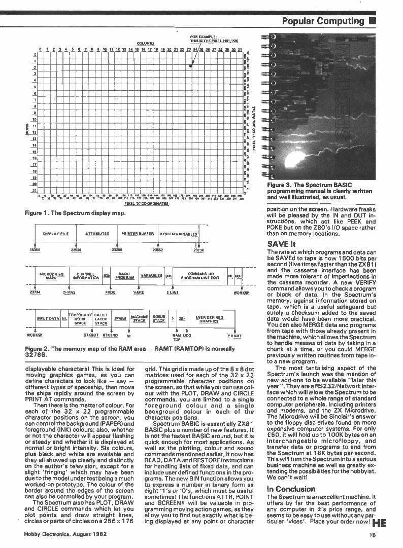
The character set includes both upper and lower case letters, block graphics characters familiar to ZX81 users, an assortment of miscellaneous symbols, including the copyright symbol, ©, and no less than three distinct types of bracketsl You can also define your own characters; each character on the screen is made up of dots in an 8 x 8 matrix and there are 21 spare character codes which you can program to whatever shapes you want. Alternatively, you can even redefine the complete set of 133
14 Hobby Electronics, August 1982
Popular Computing •
î
o 1
2
3 4 5
7
8
e 10
11
12
13
14
iL 18
COLUMNS
0 1 2 3 4 5 8 7 8 9 10 11 12 13 14 15 18 17 18 19 20 21 22 23 24
FOR EXAMPLE; THIS IS THE PIXEL (191,159)
/25 26 27 28 29 30 31
-
of
C
"r.
i▪ ; 1- < • e • • Z, e
_21
J 5 if Is 31 40 48 1111 84 72 80 88 88 104 112 120 1» 138 744 :11.7 _80 18. 171 I» 182 200 208 2_18 224 240 340 348 J. Yi 31 38 47 ma -es 71 71 87 » 103 II -iir-it1-1-18-1À3-eii X2 2232024 g,§
PIXEL 'X' CO-ORDINATES
Figure 1. The Spectrum display map.
1
2
DISPLAY FILE ATTRIBUTES PRINTER BUFFER SYSTEM VARIABLES
I 384
4 22528 23296 23552
I 2373
1 MICRODRIVE MAPS —
CHANNEL INFORMATION
anh '---=
BASIC PROGRAM
VARIABLES 80h —
COMMAND OR PROGRAM LINE EDIT _NI. 801.
3734 eHANe PRC1C: 3/ARC r I MO wiltà it
INPUT DATA NL TEMWPOORRKAR
SPACE
CLAATLCoUR
STACK SPARE — --
MACHINE STACK ______
GOSUB STACK _ _ ____
, '--
,E —h
USER DEFINED GRAPHICS —
I
h WORKSP STKBOT STK END Sp RAM UDG
TOP —
Figure 2. The memory map of the RAM area — RAMT (RAMTOP) is normally 32768.
P RAMI
SP
displayable characters! This is ideal for moving graphics games, as you can define characters to look like — say — different types of spaceship, then move the ships rapidly around the screen by PRINT AT commands.
Then there is the matter of colour. For each of the 32 x 22 programmable character positions on the screen, you can control the background (PAPER) and foreground (INK) colours; also, whether or not the character will appear flashing or steady and whether it is displayed at normal or bright intensity. Six colours, plus black and white are available and they all showed up clearly and distinctly on the author's television, except for a slight 'fringing' which may have been due to the model under test being a much worked-on prototype. The colour of the border around the edges of the screen can also be controlled by your program.
The Spectrum also has PLOT, DRAW and CIRCLE commands which let you plot points and draw straight lines, circles or parts of circles on a 256 x 176
grid. This grid is made up of the 8 x 8 dot matrices used for each of the 32 x 22 programmable character positions on the screen, so that while you can use col-our with the PLOT, DRAW and CIRCLE commands, you are limited to a single foreground colour and a single background colour in each of the character positions.
Spectrum BASIC is essentially ZX81 BASIC plus a number of new features. It is not the fastest BASIC around, but it is quick enough for most applications. As well as the plotting, colour and sound commands mentioned earlier, it now has READ, DATA and RESTORE instructions for handling lists of fixed data, and can include user defined functions in the pro-grams. The new BIN function allows you to express a number in binary form as eight '1's or 'O's, which must be useful sometimes! The functions ATTR, POINT and SCREENS will be valuable in pro-gramming moving action games, as they allow you to find out exactly what is be-ing displayed at any point or character
Figure 3. The Spectrum BASIC programming manual is clearly written and well illustrated, as usual.
position on the screen. Hardware freaks will be pleased by the IN and OUT in-structiáns, which act like PEEK and POKE but on the Z80's I/O space rather than on memory locations.
SAVE It The rate at which programs and data can be SAVEd to tape is now 1 500 bits per second (five times faster than the ZX81) and the cassette interface has been made more tolerant of imperfections in the cassette recorder. A new VERIFY command allows you to check a program or block of data, in the Spectrum's memory, against information stored on tape, which is a useful safeguard but surely a checksum added to the saved data would have been more practical. You can also MERGE data and programs from tape with those already present in the machine, which allows the Spectrum to handle masses of data by taking in a chunk at a time, or you could MERGE previously written routines from tape in-to a new program.
The most tantalising aspect of the Spectrum's launch was the mention of new add-ons to be available "later this year". They are a RS232/Network inter-face which will allow the Spectrum to be connected to a whole range of standard computer peripherals, including printers and modems, and the ZX Microdrive. The Microdrive will be Sinclair's answer to the floppy disc drives found on more expensive computer systems. For only £50, it will hold up to 100K bytes on an interchangeable microfloppy, and transfer data or programs to and from the Spectrum at 16K bytes per second. This will turn the Spectrum into a serious business machine as well as greatly ex-tending the possibilities for the hobbyist. We can't waitl
In Conclusion The Spectru'm is an excellent machine. It offers by far the best performance of any computer in it's price range, and seems to be easy to use without any par-ticular 'vices'. Place your order now! HE
Hobby Electronics, August 1982 15
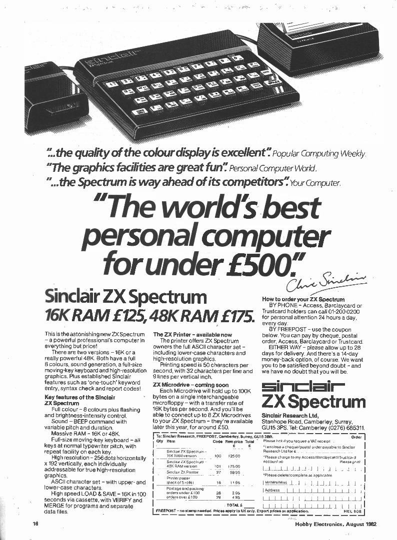
.the quality of the colour display is excellent'' Popular Computing Weekly. "The graphics facilities are great fun': Personal Computer World. "...the Spectrum is way ahead of its competitors": Your Computer.
"The worlds best personal computer for under £500
Sinclair ZX Spectrum 16K RAM £125,48K RAMI175. This is the astonishing new ZX Spectrum - a powerful professional's computer in everything but price!
There are two versions - 16K or a really powerful 48K. Both have a full 8 colours, sound generation, a full-size moving-key keyboard and high-resolution graphics. Plus established Sinclair features such as 'one-touch' keyword entry, syntax check and report codes!
Key features of the Sinclair ZX Spectrum
Full colour - 8 colours plus flashing and brightness-intensity control.
Sound - BEEP command with variable pitch and duration.
Massive RAM - 16K or 48K. Full-size moving-key keyboard - all
keys at normal typewriter pitch, with repeat facility on each key.
High resolution - 256 dots horizontally x 192 vertically, each individually addressable for true high-resolution graphics.
ASCII character set - with upper- and lower-case characters.
High speed LOAD & SAVE -16K in 100 seconds via cassette, with VERIFY and MERGE for programs and separate data files.
Oty Item Code Item price Total Please tick if you require a VAT receipt
Sinclair ZX Spectrum - 16K RAM version
Ord;r1
'I enclose a cheque/postal order payable to Sinclair Research Ltd for £
Please charge to my Access/Barclaycard/Trustcard Sinclair ZX Spectrum - account no Please print
48K RAM verston [ _1 1. 1 _1 I _1 1 1 _1 _1 _1 j 1 _1 11 •Please delete/complete as applicable
Mr/Mrs/Miss jJ J J Al_1111 I Address
LI1111111111111_11
111111111!IIIIIJJ bEEposr- no stamp needed. Prices apply to UK only. Export prices on application. HE L SOLI
Sinclair ZX Printer
Printer paper
(pack of 5 rolls) 16 11 95
Postage and packing . orders under £100 orders over £100
100 125 00
101 175 00
27 59 95
28 295 29 495
TOTAL
The ZX Printer - available now The printer offers ZX Spectrum
owners the full ASCII character set - including lower-case characters and high-resolution graphics.
Printing speed is 50 characters per second, with 32 characters per line and 9 lines per vertical inch.
ZX Microdrive - coming soon Each Microdrive will hold up to 100K
bytes on a single interchangeable microfloppy - with a transfer rate of 16K bytes per second. And you'll be able to connect up to 8 ZX Microdrives to your ZX Spectrum - they're available later this year, for around £50.
Fo: Sinclair Research, FREEPOST, Camberley, Surrey, GU15 3EIR.
I
How to order your ZX Spectrum BY PHONE - Access, Barclaycard or
Trustcard holders can call 01-200 0200 for personal attention 24 hours a day, every day.
BY FREEPOST - use the coupon below. You can pay by cheque, postal order, Access, Barclaycard or Trustcard.
EITHER WAY - please allow up to 28 days for delivery. And there's a 14-day money-back option, of course. We want you to be satisfied beyond doubt - and we have no doubt that you will be.
ZX Spectrum Sinclair Research Ltd, Stanhope Road, Camberley, Surrey, GU15 3PS. Tel: Camberley (0276) 685311.
16 Hobby Electronics, August 1982
Topics this month are CB, the MEMOPAK 64K RAM and a point concerning our "Scaling the HiFi Heights" series.
CB vs Computers
Dear Sir, Firstly, in answer to N. J. Treacher's letter (HE, June '82) re CB circuit diagrams; the only one presently obtainable from the makers is the Amstrad 900-901. This is really a super service sheet, including junction voltages, parts list and numbers for spares. The circuit is printed on a large folded sheet and is available from Amstrad to anybody for £2.50 plus 20p p&p. Hope this helps.
Now, my comments. I have taken HE from issue No.1 and I think is has been a very good mag. It was even better when you included a bit of CB (which must have helped your sales) but this was stopped when CB mags appeared. So how about finishing up the section on computing when this session comes to an end, as there are plenty of computing mags now, and stick to basic electronics. How about articles on wind
generator control circuits, charging car batteries by solar cells and other energy savers — but please stick to what HE is about; basic, useful projects and teach-ins. B. J. Shelford, Sheerness, Kent.
Firstly, then, thanks for your Point of View, and also for the tip on CB service sheets. Let's hope N. J. Treacher is still in touch!
Your comments on CB radio and computing are interesting. We don't see this as a straight-forward contest, thought,.As a long-term regular reader, you will be aware that we did as much as anybody else to publicise CB radio in the UK — but when CB magazines (including our own Citizens' Band Magazine) began to appear, it seemed that the dedicated CB nut would be better served by those specialist publications. This was confirmed by the lack of response (best described as 'underwhelming') to the demise of our Breaker One-Four page. Nevertheless, we know that many readers are still interested in CB, and that many more would like to learn more about radio generally, so we introcuded the 'teach-in' series, Radio Rules, together with regular CB/radio projects and features, under the title 'Into Radio'. We also felt that the best way we
could contribute to a better understanding of computers was to devote a number of pages to the basic electronics of micro computers — the 'nuts and bolts', as we like to say. We are still the only magazine to deal with computer technology on this level.
Lastly, our July issue contained a number of projects which could be 'solar-powered' (for further information on sources of relatively inexpensive cells, see the Monitor pages), and other energy-saving projects are being planned!
Memopak
Dear Sir, We have read your review of our MEMOPAK 64K on page 65 of Hobby Electronics for June 1982. May I say we thought it very fair? There are, however two points I would like to make.
The first concerns the amount of RAM available in our pack. There is 64K RAM physically present, but as the ZX81 can only address 56K locations above the 8K of its own ROM, we can only provide an additional 56K to the Sinclair user. However, the MEMOPAK 64K was not intended solely for use on the ZX81, and it would provide 64K of RAM to any Z80 processor that could address it. It might, for example, be used in conjunction with the Spectrum (with paging). Another possibility is that it could be combined with a disc operating system for use with the ZX81.
Secondly, the ZX81 arrays are not restricted to the upper 32K of RAM, as your diagram indicates. What happens is that the ZX81 allocates space to the instruction file, the display file and the arrays (in that Order) from about 16K onwards. Although the instruction file cannot climb above the 32K address limit, the arrays may start lower down — an array of 45K is possible. We take your point about the sticky
tabs and we are considering replacing them with Velcro tabs.
Perhaps you would consider publishing this letter in the interests of clarification for the ZX public. 'Yours Faithfully, D. J. Jay, Technical Consultant, Memotech Ltd.
We are only to happy to oblige, and hope that this clears up any misconceptions concerning the MEMOPAK 64K.
Hi-Fi Heights Revisited
Dear Sir, I bought your magazine for the first time last week, solely to read your article on "Makin' Tracks", which was well set-out for first-time PCB etchers. Reading further into the magazine, I
noticed some comments about 'Gremlins' (Letters, page 23), then further still, in 'Scaling the Hi-Fi Heights', a reference to Centrifugal Force throwing the cartridge away from the centre of a circle. Was this the Gremlins in action again, or have1 just misunderstood your meaning?
This was, of course, that the frictional force between the stylus and the groove walls tends to drag the cartridge in the direction of travel of the groove. Where there is an offset angle in the cartridge mounting (you don't offer much background to this in your paragraph on Tracking Error!) this frictional force has a component inwards, at right angles to the arm and this is compensated for by a bias out wards, which varies according to the load on the stylus.
Perhaps you could have a word with your printers and get them to sort out their Gremlins? B. A. L. Morgan, Ledbury.
A month (or two) in publishing, as in politics, is a long time (with apologies to Sir H. Wilson); apologies also to D. G. Parker of Stroud in Gloucestershire, for our late comments on this subject.
Remembering that the series was, after all, an introduction to hi-fi and not a thesis, we admit that the explanation was less than complete. In fact, there are two mutually opposed forces acting on the cartridge. The first, due to centrifugal force, tends to throw the arm away from the centre of the disc and some compensation for this force (which is readily observable when using a flat, ungrooved test disc) must be applied. The second force is, as the writers correctly point out, due to the drag of the stylus tip against the groove wall and it tends to pull the arm into the centre of the disc. Once the effects of centrifugal force, or any misalignment of the arm tending to reinforce this, have been corrected, a small adjustment to the bias can then be made to compensate for the inwards-acting force. As with all measurements and adjustments, it is first necessary to have a stable reference point; this is the reason for the first adjustment, made using a test record. We hope this explanation has not been a drag.
Lastly, lest our printers feel gravely insulted, we must also admit that the Gremlins (or 'the fairies at the bottom of the darkroom', as a colleague calls them) mostly reside in our typewriters, here at the lavish offices of A.S.P.
HE Hobby Electronics, August 1982 17
COMING SOON TO. . .
POPULAR COMPUTING
ZX INTERFACE BOARD An uncomplicated I/O port that can be adapted to suit eithér the ZX81 or the Spectrum.
MICROTRAINING The HE MicroTrainer project concludes with detailed explainations and applications.
MODEL PROJECTS
THREE-ASPECT LIGHTS CONTROLLER Red, green and amber signalling lights indicate that the way is clear — or not. With a little
ingenuity, this project can be further adapated . but more about that next month!
HE 'JUNIOR' SLOT-CAR CONTROLLER Better control for improved performance.
PROJECT:MUSIC
STEREO NOISE GATE Eliminates hisses and buzzes during pauses in music or speech.
TEST EQUIPMENT
VARIABLE PULSE GENERATOR Crystal controlled pulses from 100nS to 1S in eight ranges, with independently variable
mark/space ratio within each range. See it and believe itl
rPlease reserve
for Name
' copies of the September issue of
Address
September issue on sale at your newsagent
from 13th August
Place your order now! Although these articles are being prepared for the next issue, circumstances may alter the final content.
18 Hobby Electronics, August 1982
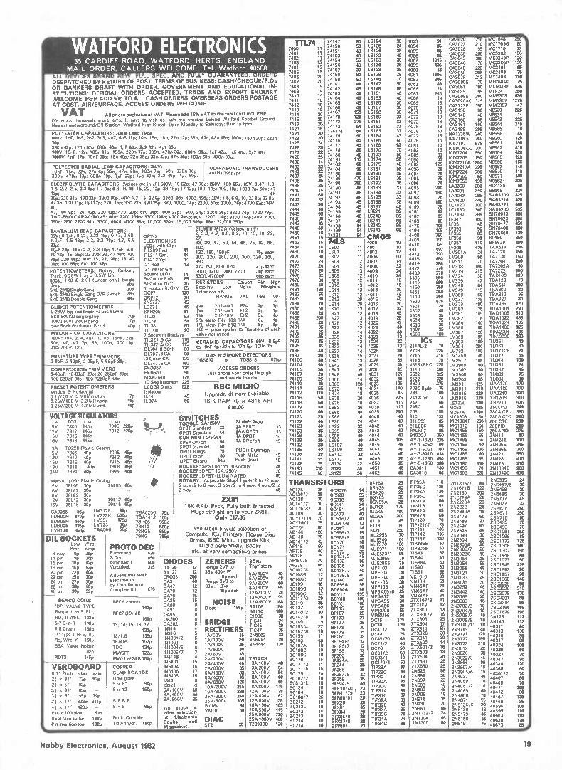
WATFORD ELECTRONICS 74011.0 (34 II 740 1 11
74147 90 74150' 50 74151 40 74153 40
LS124 90 LSI25 24 LSI26 35 LS132 LS133 40 30 LS136 26 LS138 28 LS139 28 LS145 70 LS147 150 LS148 85 LS151 40 LS153 40 LS155 30 LS157 LS158 30 30 LS160 37 LS161 37 LS162 37 LS163 37 L5164 43 LS165 60 LS166 52 LS170 70 LSI 73 LSI74 55 50 L5175 40 LSI81 95 LS190 36 LS191 36 LS192 36 LS193 37 LS194 33 LS195 33 LS196 38 LS197 48 LS221 55 LS240 55 LS241 55 LS242 55 LS243 56
4053 50 4054 as 4055 85 4056 4057 85 1915 4059 435 4060 45 4061 1195 4062 995 4063 e 4066 24 4067 245 4068 14 4069 13 4070 13 4071 13 4072 13 4073 13 4075 13 4076 4077 50 13 4078 15 4081 13 4082 13 4085 50 4086 60 4089 125 4093 20 4094 70 4095 75 4096 70 4095 290 190 4097 4098 25 4099 190 4160 75 4161 99 4162 99 4163 99 4175 106 4194 106
4408 790 4409 790 4410 726 4411 690 4412 790 4415 480 4419 280 4422 770 4433 770 4435 850 4440 999 4450 350 4451 350 4490 350 4500 675 4501 28 4502 60 4503 35 4504 75 4506 4507 35 35 4508 130
CA3020 210 T CA3023 210 CA3028 95 CA3035 255 CA3045 365 CA3046 70 CA3048 220 CA3059 285 CA3075 213 CA3080E 70 CA3081 190 CA3085 95 CA3089E 280 CA3090AQ 375 CA3I23E 150 CA3130 90 CA3140 40
CA3160 95 CA3161 160 CA3189 295 HA1336W 240 CL7106E 750 CL7107 975 CL8038CC 300 CM7204 550 CM7205 1150 CM72I6A 1950 CM72I 7A 790
CM7224 785 CM7555 80 CM7556 150 LA3350 250 LA4031 340 LA4032 295 LA4400 440 LC7120 300 LC7130 340 LC7I37 395 LF347 150 LF351 48 LF353 50 LF355 85 LF356 90 LF357 110 LF398 475 LA.4301A 24 LM308 95 LM311 70 LèA318 150 LM319 215 LM324 30 LM339 47 LM348 64 LM349 115 LM358 60 LM377 175 LM379 480 LM380 75 LM381 146 LM382 115 LL M54338846 14060
LM387 120 LM389 95 LM393 100 LM394 290 LM733 100 LM1458 40 LA/12917 195 LM3900 50 LM3302 90 LM3900 50 LM3909 85 LM3911 125 LM3914 210 LM3915 220 LM3916 220 LS7220 280 M252 825 M253A 1150 MC1303 88 MC1304P 260
MC1310 150 MC1455 150 MC1458 55 MCI488 55
MC1458 40 MC1469 300
MC1488 40 MCI 489 55 MC1495 350 MC1496 70 MC1596 225
MCI648 293 MC1709G 90 MC1710 79 MC3302 150 MC3340P 120 MC3360P 120 MC3401 65 MC3403 75 MC3403 110 MFC6040 75 MX50398 635 ML924 250 MM5303 635 MM5307 1275 MM5387 47 NE529 225 55531 14 0E543 225 NE544 210 NE555 16 5E556 45 NE560 325 NE561 398 NE562 410 NE564 420 NE565 120 NE566 155 50567 140
5E570 410 NE571 400 NE5534 225 9C4136 69 5586B 225 SA83209 425p; SAB3210 325 SAB3271 485 SAB4209 595 01476013 350 SN76023 360 SN76472 450 SN76488 480 SN76660 120 SL490 360 SP8629 299 TAA621 295 TA7120 150 TA7130 150 TA7204 200 TA7205A 90 TA7222 150 TAD100 159 TBA120 70 . TBA641 290 ' TBA800 80 TBA810 95 TBA820 BO TCA965 120 TDA1004 290 TAD1008 310 TDA1022 499 TT 00 AA11405204 321055
TDA2004 495 TDA2020 320 TL061 ao 11063 so TL071CP 24 TL072 46 TL074 100 TL081 24 TL082 45 TL083 75 TL084 80 UAA170 170 UAA180 170 UA2240 120 XR2206 300 XR22I 1 575 Z80CPU 299 Z80A CPU 350 Z80A CTC 290 280 CTC 290
Z8OPIO 260 ZBOAPIO 275 ZN414 oo ZN424E 130
ZN425E 345 ZN426E 300
ZN427 590 ZN428 410 ZN429 210 ZNI034E 200 ZN1040E 676
35 CARDIFF ROAD, WATFORD, HERTS., ENGLAND MAIL ORDER, CALLERS WELCOME. Tel. Watford 40588
ALL . 'I ; • . I . 1 TY g • E . A 1 e Fill_ ' UARA TEED. *RD •
7402 7403 11 12 7404 13 7405 15 7406 20
74154 55 74156 40 74157 30 74159 80
DESPATCHED BY RETURN OF POST. TERMS OF BUSINESS: CASH/CHEQUE/P.Os OR BANKERS DRAFT WITH ORDER. GOVERNMENT AND EDUCATIONAL IN- STITUTIONS' OFFICIAL ORDERS ACCEPTED. TRADE AND EXPORT ENQUIRY WELCOME. P&P ADD 50p TO ALL CASH ORDERS. OVERSEAS ORDERS POSTAGE AT COST. AIR/SURFACE. ACCESS ORDERS WELCOME.
VAT All prices exclusive of VAT. Please add 15% VAT to the total cost i mol. P&P We stock thousands more iems. It pays to visit us. We are situated behind Watford Footbal Ground. Nearest underground/BR Station: Watford High Street. Open Monday to Saturday: 9arn to fipm
7407 20
7408 14 7409 14 7410 14 7411 7412 1186 7413
20 7414 ,
7416 20 7417 , 7420 15.
74160 60 74161 48 74162 48 74163 48 74164 74165 48 48 74166 48 74167 150 74170 125 74172 275 74173 54
POLYESTER CAPACITORS: Axial Lead Type 4COV: InF, In5, 2n2, 3n3, 4n7, 6n8 11p; 10n, 15e, 18e. 22e 12p: 33n, 47n, 68n 16p; 100e, 150e 20p; 220n 30p; 330n 42p; 470e 52p; 680e 60p; 1µF 68p; 202 Up: 4µ7 85p. 160V: 10nE, 12e. 100e 11p; 150n, 220, 17p; 330n, 4700 30p: 680n, 38p; 1µF 42p; 1µ5 45p; 42 48p. 1000V, InF 17p: 10nF 30p: 15e 40p; 22n 36p; 33e 42p; 47e 48p; 100e 50p; 470e 99p.
7421 20 7422 „ 7425 24 7426 7427 L28 7428 7430 14
174174 54 74175 50 74176 40
45 80
7774441877087 1 40 74181 115
POLYESTER RADIAL LEAD CAPACITORS: 250V: 10nF, 150, 220. 27n 6p; 33e, 47e, 680, 100e 7p; 150n, 220n 10p. 330e, 470n 13p: 680e 19p; 1µF 23p: 45 40p; 42 46p; 4,47 60p.
ULTRASONIC TRANSDUCERS 40kHz 395p/pr
7432 22 7433 22 7437 25 28
74182 60 74184 90 74185 95 74186 470
ELECTROLYTIC CAPACITORS: IValues are in µF) 500V: 10 52p; 47 78p; 250V: 100 65p; 63V: 0.47, 1.0, 1.5, 2.2, 2.5, 3.3 8p: 4.7 9p; 6.8. 10 10; 15. 22, 12p; 33 15p; 47 12p; 100, 19p; 100, 19p; 1000 7p. 50V: 47 12p; 68 20p; 220 24p; 470 32p; 2200 90p. 40V: 4.7, 15, 22 9p: 3300, 90p; 4700, 120p; 25V: 1.5, 6.8, 10, 22 8p; 33 9 47 8p; 100 11p; 150 12p; 220, 15p; 330 22p; 470 25p; 680, 1000, 34p; 2200, 50p: 3300, 76p; 4700 92p; 16V: 40, 47, 100 9p; 125, 125; 220 13p; 470, 20p; 680 34p; 1000 27p; 1500, 31p; 2200 36p; 3300 74p; 4700 79p. TAG-END CAPACITORS: 64V: 2200 139p; 3300 198p; 4700 245p 50V, 2200 110p; 3300 154p; 40V: 4700 190p: 25V: 2200 90p; 3300, 4000, 4700 98p; 10,000 320p; 15,000 345p; 16V: 22,000 350p.
7438 7438 25 7440 15 7441 68
32 7442 „ 7443 7444 90 7445 7446 56
60 7447 35
74188 250 74190 48 74191 48 74192 48 74193 45 74194 45 2 48 744119965
46 74197 46 74198 84
TANTALUM BEAD CAPACITORS 35V: 0.1µF, 0.22, 0.33 15p: 0.47, 0.68, OPTO
SILVER MICA (Values in pH 2, 3.3, 4.7, 6.8, 8.2, 10, 15, 18, 22,
7448 ao 7450 7451 16 16
74199 84 74221 54 CMOS
4000 10 4001 10 4002 12 4006 50 4007 14 4008 32 4009 24 4010 24 4011 10 4012 16 4013 20 -4014 4§ 4015 40 4016 20
4017 rt. 4018 45 4019 25 4020 42 4021 ao 4022 40 4023 13 . 4024 32 • 4025 13' 4026 80 4027 20 4028 - 39 4029 45 4030 15 4031 125 4032 80 4033 125 4034 140 4035 45 4036 275 4037 115 4038 110 4039 290 4040 40 4041 40
4042 40 4043 40 4044 40 4045 105
4046 45 4047 40
4048 40 4049 25 4050 25 4051 45 4052 60
1.0aF, 1.5 16p; 2.2. 3.3 18p; 4.7, 6.8 22p; 10µF 28p; 16V: 2.2, 3.3 16p; 4.7µF, 6.8, 10 18p; 15, 36p; 22 30p; 33,47 405; 100 75p; 220 88p; 10V: 15, 22, 26p; 33, 47 35p: 100 56p; 61/: 100 42p.
ELECTRONICS LEDs with Clips TIL209 Red 11 TIL211 Gm. 14 TIL212 yid. 14 .2" Red 12
27, 33. 39, 47, 50, 56, 68, 75, 82, 85, 100, 120, 150, 180pF 15p each 200, 220, 250, 270, 300, 330, 360, 390, 470, 600, 800, 820 21p each
7453 16 7454 16 7460 16 7470 30 7472 24 7473 24
74LS 1.000 11 LS01 11 LSO2 11 LSO3 12 LSO4 12
POTENTIOMETERS: Rotary, Carbon, Track. 0.25W Log Et 0.5W Lin.
.2 Yell or Grn Square LEDs 14 Bi-Colour R/G 65
1000, 1200, 1800,2200 30p each
3300, 4700pF 60p each
7474 20 7475 32
LSO5 13 LSO8 12
5000, 11(0 Ft 2KII (Linear only) Single Gang 30p 51(11-2MIlSingle Gang 30p 51(0-2Mfl Single Gang 0/P Switch 78p 5K0-2MI1 Double Gang 88p
Bi-Colour G/Y 75 Tri-colour R/G/Y 85 OCP71 120
ORP12 78 2N5777 45
RESISTORS — Carbon Film High Stability. Low Noise. Miniature Tolerance 5%,
RANGE VAL 1-99 100- +
7476 30 7480 40 7481 120 7482 65 7483 38
LSO9 12 LS10 13 LS11 13 LS12 12 LS13 20
SLIDER POTENTIOMETERS 0-25W log and linear values 60mm 5K0-500KlIsingle gang 70P 1W 1CD 10-500 dual gang 110p
Self Stick Graduated Bezel 4011
LD271 46 SFH205 91 TI L32 52 TIL78 54 TIL38 86 TIL100 go
VA' 202-4M7 E24 2p 1p ;W 202.4M7 E12 2p 1p 1W 202-10M E12 Sp 4p 2% Metal Film 10G-1M 6p 4p 1% Metal Film 510 -1M Bp 6p 100, price applies to Resistors of each
7484 70
7485 60 7486 20 ,489 ' 7490 205
20 7491 35
LS14 30
L520 13 LS21 12 LS22 13 LS26 12 L027 12
MYLAR FILM CAPACITORS 7 Segment Displays value not mixed. 7492 25 7493 25
LS28 14 LS30 12
ICs 2114 L-2 70 2708 225 2716 215 4116 TO 4816 (BBC/ 225 6116 390 6502 325 6522 320 6800 2.76 709C8 pin 35 733 100 741 8 pin 74 747C 65 748C 36 753 185 810 159 81L095 85
81 LS96 85 81LS97 85 9400CJ 350 AY.1 -1320 225
AY-1-5050 99 AY-1-5051 160
AY-3-8910 438 AY-5-1230 450 AY-5-1350 388 CA3011 130 CA3018 86
100V: le, 2, 4, 4n7, 10 6p; 15nF, 220, 30e, 40, 47 7p: 56, 100e, 200 9p; 470n/50V: 12p.
TIL321 .5 CA 115
TIL322 .5 CC 115 DL704 .3 CCth 99
CERAMIC CAPACITORS 50V: 0-5pF to lOnF 4p: 22e to 470 5p, 100e 7p.
7493 35 7495 35 7496 40
LS32 13 LS33 14
MINIATURE TYPE TRIMMERS 2-6pF, 2-10pF, 2-25pF, 5-56pF »p.
01_707 .3 CA 99 .3 Green CA 120 01_747 CA 180
GAS Et SMOKE DETECTORS TGS812 or TGS813 5750
7497 90 74100 80
LS37 14 LS38 15 LS40 13
COMPRESSION TRIMMERS 3-40pF; 10-80pF 20p: 20-250pF 28p: 100-580pF 39p: 400.1250pF 48p.
.6 FND357 120 FND500 90 MAN3640 175
ACCESS ORDERS Just phone your order through
and we do the rest
74104 50 74105 55 74107 20 74109 25
LS42 28 LS47 35 LS48 45 LS55 14
PRESET POTENTIOMETERS Vertical Et Horizontal 0.1W 50 M 5 MIIMiniature 7P 0.25W 100 M 3.3 M0 horiz. 10p 0.25W 200 M-4.7 MfI vert. 10p
10 Ong Bargraph 225 LCD 31 Digits 525 Isolators IL74 45 ILD74 99
10 Ong Bargraph 225 LCD 31 Digits 525 Isolators IL74 45 ILD74 99
BBC MICRO Upgrade kit now available
16-K RAM 18 x 4816 API
MOO
74110 35 74111 55 74112 170 74116 50 74118 60 74119 80 74120 60
LS63 120 LS73 18 LS74 18 LS75 20 LS76 18 LS83 36 LS85 48
VOLTAGE REGULATORS 1A TO3 o ve ve 5V 7805 145p 7905 220p %L..j, 12V 7812 145p 7912 220p ."..1 . y 15V 7815 145p -- 18V 7818 145p —
1A TO220 Plastic Casing 5V 7805 40p 7095 45p 12V 7812 40p 7912 4.5p 15V 7815 40p 7915 45p 18V 7818 40p 7918 45p /./ 24V 7824 40p 7924 45p
SWITCHES TOGGLE: 2A/250V SLIDE: 240V SPOT Standard 33 IA SPOT 13 DPDT Standard 44 IAA DPDT 13 SUB-MIN TOGGLE IA DPDT 14 SPST On/off 54 1 A DP c/off 15
SPDT Ic/over) 60 DPDT 6 tags 25 PUSH BUTTON DPDT c/off 00 Push-Make 15 DPDT Biased 145 Push-Break 18 ROCKER: SPOT on/off 10A/250V 28 ROCKER: DPDT 10A/250V 70 ROCKER: DPST ILLUMINATED 86
74121 25 74122 40
74123 40 74123 36 74126 35 74128 35
74132 28 74135 40
74136 28 74141 55 74142 175 74143 210 74145 50
LS86 16 LS90 24
LS92 32 LS93 23 LS95 40 LS96 40
L5107 40 LS109 23
LS 112 22 LS 113 16 LS114 n LS122 36 LS123 36
100mA T092 Plastic Casing 5V 78L05 30p 79L05 60p # 6V 78L62 30p
78L82 30p
ROTARY: (Adjustable Stop) 1 pole/2 to 12 way; 2 pole/2 to 6 way; 3 pole/2 to 4 way; 4 pole/2 to 3 way 45
TRANSISTORS ' AC125 35 AC126/7 35
BC307 B 14 BC328 95
EIFY52 23 BRY39 40 BSX20 20 BSY65 35 85y95A 25 BU105 170 BU205 190 131U12,08 2 6 i'4%3
E176 50 E421 250 MJ2955 70 rob:4 JJEE334200 10054
MJE371 100 MJE520/1 95 — ,02„, _
'''''' MJE3055 70 MPF102 4i00 MPFI 03 30 MpF104 30 MPF105 30 MPFI06 40 MPSA05/6 25 MPSA12 30 MPSA55 30 MPSA56 30 MPSUO6 55 .MRSU56 60 0C35 125 0C36 120 0C41 /2 75 0C44 75 0C45/70 40 0071 /2 40 0076 50 OM /2 50 0083 /4 40 0C170/1 50 TTIIP62259Ac 438832
TIP30 TIP30A 35 TIP30C 37 TIP3IA 38 TIP31C 37 TIP32A 38 TIP32C 42 TIP33A 55 ,T.11133,43AC 7748
— -4C 95
TIP35A 110 TIP35C 128 TIP36A 130 TIP36C 140 TIP41A 50 TIP4113 52 TIP42A 55 Ti 2013 50 T Pp412r0
TIP121/2 73 TIPI41 105 TIP142 105 TT1Pp2154575 12060
TIP3055 60 TIS43 33
`I° TISB8A 5_030 TTisS4904
TIS91 ). VK1010 80 VN1OK 55 VN46AF 78 VN66AF 80 VN88AF 94 ZTX107 /8 11 ZTX109 12 ZTX300 13 ZTX301 /2 16 ZTX303 25 ZTX304 17 ZTX314 25 ZTX326 30 ZTX341 30 ZTX500 14 ZTX501 /2 15 ZTX503 18 ZTX504 25 ZTX531 25 22ZTNNX659256650 _25
?,1.,. _.'
2I4697 2N698 •2-..,
'.)'; 2N699 r... 2N706 2N918 2 2N930 ... 20 _ 2N961 22NN11,10342 /2 '26;4
2N1305 6°
2N1306/7 65 2N167113 120 2N2160 350
212 A e3 2 222106A 23 2 N2222 25
2N2369A 18 2N2476 50 2N2483 27 2N2497 63 2N2646 45 2N2894 30 2142904 28 2N2905A 26 2N2906 /7 26 2 N2926G 10 2143053 26 2N3054 58 2N3055 48 2N3121 30 2N3133 45 2N3135 30 2 N3252 e 2 N3442 140 2N3568 25 2143663 15 2N3702/3 10 2N3704/5 10 2N3706 /7 10 2143708/9 10 2N3710/11 10 2N3713 140 2143771 179 2N3772 195 2143773 210 2N3819 22 2143020 38 2N3822 /3 e 2N3866 90 2N3903/4 15 2N3905/6 15 2N4037 46 2N4058 10 2N4061 /2 10 2N4069 45 2N4859 78 2N4871 55 2N5135 /6 20 2N5138 18 2N5179 45 2N5180 45 2N5191 75
24 2N5457 /8 30 2N5459 30 2N5485 30 2N5777 45 2146027 32 2SA636 250 2SA671 250 2SA7I 5 60 2SC495 70 2SC496 70 2SC1061 250 2SC1096 85 2SCI 173 125 2SCI 306 100 2SC1307 150 2SCI449 85 2SC1923 50 2SC1945 225 20C1953 90 2SC1957 90 2SCI 969 140 2SC2028 85 2SC2029 210 2SC2078 170 2SC2091 85 2SC23I4 85 25C2166 165 2SCI679 190 314128 112 314140 112 40311 60 40313 130 40316 95 40317 ao 40324 100 40326 60 40327 70 40347 90 40348 120 40360 60 4400430681/2 70 40407 60
70 40411 285 40412 90 40467 130 40408 85 40594 105 40595 110 40603 110 40636 175 40623 /35.0#
8V 12V 78L12 30p 79L12 60p 15V 78L15 30p 79LI 5 60p
99p CA3085 95p LM31 7P TBA625B 75p LM300H 170p LM323K 500p TDA1412 150p LM305H 140p LM337 175p 78H05 550p LM309K 136p LM723 35p 78H12 580p LM317K 360p TAA550 50p 78HG5 55(1p
ZX81 16K RAM Pack, Fully built Er tested.
Plugs straight on to your ZX81. Only £17.35
We stock a wide selection of Computer ICs, Printers, Floppy Disc
28 30 1/2 AACC114 30 AC176/87 30 AC188 30 ACY17/18 70 ACY20/1 75
Ágï e
381 15 6CC434 34 El BC461 BC477 34 40 BC516 /7 40 BC547/8 12
gee /7 U
DIL SOCKETS 79HG 7135p Drives, BBC Micro upgrade Kits,
AD149 75 AD161 /2 42
8C558/9 15
Low Wire Prof. wrap
8 way 13p 25p PROTO DEC Euroboard 520
Micro peripherals, Books etc at very competitive prices.
AFI15 60 AF139 40
5 Qy20 18 BCY71 18 BCY72 20
48 14 pin 9p 35p 16 pin 10p 42p 18 pin lop 52p 20 pin 221, 60p 22 pin 25p 70p 24 pin 27p 70p 28 pin 28p 80p 40 pin 30p 99p
S Dec eo Bimboard I 500 Veroblock 375
Adventures with Electronics by Tom Duncan Complete Kit: E15
DIODES 8Y126 12 BY127 12 CR033 250 0A9 40 0A47 1 0A70 1 0A79 1
ZENERS Range 2W to 39V 400mW
Bo each - Range 3V3 to 33V. 1.3W ,
160 each
SCRs Thyristors
5A/400V 40 5A/600V 48 8A/300V 60 8A/600V 95 12A/100V 78
AAFF11 8708/6 7700
AF239 56 8C10718 10 BC108B 12 BC108C 12 BC109 10 BC10913 12 BC109C 12
BBDDI13331/2 60
BD135 45 60136/7 40 BD138,9 46
BD140 ao BD695A 99 BD696A 99 BDY17 195
DENCO COILS RFC 5 chokes 'DP' VALVE TYPE 144 Range 1 to 5 BL., RFC7 (19mH) RD, TI Wht. 122p 160p
6-713 -Y-R 110p 13; 14; 15; 16; 17 1.5 Green 150p 120p 'T' type 1 to 5, BI, 18/1.6 135P Rd, Wht. Yb 150p 18/465 152p B9A Valve liolder TOC 1 124p
42p MW5FR 122p RDT2 145p MW/LW SFR 154p
DA/35 1 0A90 0A91 0A95 0A200 0A202 N914 N916 144001/2 IA/58V N4003 N4004/5 N4006/7 N4148 N5401 1
NOISE Diode 195p
BRIDGE RECTIFIERS
18 1A/100V 20 14/400V 25 1A/600V 34 2A/50V 36 2A/200V 40
12A/400V 95 12A/800V 1813 BT106 150 BT116 180 C106D 35 TIC44 TIC45 24
29 TIC47 35 2145062 32 2145064 38 2N4444 130
TRIACS
8C117/8 20 BC1I9 38 BC137 40 BC140/3 30 BC147 /8 9 BC149 9 BC153/4 27 BCI 57/8 10 BCI 59 11 BC160 45 or..., x on YlrlUf rl MY
BC168C 10 BC169C 10 BC170 15
8DY6O 160 130Y61 160 8E115 as FIF167 29 Bryn 27 8E177 25 8E178 30 BF179 35 8E180 38 BF194/5 12 13F196 /7 12 BF198 18 8E200 30 BF224A 25
VEROBOARD 0.1" Pitch clad plain 21 x 3i" 73p 52p
21 x 5" 83p — 3j x 3I" 83p — 3j x 5" 95p 79p 32 o 17" 326p 211p 4j x 17" 426p — Pkt of 100 pins 50p Spot face cutter 118p Pin insertion tool 162p
COPPER CLAD BOARDS Fibre glass
6 x 6" 99P 6 x 12" 150p
S.R.B.P.
9 x 8 95P
Ferric Chloride 1lb Anhydr. 195p
145404 1 145408 1 N5408 644 0921 6A/100V 40 6A/400V 50 6A/800V 65
We stock a wide selection of Electronic Bocl0) . and Magazines.
2A/400V e 2A/600V 65 6A/100V 83 6A/400V 95 6A/600V 125 10A/200V 215 10A/600V 298 25A/200V 240 25A/600V 395 8Y164 56 VM18 50
DIAC 6-,-, 25
3A 100V 48 3A 200V 54 3A 400V 56 8A 100V 60 8A 400V 69 8A 800V 115 12A 100V 78 12A 400V .83 ..„.
16A 100V 103 16A 500V 115 25A 800V 220 25A 1000V 480 T280000 120
BC171 /2 11 8C177/8 16 BCI 79 20 0C182/2L 10 BC813/L 10 BC184 10 BC184L 10 513CC218126/7 26
10 BC2I2L 10 8C2I3 BC213L 1100 BC214 10 BC214L 10
BF244 28 9E256 as BF257/8 32 8E259 35 ,F694,5 40
BER39/40 23 1
11FERR4801//8261 2325 BFX29 28 oFx81 45 BBF6xX8845/6 28e
BFX87 /8 28 13FY50/1 23
Hobby Electronics, August 1982 19

MI.
• Project
• Digital Millivoltmeter
A high precision bench instrument based on a single VLSI chip.
THIS IS an item of precision test equipment which will be in constant use on the electronics work-bench, as well as being frequently called on for jobs around the home. It is battery-powered, to give it portability, and its compact layout makes it almost pocket-sized. In spite of the fact that it is built from only two ICs, its detailed specification (see box) includes most of the features found in an instrument costing appreciably more to buy ready-made.
Compared with its analogue counterpart, a digital voltmeter is an instrument of considerable complexity. To assemble an analogue voltmeter, you need only a milliammeter, a set of precision resistors and a rotary switch. An essential part of a digital voltmeter is the ingeniously designed circuit which converts the analogue voltage input into its digital equivalent. This, in itself, is a fairly complex operation if it is to be performed with precision (see How It Works). The final stage of conversion consists of the output from a series of decimal counters, one for each digit. Thd next step is to convert the counter output to a decimal number to be shown on a set of 7-segment displays. When the number of digits in the display is 3 or greater, it is more economical to use a multiplexed display, where the digits are each illuminated, in turn, for a very short period. The rate of turning the digits on •and off is so high that, to the eye, it
appears that they are continuously lit. As each digit is illuminated, the output from the corresponding counter is decoded to produce the correct figure for that display. Only one decoder IC is needed to serve all the digits, instead of one for each digit. This saves expense on decoder ICs but the multiplexing circuit requires a pulse generator (or clock) to time its opeations, plus the switches required to connect each counter, in turn, to the decoder.
To build such a circuit using MSI (Medium Scale Integration) ICs requires 2 dual counters, a decoder, a clock IC, another IC for the multiplexing counter and 2 or more for the multiplex switches, making a total of 7 ICs — as a modest estimate! The complexity of the wiring, and the difficulties of setting up and testing each stage, make the assembly of a circuit of this kind a daunting project for the inexperienced constructor. Fortunately, VLSI (Very Large Scale Integration) has made it possible to put all of the above (and more) on to a single slice of silicon!
Although it costs only as much as the total cost of the individual ICs listed above, the 7107 chip carries a complete digital millivoltmeter, including the analogue-to-digital converter, the counter, and all the circuitry required to multiplex and drive the display. All the constructor needs to do is to provide the circuits which
cater for the various ranges of input voltage, to add the few external components which the 7107 requires, and to assemble the display digits on a panel. This is still plenty enough to do, so VLSI does not rob the constructor of the interest and satisfaction of building a useful and attractive instrument.
Circuit Details The input potential dividers consist of R1, together with RV1 and R2 (2 V range) or RV2 and R3 (20 V range). These are set to divide the input voltage by 10 and 100 respectively. The dividers are brought into action by grounding the lower resistor of each, using switch SW2b. The voltage from the potential dividers is selected and passed to the IC by SW2a. For the 200 mV range, neither potential divider is grounded, so only the 10M resistor (R1) comes between the input socket and the IC. It might be thought that such a high resistance would seriously reduce the voltage reaching the IC, however, the current needed by the + ve or — ve inputs for a full-scale reading is only 1 pA (a millionth of a millionth of an amp). With so little current, the maximum voltage drop across R1 is only 0.05 mV, which can certainly be ignored.
The high resistance of R1 also serves to protect the IC from a high voltage, accidentally applied. If, by chance, the + ve socket is connected to 1000 V, say, the current flowing
20 Hobby Electronics, August 1982
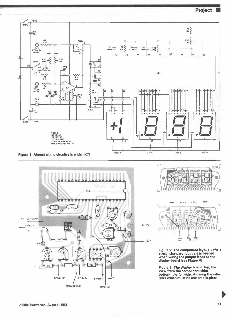
Project •
sw1b —4V5
.c4V5
+ci --- lots
R1 10M
51(3 0V2-20V (HIGH)
RV1 SW2b 470k
OV 0, R2 • _ 06 ewe
7 8
R3 91k
SK2 R4 20mV 2k7 (LOW)
SW2a A
RV2 47k
RV4 22k
ZD1 ZD2 R6 10k
IC1
7
4
R5 82k
5
6
2
RV3 10k
33
R9 180R
12
31
C7 R8 100n '""" 47k
27 128
C6 C4 RV5 470n 100p 100k
29 38
R7 221
RV6 lk
IC2
11
9r 10
SW2c
NOTES. IC1 IS 741 IC2 IS 7107 DISP1 IS M73 DISP2,3,4 ARE DL707 ZD1,2 ARE BIX61C12V
Figure 1. Almost all the circuitry is within ICI.
11 10
Al A2
1 14
Mtn'
e I bd
NIMBI
A
14
I b
•
A
14
dp
co
z
co
DISP 1 DISP 2 DISP 3 DISP 4
IN !SCREEN!
IN • (WWI
SW2b (8)
nonopneno
00 0 0 U 0 O 113
RV1•
'e
ti R3 F>411"1 R L—
/ S V2b PI
SVV2a (2,3,4)
SW2a(1 +4V5
SW2a(A)
• OV
4V5
S1Y2 SW?, SW2c (101 19.121 1111
DIST 4 DISP 3 131SP 2 D(SP 1
Figure 2. The component layout (Left) is straightforward, but care is needed when wiring the jumper leads to the display board (see Figure 4).
Figure 3. The display board; top, the view from the component side; bottom, the foil side, showing the wire links which must be soldered in place.
Hobby Electronics, August 1982 21
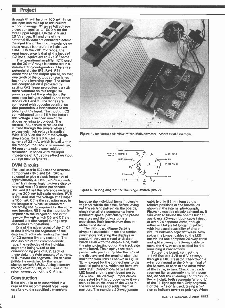
• Project
through R1 will be only 100 uA. Since the input can take up to this current without damage, R1 gives full voltage protection against ± 1000 V on the three upper ranges. On the 2 V and 20 V ranges, R1 and one of the ' potential dividers are connected across the input lines. The input impedance on these ranges is therefore a little over 10M . On the 200 mV range, the input impedance is that of the input of IC2 itself, equivalent to 2x10 11 ohms.
The operational amplifier (IC1) used on the 20 mV range is connected in a non-inverting configuration. There is a potential-divider (R5, RV4, R6) connected to the output (pin 6), so that one tenth of the output voltage is fed back to the inverting input. The offset null compensation is provided by setting RV3. Input protection is a little more elaborate on this range; R4 provides part of the protection, the remainder being provided by the zener diodes ZD1 and 2. The diodes are connected with opposite polarity, so that protection is independent of the polarity of the input. The input of IC2 can withstand up to 15 V but before this voltage is reached one of the diodes begining to conduct. The resistor, R4, serves to reduce the current through the zeners when an excessively high voltage is applied. With 100 V on the input the voltage drop across R4 is 88 V, giving a current of 33 mA, which is well within the rating of the zeners. In normal use, R4 presents only a small addition resistance, in series with the input impedance of IC1, so its effect on input voltage may be ignored.
DVM Circuits The oscillator in IC2 uses the external components RV5 and C4. RV5 is adjusted to give a clock frequency of approximately 48 kHz, which is divided down by internal logic to give a display renewal rate of 3 times per second. RV6 and R7 set the reference voltages; to give 200 mV full-scale reading, RV6 is adjusted until the voltage at its wiper is 100 mV. C7 is the capacitor used in the integrator, while C6 stores the correcting charge required for the auto-zero function. R8 links the input buffer amplifier to the integrator, and is the resistor through which C6 and C7 are charged and discharged during ramp and auto-zero operations.
One of the advantages of the 7107 is that it drives the segments of the displays directly eliminating the need for 23 current-limiting resistors. The displays are of the common anode type, the cathodes of the individual segments being wired to the corresponding pins of IC2. Each of these sinks the right amount of current, to illuminate the segment. The decimal points are switched by the range-change switch SW2c. A single current-limiting resistor (R9) is required in the return connection of the 0 V line.
Construction If the circuit is to be assembled in a case of the recommended type, keep carefully to the specified dimensions
Figure 4. An 'exploded' view of the Millivoltmeter, before final assembly.
DISPLAY BOARD
DISP 3
DISP 2
DISP 10
R3
7 R2 .4--Cèt,
5 6 e,
NC NC
12 i, ICI PIN 6
RI
IC2 PIN 31
Figure 5. Wiring diagram for the range switch (SW2).
OV
because the individual items fit closely together within the case. Before laying out the etching pattern on the boards, check that all the components have sufficient space, particularly the preset resistors and the polycarbonate capacitors. Both boards may then be etched and drilled.
The LED board (Figure 3a,b) is simple to assemble. Insert the teminal pins before soldering the displays in position; they are placed with their heads flush with the display side, with the pins projecting out on the track side of the board. The displays are then pushed into position. Solder the pins of the displays and the terminal pins, then make the wire links as shown in Figure 3b — except for the connections to the decimal-point pins, which are best left until later. Connections between the LED board and the main board are by 24 wires. The 20-way jumper cables suggested for this purpose make it very easy to insert the ends of the wires in the row of holes and solder them in position. The standard 20-way jumper
cable is only 85 mm long so the relative positions of the boards, as shown in the internal photograph, Figure 4, must be closely adhered to. If you wish to mount the boards further apart, use 20-way ribbon cable intead, or even 24 separate wires, though either will take a lot longer to solder, with increased possibility of short-circuits between adjacent wires. Now solder the jumper cables to the LED board; use one complete 20-way cable and split a 5-way or 20-way cable to make the 4-way cable needed for the remaining 4 connections.
To test the board, connect the + 4V5 line to a 4V5 or 6 V battery, through a 18OR resistor. Then touch a wire, connected to the 0 V terminal of the battery, to each of the other wires of the cable, in turn. Check that each segment lights correctly and, if it does not, inspect the soldering and tracks. In the + 1 digit, both segments 'a' and 'b' of the '1' light together. Only segment, c of the ' + ' sign is used, giving a ' — ' sign to indicate reversed polarity. When
22 Hobby Electronics, August 1982
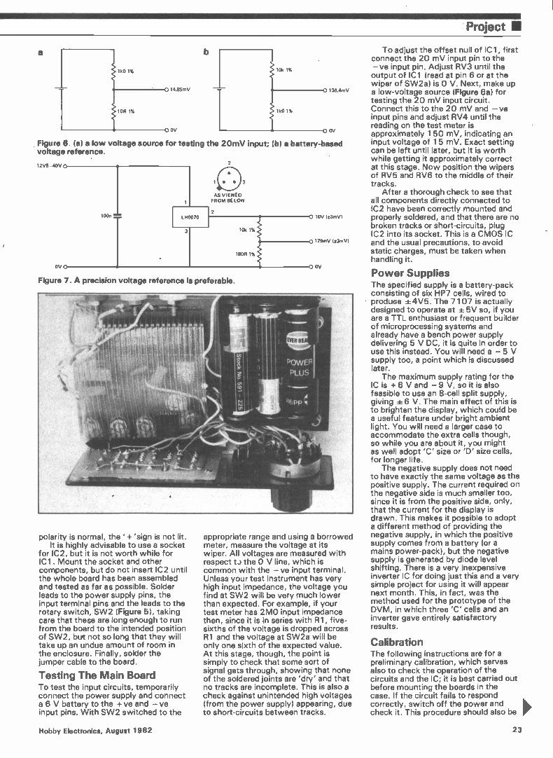
Project •
a
1k0 1%
1OR 1%
14.85mV
OV
136.4mV
OV
Figure 6. (a) a low voltage source for testing the 20mV input; (b) a battery-based voltage reference.
12V5-40V
AS VIEWED FROM BELOW
OV
Figure 7. A precision voltage reference is preferable.
polarity is normal, the ' + 'sign is not lit. It is highly advisable to use a socket
for IC2, but it is not worth while for ICI. Mount the socket and other components, but do not insert IC2 until the whole board has been assembled and tested as far as possible. Solder leads to the power supply pins, the input terminal pins and the leads to the rotary switch, SW2 (Figure 5), taking care that these are long enough to run from the board to the intended position of SW2, but not so long that they will take up an undue amount of room in the enclosure. Finally, solder the jumper cable to the board.
Testing The Main Board To test the input circuits, temporarily connect the power supply and connect a 6 V battery to the + ve and —ve input pins. With SW2 switched to the
10V (t3mV)
179mV (±3mV)
OV
appropriate range and using a borrowed meter, measure the voltage at its wiper. All voltages are measured with respect t..) the 0 V line, which is common with the —ve input terminal. Unless your test instrument has very high input impedance, the voltage you find at SW2 will be very much lower than expected. For example, if your test meter has 2M0 input impedance then, since it is in series with R1, f ive-sixths of the voltage is dropped across R1 and the voltage at SW2a will be only one sixth of the expected value. At this stage, though, the point is simply to check that some sort of signal gets through, showing that none of the soldered joints are 'dry' and that no tracks are incomplete. This is also a check against unintended high voltages (from the power supply) appearing, due to short-circuits between tracks.
To adjust the offset null of IC1, first connect the 20 mV input pin to the — ve input pin. Adjust RV3 until the output of IC1 (read at pin 6 or at the wiper of SW2a) is 0 V. Next, make up a low-voltage source (Figure 6a) for testing the 20 mV input circuit. Connect this to the 20 mV and — ve input pins and adjust RV4 until the reading on the test meter is approximately 150 mV, indicating an input voltage of 15 mV. Exact setting can be left until later, but it is worth while getting it approximately correct at this stage. Now position the wipers of RV5 and RV6 to the middle of their tracks.
After a thorough check to see that all components directly connected to IC2 have been correctly mounted and properly soldered, and that there are no broken tracks or short-circuits, plug IC2 into its socket. This is a CMOS IC and the usual precautions, to avoid static charges, must be taken when handling it.
Power Supplies The specified supply is a battery-pack consisting of six HP7 cells, wired to produce ±4V5. The 7107 is actually designed to operate at ± 5V so, if you are a TTL enthusiast or frequent builder of microprocessing systems and already have a bench power supply delivering 5 V DC, it is quite in order to use this instead. You will need a — 5 V supply too, a point which is discussed later.
The maximum supply rating for the IC is + 6 V and — 9 V, so it is also feasible to use an 8-cell split supply, giving ± 6 V. The main effect of this is to brighten the display, which could be a useful feature under bright ambient light. You will need a larger case to accommodate the extra cells though, so while you are about it, you might as well adopt 'C' size or 'D' size cells, for longer life.
The negative supply does not need to have exactly the same voltage as the positive supply. The current required on the negative side is much smaller too, since it is from the positive side, only, that the current for the display is drawn. This makes it possible to adopt a different method of providing the negative supply, in which the positive supply comes from a battery (or a mains power-pack), but the negative supply is generated by diode level shifting. There is a very inexpensive inverter IC for doing just this and a very simple project for using it will appear next month. This, in fact, was the method used for the prototype of the DVM, in which three 'C' cells and an inverter gave entirely satisfactory results.
Calibration The following instructions are for a preliminary calibration, which serves also to check the operation of the circuits and the IC; it is best carried out before mounting the boards in the case. If the circuit fails to respond correctly, switch off the power and check it. This procedure should also be
Hobby Electronics, August 1982 23
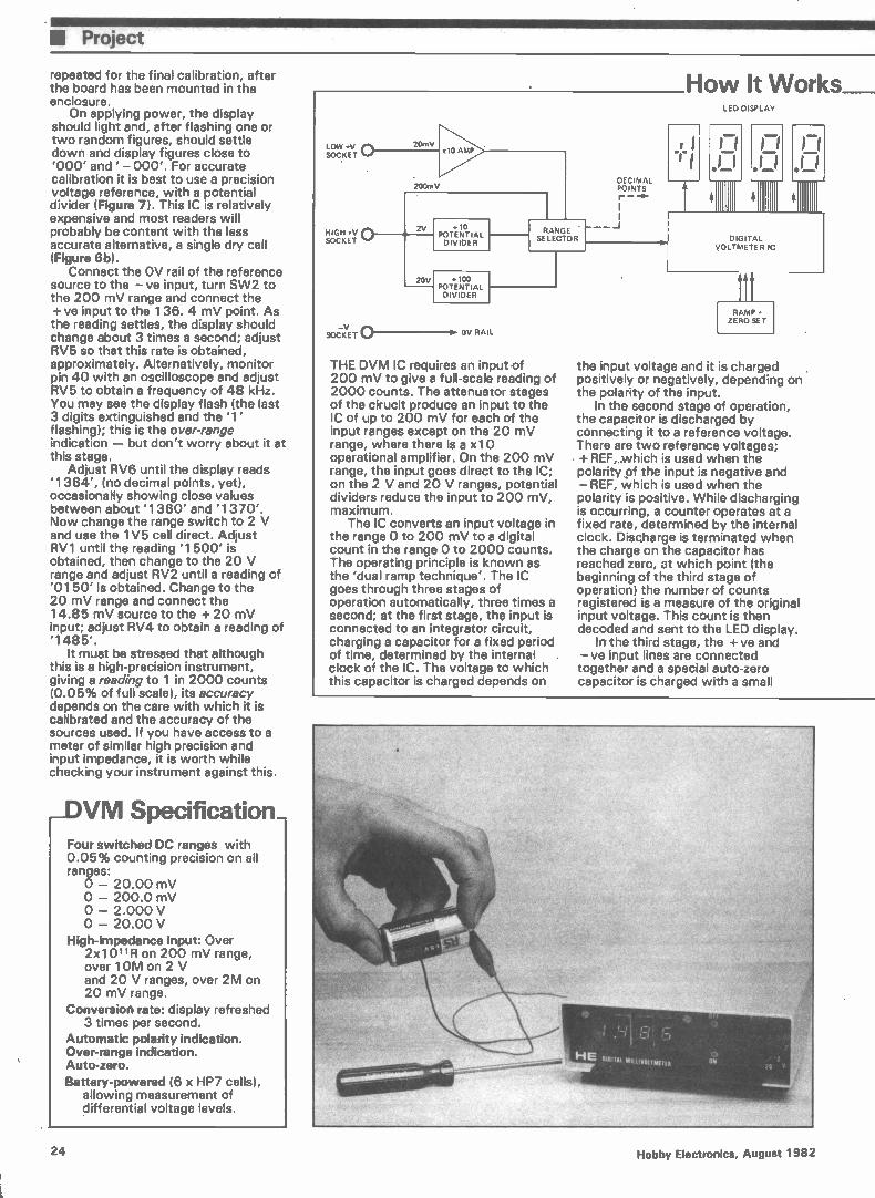
U Project
repeated for the final calibration, after the board has been mounted in the enclosure.
On applying power, the display should light and, after flashing one or two random figures, should settle down and display figures close to '000' and ' — 000'. For accurate calibration it is best to use a precision voltage reference, with a potential divider (Figure 7). This IC is relatively expensive and most readers will probably be content with the less accurate alternative, a single dry cell (Figure 6b).
Connect the OV rail of the reference source to the — ve input, turn SW2 to the 200 mV range and connect the + ve input to the 136. 4 mV point. As the reading settles, the display should change about 3 times a second; adjust RV5 so that this rate is obtained, approximately. Alternatively, monitor pin 40 with an oscilloscope and adjust RV5 to obtain a frequency of 48 kHz. You may see the display flash (the last 3 digits extinguished and the '1' flashing); this is the over-range indication — but don't worry about it at this stage.
Adjust RV6 until the display reads '1364', (no decimal points, yet), occasionally showing close values between about '1360' and '1370'. Now change the range switch to 2 V and use the 1V5 cell direct. Adjust RV1 until the reading '1500' is obtained, then change to the 20 V range and adjust RV2 until a reading of '0150' is obtained. Change to the 20 mV range and connect the 14.85 mV source to the + 20 mV input; adjust RV4 to obtain a reading of '1485'.
It must be stressed that although this is a high-precision instrument, giving a reading to 1 in 2000 counts (0.05% of full scale), its accuracy depends on the care with which it is calibrated and the accuracy of the sources used. If you have access to a meter of similar high precision and input impedance, it is worth while checking your instrument against this.
_DVM Specification_ Four switched DC ranges with 0.05% counting precision on all ranges: o — 20.00 mV O — 200.0 mV o — 2.000 V O — 20.00 V
High-Impedance input: Over 2x10 11R on 200 mV range, over 10M on 2 V and 20 V ranges, over 2M on 20 mV range.
Conversion rate: display refreshed 3 times per second.
Automatic polarity indication. Over-range Indication. Auto-zero. Battery-powered (6 x HP7 cells),
allowing measurement of differential voltage levels.
lo ceix +Eyr :)_ ( ...20m V
FOCY
SOCK ET
200mV
0 AMP
2
20V
10 POTENTIAL DIVIDER
:100 POTENTIAL DIVIDER
RANGE SELECTOR
DECIMAL POINTS r —
How It Works__ LED DISPLAY
I I .;_ II
OV RAIL
THE DVM IC requires an input •of 200 mV to give a full-scale reading of 2000 counts. The attenuator stages of the cirucit produce an input to the IC of up to 200 mV for each of the input ranges except on the 20 mV range, where there is a x10 operational amplifier. On the 200 mV range, the input goes direct to the IC; on the 2 V and 20 V ranges, potential dividers reduce the input to 200 mV, maximum.
The IC converts an input voltage in the range 0 to 200 mV to a digital count in the range 0 to 2000 counts. The operating principle is known as the 'dual ramp technique'. The IC goes through three stages of operation automatically, three times a second; at the first stage, the input is connected to an integrator circuit, charging a capacitor for a fixed period of time, determined by the internal clock of the IC. The voltage to which this capacitor is charged depends on
DIGITAL VOLTMETER IC
11 RAMP
ZERO SET
the input voltage and it is charged positively or negatively, depending on the polarity of the input.
In the second stage of operation, the capacitor is discharged by connecting it to a reference voltage. There are two reference voltages; + REF,,.which is used when the polarity of the input is negative and — REF, Which is used when the polarity is positive. While discharging is occurring, a counter operates at a fixed rate, determined by the internal clock. Discharge is terminated when the charge on the capacitor has reached zero, at which point (the beginning of the third stage of operation) the number of counts registered is a measure of the original input voltage. This count is then decoded and sent to the LED display.
In the third stage, the + ve and — ve input lines are connected together and a special auto-zero capacitor is charged with a small
24 Hobby Electronics, August 1982
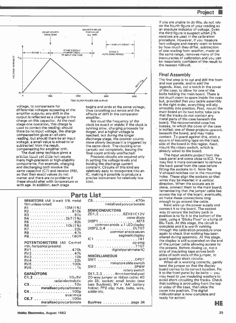
Project •
OV
STAGE 1
COUNT STARTS FROM ZERO
1.14 STAGE 2 DECAY PROPORTIONAL
TO INPUT VOLTAGE
COUNTER HOLDS THIS VALUE
(e.g. 1500)
1 —DISPLAY COUNT--
STAGE 3 AUTO-ZERO PERIOD
o 1000 2000 3000
TIME (CLOCK PULSES 1000 a- 80mS)
voltage, to compensate for differential voltages appearing at the amplifier outputs; any drift in the output is reflected as a change in the charge on this capacitor. At the next stage-one operation, this charge is used to correct the reading; should there be no input voltage, the charge compensation gives an all-zero reading, but should there be an input voltage, a small value is added to or subtracted from the result, compensating for amplifier drift.
The dual ramp techique gives a yeit elis nut iequire
many high-precision or high-stability components. For example, charging and discharging both involve the same capacitor (C7) and resistor (R8), so that their exact values do not matter and there are no problems if these should alter with temperature or with age. In addition, each stage
4000
begins and ends at the same voltage, thus cancelling out errors and the effects of drift in the comparator amplifier.
Nor must the frequency of the clock be exact or stable; if the clock is running slow, charging proceeds for longer, and a higher voltage is reached, but during the longer discharge stage, the counter counts more slowly because it is triggered by the same clock. The clocking error cancelo out completely, leaving the final count entirely unaffected!
Precison circuits are required only in setting the voltage levels and holding the discharge current constant. Circuits of this kind are relatively easy to incorporate into an IC, making it possible to produce a precise instrument for relatively low cost.
RESISTORS (All %watt 5% metal film unless noted) R1 10M (1%) R2 910k R3 91k R4 2k7 (1%) R5 82k R6 10;01%) R7 22k R8 47k R9 180R
POTENTIOMETERS (All Cermet min. horizontal presets) RV1 470k RV2 47k RV3 10k RV4 22k RV5 100k RV6 1k
CAPAÓITORS C1,2 10u6V
C3 10n
C4 100p slyer mica
C5,7 100n metallised polycarbonate
radial electrolytic
metallised polycarbonate
Parts List C6 470n
metallised polycarbonate
SEMICONDUCTORS ZD1,2 BZX61C12V
zener diode DISP1 M73
common anode ± 1 LED display DISP2,3,4 DL707
common anode seven segment display
IC1 741 op-amp
IC2 7107 digital panel meter IC
MISCELLANEOUS SW1 DPDT
miniature slide switch SW2 3P4W
rotary switch SK1,2,3 4mm terminal post 20-way jumper or ribbon cable; 40 pin DIL socket; small knob; case (see Buylines); 9V x 'AA' battery holder; PP3 clip; nuts, bolts, wire, solder etc.
Buylines page 34
If you are unable to do this, do not rely on the fourth figure of your reading as an absolute indicator of voltage. Even the third figure is suspect when 2% resistors are used in the calibration procedure. However, if you measure two voltages and merely want to know by how much they differ, subtraction of one reading from another, made'on the same range, removes many of the inaccuracies of calibration and you can be reasonably confident of the result to the nearest millivolt.
Final Assembly The first step is to cut and drill the front and rear panels, and to add the legends. Also, cut a notch in the cover of the case, to allow for one of the bolts holding the main board. There is not much room to spare inside the case but, provided that you tackle assembly in the right order, everything will slip smoothly into position. First, mount the main board on its two bolts; take care that the tracks do not contact any metal parts of the case beneath the board. The recommended case has bossés, to which the cover of the case is boltbd; one of these projects upward, beneath the board, and may make contact. To guard against this, stick a square of insulating tape on the track side of the board in this region. Next, mount the rotary switch, which is already wired to the board.
The input sockets project from the back panel and come close to IC2. You may find it more convenient to remove the back panel from the case before fitting the sockets to it. Note the V-shaped notches cut in the mounting holes. These align the sockets so that wires may be inserted in a vertical direction. When the sockets are in place, connect them to the main board, remembering that the jumper cable lies across the top of the board, eventually, so make these connections long enough to go around the cable.
Next wire up the power supply and connect it to the board. The easiest way to secure the battery pack in position is to fix it to the bottom of the case, using a 'Sticky Fixer' or a lump of Blu-Tack. At this stage, the circuit is complete and it is worth running through the calibration procedure once again to check that nothing has been altered during assembly. At this stage, the display is still suspended on the end of the jumper cable allowing access to the presets. Before closing up, run a strip of insulating tape across both • sides of both ends of the jumper, to guard against short circuits.
When all is working correctly, gently bend the jumper so that the display board comes to its correct location. Fix it to the front panel by its bolts — you may need to use insulating washers to avoid short-circuiting the tracks. Check that nothing is protruding from the top or sides of the case, then slide the cover into position. The digital millivoltmeter is now complete and ready for action!
HE
Hobby Electronics, August 1982 25
BRITAIN'S LEADING EXHIBITION FOR ELECTRONICS ENTHUSIASTS
1014 NOVEMBER 1982 at ROYAL HORTICULTURAL SOCIETY'S NEW HALL GREYCOAT ST, WESTMINSTER, LONDON SW1.
* COMPUTERS * AUDIO * RADIO * MUSIC * MAGAZINES
MORE •_ COMPREHENSIVE THAN EVER BEFORE:
* LOGIC * KITS * TEST GEAR * COMPONENTS * C.B. * DEMONSTRATIONS * GAMES * LECTURES * BOOKS * SPECIAL OFFERS
SPECIAL TICKET OFFER For the fifth consecutive year BREADBOARD is p back with even more to offer electronics enthusiasts.
BOOK NC)W
This is the best OFF (OFFER ENDS SEPTEMBER 30th) opportunity to update mu MI MI MIIMIM 1•111 BIM BIM yourself on all the latest SPECIAL ADVANCE BOOKING PRICE equipment, ideas I ADULTS f1.50 — STUDENTS/SENIOR CITIZENS rt.
PLEASE SEND tickets 0£1.50 and tickets (el. and developments. I I enclose cheque/P.O. for
NAME
ADDRESS
COME AND SEE THEM IN ACTION.
Book your tickets now at this special low rate • I Send to: BB 82, Argus Specialist Publications Ltd,
145 CHARING CROSS ROAD, LONDON WC2H OEE.
MIMI BM Ma MI BM MU MI
THE EXHIBITION YOU CAN'T AFFORD TO MISS 26 Hobby Electronics, August 1982

It's the chance every constructor wants
POWER AMPS
PRE-AMP MODULES
SEND COUPON (NO STAMP NECESSARY)
FOR YOUR FREE I.L.P CATALOGUE AND OPEN UP
TOA NEW WORLD OF QUALITY &VALUE
It's something you have always wanted....something to build your equipment into that's smart, modern, strong, adaptable to requirement and not expensive. The 'UniCase' is yet another triumph of I.L.P. design policy. It presents totally professional appearance and finish, ensuring easier and better assembly to make it equal to the most expensive cased equipment. The all-metal 'UniCase' is enhanced by precision aluminium extruded panels engineered for speedy and perfect aligned assembly within a mere five minutes. Designed in the first case to accommodate I.L.P. power amps with P.S.U's, the range will shortly be extended to house any other modular projects.
WHAT WE DO FOR CONSTRUCTORS Our product range is now so vast we cannot possibly hope to show it all in our advertisments without overcrowding or abridging information to the point of uselessness. So we have devised a solution which we invite you to take advantage of without delay. ALL YOU NEED DO IS FILL IN AND FORWARD THE COUPON BELOW TO RECEIVE OUR NEWEST COMPREHENSIVE I.L.P. CATALOGUE POST FREE BY RETURN. It gives full details of all current I.L.P. products for the constructor together with prices, full technical and assembly details, wiring and circuit diagrams etc. and it's yours, FREE. You don't even have to stamp the envelope if you address it the way we tell you.
ELECTRONICS LTD.
FREEPOST 6 GRAHAM BELL HOUSE, ROPER CLOSE, CANTERBURY CT2 7EP Telephone Sales (0227) 54778 Technical Only (0227) 64723 Telex 965780 FREEPOST Mark your envelope clearly FREEPOST 6 and post it WITHOUT a stamp to I.L.P. it address above. We pay postage when your letter reaches us.
To: I.L.P. ELECTRONICS LTD. PLEASE SEND ME I.L.P. CATALOGUE, POST PAID BY RETURN
I HAVE/HAVE NOT PREVIOUSLY BUILT WITH I.L.P. MODULES
Did you know
I.L.P. are the world's largest designers and manufacturers of hi-fi audio modules?
I.L.P. pioneered encapsulated power amps and pre-amps for enhanced thermal stability, mechanical protection and durability?
There are TWENTY power amplifiers from 15 to 240 watts RMS including the very latest super-quality Mosfets to choose from?
TWENTY pre-amp modules allow you to incorporate, exciting professional _ applications to your equipment never before available to constructors and experimenters?
I.L.P. are suppliers to the B.B.C., I.B.A., N.A.S.A., British Aerospace, Marconi, Racal, Ferranti, G.E.C., Rolls Royce etc?
Goods are despatched within 7 days of your order reaching us and covered by our 5 year no-quibble guarantee?
Name
Address
Hobby Electronics, August 1982
¡LP. products am available also from Henry's, Marshall's, Technornatic d Watford.
27
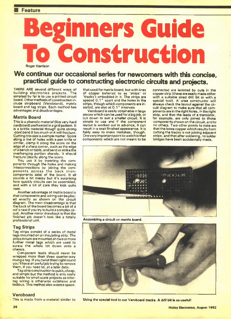
U Feature
Beginners Guide To Construction Roger Harrison
We continue our occasional series for newcomers with this concise, practical guide to constructing electronic circuits and projects.
THERE ARE several different ways of building electronics projects. The simplest by far is to use a printed circuit board. Other methods of construction in-clude stripboard (Veroboard), matrix board and tag strips. Each method has advantages and disadvantages.
Matrix Board This is a phenolic material (like very hard cardboard) perforated in a grid pattern. It is a brittle material though quite strong -dont bend it too much or it will fracture. Cutting it to size is a simple matter. Score along a line of holes with a pen knife or similar, clamp it along the score on the edge of a sharp corner, such as the edge of a bench or table, and bend or strike the overhanging portion sharply. It should fracture cleanly along the score.
You use it by inserting the com-ponents through the holes and making interconnections by joining the com-ponents across the back (non-components side) of the board. It all sounds a bit messy but it's surprising how quickly circuits can be assembled, and with a bit of care they look quite neat.
Another advantage of matrix board is that components and wiring can be plac-ed exactly as shown on the circuit diagram. The main disadvantage is that the back of the board becomes a bit of à rat's nest if you try to build a complex cir-cuit. Another minor drawback is that the finished job doesn't look like a totally professional unit.
Tag Strips Tag strips consist of a series of metal tags mounted on an insulating strip. The strips in turn are mounted on two or more further metal tags which are used to screw the whole lot down onto a chassis.
Component leads should never be wrapped more than three quarter-way roung a tag. If you twist them right round you'll have answful job trying to remove them, if you need to, at a later date.
Tag strip construction is quick,cheap, and simple but the method is only really suitable for small scale projects as inter-tag wiring is otherwise extensive and tedious. This method also wastes space.
Veroboard • This is made from a material similar to
that used for matrix board, but with lines of copper (referred to as 'strips' or 'tracks') embedded in it. The strips are spaced 0.1" apart and the holes in the strips, though which components are in-serted, are also at 0.1" intervals.
Veroboard is easily obtainable in large pieces which can be used for a big job, or cut down to suit a smaller circuit. It is simple to use and if the component layout is worked out in advance, it can result in a neat finished appearance. It is fairly easy to make mistakes, though. One very important point to watch is that components which are not meant to be
connected are isolated by cuts in the copper strip (these are easily made either with a suitable sized drill bit or with. a special tool). A' wise constructor will always check the layout against the cir-cuit diagram to make sure that all com-ponents are in the right holes, in the right strip, and that the leads of a transistor, for example, are only joined to those components shown on the circuit, and to no othecs. Two other points to note are that the loose copper which results from cutting the tracks is not joining adjacent strips, and that after soldering, no solder bridges have been accidentally made.
Assembling a circuit on matrix board.
Using the special tool to cut Veroboard tracks. A drill bit is as usefull
28 Hobby Electronics, August 1982
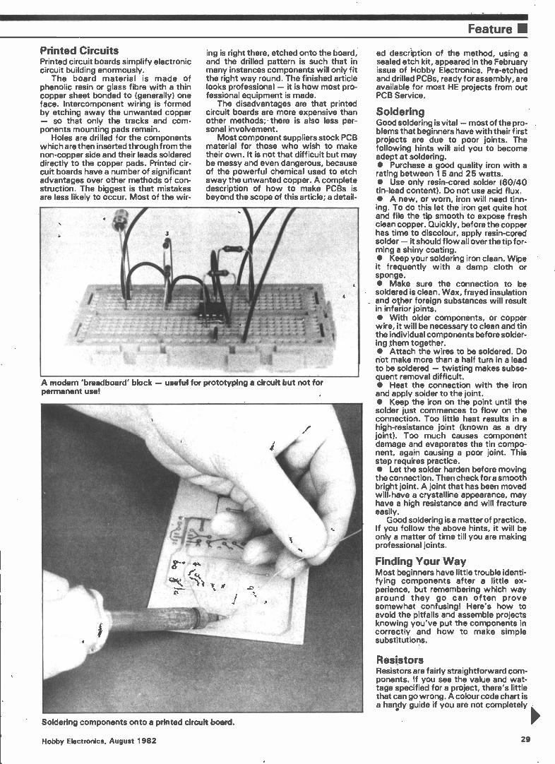
Feature
Printed Circuits Printed circuit boards simplify electronic circuit building enormously.
The board material is made of phenolic resin or glass fibre with a thin copper sheet bonded to (generally) one face. Intercomponent wiring is formed by etching away the unwanted copper — so that only the tracks and com-ponents mounting pads remain.
Holes are drilled for the components which are then inserted through from the non-copper side and their leads soldered directly to the copper pads. Printed cir-cuit boards have a number of significant advantages over other methods of con-struction. The biggest is that mistakes are less likely to occur. Most of the wir-
4•10
•nal • ".44.....• ey...•
etteletorZeele.Oir.:14.0kk i,'"
e..» • , •••••• " " 4-4 4
eoereeeetee-...sie,',
ing is right there, etched onto the board, and the drilled pattern is such that in many instances components will only fit the right way round. The finished article looks professional — it is how most pro-fessional equipment is made.
The disadvantages are that printed circuit boards are more expensive than other methods; • there is also less per-sonal involvement.
Most component suppliers stock PCB material for those who wish to make their own. It is not that difficult but may be messy and even dangerous, because of the powerful chemical used to etch away the unwanted copper. A complete description of how to make PCBs is beyond the scope of this article; a detail-
4...r.4 • 4..4.• • • _
• l'..1:...1::-:-7t-.-.2.-,.. , I.... •.. . .... at:
-` •
S' I •-..er,—.>.4
A modern 'breadboard' block — useful for prototyping a circuit but not for permanent use!
cd description of the method, using a sealed etch kit, appeared in the February issue of Hobby Electronics. Pre-etched and drilled PCBs, ready for assembly, are available for most HE projects from out PCB Service.
Soldering Good soldering is vital — most of the pro-blems that beginners have with their first projects are due to poor joints. The following hints will aid you to become adept at soldering. • Purchase a good quality iron with a rating between 15 and 25 watts. • Use only resin-cored solder (60/40 tin-lead content). Do not use acid flux. • A new, or worn, iron will need tinn-ing. To do this let the iron get quite hot and file the tip smooth to expose fresh clean copper. Quickly, before the copper has time to discolour, apply resin-cored solder — it should flow all over the tip for-ming a shiny coating. • Keep your soldering iron clean. Wipe it frequently with a damp cloth or sponge. • Make sure the connection to be soldered is clean. Wax, frayed insulation and other foreign substances will result in inferior joints. • With older components, or copper wire, it will be necessary to clean and tin the individual components before solder-ing them together. • Attach the wires to be soldered. Do not make more than a half turn in a lead to be soldered — twisting makes subse-quent removal difficult. • Heat the connection with the iron and apply solder to the joint. • Keep the iron on the point until the solder just commences to flow on the connection. Too little heat results in a high-resistance joint (known as a dry joint). Too much causes component damage and evaporates the tin compo-nent, again causing a poor joint. This step requires practice. • Let the solder harden before moving the connection. Then check for a smooth bright joint. A joint that has been moved will.have a crystalline appearance, may have a high resistance and will fracture easily.
Good soldering is a matter of practice. If you follow the above hints, it will be only a matter of time till you are making professional joints.
Finding Your Way Most beginners have little trouble identi-fying components after a little ex-perience, but remembering which way around they go can often prove somewhat confusing! Here's how to avoid the pitfalls and assemble projects knowing you've put the components in correctly and how to make simple substitutions.
Resistors Resistors are fairly straightforward com-ponents. If you see the value and wat-tage specified for a project, there's little that can go wrong. A colour code chart is a handy guide if you are not completely
Soldering components onto a printed circuit board.
Hobby Electronics, August 1982 29
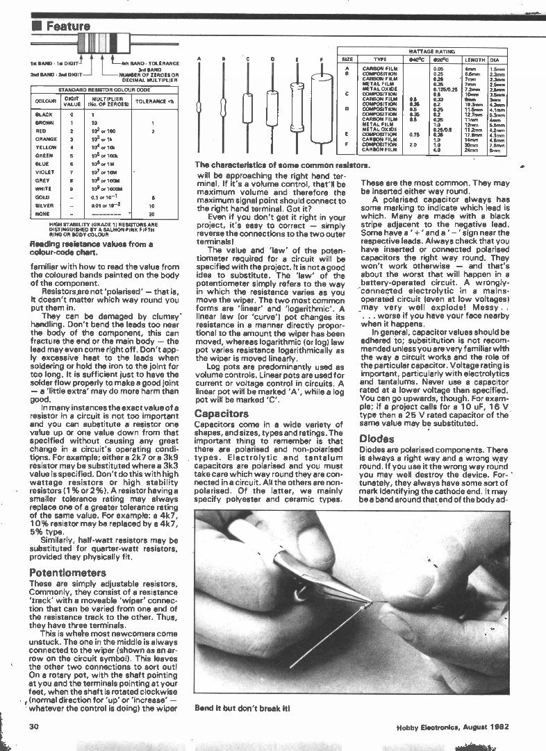
III Feature
lit BAND - lit DIGIT
2nd BAND • 2nd DIGIT
I L4th BAND. TOLERANCE
3rd BAND NUMBER OF ZEROES OR
DECIMAL MULTIPLIER
STANDARD RESISTOR COLOUR CODE.
COLOUR DIGIT VALUE
MULTIPLIER (No. OF ZEROES)
TOLERANCE •01,
BLACK
1
I ¡ 1
CD
OD
•••I
Of
VI
•
Cht
.
.• e
1
BROWN 10 1
RED 102 or 100 2
ORANGE 103 or lk
YELLOW 104 or 10k
GREEN 106 or 100k
BLUE 106 or 1M
VIOLET 107 . 10m
GREY 104 or 100M
WHITE 109 or 1000M
GOLD 0.1 or 10-1 5
SILVER 0.01 or 10-2 10
NONE • 20
HIGH STABILITY (GRADE 1) RESISTORS ARE DISTINGUISHED BY A SALMON-PINK FIFTH RING OR BODY COLOUR
Reading resistance values from a colour-code chart.
familiar with how to read the value from the coloured bands painted on the body of the component.
Resistors are not 'polarised' — that is, it doesn't matter which way round you put them in.
They can be damaged by clumsy* handling. Don't bend the leads too near the body of the component, this can fracture the end or the main body — the lead may even come right off. Don't app-ly excessive heat to the leads when soldering or hold the iron to the joint for too long. It is sufficient just to have the solder flow properly to make a good joint — a 'little extra' may do more harm than good.
In many instances the exact value of a resistor in a circuit is not too important and you can substitute a resistor one value up or one value down from that specified without causing any great change in a circuit's operating condi-tions. For example; either a 2k7 or a 3k9 resistor may be substituted where a 3k3 value is specified. Don't do this with high wattage resistors or high stability resistors (1 % or 2%). A resistor having a smaller tolerance rating may always replace one of a greater tolerance rating of the same value. For example: a 4k7, 10% resistor may be replaced by a 4k7, 5% type.
Similarly, half-watt resistors may be substituted for quarter-watt resistors, provided they physically fit.
Potentiometers These are simply adjustable resistors. Commonly, they consist of a resistance 'track' with a moveable 'wiper' connec-tion that can be varied from one end of the resistance track to the other. Thus, they have three terminals.
This is whee most newcomers come unstuck. The one in the middle is always connected to the wiper (shown as an ar-row on the circuit symbol). This leaves the other two connections to sort out! On a rotary pot, with the shaft pointing at you and the terminals pointing at your feet, when the shaft is rotated clockwise (normal direction for 'up' or 'increase' • whatever the control is doing) the wiper
A
IT
WATTAGE RATING
SIZE TYPE 0404C 0204C LENGTH DIA
A CARBON FILM 0.05 4mm EEEEEE EEE EEEEE
eigInjW,144.5j
.-eirininien *41,i an*.i.e.r.
B COMPOSITION 0.25 6.5mm CARBON FILM 025 7mm METAL FILM 0.25 7mm METAL OXIDE 0.125/0.25 7.2Inni
C COMPOSITION 0.5 10mm CARBON FILM 0.5 0.33 9rnm COMPOSITION 0.35 02 10.3mm
D COMPOSITION 0.5 0.25 11.5mrn COMPOSITION 0.35 02 12.7rnm CARBON FILM 0.5 025 11mm METAL FILM 1.0 12mm METAL OXIDE 0.25/0.5 11.2mm
E COMPOSITION 0.75 0.35 17.8mm CARBON FILM 1.0 14mrn
F COMPOSITION 2.0 1.0 30mm CARBON FILM 1.0 24mm
The characteristics of some common resistors. will be approaching the right hand ter-minal. If it's a volume control, that'll be maximum volume and therefore the maximum signal point should connect to the right hand terminal. Got it?
Even if you don't get it right in your project, it's easy to correct — simply reverse the connections to the two outer terminals!
The value and 'law' of the poten-tiometer required for a circuit will be specified with the project. It is not a good idea to substitute. The 'law' of the potentiometer simply refers to the way in which the resistance varies as you move the wiper. The two most common forms are 'linear' and 'logarithmic'. A linear law (or 'curve') pot changes its resistance in a manner directly propor-tional to the amount the wiper has been moved, whereas logarithmic (or log) law pot varies resistance logarithmically as the wiper is moved linearly.
Log pots are predominantly used as volume controls. Linear pots are used for current or voltage control in circuits. A linear pot will be marked 'A', while a log pot will be marked 'C'.
Capacitors Capacitors come in a wide variety of shapes, and sizes, types and ratings. The important thing to remember is that there are polarised and non-polarised types. Electrolytic and tantalum capacitors are polarised and you must take care which way round they are con-nected in a circuit. All the others are non-polarised. Of the latter, we mainly specify polyester and ceramic types.
These are the most common. They may be inserted either way round. A polarised capacitor always has
some marking to indicate which lead is which. Many are made with a black stripe adjacent to the negative lead. Some have a ' + 'anda ' — 'sign near the respective leads. Always check that you have inserted or connected polarised capacitors the right way round. They won't work otherwise — and that's about the worst that will happen in a battery-operated circuit. A wrongly-'connected electrolytic in a mains-operated circuit (even at low voltages) _may very well explode! Messy. . . . . worse if you have your face nearby when it happens.
In general, capacitor values should be adhered to; subsititution is not recom-mended unless you are very familiar with the way a circuit works and the role of the particular capacitor. Voltage rating is important, particularly with electrolytics and tantalums. Never use a capacitor rated at a lower voltage than specified. You can go upwards, though. For exam-ple; if a project calls for a 10 uF, 16 V type then a 25 V rated capacitor of the same value may be substituted.
Diodes Diodes are polarised components. There is always a right way and a wrong way round. If you use it the wrong way round you may well destroy the device. For- ' tunately, they always have some sort of mark identifying the cathode end. It may be a band around that end of the body ad-
Bend it but don't break It!
30 Hobby Electronics, August 1982
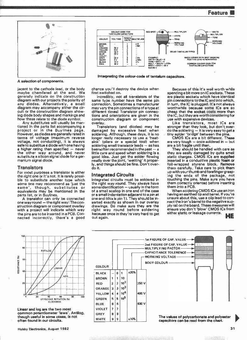
Feature II
A selection of components.
jacent to the cathode lead, or the body maybe chamfered at the end. We generally indicate on the construction diagram with our projects the polarity of any diodes. Alternatively, a small diagram may accompany either the cir-cuit or the construction diagram show-ing diode body shapes and markings and how these relate to the diode symbol.
Any substitutes will usually be men-tioned in the parts list accompanying a project or in the Buylines page. However, as diodes are generally rated in terms of voltage (maximum reverse voltage, not conducting), it is always safe to substitue a diode with one having a higher rating than specified — never the other way around, and never substitute a silicon signal diode for a ger-manium signal diode.
Transistors For most purposes a transistor is either the right one or it's not. It is rarely possi-ble to substitute another type which some one may recommend as 'just the same', though, substitutes or equivalents may be mentioned in the parts list, or in Buylines. A transistor can only be connected
one way round — the right way I The con-struction diagram or component overlay with a project will indicate which way the pins are to be inserted in a PCB. Con-nected incorrectly, there's a good
100
80
20
o
_
ANTILOG
LINEAR
—r-LOG
20 40 60 80
EFFECTIVE ROTATION MI
CLOCKWISE
100
Linear and log are the two most common potentiometer 'laws'. Antilog, though useful in some cases, is not often found in our circuits.
COLOUR CODE FOR TANTALUM CAPACITORS
COLOUR VOLTAGE TENS & UNITS MULTIPLIER
BROWN — 1 x10 RED — 2 x100 ORANGE 35 V 3 — YELLOW 6V3 4 — GREEN 16 V 5 — BLUE 20 V 6 — VIOLET — 7 — GREY 25 V e x1On WHITE 3 V 9 100n BLACK 10 V 0 ,lo PINK 35 V — —
/"Iru RED SPOT MULTIPLIER
NITS
TENS
WORKING .4. VOLTAGE
SOLID TANTALUM TYPES
EXAMPLE: UNITS. BLUE .6 TENS. GREY . MULT.. WHITE . x100n BODY . GREY . 25 V 6u13/25 V
UNITS
MULTIPLIER
TENS
WORKING VOLTAGE
WHEN VIEWED WITH SPOT SHOWING POSITIVE LEAD IS AS MARKED
Interpreting the colour-code of tantalum capacitors.
chance you'll destroy the device when first switched on.
Incredibly, not all transistors of the same type number have the same pin connection. Sometimes a manufacturer may vary the pin connections of a type at different times! Transistor pin connec-tions and orientations are given in the construction diagram or component overlay.
Transistors (and diodes) may be damaged by excessive heat when soldering. Although, these days, it is no longer really necessary to use a 'heat-sink' (pliers or a special tool) when soldering small transistor leads — as has beennften recommended in the past — a little care and speed when soldering is a good idea. Just get the solder flowing neatly over the joint, 'wetting' it proper-ly, and things should be fine. Don't over-do it.
Integrated Circuits Integrated circuits must be soldered in the right way round. They always have some identification — usually in the form of a small scallop in one end of the case or a small indentation adjacent to a pin at one end (this is pin 1 ). They should be in-serted exactly as shown in our overlay drawings. Do make sure they are the right way round before soldering because once in they're Very hard to get out again.
COMMON COLOUR CODE FOR TANTALUM CAPACITORS
Because of this it's well worth while spending a bit more on IC sockets. These are plastic sockets which have identical pin connections to the IC and into which, in turn, the IC is plugged. It's not always worthwhile because some ICs are so cheap that the socket costs more than the IC, but they are worth considering for use with expensive devices.
Like transistors, most ICs are stronger than they look, but don't over-do the soldering — it is very easy to get a tiny solder 'bridge' between the pins. CMOS ICs are a bit different. These
are very tough — once soldered in — but are a bit fragile until then.
They should be handled with care as they are easily damaged by quite small static charges. CMOS ICs are supplied inserted in a conductive plastic foam or foil-wrapped styrene block. Remove them carefully. Take care to pick them up with your thumb and forefinger grasp-ing the ends of the package, not touching the pins. Make sure you have them correctly oriented before inserting them into a PCB. When soldering CMOS ICs use an iron
having an earthed tip and barrel. If you're unsure about this, use a clip lead to con-nect the iron's barrel to the negative sup-ply rail on the board. These measures will ensure you don't 'blow' CMOS ICs from either static or leakage currents.
HE
COLOUR
1st FIGURE OF CAP. VALUE
2nd FIGURE OF CAP. VALUE MULTIPLYING FACTOR
CAPACITANCE TOLERENCE
WORKING VOLTAGE
BODY COLOUR
BLACK — 0 1 ±20%
BROWN 1 1 10
RED 2 2 102 250 V
ORANGE 3 3 103
YELLOW 4 4 104 400 V
GREEN 5 5 105
BLUE 6 6 630 V
VIOLET 7 7
GREY 8 8
WHITE 9 9 ±10% The values of polycarbonate and polyester capacitors can be read from the chart.
Hobby Electronics, August 1982 31
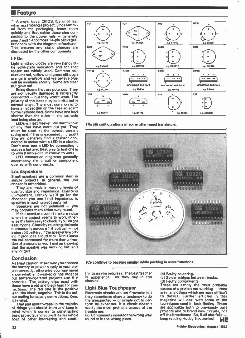
I Feature
Always leave CMOS ICs until last when assembling a project. Once remov-ed from the packaging, insert them quickly and first solder those pins con-nected to the power rails — generally pins 7 and 14 for most 1 4-pin packages, but check with the diagram beforehand. This ensures any static charges are dissipated by the other components.
LEDs Light emitting diodes are very handy lit-tle solid-state indicators and for that reason are widely used. Common col-ours are red, yellow and green although orange is available and we believe blue will be available shortly. Some are clear but glow red.
Being diodes they are polarised. They are not usually damaged if incorrectly connected — but they won't work. The polarity of the leads may be indicated in several ways. The most common is to have a flat section on the case adjacent to the cathode lead. Some have one lead shorter than the other — the cathode lead being shorter.
LEDs will last forever. We don't know of any that have worn out yet! They must be used at the correct current rating and if this is exceeded . . . poof I You will generally find a resistor con-nected in series with a LED in a circuit. Don't ever test a LED by connecting it across a battery. Best way to test one is to wire it into a circuit known to work.
LED connection diagrams generally accompany the circuit or component overlay with our projects.
Loudspeakers Small speakers are a common item in simple projects. In general, the unit chosen is not critical.
They are made in varying levels of quality, size and impedance. Quality is unimportant. Frankly we'd go for the cheapest you can find! Impedance is specified in each project parts list.
Speakers are not polarised — you may connect them either way round.
If the speaker doesn't make a noise when the project seems to work other-wise it's fairly easy to check if you've got a faulty one. Check by touching the leads momentarily across a 1 1/2 volt cell — not a nine volt battery. If the speaker is work-ing it produces a loud click. Don't leave the cell connected for more than a frac-tion of a second or you'll end up knowing that the speaker was working but isn't any longer!
Conclusion As a last caution, make sure you connect the battery or power supply to your pro-ject correctly, otherwise you may never know whether it worked or not! Most of our battery-operated projects use 9 V batteries. The battery clips used with these have a red and black lead for con-nections. The red one is the positive lead, the black, negative. This is the col-our coding for supply connections. Keep it in mind.
That just about wraps up the majority of things you should learn and keep in mind, when it comes to constructing basic projects, and you will learn a whole host of other interesting and useful
32
701 h
o
e o o
e.g. AC129
e
103
sol
° b o I 0
c
e.g. 2N3055
105 b
o
e 0 0
is e.g. BFY50
c
1019 b
0
a 0 0 c
j e.g. BC109
T066
e 0 I o I
b o 1
e.g. 2N3053
0
1092
b
c
•
e
0
0
0
g. 2N3704
10925
e
b
•
e.
0
0
0
. MPSA12
1098
b
c
e
e
0
0
0
0. 2512928
10106 e
o
e 0 o
e.g. BC209
e
10126
• e b
TOP3
b e e
TOMB
b c e
o 0 0 0 =I I= 0 0 I=1
MOUNTING SURFACE
e.g. 80139
MOUNTING SURFACE
e.g. TIP142
MOUNTING SURFACE
es. TIP41A
X09 b
X09, •
X10 e
o
o
e
o b
e.g. BC212
X11
e
b
e
e.g.
0
Do
0
ZTX108
o (o Ià
o (to Ià
e c
e.g. BC147
b c
e.g. BF195
The pin configurations of some often-used transistors.
ICs continue to become smaller while packing in more functions.
things as you progress. The best teacher is experience, as they say in the classics!
Light Blue Touchpaper Electronic circuits are not fireworks but they sometimes share a tendency to do the unexpected — or simply not to per-form as expected. If a circuit doesn't work, the most probable causes of the trouble are: (a) Components inserted the wrong way round or in the wrong place.
(b) Faulty soldering. (c) Solder bridges between tracks. (d) Faulty components. These are simply the most probable causes of a project not working — there are many others which are more difficult to detect. Further articles in this magazine will deal with some of the techniques used in fault-finding. These are applicable both to previously built projects and to brand new circuits, hot off the breadboard. So, if all else fails — keep reading Hobby Electronics! HE
Hobby Electronics, August 1982
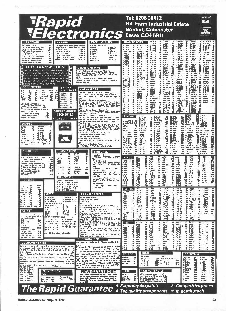
Tel: 0206 36412 Mapid Hill Farm Industrial Estate Boxted, Colchester
aVvElectronics Essex CO4 5RD HARDWARE
PP3 battery clips Red or black crocodile clips Black pointer control knob Pr Ultrasonic transducers *6V Electronic buzzer *12V Electronic buzzer *PB2720 Piezo transducer *64mm 64 ohm speaker *64mm 8 ohm speaker 20mm panel fusehokler
60 6P 15p
350p 60p 659 75p 70p 70p 25p
CABLES 20 metre pack single core connec-ting cable ten different colours 65p Speaker cable 10p/m Standard screened 16p/,n Twin screened 24p/rn 2.5A 3 core mains 23p/m 10 way rainbow ribbon 65p/m 20 way rainbow ribbon 120p/nt
rl rl
FREE TRANSISTORS! Yes that's right! It's transistor month at
Rapid! On all orders over £15 received we
give you 10 BC184L general purpose tran-
sistors (value 70p) absolutely free of
charge. Offer expires 31st August 82.
Please mention this magazine.
CONNECTORS BRIDGE PIP9 Skt
2 pin 9p gp 3 pin 12 10p 5 pin 13p lip Phono 109 12p Irnrn 12p 13p
DIN Jack 2.5mm 3.5mm Standard Stereo 4mm
Plug 10p 9P 169 24p 18p
UHF (CB) Connectors PL259 Plug 40p Reducer 14p S0239 square chassis skt 38p S0239S round chassis socket 40p IEC 3 pin 250V/6A Plug chassis mounting 38p Socket free hanging 609 Socket with 2m lead 1289
DIODES BY127 12 0A47 10 0A90 e 0A91 7 0A200 0A202 e 15914 4 *154148 2 132X61 Series 4V7-39V
*154001 3 154002 5 154006 7 154007 7 155401 15 155404 16 155406 17 400mW zen 6 zeners 1.3W
15p each
SOLDERING IRONS
Antes CS 17W Soldering iron 2.3 and 4.7mm bits to suit CS 17W elerneM Antex XS 25W Soldering iron 3.3mm and 4.7mm bits to suit Solder pump desoldering tool Spare nozzle for above 10 metres 22swg solder Soldering iron stand for above
SOCKETS
Low profileWwirraep *8 pin 7p 28p *14 pin gp 35, *16 pin 10p 42p 18 pin 15p 52p 20 pin 18p 80p 22 pin 20, yop 24 pin z2p 70p 28 pin 2gp sop 40 pin 32p 08, Soldercon pins 60p/100
VERO
* Verobloc 350p Site 0.1 matrix 2.5 x 1 22p 2.5 x 3.75 75p 25 x 5 859 3.75 x 5 96p VO board 16139 Veropins per 100 Single sided 50p Double sided 60p Spot face cutter 105p Pin insertion tool 162p
Skt 10p 9P 20p 25p 17p
rl rl rl
rl rl
PANEL METERS Size 60 x 46 x 35mm 0-50uA 0-500mA 0-100uA 0-1A 0-500uA 0-50V AC 0-1rnA VU 0-10mA 0-300V AC 0-50mA 0-25V 0-100mA 0-30V DC 495p each
POTENTIOMETERS Rotary. Carbon track Log or Lin 1K-2M2 Single 32p; Stereo 85p; Single switched 80e; Slide 6Ornm travel single Log or Un 5K-500K 63p each Preset. Submin. hor. 100 ohms-1M 7p each Cermet precision multiturn, 0.75W /in 100 ohms to 100K 88p each
TRANSISTORS
RECTIFIERS lA 50V 22 IA 400V e 2A200V 40 2A 400V 45 6A 100V 80 6A 400V 95 VM18 DIL 0.9A 200V 50
Simply phone 0206 36412
with your orde
450p 659 2189 4889 66p 480p 70p 100p
190p
BARCLAYCARD
CAPACITORS Polyester. Radial leads. 250V. CM type. 0.01, 0.015, 0.022, 0.033 6p: 0.047, 0.068, 0.1 7p: 0.15, 0.22 9p; 0.33, 0.47 13p: 0.68, 20p: lu 23p Electrolytic. Radial or axial leads. 0.47/63V, 1/63V, 2.2/63V, 4.7/63V, 10/25V 7p: 22/25V, 47/25V flp: 100/25V 9p; 220/25V 14p; 470/25V 22p; 1000/25V 389; 2200/25V 50p. Tag end Power Supply Electrolyfics. 2200/40V 1189; 4700/40V 160p: 2200/63V 1489; 4700/63V 230p Polyester. Miniature Siemens PCB ln, 2n2, 3n3, 4n7, 6n8, 10n, 15e 7p; 22e, 33e, 47e, 68n 8p: 100e 9p; 150n 11p: 220e 13p; 330e 20p; 470e 26; 680e 289; lu 33p; 2u2 50p Tantalum bead 0.1, 0.22, 0.33, 0.47, 1.0 @ 35V 12p; 2.2, 4.7, 10 @ 25V 289; 15/16V 30p; 22/16V 27p: 33/16V 45p: 47/6V 27p; 47/16V 70p; 68/6V 489: 100/10V 90p Ceramic disc. 22p.O.Olu 50V 3p each Mullard miniature ceramic plate 1.8pF to 100pF 6p each Polystyrene. 5% tolerance 10p-1000p ttp: 1500-4700p Op: 6800-0.012u Illp Trimmers. Mallard 808 Series 2-10pF 22p; 2-22pF 30p; 5.5-65pF 35p
REGULATORS 78105 78112 78115 7805 7812 7815
LAA309K LM317K LM3177 LM323K
30
30 40 40 ao
133 350 120 360
79105 79112 79115 7905 7912 7915
LM723 LM338K 78H05 5A 5V
65 65 65 46 46 45
ao 475
560
RESISTORS 1W 5% Carbon film E12 series 4.70-10M 1p each 1W 5% Carbon film 012 series 4.70 to 4M7 2p each 1W 1% Metal fOnt E24 series 100-1M 6peach
OPTO *3mm red 8 *5mm red 8 *3nun gr.n 12 *5mm green 12 *3mm yellowl2 *5mrn yellowl2 Clips to suit 3p each Rectangular 11132 ao *red 12 11178 40 green 17 111111 60 yellow 17 ORP12 es 11138 40 TIL.100 90 255777 45 Dual color 60 Seven segment displays .
Corn cathode Corn anode 01704 0.3" 95 DL707 0.3" 95 *FND500 0.5" FND507 0.5" 90
80 T1L312 0.3" 105 TIL313 0.3" se 111321 0.5" 115 TIL322 0.5" 115
LCD: 31 digit 580p 4 digit 620p
An ideal opportunity for the beginner or the experienced construc-tor to obtain a wide range of components at greatly reduced prices. 1W 5% Resistor kit. Contains 10 of each value from 4.70 to 1M 1650 resistors) 480p Ceramic Capacitor Kit. Contains 5 of each value from 22p to 001e 1135 caps) 370p Polyester Capacitor Kit. Contains 5 of each value from 0.01 toi uF 165 caps) 575p each Preset Kit. Conrad). 5 of each value from 100 ohms to 1M (total 65 presets) 425p each Nut and Bolt Kit. Total 300 items 180p 25 6BA bolts 25 6BA 1" bolts 50 6BA nuts 50 6BA washers 25 4BA J" bolts 25 6BA 1" bolts 50 6BA nuts 50 SBA washers
VERO WIRING PEN Pen* spoo1310p Spare spool 75p Combs Op
Pin Insertion Tool 162p
SWITCHES Submin toggle SPST 55p SPDT 60p *DPDT 50p Miniature toggle SPDT 80p SPDT centre off 90p DPDT 90p DPOT centre off 1130p Standard toggle SPST 35p DPDT 473p *Miniature DPDT slide 12p *Push to make 12p Push to break 22p Rotary type adjustable stop 1P12W 2P6W 3P4W all 55p each DIL switches 4 SPST 93p 6 SPST 809 8 SPST 100p
AC125 35 AC126 25 AC127 25 *AC128 20 AC176 25 AC187 22 AC188 22 AD142 120 AD149 80 AD161 40 AD162 40 AF124 60 AF126 50 AF139 40 AF186 70 AF239 75 BC107 10 BC107B 12 *BC108 9 BC108B 12 BC108C 12 *BC109 9 BC109C 12 BC114 22 BC115 n BC117 n BC119 35 BC137 40 BC139 40 BC140 30 BC141 30 BC142 25 BC143 25 BC147 8 BC148 8 BC149 9
LINEAR
BC157 8C158 BC159 BC160 BC168C BC169C BC170 BC171 BC172 BC177
10 10
45 10 10 8 10 8 18
BC178 18 8C179 18 8C182 10 *I3C1821 8 BC183 10 BC183L 10 BC184 10 *BC184L 7 BC212 10 BC2I2L 10 BC213 10 BC213L 10 BC214 10 *8C2141 8
BC238 BC308 8C327 0C328 BC337 BC338 BC477 8C478 BC479 BC517 BC547
14 15 14 14 14 14 30 30 30 40 7
C548 10 BFR80 25 C549 10 BFX29 25 C558 10 BFX84 25 CY70 18 BFX85 25 CY71 18 BFX86 28 CY72 18 BFX87 25 D115 80 EIFX88 25 D131 35 BFY50 23 0132 35 BFY51 23 D133 50 BFY52 23 0135 50 13FT53 32 D136 30 EIFY55 32 0137 30 BFY56 32 0138 30 89/39 .40 D139 35 BSX20 20 D140 35 BSX29 35 D204 110 BSY95A 25 0206 110 BU205 160 0222 85 BU206 200 F180 35 BU208 170 F182 35 MJ2955 99 F184 25 MJE340 50 F185 25 MJE520 65
12 MJE521 95 F195 12 MJE3055 70 F196 12 MPFI02 40 F197 12 MPF104 40 F198 10 MPSA05 22 F199 18 MPSA06 25 F200 30 MPSA12 30 BF244B n MPSA55 33 F245 30 MPSA56 30 F256B 45 MPSUO5 55 F257 32 MPSUO6 55 F258 25 MPSU55 60 F259 35 MPSU56 613 F337 40 T1P29A 40 FR40 23 TIP29B 55
OSRUAYCARS
IC=
TIP29C 60 ZTX300 14 *253702 TIP30A 45 ZTX301 16 253703 TIP3OB 50 ZTX302 16 *253704 TIP30C 60 ZTX304 17 253705 TIP31A 45 ZTX341 30 253706 TIP31C 55 ZTX500 15 253707 1 TIP32A 45 2TX501 15 253708 1 TIP32C 60 ZTX502 16 253709 1 TIP33A 50 2TX503 18 253772 190 TIP33C 76 213(504 25 253773 210 TIP34A 60 25697 20 *253819 18 TIP34C 85 25698 40 253820 40 TIP36A 160 25706A 20 253823 65 TIP35C 180 25708 20 253866 90 TIP36A 170 25918 35 253903 10 TIP36C 195 251132 22 253904 10 TIP41A 60 251613 30 21%13905 6 T1P42A 60 252218A 45 253906 10 TIP120 90 252219A 25 254037 45 TIP121 90 252221A 25 254058 10 TIP122 90 2N2222A 20 254060 10 TIP141 120 252368 26 254061 10 TIP142 120 252369 16 254062 10 T1P147 120 2N2484 25 255457 36 TIP2955 60 *252646 46 255458 36 TIP3055 56 252904 20 255459 30 11543 40 252904A 20 2N5485 36 TIS44 45 252905 22 255777 46 TIS45 45 252905A 22 256027 33 T1S90 30 252906 25 40360 40 TIS91 30 252906A 25 40361 50 *V510KM45 252907 25 40362 50 VN46AF 75 252907A 25 40408 70 VN66AF es 252926 9 V588AF 95 253053 23 *ZTX107 8 253054 55 *ZTX108 8 253055 60 2TX109 12 253442 120
*555CMOS 80 *556CMOS 150 709 25 *741 14 , 743 35 9400CJ 350 AY.3.1270 840 AY.3-8910 600 AY-3-8912 625 CA3046 60 CA3080 65 CA3089 215 CA3090A0 375 CA3130E 90 *CA3140E 45 CA3161E 100 CA3189 290 *CA3240E 110
C17106 C17611 CL7621 CL7622 CL8038 CL8211A CM7224 CM7555 LF351 LF353 LF356 LMIO LM301A LM311 LM318 LM324 1M3342 LM3352 LM339 194340
LM358 161377 *LM3E87) LM381 1M382 LM384 104386 194387 LM393 LM709 LM711 LM725 LM733 194741 LM747 LM1458 1512917 1513900 *LM3909 LM3911
50 150 65 120 120 130 65 120 100 25 60 350 75 14 75 40
203 50 70 120
NE566 150 11064 LM3914 200 NE567 100 11071 LM3915 220 56570 400 11072 LM13600 120 NE571 400 11074 MC1310 160 *5C4136 68 *T1081 MC1496 68 *RC4558 110 *TL082 MC3340 136 SL480 170 *TL084 ML922 400 01490 250 TL170 ML924 -195 0176018 150 *UA2240 ML925 210 S576477 250 ULN2003 ML926 140 SP8629 250 ULN2004 ML927 140 TBA1205 70 *X02206 ML926 140 TBA800 80 25414 ML929 140 TBA810 96 25423 MM5387A 465 TBA820 80 25424 NE529 225 TBA950 290 051425E 55531 150 TDAI008 320 25426E 56544 205 *TDA1022 525 254275 *NE555 16 TDA1024 125 25428E *5E556 45 11061 40 051459 NE565 120 11.062 60 051034E il
M@Mg
Miii
igga
ssgs
a
CMOS 4000 *4001 4002 4006 4007 4008 4009 4010 *4011 4012 *4013 4014 4015 4016
• 10 10 12 50 15 48 24 24 11 15 25 50 50 29
*4017 4018 4019 4020 4021 4022 4023 4024 4025 *4026 4027 4028 4029 4030 4031 4034
LS21 I.522 '1026 LS27 LS30 LS32 LS37, LS38 LS40 *LS42 *LS47 LS48 LS51 LS55 LS73 *LS74 LS75
38 45 25 50 so 50 113 33 16 80 24 50 so
125 140
4036 4039 4040 4041 4042 4043 4044 *4046 4047 4048 *4049 *4050 4051 4052 4053 4054
275 4055 290 4059 60 4060 60 4063 45 *4066 50 4067 50 4068 60 4069 80 4070 40 4071 25 4072 25 4073 46 4075 60 4076 50 4077 95 4081
95 480 55 05
295 16 16 15 15 15 15 16 50 18 14
4082 4085 4086 4089 *4093 4094 4095 4097 4098 4099 40106 40109 40163 40173 40175 40193
16 4502 88 4503 60 4507 125 4508 30 4510
121) *4511 75 4512 290 4514 75 4515 90 4516 50 *4518 110 4520 100 4521 100 4526 100 4527 95 4528 âg
eisa
legs
ssii
mas 4529
4532 4534 4538 4543 4549 4553 4555 4556 4559 4560 4584 4585 4724
150 SO 486 110 100 360 275 36 35 390 175 45
141
TRANSFORMERS Pleaso add carriage charges to our normal pest charges Miniature mans 606V, 909V, 12012V all @ 100mA 100p each PCB mounting. Miniature 3VA 0-6, 0-6 0 0.25A; 0-9, 0-9 0 0.15A, 0-12, 0-12 O 0.12A 2089 each 6VA 0-6, 0-6 0 05A; 0-9, 0-9 0.3A; 0-12, 0-12 0.25A 270p each High quality. Split bobbin construction 6VA 0-6, 0-6 0.5A; 0-9, 0-9 0.4A; 0-12, 0-12V 0 0.3A 220p each 12VA 0-6, 0-6 0 1A; 0-9, 0-9 e 0.8A, 0-12, 0-12 0 05A; 0-15, 0-15 0 0.4A 295p 1plus 40P carriage) 25VA 0-6. 0-6 1.5A; 0-9 1.2A; 0-12, 0-12 O 1A; 0-15, 0-15 0 0.8A 330p each 1plus 601 carriage) 50VA 0-12, 0-12 Or 2A, 0-15, 0-15 Or 1.5A 4489 each (plus 75p carriage)
All prices exclude VAT. Please add to total
order. Please add 50p carriage to all orders under CIO in value. Send cheque/PO or Ac-cess/Visa number with your order. Please note new address. Callers most welcome — we are just 10 minutes from the centre of Colchester. Telephone orders welcome with Access and Visa. Official orders welcome from colleges and schools etc. Export orders no VAT but please add carriage. All com-ponents brand new and full spec
LS TTL *LSOO 1.001 4 LSO2 LSO3 LS04 LSO5 LSO8 LSO9 LSIO LS11 LS12 *LS13 LS14 1015 LS20
11 11 11 12 12 13 12 12 12 12 12 22 38 12 12
12 12 14 12 12 13 15 15 13 32 38 45 14 14 18 18
LS76 LS78 LS83 LS85 LS86 *LS90 LS92 *LS93 LS95 LS96 LS107 LS109 LS112 LS113 10114 10122 LS123
18 18 40 52 19 28
25 ea 95 40 21 21
IS IS
LS125 26 LS126 25 LS132 42 LS136 26 *LS138 32 *LS139 32 LS145 70 LS147 150 LS148 85 15151 36 LS153 40 LS154 90 LS155 35 LS156 36 *LS157 30 LS158 30 LS160 37
LS161 LS162 LS163 10164 10165 LS166 LS170 LS173 LS174 LS175 LS190 LS191 LS192 LS193 10195 LS196 15197
37 LS221 37 10240 37 LS241 43 LS242 75 LS243 75 *LS244 85 *10245 65 15247 46 15251 45 LS257 45 LS258 45 LS259 45 LS266 45 LS273 36 LS279 50 LS283 00 LS353
25 74155 25 74156 25 74157 40 74160 40 74161 35 74162 36 74163 30 74164 60 74165 50 74167 90 74170 70 74173 55 74174 40 74175 55 74176
csma
rdan
noic
eeem
essw
10365 30 LS366 30 LS367 30 LS368 35 *LS373 85 LS374 65 LS375 as LS377 70 LS378 60 LS390 55 10393 56 LS399 175 10541 120 LS670 150
TTL *7400 7401 7402 7403 7404 7405 7406 7407 7408 7409 7410 7411 7412
11 11 11 12 13 15 24 25 14 14 14 16 18
*7413 7414 7416 7417 7420 7421 7422 7427 7428 7430 7432 7433 7438 7437 7440
NEW CATALOGUE Our new utelogue details over 2000 stock lines all at very competitive prices backed by Rapids return of poet service. Send 46p for your copy (free with orders over MI.
TRIACS 400V 4A 400V 8A 400V 16A 135100
50 65 55 25
SCRs
TIC45 28 C106D 30 400V 8A 70 400V 12A 99
18 28 24 24 15 20 20
26 14 20 25 25 25 15
7442 7444 7446 7447 7448 7450 7451 7453 7454 7460 7472 7473 *7474 7475 7476
32 93 65 40 45 16 16 16 16 16 26 26 20 26
7480 7482 7483 7485 7486 7489 *7490 7491 7492 *7493 7494 7495 7496 7497 74100
48 74107 65 74109 40 *74121 60 74122 20 74123 180 74125 21 74126 45 74132 25 74141 25 74145 38 74147 35 74148 40 74150 95 74153 80 74154
BOXES Aluminium 3020 lie 4 x3 xllin 4 x3 x 2in 6 x 4 x2in 6 x4 x3in
74177 74179 74180 74181 74182 74190 74191 74192 74193 74194 74195 74196 74197 74198 74199 E
SSESSUSSZegalà
Plastic 70p with lid *screws 85p 3 x2 xlin 55p 100p 41 x 3 x11 88p 120p 7 x 4 x 2in 160p 180p
PCB MATERIALS Alf. transfer sheets — please state type leg. DIL pads etc) 459 Dalo etch resist pen 100p Fbre glass board 3.75" x r 75p Ferric Chloride 250m1 bottle 100p
CRYSTALS 100KHz 200KHz 1MHz 1.008M 1.8432 2.094 2.4576M 3.276M 3.579M 4.0M 4.194M 4.43M 5.0M
200 370 300 370 300 270 220 240 120 150 150 125 240
sem 6.144M 7.0M 8.0M 10.0M 12.004 16.0M 180M 18.432 19.968 38.667 480M 116M
200 180 250 170 180 290 240 240 no 380 no no 300
* Saine day despatch * Competitive prices The Rapid Guarantee * Top quality components * In-depth stock
Hobby Electronics, August 1982 33
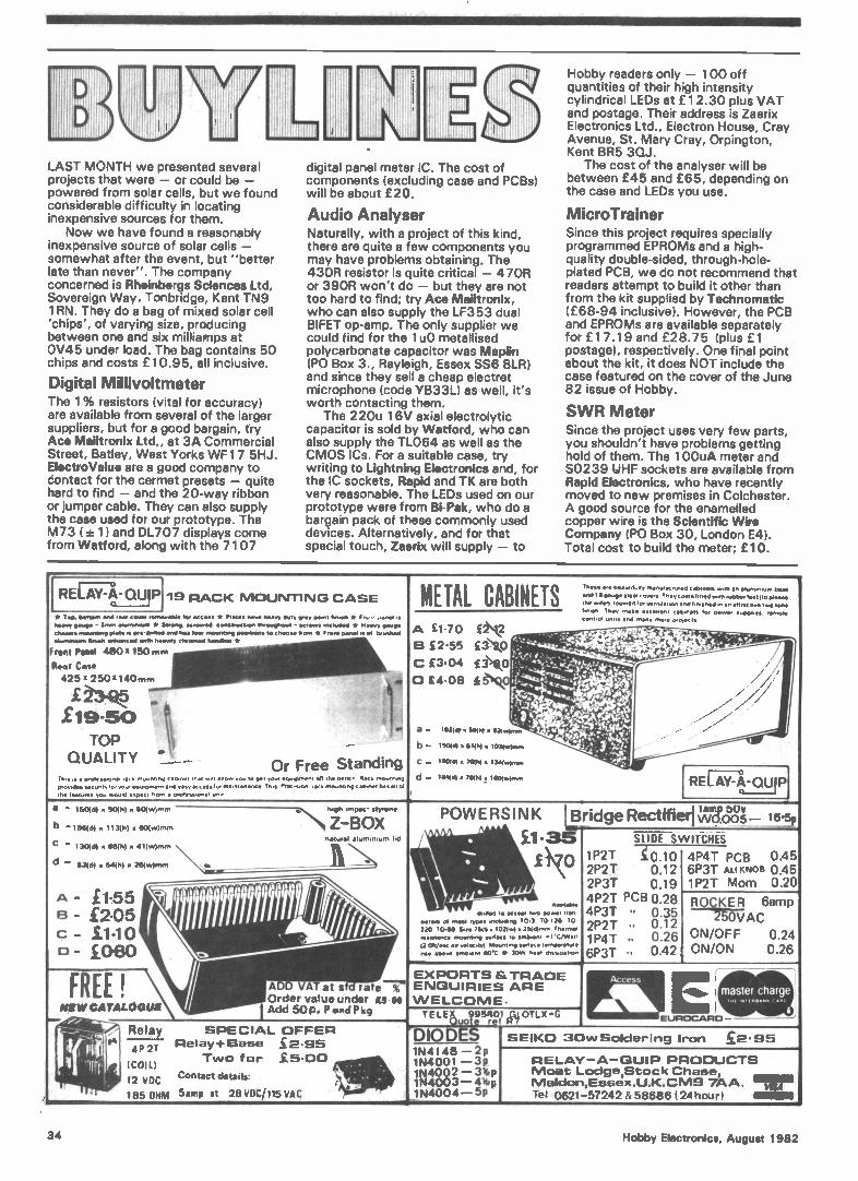
LAST MONTH we presented several projects that were - or could be - powered from solar cells, but we found considerable difficulty in locating inexpensive sources for them.
Now we have found a reasonably inexpensive source of solar cells - somewhat after the event, but "better late than never". The company concerned is Rheinbergs Sciences Ltd, Sovereign Way, Tonbridge, Kent TN9 1 RN. They do a bag of mixed solar cell 'chips', of varying size, producing between one and six milliamps at OV45 under load. The bag contains 50 chips and costs £10.95, all inclusive.
Digital Millivoltmeter The 1 % resistors (vital for accuracy) are available from several of the larger suppliers, but for a good bargain, try Ace Mailtronix Ltd., at 3A Commercial Street, Batley, West Yorks WF1 7 5HJ. ElectroValue are a good company to contact for the cermet presets - quite hard to find - and the 20-way ribbon or jumper cable. They can also supply the case used for our prototype. The M73 ( ± 1) and DL707 displays come from Watford, along with the 7107
digital panel meter IC. The cost of components (excluding case and PCBs) will be about £20.
Audio Analyser Naturally, with a project of this kind, there are quite a few components you may have problems obtaining. The 43OR resistor is quite critical - 47OR or 39OR won't do - but they are not too hard to find; try Ace Mailtronix, who can also supply the LF353 dual BIFET op-amp. The only supplier we could find for the 1 u0 metallised polycarbonate capacitor was Maplin (PO Box 3., Rayleigh, Essex SS6 8LR) and since they sell a cheap electret microphone (code YB33L) as well, it's worth contacting them.
The 220u 1 6V axial electrolytic capacitor is sold by Watford, who can also supply the TL064 as well as the CMOS ICs. For a suitable case, try writing to Lightning Electronics and, for the IC sockets, Rapid and TK are both very reasonable. The LEDs used on our prototype were from Bi-Pak, who do a bargain pack of these commonly used devices. Alternatively, and for that special touch, Zaerix will supply - to
Hobby readers only - 100 off quantities of their high intensity cylindrical LEDs at £1 2.30 plus VAT and postage. Their address is Zaerix Electronics Ltd., Electron House, Cray Avenue, St. Mary Cray, Orpington, Kent BR5 30J.
The cost of the analyser will be between £45 and £65, depending on the case and LEDs you use.
MicroTrainer Since this project requires specially programmed EPROMs and a high-quality double-sided, through-hole-plated PCB, we do not recommend that readers attempt to build it other than from the kit supplied by Technomatic (£68-94 inclusive). However, the PCB and EPROMs are available separately for £1 7.1 9 and £28.75 (plus £1 postage), respectively. One final point about the kit, it does NOT include the case featured on the cover of the June 82 issue of Hobby.
SWR Meter Since the project uses very few parts, you shouldn't have problems getting hold of them. The 1 00uA meter and S0239 UHF sockets are available from Rapid Electronics, who have recently moved to new premises in Colchester. A good source for the enamelled copper wire is the Scientific Wire Company (PO Box 30, London E4). Total cost to build the meter; £10.
REFA1-7: )A-QU P 19 RACK MOUNTING CASE
9
Tn. e We beeunt,r menu'« rurecl cetunets .th en etuminruni base METAL CABINETS i. gene steer-overt T., come rottect unth rubber feet f top... Ow wore.1 touureOlo• ventorebon•nd lonrene0 • f, en @mech. two tone nn,en. They
* Top bone.% end ter cow« removable neeve ewe)* - 3rouw Mower.. * chasers mown., Or. ue pre One. eturrantram brinh ennenceel wrIn tweed,
Front Panel 4801(150 TRI
Rear Case 425 x 250)1140mm
£19-50 t TOP
QUALITY Tn., . • Oreree•rone".• o,ronnnb x......dx. sac .......0. your eotopment In• le•ture• you woo. expect hom
toe Ito.. er Metes ...bee., dot, rev Oem, Tout. * Fn.. , ...rt. Strong «fewest coneireCte. Moaner:ha «re... encrueleel it Nee+, Paoli* SSS he• toe, merenemb pewee.. choose hem • Front pone, re et bruetted
chromed hem». *
> ,,
t , -
- Or Free Standing "b.., tn.." •rrow •outir be, tour eouroment oft the bent, Racà mount.nb end tely occ•ss tor ma., enanc e Th.. Prec.i.on rec • mountnp catorner has • protest.oner um.,
/
err o,
17n ec •-• £ • . • s, wl>'>.
\ ••• B £2.55 £3.41 ;:-
C £3.04 £1(0
D £4.08
a - 1021.0.• 5110i) • 11-1(w)own
b - 15099 • 11(9) • 1034trefenm
C .- 160(d) • 780,1 • 1344•*(x..
ma. control unati end
't.e41•1• .- ''.:»k• • - 4' .•
tier d )•••• , • • - ", ,m.t.i..., • in. n • - , , ,,(.2..,, ,E....2 -..y.,.. • -.-. . •
r.....: .--- ...,•,_ . .. . it t ...e• - ......• ....., .
, ,.. - .... !
tac.11.11 cobweb tor oowe• suPorree remote many more prOtt‘r•
•
,
7. .-- 7 .--
d - 164401 • 70(9) ffl ! I ue),,,,,
I
REGV7106.QUIP
, -
a - 1604d) a 90(h) a 504w)rnrn •,.....N tire ortipee• styrene
b -196(d) a 1(349) • 60(.v)rnm. Z «..BOX
n•turel elonirnrom Ira c - 130(6) • 684h) a 419....)nun
d - 83(d) x £.4(h) a 28(w)min
POWERSINK LFtririat.P•eintifid.. lamp bUV ..........e....----riwo.005- 16.5p .
11bI • £1-35 y
-§i-i-DE SWITCHES , • • .Ei\c)
\ .....,
1P2T 0.10 2P2T 2P3T 00..1192
4P4T PCB 0.45 6ipP23TT AmLl oKNm OB 00 ..4205
A ' £1155 8 ' £205 impi ronivi C £11 0 1 ill 11 II il !Le/it
0 ' £0430
. *vegetate
4P2T PCB 0.28 ROQ2sK0EvRAc6amp 0..0 to eccept two power 'fen
220 10 66 &re 2616 • 1021.1 • 26461,nrn flier'''. reverence mountong bur..., to embarent -1•Cittert (2 ot,.......,...,,,, m...... sun.. temperelure nse above arnewn, 60•C 6, 301N nee, chee.pahon
(
4p3T .. 0.35 12.P2T .. 0.12 p4T .. 0.26
6p3T ,,, 0.42 ON/OF F 0.24 , ON/ON 0.26
EXPORTS &TRADE ENQUIRIES ARE WELCOME.
Access
-..-..
master charge 7 rIII .10 ( /IMO
e rat - r E FRE ! ADAT at seOrder value under ES 00
NNW CATALOGUE Add 50p. P and Pkg TE LEK 95801 SsIOTLX•O i )
u0 e re 14 / EUROCARD
-1/le
'4V Relay SPECIAL OFFER ‘ DIODE
SEIKO 30wSolciering Iron £2•95 pi i1 q k PIP 1 lirr: ,
(
i
Relay+Base _£2.95 4P 2T
Two for £5.00 (COW
12 VDC , .. 185 OHM Contact derails: iee I>
5amp at 28VOC/115VAG • 1N4004
1N4148 - 2p 1N4001 -3p 1N4002-31bp
RELAY-A-QUIP PRODUCTS Moat Loclge,Stock Chase
1N4003-4vap -SP
Malclon,Essex.U.K.CM9 7ÁA. nu Tel 0621-57242 & 58686(24hour)
34 Hobby Electronics, August 1982
After a month's absence, CD returns with his usual page of wit and wisdom. Yes, I'm back . . . but did anybody even notice that I was away? Here we go again, another page another . . . well, let's not get into the sordid details. Ready then?
Dear CD, I have been reading HE for a year and I enjoy it apart from two things. Why have you stopped (in April '82 issue) printing the approximate cost of projects? This was very useful information.
Also, why do you only rent binders to people like me who are kind, and who grovel, like me? T.L Homer, Stratford-upon-Avon, Warwicks.
No Bard, this . . . a mere thousand monkeys could produce a better letter. As to the project costs, due to circumstances beyond my control (someone forgot) projects costs did not appear, as you say. However, He Who Decides has assured me that the matter will be attended to. 'Nuff said?.
Your idea concerning the Rental of binders has a certain appeal. . . .
Here's a slightly dated letter I found in my files (so you've been wondering what's happened to that letter you wrote six months ago, have you? Don't worry — I've still got itl)
Dear CD, Yours Sincerely, A. Barnes, Brentwood, Essex.
PS I didn't have anything to say. PPS Are you still doing that silly short-letter stuff? I was going to send a blank sheet of paper but then you wouldn't know where to send the binder.
Since I'm still getting a selection of "that silly short-letter stuff", I thought I'd print this one to give me the opportunity of saying NO, I'M NOT.
When will you all realise that urgent, desperate pleas for help can only be answered quickly (and I don't mean instantly) if a stamped, self-addressed envelope is enclosed. I hope this gentleman had not been waiting too long . . . .
Dear Clever Dick, I am writing to you in a state of desperation and this letter, I hope, will receive prompt attention, for which I will be very grateful.
What I would like to know is — where can obtain a slider potentiometer of value 5M0, log scale? M. McHugh, Dublin.
He's probably given up by now — but the answer is, you'll have to make one up by putting a fixed resistor in series with a high value pot. Potentiometers from Electrovalue are available up to IMO and RadioOhm of East Grinstead can supply pots up to 2M2, log.
Please remember, if you would like an early reply, to send in an SAE next time you write. I don't have an unlimited budget for postage, you know (anything extra comes out of my salary, so you can calculate your chances . . I.
Our very clever design team are always getting suggestions for new projects — and, occasionally, an idea for modification for an old project. Here's one they've taken note of.
Dear Brilliant Richard, I have been reading Hobby Electronics for about two years now, and I think it is brilliant. was scanning through my numerous back copies looking for something to build when I saw the 'Diana' Metal Detector.
After carefully transferring the PCB foil pattern on to copper-clad board, I realised that the design did not make provision for headphones or a loudspeaker. Could you please send me a circuit diagram for an audio output that can be added to this project? S. Goddard, Gwynedd, North Wales.
PS am still at school but I have learnt a lot about electronics from both HE and ET!. I think that your staff all deserve medals for producing such high quality magazines.
If you're a regular reader, as you claim to be, you should know quite well that I don't send off circuits in the mail. However, you're in luck. In response to earlier requests, our design team has produced an audio output for the 'Diana' and I am reliably informed (an impeccable source) that it will appear shortly.
I approached the Editor with your idea for awards but he only suggested that if I wanted a medal I should join the Navy.
Dear CD, Would it be possible to have a project for a computer in HE, explaining it as you go along? Yours very hopefully, F. McDonald, Dublin.
PS The ZX81 has only four ICs. PPS This is my fourth letter — binder, please. PPPS Please print this.
Short and sweet, that's the way I like them. As a matter of fact it is quite possible to have a computer project in HE; we started on in June and it continues in this issue. This month, I believe, the component overlay and assembly instructions will be given. The design is rather advanced, but most readers will be able to learn from it how the various components of a microcomputer go together. In the case of the ZX81, as you point out, there are four of them. Now tell something I didn't know.
At last an astute reader has penetrated one of Hobby Electronic's deepest, darkest secrets — but I don't mean the secret of my identity.
Dear CD, Having loyally collected all your mags, I've noticed that your numbering system has gone somewhat hay-wire (no pun intended). I noticed that in the 80/81 volume, the numbers go up to 14. Why is this, when all the previous volumes were numbered from one to twelve? K. Dutton, Walsall, West Midlands.
PS My wife said you've got to send a binder to put my HEs in, so she can tidy the place up.
The solution of the mystery is devastatingly simple. The first edition of HE was published in November 1978, and since there are twelve months in a year (just kidding), the issues were numbered from one to twelve. Last year, we decided to bring our issue numbers in line with the calendar year, so that No. 1 would be January issue, No. 2 February, and so on. To do this, though, we had to bring out 14 issues in one volume. It's that simple . . . isn't it?
Let it never be said that Clever Dick was the cause of domestic wife . . . er, strife. A binder has been dispatched with all speed. HE
Hobby Electronics, August 1982 35
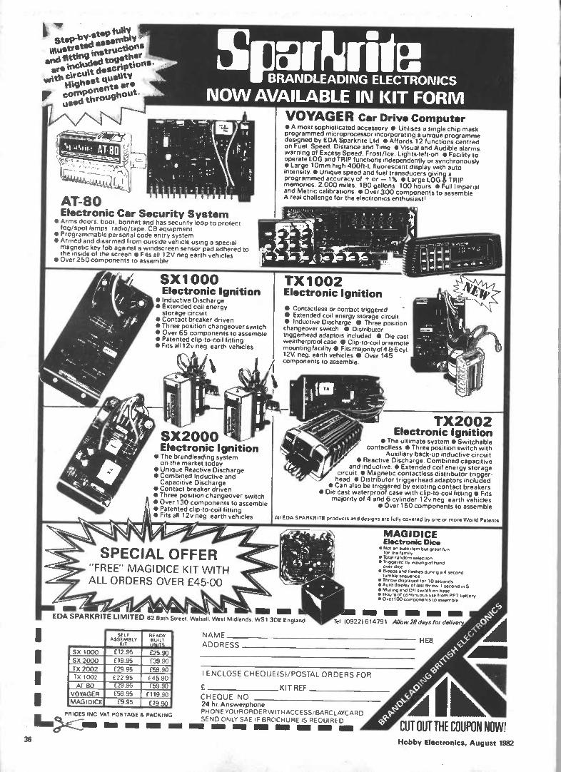
k I' ' Step-bV-step fully illustrated essernle end fitting instructions ere included tagathie
with circuit descriPtions.
tUghest . quality a
Pe components re used throughout
AT-80 Electronic Car Security System
• Arms doors, boot, bonnet and has security loop to protect fog/spot lamps. radio/tape. CB equipment
• Programmable personal code entry system • Armed and disarmed from outside vehicle using a special magnetic key fob against a windscreen sensor pad adhered to the inside of the screen • Fits all 12V neg earth vehicles
• Over 250 components to assemble
541 BRANDLEADING ELECTRONICS NOW AVAILABLE IN KIT FORM
SX1000 Electronic Ignition
• Inductive Discharge • Extended coil energy storage circuit
• Contact breaker driven • Three position changeover switch • Over 65 components to assemble • Patented clip-to-coil fitting • Fits all 12v neg earth vehicles
‘ai
SX2000 Electronic Ignition
• The brandleading system on the market today
• Unique Reactive Discharge • Combined Inductive and Capacitive Discharge
• Contact breaker driven • Three position changeover switch • Over 130 components to assemble • Patented clip-to-coil fitting • Fits all 12v neg earth vehicles
SPECIAL OFFER "FREE" MAGIDICE KIT WITH ALL ORDERS OVER £45.00
Mil -del EDA SPARKRITE LIMITED 82 Bath Street. Walsall. West Midlands, WS1 3DE England
SELF ASSEMBLY
INT
READY BUILT UNITS
£25.90 £39.90
£59.90 £45.90 f59.90
SX 1000
SX 2000 TX 2002 TX 1002
£12.95
£19.95
£29 95 £22 95 £29,95 £59.95
AT 80 VOYAGER MAGI DICE
f119.90 £9 95 £19.90
PRICES INC VAT POSTAGE & PACKING
MI NMI Ma
VOYAGER Car Drive Computer • A most sophisticated accessory • Utilises a single chip mask programmed microprocessor incorporating a unique programme designed by EDA Sparkrite Ltd • Affords 12 functions centred on Fuel, Speed, Distance and Time • Visual and Audible alarms. warning of Excess Speed, Frost/Ice, Lights-left-on I Facility to operate LOG and TRIP functions independently or synchronously • Large 10mm high 400f t-L fluorescent display with auto intensity • Unique speed and fuel transducers giving a programmed accuracy of + or — 1% I Large LOG & TRIP memories 2.000 miles 180 gallons 100 hours • Full Imperial and Metric calibrations • Over 300 components to assemble A real challenge for the electronics enthusiast'
TX1002 Electronic Ignition
• Contactless or contact triggered • Extended coil energy storage circuit • Inductive Discharge • Three position changeover switch • Distributor triggerhead adaptors included • Die cast weatherproof case • Clip-to-coil or remote mounting facility • Fits majonty of 4 & 6 cyl. 12V neg. earth vehicles • Over 145 components to assemble.
TX2002 Electronic Ignition
• The ultimate system • Switchable contactless • Three position switch with
Auxiliary back-up inductive circuit • Reactive Discharge. Combined capacitive
and inductive S Extended coil energy storage circuit • Magnetic contactless distributor trigger-head 1, Distributor triggerhead adaptors included
• Can also be triggered by existing contact breakers • Die cast waterproof case with clip-to-coil fitting • Fits
majority of 4 and 6 cylinder 12v neg earth vehicles • Over 150 components to assemble
Al! EDA.SRARKITITE products and designs are fully covered by one or more World Patents
MAGIDICE Electronic Dice
• Not an auto item but great fun for the fernily
• Total random selection • Triggered by waning of hand over dice
• Bieeps and flashes during a 4 second tumble Sequence
• Throw displayed tor 10 seconds • Auto display of fast throw 1 second in 5 • Muting and Off switch on base • Hours of continuous use from PP7 battery • Over 100 components to assemble
MMI AM MUM.. Ma Min Tel 109221614791 Allow 28 days for delivery
NAME
ADDRESS
I ENCLOSE CHEQUE(S)/POSTAL ORDERS FOR
KIT REF
CHEQUE NO 24 hr Answerphone PHONE YOURORDER wiTHACCESS/ BARCLAYCARD SEND ONLY SAE IF BROCHURE IS REQUIRED
Ma MI MR Mill Ma Inn NM MI
H
CUT OUT THE COUPON NOW! 36 Hobby Electronics, August 1982

Ill Gadgets, Games and Kits
OHMS
°Ouse burin
200» t
20 roni 'MU
101/11 e 20K
200m 200K
le 2000K
Metertech
.--,pierremittremeire.,:wimmoeme. POWE-11--.
off ON
AC
3T
ocv cola Wee c)t,
FROM TIME TO TIME the Hobby offices receive pieces of electronic equipment for review and evaluation. This month we were sent a new digital multimeter from Centemps. The Metertech model 3T is an attractive, portable multimeter with a large four digit LCD display. In addition to the usual functions the meter also has a built-in transistor tester. This makes it extremely versatile for its a small size — the case measures just 180 x 82 x 38 millimetres.
The basic measuring ranges are selected by a row of pushbutton switches along the side of the unit. Three red buttons set the requied function: Ohms, Voltage and DC current. AC current can be measured via the optional adapter; though no specification data is available at present, we were assured that technical information would be on hand soon. However the plug-in unit performed well, albeit after a slight struggle to understand it!
Each function has a number of ranges provided by the remaining five black buttons. This colour coding is quite a nice touch and makes operation just that bit easier — you've always got to ensure that one black and one red button are depressed to take a reading. Another advantage of this facility is that it permits one-handed testing, leaving the other free to position the test prods. Something I did miss though, is that the leads do not come
Paul Coster
A no-nonsense, push button multimeter with useful extra facilities.
AC Curti/too- A. MO ...Apten
Mel •
.•
e
with interchangeable tips or extras like crocodile clips — so be prepared to add your own clips or having to hold the leads in place when taking measurements.
The DC voltage scale has five steps; 200 mV, 2V, 20V, 200V, and lkV. This provides a staggering resolution of less than one millivolt on the lowest range, with a quoted accuracy of 0.5%. All five settings have an input impedance of 10M, so they will not significantly load the circuit under test. A very useful protection arrangement allows overloads up to 500V DC, so it's virtually impossible to damage the meter.
The two AC voltage ranges are equally well protected, up to 350 V RMS AC, but do not have such a high resolution. Sinusoidal voltages are measured with the red test lead plugged into a special AC socket (one of four at the bottom end of the meter). The lower two black buttons select either 200 V or lkV and work over a frequency band from 40 Hz to 500 Hz. This stated narrow bandwidth did not prove a serious limitation, however, since readings up to about 20 kHz were founded to be possible! However, the lack of a really low AC setting was found to be a drawback when dealing with audio signals within low-level circuitry.
The DC current scale has five steps, like the voltage scale. This gives readings from 100nA (not 100uA as in
the booklet) up to 200mA with a separate socket for measurements of currents up to 10A. All these ranges are protected by a 0A5 fuse and an extra fuse is supplied with the meter. With an accuracy of 1.2% (our meter was actually better than 1%), it is possible to work out exact current demands of battery powered equipment. This also allows precise setting up of regulator circuits in PSU's for minimum ripple. In fact the only slight reservation I had about the current ranges is that you have to change test sockets to move up from 200mA to 10A.
The uppermost red function button puts the meter into resistance mode. There are five steps covering the range 2k to 2M with one ohm resolution on the lower end. Accuracy is stated as 1%, but I measured several 0.1% resistors without detecting any discrepancies. The resistance ranges are protected against an overload of up to 250V AC and DC (though I didn't test this!) and test currents — the currents put throúgh the circuit being tested — are very low (100 uA maximum).
One interesting aspect about this range is that you can check the 'resistance stability' of presets and pots by watching the final digit on the display changing, even though you're not moving the wiper on the pot. The first black selector, in conjunction with the ohms range, also allows checking of diodes by providing an output current of 2 mA. By multiplying the display value by ten, an approximate measure of forward voltage is obtained. Short or open circuits are signified by a reading of '1' or '00.0' respectively.
The model 3T has an extra facility in that it can be used to measure the DC current gain or hFE (common emitter mode) of small transistors. On the right of the case below the display is a transistor socket, clearly marked to take PNP and NPN transistors. The mode is selected by the lowest black button on the DC mA/h FE setting. This makes light work of matching transistors from a bargain pack, or simply selecting the best one for a specific purpose. Indeed, backed up by such an accurate voltage/current capability, the transistor testing range makes the whole unit extremely versatile.
So, here is a no-nonsense precision multimeter with all the extras you could want from such a device. The ranges are wide and accurate, and though a low AC voltage range would have been advantageous, for most applications the unit performs admirably. I found it easy to use, due to the clear markings and colour coding on the front panel, and consider it to be a valuable addition to any hobbyist's test bench. The Metertech DVM we reviewed was from Centemp, 62 Curtis Roac!, Whitton, Hounslow, Middx. TW4 5PT. It is available from them, priced at £49.95 (including VAT, p&p). The optional case is £6.90, as is the AC current adaptor. HE
Hobby Electronics, August 1982 37
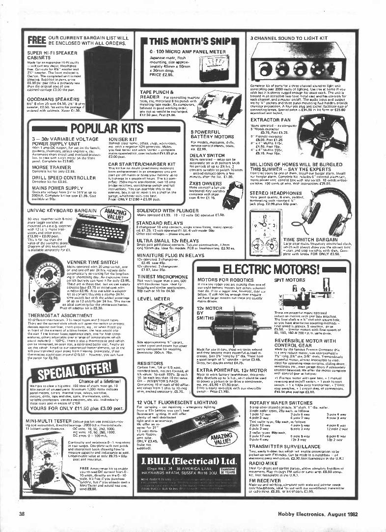
FREE OBEL., RE NCCULRORSEE NDT1 NB I AT RH GAAL1LN OL IRSDT EWR St_ L
SUPER HI-Fl SPEAKER CABINETS Made for an expensive Hi-Fi outfit - will suit any decor. ResOnance free. 0.11-Outs for 6%" wortifer and 2%" tweeter. The front material is Dacron. The completed unit is most pleasing. Supplied in pairs, price £6.90 per pair (this is probably less than the original cost of one cabinet) carriage £3.00 the pair.
GOODMANS SPEAKERS 6%" 8 ohm 25 watt £4.50. 2%" 8 ohm tweeter. £2.50. No extra for postage if ordered with cabinets. %over £1.50.
I.
THIS MONTH'S SNIP - 100 MICRO AMP PANEL METER
Japanese made, flush mounting, size approx-imately 45mm x 50mm x 30mm deep. PRICE £2.95.
TAPE PUNCH & READER For controlling machine tools, etc, motorised 8 bit punch with matching tape reader. Ex-computers, believed in good working order, any not so would be exchanged. £17.50 pair. Post £4.00.
POPULAR KITS 3 - 30v VARIABLE VOLTAGE POWER SUPPLY UNIT With 1 amp DC output, for use on the bench, students, inventors, service engineers, etc. Automatic short circuit and overload protect-ion. In case with a volt meter on the front panel. Complete kit £13.80.
MORSE TRAINER Complete kit for only £2.99.
DRILL SPEED CONTROLLER Complete kit for £3.95.
MAINS POWER SUPPLY Gives any voltage from 3V to 16V at up to 300mA. Complete kit less case £1.95. Case available at 90p.
IONISER KIT Refresh your home, office, shop, work room, etc. with a negative ION generator. Makes you feel better and work harder - complete mains operated kit, case included £11.95 plus £2.00 post.
CAR STARTER/CHARGER KIT This kit has no doubt saved many motorists from embarassment in an emergency you can start car off mains or bring your battery up to full charge in a couple of hours. The kit com-prhes, 250w mains transformer, two 10 amp bridge rectifiers, start/charge switch and full instructions. You can assemble this in the evening, box it up or leave it on a shelf in the garage, whichever suits you best. Price: ONLY £12.50 £3.00 post.
PS
UNIVAC KEYBOARD BARGAIN re..738.-.ftegui
50 keys together with 5 mini. ature toggle switches all mounted on a p.c.O. togethe with 12 i.c.'s many tran-sistors and other parts. £13.50 y £2.00 post. This is far less than the value of the switches alone. Diagram of this keyboard is available seParately for £1.
VENNER TIME SWITCH Mains operated with 20 amp switch, one on end one off per 24 hrs. repeats daily automatically correcting for the lengthen-ing or shortening day. An expensive time switch but you can have it for only £2.95. These are without case but we can supply a plastic base £1.75 or metal case with window f2.95. Also available is adaptor kit to convert this into a normal 24 hr. time switch but with the added advantage of up to 12 on/offs per 24 hrs. This makes
an ideal controllerfor the immersion heater. Price of adaptor kit is £2.30.
THERMOSTAT ASSORTMENT 10 different thermostats. 7 bi-metal types and 3 liquid types. There are the current stets which will open the switch to protect devices against overload, short circuits, etc., or when fitted say in front of the element of a blow heater, the heat would trip the stet if the blower fuses; appliance stets, one for high temp. eratures, others adjustable over a range of temperatures which could include 0 - 100°C. There is also a thermostatic pod which can be immersed, an oven stet, a calibrated boiler stat, finally an ice stet which, fitted to our waterproof heater element, up in the loft could protect your pipes from freezing. Separately, these thermostats could cost around £15.00 - however, you can have the parcel for £2.50.
Chance of a lifetime! We have to clear a big store. 100 tons of stock must go. 10 kilo parcel of unused parts. Minimum 1,000 items includes panel meters, timers thermal trips, relays, switches, motors, drills, taps and dies, tools, thermostats, coils, variable condensers variable resistors, etc. etc. Individually these must cost in excess of £100.
YOURS FOR ONLY £11.50 plus £3.00 post.
MINI-MULTI TESTER Deluxe pocket size precision mov-ing coil instrument. Jewelled bearings - 2000 o.p.v.mirrored scale. 11 instant range measures: DC volts 10, 50, 250, 1000.
AC volts 10, 50, 250, 1000. DC amps 0 - 100 mA.
Continuity and resistance 0 - 1 meg ohrns in two ranges. Cornplete with test prods
. and instruction book showing how to " • 18el, ""-... measure capacity and inductance as well.
Unbelievable value at only £6.75 y 60p post and insurance.
FREE Amps range kit to enable you to read DC current from 0-10 amps, directly on the 0.10 scale. It's free if you purchase
ickly, but if you already own a Mini.Tester and would like one, send £2.50.
8 POWERFUL BATTERY MOTORS For models, maccanos, drills, remote control planes, boats, etc. £2.95.
DELAY SWITCH Mains operated - delay can be accurately set with pointers knob for periods of up to 2% hrs. 2 contacts suitable to !witch 10 amps - second contact opens a few minutes after the 1st. £1.95.
2X81 OWNERS Make yourself a full size keyboard! Key switches complete with plain caps. 6 for £1.15.
SOLENOID WITH PLUNGER Mains operated £1.99. 10 - 12 volts DC operated £1.50.
STANDARD RELAYS 3 changeover 10 amp contacts, single screw fixing, mains operat-ed. £1.25. 12 volt operated £1.50. 6 volt model 99p. Other coil voltages - please enquire.
ULTRA SMALL 12v RELAYS Single pole gold plated contacts. Tubular construction, 17mm long 10inm dia. Ideal for models. PCB or freemounting. £2.30 ea.
MINAITURE PLUG IN RELAYS 12v operated. 3 changeover.
£2.45 base 45p. 12v operated. 2 changeover.
£1 87, base 360.
TINIEST MICROPHONE Not much bigger than a pea, 600 ohm condenser type. Ideal for bugging and similar applications. 50p each or 10 for £4.50
LEVEL METER
Size approximat ly Y." square, scaled signal and power but cover easily removable for reualing. Sensitivity 200uA. 75p.
RESISTORS Carbon film, 1/4 or 1/3 watt, standard leads, not pre-formed, all 5% values: le each 100's. 2p each 10. 5p each less than 10 per value. OR - INVENTOR'S PACK Containing 10 of each of 60 differ-ent values from 1 ohm to 10 meg-ohm, packed separately, £5.75.
3 CHANNEL SOUND TO LIGHT KIT
Complete kit of parts for a three channel sound to light unit controlling over 2000 watts of lighting. Use this at home if you wish but it is plenty rugged enough for disco work. The unit is housed in an attractive two tone metal case and has controls for each channel, and a master on/off. The audio input and output are by '6' sockets and three panel mounting fuse holders provide thyristor protection. A four-pin plug and socket facilitate ease of connecting lamps. Special price is £14.95 in kit form or £25.00 assembled and tested.
EXTRACTOR FAN Mains operated - ex-computer 5"Woods extractor
£5.75, Post £1.25. 5" Plannair extractor
£6.50. Post £1.25 4" x 4" Muffin 115v.
£4.50. Post 75p. 4" x 4" Muffin 230v.
£5.75. Post 75p,
MILLIONS OF HOMES WILL BE BURGLED THIS SUMMER - SAY THE EXPERTS Don't let yours be one of them. Install our burger alarm. Install our burglar alarm. Complete kit includes 6" external alarm bell, mains power unit control box with key switch 10 window/door switches 100 yards of wire. With instructions £29.50.
STEREO HEADPHONES Very good quality, 8 ohm, padded, terminating with standard '4' lack plug. £2.99.plus 60p post.
12
9c? ' Y 3
I TIME SWITCH BARGAIN Large clear mains frequency controlled clock, which will always show you the correct time , -1 start and stop switches with dials. Com-) plete with knobs FOR ONLY £2.50.,
ELECTRIC MOTORS! MOTORS FOR ROBOTICS If its a toy robot you are making then one of our eight battery motors (see centre column) may do. If its a bigger one, however, then see below. If still not big enough then enquire _ we have larger motors but these are usually mains driven.
12v MOTOR BY SMITHS
Made for use in cars, these are series wound and they become more powerful as load in-creases. Size 3%" long by 3" dia. These have a good length of Y." spindle - price £3.45. Ditto, but double ended £4.25.
EXTRA POWERFUL 12v MOTOR Made to work battery lawnmower, this prob-ably develops up to '4 h.p., so it could be used to power a go-kart or to drive a compressor, etc. etc. £6.90 y £1.50 post. (This is easily reversible with our reversible switch Price £1.151.
Fi [11-
SPIT MOTORS -
emu
These are powerful mains OPerated induction motors with gear box attached. The final shaft is a %" rod with square hole, so you have alternative coupling methods - final speed is approx. 5 revs/min, price £5.50. - Similar motors with final speeds of 80, 100, 160 & 200 r.p.m. same price.
REVERSIBLE MOTOR WITH CONTROL GEAR Made by the famous Framco Company this is a very robust motor, size approximately 7%" long, 314" dia. 3/8" shaft, Tremendously powerful motor, almost impossible to stop. Ideal for operating stage curtains, sliding doors , ventilators etc., even garage doors if adequately counter-balanced. We offer the motor complete with control gear as follows:
•1 Framco motor with gear box. • 1 manual reversing and on/off switch. • 1 push to start switch. • 1 x 100w auto transformer. • 2 limit stop switches. • 1 circuit diag. of connections. £19.50 plus postage £2.50.
12 VOLT FLUORESCENT LIGHTING For camping . car repairing - emergency lighting from a 12v battery you can't beat fluorescent lighting. It will offer plenty of well distributed light and is economical. We offer an in-verter for 21" 13 watt mini-ature fluores-cent tube. ONLY £3.45. (tube not supplied).
J. BULL (Electrical) Ltd. (Dept. HE), 34-36 AMERICA LANE,
HAYWARDS HEATH, SUSSEX RH16 30U. Esteblished 30 YEARS
MAIL ()ROCA 1 E HMS t 1 ox4r1. 60, fonsop 1. l'aie,. 'Plh or a I ely rp ttttt
arid go4loloi cue ijodopd, Ana,. Po Ileoloyddr,oloogles:, 1.1.1VW.Nt
035441 4541/0 Bull< OrJeos: Wrelo. lion.. 1/Plilotey toy mhos'',
ROTARY WAFER SWITCHES 5 amp silver plated contacts. '4" shaft. 1" dia. wafer. Single wafer types, 29p each, as follows, 1 pole 12 way 2 pole 6 waY 4 pole 3 way 6 pole 2 way
Two wafer type, 59p each. as follows 2 pole 12 way 4 pole 5 way 6 pole 2 way 8 pole 3 way
3 weer types 99p each, 3 pole 12 way 6 pole 5 way 9 pole 4 way 12p 3 way
3 pole 4 way 4 pole 3 way
4 pole 6 way 12 pole 2 way
6 pole 6 way 18P 2 way
TRANSMITTER SURVEILLANCE Tiny, easily hidden but wliich will enable conversation to be picked up with FM radio. Can be made in a matchbox - all electronic parts and circuit. £2.30. (not licenceable in the U.K.)
RADIO MIKE Ideal for discos and garden parties, allows complete freedom of movement. Play through FM radio or tuner amp. £6.90 comp. kit. (not licenceable in the U.K.).
FM RECEIVER Made up and working, complete with wale and pointer needs only headphones, ideal for use with our surveillance transmitter or radio mike. £5.85. or kit of parts £3.95.
38 Hobby Electronics, August 1982
Famous Names II
Julius Plucker We see one of his discoveries every night. JULIUS PLUCKER was born in 1801 at Elberfield, Germany, of well-to-do parents. His education was conventional for the time; high school, followed by the University of Heidelberg, where he show-ed considerable promise in mathematics. He pursued further courses at the Univer-sities of Berlin and of Paris and, in 1825, took a job as a lecturer at Bonn University. This post carried no salary — it was deem-ed such an honour that the lecturer was expected to be able to support himself either by inherited wealth or (less likely) by private teaching. Plucker did so for four years, in which time he distinguished himself suffiently to be appointed Assis-tant Professor of Mathematics, at Bonn, in 1829.
His achievements in Mathematics were considerable; Plucker's most notable achievements were in what is termed analytical geometry, an algebraic system for dealing with geometrical pro-blems. His discoveries resulted in his ap-pointment to a Professorship at Halle in 1834 then, in 1836, he returned to Bonn.
Faraday Fever Within nine years, however, his in-
terests totally changed. He became fascinated by the work of Faraday in England and decided to devote the rest of his life to studying this and other electrical work. The contrast between these two men, who never met, could not have been greater. Faraday was the son of a blacksmith, self-educated, with little more than simple arithmetic to his credit and a considerable aversion to mathematical ideas. Plucker, from a wealthy background and well-educated, mathematically a near-genius, was com-pletely bowled-over by Faraday's ideas — which Faraday himself could not express mathematically! Plucker, better able to analyse the ideas but lacking the feeling for the subject that Faraday had by in-stinct, saw them as totally revolutionary. He was, of course, correct — they were the most revolutionary steps in Physics since Newton's Laws of Motion.
Plucker's interest in, and devotion to, Electrical Science led to his appointment, in 1847, as Professor of Physics at Bonn, a post which left him time and provided the resources to extend very greatly his research interests; at that time, these centred on magnetism. Plucker became fascinated by the behaviour of materials in strong magnetic fields. His contem-porary in England, James Prescott Joule, had already demostrated one remarkable effect, that of magnetostriction. Magnetic materials change length as they are magnetised and demagnetised, and the effect is used nowadays as a way of producing ultrasonic waves with very high power. Plucker was interested from a different angle. He saw the effect, cor-rectly, as evidence for the idea that atoms
of materials, for so long regarded as single units, were made up of electrically charg-ed smaller particles.
Plucker soon launched himself into completely original work, however and, in 1852, announced the discovery of diamagnetism. This is a little-known ef-fect which can be observed in crystals of materials that we normally think of as non-magnetic. In fact, all materials are magnetic to some extent, in the sense that they respond to magnetic fields, but only iron and its close relatives, nickel and cobalt, are strongly magnetic. We call such substantaces ferromagnetic, mean-ing magnetic like iron (Ferrum in Latin).
Plucker, using very powerful elec-tromagnets (another idea borrowed from Faraday), was able to classify two other types of magnetism; parmagnetism and diamagnetism. The differences depend, as Plucker suspected, on fundamental dif-ferences in the way the atoms of these materials are constructed but the very in-complete knowledge of atoms, at the time, did not permit him to go much fur-ther.
Like many before and since, he turn-ed to another line of research; the conduc-tion of electricity through gases. It had been known for some time that gases were not completely insulating. Measurements made using the very sen-sitive leaf electroscopes fo the 18th cen-tury, had shown that gases would start to conduct electricity when their temperature was raised. By the middle of the 19th century, the remarkable effects produced by lowering the pressure of gases had been discovered and it was to this area that Plucker directed his resear-ch. It proved to be a most rewarding study.
Gas Displays It's not difficult to understand why
gas discharges (passing electric currents through gases at low pressures) were so fascinating; they provide some of the most beautiful spactacles in Physics. When a high voltage is placed across two metal plates, at opposite ends of a tube which can be connected to a vacuum pump, nothing much happens until the pressure of the gas in the tube (air or anything else) has been considerably reduced. The first indication of activity is a series of irregular sparks which flash between the plates (or 'electrodes'). As the pressure is reduced, the sparks merge into a continuous discharge, becoming a glow which fills the tube completely, apart from a dark space near the negative electrode (the cathode dark space). The colour of the glow is vivid and bright and depends on the type of gas that filled the tube. When neon is the filling material, the effect is the familiar orange glow of the neon lamp. This much had already been noted by Geissler and several others,
though they had little idea of what caused the effect.
We know now that the reduced pressure causes the molecules of gas to separate, and that any one molecule which splits into atoms and then into charged particles can cause all the rest of the molecules of the gas to split in the same way. What happens is that any charged particle will be accelerated to a high speed, because of the electric field, and will crash into other molecules, split-ting them into fragments; each fragment will in turn be accelerated and will split up others in a chain reaction. The cause of the glow is the energy given out when the fragments recombine and the dark space near the cathode is the region in which the fragments are accelerating rather than recombining. Most of the voltage drop is across this dark space!'
Plucker, in 1859, was determined to take the process a stage further. Using an improved vaccum pump, only just in-vented, he reduced the pressure in such a tube very much further. As the pressure dropped, the glow in the gas broke up into bands and eventually disappeared. Ex-amining the tube in a darkened room, howe,ver, Plucker found that there was still a glow — but it was not inside the tube. A faint glow now seemed to be on the wall of the tube, near the positive electrode (the anode), and was green in colour. Plucker found that any object placed between the anode and the cathode would cast a shadow under these conditions, so that it looked as if there were a ray emitted from the cathode and striking the glass. The phrase 'cathode rays' has been with us ever since!
Deflections By 1860, Plucker had gathered a
team of researchers around him, all of whom were to make their names in con-nection with cathode rays. An early result of their work was the discovery that the rays travelled in straight lines, but Plucker's interest in magnetism led him to test the effect of a magnet on the rays — and he found that they were deflected. Deflection by a voltage applied between metal plates was also demonstrated, along with the heating effect produced when the 'rays' hit any material, an effect we make use of nowadays in electron-beam welding. To crown it all, an elegant experiment proved that the rays were probably moving particles, with mass and speed, because they were capable of tur-ning a wheel held within the evacuated tube.
Plucker's publication of the results of his work, and that of his associates, pro-duced great excitement in scientific circles because cathode rays were the first firm evidence that atoms could be split, to produce smaller charged par-ticles. As an academic, Plucker did not ex-ploit the discoveries in any way, but he undoubtedly paved the way for the elegant measurement of the charge/mass ratio of the electron, by J.J. Thomson, at the end of the century, and to the inven-tion of the first practical cathode ray tube by Braun, at about the same time. HE
Hobby Electronics, August 1982 39
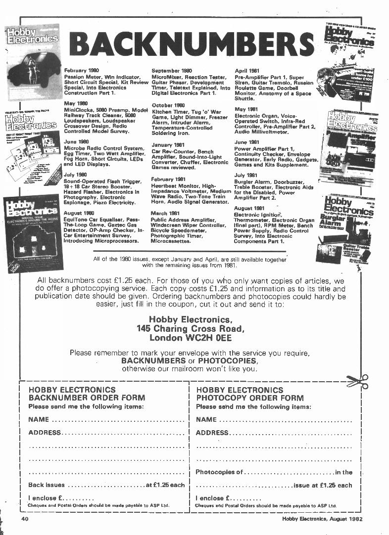
/11511LaT -WI 11C4404a FACIT
BACKNUMBERS February 1980 Passion Meter, Win Indicator, Short Circuit Special, Kit Review Special, Into Electronics Construction Part 1.
May 1980 MiniClocks, 5080 Preamp, Model Railway Track Cleaner, 5080 Loudspeakers, Loudspeaker Crossover Design, Radio Controlled Model Survey.
June 1980 Microbe Radio Control System, Egg Timer, Two Watt Amplifier, Fog Horn, Short Circuits, LEDs and LED Displays.
July 1980 Sound-Operated Flash Trigger, 18+ 18 Car Stereo Booster, Hazard Flasher, Electronics in Photography, Electronic Espionage, Piezo Electricity.
August 1980 EquiTone Car Equaliser, Pass-The-Loop Game, Gaztec Gas Detector, OP-Amp Checker, In-Car Entertainment Survey, Introducing Microprocessors.
September 1980 MicroMixer, Reaction Tester, Guitar Phaser, Development Timer, Teletext Explained, Into Digital Electronics Part 1.
October 1980 Kitchen Timer, Tug 'o' War Game, Light Dimmer, Freezer Alarm, Intruder Alarm, Temperature-Controlled Soldering Iron.
January 1981 Car Rev-Counter, Bench Amplifier, Sound-Into-Light Converter, Chuffer, Electronic Games reviewed.
February 1981 Heartbeat Monitor, High-Impedance Voltmeter, Medium Wave Radio, Two-Tone Train Horn, Audio Signal Generator.
March 1981 Public Address Amplifier, Windscreen Wiper Controller, Bicycle Speedometer, Photographic Timer, Microcassettes.
April 1981 Pre-Amplifier Part 1, Super Siren, Guitar Tremolo, Russian Roulette Game, Doorbell Monitor, Anatomy of a Space Shuttle.
May 1981 Electronic Organ, Voice-Operated Switch, Infra-Red Controller, Pre-Amplifier Part 2, Audio Millivoltmeter.
June 1981 Power Amplifier Part 1, Continuity Checker, Envelope Generator, Early Radio, Gadgets, Games and Kits Supplement.
July 1981 Burglar Alarm, Doorbuzzer, Treble Booster, Electronic Aids for the Disabled, Power Amplifier Part 2.
• August 1981 Electronic Ignitiori, Thermometer, Electronic Organ (final part), RPM Meter, Bench Power Supply, Radio Control Survey, Into Electronic Components Part 1.
All of the 1980 issues, except January and April, are still available together with the remaining issues from 1981.
Matataa ea taws mseg
«
All backnumbers cost £1.25 each. For those of you who only vant copies of articles, we do offer a photocopying service. Each copy costs £1.25 and information as to its title and publication date should be given. Ordering backnumbers and photocopies could hardly be
easier, just fill in the coupon, cut it out and send it to:
Hobby Electronics, 145 Charing Cross Road,
London WC2H OEE
Please remember to mark your envelope with the service you require, BACKNUMBERS or PHOTOCOPIES, otherwise our mailroom won't like you.
HOBBY ELECTRONICS BACKNUMBER ORDER FORM Please send me the following items:
NAME
ADDRESS
Back issues at £1.25 each
I enclose £
HOBBY ELECTRONICS PHOTOCOPY ORDER FORM Please send me the following items:
NAME
ADDRESS
Photocopies of in the
I enclose £ Cheques and Postal Orders should be made payable to ASP Ltd. Cheques and Postal Orders should be made payable to ASP Ltd.
_1
issue at £1.25 each
40 Hobby Electronics, August 1982
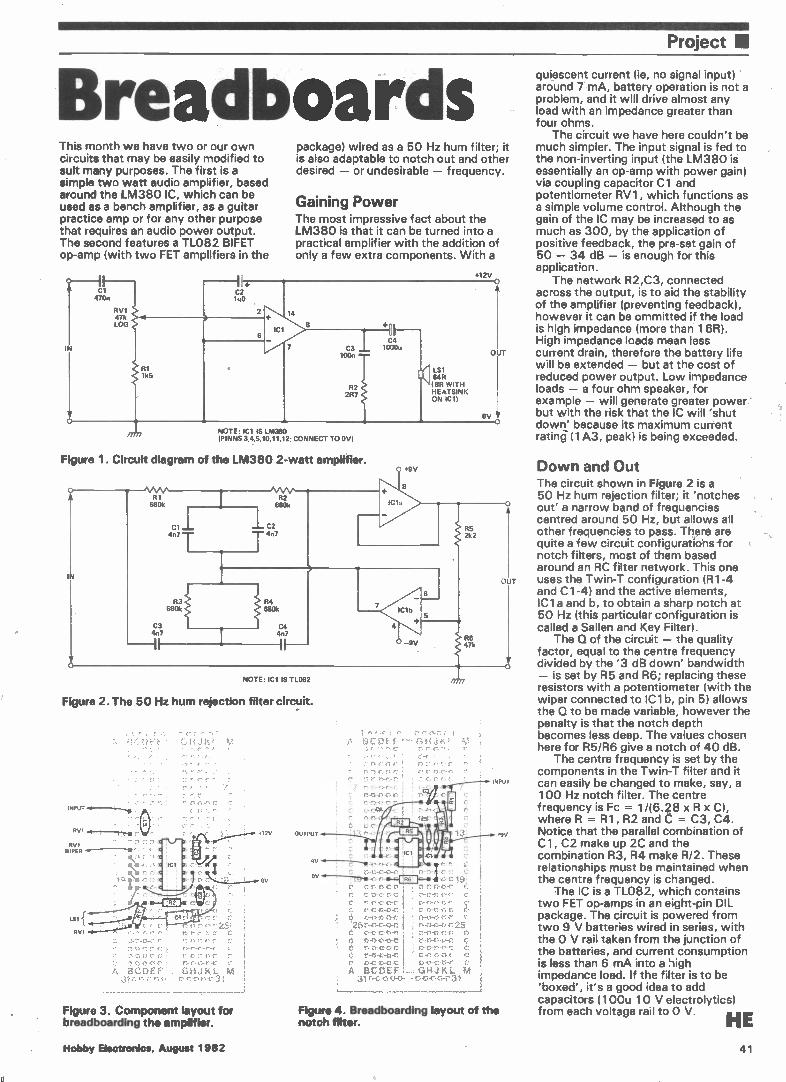
Project •
Breadboards This month we have two or our own circuits that may be easily modified to suit many purposes. The first is a simple two watt audio amplifier, based around the LM380 IC, which can be used as a bench amplifier, as a guitar practice amp or for any other purpose that requires an audio power output. The second features a TL082 BIFET op-amp (with two FET amplifiers in the
470n
IN
RV1 47k LOG
package) wired as a 50 Hz hum filter; it is also adaptable to notch out and other desired — or undesirable — frequency.
Gaining Power The most impressive fact about the LM380 is that it can be turned into a practical amplifier with the addition of only a few extra components. With a
C2 1u0
RI 1k5
IC1
7 C3 100n
R2 2R7
NOTE: ICI IS LM380 (PINNS 3,4,5,10,11,12; CONNECT TO OV)
Figure 1. Circuit diagram of the LM380 2-watt amplifier.
IN
R1 680k
C3 4n7
e\AA,/1---• 82 680k
Cl —.— C2 4n7 T 4n7
R3 S680k
C4 10001(
0 +9V
Cl,
8
(11( LS1 64R (BR WITH HEATSINK ON ICl)
+12V O
OUT
OV O
R4 680k
C4 4n7
IF—
4
IC1b
—9V
R5 2k2
R6 47k
NOTE: (Cl IS TL082
Figure 2. The 50 Hz hum rejection filter circuit.
INPUT o
RV I
RV1 WIPER
• •
rs.e è 41 ;
A BCDEF 31 e«.;-.1n..rs.t1-43
GHJKL M
Figure 3. Component layout for breadboarding the amplifier.
412V
OV
OUTPUT
9V
;
GI H à iS
• •
I......M.-,... --o41 lei En...r.1..0,C.e è
r>e"...on-e›.eSe-e-e:En ,.,;...
t o-u-S0-1:( I 0-0-r>.0 .r, è 0-43-c-cre 2e
è o-o-r.E-0-e. E , 1.5.-r.1-0-0-r, el à rre...n-n-e ' r-s-n-o.c e è e-m.-e..--ne i cree,45.-c I e r-t),----c.r. 1 c-r: -e-tre ÉI
I - te-e...r.-,.o.e El A BCDEFL-i GHJKL. M
31 rs-c-m-o-o--- ..0.--o-r.1-c--C 31
25 o-"- 0-42
O
INPUT
Figure 4. Breadboarding layout of the notch fitter.
T
quiescent current (ie, no signal input) around 7 mA, battery operation is not a problem, and it will drive almost any load with an impedance greater than four ohms.
The circuit we have here couldn't be much simpler. The input signal is fed to the non-inverting input (the LM380 is essentially an op-amp with power gain) via coupling capacitor Cl and potentiometer RV1, which functions as a simple volume control. Although the gain of the IC may be increased to as much as 300, by the application of positive feedback, the pre-set gain of 50 — 34 dB — is enough for this application.
The network R2,C3, connected across the output, is to aid the stability of the amplifier (preventing feedback), however it can be ommitted if the load is high impedance (more than 16R). High impedance loads mean less current drain, therefore the battery life will be extended — but at the cost of reduced power output. Low impedance loads — a four ohm speaker, for example — will generate greater power' but with the risk that the IC will 'shut down' because its maximum current rating (1A3, peak) is being exceeded.
Down and Out The circuit shown in Figure 2 is a 50 Hz hum rejection filter; it 'notches out' a narrow band of frequencies centred around 50 Hz, but allows all other frequencies to pass. There are quite a few circuit configurations-for notch filters, most of them based around an RC filter network. This one uses the Twin-T configuration (R1-4 and CI-4) and the active elements, IC 1 a and b, to obtain a sharp notch at 50 Hz (this particular configuration is called a Sallen and Key Filter).
The Q of the circuit — the quality factor, equal to the centre frequency divided by the '3 dB down' bandwidth — is set by R5 and R6; replacing these resistors with a potentiometer (with the wiper connected to IC1 b, pin 5) allows the Q to be made variable, however the penalty is that the notch depth becomes less deep. The values chosen here for R5/R6 give a notch of 40 dB.
The centre frequency is set by the components in the Twin-T filter and it can easily be changed to make, say, a 100 Hz notch filter. The centre frequency is Fc = 1/(6.28 x R x C), where R = R1, R2 and C = C3, C4. Notice that the parallel combination of Cl, C2 make up 2C and the combination R3, R4 make R/2. These relationships must be maintained when the centre frequency is changed.
The IC is a TL082, which contains two FET op-amps in an eight-pin DIL package. The circuit is powered from two 9 V batteries wired in series, with the 0 V rail taken from the junction of the batteries, and current consumption is less than 6 mA into a high impedance load. If the filter is to be 'boxed', it's a good idea to add capacitors (100u 10 V electrolytics) from each voltage rail to 0 V.
HE Hobby Electronics, August 1982 41
11

• "'"
INTEPODUCING TWO NEW HANDHELD DIGITAL MULTIMEtERS 28 Ranges each with full overload protection
44£79(!a95-1. 06070 De a, 5%
-%fiplus 14A r
Iwo DEL 7o3 DC iMa v
°%.% accura,.. ah /a, Tre. A AK
Plus vA 7-\\
480ígigereggs
INA rat( tEI
.oec
10o,
AM>. »MY
lo_o
t ate. 3,X.4
te. bag,
2.n• t SY Imr
Mg. t2 .0.0n: leak
• A I • 4 0
SPECIFICATION 6010 Et 7030 BATTERY: Single av dry cell BATTERY LIFE: 200 hours DIMENSIONS: 170 x 89 x 38mm WEIGHT: 400g inc battery MODE SELECT: Push button AC DC CURRENT: 200µA to 10A AC VOLTAGE: 200mV to 750V DC VOLTAGE: 200mV to 1000V RESISTANCE: 2009 to 20M9 INPUT IMPEDANCE: 10M9 DISPLAY: 31 Digit 13mm LCD 0/LOAD PROTECTION: All ranges OTHER FEATURES: Auto polarity, auto zero,
battery-low indicator, ABS plastic case with tilt stand, battery and test leads included, optional carrying case.
Please add 15% to your order for VAT. Postage- Et- Packing is free of charge. Trade prices available on application
ARMON ELECTRONICS LTD. Cottrell House. 53-63 Wembley Hill Road. Wembley. Middlesex HA9 8BH. England
Telephone 01-9024321 (31.nes) TELEX No 923985
•••Ai
\
deb „ «̀%910"- eeenar- te9 re-ogre
You'll find it just as enjoyable... cruising on the motorway..
Now! No matter where you live in Britain you can enjoy the pleasure of cruising. Any boat in the Shetland range of family cruisers can be towed behind the
average family car. Think of the advantages to be enjoyed—the rivers, the lakes, the Broads, estuary and coastal waters whenever the fancy takes you. This year take the cruise you always promised yourself...buy Shetland. Clip the coupon for free brochure and name of your nearest dealer.
FAMILY CRUISERS
MM MM MM MM MM MM MM MM MM MM MM MM MM MUM HE8M2
. To: Shetland Boats Ltd., Stanton, Nr. Bury St. Edmunds, Suffolk. Tel: (0359) 50355. Name
I Address Tel
For towing: Makeof car
Model cc
IPlease tick for further information: 0 Family Cruisers D Dories D Stratos Sportsboat O Fisherboats
BRITAIN'S NO.1 SETS THE STANDARD L. Hobby Electronics, August 1982
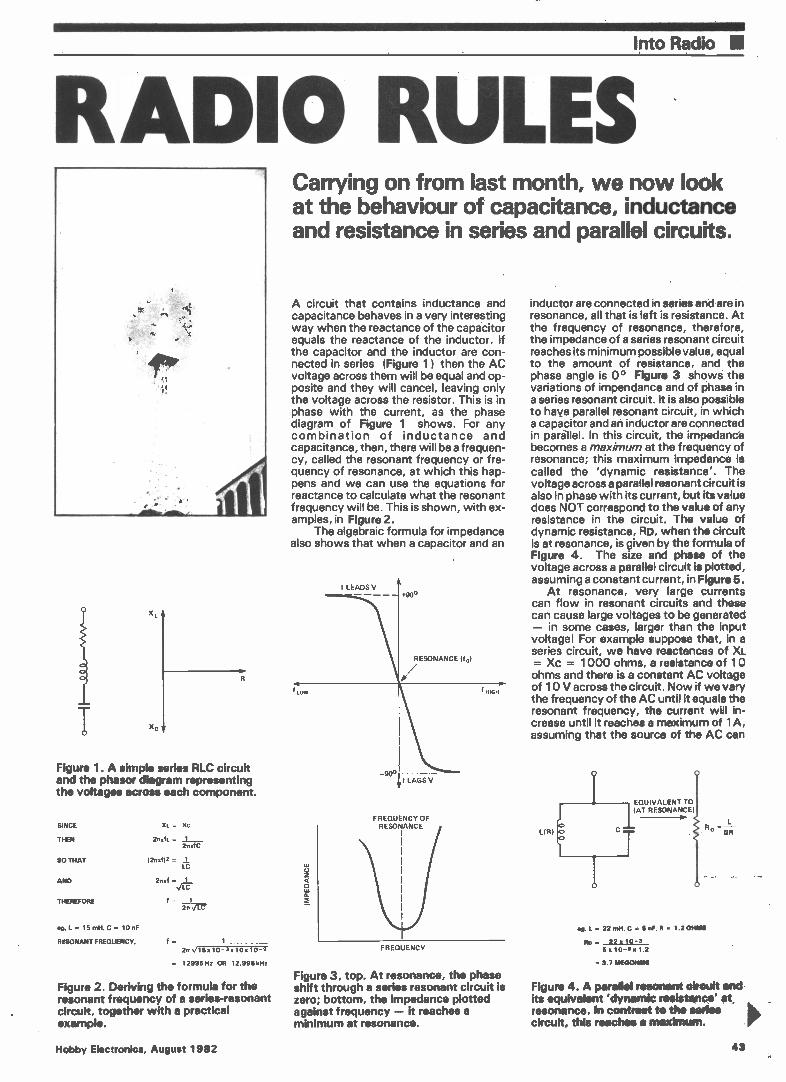
Into Radio 111
RADIO RULES
X,
xc
Figure 1. A simple series RLC circuit and the phasor diagram representing the voltages across each component.
SINCE
THEN
SO THAT
AND
THEREFORE
Xt. = Xn
2/txfi. = 1 211afC
(2n.f/2 = LC
2nd = 1 ea-
f = 1
eel.= 15mH,C= 10nF
RESONANT FREQUENCY, f - 2r,T15,10 - x10,10 -
= 12995Hz OR 12.995kHz
Figure 2. Deriving the formula for the resonant frequency of a series-resonant circuit, together with a practical example.
Carrying on from last month, we now look at the behaviour of capacitance, inductance and resistance in series and parallel circuits.
A circuit that contains inductance and capacitance behaves in a very interesting way when the reactance of the capacitor equals the reactance of the inductor. If the capacitor and the inductor are con-nected in series (Figure 1 ) then the AC voltage across them will be equal and op-posite and they will cancel, leaving only the voltage across the resistor. This is in phase with the current, as the phase diagram of Figure 1 shows. For any combination of inductance and capacitance, then, there will be a frequen-cy, called the resonant frequency or fre-quency of resonance, at which this hap-pens and we can use the equations for reactance to calculate what the resonant frequency will be. This is shown, with ex-amples, in Figure 2.
The algebraic formula for impedance also shows that when a capacitor and an
FREQUENCY OF RESONANCE
IMPEDANCE
FREQUENCY
Figure 3, top. At resonance, the phase shift through a series resonant circuit is zero; bottom, the impedance plotted against frequency — it reaches a minimum at resonance.
inductor are connected in series and are in resonance, all that is left is resistance. At the frequency of resonance, therefore, the impedance of a series resonant circuit reaches its minimum possible value, equal to the amount of resistance, and the phase angle is 0° Figure 3 shows the variations of impendance and of phase in a series resonant circuit. It is also possible to have parallel resonant circuit, in which a capacitor and an inductor are connected in parallel. In this circuit, the impedance becomes a maximum at the frequency of resonance; this maximum impedance is called the 'dynamic resistance'. The voltage across a parallel resonant circuit is also in phase with its current, but its value does NOT correspond to the value of any resistance in the circuit. The value of dynamic resistance, RD, when the circuit is at resonance, is given by the formula of Figure 4. The size and phase of the voltage across a parallel circuit is plotted, assuming a constant current, in Figure 5.
At resonance, very large currents can flow in resonant circuits and these can cause large voltages to be generated — in some cases, larger than the input voltage! For example suppose that, in a series circuit, we have reactances of XL = Xc = 1000 ohms, a resistance of 10 ohms and there is a constant AC voltage of 10 V across the circuit. Now if we vary the frequency of the AC until it equals the resonant frequency, the current will in-crease until it reaches a maximum of 1A, assuming that the source of the AC can
L(R)
EQUIVALENT TO (AT RESONANCE)
n 22 mil, C 6 nF, R = 1.2 OHMS
Ro = 22 x 10 -3 5:10-9.1.2
= 3.7 FAE0014fale
L.
CR
Figure 4. A parallel resonant circuit and-its equivalent 'dynamic resistance' at, resonance. In contrast to the serles circuit, this reaches e maximum.
Hobby Electronics, August 1982 43
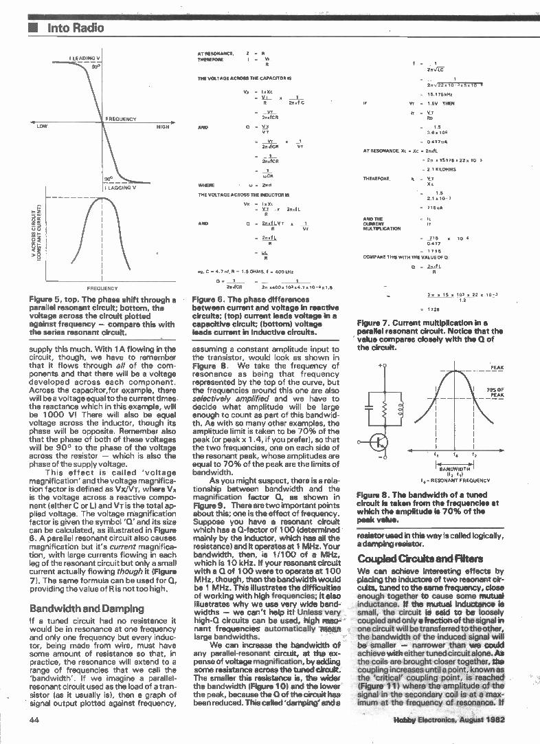
• Into Radio
I LEADING V
900
FREQUENCY
LOW
90° —
1 LAGGING V
FREQUENCY
HIGH
Figure 5, top. The phase shift through a parallel resonant circuit; bottom, the voltage across the circuit plotted against frequency — compare this with the series resonant circuit.
supply this much. With lA flowing in the circuit, though, we have to remember that it flows through all of the com-ponents and that there will be a voltage developed across each component. Across the capacitor,for example, there will be a voltage equal to the current times the reactance which in this example, will be 1000 V! There will also be equal voltage across the inductor, though its phase will be opposite. Remember also that the phase of both of these voltages will be 90° to the phase of the voltage across the resistor — which is also the phase of the supply voltage.
This effect is called 'voltage magnification' and the voltage magnifica-tion factor is defined as Vx/VT, where Vx is the voltage across a reactive compo-nent (either C or L) and VT is the total ap-plied voltage. The voltage magnification factor is given the symbol 'Q' and its size can be calculated, as illustrated in Figure 6. A parallel resonant circuit also causes magnification but it's current magnifica-tion, with large currents flowing in each leg of the resonant circuit but only a small current actually flowing though it (Figure 7). The same formula can be used for Q, providing the value of Ris not too high.
Bandwidth and Damping If a tuned circuit had no resistance it would be in resonance at one frequency and only one frequency but every induc-tor, being made from wire, must have some amount of resistance so that, in practice, the resonance will extend to a range of frequencies that we call the 'bandwidth'. If we imagine a parallel-resonant circuit used as the load of a tran-sistor (as it usually is), then a graph of signal output plotted against frequency,
44
AT RESONANCE, THEREFORE
Z = R = Vi
THE VOLTAGE ACROSS THE CAPACITOR IS
AND
VO = I,, Xc = VI x 1
211, f C
VT 2nOCR
Q = VT
= VT 21TxfCR
= 1 2n>fCR
= 1
WHERE = 2nof
THE VOLTAGE ACROSS THE INDUCTOR IS
VT
Vo I x ‘flo 2znal
AND 0 2n,fLVz , 1 VT
2rt,f L
eg, C = 4.7 nf. R = 1.5 OHMS. f = 400 kHz
- 1 1
2rtafCR 2rt x400,103,4.7,10-9,1.5
Figure 6. The phase differences between current and voltage in reactive circuits; (top) current leads voltage in a capacitive circuit; (bottom) voltage leads current in inductive circuits.
assuming a constant amplitude input to the transistor, would look as shown in Figure 8. We take the frequency of resonance as being that frequency represented by the top of the curve, but the frequencies around this one are also selectively amplified and we have to decide what amplitude will be large enough to count as part of this bandwid-th. As with so many other examples, the amplitude limit is taken to be 70% of the peak (or peak x 1.4, if you prefer), so that the two frequencies, one on each side of the resonant peak, whose amplitudes are equal to 70% of the peak are the limits of bandwidth.
As you might suspect, there is a rela-tionship between bandwidth and the magnification factor Q, as shown in Figure 9. There are two important points about this; one is the effect of frequency. Suppose you have a resonant circuit which has a Q-factor of 100 (determined mainly by the inductor, which has all the resistance) and it operates at 1 MHz. Your bandwidth, then, is 1/100 of a MHz, which is 10 kHz. If your resonant circuit with a Q of 100 were to operate at 100 MHz, though, then the bandwidth would be 1 MHz. This illustrates the difficulties of working with high frequencies; it also illustrates why we use very wide band-widths — we can't help itl Unless very high-Q circuits can be used, high reso-nant frequencies automatically mean large bandwidths.
We can increase the bandwidth of any parallel-resonant circuit, at the ex-pense of voltage magnification, by adding some resistance across the tuned circuit. The smaller this resistance is, the wider the bandwidth (Figure 10) and the lower the peak, because the Q of the circuit has been reduced. This called 'damping' and a
IF
f = 1
2n
2ns/22 x10 3,5,10 I
= 15.175kHz
VT = 1.5V THEN
IT V_T Flo
1.5 36,106
0.417 uA
AT RESONANCE. Xi. = Xc = 2zrafL
= 20 15175o 22 o 10
= 2.1 KILOHMS
THEREFORE, IL = Vo XL
ANO THE CURRENT MULTIPLICATION
1.5 2.1 10
= 715uA
Ii. 1 z
= _715 o 10 0.417
= 1715
COMPARE THIS WITH THE VALUE OF 12:
Q = 2,101
22t n 15n 103 o 22 o 10 j3 1.2
= 1728
Figure 7. Current multiplication in a parallel resonant circuit. Notice that the value compares closely with the û of the circuit.
PEAK
70% OF PEAK
2
'6 InI ' BANDWIDTH
(f,-f,)
= RESONANT FREQUENCY
Figure 8. The bandwidth of a tuned circuit is taken from the frequencies at which the amplitude is 70% of the peak value.
resistor used in this way is called logically, a damping resistor.
Coupled Circuits and Filters We can achieve interesting effects by placing the inductors of two resonant cir-cuits, tuned to the same frequency, close enough together to cause some mutual inductance. If the mutual inductance is small, the circuit is said to be loosely coupled and only a fraction of the signal in one circuit will be transferred tOthecther, the bandwidth of the induced signal will be smaller — narrower than we could achieve with either tuned circuit alone. As the coils are brought closer together, the coupling increases until a point, known as the critical coupling point, is reached (Figure' 11) where the amplitude of the signal in the secondary coil- is' at a max-imum at the frequency of resonance. if
Hobby Eiectronlcs;August 1882
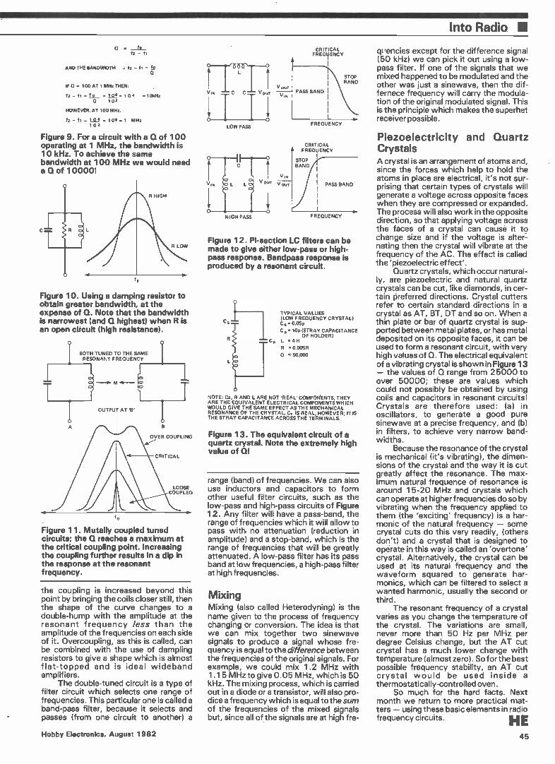
Into Radio II
O lo f2 —
AND THE BANDWIDTH = 12 — fl =
IF 0 = 100 AT 1 MHz THEN:
f2 — =fo =10 6 .1 02 =10kHz 10 2
HOWEVER. AT 100 MHz.
f2 fl — 10 8 — 106=1 MHz 1 0 2
Figure 9. For a circuit with a Q of 100 operating at 1 MHz, the bandwidth is 10 kHz. To achieve the same bandwidth at 100 MHz we would need a Q of 100001
R LOW
Figure 10. Using a damping resistor to obtain greater bandwidth, at the expense of G. Note that the bandwidth is narrowest (and Q highest) when R is an open circuit (high resistance).
BOTH TUNED TO THE SAME RESONANT FREQUENCY
o
OUTPUT AT 'B'
OVER COUPLING
CRITICAL
LOOSE COUPLED
Figure 11. Mutally coupled tuned circuits; the la reaches a maximum at the critical coupling point. Increasing the coupling further results in a dip in the response at the resonant frequency.
the coupling is increased beyond this point by bringing the coils closer still, then the shape of the curve changes to a double-hump with the amplitude at the resonant frequency less than the amplitude of the frequencies on each side of it. Overcoupling, as this is called, can be combined with the use of dampling resistors to give a shape which is almost flat-topped and is ideal wideband amplifiers.
The double-tuned circuit is a type of filter circuit which selects one range of frequencies. This particular one is called a band-pass filter, because it selects and passes (from one circuit to another) a
LOW PASS
HIGH PASS
CRITICAL FREQUENCY
PASS BAND
FREQUENCY
CRITICAL FREQUENCY
STOP BAND
PASS BAND
FREQUENCY
Figure 12. Pi-section LC filters can be made to give either low-pass or high-pass response. Bandpass response is produced by a resonant circuit.
TYPICAL VALUES (LOW FREQUENCY CRYSTAL) C.= 0.05p
C,. 10p (STRAY CAPACITANCE OF HOLDER)
Cp L = 4 H
R = 0.005R
. 50,000
NOTE: Cs, R AND L ARE NOT REAL' COMPOKENTS, THEY ARE THE EQUIVALENT ELECTRICAL COMPONENTS WHICH WOULD GIVE THE SAME EFFECT AS THE MECHANICAL RESONANCE OF THE CRYSTAL. Cp IS REAL, HOWEVER; IT IS THE STRAY CAPACITANCE ACROSS THE TERMINALS,
Figure 13. The equivalent circuit of a quartz crystal. Note the extremely high value of QI
range (band) of frequencies. We can also use inductors and capacitors to form other useful filter circuits, such as the low-pass and high-pass circuits of Figure 12. Any filter will have a pass-band, the range of frequencies which it will allow to pass with. no attenuation (reduction in amplitude) and a stop-band, which is the range of frequencies that will be greatly attenuated. A low-pass filter has its pass band at low frequencies, a high-pass filter at high frequencies.
Mixing Mixing (also called Heterodyning) is the name given to the process of frequency changing or conversion. The idea is that we can mix together two sinewave signals to produce a signal whose fre-quency is equal to the difference between the frequencies of the original signals. For example, we could mix 1.2 MHz with 1.15 MHz to give 0.05 MHz, which is 50 kHz. The mixing process, which is carried out in a diode or a transistor, will also pro-dice a frequency which is equal to the sum of the frequencies of the mixed signals but, since all of the signals are at high fre-
quencies except for the difference signal (50 kHz) we can pick it out using a low-pass filter. If one of the signals that we mixed happened to be modulated and the other was just a sinewave, then the dif-fernece frequency will carry the modula-tion of the original modulated signal. This is the principle which makes the superhet receiver possible.
Piezoelectricity and Quartz Crystals A crystal is an arrangement of atoms and, since the forces which help to hold the atoms in place are electrical, it's not sur-prising that certain types of crystals will generate a voltage across opposite faces when they are compressed or expanded. The process will also work in the opposite direction, so that applying voltage across the faces of a crystal can cause it to change size and if the voltage is alter-nating then the crystal will vibrate at the frequency of the AC. The effect is called the 'piezoelectric effect'.
Quartz crystals, which occur natural-ly, are piezoelectric and natural quartz crystals can be cut, like diamonds, in cer-tain preferred directions. Crystal cutters refer to certain standard directions in a crystal as AT, BT, DT and so on. When a thin plate or bar of quartz crystal is sup-ported between metal plates, or has metal deposited on its opposite faces, it can be used to form a resonant circuit, with very high values of Q. The electrical equivalent of a vibrating crystal is shown in Figure 13 — the values of Q range from 25000 to over 50000; these are values which could not possibly be obtained by using coils and capacitors in resonant circuits! Crystals are therefore used: (a) in oscillators, to generate a good pure sinewave at a precise frequency, and (b) in filters, to achieve very narrow band-widths.
Because the resonance of the crystal is mechanical (it's vibrating), the dimen-sions of the crystal and the way it is cut greatly affect the resonance. The max-imum natural frequence of resonance is around 15-20 MHz and crystals which can operate at higher frequencies do so by vibrating when the frequency applied to them (the 'exciting' frequency) is a har-monic of the natural frequency — some crystal cuts do this very readily, (others don't) and a crystal that is designed to operate in this way is called an 'overtone' crystal. Alternatively, the crystal can be used at its natural frequency and the waveform squared to generate har-monics, which can be filtered to select a wanted harmonic, usually the second or third.
The resonant frequency of a crystal varies as you change the temperature of the crystal. The variations are small, never more than 50 Hz per MHz per degree Celsius change, but the AT cut crystal has a much lower change with temperature (almost zero). So for the best possible frequency stability, an AT cut crystal would be used inside a thermostatically-controlled oven.
So much for the hard facts. Next month we return to more practical mat-ters — using these basic elements in radio frequency circuits. HE
Hobby Electronics, August 1982 45
THE HE BOOKSHELF is the easiest way to build up your library of electronics books. Order today to have these top titles delivered
DIRECT TO YOUR DOOR.
62 PROJECTS USING IC741 £1.25 More than 50 ways of using the ubiquitous IC741.
50 WET) FIELD EFFECT TRANSISTOR PROJECTS £1.75 Contains a wide range of projects, all based on Field Effect Transistors.
COUNTER DRIVER AND NUMERAL DISPLAY £PROJECTS 1.75
Features many varied projects using numeral displays. counter and driver ICs.
RADIO CIRCUITS USING IC's £.35 All you need to know about using IC's for AM or FM reception.
IC LM3900 PROJECTS £1.35 Provides the ground work for simple and more advanced uses of IC LM3900.
PRACTICAL CONSTRUCTION OF PRE-AMPS, TONE CONTROLS, FILTERS AND ATTENUATORS £1.45 Contains practic& designs for use with home constructed equipment or commerci al modules.
BEGINNERS GUIDE
TO MICROPROCESSORS AND COMPUTING £1.75 Basic introduction to binary arithmetic, micro-Processor operation and macin language . programming.
IC 555 PROJECTS £1.95 The 555 timer users 'Bible't
CHOOSING AND USING YOUR HI-FI£ 1.65
Concise information for all hi-fi enthusiasts.
ELECTRONIC GAMES
£1.75 Amusing electronic games which can easily and inexpensively be constructed by the enthusiast.
ELECTRONIC HOUSEHOLD PROJECTS £1.75 Packed with circuits for projects that can be used in or around the home.
A MICROPROCESSOR PRIMER £1.75 A painless approach to understanding computers and computing.
REMOTE CONTROL PROJECTS £1.96 Practical information about many applications of remote control.
ELECTRONIC MUSIC PROJECTS £1.75 Many practical circuits for less complex items of electronic music equipment.
ELECTRONIC TEST EQUIPMENT CONSTRUCTION £1.75 How to build and use a wide range of test equipment for the hobbyist.
POWER SUPPLY PROJECTS £1.75 Packed with circuits for building various kinds of power supply.
SINGLE IC PROJECTS £1.50 Easy to construct projects based around a single IC.
PRACTICAL COMPUTER EXPERIMENTS £1 .75 Build and examine a number of basic computer circuit elements.
Electronic Projects Using Solar Celle
How to te" Op AM,.
enred Guide
ELECTRONIC PROJECTS USING SOLAR CELLS £1.95 A range of practical applications using silicon solar cells.
VMOS PROJECTS £1.95 Contains a number of varied and interesting projects using VMOS power FETs.
DIGITAL IC PROJECTS £1.95 Simple and advanced projects based on digital ICs.
INTERNA-DOL TRANSISTOR EQUIVALENTS GUIDE £2.95 Find possible equivalents for a popular user- . orientated selection of modern transistors.
HOW TO USE OP AMPS £2.25 All you need to know about Op-Amps, a source book of circuits and design calculations.
AUDIO PROJECTS £1.95 Clear information on how to build pre-amps. mixers, power amps, tone controls etc.
To receive your books you have only to fill in the form below and send it, together with your payment, to the address stated. Please allow up to 21 days for delivery. This offer applies only within the U.K. Prices may be subject to change without notice.
SEND TO: HE BOOKSHELF, 513 London Road, Thornton Heath, Surrey CR4 6AR.
I am enclosing my Cheque/Postal Order/ Books Required for: (delete as necessary)
(Made payable to A.S.P. Ltd)
OR Debit my Access/Barclaycard (delete as necessary)
Please use use BLOCK CAPITALS and include post codes.
Name (Mr/Mrs/Miss) (delete accordingly)
Address
Signature Date
Price
Add 75p pEtp
Total Payment
0.75
46 Hobby Electronics, August 1982
METERTECH MODEL 31
31- DIGIT LCD
MULTIMETER
* 12.5nynDISPLAY * 10MM INPUT IMPEDANCE * AUTOMATIC ZERO ADJUSTMENT * AUTOMATIC POLARITY SWITCHING * OVER RANGE INDICATION * FUSE CIRCUIT PROTECTION * BATTERY LOW INDICATION * LIFE MEASUREMENT * DOPDE/CONTINUITY CHECK
* ACCESSORIES INCLUDED TEST LEADS, BATTERIES Er INSTRUCTION MANUAL
* SIZE 180 90 x 35mrn * WEIGHT 300g * SAMPLING TIME 0.25 sec
DC VOLTAGE (5 ranges) 0.8% accuracy 100 1.4,V to 1000V AC VOLTAGE (2 ranges) 1.2% accuracy 100mV to 1000V DC CURRENT (5 ranges) 1.2% accuracy 100nA to 10A RESISTANCE (4 ranges) 1% accuracy 10 to 21\40
Price £49.95 includes VAT, postage Et packing optional accessories.
Deluxe protective case £6.90 including VAT p&p 10AC current shunt £6.90 including VAT p&p
62 CURTIS ROAD, WHITTON, HOUNSLOW, MIDDLESEX TW4 5PT
TEL (01) 894 2723
Goodmans Fane Richard Allan Celestion Altai Multimeters Et
Accessories UK P/P 55p or £1.00 for two KRT 100 12 range pocket 1K / volt £4.95 NH55 10 range pocket 2K/volt £5.95 NH56R 22 range pocket 20K/volt £10.95 YW360TR 19 range plus hfe test 20K/volt £14.95 5T303TR-21 range plus hfe test 20K /volt £17.98 TMK500 23 range plus 12 adc plus cont. buzzer £23.95
MBE CEBINY
IE 25W to 50W
10. 25W 10 100W
12- 30W to 200W
I5'. 100W to 250W
ir mow. mow
CROSSOVERS 2 way
3 way
4 way
100W
100W
80W
POLO ELECTRIC TWEETERS
PIE20 NORN TWEETERS Up to 100 we. ea. No x• over repotted Flu. Monts.
ten. Need Noms In srodt now Large ranee of speakers. peter .Ness ...ens memo.... In. horn epuoprneng Iloà, ewe/. Feor Send.
«IL» born Nrn Ede Clem. rssAs Anelopte E.s. Cheerer
8 ohm
8 ohm
8 ohm
Power Amplifier Modules wow to 200W Stockists of leading makes of Disco Units
8i Lighting Equipment.
CITRONIC, FAL, TK, ICE,
OPTIKINETICS, PLUTO.
SEND LARGE SAE FOR LIST ALLOW 10 DAYS FOR DELIVERY
.40 Of AT «15%. Marl Orden komo.
USICRAFT (litile 303 EDGWARE ROAD.
LONDON W 2 ENGLAND ELEPRONE• 01 402 9729 01 402 2899
It's easy to complain
about advertisements.
The Advertising Standards Authority. . If an advertisement is vvrong.we're here to put it right.
ASA Ltd., Brook Hnirse,Torrington Place, London WC1E 7HN.
HOME LIGHTING KITS These kits contain all necessei y components and full Instructions & are designed to replace standard wall switch and control up to 300w. of lighting.
e..
TDR3OOK Remote Control £14.30 Dimmer
MKS Transmitter for above
TD3OOK Touchdimmer f 7.00
"Enr nxoitZeiingl kit for £ 2.00
LD3OOK reentrolled £ 3.50
3-NOTE DOOR CHIME JD Based on the SAB0600 IC the kit is suppled with all components, including loudspeaker, printed circuit board, a pre-drillid box 195 x 71 x 35mm) and full instruc-tions. Requires only a PP3 9V battery and push-switch to complete. AN IDEAL PROJECT FOR BEGINNERS. Order as XK102. £5.00
DISCO LIGHTING KITS DL 100040 This value-for-money kit features a bi-directional sequence, speed of sequence and frequency of direction change, being variable by means of potentiometers and incorporates a master
dimming control. Only £14.60 DLZ100K A lower cost version of the above, featuring undirectional channel sequence with speed variable by means of a pre-set pot. Outputs switched only at mains zero crossing points to reduce radio interference to a minimum.
Optional opto input DLA1 Only £8.00 Allowing audio ("beat") up
-light response.
feete‘ •JÑ;':
DISPLAYS
COX87A 0.5" dual, c.a. Red £1.80 DL340M 0.1" 4-Digit c.c. £4.50 END 500 0.5" c.c. 85p END 507 0.5" c.a. 85p
MP463 4-digit 0.5" multiplexed c.c. LED Clock Display £2.20
Liquid Crystal Display, 31/2 digit, 0.5" digits, d.I.I. package £6.00
KL901 9-digit, 7-sag. 0.1" c.c. LED calculator display with red filter 55p
TRIACS 400v Plastic case (texas) 3ATIC20613 49p
BATIC226D 58p 12ATIC236D 85p 16ATIC 2460 98p 25ATIC263D 190p
BA with trigger 04006LT 85p BA isolated tab TXAL2288 65p Disc 18p Opto isolated triac MOC3020 0.1A/400v 110p
LCD 31/2 DIGIT MULTIMETER 16 ranges including DC and AC voltage, DC current and resistance+NPN & PNP transistor gain and diode check. Input impedance 10M. Size 155x138s31mm. Requires PP3 9v battery. ONLY £31.00
TRANSISTORS
BC108.... 8p BC109. 15p BC182 8p 8C182L. 8p BC212.... 9p BC212... 9p BC327.. 12p BC337.. 13p
BEY50.. 20p TIP3IA. 40p TIP32A 40p 2N3055 45p 2N3442 115m 140v
2N3819 Nee let 20p
VMOS POWER FETS
VN1OKM 0.5A/60v 52p VN66AF 2A/60v 88p
REMOTE CONTROL Published remote control iL. ,j;w, syslens tend to be pude complex requiring difficult-to-get components and a well-equipped lab to ge them to work. If this has put you off making your own system we have just the kits for you. Using infra-red, our KITS range from simple on/off controllers to coded transmitter/receiver. with 16 on/off outputs or three analogue outputs for contr. offing, e.g., Tv or Hi-Fi systems. The kits are easy to build and simple to set up-end they are extremely versatile, controlling anything from garage doors to MOT lighting just by adding the required output circuits. i.e. relays, trisco. etc. If you can design your own system we stock a wide range of remote con-trol components et very competitive prices. We have compiled a booklet on remote control, containing circuits, hints, data sheets and details of our remote control kits and components. So don't control yourself-SEND US 30p and • stamped addressed
envelope for your copy TODAY!
24 HOUR CLOCK/APPLIANCE TIMER KIT
Switches any appliance up to 1kW on and off at preset times once per day. Kit contains: AY-5-1230 IC, 0.5" LED display, mains supply, display drivers, switches, LEDs, triacs, PCBs and full instructions.
CT1000K Basic Kit f14.90 CT1000K with white box (56/131 x 71mm) £17.40 (Ready Built) £22.50
SHORT FORM CATALOGUE - send SAE Ç.iikt,3--• (6 x 9). We also stock Vero, Books,
Resistors, Capacitors, Semi-Conductors etc.
Add 55p postage & packing +15% VAT to total. Overseas Customers;
Add £1.751Europe.E4.50 (elsewherel for p&p. Send S.A.E. for further STOCK DETAILS. Goods by return subject to availability.
Sam to 5pm (Mon to Fril 10am to apm ISat) OPEN
FAST SERVICE TOP QUALITY- LOW LOW PRICES EXCL.. VAT UDEES ar ELECTton RONICS HE 11 London W7 3SJ
No circuit is complete without a call to -
..te.ICARD Ir31
CtOcx tOwERE:1
UXBRIDGE ROAD
CAR PARK
1, o
î
TEL: 01-567 8910 ORDERS 01-579 9794 ENQUIRIES 01-579 2842 TECHNICAL AFTER 3PN1
DVM/ULTRA SENSITIVE THERMOMETER KIT
This new design is based on the ICL7126 la lower power version of the ICL7106 chip) and a 31/2 digit liquid crystal display. This kit will form the basis of a digital multi meter (only a few additional resis ors and switches are required-details suppl cd), or a sensitive digital thermometer (-60`C , to +150>C1 reading to 0.1*C. The basic kit has a sensitivity of 200mV for a full scale reading, automatic polarity indication and an ultra low power requirement-giving a 2 year typical battery life from a standard 9V PP3 when used 8 hours a day, 7 days a week.
EOM
Price £15.50
Hobby Electronics, August 1982 47
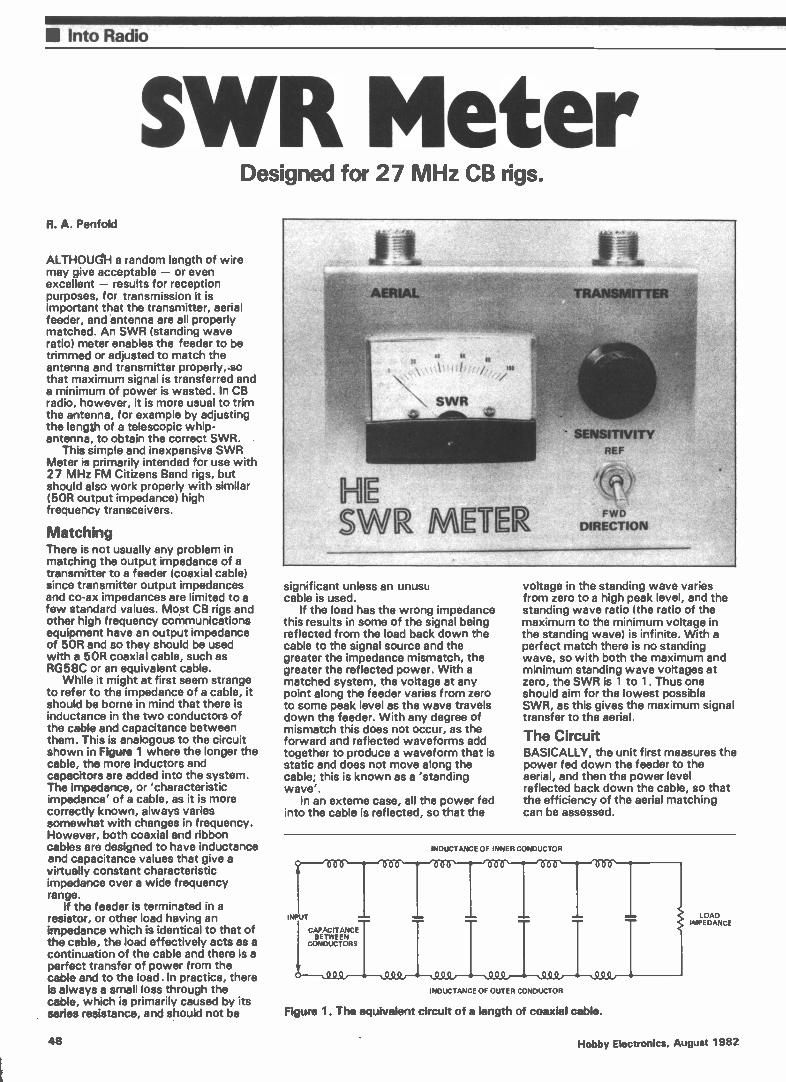
• Into Radio
SIP/11 Meter Designed for 27 MHz CB rigs.
R. A. Penfold
ALTHOUGH a random length of wire may give acceptable — or even excellent — results for reception purposes, for transmission it is important that the transmitter, aerial feeder, and antenna are all properly matched. An SWR (standing wave ratio) meter enables the feeder to be trimmed or adjusted to match the antenna and transmitter properly,so that maximum signal is transferred and a minimum of power is wasted. In CB radio, however, it is more usual to trim the antenna, for example by adjusting the length of a telescopic whip-antenna, to obtain the correct SWR.
This simple and inexpensive SWR Meter is primarily intended for use with 27 MHz FM Citizens Band rigs, but should also work properly with similar (50R output impedance) high frequency transceivers.
Matching There is not usually any problem in matching the output impedance of a transmitter to a feeder (coaxial cable) since transmitter output impedances and co-ax impedances are limited to a few standard values. Most CB rigs and other high frequency communications equipment have an output impedance of 5OR and so they should be used with a 5OR coaxial cable, such as RG58C or an equivalent cable.
While it might at first seem strange to refer to the impedance of a cable, it should be borne in mind that there is inductance in the two conductors of the cable and capacitance between them. This is analogous to the circuit shown in Figure 1 where the longer the cable, the more inductors and capacitors are added into the system. The impedance, or 'characteristic impedance' of a cable, as it is more correctly known, always varies somewhat with changes in frequency. However, both coaxial and ribbon cables are designed to have inductance and capacitance values that give a virtually constant characteristic impedance over a wide frequency range.
If the feeder is terminated in a resistor, or other load having an impedance which is identical to that of the cable, the load effectively acts as a continuation of the cable and there is a perfect transfer of power from the cable and to the load. In practice, there is always a small loss through the cable, which is primarily caused by its series resistance, and should not be
significant unless an unusu cable is used.
If the load has the wrong impedance this results in some of the signal being reflected from the load back down the cable to the signal source and the greater the impedance mismatch, the greater the reflected power. With a matched system, the voltage at any point along the feeder varies from zero to some peak level as the wave travels down the feeder. With any degree of mismatch this does not occur, as the forward and reflected waveforms add together to produce a waveform that is static and does not move along the cable; this is known as a 'standing wave'.
In an externe case, all the power fed into the cable is reflected, so that the
voltage in the standing wave varies from zero to a high peak level, and the standing wave ratio (the ratio of the maximum to the minimum voltage in the standing wave) is infinite. With a perfect match there is no standing wave, so with both the maximum and minimum standing wave voltages at zero, the SWR is 1 to 1. Thus one should aim for the lowest possible SWR, as this gives the maximum signal transfer to the aerial.
The Circuit BASICALLY, the unit first measures the power fed down the feeder to the aerial, and then the power level reflected back down the cable, so that the efficiency of the aerial matching can be assessed.
INDUCTANCE OF INNER CONDUCTOR
INPUT
ICAPACITANCE BETWEEN CONDUCTORS
INDUCTANCE OF OUTER CONDUCTOR
MM. M•••
Figure 1. The equivalent circuit of a length of coaxial cable.
LOAD IMPEDANCE
48 Hobby Electronics. August 1982

Into Radio•
TRANSMITTER o
(a)
TRANSMITTER o
Ski TRANS
PICK-UP LINE
( b
PICK-UP LINE
AERIAL o
Figure 2(a). Forward power is measured by detecting the voltage induced at the aerial end of the pick-up wire. A simple meter is adequate for this.
Figure 2(b). Reference power, from the transmitter, is measured by the reverse procedure; the aerial end of the pick-up is earthed via a resistor and the voltage induced at the transmitter end is detected and measured.
REV SWia
R1 15OR
NOTE: D1 IS 0A90
FWD
D1
SW1b 81114
Cl 3n3
RV1 101,
Figure 3. The complete circuit is simply a combination of the two circuits of Figure 2.
SK2 AERIAL
To measure forward power, the input end of the pick-up line is connected to earth via a resistor and the signal from the other end of the line is fed to an RF detector circuit which produces a DC output signal proportional to the RF signal level. This voltage is fed to a meter via a potentiometer, and the latter is adjusted to give a full scale reading on the meter. This arrangement is illustrated in Figure 2(a).
Basically the same set-up is used to measure the reverse power, as can be seen from Figure 2(b). The only change here is that the aerial end of the pick-up line now connects to the resistor and the input end connects to the RF detector. So, by simply transposing the connections to the pick-up line, the circuit indicates the power reflected down the feeder from the antenna. Thus a reading of 100. (full scale), at this stage, would mean that all the
transmitter power was being reflected and the SWR would be infinite. The ideal case would be a reading of '0' — no reflected power — indicating an SWR of 1:1.
The SWR meter uses a conventional bridge circuit; the full circuit diagram appears in Figure 3. The pick-up line is simply a piece of 5OR coaxial cable, to which an extra wire is added between the inner conducor and the outer braiding. The detector circuit is a straight-forward half wave type, which uses D1, Cl and RV1, with the latter enabling a proportion of the resultant DC voltage to be fed to meter M1. Si is used to switch the pick-up line to give 'forward' or 'reverse' power reading, as desired. R1 is part of the bridge circuit and it is important to use the specified value here, if accurate results are to be obtained.
Strickly speaking, the circuit is measuring forward and reverse
voltages, rather than power, so it is really a VSWR (voltage standing wave ratio) meter. However, units of this type are usually — and more accurately — just referred to as SWR meters because the ratio of forward to reverse power, current or voltage, will be the same in each case.
Construction There are few components in the circuit and the most practical method of construction is to hard-wire the unit. Use a metal case for this project — one having dimensions of about 193 x 102 x 38 mm is ample to accommodate all the components.
The two sockets, the two controls and the meter are fitted as shown in the photograph. It is strongly recommended that the general layout used on the prototype should be copied fairly closely, as it might otherwise be awkward to wire up the unit.
If the meter is a standard 60 x 45 mm plastic front type, it will require a main 38 mm diameter cutout and four 3.2 mm diameter mounting holes. The 38 mm hole can be cut using a fretsaw or a miniature round file; a third alternative is to drill a ring of small, closely spaced h,oles, and then punch out the metal within the ring. With the last method it will be necessary to use a large half-round file to suitably enlarge the cutout and to produce a neat finish.
It is not necessary to use an expensive meter in the circuit; there are inexpensive types of around 100 uA sensitivity which will work perfectly well! Most ready-built SWR meters seem to use inexpensive meter movements, incidentally. It may be necessary to vary the mounting of the meter to suit the particular component employed; many inexpensive meters do not have provision for screw fixing and it will then be necessary to glue the component in position.
All the wiring of the unit is shown in Figure 4 and this is mostly straight-forward. D1 is a germanium device and care should be taken not to overheat this component when wiring up the unit.
The pick-up line is make from a piece of RG58C or similar 5OR coaxial cable, about 300 mm long. This is the type of cable that is usually used as the aerial feeder for CB rigs and it will probably be possible to trim a suitable piece from the aerial lead. Do not use a heavy-duty 5OR coaxial cable, such as UR67, as this would probably be too thick and inflexible, and consequently unusable.
Step one in the construction of the pick-up line is to remove the plastic sheath from the cable; this is done by using a modelling knife to cut through the sheath along the full length of the cable. However, do be careful not to damage the copper braiding beneath the plastic sheath.
Next the braiding is bunched up slightly by pushing both ends of it towards the middle. The point of this is that it makes the outer braiding rather
Hobby Electronics, August 1982 49
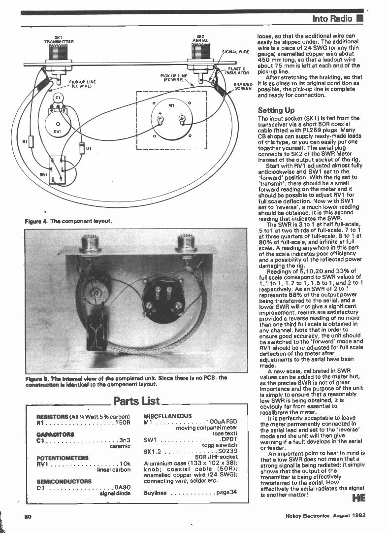
Into Radio la
SKI TRANSMITTER
Figure 4. The component layout.
Figure 6. The Internal view of the completed unit. Since there is no PCB, the constnictlon is identical to the component layout.
Parts List RESISTORS (All 14 Watt 5% carbon) 131 15OR
CAPACITORS C I 3n3
ceramic
POTENTIOMETERS RV 1 10k
linear carbon
SEMICONDUCTORS D1 0A90
signal diode
SK2 AERIAL
SIGNAL WIRE
PLASTIC INSULATOR
BRAIDED SCREEN
MISCELLANEOUS M1 100uA FSD
moving coil panel meter (see text)
SW1 DPDT toggle switch
SK1,2 S0239 5OR UHF socket
Aluminium case (133 x 102 x 38); knob; coaxial cable (50R); enamelled copper wire (24 SWG); connecting wire, solder etc.
Buylines page 34
loose, so that the additional wire can easily be slipped under. The additional wire is a piece of 24 SWG (or any thin gauge) enamelled copper wire about 450 mm long, so that a leadout wire about 75 mm is left at each end of the pick-up line.
After stretching the braiding, so that it is as close to its original condition as possible, the pick-up line is complete and ready for connection.
Setting Up The input socket (SKI) is fed from the transceiver via a short 5OR coaxial cable fitted with PL259 plugs. Many CB shops can supply ready-made leads of this type, or you can easily put one together yourself. The aerial plug connects to SK2 of the SWR Meter instead of the output socket of therig.
Start with RV1 adjusted almost fully anticlockwise and SW1 set to the 'forward' position. With the rig set to 'transmit', there should be a small forward reading on the meter and it should be possible to adjust RV1 for full scale deflection. Now with SW1 set to 'reverse', a much lower reading should be obtained. It is this second reading that indicates the SWR.
The SWR is 3 to 1 at half full-scale, 5 toi at two thirds of full-scale, 7 to 1 at three quarters of full-scale, 9 to 1 at 80% of full-stale, and infinite at full-scale. A reading anywhere in this part of the scale indicates poor efficiency and a possibility of the reflected power damaging the rig.
Readings of 5,10,20 and 33% of full scale correspond to SWR values of 1.1 to 1, 1.2 to 1, 1.5 to 1' and 2 to 1 respectively. As an SWR of 2 to 1 represents 88% of the output power being transferred to the aerial, and a lower SWR will not give a significant improvement, results are satisfactory provided a reverse reading of no more than one third full scale is obtained in any channel. Note that in order to ensure good accuracy, the unit should be switched to the 'forward' mode and RV1 should be re-adjusted for full scale deflection of the meter after adjustments to the aerial have been made. A new scale, calibrated in SWR
values can be added to the meter but, as the precise SWR is not of great importance and the purpose of the unit is simply to ensure that a reasonably low SWR is being obtained, it is obviouly far from essential to recalibrate the meter.
It is perfectly acceptable to leave the meter permanently connected in the aerial lead and set to the 'reverse' mode and the unit will then give warning if a fault develops in the aerial or feeder.
An important point to bear in mind is that a low SWR does not mean that a strong signal is being radiated; it simply shows that the output of the transmitter is being effectively transferred to the aerial. How effectively the aerial radiates the signal is another matter! HE
50 Hobby Electronics, August 1982
MASTER ELECTRONICS NOW! The PRACTICAL way!
This new style course will enable anyone to have a real understanding of electronics by a modern, practical and visual method. No previous knowledge is required, no maths, and an absolute minimum of theory. You learn the practical way in easy
steps mastering all the essentials of your hobby or to start or further a career in electronics or as a self-employed servicing engineer.
All the training can be carried out in the comfort of your own home and at your own pace. A tutor is available to whom you can write personally at any time, for advice or help during your work. A Certificate is given at the end of every course.
You will do the following: •Build a modern oscilloscope •Recognise and handle current electronic components
•Read,draw and understand circuit diagrams •Carry out 40 experiments on basic
electronic circuits used in modern equipment
•Build and use digital electronic circuits and current solid state 'chips'
•Learn how to test and service every type of electronic device used in industry and commerce today. Servicing of radio, T.V., Hi -Fi and microprocessor/computer equipment.
NewcJob?NewCareeeNewHobby?GetintoElectronicsNow! I FREE! • COLOUR BROCHURE
Please send your brochure without any obligation to I am interested in NAME
ADDRESS
BLOCK CAPS PLEASE
COURSE IN E LECI RON ICS as descnbed above
RADIO AMATEUR LICENCE
MICROPROCESSORS
LOGIC COURSE
HE/8/821
OTHER SUBJECTS
IjkasliNationalRadideElectronics School RearringIBerks.RG17BR
ITKNoRos. ELECTRONIC COMPONENTS AND
TEST EQUIPMENT 35. HIGH BRIDGE, NEWCASTLE
UPON PINE NE11EW TEL: 0632 326729
SUM OSCILLOSCOPES- 5 mV/div sensitivity. Choice of Band-width 10, MHz, 15 MHz, 20 MHz. 1S/div-100n S/div. Calibrated timebase. Solid trigger with bright line auto, normal and TV. XV facility. Z modulation. Calibration output. Bright and clear display. Portability. •Model DT410-10 MHz £205.85. Model DT4I5-1 5 MHz E217.35. S Model DT420 20 MHz f228.85. Send S.A.E. FOR FULL spec.
THANDAR POM35 3Y2 DIGIT L.E.D. DIGITAL POCKET MULTI' METER.. OC volts (4 ranges) ImV to 1000V. • AC volts IV to 500V • DC current (6 ranges) Ink to 200MA - Resistance (5 ranges) 1S2 to 20 meg.U. £39.95. • AC adaptor £5.95. • carrying case £3.65 • M711604 Battery £1.57.
THANDAR TM3.54 31/2 DIGIT LCD DIGITAL POCKET MULTIMETER . DE volts 1 mV to 1000V • AC volts IV to 500 V AC rms. DC current 1,va to 1A • Resistance 1i2 to 2 ea U • Diode check•Basic accuracy 1-(0.15% of reading + I digit) .Battery life typically 2000 hrs • leads inc. • £45.94 • 40KV Probe £34.95 •Universal test lead set £12.95.
THANOAR TM352 3% DIGIT LCD DIGITAL POCKET MULTIMETER • DC volts: 100/JV to 1000V • AC volts: IV to 1000V • OC current: 100 nA to 10A • Resistance 1iito 2 M lialliode check • hFE measurement • Audible continuity check • Basic accuracy I (0.5% of reading + 1 digit • Battery life 150 hrs + • £57.44 inc. leads • Battery • Universal test lead set £12.95 • 40 KV probe £34.95
THANDAR SC110 SINGLE TRACE LOW POWDER 2" OSCILLOSCOPE • Bandwidth OC to 10 Mhz • Sensitivity: I0mV / div to 50 V /div.• Sweep speeds: 0.1A secs / div to 0.5 secs/div.
- Power requirements 4-10 V OC 4 'C' cells : Size & weight • lb , 255.150.40mm: 800gms £159.85 a truly portable and superb
instrument • Carrying case £8.80 • AC Adaptor £5.69 • Nicad Batt. pack £8.63..1 probe £9.78..10 probe £11.50 Complete range of Thandar instruments available from stock SAE. for CAT. & Prices- VISA
Ilse-ems
1 G.S.C. SOLDERLESS BREADBOARDS • Accepts all components with leads up to .033" • Replaceable nickel-silver spring clip contacts. • Combines bus strip with board • Unlimited expansion • .3" and .8" centre chancis • Three free experimental circuits with every purchase
Centre Strip Strip Tie Term t.c. Channel Length Width PointsIClips Cpty. Price
EXP-600 15mm 152mm 61mm 550 110 328pin £7.25 III EXP-300 13rnm 152mm 53mm 550 110 614pin £6.62
al EXP-4B nia 152 mm 25mm 160 32 nia £2.65 EXP-650 15mm 91mm 61mm 270 54 140pin £4.14 EXP-350 8mm 91mm 53mm 270 54 314pin £3 62 EXP-325 trim 48mm 53mm 130 26 ‘22pin £1.84
Pleut send S.A.E. for catalogue listing complete range of G.S.C. Instruments and Boards.
o- SABTRONICS LCD MULTIMETER MODEL 2033. • DC volts 100 uV-1000V Accuracy + .5% *AC volts 100A-1000 V Accuracy 1% • OC current 10,v(A-2A Accuracy ". 1% • AC current lOniA-20 Accuracy + I% • Resistance 1(3-20 kl T) Accuracy t I% • £42.27. • Please send 30p for full Sabtronic catalogue and price list
TMK 500 MULTIMETER • 30 km. • AC volts 2.5 10 25 100 250 500 1000V • OC volts 0.25 12.5 10 25 10 25 100 250 1000 • OC current 50,ea 51AA 50MA 12 amp • Resistance 0-6K 60K, 60 meg. • Decibels -20 to + 56 d/b • Buzzer continuity test • Size 160.110 15 • Batteries and leads inc. £26.95
YN360 TR MULTIMETER • AC volts 10 50 250 1000 • OC volts 0.1, 0.5, 2.5, 10v 150v 250v, 1000v. • OC current 50/ua 2.5 MA, 2511A, 250 MA • Resistance 0-2K 20K 2M 1!, 20 MX), • Transistor check • 11/3 -10db -+ 22dh £15.95
OESOLDERING TOOL £6.45
SCHOOLS, COLLEGES, UNIVERSITIES SUPPLIED PHONE OR SENO YOUR ACCESS OR BARCLAYCARD NUMBER
PRICES INCLUDE VAT PLEASE ADD 75p POSTAGE TO ORDERS UNDER £10.00
Hobby Electronics, August 1982 51
Al° 1 As a KIT or
READY BUILT
TOTAL ENERGY DISCHARGE electronic ignition gives all the well known advantages of the best capacitive discharge systems.
PEAK PERFORMANCE - higher output voltage under all conditions.
IMPROVED ECONOMY no loss of ignition performance between services.
FIRES FOULED SPARK PLUGS no other system can better the capacitive discharge system's ability to fire fouled plugs.
ACCURATE TIMING prevents contact wear and arcing by reducing load to a few volts and a fraction of an amp.
SMOOTH PERFORMANCE - immune to contact bounce and similar effects which can cause loss of power and roughness.
PLUS SUPER POWER SPARK 3% times the energy of ordinary
capacitive systems - 3`h times the power of inductive systems.
OPTIMUM SPARK DURATION 3 times the duration of ordinary capacitive systems - essential for use on modern cars with weak fuel mixtures.
BETTER STARTING full spark power even with low battery.
CORRECT SPARK POLARITY unlike most ordinary C.D. systems the correct output polarity is maintained to avoid increased stress on the H.T. system and operate all voltage triggered tachometers.
L.E.D. STATIC TIMING LIGHT for accurate setting of the engine's most important adjustment.
LOW RADIO INTERFERENCE fully suppressed supply and absence of inverter 'spikes on the output reduces interference to a minimal level.
DESIGNED IN RELIABILITY an inherently more reliable circuit combined with top quality components - plus the 'ultimate insurance' of a changeover switch to revert instantly back to standard ignition.
IN KIT FORM it provides a top performance electronic ignition system at less than half the price of competing ready-built systems. The kit includes everything needed, even a length of solder and a tiny tube of heatsink compound. Detailed easy-to-follovv instructions, complete with circuit diagram, are provided - all you need is a small soldering iron and a few basic tools.
AS REVIEWED IN
ELECTRONICS TODAY INTERNATIONAL June'81 Issue and EVERYDAY ELECTRONICS December'81 Issue
FITS ALL NEGATIVE EARTH VEHICLES,
6 or 12 volt , with or without ballast
OPERATES ALL VOLTAGE IMPULSE TACHOMETERS Some older current impulse types (Smiths pre '74) require an adaptor - PRICE £2.95
STANDARD CAR KIT £14.85 Assembled and Tested £24.95
TWIN OUTPUT KIT £22.95 For MOTOR CYCLES and CARS with twin ignition systems
Assembled and Tested £34.70
ELECTRONIZE DESIGN Dept. E. Magnus Road, Wilnecote,
Tamworth, B77 5BY
14111e Phone(0827)281000
PLUS £1.00 U.K. P. & P.
Prices Include VAT.
VISA
.NAMAL ASSOCIATES 25:Gwydir Street, CAMBRIDGE Tel: .355 404 Telem_817445
MFM)RY EXPANSION SPECIAL OFFER FOP URI Edge conector 23 Way
ASSEMBLED £75:00 For ZX81 . £2.25
KIT ' £18,95 ICL 7660 £1.60 with full Assembley 4116 - 200ns £0.65 instructions 6845 £5.25
74 IS ser;
00 :10 37 .15 113 ,21 175 .45 4099 :50 07 .17 38 .15 127 .40 193 .45 4503 .45 03 .12 40 .12 123 :36 196 .57 4517 .55 04 .-12 42 .33 124 .90 197 .60 4518 .40 08 18 48 .59 125 .24 740 .87 CIIMP;I.C'n 09 .20 49 :59 126 .25 242 .78 2114-IP.R0 10 .70 51 :14 132 :44 244 .60 20Ons
11 .20 54 .14 133 .25 245 .88 2532 3.75 12 .20 55 .12 138 .32 247 .60 2716 1.95 13 .20 73 .21 139 .32 248 .60 2732 3.75 14 ,38 74 :16 145 .72 751 .40 4116-2 0.4 15 .12 75 .24 148 _.85 257 .43 4816 3.99 16 :12 76 .20 151 .30 259 .7R 4864 4.75 17 .12 78 .19 153 .28 266 .22 4164 4.75 18 .12 83 .44 154 .80 273 .70 55I6AP 7.50 19 .12 85 .60 155 .3R 373 .70 61I6LP 6.00 20 :12 86 :15 156 .36 374 .72 6116P3 3.95 21 .12 90 .30 157 .30 393 .60 6800 Series 22 .12 91 .74 161 .7, CMOS 6800 7r 50 26 .16 92 .33 162 :40 4011 .09 6802 3.60 27 .1.2 93 .33 163 .35 4013 .72 6809 8.75 28 15 95 .42 164 .46 4024 .28 6810 1.15 30 .12 107 .40 165 .90 4066 .74 6821 1.10 32 .17 109 .22 173 .68 4069 .15 6845 5.35 33 .16 112 .21 174 .46 4093 .30 6847 4:90 6500 series Z80 series 5080 series CRYSTALS 6502 4.25 280P10 3.25 8080A- 4,20 1.00MHZ 2.75
6520 3.00 280CPU 3.25 R085A 3.25 2:00*12 2.65 6522 4.50 180010 2.75 8212 1.70 3.575MHZ 0.60 6532 5.75 280ACPU 3.25 8216 1.50, 4.0011H2 1.40
280APIO 2.75 8226 7.„0 6.144MHZ 1.95 MOACTr 2.75 8228 .-...,75 8.00MHZ 1.25 180510 9.00 8255 3.50 10.00MHZ 1.50
PLEASE SEND MF THE FOLLOWING; ITEM I7ITY PRICE. TOTAL
1 2 3 Please attach z schedule if space is not sufficient:
TOTAL e inclusive of £1.00 P/P + VAT at 15% I, enclose a cheque/P.0 for £ Please debit my Access Card/Eve Card/Master Card
Signature Name (Please Print) Address
Telephone No; post Code -
52 Hobby Electronics, August 1982
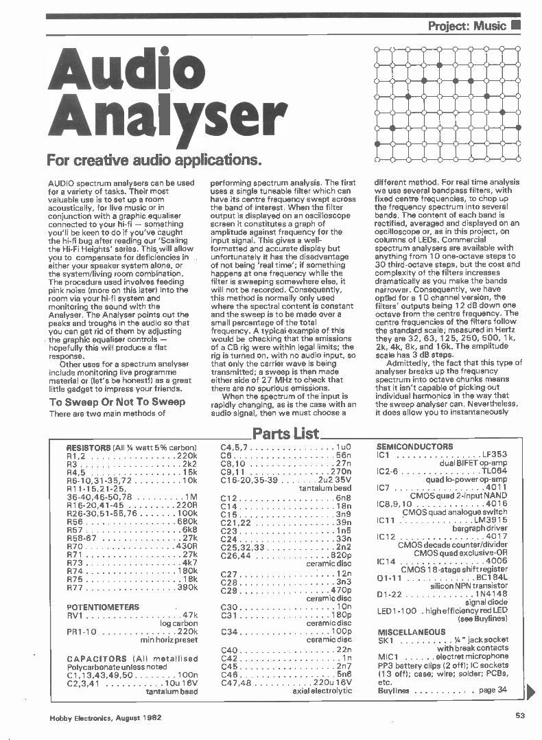
Project: Music II
Audio Analyser For creative audio applications. AUDIO spectrum analysers can be used for a variety of tasks. Their most valuable use is to set up a room acoustically, for live music or in conjunction with a graphic equaliser connected to your hi-fi — something you'll be keen to do if you've caught the hi-fi bug after reading our 'Scaling the Hi-Fi Heights' series. This, will allow you to compensate for deficiencies in either your speaker system alone, or the system/living room combination. The procedure used involves feeding pink noise (more on this later) into the room via your hi-fi system and monitoring the sound with the Analyser. The Analyser points out the peaks and troughs in the audio so that you can get rid of them by adjusting the graphic equaliser controls — hopefully this will produce a flat response.
Other uses for a spectrum analyser include monitoring live programme material or (let's be honest!) as a great little gadget to impress your friends.
To Sweep Or Not To Sweep There are two main methods of
performing spectrum analysis. The first uses a single tuneable filter which can have its centre frequency swept across the band of interest. When the filter output is displayed on an oscilloscope screen it constitutes a graph of amplitude against frequency for the input signal. This gives a well-formatted and accurate display but unfortunately it has the disadvantage of not being 'real time'; if something happens at one frequency while the filter is sweeping somewhere else, it will not be recorded. Consequently, this method is normally only used where the spectral content is constant and the sweep is to be made over a small percentage of the total frequency. A typical example of this would be checking that the emissions of a CB rig were within legal limits; the rig is turned on, with no audio input, so that only the carrier wave is being transmitted; a sweep is then made either side of 27 MHz to check that there are no spurious emissions.
When the spectrum of the input is rapidly changing, as is the case with an audio signal, then we must choose a
RESISTORS (All % watt 5% carbon) R1,2 220k R3 2k2 R4,5 15k R6-10,31-35,72 10k R11-15,21-25, 36-40,46-50,78 1M R16-20,41-45 22OR R26-30,51-55,76 100k R56 680k R57 6k8 R58-67 27k R70 43OR R71 27k R73 4k7 R74 180k R75 18k R77 390k
POTENTIOMETERS RV1 47k
log carbon PR1-10 220k
min horiz preset
CAPACITORS (All metallised Polycarbonate unless noted C1,13,43,49,50 100n C2,3,41 10u 16V
tantalum bead
Parts List
different method. For real time analysis we use several bandpass filters, with fixed centre frequencies, to chop up the frequency spectrum into several bands. The content of each band is rectified, averaged and displayed on an oscilloscope or, as in this project, on columns of LEDs. Commercial spectrum analysers are available with anything from 10 one-octave steps to 30 third-octave steps, but the cost and complexity of the filters increases dramatically as you make the bands narrower. Consequently, we have opfed for a 10 channel version, the filters' outputs being 12 dB down one octave from the centre frequency. The centre frequencies of the filters follow the standard scale; measured in Hertz they are 32, 63, 125, 250, 500, 1k, 2k, 4k, 8k, and 16k. The amplitude scale has 3 dB steps.
Admittedly, the fact that this type of analyser breaks up the frequency spectrum into octave chunks means that it isn't capable of picking out individual harmonics in the way that the sweep analyser can. Nevertheless, it does allow you to instantaneously
C4,5,7 C6 C8,10 27n C9,11 270n C16-20,35-39 2u235V
tantalum bead C12 6n8 C14 18n C15 3n9 C21,22 39n C23 1n5 C24 33n C25,32,33 2n2 C26,44 820p
ceramic disc
C27 12n C28 3n3 C29 470p
ceramic disc C30 10n C31 180p
ceramic disc C34 100p
ceramic disc C40 22n C42 1n C45 2n7 C46 5n6 C47,48 220u 16V
axial electrolytic
1u0 SEMICONDUCTORS 56n IC1 LF353
dual BIFET op-amp IC2-6 TL064
quad lo-power op-amp IC7 4011
CMOS quad 2-input NAND IC8,9,10 4016
CMOS quad analogue switch IC11 « LM3915
bargraph driver IC12 4017
CMOS decade counter/divider CMOS quad exclusive-OR
IC14 4006 CMOS 18-stage shift register
Q1-11 BC184L silicon NPN transistor
D1-22 1N4148 signal diode
LED1-100 . high efficiency red LED (see Buylines)
MISCELLANEOUS SK1 % " jack socket
with break contacts MIC1 electret microphone PP3 battery clips (2 off); IC sockets (13 off); case; wire; solder; PCBs, etc. Buylines page 34
Hobby Electronics, August 1982 53

111 Project: Music
EL ECTR ET MICROPHONE
GROUND
SK1r srri SIGNAL
1.0 'WO
R7 10k
R9 10k
R10 10k
R4\7111‹
C6 +9V 56n
R11 1M
C8 9V 27n
—Cl R12 10 1M
C10 +9V 27n.
IC4a
- C9 R13 - 11 270n 1M
C13 C14 T 100n T 18n
R14 1M
C15 9V 3119
—9V
Cl 100n
3 +9V
8
IC1a
4 IR2
—9V 220k
R1 220k
R16 22OR
R17 22OR
R18 22OR
R19 22OR
R20 220R
5
6
5
6
10
9
04
R3 2k2
+ C2 T lou
R21 D3 A 1M
5
06
32 Hz OUT o
PR1 =C16 220k 2u2
R26 100k
071
R22 1M 1M
63 Hz OUT o
PR2 C17 220k 2u2
R27 100k
• /7777
125 Hz 08 OUT
Pei 0 R23 1M
P 2e03k 2u2
100k R28
C18
250 Hz D10 OUT
• >I
D91 R24
1R0209k
2R204 C k 2 u129
IM R
D12
-1H
Figure 1. The input and filter stages of the circuit.
500 Hz OUT O
R25 1M
220k 2u2 pR5
R30 100k
T12n T 3113
R34 10k
C30 lOn
R35 10k
10
IC32 C33 2n2 2n2
1V4
R31 10k
R4 15k
V D1
IC21 C22 T39n T 39n
R32 10k
R5 15k
+ C3 10u
+9V
0 OV
SW1a
51 PP3 I
82 PP3
R41 22OR
SW1b
5
C26 820p
12
C24 C25 ÇR37 33n 2n2 SiM
R33 10k
C27 C28 ÇR3B 1M
C31
I R39 1M
13 IC5c 14
13
12
IC4c
R42 220R
R43 220R
R44 220R
IC5d
1 C47 1 C49 220u 100n I
IC4. T T lce 220u n
014
o
1100k
0+9V
OV
0 9V
016
R46 1M
PRO + C35 220k 2u2
R51
/7777
0161
10
10
9 IC4d
018
020
bel
20le
PR? C36 220k 2u2
R52 100k
R48 1M
PR8 I + C37 220k "T. 2u2
/7777
10 022
8 kHz OUT o
n49 1n4
pR. cas 220k T 2u2
R54 100k
I1 PR 10 + C39 220k «'•• 2u2
16 kHz OUT
R50 1M
R55 100k
determine the average spectrum of a sound, which is all we require.
The Circuit The input to the circuit (Figure 1 ) is either from the built-in microphone or via the external input socket. The jack socket automatically disconnects the mic if a plug is inserted. The microphone requires a reasonably flat frequency response but must be
relatively inexpensive, so we chose an electret condenser type which meets these requirements. However, electret mics require a 1V5 power supply, normally provided by an AA cell. Ours has a built-in regulated supply built around D1-D2-R4-R5-05. Zener diodes with a value of 1 V5 aren't available but, by using two ordinary diodes in series, we can get an output voltage of about 1 V2-1 V4 (each diode has a
forward voltage drop of about OV6-0V7).
The input sensitivity can be adjusted with level control RV1, while IC1 a boosts the signal to a suitable level to drive the filter bank. The gain of IC1a is set at 101, ie, (R2 + R3)/R3. Each of the ten filter-rectifier blocks is identical in structure. To obtain a bandpass response with the required roll-off, the simplest solution is to use a parallel LC
54 Hobby Electronics, August 1982
180p
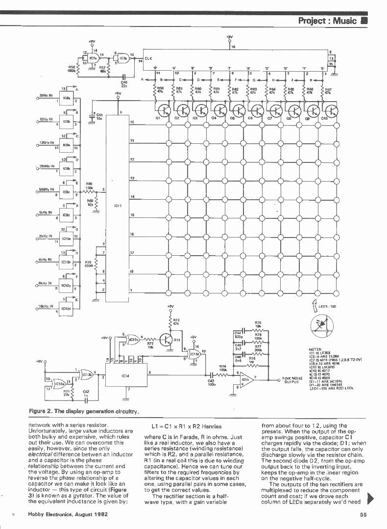
Project: Music II
+pv
32Hz IN o
63Hz IN
125Hz IN 0----11
• 250Hz IN
500Hz IN
8
2kHz IN
11
kHz IN
1
0 16kHz IN
4
R56 680k
13
IC8a
5 r —eB je• C41
A
12
+9V
14 11
IC8b
12
10
13r—.1
IC9b
r-i-E R68
IC9c
5 r--, IC9d
12 r--G
IC10c
100k
R69 15k
430R
10u
+9V LED1-100
R75 18k
+9V
Figure 2. The display generation circuitry.
PINK NOISE OUTPUT
8
15
1 am
R67 47k
o
o
o
o
o
NOTES: Cl IS LF353 2-6 ARE TL064 7 IS 4011 (PINS 1,2,5,6 TO OV) 8,9,10 ARE 4016 11 IS LM3915 12 IS 4017 13 IS 4070 14 IS 4006
01-11 ARE BC184L D1-22 ARE 1N4148 LED1-100 ARE RED LEDs
network with a series resistor. Unfortunately, large value inductors are both bulky and expensive, which rules out their use. We can overcome this easily, however, since the only electrical difference betwen an inductor and a capacitor is the phase relationship between the current and the voltage. By using an op-amp to reverse the phase relationship of a capacitor we can make it look like an inductor — this type of circuit (Figure 3) is known as a gyrator. The value of the equivalent inductance is given by:
L1 =C1 x R1 x R2 Henries
where C is in Farads, R in ohms. Just like a real inductor, we also have a series resistance (winding resistance) which is R2, and a parallel resistance, R1 (in a real coil this is due to winding capacitance). Hence we can tune our filters to the required frequencies by altering the capacitor values in each one, using parallel pairs in some cases, to get the correct values.
The rectifier section is a half-wave type, with a gain variable
from about four to 1 2, using the presets. When the output of the op-amp swings positive, capacitor Cl charges rapidly via the diode; D1 ; when the output falls, the capacitor can only discharge slowly via the resistor chain. The second diode D2, from the op-amp output back to the inverting input, keeps the op-amp in the ;inear region on the negative half-cycle.
The outputs of the ten rectifiers are multiplexed to reduce the component count and cost; if we drove each column of LEDs separately we'd need
Hobby Electronics, August 1982 55

Ill Project: Music
MICROPHONE
EXTERNAL INPUT
o
PEAK LEVEL
DETECTOR
BANDPASS FILTER 32 Hz
BANDPASS FILTER 63 HZ
BANDPASS FILTER 125 Hz
BANDPASS FILTER 250 Hz
BANDPASS FILTER 500 H
BANDPASS FILTER 1 kHz
BANDPASS FILTER 2 kHz
BANDPASS FILTER 4 kHz
BAND PASS FILTER 8 kHz
BANDPASS FILTER 16 kHz
BANDPASS FILTERS
PEAK LEVEL
DETECTOR
PEAK LEVEL
DETECTOR
PEAK LEVEL
DETECTOR
PEAK LEVEL
DETECTOR
PEAK LEVEL
DETECTOR
PEAK LEVEL
DETECTOR
PEAK LEVEL
DETECTOR
PEAK LEVEL
DETECTOR
PEAK LEVEL
DETECTOR
PEAK LEVEL DETECTORS
How It Works
ANALOGUE SWITCH
ANALOGUE SWITCH
ANALOGUE SWITCH
ANALOGUE SWITCH
ANALOGUE SWITCH
ANALOGUE SWITCH
ANALOGUE SWITCH
ANALOGUE SWITCH
ANALOGUE SWITCH
ANALOGUE SWITCH
ANALOGUE SWITCHES
The audio signal to be analysed is taken from the microphone or external input socket to the level control/preamplifier section. This amplifies the signal to a suitable level to drive the circuitry that follows. The signal is fed to 10 bandpass filters spaced one octave apart, each of which will only allow through a small section of the signal around the centre frequency. Each filter is followed by a peak level detector which averages out the signal, responding quickly to peaks but decaying slowly so that the display is easy to read. The outputs of the 10 peak detectors are connected one at time (by the CMOS analogue switches) to the input of a 10-level
10 LEVEL BARGRAPH LOG SCALE)
1 DECADE COUNTER , (COLUMN SELECT)
FAST CLOCK
CLOCK
10 x 10 LED DISPLAY
DIGITAL WHITE NOISE GENERATOR
PINK NOISE OUTPUT
3dB/OCTAVE FILTER
LO-PASS FILTER
LED bargraph driver. A logarithmic driver is used to give 3 dB steps. To reduce current consumption the baragraph operates in dot mode, so that the height of the illuminated LED up the column represents the peak level. The decade counter which controls the analogue switches also switches on the correct column of LEDs for each passband. All the columns are blanked for a short period, as the switches changed over, to prevent garbage being displayed.
The white noise is generated digitally by cyclingg a scrambled sequence of ls and Os through a shift register. The white noise is passed through a filter with a slope of 3 dB/octave to produce pink noise.
IN OUT IN OUT
°"--17L C)
• Figure 3. A gyrator circuit 'looks like' an inductor.
ten LM3915s, which is a bit expensive! Multiplexing means that each rectifier output is switched to the input of the LM3915 (IC11) one after another, by the analogue switches IC8, 9 and 10. The switches are controlled by a 4017 decade counter (IC12) with ten decoded outputs, each of which is high for one clock period only. These outputs also switch on one of the transistors Q1-10, connecting the required column of LEDs to the positive supply rail. Meanwhile the LM3915 has turned on one of its outputs corresponding to the voltage on its input (remember, it's wired in dot mode). Hence a current path between the supply rails exists for only one LED of the 100 in the display, so at any moment only one LED is turned on. By clocking the 4017 at a fairly slow speed (about 500 Hz) the display cycles through all ten columns 50 times a second and the eye sees ten LEDs 'continuously' lit.
To generate an adequate light level, a red LED requires at least 4 or 5 mA continuous current. Since each LED is only on for one-tenth of the total time, it requires ten times the current to give the same apparent brightness. The maximum current capability of the LM3915 is only 30 mA, so high efficiency LEDs must be used (see Buylines). The 4017 is even worse at supplying current, hence the use of the drive transistors.
The clock generator for IC12 is a standard configuration built round IC7a,b.
White noise is an audio signal which contains all frequencies and has equal energy per unit bandwidth. However, what we require here is equal energy per percentage bandwidth (ie, equal energy per octave). This is known as pink noise and it is obtained by passing white noise through a filter (ICI b) with a slope of 3 dB/octave. The white noise is generated digitally rather than by a Zener noise diode, which can be temperamental. IC14 is an 18-stage shift register clocked by the 30 kHz oscillator IC13a,b. Two EX-OR gates and an inverter (IC13c,d and Q11) are used to feed various outputs of IC14 back to the input (pin 6) so that a complex sequence of ls and Os flows through the register, repeating once every few seconds. This produces an apparently random jumble of fundamental frequencies with a vast number of harmonics — le, noise. And that's about enough to digest for one month! Next issue, we'll present the PCB foil patterns and all the information needed to complete the Audio Analyser. HE
56 Hobby Electronics, August 1982
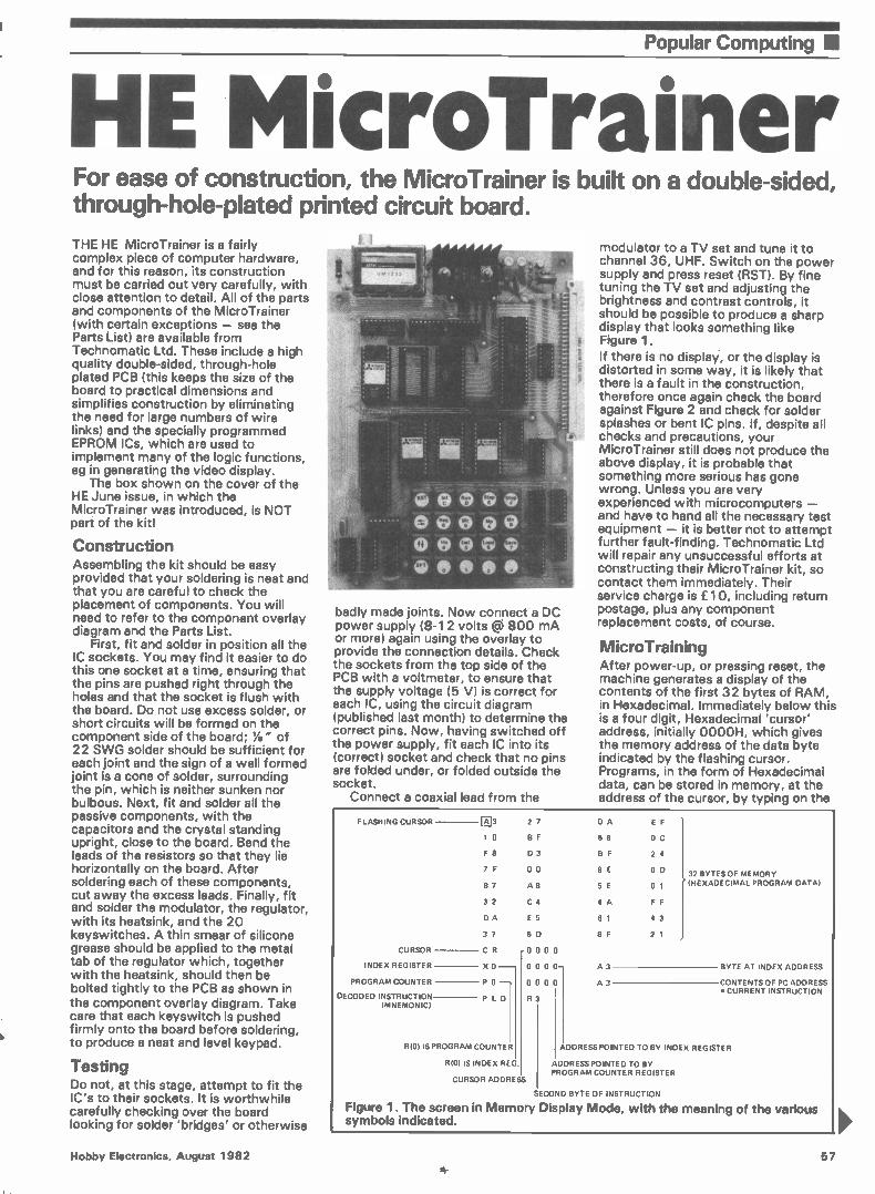
Popular Computing Ill
HE MicroTrainer For ease of construction, the MicroTrainer is built on a double-sided, through-hole-plated printed circuit board.
THE HE MicroTrainer is a fairly complex piece of computer hardware, and for this reason, its construction must be carried out very carefully, with close attention to detail. All of the parts and components of the MicroTrainer (with certain exceptions — see the Parts List) are available from Technomatic Ltd. These include a high quality double-sided, through-hole plated PCB (this keeps the size of the board to practical dimensions and simplifies construction by eliminating the need for large numbers of wire links) and the specially programmed EPROM ICs, which are used to implement many of the logic functions, eg in generating the video display.
The box shown on the cover of the HE June issue, in which the MicroTrainer was introduced, is NOT part of the kitl
Construction Assembling the kit should be easy provided that your soldering is neat and that you are careful to check the placement of components. You will need to refer to the component overlay diagram and the Parts List.
First, fit and solder in position all the IC sockets. You may find it easier to do this one socket at a time, ensuring that the pins are pushed right through the holes and that the socket is flush with the board. Do not use excess solder, or short circuits will be formed on the component side of the board; Ye" of 22 SWG solder should be sufficient for each joint and the sign of a well formed joint is a cone of solder, surrounding the pin, which is neither sunken nor bulbous. Next, fit and solder all the passive components, with the capacitors and the crystal standing upright, close to the board. Bend the leads of the resistors so that they lie horizontally on the board. After soldering each of these components, cut away the excess leads. Finally, fit and solder the modulator, the regulator, with its heatsink, and the 20 keyswitches. A thin smear of silicone grease should be applied to the metal tab of the regulator which, together with the heatsink, should then be bolted tightly to the PCB as shown in the component overlay diagram. Take care that each keyswitch is pushed firmly onto the board before soldering, to produce a neat and level keypad.
Testing Do not, at this stage, attempt to fit the IC's to their sockets. It is worthwhile carefully checking over the board looking for solder 'bridges' or otherwise
badly made joints. Now connect a DC power supply (8-12 volts g 800 mA or more) again using the overlay to provide the connection details. Check the sockets from the top side of the PCB with a voltmeter, to ensure that the supply voltage (5 V) is correct for each IC, using the circuit diagram (published last month) to determine the correct pins. Now, having switched off the power supply, fit each IC into its (correct) socket and check that no pins are folded under, or folded outside the socket.
Connect a coaxial lead from the
modulator to a TV set and tune it to channel 36, UHF. Switch on the power supply and press reset (RST). By fine tuning the TV set and adjusting the brightness and contrast controls, it should be possible to produce a sharp display that looks something like Figure 1.
If there is no display-, or the display is distorted in some way, it is likely that there is a fault in the construction, therefore once again check the board against Figure 2 and check for solder splashes or bent IC pins. If, despite all checks and precautions, your MicroTrainer still does not produce the above display, it is probable that something more serious has gone wrong. Unless you are very experienced with microcomputers — and have to hand all the necessary test equipment — it is better not to attempt further fault-finding. Technomatic Ltd will repair any unsuccessful efforts at constructing their MicroTrainer kit, so contact them immediately. Their service charge is £10, including return postage, plus any component replacement costs, of course.
MicroTraining
After power-up, or pressing reset, the machine generates a display of the contents of the first 32 bytes of RAM, in Hexadecimal. Immediately below this is a four digit, Hexadecimal 'cursor' address, initially 0000H, which gives the memory address of the data byte indicated by the flashing cursor. Programs, in the form of Hexadecimal data, can be stored in memory, at the address of the cursor, by typing on the
F LASHING CURSOR
CURSOR
INDEX REGISTER
PROGRAM COUNTER
DECODED INSTRUCTION (MNEMONIC)
El 3 27 0 A E F
1 0 BF 68 0 C
F 8 D 3 8 F 24
7 F 00 8 E 0 D
B 7 A 8 5 E 01
32 C 4 4 A F F
DA E 5 61 43
37 6 D 8 F 21
CR 0 0 0 0
X 0 0 0 0 0- A 3
P 0 0 0 0 0 A 3
PLO R
R(0) IS PROGRAM COUNTER
R10) IS INDEX REG.
CURSOR ADDRESS
32 BYTES OF MEMORY (HEXADECIMAL PROGRAM DATA)
BYTE AT INDEX ADDRESS
CONTENTS OF PC ADDRESS CURRENT INSTRUCTION
OGRESS POINTED TO BY INDEX REGISTER
ADDRESS POINTED TO BY PROGRAM COUNTER REGISTER
SECOND BYTE OF INSTRUCTION
Figure 1. The screen in Memory Display Mode, with the meaning of the various symbols indicated.
Hobby Electronics, August 1982 57
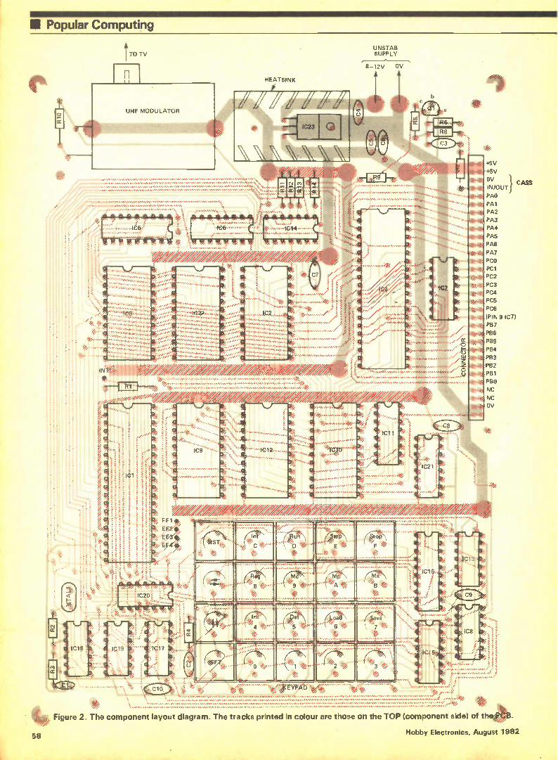
• Popular Computing
•//
TO TV
'406'•
UN STAB SUPPLY
8-12V OV
HEATSINK
1014
/ e 4,,,, e,
4,› / / 4 .,.. %
í / : 4,
..%. / ./ ' ,,,, A ,
# ,7" ,./.' ' ,','",';', ',ern, ,,,,,,,,,,,,,,,,,,,,
ti
I d)7 e A •,,,,,,,e,, , ,,,,,,,,,,, ..,.....,,,,,,,/
qt ,..,,; . iff>,.../.., ,, i ,, • , ,....,.., , ..e ,,,,,,,,,,,,, %v./ ,,,,,,,, ,,, „,,, , ,,,,,, ,,,,,
..e.H 1114.”,177e '.147,./..,....,,,,o;e.e. ,,,,,,,,,, ., , .. ,,,,,,,,,,, • ,, ez, ,,,,,,,,,,,,,, zte
% • ,.. , ,4<ezZ,' z V/ e / / / / A
•///
, ,,
-1-e„„„ ,,,,,,
IC4 ,,,,,,, '"'";1042 , • ,,,,,, ,,,,,, ,,,,,,,,,,, „
,,„„.... ,,, ,
</ze-
•
/////////".
*41 -"b•- .• • y • ..„;,,;;;,;•.., ,,,,,, /
+5V
+5V
OV
IN/OUT
PAO
PA1
PA2
PA3
PA4
PA5
PA6
PA7
PCO
PC1 PC2
PC3 PC4
PC5
PC6
(PIN 9 IC7)
PB7
PB6
PB5
PB4
PB3
PB2
PB1
PBO
NC
NC OV
e.r
r.
//
CASS
58
Figure 2. The component layout diagram. The tracks printed in colour are those on the TOP (component side) of the13'3.
Hobby Electronics, August 1982
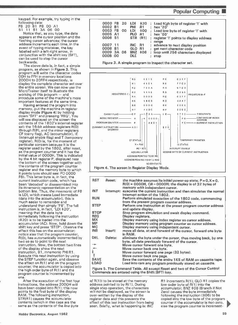
Popular Computing 11 keypad. For example, try typing in the following data: F8 20 B1 F8 00 Al 51 11 81 3A 06 00
Notice that, as you type, the data appears at the cursor position and the flashing cursor advances; the cursor address increments each time. In the event of typing mistakes, the key labelled with a left-right arrow, in conjunction with the shift key (SFT), can be used to step the cursor backwards.
The above data is, in fact, a simple program, as shown in Figure 3. This program will write the character codes 00H to FFH in memory locations 2000H to 2OFFH respecticely, ie display the complete character set over the entire screen. We can now use the MicroTrainer itself to illustrate the working of this program — and introduce some of the machine's more important features at the same time.
Having entered the program into memory, put the machine in register display mode (Figure 4) by holding down 'SFT' and pressing 'REG'. You will see displayed on the screen the contents of the 1802's internal register set: the 16-bit address registers R(0) through R(F), and the minor registers CF (carry flag), AC (accumulator), IE (interrupt enable flag) and T (temporary register). R(0) is, for the moment of particular concern because it is the register used by the 1802, after reset, as the program counter and it has the initial value of 0000H. This is indicated by the 4 bit register P, displayed near the bottom of the screen together with the contents of the program counter register and the memory byte to which it points (you should see: PO 0000 F8). This latter byte is, in fact, the current instruction code, which has been 'decoded' or disassembled into its mnemonic representation on the bottom line. Thus, the mnemonic of F8 is LDI, which means Load Immediate (data into the accumulator); this is much easier to remember and understand than simply 'F8'. The full instruction is, in fact, 'LDI $20', meaning that the data byte immediately following the instruction ($20) is to be loaded into the accumulator (AC). Now, hold down the shift key ,and press 'STEP'. Observe the effect this has on the accumulator; notice also that the program counter, R(0), has automatically incremented by two so as to point to the next instruction. Now, the bottom two lines of the display show the next instruction, Bi, mnemonic PHI Rl. Execute this next instruction by using the STEP function again, and observe the effect on R(1) and on the program counter; the accumulator is copied into the high order byte of R(1) and the program counter is incremented by one.
After the execution of the first four instructions, the address 2000H will have been copied into R(1); this now points to the first byte of the display RAM. The following instruction, STR(131) causes the accumulator contents (which in this case are the same as the contents of the low byte
0000 F8 20 LDI $20 ; 0002 B1 PHI R1 ; 0003 F8 00 LDI $00 ; 0005 Al PLO R1 ; 0006 51 STR (R1) ;
0007 11 INC R1 ; 0008 81 GLO R1 ; 0009 3A 06 BNZ $06 ; 000B 00 DIE
Load WO byte of register 'I' with hex '20' Load low byte of register 'I' with hex '00' register 'I' points to display address range advance to next display position get next character code loop until 256 characters displayed stop
Figure 3. A simple program to inspect the character set.
REGISTERS 0-7
CARRY FLAG
INDEX REGISTER
PROGRAM COUNTER
CURRENT INSTRUCTION DECODED
R o 0 0 1 5 R 8 0 3 E F
R 1 4 6 0 1 R 9 F F C 3
R 2 7 0 0 A RA 9 7 0 D
R 3 1 1 1 8 R B C 3 B 5
R 4 0 0 0 0 RC 0 3 F F
R 5 1 6 E 0 RD A 4 4 7
R 6 0 0 0 C RE 2 0 0 E
R 7 FEDC RF 0 0 0 0
CF 3 A I E 0 7 3 2
X 0 0 0 0 F 8
P 1 4 6 0 1 F C
ADI $ 2 0
CF STATUS
X - R(4)
PC 18(
ACCUMULATOR
ADDRESS POINTED TO BY PC
ADDRESS POINTED TO BY X REG
AC CONTENTS
Figure 4. The screen in Register Display Mode.
REGISTERS 8-F
CONTENTS
CONTENTS OF INDEX ADDRESS
CURRENT INSTRUCTION
EMPORARY REGISTER
IE STATUS
INTERUPT ENABLE
ECOND BYTE OF CURRENT INSTRUCTION
RST
INT
RUN
STEP
STOP REG MX MP MC INS
DEL
SAVE LOAD
Reset: the machine assumes its initial power-up state; P= 0,X =0, R(0)= 0000H, CR = 0000H; the display is of 32 bytes of memory with independent cursor.
Interrupt: executes the current instruction and then simulates the normal interrupt action of the 1802. Perform simulated execution of the 1802 code, commencing from the present program counter address. Perform one instruction at the preset program counter address and update display. Stop program simulation and await display command. Display registers. Display memory using index register as cursor address. Display memory using program counter as cursor address. Display memory using indepentent cursor.
Insert: move all data, at and forward of the cursor, forward one byte in RAM.
Delete: eliminate the byte under the cursor, thus moving back, by one byte, all data previously forward of the cursor. Move cursor forward one byte. Move cursor back one byte. Move cursor forward one page (32 bytes). Move cursor back one page. Save the contents of the entire 1K5 of RAM on cassette tape. Load into ram any program previously stored on cassette.
Figure 5. The Command Table. All except Reset and two of the Cursor Control Commands are entered using the Shift (SFT) key.
of R(1)) to be stored at the memory address pointed to by1311 I. During single step operation, the characters will not be displayed, as the screen is over-written by the display of the register data and this prevents the effect of this last instruction from being seen. Briefly, what is happening is: INC
R1 increments R(1); GLO R1 copies the low order byte of R(1) into the accumulator; BNZ $06 (Branch if Not Zero) causes the byte immediately following the instruction ($06) to be copied into the low byte of the program counter if the accumulator is non-zero, else the program counter is increment-
Hobby Electronics, August 1982 59
• Popular Computing
Parts List RESISTORS (All IA watt 5% carbon) R1,4,8*,15,16,17,18,19 ...4k7 R2,3,7*,9,14 47OR R5* 5k6 R6*,13 680R R10,11,12 22OR
CAPACITORS C 1 33p
disc ceramic C2 47u 6V3
tantalum bead C3*,6,7,8,9,10 100n
disc ceramic C4,5 2u2 16V
tantalum bead
SEMICONDUCTORS 01* BC108
silicon NPN transistor IC1 1802
microprocessor IC2 6116
8-bit RAM IC3,22* 2532
EPROM IC4* 8255
programmable peripheral interface IC5,16 74LS374
TTL octal D-type flip-flop IC6 74LS138
TTL 3-8 line decoder/multiplexer IC7* ULN 2003
darlington array IC8 74LS113
TTL dual J-K flip-flop IC9,10,12 2716
EPROM IC11 74LS165
TTL 8-bit parallel-to-serial converter IC13 74LS74
TTL dual D-type flip-flop IC14 CA3086
transistor array ICI 5 74LS156
TTL dual 1-of-4 decoder/ demultiplexer
IC17 74LS14 TTL hex Schmitt trigger
IC18 74LSO4 TTL hex inverter
IC19 74LSOO TTL quad 2-input NAND
IC20 74LSO8 TTL quad 2-input AND
IC21 74LS163 TTL binary counter
IC23 7805 voltage regulator
UHF MOD UM1233 UHF TV modulator
MISCELLANEOUS Heatsink (TV-21, for regulator); switch-caps (20, for keypad); IC sockets (optional); power supply (800mA 8-12V unregulated); double-sided, through-hole-plated PCB. NOTE: The 2716 and 2532 EPROM's (IC's 3,9,10,12) are only available from Technomatic — they have to be specially programmed.
* These components are NOT included in the kit supplied by Technomatic. Buylines Page 34
ed by two. With these limited explanations, you should be able to arrive at an understanding of the program, aided by stepping through the instructions and carefully observing what has happened. A much more detailed description of the 1802's instruction set will be given next month, together with further program examples. However, for the time being, the real point of exercise is to familiarise yourself with the operation of the MicroTrainer; the more you can work out for yourself the better.
To round off the example in hand we should now attempt to Run this program. First, type 'SFT MP' ; this enables the program to be displayed as before, however the program counter itself now becomes the cursor address counter. You can now step the cursor back using the 'left-arrow' so that the program counter points to the first byte of the program; then type 'RUN'. The TV screen will fill up with a set of characters and then stop, leaving a steady display. With a program this simple, some of the characters are placed outside the main display area and, by.their proximity to the SYNC pulses, there may be some slight distortion. How this can be avoided will be explained in a later issue.
In addition to details of the instruction set, next month, we shall be describing how to interface the MicroTrainer to external devices, with the addition of the I/O port.
HE
Su b I 11 Do yourself a favour. Make 1982 the year you start to take Hobby
Electronics, regularly. Delivered fresh every month.
MM 'Mifflin. ffl IM NMI MMMMM IMO MIMI Mil MIMI MMMMMMMMMMMM 1111
SUBSCRIPTION ORDER FORM
Cut out and SEND TO: Hobby Electronics Subscriptions
513, LONDON ROAD, THORNTON HEATH,
SURREY, ENGLAND.
Please commence my personal subscription to Hobby Electronics with the issue.
SUBSCRIPTION RATES (tick Li as
appropriate)
82/1 MMMMM ins
60
£10.75 for 12 issues U.K
£12.75 for 12 issues overseas surface Signature
£25.70 for 12 issues Air Mail Date
MI ZIM MI MU NM MI 11113 UM MI MI /II UM IMMI MOM JI
1 am enclosing my (delete as necessary) Cheque/Postal Order/International Money
Order for £ (made payable to A.S.P. Ltd)
OR Debit my Access/Barclaycard •
( 'delete as necessciry)
\\. \.,••••
IlAIICLAYCARD
1//#41
Please use BLOCK CAPITALS and include post codes.
Name (Mr/Mrs/Miss) delete accordingly
Address
Hobby Electronics, August 1982
+ USUAL DISCOUNTS + FREE POSTAGE
DISCOUNTS 5% on orders over [23 lino VATI 154h'ronorfS75Oi,nc V A T I on most catalogue items. but not on payments by credit cards
POSTAGE Not charged on U K orders over f5 75 Inc VAT 11 under, add 400 handilnd charge
FREE VOUCHERS TO SINE YOU UP TO
THREE 70p REFUND VOUCHERS FREE for spending singly at arty time on any one C.W.O. (U.K.) order mintmum list value E10. This can quickly save you up to f2.10 in
addition to the other benefits you enjoy by buying from Electrovalue. Seal 70p for *Woes 82 + 3 free
vouchers by rotors now
• SEMI-CONDUCTORSIICsIOPTOs • COMPUTERS/SOFTWARE etc. • CAPACITORS/RESISTORS • CONNECTORS/SWITCHES/KNOBS • POTS/FERRITES1METERS • BOOKS/SOLDER TOOLS AND MORE AND MORE AAID MORE
ELECTROVALUE LTD.24E St Junes Road. Englefield Green Egharn: Surrey TW20 0118 Phone: Eghara 33603 STD 0704. Union 871. Talent 264475 Northern Branch (Personal Shoppers ref() 680 Bumage lane: Nonage, Manchester M19 11AA. Mona (0611 42 4945
MAKE IT WITH BRADLEY
Marshall's OF LONDON
SPECIALIST ELECTRONIC COMPONENT DISTRIBUTORS Tel: 723-414M
PROBABLY THE LARGEST STOCK OF IC-% 41, TRANSISTORS IN THE SOUTH TRY US FIRST
LARGE RANGE OF ACCESSORIES
Plugs Sockets Audio Connectors Veroboards IC Sockets Soldering equipment Screw drivers (BANCO)
Sitam Knobs etc.
LARGE RANGE OF ICs Transistors Capacitors Diodes Triacs Thyristors Opto Resistors Potentiometers Fuses Bridges Please send S.A.E. for list.
SPECIAL OFFER
STEINAL MULTICHECK
£7-50 + VAT
Normal price £10 26
BUY WITH ACCESS
BARCLAYCARD A/EXPRESS DINERS
BAHCO TOOLS SIDE CUTTERS
2132 £7-10 2112 £9 40
END CUTTERS 2211 £10 43
PLIERS 2411 £6.75 2415 £6.78
ICE MULTIMETERS Microtest 80 £16.60 Supertest 680 R £32 00 Supertest 680E £24.50
Just phone we do the EXPERIMENTER rest BREADBOARD'S
MAIL ORDER FASTER SERVICE
PHONE 773-4242
41 WAY RIBBON CABLE £2.24 metre
Header plugs 14 way, 16 way, 40 way
- - - - -
EXP 325 EXP 350 EXP 300
EXP 600 EXP 650 EXP 4B
LOGIC PROBES LP1 £31.00 LP2 £18.00
EXPERIMENTER KITS
PB6 £9-20 PB100 £11.80
PLEASE REMEMBER To ADD 15% VAT
325 EGWARE ROAD LONDON W2 1BN
BARCLAYCARD • ACCESS • DINERS • A/EXPRESS
G . M . M ICROTRONICS LTD.
UNIT 14, GODINTON WAY INDUSTRIAL ESTATE, GODINTON ROAD, ASHFORD, KENT TN23 1JB Telephone: ASHFORD (0233) 38671/38672
"Add the power of speech to your computer"
TMS 5100 TALKING BOARD as featured in ELEKTOR
Features 170 word vocabulary in 3 Eproms
Easily interfaced to any computer (via Bus or Parallel port) ie:
Acorn, Atom, Apple , Atari, Pet, Vic, and ZX80/81.
Requires ±12v (t 50 ma and +5v.4/ 300 ma.
GM510 Talking Board Kit (with interface IC's) f82.95p GM511 Power supply Kit to Power above f16.10p GM5100 Ready Built with power supply and cased f144-00p Design notes (Inc in above) if bought separately f1.00p
SOFTY II NOW IN STOCK @ £182.00 inc VAT
ALSO AVAILABLE SHORTLY
6808/6809 6u Board Expandable Computer System
Send for further details and specification
Please send the following items: \ Box ri Softy Il Li GM510 Talking Board Kit
fl GM511 P.S.U. Kit [] GM5100 Ready Built Cased Unit n Further Details [-] Design Notes f,-) 68089 Details
I enclose cheque P 0 for value of f please add £2.00 p&p. All prices inc. VAT
Name
Address
Post Code
Hobby Electronics, August 1982 61
Send for my CATALOGUE ONLY 75p (plus 25p post/packing)
My VAT and postipaeling inclusive prices are the lowest. All below normal trade price - some at only
one tenth of manufacturers quantity trade. See my prices on the following:
CAPACITORS . . . ELECTROLYTIC; CAN, WIRE END, TANTALUM, MULTIPLE, COMPUTER GRADE, NON POLAR, PAPER BLOCK, CAN, POLY, MICA, CERAMIC. LOW AND HIGH VOLTAGE, RESISTORS. 118th WATT TO 1IX1 WATT; 0.1% TO 10% CARBON, METAL AND WIRE WOUND + NETWORKS. FANS, BATTERIES, SOLENOIDS, TAPE SPOOLS, VARIABLE CAPACITORS AND RESISTORS, TRIMMERS, PRESETS, POTS . . . SINGLE, DUAL SWITCHED, CARBON, CERMET AND WIREWOUND, SINGLE OR MULTITURN, ROTORY AND SLIDE. DIODES, RECTIFIERS, BRIDGES, CHARGERS, STYUI, SOCKETS, PLUGS, RELAYS, TRANSISTORS, ICS, CUPS, CRYSTALS, ZENERS, TRIACS, THYRISTORS, BOXES, PANELS, DISPLAYS, LED'S, COUPLERS, ISOLATORS, NEONS, OPTO'S, LEADS, CONNECTORS, VALVES, BOOKS, MAGAZINES, TERMINALS, CHOKES, TRANSFORMERS, TIMERS, SWITCHES, COUNTERS, LAMPS, INDICATORS, BELLS, SIRENS, HOLDERS, POWER SUPPLIES, HARD-WARE, MODULES, FUSES, CARRIERS, CIRCUIT BREAKERS, KNOBS, THERMISTORS, VIM'S, 'INSULATORS, CASSETTES, METERS, SOLDER, HANDLES, LOCKS, INDUCTORS, WIRE, UNITS, MOTORS, COILS, CORES, CARTRIDGES, SPEAKERS, EARPHONES, SUPPRESORS, MIKES, HEATSINKS, TAPE, BOARDS and others.
Prices you would not believe before inflation!
BRIAN J. REED TRADE COMPONENTS
ESTABLISHED 25 YEARS 161 St. Johns Hill, Battersea, London SW11 1TQ
Open 11 am till 7 pm Tues. to Sat. Telephone. 01-223 5016
USED EQUIPMENT INTERCOM TELEPHONE All you need is a PP9 battery I and plenty of wire. Our instructions tell you how to wire up these push button intercom phones. 10-button phone £5.50 15 button phone £6
£1.80 p&p
MF (Multi Frequency) PHONES Use them as they are or use 3 x 4 keypad and PCB as the heart of a remote control transmitter (will not work on most GPO lines) £5 + Cl 80 P&P
LOW-COST, RUGGED
TEMPERATURE CONTROL
HIGH QUALITY
TEMP. GAUGE 0 -120°C Remote sensor on 38" capillary, panel mounting dial 55mm. dia.
ONLY f2.50
Recent Style P.O. Telephones f4.75 + £1.80 P&P 2 for £9 + £2.50 5 for f20 + £5
COMPACT TELEPHONE With wall-mount bell f6.50 Older style black telephones £3. oar) as above. Our leaflet explains how to use G P 0 phones in home intercom systems.
16A 240V RANCO THERMOSTAT Wide control range (low room temp. to over boiling point)) Sensor on 22" capigiary. f2.30. including control knob
RANCO THERMAL CUT-OUT 100°C 15A 240V. Sensing coil on 41M. capilliary panel mounting with reset button f120
BUY ONE EACH OF ABOVE FOR £5.50
5 Digit Counters 48V coil. Non resetable 75p
UNISELECTORS. 50v, 4 Bank + Homing Bank, 25 way f3.50
LIGHT DEPENDENT RESISTORS in plastic housing with window, heavy-duty lead. Similar to ORP 61. You normally pay well over double for resistor alone. Only 30p or £2.36 for 10.
GEARED Synchronous motor, 8 r.p.m., 240V A.C. 3 Watt £2.
SOLENOID GAS VALVE. 240V A.C. 5 P.S.I. suitable for non-corrosive fluids. £2.20
BULGIN 3 pin free plug Et panel socket, 2A 240V 50p
500V ELECTRONIC BRIDGE MEGGER f15 + £2 p&p
I PRICE T.T.L. 7420/7430 10p 7496 30p
74118 50p
FREE on request Leaflet "D I.Y Telephone Systems and Automatic Exchange Design'
AUTOMATIC DIAL UNIT. (mains powered). These units connect into a telephone and dial a number when a punch-card is inserted. Card 8 instructions supplied. Cards readily available. Many uses. Only f8+ f1 p&p
LEM. SERVICES 239 RUGBY ROAD LEAMINGTON SPA C1132 SOY' WARWICKSHIRE
TEL: 0926 30622 FOR QUANTITY DISCOUNTS ETC. ALL ITEMS - MONEY BACK IF NOT DELIGHTED.
ADD 50p P&P ORDERS OVER f7.50 POST FREE unless stated otherwise
OESOLDERING TOOL Now everyone can afford one of these superb, blue anodised aluminium high pressure hand desoldering tools at nearly half our normal price. Normal Price f6.50 + VAT. With this ad £3.85 + VAT. Spare Teflon screw-in noses 750 • VAT. JAPANESE TRANSISTORS Equivalents available for most types. Please call, phone or write
LOW COST VERSATILE MULTIMETER THE MIGHTY MINI MULTI-TESTER 2,000 ohms per volt. DC Er AC Voltage ranges, to,. 50v, 250v, 1000, DC current ranges 10OrnA Resist/1m. ohms 10 v 100db frorn -10db to +22db. Minor arc scale. overload protected. complete with banery, test leads Er instructions. Usual puce CH 65 s VAT; with this Ad £4 96 + VAT.
ORDER FORM Narne . . Address .
Desoklenng tools at £3.85 - E Spare Teflon noses at 75p =
. .Mighty Mini Testers et £4.95 . Postage, packing and insurance at 60p per one device, 25p for each additional device
Sub total E Add 15% VAT E
enclose cheque no/P.O. no ... Alternatively plea. ere« my VISA/ACCESS No. ..
This offer applies to UK only. Please allow 7-10 days delivery. Overseas customers please do not add VAT but allow to cover postage. TRADE ENQUIRIES WELCOME.
CRICKLEWOOD ELECTRONICS LTD. 40 Cricklewood Broadway, London NW2 3ET. Tel: 01452 0161
1
COMPONENTS IN BIRMINGHAM CMOS-LSTTL-LINEAR-ICs NOW!!! IN DEPTH STOCK
From National Semiconductor: Some Egs: 4011 159 4013 34p 4017
4093 38p 40161 69p 4543 74L500 12p 74LS90 33p 741.5386 LM38O 75p TBA120 90p TDA2640
Full range list available + Quantity discounts. Ask for details
PCBs. The FOTOway.- Brochure on Request.
NEW BARGAIN Packs: 16 TTL ICs ... . . f1.10 -6 -- Slide Switches 60p 9 - CMOS ICs .. . ,, £1.10 100 -- 1/8 Watt Resistors 60p 10 Croc Clips also 30 -- 1 Watt Resistors 60p 5 - Ex Equipment Bds . £1 5 - Large Elect Caps £1 8 - Knobs £.20 4 - Rotary Switches £1.213
Post b packing 60p per order. FREE over £10 ALL PRICES + VAT
P.A.T.H. Electronic Services Wholesale + Retail 369 Alum Rock Road, Birmingham B8 3DR. Tel: 021 327 2339
Open 10 till 6 weekdays. 9.30 till 5 Saturdays Distributors tor: Antex - Altai - Sabani - Hills - Servisol - PATH FOTOway -
PATH Box - Salgan - Vero Electronics + MUCH MUCH MORE . .
42p 134p 28p 216p
ZX81 Keyboard £25.95 (fully built) A NEW 45 KEYBOARD FOR THE
ZX81 •45 keys, including single keys for RUBOUT, EDIT and FUNCTION
• 2 Shift Keys (left and right) • Full repeat on all keys, including single function keys • Large space key, and in proper
place! • Typewriter switches, with full movement - not touch sensitive type
•All symbols, graphics etc shown in two colours
• Simply plugs into the ZX81 (RAM etc operation not impaired). Will fit a ZX80 but requires 13 solder joints
Kit version available £22 95 Send stamped address envelope for illustrated catalogue
and data sheet for keyboard
Harris Er Lockyer Associates
DEPT HE, 33 PEDMORE CLOSE, WOODROW SOUTH, REDDITCH, WORCS.
Tel: (0527) 24452 Prices include VAT and postage. Overseas add £1.80. Cash with order or now COD. Phone orders welcome
62 Hobby !Electronics, August 1982
HE PCB SERVICE /Ready mad Ç PCB s
-zzg
Or
•
PRINTED CIRCUIT BOARDS (PCBs) for HE projects have often represented an • F Read ers! obstacle for our readers. Some of you, no doubt, make your own • • but our PCB Service saves you the trouble. NOW you can buy your PCBs direct from HE. All (non-copyright) PCBs will be available automatically from the HE PCB Service. Each board is produced from the same master as that used for the published design and so each will be a true copy, finished to a high stan-dard. Apart from the PCBs for this month's projects, we are making available some of the popular designs from earlier issues. See below for details. Please note that only boards for projects listed below are available: if it isn't listed we can't supply it.
March 81 £1.87 Steam Loco Whistle £2.11
June 80 Fog Horn Egg Timer
July 80 18 W + 18 W Car Stereo Booster (two required for stereo) each
August 80 Equitone Car Equaliser Pass The Loop Game
September 80 Guitar Phaser Development Timer Bench PSU
October 80 Nobell Doorbell Intruder Alarm Tug O' War
November 80 Memory Bank Synth:
Mainboard PCB Keyboard PCB
Party Grenade (set of three) Double Dice
December 80 Stereo Power Meter Digital Speedo (set of two)
January 81 Car Rev Counter
February 81 Heartbeat Monitor Audio Signal Generator
£1.60
£2.39 £2.64
£1.97 £1.80 £2.93
£2.64 £2.51 £2.65
£3.31 £3.60 £3.47 £2.95
£2.83 £4.67
£2.99
£2.53 £2.47
April 81 Super Siren Russian Roulette Game
May 81 Voice Operated Switch Organ 1
June 81 Envelope Generator Organ 2
July 81 Organ 3 Organ 4 Ultrasound Burglar Alarm
August 81 RPM Meter Thermometer
September 81 Power Pack Reaction Tester Game 'Diana' Metal Detector
October 81 Combination Lock
November 81 Sound Torch (Set of Two)
December 81 Pedalboard Organ
January 82 Intelligent NiCad Charger
£2.65
£1.97 £1.60
£1.67 £4.64
£1.87 £2.53
£6.00 £6.00 £2.53
£1.77 £1.67
£1.69 £1.71
• £3.31
£2.65
£5.31
£5.97
£3.04
February 82 Relay Driver Mast-Head Amp
March 82 Digital Dice
April 82 Digital Capacitance Meter Dual Engine Driver Bike Alarm
May 82 Digital Thermometer (Set of Two) Echo-Reverb Cable Tracker
June 82 Power Supply Design Auto-Wah Auto Greenhouse Sprinkler Telephone Timer (Set of Two)
July 82 Tanover TVI Filter Computer PSU Solar Radio
August 82 Digital Millivoltmeter (Set of Two) Audio Analyser (Set of Two)
£2.20 £1.31
£1.95
£4.73 £3.37 £2.64
£5.31 £5.81 £2.21
£2.64 £3.58 £3.88
£7.39
£2.31 £2.17 £8.72 £2.15
£4.82
£12.30
PLACE an order for your PCBs using the form below (or a piece of plain paper if you prefer not to cut the magazine), then simply wait fôr your PCBs to drop through your letterbox, protected by a Jiffy bag.
HE PCB Service, Argus Specialist Publications Ltd, 145 Charing Cross Road, London WC2H OEE I enclose a cheque/Postal Order made payable to ASP Ltd, for the amount shown below Price.
OR
I wish to pay by Barclaycard. Please charge my account number
OR
I wish to pay by Access. Please charge to my account number
WSA
SIGNATURE
NAME (BLOCK CAPITALS) ADDRESS (BLOCK CAPITALS)
Boards Required Price
Add45ppEtp 0.45
Please allow 21 days for delivery Total Enclosed E

RECHARGEABLE
Beilefs PRIVATE OR TRADE
ENQUIRIES WELCOME FULL RANGE AVAILABLE SEND SAE FOR LISTS. £1 .45 for Booklet "Nickel Cadmium Power" plus Catalogue. Write or call:
* NEW SEALED LEAD RANGE AVAILABLE *
SANDWELL PLANT LTD. 2 Union Drive, Boldmere
Sutton Coldfield, West Midlands 021-354 9764
After hours 0977 84093
DO YOU NEED:— Electronic components, Tools, Test Equipment, Cases, Cabinets and Hardware etc. IN A HURRY ?Mtn? THEN YOU NEED:— LIGHTNING Electroni Components. WHY ???? Because LIGHTNING Strikes out where others fail:—
Express Despatch In Depth Stock All New Guaranteed Goods from Leading
Manufacturers
With all that going for us, Going to you can you really afford to be without a copy of our brand new exciting CATALOGUE Many PRices Reduced — Many More Stock Lines Send for YOUR Copy Now ONLY 70p Post Paid.
LIGHTNING ELECTRONIC COMPONENTS 84 Birchmoor Road, Birchmoor, Tamworth Staffs B78 lAB
(NOTE New Address)
Trigger Switch on/off Built-in-Light 4 foot, 3 core wire Tired of waiting for ordinary Irons to heat up, but put off by high price of instant guns?
Now you can purchase a superb Instant Heat Gun with features for only-
t5.95 plus £1.30 p. & p. Money back if not deltghted
Send Cheque or Postal Order for £7.25 for immediate despatch, to-
Nash Smithfield Ltd., Mail Order Dept., 11 Victoria Road, Saltaire, Shipley,
West Yorkshire Telephone 582967
DEDUCT 20% OFF
SUMMERTIME SALE!! From this All prices include VAT at 15% — just add 50p post 1982/3 CATALOGUE LIE DETECTOR
Bigger! Better!! Buy one!!! Only 75p inc. post - Look what you get! I • Vouchers worth 60p • 1st class reply paid envelope • Wholesale list for bulk buyers • Bargain List with hundreds of surplus lines • Huge range of components • Low, low prices
Sent free to schools, colleges etc.
COMPONENTS 2200uF 100V cans 77 x 35mm 75p each; 10 for £5.50 MK4027 shift register 8 for £6 210213 RAM 8 for £3 2708 EPROM £1.50 MIR50 infra red 5mm LED 30p DM160 tuning indicator 50p AY-5-4007D 24DIL chip counter/. 4 decade up/down 7 seg o/p 0-6MHz. -12, -5V sup-ply El END501 + 1 0.5in red display comm. cathode 25p MAN6710 Dual digit Red 0.56M 7 seg display. Supplied with pin-out and data £1.00 Murata ceramic filter 5.5MHz 40p 10M }W resistors 5% carbon film. Pack of 200 for £1.
COMPONENT PACKS K503 150 wirewound resistors, 1W-12W. Wide range of values. f:2 K518 200 disc ceramic caps. Big variety of values and voltages el
DISC CERAMICS 0.22uF 12V 9mm dia. Ideal for decoupling. 100 for £2.75; 1000 £20 0.5uF 12V 15mm dia. 100 £1.50; 1000 £12
SWITCH BARGAIN Push-on, push-off 'table lamp type, rated 2A 250V ac. 10p each, 15 for El, 100 for £5
741 OP-AMP — 12 for £1 MIXED LED PACK A recent purchase of Raytheon IC's included a large quantity of 14 DIL 741 op- All new full spec by Micro, Fairchild, etc. Red, amps, so take advantage while stocks last! Yellow, Gre.", Aeeeer, Clear. 3e"° Pl. 5rere. Pack et 12 741's £1 50 asstd £3.95; 250 £15.
This beautifully made precision instrument is not a toy or gimmick, it was originally used on an Open University course to measure changes in emotional balance by detecting small changes in skin resistance. Full details of how to use it are provided, together with a circuit diagram. Supplied complete with probes, leads and conductive jelly. Needs 2 x 4',4V batteries. Overall size 155 x 100 x 100mm. The 100-0-100uA 4" panel meter is worth more than we're asking for the whole unit!! £7.95
'STARBIRD' Gives realistic engine sounds and flashing laser blasts - accelerating engine noise when module is pointed up, decelerating noise when pointed down. Press contact to see flash and hear blast of lasers shooting. PCB tested and working complete with speaker and batt. clip (needs PP3). PCB size 130 x 60mm. Only £2.95
1000 RESISTORS £2.50 We've just purchased another 5 million preformed .resistors, and can make a similar offer to that made two years ago, at the same price!!! K523 — 1000 mined 1 and 1W 5% carbon film resistors, preformed for PCB moto. Enormous range of preferred values. 1000 for f2.50; 5000 E10: 20k £36.
GREEN WELD 443F Millbrook Road, Southampton, SO1 OHX
TECHNICAL TRAINING IN ELECTRONICS, TELEVISION AND AUDIO IN YOUR OWN HOME—AT YOUR PACE ICS can provide the technical knowledge that is so essential to your success,knowledge that will enable you to take advant-age of the many opportunities open to the trained man. You study in your own home, in your own time and at your own pace and if you are studying for an examination ICS guarantee coaching until you are successful.
City & Guilds Certificates
Radio Amateurs BasitirElectronic Engineering (Joint MEG/ICS)
Certificate Courses
TV and Audio Servicing Radio 8E Amplfier Construction Electronic Engineering* and Maintenance Computer Engineering* and Programming Microprocessor Engineering* TV, Radio and Audio Engineering Electrical Engineering,* Installation and Contracting
b-Kdb Approved by CACC
*Qualify for LET Associate Membership
IB(C tad Member of ABCC
POST OR PHONE TODAY FOR FREE BOOKLET
IPlease send me your FREE School of Electronics Prospectus.
Subject of Interest I
111 Name III
I Address II
I I ICS Post to: Dept 262X School of Electronics
160 Stewarts Road, 01-622 9911 I London SW8 4UJ -...... (All Hours) . II --- -- ...mlimm .. Immailmmmm....•
64 Hobby Electronics, August 1982

ADVERTISEMENT INDEX
The two foilside PCB patterns for the Digital Millivoltmeter. Both boards must be cut exactly to fit the case.
Aitken Bros Ambit International Armon Electronics Bi-Pak BK Electronics BNRS J. Bull Bradley Marshall Centemp Compton Glass Cricklewood Electronics E.D.A. Sparkrite Electronize Electrovalue Flight Electronics G. M. Microtonics Greenweld Harris Et Lockyer ICS
51 ILP 27 2 LEC 64
42 LEM Services 62 4 Magenta Electronics 4 Er 5
67 Musicraft 47 61 Namal Associates 52 38 Nash Smithfield 64 61 Path 62 47 Rapid 33 40 Brian J. Reed 62 62 Relay-A-Quip 34 36 Sandwell Plant 64 52 Shetland Boats 42 61 Sinclair 16 9 Technomatic 8
51 Tempus 68 64 TK Electronics 47 62 Watford Electronics 19 64
Hobby Electronics, August 1982 65
PARAPHYSICS JOURNAL (Russianjrans-lations); Psychotronic Generators, Kirliano-graphy, gravity lasers, telekinesis. -Details: S.A.E. 4 x 9" Paralab, Downton, Wilts.
FIND-A-FRIEND through FIND-A-FRIEND'S new confidential, inexpensive service. Your ideal friendship/relationship — all ages — countrywide. SAE/Telephone: FIND-A-FRIEND (HE), Temple House, 43-48 New Street, Birmingham B2 4LH. 021-429 6346.
BURGLAR ALARM equipment. Ring Bradford (0274) 308920 for our catalogue, or call at our large showrooms opposite Odsal Stadium. C.W.A.S. Ltd. TELETEXT (Oracle/ Ceefax) add-on adaptors for your existing television. Only £159.95 including VAT/delivery. Access/Barclaycard. Also Prestel. Send for free details. Avon Office Services, Freepost, Bristol BS10 6BR. (0272) 502008 anytime. OSCILLOSCOPE £12. Easy built unit plugs into T.V. aerial socket and converts it to large screen oscilloscope. Costs approx. £12 to make. Circuit and plans £3. J. Bobker, 29 Chadderton Drive, Unsworth, Bury, Lancs. CLOSE ENCOUNTERS GROUP Personal introductions and social events. Meet interest-ing, attractive people. Local, 051-931 2844 (24 hours). TELEPHONE MONITOR KIT connects between telephone line and your cassette recorder and automatically records all phone useage. Complete kit including case and PCB only £9.95. Dep-t. HE1, Unitech (Midlands), Freepost, Sutton Coldfield, West Midlands, B74 3BR.
WANTED: Valve — Hivac 38E XFY 51 Write Roche Grange Cottage, Mulhuddart, Co Dublin Ireland. Phone Dublic 256575
ADVERTISEMENT RATES Semi-Display (min 2 cms) 1-3 insertions £6.00 per cm 4-11 insertions £5.50 per cm 12 + insertions £5.00 per cm
Lineage 21p per word (min 15 words) Box Nos. £2.00 Closing date 2nd Friday of the month preceding publication date.
All advertisements in this section must be prepaid Advertisements are accepted subject to the terms and conditions printed on the advertisement rate card (available on request)
Send your requirements and cheque P 0. to
HOBBY ELECTRONICS CLASSIFIED ADVERTISING, 145, CHARING CROSS RD, LONDON WC2H OEE
ELECTRONICS component shop in MAID-STONE, KENT! Thyronics Control Systems, 8 Sandling Road, Maidstone, Kent. Maidstone 675354. AERIAL AMPLIFIERS Improve weak television reception. Price £6.70. S.A.E. for leaflets. Electronic Mailorder, Ramsbottom, Lancashire BLO 9AGH.
AMAZING ELECTRONICS PLANS. Lasers; Super-powered Cutting Rifle, Pistol, Light Show. Ultrasonic Force Fields, Pocket De-fence Weaponry, Giant Tesla, Satellite TV Pyrotechnics, 150 more projects. Cata-logue 95p. — From The Plan Centre, 46 Bye St, Ledbury H R8 2AA.
STEREOPOWER 120 WATT AMPLIFERSII (60 + 60W protected). Case + controls. D.I.N. sockets. Fibreglass. Boxed + Data. f10.85. A. Law, 8 Cunliffe Road (Over Incatile), Ilkley LS29 9DZ.
DIGITAL WATCH REPLACEMENT parts. Batteries, displays, backlights etc. Also reports, publications, charts. S.A.E. for full list. Profords, Copnersdrive, Holmergreen, Bucks HP15 6SGE.
PRINTED CIRCUITS. Make your own sim-ply, cheaply and quickly! Golden Fotolac llight-sensitive lacquer —.now greatly im-proved and very much faster. Aerosol cans with full instructions, £2.25. De-veloper 35p. Ferric Chloride 55o. Cleu acetate sheet for master 14p. Copper-clad fibreglass board, approx. 1mm thick £1.75 sq. ft. Post/packing 75p. White House Electronics, Castle Drive, Praa Sands, Penzance, Cornwall.
BUILT TRANSMITTERS £2.90 88-110 MHz FM range 150 yds. Refund guarantee (unlicensable). P. Faherty, 37, College Dr., Ruislip.
CENTURION BURGLAR ALARM EQUIP-MENT Send S.A.E. for Free list or a Cheque/PO for £5.95 for our Special Offer of a Full Sized Decoy Bell Cover, to: Centurion, Dept HE, 265 Wakefield Rd., Huddersfield, W. Yorkshire. Access Et Barclaycard. Telephgne orders on 0484-35527.
RADINII(g DEFECTORS
1,1.11 BE PREPARED
VIEW THRU LENS
• THIS DOSIMETER WILL AUTOMATICALLY DETECT GAMMA AND X-RAYS
1K UNIT IS SIZE OF FOUNTAIN PEN d CLIPS ONTO TOP POCKET
la PRECISION INSTRUMENT METAL CASED WEIGHT 20Z
la MANUFACTURERS CURRENT PRICE OF A SIMILAR MODEL OVER £25 EACH
British design & manufacture Tested & fully guaranteed Ex-stock delivery.
1615 inc. VAT Post & Pack 60p
Ideal for the experimenter
COMPLETE WITH DATA
404 EDGWARE ROAD LONDON W2 lED
ELECTRIFY YOUR SALES!' 6' CLASSIFIED ADVERTISEMENT
1 2 3
4 5 6
7 8 9
10 11 12
13 14 15
Please place my advert in Hobby Electronics for months. Please indicate number of insertions required.
Advertise Nationally in Hobby Electronics for only 21p per
word (minimum charge 15 wordsl. Simply print your message in the coupon and send with your cheque or postal order made payable to Argus Specialist Publications Ltd
Name
Address
Tel. No. (pay) Send, together with your cheque P/0 to:Bridgete Sherliker, H.E. Classified
145 Charing Cross Rd., London WC2H OEE. Tel: 01-437 1002 Ext. 50.
66 Hobby Electronics, August 1982
MULLARD SPEAKER KIT 40 watt R.M.S. Bohm DESIGNED BY MULLARD SPECIALIST TEAM IN BELGIUM comprising a Mullard 8" woofer with foam rolled surround, Mullard 3" high power dome tweeter and a cleverly designed B. K. Electronics crossover combining spring loaded loud-speaker terminals and recessed mounting panel. Supplied complete with assembly and cabinet details. Recommended cabinet size 240 x 216 x 445mm.
'PRICE £13.90 + £1.50 P&P per kit
STEREO CASSETTE TAPE DECK MODULE. Comprising of a top panel and tape mechan-ism coupled to a record/play back printed board assembly. Supplied as one complete and for horizontal installation into cabinet or console of own choice. These units are brand new, ready built and tested Features: Three digit tape counter. Auto-stop. Six piano type keys, record, rewind, fast forward, play, stop and elect Automatic record level control. Main inputs plus secondary inputs for stereo microphones. Input Sensitivity: 100mV to 2V Input Im-pedance: 68K. Output level: 400mV to both left and right hand channels. Output Im-pedance: 10K. Signal to noise ratio/ 45dB. Wow and flutter: 0.1.0. Power Supply re-quirements: 18V DC at 300mA Connections: The lefa and right hand stereo inputs and outputs are via individual screened leads, all terminated with phono plugs I phono sockets provided). Dimensions Top panel 5' ain 11' din. Clearance required under top panel 21 tin. Supplied complete with circuit dia gram and connecting diagram. Attractive black and silver finish. Price £26.70 -i- £2.50 postage and packing Supplementary parts for 18V D.C. power supply ltransformer, bridge rectifier arid smoothing capacitor) £3.50.
NEW RANGE QUALITY POWER LOUD-SPEAKERS 115 , 12 and 8 I. These loudspeakers are ideal for both hi f and (tsar) applications Both the 12 and 15 ands have heavy duty die-cast chassis dnd aluminium centre domes All three :ants have white speaker cones and are fitted with attractive cast aluminium :ground finish) fixing escutcheons Specification and Price'
15" 100 watt R.M.S. Impedance 8ohm 59 oz. magnet, 2 al LIMI morn voice coll. Hesond nt Frequency 20Hz FrequenCy Res)onse to 2 bKHz. Sensitivity 9708, Price £32 each. 12.50 Packing and Car mage each
12 100 watt R M.S Impedance 8 ohm, 50 oz magnet 2 intine•,,j1,1 s01, CO.
Resonant Frequency 25Hz Frequency Response to 4KHz Sensihv Iy 95dB Price £23.70 each. f 2 50 Packing and Carnage each
8" 50 watt R.M.S. Impedance 8 ohms, 20 oz 1 I.," aluminium voice coil, Resonant Frequency 40Hz, Frequency Response to 6KHz, Sensitivity 92dB. Also available with black cone fitted with black metal protective grill, Price: White cone £8.90 each. Black cone/grill £9.50 each. P ft P f 1 25 each
PIEZO ELECTRIC TWEETERS MOTOROLA Join the Piezo revolution. The low dynamic mass no voice coil) of a Piezo tweeter produces an improved transient response with a lower distortion level than ordinary dynamic tweeters. As a crossover is not required these units can be added to existing speaker systems of up to 100 watts more if 2 put in series). FREE EXPLANATORY LEAFLETS SUPPLIED WITH EACH TWEETER.
TYPE A'
TYPE C
TYPE E'
TYPE 'A' IKSN2036A) 3- round with protective wire mesh, ideal for bookshelf and mod sized Hi-ti speakers. Price £3.45 each.
TYPE 'B' IKSN1005A) 3 super lioni. For general purpose speakers, dosco arid P A systems etc. Price £4.35 each.
TYPE 'C' IKSN6016A) 2- - 5- wide dispersion horn For quality Hi-ti systems and quality discos etc Price £545 each.
TYPE 'D'1KSN1025Al2" • 6" wide dispersion horn. Upper frequency response retained extending down to mid range 12KHz1. Suitable for high quality Hi-fi systems and quality discos. Price £6.90 each.
TYPE E' IKSN1038A) 33/4 " horn tweeter with attractive silver finish trim. Suitable for Hi-fi monitor systems etc. Price £4.35 each.
TYPE 'F' IKSN1057A) Cased version of type 'E'. Free standing satellite tweeter. Perfect add on tweeter fOr conventional loudspeaker systems. Price £10.75 each. U.K. post free for SAE for Piezo leaflets).
TYPE'F'
37 Whitehouse Meadows, Eastwood, Leigh-on-Sea, Essex SS9 5TY VISA
* SAE for current lists.* Official orders welcome. * All prices include VAT * Mail order only. * All items packed (where applicable) in special energy absorbing PU foam. Callers welcome by prior appointment, please phone 0702-527572.
1000 MONO DISCO MIXER
A superb fully built and tested mixer/pre-amp with integral power supply. 4 Inputs 2 turntables (ceramic cartridge). Aux. for tape deck etc., plus Mie. with override switch, all with individual level controls. Two sets of active two controls lbass and treble) for Mic. and main inputs. Master volume control. Monitor output with select switch and volune control. Outputs Main 750 mV Monitor 500 mW into 8 ohms. • Sire 221" x 4f u 2;" Price £39.99 E2.50 P&P
1K.WATT SLIDE DIMMER
• Controls loads up to 1KW • Compact size
13 " 414"v '2"," k 2 kk"
16 • Easy snap in fixing through
panel/cabinet cut out • Insulated plastic case • Full wave control using Barrio
triac • Conforms to BS800 • Suitable for both resistance
and inductive loads Innumerable applications in industry, the home, and discos theatres etc.
Price: £11.70 each + 50p PEEP (Any quantityl
BSR P256 TURNTABLE P256 turntable chassis • S shaped tone are) • Bell driven • Aluminium platter • Precision calibrated counter balance • Anti skate (bias devicel • Damped cueing lever - • 240 volt AC operation 11-1zI • Cut out template supplied • Completely manual arni This deck has a completely manual arm and is designed p lllll arily fin disco and studio IISf•
where all the advantages of a manual art. required.
Price/ £28.50 • 12 50 PEP
POVVER AMPLIFIER MODULES
4
Vu Meter
Matching 3-way loudspeakers and crossover Build a quality 60watt RMS system 8ohrns
Budd a quality 60 watt R M S system
* 10 - Woofer
* 3 Tweeter
* 5 Mid Range
* 3-way crossover
Fitted with attractive cast akammaa, fisics..I cutcheoris dO1.1111•511 protective to ills which are removable enabling a unique choice of cabinet styling Can be mounted directly on to baffle with or without conventional speaker fabrics Alt three ends have aluminum, centre domes and rolled foam sr, mound Crossover coin bines spring loaded loudspeaker terminals and recessed mounting panel Price £22.00 per kit + £2.50 postage and pack• inn Available separately prices on request
12 - 80 watt R.M.S. loudspeaker. A superb general purpose twin cone loud-speaker . 50 oz. magnet 2 aluminium voice coil. Rolled surround Resonant f re quency 25Hz Frequency response to 13KHz. Sensitivity 95dB Impedance Bohm Attractive blue cone with aluminium centre dome. Price f17.99 each r £2.50 P&P
e BK ELECTRONICS
Prompt Deliveries VAT inclusive
prices Audio Equipment Test Equipment
by Thandar and
Leader
GENERAL PURPOSE 41/2 " MINI SPEAKER
General purpose full range loudspeaker, ideal tor mini systems etc.
•Rolled fabric surround •Twin cone •8ohm impedance •15 watt RMS •1 - voice coil
•13oz magnet •Frequency range 50 15000Hz
Price: £6.90 each + 75p P&P
100 WATT R.M.S. Power Amplifier Modules with integral toroidal transformer power supply and heat sink Supplied as one complete built and tested unit. Can be fitted in minutes. Auvilliary stabilised supply and drive circuit incorporated to power an L E D V.u. meter, available as all optional extra. SPECIFICATION: Max, output power 100 watts R.M.S, IOMP100) Loads: (Open and snort circuit proof I 4 16 ohms
Frequency Response20Hz 25KHz 3dE Sensitivity for 100 watts 500mV at 10K T N.D. 00.1%
Size: 360 • 115 • 8Ornm Prices: OMP 100W £29.99 £2.00 PErP
V.u. Meter £6.50
B.K. ELECTRONICS
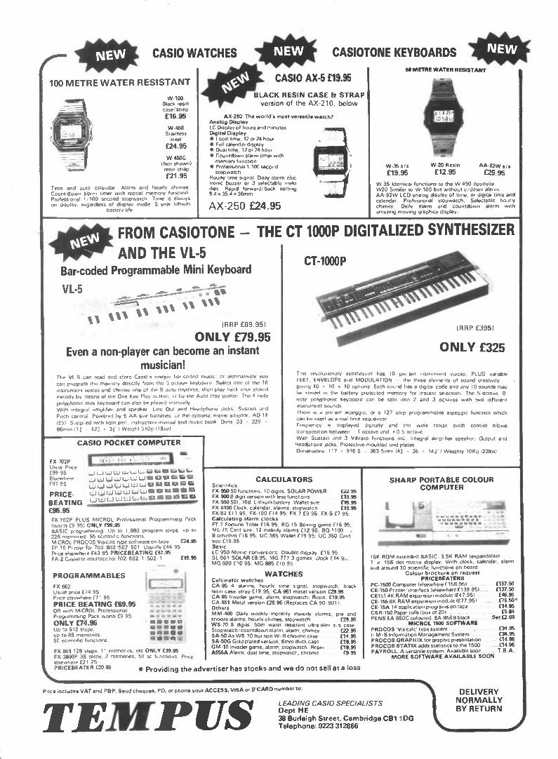
lepe CASIO WATCHES
100 METRE WATER RESISTANT
W-100 Black resin case/ strap
£16.95
W-450 Stainless
steel
£24.95
W-450C (Not shown) resin strap
£21.95
Time and auto calendar. Alarm arid hourly chimes. Count-down alarm timer with repeat memory function. Professional 1/100 second stopwatch. Time is always on display, regardless of display mode. 5 year lithium
battery life.
1011 CASIOTONE KEYBOARDS 1041F
CASIO AX-5 £19.95 1
BLACK RESIN CASE Er STRAP version of the AX-210, below
AX-210. The world's most versatile watch? Analog Display LC Display of hours and minutes Digital Display • Local time. 12 or 24 hour • Full calendar display • Dual time, 12 or 24 hour • Countdown alarm timer with memory function
• Professional 1'100 second stopwatch
Hourly time signal. Daily alarm elec tronic buzzer or 3 selectable melo dies Rapid forward/back setting. 9.4 r, 35 4 36mrn
AX-250 £24.95
90 METRE WATER RESISTANT
W-35 sis W-20 Resin AA-92W s/s
£19.95 £12.95 £25.95
W-35 Identical functions to the W 450 opposite. W20 Similar to W-100 but without c/down alarm. AA-92W LCD analog display of time, or digital time and calendar. Professional stopwatch. Selectable hourly chimes. Daily alarm and countdown alarm with amazing moving graphics display.
FROM CASIOTONE - THE
AND THE VI-5 Bar-coded Programmable Mini Keyboard
VI-5 4 Ian
IN 1111 "saNaN (RRP £89.95)
ONLY £79.95 Even a non-player can become an instant
musician! The VL 5 can read and store Casro's unique bar-coded music, or alternatively you
can program the memory directly from the 3 octave keyboard Select one of the 10 instrument voices and choose one of the 8 auto rhythms, then play back your stored
melody by means of the One Key Play button. or by the Auto Play button The 4 note polyphonic mini keyboard can also he played rri3nually With integral amplifier and speaker, Line Out and Headphone Jacks: Sustain and
Pitch control Powered by 5 AA size batteries, or the optional mauls adaptor, AD 1E fib) Supplied with light pen, instruction manual arid music book Dims 33 320 ,r 86mm 11 d ,r 12d ,r Weight 510g (18oil
CASIO POCKET COMPUTER
FX 702P Usual Price £99 95 Elsewhere 197.95
PRICE-BEATING £95.95
W La W L.Qi L4 WI La W La La t.11 Ili LI LS 1:2
La l.1 L..11,•.J U t4-i L*-11611111 Vi ma tzi La Li La V.8 ica um Es
Ea as U CCU
FX 702P PLUS MICROL Professional Programming Pack (worth £9 951 ONLY £99.95 BASIC program-twig Up to 1,680 program steps, up to 226 men-moos 55 scientific functions MICROL PROCOS Visicalc type software on tape £24.95 FP 10 Printer for 702 602 ,502 '501 Usually £44 95 Price elsewhere £43.95 PRICEBEATING £42.95 EA.2 Cassette interface for 702 602 1 - 502 1 £19.95
PROGRAMMABLES
IX 602 Usual price 1/4 95 Price elsewhere f 71.95
PRICE BEATING E69.95 OR with MICROL Professional Programming Pack worth £9 95
ONLY £74.95 Up to 512 steps, up to 88 memories. 50 scientific functions.
IX-601 128 steps, 11 memories, etc ONLY £39.95 FX•3600P 38 steps, 2 memories. 50 sc functions Price elsewhere £21 25
\ eFe'RICEBEATER E20.85 * Providing the adv
CT 1000P DIGITALIZED SYNTHESIZER
CT-1000P \ -
ii 0 01101.1.1.11.11.(RRP 095)
ONLY £325
This revolutionary synthesizer has 10 We sot instrument voices. PLUS variable FEET. ENVELOPE and MODULATION the three elements of sound creativity
giving 10 • 10 r, 10 options. Each sound has a digital code and any 10 sounds Cray be stored in the battery protected memory for instant selection. The 5-octave, 8
note polyphonic keyboard can be split into 2 and 3 octaves with two different Instrument sounds
there is a pre set arpeggio, or a 127 step programmable arpeggio function which can Ire used as a real time Sequencer Frequency is displayed digitally and the wide range pitch control allows transposition between 1 octave and c 0 5 octave With Sustain and 3 Vibrato functions etc; Integral amplifier speaker; Output arid Headphone lacks; Protective moulded end plates
Drrnerisrons 117 916 5 • 363 5rrut, (41 k 36 1411' I Weighty 10Kg 1221bs)
CALCULATORS Screntif rcs FX-950 50 functions, 10 digits. SOLAR POWER £22.95 FX-900 8 digit version with less functions £19.95 IX-550 50f, 10c1 Lithium battery Wallet size 115.95 FX•8100 Clock, calendar, alarms, stopwatch £19.95 FX-82 f 1 1 95, FX 100 114 95, FX 7 f 9 95, FX-5 £7 95. Calculating alarm clocks 11•7 Fortune Teller 116 95, BG 15 BOtong game (16 95; ML. /5 Card sue, 12 melody alarms £12.95, BO-1100 Biorhythm f 16 95, UC 365 Wallet £19.95: UC 360 Card size £19 95 Basic LC-950 Metric conversions. Double display £16.95 SL-801 SOLAR £8 95. MG-777 3 games, clock 114.9,, MG 880 f 10 95, MG 885 110.95
WATCHES Calculator watches CA-95 4 alarms, hourly time signal, stopwatch, black resin caserstrap £19 95: CA-951 metal version £29.95 CA-85 Invader game, alarm. stopwatch. Resin. £19.95 CA-851 Metal version £29.95 (Replaces CA 90 901) Others MM-400 Darly , weekly monthly melody alarms, pre and snooze alarms, hourly chimes, stopwatch f29.95 WS-70 6 digits 50m water resistant ultra slim s. s case. Stopwatch/countdown alarm, alarm, chrmes £22.95 SA•50 As WS 70 but non W, R chorme case f14.95 SA-50G Gold plated version, 6mm thick case £19.95 GM-10 Invader game, alarm, stopwatch. Resin £19.95 A656A Alarm, dual time, stopwatch, chrome £9.95
ertiser has stocks and we do not sell at a loss
SHARP PORTABLE COLOUR COMPUTER
16K ROM extended BASIC, 3.5K RAM (expandable). 7 u 156 dot matrix display. With clock, calendar, alarm and around 30 scientific functions on board.
Colour brochure on request PRICEBEATERS
PC-1500 Computer (elsewhere f 158.95) ... CE-150 Printer/Interface (elsewhere 1139.951. CE1514K RAM expansion module 147.95) CE -155 8K RAM expansion module (£77.951 . CE -15A 14 application programs on tape . CSR-150 Paper rolls (box of 201 . . PENS EA-850C coloured, EA-850B black
MiCROL 1500 SOFTWARE PROCOS 'Visicalc' type system .... I •S Information Management System . PROCOS GRAPHIX for graphic presentation 04.95 PROCOS STATIX adds statistics to the 1500 ..£14.95 PAYROLL. A versatile system. Available soon.. ..T.B.A.
MORE SOFTWARE AVAILABLE SOON
Price includes VAT and P&P. Send cheques. PO, or phone your ACCESS. VISA or B'CARD number to:
TEMP US LEADING CASIO SPECIALISTS Dept HE 38 Burleigh Street, Cambridge CB1 1DG Telephone: 0223 312866
£157.50 f137.50 f46.95 [76.50 • £14.95 £5.84
Set f2.69
£34.95 £34.95
'1\4, DELIVERY NORMALLY BY RETURN