Electronics lIb i ld - World Radio History
88
Electronics lIb i ld STATIC ELECTRICITY -The Space Age's Billion- Year -Old Gremlin ELECTRONIC CHALLENGES IN SUPERSONIC JET PROGRAM PROBLEMS AHEAD FOR TV TECHNICIANS - Integrated Circuits Will Force Major Changes SPICSs IOUS TRANSISTOR . 66.1 0-13IJONIdS C100MN11 3 47ZLZ NyWONIH r w .:SOW-147ZLZNIHOOL47IS 69SOM 4.**ACiirt.4; www.americanradiohistory.com
-
Upload
khangminh22 -
Category
Documents
-
view
1 -
download
0
Transcript of Electronics lIb i ld - World Radio History

Electronics lIb i ld STATIC ELECTRICITY -The Space Age's Billion- Year -Old Gremlin
ELECTRONIC CHALLENGES IN SUPERSONIC JET PROGRAM
PROBLEMS AHEAD FOR TV TECHNICIANS - Integrated Circuits Will Force Major Changes
SPICSs IOUS
TRANSISTOR
. 66.1 0-13IJONIdS
C100MN11 3 47ZLZ NyWONIH r w
.:SOW-147ZLZNIHOOL47IS 69SOM
4.**ACiirt.4; www.americanradiohistory.com
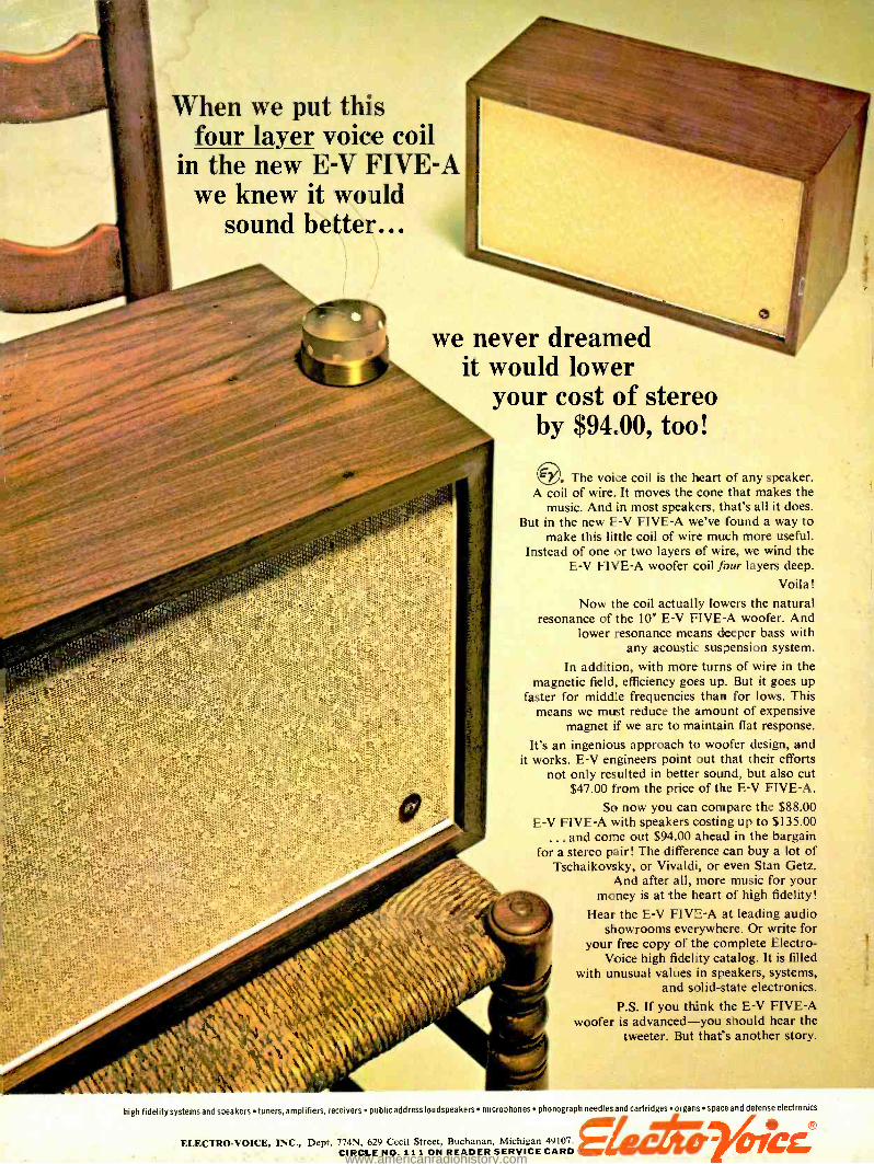
When we put this four layer voice coil
in the new E -V FIVE -A we knew it would
sound better...
we never dreamed it would lower
your cost of stereo by $9400, too!
The voice coil is the heart of any speaker. A coil of wire. It moves the cone that makes the
music. And in most speakers, that's all it does. But in the new E -V FIVE -A we've found a way to
make this little coil of wire much more useful. Instead of one or two layers of wire, we wind the
E -V FIVE -A woofer coil four layers deep. Voila!
Now the coil actually lowers the natural resonance of the 10" E -V FIVE -A woofer. And
lower resonance means deeper bass with any acoustic suspension system.
In addition, with more turns of wire in the magnetic field, efficiency goes up. But it goes up
faster for middle frequencies than for lows. This means we must reduce the amount of expensive
magnet if we are to maintain flat response.
It's an ingenious approach to woofer design, and it works. E -V engineers point out that their efforts
not only resulted in better sound, but also cut $47.00 from the price of the E -V FIVE -A.
So now you can compare the $88.00 E -V FIVE -A with speakers costing up to $135.00
... and come out $94.00 ahead in the bargain for a stereo pair! The difference can buy a lot of
Tschaikovsky, or Vivaldi, or even Stan Getz. And after all, more music for your
money is at the heart of high fidelity!
Hear the E -V FIVE -A at leading audio showrooms everywhere. Or write for
your free copy of the complete Electro- Voice high fidelity catalog. It is filled
with unusual values in speakers, systems, and solid -state electronics.
P.S. If you think the E -V FIVE -A woofer is advanced -you should hear the
tweeter. But that's another story.
1
high fidelity systemsand speakers tuners, amplifiers, receivers public address loudspeakers microphones phonograph needles and cartridges orgars space and defense electronics
410
OICC ELECTRO- VOICE, INC., Dept. 774N, 629 Cecil Street, Buchanan, Michigan 49107. CIRCLE NO. 111 ON READER SERVICE CARD www.americanradiohistory.com
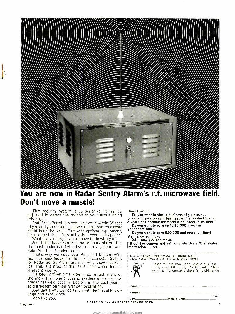
You are now in Radar Sentry Alarm's r.f. microwave field. Don't move a muscle!
This security system is so sensitive, it can be adjusted to detect the motion of your arm turning this page.
And if this Portable Model Unit were within 35 feet of you and you moved ... people up to a half -mile away could hear the siren. Plus with optional equipment, it can detect fire... turn on lights... even notify police.
What does a burglar alarm have to do with you? Just this: Radar Sentry is no ordinary alarm. It is
the most modern and effective security system avail- able. And it's also electronic.
That's why we need you. We need Dealers with technical knowledge. Fo' the most successful Dealers for Radar Sentry Alarm are men who know electron- ics. This is a product that sells itself when demon- strated properly.
It's been proven time after time. In fact, many of the more than one thousand readers of electronics magazines who became Dealers in the past year - sold a system on their first demonstration.
And that's why we need men with technical knowl- edge and experience.
Men like you.
July, 7967
How about it? Do you want to start a business of your own ...
or expand your present business with a product that in 8 years has become the world -wide leader in its field?
Do you want to earn up to $5,000 a year in your spare time?
Do you want to earn $20,000 and more full time? We'll show you how.
O.K., now you can move. Fill out the coupon and get complete Dealer /Distributor information ...free. r -
Mail to: RADAR DEVICES MANUFACTURING CORP. 22003 Harper Ave., St. Clair Shores, Michigan 48080
Please tell me how I can have a business of my own distributing Radar Sentry Alarm Systems. I understand there is no obligation.
Nanne
Address EW -7
City State & Code CIRCLE NO. t04 ON REAIDER SERVICE CARD
7
www.americanradiohistory.com
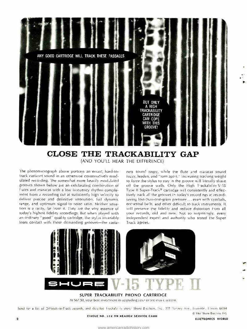
ANY GOOD CARTRIDGE WILL TRACK THESE 7-ASSAGES
BUT ONLY A HIGH
TRACKABILITY CARTRIDGE CAN COPE WITH THIS
GROOVE!
CLOSE THE TRACKABILITY GAP (AND YOU'LL HEAR THE DIFFERENCE)
The photomicrograph above portrays an errant, hard -to- track castanet sound in an otherwise conservatively mod- ulated recording. The somewhat more heavily modulated grooves shown below are an exhilarating combination of flutes and maracas with a low frequency rhythm comple- ment from a recording cut at sufficiently high velocity to deliver precise and definitive intonation, full dynamic range, and optimum signal -to -noise ratio. Neither situa- tion is a rarity, far from it. They are the very essence of today's highest fidelity recordings. But when played with an ordinary "good" quality cartridge, the stylus invariably loses contact with these demanding grooves -the casta-
Pi
SI--IVRE
nets sound raspy, while the flute and maracas sound fuzzy, leaden, and "torn apart." Increasing tracking weight to force the stylus to stay in the groove will literally shave off the groove walls. Only the High Trackability V -15 Type Il Super -Track® cartridge will consistently and effec- tively track all the grooves in today's recordings at record - saving less- than -one -gram pressure ... even with cymbals, orchestral bells, and other difficult to track instruments. It will preserve the fidelity and reduce distortion from all your records, old and new. Not so surprisingly, every independent expert and authority who tested the Super Track agrees.
SUPER TRACKABILITY PHONO CARTRIDGE At $67.50, your best investment in upgrading your entire music system.
Send for a list of Difficult -to -Track records, and detailed Trackability story: Shure Brothers, Inc., 222 Hartrey Ave
CIRCLE NO. 102 ON READER SERVICE CARD 2
Evanston, Illinois 60204
© 1967 Shure Brothers Inc.
ELECTRONICS WORLD
www.americanradiohistory.com
pec(robiesAolq
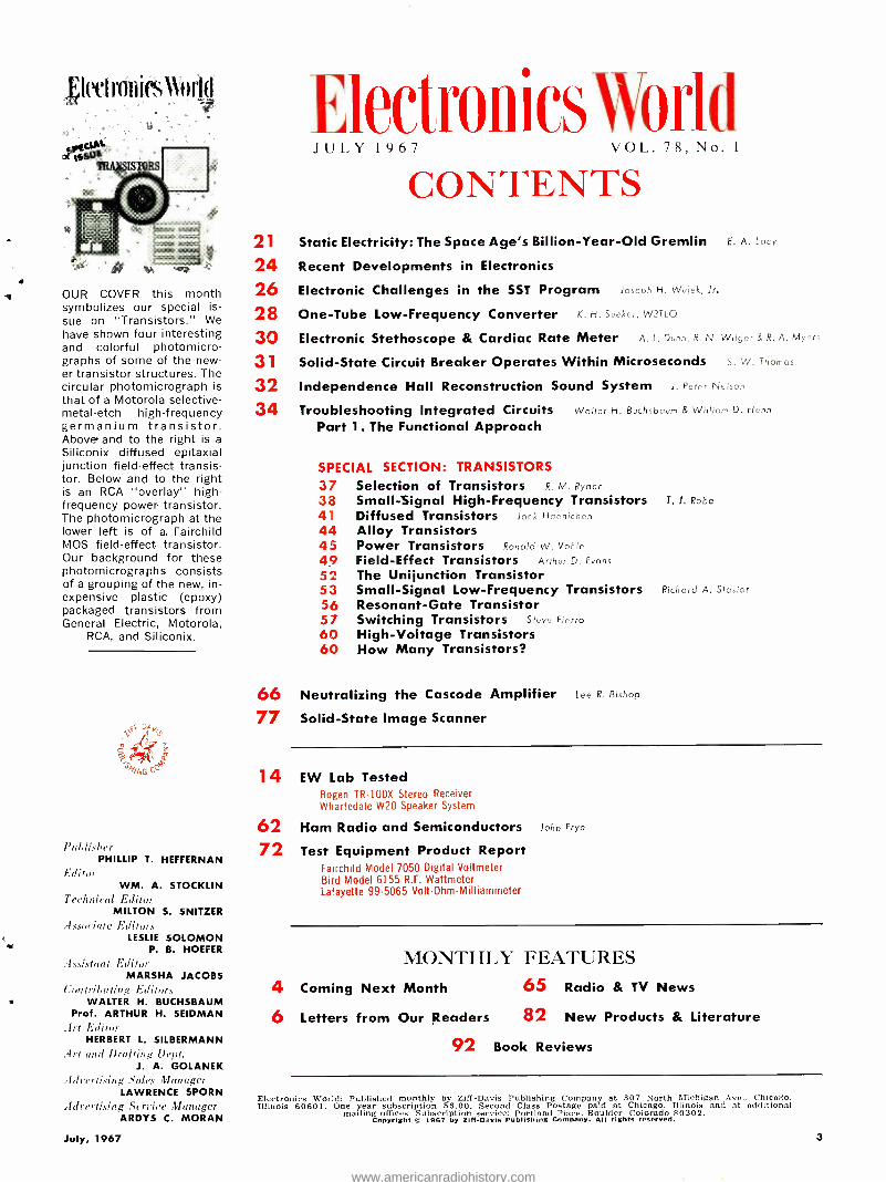
OUR COVER this month symbolizes our special is-
sue on "Transistors." We have shown four interesting and colorful photomicro- graphs of some of the new- er transistor structures. The circular photomicrograph is that of a Motorola selective - metal -etch high- frequency germanium transistor. Above- and to the right is a
Siliconix diffused epitaxial junction field -effect transis- tor. Below and to the right is an RCA "overlay" high -
frequency power- transistor. The photomicrograph at the lower left is of a. Fairchild MOS field -effect transistor. Our background for these photomicrographs consists of a grouping of the new, in- expensive plastic (epoxy) packaged transistors from General Electric, Motorola,
RCA, and Siliconix.
.e
J67i'iÜ
l'nLlishrr PHILLIP T. HEFFERNAN
Editor WM. A. STOCKLIN
Technical Editor MILTON S. SNITZER
.Issoria/i' Eillira. LESLIE SOLOMON
P. B. HOEFER
,i.,.aistant Edilnr MARSHA JACOBS
Contributing F,ditor., WALTER H. BUCHSBAUM
Prof. ARTHUR H. SEIDMAN Ist l'alilor
HERBERT L. SILBERMANN .1st and Drat ling Dept.
J. A. GOLANEK .Idreriising unles Rlandger
LAWRENCE SPORN
Adrerti.uing Neuire Manager ARDYS C. MORAN
21 24 26 28 30 31 32 34
Electronics World JULY 1967 VOL. 78, No. 1
CONTENTS Static Electricity: The Space Age's Billion- Year -Old Gremlin E. A. Lc cy
Recent Developments in Electronics
Electronic Challenges in the SST Program Jc rrrI H. We,, k, Jr.
One -Tube Low- Frequency Converter K. H. su./ W3T1Q
Electronic Stethoscope & Cardiac Rate Meter A. L. Dues. R. N.
Solid -State Circuit Breaker Operates Within Microseconds S. w. Thoma,
Independence Hall Reconstruction Sound System J. Peter Nelson
Troubleshooting Integrated Circuits Waller H. Buch5boum & William D. Hr:nn
Part 1. The Functional Approach
SPECIAL SECTION: TRANSISTORS
37 Selection of Transistors R. M. Rydor
38 Small - Signal High- Frequency Transistors T. J. Robe
41 Diffused Transistors Jac i Ha. race n
44 Alloy Transistors 45 Power Transistors Ronald W. va r,
49 Field- Effect Transistors Allar D. E.ans
52 The Unijunction Transistor 53 Small -Signal Low- Frequency Transistors Richard A. sfaciar
56 Resonant -Gate Transistor 57 Switching Transistors sh Fi..rro
60 High -Voltage Transistors 60 How Many Transistors?
66 Neutralizing the Cascode Amplifier Lse R. Bishop
77 Solid -State Image Scanner
14 EW Lab Tested Bogen TR -100X Stereo Receiver Wharfedale W20 Speaker System
62 Ham Radio and Semiconductors John Frye
72 Test Equipment Product Report Fairchild Model 7050 Digital Voltmeter Bird Model 6155 R.F. Wattmeter Lafayette 995065 Volt -Ohm- Milliammeter
MONTHLY FEATURES 4 Coming Next Month 65 Radio & TV News
6 Letters from Our Readers 82 New Products & Literature
92 Book Reviews
Electronics World: Published monthly by Ziff -Davis Publishing Company at 307 North Michigan Ave.. Chicago. Illinois 60601. One year subscription $6.00. Second Class Postage paid at Chicago. Illinois and at additional
mailing offices. Subscription service: Portland Place, Boulder. Colorado 80302. Copyright cu 1967 by Ziff -Davis Publishing Company. All rights reserved.
July, 1967 3
www.americanradiohistory.com
PRESENTS... The IDEAL Amplifier SA30 -30
Over 60 watts of dynamite
Clean Transparent Sound
Military -Grade Parts, Workmanship & Reliability
Only 1 -3/4" thin, 19" rack mount
Price $19900
For complete characteristics and
specifications write for Bulletin 114, or ask any proud owner.
MODEL 1/4 TRACK STEREO
SX124 ONLY $995
Modular Transport Low -Noise Circuitry
Third Head Monitoring
World's Finest Recording Quality Speed Response S/N 7-1/2 ±2db 30 to 25,000 55db 3-3/4 ±2db 30 to 15,000 50db
Gsay- zurr., International BOX 1000, DEPT. EW -7
ELKHART, INDIANA
MADE ONLY IN AMERICA CIRCLE NO. 97 ON READER SERVICE CARD
4 ELECTRONICS WORLD
COMING NEXT
MONTH SPECIAL FEATURE ARTICLES ON:
Audio Tape Recording
11 I:Ivei io»ies \1udtl
AUDIO TAPE
RECORDING
Two timely articles of interest to audiophiles and professional sound men will cover Selecting the Right Tape by Joseph Kempler of Audio Devices and Biasing in Magnetic Tape Recorders by John G. McKnight of Ampex. The audio tape article provides up -to -the minute information on the many varieties of tape available, including the cartridge units which are becoming so popular in both car and home. Also covered are valuable hints on recording so as to avoid print- through and distortion, along with proper storage methods to preserve valuable recordings. The article on biasing includes practical information on the biasing circuits used in home and professional tape recorders. The effect of various amounts of bias current is discussed along with the pro's and con's of different biasing schemes and freq uencies.
VALUE ENGINEERING FOR THE ELECTRONICS INDUSTRY A management philosophy of applying a forced organized approach to reducing costs while maintaining product quality is discussed in detail by Fred H. Possner, Director of Value Engineering at Air- borne Instruments Labs. Striking exam- ples of the efficacy of this approach are included.
CATV: PAST, PRESENT & FUTURE Jerry Hastings of Jerrold's CATV Divi- sion provides a comprehensive report on
the current status of community antenna television systems and their potential in the near and distant future.
THE OPERATIONAL AMPLIFIER: CIRCUITS & APPLICATIONS An in -depth discussion of these highly versatile controllable -gain modular or IC packages which have been widely used in computer and military circuits in the past but are now appearing in commer- cial and consumer products. New price and size reductions should stimulate use.
All these and many more interesting and informative articles will be yours in the August issue of ELECTRONICS WORLD . . . on sale July 20th.
.11i11
ZIFF-DAVIS William B. Ziff Chairman of the Board (1946 -1953) William Ziff President W. Bradford Briggs Executive Vice President Hershel B. Sarbin Senior Vice President Philip Sine Financial Vice President Walter S. Mills, Jr. Vice President, Circulation Stanley R. Greenfield Vice President, Marketing Phillip T. Heffernan Vice President, Electronics Division Frank Pomerantz Vice President, Creative Services Arthur W. Butzow Vice President, Production Edward D. Muhlfeld Vice President, Aviation Division Irwin Robinson Vice President, Travel Division
PUBLISHING COMPANY Editorial and Executive Offices One Park Avenue New York, New York 10016 212 679 -7200
NEW YORK OFFICE 212 679 -7200 James J. Sullivan Joseph E. Halloran
MIDWESTERN OFFICE 307 North Michigan Avenue Chicago, Illinois 60601 312 726 -0892 Midwestern Advertising Manager, Royce Richard
WESTERN OFFICE 9025 Wilshire Boulevard Beverly Hills, California 90211 213 CRestview 4 -0265; BRadshaw 2 -1161 Western Advertising Manager, Bud Dean
JAPAN James Yogi Ichikawa Mansion =4, Sakuragaoka Shibuya -ku, Tokyo 462- 2911 -3
CIRCULATION OFFICE Portland Place, Boulder, Colorado 80302
Member Audit Bureau of
Circulations
Radio & TV News Radio News Radio -Electronic Engineering Trademarks Reg. U.S. Pat. Off. SUBSCRIPTION SERVICE: All subscription correspondence should be addressed to Electronics World, Circu- lation Department. Portland Place, Boulder. Colorado 80302. Please allow at least six weeks for change of address. Include your old address, as well as new -enclosing if possible an address label from a recent issue. EDITORIAL CONTRIBUTIONS must be accompanied by return postage and will be handled with reasonable care; however publisher assumes no responsibility for return or safety of art work, photographs, or manuscripts. ELECTRONICS WORLD (July, 1967, Vol. 78, No. 1 I. Published monthly at 307 North Michigan Avenue. Chicago, Illinois 60601. by Ziff -Davis Publishing Company -also the publishers of Airline Management and Marketing, Boating, Business & Commercial Aviation, Car and Driver, Cycle, Flying, HiFi /Stereo Review. Modern Bride, Popular Aviation. Popular Electronics, Popular Photography. Skiing, Skiing Area News, and Skiing Trade News. (Travel Weekly is published by Robinson Publications, Inc.. a subsidiary of Ziff -Davis Publishing Company.) One year subscription rate for U.S., U.S. Possessions, and Canada, $6.00; all other countries, $7.00. Second Class postage paid at Chicago, Illinois and at additional mailing offices. Authorized as second class mail by the Post Office Department, Ottawa, Canada and for payment of postage in cash.
www.americanradiohistory.com
LOOK! A New Electronics Slide Rule
with Instruction Course r"- I,
6= A I
IC,
D
9 3 .1
111'. 1'1 - 70 80 10 100 ,
' 5 E 1 8 9 10
;
1
3
i ° 9 9 110- c
! . I
G
, u,
r....a. ry...n.1 Cftspl. .
. ..,
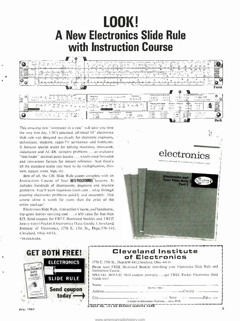
This amazing new "computer in a case" will save you time the very first day. CIE's patented, all -metal 10" electronics slide rule was designed specifically for electronic engineers, technicians, students, radio -TV servicemen and hobbyists. It features special scales for solving reactance, resonance, inductance and AC -DC circuitry problems ... an exclusive "fast- finder" decimal point locater ... widely -used formulas and conversion factors for instant reference. And there's all the standard scales you need to do multiplication, divi-
sion, square roots, logs, etc. Best of all, the CIE Slide Rule comes complete with an
Instruction Course of four AUTO-PROGRAMMED *lessons. It includes hundreds of illustrations, diagrams and practice problems. You'll learn ingenious short cuts...whip through exacting electronics problems quickly and accurately. This course alone is worth far more than the price of the entire package!
Electronics Slide Rule, Instruction Course, and handsome, top -grain leather carrying case . .. a $50 value for less than $25. Send coupon for FREE illustrated booklet and FREE heavy vinyl Pocket Electronics Data Guide. Cleveland Institute of Electronics, 1776 E. 17th St., Dept. EW -141, Cleveland, Ohio 44114.
*TRADEMARK
GET BOTH FREE!
Send coupon today -
(
t0..
Front
11111111111.111111Ne_
electronics
Eleetro Your Slide itule',
Part
Cleveland Institute of Electronics
1776 E. 17th St., Dept.EW- 141,Cleveland, Ohio 441 14
Please send FREE Illustrated Booklet describing your Electronics Slide Rule and Instruction Course. SPECIAL BONUS! Mail coupon promptly ... get FREE Pocket Electronics Data Guide too!
Name (PLEASE PRINT)
Address County
City State Zih A leader in Electronics Training ...since 1934.
CIRCLE NO. 123 ON READER SERVICE CARD July, 1967 5
J
www.americanradiohistory.com
WORTH
WAITING
FOR!
D YNACO
STEREO
120 3 years of intensive develop- ment give you all the virtues of transistorized amplifiers with none of the harsh "transistor sound."
The combined distortion of the Stereo 120 and the PAS -3X perfectionist's preamplifier does not exceed 1 10 of 1% from 20 to 20,000 cycles at most useable power levels.
60 watts continuous power per channel; fully regulated power supply; complete elec- tronic protection (no fuses or thermal cutouts) against open or short circuits; impeccable specifications; modular design for easy kit building.
Write for full specifications and detailed test reports.
dynraco 3912 POWELTON AVENUE, PHILADELPHIA, PA. 19104
LETTERS FROM OUR
READERS
SILICONIX FET'S To the Editors:
Your May issue contained an article on "Field- Effect Transistor Circuits" by Wujek and McGee. Most of these cir- cuits use field -effect transistors produced by Siliconix. However, in contacting the company to get some of these FET's, I have learned that the low prices quoted at the very beginning of the article are no longer in effect. As I re- call, these prices were 81.00 for the U -110 transistor or 82.75 for a pack- age consisting of the U -110 and U -112.
ROBERT G. SIMPSON Los Angeles, Calif.
Reader Simpson is quite correct in that these low prices were the ones quoted in a Siliconix ad that appeared wrral months ago in ELECTRONICS WORLD. The ad represented ( limited time offer and was intended to .stimu- late use of the new FET's. The prices quoted in the ad actually expired at the end of February, and the company reports that their mission has been ac- complished in introducing FET's to a large number of people.
For those readers who are interested in using these transistors note, the U -110, U -112, U -146, and U -147 are available from local Siliconix distribu- tors at prices of $5.25. $'4.55, $3.25, and $2.95, respectively, in quantities from 1 to 29. The manufacturer will be glad to direct all inquiries for these transistors to their local distributor.s or will furnish the name of the nearest distributor where such transistors may be obtained. Write to Siliconix Inc., 1140 West Evelyn. Avenue, Sunnyvale, California 94086. -Editors
* * *
ELECTRONIC EAVESDROPPING To the Editors:
Apropos of your article on electronic snooping, I thought a recent editorial in Life magazine on the subject "Ways To Control Snooping" expressed my senti- ments exactly. One paragraph in this editorial is as follows:
"But if lawmen have the power to tap wires and bug rooms of people they believe guilty, what is to prevent them from overhearing the private words of the innocent? Who has the right to overhear, and for what purpose? 'We
act differently if we believe we are be- ing observed,' Vice President Humphrey has written. `If we can never be sure whether or not we are being watched and listened to, all our actions will be altered and our very character will change.' Associate justice William Bren- nan has limned another threat: 'Elec- tronic surveillance, in fact, makes the police omniscient; and police omni- science is one of the most effective tools of tyranny.' "
PAUL BRADFORD New York, N.Y.
To the Editors: Your article on electronic eavesdrop-
ping ( April issue) vvas very enlighten- ing. However, I have some questions. (1) An Attorney General once said that banging on the floor will disable a bug for 15 minutes or so. Any truth to this? (2) If I suspect that a room is bugged, how can I hold a private conversation? (3) Why do some bugs claim a hun- dred feet of range while others mention thousands of feet? (4) How far away can a bug detector find a bug? (5) How effective are the tailing devices mentioned in the article? (6) "The i\lan From U.N.C. L.E." uses exotic commu- nications systems. Are they for real?
joiiN NV. IIOLLANDER Brooklyn, N.Y.
These are just a few of the questions we have received on our eavesdropping story. Very brief answers follow:
1. Only if you bang directly on or near enough to the bug to damage it will you stop operation. Otherwise noth- ing will happen except that you may hurt your hand.
2. Whispered conversation can take place if a radio, TV set, or music sys- tem is turned up to a reasonable vol- ume. The louder background over- shadows the conversation. The safest place to avoid eavesdropping is in the center of a large room away from furni- ture, walls, and overhead fixtures. An- other ploy sometimes used is to con- verse in the bathroom with the shower running.
3. Despite all claims, most r.f. bugs commercially available can only reach out 100 feet or so with any reliability.
(Continued on page 12) CIRCLE NO. 121 ON READER SERVICE CARD 6 ELECTRONICS WORLD
www.americanradiohistory.com
MALLORY Tips for technicians IA- Choosing electrolytic capacitors
for color TV
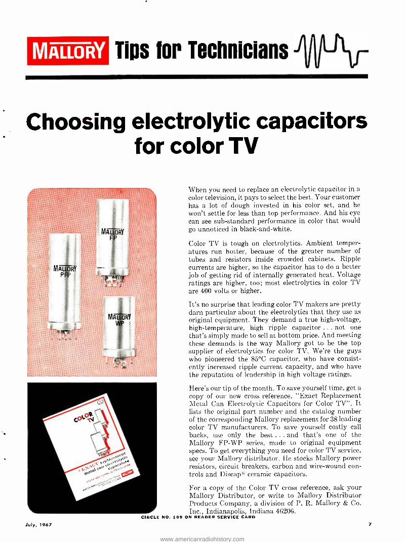
When you need to replace an electrolytic capacitor in a color television, it pays to select the best. Your customer has a lot of dough invested in his color set, and he won't settle for less than top performance. And his eye can see sub -standard performance in color that would go unnoticed in black- and -white.
Color TV is tough on electrolytics. Ambient temper- atures run hotter, because of the greater number of tubes and resistors inside crowded cabinets. Ripple currents are higher, so the capacitor has to do a better job of getting rid of internally generated heat. Voltage ratings are higher, too; most electrolytics in color TV are 400 volts or higher.
It's no surprise that leading color TV makers are pretty darn particular about the electrolytics that they use as original equipment. They demand a true high -voltage, high- temperature, high ripple capacitor ... not one that's simply made to sell at bottom price. And meeting these demands is the way Mallory got to be the top supplier of electrolytics for color TV. We're the guys who pioneered the 85 °C capacitor, who have consist- ently increased ripple current capacity, and who have the reputation of leadership in high voltage ratings.
Here's our tip of the month. To save yourself time, get a copy of our new cross reference, "Exact Replacement Metal Can Electrolytic Capacitors for Color TV ". It lists the original part number and the catalog number of the corresponding Mallory replacement for 38 leading color TV manufacturers. To save yourself costly call backs, use only the best ... and that's one of the Mallory FP -WP series, made to original equipment specs. To get everything you need for color TV service, see your Mallory distributor. He stocks Mallory power resistors, circuit breakers, carbon and wire -wound con- trols and Discap' ceramic capacitors.
For a copy of the Color TV cross reference, ask your Mallory Distributor, or write to Mallory Distributor Products Company, a division of P. R. Mallory & Co. Inc., Indianapolis, Indiana 46206.
CIRCLE NO. 109 ON READER SERVICE CARD
July, 1967 7
www.americanradiohistory.com
Discover the ease and excitement of NRI's
3D) I__
H h',"]_-;_co) 9)
of ELECTRONICS TV -RADIO TRAINING
10 HOME -STUDY PLANS TO CHOOSE FROM
Ask men whose judgment you respect about NRI's three dimensional method of home - study training. Ask about the new, remarkable NRI Achievement Kit. Ask about NRI custom - designed training equipment, programmed for the training of your choice to make Elec- tronics come alive in an exciting, absorbing, practical way. Ask about NRI "bite- size" texts, as direct and easy to read as 50 years of teaching experience can make them. Achieve- ment Kit ... training equipment ... bite -size texts ... the three dimensions of home -study training; the essentials you must have to make
OVER 50 YEARS OF LEADERSHIP
8
H
learning easier, more interesting, more mean- ingful. You get them all from NRI.
Whatever your interest . . . whatever your need ... whatever your education ... pick the field of your choice from NRI's 10 instruction plans and mail the postage free card today for your free NRI catalog. Discover just how easy and exciting the NRI 3- DIMENSIONAL METHOD of training at home can be. Do it today. NATIONAL RADIO INSTITUTE, Elec- tronics Division, Washington, D.C. 20016,
BEGIN NOW AN ABSORBING
ADVENTURE -LEARN ELECTRONICS
THE EASY NRI WAY -MAIL CARD TODAY
IN ELECTRONICS TRAINING
ELECTRONICS WORLD
www.americanradiohistory.com
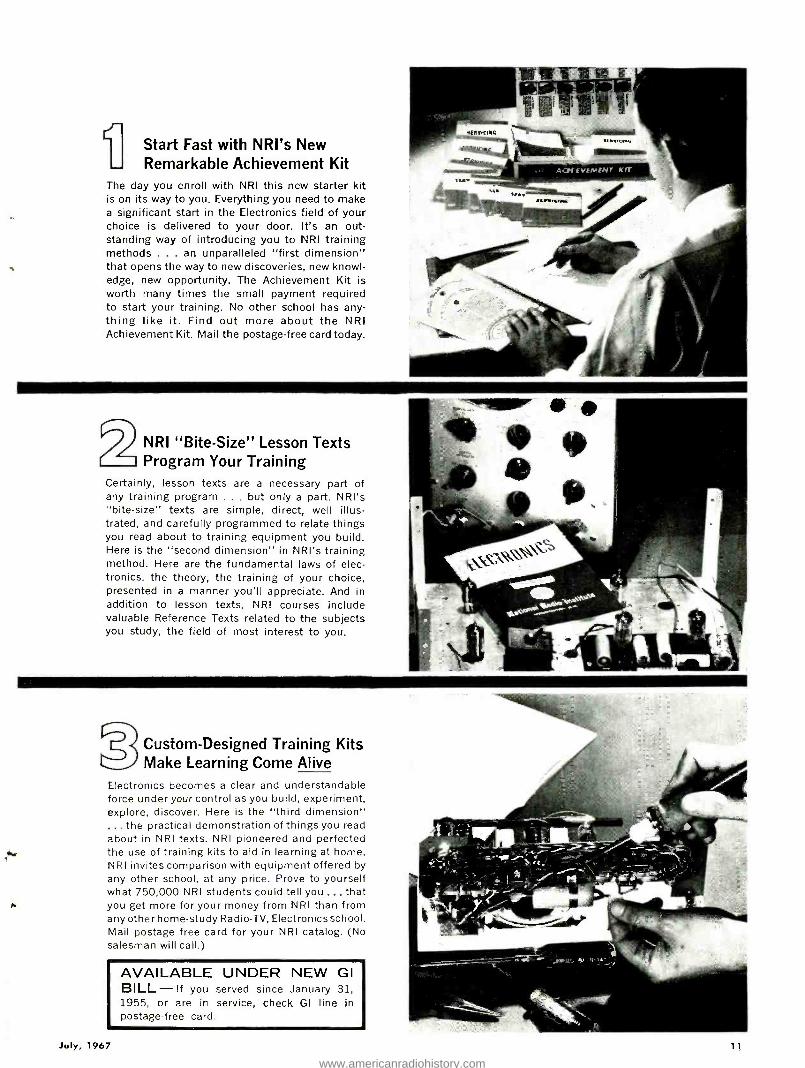
Start Fast with NRI's New Remarkable Achievement Kit
The day you enroll with NRI this new starter kit is on its way to you. Everything you need to make a significant start in the Electronics field of your choice is delivered to your door. It's an out- standing way of introducing you to NRI training methods ... an unparalleled "first dimension" that opens the way to new discoveries, new knowl- edge, new opportunity. The Achievement Kit is worth many times the small payment required to start your training. No other school has any- thing like it. Find out more about the NRI Achievement Kit. Mail the postage -free card today.
NRI "Bite- Size" Lesson Texts Program Your Training
Certainly, lesson texts are a necessary part of any training program ... but only a part. NRI's "bite- size" texts are simple, direct, well illus- trated, and carefully programmed to relate things you read about to training equipment you build. Here is the "second dimension" in NRI's training method. Here are the fundamental laws of elec- tronics, the theory, the training of your choice, presented in a manner you'll appreciate. And in addition to lesson texts, NRI courses include valuable Reference Texts related to the subjects you study, the field of most interest to you.
2 Custom -Designed Training Kits Make Learning Come Alive
Electronics becomes a clear and understandable force under your control as you build, experiment, explore, discover. Here is the "third dimension" ... the practical demonstration of things you read about in NRI texts. NRI pioneered and perfected the use of training kits to aid in learning at home. NRI invites comparison with equipment offered by any other school, at any price. Prove to yourself what 750,000 NRI students could tell you ... that you get more for your money from NRI than from any other home -study Radio -TV, Electronics school. Mail postage free card for your NRI catalog. (No salesman will call.)
AVAILABLE UNDER NEW GI BILL - If you served since January 31, 1955, or are in service, check GI line in postage -free card.
July, 1967 11
www.americanradiohistory.com
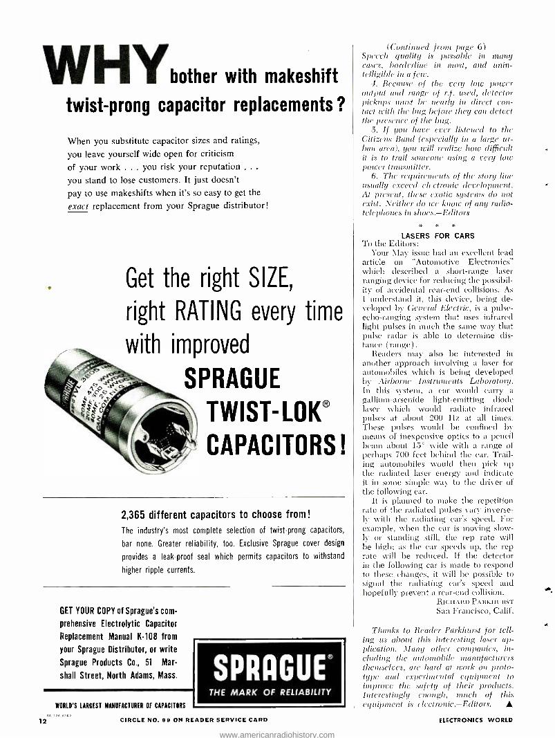
WH with makeshift
twist -prong capacitor replacements ?
When you substitute capacitor sizes and ratings,
you leave yourself wide open for criticism
of your work ... you risk your reputation .. .
you stand to lose customers. It just doesn't
pay to use makeshifts when it's so easy to get the
exact replacement from your Sprague distributor!
Get the right SIZE,
right RATING every time
with improved
SPRAGUE
TWIST -LOKS
CAPACITORS!
2,365 different capacitors to choose from!
The industry's most complete selection of twist -prong capacitors,
bar none. Greater reliability, too. Exclusive Sprague cover design
provides a leak -proof seal which permits capacitors to withstand
higher ripple currents.
GET YOUR COPY of Sprague's com-
prehensive Electrolytic Capacitor
Replacement Manual K -108 from
your Sprague Distributor, or write
Sprague Products Co., 51 Mar-
shall Street, North Adams, Mass.
12
WORLD'S LARGEST MANUFACTURER OF CAPACITORS
SPRAGUE® THE MARK OF RELIABILITY
CIRCLE NO. 99 ON READER SERVICE CARD
(Continued from page 6) Speech quality is passable in nand cases, borderline in most, and unin- telligible in a few.
4. Because of the very low power Output and range of r.f. used, detector pickups must be nearly in direct con- tact with the bug before they can detect the presence of the bug.
.5. If you have ever listened to the Citizens Band (especially in a large ur- ban area), you will realize how difficult it is to trail someone using a very low power transmitter.
6. The requirements. of the story line usually exceed electronic development. At present, these exotic systems do not exist. Neither do we know of any radio- telephones in shoes. -Editors
:r
LASERS FOR CARS To the Editors:
Your May issue had an excellent lead article on "Automotive Electronics" which described a short -range laser ranging device for reducing the possibil- ity of accidental rear -end collisions. As I understand it, this device, being de- veloped by General Electric, is a pulse - echo- ranging system that uses infrared light pulses in much the same way that pulse radar is able to determine dis- tance (range).
Readers may also be interested in another approach involving a laser for automobiles which is being developed by Airborne Instruments Laboratory. hI this system, a car would carry a
gallium -arsenide light- emitting diode laser which would radiate infrared pulses at about 200 Hz at all times. These pulses would be confined by means of inexpensive optics to a pencil beam about 15° wide with a range of perhaps 700 feet behind the car. Trail- ing automobiles would then pick up the radiated laser energy and indicate it in some simple way to the driver of the following car.
It is planned to make the repetition rate of the radiated pulses vary inverse- ly with the radiating car's speed. For example, when the car is moving slow- ly or standing still, the rep rate will be high; as the car speeds up, the rep rate will be reduced. If the detector in the following car is made to respond to these changes, it will be possible to signal the radiating car's speed and hopefully prevent a rear -end collision.
RIC:IIARD PARKIIURST San Francisco, Calif.
Thanks to Reader Parkhurst for tell- ing us about this interesting laser ap- plication. Dlany other companies, in- cluding the automobile manufacturers themselves, are hard at work on proto- type and experimental equipment to improve the safety of their products. Interestingly enough, ill reh of this equipment is electronic. -Editors.
ELECTRONICS WORLD
www.americanradiohistory.com
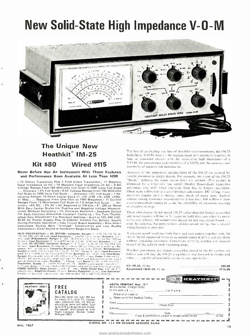
New Solid -State High Impedance V -O -M
The Unique New Heathkit IM -25
Kit $80 Wired $115 Never Before Has An Instrument With These Features
and Performance Been Available At Less Than $200
13 Silicon Transistors Plus 2 Field Effect Transistors. 11 Megohm Input Impedance on DC 10 Megohm Input Impedance on AC 9 DC Voltage Ranges From 150 Millivolts Full Scale to 1500 Volts Full Scale
. Accuracy .3% Full Scale 9 AC Voltage Ranges From 150 Millivolts Full Scale to 1500 Volts Full Scale ... Accuracy 5% Full Scale 7 Re- sistance Ranges, 10 Ohms Center Scale xl, x10, x100, x1 k, x10k, x100k, xl Meg . Measures From One Ohm to 1000 Megohms 11 Current Ranges From 15 Microamps Full Scale to 1.5 Amps Full Scale . Ac- curacy *4% DC, t 5% AC AC Response to 100 kHz 6 ", 200 ua Meter With Zero Center Scales For Positive and Negative Voltage Measure- ments Without Switching 1% Precision Resistors Separate Switch For Each Function Eliminates Constant Changing Ten -Turn Thumb - wheel Zero Adjustment For Precision Settings Built -In 120 /240 VAC, 50 -60 Hz Power Supply Plus In- Cabinet Holders For Battery Supply During Portable Operation Easy Circuit Board Assembly New Heath Instrument Styling With "Unitized "" Construction and Low Profile Appearance Color Styled in Handsome Beige and Black
IM -25 SPECIFICATIONS - DC SECTION: Voltmeter: Ranges: 0 - 0 -15, 0.5, 1.5, 15, 50, 150, 500, 1500 volts full scale. Input Resistance: 11 megch,r,s on oll ronges. Accuracy: t3' of full scale. Milliammeter: Ranges: 0 - .015, 05, 0.15, 0.5, 1 5, 5, 15, 50, 150, 500, 1500 mu full scale. Input Resistance: 0.1 ohm (1500 roo) to 10 K ohm (0 015 ma). Accuracy: o- of full scale. AC SECTION: Voltmeter: Ranges: 0 - 0.15, 0.5, 1.5, 15, 50, 150, 500, 1500 volts full scale. Input Resistance: 10 megohm shunted by 150 uaf. (Measured at probe tip.! Ac- curacy: '°S , of full scale. Frequency Response: 32 db 10 Hz - 100 kHz. Milliammeter: Ranges: 0 - 0.015, 0.05, 0.15, 0.5, 1.5, 5, 15, 50, 150, 500, 1500 ma. full stole. Input Resistant - once: 0.1 ohm (1500 ma) to 10 k ohm (0.015 ma). Accuracy: g, 5'; of full scale. Ohm Meter: Ranges: 10 ohm center scale xl, x10, x100, xl k, x10k, x100k, xl meq. Probe: Combined AC -
OHMS - DC switching probe, single jack input for Probe and Ground connections, Circuit ground isolated from cabinet. Dividers: I `; Precision Type. Meter: 6 ", 200 ua, 100 movement. Transistors, Diodes: 2 - 2N4304 FETronsistor; 13 - 2N3393 silicon junction transistor; 1 -
9.1 V zener diode; 1 -13 V zener diode; 4-1N191 germanium diode; 1 silicon Power Supply diode. POWER SUPPLIES: Ohms Circuit: 3 volts, (C - cells). Ohms Circuit Bias: 1.35 volt (ElN Mercury Cell). Amplifier Circuit: 18 volts. Battery Operation: C cells. Line Operation: Transformer operated ix wove circuit, operable on either 120 or 240 V AC 5060 Hz.
*Ma
July, 1967
FREE CATALOG Describes these and over 250 kits for stereo.' hi -fi, color TV, amateur radio, shortwave, test, CB, marine, educational, home and hobby. Save up to 50% by doing the easy assem- bly yourself. Mail coupon or write Heath Company, Benton Harbor, Michigan 49022
The first of an exciting new line of Heathkit test instruments, the IM -25 Solid -State V -O -M does all the measurement jobs normally required in tube or transistor circuits with the no- loading high impedance of a
VTVM, the convenience and versatility of a VOM, and the accuracy and sensitivity of separate lab instruments.
Accuracy of the impressive specifications of the 1M -25 arc assured by careful attention to design details. For example, the input of the IM -25 "floats," isolating the input circuit from the cabinet. (The cabinet is grounded by a three -wire line cord.) Double Zener -diode regulation minimizes zero shift when changing from line to battery operation. Ohms scale calibration is a set -and- forget adjustment. DC voltage meas- urements require only a shorted input check of meter zero. Applied voltage during resistance measurements is less than 100 millivolts from a constant -current source to avoid the possibility of erroneous readings or circuitry damage.
Those who choose the kit model IM -25 rather than the factory assembled and tested version will find it far easier to build than any other kit meter we've ever offered. All components mount on just one circuit hoard ... even the switches. No more tedious divider circuit wiring. And a special wiring harness is provided.
A die-cast panel bezel ties both front and rear panels together- with the circuit board supported between to permit removal of the cabinet shells without impairing operation. Convenient carrying to indIes are recessed in each of the cabinet shell mounting strips.
Whether you choose the factory assembled model or the kit version, we believe you will lind the 1M -25 a significant step forward in design and value ... capable of creditable service in any application.
Kit IM -25, 10 lbs. Assembled IMW -25, 10 lbs .
MM WM Man MW MO MW MM MM WM WM WM
HEATH COMPANY, Dept. I5.1 Benton Harbor, Michigan 49022
$80.00 $115.00
L] Enclosed is $ plus shipping.
Please send model (s)
Please send FREE Heathkit Catalog.
Name
1
CIRCLE NO.
Address
City
Please Print)
State Zip- Prices & specifications subject to change without notice. TE -158
>
14 ON READER SERVICE CARD 13
www.americanradiohistory.com

EW
LAB TESTED
HI -FI PRODUCT ßEPURT TESTED BY HIRSCH -HOUCK LABS
Bogen TR -100X Stereo Receiver Wharfedale W20 Speaker System
Bogen TR -100X Stereo Receiver For copy of manufacturer's brochure, circle No. 34 on Reader Service Card.
I? 1 IN NI !1IN
IN f:1 144 NI
THE Bogen TR -100X solid -state AM- FM stereo receiver combines operat-
ing simplicity with ample control flexibility for most users, and at a moderate price, Using silicon transis- tors throughout, the TR -100X has a sensitive, stable FM tuner, an AM tuner, dual preamplifiers, and a pair of 30 -watt (music power) amplifiers.
The FAI tuner has a tuned r.f. ampli- fier, three i.f. stages, and a ratio detec- tor. The shielded front -end also con- tains the AM oscillator and the tuning capacitor for the AM r.f. amplifier. Two of the FM i.f. stages do double duty as AM i.f. amplifiers. The tuning meter (which is tuned for maximum reading) operates from the AM detector or from a diode detector in the FM i.f. section.
The switc ii 1g-type multiplex de- Io.O
r 5.0
rc
Z 2.0 o
v , I.0
0.5
0.2
BOGEN TR -100X
modulator has traps which very effec- tively eliminate SCA interference (whistles and birdies) from the back- ground of FM- stereo broadcasts. The 38 -kHz oscillator is gated on automati- cally by the 19 -kHz pilot carrier, which also synchronizes it. A separate transis- tor operates the incandescent stereo - indicator lamp on the dial face.
The audio section has a pair of two - stage feedback -type phono equalizing preamps and switched inputs for AM, FM, Phono, and Aux. The Tape -Output jacks supply the selected signal to a tape recorder, unaffected by volume or tone controls. There is no provision for monitoring from the tape. The tone controls act on both channels simul- taneously. The volume control is loud- ness- compensated, boosting both lows
10.0
BOTH CHANNELS DRIVEN B11 LOADS, 1205.2.C. LINE (ONE CHANNEL MEASURED)
REF. -POWER OUTPUT (20W) HALF -POWER OUTPUT( -3dB) -- -LOW POWER OUTPUT (-100)
/ - - O.I
20 50 100 200 500 1k 2k FREQUENCY -H
14
5k 10k 20k
5.0
2.0
á z 1.0 o
0.2
0.1 .2 .5 2 5 10 20 50
CONTINUOUS(EOUIV.) SINE -WAVE POWER OUTPUT PER CHANNEL -WATTS
and highs as the setting is reduced. There is no provision for disabling the loudness compensation. A separate bal- ance control adjusts channel balance.
The driver transistors are transform- er- coupled to the output transistors which, in turn, are direct -coupled to the speakers, without blocking capaci- tors. A fixed -response roll -off below 20 Hz prevents damage to transistors or speakers by subsonic transients. A front -panel switch selects either or both of two pairs of speakers or switches the outputs to a front -panel headphone jack. The control complement is com- pleted by two slide switches for a.c. power and stereo mono selection (ef- fective on all inputs) .
The FM tuner of the TR -100X is rated at 2.7 microvolts IHF usable sen- sitivity. We measured it as 2.9 eV, well within the limits of normal measure- ment tolerances. The TR -100X was non -critical to tune and had a little over 1l distortion at 100% modulation. The FM frequency response was ±1.5 dB from 30 to 15,000 Hz. Stereo chan- nel separation was better than 30 dB from 150 to 1000 Hz and better than 20 dB from 30 to 10,000 Hz.
The amplifier frequency response was ±1 dB from 20 to 20,000 Hz at maximum volume setting. At normal lis- tening levels the loudness compensa- tion boosted lows by about 10 dB and highs by about 5 dB. The bass tone control affected on y frequencies below 100 Hz at fist, pre gressively exte idi) g
BOGEN TR -IOOX
BOTH CHANNELS DRIVEN BR LOADS, 120V.A.C.L NE (ONE CHANNEL MEASURED) -1 Hz TOTAL HARM DST.
- - --60 /7000 Hz 14:I IM DIST.
100
CIRCLE NO. 198 ON READER SERVICE CARD - www.americanradiohistory.com
5881
GONMUNICIAYIN>wl jVALin
6680/1 2AU7A L_
5881
46B/ 8298a 6t
Your Sylvania distributor can analyze your electronic replacement needs. To save you time and money. He can do an inventory analysis for you -at no cost. You'll learn which tubes to stock in quantity -and which ores not to. You'll prevent emergencies when tubes and semiconductors need replacing. Your Sylvania man is a tube ar_c semiconductor ex- pert. Because he's always in tcuch with Sylvania product ar d applications engineering staffs, so he's always kept up to date. And we furnish him with detailed technical ir.for- mation about tube and semiconductor applications -industry by industry. So he knows your prob =ems -and has the answers. Help yoc.raelf to a free analysis of your replace- ment need3. Gall your nearby Sylvania distribitor now. YoTl= save yourself some trouble. And money, too. Sylvania Electronic Tube Division, Electronic Com- ponents Group, Seneca Falls, New York 13148.
SI'LVANIA SUBSIDIARY O - GTE GENERPL-ELEPHONE & ELECTRONICS V l
2021 2D21 5692
SYLvANIA
GB1?52- $ USA ----
GOLD BRAND
SYLVANIA
GB1252- 6U8A
GOLD BRAND
SYLVANIA
GB-6005 GCLO BLAND J
SYLVANIA SYLVANIA
GB-6005
GOLD BRAND
SYLVANIA
GB-6005
GOLD LLANO
GB-6005
GOLD BRAND
SYLVANIA
GB-6005
GOLD BRAND 5551
www.americanradiohistory.com
If it moves,
The Antenna Specialists
have a great new CB antenna
to help it communicate!
New "Grip- Stick" magnetic mount sticks to its business at all legal speeds! VSWR less than 1.5/ 1.0, capacity- matched. 16' cable. Less than 27" long. No -mar vinyl underside Model M -168.
ew "Sea- Hook" Half- wave marine ntenna has exceptionally low radiation ngle. No ground plate required! Spring -
loaded fold -down feature. White cycolac ase, chrome -plated brass parts. VSWR less an 1.5'1.0. Model ASM -23.
Ìew "Sky-Hook" fiberglas ai CB an- tenna- low -profile design, wind -rated over 250 mph. Temp. range: minus 50 °Fl plus 200 °F. VSWR 1.5/1.0 or better. Only 24"
ng- reduces static, gives ample ground 1 M -149. _
the antenna specialists co.
Div. of Anzac Industries, Inc. 12435 Euclid Ave., Cleveland, Ohio 44106
Whatever your need, you can
trust the "Stripes of Quality "!
Export: 64 -14 Woodside Ave, Woodside, N.Y., 11377
CIRCLE NO. 124 ON READER SERVICE CARD 16
+5
-5 e
Id CC -25
30
-35
-40 20
,REQUENCY [ RESPONSE I iiii1 -i ; -ii®iii
BOGEN TR 00X RCVR. (STEREO)
J
I;: SEAR ATION
00 200 500 1k 2k
FREQUENCY -Hz
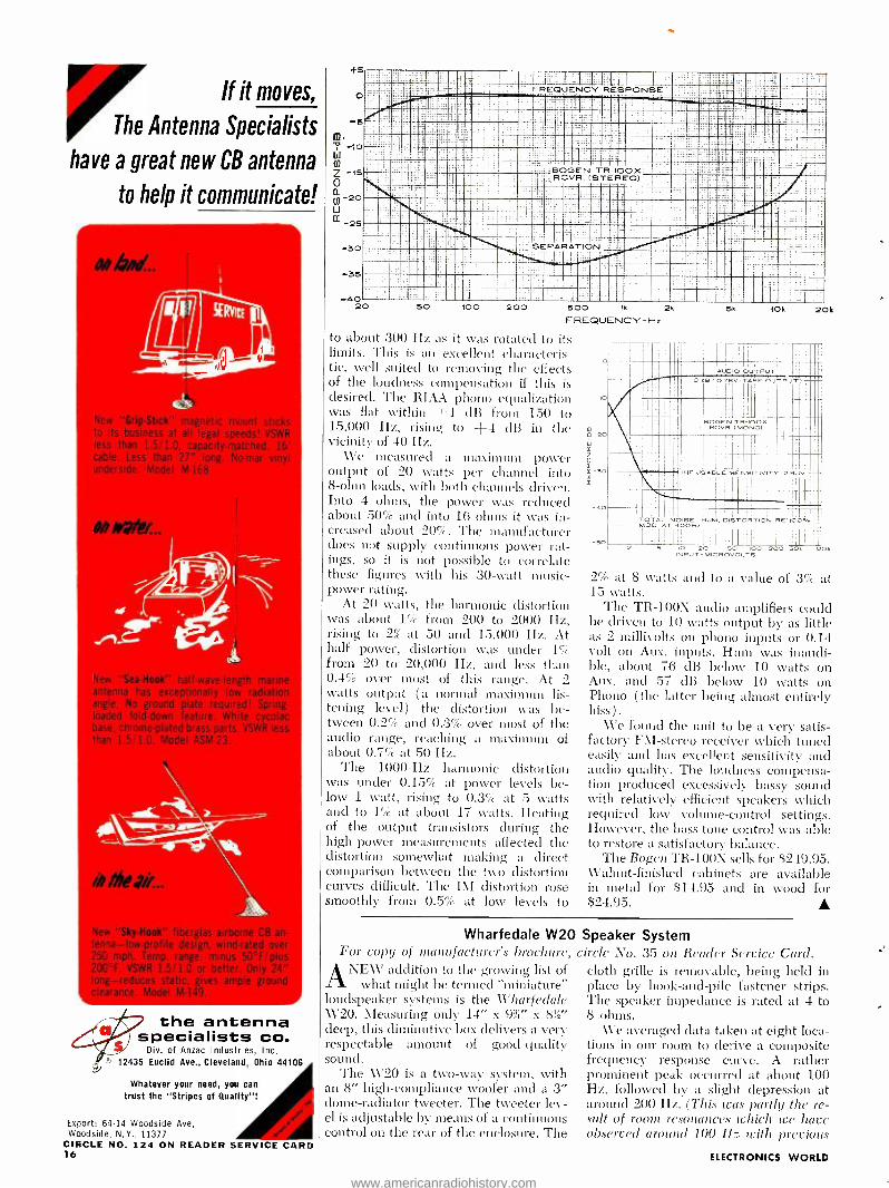
to about 300 Hz as it was rotated to its limits. This is an excellent characteris- tic, well suited to removing the effects of the loudness compensation if this is desired. The RIAA phono equalization was flat within ±1 dB from 150 to 15,000 Hz, rising to -{-4 dB in the vicinity of 40 IIz.
We pleasured a maximum power output of 20 watts per channel into 8 -ohm loads, with both channels driven. Into 4 ohms, the power was reduced about 50% and into 16 ohms it was in- creased about 20 %. The manufacturer does not supply continuous power rat- ings, so it is not possible to correlate these figures with his 30 -watt music - power rating.
At 20 watts, the harmonic distortion was about 1% from 200 to 2000 Hz, rising to 2% at 50 and 15,000 IIz. At half power, distortion was under 1' from 20 to 20,000 Hz, and less than 0.4% over most of this range. At 2 watts output (a normal maximum lis- tening level) the distortion was be- tween 0.2% and 0.3% over most of the audio range, reaching a maximum of about 0.7% at 50 Hz.
The 1000 -Hz harmonic distortion was under 0.15% at power levels be- low 1 watt, rising to 0.3 at 5 watts and to 1% at about 17 watts. Heating of the output transistors during the high -power measurements affected the distortion somewhat snaking a direct comparison between the two distortion curves difficult. The IM distortion rose smoothly from 0.5% at low levels to
IO
-20
i á N -30 R
-40
5k 10k
ÍII AUDIO OUTPUT
20k
111Ai
O US=O.7BV (TAPE OUTPUT)
SRCER.(MONOO1x
IA III
I l,
11-IF USABLE SENSITIVITY 2.9}JV
TOTAL NOISE, HUM, DISTORTION RE:100 / -- -MOD. AT 4001-Ix
! :HI 11 I B IO 20 SO 100 200 SO, 100
INPUT -MICROVOLTS
2% at 8 watts and to a value of 3% at 15 watts.
The TR -100X audio amplifiers could be driven to 10 watts output by as little as 2 millivolts on phono inputs or 0.14 volt on Aux. inputs. Hum was inaudi- ble, about 76 dB below 10 watts on Aux. and 57 dB below 10 watts on Phono ( the latter being almost entirely hiss).
We found the unit to be a very satis- factory FMI- stereo receiver which tuned easily and has excellent sensitivity and audio quality. The loudness compensa- tion produced excessively bassy sound with relatively efficient speakers which required low volume- control settings. However, the bass tone control was able to restore a satisfactory balance.
The Bogen TR -100X sells for $249.95. Walnut -finished cabinets are available in metal for $14.95 and in wood for $24.95. A
Wharfedale W20 Speaker System For copy of manufacturer's brochure, circle No. 35 on Reader Service Card. ANEW addition to the growing list of
what might be termed "miniature" loudspeaker systems is the Wharfedale W20. Measuring only 14" x 9 %" x 8)2' deep, this diminutive box delivers a very respectable amount of good -quality sound.
The W20 is a two -way system, with an 8" high -compliance woofer and a 3" dome- radiator tweeter. The tweeter lev- el is adjustable by means of a continuous control on the rear of the enclosure. The
cloth grille is removable, being held in place by hook -and -pile fastener strips. The speaker impedance is rated at 4 to 8 ohms.
We averaged data taken at eight loca- tions in our room to derive a composite frequency response curve. A rather prominent peak occurred at about 100 Hz, followed by a slight depression at around 200 Hz. (This was partly the re- sult of room resonances (chick we have observed around 100 11z with previous
ELECTRONICS WORLD
www.americanradiohistory.com

olitron, now it full production of the SDT 8950/
SDT 8650 families, has reduced the price of these fast
switching, high power silicon transistors. As shown on
the comparison Volt -Amp chart, these transistors pro-
vide more power -handling capabilities per dollar than
multiples of similar, limited- source devices. In order to meet various size and weight requirements, they are
available in either 1 1/16" hex or TO -68 packages. A
few of their many uses include visual display circuits, converters, inverters, voltage regulators and /or space
flight applications.
r 50
40
30
350 W. @ 25° C 290 W. @ 25° C
RELATIVE VOLTS- AMPS /$1.00 COST
2N3585
2N3080
2N2583 20 - 10 --
Type Number
TO -68
Type Number
HEX -CASE
DESIGN LIMITS PERFORMANCE SPECIFICATIONS
VIBR)CBO VCEO (SUS)
VIBRIEBO h FE VBE (Sat) VcE(sat) ICBO fT
Volts Volts Volts
lc =40A, VcE =10V
Volts Volts AA MN
Ic =1mA I= =0.2A IE =1mA lc =40A, IB =6A VcE =100V
Min. Min. Min. Min. Max. Max. Max. Max. Typ.
SDT8651 SDT8951 200 200 8 10 40 I 2.0 2.0 10 20
SDT8652 SOT8952 225 225 8 10 40 2.0 2.0 10 20
SDT8653 SDT8953 250 250 8 10 40 2.0 2.0 10 20
SDT8654 SDT8954 275 275 8 10 40 2.0 2.0 10 20
SDT8655 SDT8955 300 300 8 10 40 2.0 2.0 10 20
CONTACT US TODAY FOR COMPLETE INFORMATION
olitron DEVICES, INC. 1177 BLUE HERON BLVD. / RIVIERA BEACH, FLORIDA / (305) 848 -4311 / TWX: (510) 952 -6676
Leader in Germanium and Silicon Transistors, Cryogenic Thermometers, High Voltage Rectifiers, Hot Carrier Diodes, Temperature Compensated Zeners,
Voltage Variable Capacitors, Random/ White Noise Components, Microelectronic Circuits, and Power -Sink Interconnection Systems. CIRCLE NO. 199 ON READER SERVICE CARD
July, 1967 17
www.americanradiohistory.com
/ v/ .,f.7""/ e1 ' Enjoy the "music- only" programs
now available on the FM broadcast band from coast to coast.
NO COMMERCIALS NO INTERRUPTIONS
Its easy! Just plug Music Associated's Sub Carrier Detector into multiplex jack of your FM tuner or easily wire into discriminator. Tune through your FM dial and hear programs of con -
tmuous, commercial -free music you are now missing. The Detector, self- powered and with electronic mute for quieting between selections, permits reception of popular background music programs no longer sent by wire but transmitted as hidden programs on the FM broadcast band from coast to coast. Use with any FM tuner. Size 51/2" x 9 ". Shipping weight approx. 7 lbs.
KIT $4950 with pre -tuned coils, no alignment necessary)
WIRED $7500 COVER $4.95 EXTRA
current List of FM Broadcast Stations with SCA .authorisation 55.00
MUSIC ASSOCIATED 65 Glenwood Road, Upper Montclair, New Jersr.
Phone: 1201)- 744 -3387
CIRCLE NO 106 ON LEADER SERVICE CARD
WORLD'S FINEST
ERSIN
MULTILORE LASER MEASURES OCEAN WINDS AND WAVES
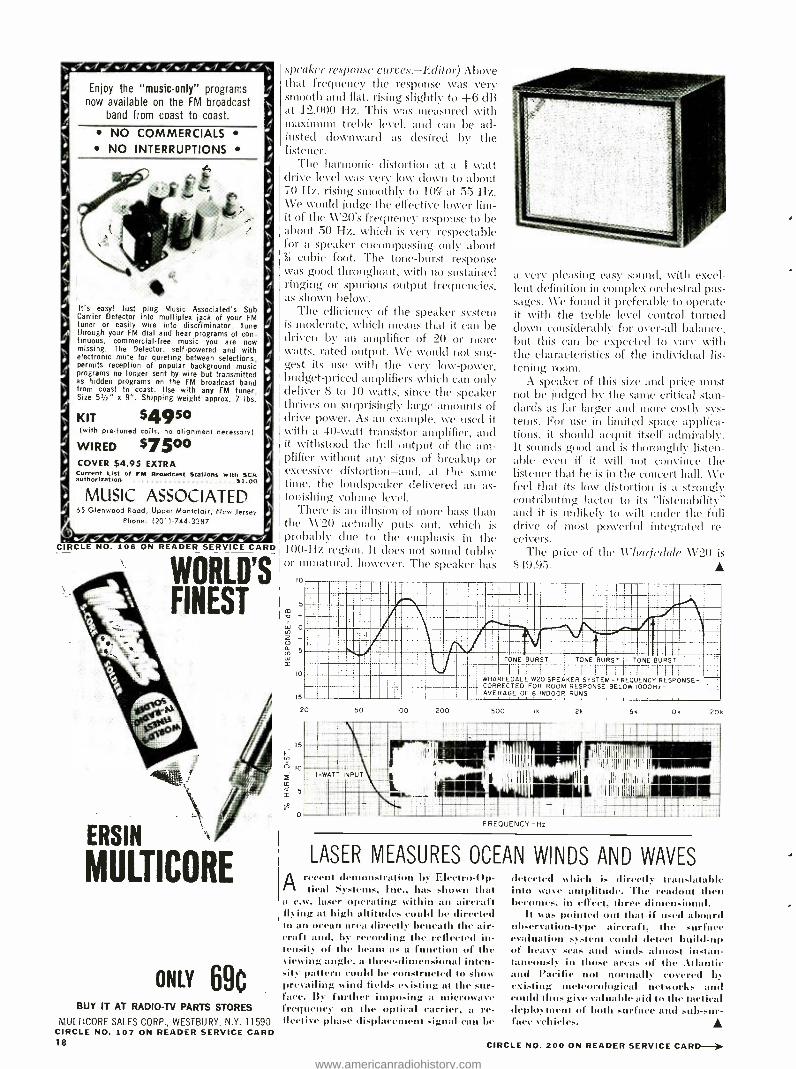
speaker response curves.- Editor) Above that frequency the response was very smooth and fiat, rising slightly to +6 dB at 12,000 Hz. This was measured Nvith maximum treble level, and can be ad- justed downward as desired by the listener.
The harmonic distortion at a 1 -watt drive level was very low down to about 70 Iiz, rising smoothly to 10% at 55 Hz. We would judge the effective lower lirn- it of the A \2O's frequency response to be about 50 Hz, which is very respectable for a speaker encompassing only about
cubic foot. The tone -burst response was good throughout, with no sustained ringing or spurious output frequencies, as shown below.
The efficiency of the speaker system is moderate, which means that it can be driven by an amplifier of 20 or more watts, rated output. We would not sag- gest its use with the very low- power, budget- priced amplifiers which can only deliver b to 10 watts, since the speaker thrives on surprisingly large amounts of drive power. As an example, we used it with a 40 -watt transistor amplifier, and it withstood the full output of the am- plifier without any signs of breakup or excessive distortion -and, at the sane time, the loudspeaker delivered an as- tonishing volume level.
There is an illusion of more bass than the \V'20 actually puts out, which is probably due to the emphasis in the I00 -Hz region. It does not sound tubby or unnatual, however. The speaker has
5
+ -: .!.
0
10
15
a very pleasing easy sound, with excel- lent definition in complex orchestral pas- sages. We found it preferable to operate it with the treble level control turned down considerably for over -all balance, but this can be expected to vary with the characteristics of the individual lis- tening room.
A speaker of this size and price must not be judged by the same critical stan- dards as far larger and more costly sys- tems. For use in limited space applica- tions, it should acquit itself admirably. It sounds good and is thoroughly listen - able even if it will not convince the listener that he is in the concert hall. We feel that its low distortion is a strongly contributing factor to its " listemtbility" and it is unlikely to wilt under the full drive of most powerful integrated re- ceivers.
The price of the Wharfedale ÁV20 is S49.95.
TONE BURST i TONE BURST TONE BURST
-1,, 1_r1 : -- l 1 i IT WHARFEDALE W20 SPEAKER SYSTEM - FREQUENCY RESPONSE - CORRECTED FOR ROOM RESPONSE BELOW I000Hx- AVERAGE OF e INDOOR RUNS
20 50 100 200 500 Ik 2k 5k
I-WATT INPUT
71T-111101r mop` r i l l', ! I11 I
.r AIIt l Ì l if<Ikllli ( I 1 tW; FREQUENCY-Hz
IOk 20k
yföltrlf/ ..
,;11111®®i- >---
ONLY 69C BUY IT AT RADIO-TV PARTS STORES
MULTICORE SALES CORP., WESTBURY, N.Y. 11590 CIRCLE NO. 107 ON READER SERVICE CARD 18
Arecent demonstration by Electro -Op- tical Systems, Inc,, has shown that
a c.w. laser operating within an aircraft (lying at high altitudes could be directed to an ocean area directly beneath the air- craft and, by recording the reflected in- tensity of the beam tux a function of the viewing angle, a three -dimensional inten- sity pattern could be constructed to show prevailing wind fields existing at the sur- face. By further imposing a microwave frequency on the optical carrier, a re- flective phase displacement signal can be
detected which is directly translatable into wave amplitude. The readout then becomes, in effect, three dimensional.
It was 110i led Out that if used aboard observation -type aircraft, the surface evaluation system could detect build-up of heavy. .seas and winds almost instan- taneously in those areas of the .atlantic and Pacific not normally covered by existing meteorological networks and could thus give valuable aid to the tactical deployment of both surface and subsur- face vehicles. A
CIRCLE NO. 200 ON READER SERVICE CARD www.americanradiohistory.com
(La, , ' ' 1 f Powo ha.,,
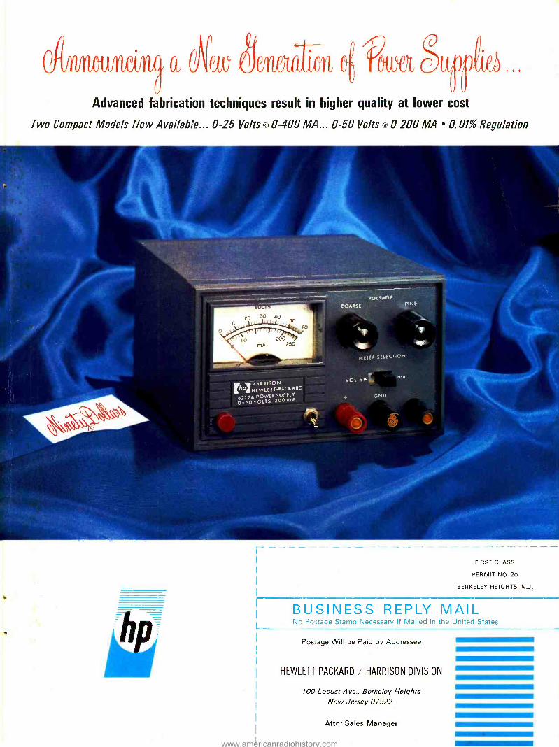
Advanced fabrication techniques result in higher quality at lower cost
Two Compact Models Now Available... 0 -25 Volts « 0 -400 MA... 0 -50 Volts ,4 0 -200 MA 0.01% Regulation
VOLTAGE
COARSE
IhPIHARRISON HE W LETT PACKARí1-
6217A POWER SUPPLY
0 -50 VOLTS 200mA
w
FIRST CLASS
PERMIT NO. 20
BERKELEY HEIGHTS, N.J.
BUSINESS REPLY MAIL No Postage Stamp Necessary If Mailed in the United States
Pos:age Will be Paid by Addressee
HEWLETT PACKARD / HARRISON DIVISION
100 Locust Ave., Berkeley Heights New Jersey 07922
Attn: Sales Manager
www.americanradiohistory.com

h HARRISON PA HEWLETTPACKARD
621 7A POWER SUPPLY 0- 50 VOLTS 200 mA
VOLTAGE
FINE
METER SELECTION
VOLTS I 4 mA
Actual Size
The NEWEST CONCEPT in Bench DC Power Supplies
Two extremely compact, well -regulated DC power supplies designed especially for bench use have just been added to the hp power supply line. New fabrication techniques have been employed for these supplies to minimize manufacturing costs while retaining component and circuit quality. Reliable, yet low cost, these "hand- size" battery substitutes have over -all performance features ideal for circuit development, component evaluation, and other laboratory applications. The all- silicon circuit uses an input differential amplifier to compare the output voltage with a reference voltage derived from a temperature - compensated zener diode. These stable input and reference circuits are combined with a high gain feedback amplifier to achieve low noise, drift -free performance. Output voltage is fully adjustable down to zero. Special design precautions prevent output overshoot during turn -on or turn -off, or when AC power is suddenly removed. The front panel meter can be switched to monitor output voltage or current. Constant Voltage /Current Limiting insures short -circuit -proof operation, and permits series and parallel connection of two or more supplies when greater voltage or current is desired.
The molded, impact- resistant case includes an interlocking feature for stacking several units vertically, thus minimizing bench space required for multiple supplies. Alternatively, up to three units can be mounted side by side on a standard 31/2" H x 19"W rack panel.
Gentlemen :
I am interested in the Bench Series Model 6215A and 6217A for the following application
Please send additional data
Please send ordering information
Have an hp sales engineer call for an appointment (phone number below)
Please send your '67 Catalog and Power Supply Handbook
Name
Title
Company
Address
City State Zip
Phone Number D
DC Output: Model 6215A 0 -25V at 0 -400 MA
Model 6217A 0 -50V at 0 -200 MA
Either positive or negative output terminal may be grounded, or the supply may be operated "floating" up to 300V off ground.
AC Input:
Load Regulation:
Line Regulation:
Ripple & Noise:
Temperature Coefficient:
Stability for Eight Hours
105-125 VAC*, 50-400 Hz
0.01%+ 1 MV
0.01% + 4 MV
<200 µv RMS
<0.02% + 1 MV/° C
After 30 Minutes Warm -up: <0.1% + 5 MV
Transient Recovery Time: <50 As for output recovery to within 10 MV following a full load change
Output Impedance: <0.03 ohms from DC to 1 KHz <.5 ohms from 1 KHz to 100 KHz <3 ohms from 100 KHz to 1 MHz
Maximum Ambient Operating Temperature: + 55 °C
Size:
Weight: Price -Model 6215A:
Model 6217A:
'210 -250 VAC input also available
31/4" (8.26 cm) H x 51/4" (13.34 cm) W x 7" (17.78 cm) D
51/4 lbs (2,38 kilograms)
$90.00 $90.00
HEWLETT PACKARD 11E HARRISON
MI DIVISION
100 Locust Ave., Berkeley Heights, New Jersey 07922
Telephone 201- 464 -1234 TWX 710 - 984 -7972
Printed in U.S.A.
www.americanradiohistory.com
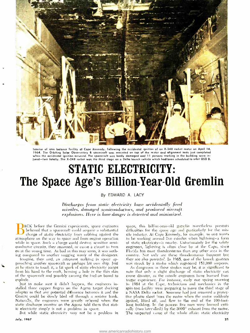
Interior of spin balance facility at Cape Kennedy, following the accidental ignition of an X -248 rocket motor on April 14, 1964. The Orbiting Solar Observatory B spacecraft was mounted on top of the motor and alignment tests just completed when the accidental ignition occurred. The spacecraft was badly damaged and 11 persons working in the building were in- jured -two fatally. The X -248 rocket was the third stage on a Delta launch vehicle which had been scheduled to orbit OSO B.
STATIC ELECTRICITY: The Space Age's Billion -Year -Old Gremlin
By EDWARD A LACY
Discharges from static electricity have accidentally fired missiles, damaged semiconductors, and produced aircraft explosions. here is hots danger is detected und minimized.
BACK before the Gemini experiments, space engineers believed that a spacecraft could acquire a substantial charge of static electricity from rubbing against the
atmosphere on the way to space and from engine operation while in space. Such a charge could destroy sensitive semi- conductor circuits, they reasoned, or cause a circuit to turn on at the wrong time. As bad as this may seem, it was noth- ing compared to another nagging worry of the designers.
Imagine, they said, an astronaut walking in space ap- proaching another spacecraft or perhaps his own ship. Just as he starts to touch it, a fat spark of static electricity jumps from his hand to the craft, burning a hole in the thin skin of the spacecraft and possibly causing the fuel on board to explode.
Just to make sure it didn't happen, the engineers in- stalled three copper fingers on the Agena target docking adapter so that any potential difference between it and the Gemini could be slowly bled off through a resistor bank. Naturally, the engineers were greatly relieved when the static discharge monitor on the Agena told them that stat- ic electricity simply is not a problem in space.
But while static electricity may not be a problem in
space, this bil lion -year -old gremlin nonetheless presents difficulties for the space age and particularly for the mis- sile industry. At Cape Kennedy, for example, no one wants to be working around live missiles when lightning -a form of static electricity -is nearby. Unfortunately for the safety engineers, lightning is often close by at the Cape, since Florida has more thunderstorms than any other area in the country. Not only are these thunderstorms frequent but they are also powerful]. In 1965, one of the launch gantries was struck by a stroke which registered 151,000 amperes.
As dangerous as these strokes may be, it is significant to note that only a slight discharge of static electricity can cause disaster, as the missile engineers have learned from tragic experience. For instance, early one spring morning in 1964 at the Cape, technicians and mechanics in the spin -test facility were preparing to move the third stage of a NASA Delta rocket. Someone had just removed a protec- tive plastic sheet from the motor when the motor suddenly ignited, lifted off, and flew to the end of the 100 -foot- long building. In the process five men were burned criti- cally (two later died) by the 3000° exhaust from the motor. The suspected cause of the whole affair: static electricity
July, 1967 21
www.americanradiohistory.com
from the protective plastic cover used. Fortunately, when we encounter stat-
ic electricity the results are not so trag- ic. On dry winter days we may get a tingle or perhaps a jolt if we shuffle across a carpeted floor and then touch a metal desk or doorknob. Self- protec- tion is simple: slap the metal object with the palm of your hand before at- tempting to use it, or touch the door- knob with a tightly held key before opening the door.
However, while static electricity may sometimes be a source of shocking dis- comfort, it may also be a source of joy and comfort, according to recent stud- ies. At the Stanford Research Institute, scientists recently used a sensitive stat- ic detector called a "feed mill" to mea- sure the electrostatic processes associ- ated with the breakup of water droplets ill a bathroom shower. The results of their study show that the exhilarating effect of a shower may be due to negative electricity instead of the warmth and force of the water.
Electronics enthusiasts have long been familiar with the problems of static electricity in phonograph records, tran- sistors, instrument meters, and automobile tires.
It is no secret, for example, that the plastic used in pho- nograph records can be given high static, electricity charges which, unfortunately, attract dirt, dust, and fluff to the grooves. Naturally, such particles cause noise and distortion as well as damage to the record. The problem has become even more acute with stereo records and with modern pick- ups which track so lightly that they ride over the dust par- ticles instead of pushing them aside.
What are the record manufacturers doing about the prob- lem? One company has added the anti -static agent Catanac SN to its high -quality records to stop the problem at its source. It is interesting to note that another major manu- facturer says such agents are costly and that still another manufacturer claims that the use of sufficient additives to eliminate static electricity causes the sound quality of the records to suffer.
Additional electronics problems with static electricity involve transistors. Some years ago it was noticed that when transistors were inserted into Styrofoam blocks for temporary storage, the very act of pushing the leads into the Styrofoam sometimes generated a static charge great enough to destroy the device.
Although this problem has generally been overcome, it
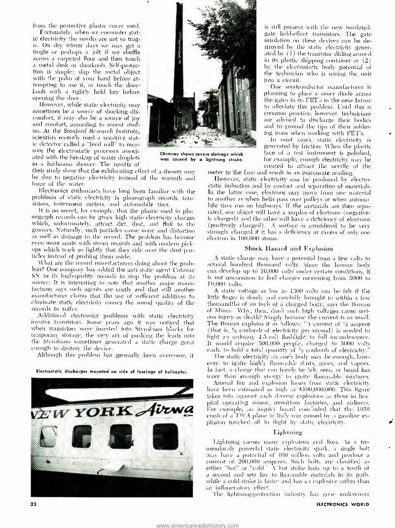
Chimney shows severe damage which was caused by a lightning stroke.
Electrostatic discharger mounted on side of fuselage of helicopter.
22
is still present with the new insulated - gate field- effect transistors. The gate insulation on these devices can be de- stroyed by the static electricity gener- ated by (1) the transistor sliding around in its plastic shipping container or (2) by the electrostatic body potential of the technician who is wiring the unit into a circuit.
One semiconductor manufacturer is planning to place a zener diode across the gates in its FET's in the near future to alleviate this problem. Until this is common practice, however, technicians are advised to discharge their bodies and to ground the tips of their solder- ing irons when working with FET's.
In most cases, static electricity is generated by friction. When the plastic face of a test instrument is polished, for example, enough electricity may be created to attract the needle of the
meter to the face and result in an inaccurate reading. However, static electricity can be produced by electro-
static induction and by contact and separation of materials. In the latter case, electrons may move from one material to another as when belts pass over pulleys or when automo- bile tires run on highways. If the materials are then sepa- rated, one object will have a surplus of electrons (negative- ly charged) and the other will have a deficiency of electrons (positively charged). A surface is considered to be very strongly charged if it has a deficiency or excess of only one electron in 100,000 atoms.
Shock Hazard and Explosion A static charge may have a potential from a few volts to
several hundred thousand volts. Since the human body can develop up to 10,000 volts under certain conditions, it is not uncommon to find charges measuring from 5000 to 10,000 volts.
A static voltage as low as 1500 volts can be felt if the little finger is slowly and carefully brought to within a few thousandths of all inch of a charged body, says the Bureau of Mines. Why, then, don't such high voltages cause seri- ous injury or death? Simply because the current is so small. The Bureau explains it as follows: "A current of 1/z ampere ( that is, '/r coulomb of electricity per second) is needed to light an ordinary 4.5 -volt flashlight to full incandescence. It would require 500,000 people, charged to 5000 volts each, to hold a total quantity of 2 coulomb of electricity."
The static electricity on one's body may be enough, how- ever, to ignite highly flammable dusts, gases, and vapors. In fact, a charge that can barely be felt, seen, or heard has more than enough energy to ignite flammable mixtures.
Annual fire and explosion losses from static electricity have been estimated as high as $100,000,000. This figure takes into account such diverse explosions as those in hos- pital operating rooms, munitions factories, and airliners. For example, an inquiry board concluded that the 1959 crash of a TWA plane in Italy was caused by a gasoline ex- plosion touched off in flight by static electricity.
Lightning Lightning causes many explosions and fires. As a tre-
mendously powerful static electricity spark, a single bolt may have a potential of 100 million volts and produce a current of 200,000 amperes. Such bolts are classified as either "hot" or "cold." A hot strike lasts up to a tenth of a second and sets fire to flammable materials in its path, while a cold strike is faster and has an explosive rather than an inflammatory effect.
The lightning- protection industry has gone undercover
ELECTRONICS WORLD
www.americanradiohistory.com

tvitla rtoich of its equipment. ent. five -fool- tall lightning rods with ornamental colored glass balls have given way to 10- inch -tall `air terminals" which may be the only parts that show in a mod- ern system. The conducting cables to ground are hidden from sight either in the framing or behind ridge rolls or downspouts.
Does a grounded "f \' antenna pro - vide lightning protection'? No, says the Lightning Protection Institute, \wheel' is sponsored by the lightning -protection industry. The Institute says that the average antennas does not have a long enough ground wire and does not have enough paths to ground. Ordinary an- tenna grounding, the Institute states, protects against accidental energization from electrical service but it cannot be expected to ground lightning, which has an amperage that may be more than one thousand tunes greater than ordinary house current.
Static Detectors
To effectively eliminate of control static electricity, it is necessary to use sensitive instruments to detect and otea- sture it. Such instruments include the gold -leaf electroscope, peon lamps, electrostatic voltmeters, and vacuum -tube electrometers. All these devices are characterized by very high input impedance.
The simplest of these and the one so often seen in ele- mentary science demonstrations is the gold -leaf electro- scope. In this device, the gold leaf is attached to a metal rod. AWhat the rod is brought near a charged body, the leaf is repelled from the rod (or itself) because like charges repel. \\'ith the electroscope, charges as low as 350 volts can be detected.
A neon lamp or fluorescent tube can be used in some ap- plications to indicate the presence of static electricity since it tvill light feebly near voltages of 100 volts or more if one terminal is grounded or held in the haul. Even a
burned -out fluorescent tube can be used. Electrostatic voltmeters are employed to measure very
high voltages such as those encountered mound radar, os- cilloscopes, and Van de Ç ;rauff generators. These voltmeters derive their torque from the attraction of charged metal- lic surfaces; the stationary surface or vane is highly insu- lated with materials such as polystyrene. With insulation resistance as ]sigh as 3 X 10' ohms, the leakage current of these voltmeters is so low that sometimes they must be shunted by a resistance in order to measure varying static voltages.
The vacuum-tube electrometer is a simple vacuttnt -tithe circuit with a ureter in the plate circuit to indicate current flow. An antenna or probe is connected to the grid of the tobe; when the probe is brought near a charged body, the plate current will increase if the body is positively charged, or the plate current will decrease if the body is negatively charged.
Van de Graaff generator shown here with the pressure vessel removed.
Control of Static Electricity Once a static electricity problem has been detected and
measured, it can be controlled or eliminated by (1) ground - ing and bonding, (2) humidification, (3) static elimina- tors, and (4) anti-static. sprays.
Grounds and 1300d.s. When two (or more) conducting bodies are connected together with a conducting wire, there will be no potential difference between them and static sparking will not occur. In this condition, the objects are said to be bonded. Although bonded, these objects may still have a potential compared with ground. By simply con-
July, 1967 23
necting a wire from the objects to ground, they become bonded and grounded.
Since static electricity currents are measured in microamperes, a very low resistance ground, as normally required in electrical work, is not needed. In fact, in hospital operating rooms, where anesthetic guises can be ignited by a
spark, low- resistance grounds are de- liberately avoided. The floors in these rooms arc made just conductive enough to drain off static charges but not con- ductive enough to be a standard elec- trical hazard.
Humidification. During the winter months when the relative humidity goes down, static electricity becomes obvious, especially when one walks across a carpet and touches a metal doorknob. On the other hand, during the summer when the humidity is high,
static electricity may scarcely be noticed. When the humidity is high, some materials may absorb
moisture, become more conductive, and thereby allow static charges to leak off. Such a condition, it should be noted, has nothing to do with the conductivity of air since water vapor does not make air electrically conductive.
At one time it was thought that this high humidity could be used to reduce the hazards and nuisance of static elec- tricity. Thus, in some factories and hospital operating rooms, the humidity was raised to 70%. Not only was this hard on the workers and expensive machinery, but it didn't work often enough to make it worth the expense and dis- comfort.
Static Eliminators. Radioactive static eliminators use radium or polonium to ionize the air. While such devices offer safety from explosions, they are naturally a hazard to anyone working nearby and therefore must be carefully shielded when installed.
High -voltage eliminators apply a high voltage ( 3000 to 15,000 volts) to a series of points close to a grounded sur- face. The voltage across this gap will discharge most charged items that are placed in the gap.
Static combs are grounded metal bars with needles or wire brushes. When a charged body ( such as a flow of paper) goes by such a comb, the charged body ionizes the gap between it and the comb, thereby discharging itself.
Air guns combine an air stream with an anti- static spray in tt Band- :Meld air gun which is useful for cleaning plastic pats. (Continued on page 67)
Lightning rods have been replaced by inconspicuous "air terminals ", whose ground resistance is shown being checked in the photograph.
www.americanradiohistory.com
RECENT
DEVELOPMENTS
IN ELECTRONICS
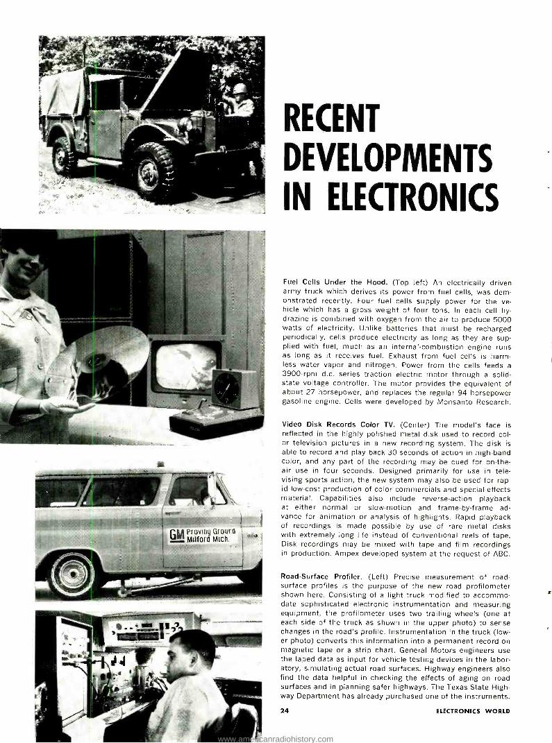
Fuel Cells Under the Hood. (Top left) An electrically driven army truck which derives its power from fuel cells, was dem- onstrated recently. Four fuel cells supply power for the ve- hicle which has a gross weight of four tons. In each cell hy- drazine is combined with oxygen from the air to produce 5000 watts of electricity. Unlike batteries that must be recharged periodically, cells produce electricity as long as they are sup- plied with fuel, much as an internal- combustion engine runs as long as it receives fuel. Exhaust from fuel cells is harm- less water vapor and nitrogen. Power from the cells feeds a
3900 -rpm d.c. series traction electric motor through a solid - state voltage controller. The motor provides the equivalent of about 27 horsepower, and replaces the regular 94 horsepower gasoline engine. Cells were developed by Monsanto Research.
Video Disk Records Color TV. (Center) The model's face is reflected in the highly polished metal disk used to record col- or television pictures in a new recording system. The disk is able to record and play back 30 seconds of action in high -band color, and any part of the recording may be cued for on -the- air use in four seconds. Designed primarily for use in tele- vising sports action, the new system may also be used for rap- id low -cost production of color commercials and special -effects material. Capabilities also include reverse -action playback at either normal or slow- motion and frame -by -frame ad- vance for animation or analysis of highlights. Rapid playback of recordings is made possible by use of rare metal disks with extremely long life instead of conventional reels of tape. Disk recordings may be mixed with tape and film recordings in production. Ampex developed system at the request of ABC.
Road -Surface Profiler. (Left) Precise measurement of road - surface profiles is the purpose of the new road profilometer shown here. Consisting of a light truck modified to accommo- date sophisticated electronic instrumentation and measuring equipment, the profilometer uses two trailing wheels (one at each side of the truck as shown in the upper photo) to sense changes in the road's profile. Instrumentation in the truck (low- er photo) converts this information into a permanent record on magnetic tape or a strip chart. General Motors engineers use the taped data as input for vehicle testing devices in the labor- atory, simulating actual road surfaces. Highway engineers also find the data helpful in checking the effects of aging on road surfaces and in planning safer highways. The Texas State High- way Department has already purchased one of the instruments.
24 ELECTRONICS WORLD
www.americanradiohistory.com
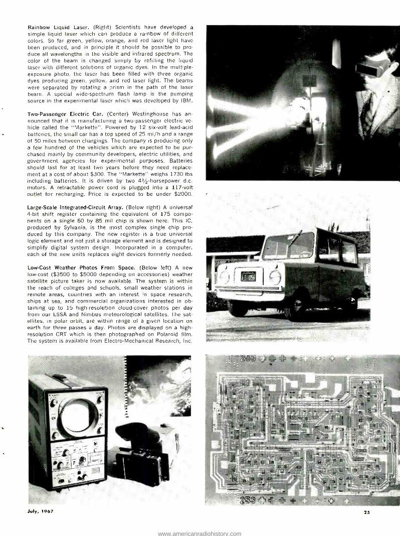
Rainbow Liquid Laser. (Right) Scientists have developed a
simple liquid laser which can produce a rainbow of different colors. So far green, yellow, orange, and red laser light have been produced, and in principle it should be possible to pro- duce all wavelengths in the visible and infrared spectrum. The color of the beam is changed simply by refilling the liquid laser with different solutions of organic dyes. In the multiple - exposure photo, the laser has been filled with three organic dyes producing green, yellow, and red laser light. The beams were separated by rotating a prism in the path of the laser beam. A special wide -spectrum flash lamp is the pumping source in the experimental laser which was developed by IBM.
Two -Passenger Electric Car. (Center) Westinghouse has an- nounced that it is manufacturing a two -passenger electric ve- hicle called the "Markette ". Powered by 12 six -volt lead -acid batteries, the small car has a top speed of 25 mi /h and a range of 50 miles between chargings. The company is producing only a few hundred of the vehicles which are expected to be pur- chased mainly by community developers, electric utilities, and government agencies for experimental purposes. Batteries should last for at least two years before they need replace- ment at a cost of about $300. The "Markette" weighs 1730 lbs including batteries. It is driven by two 41/2- horsepower d.c. motors. A retractable power cord is plugged into a 117 -volt outlet for recharging. Price is expected to be under $2000.
Large -Scale Integrated- Circuit Array. (Below right) A universal 4 -bit shift register containing the equivalent of 175 compo- nents on a single 60 by 85 mil chip is shown here. This IC,
produced by Sylvania, is the most complex single chip pro- duced by this company. The new register is a true universal logic element and not just a storage element and is designed to simplify digital system design. Incorporated in a computer, each of the new units replaces eight devices formerly needed.
Low -Cost Weather Photos From Space. (Below left) A new low-cost ($3500 to $5000 depending on accessories) weather satellite picture taker is now available. The system is within the reach of colleges and schools, small weather stations in remote areas, countries with an interest in space research, ships at sea, and commercial organizations interested in ob- taining up to 15 high -resolution cloud -cover photos per day from our ESSA and Nimbus meteorological satellites. The sat- ellites, in polar orbit, are within range of a given location on earth for three passes a day. Photos are displayed on a high -
resolution CRT which is then photographed on Polaroid film. The system is available from Electro- Mechanical Research, Inc.
July, 1967 25
www.americanradiohistory.com
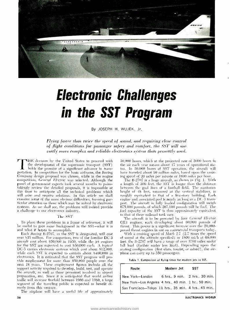
Electronic Challenges
in the SST Program By JOSEPH H. WUJEK, Jr.
Flying faster than twice the speed of sound, and requiring close control of flight conditions for passenger safety and comfort. the SST will use vastly more complex and reliable electronics system than presently used.
T HE decision by the United States to proceed with the development of the supersonic transport (SST) holds the promise of a significant advance in trans-
portation. In competition for the basic airframe, the Boeing Company design proposal was chosen, while in the engine competition, General Electric was selected. Although the panel of government experts took several months to pains- takingly review the detailed proposals, it is impossible at this time to anticipate all the technical problems which will arise and require solutions. In this article we shall examine some of the more obvious difficulties, focusing par- ticular attention on those which may be solved by electronic systems. As we shall see, the problems will indeed provide a challenge to our electronics industry.
The SST To place these problems in a frame of reference, it will
be useful to gain some background in the SST -what it is and what it hopes to accomplish.
Each Boeing B -2707, as the SST is designated, will cost over $35 million. For comparison, two of the familiar DC -3 aircraft cost about $50,000 in 1950, while the jet engines for the SST are expected to cost $50,000 each. A typical DC -3 carries electronic systems which cost about $12,000, while each SST is expected to contain about $400,000 in electronics. It is estimated that the SST program will pro- vide employment for more than 650,000 people over the next 18 years. These employment figures include all the support activity required to develop, build, test, and operate the aircraft, as well as those personnel involved in airport preparation, etc. Since it is anticipated that world airline traffic will increase fivefold between 1966 and 1980, a large segment of the traveling public is expected to benefit di- rectly from this venture.
The airplane will have a useful life of approximately
26
50,000 hours, which at the projected rate of 3000 hours in the air each year means about 17 years of operational sta- tus. In 50,000 hours of SST operation, the aircraft will have traveled about 90 million miles, based upon the cruis- ing speed of 30 miles per minute or 1800 miles per hour.
The B -2707 is a huge aircraft, as shown in Fig. 1. With a length of 306 feet, the SST is longer than the distance between the goal lines of a football field. The maximum height of 48 feet, measured at the vertical stabilizer, is roughly equivalent to that of a five -story building. Each engine and associated pod is nearly as long as a DC -3 trans- port. The aircraft in fully loaded configuration will weigh 675,000 pounds, of which 367,100 pounds will be fuel. The fuel capacity of the SST is thus approximately equivalent to that of three railroad tank cars.
The aircraft is to be powered by four General Electric GE4 engines, each developing about 60,000 pounds of thrust. This power is a significant increase over the 20,000 - pound thrust engines in use on commercial transports today.
With a cruising speed of Mach 2.7 (2.7 times the speed of sound at the altitude specified) or 1800 mi /h at 60,000 feet, the B -2707 will have a range of over 3700 miles under full load (farther under less load). Depending upon the seating configuration (first class, tourist, or mixed), the air- plane can carry up to 350 passengers.
Table 1. Comparison of flying times for modern jets vs SST.
Route Modern Jet SST
New York -London 6 hrs., 9 min. 2 hrs., 30 min.
New York -Los Angeles 4 hrs., 40 min. 1 hr., 50 min.
San Francisco -Tokyo 11 hrs., 35 min. 4 hrs., 45 min.
iLECTRONICS WORLD
www.americanradiohistory.com
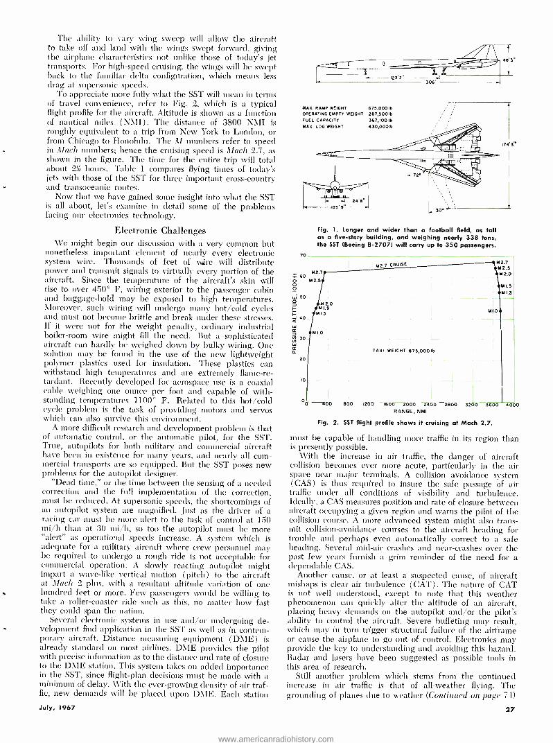
The ability to vary wing sweep will allow the aircraft to take off and land with the wings swept forward, giving the airplane characteristics not unlike those of today's jet transports. For high -speed cruising, the wings will be swept back to the familiar delta configuration, which means less drag at supersonic speeds.
To appreciate more fully what the SST will mean in terms of travel convenience, refer to Fig. 2, which is a typical flight profile for the aircraft. Altitude is shown as a function of nautical miles (NMI ) . The distance of 3800 NMI is roughly equivalent to a trip from New York to London, or from Chicago to Honolulu. The M numbers refer to speed in Mach numbers; hence the cruising speed is Mach 2.7, as shown in the figure. The time for the entire trip will total about 23 hours. Table 1 compares flying times of today's jets with those of the SST for three important cross- country and transoceanic routes.
Now that we have gained some insight into what the SST is all about, let's examine in detail some of the problems facing our electronics technology.
Electronic Challenges We might begin our discussion with a very common but
nonetheless important element of nearly every electronic system -wire. Thousands of feet of wire will distribute power and transmit signals to virtually every portion of the aircraft. Since the temperature of the aircraft's skin will rise to over 450° F, wiring exterior to the passenger cabin and baggage -hold may be exposed to high temperatures. Moreover, such wiring will undergo many hot /cold cycles and must not become brittle and break under these stresses. If it were not for the weight penalty, ordinary industrial boiler -room wire might fill the need. But a sophisticated aircraft can hardly be weighed down by bulky wiring. One solution may be found in the use of the new lightweight polymer plastics used for insulation. These plastics can withstand high temperatures and are extremely flame -re- tardant. Recently developed for aerospace use is a coaxial cable weighing one ounce per foot and capable of with- standing temperatures 1100° F. Related to this hot /cold cycle problem is the task of providing motors and servos which can also survive this environment.
A more difficult research and development problem is that of automatic control, or the automatic pilot, for the SST. True, autopilots for both military and commercial aircraft have been in existence for many years, and nearly all corn - mercial transports are so equipped. But the SST poses new problems for the autopilot designer.
"Dead time," or the time between the sensing of a needed correction and the full implementation of the correction, must be reduced. At supersonic speeds, the shortcomings of an autopilot system are magnified. Just as the driver of a racing car must be more alert to the task of control at 150 mi /h than at 30 mi /h, so too the autopilot must be more "alert" as operational speeds increase. A system which is adequate for a military aircraft where crew personnel may be required to undergo a rough ride is not acceptable for commercial operation. A slowly reacting autopilot might impart a wave -like vertical motion (pitch) to the aircraft at Mach 2 plus, with a resultant altitude vari,ition of one hundred feet or more. Few passengers would be willing to take a roller- coaster ride such as this, no matter how fast they could span the nation.
Several electronic systems in use and /or undergoing de- velopment find application in the SST as well as in contem- porary aircraft. Distance measuring equipment ( DME ) is already standard on most airlines. DME provides the pilot with precise information as to the distance and rate of closure to the DME station. This system takes on added importance in the SST, since flight -plan decisions must be made with a minimum of delay. With the ever -growing density of air traf- fic, new demands tvill be placed upon DME. Each station
I.._._.. .._-- 123'2" 305
MAX. RAMP WEIGHT 675,000 Ib
OPERATING EMPTY WEIGHT 287,500 Ib
FUEL CAPACITY 367,100 Ib
MAX. LOG WEIGHT 430,000Ib
a9 3"
70
105' 9'
174'3"
Fig. 1. Longer and wider than a football field, as tall as a five -story building, and weighing nearly 338 tons, the SST (Boeing B -27071 will carry up to 350 passengers.
Z 60
Ó ó w 50
7
F- -1 40
Cr
Ñ 30
ir A_
20
M2.7
M2.5
M 2.0 M1.5
M1.3
1.0
M2.7 CRUISE
TAXI WEICHT
M
M
M
M1.0
675,000 lb
2.7 2.5 2.0
M1.5
M 1.3
10
00 o
R 4NGE, NMI
Fig. 2. SST flight profile shows it cruising at Mach 2.7.
must be capable of handling more traffic ill its region than is presently possible.
With the increase in air traffic, the danger of aircraft collision becomes ever more acute, particularly in the air space near major terminals. A collision avoidance system ( CAS) is thus required to insure the safe passage of air traffic under all conditions of visibility and turbulence. Ideally, a CAS measures position and rate of closure between aircraft occupying a given region and warns the pilot of the collision course. A more advanced system might also trans- mit collision- avoidance courses to the aircraft heading for trouble and perhaps even automatically correct to a safe beading. Several mid -air crashes and near- crashes over the past few years furnish a grim reminder of the need for a dependable CAS.
Another cause, or at least a suspected cause, of aircraft mishaps is clear air turbulence (CAT) . The nature of CAT is not well understood, except to note that this weather phenomenon can quickly alter the altitude of an aircraft, placing heavy demands on the autopilot and /or the pilot's ability to control the aircraft. Severe buffeting may result, which may in turn trigger structural failure of the airframe or cause the airplane to go out of control. Electronics may provide the key to understanding and avoiding this hazard. Radar and lasers have been suggested as possible tools in this area of research.
Still another problem which sterns from the continued increase in air traffic is that of all- weather flying. The grounding of planes due to weather (Continued on page 7 -1)
July, 1967 27
www.americanradiohistory.com

ONE -TUBE
LOW- FREQUENCY
CONVERTER By K. H. SUEKER, W3TLQ Westinghouse Electric Corp.
Construction of ci single -tube converter operating from 15 to 2000 kHz for use with receiver tuned to 10 meters.
NYONE who has listened to a short -wave receiver is we11 aware of the vagaries of high -frequency radio transmissions. While average propagation conditions
can be predicted with reasonable certainty, high- frequency circuits are still plagued by erratic signals and sudden black- outs. Only with the advent of synchronous satellites has dependable high -frequency transmission over long hauls be- come a reality. The terminal equipment required, however, is rather cumbersome.
The glamour of the satellites and the space age has tended to overshadow the less known but vitally important v.l.f. services which have offered dependable, world -wide com- munications for over forty years. Operating on frequencies from 15 kHz to 30 kHz, super -power transmitters handle a steady flow of press, naval traffic, and special services. Since propagation is entirely by ground wave at these frequen- cies, there is no sky -wave interference and no dependence on ionospheric conditions. The v.l.f. waves hug the earth's surface and can cover the entire globe.
The author's interest in v.l.f. 'was stimulated by articles describing the 2000 -kW installation of NAA at Cutler,
L F. ANT.
ELL TI- Ic
I ó
1.5
r
Maine. AVorkbench experiments using a Wien -bridge audio oscillator as a regenerative detector proved successful at re- ceiving NAA so the decision was made to build a good re- ceiver for v.l.f. Since a faithful general- coverage communi- cations receiver had just been retired, a second objective was to provide broadcast and 160 -meter amateur band coverage as well as v.l.f. This meant that the receiver had to tune from 15 kHz to 2000 kHz -a 133 :1 frequency ratio.
Circuit Design Such an extreme range posed some interesting design
problems. A simple regenerative receiver could handle the v.l.f. but could not provide the selectivity needed for broad- cast reception with strong local stations. Adding tuned r.f. stages would improve selectivity but would impose difficult ganging problems to say nothing of requiring a lot of large inductors. A fixed i.f. superheterodyne offered much the same sort of problems.
The solution, surprising in its simplicity, was to use a single -tuned input circuit feeding a converter stage with fixed oscillator and tunable i.f. This arrangement allowed
Fig. 1. Schematic and parts list for the one -tube converter. The triode section of the 6Ú8A serves as a crystal oscillator whose output is applied to cathode circuit of mixer section.
LI
+125V, I0mA H. F. ANT.
IM
RCAVR. NT.
\
i co
SWITCH POSITIONS(SI) I- IS -60kHz 2- 70-200kHz 3- 200-700k Hz 4- 700- 20001Hz
our V I
Tyyy
,^\ M- 4 I - 528
6.3V
R1- 470,000 ohm, t/2 W res. R2 -1000 ohm, 1/2 W res. R3 -3300 ohm, 1/2 W res. R4- 100,000 ohm, t/2 \V res. Cl -See text C2 -Dual variable capacitor, 467 pF /sec C3 -0.005 µF ceramic capacitor C4, C5, C8 -0.05 pF ceramic capacitor C6, C7, C10 -3.30 pF trimmer C9 -0.1 µF paper capacitor L1 -65 -300 mH adj. tapped coil (J.W. Miller 9018) L2 -520 mH adj. tapped coil (J.W. Miller 9015) L3- 0.5 -3.5 mH adj. tapped coil (J.W. Miller 9013) L4- 0.15 -1.0 mH adj. tapped coil (J.W.
Miller 9012) L5- Ferrite -core antenna (see text) L6, L7 -12 t #22, 3/e" dia. x 5 /6" long L8 -1 t. on cold end of L6
L9 -1 t. on cold end of L7
L10 -1 t. on L7 (see text) S1- D.p.6 -pos. non -shorting sw. (Mallory 2226J) S2- D.p.2 -pos. non -shorting sw. (Mallory 3222J) Xtal -28 -MHz overtone crystal V1 -6U8A
28 ELECTRONICS WORLD
www.americanradiohistory.com
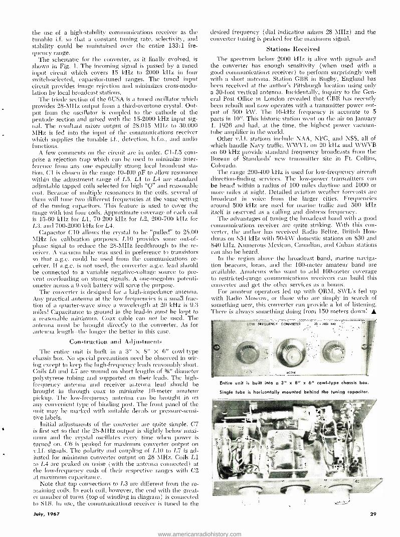
the use of a high -stability communications receiver as the tunable i.f. so that a constant tuning rate, selectivity, and stability could be maintained over the entire 133:1 fre- quency range.
The schematic for the converter, as it finally evolved, is shown in Fig. 1. The incoming signal is passed by a tuned input circuit which covers 15 kHz to 2000 kHz in four switch -selected, capacitor -tuned ranges. The tuned input circuit provides image rejection and minimizes cross -modu- lation by local broadcast stations.
The triode section of the 6U8A is a tuned oscillator which provides 28 -AIHz output from a third -overtone crystal. Out- put from the oscillator is coupled to the cathode of the pentode section and mixed with the 15 -2000 kHz input sig- nal. The resultant mixer output of 28.015 MHz to 30.000 MHz is fed into the input of the communications receiver «hieh supplies the tunable i.f., detection, b.f.o., and audio functions.
A few comments on the circuit are in order. C1 -L5 corn - prise a rejection trap which can be used to minimize inter- ference from any one especially strong local broadcast sta- tion. Cl is chosen in the range 10 -400 pF to allow resonance within the adjustment range of L5. L1 to L4 are standard adjustable tapped coils selected for high "Q" and reasonable cost. Because of multiple resonances in the coils, several of them will tune two different frequencies at the same setting of the tuning capacitors. This feature is used to cover the range with just four coils. Approximate coverage of each coil is 15 -60 kHz for L1, 70 -200 kHz for L2, 200 -700 kHz for L3, and 700 -2000 kHz for L4.
Capacitor C10 allows the crystal to be "pulled" to 28.00 MHz for calibration purposes. L10 provides some out -of- phase signal to reduce the 28 -MHz feedthrough to the re- ceiver. A vacuum tube was used in preference to transistors so that a.g.c. could be used from the communications re- ceiver. If a.g.c. is not used, the converter a.g.c. lead should be connected to a variable negative -voltage source to pre - vent overloading on strong signals. A one- megohm potenti- ometer across a 9 -volt battery will serve the purpose.
The converter is designed for a high -impedance antenna. Any practical antenna at the low frequencies is a small frac- tion of a quarter -wave since a wavelength at 20 kHz is 9.3 miles! Capacitance to ground in the lead -in must be kept to a reasonable minimum. Coax cable can not be used. The antenna must be brought directly to the converter. As for antenna length -the longer the better in this case.
Construction and Adjustments The entire unit is built in a 3" X 8" X 6" cowl -type
chassis box. No special precautions need be observed in wir- ing except to keep the high- frequency leads reasonably short. Coils L6 and L7 are wound on short lengths of 3 /8' diameter polystyrene tubing and supported on their leads. The high - frequency antenna and receiver antenna lead should be brought in through coax to minimize 10 -meter amateur pickup. The low- frequency antenna can be brought in on ally convenient type of binding post. The front panel of the unit may be marked with suitable decals or pressure- sensi- tive labels.
Initial adjustments of the converter are quite simple. C7 is first set so that the 28 -MHz output is slightly below maxi- mum and the crystal oscillates every time when power is turned on. C6 is peaked for maximum converter output on v.l.f. signals. The polarity and coupling of L10 to L7 is ad- justed for minimum converter output on 28 \IHz. Coils L1 to L4 are peaked on noise (with the antenna connected) at the low- frequency ends of their respective ranges with C2 at maximum capacitance.
Note that tap connections to L3 are different from the re- maining coils. In each coil, however, the end with the great- er number of turns (top of winding in diagram) is connected to S1ß. In use, the communications receiver is tuned to the
July, 1967
desired frequency (dial indication minus 28 MHz) and the converter tuning is peaked for the maximum signal.
Stations Received The spectrum below 2000 kHz is alive with signals and
the converter has enough sensitivity (when used with a good communications receiver) to perform surprisingly well with a short antenna. Station GBR in Rugby, England has been received at the author's Pittsburgh location using only a 30 -foot vertical antenna. Incidentally, inquiry to the Gen- eral Post Office in London revealed that GBR has recently been rebuilt and now operates with a transmitter power out- put of 500 kW. The 16 -kHz frequency is accurate to 5 parts in 10' °. This historic station went on the air on January 1, 1926 and had, at the time, the highest power vacuum - tube amplifier in the world.
Other v.l.f. stations include NAA, NPG, and NSS, all of which handle Navy traffic. WWVL on 20 kHz and WWVB on 60 kHz provide standard frequency broadcasts from the Bureau of Standar ds' new transmitter site in Ft. Collins, Colorado.
The range 200 -400 kHz is used for low- frequency aircraft direction -finding services. The low -power transmitters can be heard within a radius of 100 miles daytime and 1000 or more miles at night. Detailed aviation weather forecasts are broadcast in voice from the larger cities. Frequencies around 500 kHz are used for marine traffic and 500 kHz itself is reserved as a calling and distress frequency.
The advantages of tuning the broadcast band with a good communications receiver are quite striking. With this con- verter, the author has received Radio Belize, British Hon- duras on 834 kHz with 50 -kW domestic stations on 830 and 840 kHz. Numerous Mexican, Canadian, and Cuban stations can also be heard.
In the region above the broadcast band, marine naviga- tion beacons, loran, and the 160 -meter amateur band are available. Amateurs who want to add 160 -meter coverage to restricted -range communications receivers can build this converter and get the other services as a bonus.
For amateur operators fed up with QRM, SWL's feci up with Radio Moscow, or those who are simply in search of something new, this converter can provide a lot of listening. There is always something doing from 150 meters down! A
Entire unit is built into a 3" x 8" x 6" cowl -type chassis box.
Single tube is horizontally mounted behind the tuning capacitor.
29
www.americanradiohistory.com

ELECTRONIC STETHOSCOPE and CARDIAC RATE METER
THIS article describes the construction of a transistorized, battery- operated unit about the size of a pocket tran-
sistor radio which incorporates all the features of earlier stethoscopes with the addition of a direct -reading heart - rate meter.
The photograph ( Fig. 1) shows the general aspects of the instrument svith the calibrator at the far right. The circuit of the instrument, 'hier) is based on a five- transis- tor amplifier (available from Lafayette Electronics under catalogue number 99 -R- 9037), is shown in Fig. 3. The combination of R1 and Cl serves as a tone control to vary the frequency accepted by the amplifier. The gain control (R16) is located at the output of the amplifier. In this condition, the amplifier is running "wide open." Points "A" and "11" connect to "A" and "B" on the rate meter (Fig. 2) directly, while points "A" and "C" connect to the headphone system. The original gain control as shown in the diagram supplied with the commercial amplifier was taken out, and a 10-p .F capacitor is used to couple tran- sistor Ql to Q2.
The microphone which serves as the pickup device was constructed from an Air Force type HS -30 headphone. The case was ground down to the point where the diaphragm
By A. L. DUNN, R. N. WILGER, and R. A. MYERS
Veterans Administration Hospital, Omaha, Nebraska
Using this electronic stethoscope, the
physician can hear the heartbeats and
also observe the cardiac rate on a meter.
Fig. 1. Electronic stethoscope (left); calibrator on right.
was separated fion) the pole pieces by no more than the thickness of a piece of tissue paper. This greatly in- creased the sensitivity. The low impedance of the micro- phone was a passable match for the input to the amplifier.
(Continued on page 87)
200 n Or.
-
D2 D3
R1 -1500 ohm resistor R2, R4 -2200 ohm resistor R3 -2000 ohm potentiometer R5 -4700 ohm resistor R6- 20,000 ohm pot. (All resistors /2 watt.) C1, C2 -450 5E, 6 V cap. D1, D2, D3 -10 V zener diode
Q1 -2N170 transistor TI- transistor inte stage
trans. (Argonne AR -153 or equis.)
MI -500 5A meter
Fig. 2. The rate meter is transformer -coupled to the steth- oscope and accepts pulses which are read out on the meter.
Fig. 3. Schematic and parts list for the electronic stethoscope. This amplifier is similar to the Lafayette 99 -R -9037.
R1 -500 ohm potentiometer 119- 27,000 ohm resistor R16 -200 ohm pot. CIO -0.05 50F, 25 V capacitor R2, R5- 100,000 ohm resistor R10- 270,000 ohm res. (All resistors 1/2 watt.) T1- transistor input trans. R3- 220,000 ohm resistor R11, R14 -330 ohm res. C1, C11 -5 5F, 10 V capacitor T2- transistor output trans. R4, R8- 10,000 ohm resistor R12 -3300 ohm resistor C2 through C7 -10 pF, 10 V cap. QI, Q2, Q3- 2SB113 or equis. R6- 560,000 ohm resistor R13 -6800 ohm resistor C8 -50 5F, 10 V capacitor Q4, Q5- 2SB165 or equiv. R7 -1000 ohm resistor R15 -10 ohm resistor C9 -5 5 F, 10 V capacitor Rr- Lafayette 32S thermistor
30 ELECTRONICS WORLD
www.americanradiohistory.com
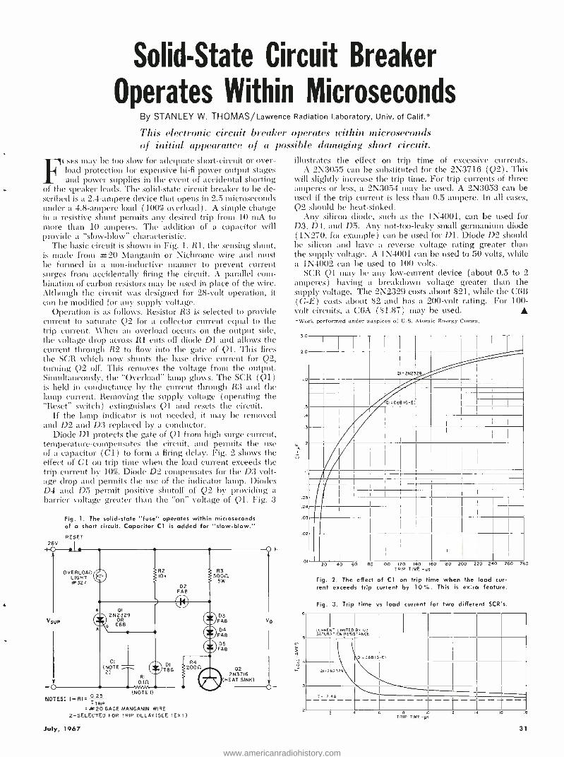
Solid -State Circuit Breaker
Operates Within Microseconds By STANLEY W. THOMAS /Lawrence Radiation Laboratory, Univ. of Calif.*
This electronic circuit breaker operates within microseconds of initial appearance of a possible damaging short circuit.
FUSES may be too slow for adequate short- circuit or over- load protection for expensive hi -fi power output stages and power supplies in the event of accidental shorting
of the speaker leads. The solid -state circuit breaker to be de- scribed is a 2.4- ampere device that opens in 2.5 microseconds under a 4.8- ampere load (100% overload) . A simple change in a resistive shunt permits any desired trip from 10 mA to more than 10 amperes. The addition of a capacitor will provide a "slow- blow" characteristic.
The basic circuit is shown in Fig. 1. R1, the sensing shunt, is made from #20 Ylanganin or Nichrome wire and must be formed in a non -inductive manner to prevent current surges from accidentally firing the circuit. A parallel com- bination of carbon resistors may be used in place of the wire. Although the circuit was designed for 28 -volt operation, it can be modified for any supply voltage.
Operation is as follows. Resistor R3 is selected to provide current to saturate Q2 for a collector current equal to the trip current. Al'hen an overload occurs on the output side, the voltage drop across R1 cuts off diode D1 and allows the current through R2 to flow into the gate of Ql. This fires the SCR which now shunts the base chive current for Q2, turning Q2 off. This removes the voltage from the output. Simultaneously, the "Overload" lamp glows. The SCR (Q1) is held in conductance by the current through R3 and the lamp current. Removing the supply voltage (operating the "Reset" switch) extinguishes Q1 and resets the circuit.
If the lamp indicator is not needed, it may be removed and D2 and D3 replaced by a conductor.
Diode D1 protects the gate of Q1 from high surge current, temperature -compensates the circuit, and permits the use of a capacitor (C1) to form a firing delay. Fig. 2 shows the effect of Cl on trip time when the load current exceeds the trip current by 10 %. Diode D2 compensates for the D3 volt- age drop and permits the use of the indicator lamp. Diodes D4 and D5 permit positive shutoff of Q2 by providing a barrier voltage greater than the "on" voltage of Ql. Fig. 3
28V
Fig. 1. The solid -state "fuse" operates within microseconds of a short circuit. Capacitor Cl is added for "slow- blow." RESET
V5UP
OVERLOAD LIGHT #327
R3 50011
SW
D3 FA8
04 FAB
05 FA8
02 2N3716
HEAT SINK)
VO
NOTES: 1 -RI= 0.25 =4k20 GAGE MANGANIN WIRE
2- SELECTED FOR TRIP DELAY (SEE TEXT)
(NOTE I)
July, 1967
illustrates the effect on trip time of excessive currents. A 2N3055 can be substituted for the 2N3716 (Q2). This
will slightly increase the trip time. For trip currents of three amperes or less, a 2N3054 may be used. A 2N3053 can be used if the trip current is less than 0.5 ampere. In all cases, Q2 should be heat -sinked.
Any silicon diode, such as the 1N4001, can be used for D3, D4, and D5. Any not- too -leaky small germanium diode (1N270, for example) can be used for Dl. Diode D2 should be silicon and have a reverse voltage rating greater than the supply voltage. A 1N4001 can be used to 50 volts, while a 1N4002 can be used to 100 volts.
SCR Q1 may be any low- current device (about 0.5 to 2 amperes) having a breakdown voltage greater than the supply voltage. The 2N2329 costs about $21, while the C6ß (G -E) costs about $2 and has a 200 -volt rating. For 100 - volt circuits, a C6A ($1.87) may be used. "Work performed under auspices of U.S. Atomic Energy Comm.
3.0
2.0
I.0
5
.3
.2
u
.05
.04
.03
.02
01
6
5
2
I I
_
01=2N232
1
..
-
- .01=C68 (G-E)
446.
20 40 60 80 IOO 120 140 160 180 200 220 240 260 TRIP TIME -Ils
Fig. 2. The effect of Cl on trip time when the load cur- rent exceeds trip current by 10%. This is extra feature.
Fig. 3. Trip time vs load current for two different SCR's.
280
CURRENT SATURATION
LIMITED RESISTANCE
r__,_, BY 02
OI=C6Bl3 -E1
01 +2N2329
1722 4A
fi 2 4 6 6 10
TRIP TIME -As 12 IS
31
www.americanradiohistory.com

INDEPENDENCE HALL
RECONSTRUCTION
SOUND SYSTEM By J. PETER NELSON /Ampex Corporation
Description of 14- chancel tape system that carries dialogue, sound effects, and switch- ing signals to recreate a historical setting.
ABRICK_BY -BRICK reconstruction of the original In- dependence Hall in Philadelphia was dedicated on July 4 last year and opened to tha public. Located
at Knott's Berry Farm, some 40 miles southeast of Los Angeles, this building houses a unique electronic exhibit that dramatizes the important events surrounding the signing of the Declaration of Independence.
The exhibit, set in a reconstruction of the assembly hall where the historic document was signed, relies primarily on the power of sound to recreate the historic aura of the spirited discussions and conversations that attended the original event. Tables, chairs, candles (electric), ink stands. and other memorabilia of the period serve as visual focal points for the program and set the mood for the audio presentation.
Spectators in tour groups sit along one side of the 40- foot- square room, roped off from the exhibit area. A pretty girl in colonial dress, the tour guide, turns a key in a door casing, and the show begins.
The house lights dim and the electric candles on the delegates' tables flicker to life. The audience is transported in imagination to the 1770's as the 56 delegates to the Second Continental Congress are heard entering the room and walking through the audience and on to their tables. Chairs scrape, men talk and laugh, and papers rustle. John
Reconstruction of 40' by 40' room where Declaration of Inde- pendence was signed. The chair in the right background be- neath the ornamental arch is a replica of the "rising sun" chair used by John Hancock, president of the Continental Con- gress. Speakers are installed under tables, in wall panels, window casements, and fireplaces for effective stereo illusion.
1 1+rLNt 111 N,N, .. l..7P7r: -
....;. M..
Hancock, President of the Continental Congress, raps his gavel for order and recognizes Richard Henry Lee as the first speaker.
During the presentation, a battle rages outside the build- ing, a marching hand tramps past playing "The White Cockade," the town crier proclaims the surrender of York- town, and the Liberty Rell tolls. As John Adams delivers an impassioned speech, the audience hears him stand and walk in ghostly fashion from one side of the room to the other.
This histrionic Nvizard y is accomplished with an elaborate audio system called "Stereo -Rama Fourteen" by its creator, Philip Stuart, Hollywood producer of documentary films and exhibits. Stuart has placed 56 (coincidentally, the number of delegates) James B. Lansing speaker systems throughout the exhibit room to give depth and presence to his special effects. They are located under delegates' tables, in walls, and in window casings and fireplaces.
The Tape System The heart of the system is a pair of Ampex AG -300 solid -
state professional audio recorders modified to handle one - inch -wide, 1.5 -mil magnetic tape and to provide 14 channels of signals. The machines run at either 71 or 15 inches per second. Ten of the channels carry dialogue, three are used for special sound effects, and the final track controls the room lights, candles, and audio special effects switching from speaker to speaker.
The program was recorded in the room where it is pre- sented. Stuart gathered more than twenty famous voices from radio, motion pictures, and the Broadway stage to portray the voices of history. These well -known voices add a dimension of familiarity to the stereo program.
All of the actors gathered in the assembly hall for ten live recording sessions over a period of six weeks. Acous- tical flats on their tables cut clown on bothersome crossfeed. Footsteps, rustles, and chair -scrapings were recorded as they took place. The final effect is a blend of these sessions, with the special effects, outside noises, and control track added later.
The tape equipment is rack- mounted in the spacious projection room of the building's second -floor movie theatre. In the original building, the space was rarely used until
32 ELECTRONICS WORLD
www.americanradiohistory.com
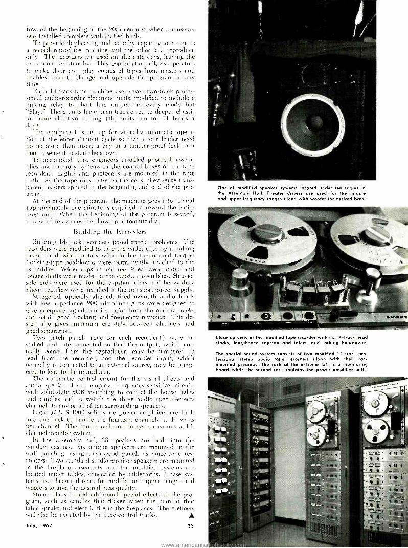
toward the beginning of the 20th century, tveen a museum was installed complete with stuffed birds.
To provide duplicating and standby capacity, one unit is a record /reproduce machine and the other is a reproduce only. The recorders are used on alternate days, leaving the extra unit for standby. This combination allows operators to make their own play copies of tapes from masters and enables then to change and upgrade the program at any time.
Each 14 -track tape machine uses seven two -track profes- sional audio- recorder electronic units, modified to include a muting relay to short line outputs in every mode but "Play." These units have been transferred to deeper chassis for more effective cooling ( the units run for 11 hours a :lay).
The equipment is set up for virtually automatic opera- tion of the entertainment cycle so that a tour leader need do no more than insert a key in a tamper -proof lock in a door casement to start the show.
To accomplish this. engineers installed photocell assem- blies and memory systems in the control boxes of the tape recorders. Lights and photocells are mounted in the tape path. As the tape runs between the cells, they sense trans- parent leaders spliced at the beginning and end of the pro- gram.
At the end of the program, the machine goes into rewind (approximately one minute is required to rewind the entire program ) . AVllen the beginning of the program is sensed, a forward relay cues the show up automatically.
Building the Recorders Building 14 -track recorders posed special problems. The
recorders were modified to take the wider tape by installing takeup and wind motors with double the normal torque. Locking -type holddowns were permanently attached to the assemblies. Wider capstan and reel idlers were added and longer shafts were made for the capstan assemblies. Heavier solenoids were used for the capstan idlers and heavy -duty silicon rectifiers were installed in the transport power supply.
Staggered, optically aligned, fixed azimuth audio heads with low impedance, 200- micro -inch gaps were designed to give adequate signal -to -noise ratios from the narrow tracks and retain good tracking and frequency response. This de- sign also gives minimum crosstalk between channels and good separation.
Two patch panels (one for each recorder) ) were in- stalled and interconnected so that the output, which nor- mally_ comes from the reproducer, may be jumpered to lead from the recorder, and the recorder input, which normally is connected to an external source, may be jump - ered to lead to the reproducer.
The automatic control circuit for the visual effects and audio special effects employs frequency- sensitive circuits with solid -state SCR switching to control the house lights and candles and to switch the three audio special- effects channels to any or all of ten surrounding speakers.
Eight JBL S -4000 solid -state power amplifiers are built into one rack to handle the fourteen channels at 40 watts per channel. The fourth rack in the system carries a 14- channel monitor system.
In the assembly hall, 38 speakers are built into the window casings. Six unique speakers are mounted in the wall paneling, using balsa -wood panels as voice -cone res- onators. Two standard studio monitor speakers are mounted in the fireplace casements and tell modified systems are located under tables, concealed by tablecloths. These sys- tems use theater drivers for middle and upper ranges and woofers to give the desired bass quality.
Stuart plans to acid additional special effects to the pro- gram, such as candles that flicker when the man at that table speaks and electric fire in the fireplaces. These effects will also be acuated by the tape -control tracks.
July, 1967 33
One of modified speaker systems located under ten tables in the Assembly Hall. Theater drivers are used for the middle and upper frequency ranges along with woofer for desired bass.
Close -up view of the modified tape recorder with its 14 -track head stacks, lengthened capstan and idlers, and hocking holddowns.
The special sound system consists of two modified 14 -track pro - fessionaR stereo audio tape recorders along with their rack mounted preamps. The rack at the extreme left is a monitoring board while the second rack contains the power amplifier units.
www.americanradiohistory.com

Editor's Note: Recently we have seen integrated circuits in TV sets, radios, phonographs, and hi -fi receivers. Al- most every day more and more IC's are finding their way into consumer electronic equipment. As a matter of fact, we expect that many color-TV sets will go directly from fates to integrated circuits, bypassing the transistor - itcd stage altogether. To the purchaser of such equip- ment, this will mean smaller, cooler, better, more reli- able, and ultimately, less expensive products (or else products with a greater number of features). But what
will this revolution mean to the service technician? In the first place, the clays of the tube puller and v.o.m. prober are definitely numbered. The technician will have to learn and use a different approach to his servicing and he will have to employ different techniques. To help orient his thinking along these lines, and to in- form the consumer as well, we are running this impor- tant 2 -part article. Part I covers the new functional approach that must be taken, while Part 2 (next month) will go into the specific test- equipment techniques.
TROUBLESHOOTING INTEGRATED CIRCUITS PART 1. THE FUNCTIONAL APPROACH
By WALTER H. BUCHSBAUM and WILLIAM D. HENN
New consumer products are being revolution i,_cd by the erse of IC's. The service technician will have to upgrade his knowledge and change his test methods in order to meet the challenge that the new circuits will present.
INTEGRATED circuits first appeared in black -and -white TV sets last year and have since found their svay into color -TV receivers, radios, phonographs, and high -fidelity
equipment. Within the next few years IC's will be used in all consumer electronic products where high power is not re- quired. RCA, one of the leading manufacturers of IC's for consumer products, has set up a special engineering task force to develop a color -TV set using only IC's and a few power transistors. The idea is to eliminate the stage of de- signing a fully transistorized color set and concentrate on new circuits and special IC's for all low -power circuit functions. It may be possible, for example, to provide all color sync and demodulation functions with only three IC's
The integrated circuits used in consumer products gener- ally fall into the category of linear or analog circuits, as op- posed to the digital circuits used in computers. Analog cir- cuits use many more semiconductors but because of the very small size of the integrated circuit itself, there is usually no difference in packaging. These IC's invariably work with conventional discrete components, such as resistors, capa- citors, and inductors, which are connected to the IC by the printed -circuit board.
When troubleshooting equipment using vacuum tubes, the first step is usually to check that the filament of each tube is on. The second step is to substitute known good tubes for 'the suspected ones. These two steps eliminate the majority of defects without test equipment and without requiring much technical know -how. Where series filaments are in- volved, or when the defect is not due to a tube, basic voltage and resistance measurements can usually locate another large category of possible defects. Sophisticated test equipment, such as signal generators and scopes, is usually needed only for alignment, which is rarely done.
In troubleshooting transistorized equipment, however, this first step -checking filaments and substituting tubes-
"In order to troubleshoot 11 "s the technician will raped two basic aids. The first is good- quality test equipment capable of dynamic in- circuit testing. The second is detailed knowledge of circuit functions and signals."
cannot be used and some form of test equipment is needed immediately to locate the defect. Voltage and resistance measurements help to isolate the defect to a particular circuit function but then individual components, including the trans- istors, must be tested. This is usually done with the power off and often requires quite a bit of unsoldering of leads. In many instances new transistors are temporarily connected into the circuit. For complete dynamic tests of a transistor a good transistor tester is needed and even this check is not always conclusive because the temperature effects in the equipment are not duplicated by the transistor tester. As a last resort, test equipment, such as signal generators and oscilloscopes, is required to trace the defect down to the responsible components.
When it comes to troubleshooting equipment using inte- grated circuits, voltage and resistance measurements are often inconclusive and difficult to perform. It is not practical to unsolder the 10 to 14 leads of the suspected IC and then solder another IC in place. The d.c. voltages alone often do not pinpoint the defect and ohmmeter measurements can damage the IC by applying wrong voltages across semicon- ductor terminals. The only remaining troubleshooting pro - cedure is signal- tracing but this, too, is often limited. As will be shown later, many IC's contain more than the basic amplification function and this means that the output sig- nal frequency may be different from that of the input. Even if signal tracing pinpoints the defect to a particular stage, it is not easy to determine whether the IC itself or one of the external components is defective. If the external component defect has caused the IC to be damaged, troubleshooting can be extremely difficult.
In order to troubleshoot IC's efficiently, the technician will need two basic aids. The first is good -quality test equipment capable of dynamic, in- circuit testing over a wide range of frequencies, modulations, and waveforms. The second is a detailed knowledge of the circuit functions and signals in each part of the equipment, and how they can be examined under dynamic conditions. The test equipment problem will be covered in depth in a subsequent article while the func- tional aspects of integrated circuits will be discussed here.
How Can IC's Become Defective? Solid -state devices, and integrated circuits in particular,
34 ELECTRONICS WORLD
www.americanradiohistory.com
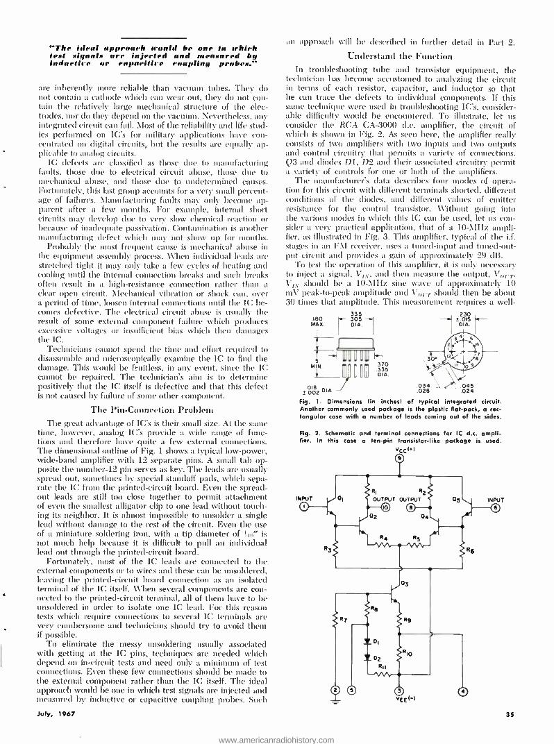
The ideal nppruarlr it-mold be unr in uhirh text xiynulx 111'1' in_prrIrd lrnal 0,11S11 red by indulli1'r or 1'1111014 lit' rouplin,y p1'ob1x...
are inherently more reliable than vacuum tubes. They do not contain a cathode which can wear out, they do not con- tain the relatively large mechanical structure of the elec- trodes, nor do they depend on the vacuum. Nevertheless, any integrated circuit can fail. Most of the reliability and life stud- ies performed on IC's for military applications have con- centrated on digital circuits, but the results are equally ap- plicable to analog circuits.
IC defects are classified as those clue to manufacturing faults, those due to electrical circuit abuse, those due to mechanical abuse, and those due to undetermined causes. Fortunately, this last group accounts for a very small percent- age of failures. \ianufacturing faults may only become ap- parent after a few months. For example, internal short circuits may develop clue to very slow chemical reaction or because of inadequate passivation. Contamination is another manufacturing defect which may not show up for months.
Probably the most frequent cause is mechanical abuse in the equipment assembly process. When individual leads are stretched tight it may only take a few cycles of heating and cooling until the internal connection breaks and such breaks often result in a high- resistance connection rather than a clear open circuit. Mechanical vibration or shock can, over a period of time, loosen internal connections until the IC be- conies defective. The electrical circuit abuse is usually the result of some external component failure which produces excessive voltages or insufficient bias which then damages the IC.
Technicians cannot spend the time and effort required to disassemble and microscopically examine the IC to find the damage. This would be fruitless, in any event, since the IC cannot be repaired. The technician's aim is to determine positively that the IC itself is defective and that this defect is not caused by failure of some other component.
The Pin -Connection Problem The great advantage of IC's is their small size. At the same
time, however, analog IC's provide a wide range of func- tions and therefore have quite a few external connections. The dimensional outline of Fig. 1 shows a typical low -power, wide -band amplifier %vith 12 separate pins. A small tab op- posite the number -12 pin serves as key. The leads are usually spread out, sometimes by special standoff pads, which sepa- rate the IC from the printed -circuit board. Even the spread - out leads are still too close together to permit attachment of even the smallest alligator clip to one lead without touch- ing its neighbor. It is almost impossible to unsolder a single lead without damage to the rest of the circuit. Even the use of a miniature soldering iron, with a tip diameter of ! Iii' is not much help because it is difficult to pull an individual lead out through the printed -circuit board.
Fortunately, most of the IC leads are connected to the external components or to wires and these can be unsoldered, leaving the printed -circuit board connection as an isolated terminal of the IC itself. When several components are con- nected to the printed -circuit terminal, all of them have to be unsoldered in order to isolate one IC lead. For this reason tests which require connections to several IC terminals are very cumbersome and technicians should try to avoid them if possible.
To eliminate the messy unsoldering usually associated with getting at the IC pins, techniques are needed which depend on in- circuit tests and need only a minimum of test connections. Even these few connections should be made to the external component rather than the IC itself. The ideal approach would be one in which test signals are injected and measured by inductive or capacitive coupling probes. Such
n approach will be described in further detail in Part 2.
Understand the Function In troubleshooting tube and transistor equipment, the
technician has become accustomed to analyzing the circuit ill terms of each resistor, capacitor, and inductor so that he can trace the defects to individual components. If this sane technique were used in troubleshooting IC's, consider- able difficulty would be encountered. To illustrate, let us consider the RCA CA -3000 d.c. amplifier, the circuit of which is shown in Fig. 2. As seen here, the amplifier really consists of two amplifiers with two inputs and two outputs and control circuitry that permits a variety of connections. ()3 and diodes D1, D2 and their associated circuitry permit a variety of controls for one or both of the amplifiers.
The manufacturer's data describes four modes of opera- tion for this circuit with different terminals shorted, different auditions of the diodes, and different values of emitter resistance for the control transistor. Without going into the various modes in which this IC can be used, let us con- sider a very practical application, that of a 10 -\IHz ampli- fier, as illustrated in Fig. 3. This amplifier, typical of the i.f. stages in an F \I receiver, uses a tuned -input and tuned -out- put circuit and provides a gain of approximately 29 dB.
To test the operation of this amplifier, it is only necessary to inject a signal, VIN, and then measure the output, Ve, .,.. VIA should be a 10-MHz sine wave of approximately 10 mV peak -to -peak amplitude and V11I y should then be about 30 times that amplitude. This measurement requires a well-
335 leo 305
MAX. I DIA.
018 2 002 DIA
Fig. I. Dimensions Another commonly tangular case with
370
O
.335 DIA.
e ,3o
230 1.015 DIA
03éß 045 (in inches) of typical integrated circuit.
used package is the plastic flat -pack, a rec- a number of leads coming out of the sides.
Fig. 2. Schematic a
fier. In this case nd terminal connections for IC d.c. ampli-
a ten -pin transistor -like package is used. VCC(*)
July, 1967 35
www.americanradiohistory.com
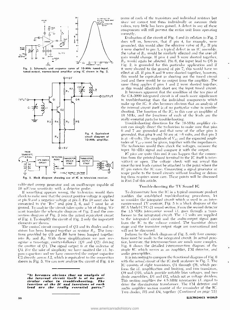
8000 OHMS e-
w
6 V60
VIN R, SO OHMS
OTS70
DOIS YF
i
32
26
24
20
V0x6v, Vrr -6v R. ROOi6000 OHMS
01.370 ,OVER -ALL EFFECTIVE
Re 92 IO 0 106
-6V6c FREOUENC, - MNx
Fig. 3. Schematic and response curve of 10 -MHz tuned -input, tuned -output, narrow -band amplifier using IC shown in Fig. 2.
INPUT
FROM
SOUND DET.
C4.5MHz
INTEGRATED CIRCUIT
ó I
DETECTED TRANSISTOR
AUDIO DRIVER STAGE
VOLUME
OUTPUT
Fig. 4. Equivalent circuit diagram of 10 -MHz amplifier.
TRANSISTOR OUTPUT
STAGE
77 7 -VOLT SUPPLY VOLTAGE
Fig. 5. Block diagram showing use of IC in television receiver.
calibrated sweep generator and an oscilloscope capable of 10 mV /cm sensitivity with a detector probe.
If something appears wrong, the technician would then check to make sure that the correct positive voltage is applied at pin 9 and a negative voltage at pin 3. Pin 10 must also be connected to the "B +" and pills 2, 6, and 7 must be at ground. To analyze the circuit takes quite a bit of doing. We must translate the schematic diagram of Fig. 2 and the con- nection diagram of Fig. 3 into the actual equivalent circuit of Fig. 4. To simplify the circuit of Fig. 2 only the important elements are shown.
The control circuit composed of Q3 and its diodes and re- sistors has been lumped together as resistor R -. The func- tions provided by Q5 and R6 have been lumped together into R,- and R7. With these simplifications we now rec- ognize a two -stage, emitter -follower (Q1 and Q2) driving the emitter of Q4. The signal output is at the collector of Q4. For the sake of simplicity we have omitted the r.f. by- pass capacitors and we have connected the output capacitor C2 directly across L2, which is equivalent to the connection shown in Fig. 3. We can now analyze the circuit of Fig. 4 in
e_It becomes obrions that an analysis of the internal circuit itself is of no par - tienlar raine in troubleshooting. The function of the 1C and fnnetions of each lead are the really essential parts."
36
terms of each of the transistors and individual resistors but since we cannot test them individually or measure their values, very little has been gained. A defect in any of these components will still prevent the entire unit from operating correctly.
Evaluation of the circuit of Fig. 4 and its relation to Fig. 2 does tell us, however, that if pin 4, for example, were grounded, this would alter the effective value of R. If pin 4 were shorted to pin 3, a typical defect in an IC assembly, the value of R r would be similarly affected and the over -all gain would change. If pins 4 and 5 were shorted together, R r- would again be affected. Pin 6, the input lead to Q5 in Fig. 2, is grounded for this particular application and if it were shorted to the ground of pin 7, this would have no effect at all. If pins 8 and 9 were shorted together, however, this would be equivalent to shorting out the tuned circuit load and there would be no output from the amplifier. The same thing applies if pins 1 and 2 were shorted together, as this would effectively short out the input tuned circuit.
It becomes apparent that the condition of the ten pins of the CA -3000 integrated circuit is of much more significance in troubleshooting than the individual components which make up the IC. It also becomes obvious that an analysis of the internal circuit itself is of no particular value in trouble- shooting. The function of the IC, in this case an amplifier of 10 MHz, and the functions of each of the leads are the really essential parts for troubleshooting.
Troubleshooting directions for the 10 -MHz amplifier cir- cuit can simply direct the technician to make sure that pins 6 and 7 are grounded and that none of the other pins is grounded, that pins 9 and 10 are at +6 volts, and that pin 3 is at -6 volts. The amplitude of Vx and the expected ampli- tudes of Vo1.... must be given, together with the impedances. The technician would then check the voltages, measure the input 10-MHz signal and compare it with the output.
IC pins are quite thin and it can happen that the connec- tion from the printed -board terminal to the IC itself is inter- mittent or open. The voltage check will not reveal this since the test leads cannot be attached to the point where the IC pin enters the IC case. Connecting a signal generator or scope probe to the tuned circuits without loading or detun- ing them requires some care. These points will be discussed in Part 2 of this article.
Troubleshooting the TV Sound IC
To demonstrate how the IC in a typical consumer product modifies the established troubleshooting procedures, let us consider the integrated circuit which is used in an inter- carrier -sound TV receiver. Fig. 5 is a block diagram of the RCA Model CTC -21 sound section. From the second detector the 4.5 -MHz intercarrier sound i.f. goes through a trans- former to the integrated circuit. The +7 volts are supplied to the integrated circuit and the audio- output signal goes from the IC to the volume control. The transistor driver stage and the transistor output stage are conventional and will not be discussed.
Judging by the block diagram of Fig. 5, only four connec- tions must be made to the integrated circuit. In actual prac- tice, however, the interconnections are much more complex. Fig. 6 shows the detailed interconnection diagram of the single IC which serves as an amplifier, FM detector, and audio preamplifier.
It is interesting to compare the functional diagram of Fig. 6 with the actual circuit of the IC itself as shown in Fig. 7. The IC consists of eight transistors, Q1 through Q8, which per- form the i.f. amplification and limiting, and two transistors, Q9 and Q10, which provide suitable bias voltages, and two diode assemblies, D1 and D2, which act as voltage dividers. This section amplifies the 4.5 -MHz intercarrier i.f. signal to drive the discriminator transformer. The F \I detector and audio amplifier section consist of the remainder of the IC. Two diodes, D3 and D4, together (Continued on page 75)
ELECTRONICS WORLD
www.americanradiohistory.com
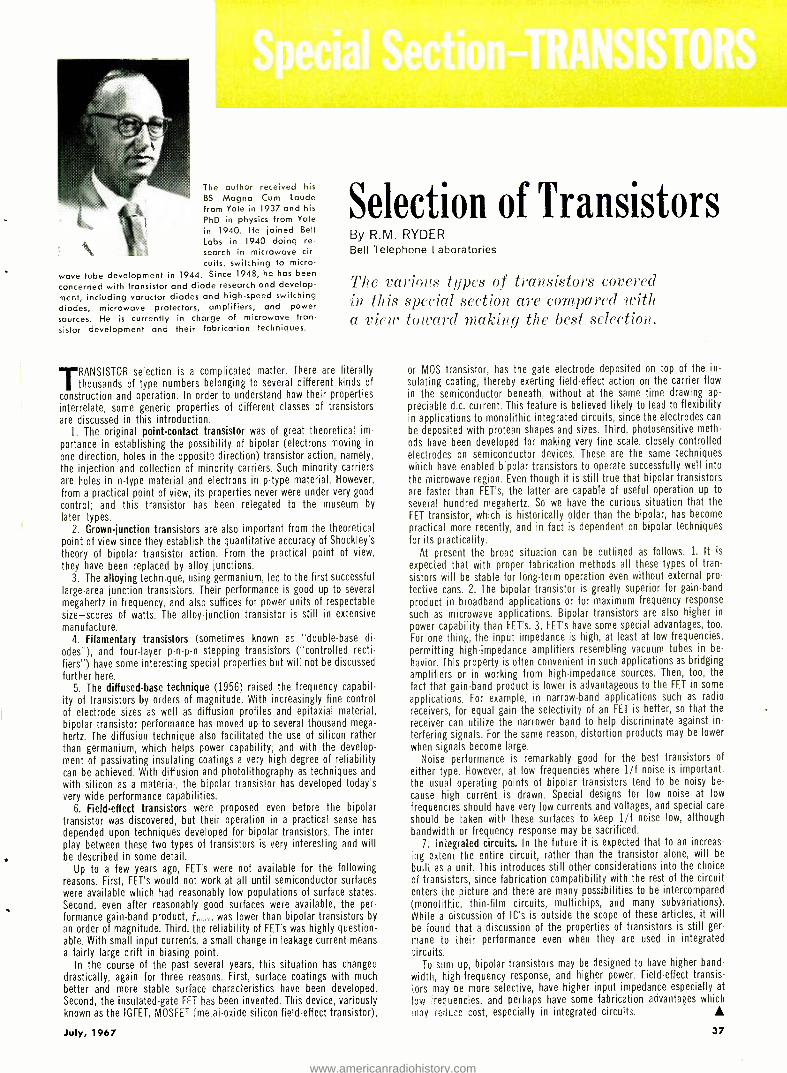
The author received his BS Magna Cum Laude from Yale in 1937 and his
PhD in physics from Yale in 1940. He joined Bell Labs in 1940 doing re- search in microwave cir- cuits, switching to micro-
wave tube development in 1944. Since 1948, he has been
concerned with transistor and diode research and develop- ment, including varactor diodes and high -speed switching diodes, microwave protectors, amplifiers, and power sources. He is currently in charge of microwave tran- sistor development and their fabrication techniques.
Selection of Transistors By R.M. RYDER Bell Telephone Laboratories
The various types of transistors cover, (1
in this special section are compared with a view toward making the best selection.
'TRANSISTOR selection is a complicated matter. There are literally 1 thousands of type numbers belonging to several different kinds of
construction and operation. In order to understand how their properties
interrelate, some generic properties of different classes of transistors are discussed in this introduction.
1. The original point- contact transistor was of great theoretical im-
portance in establishing the possibility of bipolar (electrons moving in
one direction, holes in the oppositî direction) transistor action, namely, the injection and collection of minority carriers. Such minority carriers are holes in n -type material and electrons in p -type material. However,
from a practical point of view, its properties never were under very good
control; and this transistor has been relegated to the museum by
later types. 2. Grown -junction transistors are also important from the theoretical
point of view since they establish the quantitative accuracy of Shockley's
theory of bipolar transistor action. From the practical point of view,
they have been replaced by alloy junctions. 3. The alloying technique, using germanium, led to the first successful
large -area junction transistors. Their performance is good up to several
megahertz in frequency, and also suffices for power units of respectable
size -scores of watts. The alloy -junction transistor is still in extensive manufacture.
4. Filamentary transistors (sometimes known as "double -base di-
odes"), and four -layer p -n -p -n stepping transistors ( "controlled recti-
fiers") have some interesting special properties but will not be discussed
further here.
5. The diffused -base technique (1956) raised the frequency capabil- ity of transistors by orders of magnitude. With increasingly fine control of electrode sizes as well as diffusion profiles and epitaxial material,
bipolar transistor performance has moved up to several thousand mega-
hertz. The diffusion technique also facilitated the use of silicon rather than germanium, which helps power capability; and with the develop-
ment of passivating insulating coatings a very high degree of reliability can be achieved. With diffusion and photolithography as techniques and
with silicon as a material, the bipolar transistor has developed today's very wide performance capabilities.
6. Field -effect transistors were proposed even before the bipolar transistor was discovered, but their operation in a practical sense has
depended upon techniques developed for bipolar transistors. The inter- play between these two types of transistors is very interesting and will be described in some detail.
Up to a few years ago, FET's were not available for the following reasons. First, FET's would not work at all until semiconductor surfaces were available which had reasonably low populations of surface states. Second, even after reasonably good surfaces were available, the per- formance gain -band product, f,,,:,,, was lower than bipolar transistors by
an order of magnitude. Third, the reliability of FET's was highly question- able. With small input currents, a small change in leakage current means
a fairly large drift in biasing point. In the course of the past several years, this situation has changed
drastically, again for three reasons. First, surface coatings with much
better and more stable surface characteristics have been developed. Second, the insulated -gate FE? has been invented. This device, variously known as the IGFET, MOSFET (me:ai -oxide silicon field -effect transistor),
July, 1967
or MOS transistor, has the gate electrode deposited on top of the in-
sulating coating, thereby exerting field -effect action on the carrier flow
in the semiconductor beneath, without at the same time drawing ap-
preciable d.c. current. This feature is believed likely to lead to flexibility in applications to monolithic integrated circuits, since the electrodes can
be deposited with protean shapes and sizes. Third, photosensitive meth-
ods have been developed for making very fine scale, closely controlled
electrodes on semiconductor devices. These are the same techniques which have enabled bipolar transistors to operate successfully well into
the microwave region. Even though it is still true that bipolar transistors
are faster than FET's, the latter are capable of useful operation up to
several hundred megahertz. So we have the curious situation that the
FET transistor, which is historically older than the bipolar, has become
practical more recently, and in fact is dependent on bipolar techniques for its practicality.
At present the broad situation can be outlined as follows. 1. It is
expected that with proper fabrication methods all these types of tran-
sistors will be stable for long -term operation even without external pro-
tective cans. 2. The bipolar transistor is greatly superior for gain -band
product in broadband applications or for maximum frequency response
such as microwave applications. Bipolar transistors are also higher in
power capability than FET's. 3. FET's have some special advantages, too.
For one thing, the input impedance is high, at least at low frequencies,
permitting high -impedance amplifiers resembling vacuum tubes in be-
havior. This property is often convenient in such applications as bridging
amplifiers or in working from high- impedance sources. Then, too, the
fact that gain -band product is lower is advantageous to the FET in some
applications. For example, in narrow -band applications such as radio
receivers, for equal gain the selectivity of an FET is better, so that the
receiver can utilize the narrower band to help discriminate against in-
terfering signals. For the same reason, distortion products may be lower
when signals become large.
Noise performance is remarkably good for the best transistors of
either type. However, at low frequencies where 1/f noise is important,
the usual operating points of bipolar transistors tend to be noisy be-
cause high current is drawn. Special designs for low noise at low
frequencies should have very low currents and voltages, and special care
should be taken with these surfaces to keep 1/f noise low, although
bandwidth or frequency response may be sacrificed.
7. Integrated circuits. In the future it is expected that to an increas-
ing extent the entire circuit, rather than the transistor alone, will be
buili as a unit. This introduces still other considerations into the choice
of transistors, since fabrication compatibility with the rest of the circuit enters the picture and there are many possibilities to be intercompared
(monolithic, thin -film circuits, multichips, and many subvariations).
While a discussion of IC's is outside the scope of these articles, it will
be found that a discussion of the properties of transistors is still ger-
mane to their performance even when they are used in integrated
circuits. To sum up, bipolar transistors may be designed to have higher band-
width, high -frequency response, and higher power. Field -effect transis-
tors may be more selective, have higher input impedance especially at
low Frequencies, and perhaps have some fabrication advantages which
may reduce cost, especially in integrated circuits.
37
www.americanradiohistory.com
The author received his B.S. and M.S. degrees in Electrical Engineering from Newark College of Engineering. As a 1st Lt. in the Air Force he served as Ground Electronics Offi- cer. Upon leaving the service, he joined ITT Laboratories as a design engineer. Since 1961 he has been a member of the Computer & Communications Lab at RCA where his work is primarily concerned with the design of h.f. circuits for evaluation of v.h.f. and u.h.f. transistors. He is au- thor of several published papers and a member of IEEE.
Small- Signal
High -Frequency Transistors By T. J. ROBE Electronic Components and Devices, Radio Corporation of America
Valuable tips are offered below for selecting radio-frequency transistors. Included is description of scattering parameters.
\I.AI.I,- signal high -frequency tr:utsistot's are designed lo provide high gaits and lost noise at high fre- quencies. 'fo attain Iltjs, high-frequency transistors
have a very marrow base and small hase -spreading re- sistance rt,'. Low -frequency (audio) transistors generally require a very high d.e. beta, higher breal:dottu- voltage ratings, and low lote -frequency noise. Sns :dl- sigu:tl switch- ing transistors, which :arts also required to have high - frequency capabilities, must he designed to minimize carrier storage in the base and collector regions. III gen- eral, the requirements for switching loth- and high -fre- quency transistors are incompatible and compromises must be stade to achieve the optimum characteristics for an intender l :t t,pl ica t ion.
Today's high -frequency transistors have unity- power- gain frequencies, f in the listige from 3(111 \Illz to (i GHz. \lost transistors which are .suitable l'or small- .signal high -frequency amplification cats be classified as one of the following general types:
Table 1. Significant parameters for high- frequency transistors.
C,
Ccm
f,`, ,
GM A
GAIS
Gr U
hc k
NF
ri,'
r Su
S,_
S S...,
y Y,-
y,>
38
Collector- barrier capacitance Collector -base feedback capacitance Unity- power -gain frequency (figure of merit) Gain -bandwidth product (the frequency where ht,. = 1) Maximum available transducer power gain Maximum stable power gain Transducer power gain (unilateral) Forward current gain with output a.c. short -circuited Stability factor Ratio of total transistor noise power delivered to a load to the noise power delivered to the same load by the source Base -spreading resistance Emitter -base dynamic resistance Input reflection coefficient Reverse voltage transfer ratio Forward voltage transfer ratio Output reflection coefficient Input admittance t with output a.c. Forward current -voltage ratio S short- circuited Reverse current -voltage ratio t with input a.c. Output admittance short -circuited
1. Silicon planar epitaxial transistors (examples: 2N28.57, 2N:393 °2. and 1N 1á6U) .
á. Insulated -gate field -effect transistors which are also called \IOSFET's (examples: 3N1á8 and RCA Dev. Nos. T.\ î (11(1, '1':1á(i 1-1) .
:3. ,function gate FET's (examples: °N1416, áN3823).
Important Parameters The significant parameters for high -frequency transistors
are summarized in Table 1. An examination of the internal transistor parameters which relate to the unity -power -gain frequency, f ,.,., and to lote noise at high frequency is facilitated by use of an approximate high- frequency equiv- alent circuit for a transistor (Fig. 1-A). The circuit de- scribes the diffused transistor chip. exclusive of its pack - age, which is applicable at frequencies very near f,,,,,,. It is assumed that internal feedback is negligible: this assump- tion permits the calculation of the frequency at which the unilateral potter gain is unity. Front Fig. 1A, the following expression for the trauducer power gaits, G.t.u, under con- ditions of snatched lone and matched source impedances, can he derived:
potter delivered to matched load GC° potter available from the source f
8r rt' C',. f - If the unilateral power gain is assumed to be unity,
Eq. 1 cran be rewritten to express the frequency at which this occurs:
¡ fr J - t ains- ')5 rn 'C. ,.
Eq. á indicates that if a high f,,,,,,. is required, the tran- sistor should have a high gain -bandwidth product fT, a low base- spreading resistance, rt', and a low collector - barrier capacitance,
At high frequencies, a high f -,. and a lote r1,' are required for low noise figure NF, as well as for high power gain ( Fig. 113) . The manufacturer's data on low- noise, high- frequency transistors normally specifies a minimum value for .small- signal Its,, measured at a frequency, f, above
(2)
ELECTRONICS WORLD
www.americanradiohistory.com

Nvhich the reduction 111 uiQ with frequency is given by the following relation:
lafe = fT' f (3)
The gain -bandwidth product, IT, can be easily calculated from Eq. 3.
Although it is difficult to measure rt,' directly, it is rela- tively easy to measure the rt' C,. product. The parameters f T and rt,' C. together with the power gain and noise fig- ure, serve as a good initial guide to transistor selection. Another important parameter in the selection process is
the total collector -to -base feedback capacitance Cr.t; which provides some indication of transistor stability. This feed - back capacitance includes the collector- barrier capaci- tance Ce, the internal base- contact -to- collector capacitance, and the stray interlead capacitance of the header.
High -frequency figure-of-merit parameters comparable to IT and r,' are not generally available for field -effect transistors. However. power gain and noise figure in a functional circuit are normally given for FET's which are intended for high -frequency operation. As will be dis- cussed later, if the two -port parameters are given they can also be used in the selection.
The figure -of -merit parameters fT and rt; C are related to the transistor chip only and do not include the effects o. the package stray reactances, such as series lead in- ductance and interlead capacitance. The two -port para- meters, on the other hand. characterize the total transistor at the single frequency at which they are measured. From this standpoint, these parameters paint a better over -all picture of the transistor performance at high frequency, especially for operation at frequencies above approximately 10O JIHz.
In the earlier transistors which had an upper- frequency limit of about 100 MHz, it was common to find the h- or hybrid -pi parameter; in the manufacturer's data be- cause these parameters are relatively easy to measure on these particular transistors. As the frequency capabilities of transistors increase to the higher v.h.f. and the lower u.h.f. ranges, it becomes more difficult to measure these parameters, because the "hotter" transistors tend to oscillate with open- circuit terminations. The short- circuit y -para- mcters have replaced the h- parameters in the manufac- turer's data and are today the most prominent two -port parameters given for small- signal high -frequency transis- tors. The short -circuit admittance parameters are very useful in determining the maximum stable power gain that can he realized at a given frequency.
Scattering Parameters High- frequency transistors which are capable of opera-
tion at frequencies on the order of 1 (iHz and higher are available. At these microwave frequencies. the scattering IS) parameters may be easier to measure than either the 1i- or y- parameters. Neither an open -circuit nor a short- circuit termination, both of which are difficult to achieve in the microwave region, is required for the mea- surements. Instead, the transistor is terminated by a refer- ence(' impedance, typically 5(1 ohms. which consists of a transmission line operated into a matched termination. An accurate termination of this type is much easier to achieve than the short -circuit termination required for the admit- tance parameter measurements.
The scattering parameters of a two -port network are defined in ternis of reflection coefficients and voltage - transfer ratios rather than by ratios of the terminal volt - ages and currents. For the network of Fig. 2, the scatter- ing parameters are defined as follows:
S11 = Str = E
R1 E10 = O = input reflection coefficient
with the output terminated in Z,,.
B
E
(A) (B)
WI' CC z J LOG f
Fig. 1. (Al Approximate high- frequency equivalent circuit for conventional (bipolar) transistor. (B) Frequency at which noise figure begins to rise depends on f and ri,'. } Zo LINE
EI,
ERi - Zp LINE
--`" ERz
J Ezz
BOUNDARY OF THE TRANSISTOR LEADS AS THEY EMERGE FROM THE HEADER
EZI= INCIDENT VOLTAGE AT THE INPUT
ERI = REFLECTED VOLTAGE AT THE INPUT
E12= INCIDENT VOLTAGE AT THE OUTPUT
ER2= REFLECTED VOLTAGE AT THE OUTPUT
Fig. 2. Circuit for defining scattering (S) parameters.
Z
s21 = Sfe = ' E,.. =0 = forward voltage transfer ra- Ett -
tio with the output terminated in Z.
E' .0 S.0= Soc- - Etl = 0 = output reflection coefficient t-
witlt the input terminated in Z.
Sl = ,g , _ ' 1 I F, t 1 = O = reverse voltage transfer ra-
ft_ do with the input terminated in Z.
Transistor Selection Military and aerospace applications normally require
guaranteed reliability and environmental capability, with cost somewhat subordinate. Entertainment applications tend to emphasize low cost. The reliability of the tran- sistor must also be considered, however, because field failures in auto radios and TV sets will soon cut into the set manufacturer's profit. In industrial applications, cost, reliability, and environmental factors are just about even- ly weighted.
The differences in transistor cost are primarily based on two factors: volume and guarantees in ternis of reliability and electrical performance. Low -cost entertainment tran- sistors are available because of the high volumes in which they are produced. High -reliability transistors for military and aerospace applications are produced ill relatively small quantities with extensive inspections. burn -ins, and life tests to guarantee and document their reliability. As a result their costs are relatively high. In terms of cost z'ersrts reliability. a transistor from a high -volume pro- duction line should be selected if guaranteed reliability is not required (the word guaranteed should be emphasized because reliable performance is also required of the high - volume transistor) . Of course, when transistors which represent. the limit of state -of- the -art are required in the application, the cost of these particular devices will be relatively high.
The choice between silicon and germanium has all but vanished in the small -signal high- frequency area. The planar process has allowed the environmentally superior silicon transistor to equal or exceed the high- frequency electrical performance of its germanium competitor while at the same time its cost is low if produced in large volumes.
July, 1967 39
www.americanradiohistory.com
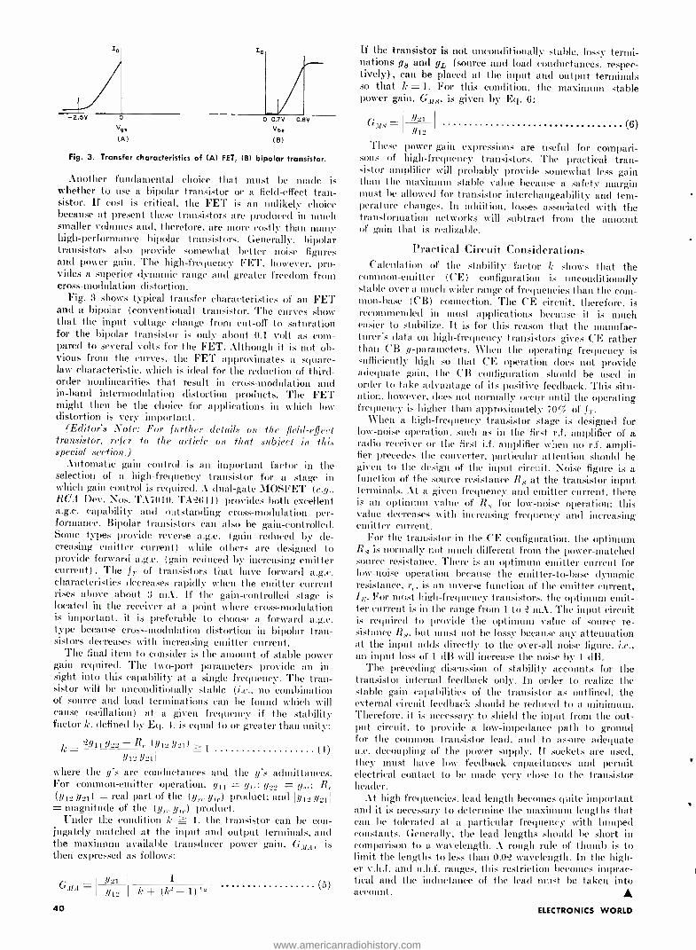
-2.5V 0
Vqe
(A)
o 0.7V
Vbe
(B)
0.9V
Fig. 3. Transfer characteristics of (Al FET, (B) bipolar transistor.
Another fundamental choice that must be made is whether to use a bipolar transistor or a field -effect tran- sistor. If cost is critical, the FET is an unlikely choice because at present these transistors are produced in much smaller volumes and, therefore, are more costly than many high -performance bipolar transistors. Generally, bipolar transistors also provide somewhat better noise figures and power gain. The high -frequency FET, however, pro- vides a superior dynamic range and greater freedom from cross-modulation distortion.
Fig. 3 shows typical transfer characteristics of an FET and a bipolar (conventional) transistor. The curves show that the input voltage change from cut -off to saturation for the bipolar transistor is only about 0.1 volt as com- pared to several volts for the FET. Although it is not ob- vious from the curves. the FET approximates a square - law characteristic, which is ideal for the reduction of third - order nonlinearities that result in cross -modulation and in -band intermodulation distortion products. The FET might then be the choice for applications in which low distortion is very important.
(Editor's Note: For further details on the field -effect transistor, refer to the article on that subject in this special section.)
Automatic gain control is an important factor in the selection of a high- frequency transistor for a stage in which gain control is required. A dual -gate AIOSFET (e.g.. RCA 1ev. Nos. TA7010, T. ((14) provides both excellent a.g.c. capability and outstanding cross -modulation per- formance. Bipolar transistors can also be gain -controlled. Some types provide reverse a.g.c. (gain reduced by de- creasing emitter current) while others are designed to provide forward a.g.c. (gain reduced by increasing emitter current) . The f T of transistors that have forward a.g.c. characteristics decreases rapidly when the emitter current rises above about 3 mA. If the gain -controlled stage is located in the receiver at a point where cross -modulation is important, it is preferable to choose a forward a.g.c. type because cross -modulation distortion in bipolar tran- sistors decreases with increasing emitter current.
The final item to consider is the amount of stable power gain required. The two -port parameters provide an in- sight into this capability at a single frequency. The tran- sistor will be unconditionally stable (i.e., no combination of source and load terminations can be found will cause oscillation) at a given frequency if the stability factor k, defined by Eq. 4, is equal to or greater than unity:
k ='4119,2 -R,. (y1_ ?/91) >1 tY1_ Y21
where the y's are conductances and the y's admittances. For common -emitter operation, g11 = g,,; g_., = y R.
(yY'21) - real part of the (, r ) product; and 1 t 12 a part yr Jfe 1 J1 s Jet i
= magnitude of the (y,.,. yo.) product. Under the condition k ? 1, the transistor can be con-
jugately matched at the input and output terminals, and the maximum available transducer power gain, G.1/A, is then expressed as follows:
Y21 GuA - th_
40
1
k (1,;"-1)'- (5)
If the transistor is not unconditionally stable, lossy termi- nations gs and gr, (source and load conductances, respec- tively) , can be placed at the input and output terminals so that k = 1. For this condition, the maximum stable power gain, Gtt5, is given by Eq. 6:
0.118 - ysi Y12
These power -gain expressions are useful for compari- sons of high- frequency transistors. The practical tran- sistor amplifier will probably provide somewhat less gain than the maximum stable value because a safety margin must be allowed for transistor interchangeability and tern - perature changes. In addition, losses associated with the transformation networks will subtract frosts the amount of gain that is realizable.
Practical Circuit Considerations Calculation of the stability factor k shows that the
common- emitter (CE) configuration is unconditionally stable over a much wider range of frequencies than the com- mon -base (CB) connection. The CE circuit, therefore, is recommended in most applications because it is much easier to stabilize. It is for this reason that the manufac- turer's data on high- frequency transistors gives CE rather than ('B y- parameters. When the operating frequency is sufficiently high so that CE operation does not provide adequate gain. the CB configuration should be used in order to take advantage of its positive feedback. This situ- ation. however, does not normally occur until the operating frequency is higher than approximately 7OÇ of f T.
When a high -frequency transistor stage is designed for low -noise operation. such as in the first r.f. amplifier of a radio receiver or the first i.f. amplifier when no r.f. ampli- fier precedes the converter. particular attention should be given to the design of the input circuit. Noise figure is a function of the source resistance R,,, at the transistor input terminals. At a given frequency and emitter current, there is am optimum value of R, for low -noise operation; this value decreases with increasing frequency and increasing emitter current.
For the transistor in the CE configuration, the optimum R,5 is normally not much different from the power-matched source resistance. There is an optimum emitter current for low -noise operation because the emitter -to -base dynamic resistance, r., is an inverse function of the emitter current, /e. For most high -frequency transistors. the optimum emit- ter current is in the range from 1 to '2 mA. The input circuit is required to provide the optimum value of source re- sistance R,,, but must not be lossy because any attenuation at the input adds directly to the over -all noise figure. i.e., an input loss of 1 dB will increase the noise by 1 dB.
The preceding discussion of stability accounts for the transistor internal feedback only. In order to realize the stable gain capabilities of the transistor as outlined, the external circuit feedback should be reduced to a minimum. Therefore, it is necessary to shield the input from the out- put circuit, to provide a low- impedance path to ground for the common transistor lead, and to assure adequate a.e. decoupling of the power supply. If sockets are used, they must have low feedback capacitances and permit electrical contact to be made very close to the transistor header.
At high frequencies, lead length becomes quite important and it is necessary to determine the maximum lengths that can be tolerated at a particular frequency with lumped constants. Generally, the lead lengths should be short in comparison to a wavelength. A rough rule of thumb is to limit the lengths to less than 002 wavelength. In the high- er v.h.f. and u.h.f. ranges, this restriction becomes imprac- tical and the inductance of the lead must be taken into account.
(6)
ELECTRONICS WORLD
www.americanradiohistory.com
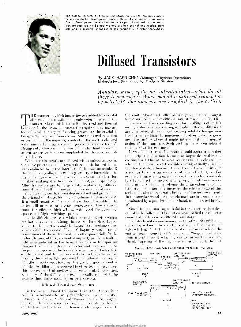
The author, inventor of annular semiconductor devices, has been active in semiconductor development since college. As manager of Motorola Device Development, he was both an active participant and section mana- ger. He received his BS and MS degrees in electrical engineering from MIT and is presently manager of the company's Thyristor Operations.
Diffused Transistors By JACK HAENICHEN /Manager, Thyristor Operations Motorola Inc., Semiconductor Products Division
Annular, mesa, epitaxial, interdigitated -what do all these terms mean? When should a diffused transistor be selected? The answers are supplied in the article.
THE manner in which impurities are added to a crystal of germanium or silicon not only determines what the transistor is called but also its electrical and thermal
behavior. In the "grown" process, the required junctions are formed while the crystal is being grown. As the crystal is
being pulled or grown from a vessel containing molten silicon or germanium, the impuritiy content of the melt is changed with time and contiguous n- and p -type regions are formed. Because of its low yield. high cost, and other limitations. the grown transistor has been supplanted by the superior dif- fused device.
When certain metals are alloyed with semiconductors in the alloy process, a small regrowth region is formed in the semiconductor near the interface of the two materials. If the metal being alloyed contains p- or tt -type impurities. the regrowth region will retain a certain amount of these im- purities. making it either a p- or an n -type, respectively. Alloy transistors are being gradually replaced by diffused transistors but still find use in high -power applications.
In epitaxial growth. silicon deposits itself and grows upon the original .substrate, forming a mechanical extension of it. If a small quantity of p- or n -type dopant is added, the latter will grow p- or n -type, respectively. The epitaxial transistor offers a high B1'c,,tu with good frequency re- sponse and high switching speeds.
In the diffusion process, while the semiconductor wafers are hot, a source containing the desired impurities is pre- sented to their surfaces and the impurities distribute them- selves within the crystal. The final impurity concentration is maximum at the surface and falls off exponentially in the wafer. Because of this exponential impurity profile, a built -in field is established in the base. This aids in transporting charges from the emitter to collector and. as a result, the frequency response of the transistor is improved. Today base widths have shrunk from several mils to less than one micron, making the electric field provided by a diffused base region of little importance. However, the great degree of control afforded by diffusion, as opposed to other techniques, makes this process most attractive and economical. In addition, reliability of the ciffused devices is usually claimed to be greater than those made by other processes.
Diffused Transistor Structures In the mesa diffused transistor (Fig. 1A) , the emitter
regions are formed selectively either by an alloy or a masked diffusion technique. A series of "mesas" are etched away tt interrupt the continuous base region. This restricts the size of the base and reduces the base- collector capacitance. It
the emitter -base and collector -base junctions are brought to the surface, a planar diffused transistor results (Fig. 1BI .
The silicon dioxide coating used for masking is often left on the wafer or a new coating is applied after all diffusions are completed. A permanent coating inhibits foreign ma- terial from reaching the junctions and other critical regions near the surface where it might interact with the normal action of the transistor. Such coatings have been referred to as passivating coatings.
It was found that such a coating could aggravate. rather than help, the situation because of impurities within the coating itself. One of the most serious effects is channeling. wherein the presence of the oxide coating actually disrupts the charge distribution near the surface of the wafer in such a way as to cause an inversion of conductivity type. For example. in an 15- p-11 transistor where the collector isnoruTal- ly ce -type, a p -type inversion layer or channel forms under the coating. Such a channel constitutes an extension of the base region and not only increases the effective size of this region. but also causes erratic behavior of the reverse current. In the annular transistor these channels are interrupted and terminated by a positive annular band, as illustrated in Fig. 1C.
Since the basic starting material in the structures just des- cribed is the collector. it is most common to find the collector connected to the case of diffused transistors.
In order to obtain maximum current rating with minimum device capacitance, the structures shown in Fig. -2 were de- veloped. Fig. '2 (left) shows a star transistor where the emitter region consists of four tapered "fingers" radiating from a center point which serves as an emitter bonding island. Tapering of the fingers is consistent with the fact
Fig. 1. Three main types of diffused transistor structures.
EMITTER -BASE JUNCTION
(EMITTER)
P (COLLEÇTOR)
ETCHED MESA _ BASE-
- COLLECTOR - JUNCTION
EMITTER -BASE JUNCTION
MESA (A)
PASSIVATING COATING
BASE - COLLECTOR JUNCTION
PASSIVATING COATING
P
PLANAR (B)
EMITTER -BASE JUNCTIONN -N -TYPE CHANNEL
j
ANNULAR
IC)
DIFFUSED CHANNEL - INTERRUPTING REGION
NOTE CROSS-HATCHED AREAS ARE METAL CONTACTS
July, 1967 41
www.americanradiohistory.com
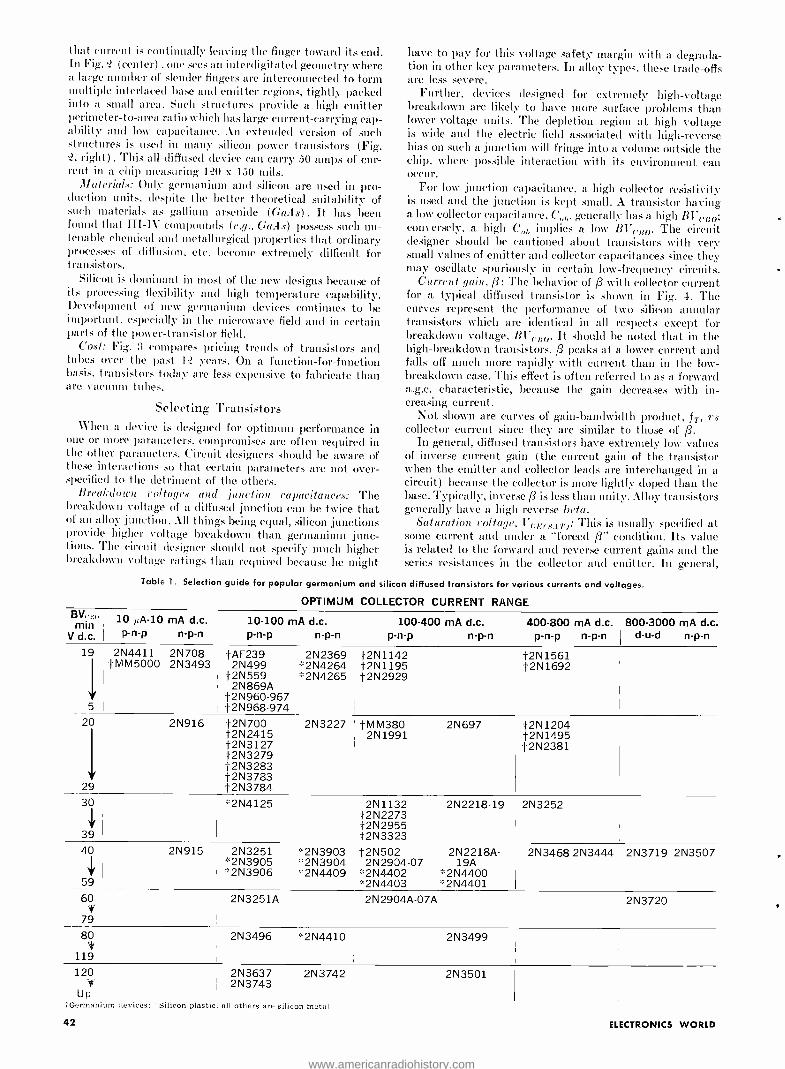
iluut current is continually leaving the finger toward its end. In Fig. .1 (center) one sees an interdigitated geometry where a large number of slender fingers are interconnected to form multiple interlaced base and emitter regions, tightly packed into a small area. Such structures provide a high emitter perimeter -to -area ratio which has large current- carrying cap- ability and low capacitance. An extended version of such structures is used in many silicon power transistors (Fig. ?, right) .This all- diffused device can carry 50 amps of cur- rent in a. chip measuring 1?0 x 150 toils.
Materials: Only germanium and silicon are used in pro- duction units, despite the better theoretical suitability of such materials as gallium arsenide (GaAs) . It has been found that III -IV compounds (e.g.. GaAs) possess such un- tenable chemical and metallurgical properties that ordinary processes of diffusion, etc. become extremely difficult for transistors.
Silicon is dominant in most of the new designs because of its processing flexibility and high temperature capability. Development of new germanium devices continues to be important, especially in the microwave field and in certain parts of the power- transistor field.
Cost: Fig. 13 compares pricing trends of transistors and tubes over the past 1? years. On a function- for -function basis, transistors today are less expensive to fabricate than are vacuum tubes.
Selecting Transistors When a device is designed for optimum performance in
one or more parameters, compromises are often required in the other parameters. Circuit. designers should be aware of these interactions so that certain parameters are not over - specified to the detriment of the others.
Breakdown voltages and junction capacitances: The breakdown voltage of a diffused junction can be twice that of an alloy junction. All things being equal, silicon junctions provide higher voltage breakdown than germanium junc- tions. The circuit designer should not specify much higher breakdown voltage ratings than required because lie might
have to pay for this voltage safety margin with a degrada- tion in other key parameters. In alloy types, these trade -offs are less severe.
Further, devices designed for extremely high -voltage breakdown are likely to have more surface problems than lower- voltage units. The depletion region at high voltage is wide and the electric field associated with high- reverse bias on such a junction will fringe into a volume outside the chip, where possible interaction with its environment can occur.
For low junction capacitance, a high collector resistivity is used and the junction is kept small. A transistor having a low collector capacitance, C l,, generally has a high BV elm; conversely, a high C l, implies a low BVrrso- The circuit designer should be cautioned about transistors with very small values of emitter and collector capacitances since they may oscillate spuriously in certain low -frequency circuits.
Current gain, ß: The behavior of /3 with collector current for a typical diffused transistor is shown in Fig. 4. The curves represent the performance of two silicon annular transistors which are identical in all respects except for breakdown voltage, Bl'c,o. It should be noted that in the high -breakdown transistors, ß peaks at a lower current and falls off much more rapidly with current than in the low - breakdown case. This effect is often referred to as a forward a.g.e. characteristic, because the gain decreases with in- creasing current.
Not shown are curves of gain -bandwidth product, IT, vs collector current since they are similar to those of ß.
In general, diffused transistors have extremely low values of inverse current gain (the current gain of the transistor when the emitter and collector leads are interchanged in a circuit) because the collector is more lightly doped than the base. Typically, inverse /3 is less than utility. Alloy transistors generally have a high reverse beta.
Saturation voltage, Vc.c,(s5T): This is usually specified at some current and under a "forced ß condition. Its value is related to the forward and reverse current gains and the series resistances in the collector and emitter. In general,
Table 1. Selection guide for popular germanium and silicon diffused transistors for various currents and voltages.
OPTIMUM COLLECTOR CURRENT RANGE BV, min
V d.c.
10 ,A-10 mA d.c. p-n-p n-p-n
10-100 mA d.c. p-n-p n-p-n
100-400 mA d.c. 400-800 mA d.c. p-n-p n-p-n p-n-p n-p-n
800-3000 d-u-d
mA d.c. n-p-n
19 2N4411 2N708 tAF239 2N2369 t2N1142 í2N1561 t M M5000 2N3493 2N499 '`2N4264 í2N1195 í2N1692 í2N559 °`2N4265 í2N2929 2N869A
t2N960 -967 5 í2N968 -974
20 2N916 í2N700 2N3227 tMM380 2N697 í2N1204 í2N2415 2N1991 í2N1495 í2N3127 í2N2381 í2N3279 í2N3283 í2N3783
29 í2N3784 30 ,:.2N4125 2N1132 2N2218 -19 2N3252
í2N2273 í2N2955
39 í2N3323 40 2N915 2N3251 *2N3903 í2N502 2N2218A-2N3468 2N3444 2N3719 2N3507
*2N3905 *2N3904 2N2934-07 19A *2N3906 :2N4409 '°2N4402 *2N4400
59 `2N4403 u2N4401 60
*1
2N3251Á 2N2904A -07A 2N3720
79 80 2N3496 *2N4410 2N3499
119 120 2N3637 2N3742 2N3501
if 2N3743 Up
"i Germanium devices: Silicon plastic, all others are silicon metal
42 ELECTRONICS WORLD
www.americanradiohistory.com

Fig. 2. Photomicrographs of transistor geometries.
at high current, such as found in power applications, alloy transistors have a lower value of this parameter than diffused transistors because the collector and emitter series resis- tances of an alloy device are negligible. Further, germanium transistors generally have an edge over silicon in this par- ticular parameter and n -p -n's (Ge or Si) are superior to p- n -p's.
Voltage VrE (sAT) is important with respect to power dis- sipation and loss of useful linear operating range in the tran- sistor. Diffused epitaxial transistors provide lower VCE(SAT) than non -epitaxial versions.
Base resistance, r,'. This is a distributed parameter, and since the base impurity concentration is not uniform (ex- ponential) is a diffused transistor, calculating r,,' is extreme- ly difficult. For this reason, it is normally determined by a high -frequency measurement.
Low r1,' designs have a low noise figure since a large por- tion of r.f. noise in diffused transistors is generated in the base resistance. However, a low rb' generally means greater emitter capacitance.
Input inr peda ce, 1ct,.: Input impedance decreases with in- creasing emitter current. A typical value at an emitter cur- rent of 1 mA is 1000 ohms, in contrast to an FET which has an input impedance in the megohm range. Clearly, where high input impedance is required, an FET should be selected.
Replacing non- diffused transistors: In most instances di- rect replacement of a non -diffused transistor (e.g., alloy) by a diffused type will not work well without circuit changes. Saturation voltage, current gain versus current, etc. are quite different than in non -diffused types. In general, the family of diffused transistors is a much higher frequency breed of device. Values of f. of 5011 \1Hz are common and amplifier circuits with poor layout will often oscillate when a high - frequency diffused transistor is used in place of an alloy or grown device.
Nevertheless, there are times when such changes can be made, especially if some circuit modifications are possible. Often a diffused device will be available in a plastic package at considerably- lower cost than an older type. Also. silicon devices can often be used to replace germanium, resulting in improved high-temperature performance. Such replace - ments must take into account silicon's higher saturation resistance. With the passage of time, diffused types vVill be more readily available as suppliers phase out production of non -diffused transistors.
Device packaging: Diffused transistors come in a variety of packages, including the TO -5, 18, 46, 51, it, and the TO -9P?, a molded plastic package. Today's plastic- encap- sulated passivated silicon transistor represents the minimum - cost transistor configuration which the industry has been seeking.
Table 1 is a selection guide for popular germanium and silicon diffused transistors in terms of current and voltage ratings.
Of the presently available types of diffused transistors, it is likely that the passivated silicon device in a plastic package will continue to be produced for the longest time. Such transistors, as well as specialty devices including the
July, 1967
(Left) star, (center) interdigitated and (right) power.
FET and UJT, will be available in plastic packages for various applications.
passivated germanium transistors might become impor- tant since government- and industry- sponsored research con- tinues in this area. In addition, considerable research is under way with germanium as u.h.f. power sources. In this work, diffused semiconductor chips are being incorporated in strip -line and coaxial packages.
Compound semiconductors continue to frustrate the in-
$100.00
10.00
1.00
10
Si
Gel
TUBE-
304
1954 56 58 60 62 64 66
Fig. 3. Selling price of tubes and transistors over the years.
1.0
6
4
2
o
LOW BREAKDOWN
HIGH BREAKDOWN
68
.001 .01 .1 1.0 10 100 1000 10,000
COLLECTOR CURRENT, MILLIAMPERES
Fig. 4. Beta vs collector current for diffused transistors.
Fig. 5. The r.f. power tran- sistor trends. In just a few years it is expected that substantial increases in output power and higher operating frequencies will be readily obtainable.
1000
100
o
1.0
0.1 0 100 1000
FREQUENCY, MHz. 10,000
43
www.americanradiohistory.com
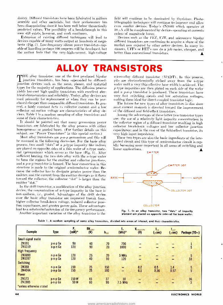
dustry. Diffused transistors have been fabricated in gallium arsenide and other materials, but their performance has been disappointing since it has been well below theoretically predicted values. The possibility of a breakthrough in this area still exists, however, and work continues.
Extension of existing diffused techniques will lead to devices capable of many watts output at hundreds of mega- hertz (Fig. 5) . Low- frequency silicon power transistors cap- able of handling perhaps 100 amperes will be developed. but the author feels that the very- high -current, high -voltage
field will continue to be dominated by thyristors. Photo- lithographic techniques will continue to improve and allow even smaller devices. Today's `2N3493 which operates at 10 ttA will be complemented by devices operating at currents orders of magnitude lower.
Devices such as the FET. UJT, and microwave bipolar diffused transistors are continuing to acquire a share of the market now enjoyed by other active devices. In many in- stances, UJT's or FET's can do a job easier, cheaper, and better than conventional transistors.
ALLOY TRANSISTORS HE alloy transistor, one of the first produced bipolar junction transistors. has been superseded by diffused -
junction devices such as the mesa, planar. and epitaxial types for the majority of applications. The diffusion process yields low -cost high -quality transistors with excellent elec- trical characteristics and reliability. Today, alloy devices are used primarily for replacement or when they can be pur- chased cheaper than comparable diffused transistors. In gen- eral, a fairly constant beta is collector current and a low collector sat oration voltage are characteristics of alloy de- vices. Table 1 is a random sampling of alloy transistors and some of their characteristics.
It should be pointed out that many germanium power transistors are fabricated by the alloy process with either homogeneous or graded bases. (For further details on this subject, see "Power Transistors" in this special section.)
Most alloy transistors are p -n -p germanium and this will be assumed in the following discussion. For the basic alloy process, two small "clots" of a p -type impurity like indium are placed on opposite sides of a thin wafer of n -type mate- rial (germanium) which serves as the base (Fig. 1) . After sufficient heating, the two dots alloy with the n -type wafer to form the regions for the emitter and collector junctions. and a p -n -p transistor is formed. The base connection in this structure is made to the original semiconductor Nvafer. Be- cause the collector has to dissipate greater power than the emitter, and the current from the emitter diverges as it flows toward the collector, the collector "dot" is larger than the emitter "clot."
In the drift transistor, a modification of the alloy junction device, the concentration of n. -type impurity in the base is non- uniform, i.e., graded. Advantages of the drift device over the basic alloy transistor are improved transit time, higher collector breakdown voltage, reduced collector junc- tion capacitance, and greater power gain. These advantages lead to a substantial extension of the frequency performance.
Another important variation of the alloy transistor is the
micro -alloy diffused transistor (\IADT) . In this process, pits are electrochemically etched away from the n -type wafer until a very thin effective base width is achieved. The p -type impurities are then plated on each side of the wafer and a p -n -p transistor is produced. These transistors have very fast switching speeds and low saturation voltages, making then ideal for direct -coupled transistor logic.
The future for new types of alloy transistors is dim since most current research is directed toward the improvement of the diffused and field -effect transistors.
Among the advantages of these latter two transistor types are: the use of a relatively light impurity concentration in the collector region of a diffused transistor resulting in high collector breakdown voltages and low collector junction capacitance: and in the case of the field -effect transistor, its very high input impedance.
These two types are also the basic ingredients of the inte- grated circuit and this type of semiconductor circuit is rap- idly becoming more important in all areas of switching and linear applications.
EMITTER
BASE
EMITTER DOT
COLLECTOR
COLLECTOR DOT
Fig. 1. In an alloy transistor, two "dots" of impurity element are placed on opposite sides of the base wafer.
Table 1. A random sampling of some alloy transistors, divided into areas of interest, and their characteristics.
WAFER
Example PC
Type (mW)*
Small- signal audio
2N591 p -n -p Ge
2N1310 n -p -n Ge
High frequency
2N1090 n -p -n Ge
2N1397 p -n -p Ge
Switching
2N388 2N404A
Power
2N173 p -n -p Ge
2N1905 p -n-p Ge
"unless otherwise sated
n-p-n Ge
p-n-p Ge
50 120
120 120
150 150
150 W
50 W
BVCSo
(V) h,t: fT
(kHz)* V(.1) AT)
(V) too
(µsec) torr
(µsec) Package (TO -)
40 90
70 20
700 1000
1
5
25 20 5 MHz 5
40 90 120 33
25 150 - 0.2 0.5 1.4 5
25 100 - 0.1 0.36 0.57 5
45 37 10 - - - 36 60 90 7.5 MHz - - - 3
44 ELECTRONICS WORLD
www.americanradiohistory.com
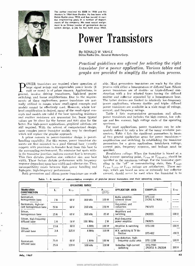
The author received his BSEE in 1956 and his Masters in 1964 from Purdue. He has been with Delco Radio since 1956 and has served in vari- ous engineering posts in a number of depart- ments of the company. His most recent assign- ment is as Group Leader of germanium device system design, a job he has held since 1965.
Power Transistors By RONALD W. VAHLE Delco Radio Div., General Motors Corp.
Practical guidelines are offered for selecting the right transistor for a power application. Various tables and graphs are provided to simplify the selection process.
POWER transistors are required where operation at large signal swings and appreciable power levels (1
watt or more) is of prime concern. Applications, in general, involve driving transducers, high -level power switching, and linear amplifications. Due to the require- ments of these applications, power transistors are nor- mally utilized in ranges where small -signal concepts and models cannot be effectively used. However, where low - level amplification is desired, many of the small- signal con- cepts and models are valid if the base spreading resistance and emitter resistance are accounted for. Some typical values are 10 ohms for the former and 0.04 ohm for the latter. For high -power applications, graphical solutions are still required. With the advent of computerized design, more complex power transistor models may be developed which will replace the graphic approach.
A prime concern in power- transistor design is power - handling capability. For this reason, power transistor ele- ments are first mounted to a good thermal base (usually copper) with provisions to transfer heat from this base to the surrounding environment. To minimize hot spots with- in the transistor ,junction, uniform current flow is necessary. This then dictates ;junction size, collector size. and base width. These factors dictate performance with frequency response dependent upon base width and collector size. Thus, incompatibility exists between high power handling and high -gain, high -frequency performance.
Both germanium and silicon power transistors are avail-
able. Most germanium transistors are made by the alloy process with either a homogeneous or diffused base. Silicon power transistors are of double- or triple -diffused con- struction with a few selected types having the diffused emitter and collector separated by a homogeneous base. The latter devices are limited to relatively low- frequency power applications, whereas double- and triple- diffused power transistors are available in a wide range of voltage, current. and frequency ratings.
Table 1 lists representative germanium and silicon power transistors and includes the high current, low volt- age and low current, high voltage ends of the operating spectrum.
For most applications, power transistors can be ade- quately defined by only a few of the many available par- ameters. Table '? lists the significant parameters in terms of two general application areas for power transistors - amplification and switching. In establishing the transistor parameters for a given application, breakdown voltage, current gain, frequency response, and leakage must be specified.
Breakdown voltage: When the transistor is biased at a high current operating point, Vr;10 or VCE(sus) should be specified as the maximum voltage. For the transistor oper- ating in the "off" or nonconducting state, then VIES, Vcr;o, Vc:ER. or VCEs ratings are satisfactory. These rat- ings, which are based on zero or extremely low collector current, should never be used when the transistor is to
Table 1. A number of representative examples of popular power transistors and their operating ranges.
OPERATING RANGE
TRANSISTOR CONSTRUCTION
le Vrr,n te Pr,,:,., (25 °C)
APPLICATION AREA EXAMPLES Vers
Germanium, homogeneous base 7 A 60 V 300 kHz 100 W
Audio amplifier, solenoid driver
DTG -110 2N392 & 2N301 - --
Germanium, high -cur- rent homogeneous base 50 A 60 V 200 kHz 150 W
Regulators and converters 2N1523 - --
Silicon, homogeneous base 15 A 60 V 500 kHz
Amplifiers and 85 W switching 2N3055 100 V
Silicon, high- frequency diffused base 1 A 18 V 100 MHz 2 W
High- frequency power amplifier 2N3925 - --
Silicon, diffused base
15 A 60 V 6 MHz 100 W Amplifier & switching DTS -100 100 V
3 A 325 V 4 MHz 100 W H.V. switching & TV de- flection DTS -402 700 V
Germanium, diffused base
25 A 60 V 1 MHz 100 W
Low -distortion, high - frequency audio amp. DTG -1106 100 V
25 A 120 V 500 kHz 100 W Inductive high- current switching
DTG -2400 2N1653 & 2N2834 300 V
July, 1967 45
www.americanradiohistory.com

POWER - AMPLIFIER
PARAMETERS
NA.] r.
ViLg, or VCI:>
VCE(SUS)
VaBO or VcE1
VEB
fT
OR
VCE(SAT1
SWITCHING - CIRCUIT HIGH -FREQ. AMP. RELIABILITY
PARAMETERS PARAMETERS PARAMETERS
VCE(.,AT)
VEB(SAT)
t,,,
toff
VCE(SeS)
ICRO,ICER,ICES,
Or ICES
Vr:u
I('B(,
Power gain
fT
V,I
PET
Table 2. Important parameters for various power applications.
VCE° VCE,
CV OR VC!°
VC E
HIGH- IMPEDANCE VOLTMETER
(A) (B)
Fig. 1. (Al Breakdown voltage dependence on the amount of collector current (B) Test circuit used to measure value of V11.
conduct any appreciable amount of collector current. The collector voltage -current dependence for the various
breakdown conditions is shown in Fig. 1A. It is important to note that whenever appreciable collector current flows, the breakdown curve, irrespective of condition, approaches the curve.
In order to evaluate transistor voltage capabilities at high current levels, the sustaining voltage (Vc.(;(,y( -s)) test was developed. The transistor under test is subjected to a specified peak current and voltage condition simultaneous- ly. The maximum collector- emitter voltage the transistor sees should never exceed l'('E(sr;s) when conducting large collector currents.
Gain and frequency: In specifying hFE, the ratio of re- quired collector -to -base current should be multiplied by 1.5. This ensures reliable operation even with possible transistor aging and gain degradation.
High -frequency gain is a linear parameter and is used in amplifier applications. Here the gain requirement, normally specified in terms of fT, is determined by multi- plying LIFE by the upper cut -off frequency. For example, if an amplifier requires an h(,,E of 30 and the desired fre- quency response of the system is 10 kHz, then an fT = 300 kHz would be required without feedback.
Leakage: Transistor leakage is normally considered with respect to thermal stability and consequently must be evaluated in tennis of the maximum temperature and volt- age the transistor will see. Since leakage parameters are closely related to the circuit design, it is not practical to include all possible contingencies of temperature and volt- age on a data sheet.
For germanium, Icaa at room temperature (25° C) is provided on the data sheet and, generally, the lower the specified 1(:110 rating, the lower the transistor leakage. (For silicon, /('BO can be ignored up to about 150° C.)
Since in many circuits the transistor is not turned off in an Icua mode, the designer can often reduce costs by evaluating available transistors in ternis of actual leakage, such as IcER or 1cEs, instead of Ic.EO.
Reliability and Parameter Variation The preceding parameters will, in most cases, adequate-
ly define the transistor requirements for a given power
PARAM- MATERIAL CHANGE WITH CURRENT ETER
V1;11 Ge Insignificant over normal range
V,;B Si Insignificant over normal range
(2 V) Ge & Si Not applicable
VCEO Ge Resistance positive at low current then becomes nega- tive with increasing current
VEO
hI E
Si
Ge & Si See Fig. 2
CHANGE WITH TEMP.
Decreases 2.2 mV per °C increase
Decreases 2.0 mV per °C increase
Doubles approxi- mately 11° C tem- perature increase
Increases with in- creasing temperature
Increases with in- creasing temperature
See Fig. 3
Table 3. Parameter variations with current and temperature.
application. However. two other specifications- floating potential (V11) and pulse energy test (PET) -should be added for reasons of device reliability.
One of the easiest of all power transistor parameters to measure. and one of the most important, is Fri. This test (Fig. 1B) consists of measuring the potential developed across the emitter -base junction (VfO at a specified col- lector -base voltage (e.g., V,,1;0). Mechanical defects or major manufacturing errors will show up as a significant emitter -base voltage. If this potential exceeds 0.5 volt, the unit should be considered a reliability hazard. Life test data has shown that units with a high I'f( fail five times faster than those with low Vfr potentials.
A second reliability test. which subjects the transistor to a power pulse for a specified length of time, is the pulse energy test. The ability of a transistor to withstand this power pulse is a measure of the transistor's durability. Be- cause of the destructive nature of the test, its primary im- portance is to establish and insure product capability. It is well suited to comparing the energy capabilities of various transistor types intended for the same application. Since it is potentially destructive, PET is not suitable for 100% production testing, but this (loes not limit its usefulness as a Quality Assurance Test.
Transistor parameters appear on most data sheets at a specific operating point and temperature. Some of the parameter variations encountered are inherent in the bulk material used for the transistor and others depend strictly upon device design. A summary of these variations with current and temperature are provided in Table 3 and Figs. 2 and 3.
Selecting and Specifying the Transistor In selecting a transistor for a given application, the
important criteria are performance, reliability, and cost. Obviously, the highest reliability transistor is unsatis- factory if it will not perform in its intended application. Conversely, a very low -cost device may, in reality, be quite expensive if its reliability or performance is unsatis- factory. Performance criteria should be established first, closely followed by reliability standards. The most econom- ical one should be selected from transistors meeting these requirements.
Table 4 lists some specific application areas and ex- pressions for computing required transistor characteristics. For maximum reliability, a VCE(sus) (and V11 for ger- manium transistors) should appear on every specification for the maximum voltage and current expected under worst -case conditions. The use of Table 4 in selecting a transistor is demonstrated in the following example.
Example: Consider a .'25 -watt, class -AB amplifier, with a transformerless output and 8-ohm load, using two power supplies of °72 volts each. Determine the transistor speci- fication.
46 ELECTRONICS WORLD
www.americanradiohistory.com
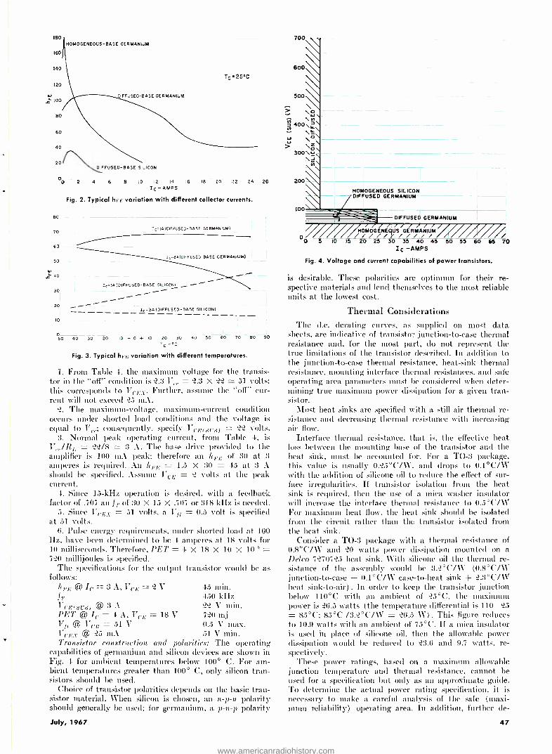
180
160
140
120
.t 100
80
60
40
20
O 0
80
70
60
50
40-
30
20
Io
HOMOGENEOUS -BASE GERMANIUM
Tc .25°C
DIFFUSED -BASE GERMANIUM
DIFFUSED -BASE SILICON
2 4 6 B 10 12 14 16 18 20 22 24 26
Ic - AMPS
Fig. 2. Typical hi variation with different collector currents.
Iç =1A (DIFFUSED -BASE GERMANIUM)
c- 8A(DIFFUSEO -BASE GERMANIUM)
ICIA (DIFFUSED -BASE SILICON)
Ic =3A (DIFFUSED -BASE SILICON)
0 50 40 30 20 10 - 0 + IO 20 30 40 50 60 70 80 90
TC -°C
Fig. 3. Typical hEU variation with different temperatures.
1. From Table 4. the maximum voltage for the transis- tor in the "off" condition is 2.3 V,.,. = 2.3 X ? 51 volts; this corresponds to VeE . Further, assume the "off" cur- rent will not exceed 25 mA.
2. The maximum -voltage, maximum- current condition occurs under shorted load conditions and the voltage is equal to V1.,.; consequently, specify VcE( sus ) _ 22 volts.
3. Normal peak operating current, from Table 4, is _ 22/8 3 A. The base drive provided to the
amplifier is 100 mA peak; therefore an IiFE of 30 at 3
amperes is required. An kF,; = 1.5 X 30 = 45 at 3 A should be specified. Assume l'c.F = 2 volts at the peak current.
4. Since 15 -kHz operation is desired, with a feedback factor of .707 an f .. of 30 X 15 X .707 or 318 kHz is needed.
5. Since VLF_t = 31 volts, a T71, = 0.5 volt is specified at 51 volts.
6. Pulse energy requirements, under shorted load at 100 Hz, have been determined to be 4 amperes at 18 volts for 10 milliseconds. Therefore, PET = 4 X 18 X 10 X 10-3 = 720 millijoules is specified.
The specifications for the output transistor would be as follows:
hFE © le = 3 A, VcE = 2 V 45 min. f T 450 kHz VcECSUS) @ 3 A 22 V min. PET @Ic= 4A,VUF =18V 720 m Vfl @VC15 =51V 0.5 Vmax. i (E.c @ 25 mA 51 V min. Transistor construction and polarities: The operating
capabilities of germanium and silicon devices are shown in Fig. 4 for ambient temperatures below 100° C. For am- bient temperatures greater than 100° C, only silicon tran- sistors should be used.
Choice of transistor polarities depends on the basic tran- sistor material. When silicon is chosen, an n -p -n polarity should generally be used; for germanium, a p -n -p polarity
July, 1967
700
600
500
3 o W \
1400 \ \LL
W \° \O
300 \ \J N
HOMOGENEOUS SILICON DIFFUSED GERMANIUM
DIFFUSED GERMANIUM
HOMOGENEOUS GERMANIUM / / / / / / / / /'i / 65 70 10 15 20 25 30 35 40 45
IC -AMPS
Fig. 4. Voltage and current capabilities of power transistors.
50 55 60
is desirable. These polarities are optimum for their re- spective materials and lend themselves to the most reliable units at the lowest cost.
Thermal Considerations The d.c. derating curves, as supplied on most data
sheets, are indicative of transistor junction -to -case thermal resistance and, for the most part, do not represent the true limitations of the transistor described. In addition to the junction -to -case thermal resistance, heat -sink thermal resistance, mounting interface thermal resistances. and safe operating area parameters must be considered when deter- mining true maximum power dissipation for a given tran- sistor.
Most heat sinks are specified with a still -air thermal re- sistance and decreasing thermal resistance with increasing air flow.
Interface thermal resistance, that is, the effective heat loss between the mounting base of the transistor and the heat sink, must be accounted for. For a TO -3 package, this value is usually 0.25 °C /W. and drops to 0.1 °C /W with the addition of silicone oil to reduce the effect of sur- face irregularities. If transistor isolation from the heat sink is required, then the use of a mica washer insulator will increase the interface thermal resistance to 0.5 °C /W For maximum heat flow, the heat sink should be isolated from the circuit rather than the transistor isolated from the heat sink.
Consider a TO -3 package with a thermal resistance of 0.8 °C /\V and 20 watts power cllissipation mounted on a Delco 727072.5 heat sink. With silicone oil the thermal re- sistance of the assembly would be 3.2 °C /W (0.8 °C /W junction -to -case + 0.1 °C /W case -to -heat sink + 2.3 °C /W heat sink -to -air) . In order to keep the transistor junction below 110 °C with an ambient of 25 °C, the maximum power is 26.5 watts (the temperature differential is 110 -25 = 85 °C; 85 °C /3.2 °C /W = 26.5 W). This figure reduces to 10.9 watts with an ambient of 75 °C. If a mica insulator is used in place of silicone oil, then the allowable power dissipation would be reduced to 23.6 and 9.7 watts, re- spectively.
These power ratings, based on a maximum allowable junction temperature and thermal resistance, cannot be used for a specification but only as an approximate guide. To determine the actual power rating specification, it is necessary to make a careful analysis of the safe (maxi- mum reliability) operating area. In addition, further de-
47
www.americanradiohistory.com
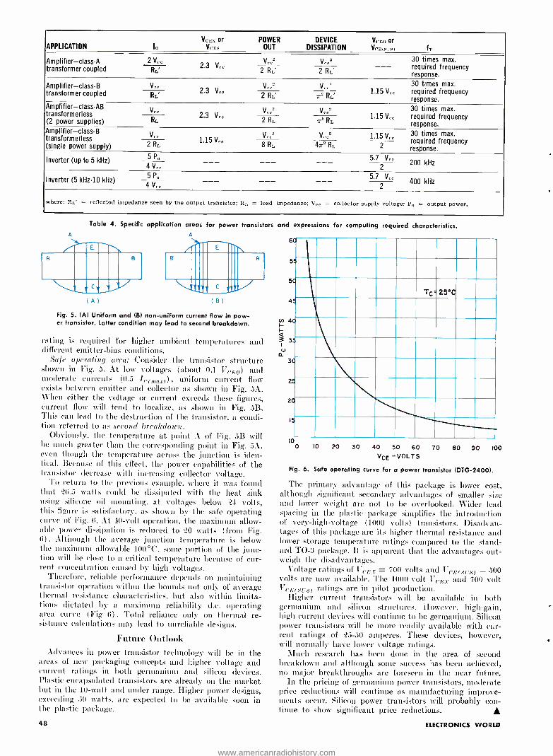
APPLICATION VCEX or
Ia VCES
POWER DEVICE OUT DISSIPATION
VCEO or VcEot -s) fr
Amplifier-class A transformer coupled
2 Voo 2.3 V°°
V ° °' Vo02 30 times max.
- -- required frequency response.
RL 2 RL' 2 RL'
Amplifier -class -B transformeress led P
Voo y,r2 V,.,.2 30 times max. 1.15 V,, required frequency
response. 2.3 V,,
RL' 2 RL' 7r` RL'
Amplifier-class-AB transformerless
(2 power supplies)
V °. 2.3
'Co" V 2 30 times max. 1.15 V,, required frequency
res onse. P
Vc° RL 2 2 RL 7r RL
Amplifier-class -B transformerless (single power supply)
y,. 1.15 V°
V, °2 V,,2 1.15 V,ß times max.
2 RL 47r2 required required frequency response.
Inverter (up to 5 kHz) 5 P. 5.7 V" 200 kHz
2 4 V-
Inverter (5 kHz -10 kHz) 5 P,, 5.7 V
4 V,° 400 kHz 2
where: RL' = reflected impedance seen by the output transistor; Rr. = load impedance; V,, = collector supply voltage; P° = output power.
Table 4. Specific application areas for power transistors and expressions for computing required characteristics. A
B
ill111©i11\
(A) (B)
Fig. 5. (A) Uniform and (B) non -uniform current flow in pow- er transistor. Latter condition may lead to second breakdown.
B
rating is required for higher ambient temperatures and different emitter -bias conditions.
Safe operating area: Consider the transistor structure shown in Fig. 5. At low voltages (about 0.1 l',,EO) and moderate currents (0.5 IC(rnar)) , uniform current flow exists between emitter and collector as shown in Fig. 5A. When either the voltage or current exceeds these figures, current flow will tend to localize, as shown in Fig. 5B. This can lead to the destruction of the transistor, a condi- tion referred to as second breakdown.
Obviously, the temperature at point A of Fig. 5B will be much greater than the corresponding point in Fig. 5A, even though the temperature across the junction is iden- tical. Because of this effect, the power capabilities of the transistor decrease with increasing collector voltage.
To return to the previous example, where it was found that '(i.5 watts could be dissipated with the heat sink using silicone oil mounting, at voltages below 24 volts, this figure is satisfactory. as shown by the safe operating curve of Fig. 6. At 40 -volt operation, the maximum allow- able power dissipation is reduced to t20 wal is (from Fig. 6) . Although the average junction temperature is below the maximum allowable 100 °C, some portion of the junc- tion will he close to a critical temperature because of cur- rent concentration caused by high voltages.
Therefore, reliable performance depends on maintaining transistor operation within the bounds not only of average thermal resistance characteristics, but also within limita- tions dictated by a maximum reliability d.c. operating area curve (Fig 6) . Total reliance only on thermal re- sistance calculations may lead to unreliable designs.
Future Outlook Advances in power transistor technology will be in the
areas of new packaging concepts and higher voltage and current ratings in both germanium and silicon devices. Plastic -encapsulated transistors are already on the market but in the 10 -watt and under range. Higher power designs, exceeding 50 watts, are expected to be available soon in the plastic package.
6C
55
5C
4!
2;
2C
15
Tc: 25 °C
10 0 10 20 30 40 50 60 70 80 90 100
VCE -VOLTS
Fig. 6. Safe operating curve for a power transistor (DTG- 24001.
The primary advantage of this package is lower cost, although significant secondary advantages of smaller size and lower weight are not to be overlooked. Wider lead spacing in the plastic package simplifies the introduction of very- high -voltage (1000 volts) transistors. Disadvan- tages of this package are its higher thermal resistance and lower storage temperature ratings compared to the stand- ard TO -3 package. It is apparent that the advantages out - weigh the disadvantages.
Voltage ratings of Ver:s = 700 volts and VcE(s,;s) = 500 volts are now available. The 1000 -volt VCEV and 700 volt VLE(ers) ratings are in pilot production.
Higher current transistors will be available in both germanium and silicon structures. However, high -gain, high- current devices will continue to be germanium. Silicon power transistors will be more readily available with cur- rent ratings of "25 -50 amperes. These devices, however, will normally have lower voltage ratings.
Much research has been clone in the area of second breakdown and although some success has been achieved, no major breakthroughs are foreseen in the near future.
In the pricing of germanium power transistors, moderate price reductions will continue as manufacturing improve- ments occur. Silicon power transistors will probably con- tinue to show significant price reductions. A
48 ELECTRONICS WORLD
www.americanradiohistory.com
The author received his BS(EE) from Southern Methodist in 1950 and took postgraduate work in solid -state physics at the University of Illinois. He joined Siliconix as Mana- ger of Applications in April 1962, shortly after the com- pany was formed. Prior to his present association, he spent 12 years at Texas Instruments where he was active in the design and development of semiconductor produc- tion and test equipment, germanium transistors, IC's, sili- con FET's, and silicon diodes. He holds several FET patents.
Field -Effect Transistors By ARTHUR D. EVANS Vice -President and Engineering Manager, Siliconix, Inc.
What to look for in using JFET's and MOSFET's is considered. Temperature effects as well as reliability are also covered.
THOUGH quite old in concept, the field -effect tran- L sistor r (FET) is fairly new in availability. Two basic types on the market today are the junction
FET (JFET) and the metal -oxide semiconductor FET (MOSFET) . The latter is also referred to as the insulated - gate FET (IGFET) . Figs. 1 and . show sectional views of these two devices, both of which may have either a p- or n- channel. Parameter symbols and definitions are provided in Table 1, while the important parameters to be considered in selecting an FET are listed in Table 2.
FET's have entered the consumer product price range. For example, FET's have been used in FM tuners for more than a year. As with bipolar transistors, FET prices cover a wide range. Units packaged in epoxy are available at less than +i0 cents each in production quantities. High - quality, military -grade. hermetically sealed units cost much more. The average price of FET's sold in 1966 was about $3.90, down from a 1965 average of $7.00.
Device Characteristics The JFET is a normally "on" device, i.e.. a conducting
channel connects the source to the drain even in the absence of a gate -to- source voltage, V ". The channel will conduct current in either direction, source -to -drain or drain -to- source, its conduction being a function of V". For the n- channel FET, a negative gate voltage depletes the channel of carriers and thus lowers channel conduction. A positive gate voltage has a similar effect on the p- channel device. The magnitude of voltage required to reduce the channel conduction to zero is called the pinch -off voltage, Vi.. Be- yond i'i,, the only ,I.,. drain or source current that flows is the reverse saturation current of the drain -gate or source - gate p -n- junctions Joao and L,vun, respectively) .
If the gate is forward -biased with respect to the source, the channel conductance, g,t,,, will increase (Fig. 3) . How- ever, beyond it few tenths of a volt, the gate -to- channel current begins to rise exponentially, hence forward -gate bias is usually avoided for the JFET. The JFET has top and bottom gate.:. In most devices, these two gates are con- nected internally_ and function as a single gate. However, the gates can be separated and provide independent control of channel conduction (e.g., the 3N89 tetrode) .
A very important characteristic of the MOSFET is that the top gate is insulated from the channel by an oxide di- electric. In contrast to the JFET, the top gate can there- fore be forward -biased to enhance the channel as well as reverse -biased to deplete it. The back gate or body is brought out to a separate terminal or is connected to the source. It is seldom used as a means of controlling channel conduction.
The insulated top gate makes feasible the normally "off"
July, 1967
Table 1. Important FET parameters and their meanings.
PARAMETER
BVc or By,;,,s
BV1,0 and BV.,,,,
or
BVusx
IGSS
Inca and Iseo
Ino,rr> and Is,urn >
Vos
Vr or Vr,s,rn+F>
h)
V6
AIVcs,-VoS21
JT g4s or lyfs1
g,,, or g,,,
g, , / g)02
rn,
g,a.g,s or Rly1.,1,R1y,d
gs..,g,,.. or Re{ySS1,Riy.s1
C, -,C C,.a,Cag,Cag.,Ce
Css
C,,0. and C,go
MEANING
Breakdown voltage from gate -to- channel with gate junction reverse -biased Similar to the above except that either source (BV,;,,) or drain (BV0,:,,) is open -
circuited Breakdown voltage from drain to source with V,;, = 0 Breakdown voltage from drain to source with V,;, # O. Normally specified for de- pletion -type MOS when V,;, > V. Gate -leakage current. This current is gate -to- channel in junction FET's, gate - to -body in MOS Leakage current from drain (I,,,;,,) or source Drain -to- source current when V,,0 = 0 Match in I,.,, for differential pairs Drain current under specified conditions Sometimes used for drain current under zero temperature coefficient conditions Drain or source current with channel cur- rent cut off. V,., >V, Gate -to- source voltage under specified conditions Gate pinch -off or cut -off voltage Gate threshold voltage Gate -to -gate differential offset voltage in matched FET pairs Incremental I,Vcs, - Vc,_ drift over tem- perature range Magnitude of small -signal, common - source, short -circuit forward transfer con- ductance (admittance, transconductance or transadmittance) Match in gr, for differential pairs Dynamic drain -source (channel) conduct- ance; r,,, = 1 /g,, Static drain -source resistance r,,, and r,,, when Vo, = 0 in junction FET's and when gate biased "on" in MOS Small -signal, common -source, short -cir- cuit, input conductance Small- signal, common -source, short-cir- cuit output conductance Small- signal, common -source, short-cir- cuit input capacitance Small- signal, common -source, short-cir- cuit reverse transfer capacitance Small- signal, common -source, short-cir- cuit output capacitance. Approximately equal to Cros Small signal source -to -gate capacitance, gate shorted to drain. Approximately equal to C,... in symmetrical units Small signal drain -to -gate (or source -to- gate) capacitance with source (or drain) open. Approximately equal to Cros
49
www.americanradiohistory.com

Analog
Switch
Digital
Switch
High -Freq.
Amplifier Low -Freq.
Amplifier Low -Noise
Amplifier Differential Amplifier
Low d.c. drift Single -Ended
Amplifier
Electrometer
Amplifier
ras(on)
ID(OFF)
n Cdgs/Csg VGS(OFF)
2N3386 2N3970 M103 M 106 G116F
r,.s(Gn)
VGS(th)
or
VGS(OFF)
ton ton
Cree and C uss
2N3970 2N3386
gr, gigs
NF
Cr..
Inss VGS(Ors)
2N3823 2N4223 U183
g16
IDSS
VGS(OFF)
C1
Cros
2N4339 2N4340 2N3458
é and i,.
0¡ NF
gr. IDSS
VGS(OFF)
2N4868 2N4340 2N3578
1VGS1- V: <_]
0 VGSl- V4:s_I
IDz(ID ZERO TC)
gf, at Inz
VGS at IDZ
l,; at IDZ
2N2843 2N4117
g`'"
IUZ
2N3631 2N4119Á
AT
Il01- If..'I gr. gf fagf sz
U205 U231 2N3921
Gi
Table 2. Pertinent parameters for a number of impor ant FET applications, along with some device examples.
(enhancement -mode) devices in Fig. 2. As indicated in 4 D Fig. 4A, a forward gate bias is required to enhance a channel
from source-to-drain and turn these units "On ". For the normally "On" MOSFET (depletion-mode type) of Fig. ?,
channel conductance 1s gate voltage characteristics are similar to junction units. An important difference, however, is that the channel can be further enhanced by a forward
S bias 011 the gate, as shown in Fig. 4B. The input resistance of the MOSFET gate is extremely high due to the good insulating properties of the silicon -oxide dielectric. Values in the range of 10' ohms are common (e.g.. the 4\3631). Usually, the leakage of the device package is the limiting
Q D factor. The JFET gate has the characteristics of an a -p diode.
Normally, it is reverse -biased and gate input leakage cur - GI G2 rent I(;,ss, at -23 °C ranges from less than one picaamperc
(4N 4117A) to a few nanoanlperes, depending upon device geometry and manufacture. As with junction diodes, approximately doubles for each ]f) °C temperature rise.
The gate voltage of the JFET is limited in the reverse direction by avalanche breakdown of the gate -to- source and gate -to -drain diodes. For the MOSFET, the gate volt- age limitation is the destructive breakdown of the oxide di- electric under the gate. This breakdown must be avoided, otherwise permanent damage to the oxide results. Gate protection can he included within the device in the form of a breakdown ( tener) diode between the gate and body. If the application requires very high input impedance, the diode is not usually included. However, for most switching
p /// i %77777-/.I p
G2 A)
GI
T /G2
G -0G2
(F
Fig. 1. IA) N- channel and (B) p- channel junction FET's.
G I c.
p
G2lBODY1
ós
50
applications it is provided. Package types. The majority of FET's are mounted in
the common 3- or I -lead TO -IS type transistor package. Most p- channel JFET's use terminal °2 for the gate. For li- channel .1FET's, terminal 3 is commonly used. The gate may be electrically connected to the case or, if the unit is
isolate(], the case may be connected separately to pin 4.
When the gate is connected to the case- care must be taken to insulate it from ground when mounting the device in a circuit.
IIOSFET's usually require four active terminals because of the body connection. _]lost available devices have the case and body connected to a common pin. Typically, their terminal connections follow neither of the junction FET connections.
Temperature effects. Mobility of majority carriers in the FET channel has a negative temperature coefficient. There- fore, except under certain bias conditions, drain current, transconductance, and channel conductance have negative temperature coefficients. If the JFET is biased for constant drain current ID, the major temperature effect is on the gate
G2IBODY)
G
rin
i* G2 (BODY)
B1
F- Fig. 2. MOSFET types. Top to bottom: depletion, enhance - mens, symbol for the (A) n- channel and (B) p- channel types.
ELECTRONICS WORLD
www.americanradiohistory.com
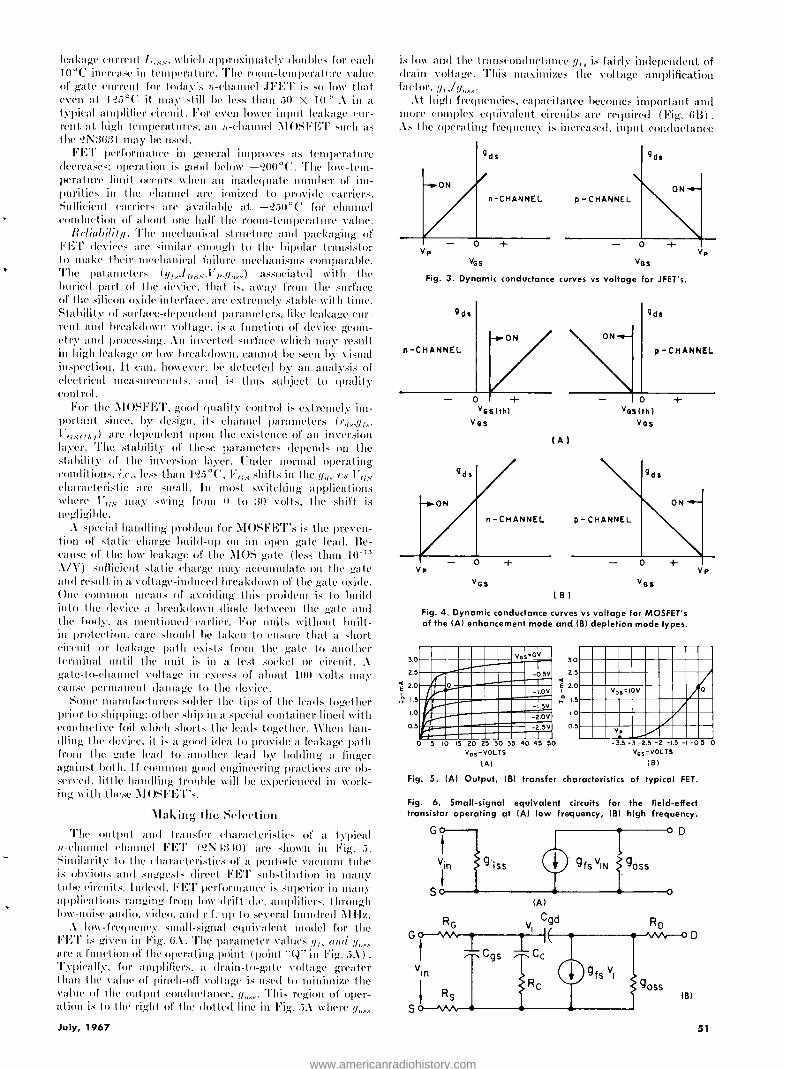
leakage current I,;,,,,, which approximately doubles for each 10 °C increase in temperature. The room-temperature value of gate current for Ioday's a- channel ,IFET is so low that even at U25 °C it may .Lill he less than 50 X 10 -" Ain a typical aunplifier circuit. For even lower iupltt leakage cur- rent at high temperatures, an n- cltamnel NIOSF1:T such as the ?N3031 may he used.
FE'l' performance in general improves as temperature decreases; operation is good below -i200°C. The low-tem- perature limit occur~ When an inadequate number of im- purities in the channel arc ionized to provide carriers. Sufficient carriers are available at -'150 °C for channel conduction of about one half the room -temperature value.
Ilrliabilify. The mechanical structure and packaging of FET devices are similar enough to the bipolar transistor to stake their mechanical failure mechanisms comparable.
` The parameters (yr. I;,ss,l' ;.,y ) associated with the buried part of the device, that is, away from the .surface of the silicon oxide interface. are extremely stable with time. Stability of surface -dependent parameters, like leakage cur- rent and breakdown voltage, is a function of device geom- etry and processing. An inverted surface which may result in high leakage or low breakdown, cannot be seen by visual inspection. It can, however, he detected by an analysis of electrical measurements, and is thus subject to quality control.
For the AIOSFET, good duality control is extremely inn - portanL since, by design, its channel parameters ('r,t,.,gj.,.,
are dependent upon the existence of an inversion layer. 'l'hc stability of these parameters depends on the stability of the inversion layer. Under normal operating conditions, i.e., less than 15 °C, 17 shifts in the q,;,, rs characteristic are small. In most switching applications where 17, ;,, may swing front (t Lo 30 volts, the shift is negligible.
A special handling problem for AIOSFET's is the preven- tion of static charge build -up on an open gate lead. Be- cause of the low leakage of the \IOS gate (less than 10-' A /V) sufficient static charge may accumulate on the gate aanid result in a voltage -induced breakdown of the gate oxide. One common means of avoiding this problem is to build into the device a breakdown diode between the gate and the body, as mentioned earlier. For units without built- in protection. care should he taken to ensure that a short circuit or leakage path exists from the gate to another terminal until the unit is in a test socket or circuit. A gate -to- channel voltage in excess of about 100 volts may cause permanent damage to the device.
Some manufacturers solder the tips of the leads together prior to shipping; other ship in a special container lined with conductive foil which shorts the leads together. When han- dling the device. it is a good idea to provide a leakage path from the gale lead to another lead by holding a finger against both. If common good engineering. practices are ob- served, little hauiulling trouble will be experienced in work- ing with these IOSFE'I"s.
Making lite Selection The output twit transfer characteristics of a typical
u>- channel channel FET (?N 1310) are shown in Fig. 5. Similarity to the characteristics of a pentode vacuum tube is obvious auul suggests direct FE'l' substitution in many tube circuits. Indeed. FI:'C performance is superior in many applications ranging from low -drift etc. amplifiers. through low -noise audio. video, and r.f. up to several hundred MHz. . low -frequency small- signal equivalent model for the FEi' is given in Fig. 0.1. The parameter values ye., and ry,,, are a function of the operating point, (point "(4 in Fig. 5.k) .
Typically, for amplifiers, a drain -to -gate voltage greater than the value of pinch -off voltage is used to minimize the value of the output: conductance. ry,,,.,.. 'l'his region of oper- ation is to the right of the dotted line in Fig. 5A where y
July, 1967
is low and the traunsconductance yf, is fairly independent of drain voltage. This maximizes the voltage amplification factor. !less. /y,,.,.,.
At high frequencies, capacitance becomes important and more complex equivalent circuits are required (Fig. GB) .
As the operati ig frequency is increased, input conductance
acs vos
Fig. 3. Dynamic conductance curves vs voltage for JFET's.
gds
ON
n -CHANNEL
- o + VOS (th)
VOS
ONr p -CHANNEL
(A)
o + Vos (thl
VOS
Vp
3.0
2.5
2.0
A. 1.5
1.0
0.5
acs tel
VOS
Hg. 4. Dynamic conductance curves vs voltage for MOSFET's of the (A) enhancement mode and (B) depletion mode types.
ves °ov
-05V
h: -I2V /i - -LSV `. _ - 2.0V
MaillOn -2.5v
0 5 10 15 20 25 30 35 VDS-VOLTS
(A)
3.0
2.5 < E 2.0
H ,.5
1.0
0.5
VDS=10V o
V.
40 45 50 -3.5 -3 -2 5 -2 -15 -1 -0 5
V.,-VOLTS (B)
Fig. 5. (A) Output, (B) transfer characteristics of typical FET.
Fig. 6. Small- signal equivalent circuits for the field- effect transistor operating at (Al low frequency, (B) high frequency.
G
vin iss
So (Al
RG V Cgd
Ggs
vin
RS
I
oD
gfs viN goss
C C c
g fs VI
goss
o
(B)
51
0
www.americanradiohistory.com

gi.,, and output conductance g increase, while transcon- ductance gr,. decreases. The maximum available gain (MAG) drops to unity when g;,,.,.g .,.y = gr '/4. The frequency at which this occurs is the maximum frequency of oscillation for the device.
An important characteristic of the FET in r.f. circuitry is its almost perfect square -law transfer characteristic (Fig. 5B) . This results in amplifier cross -modulation distortion figures of at least one order of magnitude better than those of bipolar transistor designs.
In a low -noise amplifier the equivalent input noise voltage en and current i are most important. Since these are fre- quency dependent, care must be taken in comparing device types to note the frequency at which these parameters are specified. Some device types have a specified noise figure, NF, for a given operating condition with a given generator resistance. Usually a high value of generator resistance is specified to make the device "look good ". If the value of NF is 3 dB, then the specified value of generator resistance is equal to the equivalent noise resistance of the FET.
For a differential amplifier, the incremental input drift over a specified temperature range is probably the most important parameter. An often overlooked parameter in this application is the differential output conductance, 9o.,al ,yoxa . If y,,.,,, is large or not well matched, the common - mode rejection will be poor. If the input signal source resis- tance is high, then the differential gate leakage current 'assr lass_ is also important.
When the FET is used as a switch for analog signals, the series switch resistance rd, and the drain leakage current
lurorr7 are probably the most important parameters. Gate - drain and gate -source capacitances are important because they determine how much of a "spike" is rejected into the analog signal path in turning the switch "on and "off ". Vi. or Vr;sr17i1 will determine how much gate drive voltage is needed to control the switch.
FET's are less susceptible to damage by high -energy radiation than bipolar transistors. Type 2N3631 MOSFET's perform well even after exposure to fast neutron radiation of 10'° nvt. Major effect is increase in gf.,,IUSS, and V.
Power FET's Several companies have reported work on the develop-
ment of power FET's that approach operation in the 1 GHz region. One method uses a gate structure embedded below the silicon surface. Electrons flow clown from the source con- tact at the surface, through a grid of gate elements, then to the silicon substrate which is the drain. Called a "Gridis- tor", this device is reportedly being worked on by Dr. Stanislaw Teszner of France and is expected to be capable of 5 watts at 300 MHz.
A similar multi- channel FET has been reported by R. Zuleeg of Hughes Aircraft Solid State Research Center. For five devices operating parallel, 2 watts of power was ob- tained at 100 MHz with an efficiency of 66 %. A different approach was explored by Mitchell of RCA. Using a MOS tetrode made by integrating two triodes on a single chip, a cascole circuit achieved 12 dB gain at 800 MHz. It will not be too long until power FET's become available to com- pete with bipolar transistors in many areas of application.
THE UNIJUNCTION TRANSISTOR EVEN though the unijunction transistor was developed in 1954, the
electronics industry is just beginning to utilize the potentialities of this remarkable, single p -n junction semiconductor device.
The unijunction transistor finds application in many different areas; including timing circuits, multivibrators, pulse generators, SCR firing circuits, saw -tooth generators, time -relay circuits, ring counters, and voltage -sensing circuits. Maximum frequency of oscillation is approxi- mately 1 MHz and, although low in price, the unijunction has excellent linearity, stability, and requires very simple circuits which are stable over a wide range of temperature variations.
As will be shown, the output from a unijunction oscillator can be either a positive- or negative -going pulse accurately occurring at the flyback of a saw -tooth waveform, which can also be used as the output.
Fig. lA shows the symbol for a unijunction, while Fig. 1B shows a
cross -sectional view of a typical unit. The n -type silicon bar has an alu- minum wire (emitter) alloyed to it to form the only junction within the device. The two base contacts, one at each end of the silicon bar, are ohmic contacts only and are not rectifying junctions.
The resistance between base 1 and base 2 will vary (with various types of unijunctions) from 4500 to approximately 12,000 ohms. In conven- tional operation, base 2 is connected to a source of positive voltage while base 1 is connected to the negative end (usually ground). The base bar acts as a conventional resistance and has a voltage gradient within it ranging from a maximum at base 2 to zero at base 1. As the emitter is
connected at some point above zero, some fraction of the voltage applied between the two bases also appears between the emitter and base 1. This fraction, or proportional part of the voltage between the bases, is the most important parameter of the device and is called "intrinsic stand- off ratio or 77.
As shown in Fig. 1C, RII, and RB, represent the ohmic resistance of the silicon base bar, while diode Dl represents the p -n junction formed by the alloying of the aluminum emitter wire and the silicon bar.
If an external voltage (VE) is applied to the anode of the diode, and if this voltage is less positive than the voltage on the diode cathode as a
result of the voltage division of the silicon bar (77Vßß), then the diode will be reverse biased and no current will flow through it. Voltage 77Vßß
is referred to as the peak, or firing, point. However, when V,: rises above 7711ß, the emitter junction will then be
forward biased and current will flow through the diode to base 1. This increase in current flow consists primarily of minority current carriers injected into the silicon bar. As a result of this rise in current flow, the effective resistance of RB, is decreased, allowing still more emitter current
52
to flow, further reducing the effective resistance of RBI, thus producing a
negative- resistance characteristic. There is a different peak point for each value of VBB due to a different
proportional voltage being applied at the emitter -bar junction, thus reverse biasing the junction diode at different levels of voltage.
In most practical cases, a capacitor (C) is connected between the emitter and ground, and a resistor (R,) is connected between this ca- pacitor and the positive voltage source. A resistor (R:,) is connected be- tween the positive voltage source and base 2 with another resistor (R,) between base 1 and ground. When power is applied, capacitor C starts to charge exponentially via R. towards the positive level. When the voltage across the capacitor reaches V,, (firing point), emitter current starts to flow and the resultant negative resistance action causes a very rapid discharge of the capacitor. The action then restarts to form an unbroken saw -tooth train available at the emitter junction. At the trailing (capaci- tor discharge) edge of the saw- tooth, a sharp negative -going pulse will appear across R:,, while a similar but positive -going pulse will appear across R,. The frequency of oscillation can be approximated by: f = 1/ (RP.
Resistor R:, is used primarily as temperature compensation and usual
values lie between 200 and 600 ohms. Resistor R, is determined by
the circuit signal levels required for a desired pulse output. Recently, G -E introduced its D5K unijunction transistor whose char-
acteristics are like those of conventional types, except that the currents and voltages applied to it are reversed. That is, the positive voltage is
applied to base 1, and the p -n junction formed by the emitter and bar is reversed. The intrinsic stand -off ratio is .58 to .63, or ±3%. The
unit has a low base 1 to emitter voltage drop at high current, permitting high output pulses with low base -to -base voltages. A
Fig. 1. Symbol, construction, and equivalent circuit of device.
BASE 2
(Ar
BASE!
EMITTER ALUMINUM
WIRE
BASE 2
n EMITTER r
BASE 2
R=
-T P -N JUNCTION
N -TYPE SILICON BAR
s 0 ú [ ¡I
RBI 'tYBB IB
BASE I
BASE I
(B) (C)
ELECTRONICS WORLD
www.americanradiohistory.com
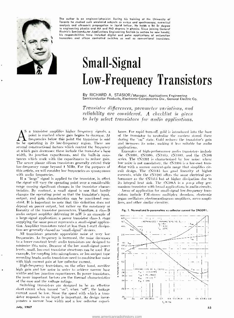
The author is an engineer /physicist. During his training at the University of Toronto he studied such unrelated subjects as x -rays and spectroscopy, numerical analysis and ultrasonic propagation in liquid helium. He holds a BA Sc degree in engineering physics and MA and PhD degrees in physics. Since joining General Electric's Semiconductor Applications Engineering Section (a section he now heads), his responsibilities have included digital and pulse applications of unijunction transistors and silicon controlled switches as well as conventional transistors.
Small -Signal
Low -Frequency Transistors By RICHARD A. STASIOR /Manager, Applications Engineering Semiconductor Products, Electronic Components Div., General Electric Co.
Transistor differences, parameter variations, and reliability are considered. A checklist is given to help select transistors for audio applications.
Aa transistor amplifies higher frequency signals, a point is reached where gain begins to decrease. At frequencies below this point the transistor is said
to be operating in its low- frequency region. There are several constructional factors which control the frequency at which gain decreases; these include the transistor's base width, its junction capacitances, and the built -in resis- tances which work with the capacitances to reduce gain. The newer planar silicon transistors generally extend their low- frequency range beyond 1 MHz. For the purposes of this article, we will consider low frequencies as synonymous with audio frequencies.
If a "large" signal is applied to the transistor, in effect the signal will vary the operating point over a considerable range causing significant changes in the transistor charac- teristics. By contrast, a small signal is one that hardly changes the operating point so that the transistor's input, output, and gain characteristics can be considered con- stant. It is important to note that this definition does not depend on power output, but rather on the constancy or linearity of the transistor parameters. Therefore, a class -B audio output amplifier delivering 50 m \V is an example of a large- signal application: a power transistor class -A stage supplying the same power represents a small -signal applica- tion. Amplifier transistors rated at less than 1 -watt dissipa- tion are generally classed as "small- signal" devices.
All transistors generate appreciable noise at very low frequencies. As frequency is increased, the noise decreases to a lower constant level: audio transistors are designed to minimize this noise. Because of the low small- signal power levels, small, low -cost transistor structures can be used. For example, for coupling into microphones, or low- output tape recording heads, audio transistors need to combine low noise with high current gain at low collector current.
High -frequency transistors, on the other hand. sacrifice high gain and low noise in order to achieve narrow base widths and low ,junction capacitances. In power transistors, the more important factors are the thermal characteristics of the case and the voltage ratings.
Switching transistors are designed to be an effective short- circuit when turned "on"; when "off ", the leakage current must be low. Since the speed with which a tran- sistor responds to an input is important, its design incor- porates a narrow base width and a low collector capaci-
July, 1967
tance. For rapid turn -off, gold is introduced into the base of the transistor to neutralize the carriers stored there during the "on" state. Gold reduces the transistor's gain and increases its noise. making it less suitable for audio applications.
Examples of high -performance audio transistors include the 2N3391, 2N3394, ?N3415. °?N3103. and the 2N508 series. The 2N3391 is characterized by low noise; where low noise is not mandatory, the 2N339- is a low -cost tran- sistor with a narrow current -gain range that simplifies cir- cuit design. The 2N3115 has good linearity at higher currents, while the 2í;1.03 offers the same electrical per- formance as the 2N3415 but at higher dissipation due to its integral heat sink. The 2N508A is a p -n -p alloy ger- manium transistor with broad applications in audio circuits.
Areas of application for small -signal low- frequency tran- sistors include FM- stereo multiplex decoders, electronic organ oscillators. electrocardiogram amplifiers. servo ampli- fiers, and other similar circuitry.
Fig. 1. Normalized h- parameters vs collector current for 2N3391.
10.0
r i- - NORMALIZED h PARAMETERS VS --- 'J, = IO v hoe
f = IKHZ TA = 25'C
h
hre.
h
0.4
0.2
0.1 h PARAMETERS AT Ia O.Ima 08 - h,e = i20K OHMS
h0, = 26 ,. MHOS 06
.04
.02
.0I
hre = 74 x10_3
hre : 420 --.- I
t
.01 .02 .04
r- I
06 080.1 0.2 0 4 0.6 0.8
IV IN mA
0 2.0 4.0 6 0 8.0 10.0
53
www.americanradiohistory.com

10
8
W
5 4 f'
> 2
1.'3 10
It If Sen A
TA 25°C
f IKMr hr. h1e
fe hn. ¢ la1
5
¢ a
ú 2 3 4 5 8 10 20 30 40 50
Ver - COLLECTOR VOLTAGE VOLTS
( A )
2
1.5
.4
h PARAMETERS Il
VC -10V IcImA
f IKHz
VS TEMPERATURE 1 ., a
/All h1e =120 K ohms
hoe =26ít mhos hre = 74 X 10 Ate =420
hoe
hte
hre hie
3
-40 -30 -20 -10 0 10
Fig. 2. Family of normalized h- parameter curves shown as a function of (A)
Important Device Parameters The most useful and practical parameters for audio -
frequency applications are the small -signal parameters h and lot,,, and the upper -3 dB cut -off frequency, f p (see Table 1). When "current gain" is meant, the term beta (ß) is often used rather than ht,. (or hFE) , For an effec- tive load impedance of 10,000 ohms or less, It;,. - input impedance of the amplifier: ht,, _ current gain of the am- plifier: and f
t= _ the upper -3 db cut -off frequency for
the amplifier. The h- parameters. with capital subscripts (hmE, hFE,
hRE, and 110E) refer to average or d.c. parameters and are useful for biasing the transistor. For example, if Ic = 10 mA and in = 0.5 mA (as measured on a v,o.m.) , hFE _ 10 /0..5 = 20.
While the h- parameters are easier to measure at low frequencies, the y- parameters of Table 1 are more con- venient for mathematical analysis and are more readily measured at high frequencies. It is for this reason that transistors such as the 2N3854 are characterized at l00, 45, 10.7, 4.5, and 1 \IHz in y- parameters and at 1 kHz in h- parameters.
It is noteworthy that the li- parameters are measured at only one operating point and normalized curves are sup- plied to permit calculation at other operating points. For any given transistor manufacturing process, all the tran- sistors tend to vary in the same manner with operating point, irrespective of the actual value of the parameter. that is, a high beta unit will have its beta peak at the same collector current as does a low beta unit. Similarly, the percentage change of beta with temperature will also he relatively independent of the actual beta. For operating points other than the one at which the parameters were measured, the measured value is multiplied by the factor shown on the vertical scale. Some example; of normalized curves are illustrated in Figs. 1 and 2.
Table 1. Small- signal parameters (common- emitter) for audio.
ft, Upper -3 dB cut -off frequency where hf,, is 0.707 its value at 1 kHz
ho. Forward current gain hi,. Input impedance with output a.c. short -circuited
h0,. Output admittance with input a.c. open- circuited h,.,, Reverse voltage transfer ratio
NF Ratio of total transistor noise power delivered to a load to the noise power delivered to the same load by the source
Input admittance with output a.c. short-circuited Forward current -voltage ratio
Reverse current -voltage ratio with input a.c. short- circuited
Output admittance
Y11
Y°1
Y1_
Y22
54
20 30 40 50 60
TEMPERATURE IN °C
(81
70 BO 90
collector voltage and (B) temperature.
h,e
hre
hfe
ho,
100
The relationship between ht,. and hFE is illustrated by the curves of Fig. 3. Either one may be greater, depending on the operating point at which they are compared. The graph also shows that hfe decreases at higher frequencies. Since there is a reasonable correlation between lot,. and h,FE, frequently only one is measured for specification purposes and the other estimated. However, current gain applies only to the point of measurement. and the gain may be different if the intended operating point is far removed.
The curves of Fig. 1 indicate typical variations of h. param- eters with collector current. For a 1000 to 1 range in collec- tor current, hte varies by less than 4 to I: therefore, beta can be considered a constant once an approximate operating point is chosen. Parameter h; , on the other hand, changes
60
501- _.
0
20
O Oi
- I
N
Fig. 3. Variation of h,, and har: with collector current.
100
approximately 2(I(1 times in the same current range. Since h;,, is very nearly equal to the input impedance of the transistor, we see that the input impedance is approxi- mately I megohm at IO p.A of collector current and 3600 ohms at 10 n1A. While h,.,,, the feedback factor, varies drastically, its absolute value is so low that it may be ignored. The variation of h,,,. can also be neglected when, as is generally the case. the output of a transistor is coupled into the base of another transistor.
Typical variations in the h- parameters with I'f.E for small -signal audio transistors are given in Fig. A. Param- eters ho. and hf,, are fairly constant over a wide range of collector voltages. The variations in h ,. and h,.. can usual- ly be ignored.
Variations in h- parameters with temperature are indi- cated in Fig. 2B. The most important variation is in ht,.; of lesser importance is h;,., (The upper cut -off frequency f behaves approximately as parameter h;,,.) Changes in h,.,.
and lt,,,. with temperature can usually be disregarded. Noise seen at the collector of an amplifying transistor
ELECTRONICS WORLD
www.americanradiohistory.com
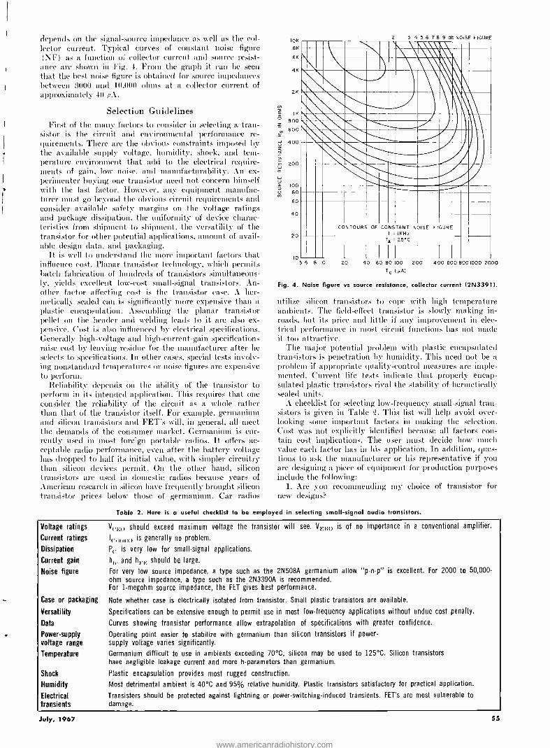
depends on the signal- source impedance as well as the col- lector current. Typical curves of constant noise figure (\ F') as a function of collector current and source resist-
ance are shown in Fig. 4. From the graph it can be seen that the best noise figure is obtained for source impedances between 3000 and 10,000 ohms at a collector current of approximately 40 AA.
Selection Guidelines First of the many factors to consider in selecting a tran-
sistor is the circuit and environmental performance re- quirements. There are the obvious constraints imposed by the available supply voltage, humidity, shock, and tem- perature environment that add to the electrical require- ments of gain, low noise. and manufacturability. An ex- perimenter buying one transistor need not concern himself with the last factor. However, any equipment manufac- turer must go beyond the obvious circuit requirements and consider available safety margins on the voltage ratings and package dissipation. the uniformity of device charac- teristics from shipment to shipment, the versatility of the transistor for other potential applications, amount of avail- able design data, and packaging.
It is well to understand the more important factors that influence cost. Planar transistor technology, which permits hatch fabrication of hundreds of transistors simultaneous- ly, yields excellent low -cost small- signal transistors. An- other factor affecting cost is the transistor case. A her- metically sealed can is significantly more expensive than a plastic encapsulation. Assembling the planar transistor pellet on the header and welding leads to it are also ex- pensive. Cost is also influenced by electrical specifications. Generally high -voltage and high -current -gain specifications raise cost by leaving residue for the manufacturer after he selects to specifications. In other cases, special tests involv- ing nonstandard temperatures or noise figures are expensive to perform.
Reliability depends on the ability of the transistor to perform in its intended application. This requires that one consider the reliability of the circuit as a whole rather than that of the transistor itself. For example, germanium and silicon transistors and FET's will, in general, all meet the demands of the consumer market. Germanium is cur- rently used in most foreign portable radios. It offers ac- ceptable radio performance, even after the battery voltage has dropped to half its initial value, with simpler circuitry than silicon devices permit. On the other hand, silicon transistors are used in domestic radios because years of American research in silicon have frequently brought silicon transistor prices below those of germanium. Car radios
IOK
8K
6K
3 4 5 6 7 8 9 db NOISE FIGURE
111111.1_ _ ' "",. n éi; 4 K ,,1-11a,"\" 2Ksommignisi _1111
_. ,,. 1 ̀ Nii aUSIVM Goll I!IY 00 I
60
40 1 20 11 CONTOURS OF CONSTANT NOISE FIGURE
Te = 25°C
IK
800
600
400
200
10 5 6 8 10
1 1111 20 40 60 80 100 I (pA)
200 400 600 8001000 2000
Fig. 4. Noise figure vs source resistance, collector current (2N3391).
utilize silicon transistors to cope with high temperature ambients. The field -effect transistor is slowly making in- roads, but its price and little if any improvement in elec- trical performance in most circuit functions has not made it too attractive.
The major potential problem with plastic encapsulated transistors is penetration by humidity. This need not be a problem if appropriate quality -control measures are imple- mented. Current life tests indicate that properly encap- sulated plastic transistors rival the stability of hermetically sealed units.
A checklist for selecting low- frequency small- signal tran- sistors is given in Table Z. This list will help avoid over- looking some important factors in making the selection. Cost was not explicitly identified because all factors con- tain cost implications. The user must decide how much value each factor has in his application. In addition, ques- tions to ask the manufacturer or his representative if you are designing a piece of equipment for production purposes include the following:
1. Are you recommending my* choice of transistor for new designs?
Table 2. Here is a useful checklist to be employed in selecting small -signal audio transistors.
Voltage ratings
Current ratings
Dissipation
Current gain
Noise figure
Case or packaging
Versatility
Data
Power-supply voltage range
Temperature
Shock
Humidity
Electrical transients
V).no should exceed maximum voltage the transistor will see. Vrmo is of no importance in a conventional amplifier.
I,.,,,,,t,) is generally no problem.
Pe is very low for small -signal applications.
he,, and hF,., should be large.
For very low source impedance, a type such as the 2N508A germanium allow "p -n -p" is excellent. For 2000 to 50,000 -
ohm source impedance, a type such as the 2N3390A is recommended. For 1- megohm source impedance, the FET gives best performance.
Note whether case is electrically isolated from transistor. Small plastic transistors are available.
Specifications can be extensive enough to permit use in most low- frequency applications without undue cost penalty.
Curves showing transistor performance allow extrapolation of specifications with greater confidence.
Operating point easier to stabilize with germanium than silicon transistors if power - supply voltage varies significantly.
Germanium difficult to use in ambients exceeding 70 °C; silicon may be used to 125 °C. Silicon transistors have negligible leakage current and more h- parameters than germanium.
Plastic encapsulation provides most rugged construction.
Most detrimental ambient is 40 °C and 95% relative humidity. Plastic transistors satisfactory for practical application.
Transistors should be protected against lightning or power- switching- induced transients. FET's are most vulnerable to damage.
July, 1967 55
www.americanradiohistory.com

2. For what market is this transistor intended? 3. Under what other numbers are transistors of this
same process sold? I. What cost advantage is there in relaxing some non-
critical specifications? 5. What would it cost to tighten up on a critical pa-
rameter?
What Lies Ahead? With the increased use of computers, more tightly con-
trolled processing, resulting in less variation between tran- sistors and less residue and thus lower cost, will be pos- sible. The computer should also permit faster and more sophisticated testing for better assurance of electrical per- formance. For the circuit designer, computer -aided design will allow more accurate compensation for transistor vari- ability, lower safety factors on specifications. and higher performance from each transistor stage.
With all the current effort being directed to the develop- ment of integrated circuits (analog and switching) , there is little doubt but that discrete transistors will eventually become obsolete for most uses. The important questions are: when ?, in what applications ?. and by what kind of inte- grated circuit? In retrospect, we see that after 18 years of transistor progress. some electronic functions are still han- dled best by tubes. Similarly. today, low -noise transistors, high -resistance values, and coupling and bypass capacitors are a problem for integrated- circuit techniques.
While integrated circuits are improving. so are tran- sistors. Also, new higher performance devices are constantly being introduced, such as the new Darlington amplifier. which is really two transistors integrated into a transistor - like structure. So while integrated circuits will continue to supplant discrete transistors in the simpler applications. we can expect to have discrete transistors with us for a number of years to come. A
RESONANT -GATE TRANSISTOR ALTHOUGH the introduction of the semiconductor per-
mitted circuits to get physically smaller, there has always been one function that has been difficult to minia- turize. That is the frequency selective network usually consisting of inductance and capacitance. In an effort to do away with LC combinations, particularly at audio fre- quencies where the values of these components would be inordinately large. circuit designers have resorted to rela- tively complex semiconductor circuits that perform the frequency selection process.
The experimental field- effect transistor shown in Fig. 1
represents a new generation of semiconductors in that it is a combination of frequency selective device and am- plifier. Like all field -effect devices. it also has the advantage of a very high input impedance.
As shown in Fig. 1, the gate electrode is cantilevered over the other electrodes. The cantilever can be made to mechanically vibrate at its resonant frequency by the ap- plication of an a.c. electrostatic field applied to the in- put electrode.
One end of the gate electrode is fixed to the silicon sub- strate while the free end is positioned over the input electrode. Both these electrodes are insulated from the silicon substrate by a silicon oxide (glass) layer.
If an alternating voltage. of a frequency matching the mechanical resonant frequency of the cantilever, is applied to the input electrode. the cantilever will vibrate at its resonant frequency. The resultant field between the canti- lever and the channel affects the conductivity between the source and drain electrodes. The output is taken from the drain in a conventional manner.
The polarizing voltage applied to the stationary section of the cantilever reduces the second harmonic output
Fig. 1. The fundamental frequency is a function of the mechanical resonance of the cantilevered gate electrode.
CANTILEVER GATE
DRAIN
OUTPUT
I LOAD RESISTOR
POLARIZING VOLTAGE
SILICON SUBSTRATE
56
SOURCE
CHANNEL
INPUT
which arises. since. without this voltage. the electrostatic force between cantilever and input electrode is proportional to the square of the input voltage.
Such a device, having a gold cantilever 0.0-1 -inch long, has been made to resonate at 3 kHz with a bandwidth of 30 Hz and a "Q" of about 150. Some other experimental devices have been produced with fundamental resonances from 1 to 7 kHz, with "Q's" up to 41)0. The devices can operate in the overtone mode, with the overtones not being related to the fundamental. The first and second overtones occur at 6.`21 and 17.55 times the fundamental frequency. thus enabling operation up to the lower i.f. frequencies.
Devices with resonant frequencies up to 1 \IHz are feasible. and gains of up to 13 dB have been reported.
The beam resonance theory has been tested for use in IC's as demonstrated by !B1! not too long ago. Called a resonistor, the device is essentially a cantilevered chip of silicon measuring 0.0350 -inch long 0.0911 -inch wide. and 0.008 -inch thick. mounted on a substrate.
An excitation electrode is connected near the stationary end of the silicon device. and a strain sensor (piezoresistor) is mounted farther out along the cantilever.
When an input signal is applied to the excitation elec- trode. it supplies ]teat to the slender silicon clip setting up strains which cause the silicon to vibrate at its mechan- ical resonant frequency. The unsupported end vibrates up and down approximately 50- millionths of an inch.
The vibration causes the output strain sensor to change its resistance proportional to the vibrating frequency. When d.c. is applied across the piezoresistor, a.c. -like out- put voltage is produced. The basic resonant frequency can be controlled by weighting the unsupported end of the cantilever.
Although the bulk of the output signal occurs at the cantilever resonant frequency. a smaller signal appears at half the resonant frequency. Several resonistors operating at different frequencies have been built.
Frequency selection by application of mechanical forces applied to a semiconductor have also been carried out in the audio field. Here the surface in the emitter region of a plan- ar transistor is mechanically stressed by a stylus. The stress changes the emitter -base clsu'acteristics, and hence changes in the stress level create changes in the transistor parame- ters. If the stylus is mechanically connected to a diaphragm, the transistor acts as a microphone.
Stressed transistors have also been used in multivibrator circuits where stress level determines frequency. A
ELECTRONICS WORLD
www.americanradiohistory.com

S. Fierro has been with Fairchild Semiconductor for 41/2 years. He is a Senior Electronics Technician with an electronics degree from City College of San Francisco. He is working on the characteristics of transistors including those of switching transistors.
Switching Transistors By STEVE FIERRO Fairchild Semiconductor
Important factors in choosing a transistor for computer and high -level switching applications are considered. Also included is a graphical method for predicting storage time.
TRANSISTOR functioning as a switch differs from one TRANSISTOR as a linear amplifier in one important re-
spect: the operating point. As a switch, the tran- sistor has two stable states -it is either "on" (conducting) or "off" (non -conducting) . Ideally, when in the "on" state, the transistor collector- emitter voltage drop is zero; when `off ", the collector current is zero. Junction tran-
sistors designed for switching can be made to approximate these ideal states to a remarkable degree. In linear ampli- fiers, like a transistor biased in class A, collector current always flows and an important objective is distortionless operation.
The two basic switching modes are saturated and non- saturated. In saturated switching, when the transistor is
in the "on" state, the collector -base ,junction becomes forward biased and the collector -emitter voltage, b't.H(x.4T)' is typically less than 0.q. volt. In non -saturated switching, Nvhen the transistor is "on", the collector -emitter voltage is greater than 1,',./.;(,,,r) and the collector -base junction remains reverse -biased. Non- saturated switching does not exhibit any storage time. Although the saturated switch suffers from storage time (sec Fig. 1) . the average power dissipation is less and the circuitry is simpler than for non -saturated operation.
The transistor sold as a switch is different, for example, from one which is marketed for linear operation at high frequencies. In addition to low internal capacitances along with a low- gain- bandwidlh product, a switching transistor must also have very low storage tine.
To minimize storage tints, gold is added to the semi-
comluctor material during the fabrication process. Gold diffused into silicon or germanium has the effect of in- troducing recombination centers which reduce the lifetime of minority carriers in the collector of the transistor. It is these minority carriers which give rise to storage time.
Table 1 lists representative transistors designed for switching applications while the important device param- eters arc summarized in Table ?. Today. the diffused planar epitaxial transistor type is preferred in most applica- tions. Its reliability is high and the price, in the plastic package, is duite low. The diffused transistor is available in standard ITO -:i, 18, 39, 46, 5 '2, etc.) and in non -standard packages. Devices like FET's and SCR's are also of im- portance in certain types of application and will be con- sidered later in the article.
Switching Parameters
The input waveform of Fig. 1 is typical of what is ap- plied to the base of a switching transistor in the common- emitter (CE) configuration. The CE connection is used predominantly in digital computer and other switching cir- cuits bcc:utse of its gain and phase inverting (not) prop- erties. The output waveform is distorted and one can define four delay times which limit the switching speed of the transistor. Referring' again to Fig. 1:
1. Delay time, t,r: measured from the 10% point on the input leading edge to the 10c.:; point on the output leading edge. Delay time varies with CTJ. Cot,. Vno (Op and in- versely with the turn -on base current, /in.
Table 1. A selection of some typical "n -p -n" and "p -n -p" switching transistors along with their characteristics.
TYPE FT -709
N -P -N SWITCHING TRANSISTORS
2N2369A 2N3014 2N3724 2N3725 FK -1213 FT -1902
P -N -P SWITCHING TRANSISTORS
2N5057 2N5022 2N5023 FK -1711
BV, ,:,,(volts) 6 15 20 30 50 6 6 15 30 50 6
hr, 30 -120 40 -120 30 -120 60 -150 60 -150 50 -125 30 -120 30 -100 40 -100 25 -100 50 -125
Optimum Ic(mA) 1 -20 10 -100 30 -300 100 -1000 100 -500 1 -20 1 -50 10 -100 100 -1000 100-500 1 -20
r,(nsec) 4 9 12 37 37 10 15 40 40
Fr(MHz) 800 675 550 450 450 1200 1200 1200 230 280 1200 'Designed for non -saturated switching.
July, 1967 57
www.americanradiohistory.com
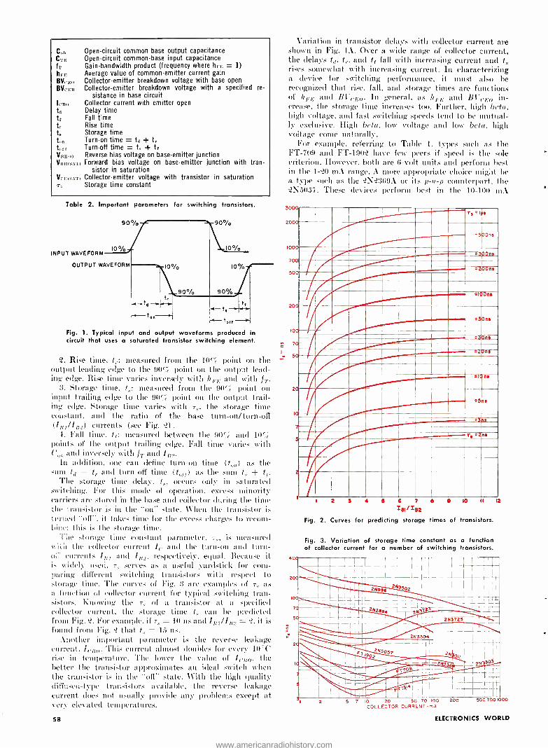
C,,,,
Crc. fT
hrr BVrro BVCICR
I, Ro
ta ti ti
teer VReoo VRLI(SAT)
VEG(SAT)
Tn
Open- circuit common -base output capacitance Open- circuit common -base input capacitance Gain- bandw;dth product (frequency where hrI., = 1) Average value of common -emitter current gain Collector- emitter breakdown voltage with base open Collector- emitter breakdown voltage with a specified re-
sistance in base circuit Collector current with emitter open Delay time Fall time Rise time Storage time Turn -on time = t,( + tr Turn -off time = L + tf Reverse bias voltage on base -emitter junction Forward bias voltage on base -emitter junction with tran-
sistor in saturation Collector- emitter voltage with transistor in saturation Storage time constant
Table 2. Important parameters for switching transistors.
90%
INPUT WAVEFORM 10 %] OUTPUT WAVEFORM
10 O/o
1o%
90 %
-4- to!!
Fig. 1. Typical input and output waveforms produced in circuit that uses a saturated transistor switching element.
c?. Rise time, t,.: measured from the 107r point on the output leading edge to the 90% point on the output lead- ing edge. Rise time varies inversely with hEE and with IT.
3. Storage time, t.,: measured from the 90rc point on input trailing edge to the 90r.'ß point on the output trail- ing edge. Storage time varies with r0, the storage time constant, and the ratio of the base turn -on /turn -off (I((t /If(,O currents (see Fig. "2).
4. Fall time, tf: measured between the 90(;' and 10% points of the output trailing edge. Fall time varies with Co, ) and inversely with IT and 18.2.
In addition, one can define torn -on time (t,,,,) as the sum t)) + tr and turn -off Iliac (t ff) as the sum t. + tf.
The storage time delay, t., occurs only in saturated switching. For this mode of operation, excess minority carriers are stored in the base and collector during the time the transistor is in the "on" state. When the transistor is terued "Off", it takes time for the excess charges to recom- bine; this is the storage time.
The storage time constant parameter. 7,, is measured with the collector current Ir and the turn -on and turn- 0;7 currents if;7 and 162, respectively, equal. Because it is widely used. 70 serves as a useful yardstick for com- paring different snitching transistors with respect to storage time. The curves of Fig. :3 are examples of -70 as a function of collector current for typical switching tran- sistors. Knowing the r,, of a transistor at a specified collector current, the storage time t,0 can be predicted from Fig. '2. For example, if T, = 10 us and /111// 110 = ?, it is found from Fig. that t,,. - 15 ns.
.mother important parameter is the reverse leakage current, I((;(,. This current almost doubles for every 111 °C rise in temperature. The lower the value of Id.(;0, the better the transistor approximates an ideal switch when the transistor is in the "off" state. With the high quality diffused -type transistors available, the reverse leakage current does not usually provide any problems except at very elevated temperatures.
58
Variation in transistor delays with collector current are shown in Fig. 4A. Over a wide range of collector current, the delays t,(. t,.. and tf fall with increasing current and t5 rises somewhat with increasing current. In characterizing a device for switching performance, it must also be recognized that rise, fall, and storage times are functions of hpE and B1'(.E,,. In general. as Il 'E and BI "(.E0 in- crease, the storage time increases too. Further, high beta, high voltage, and fast snitching speeds tend to be mutual- ly exclusive. High beta. low voltage and low beta, high voltage come naturally.
For example. referring to Table 1, types such as the FT -709 and FT -190'2 have few peers if speed is the sole criterion. However, both are 6 -volt units and perform best in the 1 -°?0 mA range.. more appropriate choice might he a type such as the '21'23691 or its p -n -p counterpart, the 215057. These devices perform best ill the 10 -100 nA
3000
200
100
700
50
__- , ,,,--® Y YYYYYYY IYYYYY =>.llr7 M1/11ItIIItlt 11111IIIIIlIIl11MMINN 11/WAIIIMIE1111=MIIIIIIM=111__ iiMI.._1.=az .V,IE iN iiii Ì/I/.11111".v .. C_..--
III/omml. virdiummarimman i- YYfi fiYYYYYYY YY Tfi - rdinnmom
20
10
7
40
r 2 3 4 0 6 7
lei1tu Fig. 2. Curves for predicting storage times of transistors.
Fig. 3. Variation of storage time constant as a function of collector current for a number of switching transistors.
(o 11
ri.T I r 1 11 1
I i,l , -f rl 1 1
1 ; _1_:. 243002
I
(2
7
253304
253725
255057
IT?
13)a
)
14330
5 7 10 20 50 70 100 200 500 700 1000
COLLECTOR CURRENT -reA
ELECTRONICS WORLD
www.americanradiohistory.com
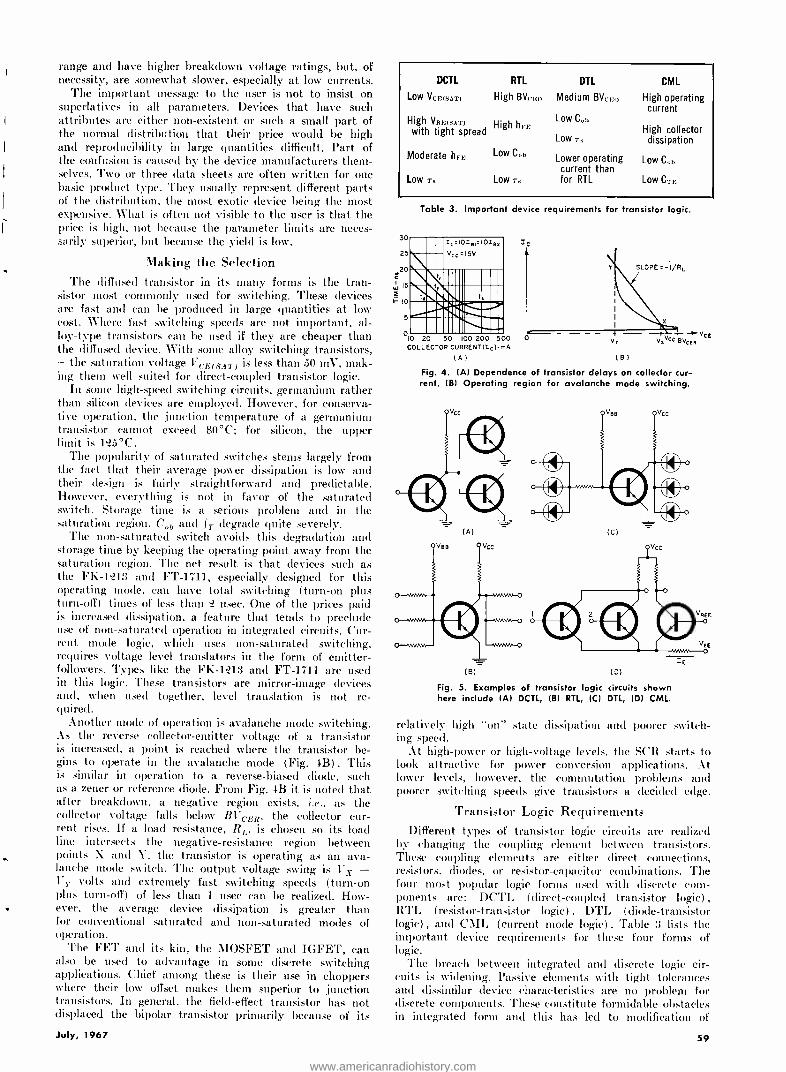
range and have higher breakdown voltage ratings, but, of necessity, are somewhat slower, especially at low currents.
The important message to the user is not to insist on superlatives in all parameters. Devices that have such attributes are either non -existent or such a small part of the normal distribution that their price would be high and reproducibility in large quantities difficult. Part of the confusion is caused by the device manufacturers them- selves. Two or three data sheets are often written for one basic product type. They usually represent different parts of the distribution, the most exotic device being the most expensive. What is often not visible to the user is that the price is high, not because the parameter limits are neces- sarily superior, but because the yield is low.
Making the Selection The diffused transistor in its many forms is the tran-
sistor most commonly used for switching. These devices are fast and can be produced in large quantities at low cost. Where fast switching speeds are not important, al- loy -type transistors can be used if they are cheaper than the diffused device. With some alloy switching transistors, -the saturation voltage VCE(a.AT) is less than 50 mV, mak- ing them well suited for direct -coupled transistor logic.
In some high-speed switching circuits, germanium rather than silicon devices are employed. However, for conserva- tive operation, the junction temperature of a germanium transistor cannot exceed 80 °C; for silicon, the upper limit is 125 °C.
The popularity of saturated switches stems largely from the fact that their average power dissipation is low and their design is fairly straightforward and predictable. However, everything is not in favor of the saturated switch. Storage time is a serious problem and in the saturation region, COt, and IT degrade quite severely.
The non- saturated switch avoids this degradation and storage time by keeping the operating point away from the saturation region. The net result is that devices such as the FK -1213 and FT-1711, especially designed for this operating mode, can have total switching (turn -on plus turn -off) times of less than 2 nsec. One of the prices paid is increased dissipation, a feature that tends to preclude use of non -saturated operation in integrated circuits. Cur- rent mode logic, which uses non -saturated switching, requires voltage level translators in the form of emitter - followers. Types like the FK -1213 and FT-1711 are used in this logic. These transistors are mirror -image devices and, when used together, level translation is not re- quired.
Another mode of operation is avalanche mode switching. As the reverse collector- emitter voltage of a transistor is increased, a point is reached where the transistor be- gins to operate in the avalanche mode (Fig. 4B) . This is similar in operation to a reverse -biased diode, such as a zener or reference diode. From Fig. 4B it is noted that after breakdown, a negative region exists, i.e., as the collector voltage falls below BVcER, the collector cur- rent rises. If a load resistance, RL, is chosen so its load line intersects the negative- resistance region between points X and Y, the transistor is operating as an ava- lanche mode switch. The output voltage swing is Vy - v i volts and extremely fast switching speeds (turn -on plus turn -off) of less than 1 nsec can be realized. How- ever, the average device dissipation is greater than for conventional saturated and non -saturated modes of operation.
The FET and its kin, the 1IOSFET and IGFET, can also be used to advantage in some discrete switching applications. Chief among these is their use in choppers where their low offset makes them superior to junction transistors. In general, the field- effect transistor has not displaced the bipolar transistor primarily because of its
July, 1967
DCTL
Low VCE(SAT)
RTL
High BVru0
High VBE(SAT) High hFE with tight spread
Moderate hFE Low Cob
Low T. Low T,
DTL CML
Medium BVc1,o High operating current
Low Co) High collector
Low T, dissipation
Lower operating Low C,,,, current than for RTL Low CTE
30
25
220
W 15
I- 10
5
Table 3. Important device requirements for transistor logic.
010 20 50 100 200 500 COLLECTOR CURRENT(Ic) rnA
(A)
Fig. 4. (Al Dependence of transistor delays on collector cur- rent. (B) Operating region for avalanche mode switching.
(A) (C)
(B) (D)
Fig. 5. Examples of transistor logic circuits shown here include (Al DCTL, (B1 RTL, IC) DTL, (DI CML.
relatively high "on" state dissipation and poorer switch- ing speed.
At high -power or high- voltage levels, the SCR starts to look attractive for power conversion applications. At lower levels, however, the commutation problems and poorer switching speeds give transistors a decided edge.
Transistor Logic Requirements Different types of transistor logic circuits are realized
by changing the coupling element between transistors. These coupling elements are either direct connections, resistors, diodes. or resistor- capacitor combinations. The four most popular logic forms used with discrete com- ponents are: DCTL (direct- coupled transistor logic) ,
RTL (resistor -transistor logic) , DTL (diode- transistor logic) , and CML (current mode logic) . Table 3 lists the important device requirements for these four forms of logic.
The breach between integrated and discrete logic cir- cuits is widening. Passive elements with tight tolerances and dissimilar device characteristics are no problem for discrete components. These constitute formidable obstacles in integrated form and this has led to modification of
59
www.americanradiohistory.com

these logic forms and to the evolution of completely dif- ferent classes of logic.
In DCTL, the collector of one device couples directly to the base of another, as shown in Fig. 3A. Its advantages are: simplicity, minimum of components required, low cost, and the fact that only a single supply voltage is required. Its disadvantages include: low signal levels and therefore sensitivity to noise, strong dependence on uni- form device characteristics, and switching speed limited by storage time.
Resistors perform the logic while the transistor serves as the inverter in RTL (Fig. 3B). For cascading purposes, the output is designed to be the same as the input sicle. This logic is relatively simple, low cost, less sensitive to variations in i'c.r,;rt_iT, and l'E(,y..cl,), and good noise immunity. On the minus side. RTL has low fan -in and fan -out capabilities, slow speed, and requires high signal voltage levels. A variation of RTL, RCTL uses a capaci- tor across the coupling resistors. This results in faster operation than RTL because the base sees a low impedance both during turn -on and torn -off and the delays are considerably reduced. However, noise immunity is poor and transient loading can be severe.
In DTL, the resistors used in RTL are replaced by diodes (Fig. 5C) . This logic provides optimum use of available base chive by avoiding the current -shunting paths existing in DCTL and RTL. Also it has good noise im- munity, fan -in capability, and is faster than RTL and DCTL. One disadvantage is that, in saturation, the bases of the following stages see a voltage equal to i-r'Etsaz) plus the diode voltage drop. This means that a larger turn- off current is required. What is more, it is also costlier than RTL.
The salient feature of C_MIL is that it is the only logic of the four listed that is non -saturating. Referring to
Fig. 5D, the emitter current, IE, is relatively constant and is switched from one transistor to another as the signal to input 1, or '2, is varied. The variation in the input signal is with respect to the reference voltage, V REF. C:IL is a vei'v fast logic because it has no storage time, very good noise immunity, and a high fan -in. The price paid for this superior performance is high power dissipa- tion and a requirement for level translation. In addition, many transistors are required, making the cost high.
Future Possibilities Regarding performance, no major breakthroughs are
anticipated in the near future. The market incentive is not there for low -level discrete applications: logic functions have been taken over by integrated circuits. Integrated semiconductor technology is particularly suited for pro- ducing large numbers of identical circuits with unprece- dented reliability. making them naturally compatible with computer circuits.
In power applications, the discrete switch will remain on the scene longer because of the heat dissipation prob- lem. In memory applications, for instance, device dissi- pation is considerable. There is a need for further improvements in discrete drivers for memory elements. As computers become faster, memory cycle times are reduced, thus imposing more stringent requirements on the switch- ing tinges of the semiconductor drivers.
Increased automation and improved yields have already caused prices to drop steadily. Refinements in processes and other developments have greatly enhanced reliability. Prices will continue to drop because the semiconductor business is highly competitive and reliability will con- tinue to improve largely because of the increasingly stringent demands of the military and large computer manufacturers.
HIGH-VOLTAGE TRANSISTORS WE tend to think of transistors as low- voltage devices even though some of the newer types reaching the market are capable of oper-
ating safely with approximately 1000 volts applied to them. Advanced diffusion techniques, coupled with other proprietary oper-
ations, have enabled the M.S. Transistor Corp. to announce a new
family of high -voltage silicon "n -p -n" transistors which includes the 2N5010 through 2N5015 (2 -watt units), and MST -50 to MST -100 (also 2 -watt units), and the MSP -50 to MSP -100 (5 -watt units).
Operating voltage of the new transistors ranges from 500 to 1000, I reaches 500 mA, h,,; is between 20 and 180, and the transistors are capable of operation to 35 MHz. The MST -xx and 2N50xx series come in TO -5 cans, while the MSP version comes in an MD -14 case.
These new high -voltage transistors open many new areas formerly the sole province of the vacuum tube, for example, the relatively high -
voltage deflection circuits for electrostatic CRT's. In addition, many conventional circuits can now be extended. In the case of these tran- sistors, they can be operated from a 120 -, 240 -, or 480 -volt a.c.
power line and require only a full -wave rectifier and capacitor filter. They would also be useful as EL panel drivers as the devices can be
used to drive the essentially capacitive loads by running class -A stages in series push -pull configuratons.
In the area of consumer electronics, the Delco Radio Division of GM
Corp. has announced its high -voltage transistor (DTS -0714) having a
VCEK of 1200 volts, V c,srs, of 750 volts, linear current gain (ht -,.,) at 2.5 amperes of 10 min.mum, and a reverse voltage (Vr,,,o) of 5 volts.
The new sil:con, tripe- diffused, mesa transistor has been used in
switching the 3800 volt- ampere load of a 25 -inch color -TV horizontal sweep deflection circuit.
In the TV circuit, a 1050 -volt pulse is transformed in the flyback transformer to 25 kV for use by the CRT. The horizontal output tran- sistor swatches about 4 amperes during this operation, and is protected from arcing by a diode and RC network.
The transistor, which replaced a pair of 700 -volt types used pre- viously (DTS -402), and a vacuum tube before that, is presently avail- able in a strip- mounted epoxy package.
60
HOW MANY TRANSISTORS? THE chip shown below, although designed as an integrated circuit,
dramatically illustrates the density attained by modern diffusion techniques. The chip is 58 mils square and, as shown, only a portion of it is used for the 415 "p "- channel enhancement -mode transistors.
Fabricated by General Instrument's Microelectronics D vision, the chip is a 64 -bit serial accumulator capable of operation to 5 MHz. The
company is presently embarking on a program having an expected density of up to one million transistors per square inch. They have al- ready produced devices having 250,000 transistors per square inch. A
ELECTRONICS WORLD
www.americanradiohistory.com
fill the gaps.. WITH A COMPLETE SELECTION OF ANNUALS, YEARBOOKS, DIRECTORIES AND
HANDBOOKS from the world's largest publisher of special interest magazines. Take a moment to review the titles and issues currently available. You're sure to find many of your favorites to help complete your library and fill those wide open spaces on your bookshelves.
PHOTOGRAPHY ANNUAL
A selection of the World's finest photographs compiled by the editors of Popular Photography. 212 pages -24 in full color.
1967 - $1.50 _ #38 1966 - $1.25......_....#1 1964 - $1.25 __... _#3
PHOTOGRAPHY m DIRECTORY
BUYIRG GUIDE
i IDfi]CAR:RRNIR - ---_. INVITATIGNTG ...:..:.......:.. .; YEARBOOK ...: . , k.:.::n: ;. PHOTGGRAPHY ; , .,.._ vy,..
.... .... .: : :.?i.
h. tin
. .........;x.. .::.ï . .:.x,;x;¿ :: '
AtAt. .: :4i':{::}Y .......; . -
- . .-..... :,:}
::...:..:::. :..:.ï...
y/
........... .........
ñ ] _
.::::::.: . . ; ii:itii ............ .......... :i:::i:
=;s' .
: :::::::::::
ELECTRONIC EXPERIMENTER'S HANDBOOK
Many challenging projects for the electronics hobbyist.
1966 - Fall Edition -$1.25 ... #39 1966 - Spring Edition -$1.25.__ #36 1965 - Fall Edition -$1.25 _ #9 1965 - Spring Edition -$1.25.... #14
CAR & DRIVER YEARBOOK
A complete buyers guide covering vir- tually every car available in the United States . Road tests . . . Technical specifications . Accessories and performance equipment buying guide
Guide to racing with action - packed photos.
1967 - $1.50. 1966 - $1.25 1965 - $1.25
#40 #I5 #17
INVITATION TO PHOTOGRAPHY
A unique 116 page guide to better pic- ture taking by the Editors of Popular Photography. Basic down -to -earth ad- vice that helps you eliminate costly trial and error, time- consuming guess work. 20 complete, fact -and -photo packed articles in all.
1966 - $1.25 ................#35
PHOTOGRAPHY DIRECTORY
World's most complete
TAPE RECORDER ANNUAL
Everything you need to know about photographic buying guide. tape recording including a complete
1967 - $1.25 #41 directory of mono and stereo recorders.
1966 - $1.25 _ 22 1967 - $1.25 #42 1966 -$1.25 #30 1965 - $1.00_ #31
ELECTRONICS INSTALLATION AND SERVICING HANDBOOK
The only complete guide for servicemen and hobbyists to every major phase of consumer electronics servicing.
1967 - $1.25 #43 1966 - $1.25.. _ #32
FLYING ANNUAL
The most valuable aviation yearbook ever compiled . . . Pilot reports . . .
Aircraft directory . How to buy a
used airplane . Navcom directory .. . Learn to fly section.
1967 - $1.50_ ... _ #44 1966 - $1.25 _ #27 1965 - $1.25 #28
STEREO /Hi Fi DIRECTORY Complete buyers guide for virtu- ally every Hi Fi component man- ufactured.
1967 - $1.25 _ #45 1966 - $1.25.....,...#29
I
POLAROID LAND PHOTOGRAPHY
Complete guide and only comprehensive and up -to -date handbook on Polaroid Land Pho- tography.
1966 - $1.25 #24 1963 - $1.00..,_..._..#25
TO PLACE YOUR ORDER, circle the num- bers of the annuals you wish to receive on the coupon, clearly print your name and address and enclose your remittance. Please be sure to enclose an additional 15¢ ship- ping and handling for each copy ordered. Add 50¢ per copy for orders outside U.S.A.
July, 1967
SKIING INTERNATIONAL YEARBOOK
A luxuriously illustrated compen dium of 1966's important events.
. A timely forecast of the excitement -packed 1967 season -by the editors of Skiing Maga- zine.
1967 - $1.25 #48 1966 - $1.25 #26
FLYING TRAVELGUIDE Here's the first really useful guide to flying vacations. Every- thing you need to know about: lodgings, restaurants, resorts, sightseeing, recreation, sports activities, airport facilities childrens fun, price information, special information for the gals -and much more.
1967 - $1.25 #46 1966 - $1.25 __ ;.34
COMMUNICATIONS HANDBOOK
The most complete and up -to- date guide to the exciting world of specialized radio communica- tions.
1967 - $1.25 _ #47 1966 - $1.25 #18 1965 - $1.00_....... #19
Ziff -Davis Service Division -Department W 595 Broadway, New York, N. Y. 10012 1 am enclosing $_. for the annuals circled below. My remittance includes an additional 15y per copy for shipping and handling (50¢ for orders outside U.S.A.). I understand quantities are limited and orders will be filled on a first come -first served basis.
1 3 9 14 15 17 18 19 20 22 24 25 26 27 28 29
30 31 32 34 35 36 38 39 40 41 42 43 44 45 46 47 48
Name
Address EW 77
City State _ Zip Code PAYMENT MUST BE ENCLOSED WITH ORDER
61
www.americanradiohistory.com
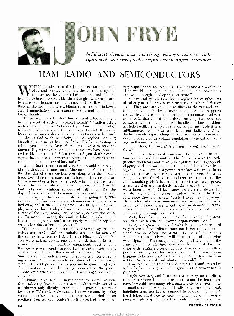
OlIN FRYE Solid -state devices have materially changed amateur radio equipment, and even greater improvements appear imminent.
HAM RADIO AND SEMICONDUCTORS WHEN thunder from the July storm started to roll,
Mac and Barney grounded the antennas, opened the service bench switches, and started for the
front office to comfort Matilda, the office girl, who was death- ly afraid of thunder and lightning. Just as they stepped through the door there was a blinding flash of light followed almost immediately by a snapping sound and a great bel- low of thunder.
"To quote Thomas Hardy: `How can such a heavenly light be the parent of such a diabolical sound ?' " Matilda asked with a nervous giggle. "Why don't you two talk about elec- tronics? That always quiets my nerves. In fact, it usually bores me so much sleep comes as a defense mechanism."
"Always glad to oblige a lady," Barney replied, perching himself on a corner of her desk. "Mac, I've been wanting to talk to you about the love affair hams have with semicon- ductors. Right from the beginning, those two have gone to- gether like guitars and folksingers, and you don't need a crystal ball to see a lot more conventional and exotic semi- conductors in the future of ham radio."
"It's not hard to understand why hams would take to sol- id -state diodes and transistors," Mac mused. "For one thing, the tiny size of these devices goes along with the modern trend toward more compact and lighter amateur radio gear. I can remember a few years back when a kilowatt ham transmitter was a truly impressive affair, occupying two six - foot racks and weighing upwards of half a ton. But the days when a ham could take over a spare upstairs bedroom or the basement for his ham shack are going fast. The average small, functional, modern house doesn't have a spare bedroom; and if there is a basement, it's likely serving as a playroom or bar. Today's ham has to make do with a corner of the living room, den, bedroom, or even the kitch- en. To meet his needs, the modern kilowatt radio station has been compressed until it fits neatly on a table top and weighs less than a hundred pounds."
"You're right, of course, but it's only fair to say that the switch from AM to SSB transmission accounts for much of this saving in weight and size. In that kilowatt AM station you were talking about, one of those six -foot racks held speech amplifier and modulator equipment, together with the husky power supply needed for the latter. Getting rid of the modulator cut the size of the transmitter in half. Since an SSB transmitter need not supply a power- consum- ing carrier, it imposes much less demand on the power supply. Current peaks drawn under modulation are of very short duration so that the average demand on the power supply, even when the transmitter is inputting 2 kW p.e.p., is modest."
"I know," Mac said. "I never cease to marvel at how those table -top linears can get around 3000 volts out of a transformer only slightly larger than the power transformer for a color -TV receiver. Of course, I know it's done by using voltage -doubling circuits employing series -connected silicon rectifiers. You certainly couldn't do it if you had to use mer-
62
cury -vapor 866's for rectifiers. Their filament transformer alone would take up more space than all the silicon diodes and would weigh a whopping lot more."
"Silicon and germanium diodes replace bulky tubes lots of other places in SSB transmitters and receivers," Barney said. "They are used as audio rectifiers in the vox and anti - trip circuits and in the balanced modulators that suppress the carrier, and as r.f. rectifiers in the automatic level -con- trol circuits that limit drive to the linear amplifiers so as not to exceed what the amplifier can handle in a linear fashion. A diode rectifies a sample of the r.f. output and feeds it to a milliammeter to provide an r.f. output indicator. Other diodes provide a.g.c. voltage for the receiver or transceiver. Zener diodes provide voltage regulation of critical low volt- ages in the vox and other circuits."
"How about transistors? Are hams making much use of them ?"
"So far, they have used transistors chiefly outside the sta- tion receiver and transmitter. The first uses were for code practice oscillators and mike preamplifiers, including speech clipping and limiting circuits. But lots of hams have been experimenting with flea -power transistorized transmitters and with transistorized communications receivers. As far as completely transistorized transmitters are concerned, the chief stumbling block has been a lack of reasonably priced transistors that can efficiently handle a couple of hundred watts input up to 30 MHz. I know there are transistors that can do this, but they are not available to hams, at least not at a price they can afford. While I keep hearing rumors about other solid -state transceivers on the drawing boards, as far as I know there is only one amateur -band trans- ceiver on the market that is completely transistorized-ex - cept for the final amplifier tubes."
"Well, how about receivers? We have plenty of transis- tors that can handle any power requirements there."
"True, but again there are drawbacks -or have been until very recently. The ordinary transistor is essentially a small - signal device. When one is used in the r.f. stage of a communications receiver, it will do a fine job of amplifying weak signals until a nearby ham fires up a full gallon on the same band. Then his signal overloads the input of the tran- sistor with resulting cross -modulation that does an excellent job of swamping out the weak station. If that weak station happens to be a rare ZA in Albania or a YI in Iraq, the ham is likely to be very disturbed-to put it mildly!"
"I suppose you're thinking about the FET and its ability to handle both strong and weak signals as the answer to this problem."
"Right you are, and I see no reason why an excellent, fully transistorized amateur receiver cannot be built right now. It would have many advantages, including such things as small size, light weight, practically no generation of heat, indefinite transistor life as opposed to comparatively short - lived tubes, resistance to shock and vibration, and simple power -supply requirements that could be easily and eco-
ELECTRONICS WORLD
www.americanradiohistory.com
( and your audience, too! )
WITH VOLUME II
SOUND FOR A PICTURE EVENING
This superb 12 -inch, 331/ rpm record brings you 30 selections of sparkling, mood-
setting off -beat music and hard -to -find, sound effects. For use "as is" by playing the appropriate tracks as y3ur slide or movie
show proceeds or for editing your selections and recording them on taae, "Sound For
A Picture Evening" adds another dimen- sion to your photography -high
fidelity sound.
IlsïION,QnR-ROW ®R ELRJe 1EXK'âREEXAö'.a o ó ó,,ç á o o q'á o n. át°P°. VOLUME ll t
re
01
O
CI a 10 K3
13
17
a
0 13
Ci
Ci CI
r=
13C1131:1:1030â78i30EMI:1l3LIMEII300110í3110aWä-fg ¡fit 'á
SOUND FOR A PICTURE EVENING
30 bands of unusual background music
& sound effects specially chosen for
slide shows & movies
MADE WITH PHOTOGRAPHERS IN MIND Photographers are travelers . . . are parents . . . are sportsmen . are restless experimenters with the unusual. And so the editors of POPULAR PHOTOGRAPHY have produced this second volume of unusual music and sound effects expressly to match the activities and moods in the most popular types of pictures shown in slide and home movie shows. These are melodies and sounds selected from the vast resources of the Capitol Record Hollywood Library to fit the special needs of photographers. The 30 bands of "Sound For A Picture Evening, Vol. II" supplement but do not duplicate any of those in the first edition of this popular record.
A POPULAR PHOTOGRAPHY EXCLUSIVE The "Sound For A Picture Evening, Vol. II" album has been produced by the editors of POPULAR PHOTOGRAPHY exclusively for our readers and is prepared by the Custom Services Division of Capitol Records. This outstand- ing album, which cannot be purchased in any store, is available by mail only to the readers of Popular Photography and other Ziff -Davis magazines.
YOU GET 30 SPECIAL MUSIC AND SOUND TRACKS
There are 19 bands of mood and special- situation music ... 11 bands of unusual, hard -to -find sound effects. MOODS: Majestic, Backyard Nature, Experimental, Mysterious, Music of the Spheres NATIONAL PORTRAITS: Vive la France, German Village Band, Soul of Spain, American West, English Countryside, Buon Giorno, Italia SOUND EFFECTS: Bass Drum, Bassoonery, Cathedral Bells, Galloping Horses, Zoo Noises, Children at Play, Cocktail Party, Birds on a Spring Morning, Outboard Motor, Oars in Water, Skis on Snow, Trumpet Fanfare, Solo Violin SPECIAL PURPOSE MUSIC: Music From Silent Movies, Music for Slow- Motion Movies, Music for Speeded -Ua Motion, Music for Stop - Motion Movies, Underwater Music, Music for Olc -Time Footage.
For photographers with wanderlust, you'll find the "National Portraits" to be authentic melodies to go with your vacation pictures of England, France, Germany, Italy, Spain and the American West. There are also those special bands to accompany the kind of pictures sports- men take: The sound of galloping horses, of boat motors, of skis on snow, of oars in the water. You'll even find other -worldiy mood -music chosen espe- cially to go with underwater pictures. Experimental photographers will find the electronic music ideal accompani- ment for abstract pictures. The music for stop- motion, slow- motion and speeded -up- motion pictures is fanciful and imaginative in helping to present the unusual scenes being portrayed on your screen. And there is even mood music to convey the visual grandeur of ancient museum relics and photo- graphs of the stars and planets. To these add many other tracks of carefully selected music and sounds - and you have "Sound For A Picture Evening, Volume II."
July, 1967
% e,1 Vaw.dd mood a`td titt-aie
1 '6a4td4 wow/tat lafrd-t4-1,, ¡ Q4tu.td e#yeced ' ,
COMPLETE WITH INSTRUC- F R E TIONS AND BAND POINTER E! A comprehensive instruction booklet comes with your record, showing you how to make a successful sound -and -music tape track for your slide or movie show, or to use the record alone as background, even if you're a rank beginner. An ingenious band pointer which fits on top of your record instantly locates any band you want. No guessing, no wasted motion, no false starts.
This 12" long playing vinyl album consisting of selections from the music masters of the Capitol Record Hollywood Library is available to you for
Only $ 3 98 POSTPAID!
It's a must for every slide and film show impresario and an album you will enjoy for many years to come.
PLACE YOUR ORDER NOW
"Sound For A Picture Evening, Volume II" P. 0. Box 3118 Church Street Station, New York, N.Y. 10008
Please send "Sound For A Picture Evening, Volume II" albums at $3.98 each, postpaid.
My check (or money order) for $ is enclosed.
(Outside U.S.A. please send $6.00 per record ordered.) N. Y. State residents please add local sales tax.
Name
Address
City
State Zip Code
PAYMENT MUST BE ENCLOSED WITH ORDER "SOUND FORA PICTURE EVENING, VOLUME I" still available I missed this first release containing 17 specific mood music backgrounds and 8 tracks for special sound effects. Please send "Sound For A Picture Evening, Volume I" albums at $3.98 each, postpaid. (Outside U.S.A. send $6.00 per record ordered.)
EW.77
63
www.americanradiohistory.com

... not hy
a long shot it isn't!!
There's certainly nothing top secret about the classified pages in Elec- tronics World Magazine. They're wide open to the searching eyes of every buyer who's in the market for the product or service that he knows can be found in Electronics World's Electronics Market Place.
The more than 191,000 buyers of Electronics World, largest reader- ship of any magazine for electronics professionals in the world, are your guarantee of knowing that your ad is being read by people who are constantly looking for and buying electronics products. It is these people to whom you MUST direct YOUR advertising as do the many key advertisers appearing in this issue and in each issue throughout the year.
No doubt about it- there's a vast market of buyers searching the classified advertising pages of Elec- tronics World and it's important that your ad be exposed to this prime buying audience. Prove to yourself that the leading magazine for electronics professionals MUST ALSO be the leader in sales re- sponses to the many classified ads presently enhancing its pages - it makes a great deal of sense -give it a try.
There's complete rate information for your convenience in the classi- fied section of this issue. Or, if you'd like a little personal service, it's right up our alley. Just write to
HAL CYMES Classified Advertising Manager
ZIFF -DAVIS PUBLISHING COMPANY One Park Avenue
New York, New York 10016
64
nornically met by batteries for mobile or portable operation."
"Well, I'll hazard a guess that if U.S. manufacturers don't get on the stick and come out with something like this at a reasonable price soon, they vvill be scooped by the Japanese."
"You can say that again. I think the Japanese are beginning to eye the ham market the way they did the CB mar- ket, and are both know what they dici there in the way of transistorized trans- ceivers. Quite recently, I've run across several DX stations who say they are using Japanese -made ham equipment. One thing is sure: the number of Japa- nese amateurs is increasing rapidly. It used to be you had to listen long and hard to hear a JA station, but now just about any time I point my beans north- west I hear Nippon stations coming ill On ten, fifteen, or twenty meters -and with darned good signals, too. Some of the fellows on the islands out ill the Pa- cific complain that the Japanese are be- ginning to swamp them out the way 1..S. hams monopolize the bands in this hemisphere."
"These things sound like straws in the wind to tae," Mac said. "We have long produced most of the manufac- tured ham equipment, probably be- cause the great majority of the world's radio amateurs are located in this coun- try. In no other country lias the home ham market been large enough to war- rant the research and development nec- essary for producing this highly spe- cialized equipment. Now, with the ham populations of other countries on the rise and with Americans' ready accep- tance of imported electronic equipment, this may be changed."
"Hey, that brings up an interesting chat I had with a ham in The Nether - lands the other morning. He suggested dart the number of active hams ill a country compared to its total popula- tion was a good index of that country's electronics know -bow and its ability to produce electronic gear. He pointed out the high percentage of hams in Eng- lund, West Germany, Japan, and the United States us examples."
"He may have something there. We both know that the electronics indus- try has always displayed an interest in amateur radio that goes beyond that segments being an important market for electronic products. Take a look at the applications section of any diode, transistor, grid -controlled rectifier, or integrated -circuit manual, and you will find several strictly ham suggestions. And hams return the compliment. Practically every one of their magazines Lis a regular semiconductor column, or nmething similar, in which new semi - c.onductor devices are introduced or cir- IlUts involving semiconductors are de- -cribed. In addition, ham magazines illten carry full -length feature articles
describing the use of semiconductors in ham gear written by top men involved in the production, research, and de- velopment of solid -state devices. This is not surprising, considering how many of these people have ham radio for a hobby."
"That brings up an important fea- ture of solid -state devices. They lend themselves to experimenting, home construction, and kit construction. Tran- sistorized gear is almost invariably as- sembled on a printed- circuit or Vector board. You don't need a machine shop to bend chassis, punch socket holes, or cut out heavy metal areas as you or- dinarily do when building equipment using tulles. What's more, since dis- tributed capacitances are easily dupli- cated with this type of construction, you can build a piece of equipment from an article and expect equivalent perfor- mance. The use of 1C's is going to make this even more true. No wonder hams who like to build and experiment are in love with transistors!"
"Okay; let's not get carried away. How do you picture transistorized ham equiputetit of the future ?"
"Well, there's a limit to how much you can reduce the panel area of a ham transceiver. No natter how small the components behind that panel, you still need room to mount all the con- trols, jacks, dials, and meters neces- sary for operation. The panel of my present transceiver carries fifteen of these components. Since many controls require a comparatively close adjust- ment, the knobs cannot be made too small. The tuning dial, for instance, has to be large enough for fine adjustment and for comfortable operation hour after hour. The meter and frequency indication must be large enough for easy reading. So 1 see the ham transceiver of the near future as not much smaller in height and width but greatly reduced in depth.
"The use of FET's and IC's will pro- duce better, more sophisticated, more trouble -free equipment. The lower volt- ages required by transistors and their lack of heat generation will greatly re- duce component failure. Alobile opera- tion, already stimulated by SSB, will increase even more when solid -state transceivers with their low current re- quirements are in Nvidespread use. We may still have to use compact ceramic - type tubes in high- powered linears, but medium -power transmitters and excit- ers will be fully transistorized and will take up touch less space than today's equipment -"
His voice trailed off as he nodded to Alatilda, sound asleep with her bead resting on her folded arras on her desk, oblivious to the intermittent growls of thunder from the retreating storm.
"I thought she was kidding!" he said in a hoarse vvhisper to \
WORLD
www.americanradiohistory.com

RADIO
TV NEWS
SERVICE MASTER
HANDIEST
HANDFUL
of service tools
THE engineers at Television Hanu- facturers of America have a gripe,
and it is a real one judging by the ex- perience of others.
After visiting a number of color -TV demonstration showrooms, they ( and we) noticed that reception in multi -set demonstrations of large dealers often leaves much to be desired.
According to the TMA chief engi- neer, "Poor tuning of sets on the show- room floor creates as much sales resis- tance as anything, including the high price of color sets.
"The colors run together, and often the purity and convergence are so poor that colors are quite the opposite of what viewers know they should be . . .
in many cases, every figure is surround- ed by a reddish halo.
"Big dealers by their very bigness are particularly vulnerable to this problem. They often tend to have too marry sets playing at one time to pay attention to each set's fine tuning (and color setup). Thus, a customer sees a variety of colors for the sane program."
Many potential customers who over- look bad showroom quality in mono- chrome sets, seem to know instinctively that the set is not at fault, but balk at baying tvhelr the same trouble shows up in a color set demonstration. There are two reasons for this. First, the main attraction of color-TV is color itself. If the customer is not impressed, he sees no reason to change from monochrome. Second, a small percentage are con- vinced that color is still too primitive. Both views are mistaken, but poor qual- ity in a demonstration set tends to sup- port each belief.
Portable VTI. The Ampex Corp. recently_ demon-
strated a battery -powered portable video tape recorder measuring 23 by 13 by 6 inches and weighing only :35
lbs. In its attaché -type case, the unit is mounted on a back pack to enable on- the -spot video tape recordings to be made by news agencies. The new VTR can record up to 20 minutes of action on an 8 -inch reel and is compatible for direct re- broadcast over conventional studio tape decks.
A companion camera weighing 13
July, 1967
lbs. complete witl its own electronic view -finder is also 'ncluded in the pack- age. A built -in clock keeps the operator aware of remaining recording time.
Laser Activities Engineers at GT&E recently demon-
strated a liquid laser about as thick as a fountain pen and six inches long cap- able of generating a burst of light en- ergy equivalent to one million watts (10,000 hundred -watt light bulbs) .
In this new laser, the medium is formed by dissolving neodymium (a rare earth) in selenium oxychloride (an inorganic compound). The whole process takes about ten minutes to corn - plete. An external flash tube provides the excitation for the laser.
In another use of the ubiquitous laser, scientists at TRW Systems Group are using laser holography to record microscopic phenomena moving a few millionths of an inch ill less than one millionth of a second. The flights of fruit flies (gnats) and bullets have been "stopped" at 100 billionths of a second and recorded on a 4 x 5 inch photo- graphic plate. And, for the first time, a photographic portrait was taken of a mixture of air and acetylene the instant it was detonated by a spark.
Both TRW and other agencies are exploring the possibility of many new breakthroughs because of this new technique. Of course, all images made using the hologram technique are three - dimensional.
Canine Detection While other countries are looking
towards electronics as a means of de- tecting buried ore deposits, a small item in the Soviet journal Razredka i Ok/uauo Nedr (Exploration and Con- servation of Resources) seems to hear looking into.
It seems that the Soviets now llave canine comrades that have been trained to sniff out ore deposits buried under seven feet of earth. These animals are also capable of detecting some ores at even greater depths.
It is assumed that in the vast, still unexplored areas of Central Russia, clogs are easier to come by than bat- teries. A
23 essential tools at your fingertips in this light- weight (only 23/4 lbs.), compact, easy -to- carry, roll -up kit. Contains long nose plier, diagonal plier, adjustable wrench, regular and stubby plastic handles with these interchangeable blades: 9 regular and 3 stubby nutdriver, 2
slotted and 1 Phillips screwdriver, 2 reamer, 1
extension. Eyelets in plastic- coated canvas case
permit wall hanging. New elastic loop secures
roll, eliminates need for tying.
many optional accessories: Junior and Tee handles ... Additional nutdriver, Phillips & slotted screwdriver, and extension blade sizes ... Allen hex type, Bristol multiple spline, Frearson, Scrulox, and clutch head blades
...Awl /Scriber...Chuck adaptors to use blades in spiral ratchet drivers.
WRITE FOR CATALOG 166
XCELITE, INC., 12 Bank St., Orchard Park, N. Y. 14127
In Canada contact Charlra W. Pointon, Ltd. CIRCLE NO. 96 ON READER SERVICE CARD
65
www.americanradiohistory.com
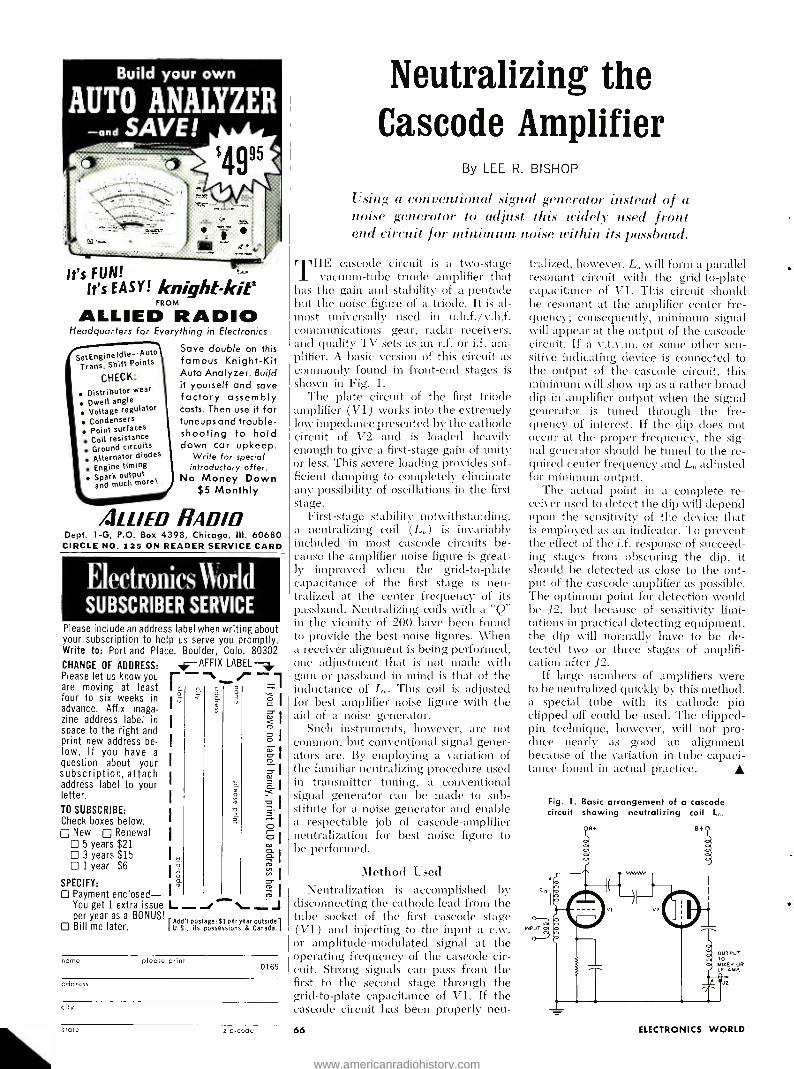
Build your own
AUTO ANALYZER and SAVE!
It's FUN! It's EASY! knight -kits
FROM
ALLIED RADIO Headquarters for Everything in Electronics
Save double on this famous Knight -Kit Auto Analyzer. Build it yourself and save factory assembly costs. Then use it for tuneups and trouble- shooting to hold down car upkeep.
Write for special introductory offer.
No Money Down $5 Monthly
SetEngineldle -Auto Trans. Shift Points
CHECK:
Distributor wear
Dwell angle Voltage reg ulator
Condensers Point surfaces Coil resistance Ground circuits Alternator diodes
Engine timing Spark output and much more!
4LL /ED RADIO Dept. 1 -G, P.O. Box 4398, Chicago, III. 60680
CIRCLE NO. 125 ON READER SERVICE CARD
Electronics World SUBSCRIBER SERVICE
Please include an address label when writing about your subscription to help us serve you promptly. Write to: Portland Place, Boulder, Colo. 80302
-AFFIX LABEL
3 I0
7, 1
E
óa -9 I D- -I oI O
aIa D N
"I
CD
Ó y a
You get 1 extra issue L _ L _ per year as a BONUS!
Add'I postage: El per year outside I=1 Bill me later. U.S., its possessions & Canada.
CHANGE OF ADDRESS: Please let us know you are moving at least four to six weeks in advance. Affix maga- zine address label in space to the right and print new address be- low. If you have a
question about your subscription, attach address label to your letter.
TO SUBSCRIBE: Check boxes below.
New Renewal 5 years $21 3 years $15 1 year $6
SPECIFY: Payment enclosed-
name please print 0169
address
city
state zio -code
Neutralizing the Gascode Amplifier
By LEE R. BISHOP
Using a conventional signal generator instead of a noise generator to adjust this widely- used front end circuit for nrininlrun noise within its passband.
T
1HE cascode circuit is a two -stage vacuum -tube triode amplifier that
his the gain and stability of a pentode but the noise figure of a triode. It is al- most universally used in u.h.f. /v.h.f. communications gear, radar receivers, mid quality TV sets as an r.f. or i.f. am- plifier. A basic version of this circuit as commonly found in front -end stages is shown in Fig. 1.
The plate circuit of the first triode amplifier (V1) works into the extremely low impedance presented by the cathode circuit of V2 and is loaded heavily enough to give a first -stage gain of unity or less. This severe loading provides suf- ficient damping to completely eliminate any possibility of oscillations in the first stage.
First -stage stability notwithstanding, a neutralizing coil (L ) is invariably included in most cascode circuits be- cause the amplifier noise figure is great- ly improved when the grid -to -plate capacitance of the first stage is neu- tralized at the center frequency of its passband. Neutralizing coils with a "Q in the vicinity of 200 have been found to provide the best noise figures. When a receiver alignment is being performed, one adjustment that is not made with gain or passband in mind is that of the inductance of L,,. This coil is adjusted Ii r best amplifier noise figure with the aid of a noise generator.
Such instruments, however, are not common, but conventional signal gener- ators are. By employing a variation of the familiar neutralizing procedure used in transmitter tuning, a conventional signal generator can be made to sub- stitute for a noise generator and enable a respectable job of cascode -amplifier neutralization for best noise figure to be performed.
Method Used Neutralization is accomplished by
disconnecting the cathode lead from the tube socket of the first cascode stage (VI) and injecting to the input a c.w. or amplitude -modulated signal at the operating frequency of the cascode cir- cuit. Strong signals can pass from the first to the second stage through the grid -to -plate capacitance of V1. If the cascode circuit has been properly neu-
66
tralized, however, L,, will form a parallel resonant circuit with the grid -to -plate capacitance of V1. This circuit should be resonant at the amplifier center fre- quency; consequently, minimum signal will appear at the output of the cascode circuit. If a v.t.v.m. or some other sen- sitive indicating device is connected to the output of the cascode circuit, tisis minimum will show up as a rather broad clip in amplifier output when the signal generator is tuned through the fre- quency of interest. If the dip does not occur at the proper frequency, the sig- nal generator should be tuned to the re- quired center frequency and L adjusted for minimum Output.
The actual point in a complete re- ceiver used to detect the dip will depend upon the sensitivity of the device that is employed as an indicator. To prevent the effect of the i.f. response of succeed- ing stages from obscuring the dip, it should be detected as close to the out- put of the cascode amplifier as possible. The optimum point for detection would be 12, but because of sensitivity limi- tations in practical detecting equipment, the clip will normally have to be de- tected two or three stages of amplifi- cation after J2.
If large numbers of amplifiers were to be neutralized quickly by this method, a special tube with its cathode pin clipped off could be used. The clipped - pin technique, however, will not pro- duce nearly as good an alignment because of the variation in tube capaci- tance found in actual practice.
INPUT
Fig. 1. Basic arrangement of a cascade circuit showing neutralizing coil L,,.
e
ouTPut TO MIXER OR I.F. AMP.
J2
ELECTRONICS WORLD
www.americanradiohistory.com
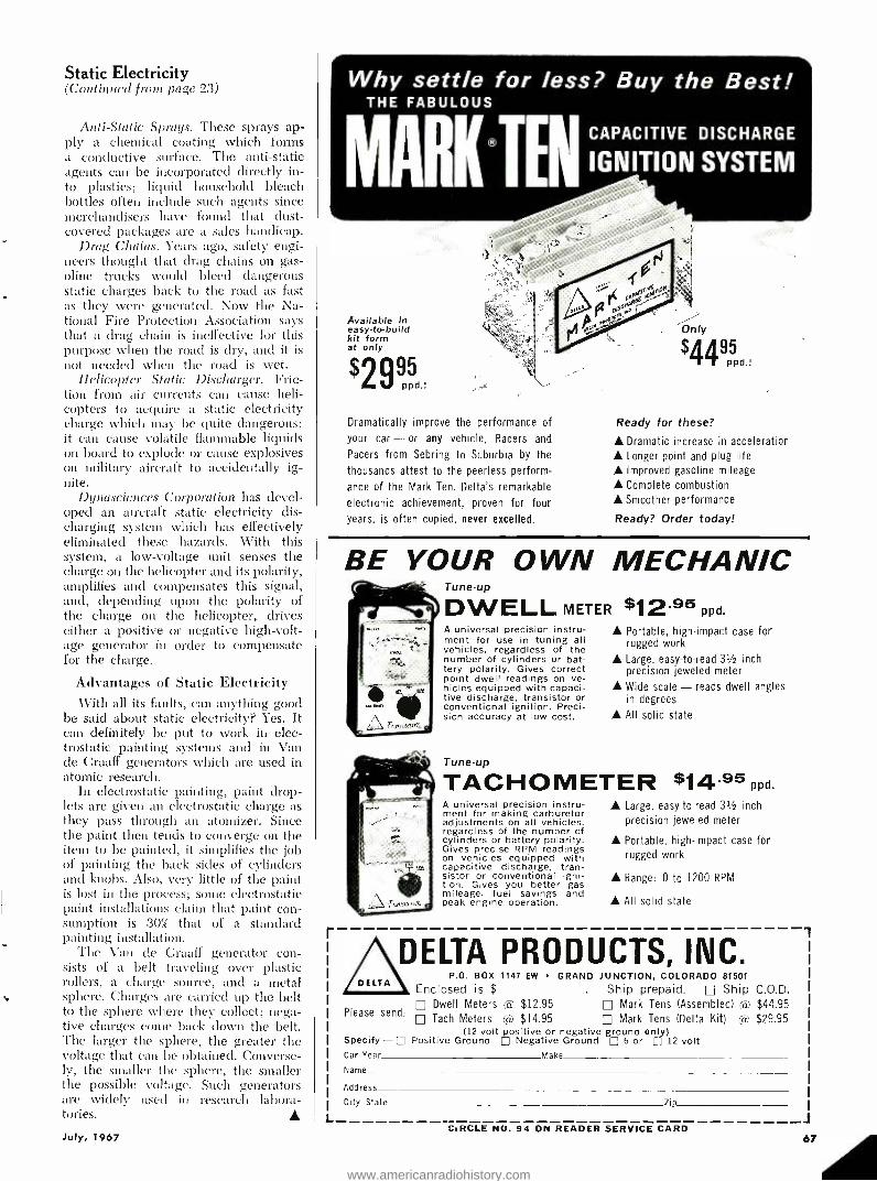
Static Electricity (Continual fruin page 23)
Anti- Static Sprays. These sprays ap- ply a chemical coating which forms a conductive surface. The anti -static agents can be incorporated directly in- to plastics; liquid household bleach bottles often include such agents since merchandisers have found that dust - covered packages are a sales handicap.
Drag Chains. Years ago, safety engi- neers thought that drag chains on gas- oline trucks would bleed dangerous static charges back to the road as fast as they were generated. Now the Na- tional Fire Protection Association says that a drag chain is ineffective for this purpose when the road is dry, and it is not needed when the road is wet.
Helicopter Static Discharger. Fric- tion from air currents can cause heli- copters to acquire a static electricity charge which may be quite dangerous: it can cause volatile flammable liquids on board to explode or cause explosives on military aircraft to accidentally ig- nite.
D,nascience-s Corporation has devel- oped an aircraft static electricity dis- charging system which has effectively eliminated these hazards. With this system, a low- voltage unit senses the charge on the helicopter and its polarity, amplifies and compensates this signal, and, depending upon the polarity of the charge on the helicopter, drives either a positive or negative high -volt- age generator in order to compensate for the charge.
Advantages of Static Electricity With all its faults, can anything good
be said about static electricity? Yes. It can definitely be put to work in elec- trostatic painting systems and in Van de Graaff generators which are used in atomic research.
In electrostatic painting, paint drop- lets are given an electrostatic charge as they pass through an atomizer. Since the paint then tends to converge on the item to be painted, it simplifies the job of painting the back sides of cylinders and knobs. Also, very little of the paint is lost in the process; some electrostatic paint installations claim that paint con- sumption is 30% that of a standard painting installation.
The Van cue Graaff generator con- sists of a belt traveling over plastic rollers, a charge source, and a metal sphere. Charges are carried up the belt to the sphere where they collect; nega- tive charges come back down the belt. The larger the sphere, the greater the voltage that can be obtained. Converse- ly, the smaller the sphere, the smaller the possible voltage. Such generators are widely used in research labora- tories.
Why settle for less? Buy the Best! THE FABULOUS
MARK TEN CAPACITIVE DISCHARGE
IGNITION SYSTEM
Available in easy -to -build kit form at only
$2995.,
Dramatically improve the performance of
your car - or any vehicle. Racers and
Pacers from Sebring to Suburbia by the
thousands attest to the peerless perform-
ance of the Mark Ten. Delta's remarkable
electronic achievement, proven for four
years, is often copied, never excelled.
Ready for these?
Dramatic increase in acceleration Longer point and plug life
A Improved gasoline mileage Complete combustion
A Smoother performance
Ready? Order today!
r
BE YOUR OWN MECHANIC Tune -up
DWELL METER $12'95 ppd.
A universal precision instru- ment for use in tuning all vehicles, regardless of the number of cylinders or bat- tery polarity. Gives correct point dwell readings on ve- hicles equipped with capaci- tive discharge, transistor or conventional ignition. Preci- sion accuracy at low cost.
Tune -up
Portable, high- impact case for rugged work
Large, easy -to -read 31/2 inch precision jeweled meter
Wide scale - reads dwell angles in degrees
All solid state
TACHOMETER $14.95 ppd.
A universal precision instru- ment for making carburetor adjustments on all vehicles, regardless of the number of cylinders or battery polarity. Gives precise RPM readings on vehicles equipped with capacitive discharge, tran- sistor or conventional igni- tion. Gives you better gas mileage, fuel savings and peak engine operation.
Large, easy -to -read 31/2 inch
precision jeweled meter
Portable, high- impact case for rugged work
A Range: 0 to 1200 RPM
A All solid state
DELTA PRODUCTS, INC.
Piease send:
P.O. BOX
Enclosed is $_
Dwell Meters
Tach Meters (12 volt
Specify -D Positive Ground Car Year
Name
1147 EW GRAND JUNCTION, COLORADO 81501
. Ship prepaid. Ship C.O.D.
n $12.95 Mark Tens (Assembled) @ $44.95
@ $14.95 Mark Tens (Delta Kit) $29.95 positive or negative ground only)
Negative Ground 6 or 12 volt Make
Address
City State Zip
i
L 1 CuRCLE NO. S4 ON READER SERVICE CARD
July, 1967 67
www.americanradiohistory.com

50 functions in a single chip. The functions of 50 separate tran- sistors, diodes, resistors and capacitors can now be formed by the tiny dot in the center of the integrated circuit held by the tweezers.
The "Chip" ...wild it make or break your job future?
THE DEVELOPMENT OF INTEGRATED CIRCUITRY is the dawn of a new age of electronic miracles. It means that many of today's job skills soon will be no longer needed. At the same time it opens the door to thousands of exciting new job opportuni- ties for technicians solidly grounded in electronics fundamentals. Read here what you need to know to cash in on the gigantic coming boom, and how you can learn it right at home.
TINY ELECTRONIC "CHIPS," each no bigger than the head of a pin, are bringing about a fantastic new
Industrial Revolution. The time is near at hand when "chips" may save your life, balance your checkbook, and land a man on the moon.
Chips may also put you out of a job... or into a better one.
"One thing is certain," said The New York Times recently. Chips "will unalterably change our lives and the lives of our children probably far beyond recognition."
A single chip or miniature integrated circuit can
perform the function of 20 transistors, 18 resistors, and 2 capacitors. Yet it is so small that a thimbleful can hold enough circuitry for a dozen computers or a thousand radios.
Miniature Miracles of Today and Tomorrow Already, as a result, a two -way radio can now be fitted inside a signet ring. A complete hearing aid can be worn entirely inside the ear. There is a new desk -top computer, no bigger than a typewriter yet capable of 166,000 operations per second. And it is almost possible to put the entire circuitry of a color television set inside a man's wrist -watch case.
And this is only the beginning! Soon kitchen computers may keep the housewife's
refrigerator stocked, her menus planned, and her calories counted. Her vacuum cleaner may creep out at night and vacuum the floor all by itself.
Money may become obsolete. Instead you will simply carry an electronic charge account card. Your employer will credit your account after each week's work and merchants will charge each of your pur- chases against it.
68 ELECTRONICS WORLD
www.americanradiohistory.com
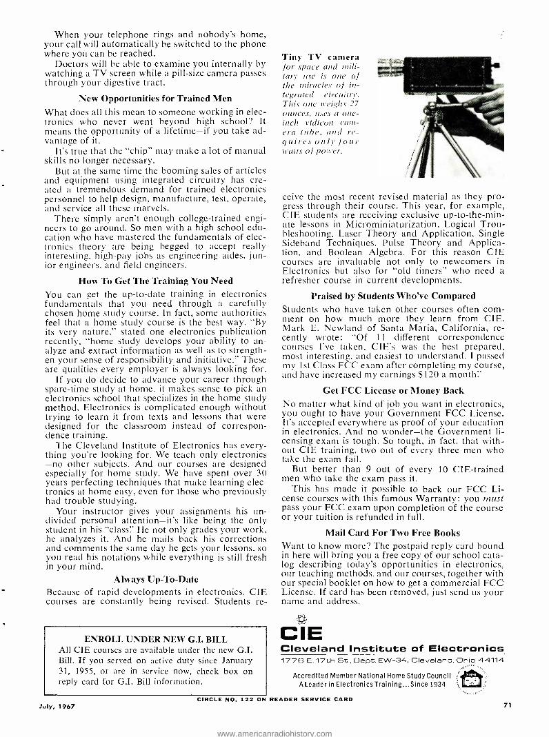
When your telephone rings and nobody's home, your call will automatically be switched to the phone where you can be reached.
Doctors will be able to examine you internally by watching a TV screen while a pill -size camera passes through your digestive tract.
New Opportunities for Trained Men What does all this mean to someone working in elec- tronics who never went beyond high school? It means the opportunity of a lifetime -if you take ad- vantage of it.
It's true that the "chip" may make a lot of manual skills no longer necessary.
But at the same time the booming sales of articles and equipment using integrated circuitry has cre- ated a tremendous demand for trained electronics personnel to help design, manufacture, test, operate, and service all these marvels.
There simply aren't enough college -trained engi- neers to go around. So men with a high school edu- cation who have mastered the fundamentals of elec- tronics theory are being begged to accept really interesting, high -pay jobs as engineering aides, jun- ior engineers, and field engineers.
How To Get The Training You Need You can get the up -to -date training in electronics fundamentals that you need through a carefully chosen home study course. In fact, some authorities feel that a home study course is the best way. "By its very nature," stated one electronics publication recently, "home study develops your ability to an- alyze and extract information as well as to strength- en your sense of responsibility and initiative." These are qualities every employer is always looking for.
If you do decide to advance your career through spare -time study at home, it makes sense to pick an electronics school that specializes in the home study method. Electronics is complicated enough without trying to learn it from texts and lessons that were designed for the classroom instead of correspon- dence training.
The Cleveland Institute of Electronics has every- thing you're looking for. We teach only electronics -no other subjects. And our courses are designed especially for home study. We have spent over 30 years perfecting techniques that make learning elec- tronics at home easy, even for those who previously had trouble studying.
Your instructor gives your assignments his un- divided personal attention -it's like being the only student in his "class:' He not only grades your work, he analyzes it. .And he mails back his corrections and comments the same day he gets your lessons, so you read his notations while everything is still fresh in your mind.
Always Up -To -Date Because of rapid developments in electronics, CIE courses are constantly being revised. Students re-
ENROLL UNDER NEW G.I. BILL All CIE courses are available under the new G.I. Bill. If you served on active duty since January 31, 1955, or are in service now, check box on reply card for G.I. Bill information.
Tiny TV camera for space and mili- tary use is one of the miracles of in- tegrated circuitry. Thi.r one weighs 27 ounces, uses a one - inch vidicon cam- era tube, and re- quires only four watts' of pouter..
ceive the most recent revised material as they pro- gress through their course. This year, for example, CIE students are receiving exclusive up-to- the -min- ute lessons in Microminiaturization, Logical Trou- bleshooting, Laser Theory and Application, Single Sideband Techniques, Pulse Theory and Applica- tion, and Boolean Algebra. For this reason CIE courses are invaluable not only to newcomers in Electronics but also for "old timers" who need a refresher course in current developments.
Praised by Students Who've Compared Students who have taken other courses often corn- ment on how much more they learn from CIE. Mark E. Newland of Santa Maria, California, re- cently wrote: "Of 11 different correspondence courses I've taken, C1E's was the best prepared, most interesting, and easiest to understand. I passed my 1st Class FCC exam after completing my course, and have increased my earnings $120 a month:'
Get FCC License or Money Back No matter what kind of job you want in electronics, you ought to have your Government FCC License. It's accepted everywhere as proof of your education in electronics. And no wonder -the Government li- censing exam is tough. So tough, in fact, that with- out CIE training, two out of every three men who take the exam fail.
But better than 9 out of every 10 CIE -trained men who take the exam pass it.
This has made it possible to back our FCC Li- cense courses with this famous Warranty: you must pass your FCC exam upon completion of the course or your tuition is refunded in full.
Mail Card For Two Free Books Want to know more? The postpaid reply card bound in here will bring you a free copy of our school cata- log describing today's opportunities in electronics, our teaching methods, and our courses, together with our special booklet on how to get a commercial FCC License. If card has been removed, just send us your name and address.
CIE Cleveland Institute of Electronics 1776 E. 17th St., Dept. EW -34, Cleveland, Dhio 44114
Accredited Member National Home Study Council ALeaderin Electronics Training...Since 1934
CIRCLE NO. 122 ON READER SERVICE CARD July, 1967 71
www.americanradiohistory.com

TEST EQUIPMENT
(9)1(3
PRODUCT REPORT
iiíiir 1110111111111 1
11111111101111111 y 'SKI
Model 7050 Digital Voltmeter For ropy on manufacturer's brochure, circle No. 36 on Reader Service Card.
NE of the hits of the recent IEEE Show in New York was the com-
pact digital voltmeter just introduced by Fairchild Instrumentation. The me- ter is easily held in the palm of one hand; it measures only about 6 inches wide by 3 inches high by 7 inches deep and it weighs just under 4 pounds. More impressive than this, however, is the price. The meter costs only 5249 in quantities of 25 or more, or 8299 in quantities of 1 to 4. The main reason for the small size and low price (for a DV\I) is the use of the company's in- tegrated circuits in the instrument.
The Model 7050 is a "31/2- digit" me- ter. This indicates that there are three full decades, each with its indicator digit, plus a fourth digit ,indicating an overrange of 50 %. The fourth digit is either a "0" or a "1" so that the instru- ment is able to give a full -scale read- out of 1500 volts with no loss of accura- cy.
The meter has four d.c. voltage ranges, from 1.5 volts to 1000 volts full scale, plus five resistance ranges, from 1500 ohms to 15 megohms full scale. Ex-
ternal current shunts are available for current readings.
The accuracy of the instrument is ±0.1% of reading, ±1 digit for d.c. voltage measurements. Accuracy of re- sistance measurements is somewhat lower.
The instrument is rugged, easy to operate and read, and was designed to replace conventional analog meters and panel indicators as well as more expen- sive digital voltmeters. It is suitable for production, general test, servicing, and educational applications.
Using the dual -slope technique (as described on page 64 of our May, 1967 issue), the Model 7050 combines the noise- rejection capabilities of integra- tion with the accuracy and stability of automatic comparison to an internal standard. Fast response time is assured by its speed of six measurement sam- ples per second. The meter has an in- put impedance of greater than 1000 megohms, a floating input which may be operated 500 volts above ground, and readout storage providing a non - blinking display.
Bird Model 6155 R.F. Wattmeter For copy of numufacturer's brochure, circle No. 37 on Reader Service Card.
HE Model 6155 is a dual -range ab- sorption -type r.f. wattmeter. It is a
portable instrument designed for direct output power measurements of radio transmitters up to 150 watts from 50- ohm coaxial transmission lines. It is intended for general field or laboratory service use on c.w., AM, and FM modu- lation envelopes, but not pulsed modes. The instrument is also useful for line - loss measurement and for checking co-
axial insertion devices. Modulation may be monitored across the meter termi- nals or fed to the scope directly from the d.c. jack with meter disconnected ( for higher audio signal levels) . When used in 50 -ohm applications, it has a termination v.s.w.r. of less than 1.1:1 from 2 to 30 MHz.
When series (FR current) or tan- gential thermal -type devices are used for r.f. power measurement, calibra-
tion adjustments or charts are required for accuracy. Series devices, when in- serted in the line, introduce resistive and reactive components which disturb the uniform impedance above the milli - watt level. (At signal- generator power level, a compensating network may be incorporated to match the line im- pedance. This is impractical at higher power because the resistive elements would become large and cumber- some.)
The major problem encountered with shunt measurement techniques is the design of a voltage divider which will maintain a constant ratio at all r.f. fre- quencies for which the wattmeter is in- tended. Basically, there are three types of shunt dividers: resistive, inductive, and capacitive.
Of the three, the capacitive divider is best because it remains purely ca- pacitive over a very wide frequency range. Since X,. increases as capaci- tance is reduced, the high values of re- actance needed to divide the r.f. line voltage to less than a volt are easily obtained with small values of capaci- tance. However, as frequency is de- creased, capacitance must be increased. The lowest frequency of measurement
finally limits further size reduction, or vice versa: a physically practical ca- pacitive divider limits power measure- ment to frequencies above 25 MHz.
An excellent technique for r.f. power measurement would be a capacitive di- vider coupled with a current -sensing loop. It would permit accurate mea- surement at lower frequencies without adjustments or references to charts. The new Bird Termaline® r.f. wattmeter utilizes this technique. (See diagram.) A special coupler -detector samples the r.f. energy from the traveling waves present in the detector block by both mutual inductance and capacitance. The inductive loop length is a small
72 ELECTRONICS WORLD
www.americanradiohistory.com

TO XMTR,
DIRECTIONAL COUPLING
CRYSTAL DIODE
COUPLER DETECTOR-.
LOAD
D.C. CONNECTOR
6
SHUNT
METER
O O
Fraction of a wavelength at the operat- ing frequency, making the loop, for all practical purposes, a Lumped- constant L. The capacitive coupling is accom- plished with a plate on top of the loop. This sampling system does not inter- fere with either line impedance or the traveling waves and exhibits uniform response over the frequency range of the wattmeter. The r.f. energy extracted by the coupling circuit is rectified, fil- tered, and displayed on a sensitive meter calibrated directly in watts, with a full -scale accuracy of ±5°iß.
The Model 6155 measures power un- der non -radiating conditions (transmit- ter output feeding into wattmeter only).
BYPASS
D.C. CONTACT METER CABLE
The wattmeter includes a coaxial load resistor immersed in a dielectric coolant enclosed within a finned radiator. Fas- tened to the radiator is the meter hous- ing which may be removed to permit remote meter readings. The scale is direct- reading in watts and is expand- ed at lower levels to increase legibility. A slide switch on the front face of the sloped meter case selects either the 0 -50 or 0 -150 watt range.
The r.f. input connector is a patented "quick- change" female "N" which per- mits easy interchange with other "QC:'- connectors without the use of adapters. The price of the Model 6155 is $21.5 with une "QC" connector.
Lafayette 99 -5065 Volt -Ohm -Milliammeter For copy of n a tfacturer's brochure, circle No.
IN spite of the emergence of com- pact, low -cost digital voltmeters, the
conventional analog -type v.o.m. remains the most versatile and widely used piece of test equipment. In those large numbers of cases where the 2% or 3% accuracy of this type of instrument is entirely adequate, it is hard to beat the analog meter, especially where price is considered.
The new Lafayette Stock No. 99- 5065 "Lab -Tester" v -o -m. is an import- ed instrument with several unique fea- tures. First, it liais the very high ( for a V.0.m.) input resistance of 100,000 ohms, volt, which means that it has a higher input resistance than does a con - ventional v.t.v.m. on ranges over 100 volts. Second, the meter has a single, unmarked 24- position selector switch to change ranges and function. As this switch is rotated, the range and func- tion of the instrument are "flagged" by means of a colored marker in one of the small windows located below each range- function marking. In this way, the user can tell what range he is on without removing his eyes from the large, 61/2-inch scale meter face.
The switch itself is interesting from a mechanical point of view. It is a spe- cial 4 -pole, 24- position unit with all its contacts arranged in a straight line. The wiper is a chain- driven, trolley -like
July, 1967
38 on Reader Service Card.
Live Better Electronically With
WATTS of POWER
You Can Hold In
Your Hand
L_ 99 30B7L*
DY`Ji1 .t 3 Switchable Crystal Controlled Trans-
mit and Receive Channel Positions for All 23 Channels
5 -Watt FCC Maximum Input . with the Power of the Most Powerful Base and Mobile CB Transceivers
. 13 Transistors, 6 Diodes
.. 7 -Stage Transmitter for Maximum Transmit Power!
-0L Operate Mobile in Your Car with Op- tional Cigarette Lighter Plug -in Adapter
Superheterodyne Receiver with Less Than 1 Microvolt Sensitivity for 10 db S+ N/N Ratio
Automatic Compressor Range Boost - Assures High Talk Power
Variable squelch and Automatic Noise Limiting for Minimum Noise
Imported*
with Leather Shoulder Strap
FREE 1967
Catalog No. 670 512 Pages
Everything in Electronics for Home and Industry from the "World's Hi -Fi Electronics Center"
LAFAYETTE Radio ELECTRONICS Dept. RG -7, P. 0. Box 10 Syosset, L. I., N. Y. 11791
1O Send me the FREE 1967 I LAFAYETTE Catalog 670 RG -7
I Name
I Address ..... ........
:City
State
CIRCLE NO. 112 ON READER assembly which moves in a straight
Zip a.uu. NI SERVICE CARD
line across the entire width of the me- ter, carrying the indicator flag with it. Side -by -side recesses in the switch hous- ing contain individual multiplier and shunt resistors in a most accessible ar- rangement.
The meter movement used is a sensitive 9 -; LA, 135 -mV type with double -diode overload protection. The instrument can measure a -c. and d.c. voltages up to 1000 volts, d.c. current up to 10 A, and resistance up to 100 megohms.
The instrument case has a stiff carry- ing handle that can be used to tilt it up for easy reading. Price is $44.95. A
PHOTOGRAPHY ANNUAL A selection of the World's finest photographs com- piled by the editors of Popular Photography. All editions $1.25 each: 1966 - $1.25............ #1 1967 - $1.50....... #t38 1964 - $1.25............ #3
Order by number from Ziff -Davis Service Div., 595 Broadway New York, N. Y. 10012. Enclose add.' 15¢ per copy for ship- ping and handling (50¢ for orders outside U.S.A.)
LEARN Engi e AT HOME r'... tV, design in oinat
lo m steins. learn tr.di.i t.r -.
complete electronics. College level Home Stud, taught s you can nd Earn erstand them. Ear
lore courses in the highly paid electronics dustry. Coi -
puters. \II.siles. theory and practical. in
furni..hvn. liver 311.11111) graduates employed. Resider,. classes tt Chicago
now tif de= irtd. Found.
1934. Catalog. 'Vets -write for Information ahnul (1 I Hill Training."
American Institute of Engineering & Technology 1141 West Fullerton Parkway Chicago, Ill. 60614
73
www.americanradiohistory.com

FROM HiFi STEREO REVIEW
DELUXE PADDED
DUST -PROOF RECORD
AND TAPE CASES plus FREE cataloging forms
These decorative, yet sturdily con- structed cases are just what you've been looking for to keep your records and tapes from getting tossed about and damaged, disappearing when you want them most and just generally getting the "worst of it" from constant handling. They're ideal too for those valuable old "78's" that always seem to get thrown about with no place to go.
Constructed of reinforced fiberboard and covered in rich leatherette in your choice of nine dec- orator colors, the HIFI /STEREO REVIEW Record and Tape Cases lend themselves handsomely to the decor of any room, whether it be your library, study, den, music room or pine -paneled garage. The padded leatherette back (in your color choice) is gold tooled in an exclusive design available only on HIFI /STEREO REVIEW Record and Tape Cases. The sides are in standard black leatherette to keep them looking new after con- stant use. With each Record and Tape Case you
order you will receive, free of charge, a specially designed record and tape cataloging form with pressuresensi- tive backing for affixing to the side of each case. It enables you to list the record names and artists and will prove an invaluable aid in helping you locate your albums. The catalog form can be removed from the side of the case at any time without damaging the leath- erette.
Record Cases are available in three sizes: for 7 ", 10" and 12" records. Each case, with a center divider that separates your records for easy acces- sibility, holds an average of 20 records in their original jackets. The Recording Tape Case holds 6 tapes in their original boxes.
The Tape Cases and the 7" Record Cases (with catalog forms) are only $3.25 each; 3 for $9; 6 for $17.
The 10" and 12" Record Cases (with catalog forms) are $3.50 each; 3 for $10; 6 for $19.
Add an additional 75c per order (regardless of number of cases ordered) for shipping and handling.
Extra
1
1
1
1
1
1
1
1
1
1
1
1
1
1
1
1
74
Ziff -Davis Publishing Company, Dept. SD One Park Avenue, New York, N. Y. 10016 My remittance in the amount of $ is enclosed for the Cases indicated below.
Quantity Tape Case at $3.25 each; 3 for $9; 6 for $17.
- 7" Record Case at $3.25 each; 3 for $9; 6 for $17. 10" Record Case at $3.50 each; 3 for $10; 6 for $19. 12" Record Case at $3.50 each; 3 for $10; 6 for $19.
Add 75c PER ORDER for SHIPPING and HANDLING
Check color choice for back of case (sides in black only):
Midnight Blue Red Saddle Tan Pine Green Orange Yellow Grey Black Spice Brown
Name
Address LW-]r
City__ _ - State_ _ ._Zip Code PAYMENT MUST BE ENCLOSED WITH ORDER r
Challenges in SST Program (Continual from page 27)
conditions, which was standard in the early days of commercial air transpor- tation, has generally declined but still remains with us. Systems now ready for adoption by the airlines enable depar- tures and arrivals under weather condi- tions which until now were considered too hazardous for civil transport. A sys- tem which allows for safe take -off and landing under any weather conditions has not yet been developed. A "hands - off" take -off and landing, that is, one without aid of human control, appears a desirable goal. This accomplishment re- quires a complex system that brings to- gether the techniques previously men- tioned (autopilot, DIME, CAS) as well as navigation. The U.S. Navy has al- ready demonstrated that an aircraft can be landed "hands- off" -a jet fighter has been successfully brought down aboard an aircraft carrier without benefit of guidance by the pilot.
Navigation Problems The problems of air navigation be-
come more prominent as planes cruise at faster speeds. Less time is permitted for course changes to avoid storms or for other reasons. Present weather radars have a range of approximately 150 miles. This range must be increased to at least 350 miles for use on the SST. The weather -radar dome must have low at- tenuation for transmitted and received r.f. energy and at the same time must be capable of withstanding the high tem- peratures of the aircraft skin. The SST cruising altitude of 60,000 to 70,000 feet means that fewer storms will be en- countered, just as today's jetliners cruis- ing at 30,000 to 40,000 feet avoid the lower altitude storms, but weather radar remains as an important system.
For course navigation, the SST will borrow the inertial guidance concept long in use aboard space vehicles. A redundant system will be employed, pro- viding back -up subsystems if one sub- system fails. More precise fixes of air- craft position will result in operating economies for the user. Here again, electronics appears to hold the key to improved performance.
Two concepts underlie all the ideas that have been discussed: the notion of system reliability and system maintain- ability. Beyond the importance of reli- ability in insuring the safe conduct of aircraft operations, there is an economic implication. If the airlines are to operate the SST profitably, the availability of the airplane must be high. "Downtime" for the SST will mean higher costs to the carrier than is the case for today's air- craft. Hence, downtime must be min- imized. Alaintainability now enters the picture. The systems must be quickly
repairable and possess the ability to be maintained with long time intervals be- tween servicings. A self- diagnosing sys- tem, one that not only indicates a fail- ure but also points to where the failure has occurred, is a worthwhile goal. Some electronic computers already have some measure of this capability.
Instrumentation System Related to maintainability is the in-
strumentation system of the SST. In addition to the usual instruments for re- cording flight parameters, a means for monitoring critical performance char- acteristics would provide information useful in maintenance planning. At least one such system is already in use. Since March, 1965, Eastern Airlines, Garret - AiResearch, and IBM have been operat- ing AIDS (Aircraft Integrated Data System) . Additional airlines, both for- eign and domestic, have since placed orders for AIDS.
A step beyond AIDS is AMAS (Air- borne Maintenance Analysis System) .
The AMAS would not only record data, as AIDS sloes, but would also transmit this information in real time for analysis by a ground station. AMAS could thus provide a warning to the pilot of im- pending trouble while the airplane is in flight. If a serious failure appears immi- nent, the pilot could land his craft at the first opportunity, preventing a crit- ical situation.
The piloting of a huge jet aircraft requires a high degree of skill, particu- larly during landing and take -off. If the pilot is not to be overburdened with a maze of instruments and controls, he must be supplied with a well -designed snarl/machine interface. This refers to the link between the controller and the controlled. Electronics can lessen the burden of the pilot's task by providing instrument displays that are easily read and hence quickly transmitted to the mind of the operator. The use of TV cameras to monitor wheel position dur- ing taxi is an example of such a display. A moving -neap indicator, showing the aircraft superimposed upon a map of the local geographic region, can also provide "quick look" information. Proper layout of the instrument panel and placement of controls can also do a great deal to prevent pilot fatigue and reduce the possibility of pilot error in operation.
From our discussion, it should be clear that electronics has much to do with the planned success of the SST program. _Many of the problems facing us are not unique to the SST. The air- craft- airline industry in general will profit by new developments in electron- ic systems. The public will benefit by having rapid, safe, low -cost transporta- tion available. The industry has been given the challenge, and we have every reason to believe the challenge will be met.
ELECTRONICS WORLD
www.americanradiohistory.com

Troubleshooting Integrated Circuits (Continued from page 36)
with D5 and D6 operating as capacitors and R11 and R12. act as a conventional discriminator. The two -stage audio preamplifier consists of Q1 and Q12.
13y comparing Figs. 6 and 7, it is immediately apparent that certain defects can occur in the IC chip itself which will affect either one of the two sections or, possibly, both. Al- though the entire IC may have to be replaced, it is still im- portant for the technician to know in which stage the defect occurs. The reason for this is that a defect in the discrim- inator transformer, the input transformer, or any of the external bypass capacitors could cause a loss of output signal.
INPUT TRANS.
n P r - I
4.3MMZ
1
/ v INPUT A
IC SN 0 1
a,SCR MINA'lR TRANS.
,-.SVO,T
Fig. 6. Interconnections for the integrated circuit used in set.
It is interesting to see how RCA's troubleshooting instruc- tions are directed towards testing everything else before the IC itself is tackled. Referring to the block diagram of Fig. 5, the manufacturer first suggests injecting an audio signal at the input of the transistor driver stage to make sure that the transistor section, the output transformer, and the speaker are all functioning normally. If audio is present at the speaker, the company recommends injecting a 4.5 -MHz FM signal at the video detector. A probe is connected to the audio output terminal, 9, of the IC. If audio can be seen on
the scope, it is assumed that the IC and its associated com- ponents are good. Next the volume control and the wiring to the transistor driver stage would have to be checked. If, however, the scope does not show a suitable audio signal, the IC and its associated components must be suspected.
To facilitate troubleshooting, the manufacturer provides a voltage chart in the service data which requires a v.t.v.m. and, in some instances, a scope. On terminals 5, 6, and 7, for example, the scope should show a peak -to -peak voltage ranging between 4 and 6 volts. RCA points out that improper bias readings on pins 1, 2, 4, or 5 might be caused by defects in the input or the discriminator transformer. The manu- facturer does not suggest unsoldering the leads of the dis- criminator transformer to check its resistance because this would require removing the transformer from its printed - circuit mounting, a procedure which is quite involved and which can easily damage the terminals or printed wiring.
Fig. 7. Complete circuit dia- gram of what is inside IC. The
outboard transformers and by- pass capacitors are also shown.
OET %FMR
I IMP MP. LIMITER VOLT. REG' FM OET.
TO AUDIO AMP.
Why not sell the best 3 ZENITH
WAVEMAGNET
INDOOR TV ANTENNAS built to the quality standards of Zenith original parts Zenith has designed these AVavemagnet antennas for sensitive reception in color or B W. Fully adjustable telescopic dipoles. Six -position selector switch for top performance on each channel. Handsome molded hase of high -impact styrene. Individually packaged for effective sales display. Order now from your Zenith distrihutor.
,2_,W141211®
DELUXE ALL -CHANNEL Part No. 973 -56 Two full -size UHF loops develop high front -to -back ratios equal to many outdoor antennas.
ECONOMY ALL- CHANNEI. Part No. 973 -55
VHF ONLY Part No. 973 -58
7 he quality goes in before the moue goes oil
CIRCLE NO. 95 ON READER SERVICE CARD July, 1967 75
www.americanradiohistory.com
A SELECTION OF
ANNUALS STILL AVAILABLE
FROM THE WORLD'S LARGEST PUBLISHER OF SPECIAL INTEREST MAGAZINES
TAIEAl4 -- - "- ''- _._..-
fíß Itiofteri
,.
/
TAPE RECORDER ANNUAL
Everything you need to know about tape recording including a com plete directory of mono and stereo recorders.
1967 - $1.25 __ #42 1966 - $1.25 _ . #30 1965 - $1.00 #31
STEREO Hl-El DIRECTORY STEREO /Hi Fi DIRECTORY
MotAl Complete buyers guide for virtu- ally every Hi Fi component man -
id . ßlä.. ufactured.
O r' 1967 - $1.25_...... #45 1966 - $1.25......... #29
CAR & DRIVER YEARBOOK w YEM " A complete buyers guide covering virtually every car available in the
States . . Road tests . .
Technial specifications . Ac- cessories and performance equip -
ment buying guide . Guide to racing with action -packed photos.
1967 - $1.50 _. #40 1966 - $1.25 #15
3
- - -United
' . L -- --- .
1965 -$1.25 _i*17
PcNOTOMINP11V
W DIRECTORY
PHOTOGRAPHY DIRECTORY
World's most complete photographic buying guide.
1967 - $1.25 _ _d±41 1966 -$1.25 ..-22
11.,
_ .0 ..3:-F- . .
' :+c
e r"'°`° ? "A°"" ANNUAL 19!17
!. PHOTOGRAPHY ANNUAL
A selection of the World's finest photographs compiled by the edi- tors of Popular Photography. 212 pages -24 in full color.
1967 - $1.50........ #38 1966 - $1.25............ #1 1964 - $1.25............ #3
POLAROID' POLAROID LAND PHOTOGRAPHY
Complete guide and only compre- hensive and up -to -date handbook on Polaroid Land Photography.
1966 - $1.25......... #24 -.,.- _... 1963 -$1.00...... #25
Ziff-Davis Service Division, Dept. W 595 Broadway, N.Y., N.Y. 10012.
I am enclosing $ for the annuals circled below. My remittance includes an additional 15¢ per copy for shipping and handling (50¢ for orders out side U.S.A.). I understand quantities are limited and orders will be filled on a first come -first served basis.
1 3 15 17 22 24 25 29
30 31 38 40 41 42 45
name please print
address EW.n
city
state zip
PAYMENT MUST BE ENCLOSED WITH ORDER
76
The manufacturer's troubleshooting instructions end with a warning that all outboard or external components asso- ciated with the IC should be checked individually before changing the IC it- self. If it is necessary to replace the IC, a soldering iron with a suction bulb is recommended for removing the solder from the pins in order to be able to in- sert the pins of the replacement IC with- out too much difficulty or damage to the circuit.
But is it Practical? The reader will ask, with some justi-
fication, whether or not the above trou- bleshooting instructions are really prac- tical and efficient. If any of the parts associated with the IC fail, the trouble- shooting procedure will be much longer than would be the case if vacuum tubes or transistors were used.
One simple approach to the problem posed by the circuits shown in Figs. 6
and 7 would be to connect a low resis- tance, such as 50 ohms, across terminals 1 and 2 and another one across terminals 5 and 10. These four terminals are avail- able at the input and the discriminator transformer, and the two resistors can be tacked to them. Next, we connect a 50- ohm signal generator (operating at a suitably low level) to the input, pref- erably at 4.5 MHz but sonic other con- venient frequency can be used because the tuned circuits are shunted by 50 ohms. The scope, with a high -gain pre- amplifier, is connected across the 50- ohm resistor at the primary of the dis- criminator transformer and we can now measure the gain of the amplifier portion of the IC.
Unfortunately- the manufacturer's data does not indicate the amount of gain that can be expected in that stage with a 50 -ohm load. Even without a detailed specification, however, we can assume that the voltage ratio would in- dicate that the amplifier is operating cor- rectly. Next, the signal generator would be connected directly across the dis- criminator transformer primary Nvith the oscilloscope connected across the sec- ondary.
We can expect a reduction in ampli- tude but we should not expect a total absence of signal at the secondary of the discriminator transformer. When the signal generator is tuned to 4.5 \IIIz with an FM modulation of at least ±7.5- kHz deviation and a 4.5-MHz signal is observed at the secondary, the next check is to see whether audio is obtained at the output of the IC. If audio is not obtained at the stage, the 1C itself must be assumed to be defective and the de- fect will of course be in the FM detector and audio section of the IC. Should the external bypass capacitors be defective, this will also become apparent during this troubleshooting procedure.
To avoid soldering the two 50-ohm
"It luttes more technical LrrouI- edge to troubleshoot I "x and use the text equipment eileetire- ly than it tool: to replace tubes or simply make u feu colt -ohnr- uilliunnreler meuvure Ill enl>r."
resistors temporarily across the trans- former terminals, a still simpler test procedure could be used. The 4.5 -N1Hz frequency -modulated signal could be inductively coupled to the input trans- former and another inductively coupled probe could detect its presence in the discriminator transformer. Once the rel- ative signal amplitudes are known, it is simple to determine whether the am- plifier functions or not. Next the signal generator would be inductively coupled to the discriminator transformer and the audio output monitored. This trouble- shooting method is even more rapid than the one just discussed but requires that a properly designed inductive coupling scheme be available for the signal generator as well as for the scope probe.
The use of sweep generators with low- impedance outputs and calibrated output attenuators, together with suit- able scope probes and high -gain, wide - band oscilloscopes makes even more efficient and versatile troubleshooting techniques possible. Testing of capaci- tors in the circuit is possible by using calibrated pulse generators together with a good scope. Pulse circuits, such as used in the sync section of TV re- ceivers and color -demodulator circuits can be tested without unsoldering leads by using more sophisticated test equip- ment. These techniques will be covered in detail in Part 2.
For efficient color -TV servicing, a wide -band, high -gain scope; a crystal - controlled sweep generator; and a color bar generator are essential. For efficient audio servicing we also need a well - calibrated signal generator, an oscillo- scope, and, possibly, a distortion ana- lyzer. Many technicians have managed to run service operations with much less than this minimum of bench equip - ment by using the trial -and -error meth- od of troubleshooting. As long as they could locate most defects with v.o.m. measurements and occasional transistor substitution, they were able to repair most sets. With the advent of IC's, how- ever, quality test equipment is abso- lutely essential to successful servicing. As will be shown in next month's article, a number of adapters and fixtures will be needed to permit present signal sources and scopes to be used for IC work.
Needless to say, it takes more techni- c-al knowledge to troubleshoot IC's and use the test equipment effectively than it took to replace tubes or simply make v.o.m. measurements.
(Concluded \r.vi Month)
ELECTRONICS WORLD
www.americanradiohistory.com
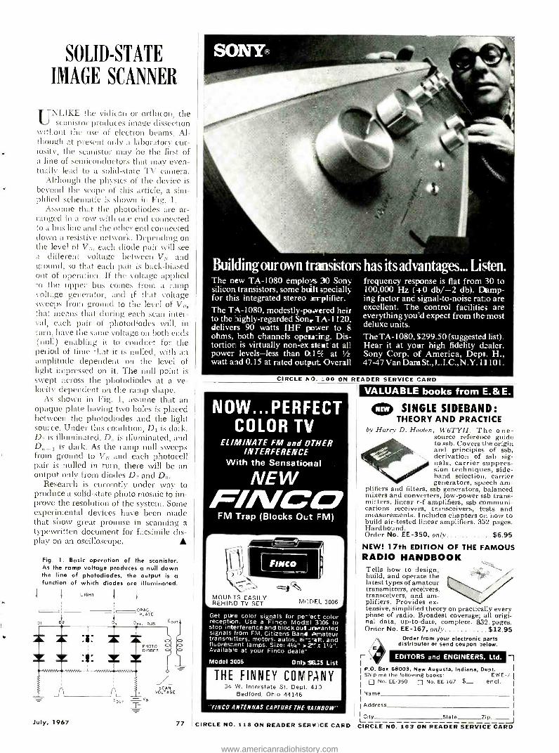
MODEL 3006 J
SOLID -STATE
IMAGE SCANNER
UNLIKE the vidicon or orthicon the scanistor produces image dissection
without the use of electron beams. Al- though at present only a laboratory cur- iosity, the scanistor may be the first of a line of semiconductors that may even- tually lead to a solid -state TV camera.
Although the physics of the device is beyond the scope of this article, a sim- plified schematic is shown ill Fig. 1.
Assume that the photodiodes are ar- ranged in a row with one end connected to a bus line and the other end connected down a resistive network. Depending on the level of Vf;, each diode pair will see a different voltage between VB and ground, so that each pair is back- biased out of operation. If the voltage applied to the upper bus comes from a ramp voltage generator, and if that voltage sweeps from ground to the level of V1i, that means that during each scan inter- val, each pair of photodiodes will, in turn, have the saute voltage on both ends (null) enabling it to conduct for the period of time that it is nulled, with an amplitude dependent on the level of light impressed on it. The null point is swept across the photodiodes at a ve- locity dependent on the ramp shape.
As shown in Fig. 1, assume that an opaque plate having two holes is placed between the photodiodes and the light source. Under this condition, D1 is dark. D_ is illuminated, D is illuminated, and D +1 is dark. As the ramp null sweeps from ground to V and each photocell pair is nulled in turn, there will be an output only from diodes D., and D,,.
Research is currently under way to produce a solid -state photo mosaic to im- prove the resolution of the system. Some experimental devices have been made that show great promise in scanning a typewritten document for facsimile dis- play on an oscilloscope.
Fig. 1. Basic operation of the scanistor. As the ramp voltage produces a null down the line of photodiodes, the output is a function of which diodes are illuminated.
L IGHT I
D2
1
OPAG_- PLATE
D BUS
PHOTO- DIODES
EouT
SCAN } VOLTAGE
Eou, - V,
July, 1967 77
Building our own transistors has its advantages... Listen. The new TA -1080 employs 30 Sony silicon transistors, some built;Decially for this integrated stereo irrplifier. The TA -1080, modestly- per.vered heir to the -lighly- regarded Son,- TA-1120. delivers 90 watts IHF power to S ohms, both channels opeta=irg. Dis- tortior is virtually non -ex stunt at al .
power levels -less than 015- at !/z watt a-1d 0.15 at rated output. Overall
frequency response is flat from 30 to 100,000 Hz ( +0 db / -2 db). Damp- ing factor anc signal -to -noise ratio are excellent. The control facilities are everything yo..fd expect from the most deluxe units.
The TA -1080, S299.50 (suggested list). Hear it at your high fidelity Thaler. Sony Corp. of America, Dept. H., 47 -47 Van Dam St.,1_.I.C.,N.Y.11101.
CIRCLE AO. ..00 ON READER SERVICE CARD
NOW... PERFECT COLOR TV
ELIMINATE FM and OTHER INTERFERENCE
With the Sensational
NEW pIIvCO FM Trap (Blocks Out FM)
r
MOUNTS EASILY BEHIND TV SET
Get pure color signals for pe --ect color reception. Use a Finco ModsI 3)06 to stop interference and block out jre anted signals from FM, Citizens Band Amateur transmitters, motors, autos, ai-.-aft, and fluorescent lamps. Size: 41,4 r 2"..r.: 11.2" Available at your Finco deale-
Model 3006 Only $6.t5 List
THE FINNEY COMPANY 34- W. Interstate St. Dept. 41ri
Bedford, Ohio 44146
"F /NCO ANTENNAS CAPTURE THE RAINBOW"
CIRCLE NO
VALUABLE books from E. &E.
® SINGLE SIDEBAND: THEORY AND PRACTICE
by Harry D. Hooten, li'UTYH. The on e - source reference guide to ssb. Covers the origin and principles of ssb, derivation of ssb sig- nals, carrier suppres- sion techniques, side - band selection, carrier generators, speech am-
plifiers and filters, ssb generators, balanced mixers and converters, low -power rab trans- mitters, linear r -f amplifiers, ssb communi- cations receivers, transceivers, tests and measurements. Includes chapters on how to build air- tested linear amplifiers. 352 pages. Hardbound. Order No. EE -350, only $6.95
NEW! 17th EDITION OF THE FAMOUS RADIO HANDBOOK Tells how to design, build, and operate the latest types of amateur transmitters, receivers, transceivers, and am- plifiers. Provides ex- tensive, simplified theory on practically every phase of radio. Broadest coverage; all origi- nal data, up -to -date, complete. 832. pages. Order No. EE -167, only $12.95
Order from your electronic parts distributor or send coupon below.
EDITORS and ENGINEERS, Ltd. 1 P.O. Bon 68003, New Augusta, Indiana, Dept. Ship me the following books: EWE -7
No. EE-350 O No. EE -167 $ encl.
Name
Address
City State Zip ils ON READER SERVILE CARD I CIRCLE NO. 103 ON READER SERVICE CARD
www.americanradiohistory.com

uet more education
or get out of electronics
...that's my advice:'
78
10morltoomwmar
ELECTRONICS WORLD
www.americanradiohistory.com
July 1967
Ask any man who really knows the electronics industry. Opportunities are few for men without advanced technical education. If you stay on that level, you'll never make much money. And you'll be among the first to go in a layoff.
But, if you supplement your experience with more education in electronics, you can become a specialist. You'll enjoy good income and excellent security. You won't have to worry about automation or advances in technology putting you out of a job.
How can you get the additional education you must have to protect your future -and the future of those who depend on you? Going back to school isn't easy for a man with a job and family obligations.
CREI Home Study Programs offer you a practical way to get more education without going back to school. You study at home, at your own pace, on your own schedule. And you study with the assurance that what you learn can be applied on the job immediately to make you worth more money to your employer.
You're eligible for a CREI Program if you work in electronics and have a high school education. Our FREE book gives complete information. Airmail postpaid card for your copy. If card is detached, use coupon below or write: CREI, Dept. 1129E, 3224 Sixteenth Street, N.W., Washington, D.C. 20010.
1- dry
The Capitol Radio Engineering Institute Dept. 1129 E, 3224 Sixteenth Street, N.W., Washington, D.C. 20010
Please send me FREE book describing CREI Programs. I am employed in electronics and have a high school education.
NAME
ADDRESS
CITY STATE ZIP CODE
EMPLOYED BY
TYPE OF PRESENT WORK GI BILL
AGE
I am interested in Electronic Engineering Technology Space Electronics Nuclear Engineering Technology
Industrial Electronics for Automation Computer Systems Technology
L J APPROVED FOR VETERANS ADMINISTRATION TRAINING
81
www.americanradiohistory.com

10 Reasons why RCA Home Training is
Your best investment
for a rewarding career
in electronics:
Performing transistor experiments on programmed breadboard - using oscilloscope.
8 ELECTRONICS WORLD
www.americanradiohistory.com
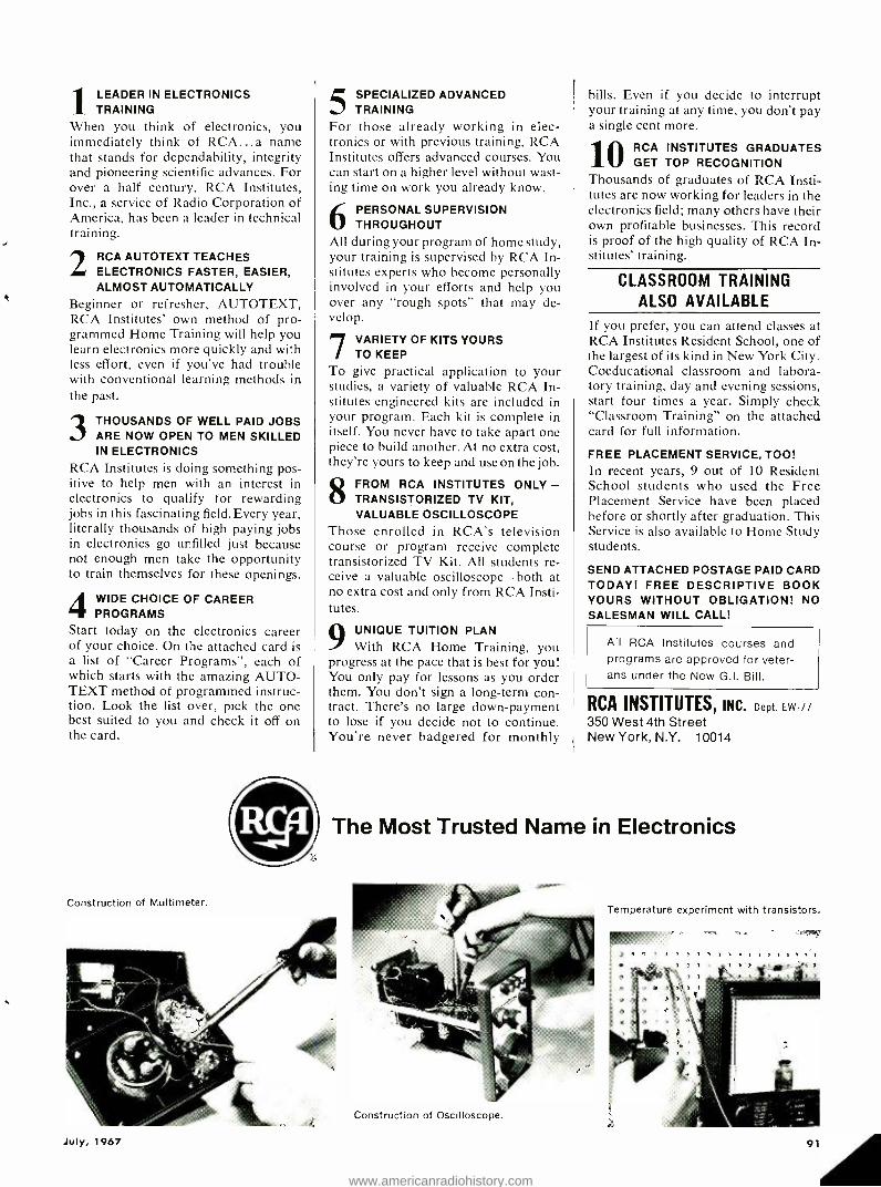
1 LEADER IN ELECTRONICS TRAINING
When you think of electronics, you immediately think of RCA ...a name that stands for dependability, integrity and pioneering scientific advances. For over a half century, RCA Institutes, Inc., a service of Radio Corporation of America, has been a leader in technical training.
2 RCA AUTOTEXT TEACHES ELECTRONICS FASTER, EASIER, ALMOST AUTOMATICALLY
Beginner or refresher, AUTOTEXT, RCA Institutes' own method of pro- grammed Home Training will help you learn electronics more quickly and with less effort, even if you've had trouble with conventional learning methods in the past.
3 THOUSANDS OF WELL PAID JOBS ARE NOW OPEN TO MEN SKILLED IN ELECTRONICS
RCA Institutes is doing something pos- itive to help men with an interest in electronics to qualify for rewarding jobs in this fascinating field. Every year, literally thousands of high paying jobs in electronics go unfilled just because not enough men take the opportunity to train themselves for these openings.
4 WIDE CHOICE OF CAREER PROGRAMS
Start today on the electronics career of your choice. On the attached card is a list of "Career Programs ", each of which starts with the amazing AUTO - TEXT method of programmed instruc- tion. Look the list over, pick the one best suited to you and check it off on the card.
Construction of Multimeter.
5 SPECIALIZED ADVANCED TRAINING
For those already working in elec- tronics or with previous training, RCA Institutes offers advanced courses. You can start on a higher level without wast- ing time on work you already know.
6 PERSONAL SUPERVISION THROUGHOUT
All during your program of home study, your training is supervised by RCA In- stitutes experts who become personally involved in your efforts and help you over any "rough spots" that may de- velop.
7 VARIETY OF KITS YOURS TO KEEP
To give practical application to your studies, a variety of valuable RCA In- stitutes engineered kits are included in your program. Each kit is complete in itself. You never have to take apart one piece to build another. At no extra cost, they're yours to keep and use on the job.
8 FROM RCA INSTITUTES ONLY - TRANSISTORIZED TV KIT, VALUABLE OSCILLOSCOPE
Those enrolled in RCA's television course or program receive complete transistorized TV Kit. All students re- ceive a valuable oscilloscope -both at no extra cost and only from RCA Insti- tutes.
9 UNIQUE TUITION PLAN With RCA Home Training, you
progress at the pace that is best for you! You only pay for lessons as you order them. You don't sign a long -term con- tract. There's no large down -payment to lose if you decide not to continue. You're never badgered for monthly
bills. Even if you decide to interrupt your training at any time, you don't pay a single cent more.
10 RCA INSTITUTES GRADUATES GET TOP RECOGNITION
Thousands of graduates of RCA Insti- tutes are now working for leaders in the electronics field; many others have their own profitable businesses. This record is proof of the high quality of RCA In- stitutes' training.
CLASSROOM TRAINING ALSO AVAILABLE
If you prefer, you can attend classes at RCA Institutes Resident School, one of the largest of its kind in New York City. Coeducational classroom and labora- tory training, day and evening sessions, start four times a year. Simply check "Classroom Training" on the attached card for full information.
FREE PLACEMENT SERVICE, TOO! In recent years, 9 out of 10 Resident School students who used the Free Placement Service have been placed before or shortly after graduation. This Service is also available to Home Study students.
SEND ATTACHED POSTAGE PAID CARD TODAY! FREE DESCRIPTIVE BOOK YOURS WITHOUT OBLIGATION! NO SALESMAN WILL CALL!
All RCA Institutes courses and programs are approved for veter- ans under the New G.I. Bill.
RCA INSTITUTES, INC. Dept. EW -77
350 West 4th Street New York, N.Y. 10014
The Most Trusted Name in Electronics
Temperature experiment with transistors.
7 , ,
July, 1967
Construction of Oscilloscope.
91
www.americanradiohistory.com
BOOK REVIEWS
ßbrSIC ((gY fix- (pIhU1U1111113
"RCA SILICON POWER CIRCUITS MAN- UAL" compiled and published by RCA Electronic Components and Devices, Harrison, N.J 412 pages. Price $2.00. Soft cover.
Although this new technical manual (SP -50) has been prepared especially for circuit and system designers who work with solid -state power devices, there is much information which will also be of interest to students, hams, and others using semiconductor devices and circuits.
Included is design information on a broad range of power circuits using the firm's silicon transistors, rectifiers, and thyristors ( SCR's and triacs ) . There is an introduction to semiconductor physics as well as descriptions of con- struction, theory of operation, and im- portant ratings and parameters for each type of device. Specific design criteria and procedures are presented for applications involving rectification and power- supply filtering, power con- version and regulation, a.c. line -voltage controls, r.f. power amplifiers, and con- trol and low -frequency power amplifiers.
The text is lavishly illustrated by line drawings, schematics, and graphs.
* * *
"MODERN CONTROL SYSTEMS" by Rich- ard C. Dorf. Published by Addison - Wesley Publishing Company, Inc., Read- ing, Mass. 01867. 379 pages. Price $12.50.
This textbook has been written for college seniors and others with a com- parable technical background. It covers the analysis and design of feedback con- trol systems in industry and in the lab- oratory, as would be encountered by electrical, mechanical, aeronautical, and chemical engineers.
The text is divided into ten chapters and five appendices. Chapter 1 pro- vides an introduction to control systems and the book then goes on to cover mathematical models of systems, feed- back control system characteristics, the performance of feedback control sys- tems, the stability of linear feedback systems, the root locus method, fre- quency response methods, stability in the frequency domain, time- domain analysis of control systems, and the de- sign and compensation of feedback con- trol systems. The appendices include
Laplace transform pairs, symbols and units, conversion factors, an introduc- tion to matrix algebra, program tran- sition, and an evaluation of the transi- tion matrix of a linear time -invariant system by means of a computational algorithm. References for further study are appended to each chapter.
Since this book is directed to a spe- cific audience who presumably have the prerequisite background, there has been no attempt to "pamper" the reader. Mathematics is used throughout and the author has assumed his readers are fa- miliar with the operations.
* * *
"MICROWAVE SYSTEMS PLANNING" by K.L. Dumas & L.G. Sands. Published by Hayden Book Company, Inc., New York. 138 pages. Price $8.00.
The ever -increasing needs of the communications industry - because of the burgeoning requirements of indus- try and business -has stimulated interest in point -to -point FM systems. This book has been prepared for non- technical personnel who must make decisions re- garding the planning, engineering, and installation of microwave equipment used for communications purposes.
The terminology and symbols used are telephone -oriented and, where re- quired, are explained by the authors. The book starts with a discussion of the theoretical aspects -from frequency and wave theory to hardware -then con- tinues to an investigation of the prac- tical aspects of setting up a microwave system.
The text is well illustrated by photos of equipment, line drawings, graphs, nomograms, and charts. Mathematics is used where required but anyone with a knowledge of simple algebra will be able to handle the equations.
* * *
"G -E SCR MANUAL" edited by F.W. Gutzwiller. Published by Semiconduc- tor Products Dept., General Electric Company, Syracuse, N.Y. 496 pages. Price $3.00. Soft cover.
This is the Fourth Edition of what has turned out to be a "bestseller" among G -E manuals, and marks the tenth "anniversary" of the introduction of the SCR in 1957.
Devoted to practical applications, available products, and new circuit de-
velopments rather than theory, the manual has been designed as a useful tool for the electronics designer and practicing technician.
This Fourth Edition includes much new information, new chapters on triacs, regulating circuits and motor controls and specifications on hundreds of new higher -performance thyristors. In addition, there are several chapters devoted to other power semiconductors and light -activated thyristors.
The table of contents is extremely comprehensive -combining as it does an index with the contents -enabling the user to locate the exact material he needs. The text is well illustrated, con- cise, and complete- making this a real bargain for the reference library of any- one interested in electronics.
* * *
"BASIC MATHEMATICS FOR ELECTRON- ICS" by F.L. Juszli, N. Mahler, and J.M. Reid. Published by Prentice -Hall, Inc., Englewood Cliffs, N.J. 439 pages. Price $12.00.
If you have a working knowledge of arithmetic you can use this book to ob- tain the skills you require to work with electric circuit problems. Since no back- ground in electricity is prerequisite, chapters on electrical fundamentals are inserted at key points throughout the text -permitting the user to learn about the behavior of electric circuits at the same time he is studying the related mathematics.
The text can be used in connection with an electrical course at the first - year technical school level or used alone. There are 18 chapters, each with a large number of "exercises" for the students to work. The answers are provided for self -checking. The appendices provide common log tables, natural trigonomet- ric functions, schematic symbols used in circuit diagrams, and electric symbols to make this volume as self -contained as possible.
* * *
"FUNDAMENTALS OF VACUUM -TUBE AMPLIFIERS" condensation of the U.S. Navy Training Manual in the "Funda- mentals of Electronics" series. Published by Techpress, Inc., Brownsburg, Ind. 46112. 303 pages. Price $3.95. Soft cover.
This condensation of a popular Navy manual involves pertinent material on triode amplifiers, tetrode and pentode amplifiers, paraphase amplifier circuits, and audio power amplifiers as well as data on microphones and speakers.
Since the excerpted material is all audio- oriented, this volume will be use- ful to audiophiles and hi -fi enthusiasts as well as students. For instructional purposes there are problems at the end of each chapter which can be used as class assignments. Answers are not pro- vided for the do -it- yourself student, however.
ELECTRONICS WORLD
www.americanradiohistory.com

ELECTRONICS MARKET PLACE
COMMERCIAL RATE: For firms or individuals offering commercial products or services. 70¢ per word (including name and address). Minimum order $7.00. Payment must accompany copy except when ads are placed by accredited advertising agencies. Frequency discount: 5% for 6 months; 10% for 12 months paid in advance. READER RATE: For individuals with a personal item to buy or sell. 40¢ per word (including name and address). No Minimum! Payment must accom- pany copy. GENERAL INFORMATION: First word in all ads set in bold caps at no extra charge. Additional words may be set in bold caps at 10¢ extra per word. All copy subject to publisher's approval. Closing Date: 1st of the 2nd preceding month (for example, March issue closes January 1st). Send order and remittance to: Hal Cymes, ELECTRONICS WORLD, One Park Avenue, New York, New York 10016
FOR SALE
JUST starting in TV service? Write for free 32 page catalog of service order books, invoices, job tickets, phone message books, statements and file systems. Oe!rich Publications, 6556 W. Higgins Rd. Chicago, III. 60656. GOVERNMENT Surplus Receivers, Transmitters, Snooperscopes, Radios, Parts, Picture Catalog 25e. Meshna, Nahant, Mass. 01908.
SUDYMONT acoustic baffles. Plans $5.95; Baffle $26.95; with cabinet from $39.95. Send speaker size. SUDYMONT, 120 Liberty Str., NYC. 10006. JAPAN & Hong Kong Electronics Directory. Prod- ucts, components, supplies. 50 firms -just $1.00. Ippano Kaisha Ltd., Box 6266, Spokane, Wash ington 99207. FREE ELECTRONICS (new and surplus) parts catalog. We repair multimeters. Bigelow Elec- tronics, Bluffton, Ohio 45817.
METERS -Surplus, new, used, panel and port- able. Send for list. Hanchett, Box 5577, River- side, Calif. 92507. INVESTIGATORS, FREE BROCHURE, LATEST SUBMINIATURE ELECTRONIC SURVEILLANCE EQUIPMENT. ACE ELECTRONICS, 11500 -J NW 7TH AVE., MIAMI, FLA. 33168. R.F. CONVERTERS World's largest selection. Also CCTV cameras, etc. Lowest factory prices. Catalog 10e. Vanguard, 196 -23 Jamaica Ave., Hollis, N.Y. 11423. CONVERT any television to sensitive big- screen oscilloscope. Only minor changes required. No electronic experience necessary. Illustrated plans, $2.00. Relco -A22, Box 10563, Houston, Texas 77018.
GET IT from GOODHEART! EVERYTHING UNCONDITIONALLY GUARANTEED!
AMPLIFY & COUNT 10 TIMES FASTER coon: 111 I ,;tl, , r I counter , i with your teli kc` counter. Absolutel , intake -proof 111:1
mtilown. Input , - br v , i,V c.hape, e '
to as U.1 v ' ft-444, iII 80, key to 14 , . Output low sq. \ a t' pk -to -1k at 1 / (11th input fre,1. is
l'o,n¡act AC -I lttoy,00'ored solid -state unit, with i
NEW t. ttitg ,St h ibs. Model 101, BRAND 99.50
BERKELEY 1110 Kl' COUNTER, OK grid... ..195.11Ì VIDAR solid- state. It' Volts 1,,,,1111., 1 kc
p accuracy " ,d , r 395.00 CMC , Berkeley Universal 1 t (ter 495.00 Hewi -Park =5248 Usi,er.nl , Infer to 10 ,I
Svithout :Aught 4higher t,ithl 14i41,ln-i 1 725.00 U5M -26 Howl-Pack Univ. 100 loo comocr 925.00 North. Engrg Counter /,511111
ube ado I,1,, 11.1'11 t l 1725.00 CMC =4008 Printer. II , I,\ "yl .475.00 AutOmichron Natiol,.-,I -St -_ ,lit 1.'4.4-soap-Bean: ire,.
5141 5 parts in 100 billion, s. n,1,,.irc,1 n
-
,u1,n1u1tirle frent... vies 4750.00 Leeds Northrup 5 -O,al special ,I' II sal Ratio
DSet e!theruu I-, p1-1111.1, traosf,r >I.mlr,r,i. SiS- envr OK'd 475.00
L &N .01% S\'h0,0 , (list. :, \0111,,,,, Pattern 711141. I,,.. \ nt:Il 475.00
L &N =7552 K2 Potentiometer 350.00 tekt. =514A0 . some PC-Iii , : tll I
Tekt. =5240 ,t' -I, Inc v /ntatrkers for` V. Tekt. =535 , S:i(' nln:,l -Ira ce pidgin Tekt. rack -mtg ,r545 w t' -:\ dual.trace ... H.P. _185A/187A 1111I11 Ille 2 -trace Polaroid -hack Fairchild 8comi Camera
.350.00
.495.00 825.00
1045.00 1750.00 149.50
. 199.50 550.00
.279.50 450.00
.150.00
.995.00 ..375.00 .265.00 .400.00 395.00
.325.00
.695.00
.395.00 395.00 650.00
.650.00 .1295.00
175.00 .550.00 .995.00 175.00 175.00
STANDARD SIGNAL GENERATORS LP !it i. k, to spi> t. hook Gen. Radio 805-C: II6 100, t, 544 Me Certitid TS -413C /U: 75 ke to 40 t crystal cant: AN URM -250 Or 25F: 10 kIr to 11 : Boonton Univerters: Ill, ke.25 TS -606' U: ,8s -.l, I Si to 1,10 \Vatts 1'n. Meas. Corp. Mod. 80: 2 -4 ,
1erti nip!
Same. uncertified Ilnt ,atisf. 1,rtd. Meas. Corp. Mod. 80R: 5 -177, um. Certified Gen. Radio =1021A Pi 1.2 2 18,111 roc Gen. Radio =1021AV l'I '1':111 111 -25t1 ,ì . .
T5 -648 /U -11.100 II 2 to I, Watts Po. TS -418A ¡U: 40 I- (0Áf1 roc :p to , dlnn Po. TS- 419,U: ,115121,i1 r
I
up t gnarl dl, Po. Hewi -Pack. 616A, 1.8 to 1
PRO -903 or TS -622: 7- 144.::0 ; 'c ¡'Si /r\1 .
Polarad SS -1218: 12.1 to 17.1,_ FM & AM /FM SIGNAL GENERATORS
Kay Radasweep =380A: 211-10 .\ 51s-711,1W FM Boonton 202E W /207E: ,.I -216 nc AIM 'FM USM -16: ASI /r\r'l'\/ 151-410 nu- s-tl calif, .
Kay Megasweep - -111A: 10.950 too r \I PRO =907: n, -null me E \I ALL -BAND SSB RCVR BARGAIN: Hallicrnfters It- 15/
Altlt -7., ss0 kr to 4:i 1 continuous. Voice. l'W, ntCW, aliened. grid. u bnnx: 2.IWF. 2 -I1.'s meter:
it Inca 3 xtl. :i nn vti scicc- 149.50 deli,' choices. Less vnl,-.It
lì11 , -snly: $30. owl-
product ñetector: $20 TIME PAY PLAN: Any Purchase totaling 01
516R.1:( .11' . down payment r nly.. l0 /O `LAB ATTENTION Buyers of Test Equipment: The
above Is 5, 51::111 sampling of our terrific illVrIll or,. We ALSO BUY! want T,ku'onix l:5. . 11 ,.1
k u5, n 1: \-m ul. 115,1 -shop ogj .. ea
Awn vu; , (II: :mean: >.,1 All 11,1..
R. E. GOODHEART CO. INC. Box 1220 -A, Beverly Hills, Calif. 90213
Phones: Area 213. Melee 272.5707. messages 275.5342 CIRCLE NO. 116 ON READER SERVICE CARD July, 1967
DETECTIVES! Free brochures! Electronic Sur- veillance devices. SILMAR ELECTRONICS, 3476 N.W. 7th Street, Miami, Florida 33125. MUSIC LOVERS, CONTINUOUS, UNINTERRUPT- ED BACKGROUND MUSIC FROM YOUR FM RA- DIO, USING NEW INEXPENSIVE ADAPTOR. FREE LITERATURE. ELECTRONICS, 11500 -Z NW 7th AVE. MIAMI, FLORIDA 33168. SURVEILLANCE EQUIPMENT -NEW HIGH PER- FORMANCE SUBMINIATURE MODELS. ELEC TRONIC COUNTERMEASURE DEVICES TO PRO- TECT PRIVACY. FREE DATA: SECURITY ELEC- TRONICS-EW. 15 EAST 43RD STREET, NEW YORK, N.Y. 10017. CRYSTALS . largest selection in United States at lowest prices. 48 Hr. delivery. Thou- sands of frequencies in stock. Types include HC6 /U, HC18 /U, FT -241, FT -243, FT -171, etc. Send 10¢ for catalog with oscillator circuits. Refunded on first order. Jan Crystals, 2400E Crystal Dr., Fort Myers, Fla. 33901. TELEPHONE RECORDER -ACTUATOR (TWI -007). SOLID STATE MODULE AUTOMATICALLY TURNS TAPE RECORDER, AMPLIFIER, INDI- CATOR LIGHT ON WHEN TELEPHONE IN USE. CONNECTED ANYWHERE ON LINE. SIMPLE INSTALLATION INSTRUCTIONS INCLUDED. PREPAID $22.85. SURVEILLANCE RECORDERS: (TWI- 1000), (TWI -1010). TWILIGHT ELECTRON- ICS, BOX 11595 -W, ST. LOUIS, MISSOURI 63105. JAPANESE PRODUCTS CATALOG by air mail $5, sea $3. Intercontinental, CPO 1717, Tokyo, Japan. LABORATORY SIGNAL GENERATOR, Measure- ments Corp 65B, pushbutton, 75Khz- 30Mhz, brand new. Cost $985. Take $475. Also Federal LX1, 240 -330 Mhz, $100. Sound projector, DeVry 16mm, $75. Osborne, Box 1171, Whittier, Calif. 90603. FACSIMILE MACHINES for receiving pictures from APT WEATHER SATELLITES. Late model, like new. VERY low price. NEWSOME, Dept. EW, 2670 Pinetree. Trenton, Michigan 48183. POLICE RADIO. Hear all police calls, fire depart- ments, Sheriffs, taxis, ambulances, Highway Pa- trol. New 5 band portable radio and direction finder. Free Booklet. NovaTech, Dept. 213, Re- dondo Beach, Calif. 90278.
RELAYS -Sigma 80030. Any quantities. ALARM RELAY SUPPLY, 20725 Burbank Blvd., Wood- land Hills, Calif. 91364. ALUMINUM Soldering Handbook -Solder alu- minum with regular 50/50 wire solder, no special fluxes. Complete step by step instructions. Handbook $1.00. Non -ferrous Metals, Box 1024, Project City, Calif. 96079.
SUPREME New 1967 Television Manual avail- able, $4.00. Individual Diagrams, servicing in- formation, Radio $1.00, Television, $1.50. Su- preme Publications, 1760 Balsam, Highland Park, Illinois 60035. TREASURE HUNTERS! Prospectors! Relco's new instruments detect buried gold, silver, coins. Kits, assembled models. Transistorized. Weighs 3 pounds. $19.95 up. Free catalog. Relco -A22, Box 10839, Houston, Texas 77018.
LAMPKIN 105B Frequency Meter. Used 30 hours. Mint condition $150. Fred Radford, 1551 Lahonda Ct, Seaside, Calif. 93955.
JAPANESE Electronics Manufacturers Directory and how to order, $1.00. Buy direct at rock - bottom prices. Hetero, Box 5187, Seattle, Wash- ington 98107.
MESHNA'S TRANSISTORIZED CONVERTER KIT. Converts car radio to receive police and fire. 30 -50MHz and 100- 200MHz. (one MHz Tuning) $5.00 with easy to follow step instructions. Meshna, No. Reading, Mass. 01864. ELECTRONIC PARTS! Components, transistors, diodes, kits, relays, and many special items. Guaranteed. Send 25¢ for 100 page catalog. General Sales Co., P.O. Box 2031, Freeport, Texas 77541.
ELECTRONICS ENGINEERING AND INSTRUCTION
ASSOCIATE Degree in Electronics Engineering earned through combination correspondence - classroom educational program. Free brochure. Grantham Technical Institute, 1505 N. Western Ave., Hollywood. Calif. 90027.
UNUSUAL BARGAINS ... MANY U. S. OOVT SURPLUS GIANT WEATHER BALLOONS
"14:111s of fun for Lids. traffic stopiel's I,: ,tore., ter, Ilic fo,' amateur :mot orologists. Create
ahnornod sensation. Great Lm
4 cklaul Inn. E.e(tlne 1,,,rit at.
tra:W,u. ]lade of heavy duty prend. ::hate with ,..11111111-21,1111.1.
11:11 :fir hose: ,,.:I l ur.: tt. iae hollun, for high tise. _60, 568ÁK 18' diam) S2 Ppd. =60, 632A8 116' chan) 57 Ppd.
FASCINATING MOIRE PATTERN KITS s, n' ',1,l ore Ille , 011,1 l'hotog,' :,4hv'. , F. nt `..t. -
feels. Limitless applications. I .0444's of uses for hui,nyists, photo, ., elle ras hu os irrllnentc rs. run! l'ritlt ,le: Contains basic Pattern, od hour cleat acetate ,,,t 'bite IS I5skit,. 1:,11 ,lot screen on 111,,. hook. ihier
incl. 1,ti,es .I , . , i l a b l e . \ \'rite for details. Stock No. 70,719AK. . 58.50 Ppd.
SAME KIT IN FULL COLOR Stock No. 60,5305K. 512.50 Ppd.
NEW SURPLUS NI -CD BATTERIES c 111:111 111:111 311 Long life-
accept p,
char,v .,I disoh 'vics. 1.25 Volts per cell- 7511 illi.,:per hou capacity. apacity. Excel.
4411,55g44 4,tention. Ile, metically Inde Unite sl:,':lee life.
\ 1 ur0l:,
lhli,I', . , CHI. , line to - Ilia. l,a 10't14. Spec 11 . price for 1,11 11.
1,4,s-cost charger sep arate. -
Order = Cells DC Volt. Price Ppd. 40.986AK 1 1.25 5 1.50 40,9875K 2 2.50 2.75 60.633AK 3 3.75 3.60 60.6344K 4 5.00 4.80 70.812AK Trickle Charger 11.10 cells) 10.95
Edmund Scientific Co., Barrington, N.J. 08007
MAIL COUPON for FREE CATALOG SEND FOR FREE CATALOG "AK Completely new 1067 edition. New Items. oede gol'ies, illustrations. 148 -:tsv- to -read pages packed with nearly J41ì,
.\stsal items. Enormous selection of tonon,iral Telescopes. Microscope- Binoculars, Magnifiers, Magnets, Len, s. PIts, :.s. Many ,vat' surplus Items: for hobbyists. experimenters, wtokshoo. factory. Write for Catalog. "AK. L.I. :Lund Scientific Co., tiorriniDon. Ni .. 4ersry 080117.
EDMUND.
NAME
ADDRESS
C1T1'
CIRCLE NO. 120 ON READER SERVICE CARD 93
www.americanradiohistory.com
GREGORY ELECTRONICS Reconditioned & Used FM 2 -WAY RADIO SAVINGS
Partial list -Send for New '67 Catalog
- ' ' !
Voice Commander 132 to 172 MC, 1W 9.5" x 5.3" x 1.7" Lowest price ever, including brand New
ramweue - Rechargeable Nickel Cad- mium Battery Pack
$148 If crystal & tuning is de-
sired add $45.00 Battery charger for these units $16.00 Write for Quantity Prices
VOICE COMMANDER Monitor Receiver only- $78 Tuned & Crystalled with dry Batteries
RCA CMV1D- 150 -170 mc. Wide Band, makes excellent monitor receiver, np complete accessories Lv MOTOROLA P33 Serles Pack Set 5 Watt 150- 170 MC with Nicad Supply and Nicad Batteries MOTOROLA T41GGV 30 -50mc 6/12 V, 30 watt vibrator power supply fully narrow banded complete with accessories $17) O less crystals and antenna lav Add $45.00 for tuning to desired frequency and new antenna MOTOROLA 30 -50mc 6/12 V, T51GGV vibrator power supply. $(1Q Fully narrow banded (TX & RX) ea97Yv
Above price include accessories less crystals and an- tenna (less accessories, deduct $30.00) To tune unit to desired frequency including new antenna add $45.00
GE 2 -Piece unit -6 volt or 12 volt 4ER6- 4ET5, 30w 30 -40, mc. -40 -50 mc. Wide Band 548 Fully narrow band (TX -f-RX) $68 Complete Accessories 4ER6 -4ET6, 60w 30 -40 mc-40-50 mc Wide Band 668 Fully Narrow Band $88 Complete Accessories
Add $45.00 for tuning and crystals to desired frequency, including new antenna.
RCA -CMCT 30 148-172 mc. transistorized power supply fully narrow banded $1f10 complete with accessories Iaa77UU
Add $40.00 for crystals and tuning and new antenna.
G.E. PACERS- EG43SA6 150 -170 mc Transis- torized Power Supply 13 -15 watts, 12 v Front Mount (Complete ac- cessories, less crystals and an- tenna) $10 81°
We Buy
-- azz.EGORY
C sa-- 249
Late Model Equipment for Cash -Write: Wire or Phone!
.. GREGORY ELECTRONICS
,-e... CORPORATION RT. 46, Saddle Brook, N.J., 07662
Phone: (201) 489 -8000
CIRCLE NO. 115 ON READER SERVICE CARD
ELECTRONICS! Associate degree -29 months. Technicians, field engineers, specialists in corn - munications, missiles, computers, radar, auto- mation. Start September, February. Valparaiso Technical Institute, Dept. N, Valparaiso, Indiana 46383. LEARN ELECTRONIC ORGAN SERVICING at home. All Makes including transistors. Experi- mental kit -troubleshooting. Accredited NHSC. Free Booklet. NILES BRYANT SCHOOL, 3631 Stockton, Dept. A, Sacramento, Calif. 95820. HIGHLY effective home study course in Elec- tronics Engineering Mathematics with circuit applications. Earn your Associate in Science Degree. Free literature. COOK'S INSTITUTE OF ELECTRONICS ENGINEERING, P.O. Box 36185, Houston, Texas 77036. REI First Class Radio Telephone License in (5) weeks Guaranteed. Tuition $295.00. Job place- ment free. (KANSAS CITY) R.E.I., 3123 Gillham Road, Kansas City, Missouri, Telephone WE1- 5444. (SARASOTA) R.E.I., 1336 Main Street, Thrasota, Florida 33577, Telephone 955 -6922.
HIGHLY- effective home study review for FCC commercial phone exams. Free literature! COOK'S SCHOOL OF ELECTRONICS, P.O. Box 36185, Houston, Texas 77036. WANTED! TV- Radiomen to learn aircraft elec- tronics servicing. Numerous job openings ev- erywhere. Write: ACADEMY AVIONICS, Reno/ Stead Airport, Reno, Nevada 89500. FCC LICENSE training by correspondence. Low cost, pay -as- you -go plan. Free particulars. The Willard Foundation, Department EW, P.O. Box 1049, Washington, N.C. 27889. FCC First Class License in six weeks -nation's highest success rate -approved for Veterans Training. Write Elkins Institute, 2603C Inwood Road, Dallas, Texas 75235.
HYPNOTISM
FREE Hypnotism, Self- Hypnosis, Sleep Learning. Catalog! Drawer H400, Ruidoso, N.M. 88345.
PHOTOGRAPHY -FILM, EQUIPMENT, SERVICES
MEDICAL FILM -Adults only -"Childbirth" one reel, 8mm $7.50; 16mm $14.95. International W. Greenvale, Long Island, New York 11548. SCIENCE Bargains- Request Free Giant Catalog "CJ" -148 pages -Astronomical Telescopes, Mi- croscopes, Lenses, Binoculars, Kits, Parts, War Surplus bargains. Edmund Scientific Co., Bar- rington, New Jersey 08007.
WANTED
QUICKSILVER. Platinum, Silver, Gold. Ores An- alyzed. Free Circular. Mercury Terminal. Nor- wood, Mass- 02062. QUICK CASH . for Electronic Tubes, Semi- conductors, Equipment (Receivers, Transmit- ters, Scopes, Vacuum Variables, etc.) Send lists now! Write: BARRY ELECTRONICS, 512 Broad- way, New York, N.Y. 10012 (212 -WA 5-7000). WANTED TO BUY -TV tuners. Any make, any quantity. Write. J. W. Electronics, Box 51B, Bloomington, Indiana 47401.
U.S. GOV'T ELECTRONIC SURPLUS
Nationally Known -World Famous SURPLUS CENTER offers finest, most expensive, Government Surplus electronic units and components at a fraction el their original acquisition Best.
ORDER DIRECT FROM AD er WRITE FOR CATALOGS
STANDARD DIAL TELEPHONE ITEM Wyly) - - Standard. commercial ' .S( >R ;
telephone same as used throu Wmi c.S.:t. Atir \. °T3.t toe polished mark, Tike new condition. Use s
ph", private systems n rt 1 II are fun i. h I vt.
connect extension I ph together Or local I t ' n'
$5.95 Original im
F.O.B.
STEP -BY -STEP AUTOMATIC SWITCH t ITEM b131 I Amazing "up -and d',
electro.magnetic telephone swit h Dial an, hank pair from I to ton Make telephone ',stem
also he to remotely control up i 100 cir- cuits u
One id Nir 1 01 It Site ba^ains toms piele sill, dale dial and one line hank` Sze, 'a 15 ". al 16 Ms. lust l.py'1 tier $75.00.
á, 11;. 1.,'r ms F.D.B.$9.95
E
1a t( ". ill.
IFIP CO TYPICAL BUYS FROM OUR 1967 CATALOGS S 350.00- Geared 2 -lip Battery Golf Car Motor $24.95 S 15.00 - Westinghouse DC Ammeter, O to 300 S 7.11
S 40.00 - Vacuum Pressure Pump, 12 -VDC $11.95 - - - - 00 -MW Walkie- Talkies, Per Pair $19.60 . - - - Deluxe, Multi- Range, AC DC Tester S 8.98
54000,00 - Carrier Telephone Amplifier System $13.91
SPECIAL SALE ` -
Correspondence iiiJIJi Course ELECTRICAL I
ENGINEERING sets For 610.74 $8.19 voslpaid® Outside c.S. v, t7 ht l'.S.A.
( ITEM : :I01 ) -- Wonderful chance Iu obtain technical in at t.,,ng Lux cost. Lincoln Engineering School has .suspended Its l+norresp.mdenee courses because 01 i sod operating offer 'a limited number of the school's complete Electrical Engineering Course but without 0,n examination paper grading scoter.. The consists of IS lesson unit books. Each book has Ne regular exams. In a separate section, "Standard Answers" to each exam question.
well written, easy to understand. profusely illustrated. Reader's higes, s to cans and study in spare lime. coln Engineering school students holding excellent labs as a L.E.S. u i latest information on transistors. icon diodes. etc :Sdd lioneltabook on how to build and operate Lalmrain,, and Experimental Bench" fumished with each course.
_
train-
coats. We
course and
Many Lin- result of
sil- a "Home
SEND 25c COIN OR STAMPS FOR 3 MAIN CATALOGS
4 All Items FOB Lincoln Money Back Guarantee
SURPLUS CENTER DEPT. EW -077 LINCOLN, NEER. 60501
CIRCLE NO. 98 ON READER SERVICE CARD
CLASSIFIED ADVERTISING ORDER FORM Please refer to heading on first page of this section for complete data concerning terms, I
frequency discounts, closing dates, etc.
1 2 3
6 7 8
11 12 13
16 17 18
21 22 23
26 27 28
31 32 33
4 5
9 10
14 15
19 20
24 25
29 30
34 35
Words (@ .40 Reader Rate - ( @ .70 Commercial Rate )
Insert time(s) Total Enclosed $
NAME
ADDRESS
CITY STATE 71P
SIGNATURE WORD COUNT: Include name and address. Name of city (Des Moines) or of state (New York) counts as one word each. Zip Code numbers not counted. (Publisher reserves right to omit Zip Code if space does not permit.) Count each abbreviation, initial, single figure or group of figures or letters as a word. Symbols such as 35mm, COD, PO, AC, etc., count as one word. Hyphenated words count as two words. EW -767
L..
ELECTRONICS WORLD
www.americanradiohistory.com
DO- IT- YOURSELF
PROFESSIONAL ELECTRONICS PROJECTS - $1.00 up. Catalog 25¢. PARKS, Box 25565B, Seattle, Wash. 98125.
HIGH FIDELITY
FREE! Send for money saving stereo catalog #E7W and lowest quotations on your indi- vidual component, tape recorder or system re- quirements. Electronic Values Inc., 200 West 20th Street, N.Y., N.Y. 10011.
HI -FI Components, Tape Recorders at guaran- teed "We Will Not Be Undersold" prices. 15- day money -back guarantee. Two -year warranty. No Catalog. Quotations Free. Hi- Fidelity Cen- ter, 239 (L) East 149th Street, New York 10451.
HIFI EQUIPMENT -GET Our "ROCK BOTTOM" prices on NAME BRAND amplifiers- tuners- tape -recorders - speakers FRANCHISED - 59 YEARS IN BUSINESS. Write for this month's specials -NOW! Rabson's 57th St., Inc., Dept. 569, 119 W. 58th St., New York, New York 10019.
LOW, LOW quotes: all components and re- corders. Hi -Fi, Roslyn, Penna. 19001.
HI -FI components, tape recorders, sleep learn equipment, tapes. Unusual Values. Free cat- alog. Dressner, 1523 R Jericho Turnpike, New Hyde Park. N.Y. 11040.
EVERYONE can afford HIGH -FIDELITY compo- nents- because of our DISCOUNT policy. In- sured guaranteed shipments -Factory sealed cartons -FRANCHISED. Send for our LOW -LOW quote today. Sound and Sight Audio, Inc., 106 West 32 Street, New York, N.Y. 10001.
EMPLOYMENT INFORMATION
FOREIGN and USA job opportunities available now. Construction, all trades. Earnings to $2,- 000.00 monthly. Paid overtime, travel, bonuses. Write: Universal Employment, Woodbridge, Con- necticut 06525.
YOUR RÉSUMÉ -Make it sell you! Instructions, samples: $2. Executive, Box 246EL, Montclair, N.J. 07042. FOREIGN EMPLOYMENT. Construction, other work projects. Good paying overseas jobs with extras, travel expenses. Write only: Foreign Service Bureau, Dept. D, Bradenton Beach, Florida 33510.
TAPE & RECORDERS
RENT STEREO -8 CAR TAPES. 10¢ /day. Send refundable $10.00 deposit and name of first selection. Autotapes, Box 19086 -E, Indianapolis, Ind. 46219. BEFORE renting Stereo Tapes, try us. Postpaid both ways -no deposit- immediate delivery. Quality- Dependability- Service- Satisfaction- prevail here. If you've been dissatisfied in the past, your initial order will prove this is no idle boast. Free Catalog. Gold Coast Tape Library, Box 2262, Palm Village Station, Hialeah, Fla. 33012. STEREO TAPES. Save up to 60% (no member- ship fees, postpaid anywhere USA). Free 60- page catalog. We discount batteries, recorders, tape accessories. Beware of slogans "not un- dersold," as the discount information you sup- ply our competitor is usually reported to the factory. SAXITONE, 1776 Columbia Rd., Wash- ington, D. C. 20009.
RENT Stereo Tapes -over 2,500 Different -all major labels -free brochure. Stereo -Parti, 1616 -E. W. Terrace Way, Santa Rosa, California 95404.
TAPE RECORDER SALE. Brand new, nationally advertised brands, $10.00 above cost. Arkay Sales, 1028 -B Commonwealth Avenue, Boston, Mass. 02215.
HI -FI _Components, Tape Recorders at guaran- teed "We Will Not Be Undersold" prices. 15- day money -back guarantee. Two -year warranty. No Catalog. Quotations Free. Hi- Fidelity Cen- ter, 239 (LT) East 149th Street, New York 10451.
RENT STEREO TAPES -75¢ week. Catalog. Art's, 1442 Blaze, Simi, Calif.
OUR TRANSISTORS & RECTIFIERS ARE GUARANTEED TO
WORK
All transistors are checked for voltage & gain to insure our customers a good transis- tor within the category we advertise. All rectifiers cost- ing over $.10 are checked for forward voltage and leakage as well as PRV. The gates on our SCR's are also checked. All nonoperable units will be refunded or exchanged im- mediately. We will stand on our reputation for quality products and service.
Users of the above men- tioned items in large quan- tities send us your specifica- tions. We feel we can meet them at a competitive price.
GLASS DIODES color coded.
Silicon 20/$1.00 6E 30/$1.00
n 10 WATT ZENERS. 2 -180v. State desired voltages. Ea. $.75
1-7 SILICON BILATERAL SWITCH. Replaces two SCR's by firing in
either direction when breakdown voltage is exceeded. Used in light dimmers, etc. ..75 ea.
ß-V-w7 O T A L A L 1 T E D E
"N" Channel Feto Similar To
2N3088 Used As Amp, Switch, Chopper -Very High Input Z $1.50 Each
n SIM. to 2N728. A high fre- quency TO -18 unit extending to
the UHF range 3/$1.00
SIM. to 2N2875 (PNP). Silicon 20 watts with 30 MHz cut off
$.75
n High voltage NPN 150V. VBCBO at 2.5A., High HFE in TO -66
pack $.75
r7 High voltage assemblies 6000v. at 150 mils. These silicon as-
semblies may be put in series to achieve high voltages $1.50
Silicon Power Rectifiers PRV 3A 120A I 40A
1
240A _ 100 .10 1 .40 1.00 s. 00 200 I .20 I .60 1.50 I 7.50 400 I .25 .80 I 2.00 15.00 600 .35 I 1.20 I 2.50 1 20.00 800 1 .45 I 1.50
1 3.00
1000 1
.65 I 4.00
1
35.00
Terms: FOB Cambridge, Mass.
Send check or Money Order. Include Postage, Average Wt. per package 3/2 lb. Allow for C.O.D. Minimum Order $3.00
POST OFFICE BOX 74B
SOMERVILLE, MASS. 02143 featuring transistors, rectifiers and
components SEND FOR OUR LATEST CATALOG
INTEGRATED CIRCUITS
SR Clocked Flip Flops $1.15 SRT Flip Flops $1.15 Expandable OR Gates $1.00 1K Flip Flops $1.15 Dual Nand Nor Gates $1.00 TO -85 flat pack guaranteed to work. They come complete with schematic, elect. characteristic sheet & some typical applications. $9.00 -$15.00 values from original manufacturer.
1.25 AMP (GLASS AMPS)
A controlled a lanche rectifier in which the rated PRV may be c ceeded without the ectifier breaking down.
PRV 100 I .12 200 I .15 400
I .20 600 1 .25 800
1 .35 1600 1.00
1000 1 .50 1800 1.20
Top Hat A Epoxy 750 MA PRV 100 .07 200 400 600 800 1000 1200 1400
.09
.12
.20
.25
.50
.65
.85
Silicon Control Rectifier #7A Silicon Control Reeti tiers
PRV so
100 iò0
3A I
7A
300 400 500 600 700
1000
.35
.50
.75 1.2S 1.50 1.75 2.00 2.25
.50
.70 1.05 1.60 2.10 2.80 3.00 3.50 5.00
20A .80
1.35 1.90 2.45 2.85 3.50
World's "BEST BUYS" in GOV'T. SURPLUS
Electronic Equipment
NAVY MARIDE WALKIE TALKIE NAVY Marine Band WALKIE- TALKIE TRANSMITTER & RECEIVER -This equip- ment is crystal controlled and can be operated on any one channel in the fre- quency range of 2.3 to 4.5 MC. Voice (A3) communication only, output of trans- is 0.2 watts and satisfactory com- munication between units over average terrain should be able to be maintained up to approx. one (1) mile. With tubes: 1/155, 1 /1R5, 2/174, 3/354. Voltages required 67.5 VDC 3 MA; 135 VDC 4 MA; 1.5 VDC 225 MA for Rec. -67.5 VDC 1.5 MA; 135 VDC 19 MA; 1.5 VDC 225 MA; & -6 VDC 30 MA for Trans. Unit comes in a waterproof plastic case with space for batt. or power supply. Telescoping antenna 8 ft. has special loading coil. Complete with tubes, antenna, 2 crystals FT 243 (no choice of freq.), headphones, carbon mi- crophone, canvas cover, & manual. Size: 8 x $A 8 x 2 /z "; Wt.: 8 lbs. 7 9 7J 5 NAVY WALKIE- TALKIE DIRECTION FINDER MODEL "DAV" -Same as "MAB" except has a direction finding loop circuit for homing, and comes in a waterproof ply- wood case with web straps for carrying on back or chest. Also complete with tubes, 2 crystals (no choice of freq.) headphones, lip microphone, 8 ft. telescoping antenna. & manual. Size: 14 x 10 x 3 "; $12.95 Wt.: 11 lbs. VIBRATOR POWER SUPPLY- Designed for use with "MAB" & "DAV" described above. Operates from 6 VDC storage battery N -T -6, that fits on bottom of P. S. pack, 6 V 4 A (Can be operated from any 6 VDC 4 A source) supplies 1.5 VDC .3 A; -6 VDC .02 A; 67.5 VDC .005 A; 135 VDC .02 A. Size: $6.95 6r /Z x 33/4 x 13/4"; Wt.: 2 lbs. NEW N -T -6 PLASTIC STORAGE BATTERY For above Power Sup- ply CRF -20221 A- Supplies 6 volts DC 4 Amp. Size: 31/2 x 2'/ x 2 "; Wt.: 2 lbs. Dry charge battery $3.95
NEW CATALOG- JUST OFF PRESS -SEND 25¢ (stamps or coin) and receive 504 CREDIT on your order! Address Dept. EW Prices F.O.B. Lima, O.
25% Deposit on C.O.D.'s
FAIR RADIO SALES 1016 E. EUREKA Box 1105 LIMA, OHIO 45802
GOVERNMENT SURPLUS
JEEPS Typically From $53.90. . . Trucks From $78.40. . . Boats, Typewriters, Airplanes, Elec- tronics Equipment, Photographic Equipment, used. 100,000 Bargains Direct From Govern- ment. Complete Sales Directory and Surplus Catalog $1.00 (Deductible First $10.00 Order). Surplus Service, Box 820 -K, Holland, Michigan 49423.
PRINTING
FREE Booklet- "Secrets of Cutting Printing Cost ", Dept. 1, 305 S. 4th, Springfield, Illinois 62701.
EMPLOYMENT OPPORTUNITIES
WANTED: Full time sales representative needed to sell a quality line of nationally known two - way radio equipment in the North Central and Mid -Western areas of the country. Salary, com- mission, plus expenses; liberal company bene- fits. Ideal opportunity for Ham or CB'er with a knack for selling. Must be willing to travel. REPLY: Mr. Warren Whittel, P. O. Box 536, Baltimore, Md. 21203.
EDUCATIONAL OPPORTUNITIES
LEARN While Asleep, hypnotize with your re- corder, phonograph. Astonishing details, sensa- tional catalog free! Sleep- Learning Association, Box 24 -ZD, Olympia, Washington 98501. USED Correspondence Courses and Books sold and rented. Money back guarantee. Catalog free. (Courses Bought). Lee Mountain, Pisgah, Alabama 35765. LEARN WHILE ASLEEP. Miraculously build Mind Power, achieve Self Confidence, improve Health, gain Success. Method 92% effective. Details free. ASR Foundation. Box 7021EG Henry Clay Station, Lexington, Kentucky 40502.
CIRCLE NO. 101 ON READER SERVICE CARD July, 1967 95
www.americanradiohistory.com

G &G CATALOG! N
24 Pal - the BEST in Military Electronic Gear. SEND NOW FOR YOUR COPY!
include 25( RIvndd with !irct ord.r
FAMOUS BC-645 TRANSCEIVER 15 Tubes 435 to 500 MC Easily adapted for 2
tt ay '4IFr
. communication, voice Or V code, on ham band 420 -450 Me. citizens radio 460 -470 , -,
fixed and mobile 450 - 46 e. 0 television expert- ' mental 4611 00 NOW
slip- BRAND With tubes,) less power p .
ply In factory carton. Ship- NEW ping weight 25 lbs. $16.05 OUR LOW PRICE 0ynatnntor, Antenna. flues, All Accessories .1vail:tble
LORAN APN -4 FINE QUALITY
-s:á ? NAVIGATIONAL EQUIPMENT 4-Channel long range dual units, will determine exact geographic position of your boat or plane. Indicator
,nd receiver complete with all tubes and crystal.
INDICATOR ID -6B /APN -4, and RECEIVER $88,50 R -9B /APN -4, complete with tubes, Exc. Used
LORAN
-I.Channet single ships and aircraft. by radio signals complete
to mpNte 'Ith
tati. IN LIKE All Accessories
R -65 /APN -9 RECEIVER & INDICATOR unit system, used In
Determines position from known . titters.
within 1.d distance. tubes and twos. e,s0 50
NEW Condition. 400 for Loran Equipment In stock.
AN /APR -4Y FM & AM RECEIVER "FB" FOR SATELLITE TRACKING!
lilgh precision lab instrument, for monitoring and
t ring frequency and relative signal strength, 38
to n111ó Mc, In 5 tuning ranges, For 110 V 60 cycle AC. Built -In power supply. Original circuit diagram Included. Checked out, perfect, LIKE NEW All Available
SCR-274 -N, ARC -5 COMMAND SET HQ! Freq. Exc. BRAND Range Type Used NEW RuCEIVER5, Complete with Tubes 190.550 KC BC-453 ...518.95 $23.50 3 -b Mc BC -454 ...$16.50 $21.50 0.9.1 Mc. BC -455 ...$14.95 $19.95 1.5 -3 Mc.. .. .. .. R25 ... - $21.50 TRANSMITTERS, Complete with TubeS 4-5.3 MC BC -457 .. .$ 6.95 511.95 5.3.7 Mc BC -458 .. .S 6.95 $12.95 7.9.1 Mc BC -459 ...517.95 $22.50 24 -3 MC T -18 .. - $10.95 3 -4 MC T -19 ..$10.50 $14.95 MODULATOR, Complete with 3 Tubes Voice BC -456 ..S 2.75 5 4.95 All Command Set Accessories in Stock
SCR -625 MINE DETECTOR $32.50 EE8 FIELD PHONES, Exc. Used, Each $16.95 BC -221 Freq. Meter, Modulated, Exc. Used..$129.50 BC -221 Freq. Meter. Unmodulated, Exc. Used $79.50 LM Freq. Meter, Exc. Used $79.50 BC1206.0 Beacon Recur, 200-400 Kc. NEW $12.95 SCR -522 Transmitter -Receiver, Like New 539.50
TG -34A CODE KEYER $24,50 ,,,...,,I New In original carton Exc. Used 518.95 Practise -Tapes at:, ilable, with Keyer P U R
EE -8 FIELD PHONES Clu-cked out, perfect working order. Complete with all parts. Excellent Condition. LIKE NEW: $16.5 Each DYNAMIC MIKE, Low Impedance, switch, rubber cov- ered cable with plug, New $2.65
Please include 25% Deposit with order -Bal- ance C.O.D., or Remittance in Full- 500 Han- dling Charges on all orders under $5.00. All shipments F.O.B. Our Warehouse, N.Y.C. All Merchandise subject to Prior Sale and Price Change.
G & G RADIO SUPPLY COMPANY Telephone: (212) CO 7 -4605
75 -77 Leonard St., New York, N.Y. 10013
AUTHORS' SERVICES
AUTHORS! Learn how to have your book pub- lished, promoted, distributed. FREE booklet "ZD," Vantage, 120 West 31 St., New York 10001. POEMS WANTED for new song hits and record- ings by America's most popular studio. Tin Pan Alley, 1650 -ZD Broadway, New York 10019.
BUSINESS OPPORTUNITIES
INVESTIGATE ACCIDENTS: Earn up to $1,000 and more a month in your own business. Work spare time with average earnings of $5 to $8 per hour. No selling. Send for FREE booklet. No obligation. No salesman will call. Write: Uni- versal Schools, CZ -7, 6801 Hillcrest, Dallas, Texas 75205. FREE BOOK "990 Successful, Little -Known Busi- nesses." Work home! Plymouth -145G, Brooklyn, New York 11218.
96
I MADE $40,000.00 YEAR by mailorder! Helped others make money! Start with $10.00 -Free proof. Torrey, Box 318 -N, Ypsilanti, Michigan 48197. FREE CATALOGS. Repair air conditioning, re- frigeration. Tools, supplies, full instructions. Doolin, 2016 Canton, Dallas, Texas 75201. MAKE up to $10,000 a year raising chinchillas, mink, rabbits or guinea pigs for us. We supply breeding stock, equipment and feed. Send $1.00 for catalog and complete information. Keeney Brothers Farms, Dept. ZE, New Freedom, Pa. 17349.
INVENTIONS WANTED
INVENTORS. We will develop, help sell your idea or invention, patented or unpatented. Our national manufacturer clients are urgently seeking new items for outright cash sale or royalties. Financial assistance available. 10 years proven performance. For free informa- tion, write Dept. 42, Wall Street Invention Bro- kerage, 79 Wall Street, New York, N.Y. 10005.
PATENT SEARCHES, $6.00! FREE "Invention Record" /Information. Miss Hayward. 1029HE Vermont, District of Columbia 20005. INVENTIONS -IDEAS developed: Cash /Royalty Sales. Member: United States Chamber Corn - merce. Raymond Lee, 130 -GE West 42nd, New York City 10036.
INVENTIONS wanted! Highest cash or royalties. Financial assistance. Free analysis. International Invention Institute. Dept. 31, 160 Broadway, New York, New York 10038. INVENTORS! Get your "Little Piggy" to market. Highest cash or royalties. New York Invention Service, Dept. 13, 160 Broadway, New York, N.Y. 10038.
RUBBER STAMPS
RUBBER ADDRESS STAMP $1.50. SIGNATURE $2.88. FREE CATALOG. JACKSON PRODUCTS, 1433 WINNEMAC, CHICAGO, ILL. 60640.
RECTIFIERS, TRANSISTORS & COMPONENTS
6 tube Amplifier, New 4 lbs. 2/$1.98 1/4 Watt Resistors, asstd. 50 /1.00 1/2 Watt Resistors, asstd. 60/1.00 2N4138 Sil. Chopper To -46 NPN 1.50 Precision Resistors, asstd. 50/1.00 Pots, 2 -4 Watt, asstd. 15 /1.00 2N1724 Sil. Pow. 50 W. 80 V. St. 60/1.50 2N1047B Sil. Pow. 80V. To -57 __ .60 Tantalum Capacitors, asstd. 10 /1.00 2N1722 Sil. Pow. 50W. 80V. To -53 1.45 2N2944 Sil. Chopper To -46 1.00 50W. Zeners 10 to 19 Volts 1.00 Thermistor bead, or 1200 ohm. 2/1.00 2N1021, Ger. Power, lamp, 100V., To -3 .60 2N456A, 7A. 40V. Ger. Power To -3 .45 2N1718, Sil. Power, 10W., 60V., Heatsink 3/1.00 70 amp Stud. 50PIV- $2.50; 100PV $3.50
SILICON CONTROLLED RECTIFIERS AMPS. 3001111V. 4009119. 50111'11V.
7A. 1.50 2.05 2.75 11iÁ. 2.15 2.65 3.25 Pots, 1W. 100K, or 1 /,W. 500K, 5/1.00 Surprise Kit, 10 lbs. components ..... 2.50 Epoxy Hi -Vol diode, 200ma, 3000PIV . .98 Computer Board, TO -3 Power, Heat Sink 1.505 I.C., TO -5, untested 5 /100 I.C., Dual- inline, untested 10 /1.00 2N389,85W 60 V. T053 .79 2N3707.11 Asstd. Plastic Silicon Xisters . _ 20/1.00 2N3704 -3706, Asstd. Plastic Sil. Xisters 10/1.00 2N2151, Sil. Power Xister . .65 2N1009 Ger. Min. Xister untested 30/1.00 3N35 Tetrode, NPN, untested 5 /1.00 Ger. Diodes, Asstd. 15/100 2N458A, 7A. 80V. Ger. Power, TO -3 .. .55 Sil. Diodes, Switching, Signal, Asst. 15/1.00 2N118, Silicon, NPN 10 /1.00 2N1149, Silicon, NPN, untested . 20/1.00 2N1300, Untest. PNP & NPN, 1/a" leads 25/1.00 2N1714, Silicon Power 10W, 60V . 4/1.00 Computer Boards, Parts Free, per transistor .05 Germanium Power, 2N457A, 7A; 60V . .50 Silicon Power 40 W, 2N1047, TO -57 2/1.00 Tophats 750 ma., 200PIV -8f, 400, 12f 600 Ply .18 1N34A 100/2.98 Varicops, 27, 47, or 100 pf _ ._ _ ._ 1.25 2NI038, Germanium 20 W. 40 V 4/1.00 With any $10.00 Order any $1.00 item Free, On $25.00 order any (3) $1.00 items Free. Catalog.
Minimum order $3.00 plus postage, C.O.D: s 25%
ELECTRONIC COMPONENTS Post Office Box 2902 Baton Rouge, Louisiana 10821
CIRCLE NO. 119 ON READER SERVICE CARD
the only comprehensive guide to consumer electronics servicing! If you're in consumer electronics servic- ing, you know that keeping up with this jet -paced field is no pushover. There are manuals to be bought. Journals to be read. Experiments to be tried. Techniques to be learned. Day in, day out. No doubt about it, staying on- the -ball in electronics takes time, effort and money. Or at least it used to.
Now there's a much easier way.
ELECTRONICS INSTALLATION
SERVICING HANDBOOK -1967
M.
THE 1967 ELECTRONICS INSTALLATION
& SERVICING HANDBOOK A single, comprehensive guide to every major phase of consumer electronics servicing. Over 132 pages of all the latest electronics information you want and need to know. From TV to CB to PA to AM /FM. From home intercoms to auto stereo tape cartridge units. Eight complete, authorita- tive chapters in all! This handy, on- the -bench reference vol- ume will lead you straight to the facts you need, when you need them presented in a crisp, concise manner that's easily under- stood by the novice, yet thorough enough to answer the professional's most complex question. Whether you earn your living by servicing ... supplement your salary by servicing
part -time ... or are an active hobbyist who services just for the fun of it .. .
the 1967 ELEC- TRONICS INSTAL- LATION & SERVIC- ING HANDBOOK is one "tool of the trade" you can't afford not to have.
ORDER YOUR COPY TODAY!
Get the Handsome Leather - flex-C d Edition for ;3 Postpaid! The 1967 ELECTRONICS INSTALLATION & SERV- ICING HANDBOOK is also available in a splendid deluxe edition. Rugged Leatherflex cover provides lasting protection yet is softly textured and gold -
embossed for the look of elegance. A collector's item -a superb addition to your electronics library. And it's yours, for just $3 postpaid, when you check the appropriate box on the order form. ONLY $1.25
aE
Ziff -Davis Service Division, Dept. ISH 595 Broadway, New York, N. Y. 10012
Please send my copy of the 1967 ELECTRONICS INSTALLATION & SERVICING HANDBOOK as checked below: I am enclosing $1.25 plus 15c for shipping and handling for the Regular Edition. ($1.75 for orders outside U.S.A.) I am enclosing $3.00. Please send me, postpaid, the Leatherflex- covered Deluxe Edition, ($3.75 for orders outside U.S.A.) (Please allow 3 addi- tional weeks for delivery of the Deluxe Edition.)
name (PLEASE IRmT)
address EW-77
city
state zip code
1
ELECTRONICS WORLD
www.americanradiohistory.com
all you need to help you TUBES
buy your 1967 car is money and information... if you have the money, the 1967 CARandDRIVER
YEARBOOK ,, R,rerroe Wwescon
has the information The 1967 C/D Year- book is loaded with over 80 pages of brand new road test reports . . . tests covering the most exciting cars in every category from Econ- omy Sedans to High- Performance Luxury Cars. And it's not just a compendium of previously printed material, all road tests in the C/D Yearbook are fresh ... specially prepared to help people in the market for a new car.
The 1967 C/D Yearbook is the most ex- citing, most comprehensive automotive fact book available. In addition to road tests it features:
BUYERS' GUIDE -complete specs for all 1967 cars -both domestic and imported models.
RACING SECTION -a portfolio of the most ex- citing racing photography from 1966.
TECHNICAL REVIEW -a comprehensive look at the most significant trends in automotive de- sign -with emphasis on performance.
BONUS SECTION SPECIAL MOTORCYCLE RE- VIEW- Gordon Jennings, editor of Cycle Maga- zine, gives his candid impressions and solid evaluations to help buyers select the right bike for their ability and need.
THIS
1967 CARand DRIVER YEARBOOK HAS EVERYTHING YOU NEED .. . JUST SIGN WHERE THE X IS MARKED TO MAKE SURE YOU GET YOUR COPY.
The 1967 CAR AND DRIVER YEARBOOK Is also available in a splendid deluxe edition. Rugged Leatherflex cover provides lasting protection, yet is softly textured and gold- embossed for the look of elegance. A collector's item -a superb addition to your automotive bookshelf. And it's yours, for just $3 postpaid, when you check the appropriate box on the order form.
XZIFF -DAVIS SERVICE DIVISION /DEPT. CDY
595 BROADWAY /NEW YORK, N.Y. 10012
Please send my copy of the 1967 Car and Driver Yearbook.
DI am enclosing $1.50 plus 15c for shipping and handling. ($2.00 for orders outside U.S.A.)
am enclosing $3.00. Please send me, post- !--1 paid, the Leatherflex- Covered Deluxe Edition ($3.75 for orders outside U.S.A.) (Please allow 3 additional weeks for delivery of the Deluxe Edition.)
NAME (Please Print) EW-77
ADDRESS
CITY STATE _ZIP CODE _(PAYMENT MUST BE ENCLOSED WITH ORDER)_
July, 1967
FREE Catalog. Electronic parts, tubes. Whole- sale. Thousands of items. Unbeatable prices. Arcturus Electronics ZD, 502 -22 St., Union City, N.J. 07087. RECEIVING & INDUSTRIAL TUBES, TRANSIS- TORS, All Brands -Biggest Discounts. Techni- cians, Hobbyists, Experimenters- Request FREE Giant Catalog and SAVE! ZALYTRON 469 Jericho Turnpike, Mineola, N.Y. 11501. TUBES, SEMICONDUCTORS, ELECTRONIC EQUIPMENT & COMPONENTS. Quality mer- chandise only! Serving engineers, Purchasing Agents, TV /HiFi Servicemen and Hams for 20 years. Write for Catalog or call 212 -WA 5 -7000. BARRY ELECTRONICS, 512 Broadway, New York, N.Y. 10012. TUBES -33C each. Year guarantee. Tuner Clean- er $1.09. Free catalog. Cornell, 4213 -W Uni- versity, San Diego, Calif. 92105. DON'T BUY TUBES- Radio, TV- Xmitting, spe- cial- purpose types until you get our price list! Lowest prices in U.S.A. 5,000 types- Guaran- teed Brand New. Send postcard for TV- Special Purpose Price List. UNITED RADIO COMPANY, P.O. BOX 1000, NEWARK, N.J. 07101.
MISCELLANEOUS WINEMAKERS: Free illustrated catalog of yeasts, equipment. Semplex, Box 7208, Minne- apolis, Minn. 55412. EMPLOYMENT Resumes. Get a better job & earn more! Send only $2.00 for expert, complete Re- sume. Writing Instructions. J. Ross, 80-34 Kent St., Jamaica, N.Y. 11432 Dept. EW.
MONEY WE PAY $10 hr. for NOTHING but your opinions, written from home about our clients' products and publications, sent you free. Noth- ing to buy, sell, canvass, or learn. No SKILL. NO GIMMICKS. Just honesty. Details from RE- SEARCH, ZD -3, Box 669, Mineola, N.Y. 11501.
SPARE TIME OPPORTUNITY -MONEY WE PAY $10 hr. for NOTHING but your opinions, written from home about our clients' products and pub- lications, sent you free. Nothing to buy, sell, canvass, or learn. No SKILL. NO GIMMICKS. Just honesty. Details from RESEARCH, ZD -3, Box 669, Mineola, N.Y. 11501.
BACK ISSUES
AVAILABLE Use this coupon to order back issues of
ELECTRONICS WORLD
We have a limited supply of back issues that can be ordered on a first -come, first -served basis. Just fill in the coupon below, enclose your remittance in the amount of 750 for each copy ordered.
ZIFF -DAVIS SERVICE DIVISION Dept. BCEW, 595 Broadway
New York, New York 10012
Please send the following back issues of
ELECTRONICS WORLD
I am enclosing to cover cost of
the magazine, shipping and handling.
Month _..,-
Month ....
Month
Name
Address _..
City ...
State ....___.
Year
Year
Year
Zip
_. Payment must be enclosed with order is_
SPECIAL 11
PURCHASE 4
1-Amp TOP HAT AND EPDXIES
-+ Ply Sale PIV Sale PIV Sale
50 5t 600 , 19( 1400 ;_, 69e. 100 7e 800 25i 1600 89e
' 200 l 9t 1000 45f 1800 ! 99c 400 '
J I l e 1200 [i 59f 2000 1.50
'GLASS !1AMPI - t,5'` ONE AMP O SILICON RECTIFIERS
PIV Sale pi sole 50 7e 600 19t
100 9t 800 - 29t 200 tic 1000 45e 400 13( 1200 59e
g00 P I V// TOP HAT
RECTIFIERS
$ for
y
, Actual Size '- --C=2--- ' l AMP
Ply Sale PIV Sale 50 L' 5e 600 í ( 20«
MICROMINIATURE 100 l-I 7c 000 L 25«
SILICON RECTIFIERS 200 1i 191100° `' sot
SILICONTMRECTIFIERS
SOLID STATE PACKS Full Wave Bridge AC
2AMP ° 1 -!
1000 P I V A. $3.57
2000 Ply
1.5 A $ 1.49
2N1100 Tp9`
$1.99 vca (valts) 11p ;r )
ZENER s
°L13NAMEP INC
Epoxy Rectifiers
Ply Sole PIV Sale 50 19t 600 59f
100 ._, 25« 800 694 200 39« 1000 . 79 t 400 ._. 45«
RECTIFIERS
°HALF WATT TOO ,29 1 -WATT 45 IO WATTS 69
Volts volt. Volta Volts ..' i la 43 82 100 64 20 47 91 110 8.0 22 61 120 9 I 24 51; 130 to 27 82 150 12
33 es
180 13 75
SILICON POWER STUD RECTIFIERS
AMPS , 50 PIV 100 PIV 200 PIV 3 1r 1 7f J 9f 1 7t
15 Tested c IJ iJ 45
.lt. 27 75f iJ
40f 90e [I 165t .25
AMPS 400 PIV 600 PIV 800 PIV 1000 PIV 3 - 221
- 31r 40c $9e 15 , 90«
.
1.3.5 _' 1.59 Î ' 1.79 45 ' 1.59 1.90 1 2.50 L 2.95
Newt C NT OOLILED RECTIFIERS
3 7 16 25 PRV AMP AMP AMP AMP
DUAL Transistors
eI VIII
1 I.í Silicon Planars
PNP (2N2807)
.. NPN (2N2060)
50 30 100 - 48 200 70 300 '_ 1.05 400. , 1.30 500 1.60 600 1.90
48 ,-- 70 - BO
70(_.1.05',_1.20 1.05 -1.30? 1.70 1.60 _ 1.90 2.20 2.10 ` 2 30' 2.70 2.80. - 3.00, 3.30 3.001:3.30 3.90
ptJ FOR OUR "SUMMER" BARGAIN CATALOG ON: 1 O7 Semiconductors Poly Pakt Parts
nclMS: scud ^ -ave. wt. per pr. O TERMS: send coeck, money order. 1 ib. Rated t 30 days. CODs 25 .
A K S P.O. BOX 942 W SO. LYNNFIELD, MASS.01940
"PAK- KING" of the World
CIRCLE NO. 105 ON READER SERVICE CARD 97
www.americanradiohistory.com

SPECIAL! FROM ELECTRONICS WORLD
DELUXE
Magazíno Casos*that
hold a full
year's
copies!
These decorative, yet sturdily con- structed cases are just what you've been looking for to keep your copies of Electronics World in easy -to -find order.
Constructed of reinforced fiberboard and covered in rich leatherette, these durable cases guard against soiling and tearing of your magazines while lending themselves handsomely to the decor of any room, whether it be a library, study, den, music room or pine -paneled garage. The magazine cases are available with embossed gold lettering in either an attractive maroon back with black sides or black back with maroon sides.
Specially designed to hold a full year's copies of Electronics World Magazine, the cases are only
$3.50 ea., 3 for $10, 6 for $19, FULLY GUARANTEED!
Note: Magazine cases are also avail- able for other of your favorite maga- zine titles. For prompt shipment, use the coupon below.
Ziff -Davis Publishing Company, Dept. SD One Park Avenue, New York, N. Y. 10016 Please send
Electronics World Magazine Cases. Also send cases for the magazine titles in- dicated below:
TITLE QUANTITY
Black backing /maroon sides Maroon backing /black sides
Enclosed is S at $3.50 per case, 3 for $10. 6 for $19 (Quantity prices apply for combination orders of more than one title). Orders outside U.S.A. please add $1 additional for each file ordered.
Name
Address
City
State Zip Code
Payment must accompany order. EW -77
ELECTRONICS WORLD JULY 1967
ADVERTISERS INDEX
READER
SERVICE NO. ADVERTISER PAGE NO. READER
SERVICE NO. ADVERTISER PAGE NO.
125 Allied Radio 66 113 Judson Research and Mfg. Co. 87
American Institute of Engineering 112 Lafayette Radio Electronics 73
& Technology 73
110 Lampkin Laboratories, Inc. 86
124 Antenna Specialists Co., The 16
109 Mallory & Co., Inc., P.R. 7
Capitol Radio Engineering Institute,
The 78, 79, 80, 81 107 Multitore Sales Corp. 18
123 Cleveland Institute of Electronics .... 5 106 Music Associated 18
122 Cleveland Institute of Electronics National Radio Institute ....8, 9, 10, 11
68, 69, 70, 71
105 Poly Paks 97 97 Crown International 4
108 RCA Electronic Components and 94 Delta Products, Inc. 67 Devices 4th Cover
121 Dynaco, Inc. 6 RCA Institutes, Inc. 88, 89, 90, 91
103 Editors & Engineers, Ltd. 77 104 Radar Devices Manufacturing Corp. 1
120 Edmund Scientific Co. 93 102 Shure Brothers, Inc. 2
101 Solid State Sales 95 111 Electro- Voice, Inc. 2nd Cover
199 Solitron Devices, Inc. 17 119 Electronic Components 96
100 Sony Corp. of America 77
Fair Radio Sales 95
99 Sprague Products Co. 12
118 Finney Company, The 77
98 Surplus Center 94
117 Finney Company, The 87
198 Sylvania Electronic Tube Division .. 15
G & G Radio Supply Co. 96 197 Texas Crystals 87
116 Goodheart Co., Inc., R.E. 93 88 Triplett Electrical Instrument
Company 3rd Cover 115 Gregory Electronics Corporation .... 94
Valparaiso Technical Institute 86
114 Heath Company 13
96 Xcelite, Inc. 65
200 Hewlett- Packard /Harrison Division
19, 20 95 Zenith 75
CLASSIFIED ADVERTISING 93, 94, 95, 96, 97
hhhPrinted in U.S.A. 98 ELECTRONICS WORLD
www.americanradiohistory.com

BEST FOR YOU-
IT'S MOST VERSATILE
USES UNLIMITED: Field Engineers Application Engineers Electrical, Radio, TV, and Appliance Servicemen Electrical Contractors Factory Maintenance Men Industrial Electronic Maintenance Technicians Home Owners,
I
FACTS MAKE FEATURES:
Long 7" easy -to -read scale. .5 D.C. volt range for transistor circuits.
High Input Impedance (11 MEGOHMS) and wide Frequency Ranges give this extremely
versatile Electronic Volt- Ohmmeter considerable advantage in the measurement of
DC voltages, AC RMS and Peak -to -Peak voltages. It measures directly the Peak -to-
Peak values of high- frequency complex wave forms and RMS values of sine waves on
separate scales. Exclusive Triplett BAR -RING instrument is fully self-shielded; high
flux magnet and spring -backed jewels for ruggedness. Wired circuit.
ADDED PROTECTION. Meter is shorted out in OFF position for greater damping,
meter safety during transit, electrically protected against accidental overload. ZERO
CENTER mark for FM discriminator alignment, plus other galvanometer measurements.
New pencil thin test probe Lsed for all functions: DC, AC, and ohms. No reed to
change cables. Beautifully styled case for professional appearance and functional
utility, 75/8" x 6' /i6" x 3Y. ". Carrying handle can be used as a tester stand to place the tester at 25° angle for ease
In reading. Frequencies to 250 MC may be measured with auxiliary Diode. Probe $8.50 extra. DC voltages to 50
KV may be measured with auxiliary High Voltage Probe, $24.00 extra.
3 HIGH STABILITY. Meter connected in cathode circuit of 12 AU7.
CARRYING CASE Case 859 -OP -Black leather Padded Carrying Case. $22.00 Net
x, RANO ,S 8 DC VOLTS RANGES 0- .5- 1.5-5- 15-50- 150 -500 -1500
7 AC RMS VOLTS RANGES 0- 1.5- 5- 15 -50- 150 -500 -1500
7 PEAK -TO -PEAK VOLTS RANGES 0- 4- 14-40- 140 -400- 1400 -4000
7 RESISTANCE RANGES
0 -1000- 10,000 -100,000 OHMS; 1- 10-100 -1000 MEGOHMS.
TRIPLETT ELECTRICAL INSTRUMENT COMPANY, BLUFFTON, OHIO
-.ti-=-r -'t
1.'. ¡ s
6304 630-PL
310
ti
310.0 800 666 -R
THE WORLD'S MOST COMPLETE LINE OF V-0-M'S. AVAILABLE FROM YOUR TRIPLETT DISTRIBUTOR'S STOCK.
CIRCLE NO. 88 ON READER SERVICE CARD
www.americanradiohistory.com

I] RCA
Transistors Rectifiers Integrated Circuits
For EXPERIIYIENTERS
hOBEYISTS
HAMS and 'l'ECHNICIANS
TILMA11.151.55 wv..1,11.11110 *Oa 11111C1
.. uiw+ms,
w
... ...... .:.
.r,v.
. . . . . ' ,..._
Here displayed on the RCA Solid -State Center is the RCA SK- Series Transistors, Rectifiers, and Integrated Circuits; the new RCA 3N128 MOS Field- Effect Transistor; RCA's 40214 Silicon Stud Rectifier; and three RCA Experimenter's Kits. This new Solid -State Center, in addition to its host of devices, also includes technical literature to support the de- vices right on the rack. It's the "one- stop" answer to the solid - state needs of experimenter, hobbyist, ham, or the replace- ment requirements of the service technician. All devices and kits are packaged in easily identifiable see - through packs for your convenience. Included with each device is broad performance data or specific ratings and characteristics where applicable. RCA Solid -State Center Includes:
RCA Experimenter's Kits. Three kits enable you to build a light dimmer or any one of 14 different circuits for dozens of applications around the house. RCA SK- Series "Top -of- the -Line" Devices: 17 Tran- sistors, 2 Rectifiers, and 2 Integrated Circuits, for exper-
LOOK t ulc, THIS
DISPLAY AT YOUR
RCA DISTRIBUTOR
imenter or replacement use. RCA Technical Manuals. Four manuals include: RCA Experimenter's Manual, RCA Transistor Manual, RCA Linear Integrated Circuits Fundamentals Manual, and RCA Tunnel Diode Manual. RCA Solid -State Replacement Guide. Lists all RCA SK- Series "Top -of- the -Line" Transistors, Rectifiers, and Integrated Circuits and the more than 7,300 types which they replace.
Keep RCA Experimenter's Kits and the RCA SK- Series in mind when you're shopping for solid -state devices. Look for the RCA Solid -State Center. Now at your RCA Distributor. Do it today!
RCA Electronic Components and Devices, Harrison, N.J
The Most Trusted Name in Electronics
CIRCLE NO. 108 ON READER SERVICE CARD
www.americanradiohistory.com


![[ Team LiB ] Crawford and Kaplan's J2EE Design Patterns ...](https://static.fdokumen.com/doc/165x107/63168edcf68b807f88034d1f/-team-lib-crawford-and-kaplans-j2ee-design-patterns-.jpg)