
Industrial electronics
204
Industrial electronics Product catalog 2017 www.ghm-messtechnik.de
-
Upload
khangminh22 -
Category
Documents
-
view
4 -
download
0
Transcript of Industrial electronics

Industrial electronicsProduct catalog 2017
www.ghm-messtechnik.de

2
Quality is GHMUncompromising measurement

3
E5 L
eist
ungs
elek
tron
ik
Modern industry places increasingly higher require-ments on all systems and components involved in the production process. With modern systems there is an expectation that downtimes are reduced to a mini-mum and that maximum process eciency is achieved. Furthermore, the cost savings and associated competi-tive ability of a new acquisition are important require-ments and a major emphasis for every machine moder-nisation. We meet these requirements with our modern product platform which is produced using state-of-the-art development methods and production processes in our factory.Industry is facing the upcoming Industry 4.0 future project in the coming years. After the rst industrial revolution in the area of mechanisation and mass production, we now have the intelligent factory in the digital revolution. Work should take place in a resour-ce-saving manner with better integration of customer requirements in the value-added chain. In order to achieve this goal, increasingly more process values from the widest variety of production processes will have to be combined without losing the information that is relevant for the users on site. GHM Messtechnik is also taking on this challenge and, in collaboration with its customers, developing highly ecient devices and systems for the next industrial revolution.
Our customers
Our customers come from a wide variety of areas in machinery and plant construction. The following areas are emphasised:
Food and beverage Plant and machinery construction Industrial and laboratory furnace construction Gas and oil industry Ship construction Plastics industry Chemical and pharmaceutical industry
This broad spectrum is the basis for an outstanding product assortment which satises the widest variety of requirements of numerous sectors. And if we do not have the right product in our portfolio, we are capable of quickly developing and producing the right product for the task on short notice, thanks to our application-based development and in-house production depth.
Our products
Our product spectrum in the area of industrial electronics extends from process value detection to signal processing, display, control and regulation, to actuators for intervening in the process. In this connection, our products always pursue the goal of being as ecient as possible in all areas of the product life cycle, and that applies particularly for:
space-saving assembly quick and uncomplicated integration short wiring times simple commissioning without software, whenever possible
use of intuitively operated conguration software, wherever it is necessary
clear process information for operators in order to minimise downtimes
fullment of necessary regulations, such as EN 14597 or SIL
long service lifeThe true cost eciency is evident over the entire period of use, beginning with the integration, followed by commis-sioning, and then long service times during the operation life. Our products satisfy this demand with solutions ranging from the simple sensor via standard isolating amplier to the modular automation unit.
No guarantee is taken for statements or indications referring to prices, product texts and/or product pictures; errors and technical changes excepted.
Industrial electronics

4

5
Industrial electronics
E1 Multifunctional controller / Displays / Controller 5 - 95
E2 Transmitters / Signal conditioning 97 - 128
E3 Isolating converter 131 - 147
E4 Safety and monitoring 151 - 176
E5 Power electronic 179 - 196
E
E1 M
ultif
unct
iona
lcont
rolle
r / D
ispla
ys /
Cont
rolle
rE2
Tran
smitt
ers
/ Sig
nal c
ondi
tioni
ngE3
Isol
atin
g con
vert
erE4
Safe
ty an
d mon
itorin
gE5
Pow
er el
ectro
nic
Page

6
E Industrial electronics
7
E1 M
ultif
unct
iona
lcont
rolle
r / D
ispla
ys /
Cont
rolle
r
Kapitel E1 Start
Multifunctional controller / Displays / Controller
Mulitfunctional controller GHM-ONE
Digital displays
Digital displays in eld case
Special types
Controller
E1
9
24
58
71
66
Page


9
Multifunction controllerProduct information
EINLEITUNG
Features Application areas
pi-ta-multifunktionsregler_en V1.00-00 1
GHM GROUP CORPORATE | GHM Messtechnik GmbHSchloßstr. 6 | 88453 Erolzheim | GERMANYPhone +49 7354 937233-76 | Fax +49 7354 937233-88www.ghm-group.de | [email protected]
Product information Multifunction controller
PID control function Multi-Loop system Program controller function Process control with more
than 100 functions Process calculations with
mathematical library Screen recorder function Data logger function Communications card with
various field buses Process visualisation with 3.5“ TFT display Process control with 4 function keys and
touch display Modular I/O concept
Industrial plants
Food industry
Machine construction
Power generation
Water supply
Hardening plants
Plastics industry
Shipbuilding
Pharmaceutical industry
Multifunction controller
E1 M
ultif
unct
iona
lcont
rolle
r / D
ispla
ys /
Cont
rolle
r
10
Multifunction controllerProduct information
pi-ta-multiregler_en V1.00-002
GHM GROUP CORPORATE | GHM Messtechnik GmbHSchloßstr. 6 | 88453 Erolzheim | GERMANYPhone +49 7354 937233-76 | Fax +49 7354 937233-88www.ghm-group.de | [email protected]
Product information Multifunction controllerFunction
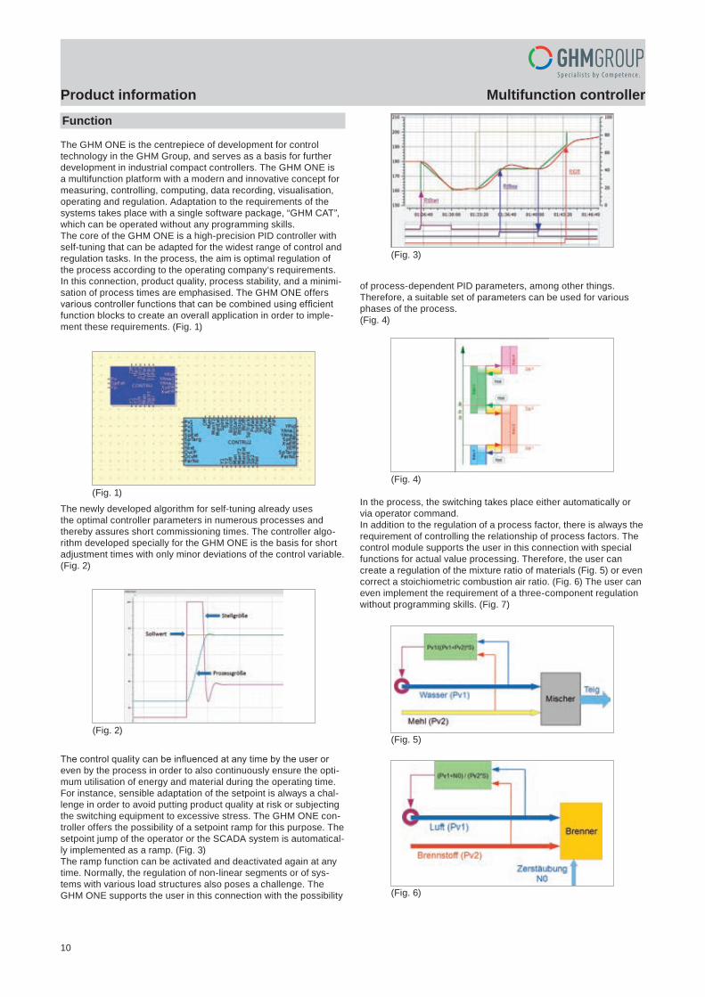
The GHM ONE is the centrepiece of development for controltechnology in the GHM Group, and serves as a basis for furtherdevelopment in industrial compact controllers. The GHM ONE isa multifunction platform with a modern and innovative concept formeasuring, controlling, computing, data recording, visualisation,operating and regulation. Adaptation to the requirements of the systems takes place with a single software package, “GHM CAT”, which can be operated without any programming skills.The core of the GHM ONE is a high-precision PID controller withself-tuning that can be adapted for the widest range of control and regulation tasks. In the process, the aim is optimal regulation of the process according to the operating company‘s requirements.In this connection, product quality, process stability, and a minimi-sation of process times are emphasised. The GHM ONE offersvarious controller functions that can be combined using efficientfunction blocks to create an overall application in order to imple-ment these requirements. (Fig. 1)
The newly developed algorithm for self-tuning already usesthe optimal controller parameters in numerous processes andthereby assures short commissioning times. The controller algo-rithm developed specially for the GHM ONE is the basis for shortadjustment times with only minor deviations of the control variable.(Fig. 2)
The control quality can be influenced at any time by the user oreven by the process in order to also continuously ensure the opti-mum utilisation of energy and material during the operating time.For instance, sensible adaptation of the setpoint is always a chal-lenge in order to avoid putting product quality at risk or subjectingthe switching equipment to excessive stress. The GHM ONE con-troller offers the possibility of a setpoint ramp for this purpose. Thesetpoint jump of the operator or the SCADA system is automatical-ly implemented as a ramp. (Fig. 3)The ramp function can be activated and deactivated again at anytime. Normally, the regulation of non-linear segments or of sys-tems with various load structures also poses a challenge. The GHM ONE supports the user in this connection with the possibility
of process-dependent PID parameters, among other things. Therefore, a suitable set of parameters can be used for various phases of the process.(Fig. 4)
In the process, the switching takes place either automatically or via operator command.In addition to the regulation of a process factor, there is always therequirement of controlling the relationship of process factors. Thecontrol module supports the user in this connection with specialfunctions for actual value processing. Therefore, the user cancreate a regulation of the mixture ratio of materials (Fig. 5) or evencorrect a stoichiometric combustion air ratio. (Fig. 6) The user caneven implement the requirement of a three-component regulationwithout programming skills. (Fig. 7)
(Fig. 1)
(Fig. 3)
(Fig. 4)
(Fig. 5)(Fig. 2)
(Fig. 6)
pi-ta-multiregler_en V1.00-00 3
GHM GROUP CORPORATE | GHM Messtechnik GmbHSchloßstr. 6 | 88453 Erolzheim | GERMANYPhone +49 7354 937233-76 | Fax +49 7354 937233-88www.ghm-group.de | [email protected]
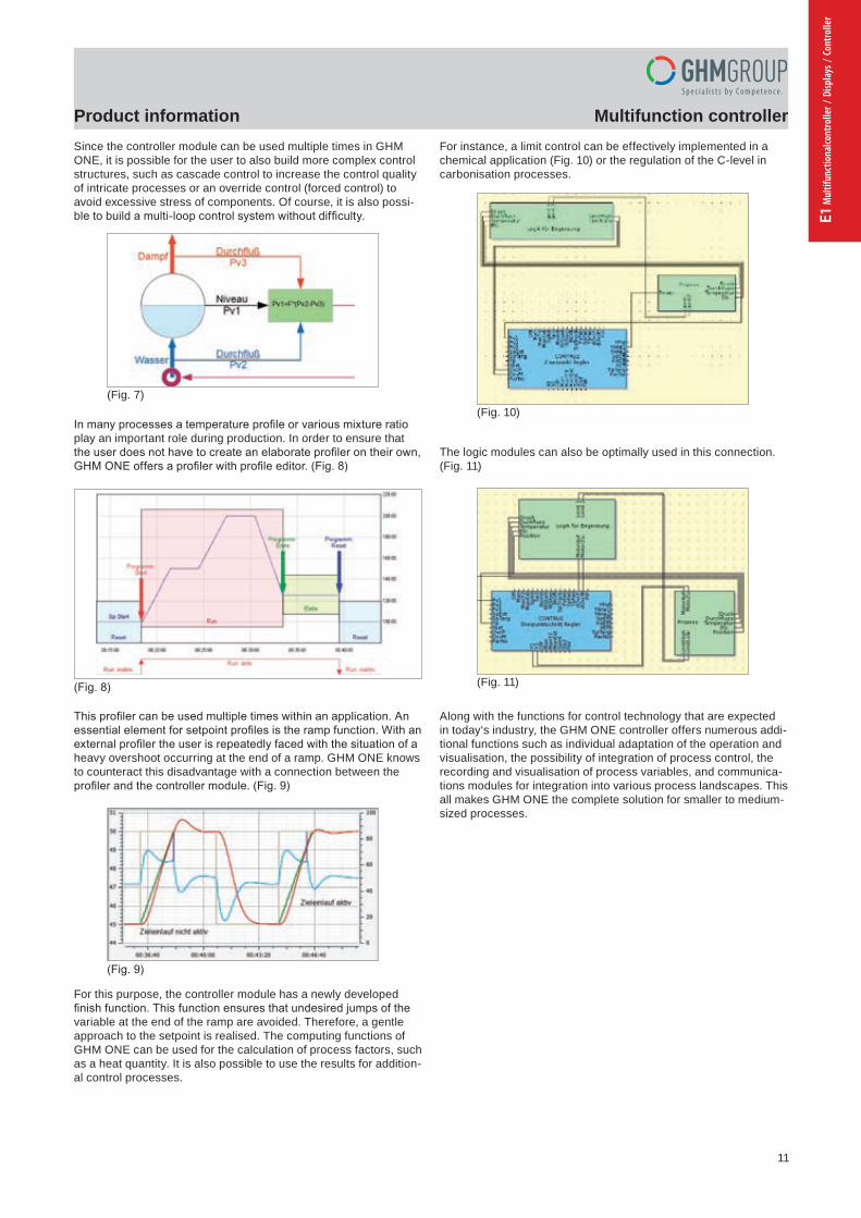
Product information Multifunction controllerSince the controller module can be used multiple times in GHMONE, it is possible for the user to also build more complex controlstructures, such as cascade control to increase the control quality of intricate processes or an override control (forced control) to avoid excessive stress of components. Of course, it is also possi-ble to build a multi-loop control system without difficulty.
In many processes a temperature profile or various mixture ratioplay an important role during production. In order to ensure that the user does not have to create an elaborate profiler on their own, GHM ONE offers a profiler with profile editor. (Fig. 8)
This profiler can be used multiple times within an application. An essential element for setpoint profiles is the ramp function. With an external profiler the user is repeatedly faced with the situation of a heavy overshoot occurring at the end of a ramp. GHM ONE knows to counteract this disadvantage with a connection between the profiler and the controller module. (Fig. 9)
For this purpose, the controller module has a newly developedfinish function. This function ensures that undesired jumps of thevariable at the end of the ramp are avoided. Therefore, a gentleapproach to the setpoint is realised. The computing functions of GHM ONE can be used for the calculation of process factors, such as a heat quantity. It is also possible to use the results for addition-al control processes.
For instance, a limit control can be effectively implemented in a chemical application (Fig. 10) or the regulation of the C-level in carbonisation processes.
The logic modules can also be optimally used in this connection.(Fig. 11)
Along with the functions for control technology that are expectedin today‘s industry, the GHM ONE controller offers numerous addi-tional functions such as individual adaptation of the operation andvisualisation, the possibility of integration of process control, therecording and visualisation of process variables, and communica-tions modules for integration into various process landscapes. Thisall makes GHM ONE the complete solution for smaller to medium-sized processes.
(Fig. 7)
(Fig. 9)
(Fig. 10)
(Fig. 11)(Fig. 8)
11
Multifunction controllerProduct information
pi-ta-multiregler_en V1.00-002
GHM GROUP CORPORATE | GHM Messtechnik GmbHSchloßstr. 6 | 88453 Erolzheim | GERMANYPhone +49 7354 937233-76 | Fax +49 7354 937233-88www.ghm-group.de | [email protected]
Product information Multifunction controllerFunction
The GHM ONE is the centrepiece of development for controltechnology in the GHM Group, and serves as a basis for furtherdevelopment in industrial compact controllers. The GHM ONE isa multifunction platform with a modern and innovative concept formeasuring, controlling, computing, data recording, visualisation,operating and regulation. Adaptation to the requirements of the systems takes place with a single software package, “GHM CAT”, which can be operated without any programming skills.The core of the GHM ONE is a high-precision PID controller withself-tuning that can be adapted for the widest range of control and regulation tasks. In the process, the aim is optimal regulation of the process according to the operating company‘s requirements.In this connection, product quality, process stability, and a minimi-sation of process times are emphasised. The GHM ONE offersvarious controller functions that can be combined using efficientfunction blocks to create an overall application in order to imple-ment these requirements. (Fig. 1)
The newly developed algorithm for self-tuning already usesthe optimal controller parameters in numerous processes andthereby assures short commissioning times. The controller algo-rithm developed specially for the GHM ONE is the basis for shortadjustment times with only minor deviations of the control variable.(Fig. 2)
The control quality can be influenced at any time by the user oreven by the process in order to also continuously ensure the opti-mum utilisation of energy and material during the operating time.For instance, sensible adaptation of the setpoint is always a chal-lenge in order to avoid putting product quality at risk or subjectingthe switching equipment to excessive stress. The GHM ONE con-troller offers the possibility of a setpoint ramp for this purpose. Thesetpoint jump of the operator or the SCADA system is automatical-ly implemented as a ramp. (Fig. 3)The ramp function can be activated and deactivated again at anytime. Normally, the regulation of non-linear segments or of sys-tems with various load structures also poses a challenge. The GHM ONE supports the user in this connection with the possibility
of process-dependent PID parameters, among other things. Therefore, a suitable set of parameters can be used for various phases of the process.(Fig. 4)
In the process, the switching takes place either automatically or via operator command.In addition to the regulation of a process factor, there is always therequirement of controlling the relationship of process factors. Thecontrol module supports the user in this connection with specialfunctions for actual value processing. Therefore, the user cancreate a regulation of the mixture ratio of materials (Fig. 5) or evencorrect a stoichiometric combustion air ratio. (Fig. 6) The user caneven implement the requirement of a three-component regulationwithout programming skills. (Fig. 7)
(Fig. 1)
(Fig. 3)
(Fig. 4)
(Fig. 5)(Fig. 2)
(Fig. 6)
pi-ta-multiregler_en V1.00-00 3
GHM GROUP CORPORATE | GHM Messtechnik GmbHSchloßstr. 6 | 88453 Erolzheim | GERMANYPhone +49 7354 937233-76 | Fax +49 7354 937233-88www.ghm-group.de | [email protected]
Product information Multifunction controllerSince the controller module can be used multiple times in GHMONE, it is possible for the user to also build more complex controlstructures, such as cascade control to increase the control quality of intricate processes or an override control (forced control) to avoid excessive stress of components. Of course, it is also possi-ble to build a multi-loop control system without difficulty.
In many processes a temperature profile or various mixture ratioplay an important role during production. In order to ensure that the user does not have to create an elaborate profiler on their own, GHM ONE offers a profiler with profile editor. (Fig. 8)
This profiler can be used multiple times within an application. An essential element for setpoint profiles is the ramp function. With an external profiler the user is repeatedly faced with the situation of a heavy overshoot occurring at the end of a ramp. GHM ONE knows to counteract this disadvantage with a connection between the profiler and the controller module. (Fig. 9)
For this purpose, the controller module has a newly developedfinish function. This function ensures that undesired jumps of thevariable at the end of the ramp are avoided. Therefore, a gentleapproach to the setpoint is realised. The computing functions of GHM ONE can be used for the calculation of process factors, such as a heat quantity. It is also possible to use the results for addition-al control processes.
For instance, a limit control can be effectively implemented in a chemical application (Fig. 10) or the regulation of the C-level in carbonisation processes.
The logic modules can also be optimally used in this connection.(Fig. 11)
Along with the functions for control technology that are expectedin today‘s industry, the GHM ONE controller offers numerous addi-tional functions such as individual adaptation of the operation andvisualisation, the possibility of integration of process control, therecording and visualisation of process variables, and communica-tions modules for integration into various process landscapes. Thisall makes GHM ONE the complete solution for smaller to medium-sized processes.
(Fig. 7)
(Fig. 9)
(Fig. 10)
(Fig. 11)(Fig. 8)
E1 M
ultif
unct
iona
lcont
rolle
r / D
ispla
ys /
Cont
rolle
r

12
Multifunction controllerProduct information
pi-ta-multiregler_en V1.00-004
GHM GROUP CORPORATE | GHM Messtechnik GmbHSchloßstr. 6 | 88453 Erolzheim | GERMANYPhone +49 7354 937233-76 | Fax +49 7354 937233-88www.ghm-group.de | [email protected]
Product information Multifunction controllerAdvantage
Industrial controller and mini PLC in one device No programming skills required to create an application Individual operation and monitoring concepts for a wide
variety of processes Modular hardware concept for optimal adaptation to the process Possible saving of individual controllers, data recorders,
and visualisation systems
Equipment Function Input Output Installation Page
GHM-ONE Measure/Control/Regulate control panel installation 5
Subject to errors and changes.
pi-ta-mureg_MSR9696H_en V1.00-00 5
GHM GROUP CORPORATE | GHM Messtechnik GmbHSchloßstr. 6 | 88453 Erolzheim | GERMANYPhone +49 7354 937233-76 | Fax +49 7354 937233-88www.ghm-group.de | [email protected]
Product information Multifunction controller
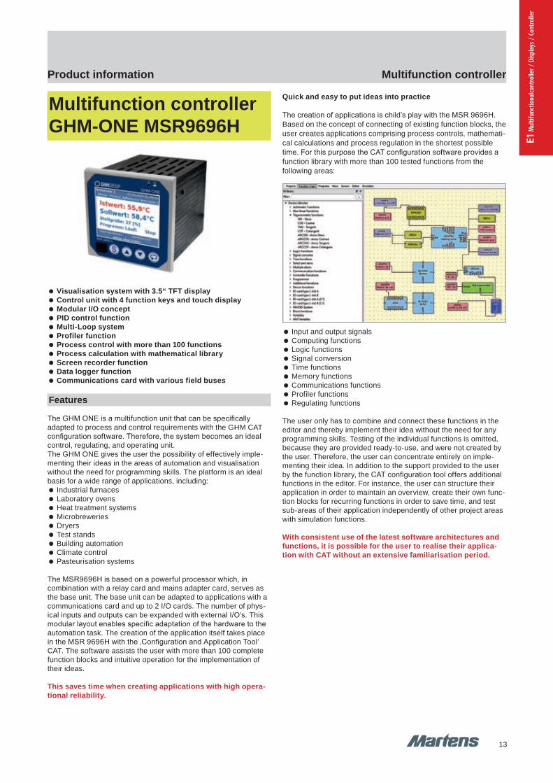
Multifunction controller GHM-ONE MSR9696H
Visualisation system with 3.5“ TFT display Control unit with 4 function keys and touch display Modular I/O concept PID control function Multi-Loop system Profiler function Process control with more than 100 functions Process calculation with mathematical library Screen recorder function Data logger function Communications card with various field buses
Features
The GHM ONE is a multifunction unit that can be specificallyadapted to process and control requirements with the GHM CATconfiguration software. Therefore, the system becomes an idealcontrol, regulating, and operating unit.The GHM ONE gives the user the possibility of effectively imple-menting their ideas in the areas of automation and visualisationwithout the need for programming skills. The platform is an idealbasis for a wide range of applications, including:
Industrial furnaces Laboratory ovens Heat treatment systems Microbreweries Dryers Test stands Building automation Climate control Pasteurisation systems
The MSR9696H is based on a powerful processor which, in combination with a relay card and mains adapter card, serves as the base unit. The base unit can be adapted to applications with a communications card and up to 2 I/O cards. The number of phys-ical inputs and outputs can be expanded with external I/O’s. This modular layout enables specific adaptation of the hardware to the automation task. The creation of the application itself takes place in the MSR 9696H with the ‚Configuration and Application Tool‘ CAT. The software assists the user with more than 100 complete function blocks and intuitive operation for the implementation of their ideas.
This saves time when creating applications with high opera-tional reliability.
Quick and easy to put ideas into practice
The creation of applications is child’s play with the MSR 9696H.Based on the concept of connecting of existing function blocks, theuser creates applications comprising process controls, mathemati-cal calculations and process regulation in the shortest possibletime. For this purpose the CAT configuration software provides afunction library with more than 100 tested functions from the following areas:
Input and output signals Computing functions Logic functions Signal conversion Time functions Memory functions Communications functions Profiler functions Regulating functions
The user only has to combine and connect these functions in theeditor and thereby implement their idea without the need for anyprogramming skills. Testing of the individual functions is omitted,because they are provided ready-to-use, and were not created bythe user. Therefore, the user can concentrate entirely on imple-menting their idea. In addition to the support provided to the user by the function library, the CAT configuration tool offers additional functions in the editor. For instance, the user can structure their application in order to maintain an overview, create their own func-tion blocks for recurring functions in order to save time, and test sub-areas of their application independently of other project areas with simulation functions.
With consistent use of the latest software architectures andfunctions, it is possible for the user to realise their applica-tion with CAT without an extensive familiarisation period.
13
13
Multifunction controllerProduct information
GHM-ONE GHM-ONE
pi-ta-multiregler_en V1.00-004
GHM GROUP CORPORATE | GHM Messtechnik GmbHSchloßstr. 6 | 88453 Erolzheim | GERMANYPhone +49 7354 937233-76 | Fax +49 7354 937233-88www.ghm-group.de | [email protected]
Product information Multifunction controllerAdvantage
Industrial controller and mini PLC in one device No programming skills required to create an application Individual operation and monitoring concepts for a wide
variety of processes Modular hardware concept for optimal adaptation to the process Possible saving of individual controllers, data recorders,
and visualisation systems
Equipment Function Input Output Installation Page
GHM-ONE Measure/Control/Regulate control panel installation 5
Subject to errors and changes.
pi-ta-mureg_MSR9696H_en V1.00-00 5
GHM GROUP CORPORATE | GHM Messtechnik GmbHSchloßstr. 6 | 88453 Erolzheim | GERMANYPhone +49 7354 937233-76 | Fax +49 7354 937233-88www.ghm-group.de | [email protected]
Product information Multifunction controller
Multifunction controller GHM-ONE MSR9696H
Visualisation system with 3.5“ TFT display Control unit with 4 function keys and touch display Modular I/O concept PID control function Multi-Loop system Profiler function Process control with more than 100 functions Process calculation with mathematical library Screen recorder function Data logger function Communications card with various field buses
Features
The GHM ONE is a multifunction unit that can be specificallyadapted to process and control requirements with the GHM CATconfiguration software. Therefore, the system becomes an idealcontrol, regulating, and operating unit.The GHM ONE gives the user the possibility of effectively imple-menting their ideas in the areas of automation and visualisationwithout the need for programming skills. The platform is an idealbasis for a wide range of applications, including:
Industrial furnaces Laboratory ovens Heat treatment systems Microbreweries Dryers Test stands Building automation Climate control Pasteurisation systems
The MSR9696H is based on a powerful processor which, in combination with a relay card and mains adapter card, serves as the base unit. The base unit can be adapted to applications with a communications card and up to 2 I/O cards. The number of phys-ical inputs and outputs can be expanded with external I/O’s. This modular layout enables specific adaptation of the hardware to the automation task. The creation of the application itself takes place in the MSR 9696H with the ‚Configuration and Application Tool‘ CAT. The software assists the user with more than 100 complete function blocks and intuitive operation for the implementation of their ideas.
This saves time when creating applications with high opera-tional reliability.
Quick and easy to put ideas into practice
The creation of applications is child’s play with the MSR 9696H.Based on the concept of connecting of existing function blocks, theuser creates applications comprising process controls, mathemati-cal calculations and process regulation in the shortest possibletime. For this purpose the CAT configuration software provides afunction library with more than 100 tested functions from the following areas:
Input and output signals Computing functions Logic functions Signal conversion Time functions Memory functions Communications functions Profiler functions Regulating functions
The user only has to combine and connect these functions in theeditor and thereby implement their idea without the need for anyprogramming skills. Testing of the individual functions is omitted,because they are provided ready-to-use, and were not created bythe user. Therefore, the user can concentrate entirely on imple-menting their idea. In addition to the support provided to the user by the function library, the CAT configuration tool offers additional functions in the editor. For instance, the user can structure their application in order to maintain an overview, create their own func-tion blocks for recurring functions in order to save time, and test sub-areas of their application independently of other project areas with simulation functions.
With consistent use of the latest software architectures andfunctions, it is possible for the user to realise their applica-tion with CAT without an extensive familiarisation period.
E1 M
ultif
unct
iona
lcont
rolle
r / D
ispla
ys /
Cont
rolle
r

14
Multifunction controllerProduct information
pi-ta-mureg_MSR9696H_en V1.00-006
GHM GROUP CORPORATE | GHM Messtechnik GmbHSchloßstr. 6 | 88453 Erolzheim | GERMANYPhone +49 7354 937233-76 | Fax +49 7354 937233-88www.ghm-group.de | [email protected]
Product information Multifunction controllerIndividual operating and monitoring concepts
The work does not end with the creation of pure process controland regulation for modern machine and system parts. The processtechnician must provide the operator on site with the possibility ofeffectively monitoring and operating the system. The user mustalso remain well-informed in the event of a fault in order to keepthe system downtime to an absolute minimum. Standard operatingconcepts are of little help in this connection. Therefore, the MSR9696H is based on a concept that enables individual design of theoperation and visualisation.For this purpose, the CAT software provides an image editor thatmakes it possible to realise the widest range of operating and monitoring concepts with a few simple standard functions. In addition to the individual operating screens, there are standards screens such as:
Regulator operation Program controller operation
Trend visualisation Parameter dialogue
available in the screen editor. With the combination of standard operating screens and individually designed screen, an efficientinterface between the operator and the process is created in theshortest time.
Thanks to the efficient software structure, even complex oper-ating structures are easy to realise with the image editor.
Commissioning and testing quickly and easily
Of course, the process technician‘s work is not finished with the creation of an application and its operation. The application still has to be tested and commissioned afterwards. For this important and in some cases lengthy phase, the new GHM platform provides various functions to streamline this phase.
An essential point is the PC simulation of the complete application.The entire application can be tested on a PC independently of theactual process. For this purpose, the CAT software has a sim-ulation environment for the MSR 9696H and for connected I/O assemblies. With this environment, the user is capable of testing the entire application, including operation on the PC, without endangering the real process. Simply test the application at a desk without risk.
There are additional testing functions available to the user for theon-site system commissioning phase. An essential component isan integrated online trend function that allows the user to view allanalogue and digital signals online in a trend and thereby quicklyand easily monitor the desired functions. Of course, there are alsodebugging and various forcing functions available for the testing.
Simulation on a PC significantly shortens testing and com-missioning times and increases system safety.
pi-ta-mureg_MSR9696H_en V1.00-00 7
GHM GROUP CORPORATE | GHM Messtechnik GmbHSchloßstr. 6 | 88453 Erolzheim | GERMANYPhone +49 7354 937233-76 | Fax +49 7354 937233-88www.ghm-group.de | [email protected]
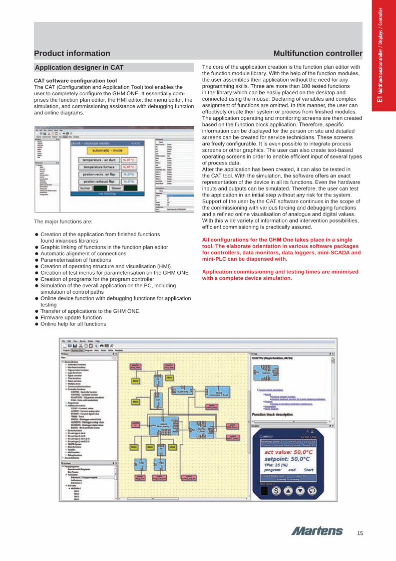
Product information Multifunction controllerApplication designer in CAT
CAT software configuration toolThe CAT (Configuration and Application Tool) tool enables the user to completely configure the GHM ONE. It essentially com-prises the function plan editor, the HMI editor, the menu editor, the simulation, and commissioning assistance with debugging function and online diagrams.
The major functions are:
Creation of the application from finished functions found invarious libraries
Graphic linking of functions in the function plan editor Automatic alignment of connections Parameterisation of functions Creation of operating structure and visualisation (HMI) Creation of test menus for parameterisation on the GHM ONE Creation of programs for the program controller Simulation of the overall application on the PC, including
simulation of control paths Online device function with debugging functions for application
testing Transfer of applications to the GHM ONE. Firmware update function Online help for all functions
The core of the application creation is the function plan editor withthe function module library. With the help of the function modules,the user assembles their application without the need for anyprogramming skills. Three are more than 100 tested functions in the library which can be easily placed on the desktop and connected using the mouse. Declaring of variables and complex assignment of functions are omitted. In this manner, the user can effectively create their system or process from finished modules.The application operating and monitoring screens are then createdbased on the function block application. Therefore, specific information can be displayed for the person on site and detailed screens can be created for service technicians. These screens are freely configurable. It is even possible to integrate process screens or other graphics. The user can also create text-based operating screens in order to enable efficient input of several types of process data.After the application has been created, it can also be tested inthe CAT tool. With the simulation, the software offers an exactrepresentation of the device in all its functions. Even the hardwareinputs and outputs can be simulated. Therefore, the user can testthe application in an initial step without any risk for the system. Support of the user by the CAT software continues in the scope of the commissioning with various forcing and debugging functions and a refined online visualisation of analogue and digital values. With this wide variety of information and intervention possibilities, efficient commissioning is practically assured.
All configurations for the GHM One takes place in a single tool. The elaborate orientation in various software packages for controllers, data monitors, data loggers, mini-SCADA and mini-PLC can be dispensed with.
Application commissioning and testing times are minimisedwith a complete device simulation.
15
Multifunction controllerProduct information
pi-ta-mureg_MSR9696H_en V1.00-006
GHM GROUP CORPORATE | GHM Messtechnik GmbHSchloßstr. 6 | 88453 Erolzheim | GERMANYPhone +49 7354 937233-76 | Fax +49 7354 937233-88www.ghm-group.de | [email protected]
Product information Multifunction controllerIndividual operating and monitoring concepts
The work does not end with the creation of pure process controland regulation for modern machine and system parts. The processtechnician must provide the operator on site with the possibility ofeffectively monitoring and operating the system. The user mustalso remain well-informed in the event of a fault in order to keepthe system downtime to an absolute minimum. Standard operatingconcepts are of little help in this connection. Therefore, the MSR9696H is based on a concept that enables individual design of theoperation and visualisation.For this purpose, the CAT software provides an image editor thatmakes it possible to realise the widest range of operating and monitoring concepts with a few simple standard functions. In addition to the individual operating screens, there are standards screens such as:
Regulator operation Program controller operation
Trend visualisation Parameter dialogue
available in the screen editor. With the combination of standard operating screens and individually designed screen, an efficientinterface between the operator and the process is created in theshortest time.
Thanks to the efficient software structure, even complex oper-ating structures are easy to realise with the image editor.
Commissioning and testing quickly and easily
Of course, the process technician‘s work is not finished with the creation of an application and its operation. The application still has to be tested and commissioned afterwards. For this important and in some cases lengthy phase, the new GHM platform provides various functions to streamline this phase.
An essential point is the PC simulation of the complete application.The entire application can be tested on a PC independently of theactual process. For this purpose, the CAT software has a sim-ulation environment for the MSR 9696H and for connected I/O assemblies. With this environment, the user is capable of testing the entire application, including operation on the PC, without endangering the real process. Simply test the application at a desk without risk.
There are additional testing functions available to the user for theon-site system commissioning phase. An essential component isan integrated online trend function that allows the user to view allanalogue and digital signals online in a trend and thereby quicklyand easily monitor the desired functions. Of course, there are alsodebugging and various forcing functions available for the testing.
Simulation on a PC significantly shortens testing and com-missioning times and increases system safety.
pi-ta-mureg_MSR9696H_en V1.00-00 7
GHM GROUP CORPORATE | GHM Messtechnik GmbHSchloßstr. 6 | 88453 Erolzheim | GERMANYPhone +49 7354 937233-76 | Fax +49 7354 937233-88www.ghm-group.de | [email protected]
Product information Multifunction controllerApplication designer in CAT
CAT software configuration toolThe CAT (Configuration and Application Tool) tool enables the user to completely configure the GHM ONE. It essentially com-prises the function plan editor, the HMI editor, the menu editor, the simulation, and commissioning assistance with debugging function and online diagrams.
The major functions are:
Creation of the application from finished functions found invarious libraries
Graphic linking of functions in the function plan editor Automatic alignment of connections Parameterisation of functions Creation of operating structure and visualisation (HMI) Creation of test menus for parameterisation on the GHM ONE Creation of programs for the program controller Simulation of the overall application on the PC, including
simulation of control paths Online device function with debugging functions for application
testing Transfer of applications to the GHM ONE. Firmware update function Online help for all functions
The core of the application creation is the function plan editor withthe function module library. With the help of the function modules,the user assembles their application without the need for anyprogramming skills. Three are more than 100 tested functions in the library which can be easily placed on the desktop and connected using the mouse. Declaring of variables and complex assignment of functions are omitted. In this manner, the user can effectively create their system or process from finished modules.The application operating and monitoring screens are then createdbased on the function block application. Therefore, specific information can be displayed for the person on site and detailed screens can be created for service technicians. These screens are freely configurable. It is even possible to integrate process screens or other graphics. The user can also create text-based operating screens in order to enable efficient input of several types of process data.After the application has been created, it can also be tested inthe CAT tool. With the simulation, the software offers an exactrepresentation of the device in all its functions. Even the hardwareinputs and outputs can be simulated. Therefore, the user can testthe application in an initial step without any risk for the system. Support of the user by the CAT software continues in the scope of the commissioning with various forcing and debugging functions and a refined online visualisation of analogue and digital values. With this wide variety of information and intervention possibilities, efficient commissioning is practically assured.
All configurations for the GHM One takes place in a single tool. The elaborate orientation in various software packages for controllers, data monitors, data loggers, mini-SCADA and mini-PLC can be dispensed with.
Application commissioning and testing times are minimisedwith a complete device simulation.
E1 M
ultif
unct
iona
lcont
rolle
r / D
ispla
ys /
Cont
rolle
r
16
Multifunction controllerProduct information
pi-ta-mureg_MSR9696H_en V1.00-008
GHM GROUP CORPORATE | GHM Messtechnik GmbHSchloßstr. 6 | 88453 Erolzheim | GERMANYPhone +49 7354 937233-76 | Fax +49 7354 937233-88www.ghm-group.de | [email protected]
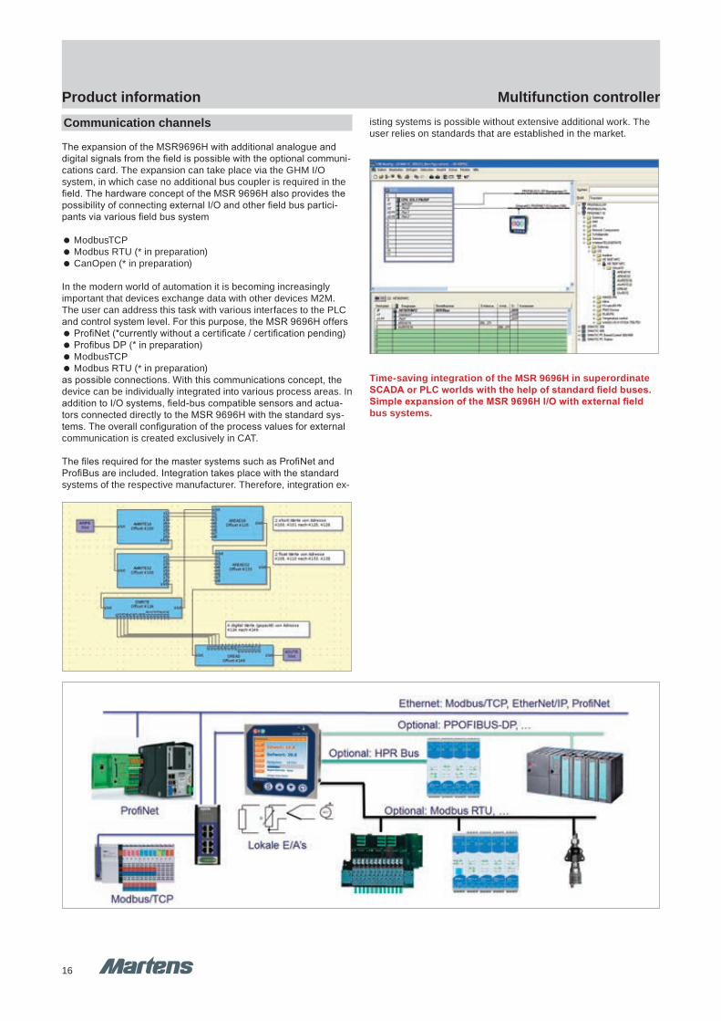
Product information Multifunction controllerCommunication channels
The expansion of the MSR9696H with additional analogue anddigital signals from the field is possible with the optional communi-cations card. The expansion can take place via the GHM I/Osystem, in which case no additional bus coupler is required in thefield. The hardware concept of the MSR 9696H also provides thepossibility of connecting external I/O and other field bus partici-pants via various field bus system
ModbusTCP Modbus RTU (* in preparation) CanOpen (* in preparation)
In the modern world of automation it is becoming increasinglyimportant that devices exchange data with other devices M2M. The user can address this task with various interfaces to the PLC and control system level. For this purpose, the MSR 9696H offers
ProfiNet (*currently without a certificate / certification pending) Profibus DP (* in preparation) ModbusTCP Modbus RTU (* in preparation)
as possible connections. With this communications concept, thedevice can be individually integrated into various process areas. Inaddition to I/O systems, field-bus compatible sensors and actua-tors connected directly to the MSR 9696H with the standard sys-tems. The overall configuration of the process values for external communication is created exclusively in CAT.
The files required for the master systems such as ProfiNet andProfiBus are included. Integration takes place with the standardsystems of the respective manufacturer. Therefore, integration ex-
isting systems is possible without extensive additional work. The user relies on standards that are established in the market.
Time-saving integration of the MSR 9696H in superordinateSCADA or PLC worlds with the help of standard field buses.Simple expansion of the MSR 9696H I/O with external field bus systems.
pi-ta-mureg_MSR9696H_en V1.00-00 9
GHM GROUP CORPORATE | GHM Messtechnik GmbHSchloßstr. 6 | 88453 Erolzheim | GERMANYPhone +49 7354 937233-76 | Fax +49 7354 937233-88www.ghm-group.de | [email protected]
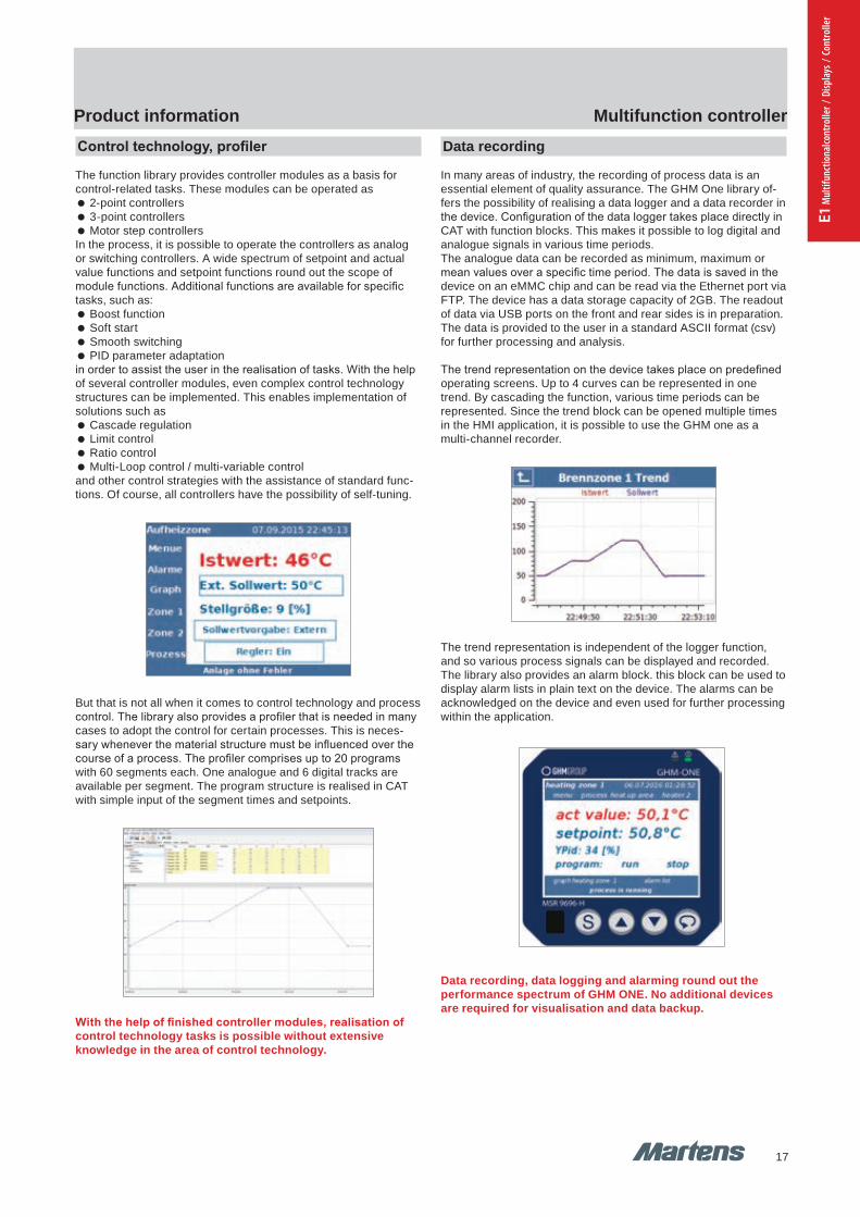
Product information Multifunction controllerData recording
In many areas of industry, the recording of process data is anessential element of quality assurance. The GHM One library of-fers the possibility of realising a data logger and a data recorder inthe device. Configuration of the data logger takes place directly inCAT with function blocks. This makes it possible to log digital andanalogue signals in various time periods.The analogue data can be recorded as minimum, maximum ormean values over a specific time period. The data is saved in thedevice on an eMMC chip and can be read via the Ethernet port viaFTP. The device has a data storage capacity of 2GB. The readoutof data via USB ports on the front and rear sides is in preparation.The data is provided to the user in a standard ASCII format (csv)for further processing and analysis.
The trend representation on the device takes place on predefinedoperating screens. Up to 4 curves can be represented in one trend. By cascading the function, various time periods can be represented. Since the trend block can be opened multiple times in the HMI application, it is possible to use the GHM one as a multi-channel recorder.
The trend representation is independent of the logger function,and so various process signals can be displayed and recorded.The library also provides an alarm block. this block can be used todisplay alarm lists in plain text on the device. The alarms can beacknowledged on the device and even used for further processingwithin the application.
Data recording, data logging and alarming round out theperformance spectrum of GHM ONE. No additional devices are required for visualisation and data backup.
Control technology, profiler
The function library provides controller modules as a basis for control-related tasks. These modules can be operated as
2-point controllers 3-point controllers Motor step controllers
In the process, it is possible to operate the controllers as analog or switching controllers. A wide spectrum of setpoint and actual value functions and setpoint functions round out the scope of module functions. Additional functions are available for specific tasks, such as:
Boost function Soft start Smooth switching PID parameter adaptation
in order to assist the user in the realisation of tasks. With the helpof several controller modules, even complex control technologystructures can be implemented. This enables implementation ofsolutions such as
Cascade regulation Limit control Ratio control Multi-Loop control / multi-variable control
and other control strategies with the assistance of standard func-tions. Of course, all controllers have the possibility of self-tuning.
But that is not all when it comes to control technology and process control. The library also provides a profiler that is needed in many cases to adopt the control for certain processes. This is neces-sary whenever the material structure must be influenced over the course of a process. The profiler comprises up to 20 programs with 60 segments each. One analogue and 6 digital tracks are available per segment. The program structure is realised in CAT with simple input of the segment times and setpoints.
With the help of finished controller modules, realisation ofcontrol technology tasks is possible without extensive knowledge in the area of control technology.
17
Multifunction controllerProduct information
pi-ta-mureg_MSR9696H_en V1.00-008
GHM GROUP CORPORATE | GHM Messtechnik GmbHSchloßstr. 6 | 88453 Erolzheim | GERMANYPhone +49 7354 937233-76 | Fax +49 7354 937233-88www.ghm-group.de | [email protected]
Product information Multifunction controllerCommunication channels
The expansion of the MSR9696H with additional analogue anddigital signals from the field is possible with the optional communi-cations card. The expansion can take place via the GHM I/Osystem, in which case no additional bus coupler is required in thefield. The hardware concept of the MSR 9696H also provides thepossibility of connecting external I/O and other field bus partici-pants via various field bus system
ModbusTCP Modbus RTU (* in preparation) CanOpen (* in preparation)
In the modern world of automation it is becoming increasinglyimportant that devices exchange data with other devices M2M. The user can address this task with various interfaces to the PLC and control system level. For this purpose, the MSR 9696H offers
ProfiNet (*currently without a certificate / certification pending) Profibus DP (* in preparation) ModbusTCP Modbus RTU (* in preparation)
as possible connections. With this communications concept, thedevice can be individually integrated into various process areas. Inaddition to I/O systems, field-bus compatible sensors and actua-tors connected directly to the MSR 9696H with the standard sys-tems. The overall configuration of the process values for external communication is created exclusively in CAT.
The files required for the master systems such as ProfiNet andProfiBus are included. Integration takes place with the standardsystems of the respective manufacturer. Therefore, integration ex-
isting systems is possible without extensive additional work. The user relies on standards that are established in the market.
Time-saving integration of the MSR 9696H in superordinateSCADA or PLC worlds with the help of standard field buses.Simple expansion of the MSR 9696H I/O with external field bus systems.
pi-ta-mureg_MSR9696H_en V1.00-00 9
GHM GROUP CORPORATE | GHM Messtechnik GmbHSchloßstr. 6 | 88453 Erolzheim | GERMANYPhone +49 7354 937233-76 | Fax +49 7354 937233-88www.ghm-group.de | [email protected]
Product information Multifunction controllerData recording
In many areas of industry, the recording of process data is anessential element of quality assurance. The GHM One library of-fers the possibility of realising a data logger and a data recorder inthe device. Configuration of the data logger takes place directly inCAT with function blocks. This makes it possible to log digital andanalogue signals in various time periods.The analogue data can be recorded as minimum, maximum ormean values over a specific time period. The data is saved in thedevice on an eMMC chip and can be read via the Ethernet port viaFTP. The device has a data storage capacity of 2GB. The readoutof data via USB ports on the front and rear sides is in preparation.The data is provided to the user in a standard ASCII format (csv)for further processing and analysis.
The trend representation on the device takes place on predefinedoperating screens. Up to 4 curves can be represented in one trend. By cascading the function, various time periods can be represented. Since the trend block can be opened multiple times in the HMI application, it is possible to use the GHM one as a multi-channel recorder.
The trend representation is independent of the logger function,and so various process signals can be displayed and recorded.The library also provides an alarm block. this block can be used todisplay alarm lists in plain text on the device. The alarms can beacknowledged on the device and even used for further processingwithin the application.
Data recording, data logging and alarming round out theperformance spectrum of GHM ONE. No additional devices are required for visualisation and data backup.
Control technology, profiler
The function library provides controller modules as a basis for control-related tasks. These modules can be operated as
2-point controllers 3-point controllers Motor step controllers
In the process, it is possible to operate the controllers as analog or switching controllers. A wide spectrum of setpoint and actual value functions and setpoint functions round out the scope of module functions. Additional functions are available for specific tasks, such as:
Boost function Soft start Smooth switching PID parameter adaptation
in order to assist the user in the realisation of tasks. With the helpof several controller modules, even complex control technologystructures can be implemented. This enables implementation ofsolutions such as
Cascade regulation Limit control Ratio control Multi-Loop control / multi-variable control
and other control strategies with the assistance of standard func-tions. Of course, all controllers have the possibility of self-tuning.
But that is not all when it comes to control technology and process control. The library also provides a profiler that is needed in many cases to adopt the control for certain processes. This is neces-sary whenever the material structure must be influenced over the course of a process. The profiler comprises up to 20 programs with 60 segments each. One analogue and 6 digital tracks are available per segment. The program structure is realised in CAT with simple input of the segment times and setpoints.
With the help of finished controller modules, realisation ofcontrol technology tasks is possible without extensive knowledge in the area of control technology.
E1 M
ultif
unct
iona
lcont
rolle
r / D
ispla
ys /
Cont
rolle
r
18
Multifunction controllerProduct information
pi-ta-mureg_MSR9696H_en V1.00-0010
GHM GROUP CORPORATE | GHM Messtechnik GmbHSchloßstr. 6 | 88453 Erolzheim | GERMANYPhone +49 7354 937233-76 | Fax +49 7354 937233-88www.ghm-group.de | [email protected]
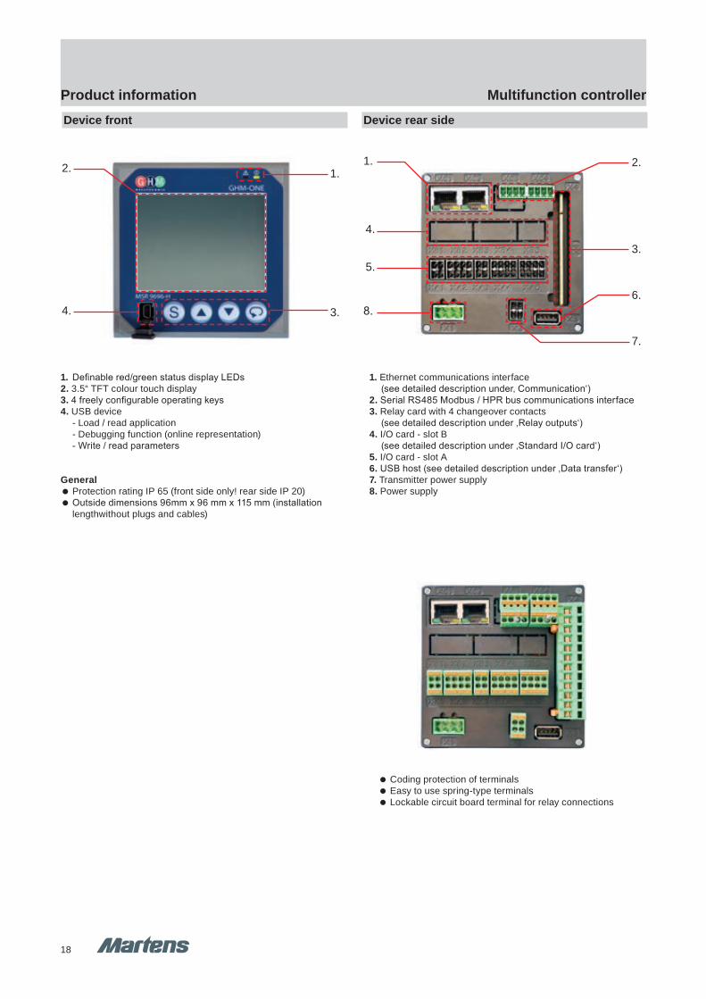
Product information Multifunction controllerDevice front Device rear side
1. Definable red/green status display LEDs2. 3.5“ TFT colour touch display3. 4 freely configurable operating keys4. USB device - Load / read application - Debugging function (online representation) - Write / read parameters
General Protection rating IP 65 (front side only! rear side IP 20) Outside dimensions 96mm x 96 mm x 115 mm (installation
lengthwithout plugs and cables)
1. Ethernet communications interface (see detailed description under‚ Communication‘)2. Serial RS485 Modbus / HPR bus communications interface3. Relay card with 4 changeover contacts (see detailed description under ‚Relay outputs‘)4. I/O card - slot B (see detailed description under ‚Standard I/O card‘)5. I/O card - slot A6. USB host (see detailed description under ‚Data transfer‘)7. Transmitter power supply 8. Power supply
1.
4.
5.
2.
7.
6.
3.
8.
2. 1.
3.4.
Coding protection of terminals Easy to use spring-type terminals Lockable circuit board terminal for relay connections
pi-ta-mureg_MSR9696H_en V1.00-00 11
GHM GROUP CORPORATE | GHM Messtechnik GmbHSchloßstr. 6 | 88453 Erolzheim | GERMANYPhone +49 7354 937233-76 | Fax +49 7354 937233-88www.ghm-group.de | [email protected]
Product information Multifunction controller
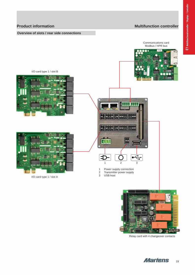
I/O card type 1 / slot B
Communications cardModbus / HPR bus
I/O card type 1 / slot A
Overview of slots / rear side connections
1 Power supply connection2 Transmitter power supply3 USB host
1 3
Relay card with 4 changeover contacts
2
19
Multifunction controllerProduct information
pi-ta-mureg_MSR9696H_en V1.00-0010
GHM GROUP CORPORATE | GHM Messtechnik GmbHSchloßstr. 6 | 88453 Erolzheim | GERMANYPhone +49 7354 937233-76 | Fax +49 7354 937233-88www.ghm-group.de | [email protected]
Product information Multifunction controllerDevice front Device rear side
1. Definable red/green status display LEDs2. 3.5“ TFT colour touch display3. 4 freely configurable operating keys4. USB device - Load / read application - Debugging function (online representation) - Write / read parameters
General Protection rating IP 65 (front side only! rear side IP 20) Outside dimensions 96mm x 96 mm x 115 mm (installation
lengthwithout plugs and cables)
1. Ethernet communications interface (see detailed description under‚ Communication‘)2. Serial RS485 Modbus / HPR bus communications interface3. Relay card with 4 changeover contacts (see detailed description under ‚Relay outputs‘)4. I/O card - slot B (see detailed description under ‚Standard I/O card‘)5. I/O card - slot A6. USB host (see detailed description under ‚Data transfer‘)7. Transmitter power supply 8. Power supply
1.
4.
5.
2.
7.
6.
3.
8.
2. 1.
3.4.
Coding protection of terminals Easy to use spring-type terminals Lockable circuit board terminal for relay connections
pi-ta-mureg_MSR9696H_en V1.00-00 11
GHM GROUP CORPORATE | GHM Messtechnik GmbHSchloßstr. 6 | 88453 Erolzheim | GERMANYPhone +49 7354 937233-76 | Fax +49 7354 937233-88www.ghm-group.de | [email protected]
Product information Multifunction controller
I/O card type 1 / slot B
Communications cardModbus / HPR bus
I/O card type 1 / slot A
Overview of slots / rear side connections
1 Power supply connection2 Transmitter power supply3 USB host
1 3
Relay card with 4 changeover contacts
2
E1 M
ultif
unct
iona
lcont
rolle
r / D
ispla
ys /
Cont
rolle
r
20
Multifunction controllerProduct information
pi-ta-mureg_MSR9696H_en V1.00-0012
GHM GROUP CORPORATE | GHM Messtechnik GmbHSchloßstr. 6 | 88453 Erolzheim | GERMANYPhone +49 7354 937233-76 | Fax +49 7354 937233-88www.ghm-group.de | [email protected]
Product information Multifunction controller
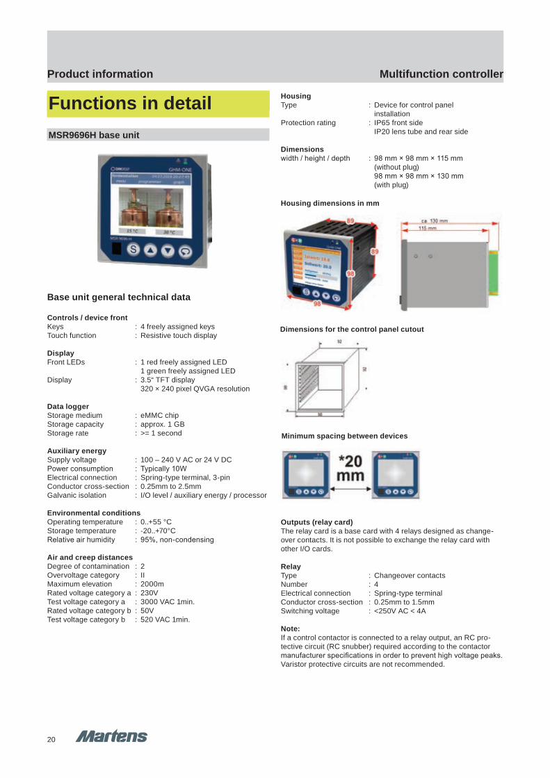
Functions in detailMSR9696H base unit
Base unit general technical data
Controls / device frontKeys : 4 freely assigned keysTouch function : Resistive touch display
DisplayFront LEDs : 1 red freely assigned LED 1 green freely assigned LEDDisplay : 3.5“ TFT display 320 × 240 pixel QVGA resolution
Data loggerStorage medium : eMMC chipStorage capacity : approx. 1 GBStorage rate : >= 1 second
Auxiliary energySupply voltage : 100 – 240 V AC or 24 V DCPower consumption : Typically 10WElectrical connection : Spring-type terminal, 3-pinConductor cross-section : 0.25mm to 2.5mmGalvanic isolation : I/O level / auxiliary energy / processor
Environmental conditionsOperating temperature : 0..+55 °CStorage temperature : -20..+70°CRelative air humidity : 95%, non-condensing
Air and creep distancesDegree of contamination : 2Overvoltage category : IIMaximum elevation : 2000mRated voltage category a : 230VTest voltage category a : 3000 VAC 1min.Rated voltage category b : 50VTest voltage category b : 520 VAC 1min.
HousingType : Device for control panel installationProtection rating : IP65 front side IP20 lens tube and rear side
Dimensionswidth / height / depth : 98 mm × 98 mm × 115 mm (without plug) 98 mm × 98 mm × 130 mm (with plug)
Outputs (relay card)The relay card is a base card with 4 relays designed as change-over contacts. It is not possible to exchange the relay card with other I/O cards.
RelayType : Changeover contactsNumber : 4Electrical connection : Spring-type terminalConductor cross-section : 0.25mm to 1.5mmSwitching voltage : <250V AC < 4A
Note:If a control contactor is connected to a relay output, an RC pro-tective circuit (RC snubber) required according to the contactor manufacturer specifications in order to prevent high voltage peaks. Varistor protective circuits are not recommended.
Dimensions for the control panel cutout
Housing dimensions in mm
Minimum spacing between devices
pi-ta-mureg_MSR9696H_en V1.00-00 13
GHM GROUP CORPORATE | GHM Messtechnik GmbHSchloßstr. 6 | 88453 Erolzheim | GERMANYPhone +49 7354 937233-76 | Fax +49 7354 937233-88www.ghm-group.de | [email protected]
Product information Multifunction controllerOption 1: I/O card type 1
Up to 2 I/O cards can be installed in the device.The type ‚1‘ card has:
2 analogue universal inputs TC / RTD / -1000..+1000mV / 0..+20mA)
2 analogue standard inputs (0..+10V / 0..+20mA)
2 analogue standard outputs (0..+10V / 0..+20mA)
6 digital inputs or outputs
Analogue universal inputThe card is equipped with 2 analogue universal inputs
Galvanic isolationThe two universal inputs are galvanically isolated from each other.There is also galvanic isolation for the power supply, the digitalinputs and outputs, analogue outputs, and the processor and thecommunications. There is a galvanic connection to the corre-sponding analogue standard input (terminal X2 / terminal X4).Converter resolution : > 18 BitCycle time : 50msGalvanic isolation : corresponding to category a
RTD measurementsInput type : ResistanceConnection type : 3-wire
Measuring rangesPt100 / Pt1000 -200..+850°C
Ni100 / Ni1000 -60..+300°C
KTY 11-6 -50..+125°C
Measured currentPt100 / Ni100 I < 0,5mA
Pt1000 / Ni 1000 I < 50µA
KTY 11-6 I < 50µA
Accuracy : ≤ 1KTemperature drift : ≤ 0.08% / 10KMeasuring circuit monitoring : Short-circuit and interruption
Thermocouple measurementsInput type : Voltage measurementConnection type : 2-wireInput resistance : >10 MΩ
ThermocouplesType Measuring range Accuracy Resolution
L -200..+900°C ≤ 2 K 0,05 KJ -210..+1200°C ≤ 2 K 0,05 KK -270..+1370°C ≤ 2 K 0,08 KN -196..+1299°C ≤ 2 K 0,08 KS -50..+1760°C ≤ 2 K 0,07 KR -50..+1760°C ≤ 2 K 0,07 KT -270..+400°C ≤ 2 K 0,02 KE -270..+1000°C ≤ 2 K 0,04 KB +25..+1820°C ≤ 3 K 0,1 KW 0..+2299°C ≤ 3 K 0,1 K
Temperature drift : ≤ 0.08% / 10KMeasuring circuit monitoring : InterruptionCold-junctioncompensation : internal / auxiliary error < 2 K
Resistance measurementInput type : Resistance measurementConnection type : 2-wireMeasuring range : 0..20 kΩDetection range : Measuring range + 10%Accuracy : ≤ 0.1%Temperature drift : ≤ 0.08% / 10KMeasuring circuit monitoring : Exceeding the detection range
Current measurementInput type : CurrentConnection type : 2-wireMeasuring range : 0..20mADetection range : Measuring range + 10%Input impedance : max. 50ΩAccuracy : ≤ 0.1%Temperature drift : ≤ 0.08% / 10KMeasuring circuit : Exceeding and/or undercuttingmonitoring the detection range Analogue standard inputThe card is equipped with 2 analogue standard inputs.
Galvanic isolationThe two standard inputs are galvanically isolated from each other.There is also galvanic isolation for the power supply, the digitalinputs and outputs, analogue outputs, and the processor and thecommunications. There is a galvanic connection to the corre-sponding analogue universal input (terminal X2 / terminal X4).
Converter resolution : > 18 BitCycle time : 50msGalvanic isolation : corresponding to category a
Current measurementInput type : CurrentConnection type : 2-wireMeasuring range : 0..20mADetection range : Measuring range + 10%Input impedance : max. 50ΩAccuracy : ≤ 0.1%Temperature drift : ≤ 0.08% / 10KMeasuring circuit : Exceeding and/or undercuttingmonitoring the detection range

21
Multifunction controllerProduct information
pi-ta-mureg_MSR9696H_en V1.00-0012
GHM GROUP CORPORATE | GHM Messtechnik GmbHSchloßstr. 6 | 88453 Erolzheim | GERMANYPhone +49 7354 937233-76 | Fax +49 7354 937233-88www.ghm-group.de | [email protected]
Product information Multifunction controller
Functions in detailMSR9696H base unit
Base unit general technical data
Controls / device frontKeys : 4 freely assigned keysTouch function : Resistive touch display
DisplayFront LEDs : 1 red freely assigned LED 1 green freely assigned LEDDisplay : 3.5“ TFT display 320 × 240 pixel QVGA resolution
Data loggerStorage medium : eMMC chipStorage capacity : approx. 1 GBStorage rate : >= 1 second
Auxiliary energySupply voltage : 100 – 240 V AC or 24 V DCPower consumption : Typically 10WElectrical connection : Spring-type terminal, 3-pinConductor cross-section : 0.25mm to 2.5mmGalvanic isolation : I/O level / auxiliary energy / processor
Environmental conditionsOperating temperature : 0..+55 °CStorage temperature : -20..+70°CRelative air humidity : 95%, non-condensing
Air and creep distancesDegree of contamination : 2Overvoltage category : IIMaximum elevation : 2000mRated voltage category a : 230VTest voltage category a : 3000 VAC 1min.Rated voltage category b : 50VTest voltage category b : 520 VAC 1min.
HousingType : Device for control panel installationProtection rating : IP65 front side IP20 lens tube and rear side
Dimensionswidth / height / depth : 98 mm × 98 mm × 115 mm (without plug) 98 mm × 98 mm × 130 mm (with plug)
Outputs (relay card)The relay card is a base card with 4 relays designed as change-over contacts. It is not possible to exchange the relay card with other I/O cards.
RelayType : Changeover contactsNumber : 4Electrical connection : Spring-type terminalConductor cross-section : 0.25mm to 1.5mmSwitching voltage : <250V AC < 4A
Note:If a control contactor is connected to a relay output, an RC pro-tective circuit (RC snubber) required according to the contactor manufacturer specifications in order to prevent high voltage peaks. Varistor protective circuits are not recommended.
Dimensions for the control panel cutout
Housing dimensions in mm
Minimum spacing between devices
pi-ta-mureg_MSR9696H_en V1.00-00 13
GHM GROUP CORPORATE | GHM Messtechnik GmbHSchloßstr. 6 | 88453 Erolzheim | GERMANYPhone +49 7354 937233-76 | Fax +49 7354 937233-88www.ghm-group.de | [email protected]
Product information Multifunction controllerOption 1: I/O card type 1
Up to 2 I/O cards can be installed in the device.The type ‚1‘ card has:
2 analogue universal inputs TC / RTD / -1000..+1000mV / 0..+20mA)
2 analogue standard inputs (0..+10V / 0..+20mA)
2 analogue standard outputs (0..+10V / 0..+20mA)
6 digital inputs or outputs
Analogue universal inputThe card is equipped with 2 analogue universal inputs
Galvanic isolationThe two universal inputs are galvanically isolated from each other.There is also galvanic isolation for the power supply, the digitalinputs and outputs, analogue outputs, and the processor and thecommunications. There is a galvanic connection to the corre-sponding analogue standard input (terminal X2 / terminal X4).Converter resolution : > 18 BitCycle time : 50msGalvanic isolation : corresponding to category a
RTD measurementsInput type : ResistanceConnection type : 3-wire
Measuring rangesPt100 / Pt1000 -200..+850°C
Ni100 / Ni1000 -60..+300°C
KTY 11-6 -50..+125°C
Measured currentPt100 / Ni100 I < 0,5mA
Pt1000 / Ni 1000 I < 50µA
KTY 11-6 I < 50µA
Accuracy : ≤ 1KTemperature drift : ≤ 0.08% / 10KMeasuring circuit monitoring : Short-circuit and interruption
Thermocouple measurementsInput type : Voltage measurementConnection type : 2-wireInput resistance : >10 MΩ
ThermocouplesType Measuring range Accuracy Resolution
L -200..+900°C ≤ 2 K 0,05 KJ -210..+1200°C ≤ 2 K 0,05 KK -270..+1370°C ≤ 2 K 0,08 KN -196..+1299°C ≤ 2 K 0,08 KS -50..+1760°C ≤ 2 K 0,07 KR -50..+1760°C ≤ 2 K 0,07 KT -270..+400°C ≤ 2 K 0,02 KE -270..+1000°C ≤ 2 K 0,04 KB +25..+1820°C ≤ 3 K 0,1 KW 0..+2299°C ≤ 3 K 0,1 K
Temperature drift : ≤ 0.08% / 10KMeasuring circuit monitoring : InterruptionCold-junctioncompensation : internal / auxiliary error < 2 K
Resistance measurementInput type : Resistance measurementConnection type : 2-wireMeasuring range : 0..20 kΩDetection range : Measuring range + 10%Accuracy : ≤ 0.1%Temperature drift : ≤ 0.08% / 10KMeasuring circuit monitoring : Exceeding the detection range
Current measurementInput type : CurrentConnection type : 2-wireMeasuring range : 0..20mADetection range : Measuring range + 10%Input impedance : max. 50ΩAccuracy : ≤ 0.1%Temperature drift : ≤ 0.08% / 10KMeasuring circuit : Exceeding and/or undercuttingmonitoring the detection range Analogue standard inputThe card is equipped with 2 analogue standard inputs.
Galvanic isolationThe two standard inputs are galvanically isolated from each other.There is also galvanic isolation for the power supply, the digitalinputs and outputs, analogue outputs, and the processor and thecommunications. There is a galvanic connection to the corre-sponding analogue universal input (terminal X2 / terminal X4).
Converter resolution : > 18 BitCycle time : 50msGalvanic isolation : corresponding to category a
Current measurementInput type : CurrentConnection type : 2-wireMeasuring range : 0..20mADetection range : Measuring range + 10%Input impedance : max. 50ΩAccuracy : ≤ 0.1%Temperature drift : ≤ 0.08% / 10KMeasuring circuit : Exceeding and/or undercuttingmonitoring the detection range
E1 M
ultif
unct
iona
lcont
rolle
r / D
ispla
ys /
Cont
rolle
r
22
Multifunction controllerProduct information
pi-ta-mureg_MSR9696H_en V1.00-0014
GHM GROUP CORPORATE | GHM Messtechnik GmbHSchloßstr. 6 | 88453 Erolzheim | GERMANYPhone +49 7354 937233-76 | Fax +49 7354 937233-88www.ghm-group.de | [email protected]
Product information Multifunction controllerVoltage measurementInput type : VoltageConnection type : 2-wireMeasuring range : 0..10VDetection range : Measuring range + 10%Input impedance : typically 1.2MΩAccuracy : ≤ 0.1%Temperature drift : ≤ 0.08% / 10KMeasuring circuitmonitoring : Exceeding and/or
Analog outputThe card is equipped with 2 analogue standard outputs
Galvanic isolationThe two standard outputs are galvanically isolated from each other. There is also galvanic isolation for the power supply, the digital inputs and outputs, analogue outputs, and the processor and the communications.
Converter resolution : 12 BitLinearity : < 0.1%Accuracy : < 0.2%Temperature drift : ≤ 0.1% / 10KCycle time : 50msGalvanic isolation : corresponding to category a
Current outputDynamic range : 0..+22mAOutput resistance : max. 500Ω
Voltage outputDynamic range : 0..+11VOutput load : RL ≥ 1 kΩ
Digital inputs and outputsThe I/O card is equipped with six inputs/outputs; the function forthe respective signal can be configured in CAT. The supply of theinputs/outputs must be provided externally.
Galvanic isolationThe inputs/outputs are not galvanically isolated from each other.There is galvanic isolation for the power supply, the analogueinputs and outputs and the processor and the communications.
Supply voltage : 24V DC +/- 20%Galvanic isolation : corresponding to category aDigital outputs : maximum output current 100 mA
Counter inputTwo digital inputs (Inputs 1 and 3) can be configured as counterinputsLimit frequency : 10kHzOutput signal : Pulses per time unit (configurable)
Electrical connectionsElectrical connection : Spring-type terminalConductor cross-section : 0.25 mm to 1.5 mm (with wire end ferrule / without plastic sleeve)Conductor cross-section : 0.25 mm to 0.75 mm (with wire end ferrule / without plastic sleeve)
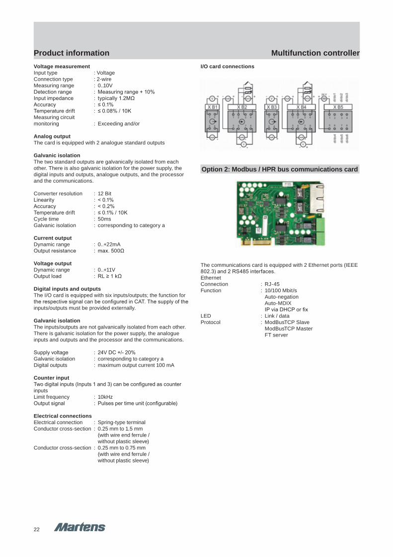
I/O card connections
Option 2: Modbus / HPR bus communications card
The communications card is equipped with 2 Ethernet ports (IEEE802.3) and 2 RS485 interfaces.EthernetConnection : RJ-45Function : 10/100 Mbit/s Auto-negation Auto-MDIX IP via DHCP or fixLED : Link / dataProtocol : ModBusTCP Slave ModBusTCP Master FT server
pi-ta-mureg_MSR9696H_en V1.00-00 15
GHM GROUP CORPORATE | GHM Messtechnik GmbHSchloßstr. 6 | 88453 Erolzheim | GERMANYPhone +49 7354 937233-76 | Fax +49 7354 937233-88www.ghm-group.de | [email protected]
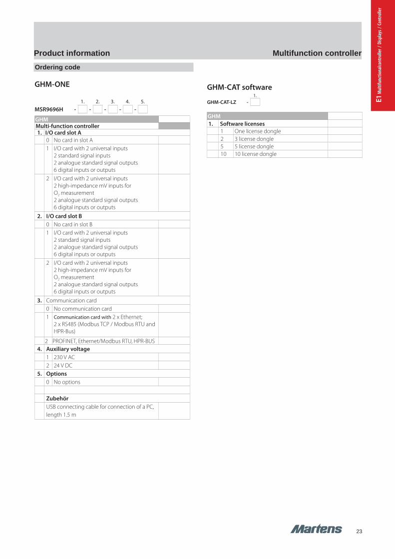
Product information Multifunction controllerOrdering code
GHM-ONE
1. 2. 3. 4. 5.
MSR9696H - - - - -
GHM Multi-function controller1. I/O card slot A
0 No card in slot A1 I/O card with 2 universal inputs
2 standard signal inputs2 analogue standard signal outputs6 digital inputs or outputs
2 I/O card with 2 universal inputs2 high-impedance mV inputs for O2 measurement2 analogue standard signal outputs6 digital inputs or outputs
2. I/O card slot B0 No card in slot B1 I/O card with 2 universal inputs
2 standard signal inputs2 analogue standard signal outputs6 digital inputs or outputs
2 I/O card with 2 universal inputs2 high-impedance mV inputs for O2 measurement2 analogue standard signal outputs6 digital inputs or outputs
3. Communication card0 No communication card1 Communication card with 2 x Ethernet;
2 x RS485 (Modbus TCP / Modbus RTU and HPR-Bus)
2 PROFINET, Ethernet/Modbus RTU, HPR-BUS 4. Auxiliary voltage
1 230 V AC2 24 V DC
5. Options 0 No options
Zubehör USB connecting cable for connection of a PC, length 1.5 m
GHM-CAT software1.
GHM-CAT-LZ -
GHM 1. Software licenses
1 One license dongle2 3 license dongle5 5 license dongle10 10 license dongle
23
Multifunction controllerProduct information
pi-ta-mureg_MSR9696H_en V1.00-0014
GHM GROUP CORPORATE | GHM Messtechnik GmbHSchloßstr. 6 | 88453 Erolzheim | GERMANYPhone +49 7354 937233-76 | Fax +49 7354 937233-88www.ghm-group.de | [email protected]
Product information Multifunction controllerVoltage measurementInput type : VoltageConnection type : 2-wireMeasuring range : 0..10VDetection range : Measuring range + 10%Input impedance : typically 1.2MΩAccuracy : ≤ 0.1%Temperature drift : ≤ 0.08% / 10KMeasuring circuitmonitoring : Exceeding and/or
Analog outputThe card is equipped with 2 analogue standard outputs
Galvanic isolationThe two standard outputs are galvanically isolated from each other. There is also galvanic isolation for the power supply, the digital inputs and outputs, analogue outputs, and the processor and the communications.
Converter resolution : 12 BitLinearity : < 0.1%Accuracy : < 0.2%Temperature drift : ≤ 0.1% / 10KCycle time : 50msGalvanic isolation : corresponding to category a
Current outputDynamic range : 0..+22mAOutput resistance : max. 500Ω
Voltage outputDynamic range : 0..+11VOutput load : RL ≥ 1 kΩ
Digital inputs and outputsThe I/O card is equipped with six inputs/outputs; the function forthe respective signal can be configured in CAT. The supply of theinputs/outputs must be provided externally.
Galvanic isolationThe inputs/outputs are not galvanically isolated from each other.There is galvanic isolation for the power supply, the analogueinputs and outputs and the processor and the communications.
Supply voltage : 24V DC +/- 20%Galvanic isolation : corresponding to category aDigital outputs : maximum output current 100 mA
Counter inputTwo digital inputs (Inputs 1 and 3) can be configured as counterinputsLimit frequency : 10kHzOutput signal : Pulses per time unit (configurable)
Electrical connectionsElectrical connection : Spring-type terminalConductor cross-section : 0.25 mm to 1.5 mm (with wire end ferrule / without plastic sleeve)Conductor cross-section : 0.25 mm to 0.75 mm (with wire end ferrule / without plastic sleeve)
I/O card connections
Option 2: Modbus / HPR bus communications card
The communications card is equipped with 2 Ethernet ports (IEEE802.3) and 2 RS485 interfaces.EthernetConnection : RJ-45Function : 10/100 Mbit/s Auto-negation Auto-MDIX IP via DHCP or fixLED : Link / dataProtocol : ModBusTCP Slave ModBusTCP Master FT server
pi-ta-mureg_MSR9696H_en V1.00-00 15
GHM GROUP CORPORATE | GHM Messtechnik GmbHSchloßstr. 6 | 88453 Erolzheim | GERMANYPhone +49 7354 937233-76 | Fax +49 7354 937233-88www.ghm-group.de | [email protected]
Product information Multifunction controllerOrdering code
GHM-ONE
1. 2. 3. 4. 5.
MSR9696H - - - - -
GHM Multi-function controller1. I/O card slot A
0 No card in slot A1 I/O card with 2 universal inputs
2 standard signal inputs2 analogue standard signal outputs6 digital inputs or outputs
2 I/O card with 2 universal inputs2 high-impedance mV inputs for O2 measurement2 analogue standard signal outputs6 digital inputs or outputs
2. I/O card slot B0 No card in slot B1 I/O card with 2 universal inputs
2 standard signal inputs2 analogue standard signal outputs6 digital inputs or outputs
2 I/O card with 2 universal inputs2 high-impedance mV inputs for O2 measurement2 analogue standard signal outputs6 digital inputs or outputs
3. Communication card0 No communication card1 Communication card with 2 x Ethernet;
2 x RS485 (Modbus TCP / Modbus RTU and HPR-Bus)
2 PROFINET, Ethernet/Modbus RTU, HPR-BUS 4. Auxiliary voltage
1 230 V AC2 24 V DC
5. Options 0 No options
Zubehör USB connecting cable for connection of a PC, length 1.5 m
GHM-CAT software1.
GHM-CAT-LZ -
GHM 1. Software licenses
1 One license dongle2 3 license dongle5 5 license dongle10 10 license dongle
E1 M
ultif
unct
iona
lcont
rolle
r / D
ispla
ys /
Cont
rolle
r
24
DisplaysProduct information
GHM Messtechnik GmbH – Sales Center InternationalSchloßstraße 6 88453 Erolzheim Germany Fon +49-7354-937233-0 Fax -88www.ghm-messtechnik.de [email protected]
Product Information Industrial Electronics
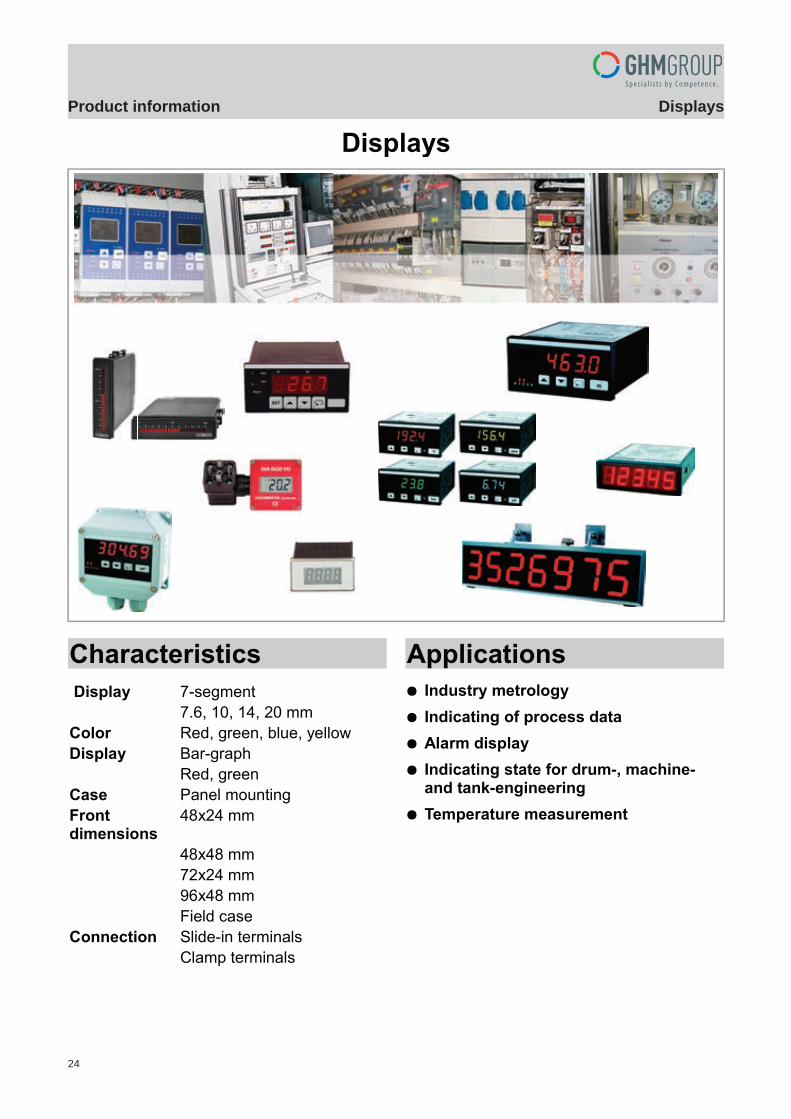
Displays
Characteristics
Display 7-segment
7.6, 10, 14, 20 mm
Color Red, green, blue, yellow
Display Bar-graph
Red, green
Case Panel mounting
Front dimensions
48x24 mm
48x48 mm
72x24 mm
96x48 mm
Field case
Connection Slide-in terminals
Clamp terminals
Applications
Industry metrology
Indicating of process data
Alarm display
Indicating state for drum-, machine- and tank-engineering
Temperature measurement
pi-ma-Displays_E V2.00-00 1
Einleitung

25
DisplaysProduct information
E1 M
ultif
unct
iona
lcont
rolle
r / D
ispla
ys /
Cont
rolle
r
GHM Messtechnik GmbH – Sales Center InternationalSchloßstraße 6 88453 Erolzheim Germany Fon +49-7354-937233-0 Fax -88www.ghm-messtechnik.de [email protected]
Product Information Industrial Electronics
Function and AdvantagesSimple user-friendly programming, or, to be precise, the setting ofthe operating parameters of each digital display, makes the trouble-free adaptation of the display systems and the fixed measuring in-struments to the customized application possible. We also havelarge displays in our portfolio to display information on ongoing pro-cesses or to display key process data,. The multitude of modifiable settings of each display remains veryclearly arranged and simple thanks to the menu-drivenparametrization, even without separate parametrization software.As manufacturer and supplier of digital displays, and the manyyears of experience gained there while, we provide our customersa high degree of flexibility and efficiency in start-up.
All devices built-in the instrument panel of this product group canbe supplied in sturdy, closed plastic casings for front face panel in-stallation in the prevalent casing dimensions of 48x24 mm, 48x48mm, 72x24 mm, 96x24 mm and 96x48 mm. Auxiliary power of thefield measuring devices, digital fixed measuring instruments andpanel meter is potential-free from the measurement input.
General
Measuring Input – Sensor type
Industry standard signal 0/4..20 mA Industry standard signal 0/2..10 V DC Voltage AC/DC Current AC/DC RTD Pt100/Pt1000 Thermocouple type J, K, N
Instrumentation – Connection
2-wire connection 3-wire connection
Output
Analogue output active 0/4..20 mA Analogue output active 0/2..10 V DC Impulse output 0/18 V DC Relay output change-over contact Transistor output PNP
Features
7-segment displays character height 7, 10, 14.2 and 20 mm Display color red, yellow, green, blue (EP9648) Loop powered displays Graphic recorder Large size displays LED dot matrix
max. 100mm character height Large size displays 7-segment
character height from 50 up to 150 mm
2 pi-ma-Displays_E V2.00-00

26
DisplaysProduct information
GHM Messtechnik GmbH – Sales Center InternationalSchloßstraße 6 88453 Erolzheim Germany Fon +49-7354-937233-0 Fax -88www.ghm-messtechnik.de [email protected]
Product Information Industrial Electronics
Device Overview
Panelmeter DIN 48x24
BA4824N 4
BCD4824 5
DP4824A 6
DP4824B 7
SP4824 8
GIA0420 9
DP4848A 10
Panelmeter DIN 72x24
BA7224N 11
BCD7224 5
Panelmeter DIN 96x24
BA9624N 13
BA9624B 14
Panelmeter DIN 96x48
GA9648 15
EP9648 17
SP9648 18
S9648 19
T9648 20
DMS9648 21
TA9648 22
DF9648 23
A9648 25
V9648 26
DR9648 27
PR9648 28
SZ9648 29
UZ9648 30
LF9648 31
pH9648 32
Connection diagram XX96 34
Field case
S1010 35
TA1010 36
T1010 37
DR1010 38
PR1010 39
UZ1010 40
LF1010 41
GIA0420 VO 42
Special devices
Integra 1530 43
migra SC/MC 44
migan 46
Mistakes reserved, technical specifications subject to change without notice.
pi-ma-Displays_E V2.00-00 3
Mo
nit
ori
ng
BC
D
Vo
lta
ge
Cu
rren
t
Re
sis
tan
ce
DM
S
Te
mp
era
ture
Imp
uls
e/
Fre
qu
en
cy
Ro
tary
/F
low
Qu
an
tity
/L
eve
l
Co
un
tin
g
0/4
..20
mA
0/2
..10
V D
C
Page
Measuring principle
Po
wer
Device
27
29
31
33
34
36
38
41
4344
46
49
51
5554
58
60
62
64
66
69
28
30
32
35
37
40
42
45
48
50
5253
57
59
61
63
65
67

27
DisplaysProduct information
E1 M
ultif
unct
iona
lcont
rolle
r / D
ispla
ys /
Cont
rolle
r
GHM Messtechnik GmbH – Location MartensKiebitzhörn 18 22885 Barsbüttel Germany Fon +49-40-670 73-0 Fax -288www.ghm-messtechnik.de [email protected]
Product Information Industrial Electronics
Bar Graph Display BA4824N
Universal version for 0/4..20 mA, 0..10 V DC Red LED indicator (optionally green) Vertical and horizontal installation All areas can be selected via connecting terminal Display area adjustable via potentiometer
Characteristics
Series BA bar graph displays are especially well suited forrepresenting continuously changing measurements. With theirsmall design, they can be easily integrated into control panels anddiagrams.
The version BA4824N is especially well-suited for processing inputsignals 0/4..20 mA, 0..10 V DC (limit value adjustable from 5..50 VDC). Adaptation to the corresponding input signal takes place viathe connecting terminal. The display zero point and limit value canbe adjusted via separate potentiometers.
Technical data
Auxiliary powerAuxiliary voltage : 24 V DC ± 10 % isolatedPower consumption : approximately 1.5 VAOperating temperature : 0..+60 °CCE Conformity : EN 61010-1 2001, EN 61326-1: 1997,
EN 55011: 1998Measurement inputCurrent input : 0/4..20 mA,Voltage input : 0..10 V DC (adjustable limit value)Input resistance : Ri at: 10 V = 100 kΩ, 20 mA = 100 ΩAccuracyResolution : 10 digitBasic precision : +/- 1 digitTemperature coefficient : 100 ppm/KDisplayRange : 10 segmentsColour : red, optionally greenHousing : DIN 48 x 24 mm, installation depth 100 mmDesign : PC/ABS blend, black colour, UL94V-0
Panel aperture 42 x 21 mmFastening : locking screw element for wall thickness
up to 50 mmWeight : 60 gConnection : rear plug terminals, max. 1.5 mm²
Protection class IP00Ingress protection : Front IP54 or IP65
Dimensions
Connection diagram
Ordering code
1. 2. 3. 4. 5. 6. 7.
BA - - - - - -
1. Construction
4824N 10 segments
2. Installation
1 Vertical
2 Horizontal
3. Bar colour
1 Red display
2 Green display
4. Auxiliary voltage
5 24 V DC with electrical isolation
5. Input signal
0 Universal version
6. Measuring range scale 0..100 %
10 Universal version
7. Ingress protection
1 IP54
2 IP65
4 pi-ma-Displays_E V2.00-00
BA4824N BA4824N

28
DisplaysProduct information
BCD4824 BCD4824
GHM Messtechnik GmbH – Location MartensKiebitzhörn 18 22885 Barsbüttel Germany Fon +49-40-670 73-0 Fax -288www.ghm-messtechnik.de [email protected]
Product Information Industrial Electronics
BCD PanelmeterBCD4824
Display red or green 3-digit LED 10 mm or 14.2 mm Input BCD parallel or multiplex Supply voltage 10..30 V DC, optional 5 V DC
Characteristics
Digital Panelmeter BCD4824 was designed for monitoring andmeasurement applications, specially in connection with SPS auto-mation. The multiplex mode minimize the number of input lines.The small case is suitable for installation in control units and panelboards.
Technical data
Power supplySupply voltage : 10..30 V DCPower consumption : approx. 1.2 VA Operating temperature : -10..+60 °CCE-conformity : IEC 61326, IEC 61000-4-2/3/4/5/6/8
Display : 3-digitLED 10 mm or 14.2 mm
Color : red or greenDecimals : single points selectable
InputsControl : Parallel or multiplexVoltage level : Low-Signal 0..3 V DC;
High-Signal 10..30 V DC,or TTL-level
Input resistance : approx. 20 kΩminimal rise time of the Strobe inputs 10 ms
Case : DIN 48x24 mm, mounting depth 97 mmType : slide-in case according to
DIN 43700, Noryl SE1 GFN2panel cut-out 44x21 mm
Weight : approx. 60 gConnection : terminal strip 16 pole, Protection class : IP54 or IP65
terminals IP20 acc. to BGV A3
Dimensions
Connection diagram
Input parallel Input multiplex
Ordering code
1. 2. 3. 4. 5.
BCD - - - -
1. Model
4824
2. Display
1 LED red 10 mm
2 LED green 10 mm
3 LED red 14.2 mm
4 LED green 14.2 mm
3. Supply voltage
5 10..30 V DC
7 5 V DC
4. Input
1 0..3 V DC low; 10..30 V DC high, parallel
2 5 V TTL-level, parallel
3 0..3 V DC low; 10..30 V DC high, multiplex
4 5 V TTL-level, multiplex
5. Protection class
1 IP54
2 IP65
Accessories connection cable with terminal strip and pigtails
AK16K-AE-3 16x0.25 mm² length 3 m
AK16K-AE-10 16x0.25 mm² length 10 m
AK16K-AE-20 16x0.25 mm² length 20 m
pi-ma-Displays_E V2.00-00 5

29
DisplaysProduct information
E1 M
ultif
unct
iona
lcont
rolle
r / D
ispla
ys /
Cont
rolle
r
GHM Messtechnik GmbH – Location MartensKiebitzhörn 18 22885 Barsbüttel Germany Fon +49-40-670 73-0 Fax -288www.ghm-messtechnik.de [email protected]
Product Information Industrial Electronics
Digital Panelmeter DP4824A
Multipurpose input for 0/4..20 mA, 0/2..10 V and potentiometer
Input for RTD sensor Pt100/Pt1000 Adjustable display range ± 1999 Digit
Characteristics
The universal conception of the multipurpose input allows indicationof all physical dimensions, which can be converted to 0/4..20 mA,0/2..10 V DC. Other models of the DP4824A are for temperaturemeasurement with Pt100 and Pt1000 sensors. The input configura-tion is switch selectable from the side, without opening the case. In-put and supply voltage are isolated. The display range is adjustablewith 20-turn trim pot´s for initial value and span.
Technical data
Power supplySupply voltage : 10.8..30 V DC; 17..30 V ACFrequency AC : 47..63 HzPower consumption : approx. 1.2 VAWorking temperature : -10..+60 °CCE-conformity : EN 55022, IEC 61000-4-2/4/11
InputVoltage : 0/2..10 V DCInput resistance : Ri = 40 kΩOverload : max. 48 VCurrent : 0/4..20 mAInput resistance : Ri = 125 ΩOverload : max. 60 mAPotentiometer : min. 1 kΩ, max. 100 kΩPt100 : -100.0..+199.9 °C / -100..+600 °CSensor current : approx. 1 mA (low self heating)Pt1000 : -50.0..100.0 °CSensor current : approx. 0.2 mA (low self heating)Accuracy : < 0.05 % +/−1 Digit
DisplayConversion rate : approx. 2 / sRange / color : 3 ½ digit, red or green, 7.6 mmDecimal point : switch selectable
Overflow : negative overflow " ",
positive overflow " "
Case : DIN 48x24 mm, mounting depth 97 mmType : slide-in case acc. to DIN 43700,
material Noryl SE1 GFN2panel cut-out 44x21 mm
Weight : 100 gConnection : plug-in terminal, max. 1.5 mm²Protection class : front IP54 or IP65,
terminals IP20 acc. to BGV A3
Dimensions
Connection diagram
Standard signal Pt100/Pt1000
Ordering code
1. 2. 3. 4.
DP4824A - - - -
1. Display
1 3 ½-digit LED red 7.6mm
2 3 ½-digit LED green 7.6mm
2. Input
10 industry standard signal
20 custom input (on request)
50 Pt100
53 Pt1000
3. Protection class
1 IP54
2 IP65
4. Unit (appears on the face plate)
6 pi-ma-Displays_E V2.00-00
DP4824A DP4824A
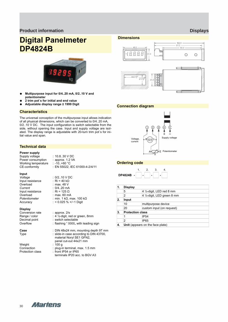
30
DisplaysProduct information
DP4824B DP4824B
GHM Messtechnik GmbH – Location MartensKiebitzhörn 18 22885 Barsbüttel Germany Fon +49-40-670 73-0 Fax -288www.ghm-messtechnik.de [email protected]
Product Information Industrial Electronics
Digital Panelmeter DP4824B
Multipurpose input for 0/4..20 mA, 0/2..10 V and potentiometer
2 trim pot´s for initial and end value Adjustable display range ± 1999 Digit
Characteristics
The universal conception of the multipurpose input allows indicationof all physical dimensions, which can be converted to 0/4..20 mA,0/2..10 V DC. The input configuration is switch selectable from theside, without opening the case. Input and supply voltage are isol-ated. The display range is adjustable with 20-turn trim pot´s for ini-tial value and span.
Technical data
Power supplySupply voltage : 10.8..30 V DCPower consumption : approx. 1.2 VAWorking temperature : -10..+60 °CCE-conformity : EN 55022, IEC 61000-4-2/4/11
InputVoltage : 0/2..10 V DCInput resistance : Ri = 40 kΩOverload : max. 48 VCurrent : 0/4..20 mAInput resistance : Ri = 125 ΩOverload : max. 60 mAPotentiometer : min. 1 kΩ, max. 100 kΩAccuracy : < 0.025 % +/−1 Digit
DisplayConversion rate : approx. 2/sRange / color : 4 ½-digit, red or green, 8mmDecimal point : switch selectable
Overflow : flashing “ 0000„ with leading sign
Case : DIN 48x24 mm, mounting depth 97 mmType : slide-in case according to DIN 43700,
material Noryl SE1 GFN2,panel cut-out 44x21 mm
Weight : 100 gConnection : plug-in terminal, max. 1.5 mmProtection class : front IP54 or IP65
terminals IP20 acc. to BGV A3
Dimensions
Connection diagram
Ordering code
1. 2. 3. 4.
DP4824B - - - -
1. Display
5 4 ½-digit, LED red 8 mm
2 4 ½-digit, LED green 8 mm
2. Input
10 multipurpose device
20 custom input (on request)
3. Protection class
1 IP54
2 IP65
4. Unit (appears on the face plate)
pi-ma-Displays_E V2.00-00 7
Supply voltageVoltage,current
Potentiometer

31
DisplaysProduct information
E1 M
ultif
unct
iona
lcont
rolle
r / D
ispla
ys /
Cont
rolle
r
GHM Messtechnik GmbH – Location MartensKiebitzhörn 18 22885 Barsbüttel Germany Fon +49-40-670 73-0 Fax -288www.ghm-messtechnik.de [email protected]
Product Information Industrial Electronics
Loop PoweredPanelmeter SP4824
LED-display without separate supply voltage Free adjustable indicating range Switch selectable conversion rate 3/s or 0,5/s
Characteristics
Loop powered Panelmeter SP4824 can be used for indicating andmeasurement applications in process technology and automation.The small case is suitable for installation in control units and panelboards. The input allows indication of any physical dimension,which are stated in a signal of 4..20mA.
Technical data
InputCurrent input : 4..20 mAOverload range : -100..+150 mAVoltage drop : 2.5..3.4 V,
depends on chosen display brightnessAccuracy : 0.1 % , +/- 1 DigitOperating temp. : -10..+60 °CCE- conformity : EN 55022, IEC 61000-4-2/4
DisplayIndicating range : -1999..+1999Span : adjustable 0..4000 DigitsZero point : adjustable -100..+25 % of the span
Brightness : adjustable ≈ 40..100 %Conversion rate : 3/s switchable 0.5/sHeight : 7.6 mm
Overflow indication : "- I " for negative and
" I " for positive overflow
Color : red
Weight- Panel case : approx. 50 g- Field case : approx. 270 gConnection : slide-in terminal strip,
max. 1.5 mm², AWG16Protection class : front IP54 or IP65
terminals IP20 acc. to BGV A3
Dimensions
Panel case
Field case
Connection diagram
Ordering code
1. 2. 3. 4.
SP4824 - - - -
1. Device type
1 panel case
2 field case 82x80x85 mm (WxHxD)
2. Display characteristics
S increasing (Standard)
F decreasing
3. Protection class
1 IP54
2 IP65
4. Unit (appears on the face plate)
Accessories
10031201 mounting brackets
8 pi-ma-Displays_E V2.00-00
Power supply 2-wire sensor
SP4824
Ø 4.2mm
M16x1.5
Mounting brackets
SP4824 SP4824

32
DisplaysProduct information
GIA0420N GIA0420N
GHM Messtechnik GmbH - Location GreisingerHans-Sachs-Straße 26 93128 Regenstauf Germany Fon +49 (0) 9402 - 9383 - 0 Fax -33www.greisinger.de [email protected]
Produktinformation Industrial Electronics
Display GIA 0420 N
Self-supplying, no additional auxiliary supply necessary Freely scalable Integrated self-diagnostic
Characteristics
The GIA 0420 is a microprocessor-controlled displaying device for4..20 mA standard signals.
Any transmitter (with 4..20 mA output) can be connected to the de-vice. The range adjustment of the GIA 0420 to the transmitter isdone by entering the initial and final value and the decimal point po-sition. No additional auxiliaries are needed for this adjustment, butthe three buttons on the back side of the device. The GIA 0420 doesn't need a separate auxiliary supply but is di-rectly supplied by the measuring current. It has an integrated self-diagnostic which checks the device that it works correctly. This self-diagnostic together with the transmitter's check for “sensor break”and “sensor short circuit” and range exceeding or falling below en-sures an optimum of operational reliability.
Technical data
Measuring inputInput signal : 4..20 mA (2-wire)Accuracy : ± 0.2 % FS ±1 digitMeasuring rate : 5 measurements / secondsVoltage load : 3,5 VPower supply : self-supplying: devices is supplied
directly from measuring currentWorking temperature : 0..50 °CFilter : adjustable in in 3 stagesSwitching output : 1x electrically isolated open collector
switching outputStorage : min- / max-memory via buttons
DisplayDisplay : LCD displayHeight : 10 mm Display range : -1999..+9999 digit
initial and final value adjustable
Connection : 2-pole screw / clamp terminals,max. cross section up to 1.5 mm²
Housing : fibre-reinforced Noryl,front screen made of polycarbonate
Protection class : front IP54
Dimensions
Housing : 24 x 48 x 65 mm (H x W x D)Panel cutout : 21.7 x 45 mm [±0.5 mm] (H x W)
Connection diagram
Design type
010N Input signal: 0..20 V (3-wire)Input resistance: approx. 100 kOhmPower supply: 12..28 V, < 10 mA
ex with ATEX protection for explosive areas
Ordering code
1. 2.
GIA -
1. Design type
0420N Display 0..20 mA
010N Display 0..10 V
0420N-ex Display 0..20 mA with Ex-protection
010N-ex Display 0..10 V with Ex-protection
2. Option
00 without option
pi-ma-Displays_E V2.00-00 9
Input 4..20 mAInput 4..20 mA
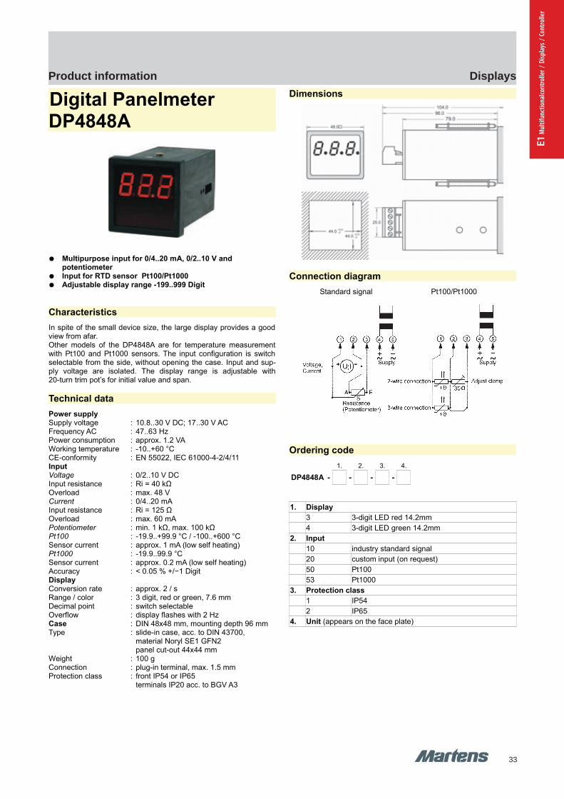
33
DisplaysProduct information
E1 M
ultif
unct
iona
lcont
rolle
r / D
ispla
ys /
Cont
rolle
r
GHM Messtechnik GmbH – Location MartensKiebitzhörn 18 22885 Barsbüttel Germany Fon +49-40-670 73-0 Fax -288www.ghm-messtechnik.de [email protected]
Product Information Industrial Electronics
Digital Panelmeter DP4848A
Multipurpose input for 0/4..20 mA, 0/2..10 V and potentiometer
Input for RTD sensor Pt100/Pt1000 Adjustable display range -199..999 Digit
Characteristics
In spite of the small device size, the large display provides a goodview from afar. Other models of the DP4848A are for temperature measurementwith Pt100 and Pt1000 sensors. The input configuration is switchselectable from the side, without opening the case. Input and sup-ply voltage are isolated. The display range is adjustable with20-turn trim pot’s for initial value and span.
Technical data
Power supplySupply voltage : 10.8..30 V DC; 17..30 V ACFrequency AC : 47..63 HzPower consumption : approx. 1.2 VAWorking temperature : -10..+60 °CCE-conformity : EN 55022, IEC 61000-4-2/4/11InputVoltage : 0/2..10 V DCInput resistance : Ri = 40 kΩOverload : max. 48 VCurrent : 0/4..20 mAInput resistance : Ri = 125 ΩOverload : max. 60 mAPotentiometer : min. 1 kΩ, max. 100 kΩPt100 : -19.9..+99.9 °C / -100..+600 °CSensor current : approx. 1 mA (low self heating)Pt1000 : -19.9..99.9 °CSensor current : approx. 0.2 mA (low self heating)Accuracy : < 0.05 % +/−1 DigitDisplayConversion rate : approx. 2 / sRange / color : 3 digit, red or green, 7.6 mmDecimal point : switch selectableOverflow : display flashes with 2 HzCase : DIN 48x48 mm, mounting depth 96 mmType : slide-in case, acc. to DIN 43700,
material Noryl SE1 GFN2panel cut-out 44x44 mm
Weight : 100 gConnection : plug-in terminal, max. 1.5 mmProtection class : front IP54 or IP65
terminals IP20 acc. to BGV A3
Dimensions
Connection diagram
Standard signal Pt100/Pt1000
Ordering code
1. 2. 3. 4.
DP4848A - - - -
1. Display
3 3-digit LED red 14.2mm
4 3-digit LED green 14.2mm
2. Input
10 industry standard signal
20 custom input (on request)
50 Pt100
53 Pt1000
3. Protection class
1 IP54
2 IP65
4. Unit (appears on the face plate)
10 pi-ma-Displays_E V2.00-00
DP4848A DP4848A
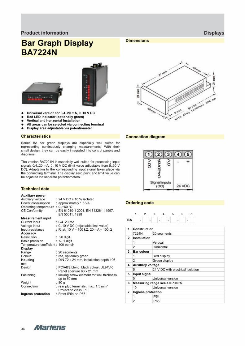
34
DisplaysProduct information
BA7224N BA7224N
GHM Messtechnik GmbH – Location MartensKiebitzhörn 18 22885 Barsbüttel Germany Fon +49-40-670 73-0 Fax -288www.ghm-messtechnik.de [email protected]
Product Information Industrial Electronics
Bar Graph Display BA7224N
Universal version for 0/4..20 mA, 0..10 V DC Red LED indicator (optionally green) Vertical and horizontal installation All areas can be selected via connecting terminal Display area adjustable via potentiometer
Characteristics
Series BA bar graph displays are especially well suited forrepresenting continuously changing measurements. With theirsmall design, they can be easily integrated into control panels anddiagrams.
The version BA7224N is especially well-suited for processing inputsignals 0/4..20 mA, 0..10 V DC (limit value adjustable from 5..50 VDC). Adaptation to the corresponding input signal takes place viathe connecting terminal. The display zero point and limit value canbe adjusted via separate potentiometers.
Technical data
Auxiliary powerAuxiliary voltage : 24 V DC ± 10 % isolatedPower consumption : approximately 1.5 VAOperating temperature : 0..+60 °CCE Conformity : EN 61010-1 2001, EN 61326-1: 1997,
EN 55011: 1998Measurement inputCurrent input : 0/4..20 mA,Voltage input : 0..10 V DC (adjustable limit value)Input resistance : Ri at: 10 V = 100 kΩ, 20 mA = 100 ΩAccuracyResolution : 20 digitBasic precision : +/- 1 digitTemperature coefficient : 100 ppm/KDisplayRange : 20 segmentsColour : red, optionally greenHousing : DIN 72 x 24 mm, installation depth 106 mmDesign : PC/ABS blend, black colour, UL94V-0
Panel aperture 66 x 21 mmFastening : locking screw element for wall thickness
up to 50 mmWeight : 80 gConnection : rear plug terminals, max. 1.5 mm²
Protection class IP00Ingress protection : Front IP54 or IP65
Dimensions
Connection diagram
Ordering code
1. 2. 3. 4. 5. 6. 7.
BA - - - - - -
1. Construction
7224N 20 segments
2. Installation
1 Vertical
2 Horizontal
3. Bar colour
1 Red display
2 Green display
4. Auxiliary voltage
5 24 V DC with electrical isolation
5. Input signal
0 Universal version
6. Measuring range scale 0..100 %
10 Universal version
7. Ingress protection
1 IP54
2 IP65
pi-ma-Displays_E V2.00-00
11

35
DisplaysProduct information
E1 M
ultif
unct
iona
lcont
rolle
r / D
ispla
ys /
Cont
rolle
r
GHM Messtechnik GmbH – Location MartensKiebitzhörn 18 22885 Barsbüttel Germany Fon +49-40-670 73-0 Fax -288www.ghm-messtechnik.de [email protected]
Product Information Industrial Electronics
BCD PanelmeterBCD7224
Display red or green 5-digit LED 10 mm or 14.2 mm Input BCD parallel or multiplex Supply voltage 10..30 V DC, optional 5 V DC
Characteristics
Digital Panelmeter BCD7224 was designed for monitoring and measurement applications, specially in connection with SPS auto-mation. The multiplex mode minimize the number of input lines. The small case is suitable for installation in control units and panel boards.
Technical data
Power supplySupply voltage : 10..30 V DCPower consumption : approx. 1.2 VA Operating temperature : -10..+60 °CCE-conformity : IEC 61326, IEC 61000-4-2/3/4/5/6/8
Display : 5-digitLED 10 mm or 14.2 mm
Color : red or greenDecimals : single selection
InputsControl : parallel or multiplexVoltage level : low-signal 0..3 V DC;
high-signal 10..30 V DC,or TTL-level
Input resistance : approx. 20 kΩminimal rise time of the strobe inputs 10 ms
Case : DIN 72x24 mm, mounting depth 85 mmType : slide-in case according to
DIN 43700, Noryl SE1 GFN2panel cut-out 68x21 mm
Weight : approx. 60 gConnection : terminal strip 16 pole, Protection class : IP54 or IP65
terminals IP20 acc. to BGV A3
Dimensions
Connection diagram
Input parallel Input multiplex
Ordering code
1. 2. 3. 4. 5.
BCD - - - -
1. Model
7224
2. Display
1 LED red 10 mm
2 LED green 10 mm
3 LED red 14.2 mm
4 LED green 14.2 mm
3. Supply voltage
5 10..30 V DC
7 5 V DC
4. Input
1 0..3 V DC low; 10..30 V DC high, parallel
2 5 V TTL-level, parallel
3 0..3 V DC low; 10..30 V DC high, multiplex
4 5 V TTL-level, multiplex
5. Protection class
1 IP54
2 IP65
Accessories connection cable with terminal strip and pigtails
AK26K-AE-3 26x0.25 mm² length 3 m
AK26K-AE-10 26x0.25 mm² length 10 m
AK26K-AE-20 26x0.25 mm² length 20 m
12 pi-ma-Displays_E V2.00-00
BCD7224 BCD7224
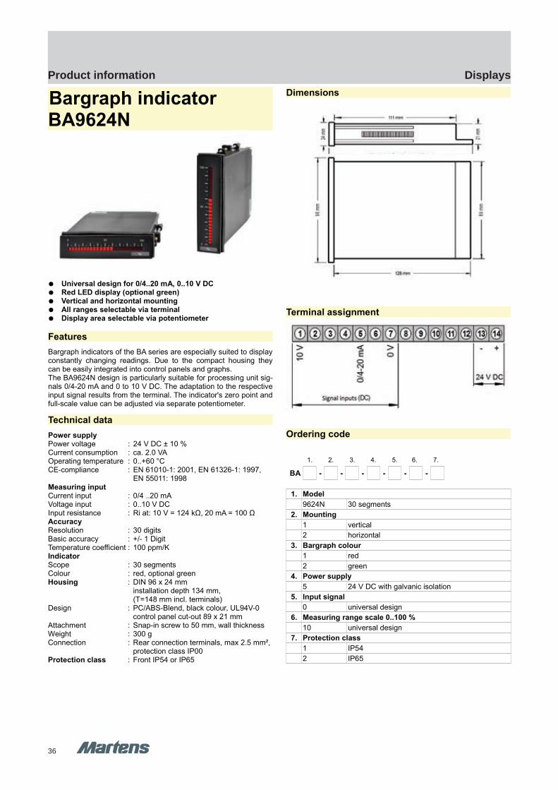
36
DisplaysProduct information
BA9624N BA9624N
GHM Messtechnik GmbH – Location MartensKiebitzhörn 18 22885 Barsbüttel Germany Fon +49-40-670 73-0 Fax -288www.ghm-messtechnik.de [email protected]
Product Information Industrial Electronics
Bargraph indicator BA9624N
Universal design for 0/4..20 mA, 0..10 V DC Red LED display (optional green) Vertical and horizontal mounting All ranges selectable via terminal Display area selectable via potentiometer
Features
Bargraph indicators of the BA series are especially suited to displayconstantly changing readings. Due to the compact housing theycan be easily integrated into control panels and graphs.The BA9624N design is particularly suitable for processing unit sig-nals 0/4-20 mA and 0 to 10 V DC. The adaptation to the respectiveinput signal results from the terminal. The indicator's zero point andfull-scale value can be adjusted via separate potentiometer.
Technical data
Power supplyPower voltage : 24 V DC ± 10 % Current consumption : ca. 2.0 VAOperating temperature : 0..+60 °CCE-compliance : EN 61010-1: 2001, EN 61326-1: 1997,
EN 55011: 1998Measuring inputCurrent input : 0/4 ..20 mAVoltage input : 0..10 V DCInput resistance : Ri at: 10 V = 124 kΩ, 20 mA = 100 ΩAccuracyResolution : 30 digitsBasic accuracy : +/- 1 DigitTemperature coefficient : 100 ppm/KIndicatorScope : 30 segmentsColour : red, optional greenHousing : DIN 96 x 24 mm
installation depth 134 mm, (T=148 mm incl. terminals)
Design : PC/ABS-Blend, black colour, UL94V-0control panel cut-out 89 x 21 mm
Attachment : Snap-in screw to 50 mm, wall thicknessWeight : 300 gConnection : Rear connection terminals, max 2.5 mm²,
protection class IP00Protection class : Front IP54 or IP65
Dimensions
Terminal assignment
Ordering code
1. 2. 3. 4. 5. 6. 7.
BA - - - - - -
1. Model
9624N 30 segments
2. Mounting
1 vertical
2 horizontal
3. Bargraph colour
1 red
2 green
4. Power supply
5 24 V DC with galvanic isolation
5. Input signal
0 universal design
6. Measuring range scale 0..100 %
10 universal design
7. Protection class
1 IP54
2 IP65
pi-ma-Displays_E V2.00-00
13

37
DisplaysProduct information
E1 M
ultif
unct
iona
lcont
rolle
r / D
ispla
ys /
Cont
rolle
r
GHM Messtechnik GmbH – Location MartensKiebitzhörn 18 22885 Barsbüttel Germany Fon +49-40-670 73-0 Fax -288www.ghm-messtechnik.de [email protected]
Product Information Industrial Electronics
Bargraph Indicator BA9624B
Multipurpose inputs for 0/4..20 mA and 0..10 V DC Bargraph with 30 segments red, yellow or green program-
mable Horizontal or vertical mounting Integrated integrated 3-digit display red, free adjustable in
the range -99..999 Digit Increasing or decreasing trend indication Bargraph or dot operation Display time 0.01..10 s programmable
Characteristics
Multi-color Bargraph Displays can be used for monitoring analogtrend indication. The small cases are suitable for installation in con-trol units and panel boards. The BA9624B includes a 3-digit display for alarm values and pro-gramming functions. The multipurpose input is designed for in-dustry standard signals 0/4..20 mA and 0..10 V DC. 4 front buttonsmakes the programming for the application possible.
Technical data
Power supplySupply voltage : 85..265 V AC, 50/60 Hz; 10..30 V AC/DCPower consumption : approx. 5 VAOperating temp. : 0..50 °CCE-conformity : EN 61010, EN60664-1
InputCurrent : 0/4..20 mA, Ri 100 ΩVoltage : 0..10 V DC, Ri 200 kΩ
IndicatorBargraph : 30 segments LED tricolorDisplay : 3-digits, 8 mm red ; -99..999 DigitDisplay time : programmable from 0.01..10 s Overflow : flashing upper or lower bargraph segmentsAccuracy : ± 0.2 %; 1 segment (bargraph);
±1 digit (display)Output2 Relay : SPDT, 250 V AC / 5 A or 30 V DC / 5 A
Case : DIN 96x24 mm, mounting depth 120 mmType : slide-in case according to DIN 43700,
Polycarbonate / frame ABSpanel cut-out 92x22 mm
Installation : 2 clips, up to 50 mm wall thicknessWeight : 0.29 kgProtection class : front IP65, terminals IP00Connection : screw terminals, with pressure plate,
max. 2.5 mm² according to BGV A3
Dimensions
Connection diagrams
Input
Output
Ordering code
1. 2. 3. 4. 5.
BA9624B - - - - -
1. Mounting direction
1 vertical
2 horizontal
2. Display color
3 bargraph tricolor red/yellow/green7-segment display red
3. Supply voltage
0 85..265 V AC
5 10..30 V AC/DC
4. Measuring range, scale 0-100 %
10 0/4..20 mA, 0..10 V DC
5. Protection class (front)
2 IP65
14 pi-ma-Displays_E V2.00-00
Signal inputs
10-30 VDCor
85-265 VAC
Relay 1 Relay 2
BA9624B BA9624B
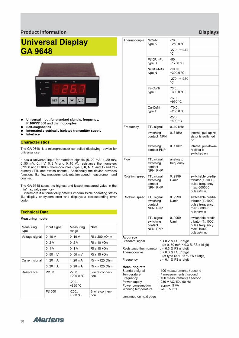
38
DisplaysProduct information
GA9648 GA9648
GHM Messtechnik GmbH – Location MartensKiebitzhörn 18 22885 Barsbüttel Germany Fon +49-40-670 73-0 Fax -288www.ghm-messtechnik.de [email protected]
Product Information Industrial Electronics
Universal DisplayGA 9648
Universal input for standard signals, frequency, Pt100/Pt1000 and thermocouples
Self-diagnostics Integrated electrically isolated transmitter supply Interface
Characteristics
The GA 9648 is a microprocessor-controlled displaying device foruniversal use.
It has a universal input for standard signals (0..20 mA, 4..20 mA,0..50 mV, 0..1 V, 0..2 V and 0..10 V), resistance thermometers(Pt100 and Pt1000), thermocouples (type J, K, N, S and T) and fre-quency (TTL and switch contact). Additionally the device providesfunctions like flow measurement, rotation speed measurement andcounter.
The GA 9648 saves the highest and lowest measured value in themin/max value memory. Furthermore it automatically detects impermissible operating stateslike display or system error and displays a corresponding errorcode.
Technical Data
Measuring inputs
Measuring type
Input signal Measuring range
Note
Voltage signal 0..10 V 0..10 V Ri ≥ 200 kOhm
0..2 V 0..2 V Ri ≥ 10 kOhm
0..1 V 0..1 V Ri ≥ 10 kOhm
0..50 mV 0..50 mV Ri ≥ 10 kOhm
Current signal 4..20 mA 4..20 mA Ri = ~125 Ohm
0..20 mA 0..20 mA Ri = ~125 Ohm
Resistance Pt100 -50.0.. +200.0 °C
3-wire connec-tion
-200.. +850 °C
Pt1000 -200.. +850 °C
2-wire connec-tion
Thermocouple NiCr-Nitype K
-70.0.. +250.0 °C
-270.. +1372°C
Pt10Rh-Pttype S
-50.. +1750 °C
NiCrSi-NiSitype N
-100.0.. +300.0 °C
-270.. +1350°C
Fe-CuNitype J
70.0.. +300.0 °C
-170.. +950 °C
Cu-CuNitype T
-70.0.. +200.0 °C
-270.. +400 °C
Frequency TTL signal 0..10 kHz
switching contact NPN
0..3 kHz internal pull-up-re-sistor is switched on
switching contact PNP
0..1 kHz internal pull-down-resistor is switched on
Flow TTL signal, switching contact NPN, PNP
analog to frequency
Rotation speed TTL signal, switching contact NPN, PNP
0..9999 U/min
switchable predis-tributor (1..1000), pulse frequency: max. 600000 pulses/min.
Rotation speed TTL signal, switching contact NPN, PNP
0..9999 U/min
switchable predis-tributor (1..1000), pulse frequency: max. 600000 pulses/min.
TTL signal, switching contact NPN, PNP
0..9999 U/min
switchable predis-tributor (1..1000), pulse frequency: max. 10000 pulses/min.
AccuracyStandard signal : < 0.2 % FS ±1digit
(at 0..50 mV: < 0.3 % FS ±1digit)Resistance thermometer : < 0.3 % FS ±1digitThermocouple : < 0.3 % FS ±1digit
(at type S: < 0.5 % FS ±1digit)Frequency : < 0.1 % FS ±1digit
Measuring rateStandard signal : 100 measurements / secondTemperature : 4 measurements / secondFrequency : 100 measurements / secondPower supply : 230 V AC, 50 / 60 HzPower consumption : approx. 5 VAWorking temperature : -20..+50 °C
continued on next page
pi-ma-Displays_E V2.00-00
15

39
DisplaysProduct information
E1 M
ultif
unct
iona
lcont
rolle
r / D
ispla
ys /
Cont
rolle
r
GHM Messtechnik GmbH – Location MartensKiebitzhörn 18 22885 Barsbüttel Germany Fon +49-40-670 73-0 Fax -288www.ghm-messtechnik.de [email protected]
Product Information Industrial Electronics
DisplayDisplay : LED displayHeight : 13 mm Display range : -1999..+9999 digit
initial, final value and decimal point freely selectable
Operation : via 4 buttons or via interfaceInterface : EASYBus interface, electrically isolated Transmitter supply : 24 V DC ±5 %, 22 mA, electr. isolated
at DC supply: 18 V DCElectric connection : via screw / clamp terminals
wire cross section from 0.14..1.5 mm2
Protection class : front IP54, with optional sealing IP65
Dimensions
HousingSize : 48 x 96 mm (H x W)Mounting depth : 115 mm
(incl. screw / clamp terminals)Panel mounting : by fixing clampsPanel cutout : 43.0 x 90.5 mm [±0.5 mm] (H x W)
Connection diagram
15 EASYBus interface
14 EASYBus interface
13 input: 0..10 V
12 input: 0..1 V, 0..2 V, mA, fre-quency, Pt100, Pt1000
11 input: 0..50 mV, thermocouple, Pt100
10 input: GND, Pt100, Pt1000
9 transmitter supply (-)
8 transmitter supply (+)
2 power supply
1 power supply
Options
230A supply voltage: 230 V AC (standard)
012D supply voltage: 12 V DC (11..14 V)
024D supply voltage: 24 V DC (22..27 V)
024A supply voltage: 24 V AC (±5 %)
115A supply voltage: 115 V AC (±5 %)
AA analog output 0..20 mA, 4..20 mA (selectable)
AV analog output 0..10 V
Ordering code
1. 2. 3.
GA9648 - - -
1. Supply voltage
230A 230 V AC (standard)
012D 12 V DC
024D 24 V DC
024A 24 V AC
115A 115 V AC
2. Analog output
00 no analog output (standard)
AA analog output 0..20 mA, 4..20 mA
AV analog output 0..10 V
3. Option
00 without option
IP sealing to increase protection class to IP65
Special design types (upon request)
SA1 Selectable scalingwith input 0..10 V and control input 24 VThe device has a 0..10 V standard signal inputand a 24 V control input. By means of the 24 Vcontrol input it is possible to switch between twofreely programmable scalings.
SA2 Input ±10 V DC
SA3 Set-point controllerThis special design type makes the GA 9648 toa microprocessor-controlled set-point controllerfor universal use. The output value can be setvia button 2 and 3 and then be output as analogsignal corresponding to selected analog outputtype.
Accessories
EAK 36Unit stickers (black with white characters), 36 different units, forlabeling of display devices
16 pi-ma-Displays_E V2.00-00
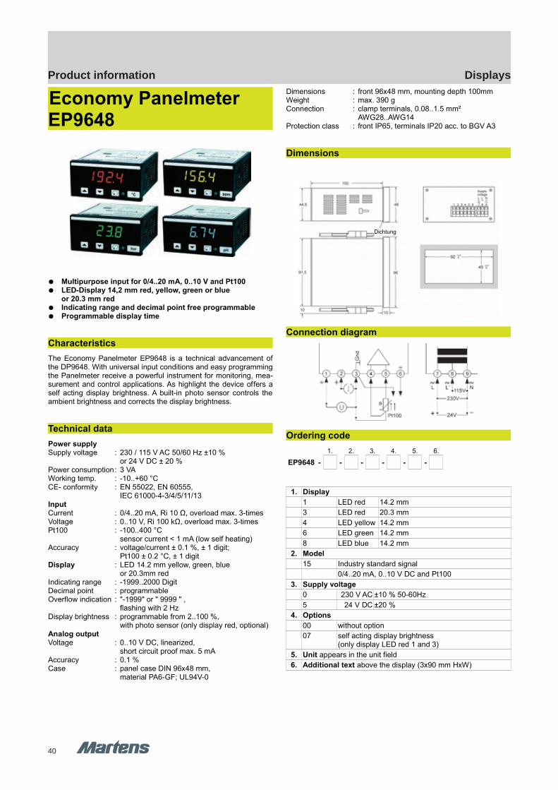
40
DisplaysProduct information
EP9648 EP9648
GHM Messtechnik GmbH – Location MartensKiebitzhörn 18 22885 Barsbüttel Germany Fon +49-40-670 73-0 Fax -288www.ghm-messtechnik.de [email protected]
Product Information Industrial Electronics
Economy Panelmeter EP9648
Multipurpose input for 0/4..20 mA, 0..10 V and Pt100 LED-Display 14,2 mm red, yellow, green or blue
or 20.3 mm red Indicating range and decimal point free programmable Programmable display time
Characteristics
The Economy Panelmeter EP9648 is a technical advancement ofthe DP9648. With universal input conditions and easy programmingthe Panelmeter receive a powerful instrument for monitoring, mea-surement and control applications. As highlight the device offers aself acting display brightness. A built-in photo sensor controls theambient brightness and corrects the display brightness.
Technical data
Power supplySupply voltage : 230 / 115 V AC 50/60 Hz ±10 %
or 24 V DC ± 20 %Power consumption: 3 VAWorking temp. : -10..+60 °CCE- conformity : EN 55022, EN 60555,
IEC 61000-4-3/4/5/11/13InputCurrent : 0/4..20 mA, Ri 10 Ω, overload max. 3-timesVoltage : 0..10 V, Ri 100 kΩ, overload max. 3-timesPt100 : -100..400 °C
sensor current < 1 mA (low self heating)Accuracy : voltage/current ± 0.1 %, ± 1 digit;
Pt100 ± 0.2 °C, ± 1 digitDisplay : LED 14.2 mm yellow, green, blue
or 20.3mm redIndicating range : -1999..2000 Digit Decimal point : programmableOverflow indication : "-1999" or " 9999 " ,
flashing with 2 HzDisplay brightness : programmable from 2..100 %,
with photo sensor (only display red, optional)Analog outputVoltage : 0..10 V DC, linearized,
short circuit proof max. 5 mAAccuracy : 0.1 %Case : panel case DIN 96x48 mm,
material PA6-GF; UL94V-0
Dimensions : front 96x48 mm, mounting depth 100mmWeight : max. 390 gConnection : clamp terminals, 0.08..1.5 mm²
AWG28..AWG14Protection class : front IP65, terminals IP20 acc. to BGV A3
Dimensions
Connection diagram
Ordering code
1. 2. 3. 4. 5. 6.
EP9648 - - - - - -
1. Display
1 LED red 14.2 mm
3 LED red 20.3 mm
4 LED yellow 14.2 mm
6 LED green 14.2 mm
8 LED blue 14.2 mm
2. Model
15 Industry standard signal
0/4..20 mA, 0..10 V DC and Pt100
3. Supply voltage
0 230 V AC ±10 % 50-60Hz
5 24 V DC ±20 %
4. Options
00 without option
07 self acting display brightness(only display LED red 1 and 3)
5. Unit appears in the unit field
6. Additional text above the display (3x90 mm HxW)
pi-ma-Displays_E V2.00-00
17
Dichtung

41
DisplaysProduct information
E1 M
ultif
unct
iona
lcont
rolle
r / D
ispla
ys /
Cont
rolle
r
GHM Messtechnik GmbH – Location MartensKiebitzhörn 18 22885 Barsbüttel Germany Fon +49-40-670 73-0 Fax -288www.ghm-messtechnik.de [email protected]
Product Information Industrial Electronics
Loop poweredPanelmeter SP9648
LED-display without separate supply voltage Free adjustable indicating range Switch selectable conversion rate 3/s or 0,5/s
Characteristics
Loop powered Panelmeter SP9648 can be used for indicating andmeasurement applications in process technology and automation.The small case is suitable for installation in control units and panelboards. The input allows indication of any physical dimension,which are stated in a signal of 4..20mA.
Technical data
InputCurrent input : 4..20 mAOverload range : -100..150 mAVoltage drop : 2.5..3.4 V,
depends on chosen display brightnessAccuracy : 0.1 % , +/- 1 DigitOperating temp. : -10..+60 °CCE- conformity : EN 55022, IEC 61000-4-2/4
DisplayIndicating range : -1999..+1999Span : adjustable 0..4000 DigitsZero point : adjustable -100..+25 % of the span
Brightness : adjustable ≈ 40..100 %Conversion rate : 3/s or 0.5/s switchableHeight : 7.6 mm
Overflow indication : "-I for negative and " I " for positive overflow
Color : redCase : DIN96x48 mm mounting depth 69 mm
acc. to DIN 43700, material Noryl GFN 2 SE 1field case polycarbonate RAL 7035
Weight- Panel case : approx. 170 g- Field case : approx. 366 gConnection : slide-in terminal strip,
max. 1.5 mm², AWG16Protection class : front IP54 or IP65
terminals IP20 acc. to BGV A3
Dimensions
Panel case
Field case
Connection diagram
Ordering code
1. 2. 3. 4.
SP9648 - - - -
1. Device type
1 panel case
2 field case 120x80x85 mm (WxHxD)
2. Display characteristic
S increasing (Standard)
F decreasing
3. Protection class
1 IP54
2 IP65
4. Unit (appears on the face plate)
Accessories
10031201 mounting brackets
18 pi-ma-Displays_E V2.00-00
Power supply 2-wire sensor
SP9648
M16x1.5
Mounting brackets
SP9648 SP9648
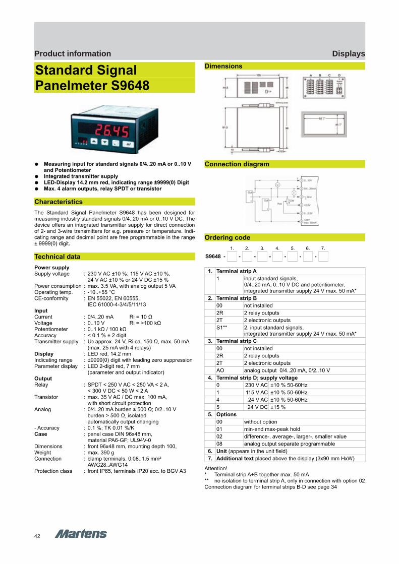
42
DisplaysProduct information
S9648 S9648 T9648
GHM Messtechnik GmbH – Location MartensKiebitzhörn 18 22885 Barsbüttel Germany Fon +49-40-670 73-0 Fax -288www.ghm-messtechnik.de [email protected]
Product Information Industrial Electronics
Standard Signal Panelmeter S9648
Measuring input for standard signals 0/4..20 mA or 0..10 V and Potentiometer
Integrated transmitter supply LED-Display 14.2 mm red, indicating range ±9999(0) Digit Max. 4 alarm outputs, relay SPDT or transistor
Characteristics
The Standard Signal Panelmeter S9648 has been designed formeasuring industry standard signals 0/4..20 mA or 0..10 V DC. Thedevice offers an integrated transmitter supply for direct connectionof 2- and 3-wire transmitters for e.g. pressure or temperature. Indi-cating range and decimal point are free programmable in the range± 9999(0) digit.
Technical data
Power supplySupply voltage : 230 V AC ±10 %; 115 V AC ±10 %,
24 V AC ±10 % or 24 V DC ±15 %Power consumption : max. 3.5 VA, with analog output 5 VAOperating temp. : -10..+55 °CCE-conformity : EN 55022, EN 60555,
IEC 61000-4-3/4/5/11/13InputCurrent : 0/4..20 mA Ri = 10 ΩVoltage : 0..10 V Ri = >100 kΩPotentiometer : 0..1 kΩ / 100 kΩAccuracy : < 0.1 % ± 2 digitTransmitter supply : U0 approx. 24 V, Ri ca. 150 Ω, max. 50 mA
(max. 25 mA with 4 relays)Display : LED red, 14.2 mmIndicating range : ±9999(0) digit with leading zero suppressionParameter display : LED 2-digit red, 7 mm
(parameter and output indicator)OutputRelay : SPDT < 250 V AC < 250 VA < 2 A,
< 300 V DC < 50 W < 2 ATransistor : max. 35 V AC / DC max. 100 mA,
with short circuit protectionAnalog : 0/4..20 mA burden ≤ 500 Ω; 0/2..10 V
burden > 500 Ω, isolatedautomatically output changing
- Accuracy : 0.1 %; TK 0.01 %/KCase : panel case DIN 96x48 mm,
material PA6-GF; UL94V-0Dimensions : front 96x48 mm, mounting depth 100,Weight : max. 390 gConnection : clamp terminals, 0.08..1.5 mm²
AWG28..AWG14Protection class : front IP65, terminals IP20 acc. to BGV A3
Dimensions
Connection diagram
Ordering code
1. 2. 3. 4. 5. 6. 7.
S9648 - - - - - - -
1. Terminal strip A
1 input standard signals,0/4..20 mA, 0..10 V DC and potentiometer,integrated transmitter supply 24 V max. 50 mA*
2. Terminal strip B
00 not installed
2R 2 relay outputs
2T 2 electronic outputs
S1** 2. input standard signals,integrated transmitter supply 24 V max. 50 mA*
3. Terminal strip C
00 not installed
2R 2 relay outputs
2T 2 electronic outputs
AO analog output 0/4..20 mA, 0/2..10 V
4. Terminal strip D; supply voltage
0 230 V AC ±10 % 50-60Hz
1 115 V AC ±10 % 50-60Hz
4 24 V AC ±10 % 50-60Hz
5 24 V DC ±15 %
5. Options
00 without option
01 min-and max-peak hold
02 difference-, average-, larger-, smaller value
08 analog output separate programmable
6. Unit (appears in the unit field)
7. Additional text placed above the display (3x90 mm HxW)
Attention!* Terminal strip A+B together max. 50 mA** no isolation to terminal strip A, only in connection with option 02Connection diagram for terminal strips B-D see page 34
pi-ma-Displays_E V2.00-00
19
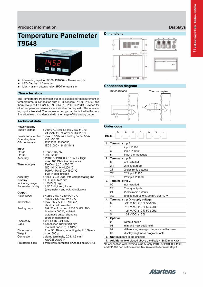
43
DisplaysProduct information
E1 M
ultif
unct
iona
lcont
rolle
r / D
ispla
ys /
Cont
rolle
r
T9648 T9648
GHM Messtechnik GmbH – Location MartensKiebitzhörn 18 22885 Barsbüttel Germany Fon +49-40-670 73-0 Fax -288www.ghm-messtechnik.de [email protected]
Product Information Industrial Electronics
Temperature Panelmeter T9648
Measuring input for Pt100, Pt1000 or Thermocouple LED-Display 14.2 mm red Max. 4 alarm outputs relay SPDT or transistor
Characteristics
The Temperature Panelmeter T9648 is suitable for measurement oftemperatures in connection with RTD sensors Pt100, Pt1000 andthermocouples Fe-CuNi (J), NiCr-Ni (K), Pt10Rh-Pt (S). Devices forother temperature sensors are available on request . The measur-ing input is isolated. The measuring range can be limited in the con-figuration level. It is identical with the range of the analog output.
Technical data
Power supplySupply voltage : 230 V AC ±10 %; 115 V AC ±10 %;
24 V AC ±10 % or 24 V DC ±15 %Power consumption : max. 3.5 VA, with analog output 5 VAOperating temp. : -10..+55 °C CE- conformity : EN55022, EN60555,
IEC61000-4-3/4/5/11/13InputPt100 : -100..+600 °C Pt1000 : -50..+200 °CAccuracy : Pt100 or Pt1000 < 0.1 % ± 2 Digit,
max. 100 Ohm line resistanceThermocouple : Fe-CuNi (J) 0..+800 °C,
NiCr-Ni (K) 0..+1200 °C Pt10Rh-Pt (S) 0..+1600 °Cbuilt-in cold junction
Accuracy : < 0,1 % ± 2 Digit with compensating lineDisplay : LED red, 14.2 mmIndicating range : ±9999(0) Digit Parameter display : LED 2-digit red, 7 mm
(parameter - and output indicator)OutputRelay SPDT : < 250 V AC < 250 VA < 2 A,
< 300 V DC < 50 W < 2 ATransistor : max. 35 V AC/DC, 100 mA,
short circuit protectedAnalog output : 0/4..20 mA burden ≤ 500 Ω; 0/2..10 V
burden > 500 Ω, isolatedautomatic output changing (burden depending)
- Accuracy : 0.1 %; TK 0.01 %/KCase : panel case DIN 96x48 mm,
material PA6-GF; UL94V-0Dimensions : front 96x48 mm, mounting depth 100 mmWeight : max. 390 gConnection : clamp terminals, 0.08..1.5 mm²
AWG28..AWG14Protection class : front IP65, terminals IP20 acc. to BGV A3
Dimensions
Connection diagram
Pt100/Pt1000 Thermocouples
Order code
1. 2. 3. 4. 5. 6. 7.
T9648 - - - - - - -
1. Terminal strip A
1 input Pt100
3 input Pt1000
5 input thermocouple
2. Terminal strip B
00 not installed
2R 2 relay outputs
2T 2 electronic outputs
T1* 2nd input Pt100
T3* 2nd input Pt1000
3. Terminal strip C
00 not installed
2R 2 relay outputs
2T 2 electronic outputs
AO analog output 0/4..20 mA, 0/2..10 V
4. Terminal strip D; supply voltage
0 230 V AC ±10 % 50-60Hz
1 115 V AC ±10 % 50-60Hz
4 24 V AC ±10 % 50-60Hz
5 24 V DC ±15 %
5. Options
00 without option
01 min-and max-peak hold
02 difference-, average-, larger-, smaller value
07 display brightness programmable
6. Unit (appears in the unit field)
7. Additional text placed above the display (3x90 mm HxW)
*In connection with terminal strip A, only Pt100 or Pt1000; Pt100 and Pt1000 can not be mixed. Not isolated to terminal strip A.
20 pi-ma-Displays_E V2.00-00
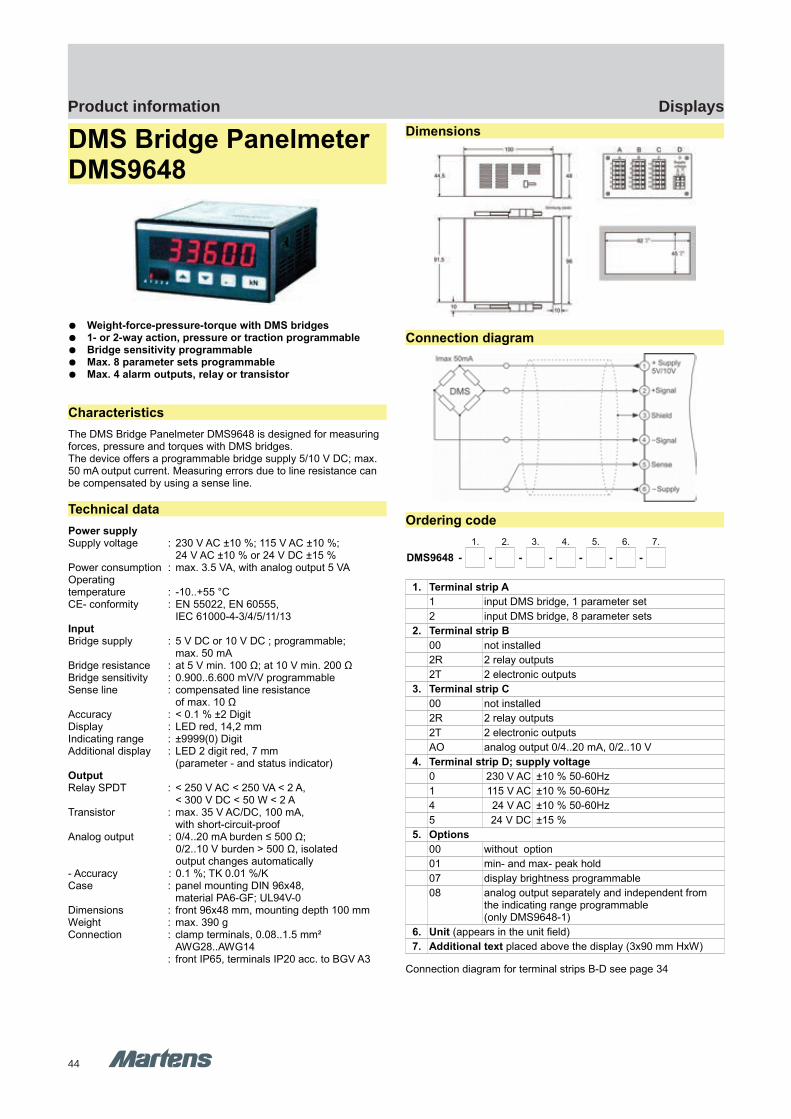
44
DisplaysProduct information
DMS9648 DMS9648
GHM Messtechnik GmbH – Location MartensKiebitzhörn 18 22885 Barsbüttel Germany Fon +49-40-670 73-0 Fax -288www.ghm-messtechnik.de [email protected]
Product Information Industrial Electronics
DMS Bridge Panelmeter DMS9648
Weight-force-pressure-torque with DMS bridges 1- or 2-way action, pressure or traction programmable Bridge sensitivity programmable Max. 8 parameter sets programmable Max. 4 alarm outputs, relay or transistor
Characteristics
The DMS Bridge Panelmeter DMS9648 is designed for measuring forces, pressure and torques with DMS bridges.The device offers a programmable bridge supply 5/10 V DC; max. 50 mA output current. Measuring errors due to line resistance can be compensated by using a sense line.
Technical data
Power supplySupply voltage : 230 V AC ±10 %; 115 V AC ±10 %;
24 V AC ±10 % or 24 V DC ±15 %Power consumption : max. 3.5 VA, with analog output 5 VAOperatingtemperature : -10..+55 °C CE- conformity : EN 55022, EN 60555,
IEC 61000-4-3/4/5/11/13InputBridge supply : 5 V DC or 10 V DC ; programmable;
max. 50 mABridge resistance : at 5 V min. 100 Ω; at 10 V min. 200 ΩBridge sensitivity : 0.900..6.600 mV/V programmableSense line : compensated line resistance
of max. 10 ΩAccuracy : < 0.1 % ±2 DigitDisplay : LED red, 14,2 mmIndicating range : ±9999(0) Digit Additional display : LED 2 digit red, 7 mm
(parameter - and status indicator)OutputRelay SPDT : < 250 V AC < 250 VA < 2 A,
< 300 V DC < 50 W < 2 ATransistor : max. 35 V AC/DC, 100 mA,
with short-circuit-proofAnalog output : 0/4..20 mA burden ≤ 500 Ω;
0/2..10 V burden > 500 Ω, isolatedoutput changes automatically
- Accuracy : 0.1 %; TK 0.01 %/KCase : panel mounting DIN 96x48,
material PA6-GF; UL94V-0Dimensions : front 96x48 mm, mounting depth 100 mmWeight : max. 390 gConnection : clamp terminals, 0.08..1.5 mm²
AWG28..AWG14: front IP65, terminals IP20 acc. to BGV A3
Dimensions
Connection diagram
Ordering code
1. 2. 3. 4. 5. 6. 7.
DMS9648 - - - - - - -
1. Terminal strip A
1 input DMS bridge, 1 parameter set
2 input DMS bridge, 8 parameter sets
2. Terminal strip B
00 not installed
2R 2 relay outputs
2T 2 electronic outputs
3. Terminal strip C
00 not installed
2R 2 relay outputs
2T 2 electronic outputs
AO analog output 0/4..20 mA, 0/2..10 V
4. Terminal strip D; supply voltage
0 230 V AC ±10 % 50-60Hz
1 115 V AC ±10 % 50-60Hz
4 24 V AC ±10 % 50-60Hz
5 24 V DC ±15 %
5. Options
00 without option
01 min- and max- peak hold
07 display brightness programmable
08 analog output separately and independent from the indicating range programmable (only DMS9648-1)
6. Unit (appears in the unit field)
7. Additional text placed above the display (3x90 mm HxW)
Connection diagram for terminal strips B-D see page 34
pi-ma-Displays_E V2.00-00
21
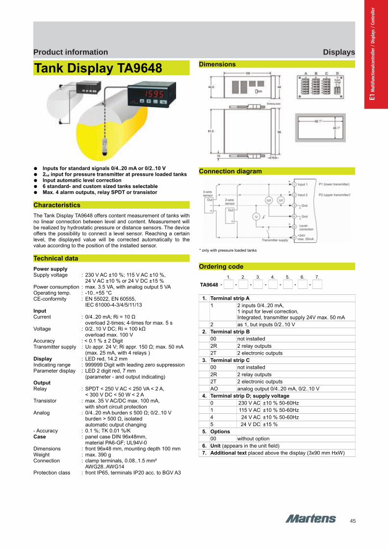
45
DisplaysProduct information
E1 M
ultif
unct
iona
lcont
rolle
r / D
ispla
ys /
Cont
rolle
r
DMS9648
GHM Messtechnik GmbH – Location MartensKiebitzhörn 18 22885 Barsbüttel Germany Fon +49-40-670 73-0 Fax -288www.ghm-messtechnik.de [email protected]
Product Information Industrial Electronics
Tank Display TA9648
Inputs for standard signals 0/4..20 mA or 0/2..10 V 2nd input for pressure transmitter at pressure loaded tanks Input automatic level correction 6 standard- and custom sized tanks selectable Max. 4 alarm outputs, relay SPDT or transistor
Characteristics
The Tank Display TA9648 offers content measurement of tanks withno linear connection between level and content. Measurement willbe realized by hydrostatic pressure or distance sensors. The deviceoffers the possibility to connect a level sensor. Reaching a certainlevel, the displayed value will be corrected automatically to thevalue according to the position of the installed sensor.
Technical data
Power supplySupply voltage : 230 V AC ±10 %; 115 V AC ±10 %,
24 V AC ±10 % or 24 V DC ±15 %Power consumption : max. 3.5 VA, with analog output 5 VAOperating temp. : -10..+55 °CCE-conformity : EN 55022, EN 60555,
IEC 61000-4-3/4/5/11/13InputCurrent : 0/4..20 mA; Ri = 10 Ω
overload 2-times; 4-times for max. 5 sVoltage : 0/2..10 V DC; Ri = 100 kΩ
overload max. 100 VAccuracy : < 0.1 % ± 2 DigitTransmitter supply : U0 appr. 24 V; Ri appr. 150 Ω; max. 50 mA
(max. 25 mA, with 4 relays )Display : LED red, 14.2 mmIndicating range : 999999 Digit with leading zero suppressionParameter display : LED 2 digit red, 7 mm
(parameter - and output indicating)OutputRelay : SPDT < 250 V AC < 250 VA < 2 A,
< 300 V DC < 50 W < 2 ATransistor : max. 35 V AC/DC max. 100 mA,
with short circuit protectionAnalog : 0/4..20 mA burden ≤ 500 Ω; 0/2..10 V
burden > 500 Ω, isolatedautomatic output changing
- Accuracy : 0.1 %; TK 0.01 %/KCase : panel case DIN 96x48mm,
material PA6-GF; UL94V-0Dimensions : front 96x48 mm, mounting depth 100 mmWeight : max. 390 gConnection : clamp terminals, 0.08..1.5 mm²
AWG28..AWG14Protection class : front IP65, terminals IP20 acc. to BGV A3
Dimensions
Connection diagram
Ordering code
1. 2. 3. 4. 5. 6. 7.
TA9648 - - - - - - -
1. Terminal strip A
1 2 inputs 0/4..20 mA, 1 input for level correction,Integrated, transmitter supply 24V max. 50 mA
2 as 1, but inputs 0/2..10 V
2. Terminal strip B
00 not installed
2R 2 relay outputs
2T 2 electronic outputs
3. Terminal strip C
00 not installed
2R 2 relay outputs
2T 2 electronic outputs
AO analog output 0/4..20 mA, 0/2..10 V
4. Terminal strip D; supply voltage
0 230 V AC ±10 % 50-60Hz
1 115 V AC ±10 % 50-60Hz
4 24 V AC ±10 % 50-60Hz
5 24 V DC ±15 %
5. Options
00 without option
6. Unit (appears in the unit field)
7. Additional text placed above the display (3x90 mm HxW)
22 pi-ma-Displays_E V2.00-00
* only with pressure loaded tanks
TA9648 TA9648
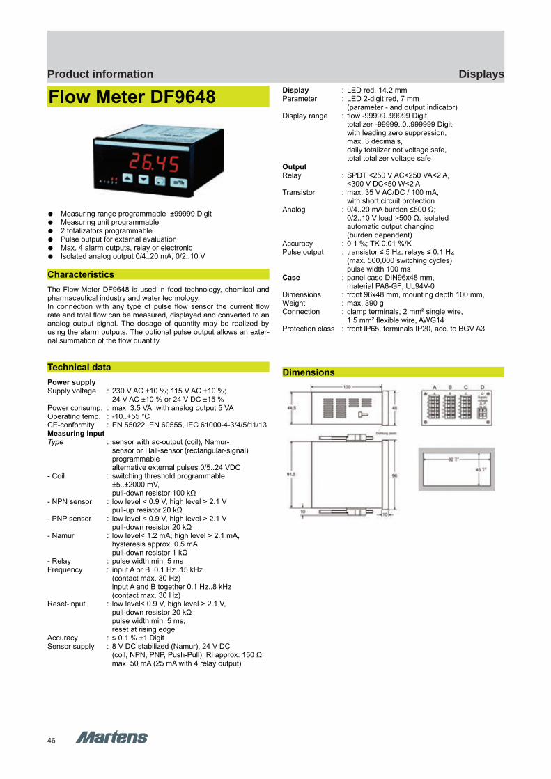
46
DisplaysProduct information
DF9648 DF9648
GHM Messtechnik GmbH – Location MartensKiebitzhörn 18 22885 Barsbüttel Germany Fon +49-40-670 73-0 Fax -288www.ghm-messtechnik.de [email protected]
Product Information Industrial Electronics
Flow Meter DF9648
Measuring range programmable ±99999 Digit Measuring unit programmable 2 totalizators programmable Pulse output for external evaluation Max. 4 alarm outputs, relay or electronic Isolated analog output 0/4..20 mA, 0/2..10 V
Characteristics
The Flow-Meter DF9648 is used in food technology, chemical andpharmaceutical industry and water technology.In connection with any type of pulse flow sensor the current flowrate and total flow can be measured, displayed and converted to ananalog output signal. The dosage of quantity may be realized byusing the alarm outputs. The optional pulse output allows an exter-nal summation of the flow quantity.
Technical data
Power supplySupply voltage : 230 V AC ±10 %; 115 V AC ±10 %;
24 V AC ±10 % or 24 V DC ±15 %Power consump. : max. 3.5 VA, with analog output 5 VAOperating temp. : -10..+55 °CCE-conformity : EN 55022, EN 60555, IEC 61000-4-3/4/5/11/13Measuring inputType : sensor with ac-output (coil), Namur-
sensor or Hall-sensor (rectangular-signal) programmablealternative external pulses 0/5..24 VDC
- Coil : switching threshold programmable±5..±2000 mV,pull-down resistor 100 kΩ
- NPN sensor : low level < 0.9 V, high level > 2.1 Vpull-up resistor 20 kΩ
- PNP sensor : low level < 0.9 V, high level > 2.1 Vpull-down resistor 20 kΩ
- Namur : low level< 1.2 mA, high level > 2.1 mA, hysteresis approx. 0.5 mApull-down resistor 1 kΩ
- Relay : pulse width min. 5 msFrequency : input A or B 0.1 Hz..15 kHz
(contact max. 30 Hz)input A and B together 0.1 Hz..8 kHz (contact max. 30 Hz)
Reset-input : low level< 0.9 V, high level > 2.1 V, pull-down resistor 20 kΩpulse width min. 5 ms, reset at rising edge
Accuracy : ≤ 0.1 % ±1 DigitSensor supply : 8 V DC stabilized (Namur), 24 V DC
(coil, NPN, PNP, Push-Pull), Ri approx. 150 Ω,max. 50 mA (25 mA with 4 relay output)
Display : LED red, 14.2 mmParameter : LED 2-digit red, 7 mm
(parameter - and output indicator)Display range : flow -99999..99999 Digit,
totalizer -99999..0..999999 Digit,with leading zero suppression, max. 3 decimals,daily totalizer not voltage safe, total totalizer voltage safe
OutputRelay : SPDT <250 V AC<250 VA<2 A,
<300 V DC<50 W<2 ATransistor : max. 35 V AC/DC / 100 mA,
with short circuit protectionAnalog : 0/4..20 mA burden ≤500 Ω;
0/2..10 V load >500 Ω, isolatedautomatic output changing(burden dependent)
Accuracy : 0.1 %; TK 0.01 %/KPulse output : transistor ≤ 5 Hz, relays ≤ 0.1 Hz
(max. 500,000 switching cycles)pulse width 100 ms
Case : panel case DIN96x48 mm, material PA6-GF; UL94V-0
Dimensions : front 96x48 mm, mounting depth 100 mm,Weight : max. 390 gConnection : clamp terminals, 2 mm² single wire,
1.5 mm² flexible wire, AWG14Protection class : front IP65, terminals IP20, acc. to BGV A3
Dimensions
pi-ma-Displays_E V2.00-00
23

47
DisplaysProduct information
E1 M
ultif
unct
iona
lcont
rolle
r / D
ispla
ys /
Cont
rolle
r
GHM Messtechnik GmbH – Location MartensKiebitzhörn 18 22885 Barsbüttel Germany Fon +49-40-670 73-0 Fax -288www.ghm-messtechnik.de [email protected]
Product Information Industrial Electronics
Connection diagram Ordering code
1. 2. 3. 4. 5. 6. 7.
DF9648 - - - - - - -
1. Terminal strip A
1 Input for sensors with AC-signals (coil),pulse signal (Namur, NPN, PNP, Push-Pull)or switching contact
2 as 1, but additional input for addition/subtraction
2. Terminal strip B
00 not installed
2R 2 relay outputs
2T 2 electronic outputs (alarm/pulse output)*
3. Terminal strip C
00 not installed
2R 2 relay outputs
2T 2 electronic outputs
AO analog output
4. Terminal strip D supply voltage
0 230 V AC ±10 % 50-60Hz
1 115 V AC ±10 % 50-60Hz
4 24 V AC ±10 % 50-60Hz
5 24 V DC ±15 %
5. Options
00 without option
11 *pulse output (only at terminal strip B)
6. Unit appears in the unit field
7. Additional text above the display (3x90 mm HxW)
* Strip B: output A1 = alarm, A2 = pulse output
Connection diagram for terminal strips B-D see page 34
24 pi-ma-Displays_E V2.00-00
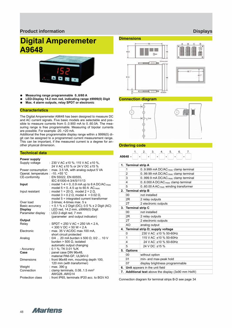
48
DisplaysProduct information
A9648 A9648
GHM Messtechnik GmbH – Location MartensKiebitzhörn 18 22885 Barsbüttel Germany Fon +49-40-670 73-0 Fax -288www.ghm-messtechnik.de [email protected]
Product Information Industrial Electronics
Digital Amperemeter A9648
Measuring range programmable 0..6/60 A LED-Display 14.2 mm red, indicating range ±9999(0) Digit Max. 4 alarm outputs, relay SPDT or electronic
Characteristics
The Digital Amperemeter A9648 has been designed to measure DCand AC current signals. Five basic models are selectable and pos-sible to measure currents from 0..0.900 mA to 0..60.0A. The mea-suring range is free programmable. Measuring of bipolar currentsare possible. For example -20..+20 mA.Additional the free programmable display range within ± 9999(0) di-git can be assigned to a programmed current measurement range.This can be important, if the measured current is a degree for an-other physical dimension.
Technical data
Power supplySupply voltage : 230 V AC ±10 %; 115 V AC ±10 %,
24 V AC ±10 % or 24 V DC ±15 %Power consumption : max. 3.5 VA, with analog output 5 VAOperat. temperature : -10..+55 °CCE-conformity : EN 55022, EN 60555,
IEC 61000-4-3/4/5/11/13Input : model 1-4 = 0..0.9 mA up to 6 A DC/ACTRMS
model 5 = 0..4.5 up to 60 A ACTRMS
Input resistant : model 1 = 20 Ω, model 2 = 2 Ω, model 3 = 0.2 Ω, model 4 = 0.02 Ω,model 5 = integrated current transformer
Over load : 2-times; 4-times max. 5 sBasic accuracy : < 0.1 % ± 2 Digit (DC); 0.5 % ± 2 Digit (AC)Display : LED red, 14.2 mm, ±9999(0) Digit Parameter display : LED 2-digit red, 7 mm
(parameter and output indicator)OutputRelay : SPDT < 250 V AC < 250 VA < 2 A,
< 300 V DC < 50 W < 2 AElectronic : max. 35 V AC/DC max.100 mA,
short circuit protectedAnalog : 0/4 ... 20 mA burden ≤ 500 Ω; 0/2 ... 10 V
burden > 500 Ω, isolatedautomatic output changing
- Accuracy : 0.1 %; TK 0.01 %/KCase : panel case DIN 96x48,
material PA6-GF; UL94V-0Dimensions : front 96x48 mm, mounting depth 100,
120 mm (with transformer)Weight : max. 390 gConnection : clamp terminals, 0.08..1.5 mm²
AWG28..AWG14Protection class : front IP65, terminals IP20 acc. to BGV A3
Dimensions
Connection diagram
Ordering code
1. 2. 3. 4. 5. 6. 7.
A9648 - - - - - - -
1. Terminal strip A
1 0..9.999 mA DC/ACTRMS clamp terminal
2 0..99.99 mA DC/ACTRMS clamp terminal
3 0..999.9 mA DC/ACTRMS clamp terminal
4 0..6.000 A DC/ACTRMS clamp terminal
5 0..60.00 A ACTRMS winding transformer
2. Terminal strip B
00 not installed
2R 2 relay outputs
2T 2 electronic outputs
3. Terminal strip C
00 not installed
2R 2 relay outputs
2T 2 electronic outputs
AO analog output
4. Terminal strip D; supply voltage
0 230 V AC ±10 % 50-60Hz
1 115 V AC ±10 % 50-60Hz
4 24 V AC ±10 % 50-60Hz
5 24 V DC ±15 %
5. Options
00 without option
01 min- and max-peak hold
07 display brightness programmable
6. Unit appears in the unit field
7. Additional text above the display (3x90 mm HxW)
Connection diagram for terminal strips B-D see page 34
pi-ma-Displays_E V2.00-00
25
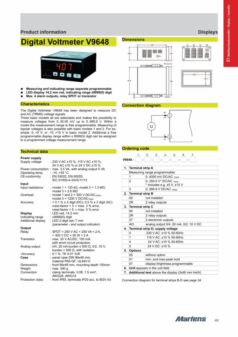
49
DisplaysProduct information
E1 M
ultif
unct
iona
lcont
rolle
r / D
ispla
ys /
Cont
rolle
r
GHM Messtechnik GmbH – Location MartensKiebitzhörn 18 22885 Barsbüttel Germany Fon +49-40-670 73-0 Fax -288www.ghm-messtechnik.de [email protected]
Product Information Industrial Electronics
Digital Voltmeter V9648
Measuring and indicating range separate programmable LED display 14.2 mm red, indicating range ±9999(0) digit Max. 4 alarm outputs, relay SPDT or transistor
Characteristics
The Digital Voltmeter V9648 has been designed to measure DCand AC (TRMS) voltage signals.Three basic models all are selectable and makes the possibility tomeasure voltages from 0..30.00 mV up to 0..999.9 V. Within amodel the measurement range is free programmable. Measuring ofbipolar voltages is also possible with basic models 1 and 2. For ex-ample -5..+5 V; or -10..+10 V in basic model 2. Additional a freeprogrammable display range within ± 9999(0) digit can be assignedto a programmed voltage measurement range.
Technical data
Power supplySupply voltage : 230 V AC ±10 %; 115 V AC ±10 %,
24 V AC ±10 % or 24 V DC ±15 %Power consumption : max. 3.5 VA, with analog output 5 VAOperating temp. : -10..+55 °CCE-conformity : EN 55022, EN 60555,
IEC 61000-4-3/4/5/11/13InputInput resistance : model 1 = 130 kΩ, model 2 = 1.3 MΩ,
model 3 = 2.6 MΩOverload : model 1 and 2 = 300 V DC/ACTRMS,
model 3 = 1200 V DC/ACTRMS
Accuracy : < 0.1 % ± 2 digit (DC); 0.5 % ± 2 digit (AC) crest-factor < 3 ⇒ max. 2 % error, crest-factor < 5 ⇒ max. 5 % error
Display : LED red, 14.2 mmIndicating range : ±9999(0) digitAdditional display : LED 2-digit red, 7 mm
(parameter - and output indicator)OutputRelay : SPDT < 250 V AC < 250 VA < 2 A,
< 300 V DC < 50 W < 2 ATransistor : max. 35 V AC/DC, 100 mA,
with short circuit protectionAnalog output : 0/4..20 mA burden ≤ 500 Ω; 0/2..10 V,
burden > 500 Ω, with isolation-Accuracy : 0.1 %; TK 0.01 %/KCase : panel case DIN 96x48 mm,
material PA6-GF; UL94V-0Dimensions : front 96x48 mm, mounting depth 100mmWeight : max. 390 gConnection : clamp terminals, 0.08..1.5 mm²,
AWG28..AWG14Protection class : front IP65, terminals IP20 acc. to BGV A3
Dimensions
Connection diagram
Ordering code
1. 2. 3. 4. 5. 6. 7.
V9648 - - - - - - -
1. Terminal strip A
Measuring range programmable:
1 0..4000 mV DC/AC TRMS
2 0..250.0 V* DC/AC TRMS
* includes e.g. ±5 V, ±10 V
3 0..999.9 V DC/AC TRMS
2. Terminal strip B
00 not installed
2R 2 relay outputs
3. Terminal strip C
00 not installed
2R 2 relay outputs
2T 2 electronic outputs
AO analog output 0/4..20 mA, 0/2..10 V DC
4. Terminal strip D; supply voltage
0 230 V AC ±10 % 50-60Hz
1 115 V AC ±10 % 50-60Hz
4 24 V AC ±10 % 50-60Hz
5 24 V DC ±15 %
5. Options
00 without option
01 min- and max-peak hold
07 display brightness programmable
6. Unit appears in the unit field
7. Additional text above the display (3x90 mm HxW)
Connection diagram for terminal strips B-D see page 34
26 pi-ma-Displays_E V2.00-00
V9648 V9648
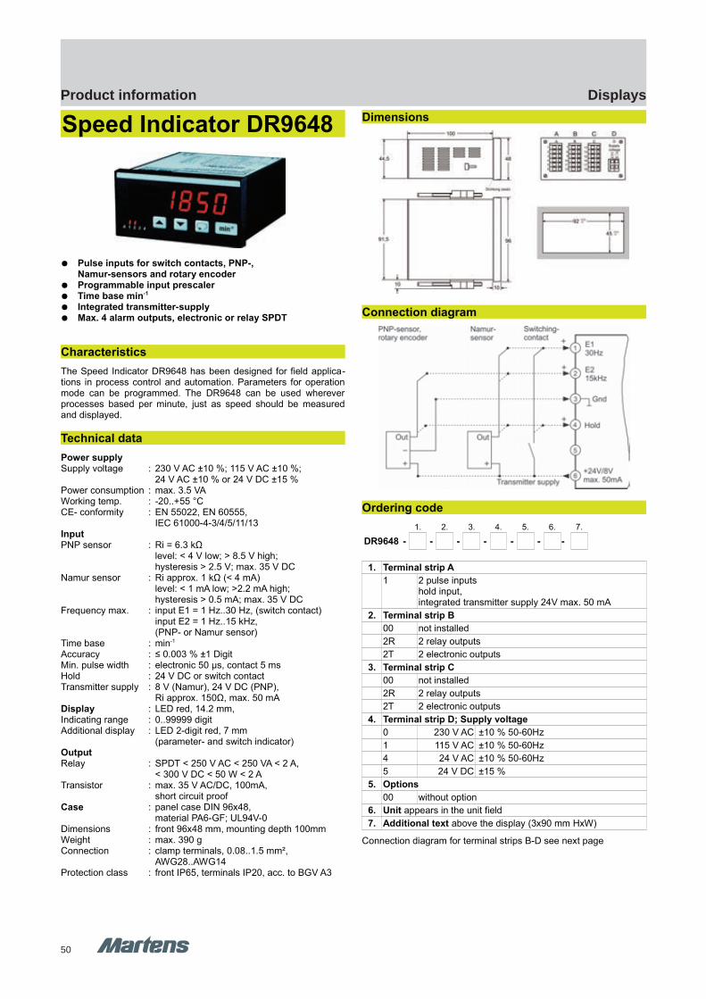
50
DisplaysProduct information
DR9648 DR9648
GHM Messtechnik GmbH – Location MartensKiebitzhörn 18 22885 Barsbüttel Germany Fon +49-40-670 73-0 Fax -288www.ghm-messtechnik.de [email protected]
Product Information Industrial Electronics
Speed Indicator DR9648
Pulse inputs for switch contacts, PNP-,Namur-sensors and rotary encoder
Programmable input prescaler Time base min-1
Integrated transmitter-supply Max. 4 alarm outputs, electronic or relay SPDT
Characteristics
The Speed Indicator DR9648 has been designed for field applica-tions in process control and automation. Parameters for operationmode can be programmed. The DR9648 can be used whereverprocesses based per minute, just as speed should be measuredand displayed.
Technical data
Power supplySupply voltage : 230 V AC ±10 %; 115 V AC ±10 %;
24 V AC ±10 % or 24 V DC ±15 %Power consumption : max. 3.5 VAWorking temp. : -20..+55 °C CE- conformity : EN 55022, EN 60555,
IEC 61000-4-3/4/5/11/13InputPNP sensor : Ri = 6.3 kΩ
level: < 4 V low; > 8.5 V high;hysteresis > 2.5 V; max. 35 V DC
Namur sensor : Ri approx. 1 kΩ (< 4 mA) level: < 1 mA low; >2.2 mA high;hysteresis > 0.5 mA; max. 35 V DC
Frequency max. : input E1 = 1 Hz..30 Hz, (switch contact)input E2 = 1 Hz..15 kHz, (PNP- or Namur sensor)
Time base : min-1
Accuracy : ≤ 0.003 % ±1 DigitMin. pulse width : electronic 50 µs, contact 5 msHold : 24 V DC or switch contactTransmitter supply : 8 V (Namur), 24 V DC (PNP),
Ri approx. 150Ω, max. 50 mADisplay : LED red, 14.2 mm, Indicating range : 0..99999 digit Additional display : LED 2-digit red, 7 mm
(parameter- and switch indicator)OutputRelay : SPDT < 250 V AC < 250 VA < 2 A,
< 300 V DC < 50 W < 2 ATransistor : max. 35 V AC/DC, 100mA,
short circuit proofCase : panel case DIN 96x48,
material PA6-GF; UL94V-0Dimensions : front 96x48 mm, mounting depth 100mmWeight : max. 390 gConnection : clamp terminals, 0.08..1.5 mm²,
AWG28..AWG14Protection class : front IP65, terminals IP20, acc. to BGV A3
Dimensions
Connection diagram
Ordering code
1. 2. 3. 4. 5. 6. 7.
DR9648 - - - - - - -
1. Terminal strip A
1 2 pulse inputshold input, integrated transmitter supply 24V max. 50 mA
2. Terminal strip B
00 not installed
2R 2 relay outputs
2T 2 electronic outputs
3. Terminal strip C
00 not installed
2R 2 relay outputs
2T 2 electronic outputs
4. Terminal strip D; Supply voltage
0 230 V AC ±10 % 50-60Hz
1 115 V AC ±10 % 50-60Hz
4 24 V AC ±10 % 50-60Hz
5 24 V DC ±15 %
5. Options
00 without option
6. Unit appears in the unit field
7. Additional text above the display (3x90 mm HxW)
Connection diagram for terminal strips B-D see next page
pi-ma-Displays_E V2.00-00
27
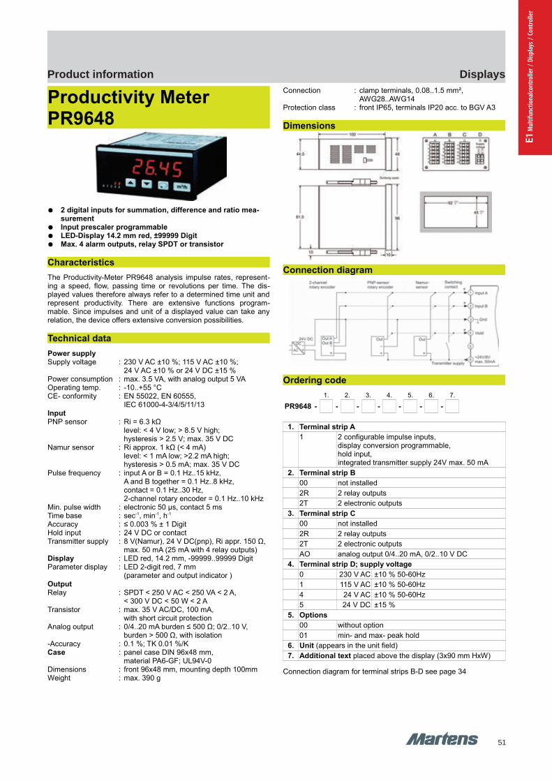
51
DisplaysProduct information
E1 M
ultif
unct
iona
lcont
rolle
r / D
ispla
ys /
Cont
rolle
r
GHM Messtechnik GmbH – Location MartensKiebitzhörn 18 22885 Barsbüttel Germany Fon +49-40-670 73-0 Fax -288www.ghm-messtechnik.de [email protected]
Product Information Industrial Electronics
Productivity Meter PR9648
2 digital inputs for summation, difference and ratio mea-surement
Input prescaler programmable LED-Display 14.2 mm red, ±99999 Digit Max. 4 alarm outputs, relay SPDT or transistor
Characteristics
The Productivity-Meter PR9648 analysis impulse rates, represent-ing a speed, flow, passing time or revolutions per time. The dis-played values therefore always refer to a determined time unit andrepresent productivity. There are extensive functions program-mable. Since impulses and unit of a displayed value can take anyrelation, the device offers extensive conversion possibilities.
Technical data
Power supplySupply voltage : 230 V AC ±10 %; 115 V AC ±10 %;
24 V AC ±10 % or 24 V DC ±15 %Power consumption : max. 3.5 VA, with analog output 5 VAOperating temp. : -10..+55 °C CE- conformity : EN 55022, EN 60555,
IEC 61000-4-3/4/5/11/13InputPNP sensor : Ri = 6.3 kΩ
level: < 4 V low; > 8.5 V high;hysteresis > 2.5 V; max. 35 V DC
Namur sensor : Ri approx. 1 kΩ (< 4 mA) level: < 1 mA low; >2.2 mA high;hysteresis > 0.5 mA; max. 35 V DC
Pulse frequency : input A or B = 0.1 Hz..15 kHz, A and B together = 0.1 Hz..8 kHz,contact = 0.1 Hz..30 Hz, 2-channel rotary encoder = 0.1 Hz..10 kHz
Min. pulse width : electronic 50 μs, contact 5 msTime base : sec-1, min-1, h-1
Accuracy : ≤ 0.003 % ± 1 DigitHold input : 24 V DC or contactTransmitter supply : 8 V(Namur), 24 V DC(pnp), Ri appr. 150 Ω,
max. 50 mA (25 mA with 4 relay outputs)Display : LED red, 14.2 mm, -99999..99999 Digit Parameter display : LED 2-digit red, 7 mm
(parameter and output indicator )OutputRelay : SPDT < 250 V AC < 250 VA < 2 A,
< 300 V DC < 50 W < 2 ATransistor : max. 35 V AC/DC, 100 mA,
with short circuit protectionAnalog output : 0/4..20 mA burden ≤ 500 Ω; 0/2..10 V,
burden > 500 Ω, with isolation-Accuracy : 0.1 %; TK 0.01 %/KCase : panel case DIN 96x48 mm,
material PA6-GF; UL94V-0Dimensions : front 96x48 mm, mounting depth 100mmWeight : max. 390 g
Connection : clamp terminals, 0.08..1.5 mm², AWG28..AWG14
Protection class : front IP65, terminals IP20 acc. to BGV A3
Dimensions
Connection diagram
Ordering code
1. 2. 3. 4. 5. 6. 7.
PR9648 - - - - - - -
1. Terminal strip A
1 2 configurable impulse inputs,display conversion programmable,hold input,integrated transmitter supply 24V max. 50 mA
2. Terminal strip B
00 not installed
2R 2 relay outputs
2T 2 electronic outputs
3. Terminal strip C
00 not installed
2R 2 relay outputs
2T 2 electronic outputs
AO analog output 0/4..20 mA, 0/2..10 V DC
4. Terminal strip D; supply voltage
0 230 V AC ±10 % 50-60Hz
1 115 V AC ±10 % 50-60Hz
4 24 V AC ±10 % 50-60Hz
5 24 V DC ±15 %
5. Options
00 without option
01 min- and max- peak hold
6. Unit (appears in the unit field)
7. Additional text placed above the display (3x90 mm HxW)
Connection diagram for terminal strips B-D see page 34
28 pi-ma-Displays_E V2.00-00
PR9648 PR9648
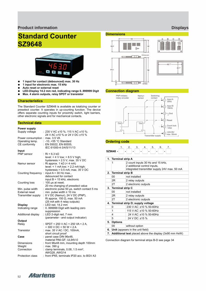
52
DisplaysProduct information
SZ9648 SZ9648
GHM Messtechnik GmbH – Location MartensKiebitzhörn 18 22885 Barsbüttel Germany Fon +49-40-670 73-0 Fax -288www.ghm-messtechnik.de [email protected]
Product Information Industrial Electronics
Standard Counter SZ9648
1 input for contact (debounced) max. 30 Hz 1 input for electronic max. 15 kHz Auto reset or external reset LED-Display 14.2 mm red, indicating range 0..999999 Digit Max. 4 alarm outputs, relay SPDT or transistor
Characteristics
The Standard Counter SZ9648 is available as totalizing counter orpreselect counter. It operates in up-counting function. The deviceoffers separate counting inputs for proximity switch, light barriers,other electronic signals and for mechanical contacts.
Technical data
Power supplySupply voltage : 230 V AC ±10 %; 115 V AC ±10 %;
24 V AC ±10 % or 24 V DC ±15 %Power consumption : max. 3.5 VAOperating temp. : -10..+55 °C StandardCE conformity : EN 55022, EN 60555,
IEC 61000-4-3/4/5/11/13InputPNP sensor : Ri = 6,3 kΩ
level: < 4 V low; > 8.5 V high;hysteresis > 2.5 V; max. 35 V DC
Namur sensor : Ri approx. 1 kΩ (< 4 mA) level: < 1 mA low; > 2.2 mA high;hysteresis > 0.5 mA; max. 35 V DC
Counting frequency : input A = 30 Hz max., debounced for contactinput B = 15 kHz, electronic
Counting loss : 100 μs at reset; 20 ms changing of preselect value
Min. pulse width : electronic pulse 50 μs, switch contact 5 msExternal reset : min. pulse width ≥ 10 msTransmitter supply : 8 V DC (Namur), 24 V DC (PNP),
Ri approx. 150 Ω, max. 50 mA(25 mA with 4 relay outputs)
Display : LED red, 14.2 mmIndicating range : 0..999999 Digit with leading zero
suppressionAdditional display : LED 2-digit red, 7 mm
(parameter - and output indicator)OutputRelay : SPDT < 250 V AC < 250 VA < 2 A,
< 300 V DC < 50 W < 2 ATransistor : max. 35 V AC / DC, 100mA,
short circuit proofCase : panel case DIN 96x48,
material PA6-GF; UL94V-0Dimensions : front 96x48 mm, mounting depth 100mmWeight : max. 390 gConnection : clamp terminals, 0.08..1.5 mm²,
AWG28..AWG14Protection class : front IP65, terminals IP20 acc. to BGV A3
Dimensions
Connection diagram
Ordering code
1. 2. 3. 4. 5. 6. 7.
SZ9648 - - - - - - -
1. Terminal strip A
1 2 count inputs 30 Hz and 15 kHz,2 additional control inputs,integrated transmitter supply 24V max. 50 mA
2. Terminal strip B
00 not installed
2R 2 relay outputs
2T 2 electronic outputs
3. Terminal strip C
00 not installed
2R 2 relay outputs
2T 2 electronic outputs
4. Terminal strip D; supply voltage
0 230 V AC ±10 % 50-60Hz
1 115 V AC ±10 % 50-60Hz
4 24 V AC ±10 % 50-60Hz
5 24 V DC ±15 %
5. Options
00 without option
6. Unit (appears in the unit field)
7. Additional text placed above the display (3x90 mm HxW)
Connection diagram for terminal strips B-D see page 34
pi-ma-Displays_E V2.00-00
29
UZ9648
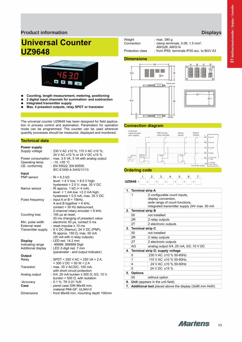
53
DisplaysProduct information
E1 M
ultif
unct
iona
lcont
rolle
r / D
ispla
ys /
Cont
rolle
r
GHM Messtechnik GmbH – Location MartensKiebitzhörn 18 22885 Barsbüttel Germany Fon +49-40-670 73-0 Fax -288www.ghm-messtechnik.de [email protected]
Product Information Industrial Electronics
Universal Counter UZ9648
Counting, length measurement, metering, positioning 2 digital input channels for summation- and subtraction Integrated transmitter supply Max. 4 preselect outputs, relay SPDT or transistor
The universal counter UZ9648 has been designed for field applica-tion in process control and automation. Parameters for operationmode can be programmed. The counter can be used whereverquantity processes should be measured, displayed and monitored.
Technical data
Power supplySupply voltage : 230 V AC ±10 %; 115 V AC ±10 %;
24 V AC ±10 % or 24 V DC ±15 %Power consumption : max. 3.5 VA, 5 VA with analog outputOperating temp. : -10..+55 °C CE- conformity : EN 55022, EN 60555,
IEC 61000-4-3/4/5/11/13InputPNP sensor : Ri = 6.3 kΩ
level: < 4 V low; > 8.5 V high;hysteresis > 2.5 V; max. 35 V DC
Namur sensor : Ri approx. 1 kΩ (< 4 mA) level: < 1 mA low; >2.2 mA high;hysteresis > 0.5 mA; max. 35 V DC
Pulse frequency : input A or B = 15kHz, A and B together = 6 kHz,contact = 30 Hz debounced, 2-channel rotary encoder = 8 kHz
Counting loss : 100 μs at reset; 20 ms changing of preselect value
Min. pulse width : electronic 50 μs, contact 5 msExternal reset : reset impulse ≥ 10 msTransmitter supply : 8 V DC (Namur), 24 V DC (PNP),
Ri approx. 150 Ω, max. 50 mA(25 mA with 4 relay outputs)
Display : LED red, 14.2 mmIndicating range : -99999..999999 Digit Additional display : LED 2-digit red, 7 mm
(parameter - and output indicator)OutputRelay : SPDT < 250 V AC < 250 VA < 2 A,
< 300 V DC < 50 W < 2 ATransistor : max. 35 V AC/DC, 100 mA,
with short circuit protectionAnalog output : 0/4..20 mA burden ≤ 500 Ω; 0/2..10 V,
burden > 500 Ω, with isolation-Accuracy : 0.1 %; TK 0.01 %/KCase : panel case DIN 96x48 mm,
material PA6-GF; UL94V-0Dimensions : front 96x48 mm, mounting depth 100mm
Weight : max. 390 gConnection : clamp terminals, 0.08..1.5 mm²,
AWG28..AWG14Protection class : front IP65, terminals IP20 acc. to BGV A3
Dimensions
Connection diagram
Ordering code
1. 2. 3. 4. 5. 6. 7.
UZ9648 - - - - - - -
1. Terminal strip A
1 2 configurable count inputs,display conversion,wide range of count functions,integrated transmitter supply 24V max. 50 mA
2. Terminal strip B
00 not installed
2R 2 relay outputs
2T 2 electronic outputs
3. Terminal strip C
00 not installed
2R 2 relay outputs
2T 2 electronic outputs
AO analog output 0/4..20 mA, 0/2..10 V DC
4. Terminal strip D; supply voltage
0 230 V AC ±10 % 50-60Hz
1 115 V AC ±10 % 50-60Hz
4 24 V AC ±10 % 50-60Hz
5 24 V DC ±15 %
5. Options
00 without option
6. Unit (appears in the unit field)
7. Additional text placed above the display (3x90 mm HxW)
30 pi-ma-Displays_E V2.00-00
UZ9648 UZ9648
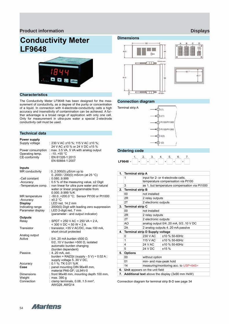
54
DisplaysProduct information
GHM Messtechnik GmbH – Location MartensKiebitzhörn 18 22885 Barsbüttel Germany Fon +49-40-670 73-0 Fax -288www.ghm-messtechnik.de [email protected]
Product Information Industrial Electronics
Conductivity MeterLF9648
Characteristics
The Conductivity Meter LF9648 has been designed for the mea-surement of conductivity, as a degree of the purity or concentrationof a liquid. In connection with 4-electrode-conductivity cells a highaccuracy and insensitivity of contamination can be achieved. A fur-ther advantage is a broad range of application with only one cell.Only for measurement in ultra-pure water a special 2-electrodeconductivity cell must be used.
Technical data
Power supplySupply voltage : 230 V AC ±10 %; 115 V AC ±10 %;
24 V AC ±10 % or 24 V DC ±15 %Power consumption : max. 3.5 VA, 5 VA with analog outputOperating temp. : -10..+55 °CCE-conformity : EN 61326-1:2013
EN 60664-1:2007
InputsMR conductivity : 0..2.000(0) μS/cm up to
0..2000 / 200(0) mS/cm (at 25 °C)-Cell constant : 0.080..9.999-Accuracy : 0.5 % of the measuring value, ±2 Digit-Temperature comp. : non linear for ultra pure water and natural
water or linear programmable from 0.000..9.999 %/K
MR temperature : -50.0..+200.0 °C; Sensor Pt100 or Pt1000-Accuracy : ±0.2 °CDisplay : LED red, 14.2 mmIndicating range : 2000(0) Digit with leading zero suppressionParameter display : LED 2-digit red, 7 mm
(parameter - and output indicator)OutputsRelay : SPDT < 250 V AC < 250 VA < 2 A,
< 300 V DC < 50 W < 2 ATransistor : transistor, <35 V AC/DC, max.100 mA,
short circuit protectedAnalog output Active : 0/4..20 mA burden ≤500 Ω;
0/2..10 V burden >500 Ω, isolatedautomatic burden changing (burden dependent)
Passive : 4..20 mA, ext. burden = RA[Ω]≤ (supply - 5 V) ÷ 0.02 A ;supply voltage 5..30 V DC,
Accuracy : 0.1 %; TK 0.01 %/KCase : panel mounting DIN 96x48 mm,
material PA6-GF; UL94V-0Dimensions : front 96x48 mm, mounting depth 100 mm,Weight : max. 390 gConnection : clamp terminals, 0.08..1.5 mm²,
AWG28..AWG14
Dimensions
Connection diagram
Terminal strip A
Ordering code
1. 2. 3. 4. 5. 6. 7.
LF9648 - - - - - - -
1. Terminal strip A
1 input for 2- or 4-electrode-cells,temperature compensation via Pt100
3 as 1, but temperature compensation via Pt1000
2. Terminal strip B
00 not installed
2R 2 relay outputs
2T 2 electronic outputs
3. Terminal strip C
00 not installed
2R 2 relay outputs
2T 2 electronic outputs
AO analog output 0/4..20 mA, 0/2..10 V DC
2A 2 analog outputs 4..20 mA passive
4. Terminal strip D Supply voltage
0 230 V AC ±10 % 50-60Hz
1 115 V AC ±10 % 50-60Hz
4 24 V AC ±10 % 50-60Hz
5 24 V DC ±15 %
5. Options
00 without option
01 min- and max-peak hold
14 measuring/monitoring acc. to USP<645>
6. Unit appears on the unit field
7. Additional text above the display (3x90 mm HxW)
Connection diagram for terminal strip B-D see page 34
pi-ma-Displays_E V2.00-00
31
LF9648 LF9648 pH9648

55
DisplaysProduct information
E1 M
ultif
unct
iona
lcont
rolle
r / D
ispla
ys /
Cont
rolle
r
GHM Messtechnik GmbH – Location MartensKiebitzhörn 18 22885 Barsbüttel Germany Fon +49-40-670 73-0 Fax -288www.ghm-messtechnik.de [email protected]
Product Information Industrial Electronics
pH and ORP Panelmeter pH9648
LED-Display 14,2 mm red Measuring range programmable -1..+15 pH / ±1500 mV Temperature compensation via P100/Pt1000 sensor Analog output 0/4..20 mA or 0/2..10 V for pH/ORP Max. 4 alarm outputs relay or transistor
Characteristics
The pH and ORP Panelmeter pH9648 is suitable for pH and ORPmeasurement in food technology, chemistry within pharmaceuticaland sewage-water technology. The pH9648 operates with all com-mon pH- and ORP electrodes. It is recommended to connect theImpedance-Converter pH40 for cable length > 5 m.
Technical data
Power supplySupply voltage : 230 V AC ±10 %; 115 V AC ±10 %;
24 V AC ±10 % or 24 V DC ±15 %Power consumption: max. 3.5 VA, with analog output 5 VAOperating temperature : -10..+55 °CCE- conformity : EN 55022, EN 60555,
IEC 61000-4-3/4/5/11/13InputpH/ORPMeasuring range : -1.00..+15.00 pH or -1500..+1500 mVRi : > 1012 ΩInput current : < 10-12 AAccuracy : 0.2 % measuring value, ±2 DigitpH setup : electrode zero point 4.00..10.00 pH
slope 40.0..70.0 mV/pHORP setup : ± 200 mVCalibration mode : - 1- or 2-point-calibration
Buffer selection possible:-Schott-WTW-Ingold (Mettler Toledo)-Puffer acc. to DIN 19266-or manual buffer input - Data entering for zero point and slope- ORP offset
TemperatureSensor : RTD, Pt100 or Pt1000,
(2- or 3-wire connection)Unit : programmable °C, °FMeasuring range : -40.0..+160.0 °C (-40.0..+320.0 °F)Accuracy : ± 0.1 %, ±1DigitTransmitter supply : 24 V DC, Ri approx. 150 Ω,
max. 50 mA (25 mA with 4 relay outputs)Display : LED red, 14.2 mmParameter display : LED 2-digit red, 7 mm
(Parameter - and output indicator)
OutputRelay SPDT : < 250 V AC < 250 VA < 2 A,
< 300 V DC <50 W < 2 ATransistor : < 35 V AC/DC, max.100 mA,
short-circuit-proofAnalog outputactive : 0/4..20 mA burden ≤500 Ω;
0/2..10 V burden > 500 Ω, isolatedautomatic output changing (burden dependent)
Analog outputpassive : 4..20 mA, ext. burden =
RA[Ω]≤ (UB-5 V) ÷ 0,02 A ;supply voltage 5..30 V DC
Accuracy : 0.1 %Panel case : DIN 96x48 mm, material PA6-GF; UL94V-0Dimensions : Front 96x48 mm, mounting depth 100 mm,Weight : max. 390 gConnection : clamp terminals, 2.5 mm² single wire,
1.5 mm² flex wire, AWG14Protection class : Front IP65, terminals IP20,
finger save acc. to BGV A3
Dimensions
Connection diagram input
32 pi-ma-Displays_E V2.00-00
Transmitter supply
LF9648 pH9648 pH9648

56
DisplaysProduct information
GHM Messtechnik GmbH – Location MartensKiebitzhörn 18 22885 Barsbüttel Germany Fon +49-40-670 73-0 Fax -288www.ghm-messtechnik.de [email protected]
Product Information Industrial Electronics
Ordering code
1. 2. 3. 4. 5. 6. 7.
pH9648 - - - - - - -
1. Terminal strip A
13 input pH / ORP electrode,temperature compensation via Pt100 / Pt1000
2. Terminal strip B
00 not installed
2R 2 relay outputs
2T 2 electronic outputs
3. Terminal strip C
00 not installed
2R 2 relay outputs
2T 2 electronic outputs
AO analog output 0/4..20 mA, 0/2..10 V DC
2A 2 analog outputs 4..20 mA passive
4. Terminal strip B supply voltage
0 230 V AC ±10 % 50-60Hz
1 115 V AC ±10 % 50-60Hz
4 24 V AC ±10 % 50-60Hz
5 24 V DC ±15 %
5. Options
00 without option
6. Unit appears in the unit field
7. Additional text above the display (3x90 mm HxW)
Connection examples pH9648
pi-ma-Displays_E V2.00-00
33
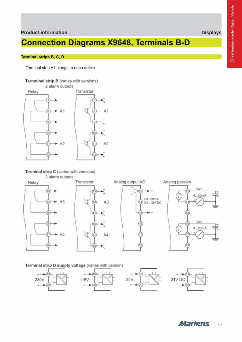
57
DisplaysProduct information
E1 M
ultif
unct
iona
lcont
rolle
r / D
ispla
ys /
Cont
rolle
r
GHM Messtechnik GmbH – Location MartensKiebitzhörn 18 22885 Barsbüttel Germany Fon +49-40-670 73-0 Fax -288www.ghm-messtechnik.de [email protected]
Product Information Industrial Electronics
Connection Diagrams X9648, Terminals B-D
Terminal strips B, C, D
Terminal strip A belongs to each article.
34 pi-ma-Displays_E V2.00-00
Connection diagramm XX96 Connection diagramm XX96
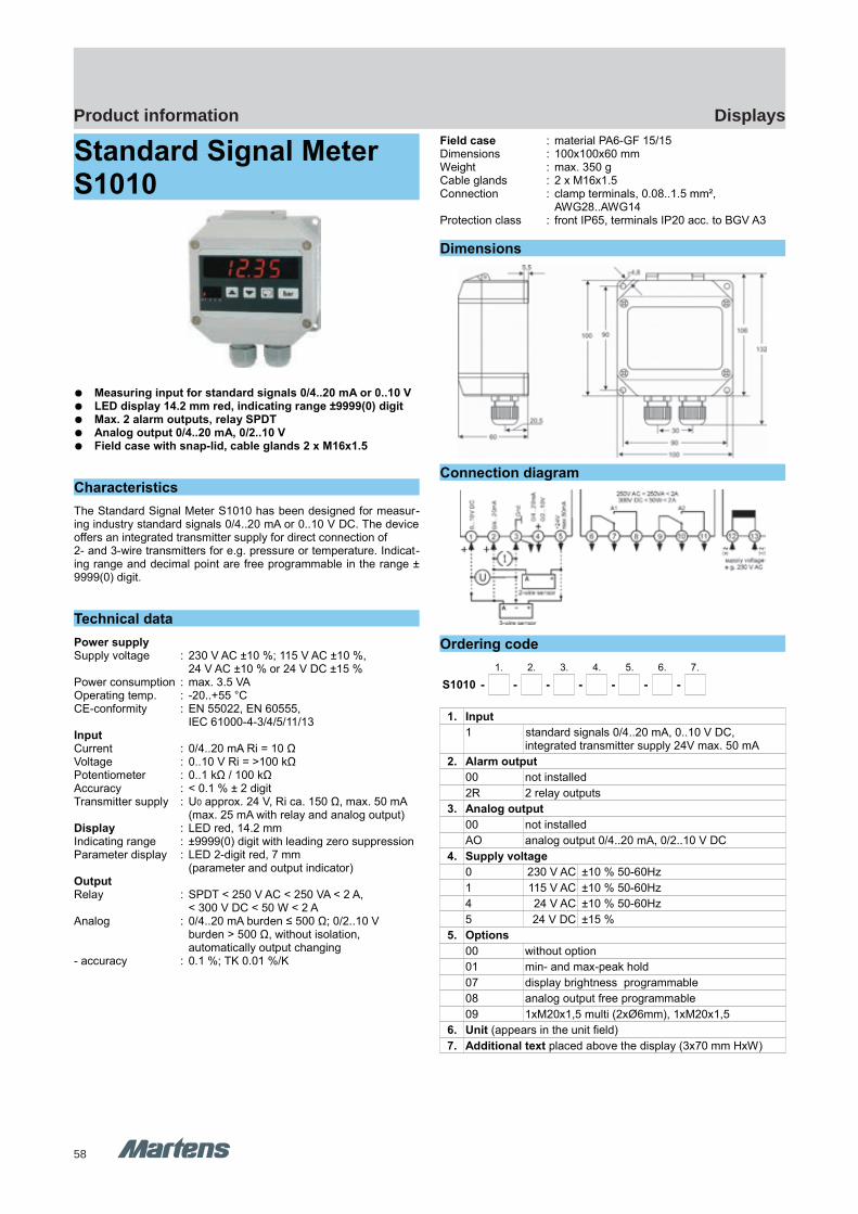
58
DisplaysProduct information
GHM Messtechnik GmbH – Location MartensKiebitzhörn 18 22885 Barsbüttel Germany Fon +49-40-670 73-0 Fax -288www.ghm-messtechnik.de [email protected]
Product Information Industrial Electronics
Standard Signal Meter S1010
Measuring input for standard signals 0/4..20 mA or 0..10 V LED display 14.2 mm red, indicating range ±9999(0) digit Max. 2 alarm outputs, relay SPDT Analog output 0/4..20 mA, 0/2..10 V Field case with snap-lid, cable glands 2 x M16x1.5
Characteristics
The Standard Signal Meter S1010 has been designed for measur-ing industry standard signals 0/4..20 mA or 0..10 V DC. The deviceoffers an integrated transmitter supply for direct connection of 2- and 3-wire transmitters for e.g. pressure or temperature. Indicat-ing range and decimal point are free programmable in the range ±9999(0) digit.
Technical data
Power supplySupply voltage : 230 V AC ±10 %; 115 V AC ±10 %,
24 V AC ±10 % or 24 V DC ±15 %Power consumption : max. 3.5 VAOperating temp. : -20..+55 °CCE-conformity : EN 55022, EN 60555,
IEC 61000-4-3/4/5/11/13InputCurrent : 0/4..20 mA Ri = 10 ΩVoltage : 0..10 V Ri = >100 kΩPotentiometer : 0..1 kΩ / 100 kΩAccuracy : < 0.1 % ± 2 digitTransmitter supply : U0 approx. 24 V, Ri ca. 150 Ω, max. 50 mA
(max. 25 mA with relay and analog output)Display : LED red, 14.2 mmIndicating range : ±9999(0) digit with leading zero suppressionParameter display : LED 2-digit red, 7 mm
(parameter and output indicator)OutputRelay : SPDT < 250 V AC < 250 VA < 2 A,
< 300 V DC < 50 W < 2 AAnalog : 0/4..20 mA burden ≤ 500 Ω; 0/2..10 V
burden > 500 Ω, without isolation,automatically output changing
- accuracy : 0.1 %; TK 0.01 %/K
Field case : material PA6-GF 15/15Dimensions : 100x100x60 mmWeight : max. 350 gCable glands : 2 x M16x1.5Connection : clamp terminals, 0.08..1.5 mm²,
AWG28..AWG14Protection class : front IP65, terminals IP20 acc. to BGV A3
Dimensions
Connection diagram
Ordering code
1. 2. 3. 4. 5. 6. 7.
S1010 - - - - - - -
1. Input
1 standard signals 0/4..20 mA, 0..10 V DC,integrated transmitter supply 24V max. 50 mA
2. Alarm output
00 not installed
2R 2 relay outputs
3. Analog output
00 not installed
AO analog output 0/4..20 mA, 0/2..10 V DC
4. Supply voltage
0 230 V AC ±10 % 50-60Hz
1 115 V AC ±10 % 50-60Hz
4 24 V AC ±10 % 50-60Hz
5 24 V DC ±15 %
5. Options
00 without option
01 min- and max-peak hold
07 display brightness programmable
08 analog output free programmable
09 1xM20x1,5 multi (2xØ6mm), 1xM20x1,5
6. Unit (appears in the unit field)
7. Additional text placed above the display (3x70 mm HxW)
pi-ma-Displays_E V2.00-00
35
S1010 S1010

59
DisplaysProduct information
E1 M
ultif
unct
iona
lcont
rolle
r / D
ispla
ys /
Cont
rolle
r
GHM Messtechnik GmbH – Location MartensKiebitzhörn 18 22885 Barsbüttel Germany Fon +49-40-670 73-0 Fax -288www.ghm-messtechnik.de [email protected]
Product Information Industrial Electronics
Tank Display TA1010
Inputs for standard signals 0/4..20 mA or 0/2..10 V 2nd input for pressure transmitter at pressure loaded tanks Input automatic level correction 6 standard- and custom sized tanks selectable Max. 2 alarm outputs, relay SPDT Field case with snap lid, cable glands 2 x M16x1.5
Characteristics
The Tank Display TA1010 offers content measurement of tanks withno linear connection between level and content. Measurement willbe realized by hydrostatic pressure or distance sensors. The deviceoffers the possibility to connect a level sensor. Reaching a certainlevel, the displayed value will be corrected automatically to thevalue according to the position of the installed sensor.
Technical data
Power supplySupply voltage : 230 V AC ±10 %; 115 V AC ±10 %,
24 V AC ±10 % or 24 V DC ±15 %Power consumption : max. 3.5 VAOperating temp. : -20..+55 °CCE-conformity : EN 55022, EN 60555,
IEC 61000-4-3/4/5/11/13InputCurrent : 0/4..20 mA; Ri = 10 Ω
overload 2-times; 4-times for max. 5 sVoltage : 0/2..10 V DC; Ri = 100 kΩ
overload max. 100 VAccuracy : < 0.15 % ±2 digitTransmitter supply : U0 approx. 24 V;
Ri approx. 150 Ω; max. 50 mA Display : LED red, 14.2 mmIndicating range : 999999 Digit, with leading zero suppressionParameter display : LED 2 digit red, 7 mm
(parameter - and output indicator)OutputRelay : SPDT < 250 V AC < 250 VA < 2 A,
< 300 V DC < 50 W < 2 AAnalog : 0/4..20 mA burden ≤ 500 Ω; 0/2..10 V
burden > 500 Ω, without isolation,automatic output changing
- Accuracy : 0.1 %; TK 0.01 %/KField case : material PA6-GFGFK 15/15Dimensions : 100x100x60 mmWeight : max. 450 gCable gland : 2 x M16x1.5
Connection : clamp terminals, 0.08..1.5 mm², AWG28..AWG14
Protection class : front IP65, terminals IP20, acc. to BGV A3
Dimensions
Connection diagram
Ordering code
1. 2. 3. 4. 5. 6. 7.
TA1010 - - - - - - -
1. Input
01 1 x 0/4..20 mA, 1 x input for level correction
11 2 x 0/4..20 mA
02 1 x 0/2..10 V, 1 x input for level correction
22 2 x 0/2..10 V
2. Alarm output
00 not installed
2R 2 relay
3. Analog output
00 not installed
AO analog output 0/4..20 mA, 0/2..10 V DC
4. Supply voltage
0 230 V AC ±10 % 50-60Hz
1 115 V AC ±10 % 50-60Hz
4 24 V AC ±10 % 50-60Hz
5 24 V DC ±15 %
5. Options
00 without option
09 1xM20x1.5 multi (2xØ 6mm), 1xM20x1.5
6. Unit (appears in the unit field)
7. Additional text placed above the display (3x70 mm HxW)
36 pi-ma-Displays_E V2.00-00
TA1010 TA1010

60
DisplaysProduct information
GHM Messtechnik GmbH – Location MartensKiebitzhörn 18 22885 Barsbüttel Germany Fon +49-40-670 73-0 Fax -288www.ghm-messtechnik.de [email protected]
Product Information Industrial Electronics
Temperature-Meter T1010
Measuring input Pt100 -100.0..+600.0 °CPt1000 -50.0..+200.0 °C
LED-Display 14.2 mm red, indicating range ±9999(0) Digit Max. 2 alarm outputs, relay SPDT Analog output 0/4..20 mA, 0/2..10 V Field case with snap lid, 2 x M16x1.5
Characteristics
The Temperature-Meter T1010 is suitable for measurement of tem-peratures in connection with RTD sensors Pt100, Pt1000. Devicesfor other temperature sensors are available on request. The meas-uring input is isolated. The measuring range can be limited in theconfiguration level. This is identical with the range of the analogoutput.
Technical data
Power supplySupply voltage : 230 V AC ±10 %; 115 V AC ±10 %,
24 V AC ±10 % or 24 V DC ±15 %Power consumption : max. 3.5 VAOperating temp. : -20..+55 °CCE-conformity : EN55022, EN60555,
IEC61000-4-3/4/5/11/13InputPt100; Pt1000 : -100..+600 °C ; -50..+200 °CAccuracy : Pt100 or Pt1000 < 0.1% ±2 Digit,
max. 100 Ω line resistance Display : LED red, 14.2 mmIndicating range : ±9999(0) digit, with leading zero suppressionAdditional display : LED 2-digit red, 7 mm
(Parameter - and output indicator)OutputRelay : SPDT < 250 V AC < 250 VA < 2 A,
< 300 V DC < 50 W < 2 AAnalog : 0/4..20 mA burden ≤ 500 Ω; 0/2..10 V
burden > 500 Ω, no isolation,automatic output changing (burden dependent)
- Accuracy : 0.1 %; TK 0.01 %/KField case : Material PA6-GF/GFK 15/15Dimensions : 100x100x60 mmWeight : max. 450 gCable gland : 2 x M16x1.5Connection : clamp terminals, 0.08..1.5 mm²,
AWG28..AWG14Protection class : front IP65, terminals IP20 acc. to BGV A3
Dimensions
Connection diagram
Ordering code
1. 2. 3. 4. 5. 6. 7.
T1010 - - - - - - -
1. Input
1 Pt100 -100.0..+600.0°C
3 Pt1000 -50.0..+200.0°C
2. Alarm output
00 not installed
2R 2 relay SPDT
3. Analog output
00 not installed
AO analog output 0/4..20 mA, 0/2..10 V DC
4. Supply voltage
0 230 V AC ±10 % 50-60Hz
1 115 V AC ±10 % 50-60Hz
4 24 V AC ±10 % 50-60Hz
5 24 V DC ±15 %
5. Options
00 without option
01 min-max-value hold
07 display brightness programmable
09 1xM20x1.5 multi (2xØ 6 mm), 1xM20x1.5
6. Unit (appears in the unit field)
7. Additional text above the display (3x70 mm HxW)
pi-ma-Displays_E V2.00-00
37
DR1010T1010 T1010
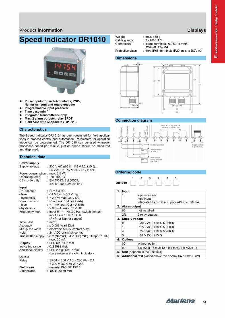
61
DisplaysProduct information
E1 M
ultif
unct
iona
lcont
rolle
r / D
ispla
ys /
Cont
rolle
r
GHM Messtechnik GmbH – Location MartensKiebitzhörn 18 22885 Barsbüttel Germany Fon +49-40-670 73-0 Fax -288www.ghm-messtechnik.de [email protected]
Product Information Industrial Electronics
Speed Indicator DR1010
Pulse inputs for switch contacts, PNP-,Namur-sensors and rotary encoder
Programmable input prescaler Time base min -1
Integrated transmitter-supply Max. 2 alarm outputs, relay SPDT Field case with snap-lid, 2 x M16x1.5
Characteristics
The Speed Indicator DR1010 has been designed for field applica-tions in process control and automation. Parameters for operationmode can be programmed. The DR1010 can be used whereverprocesses based per minute, just as speed should be measuredand displayed.
Technical data
Power supplySupply voltage : 230 V AC ±10 %; 115 V AC ±10 %;
24 V AC ±10 % or 24 V DC ±15 %Power consumption : max. 3.5 VAOperating temp. : -20..+55 °C CE- conformity : EN 55022, EN 60555,
IEC 61000-4-3/4/5/11/13InputPNP sensor : Ri = 6.3 kΩ - level : < 4 V low; > 8.5 V high;- hysteresis : > 2.5 V; max. 35 V DCNamur sensor : Ri approx. 1 kΩ (< 4 mA) - level : < 1 mA low; >2.2 mA high;- hysteresis : > 0.5 mA; max. 35 V DCFrequency max. : input E1 = 1 Hz..30 Hz, (switch contact)
input E2 = 1 Hz..15 kHz, (PNP- or Namur sensor)
Time base : min-1
Accuracy : ≤ 0.003 % ±1 DigitMin. pulse width : electronic 50 µs, contact 5 msHold : 24 V DC or switch contactTransmitter supply : 8 V (Namur), 24 V DC (PNP), Ri appr. 150Ω,
max. 50 mADisplay : LED red, 14.2 mmIndicating range : 0..99999 digit Additional display : LED 2-digit red, 7 mm
(parameter- and switch indicator)OutputRelay : SPDT < 250 V AC < 250 VA < 2 A,
< 300 V DC < 50 W < 2 AField case : material PA6-GF 15/15Dimensions : 100x100x60 mm
Weight : max. 450 gCable glands : 2 x M16x1.5Connection : clamp terminals, 0.08..1.5 mm²,
AWG28..AWG14Protection class : front IP65, terminals IP20, acc. to BGV A3
Dimensions
Connection diagram
Ordering code
1. 2. 3. 4. 5. 6.
DR1010 - - - - - -
1. Input
1 2 pulse inputs,hold input, integrated transmitter supply 24V max. 50 mA
2. Alarm output
00 not installed
2R 2 relay outputs
3. Supply voltage
0 230 V AC ±10 % 50-60Hz
1 115 V AC ±10 % 50-60Hz
4 24 V AC ±10 % 50-60Hz
5 24 V DC ±15 %
4. Options
00 without option
09 1 x M20x1.5 multi (2 x Ø6 mm), 1 x M20x1.5
5. Unit (appears in the unit field)
6. Additional text placed above the display (3x70 mm HxW)
38 pi-ma-Displays_E V2.00-00
DR1010 DR1010

62
DisplaysProduct information
GHM Messtechnik GmbH – Location MartensKiebitzhörn 18 22885 Barsbüttel Germany Fon +49-40-670 73-0 Fax -288www.ghm-messtechnik.de [email protected]
Product Information Industrial Electronics
Productivity Meter PR1010
2 digital inputs for summation,difference, ratio measurement
Input prescaler programmable LED-Display 14.2 mm red, ±99999 Digit Max. 2 alarm outputs, relay SPDT Field case with snap-lid, 2 x M16x1.5
Characteristic
The Productivity-Meter PR1010 analysis impulse rates, represent-ing a speed, flow, passing time or revolutions per time. The dis-played values therefore always refer to a determined time unit andrepresent productivity. There are extensive functions program-mable. Since impulses and unit of a displayed value can take anyrelation, the device offers extensive conversion possibilities.
Technical data
Power supplySupply voltage : 230 V AC ±10 %; 115 V AC ±10 %;
24 V AC ±10 % or 24 V DC ±15 %Power consumption : max. 3.5 VAOperating temp. : -20..+55 °C CE- conformity : EN 55022, EN 60555,
IEC 61000-4-3/4/5/11/13InputPNP sensor : Ri = 6.3 kΩ
level: < 4 V low; > 8,5 V high;hysteresis > 2.5 V; max. 35 V DC
Namur sensor : Ri approx. 1 kΩ (< 4 mA) level: < 1 mA low; >2.2 mA high;hysteresis > 0.5 mA; max. 35 V DC
Pulse frequency : input A or B = 0.1 Hz..15 kHz, A and B together = 0.1 Hz..8 kHz,contact = 0.1 Hz..30 Hz, 2-channel encoder = 0.1 Hz..10 kHz
Min. pulse width : electronic 50 µs, contact 5 msTime base : sec-1, min-1, h-1
Accuracy : ≤ 0.003 % ± 1 DigitTransmitter supply : 8 V (Namur), 24 V DC, Ri approx. 150 Ω,
max. 50 mA Display : LED red, 14.2 mmIndicating range : -99999..99999 Digit Parameter display : LED 2-digit red, 7 mm
(parameter and output indicator)OutputRelay : SPDT < 250 V AC < 250 VA < 2 A,
< 300 V DC < 50 W < 2 AAnalog output : 0/4..20 mA burden ≤ 500 Ω; 0/2..10 V,
burden > 500 Ω, without isolation-Accuracy : 0.1 %; TK 0.01 %/K
Field case : material PA6-GF 15/15Dimensions : 100x100x60 mmWeight : max. 450 gCable gland : 2 x M16x1.5Connection : clamp terminals, 0.08..1.5 mm²,
AWG28..AWG14Protection class : front IP65, terminals IP20 acc. to BGV A3
Dimensions
Connection diagram
Ordering code
1. 2. 3. 4. 5. 6. 7.
PR1010 - - - - - - -
1. Input
1 2 configurable pulse inputs,display conversion programmable,integrated transmitter supply 24V 50 mA
2. Alarm output
00 not installed
2R 2 relay outputs
3. Analog output
00 not installed
AO analog output 0/4..20 mA, 0/2..10 V DC
4. Supply voltage
0 230 V AC ±10 % 50-60Hz
1 115 V AC ±10 % 50-60Hz
4 24 V AC ±10 % 50-60Hz
5 24 V DC ±15 %
5. Options
00 without option
09 1 x M20x1.5 multi (2 x Ø6 mm), 1 x M20x1.5
6. Unit (appears in the unit field)
7. Additional text placed above the display (3x70 mm HxW)
pi-ma-Displays_E V2.00-00
39
PR1010 PR1010

63
DisplaysProduct information
E1 M
ultif
unct
iona
lcont
rolle
r / D
ispla
ys /
Cont
rolle
r
GHM Messtechnik GmbH – Location MartensKiebitzhörn 18 22885 Barsbüttel Germany Fon +49-40-670 73-0 Fax -288www.ghm-messtechnik.de [email protected]
Product Information Industrial Electronics
Universal Counter UZ1010
Counting, length measurement, metering, positioning 2 digital input channels for summation- and subtraction Integrated transmitter-supply Max. 2 preselect outputs, relay SPDT Field case with snap lid, cable glands 2xM16x1.5
Characteristics
The universal counter UZ1010 has been designed for field applica-tion in process control and automation. Parameters for operationmode can be programmed. The counter can be used whereverquantity processes should be measured, displayed and monitored.
Technical data
Power supplySupply voltage : 230 V AC ±10 %; 115 V AC ±10 %;
24 V AC ±10 % or 24 V DC ±15 %Power consumption : max. 3.5 VAOperating temp. : -20..+55 °C CE- conformity : EN 55022, EN 60555,
IEC 61000-4-3/4/5/11/13InputPNP sensor : Ri = 6.3 kΩ
level: < 4 V low; > 8.5 V high;hysteresis > 2.5 V; max. 35 V DC
Namur sensor : Ri approx. 1 kΩ (< 4 mA) level: < 1 mA low; > 2.2 mA high;hysteresis > 0.5 mA; max. 35 V DC
Counting frequency : input A or B = 15 kHz A and B together = 6 kHz, debounced for contact= 30 Hz
Counting loss : 100 μs at reset; 20 ms changing of preselect value
Min. pulse width : electronic pulse 50 μs, switch contact 5 msExternal reset : min. pulse width ≥ 10 msTransmitter-supply : 8 V DC (Namur), 24 V DC (PNP),
Ri approx. 150 Ω, max. 50 mADisplay : LED red, 14.2 mmIndicating range : -99999..999999 digit Additional display : LED 2-digit red, 7 mm
(parameter- and output indicator)OutputRelay : SPDT < 250 V AC < 250 VA < 2 A,
< 300 V DC < 50 W < 2 AField case : material PA6-GF 15/15Dimensions : 100x100x60 mm
Weight : max. 450 gCable glands : 2 x M16x1.5Connection : clamp terminals, 0.08..1.5 mm²,
AWG28..AWG14Protection class : front IP65, terminals IP20 acc. to BGV A3
Dimensions
Connection diagram
Ordering code
1. 2. 3. 4. 5. 6.
UZ1010 - - - - - -
1. Input
1 2 configurable count inputs,wide range of count functions, display conversion,reset input,integrated transmitter supply 24V max. 50 mA
2. Alarm output
00 not installed
2R 2 relay outputs
3. Supply voltage
0 230 V AC ±10 % 50-60Hz
1 115 V AC ±10 % 50-60Hz
4 24 V AC ±10 % 50-60Hz
5 24 V DC ±15 %
4. Options
00 without options
09 1xM20x1.5 multi (2xØ6 mm), 1xM20x1.5
5. Unit (appears in the unit field)
6. Additional text placed above the display (3x70 mm HxW)
40 pi-ma-Displays_E V2.00-00
UZ1010 UZ1010
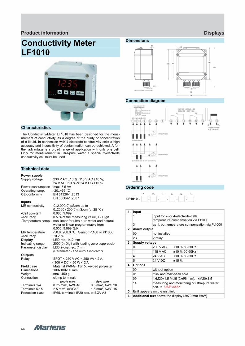
64
DisplaysProduct information
GHM Messtechnik GmbH – Location MartensKiebitzhörn 18 22885 Barsbüttel Germany Fon +49-40-670 73-0 Fax -288www.ghm-messtechnik.de [email protected]
Product Information Industrial Electronics
Conductivity MeterLF1010
Characteristics
The Conductivity-Meter LF1010 has been designed for the meas-urement of conductivity, as a degree of the purity or concentrationof a liquid. In connection with 4-electrode-conductivity cells a highaccuracy and insensitivity of contamination can be achieved. A fur-ther advantage is a broad range of application with only one cell.Only for measurement in ultra-pure water a special 2-electrodeconductivity cell must be used.
Technical data
Power supplySupply voltage : 230 V AC ±10 %; 115 V AC ±10 %;
24 V AC ±10 % or 24 V DC ±15 %Power consumption : max. 3.5 VAOperating temp. : -20..+55 °CCE-conformity : EN 61326-1:2013
EN 60664-1:2007InputsMR conductivity : 0..2.000(0) μS/cm up to
0..2000 / 200(0) mS/cm (at 25 °C)-Cell constant : 0.080..9.999-Accuracy : 0.5 % of the measuring value, ±2 Digit-Temperature comp. : non linear for ultra pure water and natural
water or linear programmable from 0.000..9.999 %/K
MR temperature : -50.0..200.0 °C; Sensor Pt100 or Pt1000-Accuracy : ±0.2 °CDisplay : LED red, 14.2 mmIndicating range : 2000(0) Digit with leading zero suppressionParameter display : LED 2-digit red, 7 mm
(Parameter - and output indicator)OutputsRelay : SPDT < 250 V AC < 250 VA < 2 A,
< 300 V DC < 50 W < 2 AField case : Material PA6-GF15/15, keypad polyesterDimensions : 100x100x60 mmWeight : max. 450 gConnection : clamp terminals
single wire flexi wireTerminals 1-4 0.75 mm², AWG18 0.5 mm², AWG 20Terminals 5-15 2.5 mm², AWG13 1.5 mm², AWG 15Protection class : IP65, terminals IP20 acc. to BGV A3
Dimensions
Connection diagram
Ordering code
1. 2. 3. 4. 5. 6.
LF1010 - - - - - -
1. Input
1 input for 2- or 4-electrode-cells,temperature compensation via Pt100
3 as 1, but temperature compensation via Pt1000
2. Alarm output
00 not installed
2R 2 relay
3. Supply voltage
0 230 V AC ±10 % 50-60Hz
1 115 V AC ±10 % 50-60Hz
4 24 V AC ±10 % 50-60Hz
5 24 V DC ±15 %
4. Options
00 without option
01 min- and max-peak hold
09 1xM20x1.5 Multi (2xØ6 mm), 1xM20x1.5
14 measuring and monitoring of ultra-pure water acc. to USP<645>
5. Unit appears on the unit field
6. Additional text above the display (3x70 mm HxW)
pi-ma-Displays_E V2.00-00
41
GIA0420 VO(T)LF1010 LF1010
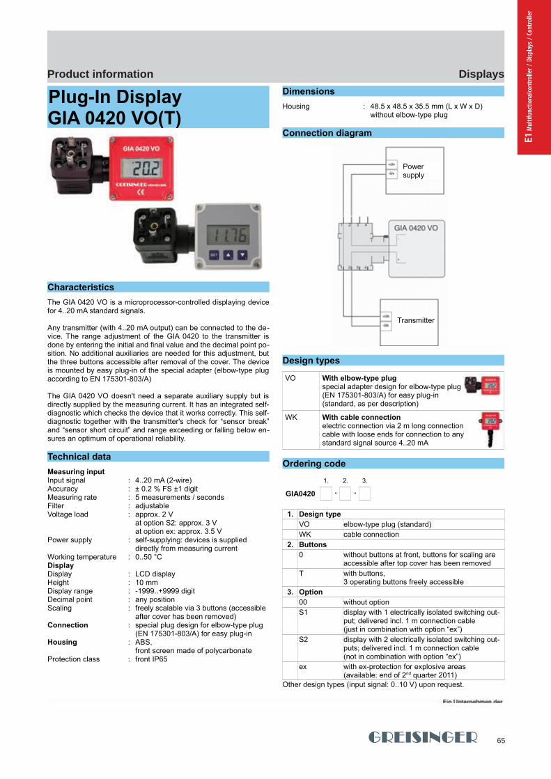
65
DisplaysProduct information
E1 M
ultif
unct
iona
lcont
rolle
r / D
ispla
ys /
Cont
rolle
r
GHM Messtechnik GmbH - Location GreisingerHans-Sachs-Straße 26 93128 Regenstauf Germany Fon +49 (0) 9402 - 9383 - 0 Fax -33www.greisinger.de [email protected]
Produktinformation Industrial Electronics
Plug-In Display GIA 0420 VO(T) Self-supplying plug-in display Freely scaling via 3 buttons Integrated self-diagnostic
Characteristics
The GIA 0420 VO is a microprocessor-controlled displaying devicefor 4..20 mA standard signals.
Any transmitter (with 4..20 mA output) can be connected to the de-vice. The range adjustment of the GIA 0420 to the transmitter isdone by entering the initial and final value and the decimal point po-sition. No additional auxiliaries are needed for this adjustment, butthe three buttons accessible after removal of the cover. The deviceis mounted by easy plug-in of the special adapter (elbow-type plugaccording to EN 175301-803/A)
The GIA 0420 VO doesn't need a separate auxiliary supply but isdirectly supplied by the measuring current. It has an integrated self-diagnostic which checks the device that it works correctly. This self-diagnostic together with the transmitter's check for “sensor break”and “sensor short circuit” and range exceeding or falling below en-sures an optimum of operational reliability.
Technical data
Measuring inputInput signal : 4..20 mA (2-wire)Accuracy : ± 0.2 % FS ±1 digitMeasuring rate : 5 measurements / secondsFilter : adjustableVoltage load : approx. 2 V
at option S2: approx. 3 Vat option ex: approx. 3.5 V
Power supply : self-supplying: devices is supplied directly from measuring current
Working temperature : 0..50 °CDisplayDisplay : LCD displayHeight : 10 mm Display range : -1999..+9999 digitDecimal point : any positionScaling : freely scalable via 3 buttons (accessible
after cover has been removed) Connection : special plug design for elbow-type plug
(EN 175301-803/A) for easy plug-inHousing : ABS,
front screen made of polycarbonateProtection class : front IP65
Dimensions
Housing : 48.5 x 48.5 x 35.5 mm (L x W x D)without elbow-type plug
Connection diagram
Design types
VO With elbow-type plug special adapter design for elbow-type plug(EN 175301-803/A) for easy plug-in(standard, as per description)
WK With cable connectionelectric connection via 2 m long connection cable with loose ends for connection to any standard signal source 4..20 mA
Ordering code
1. 2. 3.
GIA0420 - -
1. Design type
VO elbow-type plug (standard)
WK cable connection
2. Buttons
0 without buttons at front, buttons for scaling are accessible after top cover has been removed
T with buttons, 3 operating buttons freely accessible
3. Option
00 without option
S1 display with 1 electrically isolated switching out-put; delivered incl. 1 m connection cable(just in combination with option “ex”)
S2 display with 2 electrically isolated switching out-puts; delivered incl. 1 m connection cable (not in combination with option “ex”)
ex with ex-protection for explosive areas (available: end of 2nd quarter 2011)
Other design types (input signal: 0..10 V) upon request.
42 pi-ma-Displays_E V2.00-00
Powersupply
Transmitter
GIA0420 VO(T) GIA0420 VO(T)
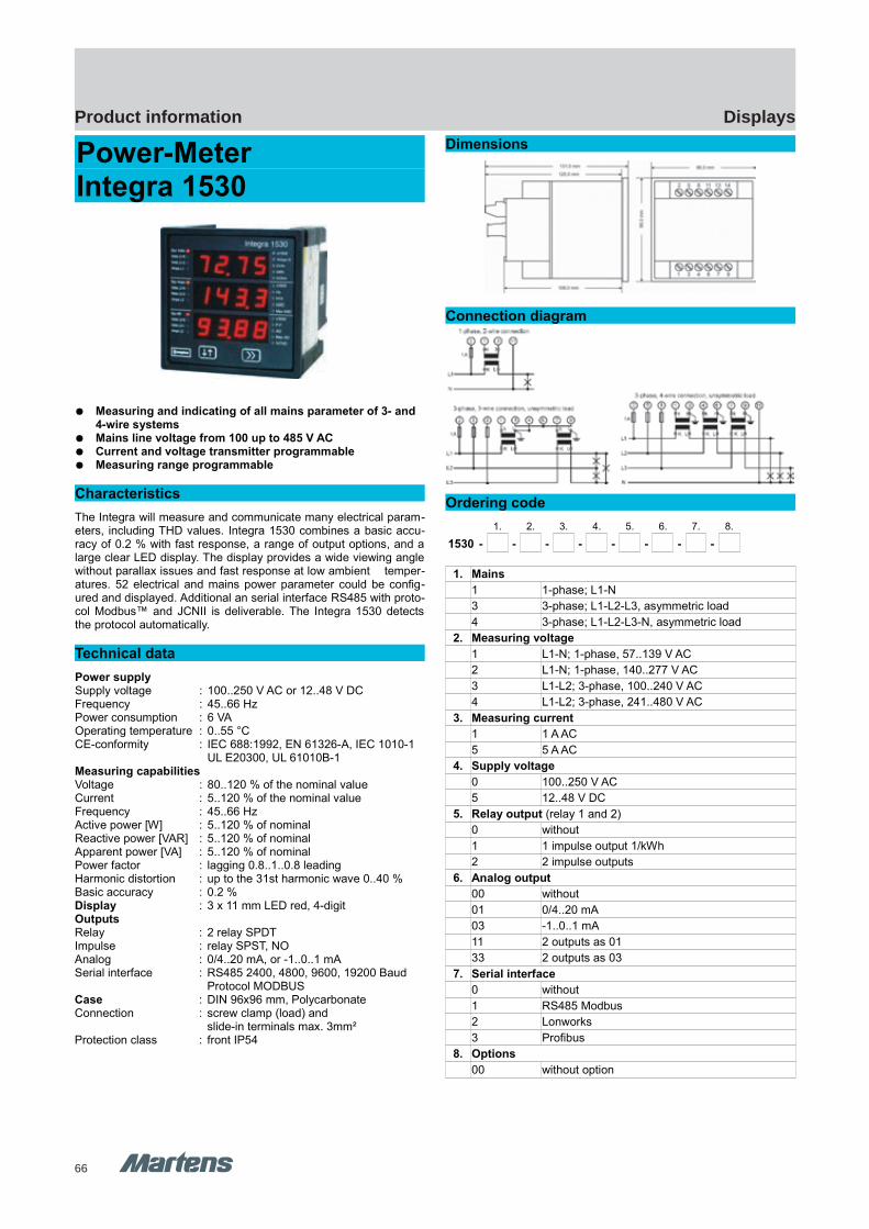
66
DisplaysProduct information
GHM Messtechnik GmbH – Location MartensKiebitzhörn 18 22885 Barsbüttel Germany Fon +49-40-670 73-0 Fax -288www.ghm-messtechnik.de [email protected]
Product Information Industrial Electronics
Power-Meter Integra 1530
Measuring and indicating of all mains parameter of 3- and 4-wire systems
Mains line voltage from 100 up to 485 V AC Current and voltage transmitter programmable Measuring range programmable
Characteristics
The Integra will measure and communicate many electrical param-eters, including THD values. Integra 1530 combines a basic accu-racy of 0.2 % with fast response, a range of output options, and alarge clear LED display. The display provides a wide viewing anglewithout parallax issues and fast response at low ambient temper-atures. 52 electrical and mains power parameter could be config-ured and displayed. Additional an serial interface RS485 with proto-col Modbus™ and JCNII is deliverable. The Integra 1530 detectsthe protocol automatically.
Technical data
Power supplySupply voltage : 100..250 V AC or 12..48 V DCFrequency : 45..66 HzPower consumption : 6 VAOperating temperature : 0..55 °CCE-conformity : IEC 688:1992, EN 61326-A, IEC 1010-1
UL E20300, UL 61010B-1Measuring capabilitiesVoltage : 80..120 % of the nominal valueCurrent : 5..120 % of the nominal valueFrequency : 45..66 HzActive power [W] : 5..120 % of nominalReactive power [VAR] : 5..120 % of nominalApparent power [VA] : 5..120 % of nominalPower factor : lagging 0.8..1..0.8 leadingHarmonic distortion : up to the 31st harmonic wave 0..40 %Basic accuracy : 0.2 %Display : 3 x 11 mm LED red, 4-digitOutputsRelay : 2 relay SPDTImpulse : relay SPST, NOAnalog : 0/4..20 mA, or -1..0..1 mASerial interface : RS485 2400, 4800, 9600, 19200 Baud
Protocol MODBUSCase : DIN 96x96 mm, PolycarbonateConnection : screw clamp (load) and
slide-in terminals max. 3mm²Protection class : front IP54
Dimensions
Connection diagram
Ordering code
1. 2. 3. 4. 5. 6. 7. 8.
1530 - - - - - - - -
1. Mains
1 1-phase; L1-N
3 3-phase; L1-L2-L3, asymmetric load
4 3-phase; L1-L2-L3-N, asymmetric load
2. Measuring voltage
1 L1-N; 1-phase, 57..139 V AC
2 L1-N; 1-phase, 140..277 V AC
3 L1-L2; 3-phase, 100..240 V AC
4 L1-L2; 3-phase, 241..480 V AC
3. Measuring current
1 1 A AC
5 5 A AC
4. Supply voltage
0 100..250 V AC
5 12..48 V DC
5. Relay output (relay 1 and 2)
0 without
1 1 impulse output 1/kWh
2 2 impulse outputs
6. Analog output
00 without
01 0/4..20 mA
03 -1..0..1 mA
11 2 outputs as 01
33 2 outputs as 03
7. Serial interface
0 without
1 RS485 Modbus
2 Lonworks
3 Profibus
8. Options
00 without option
pi-ma-Displays_E V2.00-00
43
Inegra 1530 Integra 1530
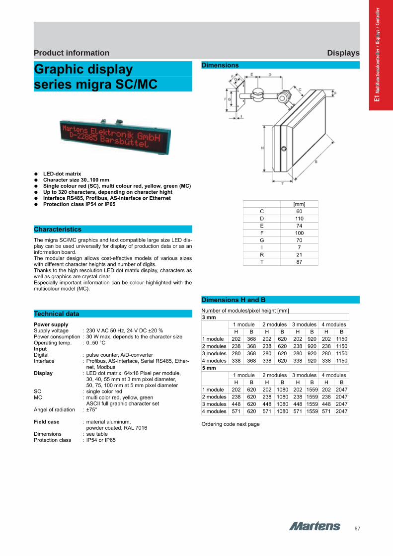
67
DisplaysProduct information
E1 M
ultif
unct
iona
lcont
rolle
r / D
ispla
ys /
Cont
rolle
r
GHM Messtechnik GmbH – Location MartensKiebitzhörn 18 22885 Barsbüttel Germany Fon +49-40-670 73-0 Fax -288www.ghm-messtechnik.de [email protected]
Product Information Industrial Electronics
Graphic display series migra SC/MC
LED-dot matrix Character size 30..100 mm Single colour red (SC), multi colour red, yellow, green (MC) Up to 320 characters, depending on character hight Interface RS485, Profibus, AS-Interface or Ethernet Protection class IP54 or IP65
Characteristics
The migra SC/MC graphics and text compatible large size LED dis-play can be used universally for display of production data or as aninformation board.The modular design allows cost-effective models of various sizeswith different character heights and number of digits.Thanks to the high resolution LED dot matrix display, characters aswell as graphics are crystal clear.Especially important information can be colour-highlighted with themulticolour model (MC).
Technical data
Power supplySupply voltage : 230 V AC 50 Hz, 24 V DC ±20 %Power consumption : 30 W max. depends to the character sizeOperating temp. : 0..50 °C InputDigital : pulse counter, A/D-converterInterface : Profibus, AS-Interface, Serial RS485, Ether-
net, ModbusDisplay : LED dot matrix; 64x16 Pixel per module,
30, 40, 55 mm at 3 mm pixel diameter,50, 75, 100 mm at 5 mm pixel diameter
SC : single color redMC : multi color red, yellow, green
ASCII full graphic character set Angel of radiation : ±75°
Field case : material aluminum, powder coated, RAL 7016
Dimensions : see tableProtection class : IP54 or IP65
Dimensions
[mm]
C 60
D 110
E 74
F 100
G 70
I 7
R 21
T 87
Dimensions H and B
Number of modules/pixel height [mm]
3 mm
1 module 2 modules 3 modules 4 modules
H B H B H B H B
1 module 202 368 202 620 202 920 202 1150
2 modules 238 368 238 620 238 920 238 1150
3 modules 280 368 280 620 280 920 280 1150
4 modules 338 368 338 620 338 920 338 1150
5 mm
1 module 2 modules 3 modules 4 modules
H B H B H B H B
1 module 202 620 202 1080 202 1559 202 2047
2 modules 238 620 238 1080 238 1559 238 2047
3 modules 448 620 448 1080 448 1559 448 2047
4 modules 571 620 571 1080 571 1559 571 2047
Ordering code next page
44 pi-ma-Displays_E V2.00-00
migra SC/MC series migra SC/MC series

68
DisplaysProduct information
GHM Messtechnik GmbH – Location MartensKiebitzhörn 18 22885 Barsbüttel Germany Fon +49-40-670 73-0 Fax -288www.ghm-messtechnik.de [email protected]
Product Information Industrial Electronics
Ordering code
1. 2. 3. 4. 5. 6. 7. 8.
migra - - - - - -
1. Display 1 basic module
SC-3 3 mm single color red (indoor mounting)
MC-3 3 mm multi color red/yellow/green (indoor mounting)
SC-5 5 mm single color red (indoor mounting)
MC-5 5 mm multi color red/yellow/green (indoor mounting)
2. Extended module (1 module = 64x16 Pixel )
n
3. Mounting position (f.e. 1x4 = 1 line with 4 modules)
For each 4x4 module 1 basic module is necessary
4. Input
0 pulse counter
1 A/D converter 4-steps
3 serial RS 485
4 Profibus DP, include cable plug
5 Ethernet TCP/IP
6 AS-Interface
B radio controlled clock DCF77
D Modbus RTU
E WLAN
5. Supply voltage
0 230 V AC ±10 % 50-60Hz
5 24 V DC ±15 %
6. Protection class
0 IP54
1 IP65
7. Mounting
1 multi hinge*
2 mounting angle *
3 suspension eyes for chains
8. Options
00 without
03 heating with controller
06 sensor for display brightness (only SC-5, MC-5)
* 2 multi hinge/mounting angle are necessary for more than 2 mod-ules in line
* 3 multi hinge/mounting angle are necessary for more than 3 mod-ules in line
pi-ma-Displays_E V2.00-00
45
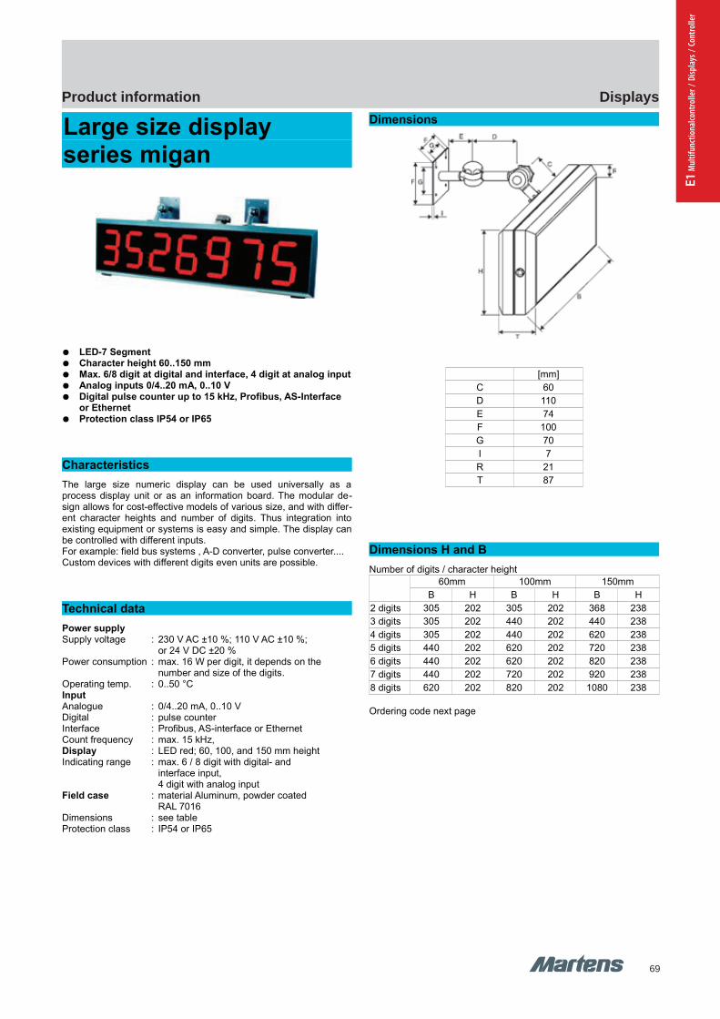
69
DisplaysProduct information
E1 M
ultif
unct
iona
lcont
rolle
r / D
ispla
ys /
Cont
rolle
r
GHM Messtechnik GmbH – Location MartensKiebitzhörn 18 22885 Barsbüttel Germany Fon +49-40-670 73-0 Fax -288www.ghm-messtechnik.de [email protected]
Product Information Industrial Electronics
Large size display series migan
LED-7 Segment Character height 60..150 mm Max. 6/8 digit at digital and interface, 4 digit at analog input Analog inputs 0/4..20 mA, 0..10 V Digital pulse counter up to 15 kHz, Profibus, AS-Interface
or Ethernet Protection class IP54 or IP65
Characteristics
The large size numeric display can be used universally as aprocess display unit or as an information board. The modular de-sign allows for cost-effective models of various size, and with differ-ent character heights and number of digits. Thus integration intoexisting equipment or systems is easy and simple. The display canbe controlled with different inputs. For example: field bus systems , A-D converter, pulse converter....Custom devices with different digits even units are possible.
Technical data
Power supplySupply voltage : 230 V AC ±10 %; 110 V AC ±10 %;
or 24 V DC ±20 %Power consumption : max. 16 W per digit, it depends on the
number and size of the digits.Operating temp. : 0..50 °C InputAnalogue : 0/4..20 mA, 0..10 V Digital : pulse counter Interface : Profibus, AS-interface or EthernetCount frequency : max. 15 kHz, Display : LED red; 60, 100, and 150 mm heightIndicating range : max. 6 / 8 digit with digital- and
interface input, 4 digit with analog input
Field case : material Aluminum, powder coatedRAL 7016
Dimensions : see tableProtection class : IP54 or IP65
Dimensions
[mm]
C 60
D 110
E 74
F 100
G 70
I 7
R 21
T 87
Dimensions H and B
Number of digits / character height
60mm 100mm 150mm
B H B H B H
2 digits 305 202 305 202 368 238
3 digits 305 202 440 202 440 238
4 digits 305 202 440 202 620 238
5 digits 440 202 620 202 720 238
6 digits 440 202 620 202 820 238
7 digits 440 202 720 202 920 238
8 digits 620 202 820 202 1080 238
Ordering code next page
46 pi-ma-Displays_E V2.00-00
migan series migan series
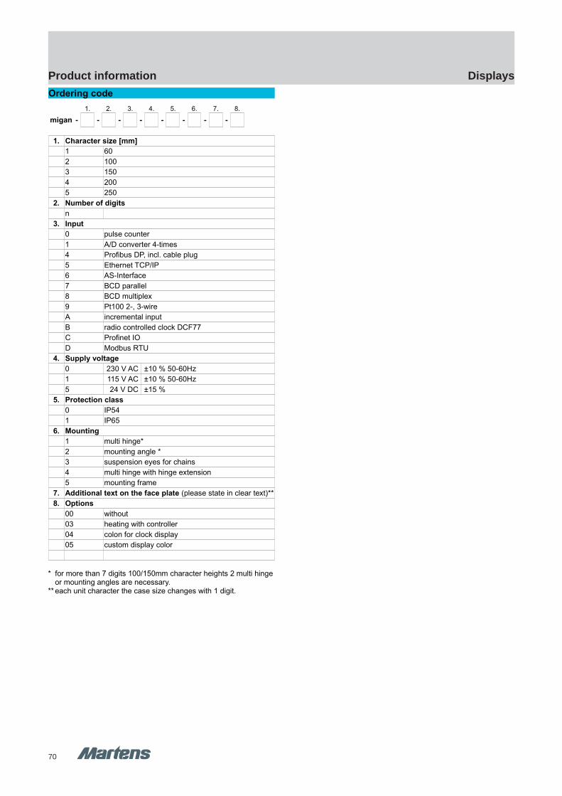
70
DisplaysProduct information
GHM Messtechnik GmbH – Location MartensKiebitzhörn 18 22885 Barsbüttel Germany Fon +49-40-670 73-0 Fax -288www.ghm-messtechnik.de [email protected]
Product Information Industrial Electronics
Ordering code
1. 2. 3. 4. 5. 6. 7. 8.
migan - - - - - - - -
1. Character size [mm]
1 60
2 100
3 150
4 200
5 250
2. Number of digits
n
3. Input
0 pulse counter
1 A/D converter 4-times
4 Profibus DP, incl. cable plug
5 Ethernet TCP/IP
6 AS-Interface
7 BCD parallel
8 BCD multiplex
9 Pt100 2-, 3-wire
A incremental input
B radio controlled clock DCF77
C Profinet IO
D Modbus RTU
4. Supply voltage
0 230 V AC ±10 % 50-60Hz
1 115 V AC ±10 % 50-60Hz
5 24 V DC ±15 %
5. Protection class
0 IP54
1 IP65
6. Mounting
1 multi hinge*
2 mounting angle *
3 suspension eyes for chains
4 multi hinge with hinge extension
5 mounting frame
7. Additional text on the face plate (please state in clear text)**
8. Options
00 without
03 heating with controller
04 colon for clock display
05 custom display color
* for more than 7 digits 100/150mm character heights 2 multi hingeor mounting angles are necessary.
** each unit character the case size changes with 1 digit.
pi-ma-Displays_E V2.00-00
47
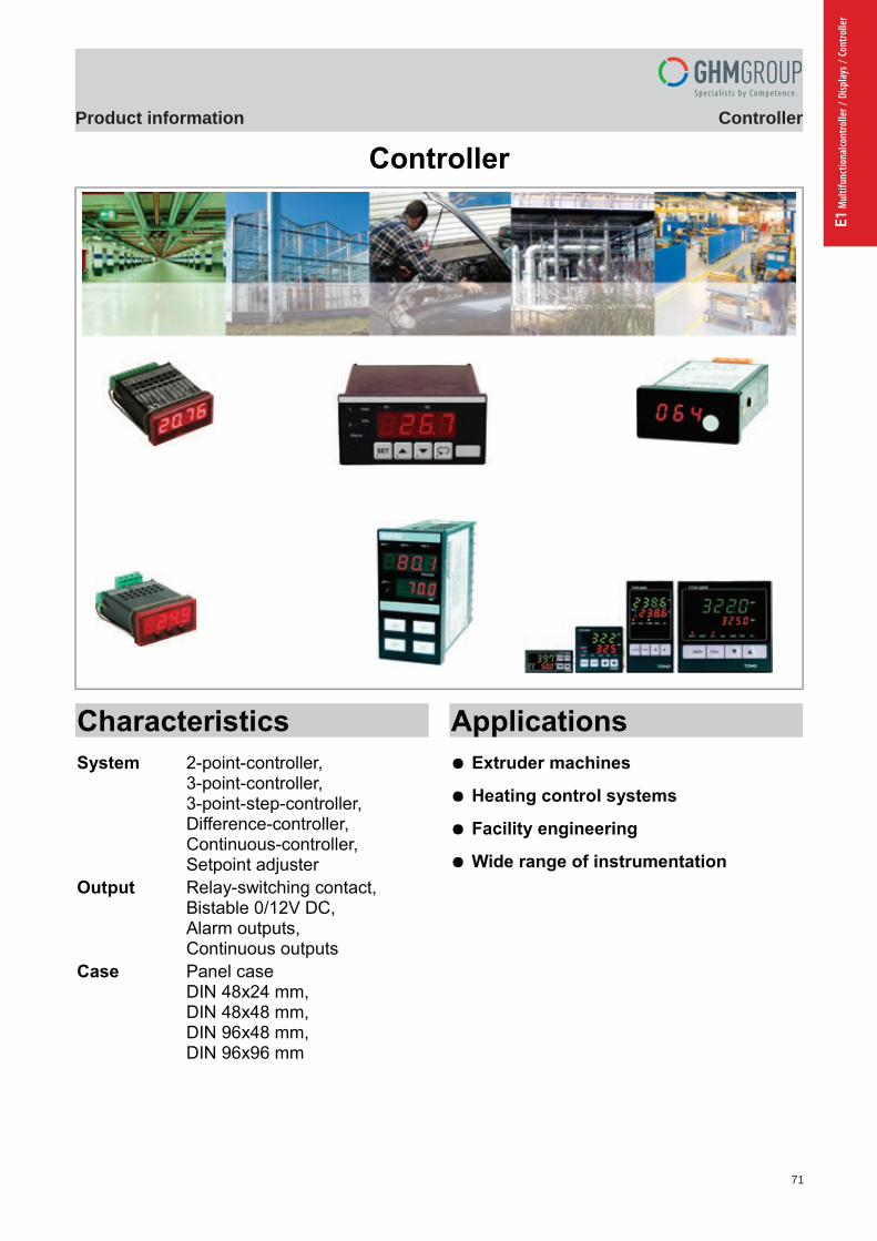
71
ControllerProduct information
E1 M
ultif
unct
iona
lcont
rolle
r / D
ispla
ys /
Cont
rolle
r
GHM Messtechnik GmbH – Sales Center InternationalSchloßstraße 6 88453 Erolzheim Germany Fon +49-7354-937233-0 Fax -88www.ghm-messtechnik.de [email protected]
Product Information Industrial Electronics
Controller
Characteristics
System 2-point-controller,3-point-controller,3-point-step-controller,Difference-controller,Continuous-controller,Setpoint adjuster
Output Relay-switching contact,Bistable 0/12V DC,Alarm outputs,Continuous outputs
Case Panel caseDIN 48x24 mm,DIN 48x48 mm,DIN 96x48 mm,DIN 96x96 mm
Applications
Extruder machines
Heating control systems
Facility engineering
Wide range of instrumentation
pi-ma-Controller_E V4.00-00 1
Einleitung
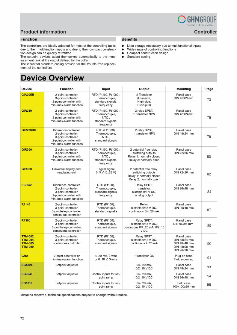
72
ControllerProduct information
GHM Messtechnik GmbH – Sales Center InternationalSchloßstraße 6 88453 Erolzheim Germany Fon +49-7354-937233-0 Fax -88www.ghm-messtechnik.de [email protected]
Product Information Industrial Electronics
Function
The controllers are ideally adapted for most of the controlling tasksdue to their multifunction inputs and due to their compact construc-tion design can be quickly retrofitted. The setpoint devices adapt themselves automatically to the mea-surement task at the output defined by the collar.The industrial standard casing provide for the trouble-free replace-ment of the controllers
Benefits
Little storage necessary due to multifunctional inputs Wide range of controlling functions Compact construction design Standard casing
Device Overview
Device Function Input Output Mounting Page
GIA20EB 2-point-controller,3-point-controller,
2-point-controller withmin-/max-alarm function
RTD (Pt100, Pt1000),Thermocouple,
standard signals,frequency
2 Transistor(Low-side,High-side,Push-pull)
Panel caseDIN 48X24mm
3
GIR230 2-point-controller,3-point-controller,
2-point-controller withmin-/max-alarm function
RTD (Pt100, Pt1000),Thermocouple,
NTC ,standard signals,
frequency
2 relay SPST,1 transistor NPN
Panel caseDIN 48X24mm
5
GIR230DIF Difference-controller,2-point-controller,3-point-controller,
2-point-controller withmin-/max-alarm function
RTD (Pt1000),Thermocouple,
NTC ,standard signals
2 relay SPST,1 transistor NPN
Panel caseDIN 48x24 mm
8
GIR300 2-point-controller,3-point-controller,
2-point-controller withmin-/max-alarm function
RTD (Pt100, Pt1000),Thermocouple,
NTC ,standard signals,
frequency
2 potential free relay switching outputs
Relay 1: normally closedRelay 2: normally open
Panel caseDIN 72x36 mm
10
GIR360 Universal display and regulating unit
Digital signal0..5 V (0..28 V)
2 potential free relay switching outputs
Relay 1: normally closedRelay 2: normally open
Panel caseDIN 72x36 mm
12
EC9648 Difference-controller,2-point-controller,3-point-controller,
2-point-controller withmin-/max-alarm function
RTD (Pt100),Thermocouple,
standard signalsfrequency
Relay SPDT,transistor,
bistable 0/6 V DC,analog output
Panel caseDIN 96x48 mm
14
R1140 2-point-controller,3-point-controller,
3-point-step-controller continuous-controller
RTD (Pt100),Thermocouple,
standard signal s
Relay,bistable 0/18 V DC,
continuous 0/4..20 mA
Panel caseDIN 96x48 mm
17
R1300 2-point-controller,3-point-controller,
3-point-step-controller,continuous controller
RTD (Pt100),Thermocouple,
standard signals
Relay SPDT,bistable 0/18 V DC,
continuous 0/4..20 mA, 0/2..10V DC
Panel caseDIN 96x96 mm
19
TTM-002,TTM-004, TTM-005, TTM-009
2-point-controller,3-point-controller,
continuous controller
RTD (Pt100),Thermocouple,
standard signals
Relay SPST,bistable 0/12 V DC,continuous 4..20 mA
Panel caseDIN 48x24 mmDIN 48x48 mmDIN 48x96 mmDIN 96x96 mm
20
GRA 2-point-controller ormin-/max-alarm function
4..20 mA, 2-wireor 0..10 V, 3-wire
1 transistor OC Plug-on caseField mounting
21
SG4824 Setpoint adjuster - 0/4..20 mA,0/2..10 V DC
Panel caseDIN 48x24 mm
23
SG9648 Setpoint adjuster Control inputs for set-point ramp
0/4..20 mA,0/2..10 V DC
Panel caseDIN 96x48 mm
24
SG1010 Setpoint adjuster Control inputs for set-point ramp
0/4..20 mA,0/2..10 V DC
Field case100x100x60 mm
25
Mistakes reserved, technical specifications subject to change without notice.
2 pi-ma-Controller_E V4.00-00
73
75
78
80
82
87
84
89
90
91
93
94
95
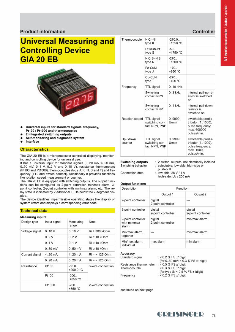
73
ControllerProduct information
E1 M
ultif
unct
iona
lcont
rolle
r / D
ispla
ys /
Cont
rolle
r
GHM Messtechnik GmbH - Location GreisingerHans-Sachs-Straße 26 93128 Regenstauf Germany Fon +49 (0) 9402 - 9383 - 0 Fax -33www.greisinger.de [email protected]
Product Information Industrial Electronics
Universal Measuring andControlling DeviceGIA 20 EB
Universal inputs for standard signals, frequency, Pt100 / Pt1000 and thermocouples
2 integrated switching outputs Self-monitoring and diagnostic system Interface
Characteristics
The GIA 20 EB is a microprocessor-controlled displaying, monitor-ing and controlling device for universal use.It has a universal input for standard signals (0..20 mA, 4..20 mA,0..50 mV, 0..1 V, 0..2 V and 0..10 V), resistance thermometers(Pt100 and Pt1000), thermocouples (type J, K, N, S and T) and fre-quency (TTL and switch contact). Additionally it provides functionslike rotation speed measurement or counter.The GIA 20 EB is equipped with switching outputs. The output func-tions can be configured as 2-point controller, min/max alarm, 3-point controller, 2-point controller with min/max alarm, etc. The re-lay state is indicated by 2 additional LEDs below the 7-segment dis-play. The device identifies impermissible operating states like display orsystem errors and displays a corresponding error code.
Technical data
Measuring inputs
Design type Input signal Measuring range
Note
Voltage signal 0..10 V 0..10 V Ri ≥ 300 kOhm
0..2 V 0..2 V Ri ≥ 10 kOhm
0..1 V 0..1 V Ri ≥ 10 kOhm
0..50 mV 0..50 mV Ri ≥ 10 kOhm
Current signal 4..20 mA 4..20 mA Ri = ~ 125 Ohm
0..20 mA 0..20 mA Ri = ~ 125 Ohm
Resistance Pt100 -50.0.. +200.0 °C
3-wire connection
Pt100 -200.. +850 °C
Pt1000 -200..+850 °C
2-wire connection
Thermocouple NiCr-Nitype K
-270.0.. +1350 °C
Pt10Rh-Pttype S
-50.. +1750 °C
NiCrSi-NiSitype N
-270.. +1300 °C
Fe-CuNitype J
-170.. +950 °C
Cu-CuNitype T
-270.. +400 °C
Frequency TTL signal 0..10 kHz
Switching contact NPN
0..3 kHz internal pull-up-re-sistor is switched on
Switching contact PNP
0..1 kHz internal pull-down-resistor is switched on
Rotation speed TTL signalswitching con-tact NPN, PNP
0..9999 U/min
switchable predis-tributor (1..1000), pulse frequency: max. 600000 pulses/min.
Up / downcounter
TTL signalswitching con-tact NPN, PNP
0..9999 U/min
switchable predis-tributor (1..1000), pulse frequency: max. 10000 pulses/min.
Switching outputs : 2 switch. outputs, not electrically isolatedSwitching behavior : selectable: low-side, high-side or
push-pullConnection data : low-side: 28 V / 1 A
high-side: Uv / 200 mA
Output functions
Description Function
Output 1 Output 2
2-point controller digital 2-point controller
---
3-point controller digital 2-point controller
digital 2-point controller
2-point controller with min/max alarm
digital 2-point controller
min/max alarm
Min/max alarm,together
--- min/max alarm
Min/max alarm,individual
max alarm min alarm
AccuracyStandard signal : < 0.2 % FS ±1digit
(for 0..50 mV: < 0.3 % FS ±1digit)Resistance thermometer : < 0.5 % FS ±1digitThermocouple : < 0.3 % FS ±1digit
(for type S: < 0.5 % FS ±1digit)Frequency : < 0.2 % FS ±1digit
continued on next page
pi-ma-Controller_E V4.00-00 3
GIA20EB GIA20EB
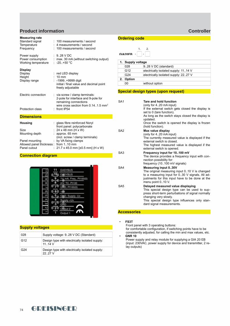
74
ControllerProduct information
GHM Messtechnik GmbH - Location GreisingerHans-Sachs-Straße 26 93128 Regenstauf Germany Fon +49 (0) 9402 - 9383 - 0 Fax -33www.greisinger.de [email protected]
Product Information Industrial Electronics
Measuring rateStandard signal : 100 measurements / secondTemperature : 4 measurements / secondFrequency : 100 measurements / second
Power supply : 9..28 V DCPower consumption : max. 30 mA (without switching output)Working temperature : -20..+50 °C
DisplayDisplay : red LED displayHeight : 10 mm Display range : -1999..+9999 digit
initial / final value and decimal point freely adjustable
Electric connection : via screw / clamp terminals:2-pole for interface and 9-pole for remaining connectionswire cross section from 0.14..1.5 mm2
Protection class : front IP54
Dimensions
Housing : glass fibre reinforced Norylfront panel: polycarbonate
Size : 24 x 48 mm (H x W)Mounting depth : approx. 65 mm
(incl. screw / clamp terminals) Panel mounting : by VA fixing clampsAllowed panel thickness : from 1..10 mmPanel cutout : 21.7 x 45.0 mm [±0.5 mm] (H x W)
Connection diagram
Supply voltages
028 Supply voltage: 9..28 V DC (Standard)
G12 Design type with electrically isolated supply: 11..14 V
G24 Design type with electrically isolated supply: 22..27 V
Ordering code
1. 2.
GIA20EB - -
1. Supply voltage
028 9..28 V DC (standard)
G12 electrically isolated supply: 11..14 V
G24 electrically isolated supply: 22..27 V
2. Option
00 without option
Special design types (upon request)
SA1 Tare and hold function(only for 4..20 mA input)If the external switch gets closed the display isset to 0 (tare function).As long as the switch stays closed the display isupdated.Once the switch is opened the display is frozen(hold function).
SA2 Max value display(only for 4..20 mA input)The currently measured value is displayed if theexternal switch is closed.The highest measured value is displayed if theexternal switch is opened.
SA3 Frequency input for 10..100 mVThe device provides a frequency input with con-nection possibility for:frequency (10..100 mV signals)
SA4 Measuring input 0..30VThe original measuring input 0..10 V is changedto a measuring input for 0..30 V signals. All ad-justments for this input have to be done at themenu point 0..10 V.
SA5 Delayed measured value displayingThis special design type can be used to sup-press short-term perturbations of signal normallychanging very slowly.This special design type influences only stan-dard signal measurements.
Accessories
• FS3TFront panel with 3 operating buttons: for comfortable configuration, if switching points have to be consistently adjusted, for calling the min and max values, etc.
• GNR 10 Power supply and relay module for supplying a GIA 20 EB(input: 230VAC, power supply for device and transmitter, 2 re-lay outputs)
4 pi-ma-Controller_E V4.00-00
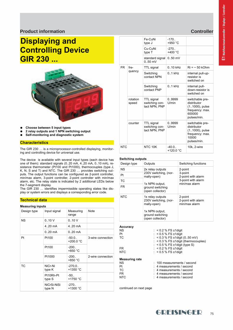
75
ControllerProduct information
E1 M
ultif
unct
iona
lcont
rolle
r / D
ispla
ys /
Cont
rolle
r
GHM Messtechnik GmbH - Location GreisingerHans-Sachs-Straße 26 93128 Regenstauf Germany Fon +49 (0) 9402 - 9383 - 0 Fax -33www.greisinger.de [email protected]
Product Information Industrial Electronics
Displaying and Controlling DeviceGIR 230 ...
Choose between 5 input types 2 relay outputs and 1 NPN switching output Self-monitoring and diagnostic system
Characteristics
The GIR 230 … is a microprocessor-controlled displaying, monitor-ing and controlling device for universal use.
The device is available with several input types (each device hasone of them): standard signals (0..20 mA, 4..20 mA, 0..10 mA), re-sistance thermometer (Pt100 and Pt1000), thermocouples (type J,K, N, S and T) and NTC. The GIR 230 … provides switching out-puts. The output functions can be configured as 2-point controller,min/max alarm, 3-point controller, 2-point controller with min/maxalarm, etc. The relay state is indicated by 2 additional LEDs belowthe 7-segment display.The GIR 230 … identifies impermissible operating states like dis-play or system errors and displays a corresponding error code.
Technical data
Measuring inputs
Design type Input signal Measuring range
Note
NS 0..10 V 0..10 V
4..20 mA 4..20 mA
0..20 mA 0..20 mA
Pt Pt100 -50.0.. +200.0 °C
3-wire connection
Pt100 -200.. +850 °C
Pt1000 -200..+850 °C
2-wire connection
TC NiCr-Nitype K
-270,0.. +1350 °C
Pt10Rh-Pttype S
-50.. +1750 °C
NiCrSi-NiSitype N
-270.. +1300 °C
Fe-CuNitype J
-170.. +950 °C
Cu-CuNitype T
-270.. +400 °C
standard signal0..50 mV
0..50 mV
FR fre-quency
TTL signal 0..10 kHz Ri = ~ 50 kOhm
Switching contact NPN
0..1 kHz internal pull-up-resistor is switched on
Switching contact PNP
0..1 kHz internal pull-down-resistor is switched on
rotation speed
TTL signalswitching con-tact NPN, PNP
0..9999 U/min
switchable pre-distributor (1..1000), pulse frequency: max. 600000 pulses/min.
counter TTL signalswitching con-tact NPN, PNP
0..9999 U/min
switchable pre-distributor (1..1000), pulse frequency: max. 10000 pulses/min.
NTC NTC 10K -40.0.. +120.0 °C
10k, 2-wire
Switching outputs
Design type Outputs Switching functions
NS 2x relay outputs230V switching, (nor-mally-open)
1x NPN output, ground switching(open collector)
2-point3-point2-point with alarm3-point with alarmmin/max alarm
Pt
TC
FR
NTC 1x relay outputs230V switching, (nor-mally-open)
1x NPN output, ground switching(open collector)
2-point2-point with alarmmin/max alarm
AccuracyNS : < 0.2 % FS ±1digit Pt : < 0.5 % FS ±1digitTC : < 0.3 % FS ±1digit (0..50 mV)
: < 0.3 % FS ±1digit (thermocouples): < 0.5 % FS ±1digit (type S)
FR : < 0.2 % FS ±1digitNTC : < 0.5 % FS ±1digit
Measuring rateNS : 100 measurements / secondPt : 4 measurements / secondTC : 4 measurements / secondFR : 4 measurements / secondNTC : 4 measurements / second
continued on next page
pi-ma-Controller_E V4.00-00 5
GIR230 GIR230
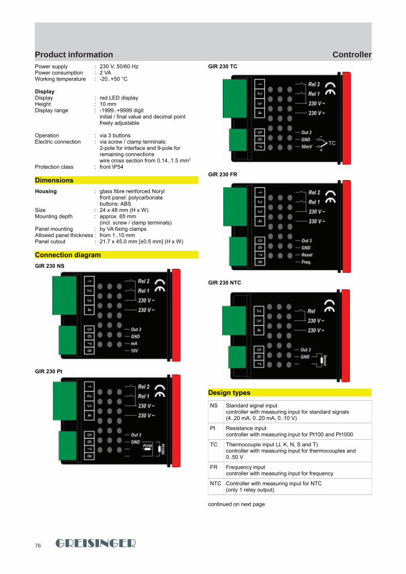
76
ControllerProduct information
GHM Messtechnik GmbH - Location GreisingerHans-Sachs-Straße 26 93128 Regenstauf Germany Fon +49 (0) 9402 - 9383 - 0 Fax -33www.greisinger.de [email protected]
Product Information Industrial Electronics
Power supply : 230 V, 50/60 HzPower consumption : 2 VAWorking temperature : -20..+50 °C
DisplayDisplay : red LED displayHeight : 10 mm Display range : -1999..+9999 digit
initial / final value and decimal point freely adjustable
Operation : via 3 buttonsElectric connection : via screw / clamp terminals:
2-pole for interface and 9-pole for remaining connectionswire cross section from 0.14..1.5 mm2
Protection class : front IP54
Dimensions
Housing : glass fibre reinforced Norylfront panel: polycarbonatebuttons: ABS
Size : 24 x 48 mm (H x W)Mounting depth : approx. 65 mm
(incl. screw / clamp terminals) Panel mounting : by VA fixing clampsAllowed panel thickness : from 1..10 mmPanel cutout : 21.7 x 45.0 mm [±0.5 mm] (H x W)
Connection diagram
GIR 230 NS
GIR 230 Pt
GIR 230 TC
GIR 230 FR
GIR 230 NTC
Design types
NS Standard signal inputcontroller with measuring input for standard signals(4..20 mA, 0..20 mA, 0..10 V)
Pt Resistance inputcontroller with measuring input for Pt100 and Pt1000
TC Thermocouple input (J, K, N, S and T)controller with measuring input for thermocouples and 0..50 V
FR Frequency inputcontroller with measuring input for frequency
NTC Controller with measuring input for NTC (only 1 relay output)
continued on next page
6 pi-ma-Controller_E V4.00-00
77
ControllerProduct information
E1 M
ultif
unct
iona
lcont
rolle
r / D
ispla
ys /
Cont
rolle
r
GHM Messtechnik GmbH - Location GreisingerHans-Sachs-Straße 26 93128 Regenstauf Germany Fon +49 (0) 9402 - 9383 - 0 Fax -33www.greisinger.de [email protected]
Product Information Industrial Electronics
Ordering code
1.
GIR230
1. Design type
NS standard signal
Pt resistance signal
TC thermocouple signal
FR frequency signal
NT NTC
Special design types (upon request)
SA1 Supply voltage: 12..24 V DC 2 relay outputs, +Uv switching1 NPN output, ground switching
SA2 Supply voltage: 12..24 V AC 2 relay outputs, supply voltage switching1 NPN output, ground switching
SA3 Supply voltage: 12..24 V DC with electric isolation2 relay outputs, +Uv switching1 NPN output, ground switching
pi-ma-Controller_E V4.00-00 7
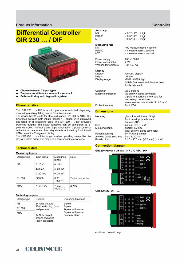
78
ControllerProduct information
GHM Messtechnik GmbH - Location GreisingerHans-Sachs-Straße 26 93128 Regenstauf Germany Fon +49 (0) 9402 - 9383 - 0 Fax -33www.greisinger.de [email protected]
Product Information Industrial Electronics
Differential ControllerGIR 230 … / DIF
Choose between 3 input types Temperature difference sensor 1 – sensor 2 Self-monitoring and diagnostic system
Characteristics
The GIR 230 … / DIF is a microprocessor-controlled displaying,monitoring and regulating device for universal use.The device has 2 inputs for standard signals, Pt1000 or NTC. Thedifference between both inputs (sensor 1 – sensor 2) is displayedand used for all regulating uses. The GIR 230 … / DIF providesswitching outputs. The output functions can be configured as 2-point controller, min/max alarm, 3-point controller, 2-point controllerwith min/max alarm, etc. The relay state is indicated by 2 additionalLEDs below the 7-segment display.The GIR 230 … identifies impermissible operating states like dis-play or system errors and displays a corresponding error code.
Technical data
Measuring inputs
Design type Input signal Measuring range
Note
NS 0..10 V 0..10 V
420 mA 4..20 mA
0..20 mA 0..20 mA
Pt1000 Pt1000 -200..+850 °C
2-wire connection
NTC NTC, 10K -40.0.. +120.0 °C
2-wire
Switching outputs
Design type Outputs Switching functions
NS 2x relay outputs230V switching, (nor-mally-open)
1x NPN output, ground switching(open collector)
2-point3-point2-point with alarm3-point with alarmmin/max alarm
Pt1000
NTC
AccuracyNS : < 0.2 % FS ±1digit Pt1000 : < 0.5 % FS ±1digitNTC : < 0.5 % FS ±1digit
Measuring rateNS : 100 measurements / secondPt1000 : 4 measurements / secondNTC : 4 measurements / second
Power supply : 230 V, 50/60 HzPower consumption : 2 VAWorking temperature : -20..+50 °C
DisplayDisplay : red LED displayHeight : 10 mm Display range : -1999..+9999 digit
initial / final value and decimal point freely adjustable
Operation : via 3 buttonsElectric connection : via screw / clamp terminals:
2-pole for interface and 9-pole for remaining connectionswire cross section from 0.14..1.5 mm2
Protection class : front IP54
Dimensions
Housing : glass fibre reinforced Norylfront panel: polycarbonatebuttons: ABS
Size : 24 x 48 mm (H x W)Mounting depth : approx. 65 mm
(incl. screw / clamp terminals) Panel mounting : by VA fixing clampsAllowed panel thickness : from 1..10 mmPanel cutout : 21.7 x 45.0 mm [±0.5 mm] (H x W)
Connection diagram
GIR 230 Pt1000 / DIF and GIR 230 NTC / DIF
GIR 230 NS / DIF - …
continued on next page
8 pi-ma-Controller_E V4.00-00
GIR230 .../DIF GIR230 .../DIF

79
ControllerProduct information
E1 M
ultif
unct
iona
lcont
rolle
r / D
ispla
ys /
Cont
rolle
r
GHM Messtechnik GmbH - Location GreisingerHans-Sachs-Straße 26 93128 Regenstauf Germany Fon +49 (0) 9402 - 9383 - 0 Fax -33www.greisinger.de [email protected]
Product Information Industrial Electronics
Design types
NS Standard signal inputdifferential controller with 2 inputs for standard signal (4..20 mA, 0..20 mA, 0..10 V)
Pt Resistance inputdifferential controller with 2 inputs for Pt1000
NT Differential controller with 2 inputs for NTC
Ordering code
1. 2.
GIR230 / DIF -
1. Design type
NS standard signal input
Pt resistance input
NT NTC input
2. Measuring input ONLY at type NS (GIR 230 NS / DIF ...)
420A input signal: 4..20 mA
020A input signal: 0..20 mA
010V input signal: 0..10 V
pi-ma-Controller_E V4.00-00 9
GIR230 .../DIF
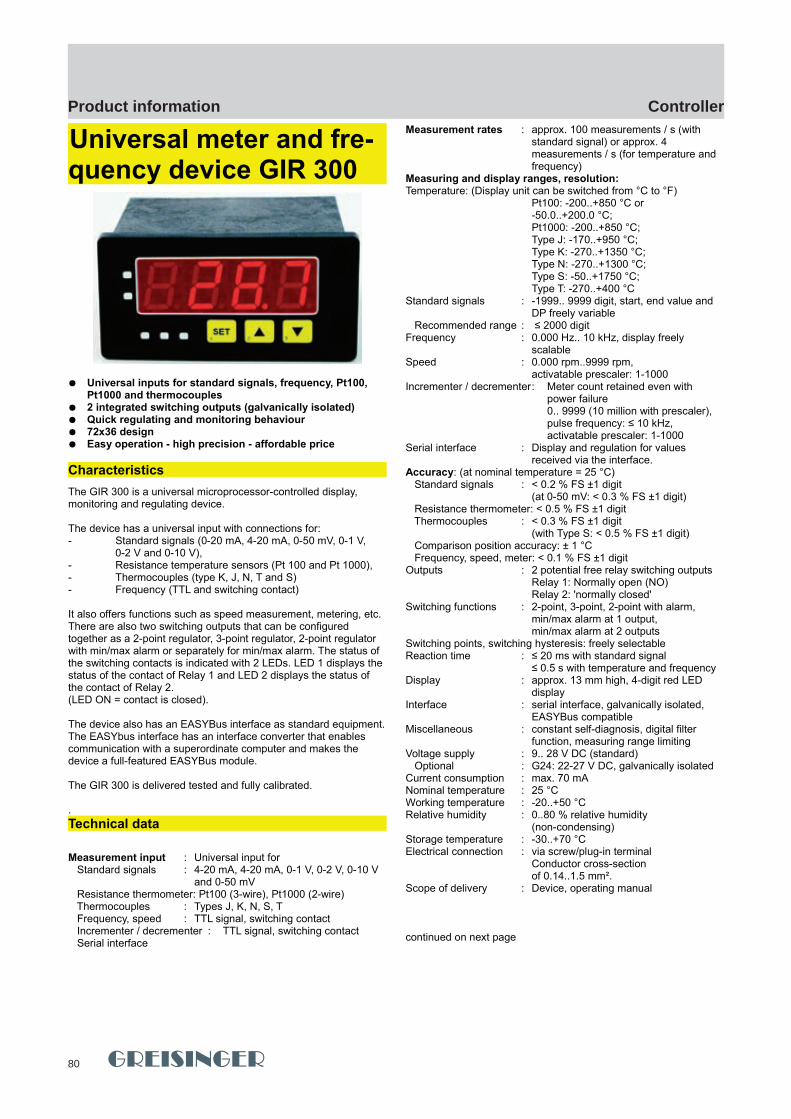
80
ControllerProduct information
GHM Messtechnik GmbH - Location GreisingerHans-Sachs-Straße 26 93128 Regenstauf Germany Fon +49 (0) 9402 - 9383 - 0 Fax -33www.greisinger.de [email protected]
Product Information Industrial Electronics
Universal meter and fre-quency device GIR 300
Universal inputs for standard signals, frequency, Pt100, Pt1000 and thermocouples
2 integrated switching outputs (galvanically isolated) Quick regulating and monitoring behaviour 72x36 design Easy operation - high precision - affordable price
Characteristics
The GIR 300 is a universal microprocessor-controlled display, monitoring and regulating device.
The device has a universal input with connections for: - Standard signals (0-20 mA, 4-20 mA, 0-50 mV, 0-1 V,
0-2 V and 0-10 V), - Resistance temperature sensors (Pt 100 and Pt 1000), - Thermocouples (type K, J, N, T and S) - Frequency (TTL and switching contact)
It also offers functions such as speed measurement, metering, etc. There are also two switching outputs that can be configured together as a 2-point regulator, 3-point regulator, 2-point regulator with min/max alarm or separately for min/max alarm. The status of the switching contacts is indicated with 2 LEDs. LED 1 displays the status of the contact of Relay 1 and LED 2 displays the status of the contact of Relay 2. (LED ON = contact is closed).
The device also has an EASYBus interface as standard equipment.The EASYbus interface has an interface converter that enables communication with a superordinate computer and makes the device a full-featured EASYBus module.
The GIR 300 is delivered tested and fully calibrated.
.
Technical data
Measurement input : Universal input for Standard signals : 4-20 mA, 4-20 mA, 0-1 V, 0-2 V, 0-10 V
and 0-50 mV Resistance thermometer: Pt100 (3-wire), Pt1000 (2-wire) Thermocouples : Types J, K, N, S, T Frequency, speed : TTL signal, switching contact Incrementer / decrementer : TTL signal, switching contact Serial interface
Measurement rates : approx. 100 measurements / s (with standard signal) or approx. 4 measurements / s (for temperature and frequency)
Measuring and display ranges, resolution:Temperature: (Display unit can be switched from °C to °F)
Pt100: -200..+850 °C or -50.0..+200.0 °C; Pt1000: -200..+850 °C; Type J: -170..+950 °C; Type K: -270..+1350 °C; Type N: -270..+1300 °C;Type S: -50..+1750 °C; Type T: -270..+400 °C
Standard signals : -1999.. 9999 digit, start, end value and DP freely variable
Recommended range : ≤ 2000 digitFrequency : 0.000 Hz.. 10 kHz, display freely
scalableSpeed : 0.000 rpm..9999 rpm,
activatable prescaler: 1-1000Incrementer / decrementer: Meter count retained even with
power failure0.. 9999 (10 million with prescaler), pulse frequency: ≤ 10 kHz, activatable prescaler: 1-1000
Serial interface : Display and regulation for values received via the interface.
Accuracy: (at nominal temperature = 25 °C) Standard signals : < 0.2 % FS ±1 digit
(at 0-50 mV: < 0.3 % FS ±1 digit) Resistance thermometer: < 0.5 % FS ±1 digit Thermocouples : < 0.3 % FS ±1 digit
(with Type S: < 0.5 % FS ±1 digit) Comparison position accuracy: ± 1 °C Frequency, speed, meter: < 0.1 % FS ±1 digitOutputs : 2 potential free relay switching outputs
Relay 1: Normally open (NO)Relay 2: 'normally closed'
Switching functions : 2-point, 3-point, 2-point with alarm,min/max alarm at 1 output,min/max alarm at 2 outputs
Switching points, switching hysteresis: freely selectableReaction time : ≤ 20 ms with standard signal
≤ 0.5 s with temperature and frequencyDisplay : approx. 13 mm high, 4-digit red LED
displayInterface : serial interface, galvanically isolated,
EASYBus compatibleMiscellaneous : constant self-diagnosis, digital filter
function, measuring range limitingVoltage supply : 9.. 28 V DC (standard) Optional : G24: 22-27 V DC, galvanically isolatedCurrent consumption : max. 70 mANominal temperature : 25 °CWorking temperature : -20..+50 °CRelative humidity : 0..80 % relative humidity
(non-condensing)Storage temperature : -30..+70 °CElectrical connection : via screw/plug-in terminal
Conductor cross-section of 0.14..1.5 mm².
Scope of delivery : Device, operating manual
continued on next page
10 pi-ma-Controller_E V4.00-00
GIR300 GIR300
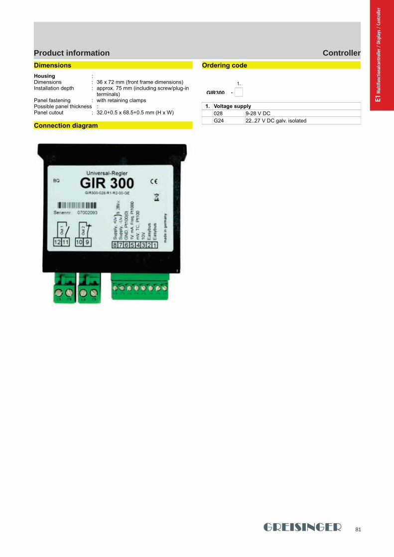
81
ControllerProduct information
E1 M
ultif
unct
iona
lcont
rolle
r / D
ispla
ys /
Cont
rolle
r
GHM Messtechnik GmbH - Location GreisingerHans-Sachs-Straße 26 93128 Regenstauf Germany Fon +49 (0) 9402 - 9383 - 0 Fax -33www.greisinger.de [email protected]
Product Information Industrial Electronics
Dimensions
Housing : Dimensions : 36 x 72 mm (front frame dimensions)Installation depth : approx. 75 mm (including screw/plug-in
terminals)Panel fastening : with retaining clampsPossible panel thickness :Panel cutout : 32.0+0.5 x 68.5+0.5 mm (H x W)
Connection diagram
Ordering code
1.
GIR300 -
1. Voltage supply
028 9-28 V DC
G24 22..27 V DC galv. isolated
pi-ma-Controller_E V4.00-00
11
GIR300
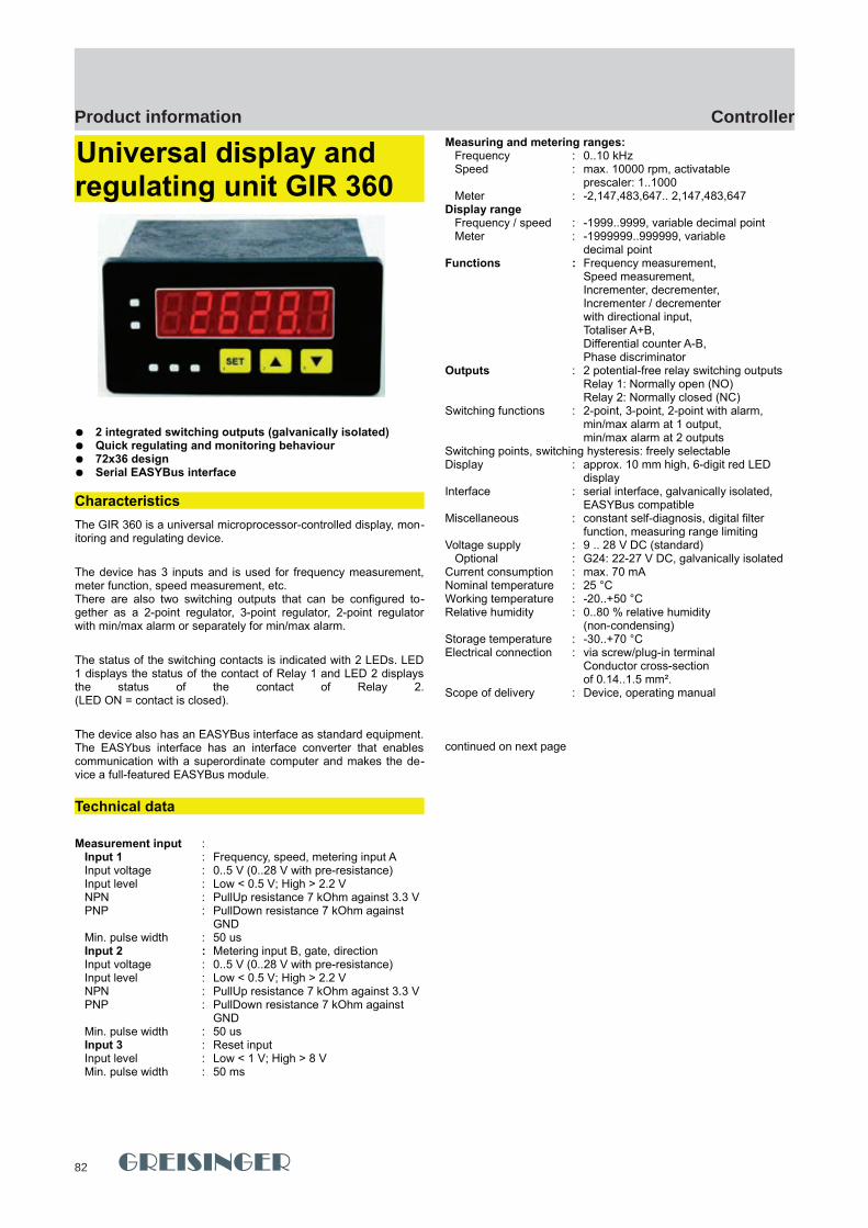
82
ControllerProduct information
GHM Messtechnik GmbH - Location GreisingerHans-Sachs-Straße 26 93128 Regenstauf Germany Fon +49 (0) 9402 - 9383 - 0 Fax -33www.greisinger.de [email protected]
Product Information Industrial Electronics
Universal display and regulating unit GIR 360
2 integrated switching outputs (galvanically isolated) Quick regulating and monitoring behaviour 72x36 design Serial EASYBus interface
Characteristics
The GIR 360 is a universal microprocessor-controlled display, mon-itoring and regulating device.
The device has 3 inputs and is used for frequency measurement,meter function, speed measurement, etc.There are also two switching outputs that can be configured to-gether as a 2-point regulator, 3-point regulator, 2-point regulatorwith min/max alarm or separately for min/max alarm.
The status of the switching contacts is indicated with 2 LEDs. LED1 displays the status of the contact of Relay 1 and LED 2 displaysthe status of the contact of Relay 2.(LED ON = contact is closed).
The device also has an EASYBus interface as standard equipment.The EASYbus interface has an interface converter that enablescommunication with a superordinate computer and makes the de-vice a full-featured EASYBus module.
Technical data
Measurement input : Input 1 : Frequency, speed, metering input A Input voltage : 0..5 V (0..28 V with pre-resistance) Input level : Low < 0.5 V; High > 2.2 V NPN : PullUp resistance 7 kOhm against 3.3 V PNP : PullDown resistance 7 kOhm against
GND Min. pulse width : 50 us Input 2 : Metering input B, gate, direction Input voltage : 0..5 V (0..28 V with pre-resistance) Input level : Low < 0.5 V; High > 2.2 V NPN : PullUp resistance 7 kOhm against 3.3 V PNP : PullDown resistance 7 kOhm against
GND Min. pulse width : 50 us Input 3 : Reset input Input level : Low < 1 V; High > 8 V Min. pulse width : 50 ms
Measuring and metering ranges: Frequency : 0..10 kHz Speed : max. 10000 rpm, activatable
prescaler: 1..1000 Meter : -2,147,483,647.. 2,147,483,647Display range Frequency / speed : -1999..9999, variable decimal point Meter : -1999999..999999, variable
decimal pointFunctions : Frequency measurement,
Speed measurement,Incrementer, decrementer,Incrementer / decrementer with directional input,Totaliser A+B,Differential counter A-B, Phase discriminator
Outputs : 2 potential-free relay switching outputsRelay 1: Normally open (NO)Relay 2: Normally closed (NC)
Switching functions : 2-point, 3-point, 2-point with alarm,min/max alarm at 1 output,min/max alarm at 2 outputs
Switching points, switching hysteresis: freely selectableDisplay : approx. 10 mm high, 6-digit red LED
displayInterface : serial interface, galvanically isolated,
EASYBus compatibleMiscellaneous : constant self-diagnosis, digital filter
function, measuring range limitingVoltage supply : 9 .. 28 V DC (standard) Optional : G24: 22-27 V DC, galvanically isolatedCurrent consumption : max. 70 mANominal temperature : 25 °CWorking temperature : -20..+50 °CRelative humidity : 0..80 % relative humidity
(non-condensing)Storage temperature : -30..+70 °CElectrical connection : via screw/plug-in terminal
Conductor cross-section of 0.14..1.5 mm².
Scope of delivery : Device, operating manual
continued on next page
12 pi-ma-Controller_E V4.00-00
GIR360 GIR360
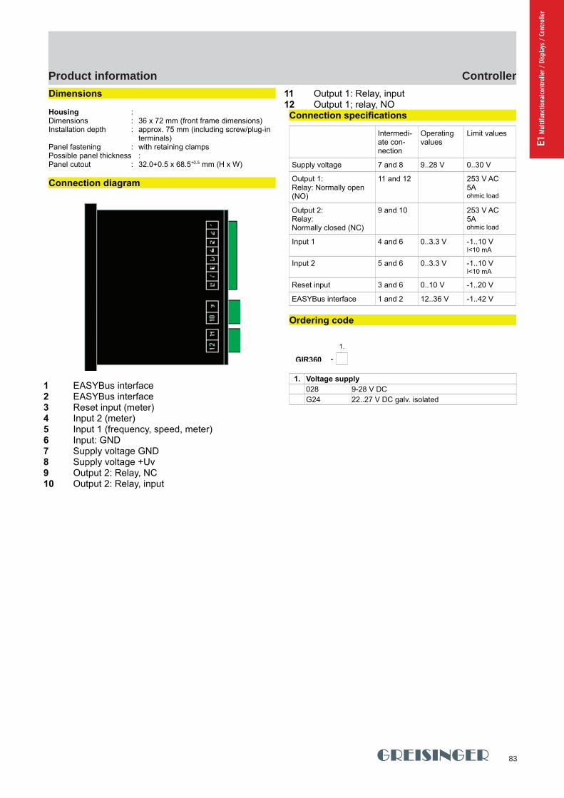
83
ControllerProduct information
E1 M
ultif
unct
iona
lcont
rolle
r / D
ispla
ys /
Cont
rolle
r
GHM Messtechnik GmbH - Location GreisingerHans-Sachs-Straße 26 93128 Regenstauf Germany Fon +49 (0) 9402 - 9383 - 0 Fax -33www.greisinger.de [email protected]
Product Information Industrial Electronics
Dimensions
Housing : Dimensions : 36 x 72 mm (front frame dimensions)Installation depth : approx. 75 mm (including screw/plug-in
terminals)Panel fastening : with retaining clampsPossible panel thickness :Panel cutout : 32.0+0.5 x 68.5+0.5 mm (H x W)
Connection diagram
1 EASYBus interface 2 EASYBus interface 3 Reset input (meter) 4 Input 2 (meter) 5 Input 1 (frequency, speed, meter) 6 Input: GND 7 Supply voltage GND 8 Supply voltage +Uv 9 Output 2: Relay, NC 10 Output 2: Relay, input
11 Output 1: Relay, input 12 Output 1; relay, NO Connection specifications
Intermedi-ate con-nection
Operating values
Limit values
Supply voltage 7 and 8 9..28 V 0..30 V
Output 1:Relay: Normally open (NO)
11 and 12 253 V AC5A ohmic load
Output 2:Relay: Normally closed (NC)
9 and 10 253 V AC5A ohmic load
Input 1 4 and 6 0..3.3 V -1..10 V ǀ<10 mA
Input 2 5 and 6 0..3.3 V -1..10 V ǀ<10 mA
Reset input 3 and 6 0..10 V -1..20 V
EASYBus interface 1 and 2 12..36 V -1..42 V
Ordering code
1.
GIR360 -
1. Voltage supply
028 9-28 V DC
G24 22..27 V DC galv. isolated
pi-ma-Controller_E V4.00-00
13
GIR360
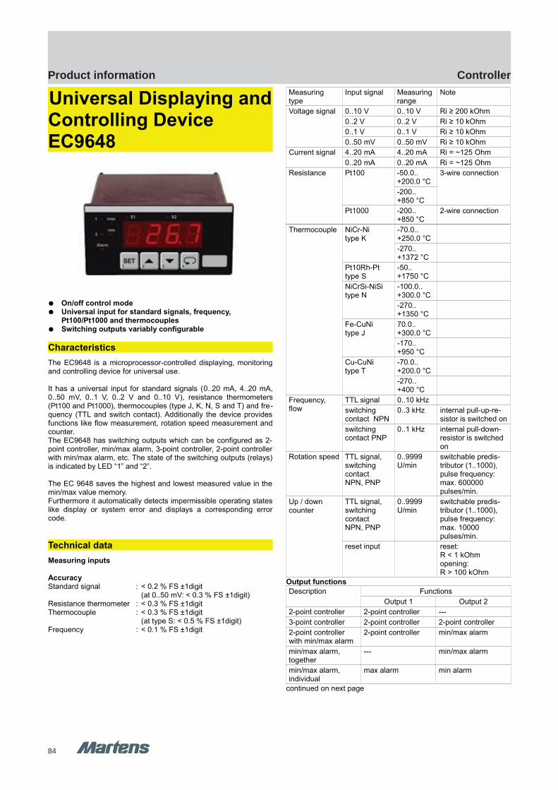
84
ControllerProduct information
GHM Messtechnik GmbH – Location MartensKiebitzhörn 18 22885 Barsbüttel Germany Fon +49-40-670 73-0 Fax -288www.ghm-messtechnik.de [email protected]
Product Information Industrial Electronics
Universal Displaying andControlling Device EC9648
On/off control mode Universal input for standard signals, frequency,
Pt100/Pt1000 and thermocouples Switching outputs variably configurable
Characteristics
The EC9648 is a microprocessor-controlled displaying, monitoringand controlling device for universal use.
It has a universal input for standard signals (0..20 mA, 4..20 mA,0..50 mV, 0..1 V, 0..2 V and 0..10 V), resistance thermometers(Pt100 and Pt1000), thermocouples (type J, K, N, S and T) and fre-quency (TTL and switch contact). Additionally the device providesfunctions like flow measurement, rotation speed measurement andcounter.The EC9648 has switching outputs which can be configured as 2-point controller, min/max alarm, 3-point controller, 2-point controllerwith min/max alarm, etc. The state of the switching outputs (relays)is indicated by LED “1” and “2”.
The EC 9648 saves the highest and lowest measured value in themin/max value memory. Furthermore it automatically detects impermissible operating stateslike display or system error and displays a corresponding errorcode.
Technical data
Measuring inputs
AccuracyStandard signal : < 0.2 % FS ±1digit
(at 0..50 mV: < 0.3 % FS ±1digit)Resistance thermometer : < 0.3 % FS ±1digitThermocouple : < 0.3 % FS ±1digit
(at type S: < 0.5 % FS ±1digit)Frequency : < 0.1 % FS ±1digit
Measuring type
Input signal Measuring range
Note
Voltage signal 0..10 V 0..10 V Ri ≥ 200 kOhm
0..2 V 0..2 V Ri ≥ 10 kOhm
0..1 V 0..1 V Ri ≥ 10 kOhm
0..50 mV 0..50 mV Ri ≥ 10 kOhm
Current signal 4..20 mA 4..20 mA Ri = ~125 Ohm
0..20 mA 0..20 mA Ri = ~125 Ohm
Resistance Pt100 -50.0.. +200.0 °C
3-wire connection
-200.. +850 °C
Pt1000 -200.. +850 °C
2-wire connection
Thermocouple NiCr-Nitype K
-70.0.. +250.0 °C
-270.. +1372 °C
Pt10Rh-Pttype S
-50.. +1750 °C
NiCrSi-NiSitype N
-100.0.. +300.0 °C
-270.. +1350 °C
Fe-CuNitype J
70.0.. +300.0 °C
-170.. +950 °C
Cu-CuNitype T
-70.0.. +200.0 °C
-270.. +400 °C
Frequency,flow
TTL signal 0..10 kHz
switching contact NPN
0..3 kHz internal pull-up-re-sistor is switched on
switching contact PNP
0..1 kHz internal pull-down-resistor is switched on
Rotation speed TTL signal, switching contact NPN, PNP
0..9999 U/min
switchable predis-tributor (1..1000), pulse frequency: max. 600000 pulses/min.
Up / down counter
TTL signal, switching contact NPN, PNP
0..9999 U/min
switchable predis-tributor (1..1000), pulse frequency: max. 10000 pulses/min.
reset input reset: R < 1 kOhmopening: R > 100 kOhm
Output functions
Description Functions
Output 1 Output 2
2-point controller 2-point controller ---
3-point controller 2-point controller 2-point controller
2-point controller with min/max alarm
2-point controller min/max alarm
min/max alarm, together
--- min/max alarm
min/max alarm, individual
max alarm min alarm
continued on next page
14 pi-ma-Controller_E V4.00-00
EC9648 EC9648
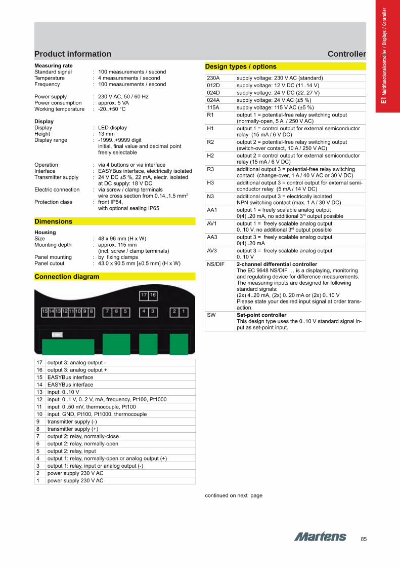
85
ControllerProduct information
E1 M
ultif
unct
iona
lcont
rolle
r / D
ispla
ys /
Cont
rolle
r
GHM Messtechnik GmbH – Location MartensKiebitzhörn 18 22885 Barsbüttel Germany Fon +49-40-670 73-0 Fax -288www.ghm-messtechnik.de [email protected]
Product Information Industrial Electronics
Measuring rateStandard signal : 100 measurements / secondTemperature : 4 measurements / secondFrequency : 100 measurements / second
Power supply : 230 V AC, 50 / 60 HzPower consumption : approx. 5 VAWorking temperature : -20..+50 °C
DisplayDisplay : LED displayHeight : 13 mm Display range : -1999..+9999 digit
initial, final value and decimal point freely selectable
Operation : via 4 buttons or via interfaceInterface : EASYBus interface, electrically isolated Transmitter supply : 24 V DC ±5 %, 22 mA, electr. isolated
at DC supply: 18 V DCElectric connection : via screw / clamp terminals
wire cross section from 0.14..1.5 mm2
Protection class : front IP54, with optional sealing IP65
Dimensions
HousingSize : 48 x 96 mm (H x W)Mounting depth : approx. 115 mm
(incl. screw / clamp terminals)Panel mounting : by fixing clampsPanel cutout : 43.0 x 90.5 mm [±0.5 mm] (H x W)
Connection diagram
17 output 3: analog output -
16 output 3: analog output +
15 EASYBus interface
14 EASYBus interface
13 input: 0..10 V
12 input: 0..1 V, 0..2 V, mA, frequency, Pt100, Pt1000
11 input: 0..50 mV, thermocouple, Pt100
10 input: GND, Pt100, Pt1000, thermocouple
9 transmitter supply (-)
8 transmitter supply (+)
7 output 2: relay, normally-close
6 output 2: relay, normally-open
5 output 2: relay, input
4 output 1: relay, normally-open or analog output (+)
3 output 1: relay, input or analog output (-)
2 power supply 230 V AC
1 power supply 230 V AC
Design types / options
230A supply voltage: 230 V AC (standard)
012D supply voltage: 12 V DC (11..14 V)
024D supply voltage: 24 V DC (22..27 V)
024A supply voltage: 24 V AC (±5 %)
115A supply voltage: 115 V AC (±5 %)
R1 output 1 = potential-free relay switching output (normally-open, 5 A / 250 V AC)
H1 output 1 = control output for external semiconductor relay (15 mA / 6 V DC)
R2 output 2 = potential-free relay switching output (switch-over contact, 10 A / 250 V AC)
H2 output 2 = control output for external semiconductor relay (15 mA / 6 V DC)
R3 additional output 3 = potential-free relay switching contact (change-over, 1 A / 40 V AC or 30 V DC)
H3 additional output 3 = control output for external semi-conductor relay (5 mA / 14 V DC)
N3 additional output 3 = electrically isolated NPN switching contact (max. 1 A / 30 V DC)
AA1 output 1 = freely scalable analog output 0(4)..20 mA, no additional 3rd output possible
AV1 output 1 = freely scalable analog output 0..10 V, no additional 3rd output possible
AA3 output 3 = freely scalable analog output 0(4)..20 mA
AV3 output 3 = freely scalable analog output 0..10 V
NS/DIF 2-channel differential controllerThe EC 9648 NS/DIF … is a displaying, monitoring and regulating device for difference measurements.The measuring inputs are designed for following standard signals:(2x) 4..20 mA, (2x) 0..20 mA or (2x) 0..10 VPlease state your desired input signal at order trans-action.
SW Set-point controllerThis design type uses the 0..10 V standard signal in-put as set-point input.
continued on next page
pi-ma-Controller_E V4.00-00
15
EC9648
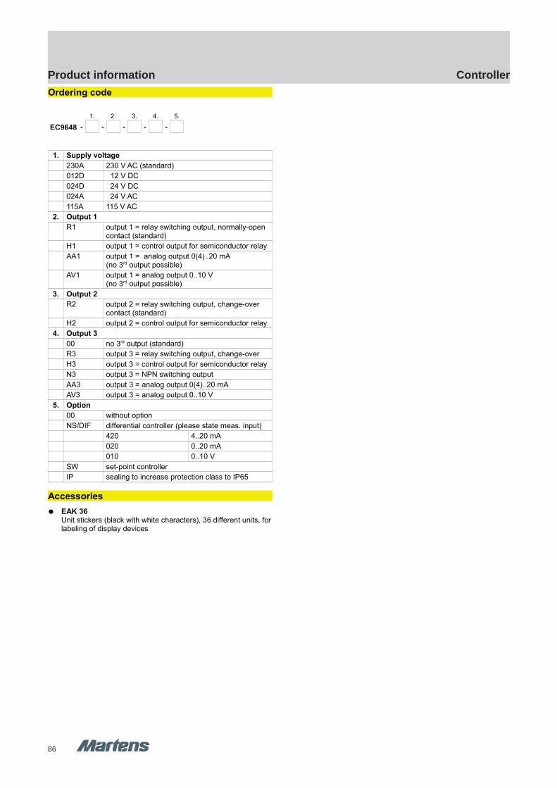
86
ControllerProduct information
GHM Messtechnik GmbH – Location MartensKiebitzhörn 18 22885 Barsbüttel Germany Fon +49-40-670 73-0 Fax -288www.ghm-messtechnik.de [email protected]
Product Information Industrial Electronics
Ordering code
1. 2. 3. 4. 5.
EC9648 - - - - -
1. Supply voltage
230A 230 V AC (standard)
012D 12 V DC
024D 24 V DC
024A 24 V AC
115A 115 V AC
2. Output 1
R1 output 1 = relay switching output, normally-open contact (standard)
H1 output 1 = control output for semiconductor relay
AA1 output 1 = analog output 0(4)..20 mA (no 3rd output possible)
AV1 output 1 = analog output 0..10 V (no 3rd output possible)
3. Output 2
R2 output 2 = relay switching output, change-over contact (standard)
H2 output 2 = control output for semiconductor relay
4. Output 3
00 no 3rd output (standard)
R3 output 3 = relay switching output, change-over
H3 output 3 = control output for semiconductor relay
N3 output 3 = NPN switching output
AA3 output 3 = analog output 0(4)..20 mA
AV3 output 3 = analog output 0..10 V
5. Option
00 without option
NS/DIF differential controller (please state meas. input)
420 4..20 mA
020 0..20 mA
010 0..10 V
SW set-point controller
IP sealing to increase protection class to IP65
Accessories
EAK 36Unit stickers (black with white characters), 36 different units, forlabeling of display devices
16 pi-ma-Controller_E V4.00-00

87
ControllerProduct information
E1 M
ultif
unct
iona
lcont
rolle
r / D
ispla
ys /
Cont
rolle
r
GHM Messtechnik GmbH – Location MartensKiebitzhörn 18 22885 Barsbüttel Germany Fon +49-40-670 73-0 Fax -288www.ghm-messtechnik.de [email protected]
Product Information Industrial Electronics
Temperature ControllerR1140
Characteristics
2-point, 3-point-, 3-point-stepping- or continuous-controller Input for Pt100 (RTD), Thermocouple and standard signal
0/4...20 mA. Control method PID with auto-tuning 2. set value, start-up function, set value ramp Control output relay, electronic output 0/18V or
continuous output 0/4..20 mA
Technical data
Power supplySupply voltage : 230 V AC ± 10 %, 24 V DC ± 25 %Power consumption : < 3.5 VAOperating temp. : 0..50 °CStrorage temp. : -30..70°CCE-conformity : EMC acc. to.2014/30/EU; EN61326-1;
safety requirements acc. to EN61010-1InputRTD : Pt100, 2- or 3-wire-Monitoring : break of sensor/short circuit-Accuracy : ≤ 0.2 % Thermocouple : L, J, K, S-Monitoring : break of sensor, internal cold junction,
reverse polarity protection -Accuracy : ≤ 0.25 %Current : 0/4..20 mA, burden max. 10 Ω-Accuracy : ≤ 0.2 %
Output Electronic : 0/18 V DC bistable, max. 10 mARelay : controller <250 V AC <250 VA <3 A
alarm <250 V AC <250 VA <3 AContinuous : 0/4..20 mA, burden max. 500 Ω;
usabale as control output or for retransmission of prcocess value
DisplayProcess value : LED 4-digit red 10 mmSetpoint value : LED 4-digit red 7.6 mmDecimal point : programmableOperating indication : LED yellow
HousingDimesions R1140 : panel mounting DIN 48 x 96 mm,
mounting depth 122 mmPanel cut-out : 45 +0.6 mm x 92+0.8 mmDimesions R1180 : panel mounting DIN 96 x 48 mm,
mounting depth 122 mmPanel cut-out : 92+0.8 mm x 45 +0.6 mmMaterial : Noryl; UL94V-1
Weight : approx. 420 gConnection : Screw terminals. Insulation class C. Protection class : front IP50, terminals IP20, acc. to BGV A3
2-, 3-point and continuous-controller
Connection diagram R1140, 48 x 96 housing
Connection diagram R1180, 96 x 48 housing
Ordering code
1. 2. 3. 4.
R - -00- MA1 -
1. Housing
1140 48 x 96 mm
1180 96 x 48 mm
2. Output
10 2-point-, 3-point-controller
60 2-point-, 3-point-, and continuous- controller
3. Interface
MA1 without interface
4. Supply voltage
1 230 V AC ± 10 %
5 24 V DC ± 25 %
pi-ma-Controller_E V4.00-00
17
R1140 R1140
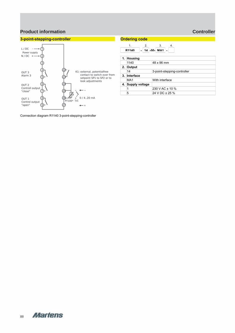
88
ControllerProduct information
GHM Messtechnik GmbH – Location MartensKiebitzhörn 18 22885 Barsbüttel Germany Fon +49-40-670 73-0 Fax -288www.ghm-messtechnik.de [email protected]
Product Information Industrial Electronics
3-point-stepping-controller
Connection diagram R1140 3-point-stepping-controller
Ordering code
1. 2. 3. 4.
R1140 - 14 -00- MA1 -
1. Housing
1140 48 x 96 mm
2. Output
14 3-point-stepping-controller
3. Interface
MA1 With interface
4. Supply voltage
1 230 V AC ± 10 %
5 24 V DC ± 25 %
18 pi-ma-Controller_E V4.00-00
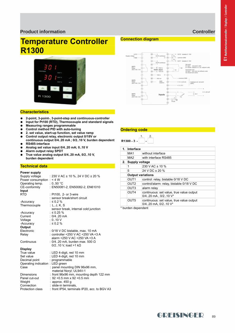
89
ControllerProduct information
E1 M
ultif
unct
iona
lcont
rolle
r / D
ispla
ys /
Cont
rolle
r
GHM Messtechnik GmbH – Location MartensKiebitzhörn 18 22885 Barsbüttel Germany Fon +49-40-670 73-0 Fax -288www.ghm-messtechnik.de [email protected]
Product Information Industrial Electronics
Temperature ControllerR1300
Characteristics
2-point, 3-point-, 3-point-step and continuous-controller Input for Pt100 (RTD), Thermocouple and standard signals Measuring ranges programmable Control method PID with auto-tuning 2. set value, start-up function, set value ramp Control output relay, electronic output 0/18V or
continuous output 0/4..20 mA ; 0/2..10 V, burden dependent RS485-interface Analog set value input 0/4..20 mA; 0..10 V Alarm output relay SPDT True value analog output 0/4..20 mA, 0/2..10 V,
burden dependent
Technical data
Power supplySupply voltage : 230 V AC ± 10 %, 24 V DC ± 20 %Power consumption : < 4 WOperating temp. : 0..50 °CCE-conformity : EN50081-2, EN50082-2, EN61010InputRTD : Pt100, 2- or 3-wire
: sensor break/short circuit-Accuracy : ≤ 0.2 % Thermocouple : L, J, K, S
sensor break, internal cold junction-Accuracy : ≤ 0.25 %Current : 0/4..20 mAVoltage : 0..10 V-Accuracy : ≤ 0.2 %Output Electronic : 0/18 V DC bistable, max. 10 mARelay : controller <250 V AC <250 VA <3 A
alarm <250 V AC <250 VA <3 AContinuous : 0/4..20 mA, burden max. 500 Ω
0/2..10 V, load >1 kΩDisplayTrue value : LED 4-digit, red 10 mmSet value : LED 4-digit, red 10 mmDecimal point : programmableOperating indication : LED greenCase : panel mounting DIN 96x96 mm,
material Noryl; UL94V-1Dimensions : front 96x96 mm, mounting depth 122 mmPanel cut-out : 92 +0.5 mm x 92 +0.5 mmWeight : approx. 450 gConnection : slide-in terminals, Protection class : front IP54, terminals IP20, acc. to BGV A3
Connection diagram
Ordering code
1. 2.
R1300 - 3 - -
1. Interface
MA1 without interface
MA2 with interface RS485
2. Supply voltage
1 230 V AC ± 10 %
5 24 V DC ± 20 %
Output variations
OUT1 control: relay, bistable 0/18 V DC
OUT2 control/alarm: relay, bistable 0/18 V DC
OUT3 alarm relay
OUT4 continuous: set value, true value output0/4..20 mA , 0/2..10 V*
OUT5 continuous: set value, true value output 0/4..20 mA, 0/2..10 V*
* burden dependent
pi-ma-Controller_E V4.00-00
19
R1300 R1300
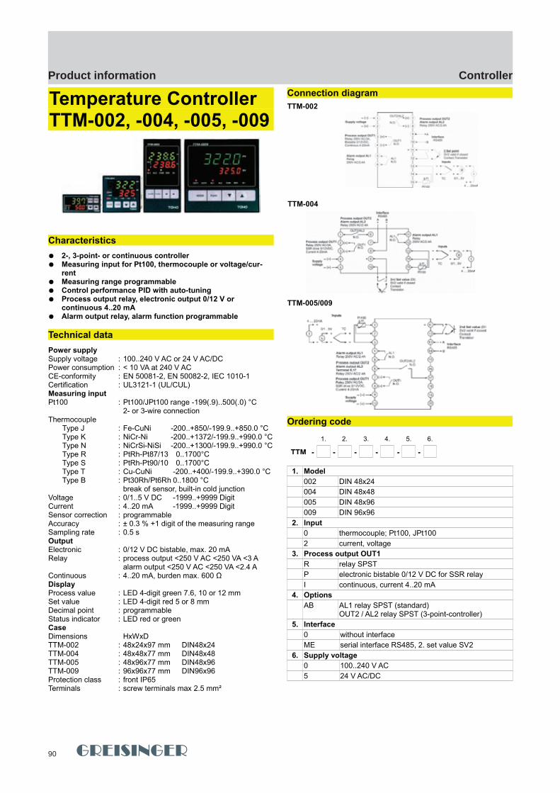
90
ControllerProduct information
GHM Messtechnik GmbH – Location MartensKiebitzhörn 18 22885 Barsbüttel Germany Fon +49-40-670 73-0 Fax -288www.ghm-messtechnik.de [email protected]
Product Information Industrial Electronics
Temperature ControllerTTM-002, -004, -005, -009
Characteristics
2-, 3-point- or continuous controller Measuring input for Pt100, thermocouple or voltage/cur-
rent Measuring range programmable Control performance PID with auto-tuning Process output relay, electronic output 0/12 V or
continuous 4..20 mA Alarm output relay, alarm function programmable
Technical data
Power supplySupply voltage : 100..240 V AC or 24 V AC/DCPower consumption : < 10 VA at 240 V ACCE-conformity : EN 50081-2, EN 50082-2, IEC 1010-1Certification : UL3121-1 (UL/CUL)Measuring inputPt100 : Pt100/JPt100 range -199(.9)..500(.0) °C
2- or 3-wire connectionThermocouple
Type J : Fe-CuNi -200..+850/-199.9..+850.0 °CType K : NiCr-Ni -200..+1372/-199.9..+990.0 °CType N : NiCrSi-NiSi -200..+1300/-199.9..+990.0 °CType R : PtRh-Pt87/13 0..1700°CType S : PtRh-Pt90/10 0..1700°CType T : Cu-CuNi -200..+400/-199.9..+390.0 °CType B : Pt30Rh/Pt6Rh 0..1800 °C
break of sensor, built-in cold junctionVoltage : 0/1..5 V DC -1999..+9999 DigitCurrent : 4..20 mA -1999..+9999 DigitSensor correction : programmableAccuracy : ± 0.3 % +1 digit of the measuring rangeSampling rate : 0.5 sOutput Electronic : 0/12 V DC bistable, max. 20 mARelay : process output <250 V AC <250 VA <3 A
alarm output <250 V AC <250 VA <2.4 AContinuous : 4..20 mA, burden max. 600 ΩDisplayProcess value : LED 4-digit green 7.6, 10 or 12 mmSet value : LED 4-digit red 5 or 8 mmDecimal point : programmableStatus indicator : LED red or greenCaseDimensions HxWxDTTM-002 : 48x24x97 mm DIN48x24TTM-004 : 48x48x77 mm DIN48x48TTM-005 : 48x96x77 mm DIN48x96TTM-009 : 96x96x77 mm DIN96x96Protection class : front IP65Terminals : screw terminals max 2.5 mm²
Connection diagram
Ordering code
1. 2. 3. 4. 5. 6.
TTM - - - - - -
1. Model
002 DIN 48x24
004 DIN 48x48
005 DIN 48x96
009 DIN 96x96
2. Input
0 thermocouple; Pt100, JPt100
2 current, voltage
3. Process output OUT1
R relay SPST
P electronic bistable 0/12 V DC for SSR relay
I continuous, current 4..20 mA
4. Options
AB AL1 relay SPST (standard) OUT2 / AL2 relay SPST (3-point-controller)
5. Interface
0 without interface
ME serial interface RS485, 2. set value SV2
6. Supply voltage
0 100..240 V AC
5 24 V AC/DC
20 pi-ma-Controller_E V4.00-00
TTM-002
TTM-004
TTM-005/009
TTM-002, -004, -005, -009 TTM-002, -004, -005, -009
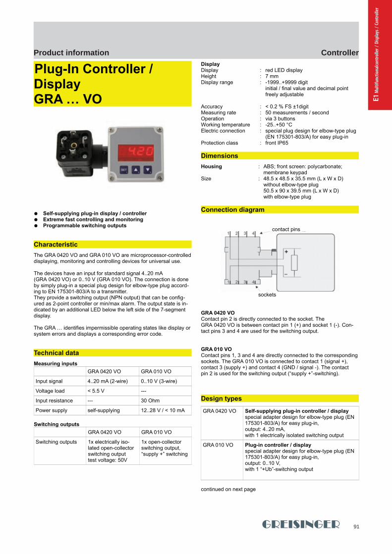
91
ControllerProduct information
E1 M
ultif
unct
iona
lcont
rolle
r / D
ispla
ys /
Cont
rolle
r
GHM Messtechnik GmbH - Location GreisingerHans-Sachs-Straße 26 93128 Regenstauf Germany Fon +49 (0) 9402 - 9383 - 0 Fax -33www.greisinger.de [email protected]
Product Information Industrial Electronics
Plug-In Controller / DisplayGRA … VO
Self-supplying plug-in display / controller Extreme fast controlling and monitoring Programmable switching outputs
Characteristic
The GRA 0420 VO and GRA 010 VO are microprocessor-controlleddisplaying, monitoring and controlling devices for universal use.
The devices have an input for standard signal 4..20 mA (GRA 0420 VO) or 0..10 V (GRA 010 VO). The connection is done by simply plug-in a special plug design for elbow-type plug accord-ing to EN 175301-803/A to a transmitter.They provide a switching output (NPN output) that can be config-ured as 2-point controller or min/max alarm. The output state is in-dicated by an additional LED below the left side of the 7-segment display.
The GRA … identifies impermissible operating states like display orsystem errors and displays a corresponding error code.
Technical data
Measuring inputs
GRA 0420 VO GRA 010 VO
Input signal 4..20 mA (2-wire) 0..10 V (3-wire)
Voltage load < 5.5 V ---
Input resistance --- 30 Ohm
Power supply self-supplying 12..28 V / < 10 mA
Switching outputs
GRA 0420 VO GRA 010 VO
Switching outputs 1x electrically iso-lated open-collector switching output test voltage: 50V
1x open-collector switching output, “supply +” switching
DisplayDisplay : red LED displayHeight : 7 mm Display range : -1999..+9999 digit
initial / final value and decimal point freely adjustable
Accuracy : < 0.2 % FS ±1digit Measuring rate : 50 measurements / secondOperation : via 3 buttonsWorking temperature : -25..+50 °CElectric connection : special plug design for elbow-type plug
(EN 175301-803/A) for easy plug-inProtection class : front IP65
Dimensions
Housing : ABS; front screen: polycarbonate;membrane keypad
Size : 48.5 x 48.5 x 35.5 mm (L x W x D) without elbow-type plug50.5 x 90 x 39.5 mm (L x W x D) with elbow-type plug
Connection diagram
GRA 0420 VOContact pin 2 is directly connected to the socket. The GRA 0420 VO is between contact pin 1 (+) and socket 1 (-). Con-tact pins 3 and 4 are used for the switching output.
GRA 010 VOContact pins 1, 3 and 4 are directly connected to the correspondingsockets. The GRA 010 VO is connected to contact 1 (signal +), contact 3 (supply +) and contact 4 (GND / signal -). The contact pin 2 is used for the switching output (“supply +”-switching).
Design types
GRA 0420 VO Self-supplying plug-in controller / displayspecial adapter design for elbow-type plug (EN 175301-803/A) for easy plug-in,output: 4..20 mA, with 1 electrically isolated switching output
GRA 010 VO Plug-in controller / displayspecial adapter design for elbow-type plug (EN 175301-803/A) for easy plug-in,output: 0..10 V, with 1 “+Ub”-switching output
continued on next page
pi-ma-Controller_E V4.00-00
21
contact pins
sockets
TTM-002, -004, -005, -009 GRA ... VO GRA ... VO

92
ControllerProduct information
GHM Messtechnik GmbH - Location GreisingerHans-Sachs-Straße 26 93128 Regenstauf Germany Fon +49 (0) 9402 - 9383 - 0 Fax -33www.greisinger.de [email protected]
Product Information Industrial Electronics
GRA 0420 WK Controller / display with cable connection approx. 2m long connection cable with loose ends for connecting to any standard signal source and for switching output;housing with mounting holes, can be directly mounted to any surface;
output 4..20 mA;with 1 electrically isolated switchingoutput
GRA 010 WK Controller / display with cable connection approx. 2m long connection cable with loose ends for connecting to any standard signal source and for switching output;housing with mounting holes, can be directly mounted to any surface;output: 0..10 V;with 1 “+Ub”-switching output
Options
S2 2 electrically isolated switching outputs,outputs with increased switching power, connection viaseparate M8 socket
OT Cover without buttonse.g. if the adjustment of the device should not be di-rectly accessible for the user
Ordering code
1. 2. 3.
GRA - -
1. Input signal type
0420 4..20 mA (standard)
010 0..10 V
2. Connection type
VO elbow-type plug (standard)
WK cable connection
3. Option (combination of multiple options upon request)
00 without option
S2 2 electrically isolated switching outputs
OT cover without buttons
22 pi-ma-Controller_E V4.00-00
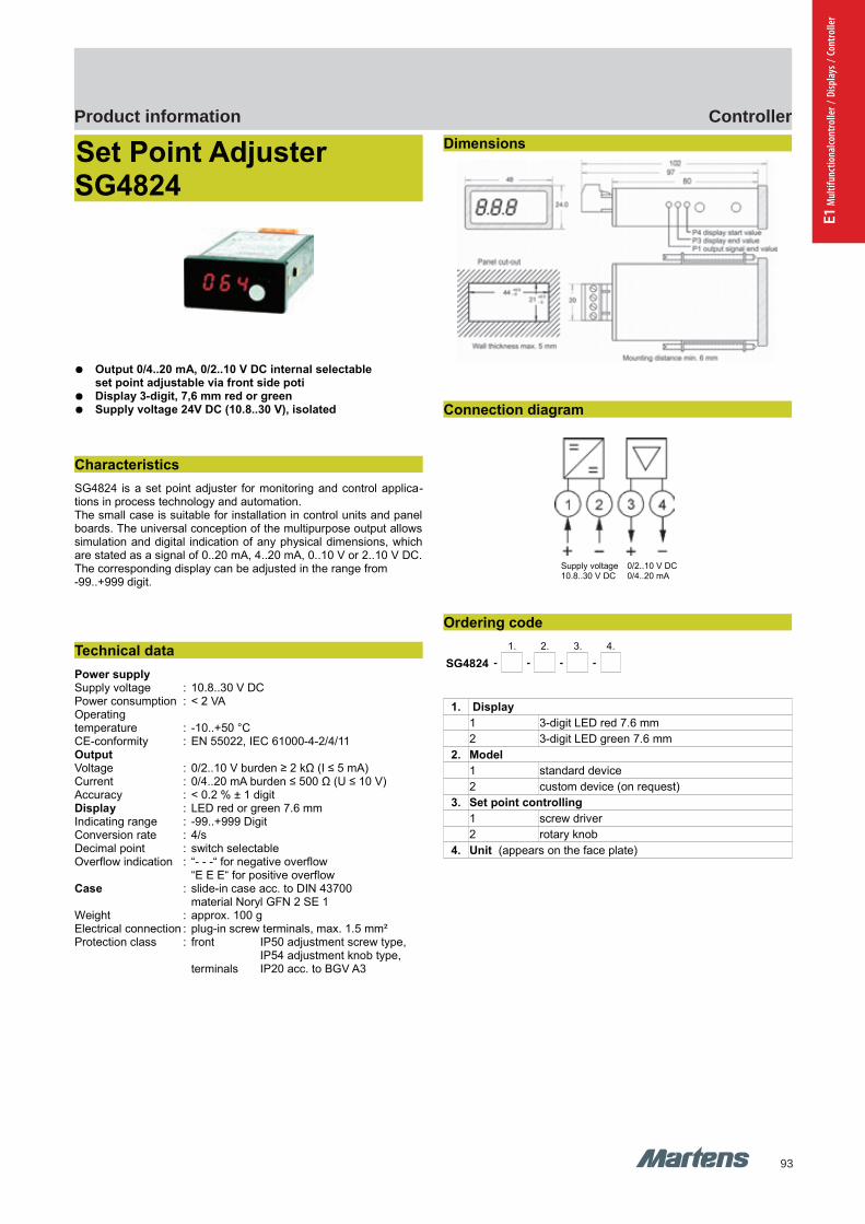
93
ControllerProduct information
E1 M
ultif
unct
iona
lcont
rolle
r / D
ispla
ys /
Cont
rolle
r
GHM Messtechnik GmbH – Location MartensKiebitzhörn 18 22885 Barsbüttel Germany Fon +49-40-670 73-0 Fax -288www.ghm-messtechnik.de [email protected]
Product Information Industrial Electronics
Set Point Adjuster SG4824
Output 0/4..20 mA, 0/2..10 V DC internal selectableset point adjustable via front side poti
Display 3-digit, 7,6 mm red or green Supply voltage 24V DC (10.8..30 V), isolated
Characteristics
SG4824 is a set point adjuster for monitoring and control applica-tions in process technology and automation.The small case is suitable for installation in control units and panelboards. The universal conception of the multipurpose output allowssimulation and digital indication of any physical dimensions, whichare stated as a signal of 0..20 mA, 4..20 mA, 0..10 V or 2..10 V DC.The corresponding display can be adjusted in the range from -99..+999 digit.
Technical data
Power supplySupply voltage : 10.8..30 V DCPower consumption : < 2 VAOperating temperature : -10..+50 °CCE-conformity : EN 55022, IEC 61000-4-2/4/11OutputVoltage : 0/2..10 V burden ≥ 2 kΩ (I ≤ 5 mA)Current : 0/4..20 mA burden ≤ 500 Ω (U ≤ 10 V)Accuracy : < 0.2 % ± 1 digitDisplay : LED red or green 7.6 mmIndicating range : -99..+999 DigitConversion rate : 4/sDecimal point : switch selectableOverflow indication : “- - -“ for negative overflow
“E E E“ for positive overflowCase : slide-in case acc. to DIN 43700
material Noryl GFN 2 SE 1Weight : approx. 100 gElectrical connection : plug-in screw terminals, max. 1.5 mm²Protection class : front IP50 adjustment screw type,
IP54 adjustment knob type,terminals IP20 acc. to BGV A3
Dimensions
Connection diagram
Ordering code
1. 2. 3. 4.
SG4824 - - - -
1. Display
1 3-digit LED red 7.6 mm
2 3-digit LED green 7.6 mm
2. Model
1 standard device
2 custom device (on request)
3. Set point controlling
1 screw driver
2 rotary knob
4. Unit (appears on the face plate)
pi-ma-Controller_E V4.00-00
23
Supply voltage 0/2..10 V DC10.8..30 V DC 0/4..20 mA
SG4824 SG4824
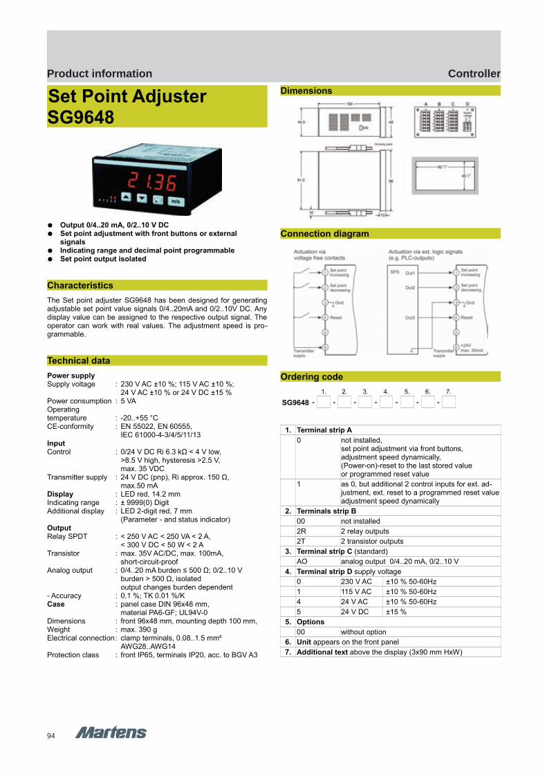
94
ControllerProduct information
GHM Messtechnik GmbH – Location MartensKiebitzhörn 18 22885 Barsbüttel Germany Fon +49-40-670 73-0 Fax -288www.ghm-messtechnik.de [email protected]
Product Information Industrial Electronics
Set Point Adjuster SG9648
Output 0/4..20 mA, 0/2..10 V DC Set point adjustment with front buttons or external
signals Indicating range and decimal point programmable Set point output isolated
Characteristics
The Set point adjuster SG9648 has been designed for generatingadjustable set point value signals 0/4..20mA and 0/2..10V DC. Anydisplay value can be assigned to the respective output signal. Theoperator can work with real values. The adjustment speed is pro-grammable.
Technical data
Power supplySupply voltage : 230 V AC ±10 %; 115 V AC ±10 %;
24 V AC ±10 % or 24 V DC ±15 %Power consumption : 5 VAOperating temperature : -20..+55 °CCE-conformity : EN 55022, EN 60555,
IEC 61000-4-3/4/5/11/13InputControl : 0/24 V DC Ri 6.3 kΩ < 4 V low,
>8.5 V high, hysteresis >2.5 V, max. 35 VDC
Transmitter supply : 24 V DC (pnp), Ri approx. 150 Ω, max.50 mA
Display : LED red, 14.2 mmIndicating range : ± 9999(0) DigitAdditional display : LED 2-digit red, 7 mm
(Parameter - and status indicator)OutputRelay SPDT : < 250 V AC < 250 VA < 2 A,
< 300 V DC < 50 W < 2 ATransistor : max. 35V AC/DC, max. 100mA,
short-circuit-proofAnalog output : 0/4..20 mA burden ≤ 500 Ω; 0/2..10 V
burden > 500 Ω, isolatedoutput changes burden dependent
- Accuracy : 0.1 %; TK 0.01 %/KCase : panel case DIN 96x48 mm,
material PA6-GF; UL94V-0Dimensions : front 96x48 mm, mounting depth 100 mm,Weight : max. 390 gElectrical connection: clamp terminals, 0.08..1.5 mm²
AWG28..AWG14Protection class : front IP65, terminals IP20, acc. to BGV A3
Dimensions
Connection diagram
Ordering code
1. 2. 3. 4. 5. 6. 7.
SG9648 - - - - - - -
1. Terminal strip A
0 not installed, set point adjustment via front buttons, adjustment speed dynamically,(Power-on)-reset to the last stored valueor programmed reset value
1 as 0, but additional 2 control inputs for ext. ad-justment, ext. reset to a programmed reset valueadjustment speed dynamically
2. Terminals strip B
00 not installed
2R 2 relay outputs
2T 2 transistor outputs
3. Terminal strip C (standard)
AO analog output 0/4..20 mA, 0/2..10 V
4. Terminal strip D supply voltage
0 230 V AC ±10 % 50-60Hz
1 115 V AC ±10 % 50-60Hz
4 24 V AC ±10 % 50-60Hz
5 24 V DC ±15 %
5. Options
00 without option
6. Unit appears on the front panel
7. Additional text above the display (3x90 mm HxW)
24 pi-ma-Controller_E V4.00-00
SG9648 SG9648
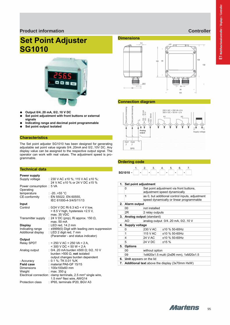
95
ControllerProduct information
E1 M
ultif
unct
iona
lcont
rolle
r / D
ispla
ys /
Cont
rolle
r
GHM Messtechnik GmbH – Location MartensKiebitzhörn 18 22885 Barsbüttel Germany Fon +49-40-670 73-0 Fax -288www.ghm-messtechnik.de [email protected]
Product Information Industrial Electronics
Set Point Adjuster SG1010
Output 0/4..20 mA, 0/2..10 V DC Set point adjustment with front buttons or external
signals Indicating range and decimal point programmable Set point output isolated
Characteristics
The Set point adjuster SG1010 has been designed for generatingadjustable set point value signals 0/4..20mA and 0/2..10V DC. Anydisplay value can be assigned to the respective output signal. Theoperator can work with real values. The adjustment speed is pro-grammable.
Technical data
Power supplySupply voltage : 230 V AC ±10 %; 115 V AC ±10 %;
24 V AC ±10 % or 24 V DC ±15 %Power consumption : 5 VAOperatingtemperature : -20..+55 °CCE-conformity : EN 55022, EN 60555,
IEC 61000-4-3/4/5/11/13InputControl : 0/24 V DC Ri 6.3 kΩ < 4 V low,
> 8.5 V high, hysteresis >2.5 V, max. 35 VDC
Transmitter supply : 24 V DC (pnp), Ri approx. 150 Ω, max. 50 mA
Display : LED red, 14.2 mmIndicating range : ±9999(0) Digit with leading zero suppressionAdditional display : LED 2 digit red, 7 mm
(Parameter - and status indicator)OutputRelay SPDT : < 250 V AC < 250 VA < 2 A,
< 300 V DC < 50 W < 2 AAnalog output : 0/4..20 mA burden ≤500 Ω; 0/2..10 V
burden >500 Ω, not isolatedoutput changes burden dependent
- Accuracy : 0.1 %; TK 0.01 %/KField case : material PA6-GF 15/15Dimensions : 100x100x60 mmWeight : max. 350 gElectrical connection : clamp terminals, 2.5 mm² single wire,
1.5 mm² flexi wire, AWG14Protection class : IP65, terminals IP20, BGV A3
Dimensions
Connection diagram
Ordering code
1. 2. 3. 4. 5. 6. 7.
SG1010 - - - - - - -
1. Set point adjustment
0 Set point adjustment via front buttons, adjustment speed dynamically
1 as 0, but additional control inputs, adjustment speed dynamically or linear programmable
2. Alarm output
00 not installed
2R 2 relay outputs
3. Analog output (standard)
AO analog output 0/4..20 mA, 0/2..10 V
4. Supply voltage
0 230 V AC ±10 % 50-60Hz
1 115 V AC ±10 % 50-60Hz
4 24 V AC ±10 % 50-60Hz
5 24 V DC ±15 %
5. Options
00 without option
09 1xM20x1.5 multi (2xØ6 mm), 1xM20x1.5
6. Unit appears on the lid
7. Additional text above the display (3x70mm HxW)
pi-ma-Controller_E V4.00-00
25
Analogoutput
SG9648 SG1010 SG1010

E Industrial electronics
96
E Industrial electronics
97
E2 Tr
ansm
itter
s / S
igna
l con
ditio
ning
Kapitel E2 Start
Transmitters / Signal conditioning
Rail systems
E2
98
Page
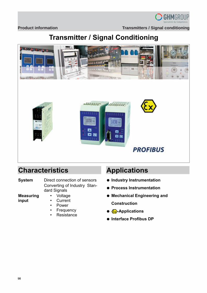
9898
Transmitters / Signal conditioningProduct information
GHM Messtechnik GmbH – Sales Center InternationalSchloßstraße 6 88453 Erolzheim Germany Fon +49-7354-937233-0 Fax -88www.ghm-messtechnik.de [email protected]
Product Information Industrial Electronics
Transmitter / Signal Conditioning
Characteristics
System Direct connection of sensorsConverting of Industry Stan-dard Signals
Measuringinput
• Voltage• Current• Power • Frequency • Resistance
Applications
Industry Instrumentation
Process Instrumentation
Mechanical Engineering and
Construction
-Applications
Interface Profibus DP
pi-ma-Transmitter_E V1.00-00 1
Einleitung
9999
Transmitters / Signal conditioningProduct information
E2 Tr
ansm
itter
s / S
igna
l con
ditio
ning
GHM Messtechnik GmbH – Sales Center InternationalSchloßstraße 6 88453 Erolzheim Germany Fon +49-7354-937233-0 Fax -88www.ghm-messtechnik.de [email protected]
Product Information Industrial Electronics
Function
According to the basic standard DIN 1319 a measuring transduceris measuring equipment which transforms an input value corres-ponding to a fixed relation in an output value. This output valuewhich is given in the form of industrial standard signals, can be fur-ther processed in the standard way by display devices or program-mable logic controllers (PLC).
Advantages
Direct connection of sensors Galvanic separation of the input signal to the output No ground loops Signal adaptation to downstream devices Compact construction design DIN rail mounting TS35 acc. to DIN EN 60715 Field case
General
Measuring inputs
0/4..20 mA 0/2..10 V DC Voltage AC/DC Current AC/DC Resistance / Potentiometer
Measuring mode – Connection types
2-wire 3-wire Plug-in terminals Screw terminals
Outputs
Analogue output active 0/4..20 mA Analogue output active 0/2..10 V DC Impulse output 0/18 V DC Relay output SPDT Transistor output PNP
Specials
Without supply Field bus Profibus DP Custom devices on request Integrated display Device for rail vehicles (FT500)
2 pi-ma-Transmitter_E V1.00-00
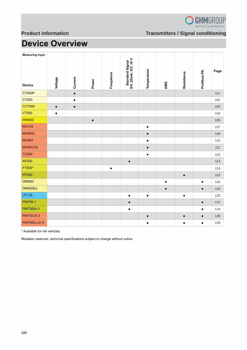
100100
Transmitters / Signal conditioningProduct information
GHM Messtechnik GmbH – Sales Center InternationalSchloßstraße 6 88453 Erolzheim Germany Fon +49-7354-937233-0 Fax -88www.ghm-messtechnik.de [email protected]
Product Information Industrial Electronics
Device OverviewMeasuring input
Device
Vo
lta
ge
Cu
rre
nt
Po
we
r
Fre
qu
en
ce
Sta
nd
ard
Sig
na
l
0/4
..2
0m
A;
0/2
..10
V
Te
mp
era
ture
DM
S
Re
sis
tan
ce
Pro
fib
us
-PA
Page
CT500P 4
CT500 5
CVT500 6
VT500 7
WM500 8
MU125 10
MU500L 12
MU500 13
MU500-Ex 14
TC500 15
AF500 16
FT500* 17
RT500 18
DMS50 19
DMS50Ex 21
UT125 23
PMT50-1 25
PMT50Ex-1 27
PMT50-2/-3 29
PMT50Ex-2/-3 31
* Available for rail vehicles.
Mistakes reserved, technical specifications subject to change without notice.
pi-ma-Transmitter_E V1.00-00 3
101
102
104
107
110
112
114
116
120
124
128
103
105
109
111
113
115
118
122
126
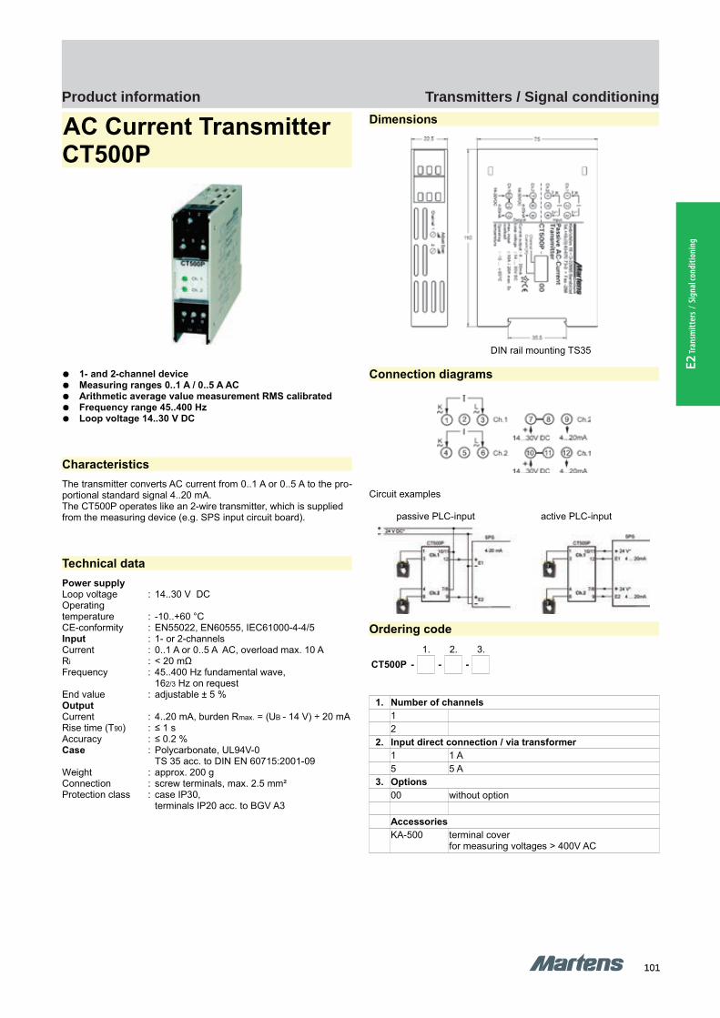
101101
Transmitters / Signal conditioningProduct information
E2 Tr
ansm
itter
s / S
igna
l con
ditio
ning
GHM Messtechnik GmbH – Location MartensKiebitzhörn 18 22885 Barsbüttel Germany Fon +49-40-670 73-0 Fax -288www.ghm-messtechnik.de [email protected]
Product Information Industrial Electronics
AC Current Transmitter CT500P
1- and 2-channel device Measuring ranges 0..1 A / 0..5 A AC Arithmetic average value measurement RMS calibrated Frequency range 45..400 Hz Loop voltage 14..30 V DC
Characteristics
The transmitter converts AC current from 0..1 A or 0..5 A to the pro-portional standard signal 4..20 mA.The CT500P operates like an 2-wire transmitter, which is supplied from the measuring device (e.g. SPS input circuit board).
Technical data
Power supplyLoop voltage : 14..30 V DCOperatingtemperature : -10..+60 °CCE-conformity : EN55022, EN60555, IEC61000-4-4/5Input : 1- or 2-channelsCurrent : 0..1 A or 0..5 A AC, overload max. 10 ARi : < 20 mΩFrequency : 45..400 Hz fundamental wave,
162/3 Hz on requestEnd value : adjustable ± 5 %OutputCurrent : 4..20 mA, burden Rmax. = (UB - 14 V) ÷ 20 mARise time (T90) : ≤ 1 sAccuracy : ≤ 0.2 %Case : Polycarbonate, UL94V-0
TS 35 acc. to DIN EN 60715:2001-09Weight : approx. 200 gConnection : screw terminals, max. 2.5 mm²Protection class : case IP30,
terminals IP20 acc. to BGV A3
Dimensions
DIN rail mounting TS35
Connection diagrams
Circuit examples
passive PLC-input active PLC-input
Ordering code
1. 2. 3.
CT500P - - -
1. Number of channels
12
2. Input direct connection / via transformer
1 1 A5 5 A
3. Options
00 without option
Accessories
KA-500 terminal cover for measuring voltages > 400V AC
4 pi-ma-Transmitter_E V1.00-00
CT500P CT500P
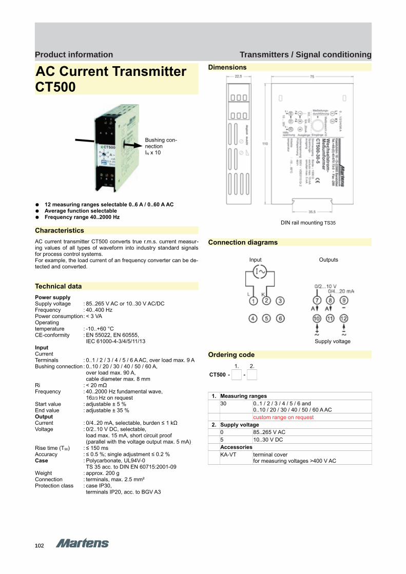
102102
Transmitters / Signal conditioningProduct information
GHM Messtechnik GmbH – Location MartensKiebitzhörn 18 22885 Barsbüttel Germany Fon +49-40-670 73-0 Fax -288www.ghm-messtechnik.de [email protected]
Product Information Industrial Electronics
AC Current Transmitter CT500
12 measuring ranges selectable 0..6 A / 0..60 A AC Average function selectable Frequency range 40..2000 Hz
Characteristics
AC current transmitter CT500 converts true r.m.s. current measur-ing values of all types of waveform into industry standard signalsfor process control systems.For example, the load current of an frequency converter can be de-tected and converted.
Technical data
Power supplySupply voltage : 85..265 V AC or 10..30 V AC/DCFrequency : 40..400 HzPower consumption: < 3 VAOperatingtemperature : -10..+60 °CCE-conformity : EN 55022, EN 60555,
IEC 61000-4-3/4/5/11/13InputCurrentTerminals : 0..1 / 2 / 3 / 4 / 5 / 6 A AC, over load max. 9 ABushing connection : 0..10 / 20 / 30 / 40 / 50 / 60 A,
over load max. 90 A, cable diameter max. 8 mm
Ri : < 20 mΩFrequency : 40..2000 Hz fundamental wave,
162/3 Hz on requestStart value : adjustable ± 5 %End value : adjustable ± 35 %OutputCurrent : 0/4..20 mA, selectable, burden ≤ 1 kΩVoltage : 0/2..10 V DC, selectable,
load max. 15 mA, short circuit proof(parallel with the voltage output max. 5 mA)
Rise time (T90) : ≤ 150 msAccuracy : ≤ 0.5 %; single adjustment ≤ 0.2 %Case : Polycarbonate, UL94V-0
TS 35 acc. to DIN EN 60715:2001-09Weight : approx. 200 gConnection : terminals, max. 2.5 mm²Protection class : case IP30,
terminals IP20, acc. to BGV A3
Dimensions
DIN rail mounting TS35
Connection diagrams
Input Outputs
Supply voltage
Ordering code
1. 2.
CT500 - -
1. Measuring ranges
30 0..1 / 2 / 3 / 4 / 5 / 6 and 0..10 / 20 / 30 / 40 / 50 / 60 A ACcustom range on request
2. Supply voltage
0 85..265 V AC 5 10..30 V DCAccessories
KA-VT terminal cover for measuring voltages >400 V AC
pi-ma-Transmitter_E V1.00-00 5
Bushing con-nectionIN x 10
CT500 CT500
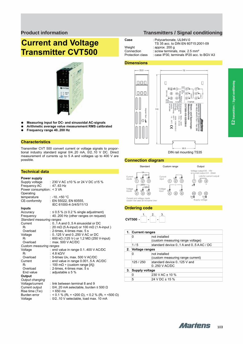
103103
Transmitters / Signal conditioningProduct information
E2 Tr
ansm
itter
s / S
igna
l con
ditio
ning
GHM Messtechnik GmbH – Location MartensKiebitzhörn 18 22885 Barsbüttel Germany Fon +49-40-670 73-0 Fax -288www.ghm-messtechnik.de [email protected]
Product Information Industrial Electronics
Current and Voltage Transmitter CVT500
Measuring input for DC- and sinusoidal AC-signals Arithmetic average value measurement RMS calibrated Frequency range 40..200 Hz
Characteristics
Transmitter CVT 500 convert current or voltage signals to propor-tional industry standard signal 0/4..20 mA, 0/2..10 V DC. Directmeasurement of currents up to 5 A and voltages up to 400 V arepossible.
Technical data
Power supplySupply voltage : 230 V AC ±10 % or 24 V DC ±15 %Frequency AC : 47..63 HzPower consumption: < 3 VAOperatingtemperature : -10..+50 °CCE-conformity : EN 55022, EN 60555,
IEC 61000-4-3/4/5/11/13InputsAccuracy : ≤ 0.5 % (≤ 0.2 % single adjustment)Frequency : 40..200 Hz (other ranges on request)Standard measuring rangesCurrent : 0..1 A and 0..5 A sinusoidal or DC Ri : 20 mΩ (5 A-input) or 100 mΩ (1 A-input ) Overload : 2-times, 4-times max. 5 sVoltage : 0..125 V and 0..250 V AC or DC Ri : 600 kΩ (125 V-) or 1,2 MΩ (250 V-input) Overload : max. 500 V AC/DCCustom measuring rangesVoltage : end value in range 0.1..400 V AC/DC Ri : 4.8 kΩ/V Overload : 5-times UN, max. 500 V AC/DCCurrent : end value in range 0.001..5 A AC/DC Ri : 100 mΩ ÷ (custom range [A]) Overload : 2-times, 4-times max. 5 s End value : adjustable ± 5 %OutputOutput changingVoltage/current : link between terminal 8 and 9Current output : 0/4..20 mA selectable, burden ≤ 500 ΩRise time (T90) : < 650 msBurden error : < 0.1 % (RL = <200 Ω), < 0.2 % (RL = <500 Ω)Voltage : 0/2..10 V selectable, load max. 10 mA
Case : Polycarbonate, UL94V-0TS 35 acc. to DIN EN 60715:2001-09
Weight : approx. 200 gConnection : screw terminals, max. 2.5 mm²Protection class : case IP30, terminals IP20 acc. to BGV A3
Dimensions
DIN rail mounting TS35
Connection diagram
Standard Custom range Output
Ordering code
1. 2. 3.
CVT500 - - -
1. Current ranges
0 not installed (custom measuring range voltage)
1 / 5 standard device 0..1 A and 0..5 A AC / DC2. Voltage ranges
0 not installed (custom measuring range current)
125 / 250 standard device 0..125 V and 0..250 V AC/DC
3. Supply voltage
0 230 V AC ± 10 %5 24 V DC ± 15 %
6 pi-ma-Transmitter_E V1.00-00
CVT500 CVT500

104104
Transmitters / Signal conditioningProduct information
GHM Messtechnik GmbH – Location MartensKiebitzhörn 18 22885 Barsbüttel Germany Fon +49-40-670 73-0 Fax -288www.ghm-messtechnik.de [email protected]
Product Information Industrial Electronics
AC Voltage TransmitterVT500
6 measuring ranges selectable 0..600 V AC Average function selectable Frequency range 40..2000 Hz
Characteristics
Voltage transmitter VT500 converts true r.m.s. voltage measuring values of all types of waveforms into industry standard signals for process control systems. For example, the load voltage of an fre-quency converter can be detected and converted.
Technical data
Power supplySupply voltage : 85..265 V AC or 10..30 V AC/DCFrequency : 40..400 HzPower consumption : <3 VAOperatingtemperature : -10..+60 °CCE-conformity : EN 55022, EN 60555,
IEC 61000-4-3/4/5/11/13InputVoltage AC : 0..100 / 200 / 300 / 400 / 500 / 600 V AC,
overload max. 1200 V max. 5 sRi : 720 kΩFrequency : 40..2000 Hz fundamental wave,
162/3 Hz on requestStart value : adjustable ± 5 %End value : adjustable ± 35 %OutputCurrent : 0/4..20 mA, selectable, burden ≤ 1 kΩVoltage : 0/2..10 V DC, selectable,
load max. 15 mA, short-circuit-proof (parallel with the voltage output max. 5 mA)
Rise time (T90) : ≤ 150 msAccuracy : ≤ 0.5 %; single adjustment ≤ 0.2 %Case : Polycarbonate, UL94V-0
TS 35 acc. to DIN EN 60715:2001-09Weight : approx. 200 gConnection : screw terminals, max. 2.5 mm²Protection class : case IP30,
terminals IP20 acc. to BGV A3
Dimensions
DIN rail mounting TS35
Connection diagram
Ordering code
1. 2.
VT500 - -
1. Measuring ranges
30 0..100 / 200 / 300 / 400 / 500 / 600 V ACcustom range on request
2. Supply voltage
0 85..265 V AC 5 10..30 V DC
Accessories
KA-VT terminal cover for measuring voltages > 400 V AC
pi-ma-Transmitter_E V1.00-00 7
Input Outputs
Supply voltage
VT500 VT500
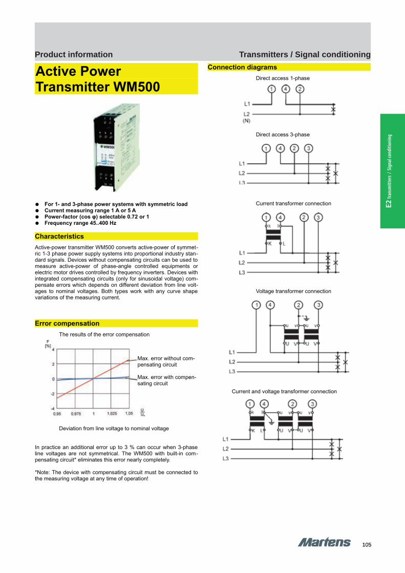
105105
Transmitters / Signal conditioningProduct information
E2 Tr
ansm
itter
s / S
igna
l con
ditio
ning
GHM Messtechnik GmbH – Location MartensKiebitzhörn 18 22885 Barsbüttel Germany Fon +49-40-670 73-0 Fax -288www.ghm-messtechnik.de [email protected]
Product Information Industrial Electronics
Active Power Transmitter WM500
For 1- and 3-phase power systems with symmetric load Current measuring range 1 A or 5 A Power-factor (cos φ) selectable 0.72 or 1 Frequency range 45..400 Hz
Characteristics
Active-power transmitter WM500 converts active-power of symmet-ric 1-3 phase power supply systems into proportional industry stan-dard signals. Devices without compensating circuits can be used tomeasure active-power of phase-angle controlled equipments orelectric motor drives controlled by frequency inverters. Devices withintegrated compensating circuits (only for sinusoidal voltage) com-pensate errors which depends on different deviation from line volt-ages to nominal voltages. Both types work with any curve shapevariations of the measuring current.
Error compensation
The results of the error compensation
Deviation from line voltage to nominal voltage
In practice an additional error up to 3 % can occur when 3-phaseline voltages are not symmetrical. The WM500 with built-in com-pensating circuit* eliminates this error nearly completely.
*Note: The device with compensating circuit must be connected tothe measuring voltage at any time of operation!
Connection diagrams
Direct access 1-phase
Direct access 3-phase
Current transformer connection
Voltage transformer connection
Current and voltage transformer connection
8 pi-ma-Transmitter_E V1.00-00
Max. error without com-pensating circuit
Max. error with compen-sating circuit
WM500 WM500
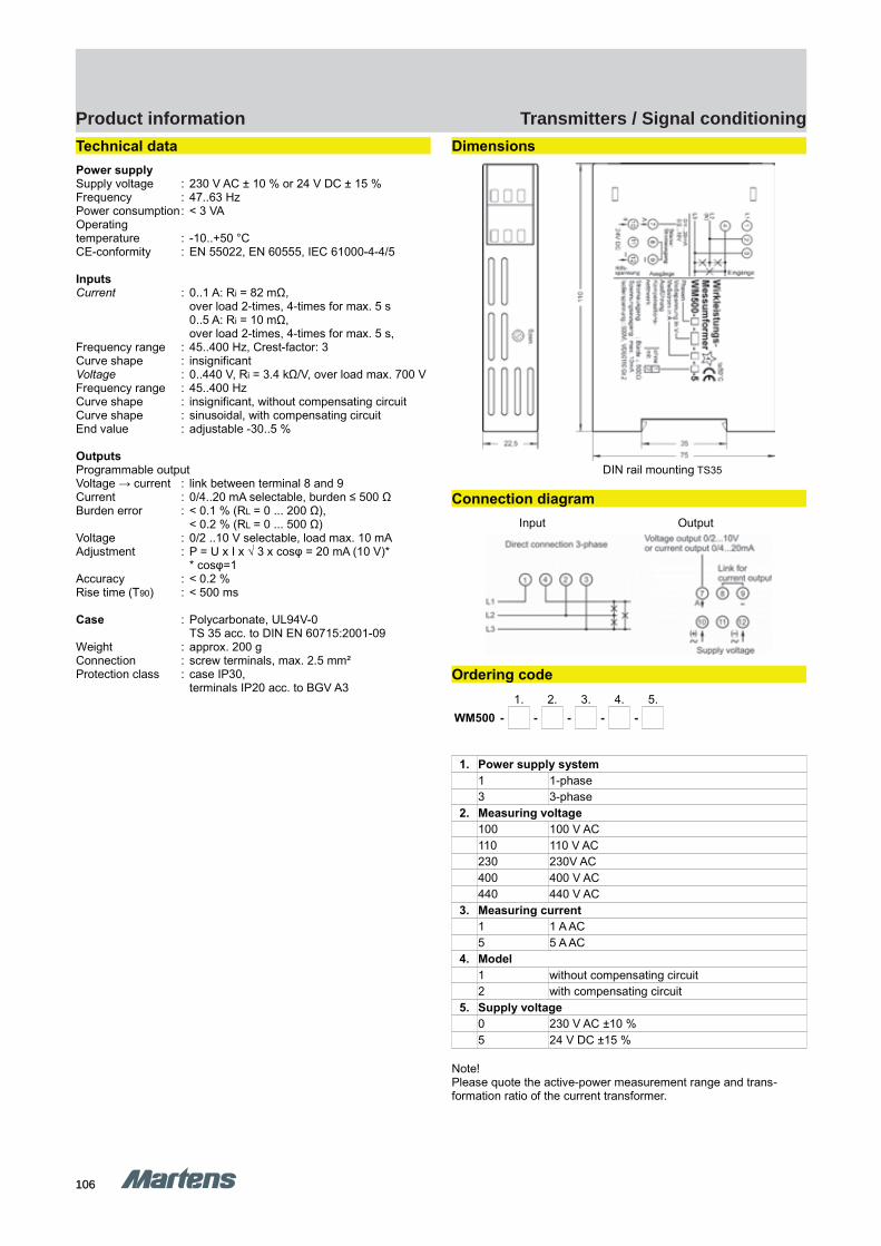
106106
Transmitters / Signal conditioningProduct information
GHM Messtechnik GmbH – Location MartensKiebitzhörn 18 22885 Barsbüttel Germany Fon +49-40-670 73-0 Fax -288www.ghm-messtechnik.de [email protected]
Product Information Industrial Electronics
Technical data
Power supplySupply voltage : 230 V AC ± 10 % or 24 V DC ± 15 %Frequency : 47..63 HzPower consumption: < 3 VAOperatingtemperature : -10..+50 °CCE-conformity : EN 55022, EN 60555, IEC 61000-4-4/5
InputsCurrent : 0..1 A: Ri = 82 mΩ,
over load 2-times, 4-times for max. 5 s0..5 A: Ri = 10 mΩ, over load 2-times, 4-times for max. 5 s,
Frequency range : 45..400 Hz, Crest-factor: 3Curve shape : insignificantVoltage : 0..440 V, Ri = 3.4 kΩ/V, over load max. 700 VFrequency range : 45..400 HzCurve shape : insignificant, without compensating circuitCurve shape : sinusoidal, with compensating circuitEnd value : adjustable -30..5 %
OutputsProgrammable outputVoltage → current : link between terminal 8 and 9Current : 0/4..20 mA selectable, burden ≤ 500 ΩBurden error : < 0.1 % (RL = 0 ... 200 Ω),
< 0.2 % (RL = 0 ... 500 Ω)Voltage : 0/2 ..10 V selectable, load max. 10 mAAdjustment : P = U x I x √ 3 x cosφ = 20 mA (10 V)*
* cosφ=1Accuracy : < 0.2 %Rise time (T90) : < 500 ms
Case : Polycarbonate, UL94V-0TS 35 acc. to DIN EN 60715:2001-09
Weight : approx. 200 gConnection : screw terminals, max. 2.5 mm²Protection class : case IP30,
terminals IP20 acc. to BGV A3
Dimensions
DIN rail mounting TS35
Connection diagram
Input Output
Ordering code
1. 2. 3. 4. 5.
WM500 - - - - -
1. Power supply system
1 1-phase3 3-phase
2. Measuring voltage
100 100 V AC110 110 V AC230 230V AC400 400 V AC440 440 V AC
3. Measuring current
1 1 A AC5 5 A AC
4. Model
1 without compensating circuit 2 with compensating circuit
5. Supply voltage
0 230 V AC ±10 %5 24 V DC ±15 %
Note!Please quote the active-power measurement range and trans-formation ratio of the current transformer.
pi-ma-Transmitter_E V1.00-00 9
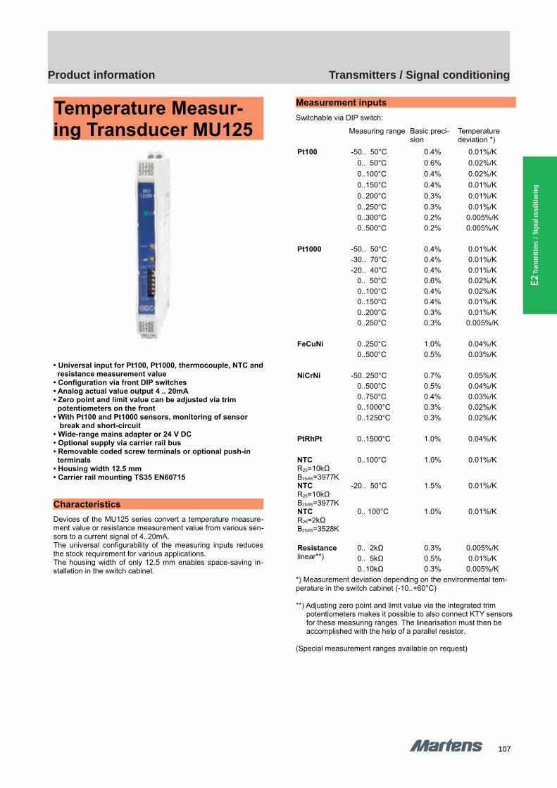
107107
Transmitters / Signal conditioningProduct information
E2 Tr
ansm
itter
s / S
igna
l con
ditio
ning
GHM Messtechnik GmbH – MartensKiebitzhörn 18 22885 Barsbüttel Germany Phone +49-40-670 73-0 Fax -288www.ghm-messtechnik.de [email protected] e
Product Information Industrial Electronic
Temperature Measur-ing Transducer MU125
• Universal input for Pt100, Pt1000, thermocouple, NTC and resistance measurement value• Configuration via front DIP switches • Analog actual value output 4 .. 20mA• Zero point and limit value can be adjusted via trim potentiometers on the front• With Pt100 and Pt1000 sensors, monitoring of sensor break and short-circuit• Wide-range mains adapter or 24 V DCa• Optional supply via carrier rail bus• Removable coded screw terminals or optional push-in terminals• Housing width 12.5 mm• Carrier rail mounting TS35 EN60715
Characteristics
Devices of the MU125 series convert a temperature measure-ment value or resistance measurement value from various sen-sors to a current signal of 4..20mA.The universal configurability of the measuring inputs reducesthe stock requirement for various applications.The housing width of only 12.5 mm enables space-saving in-stallation in the switch cabinet.
Measurement inputs
Switchable via DIP switch:
*) Measurement deviation depending on the environmental tem-perature in the switch cabinet (-10..+60°C)
**) Adjusting zero point and limit value via the integrated trim potentiometers makes it possible to also connect KTY sensors for these measuring ranges. The linearisation must then be accomplished with the help of a parallel resistor.
(Special measurement ranges available on request)
10
Measuring range Basic preci-sion
Temperature deviation *)
Pt100 -50.. 50°C 0.4% 0.01%/K
0.. 50°C 0.6% 0.02%/K
0..100°C 0.4% 0.02%/K
0..150°C 0.4% 0.01%/K
0..200°C 0.3% 0.01%/K
0..250°C 0.3% 0.01%/K 0..300°C 0.2% 0.005%/K
0..500°C 0.2% 0.005%/K
Pt1000 -50.. 50°C 0.4% 0.01%/K -30.. 70°C 0.4% 0.01%/K
-20.. 40°C 0.4% 0.01%/K 0.. 50°C 0.6% 0.02%/K
0..100°C 0.4% 0.02%/K 0..150°C 0.4% 0.01%/K
0..200°C 0.3% 0.01%/K 0..250°C 0.3% 0.005%/K
FeCuNi 0..250°C 1.0% 0.04%/K
0..500°C 0.5% 0.03%/K
NiCrNi -50..250°C 0.7% 0.05%/K 0..500°C 0.5% 0.04%/K
0..750°C 0.4% 0.03%/K 0..1000°C 0.3% 0.02%/K
0..1250°C 0.3% 0.02%/K
PtRhPt 0..1500°C 1.0% 0.04%/K
NTCR25=10kΩB25/85=3977K
0..100°C 1.0% 0.01%/K
NTCR25=10kΩB25/85=3977K
-20.. 50°C 1.5% 0.01%/K
NTCR25=2kΩB25/85=3528K
0.. 100°C 1.0% 0.01%/K
Resistancelinear**)
0.. 2kΩ 0.3% 0.005%/K
0.. 5kΩ 0.5% 0.01%/K 0..10kΩ 0.3% 0.005%/K
MU125 MU125
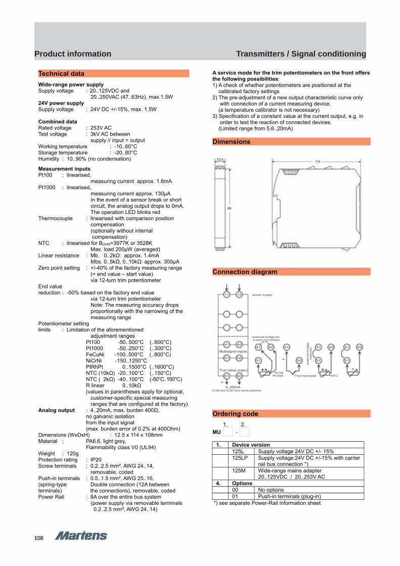
108108
Transmitters / Signal conditioningProduct information
GHM Messtechnik GmbH – MartensKiebitzhörn 18 22885 Barsbüttel Germany Phone +49-40-670 73-0 Fax -288www.ghm-messtechnik.de [email protected] e
Product Information Industrial Electronic
Technical data
Wide-range power supplySupply voltage : 20..125VDC and 20..250VAC (47..63Hz), max.1.5W24V power supplySupply voltage : 24V DC +/-15%, max. 1.5W
Combined dataRated voltage : 253V ACTest voltage : 3kV AC between supply // input = outputWorking temperature : -10..60°CStorage temperature : -20..80°CHumidity : 10..90% (no condensation)
Measurement inputs Pt100 : linearised, measuring current approx. 1.6mA Pt1000 : linearised, measuring current approx. 130µA In the event of a sensor break or short circuit, the analog output drops to 0mA. The operation LED blinks redThermocouple : linearised with comparison position compensation (optionally without internal compensation)NTC : linearised for B25/85=3977K or 3528K Max. load 200µW (averaged)Linear resistance : Mb. 0..2kΩ: approx. 1.4mA Mbs. 0..5kΩ, 0..10kΩ: approx. 300µAZero point setting : +/-40% of the factory measuring range (= end value – start value) via 12-turn trim potentiometerEnd valuereduction : -50% based on the factory end value via 12-turn trim potentiometer Note: The measuring accuracy drops proportionally with the narrowing of the measuring rangePotentiometer settinglimits : Limitation of the aforementioned adjustment ranges
Pt100 -50..500°C (..600°C)Pt1000 -50..250°C (..300°C)FeCuNi -100..500°C (..800°C)NiCrNi -150..1250°CPtRhPt 0..1500°C (..1600°C)NTC (10kΩ) -20..100°C (..150°C)NTC ( 2kΩ) -40..100°C (-50°C..150°C)R linear 0..10kΩ(values in parentheses apply for optional,
customer-specific special measuring ranges that are configured at the factory)Analog output : 4..20mA, max. burden 400Ω,
no galvanic isolation from the input signal(max. burden error of 0.2% at 400Ohm)
Dimensions (WxDxH) : 12.5 x 114 x 108mm Material : PA6.6, light grey,
Flammability class V0 (UL94)Weight : 120gProtection rating : IP20Screw terminals : 0.2..2.5 mm², AWG 24..14, removable, codedPush-in terminals : 0.5..1.5 mm², AWG 25..16,(spring-type Double connection (12A between terminals) the connections), removable, codedPower Rail : 8A over the entire bus system (power supply via removable terminals 0.2..2.5 mm², AWG 24..14)
A service mode for the trim potentiometers on the front offersthe following possibilities:1) A check of whether potentiometers are positioned at the calibrated factory settings2) The pre-adjustment of a new output characteristic curve only with connection of a current measuring device. (a temperature calibrator is not necessary)3) Specification of a constant value at the current output, e.g. in order to test the reaction of connected devices. (Limited range from 5.6..20mA)
Dimensions
Connection diagram
Ordering code
1. 2. MU -
1. Device version
125L Supply voltage 24V DC +/- 15%125LP Supply voltage:24V DC +/-15% with carrier
rail bus connection *)125M Wide-range mains adapter
20..125VDC / 20..253V AC4. Options
00 No options01 Push-in terminals (plug-in)
*) see separate Power-Rail information sheet
11
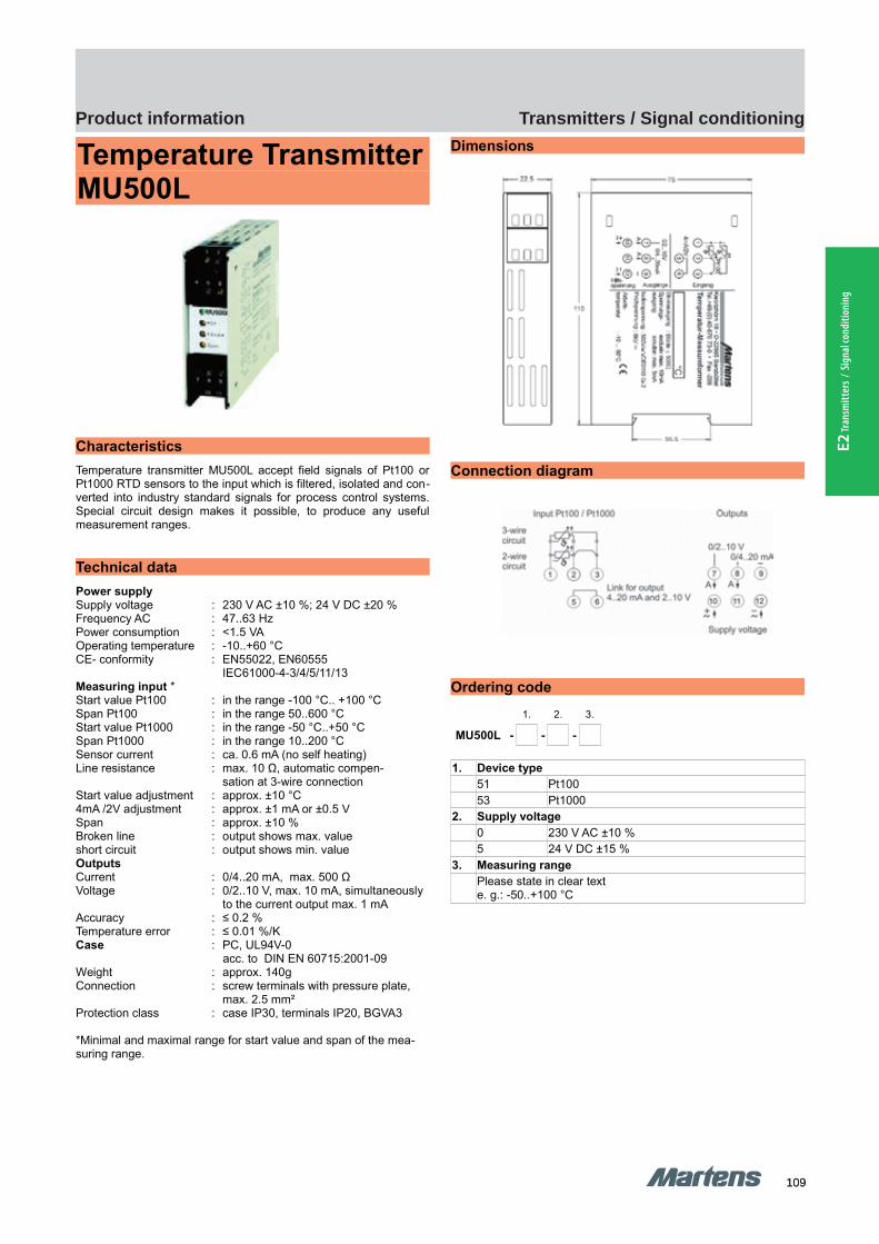
109109
Transmitters / Signal conditioningProduct information
E2 Tr
ansm
itter
s / S
igna
l con
ditio
ning
GHM Messtechnik GmbH – Location MartensKiebitzhörn 18 22885 Barsbüttel Germany Fon +49-40-670 73-0 Fax -288www.ghm-messtechnik.de [email protected]
Product Information Industrial Electronics
Temperature TransmitterMU500L
Characteristics
Temperature transmitter MU500L accept field signals of Pt100 orPt1000 RTD sensors to the input which is filtered, isolated and con-verted into industry standard signals for process control systems.Special circuit design makes it possible, to produce any usefulmeasurement ranges.
Technical data
Power supplySupply voltage : 230 V AC ±10 %; 24 V DC ±20 %Frequency AC : 47..63 HzPower consumption : <1.5 VAOperating temperature : -10..+60 °CCE- conformity : EN55022, EN60555
IEC61000-4-3/4/5/11/13Measuring input *Start value Pt100 : in the range -100 °C.. +100 °CSpan Pt100 : in the range 50..600 °CStart value Pt1000 : in the range -50 °C..+50 °CSpan Pt1000 : in the range 10..200 °CSensor current : ca. 0.6 mA (no self heating)Line resistance : max. 10 Ω, automatic compen-
sation at 3-wire connection Start value adjustment : approx. ±10 °C4mA /2V adjustment : approx. ±1 mA or ±0.5 VSpan : approx. ±10 %Broken line : output shows max. valueshort circuit : output shows min. valueOutputsCurrent : 0/4..20 mA, max. 500 ΩVoltage : 0/2..10 V, max. 10 mA, simultaneously
to the current output max. 1 mAAccuracy : ≤ 0.2 %Temperature error : ≤ 0.01 %/KCase : PC, UL94V-0
acc. to DIN EN 60715:2001-09Weight : approx. 140gConnection : screw terminals with pressure plate,
max. 2.5 mm²Protection class : case IP30, terminals IP20, BGVA3
*Minimal and maximal range for start value and span of the mea-suring range.
Dimensions
Connection diagram
Ordering code
1. 2. 3.
MU500L - - -
1. Device type
51 Pt10053 Pt1000
2. Supply voltage
0 230 V AC ±10 %5 24 V DC ±15 %
3. Measuring range
Please state in clear texte. g.: -50..+100 °C
12 pi-ma-Transmitter_E V1.00-00
MU500L MU500L
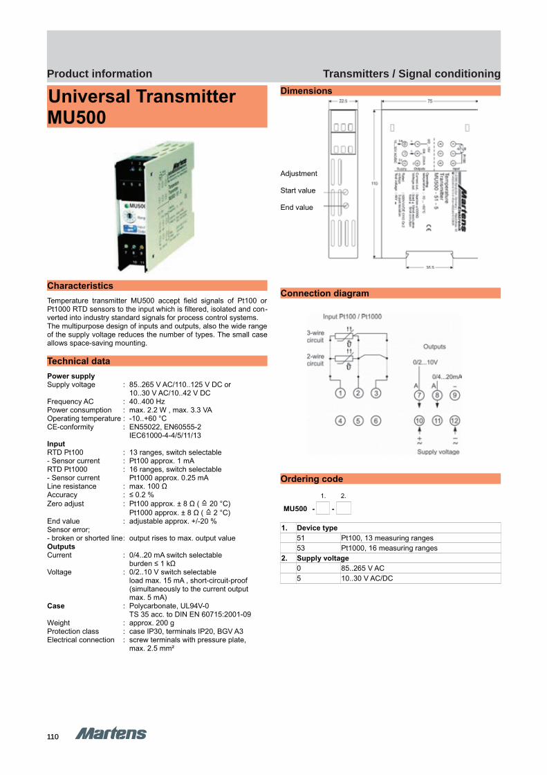
110110
Transmitters / Signal conditioningProduct information
GHM Messtechnik GmbH – Location MartensKiebitzhörn 18 22885 Barsbüttel Germany Fon +49-40-670 73-0 Fax -288www.ghm-messtechnik.de [email protected]
Product Information Industrial Electronics
Universal Transmitter MU500
Characteristics
Temperature transmitter MU500 accept field signals of Pt100 orPt1000 RTD sensors to the input which is filtered, isolated and con-verted into industry standard signals for process control systems.The multipurpose design of inputs and outputs, also the wide rangeof the supply voltage reduces the number of types. The small caseallows space-saving mounting.
Technical data
Power supplySupply voltage : 85..265 V AC/110..125 V DC or
10..30 V AC/10..42 V DCFrequency AC : 40..400 HzPower consumption : max. 2.2 W , max. 3.3 VAOperating temperature : -10..+60 °CCE-conformity : EN55022, EN60555-2
IEC61000-4-4/5/11/13Input RTD Pt100 : 13 ranges, switch selectable- Sensor current : Pt100 approx. 1 mARTD Pt1000 : 16 ranges, switch selectable- Sensor current Pt1000 approx. 0.25 mA Line resistance : max. 100 ΩAccuracy : ≤ 0.2 %Zero adjust : Pt100 approx. ± 8 Ω ( ≙ 20 °C)
Pt1000 approx. ± 8 Ω ( ≙ 2 °C)End value : adjustable approx. +/-20 %Sensor error; - broken or shorted line: output rises to max. output valueOutputsCurrent : 0/4..20 mA switch selectable
burden ≤ 1 kΩVoltage : 0/2..10 V switch selectable
load max. 15 mA , short-circuit-proof(simultaneously to the current output max. 5 mA)
Case : Polycarbonate, UL94V-0TS 35 acc. to DIN EN 60715:2001-09
Weight : approx. 200 gProtection class : case IP30, terminals IP20, BGV A3Electrical connection : screw terminals with pressure plate,
max. 2.5 mm²
Dimensions
Adjustment
Start value
End value
Connection diagram
Ordering code
1. 2.
MU500 - -
1. Device type
51 Pt100, 13 measuring ranges53 Pt1000, 16 measuring ranges
2. Supply voltage
0 85..265 V AC5 10..30 V AC/DC
pi-ma-Transmitter_E V1.00-00
13
MU500 MU500

111111
Transmitters / Signal conditioningProduct information
E2 Tr
ansm
itter
s / S
igna
l con
ditio
ning
GHM Messtechnik GmbH – Location MartensKiebitzhörn 18 22885 Barsbüttel Germany Fon +49-40-670 73-0 Fax -288www.ghm-messtechnik.de [email protected]
Product Information Industrial Electronics
Universal Transmitter MU500Ex
Characteristics
Temperature transmitters series MU500-Ex offer an intrinsicallysafe input and convert RTD sensor signals (Pt100 or Pt1000) intoindustry standard signals. The device includes a full 3-port isolation.
Technical data
Power supplySupply voltage : 85..253 V AC/110..125 V DC
10..30 V AC/DCFrequency AC : 40..400 HzPower consumption : < 3.3 VAOperating temperature : -10..+60 °CCE-conformity : ATEX directive 94/9/EG
EMC directive 2004/108/EGStandards : EN 60079-0:2013,
EN 60079-11:2012,EN 61326-1:2004-05
Explosion protectionApproval : TÜV 03 ATEX 2283, Marking : II (1) G [Ex ia Ga] IIC or
II (1) D [Ex ia Da] IIICU0 I0 P0 C0 L0
MU500Ex- … -51 : 1.3 V <3mA <3mW 29µF 100mHMU500Ex- … -53 : 4.9 V <3mA <3mW 2.2µF 100mHCi, Li : 5 nF, ca. 0 mH
The intrinsically safe circuit is galvanically separated from the non-intrinsically safe circuits up to a peak crest value of the voltage of 375 V.Measuring inputSensor current : Pt100 approx 1 mA,
Pt1000 approx. 0.25 mA Line resistance : max. 100 Ω, automatic compensation
with 3-wire connectionZero adjust : Pt100 approx. ± 8 Ω, ( ≙ 20 °C)
Pt1000 approx. ± 8 Ω ( ≙ 2 °C)End value : approx. +/-20 % adjustableSensor error : output rises to max. output
(voltage output >12V DCcurrent output > 25 mA)
OutputsCurrent : 0/4..20 mA DC switch selectable,
burden ≤ 1 kΩVoltage : 0/2..10 V DC switch selectable,
load max. 15 mA , short-circuit-proof(simultaneously with current output5 mA)
Rated voltage : 253 V AC or 125 V DC (Um) acc. to EN 60079-0
Accuracy : ≤ 0.2 % Case : Polycarbonate UL94V-0
TS 35 acc. to DIN EN 60715:2001-09Weight : approx. 200 gProtection class : case IP30, terminals IP20 (BGV A3)Connection : screw terminals with pressure plate
max. 2.5 mm²Mounting : installation in dry, clean and well
monitored areas
Dimensions
AdjustmentStart value End value
Connection diagram
Ordering code
1. 2. 3.
MU500Ex - - -
1. Device type
51 Pt100, 13 measuring ranges53 Pt1000, 16 measuring ranges
2. Supply voltage
0 85..253 V AC/110..125 V DC5 10..30 V AC/DC
3. Options
00 without option
14 pi-ma-Transmitter_E V1.00-00
MU500Ex MU500Ex
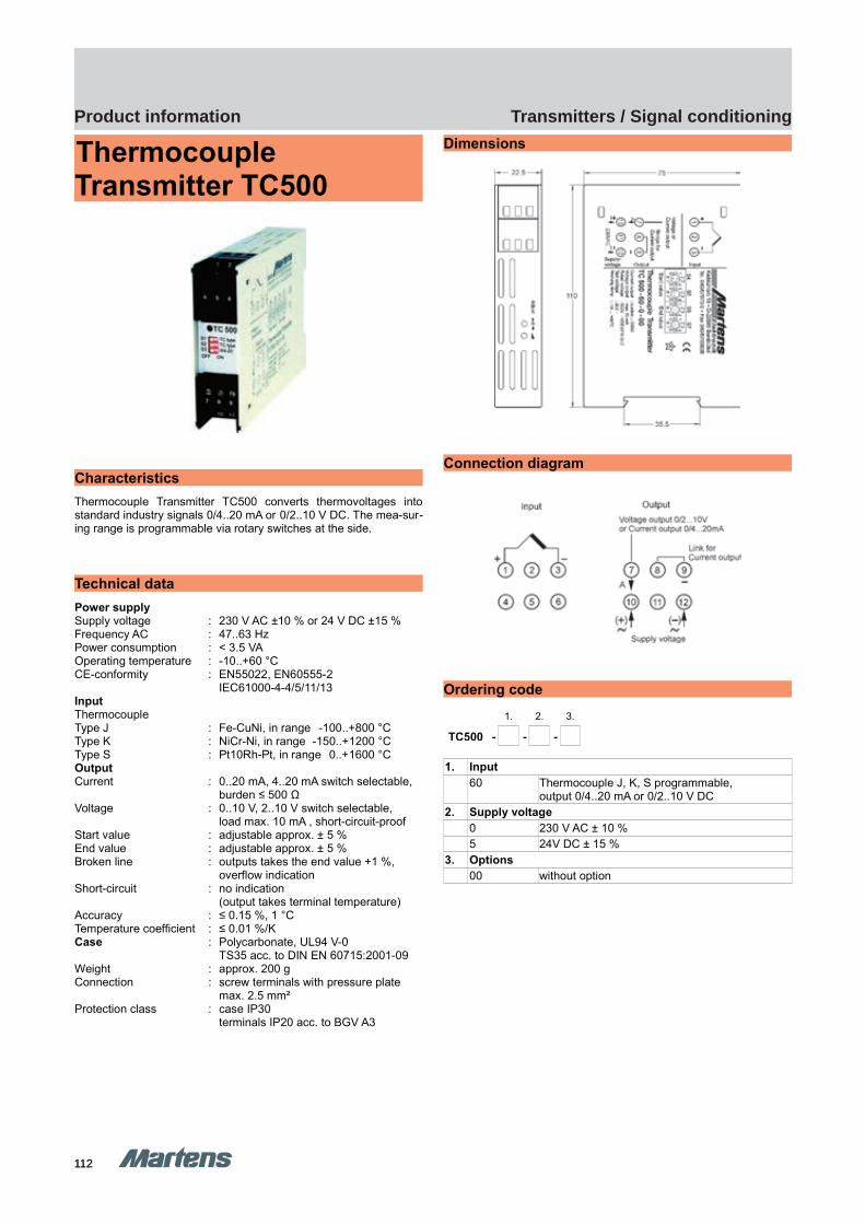
112112
Transmitters / Signal conditioningProduct information
GHM Messtechnik GmbH – Location MartensKiebitzhörn 18 22885 Barsbüttel Germany Fon +49-40-670 73-0 Fax -288www.ghm-messtechnik.de [email protected]
Product Information Industrial Electronics
Thermocouple Transmitter TC500
Characteristics
Thermocouple Transmitter TC500 converts thermovoltages intostandard industry signals 0/4..20 mA or 0/2..10 V DC. The mea-sur-ing range is programmable via rotary switches at the side.
Technical data
Power supplySupply voltage : 230 V AC ±10 % or 24 V DC ±15 %Frequency AC : 47..63 HzPower consumption : < 3.5 VAOperating temperature : -10..+60 °CCE-conformity : EN55022, EN60555-2
IEC61000-4-4/5/11/13InputThermocoupleType J : Fe-CuNi, in range -100..+800 °CType K : NiCr-Ni, in range -150..+1200 °CType S : Pt10Rh-Pt, in range 0..+1600 °COutputCurrent : 0..20 mA, 4..20 mA switch selectable,
burden ≤ 500 ΩVoltage : 0..10 V, 2..10 V switch selectable,
load max. 10 mA , short-circuit-proofStart value : adjustable approx. ± 5 %End value : adjustable approx. ± 5 %Broken line : outputs takes the end value +1 %,
overflow indicationShort-circuit : no indication
(output takes terminal temperature)Accuracy : ≤ 0.15 %, 1 °CTemperature coefficient : ≤ 0.01 %/KCase : Polycarbonate, UL94 V-0
TS35 acc. to DIN EN 60715:2001-09Weight : approx. 200 gConnection : screw terminals with pressure plate
max. 2.5 mm²Protection class : case IP30
terminals IP20 acc. to BGV A3
Dimensions
Connection diagram
Ordering code
1. 2. 3.
TC500 - - -
1. Input
60 Thermocouple J, K, S programmable,output 0/4..20 mA or 0/2..10 V DC
2. Supply voltage
0 230 V AC ± 10 %5 24V DC ± 15 %
3. Options
00 without option
pi-ma-Transmitter_E V1.00-00
15
TC500 TC500

113113
Transmitters / Signal conditioningProduct information
E2 Tr
ansm
itter
s / S
igna
l con
ditio
ning
GHM Messtechnik GmbH – Location MartensKiebitzhörn 18 22885 Barsbüttel Germany Fon +49-40-670 73-0 Fax -288www.ghm-messtechnik.de [email protected]
Product Information Industrial Electronics
Analog Frequency Transmitter AF500
Output frequency from 0..0.01Hz/20 kHz programmable Inputs for 0/4..20 mA, 0/2..10 V DC Teach-in programming for analog start- and
end value Outputs transistor and relay SPDT Power- and programming indicator via 2-color LED
Characteristics
Analog frequency transmitter AF500 converts standard industry sig-nals 0/4..20 mA or 0/2..10 V DC into a proportional frequency. Theoutput frequency is programmable with rotary switches at the caseside.
Technical data
Power supplySupply voltage : 230 V AC ±10 % or 24 V DC ±15 %Frequency : 47..63 HzPower consumption: < 3 VAOperating temperature : -10..+60 °CCE-conformity : EN 55022, EN 60555, IEC 61000-4-4/5/11/13InputCurrent : 0/4..20 mA, switch selectable - Ri : 51 ΩVoltage : 0/2..10 V DC, switch selectable - Ri : 20 kΩStart value : via software programmable 0..25 %End value : via software programmable -15..+10 %OutputTransistor : max. 30 V DC, load max. 30 mA- Frequency range : 0..0.01 Hz , 0..20 kHz duty cycle 0.5Relay SPDT : 250 V AC < 250 VA < 2 A,
100 V DC < 50 W < 1 A- Frequency range : 0..0.01 Hz, 0..9.9 Hz, duty cycle 0.5Accuracy : 0.1 % of the end valueCase : Polycarbonate, UL94V-0
TS 35 acc. to DIN EN 60715:2001-09Weight : approx. 140 gConnection : screw terminal, max. 2.5 mm²Protection class : case IP30,
terminals IP20 acc. to BGV A3
Dimensions
DIN rail mounting TS35
Connection diagrams
Ordering code
1. 2. 3.
AF500 - - -
1. Measuring range
10 0/4..20 mA, 0/2..10 V DC output frequency from 0..0.01 up to 20 kHz
2. Supply voltage
0 230 V AC ±10 %5 24 V DC ±15 %
3. Options
00 without option
16 pi-ma-Transmitter_E V1.00-00
AF500 AF500
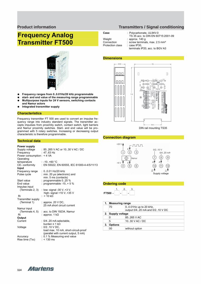
114114
Transmitters / Signal conditioningProduct information
GHM Messtechnik GmbH – Location MartensKiebitzhörn 18 22885 Barsbüttel Germany Fon +49-40-670 73-0 Fax -288www.ghm-messtechnik.de [email protected]
Product Information Industrial Electronics
Frequency AnalogTransmitter FT500
Frequency ranges from 0..0.01Hz/20 kHz programmable start- and end value of the measuring range programmable Multipurpose inputs for 24 V sensors, switching contacts
and Namur actors Integrated transmitter supply
Characteristics
Frequency transmitter FT 500 are used to convert an impulse fre-quency range into industry standard signals. The transmitter ac-cepts impulses from proximity switch, contact switch, light barriersand Namur proximity switches. Start- and end value will be pro-grammed with 5 rotary switches. Increasing or decreasing outputcharacteristic is therefore programmable.
Technical data
Power supplySupply voltage : 85..265 V AC or 10..30 V AC / DCFrequency : 47..63 HzPower consumption : < 4 VAOperatingtemperature : -10..+60 °CCE- conformity : EN 55022, EN 60555, IEC 61000-4-4/5/11/13InputFrequency range : 0..0.01 Hz/20 kHzPulse cycle : min. 20 μs (electronic) and
min. 5 ms (contacts)Start value : programmable 0..25 %End value : programmable -15..+ 5 %Impulse input
(Terminals 2, 3) : low- signal -30 V..+3 V, high- signal +10 V..+35 V
Ri : > 10 kΩTransmitter supply
(Terminal 1) : approx. 20 V DC, 25 mA short circuit current
Namur input (Terminals 4, 5) : acc. to DIN 19234, Namur
Ri : approx. 1 kΩOutputCurrent : 0/4..20 mA selectable,
burden ≤ 1 kΩVoltage : 0/2..10 V DC,
load max. 10 mA, short-circuit-proof(parallel with current output, 5 mA)
Accuracy : 0.1 % Measuring end valueRise time (T90) : < 130 ms
Case : Polycarbonate, UL94V-0TS 35 acc. to DIN EN 60715:2001-09
Weight : approx. 140 gConnection : screw terminals, max. 2.5 mm²Protection class : case IP30,
terminals IP20, acc. to BGV A3
Dimensions
DIN rail mounting TS35
Connection diagram
Ordering code
1. 2. 3.
FT500 - - -
1. Measuring range
70 0..0.01Hz up to 20 kHz,output 0/4..20 mA and 0/2..10 V DC
2. Supply voltage
0 85..265 V AC5 10..30 V AC / DC
3. Options
00 without option
pi-ma-Transmitter_E V1.00-00
17
Supply voltage
FT500 FT500
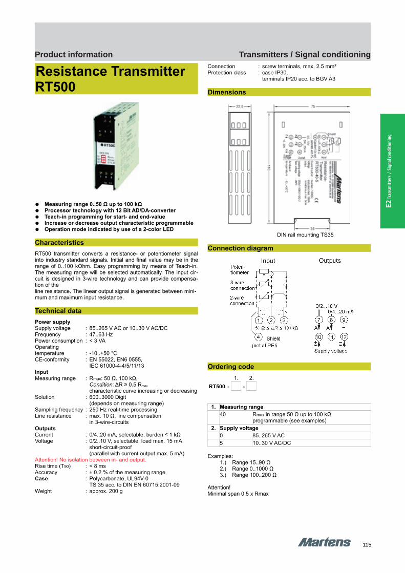
115115
Transmitters / Signal conditioningProduct information
E2 Tr
ansm
itter
s / S
igna
l con
ditio
ning
GHM Messtechnik GmbH – Location MartensKiebitzhörn 18 22885 Barsbüttel Germany Fon +49-40-670 73-0 Fax -288www.ghm-messtechnik.de [email protected]
Product Information Industrial Electronics
Resistance Transmitter RT500
Measuring range 0..50 Ω up to 100 kΩ Processor technology with 12 Bit AD/DA-converter Teach-in programming for start- and end-value Increase or decrease output characteristic programmable Operation mode indicated by use of a 2-color LED
Characteristics
RT500 transmitter converts a resistance- or potentiometer signalinto industry standard signals. Initial and final value may be in therange of 0..100 kOhm. Easy programming by means of Teach-in.The measuring range will be selected automatically. The input cir-cuit is designed in 3-wire technology and can provide compensa-tion of theline resistance. The linear output signal is generated between mini-mum and maximum input resistance.
Technical data
Power supplySupply voltage : 85..265 V AC or 10..30 V AC/DCFrequency : 47..63 HzPower consumption : < 3 VAOperatingtemperature : -10..+50 °CCE-conformity : EN 55022, EN6 0555,
IEC 61000-4-4/5/11/13InputMeasuring range : Rmax: 50 Ω..100 kΩ,
Condition: ΔR ≥ 0.5 Rmax
characteristic curve increasing or decreasingSolution : 600..3000 Digit
(depends on measuring range)Sampling frequency : 250 Hz real-time processingLine resistance : max. 10 Ω, line compensation in 3-wire-circuits OutputsCurrent : 0/4..20 mA, selectable, burden ≤ 1 kΩVoltage : 0/2..10 V, selectable, load max. 15 mA
short-circuit-proof(parallel with current output max. 5 mA)
Attention! No isolation between in- and output.Rise time (T90) : < 8 msAccuracy : ± 0.2 % of the measuring rangeCase : Polycarbonate, UL94V-0
TS 35 acc. to DIN EN 60715:2001-09Weight : approx. 200 g
Connection : screw terminals, max. 2.5 mm²Protection class : case IP30,
terminals IP20 acc. to BGV A3
Dimensions
DIN rail mounting TS35
Connection diagram
Ordering code
1. 2.
RT500 - -
1. Measuring range
40 Rmax in range 50 Ω up to 100 kΩ programmable (see examples)
2. Supply voltage
0 85..265 V AC5 10..30 V AC/DC
Examples:1.) Range 15..90 Ω2.) Range 0..1000 Ω3.) Range 100..200 Ω
Attention!Minimal span 0.5 x Rmax
18 pi-ma-Transmitter_E V1.00-00
RT500 RT500
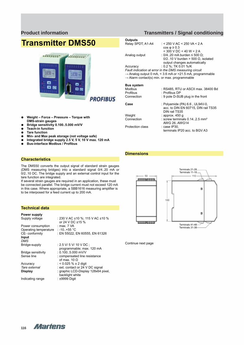
116116
Transmitters / Signal conditioningProduct information
GHM Messtechnik GmbH – Location MartensKiebitzhörn 18 22885 Barsbüttel Germany Fon +49-40-670 73-0 Fax -288www.ghm-messtechnik.de [email protected]
Product Information Industrial Electronics
Transmitter DMS50
Weight – Force – Pressure – Torque with DMS-strain gauges
Bridge sensitivity 0.100..5.000 mV/V Teach-in function Tare function Min- and Max peak storage (not voltage safe) Integrated bridge supply 2.5 V, 5 V, 10 V max. 120 mA Bus-interface Modbus / Profibus
Characteristics
The DMS50 converts the output signal of standard strain gauges(DMS measuring bridges) into a standard signal 0/4..20 mA or0/2..10 DC. The bridge supply and an external control input for thetare function are integrated.If several strain gauges are required in an application, these must be connected parallel. The bridge current must not exceed 120 mA in this case. Where appropriate, a SBB1616 measuring amplifier is to be interposed for a feed current up to 200 mA.
Technical data
Power supplySupply voltage : 230 V AC ±10 %; 115 V AC ±10 %
or 24 V DC ±15 %Power consumption : max. 7 VAOperating temperature : -10..+55 °CCE- conformity : EN 55022, EN 60555, EN 61326InputDMSBridge-supply : 2.5 V/ 5 V/ 10 V DC ;
programmable; max. 120 mABridge sensitivity : 0.100..5.000 mV/VSense line : compensated line resistance
of max. 10 ΩAccuracy : < 0.025 % ± 2 digitTare external : ext. contact or 24 V DC signalDisplay : graphic LCD-Display 128x64 pixel,
backlight whiteIndicating range : ±9999 Digit
OutputsRelay SPDT, A1-A4 : < 250 V AC < 250 VA < 2 A
cos φ ≥ 0.3< 300 V DC < 40 W < 2 A
Analog output : 0/4..20 mA burden ≤ 500 Ω;0/2..10 V burden > 500 Ω, isolatedoutput changes automatically
Accuracy : 0.2 %; TK 0.01 %/KFault indication at error in the DMS measuring circuit→ Analog output 0 mA, < 3.6 mA or >21.5 mA, programmable→ Alarm contact(s) min. or max. programmable
Bus systemModbus : RS485, RTU or ASCII max. 38400 BdProfibus : Profibus DPConnection : 9 pole D-SUB plug in the front
Case : Polyamide (PA) 6.6 , UL94V-0, acc. to DIN EN 60715, DIN rail TS35DIN rail TS35
Weight : approx. 450 gConnection : screw terminals 0.14..2.5 mm²
AWG 26..AWG14Protection class : case IP30,
terminals IP20 acc. to BGV A3
Dimensions
Continue next page
pi-ma-Transmitter_E V1.00-00
19
Terminals 21-28Terminals 11-18
Terminals 41-48Terminals 31-38
DMS50 DMS50
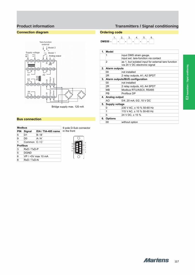
117117
Transmitters / Signal conditioningProduct information
E2 Tr
ansm
itter
s / S
igna
l con
ditio
ning
GHM Messtechnik GmbH – Location MartensKiebitzhörn 18 22885 Barsbüttel Germany Fon +49-40-670 73-0 Fax -288www.ghm-messtechnik.de [email protected]
Product Information Industrial Electronics
Connection diagram
Bridge supply max. 120 mA
Bus connection
Modbus
PIN Signal EIA / TIA-485 name
5 D1 B / B´9 D0 A / A´1 Common C / C´Profibus
3 RxD / TxD-P5 DGND6 VP / +5V max 10 mA8 RxD / TxD-N
Ordering code
1. 2. 3. 4. 5. 6.
DMS50 - - - - - -
1. Model
1 input DMS strain gauge,input ext. tare-function via contact
2 as 1, but isolated input for external tare function via 24 V DC electronic signal
2. Alarm outputs
00 not installed2R 2 relay outputs, A1, A2 SPDT
3. Alarm outputs/BUS configuration
00 not installed2R 2 relay outputs, A3, A4 SPDTMB Modbus RTU/ASCII, RS485PB Profibus DP
4. Analog output
AO 0/4..20 mA; 0/2..10 V DC5. Supply voltage
0 230 V AC, ± 10 % 50-60 Hz1 115 V AC, ± 10 % 50-60 Hz5 24 V DC, ± 15 %
6. Options
00 without option
20 pi-ma-Transmitter_E V1.00-00
9 pole D-Sub connectorin the front
Analog output
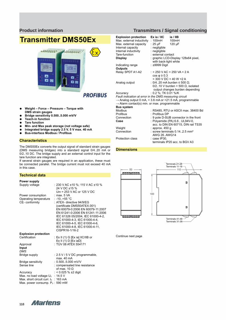
118118
Transmitters / Signal conditioningProduct information
GHM Messtechnik GmbH – Location MartensKiebitzhörn 18 22885 Barsbüttel Germany Fon +49-40-670 73-0 Fax -288www.ghm-messtechnik.de [email protected]
Product Information Industrial Electronics
Transmitter DMS50Ex
Weight – Force – Pressure – Torque with DMS strain gauges
Bridge sensitivity 0.500..5.000 mV/V Teach-in function Tare function Min- and Max peak storage (not voltage safe) Integrated bridge supply 2.5 V, 5 V max. 40 mA Bus-interface Modbus / Profibus
Characteristics
The DMS50Ex converts the output signal of standard strain gauges(DMS measuring bridges) into a standard signal 0/4..20 mA or0/2..10 DC. The bridge supply and an external control input for thetare function are integrated.If several strain gauges are required in an application, these mustbe connected parallel. The bridge current must not exceed 40 mAin this case.
Technical data
Power supplySupply voltage : 230 V AC ±10 %; 115 V AC ±10 %
24 V DC ±15 %Um = 253 V AC or 125 V DC
Power consumption : max. 5 VAOperating temperature : -10..+55 °CCE- conformity : ATEX- directive 94/9/EG
(certificate DMS50ATEX.001) EN 60079-0:2006 EN 60079-11:2007EN 61241-0:2006 EN 61241-11:2006IEC 61326 05/2004, IEC 61000-4-2,IEC 61000-4-3, IEC 61000-4-4, IEC 61000-4-5, IEC 61000-4-6, IEC 61000-4-8, IEC 61000-4-11,CISPR16-1/16-2
Explosion protectionCertification : Ex II (1) G [Ex ia] IIC/IIB or
Ex II (1) D [Ex iaD]Approval : TÜV 08 ATEX 554171InputDMSBridge supply : 2.5 V / 5 V DC programmable,
max. 40 mABridge sensitivity : 0.500..5.000 mV/VSense line : compensated line resistance
of max. 10 Ω Accuracy : < 0.025 % ±2 digitMax. no load voltage U0 : 14.5 VMax. short circuit curr. I0 : 163 mAMax. power consump. P0 : 590 mW
Explosion protection Ex ia / IIC ia / IIBMax. external inductivity : 100mH 100mHMax. external capacity : 25 μF 120 μFInternal capacity : negligibleInternal inductivity : negligibleTare-function : external contactDisplay : graphic LCD-Display 128x64 pixel,
with back-light whiteIndicating range : ±9999 DigitOutputsRelay SPDT A1-A2 : < 250 V AC < 250 VA < 2 A
cos φ ≥ 0.3< 300 V DC < 40 W <2 A
Analog output : 0/4..20 mA burden ≤ 500 Ω;0/2..10 V burden > 500 Ω, isolated output changes burden depending
Accuracy : 0.2 %; TK 0.01 %/KFault indication at error in the DMS measuring circuit→ Analog output 0 mA, < 3.6 mA or >21.5 mA, programmable→ Alarm contact(s) min. or max. programmableBus systemModbus : RS485, RTU or ASCII max. 38400 BdProfibus : Profibus DPConnection : 9 pole D-SUB connector in the frontCase : Polyamide (PA) 6.6 , UL94V-0,
acc. to DIN EN 60715, DIN rail TS35Weight : approx. 450 gConnection : screw terminals 0.14..2.5 mm²
AWG 26..AWG14Protection class : case IP30,
terminals IP20 acc. to BGV A3
Dimensions
Continue next page
pi-ma-Transmitter_E V1.00-00
21
Terminals 21-28Terminals 11-18
Terminals 41-48Terminals 31-38
DMS50Ex DMS50Ex
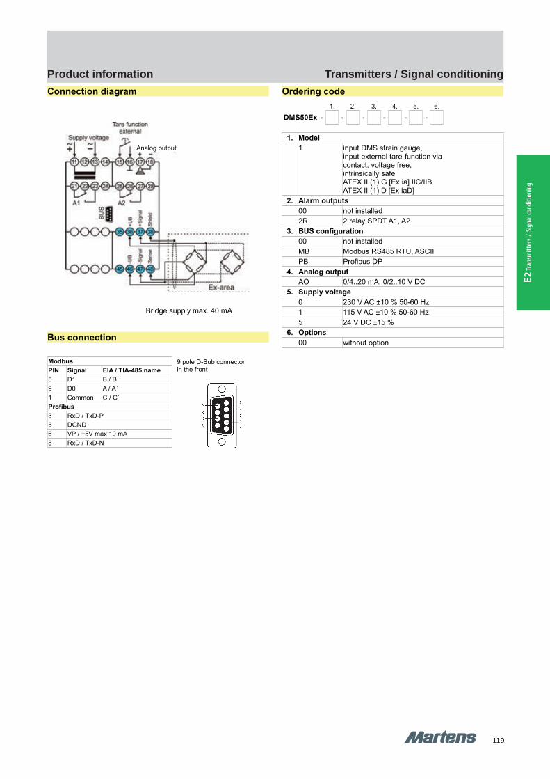
119119
Transmitters / Signal conditioningProduct information
E2 Tr
ansm
itter
s / S
igna
l con
ditio
ning
GHM Messtechnik GmbH – Location MartensKiebitzhörn 18 22885 Barsbüttel Germany Fon +49-40-670 73-0 Fax -288www.ghm-messtechnik.de [email protected]
Product Information Industrial Electronics
Connection diagram
Bridge supply max. 40 mA
Bus connection
Modbus
PIN Signal EIA / TIA-485 name
5 D1 B / B´9 D0 A / A´1 Common C / C´Profibus
3 RxD / TxD-P5 DGND6 VP / +5V max 10 mA8 RxD / TxD-N
Ordering code
1. 2. 3. 4. 5. 6.
DMS50Ex - - - - - -
1. Model
1 input DMS strain gauge,input external tare-function viacontact, voltage free,intrinsically safe ATEX II (1) G [Ex ia] IIC/IIBATEX II (1) D [Ex iaD]
2. Alarm outputs
00 not installed2R 2 relay SPDT A1, A2
3. BUS configuration
00 not installedMB Modbus RS485 RTU, ASCIIPB Profibus DP
4. Analog output
AO 0/4..20 mA; 0/2..10 V DC5. Supply voltage
0 230 V AC ±10 % 50-60 Hz1 115 V AC ±10 % 50-60 Hz5 24 V DC ±15 %
6. Options
00 without option
22 pi-ma-Transmitter_E V1.00-00
9 pole D-Sub connectorin the front
Analog output
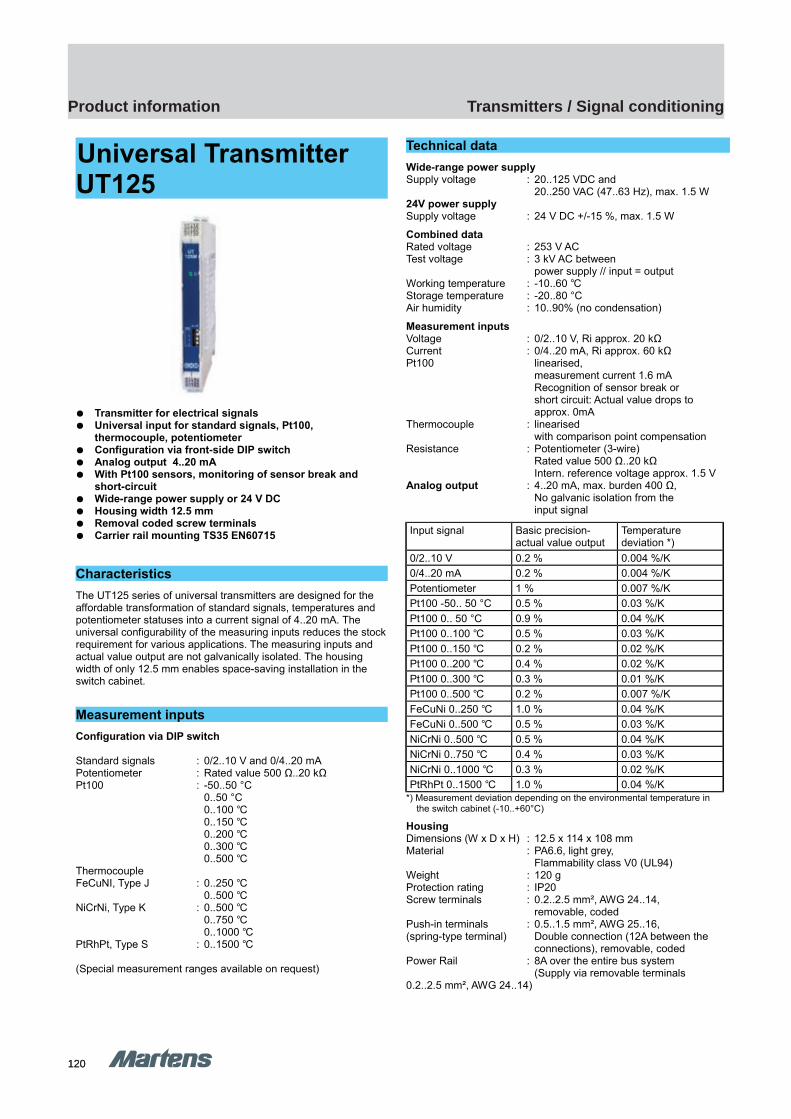
120120
Transmitters / Signal conditioningProduct information
GHM Messtechnik GmbH – MartensKiebitzhörn 18 22885 Barsbüttel Germany Phone +49-40-670 73-0 Fax -288www.ghm-messtechnik.de [email protected] e
Product Information Industrial Electronic
Universal Transmitter UT125
Transmitter for electrical signals Universal input for standard signals, Pt100,
thermocouple, potentiometer Configuration via front-side DIP switch Analog output 4..20 mA With Pt100 sensors, monitoring of sensor break and
short-circuit Wide-range power supply or 24 V DC Housing width 12.5 mm Removal coded screw terminals Carrier rail mounting TS35 EN60715
Characteristics
The UT125 series of universal transmitters are designed for the affordable transformation of standard signals, temperatures and potentiometer statuses into a current signal of 4..20 mA. The universal configurability of the measuring inputs reduces the stockrequirement for various applications. The measuring inputs and actual value output are not galvanically isolated. The housing width of only 12.5 mm enables space-saving installation in the switch cabinet.
Measurement inputs
Configuration via DIP switch
Standard signals : 0/2..10 V and 0/4..20 mA Potentiometer : Rated value 500 Ω..20 kΩPt100 : -50..50 °C
0..50 °C0..100 0..150 0..200 0..300 0..500
ThermocoupleFeCuNI, Type J : 0..250
0..500 NiCrNi, Type K : 0..500
0..750 0..1000
PtRhPt, Type S : 0..1500
(Special measurement ranges available on request)
Technical data
Wide-range power supplySupply voltage : 20..125 VDC and
20..250 VAC (47..63 Hz), max. 1.5 W24V power supplySupply voltage : 24 V DC +/-15 %, max. 1.5 W
Combined dataRated voltage : 253 V ACTest voltage : 3 kV AC between
power supply // input = outputWorking temperature : -10..60 Storage temperature : -20..80 °CAir humidity : 10..90% (no condensation)
Measurement inputs Voltage : 0/2..10 V, Ri approx. 20 kΩCurrent : 0/4..20 mA, Ri approx. 60 kΩPt100 linearised,
measurement current 1.6 mA Recognition of sensor break orshort circuit: Actual value drops toapprox. 0mA
Thermocouple : linearisedwith comparison point compensation
Resistance : Potentiometer (3-wire) Rated value 500 Ω..20 kΩIntern. reference voltage approx. 1.5 V
Analog output : 4..20 mA, max. burden 400 Ω,No galvanic isolation from theinput signal
Input signal Basic precision- actual value output
Temperature deviation *)
0/2..10 V 0.2 % 0.004 %/K
0/4..20 mA 0.2 % 0.004 %/K
Potentiometer 1 % 0.007 %/K
Pt100 -50.. 50 °C 0.5 % 0.03 %/K
Pt100 0.. 50 °C 0.9 % 0.04 %/K
Pt100 0..100 0.5 % 0.03 %/K
Pt100 0..150 0.2 % 0.02 %/K
Pt100 0..200 0.4 % 0.02 %/K
Pt100 0..300 0.3 % 0.01 %/K
Pt100 0..500 0.2 % 0.007 %/K
FeCuNi 0..250 1.0 % 0.04 %/K
FeCuNi 0..500 0.5 % 0.03 %/K
NiCrNi 0..500 0.5 % 0.04 %/K
NiCrNi 0..750 0.4 % 0.03 %/K
NiCrNi 0..1000 0.3 % 0.02 %/K
PtRhPt 0..1500 1.0 % 0.04 %/K*) Measurement deviation depending on the environmental temperature in the switch cabinet (-10..+60°C)
HousingDimensions (W x D x H) : 12.5 x 114 x 108 mm Material : PA6.6, light grey,
Flammability class V0 (UL94)Weight : 120 gProtection rating : IP20Screw terminals : 0.2..2.5 mm², AWG 24..14,
removable, codedPush-in terminals : 0.5..1.5 mm², AWG 25..16,(spring-type terminal) Double connection (12A between the
connections), removable, codedPower Rail : 8A over the entire bus system
(Supply via removable terminals 0.2..2.5 mm², AWG 24..14)
23
UT125 UT125

121121
Transmitters / Signal conditioningProduct information
E2 Tr
ansm
itter
s / S
igna
l con
ditio
ning
GHM Messtechnik GmbH – MartensKiebitzhörn 18 22885 Barsbüttel Germany Phone +49-40-670 73-0 Fax -288www.ghm-messtechnik.de [email protected] e
Product Information Industrial Electronic
Dimensions
Connection diagram
Power Rail
The power supply of multiple devices can be concentrated in themounting carrier rail (TS35 ) of a bus system.
An equivalent version is available for the entire series of GHMpower rail devices in 12.5 mm wide housing.
Ordering code
1. 2.
UT -
1. Device version
125L Supply voltage 24 V DC +/- 15 % 125LP Supply voltage 24 V DC +/- 15 %
with carrier rail bus connection *)
125M Wide-range power supply20..125 V DC / 20..253 V AC
2. Options
00 No options01 Push-in terminals (plug-in)
*) Supply including matching bus adapter piece; see also separate Power Rail information sheet
24
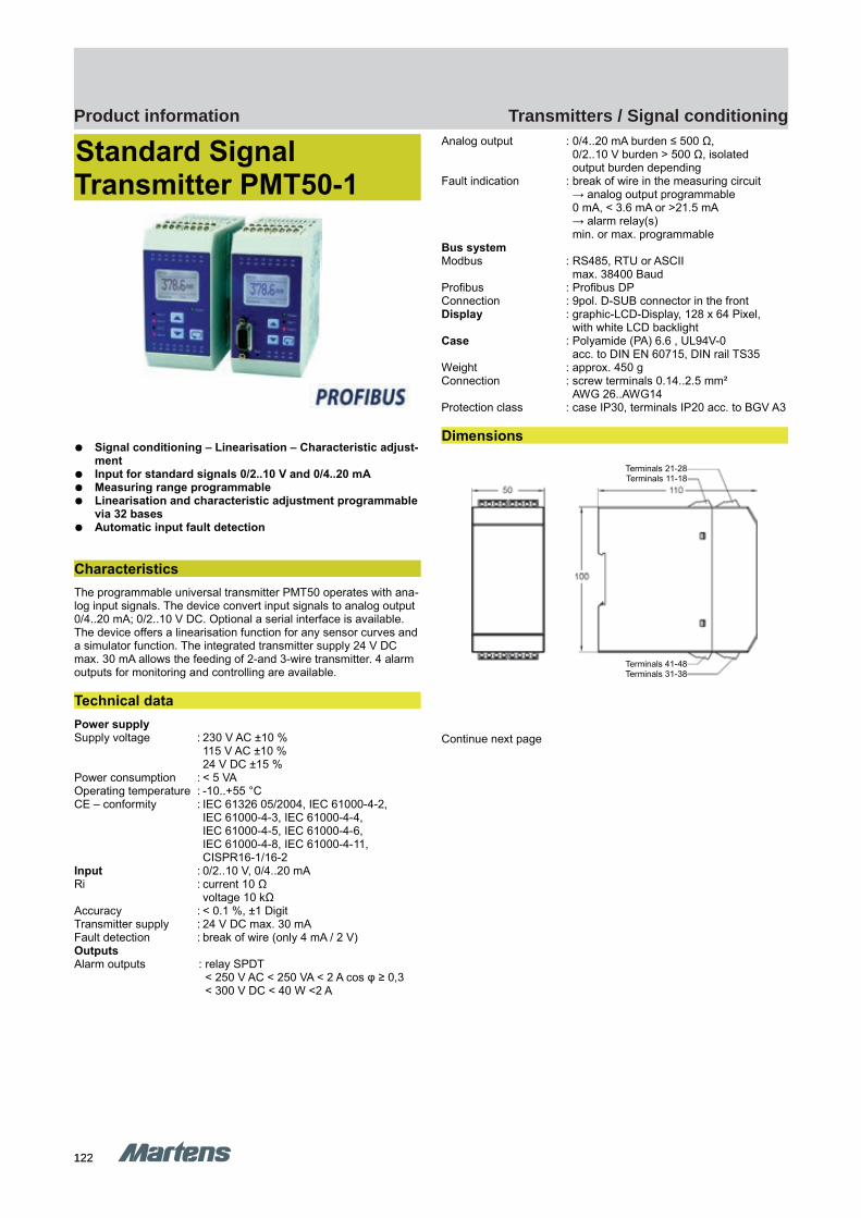
122122
Transmitters / Signal conditioningProduct information
GHM Messtechnik GmbH – Location MartensKiebitzhörn 18 22885 Barsbüttel Germany Fon +49-40-670 73-0 Fax -288www.ghm-messtechnik.de [email protected]
Product Information Industrial Electronics
Standard Signal Transmitter PMT50-1
Signal conditioning – Linearisation – Characteristic adjust-ment
Input for standard signals 0/2..10 V and 0/4..20 mA Measuring range programmable Linearisation and characteristic adjustment programmable
via 32 bases Automatic input fault detection
Characteristics
The programmable universal transmitter PMT50 operates with ana-log input signals. The device convert input signals to analog output 0/4..20 mA; 0/2..10 V DC. Optional a serial interface is available. The device offers a linearisation function for any sensor curves and a simulator function. The integrated transmitter supply 24 V DC max. 30 mA allows the feeding of 2-and 3-wire transmitter. 4 alarm outputs for monitoring and controlling are available.
Technical data
Power supplySupply voltage : 230 V AC ±10 %
115 V AC ±10 %24 V DC ±15 %
Power consumption : < 5 VAOperating temperature : -10..+55 °CCE – conformity : IEC 61326 05/2004, IEC 61000-4-2,
IEC 61000-4-3, IEC 61000-4-4, IEC 61000-4-5, IEC 61000-4-6, IEC 61000-4-8, IEC 61000-4-11,CISPR16-1/16-2
Input : 0/2..10 V, 0/4..20 mARi : current 10 Ω
voltage 10 kΩAccuracy : < 0.1 %, ±1 DigitTransmitter supply : 24 V DC max. 30 mAFault detection : break of wire (only 4 mA / 2 V)OutputsAlarm outputs : relay SPDT
< 250 V AC < 250 VA < 2 A cos φ ≥ 0,3< 300 V DC < 40 W <2 A
Analog output : 0/4..20 mA burden ≤ 500 Ω,0/2..10 V burden > 500 Ω, isolatedoutput burden depending
Fault indication : break of wire in the measuring circuit→ analog output programmable0 mA, < 3.6 mA or >21.5 mA → alarm relay(s) min. or max. programmable
Bus systemModbus : RS485, RTU or ASCII
max. 38400 BaudProfibus : Profibus DPConnection : 9pol. D-SUB connector in the frontDisplay : graphic-LCD-Display, 128 x 64 Pixel,
with white LCD backlightCase : Polyamide (PA) 6.6 , UL94V-0
acc. to DIN EN 60715, DIN rail TS35Weight : approx. 450 gConnection : screw terminals 0.14..2.5 mm²
AWG 26..AWG14Protection class : case IP30, terminals IP20 acc. to BGV A3
Dimensions
Continue next page
pi-ma-Transmitter_E V1.00-00
25
Terminals 21-28Terminals 11-18
Terminals 41-48Terminals 31-38
PMT50-1 PMT50-1
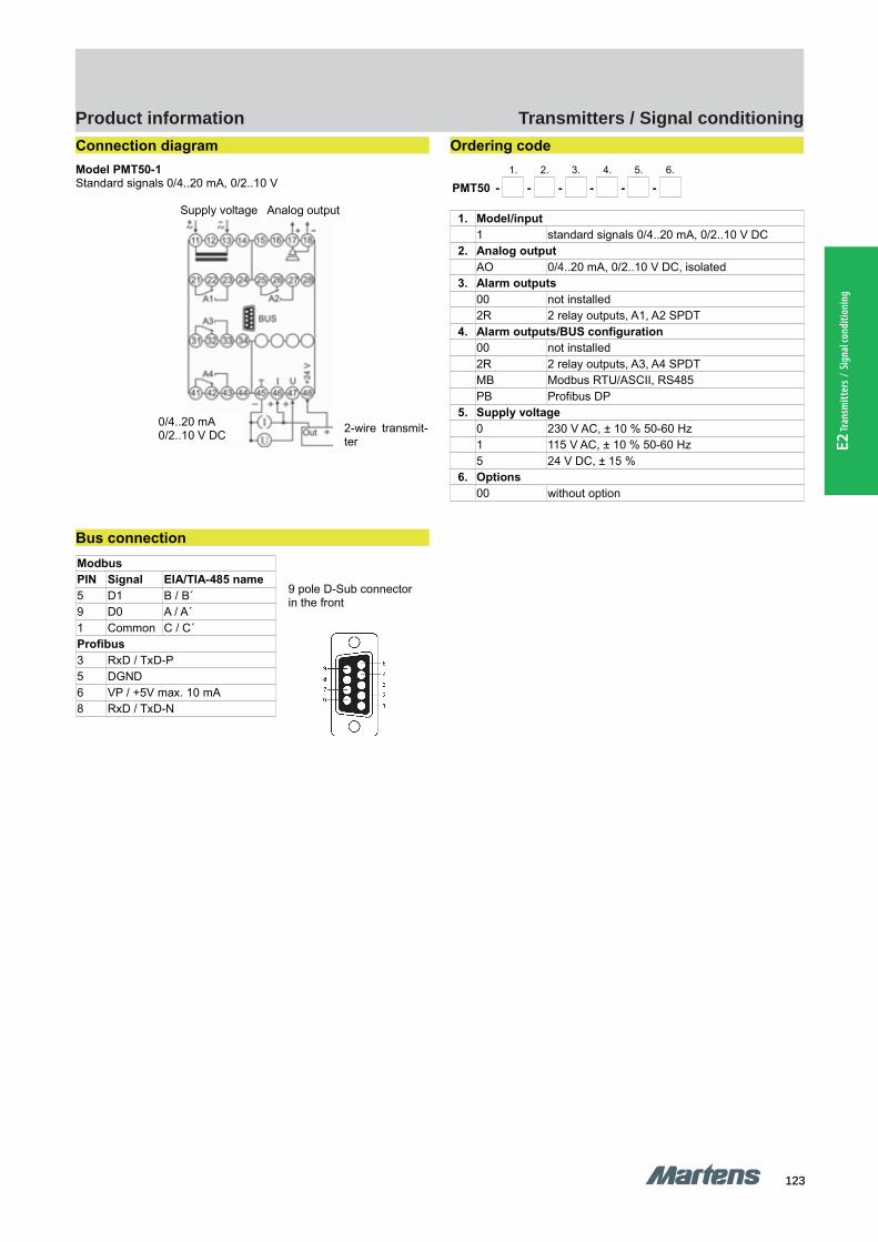
123123
Transmitters / Signal conditioningProduct information
E2 Tr
ansm
itter
s / S
igna
l con
ditio
ning
GHM Messtechnik GmbH – Location MartensKiebitzhörn 18 22885 Barsbüttel Germany Fon +49-40-670 73-0 Fax -288www.ghm-messtechnik.de [email protected]
Product Information Industrial Electronics
Connection diagram
Model PMT50-1Standard signals 0/4..20 mA, 0/2..10 V
Supply voltage Analog output
Bus connection
Modbus
PIN Signal EIA/TIA-485 name
5 D1 B / B´9 D0 A / A´1 Common C / C´Profibus
3 RxD / TxD-P5 DGND6 VP / +5V max. 10 mA8 RxD / TxD-N
Ordering code
1. 2. 3. 4. 5. 6.
PMT50 - - - - - -
1. Model/input
1 standard signals 0/4..20 mA, 0/2..10 V DC2. Analog output
AO 0/4..20 mA, 0/2..10 V DC, isolated3. Alarm outputs
00 not installed2R 2 relay outputs, A1, A2 SPDT
4. Alarm outputs/BUS configuration
00 not installed2R 2 relay outputs, A3, A4 SPDTMB Modbus RTU/ASCII, RS485PB Profibus DP
5. Supply voltage
0 230 V AC, ± 10 % 50-60 Hz1 115 V AC, ± 10 % 50-60 Hz5 24 V DC, ± 15 %
6. Options
00 without option
26 pi-ma-Transmitter_E V1.00-00
9 pole D-Sub connectorin the front
0/4..20 mA0/2..10 V DC
2-wire transmit-ter

124124
Transmitters / Signal conditioningProduct information
GHM Messtechnik GmbH – Location MartensKiebitzhörn 18 22885 Barsbüttel Germany Fon +49-40-670 73-0 Fax -288www.ghm-messtechnik.de [email protected]
Product Information Industrial Electronics
Standard Signal Transmitter PMT50Ex-1
Signal conditioning – Linearisation – Characteristic adjust-ment
Input for standard signals 0/2..10 V and 0/4..20 mA Measuring range programmable Linearisation and characteristic adjustment programmable
via 32 bases Automatic input fault detection
Characteristics
The programmable universal transmitter PMT50Ex operates withanalog input signals. The device convert input signals to an analogoutput 0/4..20 mA; 0/2..10 V DC. Optional a serial interface is avail-able. The device offers a linearisation function for any sensorcurves and a simulator function. The integrated transmitter supply16 V DC max. 20 mA allows the feeding of 2- and 3-wire transmit-ter. 2 alarm outputs for monitoring and controlling are available.
Technical data
Power supplySupply voltage : 230 V AC ±10 %
115 V AC ±10 %24 V DC ±15 %Um = 253 V AC and 125 V DC(terminals 11, 13)
Power consumption : < 5 VAOperating temperature : -10..+55 °CCE-conformity : ATEX-directive 94/9/EG
(certificate PMT50ATEX.001) EN 60079-0:2006 EN 60079-11:2007EN 61241-0:2006 EN 61241-11:2006IEC 61326 05/2004, IEC 61000-4-2,IEC 61000-4-3, IEC 61000-4-4, IEC 61000-4-5, IEC 61000-4-6, IEC 61000-4-8, IEC 61000-4-11,CISPR16-1/16-2
Explosion protectionMarking : II (1) G [Ex ia] IIC/IIB or II (1) D
[Ex iaD]Approval : TÜV 08 ATEX 554329
Input : 0/2..10 V DC, 0/4..20 mAFault detection : broken line in the measuring circuitRi : current 10 Ω
voltage 10 kΩ(terminals 45, 46, 47)
Accuracy : < 0.1 %, ±1 DigitMax. U0 no load : 18.9 VMax. I0 short circuit : 92.5 mAMax. output power P0 : 580 mWResistance : 272 ΩCharacteristic curve : trapezoidalInternal inductivity : 4 μHInternal capacity : 1.2 nFTransmitter supply : 16 V DC, max. 20 mA
(terminals 48)Explosion protection Ex ia/IIC or ia/IIC ia/IIBMax. external inductivity : 2,3 mH 0,1 mH 5 mHMax. external capacity : 0,12 μF 0,22 μF 0,76 μFMax. values Ui : 30 V Ii : 52 mA Pi : 980 mWOutputsAlarm outputs : relay SPDT
< 250 V AC < 250 VA < 2 A cos φ ≥ 0,3< 300 V DC < 40 W <2 A(terminals 21, 22, 23; 25, 26, 27)
Analog output : 0/4..20 mA burden ≤ 500 Ω0/2..10 V burden > 500 Ω isolatedoutput changes burden depending
Accuracy : 0.2 %; TK 0.01 %/K(terminals 17, 18)
Fault indicating : break of wire in the measuring circuit→ analog output programmable0 mA, < 3.6 mA or >21.5 mA → alarm relay(s) min. or max. programmable
Bus systemModbus : RS485, RTU or ASCII
max. 38400 Baud Profibus : Profibus DPConnection : 9pol. D-SUB connector in the frontDisplay : graphic-LCD-Display, 128 x 64 Pixel
with white back-lightCase : Polyamide (PA) 6.6, UL94V-0
Weight : approx. 450 gConnection : screw clamps 0.14..2.5 mm² AWG 26..AWG14Protection class : case IP30, terminals IP20 acc. to
BGV A3
Continue next page
pi-ma-Transmitter_E V1.00-00
27
PMT50Ex-1 PMT50Ex-1
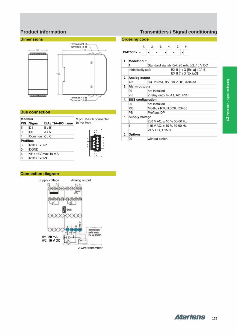
125125
Transmitters / Signal conditioningProduct information
E2 Tr
ansm
itter
s / S
igna
l con
ditio
ning
GHM Messtechnik GmbH – Location MartensKiebitzhörn 18 22885 Barsbüttel Germany Fon +49-40-670 73-0 Fax -288www.ghm-messtechnik.de [email protected]
Product Information Industrial Electronics
Dimensions
Bus connection
Modbus
PIN Signal EIA / TIA-485 name
5 D1 B / B´9 D0 A / A´1 Common C / C´Profibus
3 RxD / TxD-P5 DGND6 VP / +5V max 10 mA8 RxD / TxD-N
Connection diagram
Supply voltage Analog output
Ordering code
1. 2. 3. 4. 5. 6.
PMT50Ex - - - - - -
1. Model/input
1 Standard signals 0/4..20 mA, 0/2..10 V DCIntrinsically safe EX II (1) G [Ex ia] IIC/IIB
EX II (1) D [Ex iaD]2. Analog output
AO 0/4..20 mA, 0/2..10 V DC, isolated3. Alarm outputs
00 not installed2R 2 relay outputs, A1, A2 SPDT
4. BUS configuration
00 not installedMB Modbus RTU/ASCII, RS485PB Profibus DP
5. Supply voltage
0 230 V AC, ± 10 % 50-60 Hz1 115 V AC, ± 10 % 50-60 Hz5 24 V DC, ± 15 %
6. Options
00 without option
28 pi-ma-Transmitter_E V1.00-00
9 pol. D-Sub connecterin the front
0/4..20 mA0/2..10 V DC
2-wire transmitter
Terminals 21-28Terminals 11-18
Terminals 41-48Terminals 31-38
0/4..20 mA0/2..10 V DC

126126
Transmitters / Signal conditioningProduct information
GHM Messtechnik GmbH – Location MartensKiebitzhörn 18 22885 Barsbüttel Germany Fon +49-40-670 73-0 Fax -288www.ghm-messtechnik.de [email protected]
Product Information Industrial Electronics
Temperature TransmitterPMT50-2 /-3
Signal conditioning – linearisation – output characteristic trans-formation
Input for resistance and Potentiometer or RTD Pt100/Pt1000 and thermocouples
Measuring range programmable Linearisation or transformation of output characteristic
via 32 base-points programmable Automatic fault detection in the measuring circuit
Characteristics
The programmable universal transmitter PMT50 operates with ana-log input signals. The device convert input signals to analog output0/4..20 mA; 0/2..10 V DC. Optional a serial interface is available.The device offers a linearisation function for any sensor curves anda simulator function. The integrated transmitter supply 24 V DCmax. 30 mA allows the feeding of 2-and 3-wire sensors. 4 alarmoutputs for monitoring and controlling are available.
Technical data
Power supplySupply voltage : 230 V AC ±10 %
115 V AC ±10 %24 V DC ±15 %
Power consumption : < 5 VAOperating temperature : -10..+55 °CCE – conformity : IEC61326 05/2004, IEC 61000-4-2,
IEC 61000-4-3, IEC 61000-4-4, IEC 61000-4-5, IEC 61000-4-6, IEC 61000-4-8, IEC 61000-4-11,CISPR16-1/16-2
InputsFault detection : type -2: (only resistance measurement)
broken line;type -3: broken line (Pt100 / Pt1000,TC) and short circuit (only Pt100 / Pt1000)
Device type 2Input : resistance 0..100 kΩ,
potentiometer min.1 kΩ.. max. 100 kΩAccuracy : < 0.2 %, ±1 Digit
Device type 3Input : Pt100 (3-wire) -100.0..+600.0 °C
Pt1000 (3-wire) -100.0..+300.0 °C: Thermocouple (TC)type J -100.0..+800.0 °C type K -150..+1200 °Ctype N -150..+1200 °Ctype S -50..+1600 °C
Accuracy : < 0.1 %, ±1 DigitOutputsAlarm outputs : relay SPDT
< 250 V AC < 250 VA < 2 A cos Phi ≥ 0.3< 300 V DC < 40 W <2 A
Analog output : 0/4..20 mA burden ≤ 500 Ω,0/2..10 V burden > 500 Ω isolatedoutput changes automatically (burden depending)
Fault indication : for broken line or short circuit detection→ analog output (programmable)0 mA, < 3.6 mA or >21.5 mA → Alarm relays min. or max. programmable
Bus systemModbus : RS485, RTU or ASCII
max. 38400 BaudProfibus : Profibus DPConnection : 9 pole D-SUB plug in the frontDisplay : Graphic-LCD-Display
128 x 64 Pixel, with white LCD backlit
Case : Polyamide (PA) 6.6 , UL94V-0 TS35 acc. to DIN EN 60715:2001-09
Weight : approx. 450 gConnection : screw terminals 0.14..2.5 mm²
AWG 26..AWG14Protection class : case IP30, terminals IP20 acc. to
BGV A3
Dimensions
continue next page
pi-ma-Transmitter_E V1.00-00
29
Terminals 21-28Terminals 11-18
Terminals 41-48Terminals 31-38
PMT50-2/-3 PMT50-2/-3
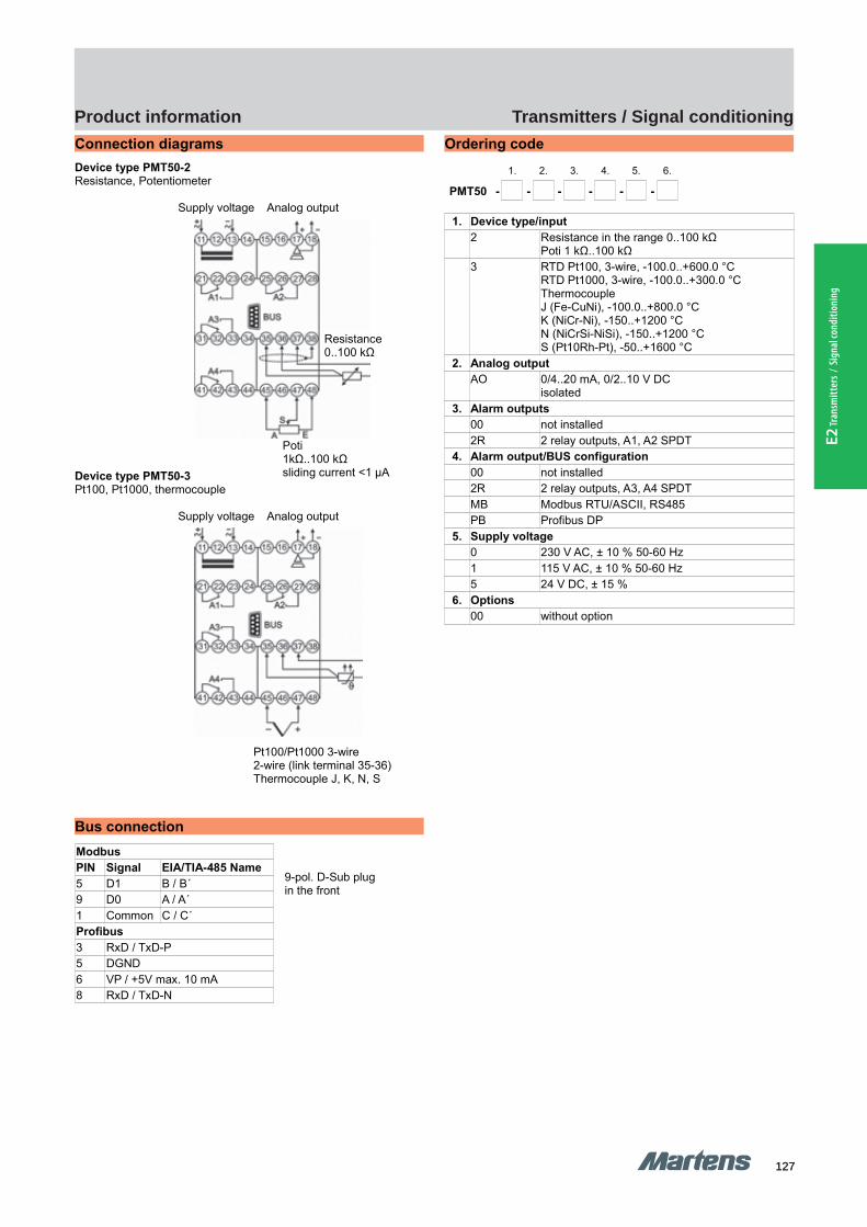
127127
Transmitters / Signal conditioningProduct information
E2 Tr
ansm
itter
s / S
igna
l con
ditio
ning
GHM Messtechnik GmbH – Location MartensKiebitzhörn 18 22885 Barsbüttel Germany Fon +49-40-670 73-0 Fax -288www.ghm-messtechnik.de [email protected]
Product Information Industrial Electronics
Connection diagrams
Device type PMT50-2Resistance, Potentiometer
Supply voltage Analog output
Device type PMT50-3Pt100, Pt1000, thermocouple
Supply voltage Analog output
Bus connection
Modbus
PIN Signal EIA/TIA-485 Name
5 D1 B / B´9 D0 A / A´1 Common C / C´Profibus
3 RxD / TxD-P5 DGND6 VP / +5V max. 10 mA8 RxD / TxD-N
Ordering code
1. 2. 3. 4. 5. 6.
PMT50 - - - - - -
1. Device type/input
2 Resistance in the range 0..100 kΩPoti 1 kΩ..100 kΩ
3 RTD Pt100, 3-wire, -100.0..+600.0 °CRTD Pt1000, 3-wire, -100.0..+300.0 °CThermocoupleJ (Fe-CuNi), -100.0..+800.0 °CK (NiCr-Ni), -150..+1200 °CN (NiCrSi-NiSi), -150..+1200 °CS (Pt10Rh-Pt), -50..+1600 °C
2. Analog output
AO 0/4..20 mA, 0/2..10 V DCisolated
3. Alarm outputs
00 not installed2R 2 relay outputs, A1, A2 SPDT
4. Alarm output/BUS configuration
00 not installed2R 2 relay outputs, A3, A4 SPDTMB Modbus RTU/ASCII, RS485PB Profibus DP
5. Supply voltage
0 230 V AC, ± 10 % 50-60 Hz1 115 V AC, ± 10 % 50-60 Hz5 24 V DC, ± 15 %
6. Options
00 without option
30 pi-ma-Transmitter_E V1.00-00
9-pol. D-Sub plugin the front
Resistance 0..100 kΩ
Poti1kΩ..100 kΩsliding current <1 µA
Pt100/Pt1000 3-wire 2-wire (link terminal 35-36)Thermocouple J, K, N, S
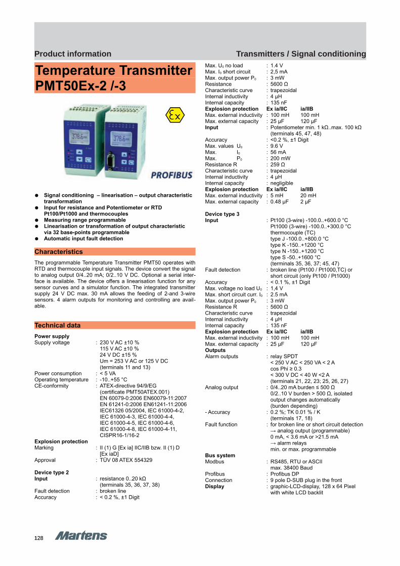
128128
Transmitters / Signal conditioningProduct information
GHM Messtechnik GmbH – Location MartensKiebitzhörn 18 22885 Barsbüttel Germany Fon +49-40-670 73-0 Fax -288www.ghm-messtechnik.de [email protected]
Product Information Industrial Electronics
Temperature TransmitterPMT50Ex-2 /-3
Signal conditioning – linearisation – output characteristic transformation
Input for resistance and Potentiometer or RTD Pt100/Pt1000 and thermocouples
Measuring range programmable Linearisation or transformation of output characteristic
via 32 base-points programmable Automatic input fault detection
Characteristics
The programmable Temperature Transmitter PMT50 operates withRTD and thermocouple input signals. The device convert the signalto analog output 0/4..20 mA; 0/2..10 V DC. Optional a serial inter-face is available. The device offers a linearisation function for anysensor curves and a simulator function. The integrated transmittersupply 24 V DC max. 30 mA allows the feeding of 2-and 3-wiresensors. 4 alarm outputs for monitoring and controlling are avail-able.
Technical data
Power supplySupply voltage : 230 V AC ±10 %
115 V AC ±10 %24 V DC ±15 %Um = 253 V AC or 125 V DC(terminals 11 and 13)
Power consumption : < 5 VAOperating temperature : -10..+55 °CCE-conformity : ATEX-directive 94/9/EG
(certificate PMT50ATEX.001) EN 60079-0:2006 EN60079-11:2007EN 61241-0:2006 EN61241-11:2006IEC61326 05/2004, IEC 61000-4-2,IEC 61000-4-3, IEC 61000-4-4, IEC 61000-4-5, IEC 61000-4-6, IEC 61000-4-8, IEC 61000-4-11,CISPR16-1/16-2
Explosion protectionMarking : II (1) G [Ex ia] IIC/IIB bzw. II (1) D
[Ex iaD]Approval : TÜV 08 ATEX 554329
Device type 2Input : resistance 0..20 kΩ
(terminals 35, 36, 37, 38)Fault detection : broken lineAccuracy : < 0.2 %, ±1 Digit
Max. U0 no load : 1.4 VMax. I0 short circuit : 2,5 mAMax. output power P0 : 3 mWResistance : 5600 ΩCharacteristic curve : trapezoidalInternal inductivity : 4 μHInternal capacity : 135 nFExplosion protection Ex ia/IIC ia/IIBMax. external inductivity : 100 mH 100 mHMax. external capacity : 25 μF 120 μFInput : Potentiometer min. 1 kΩ..max. 100 kΩ
(terminals 45, 47, 48)Accuracy : <0.2 %, ±1 DigitMax. values U0 : 9.6 VMax. I0 : 56 mAMax. P0 : 200 mWResistance R : 259 ΩCharacteristic curve : trapezoidalInternal inductivity : 4 μHInternal capacity : negligibleExplosion protection Ex ia/IIC ia/IIBMax. external inductivity : 5 mH 20 mHMax. external capacity : 0.48 μF 2 μF
Device type 3Input : Pt100 (3-wire) -100.0..+600.0 °C
Pt1000 (3-wire) -100.0..+300.0 °Cthermocouple (TC)type J -100.0..+800.0 °Ctype K -150..+1200 °Ctype N -150..+1200 °Ctype S -50..+1600 °C(terminals 35, 36, 37; 45, 47)
Fault detection : broken line (Pt100 / Pt1000,TC) orshort circuit (only Pt100 / Pt1000)
Accuracy : < 0.1 %, ±1 DigitMax. voltage no load U0 : 1,4 VMax. short circuit curr. I0 : 2.5 mAMax. output power P0 : 3 mWResistance R : 5600 ΩCharacteristic curve : trapezoidalInternal inductivity : 4 μHInternal capacity : 135 nFExplosion protection Ex ia/IIC ia/IIBMax. external inductivity : 100 mH 100 mHMax. external capacity : 25 μF 120 μFOutputsAlarm outputs : relay SPDT
< 250 V AC < 250 VA < 2 A cos Phi ≥ 0.3< 300 V DC < 40 W <2 A(terminals 21, 22, 23; 25, 26, 27)
Analog output : 0/4..20 mA burden ≤ 500 Ω0/2..10 V burden > 500 Ω, isolatedoutput changes automatically (burden depending)
- Accuracy : 0.2 %; TK 0.01 % / K(terminals 17, 18)
Fault function : for broken line or short circuit detection→ analog output (programmable)0 mA, < 3.6 mA or >21.5 mA → alarm relays min. or max. programmable
Bus systemModbus : RS485, RTU or ASCII
max. 38400 Baud Profibus : Profibus DPConnection : 9 pole D-SUB plug in the frontDisplay : graphic-LCD-display, 128 x 64 Pixel
with white LCD backlit
pi-ma-Transmitter_E V1.00-00
31
PMT50Ex-2/-3 PMT50Ex-2/-3

129129
Transmitters / Signal conditioningProduct information
E2 Tr
ansm
itter
s / S
igna
l con
ditio
ning
GHM Messtechnik GmbH – Location MartensKiebitzhörn 18 22885 Barsbüttel Germany Fon +49-40-670 73-0 Fax -288www.ghm-messtechnik.de [email protected]
Product Information Industrial Electronics
Case : Polyamide (PA) 6.6, UL94V-0TS35 acc. to DIN EN 60715:2001-09
Weight : approx. 450 gConnection : screw terminals 0.14..2.5 mm² AWG 26..AWG14Protection class : case IP30, terminals IP20 acc. to
BGV A3
Dimensions
Bus connection
Modbus
PIN Signal EIA / TIA-485 Name
5 D1 B / B´9 D0 A / A´1 Common C / C´Profibus
3 RxD / TxD-P5 DGND6 VP / +5V max. 10 mA8 RxD / TxD-N
Connection diagram
Ordering code
1. 2. 3. 4. 5. 6.
PMT50Ex - - - - - -
1. Device type/input
2 Resistance in the range 0..20 kΩPoti 1 kΩ..100 kΩ
3 RTD Pt100, 3-wire, -100.0..+600.0 °CRTD Pt1000, 3-wire, -100.0..+300.0 °CThermocoupleJ (Fe-CuNi), -100.0..+800.0 °CK (NiCr-Ni), -150..+1200 °CN (NiCrSi-NiSi), -150..+1200 °CS (Pt10Rh-Pt), -50..+1600 °C
Inputs intrinsically safe EX II (1) G [Ex ia] IIC/IIBEX II (1) D [Ex iaD]
2. Analog output
AO 0/4..20 mA, 0/2..10 V DCisolated
3. Alarm outputs
00 not installed2R 2 relay outputs, A1, A2 SPDT
4. BUS configuration
00 not installedMB Modbus RTU/ASCII, RS485PB Profibus DP
5. Supply voltage
0 230 V AC, ± 10 % 50-60 Hz1 115 V AC, ± 10 % 50-60 Hz5 24 V DC, ± 15 %
6. Options
00 without option
32 pi-ma-Transmitter_E V1.00-00
9 pol. D-Sub plugin the front
Terminals 21-28Terminals 11-18
Terminals 41-48Terminals 31-38

130
E Industrial electronic
131
E3 Is
olat
ing c
onve
rter
Kapitel E3 Start
Isolating converter
Devices for rail systems
E3
Page
132
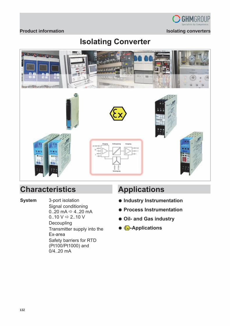
Einleitung
GHM Messtechnik GmbH – Sales Center InternationalSchloßstraße 6 88453 Erolzheim Germany Fon +49-7354-937233-0 Fax -88www.ghm-messtechnik.de [email protected]
Product Information Industrial Electronics
Isolating Converter
CharacteristicsSystem 3-port isolation
Signal conditioning0..20 mA 4..20 mA0..10 V 2..10 VDecouplingTransmitter supply into theEx-areaSafety barriers for RTD (Pt100/Pt1000) and 0/4..20 mA
Applications Industry Instrumentation
Process Instrumentation
Oil- and Gas industry
-Applications
pi-ma-Isolating_converter_E V2.01-00
1132132
Isolating convertersProduct information
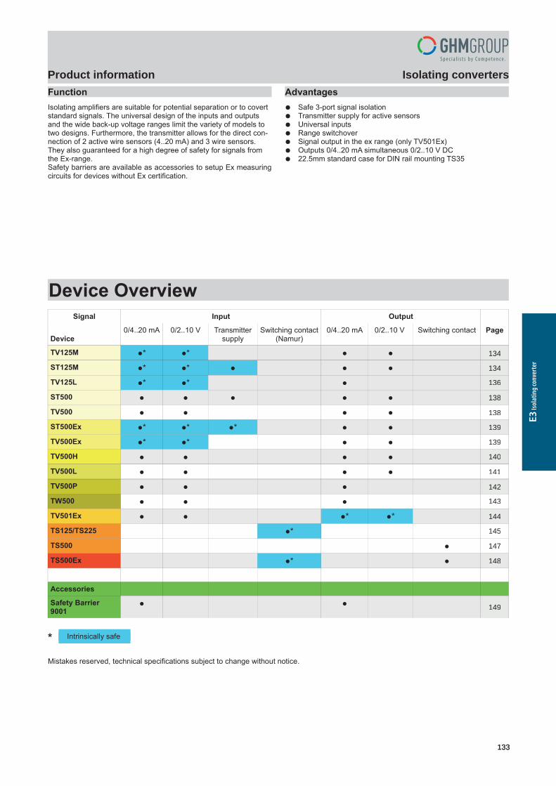
GHM Messtechnik GmbH – Sales Center InternationalSchloßstraße 6 88453 Erolzheim Germany Fon +49-7354-937233-0 Fax -88www.ghm-messtechnik.de [email protected]
Product Information Industrial ElectronicsFunctionIsolating amplifiers are suitable for potential separation or to covert standard signals. The universal design of the inputs and outputs and the wide back-up voltage ranges limit the variety of models to two designs. Furthermore, the transmitter allows for the direct con-nection of 2 active wire sensors (4..20 mA) and 3 wire sensors. They also guaranteed for a high degree of safety for signals from the Ex-range.Safety barriers are available as accessories to setup Ex measuringcircuits for devices without Ex certification.
Advantages Safe 3-port signal isolation Transmitter supply for active sensors Universal inputs Range switchover Signal output in the ex range (only TV501Ex) Outputs 0/4..20 mA simultaneous 0/2..10 V DC 22.5mm standard case for DIN rail mounting TS35
Device OverviewSignal Input Output
Device0/4..20 mA 0/2..10 V Transmitter
supplySwitching contact
(Namur)0/4..20 mA 0/2..10 V Switching contact Page
TV125M * * 3
ST125M * * 3
TV125L * * 5
ST500 7
TV500 7
ST500Ex * * * 8
TV500Ex * * 8
TV500H 9
TV500L 10
TV500P 11
TW500 12
TV501Ex * * 13
TS125/TS225 * 14
TS500 16
TS500Ex * 17
Accessories
Safety Barrier9001
18
*
Mistakes reserved, technical specifications subject to change without notice.
2 pi-ma-Isolating_converter_E V2.01-00
Intrinsically safe
133133
Isolating convertersProduct information
E3 Is
olat
ing c
onve
rter
134
134
136
138
139
140
142
144
148
149
147
145
143
141
139
138
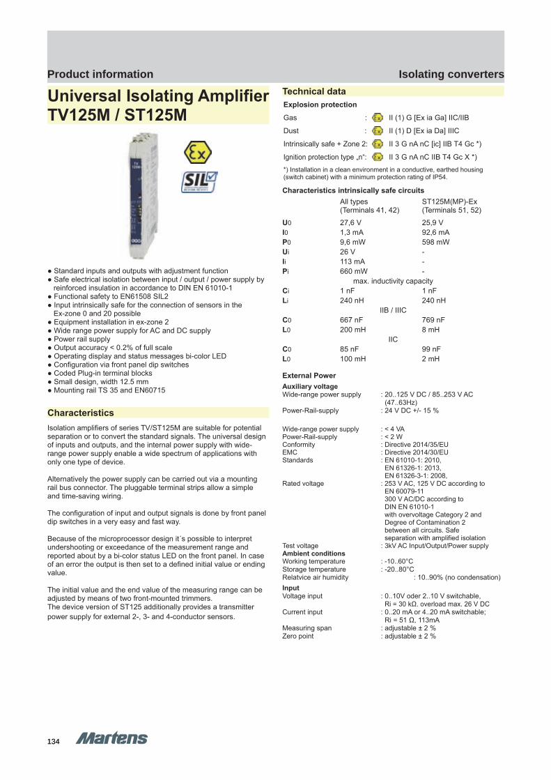
GHM Messtechnik GmbH – Location MartensKiebitzhörn 18 22885 Barsbüttel Germany Fon +49-40-670 73-0 Fax -288www.ghm-messtechnik.de [email protected]
Product Information Industrial Electronics
Universal Isolating AmplifierTV125M / ST125M
Standard inputs and outputs with adjustment function Safe electrical isolation between input / output / power supply by reinforced insulation in accordance to DIN EN 61010-1 Functional safety to EN61508 SIL2 Input intrinsically safe for the connection of sensors in the Ex-zone 0 and 20 possible Equipment installation in ex-zone 2 Wide range power supply for AC and DC supply Power rail supply Output accuracy < 0.2% of full scale Operating display and status messages bi-color LED Configuration via front panel dip switches Coded Plug-in terminal blocks Small design, width 12.5 mm Mounting rail TS 35 and EN60715
Characteristics Isolation amplifiers of series TV/ST125M are suitable for potential separation or to convert the standard signals. The universal design of inputs and outputs, and the internal power supply with wide-range power supply enable a wide spectrum of applications with only one type of device.
Alternatively the power supply can be carried out via a mounting rail bus connector. The pluggable terminal strips allow a simpleand time-saving wiring.
The configuration of input and output signals is done by front panel dip switches in a very easy and fast way.
Because of the microprocessor design it´s possible to interpret undershooting or exceedance of the measurement range and reported about by a bi-color status LED on the front panel. In case of an error the output is then set to a defined initial value or ending value.
The initial value and the end value of the measuring range can be adjusted by means of two front-mounted trimmers.The device version of ST125 additionally provides a transmitter power supply for external 2-, 3- and 4-conductor sensors.
Technical data Explosion protection
Gas : II (1) G [Ex ia Ga] IIC/IIB
Dust : II (1) D [Ex ia Da] IIIC
Intrinsically safe + Zone 2: II 3 G nA nC [ic] IIB T4 Gc *)
Ignition protection type „n“: II 3 G nA nC IIB T4 Gc X *) *) Installation in a clean environment in a conductive, earthed housing (switch cabinet) with a minimum protection rating of IP54.
Characteristics intrinsically safe circuitsAll types(Terminals 41, 42)
ST125M(MP)-Ex(Terminals 51, 52)
U0 27,6 V 25,9 VI0 1,3 mA 92,6 mAP0 9,6 mW 598 mWUi 26 V -Ii 113 mA -Pi 660 mW -
max. inductivity capacityCi 1 nF 1 nFLi 240 nH 240 nH
IIB / IIICC0 667 nF 769 nFL0 200 mH 8 mH
IICC0 85 nF 99 nFL0 100 mH 2 mH
External PowerAuxiliary voltageWide-range power supply : 20..125 V DC / 85..253 V AC
(47..63Hz)Power-Rail-supply : 24 V DC +/- 15 %
Wide-range power supply : < 4 VA Power-Rail-supply : < 2 WConformity : Directive 2014/35/EUEMC : Directive 2014/30/EUStandards : EN 61010-1: 2010,
EN 61326-1: 2013, EN 61326-3-1: 2008,
Rated voltage : 253 V AC, 125 V DC according to EN 60079-11 300 V AC/DC according to DIN EN 61010-1 with overvoltage Category 2 and Degree of Contamination 2 between all circuits. Safe separation with amplified isolation
Test voltage : 3kV AC Input/Output/Power supplyAmbient conditionsWorking temperature : -10..60°C Storage temperature : -20..80°C Relatvice air humidity : 10..90% (no condensation) Input Voltage input : 0..10V oder 2..10 V switchable,
Ri = 30 kΩ. overload max. 26 V DCCurrent input : 0..20 mA or 4..20 mA switchable;
Ri = 51 Ω, 113mAMeasuring span : adjustable ± 2 %Zero point : adjustable ± 2 %
pi-ma-Isolating_converter_E V2.01-00
3134134
Isolating convertersProduct information
TV125M ST125M ST125MTV125M

GHM Messtechnik GmbH – Location MartensKiebitzhörn 18 22885 Barsbüttel Germany Fon +49-40-670 73-0 Fax -288www.ghm-messtechnik.de [email protected]
Product Information Industrial ElectronicsOutputVoltage output : 0…10 V or 2…10 V switchable,
Load > 500 Ω.Current output : 0..20 mA or 4..20 mA switchable,
Load < 600 Ω.Step response T90 : 40 msStandard error : < 0,2 % of the end value Temperature coefficient : < 0,01 % / KTransmitter feedRated voltage at : > 15 V DC; terminals 51, 5220 mA output current > 14 V DC; terminals 51, 41,
Ri = 300 ΩHousingMaterial : Polyamid (PA) 6.6, UL94V-0 Weight : 91gProtection class : Housing IP30,
terminals IP20 BGV A3 Colour : light greyInstallation width : 12,5 mmDimension (HxT) : 108 x 114 mmAssembly : Mounting rail assembly TS35
DIN EN 60715Safety IntegrityLevel : Sil 2 (parameters in accordance with
EN 61508 and SN 29500) for input types 4..20 mA or 2..10 V and output types 4..20 mA or 2..10 V
Device type : BHFT : 0Error signalling : Output 0 V respective 0 mAReaction time : Normal function → error: 40 ms,
error → normal function: 1s (self resetting)
Controls, functional description
Status-LED Message
Green LED illuminates Operating voltage connected
Red and green LEDilluminates
See manual tab. 7: Status messages
Red LED illuminates Electronic defect
Configuration:
DIP On Off
S1 Voltage input Current input
S2 Voltage output Current output
S3 Input:S1 = On: 0 … 10 V,S1 = Off: 0 … 20 mA
Input:S1 = On: 2 … 10 V,S1 = Off: 4 … 20 mA
S4 Output:S2 = On: 0 … 10 V,S2 = Off: 0 … 20 mA
Output:S2 = On: 2 … 10 V,S2 = Off: 4 … 20 mA
Mounting
Carrier rail mounting TS35, DIN EN 60715Mounting of multiple units without distance is only permitted in hori-zontal orientation.
Mechanical design / dimensions
Connection diagram
Order code1. 2. 3. 4.
- - -
1. Device versionTV125M Wide-range mains adapter TV125MP Mounting rail bus connection *),
Auxiliary voltage 24 V DC +/- 15 %ST125M Transmitter feed, Wide-range mains adapterST125MP Transmitter feed, mounting rail bus connection *),
Auxiliary voltage 24 V DC +/- 15 %2. Explosion protection
00 No intrinsically safe input and no intrinsically safe trans-mitter feed. The devices TV125MP and ST125MP maybe installed in zone 2 according to ATEX-ignition protec-tion type “n”
Ex In case of installing the devices out of the ex-zone: Input and transmitter feed are intrinsically safe in accor-dance to ignition protection type “ia” for zones 0 and 20.The devices TV125MP and ST125MP may be installed in zone 2 according to ATEX-ignition protection type „ic“
3. Input10 0/2…10 V / 0/4…20 mA
4. Options00 without option01 Push-In terminals (plug-in)
*) see seperate information sheet power rail
4 pi-ma-Isolating_converter_E V2.01-00
Power supply:85…253 VAC / 20 … 125 VDCor 24 VDC +/- 15 %
Output: 0/2 … 10V or 0/4…20 mA
Input: 0/2 … 10 V or 0/4…20 mA
135135
Isolating convertersProduct information
E3 Is
olat
ing c
onve
rter

GHM Messtechnik GmbH – Location MartensKiebitzhörn 18 22885 Barsbüttel Germany Fon +49-40-670 73-0 Fax -288www.ghm-messtechnik.de [email protected]
Product Information Industrial Electronics
Universal IsolatingAmplifier TV125L
Safe galvanic isolation between input / output / auxiliary voltage with reinforced isolation in accordance with DIN EN 61010-1
Step response T90 40ms Output deviation < 0.2% of the limit value Overload protection of the current input with automatically
resetting fuse Operating display and status messages via two-colour LED Configuration via front DIP switches Plug-in terminal strips Narrow installation width of 12.5 mm for carrier rail mounting
TS 35
Characteristics Isolating amplifiers of the series TV125L are suitable for potentialisolation or for conversion of unit signals. The universal layout ofthe inputs and the output enables a broad range of applicationswith only one type of device. The plug-in terminal strips enablesimple and time-saving wiring. The configuration is also quick andeasy with the front DIP switches.
Brief informationThe input measuring ranges can be switched between 0..20 mAand 4..20 mA or 0..10 V and 2..10 V with a DIP switch on the front.The input measuring ranges can be switched between 0..20 mAand 4..20 mA or 0..10 V and 2..10 V with a DIP switch on the front.
With the microprocessor-controlled measurement logging,undercutting and exceeding of the measurement range aredetected and indicated via a two-colour status LED on the frontside. Then the current output is set to a defined starting or finalvalue.
The current input is protected with an automatically resetting fuse(PTC) against static overvoltages up to 32 V AC/DC.
The required auxiliary energy is less than 0.5 VA.
The three circuits: Inputs, outputs, and auxiliary voltage, are galvanically separated with amplified isolation.
Technical data
Auxiliary power
Auxiliary voltage : 18 - 30V DC
Power consumption : < 0.5 VA
Conformity : ; Directive 2004/108/EC
EMC : DIN EN 61326-1: 2013-07, Class A
Standards : DIN EN 61010-1: 2011-07,DIN EN 61010-2: 2011-07
Rated voltage: 300 V AC/DC in accordance with DINEN 61010-1with Overvoltage category 2 andDegree of contamination 2 between allcircuits.Safe separation with amplified isolation
Test voltage : 3 kV AC, 50 Hz, 1 min
Input / Output / Auxiliary power
Environmental conditions
Working temperature : -10..60°C
Storage temperature : -20..60°C
Air humidity : < 95% (no condensation)
Inputs
Voltage input : Switchable, 0..10V or 2..10 V.Ri = 47 kΩ. Max. overload 32 V AC
Current input : Switchable, 0..20 mA or 4..20 mA.Ri = 48 Ω + 15 Ω (RiPTC).Max. overload 32 V AC/DC inaccordance withDIN EN 61010-2-30
Output
Current output Switchable, 0..20 mA or 4..20 mA.Load < 150 Ω.
Step response : 40 ms
Standard error : < 0.2 % of final value
Temperature coefficient : < 0.01 % / K
Casing
Material : Polyamide (PA) 6.6 , UL94V-0,
Weight : 91g
Protection rating : Housing IP30, terminals IP20 BGV A3
Colour : light grey
Installation width : 12.5 mm
Dimensions (HxD) : 108 x 114 mm
Installation : Carrier rail mountingTS35 DIN EN 60715
pi-ma-Isolating_converter_E V2.01-00
5136136
Isolating convertersProduct information
TV125L TV125L
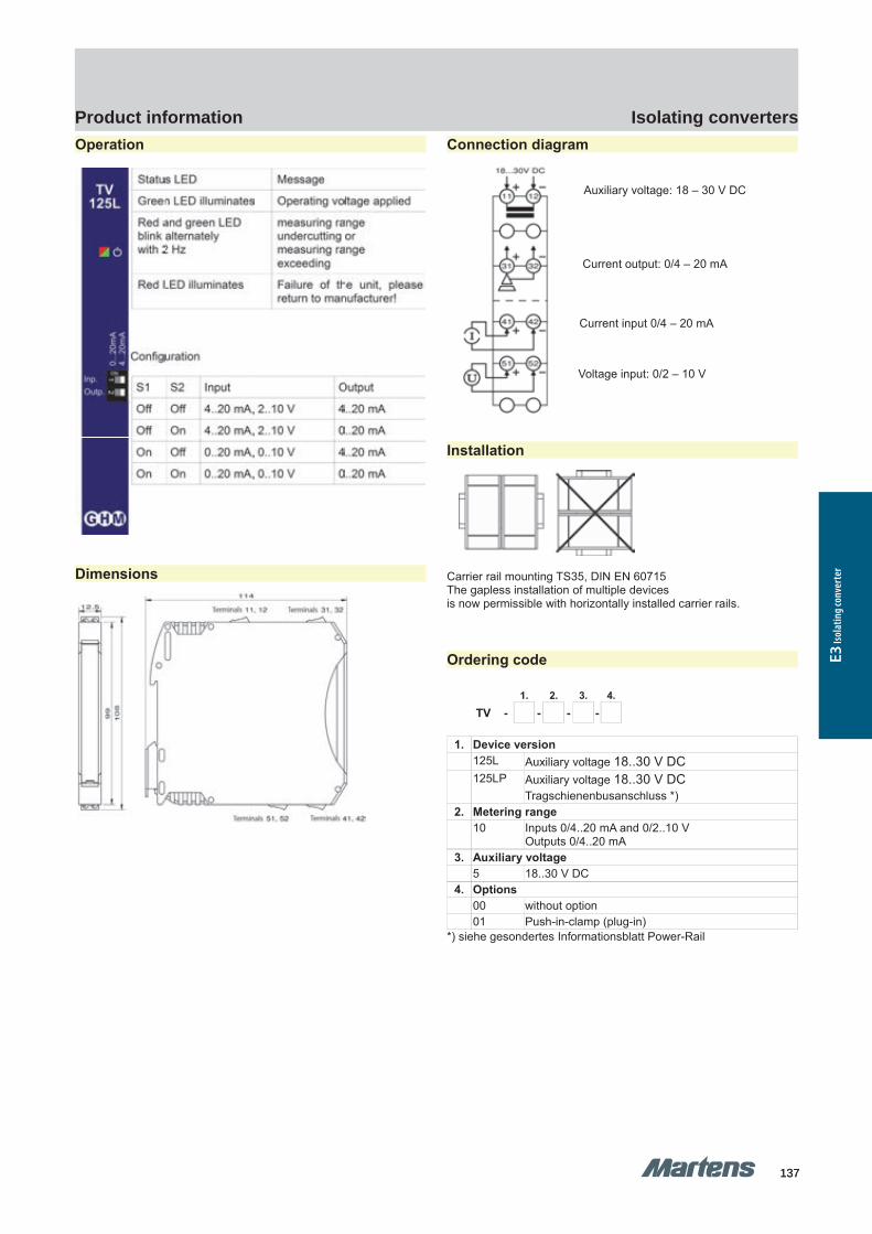
GHM Messtechnik GmbH – Location MartensKiebitzhörn 18 22885 Barsbüttel Germany Fon +49-40-670 73-0 Fax -288www.ghm-messtechnik.de [email protected]
Product Information Industrial ElectronicsOperation
Dimensions
Connection diagram
Installation
Carrier rail mounting TS35, DIN EN 60715The gapless installation of multiple devices is now permissible with horizontally installed carrier rails.
Ordering code
1. 2. 3. 4.
TV - - - -
1. Device version 125L Auxiliary voltage 18..30 V DC 125LP Auxiliary voltage 18..30 V DC
Tragschienenbusanschluss *)2. Metering range
10 Inputs 0/4..20 mA and 0/2..10 VOutputs 0/4..20 mA
3. Auxiliary voltage5 18..30 V DC
4. Options00 without option01 Push-in-clamp (plug-in)
*) siehe gesondertes Informationsblatt Power-Rail
6 pi-ma-Isolating_converter_E V2.01-00
Auxiliary voltage: 18 – 30 V DC
Current output: 0/4 – 20 mA
Current input 0/4 – 20 mA
Voltage input: 0/2 – 10 V
137137
Isolating convertersProduct information
E3 Is
olat
ing c
onve
rter
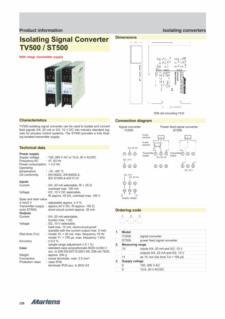
GHM Messtechnik GmbH – Location MartensKiebitzhörn 18 22885 Barsbüttel Germany Fon +49-40-670 73-0 Fax -288www.ghm-messtechnik.de [email protected]
Product Information Industrial Electronics
Isolating Signal ConverterTV500 / ST500With integr. transmitter supply
CharacteristicsTV500 isolating signal converter can be used to isolate and convertfield signals 0/4..20 mA or 0/2..10 V DC into industry standard sig-nals for process control systems. The ST500 provides a fully float-ing isolated transmitter supply.
Technical dataPower supplySupply voltage : 100..265 V AC or 10.8..30 V AC/DCFrequency AC : 47..63 HzPower consumption: < 3.5 VAOperatingtemperature : -10..+60 °CCE-conformity : EN 55022, EN 60555-2,
IEC 61000-4-4/5/11/13InputsCurrent : 0/4..20 mA selectable, Ri = 25 Ω
overload max. 100 mAVoltage : 0/2..10 V DC selectable,
Ri approx. 40 kΩ, overload max. 100 VSpan and start value 4 mA/2 V : adjustable approx. ± 5 %Transmitter supply : approx 24 V DC, Ri approx. 150 Ω,(only ST500) short-circuit current approx. 35 mAOutputsCurrent : 0/4..20 mA selectable,
burden max. 1 kΩVoltage : 0/2..10 V selectable,
load max. 15 mA, short-circuit-proof(parallel with the current output max. 5 mA)
Rise time (T90) : model 10: < 20 ms, max. frequency 18 Hzmodel 11: < 100 μs, max. frequency 1 kHz
Accuracy : ≤ 0.2 % (single range adjustment ≤ 0.1 %)
Case : standard case polycarbonate 8020 UL94V-1acc. to DIN EN 60715:2001-09, DIN rail TS35
Weight : approx. 200 gConnection : screw terminals, max. 2.5 mm²Protection class : case IP30,
terminals IP20 acc. to BGV A3
Dimensions
DIN rail mounting TS35
Connection diagramSignal converter Power feed signal converter
TV500 ST500
Ordering code1. 2. 3.
- -
1. ModelTV500 signal converterST500 power feed signal converter
2. Measuring range10 inputs 0/4..20 mA and 0/2..10 V
outputs 0/4..20 mA and 0/2..10 V 11 as 10, but rise time T90 < 100 µS
3. Supply voltage0 100..265 V AC5 10.8..30 V AC/DC
pi-ma-Isolating_converter_E V2.01-00
7138138
Isolating convertersProduct information
TV500 ST500 ST500TV500
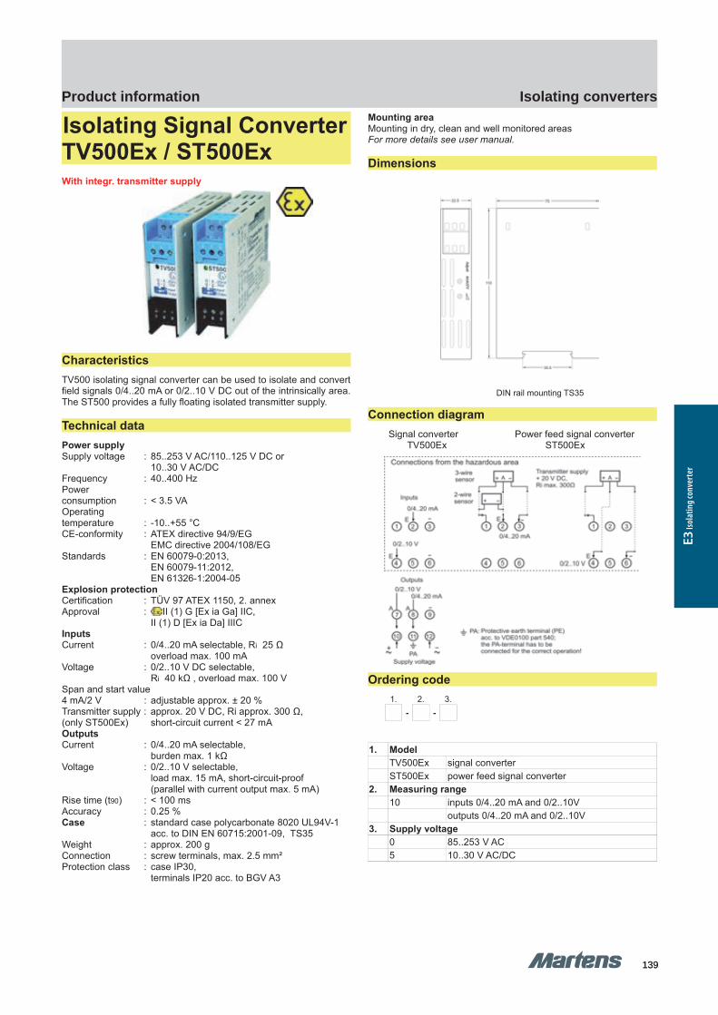
GHM Messtechnik GmbH – Location MartensKiebitzhörn 18 22885 Barsbüttel Germany Fon +49-40-670 73-0 Fax -288www.ghm-messtechnik.de [email protected]
Product Information Industrial Electronics
Isolating Signal ConverterTV500Ex / ST500ExWith integr. transmitter supply
CharacteristicsTV500 isolating signal converter can be used to isolate and convertfield signals 0/4..20 mA or 0/2..10 V DC out of the intrinsically area.The ST500 provides a fully floating isolated transmitter supply.
Technical dataPower supplySupply voltage : 85..253 V AC/110..125 V DC or
10..30 V AC/DCFrequency : 40..400 HzPower consumption : < 3.5 VAOperatingtemperature : -10..+55 °CCE-conformity : ATEX directive 94/9/EG
EMC directive 2004/108/EGStandards : EN 60079-0:2013,
EN 60079-11:2012,EN 61326-1:2004-05
Explosion protectionCertification : TÜV 97 ATEX 1150, 2. annexApproval : II (1) G [Ex ia Ga] IIC,
II (1) D [Ex ia Da] IIICInputsCurrent : 0/4..20 mA selectable, Ri 25 Ω
overload max. 100 mAVoltage : 0/2..10 V DC selectable,
Ri 40 kΩ , overload max. 100 VSpan and start value4 mA/2 V : adjustable approx. ± 20 %Transmitter supply : approx. 20 V DC, Ri approx. 300 Ω,(only ST500Ex) short-circuit current < 27 mAOutputsCurrent : 0/4..20 mA selectable,
burden max. 1 kΩVoltage : 0/2..10 V selectable,
load max. 15 mA, short-circuit-proof(parallel with current output max. 5 mA)
Rise time (t90) : < 100 msAccuracy : 0.25 %Case : standard case polycarbonate 8020 UL94V-1
acc. to DIN EN 60715:2001-09, TS35Weight : approx. 200 gConnection : screw terminals, max. 2.5 mm²Protection class : case IP30,
terminals IP20 acc. to BGV A3
Mounting areaMounting in dry, clean and well monitored areasFor more details see user manual.
Dimensions
DIN rail mounting TS35
Connection diagramSignal converter Power feed signal converter
TV500Ex ST500Ex
Ordering code1. 2. 3.
- -
1. ModelTV500Ex signal converterST500Ex power feed signal converter
2. Measuring range10 inputs 0/4..20 mA and 0/2..10V
outputs 0/4..20 mA and 0/2..10V 3. Supply voltage
0 85..253 V AC5 10..30 V AC/DC
8 pi-ma-Isolating_converter_E V2.01-00139139
Isolating convertersProduct information
E3 Is
olat
ing c
onve
rter
TV500Ex ST500Ex ST500EXTV500EX

GHM Messtechnik GmbH – Location MartensKiebitzhörn 18 22885 Barsbüttel Germany Fon +49-40-670 73-0 Fax -288www.ghm-messtechnik.de [email protected]
Product Information Industrial Electronics
Isolating Signal ConverterTV500H
CharacteristicsThe TV500H brings the function of an isolating signal converter to-gether with a set point adjuster and offers comparator and holdfunction. This combination offers therefore the possibility, to simu-late a measuring value and the easy way to change the sensorwithout process interruption.
Technical dataPower supplySupply voltage : 230 V AC ±10 % 47..63 Hz or
24 V DC ±15%Power consumption : < 3 VAOperatingtemperature : -10..+50 °CCE-conformity : EN 55022, EN 60555-2
IEC 61000-4-3/4/5/11/13InputCurrent : 0/4..20 mA selectable, Ri = 43 Ω,
overload max. 100 mAVoltage : 0/2..10 V selectable, Ri = 175 kΩ,
overload max. 100 VOutputProgrammable outputVoltage → current : link between terminal 8 and 9 Current : 0/4..20 mA selectable, burden < 500 ΩVoltage : 0/2..10 V selectable, load max. 10 mAAccuracy : < 0.2 %Rise time (T90) : < 40 msCase : standard polycarbonate 8020 UL94V-1
acc. to DIN EN 60715:2001-09Weight : approx. 200 gElectrical connection : screw terminals, max. 2.5 mm²Protection class : case IP30,
terminals IP20 acc. to BGV A3
Dimensions
DIN rail mounting TS35
Connection diagram
Ordering code1.
TV500H - 10 -
1. Supply voltage0 230 V AC ±10 %5 24V DC ±15 %
pi-ma-Isolating_converter_E V2.01-00
9140140
Isolating convertersProduct information
TV500H TV500H
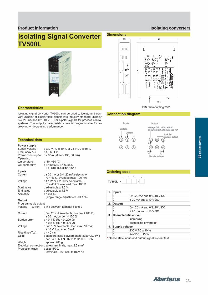
GHM Messtechnik GmbH – Location MartensKiebitzhörn 18 22885 Barsbüttel Germany Fon +49-40-670 73-0 Fax -288www.ghm-messtechnik.de [email protected]
Product Information Industrial Electronics
Isolating Signal ConverterTV500L
Characteristics Isolating signal converter TV500L can be used to isolate and con-vert unipolar or bipolar field signals into industry standard unipolar0/4..20 mA and 0/2..10 V DC or bipolar signals for process controlsystems. The output characteristic curve is programmable for in-creasing or decreasing performance.
Technical dataPower supplySupply voltage : 230 V AC ± 10 % or 24 V DC ± 15 %Frequency AC : 47..63 HzPower consumption : < 3 VA (at 24 V DC, 80 mA)Operating temperature : -10..+50 °CCE-conformity : EN 55022, EN 60555,
IEC 61000-4-3/4/5/11/13InputsCurrent : ± 20 mA or 0/4..20 mA selectable,
Ri = 43 Ω, overload max. 100 mAVoltage : ± 10V or 0/2..10 V selectable,
Ri = 40 kΩ, overload max. 100 VStart value : adjustable ± 1.5 %End value : adjustable ± 1.5 %Accuracy : < 0.3 %,
(single range adjustment < 0.1 %)OutputProgrammable outputVoltage → current : link between terminal 8 and 9
Current : 0/4..20 mA selectable, burden ≤ 400 Ω;± 20 mA, burden ≤ 150 Ω
Burden error : < 0.1 % (RL = 0..200 Ω), < 0.2 % (RL = 0..400 Ω)
Voltage : 0/2..10V selectable, load max. 10 mA;± 10 V, load max. 5 mA
Rise time (T90) : < 40 msCase : standard case polycarbonate 8020 UL94V-1
acc. to DIN EN 60715:2001-09, TS35Weight : approx. 200 gElectrical connection : screw terminals, max. 2.5 mm²Protection class : case IP30,
terminals IP20, acc. to BGV A3
Dimensions
DIN rail mounting TS35
Connection diagram
Ordering code1. 2. 3. 4.
TV500L - -
1. Inputs 1 0/4..20 mA and 0/2..10 V DC2 ± 20 mA and ± 10 V DC
2. Outputs0 0/4..20 mA and 0/2..10 V DC1 ± 20 mA and ± 10 V DC
3. Characteristic curve0 increasing1 decreasing (inverted)*
4. Supply voltage0 230 V AC ± 10 %5 24V DC ± 15 %
* please state input- and output signal in clear text
10 pi-ma-Isolating_converter_E V2.01-00141141
Isolating convertersProduct information
E3 Is
olat
ing c
onve
rter
TV500L TV500L
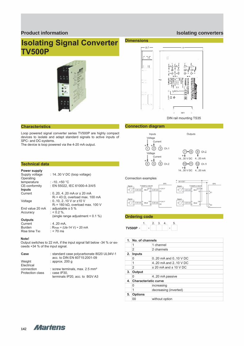
GHM Messtechnik GmbH – Location MartensKiebitzhörn 18 22885 Barsbüttel Germany Fon +49-40-670 73-0 Fax -288www.ghm-messtechnik.de [email protected]
Product Information Industrial Electronics
Isolating Signal ConverterTV500P
Characteristics Loop powered signal converter series TV500P are highly compactdevices to isolate and adapt standard signals to active inputs ofSPC- and DC-systems. The device is loop powered via the 4-20 mA output.
Technical dataPower supplySupply voltage : 14..30 V DC (loop voltage)Operatingtemperature : -10..+50 °CCE-conformity : EN 55022, IEC 61000-4-3/4/5InputsCurrent : 0..20, 4..20 mA or ± 20 mA
Ri = 43 Ω, overload max. 100 mAVoltage : 0..10, 2..10 V or ±10 V
Ri = 160 kΩ, overload max. 100 VEnd value 20 mA : adjustable ± 5 %Accuracy : < 0.2 %,
(single range adjustment < 0.1 %)OutputsCurrent : 4..20 mA, Burden : Rmax = (UB-14 V) ÷ 20 mARise time T90 : < 70 ms
Note!Output switches to 22 mA, if the input signal fall below -34 % or ex-ceeds +34 % of the input signal.
Case : standard case polycarbonate 8020 UL94V-1acc. to DIN EN 60715:2001-09
Weight : approx. 200 gElectrical connection : screw terminals, max. 2.5 mm²Protection class : case IP30,
terminals IP20, acc. to BGV A3
Dimensions
Tragschienenmontage TS35
DIN rail mounting TS35
Connection diagram
Connection examples
Ordering code1. 2. 3. 4. 5.
TV500P - - -
1. No. of channels 1 1 channel2 2 channels
2. Inputs0 0..20 mA and 0..10 V DC1 4..20 mA and 2..10 V DC2 ± 20 mA and ± 10 V DC
3. Output0 4..20 mA passive
4. Characteristic curve0 increasing1 decreasing (inverted)
5. Options00 without option
pi-ma-Isolating_converter_E V2.01-00
11142142
Isolating convertersProduct information
TV500P TV500P
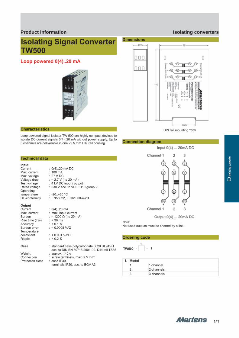
GHM Messtechnik GmbH – Location MartensKiebitzhörn 18 22885 Barsbüttel Germany Fon +49-40-670 73-0 Fax -288www.ghm-messtechnik.de [email protected]
Product Information Industrial Electronics
Isolating Signal ConverterTW500Loop powered 0(4)..20 mA
Characteristics Loop powered signal isolator TW 500 are highly compact devices toisolate DC-current signals 0(4)..20 mA without power supply. Up to3 channels are deliverable in one 22.5 mm DIN rail housing.
Technical dataInputCurrent : 0(4)..20 mA DCMax. current : 100 mAMax. voltage : 27 V DCVoltage drop : < 2.7 V (I ≤ 20 mA)Test voltage : 4 kV DC input / outputRated voltage : 630 V acc. to VDE 0110 group 2Operatingtemperature : -20..+60 °CCE-conformity : EN55022, IEC61000-4-2/4
OutputCurrent : 0(4)..20 mAMax. current : max. input currentBurden : < 1200 Ω (I ≤ 20 mA)Rise time (T90) : < 30 msAccuracy : < 0.1 %Burden error : < 0.0008 %/ΩTemperaturecoefficient : < 0.001 %/°CRipple : < 0.2 %
Case : standard case polycarbonate 8020 UL94V-1acc. to DIN EN 60715:2001-09, DIN rail TS35
Weight : approx. 140 gConnection : screw terminals, max. 2.5 mm²Protection class : case IP30,
terminals IP20, acc. to BGV A3
Dimensions
DIN rail mounting TS35
Connection diagram
Note:Not used outputs must be shorted by a link.
Ordering code1.
TW500 - - 1
1. Model 1 1-channel2 2-channels3 3-channels
12 pi-ma-Isolating_converter_E V2.01-00143143
Isolating convertersProduct information
E3 Is
olat
ing c
onve
rter
TW500 TW500
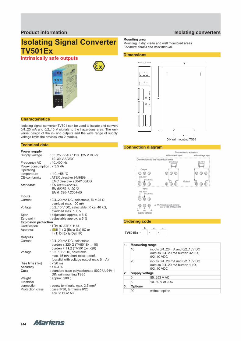
GHM Messtechnik GmbH – Location MartensKiebitzhörn 18 22885 Barsbüttel Germany Fon +49-40-670 73-0 Fax -288www.ghm-messtechnik.de [email protected]
Product Information Industrial Electronics
Isolating Signal ConverterTV501ExIntrinsically safe outputs
CharacteristicsIsolating signal converter TV501 can be used to isolate and convert0/4..20 mA and 0/2..10 V signals to the hazardous area. The uni-versal design of the in- and outputs and the wide range of supplyvoltage limits the devices into 2 models.
Technical dataPower supplySupply voltage : 85..253 V AC / 110..125 V DC or
10..30 V AC/DCFrequency AC : 40..400 HzPower consumption : < 3.5 VAOperatingtemperature : -10..+55 °CCE-conformity : ATEX directive 94/9/EG
EMC directive 2004/108/EGStandards : EN 60079-0:2013,
EN 60079-11:2012,EN 61326-1:2004-05
InputsCurrent : 0/4..20 mA DC, selectable, Ri = 25 Ω,
overload max. 100 mAVoltage : 0/2..10 V DC, selectable, Ri ca. 40 kΩ,
overload max. 100 VSpan : adjustable approx. ± 5 %Zero point : adjustable approx. ± 5 %Explosion protectionCertification : TÜV 97 ATEX 1164Approval : II (1) G [Ex ia Ga] IIC or
II (1) D [Ex ia Da] IIICOutputsCurrent : 0/4..20 mA DC, selectable
burden ≤ 320 Ω (TV501Ex-..-10)burden ≤ 1 kΩ (TV501Ex-..-20)
Voltage : 0/2..10 V DC, selectable, max. 15 mA short-circuit-proof,(parallel with voltage output max. 5 mA)
Rise time (T90) : < 20 msAccuracy : ≤ 0.3 %Case : standard case polycarbonate 8020 UL94V-1
DIN rail mounting TS35Weight : approx. 200 gElectrical connection : screw terminals, max. 2.5 mm²Protection class : case IP30, terminals IP20
acc. to BGV A3
Mounting areaMounting in dry, clean and well monitored areas For more details see user manual.
Dimensions
DIN rail mounting TS35
Connection diagram
Ordering code1. 2. 3.
TV501Ex - - -
1. Measuring range 10 inputs 0/4..20 mA and 0/2..10V DC
outputs 0/4..20 mA burden 320 Ω, 0/2..10 VDC
20 inputs 0/4..20 mA and 0/2..10V DCoutputs 0/4..20 mA burden 1 kΩ, 0/2..10 VDC
2. Supply voltage0 85..253 V AC5 10..30 V AC/DC
3. Options00 without option
pi-ma-Isolating_converter_E V2.01-00
13144144
Isolating convertersProduct information
TV501Ex TV501Ex
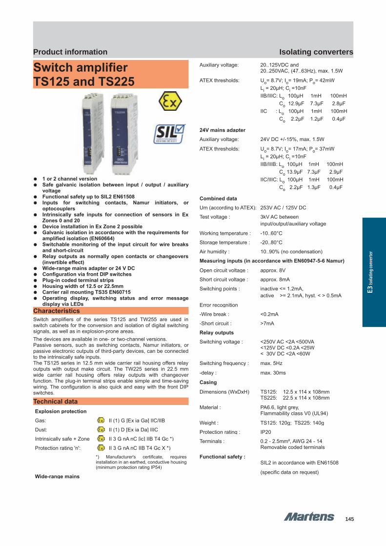
GHM Messtechnik GmbH – Location MartensKiebitzhörn 18 22885 Barsbüttel Germany Fon +49-40-670 73-0 Fax -288www.ghm-messtechnik.de [email protected]
Product Information Industrial Electronics
Switch amplifierTS125 and TS225
1 or 2 channel version Safe galvanic isolation between input / output / auxiliary
voltage Functional safety up to SIL2 EN61508 Inputs for switching contacts, Namur initiators, or
optocouplers Intrinsically safe inputs for connection of sensors in Ex
Zones 0 and 20 Device installation in Ex Zone 2 possible Galvanic isolation in accordance with the requirements for
amplified isolation (EN60664) Switchable monitoring of the input circuit for wire breaks
and short-circuit Relay outputs as normally open contacts or changeovers
(invertible effect) Wide-range mains adapter or 24 V DC Configuration via front DIP switches Plug-in coded terminal strips Housing width of 12.5 or 22.5mm Carrier rail mounting TS35 EN60715 Operating display, switching status and error message
display via LEDsCharacteristics Switch amplifiers of the series TS125 and TW255 are used inswitch cabinets for the conversion and isolation of digital switchingsignals, as well as in explosion-prone areas.The devices are available in one- or two-channel versions.Passive sensors, such as switching contacts, Namur initiators, orpassive electronic outputs of third-party devices, can be connectedto the intrinsically safe inputs.The TS125 series in 12.5 mm wide carrier rail housing offers relayoutputs with output make circuit. The TW225 series in 22.5 mmwide carrier rail housing offers relay outputs with changeoverfunction. The plug-in terminal strips enable simple and time-savingwiring. The configuration is also quick and easy with the front DIPswitches.
Technical data Explosion protection
Gas: II (1) G [Ex ia Ga] IIC/IIB
Dust: II (1) D [Ex ia Da] IIIC
Intrinsically safe + Zone II 3 G nA nC [ic] IIB T4 Gc *)
Protection rating 'n': II 3 G nA nC IIB T4 Gc X *) *) Manufacturer's certificate, requiresinstallation in an earthed, conductive housing(minimum protection rating IP54)
Wide-range mains
Auxiliary voltage: 20..125VDC and20..250VAC, (47..63Hz), max. 1.5W
ATEX thresholds: Uo= 8.7V; Io= 19mA; Po= 42mWLi = 20µH; Ci =10nFIIB/IIIC: Lo 100µH 1mH 100mH Co 12.9µF 7.3µF 2.8µFIIC : Lo 100µH 1mH 100mH Co 2.2µF 1.2µF 0.4µF
24V mains adapter
Auxiliary voltage: 24V DC +/-15%, max. 1.5W
ATEX thresholds: Uo= 8.7V; Io= 17mA; Po= 37mWLi = 20µH; Ci =10nFIIB/IIIB: Lo 100µH 1mH 100mH Co 13.9µF 7.3µF 2.9µFIIC/IIIC: Lo 100µH 1mH 100mH Co 2.2µF 1.3µF 0.4µF
Combined data
Um (according to ATEX): 253V AC / 125V DC
Test voltage : 3kV AC between input/output/auxiliary voltage
Working temperature : -10..60°C
Storage temperature : -20..80°C
Air humidity : 10..90% (no condensation)
Measuring inputs (in accordance with EN60947-5-6 Namur)
Open circuit voltage : approx. 8V
Short circuit voltage : approx. 8mA
Switching points : inactive <= 1.2mA, active >= 2.1mA, hyst. < > 0.5mA
Error recognition
-Wire break : <0.2mA
-Short circuit : >7mA
Relay outputs
Switching voltage : <250V AC <2A <500VA<125V DC <0.2A <25W< 30V DC <2A <60W
Switching frequency : max. 5Hz
-delay : max. 30ms
Casing
Dimensions (WxDxH) TS125: 12.5 x 114 x 108mm TS225: 22.5 x 114 x 108mm
Material : PA6.6, light grey,Flammability class V0 (UL94)
Weight : TS125: 120g; TS225: 140g
Protection rating : IP20
Terminals : 0.2 - 2.5mm², AWG 24 - 14 Removable coded terminals
Functional safety :SIL2 in accordance with EN61508
(specific data on request)
14 pi-ma-Isolating_converter_E V2.01-00145145
Isolating convertersProduct information
E3 Is
olat
ing c
onve
rter
TS125 TS225 TS225TS125
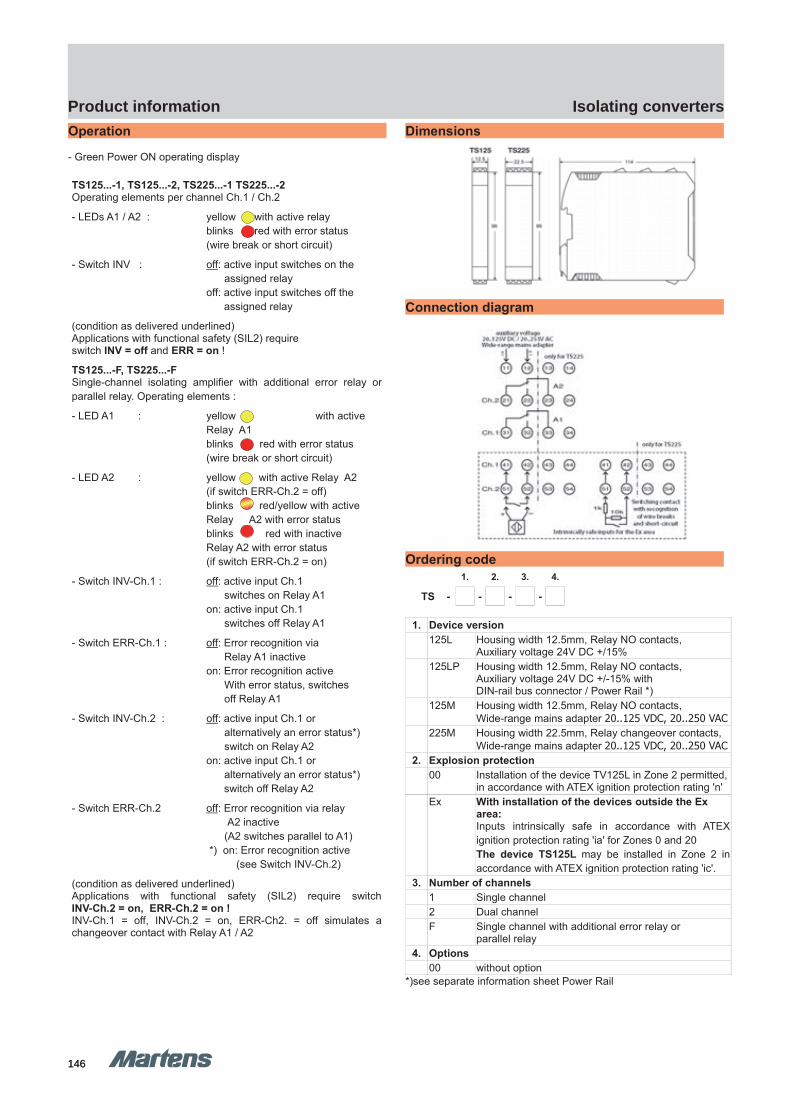
GHM Messtechnik GmbH – Location MartensKiebitzhörn 18 22885 Barsbüttel Germany Fon +49-40-670 73-0 Fax -288www.ghm-messtechnik.de [email protected]
Product Information Industrial ElectronicsOperation
- Green Power ON operating display
TS125...-1, TS125...-2, TS225...-1 TS225...-2Operating elements per channel Ch.1 / Ch.2
- LEDs A1 / A2 : yellow with active relay blinks red with error status(wire break or short circuit)
- Switch INV : off: active input switches on the assigned relay off: active input switches off the assigned relay
(condition as delivered underlined)Applications with functional safety (SIL2) require switch INV = off and ERR = on !
TS125...-F, TS225...-FSingle-channel isolating amplifier with additional error relay orparallel relay. Operating elements :
- LED A1 : yellow with active Relay A1blinks red with error status(wire break or short circuit)
- LED A2 : yellow with active Relay A2(if switch ERR-Ch.2 = off) blinks red/yellow with active Relay A2 with error status blinks red with inactive Relay A2 with error status(if switch ERR-Ch.2 = on)
- Switch INV-Ch.1 : off: active input Ch.1 switches on Relay A1 on: active input Ch.1 switches off Relay A1
- Switch ERR-Ch.1 : off: Error recognition via Relay A1 inactive on: Error recognition active With error status, switches off Relay A1
- Switch INV-Ch.2 : off: active input Ch.1 or alternatively an error status*) switch on Relay A2 on: active input Ch.1 or alternatively an error status*) switch off Relay A2
- Switch ERR-Ch.2 off: Error recognition via relay A2 inactive (A2 switches parallel to A1) *) on: Error recognition active (see Switch INV-Ch.2)
(condition as delivered underlined)Applications with functional safety (SIL2) require switchINV-Ch.2 = on, ERR-Ch.2 = on !INV-Ch.1 = off, INV-Ch.2 = on, ERR-Ch2. = off simulates achangeover contact with Relay A1 / A2
Dimensions
Connection diagram
Ordering code1. 2. 3. 4.
TS - - - -
1. Device version 125L Housing width 12.5mm, Relay NO contacts,
Auxiliary voltage 24V DC +/15% 125LP Housing width 12.5mm, Relay NO contacts,
Auxiliary voltage 24V DC +/-15% withDIN-rail bus connector / Power Rail *)
125M Housing width 12.5mm, Relay NO contacts,Wide-range mains adapter 20..125 VDC, 20..250 VAC
225M Housing width 22.5mm, Relay changeover contacts,Wide-range mains adapter 20..125 VDC, 20..250 VAC
2. Explosion protection00 Installation of the device TV125L in Zone 2 permitted,
in accordance with ATEX ignition protection rating 'n' Ex With installation of the devices outside the Ex
area: Inputs intrinsically safe in accordance with ATEXignition protection rating 'ia' for Zones 0 and 20The device TS125L may be installed in Zone 2 inaccordance with ATEX ignition protection rating 'ic'.
3. Number of channels1 Single channel2 Dual channelF Single channel with additional error relay or
parallel relay 4. Options
00 without option*)see separate information sheet Power Rail
pi-ma-Isolating_converter_E V2.01-00
15146146
Isolating convertersProduct information
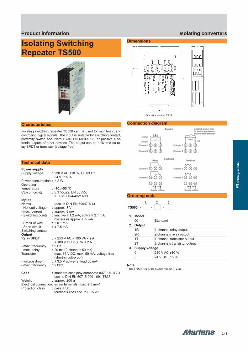
GHM Messtechnik GmbH – Location MartensKiebitzhörn 18 22885 Barsbüttel Germany Fon +49-40-670 73-0 Fax -288www.ghm-messtechnik.de [email protected]
Product Information Industrial Electronics
Isolating Switching Repeater TS500
Characteristics Isolating switching repeater TS500 can be used for monitoring andcontrolling digital signals. The input is suitable for switching contact,proximity switch acc. Namur DIN EN 60947-5-6, or passive elec-tronic outputs of other devices. The output can be delivered as re-lay SPDT or transistor (voltage free).
Technical dataPower supplySupply voltage : 230 V AC ±10 %, 47..63 Hz
24 V ±15 %Power consumption : < 2 WOperatingtemperature : -10..+55 °CCE-conformity : EN 55022, EN 60555,
IEC 61000-4-4/5/11/13InputsNamur (acc. to DIN EN 60947-5-6)- No load voltage : approx. 8 V- max. current : approx. 8 mA - Switching points : inactive ≤ 1.2 mA, active ≥ 2.1 mA,
hysteresis approx. 0.5 mA- Break of wire : ≤ 0.1 mA- Short circuit : ≥ 7.5 mASwitching contactOutputRelay SPDT : < 253 V AC < 100 VA < 2 A;
< 100 V DC < 50 W < 2 A- max. frequency : 5 Hz- max. delay : 20 ms (2-channel: 50 ms)Transistor max. 35 V DC, max. 50 mA, voltage free
(short-circuit-proof)- voltage drop : ≤ 3.5 V active (at load 50 mA)- max. frequency : 2 kHz
Case : standard case ploy carbonate 8020 UL94V-1acc. to DIN EN 60715:2001-09, TS35
Weight : approx. 200 gElectrical connection: screw terminals, max. 2.5 mm²Protection class : case IP30,
terminals IP20 acc. to BGV A3
Dimensions
Tragschienenmontage TS35
DIN rail mounting TS35
Connection diagram
Ordering code1. 2. 3.
TS500 - - -
1. Model00 Standard
2. Output 1R 1-channel relay output2R 2-channels relay output1T 1-channel transistor output2T 2-channels transistor output
3. Supply voltage0 230 V AC ±10 %5 24 V DC ±15 %
Note:The TS500 is also available as Ex-ia.
16 pi-ma-Isolating_converter_E V2.01-00147147
Isolating convertersProduct information
E3 Is
olat
ing c
onve
rter
TS500 TS500
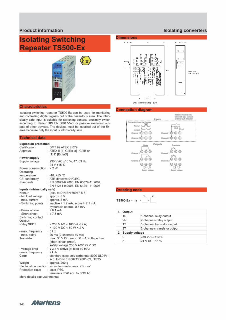
GHM Messtechnik GmbH – Location MartensKiebitzhörn 18 22885 Barsbüttel Germany Fon +49-40-670 73-0 Fax -288www.ghm-messtechnik.de [email protected]
Product Information Industrial Electronics
Isolating SwitchingRepeater TS500-Ex
Characteristics Isolating switching repeater TS500-Ex can be used for monitoringand controlling digital signals out of the hazardous area. The intrin-sically safe input is suitable for switching contact, proximity switchaccording to Namur DIN EN 60947-5-6, or passive electronic out-puts of other devices. The devices must be installed out of the Ex-area because only the input is intrinsically safe.
Technical dataExplosion protectionCertification : DMT 99 ATEX E 079Approval : ATEX II (1) G [Ex ia] IIC/IIB or
(1) D [Ex iaD]Power supplySupply voltage : 230 V AC ±10 %, 47..63 Hz
24 V ±15 %Power consumption : < 2 WOperating temperature : -10..+55 °CCE-conformity : ATE-directive 94/9/EG,Standards : EN 60079-0:2006, EN 60079-11:2007, EN 61241-0:2006, EN 61241-11:2006 Inputs (intrinsically safe)Namur (acc. to DIN EN 60947-5-6)- No load voltage : approx. 8 V- max. current : approx. 8 mA - Switching points : inactive ≤ 1.2 mA, active ≥ 2.1 mA,
hysteresis approx. 0.5 mA- Break of wire : ≤ 0.1 mA- Short circuit : ≥ 7.5 mASwitching contactOutputRelay SPDT : < 253 V AC < 100 VA < 2 A;
< 100 V DC < 50 W < 2 A- max. frequency : 5 Hz- max. delay : 20 ms (2-channel: 50 ms)Transistor max. 35 V DC, max. 50 mA, voltage free
(short-circuit-proof), safety voltage 253 V AC/125 V DC
- voltage drop : ≤ 3.5 V active (at load 50 mA)- max. frequency : 2 kHzCase : standard case poly carbonate 8020 UL94V-1
acc. to DIN EN 60715:2001-09, TS35Weight : approx. 200 gElectrical connection: screw terminals, max. 2.5 mm²Protection class : case IP30,
terminals IP20 acc. to BGV A3More details see user manual
Dimensions
DIN rail mounting TS35
Connection diagram
Ordering code1. 2.
TS500-Ex - ia - -
1. Output 1R 1-channel relay output2R 2-channels relay output1T 1-channel transistor output2T 2-channels transistor output
2. Supply voltage0 230 V AC ±10 %5 24 V DC ±15 %
pi-ma-Isolating_converter_E V2.01-00
17148148
Isolating convertersProduct information
TS500-Ex TS500-Ex
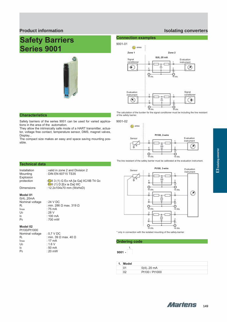
GHM Messtechnik GmbH – Location MartensKiebitzhörn 18 22885 Barsbüttel Germany Fon +49-40-670 73-0 Fax -288www.ghm-messtechnik.de [email protected]
Product Information Industrial Electronics
Safety Barriers Series 9001
Characteristics Safety barriers of the series 9001 can be used for varied applica-tions in the area of the automation. They allow the intrinsically safe mode of a HART transmitter, actua-tor, voltage free contact, temperature sensor, DMS, magnet valves,Display...The compact size makes an easy and space saving mounting pos-sible.
Technical dataInstallation : valid in zone 2 and Division 2Mounting : DIN EN 60715 TS35Explosionprotection : II 3 (1) G Ex nA [ia Ga] IIC/IIB T4 Gc
II (1) D [Ex ia Da] IIICDimensions : 12.2x104x70 mm (WxHxD)
Model 010(4)..20mANominal voltage : 24 V DCRI : min. 286 Ω max. 319 Ω Imax : 75 mAU0 : 28 VI0 : 100 mAP0 : 700 mW
Model 02Pt100/Pt1000Nominal voltage : 0,7 V DCRI : min. 39 Ω max. 40 ΩImax : 17 mAU0 : 1.6 VI0 : 50 mAP0 : 20 mW
Connection examples9001-01
9001-02
Ordering code1.
9001 -
1. Model 01 0(4)..20 mA02 Pt100 / Pt1000
18 pi-ma-Isolating_converter_E V2.01-00
The calculation of the burden for the signal conditioner must be including the line resistantof the safety barrier.
The line resistant of the safety barrier must be calibrated at the evaluation instrument.
* only in connection with the isolated mounting of the safety-barrier.
Zone 1 Zone 2
Signalconditioner
Signalconditioner
Evaluationinstrument
Evaluationinstrument
Evaluationinstrument
Evaluationinstrument
Sensor
Sensor
Pt100, 2-wire
Pt100, 3-wire
-area
-area
149149
Isolating convertersProduct information
E3 Is
olat
ing c
onve
rter
Series 9001 Series 9001

E Industrial electronics
150

E Industrial electronics
151
E4 Sa
fety
and m
onito
ring
Kapitel E4 Start
Safety and monitoring
Monitoring relay
Battery controller
Monitoring realy / Temperature limit value
Safety relay
Isolations guard
E4
152
157
161
175
176
Page

152152
Safety and monitoringProduct information
GHM Messtechnik GmbH – Sales Center InternationalSchloßstraße 6 88453 Erolzheim Germany Fon +49-7354-937233-0 Fax -88www.ghm-messtechnik.de [email protected]
Product Information Industrial Electronics
Safety and Monitoring
CharacteristicsSystem Current,
voltage,power,temperature
Principle Vibration,insulation resistance,safety end switch,safety-temperature limiting/-monitoring
Evaluation Standard-signals, switching outputswith display
Mounting Switch panel case,DIN rail mountingTS35
Applications Monitoring of AC Power systems
Temperature limiter acc. to SIL2
Battery guard for solar systems and wind power stations
Insulation guard for health care facil-ity’s and railway vehicles
Pressure monitoring, filling height
Live saving in machine controls for cutters, mixing machines etc.
pi-ma-Monitoring_E V3.01-00
1
Einleitung
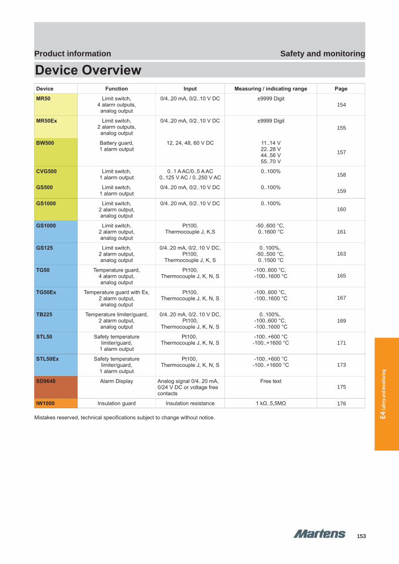
153153
Safety and monitoringProduct information
E4 Sa
fety
and m
onito
ring
GHM Messtechnik GmbH – Sales Center InternationalSchloßstraße 6 88453 Erolzheim Germany Fon +49-7354-937233-0 Fax -88www.ghm-messtechnik.de [email protected]
Product Information Industrial Electronics
Device OverviewDevice Function Input Measuring / indicating range Page
MR50 Limit switch,4 alarm outputs,
analog output
0/4..20 mA, 0/2..10 V DC ±9999 Digit 3
MR50Ex Limit switch,2 alarm outputs,
analog output
0/4..20 mA, 0/2..10 V DC ±9999 Digit 4
BW500 Battery guard,1 alarm output
12, 24, 48, 60 V DC 11..14 V22..28 V44..56 V55..70 V
6
CVG500 Limit switch,1 alarm output
0..1 A AC/0..5 A AC0..125 V AC / 0..250 V AC
0..100% 7
GS500 Limit switch,1 alarm output
0/4..20 mA, 0/2..10 V DC 0..100% 8
GS1000 Limit switch,2 alarm output,analog output
0/4..20 mA, 0/2..10 V DC 0..100% 9
GS1000 Limit switch,2 alarm output,analog output
Pt100,Thermocouple J, K,S
-50..600 °C, 0..1600 °C
10
GS125 Limit switch,2 alarm output,analog output
0/4..20 mA, 0/2..10 V DC,Pt100,
Thermocouple J, K, S
0..100%, -50..500 °C, 0..1500 °C
12
TG50 Temperature guard,4 alarm output,analog output
Pt100,Thermocouple J, K, N, S
-100..600 °C, -100..1600 °C
14
TG50Ex Temperature guard with Ex,2 alarm output,analog output
Pt100,Thermocouple J, K, N, S
-100..600 °C, -100..1600 °C
16
TB225 Temperature limiter/guard,2 alarm output,analog output
0/4..20 mA, 0/2..10 V DC,Pt100,
Thermocouple J, K, N, S
0..100%, -100..600 °C, -100..1600 °C
18
STL50 Safety temperaturelimiter/guard,
1 alarm output
Pt100, Thermocouple J, K, N, S
-100..+600 °C-100..+1600 °C
20
STL50Ex Safety temperaturelimiter/guard,
1 alarm output
Pt100, Thermocouple J, K, N, S
-100..+600 °C-100..+1600 °C
22
SD9648 Alarm Display Analog signal 0/4..20 mA, 0/24 V DC or voltage free contacts
Free text 24
IW1000 Insulation guard Insulation resistance 1 kΩ..5,5MΩ 25
Mistakes reserved, technical specifications subject to change without notice.
2 pi-ma-Monitoring_E V3.01-00
154
155
158
159
160
161
163
165
167
169
171
173
175
176
157
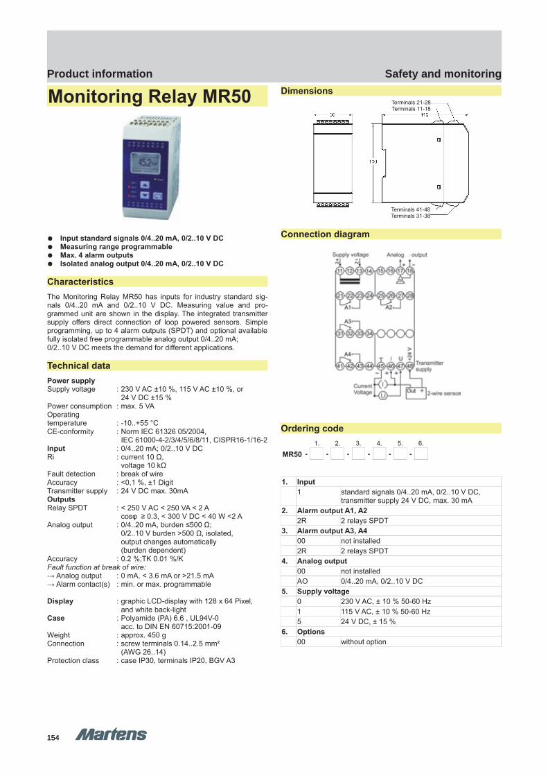
154154
Safety and monitoringProduct information
GHM Messtechnik GmbH – Location MartensKiebitzhörn 18 22885 Barsbüttel Germany Fon +49-40-670 73-0 Fax -288www.ghm-messtechnik.de [email protected]
Product Information Industrial Electronics
Monitoring Relay MR50
Input standard signals 0/4..20 mA, 0/2..10 V DC Measuring range programmable Max. 4 alarm outputs Isolated analog output 0/4..20 mA, 0/2..10 V DC
CharacteristicsThe Monitoring Relay MR50 has inputs for industry standard sig-nals 0/4..20 mA and 0/2..10 V DC. Measuring value and pro-grammed unit are shown in the display. The integrated transmittersupply offers direct connection of loop powered sensors. Simpleprogramming, up to 4 alarm outputs (SPDT) and optional availablefully isolated free programmable analog output 0/4..20 mA; 0/2..10 V DC meets the demand for different applications.
Technical dataPower supplySupply voltage : 230 V AC ±10 %, 115 V AC ±10 %, or
24 V DC ±15 %Power consumption : max. 5 VAOperatingtemperature : -10..+55 °CCE-conformity : Norm IEC 61326 05/2004,
IEC 61000-4-2/3/4/5/6/8/11, CISPR16-1/16-2Input : 0/4..20 mA; 0/2..10 V DCRi : current 10 Ω,
voltage 10 kΩFault detection : break of wire Accuracy : <0,1 %, ±1 DigitTransmitter supply : 24 V DC max. 30mAOutputsRelay SPDT : < 250 V AC < 250 VA < 2 A
cosφ ≥ 0.3, < 300 V DC < 40 W <2 AAnalog output : 0/4..20 mA, burden ≤500 Ω;
0/2..10 V burden >500 Ω, isolated,output changes automatically(burden dependent)
Accuracy : 0.2 %;TK 0.01 %/KFault function at break of wire:→ Analog output : 0 mA, < 3.6 mA or >21.5 mA → Alarm contact(s) : min. or max. programmable
Display : graphic LCD-display with 128 x 64 Pixel, and white back-light
Case : Polyamide (PA) 6.6 , UL94V-0 acc. to DIN EN 60715:2001-09
Weight : approx. 450 gConnection : screw terminals 0.14..2.5 mm²
(AWG 26..14)Protection class : case IP30, terminals IP20, BGV A3
Dimensions
Connection diagram
Ordering code1. 2. 3. 4. 5. 6.
MR50 - - - - - -
1. Input1 standard signals 0/4..20 mA, 0/2..10 V DC,
transmitter supply 24 V DC, max. 30 mA2. Alarm output A1, A2
2R 2 relays SPDT 3. Alarm output A3, A4
00 not installed2R 2 relays SPDT
4. Analog output00 not installedAO 0/4..20 mA, 0/2..10 V DC
5. Supply voltage0 230 V AC, ± 10 % 50-60 Hz1 115 V AC, ± 10 % 50-60 Hz5 24 V DC, ± 15 %
6. Options00 without option
pi-ma-Monitoring_E V3.01-00
3
Terminals 21-28Terminals 11-18
Terminals 41-48Terminals 31-38
MR50 MR50
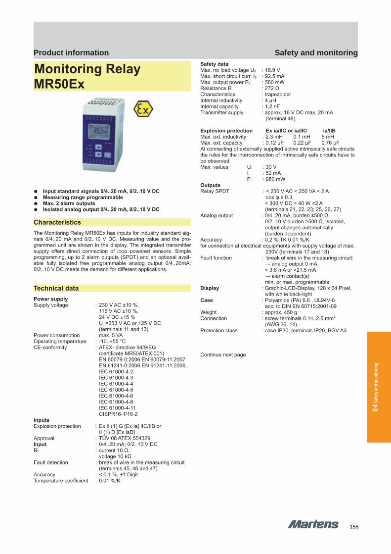
155155
Safety and monitoringProduct information
E4 Sa
fety
and m
onito
ring
GHM Messtechnik GmbH – Location MartensKiebitzhörn 18 22885 Barsbüttel Germany Fon +49-40-670 73-0 Fax -288www.ghm-messtechnik.de [email protected]
Product Information Industrial Electronics
Monitoring Relay MR50Ex
Input standard signals 0/4..20 mA, 0/2..10 V DC Measuring range programmable Max. 2 alarm outputs Isolated analog output 0/4..20 mA, 0/2..10 V DC
CharacteristicsThe Monitoring Relay MR50Ex has inputs for industry standard sig-nals 0/4..20 mA and 0/2..10 V DC. Measuring value and the pro-grammed unit are shown in the display. The integrated transmittersupply offers direct connection of loop powered sensors. Simpleprogramming, up to 2 alarm outputs (SPDT) and an optional avail-able fully isolated free programmable analog output 0/4..20mA;0/2..10 V DC meets the demand for different applications.
Technical dataPower supplySupply voltage : 230 V AC ±10 %,
115 V AC ±10 %,24 V DC ±15 %Um=253 V AC or 125 V DC(terminals 11 and 13)
Power consumption : max. 5 VAOperating temperature : -10..+55 °CCE-conformity : ATEX- directive 94/9/EG
(certificate MR50ATEX.001) EN 60079-0:2006 EN 60079-11:2007 EN 61241-0:2006 EN 61241-11:2006, IEC 61000-4-2IEC 61000-4-3IEC 61000-4-4IEC 61000-4-5IEC 61000-4-6IEC 61000-4-8IEC 61000-4-11CISPR16-1/16-2
InputsExplosion protection : Ex II (1) G [Ex ia] IIC/IIB or
II (1) D [Ex iaD]Approval : TÜV 08 ATEX 554329Input : 0/4..20 mA; 0/2..10 V DCRi : current 10 Ω,
voltage 10 kΩFault detection : break of wire in the measuring circuit
(terminals 45, 46 and 47)Accuracy : < 0.1 %, ±1 DigitTemperature coefficient : 0.01 %/K
Safety dataMax. no load voltage U0 : 18.9 VMax. short circuit curr. I0 : 92.5 mAMax. output power P0 : 580 mWResistance R : 272 ΩCharacteristics : trapezoidalInternal inductivity : 4 μHInternal capacity : 1.2 nFTransmitter supply : approx. 16 V DC max. 20 mA
(terminal 48)
Explosion protection Ex ia/IIC or ia/IIC ia/IIBMax. ext. inductivity : 2.3 mH 0.1 mH 5 mHMax. ext. capacity : 0.12 μF 0.22 μF 0.76 μFAt connecting of externally supplied active intrinsically safe circuits the rules for the interconnection of intrinsically safe circuits have to be observed.Max. values Ui : 30 V
Ii : 52 mAPi : 980 mW
OutputsRelay SPDT : < 250 V AC < 250 VA < 2 A
cos φ ≥ 0.3, < 300 V DC < 40 W <2 A(terminals 21, 22, 23; 25, 26, 27)
Analog output : 0/4..20 mA, burden ≤500 Ω; 0/2..10 V burden >500 Ω, isolated,output changes automatically(burden dependent)
Accuracy : 0.2 %;TK 0.01 %/Kfor connection at electrical equipments with supply voltage of max.
230V (terminals 17 and 18)Fault function : break of wire in the measuring circuit:
→ analog output 0 mA, < 3.6 mA or >21.5 mA → alarm contact(s)min. or max. programmable
Display : Graphic-LCD-Display, 128 x 64 Pixel, with white back-light
Case : Polyamide (PA) 6.6 , UL94V-0 acc. to DIN EN 60715:2001-09
Weight : approx. 450 gConnection : screw terminals 0.14..2.5 mm²
(AWG 26..14)Protection class : case IP30, terminals IP20, BGV A3
Continue next page
4 pi-ma-Monitoring_E V3.01-00
MR50Ex MR50Ex
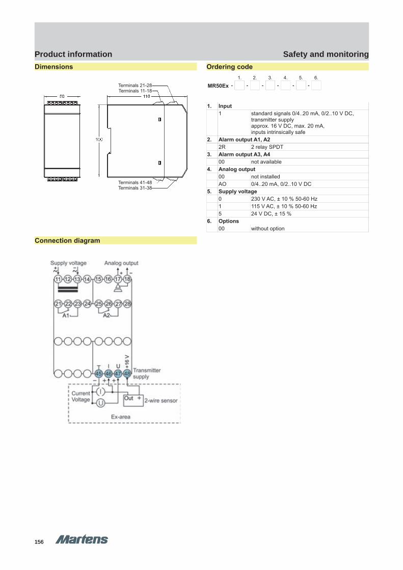
156156
Safety and monitoringProduct information
GHM Messtechnik GmbH – Location MartensKiebitzhörn 18 22885 Barsbüttel Germany Fon +49-40-670 73-0 Fax -288www.ghm-messtechnik.de [email protected]
Product Information Industrial ElectronicsDimensions
Connection diagram
Ordering code1. 2. 3. 4. 5. 6.
MR50Ex - - - - - -
1. Input1 standard signals 0/4..20 mA, 0/2..10 V DC,
transmitter supply approx. 16 V DC, max. 20 mA,inputs intrinsically safe
2. Alarm output A1, A22R 2 relay SPDT
3. Alarm output A3, A400 not available
4. Analog output00 not installedAO 0/4..20 mA, 0/2..10 V DC
5. Supply voltage0 230 V AC, ± 10 % 50-60 Hz1 115 V AC, ± 10 % 50-60 Hz5 24 V DC, ± 15 %
6. Options00 without option
pi-ma-Monitoring_E V3.01-00
5
Terminals 21-28Terminals 11-18
Terminals 41-48Terminals 31-38
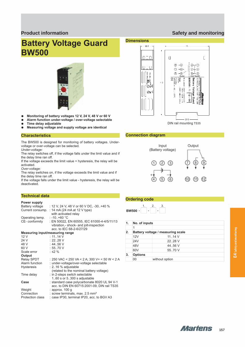
157157
Safety and monitoringProduct information
E4 Sa
fety
and m
onito
ring
GHM Messtechnik GmbH – Location MartensKiebitzhörn 18 22885 Barsbüttel Germany Fon +49-40-670 73-0 Fax -288www.ghm-messtechnik.de [email protected]
Product Information Industrial Electronics
Battery Voltage Guard BW500
Monitoring of battery voltages 12 V, 24 V, 48 V or 60 V Alarm function under-voltage / over-voltage selectable Time delay adjustable Measuring voltage and supply voltage are identical
CharacteristicsThe BW500 is designed for monitoring of battery voltages. Under-voltage or over-voltage can be selected.Under-voltage:The relay switches off, if the voltage falls under the limit value and ifthe delay time ran off.If the voltage exceeds the limit value + hysteresis, the relay will be activated.Over-voltage:The relay switches on, if the voltage exceeds the limit value and if the delay time ran off.If the voltage falls under the limit value - hysteresis, the relay will bedeactivated.
Technical dataPower supplyBattery voltage : 12 V, 24 V, 48 V or 60 V DC, -30..+40 %Current consump. : 14 mA (24 mA at 12 V type)
with activated relayOperating temp. : -10..+60 °CCE- conformity : EN 50022, EN 60555, IEC 61000-4-4/5/11/13
vibration,- shock- and jolt-inspectionacc. to IEC 68-2-6/27/29
Measuring input/measuring range12 V : 11..14 V24 V : 22..28 V48 V : 44..56 V60 V : 55..70 VScale error : ≤2 %OutputRelay SPDT : 250 VAC < 250 VA < 2 A; 300 V= < 50 W < 2 AAlarm function : under-voltage/over-voltage selectableHysteresis : 2..16 % adjustable
(related to the nominal battery voltage)Time delay : in 2-steps switch selectable
1..60 s or 5..300 s adjustableCase : standard case polycarbonate 8020 UL 94 V-1
acc. to DIN EN 60715:2001-09, DIN rail TS35Weight : approx. 100 gConnection : screw terminals, max. 2.5 mm²Protection class : case IP30, terminal IP20, acc. to BGV A3
Dimensions
DIN rail mounting TS35
Connection diagram
Ordering code1. 2. 3.
BW500 - - -
1. No. of inputs1
2. Battery voltage / measuring scale12V 11..14 V24V 22..28 V48V 44..56 V60V 55..70 V
3. Options00 without option
6 pi-ma-Monitoring_E V3.01-00
BW500 BW500

158158
Safety and monitoringProduct information
GHM Messtechnik GmbH – Location MartensKiebitzhörn 18 22885 Barsbüttel Germany Fon +49-40-670 73-0 Fax -288www.ghm-messtechnik.de [email protected]
Product Information Industrial Electronics
Current and VoltageMonitoring Relay CVG500
Arithmetic average value measuring RMS calibrated (AC) or DC
Contact function min/max selectable Hysteresis and time delay adjustable
CharacteristicsCVG500 monitoring relays can be used for monitoring current orvoltage levels. The standard model is designed for input 0...1/5 Aand 0...125/250 V AC/DC. Models with inputs in range of 0...1 mA/5 A AC/DC or 0...50 mV/400 V AC/DC are available.
Technical dataPower supplySupply voltage : 230 V AC ±10 % or 24 V DC -30/+40 %Frequency AC : 47..63 HzPower cons. : < 3 VAOperating temp. : -10..+50 °C (-25 °C..+70 °C on request)CE-conformity : EN 55022, EN 60555, IEC 61000-4-3/4/5/11/13InputsScale error : ≤ 2 %Frequency AC : 40..200 Hz (other ranges on request)Standard rangesCurrent : 0..1 A and 0..5 A AC (sinusoidal) or DCRi : 20 mΩ (5 A input) or
100 mΩ (1 A input)Over-load : 2-times, 4-times for max. 5 secondsVoltage : 0..125 V and 0..250 V sinusoidal or DCRi : 600 KΩ (125 V input) or
1.2 MΩ (250 V input)Over-load : max. 300 V AC/DCCustom rangesVoltage : end value in the range 0.05..400 VAC/DCRi : 4.8 kΩ/VOver-load : 5-times nominal voltage,
max. 500 V AC / DCCurrent : end value in the range 0.001..5 A AC/DCRi : = 100 mΩ ÷ (measuring range [A])Over-load : 2-times, 4-times for max. 5 secondsOutputRelay SPDT : 250 VAC < 250 VA < 2 A; 100 V= < 50 W < 1 ASwitching function: min. / max. selectableHysteresis : 1..25 %Time delay : 0.1..8 seconds
Case : standard case polycarbonate 8020 UL 94 V-1acc. to DIN EN 60715:2001-09, DIN rail TS35
Weight : approx. 200 gProtection class : case IP30, terminals IP20, (BGV A3)Connection : screw terminals, max. 2.5 mm²
Dimensions
DIN rail mounting TS35
Connection diagram
Ordering code1. 2. 3.
CVG500 - - -
1. Current measuring ranges0 not installed
(at custom range voltage)1/5 standard range 0..1 A and 0..5 A AC/DC
custom range state in clear text2. Voltage measuring ranges
0 not installed(at custom range current)
125/250 standard range 0..125 V and 0..250 V AC/DCcustom range state in clear text
3. Supply voltage0 230 V AC ±10 %5 24 V DC -30..40 %
pi-ma-Monitoring_E V3.01-00
7
CVG500 CVG500
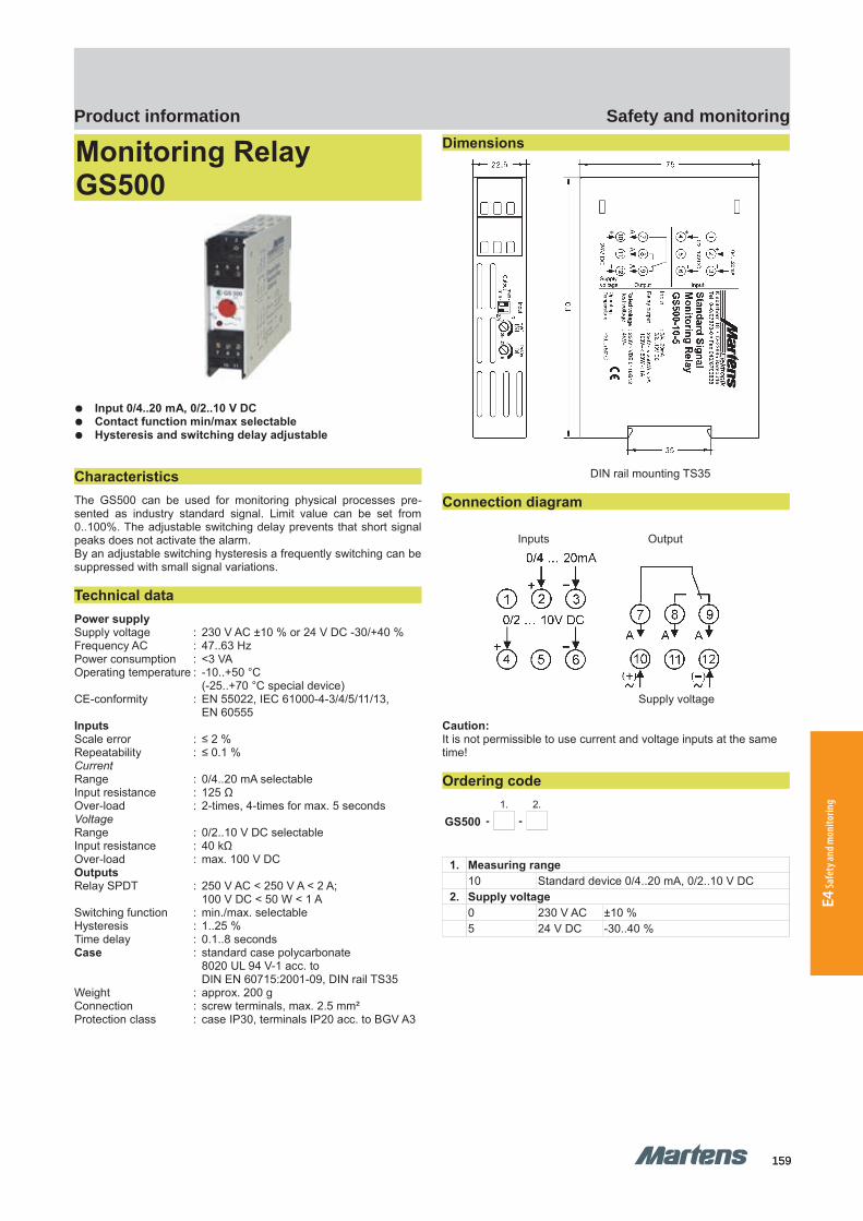
159159
Safety and monitoringProduct information
E4 Sa
fety
and m
onito
ring
GHM Messtechnik GmbH – Location MartensKiebitzhörn 18 22885 Barsbüttel Germany Fon +49-40-670 73-0 Fax -288www.ghm-messtechnik.de [email protected]
Product Information Industrial Electronics
Monitoring Relay GS500
Input 0/4..20 mA, 0/2..10 V DC Contact function min/max selectable Hysteresis and switching delay adjustable
Characteristics The GS500 can be used for monitoring physical processes pre-sented as industry standard signal. Limit value can be set from0..100%. The adjustable switching delay prevents that short signalpeaks does not activate the alarm.By an adjustable switching hysteresis a frequently switching can besuppressed with small signal variations.
Technical dataPower supplySupply voltage : 230 V AC ±10 % or 24 V DC -30/+40 %Frequency AC : 47..63 HzPower consumption : <3 VAOperating temperature : -10..+50 °C
(-25..+70 °C special device)CE-conformity : EN 55022, IEC 61000-4-3/4/5/11/13,
EN 60555InputsScale error : ≤ 2 %Repeatability : ≤ 0.1 %CurrentRange : 0/4..20 mA selectableInput resistance : 125 ΩOver-load : 2-times, 4-times for max. 5 secondsVoltageRange : 0/2..10 V DC selectableInput resistance : 40 kΩOver-load : max. 100 V DCOutputsRelay SPDT : 250 V AC < 250 V A < 2 A;
100 V DC < 50 W < 1 ASwitching function : min./max. selectableHysteresis : 1..25 %Time delay : 0.1..8 secondsCase : standard case polycarbonate
8020 UL 94 V-1 acc. to DIN EN 60715:2001-09, DIN rail TS35
Weight : approx. 200 gConnection : screw terminals, max. 2.5 mm²Protection class : case IP30, terminals IP20 acc. to BGV A3
Dimensions
DIN rail mounting TS35
Connection diagram
Inputs Output
Supply voltage
Caution:It is not permissible to use current and voltage inputs at the same time!
Ordering code1. 2.
GS500 - -
1. Measuring range10 Standard device 0/4..20 mA, 0/2..10 V DC
2. Supply voltage0 230 V AC ±10 %5 24 V DC -30..40 %
8 pi-ma-Monitoring_E V3.01-00
GS500 GS500
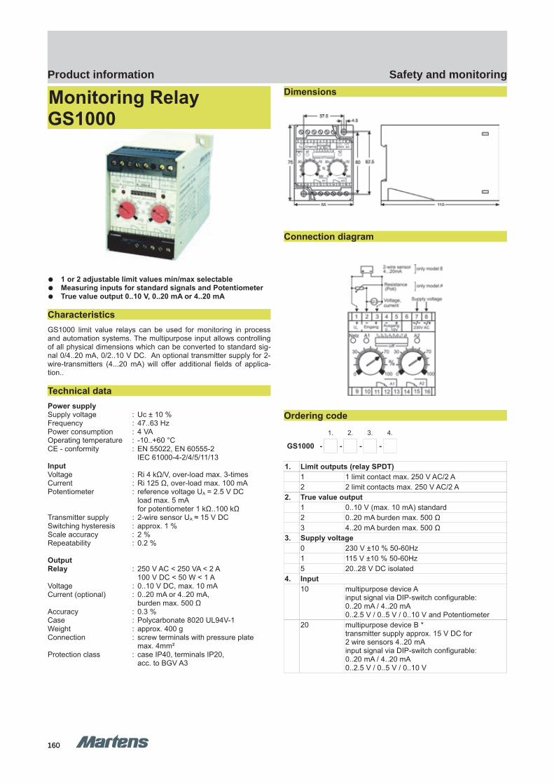
160160
Safety and monitoringProduct information
GHM Messtechnik GmbH – Location MartensKiebitzhörn 18 22885 Barsbüttel Germany Fon +49-40-670 73-0 Fax -288www.ghm-messtechnik.de [email protected]
Product Information Industrial Electronics
Monitoring Relay GS1000
1 or 2 adjustable limit values min/max selectable Measuring inputs for standard signals and Potentiometer True value output 0..10 V, 0..20 mA or 4..20 mA
CharacteristicsGS1000 limit value relays can be used for monitoring in processand automation systems. The multipurpose input allows controllingof all physical dimensions which can be converted to standard sig-nal 0/4..20 mA, 0/2..10 V DC. An optional transmitter supply for 2-wire-transmitters (4...20 mA) will offer additional fields of applica-tion..
Technical dataPower supplySupply voltage : Uc ± 10 % Frequency : 47..63 HzPower consumption : 4 VAOperating temperature : -10..+60 °CCE - conformity : EN 55022, EN 60555-2
IEC 61000-4-2/4/5/11/13InputVoltage : Ri 4 kΩ/V, over-load max. 3-timesCurrent : Ri 125 Ω, over-load max. 100 mAPotentiometer : reference voltage UA = 2.5 V DC
load max. 5 mAfor potentiometer 1 kΩ..100 kΩ
Transmitter supply : 2-wire sensor UA ≈ 15 V DC Switching hysteresis : approx. 1 %Scale accuracy : 2 %Repeatability : 0.2 %
OutputRelay : 250 V AC < 250 VA < 2 A
100 V DC < 50 W < 1 AVoltage : 0..10 V DC, max. 10 mACurrent (optional) : 0..20 mA or 4..20 mA,
burden max. 500 ΩAccuracy : 0.3 %Case : Polycarbonate 8020 UL94V-1Weight : approx. 400 gConnection : screw terminals with pressure plate
max. 4mm²Protection class : case IP40, terminals IP20,
acc. to BGV A3
Dimensions
Connection diagram
Ordering code1. 2. 3. 4.
GS1000 - - - -
1. Limit outputs (relay SPDT)1 1 limit contact max. 250 V AC/2 A2 2 limit contacts max. 250 V AC/2 A
2. True value output1 0..10 V (max. 10 mA) standard2 0..20 mA burden max. 500 Ω3 4..20 mA burden max. 500 Ω
3. Supply voltage0 230 V ±10 % 50-60Hz1 115 V ±10 % 50-60Hz5 20..28 V DC isolated
4. Input10 multipurpose device A
input signal via DIP-switch configurable:0..20 mA / 4..20 mA0..2.5 V / 0..5 V / 0..10 V and Potentiometer
20 multipurpose device B *transmitter supply approx. 15 V DC for2 wire sensors 4..20 mAinput signal via DIP-switch configurable:0..20 mA / 4..20 mA0..2.5 V / 0..5 V / 0..10 V
pi-ma-Monitoring_E V3.01-00
9
GS1000 GS1000
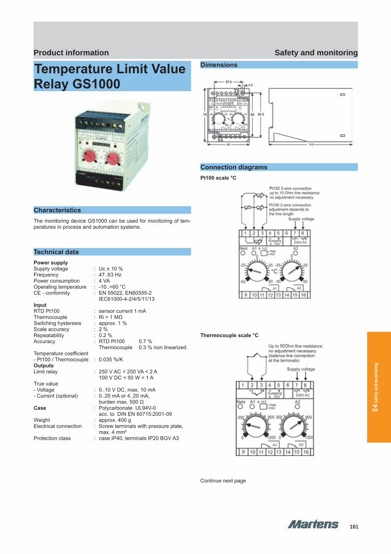
161161
Safety and monitoringProduct information
E4 Sa
fety
and m
onito
ring
GHM Messtechnik GmbH – Location MartensKiebitzhörn 18 22885 Barsbüttel Germany Fon +49-40-670 73-0 Fax -288www.ghm-messtechnik.de [email protected]
Product Information Industrial Electronics
Temperature Limit Value Relay GS1000
CharacteristicsThe monitoring device GS1000 can be used for monitoring of tem-peratures in process and automation systems.
Technical dataPower supplySupply voltage : Uc ± 10 % Frequency : 47..63 HzPower consumption : 4 VAOperating temperature : -10..+60 °CCE - conformity : EN 55022, EN60555-2
IEC61000-4-2/4/5/11/13InputRTD Pt100 : sensor current 1 mA Thermocouple : Ri > 1 MΩSwitching hysteresis : approx. 1 %Scale accuracy : 2 %Repeatability : 0.2 %Accuracy : RTD Pt100 0.7 %
Thermocouple 0.3 % non linearizedTemperature coefficient- Pt100 / Thermocouple : 0.035 %/KOutputsLimit relay : 250 V AC < 250 VA < 2 A
100 V DC < 50 W < 1 ATrue value- Voltage : 0..10 V DC, max, 10 mA- Current (optional) : 0..20 mA or 4..20 mA,
burden max. 500 ΩCase : Polycarbonate UL94V-0
acc. to DIN EN 60715:2001-09Weight : approx. 400 gElectrical connection : Screw terminals with pressure plate,
max. 4 mm²Protection class : case IP40, terminals IP20 BGV A3
Dimensions
Connection diagramsPt100 scale °C
Thermocouple scale °C
Continue next page
10 pi-ma-Monitoring_E V3.01-00
GS1000 Temperature GS1000 Temperature
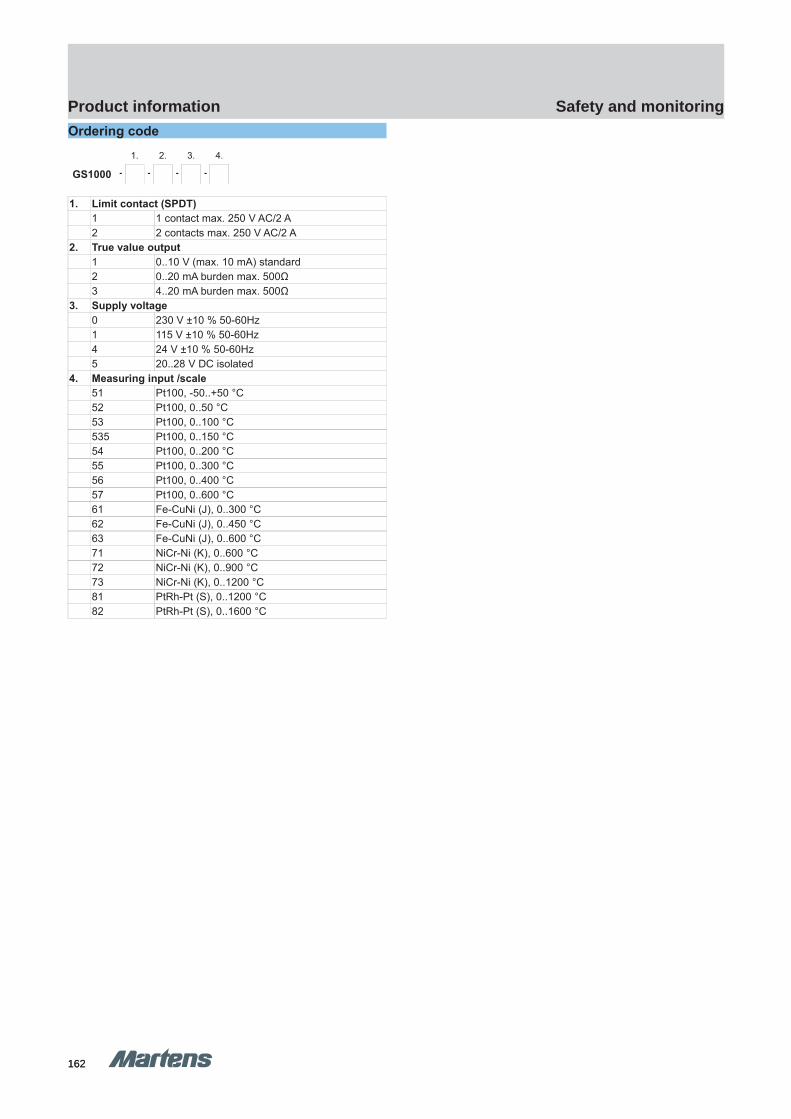
162162
Safety and monitoringProduct information
GHM Messtechnik GmbH – Location MartensKiebitzhörn 18 22885 Barsbüttel Germany Fon +49-40-670 73-0 Fax -288www.ghm-messtechnik.de [email protected]
Product Information Industrial ElectronicsOrdering code
1. 2. 3. 4.
GS1000 - - - -
1. Limit contact (SPDT)1 1 contact max. 250 V AC/2 A2 2 contacts max. 250 V AC/2 A
2. True value output1 0..10 V (max. 10 mA) standard2 0..20 mA burden max. 500Ω3 4..20 mA burden max. 500Ω
3. Supply voltage0 230 V ±10 % 50-60Hz1 115 V ±10 % 50-60Hz4 24 V ±10 % 50-60Hz5 20..28 V DC isolated
4. Measuring input /scale51 Pt100, -50..+50 °C52 Pt100, 0..50 °C53 Pt100, 0..100 °C535 Pt100, 0..150 °C54 Pt100, 0..200 °C55 Pt100, 0..300 °C56 Pt100, 0..400 °C57 Pt100, 0..600 °C61 Fe-CuNi (J), 0..300 °C62 Fe-CuNi (J), 0..450 °C63 Fe-CuNi (J), 0..600 °C71 NiCr-Ni (K), 0..600 °C72 NiCr-Ni (K), 0..900 °C73 NiCr-Ni (K), 0..1200 °C81 PtRh-Pt (S), 0..1200 °C82 PtRh-Pt (S), 0..1600 °C
pi-ma-Monitoring_E V3.01-00
11

163163
Safety and monitoringProduct information
E4 Sa
fety
and m
onito
ring
GS125 GS125
GHM Messtechnik GmbH – Location MartensKiebitzhörn 18 22885 Barsbüttel Germany Fon +49-40-670 73-0 Fax -288www.ghm-messtechnik.de [email protected]
Product Information Industrial Electronics
Limit value switchGS125
Universal input for unit signals, Pt100, thermocouple, potentiometer,
switchable via front-side DIP switch 1 or 2 relay outputs Universal relay connection Adjustable min/max contact function Actual value output 4 .. 20mA 2-colour illuminated scales for limit value adjustment,
colour depends on switch status With Pt100 sensors, monitoring of sensor break
and short-circuit Wide-range mains adapter or 24 V DC Functional safety up to SIL2 Housing width 12.5 mm Removal coded terminals Carrier rail mounting TS35 EN60715 Safe galvanic isolation between
input / output / auxiliary voltage
Technical dataLimit value switches of the series GS125 are used in switch cabi-nets for process monitoring or for simple process regulation.Both temperatures and derived variables such as voltage, currentand resistance are used as control signals. In the process, 1 or 2limit values can be monitored.
The universal configurability of the measuring inputs reduces thestock requirement for various applications.
The housing width of only 12.5mm enables space-saving installa-tion in the switch cabinet. The scales for the limit value setting, illu-minated red or green depending on the switch status, also enableoperating in dark environments.
For assignment of the measuring unit to the scale labelling, 24transparent adhesive labels are supplied. They can be glued be-tween the adjusting wheels on the front panel.
Measurement inputsSwitchable via DIP switchUnit signals : 0/2..10 V
0/4..20 mA Potentiometer : 500 Ω..20 kΩPt100 : -50..50°C
0..50°C0..100°C0..150°C0..200°C0..300°C0..500°C
ThermocoupleFeCuNI, Type J : 0..250°C
0..500°CNiCrNi, Type K : 0..500°C
0..750°C0..1000°C
PtRhPt, Type S : 0..1500°C
(Special measurement ranges available on request)
Technical dataWide-range power supplyVoltage : 20..125 V DC and
20..250 V AC, (47 - 63Hz), max. 1.5W
24 V power supplyVoltage : 24 V DC +/-15%, max. 1.5W
Combined dataRated voltage : 253 V ACTest voltage : 3kV AC be-
tween input/relay output/auxiliary voltage
Operating temperature : -10..60 °CStorage temperature : -20..80 °CAir humidity : 10..90 % (non-condensing)
Measurement inputsVoltage : 0/2..10 V, Ri approx. 20 kΩCurrent : 0/4..20 mA, Ri approx. 60 ΩPt100 : linearised,
measurement current approx. 1.6 mA Relays become inactive if there is a sensor break or short-circuit
Thermocouple : linearised withcomparison position compensation
Resistance : (3-wire), nominal value 500 Ω..20 kΩInternal reference voltage approx. 1.5 V
Relay outputsSwitching voltage : < 250 V AC <2 A <500 VA
< 125 V DC <0.2 A <25 W< 30 V DC <2 A <60 W
Switching frequency : max. 5 HzSwitching hysteresis : approx. 1%
Functional safety : SIL2 in accordance with EN61508(specific data available on request)
Setpoint setting : Scale precision: 2 %
Actual value output : 4..20 mA, resistance max. 120 Ω,No galvanic isolation from the input signal
12 pi-ma-Monitoring_E V3.01-00
Colour change of the scale lightingdepending on the switch status
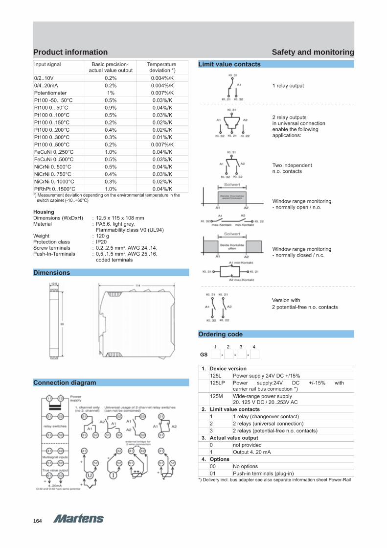
164164
Safety and monitoringProduct information
GHM Messtechnik GmbH – Location MartensKiebitzhörn 18 22885 Barsbüttel Germany Fon +49-40-670 73-0 Fax -288www.ghm-messtechnik.de [email protected]
Product Information Industrial ElectronicsInput signal Basic precision-
actual value outputTemperature deviation *)
0/2..10V 0.2% 0.004%/K0/4..20mA 0.2% 0.004%/KPotentiometer 1% 0.007%/KPt100 -50.. 50°C 0.5% 0.03%/KPt100 0.. 50°C 0.9% 0.04%/KPt100 0..100°C 0.5% 0.03%/KPt100 0..150°C 0.2% 0.02%/KPt100 0..200°C 0.4% 0.02%/KPt100 0..300°C 0.3% 0.01%/KPt100 0..500°C 0.2% 0.007%/KFeCuNi 0..250°C 1.0% 0.04%/KFeCuNi 0..500°C 0.5% 0.03%/KNiCrNi 0..500°C 0.5% 0.04%/KNiCrNi 0..750°C 0.4% 0.03%/KNiCrNi 0..1000°C 0.3% 0.02%/KPtRhPt 0..1500°C 1.0% 0.04%/K*) Measurement deviation depending on the environmental temperature in the
switch cabinet (-10..+60°C)
HousingDimensions (WxDxH) : 12.5 x 115 x 108 mm Material : PA6.6, light grey,
Flammability class V0 (UL94)Weight : 120 gProtection class : IP20Screw terminals : 0,2..2,5 mm², AWG 24..14, Push-In-Terminals : 0,5..1,5 mm², AWG 25..16, coded terminals
Dimensions
Connection diagram
Limit value contacts
Ordering code
1. 2. 3. 4.
GS - - -
1. Device version 125L Power supply 24V DC +/15% 125LP Power supply:24V DC +/-15% with
carrier rail bus connection *)125M Wide-range power supply
20..125 V DC / 20..253V AC 2. Limit value contacts
1 1 relay (changeover contact)2 2 relays (universal connection)3 2 relays (potential-free n.o. contacts)
3. Actual value output0 not provided1 Output 4..20 mA
4. Options00 No options01 Push-in terminals (plug-in)
*) Delivery incl. bus adapter see also separate information sheet Power-Rail
pi-ma-Monitoring_E V3.01-00
13
Version with 2 potential-free n.o. contacts
1 relay output
2 relay outputs in universal connection enable the following applications:
Two independent n.o. contacts
Window range monitoring- normally open / n.o.
Window range monitoring- normally closed / n.c.

165165
Safety and monitoringProduct information
E4 Sa
fety
and m
onito
ring
TG50 TG50
GHM Messtechnik GmbH – Location MartensKiebitzhörn 18 22885 Barsbüttel Germany Fon +49-40-670 73-0 Fax -288www.ghm-messtechnik.de [email protected]
Product Information Industrial Electronics
Temperature Guard TG50
CharacteristicsThe Temperature-Guard TG50 has inputs for temperature probesRTD (Pt100/Pt1000) and thermocouple J, K, N and S. Simple pro-gramming, up to 4 alarm outputs (SPDT) and an available fully iso-lated free programmable analog output 0/4..20 mA; 0/2..10 V DCoffers a lot of solutions for temperature monitoring. Peak value indi-cation for minimum and maximum measured temperature arestored in the background and can be read out from the display atany time.
Technical dataPower supplySupply voltage : 230 V AC ±10 %
115 V AC ±10 %24 V DC ±15 %
: < 5 VAOperating temperature : -10..+55 °CCE-conformity : ATEX-directive 94/9/EG
(certificate PMT50ATEX.001) EN 60079-0:2006 EN60079-11:2007EN 61241-0:2006 EN61241-11:2006IEC61326 05/2004, IEC 61000-4-2,IEC 61000-4-3, IEC 61000-4-4, IEC 61000-4-5, IEC 61000-4-6, IEC 61000-4-8, IEC 61000-4-11,CISPR16-1/16-2
InputFault function : break of wire (RTD Pt100/1000,
Thermocouple) and short-circuit (only Pt100/1000)
RTD : Pt100 (3-wire) -100.0..+600.0 °CPt1000 (3-wire) -100.0..+300.0 °C
: Thermocouple (TC)type J -100.0..+800.0 °Ctype K -150..+1200 °Ctype N -150..+1200 °Ctype S -50..+1600 °Ccold junction compensation integrated
Accuracy : <0.1 %, ±1 DigitDisplay : Graphic LCD-Display, 128 x 64 Pixel,
with white back-lite
OutputAlarm A1-A4 : relay SPDT
< 250 V AC < 250 VA < 2 A cos Phi ≥ 0.3< 300 V DC < 40 W <2 A
Analog : 0/4..20 mA burden ≤500 Ω0/2..10 V burden >500 Ωisolated, automatic output changing (burden dependent)
- Accuracy : 0.2 %;TK 0.01 %/KFault indication : for broken line or short circuit detection
→ analog output (programmable)0 mA, < 3.6 mA or >21.5 mA → Alarm relays min. or max. function programmable
Case : Polyamide (PA) 6.6 , UL94V-0 TS35 acc. to DIN EN 60715:2001-09
Weight : approx. 450 gConnection : screw terminals 0.14..2.5 mm²
AWG 26..AWG14Protection class : case IP30, terminals IP20 acc. to
BGV A3
Dimensions
Continue next page.
14 pi-ma-Monitoring_E V3.01-00
Terminals 21-28Terminals 11-18
Terminals 41-48Terminals 31-38
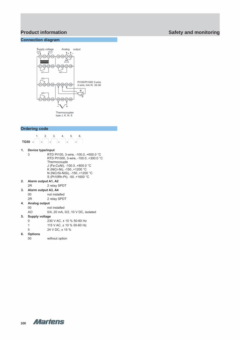
166166
Safety and monitoringProduct information
GHM Messtechnik GmbH – Location MartensKiebitzhörn 18 22885 Barsbüttel Germany Fon +49-40-670 73-0 Fax -288www.ghm-messtechnik.de [email protected]
Product Information Industrial ElectronicsConnection diagram
Ordering code1. 2. 3. 4. 5. 6.
TG50 - - - - - -
1. Device type/input3 RTD Pt100, 3-wire, -100.0..+600.0 °C
RTD Pt1000, 3-wire, -100.0..+300.0 °CThermocoupleJ (Fe-CuNi), -100.0..+800.0 °CK (NiCr-Ni), -150..+1200 °CN (NiCrSi-NiSi), -150..+1200 °CS (Pt10Rh-Pt), -50..+1600 °C
2. Alarm output A1, A22R 2 relay SPDT
3. Alarm output A3, A400 not installed2R 2 relay SPDT
4. Analog output00 not installedAO 0/4..20 mA, 0/2..10 V DC, isolated
5. Supply voltage0 230 V AC, ± 10 % 50-60 Hz1 115 V AC, ± 10 % 50-60 Hz5 24 V DC, ± 15 %
6. Options00 without option
pi-ma-Monitoring_E V3.01-00
15
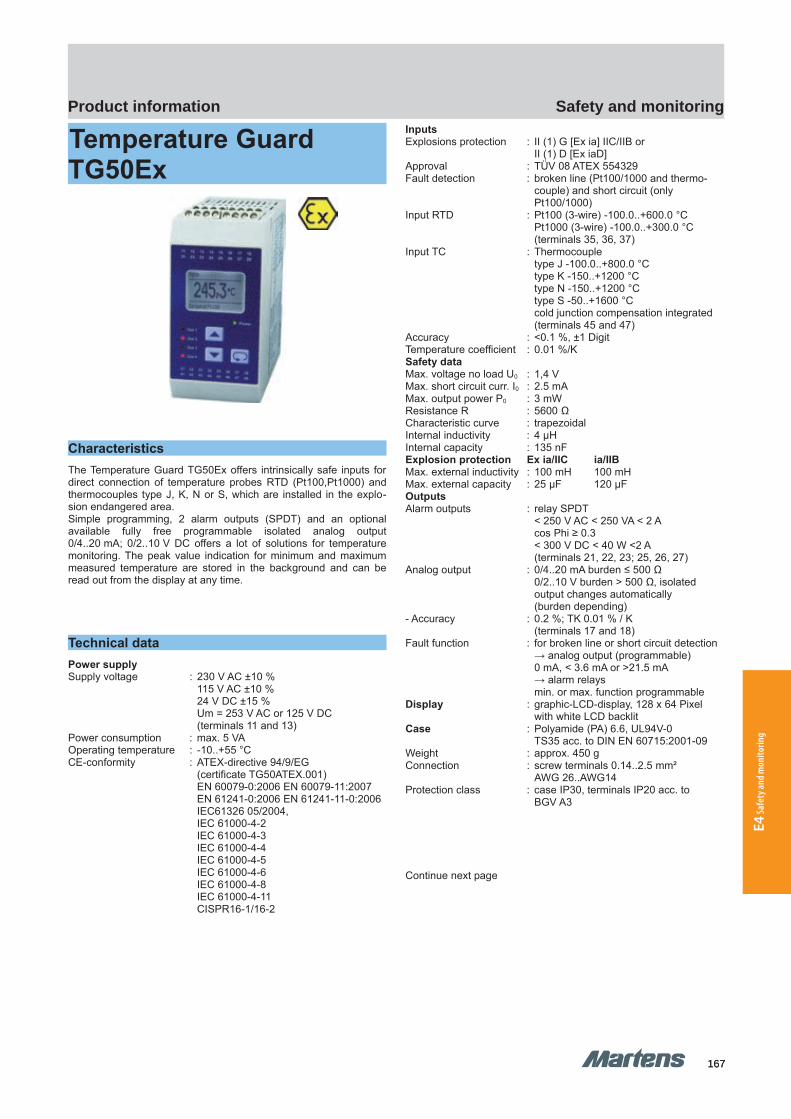
167167
Safety and monitoringProduct information
E4 Sa
fety
and m
onito
ring
TG50Ex TG50Ex
GHM Messtechnik GmbH – Location MartensKiebitzhörn 18 22885 Barsbüttel Germany Fon +49-40-670 73-0 Fax -288www.ghm-messtechnik.de [email protected]
Product Information Industrial Electronics
Temperature Guard TG50Ex
CharacteristicsThe Temperature Guard TG50Ex offers intrinsically safe inputs fordirect connection of temperature probes RTD (Pt100,Pt1000) andthermocouples type J, K, N or S, which are installed in the explo-sion endangered area.Simple programming, 2 alarm outputs (SPDT) and an optionalavailable fully free programmable isolated analog output0/4..20 mA; 0/2..10 V DC offers a lot of solutions for temperaturemonitoring. The peak value indication for minimum and maximummeasured temperature are stored in the background and can beread out from the display at any time.
Technical dataPower supplySupply voltage : 230 V AC ±10 %
115 V AC ±10 %24 V DC ±15 %Um = 253 V AC or 125 V DC(terminals 11 and 13)
Power consumption : max. 5 VAOperating temperature : -10..+55 °CCE-conformity : ATEX-directive 94/9/EG
(certificate TG50ATEX.001) EN 60079-0:2006 EN 60079-11:2007EN 61241-0:2006 EN 61241-11-0:2006IEC61326 05/2004, IEC 61000-4-2IEC 61000-4-3IEC 61000-4-4IEC 61000-4-5IEC 61000-4-6IEC 61000-4-8IEC 61000-4-11CISPR16-1/16-2
InputsExplosions protection : II (1) G [Ex ia] IIC/IIB or
II (1) D [Ex iaD]Approval : TÜV 08 ATEX 554329Fault detection : broken line (Pt100/1000 and thermo-
couple) and short circuit (onlyPt100/1000)
Input RTD : Pt100 (3-wire) -100.0..+600.0 °CPt1000 (3-wire) -100.0..+300.0 °C (terminals 35, 36, 37)
Input TC : Thermocoupletype J -100.0..+800.0 °Ctype K -150..+1200 °Ctype N -150..+1200 °Ctype S -50..+1600 °Ccold junction compensation integrated(terminals 45 and 47)
Accuracy : <0.1 %, ±1 DigitTemperature coefficient : 0.01 %/KSafety dataMax. voltage no load U0 : 1,4 VMax. short circuit curr. I0 : 2.5 mAMax. output power P0 : 3 mWResistance R : 5600 ΩCharacteristic curve : trapezoidalInternal inductivity : 4 μHInternal capacity : 135 nFExplosion protection Ex ia/IIC ia/IIBMax. external inductivity : 100 mH 100 mHMax. external capacity : 25 μF 120 μFOutputsAlarm outputs : relay SPDT
< 250 V AC < 250 VA < 2 A cos Phi ≥ 0.3< 300 V DC < 40 W <2 A(terminals 21, 22, 23; 25, 26, 27)
Analog output : 0/4..20 mA burden ≤ 500 Ω0/2..10 V burden > 500 Ω, isolatedoutput changes automatically (burden depending)
- Accuracy : 0.2 %; TK 0.01 % / K(terminals 17 and 18)
Fault function : for broken line or short circuit detection→ analog output (programmable)0 mA, < 3.6 mA or >21.5 mA → alarm relays min. or max. function programmable
Display : graphic-LCD-display, 128 x 64 Pixelwith white LCD backlit
Case : Polyamide (PA) 6.6, UL94V-0TS35 acc. to DIN EN 60715:2001-09
Weight : approx. 450 gConnection : screw terminals 0.14..2.5 mm² AWG 26..AWG14Protection class : case IP30, terminals IP20 acc. to
BGV A3
Continue next page
16 pi-ma-Monitoring_E V3.01-00
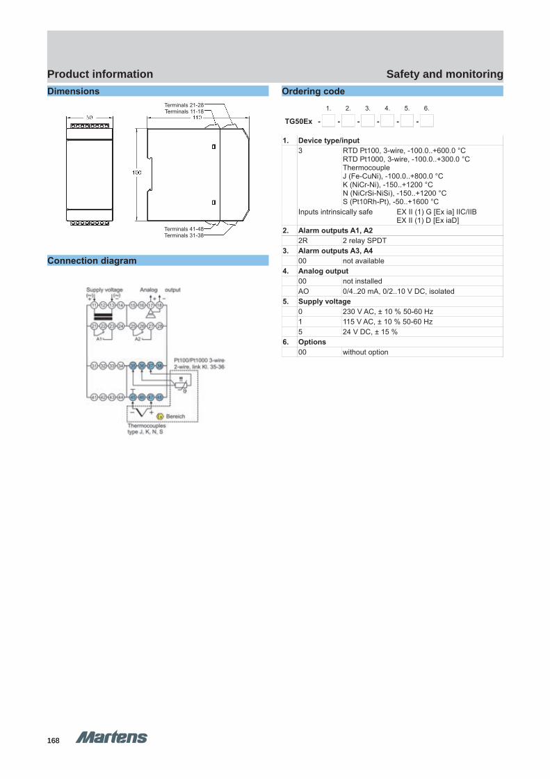
168168
Safety and monitoringProduct information
GHM Messtechnik GmbH – Location MartensKiebitzhörn 18 22885 Barsbüttel Germany Fon +49-40-670 73-0 Fax -288www.ghm-messtechnik.de [email protected]
Product Information Industrial ElectronicsDimensions
Connection diagram
Ordering code1. 2. 3. 4. 5. 6.
TG50Ex - - - - - -
1. Device type/input3 RTD Pt100, 3-wire, -100.0..+600.0 °C
RTD Pt1000, 3-wire, -100.0..+300.0 °CThermocoupleJ (Fe-CuNi), -100.0..+800.0 °CK (NiCr-Ni), -150..+1200 °CN (NiCrSi-NiSi), -150..+1200 °CS (Pt10Rh-Pt), -50..+1600 °C
Inputs intrinsically safe EX II (1) G [Ex ia] IIC/IIBEX II (1) D [Ex iaD]
2. Alarm outputs A1, A22R 2 relay SPDT
3. Alarm outputs A3, A400 not available
4. Analog output00 not installed AO 0/4..20 mA, 0/2..10 V DC, isolated
5. Supply voltage0 230 V AC, ± 10 % 50-60 Hz1 115 V AC, ± 10 % 50-60 Hz5 24 V DC, ± 15 %
6. Options00 without option
pi-ma-Monitoring_E V3.01-00
17
Terminals 41-48Terminals 31-38
Terminals 21-28Terminals 11-18

169169
Safety and monitoringProduct information
E4 Sa
fety
and m
onito
ring
TB225 TB225
GHM Messtechnik GmbH – Location MartensKiebitzhörn 18 22885 Barsbüttel Germany Fon +49-40-670 73-0 Fax -288www.ghm-messtechnik.de [email protected]
Product Information Industrial Electronics
Thermal Limiter TB225(in accordance with DIN EN 14597)
Can be used as a temperature limiter and monitor Certified in accordance with DIN EN 14597 Pt100 inputs, dual thermocouple, input signals 2 changeover relays Configuration via backlit graphic display 'White / Red' display colour change in the case of an alarm Safe galvanic isolation between input / output / auxiliary
voltage Automatic recognition of the output signal Wide-range mains adapter Carrier rail mounting TS 35
CharacteristicsThe temperature limiter TB225 is used for applications wherethermal processes must be monitored and the system must be switched to a safe operating state in the case of a fault. Thedevice has universal inputs for the connection of dualthermocouples,Pt100 sensors, and input signals (0/4..20mA or0/2..10V). The safety function is provided by means of the mainrelay with configurable threshold. An additional relay with anindependently adjustable threshold is provided for additionalsignalling. The TB225 also offers an analog output which can befreely defined within the measuring range of the temperature input.The resetting of the device in the operating mode as a temperaturelimiter can take place via the buttons on the front, the integratedgraphic display, or using an external switch or external voltage. TheTB225 has safe 3-way electrical isolation between input, output,and auxiliary voltage.
Brief informationThe connected temperature signal is evaluated and monitored. If the permissible threshold is reached or an error occurs within the permissible temperature range, the TB225 switches off immediately. The additional relay output of the TB225 enables the function of a preliminary alarm with an independent threshold. The following operating modes are possible through configuration:
Temperature limiter:Maximum or minimum monitoring with catch, manual resetting afterfault elimination via the front keys or an external switch / voltage signal.Operating methods in accordance with EN14597: 02/2015: Type 2B, 2H, 2V
Temperature monitor:Maximum or minimum monitoring without catch, automatic resettingon return to the permissible range. Operating methods in accordance with EN 14597: 02/2015: Type 2B
Technical dataAuxiliary powerAuxiliary voltage : 18 – 230 V AC/DCPower consumption : < 5 VARated voltage : 250V AC in accordance with
EN 60730-1: 10/2012,between input / relay output /auxiliary voltage, Degree ofcontamination 2,Overvoltage category IIIRated surge voltage 4kV
CE Conformity : EN 14597 02/2015EN 61326: 07/2013
Environmental conditionsOperating temperature : -10..+55 °Cstorage temperature : -20..+60 °CRelative air humidity : < 95 %Condensation : not permittedApprovals TitleDIN EN 14597: 02/2015 : Temperature control devices and
temperature limiters for heat generat-ing systems
InputPt100 : -100.0..600.0°CAccuracy : 0,2%, ±1 DigitTemperature coefficient : 0,01%/KThermocouple : Type J:Fe-CuNi-100..800°C
Type K: NiCr-Ni -150..1200°CType N:NiCrSi-NiSi -150..1200°CType S:Pt10RH-PT 0..1600°CReference junction compensation integrated
Accuracy: : <0.3 %, ±1 digitTemperature coefficient : 0.01 %/KAnalog input : 0/2..10 V DC, 0/4..20 mA
0..10 V und 0..20 mA not allowed for temperature limiter
Accuracy : 0,2%, ±1 DigitTemperature coefficient : 0,01%/KDisplay : graphic LC display with 32 x 90 pixel,
with white/red background lightingOutputsSwitching outputs : 2 x relayChangeover relay : < 250 V AC < 500 VA < 2 A
ohmic load< 30 V DC < 60W < 2 A ohmic loadInternal main relay secured with 2A fuse!Fuse is not interchangeable!
Analog output : 0/4..20 mA load ≤ 500 Ω0/2..10 V DC load > 500 Ωelectrically isolated.Output switches automatically(load-dependent)
Housing : polyamide (PA) 6.6 , UL94V-0,TS35 in accordance with DIN EN 60715
Weight : approximately 180 gConnection : screw terminals 0.14..2.5 mm²
with wire protection0.14 - 2.5 mm² (AWG 26 - 14)
Protection rating : IP20, BGV A3
18 pi-ma-Monitoring_E V3.01-00
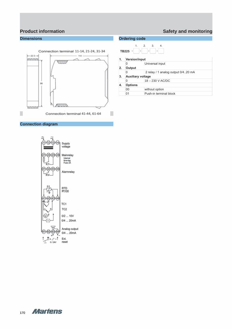
170170
Safety and monitoringProduct information
GHM Messtechnik GmbH – Location MartensKiebitzhörn 18 22885 Barsbüttel Germany Fon +49-40-670 73-0 Fax -288www.ghm-messtechnik.de [email protected]
Product Information Industrial ElectronicsDimensions
Connection diagram
Ordering code1. 2. 3. 4.
TB225 - - - -
1. Version/input0 Universal input
2. Output0 2 relay / 1 analog output 0/4..20 mA
3. Auxiliary voltage0 18 – 230 V AC/DC
4. Options00 without option01 Push-in terminal block
pi-ma-Monitoring_E V3.01-00
19

171171
Safety and monitoringProduct information
E4 Sa
fety
and m
onito
ring
GHM Messtechnik GmbH – Location MartensKiebitzhörn 18 22885 Barsbüttel Germany Fon +49-40-670 73-0 Fax -288www.ghm-messtechnik.de [email protected]
Product Information Industrial Electronics
Safety Temperature Limiter STL50(acc. to DIN EN 14597, SIL 2)
Useful as Temperature Limiter/-Guard and Exhaust gas Temperature Limiter
Certified according to DIN EN 14597 SIL 2 Inputs RTD Pt100 or double-thermocouple Alarm output 1 relay SPDT Programming via backlit LCD-graphic-Display
CharacteristicsThe STL50 safety temperature limiter is used where ever thermalprocesses must be monitored and the system must be transferredinto a safe operational state in case of fault. If the permissible tem-perature limit value is reached, or if a fault occurs within the per-missible temperature range on the monitoring equipment (sensoropen, sensor short-circuit, failure of a component part in the device,fault in the software, failure or inadmissible value of the supply volt-age etc.), the STL50 switches off without delay.The alarm contact is activated, the LED ALARM on the front paneland the back-lighting of the display light up, and the error cause isindicated as plain text on the display. In addition, there is a 24 V DCsignal present on the terminals 17-18 for an external alarm signal.
DescriptionProgramming The device is programmable via front side buttons in connection with the graphic display.
Operating modesThe device can be used as:STB Maximum- or minimum-monitoring with hold. Reset possi-
ble after omission of the fault with the external or internal button.
ASTB as before, but monitoring the exhaust gas temperatureSTW Maximum- or minimum-monitoring without hold. Auto-
matic reset after leaving the dangerous rangeSwitching hysteresis always acts in the direction of safe range.The last fault is stored as plain text and can be called up in the working level and deleted.
Temperature sensor
The device may be operate only with temperature probes which arecertified according to DIN EN 14597!
Technical dataPower supplySupply voltage : 230 V AC ±10 %
115 V AC ±10 %24 V DC ±15 %
Power consumption : < 4 VA
CE-conformity : EN 55022, EN 60555IEC 61000-4-2/3/4/5/6/11/13
Ambient conditionsOperating temperature : -10..+55 °CStorage temperature : -30..+60 °CRelative humidity : < 95 %Condensation : not permitted
operation only in vibration less ambientApprovals TitleEN 14597:2005 : temperature control devices and
temperature limiters for heat-generating systems
EN 61508:2001 SIL2 : functional security safety-related electrical/electronic/programmableelectronic systems
InputPt100 : in the range -100.0..+600.0 °C
3-wire, max. line resistance 4 Ω each linesensor current<1 mA (non self heating)
ThermocoupleType J : Fe-CuNi, -100.0..+800.0 °CType K : NiCr-Ni, -150..+1200 °CType N : NiCrSi-NiSi , -150..+1200 °CType S : Pt10Rh-Pt, 0..+1600 °C
cold junction compensation integratedAccuracy : <0.5 %, ±2 DigitTemperature coefficient : 0.01 %/KDisplay : graphic-LCD-display 28 x 64 Pixel,
with white LCD-backlightOutputRelay : SPDT
<250 V AC <200 VA <2 A cos Phi ≥0.7<250 VDC <80 W <2 A,internal fused 2 A (slow-blow)
Case : Polyamide (PA) 6.6 , UL94V-0,TS35 acc. to DIN EN 60715:2001-09
Weight : approx. 450 gConnection : screw terminals 0.14..2.5 mm²
(AWG 26 .. 14)Protection class : IP20, DIN EN 60529, BGV A3
Continue next page
20 pi-ma-Monitoring_E V3.01-00
STL50 STL50
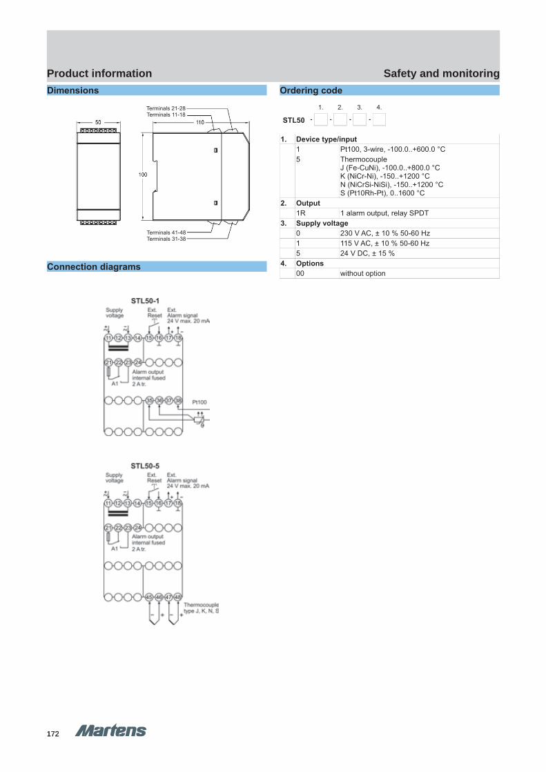
172172
Safety and monitoringProduct information
GHM Messtechnik GmbH – Location MartensKiebitzhörn 18 22885 Barsbüttel Germany Fon +49-40-670 73-0 Fax -288www.ghm-messtechnik.de [email protected]
Product Information Industrial ElectronicsDimensions
Connection diagrams
Ordering code1. 2. 3. 4.
STL50 - - - -
1. Device type/input1 Pt100, 3-wire, -100.0..+600.0 °C5 Thermocouple
J (Fe-CuNi), -100.0..+800.0 °CK (NiCr-Ni), -150..+1200 °CN (NiCrSi-NiSi), -150..+1200 °CS (Pt10Rh-Pt), 0..1600 °C
2. Output1R 1 alarm output, relay SPDT
3. Supply voltage0 230 V AC, ± 10 % 50-60 Hz1 115 V AC, ± 10 % 50-60 Hz5 24 V DC, ± 15 %
4. Options00 without option
pi-ma-Monitoring_E V3.01-00
21
Terminals 21-28Terminals 11-18
Terminals 41-48Terminals 31-38
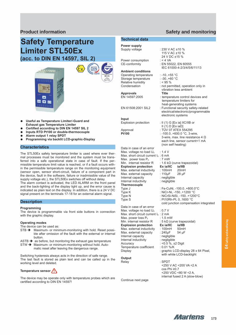
173173
Safety and monitoringProduct information
E4 Sa
fety
and m
onito
ring
GHM Messtechnik GmbH – Location MartensKiebitzhörn 18 22885 Barsbüttel Germany Fon +49-40-670 73-0 Fax -288www.ghm-messtechnik.de [email protected]
Product Information Industrial Electronics
Safety Temperature Limiter STL50Ex(acc. to DIN EN 14597, SIL 2)
Useful as Temperature Limiter/-Guard and Exhaust gas Temperature Limiter
Certified according to DIN EN 14597 SIL 2 Inputs RTD Pt100 or double-thermocouple Alarm output 1 relay SPDT Programming via backlit LCD-graphic-Display
CharacteristicsThe STL50Ex safety temperature limiter is used where ever ther-mal processes must be monitored and the system must be trans-ferred into a safe operational state in case of fault. If the per-missible temperature limit value is reached, or if a fault occurs with-in the permissible temperature range on the monitoring equipment(sensor open, sensor short-circuit, failure of a component part inthe device, fault in the software, failure or inadmissible value of thesupply voltage etc.), the STL50Ex switches off without delay.The alarm contact is activated, the LED ALARM on the front paneland the back-lighting of the display light up, and the error cause isindicated as plain text on the display. In addition, there is a 24 V DCsignal present on the terminals 17-18 for an external alarm signal.
DescriptionProgramming The device is programmable via front side buttons in connectionwith the graphic display.
Operating modesThe device can be used as:STB Maximum- or minimum-monitoring with hold. Reset possi-
ble after omission of the fault with the external or internalbutton.
ASTB as before, but monitoring the exhaust gas temperatureSTW Maximum- or minimum-monitoring without hold. Auto-
matic reset after leaving the dangerous range.
Switching hysteresis always acts in the direction of safe range.The last fault is stored as plain text and can be called up in theworking level and deleted.
Temperature sensor
The device may be operate only with temperature probes which arecertified according to DIN EN 14597!
Technical dataPower supplySupply voltage : 230 V AC ±10 %
115 V AC ±10 %24 V DC ±15 %
Power consumption : < 4 VACE-conformity : EN 55022, EN 60555
IEC 61000-4-2/3/4/5/6/11/13Ambient conditionsOperating temperature : -10..+55 °CStorage temperature : -30..+60 °CRelative humidity : < 95 %Condensation : not permitted, operation only in
vibration less ambientApprovals TitleEN 14597:2005 : temperature control devices and
temperature limiters for heat-generating systems
EN 61508:2001 SIL2 : Functional security safety-related electrical/electronic/programmableelectronic systems
InputExplosion protection : II (1) G [Ex ia] IIC/IIB or
II (1) D [Ex iaD]Approval : TÜV 07 ATEX 554295Pt100 : -100.0..+600.0 °C, 3-wire,
3-wire, max. line resistance 4 Ω each line, sensor current<1 mA (non self heating)
Data in case of an errorMax. voltage no load U0 : 1.4 VMax. short circuit current I0 : 6 mAMax. power loss P0 : 7 mWMin. internal resistor R : 1.6 kΩ (curve trapezoidal)Explosion protection Ex ia/IIC ia/IIBMax. external inductivity : 100mH 20mHMax. external capacity : 110μF 28 μFInternal capacity : negligibleInternal inductivity : negligibleThermocoupleType J : Fe-CuNi, -100.0..+800.0°CType K : NiCr-Ni, -150..+1200 °CType N : NiCrSi-NiSi, -150..+1200°CType S : Pt10Rh-Pt, 0..1600 °C
cold junction compensation integratedData in case of an errorMax. voltage no load U0 : 0.7 VMax. short circuit current I0 : 2 mAMax. power loss P0 : 1.5 mWMin. internal resistor R : 5 kΩ (curve trapezoidal)Explosion protection Ex ia/IIC ia/IIBMax. external inductivity : 100mH 50mHMax. external capacity : 240μF 54 μFInternal capacity : negligibleInternal inductivity : negligibleAccuracy : <0.5 %, ±2 DigitTemperature coefficient : 0.01 %/KDisplay : graphic LCD-display 28 x 64 Pixel,
with white LCD-backlightOutputRelay : SPDT
<250 V AC <200 VA <2 A cos Phi ≥0.7<250 VDC <80 W <2 A,internal fused 2 A (slow-blow)
Continue next page
22 pi-ma-Monitoring_E V3.01-00
STL50Ex STL50Ex
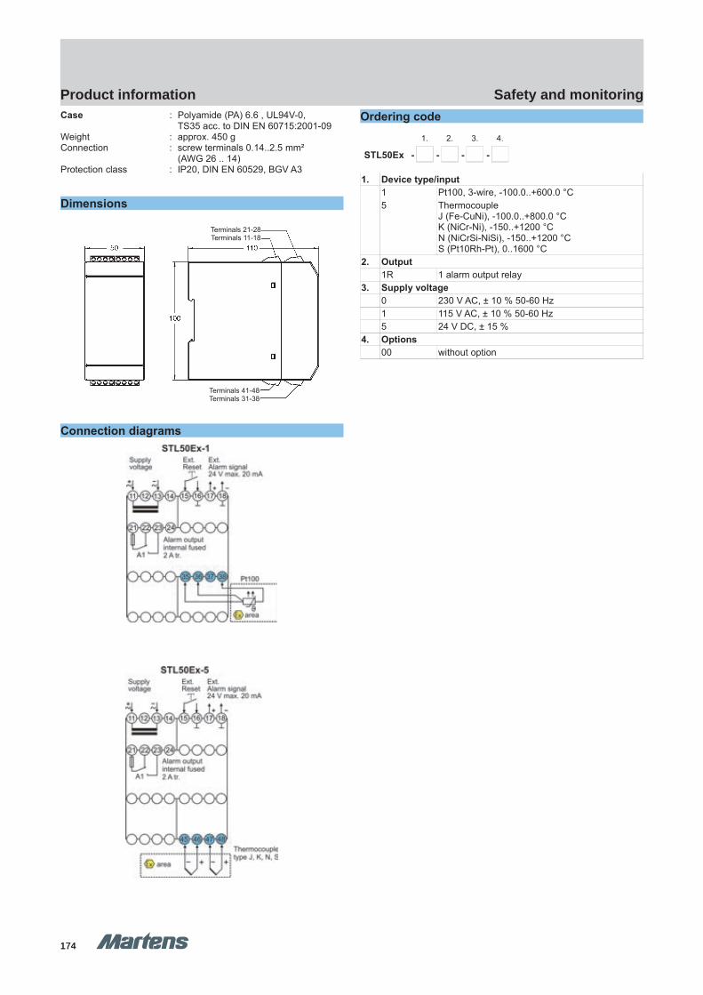
174174
Safety and monitoringProduct information
GHM Messtechnik GmbH – Location MartensKiebitzhörn 18 22885 Barsbüttel Germany Fon +49-40-670 73-0 Fax -288www.ghm-messtechnik.de [email protected]
Product Information Industrial ElectronicsCase : Polyamide (PA) 6.6 , UL94V-0,
TS35 acc. to DIN EN 60715:2001-09Weight : approx. 450 gConnection : screw terminals 0.14..2.5 mm²
(AWG 26 .. 14)Protection class : IP20, DIN EN 60529, BGV A3
Dimensions
Connection diagrams
Ordering code1. 2. 3. 4.
STL50Ex - - - -
1. Device type/input1 Pt100, 3-wire, -100.0..+600.0 °C5 Thermocouple
J (Fe-CuNi), -100.0..+800.0 °CK (NiCr-Ni), -150..+1200 °CN (NiCrSi-NiSi), -150..+1200 °CS (Pt10Rh-Pt), 0..1600 °C
2. Output1R 1 alarm output relay
3. Supply voltage0 230 V AC, ± 10 % 50-60 Hz1 115 V AC, ± 10 % 50-60 Hz5 24 V DC, ± 15 %
4. Options00 without option
pi-ma-Monitoring_E V3.01-00
23
Terminals 41-48Terminals 31-38
Terminals 21-28Terminals 11-18

175175
Safety and monitoringProduct information
E4 Sa
fety
and m
onito
ring
GHM Messtechnik GmbH – Location MartensKiebitzhörn 18 22885 Barsbüttel Germany Fon +49-40-670 73-0 Fax -288www.ghm-messtechnik.de [email protected]
Product Information Industrial Electronics
Alarm-Display SD9648
CharacteristicsThe Alarm-Display SD9648 will be used for indicating and evalu-ations of alarm signals as well as analog measured values. Activa-tion with voltage free contacts, 0/24 V signals or 0/4..20 mA formonitoring of analog measuring values.
Technical dataPower supplySupply voltage : 230 V AC ±10 %, 115 V AC ±10 %,
24 V AC ±10 %, 24 V DC ±15 %Frequency AC : 50 / 60 HzPower consumption : max. 3.5 VAOperatingtemperature : 0..50 °CCE- conformity : EN55022, EN60555,
IEC61000-4-3/4/5/11/13InputsDigital : 0 / 24 V DC, Ri = 10 kΩ,
switching threshold low < 4 V, high >11 V max. 35 V
Impulse/pause : min. 10 msAnalog : 0 / 4..20 mA, Ri = 100 Ω
voltage drop max. 2.2 V at 20 mAover-load limit approx. 23 mA (max. voltage 35 V). With powerless device the inputs be-came a high resistance
Accuracy : 0.1 %, ± 1 DigitTransmitter supply : Uo = 24 V, Ri 150 Ω, max. 50 mADisplay : LCD-dot matrix display white / blue,
character height 6.5 mm, with back-lite2 lines 16 characters each
Display interval : 0.5 s (refresh time)OutputRelay SPDT : < 250 V AC < 250 VA < 2 A,
< 300 V DC < 50 W < 2 ACase : panel case DIN 96x48,
Material PA6-GF; UL94V-0Dimensions : front 96x48 mm, mounting depth 100mmWeight : max. 390 gConnection : clamp terminals, 0.08..1.5 mm²,
AWG28..AWG14Protection class : front IP65, terminals IP20 acc. to BGV A3
Dimensions
Connection diagram
Ordering code1. 2. 3. 4. 5.
SD9648 - - - - -
1. Inputs1 20 digital inputs2 12 digital + 8 analog inputs
2. Real time clock 0 without clock1 with clock
3. Supply voltage0 230 V AC ±10 % 50-60Hz1 115 V AC ±10 % 50-60Hz4 24 V AC ±10 % 50-60Hz5 24 V DC ±15 %
4. Options00 without option
5. Additional text above the display (3x90mm HxW)
24 pi-ma-Monitoring_E V3.01-00
seal
SD9648 SD9648
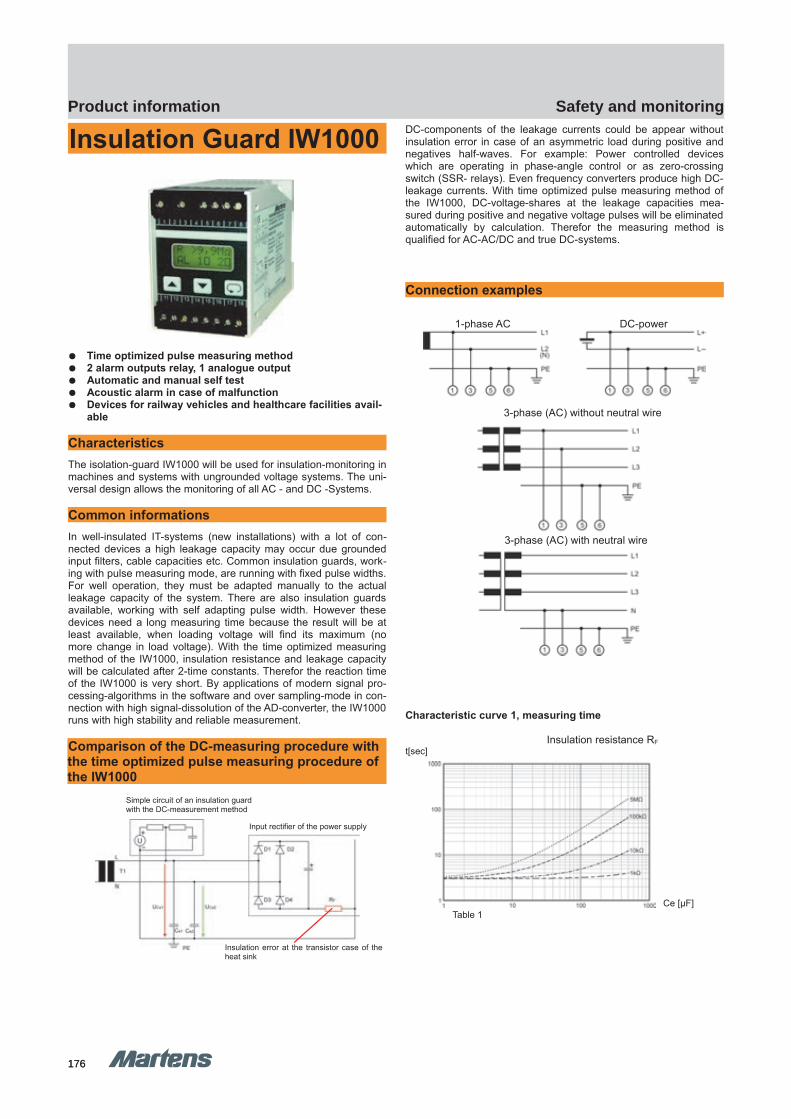
176176
Safety and monitoringProduct information
GHM Messtechnik GmbH – Location MartensKiebitzhörn 18 22885 Barsbüttel Germany Fon +49-40-670 73-0 Fax -288www.ghm-messtechnik.de [email protected]
Product Information Industrial Electronics
Insulation Guard IW1000
Time optimized pulse measuring method 2 alarm outputs relay, 1 analogue output Automatic and manual self test Acoustic alarm in case of malfunction Devices for railway vehicles and healthcare facilities avail-
able
CharacteristicsThe isolation-guard IW1000 will be used for insulation-monitoring inmachines and systems with ungrounded voltage systems. The uni-versal design allows the monitoring of all AC - and DC -Systems.
Common informationsIn well-insulated IT-systems (new installations) with a lot of con-nected devices a high leakage capacity may occur due groundedinput filters, cable capacities etc. Common insulation guards, work-ing with pulse measuring mode, are running with fixed pulse widths.For well operation, they must be adapted manually to the actualleakage capacity of the system. There are also insulation guardsavailable, working with self adapting pulse width. However thesedevices need a long measuring time because the result will be atleast available, when loading voltage will find its maximum (nomore change in load voltage). With the time optimized measuringmethod of the IW1000, insulation resistance and leakage capacitywill be calculated after 2-time constants. Therefor the reaction timeof the IW1000 is very short. By applications of modern signal pro-cessing-algorithms in the software and over sampling-mode in con-nection with high signal-dissolution of the AD-converter, the IW1000runs with high stability and reliable measurement.
Comparison of the DC-measuring procedure with the time optimized pulse measuring procedure of the IW1000
DC-components of the leakage currents could be appear withoutinsulation error in case of an asymmetric load during positive andnegatives half-waves. For example: Power controlled deviceswhich are operating in phase-angle control or as zero-crossingswitch (SSR- relays). Even frequency converters produce high DC-leakage currents. With time optimized pulse measuring method ofthe IW1000, DC-voltage-shares at the leakage capacities mea-sured during positive and negative voltage pulses will be eliminatedautomatically by calculation. Therefor the measuring method isqualified for AC-AC/DC and true DC-systems.
Connection examples
1-phase AC DC-power
Characteristic curve 1, measuring time
Insulation resistance RFt[sec]
Ce [µF]Table 1
pi-ma-Monitoring_E V3.01-00
25
3-phase (AC) without neutral wire
3-phase (AC) with neutral wire
Simple circuit of an insulation guard with the DC-measurement method
Input rectifier of the power supply
Insulation error at the transistor case of theheat sink
IW1000 IW1000
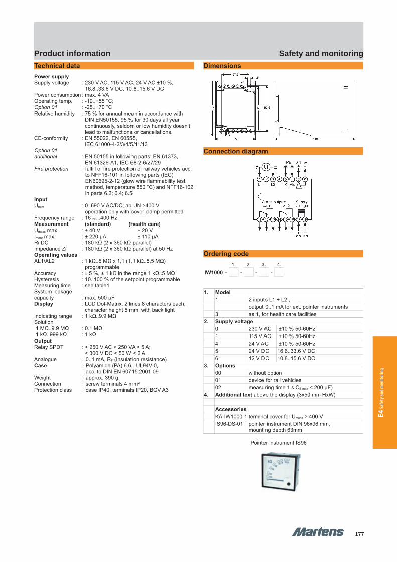
177177
Safety and monitoringProduct information
E4 Sa
fety
and m
onito
ring
GHM Messtechnik GmbH – Location MartensKiebitzhörn 18 22885 Barsbüttel Germany Fon +49-40-670 73-0 Fax -288www.ghm-messtechnik.de [email protected]
Product Information Industrial ElectronicsTechnical dataPower supplySupply voltage : 230 V AC, 115 V AC, 24 V AC ±10 %;
16.8..33.6 V DC, 10.8..15.6 V DCPower consumption: max. 4 VAOperating temp. : -10..+55 °C;Option 01 : -25..+70 °CRelative humidity : 75 % for annual mean in accordance with
DIN EN50155, 95 % for 30 days all year continuously, seldom or low humidity doesn’t lead to malfunctions or cancellations.
CE-conformity : EN 55022, EN 60555, IEC 61000-4-2/3/4/5/11/13
Option 01 additional : EN 50155 in following parts: EN 61373,
EN 61326-A1, IEC 68-2-6/27/29Fire protection : fulfill of fire protection of railway vehicles acc.
to NFF16-101 in following parts (IEC) EN60695-2-12 (glow wire flammability test method, temperature 850 °C) and NFF16-102in parts 6.2; 6.4; 6.5
InputUnom : 0..690 V AC/DC; ab UN >400 V
operation only with cover clamp permittedFrequency range : 16 2/3 ..400 HzMeasurement (standard) (health care)Umeas max. : ± 40 V ± 20 VImeas max. : ± 220 μA ± 110 μARi DC : 180 kΩ (2 x 360 kΩ parallel)Impedance Zi : 180 kΩ (2 x 360 kΩ parallel) at 50 HzOperating valuesAL1/AL2 : 1 kΩ..5 MΩ x 1,1 (1,1 kΩ..5,5 MΩ)
programmableAccuracy : ± 5 %, ± 1 kΩ in the range 1 kΩ..5 MΩHysteresis : 10..100 % of the setpoint programmableMeasuring time : see table1System leakagecapacity : max. 500 μFDisplay : LCD Dot-Matrix, 2 lines 8 characters each,
character height 5 mm, with back lightIndicating range : 1 kΩ..9.9 MΩSolution 1 MΩ..9.9 MΩ : 0.1 MΩ 1 kΩ..999 kΩ : 1 kΩOutputRelay SPDT : < 250 V AC < 250 VA < 5 A;
< 300 V DC < 50 W < 2 AAnalogue : 0..1 mA, RF (Insulation resistance)Case : Polyamide (PA) 6.6 , UL94V-0,
acc. to DIN EN 60715:2001-09Weight : approx. 390 gConnection : screw terminals 4 mm² Protection class : case IP40, terminals IP20, BGV A3
Dimensions
Connection diagram
Ordering code1. 2. 3. 4.
IW1000 - - - -
1. Model1 2 inputs L1 + L2 ,
output 0..1 mA for ext. pointer instruments3 as 1, for health care facilities
2. Supply voltage0 230 V AC ±10 % 50-60Hz1 115 V AC ±10 % 50-60Hz4 24 V AC ±10 % 50-60Hz5 24 V DC 16.6..33.6 V DC6 12 V DC 10.8..15.6 V DC
3. Options00 without option01 device for rail vehicles02 measuring time 1 s CE max < 200 µF)
4. Additional text above the display (3x50 mm HxW)
AccessoriesKA-IW1000-1 terminal cover for Umeas > 400 VIS96-DS-01 pointer instrument DIN 96x96 mm,
mounting depth 63mm
Pointer instrument IS96
26 pi-ma-Monitoring_E V3.01-00

E Industrial electronics
178
E Industrial electronics
179
E5 P
ower
elec
troni
c
Kapitel E5 Start
Power electronic
Power supplies
Power modules
Relay coupler
Current transformer
E5
180
186
194
196
Page
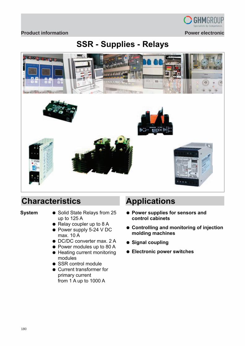
180
Power electronicProduct information
GHM Messtechnik GmbH – Sales Center InternationalSchloßstraße 6 88453 Erolzheim Germany Fon +49-7354-937233-0 Fax -88www.ghm-messtechnik.de [email protected]
Product Information Power Electronics
SSR - Supplies - Relays
Characteristics
System Solid State Relays from 25 up to 125 A
Relay coupler up to 8 A Power supply 5-24 V DC
max. 10 A DC/DC converter max. 2 A Power modules up to 80 A Heating current monitoring
modules SSR control module Current transformer for
primary currentfrom 1 A up to 1000 A
Applications
Power supplies for sensors and control cabinets
Controlling and monitoring of injectionmolding machines
Signal coupling
Electronic power switches
pi-ma-Power-electronics_E V1.00-00 1
Einleitung
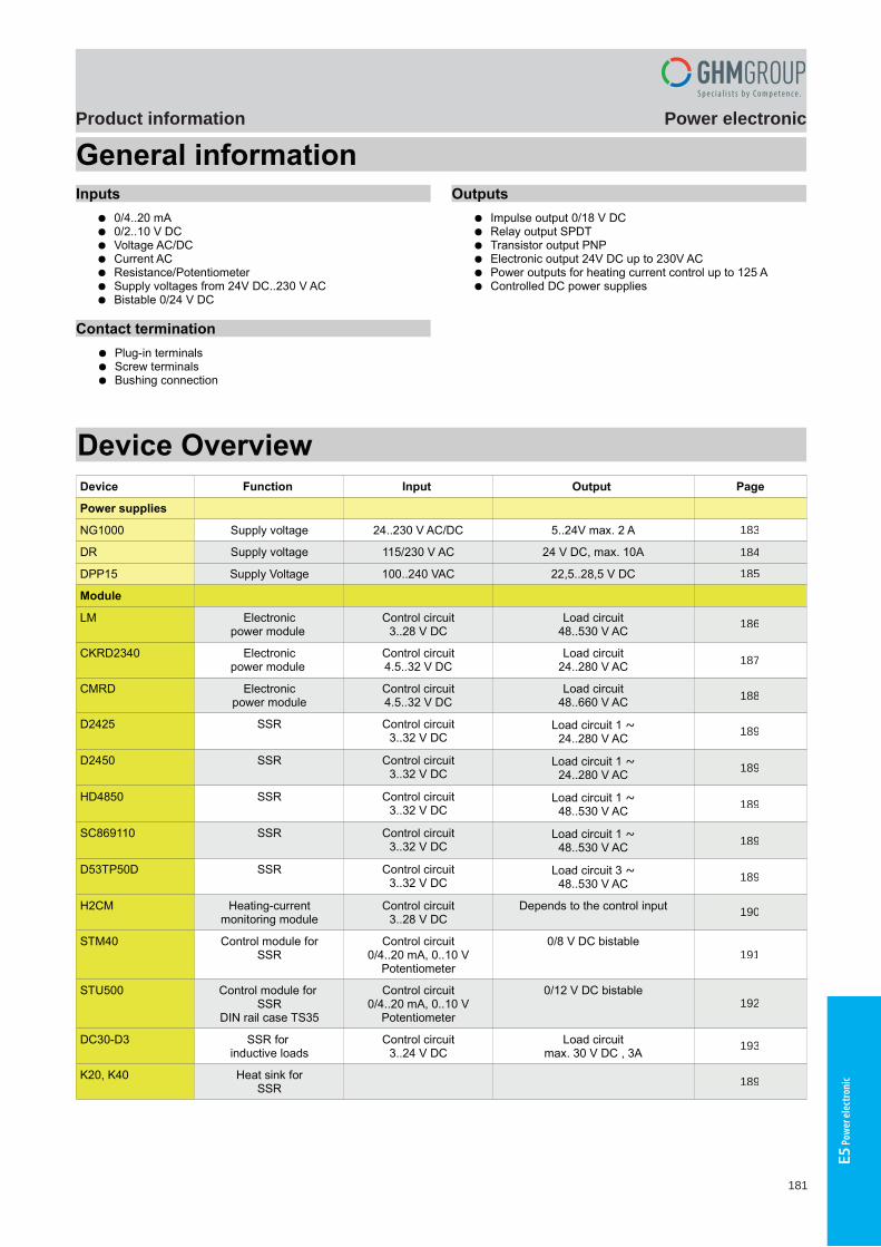
181
Power electronicProduct information
E5 P
ower
elec
troni
c
GHM Messtechnik GmbH – Sales Center InternationalSchloßstraße 6 88453 Erolzheim Germany Fon +49-7354-937233-0 Fax -88www.ghm-messtechnik.de [email protected]
Product Information Power Electronics
General informationInputs
0/4..20 mA 0/2..10 V DC Voltage AC/DC Current AC Resistance/Potentiometer Supply voltages from 24V DC..230 V AC Bistable 0/24 V DC
Contact termination
Plug-in terminals Screw terminals Bushing connection
Outputs
Impulse output 0/18 V DC Relay output SPDT Transistor output PNP Electronic output 24V DC up to 230V AC Power outputs for heating current control up to 125 A Controlled DC power supplies
Device Overview
Device Function Input Output Page
Power supplies
NG1000 Supply voltage 24..230 V AC/DC 5..24V max. 2 A 4
DR Supply voltage 115/230 V AC 24 V DC, max. 10A 5
DPP15 Supply Voltage 100..240 VAC 22,5..28,5 V DC 6
Module
LM Electronicpower module
Control circuit3..28 V DC
Load circuit48..530 V AC
7
CKRD2340 Electronicpower module
Control circuit4.5..32 V DC
Load circuit24..280 V AC
8
CMRD Electronicpower module
Control circuit4.5..32 V DC
Load circuit48..660 V AC
9
D2425 SSR Control circuit3..32 V DC
Load circuit 1 ~24..280 V AC
14
D2450 SSR Control circuit3..32 V DC
Load circuit 1 ~24..280 V AC
14
HD4850 SSR Control circuit3..32 V DC
Load circuit 1 ~48..530 V AC
14
SC869110 SSR Control circuit3..32 V DC
Load circuit 1 ~48..530 V AC
14
D53TP50D SSR Control circuit3..32 V DC
Load circuit 3 ~48..530 V AC
14
H2CM Heating-currentmonitoring module
Control circuit3..28 V DC
Depends to the control input 10
STM40 Control module forSSR
Control circuit0/4..20 mA, 0..10 V
Potentiometer
0/8 V DC bistable 11
STU500 Control module for SSR
DIN rail case TS35
Control circuit0/4..20 mA, 0..10 V
Potentiometer
0/12 V DC bistable 12
DC30-D3 SSR for inductive loads
Control circuit3..24 V DC
Load circuitmax. 30 V DC , 3A
13
K20, K40 Heat sink forSSR
14
2 pi-ma-Power-electronics_E V1.00-00
184
185
186
188
189
189
190
192
189
193
191
189
189
189
187
183

182
Power electronicProduct information
GHM Messtechnik GmbH – Sales Center InternationalSchloßstraße 6 88453 Erolzheim Germany Fon +49-7354-937233-0 Fax -88www.ghm-messtechnik.de [email protected]
Product Information Power Electronics
Device Function Input Output Page
Switching relay
RT424 Relay coupler 24V DC, 24V..230V AC
2 contacts SPDTmax. 8 A
15
PT570 Relay coupler 24V DC, 24V..230V AC
4 contacts SPDTmax. 6 A
16
Current transformer
ASW Slip-over currenttransformer
50..1000 A AC 1/5 A AC 17
WSW Wounded primary currenttransformer
1..40 A AC 1/5 A AC 17
Mistakes reserved, technical specifications subject to change without notice.
pi-ma-Power-electronics_E V1.00-00 3
196
194
195
196

183
Power electronicProduct information
E5 P
ower
elec
troni
c
GHM Messtechnik GmbH – Location MartensKiebitzhörn 18 22885 Barsbüttel Germany Fon +49-40-670 73-0 Fax -288www.ghm-messtechnik.de [email protected]
Product Information Power Electronics
DC Power SupplyNG1000
Characteristics
Full 2-port isolation Adjustable output voltage Current up to 2 A Stabilized, short circuit proof Power limiting with positive characteristics
Technical data
Input : see ordering codeFrequency : 47..63 HzOperating temperatureNG1000-1/2-X : -10..+50 °C NG1000-3/4-X : -10..+40 °CCE-conformity : acc. to EN 55022, EN 60555-2,
IEC 61000-4-4/5/11OutputVoltage : 5..12 / 24 V DC, adjustable via trimpot Max. current : see ordering codeOverload : output voltage will be reducedLoad controlNG1000-1/2-X : <50 mVNG1000-3/4-X : <70mVResidual rippleNG1000-1/2-X : <20 mVNG1000-3/4-X : <40 mVShort circuit current approx.NG1000-1-X : 290 mANG1000-2-X : 220 mANG1000-3-X : 2 ANG1000-4-X : 4 ACase : standard case of polycarbonate
8020 UL94V-1Weight : max. 380 gConnection : screw terminals with pressure plate,
max. 2.5 mm²Protection classNG1000-1/2 : case IP40, NG1000-3/4 : case IP30
terminals IP20 acc. to BGV A3
Dimensions
DIN rail mounting TS35 or 2 screws M4
Connection diagram
Input
Output
Ordering code
AC/DC Power supplies input 230 V AC ±10 %
Type Output*
NG1000-1-0 5..12 V DC; max. 250 mA
NG1000-2-0 12..24 V DC; max. 150 mA
NG1000-3-0 5..24 V DC; max. 1 A
NG1000-4-0 5..24 V DC; max. 2 A
DC/DC converter output 5..24V DC max. 1 A*
Type Input
NG1000-3-5 24 V DC ±20 %
NG1000-3-6 48 V DC ±20 %
NG1000-3-7 60 V DC ±20 %
NG1000-3-8 80 V DC ±20 %
NG1000-3-9 110 V DC ±20 %
NG1000-3-10 220 V DC ±20 %
DC/DC converter output 5..24V DC max. 2 A*
Type Input
NG1000-4-5 24 V DC ±20 %
NG1000-4-6 48 V DC ±20 %
NG1000-4-7 60 V DC ±20 %
NG1000-4-8 80 V DC ±20 %
NG1000-4-9 110 V DC ±20 %
NG1000-4-10 220 V DC ±20 %
* The output voltage is adjusted to the minimum at delivery.
4 pi-ma-Power-electronics_E V1.00-00
NG1000 NG1000
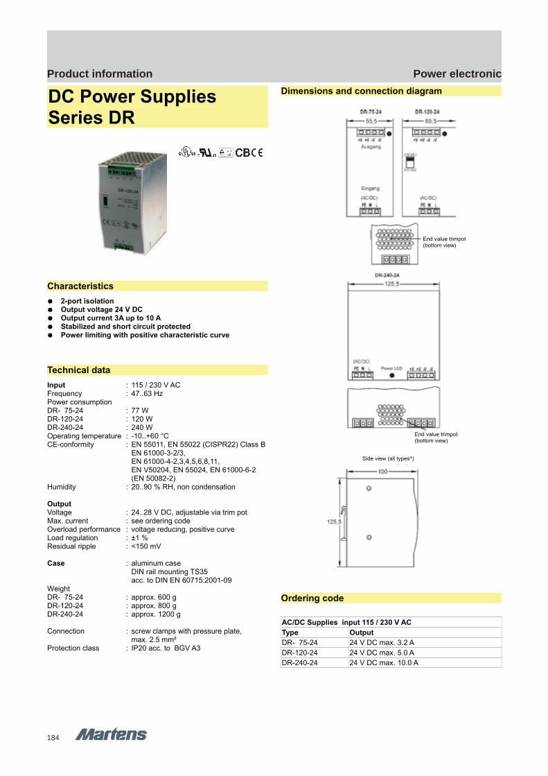
184
Power electronicProduct information
GHM Messtechnik GmbH – Location MartensKiebitzhörn 18 22885 Barsbüttel Germany Fon +49-40-670 73-0 Fax -288www.ghm-messtechnik.de [email protected]
Product Information Power Electronics
DC Power Supplies Series DR
Characteristics
2-port isolation Output voltage 24 V DC Output current 3A up to 10 A Stabilized and short circuit protected Power limiting with positive characteristic curve
Technical data
Input : 115 / 230 V AC Frequency : 47..63 HzPower consumptionDR- 75-24 : 77 WDR-120-24 : 120 WDR-240-24 : 240 WOperating temperature : -10..+60 °C CE-conformity : EN 55011, EN 55022 (CISPR22) Class B
EN 61000-3-2/3, EN 61000-4-2,3,4,5,6,8,11, EN V50204, EN 55024, EN 61000-6-2 (EN 50082-2)
Humidity : 20..90 % RH, non condensation
OutputVoltage : 24..28 V DC, adjustable via trim potMax. current : see ordering codeOverload performance : voltage reducing, positive curveLoad regulation : ±1 %Residual ripple : <150 mV
Case : aluminum case DIN rail mounting TS35acc. to DIN EN 60715:2001-09
WeightDR- 75-24 : approx. 600 gDR-120-24 : approx. 800 gDR-240-24 : approx. 1200 g
Connection : screw clamps with pressure plate,max. 2.5 mm²
Protection class : IP20 acc. to BGV A3
Dimensions and connection diagram
Ordering code
AC/DC Supplies input 115 / 230 V AC
Type Output
DR- 75-24 24 V DC max. 3.2 A
DR-120-24 24 V DC max. 5.0 A
DR-240-24 24 V DC max. 10.0 A
pi-ma-Power-electronics_E V1.00-00 5
Side view (all types^)
End value trimpot(bottom view)
End value trimpot(bottom view)
DR series DR series
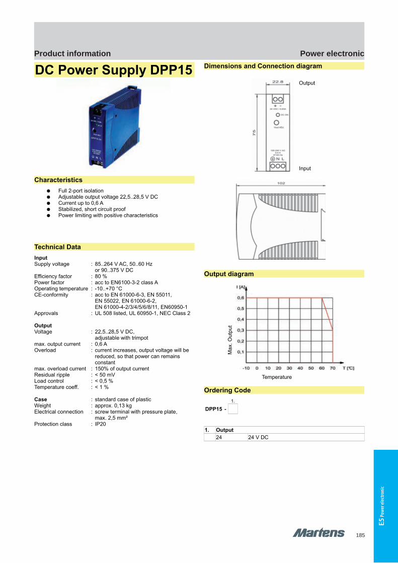
185
Power electronicProduct information
E5 P
ower
elec
troni
c
GHM Messtechnik GmbH – Location MartensKiebitzhörn 18 22885 Barsbüttel Germany Fon +49-40-670 73-0 Fax -288www.ghm-messtechnik.de [email protected]
Product Information Power Electronics
DC Power Supply DPP15
Characteristics
Full 2-port isolation Adjustable output voltage 22,5..28,5 V DC Current up to 0,6 A Stabilized, short circuit proof Power limiting with positive characteristics
Technical Data
InputSupply voltage : 85..264 V AC, 50..60 Hz
or 90..375 V DCEfficiency factor : 80 % Power factor : acc to EN6100-3-2 class AOperating temperature : -10..+70 °CCE-conformity : acc to EN 61000-6-3, EN 55011,
EN 55022, EN 61000-6-2,EN 61000-4-2/3/4/5/6/8/11, EN60950-1
Approvals : UL 508 listed, UL 60950-1, NEC Class 2
OutputVoltage : 22,5..28,5 V DC,
adjustable with trimpotmax. output current : 0,6 A Overload : current increases, output voltage will be
reduced, so that power can remainsconstant
max. overload current : 150% of output currentResidual ripple : < 50 mVLoad control : < 0,5 %Temperature coeff. : < 1 %
Case : standard case of plasticWeight : approx. 0,13 kgElectrical connection : screw terminal with pressure plate,
max. 2,5 mm²Protection class : IP20
Dimensions and Connection diagram
Output
Input
Output diagram
Temperature
Ordering Code
1.
DPP15 -
1. Output
24 24 V DC
6 pi-ma-Power-electronics_E V1.00-00
Ma
x. O
utp
ut
DPP15 DPP15
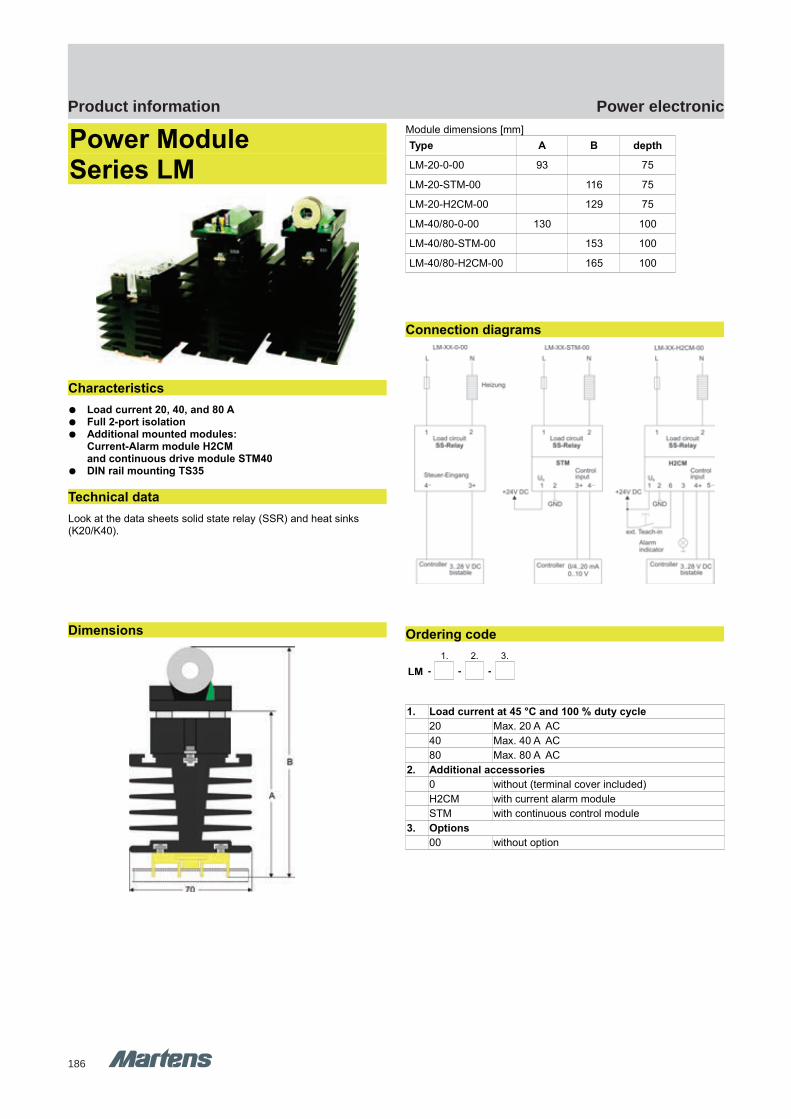
186
Power electronicProduct information
GHM Messtechnik GmbH – Location MartensKiebitzhörn 18 22885 Barsbüttel Germany Fon +49-40-670 73-0 Fax -288www.ghm-messtechnik.de [email protected]
Product Information Power Electronics
Power Module Series LM
Characteristics
Load current 20, 40, and 80 A Full 2-port isolation Additional mounted modules:
Current-Alarm module H2CM and continuous drive module STM40
DIN rail mounting TS35
Technical data
Look at the data sheets solid state relay (SSR) and heat sinks (K20/K40).
Dimensions
Module dimensions [mm]
Type A B depth
LM-20-0-00 93 75
LM-20-STM-00 116 75
LM-20-H2CM-00 129 75
LM-40/80-0-00 130 100
LM-40/80-STM-00 153 100
LM-40/80-H2CM-00 165 100
Connection diagrams
Ordering code
1. 2. 3.
LM - - -
1. Load current at 45 °C and 100 % duty cycle
20 Max. 20 A AC
40 Max. 40 A AC
80 Max. 80 A AC
2. Additional accessories
0 without (terminal cover included)
H2CM with current alarm module
STM with continuous control module
3. Options
00 without option
pi-ma-Power-electronics_E V1.00-00 7
LM series LM series
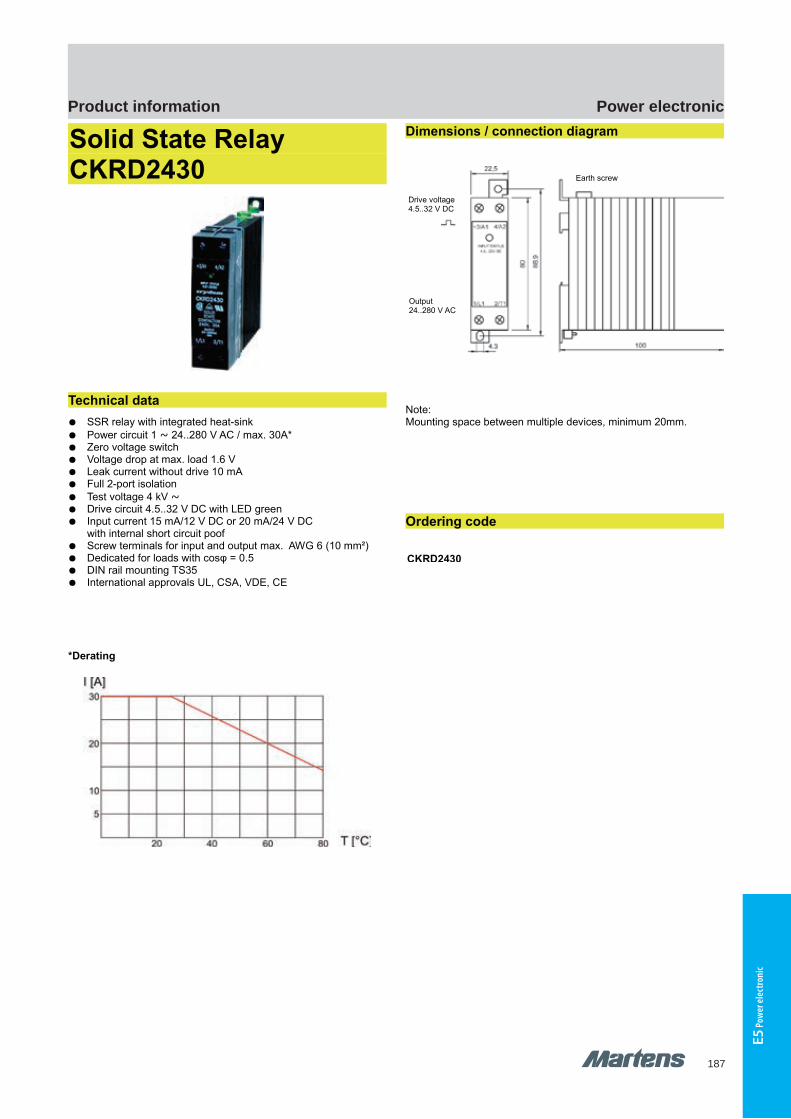
187
Power electronicProduct information
E5 P
ower
elec
troni
c
GHM Messtechnik GmbH – Location MartensKiebitzhörn 18 22885 Barsbüttel Germany Fon +49-40-670 73-0 Fax -288www.ghm-messtechnik.de [email protected]
Product Information Power Electronics
Solid State Relay CKRD2430
Technical data
SSR relay with integrated heat-sink
Power circuit 1 ~ 24..280 V AC / max. 30A* Zero voltage switch Voltage drop at max. load 1.6 V Leak current without drive 10 mA Full 2-port isolation
Test voltage 4 kV ~ Drive circuit 4.5..32 V DC with LED green Input current 15 mA/12 V DC or 20 mA/24 V DC
with internal short circuit poof Screw terminals for input and output max. AWG 6 (10 mm²) Dedicated for loads with cosφ = 0.5 DIN rail mounting TS35 International approvals UL, CSA, VDE, CE
*Derating
Dimensions / connection diagram
Note:Mounting space between multiple devices, minimum 20mm.
Ordering code
CKRD2430
8 pi-ma-Power-electronics_E V1.00-00
Earth screw
Drive voltage4.5..32 V DC
Output24..280 V AC
CKRD2430 CKRD2430
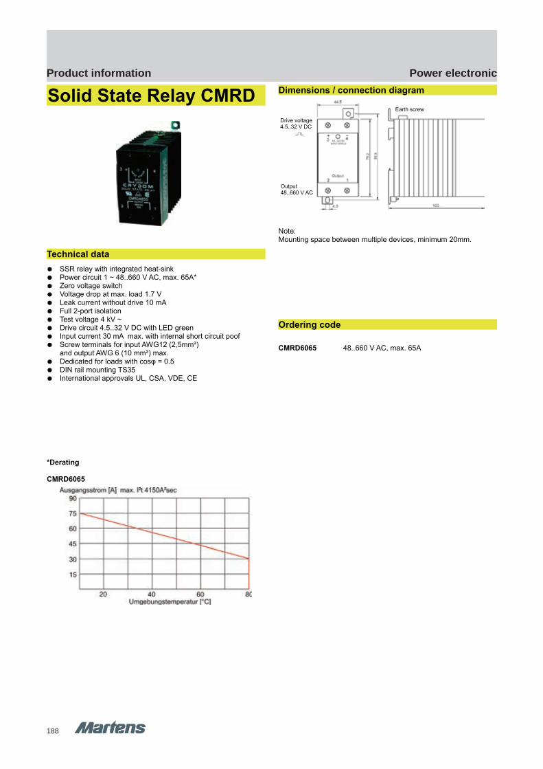
188
Power electronicProduct information
GHM Messtechnik GmbH – Location MartensKiebitzhörn 18 22885 Barsbüttel Germany Fon +49-40-670 73-0 Fax -288www.ghm-messtechnik.de [email protected]
Product Information Power Electronics
Solid State Relay CMRD
Technical data
SSR relay with integrated heat-sink Power circuit 1 ~ 48..660 V AC, max. 65A* Zero voltage switch Voltage drop at max. load 1.7 V Leak current without drive 10 mA Full 2-port isolation Test voltage 4 kV ~ Drive circuit 4.5..32 V DC with LED green Input current 30 mA max. with internal short circuit poof Screw terminals for input AWG12 (2,5mm²)
and output AWG 6 (10 mm²) max. Dedicated for loads with cosφ = 0.5 DIN rail mounting TS35 International approvals UL, CSA, VDE, CE
*Derating
CMRD6065
Dimensions / connection diagram
Note:Mounting space between multiple devices, minimum 20mm.
Ordering code
CMRD6065 48..660 V AC, max. 65A
pi-ma-Power-electronics_E V1.00-00 9
Earth screw
Drive voltage4.5..32 V DC
Output48..660 V AC
CMRD CMRD

189
Power electronicProduct information
E5 P
ower
elec
troni
c
GHM Messtechnik GmbH – Location MartensKiebitzhörn 18 22885 Barsbüttel Germany Fon +49-40-670 73-0 Fax -288www.ghm-messtechnik.de [email protected]
Product Information Power Electronics
1 ~ and 3 ~ Solid State Relay
1 ~ SSR
3 ~ SSR
Characteristics
Load circuit from 24V AC up to 530 V ACCurrent from 25 A up to 125 A
Zero voltage switch 2-port isolation Dedicated for loads up to cosφ 0.5 Case isolated Test voltage 4 kVeff Voltage drop at Imax 1.6 V UL and CSA certification
Ordering code / technical data
Type
1 ~
Drive circuit[V]
Load circuit[V AC]
Current[A]
Terminalcover
D2425 3-32 DC 24-280 25 KS100
D2450 3-32 DC 24-280 45 KS100
HD4850 3-32 DC 48-530 50 KS100
SC869110 3-32 DC 48-530 125 KS100
3 ~
D53TP50D 3-32 DC 48-530 50 KS300
Accessories
KS100 Terminal cover acc. to German BGV A3
KS300 Terminal cover acc. to German BGV A3
Heat sink K20, K40
Characteristics
Aluminum heat sink DIN rail mounting TS35 Mounting of the SSR without mechanical processing
Dimensions
Ordering code / technical data
Type Length[mm]
Thermal resistance[kW]
Weight [kg]
K20-75 75 1.5 0.42
K20-100 100 1.2 0.55
K40-75 75 1 0.72
K40-100 100 0.8 0.93
Accessories
K-MSSR1P Mounting set for 1 ~SSR
K-MSSR3P Mounting set for 3 ~SSR
WLP35 Thermal compound 35 gr. box
14 pi-ma-Power-electronics_E V1.00-00
Adapter plate andDIN rail TS35
Type K20 Type K40
Mounting slots forSSR with square head
nut M4 DIN 562
SC869110SC869110 D53TP50DD53TP50D D2425D2425 D2450D2450 HD4850HD4850 K20/K40K20/K40
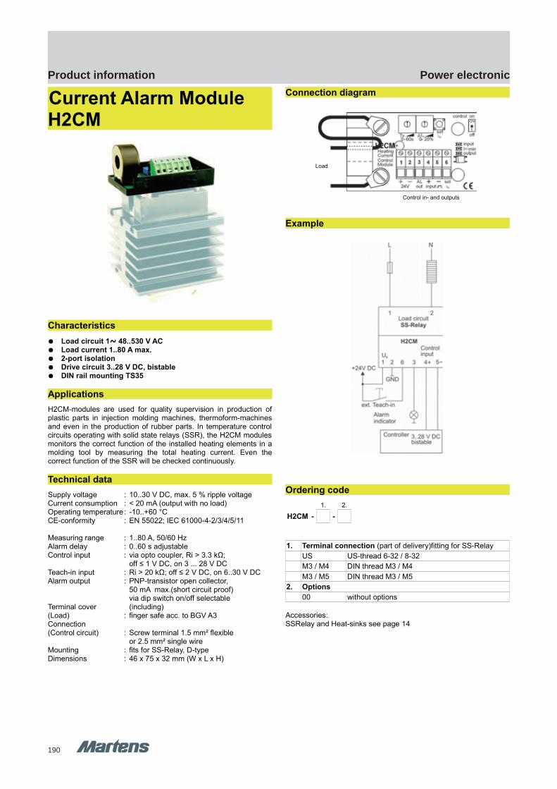
190
Power electronicProduct information
GHM Messtechnik GmbH – Location MartensKiebitzhörn 18 22885 Barsbüttel Germany Fon +49-40-670 73-0 Fax -288www.ghm-messtechnik.de [email protected]
Product Information Power Electronics
Current Alarm Module H2CM
Characteristics
Load circuit 1~ 48..530 V AC Load current 1..80 A max. 2-port isolation Drive circuit 3..28 V DC, bistable DIN rail mounting TS35
Applications
H2CM-modules are used for quality supervision in production ofplastic parts in injection molding machines, thermoform-machinesand even in the production of rubber parts. In temperature controlcircuits operating with solid state relays (SSR), the H2CM modulesmonitors the correct function of the installed heating elements in amolding tool by measuring the total heating current. Even thecorrect function of the SSR will be checked continuously.
Technical data
Supply voltage : 10..30 V DC, max. 5 % ripple voltageCurrent consumption : < 20 mA (output with no load)Operating temperature: -10..+60 °CCE-conformity : EN 55022; IEC 61000-4-2/3/4/5/11
Measuring range : 1..80 A, 50/60 HzAlarm delay : 0..60 s adjustableControl input : via opto coupler, Ri > 3.3 kΩ;
off ≤ 1 V DC, on 3 ... 28 V DCTeach-in input : Ri > 20 kΩ; off ≤ 2 V DC, on 6..30 V DCAlarm output : PNP-transistor open collector,
50 mA max.(short circuit proof)via dip switch on/off selectable
Terminal cover (including)(Load) : finger safe acc. to BGV A3 Connection (Control circuit) : Screw terminal 1.5 mm² flexible
or 2.5 mm² single wireMounting : fits for SS-Relay, D-typeDimensions : 46 x 75 x 32 mm (W x L x H)
Connection diagram
Example
Ordering code
1. 2.
H2CM - -
1. Terminal connection (part of delivery)fitting for SS-Relay
US US-thread 6-32 / 8-32
M3 / M4 DIN thread M3 / M4
M3 / M5 DIN thread M3 / M5
2. Options
00 without options
Accessories:SSRelay and Heat-sinks see page 14
10 pi-ma-Power-electronics_E V1.00-00
Control in- and outputs
Load
H2CM H2CM

191
Power electronicProduct information
E5 P
ower
elec
troni
c
GHM Messtechnik GmbH – Location MartensKiebitzhörn 18 22885 Barsbüttel Germany Fon +49-40-670 73-0 Fax -288www.ghm-messtechnik.de [email protected]
Product Information Power Electronics
Continuous Input Drive Module STM40
Direct mounting on the SSR Multi purpose input for 0/4..20 mA, 0..10 V DC Supply isolated Driving max. 3 SSR in parallel mode
Characteristics
STM40 modules are used in temperature control systems inconnection with solid-state-relays (SSR). It converts continuousinput-signals from SPS or other controllers into a pulse-width-controlled signal, suitable to operate with SSR. Input-signal may be0/4..20 mA or 0..10 V or an external potentiometer. One STM40module can drive additional 2 external SSR, except when operatingin potentiometer mode.
Technical data
Power supplySupply voltage : 10.8..30 V DC, 17..30 V ACPower consumption : appr. 1.3 VAOperating temperature : -10..+60 °CCE-conformity : EN 55022; EN 60555 IEC 61000-4-4/5/11/13
Control inputVoltage : 0..10 V DC, Ri = 40 kΩ, 3-times overloadCurrent : 0/4..20 mA, Ri = 125 Ω, 3-times overloadResistance : or potentiometer 1 kΩ..100 kΩOutputOutput clock : bistable 0/8 V DC, max. 20 mA
additional output for 2 SSR in parallel modeClock cycle : 1 sTerminal cover (Load) : acc. to German BGV A3 (included)Connection(Control circuit) : screw terminal 1.5 mm² flexible wire
or 2.5 mm² single wireMounting : on SSR, D-typeDimensions : 46x75x32 mm (WxLxH)
Connection diagram
Ordering code
1. 2.
STM40 - -
1. Terminal connection (including) fitting for SSR
US US-thread 6-32 / 8-32
M3 / M4 DIN thread M3 / M4
M3 / M5 DIN thread M3 / M5
2. Options
00 without option
Accessories
PES30-10k Potentiometer installation set, complete with 10 k Poti, mounting hole 22,5mm
Potentiometer installation set
pi-ma-Power-electronics_E V1.00-00
11
STM40 module STM40 module
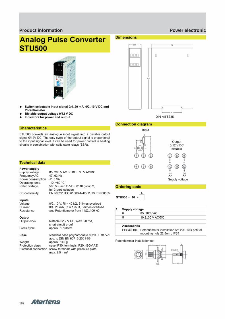
192
Power electronicProduct information
GHM Messtechnik GmbH – Location MartensKiebitzhörn 18 22885 Barsbüttel Germany Fon +49-40-670 73-0 Fax -288www.ghm-messtechnik.de [email protected]
Product Information Power Electronics
Analog Pulse Converter STU500
Switch selectable input signal 0/4..20 mA, 0/2..10 V DC and Potentiometer
Bistable output voltage 0/12 V DC Indicators for power and output
Characteristics
STU500 converts an analogue input signal into a bistable outputsignal 0/12V DC. The duty cycle of the output signal is proportionalto the input signal level. It can be used for power control in heatingcircuits in combination with solid state relays (SSR).
Technical data
Power supplySupply voltage : 85..265 V AC or 10.8..30 V AC/DCFrequency AC : 47..63 HzPower consumption : <1.5 VAOperating temp. : -10..+60 °CRated voltage : 500 V acc to VDE 0110 group 2,≃
full 3-port isolationCE-conformity : EN 50022, IEC 61000-4-4/5/11/13, EN 60555
InputsVoltage : 0/2..10 V, Ri = 40 kΩ, 3-times overloadCurrent : 0/4..20 mA, Ri = 125 Ω, 3-times overloadResistance : and Potentiometer from 1 kΩ..100 kΩ
OutputOutput clock : bistable 0/12 V DC, max. 20 mA,
short-circuit-proofClock cycle : approx. 1 pulse/s
Case : standard case polycarbonate 8020 UL 94 V-1acc. to DIN EN 60715:2001-09
Weight : approx. 140 gProtection class : case IP30, terminals IP20, (BGV A3)Electrical connection : screw terminals with pressure plate
max. 2.5 mm²
Dimensions
DIN rail TS35
Connection diagram
Ordering code
1.
STU500 - 10 -
1. Supply voltage
0 85..265V AC
5 10.8..30 V AC/DC
Accessories
PES30-10k Potentiometer installation set incl. 10 k poti for mounting hole 22.5mm, IP65
Potentiometer installation set
12 pi-ma-Power-electronics_E V1.00-00
Input
Output0/12 V DC
bistable
Supply voltage
STU500 STU500
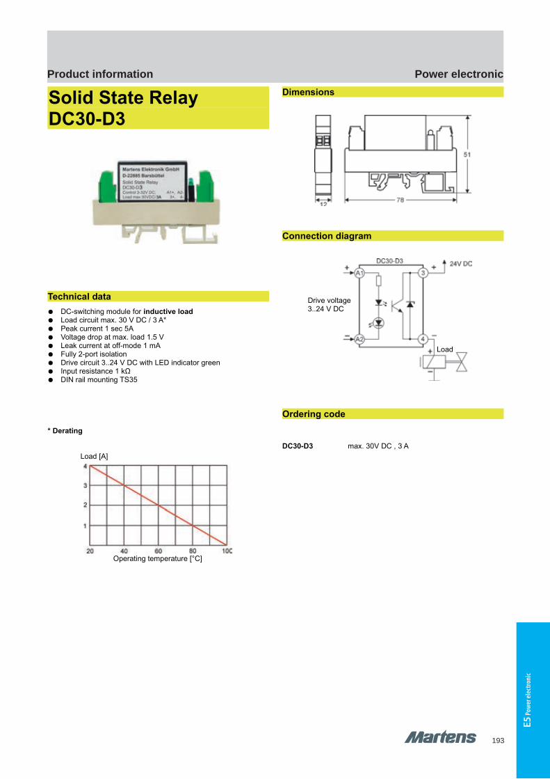
193
Power electronicProduct information
E5 P
ower
elec
troni
c
GHM Messtechnik GmbH – Location MartensKiebitzhörn 18 22885 Barsbüttel Germany Fon +49-40-670 73-0 Fax -288www.ghm-messtechnik.de [email protected]
Product Information Power Electronics
Analog Pulse Converter STU500
Switch selectable input signal 0/4..20 mA, 0/2..10 V DC and Potentiometer
Bistable output voltage 0/12 V DC Indicators for power and output
Characteristics
STU500 converts an analogue input signal into a bistable outputsignal 0/12V DC. The duty cycle of the output signal is proportionalto the input signal level. It can be used for power control in heatingcircuits in combination with solid state relays (SSR).
Technical data
Power supplySupply voltage : 85..265 V AC or 10.8..30 V AC/DCFrequency AC : 47..63 HzPower consumption : <1.5 VAOperating temp. : -10..+60 °CRated voltage : 500 V acc to VDE 0110 group 2,≃
full 3-port isolationCE-conformity : EN 50022, IEC 61000-4-4/5/11/13, EN 60555
InputsVoltage : 0/2..10 V, Ri = 40 kΩ, 3-times overloadCurrent : 0/4..20 mA, Ri = 125 Ω, 3-times overloadResistance : and Potentiometer from 1 kΩ..100 kΩ
OutputOutput clock : bistable 0/12 V DC, max. 20 mA,
short-circuit-proofClock cycle : approx. 1 pulse/s
Case : standard case polycarbonate 8020 UL 94 V-1acc. to DIN EN 60715:2001-09
Weight : approx. 140 gProtection class : case IP30, terminals IP20, (BGV A3)Electrical connection : screw terminals with pressure plate
max. 2.5 mm²
Dimensions
DIN rail TS35
Connection diagram
Ordering code
1.
STU500 - 10 -
1. Supply voltage
0 85..265V AC
5 10.8..30 V AC/DC
Accessories
PES30-10k Potentiometer installation set incl. 10 k poti for mounting hole 22.5mm, IP65
Potentiometer installation set
12 pi-ma-Power-electronics_E V1.00-00
Input
Output0/12 V DC
bistable
Supply voltage
GHM Messtechnik GmbH – Location MartensKiebitzhörn 18 22885 Barsbüttel Germany Fon +49-40-670 73-0 Fax -288www.ghm-messtechnik.de [email protected]
Product Information Power Electronics
Solid State Relay DC30-D3
Technical data
DC-switching module for inductive load Load circuit max. 30 V DC / 3 A* Peak current 1 sec 5A Voltage drop at max. load 1.5 V Leak current at off-mode 1 mA Fully 2-port isolation Drive circuit 3..24 V DC with LED indicator green Input resistance 1 kΩ DIN rail mounting TS35
* Derating
Load [A]
Operating temperature [°C]
Dimensions
Connection diagram
Ordering code
DC30-D3 max. 30V DC , 3 A
pi-ma-Power-electronics_E V1.00-00
13
Drive voltage3..24 V DC
Load
DC30-D3 DC30-D3
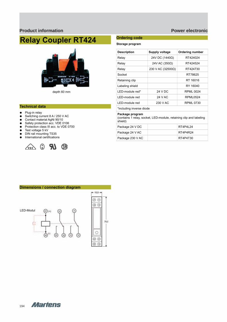
194
Power electronicProduct information
GHM Messtechnik GmbH – Location MartensKiebitzhörn 18 22885 Barsbüttel Germany Fon +49-40-670 73-0 Fax -288www.ghm-messtechnik.de [email protected]
Product Information Power Electronics
Relay Coupler RT424
depth 60 mm
Technical data
Plug-in relay Switching current 8 A / 250 V AC Contact material AgNi 90/10 Safety protection acc. VDE 0106 Protection class III acc. to VDE 0700 Test voltage 5 kV DIN rail mounting TS35 International certifications
Dimensions / connection diagram
Ordering code
Storage program
Description Supply voltage Ordering number
Relay 24V DC (1440Ω) RT424024
Relay 24V AC (350Ω) RT424524
Relay 230 V AC (32500Ω) RT424730
Socket RT78625
Retaining clip RT 16016
Labeling shield RY 16040
LED-module red* 24 V DC RPML 0024
LED-module red 24 V AC RPML0524
LED-module red 230 V AC RPML 0730
*including inverse diode
Package program(contains 1 relay, socket, LED-module, retaining clip and labeling shield)
Package 24 V DC RT4P4L24
Package 24 V AC RT4P4R24
Package 230 V AC RT4P4T30
pi-ma-Power-electronics_E V1.00-00
15
LED-Modul
RT424 RT424

195
Power electronicProduct information
E5 P
ower
elec
troni
c
GHM Messtechnik GmbH – Location MartensKiebitzhörn 18 22885 Barsbüttel Germany Fon +49-40-670 73-0 Fax -288www.ghm-messtechnik.de [email protected]
Product Information Power Electronics
Relay Coupler PT570
depth 73 mm
Technical data
Plug-in relay Switching current 6 A / 250 V AC Contact material AgNi 90/10 Safety protection acc. to IEC664 / VDE 0106 Protection class III acc. to VDE 0110b Test voltage 2 kV Finger safe test button, lock or unlock possible DIN rail mounting TS35 International certifications
Dimensions / connection diagram
Ordering code
Storage program
Description Supply voltage Ordering number
Relay 24 V DC (1780 Ω) PT570024
Relay 24 V AC (190 Ω) PT570524
Relay 230 V AC (19470 Ω) PT570730
Socket PT78704
Retaining clip PT16016
Labeling shield PT16040
LED-module red* 24 V DC RPML0024
LED-module red 24 V AC RPML0524
LED-module red 230 V AC RPML0730
*including inverse diode
Package program(contains 1 relay, socket, LED-module, retaining clip and labeling shield)
Package 24 V DC PT4P4L24
Package 24 V AC PT4P4R24
Package 230 V AC PT4P4T30
16 pi-ma-Power-electronics_E V1.00-00
LED-module
PT570 PT570
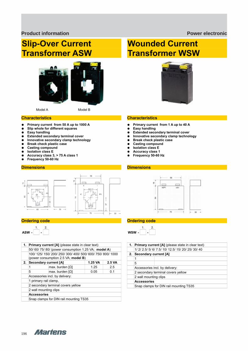
196
Power electronicProduct information
GHM Messtechnik GmbH – Location MartensKiebitzhörn 18 22885 Barsbüttel Germany Fon +49-40-670 73-0 Fax -288www.ghm-messtechnik.de [email protected]
Product Information Power Electronics
Slip-Over Current Transformer ASW
Model A Model B
Characteristics
Primary current from 50 A up to 1000 A Slip whole for different squares Easy handling Extended secondary terminal cover Innovative secondary clamp technology Break check plastic case Casting compound Isolation class E Accuracy class 3, > 75 A class 1 Frequency 50-60 Hz
Dimensions
Ordering code
1. 2.
ASW - -
1. Primary current [A] (please state in clear text)
50/ 60/ 75/ 80/ (power consumption 1.25 VA; model A)
100/ 125/ 150/ 200/ 250/ 300/ 400/ 500/ 600/ 750/ 800/ 1000 (power consumption 2.5 VA; model B)
2. Secondary current [A] 1.25 VA 2.5 VA
1 max. burden [Ω] 1.25 2.5
5 max. burden [Ω] 0.05 0.1
Accessories incl. by delivery:
1 primary rail clamp,
2 secondary terminal covers yellow
2 wall mounting clips
Accessories
Snap clamps for DIN rail mounting TS35
Wounded Current Transformer WSW
Characteristics
Primary current from 1 A up to 40 A Easy handling Extended secondary terminal cover Innovative secondary clamp technology Break check plastic case Casting compound Isolation class E Accuracy class 1 Frequency 50-60 Hz
Dimensions
Ordering code
1. 2.
WSW - -
1. Primary current [A] (please state in clear text)
1/ 2/ 2.5/ 5/ 6/ 7.5/ 10/ 12.5/ 15/ 20/ 25/ 30/ 40
2. Secondary current [A]
1
5
Accessories incl. by delivery:
2 secondary terminal covers yellow
2 wall mounting clips
Accessories
Snap clamps for DIN rail mounting TS35
pi-ma-Power-electronics_E V1.00-00
17
ASW WSW WSWASW

197
Notizen

198
Notizen

199
GHM GROUP - general terms and conditions of businessThis document has been translated from German into English. In case of doubt, the German version shall always take precedence.
§ 1 Field of Application and Denitions1. For legal relationships between the GHM Group (hereinafter GHM) and customers, these General Terms and Conditions of Business shall apply exclusively. Any condi-tions in deviation, contradiction or addition to these Terms, are hereby excluded even if known, unless there is express written agreement to the customer’s contra-dicting Conditions of Business.2. For the purposes of these Terms, a customer is an entrepreneur who places an order with GHM or who concludes a contract with GHM.3. For the purposes of this contract, according to § 14 of the German Civil Code, an entrepreneur is a natural or legal entity who makes contracts while practising their business or professional freelance activity. We do not supply to consumers as dened in § 13 of the German Civil Code.4. GHM reserves the right to change their Terms at any time. The customer is to be informed immediately about this in writing or via email. If the customer does not object within 2 weeks of the written notice or sending of the email, the imparted amendments to the Terms will be considered accepted by that customer. The messa-ge will inform the customer of the consequences of missing this deadline.§ 2 Concluding Contracts1. The product catalogues issued by GHM, as well as other brochures and technical documentation, are intended only for business customers and do not represent an oer to conclude a contract, but only an invitation to the customer to submit a writ-ten oer for a contract to GHM.2. Oers from GHM are non-binding. Contracts can only be concluded via delivery or written conrmation of an assignment. Verbal orders only become eective when they are conrmed by GHM in writing. Changes to signed contracts must be conr-med by GHM in writing in order to be eective.3. GHM reserves the right to change the technical data, shape and colour, and/or weight within reasonable bounds.4. If GHM is not supplied correctly or promptly due to a circumstance beyond its control and therefore does not have the object of the contract available, GHM shall have the contractual right to withdraw from the contract. If this withdrawal right is used, the contract must be completely reversed and any received payments are to be returned.§ 3 Prices, Payments, Discounts, Interest on Late Payments, Oset1. All prices specied in the product catalogues, brochures and technical documen-tation issued by GHM are to be understood as without VAT unless we have indicated that they include VAT. Packaging, freight, postage and any other shipping costs are additionally to be paid by the customer unless otherwise agreed.2. Insofar as expressly xed prices are agreed upon, the given prices are based on GHM’s acquisition costs at the time the order was conrmed. In case of unforeseen increases in acquisition costs beyond GHM’s control, GHM reserves the right to raise the prices correspondingly if the delivery or service was not required within four months of signing the contract.3. If not otherwise agreed in writing, all payments must be made in full, without deduction, to the given payment recipient, within 30 days of the date of invoicing. A discount of 2% is given for payments made within 10 days. This discount is excluded if the customer is late with other payment obligations due to us.4. If payments are deferred or if the customer is in arrears with payments, the legal interest fees for lateness between companies will become due (currently 8% above the baseline interest according to § 288(2) of the German Civil Code). According to § 286 of the German Civil Code, lateness with payments occurs – even without a re-minder – no later than 30 days after receiving the goods or services and the invoice.5. The customer may only oset costs towards GHM with recognised or legally ef-fective claims.§ 4 Delivery and Transfer of Risk1. The location of service and fullment is the applicable GHM branch.2. If the customer requests the contractual object to be sent to another location, the danger of its becoming mislaid transfers to the customer when the goods are given to the freight carrier. In the absence of other agreements, GHM is free to select any type of shipping. The packaging material required for shipping will be invoiced separately and is to be recycled or properly disposed of by the customers at their own cost.3. Delivery dates and deadlines are only considered binding if the contract parties have expressly made an agreement in this regard. In case of doubt, delivery periods begin on the date of job conrmation. If there is a temporary hindrance to service which is beyond GHM’s control, the delivery dates and periods will extend corres-pondingly. This applies particularly in cases of force majeure, and strikes.4. GHM has the right to make partial deliveries.§ 5 Retention of Ownership1. GHM reserves the right of ownership over contractual objects for itself until all GHM’s claims towards the customer from the business relationship have been full-led. The customer is therefore obligated to handle the contractual objects with care. If there is an open account relationship, the reserved ownership covers the recogni-sed balance. Violation of this instruction shall give GHM the right to withdraw from the relevant contract.2. The customer is permitted to process the purchased object or combine it with other objects. Processing or combining is done for GHM. The new object resulting from this process (new goods) is to be carefully kept and used for us by the customer. In case of processing with other objects not belonging to the customer, we are owed an ownership share of the new goods, at a proportion determined by the relation of the value of the item we delivered which has been processed or combined, to the value of the other processed goods at the time of processing. If the customer purchases sole ownership of the new goods, the customer shall agree to assign to GHM partial ownership of the new goods in proportion to the value of the processed item we delivered and the other processed goods at the time of processing. 3. While ownership retention is applicable, the customer is not permitted to pawn
the goods or use them as security. Onselling is only permitted to resellers in the usual course of business and only on condition that the reseller receives full pay-ment from his customers or reserves the right that ownership only transfers to the customer when the customer has fullled his payment obligations.4. In case of pawning, seizure or other control or intervention of third parties regar-ding the contractual objects, the customer must inform GHM immediately.§ 6 Guarantee1. In case of faults in the contractual objects, guarantee claims are limited to repla-cement. If the fault is still present after two replacements, then the replacement isconsidered to have failed. The customer can then request an appropriate reduction in the price or withdraw from the contract.2. All guarantee claims expire in 12 months as of the legal start date of expiration. This period is not applicable if the law according to the German Civil Code §438(1) no. 2 (Buildings and Items for Buildings) and §634a(1) no. 2 (Building Faults) prescri-bes longer deadlines, or in case of deliberate action, fraudulent concealment of the fault, or if a guarantee of quality has not been fullled.3. Damage compensation to the client due to material fault is excluded. This does not apply in case of fraudulent concealment of the fault, if a guaranteed quality has not been fullled, if there is injury to life, body or health, or if GHM deliberately or grossly neglectfully violated its obligation. These stipulations do not change the bur-den of proof to the customer’s disadvantage. Further or other claims than those in this § 6 due to material fault from the entity making the order are excluded.§ 7 Exchanges and Repairs1. GHM is not obligated to replace or take back goods without fault, and in case ofspecial orders, replacement or return is excluded per se.2. If GHM states it is willing to take back a standard item without being obligated to do so according to guarantee laws or their own given guarantee, then 15% of the purchase price will be retained if the goods are undamaged. If the goods are dama-ged, additional necessary repair costs will also be deducted. The buyer is permitted to prove that damage or reduction in value has not occurred at all or is signicantly lower than the sum specied.3. If GHM is to carry out repairs for the customer which do not fall within guarantee laws or their own guarantee, the item for repair will be sent back to the client by default at the client’s own cost. If the customer requests a price quote for the repair, GHM has the right to invoice for this additional work to the amount of the actual costs incurred. 4. Special devices and modied standard versions cannot be exchanged or returned. A return subject to a return fee of 30 % of the purchase price can be agreed upon in special cases.§ 8 Limitation of LiabilityGHM is only liable in cases where it, its legal representative or a subcontractor/ful-lment agent is guilty of deliberate or gross negligence. This does not apply if the damages are for injury to life, the body or health, or in case of violation of contractual obligations.§ 9 Disposal of electronic devicesIf the contractual items delivered include such, their disposal is governed by the fol-lowing paragraphs regarding old devices (§ 3(3), German Electronics Law) which are used outside of private households (§ 3(4), German Electronics Law).1. The customer will dispose of the delivered electronic devices at the end of their useful lives at his own cost and according to relevant legal regulations. The custo-mer releases GHM from the manufacturer’s obligations according to § 10(2) and (3) of the German Electronics Law and therefore also from any connected claims from third parties. 2. If the delivered goods are passed on to industrial third parties, the customer must also obligate these parties in writing to dispose of the devices properly after the end of their lives, to bear the related costs for this, and to impose a similar obligation if they pass the devices on again.3. If the customer neglects to contractually obligate third parties to proper disposal and to obligate further recipients according to Para. 2 above, then the customer is obligated to take back the items after the end of their useful lives and dispose of them properly according to legal regulations. This shall also apply if the onwards obligation to the third party was not in writing and the third party disputes their responsibility for disposal.4. GHM’s right to have the customer take over and release GHM will not expire before two years have passed after the nal use of the device. This two-year expiry restric-tion begins no earlier than the date of the manufacturer receiving a written notice from the customer about the end of the device’s use. However, the claim on takeover and release will expire no later than 30 years after it comes into existence.5. Conformity with WEEE for all electronic devices from GHM is ensured, based on the existing registration at the Foundation for Registering Old Electronic Devices. Our WEEE registration number is DE 93889386.§ 10 Other1. The exclusive application of the law of the Federal Republic of Germany is agreed upon. The stipulations of the United Nations Convention on Contracts for the Inter-national Sale of Goods are not applicable.2. If the customer is a businessperson, a legal entity under public law or a special fund under public law, the agreed exclusive court of jurisdiction for any disputes from this contract is Regensburg. GHM shall also have the right to bring a case at the customer’s location.3. Should individual terms of this contract be ineective, this will not aect the ef-fectiveness of the remainder. In such a case, the ineective term is to be changed or extended so that the economic goal it targets is fullled. § 139 of the German Civil Code [Partial Invalidity] is hereby waived.
Version dated: 31.12.2016
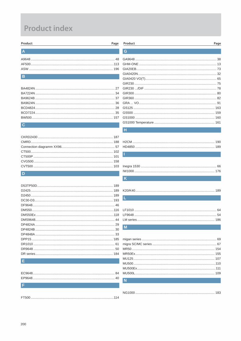
200
A9648 ............................................................................................. 48AF500 ............................................................................................113ASW ............................................................................................. 196
BA4824N ........................................................................................ 27BA7224N ........................................................................................ 34BA9624B ........................................................................................ 37BA9624N ........................................................................................ 36BCD4824 ........................................................................................ 28BCD7224 ........................................................................................ 35BW500 .......................................................................................... 157
CKRD2430 ................................................................................... 187CMRD ........................................................................................... 188Connection diagramm XX96........................................................... 57CT500 ........................................................................................... 102CT500P ........................................................................................ 101CVG500 ........................................................................................ 158CVT500 ........................................................................................ 103
D53TP50D .................................................................................... 189D2425 ........................................................................................... 189D2450 ........................................................................................... 189DC30-D3....................................................................................... 193DF9648 ........................................................................................... 46DMS50...........................................................................................116DMS50Ex ......................................................................................118DMS9648........................................................................................ 44DP4824A ........................................................................................ 29DP4824B ........................................................................................ 30DP4848A ........................................................................................ 33DPP15 .......................................................................................... 185DR1010 .......................................................................................... 61DR9648 .......................................................................................... 50DR series ...................................................................................... 184
EC9648........................................................................................... 84EP9648 ........................................................................................... 40
FT500 ............................................................................................114
GA9648 .......................................................................................... 38GHM-ONE ...................................................................................... 13GIA20EB......................................................................................... 73GIA0420N ....................................................................................... 32GIA0420 VO(T)............................................................................... 65GIR230 ........................................................................................... 75GIR230 .../DIF ................................................................................ 78GIR300 ........................................................................................... 80GIR360 ........................................................................................... 82GRA ... VO ...................................................................................... 91GS125 .......................................................................................... 163GS500 .......................................................................................... 159GS1000 ........................................................................................ 160GS1000 Temperature ................................................................... 161
H2CM ........................................................................................... 190HD4850 ........................................................................................ 189
Inegra 1530 .................................................................................... 66IW1000 ......................................................................................... 176
K20/K40 ........................................................................................ 189
LF1010 ........................................................................................... 64LF9648 ........................................................................................... 54LM series ...................................................................................... 186
migan series ................................................................................... 69migra SC/MC series ....................................................................... 67MR50 ............................................................................................ 154MR50Ex ........................................................................................ 155MU125 .......................................................................................... 107MU500 ...........................................................................................110MU500Ex .......................................................................................111MU500L ........................................................................................ 109
NG1000 ........................................................................................ 183
A
E
G
B
C
D
Product index
Product Page Product Page
M
H
I
K
L
F N

201
TTM-002, -004, -005, -009 ............................................................. 90TV125L ......................................................................................... 136TV125M ........................................................................................ 134TV500 ........................................................................................... 138TV500Ex ....................................................................................... 139TV500H ........................................................................................ 140TV500L ......................................................................................... 141TV500P ......................................................................................... 142TV501Ex ....................................................................................... 144TW500 .......................................................................................... 143
UT125 ........................................................................................... 120UZ1010 ........................................................................................... 63UZ9648 ........................................................................................... 53
V9648 ............................................................................................. 49VT500 ........................................................................................... 104
WM500 ......................................................................................... 105WSW ............................................................................................ 196
V
W
pH9648 ........................................................................................... 55PMT50-1 ....................................................................................... 122PMT50-2/-3................................................................................... 126PMT50Ex-1................................................................................... 124PMT50Ex-2/-3 .............................................................................. 128PR1010........................................................................................... 62PR9648........................................................................................... 51PT570 ........................................................................................... 195
R1140 ............................................................................................. 87R1300 ............................................................................................. 89RT424 ........................................................................................... 194RT500 ............................................................................................115
S1010 ............................................................................................. 58S9648 ............................................................................................. 42SC869110 ..................................................................................... 189SD9648......................................................................................... 175Series 9001 .................................................................................. 149SG1010 .......................................................................................... 95SG4824 .......................................................................................... 93SG9648 .......................................................................................... 94SP4824 ........................................................................................... 31SP9648 ........................................................................................... 41ST125M ........................................................................................ 134ST500 ........................................................................................... 138ST500Ex ....................................................................................... 139STL50 ........................................................................................... 171STL50Ex ....................................................................................... 173STM40 module ............................................................................. 191STU500 ........................................................................................ 192SZ9648 ........................................................................................... 52
T1010 ............................................................................................. 60T9648 ............................................................................................. 43TA1010 ........................................................................................... 59TA9648 ........................................................................................... 45TB225 ........................................................................................... 169TC500 ............................................................................................112TG50............................................................................................. 165TG50Ex ........................................................................................ 167TS125 ........................................................................................... 145TS225 ........................................................................................... 145TS500 ........................................................................................... 147TS500-Ex...................................................................................... 148
Product Page Product Page
P
R
S
Produktindex
U
T
T

202
NORTH
SOUTH
WEST
Sales Germany
Hans-Joachim PetermannKrögerstraße 3022145 HamburgPhone +49 40 67998410Fax +49 40 67998411Mobile +49 172 [email protected]
Sales area 1 + 2
Michael WulfKiebitzhörn 1822885 BarsbüttelPhone +49 40 67073-201Fax +49 40 67073-238Mobile +49 172 [email protected]
26000 – 2699927730 – 2777727794 – 27999
Sales area 10
29000 – 999930000 – 34999 37000 – 39999
Jörg WinterVor dem Lohholze 1729690 SchwarmstedtMobile +49 172 [email protected]
Sales area 5
Peter TaubertStralsunder Straße 14904349 LeipzigPhone +49 34298 159606Fax +49 34298 159605Mobile +49 171 [email protected]
Sales area 6
El LucasPhone +49 7354 937233-58Fax +49 7354 [email protected]
Customer support
70000 – 7999988000 – 89999
Sales area 980000 – 87999 90000 – 97999
Joachim Hö ingKleinhaslach 8090599 DietenhofenPhone +49 9824 928682Fax +49 9824 928681Mobile +49 172 8460512j.hoe [email protected]
Sales area 8
40000 – 4199945000 – 5099952000 – 52999
Jürgen KerstenKamperlingsweg 947906 KempenPhone +49 2152 80907-95Fax +49 2152 80907-97Mobile +49 172 [email protected]
Sales area 3
35000 – 3699942000 – 42999 44000 – 4499951000 – 51999 53000 – 53999
57000 – 59999 61000 – 61999
Stefan MüllerOttostraße 5142289 WuppertalPhone +49 202 6093374Mobile +49 171 [email protected]
Sales area 4
Thomas StumpeSales Director Germany / Austria
Phone +49 7354 937233-0Fax +49 7354 937233-88Mobile +49 172 4346882
Schloßstraße 688453 ErolzheimGERMANY
54000 – 5699960000 – 6099963000 – 69999
Christian RösnerJoseph-Berberich-Str. 863538 GroßkrotzenburgPhone +49 7354 937233-0Fax +49 7354 937233-88 Mobile +49 151 [email protected]
Sales area 7
NORTH NORTH
NORTH
NORTH
SOUTHSOUTH
WEST
WEST
WEST
17000 – 19999 20000 – 20449 20450 – 2045820459 – 21040 21041– 21450
21451 – 21480 21481 – 2150821509 – 2151321514 – 2199922000 – 22999
23000 – 2399924000 – 2599927000 – 2772927778 – 2779328000 – 28999
00000 – 09999 10000 – 16999 98000 – 99999
Sales Germany

203
Via G. Marconi 535030 Caselle di Selvazzano ITALY
Phone +39 049 8977150Fax +39 049 63 5596Mobile +39 340 [email protected]
Breitenseer Str. 76/1/36A-1140 Wien AUSTRIA
Phone +43 660 [email protected]
Andrea CasatiO ce Italy / Delta OHM S.r.l.
Alfred FröstlO ce Austria
Our International Area Sales Management Team
GHM Foreign Sales
Netherlands Czech Republic / Slovakia
Denmark South Africa Italy
GHM-Meettechniek BVZeeltweg 303755 KA EemnesNETHERLANDS
Phone +31 35 53805- 40Fax +31 35 53805- [email protected]
GHM-Greisinger s.r.o.Ovci hajek 2 / 2153158 00 Prague 5 Nove ButoviceCZECH REPUPLIC
Phone +420 251 613-828Fax +420 251 [email protected]
GHM Maaleteknik ApSMaarslet Byvej 28320 MaarsletDENMARK
Phone +45 6464 92-00Fax +45 6464 [email protected]
GHM Messtechnik SA (PTY) Ltd16 Olivier StreetVerwoerdpark, Alberton 1453SOUTH AFRICA
Phone +27 74 [email protected] www.ghm-sa.co.za
Delta OHM S.r.l.Via Marconi 535030 Caselle di SelvazzanoPadova (PD)ITALY
Phone +39 049 8977150Fax +39 049 635596 [email protected]
Occo AndriessenDirector
Michal DoubekDirector
Erling MathiesenDirector
Jan GroblerManaging Director
Carlo MeiSales Manager
GHM Sales Subsidiaries
Anita RencDirection sales international
Parimal SharmaSales Export
Feifan JinSales Export
Mina KamalSales Export
Peter WüsterSales Export
GHM GROUP – HeadquatersSchloßstraße 688453 ErolzheimGERMANY
GHM GROUP – HeadquatersSchloßstraße 688453 ErolzheimGERMANY
GHM GROUP – HeadquatersSchloßstraße 688453 ErolzheimGERMANY
GHM GROUP – HeadquatersSchloßstraße 688453 ErolzheimGERMANY
GHM GROUP – HonsbergTenter Weg 2-842897 RemscheidGERMANY
Phone +49 7354 937233- 401Mobile +49 173 [email protected]
Phone +49 7354 937233- 403 [email protected]
Phone +49 7354 937233- 405 [email protected]
Phone +49 7354 937233- [email protected]
Phone +49 2191 96 [email protected]
Area: South-East Asia, France, Swizzerland, Spain, PortugalZ
Area: Russia, India, Estonia, Lithuania, Latvia, Romania, Hungary, Bulgaria
Area: China, Japan, South Korea, South-East Asia
Area: Africa, Arabic States, Israel, Greece
Area: Scandinavia, UK, Ireland
Language: German, English, Italian, Czech
Language: English, Hindi, German
Language: Chinese, German, English
Language: English
Language: German, English
Sales international
NORTH
SOUTH
WEST
Sales Germany
Hans-Joachim PetermannKrögerstraße 3022145 HamburgPhone +49 40 67998410Fax +49 40 67998411Mobile +49 172 [email protected]
Sales area 1 + 2
Michael WulfKiebitzhörn 1822885 BarsbüttelPhone +49 40 67073-201Fax +49 40 67073-238Mobile +49 172 [email protected]
26000 – 2699927730 – 2777727794 – 27999
Sales area 10
29000 – 999930000 – 34999 37000 – 39999
Jörg WinterVor dem Lohholze 1729690 SchwarmstedtMobile +49 172 [email protected]
Sales area 5
Peter TaubertStralsunder Straße 14904349 LeipzigPhone +49 34298 159606Fax +49 34298 159605Mobile +49 171 [email protected]
Sales area 6
El LucasPhone +49 7354 937233-58Fax +49 7354 [email protected]
Customer support
70000 – 7999988000 – 89999
Sales area 980000 – 87999 90000 – 97999
Joachim Hö ingKleinhaslach 8090599 DietenhofenPhone +49 9824 928682Fax +49 9824 928681Mobile +49 172 8460512j.hoe [email protected]
Sales area 8
40000 – 4199945000 – 5099952000 – 52999
Jürgen KerstenKamperlingsweg 947906 KempenPhone +49 2152 80907-95Fax +49 2152 80907-97Mobile +49 172 [email protected]
Sales area 3
35000 – 3699942000 – 42999 44000 – 4499951000 – 51999 53000 – 53999
57000 – 59999 61000 – 61999
Stefan MüllerOttostraße 5142289 WuppertalPhone +49 202 6093374Mobile +49 171 [email protected]
Sales area 4
Thomas StumpeSales Director Germany / Austria
Phone +49 7354 937233-0Fax +49 7354 937233-88Mobile +49 172 4346882
Schloßstraße 688453 ErolzheimGERMANY
54000 – 5699960000 – 6099963000 – 69999
Christian RösnerJoseph-Berberich-Str. 863538 GroßkrotzenburgPhone +49 7354 937233-0Fax +49 7354 937233-88 Mobile +49 151 [email protected]
Sales area 7
NORTH NORTH
NORTH
NORTH
SOUTHSOUTH
WEST
WEST
WEST
17000 – 19999 20000 – 20449 20450 – 2045820459 – 21040 21041– 21450
21451 – 21480 21481 – 2150821509 – 2151321514 – 2199922000 – 22999
23000 – 2399924000 – 2599927000 – 2772927778 – 2779328000 – 28999
00000 – 09999 10000 – 16999 98000 – 99999

Denmark
Netherlands
Italy
Czech Republic
Austria
GHM Messtechnik
GHM Meettechniek
GHM Maaleteknik
GHM Sales O ce
GHM Sales O ce
South Africa
Germany
GHM Messtechnik SA (PTY) LTD
GHM MĚŘICÍ TECHNIKA
Worldwide SalesEurope: AustriaBelgiumBulgariaDenmarkFinlandEstoniaFinland
FranceGreeceUnited KingdomIrelandItalyCroatiaLithuania
MoldovaNetherlandsNorwayAustriaPolandPortugalRomania
RussiaSwedenSwitzerlandSerbiaSlovakiaSloveniaSpain
Czech RepublicTurkeyHungaryUkraineBelarus
Worldwide: EgyptAustraliaBrazilChileChinaIndiaIsrael
JapanMalaysiaMoroccoOmanPhilippinesSingaporeSouth Africa
South KoreaTaiwanThailandUSAUnited Arab EmiratesVietnam
NetherlandsGHM Meettechniek BVZeeltweg 303755 KA Eemnes | NETHERLANDSPhone +31 35 53805-40Fax +31 35 [email protected]
Czech Republic / SlovakiaGHM Greisinger s.r.o.Ovci hajek 2 / 2153158 00 Prague 5 Nove Butovice | CZECH REPUPLICPhone +420 251 613828Fax +420 251 [email protected]
DenmarkGHM Maaleteknik ApSMaarslet Byvej 28320 Maarslet | DENMARKPhone +45 646492- 00Fax +45 646492- [email protected]
South AfricaGHM Messtechnik SA (Pty) Ltd16 Olivier StreetVerwoerdpark, Alberton 1453 | SOUTH AFRICAPhone +27 74 [email protected]
Italy Delta OHM S.r.l.Via Marconi 535030 Caselle di Selvazzano Padova (PD) | ITALYPhone +39 049 [email protected]
Sales Subsidiaries
Sales O cesAustriaAlfred FröstlBreitenseer Str. 76/1/361140 Vienna | AUSTRIAPhone +43 660 [email protected]
ItalyAndrea CasatiVia Marconi 535030 Caselle di Selvazzano Padova (PD) | ITALYPhone +39 049 [email protected]
GHM GROUP - GreisingerGHM Messtechnik GmbHHans-Sachs-Straße 2693128 Regenstauf | GERMANYPhone +49 9402 9383-0Fax +49 9402 [email protected]
GHM GROUP - HonsbergGHM Messtechnik GmbHTenter Weg 2-842897 Remscheid | GERMANY
GHM GROUP - MartensGHM Messtechnik GmbHKiebitzhörn 1822885 Barsbüttel / Germany
GHM GROUP - ImtronGHM Messtechnik GmbHCarl-Benz-Straße 1188696 Owingen | GERMANY
GHM GROUP - Delta OHMDelta OHM S.r.l. a socioVia Marconi 535030 Caselle di Selvazzano, Padova (PD) | [email protected]
GHM Centers of Competence
GHM GROUP CORPORATE
GHM Messtechnik GmbH | Schloßstraße 6 | 88453 Erolzheim | GERMANY
Phone +49 7354 937233-0 | [email protected] | ghm-messtechnik.de 03/2
017/
en