VALVES AND ELECTRONICS
274
Technical Catalogue VALVES AND ELECTRONICS May 2016
-
Upload
khangminh22 -
Category
Documents
-
view
0 -
download
0
Transcript of VALVES AND ELECTRONICS

Technical Catalogue
VALVES AND ELECTRONICS
May 2016

The companyBrevini Fluid Power, part of the Brevini group, was established in 2003 in Reggio Emilia where it has its head office.Brevini Fluid Power manufactures hydraulic components and application packages: a very large range suited to several operational requirements and applications thanks to a strict interaction between mechanical, hydraulic and electronic components.Brevini Fluid Power is among the top manufacturers in Italy and a major player in Europe and in the world.
International presenceBrevini Fluid Power operates internationally with 15 branches all over the world placed in major industrialized countries: Italy, France, Germany, English, Romania, Holland, Finland, China, India, Singapore and the United States. The network is constantly expanding by opening new branches in just a few years.The branches are guided by managers that have an excellent knowledge of their own country. The advantages this brings are evident:
The production facilities are located throughout Reggio Emilia, Ozzano Emilia (BO), Noceto (PR), Novellara (RE), Yancheng (province of Jiangsu, China) which was inaugurated in 2009 and became operative since 2010.
Competitive StrategyInnovation combined with the focus on customers is the strength of the Brevini Fluid Power “brand”, born from the forty-year-long
Brevini Fluid Power proposes itself as a “local hub”, as it happened to BPE Electronics in 2008 and OT Oiltechnology in 2009, in order
The purpose is still the development of a very large range of products forming together integrated packages able to meet various ap-plication needs. Our ten-year-long partnership relations with hundreds of customers all over the world are the best synthesis of Brevini
Sharing of know-how and several experiences have made Brevini Fluid Power a more global company, more incisive in international markets and closer to its customers.
Product lines The product lines are numerous and well-structured aimed to cover every needs: a strong basis on which to develop the engineering of application packages and complete systems. The offer is improving in the direction of a solution supplier often developed in co-design with the customer, both for the mobile and industrial sector.
Hydr-App Product Line: Hydraulic power packs and mini hydraulic packs (whether standard or customised), cartridge valves and solenoid valves, gear boxes and transmission components.S.A.M. Hydraulik Product LineAron Product Lineblocks.Brevini Hydraulics Product Line: Proportional directional valves, joysticks and electronic modules.BPE Electronics Product LineVPS Brevini Product LineOT Oiltechnology Product Line

Index • IFile: 00TA_E 01/2010/e
VALVES AND ELECTRONICS TECHNICAL CATALOGUE 2016
4
2
1
5
6
7
8
9
10
11
3
12
CH. I DIRECTIONAL CONTROL
CH. II PRESSURE CONTROL
CH. III FLOW CONTROL
CH. IV MODULAR VALVES
CH. V CARTRIDGE VALVES ISO 7368 (SEE ALSO CATALOGUE CODE DOC00044)
CH. VI IN LINE VALVES
(SEE CATALOGUE CODE DOC00044)
CH. VII SUBPLATES
CH. VIII PROPORTIONAL CONTROL
CH. IX ELECTRONICS
CH. X SYSTEMS
CH. XI STACKABLE VALVES
(SEE CATALOGUE CODE DOC00046)
CH. XII DC / AC STANDARD COILS
"UL RECOGNIZED" COILS
Brevini Fluid Power S.p.A.Via Moscova, 642124 Reggio Emilia - ItalyTel. +39 0522 270711Fax +39 0522 270660www.brevinifl uidpower.cominfo@brevinifl uidpower.com
© 2016 Brevini Fluid Power S.p.A. All rights re-served. Hydr-App, SAM Hydraulik, Aron, Brevini Hydraulics, BPE Electronics, VPS Brevini, OT Oil-technology, logos are trademarks or are registe-red trademarks of Brevini Fluid Power S.p.A. or other companies of the Brevini Group in Italy and other countries.
The technical features supplied in this catalogue are non binding and no legal action can be taken against such material. Brevini Fluid Power will not be held responsible for information and spe-cifi cations which may lead to error or incorrect interpretations. Given the continuous technical research aimed at improved technical features of our products, Brevini Fluid Power reserves the right to make change that are considered appropriate without any prior notice. This cata-logue cannot be reproduced (in while or in part) without the prior written consent of Brevini Fluid Power. This catalogue supersedes all previous ones.
Use of the products in this catalogue must comply with the operating limits given in the technical specifi cations. The type of application and operating conditions must be assessed as normal or in malfunction in order to avoid endan-gering the safety of people and/or items.
General terms and conditions of sale see website: www.brevinifl uidpower.com.
The products shown on this catalog are parts of line.

File: 00TA_E 15/2013/eIndex • II
INDEX
AA.66.. CH. IV PAGE 19
A.88.. CH. IV PAGE 34
AD.2.E... CH. I PAGE 4
AD.3.D... CH. I PAGE 18
AD.3.E... CH. I PAGE 11
AD.3.E...J* CH. I PAGE 12
AD.3.I... CH. I PAGE 42
AD.3.L... CH. I PAGE 15
AD.3.M... CH. I PAGE 18
AD.3.O... CH. I PAGE 17
AD.3.P... CH. I PAGE 17
AD.3.RI... CH. I PAGE 44
AD.3.V... CH. I PAGE 14
AD.3.XG... CH. I PAGE 23
AD.5.D... CH. I PAGE 34
AD.5.E... CH. I PAGE 32
AD.5.E...J* CH. I PAGE 33
AD.5.E...Q5 CH. I PAGE 33
AD.5.I... CH. I PAGE 43
AD.5.L... CH. I PAGE 35
AD.5.O... CH. I PAGE 34
AD.5.RI... CH. I PAGE 45
ADC.3.E... CH. I PAGE 5
ADH.5... CH. I PAGE 49
ADH.7... CH. I PAGE 53
ADH.8... CH. I PAGE 58
ADL.06.6... CH. I PAGE 65
ADL.10.6 CH. I PAGE 68
ADP.5.E... CH. I PAGE 37
ADP.5.V... CH. I PAGE 40
ADPH.5... CH. I PAGE 46
AM.2.QF... CH. IV PAGE 5
AM.2.UD... CH. IV PAGE 2
AM.2.UP... CH. IV PAGE 3
AM.2.VM... CH. IV PAGE 4
AM.3.ABU... CH. III PAGE 4
AM.3.CP... CH. IV PAGE 11
AM.3.H... CH. VIII PAGE 18
AM.3.QF... CH. IV PAGE 17
AM.3.RD... CH. IV PAGE 12
AM.3.RGT... CH. IV PAGE 20
AM.3.SD... CH. IV PAGE 12
AM.3.SH... CH. IV PAGE 16
AM.3.UD... CH. IV PAGE 7
AM.3.UP... CH. IV PAGE 8
AM.3.UP1... CH. IV PAGE 8
AM.3.VI... CH. IV PAGE 9
AM.3.VM... CH. IV PAGE 9
AM.3.VR... CH. IV PAGE 13
AM.3.VS... CH. IV PAGE 15
AM.3.XMP... CH. VIII PAGE 28
AM.5.CP... CH. IV PAGE 26
AM.5.H... CH. VIII PAGE 19
AM.5.QF... CH. IV PAGE 31
AM.5.RGT... CH. IV PAGE 35
AM.5.SH... CH. IV PAGE 30
AM.5.UD... CH. IV PAGE 22
AM.5.UP... CH. IV PAGE 23
AM.5.VI... CH. IV PAGE 24
AM.5.VM... CH. IV PAGE 24
AM.5.VR... CH. IV PAGE 27
AM.5.VS... CH. IV PAGE 29
AM.7.QF... CH. IV PAGE 38
AM.7.UP... CH. IV PAGE 37
AM.66... CH. IV PAGE 18
AM.88... CH. IV PAGE 33
BBA.60.. / BA.10... CH. X PAGE 2
BA.130.. / BA.10... CH. X PAGE 5
BC.06.25/27... CH. VII PAGE 14
BC.06.30/32... CH. VII PAGE 15
BC.06.40... CH. VII PAGE 15
BC.06.41/*... CH. VII PAGE 15
BC.06.XPQ3... CH. VII PAGE 13
BC.06.XQ3... CH. VII PAGE 13
BC.10.06... CH. VII PAGE 27
BC.2.50.AB... CH. VII PAGE 4
BC.2.50.PT... CH. VII PAGE 4
BC.2.51... CH. VII PAGE 4
BC.3.07... CH. VII PAGE 12
BC.3.08... CH. VII PAGE 13
BC.3.09... CH. VII PAGE 13
BC.3.107... CH. VII PAGE 12
BC.3.25/27... CH. VII PAGE 10
BC.3.30/32... CH. VII PAGE 10
BC.3.40... CH. VII PAGE 10
BC.3.41/*... CH. VII PAGE 11
BC.3.50... CH. VII PAGE 12

File: 00TA_E 15/2013/eIndex • III
INDEX
BC.3.51... CH. VII PAGE 12
BC.5.07... CH. VII PAGE 27
BC.5.107... CH. VII PAGE 27
BC.5.30/32... CH. VII PAGE 26
BC.5.36/28... CH. VII PAGE 24
BC.5.3A... CH. VII PAGE 27
BC.5.40... CH. VII PAGE 25
BC.5.41/*... CH. VII PAGE 25
BC.5.50... CH. VII PAGE 26
BC.5.51... CH. VII PAGE 26
BDL.06.6... CH. I PAGE 66
BM.2... CH. VII PAGE 5
BM.2.50... CH. VII PAGE 6
BM.2.60... CH. VII PAGE 5
BM.2.70... CH. VII PAGE 6
BM.3... CH. VII PAGE 16
BM.3.50... CH. VII PAGE 17
BM.3.52... CH. VII PAGE 18
BM.3.60... CH. VII PAGE 16
BM.3.70... CH. VII PAGE 17
BM.3.72... CH. VII PAGE 18
BM.5... CH. VII PAGE 28
BM.5.50... CH. VII PAGE 28
BM.5.60... CH. VII PAGE 29
BM.5.70... CH. VII PAGE 29
BM.5.80... CH. VII PAGE 29
BS.2.**... CH. VII PAGE 2
BS.2.12... CH. VII PAGE 2
BS.2.14... CH. VII PAGE 2
BS.2.16... CH. VII PAGE 3
BS.2.20... CH. VII PAGE 3
BS.3.**... CH. VII PAGE 7
BS.3.10/11... CH. VII PAGE 8
BS.3.12/13... CH. VII PAGE 8
BS.3.14/15... CH. VII PAGE 8
BS.3.16/17... CH. VII PAGE 8
BS.3.2... CH. VII PAGE 3
BS.3.20/21... CH. VII PAGE 9
BS.3.W... CH. VII PAGE 9
BS.5.**... CH. VII PAGE 19
BS.5.12... CH. VII PAGE 20
BS.5.13... CH. VII PAGE 20
BS.5.14... CH. VII PAGE 20
BS.5.15... CH. VII PAGE 20
BS.5.16... CH. VII PAGE 21
BS.5.17... CH. VII PAGE 21
BS.5.29... CH. VII PAGE 23
BS.5.3... CH. VII PAGE 21
BS.5.30/31... CH. VII PAGE 22
BS.5.RGA... CH. X PAGE 8
BS.5.RIA... CH. X PAGE 8
BS.VMP.10... CH. VII PAGE 9
BS.VMP.16... CH. II PAGE 11
BS.VMP.20... CH. VII PAGE 23
BS.VMP.25... CH. II PAGE 11
BS.VMP.25/1... CH. II PAGE 11
BSC.5.69... CH. X PAGE 7
BSH.5.13... CH. I PAGE 52
BSH.5.17... CH. I PAGE 52
BSH.5.31... CH. I PAGE 52
BSH.7.12... CH. I PAGE 56
BSH.7.13... CH. I PAGE 56
BSH.7.14... CH. I PAGE 56
BSH.7.15... CH. I PAGE 57
BSH.7.16... CH. I PAGE 57
BSH.7.17... CH. I PAGE 57
BSH.8.13*... CH. I PAGE 61
BSH.8.13... CH. I PAGE 61
BSH.8.15... CH. I PAGE 61
BSH.8.17... CH. I PAGE 61
CC*P... CH. V PAGE 9
CDL.04.6... CH. I PAGE 62
CDL.06.6... CH. I PAGE 64
CDL.10.6 CH. I PAGE 67
CEP.S... CH. IX PAGE 2
CMP.10... CH. VII PAGE 30
CMP.16/25./CMP.E.16/25.. CH. V PAGE 11
CONNECTORS STANDARD CH. I PAGE 20
CSP.16/25... CH. V PAGE 11
CUP.16/25../CUP.E.16/25.. CH. V PAGE 11
JJC.3.D... CH. IX PAGE 28
JC.5.D... CH. IX PAGE 30
JC.F.D... CH. IX PAGE 32
KKEC.**.**.. CH. V PAGE 3

File: 00TA_E 15/2013/eIndex • IV
INDEX
KEC.**.M*/U*/SL... CH. V PAGE 9
KEC.16.CQ... CH. V PAGE 6
KEC.16.ME../KEC.16.MP.. CH. V PAGE 10
KEC.16.PC... CH. V PAGE 7
KEC.16.RC... CH. V PAGE 7
KEC.16.RI... CH. V PAGE 6
KEC.16.SH../KEC.16.SP.. CH. V PAGE 8
KEC.16.SL... CH. V PAGE 10
KEC.16.UE../KEC.16.UN.. CH. V PAGE 10
KEC.25.CQ... CH. V PAGE 6
KEC.25.ME... CH. V PAGE 10
KEC.25.MP... CH. V PAGE 10
KEC.25.PC... CH. V PAGE 7
KEC.25.RC... CH. V PAGE 7
KEC.25.RI... CH. V PAGE 6
KEC.25.SH... CH. V PAGE 8
KEC.25.SL... CH. V PAGE 10
KEC.25.SP... CH. V PAGE 8
KEC.25.UE../KEC.25.UN.. CH. V PAGE 10
KEL... CH. V PAGE 3
KEL.16/25... CH. V PAGE 5
KRA.16/25... CH. V PAGE 12
LLAB3 CH. IX PAGE 15
LVDT CH. I PAGE 22
LE VARIANT CH. I PAGE 21
MMAV1152 CH. IX PAGE 19
MAV1152HY CH. IX PAGE 22
MAV4211 CH. IX PAGE 25
PPVR.3... CH. II PAGE 2
PVR.5... CH. II PAGE 4
PVR.U.3... CH. II PAGE 2
PVR.U.5... CH. II PAGE 4
PVS.3... CH. II PAGE 2
PVS.5... CH. II PAGE 4
PVS.U.3.. CH. II PAGE 2
PVS.U.5... CH. II PAGE 4
QQC.3.2... CH. III PAGE 2
QC.3.3... CH. III PAGE 3
QCV.3.2 CH. III PAGE 5
RREM.D.RA... CH. IX PAGE 7
REM.S.RA... CH. IX PAGE 4
SSE.3.AN21... CH. IX PAGE 11
SE.3.AN21RS... CH. IX PAGE 13
STUDS - MODULAR VALVES
CETOP 2 CH. IV PAGE 6
CETOP 3 CH. IV PAGE 21
CETOP 5 CH. IV PAGE 36
V
V.M.L / V.S.L / V.U.L... CH. II PAGE 6
V.M.P / V.S.P / V.U.P... CH. II PAGE 6
XXD.2.A... / XD.2.C... CH. VIII PAGE 2
XD.3.A... / XD.3.C... CH. VIII PAGE 4
XDC.3. SERIE 2 CH. VIII PAGE 10
XDP.3.A../XDP.3.C.. CH. VIII PAGE 6
XDP.5.A../XDP.5.C... CH. VIII PAGE 8
XECV.3... CH. VIII PAGE 12
XEPV.3... CH. VIII PAGE 15
XP.3... CH. VIII PAGE 26
XQ.3... CH. VIII PAGE 20
XQP.3... CH. VIII PAGE 22
XQP.5... CH. VIII PAGE 24

File: 00TA_E 01/2013/eTechnical information • V
TECHNICAL INFORMATION
min. max.
ISO VG 10 10 9.00 11.0
ISO VG 15 15 13.5 16.5
ISO VG 22 22 19.8 24.2
ISO VG 32 32 28.8 35.2
ISO VG 46 46 41.4 50.6
ISO VG 68 68 61.2 74.8
ISO VG 100 100 90.0 110
15000
600
4000400
2000
5000
200
1000
1500
100
400
500
40
200
300
20
50
1505 30
50
SSU °E mm²/s
310
20000500
5000
10000 300 3000
2000
150
1500
1000
50
500
400
30
300
200
10
100
100
4
40
2
20
0 1 0
mm²/s°E
°C
°F
ISO
VG
100
ISO
VG
68
ISO
VG
32
ISO
VG
22
ISO
VG
46
-20
2.80
3
3.5
4
4.5
5
6
7
8
9
10
12
11
13
15
17
20
25
30
40
50
60
70
100
150
200
300
400
600
800
1000
1500
2000
3000
5000
7000
10000
2000
1000
500
300
200
100
70
40
20
10
8
6
4
3
2
1.8
1.6
1.4
1.3
1.2
-5-15 0-10 5 10 15 20 40 60 9025 30 50 8070 100
210140 200130100700
110
Read this instructions carefully before installation. All operations must be carried out by qualifi ed personnel following the instructions.
The user must periodically inspect, based on the conditions of use and the substances used, the presence of corrosion, dirt, the state of wear and correct function of the valves.
Always observe fi rst the operating conditions given in datasheet of the valve.
INTRODUCTION
VISCOSITY
Observe the recommendations given in the data sheet of the valve.The oil viscosity must be in the range of 10 mm²/s to 500 mm²/s.Recommended oil viscosity 46 mm2/s (32 mm2/s for Cartridge valves)
Table 1: ISO viscosity grades
Kinematic-viscosity limits
mm²/s @ 40°C
Averagekinematicviscosity
mm²/s @ 40°C
Viscositygrade
= Values used in the chart “Oil viscosity according to temperature”
OIL VISCOSITY ACCORDING TO TEMPERATURE
CONVERSION TABLE SSU / °E / mm²/s
HYDRAULIC FLUID
Observe the recommendations given in the data sheet of the valve. Use only mineral oil (HL, HLP) according to DIN 51524. Use of other different fl uids may damage the good operation of the valve.
CONTAMINATION
Oil contamination is the main cause of faults and malfunction in hydraulic systems. Abrasive particles in the fl uid erode or block moving parts, leading to system malfunction.The valves we are offering do not require fi ltering characteristics any higher than those needed for usual hydraulic components such as pumps, motors, etc.
However, accurate fi ltering does guarantee reliability and a long life to all the system’s hydraulic parts. Reliable performance and long working life for all oil-pressure parts is assured by maintaining the level of fl uid contamination within the limits specifi ed in the data sheet of the valve.
Hydraulic fl uid must also be cleaned properly before fi lling the hydraulic cir-cuit, especially when commissioning a new system, as this is when the oil contamination generally peaks due to its fl ushing effect on the components, and the running-in of the pump.Maximum contamination level is required on datasheet of the valve accord-ing to ISO 4406:1999.
In the following table there is the correspondence between ISO 4406:1999 and old standard NAS 1638 for information purpose:The standard ISO 4406:1999 defi nes the contamination level with three num-bers that relate with the number of particles of average dimension equal or greater than 4 μm, 6 μm e 14 μm, in 1 ml of fl iuid.
In following table there is a reference to reccomended contamination level and correspondence with old NAS 1638 standard.

File: 00TA_E 01/2013/eTechnical information • VI
TECHNICAL INFORMATION
Type of systemType of valve
Oil fi ltration recommendationsCleanliness class
recommendedAbsolute fi ltration
micron rating ( ** )
ISO 4406 : 1999 NAS 1638 ( * )
Systems or components operating at HIGH PRESSURE > 250 bar (3600 psi)HIGH DUTY CYCLE APPLICATIONSSystems or components with LOW dirt tolerance
18 / 16 / 13 7 - 8 5
Systems or components operating at MEDIUM / HIGH PRESSURESystems and components with moderate dirt tolerance
19 / 17 / 14 9 10
Systems or components operating at LOW PRESSURE < 100 bar (1500 psi)LOW DUTY CYCLE APPLICATIONSSystems and components with GOOD dirt tolerance
20 / 18 / 15 10 - 11 20
Type SI units Alternative units Conversion factor
Force Newton (N) [kgm/s²]Kilogram force (kgf) 1 kgf = 9.807 Npound force (lbf) [lbf/s²] 1 lgf = 4.448 N
Lengthmillimeter (mm) [10 m] inch (in) 1 in = 25.4 mmmeter (km) [1000 m] yard (yd) [3ft] 1 m = 1.0936 ydkilometer (km) [1000 m] mile (mile) [1760 yd] 1 mile = 1.609 km
Torque Newton meter (Nm) pound force.feet (lbf.ft) 1 lbf.ft = 1.356 Nm
Power kiloWatt (kW) [1000 Nm/s]horsepower (hp) 1 kW = 1.341 hpmetric horsepower (CV) 1 kW = 1.36 CV
Pressure MegaPascal (MPa) [ N/mm²]bar 1 MPa = 10 barpsi (lbf/ln²) 1 MPa = 145 psiton/f/ln² 1 ton/f/ln² = 15.45 MPa
Flow rate liter/min (l/min)UK gal/min 1 UK gal/min = 4.546 l/minUS gal/min 1 US gal/min = 3.785 l/min
Temperature Degrees Celsius (°C) Farenheit (°F) 1°F = 1.8 °C+32
Ambient temperature range: -25°C to +60°CFluid temperature range (NBR seals): -25°C to +75°CThermal shocks can affect the performance and the expected life of the prod-uct, hence it is necessary to protect the product from these conditions.
WORKING TEMPERATURES
SEALS
O-rings made in Acrylonitrile Butadiene (NBR) are normally fi tted on the valves. The backup rings that protect the O-rings are also made in NBR, or sometimes PTFE. Both the O-rings and the backup rings are suitable for the working temperatures mentioned above.In the case of fl uid temperatures > 75°C, FKM seals must be used (identifi ed with “V1” variant).
CONVERSION CHART
* Contamination class NAS 1638: it is determined by counting the total particles of different size ranges contained in 100 ml of fl uid.
** Absolute fi ltration: it is a characteristic of each fi lter, it refers the size (in micron) of the largest sperical particle wich may pass through the fi lter.
Table 2: Reccomanded contamination level.
Solenoid valves coils are designed to operate safely in the voltage range of ±10% of nominal voltage at max. 60°C ambient temperature. The combination of permanent overvoltage and very hot temperatures can stress the solenoid. Therefore always a good heat dissipation and voltage level has to be assured.Faulty coils may only be replaced by new, interchangeable, tested compo-
ELECTRICAL POWER SUPPLY
The mounting surface must feature surface quality specifi ed in data sheet of the valve: for example for Cetop valves generally is required Ra 1.6μm and fl atness 0.03 mm over 100 mm length. Normally in cartridge valve for sea-ling diameters of the cavities, is required roughness Ra 1.6μm. The surfaces and openings in the assembly plate must be free from impurity or dirt.Make sure the O-Rings fi t correctly in their seats.Fixing screws must comply with the dimensions and the strength class spe-cifi ed in the data sheet and must be tightened at the specifi ed tightening torque.Complete the electrical wiring. For circuit examples and pin assignments, see the relevant datasheet.
INSTALLATION
nents in original-equipment quality.Before removing a coil, voltage must be disconnected.When replacing the coil, be aware to insert O-Rings in order to avoid the entrance of water.
Observe the functional limits indicated in the technical catalogueOn a periodic basis and based on the conditions of use, check for cleanliness, state of wear or fractures and correct performance of the valve.If the O-rings are damaged, replace them with those supplied by the manu-facturer.To assure the best working conditions at all time, check the oiland replace it periodically (after the fi rst 100 working hours and then after every 2000 working hours or at least once every year).Attention: all installation and maintenance intervention must be performed by qualifi ed staff.
USE AND MAINTENANCE
TRANSPORT AND STORAGE
The valve must be handled with care to avoid damage caused by impact, which could compromise its effi ciency.In the case of storage, keep the valves in a dry place and protect against dust and corrosive substances.When storing for periods of more than 6 months, fi ll the valve with preserving oils and seal it.
For the general warranty and supply conditions, please consult the specifi c sales contract or the “General terms and conditions of sale” document IOP 7-2-05. Downloaded from the website: www.brevinifl uidpower.com
WARRANTY AND SUPPLY CONDITIONS

File: 01TA_E 18/2011/e
1
DIRECTIONAL CONTROL VALVES
DIRECTIONAL CONTROL VALVES
CETOP 2/NG04
CETOP 3/NG06
CETOP 3
ATEX 94/9/CEdirective
CETOP 5/NG10
CETOP 5/NG10High performances
Automatic reciprocating valves
Piloted valvesand subplate mounting
Flow diversion valves
ABBREVIATIONS
AP HIGH PRESSURE CONNECTION
AS PHASE LAG (DEGREES)BP LOW PRESSURE CONNECTION
C STROKE (MM)CH ACROSS FLATS
CH INTERNAL ACROSS FLATS
DA AMPLITUDE DECAY (DB)DP DIFFERENTIAL PRESSURE (BAR)F FORCE (N)I% INPUT CURRENT (A)M MANOMETER CONNECTION
NG KNOB TURNS
OR SEAL RING
P LOAD PRESSURE (BAR)PARBAK PARBAK RING
PL PARALLEL CONNECTION
PR REDUCED PRESSURE (BAR)Q FLOW (L/MIN)QP PUMP FLOW (L/MIN)SE ELASTIC PIN
SF BALL
SR SERIES CONNECTION
X PILOTING
Y DRAINAGE

File: 01TA_E 18/2011/e
1

File: 01TA_E 03/2013/eI • 1
1
CETOP 3/NG06
CETOP 2/NG04
CETOP 3
DIRECTIONAL CONTROL
AUTOMATIC RECIPROCATING
VALVES
ATEX 94/9/CEDIRECTIVE
CETOP 2/NG04 CH. I PAGE 2
AD.2.E... CH. I PAGE 4
"A09" DC COILS CH. I PAGE 4
ADC.3... CH. I PAGE 5
"A09" DC COILS CH. I PAGE 7
CETOP 3/NG06 CH. I PAGE 8
AD.3.E... CH. I PAGE 11
AD.3.E...J* CH. I PAGE 12
AD.3.V... CH. I PAGE 14
AD.3.L... CH. I PAGE 15
CETOP 3 OTHER OPERATORS CH. I PAGE 16
AD.3.P... E AD.3.O... CH. I PAGE 17
AD.3.M... E AD.3.D... CH. I PAGE 18
"D15" DC COILS CH. I PAGE 19
"B14" AC SOLENOIDS CH. I PAGE 19
STANDARD CONNECTORS CH. I PAGE 20
"LE" VARIANTS FOR ADC3/AD3 CH. I PAGE 21
L.V.D.T. CH. I PAGE 22
ATEX 94/9/CE DIRECTIVE CH. I PAGE 23
AD.3.XG... CH. I PAGE 25
CETOP 5/NG10
CETOP 5/NG10 CH. I PAGE 29
AD.5.E... CH. I PAGE 32
AD.5.E...J* E AD.5.E...Q5 CH. I PAGE 33
AD.5.O... E AD.5.D... CH. I PAGE 34
AD.5.L... CH. I PAGE 35
"A16" DC COILS CH. I PAGE 36
"K16" AC SOLENOIDS CH. I PAGE 37
CETOP 5/NG10HIGH PERFORMANCES
ADP.5.E... CH. I PAGE 37
"D19" DC SOLENOIDS CH. I PAGE 39
ADP.5.V... CH. I PAGE 40
"D19" DC SOLENOIDS CH. I PAGE 41
AD.3.I... CH. I PAGE 42
AD.5.I... CH. I PAGE 43
AD.3.RI... CH. I PAGE 44
AD.5.RI... CH. I PAGE 45
PILOTED VALVES
AND SUBPLATE MOUNTING
ADPH.5... CH. I PAGE 46
ADH.5... CH. I PAGE 49
BSH.5... CH. I PAGE 52
ADH.7... CH. I PAGE 53
BSH.7... CH. I PAGE 56
ADH.8... CH. I PAGE 58
BSH.8... CH. I PAGE 61
FLOW DIVERSION VALVES
CDL.04.6... "OEM MACHINERY" CH. I PAGE 62
CDL.06.6... "OEM MACHINERY" CH. I PAGE 64
ADL.06.6... "OEM MACHINERY" CH. I PAGE 65
BDL.06.6. "OEM MACHINERY" CH. I PAGE 66
CDL.10.6... "OEM MACHINERY" CH. I PAGE 67
ADL.10.6... "OEM MACHINERY" CH. I PAGE 68
"A09" AND "D15" DC COILS CH. I PAGE 69
"40W" AND "A16" DC COILS CH. I PAGE 70

File: AD2E003_E 19/2016/eI • 2
1
The diagram at the side shows the pressure drop curves for spools during normal usage. The fl uid used is a mineral based oil with a viscosity of 46 mm2/s at 40°C; the tests have been carried out at a fl uid temperature of 40°C. For higher fl ow rates than those in the diagram the losses will be those expressed by the following formula:
Δp1 = Δp x (Q1/Q)2
where Δp will be the value for the losses for a specifi c fl ow rate Q which can be obtained from the diagram, Δp1 will be the value of the losses for the fl ow rate Q1 that is used.
ORDERING CODE
AD Directional valve
2 CETOP 2/NG4
E Electrical operator
** Spool (tables next page)
* Mounting (table 1 next page)
* Voltage (table 2 next page)
** Variants (table 3 next page)
3 Serial No.
DIRECTIONAL CONTROL VALVES CETOP 2/NG4
The ARON directional control valves NG4 are designed for subplate mounting with an interface in accordance with UNI ISO 4401 - 02 - 01 - 0 - 94 standard (ex CETOP R 35 H 4.2-4-02), and are the smallest on the market in their category whilst still featuring excellent performance.
The use of solenoids with wet armatures ensures quiet operation, means that dynamic seals are no longer required and important levels of counter-pressure are accepted on the return line. The solenoid's tube is screwed at valve body directly, while a locking ring nut seal the coil in right position.
The cast body with a great care in the design and production of the ducts of the 5 chambers have made it possible to improve the spools allowing relatively high fl ow rate with low pres-sure drops (Δp).
The spool rest positions are obtained by means of springs which centre it when there is no electrical impulse. The solenoids are constructed to DIN 40050 standards and are supplied by means of DIN 43650 ISO 4400 standard connectors which, suitably assembled, ensure a protection class of IP 65.
The solenoid coils are normally arranged for DIN 43650 ISO 4400 type connectors (standard version). On request, could be available the following coil connection variants: AMP Junior connections; fl ying leads connections, with or without integrated diode; Deutsch connections with bidirectional integrated diode.
The supply may be in either DC or AC form (with the use of a connector and rectifi er) in most common voltage.
The valves are designed for use with DIN 51524 standard hydraulic mineral oils and it is recommended that fi lters should be fi tted to ensure a maximum contamination level of class 10 in accordance with NAS 1638, ß25≥75..
CETOP 2/NG04
AD.2.E... CH. I PAGE 4
"A09" DC COILS CH. I PAGE 4
STANDARD CONNECTORS CH. I PAGE 20
PRESSURE DROPS
0
2
4
6
8
10
12
14
16
18
20
0 2 4 6 8 10 12 14 16 18 20
Δp (
bar)
Q (l/min)
1 2
3
4
5
6
7
* = with energized spool
Spool Connections
type P→A P→B A→T B→T P → T
01 4 4 6 6 02 6 6 7 7 5 03 4 4 7 7 04 1 1 2 2 3 05 6 6 4 4 66 5 5 5 7 06 5 5 7 5 15 4 4 4 4 16 5 5 6 6 20* 5 5 6 6 Curve No.

File: AD2E003_E 19/2016/eI • 3
1
LIMITS OF USE (MOUNTING C-E-F)
TAB. 1 MOUNTING
DIRECTIONAL CONTROL VALVES CETOP 2/NG4
• Mounting type D is only for solenoid valves with detent• In case of mounting D with de-tent, the supply to solenoid must be longer than 100 ms.
Spool Type 01 1 02 3 03 1 04 4 05 1 66 1 06 1 15 1(7*) 16 2(6*) 20 5
The tests have been carried out with solenoids at operating temperature and a voltage 10% less than rated voltage with a fl uid temperature of 40°C. The fl uid used was a mineral oil with a viscosity of 46 mm2/s at 40 C°. The values in the diagram refers to tests carried out with the oil fl ow in two directions simultaneously (e.g. from P to A and at the same time B to T). In case of valve 4/2 or 4/3 used with fl ow in one direc-tion only, the limits of use could have variations which may even be negative.Medium switching times Energizing: 20 ms De-energizing: 40 msTests have been carried out by spool normally closed with fl ow of 10 l/min at 125 bar and a 100% supply, warm standard coil and without any electronic components. These values are indicative and depend on the following parameters: the hydraulic circuit, the fl uid used and the variation of pressure, fl ow and temperature.NOTE: Limits of use are available for C, E, F mounting.
(6*) = 16 spool used as 2 or 3 way, follow the curve n°4(7*) = with 8W coil
Curves No
STANDARD
C
D
E
F
SPECIALS (WITH PRICE INCREASING)
G
H
I
L
M
VARIANT CODE
No variant (without connectors) S1(*)Viton SV(*)Emergency button ES(*)Rotary emergency button P2(*)(**)AMP Junior connection AJ(*)Solenoid with fl ying leads (250 mm) FLSolenoid with fl ying leads (130 mm)and integrated diode LDDeutsch connection with bidir. diode CXCoil 8W (only 24V) 8W
Other variants available on request.
TAB.3 - VARIANTS
DC VOLTAGE ** L 12V M 24V N 48V* P 110V* Z 102V* X 205V* W Without DC coils
TAB.2 - A09 (27 W) COIL
Voltage codes are not stamped on the plate, their are readable on the coils.
115Vac/50Hz120Vac/60Hzwith rectifi er
230Vac/50Hz240Vac/60Hzwith rectifi er
• The AMP Junior coil, the Deutsch coil with bidirectional diode and the coil with fl ying leads (with or without diode) coils are available in 12V or 24V DC voltage only.
* Special voltage** Technical data see page I • 4
(*) Coils with Hirschmann and AMP Junior connection supplied without connectors. The connectors can be ordered separately, ch. I page 20.
(**) P2 Emergency tightening torque max. 6÷9 Nm / 0.6 ÷ 0.9 Kgm with CH n. 22
STANDARD SPOOLS
ONE SOLENOID, SIDE B "F" MOUNTING Spool Covering Transient position
Type
01 +
02 -
03 +
04* -
05 +
66 +
06 +
15 -
16 +
ONE SOLENOID, SIDE A "E" MOUNTING Spool Covering Transient position
Type
01 +
02 -
03 +
04* -
05 +
66 +
06 +
15 -
16 +
TWO SOLENOIDS, SPRING CENTRED "C" MOUNTING Spool Covering Transient position
Type
01 +
02 -
03 +
04* -
05 +
66 +
06 +
TWO SOLENOIDS "D" MOUNTING Spool Covering Transient position
Type
20* +
* SPOOLS WITH PRICE INCREASING
20
0
50
100
150
200
250 1
2
3
4
5
6
7
4 6 8 10 12 14 16 18 20

File: AD2E003_E 19/2016/eI • 4
1
Support planespecifi cations
Screws with material specifi cations min. 8.8 recommended - UNI 5931Tightening torque of screwsM5x35 = 5 Nm / 0.5 Kgm.
E = Manual override
AD.2.E... DIRECTIONAL CONTROL SOLENOID OPERATED VALVES CETOP 2/NG4
Max. pressure ports P/A/B 250 barMax pressure port T (dynamic) 250 barMax fl ow 20 l/minMax excitation frequency 3 HzDuty cycle 100% EDFluid viscosity 10 ÷ 500 mm2/sFluid temperature -25°C ÷ 75°CAmbient temperature -25°C ÷ 60°CMax contamination level class 10 in accordance with NAS 1638 with fi lter ß25≥75Weight with one DC solenoid 0,88 KgWeight with two DC solenoids 1,1 Kg
DC COILS A09Type of protection (in relation to connector used) IP 65Number of cycle 18.000/hSupply tolerance ±10%Ambient temperature -30°C ÷ 50°CDuty cycle 100% EDInsulation class wire HWeight 0,215 Kg
• The AMP Junior coil, the Deutsch coil with bidirectional diode and the coil with fl ying leads (with or without diode) coils are available in 12V or 24V DC voltage only.
DEUTSCH COIL WITH BIDIR. DIODE (CX)
DT04 - 2P
AMP JUNIOR (AJ)
FLYING LEADS (FL)LEADS WITH DIODO (LD)
(*) Emergency tightening torque max. 6÷9 Nm / 0.6 ÷ 0.9 Kgm with CH n. 22
MANUAL WITHOUT CONNECTOR (ES)MANUAL WITH CONNECTOR (E1)
ROTARY WITHOUT CONNECTOR (P2*) ROTAN ROTARY WITH CONNECTOR (P1*)
EMERGENCY (COILS WITH HIRSCHMANN CONNECTION)
VOLTAGE (V)
MAX WINDING TEMPERATURE (AMBIENT TEMPERATURE 25°C)
RATED POWER (W)
RESISTANCE AT 20°C (OHM) ±7%
12V 123°C 27 5.324V 123°C 27 21.348V* 123°C 27 85.3
102V(*)(**) 123°C 27 392110V(*)(**) 123°C 27 448205V(*)(**) 123°C 27 1577 * Special voltages
** The european low voltage directive is applied to electronical equipments used at a nominal voltages between 50 and 1000 VAC or 75 and 1500 VDC. In conformity with the low directive each part of the manifold or the subplate on which the valve is mounted should be connected to a protective earth with a resistence less than 0.1 ohms.

File: ADC3001_E 18/2016/eI • 5
1
Δp (
bar)
Q (l/min)
1
2 3
4
5
6
The diagram at the side shows the pressure drop curves for spools during normal usage.The fl uid used is a mineral oil with a viscosity of 46 mm2/s at 40 C°; the tests have been car-ried out at a fl uid temperature of 40 C°. For higher fl ow rates than those in the diagram, the losses will be those expressed by the following formula:
Δp1 = Δp x (Q1/Q)2
where Δp will be the value for the losses for a specifi c fl ow rate Q which can be obtained from the diagram, Δp1 will be the value of the losses for the fl ow rate Q1 that is used.
Spool Connectionstype P→A P→B A→T B→T P→T
01 4 4 4 4 02 6 6 6 6 6 03 4 4 6 6 04 3 3 2 2 5 15E-16E 6 3 1 5 15F-16F 3 6 5 1 Curve No.
The ARON NG6 directional control valves are designed for subplate mounting with an interface in accordance with UNI ISO 4401 - 03 - 02 - 0 - 94 standard (ex CETOP R 35 H 4.2-4-03).
The use of solenoids with wet armatures allows an extremely safe construction completely dispensing with the need for dynamic seal. The solenoid tube is screwed directly onto the valve casting whilst the coil is kept in position by a ring nut.
The operation of the directional valve is electrical. The centring is achieved by means of cali-brated length springs which, once the impulse is over, immediately reposition the spool in the neutral position. To improve the valve performance, different springs are used for each spool.
The solenoids, constructed with a protection class of IP65 in accordance with BS 5490 standards, are available in direct current form and different voltage. The electrical controls are equipped with an emergency manual control inserted in the tube.
The ADC.3 valve uses shorter solenoids than the standard AD.3.E to reduce the overall dimensions.
The solenoid coils are normally arranged for DIN 43650 ISO 4400 type connectors (standard version). On request, could be available the following coil connection variants: AMP Junior connections; fl ying leads connections, with or without integrated diode; Deutsch connections with bidirectional integrated diode.
The recommended fl uids are hydraulic mineral based oils in accordance with DIN 51524 and it is recommended that fi lters should be fi tted to ensure a maximum contamination level of class 10 in accordance with NAS 1638, ß25≥75.
Max. pressure ports P/A/B/T 250 barMax fl ow 30 l/minMax excitation frequency 3 HzDuty cycle 100% EDFluid viscosity 10 ÷ 500 mm2/sFluid temperature -25°C ÷ 75°CAmbient temperature -25°C ÷ 60°CMax contamination level class 10 in accordance
with NAS 1638 with fi lter ß25≥75Weight with one DC solenoid 1,25 KgWeight with two DC solenoids 1,5 Kg
ADC.3... DIRECTIONAL CONTROL VALVES CETOP 3SOLENOID OPERATED WITH REDUCED OVERALL SIZE
PRESSURE DROPS
ADC.3.E...
"A09" DC COILS CH. I PAGE 7
STANDARD CONNECTORS CH. I PAGE 20

File: ADC3001_E 18/2016/eI • 6
1
DC VOLTAGE ** L 12V M 24V N 48V* P 110V* Z 102V* X 205V* W Without DC coils
TAB.1 - MOUNTING
ADC.3... SOLENOID OPERATED WITH REDUCED OVERALL SIZE CETOP 3/NG6
* SPOOLS WITH PRICE INCREASING
LIMITS OF USE (MOUNTING C-E-F)The tests have been carried out with solenoids operating temperature and a voltage 10% less than rated voltage with a fl uid temperature of 50 C°. The fl uid used was a mineral oil with a viscosity of 46 mm2/s at 40 degrees C. The values in the diagram refer to tests carried out with the oil fl ow in two directions simultaneously (e.g. from P to A and at the same time B to T).
In the cases where valves 4/2 and 4/3 are used with the fl ow in one direction only, the limits of use could have variations which may even be negative (See curve No 4 and Spool No 16). The tests were carried out with a counter-pressure of 2 bar at T port.
ORDERING CODE
P (
bar)
Q (l/min)
1
2
3
4
STANDARD SPOOL
TWO SOLENOIDS, SPRING CENTRED "C" MOUNTING Spool Covering Transient position
type
01 +
02 -
03 +
04* -
ONE SOLENOID, SIDE A "E" MOUNTING Spool Covering Transient position
type
01 +
02 -
03 +
04* -
15 -
16 +
ONE SOLENOID, SIDE B "F" MOUNTING Spool Covering Transient position
type
01 +
02 -
03 +
04* -
15 -
16 +
ADC Directional valve
3 CETOP 3/NG6
E Electrical operator
** Spool (tables at the side)
* Mounting (table 1)
* Voltage (table 2)
** Variants (table 3)
1 Serial No.
STANDARD
C
E
F
SPECIALS (WITH PRICE INCREASING)
G
H
TAB.2 - A09 (27 W) COIL
Voltage codes are not stamped on the plate, their are readable on the coils.
115Vac/50Hz120Vac/60Hzwith rectifi er
230Vac/50Hz240Vac/60Hzwith rectifi er
TAB.3 - VARIANTS
No variant (without connectors) S1(*)Viton SV(*)Emergency button ES(*)Rotary emergency button P2 (*)(**)Rotary emergency button (180°) R5 (*)(**)Variant with lever for emergency button LF(*)AMP Junior connection AJ(*)Coil with fl ying leads (250 mm) FLCoil with fl ying leads (130 mm) with diode LDDeutsch connection with bidirectional diode CX
Other variants available on request.
• The AMP Junior coil, the Deutsch coil with bidirectional diode and the coil with fl ying leads (with or without diode) coils are available in 12V or 24V DC voltage only.
(*) Coils with Hirschmann and AMP Junior connec-tion supplied without connectors. The connectors can be ordered separately, ch. I page 20.
(**) P2 and R5 Emergency tightening torque max. 6÷9 Nm / 0.6 ÷ 0.9 Kgm with CH n. 22
* Special voltage** Technical data see page I • 7
(4*) = 16 spools used for 3 way valve, follow the curve n°4
Spool n° type curve
01 2 02 1 03 3 04 3 15 4 16 1(4*)

File: ADC3001_E 18/2016/eI • 7
1OVERALL DIMENSIONS
Support planespecifi cations
Fixing screws UNI 5931 M5x30with material specifi cations min. 8.8Tightening torque 5 ÷ 6 Nm / 0.5 ÷ 0.6 Kgm
E = Manual override
ADC.3... SOLENOID OPERATED WITH REDUCED OVERALL SIZE CETOP 3/NG6
• The AMP Junior coil, the Deutsch coil with bidirectional diode and the coil with fl ying leads (with or without diode) coils are available in 12V or 24V DC voltage only.
Type of protection (in relation to connector used) IP 65Number of cycle 18.000/hSupply tolerance ±10%Ambient temperature -30°C ÷ 50°CDuty cycle 100% EDInsulation class wire HWeight 0,215 Kg
AMP JUNIOR (AJ)
FLYING LEADS (FL)LEADS + DIODE (LD)
DEUTSCH COIL +BIDIR. DIODE (CX)
DT04 - 2P
A09 DC COILS
(*) Emergency tightening torque max. 6÷9 Nm / 0.6 ÷ 0.9 Kgm with CH n. 22
ROTARY 180° WITHOUT CONNECTOR (R5*)ROTARY 180° WITH CONNECTOR (P5*)
MANUAL WITHOUT CONNECTOR (ES)MANUAL WITH CONNECTOR (E1)
ROTARY WITHOUT CONNECTOR (P2*)ROTAN ROTARY TE WITH CONNECTOR (P1*)
EMERGENCY (COILS WITH HIRSCHMANN CONNECTION)
VOLTAGE (V)
MAX WINDING TEMPERATURE (AMBIENT TEMPERATURE 25°C)
RATED POWER (W)
RESISTANCE AT 20°C
(OHM) ±7%12V 123°C 27 5.324V 123°C 27 21.348V* 123°C 27 85.3
102V(*)(**) 123°C 27 392110V(*)(**) 123°C 27 448205V(*)(**) 123°C 27 1577 * Special voltages
** The european low voltage di-rective is applied to electronical equipments used at a nominal voltages between 50 and 1000 VAC or 75 and 1500 VDC. In conformity with the low direc-tive each part of the manifold or the subplate on which the valve is mounted should be connect-ed to a protective earth with a resistence less than 0.1 ohms.

File: AD3E$$3_E 19/2016/eI • 8
1
DIRECTIONAL CONTROL VALVES CETOP 3/NG6
INTRODUCTION
The ARON directional control valves NG6 are designed for subplate mounting with an interface in accordance with UNI ISO 4401 - 03 - 02 - 0 - 94 standard (ex CETOP R 35 H 4.2-4-03), and can be used in all fi elds on account of their high fl ow rate and pressure capaci-ties combined with compact overall dimensions.
The use of solenoids with wet armatures allows a very practical, safe construction completely dispensing with dynamic seals; the solenoid tube is screwed directly onto the valve chest whilst the coil is kept in position by means of a lock nut.
The special, precise construction of the ports and the improvement of the spools enables relatively high fl ow rates to be accommodated with a minimal pressure drop (Δp).The operation of the directional valves may be electrical, pneumatic, oleodynamic, mechani-cal or lever.
The centre position is obtained by means of calibrated length springs which reposition the spool in the centre or end of travel position once the action of the impulse is over.
The solenoids are constructed with a protection class of IP66 to DIN 40050 standards and are available in either AC or DC form in different voltage and frequencies.The new type DC coil "D15", of cause their high performance, allows to increasing the limits of use respect to last series.All types of electrical control are available, on request, with different types of manual emer-gency controls.
The solenoid coils are normally arranged for DIN 43650 ISO 4400 type connectors; is available on request these variant coils: with AMP Junior connections, with AMP junior and integrated diode, with Deutsch DT04-2P connections or solenoid with fl ying leads. Connectors with built in rectifi ers or pilot lights are also available.
The valves are designed for use with DIN 51524 standard hydraulic mineral oils and it is recommended that fi lters should be fi tted to ensure a maximum contamination level of class 10 in accordance with NAS 1638, ß25≥75.
PRESSURE DROPS
The diagram at the side shows the pressure drop curves for spools during normal usage. The fl uid used is a mineral oil with a viscosity of 46 mm2/s at 40°C; the tests have been carried out at a fl uid temperature of 40°C. For higher fl ow rates than those in the diagram, the losses will be those expressed by the following formula:
Δp1 = Δp x (Q1/Q)2
where Δp will be the value for the losses for a specifi c fl ow rate Q which can be obtained from the diagram, Δp1 will be the value of the losses for the fl ow rate Q1 that is used.
1 2 3 4
5 6
CETOP 3/NG06
STANDARD SPOOLS CH. I PAGE 10
AD.3.E... CH. I PAGE 11
AD.3.E...J* CH. I PAGE 12
AD.3.E...KJ CH. I PAGE 13
AD.3.V... CH. I PAGE 14
AD.3.L... CH. I PAGE 15
OTHER OPERATOR CH. I PAGE 16
AD.3.P... CH. I PAGE 17
AD.3.O... CH. I PAGE 17
AD.3.M... CH. I PAGE 18
AD.3.D... CH. I PAGE 18
"D15" DC COILS CH. I PAGE 19
"B14" AC SOLENOIDS CH. I PAGE 19
STANDARD CONNECTORS CH. I PAGE 20
"LE" VARIANTS CH. I PAGE 21
L.V.D.T. CH. I PAGE 22
Spooltype
ConnectionsP→A P→B A→T B→T P→T
01 5 5 5 5
02 7 7 7 7 6
03 5 5 6 6
04 2 2 2 2 4
44 1 1 2 2 3
05 7 7 5 5
06 5 5 7 5
66 5 5 5 7
07 2 6
08 6 6
09 5 5
Curve No.
Spooltype
ConnectionsP→A P→B A→T B→T P→T
10 5 5 5 5
11 5 5
22 5 5
12 5 6
13 5 6 6
14 4 3 3 3 4
28 3 4 3 3 4
15-19* 5 5 6 6
16 5 5 4 4
17-21* 3 4
20* 4 4 4 4
Curve No.
(*) Value with energized solenoid
0
14
16
18
20
12
10
8
6
2
4
010 20 30 40 50 60 70 80
Q (l/min)
P(b
ar)
1 2 3 4 5 6
7

File: AD3E$$3_E 19/2016/eI • 9
1
TAB.3 - VARIANTS
DIRECTIONAL CONTROL VALVES CETOP 3/NG6
AD Directional valve
3 CETOP 3/NG6
E Type of operator For other operator see next pages
** Spool see page I•10
* Mounting type (table 1)
* Voltage (table 2)
** Variants (table 3)
* Serial No.
3 = Standard 4 = Only for RS - R6 - KJ - 7J variants
ORDERING CODE
• Mounting type D is only for valves with detent
• In case of mounting D with detent a maximum supply time of 2 sec is needed (only for AC coils).
TAB.1- MOUNTING
STANDARD
C
D
E
F
SPECIALS (WITH PRICE INCREASING)
G
H
I
L
M
TAB.2 - VOLTAGE
AC SOLENOID B14 **
L 12V M 24V V 28V* N 48V* Z 102V* P 110V* X 205V* W DC without coils
A 24V/50-60 Hz B 48V/50-60 Hz J 115V/50Hz - 120V/60Hz Y 230V/50Hz - 240V/60Hz K AC without coilsOther voltages available on request.
DC COIL D15 (30W) **
Voltage codes are not stamped on the plate, their are readable on the coils.
115Vac/50Hz120Vac/60Hzwith rectifi er
230Vac/50Hz240Vac/60Hzwith rectifi er
VARIANT CODE ♦ PAGE
No variant (without connectors) S1(*) Viton SV (*)Emergency control lever for directional control valves type ADC3 and AD3E LE-LF-AX-CE(*)♦ I•21Emergency button ES(*) I•19Rotary emergency button P2(*) I•19Rotary emergency button (180°) R5(*) I•19Preset for microswitch (E/F/G/H mounting only) (see below note ◊) MS(*) ♦ I•11- I•155 micron clearance SQ(*) ♦ Spool movement speed control (only VDC) with ø 0.3 mm orifi ce 3S(*) ♦ I•12Spool movement speed control (only VDC) with ø 0.4 mm orifi ce JS(*) ♦ I•12Spool movement speed control (only VDC) with ø 0.5 mm orifi ce 5S(*) ♦ I•12Spool movement speed control (only VDC) with ø 0.6 mm orifi ce 6S(*) ♦ I•12AMP Junior coil - for12V or 24V DC voltage only AJ(*) I•19 AMP Junior coil and integrated diode - for12V or 24V DC voltage only AD(*) I•19Coil with fl ying leads (175 mm) - for12V or 24V DC voltage only SL I•19Hirschmann coil eCoat surface treatment - for 12V, 24V, 28V or 110V DC voltage only RS(*) I•19Deutsch DT04-2P connection eCoat surface treatment - for 12V, 24V DC voltage only R6 I•19High corrosion resistance valve - Hirschmann connector KJ I•13High corrosion resistance valve - Deutsch DT04-2P connector - for 12V, 24V DC voltage only 7J I•13Deutsch DT04-2P coil - for12V or 24V DC voltage only CZ I•19
Other variants available on request.
◊ = Maximum counter-pressure on T port: 8 bar - Microswitch type AM1107 code V79000001 can be ordered separately.♦ = Variant codes stamped on the plate
• AMP Junior coils (with or without diode) and coils with fl ying leads and coils type Deutsch, are available in 12V or 24V DC voltage only.
• The coil with eCoat protection (RS variant) is available in 12V, 24V, 28V or 110V DC voltage only.
(*) Coils with Hirschmann and AMP Junior connection supplied without connectors. The connectors can be ordered separately, ch. I page 20.
* Special voltage** Technical data see page I • 19

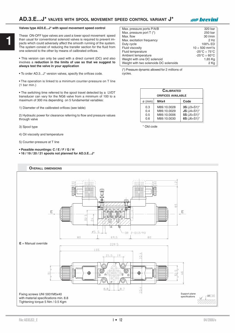
File: TCRS003_E 05/2000/eI • 10
1NOTE
TWO SOLENOIDS “D” MOUNTING Spool Covering Transient positiontype
19* -
20* +
21* +
DIRECTIONAL CONTROL VALVES
STANDARD SPOOLS CETOP 3/NG6
(*) Spool with price increasing
• With spools 15 / 16 / 17 only mounting E / F are possible
• 16 / 19 / 20 / 21 spool not planned for AD.3.E...J*
• For lever operated the spools used are different.Available spools for this kind of valve see AD3L..
ONE SOLENOID, SIDE A “E” MOUNTING Spool Covering Transient positiontype
01 +
02 -
03 +
04* -
44* -
05 +
66 +
06 +
08* +
10* +
12* +
15 -
16 +
17 +
14* -
28* -
TWO SOLENOIDS, SPRING CENTRED “C” MOUNTING Spool Covering Transient positiontype
01 +
02 -
03 +
04* -
44* -
05 +
66 +
06 +
07* +
08* +
09* +
10* +
22* +
11* +
12* +
13* +
14* -
28* -
ONE SOLENOID, SIDE B “F” MOUNTING Spool Covering Transient positiontype
01 +
02 -
03 +
04* -
44* -
05 +
66 +
06 +
08* +
09* +
10* +
22* +
12* +
13* +
07* +
15 -
16 +
17 +
14* -
28* -

File: AD3E003_E 12/2012/eI • 11
1
AD.3.E... DIRECTIONAL CONTROL VALVES SOLENOID OPERATED CETOP 3/NG6
The tests have been carried out with solenoids at operating temperature and a voltage 10% less than rated voltage with a fl uid temperature of 40°C. The fl uid used was a mineral oil with a viscosity of 46 mm2/s at 40°C. The values in the diagram refers to tests carried out with the oil fl ow in two directions simultaneously T = 2 bar (e.g.. from P to A and the same time B to T). In the case where valves 4/2 and 4/3 were used with the fl ow in one direction only, the limits of use could have variations which may even be negative. Rest times: the values are indicative and depend on following parameters: hydraulic circuit, fl uid used and variations in hydraulic scales (pressure P, fl ow Q, temperature T). The limit of use for AC solenoids were detected with 50 Hz power.
Direct current: Energizing 30 ÷ 50 ms. De-energizing 10 ÷ 30 ms.
LIMITS OF USE (MOUNTING C-E-F)
Alternating current: Energizing 8 ÷ 30 ms. De-energizing 15 ÷ 55 ms.
A max. counter-pressure of 8 bar at T is permitted for the variant with a microswitch (MS).(*) DC: Dynamic pressure allowed for 2 millions of cycles.AC: Dynamic pressure allowed for 350.000 of cycles. For dynamic pressure of 100 bar are allowed 1 milion cycles.
Support planespecifi cations
E = Manual override
MS = MicroswitchCalibrated diaphragm
Fixing screws UNI 5931 M5x30with material specifi cations min. 8.8Tightening torque 5 Nm / 0.5 Kgm
OVERALL DIMENSIONS
(**) For high differential pressure please contact our technical department.
MS
E E
Max. pressure port P/A/B 350 barMax. pressure port T (for DC) see note (*) 250 barMax. pressure port T (for AC) see note (*) 160 barMax. fl ow 80 l/minMax. excitation frequency 3 HzDuty cycle 100% EDFluid viscosity 10 ÷ 500 mm2/sFluid temperature -25°C ÷ 75°CAmbient temperature - 25°C ÷ 60°CMax. contamination level class 10 in accordance
with NAS 1638 with fi lter ß25 ≥75Weight with one DC solenoid 1,65 KgWeight with two DC solenoids 2 KgWeight with one AC solenoid 1,31 KgWeight with two AC solenoids 1,72 Kg
CALIBRATED DIAPHRAGMS (**)
Ø mm Codeblind M52.05.0023/40.5 M52.05.0023/10.6 M52.05.0023/60.7 M52.05.0023/80.8 M52.05.00231.0 M52.05.0023/21.2 M52.05.0023/31.5 M52.05.0023/72.0 M52.05.0023/102.2 M52.05.0023/92.5 M52.05.0023/5
DIRECT CURRENT SOLENOIDS (DC) ALTERNATING CURRENT SOLENOIDS (AC)
605040302010
0
40
80
120
160
200
240
280
3209
0
1716
1417
16
12
12
13
13
10
1115
11
P(b
ar)
Q (l/min)
Spooltype
SolenoidsDC AC
01 1 902 1 903 3 1004 2 1544 1 905 1 16
06-66 5 1311-22 4 1714-28 7 12
15 8 1416 6 11
Curves
60 70 805040302010
0
50
100
150
200
250
300
350
0
P(b
ar)
Q (l/min)
1
4
26
65
58
7
7
4
3
File: AD3EJ$3_E 04/2000/eI • 12
1
AD.3.E...J* VALVES WITH SPOOL MOVEMENT SPEED CONTROL VARIANT J*
Fixing screws UNI 5931M5x40with material specifi cations min. 8.8Tightening torque 5 Nm / 0.5 Kgm
E = Manual override
Max. pressure ports P/A/B 320 barMax. pressure port T (*) 250 barMax. fl ow 30 l/minMax. excitation frequency 2 HzDuty cycle 100% EDFluid viscosity 10 ÷ 500 mm2/sFluid temperature -25°C ÷ 75°CAmbient temperature -25°C ÷ 60°CWeight with one DC solenoid 1,65 KgWeight with two solenoids DC solenoids 2 Kg
Valves type AD3.E...J* with spool movement speed control
These ON-OFF type valves are used a lower spool movement speed than usual for conventional solenoid valves is required to prevent im-pacts which could adversely affect the smooth running of the system. The system consist of reducing the transfer section for the fl uid from one solenoid to the other by means of calibrated orifi ces.
• This version can only be used with a direct current (DC) and also involves a reduction in the limits of use so that we suggest to always test the valve in your application
• To order AD.3...J* version valves, specify the orifi ces code.
• The operation is linked to a minimum counter-pressure on T line (1 bar min.)
• The switching time referred to the spool travel detected by a LVDT transducer can vary for the NG6 valve from a minimum of 100 to a maximum of 300 ms depending on 5 fundamental variables:
1) Diameter of the calibrated orifi ces (see table)
2) Hydraulic power for clearance referring to fl ow and pressure values through valve
3) Spool type
4) Oil viscosity and temperature
5) Counter-pressure at T line
• Possible mountings: C / E / F / G / H• 16 / 19 / 20 / 21 spools not planned for AD.3.E...J*
Support planespecifi cations
(*) Pressure dynamic allowed for 2 millions of cycles.
OVERALL DIMENSIONS
CALIBRATED
ORIFICES AVAILABLE
ø (mm) M4x4 Code
0.3 M89.10.0028 3S (J3+S1)* 0.4 M89.10.0029 JS (J4+S1)* 0.5 M89.10.0006 5S (J5+S1)* 0.6 M89.10.0030 6S (J6+S1)*
* Old code

I • 13File: AD3EKJ4_E 01/2016/e
1
AD.3.E...KJ / 7J HIGH CORROSION RESISTANCE
• This variant has a Zinc-Nickel surfacetreatment on metallic parts for a higher corrosionresistance
• Coil windings are sealed and outer metal housinghas eCoat surface treatment
• The complete valve outstand more than 700hours exposure of Salt Spray Test (test performeraccording to UNI EN ISO 9227 and evaluationaccording to UNI EN ISO10289).
• The plastic blind retainer is assembled asstandard to protect the end surface of solenoidtube
OVERALL DIMENSIONS
AD.3.V...
“D15” DC COILS CAP.I • 19
STANDARD CONNECTORS CAP.I • 20
Fixing screws UNI 5931M5x40with material specifi cations min. 8.8Tightening torque 5 Nm / 0.5 Kgm
Support planespecifi cations
AD 3 VV
65,2
8888
83,7
51
Ø 5,5
Ø 9,5
245,5
163
Per versioni a singolo solenoide
Single solenoid versions
95,7
68,7
22
24
OR-2-012/90
21,5 19
8,8 8,7
10,4
10,4
Ø46
32,5
31
Ø46

File: AD3V002_E 10/2013/eI • 14
1
(*) Pressure dynamic allowed for 2 millions of cycles.
The single solenoid directional valves type AD.3.V are used in ap-plications where the monitoring of the position of the spool inside the valve is requested to manage the machine safety cycles in accord-ing with the accident prevention legislation. These directional valves are equipped with an horizontal positioned inductive sensor on the opposite side of the solenoid, which is capable of providing the fi rst movement of the valve when the pas-sage of a minimum fl ow is allowed. Integrated in safety systems, these valves intercept actuator movements that could be dangerous for the op-erators and for the machine.
AD.3.V... CETOP 3/NG6WITH PROXIMITY SENSOR L.V.D.T.
Support planespecifi cations
Fixing screws UNI 5931 M5x30with material specifi cations min. 8.8Tightening torque 5 Nm / 0.5 Kgm
E = Manual override
Max. operating pressure ports P/A/B 350 barMax. operating pressure port T dynamic (see note*) 250 barMax. fl ow 60 l/minMax. excitation frequency 3 HzDuty cycle 100% EDFluid viscosity 10 ÷ 500 mm2/sFluid temperature -25°C ÷ 75°CAmbient temperature -25°C ÷ 60°CType of protection (in relation to connector used) IP 66Weight 1,7 Kg
ORDERING CODE
The diagram at side shows the Δp curves for spool in normal usage. The fl uid used is a mineral oil with a viscosity of 46 mm2/s at 40°C; the tests have been carried out at a fl uid temperature of 40°C.
Spool Connectionstype P→A P→B A→T B→T P→T
01 5 5 5 5 02 6 6 6 6 5 06 5 5 6 5 16 5 5 4 4 17 1 3 66 5 5 5 6 32 1 1 2 2 Curves No.
registered mark for industrial environment with reference to the electro-magnetic compatibility. European norms: - EN50082-2 general safety norm - industrial environment - EN 50081-1 emission general norm - residential environment
AD Directional control valve
3 CETOP 3/NG6
V Directional valve with single solenoid and L.V.D.T. proximity sensor
*** Spool and mounting (table 1)
* Voltage (table 2)
** Variants (table 3)
2 Serial No.
No variant (without connectors) S1(*)Viton SV(*)Emergency button ES(*)Without proximity connector LVDT S3Without coils and proximity connector S4AMP Junior coil AJ(*)AMP Junior coil and integrated diode AD(*)Coil with fl ying leads (175mm) SLDeutsch DT04-2P Coil type CZ
Other variants available on request.
TAB.3 - VARIANTS
TAB1 - STANDARD SPOOLS FOR AD3V
• Possible mountings: E / F / H• The valve is supplied with DC solenoid only
POSSIBLE MOUNTING: E / F / H Spool Covering Transient positiontype
01E +
01F +
02E -
06H* +
16E +
17F +
66F +
32E +
(*) Spool with price increasing
AD.3.V...
"D15" DC COILS CH. I PAGE 19
STANDARD CONNECTORS CH. I PAGE 20
L.V.D.T. CH. I PAGE 22
TAB.2 - VOLTAGE
Voltage codes are not stamped on the plate, their are readable on the coils.
D15 COIL (30W) **L 12VM 24VV 28V*N 48V*Z 102V*P 110V*R 205V*W Without DC coils and connectors
115Vac/50Hz120Vac/60Hzwith rectifi er
230Vac/50Hz240Vac/60Hzwith rectifi er
Δp (
bar)
Q (l/min)
PRESSURE DROPS
1 2 3 4
5 6
(*) Coils with Hirschmann and AMP Junior connec-tion supplied without connectors. The connectors can be ordered separately, ch. I page 20.
* Special voltage** Technical data see page I • 19

File: AD3L004_E 08/2015/eI • 15
1
M1
AD.3.L... LEVER OPERATED CETOP 3/NG6
ORDERING CODE
AD Directional valve
3 CETOP 3/NG6
L Lever operation
** Spool type (see table 1) Spool symbol see page I•10
* Mounting type (see table 2)
* Z = Valve with lever X = Valve without lever
* Variants (see table 3)
4 Serial No.
Max. pressure ports P/A/B 320 barMax. pressure port T 160 barMax. fl ow 60 l/minLever angle 2 x 17°Fluid viscosity 10 ÷ 500 mm2/sFluid temperature -25°C ÷ 75°CAmbient temperature -25°C ÷ 60°CMax. contamination level class 10 in accordance with
NAS 1638 with fi lter ß25≥75Weight 1,2 KgWeight M1 variant 1,8 Kg
OVERALL DIMENSIONS
TABLE 3 - VARIANTS TABLE
M1 = microswitch
Fixing screws UNI 5931 M5x30with material specifi cations min. 8.8Tightening torque 5 Nm / 0.5 Kgm
Support planespecifi cations
AD.3.L...
STANDARD SPOOLS CH. I PAGE 10
VARIANTS CODE (♦)
No variant 00
Viton V1
Preset for microswitch M1 (♦)Microswitch type AM1107 code V79000001 can be ordered separately.
Preset for microswitch + Viton MV (♦)
With detent (*)(mechanical connection) D1 (♦)(Springs are different fromthose for standard versions)
Preset for microswitch + Detent (*) MD (♦)
Lever length 162 mm L1
Lever length 192 mm L2
♦ Variant codes stamped on the plate
(*) max. 150.000 cycles.
C
E
F (1)
TABLE 1 - SPOOLS TYPE
TABLE 2 - MOUNTING TYPE
• For these valves spools are different from ones used on the other directional valves
• Available spools:01 / 02 / 03 / 04 / 05 / 06 / 6607 / 22 / 13 / 15 / 16 / 17
(1) For spools 15-16-17 the lever is mounted on site B
Side A Side B

05/2001/eFile: AD3002_E I • 16
1
DIRECTIONAL CONTROL VALVES OTHER OPERATOR CETOP 3/NG6
INTRODUCTION
The ARON directional control valves NG6 are designed for subplate mounting with an interface in accordance with with UNI ISO 4401 - 03 - 02 - 0 - 94 standard (ex CETOP R 35 H 4.2-4-03), and can be used in all fi elds on account of their high fl ow rate and pressure capacities combined with compact overall dimensions. The use of solenoids with wet armatures allows a very practical, safe construction completely dispensing with dynamic seals; the solenoid tube is screwed directly onto the valve chest whilst the coil is kept in position by means of a lock nut.The special, precise construction of the ports and the improvement of the spools enables relatively high fl ow rates to be accommodated with a minimal pressure drop (Δp).The centre position is obtained by means of calibrated length springs which reposition the spool in the centre or end of travel position once the action of the impulse is over.The valves are designed for use with DIN 51524 standard hydraulic mineral oils and it is recommended that fi lters should be fi tted to ensure a maximum contamination level of class 10 in accordance with NAS 1638, ß25≥75.
Spool Connectionstype P→A P→B A→T B→T P→T
01 5 5 5 5 02 6 6 6 6 5 03 5 5 6 6 04 1 1 2 2 4 05 5 5 5 5 06 5 5 6 5 66 5 5 5 6 07 4 6 08 6 6 09 5 5 10 5 5 5 5
Curve No.
Spool Connectionstype P→A P→B A→T B→T P→T
11 4 6 22 4 6 12 5 6 13 5 6 6 14 2 1 1 1 2 28 1 2 1 1 2 15 - 19 4 4 6 6 16 5 5 4 4 17 - 21 1 3 18 5 5 20 4 4 4 4
Curve No.
The diagram at the side shows the pressure drop curves for spools during normal usage. The fl uid used is a mineral oil with a viscosity of 46 mm2/s at 40°C; the tests have been carried out at a fl uid temperature of 40°C. For higher fl ow rates than those in the diagram, the losses will be those expressed by the following formula:
Δp1 = Δp x (Q1/Q)2
where Δp will be the value for the losses for a specifi c fl ow rate Q which can be obtained from the diagram, Δp1 will be the value of the losses for the fl ow rate Q1 that is used.
TAB.1 MOUNTING
ORDERING CODE
• In case of mounting Dwith detent a maximum supply time of 2 sec is needed (only for AC coils).
AD Directional valve
3 CETOP 3/NG06
* Type of operator P = Pneumatic O = Oleodynamic M = Mechanically D = Direct mechanically (For other operator see past pages)
** Spool (see page I•10)
* Mounting type (tab.1)
z No voltage
** Variants: 00 = no variant V1 = Viton H1 = Marine version (for AD3P only) DI(*) = Internal draining (for AD3O only)
2 Serial No.
OTHER OPERATOR
STANDARD SPOOLS CH. I PAGE 10
AD.3.P... CH. I PAGE 17
AD.3.O... CH. I PAGE 17
AD.3.M... CH. I PAGE 18
AD.3.D... CH. I PAGE 18
STANDARD
C
D
E
F
SPECIALS (WITH PRICE INCREASING)
G
H
I
L
M
Δp (
bar)
Q (l/min)
PRESSURE DROPS
1 2 3 4
5 6
(*) The DI variant is recommended in the environments characterised by the presence of dust or any type of contamination.

File: AD3P002_E 07/2015/eI • 17
1
OVERALL DIMENSIONS
AD.3.P... PNEUMATIC OPERATION TYPE VALVES CETOP 3/NG6
Max. pressure ports P/A/B 320 barMax. pressure port T 160 barMax. fl ow 60 l/minMinimum operating pressure 2 + [0.027 x (pt*)] bar - see noteMaximum operating pressure 20 barFluid viscosity 10 ÷ 500 mm2/sFluid temperature -25°C ÷ 75°CAmbient temperature -25°C ÷ 60°CMax. contamination level
class 10 in accordance with NAS 1638 with fi lter ß25≥75Weight single pilot 1,2 KgWeight twin pilot 1,8 Kg
• Possible mountings:C / D / E / F / G / H / I L / M
Ordering code see page before
(pt*)= pressure at port T
Fixing screws UNI 5931 M5x30with material specifi cations min. 8.8Tightening torque 5 Nm / 0.5 Kgm
Support planespecifi cations
AD.3.O... OLEODYNAMIC OPERATION TYPE VALVES CETOP 3/NG6
• Possible mountings:C / D / E / F / G / H / I L / M
Ordering code see page before
(pt*)= pressure at port “T” .
Minimum pilot pres-sure depends on spool scheme, fl ow rate and pressure.To allow the spool to return to nautral position, the pilot pressuremust be below 3 bar.
E = Manual override
OVERALL DIMENSIONS
Fixing screws UNI 5931 M5x30with material specifi cations min. 8.8Tightening torque 5 Nm / 0.5 Kgm
Support planespecifi cations
IAD3P - 02/2000/e
IAD3O - 04/2015/e
Max. pressure ports P/A/B 320 barMax. pressure port T 160 barMax. fl ow 60 l/minMinimum operating pressure 15 + [0.1 x (pt*)] bar - see noteMaximum operating pressure 250 barFluid viscosity 10 ÷ 500 mm2/sFluid temperature 0°C ÷ 75°CAmbient temperature -25°C ÷ 60°CMax. contamination level
class 10 in accordance with NAS 1638 with fi lter ß25≥75Weight single pilot 1,5 KgWeight twin pilot 2,3 Kg
Further technical specifi cations (for DI variant only)Minimum operating pressure [10 + (pt*)] bar - see noteMaximum operating pressure 250 barMax. piloting leakage 1 l/min
The DI variant is recommended in the envi-ronments characterised by the presence of dust or any type of contamination.

I • 18File: AD3M002_E 04/2000/e
1
EAD3M - 02/2000/e
EAD3D - 02/2000/e
OVERALL DIMENSIONS
AD.3.M... MECHANICALLY OPERATED TYPE VALVES CETOP 3/NG6
•Possible mountings:E / F / G / H
• Ordering code see page before
• Note:
(*) In the absence of counter-pressure at port T
(**) with a pressure of 160 bar at port T
Max. pressure ports P/A/B 320 barMax. pressure port T 160 barMax. fl ow 60 l/minMinimum operating force - see note (*) 2,5 KgMaximum operating force - see note (**) 13 KgCam angle 27°Fluid viscosity 10 ÷ 500 mm2/sFluid temperature -25°C ÷ 75°CAmbient temperature -25°C ÷ 60°CMax. contamination level class 10 in accordance
with NAS 1638 with fi lter ß25≥75Weight 1 Kg
Stroke 12,4 mmWorking stroke 3 mm
Fixing screws UNI 5931 M5x30with material specifi cations min. 8.8Tightening torque 5 Nm / 0.5 Kgm
Support planespecifi cations
AD.3.D... DIRECT MECHANICALLY OPERATED TYPE VALVES CETOP 3/NG6
OVERALL DIMENSIONS
Max. pressure ports P/A/B 320 barMax. pressure port T 20 barMax. fl ow 60 l/minOperating force - see note (*) 6 KgFluid viscosity 10 ÷ 500 mm2/sFluid temperature 0°C ÷ 75°CAmbient temperature -25°C ÷ 60°CMax. contamination level class 10 in accordance
with NAS 1638 with fi lter ß25≥75Weight 1,5 Kg
• Possible mountings:E / F / G / H
• Ordering code see page before
• Note:
(*) In absence of counter-pressure at port T
Stroke 6 mmExtra stroke 2 mmWorking stroke 3 mm
Fixing screws UNI 5931 M5x30with material specifi cations min. 8.8Tightening torque 5 Nm / 0.5 Kgm
Support planespecifi cations

File: TD15K12_E 12/2016/eI • 19
1• AMP Junior coils (with or without diode) and coils with fl ying leads and coils type Deutsch, are availa-ble in 12V or 24V DC voltage only.
• The pastic type coil (RS variant) is available in 12V, 24V, 28V or 110V DC voltage only.
"D15" DC COILS FOR CETOP 3Type of protection (in relation to the connector used) IP 66Number of cycles 18.000/hSupply tolerance ±10%Ambient temperature -54°C ÷ 60°CDuty cycle 100% EDInsulation class wire HWeight 0,354 Kg
MANUAL WITHOUT CONN. (ES)MANUAL WITH CONN. (E1)
FLYING LEADS (SL)
AMP JUNIOR (AJ)AJ + DIODE (AD)
"B14" AC SOLENOIDS FOR CETOP 3
Type of protection (in relation to the connector used) IP 65Number of cycles 18.000/hSupply tolerance +10% / -10%Ambient temperature -30°C ÷ 60°CDuty cycle 100% EDInsulation class wire HWeight 0,436 Kg
85,5
80,8
112
81,1
EMERGENCY (COILS WITH HIRSCHMANN CONNECTION)ROTARY WITHOUT CONNECTOR (P2)
ROTAN ROTARY WITH CONNECTOR (P1)MANUAL WITHOUT CONNECTOR (ES)
MANUAL WITH CONNECTOR (E1)
ROTARY WITHOUT CONNECTOR (P2)ROTARY WITH CONNECTOR (P1)
ROTARY 180° WITHOUT CONNECTOR (R5)ROTAN 180° ROTARY WITH CONNECTOR (P5)
EMERGENCY (COILS WITH HIRSCHMANN CONNECTION)
EMERG. HIRSCHMANN CONN.VOLTAGE (V)
MAX WINDING TEMPERATURE (AMBIENT TEMPERATURE 25°C)
RATED POWER (W)
RESISTANCE AT 20°C
(OHM) ±10%12V 110°C 30 4.824V 110°C 30 18.828V* 110°C 30 25.648V* 110°C 30 75.2
102V(*)(**) 110°C 30 340110V(*)(**) 110°C 30 387205V(*)(**) 110°C 30 1375 * Special voltages
** The european low voltage directive is applied to elec-tronical equipments used at a nominal voltages between 50 and 1000 VAC or 75 and 1500 VDC. In conformity with the low directive each part of the manifold or the subplate on which the valve is mount-ed should be connected to a protective earth with a resist-ence less than 0.1 ohms.
VOLTAGE (V)
MAX. WINDING TEMPERATURE (AMBIENT TEMPERATURE 25°C)
RESISTANCE AT 20°C(OHM) ±10%
RATED POWER. (VA)
PICKUP CURRENT
(A)24V/50Hz - 24V/60Hz 100°C - 96°C 1.7 54 - 40 5.6 - 548V/50Hz - 48V/60Hz 112°C - 98°C 6.8 45 - 34 5.3 - 5
115V/50HZ - 120V/60HZ * 133°C - 101°C 32.5 61 - 51 3.2 - 3.2230V/50Hz - 240V/60Hz * 120°C - 103°C 134 62 - 52 1.6 - 1.6
* The european low voltage directive is applied to electronical equip-ments used at a nominal voltages between 50 and 1000 VAC or 75 and 1500 VDC. In conformity with the low directive each part of
the manifold or the subplate on which the valve is mounted should be connected to a protective earth with a resistence less than 0.1 ohms.
DEUTSCH DT04 - 2P (CZ)CZ + ECOAT (R6)
ECOAT COIL (RS)
33
*** VDC100% ED
54
Ø 4
5
1.1
Ø 2
3
Ø 2
7
31.2
12

File: TCNT000_E 09/2015/eI • 20
1
CONNECTORS DIRECTIONAL CONTROL VALVES IN ACCORDANCE WITH
DIN 43650/ISO4400
Connector Protection level Type Cable gland Code
Standard IP65
Black color PG09 V86 05 0002Grey color PG09 V86 05 0004Black color PG11 V86 05 0006Grey color PG11 V86 05 0008
Lens cover with pilot light (bipolar led) (*) IP65
12 VAC/VDC PG09 V86 10 001824 VAC/VDC PG09 V86 10 0012115 VAC/VDC PG09 V86 10 0020230 VAC/VDC PG09 V86 10 0022
Connector Protection level Type Cable gland Code
With rectifi er (*)Inlet voltage 12÷230 VACOutlet voltage 9÷205 VDC
IP65Black color PG09 V86 20 0002
Grey color PG09 V86 20 0004
Lens cover with pilot light (bipolar led) and rectifi er (*)Inlet voltage 12÷230 VACOutlet voltage 9÷205 VDC
IP65
12 VAC PG09 V86 25 001824 VAC PG09 V86 25 001948 VAC PG09 V86 25 0020115 VAC PG09 V86 25 0021230 VAC PG09 V86 25 0022
Connector Protection level Type Cable gland Code
With protection level IP67 IP67Black color — V86 28 0001Grey color — V86 28 0002
Description IP65 IP67AC rated voltageDC rated voltage
Max. 250 VMax. 300 V
Max. 250 VMax. 300 V
Pin conctat nominal currentPin conctat max. current
10A16A
10A16A
Max. section cable 1.5 mm² 1.5 mm²Cable gland PG09 - M16x1,5Cable gland PG11 - G 1/2” - M20x1,5
Ø cable 6 ÷ 8 mmØ cable 8 ÷ 10 mm
Ø cable 4 ÷ 7 mm—
Protection levelInsulation classOperating temperature
IP65 EN60529VDE 0110-1/89-40°C ÷ 90 C°
IP67 EN60529VDE 0110-1/89-20°C ÷ 80 C°
The degrees of protection indicate is guaranteed only if the connectors were properly mounted with his original seals.
AMP JUNIOR CONNECTORS
M3
4.5
42
28.5 29.5
Ø 6÷8 mm (PG09)
Ø 8÷10 mm (PG11)
34.54.5
M3
42
29.5
Ø 6÷8 mm (PG09)
4.5
M3
32
62
29.5
Ø 4÷7 mm
(*) Don’t use for proportional versions
Ø 6÷8 mm (PG09)
Ø 8÷10 mm (PG11)
IP65
GuarnizioneCable gland
Ø 4÷7 mm19
IP67
Seal
Guarnizione
Cable gland
Screw tightening torque: 0.60 Nm
(*) Don’t use for proportional versions
ELECTRICAL FEATURES OF CONNECTORS
81.5
Ø 2 ÷ 3 mm
20
23
.5
Standard Bipolar led Rectifi er andVDR protection
Bipolar led, rectifi er andVDR protection
Screw tightening torque: 0.60 Nm
Electrical circuits
Connector Type Cable section Pin conctatmax current Code
AMP Junior connector Timer 2 conctat Black color 0,5 ÷ 1,5 mm2 10A RKRC0808000
1
2
1
2
1
2
1
2

File: TLEAD3E_E 05/2010/eI • 21
1
• MOUNTING TYPE: C / F / H
• SPOOLS TYPE: 01/02/03*/04/16/17/66
HYDRAULIC SIMBOL
* The spool 03 is allowed only on AD3E. Not permitted with ADC3
The emergency control lever for solenoid valves by Aron, represents a develop in terms of safety and fl exibility among applied hydraulic components. Thanks to his fl exibility, the component was designed to be inserted between the valve body and the spool, providing total interchangeability between the different types of solenoid body valves manufactured by Aron. It is compatible with the standard CETOP 3 and stackable valves with threaded connections –G3/8” or 9/16-18UNF (SAE 6). The component is available for both directional control and proportional valves (for the last type of control please consult our Technical Department) As an emergency lever applied to solenoid valves, the control can be used as a safety device in conformity with the industry standards , also playing an useful role in the event of power cuts. The control can be used in agricultural and mobile fi elds; the manual action can be used to carry out periodic maintenance work on mobile components of the vehicle , in perfectly safe working conditions.
VARIANTS (*) - EMERGENCY CONTROL LEVER FOR
DIRECTIONAL CONTROL VALVES (ADC/AD.3.E)
Max operating pressure port T:dynamic 160 barstatic 210 bar
Max operating pressure port Pfor series connection confi guration 160 bar
OVERALL DIMENSION
Support planespecifi cations
ADC.3...VERSION
AD.3.E..VERSION
MOUNTING COMPATIBILITY
CODE VALVE DESCRIPTION COIL VOLTAGE
ADC.3... Directional control valve A09 27 W
AD.3.E... Directional control valve D15 30 W
P
182
231,5
26,5
18,5
135
46
28°28°
208
282,5
134,5
26,5
18,5
28°28°
46
P
Variant Description
LEStandard coil with Hirschmann connection or without coil (W voltage)
LFStandard coil without Hirschmann connection(*)
AX AMP Junior coil(*)
CE Deutsch coil
(*) VARIANTS
Other variants available on request.
(*) Coils with Hirschmann and AMP Junior connection supplied without connectors. The connectors can be ordered separately, ch. I page 20.

File: TLVDT000_E 01/2000/eI • 22
1
Hub
A
B
A = 3 : 1 Stroke
PROXIMITY SENSOR TYPE L.V.D.T.
OVERALL DIMENSION LVDT
OVERALL DIMENSIONS CONNECTOR
FUNCTIONAL DIAGRAM ON PIN 2 AND 4
0 = Voltage Pin 2 and Pin 4 < 1,8 V1 = Voltage Pin 2 and Pin 4 24 V ± 20%
ELECTRICAL CONNECTIONS LVDT
NB: connecting the output to Pin 4 or Pin 2 the type of contact, normally closed or open, can be chosen.
With this connection, on the Pin 4 an output signal is active when no oil is crossing the valve (from P → B).
With this connection, on the Pin 4 there is no output signal when oil is crossing the valve (from P → B).
Supply voltage 24 V ± 20%Polarity reversal protection max 300 VSwitching point hysteresis ≤ 0,06 mmReproducibility ± 0,02 mmMax. output current ≤ 250 mAProtection against short circuit yesOperating temperature -25°C ÷ 85°CConnection type connectorProtection according to DIN IP65Max. pressure 315 bar
The LVDT position transducers allow to check exactly the very instant when the passage of a minimum fl ow is allowed.
CE certifi cate according to 89/336/EEC EMC is provided. A screened cable is needed.
Type of protection IP67Ambient temperature -40°C ÷ 85°C
Switching point
Switching point
Ordering code: V86400003

File: AD3XG001_E 03/2014/eI • 23
1 94/9/CE ATEX EC DIRECTIVE (EXPLOSIVE ATMOSPHERE)
Among the main potential causes/sources of triggering an explosion, such as sparks, fl ames, electric arcs etc.., maximum surface temperature also plays an important role. The dispositions of the directive establish evaluation criteria for the maximum temperature admissible depending on the type of explosive atmosphere in which the appliance must operate.
For environments characterised by the presence of gas-air, some temperature values are supplied to which the appliances must refer. They are indicated by the letter T followed by a number. The criterion to apply is that for which the temperature of the appliance must never exceed 80% of the value indicated for its own category.
For environments characterised by the presence of dust-air, to prevent setting on fi re of the airborne dust, the surface temperature of the appliances must be decidedly lower than the predictable temperature of catching fi re of the air+dust mixture. Therefore, during planning the maximum working surface temperature must be declared directly (in degrees centigrade).
Increases in temperature deriving from an accumulation of heat and chemical reactions must also be taken into consideration. The thickness of the deposited layer of dust must also be considered and, if necessary, limit the temperature, to prevent an accumulation of heat.
INTRODUCTION Since 30/06/2003 products introduced into the market (or started-up) inside the EU, destined to be used in potentially explosive environments, must be in compliance with the 94/9/EC Directive through special marking. The directive regarding ATEX products 94/9/EC is therefore the regulation instrument that the European Union uses to obtain legislative harmonisation between the States and guarantee free circulation of goods inside the European Community itself. The directive affi rms that to eliminate obstacles from commerce it is necessary to guarantee a high level of protection and, with this aim, defi ne the essential requirements on the subject of safety and health. The dispositions base themselves on the principle of the “new approach” (NA), for which the essential safety requirements of products must be established depending on the risk evaluation concurrent at the time of their use. The 94/9/EC Directive is applied to the manufacture specifi cations of all those products (electrical and not) destined to be used in potentially explosive environments caused, by the dangers deriving from the presence of dust or gas, with the scope of reducing the risk of use that could be derived.
The term product refers to appliances, protection systems, devices, components and relative combinations, as defi ned in 94/9/EC Directive. The term appliances intends machines, materials, fi xed or mobile devices, control elements, instruments detection and prevention systems. Alone or combined these are destined for production, transport, deposit, measurement, adjustment and conversion of energy, and to the transformation of material and which, by way of the powerful triggering sources, risk causing an explosion. As a consequence, even intrinsically safe appliances re-enter within the fi eld of application of the directive.
Ther combination of two or more appliance parts, as well as any other components, makes up a whole unit that can be considered a product and therefore re-enters within the fi eld of application of the 94/9/EC Directive. If the whole unit requires adequate installation (therefore it is not immediately ready for use) the attached instructions should guarantee maintenance of compliance to the 94/9/EC Directive on installation, without further evaluations of conformity. The installer must follow the instructions correctly.
When a combination of appliances leads to a plant this may not re-enter within the fi eld of application of the directive. Each part must be certifi ed and in compliance with the directive (as well as being subject to the relative evaluation of conformity, EC marking, etc.). The plant manufacturer must therefore presume the conformity of the various components (each supplied with conformity certifi cate released by the respective manufacturer) and limit their evaluation only to any additional risks that become important in the fi nal combination. Nevertheless, if the plant manufacturer inserts parts without EC marking or components not supplied with the certifi cate it will be obligatory to carry out further conformity evaluation of the whole unit.
The 94/9/EC Directive envisions obligations of the person who introduces products into the market and/or starts them up, whether they are manufacturer’s, his agent’s, importer’s or any other responsible person. The dispositions and obligations envisioned by the directive for introduction into the market have been applied, since 30 June 2003, to every individual product, independently from the date and place of manufacture. It is the manufacturers responsibility to guarantee conformity of all products, where these re-enter within the fi eld of application of the directive. The directive does not govern the use of the appliances; rather it establishes that the products can only be used if in compliance with safety requirements at the time of their introduction into the market or of their start-up. “Start-up” means the fi rst use of the products subject of the 94/9/EC Directive on EU territory by a fi nal user. Nevertheless, a product that is immediately ready for use and does not need assembly or installation, and whose distribution conditions (deposit, transport, etc.) are not important for performance, is considered started-up at the time of introduction into the market.
AD.3.XG...
ATEX DIRECTIVE CH. I PAGE 23
ATEX CLASSIFICATION CH. I PAGE 24
SERIES AD.3.XG... CH. I PAGE 25
TECHNICAL SPECIFICATIONS CH. I PAGE 25
ORDERING CODE CH. I PAGE 25
TAB.1 ASSEMBLY CH. I PAGE 26
TAB. 2 VOLTAGES CH. I PAGE 26
TAB.3 SPOOL CH. I PAGE 26
LIMITS OF USE CH. I PAGE 26
IDENTIFICATION NAMEPLATE CH. I PAGE 27
SAFETY INSTRUCTIONS CH. I PAGE 27
OVERALL DIMENSIONS CH. I PAGE 28
AD.3.XG... DIRECTIONAL CONTROLE CETOP 3 IN ACCORDANCE WITH 94/9/CE ATEX DIRECTIVE

File: AD3XG001_E 03/2014/eI • 24
1CLASSIFICATIONS OF AREA - MIX - GROUP AND RELATIVE CATEGORY – ACCORDING TO ATEX DIRECTIVES
The 94/9/EC Directive is a “new approach” directive based on risk analysis. Its objective is to minimise the risks deriving from the use of some products indoors or in relation to a potentially explosive atmosphere. The probability of an explosive atmosphere manifesting must be considered not only as “one-off” or from a static point of view: all operative conditions that can derive from the transformation process must be taken into consideration. • An explosive atmosphere for the 94/9/EC Directive is made up from a mixture of infl ammable substances (as gas, vapours, mists and dust), with air, in determined atmospheric conditions in which, after triggering, the combustion propagates together with the unburned mixture. • An atmosphere susceptible to transforming into an explosive atmosphere because of local and/or operative conditions is defi ned potentially explosive atmosphere. Explosive atmospheres are not only formed in the presence of obviously dangerous substances such as fuel, solvents etc., but also in the presence of apparently harmless products such as wood dust, metal dusts, fl our, grain, sugar etc. Therefore it can concern not only industries in the chemical or oil industry sectors, but also industries in the foodstuffs, textile, manufacturing etc.. It is important to consider that to re-enter within the 94/9/EC Directive a product must be applied in presence of one or more of the characteristic elements listed above: presence of infl ammable substances and air, in atmospheric conditions that favour the propagation of combustion. The directive does not defi ne the atmospheric conditions itself. The relative norms indicate a temperature range, but this does not exclude that the products may be planned and evaluated specifi cally to occasionally function outside of this range, introducing the opportune construction transformations.
To defi ne a conformity evaluation procedure adequate for the directive, the Manufacturer must, on the basis of the declared use, establish the products functioning conditions (this means to say, envision the type of working area, the type of explosive mixture with which it will come into contact and the level of probability that an explosive atmosphere verifi es itself); successively he must establish to which Group the product belongs and individualise the category inside the Group.
With the Atex 99/92/EC Directive (For the safety of workers) the working conditions in which products in compliance with Atex 99/4/EC Directive will function are indicated here. These are expressed in “Areas” and defi ned according to the level of probability that a potentially explosive atmosphere is verifi ed, respectively for every type of atmosphere (gas-air mix or dust-air mix).
Area 0 and 20 Places in which an explosive atmosphere is constantly present or present for long periods or frequently.
Area 1 and 21 Places in which an explosive atmosphere is probable. It is verifi ed in normal functioning and exercise conditions.
Area 2 and 22 Places in which an explosive atmosphere has low probability of being verifi ed or, if it occurs only lasts for a brief period of time.
GAS-AIR-TYPE EXPLOSIVE MIXTURE (G) The products destined to work in environments characterised by this type of explosive atmosphere will be respectively indicated for Area 0, 1 or 2 depending on the Group and category of origin (see below) and are marked with the letter G.
DUST-AIR-TYPE EXPLOSIVE MIXTURE (D) The products destined to work in environments characterised by this type of explosive atmosphere will be respectively indicated for Area 20, 21 or 22 depending on the Group and category of origin (see below) and are marked with the letter D.
GROUP I Includes the appliances destined to be used in underground jobs in the mines and their surface plants, exposed to the risk of the release of fi redamp and/or combustible dust. The subdivision into categories depends on the fact if the power supply must be interrupted or not if an explosive atmosphere manifests due to a mixture of air and gas, vapours mists (D) or a mixture of air and dust (G).
Category M1 Very high protection level. These products must be able to remain operative, for safety reasons, in the presence of an explosive atmosphere and present specifi c performances or protection confi gurations for breakdown in case of explosion.
Category M2 High protection level. The power supply to these products must be interrupted in the presence of an explosive atmosphere. Protection means must be incorporated to guarantee the level of protection during normal functioning and also in oppressive working conditions or resulting from great stressi.
GROUP II Includes appliances destined to be used in different environments (from the mines) in which there is a probability that an explosive atmosphere manifests itself. Their subdivision into categories depends on two factors: the place, where the product will be used and if the probability that a potentially explosive atmosphere, owing to the mixture of air and gas, vapours, mists (D) and the mixture of air and dust (G), comes about in a constant or occasional manner and if it does occur, does this possibility remain for long or brief period of time.
Category 1 Very high protection level. These products must be planned to function in compliance with operative parameters established by the Manufacturer in environments in which there is a high probability that explosive atmospheres are always detected or manifest often or for long periods of time. They must present specifi c performances or protection confi gurations for breakdown in case of explosion.
Category 2 High protection level. These products must be planned to function in compliance with operative parameters established by the Manufacturer in environments in which there is a high probability that explosive atmospheres can manifest. Protection against explosions relative to this category must function in a way to guarantee the required safety level even in the presence of functioning defects of the appliances or in dangerous operative conditions, which frequently must be taken into consideration.
Category 3 Normal protection level. These products must be planned to function in compliance with operative parameters established by the Manufacturer in environments in which there is a slight probability that explosive atmospheres can manifest, and however only rarely or for a brief period of time. This type of product belonging to the category in question must guarantee the safety level required in normal functioning conditions.
AD.3.XG... DIRECTIONAL CONTROLE CETOP 3 IN ACCORDANCE WITH 94/9/CE ATEX DIRECTIVE

File: AD3XG001_E 03/2014/eI • 25
1
AD.3.XG... DIRECTIONAL CONTROLE CETOP 3 IN ACCORDANCE WITH 94/9/CE ATEX DIRECTIVE
SOLENOID VALVES FOR USE IN WORKPLACES WHERE EXPLOSIVE ATMOSPHERES
MAY OCCUR DUE TO THE PRESENCE OF GAS, VAPOUR OR MIST AND DUST.
AD3.XG solenoid valves are classifi ed in:Group II appliances (to be used in workplaces, apart from mines, where there is the probability of explosive atmospheres);category 2 (high protection level), for use in workplaces where it is probable that an explosive atmosphere may form in normal working conditions and classifi ed by the presence of explosive mixtures of gas-dust type (letter GD) for zones 1, 2 and 21, 22.
These valves are therefore designed especially and manufactured in compliance with the ATEX 94/9/EC Directive and according to European regulations EN 1127-1, EN 13463-1 and EN 13463-5.
Belonging to the "NG06 direction control" of Aron range, these valves are prepared for plate-mounting with attachment surface in compliance with UNI ISO 4401 - 03 - 02 - 0 - 94 (former CETOP R 35 H 4.2-4-03). They are activated electrically and the centre position is ensured by springs with gauged lengths, which once the pulse or command ceases, re-position the spool in the centre or at the end of travel position.
The coils used for these valves are subject to separate conformity certifi cation, according to the ATEX Directive (EC-type). For further specifi cations, please consult the documents that are always supplied with the valve.
Before marking and marketing the valves of the AD3XG series, undergo tests and inspections according to the in-house Manufacturing System and to the Certifi ed Company Quality System in compliance with ISO 9001:2008. All of the AD3XG valve series undergo 100% functional testing. These tests and inspections guarantee that the products sold comply with all the information reported in the Technical Specifi cations File registered and declared by marking with AD3X/ATEX/10.
ORDERING CODE TECHNICAL SPECIFICATIONS
AD.3.XG...
ATEX DIRECTIVE CH. I PAGE 23
ATEX CLASSIFICATION CH. I PAGE 24
SERIES AD.3.XG... CH. I PAGE 25
TECHNICAL SPECIFICATIONS CH. I PAGE 25
ORDERING CODE CH. I PAGE 25
TAB.1 ASSEMBLY CH. I PAGE 26
TAB. 2 VOLTAGES CH. I PAGE 26
TAB.3 SPOOL CH. I PAGE 26
LIMITS OF USE CH. I PAGE 26
IDENTIFICATION NAMEPLATE CH. I PAGE 27
SAFETY INSTRUCTIONS CH. I PAGE 27
OVERALL DIMENSIONS CH. I PAGE 28
Description AD3XG T4... AD3XG T6...
Valve marking II 2 GD cT4 II 2 GD cT6Max. pressure on lines P/A/B 350 bar 350 barMax. pressure on line T (dynamic) 250 bar 250 barMax. fl ow rate 80 l/min 80 l/minMax.excitation frequency 3 Hz 3 HzDuty cycle 100%ED 100%EDHydraulic fl uids mineral oils DIN 51524 mineral oils DIN 51524Fluid viscosity 10 ÷ 500 mm2/s 10 ÷ 500 mm2/sFluid temperature (*) -30°C ÷ +70°C -30°C ÷ +70°CAmbient temperature -40°C ÷ +80°C -40°C ÷ +50°CMax. contamination level ISO 4406:1999: class 21/19/16 ISO 4406:1999: class 21/19/16(fi lter ß25 ≥ 75) NAS 1638: class 10 NAS 1638: class 10Weight (one solenoid) 3 kg 3 kgWeight (two solenoids) 5 kg 5 kg
Coil rated power 8,5 W 8,5 WDegree of protection IP 67 IP 67Power supply tolerance ±10% ±10%Power supply cable standard length 3m standard length 3m with cable gland with cable gland Coil marking (**): consult documents supplied with coil Surface temperature < 135°C < 85°C
AD Directional Control Valve
3 CETOP 3/NG06
XG Solenoid valves built pursuant to ATEX Directive-94/9/EC . With coils in explosion-proof version (Ex d) and IECEx conformity marked
** Temperature Class
T4 (Tsur <135 °C)
T6 (Tsur < 85 °C)
** Spools 01/02/03/04/16 (tab.3). For further hydraulic diagrams, contact Brevini Fluid Power Customer Service
* Assembly C / E / F / G / H (tab.1). For further assembly instructions, contact Brevini Fluid Power Customer Service
* Voltage (tab.2)
** Variants 00 = None V1 = Viton LE = Emergency lever
1 Serial number
(*) AD3XG valves have been certifi ed for minimum fl uid temperatures up to -30°C. Please contact our Technical Dept. for applications at fl uid temperatures < -25°C.
(**) Coil is provided with marking for protection class according to Explosion Protection Directive ATEX-94/9/EC and IECEx certifi cate of conformity mark.

File: AD3XG001_E 03/2014/eI • 26
1
TAB.3 SPOOL
TAB.1 ASSEMBLY
(*) spool with increased price
Two solenoids - Assembly C Type of Cover Transit posit ion
spool
01 +
02 -
03 +
04* -
One solenoid - Assembly F Type of Cover Transit posit ion
spool
01 +
02 -
03 +
04* -
16 +
One solenoid - Assembly E Type of Cover Transit posit ion
spool
01 +
02 -
03 +
04* -
16 +
STANDARD
C Two solenoids centred
E One solenoid (side A)
F One solenoid (side B)Specials (with increased price )
G
H
LIMITS OF USE (MOUNTING C-E-F)
AD.3.XG...
AD.3.XG... DIRECTIONAL CONTROLE CETOP 3 IN ACCORDANCE WITH 94/9/CE ATEX DIRECTIVE
PRESSURE DROPS
The diagram at the side shows the pressure drop curves for spools during normal usage. The fl uid used is a mineral oil with a viscosity of 46 mm2/s at 40°C; the tests have been carried out at a fl uid temperature of 40°C. For higher fl ow rates than those in the diagram, the losses will be those expressed by the following formula:
Δp1 = Δp x (Q1/Q)2
where Δp will be the value for the losses for a specifi c fl ow rate Q which can be obtained from the diagram, Δp1 will be the value of the losses for the fl ow rate Q1 that is used.
AD.3.XG...
The tests have been carried out with solenoids at operating temperature with a voltage 10% less than rated voltage with a fl uid temperature of 40°C. The fl uid used was a mineral oil with a viscosity of 46 mm2/s at 40°C. The values in the diagram refers to tests carried out with the oil fl ow in two direction simultaneously (e.g.. from P to A and in the same time B to T). In cases where valves 4/2 e 4/3 were used with the fl ow in one direction only, the limits of use could have variations which may even be negative.
TAB.2 VOLTAGES
AC Voltage for AD3XG
A 24V 50Hz/60Hz B 48V 50Hz/60Hz C 110V 50HZ/60Hz D 220V 50Hz/60Hz I 230V 50Hz/60Hz
DC Voltage for AD3XG
L 12V M 24V P 110V N 48V U 36V 6 60V G 125V
The tension symbol is always printed on the nameplate.
0
14
16
18
20
12
10
8
6
2
4
010 20 30 40 50 60 70 80
Q (l/min)
P(b
ar)
2 4 5 6
7
Spooltype
ConnectionsP→A P→B A→T B→T P→T
01 5 5 5 5
02 7 7 7 7 6
03 5 5 6 6
04 2 2 2 2 4
16 5 5 4 4
Curve No.
60 70 805040302010
0
50
100
150
200
250
300
350
0
P(b
ar)
Q (l/min)
1
26
6
3
Spooltype
01 1 02 1 03 3 04 2 16 6
Curve

File: AD3XG001_E 03/2014/eI • 27
1
SAFETY INSTRUCTIONS
IDENTIFICATION NAMEPLATE AND MARKING
AD.3.XG... DIRECTIONAL CONTROLE CETOP 3 IN ACCORDANCE WITH 94/9/CE ATEX DIRECTIVE
All the solenoid valves are supplied with identifi cation nameplate and Declaration of conformity subject to Directive 94/9/EC.
The identifi cation nameplate bears the main technical specifi cations related to the functional and constructional characteristics of the valve and must therefore be kept intact and visible.
• Read the instruction handbook supplied with the valves carefully before installation. All maintenances must be carried out following the instructions given in the manual.
• The AD3XG series valves must be installed and serviced in compliance with plant engineering and maintenance regulations for workplaces classifi ed against the risk of explosion due to the presence of gas and dust and gas (for example: CEI EN 60079-14, CEI EN 60079-17, CEI EN 61241-14, CEI EN 61241-17 or other national regulations/standards).
• The valves must be connected to earth using the special anti-loosening and anti-rotation connection element.• For all safety aspects related to the use of the coils, consult the relative use and maintenance instructions. The electrical appliances/
components must not be opened when live.• The user must periodically inspect, based on the conditions of use and the substances used, the presence of scale, dirt, the state of wear
and tear and correct effi ciency of the valves.
Attention: all installation and maintenance jobs must be carried out by qualifi ed personnel.
1 Conformity to European Directive 8 T ambWorking ambient temperature:- 40°C ÷ + 80°C series AD3XG T4- 40°C ÷ + 50°C series AD3XG T6
2Conformity to ATEX Directive 94/9/EC
9 T fl uidWorking fl uid temperature:- 30°C ÷ + 70°C series AD3XG
3 II 2Group II (surface places) Category 2 (high protection)
10HYDRAULIC SCHEME
Type of hydraulic control performed by the valve
4 GDExplosive atmosphere: GD: presence of gas, vapour or mist and combustible dust
11 M82101020A Nameplate code
5 c Constructional safety 12 BATCHReference number of technical order (batch)
6 T*
Temperature class:
T4 (Tsur <135 °C) series AD3XG T4
T6 (Tsur <85 °C) series AD3XG T6
13Pmax 350 bar
Max.working pressure
7AD3X/ATX/10
Reference to Technical File registered c/o Notifi ed Body
14 CODEComplete reference number of valve ordering code
Pmax 350bar
GD
Tamb: -**°C ÷ +**°C
Tfluido: < +70°C
Made in Italy
M82101020A
www.aron.it
A
B
www.brevinifluidpower.com
plant
9
CODE
BATCH
HYDRAULIC
SCHEME
7
8
10
12
11
13 14
1 2 3 4 5 6

File: AD3XG001_E 03/2014/eI • 28
1OVERALL DIMENSIONS
AD.3.XG... DIRECTIONAL CONTROLE CETOP 3 IN ACCORDANCE WITH 94/9/CE ATEX DIRECTIVE
AD.3.XG...LE.
AD.3.XG...
1.60.03
Support surface specifi cations
Fixing screws UNI 5931 M5x30 with material specification min. 8.8Tightening torque 5 Nm / 0.5 kgm
1.60.03
Support surface specifi cations
Fixing screws UNI 5931 M5x30 with material specification min. 8.8Tightening torque 5 Nm / 0.5 kgm
22
69.5 115115
303.4
154.174.7 74.7
Ø 9.5
Ø 5.5
OR 2- 012/90SH 46
64
.5
88
.5
10
.41
0.48.8 8.7
21.5 19
303.4
32
.5
31
191.7
=
=
=
=
Ø 9.5
Ø 5.5
22
69.5 115168
356.4
207.174.7 74.7
OR 2- 012/90SH
134.5
27.8
46
88.5
10.4
10.48.8 8.7
21.5 19
356.4
244.7
31
32.5
= =
= =
Should it be necessary to change the coils position, fasten ring nut A as described in the solenoid valve assembly instructions.
(A)
B T P

File: AD5002_E 08/2014/eI • 29
1
PRESSURE DROPS
INTRODUCTION
DIRECTIONAL CONTROL VALVES CETOP 5/NG10
The ARON directional control valves NG10 designed for subplate mounting with an in-terface in accordance with UNI ISO 4401 - 05 - 04 - 0 - 94 standard (ex CETOP R 35 H 4.2-4-05), and can be used in all fi elds on account of their excellent capacity and pressure specifi cations.
The use of solenoids with wet armatures means that the construction is extremely functional and safe completely dispensing with need for dynamic seals. The solenoid dust cover is screwed directly onto the valve casing whilst the coil is kept in position by a ring nut.
Great care has been taken in the design and the production of the ducts and the improvement of the spools has allowed relatively high fl ow rates to be accommodated with minimal pressure drops (Δp). The operation of the directional valves can be electrical, pneumatic, oleodynamic, mechanical or lever operated .
The centring position is achieved by means of calibrated length springs which, once the action of impulse is over, return the spool to the centre or end travel position.
The solenoids constructed with protection class in accordance with DIN 40050 standards are available in either direct current (IP65) or alternating current (IP66) with different voltage and frequencies.
All types of electrical controls can be fi tted, on request, with different types of manual emer-gency controls. The electrical supply takes place through connectors meeting DIN 43650 ISO 4400 standards; connectors are also available with built in rectifi er or pilot lights.
The valves are designed for use with DIN 51524 standard hydraulic mineral oils and it is recommended that fi lters should be fi tted to ensure a maximum contamination level of class 10 in accordance with NAS 1638, ß25≥75.
Spool Connectionstype P→A P→B A→T B→T P→T
01 2 2 5 5 02 3 3 6 6 3 03 2 2 6 6 04 3 3 4 4 1 05 3 3 5 5 06 2 2 5 5 66 2 2 5 5 07 1 5 10 3 3 5 5 11 4 5
Curve No.
Spool Connectionstype P→A P→B A→T B→T P→T
22 4 5 14 3 3 6 6 2 15 2 2 4 5 16 2 2 4 5 17 3 3 19 3 3 4 5 20 3 3 4 5 21 3 3 28 3 3 6 6 2
Curve No.
The diagram at the side show the pressure drop curves for spools during normal usage. The fl uid used is a mineral oil with a viscosity of 46 mm2/s at 40°C; the tests have been carried out at a fl uid temperature of 40°C.
For higher fl ow rates than those in the diagram, the losses will be those expressed by the following formula:
Δp1 = Δp x (Q1/Q)2
where Δp will be the value for the losses for a specifi c fl ow rate Q which can be obtained from the diagram, Δp1 will be the value of the losses for the fl ow rate Q1 that is used.
CETOP 5/NG10
STANDARD SPOOLS CH. I PAGE 31
AD.5.E... CH. I PAGE 32
AD.5.E...J* CH. I PAGE 33
AD.5.E...Q5 CH. I PAGE 33
AD.5.O... CH. I PAGE 34
AD.5.D... CH. I PAGE 34
AD.5.L... CH. I PAGE 35
"A16" DC SOLENOIDS CH. I PAGE 36
"K16" AC SOLENOIDS CH. I PAGE 36
STANDARD CONNECTORS CH. I PAGE 20
Δp (
bar)
Q (l/min)
1 2
3
4
5
6

File: AD5002_E 08/2014/eI • 30
1TAB.2 MOUNTING
DIRECTIONAL CONTROL VALVES CETOP 5/NG10
• Mounting type D is only for valves with detent
• In case of mounting Dwith detent a maximum supply time of 2 sec is needed (only for AC coils).
• The springs for the version with detent (mounting D) are different from those for standard versions.
TAB.4 - VARIANTS
VARIANT CODE ♦ PAGE
No variant (without connectors) S1(*) Viton SV(*) Emergency button ES(*) I•36Preset for microswitch - (E/F/G/H only) see below note ◊ MS(*) ♦ I•32- I•35Rotary emergency button P2(*) I•36Marine version (AD.5.O..) H1 ♦ Preset for microswitch + Viton MV ♦ Spool movement speed control (VDC only) with ø 0.5 mm diameter orifi ce 5S(*) ♦ I•33Spool movement speed control (VDC only) with ø 0.6 mm diameter orifi ce 6S(*) ♦ I•33Spool movement speed control (VDC only) with ø 0.7 mm diameter orifi ce 7S(*) ♦ I•33Spool movement speed control (VDC only) with ø 0.8 mm diameter orifi ce 8S(*) ♦ I•33External draining solenoid (electrically operated only) S5(*) ♦ I•33Microswitch+ Detent (for lever operation) MD ♦ Detent for lever control D1 ♦
◊ = Maximum counter-pressure on T port: 4 bar - Microswitch type AM1107 code V79000001 can be ordered separately. ♦ = Variant codes stamped on the plate
ORDERING CODE
AD Directional valve
5 CETOP 5/NG10
* Type of operator (tab.1)
** Spools (see tables on page I•31)
* Mounting type (tab.2)
* Voltage / Specifi cation (tab.3)
** Variants (tab.4)
2 Serial No.
STANDARD
C
D
E
F
SPECIALS (WITH PRICE INCREASING)
G
H
I
L
M
(*) Coils with Hirschmann connection supplied without connectors. The connectors can be ordered separately, ch. I page 20.
TAB.3 - VOLTAGE / SPECIFICATION
TAB.1 - TYPE OF OPERATOR
E ElectricalD Direct mechanicalO Oleo-pneumaticL Lever
Operator VoltageSpecs. Description Note
E
A 24V/50Hz
AC Voltage **(Technical data see page I • 36)
B 48V/50Hz*
J 115V/50Hz - 120V/60Hz
Y 230V/50Hz - 240V/60Hz
E 240V/50Hz*
F 24V/60Hz*
K Without AC coils
L 12V
DC Voltage **(Technical data see page I • 36)
M 24V
N 48V*
P 110V*
Z102V* 115Vac/50Hz120Vac/60Hzwith rectifi er
X205V*230Vac/50Hz240Vac/60Hzwith rectifi er
W Without DC coils
D Z standard —
O Z standard —
LZ valve with lever —
X valve without lever —
* Special voltage** Voltage codes are not stamped on the plate, their are
readable on the coils.
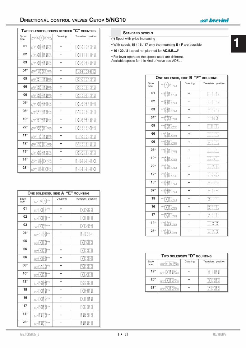
File: TCRS005_E 00/2000/eI • 31
1TWO SOLENOIDS, SPRING CENTRED “C” MOUNTING
Spool Covering Transient positiontype
01 +
02 -
03 +
04* -
05 +
66 +
06 +
07* +
08* +
10* +
22* +
11* +
12* +
13* +
14* -
28* -
STANDARD SPOOLS
ONE SOLENOID, SIDE B “F” MOUNTING Spool Covering Transient positiontype
01 +
02 -
03 +
04* -
05 +
66 +
06 +
08* +
10* +
22* +
12* +
13* +
07* +
15 -
16 +
17 +
14* -
28* -
ONE SOLENOID, SIDE A “E” MOUNTING Spool Covering Transient positiontype
01 +
02 -
03 +
04* -
05 +
66 +
06 +
08* +
10* +
12* +
15 -
16 +
17 +
14* -
28* -
TWO SOLENOIDS “D” MOUNTING Spool Covering Transient positiontype
19* -
20* +
21* +
DIRECTIONAL CONTROL VALVES CETOP 5/NG10
(*) Spool with price increasing
• With spools 15 / 16 / 17 only the mounting E / F are possible
• 19 / 20 / 21 spool not planned for AD.5.E...J*
• For lever operated the spools used are different.Available spools for this kind of valve see AD5L..

File: AD5E002_E 04/2010/eI • 32
1
MS
LIMITS OF USE (MOUNTING C-E-F)S
E = Manual override
OVERALL DIMENSIONS
AD.5.E... SOLENOID OPERATED VALVES CETOP 5/NG10
Max. pressure ports P/A/B 350 barMax. pressure port T (DC coil) see note (*) 250 barMax. pressure port T (AC coil) 160 barMax. fl ow 100 l/minMax. excitation frequency 3 HzDuty cycle 100% EDFluid viscosity 10 ÷ 500 mm2/sFluid temperature -25°C ÷ 75°CAmbient temperature -25°C ÷ 60°CMax. contamination level class 10 in accordance with NAS 1638 with fi lter ß25≥75Weight (with one DC solenoid) 4 KgWeight (with two DC solenoids) 5,1 KgWeight (with one AC solenoid) 3,5 KgWeight (with two AC solenoids) 4,3 Kg
(*) Pressure dynamic allowed for 2 millions of cycles.
A max. counter-pressure of 4 bar at T is permitted for the variant with a microswitch (MS).
The tests have been carried out with solenoids at operating temperature and a voltage 10% less than rated voltage with a fl uid temperature of 40°C. The fl uid used was a mineral oil with a viscosity of 46 mm2/s at 40°C.The values in the diagram refer to tests carried out with the oil fl ow in two directions simultaneously T = 2 bar (e.g. from P to A and the same time B to P).
In the cases where valves 4/2 and 4/3 were used with the fl ow in one direction only, the limits of use could have variations which may even be negative. Rest time: the values are indicative and depend on the following parameters: hydraulic circuit, fl uid used and variations in hydraulic scales (pressure P, fl ow Q, temperature T).
DIRECT CURRENT SOLENOIDS (DC) ALTERNATING CURRENT SOLENOIDS (AC)
Direct current : Energizing 60 ÷ 95 ms. De-energizing 25 ÷ 70 ms.
Alternating current: Energizing 12 ÷ 30 ms. De- energizing 10 ÷ 55 ms.
MS = Microswitch
Fixing screws UNI 5931 M6x40with material specifi cations min 8.8Tightening torque 8 Nm / 0.8 Kgm
Support planespecifi cations
P (
bar)
Q (l/min)
P (
bar)
Q (l/min)
1Spooltype DC AC 01 1 8 02 1 6 03 2 7 04 4 10 05 1 6 06 - 66 3 9 14-28 5 11 15 3 10 16 1 6
Solenoids
Curves
2
3
4
5
6
7
8
9
10
11

I • 33File: AD5EJ$2_E 02/2000/e
1
OVERALL DIMENSIONS
EAD5E...Q5 - 02/2000/e
EAD5E...J$ - 00/2000/e
AD.5.E...J* VALVES WITH SPOOL MOVEMENT SPEED CONTROL VARIANT J*
Valves type AD5.E... with spool movement speed control. These ON-OFF type valves are used when a lower spool movement speed than usual for conventional solenoid valves is required to prevent impacts which could adversely affect the smooth running of the system. The system consists of reducing the transfer section for the fl uid from one solenoid to the other by means of calibrated orifi ce.• This version can only be used with a direct current (DC) and also in-volves a reduction in the limits of use so that we suggest to always test the valve in your application.
E = Manual override
Max. pressure ports P/A/B 320 barMax. pressure port T - see note (*) 250 barMax. fl ow 100 l/minDuty cycle 100% EDFluid viscosity 10 ÷ 500 mm2/sFluid temperature -25°C ÷ 75°CAmbient temperature -25°C ÷ 60°CWeight with one DC solenoid 3,6 KgWeight with two DC solenoids 4,5 Kg
(*) Pressure dynamic allowed for 2 millions of cycles.
Fixing screws UNI 5931 M6x40with material specifi cations min. 8.8Tightening torque 8 Nm / 0.8 Kgm
Support planespecifi cations
AD.5.E...Q5 VALVES WITH EXTERNAL DRAINING SOLENOID - VARIANT Q5
• To order AD.5.J* version valves, specify the orifi ces code.• The operation is linked to a minimum counter-pressure on the T line (1 bar min.)• The switching time referred to the spool travel detected by a LVDT transducer can vary for the NG10 valve a minimum of 200 to a maximum of 400 ms depending on 5 fundamental variables:1) Diameter of the calibrated orifi ce (see table)2) Hydraulic power for clearance referring to fl ow and pressure values through the valve3) Spool type4) Oil viscosity and temperature5) Counter-pressure at T line• Possible mounting: C / E / F / G / H• 19 / 20 / 21 spools not planned for AD.5.E...J*
E = Manual override
Valves type AD5.E...Q5 with external draining solenoid.
This involves valves with solenoid drainage chambers separated by line T in the CETOP 5 interface distinguished by the letter L. This solution makes it possible to operate with a maximum counter-pressure at T up to 320 bar using only 12.9 material fi xing screws to ensure the maximum safety of the solenoid valve fi xing and use of an additional drain. This version can be used for direct current (DC) and alternating current (AC), but involves a reduction in the limits of usage depending on the pressure at T.• Mounting possible: C / D / E / F / G / H / I / L / M• For subplate see BSH.5.31..
Max. pressure ports P/A/B/T 320 barMax. pressure port L (DC coils) see note (*) 250 barMax. pressure port L (AC coils) 160 barMax. fl ow 100 l/minMax. excitation frequency 2 HzDuty cycle 100% EDFluid viscosity 10 ÷ 500 mm2/sFluid temperature -25°C ÷ 75°CAmbient temperature -25°C ÷ 60°CWeight with one DC solenoid 3,6 KgWeight with two DC solenoids 4,5 KgWeight with one AC solenoid 3,5 KgWeight with two AC solenoids 4,3 Kg
(*) Pressure dynamic allowed for 2 millions of cycles.
Support planespecifi cations
Fixing screws UNI 5931 M6x40with material specifi cations 12.9 must be usedTightening torque 8 Nm / 0.8 Kgm
CALIBRATED
ORIFICE AVAILABLE
ø (mm) M6x6 Code
0.5 M89.10.0031 5S (J5+S1)* 0.6 M89.10.0026 6S (J6+S1)* 0.7 M89.10.0032 7S (J7+S1)* 0.8 M89.10.0033 8S (J8+S1)*
* Old code

I • 34File: AD5O002_E 05/2000/e
1
OVERALL DIMENSIONS
AD.5.O... OLEO-PNEUMATIC OPERATION TYPE VALVES CETOP 5/NG10
Max. pressure ports P/A/B 320 barMax. pressure port T 160 barMax. fl ow 100 l/minMin. operating pressure 4 + [0.027 x (pt*)] bar - see noteMax. operating pressure 200 barFluid viscosity 10 ÷ 500 mm2/sFluid temperature -25°C ÷ 75°CAmbient temperature -25°C ÷ 60°CMax. contamination level class 10 in according with NAS 1638 with fi lter ß25≥75Weight (single pilot) 4,1 KgWeight (twin pilot) 5,4 Kg
• Possible mounting:Hydraulic control:C / D / E / F / G / H / I / L / M Pneumatic control:I / L / M
• Ordering code see page I•30
(pt*) = Pressure at port T
Fixing screws UNI 5931 M6x40with material specifi cations min. 8.8Tightening torque 8 Nm / 0.8 Kgm
Support planespecifi cations
AD.5.D... DIRECT MECHANICALLY OPERATED TYPE VALVES CETOP 5/NG10
OVERALL DIMENSIONS
Max. pressure ports P/A/B 320 barMax. pressure port T 20 barMax. fl ow 100 l/minOperating force - see note (*) 8 Kg - see note (**)Fluid viscosity 10 ÷ 500 mm2/sFluid temperature -25°C ÷ 75°CAmbient temperature -25°C ÷ 60°CMax. contamination level class 10 in accordance with NAS 1638 with fi lter ß25≥75Weight 3,8 Kg
• Possible mounting:E / F / G / H• Ordering code see page I•30• Notes:(*) In the absence of counter-pressure at port T
(**)10 Kg with a pres-sure of 20 bar at T
Stroke 8 mmmExtra stroke 2 mmWorking stroke 4 mm
Support planespecifi cations
Fixing screws UNI 5931 M6x40with material specifi cations min. 8.8Tightening torque 8 Nm / 0.8 Kgm
EAD5O - 02/2000/e
EAD5D - 03/2000/e
Minimum pilot pres-sure depends on spool scheme, fl ow rate and pressure.To allow the spool to return to nautral position, the pilot pressuremust be below 2 bar.

File: AD5L002_E 03/2015/eI • 35
1
M1
OVERALL DIMENSIONS
AD.5.L... LEVER OPERATED TYPE VALVES CETOP 5/NG10
• Possible mounting:C / E / F (with mounting “F” and spools “15-16-17” the lever is on side “B”)
• There is no D type mounting
• The variant D1specifi es the detent (mechanical connec-tion) for lever opera-tion
• The springs for the version with detent (variant D1) are dif-ferent from those for standard versions.
Max. pressure ports P/A/B 320 barMax. pressure port T 160 barMax. fl ow 100 l/minLever angle 2 x 15°Fluid viscosity 10 ÷ 500 mm2/sFluid temperature -25°C ÷ 75°CAmbient temperature -25°C ÷ 60°CMax. contamination level class 10 in accordance with
NAS 1638 with fi lter ß25≥75Weight 4,7 KgWeight with M1 variant 5,35 Kg
• Completely different spools are used for these (lever operated) valves than for all other types of operation (e.g. electrical, mechani-cal, pneumatic operation, .....)
• Available spools: 01 / 02 / 03 / 04 / 05 / 06 / 66 / 07 / 22 / 13 / 15 / 16 / 17 (for hydraulic symbols see page 1•30)
• Microswitch type AM1107 code V79000001 can be ordered separately.
M1 = Microswitch
Fixing screws UNI 5931 M6x40with material specifi cations min. 8.8Tightening torque 8 Nm / 0.8 Kgm
Support planespecifi cations
AD.5.L...
ORDERING CODE CH. I PAGE 30
STANDARD SPOOLS CH. I PAGE 31
Side A Side B

File: TA16K16_E 07/2013/eI • 36
1
Type of protection (in relation to the connector used) IP 66Number of cycles 18.000/hSupply tolerance +10% / -10%Ambient temperature -54°C ÷ 60°CDuty cycle 100% EDMax. pressure static 210 barInsulation class wire HWeight 0,8 Kg
Type of protection (in relation to the connector used) IP 65Number of cycles 18.000/hSupply tolerance ±10%Ambient temperature -30°C ÷ 60°CDuty cycle 100% EDInsulation class wire HWeight 0,9 Kg
"K16" AC SOLENOIDS FOR CETOP 5
"A16" DC COILS FOR CETOP 5
EMERGENCY (COILS WITH HIRSCHMANN CONNECTION)ROTARY WITHOUT CONNECTOR (P2)
ROTARY WITH CONNECTOR (P1)MANUAL WITHOUT CONNECTOR (ES)
MANUAL WITH CONNECTOR (E1)
EMERGENCY (COILS WITH HIRSCHMANN CONNECTION)ROTARY WITHOUT CONNECTOR (P2)
ROTAN ROTARY WITH CONNECTOR (P1)MANUAL WITHOUT CONNECTOR (ES)
MANUAL WITH CONNECTOR (E1)
VOLTAGE (V)
MAX WINDING TEMPERATURE (AMBIENT TEMPERATURE 25°C)
RATED POWER (W)
RESISTANCE AT 20°C (OHM) ±7%
12V 106°C 45 3.224V 113°C 45 12.448V* - 45 -
102V(*)(**) - 45 -110V(*)(**) 118°C 45 268205V(*)(**) - 45 - * Special voltages
** The european low voltage directive is applied to electronical equipments used at a nominal voltages between 50 and 1000 VAC or 75 and 1500 VDC. In conformity with the low directive each part of the manifold or the subplate on which the valve is mounted should be connected to a protective earth with a resistence less than 0.1 ohms.
VOLTAGE (V)
MAX. WINDING TEMPERATURE (AMBIENT TEMPERATURE25°C)
RATED POWER(VA)
IN RUSH CURRENT (VA)
RESISTANCE AT 20°C (OHM) ±10%
24V/50Hz 134°C 124 454 0.5624V/60Hz* 115°C 103.5 440 0.5548V/50Hz* 134°C 113 453 2.10
115V/50Hz-120V/60Hz(*)(**) 121°C - 138°C - - 10.8230V/50Hz-240V/60Hz(*)(**) 121°C - 138°C - - 43.0
240V/50Hz(*)(**) 134°C 120 456 47.39 * Special voltage
** The european low voltage directive is applied to electronical equip-ments used at a nominal voltages between 50 and 1000 VAC or 75 and 1500 VDC. In conformity with the low directive each part of the manifold or the subplate on which the valve is mounted should be connected to a protective earth with a resistence less than 0.1 ohms.

File: ADP5E001_E 09/2013/eI • 37
1
Δp (
bar)
Q (l/min)
1 2 3
4 5 6
7
8
C
E
F
D*
PRESSURE DROPS
The diagram at the side shows the pressure drop curves for spools during normal usage. The fl uid used is a mineral oil with a viscosity of 46 mm2/s at 40°C; the tests have been carried out at a fl uid temperature of 40°C. For higher fl ow rates than those in the diagram, the losses will be those expressed by the following formula:
Δp1 = Δp x (Q1/Q)2
where Δp will be the value for the losses for a specifi c fl ow rate Q which can be obtained from the diagram, Δp1 will be the value of the losses for the fl ow rate Q1 that is used.
Spool Connectionstype P→A P→B A→T B→T P→T
01 4 4 7 7 02 6 6 8 8 7 03 3 3 8 8 04 4 4 2 2 3 05 6 6 6 6 66 4 4 8 7 06 4 4 7 8 14 6 4 8 6 2 15-19 2 2 5 5 16-20 1 1 2 2 28 4 6 6 8 2
Curve No.
ADP. 5.E... DIRECTIONAL CONTROL CETOP 5/NG10HIGH PERFORMANCES SOLENOID OPERATED VALVES
The ARON NG10 directional control valves are designed for subplate mounting with an interface in accordance with UNI ISO 4401 - 05 - 04 - 0 - 94 standard (ex CETOP R 35 H 4.2-4-05). The use of solenoids with wet armatures allows an extremely safe construction completely dispensing with the need for dynamic seal. The solenoid tube is screwed directly onto the valve casing whilst the coil is kept in position by a ring nut. Great care has been taken over the design and production of the ducts and the improvement of the spools allows relatively high fl ow rates to be accommodated for its size with minimal pressure drops (Δp). The operation of the directional valve is electrical. The centring is achieved by means of cali-brated length springs which, once the impulse is over, immediately reposition the spool in the neutral position. The solenoids, constructed with a protection class of IP66 in accordance with BS 5490 standards, are available in direct current form and different voltage. The electrical controls are equipped with an emergency manual control inserted in the tube.The ADP.5.E.. valve has certain design features which allow it to “manage” a hydraulic power equal to Q = 120l/min with a P = 320 bar, maintaining a considerable safety margin. These features can be summarized as follows:- Solenoid D19 with an optimum ratio between the power absorbed (42W) and the magnetic force- Diameter of the spool 18 mm, with carefully designed geometry improved to compensate for the fl ow forces- Compact graphite cast iron valve casing with high mechanical resistance- Different springs, improved according to the features of the spoolThe electrical supply connectors meet DIN 43650 ISO 4400 standards; connectors are also available with built in rectifi ers or pilot lights.The recommended fl uids are hydraulic mineral based oils in accordance with DIN 51524 and it is recommended that fi lters should be fi tted to ensure a maximum contamination level of class 10 in accordance with NAS 1638, ß25≥75.For other fl uids please contact our Technical DPT.• The solenoids are in DC voltage only
ORDERING CODE
ADP High performances directional control valve
5 CETOP 5/NG10
E Electrical operator
** Spools (Table next page)
* Mounting (table 1)
* Voltage (table 2)
** Variants (table 3)
1 Serial No.
TAB.1 - MOUNTING
DC VOLTAGE ** L 12V M 24V N 48V* P 110V* Z 102V* X 205V* W Without DC coils
TAB.2 - SOLENOID D19 (42 W)
115Vac/50Hz120Vac/60Hzwith rectifi er
230Vac/50Hz240Vac/60Hzwith rectifi er
TAB.3 - VARIANTS
VARIANT CODE
No variant (without connectors) S1(*)Viton SV(*)Rotary emergency button P2(*)Adjustable spool movement speed control 4S(*)With solenoid chamber external drainage (Y) S5(*)Spool movement speed control(VDC only) with ø 0.5 mm diameterorifi ce 5S(*)Spool movement speed control VDC only) with ø 0.8 mm diameterorifi ce 8S(*)
Other variants available on request
(*) Valve with detent
Voltage codes are not stamped on the plate, their are readable on the coils.
ADP.5.E...
“D19” DC SOLENOIDS CH. I PAGE 39
STANDARD CONNECTORS CH. I PAGE 20
(*) Coils with Hirschmann connection supplied without connectors. The connectors can be ordered separately, ch. I page 20.
* Special voltage** Technical data see page I • 39

File: ADP5E001_E 09/2013/eI • 38
1
P (
bar)
Q (l/min)
1
4
2
3
ADP.5.E. HIGH PERFORMANCES SOLENOID OPERATED VALVES CETOP 5/NG10
ONE SOLENOID, SIDE A “E MOUNTING” Spool Covering Transient position
type
01 +
02 -
03 -
04* -
05 -
66 -
06 -
14* -
15 -
16 +
28* -
* SPOOLS WITH PRICE INCREASING
ONE SOLENOID, SIDE B “F MOUNTING” Spool Covering Transient position
type
01 +
02 -
03 -
04* -
05 -
66 -
06 -
14* -
15 -
16 +
28* -
STANDARD SPOOLS
TWO SOLENOIDS, SPRING CENTRED “C MOUNTING” Spool Covering Transient position
type
01 +
02 -
03 -
04* -
05 -
66 -
06 -
14* -
28* -
TWO SOLENOIDS “D MOUNTING” Spool Covering Transient position
type
19* -
20* +
The tests have been carried out with solenoids at operating temperature and a voltage 10% less than rated voltage with a fl uid temperature of 50°C.
The fl uid used was a mineral oil with a viscosity of 46 mm2/s at 40°C.
The values in the diagram refer to tests carried out with the oil fl ow in two directions simultaneously (e.g. from P to A and at the same time B to T).
In the cases where valves 4/2 and 4/3 were used with the fl ow in one direction only, the limits of use could have variations which may even be negative.
The tests were carried out with a counter-pressure of 2 bar at T.
Spool n°type curves
01 1 02 1 03 2 04 1 05 1 66 1 06 1 14 3 15 1 16 1 28 3 19 4 20 4
LIMITS OF USE (MOUNTING C-E-F)

File: ADP5E001_E 09/2013/eI • 39
1
“D19” DC SOLENOIDS
E = Manual override
GSQ = Square section seal
Fixing screws UNI 5931 M6x40 with material specifi cations 12.9Tightening torque 8 ÷ 10 Nm / 0.8 ÷ 1 Kgm
Support planespecifi cations
Max. operating pressure: ports P/A/B 350 barMax. operating pressure: port T (*) 250 barMax. fl ow 120 l/minMax. excitation frequency 3 HzDuty cycle 100% EDFluid viscosity 10 ÷ 500 mm2/sFluid temperature -25°C ÷ 75°CAmbient temperature -25°C ÷ 60°CMax. contamination level class 10 in accordance with NAS 1638 with fi lter ß25≥75Weight with one DC solenoid 5 KgWeight with two DC solenoids 6,5 Kg
(*) Pressure dynamic allowed for 2 millions of cycles
Pressure on port T valid in case Y is blocked (no external drainage). Normally the external drainaged is blocked with a plug S.T.E.I M6x6 UNI 5923
ADP.5.E... 4S variant - These ON-OFF type valves are used when a lower spool movement speed is required than it is generally available with a conventional solenoid valve in order to avoid those shocks which might otherwise compromise proper system operation. This is obtained by forcing the fl uid to pass through the gap which exists between the screw thread and the M8x1 tapped thread, restricting in this way the transfer cross section between the 2 solenoid chambers. Using this variant may entail a reduction in the operational limits according to the spool used, up to the complete blocking of the change over itself. The valve opera-tion depends on the presence of a minimum back pressure on the T line (min. 1 bar). The change over time referred to the spool stroke depends on 4 main variables:• Applicable hydraulic power, related to the fl ow rate and pressure drop across the valve;• Spool type (system confi guration);• Oil viscosity and temperature;• Back pressure on T.
ADP.5.E. HIGH PERFORMANCES SOLENOID OPERATED VALVE CETOP 5/NG10
ADP.5.E... S5 variant - These are valves with solenoid chambers drainage separated from the T line, obtained on CETOP RO5 interface and characterized by the letter Y. This solution allows operation with up to 320 bar max. back pressure on the T line while using only 12.9 material fi xing screws to ensure maximum solenoid valve mounting safety and supplementary drainage.
Type of protection (in relation to the connector used) IP 66Number of cycle 18.000/hSupply tolerance ±10%Ambient temperature -54°C ÷ 60°CDuty cycle 100% EDMax static pressure 210 barInsulation class wire HWeight 1,63 Kg
ROTARY EMERGENCY
WITHOUT CONNECTOR (P2)WITH CONNECTOR (P1)
VOLTAGE
(V)MAX WINDING TEMPERATURE
(AMBIENT TEMPERATURE25°C)
RATED POWER (W)
RESISTANCE AT 20°C (OHM)
±10%12V 105°C 42 3.4324V 105°C 42 13.7148V* 105°C 42 55
102V(*)(**) 105°C 42 248110V(*)(**) 105°C 42 288205V(*)(**) 105°C 42 1000 * Special voltage
** The european low voltage directive is applied to elec-tronical equipments used at a nominal voltages between 50 and 1000 VAC or 75 and 1500 VDC. In conformity with the low directive each part of the manifold or the subplate on which the valve is mounted should be connected to a protective earth with a resist-ence less than 0.1 ohms.

File: ADP5V001_E 10/2014/eI • 40
1
Δp (
bar)
Q (l/min)
1 2
3 4
5
6
TAB.3 - VARIANTS
ADP.5.V... WITH PROXIMITY SENSOR L.V.D.T. CETOP 5/NG10
VARIANTS CODE
No variant (without connectors) S1(*)Rotary emergency button P2(*)Without proximity connector LVDT S3Without coils and proximity connector S4With solenoid chamber external drainage (Y) S5(*)
Other variants available on request.
Max. operating pressure: ports P/A/B 350 barMax. operating pressure: port T (*) 250 barMax. fl ow 120 l/minMax. excitation frequency 3 HzDuty cycle 100% EDFluid viscosity 10 ÷ 500 mm2/sFluid temperature -25°C ÷ 75°CAmbient temperature -25°C ÷ 60°CMax. contamination level class 10 in accordance with NAS 1638 with fi lter ß25≥75Type of protection (in relation to connector used) IP 66Weight 6,2 Kg
(*) Pressure dynamic allowed for 2 millions of cycles
The ARON NG10 directional con-trol valves are designed for sub-plate mounting with an interface in accordance with UNI ISO 4401 - 05 - 04 - 0 - 94 standard (ex CETOP R 35 H 4.2-4-05).
The single solenoid directional valves type ADP5V are used in applications where the monitor-ing of the position of the spool inside the valve is requested to manage the machine safety cycles in according with the accident prevention legislation. These di-rectional valves are equipped with an horizontal positioned inductive sensor on the opposite side of the solenoid, which is capable of providing the fi rst movement of the valve when the passage of a minimum fl ow is allowed. Integrated in safety systems, these valves intercept actuator movements that could be dangerous for the operators and for the machine.
ORDERING CODE
ADP High performances directional control valve
5 CETOP 5/NG10
V Directional valve with single solenoid and L.V.D.T. proximity sensor
*** Spool and mounting (table 1)
* Voltage (table 2)
** Variants (table 3)
1 Serial No.
registered mark for industrial environment with reference to the electro-magnetic compatibility. European norms: - EN50082-2 general safety norm - industrial environment - EN 50081-1 emission general norm - residential environment
PRESSURE DROPS
The diagram at the side shows the pressure drop curves for spools during normal usage. The fl uid used is a mineral oil with a viscosity of 46 mm2/s at 40°C; the tests have been carried out at a fl uid temperature of 40°C. For higher fl ow rates than those in the diagram, the losses will be those expressed by the following formula:
Δp1 = Δp x (Q1/Q)2
where Δp will be the value for the losses for a specifi c fl ow rate Q which can be obtained from the diagram, Δp1 will be the value of the losses for the fl ow rate Q1 that is used.
Spool Connectionstype P→A P→B A→T B→T P→T
01 3 3 5 5 02 4 4 6 6 5 66 3 3 6 5 06 3 3 5 6 16 1 1 2 2 Curve No.
TAB1 - STANDARD SPOOL
ONE SOLENOID Spool Covering Transient position
type
01E +
01F +
02E -
02F -
66E -
06F -
16E +
16F +
32E +
ADP.5.V...
“D19” DC SOLENOIDS CH. I PAGE 41
STANDARD CONNECTORS CH. I PAGE 20
L.V.D.T. CH. I PAGE 22
Voltage codes are not stamped on the plate, their are readable on the coils.
DC VOLTAGE **L 12VM 24VN 48V*P 110V*Z 102V*X 205V*W Without DC coils and connectors
TAB.2 - DC VOLTAGE
• Possible mountings: E / F• The solenoid is in DC voltage only
115Vac/50Hz120Vac/60Hzwith rectifi er
230Vac/50Hz240Vac/60Hzwith rectifi er
(*) Coils with Hirschmann connection supplied without connectors. The connectors can be or-dered separately, ch. I page 20.
* Special voltage** Technical data see page I • 41

File: ADP5V001_E 10/2014/eI • 41
1OVERALL DIMENSIONS
Fixing screws UNI 5931 M6x40with material specifi cations 12.9Tightening torque 8 ÷ 10 Nm / 0.8 ÷ 1 Kgm
E = Manual override
GSQ = Square section seal
Support planespecifi cations
ADP.5.V... WITH PROXIMITY SENSOR L.V.D.T. CETOP 5/NG10
“D19” DC SOLENOIDS
Type of protection (in relation to the connector used) IP 66Number of cycle 18.000/hSupply tolerance ±10%Ambient temperature -54°C ÷ 60°CDuty cycle 100% EDMax static pressure 210 barInsulation class wire HWeight 1,63 Kg
ROTARY EMERGENCY
WITHOUT CONNECTOR (P2) WITH CONNECTOR (P1)
VOLTAGE
(V)MAX WINDING TEMPERATURE
(AMBIENT TEMPERATURE25°C)
RATED POWER (W)
RESISTANCE AT 20°C (OHM)
±10%12V 105°C 42 3.4324V 105°C 42 13.7148V* 105°C 42 55
102V(*)(**) 105°C 42 248110V(*)(**) 105°C 42 288205V(*)(**) 105°C 42 1000 * Special voltage
** The european low voltage directive is applied to elec-tronical equipments used at a nominal voltages between 50 and 1000 VAC or 75 and 1500 VDC. In conformity with the low directive each part of the manifold or the subplate on which the valve is mounted should be connected to a protective earth with a resist-ence less than 0.1 ohms.
106 99,5107
312,5
39
43
,5
72
30
694
2
46
54
E
6,5
P
A B
T T
==
= =
Y
ISO4401-05
(CETOP5)
N°4 GSQ Q25981014 / OR 2 -014/90
GSQ Q25981012 / OR 2-012/90
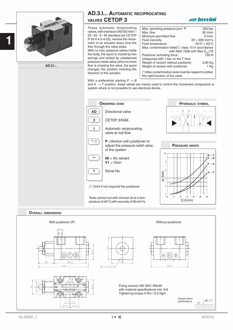
File: AD3I001_E 04/2014/eI • 42
1
Q (l/min)
Δp (
bar)
B → TP → B
P → A
A → T
OVERALL DIMENSIONS
These automatic reciprocating valves, with interface UNI ISO 4401 - 03 - 02 - 0 - 94 standard (ex CETOP R 35 H 4.2-4-03), reverse the move-ment of an actuator every time the fl ow through the valve stops.With no max. pressure valves inside the body, the spool is moved by two springs and locked by unbalanced pressure inside valve; when no more fl ow is crossing the valve, the spool changes the position inverting the direction of the actuator.
With a preferential starting P → B and A → T position, these valves are mainly used to control the movement compactors or system where is not possible to use electrical device.
ORDERING CODE
AD Directional valve
3 CETOP 3/NG6
I Automatic reciprocating valve at null fl ow
* (1) P =Version with positioner to adjust the pressure relief valve of the system
** 00 = No variant V1 = Viton
1 Serial No.
AD.3.I... AUTOMATIC RECIPROCATING
VALVES CETOP 3
HYDRAULIC SYMBOL
Max. operating pressure port P 320 barMax. fl ow 30 l/minMinimum permitted fl ow 3 l/minFluid viscosity 20 ÷ 200 mm2/sFluid temperature -20°C ÷ 60°CMax. contamination level(*) class 10 in accordance
with NAS 1638 with fi lter ß25≥75Positioner activating force 130 N (measured with 1 bar on the T line) Weight of version without positioner 0,95 KgWeight of version with positioner 1 Kg
(*) Max contamination level must be respect to obtain the right function of the valve
PRESSURE DROPS
Support planespecifi cations
Fixing screws UNI 5931 M5x40with material specifi cations min. 8.8Tightening torque 5 Nm / 0.5 Kgm
AD.3.I...
(1) Omit if not required the positioner
Tests carried out with mineral oil at a tem-perature of 40°C with viscosity of 46 mm2/s.
With positioner (P) Without positioner

File: AD5I001_E 04/2016/eI • 43
1
Q (l/min)
B → T
P → B
P → A
A → T
Δp (
bar)
AD.5.I... AUTOMATIC RECIPROCATING
VALVES CETOP 5
Max. operating pressure port P 320 barMax. fl ow 100 l/minMinimum permitted fl ow 10 l/minFluid viscosity 32 ÷ 60 mm2/sFluid temperature -20°C ÷ 60°CMax. contamination level(*) class 10 in accordance
with NAS 1638 with fi lter ß25≥75Positioner activating force 190 N(measured with 1 bar on the T line) Weight of version without positioner 3,4 KgWeight of version with positioner 3,6 Kg
(*) Max contamination level must be respect to obtain the right function of the valve
GSQ = square section seal
ORDERING CODE
AD Directional control
5 CETOP 5/NG10
I Automatic reciprocating valve at null fl ow
P Version with positioner to adjust the pressure relief valve of the system
** 00 = No variant V1 = Viton 2T = Variant for regenerative system
1 Serial No.
AD.5.I.P.2T.1 FOR REGENERATIVE SYSTEM
PRESSURE DROPS
Version AD.5.I.P.2T.1 integrated in a regenerative circuit for compactors with roll on-off mobile system, solution useful for all applications where to connect microswitch of proximity is not pos-sible. For any information about our regenerative manifold Aron please contact our technical department. For special subplate BS.5.RIA see Chapter X "Systems", next pages.
Fixing screws UNI 5931 M6x40with material specifi cations min. 8.8Tightening torque 5 Nm / 0.5 Kgm
Support planespecifi cations
The operating principle of this type of inverter valve, with interface UNI ISO 4401 - 05 - 04 - 0 - 94 standard (ex CETOP R 35 H 4.2-4-05), is based on the pressure unbalanced created in its interior as a consequence of the fl uid fl ow rate. On starting the system this valve assumes always a preferential position P → B e A → T.
When a pressure is applied to the cylinder which exceeds the system maximum pressure relief valve setting (e.g. end stroke actuator), a hydraulic unbalanced is generated capable of changing over the valve and inverting the cylinder direction of the movement.
Tests carried out with mineral oil a temperature of 40°C with a viscos-ity of 46 mm2/s.
AD.5.I...

File: AD3RI003_E 02/2000/eI • 44
1
Q (l/min)
Δp (
bar)
A → TB → T
P → AP → B
ORDERING CODE
PRESSURE DROPS
HYDRAULIC SYMBOL
E = Manual override
Max. operating pressure 320 barMax. pressure port T 160 barMin. recommended pressure 15 barMax. fl ow 25 l/minMin. fl ow 2 l/minSetting ranges: Spring 1 15 ÷ 50 bar Spring 2 20 ÷ 140 bar Spring 3 50 ÷ 320 barFluid viscosity 10 ÷ 60 mm2/sFluid temperature -20°C ÷ 75°CMax. contamination level class 10 in accordance
with NAS 1638 with fi lter ß25≥75Weight 2,3 Kg
AD.3.RI... AUTOMATIC RECIPROCATING
VALVES CETOP 3
Support planespecifi cations
Fixing screws UNI 5931 M5x40with material specifi cations min. 8.8Tightening torque 5 Nm / 0.5 Kgm
This valve type is characterized by fully hydraulic operation, as it takes advantage of the system pressure rise to cause an automatic and continuous inversion of the utilization. The change-over takes place when the system pressure exceeds the inversion valves calibration pressure, and therefore also in not predetermined positions. At cyl-inder stroke end, the overall maximum pressure valve should be adjusted on a value 30% higher than the system operating pressure.
The inverter valves pressure calibra-tion values should be 15% lower than that of the overall maximum pressure valve, and 15% higher than the maxi-mum operating pressure.
Note: to operate the push button emergency, a minimum pressure of 3 bar on the actuator is needed.
AD.3.RI...
AD Directional valve
3 CETOP 3/NG6
RI Automatic reciprocating valve hydraulically operated automatic reciprocation
211 Scheme
Z No voltage
* Setting ranges: 1 = 15 ÷ 50 bar 2 = 20 ÷ 140 bar 3 = 50 ÷ 320 bar
** 00 = No variant V1 = Viton
3 Serial No.

File: AD5RI003_E 01/2000/eI • 45
1
Q (l/min)
Δp (
bar)
P → AP → B
A → TB → T
Max. operating pressure 320 barMax. pressure port T 160 barMin. recommended pressure 15 barMax. fl ow 70 l/minMin. fl ow 6 l/minSetting ranges: Spring 1 15 ÷ 50 bar Spring 2 20 ÷ 140 bar Spring 3 50 ÷ 320 barFluid viscosity 10 ÷ 60 mm2/sFluid temperature -20°C ÷ 75°CMax. contamination level class 10 in accordance
with NAS 1638 with fi lter ß25≥75Weight 5,4 Kg
PRESSURE DROPS
HYDRAULIC SYMBOL
E = Manual override
AD.5.RI... AUTOMATIC RECIPROCATING
VALVES CETOP 5
ORDERING CODE
Fixing screws UNI 5931 M6x40with material specifi cations min. 8.8Tightening torque 8 Nm / 0.8 Kgm
Support planespecifi cations
This valve type is characterized by a fully hydraulic operation, as it takes advantage of the system pressure rise to cause an automatic and continu-ous inversion of the utilization. The changeover takes place when the system pressure exceeds the inver-sion valves calibration pressure, and therefore also in not predetermined position. At the cylinder stroke end, the overall maximum pressure valve should be adjusted on a value 30% higher than the system operating pressure.
The inverter valves pressure calibra-tion values should be 15% lower than that of the overall maximum pressure valve, and 15% higher than the maxi-mum operating pressure.
Note: to operate the push button emergency, a minimum pressure of 3 bar on the actuator is needed.
AD.5.RI...
AD Directional valve
5 CETOP 5/NG10
RI Automatic reciprocating valve hydraulically operated automatic reciprocation
211 Scheme
Z No voltage
* Setting ranges: 1 = 15 ÷ 50 bar 2 = 20 ÷ 140 bar 3 = 50 ÷ 320 bar
** 00 = No variant V1 = Viton
3 Serial No.

File: ADPH5001_E 03/2000/eI • 46
1
TAB.1 - ORIFICE ON LINE A/B
TAB.2 - PLUGS DISPOSAL
ORDERING CODE
ADPH.5... PILOTED VALVES CETOP 5/NG10WITH CETOP 2/NG4 PILOT VALVE
These ADPH 5 valves are used primarily for controlling the starting, stopping and direction of fl uid fl ow. These kind of distributors are composed by a main stage crossed by the big fl ow from the pump (ADPH.5) and by a cetop 2 pilot directional solenoid valve (AD.2.E) available with different mounting type .
When a short response time is requested, a special ver-sion of solenoids with high dynamics is available with the code AD.2.E.**.*.*FF.2 (Please, contact our Technical Aron Service).
ADPH Piloted valve The pilot valves AD.2.E... must be ordered separately
5 CETOP 5/NG10
** Spool type (Table next page)
* Mounting (Table next page) Standard orifi ce at port P: ∅ 1mm
* Orifi ce type on Cetop 2 valves (Table 1) 0 = none A / B / C / D / E / F / G = orifi ce on line A H / I / L / M / N / P / Q = orifi ce on line B
* Piloting and draining type (Tab.2) I = internal piloting internal draining E = internal piloting external draining X = external piloting internal draining (special body)
00 No variant
1 Serial No.
HYDRAULIC SYMBOL
On line A On line B ø(mm) 0 0 None
A H 0,5
B I 0,6
C L 0,7
D M 0,8
E N 0,9
F P 1
G Q 1,2
Internal pilotingInternal draining (I code)
Internal pilotingExternal draining (E code)
External pilotingInternal draining (X code)
ADPH.5...
STANDARD SPOOLS FOR ADPH.5 CH. I PAGE 47
TECH. SPECIFICATIONS ADPH5 CH. I PAGE 48
CETOP 2/NG04 CH. I PAGE 2
AD.2.E... CH. I PAGE 4
"A09" DC COILS CH. I PAGE 4
STANDARD CONNECTORS CH. I PAGE 20

File: ADPH5001_E 03/2000/eI • 47
1
Δp (
bar)
1 2 3
4 5 6
7
8
Q (l/min)
The diagram at the side shows the pressure drop curves for spools during normal usage. The used fl uid is a mineral oil with a viscosity of 46 mm2/s at 40°C; the tests have been carried out at a fl uid temperature of 40°C. For fl ow rates higher than those in the diagram, the losses will be those expressed by the following formula: Δp1 = Δp x (Q1/Q)2
where Δp will be the value for the losses for a specifi c fl ow rate Q which can be obtained from the diagram, Δp1 will be the value of the losses for the fl ow rate Q1 that is used.
PRESSURE DROPS
Spool Connectionstype P→A P→B A→T B→T P→T
01 4 4 7 7 02 6 6 8 8 7 03 3 3 8 8 04 4 4 2 2 3 06 4 4 7 8 15 2 2 5 5 16 1 1 2 2
Curve No.
(* Spools with price increasing)
PilotPiloted
Scheme
Spool Covering Transient position
type
01 +
02 -
03 -
04* -
06 +
15 -
16 +
HYDRAULIC SYMBOLS, SPOOLS AND MOUNTING
"A" MOUNTING
PilotPiloted
Scheme
Spool Covering Transient position
type
01 +
02 -
03 -
04* -
06 +
"C" MOUNTING
"B" MOUNTING
ADPH.5... PILOTED VALVES 5/NG10 WITH CETOP 2/NG4 PILOT VALVE
PilotPiloted
Scheme
Spool Covering Transient position
type
01 +
02 -
03 -
04* -
06 +
15 -
16 +

File: ADPH5001_E 03/2000/eI • 48
1
OVERALL DIMENSIONS AND MOUNTING SURFACE
EXTERNAL BACK PRESSURE ON LINE P(FOR SPOOL IN THE CENTRE POSITION)
ADPH.5... PILOTED VALVES 5/NG10 WITH CETOP 2/NG4 PILOT VALVE
Max. operating pressure: ports P/A/B 250 barMax. operating pressure: port T (dynamic) 70 barMax. piloting pressure 250 barMin. piloting pressure 10 barMax. fl ow 120 l/minSwitching times (*see note below) Energizing: 20 ms
De-energizing: 50 msPiloting oil volume for engagement 1 cm3
Hydraulic fl uid mineral oil DIN 51524Fluid viscosity 10 ÷ 500 mm2/sFluid temperature -20°C ÷ 75°CMax. contamination level class 10 in accordance with NAS 1638 with fi lter ß25≥75Mounting plateWeight ADPH5 without pilot valve 3,4 KgWeight ADPH5 with pilot valve with one solenoid 4,3 KgWeight ADPH5 with pilot valve with two solenoids 4,5 Kg
(*) All the tests have been carried out with AD.2.E pilot valve with variant FF, mounting type C, spool 03, fl ow 100 l/min,pressure 160 bar, back pressure on the T line of 2 bar and oil temperature 40°C.
PILOT SOLENOID CONTROL VALVE SPECIFICATIONS
Mounting surface
When the main spool connect P to T in the centre position, the minimum pressure of 10 bar is needed to move the main spool (see the “Specifi cations”); for this reason a check valve on the P line (see the drawing above) is necessary.
1 Pilot solenoid valve Cetop 2/NG4 type AD.2.E...FF variant
2 Calibrated springs
3 Piloted valve ADPH.5
Fixing screws UNI 5931 M6x40with material specifi cations 12.9Tightening torque 8 ÷ 10 N / 0,8 ÷ 1 Kgm

File: BSH5001_E 00/2000/eI • 52
1 BSH.5.13 WITH P, T AND A, B REAR 3/4" BSP, X AND Y CLEARANCE HOLES
BSH.5... SUBPLATES MOUNTING FOR ADH.5 TYPE PILOTED VALVES CETOP 5/NG10
BSH.5.17 WITH P AND T REAR AND A, B SIDE 3/4" BSP, X AND Y CLEARANCE HOLES
BSH.5.31 WITH P AND T REAR, A AND B SIDE 3/4" BSP, X AND Y CLEARANCE HOLES WITH MAXIMUM PRESSURE VALVE
BSH Single plate for piloted valve 5 CETOP 5/NG10
13 3/4" BSP rear connectors
00 No variant 1 Serial No.
BSH Single plate for piloted valve 5 CETOP 5/NG10
17 3/4" BSP rear and side connectors
00 No variant 1 Serial No.
BSH Single plate for piloted valve
5 CETOP 5/NG10
31 3/4" BSP rear and side connectors
* M = Plastic knob C = Grub screw
* Setting ranges 1 = Max 50 bar 2 = Max 140 bar 3 = Max 320 bar
* * 00 = No variant V1 = Viton
2 Serial No.
Weight: 3,8 Kg
Fixing screws M6x50 UNI 5931
Weight: 3,9 Kg
Fixing screws M6x50 UNI 5931
• For the minimum permissible setting pressure depending on the spring, see minimum setting curve pressure CMP30
Weight: 5,5 Kg
Fixing screws M6x75 UNI 5931

File: ADH5001_E 05/2010/eI • 49
1
ORDERING CODE
ADH.5... 4/3 AND 4/2 PILOTED VALVES CETOP 5/NG10
ADH Piloted valve (Pilot valve and any mounting valves should be ordered separately)
5 CETOP 5/NG10
* Mounting type (Table next page)
** Spool type (Table next page)
* Piloting and draining I = X internal / Y internal IE = X internal / Y external EI = X external / Y internal E = X external / Y external (see diagram at side)
** 00 = No variant LC = Main spool stroke limiter
1 Serial No.
EXTERNAL CHECK ON P
Plugs type used: M5x6 both for pilot and drain
PLUGS ARRANGEMENT FOR THE PILOT AND DRAIN LINES
ADH.5...IX internal pilotingY internal draining
ADH.5...IEX internal piloting
Y external draining
ADH.5...EIX external pilotingY internal draining
ADH.5...EX external pilotingY external draining
Type ADH.5 distributors are intended for interrupting, inserting and diverting a hydraulic system fl ow. Normally these distributors are composed of a main stage, crossed by circuit main fl ow, and of a pilot stage available in several versions.Various types of controls are available, used either individually or in combination for, among other functions, stroke limitation and main spool movement speed control, in order to optimize the hydraulic system operation where this type of valve is employed.
In those case where normally to drain spools are used, it is necessary to remember that the minimum changeover pressure due to the opposing springs is equal to approximately 7 bar (see the operating features table on page I•46) and consequently necessary to insert a check valve in the P way (as shown above).
• Mounting surface in accordance with UNI ISO 4401 - 05 - 05 - 0 - 94 standard (ex CETOP R 35 H 4.2-4-05).• Pilot operated spool, solenoid controller.• Stroke control of main spool.• Presetting for pressure reducing valve mounting.• Presetting for single-acting throttle valve mounting.
ADH.5...
STANDARD SPOOLS FOR ADH.5 CH. I PAGE 50
TECH. SPECIFICATIONS ADH.5 CH. I PAGE 51
SUBPLATES BSH.5... CH. I PAGE 52
CMP.30... BFP CARTRIDGE CATALOGUE
CETOP 3/NG06 CH. I PAGE 8
STANDARD SPOOLS FOR AD.3.E CH. I PAGE 10
AD.3.E... CH. I PAGE 11
"D15" DC COILS CH. I PAGE 19
"B14" AC SOLENOIDS CH. I PAGE 19
STANDARD CONNECTORS CH. I PAGE 20

File: ADH5001_E 05/2010/eI • 50
1PRESSURE DROPS
The diagram an the side shows the pressure drops in relation to spools adopted for normal usage (see table).
Tests carried out at a constant temperature of 40°C.
The fl uid used was a mineral based oil with a viscosity of 46 mm2/s at 40°C.
Spool Connectionstype P→A P→B A→T B→T P→T
01 3 3 5 5 02 3 3 6 6 3 03 3 3 6 6 04 2 2 5 5 1 05 3 3 5 5 06-66 3 3 6 6 07 1 6 10 3 3 5 5 11 4 5 22 4 5 14-28 3 3 7 7 2 15 3 3 4 5 16 3 3 4 5 17 3 3
Curve No.
ADH.5... 4/3 AND 4/2 PILOTED VALVES CETOP 5/NG10
(* Spools with price increasing)SPOOLS AND MOUNTING TYPE
C mounting A mounting B mounting P mounting
AD3E16E/AD3E16FADH.5.P...
AD.3.E.03.F...ADH.5.B...
AD.3.E.03.E...ADH.5.A...
AD.3.E.03.C...ADH.5.C...
PilotPiloted
Scheme
Spool
type
01
02
03
04*
05
66
06
07*
10*
11*
22*
14*
28*
15
16
17
0
7
8
9
10
6
5
4
3
1
2
010 20 30 40 50 60 70 80 90 100
Q (l/min)
P(b
ar)
4
5
6
7
3
1 2

File: ADH5001_E 05/2010/eI • 51
1PILOT SOLENOID CONTROL VALVE SPECIFICATIONS FOR DIFFERENT CONTROLS, PLEASE CONTACT OUR TECHNICAL ARON SERVICE
OVERALL DIMENSIONS CETOP 5 MOUNTING SURFACE
Max. operating pressure ports P/A/B 320 barMax. operating pressure port T (int. drainage) 160 barMax. pressure on T (ext. drainage) 250 barMax. piloting pressure 250 barMin. piloting pressure 7 barMax. fl ow 100 l/minPiloting oil volume engagement 3 position valves 0,8 cm3
Piloting oil volume engagement 2 position valves 1,6 cm3
Hydraulic fl uid mineral oil DIN 51524Fluid viscosity 10 ÷ 500 mm2/sFluid temperature -20°C ÷ 75°CMax. contamination level class 10 in accordance with NAS 1638 with fi lter ß25≥75Weight ADH5 without pilot valve 2,7 KgWeight ADH5 with pilot valve with 1 AC solenoid 4 KgWeight ADH5 with pilot valve with 1 DC solenoid 4,2 KgWeight ADH5 with pilot valve with 2 AC solenoids 4,3 KgWeight ADH5 with pilot valve with 2 DC solenoids 4,7 Kg
3 position valve. The values are indicative and depend on the hydraulic circuit, the fl uid used and the variations in pressure, fl ow rate and temperature.
1 Piloted solenoid valve type AD3E... CETOP 3/NG62 Calibrated diaphragms for AD3E...3 Flow regulation valve type AM3QF..C4 Pressure reduction valve type AM3RD..C5 Main valve type ADH5..E
ADH.5... 4/3 AND 4/2 PILOTED VALVES CETOP 5/NG10
SWITCHING TIMES PILOTED VALVE
OPERATING CURRENT ENERGIZING DE-ENERGIZING PRESSURE centre-extern extern-centre (bar) (ms) (ms)
50 30 100 ALTERNATING 25 50 200 20
50 40 100 DIRECT 35 60 200 30
SPOOL STROKE ADJUSTMENT
Fixing screws UNI 5931 M6x35with material specifi cations 12.9Tightening torque 8 N / 0,8 Kgm

File: ADH7002_E 05/2015/eI • 53
1
TAB.1 - PLUGS ARRANGEMENT FOR THE PILOT AND DRAIN LINES
ORDERING CODE
ADH Piloted valve - Pilot valves and any modulating valves should be ordered separately
7 CETOP 7/NG16
* Mounting type (see next page)
** Spool type (see next page)
* Piloting and draining I = X internal / Y internal IE = X internal / Y external EI = X external / Y internal E = X external / Y external (see Tab.1 at side)
R Check valve incorporated at port P (Tab. 2) Only for I and IE versions (omit if not required)
** 00 = No variant LC = Main spool stroke limiter
2 Serial No.
ADH.7... 4/3 AND 4/2 PILOTED VALVES CETOP 7/NG16Type ADH.7 distributors are intended for interrupting, inserting and diverting a hydraulic system fl ow. Normally these distributors are composed of a main stage, crossed by the circuit main fl ow, and of a pilot stage available in several versions.
Various types of controls are available, used either individually or in combination for, among other functions, stroke limitation and main spool movement speed control, in order to optimize the hydraulic system operation where this type of valve is employed.
In those cases where normally to drain spools are used, it is necessary to remember that the minimum changeover pressure due to the opposing springs is equal to approximately 5 bar (see the operating features table next pages) and it is consequently necessary to specify when ordering the check valve incorporated in the P line, if required (as shown below).
• Mounting surface in accordance with UNI ISO 4401 - 07 - 06 - 0 - 94 standard (ex CETOP R 35 H 4.2-4-07).• Pilot operated spool, solenoid controller.• Stroke control of main spool.• Presetting for pressure reducing valve mounting.• Presetting for single-acting throttle valve mounting.
ADH.7...
STANDARD SPOOLS FOR ADH.7 CH. I PAGE 54
TECH. SPECIFICATIONS ADH.7... CH. I PAGE 55
SUBPLATES BSH.7... CH. I PAGE 56/57
CETOP 3/NG06 CH. I PAGE 8
STANDARD SPOOLS FOR AD.3.E CH. I PAGE 10
AD.3.E... CH. I PAGE 11
ADC.3... CH. I PAGE 5
"A09" DC COILS CH. I PAGE 7
"D15" DC COILS CH. I PAGE 19
"B14" AC SOLENOIDS CH. I PAGE 19
STANDARD CONNECTORS CH. I PAGE 20
ADH.7...IX internal pilotingY internal draining
ADH.7...IEX internal piloting
Y external draining
ADH.7...EIX external pilotingY internal draining
ADH.7...EX external pilotingY external draining
Plugs type used: M5x5 both for pilot and drain.Note: standard M6x6 orifi ce Ø1,5 insert in the P port (Z)
TAB. 2 - INTERNAL CHECK ON P
• For the spools 02-04-14-28 the piloting is normally external; the internal piloting is possible only with the internal check valve (R).
ADH7*.**.*.R.**.2 VERSION

File: ADH7002_E 05/2015/eI • 54
1
SPOOLS AND MOUNTING TYPE
ADH.7... 4/3 AND 4/2 PILOTED VALVES CETOP 7/NG16
(•) For the "E mounting" the locating spring works only with the steady system
Spool Connections
type P→A P→B A→T B→T P→T 01 ENERGIZING 2 1 3 3 DE-ENERGIZ. 02 ENERGIZING 1 1 3 3 DE-ENERGIZ. 2 03 ENERGIZING 2 1 3 3 DE-ENERGIZ. 04 ENERGIZING 2 2 4 4
DE-ENERGIZ. 5 05 ENERGIZING 1 1 2 2 DE-ENERGIZ. 2 2 66 ENERGIZING 1 1 2 3 DE-ENERGIZ. 4 10 ENERGIZING 2 1 3 3 DE-ENERGIZ. 14 ENERGIZING 1 1 3 3 DE-ENERGIZ. 4 28 ENERGIZING 1 1 3 3 DE-ENERGIZ. 4 23 ENERGIZING 2 1 3 3 DE-ENERGIZ.
The two diagrams show the "Pressure drops" in relation to spools adopted for normal usage (see table).The fl uid used was a mineral based oil with a viscosity of 46 mm2/s at 40° C.
(* Spools with price increasing)
PRESSURE DROPS
Curve No.PRESSURE DROPS FOR INTERNAL CHECK ON P VERSION
Spool Connections
type P→A P→B P→T 02 1 1 1 04 1 1 2
Curve No.
LIMIT OF USE
Spooltype
01 1 02 2 03 1 04 3 05 1 66 1 10 1 14 4 28 4 23 1
No. Curve
The limit of use test has been carried out with external draining and orifi ce Ø1,5 insert in the P port (Z). The fl uid used was a mineral based oil with a viscosity of 46 mm2/s at 40° C.
C mounting A mounting B mounting E mounting (•) P mounting
PilotPiloted
AD.3.E.03.C...ADH.7.C...
AD.3.E.03.E...ADH.7.A...
AD.3.E.03.F...ADH.7.B...
AD.3.E.16.E...ADH.7.E...
AD3E16E/AD3E16FADH.7.P...
Scheme
Spooltype
01
02
03
04*
05
66
10*
14*
28*
23*
0
14
16
18
20
12
10
8
6
2
4
050 100 150 200 250 300
Q (l/min)
P(b
ar)
3
4
5
0
35
40
45
30
25
20
15
5
10
050 100 150 200 250 300
Q (l/min)
P(b
ar)
1
2
0
350
400
300
250
200
150
50
100
050 100 150 200 250 300
Q (l/min)
P(b
ar)
1
3
2
4

File: ADH7002_E 05/2015/eI • 55
1PILOT SOLENOID CONTROL VALVE SPECIFICATIONS FOR DIFFERENT CONTROLS, PLEASE CONTACT OUR TECHNICAL ARON SERVICE
ADH.7... 4/3 AND 4/2 PILOTED VALVES CETOP 7/NG16
Max. operating pressure ports P/A/B 350 barMax. operating pressure port T (int. drainage) 160 barMax. operating pressure port T (ext. drainage) 250 barMax. piloting pressure 210 barMin. piloting pressure* 12 barMax fl ow 300 l/min.Piloting oil volume for engagement 3 position valves 4 cm3
Piloting oil volume for engagement 2 position valves 8 cm3
Hydraulic fl uid mineral oil DIN 51524Fluid viscosity 2.8 ÷ 380 mm2/sFluid temperature -20°C ÷ 70°CAmbient temperature -20°C ÷ 50°CMax. contamination level class 10 in accordance with NAS 1638 with fi lter ß25≥75Weight ADH7 without pilot valve 7 KgWeight ADH7 with pilot valve with 1 AC solenoid 8,2 KgWeight ADH7 with pilot valve with 1 DC solenoid 8,4 KgWeight ADH7 with pilot valve with 2 AC solenoids 8,5 KgWeight ADH7 with pilot valve with 2 DC solenoids 9 Kg
• Piloted valve fi xing: n° 4 screws T.C.E.I. M10x60 - Tightening torque 40 Nm n° 2 screws T.C.E.I. M6x55 - Tightening torque 8 Nm
• Seals: n° 4 OR 2-118 PARKER (type 130) n° 2 OR 2-013 PARKER (type 2043)
SPOOL STROKE ADJUSTMENT
CETOP 7 MOUNTING SURFACE
TEMPI DI RISPOSTA VALVOLA PILOTATA
Switching time
Such values refer to a tests carried out with Aron solenoid valve type AD3E03 with P = 100 bar pressure and Q = 100 l/min fl ow. Orifi ce ø1.5 mm, insert on piloting port, using a mineral oil at 40°C. with 46 mm2/s viscosity.
Solenoids ENERGIZING ±10% (ms) DE-ENERGIZING ±10% (ms) No. Spool 01 - 03 01 - 03 Scheme 2 positions 3 positions 2 positions 3 positions
AC 50 20 25 30 DC 70 35 40 50
No. Spool 02 04 02 - 04 02 - 04
Scheme 2 posit. 2 posit. 3 posit. 2 positions 3 positions
AC 35 60 30 25 25 DC 55 80 40 40 50
Note: the solenoid valve type ADC.3.E... (with A09 coil) and AD3.E... (with D15 or B14 coils) could be used both as pilote valve, without any changement of technical features.
1 Piloted solenoid valve type AD3E... or ADC.3.E... CETOP 3/NG62 Calibrated diaphragms AD3E... 3 Flow regulation valve type AM3QF..C4 Pressure reduction valve type AM3RD..C5 Main valve type ADH7..E
* For valves with internal drain (Y), tank pressure on T must be added to min. piloting pressure.
For version “R” with check valve on P, the cracking pressure of 5 bar is obtained with fl ow rate > 25 l/min.

File: BSH7001_E 01/2000/eI • 56
1 BSH.7.12 WITH P, T, AND A, B REAR 3/4" BSP
BSH.7... SUBPLATES MOUNTING FOR ADH.7 TYPE PILOTED VALVES CETOP 7/NG16
BSH.7.13 WITH P, T AND A,B REAR 1" BSP
BSH.7.14 WITH P, T AND A, B SIDE 3/4" BSP
BSH Single plate for piloted valve 7 CETOP 7/NG16
12 3/4" BSP rear connectors
00 No variant 1 Serial No.
BSH Single plate for piloted valve 7 CETOP 7/NG16
13 1" BSP rear connectors
00 No variant 1 Serial No.
Weight: 5,5 Kg
Fixing screws M8x55 UNI 5931
Weight: 4,7 Kg
Fixing screws M8x55 UNI 5931
Weight: 6,3 Kg
Fixing screws M8x55 UNI 5931
BSH Single plate for piloted valve 7 CETOP 7/NG16
14 3/4" BSP side connectors
00 No variant 1 Serial No.

File: BSH7001_E 01/2000/eI • 57
1 BSH.7.15 WITH P, T AND A, B SIDE 1" BSP
BSH.7... SUBPLATES MOUNTING FOR ADH.7 TYPE PILOTED VALVES CETOP 7/NG16
BSH.7.16 WITH P AND T REAR, A AND B SIDE 3/4" BSP, X AND Y REAR
BSH.7.17 WITH P AND T REAR, A AND B SIDE 1" BSP, X AND Y REAR
BSH Single plate for piloted valve 7 CETOP 7/NG16
15 1" BSP side connectors
00 No variant 1 Serial No.
BSH Single plate for piloted valve 7 CETOP 7/NG16
16 3/4" BSP rear and side connectors
00 No variant 1 Serial No.
Weight: 6,3 Kg
Fixing screws M8x55 UNI 5931
Weight: 5,1 Kg
Fixing screws M8x50 UNI 5931
Weight: 5,3 Kg
Fixing screws M8x55 UNI 5931
BSH Single plate for piloted valve 7 CETOP 7/NG16
17 1" BSP rear and side connectors
00 No variant 1 Serial No.

File: BSH8002_E 03/2013/eI • 58
1
TAB.1 - PLUGS ARRANGEMENT FOR THE PILOT AND DRAIN LINES
ORDERING CODE
ADH.8...4/3 AND 4/2 PILOTED VALVES CETOP 8/NG25
ADH Piloted valve (Pilot valves and any modulating valves should be ordered separately)
8 CETOP 8/NG25
* Mounting type (see next page)
** Spool type (see next page)
* Piloting and draining I = X internal / Y internal IE = X internal / Y external EI = X external / Y internal E = X external / Y external (see Tab.1 at side)
R Check valve incorporated at port P - setting 5 bar (Tab. 2 below) Only for I, IE versions (Omit if not required)
** 00 = No variant LC = Main spool stroke limiter
2 Serial No.
Plugs type used: M6x6 both for pilot X and drain Y
• Mounting surface in accordance with UNI ISO 4401 - 08 - 07 - 0 - 94 standard (ex CETOP R 35 H 4.2-4-08).• Pilot operated spool, solenoid controller.• Stroke control of main spool.• Presetting for pressure reducing valve mounting.• Presetting for single-acting throttle valve mounting.
Type ADH.8 distributors are intended for interrupting, inserting and diverting a hydraulics system fl ow.Normally these distributors are composed of a main stage, crossed by circuit main fl ow, and of a pilot stage available in several versions.Various types of controls are available, used either individually or in combination for, among other functions, stroke limitation and main spool movement speed control, in order to optimize the hydraulic system operation where this type of valve is employed.In those cases where normally to drain spools are used, it is necessary to remember that the minimum changeover pressure due to the opposing springs is equal to approximately 5 bar (see the operating features table next pages) and it is consequently necessary to specify when ordering the check valve incorporated in the P line, if required (as shown below).
ADH.8...
STANDARD SPOOLS FOR ADH.8 CH. I PAGE 59
TECH. SPECIFICATIONS ADH.8... CH. I PAGE 60
SUBPLATES BSH.8... CH. I PAGE 61
CETOP 3/NG06 CH. I PAGE 8
STANDARD SPOOLS FOR AD.3.E CH. I PAGE 10
AD.3.E... CH. I PAGE 11
"D15" DC COILS CH. I PAGE 19
"B14" AC SOLENOIDS CH. I PAGE 19
STANDARD CONNECTORS CH. I PAGE 20
TAB. 2 - INTERNAL CHECK ON P
• For the spools 02-04-14-28 the piloting is normally external; the internal piloting is possible with the internal check valve (R).
TIPO DI VALVOLAMontaggio tappi
X Y
ADH8---IX internal piloting Y internal draining
NO NO
ADH8---IEX internal piloting
Y external drainingNO YES
ADH8---EIX external piloting Y internal draining
YES NO
ADH8---EX external piloting Y external draining
YES YES
ADH.8...I ADH.8...IE
ADH.8...EI ADH.8...E
YX
PT
P
PT
P
R

File: ADH8002_E 03/2013/eI • 59
1
ADH.8... 4/3 AND 4/2 PILOTED VALVES CETOP 8/NG25
PRESSURE DROPS
Spool Connections
type P→A P→B A→T B→T P→T 01 ENERGIZING 1 1 2 3 02 DE-ENERGIZ. 2 2 1 2 6(1) ENERGIZING
03 DE-ENERGIZ. 1 1 4(2) 4(3) ENERGIZING 1 2 04 DE-ENERGIZ. 6 6 3 4 5 ENERGIZING 05 DE-ENERGIZ. 4(2) 4(3) 2 3 ENERGIZING 2 2 66 DE-ENERGIZ. 1 1 2 4 ENERGIZING 2 10 1 1 2 3 ENERGIZING
14 DE-ENERGIZ. 6 6 3 4 5(3) ENERGIZING
28 DE-ENERGIZ. 6 6 4 3 5(2) ENERGIZING
23 DE-ENERGIZ. 1 4 2 3
ENERGIZING 2
Curve No.
Notes: (1) A/B stopped - (2) B stopped - (3) A stopped
C mounting A mounting B mounting E mounting P mounting
The diagram shows the pressure drops in relation to spools adopted for normal usage (see table).The fl uid used was a mineral based oil with a viscosity of 35 mm2/s at 50° C.
SPOOLS AND MOUNTING TYPE
(•) For the E mounting the locating spring works only with the steady system
PilotPiloted
Scheme
Spool
type
01
02
03
04(*) (**)
05
66
10*
14*
28*
23*
AD.3.E.03.C...ADH.8.C...
AD.3.E.03.E...ADH.8.A...
AD.3.E.03.F...ADH.8.B...
AD.3.E.16.E...ADH.8.E...
AD3E16E/AD3E16FADH.8.P...
(* SPOOLS WITH PRICE INCREASING)
(** THE SPOOL 04 IS AVAILABLE FOR OPERATING PRESSURES IN THE P/A/B LINES, MAX. 320 BAR)
0
7
8
9
10
6
5
4
3
1
2
0100 200 300 400 500 600
Q (l/min)
P(b
ar)
1
5 4 6 3
2

File: BSH8002_E 03/2013/eI • 60
1
CETOP 8 MOUNTING SURFACEOVERALL DIMENSIONS
PILOT SOLENOID CONTROL VALVE SPECIFICATIONS FOR DIFFERENT CONTROLS, PLEASE CONTACT OUR TECHNICAL ARON SERVICE
1 Piloted solenoid valve type AD3E (CETOP3 NG6)2 Flow regulation valve type AM3QF..C3 Pressure reduction valve type AM3RD..C4 Main valve type ADH8*
* The piloted valve is provided with a calibrated screw M6 with hole ø1.5, already mounted on the port "P".
• Piloted valve fi xing: n° 6 screws T.C.E.I. M12x60• Tightening torque: 115 Nm with screw Cl. 12.9**
69 Nm with screw Cl. 8.8
** Recommended for applications over 350 bar
• Seals: n°4 OR 2-123/3118 type (29.82x2.62) - 90 Shore n°2 OR 2-117/3081 type (20.24x2.62) - 90 Shore
SWITCHING TIMES PILOTED VALVE
ENERGIZING ±10% (ms) DE-ENERGIZING ±10% (ms)Solenoids 2 posit. 3 posit. 2 posit. 3 posit.
AC 60 45 90 60
DC 75 55 90 60
ADH.8... 4/3 AND 4/2 PILOTED VALVES CETOP 8/NG25
SPOOL STROKE ADJUSTMENT(LC variant)
Max. operating pressure ports P/A/B 420 barThe spool 04 is available for operating pressures in the P/A/B lines max. 320 barMax. operating pressure port T (int. drainage) 160 barMax. operating pressure port T (ext. drainage) 250 barMax. piloting pressure 350 barMax. piloting pressure with main spool stroke limiter (LC variant) 250 barMin. piloting pressure* 5 barMax. fl ow with 04-14-28 spools 500 l/min a 210 bar
450 l/min a 320 barMax. fl ow with all other spools 600 l/min a 210 bar
500 l/min a 320 barPiloting oil volume for engagement 3 position valves 11.1 cm3
Piloting oil volume for engagement 2 position valves 22.12 cm3
Hydraulic fl uid mineral oil DIN 51524Fluid viscosity 2.8 ÷ 380 mm2/sFluid temperature -20°C ÷ 70°CAmbient temperature -20°C ÷ 50°CMax. contamination level class 10 in accordance with NAS 1638 with fi lter ß25≥75Weight ADH8 without pilot valve 13,1 KgWeight ADH8 with pilot valve with 1 AC solenoid 14,3 KgWeight ADH8 with pilot valve with 1 DC solenoid 14,5 KgWeight ADH8 with pilot valve with 2 AC solenoids 14,6 KgWeight ADH8 with pilot valve with 2 DC solenoids 15,1 Kg
Switching time
Such values refer to a solenoid valve with P = 100 bar pres-sure using a mineral oil at 50°C with 36 mm2/sec viscosity PA and BT connections.
152
53,277
7753,2
92,1
115
1
2
3
4
Ø 6
6,5
42
N°6 Ø 12,5
229,5
28,5
55
40
40
126
278
188 4545
P
96 max.
Nut M12 Ch.18
Screw TCEI M12x35 Ch.10
* For valves with internal drain (Y), tank pressure on T must be added to min. piloting pressure.Min. piloting pressure is 5 bar with low fl ow rate, but it is up to 12 bar with higher fl ow rate.
For version “R” with check valve on P, the cracking pressure of 5 bar is obtained with fl ow rate > 25 l/min.

File: BSH8001_E 00/2000/eI • 61
1
BSH.8.13* WITH P, T AND A, B REAR 1"1/4 BSP OR 1" 1/2 BSP
BSH.8.15 WITH T, P AND A, B SIDE 1" BSP
BSH.8.17 WITH P AND T REAR, A AND B SIDE 1" BSP, X AND Y REAR
BSH.8.13 WITH P, T AND A, B REAR 1" BSP
BSH.8... SUBPLATES MOUNTING FOR ADH.8 TYPE PILOTED VALVES CETOP 8/NG25
BSH Single plate for piloted valve
8 CETOP 8/NG25
13 1" BSP rear connectors
00 No variant 1 Serial No.
BSH Single plate for piloted valve 8 CETOP 8/NG25
15 1" BSP side connectors
00 No variant 1 Serial No.
Weight: 6,3 Kg - Fixing screws M10x60 UNI 5931
Weight: 8,2 KgFixing screws M10x75 UNI 5931
Weight: 8,3 Kg - Fixing screws M10x75 UNI 5931
BSH Single plate for piloted valve
8 CETOP 8/NG25
17 1" BSP rear and side connectors
00 No variant 1 Serial No.
BSH Single plate for piloted valve 8 CETOP 8/NG25
13* A = 1"1/4 BSP rear connectors B = 1"1/2 BSP rear connectors
00 No variant 1 Serial No.
Weight: 21,7 Kg (BSH.8.13A) - Weight: 21,2 Kg (BSH.8.13B)Fixing screws M12x100 UNI 5931

File: CDL04001_E 09/2015/eI • 62
1
CDL.04.6... STACKABLE CIRCUIT SELECTOR VALVES
Max. pressure 250 barMax. fl ow 20 l/minOverlap positiveHydraulic fl uids Mineral oils DIN 51524Fluid viscosity 10 ÷ 500 mm2/sFluid temperature -25°C ÷ 75°CAmbient temperature -25°C ÷ 60°CMax. contamination level class 10 in accordance
NAS with 1638 with fi lter ß25≥75 Weight see “Overall dimension”
CDL.04.6...
"A09" DC COILS CH. I PAGE 69
CONNECTORS STANDARD CH. I PAGE 20
ORDERING CODE
CDL Stackable circuit selector valve
04 Size NG04
6 No. of way (single element)
W Threaded connectors 1/4” BSP
I Internal drainage
* No. of elements: 1 / 2 / 3 / 4
* Voltage (Tab. 1)
** Variants (Tab. 2)
1 Serial No.
The stackable circuit selector valves, type CDL.04.6, allows one single drive of 5 users with 4 elements connected in series.As they are moved from high perfor-mances solenoids they don’t need the external drainage.Additionally, beyond having a reduced and compact dimensions, they can manage high hydraulic powers with a minimal pressure drop. The body valve is white zinc plated.
P1 → C1P1 → C2
P2 → C3P2 → C4
HYDRAULIC SYMBOLS
MULTI STATION CONNECTION
SINGLE ELEMENT
ΔP (
bar)
Q (l/min)
PRESSURE DROPS LIMITS OF USE
ΔP (
bar)
Q (l/min)
Energizing
De-energizing
The tests have been carried out with solenoids at operating temperature and a voltage 10% less than rated voltage with a fl uid temperature of 50 C°. The fl uid used was a mineral oil with a viscosity of 46 mm2/s at 40 degrees C.
TAB. 2 - VARIANTS
VARIANT CODE
No variant (without connectors) S1(*)Viton SV(*)Rotary emergency button P2(*)(**)Emergency button ES(*)AMP Junior connection AJ(*)Bobina con fi li (250 mm) FLwith fl ying leads (130 mm) and integr. diode LDDeutsch connection with bidir. diode CX
Other variants available on request.
• The AMP Junior coil, the Deutsch coil with bidirectional diode and the coil with fl ying leads (with or without diode) coils are available in 12V or 24V DC voltage only.
(*) Coils with Hirschmann and AMP Junior connec-tion supplied without connectors. The connectors can be ordered separately, ch. I page 20.
(**) P2 Emergency tightening torque max. 6÷9 Nm / 0.6 ÷ 0.9 Kgm with CH n. 22
TAB.1 - A09 (27 W) COIL
Voltage codes are not stamped on the plate, their are readable on the coils.
115Vac/50Hz120Vac/60Hzwith rectifi er
230Vac/50Hz240Vac/60Hzwith rectifi er
DC VOLTAGE ** L 12V 4 14V M 24V N 48V* P 110V* Z 102V* X 205V* W Without DC coil
* Special voltage** Technical data see page I • 68

File: CDL04001_E 09/2015/eI • 63
1OVERALL DIMENSIONS
CDL.04.6... STACKABLE CIRCUIT SELECTOR VALVES
Tighten the screws to a torque of 5 Nm (0.5 Kgm)
(*) For multiple composition rods and studs are available.
Support planespecifi cations
Fixing screws with material specifi cations min. 8.8
No. ofelements
No. of way
L (Length)
Weight (Kg)
Fixing screws
Kit spare part code* (rods and studs)
1 06 46 1.05 — —
2 08 100 2.20 TCEI M5x95 V89.54.0020
3 10 145 3.30 TCEI M5x140 V89.54.0021
4 12 200 4.45TCEI M5x194 (special rods)
V89.54.0022

File: ADL06003_E 04/2011/eI • 64
1
CDL.06.6... STACKABLE CIRCUIT SELECTOR VALVES
Max. pressure 250 barMax. fl ow 50 l/minOverlap negativeHydraulic fl uids Mineral oils DIN 51524Fluid viscosity 10 ÷ 500 mm2/sFluid temperature -25°C ÷ 75°CAmbient temperature -25°C ÷ 60°CMax. contamination level class 10 in accordance
NAS with 1638 with fi lter ß25≥75Weight see “Overall dimension”CDL.06.6...
"40W" DC COILS CH. I PAGE 70
CONNECTORS STANDARD CH. I PAGE 20
ORDERING CODE
HYDRAULIC SYMBOLS
MULTISTATION CONNECTION
SINGLE ELEMENT
CDL Stackable circuit selector valve
06 Size NG06
6 No. of way (single element) W Threaded connectors 3/8” BSP
I Internal drainage
* No. of elements: 1 / 2 / 3 / 4 / 5
* Voltage (Tab. 1)
** Variants (Tab. 2)
1 Serial No.
PRESSURE DROPS
ΔP (
bar)
Q (l/min)
P1 → C1, P1 → C2,P2 → C3 et P2 → C4
OVERALL DIMENSIONS
The fl uid used is a mineral oil with a viscosity of 46 mm2/s at 40°C; the tests have been carried out at a fl uid temperature of 40°C.
The stackable circuit selector valves, type CDL.06.6, allows one single drive of 6 users with 5 elements connected in series.As they are moved from high perfor-mances solenoids they don’t need the external drainage.This valves can manage high hydraulic powers with a minimal pressure drop.
Fixing screws UNI 5931 M6x60with material specifi cations min. 8.8Tightening torque for studs 8 Nm / 0.8 KgmTightening torque for rods 20 Nm / 2 Kgm (*) For multiple composition rods and studs are available.
TAB.1 - 40W COIL
Voltage codes are not stamped on the plate, their are readable on the coils.
DC VOLTAGE L 12V M 24V W Without DC coil
TAB.2 - VARIANTS
No variant (without connectors) S1(*)Viton SV(*)Emergency button ES(*)Rotary emergency button P2(*)Raccordements Deutsch DT04-2P CZ
Other variants available on request.
(*) Coils with Hirschmann connection supplied without connectors. The con-nectors can be ordered separately, ch. I page 20.
G 3/8"
69.2
48
94
G 3/8"
ABC
58.610.6
65.2
5
81.2
5
44.2
5
43.2
5
25.2
5
65.2
583.2
5
188.7
G 3
/8"
Ø6.5
lam
atura Ø13
63.2
59.2
5
ch 1
325.2
5
No. ofelements
No. ofway
A B C Weight(Kg)
Kit spare part code*(rods and studs)Length (mm)
1 06 54 69 - 3 /2 08 123 138 160 6,3 V89.56.00013 10 192 207 226 9,3 V89.56.00024 12 261 276 296 12,3 V89.56.00035 14 330 345 365 15,3 V89.56.0004
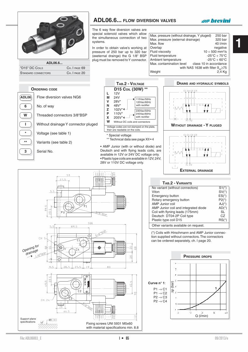
File: ADL06003_E 09/2013/eI • 65
1
Δp (
bar)
Q (l/min)
1
ORDERING CODE
Opening for
drainage
ADL06.6... FLOW DIVERSION VALVES
Max. pressure (without drainage, Y pluged) 250 barMax. pressure (external drainage) 320 barMax. fl ow 40 l/minOverlap negativeFluid viscosity 10 ÷ 500 mm2/sFluid temperature -25°C ÷ 75°CAmbient temperature -25°C ÷ 60°CMax. contamination level class 10 in accordance
with NAS 1638 with fi lter ß25≥75 Weight 2,4 Kg
ADL06 Flow diversion valves NG6
6 No. of way
W Threaded connectors 3/8"BSP
I Without drainage Y connector pluged * Voltage (see table 1)
** Variants (see table 2) 3 Serial No.
DRAINS AND HYDRAULIC SYMBOLS
EXTERNAL DRAINAGE
WITHOUT DRAINAGE - Y PLUGED
No variant (without connectors) S1(*)Viton SV(*)Emergency button ES(*)Rotary emergency button P2(*)AMP Junior coil AJ(*)AMP Junior coil and integrated diode AD(*)Coil with fl yning leads (175mm) SLDeutsch DT04-2P Coil type CZPlastic type coil D15 RS(*)
Other variants available on request.
TAB.2 - VARIANTS
Curve n° 1:
P1 → C1P1 → C2P2 → C3P2 → C4
Support planespecifi cations
PRESSURE DROPS
The 6 way fl ow diversion valves are special solenoid valves which allow the simultaneous connection of two systems.
In order to obtain valve's working at pressure of 250 bar up to 320 bar (exeternal drainge) the G 1/8" BSP plug must be removed to Y connector.
ADL06.6...
"D15" DC COILS CH. I PAGE 69
STANDARD CONNECTORS CH. I PAGE 20
TAB.2 - VOLTAGE
Voltage codes are not stamped on the plate, their are readable on the coils.
D15 COIL (30W) **L 12VM 24VV 28V*N 48V*Z 102V*P 110V*X 205V*W Without DC coils and connectors
115Vac/50Hz120Vac/60Hzwith rectifi er
230Vac/50Hz240Vac/60Hzwith rectifi er
Fixing screws UNI 5931 M5x60with material specifi cations min. 8.8
• AMP Junior (with or without diode) and Deutsch and with fl ying leads coils, are available in 12V or 24V DC voltage only.• Plastic type coils are available in 12V, 24V, 28V or 110V DC voltage only.
(*) Coils with Hirschmann and AMP Junior connec-tion supplied without connectors. The connectors can be ordered separately, ch. I page 20.
* Special voltage** Technical data see page XII • 4

File: BDL06001_E 01/2013/eI • 66
11
I • 66
OVERALL DIMENSIONS
ORDERING CODE TAB.2 - VARIANTSTAB.1 - 40W COIL
BDL06.6... FLOW DIVERSION VALVES
Max. pressure 250 barMax. fl ow 50 l/minOverlap negativeHydraulic fl uids Mineral oils DIN 51524Fluid viscosity 10 ÷ 500 mm2/sFluid temperature -25°C ÷ 75°CAmbient temperature -25°C ÷ 60°CMax. contamination level class 10 in accordance
with NAS 1638 with fi lter ß25≥75 Weight 3 Kg
HYDRAULIC SYMBOL
No variant (without connectors) S1(*)Viton SV(*)Emergency button ES(*)Rotary emergency button P2(*)Deutsch DT04-2P Coil type CZ
Other variants available on request.
P1 → C1 , P1 → C2P2 → C4 , P2 → C3
PRESSURE DROPS
The 6 way fl ow diversion valves, type BDL.06.6, are special solenoid valves which allow the simultaneous connec-tion of two systems. With all user ports on the same side, these valves allow to simplify the layout of hydraulic plant. As they are moved from high perfor-mances solenoids they don’t need the external drainage.This valves can manage high hydraulic powers with a low pressure drop.
BDL06.6...
"40W" DC COILS CH. I PAGE 70
STANDARD CONNECTORS CH. I PAGE 20
Voltage codes are not stamped on the plate, their are readable on the coils.
DC VOLTAGE
L 12V
M 24V
N 48V*
W Without DC coils
Fixing screws UNI 5931 M8x70 with strength class DIN 8.8.Tightening torque 8 Nm / 0.8 Kgm
(*) Coils with Hirschmann connection supplied without connectors. The connectors can be ordered separately, ch. I page 20.
BDL Flow diversion valves
06 Size NG06
6 No. of way
W Threaded connectors 3/8"BSP
I Internal drainage * Voltage (Tab. 1)
** Variants (Tab. 2) 1 Serial No.
Q (l/min)
P(b
ar)
0 10 20 30 40 50
0
1
2
3
4
5
6
The fl uid used is a mineral oil with a viscosity of 46 mm²/s at 40°C; the tests have been carried out at a fl uid tempera-ture of 40°C.
P2P1
C4C1C3C2
40 29,5
G 3/8" G 3/8"
33
32,5
62
92
P1 P2
187,7
Ø 8,5
8 47
102,5
Ø45
50
68
= =
= =
27
40
40
G 3/8"
G 3/8" G 3/8"
G 3/8"
26
16
41
C1 C4
C2 C3
P1 P2
C3C4C2C1
* Special voltage

File: CDL10001_E 03/2013/eI • 67
1
CDL.10.6... STACKABLE CIRCUIT SELECTOR VALVES
Max. pressure 250 barMax. fl ow 80 l/minOverlap negativeHydraulic fl uids Mineral oils DIN 51524Fluid viscosity 10 ÷ 500 mm2/sFluid temperature -25°C ÷ 75°CAmbient temperature -25°C ÷ 60°CMax. contamination level class 10 in accordance
NAS with 1638 with fi lter ß25³75Weight see “Overall dimension”CDL.10.6...
"A16" DC COILS CH. I PAGE 70
CONNECTORS STANDARD CH. I PAGE 20
ORDERING CODE
HYDRAULIC SYMBOLS
MULTISTATION CONNECTION
SINGLE ELEMENT
CDL Stackable circuit selector valve
10 Size NG10
6 No. of way (single element) W Threaded connectors 1/2” BSP
I Internal drainage
* No. of elements: 1 / 2 / 3 / 4 / 5
* Voltage (Tab. 1)
** Variants (Tab. 2)
1 Serial No.
TAB.2 - VARIANTS
No variant (without connectors) S1(*)Viton SV(*)Emergency button ES(*)Rotary emergency button P2(*)
Other variants available on request.
PRESSURE DROPS
ΔP (
bar)
Q (l/min)
P1 → C1, P1 → C2,P2 → C3 et P2 → C4
OVERALL DIMENSIONS
The fl uid used is a mineral oil with a viscosity of 46 mm2/s at 40°C; the tests have been carried out at a fl uid temperature of 40°C.
The stackable circuit selector valves, type CDL.10.6, allows one single drive of 6 users with 5 elements connected in series.As they are moved from high perfor-mances solenoids they don’t need the external drainage.This valves can manage high hydraulic powers with a minimal pressure drop.
Fixing screws UNI 5931 M6x60with material specifi cations min. 8.8Tightening torque for studs 8 Nm / 0.8 KgmTightening torque for rods 20 Nm / 2 Kgm (*) For multiple composition rods and studs are available.
TAB.1 - A16 COIL
Voltage codes are not stamped on the plate, their are readable on the coils.
DC VOLTAGE ** L 12V M 24V N 48V* P 110V* Z 102V* X 205V* W Without DC coil
115Vac/50Hz120Vac/60Hzwith rectifi er
230Vac/50Hz240Vac/60Hzwith rectifi er
(*) Coils with Hirschmann connection supplied without connectors. The con-nectors can be ordered separately, ch. I page 20.
No. ofelements
No. ofway
A B C Weight(Kg)
Kit spare part code*(rods and studs)Length (mm)
1 06 54 69 - 4,5 /2 08 123 138 160 9,3 V89.56.00013 10 192 207 226 14 V89.56.00024 12 261 276 296 18,5 V89.56.00035 14 330 345 365 23,3 V89.56.0004
C1
C2
P1
C3 P
2
C4
C1
C2
P1
C3 P
2
C4
C1
C2
P1
C3 P
2
C4
G 1/2"
69.248
100
G 1/2"ABC
58.6
external drainversion
external drainversion
10.6
65.2
5
81.2
5
44.2
5
43.2
5
25.2
5
65.2
583.2
5
210.7
G 1
/2"
Ø6.5
lam
atura Ø13
63.2
59.2
5
ch 1
325.2
5
Y
Y1
* Special voltage** Technical data see page I • 69

File: ADL10001_E 05/2013/eI • 68
1
Opening for drainage
Δp (
bar)
Q (l/min)
ORDERING CODE
ADL10.6... FLOW DIVERSION VALVES
Max. pressure (without drainage, Y plugged) 250 barMax. pressure (external drainage) 320 barMax. fl ow 80 l/minFluid viscosity 10 ÷ 500 mm2/sFluid temperature -25°C ÷ 75°CAmbient temperature -25°C ÷ 60°CMax. contamination level class 10 in accordance
with NAS 1638 with fi lter ß25≥75 Weight 3,6 Kg
DRAINS AND HYDRAULIC SYMBOLS
EXTERNAL DRAINAGE
WITHOUT DRAINAGE - Y PLUGGED
VARIANT CODE
No variant (without connectors) S1(*)Viton SV(*)Emergency button ES(*)Rotary emergency button P2(*)
Other variants available on request.
TAB.2 - VARIANTS
Support planespecifi cations
PRESSURE DROPS
The 6 way fl ow diversion valves are special solenoid valves which allow the simultaneous connection of two systems.
In order to obtain valve's working at pressure of 250 bar up to 320 bar (external drainage) the G 1/8" BSP plug must be removed to Y connector.
ADL10.6...
"A16" DC COILS CH. I PAGE 70
STANDARD CONNECTORS CH. I PAGE 20
ADL10 Flow diversion valves NG10
6 No. of way
J Connectors 3/4"BSP
I Without drainage Y connector plugged
* Voltage (see table 1)
** Variants (see table 2)
1 Serial No.
TAB.1 - A16 COIL
Voltage codes are not stamped on the plate, their are readable on the coils.
DC VOLTAGE ** L 12V M 24V N 48V* P 110V* Z 102V* X 205V* W Without DC coil
115Vac/50Hz120Vac/60Hzwith rectifi er
230Vac/50Hz240Vac/60Hzwith rectifi er
Fixing screws UNI 5931 M6x90with material specifi cations min. 8.8
(*) Coils with Hirschmann and AMP Junior connec-tion supplied without connectors. The connectors can be ordered separately, ch. I page 20.
* Special voltage** Technical data see page I • 69

I • 69File: TA09D15_E 13/2016/e
1
"D15" DC COILS FOR ADL06... AND A.66..
"A09" DC COILS FOR CDL.04...
Type of protection (in relation to the connector used) IP 66Number of cycles 18.000/hSupply tolerance ±10%Ambient temperature -54°C ÷ 60°CDuty cycle 100% EDInsulation class wire HWeight 0,354 Kg
• AMP Junior coils (with or without diode) and coils with fl ying leads and coils type Deutsch, are availa-ble in 12V or 24V DC voltage only.
• The pastic type coil (BR variant) is available in 12V, 24V, 28V or 110V DC voltage only.
Type of protection (in relation to connector used) IP 65Number of cycle 18.000/hSupply tolerance ±10%Ambient temperature -30°C ÷ 50°CDuty cycle 100% EDInsulation class wire HWeight 0,215 Kg
• The AMP Junior coil, the Deutsch coil with bidirectional diode and the coil with fl ying leads (with or without diode) coils are available in 12V or 24V DC voltage only.
DEUTSCH COIL WITH BIDIR. DIODE (CX)
DT04 - 2P
AMP JUNIOR (AJ)
FLYING LEADS (FL)LEADS WITH DIODO (LD)
FLYING WITH LEADS COIL (SL)
AMP JUNIOR (AJ)AJ + DIODE (AD)
• Emergency, plastic coil, and Amp Junior, leads or deutch coils, are not available for A66 valve.
(*) Emergency tightening torque max. 6÷9 Nm / 0.6 ÷ 0.9 Kgm with CH n. 22
MANUAL WITHOUT CONN. (ES)MANUAL WITH CONN. (E1)
ROTARY WITHOUT CONNECTOR (P2*)ROTARY WITH CONNECTOR (P1*)
EMERGENCY (COILS WITH HIRSCHMANN CONNECTION)
MANUAL WITHOUT CONNECTOR (ES)MANUAL WITH CONNECTOR (E1)
ROTARY WITHOUT CONNECTOR (P2)ROTAN ROTARY WITH CONNECTOR (P1)
EMERGENCY (COILS WITH HIRSCHMANN CONNECTION)
VOLTAGE (V)
MAX WINDING TEMPERATURE (AMBIENT TEMPERATURE 25°C)
RATED POWER (W)
RESISTANCE AT 20°C (OHM) ±7%
12V 123°C 27 5.324V 123°C 27 21.348V* 123°C 27 85.3
102V(*)(**) 123°C 27 392110V(*)(**) 123°C 27 448205V(*)(**) 123°C 27 1577 * Special voltages
** The european low voltage directive is applied to electronical equipments used at a nominal voltages between 50 and 1000 VAC or 75 and 1500 VDC. In conformity with the low directive each part of the manifold or the subplate on which the valve is mounted should be connected to a protective earth with a resistence less than 0.1 ohms.
VOLTAGE (V)
MAX WINDING TEMPERATURE (AMBIENT TEMPERATURE 25°C)
RATED POWER (W)
RESISTANCE AT 20°C
(OHM) ±10%12V 110°C 30 4.824V 110°C 30 18.828V* 110°C 30 25.648V* 110°C 30 75.2
102V(*)(**) 110°C 30 340110V(*)(**) 110°C 30 387205V(*)(**) 110°C 30 1375 * Special voltages
** The european low voltage directive is applied to elec-tronical equipments used at a nominal voltages between 50 and 1000 VAC or 75 and 1500 VDC. In conformity with the low directive each part of the manifold or the subplate on which the valve is mount-ed should be connected to a protective earth with a resist-ence less than 0.1 ohms.
DEUTSCH DT04 - 2P (CZ)CZ + ECOAT (R6)
ECOAT COIL (RS)
33
*** VDC100% ED
54
Ø 4
5
1.1
Ø 2
3
Ø 2
7
31.2
12

File: T40WA16_E 10/2013/eI • 70
1
Type of protection (in relation to the connector used) IP 65Number of cycles 18.000/hSupply tolerance ±10%Ambient temperature -30°C ÷ 60°CDuty cycle 100% EDInsulation class wire HWeight 0,9 Kg
"A16" DC COILS FOR ADL10 AND CDL10
Type of protection (in relation to the connector used) IP 66Number of cycles 18.000/hSupply tolerance +10% / -10%Ambient temperature -54°C ÷ 60°CDuty cycle 100% EDInsulation class wire HWeight 0,354 Kg
"40W" DC COILS FOR CDL06...
VOLTAGE MAX. WINDING TEMPERATURE RATED POWER RESISTANCE AT 20°C (V) (AMBIENT TEMPERATURE 25°C) (W) (OHM) ±10%
12V 135°C 40 3.6 24V 135°C 40 14.4
IT40W - 02/2004/e
MANUAL WITHOUT CONNECTOR (ES)MANUAL WITH CONNECTOR (E1)
ROTARY WITHOUT CONNECTOR (P2)ROTAN ROTARY WITH CONNECTOR (P1)
EMERGENCY (COILS WITH HIRSCHMANN CONNECTION)
DEUTSCH
(CZ)DT04 - 2P
MANUAL WITHOUT CONNECTOR (ES)MANUAL WITH CONNECTOR (E1)
ROTARY WITHOUT CONNECTOR (P2)ROTARY WITH CONNECTOR (P1)
EMERGENCY (COILS WITH HIRSCHMANN CONNECTION)
VOLTAGE (V)
MAX WINDING TEMPERATURE (AMBIENT TEMPERATURE 25°C)
RATED POWER (W)
RESISTANCE AT 20°C (OHM) ±7%
12V 106°C 45 3.224V 113°C 45 12.448V* - 45 -
102V(*)(**) - 45 -110V(*)(**) 118°C 45 268205V(*)(**) - 45 - * Special voltages
** The european low voltage directive is applied to electronical equipments used at a nominal voltages between 50 and 1000 VAC or 75 and 1500 VDC. In conformity with the low directive each part of the manifold or the subplate on which the valve is mounted should be connected to a protective earth with a resistence less than 0.1 ohms.

SUBPLATE MOUNTINGPRESSURE CONTROL VALVES
SUBPLATE MOUNTINGPRESSURE CONTROL VALVES
PRESSURE CONTROL
PV*.3 / PV*.U.3
CH. II PAGE 2
PV*.5 / PV*.U.5
CH. II PAGE 4
V.*.P
CH. II PAGE 6
V.*.L
CH. II PAGE 6
BS.VMP... P
CH. II PAGE 11
03/2011/eII • 1File: 02TA_E
2
ABBREVIATIONS
AP HIGH PRESSURE CONNECTION
AS PHASE LAG (DEGREES)BP LOW PRESSURE CONNECTION
C STROKE (MM)CH ACROSS FLATS
CH INTERNAL ACROSS FLATS
DA AMPLITUDE DECAY (DB)DP DIFFERENTIAL PRESSURE (BAR)F FORCE (N)I% INPUT CURRENT (A)M MANOMETER CONNECTION
NG KNOB TURNS
OR SEAL RING
P LOAD PRESSURE (BAR)PARBAK PARBAK RING
PL PARALLEL CONNECTION
PR REDUCED PRESSURE (BAR)Q FLOW (L/MIN)QP PUMP FLOW (L/MIN)SE ELASTIC PIN
SF BALL
SR SERIES CONNECTION
X PILOTING
Y DRAINAGE

File: PV$3001_E 01/2000/eII • 2
2
Q (l/min)
P (
bar)
Q (l/min)
P (
bar)
Q (l/min)
P (
bar)
Q (l/min)
P (
bar)
123
3
2
1
1-2-3
3
2
1
These subplate mounting piloted type pressure reducing and sequencing valves ensure a minimum variation in their calibrated pressure value with changing fl ow rate.
They are normally supplied with inter-nal piloting and internal drainage on B, but they are already provided with a hole on the front cover to allow for external drainage.
They are available with two different types of adjustment and three cali-brated ranges that cover pressure 7 ÷ 250 bar, with and without check valve.
The adjustment is carried out by means of a grub screw or a metric plastic knob.
ORDERING CODE
PV*.3 / PV*.U.3 PRESSURE REDUCING AND
SEQUENCING VALVES CETOP 3/NG6
HYDRAULIC SYMBOLS
Max. pressure 320 barSetting ranges Spring 1 max. 60 bar Spring 2 max. 120 bar Spring 3 max. 250 barMaximum allowed Δp pressure between the inlet and outlet pressure (PVR only) 150 barMax. fl ow 40 l/minDraining on port T 0.5 ÷ 0.7 l/minHydraulic fl uids Mineral oils DIN 51524Fluid viscosity 10 ÷ 500 mm2/sFluid temperature -25°C ÷ 75°CAmbient temperature -25°C ÷ 60°CMax. contamination lever class 10 in accordance
with NAS 1638 with fi lter ß25≥75Weight (without check valve) 1,5 KgWeight (with check valve) 2 Kg
DIAGRAMS
PV* R = Reducing valve S = Sequencing valve
U Check valve (omit if not required)
3 CETOP 3/NG6
* Type of adjustment: M = Plastic knob C = Grub screw
* Setting ranges 1 = max. 60 bar (white spring) 2 = max. 120 bar (yellow spring) 3 = max. 250 bar (green spring)
** 00 = No variant V1 = Viton
1 Serial No.
The fl uid used is a mineral oil with viscosity of 46 mm2/s at 40°C. The tests were carried out at a fl uid temperature of 50°C.
PVR.3... / PVR.U.3...PRESSURE - FLOW RATE
PVS.3... / PVS.U.3...PRESSURE - FLOW RATE
PVR.3... / PVR.U.3...MINIMUM SETTING PRESSURE
PVS.3... / PVS.U.3...MINIMUM SETTING PRESSURE
Curves n° 1 - 2 - 3 = setting ranges
PVR.3...
PVR.U.3...
PVS.3...
PVS.U.3...
PVR.3 / PVS.3...

File: PV$3001_E 01/2000/eII • 3
2
PV*.3 / PV*.U.3 PRESSURE REDUCING AND SEQUENCING VALVES
OVERALL DIMENSIONS
OVERALL DIMENSIONS
REDUCING VALVE
PVR.3... CETOP 3/NG6 SEQUENCING VALVE
PVS.3... CETOP 3/NG6
REDUCING VALVE WITH CHECK VALVE
PVR.U.3... CETOP 3/NG6 SEQUENCING VALVE WITH CHECK VALVE
PVS.U.3... CETOP 3/NG6
Fixing screws UNI 5931 M5x50with material specifi cations min. 8.8Tightening torque 5 Nm / 0.5 Kgm
Fixing screws UNI 5931 M5x50with material specifi cations min. 8.8Tightening torque 5 Nm / 0.5 Kgm
Type of adjustment
M Plastic knob
C Grub screw
Support planespecifi cations
Support planespecifi cations
Type of adjustment
M Plastic knob
C Grub screw

File: PV$5001_E 00/2000/eII • 4
2
Q (l/min)
P (
bar)
Q (l/min)
P (
bar)
Q (l/min)
P (
bar)
Q (l/min)
P (
bar)
123
3
2
1
1-2-3
3
2
1
These subplate mounting piloted type pressure reducing and sequencing valves ensure a minimum variation in their calibrated pressure value with changing fl ow rate.
They are normally supplied with inter-nal piloting and internal drainage on B, but they are already provided with a hole on the front cover to allow for external drainage.
They are available with two different types of adjustment and three cali-brated ranges that cover pressure 7 ÷ 250 bar, with and without check valve.
The adjustment is carried out by means of a grub screw or a metric plastic knob.
ORDERING CODE
PV*.5 / PV*.U.5 PRESSURE REDUCING AND
SEQUENCING VALVES CETOP 5/NG10
HYDRAULIC SYMBOLS
Max. pressure 320 barSetting ranges Spring 1 max. 60 bar Spring 2 max. 120 bar Spring 3 max. 250 barMaximum allowed Δp pressure between the inlet and outlet pressure (PVR only) 150 barMax. fl ow 90 l/minDraining on port T 0.5 ÷ 0.7 l/minHydraulic fl uids Mineral oils DIN 51524Fluid viscosity 10 ÷ 500 mm2/sFluid temperature -25°C ÷ 75°CAmbient temperature -25°C ÷ 60°CMax. contamination level class 10 in accordance
with NAS 1638 with fi lter ß25≥75Weight (without check valve) 3,8 KgWeight (reducing valve with check valve) 4,2 KgWeight (sequencing valve with check valve) 4,5 Kg
DIAGRAMS
PV* R = Reducing valve S = Sequencing valve
U Check valve (omit if not required)
5 CETOP 5/NG10
* Type of adjustment: M = Plastic knob C = Grub screw
* Setting ranges 1 = max. 60 bar (white spring) 2 = max. 120 bar (yellow spring) 3 = max. 250 bar (green spring)
** 00 = No variant V1 = Viton
1 Serial No.
The fl uid used is a mineral oil with viscosity of 46 mm2/s a 40°C. The tests were carried out at a fl uid temperature of 50°C.
PVR.5... / PVR.U.5...PRESSURE - FLOW RATE
PVS.5... / PVS.U.5...PRESSURE - FLOW RATE
PVR.5... / PVR.U.5...MINIMUM SETTING PRESSURE
PVS.5... / PVS.U.5...MINIMUM SETTING PRESSURE
Curves n° 1 - 2 - 3 = setting ranges
PVR.5...
PVR.U.5...
PVS.5...
PVS.U.5...
PVR.5 / PVS.5...
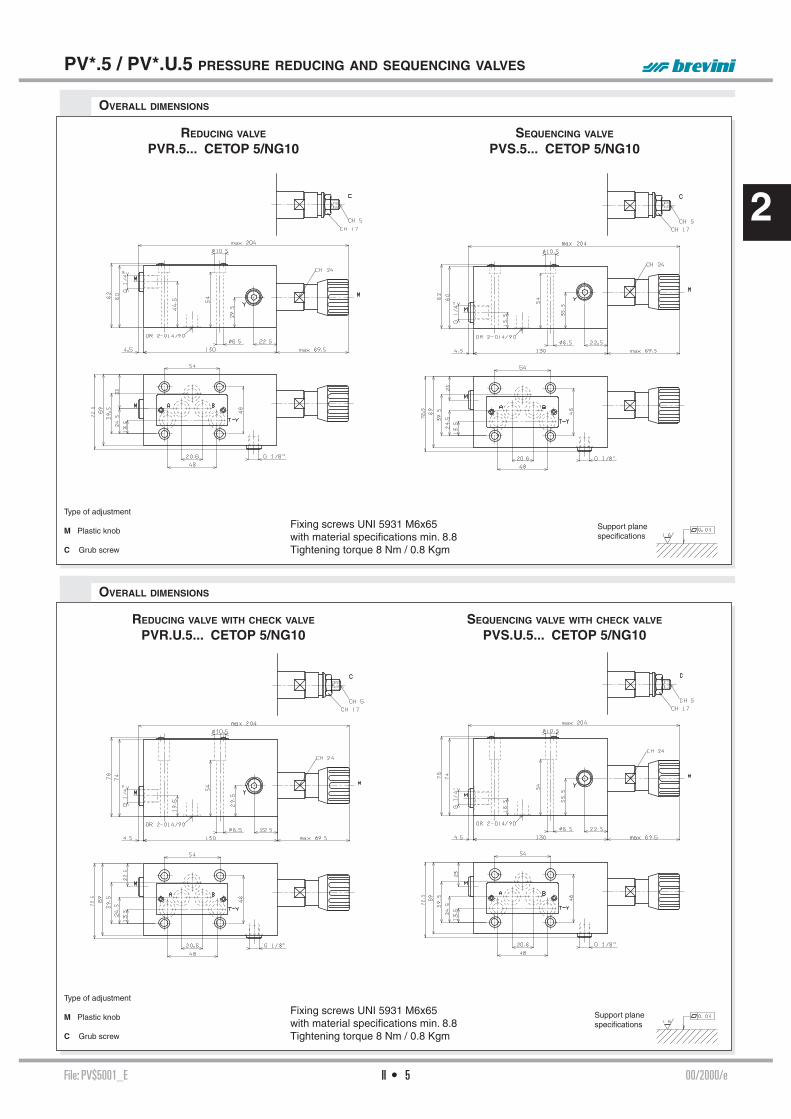
File: PV$5001_E 00/2000/eII • 5
2
PV*.5 / PV*.U.5 PRESSURE REDUCING AND SEQUENCING VALVES
OVERALL DIMENSIONS
OVERALL DIMENSIONS
REDUCING VALVE
PVR.5... CETOP 5/NG10 SEQUENCING VALVE
PVS.5... CETOP 5/NG10
REDUCING VALVE WITH CHECK VALVE
PVR.U.5... CETOP 5/NG10 SEQUENCING VALVE WITH CHECK VALVE
PVS.U.5... CETOP 5/NG10
Type of adjustment
M Plastic knob
C Grub screw
Fixing screws UNI 5931 M6x65with material specifi cations min. 8.8Tightening torque 8 Nm / 0.8 Kgm
Support planespecifi cations
Support planespecifi cations
Fixing screws UNI 5931 M6x65with material specifi cations min. 8.8Tightening torque 8 Nm / 0.8 Kgm
Type of adjustment
M Plastic knob
C Grub screw

File: V$$002_E 06/2012/eII • 6
2
Q (l/min)
P (
bar)
Q (l/min)
P (
bar)
These pressure control valves are available in the basic VMP* maximum pressure, VSP* sequence and VUP* exclusion versions, with a single pressure value and three calibration ranges that cover the band 15 ÷ 400 bar. It is possible to use auxiliary pilot valves, which can be the simple standard AD3E sole-noid valve, by the mere exchange of covers. These valves have been fi tted with an important safety feature for the operation of the system where they are used; a mechanical end of stroke stop prevents the operator from setting pres-sure values higher than those specifi ed in the catalogue (it is impossible to compress the spring completely). In the standard confi guration these valves are supplied with a 1.6 bar main spring and with calibrated ø1 mm pilot feed orifi ce (Variant part No. 00).Subplate mounting valves are suitable for covers which do not conform to DIN standards type C*P16/25.. whilst in line mounting valves are suitable for DIN standards covers type KEC16/25...
ORDERING CODE
V.*.P PRESSURE CONTROL VALVES PLATE
V.*.L PRESSURE CONTROL VALVES IN LINE
Pressure max. 400 barSetting ranges Spring 1 15 ÷ 45 bar Spring 2 15 ÷ 145 bar Spring 3 45 ÷ 400 barMax. fl ow V*P16... 150 l/minMax. fl ow V*P25... 350 l/minHydraulic fl uids Mineral oils DIN 51524Fluid viscosity 10 ÷ 500 mm2/sFluid temperature -25°C ÷ 75°CAmbient temperature -25°C ÷ 60°CMax. contamination level class 10 in accordance
with NAS 1638 with fi lter ß25≥75Drainage V*P16... 1 ÷ 2 l/minDrainage V*P25... 1 ÷ 2.5 l/minDynamic pressure at drainage Max. 2 barWeight V*P16... (without pilot valve) 3,3 KgWeight V*P25... (without pilot valve) 7,4 KgWeight V*L16... (without pilot valve) 4,6 KgWeight V*L161... (without pilot valve) 4,5 KgWeight V*L251... (without pilot valve) 7,7 KgWeight V*L25... (without pilot valve) 8,3 Kg
V Valve
* M = maximum pressure S = sequence U = exclusion (areas rep. 1,15 : 1)
* P = Plate mounting L = In line mounting
* E = Presetting for solenoid valve Not for sequencing valve V.S.P... (omit if not required)
*** Size (see overall dimensions) 16 - 25 = NG16 or NG25 161 - 251 = for V.*.L... only (in line mounting valve) * Type of adjustment: M = Plastic knob C = Grub screw * Setting ranges 1 = 15 ÷ 45 bar (white spring) 2 = 15 ÷ 145 bar (yellow spring) 3 = 45 ÷ 400 bar (green spring)
** 00 = No variant V1 = Viton AC = Exclusion valve for accumulators (only for VU* , logic element areas rep. 12.5 : 1) AQ = Presetting for XP3 2 Serial No.
PRESSURE - FLOW V.*.P.25
The fl uid used is a mineral oil with viscosity of 46 mm2/s at 40°C.The tests were carried out at a fl uid temperature 40°C.
HYDRAULIC SYMBOLS
V.M.P.16.**...V.M.P.25.**...
Maximum pressure valve
Internal pilotingand draining
V.U.P.16.**...V.U.P.25.**...
Exclusion valveExternal pilotingInternal draining
V.S.P.16.**...V.S.P.25.**...
Sequencing valve
Internal pilotingExternal draining
PRESSURE - FLOW V.*.16
V.*.P / V.*.L...
V.*.P... CH. II PAGE 7
V.*.P.E... CH. II PAGE 8
V.*.L... CH. II PAGE 9/10
BS.VMP... CH. II PAGE 11
KEC.16/25... CH. V PAGE 9
C*P.16/25... CH. V PAGE 9
CETOP 3/NG06 CH. I PAGE 8
STANDARD SPOOLS FOR AD.3.E CH. I PAGE 10
AD.3.E... CH. I PAGE 11
AM.3.VM... CH. IV PAGE 9

File: V$$002_E 06/2012/eII • 7
2
M = 1/4" BSP connector for pressure gauge for maximum pressure valve version onlyY = 1/8" BSP external draining for sequencing valve version only
OVERALL DIMENSIONS V.*.P.16...
V.*.P... PRESSURE CONTROL VALVES PLATE
OVERALL DIMENSIONS V.*.P.25...
Fixing screws UNI 5931 M12x40 with material specifi cations min. 8.8Tightening torque 70 Nm / 7 Kgm
Support planespecifi cations
M = 1/4" BSP connector for pressure gauge for maximum pressure valve version onlyY = 1/8" BSP external draining for sequencing valve version only
Fixing screws UNI 5931 M16x100 with material specifi cations min. 8.8Tightening torque 70 Nm / 7 Kgm Support plane
specifi cations
VERSION WITH PRESETTING FOR SOLENOID VALVE
VERSION WITH PRESETTING FOR SOLENOID VALVE

File: V$$002_E 06/2012/eII • 8
2
MOUNTING TYPE V.*.P.E...V.*.P.E... +
AD.3.E.15.E... OR AD.3.E.16.E...
1) Solenoid de-energized, pump pressure con-trolled by valve on cover.2 ) Solenoid A energized, pump pressure con-trolled by valve AM.3.VM.AB.3) Solenoid B energized, pump pressure con-trolled by valve AM.3.VM.AB.
1) Solenoid de-energized, pump to tank.2 ) Solenoid energized, circuit pressure controlled by valve on cover.For mounting valves to have normally dis-charged confi guration it is necessary to use an AD.3.E.15.F.. or AD.3.E.16.F... type solenoid valve, whilst for subplate mounting valves it is nec-essary to use type AD.3.E.15.E.. or AD.3.E.16.E.
1) Solenoid de-energized, pump pressure con-trolled by valve on cover.2 ) Solenoid B energized, pump to tank.
1) Solenoid de-energized, pump pressure con-trolled by valve on cover.2 ) Solenoid energized, pump pressure controlled by valve AM.3.VM.B.
1) Solenoid de-energized, pump to tank.2 ) Solenoid A energized, pump pressure con-trolled by valve AM.3.VM.B.3) Solenoid B energized, pump pressure con-trolled by valve on cover.
V.*.P.E... +AD.3.E.15.F... OR AD.3.E.16.F...
V.*.P.E... + AM.3.VM.B... +AD.3.E.15.E... OR AD.3.16.E...
V.*.P.E... + AM.3.VM.B... +AD.3.E.02.C...
V.*.P.E... + AM.3.VM.B... +AD.3.E.01.C...
V.*.P.E... PRESSURE CONTROL VALVES PLATE

File: V$$002_E 06/2012/eII • 9
2
V.*.L... PRESSURE CONTROL VALVES IN LINE
1/2" BSP P connector3/4" BSP T connector
3/4" BSP P and T connectors
M = 1/4" BSP connector for pressure gauge for maximum pressure valve version onlyY = 1/8" BSP external draining for sequencing valve version only
OVERALL DIMENSIONS V.*.L.16...
VERSION WITH PRESETTING FOR SOLENOID VALVE
VERSION WITH PRESETTING FOR SOLENOID VALVE
OVERALL DIMENSIONS V.*.L.161...
Fixing screws UNI 5931 M8x90 with material specifi cations min. 8.8Tightening torque 24 Nm / 2.4 Kgm
M = 1/4" BSP connector for pressure gauge for maximum pressure valve version onlyY = 1/8" BSP external draining for sequencing valve version only
Fixing screws UNI 5931 M8x90 with material specifi cations min. 8.8Tightening torque 24 Nm / 2.4 Kgm

File: V$$002_E 06/2012/eII • 10
2
V.*.L... PRESSURE CONTROL VALVES IN LINE
1" BSP P connector1 1/4" BSP T connector
1 1/4" BSP P connector1 1/2" BSP T connector
M = 1/4" BSP connector for pressure gauge for maximum pressure valve version onlyY = 1/8" BSP external draining for sequencing valve version only
OVERALL DIMENSIONS V.*.L.25...
VERSION WITH PRESETTING FOR SOLENOID VALVE
VERSION WITH PRESETTING FOR SOLENOID VALVE
OVERALL DIMENSIONS V.*.L.251...
Fixing screws UNI 5931M8x110 with material specifi cations min. 8.8Tightening torque 24 Nm / 2.4 Kgm
M = 1/4" BSP connector for pressure gauge for maximum pressure valve version onlyY = 1/8" BSP external draining for sequencing valve version only
Fixing screws UNI 5931M8x120 with material specifi cations min. 8.8Tightening torque 24 Nm / 2.4 Kgm

File: BSVMP001_E 02/2000/eII • 11
2
BS.VMP.16... CONNECTORS: P = 1/2" BSP - T = 3/4" BSP - X = 1/4" BSP
BS.VMP... SUBPLATE MOUNTING FOR V.*.P
BS.VMP.25... CONNECTORS: P AND T = 3/4" BSP - X = 1/4" BSP
BS.VMP.25/1... CONNECTORS: P AND T = 1" BSP - X = 1/4" BSP
BS Single plate VMP Maximum pressure
16 Size NG16
00 No variant 1 Serial No.
BS Single plate VMP maximum pressure
25 Size NG25
00 No variant 1 Serial No.
Weight: 2,2 Kg
Fixing screws M8x45 UNI 5931
Weight: 3,6 Kg
Fixing screws M12x35 UNI 5931
Weight: 4,2 Kg
Fixing screws M10x45 UNI 5931
BS Single plate VMP maximum pressure
25/1 Size NG25
00 No variant 1 Serial No.

File: BSVMP001_E 02/2000/eII • 12
2

QC.3.2...
CH. II PAGE 2
QC.3.3...
CH. II PAGE 3
QCV.3.2
CH. II PAGE 5
AM.3.ABU...
CH. II PAGE 4
File: 03TA_E
COMPENSATED FLOWREGULATORS
CHECK VALVE HOLDERFOR REGULATORS
04/2015/eIII • 1
3
ABBREVIATIONS
AP HIGH PRESSURE CONNECTION
AS PHASE LAG (DEGREES)BP LOW PRESSURE CONNECTION
C STROKE (MM)CH ACROSS FLATS
CH INTERNAL ACROSS FLATS
DA AMPLITUDE DECAY (DB)DP DIFFERENTIAL PRESSURE (BAR)F FORCE (N)I% INPUT CURRENT (A)M MANOMETER CONNECTION
NG KNOB TURNS
OR SEAL RING
P LOAD PRESSURE (BAR)PARBAK PARBAK RING
PL PARALLEL CONNECTION
PR REDUCED PRESSURE (BAR)Q FLOW (L/MIN)QP PUMP FLOW (L/MIN)SE ELASTIC PIN
SF BALL
SR SERIES CONNECTION
X PILOTING
Y DRAINAGE
FLOW CONTROL

File: QC32005_E 02/2009/eIII • 2
3
Q (
l/min
)
P (bar)
Q (
l/min
)
Q (l/min)
Δp (
bar)
Q (
l/min
)
QC.3.2.**.*.R QC.3.2.G.**.*.RQC.3.2...
6
5
4
3
21
6
5
4
3
21
ORDERING CODE
QC.3.2... 2 WAY COMPENSATED
FLOW RATE REGULATORS
No. of turns of knobNo. of turns of knob
REGULATED FLOW RATE
1 TURN VERSION
REGULATED FLOW RATE
4 TURNS VERSION
FLOW RATE - INLET PRESSURE FREE FLOW THROUGH
CHECK VALVE
QC Compensated fl ow rate regulated
3 CETOP 3/NG6
2 2 way
G Anti-jump system with internal check valve (omit if not required)
** Nominal fl ow rate ranges 1 Turn version 4 Turn version Q1 = 1,5 l/min Q1 = 1,5 l/min Q2 = 3 l/min Q2 = 4 l/min Q3 = 9 l/min Q3 = 10 l/min Q4 = 19 l/min Q4 = 21 l/min Q5 = 24 l/min Q5 = 28 l/min Q6 = 30 l/min Q6 = 35 l/min K Version with lock (omit if not required)
* 1 = 1 turn version 4 = 4 turns version
R With internal check valve (omit if not required)
** 00 = No variant V1 = Viton
5 Serial No.
HYDRAULIC SYMBOLS
DIAGRAMS
These QC.3.2... compensated fl ow rate regulators are designed to control and maintain a constant irrespective of the pressure variations upstream and downstream of the regulation section. Their new cast construction has made it possible to obtain a wider fl ow rate range, taking the upper limit to 35 l/min (4 turns version) while maintaining unchanged the pressure differential required to obtain good pressure compensation.
All models are available with and with-out reverse fl ow check valve, complete with an "anti-jump" device on request. This accessory has been designed to eliminate the problem which manifests itself as a "anti-jump" in the controlled actuator due to the instantaneous fl ow rate variation that takes place under the form of a transient every time the fl ow is made to pass through the regulator.
Max. operating pressure 320 barOpening pressure (with bypass) 1 barMin. regulated fl ow rate (Q1 version) 0.03 ÷ 0.05 l/minNominal regulated fl ow rate (1 turn version) 1,5 ÷ 30 l/minNominal regulated fl ow rate (4 turns version) 1,5 ÷ 35 l/minDifference in pressure (Δp) for vers. Q1 3 barDifference in pressure (Δp) Q2-Q3-Q4-Q5-Q6 8 barHydraulic fl uids Mineral oils DIN 51524Fluid viscosity 10 ÷ 500 mm2/sFluid temperature -25°C ÷ 75°CAmbient temperature -25°C ÷ 60°CMax. contamination level(*) class 10 in accordance
with NAS 1638 with fi lter ß25≥75Dependency on temperature (Q1 vers.) 5%Dependency on temperature (Q2 vers.) 3%Dependency on temperature (Q3-Q4-Q5-Q6) 2%Weight 1,5 Kg
(*) Max contamination level must be respect to obtain the right function of the valve
QC.3.2...
OVERALL DIMENSIONS CH. III PAGE 4

File: QC33003_E 00/2000/eIII • 3
3
P (bar)
Q (
l/min
)
Q (l/min)
Δp (
bar)
Q (
l/min
)
QC.3.3... + AM.3.ABU
QC.3.3...
5
4
3
21
This regulator type can be used whenever it is necessary to obtain a constant fl uid fl ow irrespective of the pressure variations present upstream or downstream. It is fi tted with a third T line for discharging any excessive fl ow rate.
When the reverse fl ow check valve is needed, the check valve holder type "AM.3.ABU.3..."can be fi tted under-neath the valve. (The check valve holder must be ordered separately see page III•4)
ORDERING CODE
QC.3.3... 3 WAY COMPENSATED FLOW RATE REGULATORS
Max. operating pressure 320 barOpening pressure (with bypass) 1 barMin. regulated fl ow rate (Q1 version) 0.03 ÷ 0.05 l/minNominal regulated fl ow rate 1 ÷ 22 l/minDifference in pressure (Δp) for vers. Q1 3 barDifference in pressure (Δp) Q2-Q3-Q4-Q5-Q6 8 barHydraulic fl uids Mineral oils DIN 51524Fluid viscosity 10 ÷ 500 mm2/sFluid temperature -25°C ÷ 75°CAmbient temperature -25°C ÷ 60°CMax. contamination level(*) class 10 in accordance
with NAS 1638 with fi lter ß25≥75Dependency on temperature (Q1 vers.) 5%Dependency on temperature (Q2 vers.) 3%Dependency on temperature (Q3-Q4-Q5) 2%Weight 1,5 Kg(*) Max contamination level must be respect to obtain the right function of the valve
No. of turns of knob
REGULATED FLOW RATE FLOW RATE - PRESSURE DROP
ΔP - PUMP FLOW RATE
DIAGRAMS
HYDRAULIC SYMBOLS
QC Compensated fl ow rate regulator
3 CETOP 3/NG6
3 3 way
** Flow rate ranges Q1 = 1 l/min Q2 = 3 l/min Q3 = 9 l/min Q4 = 17 l/min Q5 = 24 l/min K Version with lock (omit if not required)
* 1 = 1 turn version 4 = 4 turns version
** 00 = No variant V1 = Viton
3 Serial No.
QC.3.3...
OVERALL DIMENSIONS CH. III PAGE 4
AM.3.ABU... CH. III PAGE 4

3
File: AM3ABU001_E 01/2010/eIII • 4
00/2000/eFile: ETQC3$00$
QC.3.2... 2 WAY FLOW RATE REGULATOR QC.3.3... 3 WAY FLOW RATE REGULATOR
QC.3.2... QC.3.3... COMPENSATED FLOW RATE REGULATORS
AM.3.ABU... CHECK VALVE HOLDER
FOR REGULATORS TYPE QC.3...
Fixing screws UNI 5931 M5x40are supplied by Aron withmaterial specifi cations min. 12.9Tightening torque 6.5÷7 Nm / 0.65÷0.70 Kgm
Fixing screws UNI 5931 M5x40are supplied by Aron withmaterial specifi cations min. 12.9Tightening torque 6.5÷7 Nm / 0.65÷0.70 Kgm
This check valve holder must be fi tted underneath the QC valve when he reverse fl ow function is needed.
ORDERING CODE
AM Modulating valve 3 CETOP 3/NG06
ABU External check valve for QC.3.*.
3 For 2 way and 3 way
00 No variant 1 Serial No.
Weight: 0,4 Kg Fixing screws for regulator and modular check valve M5x60 UNI 5931 - 12.9 K

File: QCV32005_E 00/2015/eIII • 5
1
2
3
4
5
6
7
8
9
10
11
12
ORDERING CODE
QCV.3.2... 2 WAY COMPENSATED FLOW RATE REGULATORS WITH ADJUSTABLE ΔP
HYDRAULIC SYMBOL
OVERALL DIMENSIONS
Compensated fl ow regulators with antijump system and adjustable dif-ferential pressure can be defi ned as hydraulic power control units. Their design is suitable to circuits in which the fl ow rate has to be automatically operated as a function of the actuator working pressure.For application requirements, please contact our technical service that can help you to chose the right valve and use it properly.
Max. operating pressure 320 barNominal regulated fl ow rate 1 ÷ 24 l/minHydraulic fl uids Mineral oils DIN 51524Fluid temperature -25°C ÷ 75°CAmbient temperature -25°C ÷ 60°CFluid viscosity 10 ÷ 500 mm2/sMax. contamination level(*) class 10 in accordance
with NAS 1638 with fi lter ß25≥75Weight 1.5 Kg
(*) Max contamination level must be respect to obtain the right function of the valve
QCV.3.2...
Fixing screws UNI 5931 M5x40 supplied by Brevini Fluid Power with material specifi cations min. 12.9Tightening torque 6.5÷7 Nm / 0.65÷0.70 Kgm
Support planespecifi cations
1.60.03
APB QCV Compensated fl ow rate regulated with adjustable Δp
3 CETOP 3/NG06
2G Pre-setting for external operating
** Flow rate ranges Q1 = 1.5 l/min Q2 = 3 l/min Q3 = 9 l/min Q4 = 19 l/min Q5 = 24 l/min
* 1 = 1 turn version 4 = 4 turns version
R Internal check valve (omit if not required)
** 00 = No variants V1 = Viton FS = Sintered fi lters (Q1/Q2 only) KK = Version with tightening key
5 Serial No
83,5
118
OR 2012/90SH SE Ø3
65
99
46
CH3
8,7 8,8
10,4
10,4
21,5 19
32,5
= =
15,5
48
P
BA
T
150,3
170
126,9
K
32
Ø 5,5
Ø 9,5

File: QCV32005_E 00/2015/eIII • 6
1
2
3
4
5
6
7
8
9
10
11
12

File: 04TA_E
MODULAR VALVES
02/2011/eIV • 1
MODULAR VALVESCETOP 3
MODULAR VALVESCETOP 2
MODULAR VALVESCETOP 5
AM.2.UD...
CH. IV PAGE 2
AM.2.UP...
CH. IV PAGE 3
AM.2.VM...
CH. IV PAGE 4
AM.2.QF...
CH. IV PAGE 5
SCREWS AND STUDS
CH. IV PAGE 6
AM.3.UD...
CH. IV PAGE 7
AM.3.UP / AM.3.UP1
CH. IV PAGE 8
AM.3.VM... / AM.3.VI...
CH. IV PAGE 9
AM.3.CP...
CH. IV PAGE 11
AM.3.RD... / AM.3.SD...
CH. IV PAGE 12
AM.3.VR...
CH. IV PAGE 13
AM.3.VS...
CH. IV PAGE 15
AM.3.SH...
CH. IV PAGE 16
AM.3.QF...
CH. IV PAGE 17
AM.66...
CH. IV PAGE 18
A.66...
CH. IV PAGE 19
AM.3.RGT...
CH. IV PAGE 20
SCREWS AND STUDS
CH. IV PAGE 21
AM.5.UD...
CH. IV PAGE 22
AM.5.UP...
CH. IV PAGE 23
AM.5.VM... / AM.5.VI...
CH. IV PAGE 24
AM.5.CP...
CH. IV PAGE 26
AM.5.VR...
CH. IV PAGE 27
AM.5.VS...
CH. IV PAGE 29
AM.5.SH...
CH. IV PAGE 30
AM.5.QF...
CH. IV PAGE 31
AM.88...
CH. IV PAGE 33
A.88...
CH. IV PAGE 34
AM.5.RGT...
CH. IV PAGE 35
SCREWS AND STUDS
CH. IV PAGE 36
MODULAR VALVESCETOP 7
AM.7.UP...
CH. IV PAGE 37
AM.7.QF...
CH. IV PAGE 38
4
ABBREVIATIONS
AP HIGH PRESSURE CONNECTION
AS PHASE LAG (DEGREES)BP LOW PRESSURE CONNECTION
C STROKE (MM)CH ACROSS FLATS
CH INTERNAL ACROSS FLATS
DA AMPLITUDE DECAY (DB)DP DIFFERENTIAL PRESSURE (BAR)F FORCE (N)I% INPUT CURRENT (A)M MANOMETER CONNECTION
NG KNOB TURNS
OR SEAL RING
P LOAD PRESSURE (BAR)PARBAK PARBAK RING
PL PARALLEL CONNECTION
PR REDUCED PRESSURE (BAR)Q FLOW (L/MIN)QP PUMP FLOW (L/MIN)SE ELASTIC PIN
SF BALL
SR SERIES CONNECTION
X PILOTING
Y DRAINAGE

File: AM2UD001_E 00/2000/eIV • 2
4
Δp (
bar)
Q (l/min)
AM.2.UD.P
AM.2.UD.T
5 bar
1 bar
AM.2.UD type modular check valves allow one way free fl ow, while prevent-ing any fl ow in the opposite direction by means of a conical seated poppet.
They are available on single P and T lines (see hydraulic symbols).
1 bar spring is standard, while a 5 bar rated spring is available on request.
AM.2.UD... MODULAR DIRECT CHECK VALVES CETOP 2
Max. operating pressure 250 barMinimum opening pressure spring 1 1 barMinimum opening pressure spring 5 5 barMax. fl ow 20 l/minHydraulic fl uids Mineral oils DIN 51524Fluid viscosity 10 ÷ 500 mm2/s a 50°CFluid temperature -20°C ÷ 75°CMax. contamination level class 10 in accordance with NAS 1638 with fi lter ß25≥75 Weight 0,4 Kg
PRESSURE DROPS
HYDRAULIC SYMBOLSORDERING CODE
OVERALL DIMENSIONS
Support planespecifi cations
AM Modular valve
2 CETOP 2/NG4
UD Direct check valve
* Control on lines P / T
* Minimum opening pressure 1 = 1 bar 5 = 5 bar
** 00 = No variant V1 = Viton
1 Serial No.
AM.2.UD...
SCREWS AND STUDS CH. IV PAGE 6

File: AM2UP001_E 01/2000/eIV • 3
4AM.2.UP.A
AM.2.UP.B
AM.2.UP.AB
AM.2.UP... MODULAR PILOT OPERATED CHECK VALVES CETOP 2
Max. operating pressure 250 barMinimum opening pressure spring 1 1 barMinimum opening pressure spring 5 5 barPiloting ratio: 1:4Max. fl ow 20 l/minHydraulic fl uids Mineral oils DIN 51524Fluid viscosity 10 ÷ 500 mm2/s a 50°CFluid temperature -20°C ÷ 75°CMax. contamination level class 10 in accordance with NAS 1638 with fi lter ß25≥75 Weight 0,5 Kg
AM.2.UP type modular check valves allow one way free fl ow by raising a conical shutter, while in the opposite direction the fl uid can return by means of a small piston piloted by the pressure in the other line.
They are available on single A or B lines, and on double A and B lines (see hydraulic symbols ).
AM Modular valve
2 CETOP 2/NG4
UP Piloted check valve
** Control on lines A / B / AB
* Minimum opening pressure 1 = 1 bar 5 = 5 bar
** 00 = No variant V1 = Viton
1 Serial No.
OVERALL DIMENSIONS
PRESSURE DROPS HYDRAULIC SYMBOLSORDERING CODE
Support planespecifi cations
Curve n. 3 = Piloted side fl ow
AM.2.UP...
SCREWS AND STUDS CH. IV PAGE 6
Δp (
bar)
Q (l/min)
5 bar1 bar
3
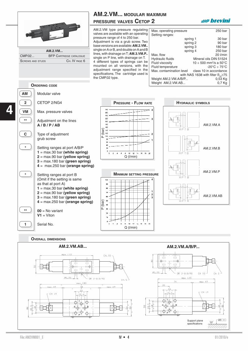
File: AM2VM001_E 01/2010/eIV • 4
4P
(ba
r)
Q (l/min)
AM.2.VM.A
AM.2.VM.B
AM.2.VM.AB
AM.2.VM.P
4
3
2
1
AM.2.VM.AB... AM.2.VM.A/B/P...
P (
bar)
Q (l/min)
4
123
AM.2.VM type pressure regulating valves are available with an operating pressure range of 4 to 250 bar.Adjustment is via a grub screw. Two base versions are available: AM.2.VM.. single on A or B, and double on A and B lines, with drainage on T; AM.3.VM.P.. single on P line, with drainage on T.4 different types of springs can be mounted on all versions, with the adjustment range specifi ed in the specifi cations. The cartridge used is the CMP.02 type.
AM.2.VM... MODULAR MAXIMUM PRESSURE VALVES CETOP 2
Max. operating pressure 250 barSetting ranges: spring 1 30 bar spring 2 90 bar spring 3 180 bar spring 4 250 barMax. fl ow 20 l/minHydraulic fl uids Mineral oils DIN 51524Fluid viscosity 10 ÷ 500 mm2/s a 50°CFluid temperature -20°C ÷ 75°CMax. contamination level class 10 in accordance with NAS 1638 with fi lter ß25≥75 Weight AM.2.VM.A/B/P... 0,53 KgWeight AM.2.VM.AB... 0,7 Kg
AM Modular valve
2 CETOP 2/NG4
VM Max. pressure valves
** Adjustment on the lines A / B / P / AB
C Type of adjustment grub screw
* Setting ranges at port A/B/P 1 = max.30 bar (white spring) 2 = max.90 bar (yellow spring) 3 = max.180 bar (green spring) 4 = max.250 bar (orange spring) * Setting ranges at port B (Omit if the setting is same as that at port A) 1 = max.30 bar (white spring) 2 = max.90 bar (yellow spring) 3 = max.180 bar (green spring) 4 = max.250 bar (orange spring) ** 00 = No variant V1 = Viton
1 Serial No.
ORDERING CODE
PRESSURE - FLOW RATE HYDRAULIC SYMBOLS
MINIMUM SETTING PRESSURE
OVERALL DIMENSIONS
Support planespecifi cations
AM.2.VM...
CMP.02... BFP CARTRIDGE CATALOGUE
SCREWS AND STUDS CH. IV PAGE 6

File: AM2QF001_E 00/2000/eIV • 5
4Δp
(ba
r)
Q (l/min)
Δp (
bar)
Q (l/min)
AM.2.QF.A AM.2.QF.B AM.2.QF.AB
FLOW REGULATION
AM.2.QF... MODULAR FLOW REGULATOR CETOP 2
Max. operating pressure 250 barFlow rate regulation on 6 screw turnsMax. fl ow. 20 l/minHydraulic fl uids Mineral oils DIN 51524Fluid viscosity 10 ÷ 500 mm2/s a 50°CFluid temperature -20°C ÷ 75°CMax. contamination level class 10 in accordance with NAS 1638 with fi lter ß25≥75 Weight AM.2.QF.A/B... 0,5 KgWeight AM.2.QF.AB... 0,6 Kg
AM.2.QF type one way non-compen-sated throttle valves are adjustable by means of a grub screw.
Three types of regulations are available on A / B / AB lines, as shown in the hydraulic symbols.
FREE FLOW THROUGH CHECK VALVE
AM Modular valve
2 CETOP 2/NG4
QF Non-compensated fl ow rate regulator
** Control on lines A / B / AB
C Type of adjustment grub screw
** 00 = No variant V1 = Viton
1 Serial No.
ORDERING CODE
HYDRAULIC SYMBOLS
OVERALL DIMENSIONS
Support planespecifi cations
AM.2.QF...
SCREWS AND STUDS CH. IV PAGE 6

File: TAMTR002_E 01/2014/eIV • 6
4
TABLE OF SCREWS AND STUDS FOR MOUNTING MODULES CETOP 2
Tighten M27.05.0001 to a torque of 5 Nm / 0.5 Kgm max.
OVERALL DIMENSIONS
SCREWS T.C.E.ICODE
Lmm
L1 *mm
COMPOSITION Q.TYSPECIAL NUTS
CODEQ26074069 35 — AD2... 4
—Q26074243 65 30 AD2... + 1 AM2... (ISO) 4
Q26074252 95 60 AD2... + 2 AM2... (ISO) 4
M80100008 135 90 AD2... + 3 AM2... 4 V89240000 (No. 20 nuts kit)M80100020 165 120 AD2... + 4 AM2... 4
* Indicative overall dimensions valves composition

File: AM3UD002_E 01/2000/eIV • 7
4
Δp (
bar)
Q (l/min)
AM.3.UD.A
AM.3.UD.B
5 bar
1 bar
AM.3.UD.P
AM.3.UD.T
AM.3.UD.AB
AM.3.UD type modular check valves allow one way free fl ow, while fl ow in the opposite direction is prevented by means of a conical seated poppet.
They are available on single A, B, P and T lines, and on double A and B, P and T lines (see hydraulic symbols).
1 bar spring is standard, while a 5 bar rated spring is available on request.
AM.3.UD... MODULAR DIRECT CHECK VALVES CETOP 3
Max. operating pressure 350 barMinimum opening pressure spring 1 1 barMinimum opening pressure spring 5 5 barMax. fl ow 40 l/minHydraulic fl uids Mineral oils DIN 51524Fluid viscosity 10 ÷ 500 mm2/s a 50°Fluid temperature -25°C ÷ 75°CAmbient temperature -25°C ÷ 60°CMax. contamination level class 10 in accordance with NAS 1638 with fi lter ß25≥75 Weight 0,8 Kg
AM Modular valve
3 CETOP 3/NG6
UD Direct check valve
** Control on lines A / B / P / T / AB
* Minimum opening pressure 1 = 1 bar 5 = 5 bar
** 00 = No variant V1 = Viton
2 Serial No.
ORDERING CODE PRESSURE DROPS
HYDRAULIC SYMBOLS
OVERALL DIMENSIONS
Support planespecifi cations
AM.3.UD...
SCREWS AND STUDS CH. IV PAGE 21
K = OR plate

File: AM3UP$003_E 04/2011/eIV • 8
4 AM.3.UP.A
AM.3.UP.B
AM.3.UP.AB
AM.3.UP... / AM.3.UP1... MODULAR PILOT OPERATED CHECK VALVES CETOP 3
Max. operating pressure 350 barMinimum opening pressure spring 1 1 barMinimum opening pressure spring 5 5 barPiloting ratio AM.3.UP 1:4Piloting ratio AM.3.UP1 1:12,5Max. fl ow 40 l/minHydraulic fl uids Mineral oils DIN 51524Fluid viscosity 10 ÷ 500 mm2/sFluid temperature -25°C ÷ 75°CAmbient temperature -25°C ÷ 60°CMax. contamination level class 10 in accordance with NAS 1638 with fi lter ß25≥75 Weight 1 Kg
AM.3.UP type modular check valves allow free fl ow in one direction by raising a conical seated poppet valve, while in the opposite direction the fl uid can return by means of a small piston piloted by the other line pressure (piloted side).
They are available on single A or B lines, and double A and B lines (see hydraulic symbols).
A pre-opening version is also available (AM3UP1..) only with 5 bar spring.
Curve n. 3 = Piloted side fl ow
HYDRAULIC SYMBOLS PRESSURE DROPS AM3UP
PRESSURE DROPS AM3UP1
ORDERING CODE
AM.3.UP / AM.3.UP1...
SCREWS AND STUDS CH. IV PAGE 21
The fl uid used is a mineral oil with a viscosity of 46 mm2/s at 40°C. The tests have been carried out a fl uid temperature of 50°C.
Δp (
bar)
Q (l/min)
5 bar
3
Q (l/min)
5 bar 1 bar 3
Δp (
bar)
OVERALL DIMENSIONS
Support planespecifi cations
AM Modular valve
3 CETOP 3/NG6
** UP = Piloted check valve UP1 = With pre-opening ** Control on lines A / B / AB
* Minimum opening pressure 1 = 1 bar (only for UP version) 5 = 5 bar 8 = 8 bar (only for UP version)
** 00 = No variant V1 = Viton
3 Serial No.

File: AM3V$003_E 05/2015/eIV • 9
4P
(ba
r)
Q (l/min)
AM.3.VM.A
AM.3.VM.B
AM.3.VM.AB
P (
bar)
Q (l/min)
AM.3.VM.P
AM.3.VI.A
AM.3.VI.B
AM.3.VI.AB
AM.3.VM type pressure regulating valves are available with a pressure range of 2 ÷ 320 bar.
Adjustment is by means of a grub screw or a plastic knob.
Three basic versions are available:- AM3VM on single A or B lines, and on A and B lines, with drainage to T;- AM3VMP on single P line, with drainage to T;- AM3VI on single A or B lines, and on A and B lines, with crossed drain-age on A or B (see hydraulic symbols).All versions can accept three types of springs with calibrated ranges as shown in the specifi cations.
The cartridge, which is the same for all versions, is the direct acting type CMP10.For the minimum permissible set-ting pressure depending on the spring, see minimum pressure setting curve.
AM.3.VM... / AM.3.VI... MODULAR MAX. PRESSURE VALVES CETOP 3
Max. operating pressure 320 barSetting ranges: spring 1 max. 50 bar spring 2 max. 150 bar spring 3 max. 320 barMax. fl ow 40 l/minHydraulic fl uids Mineral oils DIN 51524Fluid viscosity 10 ÷ 500 mm2/sFluid temperature -25°C ÷ 75°CAmbient temperature -25°C ÷ 60°CMax. contamination level class 10 in accordance with NAS 1638 with fi lter ß25≥75 Weight AM.3.VM.A/B/P... 1,2 KgWeight AM.3.VM.AB... 1,3 KgWeight AM.3.VI.A/B... 2 KgWeight AM.3.VI.AB... 2,2 Kg
AM Modular valve
3 CETOP 3/NG6
** VM = Maximum pressure VI = Maximum pressure crossline
** Adjustment on the lines AM.3.VM Version = A / B / P / AB AM.3.VI Version = A / B / AB
* Type of adjustment M = Plastic knob C = Grub screw * Setting ranges at port A/B/P 1 = max. 50 bar (white spring) 2 = max. 150 bar (yellow spring) 3 = max. 320 bar (green spring) * Setting ranges at port B (Omit if the setting is same as that at port A) 1 = max. 50 bar (white spring) 2 = max. 150 bar (yellow spring) 3 = max. 320 bar (green spring) ** 00 = No variant V1 = Viton
3 Serial No.
HYDRAULIC SYMBOLS
ORDERING CODE
PRESSURE - FLOW RATE
MINIMUM SETTING PRESSURE
Curves n° 1 - 2 - 3 = setting ranges
AM.3.VM / AM.3.VI...
CMP.10... CH. VII PAGE 30
SCREWS AND STUDS CH. IV PAGE 21
3
2
1
3
2 1
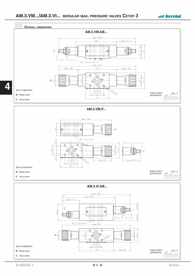
File: AM3V$003_E 05/2015/eIV • 10
4
AM.3.VM.AB...
AM.3.VM.P...
AM.3.VI.AB...
AM.3.VM.../AM.3.VI... MODULAR MAX. PRESSURE VALVES CETOP 3
OVERALL DIMENSIONS
Type of adjustment
M Plastic knob
C Grub screw
Type of adjustment
M Plastic knob
C Grub screw
Type of adjustment
M Plastic knob
C Grub screw
Support planespecifi cations
Support planespecifi cations
Support planespecifi cations

File: AM3CP003_E 04/2015/eIV • 11
4
AM.3.CP.A
AM.3.CP.B
AM.3.CP.AB
P (
bar)
Q (l/min)
3
2 1
P (
bar)
Q (l/min)
3
2
1
AM.3.CP... MODULAR BACK PRESSURE VALVE CETOP 3
AM3CP type back pressure valves are damped in-line direct acting pressure relief valves fi tted with bypass non-return valves.
Adjustment wi th in the range 2 ÷ 320 bar is by means of a grub screw or a plastic knob, on ports A or B (single) or AB (double).
The cartridge is the direct acting type CMP10.
These valves are especially used on vertically working cylinders with drag-ging loads.
For the minimum permissible set-ting pressure depending on the spring, see minimum pressure setting curve.
Max. operating pressure 350 barSetting ranges: spring 1 max. 50 bar spring 2 max. 150 bar spring 3 max. 320 barMax. fl ow 40 l/minHydraulic fl uids Mineral oils DIN 51524Fluid viscosity 10 ÷ 500 mm2/sFluid temperature -25°C ÷ 75°CAmbient temperature -25°C ÷ 60°CMax. contamination level class 10 in accordance with NAS 1638 with fi lter ß25≥75 Weight AM.3.CP.A/B... 2 KgWeight AM.3.CP.AB... 2,7 Kg
AM Modular valve
3 CETOP 3/NG6
CP Back pressure valve
** Control on lines A / B / AB
* Type of adjustment M = Plastic knob C = Grub screw
* Setting ranges 1 = max. 50 bar (white spring) 2 = max. 150 bar (yellow spring) 3 = max. 320 bar (green spring) ** 00 = No variant V1 = Viton
3 Serial No.
K = OR plate
ORDERING CODE
HYDRAULIC SYMBOLS
PRESSURE - FLOW RATE
MINIMUM SETTING PRESSURE
OVERALL DIMENSIONS
Type of adjustment
M Plastic knob
C Grub screw
Support planespecifi cations
AM.3.CP...
CMP.10... CH. VII PAGE 30
SCREWS AND STUDS CH. IV PAGE 21

File: AM3$D004_E 01/2000/eIV • 12
4
P (
bar)
Q (l/min)
AM.3.RD.A
AM.3.RD.P
AM.3.SD.P
3
2
1
Pr
(bar
)
Q (l/min)
3
2
1
Relieving ←
AM.3.RD... /AM.3.SD... MODULAR PRESSURE REDUCING / PRESSURE SEQUENCING VALVES CETOP 3
Max. operating pressure: port P 350 barMax. pressure adjustable 250 barSetting ranges: spring 1 2 ÷ 30 bar spring 2 10 ÷ 120 bar spring 3 60 ÷ 250 barMax. fl ow 40 l/minInternal drainage RD: Positive overlap version 0,5 l/minNegative overlap version 2 l/minHydraulic fl uids Mineral oils DIN 51524Fluid viscosity 10 ÷ 500 mm2/sFluid temperature -25°C ÷ 75°CAmbient temperature -25°C ÷ 60°CMax. contamination level class 10 in accordance with NAS 1638 with fi lter ß25≥75 Weight 1,3 Kg
AM3RD and AM3SD valves are direct acting spool type pressure reducing and sequencing units, respectively, with one end pre-loaded by means of a spring an the other end exposed to the hydraulic pressure.The drainage is drained within the valve to port T. Pressure is adjustable by means of a screw and locknut, or of a handwheel. Three types of springsallow adjustment within the range 2÷250 bar. The pressure reducing valves are available in two versions: with positive overlap (suitable with low fl ow rate) and with negative overlap to obtain a greater pressure reinstate-ment speed.
PRESSURE - FLOW RATE
AM3SD
AM Modular valve
3 CETOP 3/NG6
** RD = Direct pressure reducing valve SD = Direct pressure sequencing valve
* Control on lines AM.3.RD version = A / P AM.3.SD version = P
* 1 = Positive overlap 2 = Negative overlap Omit for version AM3SD
* Type of adjustment C = Grub screw V = Handwheel
* Setting ranges 1 = max. 2 ÷ 30 bar (white spring) 2 = max. 10 ÷ 120 bar (yellow spring) 3 = max. 60 ÷ 250 bar (green spring) ** 00 = No variant V1 = Viton
4 Serial No.
Applicationexample
ORDERING CODE
PRESSURE - FLOW RATE
AM3RD
The fl uid used is a mineral based oil with a viscosity of 46 mm2/sec at 40 degrees C. The tests have been carried out at with a fl uid temperature of 40 degrees C.
HYDRAULIC SYMBOLS
OVERALL DIMENSIONS
Type of adjustment
V Handwheel
C Grub screw
Support planespecifi cations
AM.3.RD / AM.3.SD...
SCREWS AND STUDS CH. IV PAGE 21
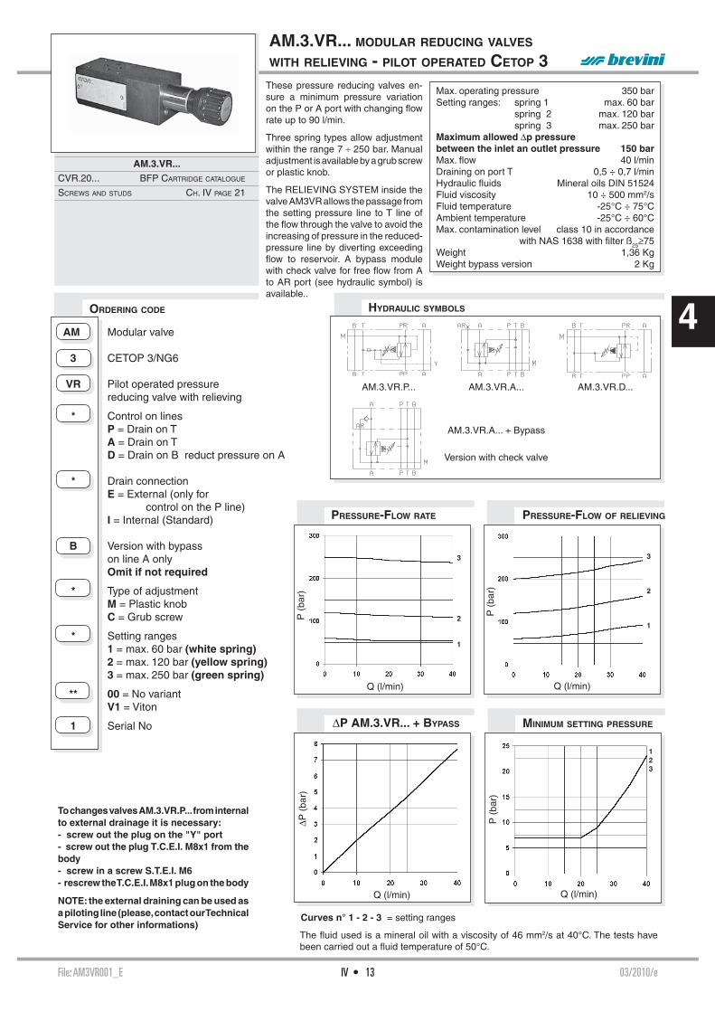
File: AM3VR001_E 03/2010/eIV • 13
4ΔP
(ba
r)
Q (l/min) Q (l/min)
P (
bar)
123
Q (l/min)
P (
bar)
3
2
1
Q (l/min)
P (
bar)
3
2
1
AM.3.VR... MODULAR REDUCING VALVES WITH RELIEVING - PILOT OPERATED CETOP 3
Max. operating pressure 350 barSetting ranges: spring 1 max. 60 bar spring 2 max. 120 bar spring 3 max. 250 barMaximum allowed Δp pressure between the inlet an outlet pressure 150 barMax. fl ow 40 l/minDraining on port T 0,5 ÷ 0,7 l/minHydraulic fl uids Mineral oils DIN 51524Fluid viscosity 10 ÷ 500 mm2/sFluid temperature -25°C ÷ 75°CAmbient temperature -25°C ÷ 60°CMax. contamination level class 10 in accordance with NAS 1638 with fi lter ß25≥75 Weight 1,36 KgWeight bypass version 2 Kg
These pressure reducing valves en-sure a minimum pressure variation on the P or A port with changing fl ow rate up to 90 l/min.
Three spring types allow adjustment within the range 7 ÷ 250 bar. Manual adjustment is available by a grub screw or plastic knob.
The RELIEVING SYSTEM inside the valve AM3VR allows the passage from the setting pressure line to T line of the fl ow through the valve to avoid the increasing of pressure in the reduced-pressure line by diverting exceeding fl ow to reservoir. A bypass module with check valve for free fl ow from A to AR port (see hydraulic symbol) is available..
ORDERING CODE
The fl uid used is a mineral oil with a viscosity of 46 mm2/s at 40°C. The tests have been carried out a fl uid temperature of 50°C.
Curves n° 1 - 2 - 3 = setting ranges
ΔP AM.3.VR... + BYPASS MINIMUM SETTING PRESSURE
PRESSURE-FLOW OF RELIEVINGPRESSURE-FLOW RATE
AM Modular valve
3 CETOP 3/NG6
VR Pilot operated pressure reducing valve with relieving
* Control on lines P = Drain on T A = Drain on T D = Drain on B reduct pressure on A
* Drain connection E = External (only for control on the P line) I = Internal (Standard)
B Version with bypass on line A only Omit if not required
* Type of adjustment M = Plastic knob C = Grub screw
* Setting ranges 1 = max. 60 bar (white spring) 2 = max. 120 bar (yellow spring) 3 = max. 250 bar (green spring)
** 00 = No variant V1 = Viton
1 Serial No
To changes valves AM.3.VR.P... from internal to external drainage it is necessary:- screw out the plug on the "Y" port- screw out the plug T.C.E.I. M8x1 from the body- screw in a screw S.T.E.I. M6- rescrew the T.C.E.I. M8x1 plug on the body
NOTE: the external draining can be used as a piloting line (please, contact our Technical Service for other informations)
AM.3.VR...
CVR.20... BFP CARTRIDGE CATALOGUE
SCREWS AND STUDS CH. IV PAGE 21
HYDRAULIC SYMBOLS
AM.3.VR.P... AM.3.VR.A...
Version with check valve
AM.3.VR.D...
AM.3.VR.A... + Bypass

File: AM3VR001_E 03/2010/eIV • 14
4
AM.3.VR.P... / AM.3.VR.D...
AM.3.VR.A... + BYPASS
OVERALL DIMENSIONS
AM.3.VR... MODULAR REDUCING VALVES WITH RELIEVING - PILOT OPERATED CETOP 3
Type of adjustment
M Plastic knob
C Grub screw
B Bypass (optional)Ordering code:V89.45.000(if ordered separately)
Support planespecifi cations

File: AM3VS001_E 03 /2010/eIV • 15
4
1-2-3
Q (l/min)
P (
bar)
3
2
1
Q (l/min)
P (
bar)
AM.3.VS... MODULAR SEQUENCING VALVES CETOP 3The sequence valve are used to assure that a secondary circuit is pressurized when the setting pressure is reached.
These valves grant a minimum variation of the setting pressure with a changing fl ow up to 40 l/min (see diagram).
Three spring types allow adjustment within the range 7 ÷ 250 bar. Manual adjustment is available by a grub screw or plastic knob.
The cartridge used is the "CVS" type.
ORDERING CODE
Max. operating pressure 350 barSetting ranges: Spring 1 max. 60 bar Spring 2 max. 120 bar Spring 3 max. 250 barMax. fl ow 40 l/minDraining on port T 0,5 ÷ 0,7 l/minHydraulic fl uids Mineral oils DIN 51524Fluid viscosity 10 ÷ 500 mm2/sFluid temperature -25°C ÷ 75°CAmbient temperature -25°C ÷ 60°CMax. contamination level class 10 in accordance with NAS 1638 with fi lter ß25≥75 Weight 1,36 Kg
Type of adjustment
M Plastic knob
C Grub screw
Curves n° 1 - 2 - 3 = setting rangesOVERALL DIMENSIONS
The fl uid used is a mineral oil with a viscosity of 46 mm2/s at 40°C. The tests have been carried out at a fl uid temperature of 50°C.
HYDRAULIC SYMBOL
MINIMUM SETTING PRESSUREPRESSURE-FLOW RATE
Support planespecifi cations
To changes valves AM.3.VS... from internal to external drainage it is necessary:- screw out the plug on the Y port- screw out the plug T.C.E.I. M8x1 from the body- screw in a screw S.T.E.I. M6- rescrew the T.C.E.I. M8x1 plug on the body
NOTE: the external draining can be used as a piloting line (please, contact our Technical Service for other informations)
AM Modular valve
3 CETOP 3/NG6
VS Sequencing valve
* Drain connection E = External I = Internal (Standard)
* Type of adjustment M = Plastic knob C = Grub screw
* Setting ranges 1 = max. 60 bar (white spring) 2 = max. 120 bar (yellow spring) 3 = max. 250 bar (green spring) ** 00 = No variant V1 = Viton
1 Serial No
AM.3.VS...
CVS.20... BFP CARTRIDGE CATALOGUE
SCREWS AND STUDS CH. IV PAGE 21

File: AM3SH001_E 02/2010/eIV • 16
4Δp
(ba
r)
Q (l/min)
PRESSURE DROPS
ON THE SHUTTLE VALVE
Modular valves type AM.3.SH are actuator load pressure selecting units, as they are fi tted with an integral shut-tle valve cartridge which allows taking of the highest pressure signal to the external port via displacement of a ball. They are usually employed to signal the actuator load to the pressure compensator of load sensing pump, or for the command of fail-safe brakes.
For seat overall dimensions see car-tridge shuttle SH.03 type.
AM.3.SH... MODULAR SHUTTLE VALVES CETOP 3
Max. operating pressure 350 barMax. fl ow at the cartridge 3 l/minMax. fl ow at ports A/B/P/T 40 l/minHydraulic fl uids Mineral oils DIN 51524Fluid viscosity 10 ÷ 500 mm2/sFluid temperature -25°C ÷ 75°CAmbient temperature -25°C ÷ 60°CMax. contamination level class 10 in accordance with NAS 1638 with fi lter ß25≥75 Weight 1 KgCartridge tightening torque 20÷30 Nm/2÷3 Kgm
AM Modular valve
3 CETOP 3/NG6
SH Cartridge shuttle
** 00 = No variant V1 = Viton
1 Serial No.
ORDERING CODE HYDRAULIC SYMBOL
OVERALL DIMENSIONS
Support planespecifi cations
AM.3.SH...
SH.03... BFP CARTRIDGE CATALOGUE
SCREWS AND STUDS CH. IV PAGE 21

File: AM3QF004_E 02/2000/eIV • 17
4Δp
(ba
r)
Q (l/min)
Δp (
bar)
Q (l/min)
AM.3.QF.B AM.3.QF.P AM.3.QF.ABAM.3.QF.A
AM.3.QF... MODULAR FLOW REGULATOR CETOP 3
Max. operating pressure 350 barMax. pressure adjustable 250 barFlow rate regulation on 8 screw turnsMax. fl ow 40 l/minHydraulic fl uids Mineral oils DIN 51524Fluid viscosity 10 ÷ 500 mm2/sFluid temperature -25°C ÷ 75°CAmbient temperature -25°C ÷ 60°CMax. contamination level class 10 in accordance with NAS 1638 with fi lter ß25≥75 Weight 1,5 Kg
AM.3.QF type one way non-compen-sated throttle valve are fi tted with an O-Ring mounting plate which allows its assembly for either input or output regulation. Adjustment is obtained by means of a grub screw or a plastic knob. They are available in the four regulating confi gurations shown in the hydraulic diagrams.
The standard valve confi guration al-lows "meter in" regulation, while it is possible to obtain "meter out" regula-tion by turning the valve by 180° along its longitudinal axis.
FREE FLOW
TOWARDS CHECK VALVEAM Modular valve
3 CETOP 3/NG6
QF Non compensated throttle valve
** Control on lines A / B / P / AB
* Type of adjustment M = Plastic knob C = Grub screw
** 00 = No variant V1 = Viton
4 Serial No.
FLOW REGULATIONORDERING CODE
HYDRAULIC SYMBOLS
OVERALL DIMENSIONS
K = OR plate
Type of adjustment
M Plastic knob
C Grub screw
Support planespecifi cations
AM.3.QF...
SCREWS AND STUDS CH. IV PAGE 21

File: AM66003_E 01/2000/eIV • 18
4AM.66.A AM.66.B AM.66.AB
AM.66.P AM.66.PT* AM.66.T
AM.66.A1 AM.66.B1 AM.66.A1B1
AM.66... MODULAR COMPENSATED FLOW CONTROL ASSEMBLY CETOP 3
Max. operating pressure 320 barHydraulic fl uids Mineral oils DIN 51524Fluid viscosity 10 ÷ 500 mm2/sFluid temperature -25°C ÷ 75°CAmbient temperature -25°C ÷ 60°CMax. contamination level class 10 in accordance with NAS 1638 with fi lter ß25≥75 Weight 1,3 Kg
AM Modular valve
66 Size
** Control on lines A / B / P / PT* / AB For T / A1 / B1 / A1B1 versions see table "Hydraulic symbols"
** 00 = No variant V1 = Viton
3 Serial No.
PT * = From line towards exhaust (P→ T drain)
• In order to obtain versions with regulation on T, the AM.66.P regulator carrying block should be turned by 180°.
• In order to obtain versions A1, B1 and A1B1 the AM.66.A, AM.66.B or AM.66.AB regulators carrying block should be turned by 180°.
ORDERING CODE
HYDRAULIC SYMBOLS
OVERALL DIMENSIONS
K = OR plate
Support planespecifi cations
This is an intermediate block (AM.66) for modular mounting of one or two fl ow rate regulators type QC.3...
The fl ow regulator type QC.3.2... must be ordered separately.
AM.66...
QC.3.2... CH. III PAGE 2
SCREWS AND STUDS CH. IV PAGE 21

File: A6600$_E 10/2013/eIV • 19
4LIMITS OF USE
p (b
ar)
Q (l/min)
A.66.*.121.*... A.66.*.*.A1 A.66.*.*.B1 A.66.*.*.P
A.66.*.120.*... A.66.*.*.A A.66.*.*.B A.66.*.*.T
121 (NC)
120 (NA)
A.66... MODULAR FLOW CONTROL VALVES FAST / SLOW ASSEMBLY CETOP 3
Max. operating pressure 320 barHydraulic fl uids Mineral oils DIN 51524Fluid viscosity 10 ÷ 500 mm2/sFluid temperature -25°C ÷ 75°CAmbient temperature -25°C ÷ 60°CMax. contamination level class 10 in accordance with NAS 1638 with fi lter ß25≥75 Weight 2,4 Kg
This is modular assembly ON/OFF solenoid valve which, by fi tting suit-able 2 way regulator, allows two speed operation in the same system via an electrical changeover command.
The fl ow rate regulator type QC.3.2... must be ordered separately.The operational limit curves have been obtained with the regulator fully closed, and those same limits improve gradually with the opening of the regulator.
H = QC.3... interface holder
The test have been carried out at operating temperature, with a voltage 10% lower than rated voltage and with a fl uid temperature of 50 degrees C. The fl uid used was a mineral based oil with a viscosity of 46 mm2/s at 40 degrees C.
HYDRAULIC SYMBOLS
OVERALL DIMENSIONS
Support planespecifi cations
A.66...
DC COILS CH. I PAGE 68
STANDARD CONNECTORS CH. I PAGE 20
QC.3.2... CH. III PAGE 2
SCREWS AND STUDS CH. IV PAGE 21
A Speed control valve
66 Size
E Electrical operator
*** 120 = Normally open 121 = Normally closed See table hydraulic symbols
* Control on lines A/B/P/T (see symbols) The interface holder "H" must be turned by 180° in order to obtain the A1 and B1 versions.
* Voltage: see tab.1
** Variants: see tab.2
4 Serial No.
TAB.2 - VARIANTS
No variant (without connectors) S1(*)Viton SV(*)
Other variants available on request
ORDERING CODE
TAB.1 VOLTAGE
L 12V M 24V V 28V* N 48V* Z 102V* P 110V* X 205V* W without coils
DC COILS **
Voltage codes are not stamped on the plate, their are readable on the coils.
115Vac/50Hz120Vac/60Hzwith rectifi er
230Vac/50Hz240Vac/60Hzwith rectifi er
(*) Coils with Hirschmann connection supplied without connectors. The con-nectors can be ordered separately, ch. I page 20.
* Special voltage** Technical data see page XII • 4

File: AM3RGT001_E 01/2000/eIV • 20
4Δp
(ba
r)
Q (l/min)
This modular valve produces a regen-erative system to increase the actuator (differential cylinder) exit speed as shown in the diagram.
In particular, if a cylinder is used with a 2:1 ratio for the operating surfaces, the exit and re-entry speeds are the same.
AM.3.RGT... MODULAR VALVES FOR REGENERATIVE CIRCUIT CETOP 3
Max. operating pressure 350 barMax. fl ow at port A/B/P/T 20 l/minHydraulic fl uids Mineral oils DIN 51524Fluid viscosity 10 ÷ 500 mm2/sFluid temperature -25°C ÷ 75°CAmbient temperature -25°C ÷ 60°CMax. contamination level class 10 in accordance with NAS 1638 with fi lter ß25≥75 Weight 1,7 Kg
AM Modular valve
3 CETOP 3/NG6
RGT For regenerative circuit
A Size of check valves 3/8"BSP
1 Opening pressure 1 bar
** 00 = No variant V1 = Viton
1 Serial No.
PRESSURE DROPS A→P HYDRAULIC SYMBOLORDERING CODE
OVERALL DIMENSIONS
Support planespecifi cations
AM.3.RGT...
SCREWS AND STUDS CH. IV PAGE 21

File: TAMTR003_E 02/2014/eIV • 21
4
TABLE OF SCREWS AND STUDS FOR MOUNTING MODULES CETOP 3
Tighten M27.05.0001 to a torque of 5 Nm / 0.5 Kgm max.
OVERALL DIMENSIONS
SCREWS T.C.E.ICODE
Lmm
L1 *mm
COMPOSITION Q.TYSPECIAL NUTS
CODEQ26074068 30 — AD3... 4
—Q26074075 70 40 AD3... + 1 AM3... (ISO) 4
Q26074076 75 45 AD3... + AM3VR 4
M80100015 97 57,5 AD3... + AM3VI... 4
V89240000 (No. 20 nuts kit)
M80100007 115 74 AD3... + A66 o AM66... 4
M80100003 120 80 AD3... + 2 AM3... (ISO) 4
M80100013 125 85 AD3... + AM3VR... + AM3... (ISO) 4
M80100011 155 114 AD3... + A66... + AM3... (ISO) 4
M80100005 160 119 AD3... + A66... + AM3VR 4
M80100005 160 120 AD3... + 3 AM3... (ISO) 4
M80100020 165 125 AD3 + AM3VR + 2 AM3... (ISO) 4
M80100017 170 130 AD3 + AM3CP + 2 AM3... (ISO) 4
M80100023 195 154 A66... + 2 AM3... (ISO) 4
* Indicative overall dimensions valves composition

File: AM5UD002_E 01/2000/eIV • 22
4
AM.5.UD.A
AM.5.UD.B
AM.5.UD.P
AM.5.UD.T
AM.5.UD.AB
AM.5.UD.PT
Δp (
bar)
Q (l/min)
5 bar
1 bar
AM5UD type modular check valves allow free fl ow in one direction, while a conical seated poppet prevents fl ow in the opposite direction.They are available on single A, B, P and T lines, and on double A and B, P and T lines (see hydraulic symbols).
1 bar springs are standard, while 5 bar rated springs are available on request.
AM.5.UD... MODULAR DIRECT CHECK VALVES CETOP 5
Max. operating pressure 350 barMinimum opening pressure spring 1 1 barMinimum opening pressure spring 5 5 barMax. fl ow 80 l/minHydraulic fl uids Mineral oils DIN 51524Fluid viscosity 10 ÷ 500 mm2/sFluid temperature -25°C ÷ 75°CAmbient temperature -25°C ÷ 60°CMax. contamination level class 10 in accordance with NAS 1638 with fi lter ß25≥75 Weight 2,1 Kg
HYDRAULIC SYMBOLS
OVERALL DIMENSIONS
Support planespecifi cations
ORDERING CODE
AM Modular valve
5 CETOP 5/NG10
UD Direct check valve
** Control on lines A / B / P / T / AB / PT
* Minimum opening pressure 1 = 1 bar 5 = 5 bar
** 00 = No variant V1 = Viton
2 Serial No.
PRESSURE DROPS
AM.5.UD...
SCREWS AND STUDS CH. IV PAGE 36
K = OR plate

File: AM5UP005_E 01/2000/eIV • 23
4
Δp (
bar)
Q (l/min)
5 bar
1 bar
AM.5.UP.A
AM.5.UP.B
AM.5.UP.AB
3
OVERALL DIMENSIONS
Support planespecifi cations
PRESSURE DROPSORDERING CODE
AM.5.UP... MODULAR PILOT OPERATED CHECK VALVES CETOP 5
Max. operating pressure 280 barMinimum opening pressure spring 1 1 barMinimum opening pressure spring 5 5 barPiloting ratio 1 : 14,3Max. fl ow 80 l/minHydraulic fl uids Mineral oils DIN 51524Fluid viscosity 10 ÷ 500 mm2/sFluid temperature -25°C ÷ 75°CAmbient temperature -25°C ÷ 60°CMax. contamination level class 10 in accordance with NAS 1638 with fi lter ß25≥75 Weight 2,7 Kg
AM5UP type modular check valves allow free fl ow in one direction by lifting a conical steel seated poppet, while in the opposite direction the fl uid can return by means of a small piston piloted by the other line pressure (piloted side).
The cast valve body allows limited pressure drops during the fl uid fl ow through the various P/A/B/T lines.
They are available on single A or B lines, and on double A and B lines (see hydraulic symbols).
HYDRAULIC SYMBOLS
AM Modular valve
5 CETOP 5/NG10
UP Piloted check valve
** Control on lines A / B / AB * Minimum opening pressure 1 = 1 bar 5 = 5 bar
** 00 = No variant V1 = Viton
5 Serial No.
Curve n. 3 = Piloted side fl ow
AM.5.UP...
SCREWS AND STUDS CH. IV PAGE 36
The fl uid used is a mineral oil with a viscosity of 46 mm2/s at 40°C. The tests have been carried out a fl uid temperature of 50°C.

File: AM5V$003_E 02/2014/eIV • 24
4
AM.5.VM.A
AM.5.VM.B
AM.5.VM.AB
AM.5.VM.P
AM.5.VI.A
AM.5.VI.B
AM.5.VI.AB
P (
bar)
Q (l/min)
3
2
1
P (
bar)
Q (l/min)
32 1
AM.5.VM type pressure regulating valves are available within operating range 7 ÷ 350 bar. Adjustment is by means of a grub screw or a plastic knob. They are three basic versions:AM.5.VM, on single A or B lines, and on double A and B lines, with drainage on T; AM.5.VM.P, on single P line, with drainage on T; AM.5.VI, on single A or B lines, and on double A and B lines, with crossed drainage on either A or B (see hydraulic symbols). Three spring types can be fi tted on all versions, with calibrated ranges as shown in the unit specifi cations.Piloted operation cartridge type CMP.30 is used on versions AM.5.VM and AM.5.VM.P (see ordering code), while on version AM.5.VI direct acting cartridge type CMP.20 is used instead.
For the minimum permissible set-ting pressure depending on the spring, see the minimum pressure setting curve.
ORDERING CODE
AM.5.VM... / AM.5.VI... MODULAR
MAX. PRESSURE VALVES CETOP 5
Max. operating pressure 350 barSetting ranges: spring 1 50 bar spring 2 140 bar spring 3 350 barMax. fl ow 80 l/minHydraulic fl uids Mineral oils DIN 51524Fluid viscosity 10 ÷ 500 mm2/sFluid temperature -25°C ÷ 75°CAmbient temperature -25°C ÷ 60°CMax. contamination level class 10 in accordance with NAS 1638 with fi lter ß25≥75 Weight AM.5.VM.A/B/P... 2,5 KgWeight AM.5.VM.AB... 2,7 KgWeight AM.5.VI.A/B... 5,7 KgWeight AM.5.VI.AB... 5,9 Kg
HYDRAULIC SYMBOLS
AM Modular valve
5 CETOP 5/NG10
** VM = Maximum pressure VI = Maximum crossline relief
** Adjustment on the lines AM.5.VM Version = A / B / P / AB AM.5.VI Version = A / B / AB
* Type of adjustment M = Plastic knob C = Grub screw
* Setting ranges at port A/B/P CMP 30 CMP 20 (AM.5.VM only) (AM.5.VI only) 1 = max. 50 bar 1 = max.50 bar (white spring) 2 = max. 140 bar 2 = max. 140 bar (yellow spring) 3 = max. 350 bar 3 = max. 250 bar (green spring)
* Setting ranges at port B Omit if the setting is same as that at port A CMP 30 CMP 20 (AM.5.VM only) (AM.5.VI only) 1 = max.50 bar 1 = max.50 bar (white spring) 2 = max. 140 bar 2 = max. 140 bar (yellow spring) 3 = max. 350 bar 3 = max. 250 bar (green spring)
** 00 = No variant V1 = Viton
3 Serial No.
PRESSURE - FLOW RATE
FOR CMP.30MINIMUM SETTING PRESSURE
FOR CMP.30
AM.5.VM... / AM.5.VI...
CMP.20... BFP CARTRIDGE CATALOGUE
CMP.30... BFP CARTRIDGE CATALOGUE
SCREWS AND STUDS CH. IV PAGE 36

File: AM5V$003_E 02/2014/eIV • 25
4
AM.5.VM.AB...
AM.5.VM.P...
AM.5.VI.AB...
OVERALL DIMENSIONS
AM.5.VM... / AM.5.VI... MODULAR MAX. PRESSURE VALVES CETOP 5
Type of adjustment
M Plastic knob
C Grub screw
Type of adjustment
M Plastic knob
C Grub screw
Type of adjustment
M Plastic knob
C Grub screw
Support planespecifi cations
Support planespecifi cations
Support planespecifi cations

File: AM5CP003_E 02/2010/eIV • 26
4
P (
bar)
Q (l/min)
3
2
1
P (
bar)
Q (l/min)
3
2 1
AM.5.CP.A
AM.5.CP.B
AM.5.CP.AB
OVERALL DIMENSIONS
Support planespecifi cations
AM.5.CP... MODULAR BACK PRESSURE VALVES CETOP 5
HYDRAULIC SYMBOLS
Back pressure valves type AM.5.CPare direct acting damped maximum pressure in-line valves fitted with bypass non-return valves. They are obtainable within the adjustable range 2 ÷ 250 bar. Adjustment is by means of a grub screw or a plastic knob, on ports A or B (single), or on AB double.The cartridge is direct acting type CMP.20.These valves are especially used on vertical working cylinders with drag-ging loads.
For the minimum permissible set-ting pressure depending on the spring, see the minimum pressure setting curve
Max. operating pressure 350 barSetting ranges: spring 1 30 bar spring 2 140 bar spring 3 250 barMax. fl ow 80 l/minHydraulic fl uids Mineral oils DIN 51524Fluid viscosity 10 ÷ 500 mm2/sFluid temperature -25°C ÷ 75°CAmbient temperature -25°C ÷ 60°CMax. contamination level class 10 in accordance with NAS 1638 with fi lter ß25≥75 Weight AM.5.CP.A/B... 5,3 KgWeight AM.5.CP.AB... 7,2 Kg
ORDERING CODE
AM Modular valve
5 CETOP 5/NG10
CP Back pressure valve
** Control on lines A / B / AB
* Type of adjustment M = Plastic knob C = Grub screw
* Setting ranges 1 = max. 30 bar (white spring) 2 = max. 140 bar (yellow spring) 3 = max. 250 bar (green spring) ** 00 = No variant V1 = Viton
3 Serial No.
K = OR plate
Type of adjustment
M Plastic knob
C Grub screw
PRESSURE - FLOW RATE
MINIMUM SETTING PRESSURE
Curves n° 1 - 2 - 3 = setting ranges
AM.5.CP...
CMP.20... BFP CARTRIDGE CATALOGUE
SCREWS AND STUDS CH. IV PAGE 36

File: AM5VR001_E 03/2010/eIV • 27
4ΔP
(ba
r)
Q (l/min) Q (l/min)
P (
bar)
123
Q (l/min)
P (
bar)
3
2
1
Q (l/min)
P (
bar)
3
2
1
AM.5.VR... MODULAR PRESSURE REDUCING VALVES
WITH RELIEVING - PILOT OPERATED CETOP 5
Max. operating pressure 350 barSetting ranges: spring 1 60 bar spring 2 120 bar spring 3 250 barMaximum allowed Δp pressure between the inlet and outlet pressure 150 barMax. fl ow 90 l/minDraining on port T 0,5 ÷ 0,7 l/minHydraulic fl uids Mineral oils DIN 51524Fluid viscosity 10 ÷ 500 mm2/sFluid temperature -25°C ÷ 75°CAmbient temperature -25°C ÷ 60°CMax. contamination level class 10 in accordance with NAS 1638 with fi lter ß25≥75 Weight 3,73 KgWeight by-pass version 6,56 Kg
These pressure reducing valves en-sure a minimum pressure variation on the P or A port with changing fl ow rate up 90 l/min.
Three spring types allow adjustment with the range 7 ÷ 250 bar. Manual adjustment is available by a grub screw or plastic knob.
The RELIEVING SYSTEM inside the valve AM.5.VR allows the passage from the setting pressure line to T line of the fl ow through the valve to avoid the increasing of pressure in the reduced-pressure line by diverting exceeding fl ow to reservoir.
A by pass module with check valve for free fl ow from A to AR port (see hydraulic symbol) is available.
ORDERING CODE
The fl uid used is a mineral oil with a viscosity of46 mm2/s at 40°C. The tests have been carried out at a fl uid temperature of 50°C.
Curves n° 1 - 2 - 3 = setting ranges
ΔP AM.5.VR... + BY-PASS MINIMUM SETTING PRESSURE
PRESSURE-FLOW OF RELIEVINGPRESSURE-FLOW RATE
To change valves AM.5.VR.P... from internal to external drainage it is necessary:- screw out the plug on the Y port- screw out the plug T.C.E.I. M8x1 from the body- screw in a screw S.T.E.I. M6- rescrew the T.C.E.I. M8x1 plug on the body
NOTE: the external draining can be used as a piloting line (please, concta our Technical Service for other informations)
AM Modular valve
5 CETOP 5/NG10
VR Pilot operated pressure reducing valve with relieving
* Control on lines P = Drain on T A = Drain on T D = Drain on B reduct pressure on A
* Drain connection E = External (only for control on the P line) I = Internal (Standard)
B Version with by-pass on line A only Omit if not required
* Type of adjustment M = Plastic knob C = Grub screw
* Setting ranges 1 = max. 60 bar (white spring) 2 = max. 120 bar (yellow spring) 3 = max. 250 bar (green spring)
** 00 = No variant V1 = Viton
1 Serial No.
AM.5.VR...
CVR.20... BFP CARTRIDGE CATALOGUE
SCREWS AND STUDS CH. IV PAGE 36
HYDRAULIC SYMBOLS
AM.5.VR.P... AM.5.VR.A...
Version with check valve
AM.5.VR.D...
AM.5.VR.A... + Bypass

File: AM5VR001_E 03/2010/eIV • 28
4
AM.5.VR.P... / AM.5.VR.D...
AM.5.VR.A... + BYPASS
OVERALL DIMENSIONS
AM.5.VR... MODULAR PRESSURE REDUCING VALVES WITH RELIEVING - PILOT OPERATED CETOP 5
Type of adjustment
M Plastic knob
C Grub screw
Support planespecifi cations
B By-pass (optional)
Ordering code: V89.46.0000(if ordered separately)

File: AM5VS001_E 03/2010/eIV • 29
4
MINIMUM SETTING PRESSUREPRESSURE-FLOW RATE
123
Q (l/min)
P (
bar)
3
2
1
Q (l/min)
P (
bar)
AM.5.VS... MODULAR PRESSURE SEQUENCING VALVES CETOP 5
The sequence valve are used to assure that a secondary circuit is pressurized when the setting pres-sure with a changing flow to up 90 l/min (see diagram).
Three spring types allow adjustment within the range 7 ÷ 250 bar.Manual adjustment is available by a grub screw or plastic knob.
The cartridge used is the "CVS" type.
ORDERING CODE
Max. operating pressure 350 barSetting ranges: spring 1 60 bar spring 2 120 bar spring 3 250 barMax. fl ow 90 l/minDraining on port T 0,5 ÷ 0,7 l/minHydraulic fl uids Mineral oils DIN 51524Fluid viscosity 10 ÷ 500 mm2/sFluid temperature -25°C ÷ 75°CAmbient temperature -25°C ÷ 60°CMax. contamination level class 10 in accordance with NAS 1638 with fi lter ß25≥75 Weight 3,73 Kg
Type of adjustment
M Plastic knob
C Grub screw
Curves n° 1 - 2 - 3 = setting rangesOVERALL DIMENSIONS
The fl uid used is a mineral oil with a viscosity of 46 mm2/s at 40°C. The tests have been carried out a fl uid temperature of 50°C.
HYDRAULIC SYMBOL
Support planespecifi cations
AM Modular valve
5 CETOP 5/NG10
VS Sequencing valve
* Drain connection E = External I = Internal (Standard)
* Type of adjustment M = Plastic knob C = Grub screw
* Setting ranges 1 = max. 60 bar (white spring) 2 = max. 120 bar (yellow spring) 3 = max. 250 bar (green spring) ** 00 = No variant V1 = Viton
1 Serial No.
To change valves AM.5.VS... from internal to external drainage it is necessary:- screw out the plug on the Y port- screw out the plug T.C.E.I. M8x1 from the body- screw in a screw S.T.E.I. M6- rescrew the T.C.E.I. M8x1 plug on the body
NOTE: the external draining can be used as a piloting line (please, contact our Technical Service for other informations)
AM.5.VS...
CVS.20... BFP CARTRIDGE CATALOGUE
SCREWS AND STUDS CH. IV PAGE 36

File: AM5SH001_E 02/2010/eIV • 30
4Δp
(ba
r)
Q (l/min)
OVERALL DIMENSIONS
PRESSURE DROPS (ΔP)ON THE SHUTTLE VALVE
Support planespecifi cations
Modular valves type AM.5.SH are actuator load pressure selecting units, as they are fi tted with an integral shut-tle valve cartridge which allows taking of the highest pressure signal to the external port via displacement of a ball. They are usually employed to signal the actuator load to the pressure com-pensator of a load sensing pump, or for the command of fail-safe brakes. For seat overall dimensions see cartridge shuttle type SH.03.
ORDERING CODE
AM.5.SH... MODULAR SHUTTLE VALVES CETOP 5
Max. operating pressure 350 barMax. fl ow at the cartridge 3 l/minMax. fl ow at ports A/B/P/T 80 l/minHydraulic fl uids Mineral oils DIN 51524Fluid viscosity 10 ÷ 500 mm2/sFluid temperature -25°C ÷ 75°CAmbient temperature -25°C ÷ 60°CMax. contamination level class 10 in accordance with NAS 1638 with fi lter ß25≥75 Weight 2,1 KgCartridge tightening torque 20÷30 Nm/2÷3 Kgm
HYDRAULIC SYMBOL
AM Modular valve
5 CETOP 5/NG10
SH Cartridge shuttle
** 00 = No variant V1 = Viton
1 Serial No.
AM.5.SH...
SH.03... BFP CARTRIDGE CATALOGUE
SCREWS AND STUDS CH. IV PAGE 36

File: AM5QF005_E 01/2013/eIV • 31
4FLOW RATEORDERING CODE
AM.5.QF... MODULAR FLOW REGULATOR CETOP 5
Max. operating pressure 350 barFlow rate regulation on 9 screw turnsMax. fl ow 100 l/minHydraulic fl uids Mineral oils DIN 51524Fluid viscosity 10 ÷ 500 mm2/sFluid temperature -25°C ÷ 75°CAmbient temperature -25°C ÷ 60°CMax. contamination level class 10 in accordance with NAS 1638 with fi lter ß25≥75 Weight 3,5 Kg
AM.5.QF type one way non-compen-sated throttle valve are fi tted with an O-Ring mounting plate which allows its assembly for either input or output regulation. Adjustment is obtained by means of a grub screw or a plastic knob. They are available in the four regulating confi gurations shown in the hydraulic diagrams.These valves are supplied with related hydraulic scheme. In case of inversion of rated fl ow direction, turn valve 180° right or left (attention: in this case the label will appear upside down with A and B inverted).
FREE FLOW
TOWARDS CHECK VALVE
AM.5.QF...
SCREWS AND STUDS CH. IV PAGE 36
100
0
50
100
150
200
250
300
350
20 30 40 50 60 70 80 90 100
DP
(bar)
Q (l/min)100
0
2
4
6
8
10
12
14
16
20 30 40 50 60 70 80 90 100
DP
(bar)
Q (l/min)Each curve represents the fl ow rate adjustment for each screw turns, starting from the closed position.
AM Modular valve
5 CETOP 5/NG10
QF Non compensated throttle valve
** Control on lines A / B / P / AB
* Type of adjustment M = Plastic knob C = Grub screw
** 00 = No variant V1 = Viton
5 Serial No.
HYDRAULIC SYMBOLS
AM5QFA
BTPA
AM5QFB AM5QFP
B BT TP PA AA P T B
AM5QFAB

File: AM5QF005_E 01/2013/eIV • 32
4
AM.5.QF... MODULAR FLOW REGULATOR CETOP 5
OVERALL DIMENSIONS
Support planespecifi cations
AM.5.QF. / A / B / AB
AM.5.QF. / P
16453max. 53 max.
270 max.
217 max.
48
,61
,2
per versioni con regolazione su due vie (AB)
versions with double regulation (AB)
C
Ch./Wr. 6
Ch./Wr. 13
72
,7
54
46
N°4
6,547,6
13
,524
,639
,7
228 max.
57max.20,6
T
A
P
B
T
per versioni con regolazione su una singola via (A o B)
versions with single regulation (A or B)
M
K
50
T
B
T
A
P
134 53 max.
69
Type of adjustment
M Plastic knob
C Grub screw
K = OR plate

File: AM88003_E 00/2000/eIV • 33
12
4AM.88.A AM.88.B AM.88.AB
AM.88.P AM.88.PT* AM.88.T
AM.88.A1 AM.88.B1 AM.88.A1B1
OVERALL DIMENSIONS
Support planespecifi cations
ORDERING CODE
AM.88... MODULAR COMPENSATED FLOW CONTROL ASSEMBLY CETOP 5
Max. operating pressure 320 barHydraulic fl uids Mineral oils DIN 51524Fluid viscosity 10 ÷ 500 mm2/sFluid temperature -25°C ÷ 75°CAmbient temperature -25°C ÷ 60°CMax. contamination level class 10 in accordance with NAS 1638 with fi lter ß25≥75 Weight 2,75 Kg
This is an intermediate block (AM.88) for modular mounting of one or two compensated flow rate regulators QC.3...
The fl ow regulator type QC32 must be ordered separately.
HYDRAULIC SYMBOLS
AM Modular valve
88 Size
** Control on lines A / B / P / T / PT* / AB For A1 / B1 / A1B1 see table "Hydraulic symbols"
** 00 = No variant V1 = Viton
3 Serial No.PT * = From line towards exhaust (P→ T drain)
• In order to obtain versions A1, B1 and A1B1 the AM.88.B, AM.88.A or AM.88.AB regulators carrying block should be turned by 180°.
K = OR plate
AM.88...
QC.3.2... CH. III PAGE 2
SCREWS AND STUDS CH. IV PAGE 36

File: A88003_E 05/2013/eIV • 34
4
A.88.*.121.*... A.88.*.*.A1... A.88.*.*.B1... A.88.*.*.P...
A.88.*.120.*... A.88.*.*.A... A.88.*.*.B... A.88.*.*.T...
p (b
ar)
Q (l/min)
121 (NC)
120 (NA) p (b
ar)
Q (l/min)
Support planespecifi cations
A.88... MODULAR FLOW CONTROL VALVES
FAST / SLOW ASSEMBLY CETOP 5Max. operating pressure 320 barHydraulic fl uids Mineral oils DIN 51524Fluid viscosity 10 ÷ 500 mm2/sFluid temperature -25°C ÷ 75°CAmbient temperature -25°C ÷ 60°CMax. contamination level class 10 in accordance with NAS 1638 with fi lter ß25≥75 Weight with a DC solenoid 4,2 Kg
This is a modular assembly ON/OFF solenoid valve which, by fi tting a suit-able 2 way regulator, allows two speed operation in the same system via an electrical changeover command.
The fl ow rate regulator type QC.3.2 must be ordered separately.The limit of use curves have been obtained with the regulator fully closed, and those same limits im-prove gradually with the opening of the regulator.
• Solenoids used are standard type A16 for DC voltage.
HYDRAULIC SYMBOLS
H = QC.3... interface holder
The test have been carried out at operating tempera-ture, with a voltage 10% lower than rated voltage and with a fl uid temperature of 50 degrees C. The fl uid used was a mineral based oil with a viscosity of 46 mm2/sec at 40 degrees C.
LIMITS OF USE
DC SOLENOID
FREE FLOW
THROUGH SPOOL
A.88...
"A16" DC COILS CH. I PAGE 36
STANDARD CONNECTORS CH. I PAGE 20
QC.3.2... CH. III PAGE 2
SCREWS AND STUDS CH. IV PAGE 36
ORDERING CODE
A Speed control valve
88 Size
E Electrical operator
*** 120 = Normally open 121 = Normally closed See table "Hydraulic symbols"
* Control on lines A/B/P/T (see symbols) The interface holder "H" must be turned by 180° in order to obtain the A1 and B1 versions.
* Voltage : see tab.1
** Variants: see tab.2
3 Serial No.
TAB.1 - A16 COIL
Voltage codes are not stamped on the plate, their are readable on the coils.
DC VOLTAGE ** L 12V M 24V N 48V* P 110V* Z 102V* X 205V* W Without DC coil
115Vac/50Hz120Vac/60Hzwith rectifi er
230Vac/50Hz240Vac/60Hzwith rectifi er
TAB.2 - VARIANTS
No variant (without connectors) S1(*)Viton SV(*)
Other variants available on request
(*) Coils with Hirschmann connection supplied without connectors. The con-nectors can be ordered separately, ch. I page 20.
* Special voltage** Technical data see page XII • 8

File: AM5RGT001_E 01/2000/eIV • 35
4Δp
(ba
r)
Q (l/min)
This modular system produces a regenerative circuit to increasing the actuator (differential cylinder) exit speed as shown in the diagram. In particular, if a cylinder is used with a 2:1 ratio for operating surfaces, the exit and re-entry speeds are the same.
ORDERING CODE
AM.5.RGT... MODULAR VALVES FOR REGENERATIVE CIRCUIT CETOP 5
Max. operating pressure 350 barMax. fl ow at port A/B/P/T 70 l/minHydraulic fl uids Mineral oils DIN 51524Fluid viscosity 10 ÷ 500 mm2/sFluid temperature -25°C ÷ 75°CAmbient temperature -25°C ÷ 60°CMax. contamination level class 10 in accordance with NAS 1638 with fi lter ß25≥75 Weight 2,1 Kg
AM Modular valve
5 CETOP 5/NG10
RGT For regenerative circuit
A Size of check valves 1/2"BSP
1 Opening pressure 1 bar
** 00 = No variant V1 = Viton
1 Serial No.
OVERALL DIMENSIONS
PRESSURE DROPS B→P
Support planespecifi cations
HYDRAULIC SYMBOL
AM.5.RGT...
SCREWS AND STUDS CH. IV PAGE 36

File: TAMTR005_E 03/2014/eIV • 36
4
OVERALL DIMENSIONS
TABLE OF SCREW AND STUDS FOR MOUNTING CETOP 5/NG10
Tighten M27.05.0002 to a torque of 8 Nm / 0.8 Kgm max.
SCREWS T.C.E.ICODE
Lmm
L1 *mm
COMPOSITION Q.TYSPECIAL NUTS
CODEQ26074090 40 — AD5... 4
—
Q26074098 90 50 AD5... + 1 AM5... (ISO) 4
Q26074301 100 60 AD5... + AM5VR 4
Q26074302 110 70 AD5... + AM5VI 4
Q26074099 120 80 AD5... + A88 4
M80150004 150 100 AD5... + 2 AM5... (ISO) 4
V89250000 (No. 20 nuts kit)
M80150012 160 110 AD5... + AM5VR + AM5... (ISO) 4
M80150010 180 130 AD5... + A88... + AM5... (ISO) 4
M80150006 190 140 AD5... + A88... + AM5VR 4
M80150011 200 150 AD5... + 3 AM5... (ISO) 4
* Indicative overall dimensions valves composition

File: AM7UP001_E 00/2006/eIV • 37
4
OVERALL DIMENSIONS
Support planespecifi cations
ORDERING CODE
AM.7.UP... MODULAR PILOT OPERATED CHECK VALVES CETOP 7
Max. operating pressure 350 barOpening pressure 2 barPiloting ratio 1 : 11,7Max. fl ow 250 l/minHydraulic fl uids Mineral oils DIN 51524Fluid viscosity 10 ÷ 500 mm2/sFluid temperature -20°C ÷ 80°CAmbient temperature -20°C ÷ 50°CMax. contamination level class 10 in accordance with NAS 1638 with fi lter ß25≥75 Weight 7,2 Kg
AM.7.UP type modular check valves allow free fl ow in one direction by lifting a seated poppet, while in the opposite direction the fl uid can return by means of a small piston piloted by the other line pressure (piloted side).
The cast valve body allows limited pressure drops during the fl uid fl ow through the various P/A/B/T lines.
They are available on single A or B lines, and on double A and B lines (see hydraulic symbols).
HYDRAULIC SYMBOLS
AM Modular valve
7 CETOP 7/NG16
UP Piloted check valve
** Control on lines A / B / AB * Opening pressure 2 = 2 bar
** 00 = No variant V1 = Viton
1 Serial No.
AM.7.UP...
PRESSURE DROPS ΔP-Q
• Valve fi xing: n° 4 screws T.C.E.I. M10 - Tightening torque 40 Nm n° 2 screws T.C.E.I. M6 - Tightening torque 8 NmThe longer of the screws depends on the type of assembly used.Fixing screws UNI 5931 with material specifi cations 12.9
• Seals: n° 4 pieces OR 2-118/90SH PARKER (type 130) n° 2 pieces OR 2-013/90SH PARKER (type 2043)
CETOP 7 (4.2-4-07) MOUNTING SURFACE
AM.7.UP.A AM.7.UP.AB AM.7.UP.B
Δp (
bar)
Q (l/min)
1
2
3
4
1 = A1→A B1→B
2 = A→A1 B→B1
3 = A1→A (AM.7.UP.B) B1→B (AM.7.UP.A)
4 = P1→T T1→P
The fl uid used is a mineral oil with a viscosity of 46 mm2/s at 40°C. The tests have been carried out a fl uid temperature of 50°C.

File: AM7QF001_E 01/2016/eIV • 38
4
Overall dimensiOns
Support planespecifications
Ordering cOde
am.7.QF... mOdular FlOw regulatOr cetOp 7
Max. operating pressure 350 barFlow rate regulation on 10 screw turnsMax. flow 250 l/minHydraulic fluids Mineral oils DIN 51524Fluid viscosity 10 ÷ 500 mm2/sFluid temperature -20°C ÷ 80°CAmbient temperature -20°C ÷ 50°CMax. contamination level class 10 in accordance with NAS 1638 with filter ß25≥75 Weight AM.7.QF for A or B versions 7,35 KgWeight AM.7.QF for AB version 7,7 Kg
AM.7.QF type one way non-compensated throttle valve.Adjustment is obtained by means of a grub screw. They are available in the three regulating configurations shown in the hydraulic diagrams.
All configurations have a built in check valve that allows reserve free flow.
AM Modular valve
7 CETOP 7/NG16
QF Non compensated throttle valve
** Control on lines A = meter out control on line A AB = meter out control on lines A and B B = meter out control on line B
* Type of adjustment M = Plastic knob C = Grub screw
** 00 = No variant V1 = Viton
1 Serial No.
am.7.QF...
AM.7.QF.A AM.7.QF.B AM.7.QF.AB
Hydraulic symbOls
• Valve fixing: n° 4 screws T.C.E.I. M10 - Tightening torque 40 Nm n° 2 screws T.C.E.I. M6 - Tightening torque 8 NmThe longer of the screws depends on the type of assembly used. Fixing screws UNI 5931 with material specifications 12.9.
• Seals: n° 4 pieces OR 2-118/90sh PARKER (type 130) n° 2 pieces OR 2-013/90sh PARKER (type 2043)
cetOp 7 (4.2-4-07) mOunting surFace
Type of adjustment
M Plastic knob
C Grub screw
pressure drOps ∆p-Q
1 = Regulator closed A→A1 / B→B1
2 = Regulator open A→A1 / B→B1
3 = Without regulator A→A1 (AM.7.QF.B) B→B1 (AM.7.QF.A)
1
3
2
regulated FlOw rate
Regulated flow rate depending on No. of turns:from 4,5 to 10 turns (unscrewing).
7,5
8
910
n° of turns (screw) 4,5 5 5,5 6 6,5 7
∆p (
bar)
Q (l/min)
∆p (
bar)
Q (l/min)
n° o
f tur
ns (
scre
w)
The fluid used is a mineral oil with a viscosity of 46 mm2/s at 40°C. The tests have been carried out a fluid temperature of 50°C.

File: 05TA_E 07/2011/e
CARTRIDGE VALVESISO 7368 (DIN 24342)
2/2 CARTRIDGE VALVES CH. V PAGE 2
2/2 LOGIC ELEMENTS CH. V PAGE 3
COVERS FOR LOGIC ELEMENTS CH. V PAGE 3
MAX. PRESSURE VALVES - COVERS CH. V PAGE 9
PLATE MOUNTING COVERS CH. V PAGE 9
KRA.16/25... CH. V PAGE 12
PROXIMITY CH. V PAGE 15
CARTRIDGE VALVES ACCORDING DIN
V • 1
5
CARTRIDGE VALVESCARTRIDGE SOLENOID VALVES WITH CHECK
VALVECARTRIDGE SOLENOID VALVES
SEE ALSO CATALOGUE
CODE DOC00044
ABBREVIATIONS
AP HIGH PRESSURE CONNECTION
AS PHASE LAG (DEGREES)BP LOW PRESSURE CONNECTION
C STROKE (MM)CH ACROSS FLATS
CH INTERNAL ACROSS FLATS
DA AMPLITUDE DECAY (DB)DP DIFFERENTIAL PRESSURE (BAR)F FORCE (N)I% INPUT CURRENT (A)M MANOMETER CONNECTION
NG KNOB TURNS
OR SEAL RING
P LOAD PRESSURE (BAR)PARBAK PARBAK RING
PL PARALLEL CONNECTION
PR REDUCED PRESSURE (BAR)Q FLOW (L/MIN)QP PUMP FLOW (L/MIN)SE ELASTIC PIN
SF BALL
SR SERIES CONNECTION
X PILOTING
Y DRAINAGE

File: TKE$002_E 01/2000/eV • 2
5
ARON cartridge valves are basi-cally composed of a cover and an operating unit insert in the ISO 7368 (DIN 24342) mounting frame. Each cartridge valve is characterized by 2 main way for the nominal fl ow (up to 350 l/min).
By combining the various covers, operating units and connections within the block, many different functions can be obtained like: direct control, non-return, hydraulically piloted non-return, pressure control, fl ow rate regulation, as well as a combination of these same functions.
Thanks to their design features and operational fl exibility, cartridge valves can be used to:• speed-up machine cycles, and therefore increase productivity and effi ciency (better response time compared to traditional valves);• ensure minimum thermal dissipation (tanks to the passageway dimensions);• reduce the hydraulic plant weight (tanks to the compact functions block);• reduce to a minimum any internal leakages;• provide ease of installation and serving.
The logic units 2/2 (Fig. 1) are formed by a cover (1), a functional unit (2), a spacer (3), a closure spring (4) and a guide bush (5) for each functional unit. Covers can be changed according to the required application and the functional unit can be combined with different springs in order to obtain various opening pressure.
CoversCovers serve to enclose the functional unit and to house the piloting ports and any incorpo-rated valves or manual adjustment devices. Inside the cover are housed also the seats for the calibrated orifi ce used to optimize the valve opening/closed response time in according to the type of hydraulic system being implemented.
CETOP 3 interface covers are available, ready to accept solenoid valves or other modular valves for the implementation of particular control functions.
The maximum allowed pressure is a function of the fl ow rate (max.400 bar).
2/2 CARTRIDGE VALVES LOGIC ELEMENTS
ACCORDING TO ISO 7368 (DIN 24342)Nominal size (max. diameter) 16mm / 25mmMax. opening pressure 350 barMax. nominal fl ow rate NG16 150 l/minMax. nominal fl ow rate NG25 350 l/minFluid temperature -20°C ÷ 75°CMax. contamination level class 10 in accordance
with NAS 1638 with fi lter ß25 ≥75
FIG. 1 - AREA RATIO
1 = COVER
2 = FUNCTIONAL UNIT
3 = SPACER
4 = CLOSURE SPRING
5 = GUIDE BUSH FOR
FUNCTIONAL UNIT
The logic unit operates as a function of the pressures acting on the relevant areas, and different opening pressures are obtained, depending on the dimensions of these areas.
A description of how to interpret the ARON cartridge opening ratios is as follows:- there are three relevant areas A1, A2, A3;- area A1 is taken to represent 100%, i.e. it is the reference area;- area A2, when a 2:1 ratio is shown, is equal to 50% of area A1 and all the other ratios shown in the Table 2 can be calculated on this basis.
As consequence of these area ratios the are different opening pressures whether proceeding from A → B or from B → A.
A MAIN FLOW
B MAIN FLOW
X EXTERNAL PILOTING
Z1 EXTERNAL PILOTING
Z2 EXTERNAL PILOTING
Y DRAINAGE
A1 A PORT EFFECTIVE CROSS SECTION
A2 B PORT EFFECTIVE CROSS SECTION
A3 SPRING CHAMBER EFFECTIVE CROSS SECTION
ORIFICE FUNCTIONAL SYMBOLS
STANDARD ORIFICE
(ALREADY INSERTED)
Ø 1mm (DIAMETER)
A GRUB SCREW ORIFICE CAN BE
INSERTED IN THE THREADED SEAT
BLIND
2/2 LOGIC ELEMENTS AND COVERS
KEL.16/25... CH. V PAGE 3
KEC.16/25... CH. V PAGE 3/6/7/8
HYDRAULIC MOUNTING SCHEMES CH. V PAGE 4
NG16/NG25 SEATS CH. V PAGE 5
KEC.16/25... WITH CMP CH. V PAGE 9/10
C.*.P.16/25... CH. V PAGE 9/11
KRA.16/25... CH. V PAGE 12
KRA.16/25... + AD.3.V... CH. V PAGE 14
PROXIMITY FOR KRA CH. V PAGE 15

File: TKE$002_E 01/2000/eV • 3
5
00/2001/dI • 3
TAB. 1 - SYMBOL, FUNCTION, AREA RATIO AND OPENING PRESSURE ORDERING CODE
KEL Logic element 2/2
** 16 = NG16 25 = NG25
* Function: see table 1 Areas ratio: U = 1 : 1 S = 12.5 : 1 B = 2 : 1 (for version with drilled poppet see CF variant) F = 2 : 1 R = 2 : 1
* Opening pressure (bar) (Tab.1 pressure values) (Tab.2 spring's colour and code) ** Calibrated orifi ces: 00 = blind 08 = 0.8 mm 09 = 0.9 mm 10 = 1.0 mm 12 = 1.2 mm 14 = 1.4 mm
** 00 = No variant V1 = Viton CF = With drilled poppet only for KEL.**.B...
2 Serial No.
COVERS ORDERING CODE
KEC Covers for logic element 2/2
** 16 = NG16 25 = NG25 ** Type of cover (see Tab. 3) RI = Directional with external piloting CQ = Directional with stroke adjustment RC = Directional with interface NG6 PC = With hydraulic outlet pilot valve SH = With built-in-exchange (shuttle) SP = With built-in-exchange and interface NG6
** 00 = No variant V1 = Viton
2 Serial No.
2/2 LOGIC ELEMENTS
TAB. 3 - COVERS HYDRAULIC SYMBOLS
Type Symbol
KEC.**.RI.**.2Directional withexternal piloting
KEC.**.CQ.**.2Directional withstroke adjustment
KEC.**.RC.**.2Directional withinterface NG6
KEC.**.PC.**.2With hydraulic outletpilot valve
KEC.**.SH.**.2With built-in-exchangevalve (shuttle)
KEC.**.SP.**.2With built-in-exchangevalve (shuttle) andinterface NG6
TAB. 2 - SPRING'S COLOUR AND CODE
Spring U S B-F Rtype NG16 NG25 NG16 NG25 NG16 NG25 NG16 NG25
Cod. L without colour red without colour red without colour red without colour redCod. M green yellow red green red green red greenCod. H blue blue yellow yellow green yellow green yellowCod. J without colour blue
Function Symbol Area Code Opening pressure ratio (bar)
A→B B→A
Directional (U) A1 : A3 KEL.*.U.L.00... L = 0.3 (normally used 1 : 1 KEL.*.U.M.00... M = 1.6 for relief valve) KEL.*.U.H.00... H = 4 KEL.*.U.J.00... J = 9
Directional (U) A1 : A3 KEL.*.U.L.**... L = 0.3 with orifi ce 1 : 1 KEL.*.U.M.**... M = 1.6 KEL.*.U.H.**... H = 4
Directional (S) A1 : A2 KEL.*.S.L.00... L = 0.3 L = 4 12.5 : 1 KEL.*.S.M.00... M = 0.6 M = 8 KEL.*.S.H.00... H = 1.5 H = 20
Directional (S) A1 : A2 KEL.*.S.L.**... L = 0.3 L = 4 with orifi ce 12.5 : 1 KEL.*.S.M.**... M = 0.6 M = 8 KEL.*.S.H.**... H = 1.5 H= 20
Directional (B) A1 : A2 KEL.*.B.L.00... L = 0.5 L = 1(normally used 2 : 1 KEL.*.B.M.00... M = 1 M = 2for check valve) KEL.*.B.H.00... H = 2.5 H = 5
Flow (F) A1 : A2 KEL.*.F.L.**... L = 0.5 L = 1 control 2 : 1 KEL.*.F.M.**... M = 1 M = 2 KEL.*.F.H.**... H = 2.5 H = 5
A → BWith NG16 NG25sensitized (R) A1 : A2 KEL.*.R.L.00... L = 0.7 L = 0.6cover 2 : 1 KEL.*.R.M.00... M = 1.5 M = 1.5 KEL.*.R.H.00... H = 4 H = 3.5 KEL.*.R.J.00... J = 9
COVERS FOR LOGIC ELEMENTS

File: TKE$002_E 01/2000/eV • 4
5
HYDRAULIC MOUNTING SCHEMES FOR KEC COVERS AND KEL LOGIC ELEMENTS
KEC.16/25.RI...COVER WITH EXTERNAL PILOTING PORT
The AP branch of the cartridge valve spring is connected with the pilot valve port. External piloting operates from Z2 → A of the pilot valve.An example is shown in the diagram of a type of connection used to keep the conical seat valve closed on both sides (interrupted fl ow both from A → B and from B → A).
A = External piloting X allows fl ow in both directions A → B andB → A. B = For rapid sequence safety circuit; A → B fl ow is allowed; when pressure reaches X valve closes.Only for CF variant (KEL.**:B... with drilled poppet), with no pressure in X it operates as a check valve between A and B.
Allows fl ow regulation in both directions A → B and B → A.By limiting the spool stroke the fl ow in both direction can be limited.
This is a cover with external piloting to be connected to B port to obtain the standard unit function. Z1 pressure piloting allows fl ow transfer from B → A. Normally, in order to ensure the holding condi-tion the main port B is connected to the load; piloting in Z1 should be at least 50% of the load pressure in B.
The logic element closes as function of the larger pressure in X and Z1, selected by the shuttle valve.
KEC.16/25.CQ...COVER WITH STROKE LIMITATION
KEC.16/25.PC...COVER WITH HYDRAULIC RELEASE PILOT VALVE
These covers have one mounting surface preset for a solenoid pilot valve.Proper connection of Y and Z2 to the A and/or B ports will allowing piloting of the valve opening and closing functions.
KEC.16/25.RC...COVER WITH INTERFACE NG6
KEC.16/25.SH...COVER WITH INTEGRAL CHANGEOVER VALVE
KEC16/25.SP... COVER WITH INTEGRAL CHANGEOVER VALVE AND INTERFACE NG6
See cartridge type KRA... next pages
KRA.16/25... COVER WITH ELECTRICAL CONTROL OF THE CLOSED POSITION AND INTERFACE NG6
CARTRIDGE VALVES

File: KEL002_E 00/2000/eV • 5
5
OVERALL DIMENSIONS OF TWO-WAY VALVE SEAT ISO 7368/BA-06-2-A NG16 (DIN 24342)
OVERALL DIMENSIONS OF TWO-WAY VALVE SEAT ISO 7368/BB-08-2-A NG25 (DIN 24342)
CARTRIDGE VALVES
X = pilotingY = drainingZ = additional pilotingZ1 = preferential pilotingZ2 = preferential draining
X = pilotingY = drainingZ = additional pilotingZ1 = preferential pilotingZ2 = preferential draining
To be respect
To be respect

File: KEC002_E 01/2000/eV • 6
5
CARTRIDGE VALVES - COVERS
OVERALL DIMENSIONS KEC.16.RI... CHECK VALVE COVER
Weight: 0,5 KgM = pressure gauge attachmentOrifi ce with calibrated ø1 mm standard diameterThe covers are supplied with M8x25 UNI 5931fi xing screws, reference pin SE ø3x12 UNI 6873-71Tightening torque 19÷24 Nm/1.9÷2.4 Kgm with 8.8 screws
OVERALL DIMENSIONS KEC.25.RI... CHECK VALVE COVER
Weight: 1,3 KgM = pressure gauge attachmentOrifi ce with calibrated ø1 mm standard diameterThe covers are supplied with M12x35 UNI 5931fi xing screws, reference pin SE ø5X12 UNI 6873-71Tightening torque 69÷80 Nm/6.9÷8 Kgm with 8.8 screws
OVERALL DIMENSIONS KEC.16.CQ.. COVER WITH STROKE ADJUSTMENT
Weight: 0,9 KgM = pressure gauge attachmentOrifi ce with calibrated ø1 mm standard diameterThe covers are supplied with M8x40 UNI 5931fi xing screws, reference pin SE ø3x12 UNI 6873-71Tightening torque 19÷24 Nm/1.9÷2.4 Kgm with 8.8 screws
OVERALL DIMENSIONS KEC.25.CQ.. COVER WITH STROKE ADJUSTMENT
Weight: 1,6 KgM = pressure gauge attachmentOrifi ce with calibrated ø1 mm standard diameterThe covers are supplied with M12x40 UNI 5931fi xing screws, reference pin SE ø5X12 UNI 6873-71Tightening torque 69÷80 Nm/6.9÷8 Kgm with 8.8 screws

File: KEC002_E 01/2000/eV • 7
5
CARTRIDGE VALVES - COVERS
OVERALL DIMENSIONS KEC.16.RC... COVER WITH INTERFACE CETOP 3/NG6
OVERALL DIMENSIONS KEC.25.RC... COVER WITH INTERFACE CETOP 3/NG6
OVERALL DIMENSIONS KEC.16.PC... COVER WITH HYDRAULIC OUTLET PILOT VALVE
OVERALL DIMENSIONS KEC.25.PC... COVER WITH HYDRAULIC OUTLET PILOT VALVE
Weight: 1,2 KgM = pressure gauge attachmentOrifi ce with calibrated ø1 mm standard diameterThe covers are supplied with M8x40 UNI 5931fi xing screws, reference pin SE ø3x12 UNI 6873-71tightening torque 19÷24 Nm/1.9÷2.4 Kgm with 8.8 screws
Weight: 1,8 KgM = pressure gauge attachmentOrifi ce with calibrated ø1 mm standard diameterThe covers are supplied with M12x45 UNI 5931fi xing screws, reference pin SE ø5X12 UNI 6873-71tightening torque 69÷80 Nm/6.9÷8 Kgm with 8.8 screws
Weight: 2,1 KgM = pressure gauge attachmentOrifi ce with calibrated ø1 mm standard diameterThe covers are supplied with M8x60 UNI 5931fi xing screws, reference pin SE ø3x12 UNI 6873-71tightening torque 19÷24 Nm/1.9÷2.4 Kgm with 8.8 screws
Weight: 2,7 KgM = pressure gauge attachmentOrifi ce with calibrated ø1 mm standard diameterThe covers are supplied with M12x60 UNI 5931fi xing screws, reference pin SE ø5X12 UNI 6873-71tightening torque 69÷80 Nm/6.9÷8 Kgm with 8.8 screws

File: KEC002_E 01/2000/eV • 8
5
CARTRIDGE VALVES - COVERS
OVERALL DIMENSIONS KEC.16.SH... COVER WITH BUILT-IN EXCHANGE VALVE
OVERALL DIMENSIONS KEC.25.SH... COVER WITH BUILT-IN EXCHANGE VALVE
OVERALL DIMENSIONS KEC.16.SP COVER WITH BUILT-IN EXCHANGE VALVE AND INTERFACE CETOP 3/NG6
OVERALL DIMENSIONS KEC.25.SP COVER WITH BUILT-IN EXCHANGE VALVE AND INTERFACE CETOP 3/NG6
Weight: 0,9 KgM = pressure gauge attachmentOrifi ce with calibrated ø1 mm standard diameterThe covers are supplied with M8x40 UNI 5931fi xing screws, reference pin SE ø3x12 UNI 6873-71tightening torque 19÷24 Nm/1.9÷2.4 Kgm with 8.8 screws
Weight: 1,5 KgM = pressure gauge attachmentOrifi ce with calibrated ø1 mm standard diameterThe covers are supplied with M12x40 UNI 5931fi xing screws, reference pin SE ø5X12 UNI 6873-71tightening torque 69÷80 Nm/6.9÷8 Kgm with 8.8 screws
Weight: 1,4 KgM = pressure gauge attachmentOrifi ce with calibrated ø1 mm standard diameterThe covers are supplied with M8x50 UNI 5931fi xing screws, reference pin SE ø3x12 UNI 6873-71tightening torque 19÷24 Nm/1.9÷2.4 Kgm with 8.8 screws
Weight: 2 KgM = pressure gauge attachmentOrifi ce with calibrated ø1 mm standard diameterThe covers are supplied with M12x50 UNI 5931fi xing screws, reference pin SE ø5X12 UNI 6873-71tightening torque 69÷80 Nm/6.9÷8 Kgm with 8.8 screws

File: TKEC003_E 00/2000/eV • 9
5
Nominal size (max. diameter) 16mm / 25mmMax. operating pressure 400 barMaximum nominal fl ow rate NG16 150 l/minMaximum nominal fl ow rate NG25 350 l/minSetting ranges 15 ÷ 400 bar
MAXIMUM PRESSURE CARTRIDGE VALVES
Aron maximum pressure cartridge valves allow control of hydraulic circuit pressures up 400 bar and 350 l/min maximum fl ow rate (NG25).Besides the normal manual pres-sure regulation mode, function like electrical command for discharge to drain, remote control, proportional pressure control or electrically selected dual pressure levels are also available.
The CETOP 3/NG6 interface allows the mounting of a AD.3.E... valve. A standard cartridge valve DIN 24342 is used. A cover not according to DIN rules is also available.
The valve response specifi cation may be modifi ed by selection of different internal orifi ces according to the required application. The standard version has calibrated orifi ces of Ø 1 mm in X and AP.
DIN STANDARDS COVER ORDERING CODE
KEC DIN standards cover
** 16 = NG16 25 = NG25
** Type of cover ME = Max. pressure valve with interface CETOP 3 MP = Max. pressure valve UE = Exclusion valve with interface CETOP 3 UN = Exclusion valve SL = Sequencing valve
* Setting ranges 1 = 15 ÷ 45 bar (white spring) 2 = 15 ÷ 145 bar (yellow spring) 3 = 60 ÷ 400 bar (green spring)
* Type of adjustment M = Plastic knob C = Grub screw
** 00 = No variant V1 = Viton
3 Serial No.
PLATE MOUNTING COVERS ORDERING CODE
C*P M = Cover with max. pressure valve U = Cover with exclusion valve S = Cover with sequencing valve
* E = Presetting for solenoid valve (Omit if not required)
** 16 = NG16 25 = NG25
* Type of adjustment M = Plastic knob C = Grub screw
* Setting ranges 1 = 15 ÷ 45 bar (white spring) 2 = 15 ÷ 145 bar (yellow spring) 3 = 60 ÷ 400 bar (green spring)
** 00 = No variant V1 = Viton
2 Serial No.
MANUAL PRESSURE REGULATION
This regulation facility is incorporated in the cartridge closing cover. A Z1 port is provided on the cover for remote piloting via directional or pressure control valves.
MANUAL PRESSURE REGULATION AND ELECTRICAL COMMAND FOR DISCHARGE TO DRAIN
This arrangement uses an electrically controlled valve type AD3E15.. which normally, in the de-energized posi-tion, allows discharge to drain of the controlled fl ow. When energized, the system operates at the pressure set on the piloting unit incorporated in the closing cover.
MANUAL REGULATION AND PROPORTIONAL CONTROL OF THE PRESSURE
This arrangement uses a proportional pressure valve type XP3.. as the pilot, which allows proportional regulation of the controlled system pressure as a function of an electrical command signal.
MANUALLY ADJUSTABLE AND ELECTRICALLY SELECTED TWO LEVEL PRESSURE UNIT
This arrangement uses a dual sole-noid electrically controlled valve type AD3E02C.. and a modular maximum pressure valve type AM3VMA... which, when combined, allow implementation of an electrically selected two level pressure system.Normally, with the solenoid valve de-energized, the controlled fl ow is discharged to drain.
MAX. PRESSURE COVERS
KEC.16/25... WITH CMP CH. V PAGE 10
C.*.P.16/25... CH. V PAGE 11
CETOP 3/NG06 CH. I PAGE 8
AD.3.E... CH. I PAGE 11
AM.3.VM... CH. IV PAGE 9
XP.3... CH. VIII PAGE 26

File: KEC003_E 01/2000/eV • 10
5
KEC.16.MP...
KEC.16.UN...
KEC.16.SL...
KEC.25.MP...
KEC.25.UN...
KEC.25.SL...
KEC.16.ME... KEC.16.UE...
KEC.25.ME... KEC.25.UE...
KEC.16.MP/UN/SL... WITH MAX. PRESSURE VALVE / EXCLUSION / SEQUENCING - IN LINE MOUNTING
Weight: 1,3 KgThe covers are supplied withM8x35 UNI 5931 fi xing screws andreference pins dia ø3x12 UNI 6874-71
DIN STANDARD
KEC.25.MP/UN/SL... WITH MAX. PRESSURE / EXCLUSION / SEQUENCING - IN LINE MOUNTING
Weight: 1,8 KgThe covers are supplied withM12x45 UNI 5931 andreference pins dia ø5x12 UNI 6874-71
DIN STANDARD
Weight: 1,3 KgThe covers are supplied withM8x35 UNI 5931 fi xing screws andreference pins dia ø3x12 UNI 6874-71
DIN STANDARD
KEC.16.ME/UE WITH MAX. PRESSURE VALVE / EXCLUSION WITH INTERFACE CETOP 3 - IN LINE MOUNTING
KEC.25.ME/UE WITH MAX. PRESSURE VALVE / EXCLUSION WITH INTERFACE CETOP 3 - IN LINE MOUNTING
Weight: 1,8 KgThe covers are supplied withM12x45 UNI 5931 fi xing screws andreference pins dia ø5x12 UNI 6874-71
DIN STANDARD
MAXIMUM PRESSURE CARTRIDGE VALVES - COVERS

File: C$P002_E 01/2000/eV • 11
5
CMP.16...
CUP.16...
CSP.16...
CMP.25...
CUP.25...
CSP.25...
CMP.E.16... CUP.E.16...
CMP.E.25... CUP.E.25...
C*P.16... WITH MAX. PRESSURE VALVE / EXCLUSION / SEQUENCING - PLATE MOUNTING
Weight: 1,3 KgThe covers are supplied withM5x45 UNI 5931 fi xing screws
MAXIMUM PRESSURE CARTRIDGE VALVES - COVERS
C*P.25... WITH MAX. PRESSURE VALVE / EXCLUSION / SEQUENCING - PLATE MOUNTING
Weight: 1,5 KgThe covers are supplied withM12x45 UNI 5931 fi xing screws
C*P.E.16 WITH MAX. PRESSURE VALVE / EXCLUSION WITH INTERFACE CETOP 3 - PLATE MOUNTING
Weight: 1,3 KgThe covers are supplied withM5X45 UNI 5931 fi xing screws
C*P.E.25 WITH MAX. PRESSURE VALVE / EXCLUSION WITH INTERFACE CETOP 3 - PLATE MOUNTING
Weight: 1,5 KgThe covers are supplied withM12x45 UNI 5931 fi xing screws

File: KRA001_E 02/2000/eV • 12
5
NG16 NG25
This valve series is used in those applications where monitoring of the "actual" valve position is required for managing machine safety cycles as required by current accident prevention legislation. Typical examples of applications where this product is used include: hydraulic presses in general, plastic component injection and blow-form presses, die-casting presses.
The valve is composed of a closure cover where the inductive position monitoring proximity sensor is inserted to signal the two possible states of logic element manufactured to DIN 24342 standard.This valve, in view of its being placed inside a safety system loop, can detect movement dangerous both for the safety of the operator and of the machine itself.
Availability of the CETOP 3 mounting interface on closure cover allows direct insertion of the piloting valves into the main valve, offering in this way to the designer the possibility to produce compact systems which can be easily mounted inside the machine.
ORDERING CODE
KRA.16/25... CARTRIDGE VALVES WITH ELECTRICAL
POSITION CONTROL NG16 / NG25
KRA Cartridge valve with electrical position control (logic element 2/2 incorporated)
** 16 = NG16 25 = NG25
* Calibrated orifi ces at ports A and P: 0 = no orifi ce 1 = Ø 1 mm dia opening (NG16 in standard confi guration) 2 = Ø 1.2 mm dia opening (NG25 in standard confi guration)
* Opening pressure (bar): NG16 NG25 H = 4 (green spring) 3.5 (yellow spring) J = 12 (no colour spring) 9 (blue spring)
00 No variant
1 Serial No.
HYDRAULIC SYMBOL
KRA.16/25...
OVERALL DIMENSIONS CH. V PAGE 13
KRA.16/25... + AD.3.V... CH. V PAGE 14
PROXIMITY FOR KRA CH. V PAGE 15
AD.3.V... CH. I PAGE 14
"D15" DC COILS CH. I PAGE 19
L.V.D.T. FOR AD.3.V CH. I PAGE 22
STANDARD CONNECTORS CH. I PAGE 20

File: KRA001_E 02/2000/eV • 13
5
KRA... CARTRIDGE VALVES WITH ELECTRICAL POSITION CONTROL
OVERALL DIMENSIONS KRA.25...
OVERALL DIMENSIONS KRA.16...
Fixing screws T.C.E.I. M8X45 UNI 5931
Reference pin dia Ø 3X12 UNI 6873
Screws S.T.E.I. M6X1X6 UNI 5923 dia Ø 1mm
Weight 2,2 Kg
Fixing screws T.C.E.I. M12X50 UNI 5931
Reference pin dia Ø 5X12 UNI 6873
Screws S.T.E.I. M6X1X6 UNI 5923 dia Ø 1.2mm
Weight 3,42 Kg
These covers are supplied complete with dowels and calibrated orifi ces on inputs A (AP)and P( X); mounting screws can be supplied on request.
These covers are supplied complete with dowels and calibrated orifi ces on inputs A (AP)and P( X); mounting screws can be supplied on request.

File: KRA001_E 02/2000/eV • 14
5 KRA.16... + AD.3.V... KRA.25... + AD.3.V...
KRA.16/25... + AD.3.V... 2/2 CARTRIDGE VALVES
WITH ELECTRICAL POSITION CONTROL VALVE
HYDRAULIC SYMBOL
Fixing screws T.C.E.I. M8X45 UNI 5931
Reference pin dia Ø 3X12 UNI 6873
Screw S.T.E.I. M6X1X6 UNI 5923 dia Ø 1mm
Fixing screws T.C.E.I. M12X50 UNI 5931
Reference pin dia Ø5X12 UNI 6873
Screw S.T.E.I. M6X1X6 UNI 5923 dia ø1.2mm
KRA.16/25... + AD.3.V...
PROXIMITY FOR KRA CH. V PAGE 15
AD.3.V... CH. I PAGE 14
D15 DC COIL CH. I PAGE 19
L.V.D.T. FOR AD.3.V CH. I PAGE 22
STANDARD CONNECTORS CH. I PAGE 20
By combining these two monitoring systems it becomes possible to evaluate the hydraulic system response speed to prevent any possible malfunctioning or dangerous situations
These covers are supplied complete with dowel and calibrated orifi ces on inputs A (AP) /P( X); mounting screws can be supplied on request
This valve series is used in those applications where monitoring of the "actual" valve position is required for managing machine safety cycle as required by current accident prevention legislation.
Typical example of application where this product is used include: hydraulic presses in general, plastic components injection and blow-form presses, die-casting presses.The valve is composed of closure cover where the induc-tive position monitoring proximity sensor is inserted to signal the two possible states of logic element manufac-tured to DIN 24342 standard.
This valve, in view of its being placed inside a safety system loop, can detect movements dangerous both for the safety of the operator and of the machine itself. Use a single solenoid directional valve AD.3.V... as piloting unit allows increase in the safety system control level, since even the piloting unit is equipped with a position monitoring proximity sensor capable of signalling the two possible valve states.

File: KRA001_E 02/2000/eV • 15
5
CONNECTION WIRING DIAGRAMSPECIFICATIONS
TECHNICAL SPECIFICATIONS PROXIMITY SENSORS AND CONNECTORS
The inductive proximity sensors make it possible to detect metal objects; the operating prin-ciple is based on a high frequency oscillator which produces an electromagnetic fi eld in the immediate vicinity of the sensor.
The presence of a metal object (activator) inside the fi eld dampness the amplitude of the oscil-lation because parte of electromagnetic energy is transferred from the sensor to the activator and from there it is dissipated through the effect of the induced currents.
In addition to the shape and the dimensions of the sensor, its sensitivity also depends on the type of metal from which the activator is made.
Outlet PNP-NA1 = brown (positive)3 = blue (negative)4 = black (positive signal)
Max. pressure 500 barExternal diameter M12x1Release distance 0 ÷ 1.1 mmOutlet function PNP - NAStabilized supply 10 ÷ 30 VDCRelease hysteresis ≤ 0.2 mmType of mounting wireMax. current supplied 130 mAResidual undulation ≤ 15%Max switching frequency 1000 HzCasing material stainless steelType of attachment connectorDegree of protection IP68 on active surfaceAmbient temperature -25°C÷70°CProtection against short circuit yes
HOUSING AND SENSOR OVERALL DIMENSIONS
TUA = Reamed working length
OVERALL DIMENSIONS CONNECTOR
Type of protection IP67Ambient temperature -40°C ÷ 85°C
Ordering code: V86400003

File: KRA001_E 02/2000/eV • 16
5

File: 06TA_I 06/2011/iVI • 1
6
IN LINE VALVES
IN LINE VALVES
CARTRIDGE VALVES
SEE CATALOGUE
CODE DOC00044
ABBREVIATIONS
AP HIGH PRESSURE CONNECTION
AS PHASE LAG (DEGREES)BP LOW PRESSURE CONNECTION
C STROKE (MM)CH ACROSS FLATS
CH INTERNAL ACROSS FLATS
DA AMPLITUDE DECAY (DB)DP DIFFERENTIAL PRESSURE (BAR)F FORCE (N)I% INPUT CURRENT (A)M MANOMETER CONNECTION
NG KNOB TURNS
OR SEAL RING
P LOAD PRESSURE (BAR)PARBAK PARBAK RING
PL PARALLEL CONNECTION
PR REDUCED PRESSURE (BAR)Q FLOW (L/MIN)QP PUMP FLOW (L/MIN)SE ELASTIC PIN
SF BALL
SR SERIES CONNECTION
X PILOTING
Y DRAINAGE

File: 06TA_I 06/2011/iVI • 2
6
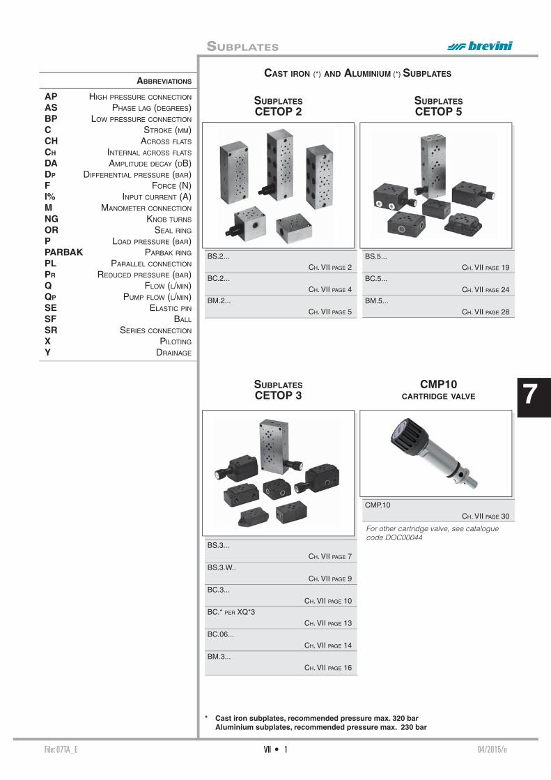
File: 07TA_E 04/2015/eVII • 1
7
ABBREVIATIONS
AP HIGH PRESSURE CONNECTION
AS PHASE LAG (DEGREES)BP LOW PRESSURE CONNECTION
C STROKE (MM)CH ACROSS FLATS
CH INTERNAL ACROSS FLATS
DA AMPLITUDE DECAY (DB)DP DIFFERENTIAL PRESSURE (BAR)F FORCE (N)I% INPUT CURRENT (A)M MANOMETER CONNECTION
NG KNOB TURNS
OR SEAL RING
P LOAD PRESSURE (BAR)PARBAK PARBAK RING
PL PARALLEL CONNECTION
PR REDUCED PRESSURE (BAR)Q FLOW (L/MIN)QP PUMP FLOW (L/MIN)SE ELASTIC PIN
SF BALL
SR SERIES CONNECTION
X PILOTING
Y DRAINAGE
SUBPLATESCETOP 2
SUBPLATESCETOP 3
SUBPLATESCETOP 5
BS.2...
CH. VII PAGE 2
BC.2...
CH. VII PAGE 4
BM.2...
CH. VII PAGE 5
BS.3...
CH. VII PAGE 7
BS.3.W..
CH. VII PAGE 9
BC.3...
CH. VII PAGE 10
BC.* PER XQ*3
CH. VII PAGE 13
BC.06...
CH. VII PAGE 14
BM.3...
CH. VII PAGE 16
BS.5...
CH. VII PAGE 19
BC.5...
CH. VII PAGE 24
BM.5...
CH. VII PAGE 28
CMP10CARTRIDGE VALVE
CMP.10
CH. VII PAGE 30
* Cast iron subplates, recommended pressure max. 320 bar Aluminium subplates, recommended pressure max. 230 bar
SUBPLATES
CAST IRON (*) AND ALUMINIUM (*) SUBPLATES
For other cartridge valve, see cataloguecode DOC00044

File: BS2001_E 01/2010/eVII • 2
7
BS.2.14 (SIDE CONNECTORS)
BS.2.12 (REAR CONNECTORS)
BS.2.**...
BS.2... SINGLE STATION SUBPLATE
BS Single subplate (blanking) 2 CETOP 2/NG4
** 02 / 03 / 04 / 05 / 07
00 No variant 1 Serial No.
BS Single subplate 2 CETOP 2/NG4
12 1/4" BSP rear connectors
00 No variant 1 Serial No.
Weight: 0,09 Kg
Fixing screwsM5x25 UNI 5931
Weight: 0,3 Kg
Fixing screws M5x35 UNI 5931
Weight: 0,3 Kg
Fixing screws M5x35 UNI 5931
BS Single subplate 2 CETOP 2/NG4
14 1/4" BSP side connectors
00 No variant 1 Serial No.
CETOP 2 SUBPLATES
BS.2.**.../ BS.2.12...
BS.2.14...
CH. VII PAGE 2
BS.2.16... / BS.2.20...
BS.3.2... CH. VII PAGE 3
BC.2.50.AB... / BC.2.50.PT...
BC.2.51... CH. VII PAGE 4
BM.2.**.../ BM.2.60...
CH. VII PAGE 5
BM.2.50... / BM.2.70...
CH. VII PAGE 6
CMP.02... BFP CARTRIDGE CATALOGUE

File: BS2001_E 01/2010/eVII • 3
7
BS.2.16 (CONNECTORS SIDE A AND B, REAR P AND T)
BS.2.20 (CONNECTORS SIDE A AND B, REAR P AND T)
BS.3.2 (REDUCTION PLATE FROM CETOP 3/NG6 TO CETOP 2/NG4)
BS.2... SINGLE STATION SUBPLATE
BS Single subplate 2 CETOP 2/NG4
16 1/4" BSP rear and side connectors
00 No variant 1 Serial No.
BS Single subplate 3 CETOP 3/NG6
2 CETOP 2/NG4
00 No variant 1 Serial No.
Weight: 0,3 Kg
Fixing screws M5x35 UNI 5931
Weight: 0,12 Kg
Fixing screws M5x20 UNI 5931
Weight: 0,45 Kg
Fixing screws M5x50 UNI 5931
BS Single subplate 2 CETOP 2/NG4
20 1/4" BSP rear and side connectors
C Type of adjustment grub screws
* Setting ranges 1 = max. 30 bar (white spring) 2 = max. 90 bar (yellow spring) 3 = max. 180 bar (green spring) 4 = max. 250 bar (orange spring)
** 00 = No variant V1 = Viton
1 Serial No.
• The minimum permissible setting pressure depending on the spring: see cartridge valve type CMP.02...

File: BC2001_E 00/2000/eVII • 4
7
BC.2.51 DOWEL CARRIER PLATE FOR SOLENOID VALVE
BC.2.50.PT INTERMEDIATE MODULE FOR PRESSURE GAUGE CONNECTION (VENTS P AND T LINES)
BC.2.50.AB INTERMEDIATE MODULE FOR PRESSURE GAUGE CONNECTION (VENTS A AND B LINES)
BC.2... MODULAR COMPONENTS
Weight: 0,4 Kg
Weight: 0,05 Kg
BC Module base 2 CETOP 2/NG4
51 Dowel carrier plate for solenoid valve
00 No variant 1 Serial No.
BC Module base 2 CETOP 2/NG4
50 Intermediate module for pressure gauge connection
AB Check at ports A and B
00 No variant 1 Serial No.
BC Module base 2 CETOP 2/NG4
50 Intermediate module for pressure gauge connection
PT Check at ports P and T
00 No variant 1 Serial No.
CALIBRATED
DIAPHRAGMS AVAILABLE
d M5x0.8x5
0.5 M89.10.0044 0.6 M89.10.0045 0.7 M89.10.0046 0.8 M89.10.0015 0.9 M89.10.0047 1 M89.10.0048 1.2 M89.10.0049
Weight: 0,4 Kg

File: BM2001_E 00/2000/eVII • 5
7
BM.2.50/60/70
BM.2.60 CONNECTED IN PARALLEL WITHOUT PRESSURE RELIEF VALVE
Fixing screws M5x50 UNI 5931
• The minimum permissible setting pressure depending on the spring: see cartridge valve type CMP.02...
BM.2... MULTI STATION SUBPLATE
Type A B Weight (Kg)
BM.2.60/2 105 91 0,64BM.2.60/3 145 131 0,87BM.2.60/4 185 171 1,10BM.2.60/5 225 211 1,33BM.2.60/6 265 251 1,56BM.2.60/7 305 291 1,79BM.2.60/8 345 331 2,02
BM Multi station subplate (supplied in aluminium material) 2 CETOP 2/NG4
** 50 = Connected in parallel with pressure relief valve and rear connectors 70 = Connected in parallel with pressure relief valve and side connectors 60 = Connected in parallel without pressure relief valve and side connectors
* No. of valve seats 2 / 3 / 4 / 5 / 6 / 7 / 8
C Type of adjustment (omit for 60 version) Grub screw
* Setting range (omit for 60 version) 1 = max. 30 bar (white spring) 2 = max. 90 bar (yellow spring) 3 = max. 180 bar (green spring) 4 = max. 250 bar (orange spring)
** 00 = No variant V1 = Viton 1 Serial No.

File: BM2001_E 00/2000/eVII • 6
7BM.2.70 CONNECTED IN PARALLEL WITH PRESSURE RELIEF VALVE
BM.2.50 CONNECTED IN PARALLEL WITH PRESSURE RELIEF VALVE
Fixing screws M5x40 UNI 5931
Type A B Weight (Kg)
BM.2.50/2 130 116 0,70BM.2.50/3 170 156 0,93BM.2.50/4 210 196 1,16BM.2.50/5 250 236 1,39BM.2.50/6 290 276 1,62BM.2.50/7 330 316 1,85BM.2.50/8 370 356 2,08
Fixing screws M5x50 UNI 5931
Type A B Weight (Kg)
BM.2.70/2 130 116 0,93BM.2.70/3 170 156 1,16BM.2.70/4 210 196 1,39BM.2.70/5 250 236 1,62BM.2.70/6 290 276 1,85BM.2.70/7 330 316 2,08BM.2.70/8 370 356 2,31
BM.2... MULTI STATION SUBPLATE

File: BS3001_E 06/2015/eVII • 7
7
BS.3.**...
BS.3.01...
BS.3... SINGLE STATION SUBPLATE
BS Single subplate (blanking) 3 CETOP 3/NG6
01 P / T / A / B closed
00 No variant 1 Serial No.
BS Single subplate (blanking) 3 CETOP 3/NG6
** 02/03/04/05/06/07/08/09
00 No variant 1 Serial No.
Weight: 0,2 Kg
Fixing screws M5x14 UNI 5931K = plate OR (Q25.95.0001)
Weight: 0,5 Kg
Fixing screws M5x30 UNI 5931
CETOP 3 SUBPLATES
BS.3.01... / BS.3.0*...
CH. VII PAGE 7
BS.3.10/11... / BS.3.12/13...
BS.3.14/15... / BS.3.16/17...
CH. VII PAGE 8
BS.3.20/21... / BS.VMP.10...
BS.3.W...
CH. VII PAGE 9
BC.3.25/27... / BC.3.30/32...
BC.3.40... CH. VII PAGE 10
BC.3.41/*...
CH. VII PAGE 11
BC.3.50... / BC.3.51...
BC.3.07... / BC.3.107...
CH. VII PAGE 12
BC.3.08... / BC.3.09...
BC.06.XQ3... / BC.06.XQP3...
CH. VII PAGE 13
BC.06.25/27...
CAP. VII PAGE 14
BC.06.30/32... / BC.06.40...
BC.06.41/*... CH. VII PAGE 15
BM.3.**... / BM.3.60...
CH. VII PAGE 16
BM.3.50.../ BM.3.70...
CH. VII PAGE 17
BM.3.52... / BM.3.72...
CH. VII PAGE 18
CMP.10... CH. VII PAGE 30
XQ.3... CH. VIII PAGE 20
XQP.3... CH. VIII PAGE 22
Use for pressures up to 200 bar.

File: BS3001_E 06/2015/eVII • 8
7
BS.3.10/11... (REAR CONNECTORS)
Weight: 0,7 Kg - Fixing screws M8x20 UNI 5931
BS Single subplate 3 CETOP 3/NG6
** 10 = 1/8" BSP rear connectors 11 = 1/4" BSP rear connectors
00 No variant 1 Serial No.
BS.3.12/13 (REAR CONNECTORS)
BS.3... SINGLE STATION SUBPLATE
BS Single subplate 3 CETOP 3/NG6
** 12 = 3/8" BSP rear connectors 13 = 1/4" BSP rear connectors
00 No variant 1 Serial No.
Weight: 1 Kg - Fixing screws M5x25 UNI 5931
BS.3.16/17 (CONNECTORS SIDE A AND B, REAR P AND T)
BS.3.14/15 (SIDE CONNECTORS)
BS Single subplate 3 CETOP 3/NG6
** 14 = 3/8" BSP side connectors (*) 15 = 1/4" BSP side connectors (*)
00 No variant 1 Serial No.
Weight: 1,2 Kg - Fixing screws M5x35 UNI 5931
Weight: 1,8 Kg - Fixing screws M5x40 UNI 5931
BS Single subplate 3 CETOP 3/NG6
** 16 = 3/8" BSP rear and side connectors 17 = 1/4" BSP rear and side connectors
00 No variant 1 Serial No.
* Do not use with XQP3C3-D---2

File: BS3001_E 06/2015/eVII • 9
7
BS.3... SINGLE STATION SUBPLATE
BS.3.20/21 (CONNECTORS SIDE A AND B, REAR P AND T)
Weight: 2,9 Kg - Fixing screws M5x65 UNI 5931
BS Single subplate 3 CETOP 3/NG6
** 20 = 3/8" BSP rear and side connectors 21 = 1/4" BSP rear and side connectors
* M = Plastic knob C = Grub screws
* Setting range 1 = max. 50 bar (white spring) 2 = max. 150 bar (yellow spring) 3 = max. 320 bar (green spring)
00 No variant
1 Serial No.
BS.VMP.10 SINGLE STATION SUBPLATE WITH MAX. PRESSURE VALVE FOR SURFACE MOUNTING (E.G. ON TAKE COVER)
Weight: 1,6 KgFixing screws M5x60 UNI 5931
• The minimum permissible setting pressure depending on the spring: see cartridge valve type CMP.10... Chapter VII page 30
BS Single subplate VMP Max. pressure valve
10 3/8" BSP connectors
* M = Plastic knob C = Grub screw V = Handwheel
* Setting range 1 = max. 50 bar (white spring) 2 = max. 150 bar (yellow spring) 3 = max. 320 bar (green spring)
00 No variant
1 Serial No.
BS.3.W...
BS Single subplate
3 CETOP 3/NG6
W Wheatstone bridge
00 No variant 1 Serial No.
Weight: 1,8 KgFixing screws M5x45 UNI 5931
• The minimum permissible setting pressure depending on the spring: see cartridge valve type CMP.10... Chapter VII page 30

File: BC3001_E 03/2013/eVII • 10
7
BC.*.25... BC.*.27...
BC.3.25/27 P/T REAR AND SIDE CONNECTORS 1/2" BSP- 3 RODS
Weight BC.3.25: 2,7 KgWeight BC.3.27: 2,6 KgFixing screws M5x30 UNI 5931
BC Module base 3 CETOP 3/NG6
** 25 = 1/2" BSP rear and side connectors with CMP 27 = 1/2" BSP rear and side connectors without CMP
* Adjustment (omit for 27 version) M = Plastic knob C = Grub screw
* Setting range (omit for 27 version) 1 = max. 50 bar (white spring) 2 = max. 150 bar (yellow spring) 3 = max. 320 bar (green spring)
00 No variant
1 Serial No.
BC.3... MODULAR COMPONENTS
• The minimum permissible setting pressure depending on the spring:see cartridge valve type CMP.10... Chapter VII page 30
BC.*.30...
BC.*.32...
BC.3.30/32 - 3 RODS
BC.3.40 - 3 RODS
Weight: 0,7 Kg
BC Module base 3 CETOP 3/NG6
** 30 = 3/8" BSP connectors in parallel 32 = 3/8" BSP connectors in series
00 No variant 1 Serial No.
BC Module base 3 CETOP 3/NG6
40 Blanking
00 No variant 1 Serial No.
Weight Kg. 1,4

File: BC3001_E 03/2013/eVII • 11
7
BC.3... MODULAR COMPONENTS
BC.3.41/* RODS FOR MODULAR ASSEMBLY
Rod code Pieces L Composition
BC.3.41/2.00.1 3 146 for 2 solenoid valvesBC.3.41/3.00.1 3 196 for 3 solenoid valvesBC.3.41/4.00.1 3 246 for 4 solenoid valvesBC.3.41/5.00.1 3 296 for 5 solenoid valvesBC.3.41/6.00.1 3 346 for 6 solenoid valvesBC.3.41/7.00.1 3 396 for 7 solenoid valvesBC.3.41/8.00.1 3 446 for 8 solenoid valves
ASSEMBLED MODULAR COMPONENT BASES - 3 RODS
• For series connection the last block high up should be connected in parallel (BC.3.30)• Single components should be ordered separately• The minimum permissible setting pressure depending on the spring: see cartridge valve type CMP.10... Chapter VII page 30
Rods code L Composition
BC.3.41/2 M80.20.0010 146 BC.3.25/27 + 2 BC.3.30/32 + BC.3.40BC.3.41/3 M80.20.0011 196 BC.3.25/27 + 3 BC.3.30/32 + BC.3.40BC.3.41/4 M80.20.0012 246 BC.3.25/27 + 4 BC.3.30/32 + BC.3.40BC.3.41/5 M80.20.0013 296 BC.3.25/27 + 5 BC.3.30/32 + BC.3.40BC.3.41/6 M80.20.0014 346 BC.3.25/27 + 6 BC.3.30/32 + BC.3.40BC.3.41/7 M80.20.0015 396 BC.3.25/27 + 7 BC.3.30/32 + BC.3.40BC.3.41/8 M80.20.0016 446 BC.3.25/27 + 8 BC.3.30/32 + BC.3.40
Nuts code Q26.56.0514Pieces 3
Tightening torque: 23 Nm (±2 Nm)

File: BC3001_E 03/2013/eVII • 12
7
BC.3.107 BASE PLATE FOR USING 4 WAY VALVE AS 2 WAY ONLY
Weight: 0,5 Kg
BC Module base
3 CETOP 3/NG6
107 base for using 4 way valve as 2 way only
00 No variant 1 Serial No.
BC.3.50 INTERMEDIATE MODULE FOR PRESSURE GAUGE CONNECTION
Weight: 1 Kg
BC Module base 3 CETOP 3/NG6
50 Intermediate module for pressure gauge connection at ports A/B/P/T
00 No variant 1 Serial No.
BC.3.07 BASE PLATE FOR DOUBLE FLOW RATE P→A AND B→T
BC.3.51 DOWEL BASE PLATE FOR SOLENOID VALVE
BC.3... MODULAR COMPONENTS
Weight: 0,2 KgK = plate OR (Q25.95.0001)
Weight: 0,5 Kg
CALIBRATED DIAPHRAGMS AVAILABLE d M8x1x8 0.6 M89.10.0007 0.7 M89.10.0008 0.8 M89.10.0009 0.9 M89.10.0012 1 M89.10.0010 1.2 M89.10.0011 1.4 M89.10.0038 1.5 M89.10.0035 1.75 M89.10.0042 2 M89.10.0041 2.5 M89.10.0036
BC Module base
3 CETOP 3/NG6
51 Dowel base plate
00 No variant 1 Serial No.
BC Module base
3 CETOP 3/NG6
07 bases plate for twin fl ow rate
00 No variant 1 Serial No.
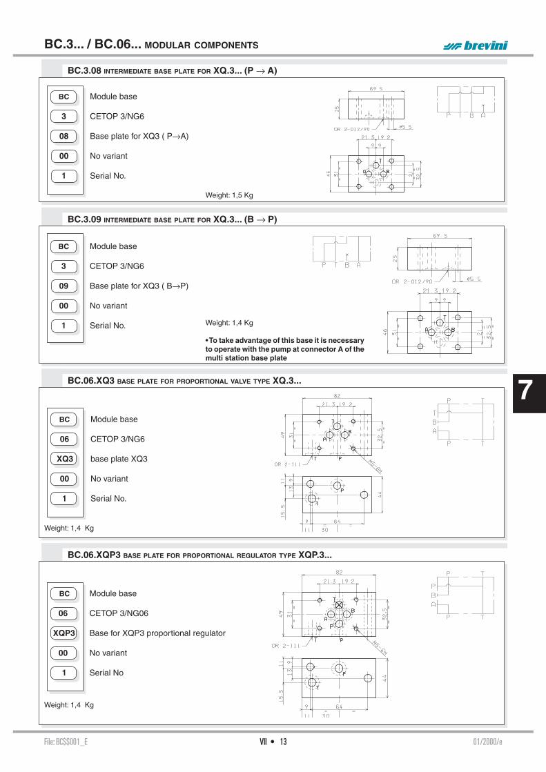
File: BC$$001_E 01/2000/eVII • 13
7
BC.3.09 INTERMEDIATE BASE PLATE FOR XQ.3... (B → P)
BC.3.08 INTERMEDIATE BASE PLATE FOR XQ.3... (P → A)
BC Module base
3 CETOP 3/NG6
08 Base plate for XQ3 ( P→A)
00 No variant 1 Serial No.
Weight: 1,5 Kg
Weight: 1,4 Kg
• To take advantage of this base it is necessary to operate with the pump at connector A of the multi station base plate
BC Module base
3 CETOP 3/NG6
09 Base plate for XQ3 ( B→P)
00 No variant 1 Serial No.
BC.3... / BC.06... MODULAR COMPONENTS
Weight: 1,4 Kg
BC.06.XQP3 BASE PLATE FOR PROPORTIONAL REGULATOR TYPE XQP.3...
BC.06.XQ3 BASE PLATE FOR PROPORTIONAL VALVE TYPE XQ.3...
Weight: 1,4 Kg
BC Module base 06 CETOP 3/NG6
XQ3 base plate XQ3
00 No variant 1 Serial No.
BC Module base 06 CETOP 3/NG06
XQP3 Base for XQP3 proportional regulator
00 No variant 1 Serial No

File: BC06001_E 03/2015/eVII • 14
7
BC.*.25... BC.*.27...
ASSEMBLED MODULAR COMPONENT BASES - 2 RODS
BC.06.25/27 P AND T REAR AND SIDE CONNECTORS 3/8" BSP - 2 RODS
Weight BC.3.25 : 3 KgWeight BC.3.27 : 2,8 KgFixing screws M5x65 UNI 5931
BC Module base 06 CETOP 3/NG6
** 25 = 3/8" BSP rear and side connectors with CMP 27 = 3/8" BSP rear and side connectors without CMP
* Adjustment (omit for 27 version) M = Plastic knob C = Grub screw
* Setting range (omit for 27 version) 1 = max. 50 bar (white spring) 2 = max. 150 bar (yellow spring) 3 = max. 320 bar (green spring)
00 No variant
1 Serial No.
• For series connection the last block high up should be connected in parallel (BC.06.30)• Single components should be ordered separately• The minimum permissible setting range depending on the spring: see cartridge valve type CMP.10... Chapter VII page 30
Rods code L Composition
BC.06.41/2 M80.20.0001 138 BC.06.25/27 + 2 BC.06.30/32 + BC.06.40BC.06.41/3 M80.20.0002 187 BC.06.25/27 + 3 BC.06.30/32 + BC.06.40BC.06.41/4 M80.20.0003 236 BC.06.25/27 + 4 BC.06.30/32 + BC.06.40BC.06.41/5 M80.20.0004 285 BC.06.25/27 + 5 BC.06.30/32 + BC.06.40BC.06.41/6 M80.20.0005 334 BC.06.25/27 + 6 BC.06.30/32 + BC.06.40BC.06.41/7 M80.20.0006 382 BC.06.25/27 + 7 BC.06.30/32 + BC.06.40BC.06.41/8 M80.20.0007 430 BC.06.25/27 + 8 BC.06.30/32 + BC.06.40
Nuts code Q26.56.0514Pieces 2
BC.06... MODULAR COMPONENTS
• The minimum permissible setting pressure depending on the spring:see cartridge valve type CMP.10...

File: BC06001_E 03/2015/eVII • 15
7
BC.*.30...
BC.*.32...
BC.06.30/32 - 2 RODS
BC.06.40 - 2 RODS
BC.06... MODULAR COMPONENTS
Weight: 0,4 Kg
BC Module base 06 CETOP 3/NG6
** 30 = 3/8" BSP connectors in parallel 32 = 3/8" BSP connectors in series
00 No variant 1 Serial No.
BC Module base 06 CETOP 3/NG6 - 2 rods
40 Blanking
00 No variant 1 Serial No.
Weight: 1,1 Kg
BC.06.41/* RODS FOR MODULAR ASSEMBLY
Rod code Pieces L Composition
BC.06.41/2.00.1 2 138 for 2 solenoid valvesBC.06.41/3.00.1 2 187 for 3 solenoid valvesBC.06.41/4.00.1 2 236 for 4 solenoid valvesBC.06.41/5.00.1 2 285 for 5 solenoid valvesBC.06.41/6.00.1 2 334 for 6 solenoid valvesBC.06.41/7.00.1 2 382 for 7 solenoid valvesBC.06.41/8.00.1 2 430 for 8 solenoid valves
Tightening torque: 23 Nm (±2 Nm)

File: BM3001_E 02/2015/eVII • 16
7 BM.3.60 CONNECTED IN PARALLEL WITHOUT PRESSURE RELIEF VALVE
BM.3.**...
Fixing screws M5x70 UNI 5931
• The minimum permissible setting pressure depending on the spring:see cartridge valve type CMP.10... Chapter VII page 30
BM.3... MULTI STATION SUBPLATE
Type A B Weight (Kg)
BM.3.60/2 120 108 3,6BM.3.60/3 170 158 5,1BM.3.60/4 220 208 6,7BM.3.60/5 270 258 8.2BM.3.60/6 320 308 9,7BM.3.60/7 370 358 11,2BM.3.60/8 420 408 12,6
BM Multi station subplate (standard versions are supplied in cast iron material) 3 CETOP 3/NG6
** 50 = Connected in parallel with pressure relief valve and rear connectors 70 = Connected in parallel with pressure relief valve and side connectors 52 = Connected in series with pressure relief valve and rear connectors 72 = Connected in series with pressure relief valve and side connectors 60 = Connected in parallel without pressure relief valve and side connectors
* No. of valve seats 2 / 3 / 4 / 5 / 6 / 7 / 8
* Type of adjustment (omit for 60 version) M = Plastic knob C = Grub screw * Setting range (omit for 60 version) 1 = max. 50 bar (white spring) 2 = max. 150 bar (yellow spring) 3 = max. 320 bar (green spring)
** 00 = No variant AL = in aluminium material versions (recommended pressure max. 230 bar) 1 Serial No.

File: BM3001_E 02/2015/eVII • 17
7
BM.3.50 CONNECTED IN PARALLEL WITH PRESSURE RELIEF VALVE
BM.3.70 CONNECTED IN PARALLEL WITH PRESSURE RELIEF VALVE
Fixing screws M6x55 UNI 5931
Type A B Weight (Kg)
BM.3.50/2 141 126 4,6BM.3.50/3 191 176 6,1BM.3.50/4 241 226 7,6BM.3.50/5 291 276 9,1BM.3.50/6 341 326 10,6BM.3.50/7 391 376 12,1BM.3.50/8 441 426 13,6
Fixing screws M5x70 UNI 5931
Type A B Weight (Kg)
BM.3.70/2 160 148 4,9BM.3.70/3 210 198 6,4BM.3.70/4 260 248 7,9BM.3.70/5 310 298 9,4BM.3.70/6 360 348 10,9BM.3.70/7 410 398 12,4BM.3.70/8 460 448 13,9
BM.3... MULTI STATION SUBPLATE

File: BM3001_E 02/2015/eVII • 18
7BM.3.72 CONNECTED IN SERIES WITH PRESSURE RELIEF VALVE
BM.3.52 CONNECTED IN SERIES WITH PRESSURE RELIEF VALVE
BM.3... MULTI STATION SUBPLATE
Fixing screws M6x55 UNI 5931
Type A B Weight (Kg)
BM.3.52/2 141 126 4,6BM.3.52/3 191 176 6,3BM.3.52/4 241 226 7,6BM.3.52/5 291 276 9,2BM.3.52/6 341 326 10,7BM.3.52/7 391 376 12,2BM.3.52/8 441 426 13,7
Fixing screws M5x70 UNI 5931
Type A B Weight (Kg)
BM.3.72/2 160 148 4,9BM.3.72/3 210 198 6,4BM.3.72/4 260 248 7,9BM.3.72/5 310 298 9,4BM.3.72/6 360 348 10,9BM.3.72/7 410 398 12,4BM.3.72/8 460 448 13,9

File: BS5001_E 03/2015/eVII • 19
7
BS.5.**...
BS.5.01...
BS.5... SINGLE STATION SUBPLATE
BS Single subplate (blanking) 5 CETOP 5/NG10
01 P/T/A/B closed
00 No variant 1 Serial No.
BS Single subplate (blanking) 5 CETOP 5/NG10
** 02/03/04/05/06/07/08/09
00 No variant 1 Serial No.
Weight: 0,5 Kg
Fixing screwsM6x15 UNI 5931K = plate OR (Q25.95.0002)
Weight: 1,2 Kg
Fixing screws M6x35 UNI 5931
• Pay attention please, use these subplate in applications at slow pressure (P max. 150 bar dynamic)
CETOP 5 SUBPLATES
BS.5.01 / BS.5.0* CH. VII PAGE 19
BS.5.12... / BS.5.13...
BS.5.14... / BS.5.15...
CH. VII PAGE 20
BS.5.16... / BS.5.17...
BS.5.3... CH. VII PAGE 21
BS.5.30/31... CH. VII PAGE 22
BS.VMP.20... / BS.5.29...
CH. VII PAGE 23
BC.5.36/28... CH. VII PAGE 24
BC.5.41/*... / BC.5.40...
CH. VII PAGE 25
BC.5.30/32... / BC.5.50... / BC.5.51...
CH. VII PAGE 26
BC.5.07... / BC.5.107...
BC.5.3A... / BC.10.06...
CH. VII PAGE 27
BM.5.**... / BM.5.50...
CH. VII PAGE 28
BM.5.60... / BM.5.70...
BM.5.80... CH. VII PAGE 29
CMP.20... BFP CARTRIDGE CATALOGUE
CMP.30... BFP CARTRIDGE CATALOGUE

File: BS5001_E 03/2015/eVII • 20
7
BS.5.12 (REAR CONNECTORS)
BS Single subplate 5 CETOP 5/NG10
12 1/2" BSP rear connectors
00 No variant 1 Serial No.
Weight: 2,7 Kg - Fixing screws M6x25 UNI 5931
BS.5... SINGLE STATION SUBPLATE
BS.5.15 (SIDE CONNECTORS)
BS.5.14 (SIDE CONNECTORS)
BS.5.13 (REAR CONNECTORS)
BS Single subplate 5 CETOP 5/NG10
13 3/4" BSP rear connectors
00 No variant 1 Serial No.
BS Single subplate 5 CETOP 5/NG10
14 1/2" BSP side connectors
00 No variant 1 Serial No.
Weight: 3,8 Kg - Fixing screws M6x50 UNI 5931
Weight: 2,6 Kg - Fixing screws M6x20 UNI 5931
BS Single subplate 5 CETOP 5/NG10
15 3/4" BSP side connectors
00 No variant 1 Serial No.
Weight: 3,8 Kg - Fixing screws M6x50 UNI 5931

File: BS5001_E 03/2015/eVII • 21
7
BS.5.3 (REDUCTION PLATE FROM CETOP 5/NG10 TO CETOP 3/NG6)
BS.5.17 (CONNECTORS SIDE A AND B, REAR P AND T)
BS.5.16 (CONNECTORS SIDE A AND B, REAR P AND T)
Weight: 2,6 Kg
Fixing screws M6x20 UNI 5931
BS Single subplate 5 CETOP 5/NG10
16 1/2" BSP rear and side connectors
00 No variant 1 Serial No.
BS Single subplate 5 CETOP 5/NG10
3 CETOP 3/NG6
00 No variant 1 Serial No.
Weight: 1,1 Kg
Fixing screwsM6x30 UNI 5931
Weight: 3,9 Kg
Fixing screwsM6x50 UNI 5931
BS Single subplate 5 CETOP 5/NG10
17 3/4" BSP rear and side connectors
00 No variant 1 Serial No.
BS.5... SINGLE STATION SUBPLATE
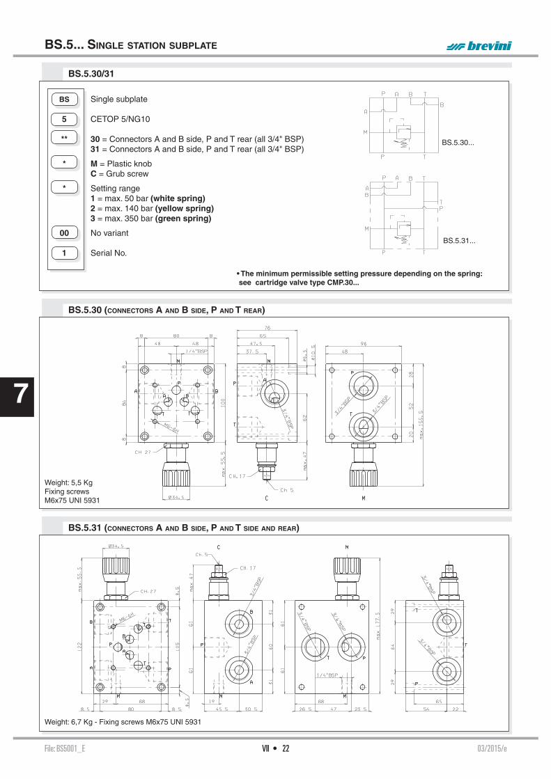
File: BS5001_E 03/2015/eVII • 22
7
BS.5.30...
BS.5.31...
BS.5.31 (CONNECTORS A AND B SIDE, P AND T SIDE AND REAR)
BS.5.30 (CONNECTORS A AND B SIDE, P AND T REAR)
BS.5.30/31
BS.5... SINGLE STATION SUBPLATE
Weight: 5,5 KgFixing screwsM6x75 UNI 5931
BS Single subplate 5 CETOP 5/NG10
** 30 = Connectors A and B side, P and T rear (all 3/4" BSP) 31 = Connectors A and B side, P and T rear (all 3/4" BSP)
* M = Plastic knob C = Grub screw
* Setting range 1 = max. 50 bar (white spring) 2 = max. 140 bar (yellow spring) 3 = max. 350 bar (green spring)
00 No variant
1 Serial No.
• The minimum permissible setting pressure depending on the spring: see cartridge valve type CMP.30...
Weight: 6,7 Kg - Fixing screws M6x75 UNI 5931

File: BS5001_E 03/2015/eVII • 23
7
BS.5.29 SINGLE STATION SUBPLATE WITH MAX. PRESSURE VALVE FOR AD.5.I...
BS.VMP.20 SINGLE STATION SUBPLATE WITH MAX. PRESSURE VALVE FOR SURFACE MOUNTING (E.G. ON TANK COVER)
BS.5... SINGLE STATION SUBPLATE
Weight: 3,1 KgFixing screws M8x65 UNI 5931
Weight: 4,5 KgFixing screws M6x60 UNI 5931
Tightening torque CMP.10...60 ÷ 70 Nm / 6 ÷ 7 Kgm
M = Manometer connector (1/4" BSP)
• The minimum permissible setting pressure depending on the spring: see cartridge valve type CMP.20...
BS Single subplate VMP Max. pressure valve
20 1/2" BSP connectors
* M = Plastic knob C = Grub screw V = Handwheel
* Setting range 1 = max. 30 bar (white spring) 2 = max. 140 bar (yellow spring) 3 = max. 250 bar (green spring)
00 No variant
1 Serial No.
BS Single subplate 5 CETOP 5/NG10
29 1/2" BSP - P rear connector 1/2" BSP - A and B side connectors 1/2" BSP - T rear connector 3/4" BSP - T side connector
C Type of adjustment Grub screw
* Setting range 2 = max. 150 bar (yellow spring) 3 = max. 320 bar (green spring)
00 No variant
1 Serial No.
• The minimum permissible setting pres-sure depending on the spring:see cartridge valve type CMP.10... Chap-ter VII page 30

File: BC5001_E 04/2013/eVII • 24
7
BC.5.36...
BC.5.28...
BC.5.28 P/T REAR AND SIDE CONNECTORS WITHOUT PRESSURE RELIEF VALVE
BC.5.36 P/T REAR AND SIDE CONNECTORS WITH PRESSURE RELIEF VALVE
BC.5.36/28 P AND T REAR AND SIDE CONNECTORS 3/4" BSP
BC.5... MODULAR COMPONENTS
Weight: 5,3 KgFixing screws M6x70 UNI 5931
BC Module base 5 CETOP 5/NG10
** 36 = 3/4" BSP (P and T rear and side connectors with pressure relief valve) 28 = 3/4" BSP (P and T rear and side connectors without pressure relief valve)
* Type adjustment (omit for 28 version) M = Plastic knob C = Grub screw
* Setting range (omit for 28 version) 1 = max. 50 bar (white spring) 2 = max. 140 bar (yellow spring) 3 = max. 350 bar (green spring)
00 No variant
1 Serial No.• The minimum permissible setting pressure valve is the same for all spring: see cartridge valve type CMP.30...
Weight: 3,9 KgFixing screwsM6x50 UNI 5931

File: BC5001_E 04/2013/eVII • 25
7
ASSEMBLED BASE MODULES - 3 RODS
• Single components should be ordered separately (see pages VII•24,26,27)• The minimum permissible setting pressure is the same for all spring: see cartridge valve type CMP.30...
Rods code L Composition
BC.5.41/2 M80.25.0001 205 BC.5.36/28+ 2 BC.5.30/32 + BC.5.40BC.5.41/3 M80.25.0002 280 BC.5.36/28+ 3 BC.5.30/32 + BC.5.40BC.5.41/4 M80.25.0003 355 BC.5.36/28+ 4 BC.5.30/32 + BC.5.40BC.5.41/5 M80.25.0004 430 BC.5.36/28+ 5 BC.5.30/32 + BC.5.40BC.5.41/6 M80.25.0005 505 BC.5.36/28+ 6 BC.5.30/32 + BC.5.40BC.5.41/7 M80.25.0006 580 BC.5.36/28+ 7 BC.5.30/32 + BC.5.40BC.5.41/8 M80.25.0007 655 BC.5.36/28+ 8 BC.5.30/32 + BC.5.40
Nuts code Q26.56.0545Pieces 3
BC.5... MODULAR COMPONENTS
BC.5.41/* RODS FOR MODULAR ASSEMBLIES
Rods code Pieces L Composition
BC.5.41/2.00.1 3 205 for 2 solenoid valveBC.5.41/3.00.1 3 280 for 3 solenoid valveBC.5.41/4.00.1 3 355 for 4 solenoid valveBC.5.41/5.00.1 3 430 for 5 solenoid valveBC.5.41/6.00.1 3 505 for 6 solenoid valveBC.5.41/7.00.1 3 580 for 7 solenoid valveBC.5.41/8.00.1 3 655 for 8 solenoid valve
BC.5.40...
Weight: 1 Kg
BC Module base 5 CETOP 5/NG10 - 3 rods
40 Blanking
00 No variant 1 Serial No.
Tightening torque: 47 Nm (±2 Nm)

File: BC5001_E 04/2013/eVII • 26
7
BC.5.30...BC.5.31...
BC.5.32...
BC.5.30/32
BC.5... MODULAR COMPONENTS
BC Module base 5 CETOP 5/NG10 - 3 rods
** 30 = 1/2" BSP connectors in parallel 31 = 3/4" BSP connectors in parallel 32 = 1/2" BSP connectors in series
** 00 = No variant AI = A and B rear connector AS = A and B upper connectors 1 Serial No.
Weight: 3 Kg
BC.5.50 INTERMEDIATE MODULE FOR PRESSURE GAUGE
Weight: 2,3 Kg
K = plate OR (Q25.95.0002)
BC Module base 5 CETOP 5/NG10
50 Intermediate module for pressure gauge connection at ports A/B/P/T
00 No variant 1 Serial No.
BC.5.51 DOWEL PLATE FOR SOLENOID VALVE
Weight: 0,5 KgK = plate OR (Q25.95.0002)
CALIBRATED
DIAPHRAGMS AVAILABLE
d M8x1x8 0.6 M89.10.0007 0.7 M89.10.0008 0.8 M89.10.0009 0.9 M89.10.0012 1 M89.10.0010 1.2 M89.10.0011 1.4 M89.10.0038 1.5 M89.10.0035 1.75 M89.10.0042 2 M89.10.0041 2.5 M89.10.0036
BC Module base
5 CETOP 5/NG10
51 Subplate for solenoid valve
00 No variant 1 Serial No.

File: BC5001_E 04/2013/eVII • 27
7
BC.10.06 REDUCTION BASE FROM BC.5... TO BC.06...
BC.5.3A REDUCTION BASE FROM BC.5... TO BC.3...
BC Module base 5 CETOP 5/NG10 - 3 rods
3A CETOP 3/NG6 - 3 rods
00 No variant 1 Serial No.
Weight: 2,4 Kg - Fixing screws M10x30 UNI 5931
BC Module base 10 CETOP 5/NG10 - 3 rods
06 CETOP 3/NG6 - 2 rods
00 No variant 1 Serial No.
Weight: 1,3 Kg - Fixing screws M10x30 UNI 5931
BC.5.07 BASE FOR DOUBLE FLOW RATE P→A E B→T
BC.5.107 BASE FOR USE WITH 2 WAY VALVE
BC Module base
5 CETOP 5/NG10
07 Base for double fl ow rate
00 No variant 1 Serial No.
Weight: 1,2 Kg
Weight: 1,2 Kg
BC Module base
5 CETOP 5/NG10
107 Base for use with 2 way valve
00 No variant 1 Serial No.
BC.5... MODULAR COMPONENTS

File: BM5001_E 01/2000/eVII • 28
7BM.5.50 CONNECTED IN PARALLEL WITH PRESSURE RELIEF VALVE
BM.5.**...
Fixing screws M6x75 UNI 5931
Type A B Weight (Kg)
BM.5.50/2 216 200 8,5BM.5.50/3 291 275 11,3BM.5.50/4 366 350 14BM.5.50/5 441 425 16,8BM.5.50/6 516 500 19,5BM.5.50/7 591 575 22,3BM.5.50/8 666 650 25
• The minimum permissible setting pressure is the same for all spring:see cartridge valve type CMP.30...
BM.5... MULTI STATION SUBPLATES
BM Multi station subplate (standard versions are supplied in cast iron material) 5 CETOP 5/NG10
** 50 = Connected in parallel with pressure relief valve and rear connectors 60 = Connected in parallel without pressure relief valve and side connectors 70 = Connected in parallel with pressure relief valve and 3/4" BSP P/T connectors and 1/2" BSP side A/B 80 = Connected in parallel with pressure relief valve and 1" BSP P/T connectors and 3/4" BSP side A/B * No. of valves seats (for BM.5.80... max 6)) 2 / 3 / 4 / 5 / 6 / 7 / 8
* Type of adjustment (omit for 60 version) M = Plastic knob C = Grub screw
* Setting range (omit for 60 version) 1 = max. 50 bar (white spring) 2 = max. 140 bar (yellow spring) 3 = max. 350 bar (green spring)
** 00 = No variant AL = in aluminium material (only for BM560 and BM570 versions), recommended pressure max. 230 bar 1 Serial No.

File: BM5001_E 01/2000/eVII • 29
7
BM.5.80 CONNECTED IN PARALLEL WITH PRESSURE RELIEF VALVE
BM.5.60 CONNECTED IN PARALLEL WITHOUT PRESSURE RELIEF VALVE
BM.5.70 CONNECTED IN PARALLEL WITH PRESSURE RELIEF VALVE
BM.5... MULTI STATION SUBPLATES
Fixing screws M6x100 UNI 5931
Type A B Weight (Kg)
BM.5.60/2 175 159 10BM.5.60/3 250 234 14,2BM.5.60/4 325 309 18,4BM.5.60/5 400 384 22,6BM.5.60/6 475 459 26,8BM.5.60/7 550 534 31BM.5.60/8 625 609 35,2
Fixing screws M6x100 UNI 5931
Type A B Weight (Kg)
BM.5.70/2 216 200 12,7BM.5.70/3 291 275 16,8BM.5.70/4 366 350 21BM.5.70/5 441 425 25,2BM.5.70/6 516 500 29,5BM.5.70/7 591 575 33,6BM.5.70/8 666 650 37,8
Fixing screws M8x110 UNI 5931
Type A B Weight (Kg)
BM.5.80/2 225 205 19,5BM.5.80/3 300 280 26BM.5.80/4 375 355 32,5BM.5.80/5 450 430 39BM.5.80/6 525 505 45,5

File: CMP10002_E 00/2015/eVII • 30
1
2
3
4
5
6
7
8
9
10
11
12
0 = CMP10.0.. - 1 = CMP10.1.. - 2 = CMP10.2.. - 3 = CMP10.3..Fluid used: mineral based oil with viscosity 32 mm²/s at 40°C.
The direct acting relief valve limits the pressure in a hydraulic circuit.It raises the safety level by mak-ing it impossible for the plant op-erators to set a higher pressure rating, than that specifi ed in the catalogue. This is limited by a pack spring with a mechanical stop, which prevents temporary P closures caused by pressure peaks.It has a galvanised steel body. The guided ball poppet is in tem-pered and ground steel.
ORDERING CODE
CMP.10... DIRECT OPERATION MAXIMUM PRESSURE VALVES
HYDRAULIC SYMBOL
Max. operating pressure 320 barSetting ranges: Spring 0 max. 15 bar Spring 1 max. 50 bar Spring 2 max. 150 bar Spring 3 max. 320 barMax. fl ow 40 l/minHydraulic fl uids Mineral oils DIN 51524Fluid viscosity 10 ÷ 500 mm2/sFluid temperature -25°C ÷ 75°CAmbient temperature -25°C ÷ 60°CMax. contamination level class 10 in accordance
with NAS 1638 with fi lter ß25 75Weight 0,2 KgTightening torque 60 ÷ 70 Nm (6 ÷ 7 Kgm) • The minimum permissible setting pressure depending on the screw: see curves below
CMP Max. pressure cartridge
10 Size (M24 x 2)
* Type of adjustment M = Plastic knob C = Grub screw V = Handwheel
* Setting ranges 0 = max. 15 bar (orange spring) 1 = max. 50 bar (white spring) 2 = max. 150 bar (yellow spring) 3 = max. 320 bar (green spring)
** 00 = No variant V1 = Viton
2 Serial No.
OVERALL DIMENSIONS
PRESSURE-FLOW RATE MIN.SETTING PRESSURE
Type of adjustment
M Plastic knob
C Grub screw
V Handwheel
SEAT DIMENSIONS
Valve seat plug code R78.30.0564
CMP.10...
T
P
1
0
2
3
0 5 10 15 20 25 30 35 40
0
40
80
120
160
200
240
280
320
360
Q (l/min)
P(b
ar)
3
2
1
0
0 5 10 15 20 25 30 35 40
0
20
40
60
80
100
Q (l/min)
P(b
ar)
00012008 Spare seals kit

File: 08TA_E 05/2011/e
PROPORTIONAL VALVES
PROPORTIONAL VALVES
XD.2.A... / XD.2.C...
CH. VIII PAGE 2
XD.3.A... / XD.3.C...
CH. VIII PAGE 4
D15P PROPORTIONAL SOLENOIDS
CH. VIII PAGE 5
XDP.3.A... / XDP.3.C ...
CH. VIII PAGE 6
D15P PROPORTIONAL SOLENOIDS
CH. VIII PAGE 7
XDP.5.A... / XDP.5.C...
CH. VIII PAGE 8
D19P PROPORTIONAL SOLENOIDS
CH. VIII PAGE 9
XDC.3... SERIE 2
CH. VIII PAGE 10
PROPORTIONAL SOLENOIDS
CH. VIII PAGE 11
XECV.3...
CH. VIII PAGE 12
XEPV.3...
CH. VIII PAGE 15
AM.3.H...
CH. VIII PAGE 18
AM.5.H...
CH. VIII PAGE 19
XQ.3...
CH. VIII PAGE 20
D15P PROPORTIONAL SOLENOIDS
CH. VIII PAGE 21
XQP.3.
CH. VIII PAGE 22
D15P PROPORTIONAL SOLENOIDS
CH. VIII PAGE 23
XQP.5.
CH. VIII PAGE 24
D19P PROPORTIONAL SOLENOIDS
CH. VIII PAGE 25
XP.3...
CH. VIII PAGE 26
AM.3.XMP...
CH. VIII PAGE 28
VIII • 1
8
ABBREVIATIONS
AP HIGH PRESSURE CONNECTION
AS PHASE LAG (DEGREES)BP LOW PRESSURE CONNECTION
C STROKE (MM)CH ACROSS FLATS
CH INTERNAL ACROSS FLATS
DA AMPLITUDE DECAY (DB)DP DIFFERENTIAL PRESSURE (BAR)F FORCE (N)I% INPUT CURRENT (A)M MANOMETER CONNECTION
NG KNOB TURNS
OR SEAL RING
P LOAD PRESSURE (BAR)PARBAK PARBAK RING
PL PARALLEL CONNECTION
PR REDUCED PRESSURE (BAR)Q FLOW (L/MIN)QP PUMP FLOW (L/MIN)SE ELASTIC PIN
SF BALL
SR SERIES CONNECTION
X PILOTING
Y DRAINAGE

File: XD2001_E 01/2013/eVIII • 2
8
XD.2.*.01.N(1.5 l/min P → A/B)
XD.2.*.01.N(6 l/min P → A/B)
XD.2.A.01.N.. XD.2.A.03.N.. XD.2.C.01.N.. XD.2.C.03.N..
ORDERING CODE INPUT SIGNAL CURVES - FLOW RATE
XD.2.A../XD.2.C.. series valves are used for controlling fl uid direction and fl ow rate as a func-tion of the supply current to the proportional control solenoid.
Any valve Δp variation causes a change in the set fl ow rate; however the valve itself ensure a high level internal compensation maintaining constant a regulated fl ow..
The XD2 cetop valve could be used for accurate proportional controls with compact sizes, reducing weights.These valves can be also combined with Mini Powerpacks type MR/MC/FP creating compact solutions. Could be also used on a Cetop 3 interface using a reduction plate type BS32001.
XD.2.A... / XD.2.C... SOLENOID OPERATING PROPORTIONAL VALVES CETOP 2
POWER LIMITS TRANSMITTED
P→A/B →T OR P→B/A→T
XD Proportional valve
2 CETOP 2/NG04
* A = Single solenoid C = Double solenoid
** Type of spool (null position)
01 = 03 =
* Flow path control (see symbols table) N = symmetrical
* Flow rating l/min (Δp 5 bar) 1 = 1.5 l/min 6 = 6 l/min * Max. spool current F = 1.4 A G = 0.7 A
** Variant: see Tab.1 1 Serial No.
XD.2...
STANDARD CONNECTORS CH. I PAGE. 20
DC SOLENOID A09 CH. I PAGE. 4
REM.S.RA... CH. IX PAGE. 4
REM.D.RA... CH. IX PAGE. 7
CEP.S CH. IX PAGE. 2
SE.3.AN21.00.. CH. IX PAGE. 11
AM.3.H... CH. VIII PAGE. 18
BS32001 CH. VII PAGE. 3
The fl uid used was a mineral oil with a viscosity of 46 mm2/s at 40°C.The tests have been carried out at with a fl uid of 40°C.
Performances shown in this catalogue are guaranteed only using a pres-sure compensator of 5 bar.
(*) Coils with Hirschmann and AMP Junior connectionsupplied without connectors. The connectorscan be ordered separately, ch. I page 20.
TAB.1 - VARIANTS
No variant (without connectors) S1(*)Viton SV(*)AMP Junior connection AJ(*)Coil with fl ying leads (250 mm) FLCoil with fl ying leads (130 mm) with diode LDDeutsch connection with bidirectional diode CX
I (%)
Q (
l/m
in)
0 20 40 60 80 1000
0.5
1.0
1.5
2.0
2.5
I (%)
Q (
l/m
in)
0 20 40 60 80 1000
1
2
3
4
6
5
7
Q (l/min)
P(b
ar)
0 2 4 6 8 10 12 14 160
20
140
40
160
60
180
80
200
120
240
100
220
260
01N1 01N6

File: XD2001_E 01/2013/eVIII • 3
8
OVERALL DIMENSIONS
OPERATING SPECIFICATIONS
Max. operating pressure ports P/A/B 250 barMax. operating pressure ports T - for dynamic pressure see note (*) 250 barRegulated fl ow rate 1.5 / 6 l/minRelative duty cycle Continuous 100% EDType of protection IP 65Flow rate gain See diagramsHysteresis with connection P/A/B/T Δp = 5 bar (P/A) ≤ 13% of max. fl ow rate Fluid viscosity 10 ÷ 500 mm2/sFluid temperature -20°C ÷ 75°CMax. contamination level class 8 in accordance with NAS 1638 with fi lter ß10≥75Weight XD.2.A... (single solenoid) 0.88 KgWeight XD.2.C... (double solenoid) 1.1 Kg
Max. current (voltage) 1.4A (a 12V) 0.7A (a 24V)Solenoid coil resistance at 25°C (77°F) 5.3 Ohm 21.3 Ohm
(*) Pressure dynamic allowed for 500000 cycles
XD.2.A... / XD.2.C... SOLENOID OPERATING PROPORTIONAL VALVES CETOP 2
Support planespecifi cation
Fixing screws UNI 5931 M5x35 (min. 8.8 material screws are recommended)Tightening torque 5 Nm / 0.5 Kgm
ELECTRONIC CONTROL UNIT
REM.S.RA.*.*. and REM.D.RA.*.*. Card type control for single and double solenoid. Recommended dither frequency 100 Hz.
SE.3.AN.21.00...EUROCARD type control for single and double solenoid
CEP.SElectronic amplifi er plug versionfor single solenoid proportional valve (150Hz PWM frequency setting)
• Operating specifi cations are valid for fl uid with 46 mm2/s viscosity at 40°C, using the specifi ed ARON electronic control units.
PROPORTIONAL SOLENOID
Type of protection (in relation to connector used) IP 65Number of cycle 18.000/hSupply tolerance ±10%Ambient temperature -30°C ÷ 60°CDuty cycle 100% EDInsulation class wire HWeight 0,215 Kg
DEUTSCH COIL + BIDIR. DIODE (CX)DT04 - 2P
AMP JUNIOR (AJ) FLYING LEADS (FL)LEADS + DIODE (LD)
57.1
74.5
170
Ø 9,5
Ø 5,25
28
75
18
,5
107,1
57.157.1
164.2
5
50
OR 2-010/9 0SH
7.7 7.7
22
.5
36
99
= =
==
==
==
==
37
24
24
Manual emergency: if necessary, use a tool that does not damage the brass button.

File: XD3002_E 11/2015/eVIII • 4
8 I (%)
Q (
l/min
)
I (%)
Q (
l/min
)
I (%)
Q (
l/min
)
I (%)
Q (
l/min
)
XD.3.*.01.N(3 l/min P → A/B)
XD.3.*.01.N(10 l/min P → A/B)
XD.3.*.01.N(15 l/min P → A/B)
XD.3.*.01.N(18 l/min P → A/B)
Q (l/min)
P (
bar)
XD.3.A... / XD.3.C... SOLENOID OPERATING PROPORTIONAL VALVES CETOP 3
POWER LIMITS TRANSMITTED
P→A / B →T OR P→B / A→T
INPUT SIGNAL CURVES - FLOW RATE
XD.3.A../XD.3.C.. series valves are used for controlling fl uid direction and fl ow rate as a func-tion of the supply current to the proportional control solenoid.Any valve Δp variation causes a change in the set fl ow rate; however the valve itself ensure a high level internal compensation by limiting the controlled fl ow rate.To ensures a constant fl ow rate and reduce leakage, we recommend to use AM3H2V or AM3H3V hydrostats.
Performances shown in this catalogue are guaranteed only using 2 or 3 way modular assembly hydrostats type AM.3.H. ...
The shown fl ow rates are typical for one line operation ( e.g. from P to B), while higher fl ow rates are obtainable by using the valve with our fl ow rate doubling sub-base type BC.3.07 (see diagram next page). This type of confi guration extends considerably the fl ow rate limit.
XD Proportional valve
3 CETOP 3/NG6
* A = Single solenoid C = Double solenoid
** Type of spool (null position)
01 = 03 =
* Flow path control (see symbols table) N = symmetrical P = meter in
* Flow rating l/min (Δp 5 bar) 1 = 3 l/min 2 = 10 l/min 3 = 15 l/min 4 = 18 l/min
* E = 9VDC (2.35 A) F = 12VDC (1.76 A) G = 24VDC (0.88 A)
** Variant (*): S1 = No variant (without connectors) VS = Viton P2 = Rotary emergency R5 = Rotary emergency 180°
2 Serial No.
XD.3...
STANDARD CONNECTORS CH. I PAGE 20
"D15P" PROPORT. SOLENOIDS CH. VIII PAGE 5
REM.S.RA... CH. IX PAGE 4
REM.D.RA... CH. IX PAGE 7
SE.3.AN21.00... CH. IX PAGE 11
AM.3.H... CH. VIII PAGE 18
BC.3.07... CH. VII PAGE 12
ORDERING CODE
The fl uid used is a mineral based oil with a viscosity of 46 mm2/s at 40°C. The tests have been carried out at with a fl uid of a 40°C.
(*) All variants are considered without connectors. The connectors must be order separately.See Ch. I Page 20
XD.3.A.01.N.. XD.3.A.03.N.. XD.3.C.01.N.. XD.3.C.03.N..
XD.3.A.01.P.. XD.3.A.03.P.. XD.3.C.01.P.. XD.3.C.03.P..

File: XD3002_E 11/2015/eVIII • 5
8
XD.3.A... OVERALL DIMENSIONS XD.3.C... OVERALL DIMENSIONS
SCHEMA FOR DOUBLE FLOW RATE
Max. operating pressure ports P/A/B 350 barMax. operating pressure ports T - for dynamic pressure see note (*) 250 barRegulated fl ow rate 3 / 10 / 15 / 18 l/minRelative duty cycle Continuous 100% EDType of protection IP 65Flow rate gain See diagramsHysteresis with connection P/A/B/T Δp = 5 bar (P/A) ≤ 7% of max. fl ow rate Fluid viscosity 10 ÷ 500 mm2/sFluid temperature -20°C ÷ 75°CMax. contamination level class 8 in accordance with NAS 1638 with fi lter ß10≥75Weight XD.3.A... (single solenoid) 1,5 KgWeight XD.3.C... (double solenoid) 1,7 Kg
Type of voltage 9V 12V 24VMax. current 2.35A 1.76 A 0.88 ASolenoid coil resistance at 25°C (77°F) 2.25 Ohm 4.0 Ohm 16.0 Ohm
(*) Pressure dynamic allowed for 2 millions of cycles.
XD.3.A... / XD.3.C... SOLENOID OPERATING PROPORTIONAL VALVES CETOP 3
ELECTRONIC CONTROL UNIT
REM.S.RA.*.*. and REM.D.RA.*.*. Card type control for single and double solenoid.Recommended dither frequency 100 Hz.
SE.3.AN.21.00...EUROCARD type control for single and double solenoid
AM.3.H.2V.P1 and AM.3.H.3V.P1Hydrostats 2 or 3 way.
XD.3.A...
BC.3.07
Standard base• Operating specifi cations are valid for fl uid with 46 mm2/s viscosity at 40°C, using the specifi ed ARON electronic control units.
OPERATING SPECIFICATIONS
"D15P" PROPORTIONAL SOLENOIDS
Type of protection (in relation to connector used) IP 66Duty cycle 100% EDInsulation class wire HWeight (coil) 0,354 Kg Weight (solenoid) 0,608 Kg
ETD15P - 01/2002/e
Support planespecifi cationFixing screws UNI 5931 M5x40 (min. 8.8 material screws are recommended)
Tightening torque 4 ÷ 5 Nm / 0.4 ÷ 0.5 Kgm
P2 Rotary emergency (1) R5 Rotary emergency 180° (2)
(1) P2 - Adjustable hand emergency.
(2) R5 - Two positions hand emergency. The regulated fl ow with emergency actua-ted can be less than nominal value.

File: XDP3002_E 05/2015/eVIII • 6
8
The open loop valves of series XDP... control the direction and the volume of the fl ow accord-ing to the feeding current to the proportional solenoid. By using a valve body equipped with increased passage channels it is possible to reach the highest capacity of its dimensions at a parity of pressure drops, (40 l/min with Δp of 10 bar).
Each Δp variation on the valve leads to the variation of the capacity which has been set, anyway the valve guarantees an high inner compensation grade and limits the adjustment capacity.
Performances shown in this catalogue are guaranteed only using 2 or 3 way modular assembly hydrostats type AM.3.H. ... By using the valve with the base for capacity doubling type BC.3.07 (see next page) a greater capacity cam be obtained.
XDP.3.A... / XDP.3.C ... PROPORTIONAL DIRECTIONAL VALVES OPEN LOOP
XDP.3...
STANDARD CONNECTORS CH. I PAGE 20
D15P PROPORTIONAL SOLENOIDS CH. VIII PAGE 7
REM.S.RA... CH. IX PAGE 4
REM.D.RA... CH. IX PAGE 7
SE.3.AN21.00... CH. IX PAGE 11
AM.3.H... CH. VIII PAGE 18
AM.5.H... CH. VIII PAGE 19
BC.3.07... CH. VII PAGE 12
XDP.3.C.01.N...
XDP.3.C.03.N...
XDP.3.C.01.P...
XDP.3.A.01.N...
XDP.3.A.03.N...
XDP.3.A.01.P...
Q (
l/min
)
I (%)
Q (
l/min
)
I (%)
Q (
l/min
)
XDP.3.*.01.N(4 l/min P → A/B)
XDP.3.*.01.N(15 l/min P → A/B)
XDP.3.*.01.N(25 l/min P → A/B)
XDP.3.*.01.N(40 l/min P → A/B)
I (%)
Q (
l/min
)
I (%)
Δp = 5 bar
Δp = 10 barΔp = 10 bar
Δp = 5 bar
Δp = 10 bar
Δp = 5 bar
INPUT SIGNAL CURVES - FLOW RATE
Q (l/min)
P (
bar)
12
POWER LIMITS TRANSMITTED
P → A/B → T o P → B/A → T
Curve 1= 15 l/min Curve = 40 l/min
I (%)
Q (
l/min
)
XDP.3.*.01.N(8 l/min P → A/B)
Δp = 10 bar
WithAM.3.H.3V.P1.08
(Δp = 8 bar)
00
1
2
3
5
4
6
20 40 40 40 100
WithAM3.H.2V.
(Δp = 8 bar)
ORDERING CODE
XDP Open loop proportional directional valve
3 CETOP 3/NG06
* A = Single solenoid C = Double solenoid
** Type of spool (null position)
01 = 03 =
* Flow path control (see hydraulic symbols table) N = simmetrico P = in mandata (solo con cursori 01)
* Flow rating l/min (Δp 10 bar) A = 4 l/min 1 = 8 l/min 2 = 15 l/min 3 = 25 l/min 6 = 40 l/min
* Max. current to solenoid E = 2.35 A F = 1.76 A G = 0.88 A
** Varianti: see Table 1 2 Serial No.
In order to reduced the un-loading pressure for rated fl ow version at 40 l/min we advise to use the 3 way type AM.5.H.3V... hydrostat
(*) All variants are considered without connectors. The connectors must be order separately.See Ch. I Page 20
TABLE 1 - VARIANTS (*)No variant (without connectors) S1Viton SVRotary emergency P2Rotary emergency 180° 180° R5

File: XDP3002_E 05/2015/eVIII • 7
8
OPERATING SPECIFICATIONS
Max. operating pressure ports P/A/B 350 barMax. pressure port T - for dynamic pressure see note (*) 250 barNominal fl ow 8 / 15 / 25 / 40 l/minDuty cycle Continuous 100% EDType of protection (depending on the connector used) IP 65Flow rate gain See diagramPower limits curves transmitted See diagramFluid viscosity 10 ÷ 500 mm2/sFluid temperature -20°C ÷ 75°CAmbient temperature -20°C ÷ 70°CMax. contamination level from class 7 at 9 in accordance
with NAS 1638 with fi lter ß10≥75Weight XDP.3.A... (single solenoid) 1,7 KgWeight XDP.3.C... (double solenoid) 2,9 Kg
Max. current 2.35A 1.76 A 0.88 ASolenoid coil resistance 25°C (77°F) 2.25 Ohm 4.0 Ohm 16.0 OhmHysteresis P / A / B / T with a pressure compensator AM.3.H.3V... ≤5% <5% <8%Response to step Δp = 5 bar (P/A) 0 ÷ 100% 32 ms 40 ms 85 ms100% ÷ 0 33 ms 33 ms 33 msFrequency response -3db (Input signal 50% ±25% Vmax) 22Hz 22Hz 12Hz
(*) Pressure dynamic allowed for 2 millions of cycles
Operating specifi cations are valid for fl uids with 46 mm2/s viscosity at 40°C, using the specifi ed ARON electronic control units. Performance data carried out using the specifi ed Aron power amplifi er SE.3.AN... serie 1 - EUROCARD format - powered to 24V.
XDP.3.A... / XDP.3.C ... PROPORTIONAL DIRECTIONAL VALVES OPEN LOOP
AMPLIFIER UNIT AND CONTROL
REM.S.RA.*.*. and REM.D.RA.*.*. Electronic card control single and double proportional solenoid valve.Recommended dither frequency 100 Hz.
SE.3.AN.21.00... Electronic card format EUROCARD for control and double proportional solenoid valve
AM.3.H.2V.P1 / AM.3.H.3V.P1and AM.5.H.3V.P1 (*)
Hydrostats 2 or 3 way(*) for rated fl ow XDP3 version at 40 l/min only
XDP.3.A...
BC.3.07
Standard subplate
CONFIGURATION FOR DOUBLE FLOW RATE
OVERALL DIMENSIONS
"D15P" PROPORTIONAL SOLENOIDS
Type of protection (in relation to connector used) IP 66Duty cycle 100% EDInsulation class wire HWeight (coil) 0,354 Kg Weight (solenoid) 0,608 Kg
ETD15P - 01/2002/e
Support planespecifi cations
Fixing screws UNI 5931 M5x25(min. 8.8 material screws are recommended)Tightening torque 4 ÷ 5 Nm / 0.4 ÷ 0.5 Kgm
P2 Rotary emergency (1)
R5 Rotary emergency 180° (2)
(1) P2 - Adjustable hand emergency.
(2) R5 - Two positions hand emergency. The regulated fl ow with emergency actua-ted can be less than nominal value.

• 8
File: XDP5001_E 09/2011/eVIII • 8
8
Q (
l/min
)
I (%)
Q (
l/min
)
XDP.5.*.01.N(60 l/min P → A/B)
XDP.5.*.01.N(100 l/min P → A/B)
XDP.5.C.01.N... XDP.5.C.03.N...
XDP.5.A.01.N... XDP.5.A.03.N...
I (%)
INPUT SIGNAL CURVES - FLOW RATE
ORDERING CODE
XDP.5.A... / XDP.5.C ... PROPORTIONAL DIRECTIONAL VALVES OPEN LOOP
XDP Open loop proportional directional valve
5 CETOP 5/NG10
* A = Single solenoid C = Double solenoid
** Type of spool (null position)
01 = 03 =
N Symmetrical fl ow path control (see hydraulic symbols table)
* Flow rating (*) Δp 10 bar 2 = 45 l/min 3 = 60 l/min 5 = 100 l/min
* Max. current to solenoid F = 2.5 A G = 1.25 A
** Variant (**): S1 = No variant (without connectors) SV = Viton P2 = Rotary emergency S5 = External drainage
1 Serial No.
XDP.5...
STANDARD CONNECTORS CH. I PAGE 20
"D19P" PROPORT. SOLENOIDS CH. VIII PAGE 9
REM.S.RA... CH. IX PAGE 4
REM.D.RA... CH. IX PAGE 7
AM.5.H... CH. VIII PAGE 19
Q (l/min)
P (
bar)
POWER LIMITS TRANSMITTED
P → A/B → T or P → B/A → T
Curve:60 l/min
Δp = 10 bar Δp = 10 bar
(*) Guaranteed with 24Volt, 2.5Amps supply.
The open loop valves of series XDP control the direction and the volume of the fl ow according to the feeding current to the proportional solenoid.
Each Δp variation on the valve leads to the variation of the capacity which has been set, anyway the valve guarantees an high inner compensation grade and limits the adjustment capacity.
Performances shown in this catalogue are guaranteed only using 2 or 3 way modular assembly hydrostats type AM.5.H. ... (see note below in ordering code).
S5 variant - This variant that consists of a solenoid chamber drainage separated from the T line and obtained on CETOP RO5 interface allows operation with up to 320 bar max. back pressure on the T line. To ensure maximum solenoid valve mounting safety and supplementary drainage, only 12.9 material fi xing screws must be used with it.
(**) All variants are considered without connectors. The connectors must be order separately.See Ch. I Page 20

File: XDP5001_E 09/2011/e
VIII • 9
VIII • 9
8
Max. operating pressure ports P/A/B 320 barMax. pressure port T - for dynamic pressure see note (*) 250 barMax. pressure port T (with external drainage - S5 variant) 320 barNominal fl ow 45 / 60 / 100 l/minDuty cycle Continuous 100% EDType of protection (depending on the connector used) IP 65Flow rate gain See diagramPower limits curves transmitted See diagramFluid viscosity 10 ÷ 500 mm2/sFluid temperature -20°C ÷ 75°CAmbient temperature -20°C ÷ 70°CMax. contamination level from class 7 at 9 in accordance with NAS 1638 with fi lter ß10≥75Weight XDP.5.A... (single solenoid) 4,97 KgWeight XDP.5.C... (double solenoid) 6,55 Kg
Max. current 2.5 A 1.25 ASolenoid coil resistance 20°C (68°F) 2.85 Ohm 11.4 OhmHysteresis P/A/B/T with a pressure compensator AM.5.H.3V... <5% <8%Response to step Δp = 10 bar (P/A) 0 ÷ 100% 56 ms 118 ms100% ÷ 0 32 ms 32 msFrequency response -3db (Input signal 50% ±25% Vmax) 10Hz 7Hz
(*) Pressure dynamic allowed for 2 millions of cycles
Operating specifi cations are valid for fl uids with 46 mm2/s viscosity at 40°C, using the specifi ed ARON electronic control units. Performance data carried out using the specifi ed Aron power amplifi er type REM.S.RA... power supplied at 24V.
XDP.5.A... / XDP.5.C ... PROPORTIONAL DIRECTIONAL VALVES OPEN LOOP
AMPLIFIER UNIT AND CONTROL
REM.S.RA.*.*. and REM.D.RA.*.*. Electronic card control single and double proportional solenoid valve.Recommended dither frequency 100 Hz.
AM.5.H.2V.P1 / AM.5.H.3V.P1(Δp=10bar)Hydrostats 2 or 3 way.
E = Manual overrideP2 = Rotary emergency button
S5 = External draining hole for XDP5 variante S5 only (Screws: material specifi cations 12.9 must be used)
GSQ = Square section seal
Support planespecifi cations
Fixing screws UNI 5931 M6x40(12.9 material screws are recommended)Tightening torque 8 ÷ 10 Nm / 0.8 ÷ 1 Kgm
OPERATING SPECIFICATIONS
"D19P" PROPORTIONAL SOLENOIDS
Type of protection (in relation to connector used) IP 65Ambient temperature -54°C ÷ 60°CDuty cycle 100% EDInsulation class wire HWeight 1,58 Kg
ETD19P - 01/2002/e

File: XDC3002_E 03/2011/eVIII • 10
8
XDC.3.C.01.N... XDC.3.C.03.N... XDC.3.C.01.P...
XDC.3.A.01.N... XDC.3.A.03.N... XDC.3.A.01.P...
ORDERING CODE
The valves XDC serie 2 control the direction and the volume of the fl ow according to the feed-ing current to the proportional solenoid. The position transducer type LDVT (inductive position transducer) monitors the actual position of the spool.
In the electronic card (type SE.AN.21.RS...serie 3) the error between the actual position and the reference signal is used to obtain a greater precision of the spool positioning, reducing also considerably the hysteresis and the repeatibility error of the valve. For a more accurate fl ow control, 2 or 3-way pressure compensators modular plate design are available.
The shown fl ow rates are typical for one line operation (e.g. from P to B). By using the valve with the base for capacity doubling type BC.3.07 greater capacity can be obtained.
XDC.3... PROPORTIONAL DIRECTIONAL VALVES CLOSED LOOP POSITION CONTROL
Registered mark for industrial environment with reference to the electromagnetic compatibility.European norms: EN50082-2 - general safety norm - industrial environment; EN50081-1 -emission general norm - residential environment
XDC.3...002
STANDARD CONNECTORS CH. I PAGE 20
PROPORTIONAL SOLENOID CH. VIII PAGE 11
SE.3.AN21.RS...03 CH. IX PAGE 13
AM.3.H... CH. VIII PAGE 18
AM.5.H... CH. VIII PAGE 19
BC.3.07... CH. VII PAGE 12
Notice: in order to control the valve XDC3...ser ie 2 it need to use the electronic card SE.AN.21.RS...serie 3, in exclusive way (See Ch. IX).
In order to reduced the un-loading pressure for rated fl ow version at 40 l/min we advise to use the 3 way type AM.5.H.3V... hydrostat.
(*) All variants are considered without connectors. The connectors must be order separately.See Ch. I Page 20
INPUT SIGNAL CURVES - FLOW RATE
CONFIGURATION FOR DOUBLE FLOW RATE
XDC.3.A...
BC.3.07
Standard subplate
I (%)
Q (
l/min
)
XDC.3.*.01.N(8 l/min P → A/B)
Δp = 10 bar
withAM.3.H.3V.P1.08
(Δp »8 bar)
Q (
l/min
)
I (%)
Q (
l/min
)
XDC.3.*.01.N(15 l/min P → A/B)
XDC.3.*.01.N(25 l/min P → A/B)
XDC.3.*.01.N(40 l/min P → A/B)
I (%)
Q (
l/min
)
I (%)
Δp = 5 bar
Δp = 10 bar
Δp = 10 bar
Δp = 5 bar
Δp = 10 bar
Δp = 5 bar
I (%)
Q (
l/min
)
XDC.3.*.01.N(4 l/min P → A/B)
00
1
2
3
5
4
6
20 40 40 40 100
withAM3.H.2V.
(Δp = 8 bar)
XDC Proportional directional valve with closed loop position control
3 CETOP 3/NG6
* A = Single solenoid C = Double solenoid
** Type of spool (null position)
01 = 03 =
* Flow path control (see hydraulic symbols N = symmetrical P = meter in (only with 01 spool)
* Flow rating l/min (Δp 10 bar) A = 4 l/min 1 = 8 l/min 2 = 15 l/min 3 = 25 l/min 6 = 40 l/min
F Max. current at solenoid: 1.76 A
S1 No variant (without connectors)*
2 Serial No.

File: XDC3002_E 03/2011/eVIII • 11
8
TRANSDUCER ELECTRICAL CONNECTIONS
SOL_XDC - 01/2000/e
OPERATING SPECIFICATIONS OF VALVE WITH TRANSDUCER
Max. operating pressure ports P/A/B 350 barDynamic pressure port T 210 barStatic pressure port T 210 barNominal fl ow 8 / 15 / 25 / 40 l/minDuty cycle Continuous 100% EDType of protection (depending on the connectors used) IP 65Performance curves See diagramsFluid viscosity 10 ÷ 500 mm2/sFluid temperature -20°C ÷ 75°CAmbient temperature -20°C ÷ 70°CMax. contamination level class 7 to 9 in accordance to NAS 1638 with fi lter ß10≥75Weight XDC.3.A... (single solenoid) 1,94 KgWeight XDC.3.C... (double solenoid) 2,55 Kg
Max. current 1.76 ASolenoid coil resistance at 20°C (68°F) 4.55 ΩSolenoid coil resistance when hot 7.34 ΩHysteresis P/A/B/T with pressure compensator AM.3.H.3V... <1%Transient function with stepped electrical input signals Δp = 5 bar (P/A) 0 ÷ 100% 65 ms100% ÷ 0 75 msRepeatibility <0,5%Frequency response -3db (Input signal ±25% Vmax) 10 Hz
Insulation class wire HWeight of solenoid 0,6 Kg
Operating specifi cations are valid for fl uids with 46 mm2/s viscosity at 40°C, using the SE3AN21RS... serie 3 ARON electronic control unit powered to 24V.
XDC.3... PROPORTIONAL DIRECTIONAL VALVES CLOSED LOOP POSITION CONTROL
AMPLIFIER UNIT AND CONTROL
SE.3.AN.21.RS...serie 3 - Electronic card EU-ROCARD format for control of the proportional valve equipped with transducer
AM.3.H.2V.P1 / AM.3.H.3V.P1AM.5.H.3V.P1 (*)
Hydrostats 2 or 3 way(*) for rated fl ow XDC3 version at 40 l/min ) only
POSITION TRANSDUCER SPECIFICATION
Electrical measuring system LVDTNominal stroke 6 mmElectrical connection M12x1Insulation(depending on the connector used) IP65Frequency response 500 HzLinearity tolerance ±1%
1 = Supply 18VDC ÷ 36VDC3 = Mass2 = Output 2V ÷ 10V
PROPORTIONAL
SOLENOID
OVERALL DIMENSIONS
Support planespecifi cations
Fixing screws UNI 5931 M5x25(min. 8.8 material screws are recommended)Tightening torque 4 ÷ 5 Nm / 0.4 ÷ 0.5 Kgm
TRANSDUCER

File: XECV3_E 05/2015/eVIII • 12
8
ORDERING CODE
The proportional directional valves XECV are designed as direct operated components for subplate mounting. They are actuated by means of proportional solenoids with central thread and removable coil. The position of the spool is controlled by integrated control electronics and LVDT linear transducer sensor.
Features:• Integrated control electronics• Setup parameters by CAN interface• Current compensation, gain current and ramps setting • Monitoring of the valve by real time scope interface
XECV.3... CLOSED LOOP PROPORTIONAL VALVE WITH ELECTRONIC ON BOARD
XECV.3...
AM.3.H... CH. VIII PAGE 18
AM.5.H... CH. VIII PAGE 19
BC.3.07... CH. VII PAGE 12
XECV.3.01.N...
XECV.3.03.N...
XECV Position loop proportional valve with integrated electronics 24Vdc
3 CETOP 3/NG6
** Type of spool
01 = spool with P, A, B and T ports, closed
03 = spool with P port closed, and A, B, T ports connected
N Symmetrical fl ow control
* Flow rating at Δp 8bar 0 = 4 l/min 1 = 8 l/min 2 = 15 l/min 3 = 25 l/min 6 = 36 l/min (we advise to use the hydrostat AM5H3VP108)
S CAN bus communication S = standard ARON
W Command Enable W = without external command Enable
* Type command V = signal voltage ± 10V C = signal current 4... 20mA
S1 No variants
1 Serial No.
S a bU
S a bU
European norms: EN 61000 - ElectroMagnetic Compat-ibility (EMC) - industrial environment
INPUT SIGNAL CURVES - FLOW RATE
(4 l/min P → A/B) (8 l/min P → A/B)
(15 l/min P → A/B) (25 l/min P → A/B)
(36 l/min P → A/B)
with

File: XECV3_E 05/2015/eVIII • 13
8
OPERATING SPECIFICATIONS OF VALVE WITH TRANSDUCER
Installation must keep horizontalMax. operating pressure ports P/A/B 350 barDynamic pressure port T 210 barStatic pressure port T 210 barNominal fl ow 4 / 8 / 15 / 25 / 36 l/minPerformance curves See diagramsFluid temperature -20 ÷ 75°C (preferably 40 ÷ 50°C)Fluid viscosity 10 ÷ 500 mm2/sMax. contamination level class 7 to 9 in accordance to NAS 1638 with fi lter ß10≥75Weight 2.76 kg
Nominal supply voltage 24VdcInput signal range (see ordering code) ± 10V or 4... 20mASupply voltage lower limit 18VSupply voltage upper limit 30VPeak power 50WMax. coil temperature 150 °CDuty cycle Continuous 100% EDHysteresis < 0.1%Response sensitivity < 0.1%Repeatibility <0,1%Frequency response -3dB (Input signal: ±25%) 30 HzFault signal output 0V = failure or not working valve 24V = valve OKSpool position monitor ± 10V Ambient temperature range -20 ÷ 60°CType of protection IP 65
Operating specifi cations are valid for fl uids with 46 mm2/s viscosity at 40°C.
XECV.3... CLOSED LOOP PROPORTIONAL VALVE WITH ELECTRONIC ON BOARD
OVERALL DIMENSIONS
Support planespecifi cations
1.60.03
Fixing screws UNI 5931 M5x25 (min. 8.8 material screws are recommended)Tightening torque 4 ÷ 5 Nm / 0.4 ÷ 0.5 kgm
STEP RESPONSE (Δp = 8 bar P/A)
0 ÷ 100%
100% ÷ 0

File: XECV3_E 05/2015/eVIII • 14
8
XECV.3... CLOSED LOOP PROPORTIONAL VALVE WITH ELECTRONIC ON BOARD
ELECTRICAL CONNECTIONS
Main connector
7 ways
CAN bus con-nector 5 ways
Fault connector 5 ways
X1: Main connector 7 ways (supplied with the valve)
Type PIN DescriptionMain power supply A +24Vdc B 0V / common supply0V / common of signal monitor C 0V / common of signal monitorInput of differential signal command D ± 10V or 4...20mA E 0V / commonOutput of signal monitor F ± 10V (10V = full stroke) GND GND
Connection cable recommended: up to 50m cable length type LiYCY 7x1.0 mm². For outside diameter see plug-in connector sketch. Only connect screen to PE on the supply side.
X2*: 5 ways M12 connector, CAN communication (to be ordered separately)
Type PIN Description 1 CAN_HCAN data 2 CAN_LAron interface 3 4 5 GND* Connection cable recommended: up to 50m cable length type LiYCY
7x0.75 mm². For outside diameter see plug-in connector sketch. Only connect screen to PE on the supply side.
X3*: 5 ways M12 connector - Fault digital command (to be ordered separately)
ARON SOFTWARE AND CABLES
ARON INTERFACE FOR SETUP PARAMETERS
Aron Firetune software code: P35150005
For further informations about Aron Firetune read the manual. The software is included with valve supply.
12
3
4 5
5 pole con-nector
5 ways connectorcode: VE0032700
AGND
B F
C E
D
12
X2Cable D-SUB to
CAN connector
Cable USB
to D-SUB
ARON
Software
DIN EN 175201-804 - 7 poles female
IEC 61076-2-101 - 5 poles female
• A positive command value 0 to +10V (or 12 to 20mA) at D and the reference potential at E, results in a fl ow from P to A and B to T.
• A negative command value 0 to -10V (or 12 to 4mA) at D and the reference potential at E, results in a fl ow from P to B and A to T.
CABLE D-SUB TO CAN CONNECTOR
CABLE USB TO D-SUBModel: KVASER Leaf light HS
Kit cable USB to D-Sub + cable D-Sub to CAN Code 7.045.550
11
6 7 8 9
2 3 4 52
3
4 5
D-Sub connector(female)
CAN connector
1
456
89
2
3
7
1
2
5
34
CAN-L
GND
CAN-H
CAN-H
CAN-L
GND
12
3
4 5
5 pole con-nector
5 ways connectorcode: VE0032700
IEC 61076-2-101 - 5 poles female
Type PIN Description
Digital output signal of valve FAULT
1 Connects to +24Vdc
2Signal out:0V = failure of electronic control24V = valve OK
3-4-5 Not used

File: XEPV3_E 04/2015/eVIII • 15
8
INPUT SIGNAL CURVES - FLOW RATE
ORDERING CODE
The proportional directional valves XEPV are designed as direct operated components for subplate mounting. They are actuated by means of proportional solenoids with central thread and removable coil. The solenoids are controlled by integrated control electronics.
Features:• Integrated control electronics• Setup parameters by CAN interface• Current compensation, gain current and ramps setting • Monitoring of the valve by real time scope interface
XEPV.3... PROPORTIONAL VALVE WITH ELECTRONIC ON BOARD
XEPV.3...
AM.3.H... CH. VIII PAGE 18
AM.5.H... CH. VIII PAGE 19
BC.3.07... CH. VII PAGE 12
XEPV Current loop proportional valve with integrated electronics 24Vdc
3 CETOP 3/NG6
** Type of spool
01 = spool with P, A, B and T ports, closed
03 = spool with P port closed, and A, B, T ports connected
N Symmetrical fl ow control
* Flow rating at Δp 8 bar 0 = 4 l/min 1 = 8 l/min 2 = 15 l/min 3 = 25 l/min 6 = 36 l/min (we advise to use the hydrostat AM5H3VP108)
S CAN bus communication S = standard ARON
W Command Enable W = without external command Enable
* Type command V = signal voltage ± 10V C = signal current 4... 20mA
00 No variants
1 Serial No.
(4 l/min P → A/B) (8 l/min P → A/B)
European norms: EN 61000 - ElectroMagnetic Compat-ibility (EMC) - industrial environment
(15 l/min P → A/B) (25 l/min P → A/B)
(36 l/min P → A/B)
XEPV.3.01.N...
XEPV.3.03.N...
a b
a b
with

File: XEPV3_E 04/2015/eVIII • 16
8
OPERATING SPECIFICATIONS OF VALVE WITH TRANSDUCER
XEPV.3... PROPORTIONAL VALVE WITH ELECTRONIC ON BOARD
OVERALL DIMENSIONS
Support planespecifi cations
1.60.03
Fixing screws UNI 5931 M5x25 (min. 8.8 material screws are recommended)Tightening torque 4 ÷ 5 Nm / 0.4 ÷ 0.5 kgm
Installation must keep horizontalMax. operating pressure ports P/A/B 350 barDynamic pressure port T 210 barStatic pressure port T 210 barNominal fl ow 4 / 8 / 15 / 25 / 36 l/minPerformance curves See diagramsFluid temperature -20 ÷ 75°C (preferably 40 ÷ 50°C)Fluid viscosity 10 ÷ 500 mm2/sMax. contamination level class 7 to 9 in accordance to NAS 1638 with fi lter ß10≥75Weight 2.45 kg
Nominal supply voltage 24VdcInput signal range (see ordering code) ± 10V or 4... 20mASupply voltage lower limit 18VSupply voltage upper limit 30VPeak power 50WMax. coil temperature 150 °CDuty cycle Continuous 100% EDHysteresis < 5%Response sensitivity < 0.5%Repeatibility <0.5%Fault signal output 0V = failure or not working valve 24V = valve OKCurrent monitor ± 10V Ambient temperature range -20 ÷ 60°CType of protection IP 65
Operating specifi cations are valid for fl uids with 46 mm2/s viscosity at 40°C.
STEP RESPONSE (Δp = 8 bar P/A)
0 ÷ 100%
100% ÷ 0

File: XEPV3_E 04/2015/eVIII • 17
8
XEPV.3... PROPORTIONAL VALVE WITH ELECTRONIC ON BOARD
ELECTRICAL CONNECTIONS
Main connector
7 ways
CAN bus con-nector 5 ways
Fault connector 5 ways
X2*: 5 ways M12 connector, CAN communication (to be ordered separately)
Type PIN Description 1 CAN_HCAN data 2 CAN_LAron interface 3 4 5 GND* Connection cable recommended: up to 50m cable length type LiYCY
7x0.75 mm². For outside diameter see plug-in connector sketch. Only connect screen to PE on the supply side.
X3*: 5 ways M12 connector - Fault digital command (to be ordered separately)
Model: KVASER Leaf light HS (not supplied, commercial parts)
ARON INTERFACE FOR SETUP PARAMETERS ADAPTER FOR PC: CABLE D-SUB TO CAN CONNECTOR
Aron Firetune software code: P35150005
For further information about Aron Firetune read the manual. The software is included with valve supply.
ADAPTER FOR PC: CABLE USB TO D-SUB X2Cable D-SUB to
CAN connector
Cable USB
to D-SUB
ARON
Software
X1: Main connector 7 ways (supplied with the valve)
Type PIN DescriptionMain power supply A +24Vdc B 0V / common supply0V / common of signal monitor C 0V / common of signal monitorInput of differential signal command D ± 10V or 4...20mA E 0V / commonOutput of signal monitor F ± 10V (10V = max current) GND GND
Connection cable recommended: up to 50m cable length type LiYCY 7x1.0 mm². For outside diameter see plug-in connector sketch. Only connect screen to PE on the supply side.
AGND
B F
C E
D
12
DIN EN 175201-804 - 7 poles female
12
3
4 5
5 pole con-nector
5 ways connectorcode: VE0032700
IEC 61076-2-101 - 5 poles female
ARON SOFTWARE AND CABLES
• A positive command value 0 to +10V (or 12 to 20mA) at D and the reference potential at E, results in a fl ow from P to A and B to T.
• A negative command value 0 to -10V (or 12 to 4mA) at D and the reference potential at E, results in a fl ow from P to B and A to T.
Cable D-Sub code: VE0110002
11
6 7 8 9
2 3 4 52
3
4 5
D-Sub connector(female)
CAN connector
1
456
89
2
3
7
1
2
5
34
CAN-L
GND
CAN-H
CAN-H
CAN-L
GND
12
3
4 5
5 pole con-nector
5 ways connectorcode: VE0032700
IEC 61076-2-101 - 5 poles female
Type PIN Description
Digital output signal of valve FAULT
1 Connects to +24Vdc
2Signal out:0V = failure of electronic control24V = valve OK
3-4-5 Not used

File: AM3H002_E 00/2016/eVIII • 18
8
Δp (
bar)
P (bar)
Q (
%)
P (bar)
Q (
%)
AM.3.H.2V.P1...FLOW - LOAD PRESSURE CURVE
AM.3.H.2V.P1...ΔP - REGULATED FLOW CURVE
AM.3.H.3V.P1...FLOW - LOAD PRESSURE CURVE
AM.3.H.3V.P1...ΔP - PUMP FLOW
Q (l/min)
Δp (
bar)
Qp (l/min) AM.3.H.2V.P1...
AM.3.H.3V.P1...
OVERALL DIMENSIONS
ORDERING CODE
Support planespecifi cation
The 2 or 3 way pressure regulator type AM.3.H ensure the constant set fl ow rate in the presence of varying system load (pressure) by keeping constant the pressure drop (Δp =4/8 bar) in relation to the fl ow rate regulation.In order to achieve the direction and fl ow rate dual control function, it is nor-mally used together with a proportional solenoid valve
AM.3.H... 2 AND 3 WAY HYDROSTATS CETOP 3
AM Modular valve
3 CETOP 3/NG6
H Hydrostat
** 2V = 2 way 3V = 3 way
P1 Function at port P
** Differential pressure (Δp) 04 = Δp 4 bar 08 = Δp 8 bar
** 00 = No variant V1 = Viton
2 Serial No.
Max. fl ow 25 l/minMax. operating pressure 350 barΔp adjustment 4 bar
8 barFluid viscosity 10 ÷ 500 mm2/sFluid temperature -25°C ÷ 75°CAmbient temperature -25°C ÷ 60°CMax. contamination level class 8 in accordance with
NAS 1638 with fi lter ß10≥75 Weight 1,4 Kg
Proportional valveXD.3.C...
Proportional valveXD.3.C...
Hydrostat AM.3.H.2V...
BASE
Hydrostat AM.3.H.3V...
BASE
AM.3.H...

File: AM5H002_E 00/2016/eVIII • 19
8
Δp (
bar)
P (bar)
Q (
%)
P (bar)
Q (
%)
AM.5.H.2V.P1...FLOW - LOAD PRESSURE CURVE
AM.5.H.2V.P1...ΔP - REGULATED FLOW CURVE
AM.5.H.3V.P1...FLOW - LOAD PRESSURE CURVE
AM.5.H.3V.P1...ΔP - PUMP FLOW CURVE
Q (l/min)
Δp (
bar)
Qp (l/min) AM.5.H.2V.P1...
AM.5.H.3V.P1...
ORDERING CODE
OVERALL DIMENSIONS
Support planespecifi cation
The 2 or 3 way pressure regulator type AM.5.H ensures a constant set fl ow rate in the presence of varying system load (pressure) by keeping constant the pressure drop (Δp =8 bar) in relation to the fl ow rate regulation.In order to achieve the direction and fl ow rate dual control function, it is normally used together with a pro-portional solenoid valve.
AM.5.H... 2 AND 3 WAY HYDROSTATS CETOP 5
AM Modular valve
5 CETOP 5/NG10
H Hydrostat
** 2V = 2 way 3V = 3 way
P1 Function at port P
08 Differential pressure (Δp) Δp 8 bar
** 00 = No variant V1 = Viton
2 Serial No.
Max. fl ow AM.5.H.2V... 65 l/minMax. fl ow AM.5.H.3V... 70 l/minMax. operating pressure 350 barΔp adjustment 8 barFluid viscosity 10 ÷ 500 mm2/sFluid temperature -25°C ÷ 75°CAmbient temperature -25°C ÷ 60°CMax. contamination level class 8 in accordance with
NAS 1638 with fi lter ß10≥75 Weight 2,7 Kg
Proportional valveXD.5.C...
Hydrostat AM.5.H.2V...
BASE
Proportional valveXD.5.C...
Hydrostat AM.5.H.3V...
BASE
AM.5.H...

File: XQ3002_E 09/2015/eVIII • 20
8P (bar)
Q (
l/min
)
I (%)
Q (
l/min
)
ΔP (
bar)
Qp (l/min)
P (bar)
Q (
l/min
)
Qa = 25 (l/min)*
TABLE 1 - FLOW / PRESSURE SPECIFICATIONS
ORDERING CODE
This is a proportional valve where both the fl ow rate and pressure control fl ow functions have been integrated according to the 3 way regulation concept.
The interface UNI ISO 4401 - 03 - 02 - 0 - 94 standard (ex CETOP R 35 H 4.2-4-03) allows for direct mounting on modular block or multiple sub-bases, which makes possible many ad-vantageous and extremely compact application solution as a consequence of their simplicity of installation.
The 3 way type pressure compensator, inserted into the valve, holds the pressure drop across the fl ow rate proportional regulator constant (approx. 8 bar) independently from the controlled load variations, whereby ensuring proportional between the set fl ow rate and the electrical command signal.
Additionally, the system maximum safety pressure can be regulated through a manual com-mand. This valve, if mounted on the feed line to the manifold block, can be used to control several circuits which are not operating at the same time.
XQ.3... PROPORTIONAL FLOW CONTROL
VALVES PRESSURE COMPENSATED CETOP 3
INPUT SIGNAL
FLOW RATE
LOAD PRESSURE
FLOW RATE
ΔP - PUMP FLOW RATE
(*) Tested with 25 l/min supply
CUTOFF PRESSURE (M)
Model Hydraulic Max fl ow Max fl ow Max limiter Max load Δp symbol rate in P pressure pressure Control
(l/min) (l/min) (bar) (bar) (bar)
XQ.3.C.3.*.M 5 8÷50
10 40 25÷170 250 8
16 50÷315
28
XQ.3.C.3.*.S 5
10 40 250 8
16
28
XQ.3...
STANDARD CONNECTORS CH. I PAGE 20
"D15P" PROPORT. SOLENOIDS CH. VIII PAGE 21
REM.S.RA... CH. IX PAGE 4
SE.3.AN21.00... CH. IX PAGE 11
BC.3.08... / BC.3.09...
BC.06.XQ3... CH. VII PAGE 13
XQ Proportional fl ow control valve
3 No. of way
C Pressure compensation 3 CETOP 3/NG6 * Flow rates F = 5 l/min G = 10 l/min H = 16 l/min I = 28 l/min
* M = With manual pressure limiter S = Without manual pressure limiter
* Setting ranges 1 = 8 ÷ 50 bar 2 = 25 ÷ 170 bar 3 = 50 ÷ 315 bar Omit for XQ.3.C.*.S version
* E = With rotary emergency (type P2) S = Without rotary emergency
* Voltage E = 9VDC (2,35 A) F = 12VDC (1.76 A) G = 24VDC (0.88 A)
** Variant (*): S1 = No variant (without connectors) SV = Viton L5 = emergency lever R5 = Rotary emergency180°
2 Serial No.
DIAGRAMS
The fl uid used is a mineral based oil with a viscosity of 46 mm2/s at 40°C. The tests have been carried out at with a fl uid of a 40°C.
(*) All variants are considered without connectors. The connectors must be order separately.See Ch. I Page 20
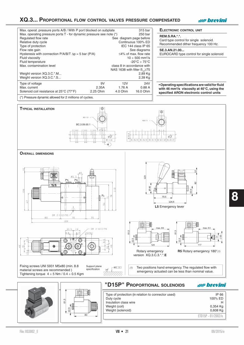
File: XQ3002_E 09/2015/eVIII • 21
8
OVERALL DIMENSIONS
BC.3.09.00.1
TYPICAL INSTALLATION
Max. operat. pressure ports A/B / With P port blocked on subplate 315 barMax. operating pressure ports T - for dynamic pressure see note (*) 250 barRegulated fl ow rate See diagram page beforeRelative duty cycle Continuous 100% EDType of protection IEC 144 class IP 65Flow rate gain See diagramsHysteresis with connection P/A/B/T Δp = 5 bar (P/A) ≤4% of max. fl ow rate Fluid viscosity 10 ÷ 500 mm2/sFluid temperature -20°C ÷ 75°CMax. contamination level class 8 in accordance with NAS 1638 with fi lter ß10≥75Weight version XQ.3.C.*.M... 2,89 KgWeight version XQ.3.C.*.S... 2,39 Kg
Type of voltage 9V 12V 24VMax. current 2.35A 1.76 A 0.88 ASolenoid coil resistance at 25°C (77°F) 2.25 Ohm 4.0 Ohm 16.0 Ohm
(*) Pressure dynamic allowed for 2 millions of cycles.
XQ.3... PROPORTIONAL FLOW CONTROL VALVES PRESSURE COMPENSATED
• Operating specifi cations are valid for fl uid with 46 mm2/s viscosity at 40°C, using the specifi ed ARON electronic control units
ELECTRONIC CONTROL UNIT
REM.S.RA.*.*. Card type control for single solenoid.Recommended dither frequency 100 Hz.
SE.3.AN.21.00... EUROCARD type control for single solenoid
"D15P" PROPORTIONAL SOLENOIDS
Type of protection (in relation to connector used) IP 66Duty cycle 100% EDInsulation class wire HWeight (coil) 0,354 Kg Weight (solenoid) 0,608 Kg
ETD15P - 01/2002/e
Support planespecifi cation
Fixing screws UNI 5931 M5x80 (min. 8.8 material screws are recommended )Tightening torque 4 ÷ 5 Nm / 0.4 ÷ 0.5 Kgm
Rotary emergencyversion XQ.3.C.3.*.*.E
R5 Rotary emergency 180°(1)
L5 Emergency lever
12
123
124,5
70,582
22,5Ø
40
(1) Two positions hand emergency. The regulated fl ow with emergency actuated can be less than nominal value.

File: XQP3002_E 03 /2015/eVIII • 22
8
HYDRAULIC SYMBOLS
ORDERING CODE
The open loop proportional fl ow regulator is 2 and 3 way compensated with priority function. It is designed to regulate fl ow in proportion to an applied electrical current (REM or SE3AN power amplifi er). Flow regulation is load independent - B port. Load compensation is achieved by a spool compensator which holds the pressure drop constant across the proportional spool.
XQP.3... OPEN LOOP 2/3 WAY PROPORTIONAL PRESSURE COMPENSATED FLOW REGULATORS
XQP Open loop 2/3 way proportional compensated fl ow regulator
3 CETOP 3/NG6
C 2/3 way compensation with priority function
3 3 way version (standard) For to obtain 2-way version the P line must be closed on the subplate
* Nominal fl ow rates F = 6 l/min G = 12 l/min H = 22 l/min I = 32 l/min L = 40 l/min
* S = without decompression D = with decompression
* Max. current to solenoid E = 2.35 A F = 1.76 A G = 0.88 A
** Variant (*): S1 = No variant P2 = Rotary emergency R5 = Rotary emergency 180° SV = Viton
2 Serial No.
The fl uid used is a mineral based oil with a viscosity of 46 mm2/s at 40°C. The tests have been carried out at with a fl uid of a 40°C.
SIMPLIFIED TYPE
• In order to obtain the 3 way pressure compensated version the cavity T have be closed on the subplate.
• In order to obtain the 2 way pressure compensated version the cavities P and T have be closed on the subplate.
Valves are available in the following versions (see hydraulic symbol):- 2 way pressure compensated - 3 way pressure compensated with priority function.- 3 way pressure compensated with priority and venting function.
XQP.3...
STANDARD CONNECTORS CH. I PAGE 20
"D15P" PROPORT. SOLENOIDS CH. VIII PAGE 23
REM.S.RA... CH. IX PAGE 4
SE.3.AN.21.00... CH. IX PAGE 11
BC.06.XQP3... CH. VII PAGE 13
DIAGRAMS
I (%)
Q (
l/min
)
INPUT SIGNAL
FLOW
Δp (
bar)
Q (l/min)
ΔP - FLOW RATE A → B(WITH 5 l/min TO P)
Δp (
bar)
Q (l/min)
ΔP - SECONDARY LINE FLOW (A → P FREE)
P (bar)
Q (
l/min
)
FLOW RATE
BACK PRESSURE ON PRIORITY LINE
Q (
l/min
)
P (bar)
FLOW RATE
BACK PRESSURE ON SECONDARY LINE
Q (
l/min
)
P (bar)
2 WAY COMPENSATION
(A VARIABLE - B 30 bar)
P (bar)
Q (
l/min
)
2 WAY COMPENSATION
(A 270 bar - B VARIABLE)(*) All variants are considered without connec-tors. The connec-tors must be order separately.See Ch. I Page 20

File: XQP3002_E 03 /2015/eVIII • 23
8
OPERATING SPECIFICATIONS
Max. operat. pressure ports A/B /P see note (*) With T port blocked on subplate 250 barRegulated fl ow rate 6 / 12 / 22 / 32 / 40 l/minDecompression drain fl ow max 0,7 l/minRelative duty cycle Continuous 100% EDType of protection (in relation to the connector used) IP 65Flow rate gain See diagram "Input signal fl ow"Fluid viscosity 10 ÷ 500 mm2/sFluid temperature -20°C ÷ 75°CAmbient temperature -20°C ÷ 70°CMax. contamination level from class 7 to 9 in accordance with NAS 1638 with fi lter ß10≥75Weight 1,7 Kg
Max. current 2.33A 1.76 A 0.88 ASolenoid coil resistance at 25°C (77°F) 2.25 Ohm 4.0 Ohm 16.0 OhmHysteresis with Δp 7 bar ≤5% <5% <8%Response to step Δp = 7 bar 0 ÷ 100% 32 ms 40 ms 85 ms100% ÷ 0 33 ms 33 ms 33 msFrequency response -3db (Input signal 50% ± 25% Vmax.) 22Hz 22Hz 12Hz
(*) Pressure dynamic allowed for 2 millions of cycles
Operating specifi cations are valid for fl uids with 46 mm2/s viscosity at 40°C, using specifi ed ARON electronic control units.
Performance data are carried out using the specifi ed Aron power amplifi er SE.3.AN... powered to 24V.
XQP.3... OPEN LOOP 2/3 WAY PROPORTIONAL PRESSURE COMPENSATED FLOW REGULATORS
AMPLIFIER UNIT AND CONTROL
REM.S.RA.*.*...Electronic card for control single proportional solenoid valve.Recommended dither frequency 100 Hz.
SE.3.AN.21.00...Electronic card format EUROCARD for control single proportional solenoid valve
OVERALL DIMENSIONS
"D15P" PROPORTIONAL SOLENOIDS
Type of protection (in relation to connector used) IP 66Duty cycle 100% EDInsulation class wire HWeight (coil) 0,354 Kg Weight (solenoid) 0,608 Kg
ETD15P - 01/2002/e
Support planespecifi cations
Fixing screws UNI 5931 M5x25(min. 8.8 material screws are recommended)Tightening torque 4 ÷ 5 Nm / 0.4 ÷ 0.5 Kgm
P2 Rotary emergency (1)
R5 Rotary emergency 180° (2)
(1) P2 - Adjustable hand emergency.
(2) R5 - Two positions hand emergency. The regulated fl ow with emergency actua-ted can be less than nominal value.

File: XQP5001_E 06/2011/eVIII • 24
8
The open loop proportional fl ow regulator is 2 and 3 way compensated with priority function. It is designed to regulate fl ow in proportion to an applied electrical current (REM power amplifi er). Flow regulation is load independent - B port. Load compensation is achieved by a spool compensator which holds the pressure drop constant across the proportional spool.
Valves are available in the following versions (see hydraulic symbol):- 2 way pressure compensated - 3 way pressure compensated with priority function.- 3 way pressure compensated with priority and venting function.
XQP.5. OPEN LOOP 2/3 WAY PROPORTIONAL PRESSURE COMPENSATED FLOW REGULATORS CETOP 5
• In order to obtain the 3 way pressure compensated version the cavities T have be closed on the subplate.
• In order to obtain the 2 way pressure compensated version the cavities P and T have be closed on the subplate.
SIMPLIFIED TYPE
XQP.5...
STANDARD CONNECTORS CH. I PAGE 20
"D19P" PROPORT. SOLENOIDS CH. VIII PAGE 25
REM.S.RA... CH. IX PAGE 4
I (%)
Q (
l/min
)
INPUT SIGNAL FLOW
Δp (
bar)
Q (l/min)
ΔP - FLOW RATE A → B(WITH 5 l/min TO P)
Δp (
bar)
Q (l/min)
ΔP - SECONDARY LINE FLOW (A → P FREE)
P (bar)
Q (
l/min
)
FLOW RATE
BACK PRESSURE ON PRIORITY LINE
Q (
l/min
)
P (bar)
FLOW RATE
BACK PRESSURE ON SECONDARY LINE
Q (
l/min
)
P (bar)
2 WAY PRESSURE COMPENSATED
(A VARIABLE - B 30 bar)
P (bar)
Q (
l/min
)
2 WAY PRESSURE COMPENSATED (A 270 bar - B VARIABLE)
DIAGRAMS
ORDERING CODE
SYMBOLS
HYDRAULIC
XQP Open loop 2/3 way proportional compensated fl ow regulator
5 CETOP 5/NG10
C 2/3 way compensation with priority function
3 3 way version (standard) For to obtain 2-way version the P line must be closed on the subplate
* Nominal fl ow rates E = 45 l/min F = 75 l/min G = 105 l/min
* S = without decompression D = with decompression
* Voltage F = 12V DC G = 24V DC
** Variant (*): S1 = No variant (without connectors) SV = Viton P2 = Rotary emergency
1 Serial No.
The fl uid used is a mineral based oil with a viscosity of 46 mm2/s at 40°C. The tests have been carried out at with a fl uid of a 40°C.
(*) All variants are considered without connec-tors. The connec-tors must be order separately.See Ch. I Page 20

File: XQP5001_E 06/2011/eVIII • 25
8
OVERALL DIMENSIONS
Max. operating pressure ports A/B /P (*) 250 barRegulated fl ow rate 75 / 105 l/minDecompression drain fl ow max 0,7 l/minRelative duty cycle Continuous 100% EDType of protection (in relation to the connector used) IP 65Flow rate gain See diagram "Input signal fl ow"Fluid viscosity 10 ÷ 500 mm2/sFluid temperature -20°C ÷ 75°CAmbient temperature -20°C ÷ 60°CMax. contamination level from class 7 to 9 in accordance with NAS 1638 with fi lter ß10≥75Weight 4,97 Kg
Type of voltage 9V 12V 24VMax. current 2.33A 2.5 A 1.25 ASolenoid coil resistance at 20°C (68°F) 2.85 Ohm 11.4 Ohm
Hysteresis with Δp 7 bar ~ 5% <5% <8%Response to step Δp = 7 bar (P/A) 0 ÷ 100% ~ 65 ms -100% ÷ 0 ~ 30 ms -Frequency response -3db (Input signal 50% ± 25% Vmax.) 7Hz -
OPERATING SPECIFICATIONS
XQP.5. OPEN LOOP 2/3 WAY PROPORTIONAL PRESSURE COMPENSATED FLOW REGULATORS CETOP 5
AMPLIFIER UNIT AND CONTROL
REM.S.RA.*.*...Electronic regulator for control single proportional solenoid valve.Recommended dither frequency 100 Hz.
E = Manual override
GSQ = Square section seal
Support planespecifi cations
Fixing screws UNI 5931 M6x40(12.9 material screws are recommended)Tightening torque 8 ÷ 10 Nm / 0.8 ÷ 1 Kgm
(*) Pressure dynamic allowed for 2 millions of cycles. T ports closed on the subplate.
Operating specifi cations are valid for fl uids with 46 mm2/s viscosity at 40°C, using speci-fi ed ARON electronic control units.
Performance data are carried out using the specifi ed Aron power amplifi er type REM.S.RA... power supplied at 24V.
"D19P" PROPORTIONAL SOLENOIDS
Type of protection (in relation to connector used) IP 65Ambient temperature -54°C ÷ 60°CDuty cycle 100% EDInsulation class wire HWeight 1,58 Kg
ETD19P - 01/2002/e

File: XP3001_E 06/2016/eVIII • 26
8
P (
bar)
Q (l/min)
P (
bar)
Q (l/min)
P (
bar)
Q (l/min)
OVERALL DIMENSIONS
ORDERING CODE
Support planespecifi cations
Fixing screws UNI 5931 M5x30(min. 8.8 material screws are recommended)Tightening torque 4 ÷ 5 Nm / 0.4 ÷ 0.5 Kgm
Proportional maximum pressure valves type XP.3.*.. are used to regulate a hydraulic circuit pressure by means of a variable electric signal. Their precise implementation allows for high and constant operational standard up to a maximum 2,5 l/min fl ow rate. A manually pressure limit setting version is also available, to protect the system from uncontrolled electrical signals.
• Other valves (e.g. subplate or in-line mounted valves) should be ordered separately.
XP.3... PROPORTIONAL PRESSURE
CONTROL VALVES CETOP 3/NG6
PRESSURE - SIGNAL(tested with Q = 1 l/min)
PRESSURE - FLOW RATE 1
PRESSURE - FLOW RATE 2
XP Max. pressure valve
3 CETOP 3/NG6
* 1 = max. 50 bar 2 = max. 140 bar 3 = max. 320 bar
* E = with manual limiter S = without manual limiter
* Voltage: F =12V DC G =24V DC
** Variant (*): S1 =No variant SV =Viton CZ =Deutsch connection
1 Serial No.
PRESSURE - FLOW RATE 3
XP.3...
STANDARD CONNECTORS CH. I PAGE 20
REM.S.RA... CH. IX PAGE 4
V.M.P... / V.M.L... / V.M.P.E... CH. II PAGE 6
(*) All variants are considered without connectors. The connectors must be order separately. See Ch. I Page 20
60.5
92
80
12
46
Ø 9.5
141
19.2
9
43
9
21.3
69.5 63.5OR 2-012/90
Ø 5.5
22
32.5
31
46
21
P
B
T
A
CZ VariantDeutsch
connection DT04-2P
About pressure range 3 it's suggested to add a modular fi lter with 5μm cartridge

File: XP3001_E 06/2016/eVIII • 27
8
VMP.E.16... A = ∅ 1 mm B = ∅ 0,3 mm
VMP.E.25... A = ∅ 1,2 mm B = ∅ 0,5 mm
TYPICAL INSTALLATION XP.3... + VMP.E.16...
Max. operating pressure (depending on the fl ow rate) 350 barMax. fl ow 2,5 l/minMax. ambient temperature 50° CLinearity See diagramsMax. hysteresis <3% of nominal valueRepeatibility error (between 150 and 680 mA) <2%Resistance at 20°C (24V) 24.6 OhmResistance at 20°C (12V) 7.2 OhmMax. resistance (ambient 20°C) (24V) at op. temp. 31 OhmMax. resistance (ambient 20°C) (12V) at op. temp. 9 Ohm Max. current at (24V) 0.68AMax. current at (12V) 1.25AType of protection IEC 144 class IP 65Max. contamination level class 8 in accordance with NAS 1638 with fi lter ß10≥75Fluid temperature -20°C÷75°CFluid viscosity 10÷500 mm2/sWeight 1,4 Kg
• Operating specifi cations are valid for fl uids with 33 mm2/s at 50°C, using specifi ed ARON electronic control units.
XP.3... PROPORTIONAL PRESSURE CONTROL VALVES CETOP 3
TYPICAL INSTALLATION XP.3... + VMP.E.25...
ELECTRONIC CONTROL UNITS
REM.S.RA.*.*.Card type control for single solenoid 12V and 24V.Recommended dither frequency 330 Hz.
• WITH MOUNTING ON VMPE USE THE FOLLOWING CALIBRATED ORIFICES (SEE V.M.P.*.E VALVE AQ VARIANT)

File: AM3XMP001_E 02/2000/eVIII • 28
8
P (
bar)
Q (l/min)
P (
bar)
Q (l/min)
P (
bar)
Q (l/min)
P (
bar)
Imput signal (%)
P (
bar)
P (
bar)
Imput signal (%)
OVERALL DIMENSIONS
ORDERING CODE
Max. operating pressure 320 barMax. fl ow 30 l/minMin. fl ow 2 l/minMax. ambient temperature 50° CLinearity See diagramsMax. hysteresis <3% of nominal valueRepeatibility error (150 ÷ 680 mA) XP3... <3%Max contamination level class 8 in accordance
with NAS 1638 with fi lter ß10³75Fluid temperature -20°C÷75°CFluid viscosity 10÷500 mm2/sWeight 0,8 Kg
Operating specifi cations are valid for fl uids with33 mm2/s viscosity at 40°C, using Aron control units
Fixing screws UNI 593 M5x70 (min. 8.8 material screws are recommended)Tightening torque 4 ÷ 5 Nm / 0.4 ÷ 0.5 Kgm
AM.3.XMP... AMPLIFIER VALVES
FOR PROPORTIONAL CONTROL VALVES
PRESSURE - FLOW RATE 1
PRESSURE - FLOW RATE 2
PRESSURE - FLOW RATE 3
Modular valve type AM.3.XMP... used together with the pressure proportional pilot type XP.3.. becomes a pressure control valve piloted by proportional command for rates up to30 lt/min. The possibility of external drainage on A ensures its correct operation even with back pressure on the discharge side. Other valves types should be ordered separately.
AM Modular valve
3 CETOP 3/NG6
XMP maximum proportional pressure
2 Spring 2 bar (standard)
0 Standard dowels (∅ 1,2 dia supply ∅ 0,5 dia damper)
* I = Internal drainage at T E = External draining at A
** 00 =No variant V1 =Viton
1 Serial No.
Support planespecifi cations
PRESSURE - SIGNAL 1 (Q=15L/MIN)
PRESSURE - SIGNAL 2 (Q=15L/MIN)
PRESSURE - SIGNAL 3 (Q=15L/MIN)
Input signal (%)
AM.3.XMP...
XP.3... CH. VIII PAGE 26

File: 09TA_E 03/2011/e
ELECTRONICS
ELECTRONICS
IX • 1
9
CEP.S...
CH. IX PAGE 2
REM.S.RA...
CH. IX PAGE 4
REM.D.RA...
CH. IX PAGE 7
SE.3.AN21...
CH. IX PAGE 11
SE.3.AN21RS...
CH. IX PAGE 13
LAB3
CH. IX PAGE 15
MAV1152
CH. IX PAGE 19
MAV1152HY
CH. IX PAGE 22
MAV4211
CH. IX PAGE 25
JC.3.D...
CH. IX PAGE 28
JC.5.D...
CH. IX PAGE 30
JC.F.D...
CH. IX PAGE. 32
ABBREVIATIONS
AP HIGH PRESSURE CONNECTION
AS PHASE LAG (DEGREES)BP LOW PRESSURE CONNECTION
C STROKE (MM)CH ACROSS FLATS
CH INTERNAL ACROSS FLATS
DA AMPLITUDE DECAY (DB)DP DIFFERENTIAL PRESSURE (BAR)F FORCE (N)I% INPUT CURRENT (A)M MANOMETER CONNECTION
NG KNOB TURNS
OR SEAL RING
P LOAD PRESSURE (BAR)PARBAK PARBAK RING
PL PARALLEL CONNECTION
PR REDUCED PRESSURE (BAR)Q FLOW (L/MIN)QP PUMP FLOW (L/MIN)SE ELASTIC PIN
SF BALL
SR SERIES CONNECTION
X PILOTING
Y DRAINAGE

File: CEPS002_E 02/2015/e
ORDERING CODE
The electronic amplifi er Plug version was designed in compliance whit EN 175301-803 (ex DIN43650), for direct mounting on the valve solenoid. The CEP.S can used whit proportional valves XD.*.A..., XDP.*.A..., XP.3..., XQP.*..., CXQ.3.. .
The output stage operates on the pulse width modulation principle (P.W.M.) and is provided with current feedback in order to obtain a solenoid output current proportional to the reference input signal.
Gain, minimum current and rise and fall ramp time adjustments are possible through the cor-responding potentiometers fi tted on top side of the card, and can be accessed by slackening the relative screw and opening the cover of the connector. While the output current to the solenoid can be measured via the Valve Current test points.
SERIE 2, has the diode reverse polarity protection inside on the power line.
CEP.S.. ELECTRONIC AMPLIFIER PLUG VERSION FOR SINGLE SOLENOID PROPORTIONAL VALVE.
• registered mark for industrial environment with re-ference to the electromagnetic compatibility. European norms:- EN61000-6-2 general safety norm - industrial environment- EN61000-6-4 emission general norm - residential environment
• Product in accordance with ROHS 2011/65/UE Europe Directive.
CEP Electronic amplifi er Plug version S Single solenoid control RS Symmetrical ramp * Max. output current ( Imax ) X = 0.88 Amp Y = 1.76 Amp Z = 2.50 Amp 0 Input reference signal 0 ÷ 10V * PWM frequency 2 = 400 Hz (per XP.3) 3 = 150 Hz (standard) 00 00 = No variant RW = Electrical circuit protected with silicone paint, for more moisture resistance 2 Serial number
ELECTRICAL SPECIFICATIONS
OVERALL DIMENSIONS OF BOX AND CONNECTOR
Power supply 12VDC o 24VDCPeak supply 40VDCMinimum power supply 10.5VDCRequired power 30WType of protection IP65
Output current Imax = 0.88AmpAll range values are come from the ordering code Imax = 1.76Amp
Imax = 2.50Amp
External reference potentiometer +10V, Imax =5mA
Input signal reference 0 ÷ 10V
I minimum adjustment 0 ÷ 50% of Imax Gain adjustment 30% ÷ 100% of Imax
Ramp time adjustment 0 ÷ 10 secondi
Operating Ambient temperature -10C° ÷ +70°CCurrent test point 1V = 1AmpWeight Kg. 0, 250
CEP.S...
ELECTRICAL SPECIFICATIONS CH. IX PAGE 2
OVERALL DIMENSIONS CH. IX PAGE 2
FUNCTIONAL BLOCK DIAGRAM CH. IX PAGE 3
ELECTRICAL CONNECTIONS CH. IX PAGE 3
SETTINGS TOPOGRAPHY CH. IX PAGE 3
REFERENCE SIGNAL CH. IX PAGE 3
9
IX • 2

File: CEPS002_E 02/2015/e
CEP.S.. ELECTRONIC AMPLIFIER PLUG VERSION
REFERENCE SIGNAL
POWER SUPPLY AND ELECTRICAL CONNECTIONSThe power supply voltage must be rectifi ed and fi ltered, whit a capacitor 4700 uF minimum. Protect the power supply circuit whit 3 A fuse. Respect the polarity supply. Use the cabling wire whit 0.75 mm2 or 1.0 mm2 section. In order to facilitate the operation of wires connection, extracts the card from the enclosure, introduce the wires through the gland-nut, connects the wires to the clips and fi nally to lodge the card to the inside of the connector.
Installation and settings, see instruction manual (code P35160008) supplied with the product.
ELECTRICAL EN 175301-803 CONNECTIONS
FUNCTIONAL BLOCK DIAGRAM
SETTINGS TOPOGRAPHY
9
IX • 3

File: REMS004_E 09/2015/eIX • 4
9
SIDE A
ORDERING CODE
ADJUSTMENT PANEL
REM.S.RA... TYPE ELECTRONIC REGULATORS FOR
SINGLE SOLENOID PROPORTIONAL CONTROL VALVES
The electronic control card type REM.S.RA has been designed to drive the “XD.*.A, XDP.3.A, XP.3, XQ.3, XQP.*. and CXQ.3” series ARON single solenoid proportional valves without in-tegral position transducer. The control card is enclosed in an “OCTAL” type housing, a typical relay mounting standard. The output stage operates on the pulse width modulation principle (P.W.M.) and is provided with current feedback in order to obtain a solenoid output current proportional to the reference input signal. Output short circuit and supply polarity inversion protection is provided.
Gain, minimum current and rise and fall ramp time adjustments are possible through the corresponding front panel trimming potentiometers, while the output current to the solenoid can be measured via the Valve Current test points, and the ramp operation can be excluded.
The product incorporates a serial interface for adjustment of parameters.
Pay attention please: electronic regulators must be used in dampness and water pro-tected places.
Supply 10VDC ÷ 30VDC (green led)Overload Protection against overload (red led)Ramp off Ramp off (red led)Output Output (current at solenoid, yellow led)I. min. Minimum current adjustmentGain Gain adjustmentRamp up Rump up adjustment time Ramp down Rump down adjustment timeValve Current Current test point at solenoid (1V =1A)
ELECTRICAL CIRCUIT AND CONNECTIONS
Sup (2-7) Power supplyOut (1-4) Output for external potentiometerRef(3) ReferenceSO (5-6) Output at solenoidDR (8) Ramp off (contact closed = exclusion)Pot External reference potentiometer (2 ÷ 5 KΩ)CS Feedback currentPWM Pulse width modulate wave
If any fi eld is missing from the ordering code the standard setting is as follows:
- Input ref. = 0÷5V - Dither 100Hz - Imin. = continuous - Imax. = 0.8A
• registered mark for industrial envi-ronment with reference to the electromagnetic compatibility. European norms: - EN61000-6-2 general safety norm - industrial environment - EN61000-6-4 emission general norm - residential environment
REM.S.RA...
CALIBRATION PROCEDURE CH. IX PAGE 5
OVERALL DIMENSIONS CH. IX PAGE 10
MOUNTING BASES CH. IX PAGE 10
REM Miniaturized electronic regulator in Octal type container
S Single solenoid
RA Asymmetrical ramp
* Maximum output current I MAX. (JU variant) X = 0.88 A (0.80 A) Y = 1.76 A (1.20 A) Z = 2.8 A
* Input reference (V) see note (*) below 2 = 0÷ + 2 V 5 = 0÷ + 5 V 0 = 0÷ + 10 V A = 0 ÷ 20 mA
* Frequency Dither 1 = 100 Hz (standard, JU var.) 2 = 330 Hz (for XP.3)
* Minimum initial current
G = step (normally for XD.*. and XDP.3 valves) C = continuous (normally for XP.3, XQ.3, XQP.*. and CXQ.3 valves)
** 00 = No variant DJ = Double gain setpoint JU = for MHPF and MSPF electrohydraulics modules (directional valves HPV) 4 Serial No.
(*) If the input reference is a current signal (mA) the regulator has to be pre-setted in the factory.
• Product in accordance with ROHS 2011/65/UE Europe Directive.
Manuals and softwareThe user and installation manual, the manual for variants DJ/JU and the software ARON DG are available on “products” section of www.brevinifl uidpower.com website (put REMS on internal search engine).

File: REMS004_E 09/2015/eIX • 5
9
REFERENCE INPUT SIGNAL
ELECTRONIC REGULATORS FOR SINGLE SOLENOID PROPORTIONAL CONTROL VALVES
REM.S.RA... INSTRUCTIONS FOR USE
CALIBRATION PROCEDURE
Connect the card in the proper way following the previous page diagram but without powering it or in the way following the next page "Typical connections". Turn completely anticlockwise (20 turns about) the trimming potentiometers of Minimu Current (Imin) and Ramp Time (Ramp-up and Ramp-down), and position the reference potentiometer on zero. Before powering the card, ensure that any unforeseen hydraulic system movement cannot cause material damage or injury to people. Power now the card; the green LED should light up.
MINIMUM CURRENT OR POLARIZATION CURRENT ADJUSTMENT
Turn slowly the minimum current trimming potentiometer clockwise (Imin) until an actuator movement can be visually detected. Turn slowly anticlockwise the potentiometer: the minimum current setting will be adjusted correctly when the actuator movement stops. For the REM model with minimum initial threshold current, set the reference signal to a Vref. of 150 mV.
MAXIMUM CURRENT GAIN ADJUSTMENT
Turn fi rst the ramp time trimming potentiometers clockwise by at least 10 turns, if the system could be damaged by a too fast solenoid operation (evaluate the application carefully). The maximum actuator speed can now be adjusted. Turn the reference signal to its maximum set-ting and rotate slowly the GAIN trimming potentiometer (GAIN) until the maximum required speed is obtained. The speed can now be varied by moving the potentiometer.
RAMP TIME ADJUSTMENT (RAMP-UP E RAMP-DOWN)
The ramp time is the time taken to pass from the minimum to the maximum current value, and vice versa. It’s adjustable from a minimum of 0s up to a maximum of 20s (to reach the maximum current value setted). Turning clockwise the trimming potentiometer, the ramp time increases.
NOTES:
- The ramp fall time affects the actuator stop position. Moving the reference to zero Volt, the actuator goes on moving till the setted ramp time is elapsed. Therefore it’s necessary to adjust it properly.- When the overload red LED lights up, it will be necessary to switch off the power to the card, switching it on again after having eliminated the cause of overload.
Power supply 10 ÷ 30 VDC
Maximum supply voltage 36 V
Power absorption 40 W
Current output setting by dip switchesImax = 2.8A
Imax = 1.76AImax = 0.88A
External potentiometer supply output short circuit protected
+5V 10mA
Reference input signal setting by dip switches
0 ÷ +2V0 ÷ +5V
0 ÷ +10V0 ÷ 20mA
Polarization current adjustment Imin = 0 ÷ 50% Imax
Current gain adjustment 50% ÷ 100% Imax
Ramp time adjustment 0 ÷ 20 sec
Ambient operating temperature -20 ÷ +70°C
Current test point 1 Volt = 1 Ampere
Weight 0.101 Kg
(*) For the current signal (mA) the regulator has to be pre-setted in the factory.

File: REMS004_E 09/2015/eIX • 6
9
REM.S.RA... DIP SWITCHES TABLE
ELECTRONIC REGULATORS FOR SINGLE SOLENOID PROPORTIONAL CONTROL VALVES
TYPICAL CONNECTIONS
For our proportional valves are recommended the following settings:
G XD.3.A DITHER =100Hz Imax. = 2.35A with 9V coilG XDP.3.A DITHER =100Hz Imax. = 2.35A with 9V coilC XQ.3 DITHER =100Hz Imax. = 2.35A with 9V coilC XQP.3 DITHER =100Hz Imax. = 2.35A with 9V coilC CXQ.3 DITHER =100Hz Imax. = 2.35A with 9V coilG XD.2.A DITHER =100Hz Imax. = 1.4A with 12V coilG XD.3.A DITHER =100Hz Imax. = 1.76A with 12V coilG XDP.5.A DITHER =100Hz Imax. = 2.5A with 12V coilG XDP.3.A DITHER =100Hz Imax. = 1.76A with 12V coilC XQ.3 DITHER =100Hz Imax. = 1.76A with 12V coilC XQP.3 DITHER =100Hz Imax. = 1.76A with 12V coilC XQP.5 DITHER =100Hz Imax. = 2.5A with 12V coilC XP.3 DITHER =330Hz Imax. = 1.25A with 12V coilC CXQ.3 DITHER =100Hz Imax. = 1.76A with 12V coilG XD.2.A DITHER =100Hz Imax. = 0.7A with 24V coilG XD.3.A DITHER =100Hz Imax. = 0.88A with 24V coilG XDP.5.A DITHER =100Hz Imax. = 1.25A with 24V coilG XDP.3.A DITHER =100Hz Imax. = 0.88A with 24V coilC XQ.3 DITHER =100Hz Imax. = 0.88A with 24V coilC XQP.3 DITHER =100Hz Imax. = 0.88A with 24V coilC XQP.5 DITHER =100Hz Imax. = 1.25A with 24V coilC XP.3 DITHER =330Hz Imax. = 0.68A with 24V coilC CXQ.3 DITHER =100Hz Imax. = 0.88A with 24V coil
1 2 3 4 5 6
Six miniature switches are mounted internally on one of the REM sides. The REM confi guration to suit any particular application can be implemented by setting these switches.PWM frequency (100 to 330 Hz), minimum (continuous or step) current, reference voltage range and maximum current (Imax) can thus be adjusted.
POT = 1000 ÷ 5000 Ω• The connection between REM and the solenoid must be direct• The common one of return to proportional solenoid must not' be shared between other valve connections or electrical equipment worker.
command signal f rom potentiometer supplied by REMS card - 0 ÷ 5V
command signal f rom potentiometer supplied by external power source, 0 ÷ 2V, 0 ÷ 5V, 0 ÷ 10V
signal command from PLC, 0 ÷ 2V, 0 ÷ 5V, 0 ÷ 10V, 0 ÷ 20mA
command signal from circuit of potentiometers
1
2
3
4
5
6
Function DITHER l min Input ref.
C G 0÷10V
0÷5V
0÷2V
0÷20mA
2.8A
1.76A
0.88A
DIP sw
100Hz
330Hz
I.max.
OFF ON
OFF ON
OFF
OFF
ON
OFF
OFF
ON
ON
OFF
OFF
OFF
ON
OFF
OFF
ON

File: REMD004_E 08/2015/eIX • 7
9
SIDE BSIDE A
ORDERING CODE
The electronic control card type REM.D.RA has been designed to drive the ARON double solenoid proportional valves series “XD.*.C...and XDP.3.C” without integral position transdu-cer. The control card is enclosed in an “UNDECAL” type housing, a typical relay mounting standard. The output stage operates on the pulse width modulation principle (P.W.M.) and is provided with current feedback in order to obtain a solenoid output current proportional to the reference input signal.
Output short circuit and supply polarity inversion protection is provided. Gain, minimum current and rise and fall ramp time adjustments are possible through the corresponding front panel trimming potentiometers, while the output current to the solenoid can be measured via the Valve Current test points, and the ramps can be excluded.
The product incorporates a serial interface for adjustment of parameters.
Pay attention please: electronic regulators must be used in dampness and water protected places.
Supply 10Vdc ÷ 30Vdc (green led)Overload Protection against over (red led)Ramp off Ramp off (red led)Output Output (current at solenoid A/B, yellow led)I. min. Minimum current adjustment A/BGain A/B gain adjustmentRamp up A/B rump up adjustment timeRamp down A/B rump down adjustment timeGND Ground1V/A Current test point at solenoid
ELECTRICAL CIRCUIT AND CONNECTIONS
REM.D.RA... TYPE ELECTRONIC REGULATORS
DOUBLE SOLENOID PROPORTIONAL CONTROL VALVES
If any fi eld is missing from the ordering code the standard setting is as follows: - Input ref. = -5 ÷ +5V - Dither = 100Hz - Imax. = 0.8A
Sup (1-11) Power supplyOut (8-10) Output external potentiometerRef (9) ReferenceSO A (5-6) Output at solenoid ASO B (5-7) Output at solenoid BDR (3) Ramp off (contact = exclusion)Pot External reference potentiometerCS Feedback currentPWM Pulse width modulated wave
• registered mark for industrial envi-ronment with reference to the electromagnetic compatibility. European norms: - EN61000-6-2 general safety norm - industrial environment - EN61000-6-4 emission general norm - residential environment
• Product in accordance with ROHS 2011/65/UE Europe Directive.
REM.D.RA...
CALIBRATION PROCEDURE CH. IX PAGE 8
OVERALL DIMENSIONS CH. IX PAGE 10
MOUNTING BASES CH. IX PAGE 10
ADJUSTMENT PANELL REM Miniaturized electronic regulator in Undecal type container
D Double solenoid
RA Asymmetrical ramp
* Maximum output current I MAX. (JU variant) X = 0.88 A (0.80 A) Y = 1.76 A (1.20 A) Z = 2.8 A
* Input reference (V) see note (*) below 2 = -2 ÷ +2 V 5 = -5 ÷ +5 V 0 ÷ +5 V 0 = -10 ÷ +10 V A = -20mA ÷ +20mA 0 ÷ +20mA
* Frequency Dither 1 = 100 Hz (standard, JU var.) 2 = 330 Hz G Minimum initial current can only be adjusted in steps
** 00 = No variant DJ = Duble setpoint gain JU = for MHPF and MSPF modules (proportional valves HPV) 4 Serial No.
(*) If the input reference is a current signal (mA) the regulator has to be pre-setted in the factory.
Manuals and softwareThe user and installation manual, the manual for variants DJ/JU and the software ARON DG are available on “products” section of www.brevinifl uidpower.com website (put REMD on internal search engine).
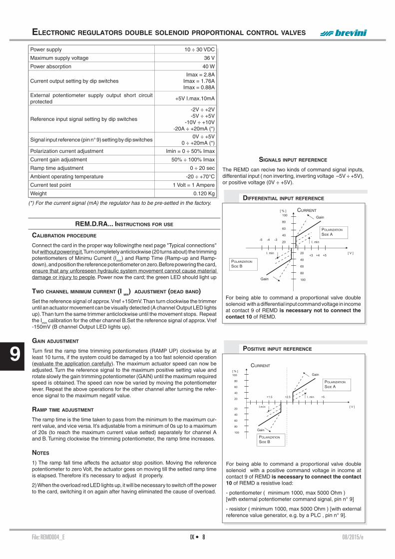
File: REMD004_E 08/2015/eIX • 8
9
ELECTRONIC REGULATORS DOUBLE SOLENOID PROPORTIONAL CONTROL VALVES
POSITIVE INPUT REFERENCE
DIFFERENTIAL INPUT REFERENCE
For being able to command a proportional valve double solenoid with a differential input command voltage in income at contact 9 of REMD is necessary not to connect the contact 10 of REMD.
For being able to command a proportional valve double solenoid with a positive command voltage in income at contact 9 of REMD is necessary to connect the contact 10 of REMD a resistive load:
- potentiometer ( minimum 1000, max 5000 Ohm )[with external potentiometer command signal, pin n° 9]
- resistor ( minimum 1000, max 5000 Ohm ) [with external reference value generator, e.g. by a PLC , pin n° 9].
SIGNALS INPUT REFERENCE
The REMD can recive two kinds of command signal inputs, differential input ( non inverting, inverting voltage –5V ÷ +5V), or positive voltage (0V ÷ +5V).
CURRENT
POLARIZATION
SIDE B
POLARIZATION
SIDE A
POLARIZATION
SIDE B
POLARIZATION
SIDE A
CURRENT
REM.D.RA... INSTRUCTIONS FOR USE
CALIBRATION PROCEDURE
Connect the card in the proper way followingthe next page "Typical connections" but without powering it. Turn completely anticlockwise (20 turns about) the trimming potentiometers of Minimu Current (Imin) and Ramp Time (Ramp-up and Ramp-down), and position the reference potentiometer on zero. Before powering the card, ensure that any unforeseen hydraulic system movement cannot cause material damage or injury to people. Power now the card; the green LED should light up
TWO CHANNEL MINIMUM CURRENT (I MIN
) ADJUSTMENT (DEAD BAND)Set the reference signal of approx. Vref +150mV. Than turn clockwise the trimmer until an actuator movement can be visually detected (A channel Output LED lights up). Than turn the same trimmer anticlockwise until the movement stops. Repeat the Imin calibration for the other channel B.Set the reference signal of approx. Vref -150mV (B channel Output LED lights up).
GAIN ADJUSTMENT
Turn fi rst the ramp time trimming potentiometers (RAMP UP) clockwise by at least 10 turns, if the system could be damaged by a too fast solenoid operation (evaluate the application carefully). The maximum actuator speed can now be adjusted. Turn the reference signal to the maximum positive setting value and rotate slowly the gain trimming potentiometer (GAIN) until the maximum required speed is obtained. The speed can now be varied by moving the potentiometer lever. Repeat the above operations for the other channel after turning the refer-ence signal to the maximum negatif value.
RAMP TIME ADJUSTMENT
The ramp time is the time taken to pass from the minimum to the maximum cur-rent value, and vice versa. It’s adjustable from a minimum of 0s up to a maximum of 20s (to reach the maximum current value setted) separately for channel A and B. Turning clockwise the trimming potentiometer, the ramp time increases.
NOTES
1) The ramp fall time affects the actuator stop position. Moving the reference potentiometer to zero Volt, the actuator goes on moving till the setted ramp time is elapsed. Therefore it’s necessary to adjust it properly.
2) When the overload red LED lights up, it will be necessary to switch off the power to the card, switching it on again after having eliminated the cause of overload.
Power supply 10 ÷ 30 VDC
Maximum supply voltage 36 V
Power absorption 40 W
Current output setting by dip switchesImax = 2.8A
Imax = 1.76AImax = 0.88A
External potentiometer supply output short circuit protected
+5V I.max.10mA
Reference input signal setting by dip switches
-2V ÷ +2V-5V ÷ +5V
-10V ÷ +10V-20A ÷ +20mA (*)
Signal input reference (pin n° 9) setting by dip switches0V ÷ +5V
0 ÷ +20mA (*)
Polarization current adjustment Imin = 0 ÷ 50% Imax
Current gain adjustment 50% ÷ 100% Imax
Ramp time adjustment 0 ÷ 20 sec
Ambient operating temperature -20 ÷ +70°C
Current test point 1 Volt = 1 Ampere
Weight 0.120 Kg
(*) For the current signal (mA) the regulator has to be pre-setted in the factory.

File: REMD004_E 08/2015/eIX • 9
9
REM.D.RA... DIP SWITCHE TABLE
ELECTRONIC REGULATORS DOUBLE SOLENOID PROPORTIONAL CONTROL VALVES
TYPICAL CONNECTIONS
• The connection between REM and the solenoid must be direct• The common one of return to proportional solenoid must not' be shared between other valve connections or electrical equipment worker.
R = 1000 ÷ 5000 ΩPOT = 1000 ÷ 5000 Ω
Six miniature switches are mounted internally on one of the REM sides. The REM confi guration to suit any particular application can be implemented by setting these switches. PWM frequency (100 to 330 Hz), reference voltage range and maximum current (Imax) can thus be adjusted.
For our proportional valves are recommended the following settings:
G XD.3.C DITHER =100Hz Imax. = 2.35A with 9V coilsG XDP.3.C DITHER =100Hz Imax. = 2.35A with 9V coilsG XD.2.C DITHER =100Hz Imax. = 1.4A with 12V coilsG XD.3.C DITHER =100Hz Imax. = 1.76A with 12V coilsG XDP.5.C DITHER =100Hz Imax. = 2.5A with 12V coilsG XDP.3.C DITHER =100Hz Imax. = 1.76A with 12V coilsG XD.2.C DITHER =100Hz Imax. = 0.7A with 24V coilsG XD.3.C DITHER =100Hz Imax. = 0.88A with 24V coilsG XDP.5.C DITHER =100Hz Imax. = 1.25A with 24V coilsG XDP.3.C DITHER =100Hz Imax. = 0.88A with 24V coils
For the version with reference signal in current it needs to be preset in-factory.
1 2 3 4 5 6
1
2
3
4
5
6
Function DITHER l min Input ref.
G -10÷10V
0÷20mA
2.8A
1.76A
DIP sw
100Hz
330Hz
I.max.
OFF ON
ON
OFF
OFF
ON
OFF
OFF
ON
ON
OFF
ON
OFF
ON
OFF
OFF
OFF
ON
OFF
-5÷5V
-2÷2V
-20mA÷20mA
0÷5V
0.88A
OFF
ON
command signal f rom potentiometer supplied by REMD card - 0 ÷ 2.5V ÷ 5V
signal command from PLC, 0 ÷ 5V, 0 ÷ 20mA
command signal f rom potentiometer supplied by external power source, ±2V, ±5V, ±10V
signal command from PLC, ±2V, ±5V, ±10V, ±20mA

File: TREM000_E 02/2008/eIX • 10
9
REM.S/D.RA... TYPE ELECTRONIC REGULATORS
SINGLE / DOUBLE SOLENOID PROPORTIONAL CONTROL VALVES
ARONDG SOFTWARE
OVERALL DIMENSION AND MOUNTING BASES ON DIN GUIDES FOR REM.D.RA...
OVERALL DIMENSION AND MOUNTING BASES ON DIN GUIDES FOR REM.S.RA...
Octal standard baseOctal OMRON base
(with mechanical connector)
Ordering code X30.80.0000 Ordering code X30.80.0004
Undecal standard baseUndecal OMRON base
(with mechanical connector)
Ordering code X30.90.0000 Ordering code X30.90.0004
AronDG program for the digital adjustment of the parameters of the REMS and REMD boards.
AronDG program for the digital adjustment of the parameters of the REMS and REMD boards. The program is used to store (the settings are cancelled when the REM board is switched off) the following parameters: • Minimum current• Upward current ramp• Upward current ramp• Downward current ramp
Italian/English version: purchase order code P35150003.
NB: the AronDG software can be used with all the REMS and REMD boards that have a TTL connector (production com-mencement year 2008).
SERIAL CABLE RS232/TTL
Ordering code VE0110001
REM connecting at computer with serial cable.

File: SE3AN210002_E - P35160005 02/2004/eIX • 11
9
SE.3.AN21.00... ELECTRONIC CARDS FORMAT EUROCARD FOR PROPORTIONAL VALVES CONTROL CETOP 3The electronic cards type SE.3.AN.21.00... have been planned for controlling double sole-noid proportional valves of the series XD.3...XDP.3…which do not incorporate the position transducer.The card has a EUROCARD format for being assembled on a connector - type DIN 41612 D 32. The output stage operates on the basis of the Pulse Width Modulation and is subject to the current feedback so that it is possible to obtain an output solenoid current directly proportional to the input signal. The regulator is supplied with standard calibration for proportional valve control. In any case it is possible to optimize the regulations by operating on the relative trimmers placed on the frontal panel (see picture).
SE.3.AN21...
INSTRUCTIONS CH. IX PAGE 12
OVERALL DIMENSIONS CH. IX PAGE 12
• The connection between the card and the solenoid must be direct • The common one of re-turn to proportional solenoid must not be shared between other valve connections or electrical equipment worker.
SE Electronic card format EUROCARD DIN 41612
3 NG06
AN21 Analogic
00 Open loop for proportional control valves type XD3.. and XDP3... without transducer 16 Corrente max. al solenoide: 1.76 A
0 No variant
2 Serial No.
ADJUSTMENT PANEL FOR CARD
ORDERING CODE
ELECTRICAL CIRCUIT AND CONNECTIONS
Fault Disable
Power on yellow – 24V DC power supply
Enable green – card enable
Gain A Solenoid A maximum current regulation
Offset A Solenoid A offset current regulation
Gain B Solenoid B maximum current regulation
Offset B Solenoid B offset current regulation
Ramp Up Ramp up regulation
Ramp Down Ramp down regulation
Current A Solenoid A current test point (1V=1A)
Current B Solenoid B current test point (1V=1A)
Reference Reference signal test point
Transducer Disable
Common 0V Common zero
Registered mark with reference to the electromagnetic compatibility.European norms: EN50082-1 - General safety norm; EN50081-1 -Emission general norm.

File: SE3AN210002_E - P35160005 02/2004/eIX • 12
9
Instructions for useFor proportional valves with code
XD.3.A.**.*.*.F.**.2 - XD.3.C.**.*.*.F.**.2XDP.3.A.**.*.*.F.**.2 - XDP.3.C.**.*.*.F.**.2
Power electric supply24 VDC nominal22÷30 VDC rectifi ed and stabilized (30W max.)2A fast-acting fuse is fi tted for power circuit protection.
Reference voltageThe card gives 1 stabilized voltage values: +10V 50mA (a10) e –10V 50mA (c10).
Available inputs± 10V (a12, c12) preseted4 ÷ 20mA (a12, c12) SW 1 bank: select I for current reference signaI.
Card enable (Enable)Usually the card is not enable. For enabling it, apply in c24 a voltage between 22 and 30VDC. Green led signal.
Ramp exclusionRamps are usually on. In order to disable them apply a16 a voltage between 22 ÷ 30VDC.
Calibration procedureConnect the card according to the scheme (See the preceding page). Set zero the reference potentiometer. Before applying the voltage, make sure that the hydraulic system does not move suddenly causing damages to people or things. Apply the voltage to the card: the green led will start blinking. Enable the card and disconnect the ramps (led "FAULT" off) and disable the ramps.
Minimum current regulationA channel: put the reference signal on 3÷5% of the max. value. Turn the minimum current trimmer clockwise (Imin A) until the actuator moves; then turn the trimmer counterclockwise until the actuator stops.
B channel: repeat the above procedure for the A channel by operat-ing on the Imin B trimmer for negative values of the reference signal.
Maximum current regulationA channel: put the reference signal on the max. (positive) value and turn the gain trimmer (Imax A) slowly, until the max. speed requested is reached. Now the speed can be varied by changing the reference signal.
B channel: repeat the above procedure for the A channel by operating on the Imax B trimmer and by putting the reference signal on the max. negative value.
Ramp time calibrationConnect the ramps. The ramp time is the time which is necessary for going from the minimum current value to the max. current value and vice versa. The time can be set from a minimum value of 0.1 sec. (ramp excluded) up to a maximum value of 10 sec. (valve max. opening) whether downwards or upwards. By turning the trimmers clockwise the ramp time increases
Notes:The ramp down time infl uences the lock position of the actuator. By setting to zero the reference signal, the actuator keeps moving until the ramp time set (in a downward direction) has passed. For this rea-son it is necessary to carry out the adjustment carefully and properly.
Solenoid current test pointOn the frontal card panel: 1V = 1A
Command signal test pointEnables reading in voltage of referencesignal sent to the card.Reading is direct, but of opposite sign, with voltage reference while current conversation is: 4mA = +10V, 20mA = -10V.
SE.3.AN21.00... ELECTRONIC CARDS FORMAT EUROCARD FOR PROPORTIONAL VALVES CONTROL CETOP 3
OVERALL DIMENSIONS
Ordering code:X30770000
Fixing screws M2.5x13
Weight Kg. 0,25
CD Connector DIN 41612 D32 IC Connector C IA Connector A

File: SE3AN21RS03_E - P35160009 01/2013/eIX • 13
9
SE.3.AN21.RS... ELECTRONIC CARDS FORMAT EUROCARD
FOR POSITIONAL TRANSDUCER VALVES CONTROL
Fault red – transducer fault signal
Power on yellow – 24V DC power supply
Enable green – card enable
Gain A Solenoid A maximum current regulation
Offset A Solenoid A offset current regulation
Gain B Solenoid B maximum current regulation
Offset B Solenoid B offset current regulation
Ramp Up Ramp up regulation
Ramp Down Ramp down regulation
Current A Solenoid A current test point (1V=1A)
Current B Solenoid B current test point (1V=1A)
Reference Reference signal test point
Transducer Transudcer signal measurement point
Common 0V Common zero
The electronic cards type SE.3.AN.21.RS...serie 3 have been planned for controlling single and double solenoid proportional valves XDC3....serie 2 equipped with position transducer type LVDT. The card has a EUROCARD format for being assembled on a connector type DIN 41612 D 32. The output stage operates on the basis of the Pulse Width Modulation (PWM) and is subject to the current feedback so that it is possible to obtain an output solenoid current directly proportional to the input signal. The regulator is supplied with standard calibration for proportional valve control. The card is equipped with a control module type PI which compares the reference signal with the position transducer signal: the eventual error is used to optimize the regulation. It is possible to carry out further regulations by operating on the relative trimmers placed on the frontal panel (see picture).
SE.3.AN21.RS...03
INSTRUCTIONS CH. IX PAGE 14
OVERALL DIMENSIONS CH. IX PAGE 14
• The connection between the card and the solenoid must be direct • The common one of re-turn to proportional solenoid must not be shared between other valve connections or electrical equipment worker.
SE Electronic card format EUROCARD DIN 41612
3 NG06
AN21 Analogic
RS Closed loop valves with positional transducer type XDC.3 .... serie 2
16 Max. current at solenoid: 1.76 A
0 No variant
3 Serial No.
ORDERING CODE
ADJUSTMENT PANEL FOR CARD
ELECTRICAL CIRCUIT AND CONNECTIONS
Registered mark with reference to the electromagnetic compatibility.European norms: EN50082-1 - General safety norm; EN50081-1 -Emission general norm.

File: SE3AN21RS03_E - P35160009 01/2013/eIX • 14
9
Instructions for useFor proportional valves with codeXDC.3.C..F.... serie 2 (SE.3.AN21.RS.16...serie 3)
Power electric supply24 VDC nominal22÷30 VDC rectifi ed and stabilized (30W max.)2A fast-acting fuse is fi tted for power circuit protection.
Reference voltageThe card gives 2 stabilized voltage values: +10V 50mA (a10) and –10V 50mA (c10).
Available inputs± 10V (a12, c12) preseted4 ÷ 20mA (a12, c12) SW 1 bank: select I for current reference signaI.
Card enable (Enable)Usually the card is not enable. For enabling it, apply in c24 a voltage between 22 and 30VDC. Green led signal.
Ramp exclusionRamps are usually on. In order to disable them apply a16 a voltage between 22 ÷ 30VDC.
Calibration procedureConnect the card according to the scheme (See the preceding page). Set zero the reference potentiometer. Before applying the voltage, make sure that the hydraulic system does not move suddenly causing damages to people or things. Apply the voltage to the card: the green led will start blinking. Enable the card and disconnect the ramps (led "FAULT" off) and disable the ramps.
Minimum current regulationA channel: put the reference signal on 3÷5% of the max. value. Turn the minimum current trimmer clockwise (Imin A) until the actuator moves; then turn the trimmer counterclockwise until the actuator stops.B channel: repeat the above procedure for the A channel by operating on the Imin B trimmer for negative values of the reference signal.
Maximum current regulationA channel: put the reference signal on the max. (positive) value and turn the gain trimmer (Imax A) slowly, until the max. speed requested is reached. Now the speed can be varied by changing the reference signal.
B channel: repeat the above procedure for the A channel by operating on the Imax B trimmer and by putting the reference signal on the max. negative value.
Ramp time calibrationConnect the ramps. The ramp time is the time which is necessary for going from the minimum current value to the max. current value and vice versa. The time can be set from a minimum value of 0.1 sec. (ramp excluded) up to a maximum value of 10 sec. (valve max. opening) whether downwards or upwards. By turning the trimmers clockwise the ramp time increases.
Notes:The ramp down time infl uences the lock position of the actuator. By setting to zero the reference signal, the actuator keeps moving until the ramp time set (in a downward direction) has passed. For this reason it is necessary to carry out the adjustment carefully and properly.The card block (FAULT) is automatically reset after that the error has been eliminated.
LVDT connectionSee the preceding page:- terminal 1 della LVDT c8 of the card- terminal 2 della LVDT a24 of the card- terminal 3 della LVDT c22 of the cardUse screened cable with earth braid.
Solenoid current test pointOn the frontal card panel: 1V = 1A
Command signal test pointEnables reading in voltage of referencesignal sent to the card.Reading is direct, but of opposite sign, with voltage reference while current conversation is: 4mA = +10V, 20mA = -10V.
Feedback signal test pointOn the frontal card panel: ± 5V according to the spool position
Ambient temperature range0°÷ 50°C
Electric connectionsThe connections concerning the reference potentiometers must be carried out with a wire having a section of ≥0.75mm2.. It is advised to use a screened cable with earth braid.
Connector ordering code:X30770000
Fixing screws M2.5x13
Weight Kg. 0,27
CD Connector DIN 41612 D32 IC Connector C IA Connector A
SE.3.AN.21.RS... ELECTRONIC CARDS FORMAT EUROCARD
FOR POSITIONAL TRANSDUCER VALVES CONTROL
OVERALL DIMENSIONS
Brevini Fluid Power S.p.AVia Moscova, 6 - 42124 Reggio Emilia (Italy)Tel. +39 0522 270511 - Fax +39 0522 270660 www.brevinifl uidpower.com
Product line by:

File: LAB3_E 02/2011/eIX • 15
9
ORDERING CODE
OVERALL DIMENSIONS
LAB3
DIMENSIONI DI INGOMBRO CH. IX PAGE 15
LED AND CONNECTORS LAYOUT CH. IX PAGE 16
MAIN CONNECTOR CH. IX PAGE 16
ELECTRICAL CONNECTIONS CH. IX PAGE 17
MOUNTING EXAMPLE CH. IX PAGE 18
LAB3 SELF LEVELLING DEVICE
FOR AERIAL PLATFORMS
Included in the furniture:- Installation and use manual
The Self leveling Device LAB3 meets the safety requirements:
- Category 3 (EN954-1)- PL d (EN13849-1)
The card has two outputs PWM current feedback to control a proportional valve, a safety re-lay output to stop the movements, two digital output signal basket inclination, when exceeds 6 °.
The optimization of working parameters can be easily done via serial connection and user interface software BPE_Terminal.
Using BPE terminal can make the alignment of the zero level of the LAB3 with the zero tilt basket, set the minimum current to the proportional levelling valve, the current gain, change the operating angle of the two current outputs for the alert of 6° exeeciding basket tilt, and fi nally adjust the width of the dead zone in correspondence of the zero grade requirements
EMC conformity 2004/108/CE- EN61000-6-2- EN61000-6-3
Code Description
7.365.1186Self Levelling Device for aerial platforms
7.003.055Connector AMP seal 35 pole
7.045.068Serial cable RS232 LAB3 , 4mt length
www.bpe.itBPE Terminal software downloaded from www.bpe.it website
140.2
70
85.54xØ
4.2
19.8
125 65.3
Power supply 9 ÷ 33V
Proportional PWM output current feedback, max load 3A
PWM frequency 4000 Hz
Dither frequency 100 Hz
Vertical position dead band Yes
Coils current offset adjustment Yes
Coils current gain adjustment Yes
Output of safety relay to stops dange-rous movements (10° of tilt basket, or device failure)
Max load 2Ampere
Two independent On/off current ou-tputs (switch on at 6° tilt basket)
Max load 1Ampere
Serial link RS232 YES-for adjustment work parameters
Working ambient temeprature -40 ÷ +70 °C
Main connector AMP seal 35 pole
Protection degree IP66

File: LAB3_E 02/2011/eIX • 16
9
LED AND CONNECTORS LAYOUT
MAIN CONNECTOR (WIRING DETAILS)
SELF LEVELLING DEVICE FOR AERIAL PLATFORMS
Conn. Description
J5 Main connector AMP seal 35 poli
J3.1 Inside connector for RS232 communication with (BPE Terminal software)
J2.1 Reserved
J4.1 Reserved
D18 Status of power on
D8 Show the status error codes of LAB3 (green)
D9 Show the status error codes of LAB3 (red)
D10 Show the status error codes of LAB3 (yellow)
SW1 Push button, for self calibrating procedures
SW2 Push button, for self calibrating procedures
SW3 Push button, for self calibrating procedures
J5
J2.1
J3.1
J4.1
J4JP3
SW3
D8
1
D18
Mh1
1
1
D9 D10
SW2 SW1
Pin Function Note
1 Positiv Supply Voltage Connects to battery positive
2 Negativ Supply Voltage Connects to battery negative
3Output of safety relay to stops dange-rous movements (10° of tilt basket, or device failure)
Maximum load 2 Ampere
4Input of safety relay to stops dange-rous movements (10° of tilt basket, or device failure)
Connects to battery positive
24 Output PWM - coil A Maximum current 3 Ampere
25 Output PWM - coil B Maximum current 3 Ampere
26 Return of coils A and B
28On/off current output (switch on at 6° tilt basket)
Maximum load 1 Ampere
29On/off current output (switch on at 6° tilt basket)
Maximum load 1 Ampere
1 12
24 35
13 23
1 2 4 3 24 262528 29
1 12 2
D5
DIODE
VIN3
0
2
U3
Vpwr
Vpwr
Vpwr
Vpwr
Vpwr
Safety Relè
VOUT
ELECTRICAL CIRCUIT

File: LAB3_E 02/2011/eIX • 17
9
ELECTRICAL CONNECTIONS
SELF LEVELLING DEVICE FOR AERIAL PLATFORMS
LAB3 connection examples to replace the model SE3LN33240804 and SE3LN33121604
switch off the main valves, to stop the platform movement and level-ling over 10° basket inclination or failure of the levelling unit card
switch off the main valves, to stop the platform movement and levelling over 10° basket inclination or failure of the levelling unit card
A BSafety Device
1 2 4 3 24 26 25
11
2
DIODE
F2
1
valvola proporzionale livellamento
levelling proportional valve
connettore 35 poli / 35 ways main connector
A BSafety Device
1 2 4 3 24 26 2528 29
1
RL3
RELAY SPST
4 4
3
1
1
2
2
RL4
RELAY SPST
3
12
DIODE
DIODE
F2
1
DIODE
valvola proporzionale livellamento
levelling proportional valve
connettore 35 poli / 35 ways main connector
switch off the valves to stop the downward arm movements and closing jib, intervenes to overcome 6 ° tilt basket
switch off the valves to stop the lifting arm movements and opening jib, intervenes to overcome 6 ° tilt basket
Connection only for example Before proceeding with the calibration on the machine, read the use and installation manual.

File: LAB3_E 02/2011/eIX • 18
9
MOUNTING EXAMPLE
SELF LEVELLING DEVICE FOR AERIAL PLATFORMS
J5
J2.1
J3.1
J4.1
J4JP3
SW3
D8
1
D18
Mh1
1
1
D9 D10
SW2 SW1
RS232
BPE Terminal

File: MAV1152_E 02/2011/iIX • 19
9
The MAV1152 controller unit is used for the control of one proportional solenoids and ad-ditional switching valves. The proportional solenoid output is pulse-width-modulated (PWM) and optimally adapted for electric proportional control of Brevini Fluid Power products. The switched outputs are designed for the direct switching of on/off solenoids, relays, and lamps. The MAV unit can managed up to 5 analog input signal and 1 PWM current output + 5x2 switched outputs ( max load 9Amperes ).
The RS232 serial interface and BPE software tool enables the connection of PC for service functions, such as diagnostics, parameter setting or display of process variables.
European norms: EN 61000-6-2, EN61000-6-3, ElectroMagnetic Compatibility (EMC) - in-dustrial environment
Optional (on request):• CANbus port communication;• on/off output for venting valve on CAT 3 safety
Adjustment parameters by RS232 link :Frequency PWMOffset currentGain currentRamp up time currentRamp down time currentAnalog input confi guration (voltage 0.5 ÷ 4.5V, 1 ÷9V, current 4 ÷ 20mA).
MAV1152 ELECTRONIC MODULE FOR INTEGRATED CONTROL
OF ONE PROPORTIONAL AND ON/OFF DIRECTIONAL VALVES
SPECIFICATIONS:
MAV product must be used with joysticks JCFD1GG1 output signal 10-90% or similar.
Nominal voltage 12V and 24V
Operating supply voltage 9 ÷ 33Vdc
Current consumption With load, max 9A
Protection Fuse Only external Rapid fuse 10A
Constant voltage source For joystick supply 5V
Analog inputSelectable by serial link
Voltage 0.5 ÷ 4.5V
Voltage 1 ÷ 9V
Current 4 ÷ 20mA
Switch input High or low active Low< 1.5V; high > 6V
Proportional PWM output 0 ÷ 2A
PWM frequency range 70Hz ÷ 250Hz
On/off output (mosfet) 3A
Led indicator Green/red/yellow
Interfaces RS232
Number of analog input 5
Number of switch input 2 (standard)
Number of PWM output 1
Number on/off outputFor directional valve 10
For venting valve 1
Protection against short circuit Input and output Yes
Reverse connect protection Power supply Yes
Operating temperature -40 ÷ 70°C
IP protection With mounted mating connector IP67
Mating connector FCI - SICMA 24 pole
ORDERING CODE
Code Description
7.365.1162
MAV1152 electronic modu-le for integrated control of one proportional and on/off directional valves
www.bpe.itBPE Terminal software downloaded from www.bpe.it website
MAV1152
LAYOUT CH. IX PAGE 20
ELECTRICAL CONNECTIONS CH. IX PAGE 20
OVERALL DIMENSIONS CH. IX PAGE 20
MOUNTING EXAMPLE CH. IX PAGE 21
Plug-in connector 24 poles FCI - SICMA(to be ordered separately)
Code Description
7.003.054 Connector
7.180.403Connector with 1 mt. cable length

File: MAV1152_E 02/2011/iIX • 20
9
MAV1152 ELECTRONIC MODULE
LAYOUT
ELECTRICAL CONNECTIONS
OVERALL DIMENSIONS
PIN 8 7 6 5 4 3 2 1 A O1A Venting O2A O3B PWM O5B O5A + OUT return Supply
B O2B 0V +5V AN2 AN1 IN3 PWM O1B output out C O3A AN5 AN4 O4A O4B AN3 IN4 - Supply
AN = analog input,IN = digital input,O1A … O(5)A = on/off output for valve 1 … (5) coil AO1B … O(5)B = on/off output for valve 1 … (5) coil B
Contacts description: Mating Connector FCI - SICMA
A
SICMA2
18
B
C
Directional on/off valve
Connection example:
Proportional single solenoid valve
A
SICMA2
18
B
C
4
2
proportional valve
A
SICMA2
18
B
C
1
8
return of the coil
SIDE B SIDE A
JCFD1GG1 fi ngertip joystick
Serial Link RS232 connector : AMP superseal 1.5
12
3
AMPPIN 1 PIN 2 PIN 3GND RX TX
83
Ø 5
118
132
41.5
329
49.7
FCI - SICMAconnector
AMP connectorsuperseal 1.5
A
SICMA2
18
B
C
4
7
6
D
B
JC
FD
1 fin
gert
ip
G F E D C B A
C

File: MAV1152_E 02/2011/iIX • 21
9
MOUNTING EXAMPLE WITH BFP PRODUCTS
MAV1152 ELECTRONIC MODULE
Proportional fi ngertip levers
NOTE: MAV product must be used with joysticks JCFD1GG1 output signal 10-90% or similar.
VERSION
WITH STACKABLE
VALVES
VERSION WITH CETOP 3OR CETOP 5VALVES

File: MAV1152HY_E 02/2011/iIX • 22
9
MAV1152HY
LAYOUT CH. IX PAGE 23
OVERALL DIMENSIONS CH. IX PAGE 23
ELECTRICAL CONNECTIONS CH. IX PAGE 23
BPE-TERMINAL SOFTWARE CH. IX PAGE 23
CONNECTION EXAMPLES CH. IX PAGE 24
MOUNTING EXAMPLE CH. IX PAGE 24
The MAV1152HY controller unit is used for the control of one proportional solenoids and additional switching valves. The proportional solenoid output is pulse-width-modulated (PWM) and optimally adapted for electric proportional control of Brevini Fluid Power products. The switched outputs are designed for the direct switching of on/off solenoids, relays, and lamps. The MAV unit can managed 1 PWM current output and 5x2 switched outputs + venting valve (max load 9Amperes).The RS232 serial interface and BPE software tool enables the connection of PC for service functions, such as diagnostics, parameter setting or display of process variables.
European norms: EN 61000-6-2, EN61000-6-3, ElectroMagnetic Compatibility (EMC) - in-dustrial environment
Optional (on request):• CANbus port communication;• on/off output for venting valve on CAT 3 safety
Adjustment parameters by RS232 link :Frequency PWMOffset currentGain currentRamp up time currentRamp down time currentAnalog input confi guration (voltage 0.5 ÷ 4.5V, 1 ÷9V, current 4 ÷ 20mA).
MAV1152HY ELECTRONIC MODULE FOR INTEGRATED CONTROL
OF PROPORTIONAL AND ON/OFF VALVES FOR ARON JOYSTICK
SPECIFICATIONS:ORDERING CODE
Code Description
7.365.1187
MAV1152HY electronic module for integrated con-trol of proportional and on/off valves for Aron Joystick
www.bpe.itBPE Terminal software downloaded from www.bpe.it website
Default settings:• Analog input segnal: 0 ÷ 5V• PWM frequency: 150 Hz• Min. current PWM output: 400mA• Max. current PWM output:: 1700mA
Nominal voltage 12V and 24V
Operating supply voltage 9 ÷ 33Vdc
Current consumption Max 9A
Protection Fuse External Rapid fuse 10A
Constant voltage source For joystick supply 5V
Analog inputSelectable by serial link
Voltage 0 ÷ 5V
Voltage 0 ÷ 10V
Current 0 ÷ 20mA
Switch input High or low active Low< 1.5V; high > 6V
Proportional PWM output 0 ÷ 2A
PWM frequency range 70Hz ÷ 250Hz
On/off output (mosfet) 3A
Led indicator Green/red/yellow
InterfacesRS232 and ( optional
as a request CAN 2.0B)
Number of analog input 1
Number of switch input 6
Number of PWM output 1
Number on/off output 5x2
Switch output for venting valve (3A)
CAT3 safety (PLd) (optional as a request)
1
Protection against short circuit Input and output Yes
Reverse connect protection Power supply Yes
Operating temperature -40 ÷ 70°C
IP protection With mounted mating connector IP67
Mating connector FCI - SICMA 24 pole
Plug-in connector 24 poles FCI - SICMA(to be ordered separately)
Code Description
7.003.054 Connector
7.180.403Connector with 1 mt. cable length

File: MAV1152HY_E 02/2011/iIX • 23
9
LAYOUT
ELECTRICAL CONNECTIONS
OVERALL DIMENSIONS
MAV1152HY ELECTRONIC MODULE
AN = analog input,IN = digital input,O1A = on/off output 1 coil A directional valveO1B = on/off output 1 coil B directional valve
Contacts description: Mating Connector FCI - SICMA
Serial Link RS232 connector : AMP superseal 1.5
A
SICMA2
18
B
C
PIN 8 7 6 5 4 3 2 1
A O1AVentingOUT
O2A O3BPWM
re-turn
O5B O5A+
Supply
B O2B 0V+5V
outputIN5 AN1 IN3
PWM out
O1B
C O3A IN8 IN7 O4A O4B IN6 IN4-
Supply
PIN Description Connects to:B4 AN1 Y signal track of joystick
B5 IN5 Push button n°2 of the joystick
C3 IN6 Push button n°3 of the joystick
C6 IN7 Push button n°4 of the joystick
C7 IN8 Push button n°5 of the joystick
B3 IN3 Push button n°1 of the joystick
C2 IN4 Dead man switch joystick
B6+5V
outputAnalogue supply track of the joystick
BPE-TERMINAL SOFTWARE
Software - BPE-Termial
The BPE terminal software, allows to set the MAV. Furthermore with BPE terminal is possible to set all the work parameters, minimum current, maximum current, PWM frequency...
The BPE Terminal software is free downloadable from BPE website www.bpe.it
12
3
AMP
83
Ø 5
118
132
41.5
329
49.7
PIN 1 PIN 2 PIN 3GND RX TX
FCI - SICMAconnector
AMP connectorsuperseal 1.5

File: MAV1152HY_E 02/2011/iIX • 24
9
MOUNTING EXAMPLE WITH BFP PRODUCTS
ELECTRICAL CONNECTIONS
MAV1152HY ELECTRONIC MODULE
A
SICMA2
JC5 joystick
p
12 way connector
handle push buttons and
dead man switch
18
1
1
9
7
B
C
7
6
11 9
4
10
A
SICMA2
JC5 joystick
16 way connector
potentiometer tracks
12 way connector
handle push buttons and
dead man switch
18
1
1
9
7
B
C
3
5
2
43 12
8
11
Directional on/off valve
Y axis Analogue track connections JC5 and MAV
Proportional single solenoid valve
A
SICMA2
18
B
C
4
2
proportional valve
A
SICMA2
18
B
C
1
8
return of the coil
SIDE B SIDE A
Dead man switch and push buttons connections
PIN Joy. Function Connect to MAV1 Button no. 4 C62 Button no. 3 C33 Button no. 2 B54 Button no. 1 B35 Button no. 5 C712 Dead man C2
(12 way connector) joystick Pin 8 and 11, connect to "+ supply voltage" (12V or 24V)
PIN Joy. Connect to MAV9 B710 B411 B6
Joystick
Proportional single so-lenoid valve and 5 on/off valves
MAV1152HY

File: MAV4211_E 02/2011/iIX • 25
9
MAV4211: Electronic module for integrated control of proportional valves, bankable valves and proportional directional valves HPV Brevini Fluid Power.The MAV4211 controller unit is used for the control of proportional solenoids and additional switching functions. The proportional solenoid outputs are pulse-width-modulated (PWM) and optimally adapted for electric proportional control of Brevini Fluid Power products. The switched outputs are designed for the direct switching of relays, lamps and switching solenoids. The MAV unit can managed up to 4 analog input signal and 8 PWM current output (4 PWM current output simultaneous, max load 9Amperes ).
The RS232 serial interface and BPE software tool enables the connection of PC for service functions, such as diagnostics, parameter setting or display of process variables.
European norms: EN 61000 - ElectroMagnetic Compatibility (EMC) - industrial environment
Optional (on request):• on/off output for venting valve on CAT 3 safety
Adjustment parameters by RS232 link :Frequency PWMOffset currentGain currentRamp up time currentRamp down time currentAnalog input confi guration (voltage 0.5 ÷ 4.5V, 1 ÷9V, current 4 ÷ 20mA).
MAV4211 ELECTRONIC MODULE FOR INTEGRATED CONTROL OF PROPORTIONAL VALVES
MAV4211
LAYOUT CH. IX PAGE 26
ELECTRICAL CONNECTINS CH. IX PAGE 26
OVERALL DIMENSIONS CH. IX PAGE 26
MOUNTING EXAMPLE CH. IX PAGE 27
MAV product must be used with joysticks JCFD1GG1 output signal 10-90% or similar.
ORDERING CODE
Code Description
7.365.1043MAV4211 electronic modu-le for integrated control of proportional valves
www.bpe.itBPE Terminal software downloaded from www.bpe.it website
SPECIFICATIONS:Nominal voltage 12V and 24V
Operating supply voltage 9 ÷ 33Vdc
Current consumption With load, max 9A
Protection Fuse External Rapid fuse 10A
Constant voltage source For joystick supply 5V
Analog input selectable by serial link
Voltage 0.5 ÷ 4.5V
Voltage 1 ÷ 9V
Current 4 ÷ 20mA
Switch input High or low active Low< 1.5V; high > 6V
Proportional PWM output 0 ÷ 2A
PWM frequency range 70Hz ÷ 250Hz
On/off output (mosfet) 3A
Led indicator Green/red/yellow
Interfaces RS232 e CAN 2.0B
Number of analog input 4
Number of switch input 1
Number of PWM output 8
Number on/off output For venting valve 1
Protezione da cortocircuito Ingresso ed uscite Yes
Protection against short circuit Yes
Operating temperature -40 ÷ 70°C
IP protection With mounted mating connector IP67
Mating connector FCI - SICMA 24 pole
Plug-in connector 24 poles FCI - SICMA(to be ordered separately)
Code Description
7.003.054 Connector
7.180.403Connector with 1 mt. cable length

File: MAV4211_E 02/2011/iIX • 26
9
LAYOUT
ELECTRICAL CONNECTINS
OVERALL DIMENSIONS
MAV4211 ELECTRONIC MODULE
Contacts description MAV4211: Mating Connector FCI - SICMA
PIN 8 7 6 5 4 3 2 1 A On/off Return Return PWM CAN_H PWM PWM + output PWM 4 PWM 1 out 2B out 4B out 4A Supply
A AND B A AND B B PWM Return Return Switch Analog Analog PWM PWM out 1B PWM 3 PWM 2 input 1 input 1 input 3 out 3B out 3A A and B A and B C PWM 5V PWM Analog Analog CAN_L - out 2A joystick out 1A Not used input 2 input 4 Supply supply
FCI - SICMAconnector
AMP connectorsuperseal 1.5
A
SICMA2
18
B
C
18
6
6
return of PWM1A and PWM1B
SIDE B SIDE A
A
SICMA2
18
B
C
12
3
AMPPIN 1 PIN 2 PIN 3GND RX TX
83
Ø 5
118
132
41.5
329
49.7
Serial Link RS232 connector : AMP superseal 1.5
Connection example:
A
SICMA2
18
B
C
1
7
4
JC
FD
1 fin
gert
ip
G F E D C B A
D B
C

File: MAV4211_E 02/2011/iIX • 27
9
MOUNTING EXAMPLE WITH BFP PRODUCTS
Proportional fi ngertip levers
Proportional bankable valves
MAV4211 ELECTRONIC MODULE
Proportional fi ngertip levers
Brevini Hydraulics proportional directional valves
MHPF-MSPF(PWM electrohydraulic modules)
NOTE: MAV product must be used with joysticks JCFD1GG1 output signal 10-90% or similar.

File: JC3D001_E - P35160006 04/2015/eIX • 28
9
POTENTIOMETER OUTPUT AXIS Y
JC.3.D... HEAVY DUTY SINGLE JOYSTICK BASE
This is a rugged joystick with single axis Y potentiometer and ergonomic handle. The joystick has a spring return lever for center position. The panel material for this joystick and thickness must be strong and rigid. The panel thickness should have a dimension of minimum 3.5mm and maximum 6mm. The joystick has two directional micro-switches per Y axis. The handle has 3 pushbuttons and it is possible to have the operator present switch too.
The IP protection of joystick is referred to above mounting panel and it can be max. IP65. N.B. below mounting panel the rating is IP40.
APPLICATIONS The joystick has been designed for aerial platform, agricultural and forestry machinery. The use of this product with the Aron electronic control unit for non contemporary movements gives the maximum advantage for hydraulic solutions controlled with a proportional valve.
JC3D...
ORDERING CODE
• Registered mark for industrial environment with reference to the compatibility. European norms:
- IEC 61000-4-3 “Electromagnetic immunity”- EN6550022 “Electromagnetic emissions”
• Product in accordance with ROHS 2011/65/UE Europe Directive.
JC Heavy duty single Joystick
3 Handle (3 switches)
D Directional switches 1 Functional operation singe axis (Y)
A With operator present trigger switch ** 00 = No variants GD = With silicon rubber protection on the switches handle
1 Serial number
Electrical features Potentiometer resistance 1.4 ÷ 2.2 KΩMax. supply voltage VDD = 32V DCMax. supply voltage Y pot 0 – 100% VDDMax. output current 5 mA
Directional switches Maximum supply voltage VCC = 32V DCMax. output current 200 mA
Resistive load
Mechanical features Mechanical angle ± 20°Maximum operating load 390 N (Measured 130 mm above the mounting surface) Mechanical Life (Y axis) 7.500.000 cyclesWeight (handle include) 0,900 Kg
Ambient operating temperature -40°C ÷ +80°CProtection according to DIN IP65Shocks Level 20G Type ½ sine 6ms
Number of shocks 1350 per axis
In order to obtain the Y axis output signal from the joystick as indicated in the diagram over it is necessary to connect the pin 9 and 11 of the AMP 16 way connector at +VDD, and to connect the pin 12 of the AMP 16 way connector at 0V.
IIn order to obtain the Y axis output signal from the joystick as indicated in the diagram over it is necessary to connect the pin 9 of the AMP 16 way connector at 0V, and to connect the pin 11 of the AMP 16 way connector at +VDD.
In order to obtain the Y axis output signal from the joystick as indicated in the diagram over it is necessary to connect the pin 9 of the AMP 16 way conector at -VDD, and to connect the pin 11 of the AMP 16 way connector at +VDD.
Connectors and electrical contacts included in the fourniture.

File: JC3D001_E - P35160006 04/2015/eIX • 29
9
CONNECTOR CONFIGURATION AND PIN ALLOCATION DETAIL
JC.3.D... . HEAVY DUTY SINGLE JOYSTICK BASE
12 WAY HANDLE CONNECTIONS
AMP Pin allocation description
2 Switch 3 - contact N/O
3 Switch 2 - contact N/O
4 Switch 1 - contact N/O
8 Operator present trigger switch
11 Switch track common
12 Operator present trigger switch
FROM THE 16 WAY PRIMARY POTENTIOMETER CONNECTIONS SINGLE POTENTIOMETER PER Y AXIS
AMP Pin allocation description
1 Y Switch track forward
9 Y Pot track back
10 Y Pot track signal
11 Y Pot track forward
12 Y Pot track centre tap
13 Y Switch track common
14 Y Switch track back
16 Y Switch track centre on
OVERALL DIMENSIONS
HANDLE ADAPTER PLATE
SPARE PARTS AMP 040 SERIES MULTILOCK
Receptacle contactsP.No. 175062-1* Loose piece
Plug housing 12 positionP.No. 174045-2*
Plug housing 16 position double rowP.No. 174046-2*
Spare parts kit, connectors and electrical contacts: V89900000
* AMP code
ANALOGUE JOYSTICK CONTROLLERS

IX • 30File: JC5D001_E - P35160007 04/2015/e
9POTENTIOMETER OUTPUT AXIS X,Y
JC.5.D... HEAVY DUTY SINGLE JOYSTICK BASE
This is a rugged joystick with potentiometer and ergonomic handle. The joystick has a spring return lever for center position. Single axis Y or dual axes XY are available. The panel material for this joystick and thickness must be strong and rigid. The panel thickness should have a dimension of minimum 3.5mm and maximum 6mm. The joystick has two directional micro-switches per axis. The handle has 5 pushbuttons and it is possible to have the operator present switch too.
The IP protection of joystick is referred to above mounting panel and it can be max. IP65. N.B. below mounting panel the rating is IP40.
APPLICATIONS The joystick has been designed for aerial platform, agricultural and forestry machinery. The use of this product with the Aron electronic control unit for non contemporary movements gives the maximum advantage for hydraulic solutions controlled with a proportional valve.
JC5D...
ORDERING CODE
JC Heavy duty single Joystick
5 Handle (5 switches)
D Directional switches * Functional operation 1 = singe axis (Y) 2 = dual axis (XY)
* A = With operator present trigger switch B = Without operator present trigger switch 00 No variants 1 Serial number
Electrical features Potentiometer resistance 1.4 ÷ 2.2 KΩMax. supply voltage VDD = 32V DCMax. supply voltage X and Y pot 0 – 100% VDDMax. output current 5 mA
Directional switches Maximum supply voltage VCC = 32V DCMax. output current 200 mA
Resistive load
Mechanical features Mechanical angle ± 20°Maximum operating load 390 N (Measured 130 mm above the mounting surface) Mechanical Life (X and Y axis) 7.500.000 cyclesWeight (handle include) 0,900 Kg
Ambient operating temperature -40°C ÷ +80°CProtection according to DIN IP65Shocks Level 20G Type ½ sine 6ms
Number of shocks 1350 each axis
In order to obtain the output signal from the joystick as indicated in the diagram over it is necessary:
- for the X axis output signal, connect the pin 3 and 5 of the AMP 16 way connector at +VDD, and connect the pin 6 of the AMP 16 way connector at 0V.
- for the Y axis output signal, connect the pin 9 and 11 of the AMP 16 way connector at +VDD, and connect the pin 12 of the AMP 16 way connector at 0V.
In order to obtain the output signal from the joystick as indicated in the diagram over it is necessary:
- for the X axis output signal, connect the pin 3 of the AMP 16 way connector at 0V, and connect the pin 5 of the AMP 16 way connector at +VDD.
- for the Y axis output signal, connect the pin 9 of the AMP 16 way connector at 0V, and connect the pin 11 of the AMP 16 way connector at +VDD.
In order to obtain the output signal from the joystick as indicated in the diagram over it is necessary:
- for the X axis output signal, connect the pin 3 of the AMP 16 way connector at -VDD, and connect the pin 5 of the AMP 16 way connector at +VDD.
- for the Y axis output signal, connect the pin 9 of the AMP 16 way conector at -VDD, and connect the pin 11 of the AMP 16 way connector at +VDD.
• Registered mark for industrial environment with reference to the compatibility. European norms:
- IEC 61000-4-3 “Electromagnetic immunity”- EN6550022 “Electromagnetic emissions”
• Product in accordance with ROHS 2011/65/UE Europe Directive.
Connectors and electrical contacts included in the fourniture.

File: JC5D001_E - P35160007 04/2015/eIX • 31
9
CONNECTOR CONFIGURATION AND PIN ALLOCATION DETAIL
JC.5.D... . HEAVY DUTY SINGLE JOYSTICK BASE
12 WAY HANDLE CONNECTIONS
AMP Pin allocation description
1 Switch 4 - contact N/O
2 Switch 3 - contact N/O
3 Switch 2 - contact N/O
4 Switch 1 - contact N/O
5 Switch 5 - contact N/O
8 Operator present trigger switch
11 Switch track common
12 Operator present trigger switch
16 WAY PRIMARY POTENTIOMETER CONNECTIONS
AMP Pin allocation description
Single potentiometer per axis
1 Y Switch track forward
2 X Switch track centre on
3 X Pot track left
4 X Pot track signal
5 X Pot track right
6 X Pot track centre tap
7 X Switch track common
8 X Switch track left
9 Y Pot track back
10 Y Pot track signal
11 Y Pot track forward
12 Y Pot track centre tap
13 Y Switch track common
14 Y Switch track back
15 X Switch track right
16 Y Switch track centre on
OVERALL DIMENSIONS
HANDLE ADAPTER PLATE
ANALOGUE JOYSTICK CONTROLLERS
SPARE PARTS AMP 040 SERIES MULTILOCK
Receptacle contactsP.No. 175062-1* Loose piece
Plug housing 12 positionP.No. 174045-2*
Plug housing 16 position double rowP.No. 174046-2*
Spare parts kit, connectors and electrical contacts: V89900000
* AMP code

File: JCFD001_E - P35160011 04/2015/eIX • 32
9
OUTPUT VOLTAGE SIGNAL
ORDERING CODE
Developed for applications where ergonomics and system in-tegrity are paramount, the JCFD is a compact, low profi le joystick that provides precise fi ngertip control. Designed for use with an electronic controller, the plastic track generates analogue and switched reference signals, proportional to the distance and direction over which the handle is moved. The analogue output is confi gured to provide signals for fault detection circuits within the controller. A center tap on the analogue track pro-vides an accurate voltage reference for the center position or a zero point for a bipolar supply voltage.
JC.F.D...
JC.F.D... SINGLE-AXIS FINGERTIP JOYSTICK
JC Joystick F Fingertip D Directional switches 1 Singolo asse
** 00 = No variants GG = 10-90% output signal 1 Serial number
In order to obtain the output signal from the joystick as indicated in the diagram it is necessary: connect the Pin B and Pin D of the connector at +VDD, and connect the Pin A at 0V.
In order to obtain the output signal from the joystick as indicated in the diagram it is necessary: connect the Pin B of the connector at +VDD, and connect the Pin D at 0V.
In order to obtain the output signal from the joystick as indicated in the diagram it is necessary: connect the Pin B of the connector at +VDD, and connect the Pin D at -VDD.
Electrical features Potentiometer resistance 5 KΩMax. supply voltage VDD = 32V DCOutput signal Y pot 0 – 100% VDDOutput signal Y pot GG variant 10 - 90% VDDMax. output current 2mA
Directional switches Maximum supply voltage VCC = 32V DCMax. output current 2mA
Resistive load
Mechanical features Mechanical angle ± 30°Maximum operating load 50 N (Measured 130 mm above the mounting surface) Mechanical Life 5.000.000 cyclesWeight 0,045 Kg
Ambient operating temperature -25°C ÷ +70°CProtection according to DIN IP66
• Registered mark for industrial environment with reference to the compatibility. European norms:
- IEC 61000-4-3 “Electromagnetic immunity”- EN6550022 “Electromagnetic emissions”
• Product in accordance with ROHS 2011/65/UE Europe Directive.
Connectors and electrical contacts included in the fourniture.

File: JCFD001_E - P35160011 04/2015/eIX • 33
9
HANDLE ADAPTER PLATE
JC.F.D... SINGLE-AXIS FINGERTIP JOYSTICK
Connections
A Center tapB Positive voltage supply + VDDC Output voltage signalD Negative or zero voltage supplyE Directional switch- handle backF Directional switch- handle forwardG Common terminal for directional switch
OVERALL DIMENSIONS
ANALOGUE JOYSTICK CONTROLLERSSPARE PARTS
ContactsP.No. 76347*
Plug housingP.No. 65240-007LF*
* FCI code
Spare parts kit, connectors and electrical contacts: V89900001

File: JCFD001_E - P35160011 04/2015/eIX • 34
9

BA.60...
CH. X PAGE 2
BA.130...
CH. X PAGE 5
BSC.5.69...
CH. X PAGE 7
File: 10TA_E 04/2011/e
SYSTEMS
LOW / HIGH PRESSURE UNITS
BS5.RGA...
CH. X PAGE 8
BS5.RGI...
CH. X PAGE 8
AD.5.I.P.2T.1
CH. I PAGE 43
SPECIAL SUBPLATE MOUNTINGS WITH AUTOMATIC EXCLUSION
REGENERATING CIRCUIT
X • 1
10
ABBREVIATIONS
AP HIGH PRESSURE CONNECTION
AS PHASE LAG (DEGREES)BP LOW PRESSURE CONNECTION
C STROKE (MM)CH ACROSS FLATS
CH INTERNAL ACROSS FLATS
DA AMPLITUDE DECAY (DB)DP DIFFERENTIAL PRESSURE (BAR)F FORCE (N)I% INPUT CURRENT (A)M MANOMETER CONNECTION
NG KNOB TURNS
OR SEAL RING
P LOAD PRESSURE (BAR)PARBAK PARBAK RING
PL PARALLEL CONNECTION
PR REDUCED PRESSURE (BAR)Q FLOW (L/MIN)QP PUMP FLOW (L/MIN)SE ELASTIC PIN
SF BALL
SR SERIES CONNECTION
X PILOTING
Y DRAINAGE

File: BA60001_E 02/2015/eX • 2
10
Curve 1= BP → P
2 = BP → T
OVERALL DIMENSIONS AND HYDRAULIC SYMBOL
BA.60... LOW / HIGH PRESSURE UNITS
Max. fl ow 60 l/minMax. operating pressure 320 barFluid viscosity 10 ÷ 500 mm2/sFluid temperature -25°C ÷ 75°CAmbient temperature -25°C ÷ 60°CMax. contamination level class 10 in accordance
with NAS 1638 with fi lter ß25≥75 Weight see "overall dimensions"
PRESSURE DROPS
The low/high pressure groups are usually employed in hydraulic sy-stems fed by dual pumps that form a single pressure circuit.
The main feature of this system con-sists in being able to set a pressure value in correspondence of which one of the two pumping sections is changed over to drain.BA.60...
BA.06/10... CH. XI PAGE 2
CMP.10... CH.VII PAGE 30
BC.06.30/32... / BC.06.40... CH.VII PAGE 15
BC.5.30/32... CH.VII PAGE 26
BC.5.40... CH.VII PAGE 25
CETOP 3/NG06 CH. I PAGE 5
CETOP 5/NG10 CH. I PAGE 29
T h e s e g r o u p s a r e f i t t e d w i t h a nadjustable maximum pressure valve to protect the hydraulic system.3 pressure adjustment ranges are available for the exclusion valve, which is fi tted with cast iron or steel seat, while the maximum pressure valve type CMP10 is available with 3 adjustment ranges.
Minimum permissible setting pressure depending on the spring: see cartridge valve type CMP10.
The series connection modular small block (BC.06.32/BC.5.32) or the parallel connection type (BC.06.30/BC.5.30) with blanking plate (BC.06.40/BC.5.40) and the solenoid valve should be ordered separately.
For the subplate mounting ordering code see "Subpla-tes" chapter; whilst for the valve ordering code see "Directional control valves" chapter.
The CETOP3/NG06 connector blocks have 2 rods, the CETOP5/NG10 have 3 rods.
BC.10.06 = reduction plate to be used only for assembly of modular blocks CETOP3/NG06.
MODULE ORDERING CODE
ORDERING CODE
BA Low/high pressure base
60 Capacity l/min
U* TDouble pump exclusion valve setting 2 = max. 30 bar 3 = max. 75 bar 4 = max. 100 bar
C Type of adjustment: grub screw
* Max. pressure valve setting 1 = max. 50 bar 2 = max. 150 bar 3 = max. 320 bar
** 00 = No variant V1 = Viton
1 Serial No.
In series connection the last block at the top, must be connected in parallel (BC.06.30) only for mounting CETOP3/NG06 modular valves.
Fixing screws M6x100 UNI 5931Weight 6.6 Kg
Q (l/min)
P(b
ar)
0 10 20 30 40 50 600
2
4
6
8
10
12
1
2
BA Subplate mounting
** 06 = CETOP 3/NG06 10 = CETOP 5/NG10
** Type of module: 62 = side CETOP interface 66 = top CETOP interface 68 = with upper threaded connectors (only for CETOP 5)
** 00 = No variant V1 = Viton
1 Serial No.

File: BA60002_E 02/2015/eX • 3
10
BA.60... LOW / HIGH PRESSURE UNITS
OVERALL DIMENSIONS AND HYDRAULIC SYMBOLS
TOP MOUNTING FOR SINGLE SOLENOID VALVE CETOP5/NG10 (CONNECTOR BLOCK BA.10.66)Fixing screws M10x50 UNI 5931 - Weight 2.4 Kg
TOP MOUNTING FOR SINGLE SOLENOID VALVE CETOP3/NG06 (CONNECTOR BLOCK BA.06.66)Fixing screws M10x50 UNI 5931 - Weight 2.5 Kg
SIDE MOUNTING FOR SINGLE SOLENOID VALVE CETOP5/NG10 (CONNECTOR BLOCK BA.10.62)Fixing screws M10x80 UNI 5931 - Weight 3 Kg
SIDE MOUNTING FOR SINGLE SOLENOID VALVE CETOP3/NG06 (CONNECTOR BLOCK BA.06.62)Fixing screws M10x55 UNI 5931 - Weight 2 Kg

File: BA60001_E 02/2015/eX • 4
10
BA.60... LOW / HIGH PRESSURE UNITS
OVERALL DIMENSIONS AND HYDRAULIC SYMBOLS
MULTIPLE MOUNTING WITH MODULAR COMPONENT CONNECTOR BLOCKS CONNECTED IN SERIES OR PARALLEL CETOP3/NG06
MULTIPLE MOUNTING WITH MODULAR COMPONENT CONNECTOR BLOCKS CONNECTED IN SERIES OR PARALLEL CETOP5/NG10
MOUNTING WITH THREADED CONNECTORS (CONNECTOR BLOCK BA.10.68)Fixing screws M10x45 UNI 5931- Weight 1.6 Kg

File: BA130001_E 05/2015/eX • 5
10
Δp (
bar)
Q (l/min)
Curve 1 = P1 → T
2 = P1 → P
1
2
OVERALL DIMENSIONS AND HYDRAULIC SYMBOL
MODULE ORDERING CODE
The low/high pressure groups are usually employed in hydraulic systems fed by dual pumps that form a single pressure circuit. The main feature of this system consists in being able to set a pressure value in correspondence of which one of the two pumping sections is changed over to drain.These groups are fitted with anadjustable maximum pressure valve to protect the hydraulic system.2 pressure adjustment ranges are available for the exclusion valve, which is fi tted with a steel seat, while the maximum pressure valve type CMP10 is available with 3 adjustment ranges.
Minimum permissible setting pres-sure depending on the spring: see cartridge valve type CMP10.
The series connection modular small block (BC.5.32) or the parallel con-nection type (BC.5.30) with blanking plate (BC.5.40) and the solenoid valve should be ordered separately.
For the subplate mounting ordering code see "Subplates" chapter; whilst for the valve ordering code see "Direc-tional control valves" chapter.
The CETOP5/NG10 connector blocks have 3 rods.
ORDERING CODE
BA.130... LOW / HIGH PRESSURE UNITS
BA Low/high pressure base
130 Capacity l/min
U* Double pump exclusion valve setting 2 = 20 ÷ 90 bar 3 = 50 ÷ 190 bar
C Type of adjustment: grub screw
* Max. pressure valve setting 1 = max. 50 bar 2 = max. 150 bar 3 = max. 320 bar
00 No variant 1 Serial No.
Max. fl ow 130 l/minMax. operating pressure 320 barFluid viscosity 10 ÷ 500 mm2/sFluid temperature -25°C ÷ 75°CAmbient temperature -25°C ÷ 60°CMax. contamination level class 10 in accordance
with NAS 1638 with fi lter ß25≥75 Weight 8 Kg
BA Subplate mounting
10 CETOP 5/NG10
** Type of module: 62 = side CETOP interface 68 = with upper threaded connectors
00 No variant
1 Serial No.
Fixing screws M6x100 UNI 5931
PRESSURE DROPSBA.130...
BA.10... CH.XI PAGE 5
CMP.10... CH.VII PAGE 30
BSC.5.69... CH.XI PAGE 7
BC.5.30/32... CH.VII PAGE 26
BC.5.40... CH.VII PAGE 25
CETOP 5/NG10 CH. I PAGE 29
ADP.5.E... CH. I PAGE 37
Pay attention please, max tightening torque for manometer (M2): 35 Nm / 3,5 Kgm

File: BA130001_E 05/2015/eX • 6
10
OVERALL DIMENSIONS AND HYDRAULIC SYMBOLS
UPPER MOUNTING FOR SINGLE SOLENOID VALVE CETOP5/NG10
MOUNTING WITH THREADED CONNECTORS (CONNECTOR BLOCK BA.10.68)Fixing screws M10x45 UNI 5931
SIDE MOUNTING FOR SINGLE SOLENOID VALVE CETOP5/NG10 (CONNECTOR BLOCK BA.10.62)Fixing screws M10x80 UNI 5931
BA.130... LOW / HIGH PRESSURE UNITS

File: BA130001_E 05/2015/eX • 7
10
OVERALL DIMENSIONS AND HYDRAULIC SYMBOL
MULTIPLE MOUNTING WITH MODULAR COMPONENT CONNECTOR BLOCKS CONNECTED IN SERIES OR PARALLEL CETOP5/NG10
BSC.5.69... TRANSFORMATION MOUNTING CETOP 5 INTERFACE TO
MODULAR COMPONENT BC.5...
BA.130... LOW / HIGH PRESSURE UNITS
BSC Modular component subplate
5 CETOP 5/NG10
69 Type of module: to modular component BC5
00 No variant
1 Serial No.
Fixing srcews M6x35 UNI 5931Weight 2,1 Kg

File: BS5R$A002_E 02/2002/eX • 8
10
ORDERING CODE
BS.5.R*A... SPECIAL SUBPLATE MOUNTINGS WITH AUTOMATIC EXCLUSION REGENERATING CIRCUIT
Max. pump fl ow (suggested) 30 l/minMax. fl ow with regenerative connected 100 l/minMax. operating pressure (relief valve) 350 barMax. operating pressure (exclusion) 200 barHydraulic fl uids Mineral oils DIN 51524Fluid viscosity 10 ÷ 500 mm2/sFluid temperature -25°C ÷ 75°CAmbient temperature -25°C ÷ 60°CMax. contamination level class 10 in accordance with NAS 1638 with fi lter ß25≥75 Weight BS.5.RGA... version Kg 5,7Weight BS.5.RIA... version Kg 9,4
TYPICAL INSTALLATION VALUES
• Cylinder area ratio (α) 1,6 : 1• Pump fl ow (QP) 30 l/min• Type of oil 46 cSt a 40°• Regenerative fl ow (QR) 80 l/min (for RGA standard subplate) 75 l/min (for RIA standard subplate)• Min. exclusion pressure setting 70 bar• Max exclusion pressure setting 200 bar• Exclusion pressure drops 6 bar
(*) These values depend on the hydraulic circuit confi guration: fl ow, dimensions and system's frictions.
BS Single subplate mounting
5 CETOP 5/NG10
*** RGA = Automatic exclusion regenerating circuit with presetting for AD.5.E...
RIA = Automatic exclusion regenerating circuit with AD.5.I.P.2T.1 included
U3 Exclusion range 20 ÷ 200 - see note (*) * Adjustment (relief valve) M = Plastic knob C = Grub screw
* Max relief setting ranges 2 = max. 140 bar (yellow spring) 3 = max. 350 bar (green spring)
** 00 = No variant
2 Serial No
These special subplates, with relief valve, have integrated a regenerative circuit which disengages automatically with increasing load.
This circuit allows a fast movement of the cylinder with low working pressure followed by an automatic disengage-ment of the regenerative function at the set pressure, consequent a higher hydraulic force is available.
Furthermore in the BS.5.RIA version the automatic reciprocating valve al-lows a continuous movement of the cylinder till the stop of the pump.
The reciprocating valve has a preferen-tial position which allows the cylinder to begin always in the same position at the start of the working cycle (P → B).
This systems are particularly useful for garbage compactors or small presses.
HYDRAULIC SYMBOLS
BS.5.RGA
TYPICAL INSTALLATION FOR BS.5.RGA
BS.5.RIA... (WITH AD.5.I.P.2T.1)
BS.5.RGA... / BS.5.RIA...
AD.5.I... CH. I PAGE 43

File: BS5R$A002_E 02/2002/eX • 9
10
OVERALL DIMENSIONS
BS.5.RGA... / BS.5.RIA... SPECIAL SUBPLATE MOUNTINGS WITH AUTOMATIC EXCLUSION REGENERATING CIRCUIT
BS.5.RIA... WITH AD.5.I.P.2T.1
BS.5.RGA...

File: BS5R$A002_E 02/2002/eX • 10
10

File: 11TA_E 11/2011/eXI • 1
11
STACKABLE VALVES
11
COMPENSATED BANKABLE VALVES
SEE CATALOGUE
CODE DOC00046
ABBREVIATIONS
AP HIGH PRESSURE CONNECTION
AS PHASE LAG (DEGREES)BP LOW PRESSURE CONNECTION
C STROKE (MM)CH ACROSS FLATS
CH INTERNAL ACROSS FLATS
DA AMPLITUDE DECAY (DB)DP DIFFERENTIAL PRESSURE (BAR)F FORCE (N)I% INPUT CURRENT (A)M MANOMETER CONNECTION
NG KNOB TURNS
OR SEAL RING
P LOAD PRESSURE (BAR)PARBAK PARBAK RING
PL PARALLEL CONNECTION
PR REDUCED PRESSURE (BAR)Q FLOW (L/MIN)QP PUMP FLOW (L/MIN)SE ELASTIC PIN
SF BALL
SR SERIES CONNECTION
X PILOTING
Y DRAINAGE

File: 11TA_E 11/2011/eXI • 2
11

File: 12TA_E 02/2011/eXII • 1
DC AND AC STANDARD COILS"UL RECOGNIZED" TYPE COILS
STANDARD COILS
A09 DC COIL
CH. XII PAGE 2
20W DC COIL (OFF-HIGHWAY MACHINERY)
CH. XII PAGE 3
D15 DC COIL
CH. XII PAGE 4
PLASTIC TYPE D15 DC COIL (RS VARIANT)
CH. XII PAGE 5
40W COIL
CH. XII PAGE 6
B14 AC SOLENOID
CH. XII PAGE 7
A16 DC COIL
CH. XII PAGE 8
D19 DC SOLENOID
CH. XII PAGE 9
K16 AC SOLENOID
CH. XII PAGE 10
22W DC COIL (FOR CARTRIDGE VALVE)
CH. XII PAGE 11
30W DC COIL (FOR CARTRIDGE VALVES)
CH. XII PAGE 12
"UL RECOGNIZED" COILS
CH. XII PAGE 13
12
ABBREVIATIONS
AP HIGH PRESSURE CONNECTION
AS PHASE LAG (DEGREES)BP LOW PRESSURE CONNECTION
C STROKE (MM)CH ACROSS FLATS
CH INTERNAL ACROSS FLATS
DA AMPLITUDE DECAY (DB)DP DIFFERENTIAL PRESSURE (BAR)F FORCE (N)I% INPUT CURRENT (A)M MANOMETER CONNECTION
NG KNOB TURNS
OR SEAL RING
P LOAD PRESSURE (BAR)PARBAK PARBAK RING
PL PARALLEL CONNECTION
PR REDUCED PRESSURE (BAR)Q FLOW (L/MIN)QP PUMP FLOW (L/MIN)SE ELASTIC PIN
SF BALL
SR SERIES CONNECTION
X PILOTING
Y DRAINAGE

File: TCOILCODE_E 12/2016/eXII • 2
12
MOUNTING COMPATIBILITY
AD.2.E CH. I PAGE 4
ADC.3... CH. I PAGE 5
CDL.04... CH. I PAGE 62
C3V.03... BFP CARTRIDGE CAT.
CDC.3... CH. V PAGE 2
SPARE PARTS
E = SEE A09 COIL TABLE
A / B / C / D / F / G = SINGLE SPARE PARTS (SEE CODES TABLE)
Type of protection (in relation to connector used) IP 65Number of cycle 18.000/hSupply tolerance ±10%Ambient temperature -30°C ÷ 50°CDuty cycle 100% EDInsulation class wire HWeight 0,215 Kg
AMP JUNIOR (AJ)
FLYING LEADS (FL)LEADS + DIODE (LD)
DEUTSCH COIL +BIDIR. DIODE (CX)
DT04 - 2P
R5(*) ROTARY
EMERGENCY 180° ES MANUAL EMERGENCY
P2(*) ROTARY
EMERGENCYE
A09 DC COILS
CODE A B C D E F G MOUNTING
SPARE PARTS O RING RING NUT COIL TUBE HEX. PUSHROD AVAILABLE
AD2E Q25831023 Q25830096 Q25860013 M37050036 M83060003 M74490001 C - E - F M74490002 G - H - I - L M74490003 D - M
CDL04 M74490004 -
ADC3 / CDC3 Q25830024 Q25860023 M37050031 M83060004 M74460001 C - E - F M74460002 G - H
C3V03 Q25861025 Q25860024 M83060002 M74480001 -
COMPLETE KIT AD2E CDL04 ADC3 CDC3
COMPLETE SOLENOID'S TUBE V85990008 V85990007
P2 ROTARY EMERGENCY V89990016 V89990017
R5 ROTARY EMERGENCY 180° - V15050098
ES MANUAL EMERGENCY M19050003
ETA09-CODE - 00/2007/e
SE
E T
AB
LE
A09
A09 DC - 27W COIL CONNECTIONS
HIRSCHMANN AMP FLYING LEADS FLYING LEADS DEUTSCH +VOLTAGE (STANDARD) JUNIOR + DIODE (130) (250) BIDIR. DIODE
(00) (AJ) (LD) (FL) (CX)
12 V (L) M14310001 M14320001 M14330001 M14070011 M1434000124 V (M) M14310002 M14320002 M14330002 M14070012 M1434000248V* (N) M14310003102V* (Z) M14310008110V* (P) M14310005205V* (X) M14310009
(*)SPECIAL VOLTAGES
(*) P2 and R5 Emergency tightening torque max. 6÷9 Nm / 0.6 ÷ 0.9 Kgm with CH n. 22
VOLTAGE (V)
MAX WINDING TEMPERATURE (AMBIENT TEMPERATURE 25°C)
RATED POWER (W)
RESISTANCE AT 20°C
(OHM) ±7%12V 123°C 27 5.324V 123°C 27 21.348V* 123°C 27 85.3
102V(*)(**) 123°C 27 392110V(*)(**) 123°C 27 448205V(*)(**) 123°C 27 1577 * Special voltages
** The european low voltage di-rective is applied to electronical equipments used at a nominal voltages between 50 and 1000 VAC or 75 and 1500 VDC. In conformity with the low direc-tive each part of the manifold or the subplate on which the valve is mounted should be connect-ed to a protective earth with a resistence less than 0.1 ohms.

File: TCOILCODE_E 12/2016/eXII • 3
12
"20W" DC COILS FOR OFF-HIGHWAY MACHINERY
ET20W - 01/2004/e
MOUNTING COMPATIBILITY
CRD.03... CH. V PAGE 34
C3V.05... CH. V PAGE 42
DEUTSCH + DIODE BIDIR.DT04 - 2P
AMP JUNIOR
SPARE PARTS
ET20W-CODE - 00/2007/e
20W DC COIL CONNECTIONS
AMP DEUTSCH +VOLTAGE JUNIOR BIDIR. DIODE (A) (D)
12V (L) M14321001 M14341001
E = SEE 20W COIL TABLE
A / B / C / D / F / G = SINGLE SPARE PARTS (SEE CODES TABLE)
Type of protection (in relation to connector used) IP 65Number of cycle 18.000/hSupply tolerance ±10%Ambient temperature -30°C ÷ 60°CDuty cycle 100% EDInsulation class wire HWeight 0,212 Kg
VOLTAGE MAX. WINDING TEMPERATURE RATED POWER RESISTANCE AT 20°C (V) (AMBIENT TEMPERATURE 25°C) (W) (OHM) ±10%
12V - 20 7.2
CODE A B C D E F GSPARE PARTS O RING RING NUT COIL TUBE HEX. PUSHROD
CRD03 M37050031 M83060007 M74480003 C3V05
Q25861010 Q25860023 Q25830022 M37050036 M83060006 M74480002S
EE
20W
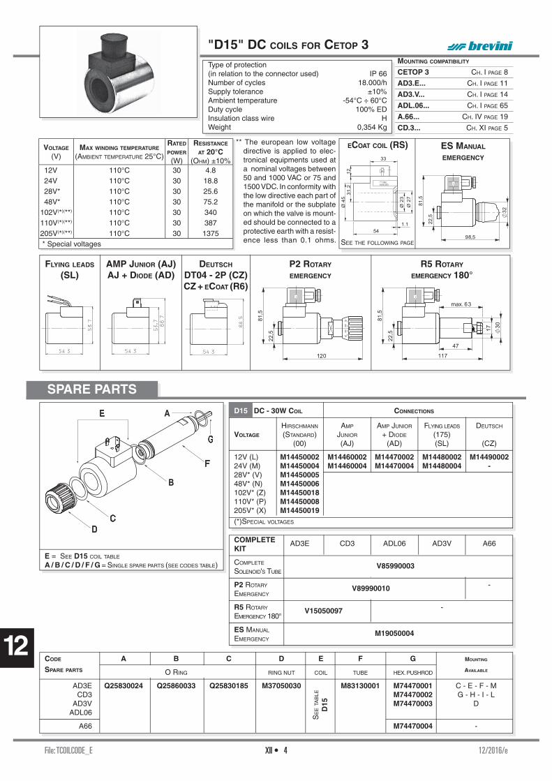
File: TCOILCODE_E 12/2016/eXII • 4
12
MOUNTING COMPATIBILITY
CETOP 3 CH. I PAGE 8
AD3.E... CH. I PAGE 11
AD3.V... CH. I PAGE 14
ADL.06... CH. I PAGE 65
A.66... CH. IV PAGE 19
CD.3... CH. XI PAGE 5
SPARE PARTS
E = SEE D15 COIL TABLE
A / B / C / D / F / G = SINGLE SPARE PARTS (SEE CODES TABLE)
"D15" DC COILS FOR CETOP 3Type of protection (in relation to the connector used) IP 66Number of cycles 18.000/hSupply tolerance ±10%Ambient temperature -54°C ÷ 60°CDuty cycle 100% EDInsulation class wire HWeight 0,354 Kg
R5 ROTARY EMERGENCY 180°
FLYING LEADS (SL)
DEUTSCH DT04 - 2P (CZ)CZ + ECOAT (R6)
AMP JUNIOR (AJ)AJ + DIODE (AD)
P2 ROTARY EMERGENCY
D15 DC - 30W COIL CONNECTIONS
HIRSCHMANN AMP AMP JUNIOR FLYING LEADS DEUTSCH
VOLTAGE (STANDARD) JUNIOR + DIODE (175) (00) (AJ) (AD) (SL) (CZ)
12V (L) M14450002 M14460002 M14470002 M14480002 M1449000224V (M) M14450004 M14460004 M14470004 M14480004 -28V* (V) M1445000548V* (N) M14450006102V* (Z) M14450018110V* (P) M14450008205V* (X) M14450019(*)SPECIAL VOLTAGES
CODE A B C D E F G MOUNTING
SPARE PARTS O RING RING NUT COIL TUBE HEX. PUSHROD AVAILABLE
AD3E Q25830024 Q25860033 Q25830185 M37050030 M83130001 M74470001 C - E - F - M CD3 M74470002 G - H - I - L AD3V M74470003 D ADL06
A66 M74470004 -
SE
E T
AB
LE
D15
COMPLETEKIT
AD3E CD3 ADL06 AD3V A66
COMPLETE
SOLENOID'S TUBE V85990003
P2 ROTARY -EMERGENCY
V89990010
R5 ROTARY - EMERGENCY 180°
V15050097
ES MANUAL EMERGENCY
M19050004
ECOAT COIL (RS)VOLTAGE (V)
MAX WINDING TEMPERATURE (AMBIENT TEMPERATURE 25°C)
RATED POWER (W)
RESISTANCE AT 20°C
(OHM) ±10%12V 110°C 30 4.824V 110°C 30 18.828V* 110°C 30 25.648V* 110°C 30 75.2
102V(*)(**) 110°C 30 340110V(*)(**) 110°C 30 387205V(*)(**) 110°C 30 1375 * Special voltages
** The european low voltage directive is applied to elec-tronical equipments used at a nominal voltages between 50 and 1000 VAC or 75 and 1500 VDC. In conformity with the low directive each part of the manifold or the subplate on which the valve is mount-ed should be connected to a protective earth with a resist-ence less than 0.1 ohms.
ES MANUAL
EMERGENCY
SEE THE FOLLOWING PAGE
33
*** VDC100% ED
54
Ø 4
5
1.1
Ø 2
3
Ø 2
7
31.2
12

File: TCOILCODE_E 12/2016/eXII • 5
12
MOUNTING COMPATIBILITY
CETOP 3 CH. I PAGE 8
AD3.E... CH. I PAGE 11
ADL.06... CH. I PAGE 65
DEUTSCH ECOAT(1) COILS (D15 R6 VARIANT)
HIRSCHMANN ECOAT(1) COILS (D15 RS VARIANT)
Type of protection (in relation to the connector) IP 66Number of cycles 18.000/hSupply tolerance ±10%Ambient temperature -54°C ÷ 60°CDuty cycle 100% EDInsulation class wire HWeight 0,354 Kg
33
*** VDC100% ED
54
Ø 4
5
1.1
Ø 2
3
Ø 2
7
31.2
12
SPARE PARTSECOAT COIL
RS VARIANTD15 ECOAT COIL (DC / 30W)
VOLTAGE HIRSCHMANN (STANDARD)
12V (L) M14820001
24V (M) M14820002
28V* (V) M14820005
110V* (P) M14820008
(*)SPECIAL VOLTAGESSEE "D15" COIL STANDARD FOR BOTH EMERGENCY MANUAL ES AND ROTARY P2.
CODE SPARE PARTS FOR RS VARIANT
B / C / D / E / F / G
B OR (TUBE) Q25830024
C RING NUT M37050062
D O RING (RING NUT) Q25830185
E O RING (COIL) Q25860033
F TUBE M83130001
G HEX. PUSHROD
(MOUNTING C-E-F) M74470001 (MOUNTING G-H-I) M74470002 (MOUNTING D) M74470003
VOLTAGE (V)
MAX. WINDING TEMPERATURE (AMBIENT TEMPERATURE 25°C)
RATED POWER (W)
RESISTANCE AT 20°C (OHM) ±10%
12V 110°C 30 4.824V 110°C 30 18.828V* 110°C 30 25.6
110V(*)(**) 110°C 30 387 * Special voltages
** The european low voltage directive is applied to electronical equip-ments used at a nominal voltages between 50 and 1000 VAC or 75 and 1500 VDC. In conformity with the low directive each part of the manifold or the subplate on which the valve is mounted should be connected to a protective earth with a resistence less than 0.1 ohms.
Type of protection (in relation to the connector) IP 69KNumber of cycles 18.000/hSupply tolerance ±10%Ambient temperature -54°C ÷ 60°CDuty cycle 100% EDInsulation class wire HWeight 0,354 Kg
SPARE PARTSECOAT COIL - R6 VARIANT
D15 ECOAT COIL (DC / 30W)
TENSIONE DEUTSCH
12V (L) M14830001
24V (M) M14830002
SEE "D15" COIL STANDARD FOR BOTH EMERGENCY MANUAL ES AND ROTARY P2.
VOLTAGE (V)
MAX. WINDING TEMPERATURE (AMBIENT TEMPERATURE 25°C)
RATED POWER (W)
RESISTANCE AT 20°C (OHM) ±10%
12V 110°C 30 4.824V 110°C 30 18.8
(1) Sealed coil winding with steel out housing with eCoat protection. Has succesfully overcome more than 700 hours of salt spray test before red rust (test according to UNI EN ISO 9227 and test evaluation according to UNI EN ISO 10289).
(1)Sealed coil winding with steel out housing with eCoat protection. Has succesfully overcome more than 700 hours of salt spray test before red rust (test according to UNI EN ISO 9227 and test evaluation according to UNI EN ISO 10289).
MOUNTING COMPATIBILITY
CETOP 3 CH. I PAGE 8
AD3.E... CH. I PAGE 11
ADL.06... CH. I PAGE 65
CODE SPARE PARTS FOR R6 VARIANT
B / C / D / E / F / G
B OR (TUBE) Q25830024
C RING NUT M37050062
D O RING (RING NUT) Q25830185
E O RING (COIL) Q25860033
F TUBE M83130001
G HEX. PUSHROD
(MOUNTING C-E-F) M74470001 (MOUNTING G-H-I) M74470002 (MOUNTING D) M74470003
33
*** VDC100% ED
54
Ø 4
5
1.1
Ø 2
3
Ø 2
7
31
.2

File: TCOILCODE_E 12/2016/eXII • 6
12
"40W" DC COIL (FOR CDL.06...)
MOUNTING COMPATIBILITY
CDL.06... CH. I PAGE 64
Type of protection (in relation to the connector) IP 66Number of cycles 18.000/hSupply tolerance ±10%Ambient temperature -54°C ÷ 60°CDuty cycle 100% EDInsulation class wire HWeight 0,354 Kg
40W DC COIL CONNECTIONS
VOLTAGE HIRSCHMANN
(STANDARD)
12V (L) M14600001
24V (M) M14600002
DEUTSCH
(CZ)
12V (L) M14610001
24V (M) M14610002 ET40W-CODE - 00/2007/e
SPARE PARTS
VOLTAGE MAX. WINDING TEMPERATURE RATED POWER RESISTANCE AT 20°C (V) (AMBIENT TEMPERATURE 25°C) (W) (OHM) ±10%
12V 135°C 40 3.6 24V 135°C 40 14.4
ES MANUAL
EMERGENCY
P2 ROTARY EMERGENCY
A = SEE 40W COIL TABLE B/C/D/E/F/G = SINGLE SPARE PARTS (SEE TABLE)
DEUTSCH
(CZ)DT04 - 2P
CODE SPARE PARTS FOR CDL06B / C / D / E / F / G
B O RING (TUBE) Q25830024
C RING NUT M37050030
D O RING (RING NUT) Q25830185
E O RING (COIL) Q25860033
F TUBE M83130001
G HEX. PUSHROD M74470003
COMPLETE
KIT CDL06
P2 ROTARY
EMERGENCY V89990010
ES MANUAL
EMERGENCY M19050004

File: TCOILCODE_E 12/2016/eXII • 7
12
"B14" AC SOLENOIDS FOR CETOP 3
Type of protection (in relation to the connector used) IP 65Number of cycles 18.000/hSupply tolerance +10% / -10%Ambient temperature -30°C ÷ 60°CDuty cycle 100% EDInsulation class wire HWeight 0,436 Kg
MOUNTING COMPATIBILITY
CETOP 3 * CH. I PAGE 8
AD3.E... * CH. I PAGE 11
B = SEE B14 COIL TABLE
A / C / D / E / F = SINGLE SPARE PARTS (SEE CODES TABLE)
P2 ROTARY
EMERGENCY
ES MANUAL
EMERGENCY
B14 AC COIL CONNECTION
VOLTAGE HIRSCHMANN
(STANDARD)
24V/50-60HZ (A) M1464000348V/50-60HZ (B) M14640007
115V/50HZ (J) M14640006120V/60HZ
230V/50HZ (Y) M14640001240V/60HZ
SE
E
B14
COMPLETE KIT CODE
TUBE KIT V85990011
ROTARY EMERGENCY P2 V89990021
MANUAL EMERGENCY ES M19050001
A
F
E
D
C
B
SPARE PARTS
85,5
80
,8
112
81,1
CODE A B C D E F MOUNTING
SPARE PARTS O RING COIL O RING RING NUT TUBE HEX. PUSHROD AVAILABLE
AD3E* Q25830024 Q25860036 M37050041 M831100001 M74520001 C - E - F - M M74520002 G - H - I - L M74520003 D
(*) serial No. 3 (AC voltage)
(*) serial No. 3 (AC voltage)
VOLTAGE (V)
MAX. WINDING TEMPERATURE (AMBIENT TEMPERATURE 25°C)
RESISTANCE AT 20°C (OHM) ±10%
RATED POWER
(VA)PICKUP CURRENT
(A)24V/50Hz - 24V/60Hz 100°C - 96°C 1.7 54 - 40 5.6 - 548V/50Hz - 48V/60Hz 112°C - 98°C 6.8 45 - 34 5.3 - 5
115V/50HZ - 120V/60HZ * 133°C - 101°C 32.5 61 - 51 3.2 - 3.2230V/50Hz - 240V/60Hz * 120°C - 103°C 134 62 - 52 1.6 - 1.6
* The european low voltage directive is applied to electronical equip-ments used at a nominal voltages between 50 and 1000 VAC or 75 and 1500 VDC. In conformity with the low directive each part of
the manifold or the subplate on which the valve is mounted should be connected to a protective earth with a resistence less than 0.1 ohms.

File: TCOILCODE_E 12/2016/eXII • 8
12
Type of protection (in relation to the connector used) IP 65Number of cycles 18.000/hSupply tolerance ±10%Ambient temperature -30°C ÷ 60°CDuty cycle 100% EDInsulation class wire HWeight 0,9 Kg
MOUNTING COMPATIBILITY
CETOP 5 CH. I PAGE 29
AD5.E... CH. I PAGE 32
CDL.10... CH. I PAGE 66
ADL.10.6... CH. I PAGE 67
A.88... CH. IV PAGE 33
SPARE PARTS
E = SEE A16 COIL TABLE
A / B / C / D / F / G = SINGLE SPARE PARTS (SEE CODES TABLE)
P2 ROTARY
EMERGENCY
ES MANUAL
EMERGENCY
ETA16-CODE - 00/2007/e
CODE A B C D E F G MOUNTING
SPARE PARTS O RING RING NUT COIL TUBE HEX. PUSHROD AVAILABLE
AD5E Q25830026 Q25860040 Q25860040 M37050033 M83160001 M74440002 C - E - F - M ADL/CDL10 M74440003 G - H - I - L M74440004 D A88 M74440006 -
SE
E
A16
A16 DC/45W COIL CONNECTION
VOLTAGE HIRSCHMANN
(STANDARD)
12V (L) M14220002
24V (M) M14220004
48V* (N) M14220006
102V* (Z) M14220013
110V* (P) M14220008
205V* (X) M14220014
(*)SPECIAL VOLTAGES
COMPLETE KIT AD5E CDL10 ADL10 A88
P2 ROTARY EMERGENCY V89990011 -
ES MANUAL EMERGENCY M19050002 -
"A16" DC COILS FOR CETOP 5
VOLTAGE (V)
MAX WINDING TEMPERATURE (AMBIENT TEMPERATURE 25°C)
RATED POWER (W)
RESISTANCE AT 20°C (OHM) ±7%
12V 106°C 45 3.224V 113°C 45 12.448V* - 45 -
102V(*)(**) - 45 -110V(*)(**) 118°C 45 268205V(*)(**) - 45 - * Special voltages
** The european low voltage directive is applied to electronical equipments used at a nominal voltages between 50 and 1000 VAC or 75 and 1500 VDC. In conformity with the low directive each part of the manifold or the subplate on which the valve is mounted should be connected to a protective earth with a resistence less than 0.1 ohms.

File: TCOILCODE_E 12/2016/eXII • 9
12
"D19" DC SOLENOIDS
MOUNTING COMPATIBILITY
ADP.5.E... CH. I PAGE 37
ADP.5.V... CH. I PAGE 40
P2 ROTARY
EMERGENCY
Type of protection (in relation to the connector used) IP 66Number of cycle 18.000/hSupply tolerance ±10%Ambient temperature -54°C ÷ 60°CDuty cycle 100% EDMax static pressure 210 barInsulation class wire HWeight 1,63 Kg
SPARE PARTS
A = SEE D19 COIL TABLE
B / C / D / E / F / G = SINGLE SPARE PARTS (SEE CODES TABLE) CODE SPARE PARTS FOR ADP5EB / C / D / E / F / G AND ADP5V
B O RING (TUBE) Q25830101
C RING NUT M37050022
D O RING (RING NUT) Q25830035
E O RING (COIL) Q25860035
F TUBE M83170002
G HEX. PUSHROD M74380002
D19 DC/42W COIL CONNECTION
VOLTAGE HIRSCHMANN
(STANDARD)
12V (L) M14270001
24V (M) M14270002
48V* (N) M14270003
102V* (Z) M14270007
110V* (P) M14270005
205V* (X) M14270008
(*)SPECIAL VOLTAGES
COMPLETEKIT ADP5E ADP5V
P2 ROTARY
EMERGENCY V89990012
ETD19-CODE - 00/2007/e
VOLTAGE
(V)MAX WINDING TEMPERATURE
(AMBIENT TEMPERATURE25°C)
RATED
POWER (W)
RESISTANCE AT 20°C (OHM)
±10%12V 105°C 42 3.4324V 105°C 42 13.7148V* 105°C 42 55
102V(*)(**) 105°C 42 248110V(*)(**) 105°C 42 288205V(*)(**) 105°C 42 1000 * Special voltage
** The european low voltage directive is applied to elec-tronical equipments used at a nominal voltages between 50 and 1000 VAC or 75 and 1500 VDC. In conformity with the low directive each part of the manifold or the subplate on which the valve is mounted should be connected to a protective earth with a resist-ence less than 0.1 ohms.

File: TCOILCODE_E 12/2016/eXII • 10
12
Type of protection (in relation to the connector used) IP 66Number of cycles 18.000/hSupply tolerance +10% / -10%Ambient temperature -54°C ÷ 60°CDuty cycle 100% EDMax. pressure static 210 barInsulation class wire HWeight 0,8 Kg
"K16" AC SOLENOIDS FOR CETOP 5
MOUNTING COMPATIBILITY
CETOP 5 CH. I PAGE 29
AD5.E... CH. I PAGE 32
P2 ROTARY
EMERGENCY
ES MANUAL
EMERGENCY
SPARE PARTS
E = SEE K16 COIL TABLE
A / B / C / D / F / G = SINGLE SPARE PARTS (SEE CODES TABLE)
CODE A B C D E F G MOUNTING
SPARE PARTS O RING RING NUT COIL TUBE HEX. PUSHROD AVAILABLE
AD5E Q25830026 Q25860026 Q25830187 M37050005 M83300000 M74210000 C - E - F M74160000 G - H - I - L M74700000 D
SE
E
K16
K16 AC COIL CONNECTION
VOLTAGE HIRSCHMANN
(STANDARD)
24V/50HZ (A) M1430001024V/60HZ* (F) M1430001248V/50HZ* (B) M14300014
115V/50HZ (J) M14300029120V/60HZ
230V/50HZ (Y) M14300027240V/60HZ
240V/50HZ* (E) M14300025
(*)SPECIAL VOLTAGES
COMPLETEKIT
AD5E
P2 ROTARY
EMERGENCY V89990002
ES MANUAL EMERGENCY M19050002
ETK16-CODE - 00/2007/e
VOLTAGE (V)
MAX. WINDING TEMPERATURE (AMBIENT TEMPERATURE25°C)
RATED POWER(VA)
IN RUSH CURRENT (VA)
RESISTANCE AT 20°C (OHM) ±10%
24V/50Hz 134°C 124 454 0.5624V/60Hz* 115°C 103.5 440 0.5548V/50Hz* 134°C 113 453 2.10
115V/50Hz-120V/60Hz(*)(**) 121°C - 138°C - - 10.8230V/50Hz-240V/60Hz(*)(**) 121°C - 138°C - - 43.0
240V/50Hz(*)(**) 134°C 120 456 47.39 * Special voltage
** The european low voltage directive is applied to electronical equip-ments used at a nominal voltages between 50 and 1000 VAC or 75 and 1500 VDC. In conformity with the low directive each part of the manifold or the subplate on which the valve is mounted should be connected to a protective earth with a resistence less than 0.1 ohms.

File: TCOILCODE_E 12/2016/eXII • 11
12
"22W" DC COILS
Type of protection (in relation to the connector) IP 65Number of cycles 18.000/hSupply tolerance +10% / -10%Ambient temperature -30°C ÷ 60°CDuty cycle 100% EDInsulation class wire HWeight 0,2 Kg
MOUNTING COMPATIBILITY
CRP/CRD BFP CARTRIDGE CAT.
C2V.02... BFP CARTRIDGE CAT.
SPARE PARTS
PS ROTARY EMERGENCY
CODE B B1 C + C1 D E F G H
SPARE PARTS PARBAK O RING O RING RING NUT O RING TUBE HEX. PUSHROD VALVE
C2V/C3V02 VALVE SEAT (R. NUT/COIL) (TUBE) SEAT
C2V02NC... Q25780026 Q25830015 Q25860055 M37050026 Q25861010 M83040005 M50070002 M70400002 C2V02NA... M50070003
C3V02... _ Q25880036 M50070001 M70400001 Q25880045
COMPLETE
KIT CRP02NA CRD01/02 CRP02NC C2V02 C3V02
PS ROTARY
EMERGENCY V89990014 V89990005 -
A = SEE 22W COIL TABLE
B+B1 / C+C1 / D / E / F / G / H SINGLE SPARE PARTS (SEE TABLE)
CODE B B1 C + C1 D E + F G H
SPARE PARTS PARBAK O RING O RING RING NUT TUBE HEX. PUSHROD VALVE
CRP/CRD VALVE SEAT (R. NUT/COIL) (+ O RING TUBE) SEAT
CRP02NC...E Q25780026 Q25830015 Q25860055 M37050026 R83100B83 M86150006 M70150003
CRP02NC...S R83100B82 M86150004
CRP02NA...E R83100B84 M86150004
CRD01...A Q25780026 Q25830015 R83100B85 M74440000 M70150004
CRD01...B Q25780030 Q25830021 M70150005
CRD02...A Q25780026 Q25830015 M74440001 M70150004
CRD02...B Q25780030 Q25830021 M70150005
AMP JUNIOR (AJ)
22W DC COIL CONNECTIONS
VOLTAGE STANDARD AMP JUNIOR (AJ)
12V (L) M14040001 M1473000124V (M) M14040002 M1473000248V* (N) M14040003 —102V* (Z) M14040006 —205V* (X) M14040007 —
(*) SPECIAL VOLTAGES ET20W-CODE - 01/2008/e
47,7
38,5
60,7
VOLTAGE (V)
MAX. WINDING TEMPERATURE (AMBIENT TEMPERATURE 25°C)
RATED POWER (W)
RESISTANCE AT 20°C (OHM) ±10%
12V 116 °C 22 6.3
24V 115 °C 22 25.6
48V* 114 °C 22 102102V(*)(**) - 22 467.85205V(*)(**) - 22 1954
* SPECIAL VOLTAGE
** The european low voltage directive is ap-plied to electronical equipments used at a nominal voltages between 50 and 1000 VAC or 75 and 1500 VDC. In conform-ity with the low directive each part of the manifold or the subplate on which the valve is mounted should be connected to a protective earth with a resistence less than 0.1 ohms.

File: TCOILCODE_E 12/2016/eXII • 12
12
"30W" DC COILS
Type of protection (in relation to the connector used) IP 65Number of cycles 18.000/hSupply tolerance +10% / -10%Ambient temperature -54°C ÷ 60°CDuty cycle 100% EDInsulation class wire HWeight 0,2 Kg
VOLTAGE MAX. WINDING TEMPERATURE RATED POWER RESISTANCE AT 20°C (V) (AMBIENT TEMPERATURE 25°C) (W) (OHM) ±10%
12V 108°C 30 4.7 24V 108°C 30 18.8
IT30W - 02/1999/i
P2 ROTARY
EMERGENCY
FLUSSO FORZA AZIONAMENTO
2 → 1 10N
1 → 2 10+ (2,5 X P) N
P = PRESSIONE DI UTILIZZO (BAR)
MOUNTING COMPATIBILITY
CRD.04... BFP CARTRIDGE CAT.
VE
RS. A
VE
RS. B
SPARE PARTS
ES MANUAL
EMERGENCY
ET20W-CODE - 00/2007/e
30W DC COIL
12V 24V
M14100010 M14100011 ( L ) ( M )
A = SEE 30W COIL TABLE
B+B1+B2 / C / D / E+E1 / F / G / H = SINGLE SPARE
PARTS (SEE TABLE)
COMPLETE KIT CDL04
P2 ROTARY EMERGENCY V89990007
ES MANUAL EMERGENCY M19050001
B B1 B2 C D E E1 F G H
PARBAK O RING O RING O RING RING NUT O RING O RING TUBE HEX. PUSHROD VALVE
VALVE SEAT (TUBO) (COIL) (RING NUT) SEAT
Q25780026 Q25830015 Q25831017 Q25861010 M37050004 Q25830026 Q25830183 R83200997 M74360000 M70150004
Q25780030 Q25830021 M70150005

File: TUL22W27W_E 02/2010/eXII • 13
12
1 Recognized Component Mark
2 Type Coil code, voltage and connector type
M.14.31.0011 12 VDC (Hirschmann) M.14.31.0012 24 VDC (Hirschmann) M.14.07.0021 12 VDC (With fl ying leads) M.14.07.0022 24 VDC (With fl ying leads)
3 22W@+ 50°C Power at +50°C (ambient temperature) for 12V coils
27W@+ 50°C Power at +50°C (ambient temperature) for 24V coils
32W@- 25°C Power at -25°C (ambient temperature) for 12 and 24V coils
4 ED 100% Duty cycle
5 Tamb Ambient operating temperature -25°C ÷ +50°C
6 Class H Insulation class wire
"22 W" DC COILS
IDENTIFICATION MARK
1 Recognized Component Mark
2 Type Coil code, voltage and connector type
M.14.04.0021 12 VDC (Hirschmann) M.14.04.0022 24 VDC (Hirschmann) M.14.04.0031 12 VDC (With fl ying leads) M.14.04.0032 24 VDC (With fl ying leads)
3 21W@+ 50°C Power at +50°C (ambient temperature) for 12 and 24V coils
27W@- 25°C Power at -25°C (ambient temperature) for 12 and 24V coils
4 ED 100% Duty cycle
5 Tamb Ambient operating temperature -25°C ÷ +50°C
6 Class H Insulation class wire
UL RECOGNIZED COMPONENT MARK COILS
6
45
1
"27W" DC COILS
IDENTIFICATION MARK
23
27 W COIL
22 W COIL
UL CATEGORY CODE (CCN)- U.S.A. YSY12- Canada YSY18
The is the accredited Unit to release the UL Mark, the most valued product safety symbol.
6
45
23
1
UL RECOGNIZED COMPONENT MARK
The UL Recognized Component Mark may be used on component parts that are part of a larger product or system. The UL Mark is the most widely recognised and accepted evidence of product's compliance with Canadian and USA safety requirements.
UL category code number (CCN) is assigned in order to identify wich product categories are covered by UL's Certifi cation. Our category covers valve parts, such as solenoid operators, coil assemblies, coil enclosures, valve assemblies and similar items intended to be used as parts of electrically operated valves as indicated in the individual Recognitions.
Visiting the UL web site (www.ul.com), linking certifi -cations and writing the correct Aron UL File Number you can fi nd our Certifi cation.
The UL File Number is an alphanumeric designation assigned to any Company upon successful completion of a product evaluation or company certifi cation.
ARON UL FILE NUMBER
MH45162

File: TUL22W27W_E 02/2010/eXII • 14
12
"22W" DC COILS - UL RECOGNIZED
FLYING LEADS (UZ)
HIRSCHMANN
(UR)
Type of protection (in relation to connector used) IP 65Number of cycle 18.000/hSupply tolerance -15% / +10%Ambient temperature -25°C ÷ 50°CPower at +50°C (ambient temperature) for 12 and 24V coils 21WPower at -25°C (ambient temperature) for 12 and 24V coils 27WDuty cycle 100% EDInsulation class wire HWeight 0,215 Kg
VOLTAGE MAX WINDING TEMPERATURE RATED POWER RESISTANCE AT 20°C (V) (AMBIENT TEMPERATURE 25°C) (W) (OHM) ±10%
12V 116°C 22 6.30 24V 116°C 22 25.60
ETUL22W - 00/2007/e
"22W" MOUNTING CRP, CRD, C2V02 and C3V02COMPATIBILITY see Ch. V "Cartridge valves"
VARIANT CODE UR = Hirschmann connection UZ = Solenoid with fl ying leads (500 mm) Other variants relate to a special design
VOLTAGE CODE L = 12 VDC M = 24 VDC Voltage code is always stamped over on the coil
VARIANT AND VOLTAGE CODES (WICH HAVE TO PUT IN THE ORDERING CODE VALVE)
FLYING LEADS (UZ)
HIRSCHMANN
(UR)
"27W" DC COILS - UL RECOGNIZED
Type of protection (in relation to connector used) IP 65Number of cycle 18.000/hSupply tolerance -15% / +10%Ambient temperature -25°C ÷ 50°CPower at +50°C (ambient temperature) for 12V coil 22WPower at +50°C (ambient temperature) for 24V coil 27WPower at -25°C (ambient temperature) for 12 and 24V coils 32WDuty cycle 100% EDInsulation class wire HWeight 0,215 Kg
VOLTAGE MAX WINDING TEMPERATURE RATED POWER RESISTANCE AT 20°C (V) (AMBIENT TEMPERATURE 25°C) (W) (OHM) ±7%
12V 123°C 27 5.30 24V 123°C 27 21.30
ET27WUL - 00/2007/e
VARIANT AND VOLTAGE CODES (WICH HAVE TO PUT IN THE ORDERING CODE VALVE)
"27W" MOUNTING AD2E... ADC3E.. and CDL04... see Ch. I "Directional control"COMPATIBILITY C3V03... see Ch. V "Cartridge valves" CDC3... see Ch. XI "Stackable valves"
VARIANT CODE UR = Hirschmann connection UZ = Solenoid with fl ying leads (250 mm) Other variants relate to a special design
VOLTAGE CODE L = 12 VDC M = 24 VDC Voltage code is always stamped over on the coil


Brevini Fluid Power S.p.A.Via Moscova, 642124 Reggio Emilia - ItalyTel. +39 0522 270711Fax +39 0522 270660www.brevinifl uidpower.cominfo@brevinifl uidpower.com
Code DOC00078- Rev. 00