
PVC FITTINGS & VALVES
80
PVC FITTINGS & VALVES Technical Catalogue
-
Upload
khangminh22 -
Category
Documents
-
view
0 -
download
0
Transcript of PVC FITTINGS & VALVES
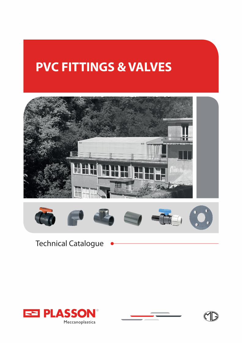
PVC FITTINGS & VALVES
Technical Catalogue

Plasson’s innovative products revolutionized the way of connecting polyethylene pipes in the 1960’s. We started with fittings for agricultural irrigation and later developed products for urban water distribution.
High pressure PVC Fittings and Valves are part of Plasson’s wide range of products. Plasson has achieved superior designs and products and a genuine commitment to quality, delivery and service.
Plasson continues to strive for the future environment. By buying Plasson products you help us invest in our vision of a world where clean, pure water will be everyone’s birthright.
2
INTRODUCTION
INTRODUCTION
CEMENTED FITTINGS 10-19
ADAPTOR FITTINGS 20-26
THREADED FITTINGS 27-33
FITTINGS ACCESSORIES 34-37
TECHNICAL SPECIFICATIONS - FITTINGS 38-39
BONDING INSTRUCTIONS 40
ASSEMBLY INSTRUCTIONS THREADED 41
FLANGE & COLLARS 42
VALVES NORMAL SUPPORT 44-45
VALVES THREADED SUPPORT 46-54
ACTUATOR 55-56
VALVES THREADED SUPPORT 57
CHECK VALVES 58-59
KNOCKER TEE 60
FOOT VALVES 61-62
AIR RELEASE VALVES 63-64
VALVES ACCESSORIES 65-70
TECHNICAL SPECIFICATIONS - VALVES 71-72
ASSEMBLY INSTRUCTIONS 73-78
3
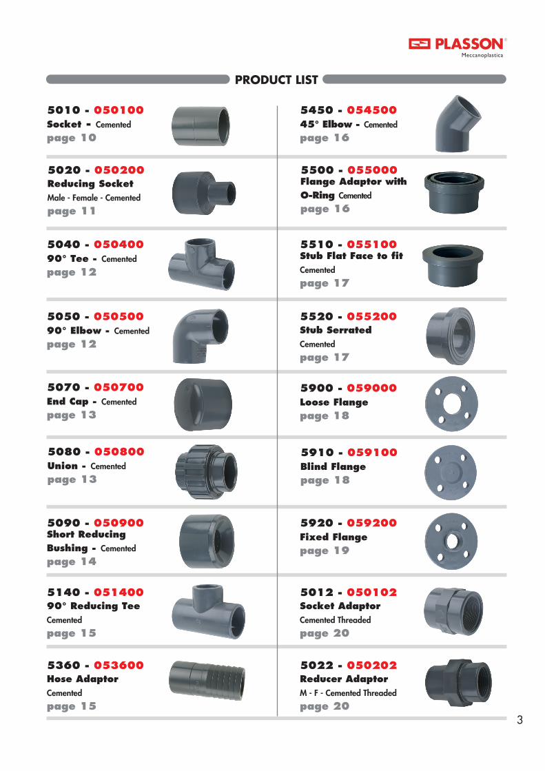
PRODUCT LIST
5010 - 050100Socket - Cemented
page 10
5020 - 050200Reducing SocketMale - Female - Cemented
page 11
5040 - 05040090° Tee - Cemented
page 12
5050 - 05050090° Elbow - Cemented
page 12
5070 - 050700End Cap - Cemented
page 13
5080 - 050800Union - Cemented
page 13
5090 - 050900Short Reducing Bushing - Cemented page 14
5140 - 05140090° Reducing TeeCemented
page 15
5360 - 053600Hose Adaptor Cemented
page 15
5450 - 05450045° Elbow - Cemented
page 16
5500 - 055000Flange Adaptor with O-Ring Cemented
page 16
5510 - 055100Stub Flat Face to fit Cemented page 17
5520 - 055200Stub Serrated Cemented
page 17
5900 - 059000Loose Flangepage 18
5910 - 059100Blind Flangepage 18
5920 - 059200Fixed Flangepage 19
5012 - 050102Socket AdaptorCemented Threaded
page 20
5022 - 050202Reducer AdaptorM - F - Cemented Threaded page 20

4
PRODUCT LIST
5032 - 050302Adaptor SocketM - F - Cemented - Threaded page 20
5042 - 05040290° TeeCemented Threaded
page 21
5052 - 05050290° ElbowCemented Threaded
page 21
5062 - 050602AdaptorM - F - Cemented - M - Threaded page 21
5082 - 050802Union AdaptorF - Cemented - Threaded page 22
5212 - 052102AdaptorM - F - Cemented - M - Threaded page 22
5222 - 052202Bushing AdaptorM - F - Cemented - M - Threaded
page 22
5362 - 053602Hose AdaptorWith Threaded Nutpage 23
5452 - 05450245° ElbowCemented - Threadedpage 23
5142 - 05140290° Reducing TeeCemented - Threaded page 23
5712 - 057102Socket Adaptor Cemented
Threaded with Reinforcing Ring page 24
5722 - 057202Reducer Adaptor with Reinforcing Ring Male Cemented - Female - Threadedpage 24
5742 - 05740290° Tee with Reinforcing Ring Cemented Threaded page 25
5752 - 05750290° Elbow with Reinforcing Ring Cemented Threaded
page 26
5732 - 057302Adaptor Socket Reinforcing Ring M - F
page 26
5011 - 050101Socket - Threaded
page 27
5021 - 050201ReducerMale - Female - Threaded
page 28
5013 - 050103Reducing SocketFemale - Female - Threadedpage 27

5
PRODUCT LIST
5041 - 05040190° TeeThreaded
page 28
5051 - 05050190° ElbowThreaded
page 29
5061 - 050601NippleThreaded
page 29
5071 - 050701CapThreaded
page 29
5081 - 050801Union FemaleThreaded
page 30
5083 - 050803Union Male - Female
Cemented Threaded
page 30
5084 - 050804Union Male - Female - Threaded page 30
5361 - 053601Hose AdaptorThreaded
page 32
5221 - 052201Nipple SocketMale - Female - Threadedpage 32
5451 - 05450145° ElbowThreaded
page 33
5921 - 059201Fixed FlangeThreaded
page 33
5480 - 054800Nut for Unions:
page 34
5580 - 055800Bushing for Union:
page 34
5581 - 055801Bushing for Unions:
page 34
5161 - 051601Reducing NippleThreadedpage 31
5171 - 051701PlugThreaded
page 32
5583 - 055803Male Threaded Union bush
page 33
5680 - 056800End for Unions:
page 35

6
PRODUCT LIST
1148 - 111480Two Nut ValvePE End Connectorpage 50
1140 - 11140Two Nut ValveCemented
page 46
1120 - 11120Two Nut ValveCemented
page 46
1140ATwo Nut ValveCemented - Potable water
page 48
1120A - 11120ATwo Nut ValveCemented - Potable water
page 48
1141ATwo Nut ValveThreaded - Potable water
page 49
1121A - 11121ATwo Nut ValveThreaded - Potable water
page 49
5681 - 056801End for Unions
page 35
5690 - 056090O-Ring for Item
page 36
5629 - 056290Seal
page 36
O-R - 056390O-Ring for Unions
page 37
1150 - 11150Two Nut ValveCemented
page 44
1151 - 11151Two Nut ValveThreaded
page 44
1350 - 11350One Nut ValveCemented page 45
1351 - 11351One Nut ValveThreadedpage 45
1361 - 11361One Nut ValveMale - Female - Threadedpage 45
1141 - 11141Two Nut ValveThreaded
page 47
1121 - 11121Two Nut ValveThreaded
page 47

7
PRODUCT LIST
1240 - 112401270 - 11270*Bistop Valve Cemented
page 51
1220 - 112201230 - 11230*Bistop Valve Cemented
page 51
1241 - 112411271 - 11271*Bistop Valve Threaded
page 52
1221 - 112211231 - 11231*Bistop Valve Threaded
page 52
1340 - 11340One Nut ValveCemented
page 53
1320 - 11320One Nut ValveCemented
page 53
1341 - 11341One Nut ValveThreaded
page 54
1321 - 11321One Nut ValveThreaded
page 54
1371 - 11371One Nut ValveMale - Female - Threadedpage 57
1379 - 11379Compression ValveFemale - Threaded - Compression page 57
1378 - 11378Compression Valve PE End Connectorpage 57
1080 - 11080 1060 - 110601090 - 11090 1000 - 11000 Check Valve Cemented page 58
1070 - 11070 1040 - 110401050 - 11050 1010 - 11010 Check Valve Cemented page 58
1091 - 11091 1041 - 110411051 - 11051 1011 - 11011 Check Valve Threaded page 59
5048 - 050408Knocker TeeCemented
page 60
1188 - 111880Two Nut ValvePE End Connectorpage 50
1081 - 11081 1061 - 110611091 - 11091 1001 - 11001 Check Valve Threaded page 59
1640 - 116401600 - 11600Foot Valve Cemented
page 61

8
PRODUCT LIST
PEI - 1115.207PE End Connector
page 68
MB - 11112Blue Handle
page 66
MRN - 11113Red Handle
page 66
MBNABlueA Handle
page 67
GH - 11114Valve Nut
page 68
1770 - 117701700 - 11700Foot Valve Cemented
page 61
1641 - 116411601 - 11601Foot Valve Threaded
page 62
1771 - 117711701 - 11701Foot Valve Threaded
page 62
1630 - 116301690 - 11690Air Release Valve Cemented
page 63
1730 - 117301790 - 11790Air Release Valve Cemented
page 63
1631 - 116311691 - 11691Air Release Valve Threaded
page 64
1731 - 117311791 - 11791Air Release Valve Threaded
page 64
EI - 11110Valve EndCementedpage 65
EF - 11111Valve EndThreaded
page 65
MBN - 11112Blue Handle
page 66
MR - 11113Red Handle
page 66
MBABlueA Handle
page 67

PVC FITTINGS
9

10
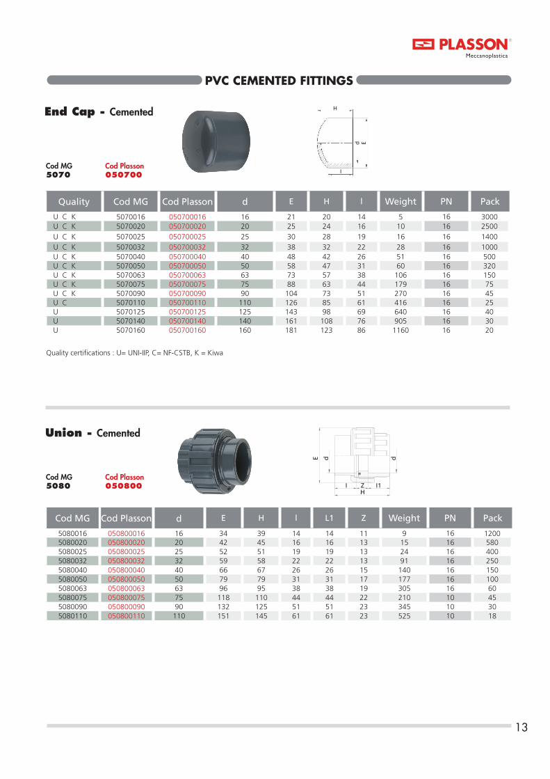
PVC CEMENTED FITTINGS
Socket - Cemented
Quality Cod MG Cod Plasson d E H l Z Weight PN Pack
U C K 5010016 050100016 16 21 30 14 2 7 16 2500 U C K 5010020 050100020 20 25 35 16 3 8 16 1500 U C K 5010025 050100025 25 30 42 19 4 11 16 1000 U C K 5010032 050100032 32 38 48 22 4 20 16 600 U C K 5010040 050100040 40 48 56 26 4 42 16 300 U C K 5010050 050100050 50 58 66 31 4 64 16 180 U C K 5010063 050100063 63 73 80 38 4 119 16 100 U C K 5010075 050100075 75 88 93 44 5 234 16 100 U C K 5010090 050100090 90 104 108 51 6 325 16 60 U C 5010110 050100110 110 126 128 61 6 525 16 28 U 5010125 050100125 125 143 145 69 7 803 16 24 U 5010140 050100140 140 161 160 76 8 1074 16 18 U 5010160 050100160 160 181 181 86 9 1339 16 9 U 5010200 050100200 200 228 224 106 12 2778 10 4
5010225 050100225 225 250 257 119 19 3670 10 3*5010250 *050100250 250 287 275 133 10 5800 10 2*5010280 *050100280 280 320 304 147 10 7750 10 1*5010315 *050100315 315 355 342 165 12 9820 10 1
H
d E
IZ
* DELIVERY PROGRAM
Quality certifications : U= UNI-IIP, C= NF-CSTB, K = Kiwa
Cod Plasson050100
Cod MG5010

11
PVC CEMENTED FITTINGS
Reducing SocketMale - Female - Cemented
Cod MG Cod Plasson Dxdxd1 L l l1 E H Weight PN Pack
5020020016 050200020016 20 x 16 x 16 16 14 14 20 36 6 16 30005020025016 050200025016 25 x 20 x 16 19 16 14 22 39 10 16 15005020025020 050200025020 25 x 20 x 20 19 16 16 25 42 10 16 15005020032016 050200032016 32 x 25 x 16 22 19 14 22 41 15 16 10005020032020 050200032020 32 x 25 x 20 22 19 19 25 45 16 16 10005020032025 050200032025 32 x 25 x 25 22 19 19 31 50 20 16 8005020040016 050200040016 40 x 32 x 16 26 22 14 22 50 23 16 8005020040020 050200040020 40 x 32 x 20 26 22 16 26 52 26 16 7005020040025 050200040025 40 x 32 x 25 26 24 19 32 49 27 16 5005020040032 050200040032 40 x 32 x 32 26 22 29 39 57 35 16 5005020050020 050200050020 50 x 40 x 20 31 26 16 27 61 50 16 4005020050025 050200050025 50 x 40 x 25 31 26 19 33 62 50 16 3005020050032 050200050032 50 x 40 x 32 33 26 22 40 65 55 16 3005020050040 050200050040 50 x 40 x 40 31 26 26 49 69 65 16 3005020063025 050200063025 63 x 50 x 25 38 31 19 32 72 88 16 1705020063032 050200063032 63 x 50 x 32 38 31 22 40 76 93 16 1705020063040 050200063040 63 x 50 x 40 38 33 26 49 79 100 16 1505020063050 050200063050 63 x 50 x 50 34 31 47 61 85 123 16 1505020075032 050200075032 75 x 63 x 32 44 38 22 40 86 120 16 1905020075040 050200075040 75 x 63 x 40 44 38 26 49 87 130 16 1705020075050 050200075050 75 x 63 x 50 44 41 42 61 92 150 16 1505020075063 050200075063 75 x 63 x 63 44 38 38 73 100 163 16 1105020090040 050200090040 90 x 75 x 40 51 44 26 49 99 225 16 1105020090050 050200090050 90 x 75 x 50 51 44 31 62 103 232 16 1005020090063 050200090063 90 x 75 x 63 51 44 38 74 111 259 16 1005020090075 050200090075 90 x 75 x 75 51 44 44 89 117 290 16 805020110050 050200110050 110 x 90 x 50 61 51 31 61 117 410 16 805020110063 050200110063 110 x 90 x 63 61 51 38 76 125 441 16 655020110075 050200110075 110 x 90 x 75 61 51 44 90 133 490 16 355020110090 050200110090 110 x 90 x 90 61 51 51 106 138 545 16 455020125063 050200125063 125 x 110 x 63 69 61 38 78 121 460 16 445020125075 050200125075 125 x 110 x 75 69 61 44 90 125 460 16 445020125090 050200125090 125 x 110 x 90 69 61 51 104 126 460 16 445020125110 050200125110 125 x 110 x 110 69 61 61 123 127 440 16 325020140110 050200140110 140 x 125 x 110 76 69 61 130 149 645 16 245020160110 050200160110 160 x 140 x 110 86 76 61 130 157 825 16 255020160125 050200160125 160 x 140 x 125 86 76 69 145 160 890 16 185020225160 050200225160 225 x 200 x 160 119 106 86 185 230 2100 10 6
H
d1dD E
I I1L
Cod Plasson050200
Cod MG5020

12
90° Tee - Cemented
Quality Cod MG Cod Plasson d E H l Z Weight PN Pack
U C K 5040016 050400016 16 23 46 14 9 18 16 1500 U C K 5040020 050400020 20 26 55 18 12 20 16 700 U C K 5040025 050400025 25 31,5 67 21 14 32 16 500 U C K 5040032 050400032 32 40 91 25 17 56 16 250 U C K 5040040 050400040 40 48 99 26 23 97 16 130 U C K 5040050 050400050 50 62 118 28 28 208 16 80 U C K 5040063 050400063 63 73 145 38 35 372 16 56 U C K 5040075 050400075 75 90 169 44 41 540 16 35 U C K 5040090 050400090 90 108 199 51 49 970 16 24 U C 5040110 050400110 110 129 239 61 59 1510 16 14 U 5040125 050400125 125 148 270 69 66 2234 16 9 U 5040140 050400140 140 162 298 76 73 2650 16 6 U 5040160 050400160 160 184 339 86 84 3793 10 3 *5040200 *050400200 200 232 420 106 102 7200 10 2
*5040225 *050400225 225 258 465 119 114 9700 10 1*5040250 *050400250 250 286 519 132.5 127 12070 10 1*5040280 *050400280 280 319 579 147.5 142 17480 10 1*5040315 *050400315 315 360 648 165 159 24350 10 1
Z
H
dE
I
* DELIVERY PROGRAM
Quality certifications : U= UNI-IIP, C= NF-CSTB, K = Kiwa
PVC CEMENTED FITTINGS
90° Elbow - Cemented
Quality Cod MG Cod Plasson d E H l Z Weight PN Pack
U C K 5050016 050500016 16 23 35 14 9 13 16 1800 U C K 5050020 050500020 20 26 41 14 12 14 16 1000 U C K 5050025 050500025 25 31 49 18 14 22 16 600 U C K 5050032 050500032 32 39 60 20,5 17 40 16 350 U C K 5050040 050500040 40 47 73 26 23 69 16 200 U C K 5050050 050500050 50 59 88 32 27 125 16 130 U C K 5050063 050500063 63 73 110 38 35 300 16 60 U C K 5050075 050500075 75 90 130 44 41 450 16 50 U C K 5050090 050500090 90 108 154 51 49 730 16 30 U C 5050110 050500110 110 132 186 61 59 1232 16 17 U 5050125 050500125 125 148 211 69 66 1668 16 12 U 5050140 050500140 140 162 230 76 73 1970 16 9 U 5050160 050500160 160 184 262 86 84 2850 16 5 *5050200 *050500200 200 232 324 106 102 5850 10 3
*5050225 *050500225 225 258 362 119 114 7500 10 2*5050250 *050500250 250 286 445 132 188 12150 10 1*5050280 *050500280 280 316 496 146 210 15620 10 1*5050315 *050500315 315 358 559 162 239 23500 10 1
H
d E
Z I
* DELIVERY PROGRAM
Quality certifications : U= UNI-IIP, C= NF-CSTB, K = Kiwa
Cod Plasson050400
Cod MG5040
Cod Plasson050500
Cod MG5050
13
PVC CEMENTED FITTINGS
End Cap - Cemented H
d E
I
Quality Cod MG Cod Plasson d E H l Weight PN Pack
U C K 5070016 050700016 16 21 20 14 5 16 3000 U C K 5070020 050700020 20 25 24 16 10 16 2500 U C K 5070025 050700025 25 30 28 19 16 16 1400 U C K 5070032 050700032 32 38 32 22 28 16 1000 U C K 5070040 050700040 40 48 42 26 51 16 500 U C K 5070050 050700050 50 58 47 31 60 16 320 U C K 5070063 050700063 63 73 57 38 106 16 150 U C K 5070075 050700075 75 88 63 44 179 16 75 U C K 5070090 050700090 90 104 73 51 270 16 45 U C 5070110 050700110 110 126 85 61 416 16 25 U 5070125 050700125 125 143 98 69 640 16 40 U 5070140 050700140 140 161 108 76 905 16 30 U 5070160 050700160 160 181 123 86 1160 16 20
Quality certifications : U= UNI-IIP, C= NF-CSTB, K = Kiwa
Union - Cemented
Cod MG Cod Plasson d E H l L1 Z Weight PN Pack
5080016 050800016 16 34 39 14 14 11 9 16 12005080020 050800020 20 42 45 16 16 13 15 16 5805080025 050800025 25 52 51 19 19 13 24 16 4005080032 050800032 32 59 58 22 22 13 91 16 2505080040 050800040 40 66 67 26 26 15 140 16 1505080050 050800050 50 79 79 31 31 17 177 16 1005080063 050800063 63 96 95 38 38 19 305 16 605080075 050800075 75 118 110 44 44 22 210 10 455080090 050800090 90 132 125 51 51 23 345 10 305080110 050800110 110 151 145 61 61 23 525 10 18
H
d dE
I Z I1
Cod Plasson050700
Cod MG5070
Cod Plasson050800
Cod MG5080

14
PVC CEMENTED FITTINGS
Short Reducing Bushing - Cemented
Z
D d
LI
Quality Cod MG Cod Plasson Dxd L l z Weight PN Pack
U C 5090020016 050900020016 20 x 16 16 14 2 3 16 4500 U 5090025016 050900025016 25 x 16 19 14 5 8 16 3000 U C 5090025020 050900025020 25 x 20 19 16 3 5 16 3000 U 5090032016 050900032016 32 x 16 22 14 8 15 16 1800 U 5090032020 050900032020 32 x 20 22 16 6 15 16 1800 U C 5090032025 050900032025 32 x 25 22 19 3 10 16 1800 U 5090040020 050900040020 40 x 20 26 16 10 25 16 1100 U 5090040025 050900040025 40 x 25 26 23 6 27 16 1000 U C 5090040032 050900040032 40 x 32 26 22 4 17 16 1000 U 5090050025 050900050025 50 x 25 31 19 12 43 16 550 U 5090050032 050900050032 50 x 32 31 22 9 50 16 550 U C 5090050040 050900050040 50 x 40 31 26 5 32 16 600 U 5090063032 050900063032 63 x 32 38 22 16 76 16 150 U 5090063040 050900063040 63 x 40 38 26 12 83 16 300 U C 5090063050 050900063050 63 x 50 38 34 6 60 16 300 U 5090075040 050900075040 75 x 40 44 26 18 121 16 126 U 5090075050 050900075050 75 x 50 44 31 13 95 16 126 U C 5090075063 050900075063 75 x 63 44 38 6 80 16 126 U 5090090050 050900090050 90 x 50 51 31 20 195 16 80 U 5090090063 050900090063 90 x 63 51 38 13 183 16 80 U C 5090090075 050900090075 90 x 75 51 44 7 141 16 80 U 5090110063 050900110063 110 x 63 61 38 23 344 16 40 U 5090110075 050900110075 110 x 75 61 44 17 315 16 40 U C 5090110090 050900110090 110 x 90 61 51 10 265 16 40 U 5090125075 050900125075 125 x 75 69 44 25 450 16 60 U 5090125090 050900125090 125 x 90 69 51 18 430 16 60 U 5090125110 050900125110 125 x 110 69 61 8 265 16 60
5090140090 050900140090 140 x 90 76 51 25 590 16 485090140110 050900140110 140 x 110 76 61 15 447 16 485090140125 050900140125 140 x 125 76 69 7 326 16 485090160110 050900160110 160 x 110 86 61 25 775 16 305090160125 050900160125 160 x 125 86 69 17 725 16 305090160140 050900160140 160 x 140 86 76 10 560 16 365090200160 050900200160 200 x 160 106 86 20 1400 10 155090200180 050900200180 200 x 180 106 96 22 1350 10 105090225160 050900225160 225 x 160 119 86 33 2450 10 105090225200 050900225200 225 x 200 119 106 13 1406 10 10*5090250160 *050900250160 250 x 160 134 87 47 2184 10 8*5090250200 *050900250200 250 x 200 134 107 27 2700 10 8*5090250225 *050900250225 250 x 225 132 120 12 2100 10 6*5090280225 *050900280225 280 x 225 147 120 27 3090 10 6*5090280250 *050900280250 280 x 250 147 132 15 2520 10 6*5090315200 *050900315200 315 x 200 165 107 58 8550 10 4*5090315225 *050900315225 315 x 225 165 132 33 8085 10 4*5090315250 *050900315250 315 x 250 165 132 33 4100 10 4*5090315280 *050900315280 315 x 280 165 149 16 4630 10 4
Quality certifications : U = UNI-IIP, C = NF-CSTB
* DELIVERY PROGRAM
Cod Plasson050900
Cod MG5090

15
PVC CEMENTED FITTINGS
90° Reducing TeeCemented
Z
EH
1 Z1I1
d
H
E1d1
I
Cod MG Cod Plasson dxd1xd E E1 l l1 Z Z1 H H1 Weight PN Pack
5140025020 051400025020 25 x 20 x 25 33 27 19 16 14 12.5 66 45 36 16 5005140032020 051400032020 32 x 20 x 32 42 33 22 16 17 27.5 78 54 69 16 3005140032025 051400032025 32 x 25 x 32 41 33 22 19 17 17.5 78 57 63 16 3005140040020 051400040020 40 x 20 x 40 50 30 26 16 23.5 22 99 63 104 16 1805140040025 051400040025 40 x 25 x 40 50 37 26 24 23.5 22 99 66 110 16 1605140040032 051400040032 40 x 32 x 40 50 44 26 22 23.5 22 99 72 120 16 1505140050025 051400050025 50 x 25 x 50 62 37 31 24 28 27.5 118 77 188 16 805140050032 051400050032 50 x 32 x 50 61 41 31 22 28 27.5 118 80 190 16 805140050040 051400050040 50 x 40 x 50 61 50 31 26 28 27.5 118 84 180 16 805140063032 051400063032 63 x 32 x 63 77 41 38 22 34 34.5 144 95 335 16 565140063040 051400063040 63 x 40 x 63 77 50 38 26 34 34.5 144 99 340 16 565140063050 051400063050 63 x 50 x 63 77 61 38 31 34 34.5 144 104 350 16 56
Hose Adaptor Cemented
Cod MG Cod Plasson d E H L Weight PN Pack
5360012 053600012 12 12 48 10 4 16 72005360016 053600016 16 16 58 14 8 16 36005360020 053600020 20 20 65 17 15 16 20005360025 053600025 25 25 75 19 26 16 12005360032 053600032 32 30 88 22 33 16 6005360040 053600040 40 40 95 26 60 16 3205360050 053600050 50 50 102 31 120 16 2005360063 053600063 63 60 118 38 163 16 120
E
H
D
L
Cod Plasson051400
Cod MG5140
Cod Plasson053600
Cod MG5360

16
PVC CEMENTED FITTINGS
45° Elbow - CementedE
Z
d
I
Quality Cod MG Cod Plasson d E Z l Weight PN Pack
U C K 5450016 054500016 16 23 5 14 11 16 1800 U C K 5450020 054500020 20 26 5 16 12 16 1400 U C K 5450025 054500025 25 31 6 19 20 16 850 U C K 5450032 054500032 32 39 8 22 32 16 450 U C K 5450040 054500040 40 50,4 10 26,8 69 16 250 U C K 5450050 054500050 50 60 12 31,9 106 16 120 U C K 5450063 054500063 63 74,9 15 39 193 16 80 U C K 5450075 054500075 75 91 17 44 366 16 65 U C K 5450090 054500090 90 109 21 51 567 16 35 U C 5450110 054500110 110 129 25 61 850 16 21 U 5450125 054500125 125 148 28 69 1320 16 14 U 5450140 054500140 140 163 31 76 1620 16 12 U 5450160 054500160 160 184 35 86 2180 16 6
*5450200 *054500200 200 232 45 106 5000 10 3*5450225 *054500225 225 258 50 119 6200 10 2*5450250 *054500250 250 287 58 131.5 7680 10 2*5450280 *054500280 280 320 62 147 10350 10 1*5450315 *054500315 315 360 66 165 14480 10 1
Quality certifications : U= UNI-IIP, C= NF-CSTB, K = Kiwa
* DELIVERY PROGRAM
Flange Adaptor with O-Ring Cemented
Quality Cod MG Cod Plasson d E E1 l Z B H Weight PN Pack
U 5500020 055000020 20 27 34 16 6 10 22 12 16 2000 U 5500025 055000025 25 33 41 19 6 10 25 18 16 1200 U 5500032 055000032 32 41 50 22 6 10 28 27 16 850 U 5500040 055000040 40 50 61 26 8 13 34 55 16 400 U 5500050 055000050 50 61 73 31 8 13 39 70 16 270 U 5500063 055000063 63 76 90 38 8 14 46 120 16 160 U 5500075 055000075 75 88 106 44 8 15 53 175 16 135 U 5500090 055000090 90 105 125 51 10 16 61 270 16 75 U 5500110 055000110 110 126 150 61 11 18 72 420 16 48 U 5500125 055000125 125 146 169 69 11 17 80 670 16 40 U 5500140 055000140 140 163 188 76 12 18 88 860 16 21 U 5500160 055000160 160 185 213 86 12 19 98 1140 16 16
5500200 055000200 200 228 254 106 13 23 119 1300 10 85500225 055000225 225 249 272 119 14 25 133 1500 10 6
Quality certifications : U = UNI-IIP
Cod Plasson054500
Cod MG5450
Cod Plasson055000
Cod MG5500

17
PVC CEMENTED FITTINGS
Stub Flat Face to fitCemented
Quality Cod MG Cod Plasson d E E1 l Z B H Weight PN Pack
U 5510020 055100020 20 27 34 16 3 7 19 10 16 2000 U 5510025 055100025 25 33 41 19 3 7 22 16 16 1200 U 5510032 055100032 32 41 50 22 3 7 25 25 16 850 U 5510040 055100040 40 50 61 26 3 8 29 40 16 400 U 5510050 055100050 50 61 73 31 3 8 34 60 16 270 U 5510063 055100063 63 76 90 38 3 9 41 100 16 160 U 5510075 055100075 75 88 106 44 4 10 48 150 16 135 U 5510090 055100090 90 105 125 51 5 11 56 240 16 75 U 5510110 055100110 110 126 150 61 5 12 66 370 16 48 U 5510125 055100125 125 146 169 69 5 11 74 585 16 40 U 5510140 055100140 140 163 188 76 6 12 82 735 16 21 U 5510160 055100160 160 185 213 86 6 13 92 1000 16 16
5510200 055100200 200 228 254 106 7 17 113 1655 10 85510225 055100225 225 249 272 119 8 18 126 1805 10 6
Quality certifications : U = UNI-IIP
Stub Serrated Cemented
E E1
H
d
B
ZI
Quality Cod MG Cod Plasson d E E1 l Z B H Weight PN Pack
U 5520020 055200020 20 27 34 16 3 7 19 10 16 2000 U 5520025 055200025 25 33 41 19 3 7 22 16 16 1200 U 5520032 055200032 32 41 50 22 3 7 25 25 16 850 U 5520040 055200040 40 50 61 26 3 8 29 40 16 400 U 5520050 055200050 50 61 73 31 3 8 34 60 16 270 U 5520063 055200063 63 76 90 38 3 9 41 100 16 160 U 5520075 055200075 75 88 106 44 4 10 48 150 16 135 U 5520090 055200090 90 105 125 51 5 11 56 240 16 75 U 5520110 055200110 110 126 150 61 5 12 66 380 16 48 U 5520125 055200125 125 146 169 69 5 11 74 590 16 40 U 5520140 055200140 140 163 188 76 6 12 82 735 16 21 U 5520160 055200160 160 185 213 86 6 13 92 1000 16 16
5520200 055200200 200 228 254 106 7 19 114 1677 10 85520225 055200225 225 249 272 119 8 18 126 1810 10 6*5520250 *055200250 250 273 307 131 10 20 131 2320 10 4*5520280 *055200280 280 308 329 142 10 23 142 3036 10 5*5520315 *055200315 315 346 379 161 11 27 161 4578 10 3
Quality certifications : U = UNI-IIP
* DELIVERY PROGRAM
Cod Plasson055100
Cod MG5510
Cod Plasson055200
Cod MG5520
MG: 5500
PLASSON: 055000

18
PVC CEMENTED FITTINGS
Loose Flange
Quality Cod MG Cod Plasson d E E1 H Dp S N Weight PN Pack
*5900020 *059000020 20 28 95 12 65 14 4 85 16 450 *5900025 *059000025 25 34 105 12 75 14 4 120 16 400 U 5900032 059000032 32 44 115 14 85 14 4 130 16 180 U 5900040 059000040 40 54 140 15 100 18 4 205 16 100 U 5900050 059000050 50 65 150 16 110 18 4 235 16 80 U 5900063 059000063 63 80 165 18 125 18 4 300 16 75 U 5900075 059000075 75 94 185 19 145 18 4 390 16 50 U 5900090 059000090 90 112 200 20 160 18 8 460 16 40 U 5900110 059000110 110 135 220 22 180 18 8 540 16 30 U 5900125 059000125 125 151 230 25 191 18 8 585 16 30 U 5900140 059000140 140 164 250 28 211 18 8 746 16 20 U 5900160 059000160 160 193 289 30 241 22 8 1050 16 18
5900200 059000200 200 233 340 32 292 22 8 1402 10 125900225 059000225 225 240 340 32 292 22 8 1249 10 12*5900250 *059000250 250 280 395 34 350 34 12 1680 10 8*5900280 *059000280 280 310 395 30 350 30 12 2000 10 8*5900315 *059000315 315 349 445 31 400 31 12 2700 10 8
E E1
H
Dp
S
Quality certifications : U = UNI-IIP
* DELIVERY PROGRAM
Blind Flange
E
H
Dp
S
Cod MG Cod Plasson d E H Dp S N Weight PN Pack
5910032 059100032 32 115 14 85 14 4 143 16 1005910040 059100040 40 140 15 100 18 4 240 16 1005910050 059100050 50 150 16 110 18 4 286 16 805910063 059100063 63 165 18 125 18 4 390 16 755910075 059100075 75 185 19 145 18 4 490 16 505910090 059100090 90 200 20 160 18 8 640 16 405910110 059100110 110 220 22 180 18 8 786 16 305910125 059100125 125 230 25 191 18 8 848 16 255910140 059100140 140 250 28 211 18 8 1125 16 205910160 059100160 160 289 30 241 22 8 1743 16 155910200 059100200 200 340 32 292 22 8 2700 10 125910225 059100225 225 340 32 292 22 8 2950 10 12
Cod Plasson059000
Cod MG5900
Cod Plasson059100
Cod MG5910
19
PVC CEMENTED FITTINGS
Fixed Flange
Quality Cod MG Cod Plasson d I E H Dp S N Z Weight PN Pack
U 5920032 059200032 32 22 115 23 85 14 4 3 140 16 144 U 5920040 059200040 40 26 140 27 100 18 4 3 240 16 70 U 5920050 059200050 50 31 150 32 110 18 4 3 290 16 60 U 5920063 059200063 63 38 165 39 125 18 4 3 400 16 45 U 5920075 059200075 75 44 185 47 145 18 4 4 540 16 25 U 5920090 059200090 90 51 200 54 160 18 8 5 710 16 18 U 5920110 059200110 110 61 220 64 180 18 8 6 940 16 12
E
H
ZDp
S
d I
Quality certifications : U = UNI-IIP
Cod Plasson059200
Cod MG5920

20
PVC ADAPTOR FITTINGS
Socket AdaptorCemented Threaded
H
Lt
Rp
C
B
Z
d
I
Cod MG Cod Plasson dxRp C B l Lt Z H Weight PN Pack
5012016 050102016003 16 x 3/8” 25 12 14 13 3 30 10 16 23005012020 050102020005 20 x 1/2” 30 12 16 17 3 36 18 16 14005012025 050102025007 25 x 3/4” 40 12 19 18 3 40 27 16 9005012032 050102032010 32 x 1” 45 12 22 20 3 45 42 16 5005012040 050102040013 40 x 1.1/4” 51 16 26 22 4 52 50 16 3005012050 050102050015 50 x 1.1/2” 63 16 31 22 4 57 100 16 2005012063 050102063020 63 x 2” 80 16 38 26 4 68 150 16 1005012075 050102075025 75 x 2.1/2” 90 20 44 29 5 78 190 16 605012090 050102090030 90 x 3” 108 24 51 33 5 89 333 16 605012110 050102110040 110 x 4” 130 28 61 40 5 106 483 16 32
Cod MG Cod Plasson DxdxRp C B L Lt H Weight PN Pack
5022025005 050202025005 25 x 20 x 1/2” 30 12 19 17 46 19 16 12005022032007 050202032007 32 x 25 x 3/4” 36 12 22 18 50 30 16 7005022040010 050202040010 40 x 32 x 1” 51 16 26 20 63 68 16 3505022050013 050202050013 50 x 40 x 1.1/4” 65 16 31 20 68 111 16 2005022063013 050202063013 63 x 50 x 1.1/4” 63 16 38 20 75 138 16 1505022063015 050202063015 63 x 50 x 1.1/2” 63 16 38 20 75 138 16 1505022075020 050202075020 75 x 63 x 2” 80 14 44 26 83 180 16 1205022090025 050202090025 90 x 75 x 2.1/2” 95 14 51 29 94 262 16 805022110030 050202110030 110 x 90 x 3” 110 14 61 33 106 462 16 50
Reducer AdaptorMale - Female Cemented Threaded
Adaptor SocketMale - FemaleCemented Threaded
Cod MG Cod Plasson dxRp C B L Lt H Weight PN Pack
5032025 050302025007 25 x 3/4” 30 12 19 18 46 24 16 7005032032 050302032010 32 x 1” 36 12 22 20 51 46 16 5005032040 050302040013 40 x 1.1/4” 50 16 26 19 60 60 16 3005032050 050302050015 50 x 1.1/2” 63 16 32 21 69 109 16 2005032063 050302063020 63 x 2” 65 16 38 26 73 148 16 1005032075 050302075025 75 x 2.1/2” 80 20 44 29 87 180 16 905032090 050302090030 90 x 3” 95 20 51 33 97 328 16 505032110 050302110040 110 x 4” 120 20 61 40 112 478 16 30
Cod Plasson050102
Cod MG5012
Cod Plasson050202
Cod MG5022
Cod Plasson050302
Cod MG5032

21
PVC ADAPTOR FITTINGS
90° TeeCemented Threaded
Lt
H
RpE
Z
d E
I
Cod MG Cod Plasson dxRpxd E l Lt Z H Weight PN Pack
5042016 050402016003 16 x 3/8” 22 14 13 9 46 16 16 14405042020 050402020005 20 x 1/2” 27 16 17 11 55 24 16 7005042025 050402025007 25 x 3/4” 33 19 18 14 65 39 16 5005042032 050402032010 32 x 1” 41 22 20 17 78 70 16 2505042040 050402040013 40 x 1.1/4” 48 26 22 21 98 121 16 1305042050 050402050015 50 x 1.1/2” 62 31 22 26 118 205 16 805042063 050402063020 63 x 2” 73 38 26 33 145 400 16 565042075 050402075025 75 x 2.1/2” 90 44 29 40 170 620 16 355042090 050402090030 90 x 3” 108 51 33 48 199 1006 16 245042110 050402110040 110 x 4” 132 61 40 58 229 1620 16 14
90° ElbowCemented Threaded
Cod MG Cod Plasson dxRp E l Lt Z H Weight PN Pack
5052016 050502016003 16 x 3/8” 23 14 13 9 34 10 16 20005052020 050502020005 20 x 1/2” 20 16 17 11 41 15 16 10005052025 050502025007 25 x 3/4” 30 19 18 14 49 25 16 6005052032 050502032010 32 x 1” 38 22 20 17 60 45 16 3505052040 050502040013 40 x 1.1/4” 48 26 22 21 74 70 16 2005052050 050502050015 50 x 1.1/2” 62 31 22 26 90 165 16 1305052063 050502063020 63 x 2” 73 38 26 33 111 315 16 605052075 050502075025 75 x 2.1/2” 90 44 29 40 130 469 16 505052090 050502090030 90 x 3” 108 51 33 47 154 775 16 325052110 050502110040 110 x 4” 132 61 40 57 186 1230 16 17
HEd
Rp
ZI
E
Lt
AdaptorMale - Female Cemented - Male Threaded
Cod MG Cod Plasson DxdxR C B l L Lt H Weight PN Pack
5062003 050602016003 16 x 12 x 3/8” 22 12 12 14 11 37 10 16 27005062005 050602020005 20 x 16 x 1/2” 24 12 14 16 16 44 18 16 20005062007 050602025007 25 x 20 x 3/4” 30 12 16 19 17,43 49 18 16 12005062010 050602032010 32 x 25 x 1” 39 12 19 22 20 55,2 28 16 7005062013 050602040013 40 x 32 x 1.1/4” 46 12 22 26 22 64 50 16 4005062015 050602050015 50 x 40 x 1.1/2” 50 12 26 31 22 69 70 16 2205062020 050602063020 63 x 50 x 2” 65 12 31 38 26 80 126 16 1405062025 050602075025 75 x 63 x 2.1/2” 76 12 38 44 29 85 158 16 1255062030 050602090030 90 x 75 x 3” 92 14 44 51 33 104 270 16 755062040 050602110040 110 x 90 x 4” 113 14 51 61 41 122 548 16 325062050 050602125050 125 x 110 x 5” 130 20 61 69 43 132 720 16 24
B
CR
H
Lt
D d
LI
Cod Plasson050402
Cod MG5042
Cod Plasson050502
Cod MG5052
Cod Plasson050602
Cod MG5062

22
PVC ADAPTOR FITTINGS
Union AdaptorFemale - CementedThreaded
Cod MG Cod Plasson dxRp E l Lt Z H Weight PN Pack
5082016 050802016003 16 x 3/8” 34 14 13 13 39 22 16 10005082020 050802020005 20 x 1/2” 42 16 17 12 46 39 16 5805082025 050802025007 25 x 3/4” 52 19 18 15 51 63 16 4005082032 050802032010 32 x 1” 59 22 20 17 57 87 16 2505082040 050802040013 40 x 1.1/4” 72 26 24 16 66 140 16 1505082050 050802050015 50 x 1.1/2” 79 31 24 17 72 190 16 1005082063 050802063020 63 x 2” 96 38 34 20 92 334 16 605082075 050802075025 75 x 2.1/2” 118 44 29 50 110 566 10 455082090 050802090030 90 x 3” 132 51 33 59 125 730 10 305082110 050802110040 110 x 4” 151 61 40 63 145 1213 10 18
H
d RpE
Lt Z Lt
AdaptorMale - Female - CementedMale - Threaded
Cod MG Cod Plasson DxdxR C B l L Lt H Weight PN Pack
5212003 052102016003 20 x 16 x 3/8” 22 12 14 16 11 40 10 16 25005212005 052102020005 25 x 20 x 1/2” 28 12 16 19 17,3 49 16 16 13005212007 052102025007 32 x 25 x 3/4” 34 12 19 22 17,7 52 25 16 8005212010 052102032010 40 x 32 x 1” 46,5 12 22 26 19 62 46 16 2005212013 052102040013 50 x 40 x 1.1/4” 50 16 26 31 22 70 64 16 2505212015 052102050015 63 x 50 x 1.1/2” 65 12 31 38 22 76 118 16 1705212020 052102063020 75 x 63 x 2” 76 12 38 44 26 82 158 16 605212025 052102075025 90 x 75 x 2.1/2” 95 20 44 51 30 101 310 16 605212030 052102090030 110 x 90 x 3” 111 14 51 61 33 114 430 16 255212040 052102110040 125 x 110 x 4” 130 20 61 69 41 130 590 16 30
B
CRH
Lt
D d
LI
Bushing AdaptorMale - Female - CementedMale - Threaded
Cod MG Cod Plasson DxdxR C B l L L1 H Weight PN Pack
5222003 052202020003 25 x 20 x 3/8” 30 12 16 19 11 42 15 16 14005222005 052202025005 32 x 25 x 1/2” 36 12 19 22 16 50 25 16 9005222007 052202032007 40 x 32 x 3/4” 46 16 22 26 17 59 51 16 4505222010 052202040010 50 x 40 x 1” 50 16 26 31 19 66 97 16 2005222013 052202050013 63 x 50 x 1.1/4” 65 16 31 38 22 76 135 16 1705222015 052202063015 75 x 63 x 1.1/2” 76 12 38 44 22 78 153 16 1205222020 052202075020 90 x 75 x 2” 95 14 44 51 26 97 266 16 245222025 052202090025 110 x 90 x 2.1/2” 110 14 51 61 30 111 528 16 505222030 052202110030 125 x 110 x 3” 126 14 61 69 33 122 578 16 42
B
CR
H
Lt
D d
LI
Cod Plasson050802
Cod MG5082
Cod Plasson052102
Cod MG5212
Cod Plasson052202
Cod MG5222

23
PVC ADAPTOR FITTINGS
Hose AdaptorWith Threaded Nut
Cod MG Cod Plasson RpxE E H Weight PN Pack
5362007 053602016007 3/4” x 16 16 67 21 10 10005362010 053602020010 1” x 20 20 72 32 10 7005362013 053602025013 1.1/4” x 25 25 80 54 10 4005362015 053602030015 1.1/2” x 30 30 91 69 10 2505362020 053602040020 2” x 40 40 97 124 10 1505362023 053602050023 2.1/4” x 50 50 104 186 10 1205362027 053602060027 2.3/4” x 60 60 118 260 10 70
E
H
Rp
45° ElbowCemented - Threaded
Cod MG Cod Plasson RpxG E Z l Weight PN Pack
5452016 054502016003 16 x 3/8” 23 5 14 13 16 18005452020 054502020005 20 x 1/2” 26 5 16 15 16 14005452025 054502025007 25 x 3/4” 31 6 19 24 16 8505452032 054502032010 32 x 1” 39 8 22 42 16 4505452040 054502040013 40 x 1.1/4” 48 10 26 70 16 2505452050 054502050015 50 x 1.1/2” 59 12 31 121 16 1205452063 054502063020 63 x 2” 74 15 38 230 16 80
E
ZRp
I
d
90° Reducing TeeCemented - Threaded
Cod MG Cod Plasson dxRpxd E E1 l l1 Z Z1 H H1 Weight PN Pack
5142025005 051402025005 25 x 1/2” x 25 33 28 19 16 14 12.5 66 45 36 16 5005142032005 051402032005 32 x 1/2” x 32 42 30 22 16 17 27.5 78 54 69 16 3005142032007 051402032007 32 x 3/4” x 32 41 33 22 19 17 17.5 78 57 63 16 3005142040005 051402040005 40 x 1/2” x 40 50 30 26 16 23.5 22 99 63 104 16 1805142040007 051402040007 40 x 3/4” x 40 50 37 26 24 23.5 22 99 66 110 16 1605142040010 051402040010 40 x 1” x 40 50 44 26 22 23.5 22 99 72 120 16 1505142050007 051402050007 50 x 3/4” x 50 62 37 31 24 28 27.5 118 77 188 16 805142050010 051402050010 50 x 1” x 50 61 41 31 22 28 27.5 118 80 190 16 805142050013 051402050013 50 x 1.1/4” x 50 61 50 31 26 28 27.5 118 84 180 16 805142063010 051402063010 63 x 1” x 63 77 41 38 22 34 34.5 144 95 335 16 565142063013 051402063013 63 x 1.1/4 x 63 77 50 38 26 34 34.5 144 99 340 16 565142063015 051402063015 63 x 1.1/2” x 63 77 61 38 31 34 34.5 144 104 350 16 56
Cod Plasson053602
Cod MG5362
Cod Plasson054502
Cod MG5452
Cod Plasson051402
Cod MG5142

24
PVC ADAPTOR FITTINGS
Socket Adaptorwith Reinforcing RingCemented - Threaded
Cod MG Cod Plasson dxRp C B l Lt Z H Weight PN Pack
5712016 057102016003 16 x 3/8” 25 12 14 13 3 30 10 16 23005712020 057102020005 20 x 1/2” 30 12 16 17 3 36 18 16 14005712025 057102025007 25 x 3/4” 40 12 19 18 3 40 27 16 9005712032 057102032010 32 x 1” 45 12 22 20 3 45 42 16 5005712040 057102040013 40 x 1.1/4” 51 16 26 22 4 52 50 16 3005712050 057102050015 50 x 1.1/2” 63 16 31 22 4 57 100 16 2005712063 057102063020 63 x 2” 80 16 38 26 4 68 150 16 100
Reducer Adaptorwith Reinforcing RingMale - Cemented Female - Threaded
Cod MG Cod Plasson DxdxRp C B L Lt H Weight PN Pack
5722025005 057202025005 25 x 20 x 1/2” 30 12 19 17 46 19 16 12005722032007 057202032007 32 x 25 x 3/4” 36 12 22 18 50 30 16 7005722040010 057202040010 40 x 32 x 1” 51 16 26 20 63 68 16 3505722050013 057202050013 50 x 40 x 1.1/4” 65 16 31 22 68 111 16 2005722063013 057202063013 63 x 50 x 1.1/4” 63 16 38 22 75 140 16 1505722063015 057202063015 63 x 50 x 1.1/2” 63 16 38 22 75 140 16 150
Cod Plasson057102
Cod MG5712
Cod Plasson057202
Cod MG5722

25
PVC ADAPTOR FITTINGS
90° Tee with Reinforcing RingCemented - Threaded
Cod MG Cod Plasson dxRpxd E l Lt Z H Weight PN Pack
5742016 057402016003 16 x 3/8” 22 14 13 9 46 16 16 14405742020 057402020005 20 x 1/2” 27 16 17 11 55 24 16 7005742025 057402025007 25 x 3/4” 33 19 18 14 65 39 16 5005742032 057402032010 32 x 1” 41 22 20 17 78 70 16 2505742040 057402040013 40 x 1.1/4” 48 26 22 21 98 121 16 1305742050 057402050015 50 x 1.1/2” 62 31 22 26 118 205 16 805742063 057402063020 63 x 2” 73 38 26 33 145 400 16 56
90° Elbow with Reinforcing RingCemented - Threaded
Cod MG Cod Plasson dxRp E l Lt Z H Weight PN Pack
5752016 057502016003 16 x 3/8” 23 14 13 9 34 10 16 20005752020 057502020005 20 x 1/2” 20 16 17 11 41 15 16 10005752025 057502025007 25 x 3/4” 30 19 18 14 49 25 16 6005752032 057502032010 32 x 1” 38 22 20 17 60 45 16 3505752040 057502040013 40 x 1.1/4” 48 26 22 21 74 70 16 2005752050 057502050015 50 x 1.1/2” 62 31 22 26 90 165 16 1305752063 057502063020 63 x 2” 73 38 26 33 111 315 16 60
Cod Plasson057402
Cod MG5742
Cod Plasson057502
Cod MG5752

26
PVC ADAPTOR FITTINGS
Adaptor Socket Reinforcing Ring Male - Female
Cod MG Cod Plasson dxRp C B L Lt H PFA (PN( W
5732020 057302020005 20 x 1/2” 30 12 16 12 40 16 155732025 057302025007 25 x 3/4” 30 12 19 18 46 16 245732032 057302032010 32 x 1” 36 12 22 20 51 16 465732040 057302040013 40 x 1¼” 50 16 26 20 63 16 625732050 057302050015 50 x 1½” 65 16 31 22 64 16 1185732063 057302063020 63 x 2” 65 16 38 26 73 16 148
Cod Plasson057302
Cod MG5732

27
PVC THREADED FITTINGS
Cod MG Cod Plasson Rp C B Lt Z H Weight PN Pack
5011003 050101003 3/8” 25 12 13 4 30 10 16 23005011005 050101005 1/2” 30 12 17 2 36 16 16 14005011007 050101007 3/4” 40 12 18 4 40 28 16 9005011010 050101010 1” 45 12 20 5 45 39 16 5005011013 050101013 1.1/4” 51 16 22 8 52 55 16 3005011015 050101015 1.1/2” 63 16 22 13 57 112 16 2005011020 050101020 2” 80 16 26 16 68 166 16 1005011025 050101025 2.1/2” 90 20 29 20 78 200 16 605011030 050101030 3” 108 24 33 23 89 310 16 605011040 050101040 4” 130 28 40 26 106 450 16 32
Socket - Threaded
H
Lt
Rp C
B
Z
Reducing Socket Female - Female - Threaded
Cod MG Cod Plasson Rp1xRp C B l Lt Z H Weight PN Pack
5013007005 050103007005 3/4” x 1/2” 40 12 13 14 3 38,3 27 16 6005013010007 050103010007 1” x 3/4” 45 12 14 17 3 42,21 37 16 500
Cod Plasson050101
Cod MG5011
Cod Plasson050103
Cod MG5013

28
PVC THREADED FITTINGS
ReducerMale - Female - Threaded
B
Rp
RC
H
Lt Lt1
Cod MG Cod Plasson RXRp C B Lt Lt1 H Weight PN Pack
5021005003 050201005003 1/2” x 3/8” 30 12 13 17 40 17 16 8005021007003 050201007003 3/4” x 3/8” 30 12 13 18 41 18 16 14005021007005 050201007005 3/4” x 1/2” 30 12 17 18 45 21 16 11005021010003 050201010003 1” x 3/8” 40 10 11 19 41 20 16 9005021010005 050201010005 1” x 1/2” 40 12 22 11 46 33 16 9005021010007 050201010007 1” x 3/4” 40 12 18 20 48 30 16 8005021013005 050201013005 1.1/4” x 1/2” 46 16 17 22 53 52 16 4505021013007 050201013007 1.1/4” x 3/4” 46 16 18 22 54 52 16 4505021013010 050201013010 1.1/4” x 1” 46 16 24 22 58 71 16 3505021015005 050201015005 1.1/2” x 1/2” 50 16 22 15 52 59 16 3405021015007 050201015007 1.1/2” x 3/4” 50 16 18 22 54 61 16 3405021015010 050201015010 11/2” x 1” 50 16 20 22 59 99 16 3405021015013 050201015013 1.1/2” x 1.1/4” 55 16 23 24 58 74 16 3005021020007 050201020007 2” x 3/4” 70 18 16 26 60 80 16 2005021020010 050201020010 2” x 1” 65 16 20 26 62 105 16 2005021020013 050201020013 2” x 1.1/4” 65 16 22 26 63 109 16 2005021020015 050201020015 2” x 1.1/2” 65 16 22 26 63 109 16 2005021025015 050201025015 2.1/2” x 1.1/2” 80 20 22 29 66 163 16 1685021025020 050201025020 2.1/2” x 2” 80 20 26 29 68 170 16 805021030020 050201030020 3” x 2” 95 20 34 19 72 245 16 505021030025 050201030025 3” x 2.1/2” 95 20 29 33 76 254 16 405021040025 050201040025 4” x 2.1/2” 120 20 29 40 87 400 16 575021040030 050201040030 4” x 3” 120 20 42 25 86 406 16 25
90° Tee - Threaded
Cod MG Cod Plasson Rp E Lt H Weight PN Pack
5041003 050401003 3/8” 22 13 46 16 16 15005041005 050401005 1/2” 28 17 55 29 16 7005041007 050401007 3/4” 33 18 65 40 16 5005041010 050401010 1” 42 24 78 77 16 2505041013 050401013 1.1/4” 48 22 98 120 16 1305041015 050401015 1.1/2” 62 22 118 240 16 805041020 050401020 2” 73 26 145 480 16 565041025 050401025 2.1/2” 90 29 170 644 16 355041030 050401030 3” 108 33 199 1100 16 245041040 050401040 4” 132 40 239 1625 16 14
Lt
H
Rp
E
Cod Plasson050201
Cod MG5021
Cod Plasson050401
Cod MG5041

29
PVC THREADED FITTINGS
90° Elbow - Threaded
Cod MG Cod Plasson Rp E Lt H Weight PN Pack
5051003 050501003 3/8” 23 13 35 10 16 18005051005 050501005 1/2” 20 17 42 15 16 10005051007 050501007 3/4” 30 18 50 25 16 6005051010 050501010 1” 38 20 60 45 16 3505051013 050501013 1.1/4” 48 22 75 90 16 2005051015 050501015 1.1/2” 62 22 90 180 16 1305051020 050501020 2” 73 26 111 355 16 605051025 050501025 2.1/2” 90 29 130 508 16 505051030 050501030 3” 108 33 154 861 16 305051040 050501040 4” 132 40 186 1225 16 17
H
Rp E
Lt
Nipple - Threaded
Cod MG Cod Plasson R C B Lt H Weight PN Pack
5061003 050601003 3/8” 22 12 11 35 10 16 28005061005 050601005 1/2” 24 12 17 47 14 16 20005061007 050601007 3/4” 30 12 17 47 20 16 6505061010 050601010 1” 34 12 20 52 30 16 7005061013 050601013 1.1/4” 46 16 22 60 56 16 4005061015 050601015 1.1/2” 50 16 22 60 65 16 3005061020 050601020 2” 66 12 26 64 98 16 1505061025 050601025 2.1/2” 80 20 30 80 190 16 965061030 050601030 3” 95 20 33 87 268 16 855061040 050601040 4” 120 20 41 102 520 16 42
B
H
R C
Lt
Cap - Threaded
Cod MG Cod Plasson Rp C B Lt H Weight PN Pack
5071003 050701003 3/8” 25 12 16 25 10 16 26005071005 050701005 1/2” 30 12 19 27 16 16 14005071007 050701007 3/4” 40 12 18 30 26 16 11005071010 050701010 1” 45 12 22 32 30 16 5305071013 050701013 1.1/4” 52 12 22 33 42 16 3005071015 050701015 1.1/2” 58 12 24 38 62 16 3005071020 050701020 2” 75 12 22 45 117 16 1605071025 050701025 2.1/2” 95 20 32 51 205 16 70
*5071025P *050701025P 2.1/2” 95 20 32 51 205 16 705071030 050701030 3” 110 20 32 51 274 16 805071040 050701040 4” 130 20 35 63 453 16 56
H
B
Rp C
Lt
* AVAILABLE IN BLACK PVC
Cod Plasson050501
Cod MG5051
Cod Plasson050601
Cod MG5061
Cod Plasson050701
Cod MG5071

30
PVC THREADED FITTINGS
Union FemaleThreaded
Cod MG Cod Plasson Rp E Lt Z H Weight PN Pack
5081003 050801003 3/8” 34 13 13 39 22 16 10005081005 050801005 1/2” 42 17 12 46 49 16 5805081007 050801007 3/4” 52 18 15 51 65 16 4005081010 050801010 1” 59 20 17 57 90 16 2505081013 050801013 1.1/4” 72 24 18 66 140 16 1505081015 050801015 1.1/2” 79 24 24 72 190 16 1005081020 050801020 2” 96 34 24 92 350 16 605081025 050801025 2.1/2” 118 30 50 110 570 10 455081030 050801030 3” 132 33 59 125 740 10 305081040 050801040 4” 151 41 63 145 1220 10 18
H
Rp RpE
Lt Z Lt
Union Male - FemaleThreaded
Cod MG Cod Plasson RpxR Lt Lt1 E H C B Weight PN Pack
5084007 050804007 3/4” x 3/4” 17 19 51 64,3 40 12 79 16 3505084010 050804010 1” x 1” 22 22 58 73,3 45 13 109 16 2505084013 050804013 1.1/4” x 1.1/4” 22 22 72 89 46 16 135 16 1505084015 050804015 1.1/2” x 1.1/2” 22 22 79 96 50 16 180 16 1005084020 050804020 2” x 2” 26 26 96 104 65 16 310 16 60
H
Rp
R CE
Lt1
B Lt
Union Male - FemaleCemented - Threaded
H
d R CE
Lt1
B Lt
Cod MG Cod Plasson dxR Lt Lt1 E H C B Weight PN Pack
5083025 050803025007 25 x 3/4” 17 19 51 64,3 40 12 79 16 3505083032 050803032010 32 x 1” 22 22 58 73,3 45 13 109 16 2505083040 050803040013 40 x 1.1/4” 25 22 72 90 55 16 187 16 1505083050 050803050015 50 x 1.1/2” 22 31 79 96 50 16 180 16 1005083063 050803063020 63 x 2” 26 38 96 108 65 16 310 16 60
Cod Plasson050801
Cod MG5081
Cod Plasson050803
Cod MG5083
Cod Plasson050804
Cod MG5084
31
PVC THREADED FITTINGS
Reducing NippleThreaded
Cod MG Cod Plasson RxR1 C B Lt Lt1 H Weight PN Pack
5161005003 051601005003 1/2” x 3/8” 24 12 16 11 39 11 16 22005161007003 051601007003 3/4” x 3/8” 30 12 17 16 45 18 16 14005161007005 051601007005 3/4” x 1/2” 30 12 17 11 40 17 16 6505161010005 051601010005 1” x 1/2” 38 12 19 17 46 27 16 9005161010007 051601010007 1” x 3/4” 36 12 19 16 45 26 16 8005161013007 051601013007 1.1/4” x 3/4” 50 16 22 19 57 57 16 4005161013010 051601013010 1.1/4 x 1” 50 16 22 17 55 54 16 3505161015010 051601015010 1.1/2” x 1” 50 16 22 22 56 59 16 3505161015013 051601015013 1.1/2” x 1.1/4” 50 16 22 22 60 60 16 3005161020013 051601020013 2” x 1.1/4” 65 16 26 22 64 104 16 2005161020015 051601020015 2” x 1.1/2” 65 16 26 22 64 97 16 1805161025015 051601025015 2.1/2” x 1.1/2” 80 20 30 22 72 170 16 1645161025020 051601025020 2.1/2” x 2” 80 20 30 26 76 176 16 705161030020 051601030020 3” x 2” 90 20 33 30 83 265 16 755161030025 051601030025 3” x 2.1/2” 90 20 33 26 79 251 16 705161040025 051601040025 4” x 2.1/2” 120 20 41 33 94 435 16 705161040030 051601040030 4” x 3” 120 20 41 30 91 422 16 70
B
R CR1
H
Lt Lt1
Cod Plasson051601
Cod MG5161

32
PVC THREADED FITTINGS
Plug - Threaded
Cod MG Cod Plasson R C B Lt H Weight PN Pack
5171003 051701003 3/8” 22 12 13 25 7 16 30005171005 051701005 1/2” 24 12 17 30 12 16 25005171007 051701007 3/4” 30 12 16 32 15 16 15005171010 051701010 1” 36 12 20 35 24 16 11005171013 051701013 1.1/4” 46 16 22 43 47 16 5005171015 051701015 1.1/2” 51 16 22 44 57 16 4805171020 051701020 2” 65 16 26 48 97 16 2505171025 051701025 2.1/2” 80 20 30 56 160 16 825171030 051701030 3” 95 20 33 61 263 16 705171040 051701040 4” 120 20 40 71 425 16 72
H
B
R C
Lt
Hose AdaptorThreaded
Cod MG Cod Plasson RxE C B Lt H Weight PN Pack
5361001 053601012004 1/4” x 12 16 12 11 49 6 16 56005361003 053601016003 3/8” x 16 22 12 13 58 12 16 22005361005 053601020005 1/2” x 20 23 12 17 65 17 16 16005361007 053601025007 3/4” x 25 30 12 17 72 30 16 8005361010 053601030010 1” x 30 36 16 19 84 38 16 5605361013 053601040013 1.1/4” x 40 46 16 22 91 70 16 2805361015 053601050015 1.1/2” x 50 50 16 22 94 107 16 2005361020 053601060020 2” x 60 65 12 26 118 152 16 1205361025 053601080025 2.1/2” x 80 80 19 29 110 236 16 90
E
H
RCB
Lt
Nipple SocketMale - Female - Threaded
Cod MG Cod Plasson RxRp C B Lt Lt1 H Weight PN Pack
5221003005 052201005003 3/8” x 1/2” 30 12 17 11 40 18 16 11005221005007 052201007005 1/2” x 3/4” 36 12 18 16 44 25 16 9005221007010 052201010007 3/4” x 1” 45 12 17 17,5 46 40 16 6005221010013 052201013010 1” x 1.1/4” 55 16 22 18 57 68 16 3005221013015 052201015013 1.1/4” x 1.1/2” 65 16 24 20 61 109 16 2505221015020 052201020015 1.1/2” x 2” 80 16 26 24 66 169 16 1505221015025 052201025015 1.1/2” x 2.1/2” 80 20 29 22 65 200 16 1705221020025 052201025020 2” x 2.1/2” 95 20 29 26 69 210 16 1705221020030 052201030020 2” x 3” 95 20 33 26 70 320 16 855221025030 052201030025 2.1/2” x 3” 120 20 33 30 74 340 16 705221025040 052201040025 2.1/2” x 4” 120 20 40 30 82 410 16 705221030040 052201040030 3” x 4” 130 20 40 33 87 430 16 70
B
C R Rp
H
Lt Lt1
Cod Plasson051701
Cod MG5171
Cod Plasson053601
Cod MG5361
Cod Plasson052201
Cod MG5221

33
PVC THREADED FITTINGS
45° ElbowThreaded
Cod MG Cod Plasson Rp E Z Lt Weight PN Pack
5451003 054501003 3/8” 23 5 14 13 16 18005451005 054501005 1/2” 26 5 17 15 16 14005451007 054501007 3/4” 31 6 18 24 16 8505451010 054501010 1” 39 8 20 42 16 4505451013 054501013 1.1/4” 48 10 22 70 16 2505451015 054501015 1.1/2” 59 12 22 121 16 1205451020 054501020 2” 74 15 26 230 16 80
E
Z
Rp
Lt
Fixed FlangeThreaded
Cod MG Cod Plasson Rp Lt E H Dp S N Z Weight PN Pack
5921010 059201010 1” 20 115 23 85 14 4 3 148 16 1445921013 059201013 1.1/4” 22 140 27 100 18 4 5 225 16 705921015 059201015 1.1/2” 22 150 32 110 18 4 10 276 16 605921020 059201020 2” 26 165 39 125 18 4 13 380 16 455921025 059201025 2.1/2” 29 185 47 145 18 4 18 659 16 255921030 059201030 3” 33 200 54 160 18 8 21 670 16 185921040 059201040 4” 40 220 64 180 18 8 24 900 16 12
Cod Plasson54501
Cod MG5451
Cod Plasson059201
Cod MG5921

34
PVC FITTINGS ACCESSORIES
Nut for Unions:
Cod MG Cod Plasson ø Rp E E1 H Weight PN
5480016 054800016 16 3/4” 22 34 20 10 165480020 054800020 20 1” 27 42 23 18 165480025 054800025 25 1.1/4” 36 52 25 27 165480032 054800032 32 1.1/2” 41 59 27 35 165480040 054800040 40 2” 53 72 30 53 165480050 054800050 50 2.1/4” 57 79 34 70 165480063 054800063 63 2.3/4” 74 96 38 110 165480075 054800075 75 3.1/2” 93 118 46 190 105480090 054800090 90 4” 107 132 53 250 105480110 054800110 110 5” 125 151 59 430 10
E
H
E1Rp
Bushing for Union:
d
H
R
IZ
Cod MG Cod Plasson d R l Z H Weight PN
5580016 055800016 16 3/4” 14 9 23 10 165580020 055800020 20 1” 16 10 26 14 165580025 055800025 25 1.1/4” 19 10 29 20 165580032 055800032 32 1.1/2” 22 10 32 34 165580040 055800040 40 2” 26 12 38 61 165580050 055800050 50 2.1/4” 31 14 45 81 165580063 055800063 63 2.3/4” 38 14 52 132 165580075 055800075 75 3.1/2” 44 18 62 205 105580090 055800090 90 4” 51 18 69 296 105580110 055800110 110 5” 61 18 79 473 10
Bushing for Unions:
Rp
H
R
LtZ
Cod MG Cod Plasson Rp R Lt Z H Weight PN
5581003 055801003 3/8” 3/4” 13 9 23 10 165581005 055801005 1/2” 1” 17 10 26 17 165581007 055801007 3/4” 1.1/4” 18 11 29 24 165581010 055801010 1” 1.1/2” 20 12 32 34 165581013 055801013 1.1/4” 2” 22 16 38 65 165581015 055801015 1.1/2” 2.1/4” 22 23 45 95 165581020 055801020 2” 2.3/4” 26 26 52 170 165581025 055801025 2.1/2” 3.1/2” 29 33 62 241 105581030 055801030 3” 4” 33 36 69 300 105581040 055801040 4” 5” 40 39 79 475 10
Cod Plasson054800
Cod MG5480
Cod Plasson055800
Cod MG5580
Cod Plasson055801
Cod MG5581
MG: 5080, 5081, 5082, 5083, 5084, 5362
PLASSON: 050800, 050801, 050802, 050803, 050804, 053602
MG: 5080
PLASSON: 055800
MG: 5081, 5082
PLASSON: 050801, 050802

35
PVC FITTINGS ACCESSORIES
End for Unions:
E
H
dZI
Cod MG Cod Plasson d l Z E H Weight PN
5680016 056800016 16 14 2 24 16 10 165680020 056800020 20 16 3 30 19 14 165680025 056800025 25 19 3 39 22 20 165680032 056800032 32 22 3 44 25 34 165680040 056800040 40 26 3 55 29 61 165680050 056800050 50 31 3 62 34 81 165680063 056800063 63 38 3 78 41 132 165680075 056800075 75 44 4 97 48 205 105680090 056800090 90 51 5 110 56 296 105680110 056800110 110 61 5 135 66 473 10
Male Threaded Union bush for items
CR1 R
LtB
Cod MG Cod Plasson R R1 Lt C B Weight PN
5583007 055803007 3/4” 1.1/4” 17 40 12 36 165583010 055803010 1” 1.1/2” 19 46 12 50 165583013 055803013 1.1/4” 2” 24 52 16 61 165583015 055803015 1.1/2” 2.1/4” 24 63 16 81 165583020 055803020 2” 2.3/4” 26 75 16 132 16
End for Unions:
Cod MG Cod Plasson Rp Lt Z E H Weight PN
5681003 056801003 3/8” 13 3 24 16 5 165681005 056801005 1/2” 17 3 30 20 10 165681007 056801007 3/4” 18 4 39 22 16 165681010 056801010 1” 20 5 44 25 23 165681013 056801018 1.1/4” 22 7 55 29 36 165681015 056801015 1.1/2” 22 12 62 34 60 165681020 056801020 2” 26 15 78 41 105 165681025 056801025 2.1/2” 29 19 97 48 135 105681030 056801030 3” 33 23 110 56 180 105681040 056801040 4” 40 26 135 66 310 10
Cod Plasson055803
Cod MG5583
Cod Plasson056800
Cod MG5680
Cod Plasson056801
Cod MG5681
MG: 5083, 5084
PLASSON: 050803, 050804
MG: 5080, 5082, 5083
PLASSON: 050800, 050802, 050803
MG: 5081, 5084
PLASSON: 050801, 050804

36
O-Ring for Item:
s
d
Cod MG Cod Plasson ø d s
5609025 05609025 25 28,17 3,535609032 05609032 32 36,1 3,535609040 05609040 40 40,65 5,345609050 05609050 50 50,16 5,345609063 05609063 63 66,04 5,34
6325 05609075 75 81,92 5,345609090 05609090 90 100,97 5,345609110 05609110 110 116,84 6,995609125 05609125 125 135,9 6,995609140 05609140 140 151,77 6,995609160 05609160 160 177,17 6,995609200 05609200 200 215,27 6,995609225 05609225 225 240,67 6,99
Seal for Item:
Cod MG Cod Plasson ø d D e
5629016 05629016 16 17 24 25629020 05629020 20 21 30 25690025 05629025 25 27 38 25629032 05629032 32 32 44 25629040 05629040 40 42 55 25629050 05629050 50 46 62 25629063 05629063 63 63 88 25629075 05629075 75 75 104 25629090 05629090 90 90 123 25629110 05629110 110 110 148 35629125 05629125 125 125 166 35629140 05629140 140 140 186 35629160 05629160 160 160 211 35629200 05629200 200 200 245 35629225 05629225 225 225 270 3
e
d
D
PVC FITTINGS ACCESSORIES
Cod Plasson05609
Cod MG5609
Cod Plasson05629
Cod MG5629
MG - 5500
PLASSON - 055000
MG - 5520, 5362
PLASSON - 055200, 053602

37
PVC FITTINGS ACCESSORIES
O-Ring for Unions:
s
d
Cod MG Cod Plasson ø d s
121 05639016 16 - 3/8” 16 2,624081 05639020 20 - 1/2” 19 3,53
569025 05639025 25 - 3/4” 27 3,534118 05639032 32 - 1” 30 3,53
569040 05639040 40 - 1.1/4” 44 3,53569050 05639050 50 - 1.1/2” 50 3,536237 05639063 63 - 2” 59.7 5,34
*569063 *05639063 63 - 2” 60 3,53569075 05639075 75 - 2.1/2” 72 5,34569090 05639090 90 - 3” 91 5,34569110 05639110 110 - 4” 100 5,34
Cod Plasson056390
Cod MGO-R
MG - 5080, 5081, 5082, 5083, 5084
PLASSON - 050800, 050801, 050802, 050803, 050804
* O-Ring for Unions: 5083, 5084, 050803, 050804

DESCRIPTION Precision moulded pressure pipe fittings and flanges madefrom PVC-U suitable for PVC pipe systems up to 16 bar.Our comprehensive range of items and sizes can be joinedeither by cold solvent cementing or through threading.Sizes and dimensions conform to international standard.All fittings are suitable for potable water, beverages, and foodcontact, as well as corrosive fluid transports (for specific chemicals, please contact your PLASSON supplier).
STANDARDS Products conform to the requirements of:EN ISO 1452-3EN ISO 15493; NF 055KIWA evaluation guideline BRL-K17301EN 10226-1EN 10226-2ISO 727-1ISO 727-2
MATERIALS PVC-U unplasticized poly (vinyl chloride) meeting the abovementioned Standards.Injection-moulded components: PVC-U.Metal reinforced rings: on the female threads INOX AISI 430.Gaskets and O-Rings: EPDM.MARKINGS
MARKINGS The fittings incorporate the following information moulded in relief:- PLASSON Trade Mark (registered in most countries)- Diameter of connection- Nominal pressure- Type of Material
COLOUR All fittings are grey, in accordance with PVC-U pressure pipeline standards.
ITEMS Sockets, 45° and 90° Elbows, 90° Tees, Bushes, Unions,Reducers, Adaptors, Hose Nozzles, Caps, Plugs, Nipples,Flanges, Flange Adaptors, SANITARY LAWS
SANITARY LAWS The PLASSON fittings conform to the sanitary lawsand regulations in force in the various European Countriesand in the U.S. relating to transportation of potable water,wine, beverages and food (for specific information, please contact your PLASSON supplier).
APPLICATION FIELDS Potable water systems, irrigation systems (includingfertilization), installation for wine, beer, beverages and
other fluids, industrial plants, conveyance of acids,bases, salts, fresh or swimming water, ship installations.(for special installations, please contact your PLASSON supplier).
JOINTING TYPES The fittings and the valves are available with three types ofconnections:Plain ends for solvent cement jointing to pressure pipes ofmetric dimensions.Fourth digit in the catalogue no. is “O” (XXXO).Threaded ends to be screwed onto BSP threaded pipes/fittings.Fourth digit in the catalogue no. is “1” (XXX1).A combination of ends (”adaptor fittings”) suitable forjoining a PVC pipeline of the metric dimensions to a BSPthreaded pipe, fitting, valve or accessory (PVC or othermaterials).Fourth digit in the catalogue no. is “2” (XXX2).
SIZES For standard pipes of the ISO metrical range: 12, 16, 20, 25,32, 40, 50, 63, 75, 90, 110, 125, 140, 160, 200, 225mm.And for pipes of the BSP threaded range: 1/4”, 3/8”, 1/2”,3/4”, 1”, 11/4”, 11/2”, 2”, 21/4”, 3”, 4” ,5”.
THREADS PLASSON fittings are female threaded (cylindrical) and malethreaded (conical) in accordance with EN 10226-1, EN 10226-2 and BS 21 standards.
FLANGES PLASSON backing flanges are to be used in connection withthe flange adaptors (catalogue no. 5500, 5510, and 5520).The number, sizes and distance between the centre of theholes conform to DIN 2501, EN 1092-1and EN 1452-3 for pressure classes of 10-16 Bar.
ACCESSORIES The fitting range is completed by some accessories such assolvent cement, primer, PTFE tape, etc.
WORKING TEMPERATURES
* in accordance with EN 805
PRESSURES The fittings and valves, in accordance with EN 805 standard,have three working pressures: PTA (PA), PFA and PEA.To every PFA values are connected the following PMA and PEA:
CELSIUS 0°-25° 25°-30° 30°-35° 35°-40° 40°-45°
PFA* (PN) Bar 16 14,4 12,8 11,2 10PFA* (PN) Bar 10 9 8 7 6,25
PFA -PA PMA PEA
PRESSURESIN BAR
16 20 2410 12,5 156 7,5 9
TECHNICAL SPECIFICATIONS - FITTINGSProduct Description
38

39
TECHNICAL SPECIFICATIONS - FITTINGSProduct Description
PVC PROPERTIES The following are the required properties for injection mouldedPVC-U fittings and valves in accordance with ISO-EN Standards:
REGRESSION CURVE FOR PVC-U
ABBREVIATIONS USED IN THIS CATALOGUE
SYMBOLS & DEFINITIONS FITTINGS
PN - Nominal Pressure in Bar - Allowable operatingpressure conveying water at 20OC during 50 years.
PFA - Allowable Operating Pressure - Maximumhydrostatic pressure that a component is capable ofwithstanding continuously in service (EN 805:1999); forwater at temperatures up to 25OC: PFA=PN.
PMA - Allowable Maximum Operating Pressure - Maximum pressure occurring from time to time, includingsurge, that a component is capable of withstanding in service(EN 805:1999).
PEA - Allowable Site Test Pressure - Maximumhydrostatic pressure that a newly installed component iscapable of withstanding for a relatively short duration, inorder to ensure the integrity and tightness of the pipeline (EN805:1999).
MRS: Minimum Required Strength
PVC-U: Unplasticized Poly (vinyl chloride) material for injection moulded components, such as PLASSON fittings and valves, with a proved MRS-value of at least 25Mpa.
EPDM: Ethylene Propylene Rubber
FPM: Fluoride Rubber (VITON)
PTFE: Polytetrafluoroethylene
d, d1 Nominal inside diameterRp, R Nominal size of thread in inches
DN Nominal boreD, D1 Outside diameterE, E1 Maximum overall external diameter1, 11 Internal length of cementing
L, L1, L2 External length for cementingLt, Lt1 Length of thread
Z Length from pipe stop to centre/other pipe stopC External size of octagon B Length of rim
Dp Pitch circle diameter of bolt holes in flangesS Diameter of bolt holes in flangesN Number of bolt holes in flangee Cross section diameter of O-RingH Total lengthW Weight in grams

40
BONDING INSTRUCTIONS
Cut pipes at right angles using a pipe cutterChamfer pipe ends with chamfering tool or file
Sand slightly to make the surfaces to be glued dull
Using a clean paper towel soaked in cleaner primer remove traces of dirt or grease from the outer surface of the pipe and from the internal surface of the socket of the fitting leaving the surfaces softened
Leave the surfaces to dry for a few minutes before applying the solvent cement.Measure the pipe insertion length and mark this length at the end of the pipe
Apply a normal layer of adhesive and cover the fitting axially Apply a normal layer of adhesive and cover the pipe axially
Fully insert the pipe into the fitting immediately and apply pressure to the joined parts. Then use paper or cloth to remove any excess solvent cement from the outer surfaces
In the case where the external diameter of the pipe (or fitting spigot) and the internal diameter of the fitting are at opposite extremes of their tolerance values, the dry pipecannot be inserted in the dry socket of the fitting.Insertion will only be possible after having applied the cleaner and solvent cement to both parts to be joined.The solvent cement is manufactured from the same PVC resin used for the production of the pipes, fittings and valves. Unless otherwise specified, the solvent cement used on the surfaces to join must also be usable with thefollowing tolerances:- maximum interference 0.2 mm,- maximum clearance 0.6 mm.

41
ASSEMBLY INSTRUCTIONS THREADED
PLASSON fittings are female threaded (cylindrical) and male threaded (conical) in accordance with EN 10226-1, EN 10226-2 and BS 21 standards.
With teflon tape wrap the end of the male threads following the direction that the threads run to make sure that both the grooves and ridges are equally covered
Properly screw the male inside the female thread using the right tools and keys
With the necessary quantity of teflon tape is possible to have the tightness even though the male is not completely inside the female and threads with teflon are visible outside of the female
Plasson_mecc_2021.indd 41Plasson_mecc_2021.indd 41 09/11/21 12:3009/11/21 12:30

42
FLANGE & COLLARS
Codes: 5900 – Loose Flange5910 - Blind Flange5920 - Fixed Flange5921 - Fixed Flange Threaded5500 - Flange Adaptor with O-Ring5510 - Stub Flat Face to fit 55005520 - Stub Serrated5629 - Seal for 55205609 - O-Ring for Item 5500
Sizes: (cemented with metric series plain female ends for solvent welding and threaded with BS parallel threaded female ends): Ø 20mm - ½”, 25mm - ¾”, 32mm - 1”, 40mm - 1 ¼” , 50mm - 1 ½”, 63mm - 2”, 75mm x 2 ½”, 90mm - 3”, 110mm – 4”, 125mm, 140mm. 160mm, 200mm & 225mm.
General: flanges are to be used in connection with the flange adaptors (catalogue no. 5500, 5510, and 5520).The number, sizes and distance between the centre of the holes conform to EN 1452-3, ISO 2536 and DIN 8063 for pressure classes of 10-16 Bar.
Instructions for connection to the system To install the flange, the specified tightening sequence must be taken into account; this sequence will always be in a cross, that is, once a bolt is mounted, the following will be the opposite one (see figure)The following notes have to be considered during installation:Install the flanges with flat gasket to assure always a perfect sealing.Tighten the flange screws with the suggested torque value.
d D C K L N PN W Nm
32 115 14 85 14 4 16 130 1040 140 15 100 18 4 16 205 1550 150 16 110 18 4 16 235 2563 165 18 125 18 4 16 300 3075 185 19 145 18 4 16 390 3590 200 20 160 18 8 16 465 40110 220 22 180 18 8 16 540 45125 230 25 191 18 8 16 585 45140 250 28 211 18 8 16 750 50160 289 30 241 22 8 16 1050 60200 340 32 297 22 8 16 1850 75225 340 32 297 22 8 16 2100 75
Order for tightening screws
Nm is the approximate torque value to tighten the flanges

43
VALVES

44
Normal SupportVALVES
Two Nut ValveCemented
Cod MG Cod Plasson d l Z H F J K DN Weight PN Pack
1150016 11150016 16 14 43 71 45 65 45 10 93 16 1601150020 11150020 20 16 43 75 45 65 45 15 103 16 1601150025 11150025 25 19 51 89 54 73 55 20 201 16 901150032 11150032 32 22 58 102 66 78 66 25 281 16 501150040 11150040 40 26 68 120 74 96 80 32 475 16 401150050 11150050 50 31 80 142 86 110 96 40 672 16 281150063 11150063 63 38 93 169 106 129 118 50 1434 16 13
Two Nut ValveThreaded
Cod MG Cod Plasson Rp Lt Z H F J K DN Weight PN Pack
1151003 11151003 3/8” 12 47 71 45 65 45 10 95 16 1601151005 11151005 1/2” 15 45 75 45 65 45 15 105 16 1601151007 11151007 3/4” 16 57 89 54 73 55 20 204 16 901151010 11151010 1” 19 64 102 66 78 66 25 284 16 501151013 11151013 1.1/4” 22 76 120 74 96 80 32 479 16 401151015 11151015 1.1/2” 22 98 142 86 110 96 40 681 16 281151020 11151020 2” 26 117 169 106 129 118 50 1439 16 13
Cod Plasson11150
Cod MG1150
Cod Plasson11151
Cod MG1151

45
VALVES
One Nut ValveCemented
Cod MG Cod Plasson d DN l Z J H F K Weight PN Pack
1350016 11350016 16 10 14 41 69 45 65 45 85 16 2001350020 11350020 20 15 16 41 73 45 65 45 90 16 2001350025 11350025 25 20 19 49 87 54 73 55 159 16 1101350032 11350032 32 25 22 55 99 66 78 66 222 16 601350040 11350040 40 32 26 64 116 74 96 80 376 16 451350050 11350050 50 40 31 76 138 86 110 96 536 16 251350063 11350063 63 50 38 90 166 106 129 118 1109 16 15
One Nut ValveThreaded
Cod MG Cod Plasson Rp DN Lt Z J H F K Weight PN Pack
1351003 11351003 3/8” 10 12 41 69 45 65 45 85 16 2001351005 11351005 1/2” 15 15 41 73 45 65 45 90 16 2001351007 11351007 3/4” 20 16 49 87 54 73 55 159 16 1101351010 11351010 1” 25 19 55 99 66 78 66 222 16 601351013 11351013 1.1/4” 32 22 64 116 74 96 80 376 16 451351015 11351015 1.1/2” 40 22 76 138 86 110 96 536 16 251351020 11351020 2” 50 26 90 166 106 129 118 1109 16 15
One Nut ValveMale-Female-Threaded
Cod MG Cod Plasson RxRp Lt Z H F J K DN Weight PN Pack
1361003 11361003 3/8” 12 55 67 45 65 45 10 76 16 2001361005 11361005 1/2” 15 57 72 45 65 45 15 82 16 2001361007 11361007 3/4” 16 68 84 54 73 55 20 150 16 1101361010 11361010 1” 19 79 98 66 78 66 25 214 16 601361013 11361013 1.1/4” 22 90 112 74 96 80 32 359 16 451361015 11361015 1.1/2” 22 108 130 86 110 96 40 504 16 251361020 11361020 2” 26 133 159 106 129 118 50 1086 16 15
Normal Support
Cod Plasson11350
Cod MG1350
Cod Plasson11351
Cod MG1351
Cod Plasson11361
Cod MG1361

46
Threaded Support
Cod MG Cod Plasson d l Z H F J K DN Weight PN Pack
1140016 11140016 16 14 43 71 45 65 45 10 93 16 1601140020 11140020 20 16 43 75 45 65 45 15 103 16 1601140025 11140025 25 19 51 89 54 73 55 20 201 16 901140032 11140032 32 22 58 102 66 78 66 25 281 16 501140040 11140040 40 26 68 120 74 96 80 32 475 16 401140050 11140050 50 31 80 142 86 110 96 40 672 16 281140063 11140063 63 38 93 169 106 129 118 50 1434 16 13
Two Nut ValveCemented
VALVES
Cod Plasson11140
Cod MG1140
Cod MG Cod Plasson d l Z H F f J K DN Weight PN Pack
1120075 11120075 75 44 137 215 128 76 132 139 65 2000 10 41120090 11120090 90 51 148 250 146 90 153 165 80 3250 10 21120110 11120110 110 61 173 295 173 107 185 207 100 6300 10 2
Two Nut ValveCemented
WITH SUPPORT FOR ACTUATOR
Cod Plasson11120
Cod MG1120

47
VALVESThreaded Support
WITH SUPPORT FOR ACTUATOR
Two Nut ValveThreaded
Cod MG Cod Plasson Rp Lt Z H F J K DN Weight PN Pack
1141003 11141003 3/8” 12 47 71 45 65 45 10 95 16 1601141005 11141005 1/2” 15 45 75 45 65 45 15 105 16 1601141007 11141007 3/4” 16 57 89 54 73 55 20 204 16 901141010 11141010 1” 19 64 102 66 78 66 25 284 16 501141013 11141013 1.1/4” 22 76 120 74 96 80 32 479 16 401141015 11141015 1.1/2” 22 98 142 86 110 96 40 681 16 281141020 11141020 2” 26 117 169 106 129 118 50 1439 16 13
Cod Plasson11141
Cod MG1141
Two Nut ValveThreaded
Cod MG Cod Plasson Rp Lt Z H F f J K DN Weight PN Pack
1121025 11121025 2.1/2” 30 137 215 128 76 132 139 65 2000 10 41121030 11121030 3” 33 148 250 146 90 153 165 80 3250 10 21121040 11121040 4” 41 173 295 173 107 185 207 100 6300 10 2
Cod Plasson11121
Cod MG1121

48
Threaded SupportVALVES
Two Nut ValveCemented - Potable water
WITH SUPPORT FOR ACTUATOR
Cod MG Cod Plasson d I Z H F J K DN Weight PN Pack
1140016A 16 14 43 71 45 65 45 10 93 16 1601140020A 20 16 43 75 45 65 45 15 103 16 1601140025A 25 19 51 89 54 73 55 20 201 16 901140032A 32 22 58 102 66 78 66 25 281 16 501140040A 40 26 68 120 74 96 80 32 475 16 401140050A 50 31 80 142 86 110 96 40 672 16 281140063A 63 38 93 169 106 129 118 50 1434 16 13
Cod Plasson Cod MG1140A
Two Nut ValveCemented - Potable water
Cod MG Cod Plasson d I Z H F f J K DN Weight PN Pack
1120075A 75 44 137 215 128 76 132 139 65 2000 10 41120090A 90 51 148 250 146 90 153 165 80 3250 10 21120110A 110 61 173 295 173 107 185 207 100 6300 10 2
Cod Plasson Cod MG1120A
Plasson_mecc_2021.indd 48Plasson_mecc_2021.indd 48 09/11/21 12:3609/11/21 12:36

49
VALVESThreaded Support
WITH SUPPORT FOR ACTUATOR
Two Nut ValveThreaded - Potable water
Cod MG Cod Plasson Rp Lt Z H F J K DN Weight PN Pack
1141003A 3/8” 12 47 71 45 65 45 10 95 16 1601141005A 1/2” 15 45 75 45 65 45 15 105 16 1601141007A 3/4” 16 57 89 54 73 55 20 204 16 901141010A 1” 19 64 102 66 78 66 25 284 16 501141013A 1.1/4” 22 76 120 74 96 80 32 479 16 401141015A 1.1/2” 22 98 142 86 110 96 40 681 16 281141020A 2” 26 117 169 106 129 118 50 1439 16 13
Cod Plasson Cod MG1141A
Two Nut ValveThreaded - Potable water
Cod MG Cod Plasson Rp Lt Z H F f J K DN Weight PN Pack
1121025A 2.1/2" 30 137 215 128 76 132 139 65 2000 10 41121030A 3" 33 148 250 146 90 153 165 80 3250 10 21121040A 4" 41 173 295 173 107 185 207 100 6300 10 2
Cod Plasson Cod MG1121A

50
VALVESThreaded Support
Two Nut ValvePE End Connector
Cod MG Cod Plasson d DN l Z J H F K Weight PN Pack
1148020 111480020 20 15 41 63 65 145 45 45 110 16 801148025 111480025 25 20 50 93 73 193 54 55 205 16 601148032 111480032 32 25 44 102 78 190 66 66 267 16 401148040 111480040 40 32 48 107 96 203 74 80 471 16 301148050 111480050 50 40 54 130 110 238 86 96 686 16 151148063 111480063 63 50 64 142 129 270 106 118 1418 16 10
Cod Plasson111480
Cod MG1148
Two Nut ValvePE End Connector
Cod MG Cod Plasson d DN I Z J H F f K Weight PN Pack
1188075 111880075 75 65 80 171 132 331 128 76 139 2000 10 41188090 111880090 90 80 88 200 153 376 146 90 165 3250 10 31188110 111880110 110 100 91 233 185 415 173 107 207 6300 10 1
WITH SUPPORT FOR ACTUATOR
Cod Plasson111880
Cod MG1188

VALVESThreaded Support
Bistop Valve - Cemented
4 7* 12X0112X0
Cod MG Cod Plasson d DN l Z H F J K Weight PN Pack
12X0016 112X0016 16 10 14 43 71 45 65 45 93 16 8012X0020 112X0020 20 15 16 43 75 45 65 45 103 16 8012X0025 112X0025 25 20 19 51 89 54 73 55 201 16 5212X0032 112X0032 32 25 22 58 102 66 78 66 281 16 3012X0040 112X0040 40 32 26 68 120 74 96 80 475 16 2212X0050 112X0050 50 40 31 80 142 86 110 96 672 16 1312X0063 112X0063 63 50 38 93 169 106 129 118 1434 16 6
51
Cod Plasson112X0
Cod MG12X0
WITH SUPPORT FOR ACTUATOR
Bistop Valve - Cemented
2 3* 12X0112X0
INDIVIDUALLY TESTED
Cod MG Cod Plasson d DN I Z H F f J K Weight PN Pack
12X0075 112X0075 75 65 44 137 215 128 76 132 139 2000 10 412X0090 112X0090 90 80 51 148 250 146 90 153 165 3250 10 212X0110 112X0110 110 100 61 173 295 173 107 185 207 6300 10 2
Cod Plasson112X0
Cod MG12X0
* with FPM O-Ring
INDIVIDUALLY TESTED* with FPM O-Ring

52
VALVESThreaded Support
Bistop Valve - Threaded
4 7* 12X1112X1
Cod MG Cod Plasson Rp DN Lt Z H F J K Weight PN Pack
12X1003 112X1003 3/8” 10 12 47 71 45 65 45 95 16 8012X1005 112X1005 1/2” 15 15 45 75 45 65 45 105 16 8012X1007 112X1007 3/4” 20 16 57 89 54 73 55 204 16 5212X1010 112X1010 1” 25 19 64 102 66 78 66 284 16 3012X1013 112X1013 1.1/4” 32 22 76 120 74 96 80 479 16 2212X1015 112X1015 1.1/2” 40 22 98 142 86 110 96 681 16 1312X1020 112X1020 2” 50 26 117 169 106 129 118 1439 16 6
Cod Plasson112X1
Cod MG12X1
Bistop Valve - Threaded
2 3* 12X1112X1
INDIVIDUALLY TESTED
* with FPM O-Ring
Cod MG Cod Plasson Rp DN Lt Z H F f J K Weight PN Pack
12X1025 112X1025 2.1/2” 65 30 137 215 128 76 132 139 2000 10 412X1030 112X1030 3” 80 33 148 250 146 90 153 165 3250 10 212X1040 112X1040 4” 100 41 173 295 173 107 185 207 6300 10 2
Cod Plasson112X1
Cod MG12X1
WITH SUPPORT FOR ACTUATOR
INDIVIDUALLY TESTED
* with FPM O-Ring

One Nut ValveCemented
Cod MG Cod Plasson d DN l Z J H F K Weight PN Pack
1340016 11340016 16 10 14 41 69 45 65 45 85 16 2001340020 11340020 20 15 16 41 73 45 65 45 90 16 2001340025 11340025 25 20 19 49 87 54 73 55 159 16 1101340032 11340032 32 25 22 55 99 66 78 66 222 16 601340040 11340040 40 32 26 64 116 74 96 80 376 16 451340050 11340050 50 40 31 76 138 86 110 96 536 16 251340063 11340063 63 50 38 90 166 106 129 118 1109 16 15
Cod Plasson11340
Cod MG1340
53
WITH SUPPORT FOR ACTUATOR
VALVESThreaded Support
One Nut ValveCemented
Cod MG Cod Plasson d DN I Z J H F f K Weight PN Pack
1320075 11320075 75 65 44 137 215 128 132 76 139 1800 10 81320090 11320090 90 80 51 148 250 146 153 90 165 2850 10 61320110 11320110 110 100 61 173 295 173 185 107 207 5300 10 3
Cod Plasson11320
Cod MG1320

54
One Nut ValveThreaded
Cod MG Cod Plasson Rp DN Lt Z J H F K Weight PN Pack
1341003 11341003 3/8” 10 12 41 69 45 65 45 85 16 2001341005 11341005 1/2” 15 15 41 73 45 65 45 90 16 2001341007 11341007 3/4” 20 16 49 87 54 73 55 159 16 1101341010 11341010 1” 25 19 55 99 66 78 66 222 16 601341013 11341013 1.1/4” 32 22 64 116 74 96 80 376 16 451341015 11341015 1.1/2” 40 22 76 138 86 110 96 536 16 251341020 11341020 2” 50 26 90 166 106 129 118 1109 16 15
Cod Plasson11341
Cod MG1341
WITH SUPPORT FOR ACTUATOR
VALVESThreaded Support
One Nut ValveThreaded
Cod MG Cod Plasson Rp DN Lt Z J H F f K Weight PN Pack
1321025 11321025 2.1/2” 65 30 137 215 128 132 76 139 1800 10 81321030 11321030 3” 80 33 148 250 146 153 90 165 2850 10 61321040 11321040 4” 100 41 173 295 173 185 107 207 5300 10 3
Cod Plasson11321
Cod MG1321

Actuator 75 – 2 ½” - 90 – 3” - 110 – 4”
d A a I i B2 Q T
75 F07 F05 8.5 6.5 88 14 2090 F07 F05 8.5 6.5 95 14 20110 F07 F05 8.5 6.5 97 14 20
55
ACTUATOR Actuator support PVC ball valves
Water line pressure
2 4 6 8 10 bar
ø110 41 44 68 70 83 Nm90 20 28 43 50 58 Nm75 18 24 29 30 32 Nm
Valve with actuator kit Valve with manual actuator Valve with pneumatic actuator Valve with electric actuator

56
Instructions for connection to the valve A) Remove the handle by pulling upwards.B) Insert the body connection lower plate (36) in the correct position of the bodyC) Fix it by screwing the parker self-tapping screw (35) inside the proper holes of the bodyD) Put the stem connection insert (34) on the stem
Instructions for connection to the actuator E) Verify the holes according to ISO 5211 on the actuatorF) The upper plate (30) is according to F05 or F07G) Verify if the connection type on the actuator is square or star (polygonal)H) The stem connection insert is orientated at 45° respect the axis of the valve flowI) Fix the upper plate (30) using the washers (32) and the cylindrical head bolt (33)J) Put the square nuts (31) inside the proper seat of the upper plate (30)
Instructions to connect the actuator and the valveK) Connect the upper and lower plate using the countersunk head screw (37) putting attention to the correct insertion of the stem connection insert (34) inside the connection type of the actuator
30 - Upper plate (PP-GR - 1)31 - Square nut 10x10 M6x5 (stainless steel - 2)32 - Grower washer 8x2 (stainless steel - 4)33 - Cylindrical head bolt M8x20 (stainless steel - 4)34 - Stem connection insert (aluminium -1)35 - Parker self-tapping screw 4x30 (stainless steel - 4)36 - Body connection lower plate (PP-GR - 1)37 - Countersunk head screw M6x12 (stainless steel - 2)
Spare parts - The material the component is made of and the quantity supplied are shown in brackets
ACTUATOR KIT FOR PVC VALVES

57
VALVESThreaded Support
One Nut ValveMale-Female-Threaded
Cod MG Cod Plasson RxRp Lt Z H F J K DN Weight PN Pack
1371005 11371005 1/2” 15 57 72 45 65 45 15 82 16 2001371007 11371007 3/4” 16 68 84 54 73 55 20 150 16 1101371010 11371010 1” 19 79 98 66 78 66 25 214 16 601371013 11371013 1.1/4” 22 90 112 74 96 80 32 359 16 451371015 11371015 1.1/2” 22 108 130 86 110 96 40 504 16 251371020 11371020 2” 26 133 159 106 129 118 50 1086 16 15
Compression ValveFemale-Threaded-Compression
Cod MG Cod Plasson dxRp Lt Z Lp H F J K DN Weight PN Pack
1379020 11379052 1/2” x 20 15 40 57 112 45 65 45 15 128 16 1101379025 11379075 3/4” x 25 16 50 58 124 54 73 55 20 212 16 701379032 11379103 1” x 32 19 53 65 137 66 78 66 25 308 16 401379040 11379184 1.1/4” x 40 22 67 85 174 74 96 80 32 531 16 251379050 11379155 1.1/2” x 50 22 82 90 194 86 110 96 40 753 16 201379063 11379206 2” x 63 26 95 109 230 106 129 118 50 1463 16 10
F
H
Rp
d K
ZLp Lt
J
Cod Plasson11371
Cod MG1371
Cod Plasson11379
Cod MG1379
Compression ValvePE End Connector
Cod MG Cod Plasson d DN l Z Lp H F J K Weight PN Pack
1378020 11378020 20 15 41 50 57 148 45 65 45 119 16 801378025 11378025 25 20 50 71 58 179 54 73 55 208 16 701378032 11378032 32 25 44 75 65 184 66 78 66 288 16 401378040 11378040 40 32 48 86,5 85 219,5 74 96 80 500 16 301378050 11378050 50 40 54 107 90 251 86 110 96 720 16 151378063 11378063 63 50 64 119,5 109 292,5 106 129 118 1440 16 10
Cod Plasson11378
Cod MG1378

CHECK VALVESCheck ValveCemented
Cod MG Cod Plasson d l Z H F K Weight PN Pack
10X0016 110X0016 16 14 43 71 23 45 90 16 8010X0020 110X0020 20 16 43 75 23 45 90 16 8010X0025 110X0025 25 19 51 89 29 55 145 16 5210X0032 110X0032 32 22 58 102 37 66 245 16 3010X0040 110X0040 40 26 68 120 44 80 410 16 2210X0050 110X0050 50 31 80 142 54 96 690 16 1310X0063 110X0063 63 38 93 169 65 118 1170 16 6
8 6 9 0 10X0 110X0
Cod Plasson110X0
Cod MG10X0
Check ValveCemented
Cod MG Cod Plasson d I Z H F K Weight PN Pack
10X0075 110X0075 75 44 137 215 108 139 1810 10 410X0090 110X0090 90 51 148 250 125 165 3015 10 310X0110 110X0110 110 61 173 295 148 207 5540 10 2
7 4 5 1
Cod Plasson110X0
Cod MG10X0
Check Valves: is equipped with a spring mechanism and closestightly with two meters of water column (around 0,2 bar)
The minimum opening pressure is around half meter of water column(mlbar 50)
10X0 110X0
58
Codes
Sizes (cemented with metric series plain female ends for solvent welding and threaded with BS parallel threaded female ends): Ø 20mm - ½”, 25mm - ¾”, 32mm - 1”, 40mm - 1 ¼” , 50mm - 1 ½”, 63mm - 2”, 75mm x 2 ½”, 90mm - 3”, 110mm – 4”.General: Equipped with spring to close the piston obturator. Any installation position is possible thanks to the spring, the check valve is equipped with a spring mechanism and closes tightly with two meters of water column (around 0.2 bar). The minimum opening pressure is around half meter of water column (around 0.05 bar).The valve must be mounted with the flow in the direction indicated by the arrow of the body. When the fluid stop to flow, the spring force the piston obturator to hermetically seals the valve seat.The valve can be built in either vertically or horizontally.
Instructions for connection to the system Completely unscrew the ring nuts (12) out of the body; extract the gasket support of the valve (16) from the body making sure the spring assisted piston (14) does not fall out. To replace valve reverse the procedure being careful to set the O-Ring properly and grease it with silicon grease.
1000XXX-1010XXX FPM 316-No coated1060XXX-1040XXX EPDM 316-No coated1080XXX-1070XXX EPDM 316-PTFE coated1090XXX-1050XXX FPM 316-PTFE coated
Cod oring spring

59
CHECK VALVES
Check ValveThreaded
Cod MG Cod Plasson Rp Lt Z H F K DN Weight PN Pack
10X1003 110X1003 3/8” 12 43 71 23 45 10 90 16 8010X1005 110X1005 1/2” 15 43 75 23 45 15 90 16 8010X1007 110X1007 3/4” 16 51 89 29 55 20 145 16 5210X1010 110X1010 1” 19 58 102 37 66 25 245 16 3010X1013 110X1018 1.1/4” 22 68 120 44 80 32 410 16 2210X1015 110X1015 1.1/2” 22 80 142 54 96 40 690 16 1310X1020 110X1020 2” 26 93 169 65 118 50 1170 16 6
8 6 9 0 10X1 110X1
Cod Plasson110X1
Cod MG10X1
Check ValveThreaded
Cod MG Cod Plasson Rp Lt Z H F K DN Weight PN Pack
10X1025 110X1025 2.1/2” 30 137 215 108 139 65 1810 10 410X1030 110X1030 3” 33 148 250 125 165 80 3015 10 310X1040 110X1040 4” 41 173 295 148 207 100 5540 10 2
7 4 5 1
Cod Plasson110X1
Cod MG10X1
Check Valves: is equipped with a spring mechanism and closestightly with two meters of water column (around 0,2 bar)
The minimum opening pressure is around half meter of water column(mlbar 50)
10X1 110X1
Codes
Sizes (cemented with metric series plain female ends for solvent welding and threaded with BS parallel threaded female ends): Ø 20mm - ½”, 25mm - ¾”, 32mm - 1”, 40mm - 1 ¼” , 50mm - 1 ½”, 63mm - 2”, 75mm x 2 ½”, 90mm - 3”, 110mm – 4”.General: Equipped with spring to close the piston obturator. Any installation position is possible thanks to the spring, the check valve is equipped with a spring mechanism and closes tightly with two meters of water column (around 0.2 bar). The minimum opening pressure is around half meter of water column (around 0.05 bar).The valve must be mounted with the flow in the direction indicated by the arrow of the body. When the fluid stop to flow, the spring force the piston obturator to hermetically seals the valve seat.The valve can be built in either vertically or horizontally.
Instructions for connection to the system Completely unscrew the ring nuts (12) out of the body; extract the gasket support of the valve (16) from the body making sure the spring assisted piston (14) does not fall out. To replace valve reverse the procedure being careful to set the O-Ring properly and grease it with silicon grease.
1001XXX-1011XXX FPM 316-No coated1061XXX-1041XXX EPDM 316-No coated1081XXX-1071XXX EPDM 316-PTFE coated1091XXX-1051XXX FPM 316-PTFE coated
Cod oring spring

60
CHECK VALVES
Knocker Tee: PN10 - Minimum closing pressure, 200 mlbarFor the assembly mantain the horizontal direction of the arrow Horizontal hydraulic system with upper inspection wellVertical hydraulic system with arrowhead at the top
Knocker TeeCemented
Cod MG Cod Plasson d l Z H Weight PN Pack
5048032 050408032 32 22 39 86 138 10 805048040 050408040 40 26 47 101 200 10 405048050 050408050 50 31 59 123 292 10 205048063 050408063 63 38 73 150 500 10 20
HZ
d
I I Cod Plasson050408
Cod MG5048

FOOT VALVES
61
Foot ValveCemented
Cod MG Cod Plasson d DN l Z H F K Weight PN Pack
16X0016 116X0016 16 10 14 43 71 23 45 93 16 8016X0020 116X0020 20 15 16 43 75 23 45 93 16 8016X0025 116X0025 25 20 19 51 89 29 55 155 16 5216X0032 116X0032 32 25 22 58 102 37 66 265 16 3016X0040 116X0040 40 32 26 68 120 44 80 465 16 2216X0050 116X0050 50 40 31 80 142 54 96 785 16 1316X0063 116X0063 63 50 38 93 169 65 118 1355 16 6
4 0 16X0116X0
Cod Plasson116X0
Cod MG16X0
Foot ValveCemented
Cod MG Cod Plasson d DN I Z H F K Weight PN Pack
17X0075 117X0075 75 65 44 137 215 108 139 2100 10 417X0090 117X0090 90 80 51 148 250 125 165 3500 10 317X0110 117X0110 110 100 61 173 295 148 207 6415 10 2
7 0 17X0117X0
with EPDM O-ring 11640-11770with FPM O-ring 11600-11700
Foot Valves: allow the fluid to flow in one direction only closestightly with two meters of water column (round 0,2 bar)r
Cod Plasson117X0
Cod MG17X0
Codes 1640-1770 (cemented with EPDM orings)1600-1700 (cemented with FPM orings)
Sizes (cemented with metric series plain female ends for solvent welding and threaded with BS parallel threaded female ends): Ø 20mm - ½”, 25mm - ¾”, 32mm - 1”, 40mm - 1 ¼” , 50mm - 1 ½”, 63mm - 2”, 75mm x 2 ½”, 90mm - 3”, 110mm – 4”.
General No spring and piston with shutter. The foot valves allow the fluid to flow in one direction only, and it hasn’t any metallic parts in contact with the fluid. Maintenance operations may be carried out with the valve body installed in-line
Use a foot valve in suction hose/pipe to help create and maintain prime; increase lift capabilities; prevent back flow.
The valve must be built in vertically with the closing piston gasket positioned downwards.
Instructions for connection to the system Completely unscrew the ring nuts (12) out of the body; extract the gasket support of the valve (16) from the body making sure the piston (14) does not fall out.To replace valve reverse the procedure being careful to set the O-Ring properly and grease it with silicon grease.
62
FOOT VALVES
Foot ValveThreaded
Cod MG Cod Plasson Rp DN Lt Z H F K Weight PN Pack
17X1025 117X1025 2.1/2” 65 30 137 215 108 139 2200 10 417X1030 117X1030 3” 80 33 148 250 125 165 3600 10 317X1040 117X1040 4” 100 41 173 295 148 207 6600 10 2
7 0 17X1117X1
Foot Valves: allow the fluid to flow in one direction only closestightly with two meters of water column (round 0,2 bar)r
with EPDM O-ring 11641-11771with FPM O-ring 11601-11701
Cod Plasson117X1
Cod MG17X1
Foot ValveThreaded
Cod MG Cod Plasson Rp DN Lt Z H F K Weight PN Pack
16X1003 116X1003 3/8” 10 12 47 71 23 45 95 16 8016X1005 116X1005 1/2” 15 15 45 75 23 45 105 16 8016X1007 116X1007 3/4” 20 16 57 89 29 55 204 16 5216X1010 116X1010 1” 25 19 64 102 37 66 284 16 3016X1013 116X1013 1.1/4” 32 22 76 120 44 80 479 16 2216X1015 116X1015 1.1/2” 40 22 98 142 54 96 681 16 1316X1020 116X1020 2” 50 26 117 169 65 118 1439 16 6
4 0 16X1116X1
Cod Plasson116X1
Cod MG16X1
Codes 1641-1771 (threaded with EPDM orings)1601-1701 (threaded with FPM orings)
Sizes (cemented with metric series plain female ends for solvent welding and threaded with BS parallel threaded female ends): Ø 20mm - ½”, 25mm - ¾”, 32mm - 1”, 40mm - 1 ¼” , 50mm - 1 ½”, 63mm - 2”, 75mm x 2 ½”, 90mm - 3”, 110mm – 4”.
General No spring and piston with shutter. The foot valves allow the fluid to flow in one direction only, and it hasn’t any metallic parts in contact with the fluid. Maintenance operations may be carried out with the valve body installed in-line
Use a foot valve in suction hose/pipe to help create and maintain prime; increase lift capabilities; prevent back flow.
The valve must be built in vertically with the closing piston gasket positioned downwards.
Instructions for connection to the system Completely unscrew the ring nuts (12) out of the body; extract the gasket support of the valve (16) from the body making sure the piston (14) does not fall out.To replace valve reverse the procedure being careful to set the O-Ring properly and grease it with silicon grease.

Foot Valves: allow the fluid to flow in one direction only closestightly with two meters of water column (round 0,2 bar)r
63
AIR RELEASE VALVES
Air Release ValveCemented
Cod MG Cod Plasson d DN l Z H F K Weight PN Pack
16X0016 116X0016 16 10 14 43 71 23 45 88 16 8016X0020 116X0020 20 15 16 43 75 23 45 88 16 8016X0025 116X0025 25 20 19 51 89 29 55 145 16 5216X0032 116X0032 32 25 22 58 102 37 66 240 16 3016X0040 116X0040 40 32 26 68 120 44 80 405 16 2216X0050 116X0050 50 40 31 80 142 54 96 680 16 1316X0063 116X0063 63 50 38 93 169 65 118 1145 16 6
3 9 16X0116X0
Cod Plasson116X0
Cod MG16X0
Air release valves: are used for aeration and venting of process plants,due to function only verticalmounting is possible and closes tightly with two meters of water column - around 0,2 bar
Air Release ValveCemented
Cod MG Cod Plasson d DN I Z H F K Weight PN Pack
17X0075 117X0075 75 65 44 137 215 108 139 2100 10 417X0090 117X0090 90 80 51 148 250 125 165 3500 10 317X0110 117X0110 110 100 61 173 295 148 207 6415 10 2
with EPDM O-ring 11630-11730with FPM O-ring 11690-11790
3 9 17X0117X0
Cod Plasson117X0
Cod MG17X0
Codes 1630-1730 (cemented with EPDM orings); 1690-1790 (cemented with FPM orings).
Sizes (cemented with metric series plain female ends for solvent welding and threaded with BS parallel threaded female ends): Ø 20mm - ½”, 25mm - ¾”, 32mm - 1”, 40mm - 1 ¼” , 50mm - 1 ½”, 63mm - 2”, 75mm x 2 ½”, 90mm - 3”, 110mm – 4”.
General No spring and closed piston without shutter. The air release valves are used for aeration and venting of process plants. In depressurized state or when a fluid level drops air or gas enters the plant via the valve. When the fluid level rises the air or gas escapes by the same way until the piston rises and hermetically seals the upper valve seat.
Use a foot valve in suction hose/pipe to help create and maintain prime; increase lift capabilities; prevent back flow.
The valve must be built in vertically with the closing piston gasket positioned upwards.

64
Air Release ValveThreaded
Cod MG Cod Plasson Rp DN Lt Z H F K Weight PN Pack
16X1003 116X1003 3/8” 10 12 47 71 23 45 88 16 8016X1005 116X1005 1/2” 15 15 45 75 23 45 88 16 8016X1007 116X1007 3/4” 20 16 57 89 29 55 145 16 5216X1010 116X1010 1” 25 19 64 102 37 66 240 16 3016X1013 116X1013 1.1/4” 32 22 76 120 44 80 405 16 2216X1015 116X0015 1.1/2” 40 22 98 142 54 96 680 16 1316X1020 116X1020 2” 50 26 117 169 65 118 1145 16 6
3 9 16X1116X1
Cod Plasson116X1
Cod MG16X1
AIR RELEASE VALVES
Air Release ValveThreaded
Cod MG Cod Plasson Rp DN Lt Z H F K Weight PN Pack
17X1025 117X1025 2.1/2” 65 30 137 215 108 139 2200 10 417X1030 117X1030 3” 80 33 148 250 125 165 3600 10 317X1040 117X1040 4” 100 41 173 295 148 207 6600 10 2
with EPDM O-ring 11631-11731with FPM O-ring 11691-11791
3 9 17X1117X1
Cod Plasson117X1
Cod MG17X1
Air release valves: are used for aeration and venting of process plants,due to function only verticalmounting is possible and closes tightly with two meters of water column - around 0,2 bar
Codes 1631-1731 (threaded with EPDM orings); 1691-1791 (threaded with FPM orings).
Sizes (cemented with metric series plain female ends for solvent welding and threaded with BS parallel threaded female ends): Ø 20mm - ½”, 25mm - ¾”, 32mm - 1”, 40mm - 1 ¼” , 50mm - 1 ½”, 63mm - 2”, 75mm x 2 ½”, 90mm - 3”, 110mm – 4”.
General No spring and closed piston without shutter. The air release valves are used for aeration and venting of process plants. In depressurized state or when a fluid level drops air or gas enters the plant via the valve. When the fluid level rises the air or gas escapes by the same way until the piston rises and hermetically seals the upper valve seat.
Use a foot valve in suction hose/pipe to help create and maintain prime; increase lift capabilities; prevent back flow.
The valve must be built in vertically with the closing piston gasket positioned upwards.

65
VALVES ACCESSORIES
Valve EndCemented
Valve EndThreaded
Cod MG Cod Plasson d K H l Weight PN
EI016 11110016 16 33 20 14 9 16EI020 11110020 20 33 20 16 9 16EI025 11110025 25 40 22 19 25 16EI032 11110032 32 50 26 22 20 16EI040 11110040 40 61 30 26 41 16EI050 11110050 50 73 34 31 68 16EI063 11110063 63 94 42 38 114 16EI075 11110075 75 119 47 44 174 16EI090 11110090 90 143 56 51 300 16EI110 11110110 110 165 67 61 492 16
Cod MG Cod Plasson Rp K H Lt Weight PN
EF003 11111003 3/8” 33 20 12 9 16EF005 11111005 1/2” 33 20 16 9 16EF007 11111007 3/4” 40 22 17 25 16EF010 11111010 1” 50 26 20 20 16EF013 11111018 1.1/4” 61 30 23 41 16EF015 11111015 1.1/2” 73 34 23 68 16EF020 11111020 2” 94 42 27 114 16EF025 11111025 2.1/2” 119 47 32 174 16EF030 11111030 3” 143 56 35 300 16EF040 11111040 4” 165 67 42 492 16
Cod Plasson11110
Cod MGEI
Cod Plasson11111
Cod MGEF

66
VALVES ACCESSORIES
Blue Handle
Cod MG Cod Plasson d E H L L1 L2 Weight
MB020 11112205 16-3/8” 22 22,15 61,7 24,2 37,5 11,2MB020 11112205 20-1/2” 22 22,15 61,7 24,2 37,5 11,2MB025 11112257 25-3/4” 24 25,2 72 29,5 42,5 16MB032 11112321 32-1” 26,5 30 77,5 30 47,5 20,2MB040 11112408 40-1.1/4” 31 32,1 94 37,4 56,6 30MB050 11112505 50-1.1/2” 35 34,9 107,8 42 65,8 38,6MB063 11112632 63-2” 41,5 38 130 52,6 77,3 60,4
Cod Plasson11112
Cod MGMB
Blue Handle
Cod MG Cod Plasson d E H L L1 L2 Weight
MBN075 11112755 75-2.1/2” 54 42,7 95 66,5 108,5 129,5MBN090 11112903 90-3” 59,8 49,5 199 79,4 119,6 176MNB110 11112114 110-4” 67 54,5 223 90 133 246
Cod Plasson11112
Cod MGMBN
Red Handle
Cod MG Cod Plasson d E H L L1 L2 Weight
MR020 11113205 16-3/8” 22 22,15 61,7 24,2 37,5 11,2MR020 11113205 20-1/2” 22 22,15 61,7 24,2 37,5 11,2MR025 11113257 25-3/4” 24 25,2 72 29,5 42,5 16MR032 11113321 32-1” 26,5 30 77,5 30 47,5 20,2MR040 11113408 40-1.1/4” 31 32,1 94 37,4 56,6 30MR050 11113505 50-1.1/2” 35 34,9 107,8 42 65,8 38,6MR063 11113632 63-2” 41,5 38 130 52,6 77,3 60,4
Cod Plasson11113
Cod MGMR
Red Handle
Cod MG Cod Plasson d E H L L1 L2 Weight
MRN075 11113755 75-2.1/2” 54 42,7 95 66,5 108,5 129,5MRN090 11113903 90-3” 59,8 49,5 199 79,4 119,6 176MRN110 11113114 110-4” 67 54,5 223 90 133 246
Cod Plasson11113
Cod MGMRN

67
VALVES ACCESSORIES
BlueA Handle
Cod Plasson Cod MGMBA
Cod MG Cod Plasson d E H L L1 L2 Weight
MB020A 16-3/8” 22 22,15 61,7 24,2 37,5 11,2MB020A 20-1/2” 22 22,15 61,7 24,2 37,5 11,2MB025A 25-3/4” 24 25,2 72 29,5 42,5 16MB032A 32-1” 26,5 30 77,5 30 47,5 20,2MB040A 40-1.1/4” 31 32,1 94 37,4 56,6 30MB050A 50-1.1/2” 35 34,9 107,8 42 65,8 38,6MB063A 63-2” 41,5 38 130 52,6 77,3 60,4
BlueA Handle
Cod Plasson Cod MGMBNA
Cod MG Cod Plasson d E H L L1 L2 Weight
MBN075A 75-2.1/2” 54 42,7 95 66,5 108,5 129,5MBN090A 90-3” 59,8 49,5 199 79,4 119,6 176MBN110A 110-4” 67 54,5 223 90 133 246

68
VALVES ACCESSORIES
Valve Nut
Cod MG Cod Plasson G E E1 H Weight PN
GH020 11114016 16-3/8” 29 45 18 16 16GH020 11114020 20-1/2” 29 45 18 16 16GH025 11114025 25-3/4” 34 55 21 27 16GH032 11114032 32-1” 41 66 26 46 16GH040 11114040 40-1.1/4” 52 80 29 75 16GH050 11114050 50-1.1/2” 65 96 36 133 16GH063 11114063 63-2” 79 118 40 198 16GH075 11114075 75-2.1/2” 96 139 52 282 16GH090 11114090 90-3” 117 165 59 436 16GH110 11114110 110-4” 142 207 68 830 16
PE End Connector
H
dK
l
h
Cod MG Cod Plasson d K h H I W Weight
PEI020 1115.207.020 20 33 5 53 41 11 11PEI025 1115.207.025 25 40 6 77 50 24 24PEI032 1115.207.032 32 49 6 68 44 33 33PEI040 1115.207.040 40 60 7 71 48 48 48PEI050 1115.207.050 50 73 9 82 54 85 85PEI063 1115.207.063 63 91 10 90 64 130 130*PEI075 *1115.207.075 75 110 7 105 80 222 222*PEI090 *1115.207.090 90 134 8 119 88 348 348*PEI110 *1115.207.110 110 163 10 127 91 590 590
* DELIVERY PROGRAM
Cod Plasson11114
Cod MGGH
Cod Plasson1115.207
Cod MGPEI
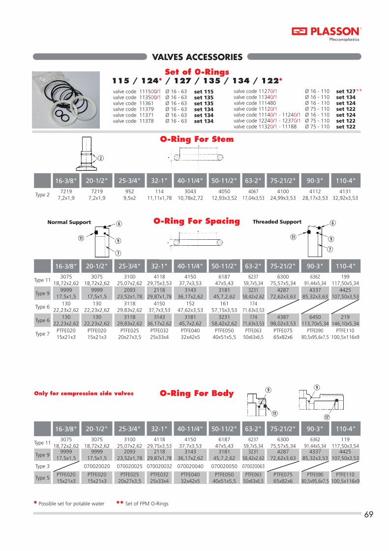
69
VALVES ACCESSORIES
valve code 11270/1 Ø 16 - 110valve code 11340/1 Ø 16 - 110 valve code 111480 Ø 16 - 110valve code 11120/1 Ø 75 - 110 valve code 11140/1 - 11240/1 Ø 16 - 110valve code 12240/1 - 12370/1 Ø 75 - 110valve code 11320/1 - 11188 Ø 75 - 110
16-3/8" 20-1/2" 25-3/4" 32-1" 40-11/4" 50-11/2" 63-2" 75-21/2" 90-3" 110-4"
Type 27219
7,2x1,97219
7,2x1,9952
9,5x2114
11,11x1,783043
10,78x2,724050
12,93x3,524067
17,04x3,534100
24,99x3,534112
28,17x3,534131
32,92x3,53
O-Ring For Stem
valve code 111500/1 Ø 16 - 63valve code 113500/1 Ø 16 - 63valve code 11361 Ø 16 - 63valve code 11379 Ø 16 - 63valve code 11371 Ø 16 - 63valve code 11378 Ø 16 - 63
16-3/8" 20-1/2" 25-3/4" 32-1" 40-11/4" 50-11/2" 63-2" 75-21/2" 90-3" 110-4"
Type 113075
18,72x2,623075
18,72x2,623100
25,07x2,624118
29,75x3,534150
37,7x3,536187
47x5,436237
59,7x5,346300
75,57x5,346362
91,44x5,34199
117,50x5,34
Type 99999
17,5x1,59999
17,5x1,52093
23,52x1,782118
29,87x1,783143
36,17x2,623181
45,7,2,623231
58,42x2,624287
72,62x3,634337
85,32x3,634425
107,50x3,53
Type 6130
22,23x2,62130
22,23x2,623118
29,83x2,624150
37,7x3,53152
47,62x3,53161
57,15x3,53174
71,63x3,53
Type 6130
22,23x2,62130
22,23x2,623118
29,83x2,623143
36,17x2,623181
45,7x2,623231
58,42x2,62174
71,63x3,534387
98,02x3,536450
113,70x5,34219
146,10x5,34
Type 7PTFE02015x21x3
PTFE02015x21x3
PTFE02520x27x3,5
PTFE03225x33x4
PTFE04032x42x5
PTFE05040x51x5,5
PTFE06350x63x6,5
PTFE07565x82x6
PTFE09080,5x95,6x7,5
PTFE110100,5x116x9
16-3/8" 20-1/2" 25-3/4" 32-1" 40-11/4" 50-11/2" 63-2" 75-21/2" 90-3" 110-4"
Type 113075
18,72x2,623075
18,72x2,623100
25,07x2,624118
29,75x3,534150
37,7x3,536187
47x5,436237
59,7x5,346300
75,57x5,346362
91,44x5,34119
117,50x3,54
Type 99999
17,5x1,59999
17,5x1,52093
23,52x1,782118
29,87x1,783143
36,17x2,623181
45,7,2,623231
58,42x2,624287
72,62x3,634337
85,32x3,534425
107,50x3,53
Type 3 070020020 070020025 070020032 070020040 070020050 070020063
Type 5PTFE02015x21x3
PTFE02015x21x3
PTFE02520x27x3,5
PTFE03225x33x4
PTFE04032x42x5
PTFE05040x51x5,5
PTFE06350x63x6,5
PTFE07565x82x6
PTFE09080,5x95,6x7,5
PTFE110100,5x116x9
Only for compression side valves
* Possible set for potable water ** Set of FPM O-Rings
Set of 0-Rings115 / 124* / 127 / 135 / 134 / 122*
O-Ring For Body
set 115set 135set 135set 134set 134set 134
set 127set 134set 124set 122set 124 set 122set 122
**
Normal Support Threaded Support
O-Ring For Spacing

70
VALVES ACCESSORIESCHECK - FOOT - AIR - RELEASE VALVES
16-3/8" 20-1/2" 25-3/4" 32-1" 40-11/4" 50-11/2" 63-2" 75-21/2" 90-3" 110-4"
Type 14*GP020V12,5x20x2
*GP020V12,5x20x2
*GP025V17x24x2
*GP032V22x32x2
*GP040V38x28x3
*GP050V51x35x4
*GP063V58x42x4
*GP075V57x77x4
*GP090V72x93x4
*GP090V110x90x4
O-Ring For Spacing
16-3/8" 20-1/2" 25-3/4" 32-1" 40-11/4" 50-11/2" 63-2" 75-21/2" 90-3" 110-4"
Type 21130
22,23x2,62130
22,23x2,623118
29,83x2,623143
36,17x2,623181
45,7x2,623231
58,42x2,62174
71,63x3,534350
98,02x3,534425
107,5x3,53420835140x4
Type 113075
18,72x2,623075
18,72x2,623100
25,07x2,624118
29,75x3,534150
37,7x3,536187
47x5,436237
59,7x5,346300
75,57x5,346362
91,44x5,34199
117,50x5,34
Set of 0-Rings*100 / 106 / 107
O-Ring For Body
Gasket For Piston
Normal Support
16-3/8" 20-1/2" 25-3/4" 32-1" 40-11/4" 50-11/2" 63-2" 75-21/2" 90-3" 110-4"
Type 113075
18,72x2,623075
18,72x2,623100
25,07x2,624118
29,75x3,534150
37,7x3,536187
47x5,436237
59,7x5,346300
75,57x5,346362
91,44x5,34119
117,50x5,34
Stainiess steel 316 core Spring Teflon coated onstanless steel 316core Spring
16-3/8" 20-1/2" 25-3/4" 32-1" 40-11/4" 50-11/2" 63-2" 75-21/2" 90-3" 110-4"
Type 23 ML020 ML020 ML025 ML032 ML040 ML050 ML063 ML075 ML090 ML110
* Set of FPM O-Rings
Spring
valve code 11080/1 ø 16 - 110 set 106 valve code 11060/1 ø 16 - 110 set 106valve code 11090/1 ø 16 - 110 set 100valve code 11000/1 ø 16 - 110 set 100 valve code 11640/1 ø 16 - 110 set 106valve code 11600/1 ø 16 - 110 set 100valve code 11630/1 ø 16 - 110 set 106valve code 11690/1 ø 16 - 110 set 100
**
*
*
valve code 11070/1-11040/1-11050/1-11010/1 ø 75 - 110 set 107valve code 11770/1-11070/1 ø 75 - 110 set 107valve code 11730/1-11790/1 ø 75 - 110 set 107

TECHNICAL SPECIFICATIONS - VALVESProduct Description
DESCRIPTION Precision moulded valves made from uPVC suitable for linepipe systems up to 16 bar. Our comprehensive range of itemsand sizes can be connected either by cold solvent cementingor through threading. Sizes and dimensions conform tointernational standards. All valves are suitable for potablewater, beverages, food as well as corrosive fluid transport.
STANDARDS Products conform to the requirements of:EN ISO 1452-4EN 10226-1EN 10226-2ISO 727-1ISO 727-2
MATERIALS PVC-U unplasticized poly (vinyl chloride) meeting the abovementioned Standards.Injection-moulded components: PVC-U.
O-Rings 1) EPDM (ethylene-propylene copolymer). Hardness: 70shore, unless otherwise specified2) FPM (Fluorised-Rubber) Hardness: 70 shore, unlessotherwise specified
Springs 1) Springs: Stainless steel 3162) Coated Springs: Teflon coated stainless steel 316 core
Gaskets (on ball) 1) PTFE (polytetrafluoroethylene)
MARKINGS The valves incorporate the following information moulded in relief:- PLASSON Trade Mark (registered in most countries)- Diameter of connection- Nominal pressure- Type of Material
COLOUR All valves are grey, in accordance with PVC-U pressurepipeline standards. Handles are blue or red.
ITEMS Ball Valves, Check Valves, Foot Valves, Air Release Valves
SANITARY LAWS The PLASSON valves conform to the sanitary laws and regulations in force in the various European Countriesand in the U.S. relating to transportation of potable water,wine, beverages and food (for specific information, please contact your PLASSON supplier).
APPLICATION FIELDS Potable water systems, irrigation systems (includingfertilization), installation for wine, beer, beverages andother fluids, industrial plants, conveyance of acids,bases, salts, fresh or swimming water, ship installations.(for special installations, please contact your PLASSON supplier).
JOINTING TYPES The valves are available with two types of connections:Plain ends for solvent cement jointing to pressure pipes of metric dimensions. Fourth digit in the catalogue no. is “O” (XXXO). Threaded ends to be screwed onto BSP threaded pipes/fittings. Fourth digit in the catalogue no. is “1” (XXX1).
SIZES For standard pipes of the ISO metrical range of mm: 16, 20,25, 32, 40, 50, 63, 75, 90, 110And for pipes of the BSP threaded range: 3/8”, 1/2”, 3/4”,1”, 11/4”, 11/2”, 2”, 21/2”, 3”, 4”.
THREADS PLASSON valves are female threaded (cylindrical) and malethreaded (conical) in accordance with:EN 10226-1, EN 10226-2 and BS 21 standards.
MECHANICAL PROPERTIES Maximum working pressure in bars:ø16-63: PN-16ø75-110: PN-10Knocker Tee: PN10 - Minimum closing pressure, 200 mbarFor the assembly maintain the horizontal direction of the arrow.Horizontal hydraulic system with upper inspection well Vertical hydraulic system with arrowhead at the topCheck Valves: is equipped with a spring mechanism andcloses tightly with two meters of water column (around 0,2bar). The minimum opening pressure is around half meter ofwater column (50 mbar). Air release valves: are used for aeration and venting of process plants, due to function only vertical mounting is possible and closes tightly with two meters of water column (around 0,2 bar).Foot Valves: allow the fluid to flow in one direction only closes tightly with two meters of water column (around 0,2 bar).
PVC PROPERTIES The following are the required properties for an injectionmoulded PVC fittings withstanding pressures PN16 in accordance with UNI standards:
71

REGRESSION CURVE FOR PVC-U
ABBREVIATIONS USED IN THIS CATALOGUE
72
TECHNICAL SPECIFICATIONS - VALVESProduct Description
d Nominal inside diameterF Distance from centre of valve to top of handle or valve
Rp, R Nominal size of thread in inchesJ Length of handleK Outside diameter or nut
DN Nominal bore corresponding approx to the inside diameter of the pipeD Outside diameterI Internal length for cementingL External length for cementingLp Internal length to PE pipeLt Length of threadZ Length from pipe stop to centre/other pipe stopH Total lengthW Weight in grams
SYMBOLS & DEFINITIONS VALVES
PN - Nominal Pressure in Bar - Allowable operating pressure conveying water at 20OC during 50 years.
PFA - Allowable Operating Pressure - Maximumhydrostatic pressure that a component is capable ofwithstanding continuously in service (EN 805:1999); forwater at temperatures up to 25OC: PFA=PN.
PMA - Allowable Maximum Operating Pwressure - Maximum pressure occurring from time to time, includingsurge, that a component is capable of withstanding in service(EN 805:1999).
PEA - Allowable Site Test Pressure - Maximumhydrostatic pressure that a newly installed component iscapable of withstanding for a relatively short duration, inorder to ensure the integrity and tightness of the pipeline (EN805:1999).
MRS: Minimum Required Strength
PVC-U: Unplasticized Poly (vinyl chloride)material for injection moulded components,such as PLASSON fittings and valves, with aproved MRS-value of at least 25 mpa.
EPDM: Ethylene Propylene Rubber
FPM: Fluoride Rubber (VITON)
PTFE: Polytetrafluoroethylene
1
22
3
599
4
77
6
8
11
10
12

73
ASSEMBLY INSTRUCTIONS
1
22
5
3
9
77
96
8
11
10
12
4
11
10
12
Instructions for connection to the system -A) Completely unscrew the ring nuts (12) and fit them to the pipe that the valve is to be connected to.B) Either glue or screw couplings (10) at the pipe ends.C) Position the valve body (5) between the two couplings.D) Lock the ring nuts for both sides.
Instructions for disassembling and reassemble -Completely unscrew the ring nuts (12).Remove the valve body (5) radially.Remove the handle (1) by pulling upwards.Release the gasket support (8) by pushing the ball (4) through the valve while the valve is closed.Remove O-Rings (6*, 9*, 11*) from gasket
support (8) and PTFE gasket (7*) using a suitable tool in order to prevent damage.Remove the ball (4) which was previously positioned during the closing phase.Remove the stem (3) by pushing downwards and extracting it from inside the valve body.Remove the O-Ring (2*) from the stem (3) using a suitable tool.Remove the O-Ring (9*) and the PTFE gasket (7*) using a suitable tool.To assemble the valve, follow the same procedure in the opposite sequence.
Notes: The valve shall be supplied with a pre-set radial seal, applicable to average operating conditions; due to particular operating conditions, it might be necessary to turn clockwise or anticlockwise the ring nuts (12) from the side of the gasket support (8).
1
22
3
599
4
77
6
8
11
10
12
Instructions for connection to the system -A) Completely unscrew the ring nut (12) and fit it to the pipe that the valve is to be connected to.B) Either glue or screw fixed side (5) to the pipe end.C) Either glue or screw coupling (10) to the pipe end.D) Lock the ring nut.
Instructions for disassembling and reassemble -Completely unscrew the ring nut (12).Remove the valve body (5) radially.Remove the handle (1) by pulling upwards.Release the gasket support (8) by pushing the ball (4) through the valve while the valve is closed.Remove O-Rings (6*, 9*, 11*) from gasket
support (8) and PTFE gasket (7*) using a suitable tool in order to prevent damage.Remove the ball (4) which was previously positioned during the closing phase.Remove the stem (3) by pushing downwards and extracting it from inside the valve body.Remove the O-Ring (2*) from the stem (3) using a suitable tool.Remove the O-Ring (9*) and the PTFE gasket (7*) using a suitable tool.To assemble the valve, follow the same procedure in the opposite sequence.
Notes: The valve shall be supplied with a pre-set radial seal, applicable to average operating conditions; due to particular operating conditions, it might be necessary to turn clockwise or anticlockwise the ring nut (12).
Normal Support
Instructions for connection to the system -A) Completely unscrew the ring nut (12) and fit it to the pipe that the valve is to be connected to.B) Screw fixed side (5) to the pipe end.C) Screw coupling (10) to the pipe end.D) Lock the ring nut.
Instructions for disassembling and reassemble -Completely unscrew the ring nut (12).Remove the valve body (5) radially.Remove the handle (1) by pulling upwards.Release the gasket support (8) by pushing the ball (4) through the valve while the valve is closed.Remove O-Rings (6*, 9*, 11*) from gasket support (8) and PTFE gasket (7*) using a
suitable tool in order to prevent damage.Remove the ball (4) which was previously positioned during the closing phase.Remove the stem (3) by pushing downwards and extracting it from inside the valve body.Remove the O-Ring (2*) from the stem (3) using a suitable tool.Remove the O-Ring (9*) and the PTFE gasket (7*) using a suitable tool.To assemble the valve, follow the same procedure in the opposite sequence.
Notes: The valve shall be supplied with a pre-set radial seal, applicable to average operating conditions; due to particular operating conditions, it might be necessary to turn clockwise or anticlockwise the ring nut (12).
1
22
3
5
4
77
996
811
10
12
Cod Plasson1115011151
Cod MG11501151
1
22
5
3
9
77
96
8
11
10
12
4
11
10
12
Cod Plasson1135011351
Cod MG13501351
Cod Plasson11361
Cod MG1361

74
ASSEMBLY INSTRUCTIONSThreaded Support
1
22
3
599
77
4
68
11
10
12 10
12
11
Instructions for connection to the system -A) Completely unscrew the ring nuts (12) and fit them to the pipe that the valve is to be connected to.B) Either glue or screw couplings (10) at the pipe ends.C) Position the valve body (5) between the two couplings.D) Lock the ring nuts for both sides.
Instructions for disassembling and reassemble -Completely unscrew the ring nuts (12).Remove the valve body (5) radially.Remove the handle (1) by pulling upwards.Insert the key in its seat in the gasket support (8).Completely unscrew the gasket support (8) by rotating the handle anticlockwise.Remove O-Rings (6*, 9*, 11*) from gasket support (8) and PTFE gasket (7*) using a suitable tool in order to prevent damage.
Remove the ball (4) which was previously positioned during the closing phase.Remove the stem (3) by pushing downwards and extracting it from inside the valve body.Remove the O-Ring (2*) from the stem (3) using a suitable tool.Remove the O-Ring (9*) and the PTFE gasket (7*) using a suitable tool.To assemble the valve, follow the same procedure in the opposite sequence.
Notes: The valve shall be supplied with a pre-set radial seal, applicable to average operating conditions; due to particular operating conditions, it might be necessary to follow the instructions below before performing the final step:1. Disconnected the handle (1) by pulling upwards.2. Insert the key in its seat in the gasket support (8).3. Turn clockwise or anticlockwise to adjust as required.
1
22
3
59
7
4
7
9
811
1012
11
10
12
6
Instructions for connection to the system -A) Completely unscrew the ring nuts (12) and fit them to the pipe that the valve is to be connected to.B) Either glue or screw couplings (10) at the pipe ends.C) Position the valve body (5) between the two couplings.D) Lock the ring nuts for both sides.
Instructions for disassembling and reassemble -Completely unscrew the ring nuts (12).Completely unscrew the ring nuts (12).Remove the valve body (5) radially.Remove the handle (1) by pulling upwards.Insert the key in its seat in the gasket support (8).Completely unscrew the gasket support (8) by rotating the handle anticlockwise.Remove O-Rings (6*, 9*, 11*) from gasket support (8) and PTFE gasket (7*) using a suitable tool in order to prevent damage.
Remove the ball (4) which was previously positioned during the closing phase.Remove the stem (3) by pushing downwards and extracting it from inside the valve body.Remove the O-Ring (2*) from the stem (3) using a suitable tool.Remove the O-Ring (9*) and the PTFE gasket (7*) using a suitable tool.To assemble the valve, follow the same procedure in the opposite sequence.
Notes: The valve shall be supplied with a pre-set radial seal, applicable to average operating conditions; due to particular operating conditions, it might be necessary to follow the instructions below before performing the final step:1. Disconnected the handle (1) by pulling upwards.2. Insert the key in its seat in the gasket support (8).3. Turn clockwise or anticlockwise to adjust as required.
Cod Plasson11140
111411112011121
Cod MG114011411120 1121 1140A1141A 1120A1121A
Cod Plasson1124011241112701127111220112211123011231
Cod MG124012411270 12711220122112301231

75
ASSEMBLY INSTRUCTIONS
1
2
3
77
99
68
1110
12
4
2
5
Instructions for connection to the system -A) Completely unscrew the ring nut (12) and fit it to the pipe that the valve is to be connected to.B) Either glue or screw fixed side (5) to the pipe end.C) Either glue or screw coupling (10) to the pipe end.D) Lock the ring nut.
Instructions for disassembling and reassemble -Completely unscrew the ring nut (12).Remove the valve body (5) radially.Remove the handle (1) by pulling upwards.Insert the key in its seat in the gasket support (8).Completely unscrew the gasket support (8) by rotating the handle anticlockwise.Remove O-Rings (6*, 9*, 11*) from gasket support (8) and PTFE gasket (7*) using a suitable tool in order to prevent damage.
Remove the ball (4) which was previously positioned during the closing phase.Remove the stem (3) by pushing downwards and extracting it from inside the valve body.Remove the O-Ring (2*) from the stem (3) using a suitable tool.Remove the O-Ring (9*) and the PTFE gasket (7*) using a suitable tool.To assemble the valve, follow the same procedure in the opposite sequence.
Notes: The valve shall be supplied with a pre-set radial seal, applicable to average operating conditions; due to particular operating conditions, it might be necessary to follow the instructions below before performing the final step:1. Disconnected the handle (1) by pulling upwards.2. Insert the key in its seat in the gasket support (8).3. Turn clockwise or anticlockwise to adjust as required.
Threaded Support
1
22
3
5
77
99
68
1110
12
4
Instructions for connection to the system -A) Completely unscrew the ring nut (12) and fit it to the pipe that the valve is to be connected to.B) Screw fixed side (5) to the pipe end.C) Screw coupling (10) to the pipe end.D) Lock the ring nut.
Instructions for disassembling and reassemble -Completely unscrew the ring nut (12).Remove the valve body (5) radially.Remove the handle (1) by pulling upwards.Insert the key in its seat in the gasket support (8).Completely unscrew the gasket support (8) by rotating the handle anticlockwise.Remove O-Rings (6*, 9*, 11*) from gasket support (8) and PTFE gasket (7*) using a suitable tool in order to prevent damage.Remove the ball (4) which was previously positioned during the closing phase.
Remove the stem (3) by pushing downwards and extracting it from inside the valve body.Remove the O-Ring (2*) from the stem (3) using a suitable tool.Remove the O-Ring (9*) and the PTFE gasket (7*) using a suitable tool.To assemble the valve, follow the same procedure in the opposite sequence.
Notes: The valve shall be supplied with a pre-set radial seal, applicable to average operating conditions; due to particular operating conditions, it might be necessary to follow the instructions below before performing the final step:1. Disconnected the handle (1) by pulling upwards.2. Insert the key in its seat in the gasket support (8).3. Turn clockwise or anticlockwise to adjust as required.
Cod Plasson11340
11341 1132011321
Cod MG1340 1341 13201321
Cod Plasson11371
Cod MG1371

76
ASSEMBLY INSTRUCTIONSThreaded Support
1
22
3
5
77
99
68
1120
12
4
11
20
12
Instructions for connection to the system A) Completely unscrew the ring nuts (12) and fit them to the pipe that the valve is to be connected to.B) Either connect to the compression fittings or electrofuse or butt weld PE spigots (20) at the pipe ends.C) Position the valve body (5) between the two couplings.D) Lock the ring nuts for both sides.
Instructions for disassembling and reassemble Completely unscrew the ring nuts (12).Remove the valve body (5) radially.Remove the handle (1) by pulling upwards.Insert the key in its seat in the gasket support (8).Completely unscrew the gasket support (8) by rotating the handle anticlockwise.Remove O-Rings (6*, 9*, 11*) from gasket support (8) and PTFE gasket (7*) using a suitable
tool in order to prevent damage.Remove the ball (4) which was previously positioned during the closing phase.Remove the stem (3) by pushing downwards and extracting it from inside the valve body.Remove the O-Ring (2*) from the stem (3) using a suitable tool.Remove the O-Ring (9*) and the PTFE gasket (7*) using a suitable tool.To assemble the valve, follow the same procedure in the opposite sequence.
Notes: The valve shall be supplied with a pre-set radial seal, applicable to average operating conditions; due to particular operating conditions, it might be necessary to follow the instructions below before performing the final step:1. Disconnected the handle (1) by pulling upwards.2. Insert the key in its seat in the gasket support (8).3. Turn clockwise or anticlockwise to adjust as required.
Cod Plasson111480111880
Cod MG11481188
Instructions for connection to the systemA) Completely unscrew the ring nuts (12) and fit them to the pipe that the valve is to be connected to.B) Either glue or screw collars (10) at the pipe ends.C) Position the valve body (5) between the two couplings.D) Lock the ring nuts (12) for both sides.
Instructions for connection of the actuator kit to the valveE) Remove the handle by pulling upwards.F) Insert the body connection lower plate (36) in the correct position of the bodyG) Fix it by screwing the parker self-tapping screw (35) inside the proper holes of the bodyH) Put the stem connection insert (34) on the stem
Instructions for connection of the actuator kit to the actuatorI) Verify the holes according to ISO 5211 on the actuatorJ) The upper plate (30) is according to F05 or F07K) Verify if the connection type on the actuator is square or star (polygonal)L) The stem connection insert is orientated at 45°
respect the axis of the valve flowM) Fix the upper plate (30) using the washers (32) and the cylindrical head bolt (33)N) Put the square nuts (31) inside the proper seat of the upper plate (30)
Instructions for connection of the actuator kit to the valveO) Connect the upper and lower plate using the countersunk head screw (37) putting attention to the correct insertion of the stem connection insert (34) inside the connection type of the actuator
Notes: The valve shall be supplied with a pre-set radial seal, applicable to average operating conditions; due to particular operating conditions, it might be necessary to follow the instructions below before performing the final step D):1. Disconnected the handle (1) by pulling upwards.2. Insert the key in its seat in the gasket support (8).3. Turn clockwise or anticlockwise to adjust as required. O-Rings and gaskets which are numbered 2,6,7,9 and 11 are packaged together in a set of O-Rings for valves.
Instructions for connection to the systemA) Completely unscrew the ring nut (12) and fit it to the pipe that the valve is to be connected to.B) Either glue or screw fixed side (5) to the pipe end.C) Either glue or screw the collar (10) to the pipe end.D) Lock the ring nut.
Instructions for connection of the actuator kit to the valveE) Remove the handle by pulling upwards.F) Insert the body connection lower plate (36) in the correct position of the bodyG) Fix it by screwing the parker self-tapping screw (35) inside the proper holes of the bodyH) Put the stem connection insert (34) on the stem
Instructions for connection of the actuator kit to the actuatorI) Verify the holes according to ISO 5211 on the actuatorJ) The upper plate (30) is according to F05 or F07K) Verify if the connection type on the actuator is square or star (polygonal)L) The stem connection insert is orientated at 45°
respect the axis of the valve flowM) Fix the upper plate (30) using the washers (32) and the cylindrical head bolt (33)N) Put the square nuts (31) inside the proper seat of the upper plate (30)
Instructions for connection of the actuator kit to the valveO) Connect the upper and lower plate using the countersunk head screw (37) putting attention to the correct insertion of the stem connection insert (34) inside the connection type of the actuator
Notes: The valve shall be supplied with a pre-set radial seal, applicable to average operating conditions; due to particular operating conditions, it might be necessary to follow the instructions below before performing the final step D):1. Disconnected the handle (1) by pulling upwards.2. Insert the key in its seat in the gasket support (8).3. Turn clockwise or anticlockwise to adjust as required. O-Rings and gaskets which are numbered 2,6,7,9 and 11 are packaged together in a set of O-Rings for valves.

1
22
3
5
4
77
996
811
20
1217
18
19
77
ASSEMBLY INSTRUCTIONS
Instructions for connection to the system -A) Connect PE pipe to the compression nut (19).B) Completely unscrew the ring nuts (12) and fit them to the pipe that the valve is to be connected to.C) Either connect to the compression fittings or electrofuse or butt weld the PE spigots (20) at the pipe ends.D) Position the valve body (5) between the two couplings.E) Lock the ring nuts for both sides.
Instructions for disassembling and reassemble -Completely unscrew the ring nuts (12).Remove the valve body (5) radially.Remove the handle (1) by pulling upwards.Insert the key in its seat in the gasket support (8).Completely unscrew the gasket support (8) by rotating the handle anticlockwise.Remove O-Rings (6*, 9*, 11*) from gasket support (8) and PTFE gasket (7*) using a
suitable tool in order to prevent damage.Remove the ball (4) which was previously positioned during the closing phase.Remove the stem (3) by pushing downwards and extracting it from inside the valve body.Remove the O-Ring (2*) from the stem (3) using a suitable tool.Remove the O-Ring (9*) and the PTFE gasket (7*) using a suitable tool.To assemble the valve, follow the same procedure in the opposite sequence.
Notes: The valve shall be supplied with a pre-set radial seal, applicable to average operating conditions; due to particular operating conditions, it might be necessary to follow the instructions below before performing the final step:1. Disconnected the handle (1) by pulling upwards.2. Insert the key in its seat in the gasket support (8).3. Turn clockwise or anticlockwise to adjust as required.
Threaded Support
1
22
3
5
4
77
996
811
10
12
17
18
19
Instructions for connection to the system -A) Connect PE pipe to the compression nut (19).B) Completely unscrew the ring nuts (12) and fit them to the pipe that the valve is to be connected to.C) Either glue or screw couplings (10) at the pipe ends.D) Position the valve body (5) between the two couplings.E) Lock the ring nuts for both sides.
Instructions for disassembling and reassemble -Completely unscrew the ring nuts (12).Remove the valve body (5) radially.Remove the handle (1) by pulling upwards.Insert the key in its seat in the gasket support (8).Completely unscrew the gasket support (8) by rotating the handle anticlockwise.Remove O-Rings (6*, 9*, 11*) from gasket support (8) and PTFE gasket (7*) using a
suitable tool in order to prevent damage.Remove the ball (4) which was previously positioned during the closing phase.Remove the stem (3) by pushing downwards and extracting it from inside the valve body.Remove the O-Ring (2*) from the stem (3) using a suitable tool.Remove the O-Ring (9*) and the PTFE gasket (7*) using a suitable tool.To assemble the valve, follow the same procedure in the opposite sequence.
Notes: The valve shall be supplied with a pre-set radial seal, applicable to average operating conditions; due to particular operating conditions, it might be necessary to follow the instructions below before performing the final step:1. Disconnected the handle (1) by pulling upwards.2. Insert the key in its seat in the gasket support (8).3. Turn clockwise or anticlockwise to adjust as required.
Cod Plasson11379
Cod MG1379
Cod Plasson11378
Cod MG1378

12
10
11
1621
22
14
13
11
10
12
78
12
14
22
11
10
13
21
16
11
10
12
Instructions for connection to the system -A) Completely unscrew the ring nuts (12) and fit them to the pipe that the valve is to be connected to.B) Either glue or screw couplings (10) at the pipe ends.C) Position the valve body (5) between the two couplings.D) Lock the ring nuts for both sides.
Instructions for disassembling and reassemble -Completely unscrew the ring nuts (12).
Remove the valve body (13) radially.Release the gasket support (16) by pushing it.Remove the the spring assisted piston (15).To replace valve reverse the procedure being careful to set the O-Ring properly and grease it with silicon grease.
Instructions for connection to the system -A) Completely unscrew the ring nuts (12) and fit them to the pipe that the valve is to be connected to.B) Either glue or screw couplings (10) at the pipe ends.C) Position the valve body (5) between the two couplings.D) Lock the ring nuts for both sides.
Instructions for disassembling and reassemble -Completely unscrew the ring nuts (12).
Remove the valve body (13) radially.Release the gasket support (16) by pushing it and making sure that the spring (17) and the spring assisted piston (15) does not fall out .Remove the the spring assisted piston (15).To replace valve reverse the procedure being careful to set the O-Ring properly and grease it with silicon grease.
ASSEMBLY INSTRUCTIONSCheck Valves
Instructions for connection to the system -A) Completely unscrew the ring nuts (12) and fit them to the pipe that the valve is to be connected to.B) Either glue or screw couplings (10) at the pipe ends.C) Position the valve body (5) between the two couplings.D) Lock the ring nuts for both sides.
Instructions for disassembling and reassemble -Completely unscrew the ring nuts (12).
Remove the valve body (13) radially.Release the gasket support (16) by pushing it.Remove the the spring assisted piston (15).To replace valve reverse the procedure being careful to set the O-Ring properly and grease it with silicon grease.
Cod Plasson1108011081110601106111090110911100011001
Cod MG10801081106010611090109110001001
Cod Plasson11630116311169011691
Cod MG1630163116901691
Cod Plasson11640116411160011601
Cod MG16401641160016011770177117001701
11770117711170011701
1730173117901791
11730117311179011791
10701071104010411050105110101011
1107011071110401104111050110511101011011

79
CERTIFICATION
K 5125
p 79 HR.indd 79p 79 HR.indd 79 15/10/21 11:0915/10/21 11:09

Via Gallinea, 28
Tel: 39+
[email protected] | www.mgmeccanoplastica.eu
010 63.19.015 | Fax: +39 010 63.19.171
- 16010 Mele (GE) Italy