Solenoid Valves PASeries Solenoid Valves PASeries
29
Single unit ● While attaining large flow rates by an effective area of 36mm 2 〔Cv: 2.0〕 , the valve achieves excellent space saving with a compact width of just 23.8mm [0.937in.]. ● Valve selection from either a 25mm 2 〔Cv: 1.4〕or a 36mm 2 〔Cv: 2.0〕 effective area with the same outer dimensions offers a choice of valves and low air consumption. ● 2-position double solenoid valves can be switched to single solenoid valves. ※1 ● External pilot type can be changed to internal pilot type ※2 (PB series only). ● A compact and highly reliable sole- noid valve is used as a pilot valve. Easy replacement is possible by opening the valve body cover. ※1: Single solenoid valves cannot be switched to double solenoid valves. ※2: Internal pilot type cannot be switched to external pilot type. ●Achieves power consumption of just 1W (DC24V) while maintaining a large flow rate. ●DC 24V coil specification uses bridge diodes for the internal circuit, enabling wiring connections without observing polarity like AC coils. A type manifold (side piping type) Sub-base Photo shows F type manifold. Space Saving with Large Flow Rate Low Power Consumption High Performance and Flexible Adaptability 430 series/430M□A 240 series/240M□AW PB series/PBM□P (effective area of 25/36mm 2 〔Cv: 1.4/2.0〕 )� 118.6 mm 63.6 mm 87mm (effective area of 40mm 2 〔Cv: 2.2〕 )� (effective area of 16mm 2 〔Cv: 0.89〕 )� 661 This highly reliable 5-port, 2- or 3-position valve can serve as a key valve for mid- sized actuators. Solenoid Valves PA Series Solenoid Valves PA Series We have achieved the “High Flow Rate” and space Operation” and “Environmental Resistance” needed in We have achieved the “High Flow Rate” and space Operation” and “Environmental Resistance” needed in
-
Upload
khangminh22 -
Category
Documents
-
view
2 -
download
0
Transcript of Solenoid Valves PASeries Solenoid Valves PASeries

Single unit
While attaining large flow rates by an effective area of 36mm2〔Cv:2.0〕, the valve achieves excellent space saving with a compact widthof just 23.8mm [0.937in.].
Valve selection from either a 25mm2〔Cv: 1.4〕or a 36mm2〔Cv: 2.0〕effective area with the same outer dimensions offers a choice ofvalves and low air consumption.
2-position double solenoid valves can be switched to single solenoidvalves.※1
External pilot type can be changed to internal pilot type※2 (PB seriesonly).
A compact andhighly reliable sole-noid valve is usedas a pilot valve.Easy replacementis possible byopening the valvebody cover.
※1: Single solenoid valves cannot be switched to double solenoid valves.※2: Internal pilot type cannot be switched to external pilot type.
Achieves power consumption of just 1W (DC24V) while maintaininga large flow rate.
DC 24V coil specification uses bridge diodes for the internal circuit,enabling wiring connections without observing polarity like AC coils.
A type manifold (side piping type)
Sub-base
Photo shows F type manifold.
Space Saving with Large Flow Rate
Low Power Consumption
High Performance and Flexible Adaptability
430 series/430MA
240 series/240MAW
PB series/PBMP(effective area of 25/36mm2〔Cv: 1.4/2.0〕)
118.
6mm
63.6
mm87
mm
(effective area of
40mm2〔Cv: 2.2〕)
(effective area of
16mm2〔Cv: 0.89〕)
661
This highly reliable 5-port, 2- or 3-positionvalve can serve as a key valve for mid-sized actuators.
Solenoid Valves PA SeriesSolenoid Valves PA Series
We have achieved the “High Flow Rate” and space Operation” and “Environmental Resistance” needed in We have achieved the “High Flow Rate” and space Operation” and “Environmental Resistance” needed in

Environmental protection rating IP65 equivalent (dust ingress andwater jet resistant) is available as an option.
Maximum 1MPa 10.2kgf/cm2 [145psi.] pressure air.
Stainless steel screws are used for high resistance to corrosion.Note
Standard screws are compatible with NCU (non-ion) specification.
Note: Nickel plated screws are used in a few sections, such as on the terminal block.
Non-neutral construction eliminates unstable operation upon valveposition switching.
Manual override islocated under a protec-tive cover, preventingthe possibility of erro-neous operation.
The PB series plug-in type offers a wide choice of wiring selections asan option, e.g., D-sub connector, terminal box and serial transmissiontypes, which are compatible with the serial transmission systems ofvarious companies, to suit the customer’s applications.
Safe BlockWhen used in combination with a 3-position exhaust center valve on thesame manifold, the safe block canensure cylinder intermediate stop andhold its posit ion for long periodswithout being affected by air leaksbetween the spool and valve body.
Individual air supply and exhaustspacerCompletely blocks 1 valve on themanifold from the other valves, andthen performs air supply andexhaust separately for each valve.
Non-plug-in type
Plug-in type, D-sub connector
Serial transmission typePhoto shows plug-in with cable type manifold.
Compatible with a Wide Range of Application Environments
Improved Safety and Reliability
Wide Range of Wiring Types and Options
Safe block
Individual air supplyand exhaust spacer
662
SOLE
NOID
VAL
VES
PA, P
B SE
RIES
Achieves new generation “easy operation”and “high performance” in an integratedvalve with a manifold.
Solenoid Valves PB SeriesSolenoid Valves PB Series
saving “Compact Body” size, as well as the “Ease of mid sized valves.saving “Compact Body” size, as well as the “Ease of mid sized valves.

663
Single Valve Unit
Direct piping Base piping
A type Manifold (side piping type)
Ported manifold typeThe side piping type manifold offerssuperior cost performance and easymaintenance.For the manifold outlet type, selectfrom either the ported manifold typeor piping block type.
Can be used with either direct piping or sub-base piping.For wiring specifications, choose from among 4 types.
The bottom piping type manifold offerssuperior cost performance and easymaintenance.For the manifold outlet type, selectfrom either the ported manifold typeor piping block type.
The direct piping type manifold offerssuperior cost performance.Achieves completely compact sizeand greatly reduced weight.
Piping block type
B type Manifold (bottom piping type)
Ported manifold type Piping block type
F type Manifold (direct piping type)
Supply and exhaust port (Rc3/8) Supply and exhaust block (Rc1/2)
Wiring specificationAs with the singlevalve units, select fromamong 4 types.
Wiring specificationAs with the singlevalve units, select fromamong 4 types.
Wiring specificationAs with the singlevalve units, select fromamong 4 types.
Solenoid Valves Series Product Range,
PA SeriesPA SeriesInstructions,Precautions
Instructions,Precautions SpecificationsSpecifications
p.665 p.671
Wiring specificationsDIN connector
Grommet type straight connector
Grommet type L connector Cabtyre cable
OrderCodeOrderCode DimensionsDimensions
p.676 p.678
OrderCodeOrderCode DimensionsDimensions
p.675 p.682
OrderCodeOrderCode DimensionsDimensions
p.675 p.682
OrderCodeOrderCode DimensionsDimensions
p.675 p.681
664
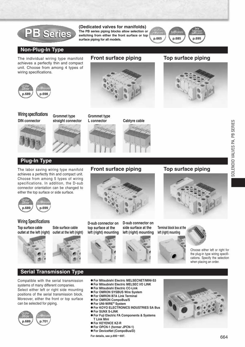
The individual wiring type manifoldachieves a perfectly thin and compactunit. Choose from among 4 types ofwiring specifications.
Non-Plug-In Type
Front surface piping
Choose either left or right forthe plug-in type wiring specifi-cations. Specify the selectionwhen placing an order.
Top surface piping
The labor saving wiring type manifoldachieves a perfectly thin and compact unit.Choose from among 5 types of wiringspecifications. In addition, the D-subconnector orientation can be changed toeither the top surface or side surface.
Plug-In Type
Front surface piping Top surface piping
Compatible with the serial transmissionsystems of many different companies.Select either left or right side mountingpositions of the serial transmission block.Moreover, either the front or top surfacecan be selected for piping.
For Mitsubishi Electric MELSECNET/MINI-S3 For Mitsubishi Electric MELSEC I/O LINK For Mitsubishi Electric CC-Link For OMRON SYSBUS Wire System For OMRON B7A Link Terminal For OMRON CompoBus/S For UNI-WIRE® System For KOYO ELECTRONICS INDUSTRIES SA Bus For SUNX S-LINK For Fuji Electric FA Components & Systems
T Link Mini For KEYENCE KZ-R For OPCN-1 (former JPCN-1) For DeviceNet (CompoBus/D)
For details, see p.695~~697.
Serial Transmission Type
SOLE
NOID
VAL
VES
PA, P
B SE
RIES
(Dedicated valves for manifolds)The PB series piping blocks allow selection orswitching from either the front surface or topsurface piping for all models.
PB SeriesPB Series Instructions,Precautions
Instructions,Precautions SpecificationsSpecifications
p.665 p.685 p.695
SerialTransmissionSpecifications
SerialTransmissionSpecifications
Wiring specificationsDIN connector
Grommet typestraight connector
Grommet typeL connector Cabtyre cable
Wiring SpecificationsTop surface cable outlet at the left (right)
Side surface cableoutlet at the left (right)
D-sub connector ontop surface at theleft (right) mounting
D-sub connector onside surface at theleft (right) mounting
Terminal block box at theleft (right) mounting
OrderCodeOrderCode DimensionsDimensions
p.689 p.698
OrderCodeOrderCode DimensionsDimensions
p.689 p.699
OrderCodeOrderCode DimensionsDimensions
p.689 p.701
665
Handling Instructions and Precautions
Solenoid
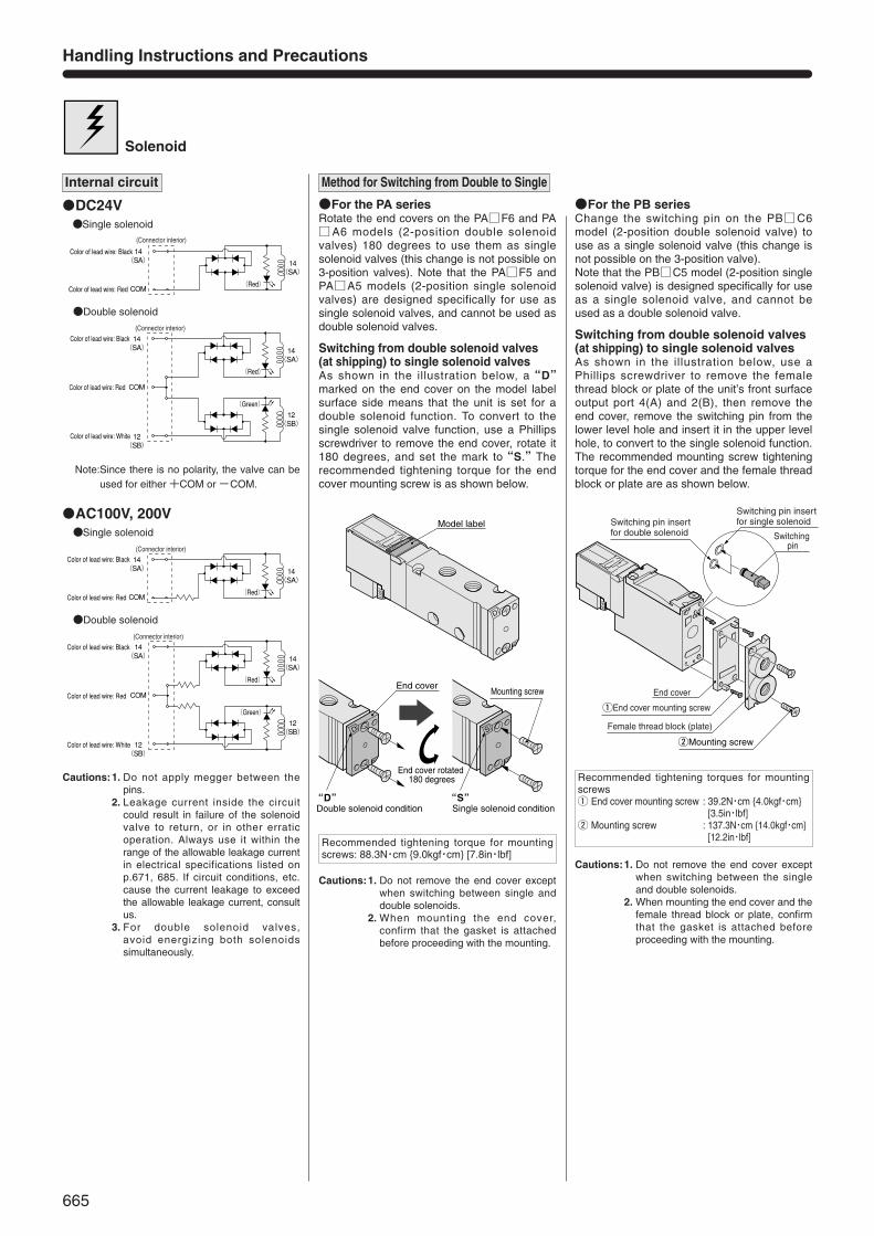
DC24V
14(SA)
14(SA)
COM
Color of lead wire: Black
Color of lead wire: Red(Red)
(Connector interior)
Double solenoid
14(SA)
12(SB)
14(SA)
12(SB)
COM
Color of lead wire: Black
(Red)
(Green)
Color of lead wire: White
Color of lead wire: Red
(Connector interior)
AC100V, 200V
14(SA)
14(SA)
COM
Color of lead wire: Black
Color of lead wire: Red(Red)
(Connector interior)
Single solenoid
Double solenoid
14(SA)
12(SB)
14(SA)
12(SB)
COM
Color of lead wire: Black
(Red)
(Green)
(Connector interior)
Color of lead wire: White
Color of lead wire: Red
Note:Since there is no polarity, the valve can beused for either +COM or -COM.
qEnd cover mounting screw
wMounting screw
Switching pin insert for double solenoid
Switching pin insert for single solenoid
Switching pin
End cover
Female thread block (plate)
End cover
End cover rotated 180 degrees
“D”Double solenoid condition
“S” Single solenoid condition
Mounting screw
Model label
Internal circuit
Single solenoid
Cautions:1. Do not apply megger between thepins.
2. Leakage current inside the circuitcould result in failure of the solenoidvalve to return, or in other erraticoperation. Always use it within therange of the allowable leakage currentin electrical specifications listed onp.671, 685. If circuit conditions, etc.cause the current leakage to exceedthe allowable leakage current, consultus.
3. For double solenoid valves, avoid energizing both solenoidssimultaneously.
Method for Switching from Double to Single
For the PA seriesRotate the end covers on the PAF6 and PAA6 models (2-position double solenoidvalves) 180 degrees to use them as singlesolenoid valves (this change is not possible on3-position valves). Note that the PAF5 andPAA5 models (2-position single solenoidvalves) are designed specifically for use assingle solenoid valves, and cannot be used asdouble solenoid valves.
Switching from double solenoid valves (at shipping) to single solenoid valvesAs shown in the illustration below, a“D”marked on the end cover on the model labelsurface side means that the unit is set for adouble solenoid function. To convert to thesingle solenoid valve function, use a Phillipsscrewdriver to remove the end cover, rotate it180 degrees, and set the mark to“S.”Therecommended tightening torque for the endcover mounting screw is as shown below.
Cautions:1. Do not remove the end cover exceptwhen switching between single anddouble solenoids.
2. When mounting the end cover,confirm that the gasket is attachedbefore proceeding with the mounting.
Recommended tightening torque for mountingscrews: 88.3N・cm 9.0kgf・cm [7.8in・lbf]
For the PB seriesChange the switching pin on the PBC6model (2-position double solenoid valve) touse as a single solenoid valve (this change isnot possible on the 3-position valve). Note that the PBC5 model (2-position singlesolenoid valve) is designed specifically for useas a single solenoid valve, and cannot beused as a double solenoid valve.
Switching from double solenoid valves(at shipping) to single solenoid valvesAs shown in the illustration below, use aPhillips screwdriver to remove the femalethread block or plate of the unit’s front surfaceoutput port 4(A) and 2(B), then remove theend cover, remove the switching pin from thelower level hole and insert it in the upper levelhole, to convert to the single solenoid function.The recommended mounting screw tighteningtorque for the end cover and the female threadblock or plate are as shown below.
Cautions:1. Do not remove the end cover exceptwhen switching between the singleand double solenoids.
2. When mounting the end cover and thefemale thread block or plate, confirmthat the gasket is attached beforeproceeding with the mounting.
Recommended tightening torques for mountingscrewsq End cover mounting screw : 39.2N・cm 4.0kgf・cm
[3.5in・lbf]w Mounting screw : 137.3N・cm 14.0kgf・cm
[12.2in・lbf]
SOLE
NOID
VAL
VES
PA, P
B SE
RIES
Mounting screw
Pilot switching pin
Switching pin insert for internal pilot
Switching pin insertfor external pilot
Plate or female thread block
q
e
w Mounting screw
Solenoid coverPilot valve14 (SA) side
LED:Red
Pilot valve12 (SB) side
LED:Green
14A12B
PUSH
TURNManual override cover
Manual override14 (SA) side
Manual override12 (SB) side
Override operation portionInner diameterφ3.5 [0.138in.] Depth 8 [0.31in.]
DIN Connector
Terminal cover
Screwdriver (blade width of about 4mm[0.16in.])
Terminal body
Screwdriver (blade width of about 3mm[0.12in.])
Lead wire
Terminal body
Terminal cover
Cable gasket
Washer
Cable gland
Cable (Outer diameter 4~7mm [0.16~0.27in.])
Terminal q
Terminal q
Terminal w
Terminal e
Terminal e
Terminal w
Terminal body (solenoid side)
Cover mounting screw Note
Note: The appropriate tightening torque for the cover mounting screw is 29.4N・cm 3kgf・cm [2.6in・lbf ].
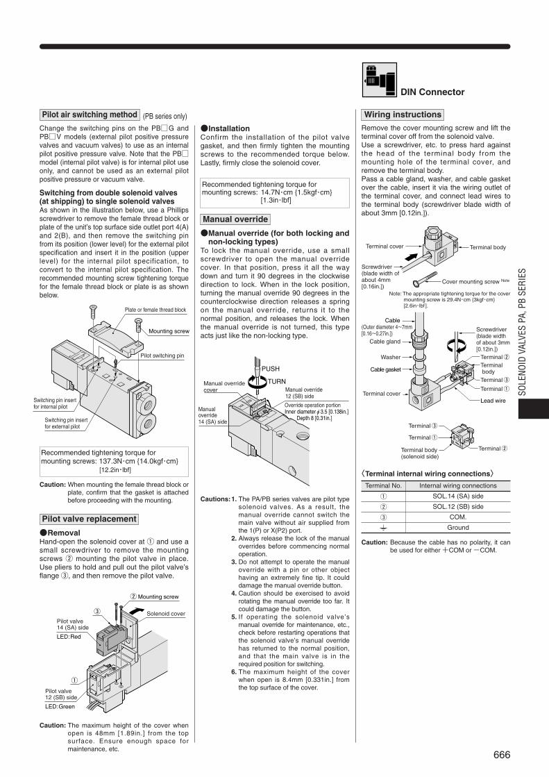
Pilot air switching method
Change the switching pins on the PBG and PBV models (external pilot positive pressurevalves and vacuum valves) to use as an internalpilot positive pressure valve. Note that the PBmodel (internal pilot valve) is for internal pilot useonly, and cannot be used as an external pilotpositive pressure or vacuum valve.
Switching from double solenoid valves (at shipping) to single solenoid valvesAs shown in the illustration below, use a Phillipsscrewdriver to remove the female thread block orplate of the unit’s top surface side outlet port 4(A)and 2(B), and then remove the switching pinfrom its position (lower level) for the external pilotspecification and insert it in the position (upperlevel) for the internal pilot specification, toconvert to the internal pilot specification. Therecommended mounting screw tightening torquefor the female thread block or plate is as shownbelow.
(PB series only)
Caution: When mounting the female thread block orplate, confirm that the gasket is attachedbefore proceeding with the mounting.
Recommended tightening torque formounting screws: 137.3N・cm 14.0kgf・cm
[12.2in・lbf]
Pilot valve replacement
RemovalHand-open the solenoid cover at q and use asmall screwdriver to remove the mountingscrews w mounting the pilot valve in place.Use pliers to hold and pull out the pilot valve’sflange e, and then remove the pilot valve.
Caution: The maximum height of the cover whenopen is 48mm [1.89in.] from the topsurface. Ensure enough space formaintenance, etc.
Recommended tightening torque for mounting screws: 14.7N・cm 1.5kgf・cm
[1.3in・lbf]
InstallationConfirm the installation of the pilot valvegasket, and then firmly tighten the mountingscrews to the recommended torque below.Lastly, firmly close the solenoid cover.
Manual override (for both locking andnon-locking types)
To lock the manual override, use a smallscrewdriver to open the manual overridecover. In that position, press it all the waydown and turn it 90 degrees in the clockwisedirection to lock. When in the lock position,turning the manual override 90 degrees in thecounterclockwise direction releases a springon the manual override, returns it to thenormal position, and releases the lock. Whenthe manual override is not turned, this typeacts just like the non-locking type.
Manual override
Cautions:1. The PA/PB series valves are pilot typesolenoid valves. As a result, themanual override cannot switch themain valve without air supplied fromthe 1(P) or X(P2) port.
2. Always release the lock of the manualoverrides before commencing normaloperation.
3. Do not attempt to operate the manualoverride with a pin or other objecthaving an extremely fine tip. It coulddamage the manual override button.
4. Caution should be exercised to avoidrotating the manual override too far. Itcould damage the button.
5. If operating the solenoid valve ’smanual override for maintenance, etc.,check before restarting operations thatthe solenoid valve’s manual overridehas returned to the normal position,and that the main valve is in therequired position for switching.
6. The maximum height of the coverwhen open is 8.4mm [0.331in.] fromthe top surface of the cover.
Wiring instructions
Remove the cover mounting screw and lift theterminal cover off from the solenoid valve. Use a screwdriver, etc. to press hard againstthe head of the terminal body from themounting hole of the terminal cover, andremove the terminal body.Pass a cable gland, washer, and cable gasketover the cable, insert it via the wiring outlet ofthe terminal cover, and connect lead wires tothe terminal body (screwdriver blade width ofabout 3mm [0.12in.]).
Internal wiring connections
SOL.14 (SA) side
SOL.12 (SB) side
COM.
Ground
〈〈Terminal internal wiring connections〉〉
q
w
e
Terminal No.
Caution: Because the cable has no polarity, it canbe used for either +COM or -COM.
666
667
Handling Instructions and Precautions
Port isolator for port 1(P)
PB-SP
29.526
24
Screw (M5×0.8)
29.526
9 or
less
qHexagon nut (M5×0.8) Nut thickness 5mm or lesswScrew (M5×0.8)
42.5
29.526
w
e
q
21 o
r mor
e
tScrew (M5×0.8)
rHexagon nut (M5×0.8)
Nut thickness 4mm or lessDIN rail (steel)
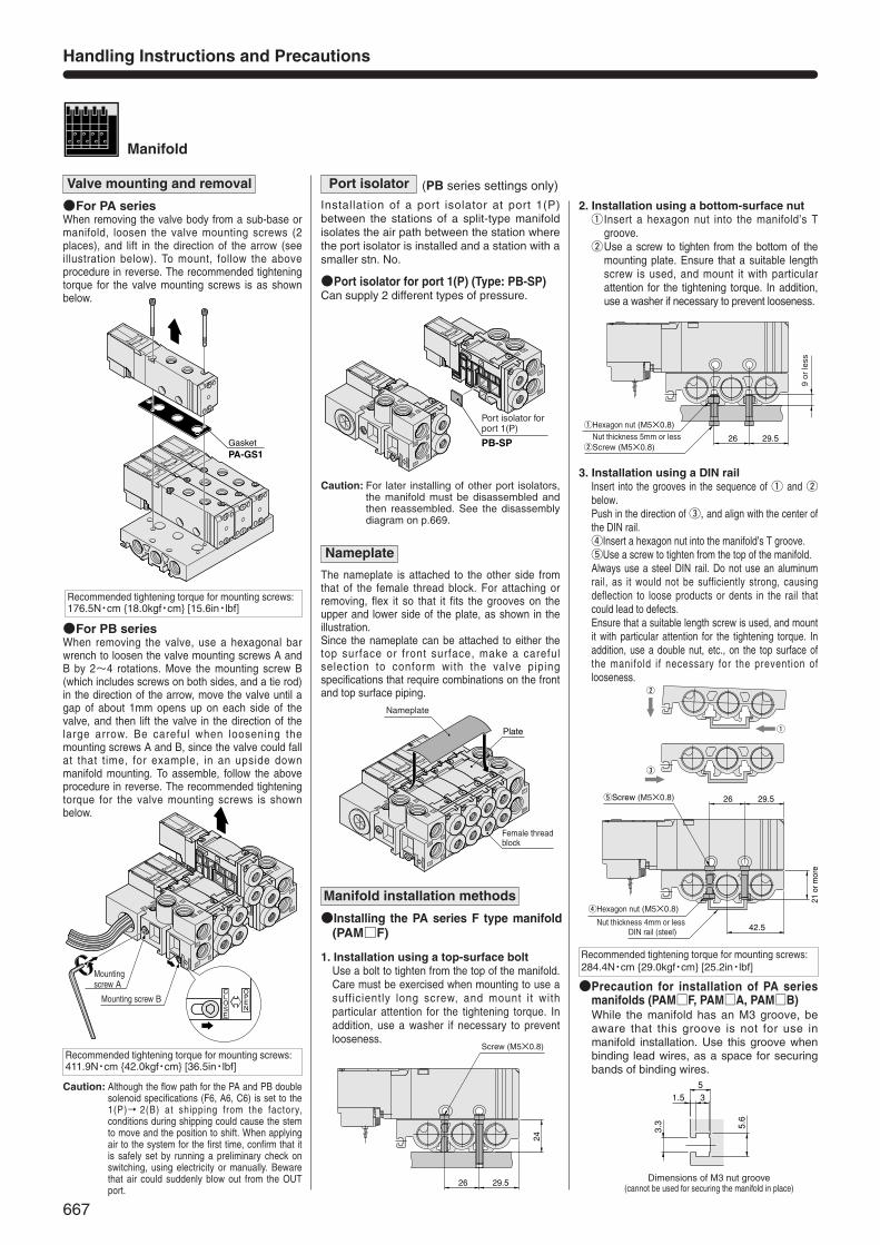
Manifold
GasketPA-GS1
Mounting screw B
Mounting screw A
51.5
3.3 5.6
3
Dimensions of M3 nut groove(cannot be used for securing the manifold in place)
Plate
Female thread block
Nameplate
Valve mounting and removal
For PA seriesWhen removing the valve body from a sub-base ormanifold, loosen the valve mounting screws (2places), and lift in the direction of the arrow (seeillustration below). To mount, follow the aboveprocedure in reverse. The recommended tighteningtorque for the valve mounting screws is as shownbelow.
For PB seriesWhen removing the valve, use a hexagonal barwrench to loosen the valve mounting screws A andB by 2~4 rotations. Move the mounting screw B(which includes screws on both sides, and a tie rod)in the direction of the arrow, move the valve until agap of about 1mm opens up on each side of thevalve, and then lift the valve in the direction of thelarge arrow. Be careful when loosening themounting screws A and B, since the valve could fallat that time, for example, in an upside downmanifold mounting. To assemble, follow the aboveprocedure in reverse. The recommended tighteningtorque for the valve mounting screws is shownbelow.
Recommended tightening torque for mounting screws:176.5N・cm 18.0kgf・cm [15.6in・lbf]
Caution: Although the flow path for the PA and PB doublesolenoid specifications (F6, A6, C6) is set to the1(P)→ 2(B) at shipping from the factory,conditions during shipping could cause the stemto move and the position to shift. When applyingair to the system for the first time, confirm that itis safely set by running a preliminary check onswitching, using electricity or manually. Bewarethat air could suddenly blow out from the OUTport.
Recommended tightening torque for mounting screws:411.9N・cm 42.0kgf・cm [36.5in・lbf]
Installation of a port isolator at port 1(P)between the stations of a split-type manifoldisolates the air path between the station wherethe port isolator is installed and a station with asmaller stn. No.
(PB series settings only)Port isolator
Port isolator for port 1(P) (Type: PB-SP)Can supply 2 different types of pressure.
Caution: For later installing of other port isolators,the manifold must be disassembled andthen reassembled. See the disassemblydiagram on p.669.
The nameplate is attached to the other side fromthat of the female thread block. For attaching orremoving, flex it so that it fits the grooves on theupper and lower side of the plate, as shown in theillustration. Since the nameplate can be attached to either thetop surface or front surface, make a carefulselection to conform with the valve pipingspecifications that require combinations on the frontand top surface piping.
Nameplate
Installing the PA series F type manifold(PAMF)
Manifold installation methods
1. Installation using a top-surface boltUse a bolt to tighten from the top of the manifold.Care must be exercised when mounting to use asufficiently long screw, and mount it withparticular attention for the tightening torque. Inaddition, use a washer if necessary to preventlooseness.
2. Installation using a bottom-surface nutq Insert a hexagon nut into the manifold’s T
groove.wUse a screw to tighten from the bottom of the
mounting plate. Ensure that a suitable lengthscrew is used, and mount it with particularattention for the tightening torque. In addition,use a washer if necessary to prevent looseness.
3. Installation using a DIN railInsert into the grooves in the sequence of q and wbelow.Push in the direction of e, and align with the center ofthe DIN rail.rInsert a hexagon nut into the manifold’s T groove.tUse a screw to tighten from the top of the manifold. Always use a steel DIN rail. Do not use an aluminumrail, as it would not be sufficiently strong, causingdeflection to loose products or dents in the rail thatcould lead to defects.Ensure that a suitable length screw is used, and mountit with particular attention for the tightening torque. Inaddition, use a double nut, etc., on the top surface ofthe manifold if necessary for the prevention oflooseness.
Precaution for installation of PA seriesmanifolds (PAMF, PAMA, PAMB)While the manifold has an M3 groove, beaware that this groove is not for use inmanifold installation. Use this groove whenbinding lead wires, as a space for securingbands of binding wires.
Recommended tightening torque for mounting screws:284.4N・cm 29.0kgf・cm [25.2in・lbf]

668
SOLE
NOID
VAL
VES
PA, P
B SE
RIES
Piping
PB24Z--ZDedicated valve
Individual air supply andexhaust side spacer
4(A) 2(B)
4(A) 2(B)
4(A) 2(B)
4(A) 2(B)
Cylinder pressure(P2)
During cylinder operation
During check valve operation
Cylinder pressure(P2)
Air supply pressure(P1)
Air supply pressure(P1)
Wiring
Insert from the back
〈Top surface outlet〉
〈Side surface outlet〉
φ3.9 [0.154in.]
White: 12 (SB) side solenoid (cannot be used with single solenoids)
Black: 14 (SA) side solenoid
Station No.
Red: COM
Cable 3-leads of AWG24
Port position for air supply andexhaust (individual air supply andexhaust spacer)
1. For front surface piping
2. For top surface piping
1(P)Air supply port
3, 5(R)Exhaust port
3, 5(R)Exhaust port
1(P)Air supply port
SA
COM
SA
COM
SB
Inte
rnal
circ
uit
Inte
rnal
circ
uit
4 A
2 B
4 A
2 B
R1
P1
51
3R2
P
12P2
Safe block
Residual pressure exhaust manual override
For top surface piping For front surface pipingResidual pressure exhaust manual override
Safe block
Use an individual air supply and exhaust spacerwhen individually supplying and exhausting air for acertain 1 station on the same manifold. Installationof the individual air supply and exhaust spacerallows control from the spacer installation positionof the air supply and exhaust to the next smaller stn. number valve. Note that a dedicated valve(PB24Z--Z) is required when using this spacer,and take particular caution on product selection.
Individual air supply and exhaust spacer (Available in PB series only)
When used in combination with a 3-position exhaustcenter valve on the same manifold, the safe block canensure cylinder intermediate stop and hold its position forlong periods without being affected by air leaks betweenthe spool and valve body. In addition, when used incombination with a 2-position valve, the safe block can beused to prevent falls at the end of cylinder stroke whenresidual pressure on the supply side is exhausted.
Safe block
Cautions: 1. Set the cylinder load so that the pressure on thecylinder side 2(B) and 4(A) ports is less thandouble the supply side pressure and also does notexceed the allowable pressure range.
2. When exhausting residual pressure on the cylinderside, use a small screwdriver, etc., to push theresidual pressure exhaust manual override, asshown in the diagram below. Caution should beexercised to guard against the possibility ofworkpieces falling or moving when the residualpressure is exhausted.
3. When a safe block is used in combination with a 3-position closed center valve or pressure centervalve, it does not ensure a cylinder’s intermediatestop and position holding, but prevents workpiecesfrom falling.
4. To lock the residual pressure exhaust manualoverride, push the manual override all the waydown and rotate it 90 degrees in the clockwisedirection. When in the locked state, rotate themanual override 90 degrees in the counter-clockwise direction; a spring returns the manualoverride to its normal position, and the lock isreleased. When the manual override is not turned,this type acts just like the non-locking type.
5. Always release the lock of the manual overridebefore commencing normal operation.
6. Do not attempt to operate the manual override witha pin or other object having an extremely fine tip. Itcould damage the manual override button.
7. Caution should be exercised to avoid rotating themanual override too far. It could damage thebutton.
8. When the residual pressure exhaust manualoverride is operated for maintenance, etc., ensurethat the manual override has returned to its normalposition before restarting operations.
D-sub connector
The D-sub connector can change the wiring outletorientation between the top surface and side surface.
Cable specification
In the case of cable specification, the shape of thecable ends is shown in the diagram below.
Recommended tightening torque for mountingscrews: 58.8N・cm 6.0kgf・cm [5.2in・lbf]
Because the cable has no polarity, it can beused for either +COM or -COM.
1. Single solenoid (C5 type)
Color oflead wire
Black
Red
+
-
-
+
Circuit diagramPositivecommon
Negativecommon
Connection polarity
Color oflead wire
Black
Red
White
+
-
+
-
+
-
Circuit diagram
2. Double solenoid (C6,C7,C8,C9 type)
Positivecommon
Negativecommon
Connection polarity

669
Connection rod
Wiring base assembly
Gasket (for IP65 or equivalent)
Gasket (for IP65 or equivalent)
Connection rod for addition
End block (left side)
End block (right side)
D-sub connector
Serial transmission block
Terminal block box
Wiring block mounting screw78.5N・cm 8.0kgf・cm [6.9in・lbf]
Cover mounting screw58.8N・cm 6.0kgf・cm [5.2in・lbf]
Gasket
Gasket
Mounting screw411.9N・cm 42.0kgf・cm [36.5in・lbf]
Mounting screw411.9N・cm 42.0kgf・cm [36.5in・lbf ]
Connection rod
End block (left side)
End block (right side)
Gasket
Gasket
Connection rod for addition
Non-plug-in type
Plug-in type
Solenoid Valves PB Series Disassembly Diagram
※Wiring-related parts are omitted.
※Wiring-related parts are omitted.

684
SOLE
NOID
VAL
VES
PA, P
B SE
RIES
Solenoid Valves Series
Solenoid Valves Series
685
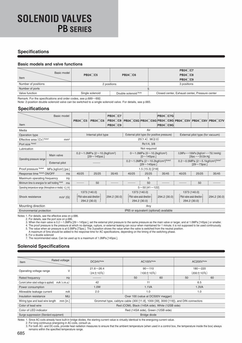
Specifications
Basic models and valve functions
Number of positions
Number of ports
Valve function
PB24C5 PB24C6
PB24C7
PB24C8
PB24C9
2 positions 3 positions
Closed center, Exhaust center, Pressure center
5
Remark: For the specifications and order codes, see p.689~692.Note: 2-position double solenoid valve can be switched to a single solenoid valve. For details, see p.665.
Single solenoid Double solenoid Note
Internal pilot type
Air
External pilot type (for positive pressure)
25〔1.4〕, 36〔2.0〕
Rc1/4, 3/8
Not required
1.5 15.3 [218]
5
50
5~50 [41~122]
Any
IP65 or equivalent (optional) available
External pilot type (for vacuum)
Media
Operation type
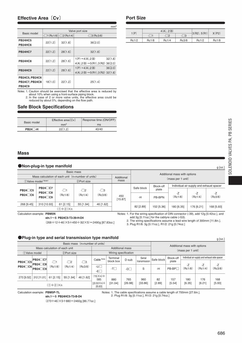
Effective area〔Cv〕Note1
Port size Note2
Lubrication
Operating pressure range
Proof pressure Note4
Response time Note5 ON/OFF
Maximum operating frequency
Minimum time to energize for self holding Note6
Operating temperature range (Atmosphere or media)
Shock resistance
Mounting direction
Environmental protection
SpecificationsBasic model
Notes: 1. For details, see the effective area on p.686.2. For details, see the port size on p.686.3. When the main valve is 0.2~1.0MPa [29~145psi.], set the external pilot pressure to the same pressure as the main valve or larger, and at 1.0MPa [145psi.] or smaller.4. The proof pressure is the pressure at which no damage, rupture, or external leaking can occur when maintained for 1 minute; it is not supposed to be used continuously.5. The value when air pressure is at 0.5MPa [73psi.]. The 3-position shows the value when the valve is switched from the neutral position.
A maximum of 5ms should be added to the response time for AC specifications, depending on the timing of the switching phase.6. For a double solenoid7. The recommended value. Can be used up to a maximum of 1.0MPa [145psi.].
mm2
MPa kgf/cm2 [psi.]
Hz
ms
°C [°F]
m/s2 G
40/25 25/25
50
40/25 25/25 35/45
294.2 30.0
40/25 25/25
50
35/45
294.2 30.0
35/45
294.2 30.0
ms
Main valve
External pilot
1373 140.0
Pilot valve axial direction294.2 30.0
1373 140.0
Pilot valve axial direction294.2 30.0
1373 140.0
Pilot valve axial direction294.2 30.0
0.2~1.0MPa 2~10.2kgf/cm2[29~145psi.]
0~1.0MPa 0~10.2kgf/cm2[0~145psi.]
0.2~1.0MPa 2~10.2kgf/cm2Note3
[29~145psi.]0.2~0.5MPa 2~5.1kgf/cm2Note7
[29~73psi.]
0.2MPa~-100kPa 2kgf/cm2~-750.1mmHg[29psi.~-29.53in.Hg]
PB24C5 PB24C6
PB24C7
PB24C8
PB24C9
PB24C7G
PB24C8G
PB24C9G
PB24C7VPB24C5G PB24C6G PB24C5V PB24C6VItem
Basic model
Item
Operating voltage range
Rated frequency
Current (when rated voltage is applied)
Power consumption
Allowable leakage current
Insulation resistance
Wiring type and lead wire length
Color of lead wire
Color of LED indicator
Surge suppression (Standard equipment)
V
Hz
mA(r.m.s)
mA
MΩmm [in.]
Solenoid Specifications
Rated voltageItem AC100VNote
90~110
(100±10%)
11
1.1VA
1.0
DC24VNote
21.6~26.4
(24±10%)
42
1.0W
2.0
Notes: 1. Since AC-coils already have built-in bridge diodes, the starting current value is virtually identical to the energizing current value.2. For long continuous energizing in AC-coils, consult us.3. For both AC- and DC-coils, provide heat radiation measures to ensure that the ambient temperature (when used in a control box, the temperature inside the box) always
remains within the specified temperature range.
Over 100 (value at DC500V megger)
Grommet type, cabtyre cable (300 [11.8], 1000 [39], 3000 [118]), and DIN connectors
Red (COM), Black (14SA side), White (12SB side)
Red (14SA side), Green (12SB side)
Bridge diode
50 60 50 60
AC200VNote
180~220
(200±10%)
6.5
1.3VA
1.0
SOLENOID VALVESSERIES
686
SOLE
NOID
VAL
VES
PA, P
B SE
RIES
Effective Area〔Cv〕
Safe Block Specifications
Port Size
Non-plug-in type manifold
Mass
qValve model Note1
PB24C5
PB24C6
268 [9.45]
PB24C7
PB24C8
PB24C9
310 [10.93]
-1
(Rc1/8)
61 [2.15]
-2
(Rc1/4)
55 [1.94]
-3
(Rc3/8)
46 [1.62]
Additionalmass
450[15.87]
Block-offplate
PB-BPN
152 [5.36]
Safe block
-H
82 [2.89]
-Z(Rc1/4)
176 [6.21]
-Z(Rc1/8)
180 [6.35]
Individual air supply and exhaust spacer
-Z(Rc3/8)
168 [5.93]
wPort size
Basic massAdditional mass with options
(mass per 1 unit)Mass calculation of each unit(n=number of units)
(q+w)×n
Calculation example: PBM5Nstn.1~~5 PB24C5-T3-39-H-D4
(268+12+46)×5+450+(82×5)=2490g [87.83oz.]
g [oz.]
Plug-in type and serial transmission type manifold
qValve model
PB24C5
PB24C6
270 [9.52]
PB24C7
PB24C8
PB24C9
312 [11.01]
-1
(Rc1/8)
61 [2.15]
-2
(Rc1/4)
55 [1.94]
-3
(Rc3/8)
46 [1.62]
Cable Note
-U
-E
(15×n)+585
[(0.53×n)+20.63]
Terminalblock box
-T
880[31.04]
D-sub
-D
765[26.98]
Serialtransmission
S
960[33.86]
Safe block
-H
82[2.89]
Block-offplate
PB-BP
157[5.54]
-Z(Rc1/8)
180[6.35]
-Z(Rc1/4)
176[6.21]
-Z(Rc3/8)
168[5.93]
Individual air supply and exhaust side spacer
wPort size Wiring specification
Basic mass(n=number of units)Additional mass with options
(mass per 1 unit)Mass calculation of each unit Additional mass
(q+w)×n
Calculation example: PBM5P-TLstn.1~~5 PB24HC5-T3-B-D4
(270+46)×5+880=2460g [86.77oz.]
g [oz.]
Basic model
PB24HC5
PB24HC6
PB24HC7
PB24HC8
PB24HC9
PB24C5, PB24C6
PB24C7, PB24C8
PB24C9
-1(Rc1/8)
22〔1.2〕
22〔1.2〕
22〔1.2〕
22〔1.2〕
18〔1.0〕
-2(Rc1/4)
32〔1.8〕
28〔1.6〕
28〔1.6〕
28〔1.6〕
22〔1.2〕
-3(Rc3/8)
36〔2.0〕
32〔1.8〕
1(P)→4(A),2(B) 32〔1.8〕
4(A),2(B)→5(R1),3(R2)36〔2.0〕
1(P)→4(A),2(B) 36〔2.0〕
4(A),2(B)→5(R1),3(R2)32〔1.8〕
25〔1.4〕
Valve port size
mm2
Basic model
PB24-H
Effective area〔Cv〕
mm2
22〔1.2〕
Response time (ON/OFF)
ms
40/40
1(P)
Rc1/2
4(A), 2(B)
-1
Rc1/8
-2
Rc1/4
-3
Rc3/8
X(P2)
Rc1/8
3(R2), 5(R1)
Rc1/2
Notes: 1. For the wiring specification of DIN connector (-39), add 12g [0.42oz.], andadd 3g [0.11oz.] for the cabtyre cable (-G3).
2. The wiring specifications assume a lead wire length of 300mm [11.8in.].3. Plug R1/8: 3g [0.11oz.], R1/2: 21g [0.74oz.]
Notes: 1. The cable specifications assume a cable length of 700mm [27.6in.].2. Plug R1/8: 3g [0.11oz.], R1/2: 21g [0.74oz.]
Notes: 1. Caution should be exercised that the effective area is reduced byabout 10% when using a front-surface piping block.
2. In the case of 2 or more valve units, the effective area could bereduced by about 5%, depending on the flow path.

687
Cylinder Operating Speed
mm/s 14001500
1200
800
600
400
200
φ50φ63
φ80φ100
φ125φ140
0 10 20 30 40 50 60 70
%
0 10 20 30 40 50 60 70
%
s1.00.90.80.70.60.50.40.30.20.1
φ125φ140
φ100φ80
φ63φ50
1000
Load ratio
Load ratio
Maximum operating speed
Delay time
PB24HC5-3
Maximum operating speed
Delay time
PB24C5-3
Maximum operating speedmm/s
14001500
1200
1000
800
600
400
200
φ50φ63
φ80φ100
φ125φ140
0 10 20 30 40 50 60 70
%
0 10 20 30 40 50 60 70
%
s1.00.90.80.70.60.50.40.30.20.1
φ125φ140
φ100φ80
φ63φ50
Load ratio
Load ratio
Maximum operating speed
Delay time
Delay time
Flow Rate
MPa
0.1
0.20.30.4
0.50.60.7
0.2
0.1
0.3
0.4
0.5
0.6
0.7
01000500 1500 2000 2500 3000
0.8
0.9
1.0
0.8
0.91.0
Flow rate R/min(ANR)
Supply pressureMPa
Val
ve o
utle
t pre
ssur
e
PB24 PB24H
How to read the graphWhen the supply pressure is 0.5MPa[73psi.] and the flow rate is 1220R/min[43.1ft.3/min.] (ANR), the valve outletpressure becomes 0.4MPa [58psi.]
MPa
0.1
0.20.30.40.50.60.7
0.2
0.1
0.3
0.4
0.5
0.6
0.7
01000 2000 3000 4000 5000
0.8
0.9
1.0
0.80.91.0
Flow rate R/min(ANR)
MPaSupply pressure
Val
ve o
utle
t pre
ssur
e
Measurement conditionsAir pressure: 0.5MPa 5.1kgf/cm2 [73psi.]Piping inner diameter and length:φ7.5×1000mm [39in.]Fitting: Quick fitting (Model: NTS10-03)
Load ratio= (%)
Cylinder stroke: 300mm [11.8in.]
LoadCylinder theoretical thrust
1mm/s = 0.0394in./sec.
1MPa = 145psi.1R/min = 0.0353ft.3/min.
688
SOLE
NOID
VAL
VES
PA, P
B SE
RIES
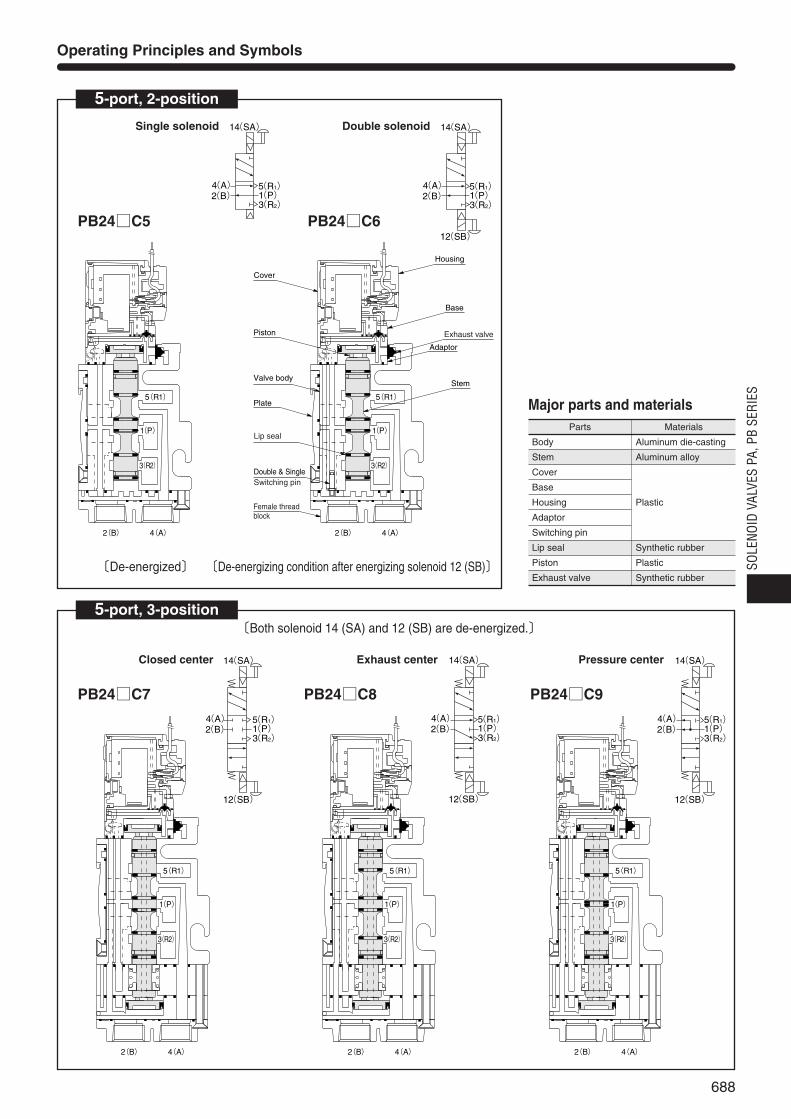
Operating Principles and Symbols
5-port, 2-position
Single solenoid
5-port, 3-position
P2注1
4(A) 5(R1)1(P)3(R2)
2(B)
14(SA)
Closed center
P2注1
4(A) 5(R1)1(P)3(R2)
2(B)
14(SA)
12(SB)
Double solenoid
P2注1
4(A) 5(R1)1(P)3(R2)
2(B)
14(SA)
12(SB)
Exhaust center
4(A) 5(R1)1(P)3(R2)
2(B)
14(SA)
12(SB)P2注1
Pressure center
P2注1
4(A) 5(R1)1(P)3(R2)
2(B)
14(SA)
12(SB)
PB24C7
PB24C5 PB24C6
PB24C8 PB24C9
〔Both solenoid 14 (SA) and 12 (SB) are de-energized.〕
4(A)2(B)
3(R2)
5(R1)
1(P)
4(A)2(B)
3(R2)
5(R1)
1(P)
Cover
Housing
Base
Adaptor
Exhaust valve
Stem
Piston
Plate
Valve body
Double & SingleSwitching pin
Female thread block
Lip seal
4(A)2(B)
3(R2)
5(R1)
1(P)
4(A)2(B)
3(R2)
5(R1)
1(P)
4(A)2(B)
3(R2)
5(R1)
1(P)
〔De-energized〕 〔De-energizing condition after energizing solenoid 12 (SB)〕
Parts Materials
Body
Stem
Cover
Base
Housing
Adaptor
Switching pin
Lip seal
Piston
Exhaust valve
Aluminum die-casting
Aluminum alloy
Plastic
Synthetic rubber
Plastic
Synthetic rubber
Major parts and materials
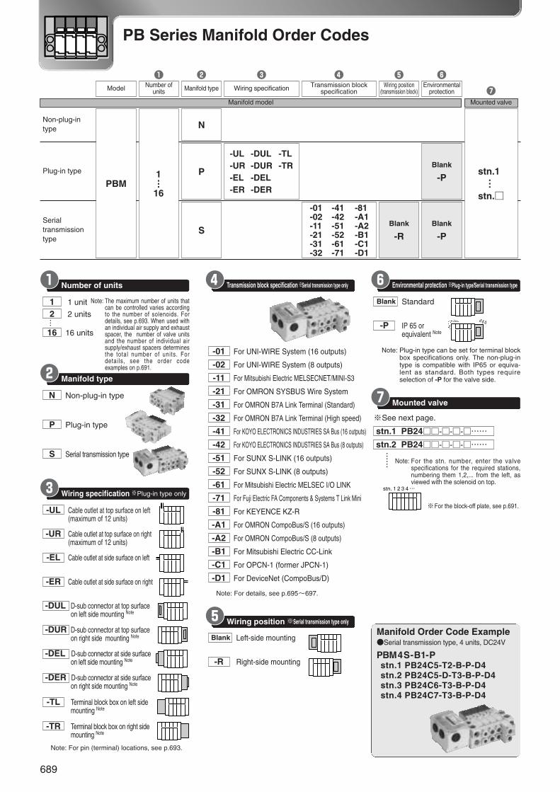
-01 For UNI-WIRE System (16 outputs)
-02 For UNI-WIRE System (8 outputs)
-11 For Mitsubishi Electric MELSECNET/MINI-S3
-21 For OMRON SYSBUS Wire System
-31 For OMRON B7A Link Terminal (Standard)
-32 For OMRON B7A Link Terminal (High speed)
-41 For KOYO ELECTRONICS INDUSTRIES SA Bus (16 outputs)
-42 For KOYO ELECTRONICS INDUSTRIES SA Bus (8 outputs)
-51 For SUNX S-LINK (16 outputs)
-52 For SUNX S-LINK (8 outputs)
-61 For Mitsubishi Electric MELSEC I/O LINK
-71 For Fuji Electric FA Components & Systems T Link Mini
-81 For KEYENCE KZ-R
-A1 For OMRON CompoBus/S (16 outputs)
-A2 For OMRON CompoBus/S (8 outputs)
-B1 For Mitsubishi Electric CC-Link
-C1 For OPCN-1 (former JPCN-1)
-D1 For DeviceNet (CompoBus/D)
Blank Left-side mounting
-R Right-side mounting
Transmission block specification※Serial transmission type onlyKr
Wiring position※Serial transmission type onlyKt
Note: For details, see p.695~697.
Non-plug-intype
Plug-in type
Serialtransmissiontype
Model
q w t y
u
re
PBM1・・・
16
N
P
Blank
-RBlank
-P
Blank
-Pstn.1・・・
stn.
-UL-UR-EL-ER
-DUL-DUR-DEL-DER
-TL-TR
S
-01-02-11-21-31-32
-41-42-51-52-61-71
-81-A1-A2-B1-C1-D1
Number ofunits Manifold type Wiring specification Transmission block
specificationWiring position
(transmission block)Environmental
protection
Manifold model Mounted valve
689
stn. 1 2 3 4 …
PB Series Manifold Order Codes
Manifold Order Code ExampleSerial transmission type, 4 units, DC24V
PBM4S-B1-Pstn.1 PB24C5-T2-B-P-D4stn.2 PB24C5-D-T3-B-P-D4stn.3 PB24C6-T3-B-P-D4stn.4 PB24C7-T3-B-P-D4
1 1 unit
2 2 units
16 16 units
Note: The maximum number of units thatcan be controlled varies accordingto the number of solenoids. Fordetails, see p.693. When used withan individual air supply and exhaustspacer, the number of valve unitsand the number of individual airsupply/exhaust spacers determinesthe total number of units. Fordetails, see the order codeexamples on p.691.
N Non-plug-in type
P Plug-in type
S Serial transmission type
…
-UL Cable outlet at top surface on left(maximum of 12 units)
-UR Cable outlet at top surface on right(maximum of 12 units)
-EL Cable outlet at side surface on left
-ER Cable outlet at side surface on right
-DUL D-sub connector at top surfaceon left side mounting Note
-DUR D-sub connector at top surfaceon right side mounting Note
-DEL D-sub connector at side surfaceon left side mounting Note
-DER D-sub connector at side surfaceon right side mounting Note
-TL Terminal block box on left side mounting Note
-TR Terminal block box on right side mounting Note
Number of unitsKq
Wiring specification ※Plug-in type onlyKe
Manifold typeKw
Note: For pin (terminal) locations, see p.693.
Note: For the stn. number, enter the valvespecifications for the required stations,numbering them 1,2,... from the left, asviewed with the solenoid on top.
※For the block-off plate, see p.691.
※See next page.
Note: Plug-in type can be set for terminal blockbox specifications only. The non-plug-intype is compatible with IP65 or equiva-lent as standard. Both types requireselection of -P for the valve side.
stn.1 PB24---……
stn.2 PB24---…………
Blank Standard
-P IP 65 or equivalent Note
Environmental protection※Plug-in type/Serial transmission typeKy
Mounted valveKu
Blank Without safe block
-H With safe block Note
Safe blockKo
Blank Without individual air supply and exhaust spacer
-Z With individual air supply and exhaust spacer Note
Individual air supply and exhaust spacerK!0
Blank Without port isolator
-SP With port isolator for P port
Port isolatorK!1
-D4 DC24V
-A1 AC100V Note
-A2 AC200V Note
VoltageK!3
Note: Not available in serial transmission type.
Blank Standard
-P IP65 or equivalent Note
Environmental protectionK!2
Note: Port isolator can be mounted in only 1 location(1 station) in the manifold. Port isolator isinstalled between the specified station and thestation to its immediate left (the smaller stn.no.) at shipping.
Note: Always enter -Z when selecting dedicatedvalves for the manifolds.For details, see the order code examples on p.691.
Note: Cannot be used with external pilot types (for positive pressure and for vacuum).
Note: The DIN connector (-39) is compatible withIP65 or equivalent as standard. In the casewhere the IP65 or equivalent is used, select -Pfor both the manifold order code and the valveorder code.
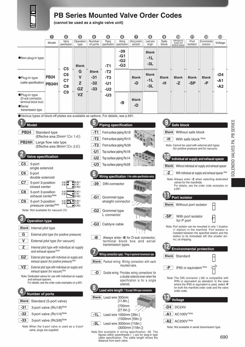
-T1 Front surface piping Rc1/8
-T2 Front surface piping Rc1/4
-T3 Front surface piping Rc3/8
-U1 Top surface piping Rc1/8
-U2 Top surface piping Rc1/4
-U3 Top surface piping Rc3/8
Piping specificationKt
Blank Lead wire 300mm[11.8in.](700mm[27.6in.])
-1L Lead wire 1000mm [39in.](1500mm [59in.])
-3L Lead wire 3000mm [118in.](3000mm [118in.])
Lead wire length※Except DIN-type connectorKi
Note: Not available in wiring specification -39. Thefigures within parentheses ( ) are for plug-in typecable specification. The cable length shows thedistance from each valve.
-39 DIN connector
-G1 Grommet typestraight connector
-G2 Grommet typeL connector
-G3 Cabtyre cable
-B Always enter -B for D-sub connector,terminal block box and serialtransmission types.
Wiring specification※No cable specification entryKy
Blank Packed wiring: Wiring connection with eachmounted valve.
-D Double wiring: Provides wiring connections fora double solenoid even when thespecif ication is for a singlesolenoid.
Wiring connection spec.※Plug-in type/serial transmission typeKu
PB24 Standard type(Effective area 25mm2〔Cv: 1.4〕)
PB24H Large flow rate type(Effective area 36mm2〔Cv: 2.0〕)
Note: Not available for vacuum (V)
ModelKq
C5 5-portsingle solenoid
C6 5-portdouble solenoid
C7 5-port 3-positionclosed center
C8 5-port 3-positionexhaust centerNote
C9 5-port 3-positionpressure centerNote
Valve specificationKw
Note: Dedicated valves for use with individual air supplyand exhaust spacers.
Note: For details, see the order code examples on p.691.
Blank Internal pilot type
G External pilot type (for positive pressure)
V External pilot type (for vacuum)
Z Internal pilot type with individual air supplyand exhaust spacerNote
GZ External pilot type with individual air supply andexhaust spacer (for positive pressure)Note
VZ External pilot type with individual air supply andexhaust spacer (for vacuum)Note
Operation typeKe
Blank Standard (5-port valve)
-31 3-port valve (Rc1/8)Note
-32 3-port valve (Rc1/4)Note
-33 3-port valve (Rc3/8)Note
Number of portsKr
Note: When the 5-port valve is used as a 3-portvalve, plugs are supplied.
690
SOLE
NOID
VAL
VES
PA, P
B SE
RIES
4(A)2(B)
5(R1)1(P)3(R2)
4(A)2(B)
5(R1)1(P)3(R2)
4(A)2(B)
5(R1)1(P)3(R2)
PB Series Mounted Valve Order Codes(cannot be used as a single valve unit)
Various types of block-off plates are available as options. For details, see p.691.
Non-plug-in type
Plug-in type
(cable specification)
Plug-in type(D-sub connector,terminal block box)Serial
transmission type
Model
q w eValve
specificationOperation
type
rNumberof ports
tPiping
specification
yWiring
specification
iLead wire
length
oSafeblock
!1Port
isolator
!2Environmental
protection
!3
Voltage
PB24
PB24H
C5C6C7C8C9
Blank
GVZ
GZVZ
Blank
-31-32-33
-T1-T2-T3-U1-U2-U3
-39-G1-G2-G3
-B
uWiring connection
specification
Blank
-D
Blank
-D
Blank
-1L-3L
Blank
-1L-3L
Blank
-H
!0Individual airsupply and
exhaust spacer
Blank
-ZBlank
-SPBlank
-P
-D4-A1-A2

PB -D4-A1-A2
-D4B-A1B-A2B
14 (SA) pilot valve, DC24V
14 (SA) pilot valve, AC100V
14 (SA) pilot valve, AC200V
12 (SB) pilot valve, DC24V
12 (SB) pilot valve, AC100V
12 (SB) pilot valve, AC200V
Replacement of pilot valve
PB -SP
Port isolator
Additional Parts Order Codes for PB SeriesBlock-off plate (single unit)
Port isolator for P port
Pilot valves are available as replacements.The valves for 14 (SA) and 12 (SB) aredistinguished from the LED color. The 14(SA) LED is red, and the 12 (SB) LED isgreen. Select the required type (a gasketand 2 mounting screws are supplied).
Only 1 port isolator can be used on the same manifold.
PB -P Plate(with 1 gasket)
Plate
PB-BP q
qEnvironmental protection Note
Blank Standard
-P IP65 or equivalent(Note: Non-plug-in type is compatible with IP65 or
equivalent as standard)
691
Block-off plate
Order code examples when using the individual air supply and exhaust spacer
PB Series Manifold Options Order Codes
Not functional as an individual air supply andexhaust spacer alone. It works when used incombination with the dedicated valve (PB24Z). Since the spacer is added as part of thetotal number of valve units, take considerationof the maximum number of units allowed inthe manifold. In the mounting case at right,the station configuration is stn.1~stn.3., butthe number of units in the manifold is countedas 4 units. For the air supply and exhaust portpositions, see p.668.
When valves are expected to be installed in the future, use these as mounted on a manifold. Note that this configuration is different from the conventional plate type block-off plates, and it is the blockshape. For instructions for mounting and removal, see the valve mounting and removal on p.667.
〈Mounting example〉
Block-off plate
PB-BP
Order Code ExamplePlug-in type cable specification
4 units DC24V
PBM4P-ELstn.1 PB24C5-T2-D4stn.2 PB24C5-T3-D4stn.3 PB24C6-T3-D4stn.4 PB-BPKD
〈Mounting example〉 PB24C6Z-T3-Z-D4 (Dedicated valve)
Note: Occupies 1 station space on the right sideof the dedicated valve.
Individual air supply and exhaust spacer
Order Code ExamplePlug-in type cable specification
4 units DC24V
PBM4P-ELstn.1 PB24C5-T2-D4stn.2 PB24C5-T3-D4stn.3 PB24C6Z-T3-Z-D4
stn.1 stn.2 stn.3
Number of units
1 2 3 4
qSpecification
N Non-plug-in type
M For D-sub connector, terminal block box, serial transmission type
K Cable specification (700mm [27.6in.])
K1 Cable specification (1500mm [59in.])
K3 Cable specification (3000mm [118in.])
wWiring connection specification Note
S Single wiring
D Double wiring(Note: Except non-plug-in type)
PB-BP q w e
eEnvironmental protection Note
Blank Standard
-P IP65 or equivalent(Note: Non-plug-in type is
compatible with IP65 orequivalent as standard)
When used in combination with individual air supply and exhaust spacer
ePiping direction
T Front surface piping
U Top surface piping
rPiping size
1 Rc1/8
2 Rc1/4
3 Rc3/8
qSpecification
N Non-plug-in type
M For D-sub connector, terminal block box,serial transmission type
K Cable specification (700mm[27.6in.])
K1 Cable specification (1500mm[59in.])
K3 Cable specification (3000mm[118in.])
wWiring connection specification Note
S Single wiring
D Double wiring(Note: Except non-plug-in type)
PB-BP q w -Z e r t
tEnvironmental protection Note
Blank Standard
-P IP65 or equivalent(Note: Non-plug-in type is compatible with IP65 or
equivalent as standard)
Use this when adding plug-in type or serialtransmission type valves. Includes a plug-in baseand relating lead wires and cables.
…
PB -B1-B2-B3
Piping block Rc1/8
Piping block Rc1/4
Piping block Rc3/8
(with 1 gasket)
Piping block (single part)
-EN
-EK
-ETL
-ETR
qSpecification
End block for non-plug-intype(one set of left and right)
End block for cable specification(one set of left and right)
End block for left-sidemounting of D-sub connector,terminal block box and serialtransmission(one set of left and right)
End block for right-sidemounting of D-sub connector,terminal block box and serialtransmission(one set of left and right)
End block set
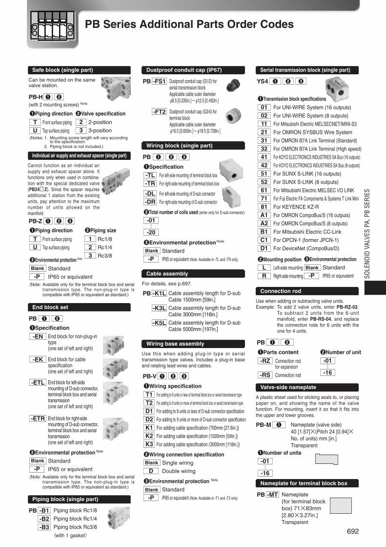
PB -FS1
-FT2
Dustproof conduit cap (G1/2) for serial transmission blockApplicable cable outer diameter φ8.5 [0.335in.]~φ12.5 [0.492in.]
Dustproof conduit cap (G3/4) for terminal blockApplicable cable outer diameter φ16.5 [0.650in.]~φ18.5 [0.728in.]
Dustproof conduit cap (IP67)
YS4 q w e
PB q w e
qTransmission block specifications
01 For UNI-WIRE System (16 outputs)
02 For UNI-WIRE System (8 outputs)
11 For Mitsubishi Electric MELSECNET/MINI-S3
21 For OMRON SYSBUS Wire System
31 For OMRON B7A Link Terminal (Standard)
32 For OMRON B7A Link Terminal (High speed)
41 For KOYO ELECTRONICS INDUSTRIES SA Bus (16 outputs)
42 For KOYO ELECTRONICS INDUSTRIES SA Bus (8 outputs)
51 For SUNX S-LINK (16 outputs)
52 For SUNX S-LINK (8 outputs)
61 For Mitsubishi Electric MELSEC I/O LINK
71 For Fuji Electric FA Components & Systems T Link Mini
81 For KEYENCE KZ-R
A1 For OMRON CompoBus/S (16 outputs)
A2 For OMRON CompoBus/S (8 outputs)
B1 For Mitsubishi Electric CC-Link
C1 For OPCN-1 (former JPCN-1)
D1 For DeviceNet (CompoBus/D)
wMounting position
L Left-side mounting
R Right-side mounting
Serial transmission block (single part)
PB q w
qParts content
-RZ Connection rod for expansion
-RS Connection rod
wNumber of unit
-01
-16
Connection rod
PB -MT Nameplate (for terminal blockbox) 71×83mm[2.80×3.27in.]Transparent
Nameplate for terminal block box
…
PB-M q Nameplate (valve side)40 [1.57]×(Pitch 24 [0.94]×No. of units) mm [in.]Transparent
qNumber of units
-01
-16…
Valve-side nameplate
Wiring block (single part)
Use when adding or subtracting valve units.Example: To add 2 valve units, enter PB-RZ-02.
To subtract 2 units from the 6-unitmanifold, enter PB-RS-04, and replacethe connection rods for 6 units with theone for 4 units.
PB-V q w e
qWiring specification
T1 For adding to 8 units or less of terminal block box or serial transmission type
T2 For adding to 9 units or more of terminal block box or serial transmission type
D1 For adding to 8 units or less of D-sub connector specification
D2 For adding to 9 units or more of D-sub connector specification
K1 For adding cable specification (700mm [27.6in.])
K2 For adding cable specification (1500mm [59in.])
K3 For adding cable specification (3000mm [118in.])
wWiring connection specificationBlank Single wiring
D Double wiring
eEnvironmental protection Note
Blank Standard
-P IP65 or equivalent (Note: Available in -T1 and -T2 only)
qPiping direction
T Front surface piping
U Top surface piping
wPiping size
1 Rc1/8
2 Rc1/4
3 Rc3/8eEnvironmental protection
Blank Standard
-P IP65 or equivalent
wEnvironmental protection Note
Blank Standard
-P IP65 or equivalent(Note: Available only for the terminal block box and serial
transmission type. The non-plug-in type iscompatible with IP65 or equivalent as standard.)
Wiring base assembly
For details, see p.697.
A plastic sheet used for sticking seals to, or placingpaper on, and showing the name of the valvefunction. For mounting, insert it so that it fits intothe upper and lower grooves.
Cannot function as an individual airsupply and exhaust spacer alone. Itfunctions only when used in combina-tion with the special dedicated valve(PB24 Z). Since the spacer requiresadditional 1 station from the existingunits, pay attention to the maximumnumber of units allowed on themanifold.
PB -K1L
-K3L
-K5L
Cable assembly length for D-subCable 1500mm [59in.]
Cable assembly length for D-subCable 3000mm [118in.]
Cable assembly length for D-subCable 5000mm [197in.]
Cable assembly
Safe block (single part)
Can be mounted on the samevalve station.
Individual air supply and exhaust spacer (single part)
PB q w
PB-Z q w e
qPiping direction
T Front surface piping
U Top surface piping(Notes: 1. Mounting screw length will vary according
to the specification.2. Piping block is not included.)
wValve specification
2 2-position
3 3-position
PB-H q w
(with 2 mounting screws) Note
eEnvironmental protection Note
Blank Standard
-P IP65 or equivalent(Note: Available only for the terminal block box and serial
transmission type. The non-plug-in type iscompatible with IP65 or equivalent as standard.)
qSpecification
-TL For left-side mounting of terminal block box
-TR For right-side mounting of terminal block box
-DL For left-side mounting of D-sub connector
-DR For right-side mounting of D-sub connector
wTotal number of coils used (enter only for D-sub connector)
-01
-20
eEnvironmental protectionNote
Blank Standard
-P IP65 or equivalent (Note: Available in -TL and -TR only)
692
SOLE
NOID
VAL
VES
PA, P
B SE
RIES
PB Series Additional Parts Order Codes
693
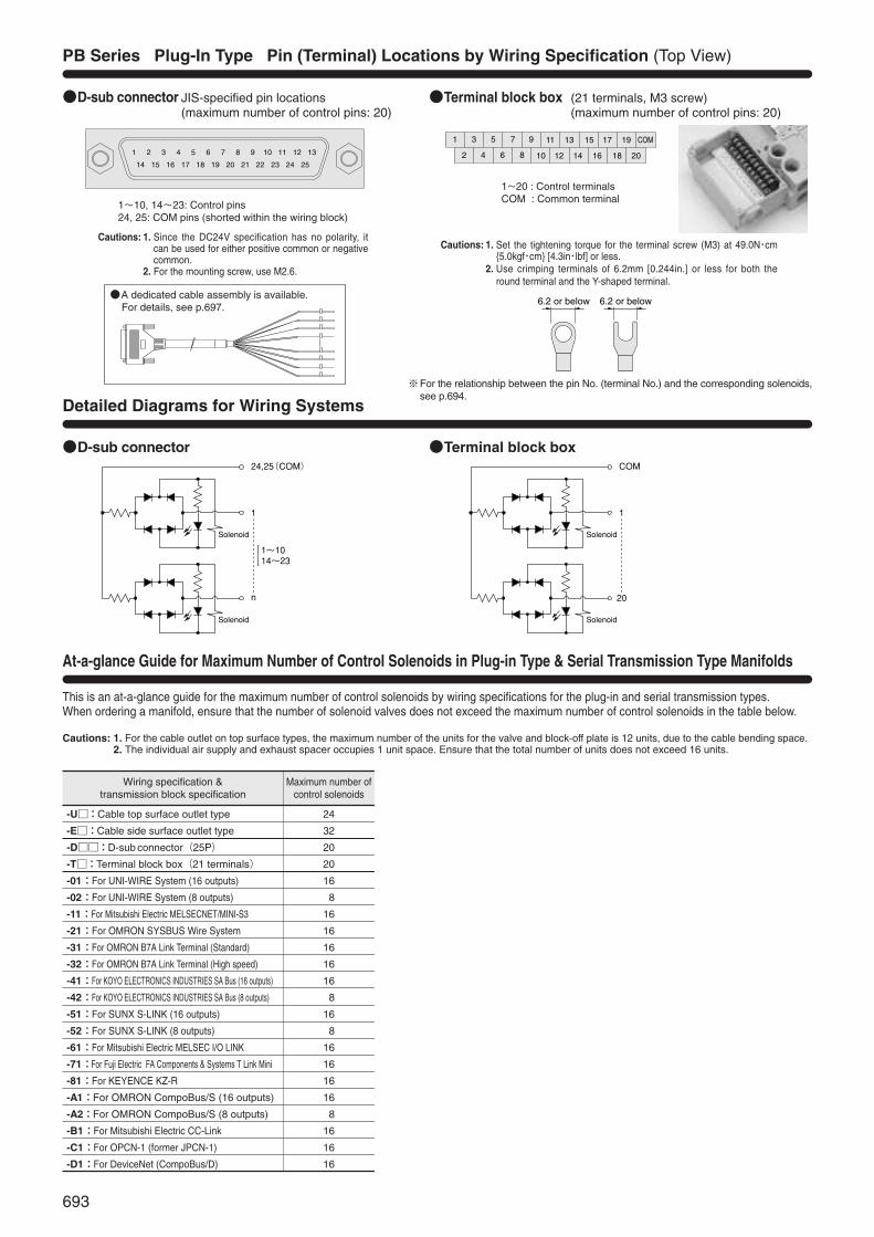
D-sub connector JIS-specified pin locations (maximum number of control pins: 20)
1~20 : Control terminalsCOM : Common terminal
1 3 5 7 9
2 4 6 8 10 12
11 13 15 17 19 COM
14 16 18 20
Terminal block box (21 terminals, M3 screw) (maximum number of control pins: 20)
1~10, 14~23: Control pins24, 25: COM pins (shorted within the wiring block)
24,25(COM)
1
n
1~1014~23
COM
1
20
Solenoid
Solenoid
Solenoid
Solenoid
D-sub connector Terminal block box
PB Series Plug-In Type Pin (Terminal) Locations by Wiring Specification (Top View)
Detailed Diagrams for Wiring Systems
1 2 3 4 5 6 7 8 9 10 11 12 13
14 15 16 17 18 19 20 21 22 23 24 25
6.2 or below6.2 or below
※For the relationship between the pin No. (terminal No.) and the corresponding solenoids,see p.694.
A dedicated cable assembly is available. For details, see p.697.
At-a-glance Guide for Maximum Number of Control Solenoids in Plug-in Type & Serial Transmission Type Manifolds
Cautions: 1. Since the DC24V specification has no polarity, itcan be used for either positive common or negativecommon.
2. For the mounting screw, use M2.6.
Cautions: 1. Set the tightening torque for the terminal screw (M3) at 49.0N・cm5.0kgf・cm [4.3in・lbf] or less.
2. Use crimping terminals of 6.2mm [0.244in.] or less for both theround terminal and the Y-shaped terminal.
Wiring specification &transmission block specification
-U:Cable top surface outlet type
-E:Cable side surface outlet type
-D:D-sub connector(25P)
-T:Terminal block box(21 terminals)
-01:For UNI-WIRE System (16 outputs)
-02:For UNI-WIRE System (8 outputs)
-11:For Mitsubishi Electric MELSECNET/MINI-S3
-21:For OMRON SYSBUS Wire System
-31:For OMRON B7A Link Terminal (Standard)
-32:For OMRON B7A Link Terminal (High speed)
-41:For KOYO ELECTRONICS INDUSTRIES SA Bus (16 outputs)
-42:For KOYO ELECTRONICS INDUSTRIES SA Bus (8 outputs)
-51:For SUNX S-LINK (16 outputs)
-52:For SUNX S-LINK (8 outputs)
-61:For Mitsubishi Electric MELSEC I/O LINK
-71:For Fuji Electric FA Components & Systems T Link Mini
-81:For KEYENCE KZ-R
-A1:For OMRON CompoBus/S (16 outputs)
-A2:For OMRON CompoBus/S (8 outputs)
-B1:For Mitsubishi Electric CC-Link
-C1:For OPCN-1 (former JPCN-1)
-D1:For DeviceNet (CompoBus/D)
詰め配線(無記入)
12連
16連
シングルソレノイド、ダブルソレノイド、ブロックプレートの搭載数により異なります。制御するソレノイドの数が最大制御ソレノイド点数以下になるように連数を指定してください。なお、全体の連数が16連を超える指定はできません。
Maximum number ofcontrol solenoids
24
32
20
20
16
8
16
16
16
16
16
8
16
8
16
16
16
16
8
16
16
16
12連
16連
10連
10連
8連
4連
8連
8連
8連
8連
8連
4連
8連
4連
8連
8連
8連
8連
4連
8連
8連
8連
ダブル配線(-D)
最大連数
結線仕様
This is an at-a-glance guide for the maximum number of control solenoids by wiring specifications for the plug-in and serial transmission types.When ordering a manifold, ensure that the number of solenoid valves does not exceed the maximum number of control solenoids in the table below.
Cautions: 1. For the cable outlet on top surface types, the maximum number of the units for the valve and block-off plate is 12 units, due to the cable bending space.2. The individual air supply and exhaust spacer occupies 1 unit space. Ensure that the total number of units does not exceed 16 units.
694
SOLE
NOID
VAL
VES
PA, P
B SE
RIES
1stn. 2 3 4 5 6 7 8 9 10 11 12
Single solenoid Double solenoid Block-off plate
1 2 3 4 5 6 7 8 9 10 11 12 13
14 15 16 17 18 19 20 21 22 23 24 25
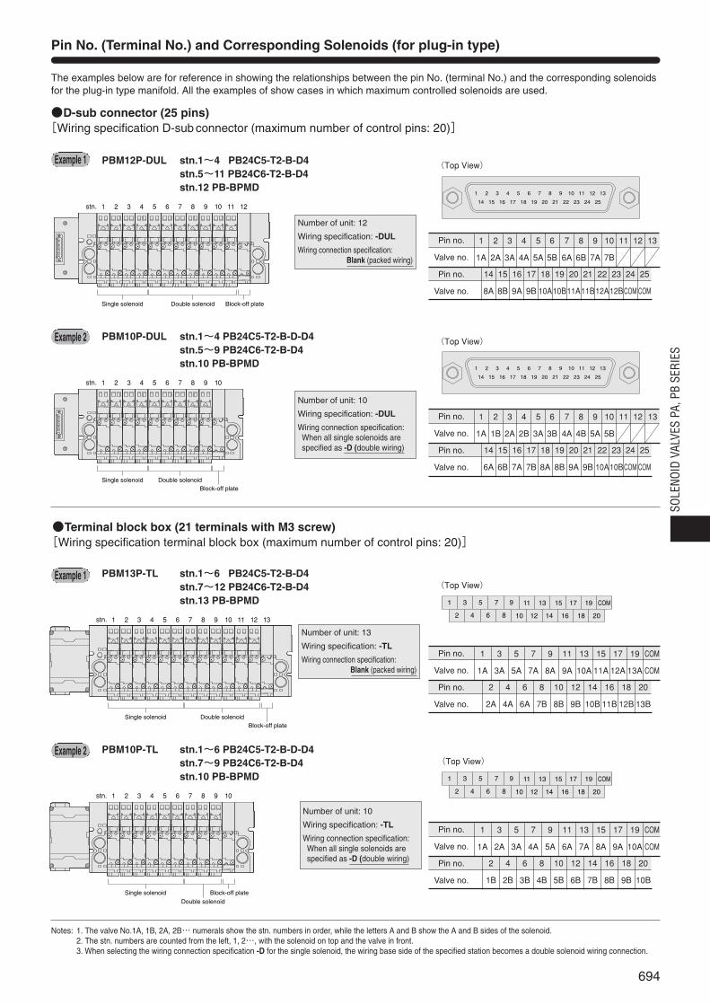
Pin No. (Terminal No.) and Corresponding Solenoids (for plug-in type)
The examples below are for reference in showing the relationships between the pin No. (terminal No.) and the corresponding solenoidsfor the plug-in type manifold. All the examples of show cases in which maximum controlled solenoids are used.
Notes: 1. The valve No.1A, 1B, 2A, 2B… numerals show the stn. numbers in order, while the letters A and B show the A and B sides of the solenoid.2. The stn. numbers are counted from the left, 1, 2…, with the solenoid on top and the valve in front.3. When selecting the wiring connection specification -D for the single solenoid, the wiring base side of the specified station becomes a double solenoid wiring connection.
D-sub connector (25 pins)[Wiring specification D-sub connector (maximum number of control pins: 20)]
PBM12P-DUL stn.1~4 PB24C5-T2-B-D4stn.5~11 PB24C6-T2-B-D4stn.12 PB-BPMD
PBM10P-DUL stn.1~4 PB24C5-T2-B-D-D4stn.5~9 PB24C6-T2-B-D4stn.10 PB-BPMD
1
1A
2
2A
3
3A
4
4A
5
5A
6
5B
7
6A
8
6B
9
7A
10
7B
11 12 13
14
8A
15
8B
16
9A
17
9B
18
10A
19
10B
20
11A
21
11B
22
12A
23
12B
24
COM
25
COM
Pin no.
Valve no.
Pin no.
Valve no.
1 2 3 4 5 6 7 8 9 10stn.
Single solenoid Double solenoidBlock-off plate
(Top View)
1 2 3 4 5 6 7 8 9 10 11 12 13
14 15 16 17 18 19 20 21 22 23 24 25
1
1A
2
1B
3
2A
4
2B
5
3A
6
3B
7
4A
8
4B
9
5A
10
5B
11 12 13
14
6A
15
6B
16
7A
17
7B
18
8A
19
8B
20
9A
21
9B
22
10A
23
10B
24
COM
25
COM
Pin no.
Valve no.
Pin no.
Valve no.
(Top View)
1 2 3 4 5 6 7 8 9 10 11 12 13stn.
Single solenoid Double solenoidBlock-off plate
1 3 5 7 9
2 4 6 8 10 12
11 13 15 17 19 COM
14 16 18 20
Terminal block box (21 terminals with M3 screw)[Wiring specification terminal block box (maximum number of control pins: 20)]
PBM13P-TL stn.1~6 PB24C5-T2-B-D4stn.7~12 PB24C6-T2-B-D4stn.13 PB-BPMD
PBM10P-TL stn.1~6 PB24C5-T2-B-D-D4stn.7~9 PB24C6-T2-B-D4stn.10 PB-BPMD
1
1A
3
3A
5
5A
7
7A
9
8A
11
9A
13
10A
15
11A
17
12A
19
13A
COM
COM
2
2A
4
4A
6
6A
8
7B
10
8B
12
9B
14
10B
16
11B
18
12B
20
13B
Pin no.
Valve no.
Pin no.
Valve no.
1
1A
3
2A
5
3A
7
4A
9
5A
11
6A
13
7A
15
8A
17
9A
19
10A
COM
COM
2
1B
4
2B
6
3B
8
4B
10
5B
12
6B
14
7B
16
8B
18
9B
20
10B
Pin no.
Valve no.
Pin no.
Valve no.
1 2 3 4 5 6 7 8 9 10stn.
Single solenoidDouble solenoid
Block-off plate
(Top View)
1 3 5 7 9
2 4 6 8 10 12
11 13 15 17 19 COM
14 16 18 20
(Top View)
Example 1
Number of unit: 12
Wiring specification: -DUL
Wiring connection specification:Blank (packed wiring)
Example 2
Number of unit: 10
Wiring specification: -DUL
Wiring connection specification: When all single solenoids arespecified as -D (double wiring)
Example 1
Example 2
Number of unit: 13
Wiring specification: -TL
Wiring connection specification:Blank (packed wiring)
Number of unit: 10
Wiring specification: -TL
Wiring connection specification: When all single solenoids arespecified as -D (double wiring)

ON
1 2 3 4 5 6 7 8
D G 24V D0V 24V 0V
POWER SEND
24V 0V
09
87
6 54
32
13 E 09
87
6 54
32
13 E
RDA RDB SDA SDB SG FG
PWR RUN ERR
S D R D ONOFF
ADDRESS×10 ×1
+- 24V 0V
O N1 2 3 4 5 6
RUNT/RERR
TERM
ONOFF
G FG
Address setting switch Rotary switch for station setting
E.C. MODE switch End station setting switch
Dip switch for various settings
695
Serial Transmission Manifold, Specifications
ON
1 2 3 4 5 6 7 8
DG 24V DG0V 24V0V
SENDPOWER
SHLD L24V
ON1
23
45
67
8
L+ L-24V 0V
PWR ERR
LOADOFF HOLD
ERR SIG
Station setting switchOutput selector switch for faultsSwitch for address setting and output processing setting during error occurrence
ERRORPOWER
Serial Transmission Block, Terminal Block (LED) Names
General SpecificationsVoltage
Operating temperature range
Vibration resistance
Shock resistance
For details of specifications, see the user’s manuals (see below).
DC24V ±10%
5~50°C [41~122°F]
49.0m/s2 5.0G (Conforms to JIS C 0911)
98.1m/s2 10.0G (Conforms to JIS C0912)
For OMRON SYSBUS Wire SystemTransmission block specification: -21
For Mitsubishi Electric MELSECNET/MINI-S3Transmission block specification: -11
For UNI-WIRE® SystemTransmission block specification: -01 (16 outputs), -02 (8 outputs)
For KOYO ELECTRONICS INDUSTRIES SA BusTransmission block specification: -41 (16 outputs), -42 (8 outputs)
For SUNX S-LINKTransmission block specification: -51 (16 outputs), -52 (8 outputs)
LED indicatorIndicator Description
•Lights up when power is turned onPOWER •Flashes during voltage drops or
when over current (a short circuit)
SEND •Flashes during normal transmission•Lights up or shuts off during faulty transmission
LED indicatorIndicator Description
RUN •Lights up when transmission is normal, and the PCis in operations mode or monitor mode
T/R •Flashes during normal transmission
ERR •Lights up during standby or faulty transmission•Shuts off during faults (during watchdog timer fault)
LED indicatorIndicator Description
PWR •Lights up when power is turned on
RUN •Lights up for normal data communication with master station
SD •Flashes during sending data
RD •Flashes during receiving data
ERR •Lights up when data receiving error occurs,shuts off for normal communicationRemarks
※The UNI-WIRE® System is a serial parallel transmissionsystem developed jointly by NKE and KURODAPRECISION INDUSTRIES. For details of the UNI-WIRE System, see the NKE or KURODA PRECISIONINDUSTRIES catalog, user’s manual, etc.
Number of outputs per block16 solenoids (transmission block specification: -01)8 solenoids (transmission block specification: -02)
Related materials: User’s manual, document No. HV017
RemarksMaster station: MELSEC-A series
AJ71PT32-S3, AJ71T32-S3, A2CCPU/A2CJCPU,A1SJ71PT32-S3, link sub-stations up to a maximum of 64stations, and link I/O numbers up to a maximum of 512.※For details, see the Mitsubishi Electric’s sequencer
MELSEC-A series catalog, user’s manual, etc.Number of outputs per block
Maximum of 16 solenoids※Since the block is equivalent to 2 stations, if sub-
stations are entirely composed of the blocks, themaximum becomes 32 units.
Related materials: User’s manual, document No. HV018
RemarksMaster station unit: SYSMAC-C (CV) series
C200H-RM201, C500-RM201※For details, see the OMRON’s programmable controller
SYSMAC C(CV) series catalog, user’s manual, etc.
Number of outputs per blockMaximum of 16 solenoids
Related materials: User’s manual, document No. HV019
LED indicatorIndicator Description
POWER •Lights up when power is turned on
ERROR •Lights up during faulty transmission or other faults
LED indicatorIndicator Description
POWER •Lights up when power is turned on
SEND •Flashes during normal transmission•Lights up or shuts off during faulty transmission
Remarks※For details of the SA Bus system, see the KOYO
ELECTRONICS INDUSTRIES catalog, user ’smanual, etc.
Number of outputs per block16 solenoids (transmission block specification: -41)8 solenoids (transmission block specification: -42)
Related materials: User’s manual, document No.HV021
Remarks※For details of the S-LINK System, see the SUNX
catalog, user’s manual, etc.
Number of outputs per block16 solenoids (transmission block specification: -51)8 solenoids (transmission block specification: -52)
Related materials: User’s manual, document No.HV022
For OMRON B7A Link TerminalTransmission block specification: -31 (standard type), -32 (high speed type)
RemarksConnection method: 1 to 1
(Transmission block spec.) Standard type (-31) High speed type (-32)Transmission delay time Max.31ms Max.5msTransmission distance Max.500m Max.100m※For details of the B7A Link Terminal, see the
OMRON catalog, user’s manual, etc.
Number of outputs per blockMaximum of 16 solenoids
Error output specificationsOutput mode: NPN open collectorRated load voltage: DC24VOutput current: Sink current MAX. 40mA
Related materials: User’s manual, document No.HV020
LED indicatorIndicator Description
PWR •Lights up when power is turned on
ERR •Lights up during faulty transmission

696
For specifications and handling details, see the above-listed user’s manuals (document Nos. HV017~HV029).
O N1 2 3 4 5 6
PWR COMM ERR
FGBS-BS+ BDH BDL
Dip switch for various settings
B A0C +24V+24C
+24C +24V
0V FG SG
ON
ALRM
PWR COMM
H L
2 1
OFF
0 1 2
34
5
6
789A
BC
DE
F3 E 0 1 2
34
5
6
789A
BC
DE
F3 E
Transmission speed setting switch (RATE)Station setting switch(STN)Fuse
Switch for setting terminal resistance (TERM)
For OPCN-1 (former JPCN-1)Transmission block specification: -C1
DB DA
0
8
6 4
2
0
8
6 4
2
0
8
6 4
2
24G +24V SLD DG(FG)
PW L RUN L ERR.
S D R D
HOLD CLEAR
B RATE STATION NO.×10 ×1
Station setting switchTransmission speed setting switch
HOLD/CLEAR switch
SOLE
NOID
VAL
VES
PA, P
B SE
RIES
24V 0VS1 S2 SD FG
PWR ALM
ON OFF HOLD CLEAR
24V 0V
09
87
6 54
32
13 E
S+ S- RUN FG
POWER/ERROR
ERROR MODE
ADDRESS
24V 0V
0 1 2
34
5
6
789A
BC
DE
F3 E
DATA DG FG
PW RUN ERR.
S D R D
ST. NO.0
9
87
6 54
32
13 E 09
87
6 54
32
13 E
ADDRESS×10 ×1
ON/OFF switch for terminal resistance
Address setting switchStation setting switch Station setting switch
Error retention switch
For OMRON CompoBus/STransmission block specification: -A1 (16 outputs), -A2 (8 outputs)
Remarks※For details about CompoBus/S, see the Omron catalog,
user’s manual, etc.
Number of outputs per block16 solenoids (transmission block specification: -A1)8 solenoids (transmission block specification: -A2)
Related materials: User’s manual, document No.HV026
Lights up
Shuts off
Lights up
Shuts off
Lights up
Shuts off
Green
Yellow
Red
LED indicator
Indicator State Color Description
PWR
COMM
ERR
•During power supply
•Power not supplied
•During normal communication
•Communication fault, or standby
•Communication fault occurred
•During normal communication, or standby
For Mitsubishi Electric CC-LinkTransmission block specification: -B1
LED indicatorIndicator Description
PW
L RUN
SD
RD
L ERR.
•Lights up when power is turned on
•Lights up when normal data is receivedfrom master station
•Lights up during sending data
•Lights up during receiving data
•Lights up during transmission errors, andshuts off when time is overLights up during station number setting erroror transmission speed setting error
Remarks※For details of the CC-Link, see the Mitsubishi Electric
catalog, user’s manual, etc.
Number of outputs per block16 solenoids (transmission block specification: -B1)※Since the block occupies 1 station, if the block is
entirely composed of remote I/O stations, a maximumof 64 units can connect to 1 master station.
Related materials: User’s manual, document No.HV027
Remarks※For details of the OPCN-1, see JIS3511: 1999 (JEM-
F3008: 1999) Programmable Controller Field NetworkStandard (level 1).
SpecificationsCompatibility class: TYPE-S52UCommunication function: Initial setting service, input/output
service, reset serviceTransmission speed (transmission distance is a reference value):
125kbps (1km), 250kbps (800m),500kbps (480m), 1Mbps (240m)
Number of outputs: 16 points/1 unitStation setting: 01H~7FH (Number of connecting stations can reach to a
maximum of 31 slave units for 1 master station)
Related materials: User’s manual, document No.HV028
Lights up
Shuts off
Lights up
Shuts off
Lights up
Shuts off
Green
Green
Red
LED indicator
Indicator State Color Description
PWR
COMM
ALRM
•Normal power
•Abnormal power
•Normal communications
•Communication fault
•Communication fault or setting fault
•Normal
For Fuji Electric FA Components & Systems T Link Mini
Transmission block specification: -71
Remarks※For details of the T Link Mini, see the Fuji Electric
FA Components & Systems catalog, user ’smanual, etc.
Number of outputs per blockMaximum of 16 solenoids
Related materials: User’s manual, document No.HV024
For Mitsubishi Electric MELSEC I/O LINKTransmission block specification: -61
Remarks16 remote I/O unit connection stations, for a maximum
of 128 inputs/outputs ※For details, see Mitsubishi Electric’s sequencer catalog,
user’s manual, etc.
Number of outputs per blockMaximum of 16 solenoids※Since the block is equivalent to 4 stations, if sub-
stations are entirely composed of the blocks, amaximum of 4 units can be connected to 1 master unit.
Related materials: User’s manual, document No.HV023
For KEYENCE KZ-RTransmission block specification: -81
LED indicatorIndicator Description
PWR •Lights up when power is turned on
ALM •Lights up during faulty transmission
LED indicatorIndicator Description
•Green: Lights up for normal communications state
•Orange: Lights up when communi-cations state is poor
POWER/ (can also light up when ERROR address settings are
incorrect)•Red: Lights up during faulty
operation, or when transmission is cut off
LED indicatorIndicator Description
PW •Lights up when power is turned on
RUN •Lights up when receiving data transmittedfrom master unit is normal
SD •Lights up during sending data to master unit
RD •Lights up during receiving data from master unit
ERR. •Lights up when faulty data transmitted from master unit
Remarks※For details of the KZ-R, see the KEYENCE
catalog, user’s manual, etc.
Number of outputs per blockMaximum of 16 solenoids
Related materials: User’s manual, document No.HV025

697
Cable Assembly
A side q w e r t y u i o !0 !1 !2 !3 !4 !5 !6 !7 !8 !9 @0 @1 @2 @3 @4 @5
1 2 3 4 5 6 7 8 9 10 11 12 13 14 15 16 17 18 19 20 COM COM
Connector No.
Label No.B side
1532
141
45
78910111213
16171819202122232425
6
(20)(300)L
AWG28
M2.6×0.45
(B side)
Label
(A side)(Connector no.)
O N
0
987654321
MS NS
Dip switch for various settings
Communication connector Power supply connector
Lights up
Flashing
Lights up
Flashing
Shuts off
Lights up
Flashing
Lights up
Flashing
Shuts off
LED indicator
Indicator State Color Description
MS
NS
•Normal state
•No setting state
•Serious breakdown
•Minor breakdown
•No power supply
•Communication connection completed
•No communication connection
•Serious communication fault
•Minor communication fault
•No power supply
Green
Red
Green
Red
For DeviceNet (OMRON CompoBus/D)Transmission block specification: -D1
Remarks※Conforms to DeviceNet (CompoBus/D)Number of outputs per block
Maximum of 16 solenoids
Related materials: User’s Manual, Document No.HV029
Cable assembly for D-subPB-K1LPB-K3LPB-K5L
(Cable length L: 1500mm [59in.])(Cable length L: 3000mm [118in.])(Cable length L: 5000mm [197in.])
Serial Transmission Block, Terminal Block (LED) Names
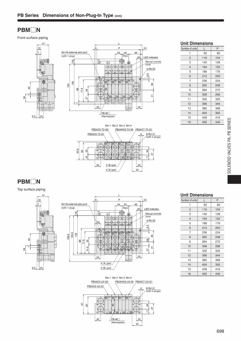
698
SOLE
NOID
VAL
VES
PA, P
B SE
RIES
PB Series Dimensions of Non-Plug-In Type (mm)
PBMNFront surface piping
PBMNTop surface piping
EOE S
N P OCL
mPm
P
R2 3
1 R1
P1
5
R1
P1
51
3R2
P
Stn.4Stn.3Stn.2Stn.1
L
P13
7
41
40
2020
2020
PB24C7-T3-G1PB24HC6-T3-39PB24C5-T2-G2
PB24C5-T2-G1
163 139
887
2827
77.5
4-R3.25
6.5
3941
6.5 16
28
742
20
6
60
37
6
1825
46
1728
(6)
24 24(Pitch)
(18)
10.5
12P263.6
34
Rc1/8 external pilot port
(with 1 plug)
Manual overridecover
LED indicator
8-Rc1/2(with 5 plugs)
2(B)port
4(A)port
PB-M(Nameplate)
4 A
2 B 2 B 2 B 2 B
4 A 4 A 4 A
EOE S
N P OCL
mPm
P
R2 3
1 R1
P1
5
R1
P1
51
3R2
P
Stn.4Stn.3Stn.2Stn.1
13
7
41
2020
2020
PB24C7-U3-G1PB24HC6-U3-39PB24C5-U2-G2
PB24C5-U2-G1
159.6
135.6
132
88 2531.5
77.5
6.5
3941
6.5 16
28
742
20
6
60
37
6
46
1728
(6)
24
20
(18)
10.5
12P2
67
2827
34
40
4-R3.25
L
P
LED indicator
24(Pitch)
8-Rc1/2(with 5 plugs)
PB-M(Nameplate)
Rc1/8 external pilot port
(with 1 plug)
4(A)port
2(B)port
Manual overridecover
4 A
2 B 2 B 2 B 2 B
4 A 4 A 4 A
Number of units L P
92
116
140
164
188
212
236
260
284
308
332
356
380
404
428
452
80
104
128
152
176
200
224
248
272
296
320
344
368
392
416
440
Unit Dimensions
1
2
3
4
5
6
7
8
9
10
11
12
13
14
15
16
Number of units L P
92
116
140
164
188
212
236
260
284
308
332
356
380
404
428
452
80
104
128
152
176
200
224
248
272
296
320
344
368
392
416
440
Unit Dimensions
1
2
3
4
5
6
7
8
9
10
11
12
13
14
15
16
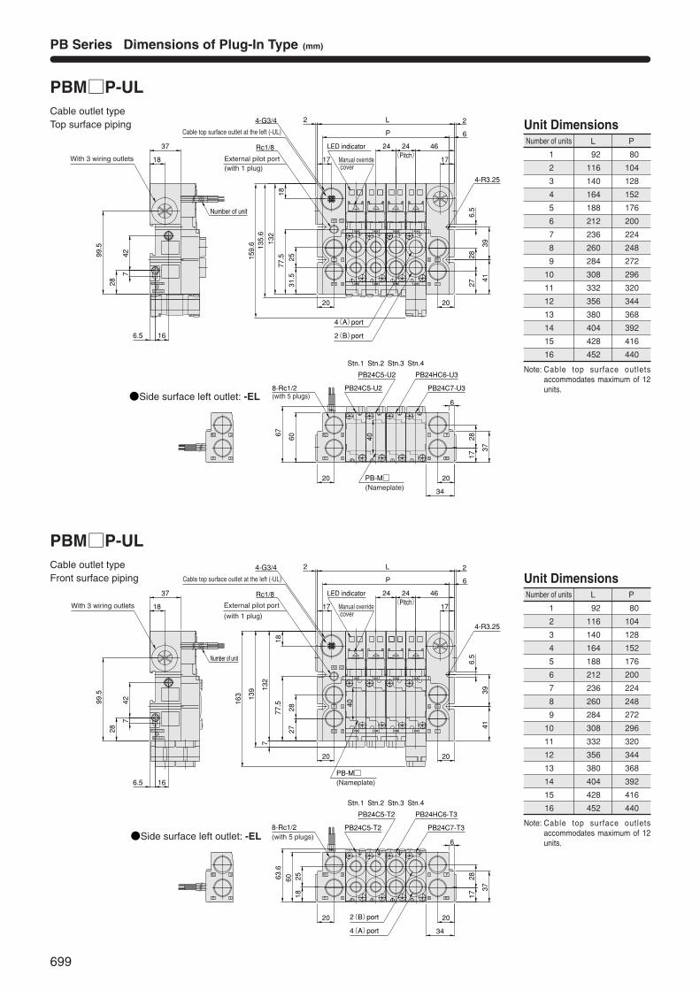
699
PB Series Dimensions of Plug-In Type (mm)
PBMP-ULCable outlet typeTop surface piping
PBMP-ULCable outlet typeFront surface piping
Rc1/8
L
P
159.6
60
132
6
34
20
17
20 20
2 2
18
99.5
77.5
17
37
166.5
4-G3/4
18
28
742
4139
4-R3.25
6.5
37
46
1728
6
24
EOE S
N P OCL
P
R2 3
1P
R2 3
1 R1
P1
5
R1
P1
51
3R2
P
12P2
001002
20
PB24C7-U3
PB24C5-U2
PB24C5-U2
PB24HC6-U3
135.6
67 40
2531.5
2827
Stn.4Stn.3Stn.2Stn.1
With 3 wiring outlets
Side surface left outlet: -EL
LED indicator 24(Pitch)
8-Rc1/2(with 5 plugs)
4(A)port
2(B)port
PB-M(Nameplate)
Cable top surface outlet at the left (-UL)
External pilot port(with 1 plug)
Manual override cover
Number of unit
4 A
2 B 2 B 2 B 2 B
4 A 4 A 4 A
Rc1/8
L
P
2827
40
7
139
163
2518
63.6
60
132
6
34
20
17
20 20
2 2
18
99.5
77.5
17
37
166.5
4-G3/4
18
28
742
4139
4-R3.25
6.5
37
46
1728
6
24
EOE S
N P OCL
P
R2 3
1P
R2 3
1 R1
P1
5
R1
P1
51
3R2
P
12P2
20
PB24C7-T3
PB24C5-T2
PB24C5-T2
PB24HC6-T3
Stn.4Stn.3Stn.2Stn.1
External pilot port
(with 1 plug)
With 3 wiring outlets
LED indicator
Cable top surface outlet at the left (-UL)
24(Pitch)
8-Rc1/2(with 5 plugs)
Manual override cover
2(B)port
4(A)port
Number of unit
Side surface left outlet: -EL
PB-M(Nameplate)
4 A
2 B 2 B 2 B 2 B
4 A 4 A 4 A
001002
Number of units L P
92
116
140
164
188
212
236
260
284
308
332
356
380
404
428
452
80
104
128
152
176
200
224
248
272
296
320
344
368
392
416
440
Unit Dimensions
1
2
3
4
5
6
7
8
9
10
11
12
13
14
15
16
Number of units L P
92
116
140
164
188
212
236
260
284
308
332
356
380
404
428
452
80
104
128
152
176
200
224
248
272
296
320
344
368
392
416
440
Unit Dimensions
1
2
3
4
5
6
7
8
9
10
11
12
13
14
15
16
Note: Cable top surface outletsaccommodates maximum of 12units.
Note: Cable top surface outletsaccommodates maximum of 12units.
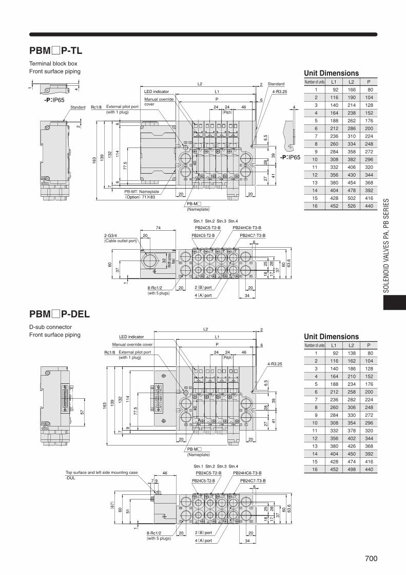
700
SOLE
NOID
VAL
VES
PA, P
B SE
RIES
PBMP-TLTerminal block boxFront surface piping
PBMP-DELD-sub connectorFront surface piping
Rc1/8
Stn.1 Stn.2 Stn.3 Stn.4
L1
P
40
7
139
163
60132
6
34
20
20 20
114
66
4139
4-R3.25
6.5
37
46
1728
6
24
EOE S
N P O
P
R2 3
1 R1
P1
5
R1
P1
51
3R2
P
12P2
20
PB24C7-T3-B
PB24C5-T2-B
PB24C5-T2-B
PB24HC6-T3-B
77.5
L2 2
4
37
1
63.6
602518
1 42
2827
20
74
-P:IP65
-P:IP65
External pilot port(with 1 plug)
Standard
LED indicator
Manual overridecover
Standard
24(Pitch)
8-Rc1/2(with 5 plugs)
2-G3/4(Cable outlet port)
PB-MT: Nameplate(Option)71×83
32
(Widt
h acro
ss
flats)
2(B)port
4(A)port
PB-M(Nameplate)
4 A
2 B 2 B 2 B 2 B
4 A 4 A 4 A
Rc1/8
L1
P
40
7
139
163
60132
6
34
20
20 20
114
9
4139
4-R3.25
6.5
37
46
1728
6
24
EOE S
N P O
P
R2 3
1 R1
P1
5
R1
P1
51
3R2
P
12P2
20
PB24C7-T3-B
PB24C5-T2-B
PB24C5-T2-B
PB24HC6-T3-B
77.5
L2 2
51
1
(67)
63.66025
18
57
2827
97
46
Stn.1 Stn.2 Stn.3 Stn.4
External pilot port(with 1 plug)
PB-M(Nameplate)
LED indicator
Manual override cover
24(Pitch)
Top surface and left side mounting case-DUL
8-Rc1/2(with 5 plugs)
2(B)port
4(A)port
4 A
2 B 2 B 2 B 2 B
4 A 4 A 4 A
Number of units PL1 L2
80
104
128
152
176
200
224
248
272
296
320
344
368
392
416
440
92
116
140
164
188
212
236
260
284
308
332
356
380
404
428
452
166
190
214
238
262
286
310
334
358
382
406
430
454
478
502
526
Unit Dimensions
1
2
3
4
5
6
7
8
9
10
11
12
13
14
15
16
Number of units PL1 L2
80
104
128
152
176
200
224
248
272
296
320
344
368
392
416
440
92
116
140
164
188
212
236
260
284
308
332
356
380
404
428
452
138
162
186
210
234
258
282
306
330
354
378
402
426
450
474
498
Unit Dimensions
1
2
3
4
5
6
7
8
9
10
11
12
13
14
15
16

701
PB Series Dimensions of Serial Transmission Type (mm)
PBMSFront surface piping
G24V
OV
DG
24VOV
D
POWER
SEND1248163264128
ADDRESS
YS401 L
MADE IN JAPAN
142649
Rc1/8
L1
P
40
7
139
163
79132
6
34
20
20 20
114
9
4139
4-R3.25
6.5
37
46
1728
6
24
EOE S
N P O
P
R2 3
1 R1
P1
5
R1
P1
51
3R2
P
12P2
20
PB24C7-T3-B
PB24C5-T2-B
PB24C5-T2-B
PB24HC6-T3-B
77.5
L25 2
53
1
63.66025
18
40
2827
26
74 Stn.1 Stn.2 Stn.3 Stn.4
4
-P:IP65
External pilot port(with 1 plug)
LED indicator
Manual overridecover
Standard24(Pitch)
Serial transmission block(Panel design varies according to transmission block specifications.)
8-Rc1/2(with 5 plugs)
2(B)port
4(A)port
PB-M(Nameplate)
4 A
2 B 2 B 2 B 2 B
4 A 4 A 4 A
Number of units PL1 L2
80
104
128
152
176
200
224
248
272
296
320
344
368
392
416
440
92
116
140
164
188
212
236
260
284
308
332
356
380
404
428
452
166
190
214
238
262
286
310
334
358
382
406
430
454
478
502
526
Unit Dimensions
1
2
3
4
5
6
7
8
9
10
11
12
13
14
15
16
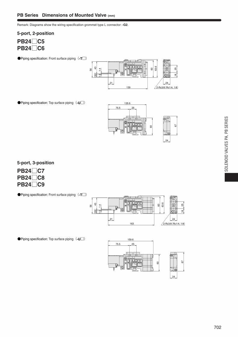
702
SOLE
NOID
VAL
VES
PA, P
B SE
RIES
PB Series Dimensions of Mounted Valve (mm)
5-port, 2-position
PB24C5PB24C6
5-port, 3-position
PB24C7PB24C8PB24C9
Remark: Diagrams show the wiring specification grommet type L connector: -G2.
2-Rc3/8(Rc1/4, 1/8)
1825
67
24
60 63.6
139
21
56
43(300) 1.4
1.5
24
67
60
135.6
75.5 25
2-Rc3/8(Rc1/4, 1/8)
1825
24
60 63.6
163
21
56
43(300) 1.4
1.5
24
60
159.6
75.5 25
Piping specification: Front surface piping(-T)
Piping specification: Top surface piping(-U)
Piping specification: Top surface piping(-U)
Piping specification: Front surface piping(-T)

703
PB Series Dimensions of Options (mm)
Block-off plate(PB-BP)
Safe block Piping specification: Front surface piping(-T)
Dustproof conduit cap: For serial transmission(-FS1)
Individual air supply and exhaust spacer(PB-Z)
Safe block Piping specification: Top surface piping(-U)
Dustproof conduit cap: For terminal block box(-FT2)
P
R2 3
1 R1
P1
5
60 63.6
R1
P1
51
3R2
P
12P2
4624(Pitch)
24
4 A
2 B
PB-BPBlock-off plate
P
R2 3
1 R1
P1
5
60 63.6
1(P)port
3, 5(R)port
4 A
2 B
R1
P1
51
3R2
P
12P2
4624(Pitch)
24
PB-ZIndividual air supply and exhaust spacer
P
R2 3
1 R1
P1
5
6037.3
114
7
Residual pressure exhaust manual override
For PB24C7, C8, C9(3 positions)
For PB24C5, C6(2 positions)
4 A
2 B
4 A
2 B
R1
P1
51
3R2
P
12P2
132
135.6
159.6
P
R2 3
1 R1
P1
5
6063.6
For PB24C7, C8, C9(3 positions)
For PB24C5, C6(2 positions)
2(B)port
4(A)port
4 A
2 B
4 A
2 B
R1
P1
51
3R2
P
12P2
Residual pressure exhaust manual override
7
61.3
210 186
132
37.3
G24V
OV
DG
24VOV
D
POWER
SEND1248163264128
ADDRESS
YS401 L
MADE IN JAPAN
142649
1
3R2
P
12P2
26
36.5
(MAX)
Applicable cable outer diameter
φ8.5~12.5
4 A
2 B 2 B
4 A
1
3R2
P
12P2
20
29.5
(MAX)6
Applicable cable outer diameterφ16.5~18.5
4 A
2 B 2 B
4 A