Series XXX - VAT Valves
82
Installation, Operating & Maintenance Instructions 603696EA Edition 2013-08-16 Control gate valve with RS232 interface Series 642 DN 100 mm (I.D. 4") This manual is valid for the following product ordering numbers: 64240-PEAG-0001 Configured with firmware: 642P.2E.02
-
Upload
khangminh22 -
Category
Documents
-
view
0 -
download
0
Transcript of Series XXX - VAT Valves

Installation, Operating & Maintenance Instructions
603696EA Edition 2013-08-16
Control gate valve with RS232 interface
Series 642 DN 100 mm (I.D. 4") This manual is valid for the following product ordering numbers:
64240-PEAG-0001 Configured with firmware: 642P.2E.02

Series 642
2/82 Edition 2013-08-16 603696EA
Imprint
Manufacturer VAT Vakuumventile AG, CH-9469 Haag, Switzerland
Website:
Phone:
Fax:
Email:
www.vatvalve.com
+41 81 771 61 61
+41 81 771 48 30
Publisher VAT Vakuumventile AG, CH-9469 Haag, Switzerland
Editor VAT Vakuumventile AG, CH-9469 Haag, Switzerland Print VAT Vakuumventile AG, CH-9469 Haag, Switzerland Copyright © VAT Vakuumventile AG 2013 No part of these instructions may be reproduced in any way (photocopies,
microfilms or any other reproduction processes) nor may it be manipulated with electronic systems, duplicated or distributed without written permission from VAT. Offenders are liable to pay damages.
The original VAT firmware and updated state of the art versions of the VAT
firmware are intended for use with VAT products. The VAT firmware contains a limited, time unlimited user license. The VAT firmware may not be used for purposes other than those intended nor is it permitted to make copies of the VAT firmware. In particular, it is strictly forbidden to give copies of the VAT firmware to other people.
The use of trade names, brand names, trademarks, etc. in these Instructions
does not entitle third parties to consider these names to be unprotected and to use them freely. This is in accordance with the meaning of the laws and acts covering brand names and trademarks.

Series 642
603696EA Edition 2013-08-16 3/82
Contents
1 Description of product ........................................................................ 5 1.1 Identification of product ................................................................................................... 5 1.2 Use of product ................................................................................................................. 5 1.3 Used abbreviations .......................................................................................................... 5 1.4 Related documents ......................................................................................................... 5 1.5 Important information ....................................................................................................... 5 1.6 Technical data ................................................................................................................. 6
1.6.1 Control and actuating unit ................................................................................. 6 1.6.2 Valve unit .......................................................................................................... 7
2 Safety ................................................................................................... 8 2.1 Compulsory reading material ........................................................................................... 8 2.2 Danger levels .................................................................................................................. 8 2.3 Personnel qualifications ................................................................................................... 9 2.4 Safety labels .................................................................................................................... 9
3 Design and Function ......................................................................... 10 3.1 Design ........................................................................................................................... 10 3.2 Function ......................................................................................................................... 10
3.2.1 Pressure control system overview and function .............................................. 11 3.2.2 Principle of a pressure control system ............................................................ 12
4 Installation ......................................................................................... 13 4.1 Unpacking ..................................................................................................................... 13 4.2 Installation into the system ............................................................................................ 14
4.2.1 Installation space condition ............................................................................. 15 4.2.2 Connection overview ....................................................................................... 16 4.2.3 Installation procedure ...................................................................................... 17
4.3 Tightening torque .......................................................................................................... 18 4.3.1 Mounting with centering rings ......................................................................... 18 4.3.2 Mounting with O-ring in grooves ..................................................................... 18
4.4 Admissible forces .......................................................................................................... 19 4.4.1 Requirements to sensor connection ................................................................ 20
4.5 Electrical connection ...................................................................................................... 20 4.5.1 Ground connection .......................................................................................... 21 4.5.2 Sensor supply concepts .................................................................................. 22 4.5.3 Power and sensor connection ( 15 VDC sensors) with opt. SPS module ...... 23 4.5.4 Service port connection ................................................................................... 24 4.5.5 RS232 Functions and Wiring .......................................................................... 25
4.6 Initial operation .............................................................................................................. 28 4.6.1 RS232 interface configuration ......................................................................... 28 4.6.2 Valve configuration.......................................................................................... 29 4.6.3 Sensor configuration ....................................................................................... 29 4.6.4 ZERO .............................................................................................................. 29 4.6.5 LEARN ............................................................................................................ 30 4.6.6 Tuning of control performance ........................................................................ 32
4.7 RS232 interface commands .......................................................................................... 36 4.7.1 RS232 Command syntax ................................................................................ 36 4.7.2 Control commands .......................................................................................... 37 4.7.3 Inquiry commands ........................................................................................... 38 4.7.4 Setup commands ............................................................................................ 43 4.7.5 Error messages ............................................................................................... 48
5 Operation ........................................................................................... 49 5.1 Normal operation ........................................................................................................... 49

Series 642
4/82 Edition 2013-08-16 603696EA
5.1.1 Local operation ................................................................................................ 50 5.1.2 Remote operation ............................................................................................ 51
5.2 Close valve .................................................................................................................... 52 5.3 Open valve .................................................................................................................... 52 5.4 Position control .............................................................................................................. 52 5.5 Pressure control ............................................................................................................. 52 5.6 Display information ........................................................................................................ 53
5.6.1 Power up ......................................................................................................... 53 5.6.2 Operation ........................................................................................................ 54 5.6.3 Errors .............................................................................................................. 54 5.6.4 Safety mode .................................................................................................... 54 5.6.5 Service indication ............................................................................................ 54
5.7 Operation during power up ............................................................................................ 55 5.8 Behavior in case of power failure ................................................................................... 55 5.9 Operation under increased temperature ........................................................................ 55
6 Trouble shooting .............................................................................. 56
7 Maintenance ...................................................................................... 59 7.1 Maintenance intervals .................................................................................................... 59 7.2 Maintenance procedures ............................................................................................... 60
7.2.1 Replacement of gate seals and valve cleaning ............................................... 61 7.2.2 Replacement of Option board ......................................................................... 66 7.2.3 Retrofit / replacement procedure ..................................................................... 68
8 Repairs .............................................................................................. 71
9 Dismounting and Storage ................................................................ 72 9.1 Dismounting ................................................................................................................... 72 9.2 Storage .......................................................................................................................... 73
10 Packaging and Transport ................................................................. 74 10.1 Packaging ...................................................................................................................... 74 10.2 Transport ....................................................................................................................... 75
11 Disposal ............................................................................................. 76
12 Spare parts ........................................................................................ 77 12.1 Drawing ......................................................................................................................... 78
12.1.1 Valve unit with seals and grease ..................................................................... 79 12.1.2 Control and actuating unit ............................................................................... 80 12.1.3 Accessories ..................................................................................................... 80
13 Appendix ........................................................................................... 81

Series 642 DESCRIPTION OF PRODUCT
603696EA Edition 2013-08-16 5/82
1 Description of product
1.1 Identification of product
The fabrication number and order number are fixed on the product directly or by means of an identification plate.
made in Switzerland Fabrication No.:
000 . . - . . . . - . . . . / . . . . A - . . . . . .
Fabrication number Order number
1.2 Use of product
This product is a control gate valve with isolation functionality. It is intended to use for downstream pressure control applications. Use product for clean and dry vacuum applications only. Other applications are only allowed with the written permission of VAT.
1.3 Used abbreviations
Abbreviation Description
CPA Control Performance Analyzer
PFO Power Failure Option
SFS Sensor Full Scale
SPS Sensor Power Supply
ADC Analog-to-digital converter
1.4 Related documents
Product Data Sheet
Dimensional Drawing
IOMI Heating device (if valve with heater)
1.5 Important information
This symbol points to a very important statement that requires particular attention.
Example:
Refer to chapter: «Technical data» for detailed information.

DESCRIPTION OF PRODUCT Series 642
6/82 Edition 2013-08-16 603696EA
1.6 Technical data
1.6.1 Control and actuating unit
Describtion
Input voltage 1)
+24 VDC (±10%) @ 0.5 V pk-pk max. [connector: POWER]
Power consumption 86 W [connector: POWER]
Sensor power supply output 2)
±15 VDC (±5%) / 1000 mA max. [connector: SENSOR]
Sensor input
Signal input voltage / Input resistance
ADC resolution
Sampling time
0-10 VDC / Ri>100 kΩ (linear to pressure)
0.23 mV
10 ms
[connector: SENSOR]
Digital inputs 3)
±24 VDC max. [connector: INTERFACE]
Digital outputs 3)
Input voltage
Input current
Breaking capacity
70 VDC or 70 V peak max.
0.5 ADC or 0.5 A peak max.
10 W max.
[connector: INTERFACE]
Analog outputs 3)
(optional) 0-10 VDC / 1 mA max. [connector: INTERFACE]
PFO4)
battery pack (optional)
Charging time
Durability
2 minutes max.
up to 10 years @ 25°C ambient refer to «Durability of power fail battery» for details
Compressed air supply
4 - 7 bar / 55 - 100 psi (above ATM)
Ambient temperature 0 °C to +50 °C max. (<35 °C recommended)
Pressure control accuracy 5 mV or 0.1% of setpoint, whichever is greater
Position resolution / position control capability 9155 (full stroke)
Closing time throttling only 3 s typ.
Opening time throttling only 3 s typ.
Closing time throttling & isolation 6 s typ.
Opening time throttling & isolation 6 s typ.
1)
Internal overcurrent protection by a PTC device. 2)
Refer to chapter «Sensor supply concepts» for details. 3)
Refer to chapter «Schematics» for details. 4)
PFO = Power Failure Option. Refer to «Behavior in case of power failure» for details.

Series 642 DESCRIPTION OF PRODUCT
603696EA Edition 2013-08-16 7/82
1.6.2 Valve unit
Valve unit
Pressure range at 20 C 1 × 10E-8 mbar to 1.2 bar (abs)
Leak rate to outside at 20 C 1 × 10E-9 mbar l/s
Leak rate valve seat at 20 C 1 x 10E-9 mbar l/s
Cycles until first service
- Throttling cycles (open - max. throttle - open)
- Isolation cycles (open - closed - open)
1’000’000 (unheated and under clean conditions)
200’000 (unheated and under clean conditions)
Admissible operating temperature +10°C to +150°C
Mounting position any (valve seat on chamber side is recommended) (valve seat to face chamber is recommended)
Process side materials body Stainless steel 316L (1.4404 or 1.4435)
plate Stainless steel 316L (1.4404 or 1.4435)
other parts Aluminum: A356 (3.2371)
Stainless steel: 301 (1.4310), 303 (1.4305), 304 (1.4301 or 1.4303), 316L (1.4435 or 1.4404), A2 (304)
Seals plate FKM (e.g. Viton®)
rotary feedthrough FKM (e.g. Viton®)
bonnet (vulcanized) FKM (e.g. Viton®)
Max. differential pressure on plate during isolation 2000 mbar in either direction
Max. differential pressure on plate
during opening and throttling
30 mbar
Min. controllable conductance
(N2 molecular flow)
1 l/s
Max. controllable conductance
(N2 molecular flow)
1700 l/s
Dimensions Refer to dimensional drawing of specific valve ordering number
(available on request)

SAFETY Series 642
8/82 Edition 2013-08-16 603696EA
2 Safety
2.1 Compulsory reading material
Read this chapter prior to performing any work with or on the product. It contains important information that is significant for your own personal safety. This chapter must have been read and understood by all persons who perform any kind of work with or on the product during any stage of its serviceable life.
NOTICE Lack of knowledge
Failing to read this manual may result in property damage.
Firstly, read manual.
These Installation, Operating & Maintenance Instructions are an integral part of a comprehensive documentation belonging to a complete technical system. They must be stored together with the other documentation and accessible for anybody who is authorized to work with the system at any time.
2.2 Danger levels
DANGER High risk
Indicates a hazardous situation which, if not avoided, will result in death or serious injury.
WARNING Medium risk
Indicates a hazardous situation which, if not avoided, could result in death or serious injury.
CAUTION Low risk
Indicates a hazardous situation which, if not avoided, may result in minor or moderate injury.
NOTICE Command
Indicates a hazardous situation which, if not avoided, may result in property damage.

Series 642 SAFETY
603696EA Edition 2013-08-16 9/82
2.3 Personnel qualifications
WARNING Unqualified personnel
Inappropriate handling may cause serious injury or property damage.
Only qualified personnel are allowed to carry out the described work.
2.4 Safety labels
Label Part No. Location on valve
T-9001-156 On protective foil covering of valve opening

DESIGN AND FUNCTION Series 642
10/82 Edition 2013-08-16 603696EA
3 Design and Function
3.1 Design
14 3 9 2 5 7 6 8 11 10
1 Valve gate 7 Gate seal
2 Ball guidance 8 Actuator shaft
3 Leaf spring 9 Counter plate
4 Ball pairs 10 Bonnet seal
5 Detents 11 Rotary feed through seals
6 Crank bolt
3.2 Function
The valve gate (1) acts as a throttling element and varies the conductance of the valve opening. Actuation is performed with a stepper motor and controller. The stepper motor/controller version ensures accurate pressure control due to exact gate positioning. For leak tight closing the VATLOCK principle is applied. For details refer to VAT catalog.

Series 642 DESIGN AND FUNCTION
603696EA Edition 2013-08-16 11/82
3.2.1 Pressure control system overview and function
Vacuum pressures are always absolute pressures unless explicitly specified as pressure differences.
M
3
4
5
7
8
2
1
9
Q
p V
Seff
6
Example: Downstream control
1 Valve
2 Process chamber
3 Gas inlet
4 Pressure sensor(s)
5 Sensor cable
6 Controller and actuator
7 Cable to remote control unit
8 Cable to power supply
9 HV Pump
Seff Q / p
Seff effective pump speed (ls-1
)
Q Gas flow (mbar)
p Pressure (mbar)
or units used in USA
Seff = 12.7 • Q / p
Seff effective pump speed (ls-1
)
Q Gas flow (sccm)
p Pressure (mTorr)

DESIGN AND FUNCTION Series 642
12/82 Edition 2013-08-16 603696EA
3.2.1.1 Way of operation
The controller compares the actual pressure in the process chamber given by the pressure sensor with the preset pressure. The controller uses the difference between actual and set pressure to calculate the correct position of the control valve. The controller drives the control valve into the correct position and the actual pressure again equals the set pressure. This control operation is performed continuously. Pressure changes in the process chamber due to leaks, desorption, and gas flow, reaction products, variations in pumping speed etc. are always corrected at once.
3.2.1.2 Pressure control
In a vacuum system which is pumped and into which gas is admitted at the same time, the pressure can be controlled in two ways: 1. Downstream control (standard):
The pressure is controlled by changing the conductance of a control valve between pump and process chamber. This changes the effective pumping speed at the process chamber. Pressure and gas flow can be independently controlled over a wide range.
2. Upstream control:
The pressure is controlled by changing the gas flow into the process chamber, while the pumping speed remains constant.
3.2.1.3 Adaptive controller (standard)
A controller adapting itself to changes in pressure, gas flow and pumping speed without any manual adjustments. This allows for a completely automatic operation of the system.
3.2.2 Principle of a pressure control system
1. Host computer sends pressure set point
2. Controller reads actual pressure from sensor
3. Optimizing module sends new PID parameters
4. Actuator sets new valve position
Host computer (Example)
1.
4.
3.
2.

Series 642 INSTALLATION
603696EA Edition 2013-08-16 13/82
4 Installation
WARNING Unqualified personnel
Inappropriate handling may cause serious injury or property damage.
Only qualified personnel are allowed to carry out the described work.
4.1 Unpacking
NOTICE Physical overstraining at controller
Inappropriate handling with the valve may cause in damage of controller.
Do not place the valve on the controller.
CAUTION Valve is a heavy component
Physical overstraining.
Use a crane to lift valves DN 200 (8”) and larger.
Make sure that the supplied products are in accordance with your order.
Inspect the quality of the supplied products visually. If it does not meet your requirements, please contact VAT immediately.
Store the original packaging material. It may be useful if products must be returned to VAT.
1. Open the transport case and remove inside packing material as far as necessary.
2. Attach lifting device for valves DN 200 (8”) and larger. For attachment refer to dimensional drawing of valve.
3. Lift the valve carefully and place it on a clean place.
Do not remove protective foils from valve opening
INSTALLATION Series 642
14/82 Edition 2013-08-16 603696EA
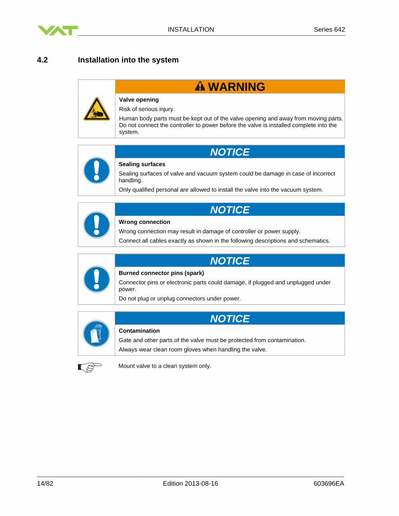
4.2 Installation into the system
WARNING
Valve opening
Risk of serious injury.
Human body parts must be kept out of the valve opening and away from moving parts. Do not connect the controller to power before the valve is installed complete into the system.
NOTICE Sealing surfaces
Sealing surfaces of valve and vacuum system could be damage in case of incorrect handling.
Only qualified personal are allowed to install the valve into the vacuum system.
NOTICE Wrong connection
Wrong connection may result in damage of controller or power supply.
Connect all cables exactly as shown in the following descriptions and schematics.
NOTICE Burned connector pins (spark)
Connector pins or electronic parts could damage, if plugged and unplugged under power.
Do not plug or unplug connectors under power.
NOTICE Contamination
Gate and other parts of the valve must be protected from contamination.
Always wear clean room gloves when handling the valve.
Mount valve to a clean system only.

Series 642 INSTALLATION
603696EA Edition 2013-08-16 15/82
4.2.1 Installation space condition
Install the valve with integrated controller with space for dismantling and air circulation as shown in figure below.
100
220

INSTALLATION Series 642
16/82 Edition 2013-08-16 603696EA
4.2.2 Connection overview
System:
M
3
4
5
6
7
2
19
8
10
11
1 Valve
2 Process chamber
3 Gas inlet
4 Pressure sensor(s)
5 Sensor cable(s)
6 Cable to RS232 remote control unit
7 Cable to power supply
8 Controller
9 Connection cable controller / actuator
10 Actuator
11 Pump
Actuator Controller

Series 642 INSTALLATION
603696EA Edition 2013-08-16 17/82
4.2.3 Installation procedure
1. Install valve [1] into the vacuum system.
Do not tighten the flange screws stronger than indicated under «Tightening torque».
Do not admit higher forces to the valve than indicated under «Admissible forces».
Make sure that enough space is kept free to do preventive maintenance work. The required space is indicated on the dimensional drawing.
2. Install the ground connection cable at controller. Refer to «Electrical connection»
3. Install connection cable between actuator (connector) and controller (connector: VALVE)
4. Install sensor(s) [4] according to the recommendations of the sensor manufacturer and directives given under «Requirements to sensor connection».
5. Connect pressure sensor cable [5] to sensor(s) and then to valve (connector: SENSOR). Refer to chapter «Electrical connection» for correct wiring.
Input for second sensor is available on 642 . . - . . . H - . . . . version only.
6. Connect valve to RS232 Interface [6] (RS232 connector). Refer to «DeviceNet schematics» for
correct wiring.
7. Connect power supply [7] to valve (connector: POWER). Refer to chapter «Electrical connection» for correct wiring.
To provide power to the valve motor pins 4 and 8 must be bridged, otherwise motor interlock is active and thevalve enters the safety mode and is not operative. Refer also to «Safety mode».
8. This valve may optionally be equipped with a heating device. Connect VAT heating device according
to manual of respective heating device.
9. Perform «Setup procedure» to prepare valve for operation.
Without performing the setup procedure the valve will not be able to do pressure control.

INSTALLATION Series 642
18/82 Edition 2013-08-16 603696EA
4.3 Tightening torque
4.3.1 Mounting with centering rings
ISO-F ISO-F
max. tightening torque (Nm)
max. tightening torque (lbs . ft)
8-10 6-8
hole depth (mm) hole depth (inch)
12 0.47
4.3.2 Mounting with O-ring in grooves
ISO-F JIS ASA-LP ISO-F JIS ASA-LP
max. tightening torque (Nm)
max. tightening torque (lbs . ft)
20-23 35-40 35-40 15-17 26-30 26-30
hole depth (mm) hole depth (inch)
12 0.47
The torque values below are dependent on many factors, such as materials involved, surface quality, surface treatment, and lubrication. The torques below are valid if immersion depth of the mounting screws is at least once the thread diameter (min. 1d), and the friction coefficient of the screw-flange
connection ( total = ( screw thread-helicoil + under screw head)/2) is bigger than 0.12. Lower friction coefficients may damage the valve, as the resulting preload force gets too high. Therefore for other friction coefficients the torque needs to be adapted. Please review design guidelines for Helicoil-Screw connections and make sure that screws in use are capable to withstand applied torques, are appropriate for the application and are not too long. Too long screws may damage the valve, the immersion depth should not exceed (hole depth – 1 mm). Tighten mounting screws of the flanges uniformly in crosswise order. Observe the maximum torque levels in the following tables.
Refer to «Spare parts / Accessories» for centering rings ordering numbers.

Series 642 INSTALLATION
603696EA Edition 2013-08-16 19/82
4.4 Admissible forces
NOTICE Force at flange and valve body
Forces from evacuating the system, from the weight of other components, and from baking can lead to deformation and malfunctioning of the valve.
Do not higher force the valve body as specified.
The following forces are admissible.
Axial tensile or compressive force «FA»
Bending moment «M»
FA
N lb. Nm lbf.
1000 220 40 30
For a combination of both forces (FA and M) the values are invalid. Verify that the depth of the mounting screws is min. 1 × thread diameter. Please contact VAT for more information.

INSTALLATION Series 642
20/82 Edition 2013-08-16 603696EA
4.4.1 Requirements to sensor connection
To achieve fast and accurate pressure control a fast sensor response is required. Sensor response time: < 50ms. The sensor is normally connected to the chamber by a pipe. To maintain that the response time is not degraded by this connection it needs to meet the following requirements:
Inner diameter of connection pipe: > = 10 mm
Length of connection pipe: < = 300 mm
These conductance guidelines must include all valves and limiting orifices that may also be present. Make also sure that there is no obstruction in front of sensor connection port inside the chamber. The sensor should also be mounted free of mechanical shock and vibration. Dynamic stray magnetic fields may introduce noise to sensor output and should be avoided or shielded.
4.5 Electrical connection
NOTICE Wrong connection
Wrong connection may result in damage of controller or power supply.
Connect all cables exactly as shown in the following descriptions and schematics.
NOTICE Burned connector pins (spark)
Connector pins or electronic parts could damage, if plugged and unplugged under power.
Do not plug or unplug connectors under power.
Isolation Valve (optional)
Process Chamber
L1 + L2 < = 300 mm
L1 min. 10 mm
min. 10 mm
Pressure Sensor
L2
Series 642 INSTALLATION
603696EA Edition 2013-08-16 21/82
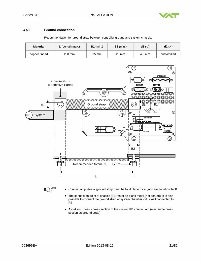
4.5.1 Ground connection
Recommendation for ground strap between controller ground and system chassis.
Material L (Length max.) B1 (min.) B2 (min.) d1 ( ) d2 ( )
copper tinned 200 mm 25 mm 25 mm 4.5 mm customized
Connection plates of ground strap must be total plane for a good electrical contact!
The connection point at chassis (FE) must be blank metal (not coated). It is also possible to connect the ground strap at system chamber if it is well connected to PE.
Avoid low chassis cross section to the system PE connection. (min. same cross section as ground strap)
d2
Chassis (PE) (Protective Earth)
B1
B2
d1
L
PE
Recommended torque: 1,3…1,7Nm
Ground strap
System

INSTALLATION Series 642
22/82 Edition 2013-08-16 603696EA
4.5.2 Sensor supply concepts
Concepts:
External +24 VDC supplied to POWER connector is converted into 15 VDC by the valve internal SPS
and supplied to SENSOR connector to supply 15 VDC sensors. Refer to chapter «Power and sensor
connection ( 15 VDC sensors) with optional SPS module» for schematic and correct wiring.
This concept is only possible when SPS retrofit is installed.
Valve versions:
642 . . - . . A . - . . . . and 642 . . - . . C . - . . . . SPS module included
The SPS module can be retrofitted. Refer to chapter «Retrofit / replacement procedure» for instruction.

Series 642 INSTALLATION
603696EA Edition 2013-08-16 23/82
4.5.3 Power and sensor connection ( 15 VDC sensors) with opt. SPS module
[642 . . - . . G . - . . . . / 642 . . - . . H . - . . . . versions recommended]
4.5.3.1 Sensor power wiring via controller
Use shielded sensor cable(s). Keep cable as short as possible, but locate it away from noise
sources.
Connect Power supply (+24 / GND) at power connector as shown in the drawing above!
Connect Sensors (±15V / 0V / + / -) at DB–15 female sensor connector exactly as shown in the drawing above!
1
2
3
4
M+24V
GND
Motor
Driver
5Chassis Ground
8
6
14
13
15
1
7
2
4
5
Pow
er
Supply
10
12
9
11
Unit
Control
InputSensor 1
Safety Switch
10nF
1M
Valve
Sensor
1
Outp
ut
-
+
0V
Input -15V
+15V
-15V
+15V
±15V Sensor
Power Supply
min. 3A
SENSORDB-15 femaleconnector
SC1069A
GROUND
connector5 pol male
POWER
5AF
1
5
Pins 2 and 3 must be bridged for operation. An optional switch would allow for motor interlock to prevent valve from moving.

INSTALLATION Series 642
24/82 Edition 2013-08-16 603696EA
4.5.4 Service port connection
The service port (connector: SERVICE) allows to connect the valve to a RS232 port of a computer. This requires a service cable and software from VAT. You can use our Software (freeware) 'Control Performance Analyzer' which can be downloaded from: http://www.vatvalve.com/customer-service/informations-and-downloads/control-performance-analyzer. Alternatively the VAT Service Box2 can be connected to the service port for setup and local operation. The service port is not galvanic isolated. Therefore we recommend using this only for setup, testing and maintenance and not for permanent control. Refer also to chapter: «Local Operation» for details and to chapter «Spare parts / Accessories» for ordering numbers of service cable, software and Service Box 2.
Use only screws with 4–40 UNC thread for fastening the service port connector.

Series 642 INSTALLATION
603696EA Edition 2013-08-16 25/82
4.5.5 RS232 Functions and Wiring
This interface allows for remote operation by means of a command set based on the RS232 protocol. In addition there are 2 digital inputs and 2 digital outputs. Digital inputs may be operated either by switches or by voltage sources.
Optional analog outputs are available on 642 . . - . . . V - . . . . and 642 . . - . . . W - . . . . versions only. Active digital inputs have higher priority than RS232 commands.
a) Configuration with switches for digital inputs:
Do not connect other pins than indicated in the schematics above! Use only screws with 4-40UNC thread for fastening the DB-25 connector!

INSTALLATION Series 642
26/82 Edition 2013-08-16 603696EA
b) Configuration with voltage source for digital inputs:
Do not connect other pins than indicated in the schematics above! Use only screws with 4-40UNC thread for fastening the DB-25 connector!

Series 642 INSTALLATION
603696EA Edition 2013-08-16 27/82
4.5.5.1 Digital inputs
Pin Function Signal type Description Priority
15 CLOSE VALVE Digital input
1)
This function will close the valve. Valve will be in interlock mode as long as function is activated. After deactivation of function it will remain effective until
- OPEN valve digital input is active
- converse RS232 control command have been received
The function is activated when optocoupler is ‘on’ in non inverted configuration.
The function is activated when optocoupler is ‘off’ in inverted configuration.
Configuration can be done in local operation via service port or in remote operation.
1 2)
17 OPEN VALVE Digital input
1)
This function will open the valve. Valve will be in interlock mode as long as function is activated. After deactivation of function it will remain effective until converse RS232 control command have been received.
The function is activated when optocoupler is ‘on’ in non inverted configuration.
The function is activated when optocoupler is ‘off’ in inverted configuration.
Configuration can be done in local operation via service port or in remote operation.
2 2)
23 DIGITAL GROUND Digital ground
Ground for all digital inputs. Ground is used when digital inputs are operated by switches. Connect switches to ground.
See also in chapter «Schematics» configuration a).
25 DIGITAL COMMON Digital
common
Common for all digital inputs. Common is used when digital inputs are driven by voltage sources. Connect + or – terminal of source with common (optocoupler inputs are capable of bidirectional operation).
See also in chapter «Schematics» configuration b).
1) All digital inputs are digitally filtered. Filter delay is 50ms. This means that digital signals must be
applied for at least 50ms to be effective. Refer to chapter «Schematics» for details about input circuit. 2) Highest priority is 1. Functions with lower priorities will not be effective as long as higher priority
functions are active. These digital inputs have higher priority than all RS232 commands. RS232 commands will not be accepted while digital inputs are active.

INSTALLATION Series 642
28/82 Edition 2013-08-16 603696EA
4.6 Initial operation
To enable the valve for pressure control setup steps 1 to 6 must be performed. In case position control is required only it’s sufficient to perform steps 1 to 3.
Setup step Description
1 Power up Turn on external + 24VDC power supply of valve (and external 15 VDC for sensor power supply if required). Refer to chapter «Behavior during power up» for details.
2 Interface
configuration
RS232 parameters and digital inputs for valve may be changed from the default values. Refer to chapter «RS232 interface configuration» for details.
3 Valve
configuration Basic configurations of valve must be adapted according to application needs. Refer to chapter «Valve configuration» for details.
4 Sensor
configuration
Basic configurations of sensor(s) must be adapted according to application needs. Refer to chapter «Sensor configuration» for details.
5 ZERO Compensation of the sensor offset voltage. Refer to chapter «ZERO» for details.
6 LEARN Determination of the vacuum system characteristic to accommodate the PID controller. Refer to chapter «LEARN» for details.
Without LEARN the valve is not able to run pressure control.
4.6.1 RS232 interface configuration
Interface configuration must be adapted according to application needs.
The factory default settings of the interface is shown in the table below.
Baud rate Data bits Stop bits Parity Digital input OPEN
Digital input CLOSE
9600 7 even not inverted
not inverted 9600
Functionality of digital interlock inputs CLOSE VALVE and OPEN VALVE. These may be configured as ‘not inverted‘, ‘inverted‘ or ‘disabled‘. Default is ‘not inverted‘. Refer also to «Digital inputs».
Pressure and position range for RS232 with analog output communication must be selected. Default for pressure is 0 - 1’000’000. Default for position is 0 - 100’000.
Local operation: (‘Control View’, ‘Control Performance Analyzer’ or ‘Service Box 2‘)
Remote operation: (Refer to chapter «Setup commands» for details)
Do configuration in menu ‘Setup / Interface’. 1. Send INTERFACE CONFIGURATION
2. Send RANGE CONFIGURATION

Series 642 INSTALLATION
603696EA Edition 2013-08-16 29/82
4.6.2 Valve configuration
Basic valve configuration must be adapted according to application needs. Definition of valve plate position in case of:
After power up, default is ‘close‘.
Power failure, default is ‘not defined‘. Only for versions that have Power Fail Option equipped [642 . . - . . C . - . . . . or 642 . . - . . H . - . . . . ].
Network failure, for default settings refer to individual product data sheet.
Local operation: (‘Control View’, ‘Control Performance Analyzer’ or ‘Service Box 2‘)
Remote operation: (Refer to chapter «Setup commands» for details)
1. Do power up configuration in menu ‘Setup / Valve’.
1. Send VALVE CONFIGURATION 2. Do power fail configuration in menu
‘Setup / Valve’.
4.6.3 Sensor configuration
Basic sensor configuration must be adapted according to application needs.
ZERO function: This may be ‘disabled’ or ‘enabled’. Default is ‘enabled‘. Refer also to chapter «ZERO».
Sensor configuration with 1 sensor version [642 . . - . . . G - . . . .].
Local operation: (‘Control View’, ‘Control Performance Analyzer’ or ‘Service Box 2‘)
Remote operation: (Refer to chapter «RS232setup commands» for details)
1. Enable or disable ZERO function in menu ‘Setup / Sensor’.
1. Send SENSOR CONFIGURATION 2. Do 1 sensor configuration in menu ‘Setup
/ Sensor’.
4.6.4 ZERO
ZERO allows for the compensation of the sensor offset voltage. When ZERO is performed the current value at the sensor input is equated to pressure zero. In case of a 2 sensor system both sensor inputs will be adjusted. A max. offset voltage of +/- 1.4 V can be compensated. The offset value can be read via local and remote operation.
Local operation: (‘Control View’, ‘Control Performance Analyzer’ or ‘Service Box 2‘)
Remote operation: (Refer to chapter «RS232 with analog output control commands» resp. «RS232 with analog output setup commands» for details)
Go to menu ‘Zero / ZERO’ and follow instructions.
1. Send OPEN VALVE
2. Wait until process chamber is evacuated and sensor signal is not shifting anymore.
3. Send ZERO

INSTALLATION Series 642
30/82 Edition 2013-08-16 603696EA
Do not perform ZERO as long as pressure gauge voltage is shifting otherwise incorrect pressure reading is the result. Refer to manual of sensor manufacturer for warm up time.
Do not perform ZERO, if the base pressure of your vacuum system is higher than 1‰ of sensor full scale. We recommend disabling ZERO function in this case; refer to «Valve and sensor configuration» of the setup procedure. Otherwise incorrect pressure reading is the result.
4.6.5 LEARN
LEARN adapts the PID controller of the valve to the vacuum system and its operating conditions. LEARN must be executed only once during system setup. The LEARN routine determines the characteristic of the vacuum system. Based on this, the PID controller is able to run fast and accurate pressure control cycles. This characteristic depends on various parameters such as chamber volume, conductance and flow regime. Therefore it must be performed with a specific gas flow according to instruction below. The result of LEARN is a pressure versus valve position data table. This table is used to adapt the PID parameters. The data table is stored in the device memory which is power fail save. The data table can be up-/downloaded via ‘Control Performance Analyzer’ software or remote interface. Due to encoding the data may not be interpreted directly. By an OPEN VALVE, CLOSE VALVE, POSITION CONTROL or PRESSURE CONTROL command the routine will be interrupted.
Local operation: (‘Control View’, ‘Control Performance Analyzer’ or ‘Service Box 2‘)
Remote operation: (Refer to chapter «Control commands» resp. «Setup commands» for details)
Go to ‘Learn / LEARN’ menu and follow instructions. Gasflow calculation according to recommendation below is done automatically based on inputs.
1. Send OPEN VALVE
2. Set specific gas flow according to calculation below and wait until flow is stable. LEARN does not need to be performed with the process gas. Instead N2 or Ar may be used.
3. Send LEARN with pressure limit set to pmax (max. pressure to control during process)
Sensor signal must not shift during LEARN. Wait until sensor signal is stable before LEARN is performed. Learn may take several minutes. Do not interrupt the routine as a single full run is required to ensure fast and accurate pressure control. The PID controller covers 5% to 5000% of the gas flow which was used for learn.

Series 642 INSTALLATION
603696EA Edition 2013-08-16 31/82
Gasflow calculation for LEARN:
Do not apply a different gasflow for learn than determined below. Otherwise pressure control performance may be insufficient.
Required pressure / flow regime must be known to calculate the most suitable learn gas flow for a specific application.
1. At first it is necessary to find out about the required control range respectively its conductance values.
Each working point (pressure / flow) must be calculated with one following formulas. Choose the applicable formula depending on units you are familiar with.
1000 qWP
CWP = pWP
CWP required conductance of working point [l/s] qWP gasflow of working point [Pa m3/s] pWP pressure of working point [Pa]
qWP
CWP = pWP
CWP required conductance of working point [l/s] qWP gasflow of working point [mbar l/s] pWP pressure of working point [mbar]
qWP
CWP =
78.7 pWP
CWP required conductance of working point [l/s] qWP gasflow of working point [sccm] pWP pressure of working point [Torr]
2. Out of these calculated conductance values choose the lowest. CR = min(CWP1, CWP2, . . . , CWPn)
CR required lower conductance [l/s] CWPx required conductance of working points [l/s]
To make sure that the valve is capable to control the most extreme working point verify that CR ≥ Cmin of the valve (refer to «Technical data»).
3. Calculate gasflow for learn. Choose the applicable formula depending on units you are familiar with.
pSFS Cmin
qL = 1100
qL gasflow for learn [Pa m3/s]
pSFS sensor full scale pressure [Pa] Cmin min. controllable conductance of valve [l/s], (refer to «Technical data»)
pSFS Cmin
qL = 1.1
qL gasflow for learn [mbar l/s] pSFS sensor full scale pressure [mbar] Cmin min. controllable conductance of valve [l/s], (refer to «Technical data»)
qL = 71 pSFS Cmin
qL gasflow for learn [sccm] pSFS sensor full scale pressure [Torr] Cmin min. controllable conductance of valve [l/s], (refer to «Technical data»)

INSTALLATION Series 642
32/82 Edition 2013-08-16 603696EA
4.6.6 Tuning of control performance
Normally the default settings will result in good pressure control performance. For some applications tuning may be required to improve performance. The tuning procedures for each parameter (grey boxes) and its default values are described separately below. Strictly keep the procedure order.
Required information for support:
Go to ‘Tools / Create Diagnostic File’ in ‘Control View’ resp. ‘Control Performance Analyzer’ and save file
Pressure / flow / gas conditions to be controlled
Chamber volume
Pumping speed (l/s) and pump type (e.g. turbo pump)
System description
Problem description Send diagnostic file with and all required information to [email protected]
No
No No No No
Gain factor adjustment
Pressure control ok ?
Sensor delay adjustment
Gain factor adjustment
Setpoint ramp adjustment
Valve speed adjustment
Start
End
Pressure control ok ?
Pressure control ok ?
Pressure control ok ?
Contact VAT
Pressure control ok ? Reset gain
factor to 1.0
Set all paramters to
default

Series 642 INSTALLATION
603696EA Edition 2013-08-16 33/82
4.6.6.1 Gain factor adjustment
The gain factor effects: Stability, Response time Default value is 1. Adjustment range is from 0.0001 to 7.5. Higher gain results in: faster response / higher over- / undershoot of pressure Lower gain results in: slower response/ lower over- / undershoot of pressure Adjustment procedure:
1. Start with gain factor 1.0 2. Open valve. 3. Control a typical pressure / flow situation. 4. Repeat from step 2 with lower (higher) gain factors until optimal pressure response is achieved and
stability is ok.
Normally adjustments down to gain factors of 0.42 should lead to good results. Otherwise you may need to improve sensor connection. Refer to «Requirements to sensor connection».
Local operation: (‘Control View’, ‘Control Performance Analyzer’ or ‘Service Box 2‘)
Remote operation: (Refer to chapter «RS232 setup commands» for details)
Set gain factor in menu ‘Setup / Control Parameter’
Send PID CONTROLLER CONFIGURATION

INSTALLATION Series 642
34/82 Edition 2013-08-16 603696EA
4.6.6.2 Sensor delay adjustment
Sensor delay adjustment effects: Stability Default value is 0. Adjustment range is from 0 to 1.0s. Pipes and orifices for sensor attachment delay response time and so badly impact pressure control stability. By adapting this parameter to the approximate delay time stability problems can be reduced. But control response time will be slowed down by this measure.
Whenever possible sensors should be attached to the chamber according to «Requirements to sensor connection». This is the most effective measure against stability issues. If your gauge attachment fulfills these criteria do not use this parameter.
Adjustment procedure:
1. Start with gain factor 1.0 and sensor delay 0s. 2. Open valve. 3. Control a typical pressure / flow situation. 4. Repeat from step 2 with higher sensor delays until best possible stability is achieved. 5. Adjustment gain factor again. Refer to «Gain factor adjustment».
Local operation: (‘Control View’, ‘Control Performance Analyzer’ or ‘Service Box 2‘)
Remote operation: (Refer to chapter «RS232 setup commands» for details)
Go to ‘Setup / Control Parameter’ menu. Select sensor delay.
Send PID CONTROLLER CONFIGURATION

Series 642 INSTALLATION
603696EA Edition 2013-08-16 35/82
4.6.6.3 Setpoint ramp adjustment
Setpoint ramp effects: Undershoot of pressure, Response time Default value for Setpoint Ramp is 0. Adjustment range for Setpoint Ramp is from 0 to 10 s. This parameter defines the time that is used to decrease / raise pressure between 2 setpoints. Especially in pressure decrease situations at low flows pressure response can be improved much by adapting setpoint ramp time. Pressure chart
Choose the applicable formula depending on units you are familiar with. t = Setpoint Ramp Adjustment procedure:
1. Start with optimal gain factor and sensor delay time according to preceding tuning steps. 2. Control a typical pressure / flow situation. 3. Control a lower pressure. 4. Repeat from step 2 with longer setpoint ramps until best response is achieved. 5. Verify pressure control response for a setpoint raise situation.
In case a long ramp time is required to get optimal performance for pressure decrease situations it may be of advantage to apply different settings for decrease / raise control situations.
Local operation: (‘Control View’, ‘Control Performance Analyzer’ or ‘Service Box 2‘)
Remote operation: (Refer to chapter «RS232 setup commands» for details)
Go to ‘Setup / Control Parameter’ menu. Select setpoint ramp.
Send PID CONTROLLER CONFIGURATION
PSTART
PSFS
t
PEND
Without setpoint ramp optimizing With setpoint ramp optimizing

INSTALLATION Series 642
36/82 Edition 2013-08-16 603696EA
4.6.6.4 Valve speed adjustment
Valve speed effects: Response time Default value is 1000. Adjustment range is from 1 to 1000. This parameter effects valve plate actuating speed. Speed adjustment is effective for PRESSURE CONTROL and POSITION CONTROL.
Normally best pressure control response is achieved with max. valve speed. In particular applications it may be of advantage to have a slower valve response. OPEN and CLOSE are always done with maximum speed.
Adjustment procedure:
1. Use optimal gain factor, sensor delay time and setpoint ramp according to preceding tuning steps. 2. Open valve. 3. Control a typical pressure / flow situation. 4. Repeat from step 2 with slower valve speed until required response is achieved.
Local operation: (‘Control View’, ‘Control Performance Analyzer’ or ‘Service Box 2‘)
Remote operation: (Refer to chapter «RS232 setup commands» for details)
Go to ‘Setup / Control Parameter’ menu. Select valve speed.
Send VALVE SPEED
4.7 RS232 interface commands
4.7.1 RS232 Command syntax
[function][value][CR][LF] Each element is separated with square brackets for clarity. Square brackets are not part of command syntax. Unless otherwise specified all elements are ASCII characters. There are no spaces between the elements necessary. Commands and values are case sensitive. Data length of value depends on command. Number of characters is specified in the description. Some commands do not require the value element. [CR] is Carriage Return (0D hexadecimal). [LF] is Linefeed

Series 642 INSTALLATION
603696EA Edition 2013-08-16 37/82
4.7.2 Control commands
Control function Command
Acknowledgement
(within 10ms after reception of command)
Description
POSITION CONTROL
Set [R:][xxxxxx][CR][LF] [R:][CR][LF]
Get [i:38][CR][LF] [i:38][00xxxxxx][CR][LF]
data length 6 characters for writing 8 characters starting with double zero for reading
xxxxxx position SETPOINT, value depends on configuration, refer to «RS232 with analog output setup commands, RANGE CONFIGURATION» for details.
Change to POSITION CONTROL mode and transfer of position SETPOINT value resp. reading of position SETPOINT.
Note: Reading returns position setpoint only in case pressure control is not selected.
HOLD
Set [H:][CR][LF] [H:][CR][LF]
This function stops the valve at the current position. It is effective in PRESSURE CONTROL and POSITION CONTROL. The function can be revoked by a POSITION CONTROL, PRESSURE CONTROL, OPEN VALVE or CLOSE VALVE command.
CLOSE VALVE Set [C:][CR][LF] [C:][CR][LF]
Valve will close.
OPEN VALVE Set [O:][CR][LF] [O:][CR][LF]
Valve will open.
PRESSURE CONTROL
Set [S:][0xxxxxxx][CR][LF] [S:][CR][LF]
Get [i:38][CR][LF] [i:38][0xxxxxxx][CR][LF]
data length 8 characters starting with a zero
xxxxxxx pressure SETPOINT, value depends on configuration, refer to «RS232 with analog output setup commands, RANGE CONFIGURATION» for details.
Change to PRESSURE CONTROL mode and transfer of pressure SETPOINT resp. reading of pressure SETPOINT.
Note: Reading returns pressure setpoint only in case pressure control is selected, otherwise position setpoint is returned.

INSTALLATION Series 642
38/82 Edition 2013-08-16 603696EA
4.7.3 Inquiry commands
Inquiry function Command
Acknowledgement
(within 10ms after reception of command)
Description
ASSEMBLY
Get [i:76][CR][LF] [i:76][xxxxxxsyyyyyyyabc][CR][LF]
data length 17 characters
xxxxxx position, return value depends on configuration, refer to «RS232 with analog output setup commands, RANGE CONFIGURATION»
for details
s sign, 0 for positive pressure readings, - for negative pressure readings
yyyyyyy pressure, return value depends on configuration, refer to «RS232 with analog output setup commands, RANGE CONFIGURATION» for details.
a 0 = local operation, 1 = remote operation, 2 = locked remote operation
b 0 = Initialization (Refer to chapter: «Behavior during power up»
1 = synchronization, 2 = POSITION CONTROL, 3 = CLOSED 4 = OPEN, 5 = PRESSURE CONTROL, 6 = HOLD , 7 = LEARN 8 = INTERLOCK (OPEN by digital input) 9 = INTERLOCK (CLOSED by digital input) C = power failure, D = safety mode E = fatal error (read «FATAL ERROR STATUS» for details)
c 0 = no warning, 1 = warning present (read «WARNINGS» and «ERROR STATUS» for details)
This function returns an assembly consisting of POSITION, PRESSURE and main status information for the valve.
POSITION
Get [A:][CR][LF] [A:][xxxxxx][CR][LF]
data length 6 characters
xxxxxx position, return value depends on configuration, refer to «RS232 with analog output setup commands, RANGE CONFIGURATION» for details.
This function returns the current valve position.
Note: When motor interlock is active during power up the valve enters the ‘safety mode’ and is not able to recognize position. In this case position 999’999 is returned.
PRESSURE
Get [P:][CR][LF] [P:][sxxxxxxx][CR][LF]
data length 8 characters
s sign, 0 for positive readings, - for negative readings
xxxxxxx pressure, return value depends on configuration, refer to «RS232 with analog output setup commands, RANGE CONFIGURATION» for details.
This function returns the actual pressure.

Series 642 INSTALLATION
603696EA Edition 2013-08-16 39/82
Inquiry function Command
Acknowledgement
(within 10ms after reception of command)
Description
SENSOR 1 READING
Get [i:64][CR][LF] [i:64][sxxxxxxx][CR][LF]
data length 8 characters
s sign, 0 for positive readings, - for negative readings
xxxxxxx sensor 1 reading, return value depends on configuration, refer to «RS232 with analog output setup commands, RANGE CONFIGURATION» for details.
This function returns direct reading from sensor 1 input.
SENSOR 2 READING
Get [i:65][CR][LF] [i:65][sxxxxxxx][CR][LF]
data length 8 characters
s sign, 0 for positive readings, - for negative readings
xxxxxxx sensor 2 reading, return value depends on configuration, refer to «RS232 with analog output setup commands, RANGE CONFIGURATION» for details.
This function returns direct reading from sensor 2 input.
PRESSURE CONTROL STATUS
Get [i:36][CR][LF] [i:36][abcdefgh][CR][LF]
data length 8 characters
a 0 = no pressure control (e.g. if position control is selected) 1 = wide range control (PD control) 2 = close up control (PID control)
cdefgh reserved, do not use
The controller distinguishes 2 control ranges and acts accordingly.
DEVICE STATUS
Get [i:30][CR][LF] [i:30][abcdefgh][CR][LF]
data length 8 characters
a 0 = local operation, 1 = remote operation, 2 = locked remote operation
b 0 = Initialization (Refer to chapter: «Behavior during power up» 1 = synchronization, 2 = POSITION CONTROL, 3 = CLOSED 4 = OPEN, 5 = PRESSURE CONTROL, 6 = HOLD , 7 = LEARN 8 = INTERLOCK (OPEN by digital input) 9 = INTERLOCK (CLOSED by digital input) C = power failure, D = safety mode E = fatal error (read «FATAL ERROR STATUS» for details)
c 0 = Power Failure Option (PFO) disabled 1 = Power Failure Option (PFO) enabled
d 0 = no warning, 1 = warning present (read «WARNINGS» and «ERROR STATUS» for details)
efg reserved, do not use
h 0 = normal operation, 1 = simulation running
This function returns status information about the valve.
Note: In simulation mode the valve can demonstrate pressure control capability independent of other equipment such as vacuum chamber, flow controller and gauge. Normal operation is not possible when simulation is running.

INSTALLATION Series 642
40/82 Edition 2013-08-16 603696EA
Inquiry function Command
Acknowledgement
(within 10ms after reception of command)
Description
WARNINGS
Get [i:51][CR][LF] [i:51][abcdefgh][CR][LF]
data length 8 characters
a 0 = no service required 1 = service request, it is indicated when the control unit detects that motor steps are apparently not effective. This may happen when the valve is heavily contaminated or the gate seal is heavily sticking. These ‚lost‘ steps are recognized and will be repeated to attempt target position in the short term. But in the medium term the valve requires cleaning or inspection.
b 0 = LEARN data set present, 1 = LEARN data set not present
c 0 = power failure battery ready 1 = power failure battery not ready
d 0 = compressed air supply ok 1 = compressed air supply not ok
efgh reserved, do not use
This function returns warning information about the valve. If a warning is present countermeasure should be taken. Use RESET command to delete service request bit.
Note: Without LEARN the valve is not able to run pressure control
SENSOR OFFSET
Get [i:62][CR][LF] [i:62][aaaabbbb][CR][LF]
data length 8 characters
aaaa offset sensor 1 (-140 ... 0140 = -1.40V ... +1.40V)
bbbb offset sensor 2 (-140 ... 0140 = -1.40V ... +1.40V)
This function returns the sensor offset voltages for both sensors (adjusted by ZERO).
SENSOR 1 OFFSET
Get [i:60][CR][LF] [i:60][xxxxxxxx][CR][LF]
data length 8 characters
xxxxxxxx offset sensor 1 (-1400000 ... 01400000 = -1.400000V ... +1.400000V)
This function returns the sensor 1 offset voltage (adjusted by ZERO).
SENSOR 2 OFFSET
Get [i:61][CR][LF] [i:61][xxxxxxxx][CR][LF]
data length: 8 characters
xxxxxxxx offset sensor 2 (-1400000 ... 01400000 = -1.400000V ... +1.400000V)
This function returns the sensor 2 offset voltage (adjusted by ZERO).

Series 642 INSTALLATION
603696EA Edition 2013-08-16 41/82
Inquiry function Command
Acknowledgement (within 10ms after reception of command)
Description
LEARN STATUS
Get [i:32][CR][LF] [i:32][abcdefgh][CR][LF]
data length 8 characters
a 0 = LEARN not running, 1 = LEARN running
b 0 = LEARN data set present, 1 = LEARN data set not present
c 0 = ok 1 = last LEARN interrupted by user (control command) 2 = last LEARN interrupted by control unit (valve open pressure > sensor full scale)
d 0 = ok 1 = valve open pressure > 50% sensor full scale (gasflow too high) 2 = valve open pressure < 0 (sensor offset present)
e 0 = ok 1 = valve max. throttle pressure < 10% sensor full scale (gasflow too low)
f 0 = ok 1 = pressure not raising during LEARN (gasflow missing)
g 0 = ok 1 = sensor unstability during LEARN
h reserved, do not use
This function checks the status of LEARN and indicates if the conditions during LEARN were ok.
LEARN PRESSURE LIMIT
Get [i:34][CR][LF] [i:34][0xxxxxxx][CR][LF]
data length 8 characters starting with a zero
xxxxxxx pressure limit for LEARN, return value depends on configuration, refer to «RS232 with analog output setup commands, RANGE CONFIGURATION» for details.
This function returns the pressure limit applied for LEARN.
ERROR STATUS
Get [i:52][CR][LF] [i:52][abcdefgh][CR][LF]
data length 8 characters
a reserved, do not use
b 1 = sensor 1 signal converter failure
c reserved, do not use
d 1 = firmware memory failure
efgh reserved, do not use
This function returns an error code in case of any malfunction of the device otherwise 0 is returned.
FATAL ERROR STATUS
Get [i:50][CR][LF] [i:50][abc][CR][LF]
data length 3 characters
abc error code = 000 (no error) or 020 (E.20) or 022 (E
.22) or 040 (E
.40)
See in chapter «Trouble shooting» for details.
This function returns an error code in case of any malfunction of the device.

INSTALLATION Series 642
42/82 Edition 2013-08-16 603696EA
Inquiry function Command
Acknowledgement (within 10ms after reception of command)
Description
THROTTLE CYCLE COUNTER
Get [i:70][CR][LF] [i:70][xxxxxxxxxx][CR][LF]
data length 10 characters
xxxxxxxxxx number of throttle cycles
This function returns the number of throttle cycles. A movement from max. throttle position to open back to max. throttle position counts as one cycle. Partial movements will be added up until equivalent movement is achieved.
ISOLATION CYCLE COUNTER
Get [i:71][CR][LF] [i:71][xxxxxxxxxx][CR][LF]
data length 10 characters
xxxxxxxxxx number of isolation cycles
This function returns the number of isolation cycles. Each closing of the sealing ring counts as one cycle.
POWER UP COUNTER
Get [i:72][CR][LF] [i:72][xxxxxxxxxx][CR][LF]
data length 10 characters
xxxxxxxxxx number of power ups
This function returns the number of control unit power ups.
HARDWARE CONFIGURATION
Get [i:80][CR][LF] [i:80][abcdefgh][CR][LF]
data length 8 characters
a 0 = Power Failure Option (PFO) not equipped 1 = Power Failure Option (PFO) equipped
b 0 = ±15V sensor power supply (SPS) not equipped 1 = ±15V sensor power supply (SPS) equipped
c 2 = RS232 Interface without analog outputs
3 = RS232 Interface with analog outputs
d 1 = 1 sensor version, 2 = 2 sensor version
efgh reserved, do not use
This function returns the hardware configuration of the device.
FIRMWARE CONFIGURATION
Get [i:82][CR][LF] [i:82][xxxxxxxx][CR][LF]
data length 8 characters
xxxxxxxx firmware version, e.g. 650P1D00
This function returns firmware version of the device.
IDENTIFICATION
Get [i:83][CR][LF] [i:83][xxxxxxxxxxxxxxxxxxxx][CR][LF]
data length 20 characters
xxx...xxx identification code, e.g. 61532-KEHW-AIQ2/0001/, unused digits are filled up with spaces (20 hexadecimal)
This function returns an identification code. This code is unique for each valve and allows tracing.

Series 642 INSTALLATION
603696EA Edition 2013-08-16 43/82
4.7.4 Setup commands
Setup function Command
Acknowledgement
(within 10ms after reception of command)
Description
ACCESS MODE
Set [c:01][xx][CR][LF] [c:01][CR][LF]
data length: 2 characters
xx 00 = local operation (service port) 01 = remote operation, change to local enabled 02 = locked remote operation, change to local not possible via service port
This function selects the access authorization to the valve. To read access mode use inquiry command DEVICE STATUS.
Note: Local operation is only possible when either ‘Control View’ or ‘Control Performance Analyzer’ software is running. When communication to service port is interrupted the valve will automatically change to remote operation.
INTERFACE CONFIGURATION
Set [s:20][abcdefgh][CR][LF] [s:20][CR][LF]
Get [i:20][CR][LF] [i:20][abcdefgh][CR][LF]
data length 8 characters
a baud rate: 0 = 600, 1 = 1200k, 2 = 2400, 3 = 4800, 4 = 9600 5 = 19.2k, 6 = 38.4k, 7 = 57.6k, 8 = 115.2k
b parity bit: 0 = even, 1 = odd, 2 = mark, 3 = space, 4 = no
c data length: 0 = 7 bit, 1 = 8 bit
d number of stop bits: 0 = 1, 1 = 2
e 0 (reserved, do not change)
f digital input OPEN VALVE: 0 = not inverted, 1 = inverted, 2 = disabled
g digital input CLOSE VALVE: 0 = not inverted, 1 = inverted, 2 = disabled
h 0 (reserved, do not change)
This function does the RS232 with analog output and digital input configuration.
Note: Digital outputs are always enabled.
VALVE CONFIGURATION
Set [s:04][abcdefgh][CR][LF] [s:04][CR][LF]
Get [i:04][CR][LF] [i:04][abcdefgh][CR][LF]
data length 3 characters
a valve position after power up: 0 = closed, 1 = open
b valve position after power failure: 0 = closed, 1 = open
c 0 (reserved, do not change)
d 0 (reserved, do not change)
e 0 (reserved, do not change)
f 0 (reserved, do not change)
g 0 (reserved, do not change)
h 0 (reserved, do not change)
This function does the valve configuration.

INSTALLATION Series 642
44/82 Edition 2013-08-16 603696EA
Setup function Command
Acknowledgement
(within 10ms after reception of command)
Description
SENSOR CONFIGURATION
Set [s:01][abcdefgh][CR][LF] [s:01][CR][LF]
Get [i:01][CR][LF] [i:01][abcdefgh][CR][LF]
data length 8 characters
a 0 = no sensor
1 = 1 sensor operation (sensor 1 input)
2 = 2 sensor operation with automatic changeover (low range = sensor 2 input, high range = sensor 1 input)
3 = 1 sensor operation (sensor 2 input)
4 = 2 sensor operation with automatic changeover
(low range = sensor 1 input, high range = sensor 2 input)
Note: Sensor operation modes 2, 3 and 4 are possible with 2 sensor hardware (615 . . - . . . H - . . . . and 615 . . - . . . W - . . . .) only.
Note: For applications where the high range sensor is used for for monitoring purpose only, select sensor operation modes 1 or 3 for pressure control with low range sensor and read high range sensor from «SENSOR 2 READING» resp. «SENSOR 1 READING».
b 1 = ZERO enabled, 0 = ZERO disabled
cdefgh High range / Low range sensor full scale ratio * 1’000 (1000 … 100000). In case of a 1 sensor valve use any value within the valid range.
This function does the sensor configuration for pressure control.

Series 642 INSTALLATION
603696EA Edition 2013-08-16 45/82
Setup function Command
Acknowledgement
(within 10ms after reception of command)
Description
RANGE CONFIGURATION
Set [s:21][abcdefgh][CR][LF] [s:21][CR][LF]
Get [i:21][CR][LF] [i:21][abcdefgh][CR][LF]
data length 8 characters
a range for POSITION: 0 = 0 – 1’000, 1 = 0 – 10’000, 2 = 0 – 100’000
bcdefgh upper value for PRESSURE and SENSOR READING: 1000 ... 1000000 e.g. 0010000 -> pressure range 0 – 10’000
This function defines the communication range between the valve and the host computer for POSITION, PRESSURE and SENSOR READING.
Note: In case ZERO has been performed, gauge offset for PRESSURE and SENSOR READING is compensated.
Note: In case 2 sensor operation for pressure control is selected, PRESSURE covers high range gauge because switchover between sensors is done automatically.
SENSOR 1 READING and SENSOR 2 READING always return full scale values according to selected range.
Above picture shows a 2 sensor system. In this configuration sensor 2 covers low range (100 mTorr) and sensor 1 covers high range (1 Torr). RANGE CONFIGURATION for PRESSURE resp. SENSOR READING is set to 10’000. Switchover between sensors is done automatically.

INSTALLATION Series 642
46/82 Edition 2013-08-16 603696EA
Setup function Command
Acknowledgement
(within 10ms after reception of command)
Description
ZERO
Set [Z:][CR][LF] [Z:][CR][LF]
This command initiates ZERO to compensate for offset of gauge(s).
Note: Refer to «ZERO» for correct zero procedure.
PRESSURE ALIGNMENT
Set [c:6002][xxxxxxxx][CR][LF] [c:60][CR][LF]
data length: 8 characters
xxxxxxxx System base pressure, value depends on configuration, refer to «RS232 with analog output setup commands, RANGE CONFIGURATION» for details. Alignment range is equivalent to max. +/-1.4V sensor signal.
This command aligns PRESSURE to a certain value. Also SENSOR READING will be aligned accordingly. It might be used instead of ZERO in case base pressure is not low enough.
LEARN
Set [L:][0xxxxxxx][CR][LF] [L:][CR][LF]
data length 8 characters starting with a zero
xxxxxxx Pressure limit for LEARN, value depends on configuration, refer to «RS232 with analog output setup commands, RANGE CONFIGURATION» for details
This command starts LEARN.
By OPEN VALVE, CLOSE VALVE or POSITION CONTROL commands the routine may be interrupted.
Note: Without LEARN the PID controller is not able to perform pressure control. Refer to «LEARN» for correct learn gas flow and procedure.
DOWNLOAD LEARN DATA
Set [d:][pppdddddddd][CR][LF] [d:][ppp][CR][LF]
data length 3 + 8 characters
ppp pointer, 000 ... 103
dddddddd single data set
This command downloads the LEARN data sets from the host computer to the valve. There are a total number of 104 data sets. Each data set consists of 8 data bytes and needs to be uploaded separately.
Note: Make sure that all 104 data sets will be downloaded.
UPLOAD LEARN DATA
Get [u:][ppp][CR][LF] [u:][pppdddddddd][CR][LF]
data length 3 + 8 characters
ppp pointer, 000 ... 103
dddddddd single data set
This command uploads the LEARN data sets from the valve up to the host. There are a total number of 104 data sets. Each data set consists of 8 data bytes and needs to be uploaded separately.
Note: Make sure that all 104 data sets will be uploaded.

Series 642 INSTALLATION
603696EA Edition 2013-08-16 47/82
Setup function Command
Acknowledgement
(within 10ms after reception of command)
Description
PID CONTROLLER CONFIGURATION
Set [s:02][abcdefgh][CR][LF] [s:02][CR][LF]
Get [i:02][CR][LF] [i:02][abcdefgh][CR][LF]
data length 8 characters
a 0 (reserved, do not change)
b gain factor: 0 = 0.10, 1 = 0.13, 2 = 0.18, 3 = 0.23, 4 = 0.32, 5 = 0.42, 6 = 0.56 7 = 0.75, 8 = 1.00, 9 = 1.33, A = 1.78, B = 2.37, C = 3.16, D = 4.22 E = 5.62, F = 7.50, G = 0.0001, H = 0.0003, I = 0.001, J = 0.003, K = 0.01, L = 0.02, M = 0.05
c sensor delay: 0 = 0.00, 1 = 0.02, 2 = 0.04, 3 = 0.06, 4 = 0.08, 5 = 0.10, 6 = 0.15, 7 = 0.20, 8 = 0.25, 9 = 0.30, A = 0.35, B = 0.4, C = 0.50, D = 0.60, E = 0.80, F = 1.00
d setpoint ramp: 0 = 0.0, 1 = 0.5, 2 = 1.0, 3 = 1.5, 4 = 2.0, 5 = 2.5, 6 = 3.0, 7 = 3.5, 8 = 4.0 , 9 = 4.5, A = 5.0, B = 5.5, C = 6.0, D = 6.5, E = 7.0, F = 7.5, G = 8.0, H = 8.5, I = 9.0, J = 9.5, K = 10.0
efgh 0000 (reserved, do not change)
This command selects gain factor, sensor response time and setpoint ramp for the PID controller.
Note: Refer to «Tuning of control performance» for details.
VALVE SPEED
Set [V:][00xxxx][CR][LF] [V:][CR][LF]
Get [i:68][CR][LF] [i:68][0000xxxx][CR][LF]
data length 6 characters starting with double zero for writing 8 characters starting with quadruple zero for reading
xxxx valve speed, 1 ... 1000 (1 = min. speed, 1000 = max. speed)
This command allows changing the actuating speed of the valve plate. Speed selection is effective for pressure control and position control. Open valve and close valve are always done with max. speed.
Note: Refer to «Valve speed adjustment» for details.
RESET
Set [c:82][xx][CR][LF] [c:82][CR][LF]
data length 2 characters
xx 00 = reset service request bit from WARNINGS
01 = reset FATAL ERROR (restart control unit)
This function resets warnings and errors.

INSTALLATION Series 642
48/82 Edition 2013-08-16 603696EA
4.7.5 Error messages
Description Error message
Protocol
Parity error [E:][000001][CR][LF]
Framing error (data length, number of stop bits) [E:][000003][CR][LF]
Input buffer overflow (to many characters) [E:][000002][CR][LF]
Commands
<CR> or <LF> missing [E:][000010][CR][LF]
: missing [E:][000011][CR][LF]
Unknown command [E:][000020][CR][LF] [E:][000021][CR][LF]
Invalid value [E:][000022][CR][LF] [E:][000023][CR][LF]
Value out of range [E:][000030][CR][LF]
Invalid number of characters (between : and [CR][LF]) [E:][000012][CR][LF]
Setup
ZERO disabled [E:][000060][CR][LF]
Device Status
Command not accepted due to local operation [E:][000080][CR][LF]
Command not accepted due to synchronization, CLOSED or OPEN by digital input, safety mode or fatal error
[E:][000082][CR][LF]
Hardware
Command not applicable for hardware configuration [E:][000041][CR][LF]

Series 642 OPERATION
603696EA Edition 2013-08-16 49/82
5 Operation
WARNING Unqualified personnel
Inappropriate handling may cause serious injury or property damage.
Only qualified personnel are allowed to carry out the described work.
WARNING Valve opening
Risk of serious injury.
Human body parts must be kept out of the valve opening and away from moving parts. Do not connect the controller to power before the valve is installed complete into the system.
5.1 Normal operation
This valve is designed for downstream pressure control in vacuum chambers. It can be employed in a pressure control mode or a position control mode. In both cases local or remote operation is possible.

OPERATION Series 642
50/82 Edition 2013-08-16 603696EA
5.1.1 Local operation
Local operation means that the valve is operated via the service port using a computer or the Service Box 2. When using a computer, a service cable and a software from VAT is required. You can use our Software (freeware) 'Control Performance Analyzer' which can be downloaded from: http://www.vatvalve.com/customer-service/informations-and-downloads/control-performance-analyzer. These softwares are beneficial especially for setup, testing and maintenance. How to start: Connect service cable between PC and valve controller, start software and push button ‘LOCAL’ to enable for operation. Then enter menu Sensor / Setup and do sensor configuration according to your application to make sure that you get the correct pressure displayed.
‘ 'Control Performance Analyzer' supports:
- Valve setup - Sensor setup - Pressure control - Interface setup - Manual control - Sequence ontrol - Numeric and
graphical monitoring
- Data recording - Data analysis - Advanced
diagnostic
When communication to service port is interrupted the valve will change to remote operation. So when service cable will be disconnected or software will be shut down, the valve returns automatically to remote operation. This may result in an immediate movement of the valve depending on remote control.
Refer to «Accessories» for ordering numbers of service cable and Service Box 2.

Series 642 OPERATION
603696EA Edition 2013-08-16 51/82
5.1.2 Remote operation
This product is equipped with a RS232 interface to allow for remote operation. See section «RS232 interface» for details. 'Control Performance Analyzer' software or 'Service Box 2' may be used for monitoring during remote control. 'Control Performance Analyzer' software
'Service Box 2'
In case ‘Control Performance Analyzer’ software is connected to valve make sure ‘REMOTE’ button is pushed to enable for remote operation. In case Service Box 2 is connected to valve make sure the LED on button ‘LOCAL’ is OFF for remote operation.

OPERATION Series 642
52/82 Edition 2013-08-16 603696EA
5.2 Close valve
Local operation: (‘Control View’, ‘Control Performance Analyzer’ or ‘Service Box 2‘)
Remote operation: (Refer to chapter: «Control commands» for details)
Push CLOSE button Send CLOSE VALVE
5.3 Open valve
Local operation: (‘Control View’, ‘Control Performance Analyzer’ or ‘Service Box 2‘)
Remote operation: (Refer to chapter: «Control commands» for details)
Push OPEN button Send OPEN VALVE
5.4 Position control
The valve position is directly controlled according to the position setpoint.
Local operation: (‘Control View’, ‘Control Performance Analyzer’ or ‘Service Box 2‘)
Remote operation: (Refer to chapter: «Control commands» for details)
Select or enter position setpoint Send POSITION CONTROL
5.5 Pressure control
To prepare valve for PRESSURE CONTROL perform complete «Setup procedure».
The valve has parameters that may be modified to tune pressure control performance. Refer to «Tuning of control performance».
The included PID controller controls the chamber pressure according to the pressure setpoint by means of the valve position. The PID controller works with an adaptive algorithm to achieve best results under altering conditions (gasflow, gas type).
Local operation: (‘Control View’, ‘Control Performance Analyzer’ or ‘Service Box 2‘)
Remote operation: (Refer to chapter: «Control commands» for details)
Select or enter pressure setpoint Send PRESSURE CONTROL

Series 642 OPERATION
603696EA Edition 2013-08-16 53/82
5.6 Display information
There is a 4 digit display located on the panel. It displays configuration, status and position information. For details see following tables.
5.6.1 Power up
Description Digit 1 Digit 2 Digit 3 Digit 4
At first all dots are illuminated then configuration is displayed:
- Firmware version [e.g. 1E00] (1st information for about 2s)
- Controller configuration (2nd information for about 2s)
SYNC indicates that power up synchronization is running. In case D C or D999 is displayed, motor interlock is active. Refer to «Safety mode» for details. If valve is closed (isolated) display shows alternately C C and INIT. Syncronization will be done when first movement command is received.
1 E 0 0
2
= RS232 Interface
3
= RS232 Interface with analog outputs
0
= basic
1
= with SPS1)
2
= with PFO2)
3
= with SPS1)
and PFO
2)
1
= 1 sensor version
2
= 2 sensor version
S Y N C
1) SPS = optional ±15 VDC Sensor Power Supply module 2) PFO = Power Failure Option
Display 1 2 3 4

OPERATION Series 642
54/82 Edition 2013-08-16 603696EA
5.6.2 Operation
Description / Mode Digit 1 Digit 2 Digit 3 Digit 4
PRESSURE CONTROL mode P
0 . . . 100
= valve position (%, 0 = closed / 100 = open)
POSITION CONTROL mode V
Valve closed C
Valve open O
HOLD (position frozen) activated H
ZERO running Z
LEARN running L
Safety mode established. Refer to «Safety mode» for details.
D
Service request1)
S R
Power failure F
1) SR is blinking alternatively with the actual mode display (e.g. C SR)
5.6.3 Errors
Description Digit 1 Digit 2 Digit 3 Digit 4
Fatal error occurred E Error code. Refer to «Trouble shooting» for details
5.6.4 Safety mode
By means of an external switch (see connection diagrams «Electrical connection») the motor power supply can be interrupted. In this case the valve enters the ‘safety mode’. This motor interlock prevents the valve from moving (e.g. maintenance work). Data reading from the control unit remains possible. When motor interlock is active during power up the valve directly enters the ‘safety mode’ and is not able to synchronize. Display shows ‘D C’ or ‘D999’. In this case synchronization cycle will be done when motor interlock is deactivated. Then Display shows ‘INIT’ for a moment followed by ‘SYNC’. When ‘safety mode’ is entered from operation (i.e. pressure control mode), the unit will automatically switch to position control mode and remain at current position. Once motor interlock is deactivated the unit remains in position control mode.
5.6.5 Service indication
This product is able to indicate that the valve unit needs to be cleaned, or an obstruction is present. A service request is indicated when the control unit detects that motor steps are apparently not effective. This may happen when the valve unit is heavily contaminated. These ‚lost‘ steps are recognized and will be repeated to attempt target position in the short term. But in the medium term the valve unit requires cleaning or inspection. ‘Service request’ (SR) would be indicated on the display or could be read via remote operation. Refer to «Display information» for details.

Series 642 OPERATION
603696EA Edition 2013-08-16 55/82
5.7 Operation during power up
Valve position before power up:
Reaction of valve:
Valve power up configuration = closed (default)
Valve power up configuration = open
Closed (isolated) Valve remains closed. Display shows alternately ‘C C’ and ‘INIT’. Synchronization will be done when first movement command is received.
Valve runs to max. throttle position to detect the limit stops to synchronize. Display shows configuration of product resp. ‘SYNC’ until synchronization is done. Valve position after power up is open.
All other than closed (not isolated)
Valve runs to max. throttle position to detect limit stop for synchronization. Display shows configuration of product resp. ‘SYNC’ until synchronization is done.
Valve position after power up is closed
Valve position after power up is open
Refer also to chapter: «Display information».
5.8 Behavior in case of power failure
Valve position before
power failure:
Reaction of valve:
Without Power Failure Option (PFO)
642 . . - . .G . - . . . . / 642 . . - . .A . - . . . .
642 . . - . .T . - . . . . / 642 . . - . .V . - . . . .
Any Closed (isolated) Valve remains at current position. Valve remains closed.
Valve open or in any intermediate position
Sealing ring moves down and blocks the pendulum plate at the current position.
All parameters are stored in a power fail save memory. For PFO retrofit and other options refer to chapter: «Option board».
5.9 Operation under increased temperature
CAUTION Hot valve
Heated valve may result in minor or moderate injury.
Do not touch valve and heating device during operation. Once heating is switched off (valve and system) await until the valve is cooled down complete before doing any work.
This valve may be operated in the temperature range mentioned in chapter «Technical data».

TROUBLE SHOOTING Series 642
56/82 Edition 2013-08-16 603696EA
6 Trouble shooting
Failure Check Action
No dots lighted on display 24 V power supply ok? Connect valve to power supply according to «Electrical connection» and make sure that power supply is working.
Remote operation does not work - Local operation via service port active
- Safety mode active, check for D on display?
- Switch to remote operation.
- Provide power to motor to allow for operation.
- Refer to «Electrical connection» for details.
Display shows «E 20»and position is 009999
(fatal error - limit stop of valve unit not detected)
Clamp coupling screw not fastened? Tighten clamp coupling screw. Refer to chapter «Maintenance» for details.
RESET or restart of valve is necessary.
Display shows «E 21»and position is 009999
(fatal error - rotation angle of valve plate limited during power up)
- Valve plate centric adjusted?
- Valve unit heavy contaminated?
- Valve plate mechanically obstructed?
- Adjust valve plate according to «Maintenance procedure».
- Clean valve unit according to «Maintenance procedure».
- Resolve obstruction.
- Reset control unit. Cycle power (OFFàON)
or
- Send reset command: local via service port with CV/CPA/Service Box2
Display shows «E 22»and position is 009999
(fatal error - rotation angle of valve plate limited during operation)
- Valve unit heavy contaminated?
- Valve plate mechanically obstructed?
- Clean valve unit according to «Maintenance procedure».
- Resolve obstruction.
- Reset control unit. Cycle power (OFFàON)
or
- Send reset command: local via service port with CV/CPA/Service Box2
Display shows «E 40»and position is 009999
(fatal error - motor driver failure detected)
Replace control and actuating unit according to «Maintenance procedure».
Display shows «D 0»
Motor Interlock is open
Motor power supplied? - Provide power to motor to allow for operation.
- Refer to «Electrical connection» for details.
Display shows «SR»
(Service Request)
Valve unit heavy contaminated? Or gate seal is sticking.
- Clean valve unit according to
«Maintenance procedures».
- Reset control unit. Cycle power (OFFàON)
or
- Send reset command: local via service port with CV/CPA/Service Box2

Series 642 TROUBLE SHOOTING
603696EA Edition 2013-08-16 57/82
Failure Check Action
CLOSE VALVE does not work - Safety mode active, check for D on display?
- Maintenance mode active
- Provide power to motor to allow for operation.
- Refer to «Electrical connection» for details.
- Refer to “Display shows «M C»” in this table
OPEN VALVE does not work - Safety mode active, check for D on display?
- Maintenance mode active
- Provide power to motor to allow for operation. Refer to «Electrical connection» for details.
- Refer to “Display shows «M100»” in this table
Display shows «M C»
Maintenance mode active
Pin 14 of service connector is connected to ground. Plate will close. Further movement of plate is blocked.
Note: Priority of pin 14 is higher than pin 13. If pin 14 is connected to ground after pin 13 the valve will close.
Ground of service connector is at pin 4 and 8.
Display shows «M100»
Maintenance mode active
Pin 13 of service connector is connected to ground. Plate will open. Further movement of plate is blocked.
Pressure reading is wrong
or
pressure reading is negative
- Sensor(s) connected?
- 2 sensor version present at valve controller?
- ZERO done?
- Does sensor power supply provide enough power for sensor(s)?
- Refer to «Electrical connection».
- Check valve version on page 1. Verify configuration. Refer to «Setup procedure».
- Perform ZERO when base pressure is reached. Refer to «ZERO» for details.
- Verify sensor supply voltage.
ZERO does not work - Valve in open position, check for O on display?
- ZERO disabled?
- OPEN VALVE and bring chamber to base pressure before performing ZERO.
- Enable ZERO. Refer to «Valve configuration» for details.
Pressure is not ‘0’ after ZERO - Sensor voltage shifting?
- System pumped to base pressure?
- Sensor offset voltage exceeds ±1.4V
- Wait until sensor does not shift any more before performing ZERO.
- OPEN VALVE and bring chamber to base pressure before performing ZERO.
- Replace pressure gauge.
PRESSURE CONTROL does not work - Safety mode active, check for D on display?
- PRESSURE CONTROL selected, check for P on display?
- LEARN done?
- Provide power to motor to allow for operation. Refer to «Electrical connection» for details.
- Select PRESSURE CONTROL mode. Refer to «Pressure control» for details.
- Perform LEARN. Refer to «Setup procedure» for details.

TROUBLE SHOOTING Series 642
58/82 Edition 2013-08-16 603696EA
Failure Check Action
PRESSURE CONTROL not optimal - Setup done completely?
- LEARN done?
- ZERO performed before LEARN?
- LEARN interrupted?
- Was gas flow stable during LEARN?
- Tuning done?
- Is sensor range suited for application?
- Noise on sensor signal?
- Perform «Setup procedure» completely.
- Perform LEARN. Refer to «LEARN» for details.
- Perform ZERO then repeat LEARN. Refer to «Setup procedure» for details.
- Repeat LEARN. Refer to «LEARN» for details.
- Repeat LEARN with stable gas flow. Refer to «LEARN» for details.
- Tune valve for application. Refer to «Tuning of control performance» for details.
- Use a sensor with suitable range (controlled pressure should be >3% and < 98% of sensor full scale).
- Make sure a shielded sensor cable is used.
If you need any further information, please contact one of our service centers. You will find the addresses on our website: www.vatvalve.com.

Series 642 MAINTENANCE
603696EA Edition 2013-08-16 59/82
7 Maintenance
WARNING Unqualified personnel
Inappropriate handling may cause serious injury or property damage.
Only qualified personnel are allowed to carry out the described work.
WARNING Valve opening
Risk of serious injury.
Human body parts must be kept out of the valve opening and away from moving parts. Disconnect power on controller before doing any work.
CAUTION Hot valve
Heated valve may result in minor or moderate injury.
Do not touch valve and heating device during operation. Once heating is switched off (valve and system) await until the valve is cooled down complete before doing any work.
NOTICE Contamination
Gate and other parts of the valve must be protected from contamination.
Always wear clean room gloves when handling the valve.
7.1 Maintenance intervals
Under clean operating conditions, the valve does not require any maintenance during the specified cycle life. Contamination from the process may influence the function and requires more frequent maintenance. Before carrying out any maintenance, please contact VAT. It has to be individually decided whether the maintenance can be performed by the customer or has to be carried out by VAT. Please write down the fabrication number of the valve before contact VAT. Refer to chapter «Identification of product» for fabrication number.

MAINTENANCE Series 642
60/82 Edition 2013-08-16 603696EA
7.2 Maintenance procedures
One maintenance procedures are defined for this valve:
Replacement of gate seal (gate and bonnet seal) and valve cleaning
Required frequency of cleaning and replacement of seals is depending on process conditions.
VAT can give the following recommendations for preventive maintenance:
Replacement of Recommendation
Gate seal (gate and bonnet seal) Every 100’000 cycles
For spare parts of gate and bonnet seal refer to chapter: «Spare parts»

Series 642 MAINTENANCE
603696EA Edition 2013-08-16 61/82
7.2.1 Replacement of gate seals and valve cleaning
7.2.1.1 Required tools
Allen Wrench 4 mm (Allen torque wrench 4 mm)
2 × Open end wrench 13mm
Open end torque wrench 13 mm
Clean room wiper
Isopropyl alcohol
Vacuum grease (see chapter spare parts)
O-ring removal tool
(see chapter Accessories)
Description Required tool
1. Vent both valve chambers
2. Open the valve
3. Turn off power to valve controller
4. Disable power-fail option (wait 60
seconds)
CPA or Service Box 2
5. Disconnect power cable at controller
6. Unfasten and remove the bonnet
screws
§
2 × Open end wrench
13 mm
7. Remove valve bonnet and vulcanized
bonnet seal
8. Deposit both parts on a clean place

MAINTENANCE Series 642
62/82 Edition 2013-08-16 603696EA
Description Required tool
9. Pull out the gate until the crank bolt
can be reached
10. Loosen and remove the crank bolt
screw
Allen wrench 4 mm
11. Remove the crank bolt from lever
12. Pull out the gate assembly complete
Caution!
Take care that gate is not scratching at
lever while pulling out
13. Place the gate on a clean place
14. Remove the gate o-ring
O-ring removal tool

Series 642 MAINTENANCE
603696EA Edition 2013-08-16 63/82
Description Required tool
15. Clean the o-ring groove and the gate
assembly
Clean room wiper a
little soaked with
isopropyl alcohol
16. Install the new o-ring equally in o-ring
groove (for new o-ring refer to
chapter: «Spare parts»)
17. Clean the valve body inside
Cleaning tool a little
soaked with isopropyl
alcohol
(refer to chapter
«Spare parts» for
cleaning tool)
18. Clean the sealing surface of valve
Clean room wiper a
little soaked with
isopropyl alcohol
19. Push in the gate assembly until…see
step 20
Caution!
Take care that gate is not scratching at
lever while pushing in.

MAINTENANCE Series 642
64/82 Edition 2013-08-16 603696EA
Description Required tool
20. Insert the crank bolt at lever
If necessary use a new crank bolt
(for new crank bolt refer to
chapter: «Spare parts»).
21. Fasten the crank bolt screw with
5.7 Nm
Allen torque wrench
4 mm
22. Push in the gate assembly into valve
body
23. Clean the valve bonnet
Clean room wiper a
little soaked with
isopropyl alcohol
24. Clean the bonnet seal
25. Lubricate the seal side with 0.1 ml
vacuum grease
If necessary use a new bonnet
seal (for new bonnet seal refer
to chapter: «Spare parts»).
If new bonnet seal is used, no
cleaning and lubrication is
needed.
Clean room wiper
Vacuum grease

Series 642 MAINTENANCE
603696EA Edition 2013-08-16 65/82
Description Required tool
26. Reassemble the bonnet and bonnet
seal with valve
27. Fasten the bonnet screws with 18 Nm
§
1 × Open end torque
wrench 13 mm
1 × Open end wrench
13 mm

MAINTENANCE Series 642
66/82 Edition 2013-08-16 603696EA
7.2.2 Replacement of Option board
NOTICE Electrostatic discharge
Electronic components could be damage.
All work on the control and actuating unit has to be done under ESD protected environment to prevent electronic components from damage.
NOTICE Burned connector pins (spark)
Connector pins or electronic parts could damage, if plugged and unplugged under power.
Do not plug or unplug connectors under power.
The option board may or may not be equipped in your valve depending on the order. Refer to page 1 of this manual to check valve version. This board includes the optional modules for the valve which are:
±15 VDC sensor power supply (SPS)
Power failure option (PFO)
It is available in 3 versions. These are:
SPS module only
PFO module only
SPS and PFO module
The modules may be retrofitted or replaced easily. The battery lifetime of the PFO module depends on the ambient temperature (see below). To assure PFO function the option board must be replaced after battery life has expired. For ordering number of the modules refer to chapter «Spare parts».

Series 642 MAINTENANCE
603696EA Edition 2013-08-16 67/82
7.2.2.1 Durability of power fail battery
The curves in the graph show the estimated life of Ultra Cap PFO in the worst condition (max. sensor load = 1 A, valve heating temperature = 150 °C). If the SPS is not fully loaded (< 1 A) or heating temperature of valve body is lower than 150 °C, the corresponding life time curve will be somewhere in between the upper and the lower curve. Therefore please determine the equivalent maintenance period for replacing the Ultra Cap battery (Option board).
This graph shows estimated life of Ultra Cap PFO for reference and not as guaranteed value.
0
20
40
60
80
100
120
20 25 30 35 40 45 50
Ambient temperature [°C]
Du
rab
ilit
y [
mo
nth
s]
w/o SPS module,valve unheated
with SPS module,valve unheated
w/o SPS module,valve heated
with SPS module,valve heated

MAINTENANCE Series 642
68/82 Edition 2013-08-16 603696EA
7.2.3 Retrofit / replacement procedure
Top view on control and actuating unit with panel removed:
All boards have a fixed position into control and actuating unit. It is not possible to fit a board in other position as shown in picture above!
7.2.3.1 Needed tools
Open end wrench 4.5 mm
Pozidriv screw driver size 1
Master board Interface board
Connector board Option board Motor driver board

Series 642 MAINTENANCE
603696EA Edition 2013-08-16 69/82
Description Required tool
1. Disconnect all electrical connections at controller.
Attention to ESD protection!
Pozidriv screw driver size1 Open end wrench 7 mm
2. Remove the panel screws.
Pozidriv screw driver size1
3. Remove this screws and the cover.
Screw driver size 2
4. Remove female screw locks from connectors.
Open end wrench 4.5 mm
5. Lift controller panel carefully.
(sample picture)

MAINTENANCE Series 642
70/82 Edition 2013-08-16 603696EA
Description Required tool
6. Remove or replace option board.
(sample picture)
7. Reassemble all parts in reverse order (see steps 6…3).
8. Tighten panel screws with 1.1 Nm
(see step 3).
9. Connect all electrical connections. Pozidriv screw driver size1 Open end wrench 7 mm
If you need any further information, please contact one of our service centers. You can find the addresses on our website: www.vatvalve.com.

Series 642 REPAIRS
603696EA Edition 2013-08-16 71/82
8 Repairs
Repairs may only be carried out by the VAT service staff. In exceptional cases, the customer is allowed to carry out the repairs, but only with the prior consent of VAT. Please contact one of our service centers. You will find the addresses on our website www.vatvalve.com.

DISMOUNTING AND STORAGE Series 642
72/82 Edition 2013-08-16 603696EA
9 Dismounting and Storage
WARNING Unqualified personnel
Inappropriate handling may cause serious injury or property damage.
Only qualified personnel are allowed to carry out the described work.
9.1 Dismounting
NOTICE Contamination
Gate and other parts of the valve must be protected from contamination.
Always wear clean room gloves when handling the valve.
NOTICE Valve in open position
Valve body may become damaged if valve gate is in open position.
Move valve gate to the closed position before dismounting the valve.
1. Close the valve
2. For dismounting the valve please follow the instructions of chapter: «Installation», however in reverse order.

Series 642 DISMOUNTING AND STORAGE
603696EA Edition 2013-08-16 73/82
9.2 Storage
NOTICE Wrong storage
Inappropriate temperatures and humidity may cause damage to the product.
Valve must be stored at: – relative humidity between 10% and 70% – temperature between +10 °C and +50 °C – non-condensing environment
NOTICE Inappropriate packaging
Product may get damaged if inappropriate packaging material is used.
Always use the original packaging material and handle product with care.
1. Clean / decontaminate valve.
2. Cover all valve openings with a protective foil.
3. Pack valve appropriately, by using the original packaging material.

PACKAGING AND TRANSPORT Series 642
74/82 Edition 2013-08-16 603696EA
10 Packaging and Transport
WARNING Unqualified personnel
Inappropriate handling may cause serious injury or property damage.
Only qualified personnel are allowed to carry out the described work.
WARNING Harmful substances
Risk of injury in case of contact with harmful substances.
Remove harmful substances (e. g. toxic, caustic or microbiological ones) from valve before you return the valve to VAT.
NOTICE Inappropriate packaging
Product may get damaged if inappropriate packaging material is used.
Always use the original packaging material and handle product with care.
When returning products to VAT, please fill out the VAT form «Declaration of
Chemical Contamination of Vacuum Valves and Components» and send it to VAT in advance. The form can be downloaded from our website www.vatvalve.com (Section: Services – Aftersales).
If products are radioactively contaminated, the VAT form «Contamination and Radiation Report» must be filled out. Please contact VAT in advance.
If products are sent to VAT in contaminated condition, VAT will carry out the decontaminating procedure at the customer's expense.
10.1 Packaging
NOTICE Valve in open position
Valve mechanism may get damaged if valve is in open position.
Make sure that the valve is closed.
1. Cover all valve openings with a protective foil.
2. Pack valve appropriately, by using the original packaging material.
VAT disclaims any liability for damages resulting from inappropriate packaging.

Series 642 PACKAGING AND TRANSPORT
603696EA Edition 2013-08-16 75/82
10.2 Transport
NOTICE Inappropriate packaging
Product may get damaged if inappropriate packaging material is used.
Always use the original packaging material and handle product with care.
VAT disclaims any liability for damages resulting from inappropriate packaging.

DISPOSAL Series 642
76/82 Edition 2013-08-16 603696EA
11 Disposal
WARNING Unqualified personnel
Inappropriate handling may cause serious injury or property damage.
Only qualified personnel are allowed to carry out the described work.

Series 642 SPARE PARTS
603696EA Edition 2013-08-16 77/82
12 Spare parts
NOTICE Non-original spare parts
Non-original spare parts may cause damage to the product.
Use original spare parts from VAT only.
Please specify the fabrication number of the product when you place an order for
spare parts; see chapter: «Identification of product». This is to ensure that the appropriate spare parts are supplied.
VAT makes a difference between spare parts that may be replaced by the customer and those that need to be replaced by the VAT service staff.
The following table(s) contain spare parts that may be replaced by the customer. If you need any other spare parts, please contact one of our service centers. You will find the addresses on our website www.vatvalve.com.

SPARE PARTS Series 642
78/82 Edition 2013-08-16 603696EA
12.1 Drawing

Series 642 SPARE PARTS
603696EA Edition 2013-08-16 79/82
All “Item“ refer to chapter «Drawing»
12.1.1 Valve unit with seals and grease
Item Description Part number
2 Bonnet plate 77779-01
3 Bonnet seal 77778-R1
4 Gate complete 205512
5 Gate O-ring N-5102-351
6 Crank bolt 79090-R1
7 Crank bolt mounting screw
with spring washer
N-6005-458
N-6162-405
8 Feedthrough connection pin N-6097-478
9 Actuator 546656
11 Actuator seal N-5100-222
19 Locking balls N-6121-052 (18 pcs)
22 Ball bearing assembly 67064-R1 (2 pcs)
Crank bolt kit complete 205048
Crank kit complete 205053
Seal kit vacuum 97446-R1
Feedthrough assembling tool 240451
VAT vacuum grease (40 g) N-6951-012
Use only spare parts manufactured by VAT to assure safe and reliable operation All “

SPARE PARTS Series 642
80/82 Edition 2013-08-16 603696EA
12.1.2 Control and actuating unit
Item Description Part number
Valve size
Product ordering number
All sizes
642 . . - . . . .
Control and actuating unit 706487
Option board with SPS module (±15 VDC sensor power supply)
371399
Option board with PFO module (power failure option)
376419
Option board with SPS and PFO module
376098
12.1.3 Accessories
Description Part number
24 VDC power supply unit
(input: 100 – 240 VAC) 572699
‘Control Performance Analyzer’ package for Windows
®
free download from: http://www.vatvalve.com/customer-service/informations-
and-downloads/control-performance-analyzer
Service cable
(PC to valve Service connector)
230327 free wiring information available for download from
www.vatvalve.com
Connector kit consisting of:
DB-9 female POWER plug
DB-15 male SENSOR plug
DB-25 male INTERFACE plug (for RS232, RS485 and Logic only)
Service Box 2 601BS-29NN-000
Control panel (rack-mount version of Service Box 2)
602BS-29LE-000
O-ring removal tool 234859
VAT valve cleaning tool 305709
12.1.3.1 Centering ring with Viton o-ring
Description
Valve size
Product ordering number
DN 100 / 4”
64240 - . . . .
Centering ring with Viton o-ring
(for ISO-F installation only)
Aluminum 32040-QAZV
Stainless steel 32040-QEZV

Series 642 APPENDIX
603696EA Edition 2013-08-16 81/82
13 Appendix
No information entered on time.

Series 642
82/82 Edition 2013-08-16 603696EA
This page left blank intentionally.


 XXX ...](https://static.fdokumen.com/doc/165x107/632f67961425277a290b3945/european-commission-brussels-xxx-2013-xxx-.jpg)