Installation, Operating & Maintenance Instructions - VAT Valves
56
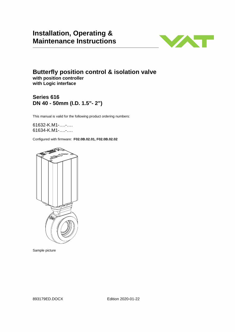
Installation, Operating & Maintenance Instructions 893179ED.DOCX Edition 2020-01-22 Butterfly position control & isolation valve with position controller with Logic interface Series 616 DN 40 - 50mm (I.D. 1.5"- 2”) This manual is valid for the following product ordering numbers: 61632-K.M1-….-…. 61634-K.M1-….-…. Configured with firmware: F02.0B.02.01, F02.0B.02.02 Sample picture
-
Upload
khangminh22 -
Category
Documents
-
view
2 -
download
0
Transcript of Installation, Operating & Maintenance Instructions - VAT Valves
Installation, Operating & Maintenance Instructions
893179ED.DOCX Edition 2020-01-22
Butterfly position control & isolation valve with position controller with Logic interface
Series 616 DN 40 - 50mm (I.D. 1.5"- 2”) This manual is valid for the following product ordering numbers:
61632-K.M1-….-…. 61634-K.M1-….-…. Configured with firmware: F02.0B.02.01, F02.0B.02.02
Sample picture

Series 616
2/56 Edition 2020-01-22 893179ED.DOCX
Imprint Manufacturer VAT Vakuumventile AG, CH-9469 Haag, Switzerland Website:
Phone: Fax: Email:
www.vatvalve.com +41 81 771 61 61 +41 81 771 48 30 [email protected]
Publisher VAT Vakuumventile AG, CH-9469 Haag, Switzerland Editor VAT Vakuumventile AG, CH-9469 Haag, Switzerland Print VAT Vakuumventile AG, CH-9469 Haag, Switzerland Copyright © VAT Vakuumventile AG 2020 No part of these instructions may be reproduced in any way (photocopies,
microfilms or any other reproduction processes) nor may it be manipulated with electronic systems, duplicated or distributed without written permission from VAT. Offenders are liable to pay damages.
The original VAT firmware and updated state of the art versions of the VAT
firmware are intended for use with VAT products. The VAT firmware contains a limited, time unlimited user license. The VAT firmware may not be used for purposes other than those intended nor is it permitted to make copies of the VAT firmware. In particular, it is strictly forbidden to give copies of the VAT firmware to other people.
The use of trade names, brand names, trademarks, etc. in these Instructions
does not entitle third parties to consider these names to be unprotected and to use them freely. This is in accordance with the meaning of the laws and acts covering brand names and trademarks.
Series 616
893179ED.DOCX Edition 2020-01-22 3/56
Contents
1 Description of product ............................ ............................................ 5
1.1 Identification of product ................................................................................................... 5
1.2 Use of product ................................................................................................................. 5
1.3 Used abbreviations .......................................................................................................... 5
1.4 Related documents.......................................................................................................... 5
1.5 Important information....................................................................................................... 5
1.6 Technical data ................................................................................................................. 6
1.6.1 Control and actuating unit ................................................................................. 6
1.6.2 Valve unit .......................................................................................................... 6
2 Safety ............................................ ....................................................... 8
2.1 Compulsory reading material ........................................................................................... 8
2.2 Danger levels .................................................................................................................. 8
2.3 Personnel qualifications ................................................................................................... 9
2.4 Safety labels .................................................................................................................... 9
3 Design and Function ............................... .......................................... 10
3.1 Design ........................................................................................................................... 10
3.2 Function ......................................................................................................................... 11
4 Installation ...................................... ................................................... 12
4.1 Unpacking ..................................................................................................................... 12
4.2 Installation into the system ............................................................................................ 13
4.2.1 Installation space condition ............................................................................. 14
4.2.2 Connection overview ....................................................................................... 14
4.2.3 Installation procedure ...................................................................................... 15
4.3 Tightening torque .......................................................................................................... 15
4.3.1 Mounting with ISO-KF flanges ........................................................................ 15
4.4 Admissible forces .......................................................................................................... 16
4.4.1 Admissible forces at controller ........................................................................ 17
4.5 Electrical connection...................................................................................................... 18
4.5.1 Ground connection .......................................................................................... 18
4.5.2 Service port connection................................................................................... 19
4.5.3 Functions and Wiring ...................................................................................... 20
4.5.4 Remote control modes .................................................................................... 22
4.6 Initial operation .............................................................................................................. 23
4.6.1 Setup procedure ............................................................................................. 23
4.6.2 Logic Interface configuration ........................................................................... 23
4.6.3 Valve configuration ......................................................................................... 23
5 Operation ......................................... .................................................. 24
5.1 Normal operation ........................................................................................................... 24
5.1.1 Local operation ............................................................................................... 25
5.1.2 Remote operation ........................................................................................... 26
5.2 Close valve .................................................................................................................... 27
5.3 Open valve .................................................................................................................... 27
5.4 Position control .............................................................................................................. 27
5.5 Display information ........................................................................................................ 27
5.5.1 Power up ......................................................................................................... 28
5.5.2 Operation ........................................................................................................ 28
5.5.3 Fatal error ....................................................................................................... 28
5.5.4 Service indication ............................................................................................ 28
5.6 Operation during power up ............................................................................................ 28
5.7 Behavior in case of power failure .................................................................................. 28
5.8 Operation under increased temperature ........................................................................ 29
Series 616
4/56 Edition 2020-01-22 893179ED.DOCX
6 Trouble shooting .................................. ............................................ 30
7 Maintenance ....................................... ............................................... 31
7.1 Maintenance intervals .................................................................................................... 31
7.2 Maintenance procedures ............................................................................................... 32
7.2.1 Replacement of plate o-ring ............................................................................ 33
7.2.2 Replacement of shaft feed through seals and valve cleaning ......................... 37
8 Repairs ........................................... ................................................... 44
9 Dismounting and Storage ........................... ..................................... 45
9.1 Dismounting ................................................................................................................... 45
9.2 Storage .......................................................................................................................... 46
10 Packaging and Transport ........................... ...................................... 47
10.1 Packaging ...................................................................................................................... 47
10.2 Transport ....................................................................................................................... 48
11 Disposal .......................................... ................................................... 49
12 Spare parts ....................................... ................................................. 50
12.1 Drawing ......................................................................................................................... 51
12.1.1 ISO-KF valve unit – aluminum hard anodized, without heating ....................... 52
12.1.2 ISO-KF valve unit – stainless steel, without heating ........................................ 52
12.1.3 Seals and grease ............................................................................................ 53
12.1.4 Control and actuating unit ............................................................................... 53
12.1.5 Accessories ..................................................................................................... 53
13 Appendix .......................................... ................................................. 55

Series 616 DESCRIPTION OF PRODUCT
893179ED.DOCX Edition 2020-01-22 5/56
1 Description of product
1.1 Identification of product
The fabrication number and order number are fixed on the product directly or by means of an identification plate.
Fabrication No.:
000 . . - . . . . - . . . . / . . . . A - . . . . . .
� �
Fabrication number Order number
1.2 Use of product
This product is a Butterfly position control valve with isolation functionality for downstream pressure control in vacuum systems. Use product for clean and dry vacuum applications only. Other applications are only allowed with the written permission of VAT.
1.3 Used abbreviations
Abbreviation Description
CPA Control Performance Analyzer Software
1.4 Related documents
• Product Data Sheet
• Dimensional Drawing
• IOMI Heating device (if valve with heater)
1.5 Important information
This symbol points to a very important statement that requires particular attention.
Example :
Refer to chapter: «Technical data» for detailed information.

DESCRIPTION OF PRODUCT Series 616
6/56 Edition 2020-01-22 893179ED.DOCX
1.6 Technical data
1.6.1 Control and actuating unit
Description
Power supply input 1) +24 VDC (±10%) @ 0.5 V pk-pk max.
Power consumption 40 W max.
Ambient temperature 0 °C to +50 °C max. (<35 °C recommended)
humidity 0 to 95% RH, non-condensing
Interface remote Logic
local service port USB-B
Analog input / output position control 0…10V; Resolution 2.5 mV
Digital inputs: 2)
- Input 1
- Input 2
open valve
close valve
adjustable with CPA 4.0
adjustable with CPA 4.0
Digital outputs: 2)
- Output 1
- Output 2
valve closed
valve open
adjustable with CPA 4.0
adjustable with CPA 4.0
Position resolution 4000 (full stroke)
Actuator backlash < 0.1°
Closing / Opening time throttling only 380 ms
throttling & isolation 390 ms
Protective system IP 40
Utilizable valve torque 2.5 Nm
1) Internal overcurrent protection by a PTC device. 2) Refer to chapter «Functions and Wiring» for details, function depending on configuration.

Series 616 DESCRIPTION OF PRODUCT
893179ED.DOCX Edition 2020-01-22 7/56
1.6.2 Valve unit
Description
Pressure range (unheated on delivery)
• Stainless steel
• Aluminum, hard anodized
1 × 10E-8 mbar to 1.2 bar (abs)
1 × 10E-6 mbar to 1.2 bar (abs)
Leak rate valve seat (unheated on delivery)
• Stainless steel
• Aluminum, hard anodized
1 × 10E-9 mbar ls-1
1 × 10E-4 mbar ls-1
Leak rate valve body (unheated on delivery)
• Stainless steel
• Aluminum, hard anodized
1 × 10E-9 mbar ls-1
1 × 10E-5 mbar ls-1
Cycles until first service:
• Isolation cycles (open – closed – open) 250’000 (Viton® seals, under clean and unheated cond.)
• Throttling cycles (open - max. throttle - open) 2’000’000 (Viton® seals, under clean and unheated cond.)
Admissible operating temperature
• Valve body • Ambient
+10°C to +120°C
10°C to 50°C
Mounting position Valve seat must face chamber side.
Wetted materials
• Body, plate (616 . . - . H. . - . . . . ) Aluminum 3.2315 (AA6082) hard anodized
• Body, plate (616 . . - . E. . - . . . . ) Stainless steel 316L (1.4404 or 1.4435)
• Shaft Stainless steel 316L (1.4404 or 1.4435)
• Plate screws Stainless steel 316L (A4)
• Shaft seal (rotary feedthrough) • Plate seal
Viton®
Viton®
• Slide bearing for shaft iglidur® X
Max. differential pressure on plate during isolation and opening and throttling
1000 mbar
DN (nominal I. D.) [mm]
[inch]
40
1½
50
2
Min. controllable conductance [N2 molecular flow] 0.05 l/s 0.1 l/s
Conductance in open position [N2 molecular flow] 60 l/s 120 l/s
Weight about
• Stainless steel [kg] • Aluminum hard anodized [kg]
3.3 kg
2.4 kg
3.6 kg
2.7 kg
Dimensions Refer to dimensional drawing of specific valve ordering number (available on request)

SAFETY Series 616
8/56 Edition 2020-01-22 893179ED.DOCX
2 Safety
2.1 Compulsory reading material
Read this chapter prior to performing any work with or on the product. It contains important information that is significant for your own personal safety. This chapter must have been read and understood by all persons who perform any kind of work with or on the product during any stage of its serviceable life.
NOTICE Lack of knowledge
Failing to read this manual may result in property damage.
Firstly, read manual.
These Installation, Operating & Maintenance Instructions are an integral part of a comprehensive documentation belonging to a complete technical system. They must be stored together with the other documentation and accessible for anybody who is authorized to work with the system at any time.
2.2 Danger levels
DANGER High risk
Indicates a hazardous situation which, if not avoided, will result in death or serious injury.
WARNING Medium risk
Indicates a hazardous situation which, if not avoided, could result in death or serious injury.
CAUTION Low risk
Indicates a hazardous situation which, if not avoided, may result in minor or moderate injury.
NOTICE Command
Indicates a hazardous situation which, if not avoided, may result in property damage.
Series 616 SAFETY
893179ED.DOCX Edition 2020-01-22 9/56
2.3 Personnel qualifications
WARNING Unqualified personnel
Inappropriate handling may cause serious injury or property damage.
Only qualified personnel are allowed to carry out the described work.
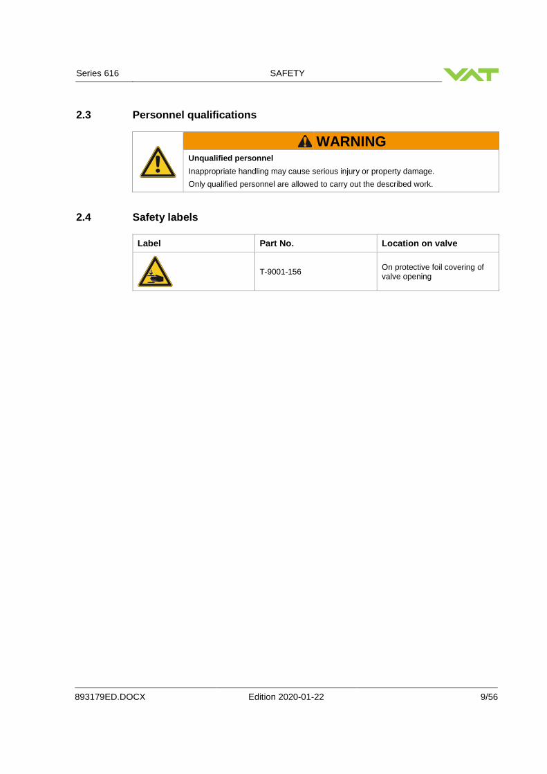
2.4 Safety labels
Label Part No. Location on valve
T-9001-156 On protective foil covering of valve opening

DESIGN AND FUNCTION Series 616
10/56 Edition 2020-01-22 893179ED.DOCX
3 Design and Function
3.1 Design
Sample picture XY: Double excentric bearing: prevents wearing of the o-ring and particle generation 1 Controller 4 Double seal
2 Coupling 5 Plate
3 Bearing 6 Body

Series 616 DESIGN AND FUNCTION
893179ED.DOCX Edition 2020-01-22 11/56
3.2 Function
The valve plate acts as a throttling element and varies the conductance of the valve opening. The integrated controller calculates the required plate position to achieve the setpoint pressure. Actuation is performed by a stepper motor. An encoder monitors the position. This principle ensures fast and accurate process pressure control even in demanding contaminating processes. The seal which is attached to the plate reduces the minimum controllable conductance and allows leak tight closing of the valve. In closed position, the seal is pressed on the body.
Open Closed Position control

INSTALLATION Series 616
12/56 Edition 2020-01-22 893179ED.DOCX
4 Installation
WARNING Unqualified personnel
Inappropriate handling may cause serious injury or property damage.
Only qualified personnel are allowed to carry out the described work.
4.1 Unpacking
NOTICE Physical overstraining at controller
Inappropriate handling with the valve may cause in damage of controller.
Do not place the valve on the controller.
NOTICE Physical overstraining at pedestal
Inappropriate handling with the valve may cause in damage of pedestal.
Lift valve at valve body out of transport case.
• Make sure that the supplied products are in accordance with your order.
• Inspect the quality of the supplied products visually. If it does not meet your requirements, please contact VAT immediately.
• Store the original packaging material. It may be useful if products must be returned to VAT.
1. Open the transport case and remove inside packing material as far as necessary.
2. Lift the valve carefully and place it on a clean place.
Do not remove protective foils from valve opening

Series 616 INSTALLATION
893179ED.DOCX Edition 2020-01-22 13/56
4.2 Installation into the system
WARNING
Valve opening
Risk of serious injury.
Human body parts must be kept out of the valve opening and away from moving parts. Do not connect the controller to power before the valve is installed complete into the system.
NOTICE Sealing surfaces
Sealing surfaces of valve and vacuum system could be damage in case of incorrect handling.
Only qualified personal are allowed to install the valve into the vacuum system.
NOTICE Wrong connection
Wrong connection may result in damage of controller or power supply.
Connect all cables exactly as shown in the following descriptions and schematics.
NOTICE Burned connector pins (spark)
Connector pins or electronic parts could damage, if plugged and unplugged under power.
Do not plug or unplug connectors under power.
NOTICE Contamination
Gate and other parts of the valve must be protected from contamination.
Always wear clean room gloves when handling the valve.
Mount valve to a clean system only.

INSTALLATION Series 616
14/56 Edition 2020-01-22 893179ED.DOCX
4.2.1 Installation space condition
Install the valve with integrated controller with space for dismantling and air circulation as shown in figure below.
Sample picture
4.2.2 Connection overview
System:
1 Valve
2 Process chamber
3 Gas inlet
4 Cable to power supply / Interface
5 Position controller
6 Pump
M
3
4
2
1
6
5

Series 616 INSTALLATION
893179ED.DOCX Edition 2020-01-22 15/56
Position Controller:
4.2.3 Installation procedure
All numbers in brackets refer to chapter: «Connection overview». 1. Install valve [1] into the vacuum system.
2. Remove protective covers from body flanges.
3. Connect controller (connector: POWER / INTERFACE) to power supply and Interface [4]. Refer to chapter «Functions and Wiring» for correct wiring.
Perform in chapter: «Setup procedure» to prepare valve for operation.
4.3 Tightening torque
4.3.1 Mounting with ISO-KF flanges
Tightening torques for ISO-KF flange connections depend on the type of seal which is used. Follow recommendations of seal manufacturer.
• Do not tighten the flange screws stronger than indicated under «Tightening
torque». • Do not admit higher forces to the valve than indicated under «Admissible forces». • Make sure that enough space is kept free to do preventive maintenance work.
The required space is indicated on the dimensional drawing. • Control unit of valves with ISO-KF flanges (615 . . – K . . . ) needs support when
mounted on horizontal piping and control unit does not hang.

INSTALLATION Series 616
16/56 Edition 2020-01-22 893179ED.DOCX
4.4 Admissible forces
NOTICE Force at valve body
Forces from the weight of other components can lead to deformation of the valve body and to malfunction of the valve.
Do not higher force the valve body as specified.
The following forces are admissible.
Axial tensile or compressive
force «F A» Bending moment «M»
N lb. Nm Lbf.
100 22 6 4.5
M FA

Series 616 INSTALLATION
893179ED.DOCX Edition 2020-01-22 17/56
4.4.1 Admissible forces at controller
NOTICE Force at pedestal
In case higher force is applied, the pedestal could be permanently damaged.
– Do not pushing, shocking load, or stressing the valve controller
– Do not deposit anything at valve controller
The admissible force at valve controller in regards to the pedestal is shown in table below
Admissible force «F»
Overview F = Force
a = middle of aluminium part of controller (b / 2)
400 N
pedestal b
a a F
pedestal b
a a F

INSTALLATION Series 616
18/56 Edition 2020-01-22 893179ED.DOCX
4.5 Electrical connection
NOTICE Wrong connection
Wrong connection may result in damage of controller or power supply.
Connect all cables exactly as shown in the following descriptions and schematics.
NOTICE Burned connector pins (spark)
Connector pins or electronic parts could damage, if plugged and unplugged under power.
Do not plug or unplug connectors under power.
4.5.1 Ground connection
Recommendation for ground connection between controller and system chassis.
Recommendation for ground connection cable: AWG 12 (4 mm2) The connection point at chassis (FE) must be blank metal (not coated).
Controller bottom side
Recommended torque: 1,3…1,7Nm
Chassis (FE) (Functional Earth)

Series 616 INSTALLATION
893179ED.DOCX Edition 2020-01-22 19/56
4.5.2 Service port connection
The service port (connector: SERVICE, USB - B) allows to connect the valve to a USB - A port of a computer. This requires a USB A–B cable male-male. The ‘Service port is used for ‘Local operation’ and setup.
You can use our Software 'Control Performance Analyzer' 4.0 for Local operation, which is integrated in the Controller. Refer to chapter: ‘Local operation’ for detail information.

INSTALLATION Series 616
20/56 Edition 2020-01-22 893179ED.DOCX
4.5.3 Functions and Wiring
Logic interface allows for remote operation by means of digital input / output and analog input / output signals. Digital inputs may be operated either by switches or by voltage sources.
a) Configuration with switches for digital inputs:
• VAT fuse recommendation: (a) 2 AF
• Connect all pins exact as shown in the schematics above!
• Use only screws with 4-40UNC thread for fastening the DB-15 connector!

Series 616 INSTALLATION
893179ED.DOCX Edition 2020-01-22 21/56
b) Configuration with voltage source for digital in puts:
• VAT fuse recommendation: (a) 2 AF
• Connect all pins exact as shown in the schematics above!
• Use only screws with 4-40UNC thread for fastening the DB-15 connector!

INSTALLATION Series 616
22/56 Edition 2020-01-22 893179ED.DOCX
4.5.4 Remote control modes
The valve can be operated in two ways:
1. Position control using an analog voltage and digital inputs.
2. Step / direction control. This is a control known from standard stepper motor drivers. The direction input defines the direction of the movement. Each pulse on the step input moves the valve by one increment.
The remote control mode can be selected with the CPA 4.0 software
4.5.4.1 Analog / digital control
Input signals: Pin Function Signal type Description Priority
11 Position setpoint Analog input
A voltage of 0-10V shall be applied to this input as position setpoint. The position setpoint is in linear relation to the applied voltage. 0V is min. conductance position, 10V is open position
3
12 Input 1 Digital Input
When actuated the valve will be moved to fully open positon 2
13 Input 2 Digital input
When actuated the valve will be moved to fully closed positon 1
14 Input
common Input common
Output signals: Pin Function Signal type Description
15 Valve
position output
Analog output This output indicates the current valve position as 0-10V voltage range. The voltage is in linear relation to the valve position. 0V is min. conductance position, 10V is open position.
5 Output 1 Digital output Valve open indication
6 Output 2 Digital output Valve closed indication
7 Output
common Digital output Output common
8 Analog output Analog output
The above describes the standard configuration. The function of the inputs and outputs can be reconfigured with the CAP 4.0 software.

Series 616 INSTALLATION
893179ED.DOCX Edition 2020-01-22 23/56
4.6 Initial operation
4.6.1 Setup procedure
To enable the valve for position control setup steps 1 to 3 must be performed .
Setup steps Description
1 Power up Turn on external + 24VDC power supply of valve. Refer to chapter «Behavior during power up» for details.
2 Interface
configuration Refer to chapter «Interface configuration» for details.
3 Valve
configuration Basic configurations of valve must be adapted according to application needs. Refer to chapter «Valve configuration» for details.
4.6.2 Logic Interface configuration
Interface configuration must be adapted according to application needs. Default configuration:
OPEN input CLOSE input OPEN output CLOSE output Not inverted Not inverted Open Close
• Functionality of digital inputs CLOSE VALVE and OPEN VALVE must be selected.
These may be configured as ‘not inverted‘ or ‘inverted‘. Default is ‘not inverted‘.
Local operation : (‘Control Performance Analyzer’ 4.0‘)
Remote operation :
Do configuration in menu ‘Valve’ > ‘Parameters’ > ‘Interface’.
It’s not possible to do ‘Interface configuration‘ via remote operation.
4.6.3 Valve configuration
Basic valve configuration must be adapted according to application needs. Definition of valve plate position in case of: • After power up , default position is min. conductance position.
Local operation : with ‘Control Performance Analyzer’ 4.0, refer to chapter: «Local operation»
Remote operation :
1. Open the CPA 4.0
2. Click [Local]
3. Click [Valve] > [Parameters]
4. Click [Valve] and do the settings
5. For saving the settings Click [Save]
It’s not possible to do ‘Valve configuration‘ via remote operation.

OPERATION Series 616
24/56 Edition 2020-01-22 893179ED.DOCX
5 Operation
WARNING Unqualified personnel
Inappropriate handling may cause serious injury or property damage.
Only qualified personnel are allowed to carry out the described work.
WARNING Valve opening
Risk of serious injury.
Human body parts must be kept out of the valve opening and away from moving parts. Do not connect the controller to power before the valve is installed complete into the system.
5.1 Normal operation
This valve is designed for position control in vacuum chambers. It works with position control mode. Local or remote operation is possible.

Series 616 OPERATION
893179ED.DOCX Edition 2020-01-22 25/56
5.1.1 Local operation
Local operation means that the valve is operated via the service port using a computer. When using a computer, a USB A–B cable male-male required. You can use our Software 'Control Performance Analyzer' 4.0 for Local operation, which is integrated in the IC2 controller. The software are beneficial especially for setup, testing and maintenance. How to start:
1. Connect service cable (USB A–B cable male-male) between PC and valve controller “SERVICE”. Refer to chapter: «Service port connection»
2. The window ‘CPA.exe’ opens.
3. Click [‘CPA.exe’]
4. The CPA 4.0 opens
5. Click [Local] for Local operation
6. Do the configuration according to your application needs.
'Control Performance Analyzer' supports:
• Valve setup • Interface setup • Manual control • Sequence control • Numeric and
graphical monitoring
• Data recording • Data analysis • Advanced
diagnostic
When communication to service port is interrupted the valve will change to remote operation. So when service cable will be disconnected or software will be shut down, the valve returns automatically to remote operation. This may result in an immediate movement of the valve depending on remote control.

OPERATION Series 616
26/56 Edition 2020-01-22 893179ED.DOCX
5.1.2 Remote operation
This product is equipped with a Logic interface to allow for remote operation. See section «Function and Wiring» for details. 'Control Performance Analyzer' 4.0 which is integrated in the Controller, may be used for monitoring during remote control. 'Control Performance Analyzer' 4.0 software
In case ‘Control Performance Analyzer’ 4.0 is used, make sure ‘Remote’ button is pushed to enable for remote operation.

Series 616 OPERATION
893179ED.DOCX Edition 2020-01-22 27/56
5.2 Close valve
Local operation : (‘Control Performance Analyzer’ 4.0)
Remote operation : (Refer to chapter «Digital inputs» for details)
Push CLOSE button Send CLOSE VALVE
5.3 Open valve
Local operation : (‘Control Performance Analyzer’ 4.0)
Remote operation : (Refer to chapter «Digital inputs» for details)
Push OPEN button Send OPEN VALVE
5.4 Position control
The valve position is directly controlled according to the position setpoint.
Local operation : (‘Control Performance Analyzer’ 4.0)
Remote operation : (Refer to chapter «Digital inputs and outputs» for details)
In menu ‘Valve’ > ‘Parameters’ > ‘Position Control‘ enter position setpoint
1. Set CONTROL MODE to POSITION CONTROL
2. Set position SETPOINT
In case CLOSE VALVE or OPEN VALVE is also set these have higher priority.
5.5 Display information
There are 4 LED’s located on the panel:
• POWER • OPEN • CLOSE • ERROR
For details refer to following tables.
LED‘s

OPERATION Series 616
28/56 Edition 2020-01-22 893179ED.DOCX
5.5.1 Power up
Description POWER (green) OPEN (green) CLOSE (green) ERROR (red)
At first is displayed blinking OFF OFF OFF
After synchronization
ON OFF OFF OFF
5.5.2 Operation
Description POWER (green) OPEN (green) CLOSE (green) ERROR (red)
OPEN ON ON OFF OFF
CLOSE ON OFF ON OFF
Position Control ON OFF OFF OFF
5.5.3 Fatal error
Description POWER (green) OPEN (green) CLOSE (green) ERROR (red)
ERROR ON OFF OFF ON
For ERROR refer to chapter: «Troubleshooting» for details.
5.5.4 Service indication
not implemented yet
5.6 Operation during power up
Valve position before power up:
Reaction of valve:
Any Valve runs a synchronization cycle (close-direction open-close) to detect the limit stops. This cycle is performed with reduced torque. Display shows configuration of product until synchronization cycle is done. Refer also to chapter «Display information».
5.7 Behavior in case of power failure
Valve position before power failure: Power failure valve position during operation:
Any Valve remains at current position.

Series 616 OPERATION
893179ED.DOCX Edition 2020-01-22 29/56
5.8 Operation under increased temperature
CAUTION Hot valve
Heated valve may result in minor or moderate injury.
Do not touch valve and heating device during operation. Once heating is switched off (valve and system) await until the valve is cooled down complete before doing any work.
This valve may be operated in the temperature range mentioned in chapter «Technical data».

TROUBLE SHOOTING Series 616
30/56 Edition 2020-01-22 893179ED.DOCX
6 Trouble shooting
Failure Check Action Power LED - 24 V power supply ok? - Connect valve to power supply according to
«Functions and Wiring» and make sure that power supply is working.
Remote operation does not work
- Local operation via service port is active
- Switch to remote operation.
LED «ERR» is on - Valve plate centric adjusted?
- Adjust valve plate according to «Maintenance procedure».
- Valve unit heavy contaminated?
- Clean valve unit according to «Maintenance procedure».
- Valve plate mechanically obstructed?
- Serious temperature difference between valve body and valve plate that led to a contact between these due material expansion?
- Resolve obstruction.
- Uniform temperature between parts or contact VAT for recommendations to your specific application.
POSITION CONTROL does not work
- POSITION CONTROL not selected
- Select POSITION CONTROL mode. Refer to «Position control» for details.
OPEN VALVE does not work Valve correct connected? Refer to «Functions and Wiring» for details.
CLOSE VALVE does not work Valve correct connected? Refer to «Functions and Wiring» for details.
If you need any further information, please contact one of our service centers. You will find the addresses on our website: www.vatvalve.com.

Series 616 MAINTENANCE
893179ED.DOCX Edition 2020-01-22 31/56
7 Maintenance
WARNING Unqualified personnel
Inappropriate handling may cause serious injury or property damage.
Only qualified personnel are allowed to carry out the described work.
WARNING Valve opening
Risk of serious injury.
Human body parts must be kept out of the valve opening and away from moving parts. Disconnect power on controller before doing any work.
CAUTION Hot valve
Heated valve may result in minor or moderate injury.
Do not touch valve and heating device during operation. Once heating is switched off (valve and system) await until the valve is cooled down complete before doing any work.
NOTICE Contamination
Gate and other parts of the valve must be protected from contamination.
Always wear clean room gloves when handling the valve.
7.1 Maintenance intervals
Under clean operating conditions, the valve does not require any maintenance during the specified cycle life. Contamination from the process may influence the function and requires more frequent maintenance. Before carrying out any maintenance, please contact VAT. It has to be individually decided whether the maintenance can be performed by the customer or has to be carried out by VAT. Please write down the fabrication number of the valve before contact VAT. Refer to chapter «Identification of product» for fabrication number.

MAINTENANCE Series 616
32/56 Edition 2020-01-22 893179ED.DOCX
7.2 Maintenance procedures
Two maintenance procedures are defined for this valve. This are:
• Replacement of plate o-ring. Refer to chapter «Replacement of plate o-ring».
• Replacement of rotary feedthrough seals and valve cleaning. Refer to chapter: «Replacement of rotary feedthrough».
Required frequency of cleaning and replacement of seals is depending on process conditions.
VAT can give the following recommendations for preventive maintenance:
Replacement of unheated 1) heated ≤ 80 °C 1) heated > 80 °C 1)
Rotary feedthrough seals 2‘000‘000 cycles 6 months but
max. 2‘000‘000 cycles
3 months but
max. 2‘000‘000 cycles
Plate o-ring 250’000 cycles 6 months but
max. 250’000 cycles
3 months but
max. 250’000 cycles
1) Those figures are reference values for clean conditions under various temperatures. These values do not include any impact of the process. Therefore preventive maintenance schedule has finally to be checked for the actual process conditions.

Series 616 MAINTENANCE
893179ED.DOCX Edition 2020-01-22 33/56
7.2.1 Replacement of plate o-ring
7.2.1.1 Required tools
• Allen Wrench 3mm
• O-ring removal tool (see chapter Accessories)
• Vacuum grease (see chapter spare parts)
• Cleanroom wipes
Description Required tool
1. Vent vacuum system on both sides of the valve.
2. Move the plate to position 30% open.
3. Disconnect electrical POWER connector at valve and remove valve from vacuum system.
Attention! Electrical power is needed for plate adjustment in step 19.
Take care to the sealing surface!
4. Unfasten and remove the 2 fastening screws
Allen Wrench 3mm
5. Push the plate a little down
6. Remove the plate on the other side of shaft

MAINTENANCE Series 616
34/56 Edition 2020-01-22 893179ED.DOCX
Description Required tool
7. Remove the plate o-ring
8. Replace the plate if necessary
O-ring removal tool
9. Clean the plate and o-ring groove
Cleanroom wipes soaked with isopropyl alcohol
10. Lubricate the new o-ring with 0.0125 ml vacuum grease
For new o-ring refer to chapter spare parts.
Vacuum grease
11. Pay attention that grease is distributed constantly over the whole circumference
12. Place the new o-ring at o-ring groove at one side

Series 616 MAINTENANCE
893179ED.DOCX Edition 2020-01-22 35/56
Description Required tool
13. Move the o-ring in the o-ring groove on the other side
14. Push in the o-ring equally around the plate into o-ring groove
15. Plate with equal mounted o-ring
16. Place the plate on the shaft in the valve body
17. Tighten plate screws to block.
18. Loosen the plate screws a quarter turn counter clockwise.
Plate is now movable on shaft and ready to sliding into valve seat. Proceed with step 19
Allen Wrench 3mm

MAINTENANCE Series 616
36/56 Edition 2020-01-22 893179ED.DOCX
Description Required tool
19. Connect electrical POWER connection at valve
Attention! Valve does synchronize automatically and moves the plate into sit of valve body (close position).
20. Disconnect electrical POWER connection
Attention!
Keep fingers out of the valve opening
during plate movement!
21. Fasten the plate screws with 2.5 Nm
22. If some grease on plate surface or valve body clean it with cleanroom wipes.
Allen torque wrench 3mm
Cleanroom wipes
23. Reinstall valve into vacuum system according to chapter «Installation» of valve manual

Series 616 MAINTENANCE
893179ED.DOCX Edition 2020-01-22 37/56
7.2.2 Replacement of shaft feed through seals and v alve cleaning
7.2.2.1 Required tools
• Allen Wrench 2mm
• Allen Wrench 3mm
• O-ring removal tool (see chapter Accessories)
• Isopropyl alcohol
• Cleanroom wipes
• Vacuum grease (see chapter spare parts)
Description Required tool
1. Vent vacuum system on both sides of the valve.
2. Move the plate to position 50% open.
3. Disconnect electrical POWER connector at valve and remove valve from vacuum system.
Take care to the sealing surface!
4. Loosen clamp coupling screw
Allen Wrench:
elastic coupling 2 mm
steel coupling
2.5 mm
5. Unfasten and remove the 3 fastening screws
Allen Wrench 3mm

MAINTENANCE Series 616
38/56 Edition 2020-01-22 893179ED.DOCX
Description Required tool
6. Remove control and actuating unit from mechanical valve unit
Take care of position (actuating unit to valve unit) for reassembling. See also dimensional drawing.
If clamp coupling is separated, assemble them at control and actuating unit.
7. Unfasten and remove the 2 fastening screws
Allen Wrench 3mm
8. Push the plate a little down
9. Remove the plate on the other side of shaft
10. Unfasten both screws complete
Allen Wrench 3mm

Series 616 MAINTENANCE
893179ED.DOCX Edition 2020-01-22 39/56
Description Required tool
11. Remove mechanical unit from valve body
12. Clean shaft
Cleanroom wipes soaked with isopropyl
alcohol
13. Remove both o-rings
Soft tool
14. Clean shaft feed through
Cleanroom wipes soaked with isopropyl
alcohol

MAINTENANCE Series 616
40/56 Edition 2020-01-22 893179ED.DOCX
Description Required tool
15. Clean the valve body
Cleanroom wipes soaked with isopropyl
alcohol
16. Lubricate seal contact surface of valve body with a slight film of 0.025 ml vacuum grease
Vacuum grease
17. Lubricate seal contact surface of shaft with a slight film of 0.0125 ml vacuum grease
Vacuum grease
18. Lubricate each o-ring with a slight film of 0.0125 ml vacuum grease.
Vacuum grease
19. Slide both o-rings onto shaft till the end
20. Deposit 0.0375 ml vacuum grease between the o-rings
21. Clean shaft from vacuum grease
Vacuum grease
Cleanroom wipes

Series 616 MAINTENANCE
893179ED.DOCX Edition 2020-01-22 41/56
Description Required tool
22. Install mechanical unit into valve body, see picture
23. Fasten and tighten the 2 mounting screws with 2.5 Nm
Allen torque wrench 3mm
24. Place the plate on the shaft in the valve body
25. Tighten plate screws to block.
26. Loosen the plat screws a quarter turn counter clockwise so that plate is still movable at shaft.
Allen Wrench 3mm

MAINTENANCE Series 616
42/56 Edition 2020-01-22 893179ED.DOCX
Description Required tool
27. Press the plate (A) into valve seat.
28. Press the lever (B) by hand to axis (C). Make sure that lever (B) is engaged at axis (C) completely. (mechanical close position).
29. Fasten the plate screws with 2.5 Nm
30. If some grease on plate surface or valve body clean it with lint and dust free cloth
Allen torque wrench 3mm
Cleanroom wipes
31. Assemble valve unit with control and actuating. Push axis (C) into clamp coupling
Take care of position (actuating unit to valve unit) for reassembling.See also dimensional drawing.
32. Tighten mounting screws adequately
Allen Wrench 3mm
33. Tighten clamp coupling: • with elastic coupling 1.1 Nm • with steel coupling 2.2 Nm
Allen Wrench:
elastic coupling 2 mm
steel coupling
2.5 mm
A
B
C
C
Series 616 MAINTENANCE
893179ED.DOCX Edition 2020-01-22 43/56
Description Required tool
34. Reinstall valve into vacuum system according to chapter «Installation».

REPAIRS Series 616
44/56 Edition 2020-01-22 893179ED.DOCX
8 Repairs
Repairs may only be carried out by the VAT service staff. In exceptional cases, the customer is allowed to carry out the repairs, but only with the prior consent of VAT. Please contact one of our service centers. You will find the addresses on our website www.vatvalve.com.
Series 616 DISMOUNTING AND STORAGE
893179ED.DOCX Edition 2020-01-22 45/56
9 Dismounting and Storage
WARNING Unqualified personnel
Inappropriate handling may cause serious injury or property damage.
Only qualified personnel are allowed to carry out the described work.
9.1 Dismounting
NOTICE Contamination
Gate and other parts of the valve must be protected from contamination.
Always wear clean room gloves when handling the valve.
NOTICE Valve in open position
Valve body may become damaged if valve gate is in open position.
Move valve gate to the closed position before dismounting the valve.
1. Close the valve
2. For dismounting the valve please follow the instructions of chapter: «Installation», however in reverse order.

DISMOUNTING AND STORAGE Series 616
46/56 Edition 2020-01-22 893179ED.DOCX
9.2 Storage
NOTICE Wrong storage
Inappropriate temperatures and humidity may cause damage to the product.
Valve must be stored at: – relative humidity between 10% and 70% – temperature between +10 °C and +50 °C – non-condensing environment
NOTICE Inappropriate packaging
Product may get damaged if inappropriate packaging material is used.
Always use the original packaging material and handle product with care.
1. Clean / decontaminate valve.
2. Cover all valve openings with a protective foil.
3. Pack valve appropriately, by using the original packaging material.

Series 616 PACKAGING AND TRANSPORT
893179ED.DOCX Edition 2020-01-22 47/56
10 Packaging and Transport
WARNING Unqualified personnel
Inappropriate handling may cause serious injury or property damage.
Only qualified personnel are allowed to carry out the described work.
WARNING Harmful substances
Risk of injury in case of contact with harmful substances.
Remove harmful substances (e. g. toxic, caustic or microbiological ones) from valve before you return the valve to VAT.
NOTICE Inappropriate packaging
Product may get damaged if inappropriate packaging material is used.
Always use the original packaging material and handle product with care.
• When returning products to VAT, please fill out the VAT form «Declaration of
Chemical Contamination of Vacuum Valves and Components» and send it to VAT in advance. The form can be downloaded from our website www.vatvalve.com (Section: Services – Aftersales).
• If products are radioactively contaminated, the VAT form «Contamination and Radiation Report» must be filled out. Please contact VAT in advance.
• If products are sent to VAT in contaminated condition, VAT will carry out the decontaminating procedure at the customer's expense.
10.1 Packaging
NOTICE Valve in open position
Valve mechanism may get damaged if valve is in open position.
Make sure that the valve is closed.
3. Cover all valve openings with a protective foil.
4. Pack valve appropriately, by using the original packaging material.
VAT disclaims any liability for damages resulting from inappropriate packaging.

PACKAGING AND TRANSPORT Series 616
48/56 Edition 2020-01-22 893179ED.DOCX
10.2 Transport
NOTICE Inappropriate packaging
Product may get damaged if inappropriate packaging material is used.
Always use the original packaging material and handle product with care.
VAT disclaims any liability for damages resulting from inappropriate packaging.

Series 616 DISPOSAL
893179ED.DOCX Edition 2020-01-22 49/56
11 Disposal
WARNING Unqualified personnel
Inappropriate handling may cause serious injury or property damage.
Only qualified personnel are allowed to carry out the described work.

SPARE PARTS Series 616
50/56 Edition 2020-01-22 893179ED.DOCX
12 Spare parts
NOTICE Non-original spare parts
Non-original spare parts may cause damage to the product.
Use original spare parts from VAT only.
• Please specify the fabrication number of the product when you place an order for
spare parts; see chapter: «Identification of product». This is to ensure that the appropriate spare parts are supplied.
• VAT makes a difference between spare parts that may be replaced by the customer and those that need to be replaced by the VAT service staff.
• The following table(s) contain spare parts that may be replaced by the customer. If you need any other spare parts, please contact one of our service centers. You will find the addresses on our website www.vatvalve.com.

Series 616 SPARE PARTS
893179ED.DOCX Edition 2020-01-22 51/56
12.1 Drawing
1 Body with mechanism 5 Plate screws
2 Lever complete 6 Body complete
3 Adapter flange, rod with bearing 7 Plate
4 Rotary feedtrough seals 8 Plate o-ring
1
2
3
4
5
6
7
8

SPARE PARTS Series 616
52/56 Edition 2020-01-22 893179ED.DOCX
All “Item“ refer to chapter «Drawing»
12.1.1 ISO-KF valve unit – aluminum hard anodized, without heating
Item Description
Valve size Product ordering number
DN 40 / 1½”
61632 - KH . .
ISO-KF
DN 50 / 2”
61634 - KH . .
ISO-KF
1 Spare parts kit body with mechanism
462173 453946
2 Spare parts kit lever complete
511515
3 Spare parts kit, adapter flange rod with bearing
453094 453106
5 Plate screws 2 × 428946
6 Body complete 443116 443180
7 Spare parts plate 433800 431309
12.1.2 ISO-KF valve unit – stainless steel, without heating
Item Description
Valve size Product ordering number
DN 40 / 1½”
61632 - KE . .
ISO-KF
DN 50 / 2”
61634 - KE . .
ISO-KF
1 Spare parts kit body with mechanism
462153 453945
2 Spare parts kit lever complete
511515
3 Spare parts kit, adapter flange rod with bearing
453094 453106
5 Plate screws 2 × 428946
6 Body complete 443048 443093
7 Spare parts plate 428257 428118

Series 616 SPARE PARTS
893179ED.DOCX Edition 2020-01-22 53/56
12.1.3 Seals and grease
Item Description
4 Vacuum seal kit (Viton) rotary feed through
237235
Vacuum grease (2ml syringe)
206792
DN 40 / 1½”
61632 – K . . ISO-KF
DN 50 / 2”
61634 – K . . ISO-KF
8 Vacuum seal kit (Viton) for plate
327291 365577
For versions such as:
• other valve sizes • heated valves • valves made of hard anodized aluminum • valves made of nickel coated aluminum
spare parts ordering numbers are available on request.
12.1.4 Control and actuating unit
Description Part number
Control and actuating unit Please contact VAT.
Option board with SPS module (±15 VDC Sensor Power Supply) 378000
Option board with PFO module (Power Failure Option) 378002
Option board with SPS and PFO module 376837
12.1.5 Accessories
Description Part number
24 VDC power supply unit (input: 100 – 240 VAC) 891528 (D-Sub15 connector)
Adapter cable for power supply with D-Sub9 connector (735567) (D-Sub15 to D-Sub9)
Service cable (PC to valve Service connector) 809474 (USB A–B male-male)
Special Allen wrench (SW3) for disassembly and assembly 244873
O-ring removal tool 234859

SPARE PARTS Series 616
54/56 Edition 2020-01-22 893179ED.DOCX
12.1.5.1 Centering ring with Viton o-ring
Description Valve size Product ordering number
DN 40 / 1½” 61632 - . . . .
DN 50 / 2” 61634 - . . . .
Centering ring with Viton o-ring (for ISO-KF and ISO-F installation only)
Aluminum 31032-KAZV 32034-KAZV
Stainless steel 31032-KEZV 32034-KEZV

Series 616 APPENDIX
893179ED.DOCX Edition 2020-01-22 55/56
13 Appendix
No information entered on time.

Series 616
56/56 Edition 2020-01-22 893179ED.DOCX
This page left blank intentionally.