socket jointing of pvc-u and pvc-o pipe systems for pressure ...
12
GUIDANCE NOTES FOR SOCKET JOINTING OF PVC-U AND PVC-O PIPE SYSTEMS FOR PRESSURE APPLICATIONS
-
Upload
khangminh22 -
Category
Documents
-
view
1 -
download
0
Transcript of socket jointing of pvc-u and pvc-o pipe systems for pressure ...

GUIDANCE NOTES FOR
SOCKET JOINTING OF PVC-U AND PVC-O PIPE SYSTEMS FOR PRESSURE APPLICATIONS

02SOCKET JOINTING OF PVC-U AND PVC-O PIPES AND FITTINGS FOR PRESSURE APPLICATIONS
I N T R O D U C T I O N
The main advantages of using PVC-U and PVC-O pipes and fittings for pressure applications are their long lifetime and trouble-free operation. In order to achieve this, there are simple proven techniques for joining pipes and fittings during the construction phase. The technique of making a push-fit connection with a rubber gasket between a PVC-U or PVC-O pipe spigot-end and a PVC-U or PVC-O pipe or fitting socket, has shown to consistently deliver good quality pipe joints under a broad range of construction situations. The purpose of this guide is to provide an understanding of the PVC-U and PVC-O pipes and fittings and their jointing techniques, leading to knowledge about how to achieve good quality outcomes. Given the knowledge and experience accrued over more than 70 years, quality joints can be achieved as a matter of routine construction practice.
In this guide you will ind important topics covered, which include:
> Jointing instructions for PVC-U and PVC-O pipe and fittings for pressure applications.
> Ductile iron and PVC-U and PVC-O socket joints, mechanical jointing systems, jointing fluids.
> The available methods to assess the quality of joints after pipeline construction.
> An ISO and CEN standards overview with references to proven jointing procedures.
> Case studies.
This document is intended as a guide to the principles of PVC-U and PVC-O jointing methods andidentification of issues things that are important to consider, in pursuit of high-quality connections. Inthe preparation of this document, every effort has been made to offer the most current and accurateinformation.
However, to the broadest extent permitted by law, all information published or referenced to in this document, is provided without any representation or warranty of any kind expressed or implied.
Changes and additions to any information contained herein may be implemented by TEPPFA without prior notification.
sibtainbandali
Sticky Note
Completed set by sibtainbandali
03
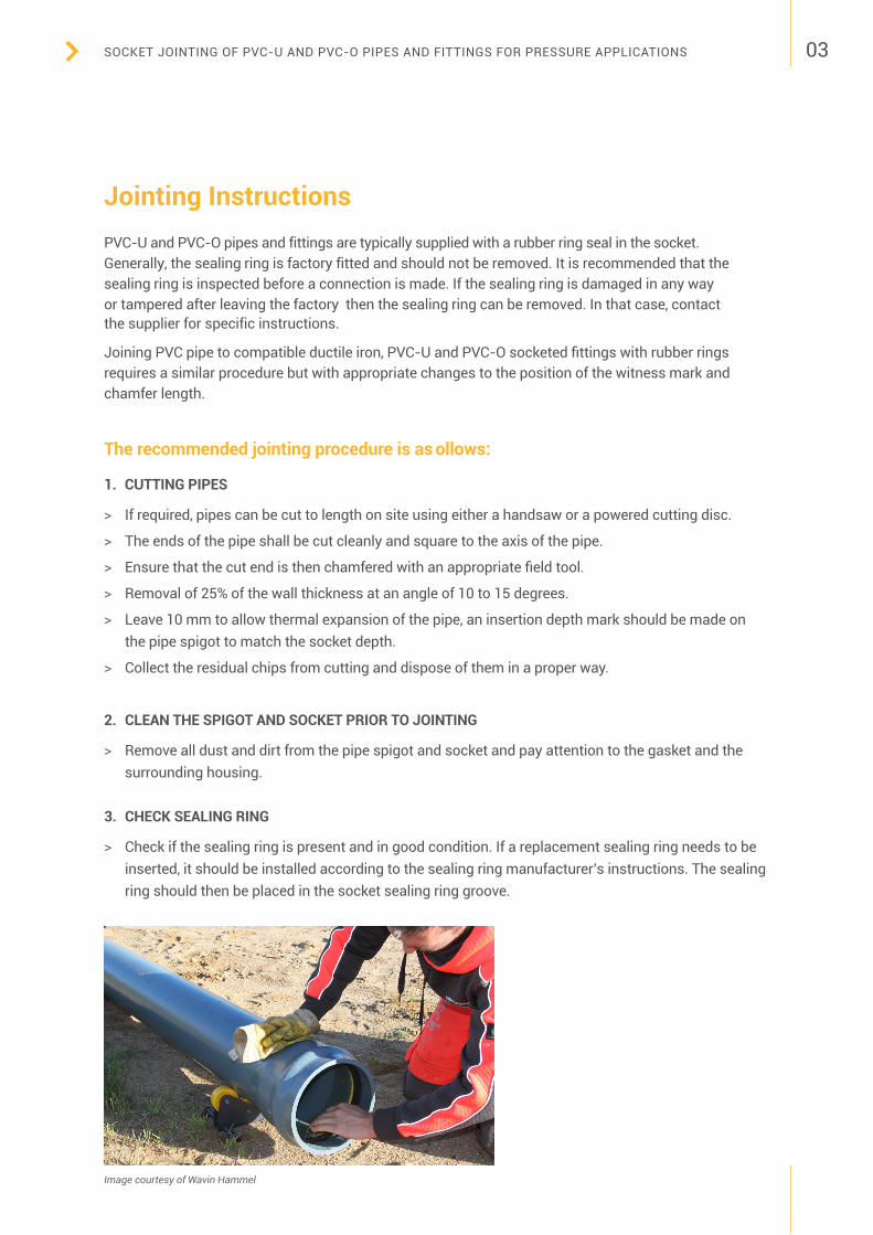
> If required, pipes can be cut to length on site using either a handsaw or a powered cutting disc.
> The ends of the pipe shall be cut cleanly and square to the axis of the pipe.
> Ensure that the cut end is then chamfered with an appropriate field tool.
> Removal of 25% of the wall thickness at an angle of 10 to 15 degrees.
> Leave 10 mm to allow thermal expansion of the pipe, an insertion depth mark should be made onthe pipe spigot to match the socket depth.
> Collect the residual chips from cutting and dispose of them in a proper way.
2. CLEAN THE SPIGOT AND SOCKET PRIOR TO JOINTING
> Remove all dust and dirt from the pipe spigot and socket and pay attention to the gasket and thesurrounding housing.
3. CHECK SEALING RING
> Check if the sealing ring is present and in good condition. If a replacement sealing ring needs to beinserted, it should be installed according to the sealing ring manufacturer’s instructions. The sealingring should then be placed in the socket sealing ring groove.
Image courtesy of Wavin Hammel
SOCKET JOINTING OF PVC-U AND PVC-O PIPES AND FITTINGS FOR PRESSURE APPLICATIONS
Jointing Instructions PVC-U and PVC-O pipes and fittings are typically supplied with a rubber ring seal in the socket. Generally, the sealing ring is factory fitted and should not be removed. It is recommended that the sealing ring is inspected before a connection is made. If the sealing ring is damaged in any way or tampered after leaving the factory then the sealing ring can be removed. In that case, contact the supplier for specific instructions.
Joining PVC pipe to compatible ductile iron, PVC-U and PVC-O socketed fittings with rubber rings requires a similar procedure but with appropriate changes to the position of the witness mark and chamfer length.
The recommended jointing procedure is as ollows:
1. CUTTING PIPES

04
4. APPLY LUBRICANT
> Apply lubricant to the spigot, fullycovering the circumference up tothe insertion depth mark.
> Ensure the lubricant is alsoapplied to the pipe chamfer.
5. ASSEMBLY
> Insert the leading edge of thespigot into the socket mouth.
> It is essential that the pipes arealigned and in a straight linebefore attempting to makethe joint.
6. PUSH SPIGOT INTO SOCKET
> A small, longitudinal force applied to the socket end of the pipe is sufficient to insert the spigot intothe adjacent pipe socket. Larger diameter pipes may require a crowbar for jointing. In that case, thepipe socket should be protected with a wooden block.
> Care must be taken to ensure that the pipe is not under-inserted as this may result in a leaking jointdue to the pipe contraction as a result of Poisson’s and/or thermal effects. Under-insertion is signifiedby the insertion depth mark not being pushed up to the end of the socket. Note: When pressurized,poisson contraction will cause shortening of the pipes and this might re-expose the insertion depthmark. This is acceptable.
> If a simple insertion past the witness mark has occurred, there is no significant risk to the performance of the join. Only if the spigot has been forced so hard that it has stressed the transition region at theback of the socket to the barrel of the pipe is there a cause for concern.
> This is generally only a risk with uncontrolled insertion using mechanical equipment like a backhoeor excavator.
7. TEST
> Upon completion of the pipeline installation, bury (or secure) the pipe. Afterwards, the pipelineshould be pressure tested to ensure there are no leakages.
Ductile iron and PVC-U and PVC-O Socket Joints
PVC-U pipes can be used with ductile iron socketed fittings complying with EN 12842:2012.and both PVC-U socketed fittings complying with EN ISO 1452-3:2009 and PVC-O socketed fittings complying with CEN TS-17176-3:2019.
Note: The insertion depth marks and chamfers to suit these particular sockets should be used.
Image courtesy of Wavin Hammel
SOCKET JOINTING OF PVC-U AND PVC-O PIPES AND FITTINGS FOR PRESSURE APPLICATIONS

05
> In hot climates, laying is best done in the cooler parts of the day.
> Rubber ring systems will allow for thermal movement of the pipeline after having been laid. In bothcases, as laying proceeds, at least partially backfill each length of the pipe.
SOCKET JOINTING OF PVC-U AND PVC-O PIPES AND FITTINGS FOR PRESSURE APPLICATIONS
Mechanical Jointing Systems
Different mechanical jointing systems can be used in PVC-U and PVC-O pressure piping systems, mostly unrestrained, when connecting with other pipe materials, cut-ins, maintenance and repairs. The examples are Gibault unions, universal couplers and steel clamps. If needed, there are also restrained mechanical couplers.
Jointing Fluids (lubricants
It is essential to use (bactericidal pipe lubricant with PVC-U and PVC-O pipes, fittings and ductile iron rubber sealing ring sockets.
Bactericidal pipe lubricant is recommended for potable water supplies as it contains a bactericide designed to limit the growth of bacteria by disinfection at its source. During installation, bacteria can enter the system and form a colony in the joint area, which is highly resistant (even to high levels of chlorine, and can cause continuing infection of the line. Being water-soluble, the fluid is quickly removed from potable water systems when flushing commences. It is important that the use of pipe lubricant should comply to the local regulations.
The abovementioned jointing fluids are safe and have no detrimental effect on the rubbers used in the sealing ring materials and because of thier properties, can also lower jointing forces. Keep the container closed when not in use to avoid spillage or contamination by dust or dirt.
Make sure to follow safety instructions of the used pipe lubricant.
Expansion and Contraction Distortion can occur when laying pipes in direct sunlight. When one side of the pipe is hotter than the other it may develop a slightly bent shape which may make jointing difficult. Common practice is to rotate pipes or place pipes in a shade to offset any uneven temperatures within the pipe.
After laying in hot weather, plastic pipe will contract as it cools. A 6-metre length of PVC pipe will expand or contract approximately 5-10 mm for each 10°C rise or fall in temperature.
The following precautions should be taken to ensure that the joints do not pull apart:

Steps in the jointing process
High level process map for the PVC jointing technique
CheckOn completion of pipeline installation, the pipeline shall be pressure tested.
LubricateApply lubricant to the full spigot and the chamfer.
Assemble Assemble the leading edge of the spigot into the socket mouth. Align the pipes and fittings in a straight line.
CutIf necessary, cut the pipe straight, deburr and chamfer. Place the mark for the insertion depth.
Clean Clean the spigot and socket prior to joining.
7
4 5 6
1 2 3JoinPush spigot into socket until the insertion mark is reached.
Check Check if the sealing ring is installed and in good condition. If the sealing ring is damaged, replace it with a new one.
06
Images courtesy of Wavin Hammel
SOCKET JOINTING OF PVC-U AND PVC-O PIPES AND FITTINGS FOR PRESSURE APPLICATIONS
07
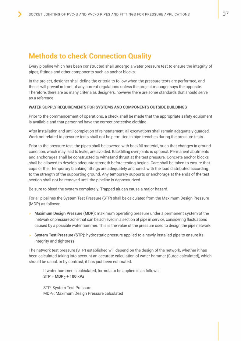
Methods to check Connection QualityEvery pipeline which has been constructed shall undergo a water pressure test to ensure the integrity of pipes, fittings and other components such as anchor blocks.
In the project, designer shall define the criteria to follow when the pressure tests are performed, and these, will prevail in front of any current regulations unless the project manager says the opposite. Therefore, there are as many criteria as designers, however there are some standards that should serve as a reference.
WATER SUPPLY REQUIREMENTS FOR SYSTEMS AND COMPONENTS OUTSIDE BUILDINGS
Prior to the commencement of operations, a check shall be made that the appropriate safety equipment is available and that personnel have the correct protective clothing.
After installation and until completion of reinstatement, all excavations shall remain adequately guarded. Work not related to pressure tests shall not be permitted in pipe trenches during the pressure tests.
Prior to the pressure test, the pipes shall be covered with backfill material, such that changes in ground condition, which may lead to leaks, are avoided. Backfilling over joints is optional. Permanent abutments and anchorages shall be constructed to withstand thrust at the test pressure. Concrete anchor blocks shall be allowed to develop adequate strength before testing begins. Care shall be taken to ensure that caps or their temporary blanking fittings are adequately anchored, with the load distributed according to the strength of the supporting ground. Any temporary supports or anchorage at the ends of the test section shall not be removed until the pipeline is depressurized.
Be sure to bleed the system completely. Trapped air can cause a major hazard.
For all pipelines the System Test Pressure (STP) shall be calculated from the Maximum Design Pressure (MDP) as follows:
> Maximum Design Pressure (MDP): maximum operating pressure under a permanent system of the network or pressure zone that can be achieved in a section of pipe in service, considering fluctuations caused by a possible water hammer. This is the value of the pressure used to design the pipe network.
> System Test Pressure (STP): hydrostatic pressure applied to a newly installed pipe to ensure its integrity and tightness.
The network test pressure (STP) established will depend on the design of the network, whether it has been calculated taking into account an accurate calculation of water hammer (Surge calculated), which should be usual, or by contrast, it has just been estimated.
If water hammer is calculated, formula to be applied is as follows: STP = MDPC + 100 kPa
STP: System Test Pressure MDPc: Maximum Design Pressure calculated
SOCKET JOINTING OF PVC-U AND PVC-O PIPES AND FITTINGS FOR PRESSURE APPLICATIONS

08
In the cases where the water hammer (Surge) has not been calculated ,the lowest of the following two values should be considered:
STP= MDPa x 1,5STP= MDPa + 500 kPa
STP: System Test PressureMDPa: Maximum Design Pressure calculated
The fixed allowance for Surge pressure included in MDPa shall not be less than 200 kPa. Under normal circumstances, the installation point for the testing equipment shall be the lowest point of the test section.
If it is not possible to install the testing equipment at the lowest point of the test section, the pressure for the pressure test shall be the system test pressure, calculated for the lowest point of the test section minus the difference in altitude.
For all types of pipes and materials, there are different approved testing procedures that may be applied. The testing procedure shall be specified by the designer and may be carried out in up to three steps:> Preliminary test
> Pressure drop test
> Main pressure test
1. PRELIMINARY TEST
The preliminary test stage will allow stabilization of the conduction to be examined, permitting mostof the time dependent movements and the pressure dependent movements to increase in volumeand occur prior to the main test. This phase will allow the pressure depending pipe to increase involume.
The pressure shall be raised up to at least the operating pressure without exceeding the SystemTest Pressure (STP).
The duration of the preliminary test is dependent upon the materials of the pipeline and shall bespecified by the designer taking due account of the appropriate product standards.
2. PRESSURE DROP TEST
The pressure drop test enables assessment of the remaining volume of air in the pipeline.The presence of air will reduce the accuracy of the pressure loss test and the water loss test.
The designer shall specify if the pressure drop test has to be carried out.
SOCKET JOINTING OF PVC-U AND PVC-O PIPES AND FITTINGS FOR PRESSURE APPLICATIONS

09
3. MAIN PRESSURE TEST
Influences of large temperatures changes shall be taken into account.Two basic test methods are recommended:
> Water loss method
> Pressure loss method
According to the EN-805 standard, the designer must specify the main test method to follow.
3.1 Water loss method
Two equivalent methods may be used to measure water loss, measurement of volume drawn off or measurement of volume pumped into the pipeline. The designer or project management should define what procedure to use.
3.1.1 Measurement o volume drawn o
Raise the pressure steadily until the system test pressure (STP is reached. Maintain STP by pumping, if necessary, for a period of not less than one hour. Disconnect the pump and do not permit any more water to enter the pipeline for a test period of one hour or a longer period if specified by the designer.
At the end of this test period measure the reduced pressure, then restore the STP by pumping and measure the loss by drawing off water until the reduced pressure reached at the end of the test is reached again.
3.1.2 Measurement of volume pumped in
Raise the pressure steadily until the system test pressure (STP is reached. Maintain STP for a test period of not less than one hour or a longer period if specified by the designer.
During this test period measure, record the quantity of water necessary to be pumped in order to maintain the STP.
The acceptable water loss, at the end of the first hour of the test, must not exceed the calculated value using the formula below.
Two equivalent methods may be used to measure water loss – measure of evacuated volume or measure of pumped or injected volume. Designer or project manager should define what procedure to use.
The acceptable water loss, at the end of the first hour of the test, must not exceed the calculated value using the following formula:
ΔVmáx: Allowable water loss in litresV: Volume of the driving section under test, in litresΔP: Allowable pressure dropEw: ER: D: e:
Water elasticity modulus (Ew = 2.10x10³ N / mm2) Pipe wall elasticity modulusInner diameter of the pipe in mPipe wall thickness in m
SOCKET JOINTING OF PVC-U AND PVC-O PIPES AND FITTINGS FOR PRESSURE APPLICATIONS

10
3.2 Pressure loss method
Raise the pressure steadily until the system test pressure (STP) is reached.
The duration of the pressure drop test must be one hour. During the test, the pressure drop p must present a regressive trend and at the end of the first hour the pressure drop must not exceed 20 kPa.
If the loss exceeds that specified, or if faults are identified, the system shall be examined and rectified where necessary. The test shall be repeated until the loss complies with that specified.
StandardsSeveral standards have been drafted by ISO and CEN organisations to provide reference guides to proven jointing procedures. An overview of these standards is given in Appendix 1.
Case StudiesPVC pipe and fitting jointing techniques have been used in Europe since the 1950’s and therefore, are well established. The techniques in practice are normally for pipes of 63 mm in diameter or larger and typically used to join pipes of up to 1200 mm.
SOCKET JOINTING OF PVC-U AND PVC-O PIPES AND FITTINGS FOR PRESSURE APPLICATIONS

11
For high performance sprinkler irrigation for fruit trees in the Fully region, Switzerland, PVC-O pipes and fittings were selected.
Also, in line with the guidance notes in this document, reliable push-fit connections in this project ensure fast and robust installation and a long service life of the system.
Case 2This example was provided by Molecor
A long lifetime and trouble-free operation are the main advantages of using PVC-U and PVC-O pipes and fittings for pressure applications. This can be accomplished by using a proven and simple jointing technique for these pipes and fittings during the construction of the pipeline system. In line with the guidance notes in this document, in this case, it is shown how a push-fit connection between a PVC pipe spigot-end and a PVC fitting socket delivers a good quality joint. The pictures show an excellent connection being made between two PVC-O pipes in a curved trajectory. This project was the installation of a PVC-O DN 150 PN 16 pressure water main in Kelburn Parade, Wellington City, New Zealand.
Case 1This example was provided by Iplex Pipelines NZ
Images courtesy of Iplex Pipelines NZ. Please note that the installation should follow the relevantnational safety regulations.
Images courtesy of Molecor. PVC-O pipes are totally compatible with other DI fittings as shown in the images.
SOCKET JOINTING OF PVC-U AND PVC-O PIPES AND FITTINGS FOR PRESSURE APPLICATIONS

Location Standards and Procedures
InternationalEN ISO 1452-series. Plastics piping systems for water supply and for buried and above-ground drainage and sewerage under pressure – unplasticized polyvinyl chloride (PVC-U).
International ISO 6993-1. Buried, high-impact polyvinyl chloride (PVC-HI) piping systems for the supply of gaseous fuels – Part 1: Pipes for a maximum operating pressure of 1 bar (100 kPa).
International EN ISO 12162: Thermoplastics materials for pipes and fittings for pressure applications - Classification, designation and design coefficient.
Europe Fpr CEN/TS 1046:2020. Thermoplastics piping and ducting systems – Outside the building structures for gravity and pressurised systems – Trench installation.
EuropeEN 17176-series:2019. Plastic Piping Systems for water supply and for buried and above ground drainage, sewerage and irrigation under pressure – Oriented unplasticized polyvinyl chloride (PVC-O) – Parts 1, 2, 3 and 5.
Europe EN 805:2000. Water supply requirements for systems and components outside buildings.
Europe EN 12842:2012. Ductile iron fittings for PVC-U or PE piping systems – Requirements and test methods.
12
Appendix 1 – Standards and Procedures
www.teppfa.eu
Registered Office: Avenue de Cortenbergh 71, 1000 Brussels, Belgiumtel: +32 2 736 24 06 e-mail: [email protected] www.teppfa.eu
The European Plastic Pipes & Fittings Association © TEPPFA, 2021 M-EX-202108-07
Disclaimer All rights including the copyright, on the materials described in this document rest with The European Plastics Pipes and Fittings Association (“TEPPFA”), Avenue de Cortenbergh, 71, B-1000 Brussels (Belgium). This document may not be reproduced or brought into circulation without the prior written consent of TEPPFA. Without prior permission in writing from TEPPFA this document may not be used, in whole or in part, for the lodging of claims, for conducting proceedings, for publicity and/or for the benefit or acquisition in a more general sense. Every effort has been made to ensure the accuracy of the information contained in this document but it is provided for information purposes only and compliance with the recommendations does not imply or guarantee performance.
About TEPPFA TEPPFA is The European Plastic Pipe and Fittings Association founded in 1991 with headquarters in Brussels. TEPPFA’s 13 multinational company members and 15 national associations across Europe represent 350 companies that manufacture plastic pipes and fittings. TEPPFA’s members have an annual production volume of 3 million tonnes directly employing 40,000 people with €12 billion combined annual sales. Its final products are subdivided into 3 application groups: 1. Building (Above ground systems for hot & cold-water supply, surface heating & cooling, waste water discharge and rainwater drainage) 2. Civils (Below ground pipe systems for sewers, stormwater management and sub soil drainage) 3. Utilities (Below ground pipe systems for distribution of drinking water, gas, energy and telecommunications).
SOCKET JOINTING OF PVC-U AND PVC-O PIPES AND FITTINGS FOR PRESSURE APPLICATIONS
sibtainbandali
Sticky Note
Completed set by sibtainbandali
sibtainbandali
Sticky Note
Completed set by sibtainbandali