Digital Electronics
24
Digital Electronics BTES301-18
-
Upload
khangminh22 -
Category
Documents
-
view
1 -
download
0
Transcript of Digital Electronics
Digital Electronics
BTES301-18

Introduction to Digital Electronics
• Digital Electronics is the sub-branch ofelectronics which deals with digital signals forprocessing and controlling various systemsand sub-systems.
• Digital Electronics uses binary numbers of 1and 0 to represent information. Number BaseSystem. Logic Operations. MathematicalOperations. Building Circuits by usingBreadboards.
Digital Signals
• Digital Signals: Digital electronics is entirelythe field in which digital signals are used.Digital signals are discretization of analogsignals. A signal carries information. In digitalsignals the values in a particular band is samei.e. constant. Digital signals form the basis ofdigital circuit and digital electronics.
Advantages/Disadvantages of Digital Systems
• Advantages
Easier Designing
Noise Immune
Information Storage is Simpler
High Accuracy And Precision
• Disadvantages
Expensive
Analog nature of Real World Entities
Number System
• Number system is used for representing theinformation. The number system has differentbases and common of them are decimal,binary, octal, and hexadecimal.
• The base/radix of the number system is thetotal number of the digit used in that specificnumber system.

Binary codes
• The digital data is represented, stored andtransmitted as group of binary bits. This group isalso called as binary code.
Advantages of Binary Code• Binary codes are suitable for the digital
communications and computer applications.• Binary codes make the analysis and designing of
digital circuits if we use the binary codes.• Only 0 & 1 are being used, implementation
becomes easy.
Classification of Binary Codes
• Weighted Codes
• Non-Weighted Codes
• Reflected Codes
• Alphanumeric Codes
• Sequential Codes
• Error Detecting and Correcting Codes
r's and (r-1)'s Complement of Numbers
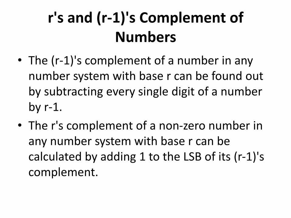
• The (r-1)'s complement of a number in any number system with base r can be found out by subtracting every single digit of a number by r-1.
• The r's complement of a non-zero number in any number system with base r can be calculated by adding 1 to the LSB of its (r-1)'s complement.
Logic gates
• Logic gates are the basic building blocks of anydigital system. It is an electronic circuit havingone or more than one input and only oneoutput. There are three basic logic gates arenamed as AND gate, OR gate, NOT gate etc.
• Universal gates are NAND and NOR gates.
• Two more gates are X-OR and X-NOR gates.
Boolean Algebra
• Digital computers contain circuits thatimplement Boolean functions.
• The simpler that we can make a Booleanfunction, the smaller the circuit. Simplercircuits are cheaper to build, consume lesspower, and run faster than complex circuits.
• We always want to reduce our Booleanfunctions to their simplest form.

Boolean Algebra
• Commutative Law A . B = B . AA + B = B + A• Distributive Law A(B + C) = A.B + A.C
A + (B.C) = (A + B).(A + C)• Associative LawA + (B + C) = (A + B) + C = A + B + CA(B.C) = (A.B)C = A . B . C

Boolean Algebra
• Identity LawA + 0 = AA . 1 = A• Idempotent Law A + A = AA . A = A• Complement LawA . A = 0A + A = 1
Boolean Algebra
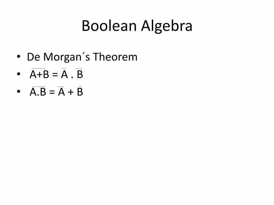
• De Morgan´s Theorem
• A+B = A . B
• A.B = A + B
K-MAP
• Karnaugh map (K-map) can be used to minimize functions of up to 6 variables.
• K-map is directly applied to two-level networks composed of AND and OR gates.
Sum-of-products, (SOP)
Product-of-sum, (POS).
QM Method
• Quine-McCluskey (QM) method is one of themost powerful techniques to simplify Booleanexpressions. Compared to other techniques,QM method is more executable and canhandle more variables.

Combinational Circuits
• Combinational circuits are defined as the time independent circuits which do not depends upon previous inputs to generate any output are termed as combinational circuits.
Examples – Encoder, Decoder, Multiplexer, Demultiplexer
Combinational Circuits
• In this output depends only upon present input.
• Speed is fast and design is easy.
• There is no feedback between input and output.
• Elementary building blocks: Logic gates
• Used for arithmetic as well as Boolean operations.
• These circuits do not have any memory element.
• It is easy to use and handle.
Sequential circuits
• Sequential circuits are those which are dependent on clock cycles and depends on present as well as past inputs to generate any output.
Examples – Flip-flops, Counters, Shift Registers
Sequential circuits
• In this output depends upon present as well as past input.
• Speed is slow.
• There exists a feedback path between input and output.
• Elementary building blocks: Flip-flops
• Mainly used for storing data.
• These circuits have memory element. It is not easy to use and handle.
Memory Devices
Computer memory is the storage space in computer where data is to be processed and instructions required for processing are stored.
• Memory is primarily of two types
Internal Memory − cache memory and primary/main memory
External Memory − magnetic disk / optical disk etc.
RAM
A RAM constitutes the internal memory of the CPU for storing data, program and program result. It is read/write memory. It is called random access memory (RAM).
RAM is of two types
• Static RAM (SRAM)
• Dynamic RAM (DRAM)
ROM
ROM stands for Read Only Memory. The memoryfrom which we can only read but cannot write on it.This type of memory is non-volatile. Theinformation is stored permanently in suchmemories during manufacture.• MROM (Masked ROM)• PROM (Programmable Read Only Memory)• EPROM (Erasable and Programmable Read Only
Memory)• EEPROM (Electrically Erasable and Programmable
Read Only Memory)
PLDs
• Programmable Logic Devices PLDs are the integrated circuits. They contain an array of AND gates & another array of OR gates. There are three kinds of PLDs based on the type of arrays, which has programmable feature.
• Programmable Read Only Memory
• Programmable Array Logic
• Programmable Logic Array

References
• www.electronics-tutorials.ws/boolean.html
• https://www.tutorialspoint.com/digital_circuits/digital_circuits_programmable_logic_devices.html