power electronics
10
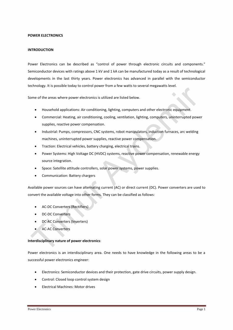
Power Electronics Page 1 POWER ELECTRONICS INTRODUCTION Power Electronics can be described as “control of power through electronic circuits and components.” Semiconductor devices with ratings above 1 kV and 1 kA can be manufactured today as a result of technological developments in the last thirty years. Power electronics has advanced in parallel with the semiconductor technology. It is possible today to control power from a few watts to several megawatts level. Some of the areas where power electronics is utilized are listed below. Household applications: Air conditioning, lighting, computers and other electronic equipment. Commercial: Heating, air conditioning, cooling, ventilation, lighting, computers, uninterrupted power supplies, reactive power compensation. Industrial: Pumps, compressors, CNC systems, robot manipulators, induction furnaces, arc welding machines, uninterrupted power supplies, reactive power compensation. Traction: Electrical vehicles, battery charging, electrical trains. Power Systems: High Voltage DC (HVDC) systems, reactive power compensation, renewable energy source integration. Space: Satellite attitude controllers, solar power systems, power supplies. Communication: Battery chargers Available power sources can have alternating current (AC) or direct current (DC). Power converters are used to convert the available voltage into other forms. They can be classified as follows: AC-DC Converters (Rectifiers) DC-DC Converters DC-AC Converters (Inverters) AC-AC Converters Interdisciplinary nature of power electronics: Power electronics is an interdisciplinary area. One needs to have knowledge in the following areas to be a successful power electronics engineer: Electronics: Semiconductor devices and their protection, gate drive circuits, power supply design. Control: Closed loop control system design Electrical Machines: Motor drives
-
Upload
khangminh22 -
Category
Documents
-
view
4 -
download
0
Transcript of power electronics
Power Electronics Page 1
POWER ELECTRONICS
INTRODUCTION
Power Electronics can be described as “control of power through electronic circuits and components.”
Semiconductor devices with ratings above 1 kV and 1 kA can be manufactured today as a result of technological
developments in the last thirty years. Power electronics has advanced in parallel with the semiconductor
technology. It is possible today to control power from a few watts to several megawatts level.
Some of the areas where power electronics is utilized are listed below.
Household applications: Air conditioning, lighting, computers and other electronic equipment.
Commercial: Heating, air conditioning, cooling, ventilation, lighting, computers, uninterrupted power
supplies, reactive power compensation.
Industrial: Pumps, compressors, CNC systems, robot manipulators, induction furnaces, arc welding
machines, uninterrupted power supplies, reactive power compensation.
Traction: Electrical vehicles, battery charging, electrical trains.
Power Systems: High Voltage DC (HVDC) systems, reactive power compensation, renewable energy
source integration.
Space: Satellite attitude controllers, solar power systems, power supplies.
Communication: Battery chargers
Available power sources can have alternating current (AC) or direct current (DC). Power converters are used to
convert the available voltage into other forms. They can be classified as follows:
AC-DC Converters (Rectifiers)
DC-DC Converters
DC-AC Converters (Inverters)
AC-AC Converters
Interdisciplinary nature of power electronics:
Power electronics is an interdisciplinary area. One needs to have knowledge in the following areas to be a
successful power electronics engineer:
Electronics: Semiconductor devices and their protection, gate drive circuits, power supply design.
Control: Closed loop control system design
Electrical Machines: Motor drives
Power Electronics Page 2
Power Systems: Reactive power compensation, active and passive filters, flexible ac transmission line
systems, smart grids and renewable energy sources.
Magnetics: High frequency transformer and inductor design, EMI and EMC issues.
Software: Microprocessors, Digital Signal Processors,
Four Principles of Power Electronics Circuit Analysis
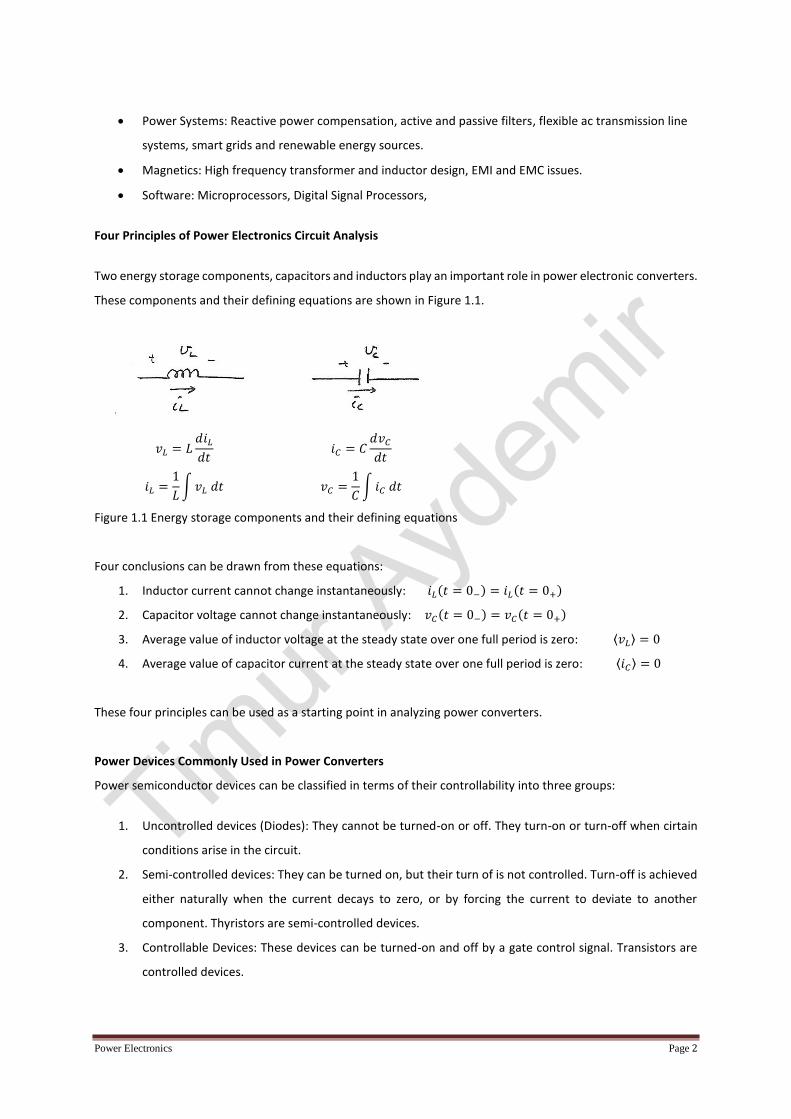
Two energy storage components, capacitors and inductors play an important role in power electronic converters.
These components and their defining equations are shown in Figure 1.1.
𝑣𝐿 = 𝐿𝑑𝑖𝐿
𝑑𝑡
𝑖𝐿 =1
𝐿∫ 𝑣𝐿 𝑑𝑡
𝑖𝐶 = 𝐶𝑑𝑣𝐶
𝑑𝑡
𝑣𝐶 =1
𝐶∫ 𝑖𝐶 𝑑𝑡
Figure 1.1 Energy storage components and their defining equations
Four conclusions can be drawn from these equations:
1. Inductor current cannot change instantaneously: 𝑖𝐿(𝑡 = 0−) = 𝑖𝐿(𝑡 = 0+)
2. Capacitor voltage cannot change instantaneously: 𝑣𝐶(𝑡 = 0−) = 𝑣𝐶(𝑡 = 0+)
3. Average value of inductor voltage at the steady state over one full period is zero: ⟨𝑣𝐿⟩ = 0
4. Average value of capacitor current at the steady state over one full period is zero: ⟨𝑖𝐶⟩ = 0
These four principles can be used as a starting point in analyzing power converters.
Power Devices Commonly Used in Power Converters
Power semiconductor devices can be classified in terms of their controllability into three groups:
1. Uncontrolled devices (Diodes): They cannot be turned-on or off. They turn-on or turn-off when cirtain
conditions arise in the circuit.
2. Semi-controlled devices: They can be turned on, but their turn of is not controlled. Turn-off is achieved
either naturally when the current decays to zero, or by forcing the current to deviate to another
component. Thyristors are semi-controlled devices.
3. Controllable Devices: These devices can be turned-on and off by a gate control signal. Transistors are
controlled devices.

Power Electronics Page 3
Diodes
Current-voltage characteristics of diodes are shown in Figure 1.2. An ideal diode has no voltage drop across the
junction when it is forward biased. When reverse biased, there is no current flow. Ideal diode can conduct any
amount of current in the forward direction and it can block any amount of voltage in the reverse direction.
Figure 1.2 Ideal and real diode characteristics
A real diode can conduct only after forward bias voltage is at least equal to a threshold voltage. This threshold
voltage is about 0.7 V in silicon devices. Forward voltage drop of a diode is equal to the sum of the threshold
voltage and voltage drop term which is proportional with the forward current. This can be viewed as a resistive
voltage drop. Forward voltage drops of silicon diodes can be between 1 V and 2 V. There are some special diodes
with smaller voltage drops.
When the voltage between the anode and cathode is negative, diodes are called to be reverse biased and they
do not conduct current. Only a negligibly small amount of current called leakage current exists in this case.
However, if the reverse voltage exceeds a specific level called breakdown voltage, a large amount of short circuit
current flows through the diode in the reverse direction causing its destruction.
Diodes can turn-on very quickly but their turn-off is slower. In the turn-off period the current first decays to zero,
then reverses. The peak reverse current can be as high as the forward current. After reaching this reverse peak
value the current turns back towards zero. This process is called reverse recovery. The time length of this is called
reverse recovery time (trr). Reverse recovery transient is shown in Figure 1.3. The reason for reverse recovery is
that diode current is due to both minority and majority carriers, and it takes time for the minority carriers to
recombine with reverse polarity carriers and neutralize.
Power Electronics Page 4
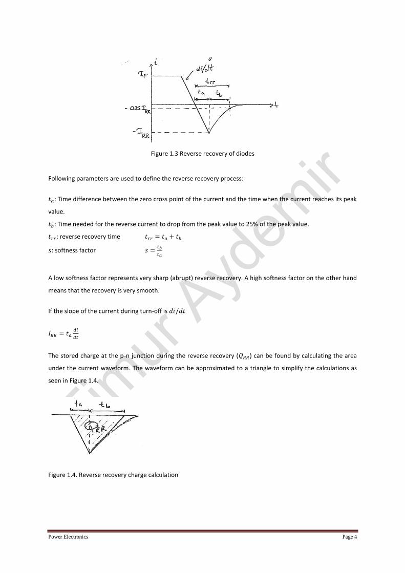
Figure 1.3 Reverse recovery of diodes
Following parameters are used to define the reverse recovery process:
𝑡𝑎: Time difference between the zero cross point of the current and the time when the current reaches its peak
value.
𝑡𝑏: Time needed for the reverse current to drop from the peak value to 25% of the peak value.
𝑡𝑟𝑟: reverse recovery time 𝑡𝑟𝑟 = 𝑡𝑎 + 𝑡𝑏
𝑠: softness factor 𝑠 =𝑡𝑏
𝑡𝑎
A low softness factor represents very sharp (abrupt) reverse recovery. A high softness factor on the other hand
means that the recovery is very smooth.
If the slope of the current during turn-off is 𝑑𝑖/𝑑𝑡
𝐼𝑅𝑅 = 𝑡𝑎𝑑𝑖
𝑑𝑡
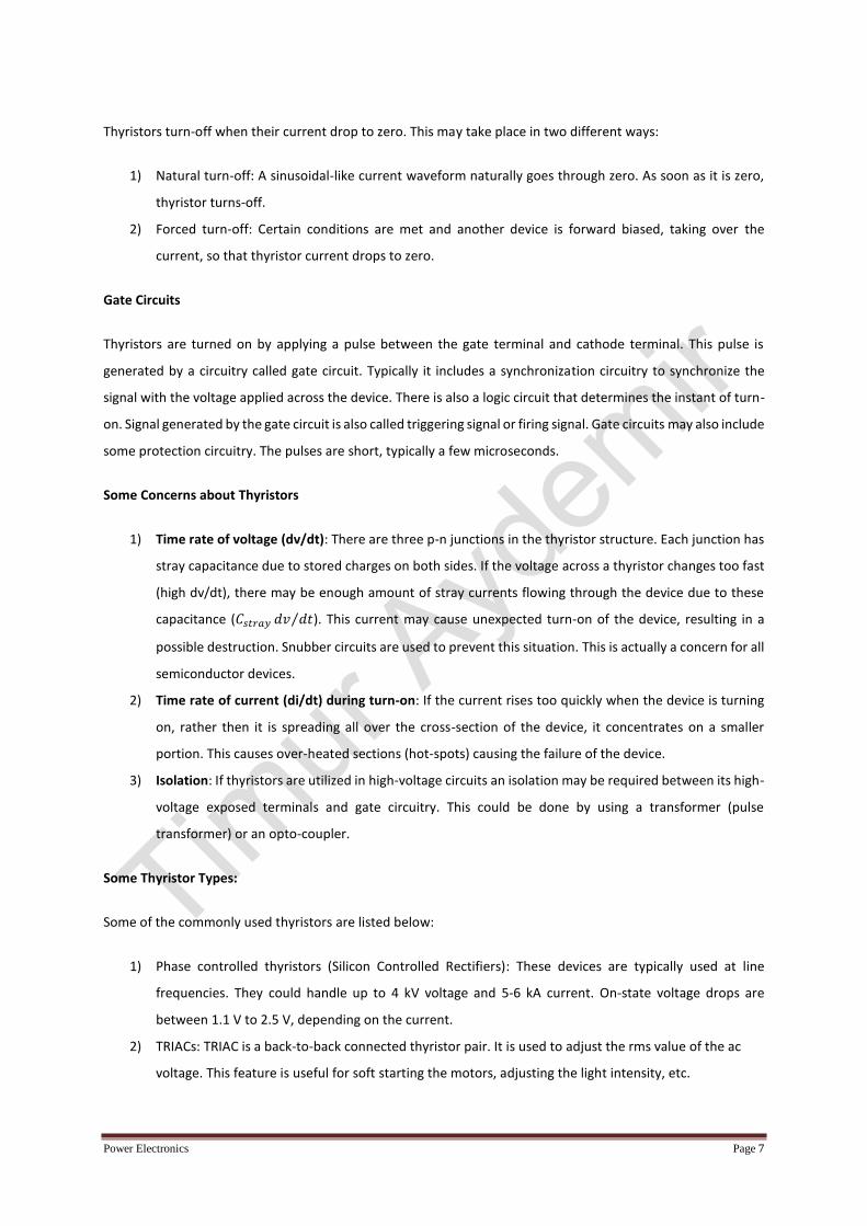
The stored charge at the p-n junction during the reverse recovery (𝑄𝑅𝑅) can be found by calculating the area
under the current waveform. The waveform can be approximated to a triangle to simplify the calculations as
seen in Figure 1.4.
Figure 1.4. Reverse recovery charge calculation

Power Electronics Page 5
𝑄𝑅𝑅 ≅1
2𝐼𝑅𝑅𝑡𝑎 +
1
2𝐼𝑅𝑅𝑡𝑏 =
1
2𝐼𝑅𝑅(𝑡𝑎 + 𝑡𝑏)
𝑄𝑅𝑅 ≅1
2𝐼𝑅𝑅𝑡𝑅𝑅
𝐼𝑅𝑅 =2𝑄𝑅𝑅
𝑡𝑅𝑅
𝑡𝑅𝑅 = 𝑡𝑎 + 𝑡𝑏 = 𝑡𝑎 + 𝑠𝑡𝑎 = 𝑡𝑎(1 + 𝑠) → 𝐼𝑅𝑅 =𝑡𝑅𝑅
1 + 𝑠
𝑑𝑖
𝑑𝑡
𝑄𝑅𝑅 ≅1
2𝑡𝑅𝑅
𝑡𝑅𝑅
1 + 𝑠
𝑑𝑖
𝑑𝑡=
1
2(1 + 𝑠)𝑡𝑅𝑅
2𝑑𝑖
𝑑𝑡
𝑡𝑅𝑅 = √2𝑄𝑅𝑅(1 + 𝑠)
𝑑𝑖/𝑑𝑡
or
𝐼𝑅𝑅 = √2𝑄𝑅𝑅(𝑑𝑖/𝑑𝑡)
1 + 𝑠
As seen from these equations, 𝑡𝑅𝑅 and 𝐼𝑅𝑅 depend on the stored charge and reverse 𝑑𝑖/𝑑𝑡. 𝑄𝑅𝑅 depends on
forward diode current 𝐼𝐹 . Typical values of 𝐼𝑅𝑅 , 𝑄𝑅𝑅 and 𝑠 can be found at the data sheets of diodes.
Diodes also need some time for the recovery of majority carriers before conducting. This is called forward
recovery.
Power Diode Types
Power diodes can be divided into three groups based on their reverse recovery characteristics:
1) General purposed diodes:
2) Fast recovery diodes:
3) Schottky diodes:
General purposed diodes: These diodes are typically used in low frequency (a few Hertz to one kHz) applications.
Typical value of reverse recovery time is 25 µs. They are slow but since the operating frequency is low, reverse
recovery characteristic can be ignored. Their ratings can be up to 6 kV and 4.5 kA.
Fast recovery diodes: These diodes have low reverse recovery times, typically less than 5 µs. Since the reverse
recovery time is shorter they can be used at higher frequency applications such as dc-dc and dc-ac converters,
with voltage ratings up to 3 kV and current ratings up to a few hundred amps. There faster diodes with less than
100 ns reverse recovery time but they cannot be used above 400 V.
Schottky diodes: These diodes have a different p-n junction structure, and as a result, they have almost none
reverse recovery. Therefore, they can be used at very high frequencies. Their voltage drop is also lower compared
to other diode types. However, they are available only up to 100 V although current ratings can go up to a few
amps.

Power Electronics Page 6
Thyristors
Thyristors are three-junction (four-layer) devices. Even if a positive voltage is applied between the Anode and
Cathod terminals, it cannot conduct since one of the p-n junctions is still reverse biased.
(a) Structure of the thyristors (b) Symbol of thryistors
Figure 1.5. Thyristor structure and symbol
Thyristors are semi-controlled devices. They can be turned-on but their turn-off cannot be controlled. Once they
are on, they behave like diodes. Thyristor characteristic is shown in Figure 1.6.
Figure 1.6 Thyristor i-v characteristic
Thyristors can be turned on by applying a positive pulse between the third terminal (gate) and cathode while the
anode-cathode voltage is positive. If the applied forward voltage is over a certain limit (breakover voltage)
thyristor fails.
Thyristors, like diodes, can withstand negative voltages up to reverse breakdown voltage.
Power Electronics Page 7
Thyristors turn-off when their current drop to zero. This may take place in two different ways:
1) Natural turn-off: A sinusoidal-like current waveform naturally goes through zero. As soon as it is zero,
thyristor turns-off.
2) Forced turn-off: Certain conditions are met and another device is forward biased, taking over the
current, so that thyristor current drops to zero.
Gate Circuits
Thyristors are turned on by applying a pulse between the gate terminal and cathode terminal. This pulse is
generated by a circuitry called gate circuit. Typically it includes a synchronization circuitry to synchronize the
signal with the voltage applied across the device. There is also a logic circuit that determines the instant of turn-
on. Signal generated by the gate circuit is also called triggering signal or firing signal. Gate circuits may also include
some protection circuitry. The pulses are short, typically a few microseconds.
Some Concerns about Thyristors
1) Time rate of voltage (dv/dt): There are three p-n junctions in the thyristor structure. Each junction has
stray capacitance due to stored charges on both sides. If the voltage across a thyristor changes too fast
(high dv/dt), there may be enough amount of stray currents flowing through the device due to these
capacitance (𝐶𝑠𝑡𝑟𝑎𝑦 𝑑𝑣 𝑑𝑡⁄ ). This current may cause unexpected turn-on of the device, resulting in a
possible destruction. Snubber circuits are used to prevent this situation. This is actually a concern for all
semiconductor devices.
2) Time rate of current (di/dt) during turn-on: If the current rises too quickly when the device is turning
on, rather then it is spreading all over the cross-section of the device, it concentrates on a smaller
portion. This causes over-heated sections (hot-spots) causing the failure of the device.
3) Isolation: If thyristors are utilized in high-voltage circuits an isolation may be required between its high-
voltage exposed terminals and gate circuitry. This could be done by using a transformer (pulse
transformer) or an opto-coupler.
Some Thyristor Types:
Some of the commonly used thyristors are listed below:
1) Phase controlled thyristors (Silicon Controlled Rectifiers): These devices are typically used at line
frequencies. They could handle up to 4 kV voltage and 5-6 kA current. On-state voltage drops are
between 1.1 V to 2.5 V, depending on the current.
2) TRIACs: TRIAC is a back-to-back connected thyristor pair. It is used to adjust the rms value of the ac
voltage. This feature is useful for soft starting the motors, adjusting the light intensity, etc.

Power Electronics Page 8
3) Gate Turn-off Thyristors (GTO): These devices can be turned off by applying a negative signal between
the gate and cathode terminals. They are especially preferred at high power applications.
Review Questions for Part-1
1) List three household devices which include power electronic application.
2) List three industrial applications which use power electronics.
3) What are the turn-on and turn-off conditions for diodes?
4) What are the turn-on and turn-off conditions for thyristors?
5) What are the turn-on and turn-off conditions for transistors?
6) What is the difference between abrupt reverse recovery and soft reverse recovery?
7) Which type of diodes has the highest voltage rating?
8) Which type of diodes is the fastest?
9) What type of diode would you choose in a 50-Hz converter?
10) What type of diode would you choose in a d-dc converter operating with a switching frequency of 20
kHz with a 600 V peak voltage?
11) What type of diode would you choose a d-dc converter operating with a switching frequency of 200
kHz with a 50 V peak voltage?
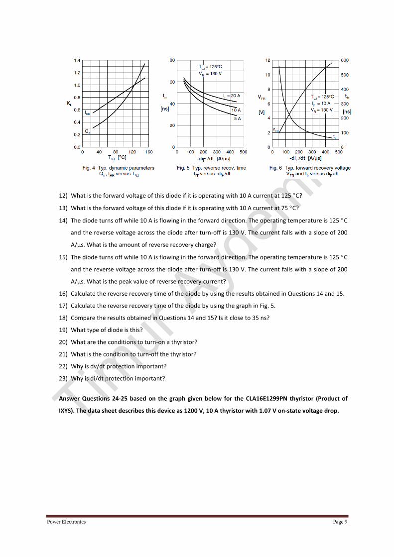
Answer Questions 12-19 based on the graphs given below for the DPG10I200PA diode (Product of IXYS).
The data sheet describes this device as 200 V, 10 A, 35 ns diode.
Power Electronics Page 9
12) What is the forward voltage of this diode if it is operating with 10 A current at 125 C?
13) What is the forward voltage of this diode if it is operating with 10 A current at 75 C?
14) The diode turns off while 10 A is flowing in the forward direction. The operating temperature is 125 C
and the reverse voltage across the diode after turn-off is 130 V. The current falls with a slope of 200
A/µs. What is the amount of reverse recovery charge?
15) The diode turns off while 10 A is flowing in the forward direction. The operating temperature is 125 C
and the reverse voltage across the diode after turn-off is 130 V. The current falls with a slope of 200
A/µs. What is the peak value of reverse recovery current?
16) Calculate the reverse recovery time of the diode by using the results obtained in Questions 14 and 15.
17) Calculate the reverse recovery time of the diode by using the graph in Fig. 5.
18) Compare the results obtained in Questions 14 and 15? Is it close to 35 ns?
19) What type of diode is this?
20) What are the conditions to turn-on a thyristor?
21) What is the condition to turn-off the thyristor?
22) Why is dv/dt protection important?
23) Why is di/dt protection important?
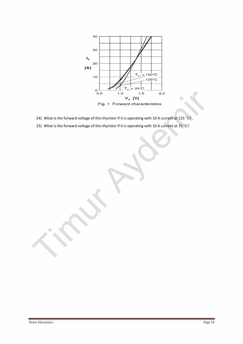
Answer Questions 24-25 based on the graph given below for the CLA16E1299PN thyristor (Product of
IXYS). The data sheet describes this device as 1200 V, 10 A thyristor with 1.07 V on-state voltage drop.
Power Electronics Page 10
24) What is the forward voltage of this thyristor if it is operating with 10 A current at 125 C?
25) What is the forward voltage of this thyristor if it is operating with 10 A current at 75 C?