Power Electronics - MADE EASY
16
Comprehensive Theory with Solved Examples and Practice Questions Power Electronics Electrical Engineering Publications
-
Upload
khangminh22 -
Category
Documents
-
view
5 -
download
0
Transcript of Power Electronics - MADE EASY

Comprehensive Theory
with Solved Examples and Practice Questions
Power Electronics
ElectricalEngineering
Publications

MADE EASY Publications
Corporate Office: 44-A/4, Kalu Sarai (Near Hauz Khas Metro Station), New Delhi-110016E-mail: [email protected]: 011-45124660, 8860378007
Visit us at: www.madeeasypublications.org
Power Electronics© Copyright by MADE EASY Publications.All rights are reserved. No part of this publication may be reproduced, stored in or introduced into a retrieval system, or transmitted in any form or by any means (electronic, mechanical, photo-copying, recording or otherwise), without the prior written permission of the above mentioned publisher of this book.
First Edition : 2015
Second Edition : 2016
Third Edition : 2017
Fourth Edition : 2018
© All rights reserved by MADE EASY PUBLICATIONS. No part of this book may be reproduced or utilized in any form without the written permission from the publisher.
Publications
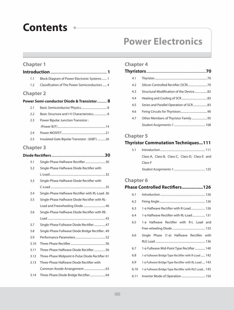
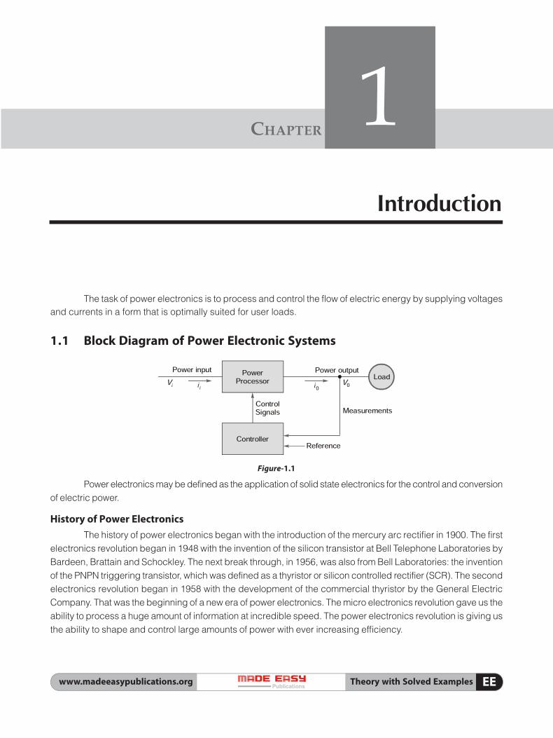
Chapter 1Introduction ��������������������������������������������������������� 1 1�1 Block Diagram of Power Electronic Systems ������� 1
1�2 Classification of The Power Semiconductors ������ 4
Chapter 2Power Semi-conductor Diode & Transistor ���������� 8 2�1 Basic Semiconductor Physics ������������������������������������ 8
2�2 Basic Structure and I-V Characteristics ������������������ 8
2�3 Power Bipolar Junction Transistor :
(Power BJT) �������������������������������������������������������������������14
2�4 Power MOSFET �������������������������������������������������������������21
2�5 Insulated Gate Bipolar Transistor : (IGBT) �����������26
Chapter 3Diode Rectifiers ������������������������������������������������������30 3�1 Single-Phase Halfwave Rectifier ����������������������������30
3�2 Single-Phase Halfwave Diode Rectifier with
L-Load ������������������������������������������������������������������������������32
3�3 Single-Phase Halfwave Diode Rectifier with
C-Load �����������������������������������������������������������������������������35
3�4 Single-Phase Halfwave Rectifier with RL-Load �36
3�5 Single-Phase Halfwave Diode Rectifier with RL-
Load and Freewheeling Diode �������������������������������40
3�6 Single-Phase Halfwave Diode Rectifier with RE-
Load ���������������������������������������������������������������������������������43
3�7 Single-Phase Fullwave Diode Rectifier ����������������47
3�8 Single-Phase Fullwave Diode Bridge Rectifier ��49
3�9 Performance Parameters ������������������������������������������52
3�10 Three-Phase Rectifier �������������������������������������������������56
3�11 Three-Phase Halfwave Diode Rectifier ����������������56
3�12 Three-Phase Midpoint 6-Pulse Diode Rectifier 61
3�13 Three-Phase Halfwave Diode Rectifier with
Common Anode Arrangement ������������������������������63
3�14 Three-Phase Diode Bridge Rectifier����������������������64
Chapter 4Thyristors ������������������������������������������������������������70 4�1 Thyristor ��������������������������������������������������������������������������70
4�2 Silicon Controlled Rectifier (SCR) ���������������������������70
4�3 Structural Modification of the Device ������������������82
4�4 Heating and Cooling of SCR ������������������������������������83
4�5 Series and Parallel Operation of SCR ��������������������83
4�6 Firing Circuits for Thyristors �������������������������������������90
4�7 Other Members of Thyristor Family ����������������������95
Student Assignments-1 ........................................... 108
Chapter 5Thyristor Commutation Techniques ...111 5�1 Introduction ��������������������������������������������������������������� 111
Class-A, Class-B, Class-C, Class-D, Class-E and
Class-F
Student Assignments-1 ........................................... 125
Chapter 6Phase Controlled Rectifiers .................126 6�1 Introduction ��������������������������������������������������������������� 126
6�2 Firing Angle ���������������������������������������������������������������� 126
6�3 1-f Halfwave Rectifier with R-Load �������������������� 126
6�4 1-f Halfwave Rectifier with RL-Load ������������������ 131
6�5 1-f Halfwave Rectifier with R-L Load and
Free-wheeling Diode ���������������������������������������������� 133
6�6 Single Phase (1-f) Halfwave Rectifier with
RLE Load ���������������������������������������������������������������������� 136
6�7 1-f Fullwave Mid-Point Type Rectifier �������������� 140
6�8 1-f Fullwave Bridge Type Rectifier with R-Load ������ 142
6�9 1-f Fullwave Bridge Type Rectifier with RL-Load ���� 143
6�10 1-f Fullwave Bridge Type Rectifier with RLE Load��� 145
6�11 Inverter Mode of Operation ��������������������������������� 150
(iii)
Power ElectronicsContents

(iv)
6�12 1-f Fullwave Semi-converter with RLE Load (or)
1-f Full wave Half Controlled Rectifier with Free
Wheeling Diode �������������������������������������������������������� 153
6�13 3-f Controlled Half Wave Rectifier ��������������������� 163
6�14 3-f Halfwave Rectifier with R-L Load ���������������� 167
6�15 3-f Full Converter (or) 3-f Full wave Rectifier with
R Load ��������������������������������������������������������������������������� 168
6�16 3-f Full Converter (or) 3-f Full wave Bridge
Rectifier with RLE Load ������������������������������������������� 171
6�17 3-f Fullwave Semi-converter with RLE Load and
Freewheeling Diode ������������������������������������������������ 174
6�18 Effect of Source Inductance in 1-f Rectifier���� 175
6�19 Dual Converter ���������������������������������������������������������� 182
Student Assignments-1 ........................................... 184
Chapter 7 Choppers �����������������������������������������������������������187 7�1 Definition �������������������������������������������������������������������� 187
7�2 Principle of Operation of Step Down Chopper ��� 187
7�3 Principle of Operation of Step-up Choppers �� 191
7�4 Step up/Step down Choppers ����������������������������� 195
7�5 Switching Mode Regulators ��������������������������������� 197
7�6 First-Quadrant or Type-A Chopper �������������������� 206
7�7 Second-Quadrant or Type-B Chopper �������������� 207
7�8 Type-D Chopper (or) Two Quadrant Type-B
Chopper ����������������������������������������������������������������������� 208
7�9 Four Quadrant Chopper or Type-E Chopper �� 208
7�10 Steady State Analysis of Type A Chopper �������� 211
7�11 Forced Commutation is of Two Types ��������������� 215
Student Assignments-1 ........................................... 228
Chapter 8Inverters ������������������������������������������������������������230 8�1 1-Phase Half Bridge Inverters������������������������������� 230
8�2 1-Phase Full Bridge Inverter ��������������������������������� 232
8�3 Fourier Analysis of 1-f Inverter Output Voltage �� 237
8�4 3-Phase Bridge Inverter������������������������������������������ 250
8�5 3-Phase 120° Mode VSI ������������������������������������������� 257
8�6 Current Source Inverter (CSI) ������������������������������� 263
Student Assignments-1 ........................................... 265
Chapter 9Resonant Converters ���������������������������������� 268 9�1 Introduction ��������������������������������������������������������������� 268
9�2 Zero-Current-Switching Resonant Converters ���� 270
9�3 L-Type ZCS Resonant Converter �������������������������� 270
9�4 M-Type ZCS Resonance Converter (DC–DC) ��� 272
9�5 Zero-Voltage Switching Resonant Converters
(DC-DC) ������������������������������������������������������������������������ 274
9�6 Comparisons between ZCS and ZVS Resonant
Converters������������������������������������������������������������������� 276
Chapter 10Power Semiconductor Drives .............277 10�1 DC Drives ������������������������������������������������������������������� 277
10�2 AC Drives�������������������������������������������������������������������� 288
10�3 Static Kramer Drive ������������������������������������������������ 290
10�4 Static Scherbius Drive ������������������������������������������� 291
Chapter 11High Frequency Inductors and Transformers ........................................293 11�1 Design of Magnetic Components for Power
Electronics ����������������������������������������������������������������� 293
11�2 Magnetic Material and Cores ����������������������������� 293
11�3 Hysteresis Loss ��������������������������������������������������������� 294
11�4 Skin Effect Limitations ������������������������������������������ 294
11�5 Eddy Current Loss in Laminated Cores ����������� 295
11�6 Coppwer Windings ������������������������������������������������� 295
11�7 Winding Loss Due to DC Resistance of
Windings �������������������������������������������������������������������� 296
11�8 Skin Effect in Copper Windings ������������������������� 296
11�9 Thermal Considerations ��������������������������������������� 297
Chapter 12Switched Mode Power Supply (SMPS) ........ 298
12�1 Switched Mode Power Supply (SMPS) ������������ 298
nnnn