
Thermodynamics - MADE EASY
25
Mechanical Engineering Thermodynamics Answer Key of Objective & Conventional Questions 2019 MPROVEMENT
-
Upload
khangminh22 -
Category
Documents
-
view
0 -
download
0
Transcript of Thermodynamics - MADE EASY

Mechanical Engineering
ThermodynamicsAnswer Key of Objective & Conventional Questions
2019MPROVEMENT

© Copyrightwww.madeeasypublications.org
©C
opyrig
ht: Sub
ject matter to M
AD
E E
AS
Y P
ublications, N
ew D
elhi. No p
art of this book m
ay be rep
roduced
or utilised in any form
without the w
ritten perm
ission.
1. (c)
2. (b)
3. (a)
4. (b)
5. (a, b & c)
6. (c)
7. (a)
8. (d)
9. (a)
10. (d)
11. (b)
12. (a)
13. (b)
14. (d)
15. (b)
16. (b)
17. (d)
18. (a)
19. (c)
20. (c)
21. (4)
22. (c)
23. (d)
Basic Concepts and ZerothLaw of Thermodynamics1

© Copyright www.madeeasypublications.org
3Rank Improvement Workbook
Solution: 24
pabs = 82.168 kPa
Solution : 25 (0.816)Δ x = 0.816 m
Solution : 26 (0.2869)R = 0.2869 kJ/kgK
Solution : 27 (0.2296)m = 0.2296 kg
Solution : 28 (419.67)T°C = –40°C and TF = –40°F
On absolute scales,TK = 233.15 KTR = 419.67 R
Solution: 29Solution: 29Solution: 29Solution: 29Solution: 29Pressure rise in tire = 26 kPa
Δm = 0.1823 kg
Solution : 30Power output of shaft = 6.96 watt
T = 7.91 × 10⁻² Nm
Solution : 31
For process 2-3, Isothermal compression
Final temperature, T3 = T2 = 208.73 K⇒ Final pressure, P3 = 5.18 kPa
V
P
Isothermal
Adiabatic
As can be seen in figure, slope of an isothermal process is less than that of an isentropic/adiabaticprocess.Hence area under the curve, which is equal to work done is minimum in case of an isothermal process.∴Isothermal process should be used in compression

© Copyrightwww.madeeasypublications.org
4 Mechanical Engineering • Thermodynamics
V
P
Isothermal
Intercoding
Adiabaticcompression
In Practise, for compression involving high compression ratios, adiabatic process with intercooling isemployed. This method closely approaches an isothermal process.

© Copyright www.madeeasypublications.org
©C
opyrig
ht: Sub
ject matter to M
AD
E E
AS
Y P
ublications, N
ew D
elhi. No p
art of this book m
ay be rep
roduced
or utilised in any form
without the w
ritten perm
ission.
First law of Thermodynamics(Non-Flow Processes)2
1. (a)
2. (d)
3. (c)
4. (b)
5. (c)
6. (b)
7. (b)
8. (a)
9. (d)
10. (c)
11. (c)
12. (c)
13. (c)
14. (a)
15. (c)
16. (15 kJ)
17. (–55.45)(–55.55 to – 55.446)
18. (d)
19. (1.69)(1.61 to 1.71)
20. (b)
21. (c)
22. (a)
23. (a)

© Copyrightwww.madeeasypublications.org
6 Mechanical Engineering • Thermodynamics
Solution : 24
pV = C1.2
1
2
pV = C1.2
1
2
p
v s
T
Q = 2.75 kJ
Solution : 25
W = 40 kJ
Solution : 26
Change in internal energy, dU = mcv(T2 – T1)
dU = ( )2 11mR T T−γ − . . . (i)
1vR
c⎛ ⎞=⎜ ⎟γ −⎝ ⎠∵ .
Work done, W =2
1
pdV∫
where pVn = C
p =n
n
CCV
V−=
∴ W =2
1
nV dV−∫ = [ ]21
1
nVCn
− +
− +
=1 1
2 2 2 1 1 1
1
n n n np V V p V Vn
− + − +−−
= 2 2 1 1
1p V p V
n−
−
W =( )2 1
1mR T T
n−
−...(ii)
Heat transfer, Q = dU + W = ( ) ( )2 1 2 1
1 1
mR T T mR T T
n
− −+
γ − −
© Copyright www.madeeasypublications.org
7Rank Improvement Workbook
=( )2 11 1
1 1mR T Tn
n−⎛ ⎞− +⎜ ⎟γ − −⎝ ⎠
= ( )2 11 1
1 1mR T Tn
n−⎛ ⎞− + γ −
⎜ ⎟γ − −⎝ ⎠
Q =( )2 1
1 1mR T Tn
n−γ −⎛ ⎞
⎜ ⎟γ − −⎝ ⎠...(iii)
Q : dU : W
( )2 1
1 1mR T Tn
n−γ −⎛ ⎞
⎜ ⎟γ − −⎝ ⎠:
( )2 1
1
mR T T−γ − :
( )2 1
1mR T T
n−
−
11 1n
nγ −⎛ ⎞ ×⎜ ⎟γ − −⎝ ⎠
:1
1γ − : 1
1 n−
(γ – n) : (1 – n) : (γ – 1)Heat transfer, Q = mcn(T2 – T1) ...(iv)
Comparing Eq. (iv) with Eq. (iii), we get
cn =1 1 1 vn R n
cn n
γ − γ −⎛ ⎞ ⎛ ⎞= ⎜ ⎟⎜ ⎟γ − − −⎝ ⎠⎝ ⎠
where cv =1
Rγ −
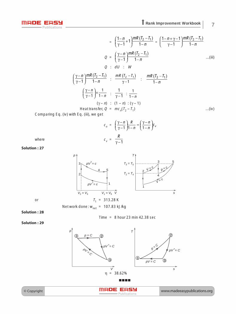
Solution : 27
1
2
3
4 5
pV = cγ
pV = cγ
p
VV = 2 V3 V = 1 V5
1
2
3
4
5
V = c
T
s
V = c p = cT T3 5 =
T T2 4 =
or T1 = 313.28 K
Net work done: wnet = 107.83 kJ/kgSolution : 28
Time = 8 hour 23 min 42.38 secSolution : 29
p
V
3
2p C =
pV Cn = pV
C =
T
s
pC =
pV Cn =
pV C =
1 2
31
η = 38.62%

© Copyrightwww.madeeasypublications.org
©C
opyrig
ht: Sub
ject matter to M
AD
E E
AS
Y P
ublications, N
ew D
elhi. No p
art of this book m
ay be rep
roduced
or utilised in any form
without the w
ritten perm
ission.
First law of Thermodynamics(Flow Processes)3
1. (a)
2. (b)
3. (b)
4. (c)
5. (a)
6. (c)
7. (c)
8. (b)
9. (d)
10. (c)
11. (b)
12. (b)
13. (a)
14. (70)(no range)
15. 523.02(523 to 524)
16. (b)
17. (c)
18. (d)
19. (2717)
20. (c)
21. (a)
22. (b)

© Copyright www.madeeasypublications.org
9Rank Improvement Workbook
Solution : 23
Assumption:
(i) Neglecting ΔK.E. and ΔP.E.(ii) Assume flow is steady.
(iii) There is no work transfer in after cooler.
Q1 = – 0.163 kW
Q2 = – 3.76 kW
Solution : 24
ΔPmax ===== 307.49 kPa
Solution : 25 (212)T2 = 255°Cm = 0.442 kg/sd2 = 212 mm
Solution : 26Q = –248.211 kJVP = 0.145 m3

© Copyrightwww.madeeasypublications.org
©C
opyrig
ht: Sub
ject matter to M
AD
E E
AS
Y P
ublications, N
ew D
elhi. No p
art of this book m
ay be rep
roduced
or utilised in any form
without the w
ritten perm
ission.
Second law ofThermodynamics4
1. (d)
2. (4)(no range)
3. (d)
4. (c)
5. (b)
6. (d)
7. (a)
8. (4)
9. (b)
10. (b)
11. (d)
12. (d)
13. (17.32)(17 to 18)
14. (c)
15. (b)
16. (b)
17. (b)
18. (d)
19. (50)
20. (c)

© Copyright www.madeeasypublications.org
11Rank Improvement Workbook
Solution : 21
Source A 700 K
Heat engine A
Source ‘ ’ K
BT
Sink 280 K
Heat engine B
Q1 = 300 kJ
Q2
Q3
Q4
WB
WA
T - Temperature of intermediate between A and B.
T = 420 K
Efficiency of each engine, ηA = 40%
ηB = 33.33%
Heat rejected by engine A and received by engine B
Q3 = 180 kJ
Heat rejected to the sink = 120 kJ
Solution : 22Total heat transferred to 30°C thermal reservoir = Q2 = 7764.56 kJ
Solution : 23Work done = 8.12 kW
Solution : 24η = 33.33%
Heat rejected to sink at T2 = (400 K) = 240Jand heat rejected to sink at T3 = 300 K = 360 kJ

© Copyrightwww.madeeasypublications.org
12 Mechanical Engineering • Thermodynamics
Solution : 25
T1
Q1
E1 W1
T2
T3
Q2
Q2
Q3
T3
W2E2
Fig : Carrnot Enginein series
T1
Q1
E3 W3
T3.
Q3.
Fig : Carnot Engine
η1 = 1 2 2
1 11
T T TT T−
= −
or 1 – η1 = 2
1
TT
Similarly, 1 – η2 = 3
2
TT
∴ (1– η1)(1– η2) =3
1
TT . . . (i)
For the Carnot engine operating directly between the temperature limits T1 and T3
η3 = 1 3 3
1 11
T T TT T−
= −
or 1 – η3 = 3
1
TT
. . . (ii)
Equating equation (i) and (ii), we get1 – η3 = (1 – η1)(1 – η2)
= 1 – η1 – η2 + η1η2
or η3 = η1 + η2 – η1η2

© Copyright www.madeeasypublications.org
13Rank Improvement Workbook
Solution : 26
T1
Q1
E1 W1
T2
Q2
Q2
Q3
T3
E2 W2
Q3
Q4
T4
E3 W3
T2 = 1100 KT3 = 500 KT4 = 250 K

© Copyrightwww.madeeasypublications.org
©C
opyrig
ht: Sub
ject matter to M
AD
E E
AS
Y P
ublications, N
ew D
elhi. No p
art of this book m
ay be rep
roduced
or utilised in any form
without the w
ritten perm
ission.
Entropy, Availability and Irreversibility5
1. (a)
2. (a)
3. (a)
4. (400)(no range)
5. (c)
6. (600)
7. (b)
8. (b)
9. (a)
10. (b)
11. (b)
12. (c)
13. (d)
14. (c)
15. (b)
16. (a)
17. (b)
18. (c)
19. (c)

© Copyright www.madeeasypublications.org
15Rank Improvement Workbook
Solution : 20
Final pressure:p = 2 bar
Now, partial pressure of O2, pA = 0.5714 bar
Partial pressure of N2, pB = 1.1428 bar
Partial pressure of CO2, pc = 0.2857 barChange in entropy of O2, (ΔS)A = 0.0875 kJ/KChange in entropy of N2, (ΔS)B = 0.07826 kJ/KChange in entropy of CO2, (ΔS)C = 0.0680 kJ/K
Solution : 21
Th2
Th1
Hot gases
Water
Tc1 Tc2
Control volume
p0 = 100 kPa, T0 = 25°C = 298K
Th2
Th1
SuperheatedSteamWet steam
WaterTc1
Tc2
T
s
1
2
Hot gases
Change in availability of water on unit mass of water basis,
ψ2 – ψ1 = 769.07 kJ/kg
Heat exchanged between combustion products (hot gases) and water in boiler,
Process irreversibility per unit mass of water flow,
I = 906.06 kJ
Second law efficiency, ηII = 45.90%
Entropy generated per kg of water,
(ΔS)uni = 3.04 kJ/K per kg of water

© Copyrightwww.madeeasypublications.org
16 Mechanical Engineering • Thermodynamics
Solution : 22Availability: a = 271.75 kJ/kg
Solution : 23Availability of a system is the maximum useful work potential of a system at the given state. Availabilityis equal to the maximum work obtainable from the system when it moves from the current state to a stateof complete equilibrium with the surroundings (also known as dead state) - temperature, pressure andchemical equilibrium.Consider a Carnot cycle as shown in figure which extracts heat Q from source at temperature T andrejects it to sink at temperature T0.
Source, T
Heat Engine
Sink, T0
Q
W
S
T
T0
T
Sx Sy
Q
Work ‘W ’ is produced by the Carnot engine during the process. This is the maximum work which can beobtained by any cycle (reversible work) and hence, as per the definition of availability.
Availability = A = Wmax = WCarnot
Efficiency of Carnot engine = 01TT
−
∴ Work obtained, W = ηC × Q
⇒ W = 01T
QT
⎛ ⎞−⎜ ⎟⎝ ⎠
∴ Availability = 01T
W QT
⎛ ⎞= −⎜ ⎟⎝ ⎠
Solution : 24
Decrease in availability of exhaust gas = 65.75 kJ/kgTotal entropy production per kg gas = 0.0738 kJ/kgK
T2a = 503.41 KSolution : 25
Net change in entropy of gas = mΔSnet = 0 kJ/K
Solution : 26Availability of the system at the given state = 560.04 kJ
Availability of air in this process = 555.1 kJEffectiveness ηII = 30.68%
Solution : 27m0 = 137.14 kg
Entropy generated = 3.18 kJ/K

© Copyright www.madeeasypublications.org
©C
opyrig
ht: Sub
ject matter to M
AD
E E
AS
Y P
ublications, N
ew D
elhi. No p
art of this book m
ay be rep
roduced
or utilised in any form
without the w
ritten perm
ission.
Properties of Pure Substance6
1. (a)
2. (c)
3. (c)
4. (c)
5. (b)
6. (b)
7. (b)
8. (b)
9. (c)
10. (a)
11. (d)
12. (b)
13. (d)
14. (b)
15. (a)
16. (a)
17. (c)
18. (b)
19. (3138.56)
20. (4158.97)
21. (a)

© Copyrightwww.madeeasypublications.org
18 Mechanical Engineering • Thermodynamics
Solution : 22
p
v
1 2
3
Total heat transfer = 0.7085 kJ
Solution : 23
1
2 3
pV = c1.2
p = c
p
v
1
2
3
p = c
T
s
T = T1 3
pV = c1.2
Work done for whole process, = 32.11 kJHeat transfer for whole process, = 32.114 kJ
Change in entropy of whole process, ΔS = 0.10511 kJ/K
Solution : 24cps = 1.978 kJ/kgK
Solution : 25Mass of vapour, mg = 2.6094 kg
Mass of water, mf = 40.274 kg
Solution : 26Mass of steam, m = 0.78392 kg
Total heat content of steam, H = 7625.63 kJ
Solution : 27Supply rate of cooling water, mw = 138815.39 kg/hr
Solution : 28Q = 129.82 kJ
Total time elapsed = 43.27 minutes

© Copyright www.madeeasypublications.org
©C
opyrig
ht: Sub
ject matter to M
AD
E E
AS
Y P
ublications, N
ew D
elhi. No p
art of this book m
ay be rep
roduced
or utilised in any form
without the w
ritten perm
ission.
Thermodynamic Relationsand Clapeyron Equation7
1. (a)
2. (b)
3. (c)
4. (c)
5. (b)
6. (a)
7. (c)
8. (b)
9. (c)
10. (c)
11. (b)
12. (c)
13. (d)
14. (c)
15. (d)
16. (2443.248)(2443.10 to 2443.45)
17. (1000)(999.5 to 1001)
18. (d)
19. (c)

© Copyrightwww.madeeasypublications.org
20 Mechanical Engineering • Thermodynamics
Solution : 20
For incompressible substance like liquids or solids, the specific volume (or density) is constant and thespecific internal energy assumed to vary only with temperature.
Since the specific internal energy of an incompressible substance depends only on temperature, thespecific heat cv is also a function of temperature alone.
cv(T ) =dudT
..(i)
Although the specific volume is constant and internal energy depends on temperature only, enthalpyvaries with both pressure and temperature according to
h (T, p) = u (T ) + pv ...(ii)
Differentiating equation (ii) with respect to temperature at constant pressure,
p
dhdT
⎛ ⎞⎜ ⎟⎝ ⎠
= 0dudT
⎛ ⎞ +⎜ ⎟⎝ ⎠
cp = cv
where cp =p
hT
∂⎛ ⎞⎜ ⎟⎝ ⎠∂
and cv = uT
∂∂
Thus, for an incompressible substance there is no difference between cp and cv, and both can be representby the same symbol, c.
Solution : 21
By definition of Joule-Thomson coefficient,
μJ =h
Tp
⎛ ⎞∂⎜ ⎟⎝ ⎠∂
...(i)
Consider s = f (T, p)
Then ds =p T
s sdT dp
T p⎛ ⎞∂ ∂⎛ ⎞ +⎜ ⎟ ⎜ ⎟⎝ ⎠ ⎝ ⎠∂ ∂
...(ii)
From Tds relations,
dh = Tds + vdp
Substituting the value of ds from Eq. (ii) in above equation.
dh =p T
s sT dT T dp vdp
T p⎛ ⎞∂ ∂⎛ ⎞ + +⎜ ⎟ ⎜ ⎟⎝ ⎠ ⎝ ⎠∂ ∂
=p T
s sT dT v T dp
T p
⎡ ⎤⎛ ⎞∂ ∂⎛ ⎞ + +⎢ ⎥⎜ ⎟ ⎜ ⎟⎝ ⎠ ⎝ ⎠∂ ∂⎢ ⎥⎣ ⎦

© Copyright www.madeeasypublications.org
21Rank Improvement Workbook
wherep
sT
T∂⎛ ⎞
⎜ ⎟⎝ ⎠∂= cp
T
sp
⎛ ⎞∂⎜ ⎟∂⎝ ⎠
=p
vT
∂⎛ ⎞− ⎜ ⎟⎝ ⎠∂from Maxwell’s relation
∴ dh = pp
vc dT v T dp
T
⎡ ⎤∂⎛ ⎞+ −⎢ ⎥⎜ ⎟⎝ ⎠∂⎢ ⎥⎣ ⎦
For throttling process, dh = 0
∴ 0 = pp
vc dT v T dp
T
⎡ ⎤∂⎛ ⎞+ −⎢ ⎥⎜ ⎟⎝ ⎠∂⎢ ⎥⎣ ⎦
– cpdT =p
vv T dpT
⎡ ⎤∂⎛ ⎞−⎢ ⎥⎜ ⎟∂⎝ ⎠⎢ ⎥⎣ ⎦
orh
Tp
⎛ ⎞∂⎜ ⎟⎝ ⎠∂
=1
p p
vv Tc T
⎡ ⎤∂⎛ ⎞− +⎢ ⎥⎜ ⎟∂⎝ ⎠⎢ ⎥⎣ ⎦...(iii)
andp
vT T∂ ⎛ ⎞
⎜ ⎟∂ ⎝ ⎠=
21 1
p
vvT TT
− ∂⎛ ⎞ ⎛ ⎞× +⎜ ⎟ ⎜ ⎟∂⎝ ⎠ ⎝ ⎠
p
vT T∂ ⎛ ⎞
⎜ ⎟∂ ⎝ ⎠=
2
1
p
vv T
TT
⎡ ⎤∂⎛ ⎞− + ⎜ ⎟⎢ ⎥∂⎝ ⎠⎣ ⎦
orp
vv TT
∂⎛ ⎞− + ⎜ ⎟∂⎝ ⎠= 2
p
vT
T T⎡ ⎤∂ ⎛ ⎞
⎜ ⎟⎢ ⎥∂ ⎝ ⎠⎣ ⎦...(iv)
From Eqs. (iii) and (iv), we get
h
Tp
⎛ ⎞∂⎜ ⎟⎝ ⎠∂
=2
p p
T vc T T
⎡ ⎤∂ ⎛ ⎞⎢ ⎥⎜ ⎟∂ ⎝ ⎠⎢ ⎥⎣ ⎦
or μJ =2
p ph
T T vp c T T
⎡ ⎤⎛ ⎞∂ ∂ ⎛ ⎞= ⎢ ⎥⎜ ⎟ ⎜ ⎟∂ ∂ ⎝ ⎠⎝ ⎠ ⎢ ⎥⎣ ⎦
Solution : 22For liquid water, cp – cv = 0.0248 kJ/kgK
Solution : 23CP – CV = R

© Copyrightwww.madeeasypublications.org
22 Mechanical Engineering • Thermodynamics
Solution : 24We know that third Maxwell relation,
v
pT
∂⎛ ⎞⎜ ⎟⎝ ⎠∂ =
T
sv
∂⎛ ⎞⎜ ⎟⎝ ⎠∂ . . .(i)
When a phase change occurs, the saturated pressure ps
depends on saturated temperature Ts only.That is, ps = f (Ts)
Sublimationcurve
Vaporisationcurve
Fusioncurve
Triplepoint
ps
p
TTs
Vapour
SolidLiquid
∂⎛ ⎞ =⎜ ⎟⎝ ⎠∂Constant
sat
pT
Phase diagram on - planes for waterp T
The partial derivative, v
pT
∂⎛ ⎞⎜ ⎟⎝ ⎠∂ can be written as a total
derivative sat
dpdT
⎛ ⎞⎜ ⎟⎝ ⎠ . The total derivative
sat
dpdT
⎛ ⎞⎜ ⎟⎝ ⎠ is the
slope on saturated curve in p-T diagram at a saturatedstate, as shown in figure, and it is independent of specific
volume. Thus, the slope sat
dpdT
⎛ ⎞⎜ ⎟⎝ ⎠
is considered as a
constant during the integration of Eq. (i) between twosaturated liquid state f and saturated vapour state g.Equation (i) is written as
sat
dpdv
dT⎛ ⎞⎜ ⎟⎝ ⎠ = ds
Integration between saturated liquid state f and saturated vapour state g, we get
g
f
v
vsat
dpdv
dT⎛ ⎞⎜ ⎟⎝ ⎠ ∫ =
g
f
s
sds∫
( )g fsat
dpv v
dT⎛ ⎞ −⎜ ⎟⎝ ⎠ = (sg – sf)
fgsat
dpv
dT⎛ ⎞⎜ ⎟⎝ ⎠ = sfg
sat
dpdT
⎛ ⎞⎜ ⎟⎝ ⎠
= fg
fg
sv
...(ii)We know that dh = Tds + vdpDuring the phase change, both temperature and pressure are constant.i.e., T = C and p = C∴ dh = TdsIntegration between two saturated states, we get
g
f
h
hdh∫ = g
f
s
sT ds∫
hg – hf = T (sg – sf)

© Copyright www.madeeasypublications.org
23Rank Improvement Workbook
hfg = Tsfg
where hfg = hg – hf, specific enthalpy of vaporizationsfg = sg – sf, change in specific entropy during a phase change process.
∴ sfg =fgh
T
Substituting the value of sfg = fgh
T in Eq. (ii), we get
sat
dpdT
⎛ ⎞⎜ ⎟⎝ ⎠
=fg
fg
hTv
...(iii)
Equation (iii) is called the Clapeyron equationClapeyron equationClapeyron equationClapeyron equationClapeyron equation. The Clapeyron equation is used to determine the changein enthalpy when phase change takes place during a process i.e., enthalpy of vaporization hfg. This equationis valid only for any phase change at constant T and p.
For liquid-vapour and solid-vapour phase change process, the Clapeyron equation can be simplified byusing some approximations.
At low pressure, vg � vf for liquid and solid∴ vfg = vg∴ vf is neglectedIf vapour is considered as an ideal gas,∴ pvg = RTfrom equation of state
or vg =RTp
∴ vfg =RTp
∵ vg = vfg
Substituting the values of vfg = RTp
in Eq. (iii), we get
sat
dpdT
⎛ ⎞⎜ ⎟⎝ ⎠ = 2
fgph
RT
dpp = 2
fghdT
RT
⎡ ⎤⎢ ⎥⎣ ⎦
. . . (iv)
Equation (iv) is called the Clapeyron-Clausius equationClapeyron-Clausius equationClapeyron-Clausius equationClapeyron-Clausius equationClapeyron-Clausius equation. This equation is used to calculate the variationof saturated pressure with temperature.
Solution : 25Consider variation of saturation pressure with saturation temperature.During a phase change process, saturation pressure which varies only with saturation temperature.

© Copyrightwww.madeeasypublications.org
24 Mechanical Engineering • Thermodynamics
ps
p
TTs
∂⎛ ⎞ =⎜ ⎟⎝ ⎠∂Constant
sat
pT
∴ Psat = sat( )T∫
⇒V
PT
∂⎛ ⎞⎜ ⎟⎝ ⎠∂
=sat
dSdV
⎛ ⎞⎜ ⎟⎝ ⎠
From Maxwell’s equation, we have:
V
PT
∂⎛ ⎞⎜ ⎟⎝ ⎠∂
=T
SV
∂⎛ ⎞⎜ ⎟⎝ ⎠∂
∴sat
dPdT
⎛ ⎞⎜ ⎟⎝ ⎠ =
g f
g f
S SV V
−− ... (i)
Also, TdS = dh – vdpDuring phase change process, dp = 0 (pressure remains constant at Psat),
∴ TdS = dh ⇒ Sg – Sf = fgh
T... (ii)
∴ From (i) and (ii), we get:sat
PT
∂⎛ ⎞⎜ ⎟⎝ ⎠∂ =
fg
fg
hTV
This equation is known as Clapeyron equation. Calculating hfg using Claperon equationError % = 0.78%
Solution : 26For an ideal gas, internal energy and enthalpy are functions of temperature alone.
∴ dh = CpdT and du = CvdTAlso, ideal gas equation holds, PV = RT
From 1st law of thermodynamics,
Q = dU + W = dU + PdV
also, Q = TdS = dU + PdV ... (i)
H = U + PV
⇒ dH = dU + PdV + VdP
∴ TdS = dH – VdP ... (ii)
From (i) TdS = CVdT + PdV ... (iii)
© Copyright www.madeeasypublications.org
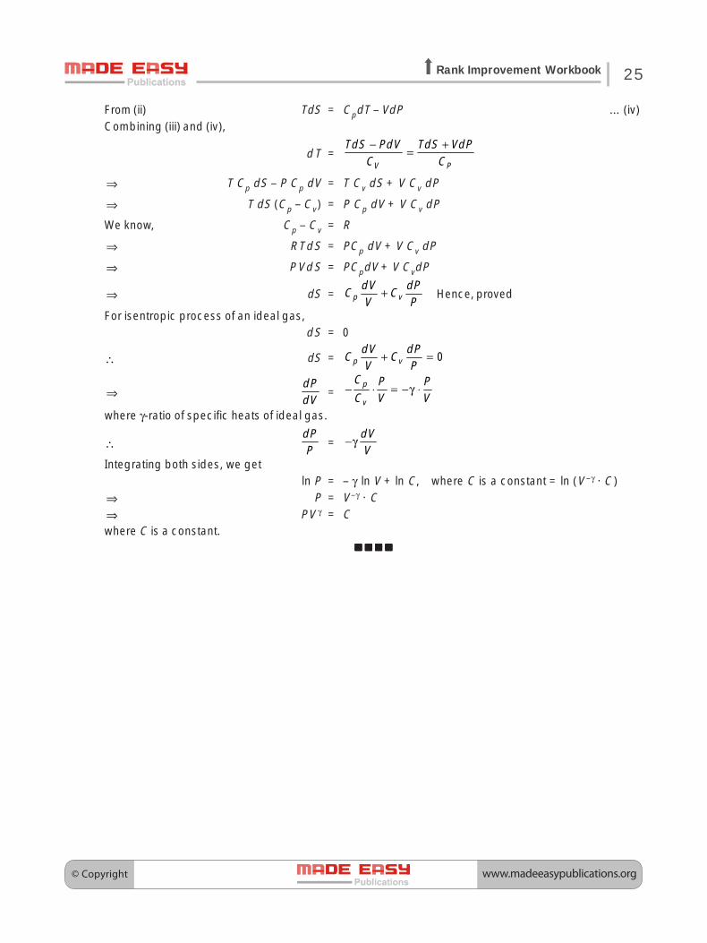
25Rank Improvement Workbook
From (ii) TdS = CpdT – VdP ... (iv)Combining (iii) and (iv),
dT =− +
=V P
TdS PdV TdS VdPC C
⇒ T Cp dS – P Cp dV = T Cv dS + V Cv dP
⇒ T dS (Cp – Cv) = P Cp dV + V Cv dP
We know, Cp – Cv = R
⇒ RTdS = PCp dV + V Cv dP
⇒ PVdS = PCpdV + V CvdP
⇒ dS = p vdV dP
C CV P
+ Hence, proved
For isentropic process of an ideal gas,dS = 0
∴ dS = 0p vdV dP
C CV P
+ =
⇒dPdV
=p
v
C P PC V V
− ⋅ = −γ ⋅
where γ-ratio of specific heats of ideal gas.
∴dPP
=dVV
−γ
Integrating both sides, we getln P = – γ ln V + ln C, where C is a constant = ln (V –γ · C)
⇒ P = V–γ · C⇒ PV γ = Cwhere C is a constant.