
Fault diagnostics in power electronics-based brake-by-wire systems
11
Fault diagnostics in power electronics-based brake-by- wire systems M A Masrur 1 *, H-J Wu 2 , C Mi 2 , Z-H Chen 2 , and Y L Murphey 2 1 US Army RDECOM-TARDEC, Warren Michigan, USA 2 Department of Electrical and Computer Engineering, University of Michigan-Dearborn, Dearborn, Michigan, USA The manuscript was received on 15 June 2007 and was accepted after revision for publication on 16 October 2007. DOI: 10.1243/09544070JAUTO385 Abstract: A d.c.-motor-based brake-by-wire system is studied for the purpose of fault diagnostics of the power electronic switches. The voltage and current generated in the switching circuit under normal and six faulted conditions are observed. A hierarchical fuzzy diagnostic system has been developed to detect certain types of fault condition in any specific solid state power switch at the moment immediately after the occurrence of the fault. The hierarchical fuzzy diagnostic system has been tested and validated using data from both a simulation and a laboratory set-up with a 1=3 hp d.c. motor and a d.c.-to-d.c. converter. The system performance has been compared with two different fuzzy diagnostic systems and the results are presented. The hierarchical fuzzy diagnostic system trained on the simulated model has the capability of detecting certain types of fault condition occurring in a brake-by-wire actuator system set-up in a laboratory in less than 0.0009 s and pinpointing the specific types of fault within less than 0.013 s. Keywords: fuzzy logic, multi-class fault detection, brake-by-wire, power electronics, d.c. motor, d.c.-to-d.c. converter 1 INTRODUCTION The automotive industry has given increased atten- tion towards the replacement of mechanical and hydraulic systems in vehicles using either fully or partially electrical systems. In addition to the main propulsion, work has progressed towards the repla- cement of various auxiliary devices, which are currently operated using mechanical, hydraulic, or pneumatic methods. These devices include steering, brakes, suspension, and various mechanical pumps. The mechanical systems are relatively heavy and difficult to package. On the other hand, electrical systems are easier to package since the wiring is flexible. Electrical systems use motors and solenoids as actuators and have a fast response. However, if the motor system fails, the entire electrical system related to the motor ceases to function properly. A motor system consists of a battery, wiring, power electronics, an embedded controller, and the motor itself. This paper presents the research on fault diagnos- tics in brake-by-wire actuator systems. Brake-by-wire systems and other X-by-wire systems with fully electromechanical devices or partial mechanical backup systems have been studied by various researchers [1–12]. Some of these studies discussed have the behaviour of the brake in the context of the whole vehicle and how the brake system behaviour influences the overall vehicle perfor- mance. Others have discussed electrohydraulic systems including slip control, precise computation of the brake force, and traction control. However, in the literature, research work on fault diagnostics in the motor and its controller in brake-by-wire systems has not been reported in depth. Fault diagnostics technology for internal combustion engine vehicles has been well investigated [13–15], but much less so in electrical system diagnostics. Moseler and Iser- mann [12] described a black-box-type model using a polynomial differential-algebraic equation with *Corresponding author: Mobility Technology, US Army RDECOM-TARDEC, AMSRD-TAR-R, MS-264, 6501 East 11 Mile Road, Warren, Michigan, 48397–5000, USA. email: md.abul. [email protected] 1 JAUTO385 F IMechE 2008 Proc. IMechE Vol. 222 Part D: J. Automobile Engineering
-
Upload
independent -
Category
Documents
-
view
1 -
download
0
Transcript of Fault diagnostics in power electronics-based brake-by-wire systems

Fault diagnostics in power electronics-based brake-by-wire systemsM A Masrur1*, H-J Wu2, C Mi2, Z-H Chen2, and Y L Murphey2
1 US Army RDECOM-TARDEC, Warren Michigan, USA2 Department of Electrical and Computer Engineering, University of Michigan-Dearborn, Dearborn, Michigan, USA
The manuscript was received on 15 June 2007 and was accepted after revision for publication on 16 October 2007.
DOI: 10.1243/09544070JAUTO385
Abstract: A d.c.-motor-based brake-by-wire system is studied for the purpose of faultdiagnostics of the power electronic switches. The voltage and current generated in theswitching circuit under normal and six faulted conditions are observed. A hierarchical fuzzydiagnostic system has been developed to detect certain types of fault condition in any specificsolid state power switch at the moment immediately after the occurrence of the fault. Thehierarchical fuzzy diagnostic system has been tested and validated using data from both asimulation and a laboratory set-up with a 1=3 hp d.c. motor and a d.c.-to-d.c. converter. The
system performance has been compared with two different fuzzy diagnostic systems and theresults are presented. The hierarchical fuzzy diagnostic system trained on the simulated modelhas the capability of detecting certain types of fault condition occurring in a brake-by-wireactuator system set-up in a laboratory in less than 0.0009 s and pinpointing the specific typesof fault within less than 0.013 s.
Keywords: fuzzy logic, multi-class fault detection, brake-by-wire, power electronics, d.c.motor, d.c.-to-d.c. converter
1 INTRODUCTION
The automotive industry has given increased atten-
tion towards the replacement of mechanical and
hydraulic systems in vehicles using either fully or
partially electrical systems. In addition to the main
propulsion, work has progressed towards the repla-
cement of various auxiliary devices, which are
currently operated using mechanical, hydraulic, or
pneumatic methods. These devices include steering,
brakes, suspension, and various mechanical pumps.
The mechanical systems are relatively heavy and
difficult to package. On the other hand, electrical
systems are easier to package since the wiring is
flexible. Electrical systems use motors and solenoids
as actuators and have a fast response. However, if
the motor system fails, the entire electrical system
related to the motor ceases to function properly. A
motor system consists of a battery, wiring, power
electronics, an embedded controller, and the motor
itself.
This paper presents the research on fault diagnos-
tics in brake-by-wire actuator systems. Brake-by-wire
systems and other X-by-wire systems with fully
electromechanical devices or partial mechanical
backup systems have been studied by various
researchers [1–12]. Some of these studies discussed
have the behaviour of the brake in the context of
the whole vehicle and how the brake system
behaviour influences the overall vehicle perfor-
mance. Others have discussed electrohydraulic
systems including slip control, precise computation
of the brake force, and traction control. However, in
the literature, research work on fault diagnostics in
the motor and its controller in brake-by-wire systems
has not been reported in depth. Fault diagnostics
technology for internal combustion engine vehicles
has been well investigated [13–15], but much less so
in electrical system diagnostics. Moseler and Iser-
mann [12] described a black-box-type model using
a polynomial differential-algebraic equation with
*Corresponding author: Mobility Technology, US Army
RDECOM-TARDEC, AMSRD-TAR-R, MS-264, 6501 East 11 Mile
Road, Warren, Michigan, 48397–5000, USA. email: md.abul.
1
JAUTO385 F IMechE 2008 Proc. IMechE Vol. 222 Part D: J. Automobile Engineering

application to a brushless d.c. machine. There these
workers estimated system parameters under normal
and faulted conditions and compared the same with
the current system parameter values; if any discre-
pancy with the normal condition was seen, a faulty
condition was declared. However, the parameter-
estimated model can easily lose the intuitive focus of
the system and in general cannot point towards the
specific problem and its location. In addition, the
model can encounter a topological change after a
fault, and hence the premises on which the model
was originally developed and the parameters esti-
mated may not hold any longer.
This paper is focused on the diagnostics of power
electronics switches since they are often considered
to be the weakest link in the brake-by-wire system,
i.e. in the whole link from the brake pedal to the
brake shoe actuator. The objective is to locate
accurately any faults within the power electronics
of a brake-by-wire system as soon as they occur. A
brake-by-wire actuator system model was developed
using Simplorer software that implements the full
control of the power electronics switches and
emulates six different fault conditions. A test bench
was designed for the actuator system. The simulated
model and the bench tests are compared under
normal and fault conditions. A hierarchical fuzzy
diagnostic system has been developed and trained to
detect all specified fault conditions in the actuator
system. The hierarchical fuzzy diagnostic system
is designed on the basis of the structure of the
brake-by-wire actuator system. It has the capabilities
of detecting fault conditions almost immediately
after they occur and pinpointing specific fault
conditions within less than 0.02 s on the bench set-
up. The performance of the hierarchical fuzzy
diagnostic system is also compared with two other
fuzzy diagnostic systems, and the results are pre-
sented in the paper.
2 A THEORETICAL MODEL OF THE BRAKE-BY-WIRE ACTUATOR SYSTEM
Figure 1 illustrates a quarter-model of the
system architecture of a fully electro-mechanical
brake-by-wire system. Although many types of
motor can be used for the brake-by-wire system, a
brushed d.c. motor is selected because it is inexpen-
sive and is available in the automotive industry
abundantly. The characteristics of a brushless motor,
for example, can be represented using equations
similar to a brushed d.c. motor, and the failure
mechanisms are very similar to each other. Further-
more, in the configuration described, the power
electronics system can be implemented using a four-
switch bridge, unlike the six-switch bridge for a
three-phase system. This factor also adds to the cost
benefit, which is one of the most important concerns
in the automotive industry. The brushed d.c. motor in
this study either can be permanent magnet-based or
can have a field winding. The system has four
actuator motors corresponding to each wheel. The
position signal from the brake pedal is fed to a
controller which generates a control signal to activate
one or more of the four brake motors. Each motor
may have a separate control wire from the controller
to allow the four actuators to run independently,
which is more robust during a failure of one or more
of the actuators. Each motor has its own power
electronics converter which receives control com-
mand from the main controller and controls each
motor separately. This helps to increase the robust-
ness during a failure of one or more of the actuators as
the remaining actuators will still function.
The simulation model for the brake-by-wire system
is illustrated in Fig. 1(a). The block diagram of the
simulated system is shown in Fig. 1(b). The input to
the system is the pedal position and pedal speed,
which are transformed to Tref, the reference torque.
Fig. 1 Brake-by-wire system: (a) architecture of a brake-by-wire system; (b) the system diagramfor a brake-by-wire system
2 M A Masrur, H-J Wu, C Mi, Z-H Chen, and Y L Murphey
Proc. IMechE Vol. 222 Part D: J. Automobile Engineering JAUTO385 F IMechE 2008

The electromechanical system can be described
through the equations
Va~RaIazLadIa
dtzK Wv ð1Þ
T~K WIa ð2Þ
T~Jdv
dtzBvzTL ð3Þ
where Va is the armature voltage, Ia is the armature
current, Ra is the armature resistance, La is the
armature leakage inductance, K is the motor con-
stant, W is the total flux per pole, v is the angular
speed of the motor, T is the output torque of the
motor, J is the inertia of the actuator system which
includes the motor rotor, and the loads connected to
the driving shaft, B is the damping, and TL is the load
torque (braking force).
The motor voltage can be derived from the brake
pedal position and pedal force. If the pedal force (or
corresponding torque) is Tref, then it can be shown
that the required motor voltage in Fig. 1(b) is given
by
V �a ~RaTref
K Wz
La
K W
dTref
dtzK Wv ð4Þ
The power electronics circuit to actuate the motor
is illustrated in Fig. 2. Based on equation (4), a
reference voltage is obtained from the d.c. battery
through pulse width modulation (PWM) techniques.
In Fig. 2, the motor voltage is
V �a ~ 2D{1ð ÞVB ð5Þ
where D is the switching duty ratio of switch A and
VB is the battery voltage.
3 SIMULATION STUDIES OF FAULTYCONDITIONS OF BRAKE-BY-WIRE SYSTEMS
The system model shown in Fig. 1(b) is implemen-
ted by using Simplorer-based simulation which can
simulate various fault conditions of the four-switch
scheme shown in Fig. 2. Figure 3 shows the simu-
lated current and voltage waveforms under normal
and different faulty conditions. The ratings and
parameters of the test motor are shown in Table 1.
It should be noted that the particular motor used
was a higher-voltage motor, rather than a motor that
would normally be encountered in an automotive
environment. This is due to the limitation of
available resources. Nevertheless, the principles are
well illustrated. In these simulations, the duty ratio
of switch A is set to 70 per cent.
It is worth noting that, at 70 per cent duty ratio,
the open-circuit fault caused by a broken switch in
B and/or A9 cannot be detected, which can be
explained by following the current paths through the
switches and the diodes. In order to detect the open-
circuit fault condition caused by B and A9, a duty
ratio of less than 50 per cent must be applied. In
other words, as soon as a duty ratio of less than 50
per cent is applied, the fault signal can be captured.
It is also worth pointing out that the fault
conditions have symmetrical characteristics due to
the symmetry of the power electronics circuit. For
example, in Fig. 2, switch A with an open-circuit
fault will result in the same behaviour as B9 with an
open-circuit fault; similarly, B with an open-circuit
fault will result in the same behaviour as A9 with an
open-circuit fault. In summary, at any given time,
one of the six fault classes can occur in the circuit
shown in Fig. 2. They are denoted hereafter as
follows: A or B9 open; A9 or B open; AA9 or BB9 open;
A or B9 short; A9 or B short; AA9 or BB9 short.
A bench set-up was implemented consisting of a
permanent magnet-brushed d.c. motor, a full bridge
converter, and a dSPACE controller as shown in Fig. 4.
The bench set-up system has the capabilities to
generate current and voltage signals under normal
operating conditions as well as various fault conditions.
The signals generated by the bench set-up and the
simulation model have similar behaviours. In the bench
set-up, the d.c. motor serves as the brake-by-wire
actuator, and the a.c. motor serves as the brake and is
programmed to emulate a car brake system.Fig. 2 The inverter circuit diagram for the
brake-by-wire system
Fault diagnostics in power electronics-based brake-by-wire systems 3
JAUTO385 F IMechE 2008 Proc. IMechE Vol. 222 Part D: J. Automobile Engineering

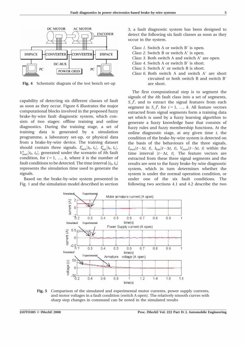
For the laboratory set-up experiments, the open-
circuit faults were emulated by simulating any one
or more of the switches open. The parameters
(Table 1) of the motor tested are the same as those
used in the simulation. The faults being tested
include the following: A or B9 open; B or A9 open;
both A and B9 open; both B and A9 open. Figure 5
gives an example of the signals generated by the
simulation program and the laboratory set-up test
when the circuit has a fault caused by switch A open
circuited. In the experiments, the sampling of data
has a limited rate. Therefore, only the average is
sampled whereas, in the simulation, the data can be
sampled at a very high rate to show the detailed
switching behaviour. For ease of comparison, the
simulation data have to be processed. For this
comparison, the simulated data were processed
using a 1000-point moving average. It can be seem
that the test data match the simulation very well.
4 A HIERARCHICAL FUZZY DIAGNOSTICSYSTEM FOR FAULT DETECTION IN A BRAKE-BY-WIRE SYSTEM
As was shown in the previous section, the fault
conditions are manifest in three output signals, i.e.
motor current, power supply current, and motor
voltages, denoted as Imot, Ibat, and Vmot respectively.
Fault diagnostics in the brake-by-wire system are
performed by an intelligent system that has the
Table 1 Parameters of the motor used in the simu-lation and experiment set-up
Rated voltage 125 VRated current 3.2 ARated power 1=3 hpRated speed 1800 r/minArmature resistance Ra 8.98 VArmature leakage inductance 5.35 mHMachine constant KW 0.45 V s/radInertia 0.661023 kg m2
Fig. 3 Simulated voltage and current waveforms under normal and fault conditions
4 M A Masrur, H-J Wu, C Mi, Z-H Chen, and Y L Murphey
Proc. IMechE Vol. 222 Part D: J. Automobile Engineering JAUTO385 F IMechE 2008
capability of detecting six different classes of fault
as soon as they occur. Figure 6 illustrates the major
computational blocks involved in the proposed fuzzy
brake-by-wire fault diagnostic system, which con-
sists of two stages: offline training and online
diagnostics. During the training stage, a set of
training data is generated by a simulation
programme, a laboratory set-up, or physical data
from a brake-by-wire device. The training dataset
should contain three signals, I imot t0, te½ �, I i
bat t0, te½ �,V i
mot t0, te½ �, generated under the scenario of ith fault
condition, for i 5 1, …, k, where k is the number of
fault conditions to be detected. The time interval [t0, te]
represents the simulation time used to generate the
signals.
Based on the brake-by-wire system presented in
Fig. 1 and the simulation model described in section
3, a fault diagnostic system has been designed to
detect the following six fault classes as soon as they
occur in the system.
Class 1. Switch A or switch B9 is open.
Class 2. Switch B or switch A9 is open.
Class 3. Both switch A and switch A9 are open.
Class 4. Switch A or switch B9 is short.
Class 5. Switch A9 or switch B is short.
Class 6. Both switch A and switch A9 are short
circuited or both switch B and switch B9
are short.
The first computational step is to segment the
signals of the ith fault class into a set of segments,
S_Ii, and to extract the signal features from each
segment in S_Ii, for i 5 1, …, k. All feature vectors
extracted from signal segments form a training data
set which is used by a fuzzy learning algorithm to
generate a fuzzy knowledge base that consists of
fuzzy rules and fuzzy membership functions. At the
online diagnostic stage, at any given time t, the
condition of the brake-by-wire system is detected on
the basis of the behaviours of the three signals,
Imot[t2Dt, t], Ibat[t2Dt, t], Vmot[t2Dt, t] within the
time interval [t2Dt, t]. The feature vectors are
extracted from these three signal segments and the
results are sent to the fuzzy brake-by-wire diagnostic
system, which in turn determines whether the
system is under the normal operation condition, or
under one of the six fault conditions. The
following two sections 4.1 and 4.2 describe the two
Fig. 4 Schematic diagram of the test bench set-up
Fig. 5 Comparison of the simulated and experimental motor currents, power supply currents,and motor voltages in a fault condition (switch A open). The relatively smooth curves withsharp step changes in command can be noted in the simulated results
Fault diagnostics in power electronics-based brake-by-wire systems 5
JAUTO385 F IMechE 2008 Proc. IMechE Vol. 222 Part D: J. Automobile Engineering

major computational components in the fuzzy
brake-by-wire fault diagnostic system, signal seg-
mentation and feature selection, and a hierarchical
fuzzy multi-class diagnostic system.
4.1 Signal segmentation and feature extraction
Under each fault condition i, the three signals
I imot 0, te½ �, I i
bat 0, te½ �, and V imot 0, te½ �, i 5 1, …, 6, are
first segmented into three sequences of segment
denoted as S I imot, S I i
bat, and S V imot, where
S Iimot~ S I i
mot j{1ð Þ Dt,j Dt½ ��� j~1, . . . ,n,and n Dt~te
� �ð6Þ
S Iibat~ S I i
bat j{1ð Þ Dt, j Dt½ ��� j~1, . . . ,n,and n Dt~te
� �ð7Þ
S V imot~ S V i
mot j{1ð Þ Dt, j Dt½ ��� j~1, . . . ,n,and n Dt~te
� �ð8Þ
S_Ii denote all the segments generated from
I imot 0, te½ �, I i
bat 0, te½ �, and V imot 0, te½ �, i.e.
S Ii~ S Iimot, S Ii
bat, S V imot
� �.
Since the three signals are acquired simulta-
neously, they are segmented into three sequences
that consist of the same number of fixed sized
segments. In every sequence, the two adjacent
segments are overlapped by one third of each
segment in order to maintain continuity of informa-
tion flow between segments. The details of the
segmentation scheme are omitted here for brevity.
Each segment is represented by three features:
minimum, maximum, and average values within
the segment. At time interval [( j 2 1) Dt, j Dt], a
feature vector is defined as
FVij~Smin ai
j,max aij,ave ai
j,min bij,max bi
j,ave bij,
min V ij ,max V i
j ,ave V ij T
where aij, bi
j, and V ij are the jth segments of I i
mot, I ibat,
and V imot respectively, generated by simulating the ith
fault class. The output from the feature extraction
block at the training stage is a set of feature vectors
FVi defined as follows: FVi~ FVij
���j~1, . . . , nn o
. The
training data used by the fuzzy learning program
contain all the feature vectors in FVi for all i 5 1, …., k.
At the online diagnostic stage, fault detection is
based on the three signals acquired within the time
interval [t2Dt, t]. From the three signal segments
Imot[t2Dt, t], Ibat[t2Dt, t], and Vmot[t2Dt, t], a feature
vector FV[t] is extracted, where
FV t½ �~ min a tð Þ,max a tð Þ,ave a tð Þ,min b tð Þ,fmax b tð Þ,ave b tð Þ,min V tð Þ,max V tð Þ,
ave V tð Þg
The fuzzy brake-by-wire fault diagnostic system will
use the fuzzy knowledge bases generated at the
training stage to derive the diagnostic decision, with
the brake-by-wire system in the normal condition or
one of the six faulty conditions.
4.2 A hierarchical fuzzy diagnostic system forbrake-by-wire fault detection
Fuzzy logic has been popular in engineering fault
diagnostics [16–20]. However, there has not been
Fig. 6 Computational steps in a fuzzy brake-by-wire (B-B-W) fault diagnostic system: (a) offlinetraining stage; (b) online fault diagnostic stage
(6)
(7)
(8)
6 M A Masrur, H-J Wu, C Mi, Z-H Chen, and Y L Murphey
Proc. IMechE Vol. 222 Part D: J. Automobile Engineering JAUTO385 F IMechE 2008

much discussion in the literature on different fuzzy
system architectures for multi-class fault detection.
There are a number of approaches that can be used to
model a fuzzy multi-class classification problem. This
paper presented a hierarchical fuzzy diagnostic
system F designed on the basis of the brake-by-wire
system structure. Figure 7 illustrates the diagnostic
stage of F. F has six fault diagnostic systems Fi for
i 5 1, 2, …, 6. F1 is designed to detect normal
conditions from abnormal conditions. When F1
decides that the current condition of the brake-by-
wire system is normal, F immediately exits to process
the next signal segment. Since most of the time a
brake-by-wire system is in the normal condition, this
system architecture ensures fast detection. When F1
detects an abnormal condition, it activates F2, which
is designed to detect whether the brake-by-wire
system is in the short-circuit or open-circuit condi-
tion. If it is in the short-circuit condition, then F3 is
activated, which decides whether the brake-by-wire
system is single-switch or double-switch short
circuited. If it is single-switch short circuited, F5 is
called to find out whether A or B9 is short circuited, or
whether A9 or B is short circuited. If F2 decides that the
brake-by-wire system is in an open-circuit fault, F4
is called to find out whether the brake-by-wire system
is single-switch or double-switch open circuited. If it is
single-switch open circuited, F6 is called to find out
whether A or B9 is open circuited, or A9 or B is open
circuited.
Fuzzy reasoning is performed within the context of a
fuzzy system model, which consists of the control, the
solution variables, the fuzzy sets, the proposition (rule)
statements, and the underlying control mechanisms
that tie all these together into a cohesive reasoning
environment. All six fuzzy diagnostic systems in F
share the same input space, a nine-dimensional
feature space as described in the last section. There-
fore each fuzzy system has nine control variables
FV~ Iminmot , Imax
mot , Iavemot, Imin
bat , Imaxbat , Iave
bat , V minmot ,V max
mot , V avemot
� �and one solution variable y to indicate whether the
input vector FV is likely to be in class 0 or class 1. The
fuzzy learning algorithm presented in reference [20] is
used to generate a fuzzy knowledge base for each fuzzy
system based on the data generated by the simulation
model presented in the last section.
5 EXPERIMENTS AND SYSTEM EVALUATION
The simulation model described in the last section
was used to generate training and testing data. The
simulation system has the following simulation
parameters: d.c. motor with Vd.c. 5 100 V, Ra 5 8.98 V,
La 5 0.005 35 H, initial speed of (650/60)626p rad/s,
and a frictional torque of 0.1 N m. The inverter’s
parameters were set to a PWM frequency of 5 kHz.
Three signals, namely the battery current Ibat, the
motor current Imot, and the motor voltage Vmot, are
measured for all six fault classes presented above.
Each fault event was triggered at the end of the first
second, and the entire simulation takes 2 s.
The training data are collected and segmented as
follows. For every fault class, the fault part of the
Fig. 7 A hierarchical fuzzy diagnostic system for fault detection in a brake-by-wire system
Fault diagnostics in power electronics-based brake-by-wire systems 7
JAUTO385 F IMechE 2008 Proc. IMechE Vol. 222 Part D: J. Automobile Engineering

signals has a duration of 15 ms, i.e. 15 000 data
samples were generated at a 1 ms sampling rate. All
three signals Imot, Ibat, and Vmot for each fault class,
are segmented simultaneously into segments of 60
samples in each, with an overlap of 20 samples
between two adjacent segments. The fault portion of
the signals was segmented into 378 segments.
A feature vector is extracted from three signal
segments Imot, Ibat, and Vmot that occur at the same
time interval as described in the last section. All
those feature vectors are divided into seven datasets,
C0, C1, …, C6, where C0 contains the feature vectors
extracted from the normal signal segments, and C1,
…, C6 contain the feature vectors representing the
respective fault classes. Each Ci is divided randomly
into a training and a test set in a ratio of 2:1.
For the purpose of evaluating the structured
hierarchical fuzzy diagnostic system, two additional
fuzzy diagnostic systems were developed to model
with a fault-against-normal scheme. Figures 8(a)
and (b) illustrate the architectures of these two
systems. The single seven-class fuzzy classification
system has the same nine control variables as the
structured fuzzy diagnostic system, and it has one
output variable that has seven terms representing
the normal class and the six fault classes.
The fuzzy diagnostic system shown in Fig. 8(b) is a
set of six independently trained fuzzy diagnostic
systems, each of which was trained by one fault class
against the normal class. The decision module,
winner takes all (WTA), selects the output class that
has the highest fuzzy belief value.
Tables 2 to 5 show the performances of these three
fuzzy diagnostic systems on the test dataset. Table 2
shows that the single fuzzy system (see Fig. 8(a)) for
the seven-class fault diagnostic system completely
missed the fault class A9 or B open. Table 3 lists the
detailed performances of the six individual fuzzy
diagnostic systems used in the fault versus normal
scheme (see Fig. 8(b)), and Table 4 lists the entire
system performance after a WTA scheme (see
Fig. 8(b)) is applied to the outputs from the six fuzzy
diagnostic systems. The fault class A or B9 open has a
rather low detection rate. The performances of all
the six fuzzy diagnostic systems in the hierarchical
fuzzy diagnostic system illustrated in Fig. 7 are listed
in Table 5. All six individual fuzzy diagnostic systems
Fig. 8 Two fuzzy diagnostic systems: (a) a single seven-class fuzzy fault classification system;(b) a fuzzy diagnostic system modelled using a fault-against-normal scheme
Table 2 Diagnostic performances of the single fuzzyclassification system illustrated in Fig. 8(a)
Case Correct rate
Normal 100A or B9 open 96.78A9 or B open 0AA9 or BB9 open 100A or B9 short 100A9 or B short 100AA9 or BB9 short 100Total 84.27
8 M A Masrur, H-J Wu, C Mi, Z-H Chen, and Y L Murphey
Proc. IMechE Vol. 222 Part D: J. Automobile Engineering JAUTO385 F IMechE 2008

performed well. Table 6 lists the performance of the
hierarchical fuzzy diagnostic system (see Fig. 7) on
all classes. It gave 100 per cent detection on the
normal class and three fault classes, and more than
99 per cent on the other three fault classes.
In order to evaluate the robustness of the
proposed diagnostic method, a set of experiments
was conducted using the data acquired through the
laboratory test set-up described in the last section.
Because of the sampling rate limitation of the data
acquisition system, the data were sampled at about
every 10 ms and only three fault classes were
generated: class 1, A or B9 open; class 2, A9 or B
open; class 3, AA9 or BB9 open. The three fuzzy
systems are as follows: F1 is trained to detect normal
versus abnormal; F2 is trained to identify whether
the current fault is {A or B9 open, A9 or B open} or AA9
or BB9 open; F3 is trained to identify whether the
current fault is {A or B9} open, or {A9 or B} open. All
three systems are trained on simulation data and
tested on the laboratory-generated data.
Since the motor voltage signal from laboratory
data is asynchronous and has a sampling rate that is
different from the motor current and the battery
current, the three signals cannot be mixed in system
training. Therefore only the battery current Ibat and
the motor current Imot are used in the system test on
the laboratory data.
When the hierarchy fuzzy diagnostic system,
which is trained on the simulation data described
earlier, is tested on the laboratory-generated data, it
detected 100 per cent correctly for normal condi-
tions and 100 per cent correctly for fault conditions
as soon as they occurred. However, the identification
of the type of fault condition took a few segments
after the fault condition occured. Class 1, A or B9
open, was identified correctly at the fifth segment
after the fault condition occurred; class 2, A9 or B
open, was identified immediately as a class 2 fault as
soon as it occurred; class 3, AA9 or BB9 open, was
identified correctly at the fourteenth segment after
the fault condition occurred. The hierarchical fuzzy
diagnostic system takes about 0.0009 s to make a
diagnostic decision for a given signal segment on a
personal computer (PC) with the Windows XP
system and a PM 1.73 processor. Any abnormal
conditions are detected within 0.0009 s after they
occur. For the fault class identity, class 2 is
immediately identified, which takes 0.0009 s; class
1 is identified in 0.0045 s, and class 2 is identified in
Table 3 The performances of six fuzzy diagnostics modelled using the fault versus normal scheme in the systemillustrated in Fig. 8(b)
Faulttype
Normal class correct rate(%)
Fault class correct rate(%)
Overall correct rate(%)
F1: normal versus A or B9 open 100 100 100F2: normal versus A9 or B open 100 100 100F3: normal versus AA9 or BB9 open 100 98.51 99.21F4: normal versus A or B9 short 100 95.07 97.22F5: normal versus A9 or B short 100 100 100F6: normal versus AA9 or BB9 short 100 100 100
Table 5 The performances of the six fuzzy diagnostics used in the hierarchical fault diagnostic system illustrated inFig. 7
Faulttype
Class 0 correct rate(%)
Class 1 correct rate(%)
Overall correct rate(%)
F1: class 0: normal versus class 1 abnormal 100 100 100F2: class 0: open versus class 1: short 100 100 100F3: class 0: single-switch short versus class 1:
double-switch short100 98.51 99.21
F4: class 0: single-switch open versus class 1:double-switch open
99.25 99.25 99.25
F5: class 0: A or B9 short versus class 1: A9 or B short 100 100 100F6: class 0: A or B9 short versus class 1: A9 or B short 100 99.30 100
Table 4 The system performance of the fuzzy faultversus normal combined with a WTA deci-sion (see Fig. 8(b))
CaseCorrect rate(%)
Normal 100A or B9 open 85.48A9 or B open 100AA9 or BB9 open 95.52A or B9 short 95.07A9 or B short 100AA9 or BB9 short 100Total 96.44
Fault diagnostics in power electronics-based brake-by-wire systems 9
JAUTO385 F IMechE 2008 Proc. IMechE Vol. 222 Part D: J. Automobile Engineering

0.0126 s. The detection time was measured accord-
ing to the time needed to detect the faults after they
occured by the proposed hierarchical fuzzy diag-
nostic system running on a PC with the Windows XP
system and PM 1.73 processor.
These results show that the proposed hierarchical
fuzzy diagnostic system trained on the basis of a
simulated brake-by-wire model has the capability of
correctly identifying all fault conditions in real time
over a wide operating domain.
6 DISCUSSION AND CONCLUSIONS
This paper presented an analytical model of the
brake-by-wire system using an electromechanical
actuator and implemented a simulation of the same
using the Simplorer software by Ansoft. A bench set-up
was also developed for the brake-by-wire system. A
d.c. motor was used as an actuator, since it is more
abundantly available with the present automotive
supplier base. A very simple system was used, since
cost-effectiveness is of prime concern in the
automotive industry. However, the methodology
illustrated is easily extendable to other kinds of
motor and the principles discussed here still remain
valid. Both the simulated and the bench test
systems have the capabilities of generating current
and voltage signals under normal operating condi-
tions and fault conditions. An innovative hierarch-
ical fuzzy diagnostic system has been developed on
the basis of the structure of a brake-by-wire system
to perform fault diagnostics. The hierarchical fuzzy
diagnostic system gives 99.68 per cent classification
accuracy on all signal segments generated by the
simulation model. While tested on the data gener-
ated by the brake-by-wire system in a bench set-up,
the hierarchical fuzzy diagnostic system has the
capability of detecting any of the specified fault
conditions in less than 0.0009 s and pinpointing to
the specific types of fault within less than 0.013 s.
This indicates that the proposed hierarchical
fuzzy diagnostic system has the promise of being
implemented easily in a real-time environment in
the automobile and operating robustly in a wide
range of conditions. Although a brake-by-wire
system was used with application in the automotive
environment in mind, the methodology is equally
applicable to other systems where such motors are
used, including manufacturing and other non-
mobile platforms. These will be studied and
reported by the present authors in future work.
ACKNOWLEDGEMENTS
This work was supported in part by funding from theUS Army RDECOM-TARDEC ILIR (In-house Lab-oratory Independent Research) programme. Theauthors would also like to thank Ansoft Corporationfor supplying the licence for Simplorer software usedin this project.
REFERENCES
1 Jonner, W., Winner, H., Dreilich, L., and Schunck, E.Electrohydraulic brake system – the first approachto brake-by-wire technology. SAE paper 960991,1996.
2 Schwarz, R., Isermann, R., Bohm, J., Nell, J., andRietch, P. Modeling and control of an electro-mechanical disk brake. SAE paper 980600, 1998.
3 Schwarz, R., Isermann, R., Bohm, J., Nell, J., andRietch, P. Clamping force estimation for a brake-by-wire actuator. SAE paper 1999-01-0482, 1999.
4 Park, K. and Heo, S. A study on the brake-by-wiresystem using hardware-in-the-loop simulation. Int.J. Veh. Des., 2004, 36(1), 38–49.
5 Underwood, S., Khalil, A., Husain, I., Klode, H.,Lequesne, B., Gopalakrishnan, S., and Omekanda, A.Switched reluctance motor based electromecha-nical brake-by-wire system. Int. J. Veh. Autono-mous Systems, 2004, 2(3–4), 278–296.
6 Ueki, N., Kubo, J., Takayama, T., Kanari, I., andUchiyama, M. Vehicle dynamics electric controlsystem for safe driving, 2004. Available from http://www.hitachi.com/ICSFiles/afieldfile/2004/11/26/r2004_04_104_3.pdf.
7 Continental Teves, Electro mechanical and electrohydraulic brake from continental Teves. Continen-tal Teves Inc., 2007, available from http://conti-online.com/generator/www/us/en/continentalteves/general/home/index_en.html.
8 ECE staff, Brush dc motor. ECN Mag., 15 May 2005.9 Takayama, T. and Suda, E. The present and future
of electric power steering. Int. J. Veh. Des., 1994,15(3–5), 243–254.
10 Lefebvre, M. Brush dc motors turning moreadvanced. ECN Mag., 1 March 2002.
Table 6 Overall performance of the hierarchical fuzzyfault diagnostic system illustrated in Fig. 7
CaseCorrect rate(%)
Normal 100A or B9 open 99.19A9 or B open 99.30AA9 or BB9 open 99.25A or B9 short 100A9 or B short 100AA9 or BB9 short 100Total 99.68
10 M A Masrur, H-J Wu, C Mi, Z-H Chen, and Y L Murphey
Proc. IMechE Vol. 222 Part D: J. Automobile Engineering JAUTO385 F IMechE 2008

11 R. Isermann, R., Schwarz, R., and Stolzl, S. Faulttolerant drive-by-wire systems. IEEE Control Sys-tems Mag., October 2002, 64–81.
12 Moseler, O. and Isermann, R. Application of model-based fault detection to a brushless DC motor. IEEETrans. Ind. Electron., 2000, 47(5), 1015–1020.
13 Nyberg, M. Model-based diagnosis of an automotiveengine using several types of fault models. IEEETrans. Control Systems Technol., 2002, 10(5), 679–689.
14 Guo, H., Crossman, J., Murphey, Y., andColeman, M. Automotive signal diagnostics usingwavelets and machine learning. IEEE Trans. Vehi-cular Technol., 2000, 49(5), 1650–1662.
15 Crossman, J., Guo, H., Murphey, Y., and Cardillo, J.Automotive signal fault diagnostics: Part I: signalfault analysis, feature extraction, and quasi optimalsignal selection. IEEE Trans. Vehicular Technol.,2003, 52(4), 1063–1075.
16 Das, B. and Reddy, J. Fuzzy-logic-based faultclassification scheme for digital distance protection.
IEEE Trans. Power Delivery, 2005, 20(2), 609–616.
17 Fuessel, D. and Isermann, R. Hierarchical motordiagnosis utilizing structural knowledge and a self-learning neuro-fuzzy scheme. IEEE Trans. Ind.Electron., 2000, 47(5), pp. 1070–1077.
18 Vasilic, S. and Kezunovic, M. Fuzzy ART neuralnetwork algorithm for classifying the power systemfaults. IEEE Trans. Power Delivery, 2004, 99, 1–9.
19 Chen, Z., Zhang, B., Murphey, Y., Jia, H., andMasrur, M. Robust fault diagnosis in electric drivesusing machine learning. In Proceedings of theInternational Symposium on Vehicular power andpropulsion, Paris, France, October 2004, paper no.FP–4–3 (CD-ROM) (IEEE Vehicular TechnologySociety, New York).
20 Murphey, Y., Chen, T., and Hamilton, B. A fuzzysystem for automotive fault diagnosis: fast rulegeneration and self-tuning. IEEE Trans. VehicularTechnol., 2000, 49(1), 651–660.
Fault diagnostics in power electronics-based brake-by-wire systems 11
JAUTO385 F IMechE 2008 Proc. IMechE Vol. 222 Part D: J. Automobile Engineering