Trailer Air Brake System Components
53
Heavy Equipment Technician Trailer Air Brake System Components First Period Module # 190108d
-
Upload
khangminh22 -
Category
Documents
-
view
0 -
download
0
Transcript of Trailer Air Brake System Components

Heavy Equipment Technician
Trailer Air Brake System
Components
First Period
Module # 190108d

Objective One:
Explain the functions and principles of operation of pre CMVSS 121 single trailer brake circuit components.

Figure 1 – Pre-CMVSS 121 trailer air brake circuit. (Courtesy Allied Signal)

Figure 2 – Service and supply lines.

Figure 3 – Relay emergency valve components. (Courtesy Allied Signal)

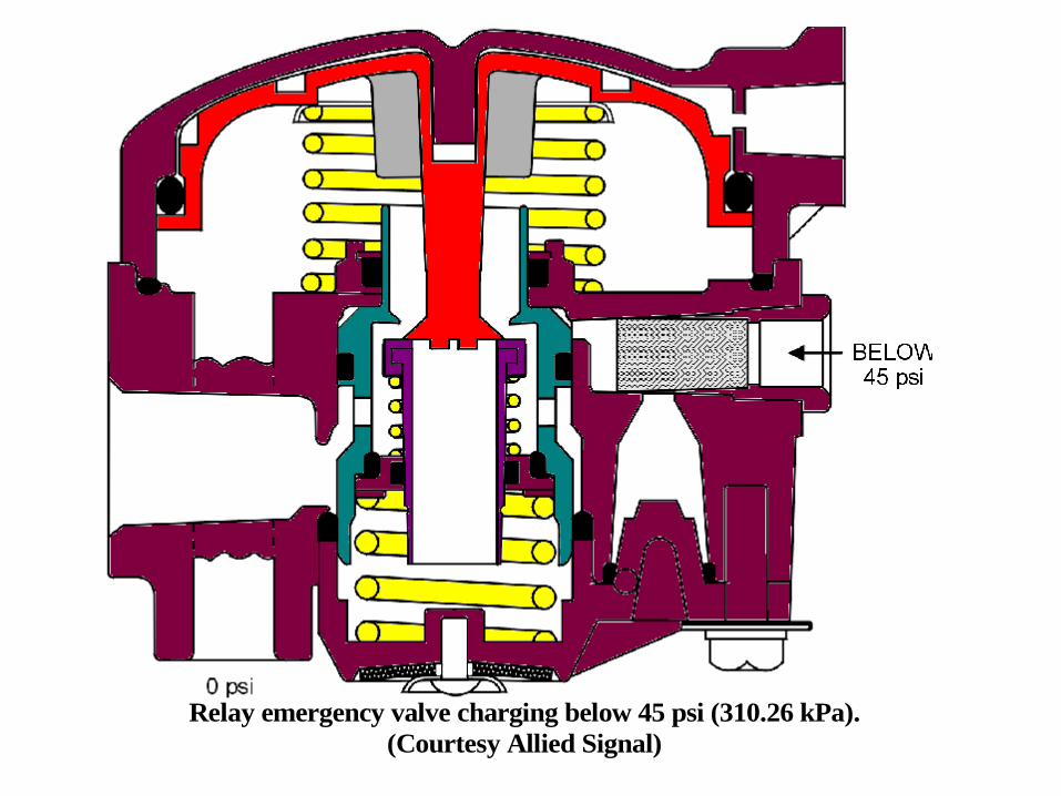
Figure 4 – Relay emergency valve charging below 45 psi (310.26 kPa).
(Courtesy Allied Signal)

Figure 5 – Relay emergency valve charging above 60 psi (413.69 kPa).
(Courtesy Allied Signal)

Figure 6 – Relay emergency valve, brakes applying. (Courtesy Allied Signal)

Figure 7 – Relay emergency valve, service application, balanced position.
(Courtesy Allied Signal)

Figure 8 – Relay emergency valve, brakes releasing. (Courtesy Allied Signal)

Figure 9 – Relay emergency valve parking/emergency application.
(Courtesy Allied Signal)

Relay Emergency Valve
Used on single air system trailers (pre-121).
The trailer reservoir is filled with air that passes through this valve via a one way check valve protects reservoir pressure.
Is a service brake relay valve.
Gives the trailer air applied parking/emergency brakes that will only stay applied as long as the trailer reservoir has air pressure.
Exhaust valve is normally closed and inlet valve normally open.

Figure 10 – Brake chamber and foundation brake. (Courtesy Allied Signal)

Objective Two:
Explain the functions and principles of operation of CMVSS 121 single trailer brake circuit components.

Figure 11 – Typical CMVSS 121 trailer air brake circuit. (Courtesy Allied Signal)

Figure 12 – CMVSS 121 Trailer air brake circuit, trailer spring brake control
valve (Bendix SR-5), trailer parked. (Courtesy Allied Signal)

Figure 13 – Trailer spring brake control valve (Bendix SR-5),
charging below 70psi (482.63 kpa). (Courtesy Allied Signal)

Figure 14 - Trailer spring brake control valve (Bendix SR-5),
charging above 85psi (586.05 kPa). (Courtesy Allied Signal)

Figure 15 – Trailer spring brake control valve (Bendix SR-5),
failure of the service reservoir. (Courtesy Allied Signal)

Trailer Spring Brake Valve
(SR-5)
Controls the spring brakes on the trailer.
Trailer reservoir is filled with air that passes through this valve via pressure protection and one way check valves protects reservoir pressure.
Has a anti-compounding feature built in that will tell operator if he has the air lines hooked up backwards.

Trailer Spring Brake Valve
(SR-5)
Gives priority to releasing spring brakes prevents automatic application of spring brakes if trailer reservoir pressure is lost.
Trailer only needs one reservoir if this valve is used.

CMVSS 121 trailer air brake circuit trailer spring brake control valve
(Bendix SR-4). (Courtesy Allied Signal)

Trailer spring brake control valve (Bendix SR-4), normal driving.
(Courtesy Allied Signal)

Trailer spring brake control valve (Bendix SR-4),
failure of #1 reservoir. (Courtesy Allied Signal)

Trailer spring brake control valve (Bendix SR-4),
failure of #2 reservoir. (Courtesy Allied Signal)

Older Styles of Trailer Spring
Brake Valves
Work similar to the SR-5 but they released the spring brakes slower as they gave priority to filling the trailer reservoirs with air before releasing the spring brakes.
Also the trailers they were used on required two reservoirs.

Objective Three:
Explain the functions and principles of operation of common components used on multiple trailer combinations.


Towing trailer air brake circuit components. (Courtesy Allied Signal)

Shutoff valve. (Courtesy Allied Signal)

Ball Valve
Are manually operated valves that are used block air flow through either the supply or the service lines that service a pup trailer.
Are closed when the lead trailer is not hooked to the pup.

Quick release valve. (Courtesy Allied Signal)

Quick Release Valve
Used in the supply line that feeds a pup trailer to allow for faster application of the park brakes.

Towing trailer air brake circuit components. (Courtesy Allied Signal)

Pintle Hitch Clamping
Chambers
Used on the rear of the lead trailer (A or C train).
Used in the no-slack pintle hitches that pull the pup trailer.

Service pressure loss due to relay valve cracking pressure.

Pilot relay valve, normal running. (Courtesy Allied Signal)

Pilot relay valve, brakes applying. (Courtesy Allied Signal)

Pilot relay valve, balanced position. (Courtesy Allied Signal)

Pilot relay valve, released position. (Courtesy Allied Signal)

Pilot Relay Valve
Used in the service lines of multiple trailer configurations.
Used to ensure that an undiminished service signal is used to activate the trailer service relays trailer service brakes apply with same force as tractor service brakes.
Also speeds up how fast the service signal gets to the rear trailer(s).

Pilot Relay Valve
Inlet and exhaust valves are both normally closed (hold position)

Single Check Valve
The single check is used in the supply line of the pilot relay, to prevent loss of a service signal to the pup trailer, if reservoir pressure is lost from the lead trailer, when a brake application is being made.

Typical converter dolly air brake circuit components.
(Courtesy Allied Signal)

Pressure protection valve. (Courtesy Allied Signal)

Pressure Protection Valve
Used on dolly converters that use a non-charging emergency relay valve.
Converter dolly reservoir is filled with air pressure that passes through this valve.
Protects reservoir pressure.
No air pressure enters reservoir until valve setting pressure is exceeded (~70 psi) (483 kPa).

Relay emergency valve, non-charging. (Courtesy Allied Signal)
Relay emergency valve charging below 45 psi (310.26 kPa).
(Courtesy Allied Signal)

Relay emergency valve charging above 70 psi (413.69 kPa).
(Courtesy Allied Signal)
Above
70psi

Non-charging Emergency
Relay
Acts as a service relay for a dolly converter.
Gives the dolly converter air applied parking/emergency brakes.

Trailer release valve. (Courtesy Allied Signal)

Trailer Release (Syncro) Valve
Is used to delay the passage of supply air flowing to the pup trailer until the lead trailer supply air pressure exceeds the valve setting (between 60 and 86 psi) ( 414 to 593 kPa).
This is done to prevent the operator from having to hold the trailer supply valve button in while the trailers charge with supply air.

Typical converter dolly air brake circuit components.
(Courtesy Allied Signal)