The Hitchcock Trailer as Assertion of Authorship - Open Screens
Upload
khangminh22Category
view
3download
0
HKN
BPW-WH-HKN 35191801e
Workshop manualBPW trai ler ax les with drum brakes

BPW-WH-HKN 35191801ePage 2
Valid: 01.04.2018
Subject to change without notice.
Current versions and additional information can be found online at www.bpw.de.
BPW trailer axles with drum brake
S-camshaft SN 420 / SN 360 / SN 300
ECO Plus 3, ECO Plus 2, ECOPlus, ECO and conventional wheel hub bearing

BPW-WH-HKN 35191801e Page 3
Contents
1. Product identifi cation ..................................................................................................................... Page 4
1.1 BPW Type plate - Axle Page 4
1.2 Explanation of BPW axle type codes Page 5
1.3 Explanation of BPW axle code numbers Page 6
2. Exploded view / name ....................................................................................................................... Page 9
3. Safety regulations, safety information ......................................................................................... Page 14
3.1 Safety regulations Page 14
3.2 Safety information Page 15
4. Tightening torques ........................................................................................................................ Page 16
5. Special tools .................................................................................................................................. Page 17
6. Lubrication and maintenance work ............................................................................................. Page 22
7. Changing the brake lining ............................................................................................................. Page 48
7.1 Removal of the wheel hub brake drum unit Page 48
7.2 Changing the brake lining Page 51
7.3 Riveting check Page 55
7.4 Brake shoe installation Page 56
7.5 Installation of the brake shoes Page 58
7.6 Installation of the wheel hub brake drum unit Page 61
7.7 Conversion to brake with split roller (BPW 95 Brake) Page 71
8. Dismantling and assembling the hub unit ................................................................................... Page 72
8.1 ECO Plus 3 Unit Page 72
8.2 ECO Plus 2 Unit Page 80
8.3 ECOPlus Unit Page 89
8.4 ECO Unit Page 101
8.5 Conventional wheel hub bearing Page 108
9. ABS / ABV .................................................................................................................................... Page 111
10. Brake back plates for Brake - ECO Drum ..................................................................................Page 113
11. Brake camshaft .............................................................................................................................Page 115
12. Manual slack adjuster GSK ..........................................................................................................Page 121
13. Automatic slack adjuster ECO-Master ........................................................................................Page 122
14. Brake wear sensing.......................................................................................................................Page 124
14.1 Function Page 124
14.2 Installation instructions Page 125
15 Brake cylinder ................................................................................................................................Page 127
15.1 Maintenance Page 127
15.2 Preparations for assembly Page 127
15.3 Installation diaphragm cylinder Page 127
15.4 Installation spring brake cylinder Page 129
16. Digital ECOMETER ........................................................................................................................Page 130
16.1 Function Page 130
16.2 Startup and setting the tyre rolling circumference Page 131
16.3 Installation Page 133
16.4 Battery Page 134
16.5 Conversion Page 135

BPW-WH-HKN 35191801ePage 4
1 Product identifi cation
1.1 BPW-Type plate - Axle

BPW-WH-HKN 35191801e Page 5
Example:
H S F A H 9010 -15 ECO
Axle series Axle beam Brake Tyre
H H..SN 420 20" - 24"
R R..
KH KH..
SN 360 19.5"KM KM..
KR KR..
KRD KRD
NH NH..
SN 300 15" / 17.5"NR NR..
NRD NRD..
B For single wheels, wheels with off set
S For single wheels, wheels without off set
Z For twin wheels
I Wheel spiders for TRILEX wheel rims, single wheels
IZ Wheel spiders for TRILEX wheel rims, twin wheels
F Wheel studs M 22 x 1.5 without wheel nuts, order wheel nuts for stud or spigot alignment separately
M For spigot alignment
A With alloy hubs
H For hanging boosters
6006 to
20010
Axle load (kg) + quantity of wheel studs per hub
-15 Axle beam - wall thickness, e.g. 15 mm
-1 Type of hub bearing (e.g. 14 t)
/3 Wheel connection - 10 wheel studs, pitch circle 335 mm
ECO Plus 3 Weight optimised trailer axle with ECO Plus 3 Unit
ECO Plus 2 Weight optimised trailer axle with ECO Plus 2 Unit
ECOPlus Weight optimised trailer axle with ECOPlus Unit
ECO-MAXX Weight optimised trailer axle with ECO Unit
ECO Trailer axle with ECO Unit
MAXX Weight optimised trailer axle with helical fi t wheel bolts
Explanation of BPW axle type codes (extract) 1.2

BPW-WH-HKN 35191801ePage 6
1 Product identifi cation
1.2 Explanation of BPW axle code numbers (extract)
Example:
30. 38. 743. 000
Axle type
20.
Trailer axle without suspension parts
21.
22.
24.
25.
27.
29.
30.
31.
Axle load Roller bearing Bearing generation
06. 6500 kg 33116 / 32310
Conventional hub bearing
08. 8000 - 9000 kg 33116 / 32310
09. 8000 - 9000 kg 33116 / 32310
10. 10000 - 12000 kg 33118 / 32313
14. 13000 - 14000 kg 32219 / 33215
16. 16000 - 18000 kg 32222 / 33214
20. 20000 kg 32224 / 32316
36. 6500 kg 33116 / 32310
ECO Unit38. 8000 - 9000 kg 33116 / 32310
40. 10000 - 12000 kg 33118 / 32313
44. 13000 - 14000 kg 32219 / 33215
48. 8000 - 9000 kg 33118 / 33213ECOPlus Unit
50. 10000 -12000 kg 33118 / 33213
56. 6500 kg 33118 / 33213
ECO Plus 2 Unit57. 8000 - 9000 kg 33118 / 33213
58. 8000 - 9000 kg 33118 / 33213
59. 8000 - 9000 kg 33118 / 33213
65. 6400 kg 33215 / 32310 Conventional hub bearing
66. 6500 kg 33118 / 33213ECO Plus 3 Unit
68. 8000 - 9000 kg 33118 / 33213

BPW-WH-HKN 35191801e Page 7
Example:
30. 38. 743. 000
Wheel brake type Dimension
10. SN 3015 BPW 95 closed Ø 300 x 150
Brake shoes with split roller (BPW 95)
11. SN 3020 BPW 95 closed Ø 300 x 200
20. SN 3620 BPW 95 closed Ø 360 x 200
30. SN 4212 BPW 95 closed Ø 420 x 120
31. SN 4218 BPW 95 closed Ø 420 x 180
32. SN 4220 BPW 95 closed Ø 420 x 200
592. SN 3015 HWG closed Ø 300 x 150 Quick-release brake shoes from 1990 onwards596. SN 3020 HWG closed Ø 300 x 200
501. SN 3015 BPW 95 closed Ø 300 x 150Brake shoes with split roller (BPW 95)502. SN 3020 BPW 95 closed Ø 300 x 200
505. SN 3015 BPW 95 closed Ø 300 x 150
542. SN 3616 closed Ø 360 x 160
546. SN 3620 closed Ø 360 x 200
551. SN 3616 BPW 95 closed Ø 360 x 160 Brake shoes with split roller (BPW 95)552. SN 3620 BPW 95 closed Ø 360 x 200
790. SN 4212-2 HWG open Ø 420 x 120
794. SN 4212-2 HWG closed Ø 420 x 120
710. SN 4218-2 HWG open Ø 420 x 180
714. SN 4218-2 HWG closed Ø 420 x 180
718. SN 4220-2 HWG open Ø 420 x 200
723. SN 4220-2 HWG closed Ø 420 x 200
739. SN 4222-2 HWG closed Ø 420 x 220
741. SN 4212 BPW 95 closed Ø 420 x 120
Brake shoes with split roller (BPW 95)
743. SN 4218 BPW 95 closed Ø 420 x 180
744. SN 4220 BPW 95 closed Ø 420 x 200
745. SN 4222 BPW 95 closed Ø 420 x 220
000 Consecutive number 000 - 999

BPW-WH-HKN 35191801ePage 8
�

BPW-WH-HKN 35191801e Page 9
�

BPW-WH-HKN 35191801ePage 10
2 Exploded view

BPW-WH-HKN 35191801e Page 11

BPW-WH-HKN 35191801ePage 12
2 Name
Item Name
28 Support bearing plate190 Booster bracket410 Brake cylinder
Brake camshaft bearing
Item Name
210 Bush214 Grease nipple215 Cover220 Bearing box221 Bearing box, for grease nipple225 Spherical bearing227 Grease nipple230 Hexagon screw231 Spring washer232 Hexagon nut / Lock nut240 Brake camshaft, left241 Brake camshaft, right250 Locking ring252 Ring254 Ring255 O-ring (black)256 O-ring (green)258 Sealing ring260 Bush260 Locking ring262 Washer266 Brake lining wear indicator268 Lock nut270 Sealing ring271 Sealing ring272 Sealing ring274 Circlip
Slack adjuster
Item Name
280 Slack adjuster283 Cap284 Grease nipple285 Shaped plate286 Shaped plate288 Hexagon screw289 Lock nut295 Return spring
Brake shoes
Item Name
325 ‚C’ Clip330 Brake shoe with lining345 Roller346 Bolt348 Ring350 Brake lining (10 rivets)351 Brake lining (8 rivets)357 Rivet363 Return spring365 Return spring (SN 3616)366 Plate (SN 3616)367 Return spring (hook)368 Return spring (eye)
Wheel hub bearing
ECO Plus 3
Item Name
380 Brake drum ECO Drum422 Oil seal430 Roller bearing432 Seal / Grease cartridge435 Hub437 Locking ring438 Locking ring441 Roller bearing445 Washer446 Axle nut448 Hooked spring ring449 Locking piece459 O-ring460 Hub cap
ECO Plus 2
Item Name
380 Brake drum ECO Drum422 Oil seal (ECO Seal)430 Roller bearing432 Grease cartridge435 Hub437 Locking ring438 Locking ring441 Roller bearing446 Axle bolt with toothed washer448 Hooked spring ring449 Locking piece459 O-ring460 Hub cap (bayonet)

BPW-WH-HKN 35191801e Page 13
ECOPlus
Item Name
380 Brake drum ECO Drum421 Thrust washer422 Oil seal (ECO Seal)423 Ring (bearing race)424 O-ring428 Dirt seal430 Roller bearing431 Dust cover (oil catcher)432 Seal435 Hub437 Locking ring438 Locking ring440 Trust cover441 Roller bearing445 Washer446 Axle nut448 Hooked spring ring449 Locking piece460 Hub cap
ECO
Item Name
380 Brake drum ECO Drum421 Thrust washer422 Oil seal423 Ring424 O-ring428 Dirt seal430 Roller bearing431 Dust cover (oil catcher)435 Hub436 Splined pin437 Locking ring438 Locking ring440 Trust cover441 Roller bearing445 Washer446 Axle nut448 Hooked spring ring449 Bolt460 Hub cap
Conventional hub bearing
Item Name
380 Brake drum ECO Drum390 Trilex screw392 Lock nut Trilex420 Thrust washer422 Oil seal (Series N)422 Ring (Nylon)
423 Ring (Nylon)430 Roller bearing431 Dust cover (oil catcher)435 Hub435 Trilex wheel436 Splined pin441 Roller bearing445 Washer446 Axle nut447 Split pin 460 Hub cap
Wheel attachment
Item Name
472 Wheel stud474 Lock nut476 Bush477 Centering ring478 Spring washer479 Wheel nut
Dust cover
Item Name
501 Dust cover, left upper502 Dust cover, left lower503 Dust cover, right upper504 Dust cover, right lower508 Return spring for dust cover510 Collar screw513 Cable grommet517 Seal520 Plug
ABS
Item Name
540 Block (Sensor bracket)542 Sensor bracket543 Sensor bracket551 Locking screw560 Exciter ring564 Clamp570 Sensor571 Bush for ABS584 Hooked spring ring585 Retaining clip586 Retaining clip587 Serrated lock washer
BPW-WH-HKN 35191801ePage 14
3 Safety regulations, safety information
3.1 Safety regulations
• All work must be performed by trained mechanics at competent repair facilities or authorised specialist companies who have access to all relevant tools and have acquired the know-how required for this work. Anyone who performs maintenance and repair work must be trained in automotive mechanics and already have experience in repairing trailers. Anyone who performs brake work must be trained in brake systems.
• Comply with local safety regulations.
• The relevant operation and service regulations as well as safety regulations of the vehicle manufacturer and of the manufacturers of other vehicle parts must be adhered to.
• The dust created from grinding brake pads comprises particulate matter that can cause lung damage. A safety mask must therefore be worn to prevent brake dust from being inhaled.
• Use prescribed dust washing devices or vacuum cleaners for cleaning, never use compressed air or other high-pressure devices.
• Ensure adequate ventilation at the workplace.
• The vehicle must be prevented from moving during repair work. Please observe the relevant safety regulations for repair work on commercial vehicles, in particular the safety regulations for jacking up and securing the vehicle.
• During repair work, make sure that the brake is not operated inadvertently.
• Do not perform repair work unless wearing protective clothing (gloves, safety boots, safety goggles, etc.) and using the recommended tools.
• Work on brake components removed from the vehicle must be carried out with the components fi xed in place such as in a vice.
• Only use recommended tools.
• A second mechanic must provide assistance when working with heavy components (brake drums or brake removal/installation).
• All air lines and components must be depressurised before being removed.
• Following each repair, perform a function check or a test drive in order to make sure that the brakes are functioning correctly. New drums and pads only have maximum eff ect after a few braking actions. Avoid hard braking.
• All exchanged components must be reused or disposed of in accordance with the applicable environmental regulations, laws and directives.
• The remaining thickness of the brake lining (see page 36) and the condition of the brake drum (see page 37) must be visually inspected at regular intervals with respect to the way in which the vehicle is used.
• Tighten screws and nuts with the prescribed tightening torque.

BPW-WH-HKN 35191801e Page 15
This workshop manual contains diff erent types of safety instructions, each of which is designated an icon and a signal word. The signal word describes the severity of the potential danger.
Danger! Immediate potential danger of serious or fatal injury (severe injury or death).
Warning! Possible potential danger of serious or fatal injury (severe injury or death).
Caution! Possible dangerous situation (slight injury or damage to property).
Repair Guide! Risk of damage to property or consequential damage if this information is not observed.
Note! Application hints and especially useful information.
Mandatory! Do not use an impact wrench; doing so would cause considerable damage!
It is essential that all maintenance work is carried out in accordance with the prescribed intervals in order to maintain the safe operation and roadworthiness of the trailer. The relevant operation and service regulations of the vehicle manufacturer and of the manufacturers of other vehicle parts must also be adhered to.Rectifi cation of any defects which are discovered or replacement of worn parts should be carried out by a BPW Service Centre or BPW Direct Service Partner unless the vehicle owner has the facilities, equipment and workshop manuals and possesses an offi cial certifi cate to perform interim inspections or special brake inspections.
When installing spare parts, it is strongly recommended that only original BPW components are used.
Parts approved by BPW for trailer axles and suspensions regularly undergo special test procedures. BPW
accepts product responsibility for them.
However, BPW cannot assess every single third-party product as to whether it can be used for BPW
trailer axles and suspensions without any risk to safety. This applies even if such products have already
been tested by an accredited test authority.
The warranty becomes null and void if spare parts other than original BPW parts are used.
i
Safety information 3.2

BPW-WH-HKN 35191801ePage 16
4 Tightening torques
Item DescriptionThread /
Spanner sizeTightening torque
460 Hub capsAccording to stamped tightening torque on face of cap
BPW form: Steel caps for ECO Plus 3 hub
BPW form: Steel caps for ECO Plus 2 hub
BPW form: Steel caps for ECOPlus hub 8 - 12 t
BPW form: Steel caps for ECO hub 6.5 - 14 t
BPW form: Steel caps for conventional hub bearing 6.5 - 9 t 10 - 12 t 13 - 14 t 16 - 18 t
BPW form: Alloy caps 6 - 12 t
Octagon: Steel caps 13 - 20 t
SW 110
bayonet lock
SW 110
SW 110 / SW 120
SW 95SW 110SW 120SW 140
SW 110
SW 120
M = 350 Nm
see page 29
M = 800 Nm
M = 800 Nm
M = 500 NmM = 500 NmM = 800 NmM = 350 Nm
M = 350 Nm
M = 700 Nm
474 Locking nuts of wheel studs (brake drum side) M 20 x 1.5 / SW 30M 22 x 2 / SW 32
M = 300 Nm (280 - 330 Nm)M = 400 Nm (370 - 440 Nm)
409 Locking nuts on hexagon bolts (Trilex wheels) M 20 - 8.8 / SW 27M 20 - 10.9 / SW 27
M = 335 Nm (320 - 350 Nm)M = 450 Nm (430 - 470 Nm)
446 Axle nut / axle bolt see pages 25, 28, 31, 32, 34
479 Wheel nuts see page 36
410,411
Attachment nuts for brake cylinder M 16 x 1.5 / SW 24 M = 180 Nm (180 - 210 Nm)
Compressed air connections on brake cylinder M 16 x 1.5 / SW 24 M = 45 Nm
Spring „hold off ” bolt on spring brake cylinder M = 40 Nm (30 - 50 Nm)
268 Locking nut for slack adjuster M 22 x 1.5 / SW 32 M = 120 Nm
510 Locking bolt on cover plates M 10 / SW 13 M = 43 Nm
551 Self-cutting bolt for sensor holder M 8 / SW 13 M = 25 Nm
232,289
Locking nut on bearing boxHexagon nut on bearing box
M 8 / SW 13M 8 / SW 13
M = 28 NmM = 23 Nm

BPW-WH-HKN 35191801e Page 17
Special tools 5
Number Description Illustration of tool Tool in operation
1 Sockets for hub caps(BPW shape)
BPW code number:
03.364.29.02.0 SW 9503.364.29.03.0 SW 110 ECO Plus 3 ECO03.364.29.05.0 SW 140
2 Ring spanner for hub caps (fl at shape / BPW shape)
BPW code number:
03.339.04.03.0 SW 9503.339.05.09.0 SW 140
03.339.05.04.0 SW 110 ECO Plus 3 /03.339.05.08.0* ECOPlus
03.339.05.02.0* SW 120 ECO Plus 2
* bent at right angle
3 Ring spanner for hub caps (fl at shape / octogonal)
BPW code number:
03.339.05.07.0 SW 12003.339.05.03.0 SW 130
4 Sockets for axle nuts(BPW shape)
BPW code number:
03.364.20.03.0 SW 6503.364.24.03.0 SW 80

BPW-WH-HKN 35191801ePage 18
5 Special tools
Number Description Illustration of tool Tool in operation
5 Sockets for axle nuts
BPW code number:
03.364.20.02.0 SW 6503.364.24.02.0 SW 8003.364.25.03.0 SW 85
6 Sockets for axle nuts
BPW code number:
03.364.25.01.0 SW 8503.364.26.02.0 SW 100
7 Sockets for axle nuts
BPW code number:
05.364.26.05.0 SW 95 ECO Plus 3 / ECOPlus
8 Sockets for axle nuts
BPW code number:
03.364.18.02.0 SW 46 (ECO Plus 2)
9 Puller for taper roller bearings for axles 6.5 to 14 tonnes
BPW code number:
02.0125.10.00

BPW-WH-HKN 35191801e Page 19
Number Description Illustration of tool Tool in operation
10 Hub puller
BPW code number:
05.012.26.03.0 SW 95 M 115 x 205.012.27.05.0 SW 110 M 125 x 205.012.28.03.0 SW 120 M 150 x 2
05.012.27.02.0 SW 120 M 135 x 305.012.28.01.0 SW 120 M 155 x 305.012.29.01.0 SW 130 M 180 x 3
Order bolt separately.
BPW code number:
02.5026.70.80 M 22 x 100
11 Driving mandrel set for bearing bushes (camshaft and brake pins)
BPW code number:
05.001.04.04.0
12 Press tools for inserting the outer rings of roller bearings
BPW code number: Roller bearing:
15.003.20052 Ø 138 3231415.005.20052 Ø 100 3231015.006.20052 Ø 202 32224
15.007.20052 Ø 188 3222215.008.20052 Ø 160 3221915.011.20052 Ø 142 33118
15.011.20052 Ø 142 3321715.012.20052 Ø 123 3311615.013.20052 Ø 113 33213
15.014.20052 Ø 123 33215

BPW-WH-HKN 35191801ePage 20
5 Special tools
Number Description Illustration of tool Tool in operation
13 Press tools for inserting ECO hub seal bearing rings
BPW code number: Bearing race:
16.005.22111 Ø 139 02.5683.62.0016.014.22111 Ø 159 02.5683.63.0016.020.22111 Ø 157 02.5683.80.00
14 Exciter ring assembly aid
BPW code number:
16.020.22953 ECOPlus 8 - 9 t
15 Exciter ring assembly aid
BPW code number:
16.038.22953 ECO Plus 3
16 Greasing tools for greasing roller bearings
BPW code number: Roller bearing:
99.00.000.9.54 33116 / 3231099.00.000.9.55 33118 / 33213
Complete set including adapter for fl at grease nipple
BPW-WH-HKN 35191801e Page 21
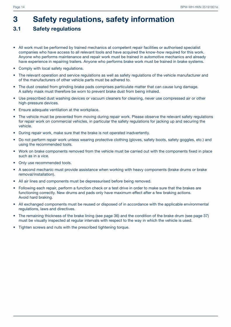
Number Description Illustration of tool Tool in operation
17 Puller for ECO Plus 2
BPW code number:
05.001.05.07.0
18 Puller for slack adjusters
BPW code number:
02.4306.15.00

BPW-WH-HKN 35191801ePage 22
6 Lubrication and maintenance work
Lubrication
Overview
For detailed description see pages 24 to 35
Lubrication with BPW special longlife grease ECO-LiPlus Ever
y 12
wee
ks
Ever
y 26
wee
ks 1
) 2
)
Ann
ually
and
at
ever
y br
ake
linin
g re
plac
emen
t 1)
2)
Ann
ually
BPW re-commendation. Does not imply warranty.
Ever
y 3
year
s
Aft
er 5
yea
rs,
ther
e-af
ter
ever
y 3
year
s
Ever
y 2
year
s
Late
st e
very
3
year
s or
min
. ev
ery
500,
000
km 2
)
1 Brake camshaft bearing, outer and inner
On-Road conditions 1
Off -Road conditions 1
Outside Europe 1
2 Slack adjusters manual 2
Automatic slack adjuster ECO-Master
On-Road conditions 2
Off -Road conditions 2
Outside Europe 2
3 Change wheel hub bearing grease, check taper roller bearings and rotary shaft seal for wear.ECO Plus 3, ECO Plus 2 and ECOPlus Unit:
On-Road conditions 3
Off -Road conditions 3
Outside Europe: On-Road conditions 3
Outside Europe: Off -Road conditions 3
ECO Unit 3
Outside Europe: 3
Conventional hub bearing 3
1) After a long idle period, prior to initial operation actuate the brake lever and lubricate the brake camshaft bearing.2) With usage extreme conditions (e.g. extreme Off-Road use) more frequent lubrication with high pressure grease is necessary.
For the positions 1 to 2 the use of a high-pressure central lubrication system which is capable of feeding special longlife grease of consistency class 2-3 is permissible. The use of liquid lubricants is not permitted!

BPW-WH-HKN 35191801e Page 23
Maintenance work
Overview
For detailed description, see pages 36 to 45
Maintenance
Initi
ally
Ever
y 1
to 3
wee
ks
Ever
y 12
wee
ks
Ever
y 26
wee
ks 2
)
Ann
ually
and
at e
very
bra
ke
linin
g re
plac
emen
t 2
)
1 Check wheel nuts for tightness. 1
1)
2 With manual slack adjusters, check brake play, adjust if necessary to 10 - 12% of the connected brake lever length and activate by hand or with 0.5 - 0.8 bar. (Not applicable in the case of automatic slack adjusters.)
2
- Check the tyres for uneven wear, adjust the infl ation pressure if necessary according to the manufacturer’s specifi cations. -
3 Check brake lining thickness is at least 5 mm (SN 300 min. 7 mm). 3
4 Check the brake drum for cracks and check the internal diameter. 4
5 Check caps for fi rm seating (not necessary with ECO Plus 3, ECO Plus 2 and ECOPlus axles). 5
° Visual inspection of all component parts and welding seams for damage and wear. °
3)
°6 Check operation of automatic slack adjusters. 6
3)
6
7 Check wheel hub bearing play, adjust if necessary.
ECO Plus 3, ECO Plus 2 and ECOPlus Unit 7
ECO Unit, conventional bearing 7
1) After the fi rst run under load conditions, likewise after each wheel change.2) Under extreme conditions, increase frequency (e.g. construction sites and poor roads).3) For use outside Europe.
Note: Components that have damages due to improper mounting are to be exchanged after a review by a BPW Service Centre.

BPW-WH-HKN 35191801ePage 24
Automatic slack adjuster ECO-Master
– every year and with each brake lining change in On-Road use –– every 6 months for Off -Road use and in use outside Europe –
Remove rubber seal cap. Grease with BPW special longlife grease ECO-LiPlus (approx. 80 g) until suffi cient new grease emerges from the ad-justment screw.
Turn back adjustment screw (keep clutch sleeve pressed down) by approx. one turn using a ring spanner. Actuate the brake lever several times by hand. The adjustment must be carried out smooth-ly. If necessary, repeat several times.Once again only use BPW special longlife grease ECO-LiPlus.
Adjust the brake, see page 123. Replace seal cap.
2 Slack adjusters (manual)
– quarterly –
Grease lubrication nipple with BPW special longlife grease ECO-LiPlus until fresh grease emerges.
6 Lubrication and maintenance work
Lubricate
Note: After cleaning the vehicle with high pressure cleaners, all lubrication points must be relubricated.
1 Brake camshaft bearing, outer and inner
– every year and with each brake lining change in On-Road use –– every 6 months in Off -Road use and in use outside Europe –
Prevent the vehicle from rolling away.
Release the service brakes and the handbrake.
Lubricate the brake camshaft bearing through the grease nipple with BPW special longlife grease ECO-LiPlus until fresh grease emerges from the bearing points.
Repair guide!
Use of other grease is not permitted.
BPW-WH-HKN 35191801e Page 25
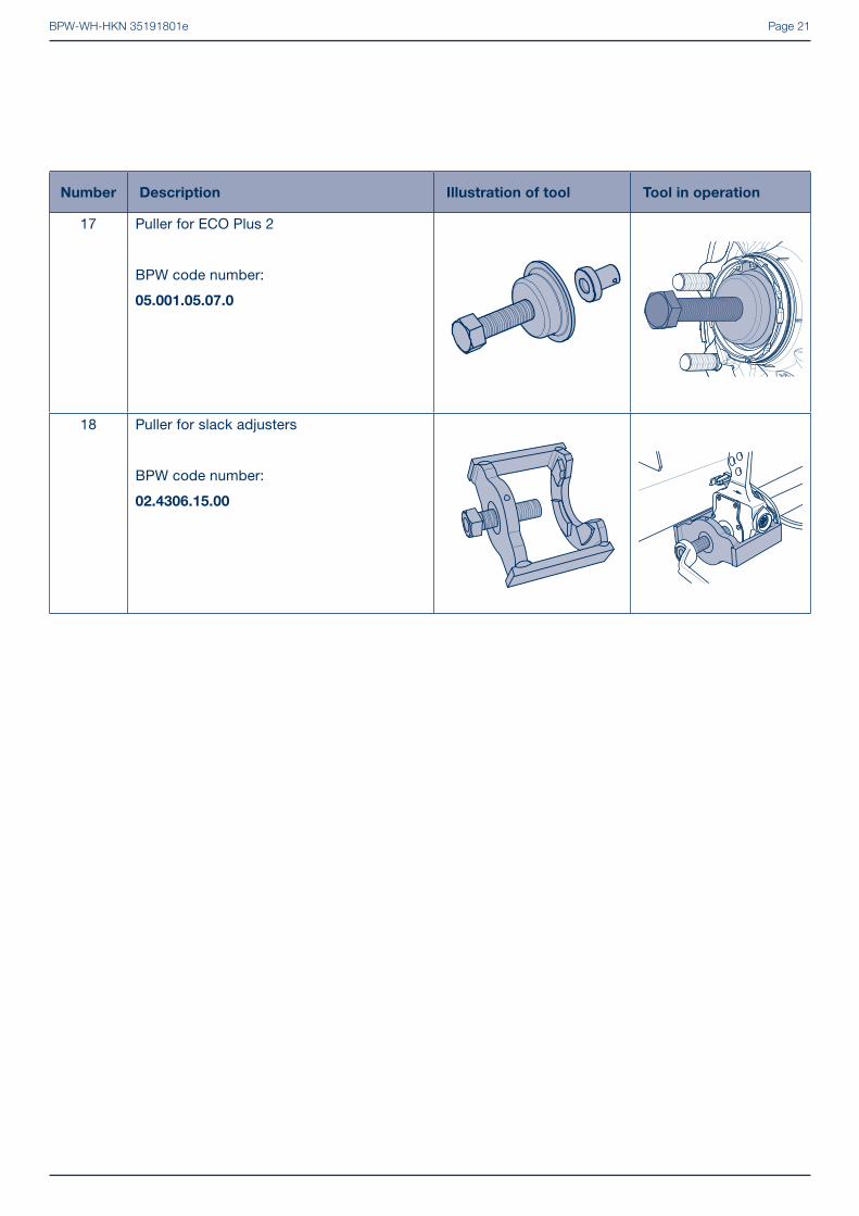
3 Change wheel hub bearing grease
� ECO Plus 3 Unit
– for the fi rst time after 5 years in on-road use, or every 3 years in off -road use in Europe, then at least every 3 years depending on operating conditions –– every 2 years in on-road use or every year in off -road use outside Europe –
Thoroughly clean taper roller bearings and seals (using e.g. diesel oil), dry and check for re-useability. Replace grease seal.
(Recommendation: Renew the tapered roller bea-rings after 5 years in On-Road and after 3 years in Off -Road use.)
Work BPW special longlife grease ECO-LiPlus thoroughly into the cavities between the taper rollers and the cage in both taper roller bearings. (For grease quantity see illustration on page 26.) Smear any residual grease into the hub‘s outer bearing race.
Smear the lip of the new seal all round with BPW special longlife grease ECO-LiPlus.
Thoroughly clean the bearing journals of the axle stub with a microfi bre cloth. The journals must be bright, dry and free from grease. Apply Castrol White T using a fi ne bristled brush evenly and thinly to the bearing journals. Ensure that the bearing journal is completely coated.Castrol White T must not be diluted.
Install ECO unit whilst continuously rotating axle nut of ECO unit. It is necessary to turn the ECO Unit numerous times before the gearing slips over the axle nut.
Important!
Do not use an impact driver.
Fit the retaining key in the groove between the stub axle and the nut (do not reset the axle nut).
Insert the hooked retainer spring behind the for-med edge of the axle nut.
Insert a new O-ring into the annular groove of the wheel hub. Apply a thin coat of BPW special long-life grease ECO-LiPlus to the O-ring contact surface and thread of the hub cap.
Screw on the hub cap and tighten to 350 Nm.

BPW-WH-HKN 35191801ePage 26
6 Lubrication and maintenance work
BPW special longlife grease ECO-LiPlus
Grease quantity per taper roller bearing
1 inner bearing 2 outer bearing
Manual greasing 170 g 120 g
Greasing with a grease applicator 130 g 90 g
ECO Plus 3 Unit

BPW-WH-HKN 35191801e Page 27
Remove the hooked spring ring and retaining key from the axle bolt.
Unscrew the axle bolt, pulling the complete ECO Unit off the bearing seats of the axle stub as you do so.
Dismantle the ECO Plus 2 Unit, see page 80.
Repair guide!
Mark both the hub and bearing to
ensure correct positioning during
re-assembly.
It is essential for the bearing inner
races and rollers to be re-inserted
in the same hubs.
Clean the tapered roller bearings thoroughly (e.g. with diesel oil), dry them and check if they can be re-used. Fit a new shaft seal.
� ECO Plus 2 Unit
– for the fi rst time after 5 years in on-road use, or every 3 years in off -road use in Europe, then at least every 3 years depending on operating conditions –– every 2 years in on-road use or every year in off -road use outside Europe –
Prevent the vehicle from rolling away.
Remove the wheel.
Unscrew the cap with a 120 mm cap spanner.
Important!
Do not use an impact driver
- bayonet lock.
Undo the cap by turning it anti-clockwise by approx. 30° from position 1 to position 2.When turned further the hub cap lifts clearly away from the ECO Unit and can be removed by pulling it away.
Position 1 Position 2

BPW-WH-HKN 35191801ePage 28
Note:
Renew the tapered roller bearings
after 5 years in on-road use and
after 3 years in off -road use.
i
Clean the grease cartridge and fi ll it on both sides up to the edge with BPW special longlife grease ECO-LiPlus. It is important to ensure that it is fi lled without any air inclusions or cavities.
Apply a ring-shaped bead of grease to the running surfaces of the bearing outer races (see arrows in illustration below and picture 39 on page 85).
� When BPW grease applicators are used, there is no need to fi ll the grease cartridge or to apply the bead of grease.
Mount the ECO Unit.
Thoroughly clean the bearing journals of the axle stub with a microfi bre cloth. The journals must be bright, dry and free from grease. Apply Castrol White T using a fi ne bristled brush evenly and thinly to the bearing journals. Ensure that the bearing journal is completely coated.Castrol White T must not be diluted.
The threaded hole in the axle stub is only allowed to be lubricated with ECO-LiPlus.
Repair guide!
Do not apply too much grease!
It is necessary to make sure that the
thread of the axle bolt (446) can be
completely screwed into the axle stub.
Mount the ECO Unit. Guide the toothed lock washer into the hole in the axle stub. The position of the pin can be seen by the indented BPW logo in the recess of the axle bolt.
Fasten axle bolt (SW46) whilst rotating the ECO hub unit. It is necessary to turn the ECO Unit numerous times before the gearing slips over the axle bolt (Do not turn back the axle bolt).
Important!
Do not use an impact driver.
Insert the retaining key into the hole recess of the axle bolt and the gearing of the toothed lock washer. (Do not turn back the axle bolt.)
6 Lubrication and maintenance work
BPW-WH-HKN 35191801e Page 29
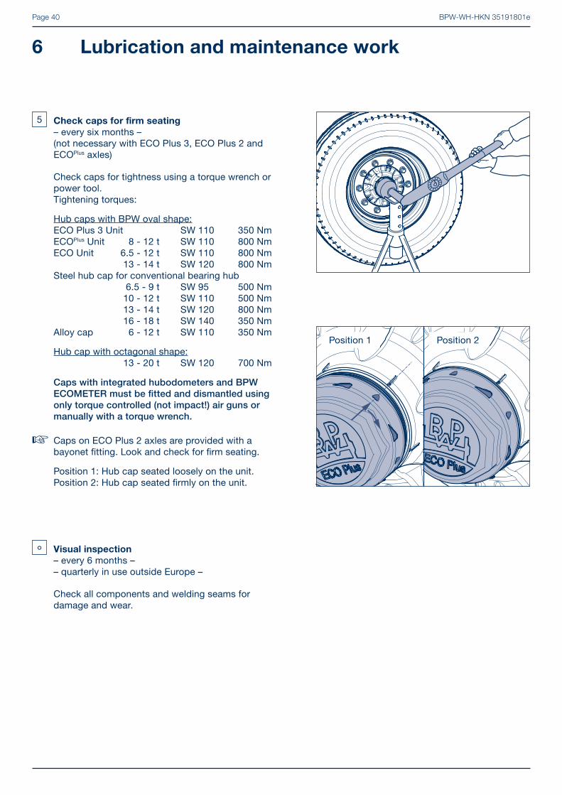
Insert a new O-ring into the groove in the wheel hub.
Apply a thin layer of BPW ECO-LiPlus special longlife grease to the cap in the area of the O-ring contact surface and the bayonet fi tting.
Screw on the cap with a 120 mm cap spanner.
Important!
Do not use an impact driver
- bayonet lock.
Push on the cap, see position 1.Press on the cap and turn it by approx. 30° in a clockwise direction to lock it in place. A tight seat is provided when position 2 is reached.
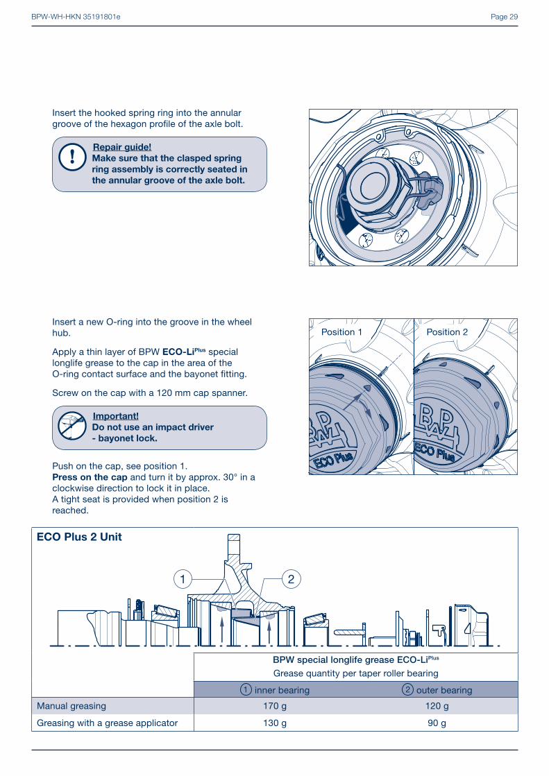
Insert the hooked spring ring into the annular groove of the hexagon profi le of the axle bolt.
Repair guide!
Make sure that the clasped spring
ring assembly is correctly seated in
the annular groove of the axle bolt.
Position 1 Position 2
BPW special longlife grease ECO-LiPlus
Grease quantity per taper roller bearing
1 inner bearing 2 outer bearing
Manual greasing 170 g 120 g
Greasing with a grease applicator 130 g 90 g
ECO Plus 2 Unit

BPW-WH-HKN 35191801ePage 30
� ECOPlus Unit
– for the fi rst time after 5 years in on-road use, or every 3 years in off -road use in Europe, then at least every 3 years depending on operating conditions –
– every 2 years in on-road use or every year in off -road use outside Europe –
Remove and dismantle wheel hubs, see chapter 7/8.
Repair guide!
Mark both the hub and bearing to
ensure correct positioning during
re-assembly.
It is essential for the bearing inner
races and rollers to be re-inserted
in the same hubs.
Clean taper roller bearings and seals (using e.g. diesel oil) thoroughly, dry and check for re-useability. Replace oil seal.
Recommendation:
Renew the tapered roller bearings
after 5 years in on-road use and
after 3 years in off -road use.
i
Work BPW special longlife grease ECO-LiPlus thoroughly into the cavities between the taper rollers and the cage in both taper roller bearings. (For grease quantity see illustration on page 31.) Smear any residual grease into the hub’s outer bearing race.
Smear the lip of the new seal all round with BPW special longlife grease ECO-LiPlus.
Thoroughly clean the bearing journals of the axle stub with a microfi bre cloth. The journals must be bright, dry and free from grease. Apply Castrol White T using a fi ne bristled brush evenly and thinly to the bearing journals. Ensure that the bearing journal is completely coated.Castrol White T must not be diluted.
6 Lubrication and maintenance work

BPW-WH-HKN 35191801e Page 31
Fasten axle nut using a hexagon socket spanner whilst rotating the ECO hub unit. It should take several turns until the clutch on the axle nut slips.
Important!
Do not use an impact driver.
Fit the retaining key in the groove between the axle stub and the nut (do not reset the axle nut).
For production date April 2000 onwards, insert the hooked spring ring behind the edge of the axle nut or, up to March 2000, into the thread on the axle stub. Screw on the cap and tighten to 800 Nm.
BPW special longlife grease ECO-LiPlus
Grease quantity per taper roller bearing
1 inner bearing 2 outer bearing
Manual greasing 170 g 120 g
Greasing with a grease applicator 130 g 90 g
ECOPlus Unit

BPW-WH-HKN 35191801ePage 32
� ECO Unit
– latest every 3 years or min. every 500,000 km (Western European road conditions), annually in use outside Europe –
Remove and dismantle wheel hubs, see chapter 7/8.
Repair guide!
Mark both the hub and bearing to
ensure correct positioning during
re-assembly.
It is essential for the bearing inner
races and rollers to be re-inserted
in the same hubs.
Clean taper roller bearings and seals (using e.g. diesel oil) thoroughly, dry and check for re-useability. Replace oil seal.
Work BPW special longlife grease ECO-LiPlus thoroughly into the cavities between the taper rollers and the cage in both taper roller bearings.
Comply with the total grease quantity in tables 1 and 2 on page 33.
Smear any residual grease into the hub’s outer bearing race. Smear the lip of the new seal all round with BPW special longlife grease ECO-LiPlus.
Thoroughly clean the bearing journals of the axle stub with a microfi bre cloth. The journals must be bright, dry and free from grease. Apply Castrol White T using a fi ne bristled brush evenly and thinly to the bearing journals. Ensure that the bearing journal is completely coated.Castrol White T must not be diluted.
Fit the ECO Unit. Fasten axle nut using a torque wrench whilst rota-ting the ECO hub unit. It should take several turns until the tightening torque has reached 150 Nm. Turn the nut back until the next securing position is aligned (max 15 degrees). Turn the nut back until the next securing position ia aligned (max 15 degrees).
The next locking hole is reached by turning back the asymmetrical axle nut cap by a maximum of 15°.
Fit pin with a snap ring. Tighten the cap to 800 Nm.
6 Lubrication and maintenance work

BPW-WH-HKN 35191801e Page 33
BPW special longlife grease ECO-LiPlus
Grease quantity per taper roller bearing
Axle load 1 Inner bearing 2 Outer bearing
6000 - 9000 kg 120 g 120 g
10000 - 12000 kg 170 g 120 g
13000 - 14000 kg 230 g 150 g
ECO Unit

BPW-WH-HKN 35191801ePage 34
� Conventional hub bearing (change wheel hub bearing grease)
– whenever brake linings are changed, at the latest annually or after 150,000 km –
Remove and dismantle wheel hubs, see chapter 7/8.
Repair guide!
Mark both the hub and bearing to
ensure correct positioning during
re-assembly.
It is essential for the bearing inner
races and rollers to be re-inserted
in the same hubs.
Clean wheel hubs thoroughly inside and outside. Clean taper bearings (using diesel oil) thoroughly, dry and check for re-useability. Replace seals.
Work BPW special longlife grease ECO-LiPlus into the cavities between the taper rollers and cage.
Comply with total grease quantity (table 1 on page 35), smear any residual grease into the hub’s
outer bearing race.
Fit wheel hubs and adjust bearing play (see point 7 page 44).
Fill hub caps with BPW special longlife grease ECO-LiPlus (table 2 ) and screw on.
For tightening torques see 5 page 40.
Repair guide!
For 16 - 18 t axles with BPW oval shape
hub cap, a new O-ring must be fi tted
on reassembly.
6 Lubrication and maintenance work

BPW-WH-HKN 35191801e Page 35
BPW special longlife grease ECO-LiPlus
Grease quantity per taper roller bearing
Axle load 1 inner bearing 2 outer bearing (cap fi lling)
4000 - 5500 kg 80 g 130 g
6000 - 9000 kg 170 g 290 g
10000 - 12000 kg 180 g 320 g
13000 - 14000 kg 240 g 500 g
16000 - 18000 kg 400 g 800 g
20000 kg 440 g 900 g
Conventional hub bearing

BPW-WH-HKN 35191801ePage 36
Maintenance work
1 Check wheelnuts for tightness
– the tightening torque of the wheel nuts must be checked after the fi rst high load journey as well as after each wheel change and, if appropriate, retightened to the prescribed value –
Tighten wheel nuts diagonally using a torque wrench to the tightening torque shown in the table.
In the case of Trilex wheels tighten the nuts consecutively several times around.
Wheel contact surfaces should not have additional coats of paint (risk of the wheels becoming detached!)
6 Lubrication and maintenance work
Tightening torques for wheel nuts
It is imperative that the prescribed tightening torques are adhered to in order to ensure the wheels are securely fastened! The wheel studs must be clean and free of damage and the nuts must be easily tightened and loosened. If needed, lightly oil the contact surface between the wheel nut and the pressure disc. Do not oil or grease the thread of the wheel studs and wheel nuts.
Stud alignment Tightening torque
M 14 x 1.5 125 Nm (120 - 130 Nm)
M 18 x 1.5 290 Nm (275 - 305 Nm)
M 20 x 1.5 380 Nm (360 - 400 Nm)
M 22 x 1.5 510 Nm (485 - 535 Nm)
M 22 x 2 460 Nm (435 - 485 Nm)
Spigot alignment Tightening torque
M 18 x 1.5 350 Nm (330 - 370 Nm)
M 20 x 1.5 480 Nm (455 - 505 Nm)
M 22 x 1.5 630 Nm (600 - 660 Nm)
M 22 x 1.5 alloy wheels 630 Nm (600 - 660 Nm)
M 24 x 1.5 860 Nm (820 - 900 Nm)
Trilex wheels Tightening torque
M 18 x 2 285 Nm (270 - 300 Nm)
M 20 x 2 335 Nm (320 - 350 Nm)
Japan connection Tightening torque
M 20 x 1.5 570 Nm (540 - 600 Nm)
M 30 x 1.5 570 Nm (540 - 600 Nm)
Wheel nut with collar

BPW-WH-HKN 35191801e Page 37
2 Check and adjust wheel brake play with
manual slack adjusters
– frequent checks are necessary –– depending upon application every 1 to 3 weeks –
Actuate slack adjusters by hand, pulling against the return spring. If there is more than 35 mm of play, the slack adjuster must be reset.
This can be done by adjusting the nut on the slack adjuster as shown.
Adjust the play ”a” to 10 - 12% of the connected brake lever length ”B”, e.g. lever length 150 mm = 15 - 18 mm of play.
Automatic slack adjusters make this adjustment automatically whenever the camshaft is rotated by more than 17.5°.
Note:
BPW brake cylinders with a round-hole
yoke do not have an outer return spring.i
- Check the tyres for uneven wear, adjust the
infl ation pressure if necessary according to
the manufacturer’s specifi cations.
– quarterly –

BPW-WH-HKN 35191801ePage 38
6 Lubrication and maintenance work
If brake lining wear indicators are fi tted to the slack adjusters, the minimum thickness of the brake linings is indicated by the horizontal position of the lever (when the brake is released).
The Brake Monitor displays the ”Service” signal when the wear sensor for drum brakes is installed. The green and yellow LED lights fl ash alternately. The service signal changes from black to red and remains in operation without voltage.
In certain cases the slack adjusters may not be fi tted in the normal (i.e. vertical) position. In such instances, the position of the wear indicator will also be different. Linings should be changed when the wear indicator is approximately at right angles to the brake lever.
3 Check brake lining thickness
– quarterly –
Open inspection hole by folding back the rubber fl ap (not required for brake type ECO Drum with hole on the outer dust cover edge).
The brake lining should be replaced at a residual lining thickness of 5 mm, SN 300 min. 7 mm (check with feeler gauge) or on reaching the bottom of the indicator machined into the edge of the lining.
Re-insert the rubber fl ap, if necessary.

BPW-WH-HKN 35191801e Page 39
4 Check the brake drum for cracks and check
the internal diameter
– quarterly –
Check the condition of the brake drum and ensure there is adequate remaining thickness. If the wear is approaching the wear edge, measure the brake drum and renew it if the maximum permitted amount of wear has been reached.
Max. amounts of wear, measured at the position with the greatest wear:
Brake Brake shoe width(mm)
Ø Max. amount of wear (mm)
Ø Max. skimming size (mm)
SN 420 120 / 160 424 423SN 420 180 / 200 / 220 425.5 424SN 360 160 / 200 364 363SN 300 100 / 150 / 200 304 303
BPW-WH-HKN 35191801ePage 40
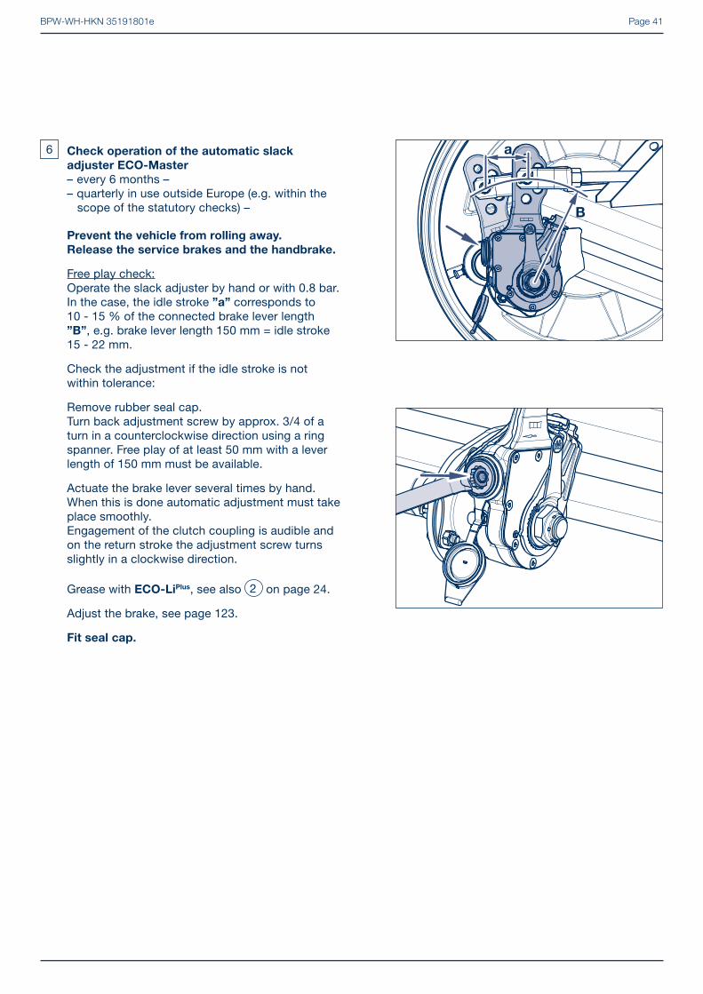
� Caps on ECO Plus 2 axles are provided with a bayonet fi tting. Look and check for fi rm seating.
Position 1: Hub cap seated loosely on the unit.Position 2: Hub cap seated fi rmly on the unit.
5 Check caps for fi rm seating
– every six months – (not necessary with ECO Plus 3, ECO Plus 2 and ECOPlus axles)
Check caps for tightness using a torque wrench or power tool.Tightening torques:
Hub caps with BPW oval shape:ECO Plus 3 Unit SW 110 350 NmECOPlus Unit 8 - 12 t SW 110 800 NmECO Unit 6.5 - 12 t SW 110 800 Nm 13 - 14 t SW 120 800 NmSteel hub cap for conventional bearing hub 6.5 - 9 t SW 95 500 Nm 10 - 12 t SW 110 500 Nm 13 - 14 t SW 120 800 Nm 16 - 18 t SW 140 350 NmAlloy cap 6 - 12 t SW 110 350 Nm
Hub cap with octagonal shape: 13 - 20 t SW 120 700 Nm
Caps with integrated hubodometers and BPW ECOMETER must be fi tted and dismantled using only torque controlled (not impact!) air guns or manually with a torque wrench.
Position 1 Position 2
6 Lubrication and maintenance work
° Visual inspection
– every 6 months –– quarterly in use outside Europe –
Check all components and welding seams for damage and wear.
BPW-WH-HKN 35191801e Page 41
6 Check operation of the automatic slack
adjuster ECO-Master
– every 6 months –– quarterly in use outside Europe (e.g. within the scope of the statutory checks) –
Prevent the vehicle from rolling away.
Release the service brakes and the handbrake.
Free play check:Operate the slack adjuster by hand or with 0.8 bar. In the case, the idle stroke ”a” corresponds to 10 - 15 % of the connected brake lever length ”B”, e.g. brake lever length 150 mm = idle stroke 15 - 22 mm.
Check the adjustment if the idle stroke is not within tolerance:
Remove rubber seal cap.Turn back adjustment screw by approx. 3/4 of a turn in a counterclockwise direction using a ring spanner. Free play of at least 50 mm with a lever length of 150 mm must be available.
Actuate the brake lever several times by hand. When this is done automatic adjustment must take place smoothly.Engagement of the clutch coupling is audible and on the return stroke the adjustment screw turns slightly in a clockwise direction.
Grease with ECO-LiPlus, see also 2 on page 24.
Adjust the brake, see page 123.
Fit seal cap.

BPW-WH-HKN 35191801ePage 42
7 Check wheel hub bearing grease
– ECO Plus 3, ECO Plus 2 and ECOPlus Unit at every brake lining replacement, latest annually –– ECO Unit and conventional hub bearing every 6 months –
Prevent the vehicle from moving away.
Release the service and parking brakes.
In order to check the wheel hub bearing play lift the axle until the wheels are off the ground. Release the brake. Apply a lever between the tyre and the ground and check the play.
6 Lubrication and maintenance work
If bearing play is detected - ECO Plus 3 Unit:
Adjust the bearing play
1. Unscrew the cap.
2. Remove the hooked spring ring with a wedge from the axle nut.
3. Fasten axle nut using a hexagon socket spanner whilst rotating the ECO hub unit. It is necessary to turn the ECO Unit numerous times before the gearing slips over the axle nut.
Important!
Do not use an impact driver.
4. Fit the retaining key in the groove between the stub axle and the nut (do not reset the axle nut).
5. Insert the hooked retainer spring behind the formed edge of the axle nut.
6. Insert a new O-ring into the annular groove of the wheel hub. Apply a thin coat of BPW special longlife grease ECO-LiPlus to the O-ring contact surface and thread of the hub cap.
7. Screw on the hub cap and tighten to 350 Nm.

BPW-WH-HKN 35191801e Page 43
If bearing play is detected on ECO Plus 2 Unit:
Adjust the bearing play:
1. Unscrew the hubcap with a 120 mm hub cap spanner (BPW no. 03.339.05.02.0). Undo the cap by turning it anti-clockwise by approx. 30° from position 1 to position 2. When turned further the hub cap lifts clear away from the ECO Unit and can be removed by pulling it away.
Important!
Do not use an impact driver
- bayonet lock.
2. Remove the hooked spring ring with a wedge from the axle bolt.
Position 1 Position 2
3. Fasten the axle bolt (SW 46) whilst rotating the ECO Unit. It is necessary to turn the ECO Unit numerous times before the gearing slips over the axle bolt.
Important!
Do not use an impact driver.
BPW-WH-HKN 35191801ePage 44
6 Lubrication and maintenance work
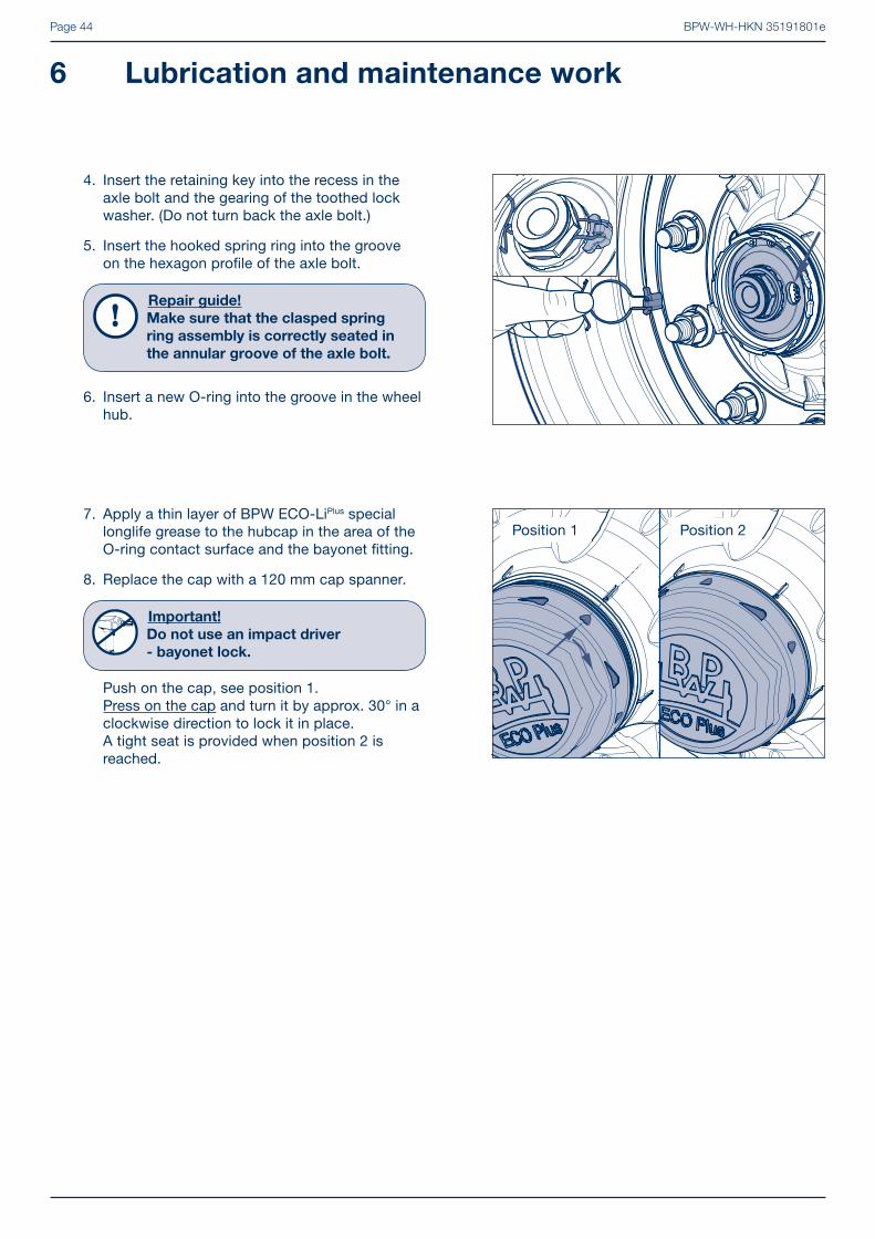
7. Apply a thin layer of BPW ECO-LiPlus special longlife grease to the hubcap in the area of the O-ring contact surface and the bayonet fi tting.
8. Replace the cap with a 120 mm cap spanner.
Important!
Do not use an impact driver
- bayonet lock.
Push on the cap, see position 1. Press on the cap and turn it by approx. 30° in a clockwise direction to lock it in place. A tight seat is provided when position 2 is reached.
4. Insert the retaining key into the recess in the axle bolt and the gearing of the toothed lock washer. (Do not turn back the axle bolt.)
5. Insert the hooked spring ring into the groove on the hexagon profi le of the axle bolt.
Repair guide!
Make sure that the clasped spring
ring assembly is correctly seated in
the annular groove of the axle bolt.
6. Insert a new O-ring into the groove in the wheel hub.
Position 1 Position 2

BPW-WH-HKN 35191801e Page 45
If bearing play is detected on ECOPlus Unit:
Adjust the bearing play:
1. Unscrew the hubcap.
2. Remove the hooked spring ring with a wedge from the axle nut.
3. Fasten axle nut using a hexagon socket spanner (BPW no. 05.364.26.05.0) whilst rotating the ECO Unit. It should take several turns until the clutch on the axle nut slips.
Important!
Do not use an impact driver.
4. Fit the retaining key in the groove between the axle stub and the nut (do not reset the axle nut).
5. For production date April 2000 onwards, insert the hooked spring ring behind the edge of the axle nut or, up to March 2000, into the thread on the axle stub.
6. Tighten the hubcap to 800 Nm.

BPW-WH-HKN 35191801ePage 46
6 Lubrication and maintenance work
If bearing play is detected on ECO Unit:
Adjust the bearing play:
1. Unscrew the cap.
2. Loosen axle nut.
3. Fasten axle nut using a torque wrench whilst rotating the ECO hub unit. It should take several turns until the tightening torque has reached 150 Nm.
- If a normal axle nut spanner is used (vehicle tool kit), tighten the axle nut until the ECO Unit drags slightly (auxiliary solution).
4. Turn back axle nut to the next locking position (max. 15°). The asymmetrical cap of the axle nut enables the next locking position to be reached after turning back max. 15°.
5. Insert bolt and locking ring.
6. Screw on cap.
Tightening torque: Steel / cast cap 800 Nm Aluminium cap 350 Nm

BPW-WH-HKN 35191801e Page 47
If bearing play is detected in conventional hub bearing:
Adjust the bearing play:
1. Unscrew the cap.
2. Remove the split pin from the axle nut.
3. Fasten the axle nut using a torque wrench and with the continuous turning of the wheel hub. It should take several turns until the tightening torque has reached the desired value.
Tightening torques: Hub caps with BPW oval shape: Up to an axle load of 5.5 tons = 70 Nm, from 6 to 18 tons axle load = 150 Nm,
Hub caps with octagonal shape: from 16 to 30 tons axle load = 350 Nm
- If a normal axle nut spanner is used (vehicle tool kit), tighten the axle nut until the wheel bearing race drags slightly.
4. Turn back the axle nut to the next available split pin hole. Should they already be in line turn back to the next hole (30° at the maximum). (Does not apply to the ECO Plus 3, ECO Plus 2, ECOPlus and ECO Unit.)
5. Insert the split pin and bend upwards slightly.
6. Refi ll the cap as required with BPW special longlife grease ECO-LiPlus and replace.
For tightening torques see point 5 page 40.
Repair guide!
For 16 - 18 t axles with BPW oval shape
hub cap, a new O-ring must be fi tted
on reassembly.
BPW-WH-HKN 35191801ePage 48
Picture 1
Picture 2
Picture 3
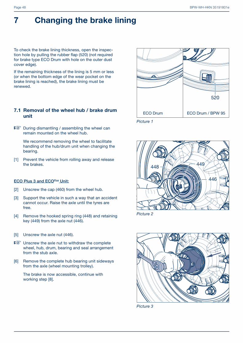
7 Changing the brake lining
To check the brake lining thickness, open the inspec-tion hole by pulling the rubber fl ap (520) (not required for brake type ECO Drum with hole on the outer dust cover edge).
If the remaining thickness of the lining is 5 mm or less (or when the bottom edge of the wear pocket on the brake lining is reached), the brake lining must be renewed.
[5] Unscrew the axle nut (446).
� Unscrew the axle nut to withdraw the complete wheel, hub, drum, bearing and seal arrangement from the stub axle.
[6] Remove the complete hub bearing unit sideways from the axle (wheel mounting trolley).
The brake is now accessible, continue with working step [8].
7.1 Removal of the wheel hub / brake drum
unit
� During dismantling / assembling the wheel can remain mounted on the wheel hub.
We recommend removing the wheel to facilitate handling of the hub/drum unit when changing the bearing.
[1] Prevent the vehicle from rolling away and release the brakes.
ECO Plus 3 and ECOPlus Unit:
[2] Unscrew the cap (460) from the wheel hub.
[3] Support the vehicle in such a way that an accident cannot occur. Raise the axle until the tyres are free.
[4] Remove the hooked spring ring (448) and retaining key (449) from the axle nut (446).

BPW-WH-HKN 35191801e Page 49
ECO Plus 2 Unit:
[2] Unscrew the cap (460) with a 120 mm cap spanner.
Important!
Do not use an impact driver
- bayonet lock.
Picture 4
Picture 5
Picture 6
[3] Undo the cap (460) by turning it anti-clockwise by approx. 30° from position 1 to position 2.When turned further the hub cap lifts clearly away from the ECO unit and can be removed by pulling it away.
[4] Support the vehicle in such a way that an accident cannot occur. Raise the axle until the tyres are free.
Position 1 Position 2
[5] Remove the hooked spring ring (448) and retaining key (449) from the axle bolt (446).
[6] Unscrew the axle bolt, pulling the complete ECO Unit off the bearing seats of the axle stub as you do so.
[7] Remove the complete hub bearing unit sideways from the axle (wheel mounting trolley).
The brake is now accessible, continue with working step [8].

BPW-WH-HKN 35191801ePage 50
Picture 7
Picture 8
Picture 9
7 Changing the brake lining
Conventional hub bearing:
[2] Unscrew the cap (460) from the wheel hub.
[3] Support the vehicle in such a way that an accident cannot occur. Raise the axle until the tyres are free.
[4] Remove the split pin (447) from the axle nut (446) and unscrew.
[5] Unscrew the axle nut (446).
� Unscrew the axle nut to withdraw the complete wheel, hub, drum, bearing and seal arrangement from the stub axle.
[6] Remove the complete hub bearing unit sideways from the axle (wheel mounting trolley).
The brake is now accessible, continue with working step [8].
ECO Unit:
[2] Unscrew the cap (460) from the wheel hub.
[3] Support the vehicle in such a way that an accident cannot occur. Raise the axle until the tyres are free.
[4] Remove the hook spring ring (448), complete with retention pin (447), from the axle nut (446).

BPW-WH-HKN 35191801e Page 51
Picture 10
Picture 11
Picture 12
7.2 Changing the brake lining
[8] Remove rubber seal cap (283) from the slack adjuster (280).
[9] Turn back adjustment screw (arrow) in a counter-clockwise direction using a ring spanner.
[10] Reset slack adjuster (280) until the S-cam of the brake cam shaft (240, 241) reaches the zero position.
[6] Position puller. Pull off the inner taper roller bearing (430), the grease seals (422, 423) and the thrust washer (420) together from the axle stub.
Extractor:BPW no. 02.0125.10.00 for axles 6.5 to 14 t.
Repair guide!
For 10 t axle series K with ABS/
ABV: Unscrew the sensor holder (542).
Repair guide!
Mark both the hub and bearing to
ensure correct positioning during
re-assembly.
It is essential for the bearing inner
races and rollers to be re-inserted
in the same hubs.
[5] Using the hub puller (BPW no. see page 19). Withdraw the wheel hub unit with the wheels from the axle stub.

BPW-WH-HKN 35191801ePage 52
Picture 13
Picture 14
Picture 15
7 Changing the brake lining
[13] Remove either one or two tension springs (363), depending on the design, from the tabs on the brake shoes (330)
[12] Place assembly lever on axle beam and lift brake shoes (330).
Repair guide!
When lifting, protect the sensor (570)
and the sensor cable from damage.
Remove brake shoes.
[11] Lever the positioning springs (367, 368) apart using a screwdriver.
BPW-WH-HKN 35191801e Page 53
Picture 16
Picture 17
Picture 18
If there is no riveting machine available:
Shear off the closed head of the rivet with a chisel (No. 1) or remove the closed head using 8.6 mm diameter drill bit. (No. 2). Drive out the rivet with a punch (No. 3).
[16] Check the diameter of the rivet hole using a rivet hole gauge. The diameter is not allowed to be more than 0.6 mm larger than the rivet diameter (DIN 7513).
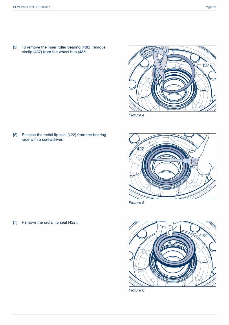
[15] Remove the old brake lining and clean the brake shoe. The surface must be free of rust and be smooth.
Repair guide!
The rivets (357) should always be
pressed out using a riveting machine,
preferably with hydraulic actuation.
The equipment used must be suitable
for the rivet diameter. Modern rivet
punches can universally accept hollow
and semi hollow rivets.
The use of unsuitable rivet punches
may damage the brake shoe.
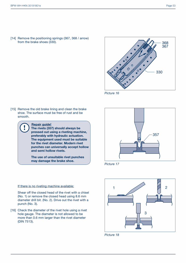
[14] Remove the positioning springs (367, 368 / arrow) from the brake shoes (330).

BPW-WH-HKN 35191801ePage 54
7 Changing the brake lining
Frequent faults
1 Loose rivets indicate enlarged rivet holes
2 Rivet hole damaged during boring
3 Damaged platform edge
4 Worn shoe support
5 Deformed shoe web
6 Rivet hole deformed during boring
7 Rivet hole damaged by riveting machine
8 Corroded platform area
9 Damaged shoe web end
10 Worn shoe roller bearings
11 Cracked welding seam
12 Damaged platform surface
13 Corroded welding seam
14 Deformed platform surface
Picture 19
Picture 21
1
2
5
4
3
6
9
8
7 10
14
11,13
12
Picture 20
Repair guide!
With skimmed brake drums use
corresponding oversize brake linings.
The brake shoe must snugly fi t on the
platform, i.e. the platform must not be
concave. The shoes must be carefully
cleaned, e.g. by sandblasting by means
of a shoe grinding unit.
[17] Insert all rivets and hold in position by crimping edges. Rivet brake lining (350) into place taking care to follow the correct riveting order (picture 22).
Series K (SN 360):Note diff erent lengths of brake lining segments. Assemble the short brake lining segment (351, arrow) to the roller end.

BPW-WH-HKN 35191801e Page 55
� A light tap with a hammer will determine whether the riveting is satisfactory or not. A dull thud indicates a loose lining. A high-pitched response indicates that the riveting is correct.
� A feeler gauge can be used to check for cavities under the lining. A cavity of more than 0.15 mm beyond the fi rst row of rivet holes can lead to noise problems.
� Finally, the linings should be checked for cracks in the area of the rivets which would indicate incorrect riveting.
7.3 Riveting check
Picture 23, Pos. 1:Rivet length correct, the hole inner wall and strength are correct.
Picture 23, Pos. 2:Rivet too short, no inner hole recess and poor closing head formation.
Picture 23, Pos. 3:Rivet too long, inadequate closing head, crack formation.
� Rivet as shown from the inside out.
Riveting force: 21000 N (20000 - 22000 N)
Rivets: Semi-tubular rivets, galvanized steel 8 x 15 mm meeting DIN 7338 B
Picture 22
Picture 23
Picture 24

BPW-WH-HKN 35191801ePage 56
7 Changing the brake lining
[19] Clean bearing bush and apply BPW special longlife grease ECO-LiPlus (4 g).
[20] Insert new roller (345) with rings (348) into the brake shoe webs.
7.4 Brake shoe installation
[18] Check roller (345) for wear, renew as appropriate. Remove bearing bolts (346).
Repair guide!
In the event of wear, exchange roller
bearing bolts and rings.
� Health and safety precautions
Brake dust contains large volumes of breathable fi ne dust and is hazardous to your health, even in case of non-asbestos material. Safety regulations prescribe extraction systems with a suction power between 40 and 50 m3/h.
Wheel brakes must never be cleaned down using compressed air or cleaned using a dry bush.
It is strongly recommended to use clean water without chemical additives or a special vacuum cleaner machine to clean down the brakes. The use of detergents might impair the braking eff ect.
Picture 25
Picture 26

BPW-WH-HKN 35191801e Page 57
Serie K (SN 3620):
[22] Hook both return springs (363) into the lugs on the outside of the brake shoes (330).
Serie K (SN 3616):
[22] Hook a return spring (363) into the lugs on the outside of the brake shoes (pointing towards the middle of the axle), see picture 36 page 58.
Repair guide!
Insert new return springs every time
the brake linings are changed.
Serie H (SN 420):
[22] Insert the return springs (363) into the lugs of the brake shoes (330).
Serie N (SN 300):
[22] Insert two return springs (363) into the lugs of the brake shoes (330).
[21] Drive in bearing bolt (346) with the bevelled side down until both rings (348) snap into the annular grooves of the bearing bolt.
Picture 27
Picture 28
Picture 29

BPW-WH-HKN 35191801ePage 58
7 Changing the brake lining
7.5 Installation of the brake shoes
[25] Check hooked spring rings (325) on the brake anchor plate for wear and seating. If necessary, change components.
Repair guide!
Hooked spring rings must be
renewed when the brake lining is
changed, if not before.
[26] Smear BPW special longlife grease ECO-LiPlus onto bearing points (arrows) of brake shoes.
� Only for models with ABS/ABV
[24] Check sensor (570) for damage and displacement (displacement force 100 - 200 N). If necessary, smear clamping bush (571) and sensor with special grease (replace clamping bush). Before fi tting hubs, always press clamping bush and sensor up to endstop. When fi tting the hub, the sensor will be pushed back into the correct position by the exciter ring (560).
[23] Hook the positioning springs (367, 368 / arrow) into the brake shoes (330).
Picture 30
Picture 31
Picture 32

BPW-WH-HKN 35191801e Page 59
[30] Link the positioning springs (367, 368) using a screwdriver.
[29] Assemble lower brake shoe (330) and fi x on to the spring ring (325) by hitting lightly with a soft hammer.
[27] Place upper brake shoe (330) with the roller (345) on to the S-cam.
[28] Fix brake shoe on to the spring ring (325) by hitting lightly with a soft hammer.
Picture 33
Picture 34
Picture 35

BPW-WH-HKN 35191801ePage 60
7 Changing the brake lining
[33] Check the condition of the brake drum and ensure there is adequate thickness remaining. If the wear is approaching the wear edge, measure the brake drum and renew it if the maximum permitted amount of wear has been reached.
Max. amounts of wear, measured at the position with the greatest wear:
Brake Brake shoe width (mm)
Ø max. amount of wear (mm)
Ø Skim-ming size
(mm)SN 420 120 / 160 424 423SN 420 180 / 200 / 220 425.5 424SN 360 160 / 200 364 363SN 300 100 / 150 / 200 304 303
All brakes
[31] Expand brake to small extent.
[32] Using a brake lathe turn down the brake linings to fi t the brake drum diameter until an even wear surface has been obtained.
Repair guide!
There is no need to machine the brake
linings when fi tting genuine BPW repla-
cement lined brake shoe assemblies.
Series K (SN 3616):Secure the outer return springs (365) onto the lugs of the brake shoes and hook into the plate (366).
Insert the plate (arrow) into the groove on the pin of the brake camshaft (240, 241).
Picture 36
Picture 37
Picture 38

BPW-WH-HKN 35191801e Page 61
7.6 Installation of the wheel hub brake
drum unit
� ECO Plus 2 Unit, see page 63.ECO Unit, see page 65.Conventional hub bearing, see page 67.
ECO Plus 3 and ECOPlus Unit:
[34] Thoroughly clean the bearing journals of the axle stub with a microfi bre cloth. The journals must be bright, dry and free from grease. Apply Castrol White T using a fi ne bristled brush evenly and thinly to the bearing journals. Ensure that the bearing journal is completely coated.Castrol White T must not be diluted.
Bild 39
[38] Fasten axle nut using a hexagon socket spanner whilst rotating the ECO hub unit. It should take several turns until the clutch on the axle nut slips (do not use an impact driver).
[35] Align the tab of the washer (445, arrow) to the groove of the stub axle by turning the axle nut (446) and gently press the wheel hub unit.
[36] Push the complete hub unit centrally onto the stub axle.
[37] Screw on the axle nut; in this way the complete hub unit is mounted onto the stub axle.
Picture 40
Picture 41

BPW-WH-HKN 35191801ePage 62
7 Changing the brake lining
[39] Fit the retaining key (449) in the groove between the axle stub and the nut (446) (do not reset the axle nut).
[40] For production date April 2000 onwards, insert the hooked spring ring (448) behind the edge of the axle nut or, up to March 2000, into the thread on the axle stub.
Picture 42
[42] Cover the hub cap (460) in the area of the O-ring contact surface (only for ECO Plus 3) and the thread with a thin coat of BPW special longlife grease ECO-LiPlus.
[43] Screw the hub cap (460) onto the wheel hub (435) and tighten with the prescribed torque.
Tightening torques:Hub cap ECO Plus 3 SW 110 350 NmHub cap ECO Plus SW 110 800 Nm
� Adjust brake.
Adjust slack adjuster (280) using adjusting
hexagon to a play of 10 - 12% of the connected
brake lever length. The automatic slack adjuster
ECO-Master adjusts itself on actuation of the
brake lever. Initial free play of the ECO-Master
should be set manually.
Warning!
New brake linings only have maximum
eff ect after a few braking actions.
Picture 43
[41] Insert a new O-ring (459) into the groove in the wheel hub (435, arrow). (The O-ring is not required for axles with ECO Plus Unit.)
Picture 44

BPW-WH-HKN 35191801e Page 63
[37] Insert the retaining key (449) into the recess in the axle bolt (446/2) and the gearing of the toothed lock washer (446/1). (Do not turn back the axle bolt.)
[35] Guide the toothed lock washer (446/1) into the hole in the axle stub. The position of the pin can be seen by the indented BPW logo in the recess of the axle bolt (446/2).
[36] Fasten axle bolt (46 mm) whilst rotating the ECO hub unit. It should take several turns until the clutch on the axle bolt slips. (Do not turn back the axle bolt.)
Important!
Do not use an impact driver.
ECO Plus 2 Unit:
[34] Thoroughly clean the bearing journals of the axle stub with a microfi bre cloth. The journals must be bright, dry and free from grease. Apply Castrol White T using a fi ne bristled brush evenly and thinly to the bearing journals. Ensure that the bearing journal is completely coated.Castrol White T must not be diluted.
The threaded hole in the axle stub is only allowed to be lubricated with ECO-LiPlus.
Caution!
Do not apply too much grease!
It is necessary to make sure that the
axle bolt can be completely bolted into
the axle stub.
Picture 45
Picture 46
Picture 47

BPW-WH-HKN 35191801ePage 64
� Adjust brake.
Adjust slack adjuster (280) using adjusting
hexagon to a play of 10 - 12% of the connected
brake lever length. The automatic slack adjuster
ECO-Master adjusts itself on actuation of the
brake lever. Initial free play of the ECO-Master
should be set manually.
Warning!
New brake linings only have maximum
eff ect after a few braking actions.
[39] Insert a new O-ring (459) into the groove in the wheel hub (435).
[40] Apply a thin layer of BPW ECO-LiPlus special long-life grease to the cap (460) in the area of the O-ring contact surface and the bayonet fi tting.
[41] Screw on the cap with a 120 mm cap spanner.
Important!
Do not use an impact driver
- bayonet lock.
[42] Push on the cap, see position 1.Press on the cap and turn it by approx. 30° in a clockwise direction to lock it in place. A tight seat is provided when position 2 is reached.
[38] Insert the hooked spring ring (448) into the groove of the hexagon profi le of the axle bolt (446/2).
Repair guide!
Make sure that the clasped spring
ring assembly is correctly seated in
the annular groove of the axle bolt.
Picture 48
Picture 49
Picture 50
7 Changing the brake lining
Position 1 Position 2

BPW-WH-HKN 35191801e Page 65
[38] Fasten axle nut using a torque wrench whilst rotating the ECO hub unit. It should take several turns until the tightening torque has reached 150 Nm. Turn the nut back until the next securing position is aligned (max. 15°).
� The next locking hole is reached by turning back the asymmetrical axle nut by a maximum of 15°.
ECO Unit:
[34] Thoroughly clean the bearing journals of the axle stub with a microfi bre cloth. The journals must be bright, dry and free from grease. Apply Castrol White T using a fi ne bristled brush evenly and thinly to the bearing journals. Ensure that the bearing journal is completely coated.Castrol White T must not be diluted.
Picture 51
Picture 53
[35] Align the tab of the washer (445, arrow) to the groove of the stub axle by turning the axle nut (446) and gently press the wheel hub unit.
[36] Push the complete hub unit centrally onto the stub axle.
[37] Screw on the axle nut. In this way the complete hub unit is mounted onto the stub axle.
Picture 52

BPW-WH-HKN 35191801ePage 66
[40] Smear the threads of the hub cap (460) all round with BPW special longlife grease ECO-LiPlus.
[41] Screw hub cap onto wheel hub.Tightening torque 800 Nm.
� Adjust brake.
Adjust manual slack adjuster (280) using
adjusting hexagon to a play of 10 - 12% of the
connected brake lever length.
On page 123 the adjustment of the automatic
slack adjuster ECO-Master is described.
Warning!
New brake linings only have maximum
eff ect after a few braking actions.
[39] Push in retention pin (447). Insert hook spring ring (448) with hook (arrow) near pin and push into the annular groove of the axle nut (446).
Picture 54
Picture 55
7 Changing the brake lining

BPW-WH-HKN 35191801e Page 67
[35] Series H / K:Push thrust washer (420) and new grease seals (422, 423) onto the axle stub.
Picture 57
Conventional hub bearing:
[34] Clean the bearing seats of the axle stub (metal must be bright, dry and free from grease).
Picture 56
Series N: Push the thrust washer (420) and shaft seal (422), onto the axle stub with the closed side to the stop ring.
Picture 58

BPW-WH-HKN 35191801ePage 68
[39] Slide on the complete hub and brake drum assem-bly concentrically. When the hub is fi tted, the ABS sensor (570) is pushed back to the correct position by the exciter ring (560). For this reason, do not cant hub.
[40] Insert outer taper roller bearing (441).
Picture 60
Picture 61
7 Changing the brake lining
Repair guide!
Do not mix up bearing races and outer
bearing rings.
[36] Clean and inspect taper roller bearing (430) thoroughly.
[37] Heat the bearing inner race (with rollers and cage) correctly to about 80°C and push on up to the stop against the thrust washer (420).Work BPW special longlife grease ECO-LiPlus into the spaces between the conical rollers and the race. Use only the maximum amount of grease, see page 35.
[38] Apply the remainder to outer bearing race of the hub.
Picture 59
Repair guide!
From January 1995, BPW axle beams
will be converted to ECO axle stubs.
These diff er from the conventional axle
stubs by a keyway in the thread area
(arrow).
A new axle nut (446) and in addition a
washer (445) is used to fi t the conven-
tional bearing to ECO axle stubs.

BPW-WH-HKN 35191801e Page 69
[41] Screw on the axle nut (446) and fasten using a torque wrench and with the continous turning of the wheel hub. It should take several turns until the tightening torque has reached the desired value.Tightening torques: Hub caps with BPW oval shape: Up to an axle load of 5.5 tons = 70 Nm, from 6 to 18 tons axle load = 150 Nm,
Hub caps with octagonal shape: from 16 to 30 tons axle load = 350 Nm
If a normal axle nut spanner is used (vehicle tool kit), tighten the axle nut until the wheel bearing race drags slightly.
[42] Unscrew axle nut to next hole or, if the axle nut is already positioned opposite a hole, turn back to the one before (max. 30°).
[44] Fill the hub cap (460) with BPW special longlife grease ECO-LiPlus.
� Comply with total grease quantity, see page 35.
[43] Axle nut (446) secured with a split pin (447).
� For 16 - 18 t axles with BPW oval shape hub cap, a new O-ring must be fi tted on reassembly.
Picture 62
Picture 63
Picture 64

BPW-WH-HKN 35191801ePage 70
7 Changing the brake lining
Picture 65
[45] Grease thread of hub cap (460) all round with BPW ECO-LiPlus and screw on.
Tightening torques for hub caps: Thread pitch 2 mm (oval shape)
Hub cap (inner thread) 500 Nm Hub cap (outer thread) 800 Nm Alloy hub cap 350 Nm
Thread pitch 3 mm Hub cap (octagonal shaped) 700 Nm
� Adjust brake.
Adjust slack adjuster (280) using adjusting
hexagon to a play of 10 - 12 % of the connected
brake lever length. The automatic slack adjuster
ECO-Master adjusts itself on actuation of the
brake lever. Initial free play of the ECO-Master
should be set manually.
Warning!
New brake linings only have maximum
eff ect after a few braking actions.

BPW-WH-HKN 35191801e Page 71
7.7 Conversion to brake with split roller
(BPW 95 Brake)
Brakes of the former version should be changed over to new brake technology.
High degree of safety Short response time and a consistent braking eff ect throughout the entire life of the lining thanks to the permanently lubricated brake rollers.
Reduced weight Weight-optimized design with fewer wear parts.
Easy to change brake linings Fast and easy brake shoe replacement.
Position springs The position springs ensure the brake shoes are fi rmly and securely seated on the locking rings (C-clips).
Brake return springs The brake return spring is hooked into lugs that are formed on the brake shoes.
Same brake components on all axles of the corres-ponding series.
The technical specifi cations of the brake remain unchanged. Consequently existing EC test certifi -cates remain valid.
Picture 66
Picture 67
Picture 68

BPW-WH-HKN 35191801ePage 72
8 Dismantling and assembling the hub unit
8.1 ECO Plus 3 Unit
Note:
Opening the ECO Plus 3 Unit before the
end of the warranty period invalidates
the ECO Plus warranty (see ECO Plus
warranty documents).
[1] Removing and installing the complete ECO Plus 3 unit, see chapter 7.
[2] To remove the outer roller bearing (441), remove circlip (438) and axle nut (446) from the wheel hub (435).
Picture 1
Picture 2
Picture 3
[4] Lever the exciter ring (560) from the wheel hub (435). In doing so, avoid damage to the base of the wheel hub.
[3] Remove lug washer (445) and roller bearing (441).
Repair guide!
Mark both the hub and bearing to
ensure correct positioning during
re-assembly.
It is essential for the bearing inner
rings with rollers to be re-inserted in
the same hubs.
BPW-WH-HKN 35191801e Page 73
Picture 4
Picture 5
Picture 6
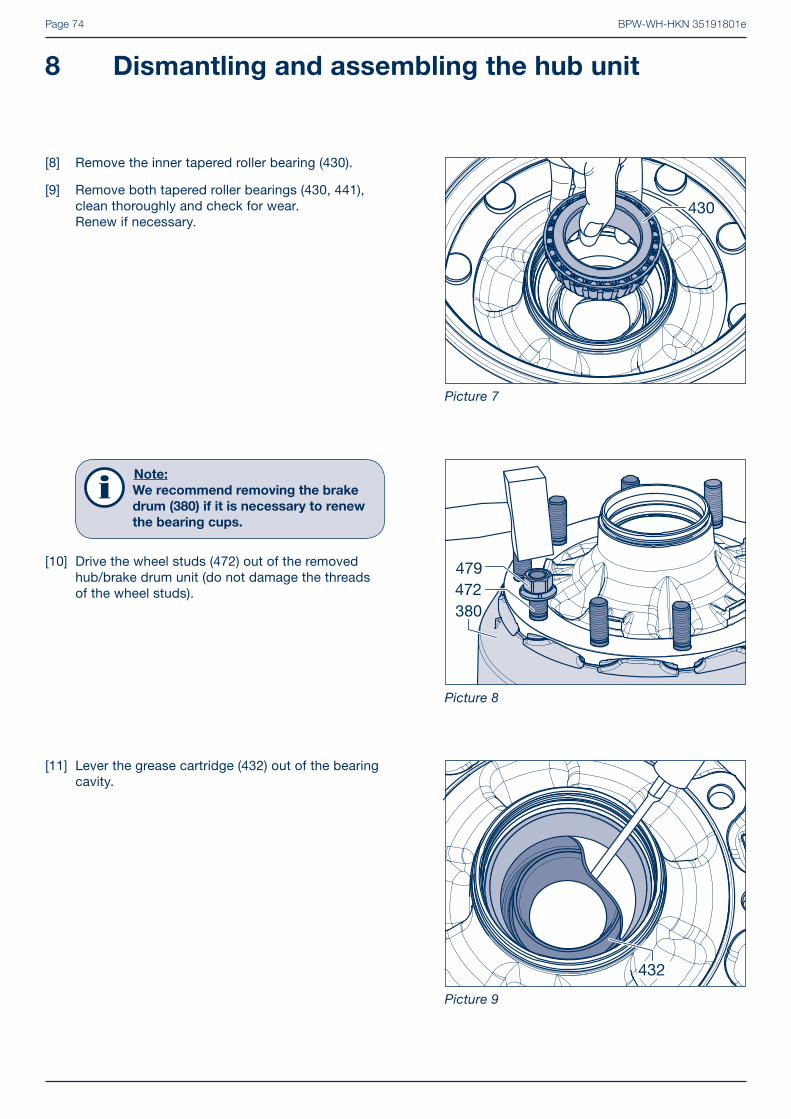
[5] To remove the inner roller bearing (430), remove circlip (437) from the wheel hub (435).
[6] Release the radial lip seal (422) from the bearing race with a screwdriver.
[7] Remove the radial lip seal (422).
BPW-WH-HKN 35191801ePage 74
[8] Remove the inner tapered roller bearing (430).
[9] Remove both tapered roller bearings (430, 441), clean thoroughly and check for wear. Renew if necessary.
Picture 7
Picture 8
Picture 9
8 Dismantling and assembling the hub unit
[11] Lever the grease cartridge (432) out of the bearing cavity.
Note:
We recommend removing the brake
drum (380) if it is necessary to renew
the bearing cups.
i
[10] Drive the wheel studs (472) out of the removed hub/brake drum unit (do not damage the threads of the wheel studs).

BPW-WH-HKN 35191801e Page 75
Picture 10
Picture 11
Picture 12
[12] Take the grease cartridge (432) out of the wheel hub (435).
[13] Drive the bearing outer rings out of the wheel hub (435).
[14] Centre the new bearing outer races and insert them in the wheel hub (435). Install using a press (min. 6 t) and the BPW insertion tools 15.011.20052 and 15.013.20052.
Repair guide!
Make sure the bearing cups are
correctly seated in the wheel hub.

BPW-WH-HKN 35191801ePage 76
Picture 13
Picture 14
Picture 15
8 Dismantling and assembling the hub unit
[15] Insert the seal (432/bearing intermediate piece) between the installed bearing outer rings.
[16] Grease both tapered roller bearings with BPW special longlife grease ECO-LiPlus.Note the total grease quantity (tapered roller bearing 33318 - 170 g and 33213 - 120 g).
Note:
We recommend greasing the
bearings with BPW grease applicators
99.00.000.9.55.
[17] Fit inner roller bearing (430) into wheel hub (435).
Repair guide!
Do not mix up bearing cage and outer
bearing rings.

BPW-WH-HKN 35191801e Page 77
Picture 16
Picture 17
Picture 18
[18] Insert the lip seal (422) into the wheel hub (435) with the 3 locating tangs facing the bearing (430).
[20] Fit circlip (437) into the groove of the wheel hub (435).
[19] Place the hub cap (460) onto the seal (422) and knock it in with light hammer blows until the seal is in contact with the bearing.
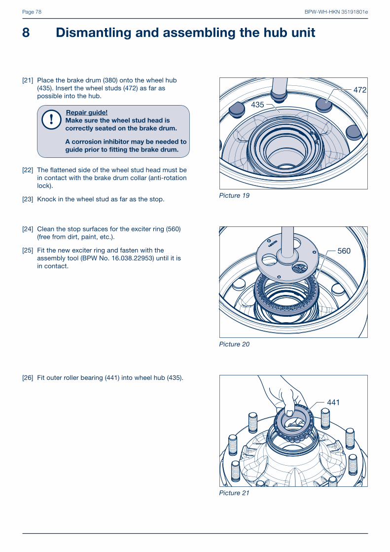
BPW-WH-HKN 35191801ePage 78
[24] Clean the stop surfaces for the exciter ring (560) (free from dirt, paint, etc.).
[25] Fit the new exciter ring and fasten with the assembly tool (BPW No. 16.038.22953) until it is in contact.
Picture 19
Picture 20
Picture 21
[26] Fit outer roller bearing (441) into wheel hub (435).
8 Dismantling and assembling the hub unit
[21] Place the brake drum (380) onto the wheel hub (435). Insert the wheel studs (472) as far as possible into the hub.
Repair guide!
Make sure the wheel stud head is
correctly seated on the brake drum.
A corrosion inhibitor may be needed to
guide prior to fi tting the brake drum.
[22] The fl attened side of the wheel stud head must be in contact with the brake drum collar (anti-rotation lock).
[23] Knock in the wheel stud as far as the stop.

BPW-WH-HKN 35191801e Page 79
Picture 22
Picture 23
[27] Place the keyed thrust washer (445) (with the embossed BPW and code number) next to the tapered roller bearing (441).
[28] Fit circlip (438) with axle nut (446) into the groove of the wheel hub.
Mounting the complete ECO Unit (434), see from page 61.

BPW-WH-HKN 35191801ePage 80
[4] Take the tapered roller bearing (441) out of the wheel hub.
Repair guide!
Mark both the hub and bearing to
ensure correct positioning during
re-assembly.
It is essential for the bearing inner
races and rollers to be re-inserted
in the same hubs.
[3] Remove the axle bolt with toothed washer and integrated pin (446).
8.2 ECO Plus 2 Unit
Note:
Opening the ECO Plus 2 Unit before the
end of the warranty period invalidates
the ECO Plus warranty (see ECO Plus
warranty documents).
[1] Removing and installing the complete ECO Plus 2 unit, see chapter 7.
[2] Remove the circlip (438) from the wheel hub (435) to remove the outer tapered roller bearing (441).
Picture 24
Picture 25
Picture 26
8 Dismantling and assembling the hub unit
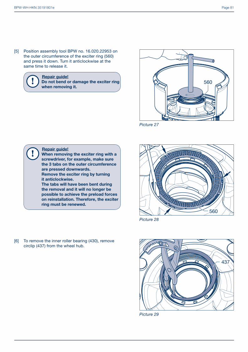
BPW-WH-HKN 35191801e Page 81
[6] To remove the inner roller bearing (430), remove circlip (437) from the wheel hub.
Repair guide!
When removing the exciter ring with a
screwdriver, for example, make sure
the 3 tabs on the outer circumference
are pressed downwards.
Remove the exciter ring by turning
it anticlockwise.
The tabs will have been bent during
the removal and it will no longer be
possible to achieve the preload forces
on reinstallation. Therefore, the exciter
ring must be renewed.
[5] Position assembly tool BPW no. 16.020.22953 on the outer circumference of the exciter ring (560) and press it down. Turn it anticlockwise at the same time to release it.
Repair guide!
Do not bend or damage the exciter ring
when removing it.
Picture 27
Picture 28
Picture 29
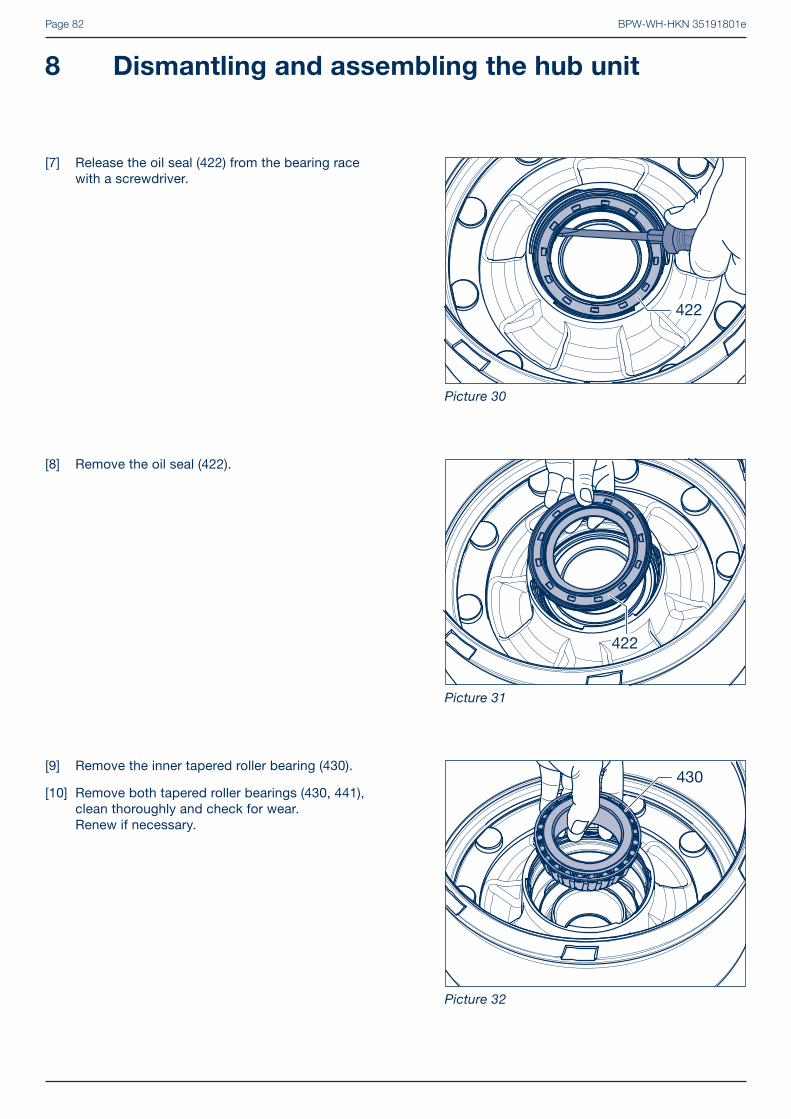
BPW-WH-HKN 35191801ePage 82
[9] Remove the inner tapered roller bearing (430).
[10] Remove both tapered roller bearings (430, 441), clean thoroughly and check for wear. Renew if necessary.
[8] Remove the oil seal (422).
[7] Release the oil seal (422) from the bearing race with a screwdriver.
Picture 30
Picture 31
Picture 32
8 Dismantling and assembling the hub unit

BPW-WH-HKN 35191801e Page 83
[13] Take the grease cartridge (432) out of the wheel hub.
[12] Lever the grease cartridge (432) out of the bearing cavity.
Note:
We recommend removing the brake
drum (380) if it is necessary to renew
the bearing cups.
i
[11] Drive the wheel studs (472) out of the removed hub/brake drum unit (do not damage the threads of the wheel studs).
Picture 33
Picture 34
Picture 35

BPW-WH-HKN 35191801ePage 84
[16] Clean the grease cartridge (432, bearing inter-mediate piece) and insert between the mounted bearing outer races.
[17] Fill both sides of the grease cartridge with BPW ECO-LiPlus grease.
Repair guide!
It is important to ensure that it is fi lled
without any air inclusions or cavities.
When BPW grease applicators are
used, there is no need to fi ll the grease
cartridge.
[15] Centre the new bearing outer races and insert them in the wheel hub (435). Install using a press (min. 6 t) and the BPW insertion tools 15.011.20052 and 15.013.20052.
Repair guide!
Make sure the bearing cups are
correctly seated in the wheel hub.
[14] Drive the bearing outer races out of the wheel hub (435).
Picture 36
Picture 37
Picture 38
8 Dismantling and assembling the hub unit

BPW-WH-HKN 35191801e Page 85
[20] Insert the seal (422) into the wheel hub (435) with the 3 locating tangs facing the bearing (430).
[19] Fit inner roller bearing (430) into wheel hub (435).
Repair guide!
Do not mix up bearing races and outer
bearing rings.
[18] Apply a ring-shaped bead of grease to the running surfaces of the bearing outer races.
Picture 39
Picture 40
Picture 41

BPW-WH-HKN 35191801ePage 86
[23] Place the brake drum (380) onto the wheel hub (435). Insert the wheel studs (472) as far as possible into the hub.
Repair guide!
Make sure the wheel stud head is
correctly seated on the brake drum.
A corrosion inhibitor may be needed to
guide prior to fi tting the brake drum.
[24] The fl attened side of the wheel stud head must be in contact with the brake drum collar (anti-rotation lock).
[25] Knock in the wheel stud as far as the stop.
[22] Fit circlip (437) into the groove of the wheel hub (435).
[21] Place the hub cap (460) onto the seal (422) and knock it in with light hammer blows until the seal is in contact with the bearing.
Picture 42
Picture 43
Picture 44
8 Dismantling and assembling the hub unit

BPW-WH-HKN 35191801e Page 87
[31] Fit outer roller bearing (441) into wheel hub.
[30] Completely fi ll the exterior grease chamber of the grease cartridge (432) with BPW special longlife grease ECO-LiPlus.
Repair guide!
It is important to ensure that it is fi lled
without any air inclusions or cavities.
When BPW grease applicators are
used, there is no need to fi ll the grease
cartridge (432).
[26] Use a new exciter ring (560)! Grease the exciter ring groove and bayonet locks on the exciter ring on both sides.
[27] Insert the exciter ring in the correct position. The rotational stops on the exciter ring must contact right-angled stop surfaces in the hub.
[28] Use a blunt object (e.g. screwdriver) to strike the exciter ring lightly behind the stop cams so as to rotate it clockwise as far as the stop (see also page 81).
Repair guide!
Do not use impact tools to fi t the exci-
ter ring. Make sure there are no signs
of damage on the teeth of exciter ring.
To avoid mistakes when mounting, we
recommend using the BPW assembly
tool 16.020.22953 when renewing the
exciter ring.
[29] Press the assembly tool down on the outer circum-ference whilst turning clockwise and anticlockwise to release or fasten the exciter ring.
Picture 45
Picture 46
Picture 47
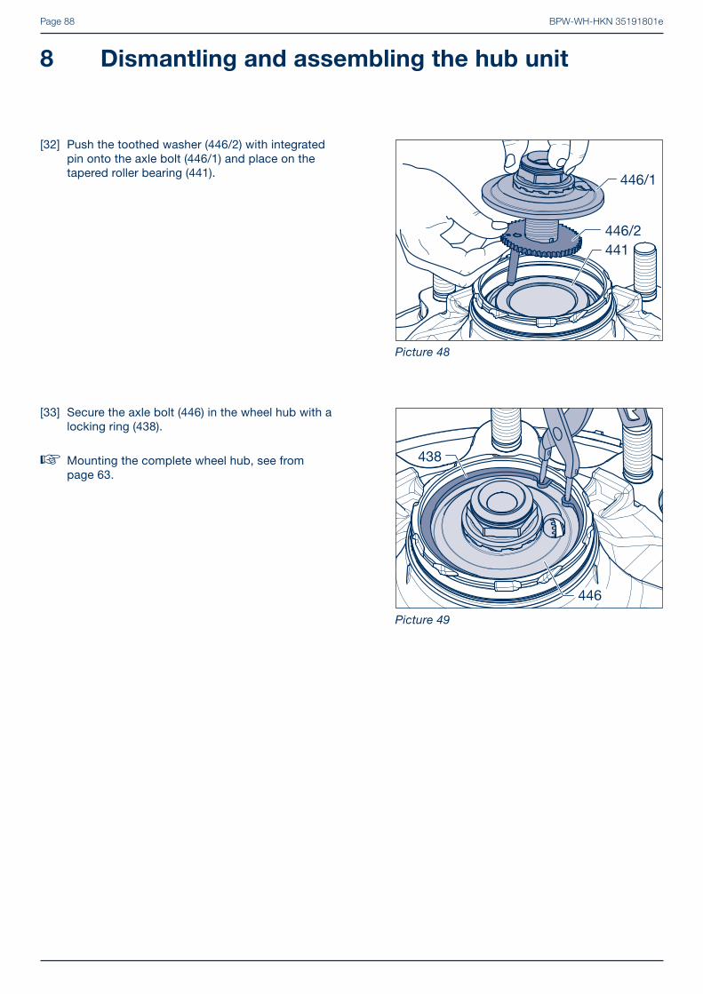
BPW-WH-HKN 35191801ePage 88
[33] Secure the axle bolt (446) in the wheel hub with a locking ring (438).
� Mounting the complete wheel hub, see from page 63.
[32] Push the toothed washer (446/2) with integrated pin onto the axle bolt (446/1) and place on the tapered roller bearing (441).
Picture 48
Picture 49
8 Dismantling and assembling the hub unit

BPW-WH-HKN 35191801e Page 89
[4] If the ABS sheet metal exciter ring (560) is fi tted, remove it from the wheel hub. Cast exciter rings should not be removed!
8 - 9 t ECOPlus:
Position assembly tool BPW no. 16.020.22953 on the outer circumference of the exciter ring and press it down. Turn it anticlockwise at the same time to release it.
Repair guide!
Do not bend or damage the exciter ring
when removing it.
[3] Remove lug washer (445) and roller bearing (441).
Repair guide!
Mark both the hub and bearing to
ensure correct positioning during
re-assembly.
It is essential for the bearing inner
races and rollers to be re-inserted
in the same hubs.
8.3 ECOPlus Unit
[1] Dismantling and refi tting the complete wheel hub bearing, see chapter 7.
[2] To remove the outer roller bearing (441), remove circlip (438) and axle nut (446) from the wheel hub (435).
Picture 50
Picture 51
Picture 52

BPW-WH-HKN 35191801ePage 90
[5] If fi tted, pry the coarse dirt seal (428) from the wheel hub (435) and from the shaft seal (422).
Series K 10 - 12 t:
Gently pull on the clamps at the outer edge of the pole wheel (560) and remove the wheel from the wheel hub
Repair guide!
Do not bend or damage the exciter ring
when removing it.
Repair guide!
When removing the exciter ring from
ECOPlus 8 - 9 t axles with a screwdriver,
for example, make sure the 3 tabs on
the outer circumference are pressed
downwards.
Remove the exciter ring by turning it
anticlockwise.
The tabs will have been bent during
the removal and it will no longer be
possible to achieve the preload forces
on reinstallation. Therefore, the exciter
ring must be renewed.
Picture 53
Picture 54
Picture 55
8 Dismantling and assembling the hub unit

BPW-WH-HKN 35191801e Page 91
ECOPlus bearings 10 - 12 t:Thrust ring (421) with oil seal (422) or ECOSeal seal and O-ring (424).
[7] ECOPlus bearings 8 - 9 t:Depending on the design of the shaft seal or ECOSeal seal (422) fi tted.
[6] To remove the inner roller bearing (430), remove circlip (437) from the wheel hub (435).
Picture 56
Picture 57
Picture 58

BPW-WH-HKN 35191801ePage 92
Removing the bearing cups
[11] Drive the bearing outer races (together with the race (423) on ECOPlus bearings 10 - 12 t before 05/2005) out of the wheel hub (435).
[12] Remove the dust cover (431) from the wheel hub.
Note:
We recommend removing the brake
drum (380) if it is necessary to renew
the bearing cups.
i
[10] Drive the wheel studs (472) out of the removed hub/brake drum unit (do not damage the threads of the wheel studs).
[8] Remove the inner tapered roller bearing (430) and then the seal (432, bearing intermediate piece).
[9] Remove both tapered roller bearings (430, 441), clean thoroughly and check for wear. Renew if necessary.
Picture 59
Picture 60
Picture 61
8 Dismantling and assembling the hub unit

BPW-WH-HKN 35191801e Page 93
Installing the bearing cups
[15] Centre the bearing outer races and insert them in the wheel hub. Install using a press (min. 6 t) and the BPW insertion tools 15.011.20052 and 15.013.20052.
Repair guide!
Make sure the bearing cups are
correctly seated in the wheel hub.
[16] Insert the seal (432, bearing intermediate piece) between the installed bearing outer races.
[14] Insert the new dust cover (431) with the curved side facing the hub (435).
[13] Fit the thrust washer (440) with the curved side facing the hub (435).
Picture 62
Picture 63
Picture 64

BPW-WH-HKN 35191801ePage 94
[18] ECOPlus 8 - 9 t bearings:In ECOPlus axles for axle loads 8 - 9 tonnes, the thrust washer is formed onto the axle stub. The oil seal is permanently attached to a stepped disc and has to be replaced as a complete unit.
The new generation ECOSeal oil seals are confi gu-red as a cartridge seal and replace the former oil seal used in ECOPlus bearings 8 - 9 t and 10 - 12 t after 06/2005.
ECOPlus bearings 10 - 12 t before 05/2005 and ECO 8 - 12 t:Press in the new oil seal (422) (with its open side facing upwards) as far as the stop against the thrust washer (421).Apply BPW special longlife grease ECO-LiPlus to the sealing lip.
[17] Take a new race (423) and prepare the BPW inserti-on tools. 16.020.22111 for race 8 - 9 t (before 09/2004) 16.014.22111 for race 10 - 12 t (before 05/2005)Press the race centrally into the old wheel hub (435).
Repair guide!
ECOPlus bearings (8 - 9 t before
09/2004):
The existing seal wear ring remains in
the wheel hub, continues to be used
and must not be renewed, until the
new ECOSeal seal is inserted.
ECOPlus bearings (10 - 12 t before
05/2005):
The old version of the seal with the
seal wear ring must continue to be
inserted in these bearings.
There is no longer a seal wear ring in
all ECOPlus bearings 8 - 9 t after 10/2004
and 10 - 12 t after 6/2005. Only the new
ECOSeal seal is inserted!
Picture 65
Picture 66
8 Dismantling and assembling the hub unit

BPW-WH-HKN 35191801e Page 95
[21a] ECOPlus 8 - 9 t and 10 - 12 t bearings after 06/2005:
Apply a light coating of BPW special longlife grease ECO-LiPlus to the outer rubber edge of the new cartridge seal (422).
[22a] Insert the seal into the wheel hub (435) with the 3 locating tangs facing the bearing (430).
[20] Fit inner roller bearing (430) into wheel hub (435).
Repair guide!
Do not mix up bearing races and outer
bearing rings.
[19] Grease both tapered roller bearings (430, 441) with BPW special longlife grease ECO-LiPlus. Note the total grease quantity (tapered roller bearing 33318 - 170 g and 33213 - 120 g).
Note:
We recommend greasing the bea-
rings with BPW grease applicators
99.00.000.9.54 / 99.00.000.9.55.
i
Picture 67
Picture 68
Picture 69

BPW-WH-HKN 35191801ePage 96
[23] Place the hub cap (460) onto the seal (422) and knock it in with light hammer blows until the seal is in contact with the bearing (430).
[22b] Insert the thrust washer (421) with oil seal (422) and O-ring (424) into the wheel hub (435).
[21b] ECOPlus bearings 10 - 12 t before 05/2005:
Insert the O-ring (424) into the groove of the thrust washer (421).
Picture 70
Picture 71
Picture 72
8 Dismantling and assembling the hub unit

BPW-WH-HKN 35191801e Page 97
[26] Place the brake drum (380) onto the wheel hub (435). Insert the wheel studs (472) as far as possible into the hub.
Repair guide!
Make sure the wheel stud head is
correctly seated on the brake drum.
A corrosion inhibitor may be needed
to the spigot guide interface prior to
fi tting the brake drum.
[27] The fl attened side of the wheel stud head must be in contact with the brake drum collar (anti-rotation lock).
[25] ECOPlus bearing from 07/2007:No coarse dirt seal is used with the ECOSeal seal (422).
ECOPlus 8 - 9 t and 10 - 12 t bearings after 06/2005:Press the coarse dirt seal (428) into the seat pro-vided in the oil seal (422). (Coarse dirt seal is not used from 07/2007 onwards when using an ECOSeal seal.)
ECOPlus bearings 10 - 12 t before 05/2005:Press seal (428) onto the thrust washer (421).
[24] Fit circlip (437) into the groove of the wheel hub (435).
Picture 73
Picture 74
Picture 75

BPW-WH-HKN 35191801ePage 98
[29a] ABS sheet metal exciter ring 8 - 9 t:Use a new exciter ring (560)! Grease the exciter ring groove and bayonet locks on the exciter ring on both sides.
[30a] Insert the exciter ring in the correct position. The rotational stops on the exciter ring must contact right-angled stop surfaces in the hub.
[31a] Use a blunt object (e.g. screwdriver) to strike the exciter ring lightly behind the stop cams so as to rotate it clockwise as far as the stop.
Repair guide!
Do not use impact tools to fi t the exci-
ter ring. Make sure there are no signs
of damage on the teeth of exciter ring.
To avoid mistakes when mounting, we
recommend using the BPW assembly
tool 16.020.22953 when renewing the
exciter ring.
[31b] Press the assembly tool down on the outer cir-cumference whilst turning clockwise and anti-clockwise to release or fasten the exciter ring.
[28] Knock in the wheel stud (472) as far as the stop or draw in with the help of a sleeve and a nut (479).
Picture 76
Picture 77
Picture 78
8 Dismantling and assembling the hub unit

BPW-WH-HKN 35191801e Page 99
[33] Place the keyed (445) thrust washer (with the embossed BPW) next to the tapered roller bearing (441).
[32] Fit outer roller bearing (441) into wheel hub (435).
[29b] ABS sheet metal exciter ring Series K 10 - 12t:
Repair guide!
Renew the exciter ring if there is
insuffi cient preload to ensure fi rm
seating of the exciter ring is no longer
guaranteed.
[30b] Clean the groove and stop surfaces for the exciter ring (560) (free from dirt, paint, etc.).
[31b] Press the new exciter ring (560) onto the wheel hub (435), turning slightly anticlockwise.The lateral brackets (arrows) must clip into the groove on the neck of the wheel hub. Picture 79
Picture 80
Picture 81
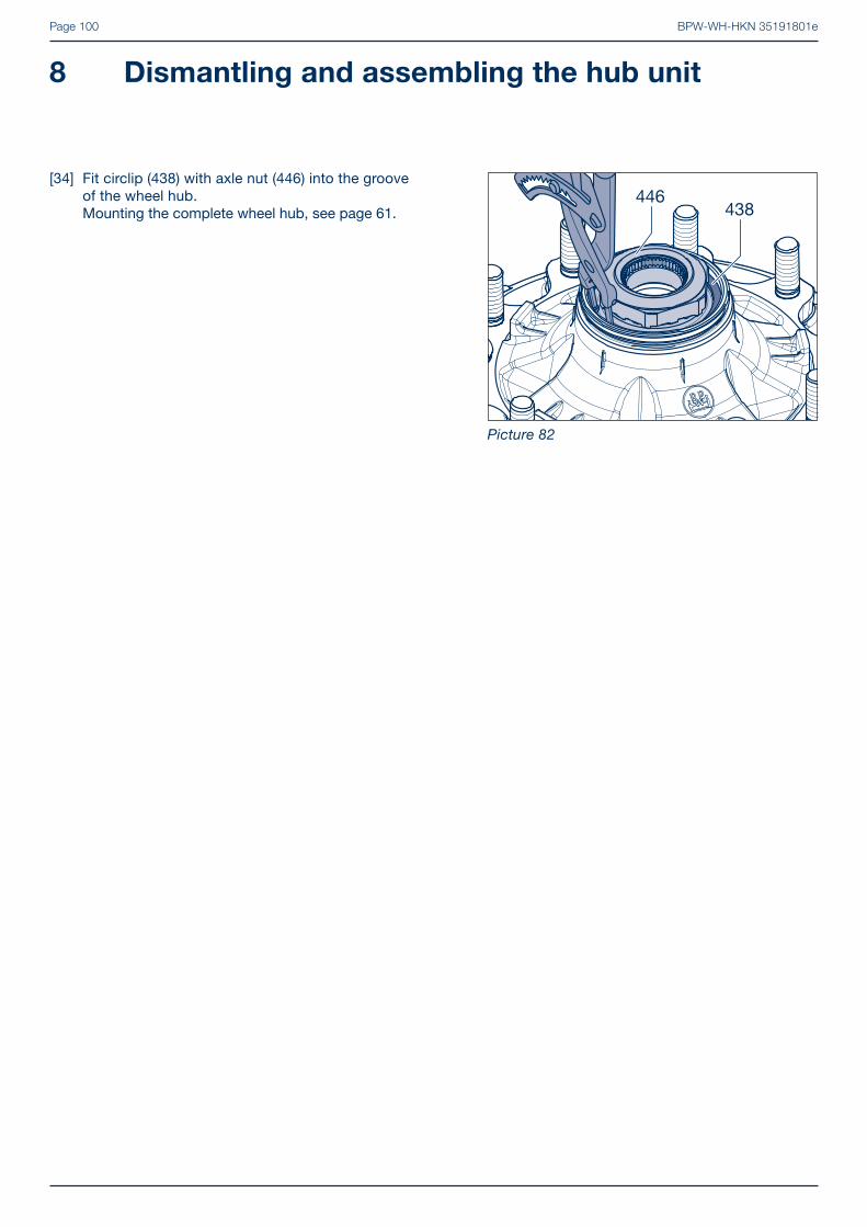
BPW-WH-HKN 35191801ePage 100
[34] Fit circlip (438) with axle nut (446) into the groove of the wheel hub.Mounting the complete wheel hub, see page 61.
Picture 82
8 Dismantling and assembling the hub unit
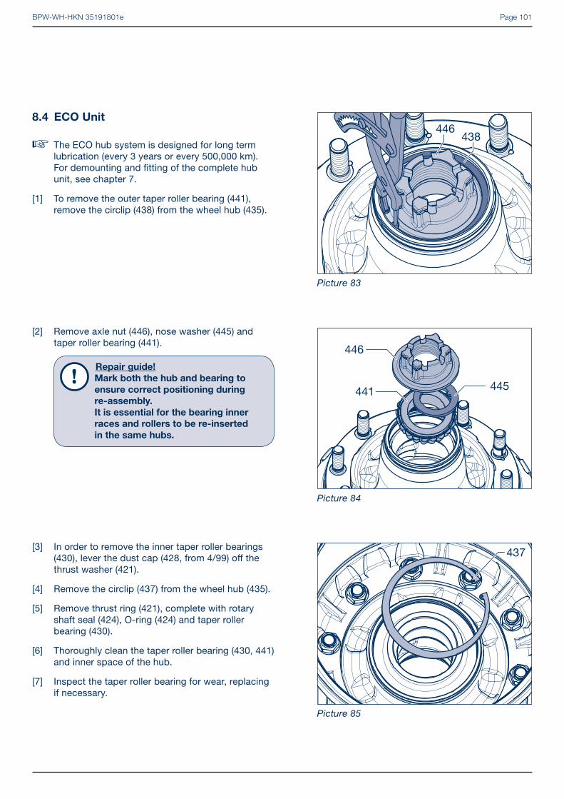
BPW-WH-HKN 35191801e Page 101
[3] In order to remove the inner taper roller bearings (430), lever the dust cap (428, from 4/99) off the thrust washer (421).
[4] Remove the circlip (437) from the wheel hub (435).
[5] Remove thrust ring (421), complete with rotary shaft seal (424), O-ring (424) and taper roller bearing (430).
[6] Thoroughly clean the taper roller bearing (430, 441) and inner space of the hub.
[7] Inspect the taper roller bearing for wear, replacing if necessary.
[2] Remove axle nut (446), nose washer (445) and taper roller bearing (441).
Repair guide!
Mark both the hub and bearing to
ensure correct positioning during
re-assembly.
It is essential for the bearing inner
races and rollers to be re-inserted
in the same hubs.
8.4 ECO Unit
� The ECO hub system is designed for long term lubrication (every 3 years or every 500,000 km).For demounting and fi tting of the complete hub unit, see chapter 7.
[1] To remove the outer taper roller bearing (441), remove the circlip (438) from the wheel hub (435).
Picture 83
Picture 84
Picture 85

BPW-WH-HKN 35191801ePage 102
[11] Centre the bearing outer races and insert them in the wheel hub. Install using a press (min. 6 t) and the BPW insertion tools for the outer bearing.15.005.20052 Ø 100 bearing 3231015.013.20052 Ø 113 bearing 3321315.014.20052 Ø 123 bearing 33215
Inner bearing15.012.20052 Ø 123 bearing 3311615.011.20052 Ø 142 bearing 3311815.008.20052 Ø 160 bearing 32219
Repair guide!
Make sure the bearing cups are
correctly seated in the wheel hub.
[9] Drive the bearing outer races including thrust washer (440) out of the wheel hub (435).
[10] Remove the dust cover (431) from the wheel hub and replace it with a new one.
� Mount the thrust washer making sure it is in the right position, see page 33.
Note:
We recommend removing the wheel to
facilitate handling of the hub/drum unit
when changing the bearing and the
brake drum.
i
[8] Collar studs:Unscrew the nuts (474) from the wheel studs (472) on the drum side. Remove the wheel studs and remove down the hub (435).
Helical wheel studs:Drive the wheel studs (472) out of the removed hub/brake drum unit (do not damage the threads of the wheel studs.) Picture 86
Picture 87
Picture 88
8 Dismantling and assembling the hub unit

BPW-WH-HKN 35191801e Page 103
Helical bolt
� Collared bolts, see page 104.
Repair guide!
Inspect the wheel studs for service-
ability and fi t new wheel studs, if ne-
cessary.
A corrosion inhibitor may be needed
to the spigot guide interface prior to
fi tting the brake drum.
[16] Place the brake drum (380) onto the wheel hub (435). Ensure that the contact surfaces are clean.
[17] Insert or knock in the wheel studs (472) as far as possible into the hub, paying attention to the anti-rotation lock in the brake drum (arrow). The fl attened side of the wheel stud head must be in contact with the brake drum collar (anti-rotation lock).
[13] Press a new rotary shaft seal (422), with the open side facing upwards, onto the thrust ring (421) until it makes fi rm contact.
[14] Version 6,5 - 12 t:Insert the O-ring (424) into the groove of the thrust washer (421).
[15] Smear seal lip and o-ring with BPW special longlife grease BPW ECO-LiPlus.
[12] Use the BPW insertion tool
16.005.22111 Ø 139 for race 6 - 9 t16.014.22111 Ø 159 for race 10 - 12 t
to press the new race (423) centrally into the wheel hub (435).
Picture 89
Picture 90
Picture 91

BPW-WH-HKN 35191801ePage 104
[17] Place wheel hub (435) with the wheel studs (472) on the wheel or another brake drum (380).
Repair guide!
A corrosion inhibitor may be needed to
guide prior to fi tting the brake drum.
[18] Fit brake drum (380) ensuring it is centred correct-ly and sits well. Screw on the nuts (474) with the locking notches facing upward and tighten to the correct tightening torque.
Tightening torques (tensile strength class = 10):
M 20 x 1.5 M = 300 Nm (280 - 330 Nm)M 22 x 2 M = 400 Nm (370 - 440 Nm)
Japan connection (8 wheel studs/pitch circle Ø 285):
M 20 x 1.5 M = 300 Nm (280 - 330 Nm)
Collared bolt
[16] Check wheel studs (472) and, if necessary, insert new wheel studs taking account of the splined pin (436, arrowed).
[18] Use a sleeve and nut (479) to draw the wheel studs (472) in as far as the stop, continue with step [19] on page 105.
Picture 92
Picture 93
Picture 94
8 Dismantling and assembling the hub unit

BPW-WH-HKN 35191801e Page 105
[20] Fit inner roller bearing (430) into wheel hub (435).
Repair guide!
Do not mix up bearing races and outer
bearing rings.
Note:
We recommend greasing the bearings
with BPW grease applicators:
99.00.000.9.54 for bearing 33116/32310
99.00.000.9.55 for bearing 33118/33213.
i
[19] Work BPW special longlife grease ECO-LiPlus thoroughly into the spaces between the conical rollers and the race (430, 441).
BPW special longlife grease ECO-LiPlus
Grease quantity per taper roller bearing
1 2
Axle load Inner bearing Outer bearing
6000 - 9000 kg 120 g 120 g
10000 - 12000 kg 170 g 120 g
13000 - 14000 kg 230 g 150 g
Smear the remaining grease into the outer bearing races of the hub (435).
Picture 95
Picture 96
Picture 97

BPW-WH-HKN 35191801ePage 106
[24] Clip the coarse dirt seal (428) onto the thrust washer (421).
[22] Snap circlip (437) into groove of wheel hub (435).
[23] In the ECO Unit up to 12 t, insert the O-Ring (424, arrow) into the groove in the thrust washer (421).
[21] Insert thrust washer (421), complete with rotary shaft seal (422), into the bearing race (423).
Picture 98
Picture 99
Picture 100
8 Dismantling and assembling the hub unit

BPW-WH-HKN 35191801e Page 107
[28] Snap circlip (438) into groove of wheel hub (435).
� For fi tting of complete hub unit, see page 65.
[26] Attach keyed washer (445) to axle nut (446), using grease.
Repair guide!
The embossed face (BPW and code
number) must point to the taper roller
bearing (441).
[27] Insert axle nut into wheel hub (435).
[25] Fit outer roller bearing (441) into wheel hub (435).
Picture 101
Picture 102
Picture 103

BPW-WH-HKN 35191801ePage 108
[5] Position puller. Pull off the inner taper roller bearing (430), the grease seals (422, 423) and the thrust washer (420) together from the axle stub.
Extractor:BPW no. 02.0125.10.00 for axles 6.5 to 14 t.
Repair guide!
For 10 t axle series K with ABS/
ABV: Unscrew the sensor holder (542).
[6] Thoroughly clean the tapered roller bearing (430, 441) and the spaces inside the hub.
[7] Check the tapered roller bearing for wear and renew it if necessary.
[4] Install hub cap puller (BPW No. see page 19) onto the wheel hub assembly (435) with brake drum (380). Extract from the stub axle.
Repair guide!
Mark both the hub and bearing to
ensure correct positioning during
re-assembly.
It is essential for the bearing inner
races and rollers to be re-inserted
in the same hubs.
8.5 Conventional hub bearing
[1] Reset brake (remove wheels).
[2] Unsrew the hub cap (460).
[3] Remove the split pin (447) from the castle nut (446) and unscrew. Remove the washer (445) from the stub.
Danger!
RISK OF INJURY!
The wheel hub brake drum unit must
be secured against falling.
Use a hoist or a second person to help.Picture 104
Picture 105
Picture 106
8 Dismantling and assembling the hub unit

BPW-WH-HKN 35191801e Page 109
[10] Drive the bearing outer races out of the hub.
[11] Insert the larger bearing outer track with grease shield (431) and the small bearing outer track (without a grease shield), into the wheel hub (435) using an insertion tool until contact is made.
Insertion tools for outer bearing15.005.20052 Ø 100 bearing 3231015.013.20052 Ø 113 bearing 3321315.014.20052 Ø 123 bearing 3321515.003.20052 Ø 138 bearing 32314
Insertion tools for inner bearing15.014.20052 Ø 123 bearing 3321515.012.20052 Ø 123 bearing 3311615.011.20052 Ø 142 bearing 3311815.008.20052 Ø 160 bearing 3221915.007.20052 Ø 188 bearing 32222
� For the correct position of the grease shield (431), refer to page 35.
[9] Remove the wheel studs (472) and then the hub (435).
Note:
We recommend removing the brake
drum to facilitate handling of the hub/
drum unit when changing the bearing.
i
[8] Unscrew the nuts (474) from the wheel studs (472) on the drum side.
Picture 107
Picture 108
Picture 109

BPW-WH-HKN 35191801ePage 110
Trilex wheels
[15] Fix brake drum (380) onto Trilex wheel (435).
[16] Tighten hexagon bolts (390) and lock nuts (392) to appropriate torques.
Tightening torques:M 20 - 8 (SW 30) = 335 Nm (320 - 350 Nm)M 20 - 10 (SW 30) = 450 Nm (420 - 500 Nm)
Repair guide!
Check the self locking function of the
nut. Maximum use of the lock nut is
3 times.
� For TRILEX hub installation and bearing adjust-ment, see installation of conventional hub bearing, see page 67.
[13] Insert wheel hub (435) with wheel studs (435) into the rim.
Repair guide!
A corrosion inhibitor may be needed to
guide prior to fi tting the brake drum.
[14] Fit brake drum (380) ensuring it is centred correctly and interfaces correctly. Screw on the nuts (474) with the locking notches facing upward and tighten to the correct tightening torque.
Tightening torques (tensile strength class 10): M 20 x 1.5 (SW 30) M = 300 Nm (280 - 330 Nm)
M 22 x 2 (SW 32) M = 400 Nm (370 - 440 Nm)
� For hub and brake drum installation and hub bearing ajustment, see page 67.
[12] Check wheel studs (472) and, if necessary, insert new wheel studs taking account of the splined pin (436, arrowed).
Picture 110
Picture 111
Picture 112
8 Dismantling and assembling the hub unit

BPW-WH-HKN 35191801e Page 111
[1] Check sensor (570) for damage and displacement (displacement force 100 - 200 N).
[2] Lubricate clamping bush (571) and sensor with special grease (replace clamping bush). Before fi tting hubs, always press clamping bush and sensor up to endstop.
Picture 1
ABS / ABV 9
The exciter ring (560) is shrink-fi tted
[3] To change a damaged exciter ring heat the exciter ring with a torch and extract.
[4] Heat the replacement exciter ring from 80° to max. 120°C and press into place, ensuring the seat is clean and undamaged.
Picture 3
Picture 2
Pressed exciter ring (560) - ECO Plus 3
[3] Lever the exciter ring from the wheel hub (435). In doing so, avoid damage to the base of the wheel hub.
[4] Clean the stop surfaces for the exciter ring (free from dirt, paint, etc.).
[5] Fit the new exciter ring and fasten with the assembly tool (BPW No. 16.038.22953) until it is in contact, see page 78.

BPW-WH-HKN 35191801ePage 112
The exciter ring (560) is clipped on with a lateral bracket
Repair guide!
Renew the exciter ring if the reduced
preload values mean that fi rm seating
of the exciter ring is no longer guaran-
teed.
[3] Clean the groove and stop surfaces for the exciter ring (free from dirt, paint, etc.).
[4] Press the new exciter ring onto the wheel hub, turning slightly anticlockwise.
[5] The lateral brackets must clip into the groove on the neck of the wheel hub.
The exciter ring (560) is clipped on with a bayonet lock
[3] To renew a damaged exciter ring, release the old exciter ring by striking it lightly anticlockwise and removing it.
Repair guide!
Renew the exciter ring if the reduced
preload values mean that fi rm seating of
the exciter ring is no longer guaranteed.
[4] Clean the groove and stop surfaces for the exciter ring (free from dirt, paint, etc.).
[5] Grease the exciter ring groove and bayonet locks on the exciter ring on both sides.
[6] Insert the exciter ring in the correct position. The rotational stops on the exciter ring must contact right-angled stop surfaces in the hub.
[7] Use a blunt object (e.g. screwdriver) to strike the exciter ring lightly behind the stop cams so as to rotate it clockwise as far as the stop.
Repair guide!
Do not place impact tools in the teeth
of the exciter ring. Make sure there
are no signs of damage on the teeth of
exciter ring.
To avoid mistakes when mounting, we
recommend using the BPW assembly
tool 16.020.22953 when renewing the
exciter ring.
Press the assembly tool down on the outer circumference at the same time as turning clockwise or anticlockwise to release or fasten the exciter ring.
Picture 5
Picture 6
Picture 4
9 ABS / ABV

BPW-WH-HKN 35191801e Page 113
Assembly
[4] Check the return spring (508) on the dust cover (501, 503) for corrosion; fi t a new one if necessary.
[2] Unscrew the (510, M10 / SW 13) securing bolts from the brake anchor plate.
[3] Remove the dust covers.
Removal
[1] Release the return spring (508) from the front dust cover.
Picture 1
Picture 2
Picture 3
Back plate for - Brake ECO Drum 10

BPW-WH-HKN 35191801ePage 114
10 Back plate for - Brake ECO Drum
[7] Mount the opposite dust cover (502, 504) in the same way.
[8] Hook in the return spring (508).
Repair guide!
Check the dust cover is correctly
seated on the edge of the brake drum
and readjust it slightly if necessary.
[6] Use the securing bolt (510, M 10 / SW 13) to secure the dust cover (501, 503) onto the brake anchor plate.Tightening torque: 43 Nm
[5] Insert the dust cover (501, 503) with return spring (508) into the groove (arrow) on the brake anchor plate (camshaft end).
Picture 4
Picture 5
Picture 6

BPW-WH-HKN 35191801e Page 115
[4] Dis-assemble hex nuts (232, 289 / SW 13), spring washers (231) and screws (230, 288).
[5] Remove spherical bearing support plates (285, 286).
Note:
From 2016, the inner camshaft support
bearing fi xing bolts will be standar-
dised and the hexagon nuts (232) with
spring washers (231) will be replaced
with self-locking nuts.
i
Brake camshafts built from 10.2000
[3] Remove the retaining ring (260) from the groove and the sealing ring (272) from the brake camshaft.
� Remove the wheel/hub unit and brake shoes, see sections 7.1 and 7.2.
[1] Unscrew nut (268, SW 32) of brake camshaft (240, 241).Remove the wear indicator (266).
[2] Remove slack adjuster (280) with disc (262).
Brake camshafts built from 10.2000
[3] Remove the push-on bush (260) from the brake camshaft.
Picture 1
Picture 2
Picture 3
Brake camshaft 11

BPW-WH-HKN 35191801ePage 116
11 Brake camshaft
[10] Check bush (210) in brake anchor plate and, if, necessary, change bush (max. bearing play 0.8 mm).
[11] Drive in new bush with mandrel (BPW no. 05.001.04.04.0), with the ring groove (arrowed) pointing towards the grease nipple.
[12] On the outside, the bush must stand back 7.2 + 0.5 mm. Only apply light strokes when driving in and out; apply counter-pressure to brake anchor plate if necessary.
[7] Open clamp (274) on rubber seal (270).
[8] Push the rubber seal with circlip to the middle of the brake camshaft (240, 241).
[9] Remove circlip (250) from the groove.Take brake camshaft out of the brake anchor plate.
[6] Check the spherical bearing (225) in the support bearing and the two sealing rings (271, 272) for wear (max. bearing play 0.8 mm).
Picture 4
Picture 5
Picture 6
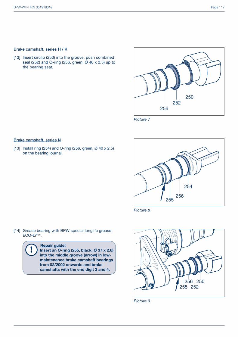
BPW-WH-HKN 35191801e Page 117
[14] Grease bearing with BPW special longlife grease ECO-LiPlus.
Repair guide!
Insert an O-ring (255, black, Ø 37 x 2.6)
into the middle groove (arrow) in low-
maintenance brake camshaft bearings
from 02/2002 onwards and brake
camshafts with the end digit 3 and 4.
Brake camshaft, series N
[13] Install ring (254) and O-ring (256, green, Ø 40 x 2.5) on the bearing journal.
Brake camshaft, series H / K
[13] Insert circlip (250) into the groove, push combined seal (252) and O-ring (256, green, Ø 40 x 2.5) up to the bearing seat.
Picture 7
Picture 8
Picture 9

BPW-WH-HKN 35191801ePage 118
11 Brake camshaft
Note!
Old versions of the support bearing
must be converted to the new version.
[21] Install spherical bearing (225) with the two grease sealing rings (271, 272) inner and outer, to the support bearing holder.
Repair guide!
Mount the grease nipple in the
direction of the wheel.
[17] Push the brake camshaft (240, 241) to the stop on the brake carrier.
[18] Position the plastic ring (258) until it contacts the brake carrier.
[19] Insert the locking ring (250) in the groove of the brake camshaft.
[20] Position rubber seal (270) and secure with clamp (274).
[15] Insert the brake camshaft (240, 241) halfway into the brake anchor plate.
[16] Push on the plastic ring (258) with the domed side pointing towards the middle of the axle, circlip (250), rubber seal (270) and the clamp (274) onto the brake camshaft.
Picture 10
Picture 11
Picture 12

BPW-WH-HKN 35191801e Page 119
[22] Replace self-cutting bolts (230) with hexagon bolts.
[23] Mount the nuts (232, 289 / SW 13) towards the slack adjuster (280).
Tightening torques:
Hexagon bolt (230) with M 8 hex nut (232, SW 13) and spring washer (231). M 8 M = 23 Nm
Hexagon bolt (288) with locknut M 8 (289, SW 13) for securing the ECO-Master shaped plate (285, 286 tighten after mounting and adjusting the slack adjuster), see page 109. M 8 M = 28 Nm Picture 13
[24] Check that the brake camshaft rotates freely.
[25] Position the rubber seal (270) to the interface of the brake carrier. If present, snap the rubber seal into the groove of the brake camshaft (arrow).
[26] Install the securing clip (274).
Picture 14
Note:
From 2016, the inner camshaft support
bearing fi xing bolts will be standar-
dised and the hexagon nuts (232) with
spring washers (231) will be replaced
with self-locking nuts.
Tightening torque: 28 Nm
i
Old design per axle: 8 x Hexagon bolt M 8 x 25 (230, 288) 4 x Hexagon nut M 8 (232) 4 x Spring washer B 8 (231) 4 x Lock nut M 8 (289)
New design per axle: 8 x Hexagon bolt M 8 x 30 (230) 8 x Lock nut M 8 (232)

BPW-WH-HKN 35191801ePage 120
11 Brake camshaft
[27] Grease all bearing surfaces of the brake camshaft via the grease nipples, using BPW special longlife grease ECO-LiPlus.
[28] Push the spacer bush (260) onto the brake cams-haft to act as a slack adjuster stop. Check the brake camshaft again to ensure it can move freely.
After the conversion to the new brake camshaft bearing, the sealing ring (272) and retaining ring is omitted (260, see Picture 2).
� Fit brake shoe and the complete hub unit, see chapter 7.
� Fit slack adjuster, see pages 121 and 122 to 123. Picture 15

BPW-WH-HKN 35191801e Page 121
Manual slack adjuster GSK 12
Brake adjustment
[4] Align slack adjuster using adjusting hexagon with reference to brake cylinder yoke.
[5] Insert and lock the clevis pin. Engage return spring (295) when lever length is between 150 to 180 mm.
Note:
BPW brake cylinders with a round-hole
yoke do not have an outer return spring
(295).
i
[6] The cylinder push rod and slack adjuster should be at an angle of approximately 90° to each other when the brake is applied.
[7] Set play ”a” to 10 - 12 % of connected brake lever length ”B”. E.g. if brake lever length = 150 mm, play = 15 - 18 mm. Grease all points with BPW special longlife grease ECO-LiPlus.
[1] Apply BPW special longlife grease ECO-LiPlus onto teeth of brake camshaft (240, 241).
[2] Slide slack adjuster (280) onto the brake camshaft.
[3] Position washer (262) with the countersink pointing towards the slack adjuster and screw on new lock-nut (268, SW 32). Tighten to a torque of 120 Nm.
Picture 1
Picture 2
Picture 3

BPW-WH-HKN 35191801ePage 122
13 Automatic slack adjuster ECO-Master
[4] Fit washer (262) and wear lining indicator (266) pointing vertically upwards, and new lock nut (268, SW 32) and tighten to 120 Nm.
[5] Remove cap (283), press down clutch sleeve with ring spanner (SW 19, arrowed) and, by turning to left or right, align the bolt hole in brake lever with round hole or end of slot in the yoke.
[1] Grease teeth of brake camshaft 240, 241 with BPW special longlife grease ECO-LiPlus.
[2] Slide automatic slack adjuster ECO-Master (280) onto the brake camshaft.
[3] In this position, fi t yoke of the reaction bracket (285, 286) onto control lever (280/1) (note left and right versions).
� See section 14.2 for wear sensor installation.
Picture 1
Picture 2
Picture 3

BPW-WH-HKN 35191801e Page 123
Adjusting the brake:
[11] Set play ”a” to 10 - 15 % of the connected brake lever length ”B” by turning the adjusting hexagon (keep clutch sleeve pressed down). E.g. if brake lever length 150 mm = play 15 - 22 mm.
[12] When the brake is applied, the cylinder push rod and slack adjuster must be at an angle of approxi-mately 90° to each other.
[13] Grease all points with BPW special longlife grease ECO-LiPlus.
[14] Fit plastic cap (283).
� The setting of the ECO-Master must be readjusted after a change or renewal of the brake cylinder, brake camshaft or the automatic slack adjuster.
[8] Holding the clutch sleeve down, press control lever (280/1) and reaction bracket (285, 286) in the direction of the arrow until it reaches the endstop.
[9] The lug on the control lever will now point to the control point.
[10] Secure plate with two hexagon bolts (230 / 288) and lock nuts (232 / 289, SW 13) to inner side of supporting bearing (see page 119). Tightning torque: M = 28 Nm.
Repair guide!
Control lever lug must align to the
control point after tightening up!
(Basic setting)
[6] Insert clevis pin and lock.
[7] Insert return spring (295) when lever length is 150 to 180 mm.
Note:
BPW brake cylinders with a round-hole
yoke do not have an outer return spring
(295).
i
Picture 4
Picture 5
Picture 6

BPW-WH-HKN 35191801ePage 124
14 Wear sensing
� The wear sensors must only be installed at the same time as the brake linings are replaced!
� Wear sensing does not replace the statutory inspections!
14.1 Function
The wear sensor moves with the slack adjuster. The inner disc (coloured) with the internal hexagon profi le is connected to the brake camshaft in a friction connection, so it turns with the camshaft. There are markings for the fi rst setting on the wear sensor. The projection on the inner disc must be adjusted in advance (A) depending on the thick-ness of the new linings when the system is fi rst fi tted.
As soon as the slack adjuster has adjusted through 90° (B), in other words the camshaft and the inner disc have turned through 90°, the wear limit has been reached and the sensor sends the „SERVICE” signal to the Brake Monitor. The red and green LED lights on the brake monitor fl ash alternately. The service signal changes from black to red and remains in operation without voltage. The brake linings must be renewed!
There is no need to renew the wear sensor; it should be turned back to the starting position like the automatic slack adjuster. It is ready for use again once it has been reset.
Note:
The wear sensor for the drum brake
does not provide the „WARNING“
function on the Brake Monitor.
i
Picture 1
Picture 2
Picture 3

BPW-WH-HKN 35191801e Page 125
Where the slack adjuster has been removed
[6] Apply BPW special longlife grease ECO-LiPlus to the tooth profi le of the brake camshaft.
[7] Push the adapter bush (3), wear sensor (1) and ECO-Master automatic slack adjuster (280) onto the camshaft.
[5] Set the lining thickness (A) on the wear sensor by turning the inner disc.
14.2 Installations instructions
[1] Reset the slack adjuster (280, 281) and renew the brake linings (330), see chapter 7.
[2] Mount the wear indicator on the side opposite to the control lever (280/1) (see arrows). One of the two slack adjusters must be removed.
[3] Remove the hexagon nut (268, SW 32) and brake lining wear indicator (266). (Item 266 is discarded.)
[4] Working on the side of the slack adjuster to be removed, pull the washer (262), the ECO-Master automatic slack adjuster (280) and the bush (260) off the brake camshaft. (Item 10 is replaced.)
Picture 4
Picture 5
Picture 6

BPW-WH-HKN 35191801ePage 126
14 Wear sensing
[12] Use the assembly aid (BPW code number 02.1427.01.00 ) to secure the adapter disc to prevent it from turning as well and tighten the hexagon nut (268, picture 8) to a tightening torque of 80 - 90 Nm.
[13] Secure the sensor cable to the base plate using a cable tie. Make sure the automatic slack adjuster can move freely!
Side of the mounted slack adjuster (280)
[10] Adjusting the brake, see page 109.
[11] Push the wear sensor (1) and the adapter disc (2) onto the camshaft.
[8] Adjusting the brake, see page 109.
Repair guide!
When doing this, make sure that the
slack adjuster does not contact the
wear sensor otherwise the setting of
the inner disc of the wear sensor
(A, picture 5) will be incorrect.
[9] Place the washer (262) and new plastic disc (4) on the brake camshaft and tighten the locking nut (268, SW 32) to a tightening torque of 80 - 90 Nm.
Picture 7
Picture 8
Picture 9

BPW-WH-HKN 35191801e Page 127
Brake cylinder 15
15.3 Installation diaphragm cylinder (410)
[1] Screw the lock nut and yoke onto the cylinder push rod.
[2] Set the specifi ed push rod length in relation to the cylinder base (maintain a clearance of min. 40 mm!). Initially screw the lock nut on to secure the yoke.
� Spring brake cylinder see chapter 15.4.
[3] Reset the slack adjuster.
[4] Fit the brake cylinder to the mounting bracket. Check the required brake lever length to appropriate hole in the slack adjuster arm.
15.2 Preparations for assembly
- In order for the brake cylinder to function correctly, the contact surfaces on the mounting bracket should be clean and fl at within 0.4 mm.
- During conversion or retrofi tting work, make sure there is no damage on the air cylinder bracket or the contact surface.
- The mounting brackets should only be primed prior to installation of the bracket cylinder (max. paint thickness 100 μm).
- BPW brake cylinders must only be installed using the fi xtures supplied by BPW. No other parts such as washers, plates, retaining rings, etc. may be used.
15.1 Maintenance
Statutory inspections must be carried out. No other particular maintenance work is required.
The diaphragm cylinder should be removed and cleaned at least every 2 years. Only new wearing parts are to be fi tted when installing brake cylin-ders.
Danger!
DANGER OF FATAL INJURY !
It is not possible to strip down the
spring brake section!
Never apply force in an attempt to
open it. Picture 1
Picture 2
Picture 3

BPW-WH-HKN 35191801ePage 128
15 Brake cylinder
Repair guide!
Comply with the installation instruc-
tions for the slack adjuster or section
13 when connecting the push rod or
yoke to the slack adjuster.
Do not pull out the push rod of the
brake cylinder during installation or
adjustment work.
Note:
BPW brake cylinders with a round-hole
yoke do not have an outer return spring
(295).
i
[8] An outer return spring (295, picture 4 page 109) is required if slot-type yokes are used. This must be taken into account in the EC brake calculation.
[9] Remove the plug from the drain hole at the lowest point.
[5] Fit on the mounting nuts until tight.
[6] Tighten alternative sides to 180 Nm (180 - 210 Nm) using a torque wrench.
[7] Tighten the lock nut (1) on the yoke to 80 Nm.
Picture 4
Picture 5
Picture 6

BPW-WH-HKN 35191801e Page 129
[15] Remove the wind off bolt to release the spring after installing the cylinder and insert it into the corresponding fi xture.
[16] Tighten the nut to 20 Nm.
[17] Insert the plug (6) back into the brake cylinder.
[18] Secure and adjust the slack adjuster in accordance to section 12.
[19] Tighten the compressed air connections (SW 24) and the plug to 45 Nm.
Note:
We recommend only installing one
brand of brake cylinders on any
particular vehicle!
i
[11] Fold open the plug (6) on top of the spring brake cylinder (410).
[12] Apply min. 6 bar to compressed air connection 1.2.
[13] Insert the wind off bolt (1) into the cylinder and clip it into place.
[14] Fit the washer (2) and hexagon nut (3) onto the wind - off bolt and use a ring spanner (SW 24) to fully compress the spring. (Brake off position.)
� See steps [1] - [9] for further assembly steps for the diaphragm cylinder.
15.4 Installation spring brake cylinder (410)
[10] Remove the wind off bolt from the retaining fi xture. The wind off bolt device consists of the threaded rod (1), washer (2), nut (3) and split pin (4).
For new versions, a protection cap with thread (5) replaces the split pin.
Picture 7
Picture 8
Picture 9

BPW-WH-HKN 35191801ePage 130
Repair guide!
The ECOMETER is not allowed to be
installed, removed or set in a poten-
tially explosive atmosphere.
Renew the unit in case of damage to
the housing, the battery compartment
or battery cables, the casting com-
pound or other damage to the unit.
Protect the reed contact in the cap
against damage. Do not stack the caps
one inside the other, for example.
The ECOMETER for ECO Plus 2 axles
with bayonet lock must be mounted
with a new O-ring.
The ECOMETER for ECOPlus axles must
be fi tted and dismantled using only
torque controlled (not impact!) airguns
or manually with a torque wrench.
Do not bend the magnet with the
spring when installing and removing.
Picture 2
Picture 3
16 Digital ECOMETER
16.1 Function
A minicomputer that is protected from water and dirt counts the wheel revolutions using a magnet and a reed contact.
The tyre rolling circumference is set initially and cannot be changed subsequently.
There is a sensed area behind the display disc which is indicated by the two protruding BPW logos. The display is activated by bringing a metallic object (ferromagnetic) close to the sensed area of the logo.
Picture 1

BPW-WH-HKN 35191801e Page 131
[1] Pass the magnet over the reed contact. The fl ashing digit can be incremented by one every time the sensed area on the outside of the display is activated (by a metallic object). After reaching 9, the digit reverts to 0, etc.
[2] Pass the magnet over the reed contact in the hub cap again. The next digit fl ashes. Set this one as well by activating the sensed area on the outside of the display. Repeat this procedure until the digits „3248“ have been changed to the precise tyre rolling circumference that is required. This confi rms the set tyre circumference.
See the table on page 132 for rolling circum-ferences.
Setting the tyre rolling circumference
The unit is changed to setting mode by touching the reed contact in the hub cap with the magnet (on the clasp locking ring) and at the same time bringing a metallic object (ferromagnetic) close to the sensed area on the outside of the display.
The display goes out if the setting procedure is interrupted for a long period. Pressing any contact resumes the setting procedure from the point at which it was interrupted.
The display „9-U3248“ appears for about 10 seconds as identifi cation of setting mode:
16.2 Start-up / Setting the tyre rolling
circumference
On delivery, the digital ECOMETER is in test mode. Bringing a metallic object (ferromagnetic) close to the sensed area on the display causes „CONT“ to be displayed. „REED“ is displayed when the reed contact is activated by the magnet.
Picture 4
Picture 5
Picture 6
Protected sensor contacts

BPW-WH-HKN 35191801ePage 132
16 Digitaler ECOMETER
Rolling circumferences
The measurements are based according to stan-dard ETRTO. Data of various tyre manufacturers can slightly deviate.
[3] Setting mode is exited by changing the fi rst digit from 9 to 0: When the nine is fl ashing, it can be reduced from nine to zero by activating the sensed area (with a metallic material). This confi rms the set tyre circumference.
Note:
Following this, it is no longer possi-
ble to change the set value for the
tyre rolling circumference!
i
[4] The display switches off automatically.
Picture 7
Tyre size Rolling circumference
± 2%
245/70 R 19.5 2559 mm
255/60 R 19.5 2469 mm
265/70 R 19.5 2644 mm
285/70 R 19.5 2730 mm
385/55 R 19.5 2785 mm
425/55 R 19.5 2937 mm
435/50 R 19.5 2840 mm
445/45 R 19.5 2730 mm
455/65 R 19.5 3251 mm
10.00 R 20 3209 mm
11 R 22.5 3203 mm
12 R 22.5 3306 mm
275/70 R 22.5 2922 mm
315/60 R 22.5 2879 mm
315/80 R 22.5 3282 mm
385/55 R 22.5 3018 mm
385/65 R 22.5 3248 mm
425/65 R 22.5 3406 mm
445/65 R 22.5 3485 mm
455/40 R 22.5 2850 mm
455/45 R 22.5 3013 mm

BPW-WH-HKN 35191801e Page 133
ECOPlus
[2] Insert the retaining key of the new clasp locking ring with integrated magnet into the groove bet-ween the axle stub and the nut. (Do not turn back the axle nut.)
[3] Hook the clasp locking ring behind the edge of the axle nut. It is essential to hook in the safety lock on the clasp locking ring.
[4] After setting the tyre rolling circumference, apply a thin coat of BPW special longlife grease ECO-LiPlus to the ECOMETER in the area of the connection thread.
[5] Screw ECOMETER onto the wheel hub and tighten to the tightening torque of 800 Nm.
Important!
Do not use an impact driver.
Repair guide!
Do not bend the magnet with the
spring during installation and removal.
[3] Insert the clasp locking ring into the annular groove on the end of the hexagon profi le of the axle bolt and make sure it is exactly seated. Press the wire into the annular groove if necessary.
[4] Insert the new O-ring into the groove in the wheel hub.
[5] After setting the tyre rolling circumference, mount the ECOMETER as described on page 60 (steps 36 - 39).
16.3 Installation
[1] Remove the hub cap and hooked spring ring, see also chapter 6.1.
ECO Plus 2
[2] Insert a new retaining key with integrated magnet into the recess in the axle bolt and the gearing of the toothed lock washer. (Do not turn back the axle screw.)
Picture 8
Picture 9
Picture 10

BPW-WH-HKN 35191801ePage 134
16 Digitaler ECOMETER
Fitting a new battery
[1] Remove the ECOMETER from the hub.
[2] Unscrew the battery housing.
[3] Fit a new battery (code number 02.0130.97.00). The display shows the current battery voltage.
The voltage of a new battery should not be less than 3 volts.
[4] Carefully close the battery compartment cover and and refi t the retaining screw.
16.4 Battery
The ECOMETER is only allowed to be operated with genuine BPW batteries (code number 02.0130.97.00).
Warning!
The ECOMETER is not allowed to
be installed, removed or set in a poten-
tially explosive atmosphere.
If the battery voltage drops below a specifi c value, the mileage display starts fl ashing during the dis-play readout and a new battery should be fi tted.
Reading out
Pass a ferromagnetic material over the sensed area to activate it:
First, the mileage appears (value in kilometres, e.g. „000567.3“) and then the set tyre rolling circumference (value in mm, e.g. „-U3248“).
The battery voltage is too low if the mileage dis-play fl ashes during the read out. Fit a new battery.
Picture 11
Picture 12
Picture 13

BPW-WH-HKN 35191801e Page 135
16.5 Modifi cation
When converting from the digital ECOMETER to the mechanical ECOMETER or BPW hub cap without kilometre counter, remove the clasp locking ring with magnet and install the standard clasp locking ring without magnet (see illustration).
After the battery has been changed, the program and the display are resumed automatically (the distance value in kilometres continues to be stored in temporary memory).
Damage Renew the unit in case of damage to the housing,
the battery compartment or battery cables, the casting compound or other damage to the unit.
Disposal Remove the battery from the ECOMETER.
Dispose of the ECOMETER and the battery in accordance with the relevant national regulations.
Picture 14

BP
W-W
H-H
KN
351
9180
1e
Your partner on the path to economic v iabi l i ty
BPW Bergische Achsen Kommanditgesellschaft
Postbox 12 80 · 51656 Wiehl, Germany · Phone +49 (0) 2262 78-0
[email protected] · www.bpw.de
Copyright © 2022 FDOKUMEN