Hydraulic Brakes - Central States Bus Sales
120
531 1 APPENDIX 2 APPENDIX 3 APPENDIX L Overview All American Forward Engine buses are available with hydraulic disc brakes. Hydrau- lic brakes are not offered on All American Rear Engine. When hydraulic brakes are applied, two hydraulic systems come into play: The brake system, which is passive; and the power steering hydraulic system, which is pump driven. Although the two systems interact, they are separate closed circuits with separate fluid supplies. The component at which the two systems interact is the Bosch Hydro-Max™ master cylinder/booster assembly. Under normal conditions with the engine running, the driver presses the brake pedal, acutating the master cylinder portion of the HydroMax which contains DOT 3 brake fluid which transfers pressure to the brake calipers on each wheel. The booster portion of the HydroMax receives hydraulic steering fluid and allows hydraulic pres- sure generated by the power steering pump to assist (boost) in actuating the master cylinder. A pressure switch mounted on the body of the brake booster monitors pressure in the hydraulic power steering system. If pressure is absent when brakes are applied (as when the engine is not running), the pressure switch activates an electric pump mounted on the underside of the HydroMax to provide brake boosting power. The BRAKES warning light on the driver’s instrument panel is also activated. When there is no boost pressure in the HydroMax, and no boost is being pro- vided by the electric pump (as when the ignition switch is off), the hydraulic brakes still operate, but require significantly greater pressure at the pedal. The master cylinder, power boosted by the power steering pump system, trans- fers hydraulic pressure to the Antilock Brake System (ABS) modulator, mounted on a frame cross member located just aft of the transmission above the front end of the driveline. The modulator distributes the pressure in the brake system caliper assem- blies mounted on each wheel, according to control signals it receives from the ABS Electronic Control Unit (ECU), which is mounted inside a compartment accessible through the Driver-side front access panel on the front of the bus. At each wheel, a wheel speed sensor detects the speed of the rotating wheel and sends a signal to the ECU. The ECU monitors these wheel speed signals and controls the modulator to adjust the braking pressure at each wheel individually, so as to maintain traction (avoid wheel lock) at all wheels. An All American Forward Engine bus equipped with hydraulic brakes may also be equipped with a brake interlock system, which actuates the brakes under certain conditions, such as a wheelchair lift door being open while the engine is running. The brake interlock system uses its own separate fluid supply, filled with DOT 5 fluid. Blue Bird All American Forward Engine buses equipped with hydraulic brakes employ a cable-actuated drum-type parking brake installed on the rear of the trans- mission. The parking brake is not to be used as a normal service brake, but can be used to help stop the bus in an emergency situation. HYDRO-MAX BOOSTER & MASTER CYLINDER ABS SYSTEM BRAKE CALIPERS HydroMax Booster / Master Cylinder unit Boost Pump Electric Motor HYDRAULIC BRAKES
-
Upload
khangminh22 -
Category
Documents
-
view
1 -
download
0
Transcript of Hydraulic Brakes - Central States Bus Sales

531
1APPENDIX
2APPENDIX
3APPENDIX L
OverviewAll American Forward Engine buses are available with hydraulic disc brakes. Hydrau-
lic brakes are not offered on All American Rear Engine.
When hydraulic brakes are applied, two hydraulic systems come into play: The
brake system, which is passive; and the power steering hydraulic system, which is
pump driven. Although the two systems interact, they are separate closed circuits
with separate fluid supplies. The component at which the two systems interact is the
Bosch Hydro-Max™ master cylinder/booster assembly.
Under normal conditions with the engine running, the driver presses the brake
pedal, acutating the master cylinder portion of the HydroMax which contains DOT 3
brake fluid which transfers pressure to the brake calipers on each wheel. The booster
portion of the HydroMax receives hydraulic steering fluid and allows hydraulic pres-
sure generated by the power steering pump to assist (boost) in actuating the master
cylinder.
A pressure switch mounted on the body of the brake booster monitors pressure
in the hydraulic power steering system. If pressure is absent when brakes are applied
(as when the engine is not running), the pressure switch activates an electric pump
mounted on the underside of the HydroMax to provide brake boosting power. The
BRAKES warning light on the driver’s instrument panel is also activated.
When there is no boost pressure in the HydroMax, and no boost is being pro-
vided by the electric pump (as when the ignition switch is off), the hydraulic brakes
still operate, but require significantly greater pressure at the pedal.
The master cylinder, power boosted by the power steering pump system, trans-
fers hydraulic pressure to the Antilock Brake System (ABS) modulator, mounted on a
frame cross member located just aft of the transmission above the front end of the
driveline. The modulator distributes the pressure in the brake system caliper assem-
blies mounted on each wheel, according to control signals it receives from the ABS
Electronic Control Unit (ECU), which is mounted inside a compartment accessible
through the Driver-side front access panel on the front of the bus.
At each wheel, a wheel speed sensor detects the speed of the rotating wheel and
sends a signal to the ECU. The ECU monitors these wheel speed signals and controls
the modulator to adjust the braking pressure at each wheel individually, so as to
maintain traction (avoid wheel lock) at all wheels.
An All American Forward Engine bus equipped with hydraulic brakes may also
be equipped with a brake interlock system, which actuates the brakes under certain
conditions, such as a wheelchair lift door being open while the engine is running. The
brake interlock system uses its own separate fluid supply, filled with DOT 5 fluid.
Blue Bird All American Forward Engine buses equipped with hydraulic brakes
employ a cable-actuated drum-type parking brake installed on the rear of the trans-
mission. The parking brake is not to be used as a normal service brake, but can be
used to help stop the bus in an emergency situation.
HyDro-mAX boostEr& mAstEr cylINDErAbs systEmbrAkE cAlIPErs
HydroMax Booster / Master Cylinder unit
Boost Pump Electric Motor
H y d r a u l i c B r a k e s

532
L
s e r v i c e m a n u a l
Appendixes In This Chapter
Appendix 1: Hydro-Max Hydraulic Brake Booster and Master Cylinder. This Bosch
publication details the operation of the master cylinder & booster assembly, and in-
cludes troubleshooting information.
Appendix 2: Hydaulic ABS. Meritor Wabco Maintenance Manual 39. Detailed in-
formation on the ABS Module and other ABS components. Includes troubleshooting
using blink codes and Meritor Wabco Toolbox diagnostic software.
Appendix 3: Four Piston Quadraulic Disc Brake Caliper. Meritor MM-2075. Detailed
information on disassembly, inspection, and reassembly of the brake calipers.
Maintenance OverviewServicing the hydraulic brake system involves procedures at several levels.
• Regularly scheduled maintenance tasks such as inspection, fluid replenish-
ment, and linkage lubrication. See the Hydraulic Brakes Maintenance chart
below (also included in the Brakes chart in the Specs & Maintenance Chap-
ter).
• Replace and/or service normal wear parts, such as brake pads and rotor sur-
faces, as they approach their service life specifications. These procedures must
be performed according to the manufacturers’ specifications. References are
provided in the various component sections that follow.
• More involved overhaul or rebuild procedures for major components; for ex-
ample, replacement of seals in the caliper(s). These also must be performed
according to manufacturers’ procedures. Appropriate references are provided
in the respective component descriptions below.
• When any part of the brake system’s hydraulic fluid circuit is disassembled
or loosened, the system must be bled before returning the bus to operation.
This must be done according to procedure for the Meritor Wabco ABS system.
See Hydraulic Brakes Appendix 2 (Meritor Wabco publication: Hydraulic ABS
Maintenance Manual no. 39). Arvin Meritor also provides additional informa-
tion online at www.arvinmeritor.com.
• Whenever servicing any part of the hydraulic brake system, remember that up
to three different sub-systems may be involved, each with its own fluid circuit
(steering & boost circuit, brake circuit, brake interlock circuit). Each of these ar
closed circuits using different fluid types. The different fluid types must not be
intermixed and must not be allowed to contaminate each other.

533
L
h y d r a u l i c b r a k e s
Hydraulic Brakes Maintenance
operation
Interval: Months/1000 MIleswhichever occurs first
notes1 / 3,
000
3 / 5,
000
3 / 24
,000
6 / 6,
000
6 / 10
,000
12 / 1
2,00
0
12 / 2
4,00
0
24 / 2
4,00
0
Hydraulic BrakesCheck fluid level • Use DOT-3 brake fluid.
Inspect booster & master cylinder • Inspect for signs of leakage or damage.
Adjust park brake lever • Adjust engagement pressure at the lever to 90-100 lbs.
Hydraulic Brakes InterlockCheck fluid level • Use DOT-5 brake fluid.
Hydraulic Brake Wheel EndsInspect calipers • Inspect for signs of leakage or damage.
Lubricate calipers • See Meritor documentation.
Check pad thickness weekly or as needed in severe applications Minimum 1⁄8 inch (3.175 mm).

534
L
s e r v i c e m a n u a l
PRIM
SEC
To Caliper Assy(Upper Piston Port)
Rotate 90° ElbowFor Maximum
Chassis Component Clearance.
To Caliper AssyRotate 90° Elbow
For MaximumChassis Component
Clearance.(Upper Piston Port)
Bracket PlacementOn Crossmember
With Hendrickson Air Suspension
To Caliper Assembly
Torque to140 ft/lbs.
Mount bracketTo top of axle
At the king-pin intersectionUsing existing fasteners.
Torque 11–16 ft lb

535
L
h y d r a u l i c b r a k e s
Hydraulic Brake system
D0
11
67
38
D
PRIM
SEC
To Caliper Assy(Upper Piston Port)
Rotate 90° ElbowFor Maximum
Chassis Component Clearance.
To Caliper AssyRotate 90° Elbow
For MaximumChassis Component
Clearance.(Upper Piston Port)
Bracket PlacementOn Crossmember
With Hendrickson Air Suspension
To Caliper Assembly
Torque to140 ft/lbs.
Mount bracketTo top of axle
At the king-pin intersectionUsing existing fasteners.
Torque 11–16 ft lb

536
L
s e r v i c e m a n u a l
Brake light switch Mounting & adjustment
1. Install brake light switch (item 5) to hydraulic brake switch bracket on driver’s
platform.
2. Pull down on brake lever assembly with just enough pressure to remove
clearances in clevis pin, bearing, and brake booster yoke.
3. Move the switch/bracket assembly vertically within the slots of the bracket
until the contacts close. Lower the assembly an additional 1/8 inch.
4. Tighten switch mounting fasteners.
5. Check to make sure switch contacts are open with brake lever assembly re-
leased.
Master cylinderThe master cylinder is mounted directly to the body of the hydraulic booster. These
two components are mounted as a unit to the underside of the chassis front assem-
bly, directly below the Driver area floor.
The fluid reservoir for the brake system is mounted in a compartment on the
floor behind the Driver’s seat, and is accessible from inside the bus. The reservoir
contains DOT 3 brake fluid.
When the brake is operated, pistons in the master cylinder drive brake fluid that
it receives from the reservoir into the brake lines, transferring the mechanical force
to the brake calipers at each wheel.
The master cylinder is internally divided into two hydraulic circuits; one for the
front brakes, and one for the rear. The fluid reservoir is similarly divided, thus its two
fill caps. Hydraulic leakage or complete failure in one system does not affect function
of the other system.
An electric sending unit is mounted to the side of the master cylinder. If signifi-
cant pressure difference is detected between the front and rear brake circuits, the
sensor sounds a warning buzzer in the driver’s area and turns on the BRAKES light on
the instrument panel.
Troubleshooting
Symptoms that may indicate master cylinder failure include, but are not limited to:
• Brake fluid leakage from between the master cylinder and booster.
• Hard pedal. Excessive pressure is required at the pedal to apply brakes.
• Excessive pedal travel. Pedal goes to the floor.
• Actuated pedal does not return.
• Brake drag.
Master Cylinder Unit
Boost Pump Electric Motor
Hydraulic Booster Unit
Pressure Sending Unit

537
L
h y d r a u l i c b r a k e s
For a more detailed description the master cylinder’s operation, as well as trouble-
shooting guidelines, see Hydraulic Brakes Appendix 1 (Bosch publication: HydroMax
Hydraulic Brake Booster and Master Cylinder). If the master cylinder is determined to
be malfunctioning, it must be replaced. Replacements are available from your Blue
Bird Parts Dealer.
Removal
The master cylinder may be unbolted from the booster without removing the entire
master cylinder/booster combination as a unit. However, it is possible that when the
master cylinder is unbolted from the booster, the booster’s internal spring may cause
its o-ring seal to pop out, spilling hydraulic fluid. Thus, it is a good practice to take
measures to catch the hydraulic fluid in case this occurs.
1. Park the bus on a level surface with parking brake on.
2. Disconnect the negative terminal of the battery.
3. Disconnect the harness wire from the master cylinder’s balance sending
unit.
4. Position a suitable container under the master cylinder/booster assembly.
5. Disconnect the two hydraulic lines from the master cylinder.
6 Remove the four bolts and nuts which fasten the master cylinder to the
booster and remove the master cylinder.
Reinstallation
Install the master cylinder by reversing the removal procedure.
1. Mount the master cylinder to the booster and tighten the four bolts to 25–30
ft. lbs. (33.9–40.7 Nm).
2. Reattach the brake fluid lines and tighten the nuts to 200 in. lbs. (22.5 Nm).
3. After installation, the brake system must be bled before operating the bus.
This must be done according to procedure for the Meritor Wabco ABS sys-
tem. See Brakes Appendix 2 (Meritor Wabco publication: Hydraulic ABS
Maintenance Manual no. 39).

538
L
s e r v i c e m a n u a l
BoosterThe brake booster is the portion of the HydroMax unit which is mounted directly to
the support bracket under the Chassis front assembly. The booster itself serves as the
support for the brake master cylinder.
During normal operation, fluid pumped by the hydraulic pump flows through
the booster’s inlet, throttle valve, and power piston, and then exits through the outlet
port. When the brake pedal is applied, the booster’s input rod activates the throttle
valve, restricting flow through the power piston. The resulting pressure, acting upon
the power piston, applies force to the master cylinder’s primary piston, “boosting”
the force applied to it by the driver.
Within the HydroMax assembly, the steering fluid which powers the booster is
isolated from the DOT 3 brake fluid which acts upon the master cylinder.
The Booster assembly incorporates an electric motor/pump which provides
braking boost whenever hydraulic flow ceases in the booster. A flow switch mounted
at the top of the booster, next to the outlet port is held open by the normal flow of
hydraulic fluid into the outlet. When pressure is absent, this switch closes, energizing
a power relay, and thereby providing electrical power to the motor. The switch also
causes a buzzer to sound in the driver’s area and the BRAKES warning light to illumi-
nate in the instrument panel.
Troubleshooting
Symptoms which may indicate booster failure include, but are not limited to:
• Hydraulic steering fluid leakage between the master cylinder and booster.
• Hard pedal. Excessive pressure is required at the pedal to apply brakes.
• Actuated pedal does not return.
• Brake self apply May indicate self applied booster due to too high fluid flow.
• Brake drag. May indicate selfapplied booster due to too high fluid flow
For a more detailed description the booster’s internal operation, as well as trouble-
shooting guidelines, see Hydraulic Brakes Appendix 1 (Bosch publication: HydroMax
Hydraulic Brake Booster and Master Cylinder). If the booster is determined to be
malfunctioning, it must be replaced. Replacements are available from your Blue Bird
Parts Dealer.

539
L
h y d r a u l i c b r a k e s
Removal
As described above, the booster supports the master cylinder. Although it is possible
to remove the booster without removing the master cylinder, doing so will require
devising means by which to support the weight of the master cylinder so as to avoid
bending the brake lines. The following procedure therefore assumes that the master
cylinder/brake booster assembly will be removed as a unit, and that the two com-
ponents will be separated after removal. Note that this will require that the brake
system be bled after reassembly.
1. Park the bus on a level surface with parking brake on.
2. Disconnect the negative terminal of the battery.
3. The brake balance sensor and the booster pressure sensor lead to a single
connector at the wire harness. Disconnect the connector. Disconnect the
boost pump motor relay.
[Caution]Do not apply the brakes after removal of the input hose unless
the reserve boost system is disconnected. Reserve boost pressure will blow the
inlet check valve out of the booster.
4. Loosen the hose clamp at the booster outlet, remove the hose and plug its
end.
5. Remove the hose fitting at the booster inlet and plug its end, and/or support
it vertically to prevent spillage.
6. Disconnect both output brake lines from the master cylinder.
7. Disconnect and plug the reservoir fluid lines which lead to / from the master
cylinder.
8. Remove the cotter pin, washer and clevis pin which connect the booster
push rod to the brake pedal lever.
9 Remove the four nuts which secure the booster’s mounting studs to the
mounting bracket. While doing this, have a helper support the master cyl-
inder/booster assembly, or devise other means to support it while removing
the nuts.
10. With the HydroMax assembly removed from the bus, remove the four bolts,
nuts, and washers which fasten the master cylinder unit to the booster unit.

540
L
s e r v i c e m a n u a l
Servicing
If found defective, the brake booster must be replaced. Contact your Blue Bird parts
dealer for a replacement. Refer to Appendix 1 for more information.
Installation
Install the booster by reversing the removal procedure.
1. Assemble the master cylinder to the booster and tighten the four bolts to
25–30 ft. lbs. (33.9–40.7 Nm).
2. Mount the reassembled master cylinder/booster unit on the vehicle and
tighten the four mounting nuts to 18–25 ft. lbs. (24.4–33.9 Nm).
3. Reattach the brake fluid lines to the master cylinder and tighten the nuts to
200 in. lbs. (22.5 Nm).
4. Reattach the brake fluid reservoir lines to the master cylinder and tighten.
5. Attach the booster push rod to the brake pedal lever with the clevis pin and
washer. Use a new cotter pin.
6. After installation, the brake system must be bled before operating the bus.
This must be done according to procedure for the Meritor Wabco ABS sys-
tem. See Appendix 2.

541
L
h y d r a u l i c b r a k e s
aBs ModulatorThe ABS modulator is mounted in a bracket affixed to a frame crossmember, just
above the forward end of the front most driveshaft. The modulator houses the ABS
solenoid control valves (one inlet valve and one outlet valve per wheel), a pump mo-
tor, and two accumulators
Under normal braking conditions, the modulator unit receives brake
fluid pressure from its two inlets (one for the front brakes; one for the rear)
and distributes it evenly to the brake calipers. However, if a one-quarter
turn of the wheels is detected, the ABS Electronic Control Unit cause a
solenoid control valve to regulate the brake pressure. During such an ABS
stop, the solenoid valve is rapidly pulsed; opening and closing up to 40
times per second to control the brake pressure and prevent wheel lock.
When this occurs, the driver may notice a pulsation of the brake pedal.
Troubleshooting
For troubleshooting and diagnosis of the modulator, see Appendix 2. The modulator
should be replaced as a unit if found to be defective.
Removal
Removing the modulator involves three electrical plugs, six brake fluid tubes, and
three mounting studs:
1. Park the bus on a level surface with parking brake on.
2. Disconnect the negative terminal of the battery.
3. Disconnect the chassis wire harness’s control plug and main ground plug
from the modulator unit. Disconnect the pump’s pigtail connector from the
chassis wire harness.
4. Mark the six brake lines for ease of installation. Place a container under the
modulator assembly to catch leaking brake fluid. Disconnect the six brake
lines.
5 The mounting holes of the bracket are slotted and open on the top. Loosen
the mounting nuts on the modulator’s three rubber isolator mounts remove
the modulator.
ABS Modulator

542
L
s e r v i c e m a n u a l
Reinstallation
Reinstall the modulator in the reverse order of removal, being sure to tighten fittings
to the appropriate torque values:
1. Place the modulator in its bracket, being sure the studs of the three rubber
isolators seat in the bottom of the mounting slots. Tighten the mounting
stud nuts to 132 in. lbs (15 Nm).
2. Connect the main ground plug and the control plug on the chassis wire
harness to the unit. Connect the pump’s pigtail connector into the wire har-
ness.
3. Connect the two small brake lines and tighten to 108 in. lbs. (12 Nm).
4. Connect the four larger brake lines and tighten to 132 in. lbs. (15 Nm.).
5. After installation, the brake system must be bled before operating the bus.
This must be done according to procedure for the Meritor Wabco ABS sys-
tem. See Brakes Appendix 2 (Meritor Hydraulic ABS Maintenance Manual no.
39) for brake bleeding procedure.

543
L
h y d r a u l i c b r a k e s
Wheel speed sensorsA wheel speed sensor is mounted on the inboard side of each wheel assembly. As the
wheel rotates, the flats of a notched casting in the wheel end assembly pass in close
proximity to the sensor. The sensor responds to the passing notches magnetically
and outputs a voltage, which increases with the speed of the wheel. This signal is
then used by the ABS ECU to determine when wheel lock is immanent. All four wheel
speed sensors are the same model, 90-degree Meritor Wabco WS-24.
Troubleshooting
Appendix 2 includes specific information on testing the output voltage and resis-
tance of the wheel speed sensors. Sensors found out of range should be replaced.
Removal
The sensors are held in place by the friction fit of spring clip sleeves which are in-
serted into the mounting blocks with the sensors. To remove a sensor:
1. Apply the parking brake. Chock the tires to prevent vehicle movement.
2. Disconnect the sensor cable from the wire harness and remove the cable
from any cable clamps or clips.
3. Pull the sensor straight out of its socket, using a twisting motion if required.
Do not pull on the wires. On front wheels, removal of the sensor may be im-
peded by interference with the steering arm casting. If this occurs, removal
may be more easily achieved by removing the two bolts which secure the
sensor’s mounting block.
4. The spring clip may remain in the socket, or may pull out with the sensor.
Remove and inspect the spring clip. Replace any damaged spring clips with
new ones.
Wheel Speed Sensor, Front
Wheel Speed Sensor, Rear

544
L
s e r v i c e m a n u a l
Installation
The steps below assume the sensor has been removed without removing its mount-
ing block. If removal of the sensor has required removal of its mounting block, install
the new sensor into the mounting block according to the steps below and reinstall
the mounting block using a thread locking compound on the threads of the two
bolts and tighten the two mounting bolts to 16–18 ft. lbs. (21.7–24.4 Nm).
1. Connect the new sensor cable to the chassis harness.
2. Press the sensor spring clip into the socket until it stops. Make sure the tabs
are on the inboard side.
3. Apply an appropriate lubricant to the shank of the sensor. Lube must be min-
eral oilbased and contain molydisulfide. It should have excellent anticorro-
sion and adhesion characteristics and be capable of continuous function in a
temperature range of 40° to 300°F (40 to 150° C).
4. Push the sensor completely into the spring clip until it contacts the exciter
ring.
5. Reattach the sensor cable to the cable clamps or clips.
6. Secure the sensor cable with tie wraps every 12 inches. Properly bundle and
store excess cable.

545
L
h y d r a u l i c b r a k e s
aBs electronic control unit (ecu)The ABS System ECU is the “computer” which monitors and controls the other com-
ponents of the ABS System. The unit receives signals from the wheel speed sensors,
processes them, and generates solenoid valve commands for the ABS modulator to
reduce, maintain, or reapply brake pressure.
When the ECU senses an error in the system, it activates the ABS light on the
driver’s instrument panel according to a set of blink codes, which can help diagnose
the system. A description of the blink codes is contained in Appendix 2
The ECU also stores ABS errors which it has detected but which are not presently
active. This information can be accessed and used to troubleshoot the ABS system
using Meritor Wabco’s PC-based diagnostic software. The PC is connected using an
appropriate adapter to the 9-pin diagnostic port located in the lower left corner of
the Driver’s leg area. Once connected, the diagnostic software can communicate with
the ECU to display system faults and wheel speed data, test individual components,
verify wiring, and more. The specific interface adapter needed varies according to
the specific computer setup being used. Meritor Wabco provides a toll-free number,
800/535-5560, for ordering the software and for assistance.
Removal
On All American Forward Engine buses with hydraulic brakes, the ECU is mounted
inside a boxed compartment just below the circuit breaker box which is located in-
side the Driver side front access panel. The compartment is covered by a metal panel
which is secured by four bolts. To remove:
1. Park the bus on a level surface with parking brake on. Disconnect the nega-
tive terminal of the battery.
2. Open the Driver side front access panel. Locate the electrical panel door cov-
ered with insulation material slightly toward the right of the opening. The
compartment which houses the ECU is immediately below that electrical
panel, immediately behind the headlight housing. Four through-bolts with
nuts and lock washers secure a cover plate to flanges of the compartment.
These bolts can be accessed through the front access panel opening and/or
from below the bus, looking upward from behind the front bumper. Remove
the four bolts, nuts, and washers and lower the cover plate.
3. Locate the ECU in the compartment. Disconnect the three harness wiring
plugs from the bottom side of the ECU.
4. Remove the three hex-head bolts which mount the ECU to the back wall of
the compartment.
Installation
Reinstall the ECU in reverse order of the removal steps.
Wabco ABS Electronic Control Module

546
L
s e r v i c e m a n u a l
Hydraulic Brakes Wheel ends, Front
HUB PILOT
Torque to12-16 ft/lbs
Torque to138-159 ft/lbs
Torque to16-20 ft/lbs
STEERING KNUCKLE
Torque to12-13 ft/lbs
00
96
73
3e

547
L
h y d r a u l i c b r a k e s
00
98
98
1e
Hydraulic Brakes Wheel ends, rear
Abs bracket in middle & bottom
hole
Torque to320-335 ft/lbs. Torque to
95-110 ft/lbs.
Torque to12-16 ft/lbs.
ABS bracket in top & middle
hole
Torque to125-135 ft/lbs.

548
L
s e r v i c e m a n u a l
calipersThe Blue Bird All American with hydraulic brakes uses Meritor 70mm four piston
Quadraulic disc brake calipers. The same model caliper is used on all four wheels,
but left and right side housings are mirror versions. An installation includes four ma-
jor components: the caliper itself, the caliper support assembly, hub/rotor assembly,
and attaching hardware.
When brakes are applied, brake fluid pressure (as regulated by the ABS modula-
tor) causes the caliper’s pistons to extend, pressing the brake friction pads against
the surfaces of the rotor. The brake fluid line from the modulator attaches directly
to the inboard side of the caliper. A crossover tube supplies fluid to the outboard
pistons.
Servicing
If a caliper assembly is leaking, has stuck piston(s), or is otherwise found damaged,
it must be replaced or rebuilt according to manufacturer’s instructions. Step by step
procedures for rebuilding the brake calipers are included in Appendix 3.
[WaRninG]Do not rebuild a caliper with damaged piston bore(s). If the pis-
ton bore is corroded, galled or scratched, replace the caliper assembly. Replac-
ing only the piston and seals will not correct the damage. Do not attempt to
hone or rebore damaged piston bores. Piston sized for honed caliper bores are
not available.
Removal
The caliper housing is mounted to the caliper support assembly by four bolts on the
inboard side of the caliper.
1. Park the bus on a level surface with parking brake on. Block the wheels to
prevent the vehicle from moving.
2. Raise the wheel to be serviced and support the vehicle with safety stands.
3. Remove the tire and wheel assembly.
4. Remove the brake hose from the inboard side of the caliper.
5. Remove the four calipertosupport assembly bolts.
Installation
To install the caliper, reverse the removal process. Torque the caliper mounting bolts
to 320–360 ft lb (434–488 Nm). Bleed the affected brake lines system and road test
the vehicle before returning it to normal service.

549
L
h y d r a u l i c b r a k e s
Brake PadsThe brake pads on the front and rear of the All American, and on the inside and
outside of the calipers are identical (8 total). Whenever working on the brake system,
avoid contamination of the brake pads by brake fluid or grease. Contaminated brake
pads, even if new, must be replaced.
Inspection
Brake pads should be inspected for amount of wear at least every 3000 miles. When
the friction pad material is worn to a thickness of 1/8 inch (3.2mm), the pads must be
replaced. It is recommended that when one brake pad has reached its service limit,
all brake pads should be replaced. If not, at least the brake pads on both sides of the
same axle must be replaced at the same time.
Removal
Removal of the brake pads requires removal of the wheel, but not of the caliper. The
brake pads are held in place by retainer spring plates, which are secured with one
bolt.
1. Park the bus on a level surface with parking brake on. Block the wheels to
prevent the vehicle from moving. Raise the wheel to be serviced and support
the vehicle with safety stands.
2. Remove the tire and wheel assembly.
3. Remove the master cylinder reservoir filler cap. Check the brake fluid level in
the reservoir. If necessary, remove fluid to keep the reservoir from overflow-
ing when the caliper pistons are compressed.
4. Remove the pad retainer spring bolt and remove the retainer spring. Remove
the two brake pads.
Installation
Because the pistons travel out from their bore during the wear of the pads, it is neces-
sary to compress them back into their bores sufficiently to accommodate the thick-
ness of the new pads.
1. Compress the caliper pistons. This can be done with a thin plate and C clamps
as shown. Compress the two pistons slowly and equally so as to avoid cock-
ing or wedging either piston in its bore.
2. When the pistons have been retracted enough to accommodate the new
pad, insert the new pad. Be sure that the friction side is against the rotor.
3. Insert the tab of the retainer spring into its retaining hole on the outboard
side of the caliper. Install the retainer spring bolt and tighten to 30 ft lb.

550
L
s e r v i c e m a n u a l
Brake rotorsDisc brake rotors are subject to temperature and stress extremes. As brake pads wear
during normal operation, grooves or ridges may develop in the rotor surfaces as a
result of road contaminants. The service life of the rotor surfaces may or may not cor-
respond to that of the pads, depending upon operating conditions.
The front axle on the Blue Bird All American with standard hydraulic brakes is a
Hendrickson 60952 axle with Meritor brake components. The rear axle is a Meritor
RS 21145NFB1012 with Meritor brake components. Removal procedures differ ac-
cordingly.
Inspection
Whenever replacing brake pads, inspect the rotors for scoring, warping, cracks, blu-
ing, heat spots or other damage, and for minimum thickness. Repair or replace if
necessary. Rotors may be resurfaced at an appropriate truck brake service shop. The
thickness of the resurfaced rotor must always exceed the minimum thickness dimen-
sion stamped or cast into the rotor. Replace if necessary.
Check the rotor while it is assembled to the hub and mounted on the axle. The
lateral runout of the rotor friction surfaces should not exceed .015 in. (.381 mm) total
indicator reading (TIR). The thickness variation of the rotor should not exceed .0012
in. (.03 mm). If the lateral runout and/or the thickness variation exceed these values
have the rotor resurfaced.
Brake rotor removalRemove the front rotor as follows:
1. Park the bus on a level surface with parking brake on. Block the wheels to
prevent the vehicle from moving.
2. Raise the wheel to be serviced and support the vehicle with safety stands.
3. Remove the tire and wheel assembly.
4. Remove the brake caliper assembly as described in the Calipers section.
5. Remove the ABS sensor.
6. Remove the drain plug from the oil lube hubcap. Drain the oil
7. Remove the six bolts which fasten the hubcap. Remove the hubcap and its
gasket.
8. Flatten the tab of the bendable lock washer to allow removal of the wheel
nut. Remove wheel nut and bendable lock washer.
9. Remove the pierced lock ring.
10. Remove the adjusting nut.

551
L
h y d r a u l i c b r a k e s
11. Remove the outer tapered cage bearing.
12. Slide the hub/rotor assembly off the axle. Note that the inner bearing and
seal will slide off together with the hub. Take care to maintain alignment so
as to avoid damaging the seal.
Front Brake reassembly
1. Clean mating surfaces of both the axle brake flange and the hydraulic brake
torque plates.
2. Install the ABS bracket (supplied with brake) onto the torque plate.
3. Install the dust shield (if equipped) onto the torque plate.
4. Install torque plates on brake mounting flange using specified hardware.
Torque plates are right and left handed and must be installed on the cor-
rect side. Torque plates are to be installed with the caliper mounting surfaces
toward the rear and outside of the chassis. Torque mounting hardware in a
crossing sequence.
Wheel Bearing Lubrication
Wheel bearings are precision components which must be kept clean and adequately
but not excessively lubricated.
1. Lay out bearings to be used on a clean area.
2. Dip clean bearings in the appropriate sae 50 gear oil until thoroughly satu-
rated.
Inner Bearing And Seal
1. Seat smaller O.D. Of seal in recess of tool.
2. Insert centering plug of tool in bore of inner bearing. Plug insures proper
alignment of seal.
3. Insert tool with bearing and seal in the vehcile center end of hub and rotor
assembly.
4. Hold tool and handle firmly and strike until sound of impact changes to indi-
cate seal has bottomed in hub seal recess.
5. After seal is bottomed in the bore recess, inspect the face of seal for dents
or deformity and check the rubber lip for a smooth even surface. Check for
freedom of movement by manually moving interior rubber componts of seal
back and forward. A slight movement indicates damage free installation.

552
L
s e r v i c e m a n u a l
Hub And Rotor Assembly
1. Clean spindles before installing wheel end components.
2. Clean the threads on the spindles with a wire brush.
3. Coat the lip of the rubber seal with a thin layer of wheel bearing lubricant.
4. Carefully slide the hub and rotor assembly straight onto the spindle to pre-
vent damage to the seal.
5. Install the outer wheel bearing. Make sure bearing is properly lubricated.
6. After the hub and bearings are assembled in place on the spindle, install the
bearing adjusting nut on the spindle against the outer bearing. The nut must
be installed so that the nipple faces outward toward the hubcap. Tighten
finger tight.
7. Torque the bearing adjusting nut to 200 ft lb while rotating the hub to seat
the bearings. Back off the adjusting nut 1/2 turn. Re-torque nut to 50 ft lb
while rotating hub back and forth. Back off nut 1/4 turn.
8. Install the pierced lock ring so that the inner tab locks into the spindle key-
way and the adjusting nut nipple engages the through holes on the lock
ring. Nut may be loosened slightly to install lock.
9. Install the lock washer onto the spindle so that the nipple engages one of the
through holes on the lock ring.
10. Install the outer nut. Tighten to 240-260 ft lb. Rotate wheel in both direc-
tions. Wheel must rotate freely without binding.
11. Bend two opposed lock washer tabs over the outer wheel nut to lock it in
position.
12. Install the axle flange gasket.
13. Install hubcap.
14. Remove plug in hub cap and fill with proper oil. Use the sight glass indicator
to fill to proper level. Do not overfill!
15. Install brake calipers.

553
L
h y d r a u l i c b r a k e s
ABS Sensor Installation
1. Firmly install the abs sensor clip in the mounting bracket on the torque plate.
The clip is designed to seat in the proper position in the clip.
2. Snap the ABS sensor into the clip just installed. The clip is designed to hold
the sensor with a pressure fit.
3. Push the ABS sensor all the way in until it stops against the tone ring. The
sensor is self gapping.
4. Route the wire from the wheel area to brake ECU Tie wrap the cable to the
brake flanges or axle housing.
rear Brake removal,
1. Park the bus on a level surface with parking brake on. Block the wheels to
prevent the vehicle from moving.
2. Raise the wheel to be serviced and support the vehicle with safety stands
under the frame rails.
3. Remove the tire and wheel assembly.
4. Remove the brake caliper assembly as described in the Calipers section.
5. Place a drain pan under the end of the axle to catch brake axle lubricant.
6. Remove the 8 axle nuts and 8 star lock washers.

554
L
s e r v i c e m a n u a l
Brass Drift 7. The axle end cap is centered by conical dowels on each of the 8 studs. It may
be necessary to loosen the dowels, to allow removal. Hold a 11/2” diameter
brass drift against the center of the axle end cap, inside the round driving
lugs. Then strike the end of the drift with a large hammer (56 lbs.). Remove
the loosened dowels.
8. Remove the axle shaft and gasket.
9. Inside the rotor hub, the outer 4” adjusting nut is held in place by a tabbed
retainer washer. Using a small hammer and punch, straighten the bent tabs
of the lock washer.
10. Remove the outer 4” adjusting nut, the tabbed washer,
and the wheel bearing lock washer.
11. Remove the 4” adjusting nut and the outer wheel bear-
ing.
The rotor can now be removed. Remove the rotor gently and
as straightly as possible to avoid damage to the inner bear-
ing rubber seal and ABS sensor.
ABS Sensor Installation
Inspect the ABS wheel sensor and replace if damage is
found.
1. Firmly install the abs sensor clip in the mounting block
on the spindle. The clip is designed to seat in the prop-
er position in the clip.
2. Push the ABS sensor into the clip just installed. The clip
is designed to hold the sensor in position.
3. Push the sensor all the way in until it is stopped by the
mounting block.
4. Route wire from wheel area to brake ECU. Tie wrap the
cable to axle housing.
5. The sensor will properly gap itself when the rotor is re-
installed.

555
L
h y d r a u l i c b r a k e s
rear Brake rotor reassembly
1. Slide the hub/rotor assembly onto the axle. Take care to main-
tain alignment so as to avoid damaging the inner seal.
2. Prelube the outer wheel bearing. Layout the bearings to be
used in a clean area. Dip the clean bearings in the appropriate
petroleum or synthetic gear oil until thoroughly saturated.
3. Install the 4” adjusting nut with locking pin facing outward.
Torque to 100 ft lb (135.5 Nm). Back the nut off 1 turn. Torque to
50 ft lb (68 Nm). Then back nut off 1/3 turn.
4. Install the wheel bearing lock washer. If the hole in the washer
is not aligned with the adjusting nut pin, remove the washer,
turn it over, and reinstall. The pin should now be aligned. If
not, slightly adjust the inner adjusting nut. Use whichever lock
washer hole causes the least movement of the adjusting nut.
5. Install the tabbed retainer washer.
6. Install outer wheel bearing adjusting nut and torque to 100–200 ft lb (136–
271 Nm). Verify hub rotation.
7. Bend two tabs of the retainer washer up against the flats of the adjusting
nut.
8. Install axle shaft gasket. Use a new gasket if the original was damaged during
removal.
9. Install the axle shaft.

556
L
s e r v i c e m a n u a l
10. Insert a tapered dowel onto each of the axle shaft studs, narrow end first. In-
stall the eight star washers and eight nuts. Working back and forth across the
center of the axle, gradually tighten the eight nuts to 150–230 ft lb (203–312
Nm).
11. Reinstall caliper assembly. Torque the four mounting bolts to 320–360 ft lb
(434–488 Nm).
12, Check bearing adjustment with a dial indicator and magnetic base. Bearing
end play should not exceed .010 in. (.254 mm).
13. Install wheel, and wheel mounting nuts. Draw up the wheel nuts evenly, ro-
tating the wheel a few turns to be sure to remove all free play in the mount-
ing nuts. Then use a calibrated torque wrench to gradually tighten the wheel
nuts to 450–500 ft. lbs. (610–678 Nm), working back and forth across the
center of the wheel as in the pattern shown:
14. Lower bus. Chock all wheels and check axle fluid level and replenish if neces-
sary.

557
L
h y d r a u l i c b r a k e s
Parking BrakeThe parking brake is a dual shoe drum type brake, similar in configuration and oper-
ating principle to a normal drum brake on a passenger car. However, rather than be-
ing mounted at the wheel(s), the single drum unit is mounted on, and rotates with,
a yoke on the forward end of the driveshaft. The brake shoe assembly is mounted to
the rear housing of the transmission.
When the driver pulls upward on the parking brake lever, the inner cable of a
conventional control cable assembly is pulled. This actuates a pivoting bellcrank
linkage mounted at the opposite end of the cable, on the top of the transmission.
The linkage rotates a cam situated between the two brake shoes, spreading them to
force their friction linings against the drum, thereby preventing the drive shaft from
turning when the bus is parked.
Adjustment
The parking brake should be adjusted so as to require between 90 and 100 pound
of force at the parking brake handle just prior to breaking over center and latching
in the applied position. Three cable adjustment locations are provided: On the right
side of the transmission housing, the outer cable is clamped to a bracket, which has
three sets of mounting holes. Any of the three sets of holes can be used to achieve
the proper working range for the finer adjustments.
The clevis at the transmission end of the cable is threaded onto the swaged fit-
ting of the inner cable. The effective cable play can be adjusted by:
1. Loosen the clevis lock nut.
2. Disconnect the clevis by removing its cotter pin and clevis pin.
3. Turn the clevis to adjust the cable length. Be sure to always leave at least a
few threads of the cable end fitting showing inside the clevis.
4. Reattach the clevis using a new cotter pin and tighten the lock nut.
The cable length can also be adjusted at the parking brake handle:
1. Remove the setscrew in the knurled end of the handle.
2. Rotate the knurled handle to adjust the tightness of the cable.
3. Replace the setscrew and tighten.

558
L
s e r v i c e m a n u a l
120-125 lbs.
Park Brake (on units with hydraulic brakes)

559
L
h y d r a u l i c b r a k e s
Inspection
Parking brake service life will be dependent upon operating conditions and usage.
Being designed for normal use with the bus stopped and parked, the drum and shoes
of the parking brake are smaller and thinner units than would be used in drum type
service brakes. Under normal usage brake lining wear should be minimal. However,
the entire parking brake assembly should be disassembled and inspected after any
use of it in an emergency stop situation.
Lubrication
A grease fitting is located on the bell crank pivot bushing. Grease should also be ap-
plied to the bearing hole on the transmission housing in which the knob of the cam
lever pivots.
Removal & Disassembly
To remove the parking brake so as to inspect its brake shoes, drum and other com-
ponents:
1. Park the bus on a level. Securely block the wheels to prevent the vehicle from
moving in either direction.
2. Loosen, but do not remove, the bearing hanger bolts forward of the drive-
shaft slip joint. This is to allow some axial movement of the driveshaft when
unbolting the front shaft from the transmission yoke.
3. Remove the two yoke clamps securing the front driveshaft pivot pin to the
yoke.
4 Use a pry bar to carefully push the driveshaft rearward enough to clear the
yoke clamps, and carefully lower the front of the drive shaft.
5. Apply the parking brake to prevent the transmission shaft from turning when
loosening the yoke mounting bolt. Remove the yoke mounting bolt. Release
the parking brake and remove the yoke & drum assembly.
6. To remove the drum from the yoke, mount the yoke in a bench vise with
drum facing upward, and remove the four bolts from the inside of the drum.
7. Remove the four bolts which fasten the brake shoe assembly and parking
brake shield to the transmission housing. The brake shoes can now be re-
moved from the plate by hand on a workbench.

560
L
s e r v i c e m a n u a l
To remove the bell crank linkage:
8. Remove the cotter pin and clevis pin at the end of the inner cable’s screwon
clevis.
9. Remove the bell crank pivot bolt. The bell crank linkage can now be removed
as an assembly.
Installation
1. Grease the socket hole on the transmission housing in which the cam lever
pivots. Insert the pivot ball of the cam lever into the hole. Insert the pivot bolt
through the bushing of the bell crank assembly, tightening it to 33 ft. lbs.
(44.7 Nm). Connect the clevis end of the cable to the bell crank, using a new
cotter pin on the clevis pin.
2. With the yoke mounted in a bench vise, assemble the drum to the yoke,
tightening the four mounting bolts to 90 ft. lbs. (122 Nm).
3. Mount the parking brake shield and brake shoe assembly to the transmission
housing. Check to ensure that the lugs of the cam lever properly engage the
space between the ends of the brake shoes. tighten the four mounting bolts
to 90 ft. lbs. (122 Nm).
4. Slip the assembled yoke and drum onto the transmission’s splined output
shaft. Insert the mounting bolt and handtighten. Apply the parking brake
by pushing on the bell crank linkage, to prevent turning of the transmission
shaft as the yoke mounting bolt is tightened. Tighten the yoke mounting
bolt to 110 ft. lbs. (150 Nm).
5. Assemble the front driveshaft to the yoke using two new yoke straps. Tighten
to 45–60 ft. lbs. (6181 Nm).
6. Tighten all driveshaft bearing hanger bolts to 29–33 ft. lbs. (39–45 Nm).

561
L
h y d r a u l i c b r a k e s

Brake interlock, HydraulicAs a safety feature, Blue Bird All Americans equipped with wheel-
chair lift doors incorporate a Mico 691 brake interlock system de-
signed to automatically apply the hydraulic service brakes when
the lift door is open. The main components of the interlock system
include a motor driven hydraulic pump called the power unit, an
actuator which operates in principle similar to a master cylinder, a
solid-state control module, and a user interface.
The interlock system has its own separate brake fluid supply and
reservoir, and uses DOT 5 fluid. The interlock system’s fluid supply is
not shared by the service brake system, which uses DOT3 fluid.
Three conditions must be met to supply power to the interlock
system control module. The bus must have the ignition key turned
to the “on” position, the bus must be stopped (under 3 mph) and
the wheelchair lift door opened. These conditions will activate the
interlock relay which provides power to the control module.
When the interlock system control module is powered, it is activated with a user
interface. The control module starts the power unit pumping fluid into the actua-
tor. As the actuator becomes pressurized it isolates the master cylinder and pressur-
izes the rear service brakes. When lock pressure is reached, the high pressure switch
signals the control module to stop the pump. While the pump is stopped, locking
pressure is held in the rear brake system. If locking pressure drops, the high pressure
switch signals the power unit to turn “on” and restore locking pressure.
When the interlock system is deactivated, the pump reverses and releases pres-
sure. The actuator releases pressure from the brakes and opens the port to the mas-
ter cylinder. When lock pressure returns to 0 psi a signal from the low-pressure switch
stops the pump.
The interlock system is controlled by the control module through the use of a
user interface. The user interface incorporates a manual activation, audible alarm
and “locked” lamp.
Hydraulic Brake Interlock User Interface562
L
s e r v i c e m a n u a l
ON
OFF

ToSecondary Brakeline.
(Item #32)
ToSecondary PortOnbooster Assy.
(Item #1)
563
L
h y d r a u l i c b r a k e s
Hydraulic Brake interlocksystem
D0
11
67
38
D

The Power Unit
The power unit incorporates two pressure switches, and is able to reverse flow to
release locking pressure. The high pressure switch starts and stops the pump while
pressurizing the system. The low pressure switch starts and stops the pump while
releasing pressure from the system.
When locking pressure is reached, the high-pressure swithch signals the control
module to stop the pump. While the pump is stopped, locking pressure is held. If
locking pressure drops, the high pressure switch signals for the power unit to turn on
and restore locking pressure.
When the interlock system is deactivated, the pump reverses, releasing pressure
from the actuator. When pressure reaches zero psi, a signal from the low pressure
switch stops the pump.
The Actuator
The actuator communicates the hydraulic pressure of the interlock system to that of
the All American’s service brake system, while keeping the two systems’ fluid circuits
separate. (The two fluid circuits use different types of brake fluid, which must not be
allowed to contaminate each other.)
The power unit’s fluid pressure acts upon one side of a piston in the actuator. The
opposite end of this piston is in contact with the fluid of the service brake system.
When the power unit pumps pressure against the interlock system side of the piston,
the piston moves toward the end of its bore, closing the port leading to the service
brake master cylinder, and applying pressure to the fluid of the service brake circuit.
When the power unit’s pump reverses, the actuator piston moves in the opposite
direction, releaving pressure from the service brakes fluid circuit, and opening the
port leading to the service brake master cylinder.
564
L
s e r v i c e m a n u a l

Control Module
In addition to acting as a solid-state starter solenoid for
the interlock system’s power unit motor, the interlock
control module also incorporates an LED array which
displays the current state of the interlock system. The
LEDs indicate the following:
Motor Down On when system is releasing
pressure. Remains on for three
seconds after PS2 goes off.
Motor Up On when system has been activated
(proper signal on +Ext or -Ext), until
PS1 comes on.
+Ext On when positive signal is present on brown harness
wire and/or green user interface wire.
PS1 (lock) On when system is locked at full pressure. Receives
ground signal from pressure switch #1 on white wire.
Alarm On when power unit is pressurizing teh system. Controls
user interface audible alarm.
PS2 On whenever any pressure is present in the system.
REceives ground signal from pressure switch #2 on violet
wire.
_Ext On when negative signal is present on gray harness wire.
Delay Alarm Comes on 9 seconds after activating the system if full
system pressure has not been attained. Also comes on
anytime the power unit runs to repressurize the system.
The input LEDs should be on when receiving their respective signal and off when not.
Replace the 691 Control Module when this is not observed.
Control Module Troubleshooting
The following lists possible causes/solutions for particular observed situations:
• When the 691 System is activated, the brakes will not lock up and the power
unit does not run.
1. No electric power. Check the battery, fuse, and wiring connection.
Mico Control Module
565
L
h y d r a u l i c b r a k e s

2. High Pressure Switch is inoperative. Activate the 691 system. If PS1
(lock) LED is on, unplug pressure switch 1. If pump runs, replace pres-
sure switch 1 (high pressure switch), or check for a short to ground in
the wiring.
3. The power unit or control module is inoperative. Activate the 691
system. If the Motor Up LED is on, check for 12v DC at the power unit
connector. Unplug the power unit and attach a voltmeter (+ to blue,
- to green) to the connector leading to the control module. If 12v DC
is present, replace the power unit. If 12v DC is not present, replace the
control module.
4. The control module is not receiving an input signal. Activate the
691 system. Check the +Ext and -Ext LEDs. If neither is on, check that a
ground signal is present at the gray lead in the main wiring harness, or
the green lead from the user interface; or that a positve signal is pres-
ent on the brown wire in the main wiring harness. If not, determine
the reason, and correct.
• When the 691 system is activated, the brakes will not lock up and the power
unit continues to run.
1. The fluid level in the reservoir is low. Deactivate the 691 system.
Verify that the power unit is mounted level. Remove the reservoir
breather/filler plug and fill the reservoir with proper fluid to within
1/4” of top. Reinstall breather/filler plug.
2. Hydraulic leak in either the 691 system or the service brake system.
Inspect all tubing and connections for leaks and tighten or replace as
necessary.
3. The actuator is not functioning properly. Activate the 691 system.
Check the master cylinder reservoir for excessive fluid level. This con-
dition indicates that the seals in the actuator are allowing 691 system
fluid to leak into the vehicle service brake system. Replace the actua-
tor and completely flush and refill the service brake fluid circuit.
4. The power unit is not properly building pressure. Replace the power
unit. (No test to troubleshoot this condition.)
• The 691 system will activate and lock up the brakes, but the power unit keeps
running.
1. High pressure switch is inoperative. Activate the 691 system. If PS2
LED is off, replace pressure switch 1 (high pressure switch).
566
L
s e r v i c e m a n u a l

• The power unit does not operate to release the brakes when the 691 system is
deactivated.
1. No electric power. Check teh battery, fuse, and wiring connections.
2. Low pressure switch is inoperative. Deactivate the 691 system. If the
PS2 LED is off, replace pressure switch 2 (low pressure switch).
3. The power unit or control module is inoperative. Deactivate the 691
system. If the Motor Down LED is on, check for 12v DC at power unit
connector. Unplug power unit and attach a voltmeter (-to blue, + to
green) to the connector leading to control module. If 12v DC is pres-
ent, replace the power unit. If 12v DC is not present, replace control
module.
• The brakes release, but the 691 power unit does not stop running.
1. Low pressure switch is inoperative. Deactivate the 691 system. If the
PS2 LED is on, replace pressure switch 2 (low pressure switch).
2. The control module is inoperative. Deactivate the 691 system. If Mo-
tor Down LED is off, replace the control module.
• The 691 system and Motor Up LED come on unexpectedly without being acti-
vated.
1. The control module is receiving false signals. Be sure stray signals
are not being introduced into the external inputs. If the gray wire is
not connected to an external input, ensure that it is capped off and
not shorting to ground inadvertently. While deactivated, occasional
operation of power unit and Motor Down LED is normal to relieve
pressure caused by thermal expansion of fluid in the power unit.
567
L
h y d r a u l i c b r a k e s

• While the 691 system is activated, the power unit and horn activate intermit-
tently.
1. Change in temperature has caused the system to contract and re-
duce brake system pressure. The power unit runs briefly to restore
brake system pressure to the orignal lock up pressure. This is consid-
ered normal operation as fluid temperature changes.
2. The service brake system or 691 system has air in it. Bleed service
brake and 691 system.
3. Hydraulic leak in either the 691 system or service brake system.
Inspect all tubing and connectors for leaks and tighten or replace as
necessary.
4. The power unit is not functioning properly. Replace the power unit.
(No test to troubleshoot this condition.)
Bleeding Procedure
Because the interlock system has its own fluid circuit separate from that of the ser-
vice brakes, the interlock system must also be bled separately.
1. Make sure the vehicle master cylinder reservoir (not the interlock reservior)
is filled with DOT 3 brake fluid, and that the service brake system has been
properly bled.
2. Activate the interlock system.
3. Open the bleeder valve on top of the power unit a quarter turn. Close the
bleeder screw when a steady stream of fluid is present.
568
L
s e r v i c e m a n u a l

�����
Hydro-Max™ Hydraulic Brake Boosterand Master Cylinder
Technical Manual
569
L1APPENDIX
h y d r a u l i c b r a k e s a p p e n d i x e s

Hydro-Max Technical Manual2
Important Service NotesThe information in this publication was current at the time of printing. Theinformation presented in this publication is subject to change without notice orliability.
The information contained in this publication is intended for use by properly trainedand equipped professional technicians. It is NOT for the "Do It Yourselfer".
Failure to follow safety and repair procedures can result in personal injury, ordamage to vehicles, components and equipment.
Correspondence concerning this manual should be addressed to:
Robert Bosch CorporationATTN: Hydraulic Actuation & Truck Brake Engineering401 North Bendix DriveSouth Bend, Indiana 46628
Fax: 574-237-2210
August 2003
570
L 1APPENDIX
s e r v i c e m a n u a l

Hydro-Max Technical Manual3
Printed in the United States of America© 2002 Robert Bosch Corp.All rights reserved.
Table of Contents
General Description.............................................................................................................................
Hydro-MaxTM Booster................................................................................................
Master Cylinder.........................................................................................................
Principle of Operation........................................................................................................................
Hydro-MaxTM Booster................................................................................................
Master Cylinder.........................................................................................................
Electrical Operating System......................................................................................
Basic Operation of Booster and Master Cylinder......................................................
Electronic Monitor Module........................................................................................
Application Information......................................................................................................................
Hydraulic Fluids........................................................................................................
Brake Fluid Tubing, Hoses and Fittings....................................................................
Booster Fluid Tubing, Hoses and Fittings.................................................................
Booster Fluid Source..................................................................................................
Installation Recommendations...................................................................................
Pedal Return Springs.................................................................................................
Pedal Stop and Proper Spring Load..........................................................................
Trouble Shooting..................................................................................................................................
1
1
3
3
5
7
8
9
13
13
13
14
15
16
17
18
19
1
571
L1APPENDIX
h y d r a u l i c b r a k e s a p p e n d i x e s

572
L 1APPENDIX
s e r v i c e m a n u a l

Hydro-Max Technical Manual4
Figure 1 Hydro-MaxTM Booster and Master Cylinder Assembly
The Hydro-MaxTM is a hydraulically powered brake booster which provides power assist forapplying hydraulic brakes. A booster combined with a master cylinder (refer to Figure 1) forms thehydraulic brake actuation unit. A typical assembly is shown in Figure 1. The booster reduces thepedal effort required to apply the brakes as compared to a non-power system.
General Description
Hydro-MaxTM BoosterThe hydraulic booster is comprised of an open center valve and reaction feedback mechanism, apower piston, a 12 and 24-volt backup pump and an integral flow switch. It is powered by eitherthe power steering pump or other hydraulic source. The backup pump provides a secondary powersource for the hydraulic booster and is controlled by the integral flow switch.
Master CylinderThe master cylinder is a split system type with separate fluid chambers, pistons and outlet ports forthe front and rear brake circuits. A differential pressure switch, fluid level indicator switch, andremote reservoir are also available.
A typical Hydro-MaxTM booster and master cylinder assembly installation in a hydraulic brakingsystem is shown in Figure 2.
1
FLUID LEVEL INDICATOR SWITCHDIFFERENTIAL PRESSURE SWITCH
SECONDARY OUTLET PORT
RELAYBACKUP PUMP
MOUNTING FLANGE
OUTLET PORT
INLET PORT
FLOW SWITCHBRAKE FLUID RESERVOIR
MASTER CYLINDER
PEDAL ROD
PRIMARY OUTLET PORT
HYDRO-MAXTM BOOSTER
573
L1APPENDIX
h y d r a u l i c b r a k e s a p p e n d i x e s

Hydro-Max Technical Manual5
Figu
re 2
T
ypic
al B
oost
er a
nd M
aste
r C
ylin
der A
ssem
bly
Inst
alla
tion
in a
Hyd
raul
ic B
raki
ng S
yste
m
2
TO F
RO
NT
BR
AK
ES
TO F
RO
NT
BR
AK
ES
AB
S U
NIT
RES
ERVO
IR &
FIL
TER
STEE
RIN
G P
UM
P
STEE
RIN
G G
EAR
BR
AK
E SW
ITC
H
TO B
ATTE
RY
TO R
EAR
BR
AK
ES
TO R
EAR
BR
AK
ES
TO I
DP
TO IG
NIT
ION
( OPT
ION
AL)
MO
NIT
OR
MO
DU
LEGR
OU
ND
TO W
AR
NIN
G B
UZZ
ERTO
WA
RN
ING
LIG
HT
DIR
ECTI
ON
OF
FLO
W
TO W
AR
NIN
G S
YSTE
M
TO W
AR
NIN
G S
YSTE
M
574
L 1APPENDIX
s e r v i c e m a n u a l

Hydro-Max Technical Manual6
Principle of Operation
Hydro-MaxTM BoosterDuring normal system operation, (refer to Figure 4) fluid flow from a hydraulic power source (usually thepower steering pump) enters the inlet port of the Hydro-MaxTM booster, flows through the power piston,around the throttle valve and through the flow switch, exiting through the outlet port.
Force applied to the brake pedal by the vehicle operator is multiplied by the lever ratio of the pedalmechanism to move the pedal rod of the booster. This movement closes the throttle valve, which restrictsflow. This restriction of flow, which results in a pressure increase acting on the power piston, applies anamplified force to the master cylinder primary piston. A reaction piston, inside the power pistonsubassembly, provides the driver "pedal feel" during an application of the brake pedal.
Fluid flow through the flow switch opens the backup pump electrical circuit during normal operation. Aseparate check valve in the backup pump prevents back-flow through the pump during normal powerapplications.
In the event normal flow from the power source is interrupted, the backup pump provides the power at areduced rate for stopping. See Figure 3 for performance curve. Upon flow interruption, the integral flowswitch closes, energizing a relay, providing electrical power to the backup pump.
During backup operation, the pump re-circulates fluid within the booster assembly with pressure built ondemand via the throttle valve. Fluid is retained within the booster by the inlet port check valve.
Figure 3 illustrates the typical relationship of master cylinder pressure and input force of the booster.
Figure 3 Typical Performance Curve
3
575
L1APPENDIX
h y d r a u l i c b r a k e s a p p e n d i x e s

Hydro-Max Technical Manual7
PRES
SU
RE
REG
ULAT
OR
SPR
ING
PED
AL R
OD
GR
OM
MET
RE
ACTI
ON
PIN
FLO
W P
ISTO
NFL
OW
SP
RIN
G
FLO
W S
WIT
CH
ASS
Y(O
PEN
)
INP
UT S
HA
FT S
EAL
S &
BUSH
ING
FLO
W S
WIT
CH
ASS
Y
(
CLO
SED
)O
UTL
ET P
OR
TFI
LTER IN
LET
PO
RT
CHE
CK
VAL
VE S
EAT
& O
-RIN
GC
HEC K
BAL
L
POW
ER
PIS
TON
INPU
T S
HAF
T
REA
CTI
ON
PIS
TON
THR
OT
TLE
VALV
EP
OW
ER
PIST
ON
VAL
VE R
ETU
RN
SPR
ING
POW
ER
PIS
TON
RET
URN
SPR
ING
CHE
CK B
ALL
BAC
KUP
PUM
P
END
CAP
POW
ER
PIS
TON
OUT
PUT
SH
AFT
FLO
W S
WIT
CH
FLO
W S
WIT
CH
ASS
’Y
Figu
re 4
H
ydro
-Max
TM B
oost
er a
nd M
aste
r C
ylin
der
4
576
L 1APPENDIX
s e r v i c e m a n u a l

Hydro-Max Technical Manual8
Master Cylinder
In the released position, (refer to Figure 5) actuators of both the primary and secondary pistons are in withtheir respective compensating valve stems, which project into the cylinder bore. This contact tilts the valvesto an open position, which allows hydraulic fluid in the reservoir sections to communicate with the primaryand secondary pressure chambers. Each pressure chamber has a piston/actuator subassembly containing apreloaded (caged) spring and return spring.
Initial forward travel of the primary piston moves the primary actuator away from its compensating valve,permitting the valve to seat. Closure of this valve shuts off the passage between the primary pressurechamber and the reservoir section serving the primary chamber.
Further movement of the primary piston creates pressure in the primary pressure chamber, causing thesecondary piston and actuator to move. As the secondary piston and actuator move, the secondary compen-sating valve closes, shutting off the passage between the secondary pressure chamber and the reservoirsection serving the secondary chamber. Additional movement of the primary piston causes both chambers tobuild pressure.
When the load on the primary piston is removed, fluid pressure in each chamber, combined with returnspring force, causes the primary and secondary pistons to return to their initial released positions. Eachactuator opens its respective compensating valve, reopening the passage between the individual reservoirsections and its associated pressure chamber.
Should the rate of release be great enough to cause a partial vacuum in the chamber, the compensating valvewill open to allow replenishment of fluid into the cylinder bore.
Any excess fluid remaining at the end of the stroke due to "pumping" and/or volume change due to tempera-ture fluctuation is released to the reservoir as the compensating valves open.
The primary circuit is separated from the secondary hydraulic circuit. Hydraulic leakage in one circuit doesnot affect the function of the other circuit.
A fluid level indicator switch is available. It illuminates a light on the dash panel to warn of low brake fluidlevel in the master cylinder reservoir. A low fluid level can result from brake shoe lining wear, or it canoccur if there is an external leak in the vehicle brake system.
A differential pressure switch is available. It illuminates a light on the dash panel to warn when there is apressure differential between the primary and secondary brake circuits caused by a leak in one circuit. Thismay occur when one circuit leaks or is improperly bled.
A remote reservoir application is available where under-the-hood space constraints prohibit the use of aconventional booster and master cylinder assembly. In a remote application, the master cylinder reservoir ismounted separately from the master cylinder.
5
577
L1APPENDIX
h y d r a u l i c b r a k e s a p p e n d i x e s

Hydro-Max Technical Manual9
Figu
re 5
M
aste
r C
ylin
der
6
578
L 1APPENDIX
s e r v i c e m a n u a l

Hydro-Max Technical Manual10
Figure 6 Schematic of Electrical Operating System
Electrical Operating Systems
7
579
L1APPENDIX
h y d r a u l i c b r a k e s a p p e n d i x e s

Hydro-Max Technical Manual11
Basic Operation of Hydro-MaxTM Booster Assembly andMaster Cylinder
Reference Figure 6 for the following electrical components of the booster and master cylinder.
Backup Pump: The Hydro-MaxTM hydraulic booster has a backup pump which will providehydraulic boost at a reduced rate if the normal source of fluid is interrupted (refer to Figure 3). Thesignal for operation of the backup pump comes from the flow switch. If normal flow is interrupted,the flow switch will close and activate the relay, which will turn on the backup pump. The backuppump is available for 12 and 24-volt systems.
The 12-volt backup pump can draw a steady state maximum of 55 amps at a power steering fluidtemperature of 100Ο F. The 24-volt backup pump can have a steady state maximum draw of 27.5amps at 100Ο F.
Relay: An optional relay is available for attachment to the booster. The relay connects to a sealedand mechanically latched wiring connector. The function of the relay is to provide current to thebackup pump when triggered by the flow switch.
Flow Switch: The function of the flow switch is to activate the relay when normal hydraulic powersource fluid flow is interrupted, turning on the backup pump. The flow switch has two terminals(A and B). A is positive. B is connected to the booster housing and can be used as an optional harnessground. The flow switch itself is grounded through the booster housing. A sealed and mechanicallylatched connector connects the flow switch to the backup pump relay circuitry.
Differential Pressure Switch: The differential pressure switch reacts to a loss of master cylinderhydraulic pressure in either side of the split hydraulic system and can illuminate a warning light at theinstrument panel. When pressure is lost in either the primary or secondary circuit of the mastercylinder, the switch closes. The electrical switch will remain closed until the malfunction is corrected.When both systems develop normal pressure, the switch will return to center and open the electricalswitch circuit. A mechanically latched connector is attached to the switch. The switch has two tabs ona common terminal (positive) and is grounded through the master cylinder.
Fluid Level Switch: When the fluid reaches a predetermined level (low fluid level), the switch closesand can illuminate a warning light at the instrument panel. A sealed and mechanically latchedconnector is attached. The switch has two terminals, positive and negative, which are interchangeable.
Chassis Ground: The booster and master cylinder assembly must be provided with a ground path thatwill carry the maximum current of the backup pump.
8
1.
2.
3.
4.
5.
6.
580
L 1APPENDIX
s e r v i c e m a n u a l

Hydro-Max Technical Manual12
Electronic Monitor Modules (12-volt only)
Bosch recommends that a monitor module be included to monitor the electrical integrity ofthe backup system. Bosch offers two types with the following features and functions:
Monitor Module Type I
Features
1. Performs start-up self test for proper electrical signal to reserve backup pump.
2. Continuously test for an open circuit in backup pump.
3. Turns on vehicle warning light and buzzer if any of the above tests indicate a backup systemelectrical malfunction. The warnings are continuous until the malfunction is corrected or thepower is shut off.
4. Conveys signal to provide electrical power to the backup pump via the relay.
5. Provides a centralized housing for diodes.
6. Includes an integral differential pressure switch light check at start up.
Figure 7 Schematic of Electronic Monitor Module Type I
9
581
L1APPENDIX
h y d r a u l i c b r a k e s a p p e n d i x e s

Hydro-Max Technical Manual13
Pin Functions
Pin Function
1 a) Provides path to flow switch to ground for pin 2 to allow test of red light duringvehicle start up.
b) Suppresses negative voltage transients into pin 5 from the relay coil.
2 Provides path to pin 1 to flow switch to vehicle ground to allow test of red light duringvehicle start up.
Note: Pin 1 and 2 are connected, with a diode in-between. With the key in the "on"position, the red dash panel light should illuminate anytime hydraulic flow (from thefluid power source) drops to a range of 0.5 to 1.1 gpm. (The range at which flow switchcontinuity occurs).
3 Open circuit when all is okay, but switches to ground (pin 4) during vehicle start or during adetected fault. Connection to ground turns on warning light and buzzer.
4 Connects monitor module to vehicle ground.
5 Supplies power from module to amber light, buzzer and relay coil. Current flow throughthis terminal must be limited to 300 mA.
6 a) Monitors for voltage to backup pump during startup. If none detected, pin 3 remainsgrounded (connected to pin 4).
b) Monitors for continuity through the backup pump to vehicle ground during vehicleoperation (engine on). Pin 3 switches to ground (pin 4) if continuity is lost.
7 Brings power into module from ignition switch.
8 Brings power into module from brake switch. Only needed when ignition switch is off.Enables backup pump to operate when ignition is off.
10
582
L 1APPENDIX
s e r v i c e m a n u a l

Hydro-Max Technical Manual14
Figure 8 Schematic of Electronic Monitor Module Type II
Monitor Module Type II (12 volt only)
Features
1. Performs start-up self test for proper electrical signal to backup pump.
2. Continuously tests for an open circuit in backup pump.
3. Tests for voltage during brake application in brake light circuit and backup pump relay coilcircuit on vehicles equipped with dual brake switches.
4. Turns on warning light(s) and buzzer if any of the above tests indicate a backup pump systemelectrical malfunction. The warnings are continuous until the malfunction is corrected or thepower is shut off.
5. Absence or malfunction of the module will not affect backup system operation.
6. Turns on light(s) and buzzer when integral differential pressure switch is activated.
11
583
L1APPENDIX
h y d r a u l i c b r a k e s a p p e n d i x e s

Hydro-Max Technical Manual15
Pin Functions
Pin Function
A Suppresses negative voltage transients into pin E from the relay coil.
B Not used.
C Open circuit when all is okay, but switches to ground (pin D) during vehicle startup orduring a detected fault. Connection to ground switches on warning light and buzzer.
D Connects monitor module to vehicle ground.
E Power input to monitor module from ignition switch or Hydro-MaxTM brake pedal switch.
F 1) Monitors for voltage to backup pump during vehicle startup. If none detected, pin Cremains grounded (connected to pin D).
2) Monitors for continuity through backup pump to vehicle ground during vehicle operation(engine on). Pin C switches to ground (pin D) if continuity is lost.
G Monitors output of the backup pump switch that turns on the backup pump, to allowcomparison with pin H. If different for > 14±5 seconds, then pin C switches to ground(pin D) and latches.
H Monitors output of stop light switch to allow comparison with pin G. If different for > 14±5seconds, then pin C switches to ground (pin D) and latches.
J Not used.
K Not used.
12
584
L 1APPENDIX
s e r v i c e m a n u a l

Hydro-Max Technical Manual16
Application Information
Hydraulic Fluids
The Hydro-MaxTM booster uses power steering fluid as the medium of transmitting power.
The master cylinder uses DOT 3 brake fluid per SAE J1703, unless otherwise specified on the topof the reservoir. Service maintenance of motor vehicle brake fluid in motor vehicle brake actuatingsystems is covered in SAE J1707 information report.
Brake Fluid Tubing, Hoses and Fittings
Brake fluid lines (tubing and flexible hose) transmit fluid under pressure between the mastercylinder and the brakes. The hoses are the flexible links between wheels or axles and the frame orbody. The hoses must withstand fluid pressure with minimal expansion and must be free to flexwithout damage during normal suspension deflection and wheel turns. The following SAEspecifications, or their successors if appropriate, are recommended for consideration as aminimum requirement when outfitting a vehicle with brake fluid tubing, hoses and fittings. Thehoses should conform to SAE J1401 Hydraulic Brake Hose - Automotive. The tubing shouldconform to SAE J1047 Tubing - Motor Vehicle Hydraulic Brake System. The fittings shouldconform to SAE J516a - Hydraulic Hose Fittings, or SAE J512 - Automotive Tube Fittings.Contact the vehicle manufacturer for specific requirements for individual applications.
Before using any other type of fluid in the booster or in the master cylinder, contactthe Bosch Hydraulic Actaution and Truck Brake Engineering Department.(See inside of front cover).
The booster and the master cylinder use two (2) distinctly different incompatiblehydraulic fluids. They must not be mixed. Using the incorrect fluid willpermanently damage the seals and can cause the brakes to malfunction.
13
585
L1APPENDIX
h y d r a u l i c b r a k e s a p p e n d i x e s

Hydro-Max Technical Manual17
Figure 10 Tube Flare Configuration
Booster Fluid Tubing, Hoses and Fittings
The pressure line that supplies fluid to the booster must be a 1/2" diameter flexible or rigid pressureline conforming to SAE J188 and typically designed to run from the steering gear to the Hydro-MaxTM inlet. The Hydro-MaxTM inlet port utilizes a tube "O" arrangement as shown in Figure 9(not supplied by Bosch). For tube flare configuration see Figure 10.
TUBE O.D.
The return line must be a 1/2" diameter hydraulic hose attached to the Hydro-MaxTM outlet port(See Figure 11). The return line and clamp must be selected so that it will withstand worst casevehicle operating conditions, such as back pressures resulting from start up at extremely coldtemperatures or from devices installed down stream of the booster.
14
TUBE AND NUT ASSEMBLY 2771464 (TIGHTEN TO 22 - 34 Nm)
O-RING 2772007
CHECK VALVE SEAT & O-RING
CHECK BALL
MINIMUMTHREAD
NOT SUPPLIEDBY BOSCH
Figure 9 Tube"O" Fitting and O-ring Seal
586
L 1APPENDIX
s e r v i c e m a n u a l

Hydro-Max Technical Manual18
Figure 11 Outlet Port
The booster is designed to perform in a flow range of 3.2 to 5.0 gpm. Flow rate through thebooster can impact vehicle stopping distance; therefore, the vehicle manufacturer must determinethe required minimum flow rate. Flow rates below 3.2 gpm can cause slower response times whenthe booster is applied. Flow rates higher than 5.0 gpm may contribute to the booster self-applying,which will cause brake drag or fluid overheating.
The fluid power source must be capable of supplying 1,000 psi to the booster plus any additionalpressure required by other devices in the system such as a power steering gear.
If a power steering gear is used, the steering gear must be "balanced" so that it can handle thepressures generated in the steering gear return line. It must also have an internal relief valvesetting lower than the pump relief to allow the steering gear to relieve before the hydraulic pumpdoes. It must also have an internal by-pass to allow manual steering during booster backup systemoperation. The manufacturer must adhere to the flow path illustrated in Figure 2.
Booster Fluid Source
15
587
L1APPENDIX
h y d r a u l i c b r a k e s a p p e n d i x e s

Hydro-Max Technical Manual19
CLEVIS
SINGLE EYE
THREADED
Figure 12 Basic Pedal Rod Designs
16
Installation Recommendations
The Hydro-MaxTM booster is generally mounted to a vehicle's dash panel. If necessary, the Hydro-MaxTM booster and master cylinder may be mounted remotely from the vehicle dash panel andactuated by appropriate linkage.
Four mounting holes are provided in the booster housing through which up to four studs can bepressed. Use of (Grade 5) 3/8-16 or M10 locknuts, having self-contained prevailing torque featuresthat are frictionally resistant to rotation, are recommended.
See Figure 12 for the three basic pedal rod designs offered. The threaded pedal rod screws into thecustomer supplied attachment to the brake pedal. The pin that attaches the pedal rod to the brakepedal must insert freely. The attachment mechanism of the pedal rod should be of sufficient strengthto prevent linkage binding.
588
L 1APPENDIX
s e r v i c e m a n u a l

Hydro-Max Technical Manual20
Pedal Return Springs
Any vehicle application utilizing a Hydro-MaxTM booster and a brake pedal return spring must have:
1. A properly adjusted pedal stop
2. A limited spring load at the pedal released position.
ATTENTIONRegardless of mounting location, the following requirements must be followed:
a. Mount the unit such that the pedal rod, throughout full pedal travel, does notarticulate more than plus or minus 5Ο above or below booster centerline. The brakepedal lever must be aligned side to side with the booster centerline to preventlinkage binding.
b. The brake pedal and mechanical linkage must provide enough travel to fully strokeboth booster and master cylinder, i.e., the brake pedal must not bottom on the floorof the vehicle. A pedal ratio of between 2.8:1and 3.3:1 is recommended to providethe desired "pedal feel".
c. The Hydro-MaxTM booster and master cylinder assembly must be mountedhorizontally.
d. The reservoir of the master cylinder must be upright. The backup pump mustalways be at the bottom of the booster.
e. The unit must be protected from environmental and fluid temperatures over 250ΟF.
171817
General Safety NoteUnique usage or applications of the Hydro-MaxTM booster andmaster cylinder assembly requires input from Bosch andvalidation by the vehicle manufacturer.
589
L1APPENDIX
h y d r a u l i c b r a k e s a p p e n d i x e s

Hydro-Max Technical Manual21
The pedal stop must be adjusted such that when the brake pedal is fully released, there is no loadon the grommet that retains the pedal rod to the Hydro-MaxTM booster. When the brake pedal isfully released, the spring load must not be greater than that required to support the pedal weight.
The reason for a properly adjusted pedal stop and for the limitation on spring load is to preventthe spring from pulling on the grommet within the Hydro-MaxTM booster and damaging thegrommet. The grommet is not designed to be loaded in this manner.
Any adjustment of the brake switch and backup pump must not compromise the adjustment of thepedal stop.
Pedal Stop and Proper Spring Load
It is a commmon practice to stack vehicles on top of each other to deliver thevehicles. An air cylinder is typically used to apply the brake pedals in the towedvehicles. When installing such a cylinder, be sure that the backup pump turns offwhen the towing vehicle brake pedal is released.
18
590
L 1APPENDIX
s e r v i c e m a n u a l

Hydro-Max Technical Manual22
TROUBLE SHOOTING
Contact dealer for service
Contact dealer for service
Repair/replace power steeringpump, check tension in belt
Repair/replace power steeringpump, check tension in belt
Replace power steering pump
See vehicle service manual fortype of fluid required. Drain,flush and refill system, replacebooster or master cylinder asappropriate, and power steeringreservoir filter as necessary
Replace master cylinder
Replace booster
Replace parts containingblocked passages
Hard Pedal
Excessivepedal travel(pedal goes tothe floor)
Improper pedal adjustment See vehicle service manualfor pedal rod adjustment(if system is adjustable)
Binding pedal linkage
Pedal misaligment(side to side)
Low booster supply flow
Power steering pump flowcontrol valve
Power steering pump reliefvalve setting too low
Fluid contamination
Master cylinder
Booster
Tube and hose passages areblocked shut
19
Condition Cause Remedy
591
L1APPENDIX
h y d r a u l i c b r a k e s a p p e n d i x e s

Hydro-Max Technical Manual23
TROUBLE SHOOTING
20
Condition Remedy
Excessive pedaltravel(pedal goes to thefloor)
(continued)
Pulsatingbrake pedal
Soft, spongybrakes
Actuated pedaldoes not return
Check all fittings andconnections for the mastercylinder, calipers, hoses, andtubes, replace if necessary
Replace master cylinder
Bleed system
Inspect and adjust, or replacebrake shoes, if necessary
Replace master cylinder
Replace hoses
Drain the system, flush andrefill with the recommendedfluid.
See vehicle service manual (ifbrakes are adjustable)Bleed brake system
Drain the system, flush and refillwith recommended fluid
Replace defective hoses
Contact dealer for service
Cause
External leak in brakefluid system
Internal master cylinderleak
Air in brake fluid system
Brake linings
Master cylinder
Weak brake hoses thatexpand under pressure
Poor quality brake fluid(low boil point)
Brake self adjustingmechanismAir in hydraulic brakesystem
Poor quality brake fluid(low boil point)
Weak brake hoses thatexpand under pressure
Binding pedal linkage
592
L 1APPENDIX
s e r v i c e m a n u a l

Hydro-Max Technical Manual24
See vehicle service manual fortype of fluid required. Drain,flush and refill system, replacebooster or master cylinder asappropriate, and power steeringreservoir filter as necessary
Replace master cylinder
Replace booster
Repair or replace powersteering pump.
See appropriate service manual
See appropriate service manual
See appropriate service manual
See appropriate service manual
Repair or replace power steeringpump
Clean vent passage in reservoircap
Repair or replace power steeringpump
TROUBLE SHOOTING
21
Condition Cause Remedy
Fluid contamination
Master cylinder
Binding booster
Self applied booster(fluid flow too high)
ABS operation
Wheel bearings loose orworn
Excessive rotor hicknessvariation
Parking brake control valve(HR1) has internal leak
Self applied booster (fluidflow too high)
Constricted master cylinderreservoir vent
Self applied booster (fluidflow too high)
Actuated pedaldoes not return
(continued)
Pulsating brakepedal
Brake self apply
Dragging brake
593
L1APPENDIX
h y d r a u l i c b r a k e s a p p e n d i x e s

Hydro-Max Technical Manual25
TROUBLE SHOOTING
22
RemedyCondition Cause
See appropriate service manual
Replace booster
Contact dealer for service
Replace master cylinder
Flush out old brake fluid thenreplace master cylinder and addnew brake fluid
Replace the parts containingthe restriction
None - Does not affect operation
See vehicle service manual
See vehicle service manual
See vehicle service manual
Remove switch components,clean, inspect for damage orcontamination and replace ifnecessary
Contact dealer for service
Stuck or bound caliperpins or rails
Binding booster
Binding pedal linkage
Master cylinder
Soft or swollen mastercylinder seals due to brakefluid contamination
Tube and hose passagesrestricted
Inherent in some boost-ers (whistle)
Brake switch
Monitor module
Relay
Flow switch
Binding pedal linkage
Dragging brake
(continued)
Noise / Whistle
Backup pumpoperatescontinuously
594
L 1APPENDIX
s e r v i c e m a n u a l

Hydro-Max Technical Manual26
TROUBLE SHOOTING
23
Remedy
None - Does not affect operation
Condition Cause
Backup pumpdoes notoperate
Silicone floatingin master cylinder
Fluid contamination
Repeat as above
See service manual
Replace backup pump
Replace master cylinder
Replace booster
Replace diaphragms and caps
See vehicle service manual fortype of fluid required. Drain,flush and refill system, replacebooster or master cylinder asappropriate, and power steeringreservoir filter as necessary
Replace seals
Replace o-ring
See vehicle service manual,tighten and replace if necessary
Leakage
Same as above
Electrical ground
Backup pump
Master cylinder
Booster
Master cylinder reservoirvent caps
This material is an assemblylubricant
Backup pump mounting seals
Flow switch seal
Hydraulic fittings andconnections
595
L1APPENDIX
h y d r a u l i c b r a k e s a p p e n d i x e s

Hydro-Max Technical Manual27
TROUBLE SHOOTING
24
Condition Cause Remedy
Inspect brake pads, replace asnecessary, add fluid as required
Replace master cylinder
Inspect brake pads, replace asnecessary, add fluid as required
See vehicle service manual
Low fluid level
Fluid level indicator switch
Brake pads worn out
Vehicle specific
Fluid levelindicator lightcomes on
Brake indicatorlight and buzzermalfunction
596
L 1APPENDIX
s e r v i c e m a n u a l

597
L1APPENDIX
h y d r a u l i c b r a k e s a p p e n d i x e s

Correspondence concerning this manual should beaddressed to:
Robert Bosch CorporationHydraulic Acutation & Truck Brake Engineering
401 North Bendix Drive South Bend, Indiana 46628
Fax: 574-237-2210
Printed in the United States of AmericaCopyright © 2002 Robert Bosch Corporation
598
L 1APPENDIX
s e r v i c e m a n u a l

Maintenance Manual MM-0677
Hydraulic Anti-Lock Braking Systems (HABS) for Medium-Duty Trucks, Buses and Motor Home ChassisFor E Version Hydraulic ABSIssued 09-07
599
L2APPENDIX
h y d r a u l i c b r a k e s a p p e n d i x e s

Service Notes
Information contained in this publication was in effect at the time the publication was approved for printing and is subject to change without notice or liability. Meritor WABCO reserves the right to revise the information presented or to discontinue the production of parts described at any time.
Meritor WABCO Maintenance Manual MM-0677 (Issued 09-07)
About This ManualThis manual provides instructions for Meritor WABCO’s E Version hydraulic anti-lock braking system (HABS) for medium-duty trucks, buses and motor home chassis.
Before You Begin1. Read and understand all instructions and procedures before
you begin to service components.
2. Read and observe all Warning and Caution hazard alert messages in this publication. They provide information that can help prevent serious personal injury, damage to components, or both.
3. Follow your company’s maintenance and service, installation, and diagnostics guidelines.
4. Use special tools when required to help avoid serious personal injury and damage to components.
Hazard Alert Messages and Torque Symbols
WARNINGA Warning alerts you to an instruction or procedure that you must follow exactly to avoid serious personal injury and damage to components.
CAUTIONA Caution alerts you to an instruction or procedure that you must follow exactly to avoid damage to components.
@ This symbol alerts you to tighten fasteners to a specified torque value.
How to Obtain Additional Maintenance and Service Information
On the WebVisit Literature on Demand at arvinmeritor.com to access and order product, service, aftermarket, and warranty literature for ArvinMeritor’s truck, trailer and specialty vehicle components. Meritor WABCO publications are also available on our website: www.meritorwabco.com
Literature on Demand DVD (LODonDVD)The LODonDVD contains product, service and warranty information for ArvinMeritor and Meritor WABCO products. To order the DVD, visit Literature on Demand at arvinmeritor.com and specify TP-0742.
How to Obtain Tools and Supplies Specified in This ManualCall ArvinMeritor’s Commercial Vehicle Aftermarket at 888-725-9355 to obtain Meritor tools and supplies.
600
L 2APPENDIX
s e r v i c e m a n u a l

Contents
pg. i Asbestos and Non-Asbestos Fibers1 Section 1: Introduction
MaintenanceManual InformationOverviewHow Hydraulic ABS Works
2 System LayoutSystem ComponentsElectronic Control Unit (ECU)
3 Modulator AssemblySensors
4 ABS Indicator LampTOOLBOX™ Software
5 Section 2: Troubleshooting and TestingMaintenanceGeneral InformationWiring DiagramsSystem Wiring Information
6 System DiagnosticsMeritor WABCO TOOLBOX™ Software
8 Blink Code DiagnosticsUsing Blink Code Diagnostics
13 Testing the SystemMeritor WABCO TOOLBOX™ SoftwareE Version Hydraulic ABS Menus and Toolbars
18 Standard TestingSystem Requirements and Component TestsStandard Component Testing
20 Section 3: Component ReplacementComponent Removal and InstallationSensorsWheel Speed Sensor Replacement — Front AxleWheel Speed Sensor Replacement — Rear Axle
21 Electronic Control Unit (ECU)22 Modulator Assembly23 Brake Bleeding Procedures
Pressure Fill and Bleed
601
L2APPENDIX
h y d r a u l i c b r a k e s a p p e n d i x e s

Asbestos and Non-Asbestos Fibers
iMeritor WABCO Maintenance Manual MM-0677 (Issued 09-07)
ASBESTOS FIBERS WARNING The following procedures for servicing brakes are recommended to reduce exposure toasbestos fiber dust, a cancer and lung disease hazard. Material Safety Data Sheets areavailable from ArvinMeritor.
Hazard SummaryBecause some brake linings contain asbestos, workers who service brakes must understand the potential hazards of asbestos and precautions for reducing risks. Exposure to airborne asbestos dust can cause serious and possibly fatal diseases, including asbestosis (a chronic lung disease) and cancer, principally lung cancer and mesothelioma (a cancer of the lining of the chest or abdominal cavities). Some studies show that the risk of lung cancer among persons who smoke and who are exposed to asbestos is much greater than the risk for non-smokers. Symptoms of these diseases may not become apparent for 15, 20 or more years after the first exposure to asbestos.
Accordingly, workers must use caution to avoid creating and breathing dust when servicing brakes. Specific recommended work practices for reducing exposure to asbestos dust follow. Consult your employer for more details.
Recommended Work Practices1. Separate Work Areas. Whenever feasible, service brakes in a separate area away from other operations to reduce risks to unprotected persons. OSHA has set a maximum allowable level of exposure for asbestos of 0.1 f/cc as an 8-hour time-weighted average and 1.0 f/cc averaged over a 30-minute period. Scientists disagree, however, to what extent adherence to the maximum allowable exposure levels will eliminate the risk of disease that can result from inhaling asbestos dust. OSHA requires that the following sign be posted at the entrance to areas where exposures exceed either of the maximum allowable levels:
DANGER: ASBESTOSCANCER AND LUNG DISEASE HAZARD
AUTHORIZED PERSONNEL ONLYRESPIRATORS AND PROTECTIVE CLOTHING
ARE REQUIRED IN THIS AREA.
2. Respiratory Protection. Wear a respirator equipped with a high-efficiency (HEPA) filter approved by NIOSH or MSHA for use with asbestos at all times when servicing brakes, beginning with the removal of the wheels.
3. Procedures for Servicing Brakes.
a. Enclose the brake assembly within a negative pressure enclosure. The enclosure should be equipped with a HEPA vacuum and worker arm sleeves. With the enclosure in place, use the HEPA vacuum to loosen and vacuum residue from the brake parts.
b. As an alternative procedure, use a catch basin with water and a biodegradable, non-phosphate, water-based detergent to wash the brake drum or rotor and other brake parts. The solution should be applied with low pressure to prevent dust from becoming airborne. Allow the solution to flow between the brake drum and the brake support or the brake rotor and caliper. The wheel hub and brake assembly components should be thoroughly wetted to suppress dust before the brake shoes or brake pads are removed. Wipe the brake parts clean with a cloth.
c. If an enclosed vacuum system or brake washing equipment is not available, employers may adopt their own written procedures for servicing brakes, provided that the exposure levels associated with the employer’s procedures do not exceed the levels associated with the enclosed vacuum system or brake washing equipment. Consult OSHA regulations for more details.
d. Wear a respirator equipped with a HEPA filter approved by NIOSH or MSHA for use with asbestos when grinding or machining brake linings. In addition, do such work in an area with a local exhaust ventilation system equipped with a HEPA filter.
e. NEVER use compressed air by itself, dry brushing, or a vacuum not equipped with a HEPA filter when cleaning brake parts or assemblies. NEVER use carcinogenic solvents, flammable solvents, or solvents that can damage brake components as wetting agents.
4. Cleaning Work Areas. Clean work areas with a vacuum equipped with a HEPA filter or by wet wiping. NEVER use compressed air or dry sweeping to clean work areas. When you empty vacuum cleaners and handle used rags, wear a respirator equipped with a HEPA filter approved by NIOSH or MSHA for use with asbestos. When you replace a HEPA filter, wet the filter with a fine mist of water and dispose of the used filter with care.
5. Worker Clean-Up. After servicing brakes, wash your hands before you eat, drink or smoke. Shower after work. Do not wear work clothes home. Use a vacuum equipped with a HEPA filter to vacuum work clothes after they are worn. Launder them separately. Do not shake or use compressed air to remove dust from work clothes.
6. Waste Disposal. Dispose of discarded linings, used rags, cloths and HEPA filters with care, such as in sealed plastic bags. Consult applicable EPA, state and local regulations on waste disposal.
Regulatory GuidanceReferences to OSHA, NIOSH, MSHA, and EPA, which are regulatory agencies in the United States, are made to provide further guidance to employers and workers employed within the United States. Employers and workers employed outside of the United States should consult the regulations that apply to them for further guidance.
NON-ASBESTOS FIBERS WARNING The following procedures for servicing brakes are recommended to reduce exposure tonon-asbestos fiber dust, a cancer and lung disease hazard. Material Safety DataSheets are available from ArvinMeritor.
Hazard SummaryMost recently manufactured brake linings do not contain asbestos fibers. These brake linings may contain one or more of a variety of ingredients, including glass fibers, mineral wool, aramid fibers, ceramic fibers and silica that can present health risks if inhaled. Scientists disagree on the extent of the risks from exposure to these substances. Nonetheless, exposure to silica dust can cause silicosis, a non-cancerous lung disease. Silicosis gradually reduces lung capacity and efficiency and can result in serious breathing difficulty. Some scientists believe other types of non-asbestos fibers, when inhaled, can cause similar diseases of the lung. In addition, silica dust and ceramic fiber dust are known to the State of California to cause lung cancer. U.S. and international agencies have also determined that dust from mineral wool, ceramic fibers and silica are potential causes of cancer.
Accordingly, workers must use caution to avoid creating and breathing dust when servicing brakes. Specific recommended work practices for reducing exposure to non-asbestos dust follow. Consult your employer for more details.
Recommended Work Practices1. Separate Work Areas. Whenever feasible, service brakes in a separate area away from other operations to reduce risks to unprotected persons.
2. Respiratory Protection. OSHA has set a maximum allowable level of exposure for silica of 0.1 mg/m3 as an 8-hour time-weighted average. Some manufacturers of non-asbestos brake linings recommend that exposures to other ingredients found in non-asbestos brake linings be kept below 1.0 f/cc as an 8-hour time-weighted average. Scientists disagree, however, to what extent adherence to these maximum allowable exposure levels will eliminate the risk of disease that can result from inhaling non-asbestos dust.
Therefore, wear respiratory protection at all times during brake servicing, beginning with the removal of the wheels. Wear a respirator equipped with a high-efficiency (HEPA) filter approved by NIOSH or MSHA, if the exposure levels may exceed OSHA or manufacturers’ recommended maximum levels. Even when exposures are expected to be within the maximum allowable levels, wearing such a respirator at all times during brake servicing will help minimize exposure.
3. Procedures for Servicing Brakes.
a. Enclose the brake assembly within a negative pressure enclosure. The enclosure should be equipped with a HEPA vacuum and worker arm sleeves. With the enclosure in place, use the HEPA vacuum to loosen and vacuum residue from the brake parts.
b. As an alternative procedure, use a catch basin with water and a biodegradable, non-phosphate, water-based detergent to wash the brake drum or rotor and other brake parts. The solution should be applied with low pressure to prevent dust from becoming airborne. Allow the solution to flow between the brake drum and the brake support or the brake rotor and caliper. The wheel hub and brake assembly components should be thoroughly wetted to suppress dust before the brake shoes or brake pads are removed. Wipe the brake parts clean with a cloth.
c. If an enclosed vacuum system or brake washing equipment is not available, carefully clean the brake parts in the open air. Wet the parts with a solution applied with a pump-spray bottle that creates a fine mist. Use a solution containing water, and, if available, a biodegradable, non-phosphate, water-based detergent. The wheel hub and brake assembly components should be thoroughly wetted to suppress dust before the brake shoes or brake pads are removed. Wipe the brake parts clean with a cloth.
d. Wear a respirator equipped with a HEPA filter approved by NIOSH or MSHA when grinding or machining brake linings. In addition, do such work in an area with a local exhaust ventilation system equipped with a HEPA filter.
e. NEVER use compressed air by itself, dry brushing, or a vacuum not equipped with a HEPA filter when cleaning brake parts or assemblies. NEVER use carcinogenic solvents, flammable solvents, or solvents that can damage brake components as wetting agents.
4. Cleaning Work Areas. Clean work areas with a vacuum equipped with a HEPA filter or by wet wiping. NEVER use compressed air or dry sweeping to clean work areas. When you empty vacuum cleaners and handle used rags, wear a respirator equipped with a HEPA filter approved by NIOSH or MSHA, to minimize exposure. When you replace a HEPA filter, wet the filter with a fine mist of water and dispose of the used filter with care.
5. Worker Clean-Up. After servicing brakes, wash your hands before you eat, drink or smoke. Shower after work. Do not wear work clothes home. Use a vacuum equipped with a HEPA filter to vacuum work clothes after they are worn. Launder them separately. Do not shake or use compressed air to remove dust from work clothes.
6. Waste Disposal. Dispose of discarded linings, used rags, cloths and HEPA filters with care, such as in sealed plastic bags. Consult applicable EPA, state and local regulations on waste disposal.
Regulatory GuidanceReferences to OSHA, NIOSH, MSHA, and EPA, which are regulatory agencies in the United States, are made to provide further guidance to employers and workers employed within the United States. Employers and workers employed outside of the United States should consult the regulations that apply to them for further guidance.
602
L 2APPENDIX
s e r v i c e m a n u a l

1 Introduction
1Meritor WABCO Maintenance Manual MM-0677 (Issued 09-07)
1 IntroductionMaintenance
Manual InformationThis manual contains service information for the Meritor WABCO E Version hydraulic ABS. For earlier versions of Meritor WABCO HABS, refer to:
� MM38 C Version HABS
� MM39 D Version HABS
Copies of these manuals are posted on our website:
meritorwabco.com.
OverviewMeritor WABCO Hydraulic Anti-lock Braking System (HABS) is an electronic wheel speed monitoring and control system used on medium-duty trucks, buses and motor home chassis equipped with a hydraulic brake system.
E Version HABS consists of an electronic control unit (ECU) mounted directly on a modulator valve. Typically, the modulator valve is mounted on the frame rail of the vehicle. Figure 1.1.
Figure 1.1
How Hydraulic ABS WorksABS wheel sensors detect wheel speeds. The sensors generate signals that are transmitted to an ECU. If the wheels start to lock, the ECU signals the modulator assembly to regulate the brake pressure of each locking wheel.
During an ABS stop, a solenoid valve in the modulator assembly is rapidly pulsed; that is, it opens and closes several times per second to control the brake pressure. When this occurs, drivers may notice a pulsation of the brake pedal.
An ABS indicator lamp on the vehicle instrument panel alerts the driver to a possible system fault and provides blink code information to diagnose the system.
If the ABS indicator lamp comes on during normal vehicle operation, drivers may complete their trip, but are instructed to have their vehicle serviced as soon as possible.
In the unlikely event of an ABS system malfunction, the ABS in the affected wheel will be disabled and will return to normal braking. The other sensed wheels will retain their ABS function.
Figure 1.1
4006333b
603
L2APPENDIX
h y d r a u l i c b r a k e s a p p e n d i x e s
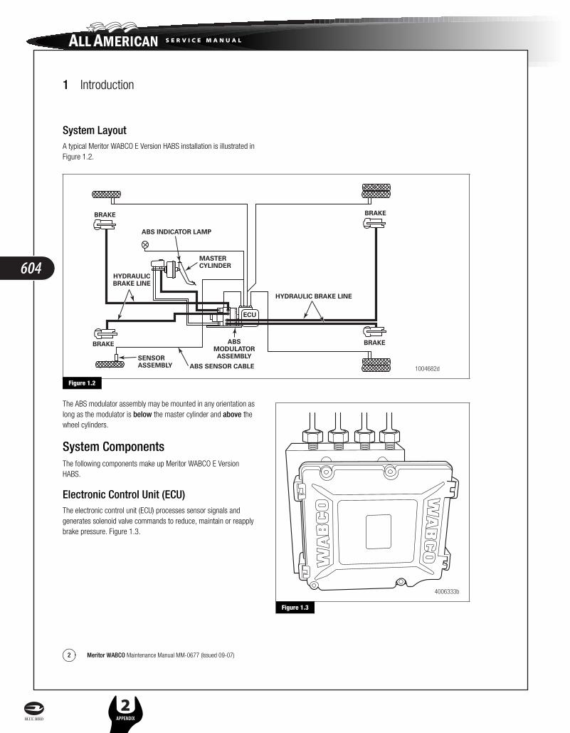
1 Introduction
2 Meritor WABCO Maintenance Manual MM-0677 (Issued 09-07)
System LayoutA typical Meritor WABCO E Version HABS installation is illustrated in Figure 1.2.
Figure 1.2
The ABS modulator assembly may be mounted in any orientation as long as the modulator is below the master cylinder and above the wheel cylinders.
System ComponentsThe following components make up Meritor WABCO E Version HABS.
Electronic Control Unit (ECU)The electronic control unit (ECU) processes sensor signals and generates solenoid valve commands to reduce, maintain or reapply brake pressure. Figure 1.3.
Figure 1.3
Figure 1.2
ABS SENSOR CABLE
MASTERCYLINDER
ABS INDICATOR LAMP
SENSORASSEMBLY
HYDRAULICBRAKE LINE
ABSMODULATORASSEMBLY
ECU
BRAKE
BRAKE
BRAKE
BRAKE
HYDRAULIC BRAKE LINE
1004682d
Figure 1.3
4006333b
604
L 2APPENDIX
s e r v i c e m a n u a l

1 Introduction
3Meritor WABCO Maintenance Manual MM-0677 (Issued 09-07)
Modulator Assembly
CAUTIONThe modulator assembly contains brake fluid. Handle the modulator assembly with appropriate care. Do not expose the modulator assembly to impact loads or excessive vibrations. Do not blow compressed air into the hydraulic ports. Mishandling the modulator assembly may lead to component damage and system failure.
The modulator assembly houses the HABS solenoid control valves, one inlet valve and one outlet valve per wheel, a pump motor and two accumulators. Figure 1.4.
Figure 1.4
Sensors
Sensor with Molded Socket
� Measures the speed of a tooth wheel rotating with the vehicle wheel.
� Produces an output voltage proportional to wheel speed. Figure 1.5.
Figure 1.5
Sensor Spring Clip
� Holds the wheel speed sensor in close proximity to the tooth wheel. Figure 1.6.
Figure 1.6
Tooth Wheel
� A machined or stamped ring mounted to a machined surface on the hub of each ABS-monitored wheel. Figure 1.7.
Figure 1.7
Figure 1.4
4006345a
Figure 1.5
Figure 1.6
Figure 1.7
1004685a
1004686a
1004687a
605
L2APPENDIX
h y d r a u l i c b r a k e s a p p e n d i x e s

1 Introduction
4 Meritor WABCO Maintenance Manual MM-0677 (Issued 09-07)
Sensor Extension Cables
� Two-wire cable with molded-on connector. Figure 1.8.
� Connects the wheel speed sensor to the ECU.
Figure 1.8
ABS Indicator Lamp� Located on vehicle instrument panel. Figure 1.9.
� Alerts drivers to a possible system fault.
� Used by service personnel to display blink codes.
� ABS indicator lamp is not provided by Meritor WABCO.
Figure 1.9
TOOLBOX™ Software� A PC-based diagnostics program.
� Displays system faults and wheel speed data, tests individual components, verifies installation wiring and more.
� Runs in Windows 98, ME, 2000, NT or XP. Figure 1.10.
Figure 1.10
NOTE: An RS232 to J1708 converter box is required.
The program is available from SPX. Call 800-328-6657.
Figure 1.8
Figure 1.9
1004688a
1004689a
Figure 1.10
4006346a
606
L 2APPENDIX
s e r v i c e m a n u a l

2 Troubleshooting and Testing
5Meritor WABCO Maintenance Manual MM-0677 (Issued 09-07)
2 Troubleshooting and TestingMaintenance
General InformationThere is no regularly scheduled maintenance required for Meritor WABCO E Version Hydraulic ABS. However, ABS does not change current vehicle maintenance requirements. For example, it is important that the vehicle brake fluid level be correctly maintained.
Wiring Diagrams
System Wiring InformationPin identification is shown in Figure 2.1. Wiring may vary according to the vehicle. Refer to the vehicle specifications for specific wiring diagrams. A typical Meritor WABCO Hydraulic ABS wiring diagram appears in Figure 2.2.
Figure 2.1
Figure 2.1
4006172a
PIN IDENTIFICATION FOR HABS WIRE HARNESS CONNECTORS TO THE ECU
Count from the pin number at the end of each row, identify pin assembly to measure. Connectorview shows the back of the connector.
1 Ignition 12v2 3rd Brake Relay (optional)3 Not Used4 Not Used5 Not Used6 Reference Ground7 Not Used8 Not Used9 Not Used10 Not Used11 Not Used12 Not Used13 Not Used14 J1939 + High – (optional)15 J1939 – Low – (optional)
27
(9511)
31
26
151
16
16 Pump Motor Supply 12v+17 Solenoid Valve Supply 12v+18 Pump Motor Ground –Gnd19 Solenoid Valve Ground –Gnd20 Not used21 ABS Warning Lamp Relay22 Rear Right Wheel Speed Sensor23 Rear Left Wheel Speed Sensor24 Front Left Wheel Speed Sensor25 Front Right Wheel Speed Sensor26 J1587 Diag. B + Low27 Rear Right Wheel Speed Sensor28 Rear Left Wheel Speed Sensor29 Front Left Wheel Speed Sensor30 Front Right Wheel Speed Sensor31 J1587 Diag. A + High
Pin # Circuit LabelPin # Circuit Label
607
L2APPENDIX
h y d r a u l i c b r a k e s a p p e n d i x e s

2 Troubleshooting and Testing
6 Meritor WABCO Maintenance Manual MM-0677 (Issued 09-07)
Figure 2.2
System DiagnosticsUse Meritor WABCO’s PC-based diagnostic program, TOOLBOX™ Software, or standard blink codes to diagnose hydraulic ABS faults. Information for using standard blink codes appears in Table A in this section.
Meritor WABCO TOOLBOX™ Software
NOTE: For complete instructions for using this program, refer to the User’s Manual, TP-99102. Contact Meritor WABCO at 800-535-5560 for information about TOOLBOX™ Software.
If you have TOOLBOX™ Software installed on your computer, use it to identify system faults. Then, follow the on-screen repair information to make the necessary repairs or replacements.
To display Hydraulic ABS faults, use the pull-down menu or the HABS icon, Figure 2.3, to select HABS (Hydraulic ABS) from the Main Menu. The Hydraulic ABS Main Menu will appear. Figure 2.4.
Select the View ECU Faults icon or select Display Faults to use the pull-down menu. Figure 2.5. This will display the Fault Informationscreen. Figure 2.6.
Figure 2.2
4006173d
WHEEL PRESSURE MODULATION SOLENOIDS
ELECTRONIC CONTROL UNIT31-PIN CONNECTOR
FRONT LEFT
IV
PUMP–MOTOR
GNDSTUD 2
SENSORFRONTLEFT
SENSORFRONTRIGHT
SENSORREARLEFT
SENSORREARRIGHT
MATCHING THE MATING CONNECTOR ACCORDINGTO DRAWING C953042 AMP P/N I-953042-6 (NO SHUNT)
CODING: NUMBER 0
GNDSTUD 1
+12VBATTERY FEED12V
30
+
–
30A**
25A***
5AIGNITIONSWITCH
DB
RO
PT
ION
AL
****
AB
S W
AR
NIN
G L
AM
P
OP
TIO
NA
LB
LIN
K C
OD
E S
WIT
CH
NO
RM
AL
CLO
SE
D
DIA
GN
OS
E "
A"
AC
C. S
AE
J15
87
DIA
GN
OS
E "
B"
CA
N H
IGH
AC
C. S
AE
J19
39
CA
N L
OW
2x0.
75 m
m2
TW
IST
ED
2x0.
75 m
m2
TW
IST
ED
2x0.
75 m
m2
TW
IST
ED
2x0.
75 m
m2
TW
IST
ED
IGN
ITIO
N
RE
FER
EN
CE
GR
OU
ND
*PU
MP
MO
TOR
SU
PP
LY
*PU
MP
MO
TOR
GR
OU
ND
*SO
LEN
OID
VA
LVE
SU
PP
LY
*SO
LEN
OID
VA
LVE
GR
OU
ND
4 5 7 16 18 17 19 1 12 6 20 21 2 13 319 26 14 15 24 29 25 30 23 28 22 27
OV IV OV IV OV IV OV
FRONT RIGHT REAR RIGHTREAR LEFT
WIRING DIAGRAMHYDRAULIC ABS E-VERSION HABS
NOTES:Electric cables without marks:AWG 18 (SAE J 1128 TYP: TXL-CABLE) respectively 1 mm2
Blade type fuses corresponding to ISO/DIS 8820Abbreviations: IV — Inlet Valve OV — Outlet Valve
* Wire size AWG 12 (SAE J 1128 TYP: GXL-CABLE) Respectively Min. 3 mm2: Total resistance including crimp = 0.04 ohms. Corresponds to an overall length of 6 meters. ** According to SAE J 1284 or SAE J 1888. *** According to SAE J 1284.**** ABS lamp circuit (optional).
608
L 2APPENDIX
s e r v i c e m a n u a l

2 Troubleshooting and Testing
7Meritor WABCO Maintenance Manual MM-0677 (Issued 09-07)
Figure 2.3
Figure 2.4
Figure 2.5
Figure 2.6
The Fault Information screen contains a description of the fault. Repair instructions for each fault appear at the bottom of the screen.
Faults that occur after the screen is displayed will not appear until a screen update is requested. Use the Update button to refresh the fault information table.
After making the necessary repairs, use the Clear Faults button to clear the fault. Use the Update button to refresh the fault information table and display the new list of faults.
Figure 2.3
Figure 2.4
1004695b
4006577a
Figure 2.5
Figure 2.6
1004697b
1004698b
609
L2APPENDIX
h y d r a u l i c b r a k e s a p p e n d i x e s

2 Troubleshooting and Testing
8 Meritor WABCO Maintenance Manual MM-0677 (Issued 09-07)
Blink Code Diagnostics
Definitions
ABS Indicator Lamp: This lamp, located on the vehicle instrument panel, serves two purposes:
1. Alerts drivers or service personnel to a possible fault in the hydraulic ABS, as follows:
IF the ABS indicator lamp comes on briefly then goes OFF when the ignition is turned ON . . . . . there are no active or stored faults in the hydraulic ABS
IF the ABS indicator lamp comes on and stays on AFTER the ignition is turned ON and
The vehicle is driven in excess of four mph (6 km/h) . . . There may be an active fault in the hydraulic ABS
IF the ABS indicator lamp comes on and stays on and
Goes OFF after the vehicle is driven in excess of four mph (6 km/h) or illuminates intermittently during driving . . . There may be a stored fault in the hydraulic ABS
2. Displays diagnostic blink codes for easy servicing.
Blink Code: A series of blinks or flashes that describe a particular ABS system condition. Refer to Table A and Table B in this section for blink code identification.
Blink Code Diagnostics: The ability of the Meritor WABCO ECU to sense faults in the ABS system and to define these faults via blink codes.
Blink Code Switch: A momentary switch that activates blink code diagnostic capabilities. Usually, it is mounted under the instrument panel or on the steering column. Refer to the vehicle specifications for type and location.
Clearing Fault Codes: The process of erasing faults from the ECU memory bank. Refer to Table A in this section.
Fault Code: An ABS condition (fault) detected and stored in memory by the Meritor WABCO ECU and displayed by blink code. System faults may be Active or Stored.
Active Fault: A condition that currently exists in the ABS system; for example, a sensor circuit malfunction on the left front steering axle. An active fault must be repaired before you can display additional faults. Once an active fault has been repaired, it becomes a stored fault.
Stored Fault: A condition that caused the system to register a fault, but is not currently active. For example, a loose wire that corrected itself. A stored fault can also be an active fault that has been corrected. Refer to Active Fault.
Table A, in this section, describes the method of distinguishing between active and stored faults and explains how to clear them.
Using Blink Code DiagnosticsFollow the steps listed in Table A to use blink code diagnostics. Refer to Figure 2.7 and Figure 2.8 in this section for blink code illustrations.
610
L 2APPENDIX
s e r v i c e m a n u a l

2 Troubleshooting and Testing
9Meritor WABCO Maintenance Manual MM-0677 (Issued 09-07)
Table A: Identifying E Version Hydraulic ABS Blink Codes
NOTE: If you receive a blink code that is not identified in this manual, contact the Customer Support Center at 800-535-5560.
Troubleshooting with Blink Code Diagnostics
Mode Procedure System Response Action
Diagnostics Step I.
Turn ignition ON.
Possible responses:
1. ABS indicator lamp comes on momentarily then goes out, indicating System O.K.
No recognizable active faults in the ABS. No action required.
2. ABS indicator lamp does not light, indicating possible wiring fault or burned-out bulb.
Inspect wiring. Inspect bulb. Make the necessary repairs.
3. ABS indicator lamp stays on, indicating:
� Fault, or faults, in the system Continue with blink code diagnostics. Go to Step II.
� Sensor fault during last operation
Continue with blink code diagnostics. Go to Step II.
� Faults cleared from ECU, but vehicle not driven.
Drive vehicle — lamp will go out when vehicle reaches four mph (6 km/h).
� ECU disconnected. Connect ECU.
Step II.
Press and hold Blink Code Switch for one second, then release.
ABS indicator lamp begins flashing two-digit blink code(s).
Determine if fault is active or stored:
Active Fault: Lamp will repeatedly display one code.
Stored Fault: Lamp will display code for each stored fault then stop blinking. Faults will be displayed one time only.
Step III.
Count the flashes to determine the blink code.
First Digit: 1-8 flashes, Pause(1-1/2 seconds).
Second Digit: 1-8 flashes, Pause (4 seconds).
Find definition for blink code on blink code chart.
Step IV.
Turn ignition OFF.
Repair and Record faults
Active Fault. Make the necessary repairs.
Stored Faults. Record for future reference.
Clear Step V.
Turn ignition ON.
Clear faults from memory: Press and hold blink code switch for at least three seconds, then release.
ABS indicator lamp flashes eight times.
All stored faults successfully cleared. Turn ignition OFF.
Turn ignition ON. The indicator lamp will stay on. This is because the ECU is looking for wheel speed. Drive the vehicle at a speed of four mph (6 km/h). Once the ECU senses wheel speed, the lamp will go off.
Eight flashes not received. Active faults still exist, repeat Step I through Step V.
611
L2APPENDIX
h y d r a u l i c b r a k e s a p p e n d i x e s

2 Troubleshooting and Testing
10 Meritor WABCO Maintenance Manual MM-0677 (Issued 09-07)
Blink Codes Illustrated
Figure 2.7
Figure 2.7
Pause1.5 s
Pause1.5 s
1-8 FlashesPause1.5 s
Pause4 s
1-6 Flashes
Light ON
Active Fault
Pause1.5 s
Pause1.5 s
Light ON
1 SecondHold
1 SecondHold
System O.K.
Continues untilignition is turned off
1st Digit(2) (3) (2) (3)
(5)
(1) (1)
(2) (3) (4)
2nd Digit
Pause1.5 s
Pause1.5 s
Pause1.5 s
Pause4 s
Light ON
Off
Stored Faults
S = Seconds
Displays all storedfaults once – last faultstored is displayed first
Blink Code 2-3: Fault in ABS modulatorvalve, right rear drive axle.
Blink Code 5-2: Sensor signal erratic,left front steer axle.
3-4: Too much sensor gap,left rear drive axle.
Blink Code 1-1: System OK
1st Digit 2nd Digit 1st Digit 2nd Digit1st Stored Fault 2nd Stored Fault
Repeat of Blink Code
1 SecondHold
1002021c
612
L 2APPENDIX
s e r v i c e m a n u a l

2 Troubleshooting and Testing
11Meritor WABCO Maintenance Manual MM-0677 (Issued 09-07)
Figure 2.8
E Version Hydraulic ABS Blink Codes
Use the information in Table B to identify a fault, check for correct volt or ohm measurements and repair the fault.
1. Identify and record the blink code. Blink codes are identified in Column 1.
2. Test the pins indicated. Pin locations to be tested are listed in Column 2.
3. Compare the measurement received against the correct volt or ohm measurement listed in Column 3.
4. Follow the instructions listed in Column 4.
Figure 2.8
Pause1.5 s
Pause4 s
Pause4 s
Light ON
Faults Cleared
Pause4 s
Pause4 s
Pause4 s
Pause4 s
Light ON
Faults Not Cleared (Active Faults Still Exist)3 SecondHold
3 SecondHold
Continuesuntil ignitionis turned off
Note: After faults are cleared andvehicle is started, ABS lamp will stayon until vehicle is driven over 4 mph (6 km/h).
Continuesuntil ignitionis turned off
8 Quick Blinks = Faults Cleared
(2)
SystemStatus
Pause4 s
Pause4 s
Code 2
1002022bS = Seconds
(2)
SystemStatus
(2)
SystemStatus
(2)
SystemStatus
(2)
SystemStatus
(2)
SystemStatus
(2)
SystemStatus
(2)
SystemStatus
613
L2APPENDIX
h y d r a u l i c b r a k e s a p p e n d i x e s

2 Troubleshooting and Testing
12 Meritor WABCO Maintenance Manual MM-0677 (Issued 09-07)
Table B: E Version Hydraulic ABS Blink Codes
Table B: E Version Hydraulic ABS Blink Codes
Ignition Key ON to determine ABS blink code fault Ignition Key OFF to test system (except where noted)
Fault Code
Column 1 Column 2 Column 3 Column 4
Problem Area Pins to be TestedCorrect Volt Ohm Meter Readings Action
1-1 System OK None required
2-1 Right Front Solenoid valve (inlet or outlet valve) failure in modulator, wiring harness or inside ECU
17 and 19 12 VDC
Less than 1 ohm to chassis ground w/key-off
Check pin 17 for 12 volts.
Check fuse.
Check pin 19 for 1 ohm or less to chassis ground w/key-off.
2-2 Left Front Solenoid valve (inlet or outlet valve) failure in modulator, wiring harness or inside ECU
2-3 Right Rear Solenoid valve (inlet or outlet valve) failure in modulator, wiring harness or inside ECU
2-4 Left Rear Solenoid valve (inlet or outlet valve) failure in modulator, wiring harness or inside ECU
2-7 Reference to ground interrupted 6 Check HABS ground connections. Make necessary repairs.
Check pin 6 for ≤1 ohm to chassis ground w/key-off.
3-1 Right Front sensor — Air gap 25 and 30 Greater than 0.2 volt AC at 30 rpm
(Rotate wheel 1/2 revolution per second)
Check for sensor adjustment. Check for excessive wheel bearing end play. Repair or replace as needed.
3-2 Left Front sensor — Air gap 24 and 29
3-3 Right Rear sensor — Air gap 22 and 27
3-4 Left Rear sensor — Air gap 23 and 28
4-1 Right Front sensor — Electrical fault 25 and 30 900-2000 ohms Check electrical resistance of affected sensor and wiring at ECU connector and at harness plugs. Repair or replace as needed.
4-2 Left Front sensor — Electrical fault 24 and 29
4-3 Right Rear sensor — Electrical fault 22 and 27
4-4 Left Rear sensor — Electrical fault 23 and 28
5-1 Right Front wheel — Erratic wheel speed Check for tire size mismatch or tooth wheel difference. Check sensor, sensor cable and connector for intermittent contact. Repair or replace as needed.
Check sensor mounting and alignment.
5-2 Left Front wheel — Erratic wheel speed
5-3 Right Rear wheel — Erratic wheel speed
5-4 Left Rear wheel — Erratic wheel speed
7-4 ABS indicator lamp 21 10-200 ohms Check bulb. Repair or replace as needed.
614
L 2APPENDIX
s e r v i c e m a n u a l

2 Troubleshooting and Testing
13Meritor WABCO Maintenance Manual MM-0677 (Issued 09-07)
Testing the SystemThis section of the manual contains information for testing the hydraulic ABS with TOOLBOX™ Software, as well as procedures for conducting standard air and electrical tests.
WARNINGTo prevent serious eye injury, always wear safe eye protection when you perform vehicle maintenance or service.
Exhaust gas contains poison. When testing a vehicle with the engine running, test in a well-ventilated area or route the exhaust hose outside.
To avoid serious personal injury, keep away, and keep test equipment away, from all moving or hot engine parts.
Refer to, and follow, the vehicle manufacturer’s Warnings, Cautions and Service Procedures.
When testing, set the parking brake and place the gear selector in NEUTRAL (manual transmission) or PARK (automatic transmission) unless otherwise directed.
Meritor WABCO TOOLBOX™ SoftwareUse TOOLBOX™ Software to verify the activation of various system components:
� Turn valves, pump and retarder relay on and off (Valve Activation Menu).
� Turn ABS indicator lamp on and off (Miscellaneous Output Activation Menu).
NOTE: TOOLBOX™ Software must be connected to the vehicle and the vehicle ignition must be ON in order to display information.
NOTE: For complete instructions for using this program, refer to the User’s Manual, TP-99102. Contact Meritor WABCO at 800-535-5560 for information about TOOLBOX™ Software.
E Version Hydraulic ABS Menus and ToolbarsSelect Hydraulic ABS from the TOOLBOX™ Main Menu.TOOLBOX™ senses the type of ECU being used and displays the HABS Main Screen.
7-7 Recirculation pump does not switch off.
OR
Recirculation pump does not switch on (low level with act).
OR
Recirculation pump motor locked.
Replace ECU.
7-8 Recirculation pump relay sticks.
8-1 No voltage to ABS solenoid valves. 17 and 19 12 VDC Check the valve relay, fuse and wiring. Repair or replace as needed.
8-2 Continuous supply to ECU with ignition off. Check for correct wiring connections. Make necessary repairs. If problem persists, replace ECU.
8-3 Internal ECU Fault Replace ECU.
Table B: E Version Hydraulic ABS Blink Codes
Ignition Key ON to determine ABS blink code fault Ignition Key OFF to test system (except where noted)
Fault Code
Column 1 Column 2 Column 3 Column 4
Problem Area Pins to be TestedCorrect Volt Ohm Meter Readings Action
615
L2APPENDIX
h y d r a u l i c b r a k e s a p p e n d i x e s

2 Troubleshooting and Testing
14 Meritor WABCO Maintenance Manual MM-0677 (Issued 09-07)
Main Screen
This screen provides icons and pull-down menu task selections. It also provides information about the current status of Meritor WABCO HABS. Figure 2.9.
Figure 2.9
ECU information is read once from the ECU and does not change. All other information (e.g., wheel sensors, voltages and fault information) is read and updated continuously.
Display
Select Display from the HABS Main Screen. A pull-down menu will appear. Figure 2.10.
Figure 2.10
Faults
Select Faults to display the Fault Information screen. Figure 2.11.
Figure 2.11
The Fault Information screen contains a description of each fault, including the type of fault (Active or Stored), number of occurrences, SID and FMI number. Repair instructions for the fault appear at the bottom of the screen.
Faults that occur after the screen is displayed will not appear until a screen update is requested. Use the Update button at the bottom of the screen to refresh the fault information table and display a new list of faults.
After making any required repairs, use the Clear Faults button to clear the fault. Clear each fault as it is repaired. Cycle the ignition after clearing the faults.
Use the Save or Print button to save or print the fault information data. Select Exit to close this section.
Figure 2.9
Figure 2.10
4006726a
4004459c
Figure 2.11
4004460b
616
L 2APPENDIX
s e r v i c e m a n u a l

2 Troubleshooting and Testing
15Meritor WABCO Maintenance Manual MM-0677 (Issued 09-07)
Wheel Speed
Select Wheel Speed to display the Wheel Speed screen. Figure 2.12.
Figure 2.12
Use the Wheel Speed screen to verify that sensors are connected at each wheel. Speed at a sensed wheel (FL, FR, RL, RR) indicates sensors are installed, but does not verify correct sensor installation.
Counters
Select Counters to display the Counters screen. Figure 2.13.
Figure 2.13
The Counters screen provides an overview of HABS component performance (pump hours, brake events, etc.) as well as general vehicle activity such as ignition cycles. Occurrences displayed on this screen accumulate until the Clear button is selected.
Component Tests
Select Component Tests from the HABS Main Screen. A pull-down menu will appear. Figure 2.14.
Figure 2.14
Miscellaneous Outputs
Select Miscellaneous Outputs to display the Actuate Miscellaneous Outputs test screen. Figure 2.15.
NOTE: Use TOOLBOX™ Software to test the following components: Retarder Relay, Brake Light Relay, Supply Valve, Cut-Off Valve, ABS Lamp, Traction Lamp, Brake Warning, Pump Front, Pump Rear, Buzzer.
Figure 2.15
Figure 2.12
Figure 2.13
4004461a
4004462b
Figure 2.14
Figure 2.15
4004463b
4005142b
617
L2APPENDIX
h y d r a u l i c b r a k e s a p p e n d i x e s

2 Troubleshooting and Testing
16 Meritor WABCO Maintenance Manual MM-0677 (Issued 09-07)
This screen provides a check of several HABS components, as well as a way to check either inlet or outlet activity of the valves, pump or retarder relay.
Highlight the component you wish to test, then select the Sendbutton to actuate the component. Component activation status appears in the Status Box field. Select Close to exit this screen.
Valves
Select Valves to display the Valve Activation test screen. Figure 2.16.
Figure 2.16
The Valve Activation test screen lets you activate the HABS valves to check for correct activation and to verify correct brake line installation.
Click on the valve you wish to test, then click the Send button to actuate the component. Component activation status appears in the Status box field. Select Close to exit this screen.
Lamps
Select Lamps to display the Lamp Test screen. Figure 2.17.
Figure 2.17
As each lamp is tested, check the actual lamp to verify correct operation. Select Close to exit this screen.
Figure 2.16
4004464a
Figure 2.17
4004465b
618
L 2APPENDIX
s e r v i c e m a n u a l

2 Troubleshooting and Testing
17Meritor WABCO Maintenance Manual MM-0677 (Issued 09-07)
Relay
Select Relay to display the Activate Relay test screen. Figure 2.18.
Figure 2.18
This screen allows you to turn the retarder relay on or off. This is helpful in verifying correct operation, installation and wiring of the unit under test. Select Close to exit this screen.
Engine Data Link
Select Engine Data Link to display the Data Link test screen. Figure 2.19.
Figure 2.19
This screen allows you to send a “limit engine torque” command to the engine or a “disable retarder” command to the retarder.
Select the data link destination (engine or retarder), then select Send to test. Use the Stop button to end testing. Select Close to exit this screen.
Reset Memorized
This is an automatic default and cannot be de-selected. It indicates the ECU has memorized the installed retarder relay. Once the ECU has seen a retarder, it expects to see it every time the vehicle is powered up. Figure 2.20.
Because there are times when an ECU is moved to another vehicle — or during diagnostic testing — you may want the ECU to disregard this learned component. Use the Reset Memorizedcommand for this purpose.
Select Component Tests from the Hydraulic ABS Main Menu.Then, select Reset Memorized from the pull-down menu to reset the Learned Component screen. Figure 2.21.
Figure 2.20
Figure 2.18
4004467a
Figure 2.19
Figure 2.20
4004468a
1004704a
619
L2APPENDIX
h y d r a u l i c b r a k e s a p p e n d i x e s

2 Troubleshooting and Testing
18 Meritor WABCO Maintenance Manual MM-0677 (Issued 09-07)
Figure 2.21
Standard Testing
Test Equipment: Volt-Ohm Meter (VOM)
Use of a VOM with automatic polarity sensing is recommended. This eliminates the concern of the polarity of the meter leads during voltage measurements.
System Requirements and Component Tests
Tire Size Range
For correct hydraulic ABS operation, front and rear tire sizes must be within 16% of each other.
Contact the Meritor WABCO Customer Support Center at 800-535-5560 if you plan a tire size difference greater than 8%.
Calculate the tire size with the following equation:
% Difference = (RPM Steer/RPM Drive)−1 x 100
RPM = tire revolutions per mile
CAUTIONWhen troubleshooting or testing the ABS system, do not damage the connector terminals. Damaged connector terminals may cause system malfunction.
Voltage Check
Voltage must be between 9.5 and 14 volts for the 12-volt hydraulic ABS to function correctly.
Check voltage as follows.
1. Turn ignition ON.
2. Check for the correct voltage.
� Pins 16 to 18
� Pins 17 to 19
� Pins 1 to 6
Standard Component Testing
ABS Indicator Lamp
If the ABS indicator lamp does not come on after the ignition is turned on, or it comes on but does not go out after three seconds, check all ABS fuses or circuit breakers and replace if necessary. Check the wiring to the ABS diagnostic switch and the indicator lamp and repair or replace the wiring as required. When checking the indicator lamp, follow these steps:
1. Check voltage potential at the lamp socket.
2. Check continuity of the wires to the socket.
3. Replace the bulb.
NOTE: A complete wiring diagram for 4S/4M D Version hydraulic ABS appears in Figure 2.2 in this section.
ABS Blink Code Switch
When testing the ABS diagnostic switch, perform the following.
1. Check the resistance between the terminals while cycling the switch. A lack of continuity is an indication of a faulty switch.
2. Check the continuity of the wires to the switch:
Pins 21 and 6 on the 31-pin harness
Figure 2.21
1004705b
620
L 2APPENDIX
s e r v i c e m a n u a l

2 Troubleshooting and Testing
19Meritor WABCO Maintenance Manual MM-0677 (Issued 09-07)
Sensor Adjustment
On steering axles, the sensor is typically accessible on the in-board side of the steering knuckle.
On drive axles, the sensor is typically accessible on the in-board side of the rear axle spindle.
To adjust the sensor, push the sensor in until it contacts the tooth wheel.
� Do not pry or push sensors with sharp objects.
� Sensors will self-adjust during wheel rotation.
NOTE: No gap is allowable at installation. During normal operation, a gap not to exceed 0.04-inch is allowable.
Sensor Output Voltage Test
Sensor output voltage must be at least 0.2 volt AC at 30 rpm. Test the sensor output voltage as follows:
1. Turn ignition OFF.
2. Disconnect the ECU to measure voltage at the pins on the ECU connector. Refer to Table C.
WARNINGPark the vehicle on a level surface. Block the wheels to prevent the vehicle from moving. Support the vehicle with safety stands. Do not work under a vehicle supported only by jacks. Jacks can slip and fall over. Serious personal injury and damage to components can result.
3. Place blocks under the front and rear tires to stop the vehicle from moving.
4. Raise the vehicle off the ground. Place safety stands under the axle.
5. Rotate the wheel by hand at 30 rpm (1/2 revolution per second).
6. Measure the voltage at the pins indicated in Table C. Voltage tolerance is ≥0.2 volts alternating current (VAC).
Table C: Sensor Check Pins
Sensor Resistance
The sensor circuit resistance must be between 900 and 2000 ohms. Measure resistance at the sensor connector, or at the pins on the ECU connector, as follows.
1. Turn ignition OFF.
2. To measure resistance at the pins on ECU connector, disconnect the ECU connector from the ECU.
To measure resistance at the sensor connector, disconnect the sensor from the sensor extension cable.
3. Measure output at the pins indicated in Table C.
If measurement is not between 900 and 2000 ohms, replace the sensor.
Sensor
HABS E Version ECU
31-Pin Harness
Left Front 24 and 29
Right Front 25 and 30
Left Rear 23 and 28
Right Rear 22 and 27
621
L2APPENDIX
h y d r a u l i c b r a k e s a p p e n d i x e s

3 Component Replacement
20 Meritor WABCO Maintenance Manual MM-0677 (Issued 09-07)
3 Component ReplacementComponent Removal and Installation
Sensors
Sensor Lube Specification
Meritor WABCO specifications call for a sensor lubricant with the following characteristics.
Lube must be mineral oil-based and contain molydisulfide. It should have excellent anti-corrosion and adhesion characteristics and be capable of continuous function in a temperature range of –40° to 300°F (–40° to 150°C).
Wheel Speed Sensor Replacement — Front Axle
Removal
WARNINGTo prevent serious eye injury, always wear safe eye protection when you perform vehicle maintenance or service.
Park the vehicle on a level surface. Block the wheels to prevent the vehicle from moving. Support the vehicle with safety stands. Do not work under a vehicle supported only by jacks. Jacks can slip and fall over. Serious personal injury and damage to components can result.
CAUTIONTo avoid damage to the electrical system or HABS components, when welding on a HABS-equipped vehicle disconnect the power connector from the ECU.
1. Park the vehicle on a level surface. Apply the parking brakes. Block the rear tires to prevent the vehicle from moving.
If necessary, raise the front tires off the ground. Place safety stands under the axle.
2. Disconnect the fasteners that hold the sensor cable to other components.
3. Disconnect the sensor cable from the chassis harness.
4. Remove the sensor from the sensor holder. Twist and pull the sensor to remove it from the sensor bracket. Do not pull on the cable. Figure 3.1.
Figure 3.1
Installation1. Connect the sensor cable to the chassis harness.
2. Install the fasteners used to hold the sensor cable in place.
3. Apply a Meritor WABCO-recommended lubricant to the sensor spring clip and sensor.
4. Install the sensor spring clip. Verify that the spring clip tabs are on the inboard side of the vehicle.
5. With the tabs on the inboard side, push the sensor spring clip into the bushing in the steering knuckle until the clip stops.
6. Push the sensor completely into the sensor spring clip until it contacts the tooth wheel.
7. Fasten the sensor cable every 12 inches. Correctly bundle and store any excess cable in the sub-frame. Figure 3.1.
8. Remove the blocks and safety stands.
9. Perform a voltage output check to ensure correct installation. Refer to Section 2.
Wheel Speed Sensor Replacement — Rear Axle
Removal
1. Apply the parking brake. Block the front tires to prevent vehicle movement.
2. Raise the rear tires off the ground. Place safety stands under the axle.
3. If the rear tire must be removed to gain access to the sensor, release the parking brake to release the brake shoe.
Remove the wheel and tire assembly from the axle.
Figure 3.1
KNUCKLE-MOUNTEDSENSOR
1004706a
622
L 2APPENDIX
s e r v i c e m a n u a l

3 Component Replacement
21Meritor WABCO Maintenance Manual MM-0677 (Issued 09-07)
4. Remove the sensor from the mounting block. Use a twisting motion if necessary. Do not pull on the cable.
5. Disconnect the sensor cable from the chassis harness.
6. Remove the sensor cable from any cable clamps or clips.
7. Remove the sensor spring clip from the sensor bracket.
Installation
1. Connect the new sensor cable to the chassis harness.
2. Press the sensor spring clip into the sensor bracket, located on the rear axle, until it stops. Verify that the tabs are on the inboard side.
3. Apply a Meritor WABCO-recommended lubricant to the sensor.
4. Push the sensor completely into the spring clip until it contacts the tooth wheel.
5. Reattach the sensor cable to the cable clamps or clips.
6. Fasten the sensor cable every 12 inches. Correctly bundle and store excess cable in the sub-frame. Figure 3.2.
Figure 3.2
7. Replace the tire and remove the safety stands. Lower the vehicle and remove the blocks from the front tires.
8. Perform a voltage output check to ensure correct installation. Refer to Section 2.
Electronic Control Unit (ECU)
Removal
WARNINGTo prevent serious eye injury, always wear safe eye protection when you perform vehicle maintenance or service.
CAUTIONHydraulic brake fluid is a caustic substance. Contact with the hydraulic brake fluid can cause skin irritation. Do not let hydraulic brake fluid touch any painted surfaces, as it will remove the paint. Hydraulic brake fluid may also damage certain non-metal surfaces. Do not let fluid contact brake pads, shoes, rotors or discs.
NOTE: Do not open the ECU. Opening the ECU to gain access to the internal components will void the warranty.
NOTE: The following general guidelines are provided to facilitate the safe removal of the ECU module from the modulator assembly.
� It is not necessary to remove the entire modulator to replace the Electronic Control Unit (ECU).
� When only the ECU is replaced, bleeding the system is not necessary.
1. Park the vehicle on a level surface. For vehicles with manual parking brakes, apply the parking brakes.
2. Block the front and rear tires to prevent vehicle movement.
3. Disconnect the battery.
4. Use a clean rag to carefully wipe the surface of the modulator and the surrounding area.
5. Open the latches on the 31-pin harness attached to the ECU. After the latch is released, remove the connectors from the ECU.
6. Use a 4 mm Allen wrench to loosen and remove the four mounting screws that attach the ECU module to the modulator valve.
7. Carefully remove the ECU by lifting straight out. To avoid damage, do not twist the ECU during removal. Determine the warranty status of the ECU. If the ECU is under warranty, return it to Meritor WABCO. If it is not under warranty, discard the used ECU.
8. Use a clean rag to carefully clean the area around the valves formerly covered by the ECU.
Figure 3.2
Bundleexcesscable.
1004707a
623
L2APPENDIX
h y d r a u l i c b r a k e s a p p e n d i x e s

3 Component Replacement
22 Meritor WABCO Maintenance Manual MM-0677 (Issued 09-07)
Installation
CAUTIONExcessive force in positioning the ECU onto the modulator will damage the ECU housing. Do not force the ECU into position. Use a gentle, even pressure when positioning the ECU.
1. Position the ECU onto the modulator valve. Apply gentle pressure to seat the ECU. Motor connectors must achieve full depth into the housing. The gap between the modulator and ECU must not exceed 0.08-inch (2 mm).
2. Use a 4 mm Allen wrench to tighten the four mounting screws that attach the ECU to the modulator. Tighten to 14 in-lb (1.5 N�m). Do not exceed this torque. The metal sleeves on the ECU housing must rest flat on the body of the modulator. @
3. When the ECU is correctly installed with the metal sleeves flat on the modulator, tighten the bolts to 21-30 in-lb (2.5-3.5 N�m). @
WARNINGElectrical connectors must be correctly installed with the latch pushed in to lock the connector. Failure to do so may allow the connectors to come loose or disconnect resulting in loss of ABS function.
4. Attach the 31-pin harness connector to the ECU.
5. Connect the battery.
Modulator Assembly
Removal
CAUTIONThe modulator assembly contains hydraulic brake fluid, a caustic substance. Remove the valve carefully so that fluid does not leak and cause skin irritation or damage to components.
NOTE: If there is interference, the entire bracket and valve assembly can be removed.
1. Apply the parking brakes. Block the front and rear tires to prevent vehicle movement.
2. Place a container under the modulator assembly to catch leaking brake fluid.
3. Disconnect the electrical harness connectors from the modulator assembly.
4. Mark the six brake lines for ease of installation. Disconnect the lines from the modulator assembly.
5. Remove the three mounting capscrews and washers that attach the modulator assembly to the bracket.
NOTE: Whenever any hydraulic system fitting is loosened or disconnected, the entire system must be bled to remove any air that may have entered. Refer to “Brake Bleeding Procedures” in this section.
6. Remove the modulator assembly.
7. Use a 4 mm Allen wrench to loosen and remove the four mounting screws that attach the ECU module to the modulator valve.
8. Carefully remove the ECU by lifting straight out. To avoid damage, do not twist the ECU during removal.
Installation
1. Position the old ECU onto the new modulator valve. Apply gentle pressure to seat the ECU. Motor connectors must achieve full depth onto the housing. The gap between the modulator and the ECU must not exceed 0.08-inch (2 mm).
2. Use a 4 mm Allen wrench to tighten the four mounting screws that attach the ECU to the modulator. Tighten to 14 in-lb (1.5 N�m). Do not exceed this torque. The metal sleeves on the ECU housing must rest flat on the body of the modulator. @
3. When the ECU is correctly installed with the metal sleeves flat on the modulator, tighten the bolts to 21-30 in-lb (2.5-3.5 N�m). @
4. Position the modulator assembly in place on the vehicle. Figure 3.3.
624
L 2APPENDIX
s e r v i c e m a n u a l

3 Component Replacement
23Meritor WABCO Maintenance Manual MM-0677 (Issued 09-07)
Figure 3.3
5. Tighten the three mounting nuts to 16 ft-lb (22 N�m). @
6. Connect the electrical harnesses to the modulator assembly.
7. Connect and tighten the brake line connections.
8. Bleed the brake system, per the following instructions.
Brake Bleeding ProceduresGeneral
The following brake bleeding methods explain how to bleed the hydraulic ABS modulator assembly during installation, or in the event of air in the brake system. There are instructions for both pressure and manual bleeding procedures.
These instructions include the procedure for bleeding both the master cylinder and the brake system. In some cases, for example, if you are replacing only the modulator assembly, it may not be necessary to bleed the master cylinder. If you have any questions, please contact the Meritor Service Center at 800-535-5560.
NOTE: The modulator assembly must be handled with appropriate care and should not be exposed to excessive impact or compressed air at the hydraulic ports prior to assembly.
WARNINGFailure to bleed the system whenever any hydraulic system fitting is loosened or disconnected will allow air to remain in the system. This will prevent the hydraulic pressure in the brake system from rising enough to apply the brakes correctly. This will cause the stopping distance to increase and can result in serious personal injury.
Correctly discard hydraulic brake fluid that is removed from the brake system. Hydraulic brake fluid that is removed can be contaminated and can cause damage, loss of braking and serious personal injury.
Use only the type of hydraulic brake fluid specified by the equipment manufacturer. Do not use or mix different types of hydraulic brake fluid. The wrong hydraulic brake fluid will damage the rubber parts of the brake caliper and can cause damage, loss of braking and serious personal injury.
NOTE: Use DOT 3 or DOT 4 hydraulic brake fluid. Refer to the vehicle specifications to determine which fluid to use.
CAUTIONHydraulic brake fluid is a caustic substance. Contact with hydraulic brake fluid can cause skin irritation. Do not let hydraulic brake fluid touch any painted surfaces, as it will remove the paint. Hydraulic brake fluid may also damage certain non-metal surfaces. Do not let fluid get on brake pads, shoes, rotors or discs.
Pressure Fill and BleedPressure fill and bleed is the preferred method for bleeding the service brake system. It requires the use of a special pressure bleeder kit, consisting of a tank, pressure pump and valve, gauge, tubing and adapter. These kits are available from a number of manufacturers and include instructions for use. Figure 3.4.
Figure 3.3
1004708b
625
L2APPENDIX
h y d r a u l i c b r a k e s a p p e n d i x e s

3 Component Replacement
24 Meritor WABCO Maintenance Manual MM-0677 (Issued 09-07)
Figure 3.4
Pressure Fill and Bleed Procedure
CAUTIONTurn the ignition OFF for the entire bleed procedure. Do not energize the unit during the bleed procedure. Improper bleeding may result in system malfunction due to the presence of air in the closed hydraulic system.
1. Apply the parking brake and block the tires. Turn the ignition OFF and disconnect the battery terminals.
2. Fill the pressure bleeder with new DOT 3 or DOT 4 hydraulic brake fluid. Refer to the vehicle specifications to determine which fluid to use.
3. Follow the manufacturer’s instructions to connect the pressure bleeder to the brake master cylinder reservoir.
4. Set the filling pressure to 20 to 30 psi (1.5 to 2.0 bar).
5. Turn on the bleed equipment until the fluid level in the reservoir reaches approximately 0.875-inches (20 mm).
6. Release pressure for three to five seconds. Apply pressure for five to 10 seconds.
7. Repeat Step 5 and Step 6 approximately 10 times. After releasing the pressure, air bubbles should rise up into the reservoir.
WARNINGDo not let the brake master cylinder fluid get below the minimum level during the bleeding operation. Keep the master cylinder reservoir filled with new DOT-approved brake fluid, as specified by the original equipment manufacturer. Failure to keep the brake reservoir level above minimum could result in more air entering the system, making it impossible to effectively bleed the system resulting in increased stopping distance.
8. Bleed the brake system:
� Set the filling pressure to 20 to 30 psi (1.5 to 2.0 bar).
� Place a wrench on the brake actuator bleeder fitting. Start with the farthest from the modulator, typically the right rear, then attach a length of clear plastic tubing to the bleeder fitting. Verify that the tube fits snugly.
NOTE: Both the tubing and container must be able to withstand the effects of hydraulic brake fluid. Tools used for bleeding the system should be brake fluid-safe.
9. Submerge the tubing in a container of clean hydraulic brake fluid. Figure 3.5.
Loosen the bleeder fitting until the fluid begins to flow (about 3/4 turn). Let the hydraulic fluid flow out of the fitting until it is free of air bubbles.
Figure 3.5
Figure 3.4
1004709a
Figure 3.5
1004710a
626
L 2APPENDIX
s e r v i c e m a n u a l

3 Component Replacement
25Meritor WABCO Maintenance Manual MM-0677 (Issued 09-07)
10. Tighten firmly to secure the fitting.
11. Repeat Step 5 through Step 8 to bleed the remaining three brake actuators. Bleed in sequence of the longest to shortest circuit from the modulator assembly.
12. Turn off bleed equipment and remove pressure. Remove the bleed device and check the fluid level in the reservoir. Fill if required. Replace the reservoir cap and dispose of used brake fluid.
13. Remove the wheel blocks.
Manual Bleed Procedure
NOTE: The ignition must remain off for the entire bleed procedure; energizing the unit during bleeding must be impossible.
1. Apply the parking brake and block the tires. Turn the ignition OFF and disconnect the battery terminals.
2. Fill the reservoir with DOT 3 or DOT 4 hydraulic brake fluid. Refer to the vehicle specifications to determine which fluid to use.
3. Depress the brake pedal five times using the stroke between 1/3 travel and maximum travel in five seconds.
4. Release the pedal for five to 10 seconds. Air bubbles will rise into the reservoir while depressing and releasing the pedal.
5. Repeat Step 3 and Step 4 another three times, or until sufficient pedal resistance is felt.
WARNINGDo not let the brake master cylinder fluid get below the minimum level during the bleeding operation. Keep the master cylinder reservoir filled with new DOT-approved brake fluid as specified by the original equipment manufacturer. Failure to keep the brake reservoir level above minimum could result in more air entering the system, making it impossible to effectively bleed the system resulting in increased stopping distance.
6. Bleed the brake system. Place a wrench on the brake actuator bleeder fitting. Start with the farthest from the modulator, (typically the right rear), then attach a length of clear plastic tubing to the bleeder fitting. Verify that the tube fits snugly.
NOTE: Both the tubing and container must be able to withstand the effects of brake fluid. Tools used for bleeding the system should be brake fluid-safe.
7. Submerge the tubing in a container of clean brake fluid. Figure 3.5.
8. Depress the brake pedal 10 to 15 times, using the maximum available stroke.
9. Loosen the bleeder fitting until the fluid begins to flow (about 3/4 turn), while depressing the brake pedal through its maximum available stroke.
10. Tighten the fitting firmly prior to releasing the brake pedal.
11. Repeat Step 6 through Step 8 several times until the discharged fluid is free of air bubbles.
12. Repeat Step 3 through Step 9 to bleed the remaining three brake actuators. Bleed in sequence of the longest to the shortest circuit from the modulator.
13. Check the travel of the brake pedal. If a firm resistance is felt, the manual bleeding procedure is complete.
14. Check the fluid level in the reservoir and fill if required. Replace the reservoir cap and dispose of used brake fluid.
15. Remove the wheel blocks.
627
L2APPENDIX
h y d r a u l i c b r a k e s a p p e n d i x e s

Meritor WABCO Vehicle Control Systems2135 West Maple Road Printed in USATroy, MI 48084-7121800-535-5560 Copyright 2007 Issued 09-07meritorwabco.com ArvinMeritor, Inc. Maintenance Manual MM-0677 (16579/22882)
628
L 2APPENDIX
s e r v i c e m a n u a l

Four-Piston QuadraulicTM
Disc Brake CaliperMaintenance Manual MM-2075
Issued 01-01$2.50
629
L3APPENDIX
h y d r a u l i c b r a k e s a p p e n d i x e s

Service Notes
1
Service NotesBefore You BeginThis manual provides maintenance and service procedures for Meritor’s four-piston quadraulic disc brake calipers. Before you begin procedures:
1. Read and understand all instructions and procedures before you begin to service components.
2. Read and observe all Caution and Warning safety alerts that precede instructions or procedures you will perform. These alerts help to avoid damage to components, serious personal injury, or both.
3. Follow your company’s maintenance and service, installation, and diagnostics guidelines.
4. Use special tools when required to help avoid serious personal injury and damage to components.
Safety Alerts, Torque Symbol and Notes
Access Information on ArvinMeritor’s Web SiteAdditional maintenance and service information for ArvinMeritor’s commercial vehicle systems component lineup is also available at www.arvinmeritor.com.
To access information, click on Products & Services/Tech Library Icon/HVS Publications. The screen will display an index of publications by type.
Additional InformationCall ArvinMeritor’s Customer Service Center at 800-535-5560 to order the following item.
� Drivetrain PlusTM by ArvinMeritor Technical Electronic Library on CD. Features product and service information on most Meritor, ZF Meritor and Meritor WABCO products. $20. Order TP-9853.
WARNINGA Warning alerts you to an instruction or procedure that you must follow exactly to avoid serious personal injury and damage to components.
CAUTIONA Caution alerts you to an instruction or procedure that you must follow exactly to avoid damage to components and possible serious injury.
A torque symbol alerts you to tighten fasteners to a specified torque value.
NOTE A Note provides information or suggestions that help you correctly service a component.
630
L 3APPENDIX
s e r v i c e m a n u a l

Table of Contents
Asbestos and Non-Asbestos Fibers Warnings. . . . . . . . . . . . . . . . . . . . . . . . . . . . . . . . . . . . . . .1
Section 1: Exploded Views . . . . . . . . . . . . . . . . . . . . . . . . . . . . . . . . . . . . . . . . . . . . . . . . . . . . . . . . . . . . .2
Section 2: Introduction Product Features . . . . . . . . . . . . . . . . . . . . . . . . . . . . . . . . . . . . . . . . . . . . . . . . . . . . . . . . . . . . . . . . . . . . . .3Four-Piston Quadraulic Disc Brake Caliper CaliperSupportHub/Rotor . . . . . . . . . . . . . . . . . . . . . . . . . . . . . . . . . . . . . . . . . . . . . . . . . . . . . . . . . . . . . . . . . . . . . . . . . . . .4
Section 3: Disassembly Removal . . . . . . . . . . . . . . . . . . . . . . . . . . . . . . . . . . . . . . . . . . . . . . . . . . . . . . . . . . . . . . . . . . . . . . . . . . . . .5Brake Pads Replace Brake Pads Brake Caliper . . . . . . . . . . . . . . . . . . . . . . . . . . . . . . . . . . . . . . . . . . . . . . . . . . . . . . . . . . . . . . . . . . . . . . . . .6Support . . . . . . . . . . . . . . . . . . . . . . . . . . . . . . . . . . . . . . . . . . . . . . . . . . . . . . . . . . . . . . . . . . . . . . . . . . . . . .7RotorDisassemble and Overhaul the Brake Caliper
Section 4: Prepare Parts for Assembly Clean, Dry and Inspect Parts . . . . . . . . . . . . . . . . . . . . . . . . . . . . . . . . . . . . . . . . . . . . . . . . . . . . . . . . . . . .10Clean Parts Dry and Inspect Parts Apply Corrosion Protection
Section 5: Assembly and Installation Assembly . . . . . . . . . . . . . . . . . . . . . . . . . . . . . . . . . . . . . . . . . . . . . . . . . . . . . . . . . . . . . . . . . . . . . . . . . . .11Brake Caliper Installation . . . . . . . . . . . . . . . . . . . . . . . . . . . . . . . . . . . . . . . . . . . . . . . . . . . . . . . . . . . . . . . . . . . . . . . . . .12RotorCaliperBrake Pads . . . . . . . . . . . . . . . . . . . . . . . . . . . . . . . . . . . . . . . . . . . . . . . . . . . . . . . . . . . . . . . . . . . . . . . . . .13Assemble the Support . . . . . . . . . . . . . . . . . . . . . . . . . . . . . . . . . . . . . . . . . . . . . . . . . . . . . . . . . . . . . . . . .14
Section 6: Inspection Inspect Parts . . . . . . . . . . . . . . . . . . . . . . . . . . . . . . . . . . . . . . . . . . . . . . . . . . . . . . . . . . . . . . . . . . . . . . . . .15CaliperCaliper Mounting Plate Brake System Bleeding Procedure
Section 7: Troubleshooting Brakes . . . . . . . . . . . . . . . . . . . . . . . . . . . . . . . . . . . . . . . . . . . . . . . . . . . . . . . . . . . . . . . . . . . . . . . . . . . . . .16
Section 8: Torque Specifications . . . . . . . . . . . . . . . . . . . . . . . . . . . . . . . . . . . . . . . . . . . . . . . . . . . . . .18
631
L3APPENDIX
h y d r a u l i c b r a k e s a p p e n d i x e s

Asbestos and Non-Asbestos Fibers
1
ASBESTOS FIBERS WARNING The following procedures for servicing brakes are recommended to reduceexposure to asbestos fiber dust, a cancer and lung disease hazard. Material SafetyData Sheets are available from ArvinMeritor.
Hazard SummaryBecause some brake linings contain asbestos, workers who service brakes must understand the potential hazards of asbestos and precautions for reducing risks. Exposure to airborne asbestos dust can cause serious and possibly fatal diseases, including asbestosis (a chronic lung disease) and cancer, principally lung cancer and mesothelioma (a cancer of the lining of the chest or abdominal cavities). Some studies show that the risk of lung cancer among persons who smoke and who are exposed to asbestos is much greater than the risk for non-smokers. Symptoms of these diseases may not become apparent for 15, 20 or more years after the first exposure to asbestos.Accordingly, workers must use caution to avoid creating and breathing dust when servicing brakes. Specific recommended work practices for reducing exposure to asbestos dust follow. Consult your employer for more details.
Recommended Work Practices1. Separate Work Areas. Whenever feasible, service brakes in a separate area away from other operations to reduce risks to unprotected persons. OSHA has set a maximum allowable level of exposure for asbestos of 0.1 f/cc as an 8-hour time-weighted average and 1.0 f/cc averaged over a 30-minute period. Scientists disagree, however, to what extent adherence to the maximum allowable exposure levels will eliminate the risk of disease that can result from inhaling asbestos dust. OSHA requires that the following sign be posted at the entrance to areas where exposures exceed either of the maximum allowable levels:
DANGER: ASBESTOSCANCER AND LUNG DISEASE HAZARD
AUTHORIZED PERSONNEL ONLYRESPIRATORS AND PROTECTIVE CLOTHING
ARE REQUIRED IN THIS AREA. 2. Respiratory Protection. Wear a respirator equipped with a high-efficiency (HEPA) filter approved by NIOSH or MSHA for use with asbestos at all times when servicing brakes, beginning with the removal of the wheels.3. Procedures for Servicing Brakes.a. Enclose the brake assembly within a negative pressure enclosure. The enclosure
should be equipped with a HEPA vacuum and worker arm sleeves. With the enclosure in place, use the HEPA vacuum to loosen and vacuum residue from the brake parts.
b. As an alternative procedure, use a catch basin with water and a biodegradable, non-phosphate, water-based detergent to wash the brake drum or rotor and other brake parts. The solution should be applied with low pressure to prevent dust from becoming airborne. Allow the solution to flow between the brake drum and the brake support or the brake rotor and caliper. The wheel hub and brake assembly components should be thoroughly wetted to suppress dust before the brake shoes or brake pads are removed. Wipe the brake parts clean with a cloth.
c. If an enclosed vacuum system or brake washing equipment is not available, employers may adopt their own written procedures for servicing brakes, provided that the exposure levels associated with the employer’s procedures do not exceed the levels associated with the enclosed vacuum system or brake washing equipment. Consult OSHA regulations for more details.
d. Wear a respirator equipped with a HEPA filter approved by NIOSH or MSHA for use with asbestos when grinding or machining brake linings. In addition, do such work in an area with a local exhaust ventilation system equipped with a HEPA filter.
e. NEVER use compressed air by itself, dry brushing, or a vacuum not equipped with a HEPA filter when cleaning brake parts or assemblies. NEVER use carcinogenic solvents, flammable solvents, or solvents that can damage brake components as wetting agents.
4. Cleaning Work Areas. Clean work areas with a vacuum equipped with a HEPA filter or by wet wiping. NEVER use compressed air or dry sweeping to clean work areas. When you empty vacuum cleaners and handle used rags, wear a respirator equipped with a HEPA filter approved by NIOSH or MSHA for use with asbestos. When you replace a HEPA filter, wet the filter with a fine mist of water and dispose of the used filter with care.5. Worker Clean-Up. After servicing brakes, wash your hands before you eat, drink or smoke. Shower after work. Do not wear work clothes home. Use a vacuum equipped with a HEPA filter to vacuum work clothes after they are worn. Launder them separately. Do not shake or use compressed air to remove dust from work clothes.6. Waste Disposal. Dispose of discarded linings, used rags, cloths and HEPA filters with care, such as in sealed plastic bags. Consult applicable EPA, state and local regulations on waste disposal.
Regulatory GuidanceReferences to OSHA, NIOSH, MSHA, and EPA, which are regulatory agencies in the United States, are made to provide further guidance to employers and workers employed within the United States. Employers and workers employed outside of the United States should consult the regulations that apply to them for further guidance.
NON-ASBESTOS FIBERS WARNING The following procedures for servicing brakes are recommended to reduceexposure to non-asbestos fiber dust, a cancer and lung disease hazard. MaterialSafety Data Sheets are available from ArvinMeritor.
Hazard SummaryMost recently manufactured brake linings do not contain asbestos fibers. These brake linings may contain one or more of a variety of ingredients, including glass fibers, mineral wool, aramid fibers, ceramic fibers and silica that can present health risks if inhaled. Scientists disagree on the extent of the risks from exposure to these substances. Nonetheless, exposure to silica dust can cause silicosis, a non-cancerous lung disease. Silicosis gradually reduces lung capacity and efficiency and can result in serious breathing difficulty. Some scientists believe other types of non-asbestos fibers, when inhaled, can cause similar diseases of the lung. In addition, silica dust and ceramic fiber dust are known to the State of California to cause lung cancer. U.S. and international agencies have also determined that dust from mineral wool, ceramic fibers and silica are potential causes of cancer.Accordingly, workers must use caution to avoid creating and breathing dust when servicing brakes. Specific recommended work practices for reducing exposure to non-asbestos dust follow. Consult your employer for more details.
Recommended Work Practices1. Separate Work Areas. Whenever feasible, service brakes in a separate area away from other operations to reduce risks to unprotected persons. 2. Respiratory Protection. OSHA has set a maximum allowable level of exposure for silica of 0.1 mg/m3 as an 8-hour time-weighted average. Some manufacturers of non-asbestos brake linings recommend that exposures to other ingredients found in non-asbestos brake linings be kept below 1.0 f/cc as an 8-hour time-weighted average. Scientists disagree, however, to what extent adherence to these maximum allowable exposure levels will eliminate the risk of disease that can result from inhaling non-asbestos dust.Therefore, wear respiratory protection at all times during brake servicing, beginning with the removal of the wheels. Wear a respirator equipped with a high-efficiency(HEPA) filter approved by NIOSH or MSHA, if the exposure levels may exceed OSHA or manufacturers’ recommended maximum levels. Even when exposures are expected to be within the maximum allowable levels, wearing such a respirator at all times during brake servicing will help minimize exposure.3. Procedures for Servicing Brakes.a. Enclose the brake assembly within a negative pressure enclosure. The enclosure
should be equipped with a HEPA vacuum and worker arm sleeves. With the enclosure in place, use the HEPA vacuum to loosen and vacuum residue from the brake parts.
b. As an alternative procedure, use a catch basin with water and a biodegradable, non-phosphate, water-based detergent to wash the brake drum or rotor and other brake parts. The solution should be applied with low pressure to prevent dust from becoming airborne. Allow the solution to flow between the brake drum and the brake support or the brake rotor and caliper. The wheel hub and brake assembly components should be thoroughly wetted to suppress dust before the brake shoes or brake pads are removed. Wipe the brake parts clean with a cloth.
c. If an enclosed vacuum system or brake washing equipment is not available, carefully clean the brake parts in the open air. Wet the parts with a solution applied with a pump-spray bottle that creates a fine mist. Use a solution containing water, and, if available, a biodegradable, non-phosphate, water-based detergent. The wheel hub and brake assembly components should be thoroughly wetted to suppress dust before the brake shoes or brake pads are removed. Wipe the brake parts clean with a cloth.
d. Wear a respirator equipped with a HEPA filter approved by NIOSH or MSHA when grinding or machining brake linings. In addition, do such work in an area with a local exhaust ventilation system equipped with a HEPA filter.
e. NEVER use compressed air by itself, dry brushing, or a vacuum not equipped with a HEPA filter when cleaning brake parts or assemblies. NEVER use carcinogenic solvents, flammable solvents, or solvents that can damage brake components as wetting agents.
4. Cleaning Work Areas. Clean work areas with a vacuum equipped with a HEPA filter or by wet wiping. NEVER use compressed air or dry sweeping to clean work areas. When you empty vacuum cleaners and handle used rags, wear a respirator equipped with a HEPA filter approved by NIOSH or MSHA, to minimize exposure. When you replace a HEPA filter, wet the filter with a fine mist of water and dispose of the used filter with care.5. Worker Clean-Up. After servicing brakes, wash your hands before you eat, drink or smoke. Shower after work. Do not wear work clothes home. Use a vacuum equipped with a HEPA filter to vacuum work clothes after they are worn. Launder them separately. Do not shake or use compressed air to remove dust from work clothes.6. Waste Disposal. Dispose of discarded linings, used rags, cloths and HEPA filters with care, such as in sealed plastic bags. Consult applicable EPA, state and local regulations on waste disposal.
Regulatory GuidanceReferences to OSHA, NIOSH, MSHA, and EPA, which are regulatory agencies in the United States, are made to provide further guidance to employers and workers employed within the United States. Employers and workers employed outside of the United States should consult the regulations that apply to them for further guidance.
632
L 3APPENDIX
s e r v i c e m a n u a l

Section 1Exploded Views
2
Section 1Exploded ViewsPrevious Style
PISTONSEAL
PISTON
DUSTBOOT
HEATSHIELD
HEATSHIELD
DUSTBOOT
PISTON
CALIPERHOUSING
PISTONSEAL
BUTTONHEAD BOLT
HEXBOLT
SPRING
LININGASSEMBLY
SPACERLINING
Current Style
PISTONSEAL
PISTON
DUSTBOOT
DUSTBOOT
PISTON
CALIPERHOUSING
PISTONSEAL
BUTTONHEAD BOLT
HEXBOLT
SPRING
LININGASSEMBLY
SPACERLINING
633
L3APPENDIX
h y d r a u l i c b r a k e s a p p e n d i x e s

Section 2Introduction
3
Section 2IntroductionProduct FeaturesFour-Piston Quadraulic Disc Brake CaliperMeritor’s quadraulic disc brakes have afour-piston, fixed-mount caliper design for use on both front and rear drive axles. An installation includes four major components — the caliper assembly, support assembly, hub/rotor assembly and the attaching hardware.
The inboard pistons apply the inboard pads and the outboard pistons apply the outboard pads. Two sizes of calipers are used, 2.520-inch (64 mm) and 2.756-inch (70 mm).
Features of the caliper include:
� Designed for hydraulic brake systems.
� Hard-mounted to the anchor plate to eliminate caliper and anchor plate replacement.
� Designed with hardened stainless steel mounting surfaces, high temperature piston boot compound, sealed bleeder screws andfull-coverage zinc plating.
� Compatible with anti-lock braking systems (ABS) and existing hydraulic systems.
� Helps to increase lining life.
� Can be adapted to fit most vehicles with a hydraulic system that supplies to 1,800 psi (12,402 kPa).
� Available in 33,000 lbs maximum GVWR (4 x 70 mm) and maximum 24,000 lbs GVWR (4 x 64 mm).
Caliper
� The caliper assembly consists of two halves assembled with four bolts and washers.
� It includes four hydraulic piston bores, two brake pads, two stainless steel lining rail covers installed with button head bolts, a pad retainer spring and bolt, bleeder screw and crossover tube.
� The piston bores contain the pistons, piston seals and piston boots.
� The crossover tubes connect the two halves of the caliper piston to supply brake fluid to the outboard pistons.
How to Identify the CaliperCheck for an assembly number on the side of the caliper.
SupportThe support assembly includes the ABS sensor bracket attached with two screws. It also has provisions to mount an optional splash shield to protect the rotor and brake assembly fromroad contamination. When the ABS system is not used or the sensor is mounted through the axle flange, the supports are not equipped with the sensor bracket.
CURRENT STYLEPREVIOUS STYLE
Current Style Previous Style
Metric caliper bolts SAE caliper bolts
Caliper housing halves held together by bolts in blind holes in the bridge area.
Caliper housing halves held together by bolts and nuts in the bridge area.
Integral piston/heat shield Separate piston and heat shield
Phenolic piston Metal piston
634
L 3APPENDIX
s e r v i c e m a n u a l

Section 2Introduction
4
Hub/Rotor
� The hub and rotor assemblies consist of a hub and rotor, fitted with bearing cups and wheel attachment studs.
� There are two types of rotors used — a U-shaped rotor and a hat-shaped rotor.
� Some rotors are equipped with a cast-in ABS speed sensor tooth wheel, typically with 100 slots. Some rotors have separate ABS speed sensor tooth wheels attached to the rotor with bolts.
� Front hub/rotor assemblies can have various ABS speed sensor tooth wheels such as: a separate ring mounted to the inboard end of the hub, ABS teeth integral to the rotor, or a separate ABS ring attached to the rotor by bolts.
� There are various hub configurations offered to accept the 19.5-inch (495.3 mm) eight-hole wheels, as well as 22.5-inch (571.5 mm) 10-hole wheels with the hub piloted or stud piloted system.
Figure 1.1
Figure 2.1
635
L3APPENDIX
h y d r a u l i c b r a k e s a p p e n d i x e s

Section 3Disassembly
5
Section 3Disassembly
WARNINGTo prevent serious personal injury, always wear safe eye protection when you perform vehicle maintenance or service.
Removal
Brake Pads1. Visually inspect all brake pads. Replace pads
when the remaining lining reaches 1/8-inch (3.175 mm) thickness.
� If you replace pads: Replace all disc brake pads at the same time to maintain original brake balance.
� If a complete vehicle pad replacement is not necessary or desirable: Replace the pads on both wheel ends on the same axle.
Replace Brake Pads1. Raise and support the vehicle.
2. Remove the wheel and tire assembly according to manufacturer’s recommendation.
3. Remove the master cylinder reservoir filler cap. Check the brake fluid level in the reservoir. If necessary, remove fluid to keep the reservoir from overflowing when compressing pistons into the caliper.
4. Remove the pad retainer spring bolt. Figure 3.1.
5. Compress the caliper pistons. Figure 3.2.
6. Remove the brake pads. Figure 3.3.
Figure 3.1
Figure 3.2
Figure 3.3
BRAKE PADRETAINER
SPRING BOLT
BRAKE PAD
636
L 3APPENDIX
s e r v i c e m a n u a l

Section 3Disassembly
6
Brake Caliper
WARNINGPark the vehicle on a level surface. Block the wheels to prevent the vehicle from moving. Support the vehicle with safety stands. Do not work under a vehicle supported only by jacks. Jacks can slip and fall over. Serious personal injury can result.
1. Raise and support the vehicle.
2. Remove the tire and wheel assembly according to manufacturer’s instructions.
3. Remove the brake hose hold down clamp bolt, if equipped. Figure 3.4.
4. Remove the brake hose/tube from the caliper. Figure 3.5.
5. Remove four caliper-to-support assembly bolts. Figure 3.6. Do not disassemble the four bolts joining the two halves of the caliper.
Figure 3.4
BRAKE HOSEHOLD DOWNCLAMP BOLT
Figure 3.5
Figure 3.6
BRAKETUBE
CALIPER-TO-SUPPORTBOLTS
637
L3APPENDIX
h y d r a u l i c b r a k e s a p p e n d i x e s

Section 3Disassembly
7
Support1. Remove the caliper from vehicle as described
in Brake Caliper in this section.
2. Remove the splash shield if installed from the support.
3. Remove the hub and rotor assembly according to vehicle manufacturer’s recommended service procedure.
4. Remove the ABS sensor.
5. Remove the support-to-axle mounting bolts. Figure 3.7.
Rotor
NOTE: The thickness of the resurfaced rotor must exceed the minimum thickness dimension stamped or cast into the rotor. Replace if necessary.
1. Check the rotor while assembled to the hub or spoke wheel and mounted on the axle spindle. The lateral runout of the rotor friction surfaces should not exceed 0.015-inches (0.381 mm) total indicator reading (TIR). The thickness variation of the rotor should not exceed 0.0012-inches (0.0300 mm).
� If the lateral runout and/or the thickness variation exceed the above values:Resurface or replace the rotor.
2. Remove the caliper. Refer to Brake Caliper in this section.
3. Remove the hub/spoke wheel and rotor assembly from the axle according to vehicle manufacturer’s recommendation.
4. Remove the hub-to-rotor attachment fasteners (hat-shaped rotor). For the U-shaped rotor, remove the studs holding the hub and rotor.
Disassemble and Overhaul the Brake Caliper1. Remove the brake caliper. Refer to Brake
Caliper in this section.
2. Drain all fluid from the caliper.
3. Push all four pistons to the bottom of their bores.
4. Remove the piston boots by prying the metal ring portion of the boot out of the bore with a screwdriver. Use care to avoid damage to the piston or bore. Discard the boots.
NOTE: The C-clamp must be between the pistons on the opposite side so they may move to the wood block without striking the C-clamp. Cover pistons with shop rag to prevent brake fluid spray.
5. Place a block of wood (7-5/8 x 3-1/2 x 2-9/16-inches thick) between the caliper pistons. Figure 3.8. Use a C-clamp to hold the block of wood against the pistons on one side of the caliper.
Figure 3.7
MOUNTINGBOLT
Figure 3.8
WOODBLOCK
638
L 3APPENDIX
s e r v i c e m a n u a l

Section 3Disassembly
8
WARNINGWhen you use compressed air to remove the pistons form the caliper bore, do not place your hands or fingers near the bore to catch or protect the pistons. Serious personal injury can result.
CAUTIONWhen you remove the pistons from the caliper bore, only direct enough compressed air into the caliper brake fluid inlet to ease the pistons out of the bore. Do not exceed 25 psi (172 kPa). Damage to components will result.
6. Apply low air pressure (no more than 25 psi [172 kPa]) to the fluid port in the caliper to move the caliper pistons out to the wood block. Figure 3.9.
7. With the pistons in contact with the wood block, there will be a small amount of seal engagement remaining. Remove the C-clamp and the wood block. The pistons may now be removed by hand.
8. To remove the pistons from the other side of the caliper, place the block of wood now over the empty bores (from where the pistons have been removed) with a thick sheet of rubber (3/8-inch) between the wood and the caliper bores.
NOTE: Use the C-clamp to hold the block of wood in position against the empty bores. The C-clamp must be between the pistons on the opposite side so they may move out to the wood block without striking the C-clamp. Cover pistons with a shop rag to prevent brake fluid spray.
9. Apply low air pressure (no more than 25 psi [172 kPa]) to the fluid port in the caliper to move the caliper pistons out to the wood block.
10. With the pistons in contact with the wood block, there will be a small amount of seal engagement remaining. Remove the C-clamp and the wood block. The pistons may now be removed by hand. Figure 3.10.
Figure 3.9
AIRSUPPLY
Figure 3.10
CALIPERPISTON
639
L3APPENDIX
h y d r a u l i c b r a k e s a p p e n d i x e s

Section 3Disassembly
9
11. Remove the piston seals with a non-metallic device and discard them. Figure 3.11. Do not knick, scratch or otherwise scar piston bores or seal grooves.
NOTE: Do not hone the caliper bores. Pistons are not available for honed caliper bores. If the caliper bores are excessively scored or corroded, install a new caliper.
Figure 3.11
640
L 3APPENDIX
s e r v i c e m a n u a l

Section 4Prepare Parts for Assembly
10
Section 4Prepare Parts for Assembly
WARNINGTo prevent serious eye injury, always wear safe eye protection when you perform vehicle maintenance or service.
Solvent cleaners can be flammable, poisonous and cause burns. Examples of solvent cleaners are carbon tetrachloride, emulsion-type cleaners and petroleum-based cleaners. To avoid serious personal injury when you use solvent cleaners, you must carefully follow the manufacturer’s instructions and these procedures:
� Wear safe eye protection.
� Wear clothing that protects your skin.
� Work in a well-ventilated area.
� Do not use gasoline or solvents that contain gasoline. Gasoline can explode.
� You must use hot solution tanks or alkaline solutions correctly. Carefully follow the manufacturer’s instructions.
Clean, Dry and Inspect Parts
Clean Parts
For Ground or Polished Metal Parts
CAUTIONDo not use hot solution tanks or water and alkaline solutions to clean ground or polished parts. Damage to parts will result.
Use a cleaning solvent or kerosene or diesel fuel to clean ground or polished metal parts or surfaces.
For Rough Metal PartsUse a cleaning solvent or a weak alkaline solution in a hot solution tank to clean rough metal parts. If you use a hot solution tank, follow the instructions below.
1. Leave the rough parts in the tank until they are completely cleaned and heated.
2. Remove the rough parts from the tank.
3. Wash the parts with water until you remove the alkaline solution.
Dry and Inspect Parts1. Use soft, clean paper or cloth rags or
compressed air to completely dry parts immediately after you clean them.
2. Carefully inspect all parts for wear or damage before you assemble them.
3. Repair or replace worn or damaged parts.
Apply Corrosion Protection1. Apply a thin layer of brake grease to cleaned,
dried parts. Be careful that you do not apply the grease to the linings or rotor.
2. If you will store the parts, apply a special material, which prevents corrosion and rust, to all surfaces. Store parts inside special paper or other material that prevents rust and corrosion.
Figure 4.1
641
L3APPENDIX
h y d r a u l i c b r a k e s a p p e n d i x e s

Section 5Assembly and Installation
11
Section 5Assembly and Installation
WARNINGTo prevent serious eye injury, always wear safe eye protection when you perform vehicle maintenance or service.
Assembly
Brake Caliper
NOTE: When using compressed air, use air lines that are completely free of oil and moisture.All brake parts must be clean and completelydried of cleaning fluid. Use ONLY ArvinMeritor replacement parts to ensure proper caliper performance.
1. Clean caliper, caliper piston bores and fluid ports with solvent. Use compressed air to clean out and dry grooves and passages.
2. Dip new piston seals in new, clean DOT 3 hydraulic brake fluid and install in piston seal groove in caliper piston bores. Make sure that they are properly seated. Apply a thin film of silicon grease or brake fluid to the caliper bore seal land between the piston boot and seal groove. Apply the grease or brake fluid around the entire circumference of the caliper bore. Figure 5.1.
3. Apply DOT 3 hydraulic brake fluid to the outside of the caliper pistons and install them in caliper bores, making sure that they are square to the bore. Figure 5.2.
4. Be careful not to cock the caliper pistons and press them into the bores. Figure 5.3.
Figure 5.1
Figure 5.2
Figure 5.3
CALIPERBORE
CALIPERPISTON
642
L 3APPENDIX
s e r v i c e m a n u a l

Section 5Assembly and Installation
12
5. Install the piston boots over the projecting ends of the pistons and press the ring side of the boots into the boot bore. Figure 5.4. An old bearing cup equal to the boot ring size helps install the boots. Make sure the piston boot bead is seated back against the shoulder of the projecting end of the piston. Boots for the 64 mm and 70 mm pistons are color-coded.
6. If required, replace the two stainless steel wear rails by removing the button head bolts.
NOTE: Inspect the caliper prior to reinstalling it onto the support. Pistons must be fully retracted into the caliper. Piston boots must be fully seated in the caliper boot grooves.
Installation
Rotor
NOTE: Do not resurface a new replacement rotor.
1. To install, reverse the removal processes, making sure that the mating surfaces of the hub or spoke wheel and rotor are clean and free of rust build-up.
2. Check the rotor for lateral runout. If the lateral runout exceeds 0.015-inches (0.381 mm), the rotor may be rotated to a different mounting hole position on the hub or spoke wheel to reduce the value.
Caliper1. Inspect the caliper for leakage, damage or
defects to piston seals or pistons. If leakage, damage or defect is found, caliper disassembly may be required. Figure 5.5.
2. To install, reverse the removal process. Figures 5.6 and 5.7.
3. Bleed the brake system and road test the vehicle.
Figure 5.4
PISTONBOOT
Figure 5.5
643
L3APPENDIX
h y d r a u l i c b r a k e s a p p e n d i x e s

Section 5Assembly and Installation
13
Brake Pads1. Inspect the rotor for scoring, warping, cracks,
bluing, heat spots or other damage or defects and minimum thickness. Repair or replace if necessary.
2. Inspect the disc brake calipers for leakage, damage or defects to piston boots, seals or pistons. Replace or repair the parts as required.
3. Clean and inspect the lining rail covers. If they are worn, they must be replaced.
NOTE: The inboard and outboard brake pads are identical, except when they are equipped with a mechanical wear sensor.
4. Install the brake pads. Ensure that the friction surface is against the rotor. Install the pad retainer spring and tighten the bolt to 30 lb-ft (40 N•m) of torque. Figure 5.8.
NOTE: Brake pad clearance adjustment is automatic.
5. Fill the master cylinder reservoir with new, clean, high-performance DOT 3 brake fluid or equivalent. Make several brake applications to move the brake pistons and linings out into contact with the brake rotors.
6. Recheck master cylinder reservoir and top off as necessary to manufacturer’s recommended level.
7. Bleed the brake system.
8. Install the tire and wheel assembly according to the manufacturer’s instructions.
9. Lower the vehicle and road test for correct operation.
Figure 5.6
Figure 5.7
BRAKETUBE
BRAKE HOSEHOLD DOWNCLAMP BOLT
Figure 5.8
T
BRAKE PADRETAINER
SPRING BOLT
644
L 3APPENDIX
s e r v i c e m a n u a l

Section 5Assembly and Installation
14
Assemble the Support1. Install the support mounting bolts. Tighten the
bolts to the specified torque. Refer to Section 8. Figure 5.9.
2. Install the ABS sensor. Tighten the bolt to8 lb-ft (11 N•m).
3. Install the hub and rotor assembly according to vehicle manufacturer’s recommended service procedure.
4. Install the splash shield, if equipped.
5. Install the caliper as described in Caliper in this section.
Figure 5.9
T
MOUNTINGBOLT
T
645
L3APPENDIX
h y d r a u l i c b r a k e s a p p e n d i x e s

Section 6Inspection
15
Section 6 Inspection
WARNINGTo prevent serious eye injury, always wear safe eye protection when you perform vehicle maintenance or service.
Inspect Parts
Caliper1. Clean the area around the brake hose. Use
brake parts cleaner.
2. Inspect the heat shields (previous style only)for wear and damage. Replace worn or damaged shields.
3. Inspect the caliper lining spacers for wear and damage. Replace worn or damaged spacers.
4. Inspect the housing for cracks or damage. Replace a cracked or damaged housing.
CAUTIONThe OUTSIDE diameter of the piston is thecaliper’s primary sealing surface and is manufactured to very close tolerances. Replace a piston if the OUTSIDE diameter is damaged. Do not refinish or use abrasives, including an emery cloth, on the piston. Damage to components can result.
5. Inspect the OUTSIDE diameter of the pistonsfor scoring, nicks, corrosion, wear and damage.
� If any of these conditions are evident:Replace the pistons. Do not refinish or use abrasives.
6. Inspect the caliper bore for scoring, nicks, corrosion, wear and damage.
� If any of these conditions are evident:Replace the caliper.
CAUTIONUse a crocus cloth to remove minor stains and corrosion from the caliper bore. Do not use abrasives, including an emery cloth. If you cannot remove minor stains and corrosion, replace the caliper bore to avoid damage to components.
7. Inspect the caliper bore for minor stains and corrosion.
� If these conditions are evident: Use a crocus cloth to remove stains or corrosion. Clean the caliper bore after using a crocus cloth. Do not use abrasives, including an emery cloth.
� If you cannot remove stains and corrosion from the caliper bore: Replace the caliper.
Caliper Mounting Plate 1. Inspect caliper mounting plate area for rust,
corrosion. Replace a damaged or worn mounting plate.
2. Use a wire brush to clean the caliper mounting area.
3. Inspect the mounting plate for cracks or elongated bolt holes.
� If these conditions are evident: Replace the mounting plate.
Brake System Bleeding ProcedureRefer to manufacturer’s service information for ABS bleeding instructions.
1. Check the master cylinder reservoir and fill, if necessary, with DOT 3 or DOT 4 brake fluid.
2. Bleed brakes in the following order: right rear, left rear, right front and left front.
3. Each four-piston caliper is equipped with two bleeder screws. Loosen the inner bleeder screw (which is always on the top) and purge the air. Tighten it loosely.
4. Open the outer bleeder screw and purge the air and tighten the bleeder screw to 9-12 lb-ft (12.2-16.3 N•m).
5. Now again open the inner bleeder screw and purge the air and tighten the bleeder screw to 9-12 lb-ft (12.2-16.3 N•m).
6. Repeat this procedure for all other brakes in the sequence specified in Step 2.
7. Test brakes prior to returning vehicle to service. A firm pedal should be felt during brake application.
T
T
646
L 3APPENDIX
s e r v i c e m a n u a l

Section 7Troubleshooting
16
Section 7TroubleshootingBrakes
Conditions Possible Causes Correction
Excessive Pedal Effort Pads worn below minimum thickness Install new pads.
Faded, overheated condition, glazed pads, “blued” or heat-checked rotors
Replace the rotor and/or reface pads if sufficient lining remains.
Grease, oil and/or brake fluid on linings Install new pads in axle sets.
Seized or frozen pistons Disassemble calipers and free pistons, or replace caliper.
Pedal Pulsation (Brake Roughness or Chatter)
Excessive lateral runout of brake rotor Check with dial indicator. Install new rotor if runout exceeds the maximum specified.
Excessive out-of-parallelism of brake rotor Check the parallelism (rotor thickness variation) with micrometer and resurface the rotor, or install new rotor if the parallelism exceeds the maximum allowed.
Loose or worn steering or suspension parts Replace parts and realign.
Excessive front bearing clearance Readjust the bearing to specifications.
Vehicle Pulls to One Side Brake fluid, oil and/or grease on linings Install new pads in axle sets.
Unmatched linings, uneven lining wear, distorted pads
Install new pads in axle sets.
Rough rotor surfaces on one rotor Resurface or replace rotor in axle sets.
Seized or frozen pistons Disassemble caliper and repair or replace.
Loose caliper mounting bolts Tighten to specifications.
Uneven tire pressure, tread wear or size, right to left
Equalize to recommended pressures. Install correct size tires with good tread.
Excessive rotor parallelism or runout Resurface or replace rotor.
Restricted hose or line Examine the hoses and lines, and replace as necessary.
Front end out of alignment Reset alignment.
Leaky Caliper Cylinder bore surface scored or corroded Disassemble calipers, clean bore and replace seals and boots.
Caliper piston seal damaged or worn Disassemble calipers and install new seals and boots.
Caliper piston damaged Replace piston.
647
L3APPENDIX
h y d r a u l i c b r a k e s a p p e n d i x e s

Section 7Troubleshooting
17
No Braking Effect or Excessive Pedal Travel
Reservoir fluid level low Check for causes of fluid leak, repair as required and refill the reservoir. Bleed system as needed.
Air in the hydraulic system Bleed the system.
Bleeder screw loose or open Bleed the system and tighten the bleeder screw.
Caliper piston seal damaged Disassemble the caliper and replace the piston seals. Replace piston if damaged.
Excessive rotor runout or bent rotor Check rotor with dial indicator. Install new rotor if runout exceeds maximum specified.
Bad or excessively loose wheel bearings Adjust or replace bearings as needed.
Poor quality brake fluid Drain and clean system. Replace with recommended brake fluid.
Weak brake hose that expands under pressure Replace defective hoses.
Brake Noise — Chatter Excessive lateral runout of rotor Check the runout with a dial indicator. Install new rotor if the runout exceeds the maximum specified.
Lack of rotor parallelism Check the parallelism with a micrometer. Resurface or install new rotor as required.
Loose wheel bearing Readjust the bearing to specified torque.
Brake Noise — Scraping Rust or mud build-up on edges of rotor and on caliper housing
Clean or replace as necessary.
Worn pad or pad installed backward Replace pads in axle sets only with friction surface against the rotor.
Faulty caliper alignment permitting rotor to scrape on housing
Correct the alignment.
Brake Noise — Groan Pressure on the brake pedal too light Slightly increase the pedal effort to eliminate noise.
Brake Noise — Rattle Excessive clearance between the shoe and caliper
Install new pads.
Pad retainer spring missing or not properly positioned
Install new pad retainer spring or position correctly.
Brake Noise — Squeal Glazed pads Resurface or replace pads in axle sets only.
Weak pad retainer spring Install new pad retainer spring.
Pad wear indicator contacting rotor Install new pads in axle sets only.
Foreign material embedded in linings Replace pads in axle sets only.
Conditions Possible Causes Correction
Brakes
648
L 3APPENDIX
s e r v i c e m a n u a l

Section 8Torque Specifications
18
Section 8Torque Specifications
Description Specification
ABS Sensor Bolts — 5/16-18 9-12 lb-ft (12.2-16.3 N•m)
Brake Hose Hold Down Clamp Bolt — 5/16-18 9-12 lb-ft (12.2-16.3 N•m)
Banjo Bolt 30-40 lb-ft (40.8-54.4 N•m)
Pad Retainer Spring Bolt — M10x1.5x16 28-32 lb-ft (38.1-43.5 N•m)
Caliper-to-Support Bolts — M20 320-360 lb-ft (435.2-489.6 N•m)
Cross Over Tube Nuts — 7/16-24 9-12 lb-ft (12.2-16.3 N•m)
Bleed Screw — 7/16-24 9-12 lb-ft (12.2-16.3 N•m)
Lining Rail Covers — M8x1.25x14 12-18 lb-ft (16.3-24.5 N•m)
Rotor to Hub Bolt (9/16-12 bolt) 100-125 lb-ft (136.0-170.0 N•m)
Rotor to Hub Bolt (9/16-18) with Lock Nuts 70-95 lb-ft (95.2-129.2 N•m)
Rotor to Hub Bolt (9/16-18) with Plain Nuts 130-165 lb-ft (176.8-224.4 N•m)
Support to Axle (5/8-18 bolt)(9/16-18 bolt)
190-250 lb-ft (258.4-340.0 N•m)130-165 lb-ft (176.8-224.4 N•m)
Description Specification
Brake Pad — Thickness Above Metal (New)Minimum Thickness Above Metal (Discard)
0.73" (18.5 mm)0.125" (3.2 mm)
Brake Fluid — High-Performance Brake Fluid DOT 3 or DOT 4
Rotor Diameter —Thickness (New)Thickness (Discard)
15.38" (390.7 mm)1.54" (39.1 mm)1.42" (36.1 mm)
649
L3APPENDIX
h y d r a u l i c b r a k e s a p p e n d i x e s

Meritor Heavy Vehicle Systems, LLC2135 West Maple RoadTroy, MI 48084 USA800-535-5560www.arvinmeritor.com
Information contained in this publication was in effect at the time the publication was approved for printing and is subject to change without notice or liability. ArvinMeritor Commercial Vehicle Systems reserves the right to revise the information presented or discontinue the production of parts described at any time.
Copyright 2001 Maintenance Manual MM-2075ArvinMeritor, Inc. Issued 01-01All Rights Reserved Printed in the USA 16579/24240
650
L 3APPENDIX
s e r v i c e m a n u a l